
Long-term thermo-mechanical behaviour of energy piles in clay
13
Long-term thermo-mechanical behaviour of energy piles in clay 1 V. T. Q2 Q3 Nguyen Q4 Laboratoire Navier – UMR 8205, École des Ponts ParisTech, Ifsttar, CNRS and Université Paris-Est, Marne-la-Vallée, France 2 N. Wu School of Civil Engineering, The University of Sydney, Sydney, Australia 3 Y. Gan School of Civil Engineering, The University of Sydney, Sydney, Australia 4 J. M. Pereira Laboratoire Navier – UMR 8205, École des Ponts ParisTech, Ifsttar, CNRS and Université Paris-Est, Marne-la-Vallée, France 5 Anh Minh Tang Géotechnique (Cermes), Laboratoire Navier – UMR 8205, École des Ponts ParisTech, Ifsttar, CNRS and Université Paris-Est, Marne-la-Vallée, France (corresponding author: [email protected]) (Orcid:0000-0002-7149-8497) 1 2 3 4 5 In engineering practice, energy pile foundations are often designed for the lifetime of the building. Thermal exchange between a pile and the surrounding soil depends on the annual energy needs of the building, as heating mode in winter and cooling mode in summer. Thus, energy pile foundations will undergo a heating–cooling cycle per year. In the present work, an experimental method based on a small-scale pile model installed in saturated clay was used to study the thermo-mechanical behaviour of energy piles under thermal cycles. Thirty cycles were applied (to represent a 30-year period if the daily cycles are neglected) while a constant pile head load was maintained. Four tests were performed corresponding to pile head loads equal to 0, 20, 40 and 60% of pile resistance. The results obtained show an increase in irreversible pile head settlement with the thermal cycles. In order to interpret the experimental results better, the finite-element method is used to simulate the experiments numerically. This allows highlighting the important role of pile thermal contraction/expansion in the pile–soil interaction under thermo- mechanical loading. Introduction Pile foundations are used to erect a structure on an Q5 underground with poor load-bearing properties. Energy piles (also called ‘heat exchanger piles’) are foundation piles that are also used as heat exchangers. A system of heat exchanger pipes is embedded in such piles, allowing exchanges of thermal energy between the ground and the building through a fluid circulating in the pipes. This system combined with a heat pump allows extracting heat from the soil in winter and re-injecting back heat to the soil in summer (Abuel-Naga et al., 2015; de Santayana et al., 2019). Thus, energy pile foundation is subjected to a heating–cooling cycle per year, which reflects seasonal temperature variations. These annual thermal cycles would then modify the soil–pile interaction from the thermo-mechanical point of view. Despite various studies on the thermo-mechanical behaviour of energy piles, few works have investigated their long-term behaviour. Actually, to deal with this aspect, some studies investigated the mechanical behaviour of energy piles subjected to numerous thermal cycles, which represent the seasonal pile temperature variations (Bidarmaghz et al., 2016; Di Donna and Laloui, 2015; Ng et al., 2014, 2016; Nguyen et al., 2017; Olgun et al., 2015; Pasten and Santamarina, 2014; Saggu and Chakraborty, 2015; Suryatriyastuti et al., 2014; Vieira and Maranha, 2016). In these studies, numerical methods are usually used and experimental methods are mainly based on physical modelling. Among the numerical methods, the conventional load transfer method is the simplest one. Suryatriyastuti et al. (2014) used this method, combined with additional mechanisms for predicting the degradation behaviour of pile–soil interface under thermal cycles, and investigated the behaviour of free- and restraint-head pile in loose sand. The results show ratcheting of pile head settlement under a constant working load and a decrease in pile head force for the restraint-head pile after 12 thermal cycles. Pasten and Santamarina (2014) developed a modified one-dimensional load transfer model to predict the displacement of pile elements. The results show that the axial force changes mainly in the middle of pile length when the pile works under a heating phase. However, in a cooling phase, the axial force changes are negligible. Moreover, the irreversible settlement of pile reaches a plateau after several thermal cycles. Besides the load transfer method, the finite-element method is also used to investigate the long-term thermo-mechanical behaviour of energy piles. Saggu and Chakraborty (2015) investigated the behaviour of a floating and end-bearing pile in envgeo1700106.pdf 01/24/2019 9:48pm Manila Typesetting Company 1 1 2 3 4 5 6 7 8 9 10 11 12 13 14 15 16 17 18 19 20 21 22 23 24 25 26 27 28 29 30 31 32 33 34 35 36 37 38 39 40 41 42 43 44 45 46 47 48 49 50 51 52 53 54 55 1 2 3 4 5 6 7 8 9 10 11 12 13 14 15 16 17 18 19 20 21 22 23 24 25 26 27 28 29 30 31 32 33 34 35 36 37 38 39 40 41 42 43 44 45 46 47 48 49 50 51 52 53 54 55 1 Cite this article Nguyen VT, Wu N, Gan Y, Pereira JM and Tang AM (2019) Long-term thermo-mechanical behaviour of energy piles in clay. Environmental Geotechnics XXXX(XXXX):1–XX, https://doi.org/10.1680/jenge.17.00106 Research Article Paper 1700106 Received 14/12/2017; Accepted 15/01/2019 ICE Publishing: All rights reserved Keywords: Q1 Environmental Geotechnics
-
Upload
khangminh22 -
Category
Documents
-
view
3 -
download
0
Transcript of Long-term thermo-mechanical behaviour of energy piles in clay

Q2 Q3Q4
Q5
1234
12345678910111213141516171819202122232425262728293031323334353637383940414243444546474849505152535455
Cite this articleNguyen VT, Wu N, Gan Y, Pereira JM and Tang AM (2019)Long-term thermo-mechanical behaviour of energy piles in clay.Environmental Geotechnics XXXX(XXXX): 1–XX,https://doi.org/10.1680/jenge.17.00106
Research ArticlePaper 1700106Received 14/12/2017; Accepted 15/01/2019
ICE Publishing: All rights reserved
Keywords: Q1
Environmental Geotechnics
Long-term thermo-mechanical behaviour ofenergy piles in clay
5
1 V. T. Nguyenenvg
67
Laboratoire Navier – UMR 8205, École des Ponts ParisTech, Ifsttar,CNRS and Université Paris-Est, Marne-la-Vallée, France
8
2 N. Wu 9 School of Civil Engineering, The University of Sydney, Sydney, Australia10
3 Y. Gan11
School of Civil Engineering, The University of Sydney, Sydney, Australiaeo1700106.pdf Manila Typesettin1
4 J. M. Pereira
g Com
Laboratoire Navier – UMR 8205, École des Ponts ParisTech, Ifsttar,CNRS and Université Paris-Est, Marne-la-Vallée, France
5 Anh Minh Tang
Géotechnique (Cermes), Laboratoire Navier – UMR 8205, École desPonts ParisTech, Ifsttar, CNRS and Université Paris-Est, Marne-la-Vallée,France (corresponding author: [email protected])(Orcid:0000-0002-7149-8497)12131415161718192021222324252627282930
1 2 3 4 5
In engineering practice, energy pile foundations are often designed for the lifetime of the building. Thermalexchange between a pile and the surrounding soil depends on the annual energy needs of the building, as heatingmode in winter and cooling mode in summer. Thus, energy pile foundations will undergo a heating–cooling cycleper year. In the present work, an experimental method based on a small-scale pile model installed in saturated claywas used to study the thermo-mechanical behaviour of energy piles under thermal cycles. Thirty cycles were applied(to represent a 30-year period if the daily cycles are neglected) while a constant pile head load was maintained. Fourtests were performed corresponding to pile head loads equal to 0, 20, 40 and 60% of pile resistance. The resultsobtained show an increase in irreversible pile head settlement with the thermal cycles. In order to interpret theexperimental results better, the finite-element method is used to simulate the experiments numerically. This allowshighlighting the important role of pile thermal contraction/expansion in the pile–soil interaction under thermo-mechanical loading.
313233343536373839404142434445464748495051525354
IntroductionPile foundations are used to erect a structure on an undergroundwith poor load-bearing properties. Energy piles (also called ‘heatexchanger piles’) are foundation piles that are also used as heatexchangers. A system of heat exchanger pipes is embedded insuch piles, allowing exchanges of thermal energy between theground and the building through a fluid circulating in the pipes.This system combined with a heat pump allows extracting heatfrom the soil in winter and re-injecting back heat to the soil insummer (Abuel-Naga et al., 2015; de Santayana et al., 2019).Thus, energy pile foundation is subjected to a heating–coolingcycle per year, which reflects seasonal temperature variations.These annual thermal cycles would then modify the soil–pileinteraction from the thermo-mechanical point of view. Despitevarious studies on the thermo-mechanical behaviour of energypiles, few works have investigated their long-term behaviour.Actually, to deal with this aspect, some studies investigated themechanical behaviour of energy piles subjected to numerousthermal cycles, which represent the seasonal pile temperaturevariations (Bidarmaghz et al., 2016; Di Donna and Laloui, 2015;Ng et al., 2014, 2016; Nguyen et al., 2017; Olgun et al.,2015; Pasten and Santamarina, 2014; Saggu and Chakraborty,2015; Suryatriyastuti et al., 2014; Vieira and Maranha, 2016).
In these studies, numerical methods are usually used andexperimental methods are mainly based on physical modelling.
Among the numerical methods, the conventional load transfermethod is the simplest one. Suryatriyastuti et al. (2014) used thismethod, combined with additional mechanisms for predicting thedegradation behaviour of pile–soil interface under thermal cycles,and investigated the behaviour of free- and restraint-head pile inloose sand. The results show ratcheting of pile head settlementunder a constant working load and a decrease in pile head forcefor the restraint-head pile after 12 thermal cycles. Pasten andSantamarina (2014) developed a modified one-dimensional loadtransfer model to predict the displacement of pile elements. Theresults show that the axial force changes mainly in the middle ofpile length when the pile works under a heating phase. However,in a cooling phase, the axial force changes are negligible.Moreover, the irreversible settlement of pile reaches a plateauafter several thermal cycles.
Besides the load transfer method, the finite-element method isalso used to investigate the long-term thermo-mechanicalbehaviour of energy piles. Saggu and Chakraborty (2015)investigated the behaviour of a floating and end-bearing pile in
01/24/2019 9:48pmpany
55
1

12345678910111213141516171819202122232425262728293031323334353637383940414243444546474849505152535455
12345678910111213141516171819202122232425262728293031323334353637383940414243444546474849505152535455
Environmental GeotechnicsVolume XXXX Issue EGXXXX
Long-term thermo-mechanical behaviourof energy piles in clayNguyen, Wu, Gan, Pereira and Tang
loose and dense sand under various thermal cycles by using thefinite-element method. The result shows an important settlementof the pile after the first thermal cycle. A similar result can befound in the numerical study of Olgun et al. (2015) where pilehead displacement and axial stress were investigated under threedifferent climatic conditions for 30 years. After 30 annual thermalcycles, even if the pile was progressively cooled, the axial stressalong the pile tended to increase. A decrease in axial stress wasobserved during heating. This was explained by the difference inthe thermal dilation between the pile and the soil during thethermal loading process. Ng et al. (2016) studied the horizontalstress change of a soil element close to the pile when the pile issubjected to 50 heating–cooling cycles. The results show that thehorizontal stress along the pile depth decreased with thermalcycles. In addition, the irreversible settlement of the pile due to adecrease in the shaft resistance leads to the densification of soilbelow the pile toe and thus a decrease in the rate of pile’ssettlement.
Few studies have investigated the long-term thermo-mechanicalbehaviour of energy pile in clay. Di Donna and Laloui (2015)developed a numerical model for estimating the additionaldisplacement of the pile and the stress–strain state at the soil–pileinterface. The result indicates that the upper part of the pileheaves in the heating phase and settles in the cooling phase. Theirreversible settlement of the pile is observed in the first cycle, butin the following cycles, the vertical displacement of the pile isalmost reversible. A greater plastic strain was obtained within thesoil mass at points located close to the soil–pile interface. Vieiraand Maranha (2016) investigated the behaviour of a floating pilemodel in clay soil under different constant static loads andseasonal temperature variations for 5 years using the finite-element method. The considered soil is saturated and normallyconsolidated. The results indicate that when the pile works with ahigh factor of safety, its displacement is reversible during thethermal cycles. However, a low factor of safety induces anincrease in axial stresses, while the rate of irreversible settlementreduces with the number of cycles.
Aside from the numerical studies mentioned earlier, fewexperimental studies have been performed to investigate the long-term behaviour of energy piles in clay. Ng et al. (2014) usedcentrifuge modelling to study the thermo-mechanical behaviour ofenergy piles constructed in lightly and heavily overconsolidatedclay under five thermal cycles. The results show that the mostirreversible settlement of pile was observed in the first thermalcycle, and then in the following cycles, the settlement increases ata lower rate. After five cycles, the cumulative settlement wasabout 3·8%·D (D being the pile diameter) for a pile in the lightlyoverconsolidated clay and 2·1%·D in the case of heavilyoverconsolidated clay.
In the present work, the long-term thermo-mechanical behaviourof an energy pile in clay is investigated by both physical andnumerical modelling. First, a small-scale pile model installed in
envgeo1700106.pdf Manila Typesettin2
2
saturated clay was used. Thirty thermal cycles were applied whilethe pile head load was maintained constant at 0, 20, 40 and 60%of pile bearing capacity. Second, the finite-element method is usedto simulate numerically the experiments. The results of the twomethods are finally analysed simultaneously to identify better themain mechanisms controlling the thermo-mechanical behaviour ofan energy pile under several thermal cycles. The novelty of thework consists in integrating results of a small-scale pile model(physical modelling) with those obtained by numerical modelling(finite-element numerical model). As mentioned earlier, few (andvery recent) works can be found in the literature dealing with thelong-term mechanical effect on energy geostructures (energypiles, in the present case) under thermal cycles.
Physical modellingThe pile model is made of an aluminium tube with internal andexternal diameters of 18 and 20 mm, respectively. The length ofthe tube is 800 mm, and it is sealed at the bottom. Its externalsurface was coated with sand to imitate the roughness of a full-scale bored pile; 600 mm of the pile was embedded in saturatedclay (see Figure 1).
The pile temperature is controlled by a metallic U-tube insertedinside it and connected to a cryostat. A temperature sensor(accuracy equals ±0·01°C) is embedded inside the pile, at 300 mmdepth, to monitor its temperature during the experiments. Theaxial load applied to the pile head is controlled by a dead weight
Force gauge Loading
LVDT
164 110
Tensiometer
Watercontainer
Geotextile
Porous plastic
548 mm
S1 Temperature transducer inside the pile
S2−S4 Temperature transducer distributed in soil
800
mm
100
300
mm
600
mm
300
mm
S1S2S3 S4
A
Figure 1. Experiment set-up. LVDT, linear variable differentialtransformer
01/24/2019 9:48pmg Company

Q6
12345678910111213141516171819202122232425262728293031323334353637383940414243444546474849505152535455
12345678910111213141516171819202122232425262728293031323334353637383940414243444546474849505152535455
Environmental GeotechnicsVolume XXXX Issue EGXXXX
Long-term thermo-mechanical behaviourof energy piles in clayNguyen, Wu, Gan, Pereira and Tang
(more details on a similar set-up can be found in the paper ofYavari et al. (2014)) and measured by a force sensor. The pilehead displacement is measured by a displacement sensor (linearvariable differential transformer) with an accuracy of ±0·001 mm.The temperature in soil is measured by three sensors embedded at300 mm depth and 20, 40 and 80 mm from the pile axis.
Speswhite kaolin clay was used in this study. It has a clay fractionof 30%, a liquid limit of 57%, a plastic limit of 33% and aparticle density of 2·60Mg/m3. Clay powder was mixed withwater by using a soil mixer to achieve a water content of 29%. Itis then stored in a sealed box for 1 month for moisturehomogenisation. Compaction was performed, into a layer of50 mm thickness, using an electrical vibratory hammer. The soilmass used for the compaction of each layer was controlled toobtain a dry density of 1·45Mg/m3 (degree of saturation equals95% and void ratio equals 0·79). After the compaction of the firstsix layers, the model pile was installed in place and the remainingsoil layers were completed. At the vicinity of the pile model, asmall metal hammer was used to avoid damaging the pile.
To control the quality of the compaction procedure, soil samples(20 mm dia.) were cored from the compacted soil mass for thedetermination of dry density and water content. The created holewas refilled afterwards prior to the test with energy pile. Resultsshow that the dry density and the water content are relativelyuniform with depth and they are close to the target values(Figure 2).
In the work of Yavari et al. (2016a), resaturating a similar soilmass from the bottom took several months. In the present work,to speed up this phase, a porous plastic plate was installed at thebottom of the soil container and a thin geotextile layer wasinstalled between the container internal surface and the soil mass(see Figure 1). Thus, water from the container can easily flowthrough the small holes at the bottom of the soil container anddiffuse into the soil mass through the porous plastic plate and thesurrounding geotextile. The water level in the water container waskept 100 mm below the soil surface to avoid water overflow onthe soil surface. During the saturation, a tensiometer (T8, UMS,2008) was used to control the soil suction at 300 mm depth and110 mm away from the pile’s axis (see Figure 1). The result inFigure 3 shows that after 18 d of saturation, the soil suction at thetensiometer position is very close to zero. The tensiometer wasthen removed, and the resulting hole was refilled to avoid itsinfluence on the thermo-mechanical behaviour of the pile. Thesaturation process was kept for 45 d in total to ensure thefull saturation of the soil mass. In should be noted that during thesaturation, the soil container was covered on its surface to avoidwater evaporation and heat exchange. Moreover, the saturationsystem was maintained during the subsequent thermo-mechanicalexperiment to ensure that the soil is always saturated.
Before conducting the experiment, the temperature of the soil andpile was kept at 20°C for 1 week. This temperature was close to
envgeo1700106.pdf Manila Typesettin3
the room temperature during that period. After the saturationprocess, the pile was initially subjected to a mechanical load (testA1) to determine its ultimate bearing capacity. A series of loadsteps was applied to the pile head with increments of 50 N, each
Water content: %
Measured dry density
Target dry density
Measured water content
Target water content
20 22 24 26 28 30 32 34
100
01·0 1·2 1·4 1·6 1·8 2·0
200
300
400
500
600
700
800
900
Dep
th: m
m
Dry density of soil: Mg/m3
Figure 2. Dry density and water content of compacted soil
8
8
6
4
4
2
00
12 16 20Time: d
Sunc
tion:
kPa
Figure 3. Evolution of soil suction during the saturation process(measured by a tensiometer)
01/24/2019 9:48pmg Company
3

123456789101112131415161718192021222324252627
12345678910111213141516171819202122232425262728293031323334353637383940414243444546474849505152535455
Environmental GeotechnicsVolume XXXX Issue EGXXXX
Long-term thermo-mechanical behaviourof energy piles in clayNguyen, Wu, Gan, Pereira and Tang
loading step being maintained for 1 h, following the Frenchstandard (Afnor, 1999). The results, shown in Figure 4, aresimilar to those obtained by Yavari et al. (2016a). This confirmsthe repeatability of the applied experimental procedure.
In test A1, the pile was loaded up to 500 N, which correspondsalso to the pile’s bearing capacity. After this test, the pile headload was removed. In test A2, 30 thermal cycles were performedwhile no load was applied to the pile head. Afterwards, the pilehead was loaded up to 20% of the pile’s capacity prior to theapplication of 30 thermal cycles (test A3 shown in Figure 4). Atthe end of these cycles, the pile head load was removed and thena load corresponding to 40% of the pile’s capacity was applied.Thirty thermal cycles were then performed under this load (testA4). A similar procedure was applied for test A5 correspondingto 60% of pile’s capacity. This procedure is similar to that appliedby Yavari et al. (2016a) where only one thermal cycle wasapplied per load step. All the five tests were performed on thesame soil mass. The mechanical test (A1) was performed at firstto identify the pile’s capacity. This allowed better defining theprogramme for the subsequent thermo-mechanical tests (A2–A5).Yavari et al. (2016a) found that loading the pile to its ultimatebearing capacity and then unloading it did not modify itsbehaviour during the subsequent tests.
For each thermal cycle, the pile temperature is increased and thendecreased with a variation of ±1°C around the initial value (shown
envgeo1700106.pdf Manila Typesettin4
28293031323334353637383940414243444546474849505152535455
4
as the thermal sensor S1 in Figure 5). This range is much smallerthan the temperature variation in the energy piles, which can reachup to ±20°C (Di Donna and Laloui, 2015; Olgun et al., 2015).Actually, in this small-scale model, the dimension of the pile is 20times smaller than a full-scale pile 0·4 m dia. and 12m long. As aconsequence, the strain related to the mechanical load is 20 timessmaller than that at the full scale (Laloui et al., 2006; Ng et al.,2014). For this reason, the temperature variation was reduced 20times in order to have a thermal strain of the pile 20 times smallerthan that at the full scale. Each thermal cycle is completed within24 h, which started with a heating period of 4 h, and followed by acooling period of 4 h; finally, the remaining time corresponded toactive heating to return to the initial temperature.
Numerical modelling
Axisymmetric finite-element modelThe finite-element analysis (FEA) was performed by using thecommercial FEA software Abaqus V6.16. To model the physicalexperiment, a two-dimensional axisymmetric model is established (asshown in Figure 6), and fully coupled four-node temperature–porepressure–displacement element (CAX4PT) and four-node bilineardisplacement–temperature element (CAX4T) are used for the regionsof soil and pile, respectively. Soil is assumed fully saturatedthroughout the loading cycles. and the top 100mm capillary zone inphysical model is ignored. Pore pressure at top surface of soil isopened to air, but no heat flow escapes from top surface. A circularhollow section aluminium pile is modelled by a solid pile with anequivalent mass density. The soil is modelled by the modified Cam-clay model, and the pile is described by a linear-elasticity model. Forcontact properties, the friction coefficient at the soil–pile interface isassumed to be tan f, where f is the soil friction angle. Note that arelatively large thermal conductance is chosen at pile–soil interface toreduce the interfacial thermal contact resistance. A lateral pressurecoefficient is assumed based on the Meyerhof correlation, K0 = (1 –
A1
0
0
100 200 300 400 500
A2 A3A4
A5
Experimental
Numerical
Pile head load: N
Pile
hea
d se
ttle
men
t: m
m
0·5
1·0
1·5
2·0
Figure 4. Pile head load–displacement curve: A1 is a purelymechanical test; A2, A3, A4 and A5 are thermo-mechanical tests
S1 (pile) exp.S2 (soil) exp.S3 (soil) exp.S4 (soil) exp.S1 (pile) num.S2 (soil) num.S3 (soil) num.S4 (soil) num.
Elapsed time: h0 4 8 12 16
18·5
19·0
19·5
20·0
20·5
21·0
21·5
Tem
pera
ture
: ºC
Figure 5. Temperature of pile and surrounding soil during onethermal cycle
01/24/2019 9:48pmg Company

Q7
Q8
Q10
Q9
12345678910111213141516171819202122232425262728293031323334353637383940414243444546474849505152535455
12345678910111213141516171819202122232425262728293031323334353637383940414243444546474849505152535455
Environmental GeotechnicsVolume XXXX Issue EGXXXX
Long-term thermo-mechanical behaviourof energy piles in clayNguyen, Wu, Gan, Pereira and Tang
sin f)OCR0·5, by taking the pressure at two-thirds the depth of thepile for averaging pressure along the pile to estimate K0, and OCR isapproximately 160. The calculation of OCR is based on the ratio ofthe historical maximum pressure to the current experienced pressure.The former is calculated based on the Cam-clay model parametersfrom Lv et al. (2017) for the normal compression line – that is,560 kPa with the experimentally measured void ratio of 0·79. As aresult, K0 = 8 is adopted for the numerical simulation, and it is withina reasonable range since preparation of physical model involves aprecompaction process. All parameters in the simulation aresummarised in Tables 1 and 2, and the constitutive parameters of soilcan be referred to paper of Lv et al. (2017). The initial temperaturefor the entire numerical model is assumed 20°C as the case of thephysical model. Bottom and side boundaries are set as a constanttemperature of 20°C. Deformation of soil is fully fixed at the bottomand only horizontally fixed at the side, while the top surface is free todeform. Finite sliding formulation is used at the soil–pile interface.
Temperature variation with time in the physical experiment isdeemed to be an input parameter for investigating settlementoccurring under the cyclic thermal loading condition. To simplify themodel, the entire pile is going to experience temperature variationuniformly instead of the water circulation process in the experiment.Thirty heating and cooling cycles are applied in every thermal
envgeo1700106.pdf Manila Typesettin5
loading stage after the given mechanical load. One complete thermalcycle includes four different thermal phases, initial, heating, coolingand reheating, which will induce settlement fluctuation.
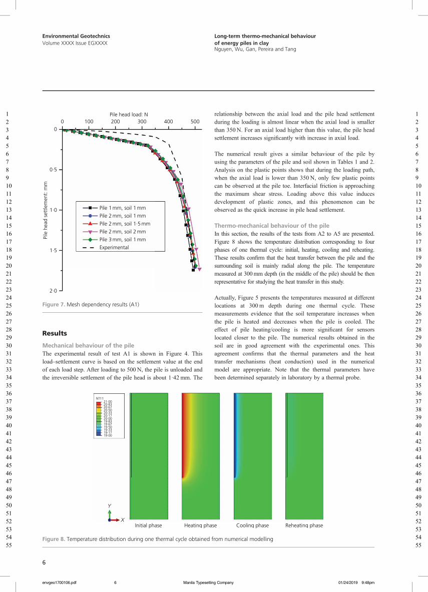
Mesh sensitivity studyFive different mesh convergence analyses were performed tostudy mesh dependency of the numerical model. For the pile,uniform 1, 2 and 3 mm seed sizes are applied in the pile regionwith an unchanged 1 mm mesh size at the soil side of thesoil–pile interface to find the appropriate pile mesh size. It isfound that a 2 mm mesh size for the pile was sufficient, and then,mesh sizes of 1, 1·5 and 2 mm are applied into the soil side of thesoil–pile interface region, which enables in total five differenttypes of mesh size combinations. At the far end, bottom and sideof the soil, the mesh seed size was set to a fixed 20 mm value forall simulations. Here only the purely mechanical loadingcondition, A1, was considered for this mesh convergence study,which was similar to Wehnert and Vermeer’s (2004) work. InFigure 7, load–settlement curves for different mesh sizecombinations are given. The mesh ‘Pile 2 mm, soil 1 mm’ isselected since it is above the threshold (i.e. ‘Pile 2 mm, soil1·5 mm’) compared with the experimental data for the puremechanical loading. This finer mesh provides a better confidencefor the results from later thermo-mechanical analyses, while onlyslightly increasing the demand on computational resources.
X-dimension: m0 0·1 0·2 0·3
Adiabatic boundary,zero pore water pressure
Constant temperature,impermeable soil
Con
stan
t te
mpe
ratu
re, i
mpe
rmea
ble
soil
Axi
sym
met
ric, a
diab
atic
bou
ndar
y, im
perm
eabl
e so
il
Y-d
imen
sion
: m
1·0
0·8
0·6
0·4
0·2
0
Figure 6. Geometry and boundary conditions of the numericalmodel
Table 1. Parameters of pile and soil in numerical modelling
g
Parameter
Company
Pile (CHSaluminium)
Clay (Speswhitekaolin clay)
Constitutive model
Linear-elastic Modified Cam-clay Dry density: Mg/m3 1·32 1·45 Volumetric weight atsaturated state: kN/m3N/A
18·53Young’s modulus E: kPa
1·3 × 107 N/A Poisson’s ratio n a 0·33 0·25 Slope of critical state line Ma N/A 0·98 Slope of virginconsolidation line laN/A
0·14Slope of swelling line k a
N/A 0·012 Initial void ratio e0a
N/A 1·6 Void ratio aftercompaction e1N/A
0·79Friction angle f:a °
N/A 25 Permeability k:a m/s N/A 1 × 10⁻⁸Thermal expansion: /°C
2·3 × 10−5 1 × 10⁻⁶Thermal conductivity:W/(m °C)
237
1·5Specific heat capacity:J/(kg °C)
9 × 10²
1·269 × 103a Soil properties are adopted from the paper of Lv et al. (2017)
Table 2. Other relevant parameters in numerical modelling
Volumetric weight of water: kN/m3
01/24/20
9·81
Friction coefficient tan f 0·47 Interfacial thermal conductance: W/(°C m2) 500 Lateral earth coefficient, K0 819 9:48pm
5
12345678910111213141516171819202122232425262728293031323334
12345678910111213141516171819202122232425262728293031323334353637383940414243444546474849505152535455
Environmental GeotechnicsVolume XXXX Issue EGXXXX
Long-term thermo-mechanical behaviourof energy piles in clayNguyen, Wu, Gan, Pereira and Tang
Results
Mechanical behaviour of the pileThe experimental result of test A1 is shown in Figure 4. Thisload–settlement curve is based on the settlement value at the endof each load step. After loading to 500 N, the pile is unloaded andthe irreversible settlement of the pile head is about 1·42 mm. The
envgeo1700106.pdf Manila Typesettin6
6
relationship between the axial load and the pile head settlementduring the loading is almost linear when the axial load is smallerthan 350 N. For an axial load higher than this value, the pile headsettlement increases significantly with increase in axial load.
The numerical result gives a similar behaviour of the pile byusing the parameters of the pile and soil shown in Tables 1 and 2.Analysis on the plastic points shows that during the loading path,when the axial load is lower than 350 N, only few plastic pointscan be observed at the pile toe. Interfacial friction is approachingthe maximum shear stress. Loading above this value inducesdevelopment of plastic zones, and this phenomenon can beobserved as the quick increase in pile head settlement.
Thermo-mechanical behaviour of the pileIn this section, the results of the tests from A2 to A5 are presented.Figure 8 shows the temperature distribution corresponding to fourphases of one thermal cycle: initial, heating, cooling and reheating.These results confirm that the heat transfer between the pile and thesurrounding soil is mainly radial along the pile. The temperaturemeasured at 300mm depth (in the middle of the pile) should be thenrepresentative for studying the heat transfer in this study.
Actually, Figure 5 presents the temperatures measured at differentlocations at 300 m depth during one thermal cycle. Thesemeasurements evidence that the soil temperature increases whenthe pile is heated and decreases when the pile is cooled. Theeffect of pile heating/cooling is more significant for sensorslocated closer to the pile. The numerical results obtained in thesoil are in good agreement with the experimental ones. Thisagreement confirms that the thermal parameters and the heattransfer mechanisms (heat conduction) used in the numericalmodel are appropriate. Note that the thermal parameters havebeen determined separately in laboratory by a thermal probe.
0
0·5
1·0
1·5
2·0
0 100 200 300 400 500Pile head load: N
Pile
hea
d se
ttle
men
t: m
m
Pile 1 mm, soil 1 mm
Pile 2 mm, soil 1 mm
Pile 2 mm, soil 1·5 mm
Pile 2 mm, soil 2 mm
Pile 3 mm, soil 1 mm
Experimental
Figure 7. Mesh dependency results (A1)
353637383940414243444546474849505152535455
Initial phase Heating phase Cooling phase Reheating phase
Y
X
NT1121·0020·8320·6720·5020·3320·1720·0019·8319·6719·5019·3319·1719·00
Figure 8. Temperature distribution during one thermal cycle obtained from numerical modelling
01/24/2019 9:48pmg Company

12345678910111213141516171819202122232425262728293031323334353637383940414243444546474849505152535455
12345678910111213141516171819202122232425262728293031323334353637383940414243444546474849505152535455
Environmental GeotechnicsVolume XXXX Issue EGXXXX
Long-term thermo-mechanical behaviourof energy piles in clayNguyen, Wu, Gan, Pereira and Tang
Figure 9 shows the results of temperature and displacement of thepile over the 30 thermal cycles under different loads. It can be seenthat the target temperature (20°C–21°C–19°C–20°C) in eachthermal cycle could not be strictly respected during the first test(A2). This is related to the variation in temperature in the room. Forthis reason, in the subsequent tests (A3, A4 and A5), the thermalisolation of the tube connecting the cryostat and the pile wasimproved, which allowed reducing significantly the influence ofroom temperature on the pile temperature. In Figure 9, the pile headsettlement of each test is set to zero at the beginning of the thermalcycles. The results show generally a pile head heave during heatingand settlement during cooling. However, the relation between thepile head displacement and the pile temperature is not strictlyreversible. Note that the temperature was controlled manually, andfor some cycles corresponding to weekend periods, the activeheating phase took longer than 2 d. Nevertheless, it seems that theselonger phases do not influence significantly the results.
In the numerical model, the pile temperature measured in theexperiment is imposed to the whole pile to simulate the thermalcycles under constant pile head load. The pile head settlementobtained by the simulation is also shown in Figure 9. Thenumerical results show equally a pile head heave during heatingand settlement during cooling. More details on pile headdisplacement during each thermal cycle and the irreversible pilehead displacement are shown in Figures 10 and 11.
envgeo1700106.pdf Manila Typesettin7
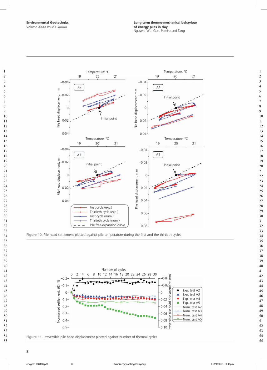
To analyse better the pile head displacement during each thermalcycle, in Figure 10, it is plotted against pile temperature for the firstand the last cycles only. The free-expansion curve, obtained with theassumption of a pile restrained at its toe, is also plotted. In eachthermal cycle, heating induces pile head heave and cooling inducespile head settlement. For A3, A4 and A5 (under constant head load),the first thermal cycle induces a significant irreversible settlement.For the case of test A2 where no head load was applied, thebehaviour during the first thermal cycle is quite reversible. For thelast thermal cycle, a reversible behaviour can be observed for allthe tests. Moreover, it can be noted that the slope of the pile headdisplacement against temperature change during the cooling phase isslightly smaller than that of the free-expansion curve.
The results obtained by the numerical simulation are generally inagreement with the experimental ones. Actually, the behaviourobtained during the last thermal cycles is strictly reversible andthe first thermal cycle in tests A3, A4 and A5 (under constant pilehead load) induces significant reversible settlement. Only thebehaviour of the first cycle of test A2 (without pile head load)shows a difference. In the numerical model, an irreversible pilehead heave was obtained after the first thermal cycle.
The irreversible pile head displacement is plotted against the numberof cycles in Figure 11. For a better comparison with full-scaleexperiments, it is also normalised with the pile diameter. For test A2,
22
20
18
Test A2
Tem
pera
ture
: ºC
Dis
plac
emen
t: m
m –0·04
–0·02
0
0·02
Exp.Num.
0 5 10 15 20 25 30 35 40Elapsed time: d
22
20
18
Test A3
Tem
pera
ture
: ºC
Dis
plac
emen
t: m
m –0·02
0
0·02
Exp.
Num.
0 5 10 15 20 25 30 35Elapsed time: d
0·04
22
20
18
Test A4
Tem
pera
ture
: ºC
Dis
plac
emen
t: m
m –0·02
0
0·02
Exp.
Num.
0 5 10 15 20 25 30 35Elapsed time: d
0·04
22
20
18
Test A5
Tem
pera
ture
: ºC
Dis
plac
emen
t: m
m –0·020
0·02
Exp.
Num.
0 5 10 15 20 25 30 35
0·040·060·08
Elapsed time: d
Figure 9. Temperature and pile head displacement plotted against elapsed time (A2–A5)
01/24/2019 9:48pmg Company
7
1234567891011121314151617181920212223242526272829303132333435
12345678910111213141516171819202122232425262728293031323334353637383940414243444546474849505152535455
Environmental GeotechnicsVolume XXXX Issue EGXXXX
Long-term thermo-mechanical behaviourof energy piles in clayNguyen, Wu, Gan, Pereira and Tang
Temperature: ºC
Temperature: ºCTemperature: ºC
Temperature: ºC
19
19 19
1920
20 20
20 2121
21 21
–0·04
–0·04 –0·04
–0·04
–0·02
–0·02 –0·02
–0·02
0·02
0·02 0·02
0·02
0·04
0·04 0·04
0·06
0·08
0·04
0
0 0
0
A2
A3 A5
A4
Initial point
Initial point
Initial point
Initial point
Pile
hea
d di
spla
cem
ent:
mm
Pile
hea
d di
spla
cem
ent:
mm
Pile
hea
d di
spla
cem
ent:
mm
Pile
hea
d di
spla
cem
ent:
mm
First cycle (exp.)
First cycle (num.)Thirtieth cycle (exp.)
Thirtieth cycle (num.)Pile free-expansion curve
Figure 10. Pile head settlement plotted against pile temperature during the first and the thirtieth cycles
3637383940414243444546474849505152535455
Number of cycles0 2 4 6 8 10 12 14 16 18 20 22 24 26 28 30
–0·2 –0·04
–0·02
0·02
0·04
0·06
0·08
0·10
–0·1
0·2
0·3
0·4
0·5
0·1
0 0
Nor
mal
ised
set
tlem
ent,
δ/D
: %
Irrev
ersi
ble
pile
hea
d di
spla
cem
ent:
mm
Exp. test A2Exp. test A3Exp. test A4Exp. test A5Num. test A2Num. test A3Num. test A4Num. test A5
Figure 11. Irreversible pile head displacement plotted against number of thermal cycles
envgeo1700106.pdf 01/24/2019 9:48pmManila Typesetting Company8
8

1234567891011121314151617181920212223
12345678910111213141516171819202122232425262728293031323334353637383940414243444546474849505152535455
Environmental GeotechnicsVolume XXXX Issue EGXXXX
Long-term thermo-mechanical behaviourof energy piles in clayNguyen, Wu, Gan, Pereira and Tang
the first cycle induces pile head heave up to 0·15% of the pilediameter with the numerical model. Afterwards, the pile behaviourremains reversible during thermal cycles. However, with the physicalmodel, the first cycle induces only a very small pile heave (0·03% ofthe pile diameter). However, pile heave continues to increase duringthe subsequent cycles and reaches 0·20% of pile diameter after fourcycles. For tests A3 and A4, the first thermal cycles inducesignificant irreversible settlement. This later becomes negligible forthe subsequent cycles. The behaviour of the pile in test A5 is alsosimilar to that in tests A3 and A4. However, after the tenth cycle, theirreversible settlement increases continuously with the increase in thenumber of cycles. Furthermore, it can be noted that the irreversiblesettlement depends on the pile head load; the higher the pile headload, the higher the irreversible settlement. For test A5, the suddenincrease in irreversible settlement from the tenth cycle should berelated to some technical problems. The possible causes of problemsoccurred could be tilting of the pile at high cumulative settlement,failure of soil around the pile toe or other physico-chemicalphenomena that occur in soil after a long period (several months).
The results obtained by the numerical simulation are generally ingood agreement with the experimental ones. The only differenceis related to test A5, where the pile head irreversible displacement
envgeo1700106.pdf Manila Typesettin9
remains constant event after the tenth cycle in the numericalsimulation.
The long-term performance of the pile is further illustratedaccording to the numerical results. The vertical displacement ofpile length in the heating phase (H), cooling phase (C) andreheating phase (R) are plotted in Figure 12. The first, second,20th and 30th thermal cycles are selected here because simulationresults show that the majority of irreversible settlement happenswithin the first three cycles and is relatively stable in the rest ofthermal cycles. Note that the vertical displacement of the pile isassumed zero at the beginning of the first cycle in order to beconsistent with Figure 11. It is obvious that heating and coolingthe pile cause displacement distribution to be mirror-reflectingeach other and the vertical displacement remains constant alongthe pile length in the reheating phase. The time evolution of thedisplacement profile is stabilised over a few cycles with a nullpoint at about 430 mm beneath the top surface.
The total vertical stress along the pile length under differentthermal cycles obtained from the numerical simulation ispresented in Figure 13. Only the results obtained from the firstand the last cycles are presented for clarity. Generally, heating the
2425262728293031323334353637383940414243444546474849505152535455
Vertical displacement of pile: mmVertical displacement of pile: mm
Vertical displacement of pile: mmVertical displacement of pile: mm
0 0
100 100
200 200
300 300
400 400
500 500
600 600
0 0·01 0·02 0·03 0·04–0·02 –0·01
0 0·01 0·02 0·03 0·04–0·02 –0·01 0 0·01 0·02 0·03 0·04–0·02 –0·01
0 0·01 0·02 0·03 0·04–0·02 –0·01
Pile
leng
th: m
mPi
le le
ngth
: mm
Pile
leng
th: m
mPi
le le
ngth
: mm
A2
A3 A5
A4
H1
H2
H20
H30
C1
C2
C20
C30
R1
R2
R20
R30
H1
H2
H20
H30
C1
C2
C20
C30
R1
R2
R20
R30
H1
H2
H20
H30
C1
C2
C20
C30
R1
R2
R20
R30
H1
H2
H20
H30
C1
C2
C20
C30
R1
R2
R20
R30
Null point
Null point
Null point
0
100
200
300
400
500
600
0
100
200
300
400
500
600
Null point
Figure 12. Vertical displacement along the pile length (numerical results)
01/24/2019 9:48pmg Company
9

12345678910111213141516171819202122232425262728293031323334353637383940414243444546474849505152535455
12345678910111213141516171819202122232425262728293031323334353637383940414243444546474849505152535455
Environmental GeotechnicsVolume XXXX Issue EGXXXX
Long-term thermo-mechanical behaviourof energy piles in clayNguyen, Wu, Gan, Pereira and Tang
pile induces a slight increase in vertical stress and cooling causesa decrease in vertical stress distribution along the pile length. Thebehaviour obtained during the first cycle of test A2 is slightlydifferent; heating induces a decrease in vertical stress and coolingdecreases it again. In addition, the vertical stress is observed toincrease slightly from the first to the last thermal cycle in allheating, cooling and reheating phases.
DiscussionIn the mechanical test paths (test A1), the material parameters forthe numerical simulation are adopted from the paper of Lv et al.(2017). From the results, it is obvious that the estimated bearingcapacity is in agreement with the experimental results (Figure 4).A carefully estimated lateral stress coefficient (K0) is important toconsider the compaction process in physical model.
In test A2, the upward displacement of the pile (as shown inFigure 9) during heating–cooling cycles, observed on bothphysical and numerical models, can be explained by the stressstate shown in Figure 13. Actually, test A2 starts after the
envgeo1700106.pdf Manila Typesettin10
10
mechanical unloading path of test A1. At the end of the unloadingpath, the pile is still subjected to compressive stress (up to300 kPa at its toe). Thermal cycles in test A2 induce thermaldilation/contraction of the pile. This movement would release thiscompressive stress and heave the pile. The results shown inFigure 13 evidence this stress release after thermal cycles.
In the subsequent tests (A3, A4 and A5), irreversible settlementwas observed during the first thermal cycles. These results are inagreement with those observed by Ng et al. (2014) (usingcentrifuge modelling) and Vieira and Maranha (2016) by usingthe finite element method. However, only five thermal cycles wereinvestigated in these works. Actually, the axial stress profilesplotted in Figure 13 show that these thermal cycles increase theaxial stress along the pile. That means the thermal dilation/contraction of the pile facilitates the transmission of the axialpile head load to the pile toe. In the present works, bothnumerical and physical models show that the pile settlementbecomes reversible under thermal cycles at high number of cycles(except for test A5).
Total vertical stress: kPa
Total vertical stress: kPa Total vertical stress: kPa
Total vertical stress: kPa
Pile
leng
th: m
mPi
le le
ngth
: mm
Pile
leng
th: m
mPi
le le
ngth
: mm
0
0
100
200
300
400
500
600
0
100
200
300
400
500
600
0
100
200
300
400
500
600
0
100
200
300
400
500
600
50 100 150 200 250 350300
InitialH1
H30
C1
C30
R1
R30
InitialH1
H30
C1
C30
R1
R30
InitialH1
H30
C1
C30
R1
R30
InitialH1
H30
C1
C30
R1
R30A2
A3 A5
A4
250 300 350 400 450 500 600 650550
250 300 350 400 450 500 600 650550
300 400 500 600 700 800 1000900
Figure 13. Thermal effect on the total vertical stress along the pile length (numerical results)
01/24/2019 9:48pmg Company
Q11
Q12
Q13
12345678910111213141516171819202122232425262728293031323334353637383940414243444546474849505152535455
12345678910111213141516171819202122232425262728293031323334353637383940414243444546474849505152535455
Environmental GeotechnicsVolume XXXX Issue EGXXXX
Long-term thermo-mechanical behaviourof energy piles in clayNguyen, Wu, Gan, Pereira and Tang
The numerical model shows a behaviour similar to that obtained bythe physical model; the pile settlement progressively achieves astable state due to the densification process in each thermal cycle. Inparticular, the first thermal cycle shows good agreement with theexperimental result (Figure 10). The explanation of why numericalsimulation is able to predict progressive settlement owes to the use ofthe modified Cam-clay model as the constitutive model for soil. TheCam-clay criterion follows the poro-plasticity rule that could moreeffectively simulate densification process during thermal cyclic loads,whereas the Mohr–Coulomb model may not well describe such soilbehaviour (Yavari et al., 2014). Therefore, the present numericalprediction of long-term thermal cyclic settlement of an energy pile isable to predict experimental data with relatively good agreement.
The results of Figure 10 show that the slope of the plot of the pilehead displacement against temperature change during the coolingphase is slightly smaller than that of the free-expansion curve.Actually, similar tests on dry sand have shown that this slope issimilar to the free-expansion curve (Kalantidou et al., 2012;Yavari et al., 2014). The behaviour observed in the present workcan be explained by the results shown in Figure 12. Actually, thenull point is not located at the pile toe but at 400–450 mm depth.For this reason, the pile head displacement does not correspond tothe free expansion of the whole pile length.
In the present work, the numerical model was able to reproducecorrectly the thermo-mechanical behaviour of a small-scale energypile under several thermal cycles. Note that the range of thetemperature variation in the physical model was limited to ±1°C.This value is much smaller than full-scale application (up to±20°C) in order to respect the scale effect. Within this limitedrange of temperature variation, the soil parameters can beassumed to be independent of temperature. However, for a highertemperature variation, the temperature change can slightly modifythe soil properties (Ghorbani et al., 2019; Hong et al., 2016;Jacinto and Ledesma, 2017; Tang et al., 2008; Vega andMcCartney, 2015; Yavari et al., 2016b). The use of the presentnumerical model to predict the behaviour of real-scale energyfoundations should consider this aspect.
Results obtained in the present study would be helpful for studieson various types of thermo-active geostructures (Angelotti andSterpi, 2019; Baralis et al., 2019; Hoyos et al., 2015; Narsilioet al., 2017; Sanchez et al., 2017).
ConclusionsThe long-term thermo-mechanical behaviour of an energy pile isinvestigated in the present work by using a small-scale model pile(physical modelling) and the finite-element method (numericalmodelling). The following conclusions can be drawn.
■ Thermal cycles applied to the pile under a constant pile headload induce stress redistribution inside the pile. This can induceirreversible pile heave in the case without a pile head load andirreversible pile settlement in the case with pile head load.
envgeo1700106.pdf Manila Typesettin11
■ The irreversible pile head settlement/heave is more importantwithin the first thermal cycles; it becomes negligible at highnumber of cycles.
■ The main mechanism that controls the soil–pile interactionduring thermal cycles under constant pile head load is the pilethermal contraction/dilation. The numerical model can capturecorrectly the experimental result without considering thetemperature effect on soil parameters.
The preliminary results shown in this paper could warrant futurenumerical studies for the serviceability design of geothermalenergy piles.
AcknowledgementsDr Gan acknowledges the financial support of Labex MMCD forhis stay at Laboratoire Navier. Labex MMCD benefits from aFrench government grant managed by ANR within the frame ofthe national programme Investments for the Future ANR-11-LABX-022-01.
REFERENCESAbuel-Naga H, Raouf MIN, Raouf AMI and Nasser AG (2015) Energy
piles: current state of knowledge and design challenges. EnvironmentalGeotechnics 2(4): 195–210.
Afnor (Association Française de Normalisation) (1999) NF P 94-150-1:Essai statique de pieu isolé sous un effort axial. Afnor, Paris, France(in French).
Angelotti A and Sterpi D (2019) On the performance of energy walls bymonitoring assessment and numerical modelling: a case in Italy.Environmental Geotechnics, https://doi.org/10.1680/jenge.18.00037.
Baralis M, Barla M, Bogusz W et al. (2019) Geothermal potential of theNE extension Warsaw (Poland) metro tunnels. EnvironmentalGeotechnics, https://doi.org/10.1680/jenge.18.00042.
Bidarmaghz A, Francisca FM, Makasis N and Narsilio GA (2016)Geothermal energy in loess. Environmental Geotechnics 3(4):225–236, https://doi.org/10.1680/jenge.15.00025.
de Santayana FP, de Santiago C, de Groot M et al. (2019) Effect ofthermal loads on pre-cast concrete thermopile in Valencia, Spain.Environmental Geotechnics, https://doi.org/10.1680/jenge.17.00103.
Di Donna A and Laloui L (2015) Numerical analysis of the geotechnicalbehaviour of energy piles. International Journal for Numerical andAnalytical Methods in Geomechanics 39(8): 861–888, https://doi.org/10.1002/nag.2341.
Ghorbani J, El-Zein A and Airey DW (2019) Thermo-elasto-plastic analysisof geosynthetic clay liners exposed to thermal dehydration.Environmental Geotechnics, https://doi.org/10.1680/jenge.17.00035.
Hong PY, Pereira JM, Cui YJ and Tang AM (2016) A two-surfacethermomechanical model for saturated clays. International Journal forNumerical and Analytical Methods in Geomechanics 40(7):1059–1080, https://doi.org/10.1002/nag.2474.
Hoyos LR, DeJong JT, McCartney JS et al. (2015) Environmentalgeotechnics in the US region: a brief overview. EnvironmentalGeotechnics 2(6): 319325, https://doi.org/10.1680/envgeo.14.00024.
Jacinto AC and Ledesma A (2017) Thermo-hydro-mechanical analysis of afull-scale heating test. Environmental Geotechnics 4(2): 123–134,https://doi.org/10.1680/jenge.15.00049.
Kalantidou A, Tang AM and Pereira JM (2012) Preliminary study on themechanical behaviour of heat exchanger pile in physical model.Géotechnique 62(1): 1047–1051, https://doi.org/10.1680/geot.11.T.013.
Laloui L, Nuth M and Vulliet L (2006) Experimental and numericalinvestigations of the behaviour of a heat exchanger pile. International
01/24/2019 9:48pmg Company
11

Q14
12345678910111213141516171819202122232425262728
12345678910111213141516171819202122232425262728293031323334353637383940414243444546474849505152535455
Environmental GeotechnicsVolume XXXX Issue EGXXXX
Long-term thermo-mechanical behaviourof energy piles in clayNguyen, Wu, Gan, Pereira and Tang
Journal for Numerical and Analytical Methods in Geomechanics30(8): 763–781, https://doi.org/10.1002/nag.499.
Lv YR, Ng CWW, Lam SY, Liu HL and Ma LJ (2017) Geometric effects onpiles in consolidating ground: centrifuge and numerical modeling.Journal of Geotechnical and Geoenvironmental Engineering 143(9):04017040.
Narsilio GA, Sanchez M, Alvarellos J and Guimaraes L (2017) Editorial:XV Pan-American Conference: selected papers on energy geotechnics.Environmental Geotechnics 4(2): 67–69, https://doi.org/10.1680/jenge.2017.4.2.67.
Ng CWW, Shi C, Gunawan A and Laloui L (2014) Centrifuge modelling ofenergy piles subjected to heating and cooling cycles in clay. GéotechniqueLetters 4(4): 310–316, https://doi.org/10.1680/geolett.14.00063.
Ng CWW, Ma QJ and Gunawan A (2016) Horizontal stress change ofenergy piles subjected to thermal cycles in sand. Computers andGeotechnics 78(2016): 54–61, https://doi.org/10.1016/j.compgeo.2016.05.003.
Nguyen VT, Tang AM and Pereira JM (2017) Long-term thermo-mechanical behavior of energy pile in dry sand. Acta Geotechnica12(4): 729–737.
Olgun CG, Ozudogru TY, Abdelaziz SL and Senol A (2015) Long-termperformance of heat exchanger piles. Acta Geotechnica 10(5):553–569, https://doi.org/10.1007/s11440-014-0334-z.
Pasten C and Santamarina JC (2014) Thermally induced long-termdisplacement of thermoactive piles. Journal of Geotechnical andGeoenvironmental Engineering 140(5): 6014003, https://doi.org/10.1061/(ASCE)GT.1943-5606.0001092.
Pasten C, Shin H and Santamarina JC (2013) Long-term foundationresponse to repetitive loading. Journal of Geotechnical andGeoenvironmental Engineering 140(4): 4013036, https://doi.org/10.1061/(ASCE)GT.1943-5606.0001052.
Saggu R and Chakraborty T (2015) Cyclic thermo-mechanical analysis ofenergy piles in sand. Geotechnical and Geological Engineering 33(2):321–342, https://doi.org/10.1007/s10706-014-9798-8.
envgeo1700106.pdf Manila Typesettin12
29
12
Sanchez M, Falcao F, Mack M et al. (2017) Salient comments from anexpert panel on energy geotechnics. Environmental Geotechnics 4(2):135–142, https://doi.org/10.1680/jenge.16.00008.
Suryatriyastuti ME, Mroueh H and Burlon S (2014) A load transferapproach for studying the cyclic behavior of thermo-active piles.Computers and Geotechnics 55: 378–391, https://doi.org/10.1016/j.compgeo.2013.09.021.
Tang AM, Cui YJ and Barnel N (2008) Thermo-mechanical behaviour ofcompacted swelling clay. Géotechnique 58(1): 45–54, https://doi.org/10.1680/geot.2008.58.1.45.
Vega A and McCartney JS (2015) Cyclic heating effects on thermalvolume change of silt. Environmental Geotechnics 2(5): 257–268,https://doi.org/10.1680/envgeo.13.00022.
Vieira A and Maranha JR (2016) Thermoplastic analysis of a thermoactivepile in a normally consolidated clay. International Journal ofGeomechanics 17(1): 4016030, https://doi.org/10.1061/(ASCE)GM.1943-5622.0000666.
Wehnert M and Vermeer PA (2004) Numerical analyses of load tests onbored piles. In Numerical Methods in Geomechanics: Proceedings ofthe 9th International Symposium on Numerical Models inGeomechanics – NUMOG IX, 25–27 August 2004, Ottawa, Canada(Pande GN and Pietruszczak S (eds)). CRC Press/Balkema, Leiden,the Netherlands, pp. 505–511.
Yavari N, Tang AM, Pereira JM and Hassen G (2014) Experimental studyon the mechanical behaviour of a heat exchanger pile using physicalmodelling. Acta Geotechnica 9(3): 385–398, https://doi.org/10.1007/s11440-014-0310-7.
Yavari N, Tang AM, Pereira JM and Hassen G (2016a) Mechanicalbehaviour of a small-scale energy pile in saturated clay. Géotechnique66(11): 878–887, https://doi.org/10.1680/jgeot.15.T.026.
Yavari N, Tang AM, Pereira JM and Hassen G (2016b) Effect oftemperature on the shear strength of soils and soil/structure interface.Canadian Geotechnical Journal 53(7): 1186–1194, https://doi.org/10.1139/cgj-2015-0355.
30
313233343536373839404142434445464748495051525354How can you contribute?
To discuss this paper, please submit up to 500 words tothe editor at [email protected]. Your contribution will beforwarded to the author(s) for a reply and, if consideredappropriate by the editorial board, it will be published as adiscussion in a future issue of the journal.
01/24/2019 9:48pmg Company
55

Author Queries
Q1: ‘energy pile’, ‘numerical modelling’, ‘physical modelling’, ‘saturated clay’, ‘thermal cycles’, and ‘thermo-mechanicalbehaviour’ are not valid keywords. Please select 3 keywords from the Environmental Geotechnics list (https://www.icevirtuallibrary.com/pb-assets/for%20authors/ENGE%20keywords%20November%202018-1542295903957.pdf).Q2: Please provide full first names for authors Nguyen, Wu, Gan, and Pereira.Q3: Please provide post-nominal qualifications and job titles for all authors.Q4: Please check that the affiliation “Laboratoire Navier” is presented correctly.Q5: Please check if “on an underground” can be changed to “below ground” for clarity.Q6: Please check change to “into a layer of 50 mm thickness”.Q7: Please define OCR.Q8: Please verify that changes in the sentence "The former is calculated based on the Cam-clay ..." have preserved yourmeaning.Q9: Please define CHS.Q10: “Wehnert et al. (2004)” has been changed to “Wehnert and Vermeer (2004)” to match the entry in the reference list.Please check.Q11: Please check change to “soil–pile interaction”.Q12: Please define ANR.Q13: Please provide DOI for Abuel-Naga H, Raouf MIN, Raouf AMI and Nasser AG (2015), Lv YR, Ng CWW, Lam SY,Liu HL and Ma LJ (2017), Nguyen VT, Tang AM and Pereira JM (2017), .Q14: Pasten et al. (2013) is not cited in the text. Please insert a citation or delete the reference.