
LED Driver Circuit Powered By Direct AC - ijareeie
6
ISSN (Print) : 2320 – 3765 ISSN (Online): 2278 – 8875 International Journal of Advanced Research in Electrical, Electronics and Instrumentation Engineering (An ISO 3297: 2007 Certified Organization) Website: www.ijareeie.com Vol. 6, Issue 3, March 2017 Copyright to IJAREEIE DOI:10.15662/IJAREEIE.2017.0603125 1890 LED Driver Circuit Powered By Direct AC Abhishek S 1 ,Akshay S 2 , Deepak Roy 3 , Vishnu R 4 , Minnu Mary Joy 5 B.Tech Students, Dept. of EEE, Mar Baselios Institute of Technology and Science, Nellimattom, Kerala, India 1,2,3 4 Assistant Professor, Dept. of EEE, Mar Baselios Institute of Technology and Science, Nellimattom, Kerala, India 5 ABSTRACT: This paper proposes a drive circuit for ac-direct LED lamps. The proposed circuit consists only of a line filter, an LED bridge, a load inductor, a bidirectional switch, and a switch-control circuit. The switch connects the LED Bridge to the power line directly. Each leg of the LED bridge consists of LEDs and a protection diode, all connected in series. The load inductor limits the bridge current. The switch operates at a zero current switching condition, so the circuit has high power efficiency. The circuit can operate at a free-volt input condition (85<V in,rms <265V). For all input voltage conditions the circuit had PE >89%, luminous efficiency ∼90 lm/W, power factor >0.9, and 120-Hz flicker index ∼0.3. The circuit satisfies the IEC 61000-3-2 Class C and the EN 55015 regulations. The proposed LED driver is well suited for use in household LED lamps. KEYWORDS:Active circuits, current control, light-emitting diodes (LEDs), lighting, power electronics. I.INTRODUCTION In outdoor lighting applications where the effect of flicker at 120/100 Hz from commercial AC mains can be neglected, AC-powered LED drivers are more attractive than switch mode LED drivers since they simplify the design as well as reduce the cost of lighting module. Recently, there have been studies of high PF, low THD AC-directly-powered LED drivers can achieve a very high performance, and they also have several short comings. With the design proposed, it is constructed with a lowest number of components; however, as the number of LED strings increases, the design shows a difficulty of realizing the switching function. Another design reported shows a high PF with a dimming feature; however it is very complicated in implementing the design with expensive blocks which degrades its robustness. As the most effective design, the technique reported can gain a high, very high PF and a low THD using self-adaptive soft-switching method without any additional control circuit as well as can be customized to balance the requirements of performance and cost. However, with these AC LED drives, dimming function using TRIAC dimmer can be challenging. All of these design cannot be performed properly with the conventional TRIAC dimmer as in switch-mode LED drivers because of the two main problems. Degrade the PF due to current chopping, (2) Increase the flicker because of the dead zone of the LED current which might result in negative effects on the health Therefore, a new and effective design of a dimmable AC-direct LED driver for outdoor applications is needed. In this paper, an on-chip step-dimmer using analog dimming method in accompany with the novel self-adaptive power processing core is proposed for regulating simultaneously LED brightness as well as maintaining a high power factor and a low total harmonic distortion via simple concept. Furthermore, there is no need of any external passive components, thereby enhancing the lifespan of an overall LED module as well as achieving a solution of a fully integrated circuit of the design.
-
Upload
khangminh22 -
Category
Documents
-
view
4 -
download
0
Transcript of LED Driver Circuit Powered By Direct AC - ijareeie
ISSN (Print) : 2320 – 3765
ISSN (Online): 2278 – 8875
International Journal of Advanced Research in Electrical,
Electronics and Instrumentation Engineering
(An ISO 3297: 2007 Certified Organization)
Website: www.ijareeie.com
Vol. 6, Issue 3, March 2017
Copyright to IJAREEIE DOI:10.15662/IJAREEIE.2017.0603125 1890
LED Driver Circuit Powered By
Direct AC Abhishek S
1,Akshay S
2, Deepak Roy
3, Vishnu R
4, Minnu Mary Joy
5
B.Tech Students, Dept. of EEE, Mar Baselios Institute of Technology and Science, Nellimattom, Kerala, India1,2,3 4
Assistant Professor, Dept. of EEE, Mar Baselios Institute of Technology and Science, Nellimattom, Kerala, India5
ABSTRACT: This paper proposes a drive circuit for ac-direct LED lamps. The proposed circuit consists only of a line filter, an LED bridge, a load inductor, a bidirectional switch, and a switch-control circuit. The switch connects the LED Bridge to the power line directly. Each leg of the LED bridge consists of LEDs and a protection diode, all connected in series. The load inductor limits the bridge current. The switch operates at a zero current switching condition, so the circuit has high power efficiency. The circuit can operate at a free-volt input condition (85<Vin,rms<265V). For all input voltage conditions the circuit had PE >89%, luminous efficiency ∼90 lm/W, power factor >0.9, and 120-Hz flicker index ∼0.3. The circuit satisfies the IEC 61000-3-2 Class C and the EN 55015 regulations. The proposed LED driver is well suited for use in household LED lamps.
KEYWORDS:Active circuits, current control, light-emitting diodes (LEDs), lighting, power electronics.
I.INTRODUCTION
In outdoor lighting applications where the effect of flicker at 120/100 Hz from commercial AC mains can be neglected,
AC-powered LED drivers are more attractive than switch mode LED drivers since they simplify the design as well as
reduce the cost of lighting module. Recently, there have been studies of high PF, low THD AC-directly-powered LED
drivers can achieve a very high performance, and they also have several short comings. With the design proposed, it is
constructed with a lowest number of components; however, as the number of LED strings increases, the design shows a
difficulty of realizing the switching function. Another design reported shows a high PF with a dimming feature; however it
is very complicated in implementing the design with expensive blocks which degrades its robustness. As the most effective
design, the technique reported can gain a high, very high PF and a low THD using self-adaptive soft-switching method
without any additional control circuit as well as can be customized to balance the requirements of performance and cost.
However, with these AC LED drives, dimming function using TRIAC dimmer can be challenging. All of these design
cannot be performed properly with the conventional TRIAC dimmer as in switch-mode LED drivers because of the two
main problems. Degrade the PF due to current chopping, (2) Increase the flicker because of the dead zone of the LED
current which might result in negative effects on the health
Therefore, a new and effective design of a dimmable AC-direct LED driver for outdoor applications is needed. In this
paper, an on-chip step-dimmer using analog dimming method in accompany with the novel self-adaptive power processing
core is proposed for regulating simultaneously LED brightness as well as maintaining a high power factor and a low total
harmonic distortion via simple concept. Furthermore, there is no need of any external passive components, thereby
enhancing the lifespan of an overall LED module as well as achieving a solution of a fully integrated circuit of the design.
ISSN (Print) : 2320 – 3765
ISSN (Online): 2278 – 8875
International Journal of Advanced Research in Electrical,
Electronics and Instrumentation Engineering
(An ISO 3297: 2007 Certified Organization)
Website: www.ijareeie.com
Vol. 6, Issue 3, March 2017
Copyright to IJAREEIE DOI:10.15662/IJAREEIE.2017.0603125 1891
II.CIRCUIT DIAGRAM
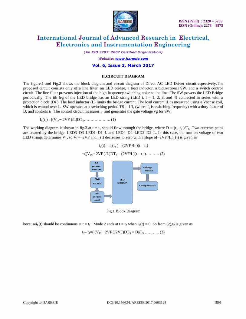
The figure.1 and Fig.2 shows the block diagram and circuit diagram of Direct AC LED Driver circuitrespectively.The
proposed circuit consists only of a line filter, an LED bridge, a load inductor, a bidirectional SW, and a switch control
circuit. The line filter prevents injection of the high frequency switching noise to the line. The SW powers the LED Bridge
periodically. The ith leg of the LED bridge has an LED string (LED i, i = 1, 2, 3, and 4) connected in series with a
protection diode (Di ). The load inductor (L) limits the bridge current. The load current iL is measured using a Vsense coil,
which is wound over L. SW operates at a switching period TS = 1/fs (where fs is switching frequency) with a duty factor of
D, and controls iL. The control circuit measures iL and generates the gate voltage vg for SW.
IL(t1) =[(VIN− 2VF )/L]DTS……………….. (1)
The working diagram is shown in fig.3.at t = t1 should flow through the bridge, where D ≡ (t1–t0 )/TS. Two currents paths
are created by the bridge: LED3–D3–LED1–D1–L and LED4–D4–LED2–D2–L. In this case, the turn-on voltage of two
LED strings determines VL, so VL=−2VF and iL(t) decreases to zero with a slope of−2VF /L.iL(t) is given as
iL(t) = iL(t1 ) – (2VF /L )(t – t1)
=((VIN− 2VF )/L)DTS – (2VF/L)(t – t1 )………. (2)
Fig.1 Block Diagram
becauseiL(t) should be continuous at t = t1 . Mode 2 ends at t = t2 when iL(t) = 0. So from (2),t2 is given as
t2– t1=( (VIN− 2VF )/2VF)DTS ≡ DaTS ……….. (3)
ISSN (Print) : 2320 – 3765
ISSN (Online): 2278 – 8875
International Journal of Advanced Research in Electrical,
Electronics and Instrumentation Engineering
(An ISO 3297: 2007 Certified Organization)
Website: www.ijareeie.com
Vol. 6, Issue 3, March 2017
Copyright to IJAREEIE DOI:10.15662/IJAREEIE.2017.0603125 1892
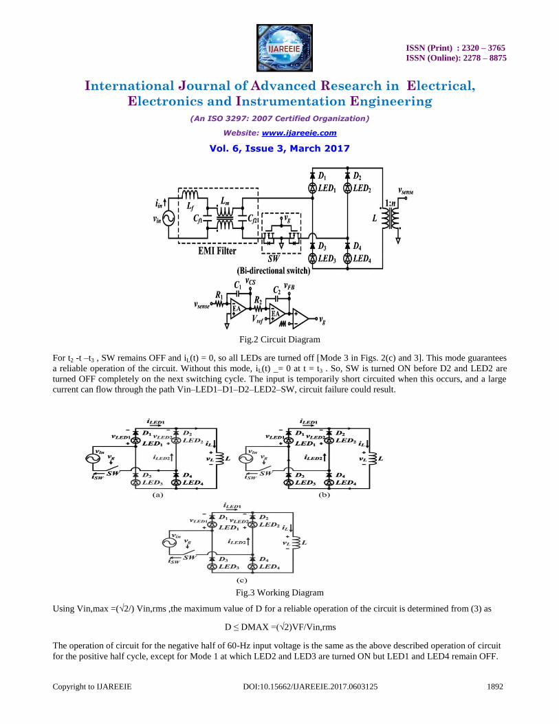
Fig.2 Circuit Diagram
For t2 -t –t3 , SW remains OFF and iL(t) = 0, so all LEDs are turned off [Mode 3 in Figs. 2(c) and 3]. This mode guarantees
a reliable operation of the circuit. Without this mode, iL(t) _= 0 at t = t3 . So, SW is turned ON before D2 and LED2 are
turned OFF completely on the next switching cycle. The input is temporarily short circuited when this occurs, and a large
current can flow through the path Vin–LED1–D1–D2–LED2–SW, circuit failure could result.
Fig.3 Working Diagram
Using Vin,max =(√2/) Vin,rms ,the maximum value of D for a reliable operation of the circuit is determined from (3) as
D ≤ DMAX =(√2)VF/Vin,rms
The operation of circuit for the negative half of 60-Hz input voltage is the same as the above described operation of circuit
for the positive half cycle, except for Mode 1 at which LED2 and LED3 are turned ON but LED1 and LED4 remain OFF.
ISSN (Print) : 2320 – 3765
ISSN (Online): 2278 – 8875
International Journal of Advanced Research in Electrical,
Electronics and Instrumentation Engineering
(An ISO 3297: 2007 Certified Organization)
Website: www.ijareeie.com
Vol. 6, Issue 3, March 2017
Copyright to IJAREEIE DOI:10.15662/IJAREEIE.2017.0603125 1893
III. DESIGN
The control circuit uses a current mode feedback to keep the output power P constant for a free-volt input (85 V <Vin,rms<265 V). It consists of a vsensecoil which is wound over L, two integrators, and a pulse width modulation generator.
The vsensecoil produces a voltage signal
vsense(t) = −nvL(t)
wheren is the turn ratio of the coil. Because iL(t0) = 0 and vL(t) = LdiL(t)/dt, the first integrator with a time constant R1C1
produces
whereiL,avgis the average of iL, and˜iLis the ripple component of iL. The second integrator outputs a feedback signal
WhereΔVFB istheinitialvoltageofC2,which has been adjusted to produce a desired D for a given iL,avg. The third term of (4)
adjusts D to provide negative feedback such that.
The power consumption P of LEDs is
P=2Vf
𝑇 𝑖𝐿 𝑡 𝑑𝑡 =
2𝑅1𝐶1𝑉𝑓𝑉𝑟𝑒𝑓
𝑛𝐿 (5)
𝑇
0
which as desired for a free-volt input operation, is independent of Vin,rms. This equation also shows that LEDs can be
dimmed by decreasing either R1 or Vrefbecause light output of the circuit is proportional to P. The averaged value of iSW(t) over one switching period determines the line current iin(t) approximately, because the proposed circuit uses a line filter
which prevents an injection of high-frequency switching noise into the line. So iin(t) = 0 when vin(t) ≤ 2VF and expressing
iin(t) with a Fourier series, the rms values of iin(t) and the 60-Hz component of iin(t) (IS and IS1) are obtained as
𝐼𝑠 =√2 × 𝐷 × 𝐷𝑉𝑓
𝜋𝐿𝑓𝑠𝐷𝑚𝑎𝑥 𝜋
2− sin−1 𝐷𝑚𝑎𝑥 − 𝐷𝑚𝑎𝑥√1 − 𝐷𝑚𝑎𝑥 × 𝐷𝑚𝑎𝑥 (6)
The power P that is delivered to the LED load by the circuit is calculated using (6) as

ISSN (Print) : 2320 – 3765
ISSN (Online): 2278 – 8875
International Journal of Advanced Research in Electrical,
Electronics and Instrumentation Engineering
(An ISO 3297: 2007 Certified Organization)
Website: www.ijareeie.com
Vol. 6, Issue 3, March 2017
Copyright to IJAREEIE DOI:10.15662/IJAREEIE.2017.0603125 1894
𝑃 = 𝑉𝑖𝑛. 𝑟𝑚𝑠 × 𝐼𝑠 =2
𝜋𝐿𝑓𝑠
𝐷𝑉𝑓
𝐷𝑚𝑎𝑥
2
× 𝜋
2− sin−1 𝐷𝑚𝑎𝑥 − 𝐷𝑚𝑎𝑥√1 − 𝐷𝑚𝑎𝑥 × 𝐷𝑚𝑎𝑥 (7)
The maximum deliverable power PMAX occurs at D =Dmax
V. PROTEUS SIMULATION AND RESULTS
For simulating the platform used is PROTEUS 8 and the circuit is drawn in the untitled and the simulation results are
obtained.
Fig.4 Proteus simulation
The circuit gives the basic circuitry of the Direct AC led driver circuit. The supply is given from the alternator which
is converted using a transformer and the bidirectional switch circuit. The comparator compares the voltage and
supplied to the LED and the output is obtained across the led lights.
VII. CONCLUSION
An inexpensive ac-direct LED drive circuit is proposed. It consists of only a line filter, an LED bridge, a load inductor, a
bidirectional SW, and a switch-control circuit. This circuit requires few components and can operate at a free-volt input
condition. The PE was >89%, the LE was ∼90 lm/W, the PF was >0.9, and the 120-Hz flicker index was ∼0.3 for all input
voltage conditions (85 <Vin,rms<265 V). The circuit satisfies the IEC 61000-3-2 Class C and the EN 55015 regulations. The
circuit can be implemented at lower cost than the multiple-string LED driver. The proposed LED driver is well suited for
use in household LED lamps. The main advantages of this system is that it will give high p.f for the system and also low
ISSN (Print) : 2320 – 3765
ISSN (Online): 2278 – 8875
International Journal of Advanced Research in Electrical,
Electronics and Instrumentation Engineering
(An ISO 3297: 2007 Certified Organization)
Website: www.ijareeie.com
Vol. 6, Issue 3, March 2017
Copyright to IJAREEIE DOI:10.15662/IJAREEIE.2017.0603125 1895
THD. The overall cost is reduced and efficiency is increased. The main applications comes in the field of lighting which
includes street lighting using LED bulbs and tubes, it can also be used in architectural lightings consumes less electricity.
REFERENCES
[1] J. Y. Tsao, “Solid-state lighting: Lamps, chips, and materials for tomorrow,” IEEE Circuits Devices Mag., vol. 20, no. 3, pp. 28–37, May 2004.
[2] D. A. Steigerwald, J. C. Bhat, D. Collins, R. M. Fletcher, M. O. Holcomb, M. J. Ludowise, P. S. Martin, and S. L. Rudaz, “Illumination with solid
state lighting technology,” IEEE J. Sel. Topics Quantum Electron., vol. 8, no. 2, pp. 310–320, Mar. 2002. [3] I. L. Azevedo, M. G. Morgan, and F. Morgan, “The transition to solid-state lighting,” Proc. IEEE, vol. 97, no. 3, pp. 481–510, Mar. 2009.
[4] M. S. Shur and R. Zukauskas, “Solid-state lighting: Toward superior illumination,” Proc. IEEE, vol. 93, no. 10, pp. 1691–1703, Oct. 2005.
[5] S. Muthu, F. J. P. Schuurmans, and M. D. Pashley, “Red, green, and blue LEDsforwhitelightillumination,”IEEEJ.Sel.TopicsQuantumElectron., vol. 8, no. 2, pp. 333–338, Mar./Apr. 2002.
[6] W. Chen and S. Y. R. Hui, “Elimination of an electrolytic capacitor in AC/DC light-emitting diode (LED) driver with high input power factor and
constant output current,” IEEE Trans. Power Electron., vol. 27, no. 3, pp. 1598–1607, Mar. 2012. [7] R.R.Verderber,O.C.Morse,andW.R.Alling,“Harmonicsfromcompact fluorescent lamps,” IEEE Trans. Ind. Appl., vol. 29, no. 3, pp. 670–674, May
1993.
[8] L. Gu, X. Ruan, M. Xu, and K. Yao, “Means of eliminating electrolytic capacitorinAC/DCpowersuppliesforLEDlightings,”IEEETrans.Power Electron., vol. 24, no. 5, pp. 1399–1408, May 2009.
[9] B. Wang, X. Ruan, K. Yao, and M. Xu, “A method of reducing the peakto-average ratio of LED current for electrolytic capacitor-less AC-DC
drivers,” IEEE Trans. Power Electron., vol. 25, no. 3, pp. 592–601, Mar. 2010. [10] S.Wang,X.Ruan,K.Yao,andZ.Ye,“Aflicker-freeelectrolyticcapacitorless AC-DC LED driver,” in Proc. IEEE Energy Convers. Cong. Expo., Sep.
2011, pp. 2318–2325.
[11] D. G. Larmar, M. Fernandez, M. Arias, M. M. Hernando, and J. Sebastian, “Tapped-inductor buck HB-LED AC-DC driver operation in boundary
conduction mode for replacing incandescent bulb lamps,” IEEE Trans. Power Electron., vol. 27, no. 10, pp. 4329–4337, Oct. 2012.
[12] S. C. Moon, G. B. Koo, and G. W. Moon, “A new control method of interleaved single-stage flyback AC-DC converter for outdoor LED lighting
systems,” IEEE Trans. Power Electron., vol. 28, no. 8, pp. 4051–4062, Aug. 2013.