
lecture notes on - automobile engineering
157
AUTOMOBILE ENGINEERING LECTURE NOTES ON AUTOMOBILE ENGINEERING PREPARED BY RANI MARANDI DEPARTMENT OF MECHANICAL ENGINEERING SK DAV Govt.Polytechnic Rourkela
-
Upload
khangminh22 -
Category
Documents
-
view
3 -
download
0
Transcript of lecture notes on - automobile engineering

AUTOMOBILE ENGINEERING
LECTURE NOTES ONAUTOMOBILE ENGINEERING
PREPARED BYRANI MARANDI
DEPARTMENT OF MECHANICAL ENGINEERINGSK DAV Govt.Polytechnic
Rourkela

1.0 INTRODUCTION AND TRANSMISSIONSYSTEM
1.1Automobile:-
“Auto” means self and “mobile” means movable.Thus a self-moving vehicle is known as “automobile”. The term is generallyused for motor cars, delivery vans, trucks etc.
Definition:-It is a self-propelled vehicle which is used for the transportationof goods and passengers(on the ground).
Necessity:-Automobiles are an important part of life in today's world. It isa basic need for every household. Imagine walking hundreds ofmiles for days to get from one place to another, but because ofthe discovery of automobiles, transportation today is muchfaster, easier and reliable.
Classification:-*Purpose:- > goods
E.g- truck, dump truck, lorry> PassengersE.g- car, bus, motorcycle
*Capacity of vehicle:- > light duty> heavy duty
*On the basis of fuel used:- > petrol> Diesel> Electric> Gas and solar
*No. Of wheels used:- > 2-wheeler> 3-wheeler

> 4-wheeler> 10-wheeler etc.
*On the basis of construction:-> saloon cars> bus> trucks, half and full body, folding or
detachable> pick up vans> station wagon> Matador vans> Vanity vans> Jeep> dumper
MAIN UNITS of a motor-car
(a) Body: Where passengers sit or luggage is kept. (b) Chassis:This unit which is used as a base forengine-parts andother parts of motor car.
(c) Engine: This unit is also known as power unit. It includes fuelpump, carburettor, self, dynamo, distributor, spark plug,lubrication pump, etc.
(d) Running Gear: This unit consists of those parts which givemotion to the vehicle such as frontand rear axles, wheels, springs,frame, brake, steering etc.
(e) Transmission System: Those parts of the motor-car whichtransmit the engine power to itswheels, such as clutch, gear box,universal joint, propeller shaft,differential and axle shaft etc. are

included in the transmission system.Variations of speed ratios and forwardand reverse motion are obtainedthrough the transmission system.
Functions of a Car (Main Assembly)
•Motion•Stopping of Motion•Changing direction of Motion•Comfort of the Passenger•Music and air-conditioning system•Protection of the Passengers and goods from external
environmental factors
→ (Sub Assembly)
•Engine•Transmission System•Braking System•Steering System•Suspension System•Electrical System•Safety System

LAYOUT OF Automobile chassis

INTRODUCTION TO TRANSMISSION SystemThe transmission system is the system utilizing which powerdeveloped by the engine is transmitted to road wheels to propelthe vehicle. In automobiles, the power is developed by theengine which is used to turn wheels. Therefore, the engine is tobe connected to the transmission systems for transmittingpower to wheels. Also, there should be a system utilizing whichengine could be engaged and disengaged with the transmissionsystem smoothly and without shock so that the vehiclemechanism is not damaged and passengers do not feelinconvenience. A clutch is employed in automobiles for thispurpose.
> The engines employed in automobiles are of very high speed.Hence, a speed reduction is necessary to reduce the speed tomoderate level as well as to get the required high torque whilemoving from rest. For this purpose, a gearbox is employed inautomobiles.> The figure shows the general arrangement of a powertransmission system of an automobile.

> The motion of the crankshaft is transmitted to the gearboxthrough the clutch. The gearbox consists of a set of gears tochange the speed according to the requirement. The motion isthen transmitted to the propeller shaft from the gearboxthrough a universal joint. The purpose of the universal joint is toconnect two shafts at an angle for power transmission.> The power is transmitted to the differential unit throughanother universal joint. Finally, the power is transmitted fromthe differential to wheels through the rear end. The differentialunit is used to provide the relative motion between two-runwheels while the vehicle is taking a turn
1.2CLUTCH System
A Clutch is a mechanism used to connect or disconnect theengine from the rest of the transmission elements. It is locatedbetween the engine and gearbox.During normal running and stationary position, it is always inthe engaged condition. The clutch is disengaged when thedriver processes the clutch pedal. The clutch is disengaged forstarting, changing gears, stopping and idling.When the clutch is engaged, the engine will be connected tothe transmission, and power flows from engine to rear wheelsthrough a transmission system.When ‘the clutch is disengaged by pressing the clutch pedal,the engine will be disengaged from the transmission. Thus, thepower does not flow to rear wheels while the engine is stillrunning

Principles of Operation of Friction Clutch
Principle of friction clutchThe clutch works on the principle of friction. In Figure, thedriving shaft A with flange C is rotating at ‘N’ rpm, and shaft Bwith the flange 0 is keyed to the driven shaft which is instationary position when the clutch is not engaged.Now, an external force is applied to the flange D so that itcomes in contact with flange C.As soon as the contact is made, they are united due to frictionbetween them and the flange D starts rotating with flange C.The rotational speed of flange D depends on the frictionbetween surfaces C and D which in turn proportional to theexternal force applied.
Functions of a Clutch:
The torque developed b the engine at the starting speed is verylow. Therefore, it is not possible to start the engine under load.This requires that the transmission system should provide ameans of connecting and disconnecting the engine from therest of the transmission system. Such an operation must besmooth and without shock to the occupants of the vehicle.

Thus the two main functions of a clutch are:
1. To engage and disengage the transmission from engine tothe remaining parts of the transmission. (To allow the engine tobe separated from rest of the transmission system) This isrequired when:
(a) Starting and running the engine at a sufficiently high speedlo generate sufficient power necessary for moving the vehiclefrom rest.(b) Shifting the gears so that damage to gear teeth can beavoided. (c) Stopping the vehicle after applying brakes.
2. The second function of the clutch is to allow the engine totake up the driving load of the vehicle gradually and withoutshock.
Requirements of clutch:The main requirements of a clutch are as follows:
It should be able to transmit the maximum torque of theengine.It should engage gradually to avoid sudden jerks.It should be able to dissipate a large amount of heat generatedduring clutch operation.It should be dynamically balanced, particularly in the case ofhigh-speed engine clutches.It should have a suitable mechanism to damp vibrations and toeliminate noise produced during power transmission.It should be as small as possible so that it will occupy minimumspace.It should be easy to operate requiring as little exertion aspossible on the part of the driver.

It should be made as light as possible so that it will continue torotate for any length of time after the clutch has beendisengaged.It must be trouble-free and have longer life.It must be easy to inspect, adjust, and repair
Clutch Friction Lining material and their Necessity :The materials for clutch lining are:
1. Leather2. Cork3. Fabric4. Asbestos5. Raybestos and Ferodo6. Non- asbestos clutch lining material.
Necessity of clutch lining:
1. To transmit maximum power from engine flywheeltransmission without jerk2. To dissipate the heat and able to withstand higher heatgenerated3. It should have a higher coefficient of friction4. It should be cheap and easy to manufacture.
Main parts of Clutch :It consists of-
(a) a driving member,.The driving members consists of a flywheel which is mountedon the engine crankshaft.The flywheel is bolted to a cover which carries pressure plate,pressure springs, and release levers.

.As the flywheel is bolted to the cover assembly, thus, theentire assembly of the flywheel and the cover rotate all thetime..The clutch housing and cover provided with openings so thatthe heat produced during the function dissipates easily
(b) a driven member, and.The driven members consist of a disc or plate called a clutchplate..The clutch is free to slide on the splines of the clutch shaft..It carries friction materials on both of its surfaces..When the clutch plate is gripped between the flywheel and thepressure plate, it rotates the clutch shaft through splines.
(c) an operating member.Parts Of Clutch
The operating member consists of a pedal or lever which can bepressed to disengage the driving and driven plate.

Types Of Clutch :
Some types of clutches used in vehicles are given below :The classification of clutch1)Positive clutchDog clutch or spline clutch (In and Out clutch)2) Gradual engagement Clutcha) Electromagnetic clutchb) Vacuum operated clutchc)Hydraulic clutchd) Fluid clutch or Fluid flywheel clutche) Friction clutchi) Cone clutch (Internal and External)ii)Disc Plate clutch (Single plate and Multi-Plate)iii) Semi centrifugal clutchiv) Diaphragm or conical spring clutch (Taper finger and crownspring)v) Centrifugal clutch

Multi-Plate (Dry) Clutch:It is the extension of a single plate clutch. It consists of severalclutch (friction) as well as pressure plates. As the number ofplates increased, the friction surfaces also increase. Theincrease in the number of friction surfaces increases thecapacity of the clutch to transmit torque. The plates arealternately fitted to the engine shaft and gearbox shaft. Theyare firmly pressed by strong coil springs and assembled in acover assembly. Each alternate plate has inner and outersplines, this each of the alternate plate slides on the splines onthe pressure plate.
Multi plate (dry) clutch
Working of Multi-Plate Clutch:
The pressure plates are used to apply the pressure on frictionplates and the inside diameter of the pressure plate is splinedwhile making the inside diameter splined, the rotating motionof the pressure plate is restricted. The pressure plate moves onthe driven shaft axially. When we apply the pedal the pressure

plates and the friction plates come in contact with each otherand the speed or power is transmitted from the engine shaft tothe transmission shaft.
Applications Of Multi-Plate Clutch :
This type of clutch is used in Scooters and Motor Cycles, wherespace availability is limited. Besides, this finds the application insome Heavy Transport Vehicles and Racing Cars where hightorque is to be transmitted.
Single plate Clutch :
A single disc or plate clutch as shown in the figure consists of aclutch plate whose sides are faced with the friction material(usually ferrodo). It is mounted on the hub which is free tomove axially along the splines of the driven shaft. The pressureplate is mounted inside the clutch body which is bolted to theflywheel. Both the pressure plate and the flywheel rotate withthe engine crankshaft or the driving shaft. The pressure platepushes the clutch plate towards the flywheel by a set of strongspring which is arranged radially inside the body. The threelevers (also known as release levers or fingers) are carried onthe pivots suspended from the case of the body. These arearranged in such a manner so that the pressure plate movesaway from the flywheel by the inward movement of a thrustbearing. The bearing is mounted upon the forked shaft andmoves forward when the clutch pedal is pressed.
Necessity of Single plate clutch
1) To transmit a large amount of torque single plate clutchrequired

2) Response time to operate is very less compared to the multi-plate clutch.3) It generates low heat so no need of cooling media required.4) It should be dynamically balanced and easy to operate.
single plate clutch diagram
1.3GearboxThe gearbox is a mechanical device used to increase the outputtorque or to change the speed (RPM) of a motor. The shaft ofthe motor is connected to one end of the gearbox and throughthe internal configuration of gears of a gearbox, provides agiven output torque and speed determined by the gear ratio.
Introduction

Gearbox Diagram
High torque is required to start the vehicle from rest,accelerating, hill climbing, pulling a load and facing otherresistances. But the IC engine operates over a limited effectivespeed range which produces a comparatively low torque. Insuch a situation, the engine is responsible for the stall and thevehicle rests if the speed falls below the limit.
The torque developed by the engine is increasing within limitswith the increase of engine speed and reaches a maximumvalue at some predominant speed. If the engine directlyconnects to the driving axle, the engine speed may reduce.
Due to the variable nature of the vehicle resistance resulting inload and gradient changes, it require that the engine powershould be available over a wide range of road speeds. Hence,for this reason, the engine speed maintain by using a reductiongear resulting in the road wheels rotating at a proper speedsuited to the operating conditions of the vehicle.

Therefore, a single torque multiplication in the rear axle mustbe interposed and a variable multiplication factor in thegearbox is provided for this purpose.
The Necessity Of GearboxTo maintain engine speed on all conditions of load and vehiclespeed, the gearbox uses a system to maintain engine speed,while sacrificing the same road speed. To enable the engine torun faster on-road wheels as well as to multiply the torque, agearbox is required.
Parts Of GearboxThe Parts Of Gearbox are as follows given below :
1. Clutch Shaft / Driving Shaft / Input ShaftA clutch shaft is a shaft that takes power from the engine tosupply another shaft. The clutch shaft or driving shaft isconnected through the clutch and when the clutch is engaged,the driving shaft also rotates. Only one gear is fixed on the

clutch shaft and this engine rotates with the same speed as thecrankshaft. In addition, the driving shaft and main shaft are inthe same line.
2. Counter Shaft / LayshaftThe counter shaft is a shaft that connects directly to the clutchshaft. It has gear which connects it to the clutch shaft as well asthe main shaft. It can be run at engine speed or below enginespeed according to gear ratio.
3. Main Shaft / Output ShaftThe main shaft or output shaft that rotates at different speedsand also provides the necessary torque to the vehicle. Theoutput shaft is a splined shaft, so that the gear or synchronizercan be moved to engage or disengage.
4. BearingsThe bearings are required to support the rotating part andreduce friction. The gear box has both a counter and main shaftwhich is supported by the bearing.
5. GearsGears are used to transmitting the power from one shaft toanother shaft. The amount of torque transmitted through thegears depends on the number of teeth and the size of the gears.Higher the gear ratio, higher the torque / acceleration andlower the speed. All gears except those on the main shaft arefixed to their respective shafts; they can slide in any of thedirections along the shaft.
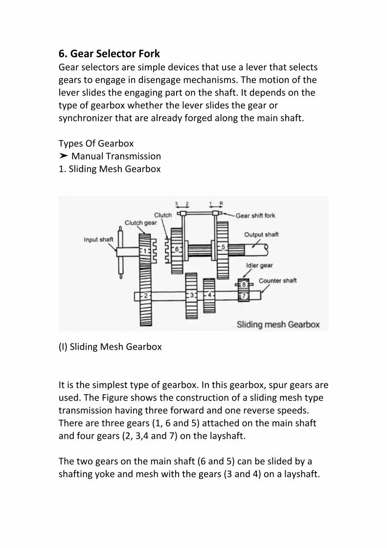
6. Gear Selector ForkGear selectors are simple devices that use a lever that selectsgears to engage in disengage mechanisms. The motion of thelever slides the engaging part on the shaft. It depends on thetype of gearbox whether the lever slides the gear orsynchronizer that are already forged along the main shaft.
Types Of Gearbox➤ Manual Transmission1. Sliding Mesh Gearbox
(I) Sliding Mesh Gearbox
It is the simplest type of gearbox. In this gearbox, spur gears areused. The Figure shows the construction of a sliding mesh typetransmission having three forward and one reverse speeds.There are three gears (1, 6 and 5) attached on the main shaftand four gears (2, 3,4 and 7) on the layshaft.
The two gears on the main shaft (6 and 5) can be slided by ashafting yoke and mesh with the gears (3 and 4) on a layshaft.

Therefore, it is called a sliding mesh gearbox. A separate idlergear (8) is mounted on the idler shaft.
2. Constant Mesh Gearbox
(II) Constant Mesh Gearbox
Figure shows the construction of a constant mesh type gearboxhaving three forward and one reverse speeds. In this type ofgearbox, all gears are constantly in mesh and dog clutches areused for engaging and disengaging the gears. The dog clutches(D) and D2) are mounted on the main shaft. One (D2) isconnected between clutch gear and reverse gear whereas theother (D)) is placed between low speed gear and reverse gear.movement of dogs. Dog clutch can slide on the shaft and rotatealong with it. All gears are rigidly fixed on the counter shaft.
All main shaft and layshaft gears, and idler gears are engagedby dog clutch to obtain opposite and slow speed. Only reversegears are spur gear type and all others are helical gears.

As compared with the sliding mesh type, the constant meshtype gearbox meshes more readily with the gears having lessdanger of damaging during meshing because the geardiameters are smaller with few numbers of teeth. So, this typehas more defects when compared to a synchromesh type. Thenecessity of double clutching is needed so that it is not used toany large extent
3. Synchromesh Gearbox
(III) Synchromesh Gearbox
Synchromesh gearbox uses synchronizer instead of sliding dogclutches to affect the ratio change. The synchromesh gearbox issimilar to the constant-mesh gearbox, but the synchromeshgearbox is provided with a synchronizer, the device by whichtwo gears to be engaged are first brought into frictional contactwhich equalizes their speed, afterward they are engagedsmoothly.
To engage, when the gear lever is moved the synchronizer conemeets with a similar cone on the pinion. Due to friction, therotating pinion is made to rotate at the same speed as the

synchromesh unit. To give a positive drive further, movementof the gear lever enables the coupling to override several springload balls and the coupling engages with the dogs on the sideof the pinion.
Since both pinions and synchromesh units are moving at thesame speed, this engagement is done without noise or damageto the dogs. A slight delay is necessary before engaging the dogteeth so that the cones have a chance to bring the synchronizerand pinion to the same speed.
➤ Epicyclic Gearbox
2. Epicyclic Gearbox
An epicyclic gear train (also known as planetary gear) consistsof two gears so that the center of one gear rotates around thecenter of the other. A carrier connects the centers of two gearsand rotates to carry one gear, called planet gear or planetpinion, around the other, called sun gear or sun wheel. The raysof the planet and the sun form traps so that their pitch circlesare rolled without slip. A point on the pitch circle of the

planetary gear traces an epicyclic curve. In this simplified case,the sun gear is fixed and there is planetary gear rolled aroundthe sun gear.
An epicyclic gear train can be assembled so the planetary gearis rolled onto a fixed, external gear ring or inside the pitch circleof the ring gear, sometimes called the annular gear. In this case,the curve detected by a point on the planet pitch circle is ahypocycloid.
The combination of epicyclic gear trains with a planet engagingboth a sun gear and a ring gear is called planetary gear train. Inthis case, the ring gear is usually fixed and the sun gear isoperated
Purpose Of GearboxIt helps the engine to disconnect from driving wheels.It helps the running engine connect to the driving wheelsmoothly and without shock.It provides the leverage between engine and driving wheels tobe varied.
This helps in reducing the engine speed in the ratio of 4 : 1 incase of passenger cars and in a greater ratio in case of heavyvehicles like trucks and lorries.It helps the driving wheels to drive at different speeds.It gives the relative movement between engine and drivingwheels due to flexing of the road spring.
Function Of GearboxTorque ratio between the engine and wheels should be variedfor fast acceleration and for climbing gradients.It provides means of reversal of vehicle motion.

Transmission can disconnect from the engine by the neutralposition of the gearbox.
Gear RatioGear ratios are geared reduction steps in the gearbox. A gearreduction multiplies the engine torque by gear ratio amount.Torque requirement at the wheel depends on operatingconditions.
For example :
Moving a vehicle from a standstill requires much more torquethan the peak torque of the engine. Therefore the torquemultiplies by the first gear ratio.
Once starting the vehicle and moving using first gear, it requiresless torque at the wheels to keep it moving. Hence it requiresno multiplication or very less multiplication.
If the vehicle suddenly encounters a gradient , it will requiremore torque on the wheels to keep the vehicle moving. Hencean intermediate ratio requires.
CONSTRUCTION ANDWORKING OF 4 SPEED GEARBOX
Four speed gearbox constructionManual gearbox is a type of transmission used in motor vehicleapplications. This is article about four speed gearboxconstruction. We will know about how a four speed gearboxworks and its construction.
At the beginning we should know the scheme gearbox workingof the gearbox and then we can new information about 4-, 5-speed gearbox construction too.

Four-speed Gearbox Construction: 1 – oil drain plug; 2 – gear housing; 3 –drive shaft; 4 – drive shaft bearing cap; 5, 8, 18 – locking rings; 6 –reverse drive shaft bearing; 7 – roller bearing; 9 – synchronizer couplingof third and fourth gears; 10 – synchronizer coupling of the third andfourth gears; 11 – gear wheel of the third speed; 12 – gear wheel of thesecond speed; 13 – synchronizer coupling of the first and the secondgears; 14 – washer; 15 – synchronizer hub of the first and the secondgears; 16 – gear wheel of the first gear; 17 – adjusting washer; 19 – ballbearing; 20 – top cap gearbox; 21 – gearbox extension; 22 – driven shaft;23 – steel-babbit bearing; 24 – screw cap; 25 – stuffing box; 26 –extension flange; 27 – rubber coupling; 28 – axis of intermediate gearwheel of reverse; 29 – intermediate gear wheel of reverse gear; 30 – gearwheels block of intermediate shaft; 31 – needle bearing of intermediateshaft; 32 – gear wheel reverse gear; 33 – axis of intermediate shaft.
The driving shaft 3 of the four-speed gearbox has a gear wheelpermanent gearing connect to the block of gear wheels 30 ofintermediate shaft. Other gear wheels of this block are in permanentgearing to the gear wheels 11, 12, 16 according with third, fourth, fifth

gears of the driven shaft 22. To turn on all four gears of front moving areused connecting of the sliding couplings 9 and 13 of synchronizers.
WORKING of Four-speed gearboxWhen the first speed is on: The crankshaft rotation moment istransmitting to the gear wheels block of intermediate shaft 30 throughdrive shaft 3, and then to the driven shaft 22 through gear wheel 16,sliding coupling 13 and synchronizer 15 hub of the first and second gearsWhen the second speed is on: The crankshaft rotation moment istransmitting to the driven shaft though the drive shaft 3, gear wheelsblock of intermediate shaft, gear wheel 12, sliding coupling 13 andsynchronizer 15 hub of the first and second gears.
When the third speed is on: The crankshaft rotation moment istransmitting to the driven shaft though the gear wheel 11, slidingcoupling 9 and synchronizer 10 hub of the third and fourth gears.
When the fourth speed is on: the synchronizer of the third and fourthspeed connects drive shaft to the driven shaft directly.
When the reverse gear is on: gear wheel 29 is gearing to gear wheel 32 ofthe intermediate gear wheels block and gear rim of the synchronizersliding coupling of the first and second gears.
1.4 Concept of automatic gear changing mechanisms
The most common type of automatic transmission uses hydraulic powerto shift gears. This device combines a torque or fluid coupling converterwith gearsets that provide the desired range of gears for the vehicle. Thetorque converter connects the engine to the transmission and usespressurized fluid to transfer power to the gears. This apparatus replaces amanual friction clutch and lets the vehicle come to a complete stopwithout stalling.
As the engine transmits power to the pump of the torque converter, thepump converts this power into transmission fluid that powers the turbineof the torque converter. This apparatus increases the power of the fluidand transmits even more power back to the turbine, which creates avortex power rotation that spins the turbine and the attached central

shaft. The power created by this rotation is then transmitted from theshaft to the transmission's first planetary gear set.
This type of transmission has what is called hydraulic control. Thetransmission fluid is pressurized by an oil pump, which allows the speedto change depending on the vehicle's speed, tire revolution per minute,and other factors. The gear pump is placed between the planetarygearset and torque converter, where it pulls and pressurizerstransmission fluid from a sump. The pump input leads directly to thehousing of the torque converter attached to the flexplate of the engine.When the engine is not running, the transmission does not have the oilpressure needed to operate and thus the vehicle cannot be push-started.
The planetary gear train is a mechanical system in which the gears areconnected with a set of bands and clutches. When the driver changesgears, the bands hold one gear still while rotating another to transmittorque from the engine and increase or decrease gears.
The different gears are sometimes called the sun gear, the ring gear, andthe planetary gear. The arrangement of the gears determines how muchpower will flow from one gear to another and out to the drive train of thevehicle when you shift.
Gears of an Automatic TransmissionThe gears of an automatic transmission include the following:
> When you shift your vehicle into drive, you engage all available forwardgear ratios. This means that the transmission can move between its fullrange of gears as needed. Six-speed automatic transmissions are themost common number of gears, but older cars and entry-level compactcars may still have either four or five automatic gears.> Third gear either locks the transmission in third gear or limits it to thefirst, second, and third gear ratios. This provides the power and tractionneeded to go either uphill or downhill or to tow a boat, RV, or trailer.When the engine reaches a designated level of revolutions per minute(RPM), most vehicles automatically drop third gear to keep the enginefrom harm.> Second gear either locks the transmission in second gear or limits it tothe first and second gear ratios. This gear is ideal for going uphill and
downhill in slippery conditions as well as driving during ice, snow, andother types of inclement weather.> First gear is used when you want to lock the transmission in first gear,although some vehicles will automatically switch out of this gear toprotect the engine at a certain RPM. Like second and third gear, this gearis best used for towing, driving uphill or downhill, and when travelingduring slippery, icy conditions.Advantages of an Automatic Transmission
The biggest advantage of an automatic transmission is the ability to drivewithout the need for a clutch as is required with a manual transmission.Individuals with many disabilities are able to drive using an automaticsince operation only requires two usable limbs.
The lack of a clutch also eliminates the need to pay attention to shiftingmanually and monitoring the tachometer to make the necessary shifts,which gives you more attention to focus on the task of driving.
Many drivers also find it easier to control an automatic transmission atlow speeds than a manual transmission. The hydraulic automatictransmission creates a phenomenon called idle creep, which encouragesthe vehicle to move forward even when idling.
1.5 PROPELLER SHAFT
The drive shaft (also called propeller shaft or prop shaft) is a componentof the drive train in a vehicle, with the purpose of delivering torque fromthe transmission to the differential, which then transmits this torque tothe wheels in order to move the vehicle. The drive shaft is primarily usedto transfer torque between components that are separated by adistance, since different components must be in different locations inthe vehicle. A front-engine rear-wheel drive car must have a long driveshaft connecting the rear axle to the transmission since these parts areon opposite sides of the car.
Drive shafts are used differently in different vehicles, varying greatly incars with distinct configurations for front-wheel drive, four-wheel drive,

and the previously mentioned front-engine rear-wheel drive. Othervehicles also use drive shafts, like motorcycles, locomotives, and marinevessels
Propeller Shaft is the shaft that transmits power from the gearbox to thedifferential gear in a motor vehicle from the engine to the propeller in aboat or flying machine.Propeller shaft, sometimes called a cardan shaft, transmits power fromthe gearbox to the rear axle. Regularly the shaft has a tubular sectionand is made in maybe a couple piece construction.The two-piece arrangement is supported at the mid point by an elasticmounted bearing. Short drive shafts are incorporated for thetransmission of power from the last drive assembly to the road wheels inboth front and rear wheel drive layouts.
FUNCTIONS OF THE PROPELLER SHAFT
In most of the automotive vehicles, the engine is located at the front andthe rear wheels of the vehicle are being driven. This arrangementstipulates a longer propeller shaft to be used. In some arrangements twoor three propeller shafts are used to make up the length.
In some vehicles, the engine is kept at the front and the front wheels ofthe vehicle are being driven. In some other vehicles, the engine is at therear and the rear wheels are being driven. For such arrangements ashort propeller shaft is used to drive each wheel.
The engine and the transmission unit are attached to the vehicle framewith some flexible mounting. The rear axle housing with differential andwheels are attached to the vehicle frame by suspension springs.
Due to the above arrangement, the transmission output shaft and theinput shaft to the rear axle housing are in different planes. This compelsthe propeller shaft that connects these two shafts to be kept inclined.

Further, whenever the rear wheels encounter irregularities in the road,the rear axle housing moves up and down, compressing and expandingthe suspension springs. As this happens, the angle between thetransmission output shaft and the propeller shaft changes. Further, thelength to be occupied by the propeller shaft also changes.The variation in the length of the propeller shaft happens because thepropeller shaft and the rear axle housing rotate on arcs with differentpoints as their centres of rotation.
The rear axle housing moves in the shorter arc than that of the propellershaft. This is because the centre of the rear axle housing arc is the pointof attachment of the rear spring or control arm to the vehicle frame.This aspect causes a reduction in the length occupied by the propellershaft as the angle between the transmission and the propeller shaftincreases.
PROPELLER SHAFT

TYPES OF PROPELLER SHAFT:1. Single-Piece-Type Propeller Shaft:Used in vehicles with a short distance between the engine and axles, andMR based four-wheel-drive vehicles.The friction welding adopted at the junction contributes to animprovement in the strength, quality, and durability of the junction.2-piece-type/3-piece-type Propeller Shaft:Utilized as a part of vehicles with a long distance between the engineand axles, and Front engine front drive base four-wheel-drive vehicles.The division of the propeller shaft into two- or three-parts allows thecritical number of revolution to lowered preventing vibration issue fromoccurring, when the overall length of the shaft increased.
COMPONENTS OF PROPELLER SHAFT:The propeller shaft transfers engine torque to the rear axle through oneor more universal joints.The splines on the ends at the propeller shaft fit perfectly into thesplines in the sleeve. This permits a length variation between the drivingand the driven unit to vary slightly without damaging the output andinput bearings.The main bearing support and guide the propeller shaft.The flanges associate the propeller shaft to the gearbox.
REQUIREMENTS OF PROPELLER SHAFT:For achieving efficient functions, the following are expected in apropeller shaft
High torsional strength: Therefore, they are made of solid or hollowcircular cross sectionToughened and hardened: Therefore, they are made of superior qualitysteel and are induction hardenedEfficiently jointed: Therefore they are generally welded by submergedare carbon dioxide welding process.Dynamically balanced: Since the phenomenon of whirling may be criticalat higher speeds, therefore, propeller shafts are tested on electronicbalancing machine.Reduced thrust loads: Since resonance is dangerous for the life of shaft.It also transmits excessive dynamic force to the shaft’s end supports,and so its occurrence should be avoided.

NOTE: Since the propeller shaft sleeve end is pulled out from thetransmission extension housing with the transmission still mounted,overflow of the transmission oil, damage of oil seal lip or entrance ofdust may result if the vehicle is raised higher toward its front end. Useextreme care in removing the propeller shaft.
1.6 DIFFERENTIAL
Functions Of Differential gear Box.When a four-wheeler (car) takes a turn, the outer wheel turns fasterthan the inner wheel. Thus, there is relative movement between theinner and outer wheel.
The function of the differential is to permit the relative movementbetween inner and outer wheels when vehicle negotiates (takes) a turn.The torque transmitted to each rear wheel is equal in this case, althoughtheir speed is different.
The differential is made up of a system of gears that connect thepropeller shaft and rear axles. It is a part of inner axle housing assembly.The assembly consists of differential, rear axles, wheels, and bearings.
The need of differential gearbox:When a vehicle travels in a straight line, the two rear wheels turn on theroad exactly at the same speed and there is no relative movementbetween two rear wheels.But when vehicle takes a turn the outer wheel travels on a longer radiusthan the inner wheel. The outer wheel turns faster than inner wheel i.e.there is relative movement between two rear wheels. If two rear wheelsare rigidly fixed to a rear axle, the inner wheel will slip, which will causerapid tire wear, steering difficulties and poor road holding. Thereforethere must be some device, which will divide the input torque of thetransmission system between two rear axles. Differential serves thispurpose.
Differential gearbox Location :Location in a different type of vehicle layouts-

1. In Front-engine front-wheel-drive layout – differential is located at thefront next to gearbox.2. In Rear engine rear-wheel-drive layout – differential is located at therear next to gearbox.3. Four wheels drive layout – differential is located at the front as well asrear.4. Front engine rear-wheel-drive layout – it is located at the rear inbetween two half shafts.
Principle of differential-If a vehicle travels in a straight line, the two rear wheels turn exactly atthe same speed, and there is no relative movement between them. Butwhen the vehicle takes a turn the outer wheel travels a longer radiusthan the inner wheel i.e. there is relative movement between the tworear wheels. The outer wheel turns faster and covers a larger distancethan the inner wheel. The inner wheel makes a larger angle than theouter wheel. thus the vehicle negotiates the turn safely.

DIFFERENTIAL GEARBOX DIAGRAM
Construction of differential:Major Components of DifferentialThe following main components are used in the differentialassembly.l. Drive pinion or Bevel pinion2. Ring gear or Crown wheel3. Differential case4. Differential side gear or Sun gears5. Differential pinions (or) Planet gears6. Axle shafts or Half shafts7. Pinion shaft or Cross pin (or) spider.Figure. shows the basic parts of the type of differential used inrear-wheel-drive cars.

On the inner ends of each axle a smaller bevel gear calleddifferential side gear is mounted. Two bevel gears are puttogether to mesh both driving and driven shafts at an angle of90°. The differential case is mounted with two-wheel axles anddifferential side gears. The differential case has bearings thatrotate two axle shafts. Then, the two pinion gears and theirsupporting shaft, called pinion shafts, are fitted into thedifferential case. Then, the pinion shaft meshes with the twodifferential side gears connected to the inner ends of the axleshafts.
The ring gear is bolted to a flange on the differential case. The’ring gear rotates the differential case. Finally, the drive pinion ismounted. The drive pinion is assembled with the differentialhousing called differential case or carrier. The driver shaft isconnected with the drive pinion by a universal joint and itmeshes with the ring gear. So, the drive pinion is rotated whenthe drive shaft turns. Thus, the ring gear is rotated.

WORKING OF GEARBOX
Working of differential gearbox :
1. When Running Straight:When the vehicle moves in a straight line, the power comesfrom the propeller shaft to the bevel pinion which drives thecrown wheel. Then it is carried to the differential cage in whicha set of planet pinions and sun gears are located. From the sungear it is transmitted to the road wheels through-axle halfshafts. In this case, the crown wheel, differential cage, planetpinions, and sun gears all turn as a single unit and there is norelative motion between the sun gear and planet pinion. Theplanet pinions do not rotate about their own axis. The roadwheels, half shafts, and sun wheels offer the same resistance tobeing turned and the differential gearing does not thereforeoperate. Both the road wheels turn at the same speed.

2. When taking a turn:When the vehicle takes a turn, the inner wheel experiencesresistance and tends to rotate in the opposite direction. Due tothis the planet pinions start rotating about their own axis andaround the sun gear and transmit more rotary motion to theouter side sun gear. So that outer sun gear rotates faster thanthe inner sun gear. Therefore the outer road wheel runs fasterthan the inner road wheel and covers a more distance.
TYPES OF DIFFERENTIALThere are three types of differential :(a) Conventional type,(b) Non-slip or self-locking type, and(c) Double reduction type.
1) Conventional TypeConventional type differential described in Section 5.6 deliversthe same torque to each rear wheel. If any of the wheels slipsdue to any reason the wheel does not rotate and the vehicledoes not move.
2) Non-slip or Self Locking TypeNon-slip or self-locking type differential overcomes thisdrawback. It construction is similar to that of conventional typedifferential. But, two sets of clutch plates are providedadditionally. Also, the ends of planet shafts are left loose innotches provided on the differential cage.
3) Double Reduction TypeDouble reduction type differential provides further speedreduction by additional gear. This type of differential is used inheavy-duty automobiles which require larger gear reductionbetween engine and wheels.

A brake is one of the most important controls of the vehicle. This is acombination of some interactive parts. It absorbs energy from the movingpart and slows down the vehicle with the help of friction.
Functions of Brake System:
The function of the brake system is to stop the vehicle within the smallestpossible distance and hence this is done by converting the kinetic energyof the vehicle into the heat energy which is dissipated into theatmosphere.
Types of Brake System in Automobile:
The brake system in an automobile can be classified into these followingcategories:
Mechanical Brake Disc Brake Hydraulic Brake Power-assisted Brake Air Brake Electric and Hand brake System
Let me go through all these break systems.

Mechanical Brake:
The mechanical brake is used in small power automobiles like scooters,motorcycles and some modern vehicles. The figure of the mechanicalbrake is shown below:
As the brake pedal is pressed cam rotates, which pushes the brakeshoes outwards and hence brake lining provided on the outer surface ofthe shoes rub against rotating the drum and hence slow down or stopsthe vehicles because the drum is connected to the wheels.
As the pedal is released, due to retracting spring force shoes return to itsoriginal position.
Disc Brake:
The disc brake is used in motor vehicles and cars, etc.
When the pedal is pressed piston pushes the pad by the pressure ofthe hydraulic fluid. The diagram is shown below:

These friction pad rub against the rotating disc connected to the wheelsof the vehicle and thus braking takes place.
And as the pedal is released friction pad returns to its original positionbetween the pressure of hydraulic fluid reduces.
Hydraulic Brake:
Hydraulic brake works on the principle which is based on Pascal'sprinciple, which states that "confined liquid transmits pressure withoutloss in all direction".
This is simple in construction and has an equal braking effort to all wheelsand smooth operation.

When the brake pedal is pressed, fluid from the master cylinder entersinto the wheel cylinders through pipelines by the force of the piston.
Due to the liquid force, the piston of the wheel cylinder pushes outwardwhich pushes the shoes outward.
Lining rub against the drum and hence braking take place.
Now when the pedal is released, the piston of the master cylinder movesbackward and fluid from the wheel cylinder moves to the master cylinderthrough the check valve.
This type is commonly used in all cars etc.
Master Cylinder:
The master cylinder is the heart of the hydraulic brake system.
It consists of two chambers:
The reservoir. Compression chamber, in which piston reciprocates.
The piston is connected to the brake pedal through the piston rod. Fromthe reservoir, fluid enters the compression chamber through the parts asshown.
The master cylinder is connected to the wheel cylinder through the pipe.
The check valve is provided in order to give passage for entering fluidfrom the wheel cylinder to the master cylinder when the pedal is released.

Power-assisted or Vacuum brake:
The line diagram indicates the construction of a power-assisted orvacuums brake as shown below.
As the brake pedal is pressed, the fluid pressure causes the upper valve ofa control unit to open and lower the valve to close.
Thus left the side of the servo cylinder piston is exposed to atmosphereand vacuum acts on the right side, which causes the braking effort.
Braking takes place by suction from the engine inlet manifold.

Air Brake:
This type of air brake system is commonly used in heavy vehicles such asbuses, trucks, etc.
In this also when the brake pedal is pressed, air to atmosphere enters thecompressor through the air filter to the reservoir through unloader value.
From unloader valve air enter brake chamber through brake valve.
Brake valve is fitted in order to control the intensity of braking. Thusbraking takes place.
When the pedal is pressed shoes return to its original through positionthrough the spring force.
Girling Mechanism Brake:
This system consists of an expander used for braking and adjuster unit toadjust the brake shoes when desired.
As the brake pedal is pressed, the pulls rod of expander pulled out whichpulls out the conical wedge.
The brake shoe connected to the conical wedge through plunger andsteel roller ball pulls outward. Thus braking the wheel.

When the pedal is released, spring force brings the brake shoe to itsoriginal position.It requires less friction. Without jacking up vehiclesbrakes can be adjusted.
Electrical Brake System:
The principle of working of this type of brake is to utilizethe electromagnetic force on the brake shoes.
It consists of an electromagnet, armature disc.
An electromagnet is mounted on the backplate and armature disc is fedto the drum.
This is simple in construction.
For working, electric current for the battery is utilized to energize theelectromagnet which actuates the cams that expands the shoes. Thusbraking the wheel.
Hand brake System:
Hand brakes or the parking brakes operate independently of the footbrakes.
These are used for parking on slopes or while waiting at traffic lights,where the handbrake function is mainly to minimize accidents.
This brake is applied after the foot brake is applied.

These are mechanical brakes.
Apart from the hydraulic braking system, all cars have a mechanicalhandbrake acting on two wheels - usually the rear ones
The handbrake gives limited braking if the hydraulic system failscompletely, but its main purpose is as a parking brake.
The handbrake lever pulls a cable or pair of cables linked to the brakes bya set of smaller levers, pulleys, and guides whose details vary greatly fromcar to car.
A ratchet on the handbrake lever keeps the brake on once it is applied. Apush-button disengages the ratchet and frees the lever.
On drum brakes, the handbrake system presses the brake linings againstthe drums.
Disc brakes sometimes have a comparable handbrake arrangement, butbecause it is difficult to place the linkage on a compact caliper, there maybe a completely separate set of handbrake pads for each disc.
Principal Parts of the Vacuum BrakeSystem

1)Driver’s Brake Valve:driver controls the brake using this. It has the following positions:“Release”, “Running”, “Lap” and “Brake On”.”Neutral” or “ShutDown” positions are also available which locks the valve out of use.he “Release” position connects the exhauster to the brake pipe andswitches the exhauster to full speed. This raises the vacuum in thebrake pipe as quickly as possible to get a release. the exhausterkeeps running but at its slow speed in the “Running” position. Thisensures that the vacuum is maintained against any small leaks orlosses in the brake pipe, connections and hoses.”Lap” is used toshut off the connection between the exhauster and the brake pipeto close off the connection to atmosphere after a brake applicationhas been made.”Brake On” closes off the connection to theexhauster and opens the brake pipe to atmosphere.
2) ExhausterA two-speed rotary machine fitted to a train to evacuate the atmosphericpressure from the brake pipe, reservoirs and brake cylinders to effect abrake release.
3) Dummy Coupling:a dummy coupling point is provided At the ends of each vehicle to allowthe ends of the brake pipe hoses to be sealed when the vehicle isuncoupled.
4)Coupled Hoses:The brake pipe is carried between adjacent vehicles through flexiblehoses.
5)Vacuum Reservoir:a vacuum reservoir is provided on, or connected to the upper side of thepiston to ensure there is always a source of vacuum available to operatethe brake.
6)Brake Cylinder (shown in blue):The movement of the piston contained inside the cylinder operates thebrakes through links called “rigging”.

7)Brake Rigging:the movement of the brake cylinder piston transmits pressure to thebrake blocks on each wheel through this system.
8)Brake Block:the friction material which is pressed against the surface of the wheeltread by the upward movement of the brake cylinder piston.
9)Ball Valve:The ball valve is needed to ensure that the vacuum in the vacuumreservoir is maintained at the required level, i.e. the same as the brakepipe, during brake release but that the connection to the brake pipe isclosed during a brake application.
ADVANTAGES• simple in design• ability to get partial release , something the pneumatic brake could notdo without additional equipment• greater amount of safety because the vacuum lossage results in thebraking of the vehicle• highly reliable in the case of rail wagons• Permits the automatic application of brakes down the entire length ofthe train from a simple control in the drivers hand• vacuum brakes are also fail safe since the vacuum is used for applyingthe brake
CONCLUSIONThe vacuum brake was considered preferential to the air brake in railroadapplications largely because it was cheaper to install on a steamlocomotive. Air brakes required a steam-powered compressor – bulky,noisy, unsightly and using a lot of power, while the vacuum ejector usedto generate vacuum was a much simpler device. It has the advantage ofbeing simple in design and of having the ability to get a partial release,something the air brake could not do without additional equipment.

3.1 Describe the Battery ignition and Magnet ignitionsystem
A battery Ignition System is used in an automobile to produce a spark inthe spark plug with the help of a Battery. It is generally used in the 4-wheeler vehicle but nowadays it is also used in two-wheeler vehicleswhere a 6-volt or 12-volt battery supplies the current to the ignition coil.
Parts of Battery Ignition System:
The main components of Battery Ignition system are listed below:
1. Ignition switch2. Battery3. Ignition coil4. Ballast resistor5. Contact breaker6. Distributor7. Capacitor8. Spark Plug
Diagram of Battery Ignition System, Learn Mechanical

#1 Ignition Switch:
It is used for ON or OFF the engine. One end of the switch is connected withthe Primary Winding of Ignition Coil via Ballast Resistor, and another end isconnected with the Battery.
Basically when the key is put inside it and turned the switch in ON positionthen the circuit is completed (Close Circuit), and when moved towards the OFFposition than its work as an open circuit. Nowadays, this switch is replaced bythe Push Button, and this system is called a keyless system.
#2 Battery:
The battery is provided for supply the initial current to the ignition systemmore specifically ignition coil. Generally, the voltage of the battery is 6V or12V or 24 V. In an automobile there are two types of Battery use widely, one islead-acid battery and another one is the alkaline battery. Although there areZinc Acid Battery and Lithium-Ion Battery is used in modern vehicles.
#3 Ignition coil:
It is the main junction or you can say the main part of Battery Ignition System.The main purpose of it is to step up battery voltage so that it is sufficient forgenerates the spark.
It is working as a step-up transformer, and have two winds, one is primarywhich have a lesser turn, and the other one is secondary which have a highernumber of turn.
#4 Ballast resistor:
This is used to limit the current in the ignition circuit and generally made ofIron. It is placed in series between the Ignition Switch and Ignition Coil.However, it is used in old automobile vehicles.
#5 Contact Breaker:
The contact breaker is an electrical switch which is regulated by the cam andwhen the breaker is open, current flows through the condenser and charges it.
#6 Distributor:
It is used in the multi-cylinder engine, and its purpose is to regulate spark ineach spark plug at the correct sequence.

There are two types of distributors.
Carbon Brush Type Gap Type
Carbon Brush Type:
It is consist of Carbon Brush which is slides over the metallic sectionembedded in the distributor cap.
Gap Type:
In this type, the rotor arm is passed through the metallic section of thedistributor cap but it does not touch the surface of the distributor cap. that'swhy it is called Gap Type Distributor.
#7 Capacitor:
A capacitor is a storing device where electrical energy is stored. It is fittedparallel to the contact breaker, when the current drops then it supplied theadditional current so that the spark is produced. It is made of two metal platesseparated by air or any other insulating material.
#8 Spark Plug:
Spark Plug is another important part of Battery Ignition system.Here the actual Spark is generated for the combustion of Fuel orCharge. If there is more then one spark plug exists then each one isconnected separately with the distributor and gives the spark inthe sequence.
Working Principle of Battery Ignition System:
In Battery Ignition System, when the Ignition Switch is turned onthen the current will flows to the primary circuit through ballastregister, primary winding and contact breaker
The flowing current induced a magnetic field around the primarywinding, the more current we supply the more magnetic filed willgenerate. At a certain time, the contact breaker opens the currentis flowing through the primary winding and fall. This sudden fall of

current generates very high voltage around 300 V in the primarywinding section.
Due to this immense amount of voltage the capacitor comes intothe charging state when the capacitor charged fully then it startsdelivering the current towards the battery, due to this reverseflowing of the current and already induced magnetic field in theprimary winding, a very high voltage of 15000 V to 30000 V isgenerated in the secondary winding.
This high voltage current then transferred to the distributor viahigh tension cable, where already a rotor rotates inside thedistributor cap and has metallic segments embedded on it. Sowhen its start rotating then at a certain stage it opens the contactbreaker point which allows the high voltage current to transferredto the spark plugs through the metallic segments.
So when the high voltage current reaches the spark plug then itsgenerates a high intensity of spark inside the engine cylinder,which allows the combustion fuel to burn.
Advantages of Battery Ignition System:
These are the following advantages of Battery Ignition System:
The intensity of spark is good. It can also provide a high concentration of spark even in lowengine speed or starting of Engine.
The maintenance of this ignition system is very lesscompared to others.
Disadvantages of Battery Ignition System:
The disadvantages are:
Efficiency decreased with a reduction in spark intensity. Occupies more space. Efficiency decreased with a reduction in spark intensity. Need periodic maintenance is needed for Battery only.

Applications of Battery Ignition System:
Here is the application of it:
Battery Ignition System is used in Automobile (Car, Bus, Truckeven in the Bike) to produce the Spark so that Combustionfuel can be burned
MAGNET IGNITION SYSTEM
Magneto ignition system is an ignition system in which magneto is used[produces high volatge] for the generation of electricity and further thatelectricity is used in several things like to run the vehicles. This is basicallyused in two-wheeler vehicles (Spark Ignition Engine) nowadays.
Parts of Magneto Ignition System:
The main parts of Magneto Ignition System are:
1. Transformer core2. Contact Breaker3. Cam4. Capacitor5. Ignition Switch6. Distributor7. Spark Plug
Magneto Ignition System

#1 Transformer core:
There are two types of winding we can see in Magneto Ignition System,those are:
1. Primary Winding: The main function of this winding is to draw thepower from the source.
2. Secondary Winding: This winding has more turns of wire (thenumber is 1000 of turns of wire ) as compared to the primarywinding. This is connected to the Distributor (Which is having arotor ).
#2 Contact Breaker:
The contact breaker is regulated by the cam and when the breaker isopen, current flows through the capacitor and charges it.
#3 Cam:
Cam is connected to the North and south magnet.
#4 Capacitor:
The main work of the capacitor is to Store the charger. The capacitor isused here is a simple electric capacitor.
#5 Ignition switch:
Works for of and on the vehicles and this is set to the parallel of thecapacitor because it helps to avoid the damage of excessive air.
#6 Distributor:
This is connected to the spark plug and Distributor having the rotor.
#7 Spark Plug:
The main work of the spark plug is firing the explosive mixture in the ICengine.
Working Principle of Magneto Ignition System:

In the Magneto Ignition System, magneto is used. When the engine of thesystem starts, it helps the magneto to rotate and thus it's producing theenergy in the form of high voltage then, one end of the magneto isgrounded through a contact breaker, and the ignition capacitor isconnected to its parallel.
The contact breaker is regulated by the cam and when the breaker isopen, current flows through the capacitor and charges it.
Now the capacitor is acting as a charger now, the primary current flow isreduced, thus reducing the overall magnetic field, generated in thesystem.
This increases the voltage in the capacitor. This increased high voltage inthe capacitor will act as an EMF thus producing the spark, at the rightspark plug through the distributor.
And at the starting stage, the speed of the engine is low and hence thevoltage generated by the magneto is low.
But as the rotating speed of the engine increases, it also increases thevoltage generated by the magneto thus the flow of the current is alsoincreased.
Schematic Diagram of Magneto Ignition System:

Circuit Diagram of Magneto Ignition System:
Applications of Magneto Ignition System:
Magneto Ignition System nowadays widely used in:
This system is used for the generation of electricity(In case of Battery system their Battery is used) and torun the vehicles.
This is basically used in two-wheeler vehicles (SIEngine) nowadays.
A rotating magnet produces high voltage.
. And also this is used in various places like: Tractors,Outboard Motors, Washing Machines, Buses, PowerUnits, Marine Engines, and Natural Gas Engines.
Advantages of Magneto Ignition System:
These are the following advantages of Magneto IgnitionSystem:

This system requires less maintenance as comparedto the Battery ignition system.
This is more useful because no battery is used. It occupies less space. An electric circuit is generated by the magneto No battery is needed, so no problem of battery
discharge Efficiency improves due to high-intensity spark.
Disadvantages of Magneto Ignition System:
Although there are some disadvantages:
During starting, the quality of spark is poor due tolow speed.
This is a little expensive as compared to anotherignition system.
Some FAQ:What is Magneto Ignition System?The magneto ignition system is an ignition system inwhich we use magneto for the generation of electricity.How do magneto ignition systems work?When the engine of the system starts, it helps magnetoto rotate and thus it's producing the energy in the formof high voltage. This increased high voltage in thecapacitor will act as an EMF thus producing the spark, atthe right spark plug through the distributor.What are the 3 types of ignition systems?The 3-types of Ignition Systems are:1. Battery Ignition System2. Magneto Ignition System3. Electronic Ignition System

3.2 Spark plugs: Purpose, construction andspecifications
A spark plug is an electrical device that fits into the cylinderhead of some internal combustion engines and ignitescompressed aerosol gasoline by means of an electric spark.Spark plugs have an insulated center electrode which isconnected by a heavily insulated wire to an ignition coil ormagneto circuit on the outside, forming, with a groundedterminal on the base of the plug, a spark gap inside the cylinder.
PURPOSE OF SPARK PLUG
1. To ignite the air/fuel mixture.Electrical energy is transmitted through the spark plug, jumpingthe gap in the plugs firing end if the voltage supplied to the plugis high enough. This electrical spark ignites the gasoline/airmixture in the combustion chamber.
2. To remove heat from the combustion chamber.Spark plugs cannot create heat, they can only remove heat. Thetemperature of the end of the plug\’s firing end must be keptlow enough to prevent pre-ignition, but high enough to preventfouling. The spark plug works as a heat exchanger by pullingunwanted thermal energy from the combustion chamber andtransferring heat to the engines cooling system. The heat rangeof a spark plug is defined as its ability dissipate heat from the tip.

CONSTRUCTION
spark plug construction
1. Ribs-Insulator ribs provide added protection against secondaryvoltage or spark flashover and also help to improve the grip ofthe rubber spark plug boot against the plug body.The insulator body is molded from aluminum oxide ceramic. Inorder to manufacture this part of the spark plug, a high-pressure,dry molding system is utilized. After the insulator is molded, it iskiln-fired to a temperature that exceeds the melting point ofsteel. This process results in a component that featuresexceptional dielectric strength, high thermal conductivity andexcellent resistance to shock.
2. Insulator:The insulator body is molded from aluminum oxide ceramic. Inorder to manufacture this part of the spark plug, a high-pressure,dry molding system is utilized. After the insulator is molded, it iskiln-fired to a temperature that exceeds the melting point of

steel. This process results in a component that featuresexceptional dielectric strength, high thermal conductivity andexcellent resistance to shock.The pointer shows the spark plug insulator. As mentioned above,it is formed from aluminum oxide ceramic. The outer surface isribbed to provide grip for the spark plug boot and tosimultaneously add protection from spark flashover (crossfire).
3. Hex:The hexagon provides the contact point for a socket wrench.The hex size is basically uniform in the industry and is generallyrelated to the spark plug thread size.
4. Shell:The steel shell is fabricated to exact tolerances using a specialcold extrusion process. Certain types of spark plugs make use ofa steel billet (bar stock) for shell construction.
5. Plating:The shell is almost always plated. This enhances durability andprovides for rust and corrosion resistance. The steel shell isfabricated to exact tolerances using a special cold extrusionprocess or in other specialized cases, machined from steel billet.The hexagon machined onto the shell allows you to use a socketwrench to install or remove the plug.
6. Gasket:Certain spark plugs use gaskets while other examples are“gasketless.” The gasket used on spark plugs is a folded steeldesign that provides a smooth surface for sealing purposes.Gasketless spark plugs use a tapered seat shell that seals via aclose tolerance incorporated into the spark plug.
7. Threads:Spark plug threads are normally rolled, not cut. This meets thespecifications set forward by the SAE along with theInternational Standards Association.

8. Ground electrode:There are a number of different ground electrode shapes andconfigurations, but for the most part, they are manufacturedfrom nickel alloy steel. The ground electrode must be resistantto both spark erosion and chemical erosion, both under massivetemperature extremes.
9. Center electrode:Center electrodes must be manufactured from a special alloythat is resistant to both spark erosion and chemical corrosion.Keep in mind that combustion chamber temperatures vary (andsometimes radically). The center electrode must live underthese parameters.
10. Spark park electrode gap:The area between the ground electrode and the centerelectrode is called the gap. Center electrodes must bemanufactured from a special alloy that is resistant to both sparkerosion and chemical corrosion.
11. Insulator nose:There are a large number of insulator nose shapes and sizesavailable, but in essence, the insulator nose must be capable ofshedding carbon, oil and fuel deposits at low speeds. At higherengine speeds, the insulator nose is generally cooled so thattemperatures and electrode corrosion are reduced.
WORKING PRINCIPLE
The spark plug is connected to a high voltage source like themagneto or the ignition coil at one end. The other end with thetwo electrodes is immersed into the combustion chamber.When current passes through the terminal and into the maincenter electrode, a potential difference (voltage drop) is createdbetween two electrodes. The gas mixture that occupies the gapbetween them acts as an insulator and thus the electricitydoesn’t flow beyond the tip of the center electrode.

But as the voltage increases, the gases in the gap begin to getenergized. Once the voltage increases to the point that crossesthe dielectric strength (resistance to conduct electricity) of thegases, they become ionized. Once the gases get ionized, theybegin to act as conductors and permit the current to travelthrough the insulating gap. When the dielectric strength iscrossed, the electrons begin to surge through that gap. Thissudden movement of electrons rapidly increases the heat in thatregion due to which they begin to expand rapidly causing a miniexplosion which results in the formation of a spark.
TYPESSpark Plugs can be put into two different primary classifications,based on their operating temperatures and based on theirconstruction.
Based on Operating Temperatures
Once the combustion process is completed in the combustioncycle, the heat generated needs to dissipate. The heat escapesthrough the exhaust gases, the cylinder wall of the engine andthe spark plug surface. Based on the operating temperature andlevel of heat dissipation, spark plugs can be classified into twotypes:
1. Hot Spark Plug:A hot spark plug operates in a higher temperature range. It hasa lesser ceramic area which is used to insulate the heat. A hotspark plug dissipates lesser combustion heat and allows the tipand electrode to stay hotter. This ensures that any depositaccumulation is burned off and isn’t allowed to stay for long.
2. Cold Spark Plug:For high-performance engines that run hot by default, using ahot spark plug will cause pre-ignition. In extreme cases, it canalso lead to the tip melting off. In such cases, a cold spark plug isused. Here the ceramic insulation area is higher and this it will

dissipate more heat. But on the flipside, it is prone to greaterdeposit accumulation. Be sure to follow your instruction manualand use the correct type of plug recommended for your enginefor optimum performance.
Based on Material UsedSpark Plugs are further classified based on the material used onthe ends of the electrodes.
They are of 4 types:
1. Copper- Nickel Type:These are the most basic types of spark plugs. Here the centerelectrode is made of a copper-nickel alloy as copper on its ownis very weak and will melt off due to engine heat. Nickel is addedto strengthen the plug but even then these are the weakesttypes available in the market. They are also required to be madewith a larger diameter and hence require more voltage foroperation.
2. Single Platinum Type:These plugs have a small platinum disc on the tip of the centerelectrode. This platinum tip is exponentially stronger than acopper-nickel coating making this type of plug last long as well.They are also less prone to debris build up.
3. Double Platinum Type:These plugs have platinum tips on both the center electrode andthe side electrode. They spark up twice in the combustion cycle,once before the combustion and once during the exhaust stroke.The second spark is wasted and so this spark plug can only beused if your vehicle is equipped with a waste spark ignition typedistributor.
4. Iridium Type:These are the best spark plugs available in the market. Here thetip of the center electrode is made of Iridium which is the

strongest out of nickel, copper, and platinum. Hence, they arethe least prone to deposits and damage. They also have a smallsized electrode which requires less voltage for operation as well.Iridium plugs are much more expensive than the other types butthen again you pay for what you get.
3.3 State the common ignition troublesand its remedies
COMMON IGNITION PROBLEMS
1FAULTY IGNITION COIL, SPARK PLUG, OR SPARK PLUG WIRES
An ignition issue can be caused by a faulty or failing ignitioncoil, spark plug, or spark plug wire set. These criticalcomponents of your ignition system keep your engine runningsmoothly. If they have a problem, you’ll notice a rough ride,engine misfires, and possibly decreased gas mileage, along within most cars, a Check Engine Light (CEL) for a misfire.
Often times, replacing the failed or failing part will correct thisissue.
Ignition coils and wire sets are fairly straightforward to replace.However, some applications will require removal of majorcomponents such as the upper intake plenum manifold.Reference a repair guide for more specific information for yourvehicle.
Spark plugs may require a bit more attention on some vehicles.Some can be very easy to get to and replace, where other onesare a long, complex job depending on their location. We have

a guide on replacing spark plugs. Some spark plugs need to begapped and have anti-seize applied before installing and somedo not. Check the spark plug manufacturer’s requirements.
Spark plugs should always be installed with a spark plug socketand tightened to the proper torque. If you need a torque wench.
2
CRANK POSITION SENSOR FAILURE
Any modern ignition system that doesn’t use a distributor has tohave a method at which to determine the precise moment tofire the ignition coils. To do this, a crank position sensor is used,which is essentially a magnetic trigger. At the precise moment inrevolution, the sensor picks up a trigger point in the rotatingcrank, and sends signal. When this sensor fails, this signal is lost.Sometimes, it the part fails completely and you have either adead vehicle on the road, or a no-start situation. Other times,the problem can be intermittent, leading to misfires, or stallingissues. In most cases, when this occurs, the vehicles enginecomputer will pick up a code for crank position sensors.
3CAM POSITION SENSOR
Like it’s cousin, the crank position sensor, a cam position sensordoes the same thing on the engine’s camshafts, or multiplecamshafts. These devices read the position of the cam in respectto ignition timing, to either advance (make the spark comeearlier) or retard (make the spark come later) in the stroke.
When a cam position sensor goes awry, you can experiencemuch of the same issues – misfires, lack of power, poor gasmileage, or a no-run / no-start situation. Like most sensors, it’salso picked up by the vehicles engine computer, so if there’s afault, an engine code will pick it up.

4DISTRIBUTOR PICK-UP COIL / HALL EFFECT SENSOR
Very similar to a crank position sensor, in distributor-styleignition systems that do not use breaker points, each distributorhas a pick-up coil, or hall effect sensor (same thing) that reads acog wheel inside the distributor to accurately pick up and tellthe precise moment when to send a signal to the coil to fire.
When a pick up coil goes out, you generally have a no-startsituation. Many people often think this is the ignition coil, butoften times, the pick-up coil is the culprit. Changing these coilscan be difficult, because often, the distributor must becompletely removed to gain access to it.
5IGNITION MODULE
Many vehicles made in the last 10 years no longer use a properIgnition Module, and instead house its function either in eachindividual coil, or in the vehicles onboard computer. IgnitionModules were the standard for many electronic ignition systemsfrom the late 70’s all the way through the early 2000’s. Manyforeign vehicles refer to the unit as a power output stagecontrol, or ignition control unit, but they are all the same thing.
These devices help process the signal from a crank positionsensor or pick-up coil in a distributor system and distribute thesignal of when the coil should fire. When they go out, you canhave a misfire, coil packs not functioning properly, or a no-run /no-start situation.

3.4 Description of the conventionalsuspension system for Rear and FrontaxleIn this type, wheels are mounted on
the two sides of the axle. Leaf spring or coil spring is mounted inbetween the chassis frame and axle. One end of the leaf springis attached rigidly usually the front, and the other end isattached through a shackle as movable. The vibration isabsorbed by the compression and expansion of leaf spring whiletravelling over a road with bump and pit. Two ends of themaster leaf are connected with the kingpin and knuckle, so thatvibration transferred from one side to
another. These types of suspension systems are mostly used inrear wheels alone.

Advantages
1. Simple in design
2. Low cost
3. Less number of components
4. Less maintenance

Disadvantages
1. Road shocks from one wheel is
transmitted to another wheel. If the
road is irregular, the whole vehicle
leans on one side.
2. As both the wheels do not get up or
down simultaneously, so they will
rotate in different positions.
Note Due to the gyroscopic effect during turning, wheel wobbleor wheel shimmy takes place in a wheel. This is a very dangerousproblem.
3.5 Description of independent suspensionsystem used in cars (coil spring and tensionbars)In this type of suspension, each front wheel is independently supportedby a coil, torsion bar, or leaf spring. Most of the passenger cars now usethe independent front suspension in which the coil spring system is themost common.
Types of Independent Front Suspension
1. Twin I-Beam Suspension System
Different types of front suspension, besides coil spring type, are also inuse. The twin I-beam construction is another type, used on some modelsof Ford trucks. Each front wheel is supported at the end by a separate Ibeam.

The ends of the I-beams are attached to the frame by pivots. The wheelends of the two I-beams are attached to the frame by radius arms, whichprevent backward or forward movement of the wheels. This type ofsuspension provides more flexibility.
2. Single I-Beam Front Suspension System
Single I-beam front suspension is employed in larger vehicles. The I-beamhas a hole in each end through which a kingpin is assembled to hold thesteering knuckle in place. Each end of the I-beam is supported by a leafspring.
3. Independent Front End Suspension Using Torsion Bar
This type of suspension system, a steel rod, known as a torsion bar, act asa spring to hold the upper and lower control arms parallel under load.The front end of the rod is of hexagonal shape to fit tightly into anopening in the lower control arm.

Its rear reaction is also the hexagonal shape to fit tightly into an openingin an anchor attached to the frame cross member. A seal hides thehexagonally shaped end of the torsion bar.
The torsion bar gets twisted due to the forces on the wheel assemblyouter end of the lower control arm. The torsion bar is designed tobalance these forces so that the lower arm is kept at a designated height.
The height can be adjusted by a tightening mechanism at the anchor endwhich twists the rod by means of an adjusting bolt and swivel. A strut rodis used to keep the suspension in alignment.
This suspension is able to protect road shock causing the lower arm totwist the torsion bar. When the wheels are no longer under stress, thearm returns to normal.

4. Parallelogram Type Independent Front Suspension
The figure shows the simplified diagrams of the independent frontsuspensions using a coil, torsion bar and leaf spring. Basically, the systemis known as parallelogram type independent front suspension. It consistsof an upper and lower link connected by stub axle carrier.
In general, the lower link is larger than the upper and they may not beparallel. This arrangement maintains the track width as the wheels riseand fall and so minimize tyre wear caused by the wheel scrubbingsideways.
5. Struck and Link Type Suspension System
This type of suspension system is unusually for integral body constructionbecause the loading points are widely spaced. The normal top link isreplaced by a flexible, mounting and the telescopic damper acts as thekingpin. This suspension system known as the Mac Pherson System hasslight rolling action and absorbs shocks easily.
6. Trailing Arm Independent Front Suspension
Trailing arm independent front suspension maintains constant track andwheel attitude with a slight change in wheelbase and caster angle. A coilspring is attached to the trailing arm which itself is attached to the shaftcarrying the wheel hub. When the wheel moves up and down, it windsand unwinds the spring. A torsion bar has also been used in certaindesigns in place of the coil springs.
7. Sliding Types Suspension System
In this type suspension system, the stub axle can move up and down aswell as rotate in the frame members. Track, wheel attitude andwheelbase remain unchanged throughout the rise and fail of the wheel.
8. Vertical Guide Suspension System
In the vertical guide suspension system, the kingpin is attached directly tothe cross member of the frame. It can slide up and down, thuscompressing and expanding springs.
Coil Spring Front Suspension.

There are 3 types of coil spring front suspension.
1. In the first type, the coil spring is located between the upper and lowercontrol arms. The lower control arm has one point of attachment to thecar frame.
2. In the second type, the coil spring is located between the upper andlower control arms. The lower control arms have two points to theattachment to the car frame.
3. In the third type, the coil spring is between the upper control arm andspring tower or housing that is part of front end sheet metal work.

2. Rear End Suspension System
Following are three types of rear-end suspensions generally found invehicles.
1. Longitudinal leaf spring rear end suspension2. Transverse leaf spring rear end suspension3. Coil spring rear end suspension
Longitudinal and Transverse Leaf Spring Rear End Suspension
Longitudinal leaf spring and coil spring rear end suspensions are widelyused in modern vehicles. Transverse leaf spring rear end suspension isused in conjunction with the Hotchkiss drive, the leaf springs must bemade strong and resilient enough to transmit the driving thrust andtorque to resist sideways, in addition, to hold the spring weight of thebody.

The spring weight is kept as less as possible, in order to improve the sideof the vehicle. Because the springs do not generally support the wheels,rims, tyres, brakes and rear axles, the weight of these parts is called thespring weight. The spring is clamped the rear-axle housing by U-bolts, itsevery end is pivoted to the frame, by means of eyes formed in the endsof the longest leaf.
One end of the long leaf is secured to the front hanger by a bolt and theother end to the rear hanger by spring shackles. Both the hangers arebolted to the frame. The spring elongates in compression and shortens inexpansion. This change in length of the spring is compensated by ashackle.
At the middle position of the spring length, the rebound clips are placed.They are loose enough to permit the leaves to slide on the other, and yettight enough to permit the leaves together when the spring rebounds.The spring eyes are usually provided with bushings or some anti-frictionmaterial, such as bronze or rubber.

The figure shows a heavy-duty truck rear end suspension with leaf typeauxiliary springs and torque rods. This type of suspension is used in truckintended for more severe operations and with rear axle loadingexceeding 10000 kg. The figure shows rear-end suspension of a car withHotchkiss drive.
Coil Spring Rear End Suspension
The figure shows coil spring rear end suspension. This type of suspensionis always used in conjunction with torque tube, torque reaction link, ortorque rod drive. Therefore the coil springs are not subjected to drivingthrust or twist.
Stabilizers and radius rods are also used which relieve the coil springs ofall stresses except those acting in a vertical direction. The stabilizerprevents excessive roll or sideways when the car is concerning.
The radius rod keeps the rear axle and frame in lateral alignment. The coilsprings are seated in pan-shaped brackets spring seats attached to therear axle.
De-Dion and Independent Type Coil Spring Rear End Suspensions
The figure shows De-Dion and independent type coil spring rear endsuspensions. At (A), the rigid De-Dion tube is located longitudinally by twoparallel links and laterally by a watt linkage. The tube maintains the trackat a constant width.

It is to be noted that De-Dion suspension is not an independentsuspension because a tubular axle connects and supports both thewheels. At (B) is shown a rear-end suspension using the radius arm. Thisis an independent rear end suspension.
In traverse leaf spring rear end suspension, a single transverse spring isused. Such springs are mounted in an inverted position parallel to andabove the rear axle. Each end is shaken to the axle.
The transverse rear springs are always used in combination with torque-tube drive, and hence they do not carry the driving thrust and torque.

3.6 Constructional features and working of atelescopic shock absorber
Function of shock absorber:The shock absorber is a part of suspension system used as springingdevice to compromise between flexibility and stiffness. It absorbs theenergy of shock converted into the vertical movement of the axle byproviding damping and dissipating the same into heat.
Purpose of shock absorber:(i) To control the vibrations on springs.(ii) To provide a comfortable ride.(iii) To act flexible and to be rigid enough.(iv) To resist the unnecessary motion of the spring.
Construction of Shock Absorber :The upper eye of the telescopic shock absorber is attached to the axleand the lower eye is attached to the chassis frame as shown in Figure4.55. A two-way valve V1 is connected to a rod. Another one two-wayvalve V2 is connected to the lower end of the cylinder. The fluid occupiesin the space between above and below the valve VI and also the annularspace between the cylinder and tube. A gland is provided on the head.Fluid scrapped out by the rod is brought down into the annular spacethrough the inclined passage.
Working of Shock Absorber :When the vehicle comes across a bump, the lower eye will move up. So,the fluid follows from the lower side of the valve V1 to the upper side.Due to less volume of the space above valve V1 than the volume of therod, the pressure is exerted on valve V2 Thus, the damping force isproduced by this pressure of the fluid. The fluid will flow from the upperside of the valve V1 to the lower side when the lower eye moves downand from the lower side of the valve V2 to its upper side.When a car absorbs shocks from the road surface, the suspension springswill compress and expand because the spring has the characteristic ofcontinuing to oscillate for a long time of oscillation to stop. So, a ridingcomfort will be poor even the damp oscillation is supplied. Shockabsorbers provide better road-holding characteristics and improvedsteering stability to tires.

telescopic shock absorber diagramThe stronger is the damping force, the more will be the oscillations of thebody. But, the shock from the damping effect becomes greater than thestrength of the stronger damping force. The damping force varies withthe speed of the piston.

Types of shock absorbers:1. Mechanical shock absorber (friction type)2. Hydraulic shock absorber.
Again the hydraulic shock absorbers are further divided into various types.1. Van type2. Piston typea. Single-actingb. Double acting3. Telescopic type.
Shock absorber

Advantages of telescopic shock absorber:1. A large amount of energy is dissipated due to a large volume of fluiddisplaced without causing a high-temperature rise.2. There is no wear development in the damper with the absence ofconnecting arm pivots.3. The applied force is increased when compared to the indirect-actingtype. Low fluid pressure due to the fairly large piston area occurs withreduced levers.4. The leakage is very less due to lower pressure and absence of therotating shaft entering the reservoir.5. The cost is less than springs.6. No need of topping up is necessary for most of the telescopic dampers.

4.1 Engine cooling: Need and classification
The Engine cooling system is one of the necessary thing that ispresent in the Internal Combustion Engine to reduce thetemperature of the components inside the engine. It also helpsto reduce the wear out of the component and provide smoothfunctioning and long life of the components.What are the Types of Engine Cooling Systems?
Generally, there are two types of the cooling system, and those are:
Air Cooling System Water Cooling System
Air Cooling system:
In this system, the heat from the engine is directly dissipated to theatmosphere.
The Basic Principle of this type of system is to allow a flow ofcurrent through the parts from which heat is to be dissipated,which depends upon the surface area of metal in contact rate offlow of air, a temperature difference between hot surface and air.
And Surface area of metal will be increased by providing the finsaround the cylinder which is made of copper or steel.

Air-Cooling System
Advantages of Air Cooling System:
These are some advantages of using Air Cooling System:
Light in weight No antifreeze is required This system can be used where water scarcity is there Simple in design Require less space No tapping up of water, etc.
Disadvantages of Air Cooling System:
Air Cooling System also has some disadvantages, and those are:
More noise in operation. The coefficient of heat transfer of air is less, hence lessefficient in working.

Examples of Air Cooled Engine:
It is used in scooters, motorcycles, and tractor.
Water Cooling System:
This type is the most commonly used type of system.
In this system dissipation of heat is done by the circulation ofwater through the jackets around the cylinder and passes this hotwater through the radiator where air absorbs heat from the water.
There are two types of water cooling system.
1. Thermosyphon2. Pump circulation system
Thermosyphon System:
The pump is not fitted in this system.
Circulation of water is done due to the difference in densitiesbetween hot and cold water.
However, in this cooling system, the rate of cooling is low.Nowadays its usage is limited because we need to maintain thewater to a certain level.It is simple in construction and cheap.
diagram of Thermosyphon System

Working of Thermosyphon System:
The thermosyphon cooling system operates on the principle ofnatural convection.
Thermo-syphon water cooling system is based on the fact thatwater becomes light on heating and,
The top and bottom of the radiator are connected to the top andbottom of the cylinder water jacket respectively with the help ofpipes.
The radiator is cooled by causing air to flow over it. Airflow isachieved by vehicle motion or a fan provided.
The heated water inside the cylinder water jacket becomes lightand moves out of the upper connection pipe into the radiator andtravels down from the upper tank to the lower tank, and rejectingheat as it travels.
This cooled water from the lower tank is passed into the cylinderwater jacket and hence circulated again for the process.
The limitation of this system is that this cooling depends only ontemperature and is independent of engine speed.
Pump Circulation System:
In this cooling system, the circulation of water is done by providinga centrifugal pump.
Due to this pump, the rate of flow of water is more.
Here radiator may be fitted at any place convenient to the designer.
The pump is driven by a belt from a crankshaft.

Diagram of Pump Circulation Cooling System
Working of Pump Circulation System:
In this system, the direction of cooling water flow is upward fromthe cylinder head to the top tank of the radiator, then downthrough the radiator core to the bottom tank.
From the bottom tank, it moves through the lower radiator hoseto the cylinder block water jackets by the help of the water pump,which circulates the water.
Water enters the engine at the center of the inlet side of the pump.
The circulating pump is driven by a belt from the crankshaft.
As engine speed increases, the flow of coolant increases.
Parts of the Water Cooling System:
These are some major parts of water cooling system:
Radiator Water Pump Fan Water Jackets around the Cylinders

Hose Pipe Thermostat Valve
Radiator:
Radiator is a heat exchanger used in a IC Engine, it consist of twotanks [oner is called upper tank, and other one is lower tank] andbuch of tubes connected to the both tanks.
The upper tank is connected with the exit channel of engine jacketsvia hose pipe, and bottom tank is connected with the entry channelof the cooling jacket via a water pump.
The hot water comes from the engine cylinder filled the upper tank,from the upper tank with the help of radiator tubes the hot watercomes to the lower tank. By the time of following through thetubes the hot water is cooled by the flow of atmospheric air orsometimes a fan is fitted at the backside of the radiator.
In general radiators are made of these metarials:
Cast iron Mild steel Stainless steel Aluminium Copper Brass
Water Pump:
Water pump is used for the force circulation of water inside theengine. The water pump is driven by a belt which is connected tothe crankshaft.
Fan:
Fan is used for blowing the air through the radiator tubes. It isdriven by the same belt which drive the pump.

Water Jackets:
It is fitted outside the engine cylinder. These jackets are used fortrasffering the heat fromt he engine cylinder.
Hose Pipe:
It is the pipe connected between the engine's water jackets andradiator.
Thermostat Valve:
The function of this valve is to restrict the flow of water from the engineto the radiator. This valve design as when the water temperature insidethe engine cylinder exceeds a certain value (Generally 70-degreecentigrade) then the valve allows the flow of water, if the temperature ofthe water inside the cylinder is below 70-degree centigrade then thevalve restrict the flow of water.
Parts of Water Cooling System
Advantages of Water Cooling System:
These are some advantages of Water Cooling System:
In these types of cooling, we see a high heat transfer rate. This type of cooling system is used where the size or power of the
engine is more. Thermal Conductivity is more Water is easily available

Liquid has a high enthalpy of vapourization so that e=the efficiencyof water cooling is more.
Disadvantages of Water Cooling System:
The disadvantages of Water Cooling System is mentioned below:
Some time corrosion occurs inside the radiator or pipe or storage. Due to scaling heat transfer rate is goes down after the long run, so
it needs regular cleaning and maintenance.
Examples of Water Cooled Engine:
All the modern engines (Cars, Bus, Trucks, etc.) are nowadays use thistype of cooling system.
Necessity of Cooling System:The need of cooling system in an IC Engine because of the following reason:
During the operation of an engine, the temperature inside the enginecan go up to 2500 degree centigrade (Source: How Stuff Works), whichis above the melting point of the components used to make the engine.So we need to use the cooling system to dissipate the heat as much aspossible.
As we know, we also need lubrication system to the proper functioningof the engine, but due to the high heat, the property of lubricating oilcan be changed. That result seized of the engine. So to avoid that weneed to use a cooling system.
Sometimes due to the enormous heat, thermal stress in built-up insidethe engine, so to minimize the stress we need to keep the enginetemperature as low as possible.
4.2 Describe defects of cooling and theirremedial measuresExternal Leakage
1. Loose hose clips.2. Defective rubber hose.3. Damaged radiator seams.4. Excessive wear in the water pump.5. Loose core plugs.

6. Damaged gaskets.7. Leaks in the heater connection or plugs.8. Leak at the water temperature gauge plugs.
Internal Leakage
1. Defective cylinder head gasket.2. Cracked cylinder wall.3. Loose cylinder head bolt.
Water Loss
1. Boiling.2. External or internal leakage.3. Restricted radiator or inoperative thermostat.
Poor Circulation
1. Restricted in the system.2. Insufficient coolant.3. Inoperative water pump.4. Loose fan belt.5. Inoperative thermostat.
Corrosion
1. Excessive impurity in the water.2. Infrequent flushing and draining of the system.3. Incorrect anti-freeze mixture.
Overheating
1. Poor circulation due to any reason.2. Dirty oil and sludge in the system.3. Radiator fins choked.4. Incorrect ignition system.5. Incorrect valve timing.6. Low oil level.7. Tight engine.8. Engine oil too thick.9. Clogged exhaust system.10. Dragging brakes.
Overcooling
1. Defective thermostat.2. Inaccurate temperature gauge.

Cooling System:If the middle combustion of the cylinder is not controlled, it will beimpossible to run the engine. Receives up to 40% of the heat and helpsthe engine to run normally.There are two main types of calling method used to keep the engine cool.Such as1. method of cooling with the help of air2. method of cooling with the help of water.
Cooling method with the help of air:Air cooling engines are cars that use air to cool their engines. Such asmotorcycles, small engines, airplanes, etc.
Cooling method with the help of water:The water cooling system is used in cars that use water to cool the engine.The water cooling system is used in most of the cars in the world.
1. Radiator
2. Radiator cap
3. Overflow line
4. Water pump
5. Thermostat valve
6. Reserve bottle
7. Bypass line
8. Hose pipe water
9. Jacket return line

10. Cylinder head
11. Crankcase
.
Some important components of cooling system are discussed
Radiator:
Radiator

It contains about 10 liters to 13 liters of water. This water should becompletely clean. For example, rivers, rain, or mineral water should begiven. tubewell water cannot be given because it contains a lot of iron.Tubewell water destroys the radiator core or tubes in a short time. Neverdrive without opening the radiator cap. The opening pressure of this capis 0.5 to 0.9 bar.
Thermostat valve:
It works a lot like a switch gate, meaning that the engineer controls theflow of water according to the temperature of the water flowing throughthe water jacket. If it is not allowed to drive the car, the life of the enginewill be reduced. It starts at 74 degrees Celsius and opens completely at90 degrees.
Cooling System Problems And Solutions
S.N Problems Problems Solutions01. The engine
isoverheated.
First of all youhave to test thecooling method.
Radiators aredirty or the tubesare jammed withdirt.
The waterjacket is jammedwith rusty dirt.
The fan isbroken or notworking.
Loosen orloosen the pump
Cleaning orrepair.
Need to becleaned.
Need tochange.
Change ortighten.
Need to cleanor change.
Clear orchange.
Oil should begiven as required.

belt. Hose pipe
closed or bad. The
thermostat valve isnot workingproperly.
The impelleror shaft of the waterpump is broken.
The aircleaner is dirty orobstructed.
There is moreor less engine oil.
If the injectoror nozzle isdamaged.
If the timingof the fuel pump isnot correct.
If the cylindergas kit leaks.
If the valvetiming is not correct.
Repair orreplacement.
The timingneeds to be right
The headbolts should betightened well.
And gaskettiming must becorrect.
02. Leakageand noiseare createdat the baseof thewaterpump.
The seal onthe water pump maybe damaged.
The shaft ofthe pump maybreak.
The pumpbearings may break.
Puli has lostone line.
The sealneeds to bechanged.
The shaftneeds to bechanged.
The bearingsneed to be changed.
Repair orreplacement.
Repair orreplacement.

03. Waterleakage orwater isreduced.
The radiatormay have a top-down hole or a coreor tube hole.
Hose pipeholes or connectionsmay be loose.
Drain plugleaked or damaged.
If the radiatorcap is damaged ornot.
If the headgasket is bad.
If the engineblock is cracked.
The holeneeds to be repairedor replaced.
Need tochange or tightenwell.
Need torepair or change.Need to change.
Need tochange.
Need torepair or change.
4.3 Describe the Function of lubricationFunction of lubrication :Lubrication produces the following effects:
(a) Reducing friction effect(b) Cooling effect(c) Sealing effect and(d) Cleaning effect.
(a) Reducing frictional effect:
The primary purpose of the lubrication is to reduce friction and wearbetween two rubbing surfaces. Two rubbing surfaces always producefriction. The continuous friction produce heat which causes wearing ofparts and loss of power. In order to avoid friction, the contact of twosliding surfaces must be reduced as far as possible. This can be done byproper lubrication only. Lubrication forms an oil film between two moving

surfaces. Lubrication also reduces noise produced by the movement oftwo metal surfaces over each other.
(b) Cooling effect:
The heat, generated by piston, cylinder, and bearings is removed bylubrication to a great extent. Lubrication creates cooling effect on theengine parts.
(c) Sealing effect:
The lubricant enters into the gap between the cylinder liner, piston andpiston rings. Thus, it prevents leakage of gases from the engine cylinder.
(d) Cleaning effect:
Lubrication keeps the engine clean by removing dirt or carbon frominside of the engine along with the oil.
[1] It should have a high viscosity index.
[2] It should have flash and fire points higher than the operatingtemperature of the machine.
[3] It should have high oiliness.
[4] The cloud and pour points of a good lubricant should always be lowerthan the operating temperature of the machine.
[5] The volatility of the lubricating oil should be low.
[6] It should deposit least amount of carbon during use.
[7] It should have higher aniline point.
[8] It should possess a higher resistance towards oxidation and corrosion.
[9] It should have good detergent quality.
Lubrication theory:
There are two theories in existence regarding the application oflubricants on a surface:
(i) Fluid film theory and(ii) Boundary layer theory.

(i) Fluid film theory:
According to this theory, the lubricant is, supposed to act like mass ofglobules, rolling in between two surfaces. It produces a rolling effect,which reduces friction.
(ii) Boundary layer theory:
According to this theory, the lubricant is soaked in rubbing surfaces andforms oily surface over it. Thus the sliding surfaces are kept apart fromeach other, thereby reducing friction.
4.4 Describe the lubrication System ofI.C. enginevarious lubrication system used for IC engines are,(a) Mist lubrication system(b) Wet sump lubrication system(c) Dry sump lubrication system
(a) Mist lubrication system:-Used where crankcase lubrication is not suitable– Generally adopted in two stroke petrol engine linescooter and motor cycle. It is the simplest form oflubricating system.– It is the simplest form of lubricating system. It does notconsist of any separate part like oil pump for the purposeof lubrication.– In this system the lubricating oil is mixed into the fuel(petrol) while filling in the petrol tank of the vehicle in aspecified ratio (ratio of fuel and lubricating oil is from 12:1to 50:10 as per manufacturers specifications orrecommendations.– When the fuel goes into the crank chamber during theengine operation, the oil particles go deep into the bearingsurfaces due to gravity and lubricate then. The pistonrings, cylinder walls, piston pin etc. are lubricated in the

same way.-If the engine is allowed to remain unused for aconsiderable time, the lubricating oil separates oil frompetrol & leads to clogging (blocking) of passages in thecarburettor, results in the engine starting trouble. This isthe main disadvantage of this system.-It causes heavy exhaust smoke due to burning oflubricating oil partially or fully-Increase deposits on piston crown and exhaust portswhich affect engine efficiency-Corrosion of bearing surfaces due to acids formation-thorough mixing can fetch effective lubrication-Engine suffers insufficient lubrication during closedthrottle i.e. vehicle moving down the hill.
(b) Wet sump lubrication system:Bottom of the crankcase contains oil pan or sump fromwhich the lubricating oil is pumped to various enginecomponents by a pump. After lubrication, oil flows back tothe sump by gravity. Three types of wet sump lubricationsystem,
(i) Splash system(ii) Splash and pressure system(iii) Pressure feed system

(i) Splash system:-In this system of lubrication the lubricating oil is stored inan oil sump. A scoop or dipper is made in the lower part ofthe connecting rod. When the engine runs, the dipper dipsin the oil once in every revolution of the crank shaft, the oilis splashed on the cylinder wall. Due to this action enginewalls, piston ring, crank shaft bearings are lubricated.-It is used for light duty engine

(ii) Splash and pressure system:Lubricating oil is supplied under pressure to main,camshaft bearings and pipes which direct a stream of oilagainst the dippers on the big end of connecting rodbearing cup and thus crankpin bearings are lubricated bythe splash or spray of oil thrown up by the dipper.

(iii) Pressure feed system:In this system of lubrication, the engine parts arelubricated under pressure feed. The lubricating oil isstored in a separate tank (in case of dry sump system) orin the sump (in case of wet sump system), from where anoil pump (gear pump) delivers the oil to the main oil galleryat a pressure of 2-4 kg/cm2 through an oil filter. The oilfrom the main gallery goes to main bearing, from wheresome of it falls back to the sump after lubricating the mainbearing and some is splashed to lubricate the cylinderwalls and remaining goes through a hole to the crank pin.From the crank pin the lubricating oil goes to the piston pinthrough a hole in the connecting rod, where it lubricatesthe piston rings. For lubricating cam shaft and gears theoil is led through a separate oil line from the oil gallery.The oil pressure gauge used in the system indicates theoil pressure in the system. Oil filter & strainer in thesystem clear off the oil from dust, metal particles and otherharmful particles.

5.1 Describe Air fuel ratio
Air Fuel Ratio in Internal Combustion Engine
Higher compression ratio and larger piston bore in an engineproduce higher power and torque. The higher compression in acombustion chamber makes the air and fuel particlescompressed in larger density and in high pressure. Larger pistongeometry (bore) will let more air passing through thecombustion chamber. Both of these variables will createpowerful explosion and burns fuel more efficiently. The

modification will generate fuel economy and will deliver peakperformance. However, these modifications have its drawbackstoo. High octane gas is needed to keep the engine running ingood condition which is more expensive than regular unleadedgas. Using low octane will develop engine knock. Engineknocking happens when the air-fuel combustion doesn’t happenat the exact time of spark ignition in the piston’s stroke.Furthermore, larger explosion actually create more power andwill make the engine runs hotter than normal. Larger pistonbore also require more fuel to burn to compensate the larger airflow through combustion chamber [1].
As we known gasoline engines burn fuel to create motions. Thereaction of mixture of fuel with oxygen in the air is cause fromburning of fuel. This is called air-fuel ratio (AFR). AFR is the massratio of air to fuel present in an internal combustion engine. Forgasoline engines, the stoichiometric, A/F ratio is 14.7:1, whichmeans 14.7 parts of air to one part of fuel [2]. It depends ontype of fuel. Different fuel gives different AFR. The AFR isnecessary for controlling emission and performance-tuningreasons [3]. The mixture combust and produce the product ofcarbon dioxide, water and nitrogen [4]. The AFR calculation isbased on Lambda Oxygen (O2) sensor in gasoline engine. TheAFR are defined below [5]:
The AFR is related to mixture of air and fuel. The AFR isimportant measure for anti-pollution and performance tuningreasons. Furthermore, it is important to know the AFR at whichexactly all the available oxygen is used to burn the fuelcompletely or at least to the best possible value. This ratio iscalled stoichiometric AFR. However, standard stoichiometric

AFR is not giving best performance when modification ofmodified piston geometry and compression ratio is done. Thestoichiometric mixture in gasoline engine and its products aredefined below:
where the mixture of fuel, oxygen and nitrogen produce theproducts of water, carbon dioxide and nitrogen.
Relatively rich mixture of air fuel ratio of 12:1 is required by theengine while accelerating or running at high speeds. A leanermixture of air-fuel ratio of 16:1 is sufficient while running onlevelled roads. For idling, a richer mixture of about 14:I isneeded. Similarly, an extremely rich mixture having a ratio of 9:1is required during cold starting.

5.2 Describe Carburetion process for PetrolEngineWorking of a Carburetor:
As we already knew, the Simple carburetor mainly consists of
1. Throttle Valve2. Strainer3. Venturi4. Metering system5. Idling system6. Float Chamber7. Mixing Chamber8. Idle and Transfer port9. Choke Valve
The Float and needle valve system maintains a constant level ofgasoline in the float chamber.
If the amount of the fuel in the float chamber falls below thedesigned level, the float goes down, thereby opening the fuelsupply valve and admitting fuel.
When the designed level has been reached, the float closes thefuel supply valve thus stoping additional fuel flow from thesupply system.
The float chamber is vented either to the atmosphere or to theupstream side of the venturi.
During the suction stroke, the air is drawn through the venturi.Venturi is a tube of decreasing cross-section with a minimumarea at the throat.
Venturi tube is also known as a choke tube and is so shaped thatit offers minimum resistance to the airflow. As the air passes

through the venturi the velocity increase reaching a maximumat the venturi throat.
Correspondingly, the pressure decreases reaching a minimum.
From the float chamber, the fuel is fed to a discharge jet, the tipof which is located in the throat of the venturi.
Because of the differential pressure between the float chamberand the throat of the venturi, known as carburetor depression,fuel is discharged into the air stream.
The fuel discharged is affected by the size of the discharge jetand it is chosen to give the required Air fuel ratio.
Functions of a carburetor:
The main functions of a carburetor are
1. The main function of carburetors to mix air and gasolineand provides a high combustion mixture.
2. It controls the engine speed.3. It also regulates the air-fuel ratio.4. Increase or decrease the amount of mixture according to
the engine speed and load changing.5. To keep certain head of fuel in the float chamber all the
time.6. Vaporize the fuel and mix to air to a homogeneous air-fuel
mixture.7. To supply the correct amount of air-fuel mixture at the
correct strength under all conditions of load and speed ofthe engine.

5.3 Describe Multipoint fuel injection systemfor Petrol Engine(MRFI)
The MPFI is a system or method of injecting fuel into internalcombustion engine through multi ports situated on intake valveof each cylinder. It delivers an exact quantity of fuel in eachcylinder at the right time. There are three types of MPFI systems– Batched, Simultaneous and Sequential.In the batched MPFI system fuel is injected to the groups orbatches of the cylinders without bringing their intake stroketogether. In the simultaneous system, fuel is inserted to allcylinders at the same time, while the sequential system injectionis timed to overlap with intake stroke of each cylinder.
Working of MRFIMPFI includes a fuel pressure regulator, fuel injectors, cylinders,pressure spring and a control diaphragm. It uses multipleindividual injectors to insert fuel in each cylinder through intakeport situated upstream of cylinder’s intake value. The fuelpressure regulator, connected to the fuel rail by means of aninlet and outlet, directs the flow of the fuel. While the controldiaphragm and pressure spring controls the outlet valve openingand the amount of fuel that can return. The pressure in the

intake manifold significantly changes with the engine speed andload.Advantages of multi point fuel injection system?
The multi-point fuel injection technology improves fuelefficiency of the vehicles. MPFI uses individual fuel injectorfor each cylinder, thus there is no gas wastage over time. Itreduces the fuel consumption and makes the vehicle moreefficient and economical.
The vehicles with MPFI automobile technology have lowercarbon emissions than a few decades old vehicles. Itreduces the emission of the hazardous chemicals or smoke,released when fuel is burned. The more precise fueldelivery cleans the exhaust and produces less toxicbyproducts. Therefore, the engine and the air remaincleaner.
MPFI system improves the engine performance. Itatomizes the air in small tube instead additional air intake,and enhances the cylinder-to-cylinder fuel distribution thataid to the engine performance.
It encourages distribution of more uniform air-fuel mixtureto each cylinder that reduces the power differencedeveloped in individual cylinder.
The MPFI automobile technology improves the engineresponse during sudden acceleration and deceleration.
The MPFI engines vibrate less and don’t require to becranked twice or thrice in cold weather.
It improves functionality and durability of the enginecomponents.
The MPFI system encourages effective fuel utilization anddistribution. .
Other benefits Smooth operations and drivability Reliability Competent to accommodate alternative fuels Easy engine tuning

Diagnostic capability Initial and maintenance cost
5.4 Describe the working principle of fuelinjection system for multi cylinder Engine
# a fuel injection system for a multi-cylinder endothermicengine is provided which comprises: a plurality of first cylinders provided along a first axis; a plurality of second cylinders provided along a secondaxis which is parallel to the first axis; a plurality of intake valves, each of which is mountedin the head of a respective cylinder; a fuel manifold with a longitudinal axis which is parallelto the first and second axis; a plurality of fuel supply pipes which lead to the headof a respective cylinder; a plurality of fuel injectors, one for each cylinder, thelongitudinal axis of which converges towards a medianarea defined between the first and second axis, and whichcan collect fuel from the fuel manifold and inject this fuelinto a respective fuel supply pipe; and an air intake manifold which can convey air into thefuel supply pipes; characterized in that the injectors comprise a nozzle inwhich there is provided an injection hole which is definedalong an axis which converges on the longitudinal axis ofthe injector, according to a respective and predeterminedangle, and characterized in that the axis of the injectionhole of the injectors which supply the first cylindersconverges on the intake valve of the first cylinders,whereas the axis of the injection hole of the injectorswhich supply the second cylinders converges on the intakevalve of the second cylinders.

# For improved understanding of the presentinvention, a preferred embodiment is now described,purely by way of non-limiting example, withreference to the attached drawings, in which:
Figure 1 is a schematic plan view of an injectionsystem according to the present invention;
Figure 2 is an enlarged cross-section along lineII-II in Figure 1; and
Figure 3 is a partial enlarged cross-section of adetail of the system in Figure 2.
# As Figure 1 illustrates, 1 indicates as a whole a fuelinjection system for an endothermic engine 2 of thetype which has a plurality of cylinders distributed intwo rows. The engine 2 comprises a base 4 in whichthere are defined two parallel axes Y and Z; along the
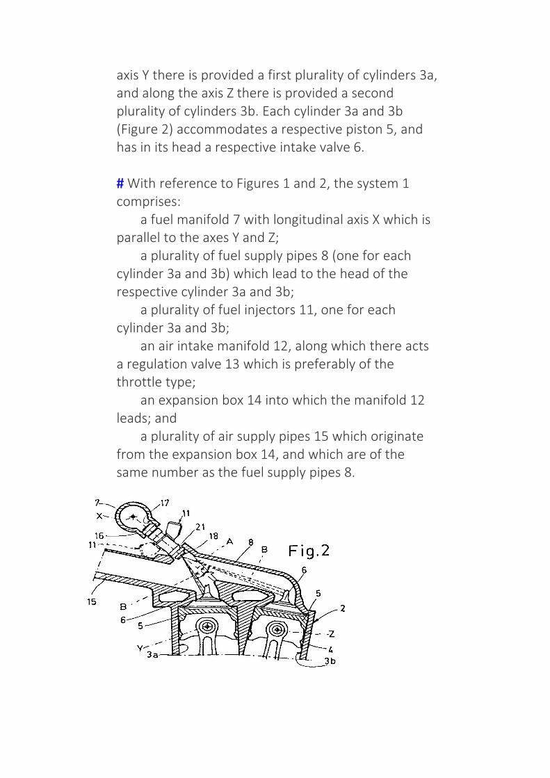
axis Y there is provided a first plurality of cylinders 3a,and along the axis Z there is provided a secondplurality of cylinders 3b. Each cylinder 3a and 3b(Figure 2) accommodates a respective piston 5, andhas in its head a respective intake valve 6.
# With reference to Figures 1 and 2, the system 1comprises: a fuel manifold 7 with longitudinal axis X which isparallel to the axes Y and Z; a plurality of fuel supply pipes 8 (one for eachcylinder 3a and 3b) which lead to the head of therespective cylinder 3a and 3b; a plurality of fuel injectors 11, one for eachcylinder 3a and 3b; an air intake manifold 12, along which there actsa regulation valve 13 which is preferably of thethrottle type; an expansion box 14 into which the manifold 12leads; and a plurality of air supply pipes 15 which originatefrom the expansion box 14, and which are of thesame number as the fuel supply pipes 8.

# With reference to Figure 2, the injectors 11 have ahead 16, in which there is recessed the fuel inletmouth, which is accommodated in a respective seat17 recessed in the fuel manifold 7, and a nozzle 18(Figure 3) which is accommodated in a seat 21recessed along the respective fuel supply pipe 8. Thefuel manifold 7 is mounted to the side of the base 4,and in particular in the vicinity of the axis Y, such thatthe pipes 8 which supply the cylinders 3a have alength which is shorter than that of the pipes 8 whichsupply the cylinders 3b. The injectors 11 have arespective longitudinal axis A which convergestowards an area of the base 4 in a median positionbetween the axes Y and Z. The axes A of all theinjectors 11 are defined on a single plane, i.e. all theinjectors 11 have the same angle relative to thelongitudinal axis X of the fuel manifold 7. The airsupply pipes 15 lead to a respective fuel supply pipe8, inside which the air and fuel are mixed in order toobtain the air-fuel mixture which the cylinder 3a, 3bwill take in by means of the valve 6 during the intakestage.
# With reference to Figure 3, the nozzle 18 of theinjector 11 has a plate 22 in which there is providedan injection hole 23 defined along an axis B whichconverges on the axis A according to an angle α; the

fuel jet is thus not in line with the axis A but is at anangle α relative to the latter.
# With reference to Figure 2, the injectors 11 whichsupply the cylinders 3a are oriented differently, andin particular are rotated around the axis A by 180°relative to the injectors 11 which supply the cylinders3b. The orientation of the injectors 11 which supplythe cylinders 3a, and the angle α of the fuel jetrelative to the axis A, cause the fuel jet to strike fullythe valve 6 of the cylinders 3a. Whereas theorientation of the injectors 11 which supply thecylinders 3b and the angle α of the fuel jet relative tothe axis A, cause the fuel jet to strike fully the valve 6of the cylinders 3b, this latter solution beingillustrated in broken lines in Figure 3.
# According to the above description, the advantagesobtained by implementing the present invention areclear.
# In particular, an injection system is providedaccording to which all the cylinders use the sameinjectors, in which the injection hole is at an anglerelative to the axis of the injector. If the injector isnow positioned according to a predeterminedorientation of the injection hole axis, the fuel jet canbe directed against the intake valve of the closercylinder or of the further cylinder. This aimeddirection of the fuel jet does not give rise to thedepositing of particles on the walls of the fuel supplypipe, since these walls are not along the axis of thejet. Consequently, all the quantity of fuel injected isthen taken in by the cylinder, and in addition there is

no distortion of the stoichiometry prescribed for theair-fuel mixture.
# Finally, it is clear that modifications and variantsmay be applied to the system 1 described andillustrated here, without departing from theprotective context of the present invention.
# In particular, the system 1 can contain anynumber of cylinders distributed in two rows, and caninclude injectors of a type other than that described.The cylinders of one row can have their longitudinalaxis parallel or converging with the longitudinal axisof the cylinders of the other row. In addition, theinjectors which supply the cylinders 3a could havetheir injection holes defined along angled axes, withan angle which differs from that of the injectionholes of the injectors which supply the cylinders 3b.
# According to a different embodiment, all theinjectors could have the same orientation, andinclude a plate 22 which can be pivoted around theaxis A in order to determine the injection hole 23defined on an axis which converges on the respectiveintake valve 6.
Claims (4)Hide Dependent
1.

Fuel injection system for a multi-cylinder endothermicengine (2) comprising; a plurality of first cylinders (3a) provided along a firstaxis (Y); a plurality of second cylinders (3b) provided along asecond axis (Z) which is parallel to the first axis (Y); a plurality of intake valves (6) each of which ismounted in the head of a respective cylinder (3a, 3b); a fuel manifold (7) with a longitudinal axis (X) which isparallel to the first and second axis (Y and Z); a plurality of fuel supply pipes (8) which lead to thehead of a respective cylinder (3a, 3b); a plurality of fuel injectors (11), one for each cylinder(3a, 3b), the longitudinal axis (A) of which convergestowards a median area defined between the first andsecond axis (Y and Z), and which can collect fuel from thefuel manifold (7) and inject this fuel into a respective fuelsupply pipe (8); and an air intake manifold (12) which can convey air intothe fuel supply pipes (8); characterized in that the injectors (11) comprise anozzle (18) in which there is provided an injection hole (23)which is defined along an axis (B) which converges on thelongitudinal axis (A) of the injector (11) according to arespective and predetermined angle (α), and characterizedin that the axis (B) of the injection hole (23) of theinjectors (11) which supply the first cylinders (3a)converges on the intake valve (6) of the first cylinders (3a),whereas the axis (B) of the injection hole (23) of theinjectors (11) which supply the second cylinders (3b)converges on the intake valve (6) of the second cylinders(3b).
2. System according to Claim 1, characterized in that allthe injectors (11) have the same angle between their

own longitudinal axis (A) and the axis (B) of their owninjection hole (23).
3. System according to Claim 2, characterized in thatthe injectors (11) which supply the first cylinders (3a)are oriented differently, and in particular are rotatedaround their own longitudinal axis (A) by 180°relative to the injectors (11) which supply the secondcylinders (3b).
4. System according to Claim 2, characterized in that allthe injectors (11) have the same orientation, and inthat the nozzles (18) of the injectors (11) whichsupply the first cylinders (3a) are oriented differently,and in particular are rotated around the longitudinalaxis (A) by 180° relative to the nozzles (18) of theinjectors (11) which supply the second cylinders (3b).
5.5 Filter for Diesel engine
The fuel filter of diesel engine can filter out the harmfulimpurities and moisture in the fuel system, protect the normalwork of the engine, reduce wear and tear, avoid clogging andimprove diesel engine life. Here, we are willing to share thebasic working principle of diesel engine fuel filter.
Basic Working Principle of Diesel Fuel Filter
The purpose of any diesel fuel filter is to remove foreignparticles as well as water. The use of a suitable filtration systemon diesel engines is a must to avoid damage to closely fitted

injection pump and injector components. Filter's ability variesbetween the type and manufacturer. On diesel engines primaryand secondary filters are used. The primary filter is capable ofremoving dirt particles down to 30 microns and the secondaryfilter between 10 to 12 microns. Secondary filters are availablebetween 3 and 5 microns, which are used in severe serviceoperations. The primary filter is usually located between thetank and the supply pump, the FWS is one type of the primaryfilters. The secondary filter between the supply pump and theinjection pump.
Diesel fuel filter is referred to as full-flow filter, because all thefuel must pass through it before reaching the injection pump.Some filters use internal replaceable element inside a bowl orshell. These are commonly referred to as a shell and elementdesign. Most fuel filters used today are of the spin-on type,which allow for faster change out since the complete filter is athrowaway.
Besides, if the filter is installed on the pressure side of the boostpump it must have sufficient strength to handle pump pressurewithout bursting or leaking. The filter must be located well awayfrom sources of heat, preferably outside of the enginecompartment.
Components
The fuel filter of diesel engine is mainly composed of three parts:filter element, the shell and filter base (As shown in Figure 1). Allmodels are universal except for the overflow valve 8 that hastwo structures. Choosing C0810A or C0810B filter should be onthe basis of different models. For the 12 cylinder V type dieselgenset, it should be installed in parallel with each one of C0810Aand C0810B.

Figure 1: Fuel filter assembly section
1. Gasket 2. Base of filter 3. Pull rod 4. Bleed screw 5.Gasket 6. Pull-rod nut 7. Jump ring 8. Overflow valve 9. Oilpipe connection 10. Seal ring 11. Sealing washer 12. Filterelement 13. Seal ring 14. Tray 15. Spring seat 16. Shell 17.Seal ring 18. Spring
The fuel is sent to the fuel filter mainly by the fuel pump. Theimpurities in the fuel will be cleared through the paper filterelement. And then the fuel can enter the inner cavity of thefilter cylinder. Through the collection chamber of the filter sea,it leads to the fuel injection pump. The filter holder is equippedwith fuel return fitting and the overflow valve is also installedinside. When the fuel pressure in the fuel filter is more than78kPa(0.8kgf/C ㎡), the excess fuel will return back to the fueltank from the fuel return fitting. When connecting the lowpressure fuel line, you should connect it according to the arrowpointing direction on the socket to avoid connection error. Thefilter seat and the shell are connected by pull rod, and it issealed by rubber ring. Due to there is a bleeder plug on the topof filter seat, users can release the screw to clear the air of thefuel filter in use.

Figure 2: Fuel filter overhauling
The fuel filter of the diesel engine is fixed on the engine bodyand bracket with two M8-6H screws. If users find that the fuelsupply is not smooth, it is possible that the filter element ispluged. At the moment, you should dump the fuel oil. You candirectly loosen the pull rod nut of diesel generator set, removethe shell, and take out the filter cartridge (As shown in Figure 2).After the filter element is dipped into gasoline or diesel oil, youcan gently wash the dirt off with brush (As shown in Figure 3). Ifthe filter cartridge is broken or hard to clean, it must berenewed. Then install it as shown in Figure 1 and inject the cleanfuel.
Figure 3: Cleaning fuel filter element

5.6 Describe the working principle of Fuel feedpump and Fuel Injector for Dieselengine
Fuel feed pump diesel engine construction and workingFuel feed pump diesel engine is a mechanical device which works forsupplying the fuel. The fuel feed pump diesel engine brings fuel from fueltank and sends to the filters, FIP and injectors. Fuel feed pump has drivenby engine cam shaft.
Construction of fuel feed pump diesel engine;The fuel feed pump diesel engine have a fuel inlet which is connected withfuel tank by the fuel feed pump pipe line. It also have a fuel outlet whichis connected with filter and FIP by the low pressure pipeline
The fuel feed pump diesel engine have two check valve namely inletcheck valve and outlet check valve, both are fitted inside the pump bodyat inlet and outlet of the fuel
For airlock removing operation the fuel feed pump diesel engine have amanual operating lever. For normal cleaning of the fuel it has a gaugefilter inside the body.
There is a plunger fitted inside the fuel feed pump diesel engine bodyand to keep in initial position of the plunger there is a returning speedprovided.There is a continuity channel casted inside the body which makescontinuity of fuel supply f or the system.
WORKING OF FUEL FEED PUMP DIESEL ENGINEThere are two different workings:

1.Manual operation while removing airlock:When vehicle is getting off because of the airlock in the fuel supplysystem.Now the user has to open the manual priming lever and start priming bypulling and pushing this leverContinuous priming of the lever there is a suction being created and takesfuel from fuel tank and supply to the system.
2.Fuel supply while the engine is startingDuring starting the engine the cam shaft of the engine gives drive to thefuel feed pump diesel engine. The plunger starts moving front and back.When the plunger comes back then suction takes place inside the body.Because of this suction fuel flows from fuel tank and filled into the pumpbody by opening the inlet check valve.When the plunger goes front then it makes pressure on the fuel and fuelflows to the system by opening the outlet check valve. During fuel outletsome fuel goes behind the plunger through the continuity channel, whileplunger goes back again the fuel comes from fuel tank into the pumpbody but the fluid behind the plunger flows to the system and then thereis continuity of fuel supply.

6.1 Introduction, Social and Environmental importance ofHybrid and Electric Vehicles
Since the dawn of the modern era, consumption anddistribution of energy has quickly become mankind’s highestpriority. However, the continued apathetic attitude that wasinitially taken toward energy and its side effects can no longerbe used. A new more environmentally friendly source of energyhas to be utilized in order to fulfill our own needs otherwise weselfdestruction while relying on non-renewable oil basedmethods. In the last few decades two new technologies haveemerged; the development and implementation of HybridElectric Vehicles (HEVs) and more recently the Plug-in HybridElectric Vehicles (PHEVs). These emerging technologies maymake it possible for the United States to adapt thesetechnologies on a larger scale to reduce harmful emissions andcut our dependence on foreign oil dramatically. However, thefuture of the technologies will heavily depend on the everydayAmerican consumer’s willingness to forgo the ‘tried and true’combustion engine for the infantile technologies of the HEV andPHEV. With the introduction and continued popularity of HEVsand as well as the recent hype over the PHEVs, the future oftransportation in the United States is on the brink of change.
First, verify if independence of foreign oil is truly a possibilityand how to accomplish this feat. Second, identify the majormotivators for the American consumers who purchase thesevehicles and how that can be used to increase the sales of HEVsand PHEVs respectively. The third and last objective is todetermine the future impact of the all electric vehicle (EV).Earlier civilizations relied on a number of power sources such as

water to turn wheels, to run mills, fire to heat water and createsteam, or windmills to turn grinding stones. Since roughlyEnvironmental and Social Issues Concerned with Hybrid Cars 5the 17th century various forms of oil have been used, such askerosene, as fuel for lanterns. Even into the 18th , 19th , andearly 20th centuries whales were hunted for their blubber whichcould be converted into oil among other things. In the morerecent years with the invention of the combustion engine, whichhas not only increased the shear amount of oil consumedannually but also drastically augmented our dependence upon itin our daily lives.
Our oil ‘addiction’ has lead us to the realization that our usagehas its limits, not only does the environment suffer adverseeffects because of its use but our society is so dependent uponthat if it were suddenly removed, most of modern society wouldcease to function properly if it all. Without a reasonablealternative this fate is all too possible and this has caused hugeconcerns over how, on a large scale, we can change ourconsumption habits and create a cleaner energy for our use.
Hybrid cars have come a long way in the past 20 years, but mostpeople are unaware they have been around since the mid 1800s.The early electric vehicles at the turn of the 20th century wereexpensive, problematic and not very powerful. Given certainweather conditions or too steep a hill the electric vehicle ofyesteryear was simply unable to perform up to our expectations.
With the introduction of the Ford Model T, a revolution invehicles was made. The Model T was cheaper and morepowerful and was made relatively simplistic, it also ran on a thenabundant source of gasoline, and the United States could meetits own internal demand enough so that it actually exported itsexcess to European countries such as France and Britain.Ultimately, the Model T made the early EVs defunct and as such

fell off the radar until events like the 1973 oil crisis and 1979energy crisis where the electric technologies were eventuallyreconsidered.
The first electric car is claimed to have been built between 1832and 1893 by Robert Anderson of Scotland. From then until thelate 1800s, when they became efficient enough to use as taxicabs in England, the cars were heavy, slow and impractical.Modern batteries development in the early 1900s pushed thedevelopment of more efficient, reliable, and practical electriccars in that period.
The Hybrid came about in 1900 in Belgium, when a smallgasoline engine was paired with an electric motor. Duringnormal operation the electric motor charged onboard batteries,but during acceleration and uphill stints the electric motorprovided a boost to the 3.5 horsepower motor. In 1905 H Piperpatented the first hybrid in America. In 1910 a hybrid truck wasmanufactured in Pennsylvania, which used a 4 cylinder to powera generator and an electric motor. 1916 saw the production ofhybrid cars claiming 35 mph and 48 mpg, however this also sawthe end of the electric car era due to the advances incombustion engine technology.
Until the mid to late 1960s, there is little commercial advance inhybrid or electric cars. As early as the mid 1960s congressrecognized the importance of reducing emissions to improve airquality, and that the use of electric cars was a possible way toachieve this. In the late 60s and early 70s the oil embargosparked a renewed interest in hybrid and electric vehicles. A fewhybrids were released by major manufacturers, but most wereunderpowered and small. More importantly, three scientistspatented the first modern hybrid system in 1971, much of whichclosely resemble the hybrids of today.

The next big push from congress come s with the 1976 Electricand Hybrid Vehicle Research, Development, and DemonstrationAct which encouraged the commercial improvement of electricmotors and other hybrid components. The research lead towardnew developments and new vehicle released in the UnitedStates, including all electrics from GM and Honda, evenincluding an electric truck, the Chevrolet S-10. These vehiclesreached a niche group, but still did not receive the salesnumbers Environmental and Social Issues Concerned withHybrid Cars 7 to be feasible. This all changed with the release ofthe Toyota Prius in Japan in 1997.
With 18000 sold in the first year it becomes the firsteconomically feasible hybrid produced. With its import to theunited stated in 2000 and the release of Hondas Insight to theUS in 1999 the hybrid age had finally arrived. However, PHEVsand HEVs are not without limitations, which are mainly causedby the current state of battery technology. With future researchand development into creating improvements on batterytechnology many of the limitations will be greatly reduced if notexpunged completely.
We have come a long way since the nickel and lead batteries ofthe 1960s, more recently the Nickel Metal Hydride and LithiumIon battery technologies have been developed and successfullyimplemented. Today’s HEVs are a far cry from the small fourhorse power models of the 1800s, modern HEVs include thesame power, acceleration, comfort, and price of theircounterpart conventional cars (CVs), but can reach upwards of50 miles per gallon depending on the model

One of the major technologies found to have a significantcontribution towards carbon emission reduction is the HybridElectric Vehicles or HEVs. This new type of vehicle is beingpraised for fuel efficiency and ultimately being environmentalfriendly.
On the other hand, there are contradicting arguments regardingthe impact of HEVs on the environment, which needs to beexamined further. The environmental implications of HEVs canbe better explored when observed in a smaller region where thedata is more specific. Fuel prices in Oman are at a record highdespite the fact that the country is a major global producer ofpetroleum products. As a result, a significant number of carowners in the country are shifting to HEVs.
However, the shift towards HEVs is more on the economic thanenvironmental position. In this regard, the discussion willexplore how the shift towards HEVs impacts the environmentspecifically in Oman. Hybrid Cars vs. Traditional Cars There aretwo major questions that car consumers in Oman asks todaywhen purchasing new vehicle, and that is whether the car is fuelefficient and environment friendly. Only HEVs have the highestpotential for meeting the aforementioned two conditions.However, to compare conventional versus HEVs it is importantto note pros and cons of each type. For HEVs, the advantage ishigher mileage, high resale value, uses cleaner energy, but thetradeoff would be a higher price tag, higher maintenance cost,and no sport-tuned suspensions (Lexus, N.D.).
On the other hand, conventional fuel cars command a lowerprice tag, better engine power, and low maintenance cost, butthe drawbacks would be harmful emissions and low mileage. Areport published by Argonne in 2009 suggests that HEVs offer

90% reduction on petroleum energy use and 40-80% reductionon greenhouse gas emission (Elgowainy et al., 2009). CarbonFootprint and Environmental Impact in Oman In the case ofOman, the current environmental statistics suggests that carbonemission in the country is on a steady increase since the earlydiscovery and production of oil and gas.
From 1972 to 2011 there has been steep climb on the total CO2emissions in Oman from 2,000 Gg to 40,000 Gg (Abdul-Wahabet al., 2015). Similarly, the study conducted by Yousif et al.(2017) shows a forecasted further increase in CO2 andgreenhouse gas emissions of nearly 60 million tons in thecountry in the next decade. The major contributors of theseemissions are continuous fuel combustion at 57.9,manufacturing at 24.2 and transportation at 12.3 .
The CO2 emitted by conventional cars in the country are addedon both transportation and fuel combustion segments, whichencompasses a much higher statistic when combined. In thisregard, the Sultanate of Oman is seeing the potential of HEVs tocounter the continuously increasing CO2 and GHG emissions inthe country .
In 2015, major car brands introduced HEVs in Oman such asToyota Prius, which is spearheading the shift to HEVs across theMiddle East (Times of Oman, 2016). Expectations of the carmodel 3 / 14 Journal of Student Research Fourth Middle EastCollege Student Research Conference, Muscat, Sultanate ofOman (2019) ISSN: 2167-1907 (www.jofsr.org) suggest that it islikely to reduce approximately 67 million tons of CO2 emissionover the span of 20 years (Times of Oman, 2016). To date it isnot certain how many of the HEVs were deployed in Oman,hence, the exact measure of its impact towards the country’sCO2 emission reduction is still undetermined (CMS, 2018).There are several challenges observed in terms of further

deployment of HEVs in Oman and one of them is theestablishment of regulators that will oversee the operationsencompassed by the introduction of HEVs in the country. One ofthe primary considerations is who would be responsible for theimplementation and regulation of facilities such as chargingstations, tariff fixing, and government registration andrequirements (CMS, 2018).
RESULTS
The topic of hybrid cars was keenly inspected. The major partsof it were broken down and critically analyzed. The studyproduced results that could positively affect everyone involved.With respect to different aspects, the results reviewed are asproduced below:
Environmental Impact The first and one of the most importantresult of implementing hybrid cars usage, is the environmentalfactor. According to the survey conducted among 36 people,88% of the respondents agreed that air pollution has increaseddue to the automobiles on road. Cars driven in the city, whenthey run on low speeds, or are stuck in heavy traffic, the regulargasoline cars keep the engine running which at the same timeexhales fumes causing increasing air pollution on extreme levels.
The same situation when applied to hybrid cars, they smartlyswitch to the electric motor, causing zero fuel consumption andzero air pollution. This not only contributes to saving money butalso to a greener and healthier environment.. Money Saver Thesurvey shows that on an average around 66% of people agreedto spending between 50 – 60 10 / 14 Journal of StudentResearch Fourth Middle East College Student ResearchConference, Muscat, Sultanate of Oman (2019) ISSN: 2167-1907OMR per month just on petrol/diesel. Going by the figure 60,that is 720 OMR per year. And people that fall into the more

than 70 category; that would sum up to a whopping 960 OMRper year.
For most of the people, 960 to 1000 OMR per year is a hugeamount to be wasted just for refilling cars. With hybrid vehiclesin place, this number is sure to come down by a few hundreds,saving money in the long term. Safety Referring to the reportissued by Insurance Institute for Highway Safety, it claimed thatin crash tests, hybrid cars performed better than the regular gascars. The data showed that the people within a hybrid vehiclewould be 25% less injured than a same standard gasoline vehicle,as well as the driver’s death rate showed a reduction when itcame to hybrid models. The reason the hybrid models executedwell in the crash tests was due to the heavy weight they carry.
According to the reports, these models are 10% more heavierthan the regular gasoline cars, and hence when they crash, theheavier vehicle tends to have a greater impact on the lightweighted gasoline counterparts and pushes it backwards.(Edgerton, 2011) For example, the hybrid variant of Accord is217 kg’s more than the standard Accord. A lot of news issurrounded around the topic of how Lithium Ion battery used inthese vehicles could prove dangerous by getting overheated andmay also catch fire. Companies manufacturing and producinghybrid cars have stated that it takes a long process to modifyand tame the li-ion batteries to make it safer and runnable foryears (Tajitsu, 2016).
Along with the newly modified and now much safer lithium ionbatteries, Tesla Motors mentioned that they developed acooling system and have also created sensors and fuses up tothree layers of protection to safeguard the batteries fromovercharging. The role of the fuses and the sensors is toimmediately disengage the battery in use, when there is a rise inthe temperature, a roll-over or an unexpected impact. From a
safety point of view, the makers decided to use a number ofsmaller batteries in comparison to a few large ones, since theenergy stored will also be in small amounts and enclosed withinits own steel cases, it will also prove safer.(Bullis, 2006)DISCUSSION The main objective of this research is to analyzeHybrid-Electric Vehicles (HEV) and their components and justifyhow these vehicles are less harmful than gasoline cars to theenvironment. This is done by analyzing and conspicuouslyexplaining how an HEV works, its characteristics and thecomponents that differentiate it between traditional gasoline.
The result after testing the vehicles and researching andunderstanding its components is that HEV does is indeed lessharmful to the environment due to it consuming less gasolineand because the components; mainly the battery and motor,are naturally built to be less impactful to the environment. Thisresearch also aims to encourage consumers into buying HEV. Ifthe number of total hybrid vehicles increase and the totalnumber of gasoline vehicle decrease, the total amount ofpollution caused by vehicles would drastically decrease due tothe total consumption of gasoline decreasing as large amountsof gasoline won’t be needed to fulfill the needs of hybridvehicles.
This ultimately reduces environmental pollution caused byvehicles. Along with the reduction of pollution, the amount ofmoney saved of fuel refilling’s could be turn out to be helpful formost of the individuals, who are struggling with balancing theirbudget.
CONCLUSION
All the above topics, which have been analytically studied, itconcludes that the hybrid vehicles prove to be more eco-friendly and safer for the environment than the IC engine

vehicles. With increasing production of hybrid variants, batteriesare being planned and designed in way that extends its life aswell as provides the ability of recycling.
This all in all, turns to be safer, healthier 11 / 14 Journal ofStudent Research Fourth Middle East College Student ResearchConference, Muscat, Sultanate of Oman (2019) ISSN: 2167-1907(www.jofsr.org) and also a money saver package, saving you afine amount spent on fuel. Investigation into other vitalitysources, for example, power devices and sustainable powersmake the future look more splendid for hybrid vehicles.
RECCOMENDATIONS
Many people have the conception of hybrid vehicles being a lotmore expensive than the regular gasoline vehicles.
The truth in fact, is that the hybrid types cost only a very fewmore thousands than the gasoline types of the same model. Forexample; the Hyundai Sonata Hybrid costs $26,000, whereas thegasoline counterpart costs $22,000. In the long run, these fewextra thousands will cover up the huge amount spent on fuelyearly. It was also witnessed that the EU is providing incentivesfor people who use fully electric cars, such as reduced taxes andother similar traits. A similar trait can be introduced andimplemented in GCC counties to encourage the purchase ofhybrid vehicles, like for example reduced gas rates per liters forcertified hybrid cars.
Due to the nature of electric cars, it doesn’t seem like a viablesolution; at least in GCC to implement them since they are themost environmentally friendly vehicles due to the exclusion ofan IC engine. The reasons behind this are: electric cars don’tcover enough millage without needing to be recharged. Basedon experiments conducted, the most distance that an electric

car was able to attain by driving in specific conditions wasapproximately 300kilometers without needing to charge the car.Another reason is that there are not enough charging stations.Until that reality comes into fruition, hybrid vehicles are deemedto be the most viable solution to reduce pollution; at least in theGCC.
6.2 Description of Electric Vehicles, operationaladvantages, present performance andapplications of Electric Vehicles
The electric car (EV) is a relatively new concept in the world of theautomotive industry. Although some companies have based their entiremodel of cars around being proactive and using electricity, some alsooffer hybrid vehicles that work off both electricity and gas.
An electric car such as Nissan Leaf, Ford Focus Electric or Tesla Model S,Chevrolet Volt is a great way for you to not only save money but alsohelp contribute towards a healthy and stable environment.
Cars produce a lot of carbon emissions that are ejected into our naturalatmosphere, leaving us vulnerable to thingslike pollution and greenhouse gases. In order to positively help theenvironment we live in, an electric car is a great step forward.
By buying an electric car, you can also receive government subsidiesfor being environmentally conscious. Although you may end up payingmore for your vehicle, the positives greatly overshadow the negatives.However, there are still two sides to consider when you’re thinkingabout investing in an electric vehicle.
EV’s get their power from rechargeable batteries installed inside the car.These batteries are not only used to power the car but also used for thefunctioning of lights and wipers.
Electric cars have more batteries than a regular gasoline car. It’s thesame kind of batteries that are commonly used when starting up a

gasoline engine. The only difference comes in the fact that in electricvehicles, they have more of them, which are used to power the engine.
Advantages of an Electric CarAn electric car can be a great way for you, as a consumer, to save a lotof money on gas. However, there are so many different reasons why youshould invest in an electric car in the modern-day of technology.
1. No Gas Required
Electric cars are entirely charged by the electricity you provide, meaningyou don’t need to buy any gas ever again. Driving fuel-based cars canburn a hole in your pocket as prices of fuel have gone all-time high.
The average American pays about 15 cents a mile to drive a gas-powered vehicle, whereas many electric cars run on five cents a mile.Electricity is largely less expensive than gasoline.
If most people charge their cars in the garage installing a few solarpanels, that price can get cut even further, offering savings on poweringyour entire home. With electric cars, this cost of $2000 – $4000 on gaseach year can be avoided.
2. More ConvenientThe electric vehicle is easy to recharge, and the best part is you will nolonger need to run to the fuel station to recharge your car before hittingthe road! Even a normal household socket could be used for chargingan electric car.
3. Savings
These cars can be fuelled for very low prices, and many new cars willoffer great incentives for you to get money back from the governmentfor going green. Electric cars can also be a great way to save money inyour own life.
4. No Emissions

The biggest advantage of an electric vehicle is its green credential.Electric cars are 100 percent eco-friendly as they run on electricallypowered engines.
It does not emit toxic gases or smoke in the environment as it runs on aclean energy source. They are even better than hybrid cars as hybridsrunning on gas produce emissions. You’ll be contributing to a healthyand green climate.
5. Popularity
EV’s are growing in popularity. It is nearly three times as efficient as carswith an internal combustion engine, according to Wikipedia. Withpopularity comes all new types of cars being put on the market that areunique, providing you with a wealth of choices moving forward.
6. Safe to Drive
Electric cars undergo the same fitness and testing procedures test asother fuel-powered cars. An electric car is safer to use, given their lowercenter of gravity, which makes them much more stable on the road incase of a collision.
In case an accident occurs, one can expect airbags to open up andelectricity supply to cut from the battery. This can prevent you and otherpassengers in the car from serious injuries. They are even less likely toexplode in the absence of any combustible fuel or gas.
7. Cost-Effective
Earlier, owning an electric car would cost a bomb. But with moretechnological advancements, both cost and maintenance have gonedown.
The mass production of batteries and available tax incentives furtherbrought down the cost, thus, making it much more cost-effective.Consult a tax specialist to learn more about any tax credits that mightbe available to you on the state or federal level.
8. Low Maintenance

Electric cars run on electrically powered engines, and hence there is noneed to lubricate the engines, anything related to the combustionengine or a ton of maintenance tasks that are usually associated with agas engine.
Other expensive engine work is a thing of the past. Therefore, themaintenance cost of these cars has come down. You don’t need to sendit to the service station often as you do for a standard gasoline-poweredcar.
9. Reduced Noise Pollution
Electric cars put a curb on noise pollution as they are much quieter.Electric motors are capable of providing smooth drive with higheracceleration over longer distances. Many owners of electric cars havereported positive savings of up to tens of thousands of dollars a year.
10. Battery Life & CostBatteries are an integral part of an electric vehicle. Most electric vehiclebatteries are lithium ones, and their costs are improving every year.
The full capacity of a lithium-ion battery cell should be good for 300 to500 cycles. A good battery could last you up to ten years. With theimproving technologies, the cost of these batteries is expected to comedown even more.
11. Easy Driving
In the world of automobiles, electric cars have the simplest drivingmethod. Commercial electric cars come with a transmission comprisingof only one really long gear and also don’t suffer from the stallingproblem as petrol cars do.
This effectively eliminates the need to add a clutch mechanism toprevent that from happening. Therefore, you can operate an electric carwith just the accelerator pedal, brake pedal and steering wheel.
Another really useful feature is regenerative braking. In normal cars, thebraking process is a total wastage of kinetic energy that gets released as

frictional heat. However, in an electric vehicle, the same energy is usedto charge the batteries.
Considering the demand for oil will only be going up as the supplies runout, an electric car will most likely be the normal mode oftransportation in the coming future.
Companies like Nissan and Tesla offer great electric models with anoutstanding amount of benefits for people who decide to invest. You’llbe saving not only yourself but also your family a huge amount ofmoney.
The environmental impact of an electric car is zero, as well, meaningyou’re reducing your carbon footprint and positively affecting theeconomy.
APPLICATIONS OF ELECTRIC VEHICLE
.Consumer electronics
.public transportation
.aviation
.electricity grid
.renewable energy storage
.military
.spaceflight
.wearable technology

An electric vehicle battery (EVB, also known as a traction battery) isa rechargeable battery used to power the electric motors of a batteryelectric vehicle (BEV) or hybrid electric vehicle (HEV). Typically lithium-ionbatteries, they are specifically designed for high electric charge (or energy)capacity.
Electric vehicle batteries differ from starting, lighting, and ignition (SLI)batteries as they are designed to give power over sustained periods oftime and are deep-cycle batteries. Batteries for electric vehicles arecharacterized by their relatively high power-to-weight ratio, specificenergy and energy density; smaller, lighter batteries are desirablebecause they reduce the weight of the vehicle and therefore improve itsperformance. Compared to liquid fuels, most current batterytechnologies have much lower specific energy, and this often impacts themaximum all-electric range of the vehicles.
The most common battery type in modern electric vehicles are lithium-ion and lithium polymer, because of their high energy density comparedto their weight. Other types of rechargeable batteries used in electricvehicles include lead–acid ("flooded", deep-cycle, and valve regulatedlead acid), nickel-cadmium, nickel–metal hydride, and, lesscommonly, zinc–air, and sodium nickel chloride("zebra") batteries.[1] The amount of electricity (i.e. electric charge)stored in batteries is measured in ampere hours or in coulombs, with thetotal energy often measured in kilowatt-hours.
Since the late 1990s, advances in lithium-ion battery technology havebeen driven by demands from portable electronics, laptop computers,mobile phones, and power tools. The BEV and HEV marketplace hasreaped the benefits of these advances both in performance and energydensity. Unlike earlier battery chemistries, notably nickel-cadmium,

lithium-ion batteries can be discharged and recharged daily and at anystate of charge.
The battery pack makes up a significant cost of a BEV or a HEV. As ofDecember 2019, the cost of electric vehicle batteries has fallen 87% since2010 on a per kilowatt-hour basis.[2] As of 2018, vehicles with over250 mi (400 km) of all-electric range, such as the Tesla Model S, havebeen commercialized and are now available in numerous vehiclesegments.
In terms of operating costs, the price of electricity to run a BEV is a smallfraction of the cost of fuel for equivalent internal combustion engines,reflecting higher energy efficiency.
Types of Electric Car Batteries
Electric car batteries are different from SLI batteries (starting, lightningand ignition). SLI batteries are batteries that are usually installed ingasoline or diesel cars. This type of electric cars battery is designed as anenergy storage system, capable of delivering power for long andsustainable periods.
There are 5 types of electric vehicle batteries to be discussed in thisarticle:
Lithium-Ion (Li-On) Nickel-Metal Hybrid (NiMH) Lead Acid (SLA) Ultracapacitor ZEBRA (Zero Emissions Batteries Research Activity)
The comparison of the first four types of electric car batteries can beseen as

follows:
———————————————
Lithium-Ion Battery (Li-On)
This type of electric vehicle battery is mostwidely applied is the Li-On battery. This battery may already be familiar tous because it is also used in many portable electronic equipment such ascellphones and laptops. The main difference is a matter of scale. Itsphysical capacity and size on electric cars is much greater – this is oftenreferred to as a traction battery pack.
Li-on batteries have a very high power to weight ratio. This type ofelectric car battery is high energy efficiency. Performance at hightemperatures is also good. The battery has a greater energy ratio perweight – a parameter that is very important for electric car batteries. Thesmaller the battery weight (same kWH capacity) means the car can travelfurther with a single charge.
This battery also has a low “self-discharge” level, so the battery is betterthan any other battery in maintaining its ability to hold its full charge.

In addition, most parts of Li-on batteries can be recycled, making it theright choice for those interested in environmentally conscious electriccars. BEV cars and PHEVs use the most lithium batteries.
Li-on battery Types
Lithium Iron Phosphate(LiFePO4) — LFP Lithium Nickel Cobalt Aluminum Oxide (LiNiCoAlO2) — NCA Lithium Nickel Manganese Cobalt Oxide (LiNiMnCoO2) — NMC Lithium Titanate (Li2TiO3) — LTO LithiumManganese Oxide (LiMn2O4) — LMO Lithium Cobalt Oxide(LiCoO2) — LCO
Li-ion batteryparameters
———————————————
Hybrid Nickel-Metal (NiMH) Batteries
NiMH batteries are more widely used byhybrid-electric vehicles (HEV), but are also used successfully in some BEVcars. This type of hybrid electric car battery does not get power fromoutside (can be recharged from an outside source of the car system). Therecharging of hybrid electric car batteries depends on engine speed,wheels and regenerative braking.

NiMH batteries have a longer life cycle than lithium-ion batteries or SLAbatteries. NiMH batteries are safe and tolerant of incorrect usage. Thebiggest disadvantages of NiMH batteries include:
The price is relatively more expensive High self-discharge rate Generate significant heat at high temperatures.
These deficiencies make NiMH less effective as a battery for electric carswhose batteries must be able to be recharged from outside the system,such as from the PLN network. That is why the car battery is the mostwidely applied by hybrid cars.
NiMH batteryparameters
———————————————
Lead-Acid (SLA) Batteries
SLA (lead-acid) batteries are the oldest rechargeable batteries. Comparedto lithium and NiMH batteries, lead-acid batteries do lose capacity andare much heavier, but the price is relatively cheap and safe. There arelarge capacity SLA electric car batteries under development, but SLAbatteries are now only used by commercial vehicles as a secondarystorage system.

Lead-acid batteryparameters
———————————————
Ultra-capacitor Batteries
The ultra-capacitor battery is not like thegeneral definition of a battery. In contrast to other electro-chemicalbatteries, this type of electric vehicle battery actually stores polarizedliquid between the electrode and the electrolyte. As the surface area ofthe liquid increases, the energy storage capacity also increases. Like SLAbatteries, ultra-capacitor batteries are very suitable as secondary storagedevices in electric vehicles. This is because the ultra-capacitor helpselectro-chemical batteries increase their load levels. In addition, ultra-capacitor can provide extra power to electric vehicles during accelerationand regenerative braking.
———————————————

ZEBRA Batteries
The battery for ZEBRA electric cars is a low-temperature variant of sodium-sulfur (NaS) batteries and is adevelopment of ZEBRA (originally “Zeolite Battery Research Africa” then became a “Zero Emissions Batteries Research Activity” battery)in 1985. From the beginning ZEBRA batteries were indeed developed forelectric vehicle applications. The battery uses NaAlCl4 with Na + -beta-alumina ceramic electrolyte.
Characteristics of ZEBRA batteries
High power cell so that it fits as an electric car battery High temperature batteries operate at more than 270 ° C The chemical Sodium Nickel Chloride (NaNiCl) provides a nominal
operating cell voltage of 2.58 Volts
Fuel Cell Electric Vehicles
Fuel cell electric vehicles (FCEVs) are powered by hydrogen. They aremore efficient than conventional internal combustion engine vehicles and

produce no tailpipe emissions—they only emit water vapor and warm air.FCEVs and the hydrogen infrastructure to fuel them are in the earlystages of implementation. The U.S. Department of Energy leads researchefforts to make hydrogen-powered vehicles an affordable,environmentally friendly, and safe transportation option. Hydrogen isconsidered an alternative fuel under the Energy Policy Act of 1992 andqualifies for alternative fuel vehicle tax credits.
Fuel cell electric vehicleFCEVs use a propulsion system similar to that of electric vehicles, whereenergy stored as hydrogen is converted to electricity by the fuel cell.Unlike conventional internal combustion engine vehicles, these vehiclesproduce no harmful tailpipe emissions. Other benefits include increasingU.S. energy resiliency through diversity and strengthening the economy.
FCEVs are fueled with pure hydrogen gas stored in a tank on the vehicle.Similar to conventional internal combustion engine vehicles, they can fuelin less than 4 minutes and have a driving range over 300 miles. FCEVs areequipped with other advanced technologies to increase efficiency, suchas regenerative braking systems that capture the energy lost duringbraking and store it in a battery
Hybrid electric vehicles are powered by an internal combustion engineand an electric motor, which uses energy stored in batteries. A hybridelectric vehicle cannot be plugged in to charge the battery. Instead, thebattery is charged through regenerative braking and by the internalcombustion engine. The extra power provided by the electric motor can

potentially allow for a smaller engine. The battery can also powerauxiliary loads and reduce engine idling when stopped. Together, thesefeatures result in better fuel economy without sacrificingperformance. Learn more about hybrid electric vehicles.
Key Components of a Hybrid Electric Car
Battery (auxiliary): In an electric drive vehicle, the low-voltage auxiliarybattery provides electricity to start the car before the traction battery isengaged; it also powers vehicle accessories.
DC/DC converter: This device converts higher-voltage DC power from thetraction battery pack to the lower-voltage DC power needed to runvehicle accessories and recharge the auxiliary battery.
Electric generator: Generates electricity from the rotating wheels whilebraking, transferring that energy back to the traction battery pack. Somevehicles use motor generators that perform both the drive andregeneration functions.
Electric traction motor: Using power from the traction battery pack, thismotor drives the vehicle's wheels. Some vehicles use motor generatorsthat perform both the drive and regeneration functions.

Exhaust system: The exhaust system channels the exhaust gases fromthe engine out through the tailpipe. A three-way catalyst is designed toreduce engine-out emissions within the exhaust system.
Fuel filler: A nozzle from a fuel dispenser attaches to the receptacle onthe vehicle to fill the tank.
Fuel tank (gasoline): This tank stores gasoline on board the vehicleuntil it's needed by the engine.
Internal combustion engine (spark-ignited): In this configuration, fuel isinjected into either the intake manifold or the combustion chamber,where it is combined with air, and the air/fuel mixture is ignited by thespark from a spark plug.
Power electronics controller: This unit manages the flow of electricalenergy delivered by the traction battery, controlling the speed of theelectric traction motor and the torque it produces.
Thermal system (cooling): This system maintains a proper operatingtemperature range of the engine, electric motor, power electronics,and other components.
Traction battery pack: Stores electricity for use by the electric tractionmotor.
Transmission: The transmission transfers mechanical power from theengine and/or electric traction motor to drive the wheels.
he type of HEV is determined by how the powertrain propels the vehicledown the road and may be considered either series, parallel, or series-parallel.

Energy Flow Diagrams and Descriptions
Series (Extended-Range) HybridA series hybrid is like a battery electric vehicle (BEV) in design. Here, thecombustion engine drives an electric generator instead of directly drivingthe wheels. The generator both charges a battery and powers an electricmotor that moves the vehicle. When large amounts of power arerequired, the motor draws electricity from both the battery and thegenerator. Series hybrids may also be referred to as extended-rangeelectric vehicles (EREVs) or range-extended electric vehicles (REEVs) sincethe gas engine only generates electricity to be used by theelectric motor and never directly drives the wheels. Modern examplesinclude the Cadillac ELR, Chevrolet Volt, and Fisker Karma.

Parallel HybridA parallel hybrid is propelled by both an internal combustion engine (ICE)and an electric motor connected to a mechanical transmission. Powerdistribution between the engine and the motor is varied so both run intheir optimum operating region as much as possible. There is no separategenerator in a parallel hybrid. Whenever the generator's operation isneeded, the motor functions as generator. In a parallel mild hybrid, thevehicle can never drive in pure electric mode. The electric motor turns ononly when a boost is needed.
Series-Parallel

The vehicle can be powered by the gasoline engine working alone, theelectric motor by itself, or by both energy converters working together.Power distribution between the engine and motor is designed so that theengine can run in its optimum operating range as much as possible.
Note: All configurations above may use more than one motor to drive thevehicle.
A drivetrain is the collection of components that deliver power from avehicle’s engine or motor to the vehicle’s wheels. In hybrid-electric cars,the drivetrain’s design determines how the electric motor works inconjunction with the conventional engine. The drivetrain affects thevehicle’s mechanical efficiency, fuel consumption, and purchasing price.
Hybrids that use a series drivetrain only receive mechanical power fromthe electric motor, which is run by either a battery or a gasoline-poweredgenerator. In hybrids with parallel drivetrains, the electric motor andinternal combustion engine can provide mechanical powersimultaneously. Series/parallel drivetrains enable the engine and electricmotor to provide power independently or in conjunction with oneanother.
Both conventional hybrids and plug-in hybrids have models with series,parallel, and series/parallel drivetrains. Since battery-electric and hydrogen fuel cell vehicles don’t have internal combustionengines, they utilize different drivetrain assemblies.

Battery recharging and range issues have been the Achilles heel ofelectric vehicles. Some automotive engineers believe solar power may bethe solution.
The goal of vehicle-integrated photovoltaics is to enable EVs to rechargewithout stopping. Unlike traditional EVs that must periodically pull overto recharge batteries during a long road trip, solar cars can keep on going.
Electric cars and trucks embedded with photovoltaic cells can convertenergy from sunlight into electricity. Storing solar energy in batteriesenables them to run smoothly at night or in the absence of direct sunlight.
Several start-ups, such as Aptera Motors, Atlis Motor Vehicles, Fisker Inc.,Lightyear One and Sono Motors, as well as established OEMs like Hyundai,Tesla and Toyota, are developing solar cars or hybrid versions of them.They are integrating solar cells into roofs. However, other body parts,such as doors, hoods, tailgates and trunks, are also prime real estate.
"Automotive solar panels are a very interesting topic, because thetechnology can enable electric vehicles to recharge up to 40 percentfaster," says Peter Harrop, Ph.D., chairman of IDTechEx, a marketresearch firm that recently published a report on the subject. "Some carshave up to 7 square meters of space available for solar panels.
"The technology has already been successfully used on everything fromboats to satellites," notes Harrop. "Any car or truck manufacturer that isnot considering solar panel bodywork is crazy."
Solar panels can be attached to vehicle bodies using mechanical fastenersor structural adhesives. However, to be aerodynamic and aestheticallypleasing, automotive engineers prefer to integrate solar modules intobody panels.
“While it may be possible to use flexible film in the future, solar panelsare not simply stuck onto vehicles today,” explains Harrop. “To achievethe complex shapes needed for car bodies, thin solar cells must bemolded into carbon fiber, glass or polycarbonate sheets. They becomeless like traditional solar panels, because they are actually structuralelements.”

As an example, Harrop points to Lightyear One, a Dutch company thatplans to launch a “long-range solar electric vehicle designed to be gridindependent” later this year. It will feature 5 square meters of integratedsolar cells protected by double-curved and super-strong safety glass.
The solar roof will capture sunlight continually whether the car is movingor stationary. Lightyear One claims that feature will deliver enoughenergy to cover an average of more than 70 percent of annual mileage.
A conductive backsheet produced by Royal DSM is an integral element ofLightyear One’s solar roof. It enables all the connections of the solar cellsto be put on the back of the solar panel, which makes every availablecentimeter on the front of the module available for capturing sunlight.
“The reduction in electrical (cell-to-module) losses not only delivers a 3percent increase in power output; it has the added advantage ofcontributing to a more stylish sunroof with aesthetic appeal,” claimsPascal de Sain, vice president of DSM Advanced Solar.
Another solar roof concept was recently developed by engineers at TeijinLtd. It uses the company’s Panlite polycarbonate resin glazing for itssurface.
“[We molded] the roof’s curved surface into an ideal shape, an extremelychallenging process in the case of using glass,” says Toshiaki Hotaka,general manager of Teijin’s mobility division. “Not only is the roof ideallyshaped, it achieves the strength and rigidity required for the [application.”
The Teijin solar roof was installed on a prototype from Applied ElectricVehicles. During tests conducted in Australia, it achieved output of about330 watts, which is equivalent to a conventional solar panel housedunder glass.
Numerous Benefits
“The benefit of solar-powered vehicles is that they don’t require fuel andhave a low cost of maintenance,” says Lex Hoefsloot, CEO of LightyearOne. “Solar cars run longer on the same battery. This requires lesscharging stops and will get you faster from point A to point B. Solarenergy will never run out and it is free.

“Because the pressure on the grid from solar cars is far less, they offerthe potential to truly scale clean mobility,” explains Hoefsloot. “From auser perspective, all you need is a regular power outlet combined withthe sun; no need to wait for charging infrastructure, again creating ascalable solution.”
Hoefsloot claims that Lightyear One will “consume two to three times lessenergy than any other electric vehicle on the market today, which resultsin an exceptional range of 725 kilometers.” However, the overallachievable yield strongly depends on the driving patterns of individuals.
“[Our vehicle] has around 1,000 individual solar cells across the car thatultimately add 50 to 70 kilometers of range per day during summer,”Hoefsloot points out. “[Our solar modules] can charge the car’s batterywith up to 12 kilometers of range an hour. These solar cells are 20percent more efficient than the solar panels you can buy for your home.And, they’re encased in safety glass to protect them from damage.
“We will outsource the production of our vehicles,” says Hoefsloot. “Weare currently talking to [several] potential production partners...inEurope.”
“The power that can potentially be generated on a car roof has increasedsubstantially, due to the continuous improvement of solar cell and solarmodule technology, leading to higher efficiency,” adds Martin Heinrich,Ph.D., head of the department of module technology at the photovoltaicsdivision of the Fraunhofer Institute for Solar Energy Systems. “Therefore,not only a cooling of the passenger cabin could be provided by the solarroof, but even a significant extension of the driving distance could befeasible.”
According to Heinrich, both transparent and opaque photovoltaics can beused for automotive applications. “But, since the available area onvehicles is quite small, we would rather use as much irradiation aspossible for power generation instead of receiving light in the vehicle,” heexplains.
“Opaque PV works better and offers higher power output, and thereforegenerates a larger solar range,” says Heinrich. “If transparency is required(such as a sun roof or rear window), transparent solar cell technology canbe used, but it currently has a significantly lower power output.”

Heinrich and his colleagues are working on several projects involvingsolar panel integration into roofs and hoods for passenger cars, includingefficient connection to the vehicle power management system. They’realso developing module technology for box bodies on trucks that can beintegrated into bodywork seamlessly, without any parts sticking out.
Engineering Challenges
Despite tremendous potential, equipping a vehicle with solar panelspresents numerous challenges to automotive engineers. According toHeinrich, there are three big challenges:
Making the most of the generated energy. Battery charginglosses due to self-consumption or charging status where thebattery is full but solar power can still be generated must beaddressed.
Manufacturing safe, reliable and cost-effective modules forvehicle integration.
The reduction of power generation by bad weather andshadowing by other vehicles, in addition to buildings, bridges,trees and tunnels. “This cannot be avoided, but predictionmodels would provide better estimates for yield calculationsand charging optimization,” explains Heinrich.
“There are solutions available to those challenges, but in most cases, theyare still being studied,” says Heinrich. “The main technological challengeis the utilization of the generated power. For a high utilization, the high-voltage drivetrain battery is preferred. However, this could lead tosignificant transformation losses and potentially safety concerns.”
Further challenges arise due to the curvature of car roofs. For instance, astrong curvature may lead to a significant irradiance mismatch andresulting cell power, which could reduce the yield of the solar module. Inaddition, module and cell technology needs to provide the highest yield,but also a premium aesthetic appearance and durability.

“The challenge with integrating solar cells into an electric vehicle is tomaximize the surface area, making sure you achieve automotive-gradestandards for reliability and safety, while still optimizing the totalperformance,” says Arjo van der Ham, chief technology officer atLightyear One. “Integrating the cells on a double curved surface ensures agreat aerodynamic performance of the vehicle, but also creates achallenge in optimizing the yield.
“Normally solar cells are put in series,” explains van der Ham. “In thatcase, the part in the shadow will reduce the yield of the total panel.
“We have developed proprietary and highly efficient solar electronics tocompensate for this loss,” adds van der Ham. “[It enables us] to putgroups of cells in parallel. We have also performed many types of impact,heat and vibration tests.”
Another startup firm that has been studying the pros and cons of solarpower is Atlis Motor Vehicles Inc. The company is getting ready toproduce an electric pickup truck at a new factory in Mesa, AZ. Itsinnovative XT model, which is aimed at commercial users, will beequipped with a solar panel tonneau cover system called TerraVis.
“We believe there can be a role for solar to play on a full-size truck likeours,” says Mark Hanchett, CEO of Atlis Motor Vehicles. “There areancillary functions where we feel solar could offer some advantages.
“One example is climate control, especially in hot climates where the sunis high,” notes Hanchett. “Even getting a couple hundred watts from asmall solar array may be enough to run fans to provide circulation of airinto the cab to avoid the 140 to 160 F peaks that are possible during thesummer. Another possible use for on-board solar is for long-term storage,to compensate for parasitic or ‘vampire’ drains on the battery.
“Even in a much shorter term, like during the day on a job site, solar maybe able to keep the battery at a consistent level while using power toolsor chargers powered from the truck’s on-board power inverter,”Hanchett points out. “For these tasks and more, a smaller set of panelsable to make 250 to 500 watts of power would be sufficient.
“The problem comes down to the energy density of solar,” warnsHanchett. “Simply put, only so much energy from the sun is available per

square meter, and solar panels can only capture a portion of that energy.Further complications arise from the orientation of the panels.
“[Unlike solar panels on homes], vehicles really only have horizontalsurfaces to work with, and they are at a very flat angle, which is not themost optimal for making power,” says Hanchett. “And, parking in partialshade near a tree may also mean that a certain panel can’t make enoughpower, which can affect the output of the whole array.”
Let the Sun Shine
Several solar-powered cars are currently available, with others on thehorizon. Last year, Hyundai Motor Co. unveiled a hybrid version of itspopular Sonata sedan that is equipped with a roof-mounted system. Itconsists of a solar panel and controller that enable the vehicle togenerate and store electricity in a battery.
According to Hyundai, the system can charge 30 percent to 60 percent ofthe battery per day, which can increase the vehicle’s travel distance by anextra 1,300 kilometers annually.
Several startup companies are also jumping on the solar car bandwagon.
Later this year, Aptera Motors Corp. plans to begin mass-producing athree-wheeled solar vehicle at its factory in San Diego. Its carbon-fibercomposite body will be covered in 3 square meters of solar cells. Thecompany claims that at least 90 percent of the power produced by thesolar panels will go toward propelling the vehicle.
“Integrated solar can be configured to provide up to 45 miles of rangeper day,” claims Chris Anthony, CEO of Aptera Motors. “[This will be the]first vehicle capable of meeting most daily driving needs using solarpower alone.
“Our built-in solar array keeps the battery pack topped off,” explainsAnthony. “Never Charge technology is built into every vehicle and isdesigned to harvest enough sunlight to travel over 11,000 miles per yearin most regions.”

Sono Motors is a German start-up company that plans to ramp upproduction of its Sion vehicle in 2023 at a former Saab plant in Trollhättan,Sweden. Sono's proprietary technology replaces traditional paint withintegrated solar panels.
“Solar modules are worked seamlessly into the surface of the body partsto supply vehicles with electricity,” says Mathieu Baudrit, director ofphotovoltaic integration at Sono Motors. “Drawing on the power of thesun, [our] system will be able to provide energy for an additional range ofup to 245 kilometers a week.
“We have found a way to deliver sustainable, free power across varioustransportation applications by replacing the traditional paint shopprocess with integrated solar technology,” claims Baudrit. “[Our] solartechnology is cheaper, lighter and much more efficient than conventionalglass-based solar cells. With a boundless range of potential applications,[it] is a seamless, flexible solution for efficient electric charging.
"We wanted to develop a vehicle that can harvest the maximum amountof energy from the sun," explains Baudrit. "Current technologies availableon the market are based on glass photovoltaics, only allowing solar cellsto integrate on flat surfaces such as the roof. Having solar cells only onthe roof will not harvest the maximum solar energy throughout the entireyear, because the sun is lower in the sky during winter.
"We had to create a whole new manufacturing process to integrate thesolar cells on the vehicle body, based on injection molding," says Baudrit."Injection molding is a manufacturing process which allows us to makecomplex shaped parts out of polymers. It is a very fast manufacturingprocess, allowing low scrap rate and many different applications.
"[This enables us to] achieve a seamless integration of the photovoltaicfunction into the car body panels," adds Baudrit. "It is flexible in the sensethat we can shape the PV function to the form of the host vehicle asrobust as conventional polymer car body panels and cheaper. Thanks tothe injection molding process, we remove the need for curved glass.
"We are planning to integrate more than 248 solar cells into the Sion,with a target of having 1.2 kWp of solar cells installed on the vehicle,"Baudrit points out. "The solar panels are the body panels. The solar

panels will be integrated into the hood, fenders, sides, roof and rear ofthe vehicle, visually blending into the surface."

THANK YOU