
Lecture Notes in Computer Science 3826
612
Lecture Notes in Computer Science 3826 Commenced Publication in 1973 Founding and Former Series Editors: Gerhard Goos, Juris Hartmanis, and Jan van Leeuwen Editorial Board David Hutchison Lancaster University, UK Takeo Kanade Carnegie Mellon University, Pittsburgh, PA, USA Josef Kittler University of Surrey, Guildford, UK Jon M. Kleinberg Cornell University, Ithaca, NY, USA Friedemann Mattern ETH Zurich, Switzerland John C. Mitchell Stanford University, CA, USA Moni Naor Weizmann Institute of Science, Rehovot, Israel Oscar Nierstrasz University of Bern, Switzerland C. Pandu Rangan Indian Institute of Technology, Madras, India Bernhard Steffen University of Dortmund, Germany Madhu Sudan Massachusetts Institute of Technology, MA, USA Demetri Terzopoulos NewYork University, NY, USA Doug Tygar University of California, Berkeley, CA, USA Moshe Y. Vardi Rice University, Houston, TX, USA Gerhard Weikum Max-Planck Institute of Computer Science, Saarbruecken, Germany
-
Upload
khangminh22 -
Category
Documents
-
view
0 -
download
0
Transcript of Lecture Notes in Computer Science 3826

Lecture Notes in Computer Science 3826Commenced Publication in 1973Founding and Former Series Editors:Gerhard Goos, Juris Hartmanis, and Jan van Leeuwen
Editorial Board
David HutchisonLancaster University, UK
Takeo KanadeCarnegie Mellon University, Pittsburgh, PA, USA
Josef KittlerUniversity of Surrey, Guildford, UK
Jon M. KleinbergCornell University, Ithaca, NY, USA
Friedemann MatternETH Zurich, Switzerland
John C. MitchellStanford University, CA, USA
Moni NaorWeizmann Institute of Science, Rehovot, Israel
Oscar NierstraszUniversity of Bern, Switzerland
C. Pandu RanganIndian Institute of Technology, Madras, India
Bernhard SteffenUniversity of Dortmund, Germany
Madhu SudanMassachusetts Institute of Technology, MA, USA
Demetri TerzopoulosNew York University, NY, USA
Doug TygarUniversity of California, Berkeley, CA, USA
Moshe Y. VardiRice University, Houston, TX, USA
Gerhard WeikumMax-Planck Institute of Computer Science, Saarbruecken, Germany

Boualem Benatallah Fabio CasatiPaolo Traverso (Eds.)
Service-OrientedComputing –ICSOC 2005
Third International ConferenceAmsterdam, The Netherlands, December 12-15, 2005Proceedings
1 3

Volume Editors
Boualem BenatallahThe University of New South Wales, School of Computer Science and EngineeringSydney, NSW 2052, AustraliaE-mail: [email protected]
Fabio CasatiHewlett-Packard1501 Page Mill Rd, MS 1142, Palo Alto, CA, 94304, USAE-mail: [email protected]
Paolo TraversoITC-IRSTVia Sommarive 18, Povo, 38050 Trento, ItalyE-mail: [email protected]
Library of Congress Control Number: 2005936810
CR Subject Classification (1998): C.2, D.2, D.4, H.4, H.3, K.4.4
ISSN 0302-9743ISBN-10 3-540-30817-2 Springer Berlin Heidelberg New YorkISBN-13 978-3-540-30817-1 Springer Berlin Heidelberg New York
This work is subject to copyright. All rights are reserved, whether the whole or part of the material isconcerned, specifically the rights of translation, reprinting, re-use of illustrations, recitation, broadcasting,reproduction on microfilms or in any other way, and storage in data banks. Duplication of this publicationor parts thereof is permitted only under the provisions of the German Copyright Law of September 9, 1965,in its current version, and permission for use must always be obtained from Springer. Violations are liableto prosecution under the German Copyright Law.
Springer is a part of Springer Science+Business Media
springeronline.com
© Springer-Verlag Berlin Heidelberg 2005Printed in Germany
Typesetting: Camera-ready by author, data conversion by Scientific Publishing Services, Chennai, IndiaPrinted on acid-free paper SPIN: 11596141 06/3142 5 4 3 2 1 0

Preface
This volume contains the proceedings of the Third International Conference on Service-Oriented Computing (ICSOC 2005), that took place in Amsterdam, The Netherlands, December 12-15, 2005.
The 2005 edition had the important and ambitious goal of bringing together the different communities working in Web services and service-oriented computing. By attracting excellent contributions from different scientific communities, ICSOC aims at creating a scientific venue where participants can share ideas and compare their approaches to tackling the many still-open common research challenges. The commitment to cross-area fertilization was put into practice by having a very diversified Program Committee and by the presence of several area coordinators, leaders in the respective communities who encouraged and supervised submissions in each area. This is also the first edition to feature a successful workshop and demo program, with selected demos also presented in a paper-like fashion so that they get the attention they deserve.
In addition, ICSOC 2005 inherited from previous editions a strong industrial presence, both in the conference organization and in the program. This is very important due to the industrial relevance and the many challenges of service oriented technologies.
The paper selection process was very thorough. This year, ICSOC introduced a two-phase review process where authors were invited to provide their own feedback, which the Program Committee took into account in the discussion and final decision on paper acceptance. ICSOC 2005 received over 200 contributions, accepting 32 full papers (3 of which are industrial papers) and 14 short papers. In addition to the regular, industry, and short presentations, the conference featured tutorials, panels, a vision session to discuss the evolution of service-oriented computing, and – as customary in ICSOC – top-notch keynotes, given by leaders in the industrial and academic community.
The excellent program that was assembled for presentation at this conference is a reflection of the hard and dedicated work of numerous people. We thank the members of the Program Committee and the reviewers for their great efforts in selecting the papers, even more so this year as the two-phase review process posed an additional burden on the reviewers. We also acknowledge the great contribution of Willem Jan van den Heuvel and Kees Leune in the local organization, of Shonali Krishnaswamy, Helen Paik, and Michael Sheng in handling the publicity, and of Frans Laurijssen, who maintained the website. Special thanks go to Piergiorgio Bertoli and Maurizio Napolitano for the tremendous job and their impressive and continuous assistance with the review process logistics and for handling the camera-ready contributions. We also thank Christoph Bussler and Meichun Hsu (Panel Chairs), Schahram Dustdar (Demo Program Chair), Asit Dan and Vincenzo D'Andrea (Tutorial Chairs), Frank Leymann and Winfried Lamersdorf (Workshop Chairs), and Maurizio Marchese

Preface VI
(Financial Chair). Last but not least, we thank our sponsors, which include IBM, Hewlett-Packard, the Universities of Tilburg and Trento along with the Vrijie Universiteit Amsterdam, NICTA, ITC-irst, and our partners ACM SIGWeb and SIGSoft.
We hope you find the papers in this volume interesting and stimulating. Paco Curbera and Mike Papazoglou (ICSOC 2005 Conference Chairs) Boualem Benatallah, Fabio Casati, and Paolo Traverso (ICSOC 2005 Program
Chairs) Jean Jaques Dubray (ICSOC 2005 Industrial Chair)

Conference Chairs Francisco Curbera, IBM Research, USA Mike Papazoglou, Tilburg University,
Netherlands
Program Chairs Boualem Benatallah, UNSW, Australia Fabio Casati, Hewlett-Packard, USA Paolo Traverso, ITC-irst, Italy
Industrial Track Chair
Jean Jacques Dubray, Attachmate, USA
Demo Chair Schahram Dustdar, Vienna University of Technology, Austria
Panel Chairs Christoph Bussler, DERI, Ireland Mei Hsu, USA
Tutorial Chairs Asit Dan, IBM Research, USA Vincenzo D’Andrea, Univ. of Trento, Italy
Workshop Chairs Frank Leymann, Univ. of Stuttgart, Germany Winfried Lamersdorf, Hamburg University,
Germany
Financial Chair Maurizio Marchese, Univ. of Trento, Italy
Publicity Chairs Helen Paik, QUT, Australia Shonali Krishnaswamy, Monash Univ.,
Australia Michael Sheng, UNSW, Australia
Area Coordinators Roger Barga, Microsoft
Elisa Bertino, Purdue
Jim Blythe, ISI/USC
Stefano Ceri, Politecnico di Milano
Boi Faltings, EPFL
Ian Foster - ANL & University of Chicago
Carlo Ghezzi, Politecnico di Milano
Richard Hull, Bell Labs Research, Lucent
Tech.
Hui Lei, IBM
Ugo Montanari, University of Pisa

Organization VIII
John Mylopolous, University of Toronto
Colette Roland, University of Paris
Local Organization Chairs Willem Jan van den Heuvel, Tilburg University, Netherlands
Kees Leune, Tilburg University, Netherlands
Wil van der Aalst Eindhoven University of Technology, Netherlands
Marco Aiello University of Trento, Italy Jose Luis Ambite ISI, USA Mikio Aoyama Nanzan University, Japan Carlo Batini Univ. Milano – Bicocca, Italy Luciano Baresi Politecnico di Milano, Italy Walter Binder EPFL, Switzerland Susanne Biundo Univ. of Ulm, Germany Sjaak Brinkkemper Univ. of Utrecht, Netherlands Athman Bouguettaya Virginia Tech, USA Marco Brambilla Politecnico di Milano, Italy Tevfik Bultan University of California, USA Malu Castellanos Hewlett-Packard, USA Jen-Yao Chung IBM T. J. Watson Research center, USA Bruno Crispo Free University Amsterdam, Netherlands Ernesto Damiani University of Milano, Italy Umesh Dayal Hewlett-Packard, USA Jens-Peter Dittrich ETH Zurich, Switzerland Alex Delis University of Athens, Greece Asuman Dogac METU, Turkey John Domingue Open University, UK Schahram Dustdar Vienna University of Technology, Austria Kim Elms SAP, Australia Dieter Fensel DERI, Ireland Ioannis Fikouras BIBA, Germany Gianluigi Ferrari University of Pisa, Italy Daniela Florescu Oracle, USA Dimitrios Georgakopoulos
Telcordia, USA
Enrico Giunchiglia University of Genoa, Italy Claude Godart INRIA, France Andrew D. Gordon Microsoft Research, Cambridge, UK Jaap Gordijn Free Univ. Amsterdam, Netherlands

Organization IX
Paul Grefen Eindhoven Univ. of Technology, Netherlands
John Grundy University of Auckland, New Zealand Mohand-Said Hacid Université Claude Bernard Lyon, France Jos van Hillegersberg Erasmus Univ., Netherlands Meichun Hsu HP, USA Subbarao Kambhampati Arizona State University, USA Alfons Kemper TU München, Germany Matthias Klusch DFKI, Germany Jana Koehler IBM Zurich, Switzerland Bernd Kraemer University of Hagen, Germany Ruben Lara Tecnologia, Informacion y Finanzas, Spain Ninghui Li Purdue University, USA Ling Liu Georgia Tech, USA Brian LaMacchia Microsoft, USA Frank Leymann University of Stuttgart, Germany Heiko Ludwig IBM Research, USA Pierluigi Lucchese ITC-irst, Italy Ioana Manolescu INRIA, France Neil Maiden City University, London, UK David Martin SRI International, USA Massimo Mecella University “La Sapienza” Rome, Italy Aad Van Moorsel Newcastle Univ., UK Brahim Medjahed University of Michigan, USA Anne Ngu Southwest Texas State University, USA Tommaso Di Noia Politecnico di Bari, Italy Aris M. Ouksel University of Illinois at Chicago, USA Beng Chin Ooi National University of Singapore, Singapore Maria Orlowska UQ, Australia Flavio De Paoli Univ. Milano – Bicocca, Italy Barbara Pernici Politecnico di Milano, Italy Marco Pistore Università di Trento, Italy Dimitris Plexousakis FORTH, Greece Bijan Parsia University of Maryland at College Park,
USA Axel Polleres Digital Enterprise Research Institute
InnsbrAustria Omer Rana Cardiff Univ., UK Calton Pu Georgia Tech, USA Rainer Ruggaber SAP, Germany Vladimiro Sassone University of Sussex, UK Akhil Sahai Hewlett-Packard, USA Rizos Sakellariou University of Manchester, UK

Organization X
Ming-Chien Shan Hewlett-Packard, USA Amit Sheth University of Georgia, USA John Shepherd UNSW, Australia Biplav Srivastava IBM, India Ian Sommerville Lancaster University, UK Maarten Steen Telematica Institute, Netherlands Jianwen Su UCSB, USA Katia Sycara Carnegie Mellon University, USA Kian-Lee Tan National University of Singapore, Singapore Paolo Tonella ITC-irst, Italy Farouk Toumani LIMOS, France Vijay Varadharajan Macquarie Univ. and Microsoft, Australia Athena Vakali Aristotle University, Greece Raymond Wong University of New South Wales, Australia Michael Wooldridge University of Liverpool, UK Martin Wirsing Ludwig Maximilians University Munich,
Germany
Roel Wieringa University of Twente, Netherlands Jian Yang Macquarie University, Australia Arkady Zaslavsky Monash University, Australia Gianluigi Zavattaro University of Bologna, Italy Yanchun Zhang Victoria University, Australia D. Ardagna C. Ardagna R. Batenburg D. Berardi P. Bertoli C. Braghin F. Cabitza C. Cappiello P. Ceravolo G. Chafle G. Conforti A. Corallo V. D’Andrea M. Daneva S. De Capitani di Vimercati F. De Rosa E. Di Sciascio F. Donini
G. Elia F. Eruysal D. Florescu P. Fournogerakis G. Frankova F. Frati E. Freiter C. Fugazza G.R. Gangadharan G. Gianini D. Gorla R. Helms W. Hordijk K. Hribernik S. Jansen R. Kazhamiakin N. Kokash J. Kopecky

Organization XI
K. Kuladinithi A. Kumar M. Lankhorst H. Lausen A. Lazovik R. Levenshteyn L. Liang T. Liebig X. Liu M. Loregian D. Lundquist J. Ma L. Maesano A. Marconi L. Mariani S. Marrara A. Maurino N. Mehandjiev C. Mentrup P. Missier S. Mittal S. Modafferi E. Mussi
P. Philipopoulos P. Plebani S. Pokraev Y. Qi B. Schattenberg M. Sheng P. Strating D. Teller C. Tziviskou A. Udugama J. van der Spek P. van Eck J. Versendaal M. Viviani G. Vizzari J. Vonk T. Wang K. Windt A. Wombacher D. Wong L. Xu X. Yang G. Zheng
Tilburg University, Netherlands University of Trento, Italy Vrije Universiteit Amsterdam, Netherlands ITC-irst, Italy NICTA, Australia ACM SIGWeb, USA ACM SIGSoft, USA Hewlett-Packard , USA IBM, USA

Table of Contents
Vision Papers
Autonomic Web ProcessesKunal Verma, Amit P. Sheth . . . . . . . . . . . . . . . . . . . . . . . . . . . . . . . . . . . . 1
The (Service) Bus: Services Penetrate Everyday LifeFrank Leymann . . . . . . . . . . . . . . . . . . . . . . . . . . . . . . . . . . . . . . . . . . . . . . . . 12
Service Oriented Architectures for Science Gateways on Grid SystemsDennis Gannon, Beth Plale, Marcus Christie, Liang Fang,Yi Huang, Scott Jensen, Gopi Kandaswamy, Suresh Marru,Sangmi Lee Pallickara, Satoshi Shirasuna, Yogesh Simmhan,Aleksander Slominski, Yiming Sun . . . . . . . . . . . . . . . . . . . . . . . . . . . . . . . 21
Service Specification and Modelling
Toward a Programming Model for Service-Oriented ComputingFrancisco Curbera, Donald Ferguson, Martin Nally,Marcia L. Stockton . . . . . . . . . . . . . . . . . . . . . . . . . . . . . . . . . . . . . . . . . . . . . 33
Speaking a Common Language: A Conceptual Model for DescribingService-Oriented Systems
Massimiliano Colombo, Elisabetta Di Nitto, Massimiliano Di Penta,Damiano Distante, Maurilio Zuccala . . . . . . . . . . . . . . . . . . . . . . . . . . . . . 48
A Rule Driven Approach for Developing Adaptive Service OrientedBusiness Collaboration
Bart Orriens, Jian Yang, Mike Papazoglou . . . . . . . . . . . . . . . . . . . . . . . . 61
Service Design and Validation
Pattern-Based Specification and Validation of Web Services InteractionProperties
Zheng Li, Jun Han, Yan Jin . . . . . . . . . . . . . . . . . . . . . . . . . . . . . . . . . . . . 73
Using Test Cases as Contract to Ensure Service Compliance AcrossReleases
Marcello Bruno, Gerardo Canfora, Massimiliano Di Penta,Gianpiero Esposito, Valentina Mazza . . . . . . . . . . . . . . . . . . . . . . . . . . . . . 87

XIV Table of Contents
Towards a Classification of Web Service FeatureInteractions
Michael Weiss, Babak Esfandiari, Yun Luo . . . . . . . . . . . . . . . . . . . . . . . 101
Service Selection and Discovery
A High-Level Functional Matching for Semantic Web ServicesIslam Elgedawy, Zahir Tari, James A. Thom . . . . . . . . . . . . . . . . . . . . . . 115
Service Selection Algorithms for Composing Complex Services withMultiple QoS Constraints
Tao Yu, Kwei-Jay Lin . . . . . . . . . . . . . . . . . . . . . . . . . . . . . . . . . . . . . . . . . . 130
On Service Discovery Process TypesPeer Hasselmeyer . . . . . . . . . . . . . . . . . . . . . . . . . . . . . . . . . . . . . . . . . . . . . . 144
SPiDeR: P2P-Based Web Service DiscoveryOzgur D. Sahin, Cagdas E. Gerede, Divyakant Agrawal,Amr El Abbadi, Oscar Ibarra, Jianwen Su . . . . . . . . . . . . . . . . . . . . . . . . . 157
An Approach to Temporal-Aware Procurement of Web ServicesOctavio Martın-Dıaz, Antonio Ruiz-Cortes, Amador Duran,Carlos Muller . . . . . . . . . . . . . . . . . . . . . . . . . . . . . . . . . . . . . . . . . . . . . . . . . 170
Service Composition and Aggregation
Approaching Web Service Coordination and Composition by Means ofPetri Nets. The Case of the Nets-within-Nets Paradigm
P. Alvarez, J.A. Banares, J. Ezpeleta . . . . . . . . . . . . . . . . . . . . . . . . . . . . . 185
Modeling and Analyzing Context-Aware Composition of ServicesEnzo Colombo, John Mylopoulos, Paola Spoletini . . . . . . . . . . . . . . . . . . 198
Towards Semi-automated Workflow-Based Aggregation of WebServices
Antonio Brogi, Razvan Popescu . . . . . . . . . . . . . . . . . . . . . . . . . . . . . . . . . . 214
Choreography and Orchestration: A Synergic Approach for SystemDesign
Nadia Busi, Roberto Gorrieri, Claudio Guidi, Roberto Lucchi,Gianluigi Zavattaro . . . . . . . . . . . . . . . . . . . . . . . . . . . . . . . . . . . . . . . . . . . . 228

Table of Contents XV
Service Monitoring
PerfSONAR: A Service Oriented Architecture for Multi-domainNetwork Monitoring
Andreas Hanemann, Jeff W. Boote, Eric L. Boyd, Jerome Durand,Loukik Kudarimoti, Roman Lapacz, D. Martin Swany,Szymon Trocha, Jason Zurawski . . . . . . . . . . . . . . . . . . . . . . . . . . . . . . . . . 241
DySOA: Making Service Systems Self-adaptiveJohanneke Siljee, Ivor Bosloper, Jos Nijhuis, Dieter Hammer . . . . . . . . 255
Towards Dynamic Monitoring of WS-BPEL ProcessesLuciano Baresi, Sam Guinea . . . . . . . . . . . . . . . . . . . . . . . . . . . . . . . . . . . . 269
Service Management
Template-Based Automated Service Provisioning – Supporting theAgreement-Driven Service Life-Cycle
Heiko Ludwig, Henner Gimpel, Asit Dan, Bob Kearney . . . . . . . . . . . . . 283
Proactive Management of Service Instance Pools for Meeting ServiceLevel Agreements
Kavitha Ranganathan, Asit Dan . . . . . . . . . . . . . . . . . . . . . . . . . . . . . . . . . 296
Adaptive Component Management Service in ScudWare Middlewarefor Smart Vehicle Space
Qing Wu, Zhaohui Wu . . . . . . . . . . . . . . . . . . . . . . . . . . . . . . . . . . . . . . . . . 310
Semantic Web and Grid Services
Semantic Caching for Web ServicesStefan Seltzsam, Roland Holzhauser, Alfons Kemper . . . . . . . . . . . . . . . . 324
ODEGSG Framework, Knowledge-Based Annotation and Design ofGrid Services
Carole Goble, Asuncion Gomez-Perez, Rafael Gonzalez-Cabero,Marıa S. Perez-Hernandez . . . . . . . . . . . . . . . . . . . . . . . . . . . . . . . . . . . . . . 341
Implicit Service Calls in ActiveXML Through OWL-SSalima Benbernou, Xiaojun He, Mohand-Said Hacid . . . . . . . . . . . . . . . 353
Semantic TuplespaceLiangzhao Zeng, Hui Lei, Badrish Chandramouli . . . . . . . . . . . . . . . . . . . 366

XVI Table of Contents
Security, Exception Handling, and SLAs
Trust-Based Secure Workflow Path ConstructionM. Altunay, D. Brown, G. Byrd, R. Dean . . . . . . . . . . . . . . . . . . . . . . . . . 382
Reputation-Based Service Level Agreements for Web ServicesRadu Jurca, Boi Faltings . . . . . . . . . . . . . . . . . . . . . . . . . . . . . . . . . . . . . . . . 396
Handling Faults in Decentralized Orchestration of Composite WebServices
Girish Chafle, Sunil Chandra, Pankaj Kankar, Vijay Mann . . . . . . . . . 410
What’s in an Agreement? An Analysis and an Extension ofWS-Agreement
Marco Aiello, Ganna Frankova, Daniela Malfatti . . . . . . . . . . . . . . . . . . . 424
Industrial and Application Papers
SOA in the Real World – ExperiencesManoj Acharya, Abhijit Kulkarni, Rajesh Kuppili,Rohit Mani, Nitin More, Srinivas Narayanan, Parthiv Patel,Kenneth W. Schuelke, Subbu N. Subramanian . . . . . . . . . . . . . . . . . . . . . 437
Service-Oriented Design: The RootsTiziana Margaria, Bernhard Steffen, Manfred Reitenspieß . . . . . . . . . . . 450
A Service Oriented Architecture for Deploying and Managing NetworkServices
Victor A.S.M. de Souza, Eleri Cardozo . . . . . . . . . . . . . . . . . . . . . . . . . . . 465
Demo Papers
Dynamo: Dynamic Monitoring of WS-BPEL ProcessesLuciano Baresi, Sam Guinea . . . . . . . . . . . . . . . . . . . . . . . . . . . . . . . . . . . . 478
WofBPEL: A Tool for Automated Analysis of BPEL ProcessesChun Ouyang, Eric Verbeek, Wil M.P. van der Aalst,Stephan Breutel, Marlon Dumas, Arthur H.M. ter Hofstede . . . . . . . . . 484
OpenWS-Transaction: Enabling Reliable Web Service TransactionsIvan Vasquez, John Miller, Kunal Verma, Amit Sheth . . . . . . . . . . . . . . 490

Table of Contents XVII
ASTRO: Supporting Composition and Execution of Web ServicesMichele Trainotti, Marco Pistore, Gaetano Calabrese,Gabriele Zacco, Gigi Lucchese, Fabio Barbon, Piergiorgio Bertoli,Paolo Traverso . . . . . . . . . . . . . . . . . . . . . . . . . . . . . . . . . . . . . . . . . . . . . . . . 495
Demonstrating Dynamic Configuration and Execution of Web ProcessesKarthik Gomadam, Kunal Verma, Amit P. Sheth,John A. Miller . . . . . . . . . . . . . . . . . . . . . . . . . . . . . . . . . . . . . . . . . . . . . . . . 502
Short Papers
Programming and Compiling Web Services in GPSLDominic Cooney, Marlon Dumas, Paul Roe . . . . . . . . . . . . . . . . . . . . . . . 508
Semantic Management of Web ServicesDaniel Oberle, Steffen Lamparter, Andreas Eberhart,Steffen Staab . . . . . . . . . . . . . . . . . . . . . . . . . . . . . . . . . . . . . . . . . . . . . . . . . . 514
Composition of Services with Nondeterministic Observable BehaviorDaniela Berardi, Diego Calvanese, Giuseppe De Giacomo,Massimo Mecella . . . . . . . . . . . . . . . . . . . . . . . . . . . . . . . . . . . . . . . . . . . . . . 520
Efficient and Transparent Web-Services SelectionNicolas Gibelin, Mesaac Makpangou . . . . . . . . . . . . . . . . . . . . . . . . . . . . . . 527
An Approach to Parameterizing Web Service FlowsDimka Karastoyanova, Frank Leymann, Alejandro Buchmann . . . . . . . 533
Dynamic Policy Management on Business Performance ManagementArchitecture
Teruo Koyanagi, Mari Abe, Gaku Yamamoto, Jun Jang Jeng . . . . . . . . 539
A Lightweight Formal Framework for Service-Oriented ApplicationsDesign
Aliaksei Yanchuk, Alexander Ivanyukovich, Maurizio Marchese . . . . . . 545
A MDE Approach for Power Distribution Service DevelopmentCristina Marin, Philippe Lalanda, Didier Donsez . . . . . . . . . . . . . . . . . . 552
Semantic Web Services for Activity-Based ComputingE. Michael Maximilien, Alex Cozzi, Thomas P. Moran . . . . . . . . . . . . . 558
The Price of ServicesJustin O’Sullivan, David Edmond, Arthur H.M. ter Hofstede . . . . . . . . 564

XVIII Table of Contents
Managing End-to-End Lifecycle of Global Service PoliciesDaniela Rosu, Asit Dan . . . . . . . . . . . . . . . . . . . . . . . . . . . . . . . . . . . . . . . . 570
Applying a Web Engineering Method to Design Web ServicesMarta Ruiz, Pedro Valderas, Vicente Pelechano . . . . . . . . . . . . . . . . . . . . 576
An Architecture for Unifying Web Services Authentication andAuthorization
Robert Steele, Will Tao . . . . . . . . . . . . . . . . . . . . . . . . . . . . . . . . . . . . . . . . . 582
Specifying Web Service Compositions on the Basis of Natural LanguageRequests
Alessio Bosca, Giuseppe Valetto, Roberta Maglione, Fulvio Corno . . . . 588
Author Index . . . . . . . . . . . . . . . . . . . . . . . . . . . . . . . . . . . . . . . . . . . . . . . . . . . 595

B. Benatallah, F. Casati, and P. Traverso (Eds.): ICSOC 2005, LNCS 3826, pp. 1 – 11, 2005. © Springer-Verlag Berlin Heidelberg 2005
Autonomic Web Processes
Kunal Verma and Amit P. Sheth
LSDIS Lab, Dept. of Computer Science, University of Georgia, Athens, GA 30605, USA verma, [email protected]
Abstract. We seek to elevate autonomic computing from infrastructure to proc-ess level. Different aspects of autonomic computing – self configuring, self heal-ing, self optimizing and self aware are studied for Autonomic Web Processes (AWPs) with the help of a supply chain process scenario. Existing technologies and steps needed to shorten the gap from current process management systems to AWPs are studied in this paper. The behavior of AWPs is controlled by policies defined by users. Sympathetic and parasympathetic policies are introduced to model short and long term policies. A key advantage for elevating autonomic computing to a process level is that the trade-offs can be more evident because the process components map more readily to business functions.
1 Introduction
The increasing complexity in computing models, as well as massive growth in com-puting resources has made efficient interaction of humans and information technology increasingly difficult [10]. The vision of autonomic computing [14] proposes a com-puting model analogous to the autonomic functioning of the human nervous system which regulates various human functions without conscious control of the human mind. Autonomic computing is characterized by systems with capabilities of self management of their resources based on policies. The field of autonomic computing has addressed some very important research issues like self adaptive middleware [16], autonomic server monitoring [20] and policy driven data centers [15]. In this paper, we propose to elevate autonomic computing from infrastructure level to the process level to create Autonomic Web Processes (AWPs).
We present AWPs as a natural evolution of autonomic computing from individual in-formation technology resources to the business processes that govern the functioning of various businesses activities. Essentially, AWPs are self aware, self configuring, self optimizing and self healing processes that interact with the environment based on user specified policies. AWPs may be a more appealing way to benefit from autonomic computing. This is because it is inherently more difficult to define and measure tangible ROI for an infrastructure, but it can be more possible to do so since business functions that can be directly supported by AWPs or mapped to its components.
In this paper, we will build upon previous research on semantic Web processes [18], workflows and autonomic computing to create a framework for AWPs. One of the three process architectures presented in [22] termed “dynamic trading processes” shared the characteristics of AWPs such as self configuration and dynamism. We use

2 K. Verma and A.P. Sheth
a motivating scenario to discuss the potential advantages of supporting autonomic properties at the process level. We also briefly survey the current research and techno-logical expertise for supporting each of the properties and try to outline enhancements to current state of the art to create AWPs.
Consider following examples:
• When there is a change in supplier’s capabilities in highly reactive part procure-ment process of a computer manufacturer such as Dell. Currently delays in part deliveries lead to huge losses [13]. This is largely due to non responsive business processes that take time to react to the environment. Using an AWP would help the process to react to the situation with the help of declaratively specified poli-cies. It is important to be able to model both the short term and the long term policies. A short term policy may want to re-order the part from some other sup-plier to reduce the immediate loss, but a long term policy might consider the pre-vious order fulfillment history of the supplier, as well as, the relationship with the supplier. In order to capture such policies, we introduce the concept of sympa-thetic (short term) and parasympathetic (long term) policies.
• Where the manufacturer has already decided the suppliers, but a sudden change in foreign currency exchange rate (modeled as an external/environmental con-straint/parameter), may make another set of suppliers more optimal. For example, Indian textiles became cheaper and the need to distribute risks became more im-portant when China announced 2.5% devaluation of its currency and stopped linking it solely to US$.
• When market demands and buyer needs change suddenly. Consider the case of iPOD component manufacturers, before and after the announcement of iPOD Nano. Based on the popularity of iPOD Mini, a manufacturer of its component mini-drive could raise the cost or even be tempted to invest into new production lines to increase capacity. However, if the manufacturer does not very quickly react to the announcement and sudden popularity of the iPOD Nano which uses flash memory, it could face substantial losses.
An AWP must continuously try to self optimize and must have the ability to recon-figure the process. The rest of the paper is organized as follows. Section 2 provides some background information about the autonomic nervous system and autonomic computing. AWPs are defined in Section 3. The motivating scenario is presented in Section 4. Section 5 presents AWP Properties in detail. Finally, Section 6 outlines the conclusions and future work.
2 Background – Autonomous Nervous System and Autonomic Computing
In this section, we provide a brief background of the autonomic nervous system (ANS) and autonomic computing. The ANS is responsible for maintaining constant internal environment of the human body by controlling involuntary functions like digestion, respiration, perspiration, and metabolism, and modulating blood pressure [6]. All these functions are not voluntarily controlled by us (e.g., a person does not have direct control over blood pressure). At a high level of granularity, the ANS has

Autonomic Web Processes 3
four main functions [12]: 1) Sensory function – It gathers information from the out-side world and inside the human body, 2) Transmit function – transmits the informa-tion to the processing area, 3) Integrative Function – processes the information and decides the best response and 4) Motor function – sends information to the muscles, glands and organs so that they can respond properly. It is divided into two subsys-tems- sympathetic and parasympathetic. The sympathetic nervous systems deals with providing responses and energy needed to cope with stressful situations such as fear or extremes of physical activity. It increases blood pressure, heart rate, and the blood supply to the skeletal muscles at the expense of the gastrointestinal tract, kidneys, and skin. On the other hand, the parasympathetic nervous systems brings normalcy in between stressful periods. It lowers the heart rate and blood pressure, diverts blood back to the skin and the gastrointestinal tract.
The vision of autonomic computing aims to make systems that simulate the auto-nomic nervous system by being more self managing. The objective is to let user spec-ify high level policies and then the system should be able to manage itself, based on those policies. The following properties have been defined for autonomic systems [10] – self aware, self configuring and reconfiguring, self optimizing, self healing, policy based interaction with other components and self protecting.
A blueprint for autonomic architectures [30] was presented in [11]. It identifies the main entities in an autonomic system as – resources, touchpoints and autonomic man-agers. The resources are the entities that are managed by managers. Touchpoints are the interfaces by which the entities interact with the autonomic managers or other resources. A touchpoint has two sub components – sensors and effectors. Sensors are used to disseminate information about the resource by providing an interface for ac-cessing the state of the resources. They also support event generation for sending events to the autonomic managers. Effectors provide interfaces which are used by autonomic managers to change state of resources. Another crucial aspect of auto-nomic computing is the representation and reasoning based on policies.
3 Autonomic Web Processes
AWPs are Web service based processes that support the autonomic computing proper-ties of being self configuring, self healing, self optimizing, self aware, self protecting and self healing. The underlying backbone of AWPs will be based on autonomic infrastructure proposed by various autonomic computing researchers. Our aim is elevate these properties to the business process level, as the business processes are the backbone of the businesses and key to their competitiveness. Fig. 1 shows the benefits of autonomic computing at the infrastructure level and the process level. The benefits of autonomic computing at the infrastructure level are manifold. Human involvement is reduced in configuring infrastructure and recovering from failures. In addition, businesses are able to guarantee SLAs based on autonomic resources. We believe that these benefits can be leveraged in an even more efficient manner if the business proc-esses that control the infrastructure were also autonomic. Hence, the benefits of auto-nomic computing would be magnified by reducing human involvement in configuring the processes and recovering from failures. In addition, the processes would be self optimizing and highly reactive to changes in the environment.

4 K. Verma and A.P. Sheth
Autonomic Computing
Autonomic Web Processes
Networks Servers
Autonomic IT Infrastructure
•Self Configuring: Lower IT cost on maintenance and de-ployment.
•Self Healing: Lower human involvement in problem detec-tion, analysis and solving.
•Self Optimizing: Better SLAs to customers of the IT infrastructure.
Business Processes
•Self Configuring: Proc-esses configured with respect to business policies.
•Self Healing: Quick re-sponses to failures, leading to large savings in cost.
•Self Optimizing: Environ-ment changes lead to reconfigu-ration to a lower cost process.
Databases
Fig. 1. Autonomic Web Processes and Autonomic Computing
4 Motivating Scenario
Consider the part procurement process of a computer manufacturer. The inventory management software (IMS) sends an order of a number of parts to the procurement module (PM). It is the IMS’s job to decide the quantities and number of parts to be ordered. It is also responsible for deciding the amount of money to be spent on the whole process and/or for each individual part and setting required times for delivery. In addition, it may specify some compatibility issues between some quantities of the parts (e.g. ordering a certain quantity of a type motherboard requires ordering matching quantities of compatible memory, video cards, etc.). In other words, the IMS is responsible for setting the configuration parameters for the part procurement process.
We now introduce the part procurement process of the PM, which is responsible for actually procuring the parts from suppliers without violating the constraints set by the IMS. The PM has some more factors to consider like whether to order only from preferred suppliers, or to choose cyclically among its bag of suppliers [13]. Ideally, it should be able to optimally configure the part procurement process and then place the orders. Then it should monitor the orders for physical and logical failures and have the ability to deal with them. Physical failures are based on the supplier service going off-line, while logical failures might include delay in delivery or partial order fulfill-ment by suppliers.

Autonomic Web Processes 5
In this paper, we will explore the autonomic aspects of the process shown in Fig. 2. The AWP properties that we will consider are as follows.
• Self Configuring: How can the process be self-configured without violating the constraints (policies) of the IMS and PM?
• Self Healing: Can the process use the policies to recover from physical and logical failures?
• Self Optimizing: Identifying points for the process to be notified of more opti-mal suppliers or currency exchange rates.
• Self Aware: Creating a comprehensive semantic model expressive enough to support the above mentioned AWP properties.
In order to support these properties, we propose four AWP components, the auto-nomic execution engine and three autonomic managers that support self configuring, self healing and self optimizing functionalities.
Fig. 2. Autonomic Part Procurement Process
5 Defining Autonomic Computing Properties for AWPs
In this section, we describe different properties for AWPs. We start by explaining each property with the help of motivating scenario presented in Section 4 and then survey some of the research work relevant for supporting the property.
5.1 Self Configuring
An AWP must be able to configure itself on the basis on the user policies. For an AWP, configuration may include the following functions- discovery of partners, que-rying partners for quotes, negotiation with the partners, constraint analysis (non quan-titative analysis, optimization using integer linear programming/genetic algorithms, etc.) and dynamic/runtime binding. For the motivating scenario in Section 4, self
Autonomic Execution Engine
Receive Order
Configure
Order Part 1
Order Part 2
Order Part N
Monitor Order Status
Schedule Manufac-turing
Autonomic Configuration Manager
Autonomic Healing Manager
Autonomic Self Optimization-Manager
Sensor Effector

6 K. Verma and A.P. Sheth
configuration refers to the optimal selection of suppliers of the process on the basis of the computer manufacturer’s policies. The AWP configuration manager must be able to configure the process with respect to the policies. The policy language must be able to specify the goals of the configuration. In this case the goals of configuration are the following:
1. Identify supplier(s) for each part (discovery) 2. Retrieve quote from database/ Query suppliers for quotes (cost estimation) 3. Negotiate better prices if possible (negotiation) 4. Find optimal suppliers and quantities based on the policies (constraint analysis) 5. Configure the process with the optimal suppliers (dynamic binding)
Fig. 3. AWP Configuration Manager
A high level overview of the AWP configuration manager is shown in Fig. 3. There are three steps to the configuration. The AWP sends the configuration module the goals for configuring it. Then the configuration module finds the required compo-nents for the tasks needed and configures them. (e.g., a certain protocol may be loaded for negotiation to configure the negotiation module). Finally, the process must be configured using the different components.
There has been noteworthy research in all modules mentioned for configuration. Semantic Web service which enhances the querying capabilities of UDDI has been discussed [19] [26] [24]. The process of requesting quote from suppliers in the elec-tronics domain has been standardized by RosettaNet. Negotiation using game theory was discussed in [7] [9]. Constraint analysis has been discussed using integer linear programming [2], genetic algorithms and SWRL [28]. Dynamic binding capabilities for Web processes have been discussed in [25]. For creating an infrastructure for self configuration AWPs all the modules must be created as autonomic components and the interactions between them should be policy driven.
2. Discover and configure compo-nents according to polices
3. Configure proc-ess using the auto-nomic components
Autonomic Components Layer
1. User Policies speci-fying goals for process configuration
AWP Configuration Manager
Discovery Engine
Cost Estima-tion Module
Negotiation Module
Constraint Analyzer
Dynamic Binder

Autonomic Web Processes 7
5.2 Self Healing
An AWP must be able to recover from failures. There could be two types of failures – system level failures and logical level failures. An example of a physical level failure is a supplier Web service failing during order placement. Logical failures include delay in delivery or the supplier fulfilling only part of the order. For either kind of failure, the AWP must be able to make an optimal choice based on existing alterna-tives. The choices could include replacing the supplier or canceling the order as a whole. Replacing the supplier could be costly, as there may be a long term relation-ship or some other parts’ orders may have to be cancelled and re-ordered because of part dependencies.
The self healing behavior of an AWP should be governed by policies. In order to preserve the long term business policies, we propose to model the recovery policies as sympathetic policies (e.g., replace supplier after 5 retries or short term profit maximi-zation) and the long term policies as parasympathetic policies (e.g., preferred supplier order cancellation should be avoided). The AWP framework should be able to reason on the policies and choose the most appropriate plan for healing. The self healing aspect of an AWP can borrow from the rich work on workflow transactions [21], compensation [4] and recovery [17]. Ideally, a cost based healing mechanism must be created for AWPs, which combines all the three models (transaction, compensation, recovery) with some optimization model.
5.3 Self Optimizing
An AWP must be able to optimize itself with changes in the environment. It must have the ability to monitor the changes in the environment and reconfigure itself, if there exists a more optimal configuration. As an example of change of the environ-ment, consider the case where some of the suppliers are in different countries and the change in currency conversion rates can render an optimal process sub-optimal. In that case, the AWP must be able to change the suppliers by reconfiguring the process. Other changes in the environments include a supplier announcing a discount, the most favorable clause of a contract getting activated because the supplied offered a better deal to another buyer or a new supplier registering itself with the manufacturer.
As shown in Fig. 4, the self optimization manager has a number of listeners, which monitor the environment of the AWP. The entities and variables to be monitored are selected according to the user specified policies. In this case, there are two entities being monitored – currency exchange rates and supplier discounts. Fig. 4 shows a currency change event above the user specified threshold which is detected by a lis-tener and sent to the self optimization manager. The self optimization manager gener-ates a reconfigure event for the configuration manager, which performs analysis using different reasoning engines at its disposal. If a more optimal solution is found, it uses the effector of the execution engine to change the process configuration. The self optimization property creates a need for a new generation of process coordination (workflow) engines that are not only guided by control flow constructs but also by optimal execution based on the changing environment.

8 K. Verma and A.P. Sheth
Fig. 4. Self Optimization of AWP due to change in Environment
5.4 Self Aware
In order to achieve the autonomic computing properties in this section, an AWP must be aware of itself and its environment. This implies that there must be a comprehen-sive model of the AWP, the Web services, the environment and the policies that guide its operation. Given the already entrenched position of the WSDL and related stan-dards, a truly extensible and upwardly compatible approach that preserves current investment in tools, techniques and training must be used to create model. Based on our experience with the METEOR-S [18] project, which deals with modeling the complete lifecycle of Web processes, we have concluded that no one approach is enough to capture all the intricacies of AWPs. We will build upon our broad classifi-cation of the semantics [23] required for this – data, functional, execution and non-functional semantics to outline the model.
The emerging field of the Semantic Web [29] proposes using description logics based ontologies (with the W3C recommended OWL language) to capture the seman-tics of data on the Web. While, this seems adequate to capture the necessary data semantics (inputs/outputs) of Web services, it is not adequate to capture the functional semantics of Web services (what the Web service does), where a different representa-tion like horn logic based SWRL may be more adequate. The execution semantics focus on the behavioral aspects of Web services, the current state of Web processes and different approaches like task skeletons [5], Petri nets based YAWL [1] or differ-ent variants of temporal logic can be considered to represent the behavior of Web services.
3. Optimize and send new process configuration to Execution Engine
2. Notify configuration manager that possible reconfiguration is needed
1. Change in relevant currency rate beyond threshold
Autonomic Execution Engine
Receive Order
Configure
Order Part 1
Order Part 2
Order Part N
Monitor Order Status
Schedule Manufac-turing
Sensor Effector
Autonomic Self Optimiza-tion Manager
Listener1 (monitor currency exchange rates)
Listener2 (monitor supplier discounts)
Sensor Effector
Autonomic Self Configu-ration Manager
Sensor Effector

Autonomic Web Processes 9
The non-functional semantics include the policies, business rules, constraints, and configuration/reconfiguration parameters. While the logic based modeling languages are good for capturing qualitative aspects of business rules, and process constraints, they are not effective in capturing the quantitative constraints for process optimiza-tion, which can be represented using an operations research based technique like inte-ger linear programming (ILP). For goal or utility based reconfiguration of processes [15] or decision theoretic planning models like Markov decision processes may be more adequate. Another important issue in non functional semantics is the ability to represent the policies at different levels - Business Level Policies, Process Level Poli-cies, Instance Level Policies, and Individual Component Level Policies and have the ability to resolve conflicts between them.
For self configuration, the discovery phase would require functional, data and non functional semantics. All other phases – negotiation, constraint analysis and binding will be guided by policies (i.e. non functional semantics). For self healing the execution semantics which includes the state of process and transactional traits on the Web ser-vices will be required. In addition, the best plan for healing will be decided using the policies. For self optimizing, the entities in the environment to be monitored will be specified using policies. Both, self optimizing and self healing involve reconfiguration.
An important aspect of our approach is the ability to map our model to existing service oriented architecture standards [8] using the extensibility features, provided by the standards. This has been illustrated in our previous work in WSDL-S [3] [24], which adds data and functional semantics to WSDL and semantic extensions to WS-Policy [27], which proposes using OWL ontologies and SWRL rules to represent non-functional semantics of Web services using the WS-Policy framework.
6 Conclusions and Future Work
In this paper, we have a presented an approach for elevating autonomic computing to the process level. We have provided a brief outline of how an AWP can support self configuration, self healing and self optimizing properties. The contributions of this paper include:
• Defining and creating a framework for AWPs.
• Studying the applicability of current research for creating AWPs.
As we discussed earlier, there has been significant work done on autonomic com-puting, semantic and dynamic Web processes and workflows. AWPs are the logical next step in the evolution of all these fields, as it builds upon the work done in these vast and rich areas. As a first step towards creating AWPs, a comprehensive semantic model of all aspects of AWPs will have to be created. In future, we will demonstrate explicit need and use of the four types of semantics we have identified: data seman-tics, functional semantics, non-functional semantics and execution semantics [23].
We have also tried to outline some of the initial steps which will be needed to sup-port the other AWP properties. We have provided initial discussions on how to model the first two examples mentioned in the introduction – autonomic supply chain recov-ery from failure with the sympathetic and parasympathetic policies and self optimiza-tion due to changes in environment with the help of the sensors, effectors and

10 K. Verma and A.P. Sheth
autonomic managers. We plan to implement these scenarios and test our hypotheses about the benefits of AWPs.
As the benefits from creating AWPs are manifold for both business and scientific processes, we aim to collaborate with our research partners in the industry and the aca-demia to realize this vision. Our future work includes creating a research prototype that supports AWPs and creating a theoretical model to represent all aspects of AWPs.
Acknowledgements
We would to thank members of the LSDIS Lab and the METEOR-S project whose valuable insights and ideas helped us in writing this paper. In particular, special thanks go to John A. Miller, Karthik Gomadam and Prashant Doshi.
References
[1] Wil M. P. van der Aalst, A.r H. M. ter Hofstede: YAWL: yet another workflow language. Inf. Syst. 30(4): 245-275 (2005)
[2] R. Aggarwal, K. Verma, J. Miller and W. Milnor, "Constraint Driven Web Service Com-position in METEORS," Proc. of the 2004 IEEE International Conference on Services Computing (SCC 2004), 2004, pp. 23-30
[3] R. Akkiraju, J. Farrell, J. Miller, M. Nagarajan, M. Schmidt, A. Sheth, K. Verma, Web Service Semantics - WSDL-S, A joint UGA-IBM Technical Note, version 1.0, http:// www.alphaworks.ibm.com/g/g.nsf/img/semanticsdocs/$file/wssemantic_annotation.pdf
[4] G. Alonso, D. Agrawal, A. Abbadi, M. Kamath, R. Günthör, C. Mohan: Advanced Trans-action Models in Workflow Contexts. ICDE 1996: 574-581
[5] P. Attie, M.. Singh, E. A. Emerson, A. P. Sheth, M. Rusinkiewicz: Scheduling workflows by enforcing intertask dependencies. Distributed Systems Engineering 3(4): 222-238 (1996)
[6] S. Bakewell, The Autonomic Nervous System, available at http://www.nda.ox.ac.uk/ wfsa/html/u05/u05_010.htm
[7] M. Burstein, C. Bussler, T. Finin, M. Huhns, M. Paolucci, A. Sheth, S. Williams, M. Za-remba, A Semantic Web Services Architecture, To appear in IEEE Internet Computing, 2006.
[8] F. Curbera, R. Khalaf, N. Mukhi, S. Tai, S. Weerawarana: The next step in Web services. Communication of the ACM 46(10): 29-34 (2003)
[9] H. Davulcu, M. Kifer, I. V. Ramakrishnan: CTR-S: a logic for specifying contracts in semantic web services. WWW (Alternate Track Papers & Posters) 2004: 144-153
[10] IBM Autonomic Computing Website, http://researchweb.watson.ibm.com/autonomic/ [11] IBM Autonomic Computing Blueprint Website, http://www-03.ibm.com/autonomic/
blueprint.shtml [12] J. Johnson, Autonomic Nervous System, http://www.sirinet.net/~jgjohnso/nervous.html [13] R. Kapuscinski, R.. Zhang, P. Carbonneau, Robert Moore, Bill Reeves, Inventory Deci-
sions in Dell’s Supply Chain, Interfaces, Vol. 34, No. 3, May–June 2004, pp. 191–205 [14] Jeffrey O. Kephart, David M. Chess: The Vision of Autonomic Computing. IEEE Com-
puter 36(1): 41-50 (2003) [15] J. Kephart, W.. Walsh: An Artificial Intelligence Perspective on Autonomic Computing
Policies. POLICY 2004: 3-12

Autonomic Web Processes 11
[16] V. Kumar, B. Cooper, K. Schwan, Distributed Stream Management using Utility-Driven Self-Adaptive Middleware, The Proceedings of the 2nd IEEE International Conference on Autonomic Computing, 2005.
[17] F. Leymann: Supporting Business Transactions Via Partial Backward Recovery In Work-flow Management Systems. BTW 1995: 51-70
[18] METEOR-S: Semantic Web Services and Processes, http://lsdis.cs.uga.edu/projects/ meteor-s/
[19] M. Paolucci, T. Kawamura, T. Payne and K. Sycara, Semantic Matching of Web Services Capabilities, Proc. of the 1st International Semantic Web Conference, 2002.
[20] C. Roblee V. B. George Cybenko, Large-Scale Autonomic Server Monitoring Using Process Query Systems, The Proceedings of the 2nd IEEE International Conference on Autonomic Computing, 2005.
[21] M. Rusinkiewicz, A. P. Sheth: Specification and Execution of Transactional Workflows. Modern Database Systems 1995: 592-620
[22] A. P. Sheth, W. M. P. Aalst, I. B. Arpinar: Processes Driving the Networked Economy. IEEE Concurrency 7(3): 18-31, 1999
[23] A. P. Sheth, “Semantic Web Process Lifecycle: Role of Semantics in Annotation, Dis-covery, Composition and Orchestration,” Invited Talk, Workshop on E-Services and the Semantic Web, WWW, 2003.
[24] K. Sivashanmugam, K. Verma, A. P. Sheth, J. A. Miller, Adding Semantics to Web Ser-vices Standards, Proc. of the 1st International Conference on Web Services, 2003.
[25] K. Verma, R. Akkiraju, R. Goodwin, P. Doshi, J. Lee, On Accommodating Inter Service Dependencies in Web Process Flow Composition, Proc. of the AAAI Spring Symposium on Semantic Web Services, March, 2004.
[26] K. Verma, K. Sivashanmugam, A. Sheth, A. Patil, S. Oundhakar and J. Miller, METEOR-S WSDI: A Scalable Infrastructure of Registries for Semantic Publication and Discovery of Web Services, Journal of Information Technology and Management, 6 (1), pp. 17-39, 2005.
[27] K. Verma, R. Akkiraju, R. Goodwin, Semantic matching of Web service policies, The Proceedings of the Second Workshop on Semantic and Dynamic Web Processes (SDWP), (in conjunction with ICWS), Orlando, Fl, 2005.
[28] K. Verma, K. Gomadam, A. P. Sheth, J. A. Miller, Z. Wu, "The METEOR-S Approach for Configuring and Executing Dynamic Web Processes", LSDIS Lab Technical Report , University of Georgia, June 24, 2005
[29] W3C Semantic Web Activity, http://www.w3.org/2001/sw/ [30] S. White, J. Hanson, I. Whalley, D. Chess, J. Kephart: An Architectural Approach to
Autonomic Computing. ICAC 2004: 2-9

B. Benatallah, F. Casati, and P. Traverso (Eds.): ICSOC 2005, LNCS 3826, pp. 12 – 20, 2005. © Springer-Verlag Berlin Heidelberg 2005
The (Service) Bus: Services Penetrate Everyday Life
Frank Leymann
Institute of Architecture of Application Systems, University of Stuttgart, Universitätsstr. 38,
70569 Stuttgart, Germany
Abstract: We sketch the vision of a ubiquitous service bus that will be the base for hosting and accessing services everywhere. The utility model for using IT artifacts is implied. Applications on top of the service bus will be centered on business processes and will be adaptive in multiple dimensions. The ubiquitous service bus will change the way we think about information technology.
1 Introduction
Service oriented computing and service oriented architectures are accepted as the next step in building distribute applications. Especially, Web services ([ 1], [ 16]) as particular incarnation of service oriented technology has broad acceptance in the industry and is supported by products of many vendors.
In this paper we sketch the vision of a globally available infrastructure for hosting and accessing services everywhere. Services in our context are not only software functions usually thought of when talking about services but also hardware artifacts. The latter is brought to the area of service orientation by recent movements of Grid computing towards Web service technology [ 4].
Section 2 describes the basic component of this infrastructure, namely the service bus, and its key capabilities supporting our vision. The new model of using IT in a manner we are familiar with from traditional utilities is sketched in Section 3. Application structures fostered by the envisioned infrastructure and envisioned exploitation model are portrayed in Section 4.
2 The Bus
The architecture of a middleware platform for realizing service oriented computing based on Web service standards is outlined in [ 16]. We refer to this middleware simply as service bus. Complying to Web service standards a particular implementation of a service bus interoperates by definition with all other implementations of a service bus – at least when ignoring all the interoperability issues addressed by initiatives like WS-I, which we take the liberty to do in sketching our vision. In this sense, the collection of

The (Service) Bus: Services Penetrate Everyday Life 13
interacting service bus implementations can be viewed as one single piece of middleware referred to as the service bus (or even just the bus) – similar to the Web being realized by a collection of interacting components like HTTP origin servers, proxies, browsers, etc.
2.1 Virtualization
The main functionality of the service bus is virtualization (see Fig. 1): Since all services accessible via the service bus are described by WSDL the service bus hides from a user of a service the implementation details of a service like the programming language used for its implementation, the hosting application server, the underlying operating system platform, and so on. When making a request, a user of a service simply refers to the (WSDL) interface an implementation of which is needed and passes the data to be processed by an implementation, and the service bus will select one of the available corresponding implementations of this interface to perform the user’s request [ 11].
To further support proper selection done by the service bus, both, requests as well as services may be annotated by policies. Policies describe non-functional properties like transactional capabilities, security features, costs etc. Basically, services publish the non-functional properties they support, and requests specify the non-functional properties expected. The service bus uses the policies associated with a request to further reduce the number of matching services. In doing so, the service bus determines based on both policies an “effective policy” that will govern the actual interaction between the requestor and the service chosen.
Message
OperationPort TypeBinding( ), ,
Port
RequestRequestor
Policy
I nput Data
ProviderPolicy
EffectivePolicy
1 Find
Service Bus
WSDL
2 Select
4 Bind
3 Match
5 Connect
6 Send0 Submit
Discovery
EPR
Fig. 1. Executing Requests within the Bus

14 F. Leymann
The service bus may even support requests without requestors having to specify the interface a service has to implement. Services may be annotated with semantics describing the business meaning of the functions provided. In turn, requestors have to provide semantic descriptions of the function requested instead of explicitly naming a corresponding interface. The service bus locates and selects a matching service based on these semantic descriptions. Web services describing the functions they offer semantically are referred to as “semantic Web services” [ 6].
2.2 Optimization
Thus, the service bus virtualizes services based on interface descriptions or semantic descriptions as well as based on non-functional properties: All service implementations supporting the interface or semantic description as well as the non-functional properties of a request are interchangeable from the requestor’s point of view. The corresponding services can be jointly viewed as a pool of services being able to satisfy the request. The members of such a pool can be distributed over the network, they can be implemented in very different environments, they can be accessible over very different protocols etc. In case more than one service qualifies the service bus will use additional criteria to select a particular member from that pool.
When selecting such an implementation on behalf of a user the service bus has all liberties as long as the service chosen matches the functional and non-functional properties of the request of the user. Consequently, the spectrum of possible mechanisms for choosing a member from the pool of all qualifying services reaches from very simply mechanisms like random selections up to sophisticated optimization mechanisms.
Optimization may be done according to various sets of criteria. For example, the service bus may consider the workload of the overall environment (evenly distributing work), the cost of mediating the request (preferring local implementations of a service over remotely available implementations) etc. Optimization may favor implementations of the provider of the local service bus used by the requestor, may strive towards reducing costs for the requestor, or may strive towards maximizing profit across all requests served by a certain provider considering a set of service level agreements, and so on (see Section 3.3 below).
2.3 Management
To enable optimization the service bus must able to retrieve information required for the various kinds of optimizations like state data and so on. Similarly, the service bus must be able to influence the state of services like restarting a certain service. For this purpose, services have to support corresponding interfaces in addition to the interface providing the proper (application) functions.
Data that is providing the context for performing a request offered by a service is referred to as a “WS-Resource”. An element of this data context is called a “resource property”. The resource framework ([ 24], [ 25]) specifies certain requests to manipulate resource properties and to manage the lifecycle of WS-Resources (see [ 18] for more details). Changes of resource properties may influence optimization decisions or may require actions on the corresponding services to change their state.

The (Service) Bus: Services Penetrate Everyday Life 15
For this purpose, a topic-based notification or publish/subscribe infrastructure has been defined that is part of the service bus itself ([ 26], [ 27]) and allows to register for changes of resource properties.
The corresponding infrastructure can be used in a much broader sense: Any data required to decide about proper management of a resource may be specified as a collection of corresponding resource properties. Here, a resource is any software or hardware artifact made available as a (manageable) service. Resources of different types support specific operations to enable management of its instances. The publish/subscribe features of the service bus may then be used by systems management components to monitor resources and properly react by using the resource specific interfaces. In this sense, the service bus itself becomes the basis for managing an overall environment in a service-oriented manner [ 28].
The publish/subscribe features can also be used as the basis for realizing feedback loops to control resources in an autonomic manner [ 13]: The monitoring component of such a feedback loop filters and aggregates notification events from the resources, the analysis component correlates the remaining events and predicts potential critical situations, the planning component decides on actions needed to prevent such situations by generating a corresponding plan, and the execution component performs this plan (see [ 20] for more details). After executing the plan, the predicted situation is unlikely to occur. Furnishing the service bus with such feedback loops results in an infrastructure that can protect, optimize, and heal itself [ 5].
For example, a critical situation may indicate that a certain application needs more resources to meet its goals in terms of the number of users to be supported with a certain response time. The plan for preventing not meeting this goal is a flow with activities that use the interfaces of the resource types required (like CPUs, storage, installation services). After executing such a “provisioning flow” [ 8] additional resource are available to the application such that it will not miss its goal [ 2].
3 Utility Computing
The service bus is the basis for sharing resources. For example, resources owned by one company can be made available to other parties – and this can be done on a fee base enabling a business for outsourcing IT artifacts.
3.1 Traditional ASP Model
Abstracting from technology, this is the “traditional” service provider model. Within the application service provider (ASP) model, the provider hosts, runs, maintains an application on behalf of another company for a fee. When the ASP model came up fees had been determined upfront based on an estimation of the resources needed to satisfy the non-functional requirements (response time, availability, number of users etc.) of a customer. Typically, these estimations were based on expected peak loads and as a consequence, customers had to pay for resources that they seldom need. This is often seen as an obstruction to the broad acceptance of the ASP model – despite the fact that companies ask for the ability to outsource parts of their IT infrastructure to be able to focus on their core business competencies.

16 F. Leymann
3.2 Dynamic Provisioning
Dynamic provisioning technology and autonomic technology will remove this hurdle: Customers specify service levels objectives for outsourced resources with their provider and will only pay for the actual resources used. At the provider side this is based on the kind of feedback loops sketched above that ensure to meet the service levels agreed, with provisioning flows being performed when service level objectives are jeopardized. When dynamically provisioned resources are no longer needed they will be automatically de-provisioned. Thus, over-provisioning will no longer take place as in the original ASP model resulting in an economy of scale that reduces fees for outsourced resources.
The corresponding model is referred to as “utility model” [ 14]: Paying only for what has been actually used is the model of classical utilities (power, gas, water…). Using compute resources (both, software and hardware) in such a manner will create a new kind of utility called “computing utility”. Making compute resources available when needed and for the time needed is also called “computing on demand”.
3.3 Software as a Service
Using software in the utility model implies that the provider does also provide the hardware and middleware required to actually run the software. Thus, using software in the utility model typically means for a customer to outsource the corresponding complete infrastructure to the provider. The customer uses “software as a service” (aka SaaS).
If critical functions are used based on this model customers negotiate service level objectives such as average response time, availability etc. with the service provider. The agreed too set of objectives together with fees to be paid by the customer if the objectives are met and penalties to be paid by the provider if objectives are not met result in a service level agreement (SLA) [ 3]. The service provider strives to optimize profits based on the set of SLAs negotiated with his customers: This is one kind of optimization mentioned above (see Section 2.2) that the service bus must support (either directly or by some component extending its functionality).
4 Applications
Often, services are composed of other services. Business processes are the most widespread example for such a composition. The term orchestration got established in the meantime for supporting the composition of services into a business process. Since the services offered by an orchestration may be used in other orchestrations a recursive composition model for services results. BPEL ([ 21], [ 22]) is the established language for specifying orchestrations in the Web service area.
When specifying an orchestration it is opaque whether or not a service used is also an orchestration. If a service used in an orchestration is again structured as an orchestration and both of the structures are considered for composition more precise interaction details can be specified. Such a specification is referred to as choreography in the meantime. WS-CDL [ 23] has been proposed as language for specifying choreographies.

The (Service) Bus: Services Penetrate Everyday Life 17
4.1 Structure
Applications based on services thus consist of orchestrations and services they use, i.e. applications in a service environment are based on a two-level programming model ([ 9], [ 17]). To be precise, an orchestration specifies the types of services used, and during deployment of an orchestration additional information must be provided that allows the service bus to select appropriate services at runtime of the orchestration (see [ 12], [ 13]).
The overall infrastructure, thus, includes an orchestration engine as an integral part which is typically based on workflow systems [ 10] that support BPEL. Even business processes that include interactions with human beings may be supported [ 19]. The orchestration engine navigates through the underlying process model and determines the kind of service needed. The underlying service bus selects a matching service on behalf of the orchestration engine and returns the response of the service chosen to it.
In doing so, quality of services are folded in based on policies that describe the requirements of the business process and polices that are associated with the candidates considered by the service bus (see Section 2.1). For example, a business process may specify that messages exchanged between the orchestration and the service chosen must be encrypted and transported reliably, or that an invocation of a service must be done transactional. Thus, non-functional requirements of an application can be specified that will be enforced at runtime by the service bus.
4.2 Adaptability
The service bus may choose for different instances of the same business process model different services for one and the same activity of the business process model. Thus, the overall orchestration is adaptive in terms of services used, i.e. the underlying services available to an orchestration may change in terms of different providers, different implementation etc. This is similar to adaptability in terms of people performing a certain activity which is supported since long in workflow systems [ 10]. Adaptability in terms of services chosen may even go further by supporting the selection of services that deviate from the type of service prescribed by the business process model [ 7]. Adaptability in terms of the logic (i.e. control and data flow) of an orchestration may be supported too [ 15]. Finally, based on dynamic provisioning technology the environment hosting an application is adaptive too as described in Section 2.3.
Additional flexibility can be supported based on providing “skeletons” of process models (Fig. 2). Being characterized as a skeleton has various aspects, represented to the outside via “points of variability” (see v1,…,v4 in the figure below). For example: A business process model may only specify that certain kind of activities have to be performed and the type of messages exchanged with each of such an activity, but the type of services to be used is not specified – the type has to be detailed by the organization deploying the process model (point of variability v1 below). Or a business process model may define some of its structure as fixed while other parts of the model may be changed by the deploying organization; point of variability v2 below allows to change transition condition q, for instance, and point of variability v4 allows to omit

18 F. Leymann
v1
v2
v3
v4
q
A
B
C
Xpt
pt ’
Fig. 2. Variable Applications
activity C at all in the business process model. Or a business process model vaguely specifies that some sort of actions must happen in course of the business process but the whole corresponding fragment of the model must be provided by the deploying organization (point of variability v3 below). Or a business process model may only specify its externally observable behavior while its internal implementation is “arbitrary” (and possibly hidden) as long as the specified behavior results.
This spectrum of adaptability is important for reasons like customization of applications, representing best practices, or specifying constraints for using collections of services. Applications will externalize their points of variability, and tools will present them allowing to modify the applications accordingly. Not only will application logic be represented as points of variability but also environment aspects of an application; these aspects correspond to service level objectives, for example, which influence the selection of underlying hardware, middleware etc. to satisfy the objectives. Dynamic provisioning (Section 3.2) and using software as a service (Section 3.3) will make use of these kinds of points of variability to negotiate SLAs and set up the overall environment appropriately (see [8] and [13] for more details).
4.3 Outsourcing
Since BPEL itself is portable across environments customers can specify their business processes in BPEL and run them anywhere in the environment. The services needed by the orchestration are selected by the bus based on deployment information specified for the orchestration. This selection can be influenced by preferences of the provider of the hosting infrastructure of the orchestration, i.e. the provider may itself offer the corresponding services or may have special contracts with other providers of those services. Thus, a customer may outsource a business process completely, even without taking care about the providers of the services composed by the corresponding orchestration. I.e. the utility computing model applies to complete business processes and applications.

The (Service) Bus: Services Penetrate Everyday Life 19
5 Conclusion
The current Web is an infrastructure for accessing content everywhere (“content Web”). Web service technology will likely provide an infrastructure for accessing services everywhere (“service Web”). Since Web service technology is not restricted to Web protocols access to services over any kind of suitable protocols, across heterogeneous environments will be supported. Quality of services used from today’s application servers will be supported by the service bus. Composition of services from other services available on the bus will be the way of building new applications. These applications can be hosted anywhere on the bus resulting in a utility model for IT artifacts. As a consequence, outsourcing and off-shoring of IT will become ubiquitous allowing companies to focus on their core business.
References
1. G. Alonso, F. Casati, H. Kuno, V. Machiraju. Web Services, Springer 2004. 2. K. Appleby, S.B. Calo, J.R.Giles, K.-W.Lee. Policy-based automated provisioning, IBM
Systems Journal 43(1) (2004). 3. A. Dan, D. Davis, R. Kearney, A. Keller, R. King, D. Kuebler, H. Ludwig, M. Polan, M.
Spreitzer, A. Yousse. Web services on demand: WSLA-driven automated management, IBM Systems Journal 43(1) (2004).
4. I. Foster, C. Kesselmann. The Grid 2, Morgan Kaufmann 2004. 5. A.G. Ganek, T.A. Corbi. The dawning of the autonomic computing area, IBM Systems
Journal 42(1) (2003). 6. M. Hepp, F. Leymann, J. Domingue, A. Wahler, D. Fensel. Semantic Business Process
Management: Using Semantic Web Services for Business Process Management, Proc. IEEE ICEBE 2005 (Beijing, China, October 18-20, 2005).
7. D. Karastoyanova, A. Houspanossian, M. Cilia, F. Leymann, A. Buchmann. Extending BPEL for Run Time Adaptability, Proc. EDOC’2005, (Enschede, The Netherlands, September 19 – 23, 2005).
8. A. Keller, R. Badonnel. Automating the Provisioning of Application Services with the BPEL4WS Workflow Language, Proc. DSOM 2004 (Nancy, France, November 2004).
9. F. Leymann, D. Roller. Workflow based applications, IBM Systems Journal 36(1) (1997) 102-123.
10. F. Leymann, D. Roller. Production Workflow: Concepts and Techniques, Prentice Hall 2000.
11. F. Leymann. Web Services: Distributed applications without limits, Proc. BTW'03 (Leipzig, Germany, February 2003), Springer 2003.
12. F. Leymann. The Influence of Web Services on Software: Potentials and Tasks, Proc. 34th Annual Meeting of the German Computer Society (Ulm, Germany, September 20 – 24, 2004), Springer 2004.
13. F. Leymann, Combining Web Services and the Grid: Towards Adaptive Enterprise Applications, Proc. CAiSE/ASMEA’05 (Porto, Portugal, June 2005).
14. M.A. Rappa. The utility business model and the future of computing services, IBM Systems Journal 43(1) (2004).
15. M. Reichert, P. Dadam. ADEPTflex - Supporting Dynamic Changes of Workflows Without Losing Control, Journal of Intelligent Information Systems 10(2) (1998).

20 F. Leymann
16. S. Weerawarana, F. Curbera, F. Leymann, T. Storey, D.F. Ferguson. Web Services Platform Architecture, Prentice Hall 2005.
17. G. Wiederhold, P. Wegner, S. Ceri. Towards Megaprogramming: A paradigm for component-based programming, Comm. ACM 35(22) 1992, 89 – 99.
Links: (followed on September 17, 2005) 18. K. Czajkowski, D. Ferguson, I. Foster, J. Frey, F. Leymann, M. Nally, T. Storey,
S. Tuecke, S.Weerawarana. Modeling stateful resources with Web services, Globus Alliance & IBM, 2004, http://www.ibm.com/developerworks/library/ws-resource/ws-modelingresources.pdf
19. M. Kloppmann, D. Koenig, F. Leymann, G. Pfau, A. Rickayzen, C. von Riegen, P. Schmidt, I. Trickovic, WS-BPEL Extension for People (BPEL4People), IBM, SAP 2005 http://www-128.ibm.com/developerworks/webservices/library/specification/ws-bpel4people/
20. D. H. Steinberg. What you need to know now about autonomic computing, Part 2: The infrastructure, IBM Developerworks, 2003. ftp://www6.software.ibm.com/software/ developer/library/i-autonom2.pdf
21. Business Process Execution Language For Web Services V1.1, BEA, IBM, Microsoft, SAP & Siebel, 2003, http://www-128.ibm.com/developerworks/library/specification/ws-bpel/
22. OASIS BPEL Technical Committee, http://www.oasis-open.org/committees/tc_home.php? wg_abbrev=wsbpel
23. Web Services Choreography Description Language, W3C Working Draft, 2004, http://www.w3.org/TR/ws-cdl-10/
24. Web Services Resource Framework, IBM, Globus, Computer Associates, Fujitsu, Hewlett-Packard http://www-106.ibm.com/developerworks/library/ws-resource/
25. OASIS Resource Framework Technical Committee, http://www.oasis-open.org/ committees/tc_home.php?wg_abbrev=wsrf
26. Web Services Notification, Akamai, Computer Associates, Fujitsu, Globus, Hewlett-Packard, IBM, SAP, Sonic Software, TIBCO Software 2004, http://www-106.ibm.com/ developerworks/library/specification/ws-notification/
27. OASIS WS-Notification Technical Committee, http://www.oasis-open.org/committees/ tc_home.php?wg_abbrev=wsn
28. OASIS Web Services Distributed Management (WSDM) http://www.oasis-open.org/ committees/tc_home.php?wg_abbrev=wsdm

B. Benatallah, F. Casati, and P. Traverso (Eds.): ICSOC 2005, LNCS 3826, pp. 21 – 32, 2005. © Springer-Verlag Berlin Heidelberg 2005
Service Oriented Architectures for Science Gateways on Grid Systems
Dennis Gannon, Beth Plale, Marcus Christie, Liang Fang, Yi Huang, Scott Jensen, Gopi Kandaswamy, Suresh Marru,
Sangmi Lee Pallickara, Satoshi Shirasuna, Yogesh Simmhan, Aleksander Slominski, and Yiming Sun
Department of Computer Science, Indiana University, Bloomington Indiana, USA
Abstract. Grid computing is about allocating distributed collections of resources including computers, storage systems, networks and instruments to form a coher-ent system devoted to a “virtual organization” of users who share a common in-terest in solving a complex problem or building an efficient agile enterprise. Ser-vice oriented architectures have emerged as the standard way to build Grids. This paper provides a brief look at the Open Grid Service Architecture, a standard be-ing proposed by the Global Grid Forum, which provides the foundational con-cepts of most Grid systems. Above this Grid foundation is a layer of application-oriented services that are managed by workflow tools and “science gateway” por-tals that provide users transparent access to the applications that use the resources of a Grid. In this paper we will also describe these Gateway framework services and discuss how they relate to and use Grid services.
1 Introduction
A Grid is a network of compute and data resources that has been supplemented with a layer of services that provide uniform and secure access to a set of applications of inter-est to a distributed community of users. The most significant examples of Grid systems have come from communities engaged in distributed scientific collaborations. For ex-ample, NEESGrid [1] is a set of shared resources used by earthquake engineers. The Particle Physics Data Grid [2] is a collaboration based on sharing data and analysis tools used in the hunt for subatomic particles. There are many more examples. There is also now a very active industrial community that is defining Grid technology in terms of the requirements of data center management and application service provisioning.
In the early days, Grid systems were built with ad hoc collections of software, but the emergence of Web Services has galvanized the community around Service Ori-ented Architectures (SOAs). Two organizations have emerged to help organize stan-dard for these groups. The Enterprise Grid Alliance [3], let by Oracle is defining use cases for service frameworks for the data center. The Global Grid Forum (GGF) [4] is the older and larger organization that represents both the scientific and industrial community in defining the standards for Grid technology. GGF is organized along a standards track and a community track. The focus of the standards track is the Open

22 D. Gannon et al.
Grid Services Architecture (OGSA), which is being promoted by GGF as the future SOA for Grid systems. The community track is a forum of research groups that are looking at the role of new technologies in both the scientific and vertical market do-mains such as telecommunications, biotechnology and media.
In this paper we will provide a very brief, high level overview of OGSA and then turn to a discussion of the service architecture that is used by virtual organizations centered around scientific applications of Grid systems. Within the Teragrid project [5] these are referred to as “Science Gateways”. The goal of a science gateway is to provide a community of users access to scientific tools and applications that execute on the back-end compute and data resources. The users should be able to use the applications as an extension of their desktop without ever knowing that there may be a massive Grid framework in the background supplying the computing power. Typically these gateways are organized around a web portal and a family of desktop tools. The portal server authenticates the user and establishes the user’s authorization to access data resources and applications. The applications often take the form of workflow templates that are instantiated and executed on the user’s behalf. As illustrated in Figure 1, the workflow engine must interact with applica-tion metadata and data services, application registries and data directories and Grid resource brokers. Notification services are used to log and monitor application progress and to create the provenance documentation needed to make computational experiments repeatable.
There are many examples of gateway systems in use today and each has a slightly different version of the service architecture that supports it. In many cases the gateway services are built directly on top of an OGSA-like SOA, and in other cases the true Grid layer is very thin or even non-existent. In this paper we will describe examples of each and we will consider one in detail that does build upon a solid Grid foundation.
Fig. 1. Service Architecture for a Science Gateway

Service Oriented Architectures for Science Gateways on Grid Systems 23
2 The Open Grid Service Architecture
The Open Grid Service Architecture (OGSA) is a product of the Global Grid Forum OGSA-WG led by Hiro Kishimoto. The first specification of OGSA [6] can be viewed as a profile for the organization of a standard Grid. OGSA contains six families of services which, when properly integrated, deliver a functioning Grid system. It must be noted that, at the time of this writing, there are no official implementations of OGSA, because the details of a basic service profile is still being developed. However, under-standing the six core components can be a useful way to understand how Grid systems differ from other SOAs. We describe each of these service classes below.
2.1 Execution Management Services
Most Grid systems must manage the execution of computing tasks on the resources that comprise the Grid. OGSA models execution management in terms of three classes of services: Resources, Job Management and Monitoring, and Resource selec-tion. The Resource services describe service containers and persistent state handlers. The Job Manager handles the full lifecycle of the execution of a set of jobs. It inter-acts with task queues on each computation resource as well as the other services in-volved in resource brokering and resource monitoring. The resource selection ser-vices consist of execution planning, which build schedules of jobs and resources, candidate set generation services, which produce the likely resources for running a particular job or set of jobs, and reservation services which interact with accounting and authorization systems. One interesting outcome of this work has been the Job Submission Description Language that is a schema for describing jobs. JSDL [7] is being used by a variety of Grid projects including the large Japanese Grid project NARAGI [9] and GridSAM [8] from the London e-Science Centre and the Open Middleware Infrastructure Institute [10].
2.2 Data Services
OGSA data services are intended to address the movement and management of a number of different data resources. These include the standards such as flat files, data streams and relational, object and XML databases. But they are also concerned with derivations, i.e. data that is derived by queries or transformations on other data, and Data services such as sensors. The types of activities that must be supported by the data services include remote access, staging, replication, federation, derivation and metadata generation and management. In addition, these capabilities are to be pre-sented to the user in the form of virtualized services that hide the different implemen-tations that are required to support different media and low-level data types. Virtual-ized services are a way to realize in practice the distributed systems notion of “access transparency”.
The OGSA working groups involved with defining the specific data services are still hard at work. However, there are important pieces that are currently in use. One important component is OGSA Data Access and Integration [11], which establishes the definition and development of generic Grid data services providing access to and integration of data held in relational database management systems, as well as

24 D. Gannon et al.
semi-structured data held in XML repositories. Another important contribution is the replica location service provided by the Globus toolkit GT4.
2.3 Resource Management Services
There are three categories of resource management that are of concern to OGSA. First there are the actual physical resources: computers, networks, storage systems and in-struments. At the lowest level this management is done through standard protocols and frameworks like CIM and SNMP. But OGSA stipulates that there is another intermedi-ate level where a common interface and approach is needed. This is where the Web Service Resource Framework (WSRF), a proposed standard, is most appropriate be-cause it gives a standard way to discover and interrogate services that interact with the management interface of each resource. WSDM, Web Services Distributed Manage-ment, is an additional tool that OGSA envisions using for this activity.
The second class of resource management involves resources of a Grid such as re-source reservation and monitoring. The third class is the management of the OGSA infrastructure itself. There are two type of interfaces to these management services: functional interfaces, which accomplish tasks such as creating or destroying a job, and manageability interfaces, which provide the mechanisms to manage a capability, such as monitoring a job manager. In general, these services provide resource reser-vation, monitoring and control of resources, virtual organization management, prob-lem determination and fault management, metering and policy management.
2.4 Security Services
The OGSA security services are designed to make it possible to enforce the security policies of a particular Grid and its member organizations. OGSA postulates the existence of six services: a credential validation service, a trust service, an authoriza-tion service, an attribute service, an audit service and a bridge translation service. Though OGSA does not give the precise definition of these services they observe that the services must support the following capabilities:
• Authentication. The credential validation and trust service should be able to verify an identity assertion.
• Identity Mapping. The trust, attribute and bridge translation service should en-able the translation of an identity that is valid in one domain within the Grid into an identity that is valid in another domain within the same Grid.
Authorization should be provided by the authorization service. The audit service tracks security-relevant events and is policy driven.
2.5 Self-management Services
An important concept in OGSA is that interactions between users and services are largely based on Service Level Agreement (SLA), which are documents that govern the way transactions are carried out. For example, when submitting a job, a user negotiates the jobs priority, a guaranteed completion time and required resources with a service level manager to arrive at a working SLA. Self-management services

Service Oriented Architectures for Science Gateways on Grid Systems 25
automate the tasks of configuration, healing and optimization needed to keep the Grid operating correctly and meeting its SLAs. The service level management ser-vices operate by monitoring load and utilization of resources and the running state of the other services. Based on the monitoring data, the management services must do an analysis to make sure that all the SLAs can be satisfied. If not, the management services must adjust priorities or provision additional resources.
2.6 Information Services
Information services provide the mechanisms for the other Grid services to learn about dynamic events used for status monitoring and directory information that is used to discover services and logged data. The information services are typically based on a web service publish-subscribe event notification system such as WS-Eventing or WS-Notification. But dynamic directory and query services also play a critical role.
A closely related and important concept is that of naming. OGSA assumes a three level naming systems in which the top-level is a human readable name. The middle level is a persistent abstract unique identifier. The lowest level is the actual address (or addresses) of the object being named. For example, a Grid notification may state that a new resource exists identified by its abstract unique name. A user or another service can use a name resolver service or directory to obtain an address for this ob-ject. A human user can use the directory services to discover entities that correspond to a particular human readable name.
3 Actual Grid Systems
OGSA is still a work in progress, so there are no certified implementations. However there are a number of software stacks that are available that are used in different Grid deployments and many of these contain many of the features of OGSA. Several of these are available as open source systems and are used extensively in the scientific community. The Globus Toolkit GT4 [12] is the most frequently used. It contains elements of all of the OGSA core service areas except for self-management. It will be used as the core service layer for the National Science Foundation TeraGrid project [5]. It is also used in the bioinformatics Grid GeneGrid [13], and GridCast [14], a Grid to support the delivery of multi-media for the BBC. The Laser Interferometer Gravitational Wave Observatory (LIGO) [15] uses GT3, the previous version of Globus. GT3 is also used in the Network for Earthquake Engineering [1] and Cancer Biomedical Informatics Grid caGrid [16].
Another SOA for Grids, gLite [17], coming out of CERN, supports research in high-energy physics. gLite is used in the “Enabling Grids for E-SciencE” EGEE project [18] and the LHC Computing Grid [19]. Another large Physics project is the Open Science Grid OSG [20], which uses elements of GT4 and gLite. The Legion system, which is one of the oldest software platforms for Grid computing is being redeveloped as a web SOA by the University of Virginia and is being used in the Global Bio Grid [21]. Another early OGSA-like Grid is Discovery Net [22]. In addition to these OGSA-like SOAs used in large science Grids, there are several

26 D. Gannon et al.
commercial products that are available and in use in the enterprise computing sector. We expect that many of these will evolve into close compliance with OGSA.
4 The Application Service Layer: Scientific Gateways
There are really two types of Science Gateways. One type is a service gateway that bridges two Grids. An example of this is a proposed Gateway between TeraGrid and the Open Science Grid (OSG) that will allow OSG users access to TeraGrid re-sources. The second type of Gateway is a collection of tools that allow a large num-ber of users transparent access to remotely deployed application and database ser-vices. Typically these systems use a web portal and desktop tools such as a workflow composer and visualization tools. There are many excellent examples of this type of service organization. Some projects use an extensive Grid infrastructure similar to OGSA as the underlying foundation, while others are relatively lightweight and self-contained. For example, the Taverna [23] system, which is widely used in biomedical applications, does not rely on an underlying Grid. Rather it directly orchestrates web service and other services available on the Internet. Another powerful tool to help scientists orchestrate web services and other applications is Kepler [24]. While Ke-pler can be used as a desktop tool to orchestrate simple services, it can also be used in a large grid-based gateway, such as the Biomedical Informatics Research Network BIRN [25]. Finally, Triana [26] is a workflow composition tool that can be used by scientists either as a desktop application, or as a component to a larger Grid Gateway, such as used with the GridLab project [27]. Another excellent Gateway that does not require extensive backend OGSA-style Grid support is ServoGrid [28], a portal for computation geophysics. On a closely related topic, the Earth Systems Grid [29] pro-vides an excellent portal that provides access to tools for climate research. Unlike some of the others, it is based on a substantial Globus-based Grid foundation.
To provide a better idea of what a Grid based Gateway architecture looks like, we will look at one project in detail. The Linked Environments for Atmospheric Discov-ery (LEAD) project is an National Science Foundation sponsored effort to vastly improve our ability to predict tornadoes, hurricanes and other mesoscale weather events. The project, led by Kelvin Drogemeier at the University of Oklahoma in-volves seven other primary institutions1. The use-case for LEAD can be described as follows. Vast arrays of instruments are constantly collecting data about the weather. This includes ground sensors measuring pressure, humidity, lighting strikes as well as Doppler radars and airborne detectors such as balloons and commercial aircraft, and satellites. There are also substantial data about previous weather events. In LEAD, data-mining agents will monitor the instrument data streams looking for interesting emerging severe storm conditions. When something significant is detected, the agent will broadcast notification events to a workflow engine. These events will trigger one or more waiting workflows to begin executing. The job of the workflows is to inter-act with resource broker services to invoke a series of data “ingest” analysis services and start up an “ensemble” of weather forecast simulations each representing a 1 Indiana University, the University of Alabama Huntsville, the National Center for Supercom-
puting Applications (NCSA), UNIDATA/UCAR, Millersville University, Howard University and the University of North Carolina.

Service Oriented Architectures for Science Gateways on Grid Systems 27
slightly different scenario. (An ensemble may be a few dozen simulations or hun-dreds, depending on resource availability.) As these simulations proceed other data analysis services will compare the output of each with the evolving state of the real weather. Those simulations that fail to track reality will be terminated and those that are doing well will be given more resources. As the simulations predict a developing area of trouble, the workflows will be able to direct some of the instruments, such as the newest generation of Doppler radars, to gather more detailed information in the region of concern. This improved data can be used to increase the resolution of the simulation. When the simulations begin to converge on a serious severe storm in the making, the scientific team will be alerted. At this point the scientists may choose to interact with the workflow to cause additional scenarios to be explored or to generate visualizations.
In addition to this real-time adaptive storm prediction scenario, LEAD must also support a workbench for researchers, teachers and students of all age groups. This diverse user base has vastly different requirements. The LEAD Gateway service architecture has components that support two primary activities:
• Data discovery, data and metadata management, and data storage. • Workflow management for simulation and data analysis services.
To support these activities there are six persistent services as illustrated in Figure 2. The portal server is user’s primary access point. When the user authenticates with the server (via standard https protocols), the portal server fetches the user’s Proxy X.509 certificate and a set of SAML based authorization tokens. The authorization tokens determine which other services the user has access to. The portal server pre-sents the user with a series of JSR-168 portlets that provide the interfaces to the other core services.
Fig. 2. LEAD Gateway Services

28 D. Gannon et al.
For most users, the primary portlet is the MyLEAD service [30] and associated tools. MyLEAD is a metadata catalog of each users experimental data and results. The tools associated with MyLEAD include an interactive query tool that allows a user to search for data based on a variety of experimental attributes, a Geo-query tool that allows a user to define data in terms of geospatial (i.e., map coordinates), tempo-ral and data attributes, and a resource catalog, that allows the user to select data from public weather services such as UNIDATA Local Data Manager (LDM) servers. The portal components of MyLEAD talk to the MyLEAD agent web service which is the front end for the MyLEAD catalog which is built on the OGSA-DAI service [11].
The “high-end” experimental users of LEAD need the ability to integrate large scale simulation and data analysis codes into experimental workflows. The way they do this is through an Application Factory service. They begin by deploying their application on some host in the back-end Grid. A description of the deployment and how it is invoked (including the types of input files it needs and output files it gener-ates) is encoded by the scientist into a “service map document”. This document can then be uploaded into the portal application factory interface, which passes it to the application factory service. The application factory is now able to create a web ser-vice component that can launch the application as part of a workflow or directly from the portal. The WSDL for the generated application service is loaded into a service registry, which uses soft-state concept of “leases” to keep track of the state of the service. These application service instances are not assumed to be persistent because they run on remote hosts as user processes. The application factory is capable of re-starting an application service that is no longer running if it is needed by a workflow.
Fig. 3. The workflow composer tool

Service Oriented Architectures for Science Gateways on Grid Systems 29
Fig. 4. The workflow composer can be used to monitor events published by a data mining workflow
The workflow service is based on a limited version of BPEL we call GPEL. It has been designed specifically to host long-running workflows that interact with applica-tion and data management services. Because BPEL is not a language that atmospheric scientists find very friendly, we have built a graphical user interface along the lines of Kepler and Triana. As shown in Figure 3, this interface allows the user to compose application components from a pallet of known application components. The com-poser tool compiles the graphical description into a BPEL document which is stored in the user’s persistent space (i.e., MyLEAD) and in the workflow engine. Because the application services typically work by consuming and producing large files, the input and output components allow the user to specify these files by the persistent abstract unique identifier which can be used by a Grid name resolver to locate and stage a copy of the desired object.
The final service is Notification. The LEAD notification system is based on a ser-vice that implements both the WS-Eventing and an early version of the WS-Notification standards. This critical service ties together many of the components of the LEAD gateway. Every application service publishes events about its current state for each invocation of that service. Collectively, the event histories for each service invoked as part of a workflow form a record of each computational experiment. The entire event history is logged in the user’s MyLEAD space as part of the record for that experiment. This gives the user the ability to examine each step of the process and also provides provenance information for every data product generated along the way. As shown in Figure 4, it is possible for the workflow composer to subscribe to the experiment event stream and monitor it as it progresses. This has proven to be an essential tool for debugging. The anticipated number of users who will actually com-pose and debug new workflows is expected very small. But to simplify their task, the portal contains an Experiment wizard which is able to guide a user through all the

30 D. Gannon et al.
steps required to set up an experiment, compose a workflow (or select a pre-composed workflow template and bind parameters to it), and run it. The results are automatically registered with MyLEAD.
The vast majority of LEAD Gateway users will probably only use the MyLEAD interface to browse data and apply canned transformations to them. Teachers will want to present students with simple simulation scenarios and allow them to execute them with limited capabilities. To facilitate this we are developing special tools that allow teachers to imbed a “user interface” to a workflow so that any authorized stu-dent can enact it. The user interface can be embedded into the xhtml text of an educa-tional module.
5 Conclusions
It should now be clear that a service-oriented architecture is both an elegant and a practical way in which to provide scientific communities shared access to tools and resources. SOAs are the basis for both OGSA-style Grids and science gateways. These gateway frameworks are usually built around a web portal and a set of desk-top clients that access backend application services. The OGSA group has done an excellent job of characterizing the families of services required for different classes of computing and data Grids. What remains unclear is the degree to which a gate-way framework needs the full power of an OGSA-style Grid. In many communities, it is sufficient to provide a portal and tools that allow users unfettered access to public web services. These communities resist installing complex grid infrastruc-tures because of the management overhead it requires. They want lightweight, sim-ple solutions that can be dropped into any user’s environment with little or no effort.
In other cases, such as the LEAD example described here, a full-blown Grid infra-structure is needed to handle the task of doing state-of-the-art predictions of storms. Yet LEAD must also serve a community of educators and scientists that demand lightweight solutions. The dividing line between these two extremes involves the size of the data and the scale of computing required to satisfy the users needs. The high-end of LEAD tasks require massive data management and supercomputing support, while the educational environment requires modest data access and analysis and very limited simulation capability. In the majority of life science applications, the work is data analysis and transformation based on relatively small data sets available from public web services. Consequently, large Grid deployment is not always necessary in many bioinformatics applications.
A flexible service oriented architecture for Science Gateways is one that allows application services to be installed as simple components on any platform, yet they must be able to connect and interoperate with the larger, more secure back-end Grid services in a manner that is transparent to the user. By building the gateway service architecture as a modular component framework where one can deploy application services as needed, it is possible to create a system that works in a local environment but also exploits the power of large Grids.

Service Oriented Architectures for Science Gateways on Grid Systems 31
References
1. Network for Earthquake Engineering http://it.nees.org/ 2. The Particle Physics Data Grid. http://ppdg.net 3. The Enterprise Grid Alliance. http://www.gridalliance.org/en/index.asp 4. The Global Grid Forum. http://www.ggf.org 5. NSF Teragrid Project, http://www.teragrid.org/ 6. Foster, I., Berry, D., Djaoui, A., Grimshaw, A., Horn, B., Kishimoto, H., Maciel, F.,
Savva, A., Seibenlist, F., Subramaniam, R., Treadwell, J., Von Reich, J.: The Open Grid Service Architecture, V. 1.0, www.ggf.org/ggf_docs_final.htm, GFD.30. July 2004.
7. Global Grid Forum, Job Submission Description Language. Draft specification available at http://forge.gridforum.org/projects/jsdl-wg
8. GridSAM – Grid Job Submission and Monitoring Web Service, http://www.lesc.ic.ac.uk/ gridsam/
9. Matsuoka, S., Shimojo, S, Aoyagi, M., Sekiguchi, S., Usami, H., Mura, K., Japanese Computational Grid Project: NAREGI. Proc. IEEE vol. 93, no. 510, 2005.
10. Open Middleware Infrastructure Institute, http://www.omii.ac.uk 11. Antonioletti, M., Atkinson, M., Baxter, R., Borley, A., Chue Hong, N., Collins, B.,
Hardman, N., Hume, A., Knox, A., Jackson, M., Krause, A., Laws, S., Magowan, J., Pa-ton, N., Pearson, D., Sugden, T., Watson, P., and Westhead, M.: Design and implementa-tion of Grid database services in OGSA-DAI, Concurrency and Computation: Practice and Experience, Vol. 17, No. 2-4, Feb-Apr 2005, pp. 357-376.
12. The Globus Project: GT4. http://www.globus.org/toolkit/. 13. Jithesh, P., Kelly, N., Donachy, P., Harmer, T., Perrott, R., McCurley, M., Townsley, M.,
Johnston, J., McKee, S.: GeneGrid: Grid Based Solution for Bioinformatics Application Integration and Experiment Execution. CBMS 2005: 523-528
14. Belfast e-Science Center, http://www.qub.ac.uk/escience/projects/gridcast. 15. Laser Interferometer Gravitational Wave Observatory, http://www.ligo.caltech.edu 16. William Sanchez, Brian Gilman, Manav Kher, Steven Lagou, Peter Covitz, caGRID White
Paper, https://cabig.nci.nih.gov/guidelines_documentation/caGRIDWhitepaper.pdf 17. Light Weight Middleware for Grid Computing, http://glite.web.cern.ch/glite/ 18. Enabling Grids for E-SciencE, http://public.eu-egee.org 19. LHC Computing Grid, http://lcg.web.cern.ch/lcg/ 20. Open Science Grid, http://www.opensciencegrid.org/gt4 21. The University of Virginia, The Global Bio Grid http://www.cs.virginia.edu/~gbg 22. Al Sairafi, S., Emmanouil, S., Ghanem, M., Giannadakis, N., Guo, Y., Kalaitzopolous, D.,
Osmond, M., Rowe, A., Syed I., and Wendel P.: The Design of Discovery Net: Towards Open Grid Services for Knowledge Discovery. IInternational Journal of High Perform-ance Computing Applications. Vol 17 Issue 3. 2003.
23. Oinn, T., Greenwood, M., Addis, M., Ferris, J., Glover, K., Goble C., Hull, D., Marvin, D., Li,, P., Lord, P., Pocock, M., Senger, M., Wipat, A. and Wroe, C.: Taverna: Lessons in creating a workflow environment for the life sciences. Concurrency and Computation: Practice & Experience, Special Issue on Scientific Workflows, to appear 2005.
24. Ludaescher, B., Altintas, I., Berkley, C., Higgins, D., Jaeger-Frank, E., Jones, M., Lee, E., Tao, Zhao, J.: Scientific Workflow Management and the Kepler System. CC:P&E, Spe-cial Issue on Scientific Workflows, to be published 2005.
25. Grethe JS, Baru C, Gupta A, James M, Ludaescher B, Martone ME, Papadopoulos PM, Peltier ST, Rajasekar A, Santini S, Zaslavsky IN, Ellisman MH. : Biomedical informatics research network: building a national collaboratory to hasten the derivation of new under-standing and treatment of disease. Stud Health Technol Inform. 2005;112:100-9.

32 D. Gannon et al.
26. Churches, D., Gombas, G., Harrison, A., Maassen, J., Robinson, C., Shields, M., Taylor, I., Wang, I.: Programming Scientific and Distributed Workflow with Triana Services. CC:P&E, Special Issue on Scientific Workflows, to appear 2005.
27. The GridLab Project. http://www.gridlab.org/ 28. Aktas, M., Aydin, G., Donnellan, A., Fox, G., Granat, R., Lyzenga, G., McLeod, D., Pal-
lickara, S., Parker, J., Pierce, M., Rundle, J., and Sayar, A.: Implementing Geographical Information System Grid Services to Support Computational Geophysics in a Service-Oriented Environment. NASA Earth-Sun System Technology Conf., June 2005
29. Bernholdt, D., Bharathi, S., Brown, D., Chanchio, K., Chen, M., Chervenak, A., Cinquini, L., Drach, B., Foster, I., Fox, P., Garcia, J., Kesselman, C., Middleton, M. VNefedova, V., Pouchard, L., Shoshani, A., Sim, A., Strand, G., and Williams, D.: The Earth System Grid: Supporting the Next Generation of Climate Modeling Research. Proc. IEEE, vol. 93, no. 485, 2005
30. Plale, B., Gannon, D., Huang, Y., Kandaswamy, G., Lee Pallickara, S., Slominski, A.: Cooperating Services for Data-Driven Computational Experimentation, Computing in Sci-ence & Engineering, IEEE Computing in Science and Engineering, vol 7, no. 5, pp. 24-33, 2005.

B. Benatallah, F. Casati, and P. Traverso (Eds.): ICSOC 2005, LNCS 3826, pp. 33 – 47, 2005. © Springer-Verlag Berlin Heidelberg 2005
Toward a Programming Model for Service-Oriented Computing
Francisco Curbera, Donald Ferguson, Martin Nally, and Marcia L. Stockton
IBM Corp. curbera, dff, nally, [email protected]
Abstract. The service oriented paradigm is, at its core, a model of distributed software components, built around the idea of multi-protocol interoperability and standardized component contracts. The Web Services Interoperability (WS-I) profiles provide standards for runtime interoperability, and the Web Services Description Language (WSDL) and WS-Policy define service contracts that support interoperability between developer tools. A major goal of Service Oriented Architectures (SOAs) is to enable an abstraction layer that integrates and bridges over platform and implementation technology differences, effectively providing a universal business software component and integration framework. Achieving a complete solution requires a portable component model and well-defined patterns for components types. This paper examines the main requirements for a SOA programming model and identifies its most relevant characteristics. In line with SOA’s goals, such model must allow a broad community of users (including non-programmers) to create service-oriented applications by instantiating, using, assembling and customizing different component types that match the user’s goals, skills, and conceptual framework. Moreover, these component types must be portable and interoperable between multiple different vendors’ runtimes.
1 Introduction: Service Oriented Architectures
This paper deals with the problem of defining a service-oriented programming model (component model). At its core, a programming model defines
1. A set of roles, and skills for each role. 2. A set of tasks and an associated role. 3. A set of part types or component types that the roles create and use. 4. A set of interfaces that a role uses when implementing a specific component type.
As an example, in Java 2 Enterprise Edition™ (J2EE) [1], “dynamic Web page developer” might be a role. A programmer in this role produces Java Server Pages (JSPs) [2] and Servlets [3], and may use JavaBeans™ [4] that encapsulate access to business logic and back-end systems. Programmers in other roles provide the JavaBeans, isolating the dynamic Web page developers from the details of relational database access or integration with non-J2EE applications through connectors and adaptors.
Roles are not necessarily programmer roles, and we use the terms “implement” and “interface” in a loose sense. Defining a programming model has many benefits, most noticeably a reduction in complexity. No single role needs to understand all of the

34 F. Curbera et al.
possible ways of implementing a function, or all the interfaces a system exports. There are well defined bounds on the breadth of complexity exposed to each role, and well-defined hand-offs between differently skilled developers (different roles). Finally, a programming model enables vendors to provide role and task based tools. The visual metaphors a tool should surface to a programmer implementing a workflow process are significantly different from the metaphors for WYSIWYG Web page design.
This paper focuses primarily on the part types or components of a programming model for Service Oriented Architectures (SOAs). The goals of the service-oriented architecture approach to building enterprise applications include enabling faster integration of business applications inside and between organizations, fostering reuse of application logic, and supporting flexible transformation of enterprise business processes. Taking their cue from the success of the Web in the realm of human-to-application interactions, some say that eventually SOAs should be able to provide support for a new global, fully networked, and dynamic economy.
A precise characterization of SOA may at this point still be a matter of debate. Some key aspects, however, seem to have been widely accepted by now:
1. SOA is a “distributed component” architecture. SOA components are transparently located inside or outside the enterprise and universally accessible as services through a stack of universally supported, interoperable remote procedure call (RPC) and messaging protocols. Standards for defining interfaces provide interoperability between developer tools. “On the wire” protocol interoperability, as opposed to code portability, is the centerpiece of SOA component interactions because it supports the principle of universal access and platform independence. Today, SOA only provides platform independence from the caller’s perspective; the service implementer, however, is linked to a specific platform and development tool.
2. Like other component models before it, SOA components encapsulate functionality and enable reuse. However, well-defined SOA components do so at a level granularity and abstraction much closer to the business functions and requirements that are meaningful at the business modeling level (as opposed to the information technology level).
3. SOA components offer declarative, machine processable contracts that enable third parties to access the services that the components provide. SOA contracts explicitly state functional characteristics as well as non-functional (quality of service - QoS) capabilities and requirements. SOA components may document their operations using the Web Services Description Language WSDL [5], and extend this definition to document valid sequences of operations using Business Process Execution Language for Web Services (BPEL4WS) [6] abstract processes.
4. Based on their explicit contracts, components can be automatically and dynamically found, selected and bound by means of their declarative properties, and integrated using composition mechanisms.
The purpose of this paper is to discuss requirements and characteristics of a SOA programming model. Current standards and specifications imply much about the design of the programming model. Four important aspects of a SOA programming model may be derived from the preceding summary characterization of SOA:

Toward a Programming Model for Service-Oriented Computing 35
1. Platform independence and virtualization. 2. Centrality of composition mechanisms. 3. Flexibility in the component configuration. 4. Loose coupling between components.
We discuss these aspects below.
Virtualization The central role of universal interoperability in SOA naturally leads to the notion of virtualization. From an interoperability standpoint, all applications are accessed as services regardless of their underlying implementation differences and their location in the network (co-resident, inside an enterprise, over the Internet). Likewise, from a SOA programming model perspective, applications are (potentially) SOA components, despite being implemented in a variety of different underlying technologies.
A SOA programming model in this sense is fundamentally different from other programming models in that it is “virtual” and maps over and into a variety of platform-specific concrete programming models.
Consider two examples:
1. Programmers can use the XSL Transformations (XSLT) language [7] to implement a service that converts the messages used by a “legacy” application to the XML schema defined by an industry standard. The abstraction is portable (XSLT, service invocation). Concrete infrastructures may choose to “compile” the XSLT in Java, C, stored procedure languages, or use an XSLT interpreter.
2. BPEL4WS provides support for defining a service implementation that choreographs and aggregates other services. BPEL4WS invoke activity and partnerLinks provide a virtual calling mechanism. Other activity types provide support for implementing the service. The programming model is virtual, and specific infrastructures may interpret or compile BPEL4WS as needed.
Although SOA components are not native to any particular platform (.NET, J2EE), applications developed for any platform are potentially SOA components. If the J2EE, .NET, etc. components implement the SOA component model externals (protocols, contracts), other SOA component implementations and solutions can call them.
The preceding examples reveal three aspects of a SOA virtual component and programming model:
1. An abstract primitive for defining requirements on other services (e.g. BPEL4WS partnerLink).
2. An abstraction for calling an operation on a service. 3. A portable abstraction for defining implementation logic (e.g. BPEL4WS, XSLT).
A SOA component model is introduced in Section 2. A virtual component model also requires an abstraction for access to “data” or “information” from within a component’s implementation. In the XSLT example, some of the transformations may require table look-ups. The component is inextricably linked to a specific data access model for data format without such an abstraction. Section 6 describes how Service Data Objects (SDOs) provide this data virtualization layer.

36 F. Curbera et al.
Component Composition The development of individual (or atomic 1 ) service components may rely on platform-specific programming models and languages, or may use an atomic SOA component type like a transform component. Programmers may choose to implement base components using J2EE, PHP [8], etc. A core concern of SOA as a programming model is the interaction of those components and their integration into new composite components or applications. SOA composition may be achieved using platform-specific models, such as a J2EE session bean that accesses back-end services to provide a new service.
SOA-centric composition models, however, can also build directly on top of a SOA component model without mapping into another programming model. BPEL4WS is probably the best known SOA composition language, but different composition models are possible. Most successful composition models will naturally derive from current practice, incorporating proven integration approaches into a SOA programming model.
There are two main perspectives on composition. Behavioral composition describes the implementation of the composite; process-oriented composition (derived from workflow models), and a state machine metaphor (such as UML State Diagrams [9]) are good examples of this type of composition. A structural composition, on the other hand, defines the assembly of a set of existing components into larger solutions. We discuss composition paradigms in Section 3.
Flexibility and Customization SOA aims to enable the wide reuse of service components. The composition model allows programmers to find services having the desired interfaces and infrastructure (QoS) policies, and aggregate them into new services and solutions. These new services can themselves be composed. It is unlikely, however, that a service can be always be reused “as is”, without configuration, customization or tailoring. When change is needed, the current state of the art is source code modification. However, the ability to deliver wide reuse of components depends heavily on the capability to adapt components to the environment in which they are used. A SOA programming model should enable building services and modules that “programmers” can customize without source code modification. This is especially important when the programmer is in a different organization than the programmers who built the components.
In Section 4 we discuss two possible mechanisms for supporting component customization: adaptation though points of variability (POV) on the component’s behavior, and mediation which focuses on processing in-flight messages.
Loose Coupling Another benefit of a SOA programming model is the ability to substitute one component for another at various times during the software lifecycle. This is enabled by the late binding of declared interfaces to implementations supporting them. There are many business reasons why substituting units of functionality is desirable. Most important of these, perhaps, is to reduce the difficulty of managing change in a large
1 This use of the term atomic is different from the use in transaction processing. In this context,
we use atomic to mean a service that is not a composite or aggregate of other components.

Toward a Programming Model for Service-Oriented Computing 37
enterprise. Being able to introduce change gradually, and limiting the impact of change by adhering to defined interfaces, confers increased flexibility. It also matches the loose coupling that is often characteristic of large human organizations. This feature of a SOA programming model enables groups with different skills, needs and timetables to work collaboratively in a way that maximizes the efficiency of resources, and allows the business to respond more rapidly to change.
There are several elements to loose coupling:
1. Describing messages (operation parameters) using XML Schema makes services less fragile in the face of message evolution. Messages can evolve, for example, through reordering or by adding elements, without breaking existing service implementations. Operation addition or reordering in WSDL does not break existing callers.
2. Dynamic binding is inherently more flexible than existing approaches based on program linking or class paths.
3. The mediation model allows message (request) routing and processing, expanding on the flexibility of dynamic binding. Using routing mediations allows for addition of new or alternate implementations of services, which can be selected during operation invocation based on business logic or rules.
Paper Overview The rest of this paper examines these aspects of the service oriented architecture from a programming model point of view. Section 2 introduces the notion of SOA components and component types, and discusses some of these component types. Section 3 presents SOA composition models, focusing on structural and behavioral composition paradigms. Section 4 discusses component customization, and in Section 5 we show how data access virtualization is supported by Service Data Objects. Section 6 provides an architectural perspective to the concepts of this paper. In Section 7 we discuss related work and the Service Component Architecture, a recently released SOA programming model. Finally, Section 8 summarizes the results of this paper.
2 SOA Components
Most literature on Web services, especially standards, focuses on the interoperability protocols and service interfaces, and their use. This paper instead focuses on the programming model for implementing services and assembling them into solutions. A component model simplifies the process of building and assembling services. Here we outline the design of a SOA component model. First, an important distinction between a SOA component and a service must be made. A service is a visible access point to a component. A component can offer multiple services, while at the same time require, as part of its implementation, access to a number or external services. With this distinction in mind, we distinguish three main elements in a SOA component model: service specifications, the service component implementation, and the service component.
A “service specification” defines an access channel to a SOA component. It is defined by the following 3 groups of specifications.

38 F. Curbera et al.
• Interfaces, which are typically WSDL portTypes. • Policies that document QoS properties like transactional behavior, security, etc. • Behavioral descriptions, for example a BPEL4WS abstract process, or a UML2
state model. Callers can compute valid sequences of operations from the abstract process or state model.
A service specification is different form a Web service in that it is not bound to a network address. An address is assigned to the services provided by a specific component instance, not to the service specifications.
A service component implementation is the definition of a particular kind of component, which will in turn admit multiple realizations or instantiations as actual service components. It is defined by 5 groups of specifications.
• Provided “service specifications” define the characteristics of the services that components exposes to potential users.
• Required “service specifications” define the services that the component requires from other service providers to function.
• Properties that may be set on the component to tailor or customize the behavior of each instance of the implementation.
• “Container directives” (policies) that are invariant for all instances of the implementation, including information of the kind typically encoded in J2EE deployment descriptors.
• An implementation artifact (Java class, BPEL document, set of XSLT rules, etc) that defines the implementation of the component.
Finally, a service component (instance) represents a component actually deployed and accessible to other applications. It defined by the following.
• A component name. • A service component implementation • The values of any properties of the implementation that are being set to tailor
the instance • The specification of any services that resolve the “required” service specifications
of the implementation. These may be “wires” that connect component instances or a “query” that executes to find a component at runtime that implements an interface, and has the right QoS policies and the required behavior (abstract process, etc.).
There are two basic approaches to defining a SOA component. The first is a control file: a document that, by reference, associates or joins all the parts of the component. For example, the control file may reference the WSDL definition (interface provided), the Java class that implements the component (implementation artifact), the associated policy documents (policy assertions), etc. The control file format gathers several individually-developed artifacts into a collection that, together, comprises the component. Application development tools aid in defining the control file.
The second format uses pragmas: structured comments (e.g. XDoclet tags [10]) or metadata language elements (as in JSR 175 [11]) specifying the same information, but contained within the body of a single source file. There is evolving support in Java [11] to make these annotations part of the language, but this approach does not

Toward a Programming Model for Service-Oriented Computing 39
support other models like a set of SQL or XQuery statements. For example, structured comments in a Java source file indicate which Java methods will become Web service operations on the generated WSDL defining the component’s service interfaces. We will illustrate this concept further in the discussion of individual component types.
2.1 Component Types
Because of the virtual nature of the SOA component model, many SOA components naturally support multiple implementation technologies. On the other hand, different implementation technologies are better suited for different tasks. To improve transparency, we introduced the notion of service component types, each suited for a developer with a given set of skills, performing a specific task, and using a certain tool. For queries, the programmer implements a .SQL file and a file containing a set of XQuery statements; for document conversion, XSLT style sheets, and so forth, using tools optimized for that task. There is no need to know that a Web service, Enterprise JavaBean (EJB) or other artifact is generated upon deployment, just that the overall result will be exposed and made available as a generic SOA component.
Programmers build a specific type of component adapted to the task, concentrating on the problem to be solved and the tool for doing so, not on the resulting artifacts. SOA development tools should focus on the skills of the developer and the concepts they understand. In the remainder of this section we take a brief look as some component types. When necessary, references are made to IBM products supporting the function being described.
Plain Old Java Object and Stateless SessionBeans The most basic type of service component implementation is a “plain old Java object” (a “POJO”). JSR 109 defines the model and architecture for implementing Web services in J2EE [13, 14]. Tools like WebSphere Studio [15] can publish a Java class through a Web service abstraction. The Java class runs in the Web container, and has full access to the J2EE programming model’s facilities. The WebSphere tools and runtime automate the conversion from SOA-encoded XML to the Java interface and operations of the POJO, and vice versa. Programmers may also use Stateless SessionBeans to implement services. WebSphere Studio tools automate publishing a Stateless SessionBean through a WSDL/SOA abstraction.
WebSphere Rapid Deployment [12] is a tool that simplifies defining a service in Java using the pragma format described previously. Using an editor, a programmer annotates the Java source file with control tags derived from the XDoclet model [10]. These tags specify whether the component is a POJO or Stateless SessionBean, the values for deployment descriptors (e.g. the transaction model), and the operations that must become part of the remote interface and WSDL.
IMS Transactions The IMS SOAP Gateway [17] adds the ability to seamlessly expose existing and newly-created IMS application assets as Web services, in conjunction with the IMS Connect capabilities in IMS version 9. The gateway supports synchronous SOAP interactions over HTTP and HTTPS to enable the IMS application to receive inbound service requests. Additional functions such as SOAP client outbound support and

40 F. Curbera et al.
additional Web service protocols such as WS-Security, WS-Atomic Transaction, and WS-Addressing support are expected to be available in the near future.
The mapping of an IMS transaction to a Web service operation is defined by several files: an XML-COBOL converter, a WSDL Web service interface definition, and an XML correlator that relates the name of the application to the name of the XML-COBOL converter and provides protocol details for the connection between the SOAP runtime and IMS Connect. An XML Enablement utility in WebSphere Studio Enterprise Developer generates these artifacts to repurpose IMS COBOL applications as Web services.
SQL Statements Products like the Websphere Information Integrator (WII) [18] enable databases to consume Web services. WII can make data sources described by XML schema accessible through standard SQL queries, the form familiar to DB2 programmers. The tools and runtime convert XML data sources to relational tables. A set of adapters provide a common WSDL-described interface for accessing XML information from WII. The basic SQL SELECT, UPDATE, and INSERT commands are integrated with compatible Web service operations. The DB2 database can invoke operations on Web services, both in queries and stored procedures, from SQL. Likewise, to publish enterprise information as Web services without programming, it is possible to expose SQL queries, database stored procedures, and other database artifacts as Web services.
3 Component Assembly and Customization
As has been mentioned before, composition is the core development task in a SOA programming model. We focus in this section on two forms of component composition that can be used to compose new services from existing ones. Each one derives from well established models of application integration and assembly.
1. Structural composition is the assembly of modules and solutions from existing components. Structural composition reflects the current practice of deploying solutions by assembling and connecting (logically “wiring” together) a set of existing components.
2. Behavioral or process-oriented composition describes the implementation of the composite service, called a process, via a classic procedural programming metaphor: what services to call, in what order, and how to aggregate the results. Process-oriented composition, directly derived from the legacy of workflow-oriented integration of applications [20] and human tasks, is one approach. Many programmers will also approach behavior composition through a state machine or event, state, action metaphor using, for example, UML State Diagrams [9].
Structural Composition As we have seen, SOA components document the interfaces they need from other services (imports), and the interfaces they offer (exports). In structural composition,

Toward a Programming Model for Service-Oriented Computing 41
programmers wire the required interfaces of a component to interfaces that other components or services provide. This wiring metaphor is similar to defining UML collaboration diagrams. The “wires” represent the flow of messages from one component’s required interface to an interface that another component implements. Service composition can also connect a service’s exported interfaces to event driven architecture (EDA) environments, allowing services’ operations to be driven by subscriptions to events. Wiring can also connect imported interfaces, the interfaces the service calls, to topics to generate events that drive other services or software. The WS-Notification [31] family of specifications provides a model for integrate EDA with SOA.
A collection of services wired together into a bundle is called a module. A module can likewise declare imports and exports and be wired into a larger assembly, thus supporting a recursive composition model, so modules can aggregate other modules. Wires defined at assembly time are not satisfied until, at runtime, they are bound to deployed component instances.
An important concept in structural composition is that of mediation services. A mediation service defines the “behavior” of a wire, and is invoked by the SOA infrastructure (such as an Enterprise Service Bus (ESB) [21, 22]) whenever a message traverses the wire. Mediations typically do one of the following:
• Content based routing – Route the message to one or more alternative destinations based on content.
• Transformation – Transform messages and map operations, adapting the required interface to the implemented interface.
• Augmentation – Retrieve additional information to put the message into the form expected by the target service.
• Side effect – Perform an extra operation needed by the infrastructure or by an enterprise policy, beyond that specified in the data payload. For example, log financial messages.
Mediations are first class services, with supporting tools. WebSphere Business Integration Message Broker [23] for example supports powerful, complex mediations including augmentation, transformation and routing mediations.
Behavioral Composition BPEL4WS provides Web services centric process composition. A BPEL4WS process is a directed graph2 of activity nodes representing a single business activity—for example, a “quick loan” service in a banking business. Processes are classified as short- or long-running. Short-running processes have a single transaction per process and can be defined using basic process choreography. Long-running processes persist their execution state in a database. They require advanced process choreography and support transactionality at the activity level. They may include compensations to roll back partially completed work in the event of a failure, for long lived processes that
2 BPEL4WS also supports other compound activities in addition to the directed graph model.
For example, there is a language construct for a sequence of more basic activities.

42 F. Curbera et al.
cannot rely on the resource locking mechanisms of transaction managers, or for operations that lack transaction support.
A business state machine (BSM) is a service that aggregates other services and business logic relying on state based behavior. Consider the example of a purchase order processing service. The implementation of the cancelPurchaseOrder operation may depend on the “state” of the purchase order. If the purchase order has been entered, but not processed, there is one implementation of cancel. If, however, purchase ordering processing is complete and the PO is shipping, there may be a different implementation. A business state machine has one or more interfaces, which in turn have operations. The business state machine instance has a current state, and the state determines which operations are enabled.
4 Component Customization
A customizable component is one that can be tailored for reuse in a new context or within an assembly, or adapted to evolving business policies, without changing the source code. Our SOA programming model introduces two approaches to customization: adaptation, and mediation. Adaptation is achieved by providing points of variability (POV) on the component’s behavior and its contract, which allow flexibility in the use of the component while not requiring any modification to the component’s intrinsic implementation. The component provider declares points of variability by documenting a required interface. Other programmers configure or customize the component by providing a companion service that implements the POVs. The documentation of POVs is a generalization of the Strategy Pattern [24].
Mediation (selection) is a model in which the infrastructure or new customization logic processes in-flight messages. Processing can include routing to one of multiple implementations.
Consider an example of a commerce (shopping) component.
1. Discount algorithms change over time, and change from one organization to another. By declaring a POV computeDiscount(shoppingCart), the commerce component provider role allows another programmer to tailor the component’s behavior over time, changing the discount computation without affecting the component’s intrinsic behavior or source code.
2. A commerce component may require access to an inventory management service. The component provider cannot know which of several inventory systems a particular enterprise will use. By mediating the interaction between the commerce component’s required interface and implementing services, it is possible to route and transform the messages for the proper inventory system.
5 Virtualization of Data Access
Service Data Objects (SDOs) [25] replace diverse data access models with a uniform abstraction for creating, retrieving, updating, iterating through and deleting business data used by service implementations. A SDOs data graph is a collection of

Toward a Programming Model for Service-Oriented Computing 43
tree-structured objects that may be disconnected from the data source. Programmers use the single data graph abstraction to access data available through heterogeneous sources and technologies such as JDBC, the Java Messaging Service, Web services, Java 2 Connectors, RMI/IIOP, etc.
To maintain this abstraction, applications don’t connect to a data source directly. Instead, they access an intermediary called a data access service (DAS) and receive a data graph in response. A DAS is an adapter that handles the technical details for a particular kind of data source. It transforms the data into a SDO graph for the client. To apply an update to the original data source, the application returns the updated graph to the DAS, which in turn interacts with the data source.
SDO sidesteps technology churn -- the rewriting of applications to keep up with shifting technology -- by encapsulating data access details to insulate business applications from technology changes. For example, consider a Java web application designed to read product descriptions from a database and display them as web pages. To access product descriptions in the database, the application might use JDBC heavily. Suppose that later the application topology changes, placing a web service between the application and the database. Now the application can no longer use JDBC to access the data and needs substantial rework to substitute a Web service data access application programming interface (API) such as DOM or JAX-RPC. SDO avoids this problem; an application written with SDO need not change.
6 Architectural Perspective
A runtime architecture supporting SOA and a SOA centric programming model comprises two broad categories of artifacts: service endpoints and the message transport fabric interconnecting them. A general architecture as provided by the IBM family of runtimes (none of which individually is the sole delivery vehicle for SOA) is illustrated in Figure 1.
At the core is an enterprise service bus (ESB) supplying connectivity among services. The ESB is multi-protocol, and supports point-to-point and publish-subscribe style communication between services, as well as being the container for mediation services that process messages in flight.
There are three key insights into the ESB concept:
1. WSDL and WS-I protocols provide the conceptual model. A specific deployed service may support additional optimized bindings, for example local calls or IIOP. Service implementers and callers are isolated from the optimizations.
2. There is a point-to-point, wire model for connecting component instances, but interfaces may also be connected to “topics” in a publish/subscribe infrastructure.
3. All calls may be mediated – The ESB is a logical concept, and may reside in endpoints when services are co-resident in a container.
A SOA component resides in an abstract hosting environment known as a container and provides a specific programming metaphor. The container loads the service’s implementation code, provides connectivity to the ESB, and manages service instances. Figure 1 shows how different component types typically reside in different containers.

44 F. Curbera et al.
Enterprise Service Bus:
Transform, Route, Notify, Augment, Side Effect
Portal
Service
Workflow
Business
Activity
Business-to-Business
Interactions
Enterprise
Information
System Adapter
Script, POJO,
Stateless Session
Bean
Distinguished
Services
Information Mgmt
XML Database
Fig. 1. A general service-oriented architecture
7 Related and Previous Work
Service Oriented Architectures are a paradigm or model which many enterprises have exploited for many years. The new concepts resonate with customers and have rapid adoption because they map to existing enterprise scenarios.
A key aspect of SOA is well-defined interfaces decoupled from implementation. There have been many previous systems employing this concept, most notably CORBA [26] and COM [27]. These approaches typically implemented an RPC model for connecting a caller to a component implementation, and supported a naming service for binding to a component by “name.” J2EE [1] introduced a component model tightly linked with the Java language. J2EE uses Java interfaces for the IDL, supports declaring required interfaces through “ejbRefs” and “serviceRefs” and uses a naming service to bind required interfaces to implemented interfaces. An explicit role, the application assembler, manually connects the requested interfaces to deployed components that implement the interface. J2EE also supports component “policies” (deployment descriptors) for annotating a component with infrastructure requirements like security or transactions. Many of these concepts derive from IBM’s Component Broker [29].
The SOA component model and SOA/Web services in general introduce several extensions or improvements to CORBA, J2EE, COM and other interface definition models:

Toward a Programming Model for Service-Oriented Computing 45
• Contract languages (XML Schema, WSDL) are programming language agnostic. Even CORBA and COM IDL favored the C type space, while J2EE focuses on Java.
• XSD and WSDL are more tolerant of interface evolution. Element and operation reordering and addition typically do not affect implementations using prior versions.
• SOA and Web services inherently support both a call-return model and an asynchronous, one way messaging model. Previous systems either started with message driven processing and added an RPC model, or started with an RPC model and added asynchronous messaging. These approaches did not work well over complex, multi-hop, fire-walled Internet scenarios.
• SOA components support richer contracts that include quality of service properties and behavioral descriptions (using abstract processes) in addition to interface definitions. The SOA components model also introduces mediations and intermediaries.
Both J2EE and COM, and its evolution to .NET, provide some support for virtual access to data. J2EE introduced the concept of container managed persistence (CMP) for EntityBeans. COM and .NET also introduced the concept of ADOs [28], an abstraction for data that can map to multiple back-ends systems. SOA component models build on these approaches. The most noticeable improvement is linking the “data object” concept with the SOA model. There are two well-defined contracts in the SOA data object model: the contract between the component implementation and the data object (similar to ADOs and CMP EntityBeans), and a well-defined, data delivery and access service interface.
Finally, a key element of the SOA component model is the concept of “component types.” J2EE introduced this concept with SessionBeans that implement the task model, and EntityBeans that represent the “data” model. The SOA component model we describe in this paper builds on this initial approach to introduce component kinds that more closely match the intent or tasks that programmers have when implementing a component/solution.
7.1 The Service Component Architecture
The Service Component Architecture (SCA) [30] is a common model for logic dealing with business data. SCA and Web Services together provide a framework for delivering SOA: SCA provides the common abstraction of implementation concerns and Web Services provides the common abstraction of interoperability concerns. SCA provides an implementation and assembly model for service oriented business applications. Here we briefly review the main concepts of the SCA programming model.
An SCA “implementation” provides the business logic for one or more services. Implementations can be written in many languages, such as Java, BPEL4WS, PHP, C, COBOL, etc. Implementations define their requirement on other services in form of “references”. Further, an implementation can define “properties” that allow for configuration of its behavior. Both the services and references of an implementation are typed by interfaces. SCA is open with respect to the interface type system used (Java interfaces, WSDL portTypes, etc.) to type the services and references of the implementation, but favors the simple single-input single-output pattern standardized by WS-I [WSI] to promote interoperability among Web services.

46 F. Curbera et al.
Services, references, and properties define the configurable aspects of an SCA implementation, and together determine the “component type” of the implementation. An “SCA component” is defined in terms of a configured SCA implementation, by setting the values of the implementation properties and resolving its references to other SCA components via a “component wiring” specification. Finally, an “SCA module” is the packaging mechanism for implementations and components. Components are contained in the module assembly file that is part of the module package.
An SCA module can provide for the interaction between internal components and external applications by defining “external services” and “entry points”. An external service allows components inside the module to access services outside of it; entry points are used to publish services of the module to external clients (outside of the module). External services and entry points use “SCA bindings” to configure the possible interaction mechanisms (Web services binding, stateless session EJB, etc.). SCA supports quality of service policies at the binding level and implementation level. Binding level policies are based on WS-Policy and define the quality of service (e.g. security, transactions, reliability, and so on) of the interaction across module boundaries. Implementation level policies are quality of service directives to the container hosting the implementation.
8 Conclusion
To support SOA requirements, a SOA programming model should support virtualization, multiple composition mechanisms, flexible component configuration, and loose coupling. The discussion of SOA programming models rises above the debate on the merits of different platform-specific technologies to a higher level of abstraction, integration and synthesis that is only achievable through the use of platform- and language-neutral standards. Standards are vital not only to insulate individual developers (who may not be IT professionals) from technology churn and enable them to utilize IT assets to perform their business duties. They are also vital to enable conceptual simplification by abstracting the alarming proliferation of software technologies, practices, tools, and platforms.
This article has described features of a new SOA programming model that can enable persons with different skill levels and different roles in the enterprise, not necessarily IT professionals, to create and use IT assets throughout every stage of the software development lifecycle. The result can be dramatically improved business agility for the on-demand enterprise.
References
1. Sun Microsystems, “Java 2 Platform, Enterprise Edition (J2EE),” java.sun.com/j2ee/1.4/ download.html#platformspec.
2. Sun Microsystems, “Java Server Pages”, http://java.sun.com/products/jsp/. 3. Sun Microsystems, “Java Servlets”, http://java.sun.com/products/servlet/. 4. Sun Microsystems, “JavaBeans”, http://java.sun.com/products/javabeans/. 5. “Web Services Description Language (WSDL) 1.1”, http://www.w3.org/TR/wsdl, March
2001.

Toward a Programming Model for Service-Oriented Computing 47
6. “Business Process Execution Language for Web Services (BPEL4WS) v1.1,” http://www. ibm.com/developerworks/library/ws-bpel/, May 2003.
7. “XSL Transformations (XSLT) Version 1.0”, http://www.w3.org/TR/xslt, November 1999.
8. R. Lerdorf and K. Tatroe, “Programming PHP”, O’Reilly, March 2002. 9. Object Management Group, “Universal Modeling Language 2.0 Superstructure FTF
convenience document”, http://omg.org/cgi-bin/doc?ptc/2004-10-02, Oct 2004. 10. R. Hightower, “Enhance J2EE Component Reuse With XDoclets,” http://www-106.ibm.
com/developerworks/edu/ws-dw-ws-j2x-i.html. 11. Sun Microsystems, “JSR 175: A Metadata Facility for the JavaTM Programming
Language”, http://www.jcp.org/en/jsr/detail?id=175. 12. IBM Corp., “WebSphere Application Server”, http://www-306.ibm.com/software/
webservers/appserv/was/. 13. IBM Corp., “Build Interoperable Web Services with JSR-109”, http://www-106.ibm.com/
developerworks/li brary/ws-jsrart/?ca=dnt-431, Aug 2003. 14. Sun Microsystems, “Java 2 Platform, Enterprise Edition (J2EE),” java.sun.com/j2ee/1.4/
download.html#platformspec. 15. IBM Corp., “Websphere Studio”, http://www-306.ibm.com/software/info1/websphere/
index.jsp?tab=products/studio. 16. S. Kim, “Java Web Start: Developing and Distributing Java Applications for the Client
Side,” http://www-106.ibm.com/developerworks/java/library/j-webstart/. 17. IBM Corp., “IMS SOAP Gateway”, http://www-306.ibm.com/software/data/ims/soap/. 18. IBM Corp., “IBM DB2 Information Integrator Application Developer’s Guide v8.2”. 19. “XQuery 1.0: An XML Query Language,” W3C working draft, http://www.w3.org/
TR/xquery/, February 2005. 20. F. Leymann and D. Roller, “Production Workflow. Concepts and Techniques”, Prentice
Hall, September 1999. 21. R. Robinson, “Understand Enterprise Service Bus scenarios and solutions in Service-
Oriented Architecture”, http://www-128.ibm.com/developerworks/webservices/library/ws-esbscen/index.html.
22. D. Chappell, “Enterprise Service Bus”, O’Reilly, June 2004. 23. IBM Corp. “WebSphere Business Integration Message Broker”, http://www-306.ibm.com/
software/integration/wbimessagebroker/. 24. E. Gamma, R. Helm, R. Johnson, and J. Vlissides, “Design Patterns: Elements of Reusable
Object-Oriented Software”, Addison-Wesley, January 1995. 25. B. Portier and F. Budinsky, “Introduction to Service Data Objects: Next-generation data
programming in the Java environment”, http://www-106.ibm.com/developerworks/java/ library/j-sdo/, September 2004.
26. M. Henning and S. Vinoski, “Advanced CORBA(R) Programming with C++”, Addison Wesley, February 1999.
27. D. Box, “Essential COM”, Addison Wesley, December 1997. 28. D. Sceppa, “Microsoft ADO.NET (Core Reference)”, Microsoft Press, May 2002. 29. O. Gample, A. Gregor, S. B. Hassen, D. Johnson, W. Jonsson, D. Racioppo, H. Stöllinger,
K. Washida, and L. Widengren, “Component Broker Connector Overview”, IBM ITSC, May 1997.
30. IBM Corp., “Websphere Integration Developer 6.0. Technical Product Overview”, available at http://publib.boulder.ibm.com/infocenter/dmndhelp/v6rxmx/topic/com.ibm. wbit.help.prodovr.doc/pdf/prodovr.pdf.
31. WS-Notification”, http://www.ibm.com/developerworks/library/specification/ws-pubsub.

Speaking a Common Language: A ConceptualModel for Describing Service-Oriented Systems
Massimiliano Colombo1, Elisabetta Di Nitto1, Massimiliano Di Penta2,Damiano Distante2, and Maurilio Zuccala1
1 CEFRIEL – Politecnico di Milano,Via Fucini 2, 20133 Milano, Italy
[email protected], mcolombo, [email protected]://www.cefriel.it
2 RCOST – Research Centre on Software Technology,University of Sannio, Department of Engineering,
Palazzo ex Poste, Viale Traiano, 82100 Benevento, Italydipenta, [email protected]://www.rcost.unisannio.it
Abstract. The diffusion of service-oriented computing is today heavilyinfluencing many software development and research activities. Despitethis, service-oriented computing is a relatively new field, where many as-pects still suffer from a lack of standardization. Also, the service-orientedapproach is bringing together researchers from different communities orfrom organizations having developed their own solutions. This introducesthe need for letting all these people communicate with each other usinga common language and a common understanding of the technologiesthey are using or building.
This paper proposes a conceptual model that describes actors, ac-tivities and entities involved in a service-oriented scenario and the re-lationships between them. While being created for a European project,the model is easily adaptable to address the needs of any other service-oriented initiative.
1 Introduction
Service-oriented computing represents a conceptual approach and a set of tech-nologies that are greatly contributing to radically change the perspective oftoday’s software development. Services are an effective solution to let softwaresystems, developed by different organizations and spread across the world, in-teroperate. One typical example is, for sure, the one of bioinformatics [1], whereservices allow an easier integration of solutions developed by different researchgroups, each one having different skills and using various development tech-nologies. Also, services permit to parallelize computational-intensive tasks: GridComputing is probably the most relevant example in which parallel computingcan benefit from services.
Lately, interesting challenges such as automatic service discovery, composi-tion, or verification, have pushed several researchers, coming from different fields
B. Benatallah, F. Casati, and P. Traverso (Eds.): ICSOC 2005, LNCS 3826, pp. 48–60, 2005.c© Springer-Verlag Berlin Heidelberg 2005

Speaking a Common Language: A Conceptual Model 49
and communities, to put together their efforts. However, service-oriented com-puting is still a relatively new field. There are too many different issues thatare not yet mature, lacking standardization or even full comprehension by re-searchers. A significant example of these problems is ensuring trustworthiness [2]between interacting parties. There are attempts to identify approaches solvingthe issue under specific constraints, which usually imply the preliminary es-tablishment of a service level agreement (SLA). However, the issue of offeringmechanisms to enable trust in a dynamically changing set of services is still open.
More in general, there is no common terminology nor common understandingon the basic concepts of the service domain. For example, in some cases servicesare assimilated to components, while in some others they appear to be a distincteven if related concept. This introduces the need for a rationalization of activi-ties, entities, and stakeholders involved in the service-oriented scenario, clearlyindicating their meaning and their relationships.
Working within the SeCSE European project [3] – which aims at developingprocesses, methods and tools to develop service-oriented systems – we faced theurgent need to provide a clear definition of the concept of service and of the re-lated concepts concerning service publication, discovery, composition, execution,and monitoring, as a common reference for partners involved in the project. Aswe discuss in Sect. 5, although other conceptualization attempts have been pro-posed in the literature, they focus on aspects that are different or complementaryto our goals.
This paper presents our conceptual model for service-oriented systems. Evenif it has been originally created to deal with the needs of the SeCSE project,its main principles should fit any service-oriented scenario. The model describesactors, entities, and activities relevant to the service domain, and the relation-ships existing between them. The model is specified using UML class diagramscomplemented with a data dictionary. To properly ensure the model understand-ing, we have instantiated it on a simple scenario. The remainder of the paper isorganized as follows. Sect. 2 presents the requirements for our conceptual model.Sect. 3 presents the model itself describing the diagrams it is composed of. Sect. 4introduces the scenario we use to exemplify the conceptual model. Sect. 5 sum-marizes other attempts to conceptualize the world of service-oriented systemsand relates them to our approach. Sect. 6 concludes the paper.
2 Requirements for the Conceptual Model
The definition of our conceptual model has been driven by the need to provide acommon conceptual framework within the SeCSE project. The first two (meta)requirements we faced were compactness – thus avoiding the redundancies andinconsistencies we found in other models (see Sect. 5) – and extensibility – thusenabling the possibility to add new concepts, relationships, and activities to themodel itself. Moreover, for the sake of generality, we decided to keep the modelindependent of any technological choice or standard, even if the SeCSE projectis currently focusing on Web services as its main technology.

50 M. Colombo et al.
Such overall needs led to the following more specific requirements:
– To clarify the meaning of ‘service’. We have noticed that this term is beingused in quite different ways in various domains. For example, in the tech-nical domain it is usually considered as a particular software system thatcan be published, located, and invoked across the Internet. In the businessdomain it has a much broader and abstract meaning, and it is defined as thenon-material equivalent of a good, while service provision is defined as aneconomic activity that does not result in ownership; this is what differenti-ates it from providing physical goods.
– To clarify the difference between a service and its public description. A ser-vice is really available if information on how to access it is made public. Insome cases services are confused with their public descriptions. While thisis understandable from the service consumer viewpoint, we think that forservice developers and integrators it is beneficial to highlight differences andrelationships between those concepts.
– To clarify the distinction between ‘simple’ vs. ‘stateless’, and ‘composite’vs. ‘stateful’ services. While in [4] there is no clear distinction between theelements of these two pairs, we think that they are distinct if not orthogonal.In particular, we argue that the term ‘stateful’ refers to the possibility fora service to maintain a state between two consecutive operation requests,while the term ‘stateless’ has the opposite meaning. Moreover, we feel thatthe terms ‘simple’ and ‘composite’ are better used to mean, respectively,services that do not rely on the execution of others, and services that do so.
– To identify the various stakeholders that exploit, offer, and manage services.Various actors are involved in a service-oriented system. Besides the usualroles of service consumers and providers, we have noticed that other im-portant roles are the different mediators who compose or certify services,support service discovery, etc. Indeed, we have also noticed that such rolesare increasingly played by automated agents, not only by human beings.
– To capture the relevant aspects concerning service discovery, composition,publication, execution, and monitoring. These, in fact, are the main researchareas of the SeCSE project. More in detail, the project is structured in thefollowing research activities:
• Service engineering: extending the existing approaches to service and sys-tem specification in order to include requirements capable of modeling,from a service perspective, quality of service (QoS) specifications, andto provide support for using these specifications within service discoveryand binding mechanisms. The project is also developing approaches andtools for service testing.
• Service discovery: providing means to discover services in different phasesof the service life-cycle, from requirement analysis to run-time execution.
• Service delivery: focusing, at deployment and operation level, on toolsand techniques for the validation, testing and run-time monitoring ofservices and service-centric systems.

Speaking a Common Language: A Conceptual Model 51
• System engineering: focusing on the analysis and development of archi-tectural models for service-centric systems that accommodate services,components, and their dynamic composition.
3 Conceptual Model Overview
The SeCSE conceptual model aims at providing a common terminology acrossthe project. It has been designed as a compact and extensible model that takesinto account all the service-related concepts that have been identified inside theproject. The model is specified using UML and is described by means of differentdiagrams, each offering a view on a specific aspect of the service-oriented systemengineering process. Namely these diagrams are: Agent-Actors, Core, ServiceDescription, Service Discovery, Service Composition, Service Monitoring andService Publication. In the remainder of this section we briefly describe eachdiagram (conceptual model items are capitalized and formatted in italic the firsttime they appear). We only show the most interesting ones due to the limitedspace available. The interested reader can find all the diagrams in the extendedtechnical report [5]. It is worth pointing out that any ontology-based languagecould be used instead of UML for describing the model.
3.1 Agents and Actors
A very important aspect concerning the development and operation of any appli-cation is to identify the stakeholders and the roles they play. This is particularlyimportant for service-oriented systems since in this case, as we have highlightedin Sect. 2, the number of different stakeholders and roles can be quite high. Weuse the term Agents to mean entities of the real-world, and Actors to indicateroles that Agents may play. Agents include Person or Organization, SoftwareSystem, Service and Legacy System. Actors include Service Provider, ServiceDeveloper, Service Integrator, Service Broker, Service Consumer, Service Moni-tor, Service Certifier and System Engineer. In principle, an Agent can take anyof the roles identified by Actors (e.g., a Person can act as an Operation Provider),and vice versa a role can be taken by any Agent (e.g., a Service Consumer caneither be a Person or a Service). Some of the identified Actors are representedin the Core model in Fig. 1, while a complete diagram showing the hierarchy ofAgents and Actors can be found in [5].
3.2 Core Model
Fig. 1 depicts the main concepts that are part of the conceptual model, andhighlights the main Actors that interact with them. A Service is a particularconcrete Resource which is offered by a Software System.
A Service has a Service Description. In order to discover a Service, a ServiceConsumer can express a Service Request that may match with zero or more

52 M. Colombo et al.
Fig. 1. Core model
Service Descriptions. After being discovered, a Service will serve the Service Re-quest, i.e., it will be used by the Service Consumer that invokes its Operations.Either a Service Request or a Service Description by itself can represent an Ab-stract Service, i.e., the ‘idea’ of a service, a service that does not have a concreteimplementation (yet). An Abstract Service can be published, discovered, andthen concretized when needed in a (concrete) Service. A Composed Service is aparticular kind of Service, developed by a Service Integrator, which makes useof other Services.
3.3 Service Description
An important aspect of services is their Service Description. In fact, it is throughsuch a description that they are known by the potential consumers. In our modelboth aspects of a Service Description, i.e., Service Specification and ServiceAdditional Information, are expressed by means of Facets. Each Facet is theexpression of one or more Service Properties in some specification language. AService Specification is usually provided by the Service Provider and may includeboth functional and non-functional information such as the service interface,service behavior, information on service exceptions, test suites, or service QoSattributes. The Service Additional Information is usually provided by actorsdifferent from the Service Provider (e.g., by Service Consumers, or by Service

Speaking a Common Language: A Conceptual Model 53
Certifiers) and may include information such as user Ratings, Measured QoS,Usage History, some measure of trustworthiness, etc.
3.4 Service Discovery
Service discovery can be performed in various phases of a service–oriented systemlife cycle. It can be done when the requirements for a new system are gathered(within the SeCSE project this is called ‘early discovery’), when the system isbeing designed and new specific needs for services are identified (in SeCSE this iscalled ‘Architecture-time discovery’), or when the system is running. Run-timediscovery has the goal of finding Services that can replace the ones that thesystem is currently using or, also, part of the internal logic of the system itself.Consistently with this classification, the conceptual model includes three typesof queries that are executed in the three cases described above.
3.5 Service Composition
Fig. 2 presents the classification of a Service with respect to its state (i.e., state-less vs. stateful) and its compositeness (i.e., simple vs. composed), already dis-cussed in Sect. 2. The diagram also shows the relationships existing between aComposed Service and the adopted Composition Architectural Styles, the Rolesa Service can accordingly play, etc. In addition, the diagram links the concept
Fig. 2. Service composition

54 M. Colombo et al.
of Transaction and Work Unit with a Service: a Service performs Transactions,which are composed of Work Units (these are atomic steps for which some prop-erty applies, e.g., ACID). A Policy associated with a Transaction is a collectionof assertions that declare the semantics of the Transaction itself (e.g., ACID orlong-running, participants, coordination protocol, transaction faults and corre-sponding actions to be performed, etc.).
3.6 Service Monitoring
Monitoring is very important in a service-oriented scenario where the servicesbeing used within a system are not under the control of the system itself. Fig. 3depicts the main concepts and the relationships involved in monitoring. A Servicecan be monitored if the software system that features it offers some appropri-ate monitoring mechanisms, i.e. the Monitoring Sockets. A Monitoring Socketis able to produce some Monitoring Data that are then checked by some Mon-itoring Rule, to verify some Monitored Constraints expressed over one or moreQuality Metrics. These, in turn, express some measure of some Service Prop-erty (see Sect. 3.3). Service Properties can refer either to an entire Service (e.g.,Mean Time Between Failure (MTBF) of 1 hour per week) or to one or moreOperations offered by the Service itself (e.g., operation ‘X’ has to feature sometransactional property). Monitoring Data can be collected in a History. In somecases the Monitored Constraints check an entire History rather than a singledatum. Service monitoring is performed by a Service Monitor. The kind of prop-
Fig. 3. Service monitoring

Speaking a Common Language: A Conceptual Model 55
erties involved in a Monitored Constraint usually depends on the actual agentthat performs the monitoring and on its visibility on the service execution.
3.7 Service Publication
The service publication model addresses the fact that a Service Provider canpublish one or more Service Descriptions on a Service Registry. Service Reg-istries can be organized in Federations resulting from an agreement made byorganizations running Service Registries to achieve a joint aim (e.g., being fo-cused on a similar topic, having some trust relationship, etc.). Federations canbe used to propagate information (e.g., Service Requests or Service Descriptions)among different Service Registries.
4 An Example Scenario: The Pizza Delivery System
In this section we exemplify the concepts composing the conceptual model pre-sented in Sect. 3 by describing an example scenario. We firstly describe thescenario from a service consumer viewpoint. Then, we provide a description ofthe scenario from a behind-the-scenes perspective. Finally, we explicitly mapthe conceptual model component elements over the scenario. Services are for-matted in typewriter style, while in Sect. 4.3 conceptual model items are againcapitalized and formatted in italic the first time they appear.
4.1 Pizza Delivery System: The Service Consumer Viewpoint
James and his wife Sarah want to have pizza for dinner at home. Through hisPDA, James connects to the service directory of his Internet Service Provider(ISP) and searches for ‘pizza’. He gets assorted results (pizza restaurants, pizzaparlors offering delivery or takeaway, supermarkets selling frozen pizzas, recipesto prepare and bake pizza at home, etc.).
James refines his request searching for ‘pizza parlor and delivery’. Then heselects one of the available parlors, taking into account criteria such as oven type,price range, maximum delivery time and rating expressed by previous clients ofthat service. The selected service is PizzaOverall.
James accesses the PizzaOverall service interface and orders two pizzas pro-viding his and Sarah’s preferences as for topping and baking options (with pep-peroni and crusty for James, with mushrooms and soft for Sarah) together withother required information such as delivery address and time. He invokes theproper service operations providing necessary input data.
James is also requested to select a payment method to complete the order. Hechooses to pay by credit card, so he has to provide further details such as cardcompany, card number, expiration date, etc. After this, the service invocation isfinished and James receives a receipt via e-mail with a detailed summary.
At 8 p.m., perfectly on time, a delivery boy knocks at James and Sarah’s doorand delivers their pizzas. James signs a delivery receipt on the delivery boy’sPDA which records the delivery time and completes the payment transaction.

56 M. Colombo et al.
James and Sarah have a very nice dinner and at the end, since they are verysatisfied of the service received, they decide to recommend the service to otherInternet users.
4.2 Pizza Delivery System: Behind the Scenes
PizzaOverall, the service chosen by James, is a ‘virtual’ pizza parlor: it repre-sents a service capable of dynamically discovering and combining actual servicesin order to accomplish its task. In particular, PizzaOverall has to discoverand compose services such as an actual pizza parlor, a delivery service, and apayment gateway service.
In order to discover other services, PizzaOverall relies on the ‘local’ registrymade available by its service provider. Through the discovery phase, Pizza-Overall can find services that, once properly composed, can satisfy James’srequest and meet the related criteria (price range, delivery time, etc.).
PizzaOverall finds PizzaExpress, a pizza parlor which also offers deliv-ery. The credit card transaction will be handled through PayBridge, as mostof PizzaOverall payment transactions. In this case there was no need to dy-namically discover a payment gateway since PayBridge is a well-known service,which, in addition, offers to its clients a price per transaction decreasing withthe number of processed transactions.
PizzaOverall forwards James’s order to PizzaExpress. PizzaExpressstarts to bake two pizzas as requested, but then it encounters a problem: itsdrivers unexpectedly go on strike. PizzaOverall recognizes that PizzaExpresswill not be able to perform the delivery task, so a substitutive service has to befound not to loose James’ order.
PizzaOverall searches the registry again, this time broadening the searchscope: this is possible because the local registry links to other external registries,so service requests can be properly propagated to other registries (e.g., follow-ing a topic-based approach). PizzaOverall discovers a delivery service, namedPizzaWherever, which is likely to solve the delivery issue. A delivery is bookedin order to pick up the pizzas baked by PizzaExpress and bring them to James’splace all the same.
PizzaWherever has tens of delivery boys spread all over the city, driving bikesor mopeds equipped with wireless devices that they use to receive delivery orders,directions, and to communicate delivery status information to PizzaWherever’scentral logistic system.
One delivery boy is thus notified to pick up two pizzas at PizzaExpress’sparlor at 7.45 p.m., and to promptly deliver them to James’s place. He reachesJames’s apartment at 8 p.m. sharp. PizzaWherever, and then PizzaOverall inturn, are notified of the final delivery, as James signs the delivery receipt. Allthe pending payment transactions are finalized as well.
Another service, named DeliveryMonitor, transparently to James andSarah, has followed the pizza order and delivery process, and is also notifiedof the time of delivery, then stored in the service history.

Speaking a Common Language: A Conceptual Model 57
4.3 Explaining the Mapping Between the Example and theConceptual Model
James is a Person acting as a Service Consumer. He uses his PDA to queryhis ISP Service Registry in order to discover Services and then invoke theOperations they expose. James’s ISP is an Organization acting as a ServiceProvider.
James’s Service Requests (e.g., ‘have pizza for dinner’) can be considered asAbstract Services, i.e., they represent the description (more or less detailed) ofServices.
Through the discovery phase, James finds one or more Service Descriptionsof one or more abstract or concrete Services that match or are relevant to hisService Requests. In particular, Service Requests are matched up with the Ser-vice Properties. Service Properties may belong to the Service Specification (i.e.,type of oven, price range) or to the Service Additional Information (e.g., ratingsexpressed by previous customers) stored in the Service Registry by means ofFacet structures. The Service Specification and Service Additional Informationform the Service Description.
PizzaOverall, the Service James has chosen, is actually an Abstract Service,i.e., it describes a Service which does not correspond to any fixed concrete imple-mentation. Such an Abstract Service has been published by the ISP itself on itsown Service Registry, in order to globally represent a possible way to composesome of the available concrete Services.
James’s choice to invoke PizzaOverall leads to the concretization of theService which will actually satisfy his request. PizzaOverall is concretized bymeans of a Service Integrator, that is able to perform dynamic Composition ofServices, based on the goals to be achieved (i.e., pizza baking, delivery, and pay-ment), and according to one or more specific Composition Architectural Styles(e.g., peer to peer). The resulting process is annotated with assertions whichenable run-time monitoring. For example, the fact that PizzaExpress couldnot perform the delivery corresponds to a violation of the postcondition of itsOperation ‘bake and delivery’, thus triggering a proper Recovery Action (i.e.,federated discovery of a delivery service) leading to run-time discovery of a sub-stitute Service. This time the discovery phase involves external Service Reg-istries which are linked by the local registry and form with this a Federation ofRegistries.
PizzaWherever’s central logistic system can be seen as a Legacy System, whichhas been enabled to communicate with delivery boy’s wireless devices. PayBridgeis a Stateful Service, i.e., the results of its invocation depend also on its inner Cur-rent Service State (e.g., number of previous invocations by the sameconsumer).
The feedback provided by James and Sarah enriches the Service AdditionalInformation available for PizzaOverall. DeliveryMonitor, finally, is a ServiceMonitor that tracks James’s order till the pizzas are delivered, and uses properMetrics to measure PizzaOverall service properties, such as delivery time, thenstoring the Monitoring Data in the service History.

58 M. Colombo et al.
5 Related Work
Several attempts to conceptualize the world of services can be found in theliterature, and our work was initially inspired by some of them. In particular, ourcore model is rooted in the Web Service Architecture (WSA) [6] drafted by theW3C. The WSA conceptual model is structured in four parts each focusing on aspecific aspect, namely the service (Service Model), messages (Message OrientedModel), resources (Resource Oriented Model), and policies that can constrainresources and behaviors (Policy Model).
In general, the WSA model and our model can be seen as complementarysince we do not fully address the message oriented, resource oriented, and policymodels of the WSA, but we try to clarify and detail more than the WSA doesthe concept of service, as well as all the concepts relevant to the service-relatedactivities (i.e., publication, discovery, composition, and monitoring). Also, we tryto clarify the relationships between the concepts of service description, semantics,and service interface, while the distinction among these concepts is not evidentin the WSA. Moreover, we have choosen a different approach to characterizeagents and actors which allows us to express the fact that roles can be covered,in principle, by any agent and vice versa.
Our model also has similarities with the Service-Oriented Solutions Approach(SOSA) [7] proposed by Computer Associates International, Inc. technology ser-vices department. The SOSA conceptual model is part of a method that aims tomaximize the potential of Web services and SOA within medium and large enter-prises. Such method is based on best practices (e.g., tracks, techniques, work pack-ages, and deliverables) for service-oriented development [7]. The SOSA model hasa complementary relationship to our model since it focuses more on service inter-faces and business oriented issues, while it is less detailed with respect to otheraspects related, e.g., to the publication, discovery, and execution of services.
Our model is quite different in objectives and scopes to other works suchas OWL-S [4] and the Web Services Modeling Ontology (WSMO) [8]. A firstdifference between our model and OWL-S stands in their different objectives.Our model provides a common understanding for human readers about the mainactors, entities and artifacts that are somehow involved in the creation of aservice-centric system. On the contrary, the OWL-S ontology was created toprovide a computer-interpretable description of a service (particularly, web-basedservices), to allow software agents to discover, invoke, compose, and monitorWeb resources offering services having particular properties. As a consequence,the OWL-S ontology pursues a very detailed service description suitable for theneeds of software agents. On the other hand, our model tries to embrace a largerapplication domain than OWL-S, i.e., the overall set of main actors and conceptsinvolved in the various steps of the service-centric system creation process.
The WSMO, in line with the Web Services Modeling Framework (WSMF) [9],aims at providing a conceptual model for developing and describing Web servicesand their composition by means of a language (Web Services Modeling Language,WSML) and an execution environment (Web Services Modeling eXecution Envi-ronment, WSMX). The WSMF consists of four different main elements: ontologies

Speaking a Common Language: A Conceptual Model 59
that provide the terminology used by other elements, goal repositories that definethe problems that should be solved by Web services,Web services descriptions thatdefine various aspects of a Web service, and mediators which bypass interoperabil-ity problems. The WSMO extends these main elements by defining a set of cross-wise non-functional properties named core-properties. WSMO mainly focuses onservice descriptions, i.e., pre and post-conditions, non-functional properties, etc.Differently from our model, it does not provide a conceptual model of some keyactivities of a service-centric scenario, such as discovery, delivery, and monitoring.
6 Conclusions
The aim of this work is to provide a conceptual model that is complementary tothe ones already presented in the literature, and is focused on the main issuesconcerning the development and operation of service-oriented systems.
We are currently enacting the adoption of the model within the SeCSE projectas a unique reference for definitions and main concepts for the whole consortium.We experimented the first release of the model by having the other projectpartners check if their main ideas, requirements, and technical solutions fit intoit. All partners provided comments and inputs that will be included in the nextreleases.
The model now plays a key role in the project, since it is used as a meansfor exchanging ideas and results in a coherent framework, thus helping everypartner to better achieve the project goals (e.g., the development of a platformsupporting the life cycle of SOA-based solutions).
The interest of the project partners, their willingness to participate in ourdiscussions, and the number of debates we are still triggering convince us thatthe model can evolve to become a good common language, not necessarily limitedto the SeCSE project.
Our model is already being exploited by the European Commission (Direc-torate D – Network and Communication Technologies, Software Technologies)as a framework to classify and explain the European projects related to servicedevelopment [10].
Acknowledgements
This work is framed within the IST European Integrated Project SeCSE (ServiceCentric Systems Engineering) [3], 6th Framework Programme, Contract No.511680. We thank all our partners in the project for their valuable commentsand proposals aiming at improving the conceptual model.
References
1. Hong Gao, T., Huffman Hayes, J., Cai, H.: Integrating Biological Research throughWeb Services. IEEE Computer 38 (2005) 26–31
2. de Mes, A., Rongen, E.: Technical note: Web service credentials. IBM SystemsJournal 42 (2003) 532–537

60 M. Colombo et al.
3. SeCSE Website: http://secse.eng.it/ (2005)4. Martin, D., Burstein, M., Hobbs, J., Lassila, O., McDermott, D., McIlraith, S.,
Narayanan, S., Paolucci, M., Parsia, B., Payne, T., Sirin, E., Srinivasan, N., Sycara,K.: OWL-S: Semantic Markup for Web Services. W3C Member Submission (2004)
5. Colombo, M., Di Nitto, E., Di Penta, M., Distante, D., Zuccala, M.: Speaking aCommon Language: A Conceptual Model for Describing Service-Oriented Systems.Technical report, RCOST (2005) http://www.rcost.unisannio.it/mdipenta/cm.pdf.
6. W3C: Web Services Architecture (WSA). W3C Working Group Note 11 February2004. (2004)
7. Lefever, B.: Service-Oriented Solutions Approach (SOSA). Technical report, Com-puter Associates International, Inc. (2005) http://www.ca.com/be/english/past-events/lunch-s3/041209-sosa-lb-final-lefever.pdf.
8. de Bruijn, J., Bussler, C., Domingue, J., Fensel, D., Hepp, M., Kifer, M., Konig-Ries, B., Kopecky, J., Ruben, L., Oren, E., Polleres, A., Scicluna, J., Stollberg, M.:Web Service Modeling Ontology WSMO (2005)
9. Fensel, D., Bussler, C.: The Web Service Modeling Framework WSMF. ElectronicCommerce: Research and Applications (2002) 113–137
10. Sassen, A.M., Macmillan, C.: The service engineering area: An overview of itscurrent state and a vision of its future. European Commission, DirectorateD – Network and Communication Technologies, Software Technologies (2005)ftp://ftp.cordis.lu/pub/ist/docs/directorate d/st-ds/sota v1-0.pdf.

A Rule Driven Approach for DevelopingAdaptive Service Oriented Business
Collaboration
Bart Orriens1, Jian Yang2, and Mike Papazoglou1
1 Infolab, Tilburg University,PO Box 90153, 5000 LE Tilburg, The Netherlands
b.orriens, [email protected] Department of Computing, Macquarie University,
Sydney, NSW, 2109, [email protected]
Abstract. Current composite web service development and manage-ment solutions, e.g. BPEL, do not cater for flexible and adaptive busi-ness collaborations due to their pre-defined and inflexible nature thatprecludes them accommodating business dynamics. In this paper wepropose a rule driven approach for adaptive business collaboration de-velopment in which rules drive and govern the development process. Weintroduce the Business Collaboration Development Framework (BCDF),which provides enterprizes with the context to define their capabilitiesand business collaboration agreements. Subsequently, we explain howrules can drive and control the business collaboration development pro-cess to develop complete, correct and consistent business collaborationagreements that are conform the conditions under which parties wish tocooperate.
1 Introduction
Nowadays enterprizes need to be dynamic and adaptive in order to stay compet-itive. This has led to an increasing demand for providing business services thatcan adapt to changes. Recently there has been increasing focus on service orientedcomputing to deliver flexible and adaptable corporate business services by utiliz-ing existing business services cross organizational boundaries, i.e. via business col-laboration. Business collaboration here refers to a cooperation between multipleenterprizes working together to achieve some common business-related goal.
In order to realize this vision enterprizes require an environment in whichthey can: 1) easily define their business collaboration potential both from abusiness and technical point of view; and 2) quickly establish the possibility tocooperate with each other. If collaboration is possible, a business collaborationagreement can eventually be negotiated. This type of negotiation also requiresthat enterprizes can foresee how future changes like new legislative requirementsmay influence their ability to cooperate with each other. In addition, enterprizesneed to be able to assess how such changes may affect existing collaborations,
B. Benatallah, F. Casati, and P. Traverso (Eds.): ICSOC 2005, LNCS 3826, pp. 61–72, 2005.c© Springer-Verlag Berlin Heidelberg 2005

62 B. Orriens, J. Yang, and M. Papazoglou
which moreover need be managed properly (i.e., defined, verified and versioned)and deliver consistent results when executed [30].
Unfortunately, current composite web service development and managementsolutions including the defacto standard BPEL4WS [11] are too narrowly fo-cused and not capable of addressing the requirements of business collaboration,which relies on agile and dynamic processes. As a result existing technologiesand standards to development business collaborations and agreements is verydifficult to manage. To address this problem, we propose a rule-based approachwhere business rules are used to drive and constrain business collaborations.Flexibility then comes from the fact that development of business collabora-tions is governed by business rules, which further more can be chained and usedfor making complex decisions and diagnoses. Adaptability can be achieved aschanges can be managed with minimum disruption to existing collaborations.
The ideas presented are illustrated using a complex multi-party, insuranceclaim handling scenario [18]. The example outlines the manner in which a cardamage claim is handled by an insurance company (AGFIL). AGFIL cooperateswith several contract parties to provide a service that enables efficient claim set-tlement. The parties involved are Europ Assist, Lee Consulting Services, Garagesand Assessors. Europ Assist offers a 24-hour emergency call answering service topolicyholders. Lee C.S. coordinates and manages the operation of the emergencyservice on a day-to-day level on behalf of AGFIL. Garages are responsible forcar repair. Assessors conduct the physical inspections of damaged vehicles andagree repair upon figures with the garages.
2 Business Collaboration Development Framework
Before we discuss how enterprizes can use rules to drive the process of coming toa business collaboration agreement, we shall first explore the context of businesscollaboration to determine the requirements for our approach. In order to capturethe context in which business collaboration development takes place, we havedeveloped the Business Collaboration Development Framework (BCDF). Thisframework provides context by adopting a three dimensional view in order toachieve separation of concern and modularization in the definition of businesscollaborations. An overview is shown in Fig. 1.
The first dimension is collaboration aspects which place emphasis on the dif-ferent behaviors of an enterprize in business collaboration; where the purposeand target of development varies [15, 24, 29]: 1) before seeking partners to coop-erate with an enterprize will first need to capture its private behavior in theinternal business process aspect (like e.g. [1, 8]); 2) Based on its internal behav-ior the enterprize can then specify its capabilities in its exposed behavior (i.e.its externally visible behavior) in the participant public behavior aspect (similarto e.g. WSDL [10] and ebXML CPP [16]); 3) Subsequently, the enterprize canstart negotiating with other parties to establish a cooperation. If negotiation issuccessful, the result will be the definition of an agreed upon behavior (i.e.the externally observable behavior in a business collaboration) captured in the

Developing Adaptive Service Oriented Business Collaboration 63
Constraint Trigger ServiceEndpoint OperationMessageService
Rule EventActorUnitTaskDocument Operational
Goal Schedule StakeholderEnterprizeStepResourceStrategic
Motivation(why)
Time(when)
Resource(who)
Location (where)
Tasks(how)
Structure(what)
Fig. 1. Business Collaboration Development Framework (BCDF)
business conversation aspect; where the agreement is based on the participantpublic behavior aspects of the parties involved (somewhat akin as the mergingof two CPPs to form a CPA in the ebXML architecture [16]). Note: the temporalorder implied above is illustrative for developing customized, complex businesscollaborations like the AGFIL scenario. The order may be different when dealingwith standardized, simple collaborations (as defined e.g. by RosettaNet [25]).
When enterprizes try to cooperate they must take into consideration bothbusiness and technical requirements as well as dependencies between them. Thisis addressed in the second dimension levels, which identifies three different layersof abstraction to allow separation of concern [20, 31]: 1) strategic level: at whichenterprizes describe their purpose and high level requirements for a businesscollaboration, with the development process resulting in a strategic agreementexpressing shared objectives (like [6, 29]); 2) operational level: at which enter-prizes depict the operational conditions under which they can cooperate, wherethe result of development is an operational agreement capturing how set outobjectives will be realized in terms of concrete business activities (similar toe.g. RosettaNet [25]); 3) service level: at which enterprizes define the technicalrealization of their business activities, where negotiation amounts to an agree-ment describing the interactions among the services from the different parties(comparable to e.g. [7], [11]).
At each level of abstraction enterprizes need to consider many issues, for ex-ample scheduling, resource usage and logistic optimization at the strategic level.To reduce the complexity resulting from covering all these different issues, thethird dimension of facets achieves modularization in the definition of businesscollaborations. This helps enterprizes describe the different contexts from whicha business collaboration can be observed at the different levels. The identifiedfacets are [12, 28, 31]: what facet emphasizing the structural view, how facet tak-ing functional standpoint, where facet expressing geographical facet, who facetconcerning participants, when facet covering temporal aspect, and why facet con-centrating on rationale. The facets provide a complete coverage for each individ-ual level, where their semantics are dependent on the level that they modularize.

64 B. Orriens, J. Yang, and M. Papazoglou
Facet interactions reflect the relationships that exist among the different con-texts, such as the interaction between the temporal context of a collaborationand its control flow.
In summary, the main conclusion is that business collaboration is highly com-plex; which in turn makes their development a very complex affair. An importantfactor that contributes to this complication is that enterprizes must be able tohandle a diverse range of changes. In the current business environment changescan occur anywhere, ranging from technological innovation to adoption of newbusiness strategies. Enterprizes need to be able to assess the effect of such changes,both in terms of their potential to collaborate with others as well as regards theconsistency of their own behavior. Only in this way, can enterprizes effectivelyand adequately deal with change in the business collaboration context.
3 Modeling in the BCDF
To capture the three dimensions of collaborations aspects, levels and facetsBCDF uses two types of model: meta models and models, both of which aredefined for individual levels. Meta models provide design guidelines in termsof classes and their relationships, where depending on the collaboration aspectbeing modeled additional constraints are placed on the meta-model. Modelsrepresent a particular application design, and are derived by populating a metamodel’s classes. Every meta model consists of six classes, where each class cap-tures a particular facet; i.e. for what, how, where, who, when and why facet.Every class constitutes a set of logically related attributes. Associations connectthe classes expressing dependencies among facets. Mappings define dependenciesamong levels by providing links between classes that describe the same facet atdifferent perspectives (illustrated by the arrows between facets at different per-spectives in Fig. 1). Dependencies among collaboration aspects are expressedusing connections, which link the same meta model classes as they are appliedin different aspects.
Snippets of exemplary models for the AGFIL application are illustrated inFig. 2, showing its strategic, operational and service model respectively; wherethe models are represented based on UML conventions. In order to distinguishdifferent development facets, we represent them in different shapes in their UMLmodels (see also legend in Fig. 2): what facet is shown as folded corners, how facetas rounded rectangles, where facet as plaques, who facet as octagons, when facetas hectagons, and why facet as diamonds. In the following we briefly discuss thepurpose of these models in relation to existing work (see [21] for more details).
At strategic level, strategic models like the AGFIL-BM in Fig. 2 capturepurpose and high level requirements of business collaborations, akin to require-ments analysis [6, 29]. Participant public behavior aspect (all elements at borderof stakeholder like Lee C.S) specifies strategic capabilities of individual enter-prizes such as consume car, whereas internal business process aspect (insideparticular stakeholders) identifies the private enterprize processes (e.g. handlecar) to realize these capabilities. When a strategic agreement is made, business

Developing Adaptive Service Oriented Business Collaboration 65
Fig. 2. AGFIL Application Models
conversation aspect (all modeling elements external to or on boundary of stake-holders like garage owner) defines the exchange of resources like car repairinformation between enterprizes to achieve shared strategic objectives.
At operational level, strategic models are concretized in operational mod-els via mappings; where for example car repair information in AGFIL-BMleads to car repair report in AGFIL-CM (see the dotted arrow in Fig. 2labeled ’leadsTo’). Note that due to space limitations other mappings are notdiscussed here. In terms of aspects, in participant public behavior aspect (e.g.elements on border of garage repairer) the tasks an actor can perform aredepicted e.g. get estimate (like ebCPP [16]); whereas internal business processaspect (elements within actor) is similar to e.g. BPML [8] or workflow [1], speci-fying how and when activities such as estimate repair are conducted. Businessconversation aspect (all elements on or outside actor borders e.g. consultant)captures operational agreements between enterprizes by defining the flow of in-formation between actors; like specified by RosettaNet [25] or BPSS [16].
At service level, operational models are translated in service models wherespecified activities are realized by services and their operations. Resembling in-terface behavior in [15], the public participant behavior aspect is captured inmodels formed by elements placed on the border of individual services like carrepair service depicting offered operations (akin to e.g. WSDL [10]). Withina service the modeling elements depict internal business process aspect akinto orchestration; where a service internally engages other services to realize itsfunctionality (not shown in Fig. 2). Finally, business conversation aspect (the el-

66 B. Orriens, J. Yang, and M. Papazoglou
ements on or outside the border of services) is akin to the notion of choreography[24] defining the agreed upon exchange of messages among services.
4 Using Rules to Drive Business CollaborationDevelopment
We believe that business collaboration development and management is too com-plex and dynamic to handle manually. We therefore submit that enterprizes needa mechanism which assists them in the flexible development and adaptive man-agement of business collaboration. We adopt a rule driven mechanism for thispurpose where the central notion is to let enterprizes explicitly specify the rulesunder which 1) they conduct their private behavior, 2) are willing to coop-erate and 3) are observing in factual business collaborations. These rules canthen be used to drive and constrain the process of defining and/or changing abusiness collaboration agreement. Flexibility comes from the fact that businesscollaboration development is governed by the rules, which are used for appropri-ately chaining complex decisions and diagnoses; while adaptability is achievedas changes can be managed with minimum disruption to existing collaborations.
4.1 Types of Rules
Rules in our approach are defined as ”precise statements that describe, constrainand control the structure, operations and strategies of a business” [26]. Threemain types of rules are employed: development, management and derivationrules. Development rules are employed to drive development expressing thepeculiarities, originality and values of individual enterprizes. Classified along col-laboration aspect in internal business process aspect they depict internal guide-lines and policies, in participant public behavior aspect stipulate cooperations,whereas in business conversation aspect, they reflect the conditions agreed uponby the parties involved.
Development rules are also classified along level and facet. Along level they aresub-categorized to enable their usage at different levels of abstraction resultingin a) strategic rules expressed in terms of goals, b) operational rules defined interms of business rules, and c) service rules specified in terms of constraints.In order to achieve alignment of the different levels in BCDF the strategic,operational and service rules of an enterprize must not contradict each other.Along facet development rules are grouped in relation to the context in whichthey are applied, resulting in a) structural rules in what facet, b) functional rulesin how facet, c) geographical rules in where facet, d) participant rules in whofacet; and e) temporal rules in when facet. As the different contexts interact withone another, consistency among these five types of rules is required to definecoherent models.
Assurance of outlined forms of consistency is facilitated via managementrules, serving two purposes: firstly, consistency rules ensure semantical sound-ness of models, i.e. that their meaning is consistent. Consistency rules are sub-categorized in: a) individual rules dealing with consistency of individual models

Developing Adaptive Service Oriented Business Collaboration 67
(e.g. agreement at strategic perspective), b) alignment rules dealing with consis-tency between models at different levels; and c) compatibility rules dealing withconsistency between models describing different collaboration aspects. Secondly,completeness rules and correctness rules enforce syntactical soundness; wherethe former ensure that models and relationships among models are complete,and the latter ensure the correctness of these models and dependencies.
To partially automate the development process we employ so-called derivationrules. These rules assist enterprizes by automatically deriving (parts of) mod-els, where they fall in three categories: a) individual level enabling derivationof links between elements (i.e. interactions between facets) in strategic, opera-tional and service model, b) between levels facilitating derivation of mappingsbetween elements from models at different levels, and c) between aspects facil-itating derivation of (skeleton) exposed behavior from private behavior as wellas (skeleton) agreements from exposed behavior of two parties.
4.2 Rule Specification
Specification of discussed types of development, management and derivation ruleis done in the context provided by the meta models and models introduced inSect. 3. Concretely, rules are grounded on the modeling description atoms (i.e.elements, attributes, links, mappings and connections) that constitute the dif-ferent BCDF models constraining their existence and/or value. To express ruleswe adopt RuleML [27], an XML based standard for rule specification currentlyunder development. For conciseness we use its shorthand counterpart POSL [4](Positional-Slotted Language) here to express rules; whereas RuleML can beused for communication with other parties and execution purposes.
To exemplify, suppose Garage Inc has a strategic security rule with regardto car repair information in Fig. 2. Let us assume here that for high repaircost estimates Garage Inc will want the estimate to be communicated withoutit being modifiable. For this purpose Garage Inc includes the following goalGmodification (where the label ’G’ reflects the fact that it is a goal) in its publicparticipant behavior aspect model:
Gmodification: property(?ModProp modification,true,carRepairInformation) :-element(carRepairInformation,resource)
In this Prolog like notation Gmodification states that if there is an element namedcarRepairInformation its property ’modification’ must be set to ’true’.
Goals, business rules and constraints are all expressed in an uniform manner.For example, operational rule BRintegrity (’BR’ indicating that it is a businessrule) states that for all car repair report files that contain a car repair valuegreater than $1000, integrity must be guaranteed:
Rgarageintegrity: property(?IntProp integrity,true,carRepairReport) :-element(?Element carRepairReport,document),

68 B. Orriens, J. Yang, and M. Papazoglou
link(?Link has,carRepairReport,carRepairReportValuePart), property(?ValuePropvalue,?X,carRepairReportValuePart), greaterThan(?X,1000)
We can define the different kinds of management rule in a similar manner. Forexample, MAPmodification states that for all resources that require modificationprotections, all documents communicated to realize exchange of these resourcesmust use some form of integrity mechanism:
MRmodificationMapping: mappingConflict(leadsTo,?X,?Y) :- property(integrity,true,?Y)∧ element(?X,resource) ∧ property(modification,true,?X) ∧ element(?Y,document) ∧mapping(leadsTo,?X,?Y)
which states that if a resource X is mapped to a document Y, ’modification’ isset to true for the resource and ’integrity’ to ’false’ for the document, a mappingconflict exists. To conclude our discussion on rule specification the derivation ruleCDRmatchinteractions exemplifies that the rule language can express all types ofrule in a singular manner:
element(?Element document, ?ConversationModel) :- conversation(?Conversation-Model), element(?Element document, ?ParticipantModelOne), link(?MyLink receives,?Source, ?Element, ?ParticipantModelOne), link(?MyLink sends, ?Source, ?Element,?ParticipantModelTwo), Naf(equal(?ParticipantModelOne,?ParticipantModelTwo)),Naf(equal(?ConversationModel,?ParticipantModel)).
where the intuitive purpose behind this rule is to find all matching receive/sendpairs concerning communication of documents in the exposed behaviors of twoparties in order to derive a skeleton business collaboration agreement.
4.3 Developing Business Collaboration Agreements
In the previous subsections we introduced the different kinds of rule in ourapproach, and discussed their specification in context of BCDF. Here we shallexplain how the development of business collaboration agreements is drivenby combining the development, management and derivation rules introducedin Sect. 4. The development of such agreements constitutes the following: 1)take the exposed behaviors of both parties and merge them into a businessconversation aspect model using derivation rules; 2) verify the model usingconsistency rules; and 3) any detected inconsistencies can then be resolved,where changes are verified against the exposed behaviors of both parties usingcompatibility rules.
To illustrate, let us look at development of operational agreement betweengarage repairer and consultant, where their exposed behavior is as depictedin Fig. 2. That is, garage repairer can perform report estimate and receiveapproval, whereas consultant can carry out get estimate and approverepair. We merge these two behaviors using compatibility derivation rules suchas CDRmatchinteractions in subsection 4.2 to generate an initial, skeleton-like

Developing Adaptive Service Oriented Business Collaboration 69
agreement. Taking document car repair report in Fig. 2 as an example,garage repairer has a link between this document and task report estimateof type ’send’; whereas consultant has a link with its task get estimate. Ap-plication of CDRmatchinteractions will result in finding a matching receive/sendpair, i.e. a feasible interaction between the two.
Once the initial model has been established, the development rules of bothparties are applied and checked. Assume that BRgarageintegrity from subsection4.2 is part of Garage Inc’s exposed behavior at operational level stating thatGarage Inc. will send car repair report containing a car repair value greaterthan $1000 using some integrity mechanism. Also assume that Lee C.S hasadopted a similar rule BRleecsintegrity , however, it expects car repair reportto be tamper proof if car repair value greater than $500. To detect such in-consistencies rule consistency checking is performed using consistency rules likeCRpropertyConsistency , which states that if there are two properties of the sametype belonging to the same element but with different values, they are in conflict:
CRpropertyConsistency: propertyValueConflict(?Type, ?Element) :- property(?Prop1?Type, ?Value1, ?Element), property(?Prop2 ?Type, ?Value2, ?Element), notEqual(?Value1, ?Value2)
Through negotiation Garage Inc. and Lee C.S. agree to observe Rleecsintegrity .Garage Inc. can ensure that it can accommodate this change as follows: firstly,Garage Inc. updates its exposed behavior, where affected areas are identifiedthrough compatibility rules like CORpropertyCompatibility :
CORpropertyCompatibility : propertyValueConflict(?Type, ?Element) :-property(?Prop ?Type, ?Value, ?Element, ?Exposed), property(?Prop1 ?Type,?Value1, ?Element, ?AgreedUpon), notEqual(?Value, ?Value1)
Then, by using similar compatibility rules governing the relation between itsprivate and exposed behavior, Garage Inc. can assess the affect and feasibilityof the change on its internal business process activities.
One type of rule not discussed so far concerns the alignment of agreementsat different levels. To illustrate their usage, suppose that at strategic level LeeC.S. has goal Gmodification in its exposed behavior, stating that for all elementsof type ’resource’ named car repair information, their property ’modifica-tion’ must be set to ’true’:
Gmodification: property(modification,true,carRepairInformation) :-element(carRepairInformation,resource)
Now, car repair information at strategic level leads to car repairreport at operational level. Let us assume that earlier defined Rleecsintegrity ap-plies to car repair report. Now goal GcarRepairInformation requires

70 B. Orriens, J. Yang, and M. Papazoglou
modification protection for all claims, whereas Rleecsintegrity does not mandateintegrity until claim value exceeds $1000). To detect the described inconsistencyMRmodificationMapping in subsection 4.2 can be used.
This works as follows: suppose we have car repair information with value$750. Consequently we also have car repair reportwith document part ’value’equal to $750. According to Gmodification we can conclude that ’modification’ isset to ’true’; whereas from Rintegrity we can conclude that ’integrity’ is set to’false. Based on these conclusions and the fact that car repair informationleads to car repair report, MmodificationMapping results in the conclusion of amapping conflict; as it states that when ’modification’ is ’true’, ’integrity’ mustbe true for a mapped resource and document.
In the above we have briefly illustrated how rules can assist enterprizes duringthe development of business collaboration agreements. Whereas the exact typesof rules used depend on the behavior being modeled (i.e. private, exposed oragreed upon behavior) the combined usage of development, management andderivation rules remains principally the same; where development rules ensurethat models are conform organizational policies, legislations, etceteras, man-agement rules enforce that they are semantically and syntactically correct, andderivation rules partially automate the development process.
5 Related Work
When it comes to service composition and business collaboration in general,most work has focused on development without taking adaptability into toomuch consideration. Current solutions like BPEL [11] and ebXML BPSS [16]are pre-determined and pre-specified, have narrow applicability and arealmost impossible to reuse and manage. The same applies to works fromacademia like from workflow [1, 5], system development [6, 29] and enterprizemodeling [31].
Relevant work in [3] and [19] describe a generic mechanism for defining WS-Policy based policies (e.g. in [14]), but only web service based rule specification issupported. Also, only rules in participant public behavior aspect are considered.[2] describes a way to establish WS-Agreements between service providers andrequesters, but business and technical details are mixed. [9] presents a web servicemanagement architecture, however, its metrics cannot capture high level businessrequirements. [32] describes the rule inference framework DYflow, but there isno clear separation between technical and business rules.
In comparison our work provides a systematic way of specifying developmentrules for business collaboration in the BCDF context. The business collabora-tion development process is driven by these development rules to capture thedifferent behaviors of enterprizes; where it is constrained by management rulesin terms of 1) conformance and consistency of models, 2) alignment of strategic,operational and service models, and 3) compatibility among different modelsdescribing private, exposed and agreed upon behavior; and where it is partiallyautomated by derivation rules.

Developing Adaptive Service Oriented Business Collaboration 71
6 Conclusions
Current standards in business collaboration design, due to their pre-defined andinflexible nature, are precluded from accommodating business dynamics. Thechallenge is thus to provide a solution in which business collaboration develop-ment can be done in an flexible and adaptive manner.
In this paper we presented a rule driven approach for business collabora-tion development. We introduced the Business Collaboration Design Framework(BCDF), which gives context for business collaboration modeling. Subsequentlywe explained how rules drive, control and further the design process to facilitateflexible and adaptive business collaboration development.
Work for future research will foremost be focused on incorporation of payment,quality of service and security details. A prototype for presented approach iscurrently under development; where an early, partial implementation has beenreported in [22].
References
1. W. van der Aalst et al, Business Process Management: A Survey, Proceedings ofthe International Conference on Business Process Management, 2003.
2. A. Andrieux et al, Web Services Agreement Specification (WS-Agreement),http://www.gridforum.org/Meetings/GGF11/Documents/draft-ggf-graap-agreement.pdf, June 2004
3. S. Bajaj et al, Web Services Policy Framework (WS-Policy), http://www-106.ibm.com/developerworks/library/specification/ws-polfram/, September 2004
4. Harold Boley, Integrating Positional and Slotted Knowledge on the Se-mantic Web?, http://www.cs.unb.ca/ bspencer/cs6795swt/poslintweb-talk-pp4.pdf,September 2004
5. J. Bowers et al, Workflow from within and without, Proceedings of the 4th EuropeanConference on CSCW, 1995
6. P. Bresciani et al, Tropos: An Agent-Oriented Software Development Methodology,Autonomous Agents and Multi-Agent Sytems, Vol. 8, No. 3, pp. 203-236, 2004
7. D. Burdett et al, Web Service Conversation Language http://www.w3.org/TR/ws-chor-model/, March 24, 2004
8. Business Process Modeling Initiative, Business Process Modeling Language,http://www.bpmi.org, June 24, 2002
9. F. Casati et al, Business-Oriented Management of Web Services, Communicationsof the ACM, Vol. 46, No. 10, pp. 55-60, 2003
10. E. Christensen et al, Web Service Description Language, http://www.w3.org/TR/wsdl, March 15, 2001
11. F. Curbera et al, Business Process Execution Language for Web Services,http://www-106.ibm.com/developerworks/webservices/library/ws-bpel/, July 31,2002
12. B. Curtis et al, Process Modeling, Communications of the ACM, Vol. 35, No. 9,pp. 75-90, 1992
13. W. Deiters et al, Flexibility in Workflow Management: Dimensions and Solutions,International Journal of Computer Systems Science and Engineering, Vol. 15, No.5, pp. 303-313, September 2000

72 B. Orriens, J. Yang, and M. Papazoglou
14. G. Della-Libera et al, Web Services Security Policy, http://www-106.ibm.com/developers/library/ws-secpol/, 2002
15. R. Dijkman et al, Service-oriented Design: A Multi-viewpoint Approach, Interna-tional Journal of Cooperative Information Systems, Vol. 13, No. 4, pp. 337-368,2004
16. ebXML, http://www.ebxml.org17. D. Fensel et al, The Web Service Modeling Framework WSMF, Electronic Com-
merce Research and Applications, Vol. 1, No. 2, pp. 113-137, 200218. P. Grefen et al, CrossFlow: Cross-Organizational Workflow Management in Dy-
namic Virtual Enterprises, International Journal of Computer Systems Science &Engineering, Vol. 15, No. 5, pp. 277-290, 2000
19. P. Nolan, Understand WS-Policy processing, http://www-106.ibm.com/developerworks/webservices/library/ws-policy.html, 2004
20. Object Management Group, Model Driven Architecture, http://www.omg.org/docs/ormsc/01-07-01.pdf, July 2001
21. B. Orriens et al, Establishing and Maintaining Compatibility in Service OrientedBusiness Collaboration, Proceedings of the 7th International Conference on Elec-tronic Commerce, Xi’an, China, August 2005
22. B. Orriens et al, ServiceCom: A Tool for Service Composition Reuse and Spe-cialization, Proceedings of the 4th International Conference on Web InformationSystems Engineering, Rome, Italy, 2003
23. M. Papazoglou et al, Service-Oriented Computing, Communications of the ACM,Vol. 46, No. 10, pp. 25-28, October 2003
24. C. Peltz, Web services orchestration: a review of emerging technologies, tools, andstandards, Hewlett Packard White Paper, January 2003
25. RosettaNet, http://www.rosettanet.org26. R. Ross, Principles of the Business Rule Approach, Addison-Wesley, 200327. RuleML, http://www.ruleml.org28. A. Scheer, Architecture for Integrated Information Systems - Foundations of En-
terprise Modeling, Springer-Verlag New York, Secaucus, NJ, USA, 199229. P. Traverso et al, Supporting the Negotiation between Global and Local Business
Requirements in Service Oriented Development, Proceedings of the 2d InternationalConference on Service Oriented Computing, New York, USA, 2004
30. J. Yang, Web Service Componentization: Towards Service Reuse and Specializa-tion, Communications of ACM, Vol. 46, No. 10, pp. 35-40, October 2003
31. J.A. Zachman, A framework for information systems architecture, IBM SystemsJournal, Vol. 26, no. 3, pp. 276-292, 1987
32. L. Zeng et al, Flexible Composition of Enterprise Web Services, Electronic Markets- The International Journal of Electronic Commerce and Business Media, Vol. 13,No. 2, pp. 141-152, 2003

B. Benatallah, F. Casati, and P. Traverso (Eds.): ICSOC 2005, LNCS 3826, pp. 73 – 86, 2005. © Springer-Verlag Berlin Heidelberg 2005
Pattern-Based Specification and Validation of Web Services Interaction Properties
Zheng Li, Jun Han, and Yan Jin
Faculty of ICT, Swinburne University of Technology, John Street, Hawthorn, Melbourne, Victoria 3122, Australia
zli, jhan, [email protected]
Abstract. There have been significant efforts in providing semantic descriptions for Web services, including the approach as exemplified by OWL-S. Part of the semantic description in OWL-S is about the interaction process of the service concerned, and adopts a procedural programming style. We argue that this style of description for service interactions is not natural to publishing service behavior properties from the viewpoint of facilitating third-party service composition and analysis. In this paper, we introduce a declarative approach that better supports the specification and use of service interaction properties in the service description and composition process. This approach uses patterns to describe the interaction behavior of a service as a set of constraints. As such, it supports the incremental description of a service's interaction behavior from the service developer's perspective, and the easy understanding and analysis of the interaction properties from the service user's perspective. We also introduce a framework and tool support for monitoring and checking the conformance of the service's run-time interactions against its specified interaction properties, to test whether the service is used properly and whether the service fulfils its behavioral obligations.
1 Introduction
Service-Oriented Computing (SOC) is emerging as an important paradigm for IT architectures and applications. A service provider publishes the interface description of the service in a registry, through which a user may search and access the description to locate the required services. The interface description of a Web service serves as the contract of interaction with its consumers and is the place where a consumer can find information about the service. In general, such a contract should cover issues beyond interface signatures, including functionality, quality and interaction behavior of the service. The more information about the service is provided, the more likely the service will be properly understood and utilized. However, the current Web service description standard - WSDL, only specifies the location and operation signatures of a service, but lacks the mechanisms for capturing its behavioral properties. This may cause significant problems regarding behavioral interoperability when the service is used. Without the behavioral properties or knowledge of a service, the consumer may make incorrect assumptions about the service, which may lead to interaction failure. As such, a rich

74 Z. Li, J. Han, and Y. Jin
service description model is needed to publish the observable behavior of Web services in general and its interaction protocols in particular, so that the consumer can have a better understanding of the service execution semantics and know how to interact with the service in a proper manner [12].
OWL-S is a prevailing rich description model for Web services. Its service model describes the interaction behavior of a service by viewing the service as a process. It provides a set of control constructs such as sequence, split, split+join etc. to specify the possible execution flow of a service’s operations. The service model employs a procedural/imperative programming approach, and specifies step by step the process that the service will perform to reach a particular result. Although this procedural approach is suitable to certain situations, it has obvious limitations in characterizing services with diverse behaviors because the resulting process model will become too complex as part of the interface description. A complex interface description is difficult to comprehend, process and therefore use.
We argue that a rule-based declarative approach provides a better choice as it requires much simpler description, needing only one-third to one-sixth of the statements required by the procedural approach, when representing the same behavior [10]. In fact, a declarative style conveys the “what” rather than the “how” of the procedural style, and is consistent with the intention of service (interaction) description, i.e., “what” the service (interaction) behavior is. In addition, describing a service in a declarative manner enables the consumer to use the service in ways that the service designer does not foresee [11]. It also gives better support to automatic reasoning-based validation of the composition of multiple services with diverse behaviors [18]. For frequently changing services, adding and removing rules require much less effort than modifying existing procedural definitions. This is a very useful feature in the service design process, which always involves many iterations of modification and revision on the service behavior definition.
In this paper, we introduce a declarative approach to specifying the interaction behavior of Web services as interaction constraints. Each constraint states an occurrence or sequencing properties of a service’s operation invocations, representing a partial view of the service protocol on the invocations. As such, this approach allows incremental specification of a service’s interaction protocol.
This approach is based on our previous research on interaction constraint specification for software components [14, 15], which advocates the use of the property specification pattern system proposed by Dwyer et al. in [9] in order to give software practitioners easy access to the specification approach. As the basis for the interaction constraint specification for Web services, we develop an OWL-based ontology for the property patterns in this paper. We add this ontology to OWL-S as an enhancement and an alternative to its procedural style definition of service interaction behaviors.
We further introduce a framework and tool to monitor and check the conformance of a service's run-time behavior against the specified service interaction constraints. The framework employs finite state automata (FSA) to represent semantically an interaction constraint, utilizes a SOAP message monitor to track the run-time interactions of the service, and includes a validation module that checks the interactions against the FSAs (i.e. interaction constraints) for error detection.

Pattern-Based Specification and Validation of Web Services Interaction Properties 75
The remainder of the paper is structured as follows. In section 2, we give a reference example as a basis for further discussion. Section 3 presents our constraint-based approach to specifying service behavioral properties together with the ontology for the interaction property patterns. Section 4 introduces the validation framework and its implementation. We then discuss the related work in section 5 before drawing some conclusions in section 6.
2 A Reference Example
Let us consider an auctioneer service that provides auction services on the Web. The auctioneer publishes its interface description in WSDL and communicates with a number of bidders and sellers by exchanging SOAP messages. The service is able to accept registrations from new bidders/sellers and hold auctions among registered bidders. It provides several operations to allow users to query the information of auction items, register and un-register themselves to the service, login and logout the service, bid or sell an item. The service also provides an operation allowing bidders to retract their previous bids. Figure 1 shows an excerpt of the WSDL description for the auctioneer.
<wsdl:definitions targetNamespace="http://localhost:8080/axis/services/Auctioneer" …… <wsdl:portType name="Auctioneer">
<wsdl:operation name="opRegister" parameterOrder="userInfo"> <wsdl:input message="impl:opRegisterRequest" name="opRegisterRequest"/> <wsdl:output message="impl:opRegisterResponse" name="opRegisterResponse"/> </wsdl:operation>
<wsdl:operation name="opUnRegister" parameterOrder="userInfo"> <wsdl:input message="impl:opUnRegisterRequest" name="opUnRegisterRequest"/> <wsdl:output message="impl:opUnRegisterResponse" name="opUnRegisterResponse"/> </wsdl:operation> <wsdl:operation name="opLogin" parameterOrder="userInfo">
<wsdl:input message="impl:opLoginRequest" name="opLoginRequest"/> <wsdl:output message="impl:opLoginResponse" name="opLoginResponse"/> </wsdl:operation>
<wsdl:operation name="opLogout" parameterOrder="userInfo"> <wsdl:input message="impl:opLogoutRequest" name="opLogoutRequest"/> <wsdl:output message="impl:opLogoutResponse" name="opLogoutResponse"/> </wsdl:operation>
<wsdl:operation name="opBid" parameterOrder="userInfo itemNo price"> <wsdl:input message="impl:opBidRequest" name="opBidRequest"/> <wsdl:output message="impl:opBidResponse" name="opBidResponse"/> </wsdl:operation>
<wsdl:operation name="opRetract" parameterOrder="userInfo bidRefNo"> <wsdl:input message="impl:opRetractRequest" name="opRetractRequest"/> <wsdl:output message="impl:opRetractResponse" name="opRetractResponse"/> </wsdl:operation>
<wsdl:operation name="opSell" parameterOrder="userInfo itemInfo"> <wsdl:input message="impl:opSellRequest" name="opSellRequest"/> <wsdl:output message="impl:opSellResponse" name="opSellResponse"/> </wsdl:operation> </wsdl:portType> ……
</wsdl:definitions>
Fig. 1. Excerpt of the Auctioneer Web Service Description in WSDL 1.1

76 Z. Li, J. Han, and Y. Jin
3 Pattern-Based Interaction Property Specification
In this section, we first introduce our pattern-based approach to specifying the interaction behavior of Web services. We then define an ontology for the pattern system to provide the semantic basis for such service behavior description. An example is given to illustrate how the ontology is used to define service interaction constraints.
3.1 Property Specification Patterns
Our approach to defining interaction constraints for Web services builds on the property Specification Pattern System (SPS) proposed by Dywer et al. in [9]. The SPS patterns were originally developed as “high-level specification abstractions” to assist practitioners to formally specify system properties. The authors showed in [9] that SPS is able to cater for a majority of system properties.
In our approach, the SPS patterns and scopes are used to define basic and higher-level operators used to specify the occurrence and sequencing rules about invocations to a Web service. The introduction of SPS is aimed to facilitate the use of formal methods by Web service developers in describing the service interaction constraints or protocol. Precisely defined constraints are essential to ensure the proper use of the services when composing business applications or processes. In Figure 2, we list the basic pattern and scope operators used in our work as well as their usage, where op1, …, and op4 are distinct operations and n is a natural.
op1 is absent
op1 exists [ ⎥⎦
⎤⎢⎣
⎡leastat
mostat n times]
op1 precedes op2 op1 leads to op2
⎪⎭
⎪⎬
⎫
× ⎪⎩
⎪⎨
⎧
globally before op3
after op3
after op3 until op4 between op3 and op4
Fig. 2. Pattern and Scope Operators
Specifically, for a Web service, we provide SPS patterns for specifying the restrictions on both the occurrence of individual operations’ invocations and the order (or sequencing) between different operation invocations. The occurrence patterns include absence, existence, and bounded existence. In particular, the absence pattern requires that invocations to the given operation not occur (within the given scope). The existence pattern states that invocations to the given operation must appear. The bounded existence pattern extends it with lower and upper bounds on the number of invocations. For example, to control the overall system performance, the auction service provider may want to set a limit on the number of bids that a bidder can make during each session. This can be stated as:
opBid exists at most 3 times after opLogin until opLogout;
where the upper bound is 3 (see below for explanations of the “after-until” scope). The sequencing patterns include precedence, response, precedence chain, and
response chain. For instance, a precedence property of the auctioneer service “opRegister precedes opUnRegister” states that there must be at least one opRegister

Pattern-Based Specification and Validation of Web Services Interaction Properties 77
invocation before any opUnRegister invocation. One may think opRegister enables opUnRegister. A response property “opLogin leads to opLogout” states that an opLogin invocation must eventually be followed by an opLogout invocation. In essence, this specifies a cause-effect relationship between opLogin and opLogout.
To handle more complex properties, SPS patterns can be associated with various scopes such as global, before, after, between-and, and after-until. Each scope specifies a portion(s) of a service’s interaction history, in which the given pattern takes effect. More specifically, the global scope refers to the entire history. The before scope refers to the initial portion of the history up to the first occurrence of an call message of the given operation. The after scope however states the inverse, i.e. the portion after the first occurrence of a reply message of the given operation. In the between-and scope, each portion is marked between consecutive occurrences of two messages. The starting message is the reply message of the first given operation, while the ending message is the call message of the second given operation. The after-until scope is similar but allows the portion to be open ended. That is, the given pattern continues to take effect after a reply to the first operation, even if the second operation will never be invoked afterwards. In contrast, in the between-and scope, the second operation has to be invoked in order for the given pattern to be applicable.
In the above, we have assumed operations be the atomic unit of concern. To cope with realistic services, however, one needs to consider the effect of different parameter values on the service interaction logic. Therefore, we allow conditions to be associated with each constraint specification to fine-tune the specified relationship. For example, the earlier constraint on the upper bound of bids by each bidder can be elaborated as:
opBid exists at most 3 times after opLogin until opLogout where opBid.userInfo = opLogin.userInfo = opLogout.userInfo;
As detailed later, we make use of the Semantic Web Rule Language (SWRL) to state such conditions.
Note that, in general, SPS patterns can be nested to describe complex constraints [9]. For simplicity, we do not explicitly deal with pattern nesting in this paper. It is however easy to accommodate them in our specification approach.
The following are two further example constraints for the auctioneer service:
opBid precedes opRetract after opLogin until opLogout where opBid.userInfo = opRetract.userInfo = opLogin.userInfo = opLogout.userInfo and opBid.bidRefNo = opRetract.bidRefNo;
opSell precedes opBid where opSell.itemNo = opBid.itemNo;
The first constraint states that if a bidder is to retract a valid bid (opRetract), there must be a preceding successful bid (opBid) by the same bidder in the same session. The second constraint says that a bidder can only bid for items on sale.
3.2 An Ontology for Interaction Property Patterns
The patterns and scopes used to specify service interaction constraints are defined in the ontology for Interaction Property Patterns (IPPs). It provides a common

78 Z. Li, J. Han, and Y. Jin
terminology for service developers to specify the interaction constraints of Web services in a standard and formal way.
The IPP ontology is defined using OWL and is designed as an add-on to OWL-S as a complement to the Service Model. More specifically, the topmost class defined in this ontology, InteractionContract, serves as an alternative to OWL-S CompositeProcess class. Figure 3 depicts the relationship between the IPP ontology and OWL-S. As shown, InteractionContract is embedded in the Service Model and uses the AtomicProcess class as the basic entities to define the interaction constraints of Web services in a rule-based/declarative manner. Note that the Service Profile and Service Grounding are not affected.
Figure 4 presents all the classes and their relationships as defined in the IPP ontology, where classes are drawn as ovals and properties are depicted as arc labels. Note that the shaded classes are not part of the IPP ontology, but are defined in OWL-S or XML Schema.
Fig. 3. Relationship between the IPP ontology and OWL-S
Fig. 4. Classes in the IPP Ontology

Pattern-Based Specification and Validation of Web Services Interaction Properties 79
Class InteractionContract. In the IPP ontology, InteractionContract is the topmost concept denoting all the interaction constraints for a service. InteractionContract is defined as a subclass of OWL-S ServiceModel. It has a hasIConstraint property, specifying an InteractionConstraint instance.
Class InteractionConstraint. The InteractionConstraint class has three properties, hasPattern, hasScope and hasCondition. The hasPattern property ranges over the class PatternConstruct. Its value specifies an occurrence or sequencing rule over some operations’ invocations. The hasScope property ranges over the class ScopeConstruct. Its value indicates the scope over which the specified rule applies. The hasCondition property specifies an SWRL-Expression (defined in the OWL-S) for the condition governing operation parameter values.
Class PatternConstruct. PatternConstruct is the superclass of four pattern classes: PatternIsAbsent, PatternExists, PatternPrecedes and PatternLeadsTo. Each of them is used to express one specific type of the service behavior. PatternIsAbsent has one property subject that names the operation of concern. The value of subject is an instance of PatternOperand that can be of either type OWL-S AtomicProcess, or PatternConstruct. The latter enables potential pattern nesting. The subject property of PatternExists is similar. In addition, PatternExists has three cardinality properties: maxOccurBound, minOccurBound and occurBound used to restrict the number of invocations to the operation of interest. All these properties are of the XML schema data type: xsd:nonNegativeInteger. Well-formedness rules about their occurrences are straightforward and thus omitted here. Both PatternPrecedes and PatternLeadsTo have two properties, firstOperand and secondOperand, ranging over PatternOperand.
Class ScopeConstruct. As noted earlier, the ScopeConstruct class is used to indicate a portion of the interaction history over which the constraint must be satisfied. There are five ScopeConstruct subclasses: ScopeGlobal, ScopeBefore, ScopeAfter, ScopeBetween, ScopeAfterUntil. Each of these classes defines zero, one or two delimiters, specifying the starting and ending operation invocations or replies. It is worth noting that the scope within which the constraint is evaluated starts, if applicable, after the reply message of the first operation is received, and finishes, if applicable, before the call message of the second operation is received.
ClassSWRL-Expression. As noted above, we use the SWRL-Expression class to specify conditions for interaction constraints. The detail of this class can be found in OWL-S and is thus not repeated here.
3.3 Example
To illustrate the use of the IPP ontology, consider the auctioneer Web service. As discussed earlier, assume that a user can only bid at most 3 times within each of his logins. This means the opBid operation can only be invoked at most 3 times after the user successfully invokes opLogin and before he invokes opLogOut. Figure 5 shows the definition of this constraint according to the IPP ontology.

80 Z. Li, J. Han, and Y. Jin
<ipp:InteractionConstraint> <ipp:hasPattern> <ipp:PatternExists> <ipp:subject> <process:process rdf:resource="#opBid"/> </ipp:subject> <ipp:maxOccurBound rdf:datatype="&xsd;#nonNegativeInteger">3</ipp:maxOccurBound> </ipp:PatternExists> </ipp:hasPattern> <ipp:hasScope> <ipp:ScopeAfterUntil> <ipp:firstDelimiter> <process:process rdf:resource="#opLogin"/> </ipp:firstDelimiter> <ipp:secondDelimiter> <process:process rdf:resource="#opLogOut"/> </ipp:secondDelimiter> </ipp:ScopeAfterUntil> </ipp:hasScope> <ipp:hasCondition> <expr:SWRL-Expression> <expr:expressionBody rdf:parseType="Literal"> <swrl:AtomList> <rdf:first> <swrl:sameIndividualAtom> <swrl:argument1 rdf:resource="#opBidUserInfo"/> <swrl:argument2 rdf:resource="#opLoginUserInfo"/> <swrl:argument3 rdf:resource="#opLogOutUserInfo"/> </swrl:sameIndividualAtom> </rdf:first> <rdf:rest rdf:resource="&rdf;#nil"/> </swrl:AtomList> </expr:expressionBody> </expr:SWRL-Expression> </ipp:hasCondition> </ipp:InteractionConstraint>
Fig. 5. An Example Interaction Constraint Definition
4 Runtime Validation of Interaction Constraints
Explicit specification of Web service interaction constraints helps the service designer and the service client to implement and use a service properly. Whether or not a service is actually used correctly at run-time is a different question. Validation or testing is often required. In this section, we introduce a framework and a tool that allows us to validate the interactions with a Web service at run-time against its pre-defined interaction constraints.
4.1 Validation Framework
Our validation framework and tool monitor and validate the messages received and sent by a service against its interaction constraint specifications. Its message monitoring and interception builds on Web service platforms and tools. Its validation mainly makes use of the tool implementation of [14]. The monitoring and validation process is fully automated at run time. Figure 6 shows the overall validation architecture. The key techniques used include:
− Translating the constraint specifications into finite state automata (FSAs) that serve as the constraints' internal representation for easy processing;
− Identifying and intercepting the run-time messages exchanged with a Web service;

Pattern-Based Specification and Validation of Web Services Interaction Properties 81
Fig. 6. Validation Framework
− Advancing the effective constraint FSAs using the intercepted message, and reporting violations, if any. The monitoring framework consists of five components: Validation Manager
(VM), Constraint Specification Manager (CSM), FSA Validators (FVs), Message Monitor (MM) and Pattern Library (PL), with VM coordinating all the other four components. PL maintains all the patterns and scopes and their FSA semantics. CSM reads the interaction constraint specifications embedded in the OWL-S service description file, translates them into an internal format. MM observes the incoming and outgoing SOAP messages of the Web service and intercepts the run-time operation invocations. All the SOAP messages exchanged between the service and the user are logged and forwarded to VM. Upon receiving a message, VM queries CSM to get all relevant constraint specifications. If the corresponding FVs have not been created, VM initialize them based on the used patterns and their FSA semantics stored in PL. It then asks all the relevant FVs to check the intercepted operation invocation message against their internal FSAs. If the message is not acceptable to any FSA, a violation report is issued.
4.2 Constraint Representation
The semantics of interaction constraints is informally given in section 3. To enable tool support, their semantics needs to be precisely defined. To do so, we choose FSAs as their formal semantic representations. When involving no condition about parameter values, in general, each interaction constraint has a corresponding FSA representation where arc labels are sets of operation call or reply messages. Such a FSA can be constructed prior to the first relevant message being identified. When a “where” condition is stated, an interaction constraint corresponds to a number of FSAs, each for a possible value combination of the parameters. Such an FSA is dynamically instantiated only when a parameter value of interest is observed. Further details about the FSA representation can be found in [13, 14]. We illustrate below the FSA representation of constraints using the earlier example on the bounded existence of bids (Figure 5).
Figure 7 shows the FSA corresponding to this example constraint, where b1opBid
denotes the set of all opBid call and reply messages exchanged with bidder b1 (i.e., opBid.userInfo refers to b1 as the ID). reply
b1opLogin is the set of opLogin reply messages

82 Z. Li, J. Han, and Y. Jin
Fig. 7. FSA for the Example Interaction Constraint of Figure 5
to b1.
call
b1opLogout is the set of opLogout call messages from b1. Note that we have
omitted all the other messages that can be received at every state for brevity. As shown, opBid cannot be invoked when the FSA enters the rightmost state until b1 logs out and re-logs in.
4.3 Validation Process
The validation process starts when the Message Monitor detects a SOAP request/response message and forwards the message to the Validation Manager. Then VM finds out from CSM all the interaction constraint specifications in which such a message is of interest, and creates a FSA validator for each constraint using the message’s parameter values, if such a FV does not already exist. VM then tries to advance the state of each of these relevant FVs using the observed message. An error or violation will be reported if the intercepted message is inhibited at the current state of any FSA. That is, the message does not appear in any labeling set of any outgoing arc of the current state. For example, an opBid call message received at the rightmost state of Figure 7 represents a constraint violation. If there is no interaction constraint in which an observed message is of interest, the message will be ignored by the Validation Manager.
4.4 Implementation
Our implementation of the run-time monitoring framework is based on open source platforms and tools. The reason behind this decision is that the source code is available and new features can be added if required. For our implementation, Tomcat 5 and Apache Axis 1.2 are used to set up a web server to run Web services. Tomcat is a lightweight HTTP server with all the features we need to run Web services. Axis provides an implementation of the W3C SOAP standard. They constitute a reliable and stable platform on which to implement Java Web Services.
In implementing the validation framework, we have reused the architecture of a runtime validation tool developed in [14] for CORBA-based systems, including the Pattern Library, Validation Manager and FSA Validator. However, these modules have been enhanced to better deal with the full range of interaction property patterns. We have also modified the Constraint Specification Manager module for processing the XML-based specifications of service interaction constraints. A new addition in this

Pattern-Based Specification and Validation of Web Services Interaction Properties 83
work is the Message Monitor that captures the SOAP messages (calls and returns) exchanged between a service and its user(s), and analyzes them at run-time as to their types, corresponding operations, etc. Part of it is a tool in the Axis package called SOAP Monitor, providing a way to intercept the SOAP messages. The SOAP Monitor utility adds one new handler to the global handler chain in the Axis architecture. As SOAP requests and responses go in and out of the service, the SOAP messages are forwarded to the SOAP Monitor service where it can be displayed using a web browser interface.
It is worth noting that our validation framework is not centralized. The Message Monitor (MM) resides on each server hosting services. The other parts of the framework can be deployed on the server, with the client or elsewhere. As long as the MM on the server side is working, one or more validation applications can be connected to MM, which enables multiple parties, such as service owner and users, to monitor and validate service behavior simultaneously.
5 Related Work and Discussion
Some proposed Web service standards, such as BPEL [3] and WSCDL [16], are composition languages in nature and specify service behavior from the service composition or business process point of view [6].What they specify is the required behavior for services rather than the behavior services actually provide.
Some ongoing research efforts recognize the needs for describing the behavior properties of individual services, but use rather abstract notations that are not suitable for service developers or users. [6-8] use a single finite state machine (FSM) to describe the overall observable behavior of a service. [8] focuses on protocol compatibility checking and [6, 7] extend FSMs by associating more properties to transitions. Such a FSM-based approach is good at describing services with simple behavior. However, when dealing with services with diverse behavior, this approach does not scale well with the increase in the number of states and transitions. The resultant FSMs can become difficult to understand and process. In contrast, our divide-and-conquer specification approach scales well with the number of constraints. On the other hand, [6, 7] deal with time-based service protocols. This can be potentially integrated with our work emphasizing inter-message relationships, resulting in more comprehensive service protocol descriptions.
[4, 19, 20] employ an ontological approach to specify interaction protocols. [4, 20] define ontologies for FSMs. Like [6-8], they use a single FSM to model each service behavior. Therefore, their approaches are subject to the same scalability limitation. Whereas in our approach, the FSA is only used for run-time validation and we use interaction property patterns for service behavior specification. Furthermore, we use multiple constraints/FSAs to cover the full behavior of services, which offers modularity and better scalability. [19] uses ontologies to represent service operation, input, conditional/unconditional output, precondition, and conditional/unconditional effect as the behavior constraint of a service. This approach is not capable of expressing temporal sequencing interaction constraints.
A body of work on Web service monitoring has been reported. [17] proposes an approach to specifying and monitoring Service Level Agreements. It focuses on Quality of Service, and monitors such properties as performance and costs instead of interaction

84 Z. Li, J. Han, and Y. Jin
behavior. [5] aims to monitor service compositions at run-time to see whether services satisfy the assertions specified in the service composition defined by BPEL. The assertions are the requirements from the service consumer, rather than services’ properties. In contrast, our monitoring framework intends to assess whether a service’s behavior conforms to its designer’s intent. In addition, our monitor attaches to the service itself rather than to a service consumer such as the BPEL process.
Also related to our approach is the work based on patterns. [1] provides a rich set to patterns that can be used to model workflow. The workflow patterns follow the procedural approach to interaction specification and are very similar to the ControlConstructs defined in OWL-S's Service Model. The approach we propose is declarative in nature and is aimed at addressing the limitations of procedural approach employed by OWL-S. The "Service Interaction Patterns" in [2] describes how an individual message or a request/response message pair is transferred between two or more parties, whereas our patterns describe the sequential order in which multiple messages or operation invocations may occur. They mainly look at message exchanges from a system point of view, while we primarily study message exchanges from an individual service's point of view. As such, these two approaches have different focuses.
When putting our approach into practical use, the service designer needs to ensure the consistency of all the interaction constraints of a service. Inconsistency among constraints will leads to a situation where calls to an operation will always violate some rules. This issue is discussed in [13] where consistency checking is done by testing the non-emptiness of the language intersection of the interaction constraints and proving that each operation has its role in the intersection.
6 Conclusion
In this paper, we have introduced a declarative constraint-based approach to speci-fying the observable behavioral properties of Web services. The approach employs intuitive patterns to help practitioners describe the interaction constraints of a Web service. The constraints conjunctively determine the behavioral properties of the service. We have defined an ontology for these patterns and embed it into the OWL-S framework, enabling pattern-based interaction behavior description for Web services.
We have also presented a framework that supports the monitoring and validation of the runtime interactions with Web services against their specified interaction constraints. This provides a useful tool for adjudicating whether a service's behavior conforms to its design and whether the service is being used properly. The tool is able to identify and report any violations of such nature.
Our future work will include considering required operations of services and static checking of interaction compatibility between services or between individual services and the service composition specification.
Acknowledgement. This work is partially supported by the Department of Education, Science and Training (DEST) grant (AU-DEST-CG060081) from the Innovation Access Programme - International Science and Technology established under the Australian Government's innovation statement, Backing Australia's Ability.

Pattern-Based Specification and Validation of Web Services Interaction Properties 85
References
1. Workflow Patterns. www.workflowpatterns.com (2005) 2. Alistair Barros, M.D., Arthur ter Hofstede: Service Interaction Patterns. In Proc. 3rd
International Conference on Business Process Management (2005) 302-318, Eindhoven, The Netherlands
3. Andrews, T., Curbera, F., Dholakia, H., Goland, Y., Klein, J., Leymann, F., Liu, K., Roller, D., Smith, D., Thatte, S., Trickovic, I., Weerawarana, S.: Business Process Execution Language for Web Services version 1.1. http://www-128.ibm.com/developerworks/library/ specification/ws-bpel/ (2003)
4. Ashri, R., Denker, G., Marvin, D., Surridge, M., Payne, T.R.: Semantic Web Service Interaction Protocols: An Ontological Approach. In Proc. Third International Semantic Web Conference, Vol. 3298 (2004) 304-319, Hiroshima, Japan
5. Baresi, L., Ghezzi, C., Guinea, S.: Smart Monitors for Composed Services. In Proc. International Conference on Service-Oriented Computing (2004) 193-202, New York City, NY, USA
6. Benatallah, B., Casati, F., Skogsrud, H., Toumani, F.: Abstracting and Enforcing Web Service Protocols. International Journal of Cooperative Information Systems Vol. 13 (4) (2004) 413-440
7. Benatallah, B., Casati, F., Toumani, F., Hamadi, R.: Conceptual Modeling of Web Service Conversations. In Proc. Advanced Information Systems Engineering (CAiSE), Vol. 2681 (2003) 449-467, Klagenfurt/Velden, Austria
8. Berardi, D., Calvanese, D., Giacomo, G.D., Lenzerini, M., Mecella, M.: Automatic Composition of e-Services that Export their Behavior. In Proc. International Conference on Service-Oriented Computing (2003) 43-58, Trento, Italy
9. Dwyer, M.B., Avrunin, G.S., Corbett, J.C.: Patterns in Property Specifications for Finite-state Verification. In Proc. International Conference on Software Engineering (1999) 411-420, Los Angeles, CA, USA
10. Gottesdiener, E.: Procedural versus declarative. Application Development Trends Magazine (1997)
11. Guillaume, D., Plante, R.: Declarative Metadata Processing with XML and Java. In Proc. Astronomical Society of the Pacific Conference Series, Vol. 238 (2001)
12. Han, J.: Interaction Compatibility: An Essential Ingredient for Service Composition. In Proc. International Workshop on Grid and Cooperative Computing (2003) 59-66, Shanghai, China
13. Jin, Y., Han, J.: Consistency and Interoperability Checking for Component Interaction Rules. In Proc. Twelfth Asia-Pacific Software Engineering Conference (2005), Taipei, Taiwan
14. Jin, Y., Han, J.: Runtime Validation of Behavioural Contracts for Component Software. In Proc. Fifth International Conference On Quality Software (2005) 177-184, Melbourne, Australia
15. Jin, Y., Han, J.: Specifying Interaction Constraints of Software Components for Better Understandability and Interoperability. In Proc. International Conference on COTS-Based Software Systems, Vol. 3412 (2005) 54-64, Orlando, Florida, USA
16. Kavantzas, N., Burdett, D., Ritzinger, G.: Web Services Choreography Description Language Version 1.0. http://www.w3.org/TR/2004/WD-ws-cdl-10-20040427/ (2004)
17. Keller, A., Ludwig, H.: Defining and Monitoring Service-Level Agreements for Dynamic e-Business. In Proc. Conference on Systems Administration (2002) 189-204, Philadelphia, PA, USA

86 Z. Li, J. Han, and Y. Jin
18. Lara, R., Lausen, H., Arroyo, S., Bruijn, J.d., Fensel, D.: Semantic web services: description requirements and current technologies. In Proc. International Workshop on Electronic Commerce, Agents, and Semantic Web Services, In conjunction with the Fifth International Conference on Electronic Commerce (ICEC) (2003), Pittsburgh, PA, USA
19. Sriharee, N., Senivongse, T.: Discovering Web Services Using Behavioural Constraints and Ontology. In Proc. International Conference on Distributed Applications and Interoperable Systems, Vol. 2893 (2003) 248-259, Paris, France
20. Toivonen, S., Helin, H.: Representing Interaction Protocols in DAML. In Proc. International Symposium on Agent Mediated Knowledge Management, Vol. 2926 (2003) 310-321, Stanford, CA, USA

Using Test Cases as Contract to Ensure ServiceCompliance Across Releases
Marcello Bruno, Gerardo Canfora, Massimiliano Di Penta,Gianpiero Esposito, and Valentina Mazza
RCOST - Research Centre on Software Technology,University of Sannio, Palazzo ex Poste,Via Traiano 82100, Benevento, Italy
marcello.bruno, canfora, dipenta, gianpiero.esposito,[email protected]
Abstract. Web Services are entailing a major shift of perspective insoftware engineering: software is used and not owned, and operation hap-pens on machines that are out of the user control. This means that theuser cannot decide the strategy to migrate to a new version of a service,as it happens with COTS. Therefore, a key issue is to provide users withmeans to build confidence that a service i) delivers over the time thedesired function and ii) at the same time it is able to meet Quality ofService requirements.
This paper proposes the use of test cases as a form of contract betweenthe provider and the users of a service, and describes an approach anda tool to allow users running a test suite against a service, to discover iffunctional or non-functional expectations are maintained over the time.The approach has been evaluated by applying it to two case studies.
Keywords: Service Testing, Evolution of Service–Oriented Systems, Re-gression Testing, Service Level Agreements.
1 Introduction
Service–oriented architectures are having a relevant impact on the developmentof today’s software systems, and promise to become a major technology to evenenable the development of business–critical applications. This, however, requireshighly reliable and robust services. To this aim, it is necessary to perform servicetesting. All in all, a service can be considered very similar to a component, andthus testing approaches developed in Component–Based Software Engineering(CBSE) can be adapted to services. Much in the same way, a complex service–oriented system is a distributed system, thus, again, existing techniques can bereused.
However, service–oriented architectures introduce some important issues thatneed to be considered when performing software testing. In a service–orientedscenario, users just invoke a service, instead of physically integrating it (as it hap-pens for components). The service provider can decide to maintain the service,and the user could not be aware of that. For example:
B. Benatallah, F. Casati, and P. Traverso (Eds.): ICSOC 2005, LNCS 3826, pp. 87–100, 2005.c© Springer-Verlag Berlin Heidelberg 2005

88 M. Bruno et al.
– new features can be added: despite that, the service provider could decidenot to advertise in the service interface the change performed, because theinput and output parameters are not affected. However, the change madealters the service behavior, and alters the service non-functional properties(e.g., the response time) as well;
– optimizations (e.g., changes in algorithmic solutions) can be performed: thiswill, for sure, cause a variation in the service non-functional properties. Asa result, the Service Level Agreement (SLA) stipulated between the userand the provider may or may not be violated. In fact, an optimization couldimprove a non-functional property while worsening another, or even an im-provement of some Quality of Service (QoS) attributes (e.g., the responsetime) may not be desirable since it may cause unwanted effects in the wholesystem behavior. Last but not least, any optimization could introduce faults,thus varying the service functional behavior as well.
To deal with the aforementioned issues, this paper proposes the use of testcases as a way to stipulate contracts between a service provider and serviceusers1. This calls for empowering users to perform regression testing [1] withthe aim of discovering if a new version of a given service is still in line with theexpectations and assumptions that led to the inclusion of the service in a system.
Test suites are published by the service provider as a part (facet) of the servicedescription. When a user acquires a service, s/he can use such test suites to checkwhether the service behaves as desired. In addition, the user can add a furthertest suite (this can be particularly important since the user may not completelytrust test cases delivered by the provider). If no deviation from the expectedbehavior is noticed, the contract is stipulated, and the test suite specifies theservice behavior required to fulfill the contract. Then, the user can periodicallyrun the test suite to discover if changes made to the service implementationentail the violation of any of the initial assumptions and expectations, eitherfunctional or related to QoS.
This paper makes the following contribution:
– it proposes to support service consistency verification through evolution byexecuting test suites contained in a XML–encoded facet attached to theservice;
– it presents a toolkit that allows to generate testing facets from JUnit testsuites, combining static and dynamic analysis, and to run them against theservice; and
– it discusses empirical data demonstrating the effectiveness of using test casesas a contract between service providers and users.
The rest of the paper is organized as follows. Section 2 describes the proposedapproach and tool. Section 3 presents and discusses results from empirical studies1 According to service–oriented architecture terminology, the term user is used here
to refer to the organization or individual engineer that integrates a service into aservice–oriented system, and not to the end user of the system itself, that is notexpected to test a service.

Using Test Cases as Contract to Ensure Service Compliance Across Releases 89
performed to assess the approach. Finally, after a discussion of the related work,Section 5 concludes.
2 The Approach
The basic idea behind our approach is to provide a service with i) a set of testcases and ii) a set of QoS assertions. This idea comes from component–basedsoftware testing, where some authors proposed the idea of providing a test suitetogether with the component [2, 3]. However, the fact that a service is executedon the server machine and evolves independently from the systems using it, andthe need for a service to meet non-functional requirements established in theSLA, introduce new issues that the approach has to fulfill.
When the user acquires a service, s/he is able to access the XML–encodedtest cases and QoS assertions hyperlinked to the service WSDL. These test casesand assertions constitute a kind of “contract” between the user and the serviceprovider. By executing the test cases, the user can observe the service functionaland non-functional behavior. If satisfied, the user stipulates the contract. Theprovider, on his/her own, agrees to guarantee such a behavior over a specifiedperiod of time, regardless of any change that will be made to the service im-plementation. If, during that period, the service evolves (i.e., a new release isdeployed), deviations from the agreed behavior would cause a contract violation.
Fig. 1 provides an overview of the whole test case generation and regressiontesting process. The light gray area indicates what happens when the service
WEBSERVICE
(release r )
Unit TestTool
(e.g. JUnit)
TestSuites
Tester
User-developed test suite
StaticAnalysis
JUnit classInstrumentation
Test suiteExecution
DynamicAnalysis
XML test suitegeneration
WSDL
RegressionTest Runner
QoSMonitoring
Generation ofQoS Assertions
GeneratedQoS
Assertionsn
WEBSERVICE
(release r )n+k
RegressionTest Runner
Tester
TestLog
XML-ENCODED TEST SUITE GENERATION
FunctionalTest Suite
DEPLOYED SERVICE
Developer
QoSMonitoring
SLA
Fig. 1. Test generation and execution

90 M. Bruno et al.
is acquired (release rn). The dark gray area indicates what happens when theservice evolves (to release rn+k) and the user re-tests the service. When thedeveloper implements the service, s/he also provides for it a unit test suite.By proper analysis and transformations, the test suite is XML-encoded andattached to the service interface. The service is therefore published togetherwith the testing facet, comprising test cases (and, eventually, QoS assertions).Subsequently, the service user can periodically re-execute the test suite againstthe service to verify whether the service still exhibits the functional and non-functional properties held when the service was acquired. The whole approachis supported by a toolkit, developed in Java, composed of two modules:
– the testing facet generator that, as described in Section 2.2 supports thegeneration of the XML-encoded testing facet. In the current implementa-tion, the tool accepts JUnit2 test suites, although we plan to extend our toolso to be able to accept as input test suites developed using other tools (andfor services written using different languages). JUnit supports the develop-ment of a unit test suite as a Java class, containing a series of methods thatconstitute the test cases. Each test case is composed of a sequence of asser-tions checking properties of the class under test. The tool relies on JavaCC3
to perform Java source code analysis and transformation, on the Axis webservices framework4 on the Xerces5 XML parser.
– the test suite runner that permits the service consumer to execute the testsuite against the service and produces the test log.
After describing the approach’s assumptions, the next subsections thoroughlydescribe the different phases of the test case generation and execution process.
2.1 Assumptions
In order to let the approach work properly, we need to make some assumptions,and, in case they fail, proper countermeasures should be taken.
An user can test someone else’s service with the assumption that the testcase execution does not produce any side effect, but only a service response.This is reasonable, for example, for services used for distributed computationsor in a grid environment. For example, services performing computations (e.g.,image compressing, DNA microarray processing, or any scientific calculus) aresuitable. This is not the case, however, of services whose execution produces anirreversible effect, such as services for hotel booking or book purchasing.
In the case of services with side effects, the approach is still feasible from theprovider’s side, after isolating the service from its environment (e.g., databases),or even from the user side if the provider exports operations to allow users totest the service in isolation.2 http://www.junit.org/3 https://javacc.dev.java.net/4 http://xml.apache.org/axis/5 http://xml.apache.org/xerces2-j/

Using Test Cases as Contract to Ensure Service Compliance Across Releases 91
Testing may become problematic for the provider if it is highly resource–demanding or, for the user, if the service has not a fixed fee (e.g., a monthly–usage fee) but the cost depends on the number of its invocations. These issuesare discussed in Section 5.
Finally, as explained in Section 2.2, the approach is able to generate asser-tions for testing service non-functional properties. However, this is based onmonitoring data that can depend on the current configuration (server machineand load, network bandwidth and load, etc.). While averaging on several mea-sures can mitigate the influence of network/server load at a given time, changesin network or machines may lead to completely different QoS values.
2.2 Step 1: Generating the XML–Encoded Test Suite
The testing facet generator XML–encodes a unit test suite provided with theservice. First, the service provider indicates to the tool the service class andthe JUnit class containing the test suite for the service–under–test. Then, thetool starts analyzing both the service and the JUnit class. The translation ofthe JUnit test suite into the facet is not straightforward: in general, any JUnitassertion involves expressions of variables containing references to local objects,and method invocations related to these objects. However, the XML–encodedtest suite needs to be executed from user–side. The service user can only access toservice operations. Any other expression needs therefore to be evaluated on serverside and thus XML–encoded as a literal. Expression evaluation is performed
Fig. 2. Test case generation tool

92 M. Bruno et al.
by executing an instrumented version of the JUnit test class from server–side.The obtained dynamic information is then complemented with test suite staticanalysis to generate the XML testing facet.
The tool shows to the user the list of test cases contained in the test suite(“Choose test case” window in Fig. 2). The user can decide which JUnit testcases should be encoded in XML. For the selected test cases, the user can select(from the “Select analysis” window) two options:
1. automatic test case transformation: the tool automatically translates anyexpression, but service operation invocations, in literals and generates theXML–encoded test suite;
2. selective translation: the user can select which method invocations, corre-sponding to service operations (see the “Method list” window) should beevaluated and which should be left symbolic in the testing facet.
Finally, the service needs to be complemented with QoS assertions, that canbe used to verify whether the service is able to preserve its non-functional be-havior over the evolution. These assertions can be automatically generated byexecuting all test cases against the deployed service and measuring each timethe QoS attributes by means of a monitoring system. Supposing that each testcase contains an assertion involving a service operation, when the test case isexecuted (and thus the operation invoked) QoS values can be measured. In thecurrent implementation, we are able to measure response time and throughput;however, with the aid of external monitoring systems, even more complex QoSmeasures can be used.
The measured values will constitute constraints that should hold in futurereleases of the service. After obtained this set of constraints and encoded themin XML (see Section 2.2), the service user will send the XML file to the provider.Under some extents, these constraints can be part of the SLA. For example, ifthe user acquires a service and, invoking one of its operation with a given set ofparameters (contained in the test case), observes a response time of 20 ms (overa large number of runs), then the generated constraint should be something like:
ResponseT ime < 20ms + ∆ (1)
where ∆ represents a tolerance threshold for the expected response time, or
ResponseT ime < pi (2)
where pi is the ith percentile of the response time distribution as measured whenacquiring the service.
As an alternative of using QoS assertions, the service non-functional behaviorcan be checked against any SLA document attached to the service. However,while the assertions allow to check the QoS achieved for each test case, SLA canonly be used to check the average QoS values.
XML–Encoding of Test Suites. The testing facet generator produces a facetorganized in two levels:

Using Test Cases as Contract to Ensure Service Compliance Across Releases 93
Fig. 3. XML-encoding of a JUnit assertion
1. A first level, containing a Facet Description and a Test Specification. TheFacet Description contains general information such as the facet owner orthe creation date. The Test Specification Overview contains, for each testsuite enclosed in the facet, information such as the testing strategy adopted(e.g., Functional or Structural) and the tool used to develop the test suite(e.g., JUnit). Then, the Data section contains links to XML files containingthe test suite itself and QoS assertions.
2. A second level, comprising files containing XML–encoded test suites andQoS–assertions.
Fig. 3 shows an example of how a JUnit test case can be mapped to a XMLfile. The example is related to a service returning travel information for a givenlocation (i.e., closest airport and train station, plus distance to get to the air-port and to the station). The left–side of the figure shows a portion of the JUnittest case. The method setUp() creates an instance variable containing a Loca-tion object (location1), while the testLocationInfo() method asserts thatlocation1 must match the result of the getLocationInfo operation when thepassed parameter is “Benevento”.
The right–side of Fig. 3 shows the XML mapping. In particular, it is worthnoting that:
– objects are serialized in XML (using the XStream6 serializer);– the param tag has an attribute (evaluation) indicating whether the parameter
is a literal serialized in the XML, or whether it is symbolic (i.e., it is a serviceoperation that needs to be invoked). For the latter, actual parameters arespecified.
QoS assertions are XML–encoded using the WSLA schema [4]. While theSLA poses general QoS constraints7 (e.g., “Throughput > 1 Mbps” or “Averageresponse time < 1 ms.”), QoS assertions indicate which will be the expectedservice performance in correspondence of a given set of inputs (specified in thetest case). For example, when the input (as specified in the test case) of a MP3
6 http://xstream.codehaus.org/7 That must hold for any service usage.

94 M. Bruno et al.
compression service is a 5 MBytes file, the QoS assertion may indicate a responsetime of 30 s (that will clearly be different in case the input file is smaller orbigger).
2.3 Step 2: Running the Test Suite
Once the test suite has been published together with the service, the tester(either a user, a third-party or the provider) can:
1. download the test suite and the QoS assertions, hyperlinked to the serviceWSDL interface;
2. run the test suite and get the test log: service operations contained in thetest suite are invoked, and assertions evaluated. A test log is generated,indicating, for each test case, i) whether the test case has passed or failedand ii) the differences between the expected and actual QoS values. Also inthis case, the QoS monitoring is used to measure actual QoS values, thuspermitting the evaluation of QoS assertions.
The service user can also provide, on his/her side, further test cases. Thisis particularly important: the user might not trust the developer’s test suite;on the contrary, s/he wants to develop an additional test suite as a contractreflecting the intended service usage (that might have not been contemplatedby the provider). In a semi–structured environment (e.g., a service registry ofa big organization) the user can therefore publish this new test suite to theservice, and other users can eventually reuse it. On the contrary, this may not
Fig. 4. Test suite runner

Using Test Cases as Contract to Ensure Service Compliance Across Releases 95
be possible in an open environment, where the additional test suite is stored bythe user, and only serves to check whether future service releases still satisfy theuser requirements.
The decision on whether the user has to add further test case may be based onthe analysis of the provider’s test suite (e.g., characterizing the range of inputscovered), and from the test strategy used by the provider to generate such a testsuite – e.g., the functional coverage criterion used – also advertised in the testfacet.
The trustability level of the provider’s test suite can be assessed, for instance,by analyzing the domain in which the service inputs varies, and the functionalcoverage criteria adopted.
Fig. 4 shows a screenshot of the test suite runner. As shown, after specifyingthe service URL, it is possible to run the test cases against the service. Thewindow reports the log indicating whether the different assertions passed orfailed, and, each time an assertion uses a XML-serialized object, such an objectis shown in the window as well.
3 Empirical Study
To validate the proposed approach, we need to generate test cases and relatedQoS assertions on a service release. Then, test cases need to be run again againstsubsequent releases, to check whether the service “violates the contract”.
We published as web services five releases of two open source systems, dns-java and InetAddressLocator. dnsjava8 is a Domain Name System (DNS) clientand server; in particular, for this study’s purpose, the dig (domain informationgroper) utility has been wrapped with a web service. dig is used to gather infor-mation from DNS servers, while InetAddressLocator9 is a utility that, given anIP address, returns its geographical location.
The dig web service has five parameters: the domain to be solved (compul-sory), the server used to solve the domain, the query type, the query class and anoption switch. The service answers with two strings: the query sent to the DNS,and the DNS answer. The InetAddressLocator service interface is quite simple:the input parameter is just the IP address to be located, while the output is astring specifying the geographic location. For both services, we carefully checkedwhether the response message contained values such as timestamps, increasingid, etc., that could have biased the result, i.e., causing a failure for any test caseexecution. Test case generation was guided by determining, for each input pa-rameter, equivalence classes. The number of test cases was large enough (1000for dnsjava and 2500 for InetAddressLocator) to cover any combination of theequivalence classes. After services have been deployed, test cases are run againstall the releases of each system. For dnsjava, two different analyses of the testexecution logs have been performed:
8 http://www.dnsjava.org/9 http://javainetlocator.sourceforge.net/

96 M. Bruno et al.
Table 1. dnsjava: % of failed test cases
strong check soft check1.3.0 1.4.0 1.5.0 1.6.1 1.3.0 1.4.0 1.5.0 1.6.1
1.2.0 3% 74% 74% 74% 1% 7% 7% 7%1.3.0 74% 74% 74% 9% 9% 9%1.4.0 0% 0% 0% 0%1.5.0 0% 0%
1. strong check, comparing both dnsjava response messages (i.e., the DNS queryand answer). This is somewhat representative of a “stronger” functional–contract between the service user and the provider, that guarantees an exactmatch of the whole service response over a set of releases;
2. soft check, comparing only the DNS answer, i.e., the information that often auser needs from a DNS client. This is somewhat representative of a “weaker”functional contract.
For InetAddressLocator, we simply compared the (single) response message.Finally, for dnsjava we also measured two QoS attributes, i.e., the response timeand the throughput. To mitigate the randomness of these measures, the test caseexecution was replicated 10 times, and average values considered10.
This section reports and discusses the results obtained analyzing test caseexecutions. The following subsections will discuss results related to functionaland non-functional testing.
Functional Testing. Table 1 reports the percentage of test cases that failedwhen comparing different dnsjava releases, considering the strong check contract.Rows represent the releases when the user could have acquired the service, whilecolumns represent the service evolution. It clearly appears that a large percentageof failures (corresponding to contract violations) is reported in correspondenceof release 1.4. This is mostly explained by changes in the set of DNS typessupported by dnsjava.
All the users who bought the service before could have reported problemsin the service usage. User–side testing would have therefore noticed the userof the change, while provider–side testing would have suggested to advertise(e.g., updating the service description, although leaving the service interfaceunaltered) the change made. Vice–versa, users who bought the services at release1.4 experienced no problem when the service evolved towards releases 1.5 and 1.6.
Let us now consider the case in which the comparison is limited to the DNSanswer (soft check). As shown in Table 1, in this case the percentage of violationsin correspondence of release 1.4 is lower (it decreases from 74% to 7–9%). Thislarge difference is due to the fact that only the DNS query (compared withthe strong check) reports DNS types: here the comparison of just resolved IPaddresses did not produce a large percentage of failures. Where present, failures10 According to what we verified, the standard deviation was below 10% of the average
value.

Using Test Cases as Contract to Ensure Service Compliance Across Releases 97
Table 2. InetAddressLocator: % of failed test cases
2.12 2.14 2.16 2.182.10 0% 1% 1% 5%2.12 1% 1% 5%2.14 0% 4%2.16 4%
Fig. 5. dnsjava measured QoS over different releases
are mainly due to the different way subsequent releases handle exceptions. Whilethis happens in a few cases, it represents a situation to which both provider andservice users should pay careful attention.
Finally, Table 2 shows results for the InetAddressLocator software system.Here the differences, mainly appearing in the last release (2.18) are mainly dueto updates in the location database. While in this case a different behavior maybe considered as a service improvement, it is worth noticing that this could stilllead to undesired behaviors from user’s side. For example, if the user expectsthat the InetAddressLocator replies with the string Europe to a given set of IPaddresses, while the new release (more precise) returns the string Italy, then thebehavior of the system using the service may be affected.
Non-functional Testing. Fig. 5 reports average response time and throughputvalues measured over the different dnsjava releases. A response time increase (ora throughput decrease) may cause a violation in the SLA stipulated between theprovider and the user. Basically, the figure indicates that:
– except for release 1.6, the performance always improved;– users who acquired the service at release 1.5 could have noticed a SLA vio-
lation, in case the provider guaranteed, for future releases, at least the sameperformances exhibited by release 1.5;
– users who acquired the service at release 1.4 could have noticed, in corre-spondence of release 1.6, a (slight) decrease of the response time, even if a(slight) improvement in terms of throughput; and
– finally, all users who acquired the service before release 1.4 were fullysatisfied.

98 M. Bruno et al.
Overall, we thus noticed that the QoS always improved over its evolution,but for release 1.6.5, where developers decided to add new features at the costof worsening the performances.
4 Related Work
As stated in Section 2, the idea of complementing web services with a supportfor testing comes from the testing of component–based systems. As describedby Weyuker [3], Bertolino et al. [2] and Orso et al. [5, 6], components can becomplemented with a high–level specification, a built-in test suite, and also atraceability map able to relate specifications to component interfaces and to testcases. Weyuker [3] indicates that, especially for components developed outsidethe user organization, the provider might not be able to effectively performcomponent unit testing, because s/he is not aware of the target usage scenarios.As a consequence, the component user is required to perform a more carefulre-test inside his/her own scenario. As discussed in Section 5, this is particularlytrue for services. For this reason, developer’s test cases need to be complementedwith user’s test cases.
In literature there are plenty of approaches for regression testing. The stateof the art is presented by Harrold [7], explaining the different techniques andissues related to coverage identification, test–suite minimization and prioritiza-tion, testability etc. Regression test selection [8, 9, 10] constitutes an importantaspect aiming to reduce the cost of regression testing, that largely affects theoverall software maintenance cost [1]. Much in the same way, it is important toprioritize test cases that better contribute to achieve a given goal, such as codecoverage or the number of faults revealed [11, 12].
Cost–benefits models for regression testing have also been developed[13, 14, 15]. Although this is out of scope of the present paper, the issue of model-ing, predicting and trying to reduce the testing cost is particularly important forweb service testing. Even when test cases are available, service testing consumesnetwork resources, and the provider might want to limit it (see Section 5).
5 Concluding Remarks
Regression testing, performed to ensure that an evolving service maintains thefunctional and QoS assumptions and expectations valid at the time of integrationinto a system, is a key issue to achieve highly–reliable service–oriented systems.We have proposed the idea of test cases as a form of contract between a serviceprovider and a service user, and have shown an approach to publish test casesas a facet of the service description, and using such a facet to regression test aservice over the time. Whilst the focus of the paper is on the user-side testing, theapproach proposed can also be useful for third-party-side testing and provider-side testing, which, similarly to what happens for components [16], constitutethe three main perspectives when testing a service–oriented system:

Using Test Cases as Contract to Ensure Service Compliance Across Releases 99
1. provider/developer perspective: the service developer would periodicallycheck whether the service, after its maintenance/evolution, is still compliantto the contract stipulated with the customers. To avoid affecting service per-formance, testing can be performed off–line, possibly on a separate instance(i.e., not the one deployed) of the service and on a separate machine;
2. user perspective: on his/her side, the user may periodically want to re-testthe service to ensure that its evolution, or even changes in the underlyingsoftware/hardware do not affect the functional and non-functional behavior.Particular attention needs to be paid from the provider’s side: service invo-cation is supposed to have a cost and to consume resources. High–frequency,massive testing of the service from many users would lead to a denial–of–service. Proper countermeasures need therefore to be set from provider’s side,limiting the number of service invocations per period of time, and maybe al-lowing access during periods when the service workload is low;
3. certifier perspective: a certifier acts similarly to a user, with the aim of re-peatedly testing the service, possibly on behalf of a user, to check whetherit is compliant to some functional and non-functional behavior specified inthe test suite.
Work–in–progress is devoted to enhance the tool and to integrate it in a com-plex service–oriented development environment. We are also tackling issues suchas the automatic generation of test cases, starting from a service specification orinterface, with the aim of violating functional or non-functional contracts. Also,supporting test case reuse and performing cost–benefits analysis are importantissues to be considered. Finally, the preliminary empirical studies performed needto be replicated with larger, industrial service–oriented systems.
Acknowledgments
This work is framed within the IST European Integrated Project SeCSE (ServiceCentric Systems Engineering) – http://secse.eng.it, 6th Framework Programme,Contract No. 511680. Authors would like to thank Alberto Troisi for his workthe service regression testing tool.
References
1. Leung, H.K.N., White, L.: Insights into regression testing. In: Proceedings of IEEEInternational Conference on Software Maintenance. (1989) 60–69
2. Bertolino, A., Marchetti, E., Polini, A.: Integration of ”components” to test soft-ware components. ENTCS 82 (2003)
3. Weyuker, E.: Testing component-based software: A cautionary tale. IEEE Softw.15 (1998) 54–59
4. Ludwig, H., Keller, A., Dan, A., King, R., Franck, R.: Web Service Level Agreement(WSLA) language specification (2005)http://www.research.ibm.com/wsla/WSLASpecV1-20030128.pdf.

100 M. Bruno et al.
5. Orso, A., Harrold, M., Rosenblum, D., Rothermel, G., Soffa, M., Do, H.: Usingcomponent metacontent to support the regression testing of component-based soft-ware. In: Proceedings of IEEE International Conference on Software Maintenance.(2001) 716–725
6. Orso, A. Harrold, M., Rosenblum, D.: Component metadata for software engineer-ing tasks. In: EDO2000. (2000) 129–144
7. Harrold, M.J.: Testing evolving software. J. Syst. Softw. 47 (1999) 173–1818. Graves, T.L., Harrold, M.J., Kim, J.M., Porter, A., Rothermel, G.: An empirical
study of regression test selection techniques. ACM Trans. Softw. Eng. Methodol.10 (2001) 184–208
9. Harrold, M.J., Rosenblum, D., Rothermel, G., Weyuker, E.: Empirical studies of aprediction model for regression test selection. IEEE Trans. Softw. Eng. 27 (2001)248–263
10. Rothermel, G., Harrold, M.J.: Empirical studies of a safe regression test selectiontechnique. IEEE Trans. Softw. Eng. 24 (1998) 401–419
11. Elbaum, S., Malishevsky, A.G., Rothermel, G.: Test case prioritization: A familyof empirical studies. IEEE Trans. Softw. Eng. 28 (2002) 159–182
12. Rothermel, G., Untch, R.J., Chu, C.: Prioritizing test cases for regression testing.IEEE Trans. Softw. Eng. 27 (2001) 929–948
13. Leung, H.K.N., White, L.: A cost model to compare regression testing strategies.In: Proceedings of IEEE International Conference on Software Maintenance. (1991)201–208
14. Malishevsky, A., Rothermel, G., Elbaum, S.: Modeling the cost-benefits tradeoffsfor regression testing techniques. In: Proceedings of IEEE International Conferenceon Software Maintenance, IEEE Computer Society (2002) 204
15. Rosenblum, D.S., Weyuker, E.J.: Using coverage information to predict the cost-effectiveness of regression testing strategies. IEEE Trans. Softw. Eng. 23 (1997)146–156
16. Harrold, M.J., Liang, D., Sinha, S.: An approach to analyzing and testingcomponent-based systems. In: First International ICSE Workshop on Testing Dis-tributed Component-Based Systems, Los Angeles, CA (1999) 333–347

Towards a Classification of Web Service FeatureInteractions
Michael Weiss1, Babak Esfandiari2, and Yun Luo1
1 School of Computer Science, Carleton University, Ottawa, Canadaweiss, [email protected]
2 Department of Systems and Computer Engineering, Carleton [email protected]
Abstract. Web services promise to allow businesses to adapt rapidlyto changes in the business environment, and the needs of different cus-tomers. The rapid introduction of new web services into a dynamic busi-ness environment can lead to undesirable interactions that negativelyimpact service quality and user satisfaction. In previous work, we haveshown how to model such interactions between web services as featureinteractions, and reason about undesirable side-effects of web servicecomposition. In this paper we present the results of subsequent researchon a classification of feature interactions among web services. Such aclassification is beneficial as we can then search for ways of detectingand resolving each class of feature interaction in a generic manner. Toillustrate the interactions we use a fictitious e-commerce scenario.
1 Introduction
Feature interactions are interactions between independently developed features,which can be either intended, or unintended and result in undesirable side-effects.In previous work [9], we have shown how to model undesirable side-effects of webservice composition as feature interactions. The formal study of feature interac-tions is known as the feature interaction problem. This problem has first beeninvestigated in the telecommunications domain [4]. It concerns the coordinationof features such that they cooperate towards a desired result at the applicationlevel. However, the feature interaction problem is not limited to telecommuni-cations. The phenomenon of undesirable interactions between components of asystem can occur in any software system that is subject to changes.
Interaction is certainly the very foundation of service-oriented architectures.Web services must interact, and useful web services will “emerge” from the in-teraction of more specialized services. As the number of web services availableincreases, their interactions will also become more complex. Systems we build willuse third-party services, over whose implementation we have little control. Manyof the web service interactions will be intended, but others may be unintendedand undesirable, and we need to prevent their consequences from occurring. Asnoted by [7], many of the side-effects are related to security and privacy.
B. Benatallah, F. Casati, and P. Traverso (Eds.): ICSOC 2005, LNCS 3826, pp. 101–114, 2005.c© Springer-Verlag Berlin Heidelberg 2005

102 M. Weiss, B. Esfandiari, and Y. Luo
This paper builds on our previous work [9, 11] by providing a categorizationof feature interactions in web services by cause, following similar work in thetelecommunications domain [2]. We also now propose a unified, realistic, andquite generic case study (the “Amazin” virtual bookstore) that illustrates all thediscussed causes while remaining technology-agnostic and easily translatable toother domains. We believe that the case study can be used as a benchmark forfuture studies in feature interactions in web services.
While in our previous work we had hand-crafted our examples in order tohighlight the potential for feature interaction, in this work we used a candid ap-proach in which features were described individually, and without considerationas to their possible participation in feature interactions. The feature interactionsthat we can observe only arose from composing the services for the scenario inthe case study. We believe that this approach strengthens our claims with respectto the pervasiveness of the feature interaction problem in web services.
The paper is organized as follows. We first provide more background on thefeature interaction problem as it applies to web services, and on modeling webservices as features. We then present our classification of web service featureinteractions. To illustrate the interactions we present our case study of a fictitiousvirtual bookstore. This classification is followed a summary of related work. Weconclude with a discussion and an outlook on future research.
2 Feature Interaction Problem
The first generation of web services did not exploit the benefits of a web ofservices. They were either of a simple, non-composite nature (often informationservices, such as a stock quote lookup service), or provided access to applicationfunctionality over pre-existing business relationships. By contrast, the currentgeneration of web services are typically composite (i.e., they are constructedfrom other, more primitive web services), and offered by third-party serviceproviders, and thus not grounded in existing relationships.
Web services of the first generation were predicated on two implict assump-tions: (1) that services developed in isolation would either be used in isolation,or, if part of a composite service, would not interact in inadvertent ways, and (2)that users had full control over the services they used, or there was a commonunderstanding of the operation, and side-effects of these services. We argue thatthose assumptions are no longer valid for current web services.
Consider the example of a word-processing service that uses two third-partyservices, spell-checking and formatting [9]. Assume that the user has set herlanguage preference for the word-processing service to UK English. However, letus also assume that, hidden to the word-processing service, the formatting serviceitself incorporates a spell-checking service. This time, the formatting servicedoes not specify a language preference to the spell checking service. Supposethat the spell checking service uses a US English dictionary by default. Theresult of the service composition is that the incorrect language option will beapplied.

Towards a Classification of Web Service Feature Interactions 103
This is a case of an undesirable feature interaction. The concepts of featureand feature interaction originated in the telecommunication domain. A featureis the minimum user-visible service unit in this domain [4]. Features are oftenindependently developed and deployed. A feature interaction occurs when a fea-ture invokes or influences another feature directly or indirectly. Although manyof these interactions are, indeed, intended, undesirable side-effects as a result ofthe interaction of features are referred to as feature interaction problem.
3 Modeling Web Services as Features
Our approach is to model features at the early requirements stage using theUser Requirements Notation (URN) [1]. These models allow us to reason aboutfeature interactions, and document detection and resolution strategies. In thisapproach, the intent and side-effects of a feature are modeled as goals, and theiroperation in the form of scenarios. The interaction of features is captured in theform of links between goals. Finally, we can represent the allocation of featuresto subsystems (known as actors or components in URN), and the relationshipsbetween these actors. This section provides a brief overview of the approach.
3.1 User Requirements Notation
URN contains two complementary notations: Goal-oriented Requirements Lan-guage (GRL) [3], and Use Case Maps (UCM) [8]. In GRL requirements aremodeled as goals to be achieved by the design of a system. The main elementsof the notation are summarized in Fig. 1. During the analysis, a set of initialgoals is iteratively refined into subgoals. These goals and their refinement re-lationships form a goal graph that shows the influence of goals on each other,and can be analyzed for goal conflicts. The perspectives of different stakeholders
Satisficed
Weakly Satisficed
Undecided
Weakly Denied
Denied
Conflict
(b) GRL Satisfaction Levels
Dependency
Contribution
Correlation
Means-end
Decomposition
(d) GRL Links
?Break Hurt Some- Unknown
Make Help Some+ Equal
(e) GRL Contributions Types
OR
AND
(c) Link Composition
Goal
Softgoal
Belief
Actor
ActorBoundary
Resource
(a) GRL Elements
Task
Fig. 1. Summary of the Goal-oriented Requirements Language (GRL)

104 M. Weiss, B. Esfandiari, and Y. Luo
…
…
…
…[C1]
[C2]
[C3]
OR-Fork& GuardingConditions
…
…
…
…OR-Join
……
…… …
…
……
AND-JoinAND-Fork
(b) UCM Forks and Joins
StartPoint
EndPoint
Path
… …… … Responsibility
Direction Arrow
… … Timestamp Point
Failure Point… …
Shared Responsibility… …(a) UCM Path Elements
Waiting Place
TriggerPath(asynchronous)
WaitingPath
ContinuationPath
Timer
TimerRelease(synchronous)
WaitingPath
ContinuationPath
TimeoutPath
(e) UCM Waiting Places and Timers
… …IN1 OUT1 Static Stub & Segments ID
Dynamic StubIN1 OUT1… …SIN1 EOUT1
(d) UCM Stubs and Plug-ins
Plug-in Map
(c) UCM Components
Team Agent
Fig. 2. Summary of the Use Case Map (UCM) notation
can also be described in GRL. For each stakeholder we model their goals, aswell as their dependencies on one another to achieve those goals. These goals ofone stakeholder can now also compromise the goals of other stakeholders. Theobjective of the analysis is to determine the design alternative that resolves thegoal conflicts in a way that best satisfies all stakeholder’s initial goals.
The UCM notation provides a way of describing scenarios without the needto commit to system components. The main elements of the notation are sum-marized in Fig. 2. A scenario is a causally ordered set of responsibilities thata system performs. Responsibilities can be allocated to components by placingthem within the boundaries of that component. This is how we will be modelingfeature deployment. With UCMs, different structures suggested by alternativesthat were identified in a GRL model can be expressed and evaluated by movingresponsibilities from one component (which is the UCM equivalent of a GRLactor) to another, or by restructuring components. This perspective allows usto refine the goals identified in a GRL model into greater detail, as necessary.Generally, when creating these models we would iterate between both views.That is, we cannot decide on the allocation of goals to actors simply within, eg,a GRL model, but only after repeatedly refining both perspectives.
3.2 Feature Interaction Analysis
In our adoption of URN, we model features as goals, and service providers asactors/components. The methodology proposed in [9] includes three steps:
1. Model the features to be analyzed as a GRL goal graph. Goal graphs allowus to represent features, and to reason about conflicts between them.

Towards a Classification of Web Service Feature Interactions 105
2. Analyze the goal graph for conflicts. Conflicts point to possible feature in-teractions, in particular, if a conflict “breaks” expected functionality.
3. Resolve the interactions. During this step, UCM models allow us to explorethe different alternatives suggested by the GRL models.
Examples of applying steps 1 and 2 will be provided in Section 5.
4 Classification of Feature Interactions
We propose to classify feature interactions among web services by their type,and their cause. We thus position our classification in the tradition of exist-ing classifications of feature interactions for the telecommuncations domain [2],while emphasizing web service-specific aspects. A classification of web servicefeature interactions is beneficial as it allows their avoidance, detection, and res-olution in a generic manner for each type of interaction. Solutions for specificfeature interactions can then be generalized to other interactions of the samecategory.
Our classification is an extension of the work by [2] for the telecommunicationsdomain. That work was based on the premise, even more important now withweb services, that service creation is no longer governed by a single organization.It also discusses a categorization by nature of the interactions, which dependedon the nature of the features involved ,the number of users, and the numberof components in the network. However, some causes of feature interactions donot carry over to the web services domain. So we have dropped “Limitations onNetwork Support” as a cause, since explicit service invocation in web servicespossibly avoids all signaling ambiguity.
Cause
Violation of
Assumptions
Invocation Order
Resource
ContentionPolicy Conflict
Goal Conflict Deployment and
Ownership
Information
Hiding
Fig. 3. Classification by cause
In our classification, a first distinction is made between functional and non-functional interactions with [9]. This distinction reflects that many of the side-effects are, in fact, of a non-functional nature, that is, they affect service proper-ties such security, privacy, or availability. What this paper adds is a classificationby cause shown in Fig. 3. It introduces two causes of interactions that we considerspecific to web services, and are not encountered in closed, centralized telecom-munications systems: deployment and ownership, and information hiding.

106 M. Weiss, B. Esfandiari, and Y. Luo
Goal conflicts take the shape of conflicting (non-functional) goals. They oftenoccur as a result of unanticipated side effects, where in trying to achieve onegoal, we inadvertently negatively impact another goal. We can indicate sideeffects in a GRL diagram by using a positive contribution link for the first, anda negative correlation link for the second goal. Resource contention is the factthat the use of some resource by a service makes it unavailable to another. It mayresult in service availability issues. Deployment and ownership decisions (whereservices are deployed, and who provides them) lead to performance, scalabilityand quality assurance issues, as well as conflicts of interest.
Assumption violations are caused by services that make incorrect assumptionsabout how another service works, and can, for example, be due to semanticambiguity (use of the same concepts in different ways), or the presence of differentversions of the same service. A result of information hiding is that service userscannot control how a service is implemented. This can lead to duplication ofeffort, inconsistencies, and even incorrect execution. Policy conflicts arise overcontradictory policies that govern the behavior of services. Finally, invocationorder is about features being invoked in a incorrect order, which may causefeatures to become ineffective, or timing glitches causing intermittent errors.
5 Selected Examples of Interactions
In this section, we provide examples of interactions to illustrate the classification.The context is a fictitious virtual bookstore, described in two parts:
1. We first describe the individual web services that will be used by the appli-cation. These services are developed without knowledge of how they will becomposed later. Often they include third-party services that provide certainsupplementary functionality such as identity management or payment.
2. We then create a composite service for an virtual bookstore from these ser-vices. We analyze the feature interactions that can occur as a result. As theservices have been implemented independently they may embody assump-tions that cause unexpected behavior as the services are composed.
This purpose of this division is to reproduce the problems that can result inthe actual development of service-based applications. Each web service/featureis implemented with developers making assumptions that are individually valid,that is they faithfully implement the service interfaces. Feature interactions onlyresult when these services are composed, often in unanticipated ways.
5.1 Examples of Features
The following features have one aspect in common: they all focus on one narrowtype of service, and are usually employed in a supporting role. Examples ofsuch supplementary services are identity management, payment processing, orshipping. In principle, any of these services could be provided by the requestingactor, but usually at a significant development cost, or risk of poor quality.

Towards a Classification of Web Service Feature Interactions 107
Fig. 4. GRL model of the iPassport feature
iPassport. The first example is an identity management feature. Identity man-agement simplifies authentication with multiple service providers. It allows ser-vice requesters to authenticate themselves once with one service provider, andto access other service providers related to the initial service provider througha circle of trust. It simplifies the implementation of service providers, as well,because they no longer need to provide their own authentication component.
Fig. 4 is a GRL model of the iPassport feature. It models the service as well aseach type of client as an actor (circle). As the diagram shows, iPassport mediatesbetween Requesters [Service] and Providers [Service], and acts thus as a kindof broker. Requesters [Service] use iPassport to manage their profiles throughthe Manage Profile service, while Providers [Service] can authenticate users andaccess their profiles through the Authenticate and Access Profile services. Serviceprovisioning relationships are modeled as functional dependencies. Functionalrequirements are represented as goals (rounded rectangle) that an actor wantsto achieve. As shown, the dependencies are not restricted to interfaces. They alsoinclude non-functional and resource dependencies, for example, iPassport ensures
Requester [Service] iPassport Provider [Service]
access signIn performServiceaccessProfileOUT1
edit IN1 storeOUT1
signInOtherProvider
IN1Authenticate
Update
Fig. 5. UCM model of the iPassport feature

108 M. Weiss, B. Esfandiari, and Y. Luo
the requester’s Legitimacy. Non-functional requirements are specified as softgoals(clouds) that cannot be achieved in an absolute manner. Resources (rectangles)represent physical or informational entities that must be available.
Internally, the iPassport feature is composed of an Authentication and a Pro-file Management features, which is responsible for storing profiles, and givingaccess to profile information. These features are shown as tasks (hexagons) thatspecify ways of achieving a goal. They are related to the Identity Managementgoal via decomposition links. More insight into behavioral and deployment as-pects of a feature (how the tasks are performed) can be gained from a UCMmodel.
Fig. 5 shows the UCM model for iPassport. Note that this is only a top-levelmodel with placeholders (also known as stubs) for submaps that define the Au-thenticate and Update behaviors (not shown). For example, the diagram captures(in the feedback loop with signInOtherProvider) that one Provider [Service] canlink to another outside of the user’s control. In the diagram crosses representresponsibilities, filled circles start points, and bars end points of paths.
PayMe. Payment processing allows payers to make secure payments online, andsimplifies credit card processing for payees, while contributing to increased salesfor them. As shown in Fig. 6, the payment processing feature PayMe providestwo service interfaces: one to the Payer [Order] to Manage Accounts, and one tothe Payee [Order] to receive payment for an order. The Process Payment serviceincludes functionality to submit order details, as well as to cancel payments.
Fig. 6. GRL model of the PayMe service
Other Features. For reasons of space, we will sketch out the descriptions ofthe other features. The ShipEx feature provides a Delivery service to the Ship-per [Order] with functionality for initiating shipment of an order, and cancelingshipments, as well as a Tracking service for the Shippee [Order] to check on thestatus of a shipment. The EvilAds feature is an advertisement placement ser-vice, which provides a ClickAds service to any Host [Ad] that chooses to embedads into its services. Finally, the Shark proxy service provides a Caching ser-vice through which a Provider [Service] can cache the results of popular servicerequests.
We implemented prototypes of these features, and tested them independently.However, space does not permit us to provide details of the implementation here,and we limit ourselves to describing the analysis of the observed interactions.Then we combined them into composite services, and analyzed the result forfeature interactions. The largest of these case studies is described next.

Towards a Classification of Web Service Feature Interactions 109
5.2 Composite Service: Virtual Bookstore
The actor diagram for the composite service is shown in Fig. 7. The diagrammodels the Amazin virtual bookstore that gives Customers access to its vir-tual catalog, and the option to order books from the catalog through its Or-der Processing service. This service is composed from the features describedabove.
Amazin relies on a number of Suppliers to fulfill customer orders. Customerlogins are handled through the iPassport identity management service, whichprovides an Authenticate User and an Access Profile service. On receiving a cus-tomer order, Amazin authenticates the customer, and accesses the customer’sprofile. It then selects a Supplier which stocks the ordered book and invokes itsOrder Processing service, passing along the customer’s identity.
Fig. 7. GRL model of virtual bookstore Amazin
An internal structure of the Amazin service that fits this description is alsoshown in Fig. 7. This design makes assumptions that, while in agreement withservice interfaces, may cause feature interactions. One potential source of inter-actions is the following optimization: in addition to physical books, Amazin alsooffers digital books for download, and it caches copies of popular orders.
The Supplier determines the availability of the ordered book, and, if successful,obtains the customer’s payment and shipping preferences from the iPassportservice. It then invokes the Payment Processing service provided by the PayMefinancial service provider, and the Delivery service of Amazin’s ShipEx fulfillmentpartner. Customers can track the progress of their orders via the Tracking service.They can also manage their online profiles, and accounts through services.

110 M. Weiss, B. Esfandiari, and Y. Luo
If a Supplier cannot fulfill an order, it will attempt to satisfy it from its net-work of Other Suppliers. Although omitted from the diagram, the chosen OtherSupplier will use the same payment and delivery services as Supplier. Finally,some Suppliers choose to share selected customer information to an EvilAds ad-vertisement agency via its ClickAds service as an additional source of revenue.
In the following we use this application to provide examples of the differentcauses of interactions identified in Fig. 3, as well as their types.
5.3 Goal Conflict
One conflict arises between Manage Profile and Access Profile, and is of typenon-functional. As refined GRL model of the interaction is given in Fig. 8. TheConvenience and Privacy goals of the Customer conflict with one another, sinceany iPassport member organization can access the profile, including those orga-nizations with whom the customer has no trusting relationship.
While there is a trusting relationship between Customer and Amazin, the re-lationships between Customers and Suppliers are untrusted, and there is no guar-antee that a Supplier will adhere to Amazin’s privacy policy. Instead, it coulddecide, as an example, to sell the profile information to the target marketerEvilAds, which will then target the Customer with unsolicited ads.
Fig. 8. Goal conflict between Manage Profile and Access Profile
This interaction is an example of a goal conflict, but it can also be classifiedas caused by deployment and ownership, information hiding, or a policy con-flict. Deployment and ownership because at the root of the problem is one andthe same entity (iPassport) authenticates the Customer and controls access to itsprofile. Profile information is shared between Amazin and its Suppliers withoutinvolvement of the Customer (as the UCM model in Fig. 5 clearly shows). Infor-mation hiding since the Manage Profile interface does not declare that profileswill be shared with parties the customer does not trust directly. Policy conflict

Towards a Classification of Web Service Feature Interactions 111
because Suppliers are not bound to the same privacy policy as Amazin, whosepolicy is the only one the Customer has accepted explicitly.
5.4 Resource Contention
When Amazin invokes the Order Processing service of one of its Suppliers, thissupplier will, in turn, place an order with one of its network of Other Suppliers, ifit does not have the requested book in stock. However, this can lead to a situationwhere the order is sent back to Amazin itself, which is just an Other Supplier.Fig. 9 shows a scenario where Amazin is both a client, as well as a supplier to agiven Supplier. If undetected, this can lead to an infinite loop of order requests,which could cause all actors linked via the loop to become unavailable. Thedependencies at the source of the issue have been highlighted for emphasis.
This is a feature interaction between two implementations of the same feature,Order Processing, as implemented by multiple actors.
PLAYS
Fig. 9. Resource contention between OrderProcessing and OrderProcessing
5.5 Violation of Assumptions
The Caching service used by the Amazin service to keep local copies of digi-tal content, and the Payment Processing service interact as result of a violationof assumptions. Caching digital content (in Shark, or another proxy) has thepotential of preventing that access to the content will be properly billed. TheAmazin service works correctly without caching, and thus an assumption mayhave been built in that for every order, a respective order will be placed witha supplier, and thus no internal accounting is required. If caching is added toimprove the performance of the service, there is a potential that the implica-tions of this change (breaking this assumption) are not fully understood by thedesigners.

112 M. Weiss, B. Esfandiari, and Y. Luo
Amazin
Supplier
Customer
PayMe
ShipEx
PlaceOrder [Digital
OrderCompleted
SubmitOrder
ProcessPayment
Ship
ProcessOrder
SelectSupplier[!ProductInCache]
OrderCompleted [ProductInCache]
Fig. 10. Interaction between between Caching and Payment Processing–Delivery
The UCM model in Fig. 10 helps explain the situation. If ProductInCache istrue, the return path in the upper left of the diagram will be taken.
5.6 Invocation Order
There is a potential conflict between Payment Processing and Order Processing,or Payment Processing and Delivery due to timing errors. The interaction canresult in either the customer getting charged without the product shipped, orthe customer getting the product for free. Both errors exploit timing glitches, for
Amazin
Supplier
Customer
PayMe
ShipEx
PlaceOrder
OrderCompleted
PlaceOrder
ProcessPayment
Ship
ProcessOrder
SelectSupplier
Cancel
Cancel
Cancel
Fig. 11. Interaction between between Payment Processing and Order Processing

Towards a Classification of Web Service Feature Interactions 113
example, when the customer cancels their order, it could be that payment stillgets processed (because Payment Processing was started before the order wascanceled) but Delivery is aborted. The cancellation request was sent just beforepayment started, but arrived after Payment Processing has proceeded.
The UCM model in Fig. 11 provides the basis for understanding the causeof the interaction. The ProcessPayment and Ship responsibilities are initiated inparallel (the vertical bar after ProcessOrder indicates concurrency), and can exe-cute in any order of one another. The Cancel requests to a component only takeeffect, if the ProcessPayment and Ship requests have not been started yet. Thismeans that there are two successful cancellation scenarios, and two unsuccessfulones (where one of these requests has already been performed).
6 Related Work
In our earlier work [9] we have provided additional examples of interactions, aswell as approaches for resolving them. By contrast this paper does not con-sider resolution. The goal conflict scenario is based on our work on assess-ing privacy technologies [10]. This paper also describes other privacy-causedinteractions.
Liu und Yu [5] describe work on discovering privacy and security problems inP2P networks using GRL/i*. Although they do not refer to feature interactions,they introduce a concept of conflict, and an extension to the GRL notation toindicate sources of conflict, as well as potential threats in a GRL model. In futurework, we will integrate their results into our approach.
7 Conclusion
In this work we have presented work towards a classification of web service fea-ture interactions. Our goal was to identify potential feature interactions in acomposite web service. While some of these interactions can clearly be antici-pated by service designers from past experience, it is impossible to plan for allcircumstances during which interactions may occur, including interactions withservices that do not even exist when a service is developed.
In our example, we therefore did not try to anticipate possible interactions,but focused on implementing the specified service interfaces. We can liken thedevelopment of web services to an iceberg. When we view a web service throughits interface we only see the tip of the iceberg. While we can make the inter-face more specific, there will always be elements of its operation that escapethe interface specification, just as the tip of the iceberg is no indication of itssize.
More work on the classification is required. Our vision is that once a stableclassification is in place we will be able to describe in a generic manner howinteractions of services that fit a certain type and cause can be detected andresolved. Identifying and describing such patterns for detecting and resolvingdifferent kinds of interactions will set the agenda for our future work.
114 M. Weiss, B. Esfandiari, and Y. Luo
References
1. Amyot, D., Introduction to the User Requirements Notation: Learning by Example.Computer Networks, 42(3), 285–301, 2003.
2. Cameron, J., Griffeth, N., et al, A Feature Interaction Benchmark for IN andBeyond, Feature Interaction Workshop, 1–23, 1994.
3. GRL, http://www.cs.toronto.edu/km/GRL, last accessed in June 2005.4. Keck, D, and Kuehn, P., The Feature and Service Interaction Problem in Telecom-
munications Systems, IEEE Trans. on Software Engineering, 779–796, 1998.5. Liu, L., Yu, E., and Mylopoulos, J., Analyzing Security Requirements as Rela-
tionships among Strategic Actors, Symposium on Requirements Engineering forInformation Security (SREIS), 2002.
6. O’Sullivan, J., Edmond, D., and ter Hofstede, A., What’s in a Service? Towards Ac-curate Description of Non-Functional Service Properties, Distributed and ParallelDatabases, 12, 117–133, Kluwer, 2002.
7. Ryman, A., Understanding Web Services, http://www.software.ibm.com/wsdd/techarticles/0307 ryman/ryman.html, 2003.
8. UCM, http://www.usecasemaps.org, last accessed in June 2005.9. Weiss, M. and Esfandiari, B., On Feature Interactions among Web Services, Inter-
national Conference on Web Services (ICWS), 88–95, IEEE, 2004.10. Weiss, M., and Esfandiari, B., Modeling Method for Assessing Privacy Technolo-
gies, in: Yee, G., Privacy in e-Services, Idea Books, 2006 (to appear).11. Weiss, M., and Esfandiari, B., On Feature Interactions among Web Services, Inter-
national Journal on Web Services Research, 2(4), 21-45, October-December, 2005.

A High-Level Functional Matchingfor Semantic Web Services
Islam Elgedawy, Zahir Tari, and James A. Thom
School of Computer Science and Information Technology,RMIT University, Melbourne, Australia
elgedawy, zahirt, [email protected]
Abstract. Existing service matching techniques such as keyword-basedand ontology-based, do not guarantee the correctness of the matchingresults (i.e. do not guarantee fulfilling user goals). This paper dealswith this problem by capturing the high-level functional aspects (namelygoals, contexts, and expected external behaviors) for both web servicesand users in a machine-processable format, then matching these aspectsusing the proposed functional substitutability matching scheme (FSMS).Based on FSMS, this paper describes a direct matching technique inwhich a user request is examined against one service description at atime, such that web services match users requests when they have sub-stitutable goals, contexts and expected external behaviors. The substi-tutability semantics between the elements of application domains arecaptured via the proposed substitutability graphs, which are used dur-ing the matching process to mediate between users requests and web ser-vices descriptions. Simulation results show that the proposed matchingapproach succeeds in retrieving only the correct answers, while keyword-based and ontology-based retrieval techniques could not eliminate theappearance of false negatives and false positives.
1 Introduction
Existing matching techniques used in web service discovery, such as keyword-based techniques and ontology-based techniques, fail to provide high matchingprecision [4]. These techniques can be classified as “generic” as they are sup-posed to work in all contexts and for all application domains. In a nutshell,generic matching techniques examine the descriptions of web services by elicitingthe various concepts, including inputs, outputs and entities, from the descrip-tions. Later, such concepts are matched using a keyword-based approach ( [3]),a more precise approach (which uses generic subsumption rules given via do-main taxonomies [8]), a form of Logic ( [1, 9]), or a combination of approaches.Generic matching techniques are not suitable for web services as they do nottake into consideration additional semantics related to web services and users1,such as goals, contexts and expected external behaviors, that are needed to ob-tain correct results [4, 6, 7], as they provide information about (what a service1 The term “user” is used to refer to humans and machines.
B. Benatallah, F. Casati, and P. Traverso (Eds.): ICSOC 2005, LNCS 3826, pp. 115–129, 2005.c© Springer-Verlag Berlin Heidelberg 2005

116 I. Elgedawy, Z. Tari, and J.A. Thom
does/what a user wants) [4], the adopted constraints [6] and how the requiredgoal is going to be achieved[7]. To guarantee the correctness of the matchingresults, we have identified the following requirements:
– User goals, contexts and expected external behavior should be semanticallycaptured in a machine understandable format so that the matchmaker canunderstand them and later use them to find the correct answers.
– The high level functional aspects of web services, such as goals, contextsand expected external behavior should be explicitly captured in a machineunderstandable format so that the matchmaker can understand them anduse them to find the correct answers.
– The functional semantics of the application domain should be explicitly cap-tured in a machine understandable format such that the matchmaker canuse them to mediate between the user request and web services descriptions.
– A formal matching scheme should use all these captured semantics (usersemantics, web service semantics, and application domain semantics) andshould guarantee the correctness of the matching results.
The G+ model we previously proposed in [4, 6] captures high-level functionalaspects (such as goals, functional contexts2, and expected external behaviors)for both web services and users. Existing solutions for describing web services(such as OWL-S[2]) do not have explicit representations for these high-level func-tional aspects as they are described via text descriptions in the service profile.Recently, WSMO [9] followed a similar approach to ours by providing an explicitsemantic representation for the high-level functional aspects such as goals, how-ever it lacks explicit representation for web services behaviors (both internal andexternal).
The matching scheme indicates what comparison aspect between the involvedelements is used, what matching rule is used, and how to judge the correctnessof the matching results. Therefore, this paper introduces the functional sub-stitutability matching scheme (FSMS) that uses high-level functionality as thecomparison aspect, substitutability as the matching rule, and goal achievementas the correctness criterion.
The proposed direct matching approach starts by filtering services that corre-spond to different application domains and supports different domain roles. Thenchecks the substitutability of the G+ models against user G+ model to find thesuitable set of services that fulfill user request. Substitutability between twoG+ models is determined according to the substitutability status between thefunctional contexts and the operation sequences of the corresponding scenarios.Functional context substitutability is determined according to the substitutabil-ity of their pre, post and describing sets of constraints. Substitutability statusbetween two sets of constraints is determined by finding a sequence of consistenttransformations that transform the elements of the source set into the elementsof the target set using the proposed substitutability graphs. Substitutability of
2 A functional context describes the requirements for correct goal achievement, asindicated in later sections.

A High-Level Functional Matching for Semantic Web Services 117
operation sequences is determined according to the substitutability of their cor-responding behavior models. A behavior model is a sequence of states elicitedby tracing the transition points between the operations in the correspondingoperation sequence, such that a state is represented by the active constraintsat the corresponding transition point. Two states are matched according to thesubstitutability status between their constraints.
This paper is organized as follows. Section 2 provides an overview of theG+ model used to capture the high-level functional aspects. An overview of themeta-ontology used is also provided. Section 3 introduces the functional substi-tutability matching scheme. Section 4 provides details related to the proposeddirect matching approach between two given G+ models. Experiment results aredescribed in Section 5, and Section 6 concludes the paper.
2 The G+ Model
The G+ model [4, 6] is an extended goal model that provides an integration ofvarious concepts, including operational goals3, the corresponding functional con-texts4, and the corresponding realization scenarios5. A functional context is rep-resented by three sets of constraints6: pre-constraints (goal pre-conditions), post-constraints (goal post-conditions), and describing-constraints. Table 1 providesan example of a G+ instance, describing HotelReservationService, where Hotel-Reservation, Submit-Room-Details, Submit-Payment-Details, Send-Confirmat-ion are tourism domain operations defined in the used domain ontology.
Table 1. A G+ Example
Goal= “Hotel-Reservation”FunctionalContext =〈 CreditCard.Type = VISA, Hotel.Country = Australia,
Payment.Status = OK, Confirmation.Status = Sent,Hotel.Function ∈ (Casino, Bank, Baby Setting, SPA, GYM)〉
RealizationScenario=SubmitRoomDetails: SubmitPaymentDetails: SendConfirmation
As an application domain can be described by multiple ontologies, our ap-proach uses a meta-ontology that acts as a schema for domain ontologies that in-dicate what should be captured in an ontology and how. Hence during the match-ing process, specific types of application domains’ elements and their semanticswill be used. The proposed meta-ontology consists of two layers: schematic layerand a semantic layer. At the schematic layer, the types of the domain elementsare defined. At the semantic layer, the relations between the domain elements are3 A goal that is represented by an application domain operation.4 The requirements for correct goal achievements.5 A scenario represents a sequence of application domain operations that tells one
story about how to achieve the goal.6 Any constraint is formulated as Entity.Attribute Operator Value.

118 I. Elgedawy, Z. Tari, and J.A. Thom
Goal
Op2Op1
Op6Op5
Op8Op7
Op10Op9
Op12Op11
Op16Op15
Op1
9
Op14Op13
Op22Op21
Op17Op18
FunctionalContext
Has
Realized ByFollowed By
Or
Fig. 1. An Example of a Scenario Network
captured. The proposed approach, however, restricts these relations to only onetype, namely the functional substitution relation, as FSMS uses substitutabilityas the matching rule. The components of the schematic layer are concepts, op-erations and roles. Concepts represent the domain entities, which are describedby a set of features. A feature is an attribute with its corresponding value. Op-erations represent the domain legitimate transaction types. Every operation isdescribed by a set of features. Every operation has a set of input concepts anda set of conditions over these concepts. Every operation has a set of outputconcepts and a set of conditions over these concepts. Roles represent domainlegitimate actors. Every role is described by a set of features.
As many different scenarios can describe the achievement of a given goal, amore complex G+ model can be defined by a scenario network allowing multipleabstraction levels, showing how such a goal could be achieved. An example isgiven in Figure 1. Tracing a goal scenario network from the goal node until a leafoperation node represents one of the expected paths for achieving the goal. Sucha path is called Goal Achievement Pattern (GAP). A GAP describes a global(end-to-end) snapshot of how a service goal is expected to be accomplished. Thissnapshot provides information that helps the matchmaker to anticipate the ex-ternal behavior of a service in a given context. In a nutshell, a GAP consistsof the following information: a functional context, a goal, and an operation se-quence. A functional context represents the context of the corresponding servicedefined in conjunction with any existing sub-contexts (that is the value cases ofthe branching conditions along the path). Sub-contexts are added to the set ofpre-constraints that belongs to the functional context. An operation sequence isa result of the tracing of a scenario network from the goal node till a leaf opera-tion node. Formally, GAP = 〈Cntxt,G,OpSeq〉, where Cntxt is the GAP functionalcontext, G represents the GAP goal, and OpSeq is the GAP operation sequence.
A scenario network provides multiple abstraction levels for describing theachievement of a given service goal (that is, an operation in a given scenariocould be described by another scenario network). So, we can extract multipleabstraction level GAPs such that a group of GAPs will describe the same storybut at different levels of detail. This provides great flexibility to the matchmakerto choose a suitable abstraction level to work on.

A High-Level Functional Matching for Semantic Web Services 119
3 The FSMS Matching Scheme
The following factors are used to judge the correctness of the results producedby a the proposed matching approach. (i) A comparison aspect that indicateswhich facts (about the involved entities) will be considered. (ii) A matchingrule that indicates how the comparison aspect will be examined. Finally, (iii)a correctness criterion that validates the obtained results after applying thematching rule. Any matching scheme should define its own comparison aspect,matching rule and correctness criterion. This section describes a new matchingscheme, called Functional Substitutability Matching Scheme (FSMS), which usesfunctionality as the comparison aspect, substitutability as the matching rule, andgoal achievement as the matching correctness criterion. A service’s functionalityis the service’s capability for achieving a given goal. This is captured using theG+ model. In general, a goal G is considered achieved when transforming aset of constraints Wi into another set of constraints Wj . This is denoted as(Wi −→G Wj), and its reads as “the goal G is achieved when transforming W1into W2 using S”, where −→ is the achievement operator. Adopting the G+
model, a goal is considered achieved when transforming the pre-constraint setinto the post-constraint set of the functional context using the defined GAP(that is invoking the corresponding sequence of operations).
A user specifies both the request (in the G+ format) and the G+ models tobe published. The matchmaker succeeds in the matching of a service with theuser’s request when the service can achieve the request goal. For example, if therequest’s goal G is achieved when (W1 −→G W2), and a service S achieves Gby transforming W3 into W4 (W3 −→G W4), then S is considered a match forthe request when W1 ⇒ W3 (W1 can substitute W3) and W4 ⇒ W2 (W4 cansubstitute W2). This enables the transformation of W1 into W2 by invoking S,which means G is achieved. Constraint substitution via implication is restric-tive as it leads to the appearance of false negatives. For example, the constraint(City.Name=Cairo) implies the constraint (Country.Name= Egypt). Howeverthis cannot be derived using implication as the two constraints have two differ-ent scopes. To overcome this problem, we propose the concept of “constraintssemantics subsumption” that adopts the substitution semantics of applicationdomains; to find a transformation that transforms the source constraints intothe target constraints to determine the substitutability status between theseconstraints. We propose to extend the meta-ontology to support use of substi-tutability graphs.
Definition 1. (Substitutability Graph) A substitutability graph is a directedgraph, where a node is in the form of entity.attribute and an edge indicates thesubstitutability direction. Every edge has the corresponding substitutability con-ditions that must be satisfied in order to substitute a given entity’s attribute withanother entity’s attribute with respect to a given domain operation. Also everyedge has the corresponding conversion function between the attributes’ values.
As an entity could be a concept or a role, this implies for every domain twosubstitutability graphs will be defined: a concept substitutability graph and a

120 I. Elgedawy, Z. Tari, and J.A. Thom
------------------------------------------
------------------------------------------
Concept
Concept
Operation
------------------------------------------
SubstitutabilityConstraints
+ ConversionFunction
Attri
bute
sDi
men
sion
iConcept jConcept
A Segment
Fig. 2. Concepts Substitutability Graph
role substitutability graph. Figure 2 shows how a concept substitutability graphhas been introduced: for every domain operation, and for every pair of concepts,substitutability conditions are defined.
If no attributes are explicitly defined; this means all the concepts’ attributeswith the same name are substitutable with respect to such domain operation.Their corresponding conversion functions will be a simple equality between theattributes values. However if only specific attributes are substitutable, for ev-ery pair of substitutable attributes an edge should be created such that thecorresponding substitutability constraints and conversion functions are defined.For example, the attribute Rank of the concept Hotel can have the values inthe set 5,4,3,2,1, which corresponds to the number of stars of the hotel,while the attribute Class of the concept Accommodation can have values inBusiness,Economy. For a hotel-reservation operation in the tourism domain,the concept Accommodation could be substituted with the concept Hotel if the ac-commodation type is temporary. Hence, the attribute Class could be substitutedby the attribute Rank using a specific conversion function, as indicated in Table 2.
Table 2. An Example of a Substitutability Graph Entry
Source Target Conversion Function Substitutability ConditionsHotel.Rank Accommodation.Class If Hotel.Rank ≥ 3 Accommodation.Type=
Then Accommodation.Class = Business TemporaryElseAccommodation.Class = EconomyEnd IF

A High-Level Functional Matching for Semantic Web Services 121
For instance (Hotel.Rank=4) and a service description (that indicates thatthe service can book temporary business class accommodations), the match-maker can return the service as a correct one if the other constraints in therequest are fulfilled. Formally, we introduce concepts substitutability graphSGc as a directed graph such that SGc =
⋃ni=1〈Opi, Vc, Ec〉, where Opi is
a domain operation, n is the number of operations in the domain, Vc is a setof graph nodes such that Vc ⊆ ∆c
⊗∆A that ∆c is the set of all concepts
∆A is the set of all attributes. Ec represents a set of graph edges such that∀Ei ∈ Ec, Ei = 〈Va, Vb, Πab, Ψab〉. Πab is the set of substitution conditions thatmust be satisfied in order for the concept.attribute represented by the node Va
(source node) to be substituted with the concept.attribute represented by thenode Vb (target node)7. Ψab is the conversion function that maps the value of thesource node into a value for the attribute in the target node. In a similar way, wedefine role substitutability graph SGr. A substitutability graph is used todetermine if there exists a direct substitution (DS) between constraints’ scopes.
Definition 2. (Direct Substitution) Given two constraints Cni and Cnj andtwo scopes A and B, such that A is the scope of Cni and B is the scope of Cnj,a goal G, and a set of constraints W such that Cnj ∈ W , there exists a directsubstitution (DS) between A and B with respect to G and W iff there exists avalid path P=L1, L2, ..., Ln between A and B in the corresponding substitutabilitygraph such that W ⇒ ∧i=n
i=1 ΠLi where Li is an edge between two scopes, and ΠLi
is the substitution constraints of edge Li8.
When a matchmaker attempts to transform a constraint Cni (the sourceconstraint) into another constraint Cnj (the target constraint) with respect toa given goal, first it checks if there exists a DS between their scopes. If so,it uses the conversion function(s) to transform the source constraint Cni intoanother constraint Cnk such that Cnk ⇒ Cnj
9. Otherwise the transformationis considered not valid and the constraints cannot be substituted.
Two scopes are considered reachable if there exists a DS, or a sequence of DSsbetween them. This sequence of DSs is the required transformation in orderto substitute the target constraint with the source one. When such a transfor-mation exists, the source constraint is considered to semantically subsume thetarget constraint with respect to the involved goal.
Definition 3. (Constraints Semantic Subsumption) Given two constraints Cni,Cnj and a goal G, Cni semantically subsumes Cnj with respect to G (denotedas Cni →G Cnj) iff Cni and Cnj scopes are reachable with respect to G using atransformation β, and Cni is transformed to Cnq using β such that Cnq ⇒ Cnj.
7 The correctness of the substitution conditions is the responsibility of the ontologyengineer.
8 A set of constraints is treated in implication as one constraint that is a conjunctionof the set elements.
9 It is important to note that Cnk and Cnj have the same scope.

122 I. Elgedawy, Z. Tari, and J.A. Thom
Adopting Definition 3, Cni matches Cnj when the involved transformationdoes not violate the set of active constraints existed at the substitution time.
4 The Direct Matching Approach
Matching two web services based on their high-level functional aspects usingFSMS is determined according to the substitutability of their corresponding G+
models. We will first show how simple G+ models (represented by only oneGAP) are matched. Later we will show the same process on complex G+ models(represented by a GAP forest).
Definition 4. (Direct G+ Matching) Given two simple G+ models G+i and G+
j ,G+
j can be substituted by G+i , denoted as (G+
i G+j ), iff (Opi = Opj) ∧ (Ctxti
Opj Ctxtj) ∧ (GAPi Opj GAPj), where Opi and Opj are the operations rep-resenting the goals of G+
i and G+j respectively. Ctxti and Ctxtj are the functional
contexts of G+i and G+
j respectively. GAPi and GAPj are the goal achievementpatterns of G+
i and G+j respectively.
Definition 4 indicates that G+j matches G+
i when they are represented by thesame domain operation and the achievement requirements of G+
j (captured byits functional context) are substitutable by the achievement requirements of G+
i .So, the goal achievement pattern of G+
j is substitutable by the goal achievementpattern of G+
i . The first step to realize Definition 4 is to illustrate how twofunctional contexts are going to be matched in FSMS; later we will show howtwo GAPs will be matched in FSMS.
Definition 5. (Functional Context Matching) Given two contexts Ctxti , Ctxtjand a given goal G, Ctxtj can be substituted by Ctxti with respect to G (denotedas Ctxti G Ctxtj) iff ((CtxtPre
i G CtxtPrej ) ∧ (CtxtPost
i G CtxtPostj )∧
(CtxtDesci G CtxtDesc
j )).
Definition 5 indicates that a functional context Ctxtj matches Ctxti when itsconstraints sets (pre, post and describing) are substitutable by the correspondingconstraints sets of Ctxti. More details about context matching can be foundin [6]. So, two GAPs are matched in FSMS as indicated in Definition 6.
Definition 6. (GAP Matching) Given two goal achievement patterns GAPi andGAPj such that GAPi = 〈 Cntxti, Gi, OpSeqi 〉 and GAPj = 〈 Cntxtj , Gj,OpSeqj 〉. GAPj can be substituted by (matches) GAPi denoted as (GAPi GAPj) iff (Gi = Gj) ∧ (Cntxti Gj Cntxtj) ∧ (OpSeqi Gj OpSeqj).
Definition 6 indicates that matched GAPs will be realizing the same goaland will be having substitutable contexts and substitutable operation sequences.Operation sequences could be matched syntactically, semi-semantically (adopts1-to-1 state matching) or semantically (adopts many-to-many state matching).

A High-Level Functional Matching for Semantic Web Services 123
The semantic approach takes into consideration the effect of a group of opera-tions on the external behavior of the service. The effect of invoking a sequence ofoperations on (the external behavior of) a service resembles a sequence of statetransitions, where a state represents the (active) constraints at the correspond-ing transition point. Every state corresponds to a specific set of user interactionswith the service (the external behavior). These user interactions are reflectedby the active constraints captured in the state. The state model corresponds tothe transition point between two operations (Opx and Opx+1) and differenti-ates between the active and idle constraints, as the idle constraints do not haveany effects over the successor operation so they will be discarded during statematching.
Definition 7. (State Definition) Given an operation sequence OpSeq = Op0,Op1, . . . , Opn, a state Sx between the operations Opx−1 and Opx is defined as〈fe
x, f ix〉 such that fx = fe
x + f ix, where fx is the set of active constraints at
transition point x, fex is the set of effective constraints, f i
x is the set of idleconstraints and + represents the union operator between two sets. fx, fe
x ,andf i
x are computed as follows:(1) f0 = CtxtPre. (2)fx = f ix−1 + OpPost
x−1 , where1 ≤ x ≤ n+1. (3) f i
x = fx G OpPrex , where G is the semantic difference between
two sets of constraints with respect to G.10 (4)fen+1 =fn+1. (5) f i
n+1 =.
Every state has a corresponding scope that is defined as the set of ele-ment.attribute appearing as scopes in fe
x of the state. The following exampleindicates how a state is automatically created.
Example 1. (State Creation) Let us consider two consecutive operations Submit-Payment(Payment):Payment and Confirm-Order (Order, Payment): Order in agiven purchase online transaction. The pre-conditions of “Submit-Payment” op-erations are Payment.method = Null , Payment.details = Null , while its post-conditions are Payment.method = Null, Payment.details = Null, Payment.status= valid . The pre-conditions of “Confirm-Order” are Payment.status =valid,Order.status = created , while its post-conditions are Order.status = con-firmed . According to Definition 7, the state that represents the transition pointbetween “Submit-Payment” and “Confirm-Order” will be as follows: Assuming theindependent set f i
x−1 = Order.status = created, hence fx is equal toOrder.status =created , Payment.method = Null, Payment.details = Null, Pay-ment.status = valid , the effective constraints are the ones that imply the pre-conditions of “Confirm-Order” operation and the rest of the constraints will be theindependent idle constraints as follows:
fex f i
x
Order.status = created, Payment.method = Null,Payment.status = valid Payment.details = Null
10 A semantic difference between fx and OpPrex is a subset of fx that has no reachable
scopes to elements of OpPrex .

124 I. Elgedawy, Z. Tari, and J.A. Thom
The corresponding state sequence is created by applying Definition 7 at everytransition point, by tracing all the transition points in a given operation sequence.After automatically constructing the state sequences from the involved operationsequences, they are going to be matched using FSMS such that when the two statesequences are matched, the corresponding operation sequences will be consideredmatched. State sequences will be matched adopting many-to-many manner, inwhich a group of states will be examined against another group of states.
Definition 8. (State Matching) Given two states Sx = 〈Sex, Si
x〉, Sy = 〈Sey , Si
y〉and a goal G, Sy can be substituted by Sx with respect to G (denoted as Sx G Sy)iff (Se
x G Sey).
As the many-to-many approach is adopted, state merging is required to real-ize such an approach. A state is represented by a set of constraints at a giventransition point. Merging two states means generating a new state that repre-sents the set of constraints resulted after forming a virtual composite operation,that is resulted from merging the operations following the transition points ofthe merged states, as indicated in Figure 3.
0OpContext 1Op xOp yOp nOp
0OpContext 1Op
0S 1S
zOp
mS ZS
nOpzOp
1 nS
mOp
ySxS
Corresponding Merged Operations
Merged States
The New VirtualOperation
New Merged States
Fig. 3. Merging States
Opm should not affect any other state in the corresponding sequence. Tomaintain this principle, both the pre/post conditions of Opm are defined asfollows: OpPre
m = OpPrex + (OpPre
x+1 G OpPostx ), and OpPost
m = OpPostx+1 + (OpPost
x
G OpPrex+1) [5]. The new state resulting from the merge Sm will be created
according to the operator defined in Definition 7, adopting the values of Opm’spre/post conditions (see Definition 9).
Definition 9. (State Merge) Given two consecutive states Sx = 〈fex, f i
x〉, Sx+1= 〈fe
x+1, fix+1〉 and a goal G, the state Sm = 〈fe
m, f im〉 resulting from merging Sx
and Sx+1 with respect to G (denoted as Sm=Sx⊕GSx+1) is defined as follows:f i
m = (f ix G fe
x+1). fem = (f i
x + fex) G (f i
x G fex+1).
Definition 10. (Expandable State) Given states Sx and Sy belonging toStatSeqi and StatSeqj respectively and a goal G, Sx is expandable with respect toSy and G iff there exists a state Sq belonging to StatSeqi, x≤q, such that (Sw G
Sy), where Sw is a new state resulting from merging the states from Sx to Sq.
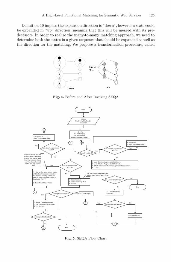
A High-Level Functional Matching for Semantic Web Services 125
Definition 10 implies the expansion direction is “down”, however a state couldbe expanded in “up” direction, meaning that this will be merged with its pre-decessors. In order to realize the many-to-many matching approach, we need todetermine both the states in a given sequence that should be expanded as well asthe direction for the matching. We propose a transformation procedure, called
Fig. 4. Before and After Invoking SEQA
Start
GivenStatSeq1, StatSeq2,
and Cntxt
i=0; j=0;S= StatSeq1[i]T= StatSeq2[j]
BackTrackFlag= false
Does S match T?
Is T down expandablew.r.t S?Yes
1- Expand T.2- j=j + Expansion step.
Yes
1- Add S to the Augmented StatSeq1.2- Add T to the Augmented StatSeq2.3- Mark S matches T in the augmented sequences.4- j = j+1.
No
j > Length(StatSeq2) ?
End
1- T = StatSeq2[j].2- i= i +1.
i > Length(StatSeq2) ?
S = StatSeq1[Length(StatSeq1)-1]. S = StatSeq1[i].
A
A
Yes
No
Yes No
Is S down expandablew.r.t T?
No
1- Expand S2- i=i +Expansion Step.
Yes
A
Is S up expandablew.r.t T?
No
1- Merge the augmented statesof StatSeq1 located within theS’s expansion step with S aswell as their matching peers inStatSeq2 With T.
2- BackTrackFlag = false
Yes
A
1- BackTrack= i2- BackTrackFlag=true3- i= i +1.
i > Length(StatSeq2) ?
No
S = StatSeq1[i].
A
No
1- Mark T as Unmatched.2- S= Statseq1[BackTrack].3- 4- j = j+1.
Yes
j > Length(StatSeq2) ?
End
Yes
No
A
Do not Overwrite BackTrackwhen BackTrackFlag = True
If Scope of S is not partof Scope of T, excludeS from the merge suchthat the merged statesare the states locatedwithin the expansion
step
Fig. 5. SEQA Flow Chart

126 I. Elgedawy, Z. Tari, and J.A. Thom
sequence augmenter (SEQA), to decide which and when states will be mergedand the direction of merging. SEQA accepts two state sequences, a source se-quence and a target sequence and the involved goal as its input, then returnstwo augmented state sequences and their corresponding matching peers. Figure 4shows how the sequence augmenter works.
Figure 5 depicts the flow chart of SEQA. StatSeq1 is the source sequenceand StatSeq2 is the target sequence. Let T represent the current target stateto be matched in StatSeq2 and S represent the current proposed matchingstate in StatSeq1 that will be examined against T . Using Definition 8, SEQAchecks whether or not S matches T . If this holds, this will mean that Scope(S)⊇ Scope(T ), which gives an opportunity to check whether S also matches T ’ssuccessor when merged with T . If this is true, T will be down expanded, andthis process will be repeated until T is not down expandable. The current S isadded to the augmented source sequence and the current T (the expanded T ifso) is added to the augmented target sequence. Also, S and T are marked as amatching peer. S may not match T , meaning either they have different scopesor they have the same scope but the states’ conditions contradict, meaning theywill never match. However, having different scopes implies either (Scope(S) ⊂Scope(T )) or (Scope(S) ∩ Scope(T ) = ∅).
When Scope(S) ⊂ Scope(T ), there is a chance for S to match T by downexpanding S. Even for the case of (Scope(S) ∩ Scope(T )= ∅) by down expand-ing S, there may be a chance for the successors of S to match T . Hence, SEQAwill try to down expand S, marked as backtracking point. If S down expansionfails, there is an opportunity for S to be up expandable with respect to T. If upexpansion succeeds, then the augmented sequences (source and target) shouldbe restructured. This happens by both merging all the states that lie withinthe expansion step and merging their matching peers in the other augmentedsequence. If the up expansion procedure fails, this means the current S cannotmatch the current state T . Therefore SEQA will try the S’s successor to matchit with T and also will check all the previous scenarios. If one of the previousscenarios works and S matches T , SEQA prepares the next state in the tar-get sequence to be matched. But if all the previous scenarios did not work forall the successors of S, this implies that T cannot be matched with the givensource state sequence. Therefore T will be marked as unmatched, and SEQAprepares the successor of T to be matched. It backtracks to the S’s state thatfirst tested with the unmatched T so as to give a chance for the successor of T tobe checked against this backtracked S. SEQA considers a source state sequenceis a match for a target state sequence, when every state in the target augmentedsequence must be substituted by an augmented state in the source in an order-preserving manner. Complexity of SEQA is O(n3). The complexity of SEQA ishigh as the worst case is every state in the target sequence must be examinedagainst the states of the source sequence for up and down state expansion, whichcosts O(n2).

A High-Level Functional Matching for Semantic Web Services 127
5 Validation
The correctness of matching results can be judged through the F-measure met-ric 11, as when having its value equal to one implies the matching results aretotally correct. Unfortunately, there are neither benchmarks nor standard datasets for matching semantic web services. Hence we opted to use a random ap-proach, where a random data set and queries are generated so as to validate thedevised matching techniques, following the same simulation experiments indi-cated in [6] used for testing context matching. This section will therefore focuson the evaluation of devised GAP matching techniques and compare them tothe semantic, semi-semantic and syntactic approaches.
Work-Load Generation. The proposed technique requires the existence of adomain ontology that adopts the meta-ontology structure. The elements of theconducted experiments are: a domain ontology (that includes concepts, opera-tions, roles and the substitutability graphs); a data set of generic GAPs; anda query set and its correct answers. We have generated a random number ofconcepts, a random number of operations and a random number of roles to rep-resent the domain elements. To make sure there are no contradicting conditionswhen a new operation is generated, the following restrictions are followed whengenerating the domain operations: (i) every operation has one distinct conceptas input parameter and it will be the operation output concept as well. (2) Ev-ery operation has one pre condition over an attribute of the input concept, suchthat the value of this attribute equals to its lower limit. (3) Every operationhas one post condition over the same attribute used in the pre conditions suchthat the value of this attribute is less than its upper limit. Operation sequencesare generated by selecting a random number of operations from the generatedoperations; in order to form our data set of generic GAPs.
Experiment Logic. We have generated a random data set of generic GAPs.Then a query set is constructed by randomly selecting 10% of the data set.Experiments are performed as follows. First, data and query sets are generated.Second, ten mutated query sets are produced such that the first mutated queryset has the first 10% of the query set being mutated, the second mutated queryset has the first 20% of the query set being mutated, and so on until the tenthmutated query set has 100% mutated queries. Third, all query sets are appliedto the semantic matching approach, the semi-semantic matching approach andthe syntactic approach. Fourth, the retrieval precision is calculated as indicatedbefore for all approaches. Finally, the above procedure is repeated 1000 timesand the final average result is computed.
Without a loss of generality, the mutation process is performed by mergingall the operations of a given GAP into one operation such that the new mutatedGAP will have only one operation. This operation is constructed as follows: (1)Its input is a collection of the GAP operations’ inputs. (2) Its output is a col-lection of the GAP operations’ outputs. (3) Its pre condition is a conjunction of11 F-measure = 2×Precision×Recall
Precision+Recall.

128 I. Elgedawy, Z. Tari, and J.A. Thom
0
0.1
0.2
0.3
0.4
0.5
0.6
0.7
0.8
0.9
1
0 20 40 60 80 100
Mutation Percentage
F-M
easu
re
1-to-1 Syntactic
1-to-1 Semantic
many-to-ManySemantic
0
0.2
0.4
0.6
0.8
1
1.2
1.4
100 1000 10000 100000
Data Set No Of Scenarios
Avg
Que
ry R
espo
nse
in S
ec Syntactic
1-to-1 Semantic
many-to-manySemantic
Fig. 6. A Comparison of GAP Matching Techniques
the GAP operations’ pre conditions. (4) Its post condition is a conjunction ofthe GAP operations’ post conditions. The pre/post conditions of the new con-structed operation are deliberately mutated to generate new sets of conditions,so that the scopes of the original conditions are reachable from the scopes ofthe mutated conditions using a randomly generated substitutability graphs. Forexample, constraint (x>12) will be mutated into constraint (y>12) such that xis reachable from y. Experiment results are shown in Figure 6.
As the original query set and the mutated query sets have the same answers,the syntactic approach fails to answer the mutated queries. This is reflected bythe decrease of retrieval precision, as the percentage of mutated queries increases.Also the semi-semantic approach fails to answer the mutated queries, except forthe cases that its GAP has only one operation. Therefore, the semi-semanticapproach could have the same behavior of the syntactic approach against themutated queries. This indicates that many-to-many matching approach shouldbe used instead of one-to-one approach when semantic matching is adopted.However, precision is expensive as indicated in the figure but we believe there isa good potential for performance enhancement as basic retrieval techniques areused in these experiments.
6 Conclusion
This paper demonstrates that capturing the semantics of web services, usersand application domain in a machine-processable format is crucial for obtainingcorrect matching results. This paper proposed an advanced matching schemefor semantic web services, called Functional Substitutability Matching Scheme(FSMS), which uses high-level functionality (as a comparison aspect), substi-tutability (as a matching rule), and goal achievement (as a correctness criterion).The application domain functional substitutability semantics are captured viaconcept and role substitutability graphs. Adopting FSMS, we devised a directmatching technique for semantic web services that is shown to provide correctmatching results (more details about other approaches are in [10] ). Aggregateservice matching adopting FSMS is the future extension of this work (more de-tails in [5]).

A High-Level Functional Matching for Semantic Web Services 129
Acknowledgment
This project is proudly supported by the ARC (Australian Research Council),under the ARC Linkage project no. LP0347217.
References
1. J. Castillo, D. Trastour, and C. Bartolini. Description logics for matchmaking ofservices. In Proceedings of Workshop on Application of Description Logics, Austria,September 2001.
2. OWL Services Coalition. Owl S : Semantic markup for web services. http://www.daml.org/services/owl-s/1.0/owl-s.pdf, 2003.
3. X. Dong, A. Halevy, J. Madhavan, E. Nemes, and J. Zhang. Similarity search forweb services. In Proceedings of the 30th International Conference on Very LargeData Bases (VLDB), pages 132–143. Morgan Kaufmann, 2004.
4. I. Elgedawy. A conceptual framework for web services semantic discovery. InProceedings of On The Move (OTM) to meaningful internet systems, pages 1004–1016, Italy, 2003. Springer Verlag.
5. I. Elgedawy and Z. Tari. Aggregate high-level functional matching for semanticweb services. Technical Report TR-05-3, RMIT University, Australia, 2005.
6. I. Elgedawy, Z. Tari, and M. Winikoff. Exact functional context matching for webservices,. In International Conference on Service Oriented Computing (ICSOC),November 2004.
7. I. Elgedawy, Z. Tari, and M. Winikoff. Scenario matching using functional substi-tutability in web services. In Proceedings of the International Conference on WebInformation Systems Engineering (WISE), 2004.
8. P. Ganesan, H. Garcia Molina, and J. Widom. Exploiting hierarchical domainstructure to compute similarity. ACM Transactions on Information Systems,21(1):64–93, January 2003.
9. U. Keller, R. Lara, A. Polleres, I. Toma, M. Kifer, and Dieter Fensel. Wsmo webservice discovery. http://www.wsmo.org/2004/d5/d5.1/v0.1/20041112, 2004.
10. I. Elgedawy, Z. Tari, and M. Winikoff. Functional context matching for web ser-vices. Technical Report TR-04-3, RMIT University, Australia, 2004.

Service Selection Algorithms for ComposingComplex Services with Multiple QoS Constraints
Tao Yu and Kwei-Jay Lin
Dept. of Electrical Engineering and Computer Science,University of California, Irvine, California 92697-2625, USA
Abstract. One of the promises of the service-oriented architecture(SOA) is that complex services can be composed using individual ser-vices. Individual services can be selected and integrated either staticallyor dynamically based on the service functionalities and performance con-straints. For many distributed applications, the runtime performance(e.g. end-to-end delay, cost, reliability and availability) of complex ser-vices are very important. In our earlier work, we have studied the serviceselection problem for complex services with only one QoS constraint. Thispaper extends the service selection problem to multiple QoS constraints.The problem can be modelled in two ways: the combinatorial model andthe graph model. The combinatorial model defines the problem as themulti-dimension multi-choice 0-1 knapsack problem (MMKP). The graphmodel defines the problem as the multi-constraint optimal path (MCOP)problem. We propose algorithms for both models and study their per-formances by test cases. We also compare the pros & cons between thetwo models.
1 Introduction
Web services present a promising technology to compose complex service ap-plications from individual (atomic) services. Using Web services, distributedapplications and enterprise business processes can be integrated by individualservice components developed independently. The service components may alsobe upgraded or replaced dynamically at run time as system conditions changeor applications’ needs evolve. The enhanced service composability provides adesirable flexibility and reusability in building distributed enterprise or grid so-lutions. This is important for enterprise computing since the fast and dynamicconstruction of business processes (for supply chain or service network) is essen-tial for companies in order to adapt their operations to dynamic market condi-tions. Similar needs exist in global transaction systems, health care and travelindustry.
However, the composition flexibility comes at the price of increased systemengineering complexity. The complexity of Web service composition includesthree main factors: (1) the large number of atomic services that may be available;(2) the different possibilities of integrating atomic service components into acomplex service; (3) various performance requirements (e.g. end-to-end delay,
B. Benatallah, F. Casati, and P. Traverso (Eds.): ICSOC 2005, LNCS 3826, pp. 130–143, 2005.c© Springer-Verlag Berlin Heidelberg 2005

Service Selection Algorithms for Composing Complex Services 131
service cost, server capability) of a complex service. Web service compositionthus creates a QoS engineering problem since the service selection must selectthe best services to compose an efficient complex service.
In recent years, it has become a common practice for service providers to offerdifferent service levels so as to meet the needs of different customers. Companieshave offered different service qualities (e.g. first class vs. coach class, gold cardmember vs. regular member) based on user qualifications or service costs. Simi-larly, although many atomic services have a similar functionality (e.g. checkingmarket condition, making reservations, planning meetings, etc.), they differ fromeach other by non-functional qualities, such as service time, transaction cost, andsystem availability. The QoS of a Web service may be offered by different servicelevel agreements (SLA) between service providers and clients [5].
In our study, we have proposed a broker-based framework (QCWS) for QoS-aware Web service composition [16]. In QCWS, Web service composition withQoS assurance includes two steps: service planning and service selection, whichare are performed by the Composition Manager (CM) and Selection Manager(SM) in the QoS broker, respectively. In [15], we study the service selectionproblem for complex service with one QoS requirement. In this paper, we ex-tend the system model to handle multiple QoS requirements. We study thisproblem using two different models: the combinatorial model, by defining theproblem as a multi-dimension multi-choice 0-1 knapsack problem (MMKP) andthe graph model, by defining the problem as a multi-constraint optimal path prob-lem (MCOP). The objective of service selection is to maximize a user-definedutility function under the overall QoS constraints. The utility function definitionmay include an extended set of system parameters to achieve some user specificobjective. We propose several service selection algorithms and report simulationresults to compare their performances.
The rest of this paper is organized as follows. Section 2 reviews some relatedwork. Section 3 presents the system model and assumptions for the Web ser-vice composition with QoS assurance in our study. Section 4 discusses variousalgorithms in both combinatorial and graph approaches, including heuristic andoptimal ones. Section 5 shows the performance evaluation and comparison ofdifferent algorithms. The paper is concluded in Section 6.
2 Related Work
Web service composition has received much interest for supporting enterpriseapplication integration. Many industry standards have been developed, such asBPEL4WS (Business Process Execution Language for Web Services) [4] andBPML (Business Process Modelling Language) [2]. Many projects have studiedthe Web service composition problem. The SWORD project [13] gives a simpleand efficient mechanism for offline Web service composition using a rule-basedexpert system. SWORD is more focused on the service interoperability and noQoS issue has been addressed. The eFlow project [3] provides a dynamic andadaptive service composition mechanism for e-business process management. In

132 T. Yu and K.-J. Lin
eFlow, each service node contains a search recipe, which defines the serviceselection rule to select a specific service for this node. The selection rule is basedon local criteria and does not address the overall QoS assurance problem of thebusiness process.
QoS guarantee for Web services is one of the main concerns of the SLA frame-work [5]. The framework proposes differentiated levels of Web services using au-tomated management and service level agreements (SLAs). The service levelsare differentiated based on many variables such as responsiveness, availabilityand performance. An initial version of the framework was released as part ofthe IBM Emerging Technologies Toolkit (ETTK) version 1.0 in April 2003. Al-though it included several SLA monitoring services to ensure a maximum levelof objectivity, no end-to-end QoS management capability was implemented.
There are projects studying QoS-empowered service selection, such as [17]and [1]. In [17], authors propose a quality driven approach to select compo-nent services during execution of a composite service. They consider multipleQoS criteria such as price, duration, reliability and take into account of globalconstraints. [1] has studied a similar approach. Both of them use the integerlinear programming method to solve the service selection problem, which is toocomplex for run time decisions.
3 System Model and Assumptions
We assume that the same service interface definition is used by all atomic servicecandidates for a specific service component. So we are not concerned about thecompatibility issue among services and focus on the QoS service selection prob-lem. In this study, we define the concept of service class. A service class (denotedas S) is a collection of atomic Web services with a common functionality butdifferent non-functional properties (e.g. time, quality). A class interface param-eter set (Sin, Sout) is defined for each service class. We also assume each atomicWeb service (denoted as s) in the service class can provide a service accordingto the class interface.
Each atomic service may provide L different service levels; each level is associ-ated with a QoS vector q(s, l) = [q1(s, l), .., qn(s, l)] (1 ≤ l ≤ L) which contains napplication-level QoS parameters such as service time, cost, reliability, availabil-ity [5]. Each service level is a candidate in the service class for service selection.Each service level also has an associated utility function F . The utility functionis defined by a set of system parameters including system load, cost and/or otherQoS attributes. The system load can be considered by a benefit function ([15]).Definition 1 shows the utility function definition. Users can set the number ofQoS values to be considered as well as their weights according to their require-ments. In our study each user has m QoS attribute constraints in their QoSrequirements: Qc = [Q1, .., Qm] (1 ≤ m ≤ n).
Definition 1 (Utility Function). Suppose there are α QoS values to be max-imized and β QoS values to be minimized. The utility function for candidate kin a service class is defined as:

Service Selection Algorithms for Composing Complex Services 133
User Requests
Process plan 1
Process plan 2
…………
Step 1: Service Planning
v1
v2
v3
v4
v5
v6
v7
v11
v8
v9
Service candidate
graph
F1 F2 F3 F4
F2F5 F6
S1
S2 S3 S4
Function graph…………
v1 v4 v6 v9
Executable complex service
Step 2: QoS Service Selection
v10 v
12S6S5
Fig. 1. QoS Web service composition model
F(k) =α∑
i=1
wi ∗ (qai(k) − µai
σai) +
β∑
j=1
wj ∗ (1 − qbj(k) − µbj
σbj)
where w is the weight for each QoS parameter set by a user (0 < wi, wj < 1,∑αi=1 wi +
∑βj=1 wj = 1, α + β = m). µ and σ are the average value & the
standard deviation of the QoS attribute for all candidates in the service class.
In our study, the QoS Web service composition is conducted in two steps: ser-vice planning and service selection, as shown in Figure 1. For each user request,the Composition Manager in the QoS broker first matches the request with oneor more process plan(s). Each of them is an abstract process that defines a flowof component functions (F , each can be accomplished by a service class) as wellas their relationships. All potential process plans together constitute a functiongraph. The Selection Manager then maps the function graph into a service can-didate graph and constructs an executable complex service. The mapping froma user request to process plans (step 1 ) only considers the functional require-ments of the user request and does not handle the QoS requirement. It performsthe parametric consistency checking of service classes in order to integrate themwith each other. This problem has been addressed by several research work suchas [13, 6]. The mapping from a function graph to an executable complex service(step 2) is decided by the distributed performance of services and a user’s QoSrequirements. Step 2 is the focus of this paper.
The QoS attributes of the complex service are decided by the QoS attributes ofits component services as well as their integration relationships, such as sequen-tial, parallel, conditional or loop. In this paper, we only consider the sequentialcomposition model in which the QoS attribute and the utility of the complexservice is the sum of its component services’ QoS attributes and utilities at theselected service level. If a QoS attribute is the product of its component QoS,such as reliability and availability, we can apply a logarithm operation to con-vert it into a summation relationship. For QoS attribute with convex/concave

134 T. Yu and K.-J. Lin
characteristic, it may be processed by a filter operation and is not considered inthis paper. Other composition models, such as parallel, conditional or loop, maybe reduced or converted to the sequential model.
4 Service Selection Algorithms
In this section, we present the service selection algorithms used by the QoSbroker for service composition with two or more QoS constraints. There are twomodels to solve the problem: the combinatorial model and the graph model.
4.1 The Combinatorial Algorithm
The Multi-choice, Multi-dimension 0-1 Knapsack Problem (MMKP) [12] is de-fined as follows: Suppose there are K groups, each has li (1 ≤ i ≤ K) items,where each item has a profit pij and requires resource rij = (rij1, ..rijm). Thetotal amount of available resources in the knapsack are R = (R1, .., Rm). Theobjective of MMKP is to select exactly one item from each group to be includedin the knapsack within the resource constraint while maximizing the total profit.
For a complex service that contains N service classes (S1, S2, ..., SN ) in aprocess plan and with m QoS requirements, the service selection problem can bemapped to an MMKP as follows: (1) each service class can be viewed as a groupin MMKP; (2) every candidate in a service class represents an item in a group;(3) the QoS attributes of each candidate are equivalent to the resources neededby the item; (4) the utility a candidate produces is mapped to the profit of theitem; (5) a user’s QoS requirements are considered as the available resourcesof the knapsack. The objective of service selection is to select one candidatefrom each service class to construct a complex service that meets a user’s QoSrequirements yet maximize the total utility. The problem is formulated as:
Max
N∑
i=1
∑
j∈Si
Fijxij
Subject to
N∑
i=1
∑
j∈Si
qαijxij ≤ Qα (α = 1, .., m) (1)
∑xij = 1
xij ∈ 0, 1 i = 1, ..., N, j ∈ Si
The MMKP problem is NP-hard [12]. [7] proposes a branch and bound algo-rithm (BBLP) to find the optimal solution for MMKP. The branch and boundmethod uses a search tree to find a solution. A node in the search-tree representsa solution state where some classes are fixed (an item has been chosen in theseclasses) and some others are free (no item has been selected). A node that hasfree classes may be expanded to generate new nodes. BBLP has a very high

Service Selection Algorithms for Composing Complex Services 135
complexity and is not suitable for large size problems. The detailed descriptionabout the BBLP algorithm can be found in [7].
A heuristic algorithm (HEU) for MMKP has been presented in [8]. The ideaof the algorithm is to find a feasible solution at first, then iteratively improve thesolution by replacing items with a low utility with items with higher utilities ineach group while keeping the solution feasible. If no such item can be found, ittries to replace items with a higher utility in a group (which makes the solutioninfeasible) followed by replacing items in other groups with a lower utility andless resource requirements to keep the solution feasible. This method of upgradesfollowed by downgrades may increase the total utility of the solution.
We modify HEU by always selecting a feasible solution (if one exists) at firstwithout considering those infeasible ones. (In HEU, an infeasible solution maybe picked at first and iterations are needed to make it feasible.) The modificationcan shorten the algorithm execution time. The modified algorithm WE HEU ispresented in Algorithm 1. The algorithm is used to select services for one processplan. If a user request can be matched with more than one process plans, we needto apply the algorithm to every plan and produce several executable complexservices. Among them, the one with the highest utility is the final solution.
Algorithm 1. WS HEU
Step 1: Select item ρi from each group i (i = 1, 2, .., N), such that ρi =minjmaxα qα
ij
Qα ; if ∀α,∑N
i=1 qαiρi
≤ Qα, use it as the initial feasible solu-tion and proceed to step 2 ; If no feasible solution exists, stop;
Step 2: Iteratively upgrade the current solution with another solution;(a) For each item in the solution, find an item with a higher utility from the samegroup under resource constraint with the highest aij = (qiρi − qij) × C/ | C |,where q = [q1, .., qm], C =
∑Ni=1 qiρi . C is the current resource usage;
(b) If no such item is found in group i, then select the item under resourceconstraint that maximizes the value gain per unit of extra aggregate resource:pij = (Fiρi − Fij)/ aij ;(c) If no feasible upgrade is possible, go to Step 3 ;
Step 3: Upgrade the solution by using one upgrade followed by downgrades;
Step 3.1: Find a higher-utility item in any group with the highest value ofp′ij = (Fiρi − Fij)/ t′ij and t′ij = (qiρi − qij)/(Q − C). Qc = [Q1, .., Qm]indicates user’s QoS requirements;Step 3.2: Find a lower-utility item in any group with the highest value ofp
′′
ij = (Fiρi −Fij)/t′′ij and t′′ij = (qiρi −qij)/(C−Qc) while after downgrade,the total utility is still higher than achieved in Step 2 ;Step 3.3: If an item ρ
′
i is found in Step 3.2 and ρ′
i satisfies the resource con-straint, use ρ
′
i to replace ρ and go back to Step 2. If ρ′
i is found in Step 3.2 butviolates the resource constraint, go back to Step 3.2 for another downgrade. Ifno item can be found in Step 3.2, the algorithm stops.

136 T. Yu and K.-J. Lin
To include the network performance factor in the model, we could add thenetwork QoS attribute (such as transmission delay) to the sender service. Thatis, if service a ∈ Si → b ∈ Sj (b = 1, 2, ...l), the corresponding network QoSattribute can be set to q = 1
l
∑lb=1 qα(a, b) (α = 1, ..m), and qα
a = qαa + qα.
The utility of every candidate in a service class can be computed according toDefinition 1 after the network attributes are included.
4.2 The Graph Algorithm
Algorithms designed for the graph model can process more than one processplans at a time to find the best solution, although they have a higher complex-ity than the combinatorial algorithms. We first generate a candidate graph asfollows: (1) Each candidate item in the service class is represented by a node inthe graph, with a benefit value and several QoS attributes; (2) If service si isconnected to service sj , all service levels in si are connected to all service levelsin sj ; (3) Set the network QoS attributes of every links; (4) Add a virtual sourcenode vs and sink node vd. vs is connected to all nodes without incoming linkand vd is connected to all nodes without outgoing links. The QoS attributes ofthese links are set to zero; (5) Add QoS attributes of the node to its incominglink and compute the utility of every link according to Def. 1.
After these steps, we have a Directed Acyclic Graph (DAG), in which everyedge has a set of QoS attributes and a utility value. A service candidate graphis shown in Figure 2. The selection problem is to find a path that producesthe highest utility from source vs to sink vd subject to the multiple constraintsQc = [Q1, .., Qm]. This is the well-known multi-constraint optimal path problemin the graph theory. Based on the CSP algorithm designed for one QoS constraint[15], we propose the MCSP algorithm to solve the MCOP problem. Same as CSP,during the execution of MCSP, each node needs to keep several paths from thesource to it.
MCSP is shown in Algorithms 2 and 3. One potential problem for MCSP isthat, for every intermediate node, the number of paths a node needs to keep maybe huge if none of them dominates each other. That may cause the algorithm torun very slow. In order to speed up the algorithm and reduce the space needed,we modify the MCSP algorithm by keeping only K paths on each node. This
v1
v2
v3
v4
v5
v6
v7
v11
v8
v9
S1S2 S3 S4
v10 v12 S6S5
vs vd
nFq ,..1, =>< αα
Fig. 2. Service Candidate Graph

Service Selection Algorithms for Composing Complex Services 137
Algorithm 2. MCSPMCSP (G = (V, E), vs, vd, Qc)// every node ν keeps L(ν)paths p(µ, q, F) from source to it that satisfy con-straints requirements1 Topologically sort nodes in G;2 for each node µ, in topological order3 for each ν ∈ adj[µ]4 if (µ==s) then5 qα:=qα(µ, ν) ∀α = 1, 2, ..., m6 F := F(µ, ν)7 MCSP RELAX(µ,ν,q,F)8 else for each p ∈ L(µ)9 qα=qα(p)+qα(µ, ν) ∀α = 1, 2, ..., m10 F := F(p) + F(µ, ν)11 MCSP RELAX(µ,ν,q,F)
12 p∗ ←∃ p∗ ∈ L(vd), ∀p ∈ L(vd), F(p∗)≥F(p)
Algorithm 3. MCSP RELAXMCSP RELAX (µ, ν, q, F)
1 if (∃α, qα > Qα) then return;2 for each p ∈ L(ν)3 if F(p) > F and ∀α qα(p) ≤ qαthen return4 if F(p) < F and ∀α qα ≤ qα(p) then5 remove p from L(ν)6 Add (µ, q, F) to L(ν)
heuristic algorithm is called MCSP-K. The K-path selection criteria are basedon the nonlinear cost function concept that is used to combine the multipleconstraints into one [9]. The cost function for any path p can be defined as:
gλ(p) (q1(p)Q1 )λ + (
q2(p)Q2 )λ + ... + (
qm(p)Qm
)λ
where λ ≥ 1. qi(p) is the aggregated ith QoS attribute for path p . As λ → ∞,g∗(p) limλ→∞ gλ(p) is equivalent to the cost function
ξ(p) max( q1(p)Q1 ), ( q2(p)
Q2 ), ..., ( qm(p)Qm ). The paths with K minimum gλ/ξ
values will be kept at each intermediate node. This ensures that MCSP-K willnever prune out a feasible path if there exists one.
Compared to MCSP, the only difference of MCSP-K lies on the relax function,in which it needs to check the number of paths it has currently and remove thepath with the maximum gλ/ξ if the maximum number K is reached. The relaxfunction for MCSP-K is shown in Algorithm 4. MCSP-K drastically reduces thespace cost and speeds up the MCSP algorithm while keeps the result close tothe optimal. The simulation results and comparison of the two algorithms areshown in the next section.

138 T. Yu and K.-J. Lin
Algorithm 4. MCSP-K RELAXMCSP-K RELAX (µ, ν, q, F , λ)
1 if (∃α, qα > Qα) then return;2 for each p ∈ L(ν)3 if F(p) > F and ∀α qα(p) ≤ qαthen return4 if F(p) < F and ∀α qα ≤ qα(p) then5 remove p from L(ν)6 Add (µ, q, F) to L(ν)7 if size(L(ν)) > K then8 if λ == ∞ then9 remove p′ ∈ L(ν), ∀p ∈ L(ν), ξ(p′) ≥ ξ(p)10 else11 remove p′ ∈ L(ν), ∀p ∈ L(ν), gλ(p′) ≥ gλ(p)
5 Performance Study
For systems with only one process plan connected in a sequential flow model,which contains N service classes and each class has l candidates, the worst-case time complexity of BBLP using the simplex method [11] is an exponentialfunction 2Nl. Using WS HEU, suppose the number of QoS requirements is m,the worst case time complexity is O(N2(l − 1)2m) [8]. The worst case timecomplexity for MCSP is O(Nl2 + l2N−1) = O(l2N−1) and the maximum spaceneeded in vd to keep all feasible paths is O(lN ). For MCSP-K, the maximum timecomplexity is O(Nl2 + KlN−1) = O(KlN−1) and the maximum space neededin vd is O(lK). Although the worst case complexity of MCSP and MCSP-K isnot a polynomial function, they perform very well in practice. In this section,we study their performance by simulations.
5.1 Evaluation Methodology
We have compared the performance of BBLP, WS HEU, MCSP and MCSP-K algorithms by extensive simulations. First, we use the degree-based Internettopology generator Inet 3.0 [14] to generate a power-law random graph topologywith 4000 nodes to represent the Internet topology. Then we randomly select25 ∼2500 (depends on different test cases) nodes as the service candidate nodesand 2 other nodes as source and sink. In our study, we assume an equal-degreerandom graph topology for the service candidate graph. For simplicity, we onlyconsider one process plan with the sequential composition model. The numberof service class and candidates in each service class involved in the process planrange from 5 to 50.
For our evaluation we also need to generate the service and network QoSattributes and utility. Suppose all QoS attributes have the summation properties.Five QoS attributes are considered for each service/link, each is associated with arandomly generated values: qk(µ,ν) (k = 1, 2, 3, 4, 5) with a uniform distributionbetween [1,100]. We also generate the utility F(µ, ν) of each link as a randomvalue with a uniform distribution between [1,200]. For QoS attributes of each

Service Selection Algorithms for Composing Complex Services 139
service candidate, a base value is first generated with a uniform distributionbetween [1,100]. Then an impact factor (ε) is multiplied to each service. Weconsider two different situations with different network impact factors: (1) large:network QoS value is comparable to services and varies; (2) small: network QoSvalue is less than 1
10 of services. The ε is set to 2 and 200 for the two casesrespectively. The utility of each service is also generated as random value witha uniform distribution between [1, 200].
For the combinatorial model, we compute the average value of QoS attributesand utility for all outgoing links of a service and add to that service. For servicesin the first class, it also needs to add the values of link from the source to it.For the graph model, we add the QoS attributes and the utility of the servicecandidate to every incoming link of it. The number of user’s QoS requirementsranges from 2 to 5.
Our study includes two parts: (1) Optimal and heuristic algorithms compar-ison; (2) The comparison of combinatorial and graph models. The metrics wemeasure for Part 1 include run time, approximation ratio (heuristic utility vs.the optimal value), memory usage (for the graph approach). The metric weuse for Part 2 is the provisioning success rate, running time and utility. Wecompare two heuristic algorithms: WS HEU and MCSP-K. A composed serviceprovisioning is said to be successful if the generated result satisfies a user’s QoSrequirements. From the description of MCSP-K, we know its success rate is al-ways 1 since it never prunes out the optimal path in all intermediate steps. Butfor MMKP, since the network QoS attributes are only estimated, the generatedresults may not meet a user’s requirements.
In our study, for each test case (representing different numbers of serviceclasses and service candidates combinations), we randomly generate 10 instancesand run 10 times for each instance. We then use the average value of the 100rounds as the result for comparison.
5.2 Result Analysis
For performance evaluation about the MCSP-K and MCSP algorithms, 25 testcases are used in the simulation (Table 1). The cases are divided into 5 groups;each group has the same number of candidates. For each group, we test differentnumbers of service classes (from 10 to 50). There are two parameters: λ is usedto compute the non-linear cost for MCSP-K and k is the number of paths eachintermediate node keeps. We conducted tests on λ = 5, 10, 15, 20, 25, 30, ∞ andk = 5, 10, 15, 20. We find that λ = ∞ always gets a better performance (in termsof utility) than other values. So here we only report the results for λ = ∞ underdifferent k values.
Figures 3 and 4 show the running time and memory usage comparison ofMCSP-K and MCSP under 2 and 5 QoS constraints, respectively. For bothk values, MCSP-K can achieve a near optimal performance (producing utility> 90% of MCSP). For the cases of 2 QoS constraints, MCSP-K is not attractivesince not much space can be saved and the running time is even longer thanMCSP in some cases (k = 10, 15, 20). The extra time is used to compute the

140 T. Yu and K.-J. Lin
Table 1. Test Cases
Test Case 1 2 3 4 5 6 7 8 9 10 11 12 13 14 15 1617181920 21 22 23 24 25Test Group 1 1 1 1 1 2 2 2 2 2 3 3 3 3 3 4 4 4 4 4 5 5 5 5 5No. Candidates 10 10 10 10 10 20 20 20 20 20 30 30 30 30 30 40 40 40 40 40 50 50 50 50 50No. Service Class 10 20 30 40 50 10 20 30 40 50 10 20 30 40 50 10 20 30 40 50 10 20 30 40 50
0 5 10 15 20 250
0.2
0.4
0.6
0.8
1
1.2
1.4
Test case
Run
tim
e (M
CS
P−
K/M
CS
P)
QoS constraints = 2, λ = ∞
k = 5k = 10k = 15k = 20
(a) QoS constraints = 2
0 5 10 15 20 250
0.2
0.4
0.6
0.8
1
1.2
1.4
Test caseR
un ti
me
(MC
SP
−K
/MC
SP
)
QoS constraints = 5, λ = ∞
k = 5k = 10k = 15k = 20
(b) QoS constraints = 5
Fig. 3. Running time comparison (MCSP-K/MCSP)
0 5 10 15 20 250
0.10.20.30.40.50.60.70.80.9
1
Test case
Mem
ory
usag
e (M
CS
P−
K/M
CS
P)
QoS constraints = 2, λ = ∞
k = 5k = 10k = 15k = 20
(a) QoS constraints = 2
0 5 10 15 20 250
0.10.20.30.40.50.60.70.80.9
1
Test case
Mem
ory
usag
e (M
CS
P−
K/M
CS
P)
QoS constraints = 5, λ = ∞
k = 5k = 10k = 15k = 20
(b) QoS constraints = 5
Fig. 4. Memory usage comparison (MCSP-K/MCSP)
non-linear cost and decide the paths to be pruned out. As the numbers of serviceclasses and candidates in each class increase, MCSP-K outperforms MCSP. Theadvantage of MCSP-K is more obvious in the cases of 5 constraints. Both runningtime and space needed are significantly lower while the performance remainsnearly optimal (> 95% for k = 10, 15, 20). So if the process plan contains a largenumber of service classes or there are many candidates in each service class, usingthe heuristic algorithm MCSP-K can get a close to optimal solution quickly andavoid the memory growth problem. λ = ∞ and k = 10 or 15 are the best settingfor MCSP-K.
Figure 5 shows the running time and utility comparison between BBLP andWS HEU algorithms when the number of QoS constraints is from 2 to 5, re-spectively. The number of service classes ranges from 5 to 50 and the number of

Service Selection Algorithms for Composing Complex Services 141
0 5 10 15 20 25 30 35 40 45 500
2000
4000
6000
8000
10000
12000
No. of service classes
Run
tim
e (B
BLP
/WS
_HE
U)
(Candidates/class=5)
QoS constraints=2QoS constraints=3QoS constraints=4QoS constraints=5
(a) Run time
0 5 10 15 20 25 30 35 40 45 500.98
0.982
0.984
0.986
0.988
0.99
0.992
0.994
0.996
0.998
1
No. of service classes
App
roxi
mat
ion
ratio
(Candidates/class=5)
QoS constraints=2QoS constraints=3QoS constraints=4QoS constraints=5
(b) Utility
Fig. 5. WS HEU vs. BBLP
10 20 30 40 500
0.05
0.1
0.15
0.2
0.25
0.3
No. of service classes
Run
tim
e (W
S_H
EU
/MC
SP
−K
)
WS_HEU vs. MCSP−K (K = 10, λ = ∞) (QoS constraints=2)
Candidates/class=10Candidates/class=20Candidates/class=30Candidates/class=40Candidates/class=50
(a) Run time
10 20 30 40 500.8
0.82
0.84
0.86
0.88
0.9
0.92
0.94
0.96
0.98
1
No. of service classes
Util
ity (
WS
_HE
U/M
CS
P−
K)
WS_HEU vs. MCSP−K (K = 10, λ = ∞) (QoS constraints=2)
Candidates/class=10Candidates/class=20Candidates/class=30Candidates/class=40Candidates/class=50
(b) Utility
Fig. 6. WS HEU vs. MCSP-K (K = 10, λ = ∞)
candidates in each service class is 5. We can see that the performance of WS HEUis near optimal (> 98.5%) while the running time is dramatically reduced.
The heuristic algorithms in both models perform very well. To see which oneshould be used for service composition, we test the provisioning success rate forWS HEU under 2 and 5 constraints. (The provisioning success rate for MCSP-Kis 1). When the network factor is comparable to the service, the success rate ofWS HEU is very low (0.32 for 2 constraints and 0.04 for 5 constraints). If thenetwork impact factor is small, the success rate is high (0.96 in both cases). Thereason for the low success rate lies on that MMKP does a combinatorial selectionwithout the flow concept. Figure 6 shows the run time and utility comparisonof WS HEU and MCSP-K with k = 10 and λ = ∞ in the situation that thenetwork impact factor is small. It shows that WS HEU outperforms MCSP-K.So the combinatorial approach should be used in the situation when the networkimpact is small. It can also be used in the situation where the network conditionfor all services is uniform, such as all are on the same LAN.
From our experiments, we can see that different algorithms should be usedunder different system conditions. Table 2 presents a comparison of the fouralgorithms presented in this paper and suggests when they should be used.

142 T. Yu and K.-J. Lin
Table 2. Comparison of Algorithms
BBLP WS HEU MCSP MCSP-KRunning Time very slow fast slow fastMemory Usage low low high lowOptimality optimal near-optimal optimal near-optimalNetwork Cost inaccurate inaccurate accurate accurateAlgorithmUsage
very small sizeproblem, smallor uniformnetwork factor
large size prob-lem, small oruniform networkfactor
small sizeproblem, net-work factoris large
large sizeproblem, net-work factoris large
6 Conclusions
In this paper, we study the problem of complex service composition with multipleQoS constraints. Two problem models are proposed: the combinatorial model,by defining the problem as an MMKP, and the graph model, by defining theproblem as an MCOP. The utility function may be defined by an extended setof system parameters, including static server information (service level), clientQoS requirement (QoS constraint), dynamic server capacity (service benefit),and network factor. We have presented various algorithms, both optimal andheuristic, to compose and select services under multiple QoS constraints as wellas to achieve the maximum utility. We have also compared the pros & cons be-tween the two models and suggested their usage context. We believe the proposedmodels and algorithms provide a useful engineering solution to the end-to-endQoS problem for building distributed complex services.
References
1. Aggarwal, R., et al.: Constraint driven Web service composition in METEOR-S.Proc. of IEEE Conf on Service Computing (SCC’04), Shanghai, China, Sep. 2004
2. BPMI.org.: Business Process Modeling Language (BPML), Version 1.0,http://www.bpmi.org/bpml.esp, November, 2002
3. Casati, F., Ilnicki, S., Jin, L., Krishnamoorthy, V. and Shan, M.: Adaptive anddynamic service composition in eflow. Technical Report, HPL-200039, SoftwareTech Lab, March 2000
4. Curbera, F., Goland, Y., Klein, J., Leymann, F., Roller, D., Thatte, S. and Weer-awarana, S.: Business Process Execution Language for Web services, Version 1.1.http://www-106.ibm.com/developerworks/webservices/library/ws-bpel, May 2003
5. Dan, A. et al. : Web services on demand: WSLA-driven automated management,IBM Systems Journal, Vol. 43, No. 1, 2004, pp. 136-158
6. Fu, X., Shi, W., Akkerman, A. and Karamcheti, V.: CANS: Composable, Adap-tive Network Services Infrastructure. Proceeding of 3rd USENIX symposium onInternet Technologies and Systems, March 2001
7. Khan, S.: Quality Adaptation in a Multisession Multimedia System: Model, Algo-rithms and Architecture, Ph.D. Dissertation, Department of ECE, University ofVictoria, Canada, May 1998

Service Selection Algorithms for Composing Complex Services 143
8. Khan, S., Li, K.F., Manning, E.G. and Akbar, M.: Solving the knapsack problem foradaptive multimedia systems, Studia Informatica Universalis, Volume 2, Number1, September 2002, pp. 157-178
9. Korkmaz, T., Krunz, M.: Multi-Constrained Optimal Path Selection. Proceedingof 20th Joint Conf. IEEE Computer & Communications (INFOCOM 2001), 2001,pp. 834-843
10. Ludwig, H., Keller, A., Dan, A., King, R.P. and Franck, R.: Web Service LevelAgreement (WSLA) Language Specification, Jan. 2003, http://www.research.ibm.com/wsla/WSLASpecV1-20030128.pdf
11. Maros, Istvn: Computational Techniques of the Simplex Method, Springer Pub-lisher, December 2002
12. Martello, S. and Toth, P.: Algorithms for Knapsack Problems. Annals of DiscreteMathematics, 31:70-79, April 1987
13. Ponnekanti, S.R. and Fox, A.: Sword: A developer toolkit for Web service compo-sition. In 11th World Wide Web Conference, Honolulu, Hawaii, May 2002
14. Winick, J. and Jamin, S.: Inet 3.0: Internet Topology Generator. Tech Report UM-CSE-TR-456-02 (http://irl.eecs.umich.edu/jamin/), University of Michigan, 2002
15. Yu, T. and Lin, K.J.: Service Selection Algorithms for Web Services with End-to-end QoS Constraints., Journal of Information Systems and E-Business Manage-ment, Volumn 3, Number 2, July 2005
16. Yu, T. and Lin, K.J.: A Broker-based Framework for QoS-Aware Web ServiceComposition, Proceeding of IEEE International Conference on e-Technology, e-Commerce and e-Service (EEE-05), Hong Kong, China, March 2005
17. Zeng, L., Benatallah, B., Dumas, M., Kalagnanam, J. and Sheng, Q.Z.: QualityDriven Web Service Composition. Proceeding of 12th International World WideWeb Conference (WWW), 2003

On Service Discovery Process Types
Peer Hasselmeyer
C&C Research Laboratories, NEC Europe Ltd.,53757 Sankt Augustin, [email protected]
Abstract. With the growing adoption of service-oriented computing,locating services becomes increasingly commonplace. Accordingly, a largenumber of systems for service discovery have been developed. Althoughall these systems perform the same function, they do it in lots of differentways. Finding commonalities of and differences between these systemscan be hard due to the lack of criteria to compare and classify variousdiscovery schemes.
This paper identifies the processes of registration and look-up as adistinguishing feature of the various discovery systems. It describes thepossible types of processes, shows how they are distributed across thelifecycles of the involved entities and classifies existing service discoverysystems according to these criteria. Some hints are given on how theprocess-based view can help guide the selection of a particular discoverystyle for a problem at hand.
1 Introduction
The use of service-oriented computing and service-oriented architectures be-comes increasingly prevalent. The main principle of service-oriented architec-tures is the loose coupling between service providers and service users. Serviceproviders can be internal to an organization as well as third parties external tothe service user’s organization. In any case, the service user needs to know theservice’s location and communication protocol before he can access it. Accord-ingly, all service-oriented architectures offer some facility for locating services.Although the functionality of these facilities is always the same (i.e. findingan access point to a desired service), its realizations vary significantly amongthe available architectures. The systems have different methods for describingservices, they offer different query possibilities, they use different transport pro-tocols, and they have different registration and query interfaces. The multitudeof these features can make comparing different architectures hard. Hidden be-low these features are the processes for service registration and look-up. Theseprocesses are usually not mentioned explicitly, although they make comparingand classifying different architectures possible.
This paper analyzes the processes used for registration and look-up. It isdiscovered that both processes have a static and a dynamic form. These formsare distinguished by how the processes are spread across the lifecycles of the
B. Benatallah, F. Casati, and P. Traverso (Eds.): ICSOC 2005, LNCS 3826, pp. 144–156, 2005.c© Springer-Verlag Berlin Heidelberg 2005

On Service Discovery Process Types 145
components performing registration or look-up. It is described how the differentprocesses affect certain aspects of systems using service discovery, e.g. applicationdevelopment. Existing discovery systems are classified according to their typesof processes. In addition, it is shown how a process-based view can guide theselection of a discovery architecture.
The paper starts in section 2 with definitions of the terms used throughout thepaper. It continues in section 3 with a detailed description of the various typesof processes commonly found in service discovery systems. Section 4 describes anumber of systems providing a discovery facility and classifies them accordingto the process types. Some advice on selecting a particular service discoverysystem using the proposed process-based view is given in section 5. Relatedwork is discussed in section 6 and some conclusions are presented in section 7.
2 Definitions
There are many different understandings of the terms involved in service-orientedarchitectures. For example, the term “service” means different things to differentpeople. It is therefore necessary to first define the terms used throughout thispaper to avoid ambiguity.
Service. A service is a component that provides a certain set of functions toother entities over a communications network. Service instance is a synonym forservice.
Service Type. A service type names the functionality of a service. Services areof a certain service type if they provide at least the set of functions referredto by this type. The actual description of these functions is called service typedescription. It is assumed that this is a syntactic (interface) description.
Service Description. Description of non-functional service attributes. Servicedescriptions can be used in registrations as well as in queries. In registrations,they provide information about actual service properties, while in queries, theystate desired service properties.
Service Metadata. The service metadata includes all the information a serviceis registered with. It consists of the service type, the service description, and theservice’s endpoint.
Service Provider. An entity that operates one or more services.Client. An entity acting in the role of a service consumer in a specific service
interaction. A client can be a “real” client, i.e., it only consumes services, or aservice that happens to be in the client role in this particular interaction butprovides services in other interactions.
Service-Oriented Architecture. A service-oriented architecture (SOA) is basedon services as the main entities. Services provide certain functions to other enti-ties. These entities can be pure clients or services themselves. Services and theirfunctions are discovered using a service registry.
Service Discovery. The process of finding services and their endpoints. Thisincludes registration and look-up.

146 P. Hasselmeyer
Endpoint. A communication port at which a service can be contacted. Servicesmight offer multiple endpoints.
Service Registry (often just called registry). A service that provides referencesto other services. It accepts requests for registration from services (or otherentities that act on behalf of a service) and relays registration information ondemand to clients.
Registration. Registries keep records of available services. The resources thatsuch a record consumes at a registry are called a registration. Also, the processof having registries store information about a service is called registration.
Look-up. The process of mapping queries to service endpoints. Clients lookingfor certain services send queries to service registries. The queries contain somedescription of what kind of service clients are looking for. Registries return aset of available services matching the query. Services are represented by theirendpoints.
3 Discovery Processes
Service discovery consists of two main processes: the registration process and thelook-up process. Registration is used by services or their operators to announceservice availability. Look-up is used by clients to find the endpoints of neededservices.
Different service discovery architectures employ different processes for reg-istration and look-up. These will be described in the following sections. Themethod for distinguishing them involves looking at how the individual steps inthe process are allocated to the stages in the lifecycles of the entities execut-ing the process. The registration process is executed by services, the relevantlifecycles therefore are the ones of the services. The look-up process is executedby clients, the relevant lifecycles therefore are the ones of the clients. As bothservices and clients are software components, they follow a software lifecycle.The stages of that lifecycle that are relevant to the registration and look-upprocesses are the development, the deployment, the operation, and the unde-ployment phases.
3.1 Registration Process
The basic lifecycle of a registration is rather simple. The registry creates a reg-istration when a service is registered. From that point on, the registry includesthe registered data in responses to matching queries. The registration is deletedwhen a service is removed from a registry.
As registrations belong to registries, their lifecycles can be observed at reg-istries. The process for performing registration is executed by services (or theirproviders), though. For the registration process, only the lifecycle of the associ-ated service is relevant. This is the lifecycle considered here. Two different typesof service registration processes can be identified: a static and a dynamic type.Figure 1 presents an overview of these two types. Interactions with the registryare shown as rounded rectangles while supplied information is shown as bubbles.

On Service Discovery Process Types 147
Fig. 1. Registration Process Types
Static Registration Process Type. In systems using static registrations,services are registered once and stay registered for an extended period of time.Registration and removal are usually initiated by human staff members ofthe service’s provider. Registrations are rarely updated. Different parts of theservice’s metadata are supplied at different stages of the service’s lifecycle. Theservice type is usually encoded in the implementation, i.e., it is supplied duringthe development phase. The service endpoint is only known at deployment timeand is therefore supplied in the deployment phase. Some default values for theservice description and the service registry’s endpoint can be supplied in the de-velopment phase, but they will likely be modified during the deployment phase.
The actual registration of a service following a static process type happenswhen it is initially deployed. The registration is removed when the service isdiscontinued. Between registration and removal no communication is going onbetween the service (or its provider) and the registry. The exception to thisrule is a possible maintenance phase in which the service’s metadata is changed.Obviously, the new metadata needs to be supplied to the registry which involvescommunication between the service (provider) and the registry. A consequenceof the absence of communication is that static registrations do not contain anycurrent information, e.g. about the availability of services.
Dynamic Registration Process Type. Systems supporting a dynamic reg-istration process type usually employ automated methods for service registra-tion. Services or their supporting middleware initiate service registration uponstartup. Human intervention is not needed. Registries use soft-state (lease-based)registrations [3]. Such registrations are valid for only a limited amount of time,

148 P. Hasselmeyer
most commonly minutes to hours. To stay registered, services must periodicallyextend the lifetime of their registrations. Upon expiration, registrations are au-tomatically removed from the registry. The system is therefore automaticallycleaned from stale registrations and can be considered self-managing. The man-ual removal of services is nevertheless possible as well.
Service metadata is again supplied at different stages in the lifecycle. Servicetype information is handled the same way as in the static case – it is suppliedduring the development phase. The service description can be supplied in thedevelopment, the deployment, and, contrary to the static case, in the operationphase. Depending on the middleware used, the service endpoint is either suppliedat deployment time or run-time. With technologies like CORBA (Common Ob-ject Request Broker Architecture) or Java RMI (Remote Method Invocation),the endpoint will be supplied at run-time as it can change across restarts. Usingweb service technologies, the endpoint may be supplied during the deploymentphase as it rarely changes. The registry location can, as in the static case, besupplied during the deployment phase. Alternatively, as the actual registrationhappens during the operation phase, supplying the registry location can be post-poned to that phase. One popular solution for this is to use a multicast schemeto discover the registry location at run-time.
3.2 Look-Up Process
Just as service registrations can be static or dynamic, so can be service look-upprocess types. The two different types are shown in figure 2. Although the figure
Fig. 2. Look-up Processes

On Service Discovery Process Types 149
shows look-up as a single step, it might actually consist of multiple steps, e.g. ifsome iterative method to slowly narrow down the selection is used. The look-upmethod is independent of the use of a static or a dynamic look-up process type.
Static Look-Up Process Type. In a static environment it is common practiceto look up services during the application development phase and put theirlocations in the code. Alternatively, a configuration file can be used and thelook-up process can be moved to the deployment phase. In this case, only theservice type is supplied during the development stage. The service description(i.e. the query) as well as the registry’s endpoint only need to be known duringthe deployment phase. In both cases, the registry is not accessed at applicationrun-time.
Dynamic Look-Up Process Type. In a dynamic system, services are as-sumed to be volatile and those available during the development or deploymentphases might not exist during the operation phase. Applications in dynamicenvironments therefore usually perform look-up at run-time to find currentlyavailable services and their endpoints. Information supplied during the develop-ment phase are the service type and the look-up algorithm. This algorithm israther simple in “traditional” discovery systems, but is an important part of thediscovery process in content addressable networks [8].
The registry endpoint and the service description can be supplied during thedeployment or the operation phase. During deployment, this information goesinto some configuration file. If the endpoint is supplied at run-time, it can beretrieved via some multicast scheme or calculated with the help of the look-upalgorithm. The service description might be affected by user input and mighttherefore only be available at run-time.
The choice of a static or dynamic look-up process type is not directly related tothe choice of a particular registration process type. A dynamic look-up style canbe used in conjunction with a static registry. A static look-up style is ill-suited fora dynamic registry, though, as service information is expected to change duringthe lifetime of the service client. It is therefore common to bundle static look-upwith static registration and dynamic look-up with dynamic registration.
3.3 Foreknowledge
To perform service registration or look-up, the endpoint of the registry needs tobe known. This information is called “foreknowledge” in [10]. Such informationis needed by all entities using the service registry, i.e. services as well as clients. Itis important to note that the information does not need to be available explicitly.In content addressable networks the location of the registry can be derived fromregistration metadata and look-up queries at run-time. The foreknowledge inthis case is embedded in the queries or the service metadata and the algorithmmapping that information to the registry location. Another important observa-tion is the fact that the foreknowledge does not need to exist in all phases of theregistration and look-up lifecycles. The knowledge needed and the lifecycle phase

150 P. Hasselmeyer
in which it is supplied are shown in Figures 1 and 2 in the form of bubbles. Theforeknowledge needed does not depend on whether a process’ type is static ordynamic. Only the lifecycle phase in which it is used varies with the process type.
In a system using static registrations information about the registry is onlyneeded at development or deployment time. It is therefore sufficient that the hu-man developer or deployer has access to the registry’s endpoint information. Asthat data is not needed at run-time, it is not kept anywhere in a running client.
In a dynamic system, information on the registry’s endpoint must be availableat run-time. The required information can be supplied in different ways. It couldfor example be read from some configuration file. A multicast scheme can beemployed when a local registry is used thereby reducing configuration effort toa minimum.
3.4 Process Type Implications
The adoption of a particular type of process influences the functionality of reg-istries, the development of entities using discovery, and the performance of aservice-oriented system as a whole.
Functionality. The functionality of a registry depends on the registration style.In the dynamic case, it must support soft-state registrations and the associatedfunctionality which is not needed in the static case. Furthermore, lifetime ex-tensions happen quite frequently and those changes to the registration databaseneed to be accommodated. In systems using a static registration process type,registrations have to be made persistent as they occur only once. For systemsusing a dynamic registration process type it is okay to forget all the registrationsevery once in a while as services will eventually re-register.
Implementation. Entities that are using service discovery, i.e., services per-forming registration and clients using look-up, are implemented in different waysdepending on the type of the registration and look-up processes. When usingstatic registrations, services do not need to care about the actual registration asthis is supposed to be done by human operators before the service’s operationphase. In systems using dynamic registrations, services must register at run-timeand need to take care of their registrations. This job can be delegated to theinfrastructure, though. In that case, services do not need to care about registra-tions and their renewal. In fact, they do not even need to be aware of what kindof registration process is used.
The situation is a bit different for look-ups. There is a difference in the pro-gram logic depending on when look-up is performed. If a static look-up processtype is adopted, the client code does not need to contact the registry at run-time. With a dynamic look-up process type, though, some communication withthe registry has to occur at run-time. The program code therefore needs to bedifferent depending on the look-up type. It is nevertheless possible to always usecode that assumes a dynamic look-up style and let the infrastructure map thisto a static environment.

On Service Discovery Process Types 151
Performance. The registration and look-up process types also affect the per-formance of systems using service discovery. Obviously, a static system has abetter run-time performance as no communication between services or clientsand the registry has to occur during the operation phase. Depending on whatkind of discovery technique is used, the run-time penalty of dynamic look-upcan be significant. On the other hand, using dynamic registration and look-upimproves a system’s failure resilience. If look-ups follow a static process type, thedisappearance of an endpoint to a particular service renders all clients unusable.A dynamic look-up process type allows this failure to be masked by being ableto switch over to other instances/endpoints of services.
4 Classifying Discovery Systems
This section briefly describes a number of well-known service discovery systems.The main part of each description deals with registration and look-up properties.Each system is classified according to its use of static or dynamic registrationand look-up process types. The results of the analysis are shown in Figure 3.
4.1 UDDI
The Universal Description, Discovery and Integration (UDDI) specification [7]is the most well-known service discovery standard for the web services world. Itdefines a centralized registry service, the interface to access it, and a data modelto describe services. The UDDI registry is modeled after the telephone book.It lists companies (“white pages”) and the services that they provide (“yellowpages”). Sticking to the telephone book analogy, data in UDDI registries is stored
registration process type
look
-up
proc
ess
type
static dynamic
dyna
mic
stat
ic
UDDI
DNS
floodingP2P
orderedP2P
Jini
Fig. 3. Classification of Popular Service Discovery Systems

152 P. Hasselmeyer
once and stays in them until it is actively removed. UDDI registries obviouslyemploy a static registration lifecycle and therefore follow a static registrationprocess type.
Look-up in UDDI registries usually follows a static process type as well. Thestructure of the data in the directory makes drill-down operations a convenientway of finding a needed service. A common approach to finding services in UDDIregistries is looking at the list of companies, finding a few that are trusted andpresumably offer the needed service, have a look at their service offers, and thenchoose one of them. As trust is a complicated concept for machines, the describedprocess is always done by human beings. Usually, the developer of a service clientis looking for an appropriate service, not the deployer. The reason for this is thelack of standardized interfaces that would make exchange of services a simpleconfiguration option. Currently, more often than not, the program code needsto be modified to accommodate a different service provider.
Although dynamically exchanging a service provider in a web-service-basedworld is currently not widely practiced, performing look-up at run-time is still asensible option. In this case, it is not used to make the choice of a service providerconfigurable or dynamic, it is used to automate locating the current endpoint ofa well-known service of a well-known provider. A service client would perform alook-up with a predefined query that returns the current endpoint of the neededservice. With this scheme, a provider can change the location of his serviceswithout explicitly telling his clients. Dynamic look-up can increase the loosenessof the coupling between service provider and service client.
Because UDDI-based systems can work with both static and dynamic look-up,the system appears in both sections with a tendency towards the static side.
4.2 Jini
Jini [9] is a Java-based infrastructure for handling service discovery. Registriescan be statically configured, or found at run-time via a multicast-based proto-col. Registrations contain service descriptions and, instead of the endpoint of aservice, a Java object that enables remote service access. Such proxy objects arestored at the registry and copied to the service user’s address space at run-time.There, they adapt local function calls to whatever communications protocol theassociated service uses. Information about the endpoint of a service is thereforestored inside the proxy object and kept hidden from the service user.
Registrations in Jini are lease-based. Clients wanting to register a service ne-gotiate the registration lifetime with the registry. Leases need to be renewedin time for services to stay registered. Registrations therefore follow a strictlydynamic process type. Due to the use of proxy objects, this method is the onlyviable option. Most of the Jini services use the Java RMI mechanisms for remoteprocedure calls. Proxy objects contain the remote stubs for performing invoca-tions. These in turn contain references to the associated server object. As theserver object might change with every restart of the server, previously handedout references become invalid. Registration data therefore needs to be updatedat the registry. With an automated update system (as used with dynamic reg-

On Service Discovery Process Types 153
istrations), this is no problem. Performing updates by hand is rather tedious,though. A static model is therefore not an optimal solution.
Look-ups also follow a dynamic process type, basically for the same reasonwhy registrations are dynamic. Remote object references may change frequently.Embedding fixed, static references in client code is no option. In addition to that,Jini transfers around proxy objects. These consist of data (e.g. object references)and code. Just as the data changes, the code might change as well. As the code issupplied by the service provider, it is impractical to statically embed that codein service clients.
4.3 DNS
The Domain Name System (DNS) [6] is the most commonly used method forresolving human-readable internet host names. The DNS system translates thosenames to machine-understandable Internet Protocol (IP) addresses. DNS canstore mappings for different types of services, e.g. for mail relays. It can thereforebe considered a service discovery system.
The assumption for the DNS is that internet host names and the correspond-ing addresses do not change frequently. As a result, registrations follow a staticprocess type. New internet host and domain names are stored at designatedname servers. The mapping stays at the name server until it is removed.
DNS look-ups follow a dynamic process type. To find a host, clients send aquery to the DNS sub-system on the local host. Queries that cannot be answeredlocally are passed on to DNS servers one level up in the hierarchy. The pathfollowed by a query is statically configured by the administrators of the involvedDNS servers. The location information of the registry (the next DNS server) istherefore configured for a host, not an individual client.
4.4 Peer-to-Peer Systems
Peer-to-peer (P2P) systems are dynamic networks of entities that cooperate toprovide certain services to participants. At present, P2P system are aimed mostlyat locating content, usually media files, but the same concepts can be used tolocate arbitrary services. As the set of participants in a P2P system is dynamic,the set of offered services (or content) is dynamic as well. Searching (i.e. look-up)in P2P systems therefore always follows a dynamic process type.
Regarding registrations, two different kinds of peer-to-peer systems can bedistinguished. Most of the P2P systems popular today employ a flooding searchapproach. They send queries to all (or at least a large subset of) the serviceproviders. Service providers also act as registries. Content files are registeredlocally and they are usually registered implicitly by putting them in specificplaces on the local file system. They are unregistered by removing the files fromthat location. It is therefore a registration process of the static type.
As flooding is not a scalable query mechanism, a second type of P2P systemsuses a controlled search approach. Systems of this type designate responsibility

154 P. Hasselmeyer
for a subset of the whole search space to certain nodes in the system. A re-sponsible node can be found at a predictable location by applying a well-knownalgorithm to the service’s metadata. An example of such a system is describedin [2]. In such systems, all nodes act as registries, but each service is registeredwith just a (small) subset of them. Registrations are constrained in the temporaldomain and therefore need to be renewed. This is necessary because not onlythe set of service providers (and with it, the set of services) changes, but so doesthe set of registries and therefore the set of registries responsible for a specificservice. Registrations therefore follow a dynamic process type.
5 Architecture Selection
Besides offering a method for classification, a process-based viewpoint can alsoguide the selection of a particular discovery architecture for a given problem. Forselecting a discovery system, a large number of different criteria exist, includingdescription capabilities, performance, scalability, supported platforms, protocolsused, etc. Most of these are of a low-level, technical nature. The process-basedviewpoint proposed here is on a higher level of abstraction, working more on thearchitectural level than the implementation level.
The guidelines given here are not necessarily the most important ones. De-pending on the circumstances in which a discovery system is to be used, differentcriteria have different priorities. Nevertheless, we think that looking at discov-ery process types gives a hint on what kind of discovery system is suitable to agiven problem. As it works on a comparatively high level of abstraction, it mightactually be the first criterion to consider.
When thinking of discovery, the processes for registration and look-up are nota natural starting point. And indeed, they are not the first thing to look at, asthey only exist in conjunction with the entities that enact them, i.e., the servicesand clients.
Therefore, to select a discovery architecture, one should first analyze the ser-vices that are to be found by discovery. If these services are rather volatile,their registrations are as well. Dynamic process types for registration and look-up are therefore appropriate. A matching service discovery system should bechosen.
If the set of services is small and the services’ metadata is static, a systemusing static registrations is sufficient. Whether to use a static or dynamic look-up process type in this case is a delicate trade-off. Static look-ups require somemanual configuration effort when services migrate. Dynamic look-ups need someadditional infrastructure that usually causes some initial set-up costs. The de-cision therefore depends on the estimate of how frequently service registrationschange and thereby cause additional configuration costs.
It is important to note that even if individual services are rather static, butthere is a large set of services, the set as a whole becomes volatile, becausesome changes in the set of services and their metadata always occur. Such asystem would benefit from at least a dynamic look-up style. Making registrations

On Service Discovery Process Types 155
dynamic can be a good idea as well, because static registrations become staleeventually and their removal or update is often forgotten [5].
6 Related Work
There is a host of literature that compares various discovery systems. Most ofthis literature, e.g. [1, 4], compares systems primarily aimed at ubiquitous com-puting, especially SLP, UPnP, Bluetooth, and Jini. Among the criteria usedfor distinction are the network protocol used for communication, the type ofservice description, and the functionality of the systems. None of these compar-isons deal with higher level abstractions or give guidance on where to use whicharchitecture.
To the knowledge of the author, only one paper [10] compares service discoverysystems on a more abstract level. Vanthournout et al. introduce a taxonomy ofdiscovery systems distinguishing them by design aspects. They analyze discoverysystems with respect to their structure, their foreknowledge, their registrationbehavior, their query routing, the supported resources, and resource naming.Although these represent a large set of criteria, the registration and look-upprocesses are neither mentioned nor evaluated. As described here, those processesinfluence the architecture of service discovery systems as well as the design ofapplications. In fact, some of the above mentioned design aspects are influencedby the processes. Namely, these are the foreknowledge, the registration behavior,and the supported resources.
7 Conclusion
In this paper, we have identified the registration and look-up processes as dis-tinguishing aspects of service discovery systems. Registration as well as look-upcan be either static or dynamic. A particular choice for either the registration orthe look-up process type does not influence the choice of the other process type.The only caveat is that a static look-up process type does not match a dynamicregistration scheme.
We showed that individual registration and look-up process steps are dis-tributed differently across component lifecycle phases depending on the type ofprocess used. We classified a number of well-known discovery architectures ac-cording to the process-based view and showed that for each viable combinationof processes an examplar exists. We also described how the choice of a particularprocess type influences the functionality of the registry, the implementation ofthe entities, the performance of the system as a whole, and how foreknowledgeis spread across the lifecycle phases.
We hope that the presented work makes developers adopting service-orientedarchitectures aware of the discovery processes and their interaction with com-ponent lifecycles. We think that a classification according to process types facil-itates the selection of a particular style of discovery and therefore the selectionof a particular discovery architecture.

156 P. Hasselmeyer
Acknowledgements
This work has been supported by the NextGRID project and has been partlyfunded by the European Commission’s IST activity of the 6th Framework Pro-gramme under contract number 511563. This paper expresses the opinions ofthe author and not necessarily those of the European Commission. The Euro-pean Commission is not liable for any use that may be made of the informationcontained in this paper.
References
1. Christian Bettstetter and Cristoph Renner. A Comparison of Service DiscoveryProtocols and Implementation of the Service Location Protocol. In: ProceedingsEUNICE Open European Summer School, Twente, Netherlands, September 2000.
2. Jun Gao and Peter Steenkiste. Design and Evaluation of a Distributed Scal-able Content Discovery System. Journal on Selected Areas in Communications,22(1):54–66, January 2004.
3. Cary G. Gray and David R. Cheriton. Leases: An Efficient Fault-Tolerant Mech-anism for Distributed File Cache Consistency. In: Proceedings of the 12th ACMSymposium on Operating System Principles, pages 202–210, December 1989.
4. Sumi Helal. Standards for Service Discovery and Delivery. IEEE Pervasive Com-puting, 1(3):95–100, July 2002.
5. Mike Clark. UDDI – The Weather Report, November 2001. http://www.webservicesarchitect.com/content/articles/clark04.asp
6. Paul V. Mockapetris. Domain Names - Concepts and Facilities, November 1987.Internet RFC 1034.
7. OASIS Open. UDDI Version 3.0.2, October 2004. http://www.oasis-open.org/committees/uddi-spec/doc/spec/v3/uddi-v3.0.2-20041019.htm.
8. Sylvia Ratnasamy, Paul Francis, Mark Handley, Richard Karp, and Scott Schenker.A Scalable Content-Addressable Network. In: Proceedings of the 2001 Conferenceon Applications, Technologies, Architectures, and Protocols for Computer Com-munications (SIGCOMM 2001), pages 161–172, August 2001.
9. Sun Microsystems Inc. Jini Architecture Specification – Version 2.0, June 2003.http://www.sun.com/software/jini/specs/jini2 0.pdf.
10. Koen Vanthournout, Geert Deconinck, and Ronnie Belmans. A Taxonomy forResource Discovery. Personal and Ubiquitous Computing Journal, 9(2):81–89,February 2005.

SPiDeR: P2P-Based Web Service Discovery
Ozgur D. Sahin, Cagdas E. Gerede, Divyakant Agrawal,Amr El Abbadi, Oscar Ibarra, and Jianwen Su
Department of Computer Science,University of California at Santa Barbara, Santa Barbara, CA 93106
odsahin, gerede, agrawal, amr, ibarra, [email protected]
Abstract. In this paper, we describe SPiDeR, a peer-to-peer (P2P)based framework that supports a variety of Web service discovery oper-ations. SPiDeR organizes the service providers into a structured P2Poverlay and allows them to advertise and lookup services in a com-pletely decentralized and dynamic manner. It supports three differentkinds of search operations: For advertising and locating services, serviceproviders can use keywords extracted from service descriptions (keyword-based search), categories from a global ontology (ontology-based search),and/or paths from the service automaton (behavior-based search). Theusers can also rate the quality of the services they use. The ratings areaccumulated within the system so that users can query for the qualityratings of the discovered services. Finally, we present the performance ofSPiDeR in terms of routing using a simulator.
1 Introduction
The adoption and evolution of the Web services technology continue to hap-pen in many different domains from business environments to scientific applica-tions. This technology promises to enable dynamic integration and interactionof heterogeneous software artifacts, and thereby, to facilitate fast and efficientcooperation among the entities in cooperative environments. Lately, there hasbeen a lot of attention drawn to this promising technology from both industryand academia and it has been supported with various emerging standards andproposals such as SOAP[1], WSDL[2], BPEL[3], and OWL-S[4]; accompanyingtechnologies such as IBM’s Web Sphere, Microsoft’s .NET, and Sun’s J2EE; andseveral research efforts (see recent conferences such as [5, 6, 7, 8]).
Web services are “software applications identified by a URI, whose interfacesand bindings are capable of being defined, described, and discovered as XML ar-tifacts. A Web service supports direct interactions with other software agents us-ing XML-based messages exchanged via Internet-based protocols”[9]. The mainresearch challenges services oriented computing poses include automated compo-sition, discovery, invocation, monitoring, validation and verification[10]. Servicediscovery, in particular, refers to the problem of how to search for and locate
This research was supported in parts by NSF grants CNF 04-23336 and IIS 02-23022.
B. Benatallah, F. Casati, and P. Traverso (Eds.): ICSOC 2005, LNCS 3826, pp. 157–169, 2005.c© Springer-Verlag Berlin Heidelberg 2005

158 O.D. Sahin et al.
services, the descriptions of which are usually considered lying in well-definedservice repositories.
Recently, a substantial progress has been done in this area thanks to sev-eral research and industrial efforts including UDDI registries [11, 12], similaritysearch [13], the query languages and indexing efforts [14, 15, 16], peer-to-peer(P2P) discovery techniques [17, 18, 19, 20, 21], semantic web approaches and on-tological matching [22, 23]. These solutions, however, are typically limited for 2reasons:
1. They are usually centralized where there is a single central server (e.g.,UDDI registry) that keeps track of all available services. Centralized ap-proach has well-known limitations. It is not scalable since the server has tokeep information about all services and answer all queries. It is not faulttolerant because the server is a single point of failure and if the server goesdown, the whole service discovery mechanism becomes unusable.
2. They usually offer limited search capabilities. There are different techniquesto increase the accuracy of service discovery including functional matching(what a service does), behavioral matching (how a service performs), seman-tic matching (the underlying semantics of a service) and ontological matching(how a service relates to other services). Each of these provides a differentmetric to measure the relevance among different services and therefore, eachone is important. Many existing approaches, on the other hand, concentrateon a single one or a small subset of these techniques.
In this paper, we address above issues by introducing SPiDeR, a P2P basedWeb service discovery framework that supports a rich set of search operations.A subset of the participating service providers (those that have good resources)are dynamically assigned as super peers and organized into a structured P2Psystem. Due to its P2P based design, SPiDeR distributes the tasks of indexingavailable services and resolving service lookups among the participants, thus pro-viding decentralization, scalability, dynamicity, and fault tolerance. It supports3 different types of search operations based on keywords, global service ontology,and service behavior. It also has a reputation system component for assessingthe quality of the services based on the experiences of other services. The ratingsgiven to the services are stored in the system so that users can lookup for servicequality ratings when deciding which of the discovered services to use.
The rest of the paper is organized as follows. The related work is surveyed inSection 2. Section 3 introduces SPiDeR, a P2P based distributed Web servicediscovery framework. Section 4 describes how the different types of discoveryoperations (keyword-based search, ontology-based search, and behavior-basedsearch) are supported in the framework. The quality rating scheme that enablesthe ranking of discovered Web services is also explained in that section. In Sec-tion 5, dynamic peer operations are discussed in detail. Those include installingand refreshing service advertisements, performing composite lookups, and in-dexing at the super peers. Additionally, an evaluation of SPiDeR in terms ofrouting performance using a simulator is presented in Section 5.4. Finally, thelast section concludes the paper and outlines the future work.

SPiDeR: P2P-Based Web Service Discovery 159
2 Related Work
P2P Systems: P2P systems are a popular paradigm for exchanging data in adecentralized manner. They distribute the data and load among the peers andthus appear as a good alternative to the centralized systems. Early P2P systems,such as Napster [24] and Gnutella [25], are mainly used for file sharing. These sys-tems are referred to as unstructured P2P systems [26] since the overlay networkis constructed in a random manner and the data can be anywhere in the system.As a result, search and routing in these systems tend to be inefficient. StructuredP2P systems, on the other hand, impose a certain structure on the overlay net-work and control the placement of data. These systems provide desirable proper-ties such as scalability, fault tolerance, and dynamic peer insertion and departure.For example, Distributed Hash Tables (DHTs) [27, 28, 29, 30] partition a logicalspace among the peers and assign each object to a peer dynamically by hashingthe object’s key onto the logical space. DHTs offer efficient routing and exact keylookups, which are logarithmic or sublinear in the number of peers.
Web Service Discovery: There are several proposals to increase the accu-racy and efficiency of service discovery mechanisms. [13] introduces Woogle, asimilarity search technique based on clustering the services according to the in-formation gathered from their WSDL documents. It is a centralized approachand do not allow behavioral search. In [17], the authors propose a behavioralsearch mechanism on a P2P architecture where the service behaviors are repre-sented as finite state automata and the services are indexed in the P2P systemwith keys extracted from their service automata. It only provides behavior-basedsearch mechanism, but not the others.
SPiDeR shares similarities with [14, 15, 16]. In [14], services are represented asfinite state machines which are then transformed into a form that can be indexedfor efficient matching. [15] proposes an integrated directory system and a querylanguage. The matching and ranking of the services are done via matching andranking functions which can be customized by the users. In [16], the servicesare represented as message-based guarded finite state machines and behavioralsignatures are used for discovering relevant services. The behavioral signaturesare represented using temporal logic statements. All three approaches mentionedabove consider a centralized index structure, whereas in our approach, the indexis distributed over a structured P2P system.
SPiDeR also has architectural similarities with [18, 19, 20, 21]. [18] usesDAML-S (previous version of OWL-S) for service representation and usesGnutella P2P protocol for service discovery. [19] proposes a federation of serviceregistries in a decentralized fashion where federations represent service groupsof similar interests. Similarly, [20] and [21] consider a P2P infrastructure. While[20] uses ontologies for publishing and querying purposes, [21] describes eachWeb service with a set of keywords and then map the corresponding index to aDHT using Space Filling Curves. SPiDeR differs from these proposals as it canalso consider the functionality and process behavior of services during discoveryand supports quality rating lookups.

160 O.D. Sahin et al.
In terms of use of ontologies and semantic matching, we also would like tomention [22] and [23]. In [22], the authors integrate semantics and ontologicalmatching via domain-independent and domain-specific ontologies, and proposean indexing method, namely attribute hashing. In [23], a federated registry archi-tecture is proposed where ontologies are to provide a domain-based classificationof the registries.
3 SPiDeR Overview
SPiDeR allows distributed Web service discovery over a P2P system and sup-ports a variety of different lookup operations (those operations will be discussedin Section 4). It organizes the participants into a super-peer based structuredP2P overlay and allows them to advertise their own services as well as search forother available services.1 Chord [28] is used as the underlying P2P overlay dueto its simplicity and robustness [31], though any other DHT could have beenused instead. In this section we briefly introduce the Chord system and thendescribe the super-peer based architecture of SPiDeR.
3.1 Chord
Chord [28] is a P2P system that implements a DHT. It uses an m-bit identifierring, [0, 2m −1], for routing and locating objects. Both the objects and the peersin the system are assigned m-bit keys through a uniform hash function andmapped to the identifier ring. An object is stored at the peer following it onthe ring, i.e., its successor. Figure 1 depicts a 4-bit Chord system with 5 peers.It shows the peers that are responsible for a set of keys with different IDs. Forexample, key 15 is assigned to its successor P0, which is the first peer after ID15 on the Chord ring in clockwise direction.
Routing and Lookup: Each peer maintains a finger table for efficient routing.The finger table of a peer contains the IP addresses and Chord identifiers ofO(logN) other peers, i.e., its neighbors, that are at exponentially increasingdistances from the peer on the identifier ring, where N is the number of peers inthe system. The finger table for peer P3 is shown in Figure 1. Peers periodicallyexchange refresh messages with their neighbors to keep their finger tables up todate. Chord is designed for very efficient exact-key lookups. A lookup requestis delivered to its destination via O(logN) hops. At each hop, the request isforwarded to a peer from the finger table whose identifier most immediatelyprecedes the destination point. In Figure 1, peer P3’s request for key 15 isrouted through P13 to 15’s successor P0, by following the finger pointers.
Peer Join and Departure: Chord is a dynamic system where peers constantlyjoin and leave the system. When a new peer wants to join, it is assigned anidentifier and it sends a join request toward this identifier through an existing1 In the rest of the paper, the terms participants and peers will be used interchangeably.

SPiDeR: P2P-Based Web Service Discovery 161
K 15
P6P6P10P13
P3+1P3+2P3+4P3+8
Finger Tableof Node P3
K 12
K 2
K 5
K 7
Q 15
P13
P0
P3
P6P10
Fig. 1. 4-bit Chord System
SP1
SP3
SP2
CPA
Super Peers
Chord Ring
Client Peers
route m
msg m
Fig. 2. Architecture of SPiDeR
peer. Thus the new peer locates its successor, from which it obtains the keysit is responsible for. The affected finger tables are then updated accordingly.Similarly, upon departure of a peer, its keys are assigned to its successor andthe affected finger tables are updated.
3.2 SPiDeR Architecture
Chord supports efficient exact key lookups. However dynamic peer join anddeparture might be costly due to finger table updates and key transfers. Ad-ditionally, Chord does not consider the heterogeneity of the peers and treatseach peer equally. Thus SPiDeR uses a super peer based overlay built on top ofChord. Instead of inserting all participants into the Chord ring, only a subset ofthe participants are assigned as super peers and join the Chord ring. The superpeers are selected among the peers that have good resources such as high avail-ability, high computing capacity, etc. In this architecture, the super peers do allthe indexing and query routing. The remaining peers are called the client peersand they use the system by connecting to a super peer. Each client peer forwardsits requests to its super peer, which processes the requests on its behalf.
The super peer overlay can be maintained dynamically without any centralcontrol [32]. Each new peer joins the system as a client peer (except the initialpeer starting the system). Whenever a new super peer is required (e.g., an ex-isting super peer leaves or gets overloaded), a super peer assigns one of its clientpeers with good resources as a new super peer. The super peer based architectureof SPiDeR provides the following advantages:
– Peer capabilities vary widely in terms of computing/storage resources, band-width and availability/reliability. Peers with lots of resources will be desig-nated as super peers and will do all the message routing and indexing. Clientpeers, on the other hand, just ask queries and answer service requests.
– With less peers on the Chord ring, both the routing cost and join/leave over-head are less. Client peers can join (leave) the system by simply connectingto (disconnecting from) their super peers. Thus the system is more resilientto high churn (frequent peer joins and departures).
Figure 2 depicts the architecture of SPiDeR. Note that the central UDDIregistry is replaced with the Chord ring in SPiDeR. Any peer in Figure 2 (super

162 O.D. Sahin et al.
or client) can be offering services, which are indexed within Chord by superpeers. Similarly, the lookup requests are resolved in a decentralized manner byrouting them to the corresponding super peer.
4 Distributed Discovery
SPiDeR organizes service providers into a structured P2P overlay that efficientlysupports exact key lookups. In this section we will discuss how this overlay isused to support different types of discovery operations.
4.1 Web Service Description
Web services are software artifacts that consist of a set of operations. Thereare several competing and complementary languages to describe Web servicessuch as WSDL[2], BPEL[3], OWL-S[4], WSDL-S[33], SWSL[34], and WSML[35].Among these, WSDL defines the service interface by specifying the following:
– Service Information: Contains the address, name and the textual descrip-tion of the service.
– Operation Information: Contains the name and the description of eachoperation.
– Input/Output Information: Defines the names and the types of the op-eration parameters.
The interface of a service describes how to access and invoke a service. WSDL-S extends WSDL by supporting inline semantic annotation. The service behavior(choreography), on the other hand, defines how to interact with the service, i.e.,the possible interaction sequences the service can go through during a communi-cation with other parties. BPEL, OWL-S, SWSL, and WSML are some examplesof complimentary languages to capture service behavior.
4.2 Keyword-Based Search
The first discovery method supported by SPiDeR is keyword search. In thismethod, each service is advertised in the system with a set of keywords. Inter-ested parties can then locate the services they are looking for by querying thesystem with keywords. When keyword-based search is used, all services that areadvertised for the specified keyword will be returned.
Extracting Keywords: The keywords associated with a service can be ex-tracted from its description, e.g., its WSDL document. Popular information re-trieval tools such as Smart [36] can be used to automatically extract the tokensfrom the description file. These tools can also be configured to remove stop wordsand do stemming. The tokens that appear in name and description fields canthen be used as keywords. For more accuracy during keyword extraction from

SPiDeR: P2P-Based Web Service Discovery 163
P2
P1 P3
SPA
SP1 SP3
SP2
P , P , P1 2 3
PA
Associated servicesrental W11, W12, W13, ...museum. . . . . . . . . . . .
Keyword
W21, W22, ..., WA
Keyword List
Associated services
. . . . . . .
W51, W52, ..., WAW61, W46, W63, ...,
SequenceBehavior List
?reserveRequest−!checkAvailability−...?searchRequest−!searchResponse
. . . . .
Associated services
W41, W42, W43, ...,W31, W32, ..., WA
/TravelService/TransportationService/FlightService/.../TravelService/AttractionService/MuseumService
PathOntology List
. . . . . . . . . . . .P2: ontologyAdvertise("/TravelService/AttractionService/MuseumService", WA)P1: keywordAdvertise("museum", WA)
P3: behaviorAdvertise("?searchRequest−!searchResponse", WA)
(offers museum service WA)
Fig. 3. Advertising Services
tokens, a thesaurus can be used or common naming conventions can be consid-ered. A detailed discussion of extracting keywords from service description filescan be found in [22].
Advertising Services: Once the keywords for advertising a service are deter-mined, the peer offering the service sends a keywordAdvertise message into thesystem for each keyword. This message contains the keyword and the necessaryinformation to contact the service (i.e., the address of the service). The key-word string is used as the key, so that the super peer processing the messagehashes the keyword to determine its location on the Chord ring. The message isthen routed and the corresponding super peer stores the service in its keywordlist. For example, in Figure 3, peer PA advertises its service WA for keywordmuseum by sending keywordAdvertise(‘museum’,WA) message P1 to its su-per peer SPA. The message is then routed to SP1, which is responsible for thekey “museum”. SP1 stores the association (museum, WA) in its keyword list.
Locating Services: When the system is queried for a keyword, the messageis routed to the corresponding super peer PS by hashing the keyword. PS thensearches its keyword list and returns all matching services to the querying peer.
4.3 Ontology-Based Search
Another important search operation is category search, where the user wants tofind all services within a certain category.
Common Ontology: SPiDeR assumes that there is a common domain ontologythat is known by all peers in the system. This can be achieved by having each newpeer download the ontology from the peer it contacts during join. This ontologyidentifies all possible categories for which the services can be advertised in thesystem. Figure 4 shows an example domain ontology for a system composed oftravel related services.

164 O.D. Sahin et al.
TravelService
AttractionService
TransportationService
LogdingService
RailService
RentalVehicleService
FlightService
TruckRentalService
CarRentalService
MotorbikeRentalService
…
…
…
…
…
…
…
…
Fig. 4. Example Domain Ontology
Advertising Services: Service providers can advertise their services for eachrelated category from the domain ontology. For each selected category, an ontol-ogyAdvertise message is sent to the system. In this case, the path from the root tothe corresponding node in the domain ontology is used as the key to determinethe message destination. The message is routed to the super peer responsiblefor the path string. That peer then stores the corresponding information in itsontology list (see advertise message P2 in Figure 3 for an example).
Locating Services: When ontology-based search is used, the path string ishashed and the corresponding super peer returns all matching services from itsontology list to the querying peer.
4.4 Behavior-Based Search
Considering Web services as simple method invocations might not be sufficientin some cases. Web services can interact with other services, send and receivemessages, and perform a set of activities. Such service behaviors can be definedby means of, for instance, process flow languages like BPEL. When this infor-mation is available, it can be used to improve the accuracy of service discoveryby allowing users to specify the desired service behavior. For instance, Figure5 illustrates a travel service. The automaton describes the message exchangesbetween the service and a user. If we examine the service behavior, we can seethat the service allows its users to cancel their reservations and purchases untilit finalizes the transaction. Some users may look for such specific behaviors. Abehavior-based analysis can facilitate the system to differentiate among servicesbased on their behaviors and perform the service discovery more accurately.
Advertising Services: For a given finite state automaton representing theservice behavior of a Web service (such a finite automaton can be automaticallyextracted from the service’s BPEL document[37]), we extract all the acceptingpaths from the automaton. An accepting path starts from the initial state ofthe automaton and ends in an accepting state without any loops (semanticallythe path implies a sequence of activities successfully performed by the service).Each accepting path is then advertised in the system using the path as a key. Theentire service automaton of the service is included in the advertise message andstored in the behavior-list. For the service automaton given in Figure 5, two of theaccepting paths are <?searchRequest - !searchResponse> and <?reserveRequest -!checkAvailability - !notAvailable>. The advertise message P3 in Figure 3 shows

SPiDeR: P2P-Based Web Service Discovery 165
?a!b
?c !d
a: searchRequest
b: searchResponse
c: reserveRequest
d: checkAvailability
e: available
f: reserveResponse
g: notavailable
h: cancelRequest
i: cancelResponse
j: payRequest
k: bankPaymentRequest
l: paymentOK
m: paymentFailed
n: payResponse
!e
!g !f
?h!i
?j
!l !k
!m
!n
?h
!i
?m: receives message m
!m: sends message m
initial state
accepting tate
Legend
Messages
Fig. 5. Example Service Automaton
how service WA is advertised for the first accepting path above. A detaileddiscussion of the behavior-based search can be found in [17].
Locating Services: Users can ask behavior-based lookup queries for acceptingpaths they are looking for. In this case, the super peer that is responsible forthat path will search through its behavior-list to find the service automata thatmatches with the query path and return them.
Overview
SPiDeR allows peers to search for Web services in 3 different ways: keyword-based, ontology-based, and behavior-based. All three of these techniques leveragethe basic exact key lookup functionality provided by the super-peer overlay, butthey incorporate different semantic meanings and thus enable SPiDeR to providea richer set of querying capabilities. For example, a user Px looking for servicesrelated to museums might not be able to find a relevant service Sm using keywordsearch just because the service is not advertised for the keyword(s) provided byPx. However, if Sm is advertised based on ontology, Px can locate it by issuingan ontology-based search on /TravelService/AttractionService/MuseumService.Similarly, consider a user Py looking for flight booking services with express de-livery option. If keyword-based or ontology-based search is used, Py will haveto investigate the set of returned services to determine the ones that have ex-press delivery option. Instead, Py can use behavior-based search so that only theservices with express delivery option are returned.

166 O.D. Sahin et al.
4.5 Ranking Services
In addition to the above search methods, SPiDeR provides a rating discoverymechanism. After using a Web service, a user can rate the quality of the service.The user (PU ) sends a message containing its own address, the address of theservice being rated (WS), and the corresponding score (a real value between 0and 1, where 1 is the highest score). The message is then routed in the systemby hashing the address of the service being rated. The corresponding super peerstores all ratings given to WS in its rating list.
The rating of a Web service then can be retrieved by querying for its address.This query will return the average of all the scores the service had been given.The quality ratings are useful for selecting the service to use once a list ofmatching services are obtained.
5 Peer Operations in SPiDeR
In this section, we provide a more detailed discussion of some peer operationssuch as advertising services, composite lookups, and indexing services. We alsoshow the routing performance of SPiDeR.
5.1 Advertising Services
After joining the system, each peer P periodically advertises the services itprovides. For advertising a service, Pn sends the necessary information to itssuper peer (if it is not a super peer). This message specifies the address of theservice, advertisement type(keyword-based, ontology-based or behavior-based),and the additional information (keyword, ontology path, service automaton).The super peer then routes the corresponding message within the Chord so thatthe responsible super peer stores the index information.
Peers periodically refresh their service advertisements to avoid stale indexentries (super peers remove the index entries that are not refreshed) and torecover lost index information (if a super peer leaves without transferring itsindex information to another super peer).
5.2 Composite Lookups
Peers can use any of the supported search methods to locate the services theyare looking for. The query message contains the address of the querying peer,query type (keyword/ontology/behavior/rating), and the corresponding argu-ments (keyword/ontology path/request automaton/service address, respectively).The super peer responsible for the argument receives the message and searchesthrough the corresponding index. It then returns the list of matching servicesto the querying peer. SPiDeR can also be used for composite lookups such assearching for multiple keywords or for services with a keyword within a cate-gory. In this case, the user can retrieve the result of each elementary lookup andlocally compute the intersection.

SPiDeR: P2P-Based Web Service Discovery 167
5.3 Indexing at Super Peers
In SPiDeR, super peers index the information about Web services they are as-signed through Chord hashing. Each super peer keeps 4 different lists for support-ing the corresponding discovery operations: keyword list, ontology list, behaviorlist, and rating list. SPiDeR is flexible in the sense that each super peer canindividually choose the indexing methods it uses. For example, a peer mightchoose to keep each list as a sequential file, which might not be very efficient.More efficient index lookups can be achieved by using more efficient indexingschemes. For keyword, ontology, and rating lists, hashtable-like indexing meth-ods are desirable since these lists only require exact key lookups. For behaviorlist, the matching regular expressions should be identified, so an RE-tree (Reg-ular Expression tree) [38] might be suitable.
5.4 Routing Cost
We measured the performance of SPiDeR in terms of routing using a simulatorimplemented in Java. To measure the routing cost, we measured the averagenumber of peers visited for routing a message in the super peer ring for differentnumber of peers. For each message, the initiating peer is selected uniformly atrandom from the existing super peers and the message destination is set to arandom Chord identifier. Figure 6 shows the results, where each data point isthe average over 1000 runs. The routing cost is low and also increases gracefullywith increasing number of peers. For example, routing a message takes 3.7 overlayhops on the average in a 50 peer system, whereas it takes 5.4 hops when the peernumber increases to 500. Note that the peer numbers shown on the graph are thenumber of super peers and do not include the client peers. The actual number
0
1
2
3
4
5
6
7
8
0 100 200 300 400 500 600 700 800 900 1000
Rou
ting
Cos
t
Number of Super Peers
Fig. 6. Routing Performance of SPiDeR

168 O.D. Sahin et al.
of peers in the system can be much more than the number shown in the graph.Thus we conclude that SPiDeR is both scalable and efficient in terms of routing.Compared to a centralized service discovery system, SPiDeR is more robust andscalable, and supports a richer set of discovery operations at the expense of alittle routing overhead.
6 Conclusion
With the proliferation of Web services technology and the increase in the numberof Web services, the service discovery problem gets more challenging. There aredifferent dimensions like functionality, behavior and semantics each describing aservice from a different perspective. In this paper, we proposed a structured P2Pframework which unifies these perspectives by means of providing different searchmethods in a distributed environment without a central component. We believeour results will contribute to the efforts towards comprehensive service discoverysystems. As future work, we plan to look into other possible perspectives thatusers may be interested in and improve our system with the addition of newsearch methods.
References
1. Simple Object Access Protocol (SOAP) 1.2: http://www.w3.org/TR/SOAP/ (2003)2. Web Services Description Language (WSDL) 2.0: http://www.w3.org/tr/ (2001)3. Business Process Execution Language (BPEL) 2.0: http://www.oasis-open.org/
committees/download.php/10347/wsbpel-specification-draft-120204.htm(2004)
4. OWL-S 1.1: http://www.daml.org/services/owl-s/1.1/ (2004)5. Aiello, M., Aoyama, M., Curbera, F., Papazoglou, M., eds.: Proceedings of the
International Conference of Service Oriented Computing (ICSOC’04), November15-19, 2004, New York City, NY, USA,. In Aiello, M., Aoyama, M., Curbera, F.,Papazoglou, M., eds.: ICSOC, ACM Press (2004)
6. Proceedings of the IEEE International Conference on Web Services (ICWS), SanDiego, California, USA. (2004)
7. Proceedings of the IEEE International Conference on Services Computing (SCC),Shanghai, China. (2004)
8. Ellis, A., Hagino, T., eds.: Proceedings of the 14th international conference onWorld Wide Web, Chiba, Japan, May 10-14, 2005. In Ellis, A., Hagino, T., eds.:WWW, ACM (2005)
9. Web Services Architecture Requirements: http://www.w3.org/tr/wsa-reqs (2004)10. Alonso, G., Casati, F., Kuno, H., Machiraju, V.: Web Services: Concepts, Archi-
tectures and Applications. Springer (2004)11. Binding Point: http://www.bindingpoint.com/ (2005)12. Web Service List: http://www.webservicelist.com/ (2005)13. Dong, X., Halevy, A., Madhavan, J., Nemes, E., Zhang, J.: Similarity search for
web services. In: VLDB. (2004)14. Mahleko, B., Wombacher, A., Frankhauser, P.: A grammar-based index for match-
ing business processes. In: ICWS. (2005)

SPiDeR: P2P-Based Web Service Discovery 169
15. Constantinescu, I., Binder, W., Faltings, B.: Flexible and efficient matchmakingand ranking in service directories. In: ICWS. (2005)
16. Shen, Z., Su, J.: Web service discovery based on behavior signatures. In: Proceed-ings of International Conference on Services Computing. (2005)
17. Emekci, F., Sahin, O.D., Agrawal, D., El Abbadi, A.: A peer-to-peer frameworkfor web service discovery with ranking. In: ICWS. (2004) 192–199
18. Paolucci, M., Sycara, K., Nishimura, T., Srinivasan, N.: Using daml-s for p2pdiscovery. In: ICWS. (2003) 203–207
19. Papazoglou, M.P., Kramer, B., Yang, J.: Leveraging web-services and peer-to-peernetworks. In: CAISE. (2003) 485–501
20. Schlosser, M., Sintek, M., Decker, S., Nejdl, W.: A scalable and ontology-basedp2p infrastructure for semantic web services. In: P2P. (2002) 104–111
21. Schmidt, C., Parashar, M.: A peer-to-peer approach to web service discovery. In:WWW. (2004) 211–229
22. Syeda-Mahmood, T., Shah, G., Akkiraju, R., Ivan, A., Goodwin, R.: Searchingservice repositories by combining semantic and ontological matching. In: ICWS.(2005)
23. Verma, K., Sivashanmugam, K., Sheth, A., Patil, A., Oundhakar, S., Miller, J.:Meteor-s wsdi: A scalable p2p infrastructure of registries for semantic publicationand discovery of web services. Inf. Tech. and Management 6 (2005) 17–39
24. Napster: (http://www.napster.com/)25. Gnutella: (http://www.gnutella.com/)26. Lv, Q., Ratnasamy, S., Shenker, S.: Can heterogeneity make gnutella scalable? In:
IPTPS. (2002) 94–10327. Ratnasamy, S., Francis, P., Handley, M., Karp, R., Schenker, S.: A scalable content-
addressable network. In: SIGCOMM. (2001) 161–17228. Stoica, I., Morris, R., Karger, D., Kaashoek, M.F., Balakrishnan, H.: Chord: A scal-
able peer-to-peer lookup service for internet applications. In: SIGCOMM. (2001)149–160
29. Rowstron, A., Druschel, P.: Pastry: Scalable, distributed object location and rout-ing for large-scale peer-to-peer systems. In: Middleware. (2001)
30. Zhao, Y.B., Kubiatowicz, J., Joseph, A.: Tapestry: An infrastructure for fault-tolerant wide-area location and routing. Technical Report UCB/CSD-01-1141,University of California at Berkeley (2001)
31. Gummadi, P.K., Gummadi, R., Gribble, S.D., Ratnasamy, S., Shenker, S., Stoica,I.: The impact of dht routing geometry on resilience and proximity. In: SIGCOMM.(2003) 381–394
32. Yang, B., Garcia-Molina, H.: Designing a super-peer network. In: ICDE. (2003)49–60
33. Web Service Semantics - WSDL-S: http://www.w3.org/2005/04/fsws/submissions/17/wsdl-s.htm (2005)
34. Semantic Web Services Language - SWSL: http://www.daml.org/services/swsl/(2005)
35. Web Service Modeling Language - WSML: http://www.wsmo.org/wsml/ (2005)36. Buckley, C.: Implementation of the SMART information retrieval system. Technical
Report 85-686, Cornell University (1985)37. Fu, X., Bultan, T., Su, J.: Wsat: A tool for formal analysis of web services. In:
International Conference on Computer Aided Verification. (2004)38. Chan, C.Y., Garofalakis, M.N., Rastogi, R.: Re-tree: An efficient index structure
for regular expressions. In: VLDB. (2002) 263–274

An Approach to Temporal-Aware Procurementof Web Services
Octavio Martín-Díaz, Antonio Ruiz-Cortés,Amador Durán, and Carlos Müller
Dpto. Lenguajes y Sistemas Informáticos,ETS. Ingeniería Informática - Universidad de Sevilla,
41012 Sevilla (Spain - España)octavio, [email protected], [email protected]
Abstract. In the context of web service procurement (WSP), temporal–awareness refers to managing service demands and offers which are subject tovalidity periods, i.e. their evaluation depends not only on quality of service (QoS)values but also on time. For example, the QoS of some web services can be con-sidered critical in working hours (9:00 to 17:00 from Monday to Friday) andirrelevant at any other moment. Until now, the expressiveness of such temporal–aware specifications has been quite limited. As far as we know, most proposalshave considered validity periods to be composed of a single temporal interval.Other proposals, which could allow more expressive time–dependent specifica-tions, have not performed a detailed study about all the underlying complexitiesof such approach, in spite of the fact that dealing with complex expressions ontemporality is not a trivial task at all. As a matter of fact, it requires a specialdesign of the so–called procurement tasks (consistency and conformance check-ing, and optimal selection). In this paper, we present a constraint–based approachto temporal–aware WSP. Using constraints allows a great deal of expressiveness,so that not only demands and offers can be assigned validity periods but alsotheir conditions can be assigned (possibly multiple) validity temporal subinter-vals. Apart from revising the semantics of procurement tasks, which we previ-ously presented in the first edition of the ICSOC conferences, we also introducethe notion of the covering set of a demand, a topic which is closely related totemporality.
Keywords: services, procurement, quality, temporality, constraint programming.
1 Introduction
Web service procurement (WSP)—including automated search and selection—of thebest web services according to their offered quality of service (QoS) is an activity whichis gaining importance in the development of enterprise–level systems with a service–oriented architecture (SOA) [18, 24].
This work has been funded by the Spanish Government under grant TIC2003-02737-C02-01,AGILWEB project.
B. Benatallah, F. Casati, and P. Traverso (Eds.): ICSOC 2005, LNCS 3826, pp. 170–184, 2005.c© Springer-Verlag Berlin Heidelberg 2005

An Approach to Temporal-Aware Procurement of Web Services 171
Web services, as a particular case of software packages, must be selected accordingto user requirements [3, 4]. On the one hand, these user requirements, to which werefer to as demands, are usually specified using boolean expressions, i.e. conditions onattributes describing the desired QoS of a service, for example1 MTTF ≥ 100. Onthe other hand, web service providers usually guarantee the QoS of the service theyprovide, i.e. their offers, for example 100 ≤ MTTF ≤ 120.
Procurement is the process of finding the best offer for a given demand [18]. Itstypical scenario is: (1) a provider advertises its offers in a repository, (2) a customerasks its matchmaker for an offer to meet its demands, and (3) the matchmaker searchesfor matching offers, returning a result which may be an optimal offer according to agiven customer criterion, or a failure message if no matching offer is found [21].
Temporality is an important aspect of WSP. If a demand or offer is subject to avalidity period, it is said to be temporal–aware. As an example, in order to specify a(part of a) demand as “the MTTF of the web service at working hours (9:00 to 17:00,Monday to Friday) should be (at least) of 99%, otherwise 90%”, we would requireto define multiple, periodical validity periods associated to concrete conditions of thedemand. Other temporal aspects to be taken into consideration are the granularity oftime points, periods and durations, and the different time zones in which demands andoffers (D&O) can be available.
Not only it is necessary to extend the current models in WSP in order to improvetheir expressivess regarding temporality, but it is also needed to re–think the so–calledprocurement tasks, i.e. consistency and conformance checkings, and optimal selec-tion, because of the non-trivial, intrinsic semantics of temporal expressions. For ex-ample, in a non-temporal-aware context we define the notion of pessimistic confor-mance so that an offer is conformant to a demand iff all the quality values guaran-teed by the offer satisfy the conditions imposed by the demand. Let imagine a dummydemand and offer which were constituted by only a validity period, with no condi-tions regarding any quality attribute. If the validity period of the offer were includedin the validity period of the demand, then such offer could be considered as con-formant. But this is not the case, because the offer does not cover the validity pe-riod of the demand, so the offer is not conformant. In general, if temporality is takeninto account, the notions of consistency, conformance, and optimal selection must berevised.
Until now—to the best of our knowledge— proposals allow a demand or an of-fer to have a validity period composed of only a single temporal interval. Only a fewof them allows more complex temporal expressions, but most of them have not pro-vided a detailed study about the underlying complexities of operations due to temporalsemantics.
In this paper, we present an approach to temporal–aware WSP which is based onconstraint programming (CP). It is based on notions introduced in our previous non–temporal–aware, constraint–based approach to WSP [15, 18]. Using CP for WSP en-tails some advantages. First, D&O can be stated declaratively, endowing the symmetricmodel with a very powerful expressiveness so that D&O can be specified with the sameexpressiveness. Thus, offers are not limited to single parameter–value pairs. Moreover,
1 MTTF stands for mean time to failure.

172 O. Martín-Díaz et al.
guarantees D4: HOST = SPAIN;
assessment MTTF importance = VERY_HIGH, WORKING (0,0), (80,0), (100,0.5), (120,1); HOME (0,0), (60,0), (90,0.5), (120,1) ; MTTR importance = LOW, global (0,1), (5,1), (10,0.5), (15,0) ;
// Service Demand for IVideoServer
using Reliability, Hosting;product IVideoServer;
valid zone GMT +1 global during 01/JUN/2005..31/AGO/2005; WORKING from 9..17 on MON..FRI; HOME global except WORKING; SEASON during 15/JUL/2005..15/ AGO/2005;
requires D1: MTTF ≥ 100 and MTTR ≤ 10 on WORKING; D2: MTTF ≥ 90 and MTTR ≤ 15 on HOME; D3: COST ≤ 10 on SEASON;
Fig. 1. An example of temporal-aware demand written in QRL
it is not necessary to write specific procedures for procurement tasks because they areimplemented by checking properties of D&O by means of a constraint solver.
Figure 1 shows an illustrative example of a temporal-aware demand. It is writtenin QRL (Quality Requirements Language), which is a language specifically devisedfor that purpose by one of the authors of this work as part of his PhD thesis [17].This example is intended to be self–explanatory, in order to give an overview of theexpressiveness of our approach. First, the demand establishes the Central Europe timezone (UTC/GMT+1). Then, it defines the global validity period (VP) together withother validity periods. The working hours VP is composed of some periodical temporalintervals, whereas the home hours VP is computed from the global VP and the previousone. Another valididy period is season which is non-periodical.
Note the validity periods can be assigned to conditions of the demand, so that theconditions on the same quality attributes are different at working hours or home hours.The season VP indicates the dates between which the cost of using the service shouldnot be greater than 10 e. The demand’s host is always in Spain at any time of theglobal VP.
Note also the assessment criteria include utility functions which depends upon time.These functions are defined in a piecewise–like way. Each point is associated to thecorresponding utility value (between 0 and 1), so that two consecutive points form asegment of the function. Utility functions are weighted by their grades of importance.
We also introduce the notion of covering. Since it is possible that none of the avail-able offers were conformant to a given demand because they did not cover it, one couldthink of selecting several offers which are grouped together, in order to build a confor-mant offer which covers the validity period of the demand.
The rest of the paper is structured as follows. First, Section 2 introduces the theoret-ical basis for interpreting the temporal-aware procurement tasks by means of CSP, sothat Section 3 presents our proposal to model them. Next, Section 4 provides a reviewof the state–of–the–art. Finaly, Section 5 concludes the paper and presents the futurework.

An Approach to Temporal-Aware Procurement of Web Services 173
2 Constraint Programming in a Nutshell
Constraint programming (CP) is the study of computational models and systems basedon contraints. CP is becoming a very interesting alternative to the modeling of opti-mization problems because of its potential to solve hard, real–life problems, and itsdeclarative nature. A problem expressed as a set of constraints is formalized as a con-traint satisfaction (optimization) problem (CSP) [5, 7, 8].
2.1 Basic Definitions
In this section, we introduce CP as the underlying formalism of our approach for ex-pressing D&O. The core of our proposal was a set of definitions used to rigorouslydefine the so–called procurement tasks.
Definition 1 (CSP). A CSP is a three–tuple of the form (V, D, C) where V = ∅ is afinite set of variables, D = ∅ is a finite set of domains (one for each variable) and C isa set of constraints defined on V .
For instance, for the following CSP (x, y, [0..2], [0..2], x+y < 4, x−y ≥ 1),the assignment σ = x → 2, y → 0 is one of its solutions.
Definition 2 (Solution Space). Let ψ be a CSP of the form (V, D, C), its solutionspace, denoted as sol(ψ), is composed of all its possible solutions.
sol(ψ) = σ ∈ V → D | σ(C)
where σ(C) holds iff each assignment in σ satisfies every constraint in C.
In the previous example the solution space is x → 1, y → 0, x → 2, y → 0,x →2, y →1.
Definition 3 (Satisfiability). Let ψ be a CSP of the form (V, D, C), ψ is said to besatisfiable, denoted as sat(ψ), iff its solution space is not empty.
sat(ψ) ⇔ sol(ψ) = ∅
Definition 4 (Minimum Space and Value). Let ψ be a CSP of the form (V, D, C),its minimum space with regard to an objective function O, denoted as minS(ψ, O), iscomposed of all the solutions of ψ that minimize O. Its minimum value with regard toO, denoted as minV (ψ, O), is the value the objective function takes on minS(ψ, O).
minS(ψ, O) = σ ∈ sol(ψ) | ∀ σ′ ∈ sol(ψ) · O(σ) ≤ O(σ′) minV (ψ, O) = m ⇔ ∀ σ ∈ minS(ψ, O) · O(σ) = m
For instance, consider the CSP in the previous example and an objective functiondefined as O(x, y) = x2y. In this case, minS(ψ, O) = x → 1, y → 0,x → 2, y → 0. The minimum value is 0.

174 O. Martín-Díaz et al.
2.2 Filters and Projections
In general, the solution space of a CSP can be restricted by means of intersecting asecond CSP.
Filters. A filter is a kind of selection, which allows to obtain a CSP whose solutionspace has been restricted to those solutions containing a (possibly partial) assignmentover the variables.
Definition 5 (Filtering). Let ψ be a CSP of the form (V, D, C), andσπ = v1 → d1, . . . , vk → dk an assignment defined over the k variables in π ⊆ V ,the filtering of ψ on σπ , denoted as ψv1→d1,...,vk→dk
, is another CSP defined on V andD whose constraint set C′ is C wherein as many equality constraints as assignments inσπ have been added.
C′ = C ∪k⋃
i=1
vi = di
In the previous example, the filtering over σπ = y → 0 results in a CSP whosesolution space is x → 1, y → 0, x → 2, y → 0.
Projections. A projection is another kind of selection, which allows to obtain thosevalues which take a set of variables whenever the CSP is satisfiable.
Definition 6 (Projection). Let ψ be a CSP of the form (V, D, C), and π a set of vari-ables such that π ⊆ V , the projection of ψ over π, denoted as ψ⇓π , is another CSPdefined on π and Dπ whose solution space is composed of values of variables in πwhich are part of any solution in sol(ψ).
sol(ψ⇓π) = σπ ∈ π → Dπ | ∃ σ ∈ sol(ψ) · σπ ⊆ σ
where Dπ ⊆ D is the set of domains of variables in π.
In the previous example, the projection of the solution space over π = x results inx → 1, x → 2.
3 Temporal-Aware Procurement Using Constraint Programming
In [15, 18], we described how CP can help automating the procurement tasks, i.e. thechecking for consistency and conformance, and selection of optimal offers. The keyto automating the procurement tasks is to map D&O onto CSPs. In order to do so,each attribute must be mapped onto a variable with its corresponding domain, and eachcondition must be mapped onto a constraint.
In this section, we review these notions in order to make them temporal-aware. Weassume a linear, discrete time-structure based on natural numbers. Time elements arepoint times and temporal intervals. A temporal interval is given by two time pointsrepresenting their extremes.

An Approach to Temporal-Aware Procurement of Web Services 175
x
1
2
3
4
8 τ
5
14
x
1
2
3
4
8 2014 τ
5
x
1
2
3
4
8 2014 τ
5
δ1 ≡ τ ∈ [8..14] ⇒ x ≥ 2ω1 ≡ τ ∈ [8..13] ⇒ 3 ≤ x ≤ 4, τ ∈ [14..20] ⇒ 1 ≤ x ≤ 2
δ2 ≡ τ ∈ [8..14] ⇒ x ≥ 3, τ ∈ [16..20] ⇒ x ≥ 1
16
ω1T Tδ1
Tδ2
13
Fig. 2. Solution spaces of temporal-aware offers and demands
3.1 Demands and Offers
Demands assert the conditions the provider shall meet, whereas offers assert the con-ditions a provider guarantees2. Regarding temporality, all D&O are considered as (bydefault) temporal-aware, i.e. they all have a validity period and their inner conditionscan (optionally) establish time-dependent demand requirements or offer guarantees. Ifa D&O does not have an explicit validity period, it will be supposed to have an infinitetemporal interval.
Let δ denote a demand, and ω denote an offer. Their corresponding CSP are denotedas ψδ and ψω, respectively. Let α denote a demand or offer. Any demand or offer α hasan (implicit) temporal variable, denoted as τ , so that its domain Dτ corresponds to thevalidity period. Inner conditions of D&O are based on QoS attributes and (eventually)the temporal variable, so that distinct temporal subintervals can be assigned to them,provided these subintervals are included in the validity period.
Tα stands for a CSP of the form (τ, Dτ , true) whose its solution space correspondsto the validity period of α. Note τ ′ ∈ Tα is a shorthand for an assignment at time τ ′
which belongs to the validity period.For instance, the following tuples denote an offer ω1 and two demands δ1 and δ2:
ω1 = (x, τ, [0..5], [8..20], τ ∈ [8..13] ⇒ 3≤x≤4, τ ∈ [14..20] ⇒ 1≤x≤2)δ1 = (x, τ, [0..5], [8..14], τ ∈ [8..14] ⇒ x≥2)
δ2 = (x, τ, [0..5], [8..14]∪[16..20], τ ∈ [8..14] ⇒ x≥3, τ ∈ [16..20] ⇒ x≥1)
Their solution spaces are shown graphically in Figure 2. The offer ω1 has the tem-poral interval [8..20] as validity period, representing the office hours of a day. Eachguarantee of this offer is assigned a temporal subinterval which is included in the valid-ity period, covering the overrall temporal interval. The first guarantee of ω1 is valid attimes in [8..13]. The second guarantee of ω1 is valid at times in [14..20].
Note the “⇒” operator is the logic implication with its usual meaning.
2 For the sake of simplicity, we are assuming a one-way matchmaking, i.e. demands only requiresomething from offers, and offers only guarantee something to demands, but not viceversa. Theinterested reader is referred to [18] wherein a two-way matchmaking is presented.

176 O. Martín-Díaz et al.
x
1
2
3
4
8 2014 τ
5
ω2
x
1
2
3
4
8 2014 τ
5
ω1
ω1 ω2T T
a) Consistency b) Non-consistency
13 13 15
Fig. 3. Temporal-aware consistency
The first demand δ1 has a unique requirement whose temporal subinterval is regardedto the overrall validity period [8..14]. This demand is not defined at any other timeof a day.
The second demand δ2 has a validity period composed of two subintervals [8..14]and [16..20] so that each requirement is assigned to every subinterval.
3.2 Consistency
Checking a demand or offer for consistency allows to unveil whether they have inter-nal contradictions or not along the times whenever it is defined. If temporality is takeninto account, consistency must also involve a checking of their validity periods. More-over, since their requirements or guarantees can be also assigned one or more temporalintervals, they should be included in the validity period in order to be considered asconsistent.
Note that it is also possible different demand requirements or offer guarantees haveto be fulfilled at the same time. Checking the consistency of conditions and validityperiods separately is not enough, but once validity periods have been checked, the con-sistency of conjunction of all demands requirements or offer guarantees at any time ofthe validity period has to be checked, as well.
Definition 7 (Consistency). A demand or offer α is said to be consistent iff the projec-tion over time of its corresponding CSP ψα equals its non-empty validity period.
consistent(α) ⇔ sol(ψα⇓τ ) = sol(Tα)
For instance, consider the offer ω1 in the previous example, and another offer ω2defined on the same attributes and domains but with the following conditions:
τ ∈ [8..14] ⇒ 3 ≤ x ≤ 5, τ ∈ [14..20] ⇒ 1 ≤ x ≤ 3
Both of them are shown in Figure 3. Note that the offer ω1 is consistent (see Figure3.a) because there are no contradictory conditions at any time in the validity period.However, the offer ω2 is not consistent (see Figure 3.b) because at time τ = 14 (markedwith an arrow) there exist two contradictory conditions, so that the solution space of

An Approach to Temporal-Aware Procurement of Web Services 177
their conjuction at such a time is empty, and that point time is not included in theprojection. Therefore, since the projection does not equal the validity period, the offerω2 is not consistent.
3.3 Conformance
Checking if an offer conforms to a demand allows to know whether the values guaran-teed by a party (the offer from a provider) meet the values required by the other party(the demand of a client) whenever the demand is defined. A non-temporal-aware offerω and a non-temporal-aware demand δ is said to be pessimistic-conformant iff the so-lution space of ψω is a subset of the solution space of ψδ . In terms of CP, this can beexpressed by means of Marriott and Stuckey expression [14]:
conformant(ω, δ) ⇔ ¬sat(ψω ∧ ¬ψδ)
If temporality is taken into account, this checking must be carried out at any time ofthe validity period of the demand. In Section 1, we have introduced the need of revisingthe conformance notion, so that if an offer and a demand were defined exclusivelyby their validity periods, then they would be considered as conformant iff the validityperiod of the offer covered the validity period of the demand.
Definition 8 (Conformance). An offer ω and a demand δ are said to be conformant iffthe validity period of ω covers the validity period of δ, and the projection over time ofthe CSP representing those solutions of ω which are not a solution of δ is disjoint to thevalidity period of δ.
conformant(ω, δ) ⇔ sol(Tδ) ⊆ sol(Tω)∧ sol(ψω ∧ ¬ψδ⇓τ ) ∩ sol(Tδ) = ∅
For instance, consider the offer ω1 and the demand δ1 in the previous example, to-gether with the demands δ3 and δ4 whose definitions are:
δ3 = (x, τ, [0..5], [8..20], τ ∈ [8..13] ⇒ x ≥ 3, τ ∈ [14..20] ⇒ x ≥ 1)δ4 = (x, τ, [0..5], [7..20], τ ∈ [7..13] ⇒ x ≥ 3, τ ∈ [14..20] ⇒ x ≥ 1)
Their conformance relationships are shown in Figure 4. Note that the offer ω1 isnot conformant to the demand δ1 (see Figure 4.a) because at τ = 14 (marked with anarrow) the solution space of the offer is not a subset of solution space of the demand.Note this situation is detected by the above formula, because the time τ = 14 belongs tothe projection over time of those solutions of ω1 which are not included in the solutionspace of the demand δ1, and it is also included in its validity period Tδ1 . The offer ω1 isconformant to the demand δ3 (see Figure 4.b) because it is conformant at any time of itsvalidity period, covering it completely as well. Finally, the offer ω1 is not conformantto the demand δ4 (see Figure 4.c) because it does not cover its validity period since itdoes not supply anything at τ = 7 (marked with an arrow). The striped zones in Figure4 represent the solution spaces of the negated CSP corresponding to the demands.

178 O. Martín-Díaz et al.
x
1
2
3
4
8 2014
δ1
τ
5
ω1
x
1
2
3
4
8 2014 τ
5
δ3
Tδ1
Tδ3x
1
2
3
4
8 2014 τ
5
δ4
Tδ4
7
Tω1Tω1
Tω1
a) Non-conformance due to conflict at τ = 14 b) Conformance c) Non-conformance due to conflict at τ = 7
13 13 13
ω1 ω1
Fig. 4. Temporal-aware conformance
3.4 Finding the Optimal Offers
The final goal of matchmaking is, given a demand, finding a conformant offer thatis optimal from the customer’s point of view. This task is interpreted as a contraintsatisfaction optimization problem (CSOP), which requires a preference order defined onthe offer set. It is usual to establish such an order by means of a weighted compositionof utility functions, whose general form is as follows:
U(a1, . . . , an) =n∑
i=1
kiUi(ai) ki ∈ [0, 1]n∑
i=1
ki = 1
where each ai denotes a quality attribute, each ki its associated weight, and each Ui itsassociated utility function ranging over [0, 1] and describing how important the valuesof attribute are for the client.
Definition 9 (Set of Optimal Offers). Let Ωδ be a set of conformant offers to thedemand δ, and U the assessment criteria given by an utility function, the set of optimaloffers, denoted as Ω∗
δ,U , is constituted of those offers in Ωδ which maximize U .
Ω∗δ,U = ω ∈ Ωδ | ∀ω′ ∈ Ωδ · U(ω) ≥ U(ω′)
where U(ω) stands for the utility of the offer ω given U .
In a non-temporal-aware context, the utility of an offer corresponds to the worst case,that is to say, the utility of those values which minimize the utility function:
U(ω) = minV (ψω, U)
If temporality is taken into account, utility functions can be dependent upon time, sothat quality attributes can have different utility values at distinct temporal intervals. Theutility of an offer is the average utility during the validity period of δ:
U(ω) =1
|sol(Tδ)|∑
τ ′∈Tδ
minV (ψω,τ →τ ′ , U)
where ψω,τ →τ ′ stands for the CSP which corresponds to ω filtered at time τ = τ ′.

An Approach to Temporal-Aware Procurement of Web Services 179
x
U
0.2
0.4
0.6
0.8
8 20 τ
1
15
13
5
x
1
2
3
4
8 2014 τ
5
15
ω1
x
1
2
3
4
8 20 τ
5
ω3Temporal-aware utility function
13 14
Fig. 5. Optimal selection with temporal-aware utility functions and offers
For instance, consider the offer ω1 in the previous example, and another offer ω3defined on the same attributes and domains but with the following conditionτ ∈ [8..20] ⇒ 2 ≤ x ≤ 3. Assume these offers are conformant to a demand δwhose validity period is [8..20], so that the assessment criteria is given by the utilityfunction U in Figure 5. Note it gives different utility values for intervals τ ∈ [8..14] andτ ∈ [15..20]. The set of optimal offers is Ω∗
δ,U = ω3, according to their utility values:
U(ω1) = 113 3
5 × 6 + 15 × 1 + 1
3 × 6 = 0.45U(ω3) = 1
13 25 × 7 + 2
3 × 6 = 0.52
The utility of ω1 is computed in this way. Note that the number of time points whichbelongs to Tδ is 13. If τ ∈ [8..13] (six time points) then x = 3 is given an utility of 3/5,if τ = 14 (one time point) then x = 1 is given an utility of 1/5, and if τ ∈ [15..20](another six time points) then x = 1 is given an utility of 1/3. The utility of ω3 iscomputed in a similar way.
3.5 Finding the Optimal Covering
Since it is possible that none of the available offers were conformant to a given demandbecause they did not cover it, one could think of selecting several offers so that alltogether are conformant to the demand, covering all the validity period. The coveringproblem is to find such a set of offers, optimizing according to assessment criteria fromdemand and other (optional) criteria, in order to adopt different strategies such as, forexample, to minimize the number of offers.
Definition 10 (Covering). Let δ be a demand and Ω a set of available offers3. Ω issaid to be a covering set of δ iff there exists (at least) a conformant offer in Ω at anytime of the validity period of the demand.
isCoveringSet(Ω, δ) ⇔ ∀τ ′ ∈ Tδ, ∃ω ∈ Ω · conformant(ωτ →τ ′ , δτ →τ ′)
where ωτ →τ ′ and δτ →τ ′ stand for the offer ω and the demand δ at time τ = τ ′, respec-tively.
3 An offer is available iff it provides the functionality required by a demand.

180 O. Martín-Díaz et al.
x
1
2
3
4
8 τ
5
x
1
2
3
4
5
x
1
2
3
4
8 2014 τ
5
δ1 ω1
10
ω4
16 20 8 τ1510 20
ω5
15
Tδ1
Tω4Tδ1
Tω1Tδ1
Tω5
13 11 14 1411
δ1 δ1
10 11 13
covering set ω1,ω5
15
Fig. 6. Covering and temporal-awareness
For instance, consider the demand δ1 whose valid period is Tδ1 = [8..15] and theassessment criteria given by the utility function U , and the offer ω1 in the previousexample, together with the following offers ω4 y ω5 which are also defined on the sameattributes and domains as ω1, but with the following constraints:
Cω4 = τ ∈ [8..10] ⇒ 1≤x≤3, τ ∈ [11..15] ⇒ 3≤x≤4, τ ∈ [16..20] ⇒ 1≤x≤3Cω5 = τ ∈ [8..10] ⇒ 1≤x≤2, τ ∈ [11..20] ⇒ 4≤x≤5
The demand and offers are shown in Figure 6. None of them is conformant to thegiven demand, but if it were possible to join two (or more) of them, then one would beable to build a conformant offer, i.e. the so-called covering set of a demand.
Figure 6 shows the covering set of δ1 which is constituted by the offers ω1, ω5(marked with the arrows). It is a covering set because at any time of Tδ1 there exist (atleast) a conformant offer:
τ ∈ [8..10] → ω1; τ ∈ [11..13] → ω1, ω5; τ ∈ [14..15] → ω5
The sets of offers ω1, ω4 and ω1, ω4, ω5 also conform a covering set of thedemand. However, the set of offers ω4, ω5 is not a covering set, because at timeτ ∈ [8..10] there is no offer conformant to the demand.
Among all the covering sets which can be conformed from a set of offers, one shouldbe able to select the best one. Therefore, we need to compute their utility according toassessment criteria attached to a demand.
Let Ω be a covering set of the demand δ1, and U the utility function of δ1, the utilityof a covering set is given by the aggregation of maximum utilities at any time in thevalidity period of δ1:
U(Ω) =1
|sol(Tδ)|∑
τ ′∈Tδ
maxω ∈ Ωδ,τ →τ′
minV (ψω,τ →τ ′ , U)
where Ωδ,τ →τ ′ is the subset of offers in Ω which are conformant to δ at time τ = τ ′:
Ωδ,τ →τ ′ = w ∈ Ω | conformant(ωτ →τ ′ , δτ →τ ′)

An Approach to Temporal-Aware Procurement of Web Services 181
For instance, consider the set of offers Ω = ω1, ω4, ω5 available to the demandδ1, whose assessment criteria is U , in the previous example, the utility values of thecovering sets of δ1 are:
U(ω1, ω4) = 17 3
5 × 3 + 35 × 3 + 3
5 × 1 + 33 × 1 = 0.74
U(ω1, ω5) = 17 3
5 × 3 + 45 × 3 + 4
5 × 1 + 1 × 1 = 0.86U(ω1, ω4, ω5) = 1
7 35 × 3 + 4
5 × 3 + 45 × 1 + 1 × 1 = 0.86
The utility of the covering ω1, ω5 is computed in this way. Note that the number oftime points which belongs to Tδ is 7. If τ ∈ [8..10] (three time points) then the offer ω1has the conformant value x = 3 which is given an utility of 3/5, if τ ∈ [11..13] (threetime points) then both offers are conformant, but the best one is ω5 because it offers aconformant value x = 4 which is given an utility of 4/5 whereas ω1 has a conformantvalue x = 3 which is given a worse utility of 3/5, if τ = 14 (one time point) thenthe offer ω5 has the conformant value x = 4 which is given an utility of 4/5, and ifτ = 15 (another one time point) then the offer ω5 has the conformant value x = 4which is given an utility of 1. The utility of the remaining coverings is computed in asimilar way.
Definition 11 (Set of Optimal Coverings). Let δ be a demand, U an utility function asassessment criteria, and Ω+
δ the set of all coverings given a set of available offers. Theset of optimal coverings, denoted as Ω+
δ,U , is constituted of those covering sets whichmaximize the utility function U .
Ω+δ,U = Ω ∈ Ω+
δ | ∀Ω′ ∈ Ω+δ · U(Ω) ≥ U(Ω′)
Given the offers and demand in the previous example, the set of optimal coveringsis ω1, ω5, ω1, ω4, ω5.
Note that these covering sets have the same utility, although the latter seems to beredundant because values from ω5 override those from ω4. We can establish a pref-erence order by means of any secondary assessment criteria, for example, by min-imizing the number of offers. In this case, the optimal subset regarding min|Ω| ofω1, ω5, ω1, ω4, ω5 is ω1, ω5.
4 Related Work
Figure 7 shows a brief comparison among related proposals, showing their characteris-tics on temporality at a first sight. Because of the limited extension of this paper, thissection is devoted solely to temporal–aware proposals. A broader outline, which alsoincludes the non–temporal–aware proposals, is available in [15, 18].
Note that our point of view is different from the perspective of service workflows,which is interested in the problem of finding an optimal execution plan of services inthe context of a workflow [24]. We are interested in the procurement of web serviceswhose demands and offers are temporal–aware. Of course, the workflow issue is veryrelated to our problem, and they can be studied as a whole.

182 O. Martín-Díaz et al.
UDDIe
QRL
~
V
WSLA
WS-QoS
WSOL
WSML
OWL-TIMEN
on-P
erio
dica
l V
PE
ntire
Dem
and/
Offe
r
Mul
tiple
Inte
rval
s
Per
iodi
cal V
PIn
ner
Con
ditio
ns
Tem
pora
l Rea
soni
ng /S
olvi
ngw
ith D
ecid
able
Sat
isfia
bilit
y
V
V
V
VV
V VV
V VV V
V
Non
-Per
iodi
cal V
PIn
ner
Con
ditio
ns
V
V
V
Cov
erin
g
V
Fig. 7. A comparison among temporal–aware proposals
4.1 Proposals Based on Ad-Hoc Formalisms
These proposals do not have any formalism for temporal specifications, such as theUDDI Extension [20] and the WS-QoS ontology [22]. In general, they only allow todefine an unique validity period for an entire demand or offer.
Fortunately, other proposals do allow to assign a validity period to every condition ofa demand or an offer, such as the IBM WSLA Web Services Level Agreement language [6,11] and the WSOL Web Service Offerings Language [23]. The HP WSML Web ServicesLevel Agreement Management language [19] allows to specify both a single validityperiod for the entire agreement and also a periodic temporal interval to every condition.Both WSLA and WSML languages allow validity periods to be composed of multiplesub-intervals in distinct, limited ways as well.
4.2 Proposals Based on Semantic Web
These proposals are based on formalisms of the semantic web, having a much greaterdeal of expressiveness. The OWL+TIME Ontology [9, 10] is a very expressive languagewhich is used by semantic-web-based approaches of WSP, such as the Web OntologyLanguage - Services (OWL-S) [2, 13, 16].
However, having a greater deal of expressiveness leads to several computation prob-lems of the Description Logics (DL) reasoners able to reason about such temporal speci-fications. As a matter of fact, in logics there exist a tradeoff between expressiveness andthe computability of reasoning procedures [12], so the more expressive temporal DLlanguages are known to be undecidable, that is to say, there is no algorithm for comput-ing the satisfiability of a DL specification. Most of temporal DL reasoners overcome thisproblem by making the language less expressive, or treating the time as a concrete do-main in order to use hibrid reasoners so that temporal specifications are processed by ex-ternal solvers, such as the CSP solvers. In general, both (1) the reasoning on less expres-sive temporal DL specifications, or (2) solving a CSP, are known to be NP-complete [1].

An Approach to Temporal-Aware Procurement of Web Services 183
5 Conclusions and Future Work
In this paper, we have presented an approach to add temporal–awareness to WSP byusing CP, which endows our proposal with a declarative way to specify demands andoffers so that the procurement tasks can be carried out by means of constraint satisfac-tion problems. We have introduced the notion of covering of a demand. We have alsoshown the need to review the semantics of procurement tasks if temporality is takeninto account, and proposed a rigorous definition for them.
Our approach allows to specify a global validity period for a demand or an offer,and other validity periods which can be periodical or not, or composed of multipleintervals. These validity periods can be assigned to different conditions of the demandor the offer. Utility functions can be temporal–aware too, so that different utility valuesfor a quality attribute can be defined at distinct time periods. The expressiveness of ourapproach is similar to semantic web–based proposals, though their major drawback isthe undecidable nature of more complex temporal DL languages.
For future work, we are currently finishing the development of a proof–of–conceptimplementation, by adapting the prototype introduced in [18] so that it becomes tempo-ral–aware. At operational level, consistency, conformance, and optimality have not tobe computed at every time point of validity periods, just as they were defined in theory.A pre–processing step is needed in order to get the concrete time intervals of interest,then such tasks can be carried out on such time intervals.
Experiments need to be carried out in order to characterize the complexity of tempo-ral–aware procurement tasks. As a result, it is expected to know what kind of tempo-ral expressions to avoid because of their impact on the exponential behavior of CSPsolving.
References
1. A. Artale and E. Franconi. A Survey of Temporal Extensions of Description Logics. Annalsof Mathematics and Artificial Intelligence, 30(1-4):171–210, 2000.
2. The OWL Services Coalition. OWL-S: Semantic Markup for Web Services. Technicalreport, DARPA, 2004. http://www.daml.org.
3. A. Finkelstein and G. Spanoudakis. Software Package Requirements and Procurement. InProc. of the 8th Int’l IEEE Workshop on Software Specification and Design (IWSSD’96).IEEE Press, 1996.
4. X. Franch and J.P. Carvallo. Using Quality Models in Software Package Selection. IEEESoftware, 20(1):34–41, 2003.
5. E.C. Freuder and M. Wallace. Science and substance: A challenge to software engineers.Constraints IEEE Intelligent Systems, 2000.
6. P. Grefen, H. Ludwig, and S. Angelov. A Three-Level Framework for Process and Data Man-agement of Complex E-services. International Journal of Cooperative Information Systems,12(1):455–485, December 2003.
7. P. Hentenryck. Constraint and Integer Programming in OPL. Informs Journal on Computing,14(4):345–372, 2002.
8. P. Hentenryck and V. Saraswat. Strategic directions in constraint programming. ACM Com-puting Surveys, 28(4), December 1996.

184 O. Martín-Díaz et al.
9. J. Hobbs and J. Pustejovsky. Annotating and Reasoning about Time and Events. In Proc.of the AAAI Spring Symposium on Logical Formalization of Commonsense Reasoning, Stan-ford, CA, March 2003.
10. J. Hobbs and J. Pustejovsky. An Ontology of Time for the Semantic Web. ACM Transactionson Asian Language Processing, Special Issue on Temporal Information Processing, 3(1):66–85, March 2004.
11. Y. Hoffner, S. Field, P. Grefen, and H. Ludwig. Contract-driven Creation and Operation ofVirtual Enterprises. Computer Networks, (37):111–136, 2001.
12. H.J. Levesque and R.J. Brachman. Expressiveness and Tractability in Knowledge Represen-tation and Reasoning. Computational Intelligence, 3(2):78–93, May 1987.
13. L. Li and I. Horrocks. A Software Framework for Mathmaking based on Semantic WebTechnology. In Proc. of the 12th ACM Intl. Conference on World Wide Web (WWW’03),pages 331–339, 2003.
14. K. Marriottt and P.J. Stuckey. Programming with Constraints: An Introduction. The MITPress, 1998.
15. O. Martín-Díaz, A. Ruiz-Cortés, A. Durán, D. Benavides, and M. Toro. Automating theProcurement of Web Services. In 1st Int.l Conf. on Service-Oriented Computing, volume2910 of LNCS, pages 91–103, Trento, Italy, 2003. Springer Verlag.
16. F. Pang and J. Hobbs. Time in OWL-S. In Proc. of the AAAI Spring Symposium on SemanticWeb Services, pages 29–36, Stanford, CA, 2004.
17. A. Ruiz-Cortés. A Semiqualitative Approach for the Automatic Management of Quality Re-quirements (in Spanish). PhD thesis, University of Seville, 2002.
18. A. Ruiz-Cortés, O. Martín-Díaz, A. Durán, and M. Toro. Improving the Automatic Procure-ment of Web Services using Constraint Programming. Int. Journal on Cooperative Informa-tion Systems, 14(4):439–467, December 2005.
19. A. Sahai, V. Machiraju, M. Sayal, L.J. Jin, and F. Casati. Automated SLA Monitoring forWeb Services. Research Report HPL-2002-191, HP Laboratories, 2002.
20. A. ShaikhAli, O. Rana, R. Al-Ali, and D. Walker. UDDIe: An Extended Registry for WebServices. In Proc. of the IEEE Int’l Workshop on Service Oriented Computing: Models,Architectures and Applications at SAINT Conference. IEEE Press, January 2003.
21. K. Sycara, M. Klusch, S. Widoff, and J. Lu. Dynamic Service Matchmaking among Agentsin Open Information Environments. SIGMOD Record, 28(1):47–53, 1999.
22. M. Tian, A. Gramm, T. Naumowicz, H. Ritter, and J. Schiller. A Concept for QoS Integrationin Web Services. In Proc. of the IEEE Int’l Web Services Quality Workshop (at WISE’03),pages 149–155, 2003.
23. V. Tosic, K. Patel, and B. Pagurek. Reusability Constructs in the Web Service OfferingLanguage (WSOL). Research Report SCE-03-21, The Department of System and ComputerEngineering, Carleton University, Ottawa, Canada, 2003.
24. L. Zeng, B. Benatallah, A.H.H. Ngu, M. Dumas, J. Kalagnanam, and H. Chang. QoS-AwareMiddleware for Web Services Composition. IEEE Transactions on Software Engineering,30(5):311–327, May 2004.

Approaching Web Service Coordination andComposition by Means of Petri Nets. The Case
of the Nets-within-Nets Paradigm
P. Alvarez, J.A. Banares, and J. Ezpeleta
Department of Computer Science and Systems Engineering,Instituto de Investigacion en Ingenierıa de Aragon (I3A),
University of Zaragoza. Marıa de Luna 3, E-50015 Zaragoza (Spain)alvaper, banares, [email protected]
Abstract. Web service coordination and composition have become acentral topic for the development of Internet-based distributed comput-ing. A wide variety of different standards have been defined to deal withthe composition of Web services (usually represented as workflows) andthe execution of coordination protocols. On the other hand, some relevantresearch proposals have already pointed to the use of the same formalismfor both aspects, being Petri nets one of the adopted formalisms. In thiswork we present a case study showing how the adoption of the Nets-within-Nets paradigm helps in the modelling of complex coordinationprotocols and workflows. We first propose a Petri net model for a Webservice peer able to run any workflow and to dynamically interpret thecoordination required protocols. The execution of these protocols allowsthe peer to integrate functionalities offered by external peers. The Lindacommunication model has been used to support the integration amongpeers.
Keywords: Service Composition and Coordination, Formal Methods forService-Oriented Architectures, Petri nets, Nets-within-Nets paradigm.
1 Introduction
In service-oriented computing, Web services are the basic building blocks to cre-ate new applications. Many efforts have been devoted to define some standardsto access Web services. As pointed in [1], some research should be done on howto weave those services together and subsequently expose the resulting artifactsas new Web services, namely, service coordination and composition (choreogra-phy and orchestration terms are also used alternatively to refer to them). Thecornerstone of this style of building Web-based applications is a communication
This work has been partially supported by the Spanish Ministry of Education andScience through the project TIC2003-09365-C02-01 from the National Plan for Sci-entific Research, Development and Technology Innovation.
B. Benatallah, F. Casati, and P. Traverso (Eds.): ICSOC 2005, LNCS 3826, pp. 185–197, 2005.c© Springer-Verlag Berlin Heidelberg 2005

186 P. Alvarez, J.A. Banares, and J. Ezpeleta
middleware able to glue Web services using new interaction models, more com-plex than the provided by the client/server model (asynchronous, event-basedcommunication, etc.).
Service composition is an aspect related to the implementation of a Web ser-vice whose internal logic involves the invocation of operations offered by otherWeb services. From this definition, it is obvious that composition requires in-teractions between different Web services: a Web service may require specificdialogs (sequences of interchanged messages) in order to respond to a servicerequested by another participant. A conversation is a dialog among two or moreWeb services participating in these complex interactions, whereas a coordina-tion protocol describes a set of accepted conversations (the external observablebehavior of involved Web services) [1].
Most coordination and composition standard initiatives have been launchedwith industry-wide support. For Web service coordination, behavioral descrip-tions (i. e., the set of protocols and their conversations) of Web services can bedefined using high-level declarative languages, such as WCSI [2], WS-CDL [3]and OWL-S [4]. On the other hand, many composition tools are available in themarketplace, most of them offering some type of modelling mechanism basedon the BPEL4WS specification [5]. In any case, despite all the efforts investedin the standardization of coordination and composition languages and tools, animportant problem is the lack of a clear methodology to develop complex Webservices. Another interesting question refers to the fact that both, compositionand coordination, have quite similar aspects, which lead us to the question ofwhy not to use the same tool/formalism to work with them.
Different solutions can be adopted to deal with this last point, being Petrinets a quite natural approach. Petri nets [6] are a well-known formalism in theworld of concurrent systems, which easily fits into Web service environmentsto deal with composition and coordination aspects (see for instance [7, 8, 9, 10]).The Petri net family of formalisms are of interest for the Web service communitybecause they provide a clear and precise formal semantics, an intuitive graphicalnotation and many techniques and tools for their analysis, simulation and exe-cution [7]. However, Petri nets are not the unique formalism that can be usedfor that purposes: in [11, 12] alternative solutions can be found using automata-based specifications of the peers’ behaviors, using queues as intermediate mes-sage stores; and, in [13] is investigated the use of process-calculus techniques forproviding distributed protocols in a mobile agent-based environment.
In this paper we propose a formal model based on Petri nets to representa Web service peer able to run workflows representing composed services, todynamically interpret the coordination protocols required by them during theexecution and to communicate with other external peers via an abstraction of acommunication middleware. The use of Petri nets as the same formalism to rep-resent together conversations and workflows and the adoption of the Nets-within-Nets paradigm allow a natural integration of the coordination and compositionmodels, making their interactions easier. The model imposes a methodology foravoiding the confusion between workflows and conversations, and provides a co-
Approaching Web Service Coordination and Composition 187
ordination space based on the Linda paradigm [14] to model the asynchronouscommunications among peers. The choice of Linda is motivated because its com-munication primitives are particulary well-suited for Web service environmentsallowing an uncoupled communication and requiring a minimum prior knowledgebetween the cooperating peers.
Our approach is similar to the one in [15]. Moldt et al. follow a more agent-centric view to cope with adaptability for workflows in the Web service field.They use Nets-within-Nets to deal with different aspects related with Web ser-vices, such as the deployment of Web services into physical hosts, the servicecontainer, and the internal and external service flows. Our proposal provides amore concrete model based on a Linda-like communication model. This simplerand narrower point of view allows us to provide a more detailed representationof peers, recovering the explicit separation between protocols (workflows) andconversations of agent models presented in [16].
The paper is organized as follows. Section 2 presents a brief introductionto the Linda communication model and the Nets-within-Nets paradigm. Theseformalisms constitute the framework for modelling Web service composition andcoordination. Section 3 introduces our view of a Web service peer able to executecomplex workflows involving complex conversations, which is then applied to thedevelopment of a concrete example from [17]. Finally, Section 4 contains someconcluding remarks and future work directions.
2 Underlying Technologies: Linda and Nets-Within-Nets
Let us briefly introduce Linda and Nets-within-Nets as the underlying technolo-gies used in the approach we are proposing.
2.1 Linda as the Communication Model
Linda is a coordination model based on generative communication. If two or moreprocesses need to communicate, they cooperate exchanging messages through ashared memory. In Linda, messages are represented as tuples, while the commontuple repository is called a tuple space [14]. Informally speaking, a tuple is alist of untyped atomic values, as ("a string", 18), for instance. A few simpleoperations have been defined to insert (withdraw) tuples into (from) the tuplespace: out places a tuple into the tuple space; rd returns a copy of a tuplefrom the space that matches with a template tuple (a template is a query tuplecomposed of values and wildcards, like ("a string", ???); the matching is freefor the wildcard and literal for the constant values); finally, in works like rd,except that the matched tuple is removed from the space. If no matching tuplesare into the space, the rd and in operations block the calling process until aconvenient tuple appears (until a matching occurs). In this paper, the Lindaoperations have been renamed according to the point of view of the externalprocesses: write (out), read (rd) and take (in).
The use of Linda in distributed and open environments is promising because itallows for an uncoupled cooperation in space and time and a flexible modelling of

188 P. Alvarez, J.A. Banares, and J. Ezpeleta
interactions among processes without adapting or announcing themselves. How-ever, due to the fact that processes distributed over Internet communicate ex-changing XML-encoded data, and the reading operations can involve long waitsif no matching tuple is available in the space, Linda must be extended for improv-ing its data representation capabilities and the set of associated operations. Inthis sense, the definition of tuple has been broadened to be able to represent dataaccording to the XML encoding-format by means of attribute/value pairs, andnew non-blocking reading operations inspired by an event-based communicationstyle have been added to coordinate Web services [18].
2.2 The Nets-within-Nets Paradigm
Assuming the reader knows about Petri nets, let us now briefly introduce theclass of Reference nets [19], which is a subclass of the Nets-within-Nets familyof Petri nets [20]. Nets-within-Nets are an extension of the Colored Petri netformalism [21]. They fall into the set of object oriented approaches. In classicalPetri nets, the net structure is static, and tokens move inside the net. Nets-within-Nets have a static part (the environment, also called system net) and adynamic part, composed of instances of object nets that move inside the systemnet. These instances can be created in a dynamic way. Each object net can haveits own internal dynamic behavior and can also interact with the system net bymeans of interactions. The system net can also move (transport) object nets byits own.
[]
system net
x x
x
x x
n nt10
t11 t12
t13
n: new objectClass1
x:i():i()
x
objectClass1
t2t1
x x
x
x x
n nt10
t11 t12
t13
n: new objectClass1
x:i()
x
[]
:i()t2t1
x x
x
x x
n nt10
t11 t12
t13
n: new objectClass1
x:i()
x
[]
:i()t2t1
x x
x
x x
n nt10
t11 t12
t13
n: new objectClass1
x:i()
x :i()t2t1
x
x
x x
n nt10
t12
t13
n: new objectClass1
x:i()
x:i()t2t1
[][]
b)
d)c) e)
t11
x
a)
Fig. 1. a) A reference Net-within-Net example with the system net and an object net.b) The previous systems once transition t10 has been fired. c) Evolution from the statein Figure-b) when t11 fires (transport). d) Evolution from the state in Figure-b) whent1 fires (autonomous object event). e) Evolution from the state in Figure-b) when thesynchronized firing of t12 and t2 occurs (interaction).

Approaching Web Service Coordination and Composition 189
Reference nets are a special subclass of Nets-within-Nets in which tokens inthe system net, instead of object nets, are references to object nets, so thatit is possible for different tokens to refer to the same object net. Figure 1-a)depicts a system net and an object net class. Firing transition t10 creates tworeferences to a new instance of objectClass1, moving the system to the statein Figure 1-b). In Nets-within-Nets three different types of transition firingsare possible. The first one corresponds to the case in which an object instanceexecutes an object autonomous action: in the state in Figure 1-b), transitiont1 of the object net is enabled, and can fire independently of the system net,leading to the state in Figure 1-d). The second one corresponds to the initiativeof the system net: in the state in Figure 1-b), transition t11 of the system netis enabled, and can fire moving the reference from the input place of transitiont11 to its output place, leading to the state in Figure 1-c) (notice that nothinghas changed in the internal state of the object net). This is the reason whythese firings are called transports. The last case corresponds to the synchronizedfiring of a transition of the system net with a transition of an object: in thestate in Figure 1-b), transitions t12 and t2 can synchronize their firings (this isindicated by the common part in their inscriptions, :i()), whose firing will givethe state in Figure 1-e). This way of firing is called an interaction. It is importantto remark that the mentioned inscriptions may optionally consist of a common-separated list of parameters (e.g., :i(x,y,z)), which are used to communicatevalues between the synchronized nets.
Reference nets have a powerful tool called Renew [22] that allows to executereference nets. It is developed in Java, and allows an easy integration of referencenets and Java code associated to transitions (it is possible to access Java codefrom the net, but also to access the net from Java code). This makes Renew tobecome a very interesting and useful tool to work on Web services environments.
3 Nets-within-Nets for Web Services Composition andCoordination
In this section we describe the architectural design of the approach we propose.In order to introduce the way we propose to integrate Web service compositionand coordination, an example from the literature is developed.
3.1 The System Components
Figure 2 depicts the Petri net model we propose for a Web service peer. Basically,a Web service peer has the following elements. First, it contains a work-space.This is a kind of process space where the services in which the peer is involvedare being executed. These can be either simple (“atomic” services) or compositeservices. Composite services are described by means of workflows where a com-ponent is a service provided by either an external peer or the peer itself. On theother hand, the interactions between the peer and other peers usually require theexecution of (simple or complex) interaction protocols (choreographies) whose

190 P. Alvarez, J.A. Banares, and J. Ezpeleta
w:end()
w:begin()
w
w
[w,r,idC]
r:r(t);coordSystem:r(t)
r:t(t);coordSystem:t(t)
r:w(t);coordSystem:w(t)
w
w
[w,r,idC]
[w,r,idC]
[conv,rol,idC][conv,rol,idC]
this:idConv(idC);w: prepareConv(w,conv,rol,r,idC);coordSystem:w([conv,rol,idC],...)
w:prepareConv(w,conv,rol,r,idC)
[w,r,idC]
[w,r,idC]
w:execute(id,service, pars,results)
[w,r,idC]
[w,r,idC]
[w,r,idC]
w
w
w
w
w: new workFlow(...);
w:endConv(w,idC,XML);r:end(w,idC,XML)
w:beginConv(w,idC,XML);r:begin(w,idC,XML)
w:absCond(w,idC,XML);r:absCond(w,idC,XML)
t1
t2
t3
t4
t5
t6
t7
t8 t11
t12
t13
t9
t10
coordSystem:r([conv,rol,idC]);w: new workFlow(...)
conversation-space
work-space
Fig. 2. The general architecture of a Web service peer
possible executions correspond to possible conversations. Conversations may in-volve two or more peers and, in each conversation, each peer has to execute agiven part (the peer must play a given “role”). The set of roles that a peer isplaying at a given moment stay in the conversation-space.
Adopting the Nets-within-Nets paradigm, Figure 2 corresponds to the “sys-tem net”. Place work-space corresponds to the work space as described in theprecedent paragraph, while place conversation-space contains the active roles inwhich the peer is involved in. Tokens inside these places will be Petri nets (objectnets in Nets-within-Nets terminology) corresponding to workflows and roles inexecution, respectively. Let us first take a closer look at the system net. Noticethat transitions t1 and t2 both contain the new workFlow(...) action; thesetransitions are the way of starting the execution of new workflows. The maindifference is that t2 corresponds to the case of a new workflow generated by theinitiative of the peer itself, while transition t1 corresponds to the case of a work-flow started in response to the requirement of a service initiated by another peer
tt t
:w(t) :r(t):t(t)
tuple space
commnication-space
t60 t62t61
Fig. 3. A Linda coordination system

Approaching Web Service Coordination and Composition 191
(accepting to participate in a conversation demanded by another peer requiresto be able to execute a given role of a conversation).
A workflow whose execution has started can execute a set of different actions,corresponding to transitions around the work-space place:
– The workflow must execute a begin action (transition t3) as a first step aftercreation and, once terminated, it must execute an end action (transition t4).
– The workflow may require the execution of inner services, this is the task oftransition t5. For that, a call to a local service or application is generatedwith a set of input and output arguments. For instance, once a set of datahas been received, some local processing can be necessary before continuingan active conversation.
– Transitions t6 and t7 are the ones that generate new conversations, whichare inserted into the conversation space. There are two different situationsin which insertion of new conversations can occur (in fact, new roles corre-sponding to either a new conversation or an existing one): 1) the workflowrequires the new conversation and starts it (transition t7); this means thata new conversation correlator idC is generated, a role (or set of roles) isassumed by the initiating workflow and a set of peers are demanded puttingthe corresponding service demands on the coordination system; 2) the work-flow decides to meet the requirements of another peer to participate in anstarted conversation, in which a required role is assumed (transition t6).
– Once a given in-execution workflow starts the execution of a role of a conver-sation, some interactions are needed between the workflow and the conver-sation (these typically involve the necessity of passing information betweenthe workflow and the role in order to be able to execute the conversation).They must synchronize the conversation begin and end points (transitionst10 and t9, respectively). On the other hand, the execution of a role of agiven conversation by a peer sometimes requires the invocation of properservices, whose results may also be needed to continue the conversation (forinstance, to do some calculations, to take some decisions, etc.). This ap-proach is similar, but more flexible, to abstract properties (WSCI notation[2]) or variables (WS-CDL notation [3]) used by declarative XML-based co-ordination languages for the evaluation of conditions against the internalimplementation of the service. This is the task of transition t8.
Obviously, Web services must interact, usually in an asynchronous way. Thismeans that some mechanism must be provided allowing Web services to inter-act. Its asynchronous nature made interesting to adopt the Linda coordinationsystem [14]. In fact, independently of its implementation, a Linda system willbe considered along all the paper. Figure 3 is a model of a Linda coordinationspace. The three transitions t60,t61,t62 correspond to the write, take andread Linda operations, respectively, while place tuple space holds the tuples in-serted into the Linda space. The peer will execute the communication operationsby firing transitions t11,t12,t13, which will synchronize with t62,t61,t60,respectively.

192 P. Alvarez, J.A. Banares, and J. Ezpeleta
Workflows and conversations have some common elements, which pushed usto model both using the same formalism. Among other common elements, thefollowing can be considered: a) there may have some partial ordering to beimposed (on the way services are composed and also on the way messages areexchanged); b) the same way as some services can be satisfied in parallel, a peer,inside a given conversation, can dialog with a set of involved peers (even if thedifferent dialogs would be executed in an interleaved way). This leads to the useof Petri nets for both types of elements. Since these elements must live and evolveinside a peer, to model them by means of object nets in the Nets-within-Netsparadigm is a quite natural approach. Let us introduce in the next subsectionan example and to explain how it can be viewed from our perspective.
1:request
1.4:proposal
1.1:part_request
1.1.1:part_response
1.3:part_request
1.3.1:part_response
Buyer Agent Supplier1 Supplier2 Supplier3
1.2:part_request
1.2.1:part_response
Fig. 4. The case study sequence considered in [17]
[]
:begin()
[id,xml]
[id,service,pars]
[id,xml]
[id,service,pars]
:callService(id,service,pars)
:returnService(id,xml)
:execute(id,service,pars,xml)
[idC,id]
buyer: new buyerRol;:prepareConv(this,"purchase","agent",buyer,idC)
[idC,id]
idCall1
id
id+1:idCall(id) :beginConv(this,idC,"theRequest")
this: idCall(id);this: callService(id,"proposalDecision",XMLproposal)
:endConv(this,idC,XMLproposal)
t70
t71
t72
t73
t74
t75
t77
t80t79
...
t76
t78
WF_Buyer
[idC,XMLproposal]
this:returnService(id,decision);
[idC,decision]
[idC,decision]
order cancel
[idC,decision]
idC
idC
idC
idC
[idC,XMLproposal]
...
Fig. 5. The (partial) workflow of the buyer peer

Approaching Web Service Coordination and Composition 193
3.2 An Example
Let us use the same case study in [17] to show how Petri nets can be used forcomposition and coordination, and how the Nets-within-Nets paradigm allowsa natural integration with the previously defined architecture. The case corre-sponds to a PC manufacturer which needs to build a set of PC machines withdifferent configurations, and using a list of available component suppliers. In theprocess, a buyer uses a purchasing agent to fulfill the inventory requests. Thepurchasing agent communicates with a set of suppliers, each of them offeringspecific components needed to build the PC machines. Once a complete configu-ration can be build (using components of one or multiple suppliers), a proposalis constructed and sent to the buyer, which can either place the parts order orcancel the request. Figure 4 shows a possible view of the process just described.
Figure 5 is a Petri net model of the workflow a buyer executes (by now, donot pay attention to the left small Petri nets in the figure: they are just technicalelements to get a unique local identifier for local service calls, the upper one,and to implement the local service calls, the bottom one). Firing transition t2in Figure 2 generates a new instance of this workflow, which is inserted into thework-space place. The synchronized firing of transitions t3 and t70 makes theexecution of the workflow to start. The synchronized firing of transitions t7 andt71 makes a lot of work. First, a net instance of the role "buyer" (left part of
[]
idCidC
idC
idC
idC
XMLrequest
:absCond(this,idC,XMLproposal)
:begin()
XMLproposal
:endConv(this,idC,XMLproposal)
:absCond(this,idC,XMLrequest)
idC
:beginConv(this,idC,"")
idC
idC_AS
idC_AS
XMLpartResponse
XMLpartResponse
idC_AS
idC_AS
XMLrequest
idC_AS
idC_AS
XMLrequest
XMLpartResponse
XMLrequest
XMLpartResponse2
XMLrequest
idC_AS
XMLrequestidC
idC
:end()
t20
t21
t22
t23
t24
t25
t26
t27
t28
t32
t33
t34
t36
t36
t37
idC_AS
agent: new purchasingRol;:prepareConv(this,"request","supplier",agent,idC_AS)
:beginConv(this,idC_AS,"partRequest1")
:endConv(this,idC_AS,XMLpartResponse)
idC_AS
agent: new purchasingRol;:prepareConv(this,"request","supplier",agent,idC_AS)
:beginConv(this,idC_AS,"partRequest2")
idC_AS
:endConv(this,idC_AS,XMLpartResponse)
idC_AS
agent: new purchasingRol;:prepareConv(this,"request","supplier",agent,idC_AS)
:beginConv(this,idC_AS,"partRequest3")
idC_AS
XMLrequest
XMLpartResponse3XMLpartResponse1
XMLrequest
agent: new agentRol;:prepareConv(this,"purchase","agent",agent,idC)
idC
t29
:endConv(this,idC_AS,XMLpartResponse)
this:idCall(id);this:callService(id,"createProposal", [XMLpartResponse1, XMLpartResponse2, XMLpartResponse3])
t31id
id
t30t38
XMLproposal
this:returnService(id,XMLproposal)
Fig. 6. The workflow of the agent peer

194 P. Alvarez, J.A. Banares, and J. Ezpeleta
[]
[wf,idC,XMLinput]
[wf,idC,XMLproposal]
:end(wf,idC,XMLproposal)
:begin(wf,idC,"")
[wf,idC]
[wf,idC]
:absCond(wf,idC,XMLinput)
:absCond(wf,idC,XMLproposal)
[]
[wf,idC]
[wf,idC]
[wf,idC,XMLoutput]
[wf,idC,XMLoutput]
[wf,idC,XMLinput]
[wf,idC,XMLinput]
:end(wf,idC,XMLoutput)
[wf,idC]
[wf,idC]
[wf,idC,XMLinput]
[wf,idC,XMLproposal]
[wf,idC,XMLproposal]
[wf,idC,XMLproposal]
:begin(wf,idC,XMLinput)
t51
t52
t53
t54
t55
t56
t57
t58
t59
:t(["buyer","agent",idC,XMLinput])
:w(["agent","buyer",idC,XMLproposal])
:w(["buyer","agent",idC,XMLinput])
:t(["agent","buyer",idC,XMLoutput]);
t50
Fig. 7. A PN model of the buyer-agent interaction protocol (the "purchase" protocol).The left part corresponds to the "buyer" role, while the right one to the "agent" role.
Figure 7) of the coordination protocol "purchase" is created (the buyer: newbuyerRol is executed); then the coordination protocol is prepared (a new cor-relator, idC, is generated and associated to the pair (workflow,coordinationprotocol)). The generated instance of the buyer role in the coordination pro-tocol is then inserted into the conversation space. Finally, a request of theform ["purchase","agent",idC] is sent to the coordination system, whichmeans that a peer playing the "agent" role of a coordination protocol of type"purchase" is looked for. Firing transition t72 starts the execution of the buyerrole of the coordination protocol.
On the other side, Figure 6 is a Petri net model of the workflow an agentmust execute as the answer to the request just commented. Notice that firingtransition t21 prepares an instance of the agentRol; the conversation betweenthe buyer and the agent takes place while both roles are executing. Figure 7is the communication protocol where transitions t51,t52, t55 and t58 executeasynchronous communication operations on the Linda-like asynchronous com-munication system.
Let us now concentrate on the agent workflow to remark some importantelements. Once the instance of the agent role net has been created, the syn-chronized firing of transitions t10, t22 and t54 is possible, which means thatthe agent part of the "purchase" conversation can start. When possible, thesynchronized firing of t9, t25 and t59 will terminate that conversation. Butpreviously, a lot of things must occur. The synchronized firing of t8, t23 andt56 allows the agent role part of the "purchase" coordination protocol to pass tothe associated workflow, in form of an XML string/file, for instance, the descrip-tion of the request. With this information, that workflow initiates, in parallel, a

Approaching Web Service Coordination and Composition 195
set of request coordination protocols with the three suppliers (transition t27).Once the offers from the suppliers arrive (firing transition t31), the local servicecreateProposal is called, using the set of offers as parameter. By firing transi-tion t24, the workflow of the agent peer communicates the proposal elaboratedfrom the set of offers to its role ("agent" role) of the current conversation. Thementioned proposal is sent to the buyer by firing transition t58. The conversa-tion between the buyer and the agent is then terminated, as well as the agentworkflow (synchronized firing of transitions t9, t25 and t59).
4 Conclusions
Most of the XML-based languages for modelling coordination protocols andworkflows are declarative and cannot, by itself, be executed. Moreover, differ-ent languages are used as appropriate. In this work, Petri nets and the Nets-within-Nets paradigm are used as the same formalism to deal with complexcoordination protocols and workflows. Its intuitive graphical notation, its formalsemantics and the possibility of doing some properties analysis offer interestingadvantages.
We have proposed a Petri net model for a Web service peer able to executeworkflows and dynamically interpret the required coordination protocols. Thisproposal allows the development of complex Web based systems by the descrip-tion of the workflows and protocols of the involved services, and subsequently,their distributed execution over a set of physical hosts. The cooperation amongthese distributed peers has been done by a Linda-like communication model,which is orthogonal to the formalism in which it is embedded. The decision ofusing a more concrete communication model, and a more concrete and delimitedview of a Web services architecture which, as a counterpart, looses generalitywith respect to the proposal in [15], distinguishes our proposal from the approachfollowed by Moldt et al.
At present, we have also implemented Linda as a Petri net of the class of theNets-within-Nets, so that we are able, using the Renew tool, to execute Web ser-vice peers and Linda-like coordination primitives on distributed physical hosts.We will study, in further work, the incorporation of some new functionalitiesto use Renew as a well-adapted tool for the modelling and prototyping of WebServices. It should include some important aspects as the automatic translationOWL-S into Petri nets, as pointed in [16], the addition of some horizontal co-ordination protocols, and the inclusion of transaction processing or time relatedaspects, as timeouts, for instance.
References
1. Alonso, G., Casati, F., Kuno, H., Machiraju, V.: Web Services. Concepts, Archi-tectures and Applications. Springer Verlag (2004)
2. A. Arkin et al.: Web Service Choreography Interface (WSCI). Technical report,World Wide Web Consortium (W3C) (2002)

196 P. Alvarez, J.A. Banares, and J. Ezpeleta
3. N. Kavantzas et al.: Web Service Choreography Description Language (WS-CDL).Technical report, World Wide Web Consortium (W3C) (2004)
4. D. Martin et al.: Bringing Semantics to Web Services: The OWL-S Approach.Number 3387 in Lecture Notes in Computer Science. In: First International Work-shop, SWSWPC 2004. Revised Selected Papers. Springer Verlag (2004) 26–42
5. T. Andrews et al.: Business Process Execution Language for Web Services(BPEL4WS). Technical report, BEA Systems & IBM & Microsoft & SAP AG& Siebel Systems (2003)
6. Murata, T.: Petri nets: Properties, analysis and applications. In: Proceedings ofIEEE. Volume 77. (1989) 541–580
7. Aalst, W., Hee, K.: Workflow Management: Models, Methods, and Systems. MITPress, Cambridge, MA, USA (2004)
8. M. Mecella, F.P. Presicce, B.P.: Modeling E-Service Orchestration Through PetriNets. Number 2444 in Lecture Notes in Computer Science. In: Proceedings of the3rd VLDB International Workshop on Technologies for e-Services (VLDB-TES2002). Springer Verlag (2002) 38–47
9. Hamadi, R., Benatallah, B.: A Petri net-based model for Web service composition.In: CRPITS’17: Proceedings of the Fourteenth Australasian database conference onDatabase technologies 2003, Darlinghurst, Australia, Australia, Australian Com-puter Society, Inc. (2003) 191–200
10. Yi, X., Kochut, K.J.: Process Composition of Web Services with Complex Con-versation Protocols: a Colored Petri Nets Based Approach. In: Proceedings of theDesign, Analysis, and Simulation of Distributed Systems Symposium (DASD’04),Advanced Simulation Technology Conference 2004. (2004) 141–148
11. Hull, R., Benedikt, M., Christophides, V., Su, J.: E-services: a look behind thecurtain. In: PODS ’03: Proceedings of the twenty-second ACM SIGMOD-SIGACT-SIGART symposium on Principles of database systems, New York, NY, USA, ACMPress (2003) 1–14
12. Fu, X., Bultan, T., Su, J.: Analysis of interacting BPEL Web services. In: WWW’04: Proceedings of the 13th international conference on World Wide Web, NewYork, NY, USA, ACM Press (2004) 621–630
13. Fournet, C., Gonthier, G., Levy, J.J., Maranget, L., Remy, D.: A calculus of mobileagent. In: Proc. of CONCUR’96. Volume 1119 of Lecture Notes in ComputerScience. Springer-Verlag, Berlin (1996) 406–42
14. Carriero, N., Gelernter, D.: Linda in context. Communications of the ACM 32(1989) 444–458
15. Moldt, D., Offermann, S., Ortmann, J.: Proposal for Petri Net Based Web Ser-vice Application Modeling. Number 3140 in Lecture Notes in Computer Science.In: Web Engineering: 4th International Conference, ICWE 2004. Springer Verlag(2004) 93–97
16. Moldt, D., Ortmann, J.: A Conceptual and Practical Framework for Web-basedProcesses. Unpublished manuscript (2004)
17. Peltz, C.: Web Service Orchestration and Choreography. A look at WSCI andBPEL4WS. Web Services Journal (2003) 1–5
18. Alvarez, P., Banares, J.A., Muro-Medrano, P.: An Architectural Pattern to Ex-tend the Interaction Model between Web-Services: The Location-Based ServiceContext. Number 2910 in Lecture Notes in Computer Science. In: First Interna-tional Conference on Service Oriented Computing –ICSOC 2003. Springer Verlag(2003) 271–286
19. Kummer, O.: Introduction to Petri Nets and Reference Nets. Sozionik Aktuell (1)

Approaching Web Service Coordination and Composition 197
20. Valk, R.: Petri nets as token objects - an introduction to elementary object nets.Lecture Notes in Computer Science: 19th Int. Conf. on Application and Theory ofPetri Nets, ICATPN’98, Lisbon, Portugal, June 1998 1420 (1998) 1–25
21. Jensen, K.: Colored Petri nets: A high level language for system design and analysis.In Rozenberg, G., ed.: Advances in Petri Nets 1990. Volume 483 of Lecture Notesin Computer Science. Springer Verlag, Berlin (1991) 342–416
22. Kummer, O., Wienberg, F.: Renew - the reference net workshop. In: Tool Demon-strations, 21st International Conference on Application and Theory of Petri Nets,Computer Science Department, Aarhus University, Aarhus, Denmark (2000) 87–89

Modeling and Analyzing Context-AwareComposition of Services
Enzo Colombo1, John Mylopoulos2, and Paola Spoletini1
1 Politecnico di Milano, Dipartimento di Elettronica e Informazione,Via Ponzio 34/5, 20133, Milano, Italycolombo, [email protected]
2 Dept. of Computer Science, University of Toronto,40 St. George Street, Toronto, Canada M5S 2H4
Abstract. Service-oriented modeling and analysis is a promising ap-proach to manage context-aware cooperation among organizations be-longing to the same value chain. Following this approach, a value chainis modeled as a composition of services provided by different partners andcoordinated in a way that their interactions can be reorganized accordingto changes in the environment. However, so far, most of the research workin this area has been focused on the design of architectures handling ser-vice discovery, compatibility and orchestration. Little attention has beengiven to the specification and verification of context-aware compositionof services during the requirement engineering process. The goal of thispaper is to fill this gap through a methodological approach based on thestrict coupling between a social and a process model. The methodologyis discussed through a simple example.
1 Introduction
Industrial districts consist of a number of enterprises, often small-to-medium(SME), that are physically close. These enterprises often collaborate throughshort-term projects to deliver products and services. In such a setting, enter-prises strive to exploit flexible forms of collaboration with their business part-ners as a means to extend the boundaries of their planning activities, increaseperformance through cooperation and reduce TCO (Total Cost of Ownership).Industrial districts often include alliances, temporary or permanent, between twoor more legal entities that exist for the purpose of furthering business or social ob-jectives without causing the participants to lose their autonomy. In general, thiscooperative environment is characterized by organizations that own heteroge-neous information systems, with their own processes, procedures, data schemes,internal roles and responsibilities.
As a consequence, industrial districts represent an ideal environment for theimplementation of a cooperative environment that supports the automation ofinter-organizational business processes through the logical composition of dis-tributed services representing public views on organizations’ private workflows.
B. Benatallah, F. Casati, and P. Traverso (Eds.): ICSOC 2005, LNCS 3826, pp. 198–213, 2005.c© Springer-Verlag Berlin Heidelberg 2005

Modeling and Analyzing Context-Aware Composition of Services 199
In this context, ebXML is an example of a stable architectural solution thatprovides a specification language and an architecture shifting the logic of com-position from information to service exchange [14].
However, ebXML does not support inter-organizational business processesthat are context-aware in the sense that they are run-time customizable, i.e.,they can readily adapt their structure according to feedbacks from the envi-ronment. For example, a previous agreement cannot be re-negotiated duringthe execution of a collaborative activity and a partner cannot be automaticallyreplaced when cooperative goals are not fulfilled. In order to overcome theselimitations, researchers and practitioners have focused much effort on imple-menting service-oriented architectures supporting context-aware collaborationsamong organizations [17,10]. In such settings, an inter-organizational processis implemented through a composition of services supplied over multiple chan-nels by different actors. In particular, a composition of services describes therelationships among cooperating organizations according to a global, neutralperspective, in terms of valid control and coordination mechanisms. Moreover, aservice composition is usually public, since it specifies the common rules defininga valid interaction among distributed business processes.
Unfortunately, the fruits of this research on context-aware applications doesnot have counterparts in methods, models and tools supporting the requirementsengineering process. Indeed, according to [3], the conceptual modeling and anal-ysis of context-aware composition of services is in its early stage even if this isthe phase where the most and costliest errors are introduced to a design.
The goal of this work is to present a methodological framework that supportsthe conceptual modeling and formal analysis of requirements for context-awareservice compositions through a social and a complementary process perspective.The paper also explores how modelers can analyze different process alternativescomplying with the same social specification. Finally, our approach supports theformal verification of critical properties of a service composition (e.g., termina-tion, structural soundness and achievement of shared goals). This work repre-sents therefore a first step toward the design of service compositions aligned withdifferent requirements policies.
In the remainder of the paper, we first motivate this work in terms of thestate of the art. Then in Section 3, we define a set of different requirementspolicies adopted from the autonomic computing literature [9,13] that modelerscan adopt during the requirements analysis and process specification. Section 4discusses the requirements analysis process supporting the implementation of acomposition of services. Finally, Section 5 discusses an example highlighting howour model formalizes service compositions with respect to different requirements.
2 Related Work
Most of the current work on context-aware composition of services is focusedon service orchestration, discovery and semi-automatic management of com-positions. For example, a theoretical model supporting service orchestration

200 E. Colombo, J. Mylopoulos, and P. Spoletini
through colored Petri nets is proposed in [12]. In particular, this work pro-poses a novel formal approach to the distribution of control responsibilitiesamong different actors.
Moreover, formal models of service compositions supporting e-service dis-covery and composition are discussed in [1,18]. The work of Bultan et al. ismainly focused on providing a model of compositions for detailed design. Underthis framework, individual services communicate through asynchronous messagesand each service maintains a queue for incoming messages. Moreover, a globalwatcher keeps track of messages as they occur. However, this work pays littleattention to the problem of specifying and analyzing service compositions, eventhough this is a key factor to improve collaboration among organizations. Noticethat these modeling techniques are particularly important within industrial dis-tricts where the final output of a composition must comply with strategic goalsshared among different organizations. Moreover, the violation of goals requirescompensation actions aimed at leading the composition to a consistent state.
A promising starting point for a methodology supporting the specification ofcontext-aware composition of services is the adoption of a social model. Indeed,this model facilitates goal refinement, the discovery of goal interactions, and theidentification of services that can contribute to their achievement. Moreover,social models are consistent with coordination theory that constitutes the con-ceptual background for modeling service compositions [11]. Requirements specifi-cation through social models is discussed within the Tropos project, where the i*model for early and late requirements analysis is discussed and formally defined.The i* framework supports the modeling of social relationships among actorsand has been widely experimented within the context of Multi-Agent System(MAS) development [3]. However, social specifications alone are inadequate formodeling control and coordination mechanisms. In particular, they lack a formalsemantics to represent the standard and exceptional control flow for the actionsconstituting a service composition. Accordingly, i* needs to be supplemented inorder to be adopted in our particular application domain.
3 Policies for Context-Aware Service Composition
In the following, we define a core set of policies that modelers should eval-uate during the requirements engineering process associated with the specifi-cation and verification of context-aware composition of services. This core setinvolves a level of self error detection, i.e. controllability, that defines the strate-gies to identify anomalous situations within a composition, and two levels ofself-management, flexibility and adaptability. Flexibility (also, self-repair) con-cerns the management of problems repaired through the specification of ad-hoccompensation flows, while adaptability (also, self-configuration) addresses coop-eration scenario changes when the same problem occurs over time. It should benoted that self-repair and self-composition are generally acknowledged as keyfeatures of autonomic systems [13].

Modeling and Analyzing Context-Aware Composition of Services 201
Flexibility. Flexibility is referred to as the run-time management of service self-repair intended to bring a composition in a consistent state at the lowest costand it is formalized according to three dimensions of analysis: automation level,compensation classes and sparsity.
Automation level is concerned with the degree of human intervention in con-ducting self-repair. We recognize three levels of intervention: automatic, manualand semi-automatic. If the system can self-repair by itself in the presence ofanomalous events, the automation level is automatic, while if it only providesmonitoring capabilities the automation level is manual. Finally, if a system doesrequire some input to perform a compensation action, the automation level issemi-automatic.
Compensation actions are distinguished into five classes that, as discussed in[16], represent an exhaustive set of tasks that organizations may implement toreturn a composition to a consistent state.
– Delay class calls for simply waiting a predefined time interval hoping thatthe anomalous event is resolved; for example, missing information receivedafter waiting beyond the due date.
– Informative class calls for actions that communicate a particular anomalousstate of affair; for example a violation is notified to a business partner.
– Re-negotiatiation class involves either relaxation or tightening of goals andconstraints a result of process failures.
– Re-execution class involves the re-execution of one or multiple services, pos-sibly starting the execution of the whole process.
– Re-transact class involves the re-execution of the entire composition withother potential business partners. This kind of actions always involves thefailure of the current composition and, possibly, the replacement of one ormore process partners.
Sparsity formalizes where compensation actions take place with respect towhere the violation of goals occurs [2]. When the compensation is executed by thebusiness actor that detects the violation, the compensation is called centralized.On the other hand, when the action is executed elsewhere it is called delegated.A delegated compensation can be based on either a centralized or a delegateddecision. When the actor raising the anomalous event specifies the compensationthat its business partner should perform, the decision is centralized, otherwiseit is delegated. Moreover, a delegated compensation can be deterministic or notdepending on the knowledge of the identity of the business partners involvedin the composition. A typical example of non-determinism is the delegation ofa compensation action to any actor that plays a given role within the system.Finally, a compensation is participative if it is performed by more than one ac-tor. For example, re-negotiation is intrinsically participative since it requires toestablish a new agreement between two or more counterparts.
Controllability. During a service composition, anomalous events are detectedand communicated by control activities whose aim is to evaluate the fulfillmentof goals. Controllability concerns the level of visibility on the private business

202 E. Colombo, J. Mylopoulos, and P. Spoletini
process that implements a service, or the localization of control activities. Noticethat, in our environment, control activities typically monitor quality of servicegoals (for example, service lead-time, productivity and use of resources).
Controllability is defined through two dimensions of analysis: service viewand control policy. In service compositions such as the purchase of commoditiesby an occasional buyer, control is typically targeted to the end of the servicewith no intermediate checks during service execution. This view can be seenas black box since control is only possible when service outputs are delivered.Conversely, when control is possible on different activities during service execu-tion, the service provides a public view on the private production process (i.e.,grey-box).
Moreover, three control policies can be implemented when a service composi-tion takes place. If control activities are performed where operating activities areexecuted, control is said to be centralized. On the other hand, control is delegatedwhen control activities are performed elsewhere. Finally, if control activities areperformed where operating activities are executed and repeated elsewhere, thecontrol policy is redundant.
Let us consider a scenario that involves a service supplier and an occasionalbuyer. The former always monitors service lead-time since it have to guaranteean high quality of service (a violation of this commitment reduces the reputa-tion of the buyer). The latter monitors the same attribute since it does not trustthe supplier completely. This short-term relationship represent a simple case ofredundancy since control is repeated by the buyer. However, we note that thesetwo control activities could return different results if compared each other sinceservice lead-time measured by the supplier could not consider network delays.As a consequence, redundant does not mean superfluous.
Adaptability is concerned with modifications of the standard and exceptionalbehavior of a composited process depending on the environment within whichthe composition is deployed. The environment is modeled through (i) the set oforganizations involved within a composition (i.e., stakeholders) and through (ii)their goals over time.
In particular, adaptability is required when stakeholders’ goals are repeti-tively violated over time. According to the stakeholder dimension, a designermay want to model different compositions as a function of the actors partic-ipating in the cooperative process. For example, when a business-to-consumerrelationship is deployed, a provider could require payment before service deliv-ery. On the contrary, for business-to-business interactions, payment could berequired after delivery. We note that the specification of this adaptive behaviorrequires the formalization of two roles, i.e., corporate and retail. A stakeholdercould be also modeled through either the channel or the device used during aservice composition and, as a consequence, the behavior of a composition mayvary accordingly. For example, a device could be a desktop, a laptop or a mobilephone. A channel could be a Virtual Private Network (VPN), Internet, a Wire-less LAN or the GSM network. For each channel a designer may want to consider

Modeling and Analyzing Context-Aware Composition of Services 203
the bandwidth and the level of security of the channel (e.g., low, medium, high).Therefore, a composition may vary depending on channel since organizationsmay decide that strategic information provided by a given service can be sharedon a VPN (high-security, high-bandwidth) but not when the same service is re-quired over the Internet. Moreover, a composition with an information serviceprovided for a laptop (e.g., querying a warehouse to check the availability of aproduct) can be simpler if compared with a composition modeled for a desktop.
As discussed before, adaptation is especially desired when stakeholders’ goalsare repetitively violated over time. In this context, modelers should identify dif-ferent alternatives to adapt the composition in order to reduce the violationof their goals. In our framework, we identify a main composition and a set ofalternatives corresponding to other configurations when a goal/softgoal is repet-itively violated. As a consequence, a composition shifts from an alternative toanother depending on nature and number of violations. We note that viola-tions can be either interleaved or not depending on the policy that we adopt forcounting anomalous events. If the counter is reset every time a desired behavioris reached, the policy is not interleaved, otherwise it is.
4 Domain Requirements Analysis of ServicesComposition
Figure 1 shows the methodological steps through which modelers can performthe requirements modeling and analysis for a service composition. These stepscomply with coordination theory that provides a theoretical foundation [11].In particular, the methodology consists of a social analysis, a process analysisand a verification phase. In the following we present each step. We note thata social representation of a composition could generate different scenarios withdifferent business rules and, as a consequence, different process models. Thesealternatives are evaluated studying the impact of different specification policies(see Sect. 3) on strategic goals. The evaluation process is performed adopting thelabeling notation proposed in the NFR framework. Labels are defined as follows:satisfied (), weakly satisfied (W+), undecided (U), weakly denied (W−), denied(), conflict (z) [5].
4.1 Social Analysis
The social specification of a service composition is organized in the followingsteps:
– Step 1.1. Identification of market players and dependencies; this step de-termines the organizations involved in the composition and their businessrelationships;
– Step 1.2. Refinement of business relationships, i.e., the actual pruning ofintentional elements according to control and coordination policies.

204 E. Colombo, J. Mylopoulos, and P. Spoletini
Phase-1Social Specification of a Service Composition
Step 2.1Operationalization of intentional elements andspecification of business rules
Phase-2Process Specification of a Service Composition
Step 2.2Specification of the processmodel of the composition
Step 1.2Refinement of business relationships(SR model)
Step 1.1Identification of marketplayers and dependencies(SD model)How do you achieve goals?
Board of directors andDecision MakersDefine general strategies
and the way strategies canbe achieved
Decision MakersReason on strategic objectives
Decision Makers andProcess AnalystsDefines performance
indicators from operatinggoals
What are the alternatives complying with the social model?
Process AnalystsEvaluate scenarios according to functional and non functional requirements;Define standard and exceptional behaviours
How modelers organize an effective conversations?
Conflicting goals?
Step 3.1Formalization of formalproperties
Phase-3Verification of Service CompositionRequirements through Model checking
Step 3.2Translation into Promela
there existscounter examplesthat does not satisfyour requirements
Does this model embed illnesses?
Process AnalystsEngineersDefine liveness and
safety properties
Abstractionof counter examples
EngineersRun the model checker,provide and abstractionfor the counter examples
Process model documented with specification choices
Fig. 1. Methodological steps supporting the analysis and specification of a compositionof services
Our social analysis concerns a description of service composition that formal-izes the strategy and the rationale of organizations interactingwithin a cooperativeenvironment (i.e., who, why and what). In particular, directors and decision mak-ers receive feasibility analysis and define the general goals that the compositionshould satisfy and the strategies through which these can be achieved. Then, gen-eral strategies are refined into more operating goals and the corresponding servicesfulfilling these goals are identified. The output of this step is an i* social model ofservice composition and its level of detail is at the discretion of modelers.
In particular, our i* specification embeds intentional elements such as soft-goals, goals, service (i.e., a task in the traditional i* notation) and informationresources [3,6]. Goals represent requirements to be fulfilled ( = goal); softgoalsare similar to goals but their fulfillment is not clearly defined ( = softgoal). A ser-vice is a structured sequence of decisions and actions aimed at producing an addedvalue transformation of inputs into outputs ( = service) and, finally, informationresources represent inputs/outputs to services ( = resource).
Intentional elements are related to each other through Strategic Relationships(SR) and Strategic Dependencies (SD). The SD model concerns with the speci-

Modeling and Analyzing Context-Aware Composition of Services 205
fication of social dependencies among organizations. In particular, an SD modelis a graph where each node represents an organization and each link betweentwo actors describes a dependency in terms of intentional entities. A dependencyformalizes an agreement between two organizations, i.e. a depender and a de-pendee (depender – – int. entity – – dependee). The type of dependencydefines the nature of the agreement. In particular, a goal (or softgoal) depen-dency represents the delegation of responsibility over the fulfillment of a goal(or softgoal) from a depender to a dependee. A service dependency representsthe delegation of responsibility over the execution of a service from a depen-der to a dependee. With respect to goal (or softgoal), a service dependency isstronger since the depender also specifies how the service needed to fulfill a goal(or a softgoal) must be implemented. Finally, a resource dependency representsthe need for an input that must be provided to a depender by a dependee. Onthe other hand, the SR model supports the refinement process of stakeholdergoals through decomposition (—|–), contribution (→) and means-end (–) links.Directors and decision makers (see Figure 1) define their high-level goals andstrategies and then, following a refinement process, elicit the set of services (andthe corresponding resources) that should be performed to achieve their goals(and softgoals).
4.2 Process Analysis
The process specification of a service composition is organized according to thefollowing steps:
– Step 2.1. Operationalization of intentional elements and specification of busi-ness rules managing either goals fulfillment or violation.
– Step 2.2. Specification of the process model of composition complying withboth (i) the social model and (ii) the core set of policies that could beadopted when modeling context-aware compositions (see Sect. 3).
Our process analysis describes the control and coordination mechanisms of aservice composition. In particular, decision makers receive a social model fromthe previous step and, together with process analysts, define the business rulesmodeling the standard and exceptional behavior of a service composition. Ourapproach to the transformation of a social model into business rules has beendiscussed in [6]. Moreover, business rules are specified according to ECA (event,condition, action) rules complying with the following semantics [4]:
Events are only of two types End(sv), Begin(sv) where sv is a service, withthe natural meaning of beginning and end of the service passed as argument.
Let S be a set of symbols representing actors, RO a set of symbols represent-ing roles played by actors in S, G a set of symbols representing strategic goals,R a set of symbols representing information resources, Xt a set of discrete clocksand CH and DV sets of symbols representing respectively channels and devicesused to supply a service in the conversation. A condition is a predicate p, thatcan be categorized in the following classes:

206 E. Colombo, J. Mylopoulos, and P. Spoletini
1. If p has the form Achieved(g), g ∈ G, it is a goal condition.2. If p has one of the forms Fulfilled(a) or Done(a), a ∈ A, p is called com-
pensation condition.3. If p has one of the forms Actor(s), Role(s, ro), Device(dv), Channel(ch), p
is called user condition. Actor(s) is satisfied when the current actor is s ∈ S;Role(s, ro) is satisfied when the actor s ∈ S plays the role expressed byro ∈ RO; Device(dv) is satisfied when the current device is dv ∈ DV andChannel(ch) is satisfied when the current channel is ch ∈ CH.
4. If p is a conjunction of predicates of the form [ρ•c]t, where •∈≤,≥,=, <,>,ρ ∈ Xt is a discrete clock, c ∈ is a constant and the subscript t indicatesa time measurement unit, it is a temporal condition.
5. If p has the form (i) [ρ • c]t, where • ∈ ≤,≥,=, <,>, ρ is a variable, c is aconstant and the square brackets with the index t denote that ρ and c are ofthe same measurement unit t or (ii) Received(x, s, r)∧x ∈ X, where r ∈ R,s ∈ S and X is a set of temporal conditions, p is a resource condition.
Actions can be composed by means of logical (i.e., ¬, ∨, ∧) and Sequence op-erators. When actions are composed with ∨, the action to be enacted is selectednon-deterministically. The Sequence operator involves the execution of a finitenumber of compensation actions in a sequence. However, compensation stops atthe first successful compensation action in the sequence. Moreover, compensa-tion actions are grouped into classes (see Sect. 3), i.e. delay (e.g., wait for, delay,. . . ), informative (e.g., notify, urge,. . . ), re-execute (e.g., re-execute, skip,. . . ), re-negotiate (e.g., relax, tighten,. . . ) and re-transact (e.g. delegate execution,. . . ).
For example, Wait_for([t0, t1], r) requires to wait for a resource within t0 andt1 time units, Re_execute([t0, t1], sv) requires the re-execution of a service sv,Urge([t0, t1], sv, r) urges to the service sv the delivery of a resource r and Relax([t0, t1], sv, [ρ • c]m) requires to service sv the relaxation of the constraint [ρ • c]m.
Finally, business rules are then mapped into a process model, i.e. a particularinstance of statechart [7] where transitions are labeled by the set of business rulesdefined so far and where states labels are defined as follows [4].
A state label lq is a 5-uple lq =< sv, s1, . . . , sn / ro1, . . . , ron , x, ch, dv >,with sv ∈ SV , si ∈ S ∀i ∈ [1 . . . n], roj ∈ RO ∀j ∈ [1 . . . n], x ∈ X, ch ∈ CH,dv ∈ DV . The initial state q0 has no label. Final state labels are modeled as< [commit, abort, pending], null, null, null, null>.
We note that the symbol ξ in the action part of an ECA rule means that noaction is performed during the transition from a state to another.
4.3 Verification Phase
The verification phase is organized as follows:
– Step 3.1. Formalization of safety and liveness properties [15] related to ourprocess model.
– Step 3.2. Translation of the process model into the Promela language of theSPIN model checker [8].

Modeling and Analyzing Context-Aware Composition of Services 207
This final step verifies that the process model is correct, or otherwise providesa counter example that points to specification inconsistencies.
Properties are generally defined by process analysts on the basis of require-ments and then specified as LTL logic formulas by engineers. Hence, the processdescription of a composition of services C is accepted iff it satisfies a set of LTLformulas. Formally, let ϕ the conjunction of all LTL formulas, the process modelis accepted iff C| = ϕ.
Our properties can be classified as follows:
– Structural properties, modeling the functional characteristics of a compo-sition of services. Critical structural properties include the verification thata composite system is deadlock-free (i.e., absence of invalid end-states), thatit does not embed infinite cycles and that each service belonging to the pro-cess is invoked (i.e., total functional coverage). More in general, structuralproperties model each functional expectation from a run of a compositionof services involving a particular sequence of invocations, the ownership ofeach service and the device/channel used to deliver a service.
– Temporal properties, modeling time constraints of a composition. In par-ticular, temporal requirements state that a service belonging to the compo-sition can not be invoked in a time less then or equal to t. Moreover, we canalso require that a service is not invoked before t.
– Quality of Service (QoS) properties, modeling the quality requirementsof a composition. Critical QoS properties formalize strategic business goalswhose fulfillment depends from the satisfaction of Service Level Agreement(SLA) parameters such as productivity, yield, price and throughput.
Accordingly, LTL formulas can formalize the following critical scenarios:
– a scenario involving a single property. For instance, we may require thatthe process lead-time is always constrained below a given threshold (i.e.,(lead − time < threshold);
– a scenario involving dependencies among properties belonging to the sameclass. For instance, we may require that when a particular quality require-ment is not fulfilled, the overall price of the composition must be below a pre-defined threshold (i.e., [(throughput ≤ .5) –> (price < InitialPrice)]);
– a scenario involving dependencies among properties belonging to differentclasses. In particular, assertions relating either temporal and QoS proper-ties with structural properties are useful to validate scenarios involving thebehavior expected from a composite system as a consequence of exceptions.For instance, we may require that the violation of a quality requirementalways lead to a negotiation of the initial agreement and viceversa (i.e.,[(throughput ≤ .5) ⇔ Done(negotiation)]).
Notice that verification is possible since we generate non-deterministicallyall the possible values of temporal and QoS variables. These values are obtainedby discretizing the domain of each variable into a finite number of significantvalues. In this way, we keep finite the number of alternatives. For sake of the

208 E. Colombo, J. Mylopoulos, and P. Spoletini
simplicity, the reader can assume that each state of the model is mapped intoa Promela process and that transitions among states are represented throughthe exchange of messages between Promela processes. Under such sattings, thenon-deterministic generation of a temporal and QoS variable associated with aservice is implemented within its corresponding Promela process. An in-depthdiscussion of the performances of our model checking technique has been pro-vided in [4].
5 Example
This section illustrates how the social and process models proposed in Sect. 4support the specification of a service composition according to different degreesof flexibility, controllability and adaptability. Hence, our goal in this section isthreefold. First, we provide an intuitive use of our specification models througha simple example. Second, we discuss how a single social specification can bemapped into multiple alternative process models. Finally, we show how modelchecking supports the identification of inconsistent behaviors in the process spec-ification thus guiding modelers in their work.
Let us suppose that, within an industrial district, a buyer company buys lap-top components on the market and supplies assembled laptops to a selected net-work of retailers. Moreover, this buyer company decides to control componentsbefore assembly since it aims at minimizing laptop malfunctions (i.e., errors). Inorder to reduce total costs, the buyer also aims at minimizing the interactionwith the supplier. On the other hand, potential sellers within the district doesnot provide any visibility on their production process. The production processis thus private. However, during component delivery, they provide componenttechnical features required by the buyer to make quality control. We note thatthis example precisely defines our requirements for controllability (i.e., controldelegation, black-box control). We note that control is considered delegated sinceit is not implemented by the seller locally.
Fig. 2. Social model involving a buyer company and its laptop components supplier

Modeling and Analyzing Context-Aware Composition of Services 209
Table 1. Contribution of different alternatives on strategic goals (NFR Analysis)
Policy ResultFlexibility Controllability Subgoals Goal
1 black-box control delegated control minimize interac-tions W+ Contain Cost W+
minimize errorsW−
2 centralized decision black-box control delegated control minimize interac-tions
Contain Cost W+
minimize errors
3 delegated decision black-box control delegated control minimize interac-tions U
Contain Cost
minimize errors
However, there are several possible choices with respect to flexibility thatneed to be explored and compared during the design process. The social modelassociated with this cooperating scenario is shown in Figure 2.
At this stage, the buyer may want to evaluate the impact of different policies(see Sect. 3) on its high-level Contain Costs softgoal under the hypothesis that thisgoal is decomposed into Minimize Errors and Minimize Interactions. Table 1 stud-ies the impact of controllability and flexibility on these softgoals through the NFRframework. In particular, flexibility impacts negatively on the Minimize Interac-tion softgoal but, on the contrary, it contributes positively to Minimize Error.
First of all, let us consider the simplest specification scenario, i.e. flexibilityis not satisfied. This means that violations of the Guarantee QoS goal are notmanaged. The analysis of the NFR three shows that this configuration weaklysatisfies the Contain Cost softgoal. In particular, the Minimize Interaction soft-goal is weakly satisfied and the Minimize Error softgoal is weakly denied. If thebuyer is happy with the adoption of a strategy resulting in a weak satisfaction ofits high-level softgoal, the process model formalizing our cooperating scenario isshown in Figure 3(a). This specification presents a black-box delegated controlwhere compensation is not implemented since when the QoS goal is violated thecomposition automatically aborts.
The second alternative (see Table 1) is intended to specify a cooperatingscenario where the buyer wants to be sure that the compensation action raised byviolations of the Guarantee QoS goal brings the composition in a consistent state.Accordingly, the buyer requires the implementation of a centralized decision,but this requirement denies the Minimize Interactions softgoal. On the otherhand, the implementation of a centralized decision guarantees the satisfaction ofMinimize Errors. The final result is weak satisfaction of Contain Costs, as withthe first alternative. This means that the fulfillment of the Minimize Errorssoftgoal balances the structural complexity derived by more interactions.
Figure 3(b) shows the process model associated with our second alternative.With respect to the previous specification, from the perspective of controllability,our scenario is unchanged since control is black-box and delegated. However,the specification is a little bit more complex since compensation classes are in-troduced together with sparsity. Figure 3(b) enriches the scenario described inFigure 3(a) by allowing the re-execution of the production service when the QoSgoal is violated. Moreover, since re-execution is allowed exactly once, if the QoS

210 E. Colombo, J. Mylopoulos, and P. Spoletini
ProdProd
commitabort
End(QoS_Control)[¬Achieved(QoS_goal)]|ξ
seller
End(QoS_Control)[Achieved(QoS_goal)]|ξ
Beg(Production)[Received(null, seller, order)]|ξ
buyer
End(Production)[Received(null, buyer, Technical Features)]|ξ
ConCon
ConCon
buyer
commit
abort
End(QoS_Control)[¬Achieved(QoS_goal) ∧Done(Re-execute(null, s, seller))]|ξ
seller
Beg(Production)[Received(null, seller, order)]|ξ
End(QoS_control)[¬Achieved(QoS_goal) ∧¬(Done(Re-execute(null, prod, seller))]|Re-execute(null, prod, seller)
End(QoS_Control)[Achieved(QoS_goal)|ξ
End(Production)[Received(null, buyer, Technical Features)]|ξ
ProdProd
(a)
(b)
(c)
Prod
Con
buyer
commit
abort
End(Prod)[¬Fulfilled(action)]| Notify(null, seller, QoS_goal)
seller
Beg(Prod)[Received(null, seller, order)]|ξ
End(Production)[Received(null, buyer, Technical Features)]|ξ
End(QoS_control)[¬Achieved(QoS_goal)]|Notify(null, seller, context)
End(QoS_control)[Achieved(QoS_goal)|ξ
End(Prod)[Fulfilled(action)]|ξ
Fig. 3. Poor flexibility (a), centralized decision (b), delegated decision (c)
goal is still violated the composition aborts. Re-execution is performed accord-ing to the following guard condition: ¬Achieved(QoS_goal) ∧ ¬(Done(Re −execute(null, s, seller)).
In summary, from the perspective of flexibility, this scenario is automatic, usesre-execute compensation class and compensation is delegated with a centralizeddecision. The compensation is delegated since it is executed by an actor differentfrom the one raising the exception, i.e. the seller. Moreover, decision is centralized

Modeling and Analyzing Context-Aware Composition of Services 211
since the compensation action is decided by the actor raising the exception (i.e.,the buyer).
Finally, the third alternative in Table 1 studies the impact of flexibility onhigh-level softgoals in case of delegated decision. According to this scenario, theimpact of flexibility on the Minimize Interaction softgoal improves from break tohurt [5]. As a consequence, the Minimize Interaction softgoal is not denied butundecided. Moreover, the Minimize Errors softgoal is still satisfied meaning thatthe Contain Costs softgoal is satisfied as well. Hence, with respect to previoustwo alternatives, this current alternative seems to capture a better compromise.
Figure 3(c) shows the process model associated with this third alternative. Inthis case, a notification is provided to the seller that will perform a correspond-ing compensation action. If the compensation fails the composition is aborted,otherwise committed. Since the service view is black-box, the buyer is not awareof the rules followed to compensate the violation. The buyer is only aware of thebehavior of the composition, independently of whether the compensation failsor not.
Once the better policy has been identified, our last step is requirementsverification. Indeed, checking that the behavior of the compensation is consistentwith our requirements is a critical activity of our modeling process. Under thisscenario, we have two main vital requirements for our composition of services.
– An instance of the composition always terminates: (commit ∨ abort).– The composition commits either if the QoS goal is fulfilled or if its violation
is successfully compensated:∃qn ∈ F [ln = 〈commit, null, null, null, null〉 →(∃a : Action, qs : QoSGoal(Achieved(qs) ∨ Fulfilled(a)))].
The analysis of the process model through model checking shows that Prodis an invalid end state [8]. In particular, the generated counter-example showsthat the composition does not terminates into either commit or abort since ourspecification does not model what happens when the order information resourceis not received. Hence, our model is enriched with a transition from Prod toabort labeled as following:Beg(Production)[¬Received(null, seller, order)]|ξ.
Moreover, a successive analysis shows the same problem for the Con state.However, in this case Production has been already executed and modelers wantto avoid, if possible, an abort of the composition. As a consequence the processmodel is completed as follows:
– A self-loop on the Prod state is added to urge the provisioning of TechnicalResources This transition is labeled as follows:End(Production)[¬Received(null, seller, TechnicalFeatures)]|Urge([1, 3], buyer, TechnicalFeatures).
– A pending state modeling that control is given to a human operator is addedto the composition to handle a failure of the Urge compensation action. Thetransition from Prod to pending is labeled as follows:End(Production)[¬Fulfilled(Urge([1, 3], buyer, TechnicalFeatures)]|ξ.

212 E. Colombo, J. Mylopoulos, and P. Spoletini
This new version of the original process model fully satisfies the two criticalrequirements formalized for our composition of services.
6 Conclusion and Future Work
This paper has presented a methodological framework that supports the mod-eling and formal analysis of service compositions extending the i* social modeladopted in Tropos [3] with a complementary process perspective. Moreover, thiswork has discussed a set of policies that designers should consider when shiftingthe attention from a social representation of the cooperative environment to oneof the possible process scenarios. In summary, our proposal represents the firststep toward the implementation of autonomic inter-organizational business pro-cesses, i.e., business processes that can self-repair, self-configure and self-tuneon the basis of feedbacks from the environment [13]. Specifically, we envisionan environment where several service compositions exist, but one is selected forexecution. If there are problems with this execution, the system can self-repairor self-reconfigure by shifting to an alternative composition to improve its per-formance with respect to the fulfillment of stakeholder goals. Mechanisms forchanging the composition on the basis of different types of feedback have notbeen studied yet in our work.
Future research direction will include the development of a theory of robust-ness for service compositions. In particular, we will study techniques to ensurethat a composition behaves in a reasonable way even when part of the goals areinconsistent, implausible or unrealizable with the resources available.
References
1. T. Bultan, X. Fu, R. Hull, and J. Su. Composition specification: a new approachto design and analysis of e-service composition. In Proceeding of the InternationalConference on the World Wide Web (WWW’03), ACM press, pages 403–410, 2003.
2. F. Casati and G. Pozzi. Modeling exceptional behaviours in commercial workflowmanagement systems. In Proceeding of the CoopIS/DOA/ODBASE 1999, LNCS,pages 127–138, 1999.
3. J. Castro, M. Kolp, and J. Mylopoulos. Towards requirement-driven informationsystems engineering: the tropos project. Information Systems, 27:365–389, 2002.
4. A. Cherubini, E. Colombo, C. Francalanci, and P. Spoletini. A formal approachsupporting the specification and verification of business conversation requirements.In Proceeding of the IADIS International Conference on Applied Computing, 2005.
5. L. Chung, B. A. Nixon, E. Yu, and J. Mylopoulos. Non-Functional Requirementsin Software Engineering Series, volume 5. Kluwer Internationale Series in SoftwareEngineering, 2000.
6. E. Colombo, C. Francalanci, and B. Pernici. Modeling cooperation in virtual dis-tricts: a methodology for e-service design. International Journal of CooperatingInformation Systems, Special Issue on Service Oriented Modeling, 13(4):337–369,2004.
7. D. Harel and A. Naamad. The statemate semantics of statecharts. ACM Trans.on Soft. Eng. and Method., 5(4):293–333, 1996.

Modeling and Analyzing Context-Aware Composition of Services 213
8. G.J. Holtzmann. The SPIN Model Checker. Addison-Wesley, 2004.9. J. Kephard, M. Parashar, V. Sunderam, and R. Das, editors. Proceedings of the
International Conference on Autonomic Computing, 2004.10. Mais project. http://black.elet.polimi.it/mais/index.php.11. T.W. Malone and K. Crowston. The interdisciplinary study of coordination. ACM
Comp. Surveys, 26(1):87–119, 1994.12. M. Mecella, F. Parisi-Presicce, and B. Pernici. Modeling e -service orchestration
through petri nets. In Proceedings of the 3nd VLDB International Workshop onTechnologies for e-Services, pages 38–47, 2002.
13. R. Murch. Autonomic Computing. Prentice Hall, 2004.14. ebxml project. www.ebXML.org.15. A. Pnueli. A temporal logic of concurrent programs. Theoretical Computer Science,
13:45–60, 1981.16. W. R. Scott. Organizations: Rational, Natural and Open Systems. Prentice Hall,
1992.17. Vispo project. www.casaccia.enea.it/vispo.18. A. Wombacher and B. Mahlenko. Finding trading partners to establish ad-hoc
business processes. In Proceeding of the CoopIS/DOA/ODBASE 2002, LNCS,pages 339–355, 2002.

Towards Semi-automated Workflow-BasedAggregation of Web Services
Antonio Brogi and Razvan Popescu
Computer Science Department, University of Pisa, Italy
Abstract. Service aggregation is one of the main issues in the emerg-ing area of service-oriented computing. The aim of this paper is to con-tribute to the long-term objective of lifting service aggregation from man-ual hand-crafting to a semi-automated engineered process. We presenta methodology which, given a set of service contracts, tries to constructan aggregation of such services. Service contracts include a descriptionof the service behaviour (expressed by a YAWL workflow), as well as an(ontology-annotated) signature. The core aggregation process basicallyperforms a control-flow and an (ontology-aware) data-flow analysis of aset of YAWL workflows to build the contract of an aggregated service.
1 Introduction
Service-oriented computing [18] is emerging as a new promising computing pa-radigm that centres on the notion of service as the fundamental element fordeveloping software applications. In this scenario, two prominent issues involvedin the development of next generation distributed software applications can beroughly synthesised as: (1) discovering available services that can be exploited tobuild a needed application, and (2) suitably aggregating such services to achievethe desired result. A typical example [16] of the need of aggregating servicesis a client wishing to make all the arrangements necessary for a trip (flights,hotel, rent-a-car, and so on). Such a client query may not be satisfied by a singleservice, while it could be satisfied by composing several services. Complex Webservice interactions however require more than SOAP, WSDL and UDDI canoffer [7], and semi-automatic aggregation frameworks based on such standardsare not available yet.
The aim of this paper is to contribute to the long-term objective of liftingservice aggregation from manual hand-crafting to a semi-automated engineeredprocess. We present a methodology which, given a set of service contracts, triesto construct an aggregation of such services. Service contracts include a descrip-tion of the service behaviour (expressed by a YAWL [23] workflow), as well asan (ontology-annotated) signature. The core aggregation process basically per-forms a control-flow and an (ontology-aware) data-flow analysis of a set of YAWLworkflows to build the contract of an aggregated service. Technically, these anal-yses are defined by first expanding the services’ workflows with dummy YAWLflow constructs, and by exploiting ontology-matching mechanisms to perform
B. Benatallah, F. Casati, and P. Traverso (Eds.): ICSOC 2005, LNCS 3826, pp. 214–227, 2005.c© Springer-Verlag Berlin Heidelberg 2005

Towards Semi-automated Workflow-Based Aggregation of Web Services 215
a semantics-aware data-flow analysis. It is worth noting that the aggregationprocess is parametric with respect to the type of semantic annotations andthe matching mechanism. Namely different ontology-matching mechanisms canbe plugged-in (e.g., [4, 5, 17]), including the “void” one for syntactic matching(matching=identity) in absence of ontological information. The result of the ag-gregation process is a YAWL workflow which describes the interplay among allthe services considered, namely all the control-flow and data-flow relationshipsamong them.
In this paper we will try to focus on the aggregation process, and directlyconsider the problem of how to aggregate a given set of service contracts. Wewill not describe here how service contracts can be generated from service im-plementations. (A thorough analysis of how to transform BPEL [3] specifica-tions into workflows can be found in [26].) We will not describe either how theinitial set of services is chosen. We may assume that it has been selected bysome matchmaking algorithm in response to some client query. For instance, thecomposition-oriented matchmaking algorithm in [4] returns a candidate set ofservices which may collectively satisfy a client query. It is worth observing thatthe aggregation process is completely separated from the process of selecting theinitial set of services. For instance, the latter can be also performed by a userbrowsing a (semantics-enabled) UDDI registry and selecting some services.
It is worth noting that the proposed aggregation process can accept bothblack-box and glass-box queries to drive the aggregation. Black-box queries sim-ply specify the sets of inputs and outputs that the aggregated service shouldrequest and offer respectively. Glass-box queries specify instead a process be-haviour (i.e., a workflow and not just inputs/outputs) and can be used to checkwhether it can be aggregated together with a given set of services.
The description of the proposed aggregation process can by synthesised inthree main steps: (1) perform control-flow and data-flow analysis on the inputservices to determine their aggregation, (2) generate the contract of the aggre-gated service, (3) deploy the aggregated service. We will concentrate on steps(1) and (2) in this paper, and it is worth stressing the importance of separatingthe phase of contract generation from the deployment of the aggregated service,thus allowing multiple deployments of the latter.
2 Aggregation Framework
2.1 Service Contracts
We consider services that are described by contracts [13], and we argue that con-tracts should in general include different types of information: (a) Ontology-annotated signatures, (b) Behaviour, and (c) Extra-functional proper-ties. Following [16], we argue that WSDL signatures should be enriched withontological information (e.g., expressed with OWL [10] or WSDL-S [15]) to de-scribe the semantics of services, necessary to automatise the process of overcom-ing signature mismatches as well as service discovery and composition. Still, the

216 A. Brogi and R. Popescu
information provided by ontology-annotated signatures is necessary but not suffi-cient to ensure a correct inter-operation of services. Following [13], we argue thatcontracts should also expose a (possibly partial) description of the interactionprotocols of services. Indeed, such information is necessary to ensure a correctinter-operation of services, e.g., to verify absence of locks. We argue that YAWL[23] (see below) is a good candidate to express service behaviour as it has a well-defined formal semantics and it supports a number of workflow patterns. Finally,we argue that service contracts should expose, besides annotated signatures andbehaviour, also so-called extra-functional properties, such as performance, reli-ability, or security. (We will not however consider these properties in this work,and leave their inclusion into the aggregation framework as future work.)
We intend to build an aggregation framework capable of translating the be-haviour of a service described using existing process/workflow modellinglanguages (e.g., BPEL, OWL-S [16], etc.) into equivalent descriptions expressedthrough an abstract language with a well-defined formal semantics, and vice-versa. An immediate advantage of using such an abstract language is the pos-sibility of developing formal analyses and transformations, independently of thedifferent languages used by providers to describe the behaviour of their services.We consider that YAWL [23] is a promising candidate to be used as an abstractworkflow language for describing service behaviour. YAWL is a new proposal ofa workflow/business processing system, which supports a concise and powerfulworkflow language and handles complex data, transformations and Web serviceintegration. YAWL defines twenty most used workflow patterns gathered by athorough analysis of a number of languages supported by workflow managementsystems. These workflow patterns are divided in six groups (basic control-flow,advanced branching and synchronisation, structural, multiple instances, state-based, and cancellation).1 YAWL extends Petri Nets by introducing some work-flow patterns (for multiple instances, complex synchronisations, and cancella-tion) that are not easy to express using (high-level) Petri Nets. Being built onPetri Nets, YAWL is an easy to understand and to use formalism. With respectto process algebras, YAWL features an intuitive (graphical) representation of ser-vices through workflow patterns. Furthermore, as illustrated in [22], it is likelythat a simple workflow which is troublesome to model for instance in π-calculusmay be instead straightforwardly modelled with YAWL. A thorough comparisonof workflow modelling with Petri Nets vs. π-calculus may be found in [22]. Withrespect to the other workflow languages (mainly proposed by industry), YAWLrelies on a well-defined formal semantics. Moreover, not being a commercial lan-guage, YAWL supporting tools (editor, engine) are freely available.
2.2 Aggregation Phases
As mentioned in the Introduction, a prerequisite of our framework is the set ofservices to be aggregated which may be obtained either by manual selection or as
1 Space limitations do not allow us to illustrate these patterns. A thorough descriptionof them may be found in [24].

Towards Semi-automated Workflow-Based Aggregation of Web Services 217
output of a service discovery framework. It is worth noting that our aggregationapproach copes both with black-box and glass-box queries. On the one hand, ablack-box query specified only in terms of offered inputs and requested outputsis transformed into an equivalent service which is then added to the registryof matched services. On the other hand, one may submit services as glass-boxqueries. By doing so one may also check whether the corresponding service canbe aggregated with a given set of services.
The semi-automated aggregation framework we propose can be synthesisedby the following phases:
0. Service Translation. This preliminary phase deals with translating real-world descriptions (e.g., BPEL + semantics, or OWL-S, etc.) of the servicesto be aggregated into equivalent service contracts using YAWL as an ab-stract workflow language for expressing behaviour, and OWL for examplefor expressing the semantic information. One may note that such a transla-tion may be done off-line and hence it is not a burden for the aggregationprocess. (A thorough analysis of how to transform BPEL specifications intoworkflow patterns can be found in [26].)
1. Core Aggregation. During this phase YAWL processes are expanded withexplicit data- and control-flow (dummy) constructs, also called Input/Output Control/Data enabler processes (or ICs/IDs/OCs/ODs for short).We then express the initial control-flow connections in terms of the newlyadded ICs and OCs. Next, we use data-flow dependencies (i.e., operationand message mapping among the involved parties) provided by an ontology-aware matching algorithm (e.g., [4, 5, 17]) to derive a data-flow mapping. Weexpress such mapping by suitably linking IDs and ODs.
2. Contract Generation. Firstly, we perform a basic check to see whether theaggregated service does not have processes with unsatisfied inputs. Shouldthis be the case, we adequately eliminate unlinked ODs and other redundantdummies introduced by the previous phase, and we cancel redundant control-flow constructs. The ontology-annotated signature and behaviour we obtainform the service contract of the aggregated service. The generated contractcan be further analysed (e.g., lock analysis) and optimised.
3. Service Deployment. Finally, the aggregated service can be deployed as areal-world Web service (i.e., described using OWL-S, or BPEL + semantics,etc.). Clients will hence see the aggregation as another Web service that cannow be discovered and further aggregated with other services. This operationis the inverse of the operation done during the Service Translation phase.
As already mentioned in the Introduction, we will describe phases (1) and (2)in the following, after introducing some definitions.
2.3 Definitions
We shall use the term “service” to denote the YAWL notion of “workflow spec-ification”, “process” to denote a YAWL “task” as well as “start” and “end” todenote YAWL “input condition” and “output condition”, respectively.

218 A. Brogi and R. Popescu
We consider a set or registry of service contracts to be aggregated, whereeach contract corresponds to an original service implementation (e.g., describedwith BPEL and OWL for semantics, etc.). A contract S consists of an ontology-annotated signature (i.e., semantic information, Sem for short) and of a be-haviour description (Beh).2
Sem specifies the set of processes (Procs) as well as the name (Sname) andthe type (Stype) of the service. Indeed we argue that services, processes as wellas parameters (i.e., messages) should be annotated with ontological informationdescribing their types. Such information can be used by discovery frameworksto better match services. For example, considering ontologies for services, pro-cesses and parameters, we may have for example a “stock quote” service type,a “flight reservation” process type, or a “notebook computer” parameter type,and so on. Procs consists of the m processes of S together with start and end,which are two special dummy processes used to mark the entry end exit points,respectively, of S. A process P contains the sets of input (I) and output (O)parameters, its name (Pname) and type (Ptype). Similarly to services and pro-cesses, a parameter exposes its name (Iname) and type (Itype). Note that thematching concerns types — rather than names — of parameters, processes or ser-vices3. Name matching should be employed in absence of ontology-annotations.The start and end dummy processes are defined similarly to the other processesP yet they do not have IOs and ontological values associated. They are named“DummyStart of P” and “DummyEnd of P”, respectively.
Beh contains information about both the control-flow constructs used by pro-cesses in Procs (PC), as well as information about the control-flow dependenciesamong such processes (PD). PC associates one join and one split construct toeach process P . A join or split control construct may be one of the following:AND, OR, XOR, or EMPTY. Intuitively, the join specifies “how many” processesbefore P are to be terminated in order to execute P , while the split constructspecifies “how many” processes following P are to be executed. The EMPTYjoin (split) is used when at most one process execution precedes (follows, respec-tively) the execution of P . PD defines the control-flow of S by means of a set ofprocess pairs. A pair < P, Q > specifies that P must be executed before processQ (i.e., Q may begin its execution provided P has finished its execution).
Consider the following example which will be used as a basis for presentingthe applicability of our methodology, and for enhancing the description of theproposed approach. A youngster passionate about winter sports and computerscience, decides to publish on her homepage a Web service providing informationon the conditions of her favourite slope. Basically, she wishes that other winter
2 When necessary, indexes shall be used for disambiguation.3 Roughly, service matching may restrict the set of services to be considered, while
process matching may help refining further the selection (e.g., matching a “com-puter selling” process of an “e shop” service) to possibly aggregate sub-servicesrather than whole services. Finally, parameter matching can provide the data-flowinformation necessary to achieve the aggregation.

Towards Semi-automated Workflow-Based Aggregation of Web Services 219
WinterResort
ClimateSensor
WeatherMonitor
ReportWindState
ReportSnowState
PreliminaryAnalysis
WaitForResortDecision
NotifyBaseStation
ClearSlope&StopCabin
ReopenSlope&StartCabin
BasicSlopeInfo
SendReportToBaseStation
sensorLocation&Warning
sensorLocation&Warning
dangerFlag clearFlag
danger
resortID
resortID
resortIDwindCondition
snowCondition
windState snowState
clearFlagslopeClosedFlag
slopeOpenedFlag
resortReport
resortReport
windState snowState
start
end
P sj
control-flow
joinprocess
split
input
output
AND joinor
XOR split
XOR joinor
AND split
EMPTY joinor split
LEGEND
Fig. 1. Example registry with three services to be aggregated
sports enthusiasts like her may access her page in order to see whether the slopeis practicable and the cabin is working.
One may assume that she locates the ontologically-enriched WR4 service (seeFigure 15) from a (semantically anotated) UDDI registry. Next, she feeds thisservice as a black-box query to a discovery framework (e.g., [9] or [5]). This maylead to selecting the other two services in Figure 1.
It is important to note that the example is not supposed to present a softwaremasterpiece as we would like to underline the fact that different services writtenby different persons with different programming styles and backgrounds maypresent (aggregation) issues. It is likely that the selected services do not matchperfectly, or that the ensemble is not optimal, and so on. Redundancies (e.g.,redundant outputs) may occur as well. The three services are as follows:
CS basically gathers data from sensors located on top of the mountain. Uponinvocation, it executes process NBS which outputs the sensor’s location andthe warning level for the slope it is monitoring sLW , as well as the snow’scondition sS (e.g., indication of avalanche danger) and the wind’s condition wS(e.g., strong wind leads to stopping the cabin). We may assume that CS runsperiodically (e.g., every hour).
WM (or BaseStation) centralises data gathered from various CSs. It firstlyperforms a preliminary analysis (e.g., reasoning based on a history record overthe past X years) through the execution of PA. On the one hand it specifieswhether there is an avalanche danger by enabling dF or, on the other handwhether the slope is safe (e.g., it may be (re)opened). In the latter case cF isenabled. The AND split of PA indicates that both RWS and RSS are to beexecuted after it. RWS makes its own prediction on the wind state based on therID input. Similarly, RSS sets the snow state based on its prediction. The ANDjoin construct of WRD states that WRD may be executed provided both RWS
4 Due to space limitations, we shall use abbreviations throughout the paper (e.g., WRinstead of WinterResort).
5 In addition to the representation of YAWL tasks (i.e., processes) we graphicallydescribe their parameters as well.

220 A. Brogi and R. Popescu
and RSS finished execution. WRD is in charge of waiting for a report from aWR service (i.e., the decision of the latter on whether to close or to (re)openthe slope).
WR is a service that manages access to a slope and cabin. From a workflowpoint of view, WR behaves differently from WM in the way that it uses a XORsplit in the BSI process and a XOR join in the SRBS process. The formerindicates that either CSSC or RSSC will be activated for execution, while thelatter indicates that SRBS will be invoked after each execution of either CSSCor RSSC. BSI inputs the danger flag produced by the WM and it decideseither to clear the slope and stop the cabin (by executing the CSSC process), orto (re)open the slope and (re)start the cabin (by executing the RSSC process).Finally, SRBS sends a report to the WM service with its decision.
2.4 Core Aggregation
During this phase, all processes (except start and end ones) are expanded withexplicit control- and data-flow dummies. Then, a control-flow analysis expressesthe initial flow dependencies in terms of the newly added dummies. Last but notleast, a data-flow analysis coordinates processes of (possibly) different servicesby taking into account a given data-flow mapping. The three steps are detailedhereafter.
Process Expansion
Let us consider the empty (aggregated) service A. For each process P of eachservice S, we generate the following five dummy processes:
– P ∗ corresponding to process P “stripped off” its join and split control con-structs, and augmented with AND join and split constructs,
– an Input Control enabler IC P which inherits the initial join of P ,– an Output Control enabler OC P which inherits the initial split of P ,– an Input Data enabler ID P which is in charge of gathering all inputs needed
for the execution of P (if P has at least one input), as well as– an Output Data enabler OD P which “offers” all outputs of P to other
processes (if P has at least one output).
With the exception of P ∗, all such processes lack IOs and ontological values.Their purpose is to explicitly separate the control- and data-flow logic of P .From a control-flow point of view, IC P and ID P are linked as inputs of P ∗
while OC P and OD P are linked as outputs. All added dummies as well as thecorresponding dependencies have to be added to BehA.
Initial PAExpanded PA
OD_PA
IC_PA OC_PA
ID_PAPA PA*
sLW
dF cF
sLW
dF cF
Fig. 2. Expansion of PA

Towards Semi-automated Workflow-Based Aggregation of Web Services 221
Figure 2 describes the process expansion step applied to process PA of serviceWM . As one may note, PA∗ employs AND join and split constructs as, on theone hand, both IC PA and ID PA have to finish execution before executingPA∗ and, on the other hand, both OC PA and OD PA are to be executedafter PA∗ terminates. From a data-flow point of view, the AND join of ID PAindicates that all inputs of PA must be available in order to execute PA. Dually,the AND split of OD PA specifies that after PA finishes its execution, all itsoutputs will be available to all processes requesting at least one of them as input.
Once all processes have been expanded, two more processes are introduced.They are IC A and OC A corresponding to the input and the output controlenabler dummies of A. IC A has an AND split in order to activate ICs of allservices to be aggregated. Dually, OC A has an AND join in order to wait forOCs of all services to finish execution. Links from start A to IC A as well asfrom OC A to end A are added to BehA.
Control-Flow Analysis
During this step, control-flow dependencies of each service S are specified interms of the newly added ICs and OCs, as well as IC A and OC A, and thenadded to BehA. The result of applying this step on the WM service may beseen in Figure 3.6
Control-flow dependencies of WM
RWS*
RSS*
OC
WRD*PA*
ODID
OC
OD
IC
ID
OC
OD
IC
ID
OCIC
ID
IC_A OC_AIC
Fig. 3. Control-flow analysis for WM
For example, the initial link between PA and RWS has been translated to alink between OC PA and IC RWS. Moreover, one should note that start WMand end WM are now connected to IC A and OC A respectively. That is,IC A enables (from the control-flow point of view) IC PA for execution. Du-ally, OC WRD is connected to OC A and hence (from the control-flow point ofview) its execution is to be interpreted as the termination of WM .
Data-Flow Analysis
In order to derive data-flow information linking processes of (possibly) differentservices, one has to match requested inputs with offered outputs. Our flexiblemethodology allows for an ontology-based matching algorithm (e.g., [17, 5]) tobe plugged-in. “An input i of process P matches an output o of process Q ifand only if Itypei is in an exact or subsumes relation with Otypeo”. Dually, “anoutput o of process Q matches an input i of process P if and only if Otypeo isin an exact or plug-in relation with Itypei”. One should note that the notion of6 All enabler dummies shall be abbreviated in figures from now onwards (e.g., IC
instead of IC PA, and so on).

222 A. Brogi and R. Popescu
Data-flow mapping for WMData-flow mapping for WR
OD_RWS
OD_NBSID_CSSC
OD_RSS
wS
sS
OD_NBS ID_PAsLW
OD_BSI ID_RWSrID
OD_BSI ID_RSSrID
OD_SRBS ID_WRDrR
OD_PA ID_BSId
OD_PA ID_RSSCcF
Fig. 4. Data-flow analysis for our example
“match” used in this paper is in line with the one defined in [17, 16]. We shall callsuch a match a data-flow dependency and a set of them as data-flow mapping.
From a data-flow point of view, a process P must have all its inputs availablein order to be executable. In this paper we assume that such data-flow dependen-cies are provided by the matching framework. A maximal such mapping can beobtained by employing a one-to-one matching between all process parameters ofthe services to be aggregated. One should note that the user should be allowedto modify, cancel or add dependencies in the mapping. A data-flow mappingcan be expressed in terms of IDs and ODs as follows. If input x of process Pmatches output(s) y of process(es) Q then we generate the following:
1. A dummy process P x7 with no IOs or ontological value. However, it is impor-tant to note that such a dummy employs a XOR join and an EMPTY split.This is due to the fact that values for x may be obtained from different ys, yetonly one is needed. Furthermore, a link from P x to ID P is added to BehA.
2. A link from OD Q to P x which is added to BehA for every matched y.
Figure 4 illustrates the data-flow mapping for our example. Due to space issues,P x dummy names will be abbreviated to x in figures from now onwards. Oneshould note that the CS service is not depicted as its only process (NBS) doesnot have inputs.
2.5 Contract Generation
During this phase, the algorithm employs an input-driven basic check and thenit cleans the aggregated service A of redundant constructs.
Basic Validation
We firstly assume that all services are “well defined” in the sense that each initialprocess P has at least one incoming link (with the exception of “start”) and atleast one outgoing link (with the exception of “end”). This means that each IChas at least one incoming link, and that each OC has at least one outgoing link.At this point one may encounter two situations:– All processes P have their inputs satisfied. In other words, every input x
of P has been matched with at least one output y of a process Q. This7 For simplicity we assume here that all P x are unique.

Towards Semi-automated Workflow-Based Aggregation of Web Services 223
translates to the fact that the P x dummy process has at least one incominglink. Should this be the case, we say that the aggregation is successful — inthe way that there are no unsatisfied data- (and control-) flow constraints.
– At least one process P is missing some inputs. In other words there exists aninput x of P which has not been matched to any output(s) y of process(es)Q. This translates to the fact that the P x dummy process has no incominglinks. Should this be the case, we say that the aggregation has not succeeded— in the way that there is at least one unsatisfied data-flow constraint. The(additional) missing inputs must be provided by other services, hence eithera refined query can be launched or the needed services can be manuallyadded to the set of services to be aggregated.
We chose to consider as valid such a “closed” workflow (i.e., without unsatis-fied inputs) in order to enforce a necessary yet not sufficient condition for theexecution of (all) processes. Given a valid service contract, one may use analy-sis tools in order to verify (dead-)lock freedom for example. As YAWL is builtupon Petri Nets (PN), analysis tools for the latter can be exploited to checkproperties of PN translations of the former. For example WofYAWL [25] is ananalysis tool for YAWL workflows. WofYAWL maps an input YAWL workflowinto a PN with inhibitor arcs, and then analyses semi-positive transitions in theshort-circuited net. If the net is bound, it performs a relaxed soundness checkin the regular net. Finally the results are mapped back into a YAWL workflow,possibly annotating the output with warnings (e.g., in the case of unboundednets). Figure 5 describes the aggregation contract we have obtained so far forour example.8 One should note that all ICs (e.g., IC PA and so on) have atleast one incoming link, as well as, all OCs (e.g., OC PA and so on) have atleast one outgoing link. Moreover, all process with the exception of OD CSSCand OD RSSC have at least one incoming and one outgoing link. We can saythat the aggregation is successful as there are no unsatisfied data- (or control-)flow constraints.
Eliminating Redundancies
As one may have noted, not all dummy constructs introduced during the CoreAggregation phase are necessary. Given the aggregated service is valid, wecan (repeatedly) eliminate redundant items, that is, dummies and join/splitconstructs. One obtains at the end of this step the final service contract of A.We hereafter describe three elimination criteria.Dummy Absorption. Assume a dummy (i.e., control or data process enabler,or process added during the data-flow analysis) iD connected as input of an-other process P such that the pair < joiniD, joinP > is one of the follow-ing – < EMPTY, EMPTY >, < EMPTY, α >, < α, α > –, where α ∈AND, XOR, OR. Then, we “absorb” iD into P which remains unchanged. If< joiniD, joinP > is < α, EMPTY > then we absorb iD into P with the obser-vation that P inherits the join of iD (i.e., joinP := joiniD). The scenario is dual
8 Due to its verbosity we chose not to represent dummies introduced during the Data-
Flow step – with the exception of wS and sS. Moreover, the full graphical form ofthe workflow (i.e., including process parameters and so on) has been omitted.

224 A. Brogi and R. Popescu
-- Aggregated service -- before optimisation
IC
OC
RWS*
RSS*
OC WRD*
NBS*
CSSC*
BSI*SRBS*
PA*ODID
OD
OC
OD
IC
ID
OC
OD
IC
ID
OCIC
ID
ODID
OCIC
ID
OC
OD
RSSC*
OCIC
ID
wS
sS
IC_A
IC
OC_A
IC
IC
OC
OD
OD
Fig. 5. Service contract A (before eliminating redundancies)
for absorbing output dummies. Absorbing means eliminating iD and updatingBehA correspondingly.Dummy Elimination. An OD P employing an EMPTY split construct and thatdoes not have at least one outgoing link to other join of an ID Q can be elimi-nated together with its corresponding link (from P to OD P ) from BehA. Oneshould note that the initial AND split of OD P should be cancelled first by thefollowing criteria.Join/Split Elimination. A joinP = EMPTY has to be set to EMPTY providedPhas only one incoming link. The dual (i.e., the “reset” of splitP given P has atmost one outgoing link) is resolved in similar way.
-- Aggregated service -- after optimisation
OC
RWS*
RSS*
WRD*
NBS*
CSSC*
BSI*SRBS*
PA*
RSSC*
wS
sS
IC_A
OC_A
Fig. 6. Final service contract A

Towards Semi-automated Workflow-Based Aggregation of Web Services 225
Let us come back to our example. Figure 4 indicates that all dummies in-troduced during the data-flow analysis are redundant, except for wS (input ofCSSC) and sS (input of RSSC). The redundant joins are cancelled first andthen the respective redundant processes are absorbed into IDs and ODs. More-over, the elimination criteria allow us to cancel almost all dummies introducedduring Process Expansion with the exception of OD CSSC, OD RSSC, andOC BSI. The former two are tackled by the dummy elimination criterion. Thefinal version of A is given in Figure 6.
3 Concluding Remarks
The aim of this paper is to contribute to the long-term objective of lifting serviceaggregation from manual handcrafting to a semi-automated engineered process.We have presented the kernel of a semi-automated workflow based aggregationframework of Web services. It consists of a methodology which, given a set ofservice contracts, tries to construct an aggregation of such services.
We have synthesised three main phases of the proposed aggregation process:(1) Core Aggregation – perform control- and data-flow analysis on the inputservices to determine their aggregation, (2) Contract Generation – generate thecontract of the aggregated service, (3) Service Deployment – deploy an imple-mentation of the aggregated service. While we concentrated on steps (1) and(2) in this paper, it is worth stressing the importance of separating the phase ofcontract generation from the deployment of the aggregated service, which allowsmultiple deployments of the latter.
The main features of our approach are: (a) It can be used to aggregate serviceswritten with different description languages (e.g., BPEL + semantics, OWL-S),(b) It is (semi-)automatic – both with respect to service translation and co-ordination (core aggregation and contract generation), (c) It allows a seamlessintegration with service discovery systems (third-party matchmaking frameworkscan be straightforwardly plugged in), (d) It supports both black- and glass-boxqueries (i.e., behaviour-less and behavioural queries), (e) It features composi-tional aggregation (e.g., the aggregation of A, B, and C can be computed byfirst aggregating A and B and then aggregating the obtained service with C),and finally (f) It supports multiple deployments of the aggregated service.
Regrettably, space limitations do not allowa thoroughdiscussion of relatedwork(e.g., manual [3, 28], semiautomatic [9, 12] or fully automatic approaches [2, 11,19, 20, 21, 27]). Surveys on Web service composition can be found in [1, 6, 8, 14].In manual Web service composition the requester acts as the service composer aswell. She has to browse the registry, find the desired service operations and modeltheir interactions into a flow structure. Fully automatic composition of services isvery difficult to achieve as the requester has to specify all input requirements ofregistered service operations that make the composite service. Furthermore, pro-cessing the request is a very time consuming process. A significant number of fullyautomatic approaches employ planning techniques. A downside of planning is thatboth the goal and the status are difficult to represent. Another issue is that all ser-

226 A. Brogi and R. Popescu
vices involved in the composition have to be known a priori. It is however worthobserving that, while some of the previously mentioned features ((a) – (f)) are con-sidered in some existing approaches, our approach is the first — at the best of ourknowledge — that provides all of them in a single framework.
A key ingredient of our framework is the notion of service contract, which in-cludes a description of the service’s behaviour (expressed by a YAWL [23] work-flow), as well as an (ontology-annotated) signature.Contracts are the basis for link-ing services throughdata-flowdependencies aswell as for overcoming signature andbehaviour mismatches. They also pave the way for aggregrating services writtenin different languages and for multiple deployments of the aggregated service.
Further investigation will be devoted to extend the core aggregation processin order to ensure stronger formal properties of computed aggregations, and toaccount for the adaptation of signature and behavioural mismatches in contracts.Future work will also be devoted to the development of the semi-automatedderivation of contracts from real service implementations (considering first BPELand OWL-S, and exploiting the techniques described in [26]), and of the servicedeployment phase (again considering BPEL and OWL-S first).
References
1. W. Aalst, M. Dumas, and A. Hofstede. Web service composition languages: Oldwine in new bottles? In Proceedings of Euromicro ’03, pages 298–307. IEEE Com-puter Society, 2003.
2. D. Berardi, G. D. Giacomo, M. Lenzerini, M. Mecella, and D. Calvanese. Synthesisof underspecified composite e-services based on automated reasoning. In ICSOC’04: Proceedings of the 2nd international conference on Service oriented computing,pages 105–114, New York, NY, USA, 2004. ACM Press.
3. BPEL4WS Coalition. Business Process Execution Language for Web Ser-vices (BPEL4WS), 2002. http://www-106.ibm.com/developerworks/webservices/library/ws-bpel/.
4. A. Brogi, S. Corfini, and R. Popescu. Flexible Matchmaking of Web Services UsingDAML-S Ontologies. In P. Traverso and S. Weerawarana, editors, Proceedings ofSecond International Conference on Service Oriented Computing (ICSOC04 - shortpapers), IBM Research Report. NY, USA, pages 30–45, November 15-18 2004.
5. A. Brogi, S. Corfini, and R. Popescu. Composition-oriented Service Discovery.In F. Gschwind, U. Assmann, and O. Nierstrasz, editors, Proceedings of SoftwareComposition ’05, LNCS, vol. 3628, pages 15–30, 2005.
6. Y. Charif and N. Sabouret. An Overview of Semantic Web Services CompositionApproaches. To appear in Proceedings of the International Workshop on Contextfor Web Services 2005, Elsevier.
7. H.-P. Company. Web Services Concepts – a technical overview. http://www.hpmiddleware.com/downloads/pdf/web services tech overview.pdf. Technical re-port, 2001.
8. J. Koehler and B. Srivastava. Web Service Composition: Current Solutions andOpen Problems. ICAPS Workshop on Planning for Web Services, pp. 28-35, 2003.
9. Q. Liang, L. N. Chakarapani, S. Y. W. Su, R. N. Chikkamagalur, and H. Lam. ASemi-Automatic Approach to Composite Web Services Discovery, Description andInvocation. International Journal of Web Services Research, 1(4):64–89, 2004.

Towards Semi-automated Workflow-Based Aggregation of Web Services 227
10. D. McGuiness and F. van Harmelen (Eds). OWL Web Ontology LanguageOverview. Web guide, February 2004. http://www.w3.org/TR/owl-features.
11. S. McIlraith and C. T. Son. Adapting Golog for composition of semantic Web ser-vices. Proceeding of 8th Conference on Knowledge Representation and Reasoning(KR’02), 2002.
12. B. Medjahed, A. Bouguettaya, and A. K. Elmagarmid. Composing Web serviceson the Semantic Web. The VLDB Journal, 12(4):333–351, 2003.
13. L. Meredith and S. Bjorg. Contracts and types. CACM, 46(10), 2003.14. N. Milanovic and M. Malek. Current Solutions for Web Service Composition. IEEE
Internet Computing Online, 8(6):51–59, Dec. 2004.15. J. Miller, K. Verma, P. Rajasekaran, A. Sheth, R. Aggarwal, and K. Sivashan-
mugam. WSDL-S: Adding Semantics to WSDL - White Paper. http://lsdis.cs.uga.edu/library/download/wsdl-s.pdf.
16. OWL-S Coalition. OWL-S 1.1 release. http://www.daml.org/services/owl-s/1.1/.
17. M. Paolucci, T. Kawamura, T. Payne, and K. Sycara. Semantic Matchmakingof Web Services Capabilities. In I. Horrocks and J. Hendler, editors, First In-ternational Semantic Web Conference on The Semantic Web, LNCS 2342, pages333–347. Springer-Verlag, 2002.
18. M. P. Papazoglou and D. Georgakopoulos. Service-Oriented Computing. Commun.ACM, 46(10):24–28, 2003.
19. R. Ponnekanti and A. Fox. SWORD: A developer toolkit for building com-posite Web services. Computer Science Department, StanfordUniversity, 2002.http://www2002.orgCDROM/alternate/786/.
20. S. Thakkar, A. C. Knoblock, and L. Ambite. A view integration approach todynamic composition of Web services. Proceedings of the ICAPS ’03 Workshopon Planning for Web Services, Italy, 2003.
21. P. Traverso and M. Pistore. Automated Composition of Semantic Web Services intoExecutable Processes. In International Semantic Web Conference, pages 380–394,2004.
22. W. M. P. van der Aalst. Pi calculus versus Petri nets: Let us eat humble pie ratherthan further inflate the Pi hype, 2004. Available from http://tmitwww.tm.tue.nl/staff/wvdaalst/pi-hype.pdf.
23. W. M. P. van der Aalst and A. H. M. ter Hofstede. YAWL: Yet Another WorkflowLanguage. Technical report, Queensland Univ. of Technology, FIT-TR-2003-04,2003.
24. W. M. P. van der Aalst, A. H. M. ter Hofstede, B. Kiepuszewski, and A. P. Barros.Workflow Patterns. Distrib. Parallel Databases, 14(1):5–51, 2003.
25. E. Verbeek. WofYAWL Version 0.3. Technical report available online at http://home.tm.tue.nl/hverbeek/wofyawl03.pdf.
26. P. Wohed, W. M. P. van der Aalst, M. Dumas, and A. H. M. ter Hofstede. Analysisof Web Services Composition Languages: The Case of BPEL4WS. In I.-Y. Song,S. W. Liddle, T. W. Ling, and P. Scheuermann, editors, Proceedings of the 22ndInternational Conference on Conceptual Modeling, volume 2813 of Lecture Notesin Computer Science, pages 200–215. Springer, 2003.
27. D. Wu, E. Sirin, J. Hendler, D. Nau, and B. Parsia. Automatic Web servicescomposition using SHOP2. Proceedings of the ICAPS ’03 Workshop on Planningfor Web Services (P4WS ’03), 2003.
28. J. Yang and M. P. Papazoglou. Service components for managing the life-cycle ofservice compositions. Information Systems, 29(2):97–125, 2004.

Choreography and Orchestration:A Synergic Approach for System Design
Nadia Busi, Roberto Gorrieri, Claudio Guidi,Roberto Lucchi, and Gianluigi Zavattaro
Department of Computer Science, University of Bologna, Italybusi, gorrieri, cguidi, lucchi, [email protected]
Abstract. Choreography and orchestration languages deal with busi-ness processes design and specification. Referring to Web Services tech-nology, the most credited proposals are WS-CDL about choreographyand WS-BPEL about orchestration. A closer look to such a kind of lan-guages highlights two distinct approaches for system representation andmanagement. Choreography describes the system in a top view mannerwhereas orchestration focuses on single peers description. In this paperwe define a notion of conformance between choreography and orchestra-tion which allows to state when an orchestrated system is conformantto a given choreography. Choreography and orchestration are formal-ized by using two process algebras and conformance takes the form of abisimulation-like relation.
1 Introduction
In the design and deployment of service oriented applications two different andopposite features should be taken into account. On the one hand, it is importantto program single peers services, which could be involved in different systemsat different times, preserving their composionality, and on the other hand, itis fundamental to guarantee overall systems functionalities. Orchestration andchoreography deal with such a kind of issues where the former focuses on singlepeers description whereas the latter describes a system in a top view manner.
In this paper we present a notion of conformance between two simple formallanguages we have developed for representing choreography and orchestration.They are inspired by Web Services technical specifications as WS-CDL [W3C]and WS-BPEL [OAS]. Here we intend to give a mathematical liaison betweenthe two different approaches of choreography and orchestration in order to give apowerful mechanism for designing systems where peers behaviours and systemsfunctionalities are developed together in a complementary fashion.
The choreography language has been presented in our previous works [BGG+][GGL05] whereas the orchestration one is introduced in this work. They are basedboth on basic Web Services interaction mechanisms, the so called operations,defined in WSDL specifications. Briefly, we remind that an operation contains Research partially funded by EU Integrated Project Sensoria, contract n. 016004.
B. Benatallah, F. Casati, and P. Traverso (Eds.): ICSOC 2005, LNCS 3826, pp. 228–240, 2005.c© Springer-Verlag Berlin Heidelberg 2005

Choreography and Orchestration: A Synergic Approach for System Design 229
the definition of an incoming message for a service and, when used, the definitionof the response one.
The orchestration language takes inspiration from WS-BPEL. More preciselywe have been inspired by the abstract non-executable fragment of WS-BPELused to specify the observable behaviour of services abstracting away from inter-nal details. Abstract WS-BPEL exploits opaque variables (i.e. variables withouta specified content) to indicate which state variables could influence a choicetaken from a service, without specifying the internal decision procedure of theservice. In our language, all variables are opaque; this permits us to focus oninteraction mechanisms and data flow abstracting away from variable values.
The choreography language is named CLP and is used to describe the be-haviour of a system by defining the involved roles and their interactions whereasthe orchestration language is called OL and it allows to program communicatingbehaviours of the single peers which can be composed for obtaining an orches-trated system. We define the semantics of such languages by using two differentlabelled transition systems and we present a notion of conformance based on abisimulation between them with some similarities with branching bisimulation[vGW96]. In particular, we define a so called joining function in order to associatethe orchestrators of the orchestrated system to the roles of the choreography andwe construct the definition of conformance on a bisimulation which exploits sucha function in order to compare the labels of the two different labelled transitionsystems.
In section 2 we present the choreography language whereas in section 3 wepresent the orchestration one. Then in section 4 we present the joining functionand we give the notion of conformance. Furthermore, in section 5, an exampleis reported and in section 6 conclusions are presented.
2 A Formal Model for Choreography
In this section we introduce the formal model for representing choreographywhichis based on a declarative part and on a conversational one. The former deals withroles, operations and variables whereas the latter deals with a language for de-scribing the conversations (interactions composition) among the roles.
Declarative Part. Here we explain the declarative part of our choreographyformal model which is based on the concept of role. A role represents the be-haviour that a participant has to exhibit in order to fulfill the activity definedby the choreography. Each role can store variables and exhibit operations.
As far as variables are concerned, we associate to each role a set of variableswhich represent the information managed by the role and which will be used inthe interactions between roles. In this model we abstract away from the valuesand we consider variables as names which are exploited for representing the dataflow among the roles.
As far as operations are concerned, each role is equipped with a set of opera-tions it has to exhibit which essentially represent the access points that will be

230 N. Busi et al.
used by the other roles to interact with the owner one. Operations can have oneof the following interaction modalities: One-Way or Request-Response. Indeed,in WSDL specifications, the most significant types of operations are the One-Way, where only the incoming message is defined, and the Request-Response,where both the incoming message and the response one are defined.
Let us now introduce the formalization of roles, variables and operations.Let V ar be the set of variables ranged over by x, y, z, k. We denote with x
tuples of variables, for instance, we may have x = 〈x1, x2, ..., xn〉.Let OpName be the set of operation names, ranged over by o, and OpType =
ow, rr be the set of operation types where ow denotes a One-Way operationwhereas rr denotes the Request-Response one. An operation is described by itsoperation name and operation type. Namely, let Op be the set of operationsdefined as follows where each operation is univocally identified by its name.
Op = (o, t) | o ∈ OpName, t ∈ OpType
A role is described by a role name, the set of operations it exhibits and by a setof variables. Namely, let RName be the set of the role names, ranged over by ρ.The set Role, containing all the possible roles, is defined as follows:
Role = (ρ, ω, V ) | ρ ∈ RName, ω ⊆ Op, V ⊆ V ar
Conversational Part. The conversations among the roles are defined by usingthe following grammar:
CP ::= 0 | µ | CP ; CP | CP |CP | CP + CP
µ ::= (ρA, ρB, o, x, y, dir)
In the following we use CLP , ranged over by Con, to denote the set of conversa-tions of such a language. CP denotes a conversation which can be the null one (0),the interaction µ, the sequential composition (CP ; CP ), the parallel composition(CP | CP ) or the choice one (CP +CP ). (ρA, ρB, o, x, y, dir) means that an inter-action from role ρA to role ρB is performed. In particular, o is the name of theoperation (o, t) ∈ Op on which the message exchange is performed. Variables xand y are those used by the sender and the receiver, respectively. They representthat after the interaction the information stored in x are assigned to the variablesy. Finally, dir ∈ ↑, ↓ indicates whether the interaction is a request (↑) or aresponse (↓) one. Choreography well-formedness rules can be found in [BGG+].
Semantics of CLP . The semantics of CLP is defined in terms of a labelledtransition system [Kel76] which describes the evolution of a conversation. LetActC be a set of parameterized actions (ρA, ρB, o, x, y, dir) ranged over by µ.CP
µ→ C′P means that the conversation CP evolves in one step in a configuration
C′P performing the action µ. We define →⊆ CLP × ActC × CLP as the least
relation which satisfies the axioms and rules of Table 1 and closed w.r.t. ≡,where ≡ is the least congruence relation satisfying the axioms at the end ofTable 1. The structural congruence ≡, which equates the conversations whose

Choreography and Orchestration: A Synergic Approach for System Design 231
Table 1. Semantics of CLP conversations
(Interaction)
µµ→ 0, µ = (ρA, ρB , o, x, y, dir)
(Sequence)
CPµ→ C′
P
CP ; DPµ→ C′
P ; DP
(Parallel)
CPµ→ C′
P
CP | DPµ→ C′
P | DP
(Choice)
CPµ→ C′
P
CP + DPµ→ C′
P
(Struct)
C′P ≡ CP , CP
µ→ DP , DP ≡ D′P
C′P
µ→ D′P
(Structural Congruenge)
0; CP ≡ CP CP | 0 ≡ CP CP + 0 = CP
CP + DP ≡ DP + CP CP | DP ≡ DP | CP
(CP + DP ) + EP ≡ CP + (DP + EP ) (CP | DP ) | EP ≡ CP | (DP | EP )
behavior cannot be distinguished, expresses that (CP , +) and (CP , | ) are abelianmonoids where 0 is the null element. Furthermore, the rule 0; CP ≡ CP meansthat when a conversation completes then the other one which follows in sequencecan be performed.
The description of axioms and rules follows. The axiom Interaction de-scribes that an interaction µ, which is a request or a response one dependingon the value of dir, is performed. When a request is performed (dir =↑) theinformation contained in the variables x within the sender role ρA are passedto the variables y within the receiver role ρB exploiting the operation o of therole ρB . When a response is performed (dir =↓) the information contained inthe variables y within the request receiver role ρB are passed to the variablesx within the request sender role ρA exploiting the operation o of the role ρB .Response must be performed always after a request interaction from ρA to ρB .The rules Sequence, Parallel, Choice and Struct are standard.
Now we are ready to define a choreography. A choreography, denoted by C,is defined by a pair (Con, Σ) where Con ∈ CLP and Σ ⊆ Role with Σ finite.
3 A Formal Model for Orchestration
In this section we introduce a formal language for orchestration called OL. Anorchestrator can be seen as a process, associated to an identifier, that can ex-change information, represented by variables, with other processes. Our modeltakes inspiration from the abstract non-executable fragment of WS-BPEL andabstracts away from variables values focusing on data-flow. Let V ar be the setof variables used for choreography ranged over by x, y, z, k and ID be the set ofpossible identifiers ranged over by id. We denote with x tuples of variables. Thelanguage syntax follows:
P ::= 0 | o | o | o(x) | o(y) | o(x, y, P ) | o(x, y) | P ; P | P + P | P | PE ::= [P ]id | E ‖ E

232 N. Busi et al.
An orchestrated system E is a pool of named processes. An orchestrator [P ]idis a process P identified by id. Informally the idea is that orchestrators areexecuted on different locations, thus they can be composed by using only theparallel operator (‖). Processes can be composed in parallel (|), sequence (;)and alternative composition (+). 0 represents the null process. Communicationmechanisms model Web Services One-Way and Request-Response operations.In particular, we have three kinds of primitives for synchronization, one forthe internal synchronization and two for the external one. The former simplyconsists of a channel o that different threads of the process running in parallel,can use to coordinate their activities. In this case no message is exchanged; thisis because the orchestrator variables are shared by any processes running onthat orchestrator. The primitives for external synchronization, that is betweendifferent orchestrators, are the following ones: o(x) and o(y) represent the inputand the output of a single message whereas the primitives o(x, z, P ) and o(y, k)represent coupled messages exchanges. In particular we have that o(x) representsa One-Way operation whose name is o where the received information are storedin the tuple of variable x of the receiver. o(y) represents a One-Way invocationwhose name is o and the sent information are stored in the tuple y of the sender.o(x, z, P ) represents a Request-Response operation whose name is o. In this casethe process receives a message and stores the received information in x then itexecutes the process P and, at the end, sends the information contained in z asa response message to the invoker. Finally, o(y, k) represents the invocation of aRequest-Response operation whose name is o. The process sends the informationcontained in y as a request message and stores the information of the responsemessage in k.
Semantics of OL. The semantics of OL is defined in terms of a labelled transitionsystems which describes the evolution of an orchestrated system. We define →as the least relation which satisfies the axioms and rules of Table 2. Let ActOL =
o, o, o(y), o(x), o(y, k)(n), o(x, z)(n), on(y), on(x), σ, τ
, ranged over by γ, bethe set of actions. σ is a parameterized action of the form (id, id′, o, x, y, dir)where id, id′ are orchestrators ids, o is an operation name, x, y are tuples ofvariables and dir ∈ ↑, ↓.
Table 2 is divided into two parts describing the rules and structural con-gruence for processes and orchestrated systems respectively. In, Out, One-
WayOut, One-Way-In, Req-Out, Req-In, Resp-Out, Resp-In are axiomswhere it is important to note the behaviour of the Req-In one. It stands thatafter the reception of a request on a Request-Response operation the process Pmust be executed before sending the response. Rule Int-Sync deals with inter-nal synchronization whereas Par-In and Choice ones deal with internal paralleland choice respectively. Seq describes the behaviour of sequentially composedprocesses. CongrP deals with internal structural congruence denoted by ≡P .
Rule One-WaySync deals with the synchronization on a One-Way operationbetween two orchestrators whereas the rules Req-Sync and Resp-Sync dealwith that on a Request-Response one. Rule Req-Sync exploits a fresh labeln which is generated in order to univocally link the response synchronization

Choreography and Orchestration: A Synergic Approach for System Design 233
Table 2. OL operational semantics
(Rules over P )
(In)
oo→ 0
(Out)
oo→ 0
(One-WayOut)
o(y)o(y)→ 0
(One-WayIn)
o(x)o(x)→ 0
(Req-Out)
o(x, y)o(x,y)(n)→ on(y)
(Req-In)
o(x, y, P )o(x,y)(n)→ P ; on(y)
(Resp-Out)
on(y)on(y)→ 0
(Resp-In)
on(x)on(x)→ 0
(Int-Sync)
Po→ P ′ , Q
o→ Q′
P | Qτ→ P ′ | Q′
(Par-Int)
Pγ→ P ′
P | Qγ→ P ′ | Q
(Seq)
Pγ→ P ′
P ; Qγ→ P ′; Q
(Choice)
Pγ→ P ′
P + Qγ→ P ′
(CongrP)
P ≡P P ′ , Q′ ≡P Q , P ′ γ→ Q′
Pγ→ Q
(Structural Congruenge over P )
P + 0 ≡P P P | 0 ≡P P 0; P ≡P P (P + Q) ≡P (Q + P )(P | Q) ≡P (Q | P ) (P + Q) + R ≡P P + (Q + R) (P | Q) | R ≡P P | (Q | R)
(Rules over E)
(One-WaySync)
[P ]ido(x)→ [P ′]id , [Q]id′
o(y)→ [Q′]id′
[P ]id ‖ [Q]id′σ→ [P ′]id ‖ [Q′]id′
, σ = (id, id′, o, x, y, ↑)
(Req-Sync)
[P ]ido(z,k)(n)→ [P ′]id , [Q]id′
o(x,y)(n)→ [Q′]id′
[P ]id ‖ [Q]id′σ→ [P ′]id ‖ [Q′]id′
, n fresh, σ = (id, id′, o, z, x, ↑)
(Resp-Sync)
[P ]idon(k)→ [P ′]id , [Q]id′
on(y)→ [Q′]id′
[P ]id ‖ [Q]id′σ→ [P ′]id ‖ [Q′]id′
, σ = (id, id′, o, k, y, ↓)
(Par-Ext)
E1γ→ E′
1
E1 ‖ E2γ→ E′
1 ‖ E2
(CongrE)
E1 ≡ E′1 , E′
2 ≡ E2 , E′1
γ→ E′2
E1γ→ E2
(Int-Ext)
Pγ→ P ′
[P ]idγ→ [P ′]id
(Structural Congruence over E)
P ≡P Q
[P ]id ≡ [Q]idE1 ‖ E2 ≡ E2 ‖ E1 E1 ‖ (E2 ‖ E3) ≡ (E1 ‖ E2) ‖ E3

234 N. Busi et al.
defined in rule Req-Resp. Considering the axiom Req-Out and Req-In in-deed, the Request-Response primitives will be transformed into two One-Way
(invocation and reception) identified by the label n which is unique and uni-vocally determined during the synchronization. It is worth noting that all thesynchronizations which are performed between different orchestrators are la-belled with an action σ. This fact will be fundamental for the definition of theconformance notion presented in the next section. Par-Ext deals with externalparallel composition and CongrE is for external structural congruence denotedby ≡. Int-Ext expresses the fact that an orchestrator behaves accordingly withits internal processes.
4 Conformance Between Choreography and Orchestration
Our proposal defines a conformance notion based on a bisimulation-like relationbetween the labelled transition system of choreography and the labelled tran-sition system of the orchestrated system where orchestrators are associated toroles. Such a kind of machinery allows us to test if all the interactions performedby the orchestrated system are coherent with the conversations expressed in thechoreography. Furthermore, it guarantees, by exploiting the fact that the nameof the variables must be the same, that the data flow of the orchestrated systemis conformant with that expressed by choreography conversations. In particular,let C be a choreography where Con represents the conversation rules and let Ebe an orchestrated system. We define a joining function, named Ψ , for associ-ating the orchestrators of E to the roles of C and we test the conformance, upto Ψ , of E and C by using a bisimulation-like relation where the σ labels of theformer are compared with the µ ones of the latter.
Definition 1 (joining function). A joining function is an element of the setΨ | Ψ : ID → RName ∪ ⊥ containing functions which associate to each or-chestrator identifier id a choreography role ρ or the ⊥ value.
Given a joining function Ψ and an action σ = (id, id′, o, x, y, dir) of a givenorchestrated system where id and id′ are orchestrator identifiers, o is an op-eration, x and y are tuples of variables and dir ∈ ↑, ↓, we denote withΨ [σ] = (Ψ(id), Ψ(id′), o, x, y, dir) the renaming of the orchestrator identifierswith the joined roles.
Now we introduce the conformance notion, namely conformability bisimula-tion, between an OL system and a CLP one. It is based on a relation whichresembles branching bisimulation and it tests that, given a joining function Ψ ,all the conversations σ produced by the OL system are equal to the µ producedby the CLP one excluding τ actions.
Definition 2 (Conformability bisimulation). Let Ψ be a joining function.A relation RΨ ⊆ (CLP × OL) is a conformability bisimulation if (C, E) ∈ RΨ
implies that for all µ ∈ ActC and for all σ ∈ ActOL:

Choreography and Orchestration: A Synergic Approach for System Design 235
1. Cµ→ C′ ⇒ E
τ→∗
E′ ∧ E′ σ→ E′′ ∧ (C′, E′′) ∈ RΨ ∧ Ψ [σ] = µ
2. Eτ→ E′ ⇒ (C, E′) ∈ RΨ
3. Eσ→ E′ ⇒ C
µ→ C′ ∧ (C′, E′) ∈ RΨ ∧ Ψ [σ] = µ
We write C Ψ E if there exists a conformability bisimulation RΨ such that(C, E) ∈ RΨ .
Such a kind of notion is not enough for defining conformance because it is pos-sible that there exist synchronizations between orchestrators on operations whichare not considered in choreography. Furthermore, there could be orchestratorswhich are not joined with the roles of the choreography (this case correspondsto those identifiers that Ψ maps in ⊥) and which are used for coordinating theothers. To the end of conformance, only the interactions which are performed onthe operations within the choreography roles and which involve only orchestra-tors joined with roles must be considered relevant (i.e. observable). The followingdefinition defines the notion of conformance between a choreography and an OLsystem exploiting a hiding operator which makes observable those interactionswhich contain operations included in the choreography and orchestrators joinedwith roles.
Definition 3 (Conformance Notion). Given a choreography C = (Con, Σ),an orchestrated system E ∈ OL and a joining function Ψ such that Im(Ψ) =Σρ ∪⊥1 where Σρ is the set of role names contained in Σ, let ωC be the set ofthe operations involved within the choreography C, let ωo be the set of operationsexhibited by the processes of E and let EOP = ωo\ωC be the set of operationsexhibited by E and which do not appear within the roles of C. Let E⊥ be theset of orchestrator identifiers id of E for which Ψ(id) = ⊥. We say that E isconformant to C if the following condition holds:
C Ψ E/EOP //E⊥
where /EOP is a hiding operator which hides (replaces with τ moves) all thetransitions which contain operations contained in EOP and //E⊥ is a hidingoperator which hides all the transitions which contain orchestrators not joinedwith any role.
5 Example
Here we reason about the meaning of conformance by using an example. Letus now consider a business scenario where a customer invokes a store service inorder to buy a good and where, depending on the customer’s credit card type,the store service will invoke the respective payment service. In order to definethe choreography let us consider four roles: ρC which represents the customerbehaviour, ρS which represents the store service, ρV which represents the VISA
1 Im(Ψ) = Ψ(id) | id ∈ ID.

236 N. Busi et al.
payment service and ρAE which represents the American Express payment ser-vice. For each role we define the following operations:
ωC = (RECEIPT, ow), ωS = (BUY, rr),ωV = (PAY-VISA, rr), ωAE = (PAY-AE, rr).
Referring to the role definitions described in Section 2 the role ρC exhibits a One-Way operation named RECEIPT whereas the other roles exhibit a Request-Response operations (respectively BUY, PAY-VISA, PAY-AE).
Let typeC and typeS be the variables which hold the credit card type of roleρC and ρS respectively, let dC , dS , dV and dAE be the tuples of variables repre-senting the customer data respectively owned by each role and let ackC , ackS ,ackV and ackAE be the variables used for modelling the response informationinto the Request-Response operations. We denote with (e.g. dC typeC) theconcatenation of tuples. We define the variable sets of each role in the follow-ing way:
VC =
typeC , dC , ackC
, VS =
typeS, dS , ackS
,
VV =
dV , ackV
, VAE =
dAE , ackAE
Let Σ be the set of roles defined in the following way:
Σ = (ρC , ωC , VC), (ρS , ωS , VS), (ρV , ωV , VV ), (ρAE , ωAE, VAE) .
Let Con be the following conversation:
Con ::= CustBuyReq;(V isaPay; CustBuyResp ; V isaReceipt+AEPay; CustBuyResp ; AEReceipt)
CustBuyReq ::= (ρC , ρS ,BUY, dC typeC , dS typeS, ↑)CustBuyResp ::= (ρC , ρS ,BUY, ackC , ackS , ↓)V isaPay ::=
(ρS , ρV ,PAY-VISA, dS , dV , ↑); (ρS , ρV ,PAY-VISA, ackS , ackV , ↓)V isaReceipt ::= (ρV , ρC ,RECEIPT, dV , dC , ↑)AEPay ::=
(ρS , ρAE ,PAY-AE, dS , dAE , ↑); (ρS, ρAE ,PAY-AE, ackS , ackAE , ↓)AEReceipt ::= (ρAE , ρC ,RECEIPT, dAE , dC , ↑)
In Fig. 1 are graphically represented the interactions among the roles set byCon without showing the order they are performed. The circles are the roleswith their own variables depicted inside, the bold segments are the operationsand the arrows are the interactions. CustBuyReq is the request interaction fromthe customer to the store service for purchasing a good. Depending on the in-formation held by the variable typeS the Visa payment interaction V isaPay orthe American Express one AEPay, will be enabled. After the payment is per-formed the store service can send the response to the customer (CustBuyResp).

Choreography and Orchestration: A Synergic Approach for System Design 237
Fig. 1. Interactions among the roles
At the end the receipt from the credit card agency can be sent to the customer(V isaReceipt or AEReceipt). We consider the choreography C = (Con, Σ).
In the following we present two possible orchestrated systems where the for-mer is not conformant with the choreography C and the latter satisfies the notiongiven in the previous section.
1. We consider an orchestrated system E1 with four orchestrators: C, S, Vand AE whose definition follows:
E1 ::= C ‖ S ‖ V ‖ AEC ::= [BUY(dC typeC, ackC) | RECEIPT(dC)]CS ::= [BUY(dS typeS, ackS , Payment)]S
Payment ::= (PAY-VISA(dS , ackS) + PAY-AE(dS , ackS))V ::= [PAY-VISA(dV , ackV );RECEIPT(dV )]VAE ::= [PAY-AE(dAE , ackAE);RECEIPT(dAE)]AE
We consider a joining function Ψ where C, S, V and AE embody roles ρC , ρS , ρV
and ρAE , that is:
Ψ(C) = ρC , Ψ(S) = ρS , Ψ(V ) = ρV , Ψ(AE) = ρAE ,Ψ(id) = ⊥ for id /∈ C, S, V, AE .
Analysing system E1 is possible to note that it is not conformant with thechoreography C because of the RECEIPT operation. Indeed, there exist somepaths where the interaction on the RECEIPT operation is performed beforethe response interaction on the BUY operation. Such a kind of behaviour isin contrast with that of choreography C where the receipt interaction must beperformed after the response interaction on the BUY operation. For this reasonthe conformance notion is not satisfied. 2. We consider a system E2 where there

238 N. Busi et al.
is an additional orchestrator whose identifier is B which is not joined with anyrole of the choreography and which is a bank service. The store service invokesthe bank service when it has performed the credit card request (PAY-VISA
or PAY-AE) for charging its transactions. The bank service will invoke therespective credit card service for charging the purchase order of the customerwhose behaviour is the same of previous case E1 as well as for the Paymentprocess. At the end the credit card service will send the receipt to the customer.
E2 ::= C ‖ S ‖ V ‖ AE ‖ B
S ::= [BUY(dS typeS, ackS , Payment);CHARGE(dS)]SV ::= [(PAY-VISA(dV , ackV );CH-VISA(dV );RECEIPT(dV )]VAE ::= [PAY-AE(dAE , ackAE);CH-AE(dAE);RECEIPT(dAE)]AE
B ::= [CHARGE(dB); (CH-VISA(dB) + CH-AE(dB))]B
We consider the same joining function Ψ of the example above. E2 is conformantto the choreography C. Indeed, differently from E1, the receipt interaction alwaysfollows the response on the BUY operation. This condition is guaranteed bythe fact that the receipt interactions from the two credit card orchestrators areblocked by the CH-VISA and the CH-AE operations which are performed afterthe CHARGE operation in B. Indeed, the CHARGE operation in S is invokedafter the response on the BUY operation.
It is important to note that the operations CHARGE, CH-VISA and CH-
AE are not described in the choreography C. Considering the conformance no-tion given at Section 4 all the interactions which involve such a kind of op-erations are hidden in τ actions by using the operator /E2OP where E2OP =CHARGE,CH-VISA,CH-AE. In the same way, all the interactions whichinvolve the orchestrator B must be hidden by using the operator /E2⊥ whereE2⊥ = B. Thus we can write that: C Ψ E2/E2OP /E2⊥.
6 Conclusions
In this work we have formalized a notion of conformance between choreographyand orchestration. To this end we have exploited previous work where the chore-ography language CLP were defined, and we have introduced here a language fororchestration equipped with a formal semantics. Choreography abstracts awayfrom some aspects (e.g., coordination activities that should be performed byroles to preserve the conversation rules) while orchestrated systems can be seenas a further development step of systems described by choreography which musttake into account also coordination activities between roles. We consider thatthe usage of a bisimulation-like technique, of the hiding operators and of thejoining function between orchestrator identifiers and roles permits to capturesuch a relationship.
The notion of conformance between the choreography and the orchestrationlanguages we introduce in this paper provides a methodology to approach boththe system design and the development phase which allows us to verify whether

Choreography and Orchestration: A Synergic Approach for System Design 239
the implementation, that is the orchestrated system, behaves accordingly withthe conversation rules of the choreography. As future work we intend on onehand to extend the two languages by introducing the notion of variables stateand, on the other hand, to investigate how to capture the conformance betweenchoreographies and more structured solutions at the level of orchestrated sys-tems. Variables states can be used to express behaviours depending on the valuesstored in the variables and, on the orchestration side, to be closer to executablelanguages and in particular with the executable fragment of WS-BPEL. As forthe conformance we intend to refine the notion in order to perform conformancetests also in cases where, for instance, more orchestration processes embody acertain role, or viceversa.
While there are several works which separately deal with services orchestra-tion or choreography that we list below, to the best of our knowledge the onlyrelated work is [BBM+05] where, by means of automaton, defines a conformancenotion which allows us to test whether interoperability is guaranteed. Such a no-tion is limited to systems involving only two peers.
Papers [BMM05, BHF04, LZ05, ML04] investigate mechanisms for supportinglong running transactions in orchestration languages and security issues havebeen investigated in [BFG04]. Another aspect related with orchestration is thecorrelation sets mechanism (used, e.g., by WS-BPEL) which provides a meanfor correlating some interactions between services; such a mechanism have beenformalized in an orchestration language in [Vir04]. Besides our work on choreog-raphy we have mentioned in the paper, here we cite [BCPV04] where the WebService Choreography Interface (WSCI) language is modeled.
References
[BBM+05] M. Baldoni, C. Badoglio, A. Martelli, V. Patti, and C. Schifanella. Ver-ifying the conformance of web services to global interaction protocols: afirst step. In Proc. of Web Services and Formal Methods Workshop (WS-FM’05), volume 3670 of LNCS, pages 257–271. Springer-Verlag, 2005.
[BCPV04] A. Brogi, C. Canal, E. Pimentel, and A. Vallecillo. Formalizing web ser-vices choreographies. In M. Bravetti and G. Zavattaro, editors, Proc. of 1stInternational Workshop on Web Services and Formal Methods (WS-FM2004), volume 105 of ENTCS. Elsevier, 2004.
[BFG04] K. Bhargavan, C. Fournet, and A.D. Gordon. A semantics for web servicesauthentication. In Proceedings of the 31st ACM SIGPLAN-SIGACT Sym-posium on Principles of Programming Languages (POPL), pages 198–209.ACM, 2004.
[BGG+] N. Busi, R. Gorrieri, C. Guidi, R. Lucchi, and G. Zavattaro. Towardsa formal framework for Choreography. In Proc. of 3rd InternationalWorkshop on Distributed and Mobile Collaboration (DMC 2005). IEEEComputer Society Press. To appear. [http://www.cs.unibo.it/%7Elucchi/papers/dmc.pdf].
[BHF04] Michael Butler, C. A. R. Hoare, and Carla Ferreira. A trace semantics forlong-running transactions. In 25 Years Communicating Sequential Pro-cesses, pages 133–150, 2004.

240 N. Busi et al.
[BMM05] R. Bruni, H. Melgratti, and U. Montanari. Theoretical foundations forcompensations in flow composition languages. In POPL ’05: Proceedingsof the 32nd ACM SIGPLAN-SIGACT symposium on Principles of pro-gramming languages, pages 209–220, New York, NY, USA, 2005. ACMPress.
[GGL05] R. Gorrieri, C. Guidi, and R. Lucchi. Reasoning on the interaction patternsin choreography. In Proc. of Web Services and Formal Methods Workshop(WS-FM’05), volume 3670 of LNCS, pages 333–348. Springer-Verlag, 2005.
[Kel76] Robert M. Keller. Formal verification of parallel programs. Commun.ACM, 19(7):371–384, 1976.
[LZ05] C. Laneve and G. Zavattaro. Foundations of Web Transactions. In Proc.of International Conference on Foundations of Software Science and Com-putation Structures (FOSSACS’05), volume 3441 of LNCS, pages 282–298,2005.
[ML04] M. Mazzara and R. Lucchi. A Framework for Generic Error Handling inBusiness Processes. In M. Bravetti and G. Zavattaro, editors, Proc. of 1stInternational Workshop on Web Services and Formal Methods (WS-FM2004), volume 105 of ENTCS. Elsevier, 2004.
[OAS] OASIS. Web Services Business Process Execution Language Version2.0, Working Draft. [http://www.oasis-open.org/committees/download.php/10347/wsbpel-specification-draft-120204.htm].
[vGW96] Rob J. van Gabbeek and W. Peter Weijland. Branching time and abstrac-tion in bisimulation semantics. J. ACM, 43(3):555–600, 1996.
[Vir04] M. Viroli. Towards a Formal Foundation to Orchestration Languages. InM. Bravetti and G. Zavattaro, editors, Proc. of 1st International Work-shop on Web Services and Formal Methods (WS-FM 2004), volume 105 ofENTCS. Elsevier, 2004.
[W3C] W3C. Web Services Choreography Description Language Version 1.0.Working draft 17 December 2004. [http://www.w3.org/TR/2004/WD-ws-cdl-10-20041217/].

PerfSONAR: A Service Oriented Architecturefor Multi-domain Network Monitoring
Andreas Hanemann1, Jeff W. Boote2, Eric L. Boyd2, Jérôme Durand3,Loukik Kudarimoti4, Roman Łapacz5, D. Martin Swany6,
Szymon Trocha5, and Jason Zurawski6
1 German Research Network (DFN), c/o Leibniz Supercomputing Center,Barer Str. 21, D-80333 Munich, Germany
[email protected] Internet2, 1000 Oakbrook Drive, Suite 300, Ann Arbor, MI 48104, USA
boote,[email protected] GIP Renater, 151 Boulevard de l’ Hôpital, 75013 Paris, France
[email protected] DANTE, 126-130 Hills Road, Cambridge CB2 1PG, United Kingdom
[email protected] Poznan Supercomputing and Networking Center, Noskowskiego 12/14,
61-704 Poznan, Polandromradz,[email protected]
6 Department of Computer and Information Sciences, University of Delaware,Newark, DE 19716, USA
[email protected],[email protected]
Abstract. In the area of network monitoring a lot of tools are already availableto measure a variety of metrics. However, these tools are often limited to a singleadministrative domain so that no established methodology for the monitoring ofnetwork connections spanning over multiple domains currently exists. In addi-tion, these tools only monitor the network from a technical point of view withoutproviding meaningful network performance indicators for different user groups.These indicators should be derived from the measured basic metrics.
In this paper a Service Oriented Architecture is presented which is able to per-form multi-domain measurements without being limited to specific kinds of met-rics. A Service Oriented Architecture has been chosen as it allows for increasedflexibility and scalability in comparison to traditional software engineering tech-niques. The resulting measurement framework will be applied for measurementsin the European Research Network (GÉANT) and connected National Researchand Education Networks in Europe as well as in the United States.
1 Introduction
The administrators of a network domain can currently make use of a lot of availabletools to monitor a variety of metrics. However, the situation gets much more compli-cated if information about the performance of a connection involving different admin-istrative domains is requested. Besides of examples like transnational videoconferences
B. Benatallah, F. Casati, and P. Traverso (Eds.): ICSOC 2005, LNCS 3826, pp. 241–254, 2005.c© Springer-Verlag Berlin Heidelberg 2005

242 A. Hanemann et al.
the monitoring of multi-domain connections is especially interesting for Grid projectswhich are currently being deployed across Europe and elsewhere.
The subproject Joint Research Activity 1 of the GN2 project [4] aims at providing aframework for performing multi-domain measurements in the European Research Net-work (GÉANT) and the connected National Research and Education Networks(NRENs). It is carried out in close cooperation with Internet2’s End-to-End piPEs [6]initiative and will result in a common system called PerfSONAR (Performance focusedService Oriented Network monitoring ARchitecture). The name reflects the choice of aService Oriented Architecture for the system implementation.
A survey performed in the requirement phase of the project showed the diversityof measurements that are currently applied in different networks together with the de-mand for a common framework. The survey has also been useful to derive a list ofmetrics being of common interest. These metrics can be retrieved by active and pas-sive measurement methodologies as well as by requesting SNMP variables. Metrics ofprimary interest for the users include round-trip time and one-way delay as well as itsvariation (aka jitter), round-trip and one-way packet loss ratio, bandwidth utilization, IPavailable bandwidth, and interface errors/drops. For each metric a differentiation can bemade between IPv4 and IPv6, unicast and multicast, different classes of service as wellas between different time-scales ranging from short-term for performance debugging tolong-term for trend observation. The metric definition in the project is done in accor-dance with current recommendations (such as those from IETF IPPM (IP PerformanceMetrics) and IPFIX (IP Flow Information Export)). Currently, most public networksprovide information about the core network topology, link bandwidth, and current uti-lization data (sometimes with some limitations), while information about other metricsis hardly provided.
The rest of the paper is organized as follows. In Section 2 requirements from differentuser groups concerning the networking monitoring functionality are motivated. RelatedWork is examined in Section 3 which includes the examination of previous projectsand different software architectures interesting for the framework implementation. OurService Oriented Architecture is presented in Section 4, while the current status of itsprototypical implementation is subject to Section 5. Conclusion and future work can befound in the last section.
2 Requirements
The multi-domain monitoring framework that is addressed in the project should be ableto fulfill the requirements of different user groups.
NOC/PERT: For the Network Operation Center (NOC) or people from the Perfor-mance Emergency Response Team (PERT) the framework shall provide a multi-domainperspective on the networks and juxtapose a variety of metrics. This is needed to linkseveral information sources in order to allow for a better understanding of performancedegradations in the network.
Network Managers: The framework should also allow for different kinds of policieswith regard to user groups and metrics. An example policy could be that the access to

PerfSONAR: A Service Oriented Architecture for Multi-domain Network Monitoring 243
interface packet drops is only allowed for NOC and PERT staff. Therefore, it should beeasy for the network managers to apply their network policies for information filteringto the framework.
Projects: A dedicated view is required for projects spanning over multiple adminis-trative domains to show to each partner the performance of the underlying backbonenetwork. This information complements the end-to-end view of the projects gatheredby their own systems (e.g. DataGrid WP7 software [5]) to gain a better understanding ofthe network behavior and its impact for application tuning. Furthermore, special kindsof metrics have to be offered for the project links, e.g. an aggregated metric showingthe performance of the connections to important partners.
End Users: For end users the framework shall provide a view of the backbone net-works which allows to easily track whether a problem is located in the backbone or issupposed to be present in the user’s local area network. This is a major improvementin comparison to the current situation (see Figure 1). Today, a user who experienciesa network performance problem is often able to get information about the local areanetwork, but it is hardly possible to get timely information about the performance ofthe national research backbone and of Geant. The use of simple test tools like ping
no informationavailable
information availableon demand
informationavailable
user A user B
Local area network Local area network
NRENNREN
GEANT
Fig. 1. Network transparency today
no informationavailable
information availableon demand
informationavailable
user A user B
Local area network Local area network
NREN
GEANT
NREN
Fig. 2. Network transparency after PerfSONAR deployment

244 A. Hanemann et al.
and traceroute cannot be regarded as satisfactory. The aim in the project is to providean edge-to-edge view of the research backbones facilitating the easy identification ofproblems in the networks for the user (see Figure 2).
3 Related Work
This section deals with monitoring projects related to the purpose of JRA1. In addition,the different possibilities for the realization of the PerfSONAR framework using theService Oriented Architecture paradigm are evaluated.
3.1 Monitoring Projects
One of the issues of the EU-funded INTERMON [10] project was inter-domain QoSmonitoring. The modeling in the project is based on abstractions for traffic, topology,and QoS parameter patterns. This allows to run simulations for network configurationplanning. To fulfill these goals, the project has based its entire design on a huge cen-tralized and complex database for topology, flow, and test information, collecting allnetwork data in a single location. However, such model is not acceptable in a multi-domain environment. It is not conceivable that an entity supersedes the others and hasa complete control of other networks. Also, while INTERMON centralizes the collec-tion of pre-defined measurements, JRA1 provides an architecture where any entity can,based on authentication and authorization rules, schedule new types of measurementsand run tests over the multi-domain network. JRA1 has a more focused goal and hasreal production constraints from NOCs, requesting data for day-to-day operation of thenetworks. There are also many constraints for allowing distributed policies among thedifferent networks, for exchange of monitoring data and access to on-demand test tools.
The MonALISA project [13] has also provided a framework for distributed moni-toring. It consists of distributed servers which handle the metric monitoring for eachconfigured host at their site and for WAN links to other MonALISA sites. JRA1 sharesthe idea of servers acting as a dynamic service system and providing the functionalityto be discovered and used by any other services or clients that require such information.Even though MonALISA has similar concepts to our approach, JRA1 details its ap-plication to multi-domain environments with mechanisms for measurements spanningindependently managed domains, especially with respect to metrics concatenation andaggregation. The MonALISA system relies on JINI (see Section 3.2) for its discoveryservice.
The PlanetLab [15] initiative is also related to our work. It is a huge distributed plat-form over currently 568 nodes, located in 271 different sites. It enables people beingmembers of the consortium to access the platform (or a part of it) to run networkingexperiments. Most of the projects which run over the PlanetLab infrastructure deal withnetwork monitoring and management in general. Those tests aim at properly design-ing services at a large scale. The architecture is similar to PerfSONAR - resources aremade available through designed architecture services. In PlanetLab a node manager(i.e. access interface for each node) has been proposed which just allocates local re-sources based on a policy enforced by the infrastructure service. Even though analogies

PerfSONAR: A Service Oriented Architecture for Multi-domain Network Monitoring 245
between the components defined in the two projects can be identified, the PlanetLabinfrastructure service is centralized and relies on a single database. Similar to INTER-MON it can therefore not be applied as is to a multi-domain environment.
The Enabling Grids for E-SciencE (EGEE) project, which has been launched in April2004 and is funded by the European Commission, continues the work of the DataGridproject [5]. The project aims at network service deployment for the Grid community.This includes the development of network interfaces and the use of network services likeperformance measurements and advance reservations. The task of its subactivity JRA4[7] is to retrieve network measurements from a set of domains by using Web Services.The measurement services being accessed can be divided into end-to-end measurements(host-to-host) and backbone measurements using dedicated monitoring equipment.
EGEE JRA4 has in total designed and developed three prototypes which communi-cate with both kinds of measurement services. The third protoype communicates withPerfSONAR instances located in different domains to retrieve backbone measurementsfor capacity, bandwidth utilization, and available bandwidth. It decides on the correctservice end point to contact by using a discovery functionality which is currently stat-ically configured. The transportation layer of EGEE being implemented as a Web Ser-vice translates between different versions of the GGF NMWG schema [14].
3.2 Implementation Options
In JRA1 it has been decided to realize the network monitoring framework by adoptingthe Service Oriented Architecture (SOA) paradigm. This new paradigm in softwareengineering proposes to use independent pieces of software (called “services”) whichcan be orchestrated to collaborate in order to reach a common goal.
A SOA has several advantages in comparison to traditional software architectures.A large task can be split into independent services which helps to avoid monolithicsoftware blocks being difficult to maintain. At runtime, the services can be dynamicallyadded/dropped which results in an increased flexibility and robustness. Furthermore,different implementations of a SOA design do not have to realize all services if only apart of the functionality is needed.
The most common technology for the realization of a SOA are Web Services. Fromthe evolving Web Service standards WS-Notification is of particular interest for theproject and is going to be adapted in multiple scenarios. It deals with the communicationbetween services using publish/subscribe mechanisms and therein supports two dataflow models: Direct notifications (WS-BaseNotification) from service to client, wherethe service itself maintains a list of interested clients, and brokered notifications (WS-BrokeredNotification), where a client can act as a broker and can have several clientsof his own. The specification contains standardization of message exchanges and XMLschema specifications.
In JRA1 several options have been considered for the implementation of the frame-work using a SOA. Besides of Web Services are also other possibilities as described inthe following.
JINI. One possibility to implement a distributed Service Oriented Architecture is toapply JINI [11] which is provided by Sun Microsystems under an open source licence.

246 A. Hanemann et al.
It is a set of Java APIs and runtime conventions that facilitate the building and deployingof distributed systems. JINI itself is fully implemented in Java and uses its integralmechanisms such as remote method invocation (RMI).
Applications using JINI are treated as a set of cooperating distributed services. Thereis one specialized service called Lookup Service where other services can register andclient applications can fetch information about required services.
The default communication between services is done in RMI offering remote pro-cedure calls, but also any other protocol offering message passing is allowed (one canchoose UDP or TCP on transport level and any protocol on application level). The dis-covery of the Lookup Service depends on the existence of multicast in the network.Without multicast the address(es) of Lookup Service(s) need to be well-known.
Even though some mechanisms like the lookup procedure are interesting for theproject, it has been decided not to use JINI because of its tight Java coupling and limi-tations like the necessity to use multicast.
JXTA. Sun Microsystems also promotes the open source peer-to-peer software archi-tecture JXTA [12] which can be regarded as complementary to JINI. The basic entitiesdefined by JXTA are peers which can interact by using defined protocols. These proto-cols deal with peer discovery, peer information exchange, peer-to-peer routing, and theestablishing of communication channels (called pipes).
A variety of different types of low-level message transport protocols, such as HTTP,TCP/IP, and TLS (Transport Layer Security) can be used in the current reference im-plementation of JXTA. One of the JXTA protocols enables the communication betweenpeers connected to different low-level network types.
There is a reference implementation of the architecture in Java, but other implemen-tations in C, Ruby, Phyton, or Perl are also available. Like in other P2P architecturespeers can be added/dropped at any time. To allow for a service provisioning changeusing other resources, no physical network addresses are used, but a JXTA addressingscheme is applied.
JXTA is supposed to be suitable for peer-to-peer applications, even though only fewinformation about successful JXTA-related projects can be found best to our knowl-edge. The measurement framework in JRA1 cannot be classified as a true peer-to-peerscenario as we have different classes of service in our framework (see Section 4). There-fore, JXTA would have to be combined with JINI or Web Services.
Apache Axis. For the implementation of Web Services Apache Axis [1] which is a pop-ular Simple Object Access Protocol (SOAP, [18]) implementation has been examined.Axis is mainly a Java platform for creating and deploying Web Services. A C/C++ ver-sion of Axis is available as well. The Axis package also provides an application calledSOAPMonitor to view and debug SOAP communications received and replied to bydeployed Web Services. A web-based interface for viewing and managing services isalso part of the package. Application servers such as Tomcat [19] are required to use theJava version of Apache Axis. The C/C++ version needs a Web Server (such as Apache)and uses Xerces C++ [20] to parse SOAP. The examination of Axis in the project hasfocused on the Java version.

PerfSONAR: A Service Oriented Architecture for Multi-domain Network Monitoring 247
Deploying services can be done in many ways with all of them requiring the use ofWeb Service Deployment Descriptors (WSDD). It can work with or without server sidestubs and can also create service descriptions in Web Service Description Language(WSDL) at run time. It is also possible to have clients without stubs thus making iteasier to have dynamic invocations.
In the Axis case, a client connects to the web (application) server and feeds a SOAPmessage, which conforms to the service WSDL definition. Axis converts the SOAPmessage to proper method calls of the classes that implement the service (businesslogic). Axis is therefore called a SOAP proxy. A Document Type/Literal Style of WebService, which uses an XML document as input in the request, can be deployed by usingAxis. Information required by the service to handle and satisfy the request (includingthe operation name) are “derived” from this XML Document.
The use of SOAP, WSDLs and the possibility to use Document Type/Literal Style ofWeb Services makes it easy to deploy services without worrying about how the clientsare built (using Java/C++/Perl/Python/etc.). The clients only need to build acceptableXML documents (conformant to a defined schema) and use the standard SOAP protocolin order to make use of the service. The operating system or the platform used on theclient side bears no importance or effect on the entire process. Consequently, the use ofWeb Services (and hence Axis, which provides an “easy-to-use” Web Service (SOAP)implementation) has an edge over its competitors.
Globus Toolkit. The Globus Toolkit 4.0 [9] has evolved from a Web Services-basedreimplementation of a software suite from the Grid community. It is based on Axis,but has build several modules on top of it which can be used independently. Its mod-ules include implementations of the Grid Resource Allocation Manager (WS-GRAM),Replica Location Service, Monitoring and Discovery Service (MDS), etc.
It intends to implement a stable reference implementation of the Web Services Re-source Framework (WSRF, refactoring of the Open Grid Services Infrastructure speci-fication, OGSI) in Java, C, and Python. The management of stateful resources providedby WSRF is interesting, as stateful resources like links are encountered in the JRA1context.
The Globus Toolkit is much more difficult to deploy than Axis. Even though somemodules are application agnostic so that they are supposed to be suitable for networkmonitoring, it needs to be examined whether it makes sense to incorporate some GlobusToolkit modules in the framework or to implement some more lightweight functionali-ties for the JRA1 purpose on top of Axis directly. A sophisticated module of Globus isthe implementation of the Grid Security Infrastructure which is hard to deploy due tothe needed certificates which have to be provided and managed.
Summary. In the project it has been chosen to implement the monitoring frameworkby using Web Services. Web Services provide a lot of flexibility in the client program-ming as these only have to be conformant to an XML description, i.e. there are nodependencies from operating systems or programming languages. The communicationcan happen via the easy-to-use SOAP. Our examination of Apache Axis showed that itis a mature open source tool for implementation. Some modules of the Globus Toolkitcould be adopted in later stages of the project.

248 A. Hanemann et al.
4 Multi-domain Monitoring Framework and Service OrientedArchitecture
The monitoring framework which is designed by JRA1 as well as JRA1’s PerfSONARsystem being applied for the middle layer of the framework are outlined in this section.
4.1 Monitoring Framework
The general monitoring framework which is explained in detail in the following is de-picted in Fig. 3.
The Measurement Points are the lowest layer in the system and are responsible formeasuring and storing network characteristics as well as for providing basic network in-formation. The measurements can be carried out by active or passive monitoring tech-niques. The Measurement Point Layer of a domain consists of different monitoringcomponents or agents deployed within the domain. A monitoring agent provides infor-mation on a specific metric (e.g., one-way delay, jitter, loss, available bandwidth) byaccessing the corresponding Measurement Points. Each network domain can, in princi-ple, deploy Measurement Points of its choice.
The Service Layer is the middle layer of the system and consists of administrativedomains. It allows for the exchange of measurement data and management informa-tion between domains. In each domain, a set of entities (services) is responsible for thedomain control. Each of them is in charge of a specific functionality, like authentica-tion and authorization, discovery of the other entities providing specific functionalities,resource management, or measurement of network traffic parameters. The interactionof the entities inside a domain as well as the access to the Measurement Point Layeror other domains may not be visible to the end user. Some of the entities contain aninterface which can be accessed by the User Interface Layer.
metric 2measurement point
type 2
MeasurementPoint Layer
UserInterface
Layer
metric 1measurement point
metric 2measurement point
type 1
ServiceLayer
domain A −services
domain B −services
domain C −services
user interface 1 user interface 2
domain Cdomain Bdomain A
Fig. 3. JRA1 architecture proposal

PerfSONAR: A Service Oriented Architecture for Multi-domain Network Monitoring 249
The User Interface Layer consists of visualization tools (user interfaces) which adaptthe presentation of performance data to be appropriate for the needs of specific usergroups. In addition, they may allow users to perform tests using the lower layers of theframework. From the user interface perspective, the Service Layer provides an addi-tional level of abstraction to hide the differences between Measurement Points deployedin the different domains.
The design aim is to provide the main functionalities in the Service Layer as inde-pendent entities to allow for an increased flexibility of the system: existing elementsmay be easily replaced or new ones inserted. Even if the number of entities is largeeach one can be identified and invoked using discovery functionalities.
4.2 Service Oriented Architecture
There are three general categories of performance measurement data, i.e., active andpassive measurement results as well as network state variables (SNMP variables) thatcan be thought of as data producers and are provided by the Measurement Point Layer.From the user or network administrator point of view, analysis tools, threshold alarms,and visualization graphs can be thought of as data consumers which are contained inthe User Interface Layer. Between data producers and data consumers is a pipeline ofaggregators, correlators, filters, and buffers, which can be regarded as data transform-ers and data archives. Data producers, consumers, transformers, and archives are allresources that need to be discovered and (possibly) protected from over-consumptionusing authentication and authorization.
A services-based measurement framework implements each of these roles as an in-dependent service: Lookup (LS), Authentication (AS), Measurement Archive (MAS),Transformation (TS), and Resource Protector (RPS). These services form the ServiceLayer. The Measurement Point Layer is also regarded as it contains Measurement PointServices (MPS).
Users of any service, whether they are end user applications or other services, arespecified as clients. Providers of any service are denoted as servers. Therefore, manyservices can be both client and server, depending upon the context. To achieve this,all data providers implement a publisher interface and all data consumers implement asubscriber interface. When a data flow is requested, the consumer provides a handle to asubscription interface if it wants a push interaction. If it does not provide a subscriptionhandle, the data producer creates a publisher interface that the consumer can poll.
The service interactions are depicted in Fig. 4 and are referenced at the end of the de-scription of each service. In [2] use case examples for the application of the frameworkcan be found.
Measurement Point Service (MPS). The Measurement Point service creates and pub-lishes measurement data by initiating active measurements or querying passive mea-surement devices [3]. A common interface to these capabilities is required for easeof integration into the monitoring system as a whole. MPSs use a measurement setupprotocol to allow the user to request measurements to be made for a specified set ofparameters and then publish the results of these measurements to one or more sub-

250 A. Hanemann et al.
MeasurementPoint Service
TransformationService
ResourceProtector Service
AuthenticationService
MeasurementArchive Service
LookupService
Client
service interactions interactions with otherservices of the same typeinteractions with LS
Fig. 4. Interactions of Services
scriber interfaces. Legacy capabilities (e.g., existing active measurement tools, Netflow,SNMP) can be wrapped within an MPS.
When acting as a server, the MPS accepts measurement requests and uses a pushmethod for data publishing. In this case the client has to provide in advance one ormore subscriber handles to send the results directly to it. It is also possible to send dataindirectly via a TS (see below). When acting as a client, the MPS registers its ownpresence with an LS and publishes measurement data to subscribers. The MPS maysend resource availability and authorization requests to the Resource protector service.
Lookup Service (LS). Services register their existence and capabilities, subject tolocally-determined policies and limits, with a Lookup Service. The registration is per-formed using a join protocol. A service may register for a limited period of time orleave without disrupting the interaction of other services. Clients discover needed ser-vices by querying an LS using the lookup protocol. The first LS is found by one ofseveral approaches, including multicast, well-known servers, or internal configuration.Once an LS is found, additional LSs are identified by querying the first one. LSs registerthemselves with other LSs and are organized using peer-to-peer distribution techniques.
The lookup protocol of the service network defines the kinds of queries a client canmake when looking for a resource. The LS is not a simple name-based directory ser-vice. Queries about the services are based upon attributes such as service type, requiredauthentication attributes, and service capabilities, as well as more complex constructs,such as network location or community affiliations. It is expected that the information inthe LS will be much more expansive than a typical UDDI directory, although this couldbe one way to implement the LS information store. It is likely a more generic store willbe put in place to allow for more targeted service specific information to be registered.This could be implemented using a direct XML database with XQuery capabilities.

PerfSONAR: A Service Oriented Architecture for Multi-domain Network Monitoring 251
When the service acts as a server the LS accepts requests for service-related infor-mation, registration and deregistration requests (including advertisements from otherLSs announcing their existence), and keep-alive requests. When acting as a client, theLS registers its own presence to other LSs. The service can also work in peer-to-peernetworks where an LS shares directory information with other LSs.
Measurement Archive Service (MAS). The Measurement Archive service stores mea-surement data in database(s) optimized for the corresponding data type and publishesmeasurement data produced by MPSs and/or TSs. In addition to providing a histori-cal record for analysis, the MAS serves to reduce queries to the MPS by effectivelyoffloading the publication to multiple clients. MAS makes use of a set of protocols:storage setup protocol which is used to setup the MAS to accept and store measure-ment data from a publisher, e.g. MPS and measurement data retrieval protocol to getmeasurement data from MAS by the client.
In case the MAS is perceived as a server, it accepts and stores setup requests as wellas publication requests. The publication request includes a subscription handle and theresults are sent directly to the client (or indirectly via a TS). As a client, the MASregisters its own presence with an LS, subscribes to an MPS, other MAS, or TS, andpublishes measurement data to subscribers. The MAS may send resource availabilityand authorization requests to the RPS.
Authentication Service (AS). The Authentication service provides the authenticationfunctionality for the framework as well as an attribute authority. The AS supports clientswith multiple identities, including individual identities that represent different roles atdifferent times. Role-based authentication using attribute assertion style authorizationprotects the privacy of the user [17]. This typically means a handle is created to provideadditional information about the attributes of that user and that resources can use thathandle to make queries about the user subject to the privacy policy. Communities ofmultiple administrative domains that accept each other’s authentication can be formedby federating ASs. Federation details are held solely in the AS and are hidden from otherservices within a given administrative domain. In other words, the trust relationshipwithin a domain is between the domain’s services and the local AS domain, while thetrust relationship between any two federated domains is managed by the ASs.
When acting as a server, the AS accepts authentication requests and attribute requestsvia its interfaces. As a client, it registers its own presence with an LS and may queryother ASs for attributes of a federated identity.
Transformation Service (TS). The Transformation service performs a function (e.g.,aggregation, correlation, filtering, or translation) upon measurement data. The TS sub-scribes to one or more servers and publishes to one or more clients, making it a keycomponent of a data pipeline within the measurement framework. For example, a TSmight compress datasets from more recent, high-resolution data to less recent, low-resolution data and publish that data to an MAS. A TS also might read from multipledata publishers to create a specific correlation. A very simplistic data analysis examplewould be a threshold detection operation that then pushed data out for the purposes of

252 A. Hanemann et al.
triggering a Network Operations Center alarm. For the Alarm Notification Service (atype of TS) the WS-Notification standard is going to be applied for distributing alarms.
When considering the TS as a server, it accepts publication requests. If the requestincludes a subscription handle, the results are sent directly. If no subscription handleis included, the TS returns a publisher handle to the client which is then responsiblefor initiating dataflow. When TS acts as a client, it registers its own presence with anLS, subscribes to one or more MPs, MAs, or TSs, and publishes measurement datato subscribers. The TS may send resource availability and authorization requests tothe RPS.
Topology Service (ToS). The Topology service is a specific example of a TS used tomake topological information about the network available to the framework. It collectstopological information from a variety of sources (i.e. multiple MPSs) and uses algo-rithms to derive the network topology. The ToS also reflects multiple network layers.That is, the topology can be described on the domain level through network elements,but also by wavelengths representing the physical level. Understanding the networktopology is necessary for the measurement system to optimize its operation. For ex-ample, the LS relies on the ToS to determine MPS that are “closest to” interestingnetwork locations (e.g. routers). Thus, in the same way that a host may ask for an MPSinstance that has a particular set of properties, a service component can also requestinformation about node proximity. Additionally, the Topology service may be used foroverviews/maps that illustrate the network with relevant measurement data.
Resource Protector Service (RPS). The Resource Protector service is used to arbi-trate the consumption of limited resources, such as network bandwidth. This service isdistinct from the individual MPSs to allow the consumption of resources that are com-mon across multiple types of MPSs to be tracked in a single place. (For example, aone-way latency test would be adversely effected by a throughput test going over thesame network interface.) The RPS also has a scheduling component to deal with theconsumption of time-dependent resources. When measurement activities are involved,resources may be related to the measurement infrastructure or real network resources.The RPS can allocate portions of a resource based upon configuration rules and canschedule the time-dependent resources. Services that consume resources contact theassociated RPSs to allocate them. Because RPSs reduce scheduling flexibility, RPSsshould only be deployed to protect limited resources. In other words, some MPSs donot have to contact an RPS at all.
Authenticated requests provide a way of making attribute assertion queries back tothe authenticating entity. A handle is included within the Authentication Token thatis sent with the request. This makes it possible for the RPS to determine whether aparticular resource requestor has the right to access a given resource without beingcompletely aware of the identity of the requestor.
If the RPS acts as a server, it accepts authorization and resource availability requests.If it acts as a client, the RPS registers its presence with an LS. The RPS may requestauthorization and resource availability for other resources from other RPSs. The RPSmay request additional attribute information about an authenticated identity from an AS.

PerfSONAR: A Service Oriented Architecture for Multi-domain Network Monitoring 253
5 Prototypical Implementation
This work is based upon lessons learned from many European and international ini-tiatives and deployed measurement frameworks, including DANTE’s perfmonit project[4] and Internet2’s piPEs project [6]. The work is also carried out with respect to ef-forts of the GGF Network Measurement Working Group [14] to develop schemas forinteroperable measurement frameworks.
A prototypical implementation is currently carried out to realize the model as WebServices aiming at the retrieval of link utilization data from several networks. The focusof this implementation is to validate the framework design and the service interactions.
Simplified versions of the services are applied to reduce the complexity of the archi-tecture at the first stage. The number of services and their complexity will increase overtime by adding additional modules, features, and measurement types. The initial ser-vice is the Lookup Service which is needed to locate other services (in this case MASand MPS). The crucial portion of the prototype system is the MAS, which is initially awrapper around Round Robin Databases (RRD) [16] and provides link utilization statis-tics. in the beginning, several MASs have been deployed in multiple domains, makinguse of different RRD collections already performed in these networks and providinga picture of a few research networks’ utilization both from Europe (e.g. GÉANT) andNorth America (e.g. ESnet [8]). As mentioned before, the prototypical implementationis already used by EGEE [7] to retrieve link utilization data for enabling its own Gridnetwork monitoring.
Two other phases are targeted in the prototype. The first extension will be to addauto-registration capabilities to the LS, so that any service coming into live could reg-ister its capabilities and will automatically be known by the LS. It is also intended toadd new measurement capabilities like packet loss and interface errors to the MAS. Itis considered to replace user scripts with intuitive graphical interface for test setup, dataretrieval and presentation.
6 Conclusion and Future Work
In this paper a motivation has been given for the necessity of a multi-domain networkmonitoring framework. Due to the deficits of existing frameworks with respect to flex-ibility and the disregard of organizational boundaries such a framework is subject tothe JRA1 project. The examination of different implementation options has resulted inchoosing a Web Services approach using Apache Axis and maybe some modules of theGlobus Toolkit.
While the project primarily aims to provide a monitoring framework for the involvedresearch networks, the open source tool development will also make it feasible to applythe framework to other multi-domain network monitoring scenarios.
Acknowledgments
The authors wish to thank Nicolas Simar (DANTE) and Thanassis Liakopoulos (GR-NET) for the collaboration in the project and their valuable comments on previous ver-sions of the paper.

254 A. Hanemann et al.
References
1. Apache Axis. http://ws.apache.org/axis.2. J. Boote, E. Boyd, J. Durand, A. Hanemann, L. Kudarimoti, R. Lapacz, N. Simar, and
S. Trocha. Towards multi-domain monitoring for the european research networks. In Pro-ceedings of the Tenera Networking Conference 2005 (TNC 2005), Poznan, Poland, June2005. TERENA.
3. T. Chen and L. Hu. Internet performance monitoring. Proceedings of the IEEE, 90(9):1592–1603, September 2002.
4. DANTE homepage including information about GÉANT, performit and GN2 projects.http://www.dante.net/.
5. Wp7 - network services, DataGrid project. http://ccwp7.in2p3.fr.6. E2Epi performance evaluation system (piPEs), Internet2, End-to-End Performance Initiative.
http://e2epi.internet2.edu/.7. Joint Research Activity 4, Enabling Grids for E-SciencE (EGEE) project. http://egee-
jra4.web.cern.ch/EGEE-JRA4/.8. Energy Sciences Network. http://www.es.net.9. Globus toolkit, version 4.0. http://www.globus.org/.
10. INTERMON project. http://www.intermon.org/.11. JINI network technology, Sun Microsystems. http://www.sun.com/software/jini and
http://www.jini.org.12. JXTA, Sun Microsystems. http://jxta.org/.13. MONitoring Agents using a Large Integrated Services Architecture (MonALISA), California
Institute of Technology. http://monalisa.caltech.edu/.14. Network measurements working group (NMWG), Global Grid Forum. http://www-
didc.lbl.gov/NMWG.15. PlanetLab project. http://www.planet-lab.org/.16. Round robin database tool homepage. http://people.ee.ethz.ch/ oetiker/webtools/rrdtool/.17. Specification of the general architecture, protocolas, and message formats of the shibbo-
leth mechanism. http://shibboleth.internet2.edu/docs/draft-mace-shibboleth-arch-protocols-06.pdf.
18. Simple Object Access Protocol, World Wide Web consortium. http://www.w3.org/-2000/xp/Group.
19. Apache Tomcat, Apache Jakarta project. http://jakarta.apache.org/tomcat/.20. Xerces xml parser, c++ version, Apache project. http://xml.apache.org/xerces-c/.

B. Benatallah, F. Casati, and P. Traverso (Eds.): ICSOC 2005, LNCS 3826, pp. 255 – 268, 2005. © Springer-Verlag Berlin Heidelberg 2005
DySOA: Making Service Systems Self-adaptive
Johanneke Siljee, Ivor Bosloper, Jos Nijhuis, and Dieter Hammer
Department of Computing Science, University of Groningen, P.O. Box 800, 9700 AV Groningen, The Netherlands
b.i.j.siljee, i.e.bosloper, j.a.g.nijhuis, [email protected]
Abstract. Service-centric systems exist in a very dynamic environment. This requires these systems to adapt at runtime in order to keep fulfilling their QoS. In order to create self-adaptive service systems, developers should not only design the service architecture, but also need to design the self-adaptability aspects in a structured way. A key aspect in creating these self-adaptive service systems is modeling runtime variability properties. In this paper, we propose DySOA (Dynamic Service-Oriented Architecture), an architecture that extends service-centric applications to make them self-adaptive. DySOA allows developers to explicitly model elements that deal with QoS evaluation and variable composition configurations. Having the DySOA elements explicit enables separation of concerns, making them adaptable at runtime and reusable in next versions. We demonstrate the use of DySOA with an example.
1 Introduction
Building systems from services has been emerging as a software paradigm [1], [2]. Service-centric systems consist of multiple services, possibly from different service providers, working together to perform some functionality. A service implemented by combining the functionality provided by other services is a composite service [3], and the way a composite service is structured and behaves is the service composition.
Service-centric computing provides new techniques that allow for greater runtime flexibility. Services are located, bound, and executed at runtime using standard protocols such as UDDI, WSDL, and SOAP [4]. Because services are loosely-coupled and have an explicit interface, it is relatively easy to integrate third-party services, and to substitute one service for another at runtime.
Although the techniques for runtime adapting service systems are available, it currently happens seldom. The reason is that no standards exist for self-adaptation, the process where the service system autonomously makes decisions on when and what to change and autonomously enacts the changes. Because technologies for self-adaptation still miss, the burden for adaptation would fall on service users or service providers. But users just want to use the service system, without being bothered with collecting and composing the right services to make up the system. And service providers might provide service systems that have thousands of users, making manual adaptation an impossible task. This results in service-centric systems that, once bound, will always call the same services.

256 J. Siljee et al.
Having such “static” service systems would not provide any problems, if nothing changes during the period that a user makes use of the service system. Unfortunately, this is not the case. Almost every service system exists in a very dynamic environment that makes it nearly impossible to keep delivering the quality of service (QoS) that the user pays for. The QoS that the service system has to deliver is often formalized in a Service Level Agreement (SLA), and not fulfilling these QoS requirements may result in penalties, e.g. the provider has to pay a fine or will loose customers. Examples of the dynamics that service systems are confronted with are:
• Unreliable third-party services: third-party services are not controlled by the service system provider and can fail unexpectedly.
• User changes: a service composition may serve multiple users, with each a different SLA and thus different QoS requirements. These QoS requirements can change when the user’s context changes, for example because the user moves or starts using the same service on a different device. An example is a changing security requirement, caused by a user leaving the office building and going out on the street. Data transfer should then be better encrypted and limited to non-secure documents.
• Network irregularities: available network bandwidth and throughput rates between distributed services vary over time, potentially causing services to be unreachable.
The dynamic context of service systems requires them to adapt to context changes in order to keep fulfilling the QoS requirements. Service systems should be self-adaptive, because, as explained earlier, manual adaptations by users or service providers are not a feasible solution. In order for service systems to be self-adaptive, they must be able to self-detect when and what to change and make this change autonomously. This ability requires, among other things, runtime evaluating if the current QoS fulfills the QoS requirements, and knowing the runtime variability options. In this paper, we focus on modeling the possible configurations (i.e. the variability) in self-adaptive service systems.
1.1 Design of Self-adaptive Systems
A software architecture provides a global perspective on the software system in question. Architecture-based design of large-scale software systems provides major benefits [5]. Designing the architecture for a software system shifts the focus away from implementation issues towards a more abstract level. This enables designers to get a better understanding of the big picture, to reason about and analyze behavior, and to communicate about the system with others.
Part of a service architecture is the service composition, which can be described with languages like BPEL and UML. Many other Web Service standards are used to describe other aspects of the system. Each standard allows developers to specify a certain part of self-adaptive service systems, but no approach exists for developers to design variability options of these systems. This void results in ad-hoc solutions at the implementation level, which hinders the development, reuse and evolution of systems.
In this paper we present DySOA, a Dynamic Service-Oriented Architecture. DySOA extends service applications to make them self-adaptive in order to guarantee

DySOA: Making Service Systems Self-adaptive 257
the QoS, despite the dynamic context of service systems. DySOA structures the elements that deal with self-adaptation and variability, making them easier for developers to model and reason about. DySOA provides explicit components that deal with QoS evaluation and composition variability. Having all major self-adaptation elements first-class makes it easier to develop them, to runtime update them, and to reuse them for other systems.
The remainder of this paper is structured as follows. We describe the DySOA architecture in section 2. We show the use of DySOA with an example in Section 3. Section 4 covers related work and Section 5 concludes the paper.
2 DySOA
DySOA stands for Dynamic Service-Oriented Architecture, and is an architectural extension for service-based application systems. DySOA provides a framework for monitoring the application system, evaluating acquired monitoring data against the QoS requirements, and adapting the application at runtime.
The purpose of DySOA is to assist the service application system in maintaining its QoS. At design time, an application developer designs a system that is targeted to fulfill the requirements. However, some of the QoS requirements are only known at runtime (e.g. negotiated in an SLA), and service systems live in dynamic environments, of which the properties cannot always be foreseen at design time. In order to keep delivering the QoS requirements, the application system should be able to self-adapt when necessary.
Many different aspects need to be taken into consideration for the development of a self-adaptive system. It is very difficult to address all concerns in one model, and this one model would be hard to evolve. The complexity can be reduced by splitting the process from monitoring to reconfiguration into several steps. The different concerns are then addressed in different components and models within each step. Having explicit, separate models for the different aspects allows better communication between different stakeholders (e.g. service providers or service users) and independent evolution of the aspects. Furthermore, in order to evolve at runtime, the specific models have to be available at runtime. In the next sections we describe the architectural model of DySOA and the relation with service-based applications.
2.1 The DySOA Adaptation Process
Figure 1 shows the activity diagram of the DySOA runtime adaptation process. First, monitors collect data about the application context. From the collected monitoring data the QoS is determined. Some QoS attributes are directly measurable (e.g. response time), but the values of many QoS attributes cannot be directly monitored and need to be inferred from other context information. The determined QoS is compared with the QoS requirements. If the result of this evaluation indicates the QoS is good enough, then monitoring continues. If the QoS is not good enough, a new configuration is chosen that will satisfy the QoS requirements. Finally, the changes are enacted in the application. Possible changes are substituting a bound service for an alternative service or changing the structure and the flow of the service composition.

258 J. Siljee et al.
Fig. 1. Activity diagram of the DySOA monitoring and adaptation process
configuration
<< component >>
VariationModelManager
<< component >>
TransitionFacilitator<< component >>
SystemManipulator
<< component >>
Configurator
<< component >>
Verifier
evaluation
<< component >>
Evaluator
analysis
<< component >>
QoSCalculator
<< component >>
QoSEstimator
<< component >>
ContextEstimator
monitoring
<< component >>
Monitor
<< component >>
Collector
application
<< component >>
Application
DySOA
Fig. 2. Overview of the DySOA component architecture
2.2 Overview of the DySOA Architecture
Figure 2 shows an overview of the DySOA architecture. It consists of four component packages: the Monitoring component, the Analysis component, the Evaluation component, and the Configuration component. The Application component does not belong to the DySOA architecture, but refers to the service-based application system that DySOA monitors and configures. Next we describe the functionality of each component and its subcomponents.
2.2.1 Monitoring The Monitoring component deals with acquiring information about the running application and its environment. The Collectors gather the data necessary to

DySOA: Making Service Systems Self-adaptive 259
determine the current application QoS. A Collector can, for example, intercept and inspect service messages, or monitor a system resource. The kind of data collected depends on the application domain and the QoS requirements itself, but it typically involves data about individual services in the application (e.g. response times, failure rates, exceptions), the execution environment (e.g. network bandwidth, processor load), and the context of the application users (e.g. user GPS coordinates).
Collectors are runtime created, deployed and removed by the Monitor, which does not interfere or deal with monitoring data itself, but manages the Collectors based on a list of collectors needed per QoS attribute. Upon application reconfiguration the Monitor re-evaluates the list and removes or deploys Collectors where necessary. The Collectors provide the monitoring data to the QoSCalculator.
2.2.2 Analysis The QoSCalculator uses monitoring data to determine the current QoS of the running application. The determination may be executed in two steps; this depends on whether QoS attribute information can be monitored directly. We distinguish three cases:
1) The QoS can be directly monitored, and the QoSCalculator just sends the monitoring data on to the Evaluator. For instance, response time is directly measurable.
2) The monitoring data contains information on the application or user context, and has to be combined with e.g. information on the current application configuration to determine the current QoS. In this case the QoSCalculator sends the monitoring data to the QoSEstimator for QoS determination. The result is provided to the Evaluator.
3) Again, the monitoring data only contains information on the application or user context, but of such a low level that first a better understanding of the context is necessary before the QoSEstimator can be used. In this case the QoSCalculator transforms the monitoring data with the ContextEstimator. The returned context information is used by the QoSEstimator to determine the QoS sent to the Evaluator. For example, the GPS-coordinates of the user location first need to be translated to country and corresponding language.
The ContextEstimator determines the context by analyzing the monitoring data. A context model is used to associate monitoring data with context situations. A context model can be based on a table or ontology (e.g. OWL [6]), and may be designed by experiments. In the example of the GPS-coordinates, the context model associates them with a language.
The QoSEstimator determines the QoS of the application, based on the context information or the monitoring data. For example, to determine the availability of the entire application system, the down-times of the individual services making up the application are monitored. Because the overall availability depends on the workflow between several services (e.g. parallel or in series), to determine the overall availability the monitoring data is combined with a representation of the dynamic structure of the application.
The QoSEstimator may use a composition model, containing the current configuration of the application and QoS metrics, to calculate the QoS from the monitoring data. Another option is a number of formulas to calculate the QoS. Distinguishing between ContextEstimator and QoSEstimator allows both to be

260 J. Siljee et al.
adapted separately: the former when the context interpretation has to be changed and the latter when the translation to QoS has to be changed.
2.2.3 Evaluation The Evaluator determines if the current QoS satisfies the application QoS requirements. For this purpose, it uses the QoS information provided by the QoSCalculator, and uses a model containing the QoS requirements. The Evaluator compares the QoS information to the QoS requirements; if the current QoS does not satisfy, a reconfiguration is needed. The Evaluator sends this evaluation, including a description of how well each QoS requirement is fulfilled and (expected) reasons of failure, to the Configurator.
2.2.4 Reconfiguration The Configurator is responsible for determining new application configurations. Configuring the application is only possible if the configuration options are known. Furthermore, the system should be able to determine if a configuration is valid. Also, the Configurator should be able to enact a new configuration in the application system. Having these features, Dysoa can reconfigure the service system.
Configuration Variability In DySOA, designers can model the runtime variability of the self-adaptive service system in a variation point view; a view that can be used as a supplement to other design views. Variation points have been recognized as elements that facilitate systematic documentation and traceability of variability, assessment, and evolution [7]. Thus, variation points are perfectly suited as central elements in managing variability, which holds for runtime variability as well. The variation model behind this view is available at runtime, and is used by the Configurator. Our variation point view is largely based on the one presented in [8]. In this paper, we have altered some aspects to tailor the variation point view to self-adaptive software.
Variation Model A variation point is uniquely identified by its name, and contains a description of the variability it provides. This description can be informal or formal, as long as the software developers can describe and understand the rationale behind each variation point. A variation point identifies a location where variation occurs, and is therefore associated with one or more variants. The variants of a variation point are, for example, several services that provide the same functionality but with different QoS characteristics, or several composition fragments: sets of services organized in different process flows (e.g. BPEL activities).
An intrinsic variation point constraint restricts the variant selection of one variation point. An extrinsic variation point constraint restricts the selection of two or more variants from different variation points. The selection of variant a for variation point vp1 might, for instance, demand the selection of variant b of variation point vp2, or it might prohibit the selection variant c of variation point vp3.
Part of the specification of a variant is the realization, which can be described as a recipe with instructions for realizing the binding of the variant dynamically. The current bindings of a variation point are its currently bound variants.

DySOA: Making Service Systems Self-adaptive 261
vp1a vp1b vp1c
vp2a
vp2b
Constraint dependency
forbids selection
vp1 vp2
a b c ba
(a) (b)
namerealizationQuality attributes
...
namerealizationQuality attributes
...
namerealizationQuality attributes
...
namerealizationQuality attributes
...
namerealizationQuality attributes
...
Fig. 3. (a) Two variation points. (b) The VariationModel containing the set of possible configurations of the associated variants. The VariationModel does not contain configuration (vp2a, vp1c) because an extrinsic constraint forbids its selection.
Furthermore, service systems often have open variation points: variants can be added to or removed from an existing variation point while the system is running. For service compositions this means that at runtime newly discovered services can be added to the composition.
The VariationModel of a set of variation points vps is the set of possible configurations of the variants belonging to vps, together with the (possibly estimated) QoS attribute values of the variants. A DySOA VariationModel only represents configurations possible at runtime. Furthermore, if an intrinsic or extrinsic constraint forbids a certain configuration, then that configuration is not part of the VariationModel. For example, Figure 3 (a) shows two variation points: vp1 and vp2. vp1 has three variants, vp1a, vp1b, and vp1c, and vp2 has two variants, vp2a and vp2b. An extrinsic constraint forbids the selection of both vp1c and vp2a. Each variant has an explicit realization and quality attributes. Figure 3 (b) shows the corresponding VariationModel. Five possible configurations exist, as the selection of (vp2a,vp1c) is forbidden by the extrinsic constraint.
The VariationModel is not static; new services can be automatically discovered at runtime or inserted by the user or provider of the service system. Additionally, the QoS characteristics of a variant are not static and should be updatable as well. New QoS values can be determined by monitoring, or a service provider can publish a new QoS specification of its services. The VariationModelManager manages all the runtime variability options of the application. The VariationModelManager is responsible for keeping the available variability options up-to-date, e.g. by using service discovery techniques to update the available services (e.g. UDDI).
Configuration Verification The Verifier checks the correctness of new configurations proposed by the Configurator. Examples of checks include variability constraints and deadlock detection.
Configuration Realization When a new configuration has been verified, the SystemManipulator deploys the new configuration in the running system, e.g. by deploying a new orchestration in the BPEL engine of the application system or by reconfiguring a service proxy. The

262 J. Siljee et al.
SystemManipulator makes sure that application state and transactions are managed safely by using the TransitionFacilitator. This component can for instance make sure that no transactions are running during configuration, by postponing the start of new transactions. A different approach is to interrupt transactions, send the appropriate exceptions, and execute rollback- or compensation-actions. The state of the running business process (e.g. contained in variables) is copied to the new application state if necessary.
Configuration Selection Now we are able to deploy new application configurations safely, the Configurator should be able to choose a new configuration, based on the results of the Evaluator. There are several strategies to deal with evaluation results. The Configurator could optimize, by always looking for a better configuration, handle pro-actively: switching the configuration when danger for QoS failure appears, or recover: only choose a new configuration if the QoS fails. Also, the timing for dealing with insufficient QoS is variable; instead of immediate action, it might be allowable to wait for a while to see if the QoS failure is not temporary. Additionally, choosing a new configuration can be based on a formal trade-off of quality attributes (e.g. linear programming), a random choice (in case no quality characteristics of variants are available in the VariationModel) or anything in between. For instance, if time is no issue, the Configurator can test many different configurations before making a decision.
These aspects are specified in the Strategy, a data structure that explicitly represents how to act on the Evaluation results. The Configurator bases the decision process on the currently chosen Strategy.
To summarize: the Configurator uses information from the Evaluator, the Strategy, and the VariationModel to determine a new configuration, and uses the Verifier to verify the correctness of the new configuration.
3 Example
In this section we show how to use DySOA to make a service application self-adaptive. The service application is a video-on-demand service, consisting of third-party services. In order to provide the user with the best QoS for his video stream, the service application needs to be self-adaptive.
The Streaming Video Service (SVS) offers different kinds of streaming video: movies and television series. Users contact the SVS on the internet and select a movie or series episode to watch. For the actual delivery of the video, the SVS uses services from video content suppliers. Each content supplier offers a certain set of streaming video, in several resolutions, and with specific quality characteristics. The SVS discovers the available video suppliers at runtime using a registry.
The SVS automatically binds to a video supplier service that provides the required video content. For the actual streaming, the SVS invokes a proxy service that handles the network connection between the video supplier and the user. The proxy buffers the video stream, in order to protect against short discontinuities and to provide the capability to rebind to another supplier without the user noticing. See Figure 4 for an overview of the streaming video system. Below we show how the components and data structures of the DySOA architecture are instantiated.

DySOA: Making Service Systems Self-adaptive 263
Streaming Video
Service
Video Supplier
4
Video Supplier
1
Video Supplier
2
Video Supplier
3
Proxy service
Fig. 4. Service composition of the SVS application
Qos Requirements Because of space limitations, we do not specify DySOA for all QoS requirements that can trigger adaptations, like performance or cost. Here, we concentrate on two requirements:
• Req 1: continuous availability of the video stream. The video should not stop unless the user explicitly turns it off.
• Req 2: best possible video quality for the user. This is related to the user’s display resolution, bandwidth and available streams from video suppliers.
Figure 5 shows the requirements representation.
Monitoring The quality attributes referred to in the requirements cannot be directly measured. In order to be able to evaluate whether the system fulfills these two requirements, DySOA inserts the following collectors:
Fig. 5. The QoS Requirements
<wsp:Policy> <wsp:All> <qos:Policy
serviceName=”VideoProxy”> <qos:QoS name=”Availability”> <qos:Value>
<qos:Min>0.95</qos:Min> <qos:Pref>1</qos:Pref> </qos:Value>
</qos:QoS>
<qos:QoS name=”VideoQuality”> <qos:Value> <qos:Min>0.8</qos:Min> <qos:Pref>1</qos:Pre> </qos:Value> </qos:QoS> </qos:Policy> </wsp:All> </wsp:Policy>

264 J. Siljee et al.
1. A collector monitoring the output bit rate of the proxy video stream sent to the user.
2. A collector monitoring the number of dropped packets on the proxy-to-user connection. From time to time, the collector sends a small burst of packets to estimate the available bandwidth.
3. A collector at the proxy monitoring the user video resolution. The streaming protocol defines that if the video is resized, the collector is notified.
Analysis Req 1 specifies availability of the video stream at the user playback device. The measured proxy bit rate does not directly define this video stream availability; we need to relate measured data to the video stream availability at the playback device. For this example, the ContextEstimator uses a context model based on the simple heuristic that the bit rate at the playback device is equal to the bit rate at the proxy output. The advantage of having this rule explicit is that it is possible to adapt this heuristic when it turns out to be incorrect.
The ContextEstimator returns the bit rate to the QoSCalculator. The latter sends this information, together with the estimated bandwidth and resolution, to the QoSEstimator, which calculates the availability and video quality.
The QoSEstimator is implemented by several functions that relate the data coming from the QoSCalculator with the QoS requirements on availability and video quality. The availability is specified in terms of the Mean Time To Failure (MTTF) and the Mean Time To Repair (MTTR) of the video stream at the user, see Table 1. The MTTF is determined from the bit rate as follows:
Let B be the bit rate at the playback device. A failure Fi refers to the event that the bit rate drops to 0, where Fi (B) refers to failures in B. Ri (Fi) is the repair time after Fi.
If n is the number of failures during time t, then:
∑=
=n
ii BF
tMTTF
1
)(
∑=
=n
ii
ii
BF
FRMTTR
1
)(
)(
The video quality is determined from the bit rate B, the available bandwidth A and
the horizontal resolution of the offered stream ( offeredR ) and of the playback
device userR , see Table 1.
Table 1. Table with the functions for estimating the QoS attributes
QoS Attribute Function Availability
MTTRMTTF
MTTF
+
VideoQuality
A
AB
R
RR
user
useroffered −−
−−1

DySOA: Making Service Systems Self-adaptive 265
The data flow in the Analysis is as follows; the QoSCalculator sends the collector monitoring data to the ContextEstimator, which returns context information on the playback device’s bit rate. The QoSCalculator sends the context information and monitoring data to the QoSEstimator. After the QoSEstimator has determined the current QoS for availability and video quality, the QoS values are sent back to the QoSCalculator, who provides it to the Evaluator.
Evaluation The Evaluator compares the determined QoS values from the QoSCalculator with the QoS requirements. In our example, the Evaluator checks if the current Availability value is higher than 0.95, and if the current VideoQuality is higher than 0.8. The results of this evaluation specify how each QoS requirement performs, and this is sent to the Configurator. In this example we do not include possible causes for the failure in the message.
Configuration The VariationModel contains two variation points; a sup variation point for choosing between movie suppliers, and a res variation point for choosing the video resolution (see Figure 6). The VariationModelManager initially creates the list of variants for sup by discovering available services that fulfill the functional requirements (i.e. provide the selected movie). Each variant has a realization that specifies how to invoke the variant. A supplier variant is realized by binding to the video supplier, and a resolution variant is realized by passing the right parameters during binding.
These variation points cannot be configured independently, as not every supplier provides all resolutions. Choosing a supplier can therefore rule out the choice for a certain resolution. The VariationModel also models these dependencies.
When a QoS requirement is violated, a new configuration is chosen. In this case the Strategy is a recovery strategy that acts immediately if the required QoS is not met. The Configurator asks the VariationModelManager to look up alternative variants, and to update the VariationModel with the observed QoS properties of the
Variant
Variation pointvp
a
Realization relationship
......
Variant properties
legendsup
supplier1
supplier2
supplier3
name: stream2realization: http://stream2/
bitrate: 320quality
...
stream1/name:realiza
bitratqual
res
resolution 1 resolution 2
name: largerealization: <res>640x480</res>
name: smallrealization: <res>320x240</res>
Fig. 6. The SVS VariationModel; the sup variation point has discovered video suppliers as variants. The resolution variation point has two variants.

266 J. Siljee et al.
failing variant. The Strategy is configured to select the variants that best match the QoS requirements. The selected variants are bound as described by their realizations, and the SystemManipulator is implemented by calling a management method on the proxy to switch the variant.
In this example we have shown how DySOA is instantiated for a simple example. Because all data structures and components that deal with the self-adaptation of DySOA are explicit in the architecture, it is relatively easy to runtime adapt these elements, and to reuse the design for new service applications.
4 Related Work
Most methods for developing runtime self-adaptive systems concentrate on a specific application domain or only on the implementation mechanisms for runtime change. This related work discussion is limited to the more general development approaches at the architectural level.
Some research focuses on a specific part of a dynamic architecture. Yang [9] for example proposes a modeling method for a dynamically extendable adaptation kernel that monitors whether changes should be made. The “adaptation rules” are composed of a condition, which determines when to change, and an action, which specifies how and what to change. The Lasagne framework [10] models runtime variability with “extension identifiers” and provides composition policies attached to a component to change its (messaging) behavior. Tsai [11] presents a framework and tool to specify constraints and audit these constraints at runtime. Service providers register their services at the framework, which tests the service to verify the constraints. Services that pass the tests are available to incorporate in service compositions. Tsai’s approach enables quality assurance beforehand, but limits the amount of services that can be used by requiring testing every service before it is published, as not all services and all quality constraints can be tested.
Architecture description languages (ADLs) are used to formally describe a software architecture [12], and several ADLs support dynamism with specific first-class language elements. Dynamic Wright [13] allows defining a variation model by having explicit definitions of variable components. A “configuror” enacts changes and contains a rule block that specifies when to exchange certain components for other components. Weaves [14] provides explicit elements called “instruments” to collect context information. “Observers” are modeled to evaluate this information. “Actors” support enacting change by translating high-level to low-level changes.
Software construction methodologies go beyond modeling and additionally define how to implement dynamic software. Bapty [15] presents an overall design approach called Model Integrated Computing (MIC) for the development of a domain-specific dynamic system. The models of a dynamic system are defined in “multi-aspect domain-specific modeling environments”. To create a resulting implementation, the MIC defines a development approach for “system synthesis tools” to turn the created models into executable artifacts, and describes how to create the “runtime execution environment”.
The architecture of a dynamic system can systematically be evaluated. Brusilovsky [16] presents a layered evaluation framework for dynamic systems, designed to

DySOA: Making Service Systems Self-adaptive 267
determine what parts of the architecture should be adapted if the dynamic behavior does not resemble the required dynamic behavior. The framework separates the responsibilities in the architecture of a dynamic system in two layers. The “adaptation decisions” layer focuses on the architecture for reconfiguration, and the “interaction assessment” layer describes the part of the architecture that monitors environment data and transforms it into information.
5 Conclusion
Designing self-adaptive service systems is a major undertaking and requires software engineering modeling methods and tools. The dynamic context of service systems requires them to adapt to context changes in order to keep fulfilling the QoS requirements. Current standards and techniques for service system engineering typically provide an implementation-level solution for a single aspect of the dynamic behavior. DySOA combines, at the architecture level, the necessary components and data structures for the entire process. This allows separation of concerns and enables developers to manage the complexity of the self-adaptive behavior.
The DySOA architecture can be used to develop service systems that autonomously and dynamically adapt to a changing context and changing user requirements. We demonstrated how the runtime variability is modeled in the architecture for a self-adaptive service application example. Currently we are working on the implementation of DySOA.
Acknowledgements
This research has been sponsored by SeCSE (Service-Centric System Engineering) under contract no. IST-511680.
References
1. Microsoft, Service-Oriented Architecture: Implementation Challenges, http://msdn. microsoft.com/library/en-us/dnmaj/html/aj2soaimpc.asp (2004)
2. Schmelzer R., "Service-Oriented Process Foundation Report", ZTR-WS108, ZapThink (2003)
3. Alonso G., Casati F., Kuno H., Machiraju V., Web Services - Concepts, Architectures and Applications, Springer Verlag (2004)
4. Tsai W. T., Song W., Paul R., Cao Z., Huang H., "Services-Oriented Dynamic Reconfiguration Framework for Dependable Distributed Computing", COMPSAC 2004, Hong Kong (2004) 554-559
5. Shaw M., Garlan D., Software Architecture: Perspectives on an Emerging Discipline, Prentice Hall, Upper Saddle River, New Jersey (1996)
6. W3C Recommendation, OWL Web Ontology Language Overview, Recommendation, http://www.w3.org/TR/REC-owl-ref-20040210 (2004)
7. Bosch J., Design & Use of Software Architectures - Adopting and Evolving a Product Line Approach, Addison-Wesley, Boston (2000)

268 J. Siljee et al.
8. Sinnema M., Deelstra S., Nijhuis J., Bosch J., "COVAMOF: A Framework for Modeling Variability in Software Product Families", The Third Software Product Line Conference (SPLC 2004), Boston, USA (2004)
9. Yang Z., Cheng B., Stirewalt K., Sadjadis M., Sowell J., Mckinley P., "An Aspect-Oriented Approach to Dynamic Adaptation", Proceedings of the Workshop on Self-Healing Systems (WOSS'02), ACM SIGSOFT, Charleston, SC (2002)
10. Truyen E., Vanhaute B., Nørregaard Jørgensen B., Joosen W., Verbaeten P., "Dynamic and selective combination of extensions in component-based applications", IEEE, Toronto, Ontario, Canada (2001) 223-242
11. Tsai W. T., Song W., Paul R., Cao Z., Huang H., "Services-Oriented Dynamic Reconfiguration Framework for Dependable Distributed Computing", Hong Kong (2004) 554-559
12. Allen R., Douence D., Garlan D., "Specifying and analyzing Dynamic Software Architecture", Springer-Verlag (1998) 21-37
13. Magee J., Kramer J., "Dynamic Structure in Software Architectures", Fourth Symposium on the Foundation of Software Engineering (FSE 4), ACM SIGSOFT (1996) 24-27
14. Gorlick M. M., Razouk R. R., "Using Weaves for Software Construction and Analysis", 13th International Conference on Software Engineering (ICSE 13) (1991) 23-34
15. Bapty T., Scoot J., Neema S., Sjtipanovits S., "Uniform Execution Environment for Dynamic Reconfiguration", IEEE Conference and Workshop on Computer-Based Systems, Nashville, Tenessee (1999)
16. Brusilovsky P., Karagiannidis C., Sampson D., "The benefits of layered evaluation of adaptive applications and services", Workshop on Empirical Evaluation of Adaptive Systems, Sonthofen, Germany (2001)

Towards Dynamic Monitoring of WS-BPEL Processes
Luciano Baresi and Sam Guinea
Dipartimento di Elettronica e Informazione - Politecnico di Milano,Piazza L. da Vinci 32, I-20133 Milano, Italy
baresi, [email protected]
Abstract. The intrinsic flexibility and dynamism of service-centric applicationspreclude their pre-release validation and demand for suitable probes to monitortheir behavior at run-time. Probes must be suitably activated and deactivated ac-cording to the context in which the application is executed, but also according tothe confidence we get on its quality. The paper supports the idea that significantdata may come from very different sources and probes must be able to accommo-date all of them.
The paper presents: (1) an approach to specify monitoring directives, calledmonitoring rules, and weave them dynamically into the process they belong to;(2) a proxy-based solution to support the dynamic selection and execution ofmonitoring rules at run-time; (3) a user-oriented language to integrate data acqui-sition and analysis into monitoring rules.
1 Introduction
The flexibility and dynamism of service-centric applications impose a shift in the vali-dation process. Conventional applications are thoroughly validated before deployment,and testing is the usual means to discover failures before release. In contrast, service-centric applications can heavily change at run-time: for example, they can bind to differ-ent services according to the context in which are executed or providers can modify theinternals of their services. New versions of selected services, new services supplied bydifferent providers, and different execution contexts might hamper the correctness andquality levels of these applications. Testing activities cannot foresee all these changes,and they cannot be as powerful as with other applications: we need to shift validationto run-time, and introduce the idea of continuous monitoring.
Runtime monitors [6] are the “standard” solution for assessing the quality of runningapplications. Suitable probes can control functional correctness, and also the satisfac-tion of QoS parameters, but web services introduce some peculiar aspects. Functionalcorrectness can be easily monitored by analyzing the data exchanged among services,but service-centric applications also require that the many QoS aspects be monitoredwith data that can be collected at different abstraction levels. We can analyze the SOAPmessages exchanged between client and provider, trace the events generated duringexecution, and collect data from external metering tools. All these options must be ac-commodated in a general framework that lets designers choose the values of interestand the way they want to collect them.
B. Benatallah, F. Casati, and P. Traverso (Eds.): ICSOC 2005, LNCS 3826, pp. 269–282, 2005.c© Springer-Verlag Berlin Heidelberg 2005

270 L. Baresi and S. Guinea
Current technology for executing (composed) services, like the WS-BPEL enginesavailable in these days, does not support monitoring. It only allows designers to inter-twine the business logic with special-purpose controls at application level, thus hamper-ing the separation between the definition of the application (i.e., the WS-BPEL process)and the way it can be monitored. Designers must be free to change monitors without af-fecting the application, and the actual degree of control must be set at run-time. In fact,since monitoring impacts performance, the user must be able to change the amountof monitoring while the application executes to adjust the ratio between control andperformance.
In this context, the paper presents an approach towards the dynamic monitoring ofWS-BPEL processes. It proposes external monitoring rules as means to dynamicallycontrol the execution of WS-BPEL processes. This separation allows different sets ofrules to be associated with the same process. Monitoring rules abstract Web servicesinto suitable UML classes, and use this abstraction to specify constraints on execution.Assertions are specified in WS-CoL (Web Service Constraint Language), a special-purpose assertion specification language that borrows its roots from JML (Java Model-ing Language [11]), and extends it with constructs to gather data from external sources(i.e., to interact with external data collectors).
Besides constraining the execution, monitoring rules provide parameters to governthe degree of run-time checking. After weaving selected rules into the process at de-ployment time, the user can set the amount of monitoring at run-time by means of theseparameters (see Sections 3 and 4). The weaving introduces a proxy service, called moni-toring manager, which is responsible for understanding whether a monitoring rule mustbe evaluated, interacting with the external services, and calling known data analyzers(monitors) to evaluate specified constraints. This solution can be seen as a feasibilitystudy (proof of concept) before embedding the manager in a WS-BPEL engine andletting monitoring rules become part of the execution framework.
The approach is demonstrated on a simple example taken from [8]. Even if the pro-posal is suitable for checking both functional and non-functional constraints, here weonly address QoS related monitoring rules since functional aspects were already studiedin [7].
This paper is the natural continuation of the work already presented in [7], and itsnovel aspects are: (1) the idea of monitoring rules, (2) WS-CoL to specify constraintson execution, (3) the capability of setting the degree of monitoring at run-time, and (4)the proxy-based solution to enact the monitoring rules.
The rest of the paper is organized as follows. Section 2 introduces the monitoringapproach, while Section 3 describes monitoring rules and Section 4 introduces the mon-itoring manager. Section 5 surveys similar proposals and Section 6 concludes the paper.
2 Monitoring Approach
The ideas behind the monitoring approach presented in this paper come from assertionlanguages, like Anna (Annotated Ada [4]) and JML (Java Modeling Language [11]),which let the user set constraints on program execution by means of suitable commentsadded to the source code. Similarly, we propose monitoring rules to annotate WS-BPEL

Towards Dynamic Monitoring of WS-BPEL Processes 271
processes and constrain their executions both in terms of functional correctness andsatisfiability of the QoS agreements set between the client, which runs the WS-BPELspecification, and the providers, which supply the services invoked by the WS-BPELprocess.
Monitoring rules are blended with the WS-BPEL process at deployment-time. Theexplicit and external definition of monitoring rules allows us to keep a good separationbetween business and control logics, where the former is the WS-BPEL process thatimplements the business process, and the latter is the set of monitoring rules defined toprobe and control the execution. These rules also comprise meta-level parameters thatallow for run-time tailoring of the degree of monitoring activities. This separation ofconcerns lets designers produce WS-BPEL specifications that only address the problemthey have to solve, without intertwining the solution and the way it has to be checked.Different monitoring rules (and/or monitoring parameters) can be associated with thesame WS-BPEL process, thus allowing the designer to tailor the degree of control tothe specific execution context without any need for reworking the business process.Moreover, a good separation of concerns allows for a neater management of monitor-ing rules, and it is an effective way to find the right balance between monitoring andperformance.
Besides separation of concerns, the approach was conceived with the goal of reusingexisting technology to ease the acceptability of the approach and foster the adoption ofmonitoring techniques.
All these reasons led to the monitoring approach summarized in Figure 1. It starts assoon as a WS-BPEL process exists (or the designer starts working on it):
– Monitoring rules are always conceived either in parallel with the business processor just after designing it. These rules are associated with specific elements (forexample, invocations of external services) of the business process, and are stored inmonitoring definition files.
– When the designer selects the rules to use with a specific execution, BPEL2 instru-ments the original WS-BPEL specification to make it call the monitoring manager.
A
B
C
NET
WS A
WS B
WS C
Monitoring Definition File
BPEL
MM Setup
A
MM NET
WS A
WS B
WS C
Monitoring Manager
MM
C
2
MM Release
WS-BPEL Process
Instrumented WS-BPEL Process
Monitor
Fig. 1. Our Monitoring Approach

272 L. Baresi and S. Guinea
Fig. 2. The monitoring manager’s interface
– When the instrumented WS-BPEL process starts its execution, it calls the monitor-ing manager whenever a monitoring rule has to be considered. The actual invoca-tion of the monitor, that is, the actual analysis of execution/QoS data depends onthe current status of the manager. For example, if a rule has priority lower than thecurrent one, the manager skips its execution and calls the actual service directly.
– The designer has a special-purpose user interface (see Figure 2) to interact with themonitoring manager and change its status. This happens when the designer wantsto change the impact of monitoring at run-time without re-deploying the wholeprocess.
– If some constraints are not met, that is, if some monitoring rules are not satisfied,the monitoring manager is in charge of letting the WS-BPEL process know. It couldalso activate recovery actions specified in the monitoring rules, but this topic is notpart of this paper, and recovery actions are still work in progress.
2.1 Weaving
Code weaving is performed by the BPEL2 pre-processor. Its job is to parse the monitor-ing rules associated with a particular process and to add specific WS-BPEL activities tothe process in order to achieve dynamic monitoring . If the rule embeds a post-conditionto the invocation of an external web service, BPEL2 substitutes the WS-BPEL invokeactivity with a call to the monitoring manager (Figure 3), preceded by WS-BPEL as-sign activities that prepare the data that have to be sent to the monitoring manager, andfollowed by a switch activity which checks the monitoring manager’s response. Themonitoring manager is then responsible for invoking the web service that is being mon-itored and for checking its post-condition with the help of an external data analyzer.

Towards Dynamic Monitoring of WS-BPEL Processes 273
Invocation of Service A
BPEL2
PostConditionAssign activities in
preparation of monitoring manager invocation
Monitoring Manager invocation
Throw BPEL exceptionAssertion verified
Assertion not verifiedSwitch
Monitoring Manager
Monitor
WS A
WS A
Fig. 3. The effects of weaving
Depending on the response it receives from the monitoring manager, the process flowcan either continue or stop (see Figure 3). Pre-conditions are treated the same way, ex-cept that the monitoring manager first checks the pre-condition, and only if it is verifiedcorrectly does it then proceed to invoke the web service being monitored.
If the rule represents an invariant on a scope, BPEL2 translates it as a post-conditionassociated with each of the WS-BPEL activities defined in the scope. If the rule is apunctual assertion then a single call to the monitoring manager is added, together withthe corresponding WS-BPEL assign and switch activities.
BPEL2 always adds to the WS-BPEL process an initial call to the monitoring man-ager to send the initial configuration such as the monitoring rules and information aboutthe services it will have to collaborate with (see MM Setup in Figure 1). BPEL2 alsoadds a ”release” call to the monitoring manger to communicate it has finished execut-ing the business logic (see MM Release in Figure 1). This permits the monitoringmanager to discard any configurations it will not be needing anymore. Every call to themonitor manager (which is not a setup or a release call) is also signed with a uniqueincremental identifier. This is used for matching the manager call to the specific rulesand the data stored in the monitoring manager during setup.
This solution does not require any particular tool to run and monitor WS-BPEL pro-cesses. Once the weaving of rules has been performed, the resulting process continuesto be a standard WS-BPEL process which simply calls an external proxy service toselectively apply specified monitoring rules.
3 Monitoring Rules
Monitoring rules reflect the ”personal” monitoring needs that single users of WS-BPELprocesses may have. Every time a WS-BPEL process is run, different monitoring ac-tivities should be enacted, depending on ”who” has invoked the process. This requiresthe ability to define and associate monitoring activities to a single WS-BPEL processinstantiation, or execution. These definitions are conceived by producing a monitoringdefinition file.
The monitoring definition file follows the structure illustrated in Figure 4. The infor-mation it provides is organized into three main categories: General Information, Initial

274 L. Baresi and S. Guinea
General Information
Initial Configuration
Monitoring Rules
Monitoring Rule #1
Monitoring Location
Monitoring Parameters
Monitoring Expression
Fig. 4. Monitoring Definition
Configuration, and Monitoring Rules. The first part provides generic data regarding theWS-BPEL process to which the monitoring rules will be attached. The second part con-tains values that are associated with the process execution as a whole and can impact theamount of monitoring activities that will be performed at run-time. This concept willbe further analyzed in Section 4. The third part, the monitoring rules, represent the coreof the monitoring definition. They are organized in Monitoring Location, MonitoringParameters, and Monitoring Expressions.
The first element indicates the exact location in the WS-BPEL process in which themonitoring rule must be evaluated. The second element contains a set of monitoringparameters, meta level information that define the context of the monitoring rule itself.These parameters influence the actual evaluation of the rule, and can even impede itsrun-time checking. Since we envisage the existence of multiple external monitors, thetype of monitor that should be used for the given rule is an important parameter. Besidesthis, we currently consider three parameters (but many others could easily be added inthe future1). The three parameters considered so far are:
Priority. It is a number between one and five indicating the level of importance thatis associated with the rule. A priority level of one indicates a very low priority level,while a priority level of 5 indicates a very high priority level. The idea is that a processcan run at various levels of priority. Given a process priority, any monitoring rule with apriority level inferior to this threshold would not be considered at run-time. This makesit possible to execute the same business logic with different degrees of monitoring.
1 The context could be more complex and address the physical location in which the process isexecuted, or interact with the device on which the process executes through interfaces such asWMI (Windows Management Instrumentation).

Towards Dynamic Monitoring of WS-BPEL Processes 275
Validity. The user defining the monitoring rules can decide to associate a time-framewith a monitoring rule. Every time a process execution occurs within this time-frame,the monitoring rule is checked; while, should it occur outside the time-frame, it wouldbe ignored. This can be useful when a service invocation must be initially monitoredfor a certain amount of time before deciding that it can be trusted.
Certified Providers. It is a list of providers that gives us a way of indicating that themonitoring activity does not have to be executed if the actual service is supplied by oneof the providers in the list. This is because we envisage monitoring playing a key rolein systems living in highly dynamic environments, and for this reason we imagine thata specific service with which to do business could be chosen dynamically. We are neverentirely sure of ”who” will really be providing that service at run-time. In fact, evenwhen a service has been chosen statically, it can still need to be substituted at run-timein the wake of erroneous situations.
The third and last element, the monitoring expression, states the constraint that hasto be evaluated.
The monitoring definition file is mainly a container for the definition of the moni-toring rules that are to be executed at run-time and of the conditions at which they canbe ignored. Obviously, this leads to the need of specific languages for identifying thelocations and for defining the expressions embedded in the rules.
3.1 Locations
In our approach we want to monitor pre- and post-conditions associated with the invo-cations of external web services, invariants that can be attached to WS-BPEL scopes,and punctual assertions indicating a property that must hold at a precise point of execu-tion. While defining locations, we specify two things: the kind of condition we want tomonitor, and in which point of the process definition we want to monitor it. For the firstpart, we use a keyword indicating whether the monitoring rule specifies a pre-condition,a post-condition, an invariant, or an assertion. For the second part, we use an XPATHquery capable of pointing out where the rule has to be checked in the process, inde-pendently of the fact that the run-time checking could later be dynamically switchedoff. In the first two cases (pre- and post-conditions) the XPATH query indicates theWS-BPEL invoke activity to which we associate the rule, in the case of an invariant itindicates the WS-BPEL scope to which we associate it, and in the case of an assertionit indicates any point of the WS-BPEL process (in this case we indicate the WS-BPELactivity prior to which the assertion must hold). Regarding pre- and post-conditions,we are only interested in attaching monitoring rules to WS-BPEL activities that can insome way modify the contents of the process’ internal variables. We are not interestedin attaching monitoring rules to activities that are used by WS-BPEL to define the pro-cess topology. Therefore, we assume that pre- and post-conditions can be attached toWS-BPEL invoke activities, post-conditions to receive activities, and pre-conditions toreply activities. We also assume that post-conditions can be associated with onMessagebranches in WS-BPEL pick activities. The reason for this is that although pick activitiescontribute to the process topology, they also help define the internal state of the process,and therefore should be monitored.

276 L. Baresi and S. Guinea
For example, recalling the Futuristic Pizza Delivery example presented in [8], ifwe want to define a post-condition on the invocation of the operation named getMappublished by the MapWS web service and linked to the WS-BPEL process throughpartnerlink MapServicePartnerLink, we would define the location as2:
type = "post-condition"path = "//:invoke[@partnerLink="lns:MapServicePartnerLink" and
@operation="getMap"]"
3.2 Expressions
For monitoring expressions, we propose to reason on an abstraction of the WSDL def-initions of the services the WS-BPEL process does business with. Depending on thedegree of dynamism, these could be the actual services used by the application, or ab-stract descriptions of the services the process would like to bind to (dynamic binding isnot treated in this paper). To do this we use a tool based on Apache AXIS WSDL2Java[2]. The tool permits us to reason on stereotyped class diagrams that represent theclasses that are automatically extracted from a WSDL service description. In the tool,a web service becomes a service class that provides one public method for eachservice operation and no public attributes. Similarly, for each message type defined inthe WSDL a dataType class is introduced, containing only public attributes andno methods. Figure 5 shows a MapWS service class that provides a single methodcalled getImage. The exposed method takes a GetImageRequest dataTypeas input and produces a GetImageResponsedataType as output. This way wecan state our pre- and post-conditions by referring to these classes. If we want to expressan invariant, we can only express conditions on variables visible within the WS-BPELscope to which the invariant is attached. Since internal WS-BPEL variables are struc-tured as simple or complex XSD types, the automatic translation to stereotyped classdiagrams can still be achieved. The same holds for expressions that are punctual as-sertions. The only difference lies in the visibility of the variables the expression canrefer to.
Expressions are defined using WS-CoL , inspired by the light-weight version of JML(Java Modeling Language [11]). WS-CoL further simplifies it and introduces a set ofinstructions for specifying how we can retrieve data that are external to the process.This may be the case in which the monitoring rule defines a relationship that must holdbetween data existing within the process in execution and data that can be obtained byinteracting with external data collectors.
WS-CoL does not make use of keywords \old and \result3. The first is notuseful because services are black-boxes that take input messages and produce outputmessages. Therefore, it is never necessary to refer to the value a certain ”variable” pos-sessed prior to the invocation of the operation. The second keyword is useless becausewe can refer to returned messages with their names.
2 This is what the system produces but the user defines locations by pointing to the specificWS-BPEL elements directly in the graphical editor, and by choosing the annotation type.
3 Lack of space does not allow us to thoroughly introduce the language, but JML uses \oldto refer to old values in post-conditions, and \result to identify the value returned by amethod.

Towards Dynamic Monitoring of WS-BPEL Processes 277
<<service>>MapWS
+ getImage(GetImageRequest) : GetImageResponse
<<dataType>>GetImageRequest
HCoord : longVCoord : long
<<dataType>>GetImageResponse
GetImageReturn : byte[]
Fig. 5. The MapWS Web Service
WS-CoL adds a set of keywords that represent ways of obtaining data from externaldata collectors. A different extension is introduced for each of the standard XSD typesthat can be returned by external data collectors: \returnInt, \returnBoolean,\returnString, etc. Therefore, while defining a monitoring expression, we can usethese extensions. All follow the same design pattern. They take as input all the informa-tion necessary for interacting with the external data collector, such as the URL locationof its WSDL description, the name of the operation to be called upon it, the parametersto be passed to the data collector service, etc (see Section 4).
For example, if we want to specify a post-condition for the getImage operation inFigure 5 and state that the returned map must have a resolution less than ”80x60” pixelswe would define the expression as:
@ensures \returnInt(wsdlLoc, getResolution,’image’, GetImageResponse.GetImageReturn,HResolution) <= 80 &&\returnInt(wsdlLoc, getResolution, ’image’,GetImageResponse.GetImageReturn, VResolution) <= 60;
In this example, a getResolution operation is invoked on a service that publishesits interface at the URL wsdlLoc. The array of bytes GetImageReturn (see Fig-ure 5) is passed as an input value and mapped onto the image message part defined atwsdlLoc. HResolution and VResolution, on the other hand, are the messageparts defined in the output message at wsdlLoc that should be returned as integers.These returned values are compared with the desired resolution (80 pixels for the hori-zontal dimension and 60 pixels for the vertical dimension).
4 Monitoring Manager
The Monitoring Manager is the key component of our proxy-based solution for dy-namic monitoring. This section illustrates its architecture and how it can be used by aWS-BPEL process that requires monitoring. We also analyze how its structure impactsthe transformation produced by the BPEL2 pre-processor.

278 L. Baresi and S. Guinea
Monitoring Manager
CLiX Monitor Plugin
Monitor Plugin
Monitor Plugin
External Monitors Manager
Configuration Manager
Invoker
Rules Manager
Monitor Manager Interface
Plugin Interface
Plugin Interface
Plugin Interface
Fig. 6. The Monitoring Manager
The manager, whose architecture is shown in Figure 6, is capable of interpretingmonitoring rules, of keeping trace of the configuration with which a user wants to runa process, of interacting with external data collectors to obtain additional data for mon-itoring purposes, and of invoking external monitor services.
We illustrate its use in the case of monitoring of pre- and post-conditions; its usagefor the other cases is similar. To evaluate pre-conditions, the manager is used in substi-tution to the services which have rules associated with them. In fact, it is called insteadof the service to be monitored. When called, it decides if the rule is to be evaluatedby looking at its associated monitoring parameters and if it is, it proceeds to evaluateit. If the condition is verified correctly, it then invokes the original web service beingmonitored. Post-conditions are evaluated in the same way.
The manager is constructed to keep a configuration table for each process execu-tion. These configurations are managed by the Configuration Manager. In particular,the manager needs to know: the initial overall process configuration (contained in themonitoring definition file), the monitoring rules, and all the information necessary forinteracting with external services (the service being monitored, the external data collec-tors, and the external monitor service). Most of these data can be sent to the managerat the beginning of the process by invoking the setup method published by the man-ager (see Figure 1). In particular, everything except the input/output values that willbe exchanged at run-time can be sent at the beginning of the process, before startingto perform the real business logic. This solution is preferable, with respect to sendingall the data every time the process needs to interact with the manager, since an initialslowdown is certainly better than slowing down all the intermediate steps. All the in-

Towards Dynamic Monitoring of WS-BPEL Processes 279
Fig. 7. The Monitoring Manager
formation sent during the setup phase is stored in the Configuration Manager and isassociated with a process execution through the unique identifier produced by the WS-BPEL engine. Similarly, at the end of a process execution the manager is warned to freeitself of the burden of keeping the corresponding configuration table.
The manager also supplies a graphical interface to the user. It permits the run-timeconsultation and modification of the values contained in the configuration table. Forexample, it is possible to modify the priority level at which a process is being run orto add a new provider to the list of certified providers that are associated with a givenmonitoring rule.
Figure 7 shows the step by step interaction of the components that cooperate toexecute the service presented in Section 3 and to check its post-condition4. Initially, theBPEL process sends the data that will be necessary to the manager (Step 1). Since nopre-condition needs to be checked, the Rules Manager asks the Invoker to go on andinvoke the external web service (in our case service MapWS) (Steps 2 and 3). When theRulesManager receives the results of the service invocation (Steps 4 and 5), it interactswith the Configuration Manager to retrieve the monitoring rule (i.e. the post-condition)that has to be checked (Step 6). By examining the monitoring parameters attached tothe rule, the Rules Manager dynamically decides if the rule is to be checked or not. Forexample, if we consider the expression presented in Section 3, we could imagine the
4 More complete running examples are available at : http://www.elet.polimi.it/upload/guinea.

280 L. Baresi and S. Guinea
associated priority parameter to be 4. If the process is then run with a priority valueof 3, the rule would be checked since its priority parameter is higher than the valueassociated with the process.
Then, Rules Manager decides whether additional data are required from externaldata collectors. If this is the case, it calls the Invoker to obtain them (Step 7). Thiscomponent is built around Apache WSIF (Web Service Invocation Framework [3]) andis capable of invoking a web service without previously creating client-side stubs butby dynamically interacting with the service through its WSDL description. The Invokercan be used to invoke any service provided it knows: the URL of the WSDL of theservice to be invoked, the name of the operation that is to be invoked on that service,a list of keys that help map the operation’s input values onto the operation’s messageparts as defined in the WSDL description, a list of input values for the operation tobe invoked, and a list of keys for indicating the parameters (as indicated in the outputmessage parts contained in the WSDL description) we want to receive as output. TheInvoker can also be called when an expression uses a WS-CoL to obtain additionalmonitoring data from external data collectors. In this case, the list of output keys isreduced to a single key that corresponds to a part of the output message as described inthe WSDL description of the service (see the expression given in Section 3.1).
Once all the data necessary have been obtained (Steps 8, 9, and 10), the RulesMan-ager begins its interaction with the External Monitors Manager (Step 11). This com-ponent is responsible for managing the different kinds of external monitors that themanager is capable of working with. In particular, it manages the set of plugins thatcontain the logic necessary for converting the WS-CoL syntax used for defining themonitoring expressions into the proprietary syntax used by each external monitor. Themonitor plugin also prepares the data that must be sent to the monitor by formattingthem in a way that the monitor is capable of interpreting (Step 12). In this paper, weuse a monitor built around XlinkIt [1]. For this monitor the WS-CoL expressionsmust be re-written as CLiX rules and the data expressed as XML fragments. When theExternal Monitors Manager has finished adapting the monitoring data and the monitor-ing rules (Steps 13 and 14), the Invoker is called once again for invoking the externalmonitor (Step 15). If the monitor responds with an error, meaning the condition is notsatisfied, the Rules Manager communicates it to the WS-BPEL process by returning astandard fault message, as published in the WSDL description of the manager. If themonitor’s response is that the condition is satisfied, the manager can then proceed toreturn the original service response to the WS-BPEL Process (Step 19).
5 Related Work
The research initiatives undertaken in the field of web service monitoring share thecommon goal of discovering erroneous situations during the execution of services. Theydiffer, although, in a number of ways: degree of invasiveness, abstraction level at whichthey work, reactiveness or pro-activeness.
For example, Spanoudakis and Mahbub [9] developed a framework for monitor-ing requirements of WS-BPEL-based service compositions. Their approach uses event-calculus for specifying the requirements that must be monitored. Requirements can be

Towards Dynamic Monitoring of WS-BPEL Processes 281
behavioral properties of the coordination process or assumptions about the atomic orjoint behavior of deployed services. The first can be extracted automatically from theWS-BPEL specification of the process, while the latter must be specified by the user.Events are then observed at run-time. They are stored in a database and the run-timechecking is done by an algorithm based on integrity constraint checking in temporaldeductive databases. Like our approach, it supports reactive monitoring since erroneoussituations can be found only after they occur, but it is less intrusive since it proceedsin parallel with the execution of the business process. This leads to a lesser impact onperformance but also to a lesser responsiveness in discovering run-time erroneous situ-ations. The approach also proposes a lower abstraction level, placing therefore a heavierburden on the designer.
Lazovik et al. [10] proposes another approach based on operational assertions andactor assertions. The first can be used to express properties that must be true in one statebefore passing to the next, to express an invariant property that must hold throughout allthe execution states, and to express properties on the evolution of process variables. Thesecond can be used to express a client request regarding the entire business process, allthe providers playing a certain role in the process execution, or a specific provider. Thesystem then plans a process, executes it, and monitors these assertions. This approachshares with ours the fact of being assertion-based. Once the assertions are inserted, itis completely automatic in its setup and monitoring. It lacks although the possibility ofdynamically modifying the degree of monitoring. It also lacks adoptability since it isbased on proprietary solutions.
Our approach must also be compared with the proposals that integrate Aspect Ori-ented programming and WS-BPEL. An example can be found in the work by Finkel-stein et al. [5]. It exploits the semantic analyzers present in their development toolkit(called SmartTools) to implement a WS-BPEL engine as an interpreter. Abstract syntaxtrees are built for each process and are then traversed by the semantic analyzer that im-plements the visitor design pattern. These methods facilitate aspect oriented adaptation.The approach concentrates more on weaving at the engine level and less at the processlevel, which is where our approach works.
6 Conclusions and Future Work
The paper has presented an approach to support the dynamic monitoring of WS-BPELprocesses. It is an evolution and refinement of the ideas already presented in [7]. Theproxy-based solution is dictated by the wish of using available technology, instead ofinventing new non standard executors, but this proposal can also be seen as a feasi-bility study to better understand the different pieces of the approach, and evaluate thepossibility of embedding them in an existing WS-BPEL engine.
Our future work will concentrate on further studying the possibility of embedding themonitoring manager into a WS-BPEL engine, on experimenting with new data collec-tors and data analyzers, on extending the language to support other types of monitoring(e.g., the capability of predicating on histories instead of concentrating on punctual val-ues), and on providing real-world results of the performance ”overhead” that can beintroduced by our approach.

282 L. Baresi and S. Guinea
References
1. XlinkIt: A Consistency Checking and Smart Link Generation Service. ACM Transactionson Software Engineering and Methodology, pages 151–185, May 2002.
2. AXIS. Apache AXIS Web Services Project, 2005. http://ws.apache.org/axis/.3. Web Service Invocation Framework. Apache WSIF Project, 2005. http://ws.apache.
org/wsif/.4. D.C. Luckham. Programming with Specifications: An Introduction to Anna, A Language for
Specifying Ada Programs. Texts and Monographs in Computer Science, Oct 1990.5. C. Courbis and A. Finkelstein. Towards Aspect Weaving Application. In Proceedings of the
25th International Conference on Software Engineering, 2005.6. N. Delgado, A.Q. Gates and S. Roach. A Taxonomy and Catalog of Runtime Software-Fault
Monitoring Tools . IEEE Transactions on software Engineering, pages 859-872, December,2004.
7. L. Baresi, C. Ghezzi and S. Guinea. Smart Monitors for Composed Services. In Proceedingsof the 2nd International Conference on Service Oriented Computing, 2004.
8. L. Baresi, C. Ghezzi and S. Guinea. Towards Self-healing Service Compositions. In Pro-ceedings of the First Conference on the PRInciples of Software Engineering, 2004.
9. K. Mahbub and G. Spanoudakis. A Framework for Requirements Monitoring of ServiceBased Systems. In Proceedings of the 2nd International Conference on Service OrientedComputing, 2004.
10. A. Lazovik, M. Aiello and M. Papazoglou. Associating Assertions with Business Processesand Monitoring their Execution. In Proceedings of the 2nd International Conference onService Oriented Computing, 2004.
11. Gary T. Leavens, Albert L. Baker, and Clyde Ruby. Preliminary Design of JML: A Be-havioral Interface Specification Language for Java. Department of Computer Science, IowaState University, TR 98-06-rev27, April, 2005.

B. Benatallah, F. Casati, and P. Traverso (Eds.): ICSOC 2005, LNCS 3826, pp. 283 – 295, 2005. © Springer-Verlag Berlin Heidelberg 2005
Template-Based Automated Service Provisioning – Supporting the Agreement-Driven Service Life-Cycle
Heiko Ludwig2, Henner Gimpel1, Asit Dan2, and Bob Kearney2
1 Universität Fridericiana zu Karlsruhe (TH), Englerstrasse 14, 76131 Karlsruhe, Germany
[email protected] 2 IBM T.J. Watson Research Center, 19, Skyline Drive,
Hawthorne, NY, 10025, USA hludwig, asit, [email protected]
Abstract. Service Level Agreements (SLAs) are a vital instrument in service-oriented architectures to reserve service capacity at a defined service quality level. Provisioning systems enable service managers to automatically configure resources such as servers, storage, and routers based on a configuration specifi-cation. Hence, agreement provisioning is a vital step in managing the life-cycle of agreement-driven services. Deriving detailed resource quantities from arbi-trary SLA specifications is a difficult task and requires detailed models of algo-rithmic behavior of service implementations and capacity of a – potentially het-erogeneous – resource environment, which are typically not available today. However, if we look at, e.g., data centers today, system administrators often know the quality-of-service properties of known system configurations and modifications thereof and can write the corresponding provisioning specifica-tions. This paper proposes an approach that leverages the knowledge of existing data center configurations, defines templates of provisioning specifications, and rules on how to fill these templates based on a SLA specification. The approach is agnostic to the specific SLA language and provisioning specification format used, if based on XML.
1 Introduction
Agreements, particularly Service Level Agreements (SLAs), play an important role in the binding process of service-oriented architectures. They are used for the reser-vation of service capacity at defined service levels for a specific customer. Agree-ments enable a service provider to learn about future demand in advance – as stated in the agreements – and provision the required resources for the agreed service capacity.
The use of agreements to reserve and bind to services is relevant for various types of services. Agreements are used for reserving capacity of software-as-a-service, e.g., Customer Relationship Management services, for scheduling Grid jobs, and also for resource-level services within a complex system such as storage capacity, network bandwidth, computing nodes, and memory. Furthermore, the mechanism of binding to services by agreement is applied within an organization and across organizational boundaries – with changing security requirements, though.

284 H. Ludwig et al.
Traditionally, SLAs have been used primarily between organizations in a, mostly, paper-based process. SLA creation was then followed by a phase of service provision-ing that could take once more a significant amount of time, depending on the degree of automation of the design of the resource infrastructure that provisions the service and of the provisioning process.
Recently, however, a number of efforts were undertaken to streamline the creation and monitoring of SLAs for service-oriented architectures by representing SLA con-tents in a machine-readable format and using electronic (Web services) interactions to negotiate and sign them. WSOL [15] and WSLA [12] are research approaches propos-ing agreement representations. SNAP is a proposal for an agreement negotiation pro-tocol [4]. WS-Agreement [1] is a specification of the Global Grid Forum that stan-dardizes a top-level agreement structure, a simple negotiation protocol and a compliance monitoring interface. Standardized representations of agreements and ne-gotiation processes enable dynamic service acquisition processes for capacity-aware service clients. However, to be effective in practice, they also demand automation of the provisioning process of service providers, which is the subject of this paper.
Provisioning is the act of deploying, installing and configuring a service [9]. It is an important aspect of management of data centers and networks. Provisioning typi-cally involves the following steps:
1. Identifying the target system state that delivers the service as intended; this in-volves the derivation of the system’s topology, the configuration of firewalls, application servers, database servers and the like, as well as the quantification of those resources, i.e. how many servers of each type.
2. Deriving a process that transitions the system from its current state to the tar-get state, often referred to as change management [10];
3. Executing the process consistently, usually driven by a workflow or script sys-tem accessing instrumentation on those resources.
The term provisioning is applied to both, low-level provisioning of servers or other raw resources, i.e. installing and configuring operating systems, as well as to high-level application provisioning, installing, updating and configuring applications on re-sources that underwent low-level provisioning earlier. Given the complexity of the steps of the provisioning process listed above, particularly steps 1 and 2, a generic so-lution for automating the end-to-end service provisioning process is a daunting task. While some approaches address partial aspects such as deriving a service topology [6] and deriving and optimizing a provisioning workflow [9], no generic, derivative pro-visioning solution is available as of now.
The approach presented here tackles exactly this problem, i.e. the automation of end-to-end service-provisioning based on agreement terms. More precisely, we pro-pose a template mechanism that automatically handles service requests: it derives re-source types and quantities necessary to guarantee quality requirements, it determines the resource configuration and assembly, and acquires resources from heterogeneous resource managers.
To make provisioning work in practice, service providers capture the experience of their system administrators in provisioning process templates and rules of thumb for capacity planning, an approach that is often pragmatic. The approach proposed in this paper leverages this pragmatic approach for agreement-driven provisioning. It

Template-Based Automated Service Provisioning 285
provides a formal representation for templates of an executable provisioning process and an executable way of defining how to fill in these templates based on content of a formal agreement, which we call the Agreement Implementation Plan Template (IP Template). These templates are predefined parametric examples of how to provision services of a given basic structure. Thus, the presented mechanism does not go against the administrators’ rules of thumb or best practices on a general basis, but embraces them in providing an automatically executable process, and thus more appropriate if time is a crucial factor. The approach enables dynamic acquisition of service capacity in a service-oriented environment in a pragmatic way.
To this end, the remainder of the paper is structured as follows: Section 2 estab-lishes relevant terminology by defining a model of provisioning in the service live-cycle. Section 3 outlines the problem definition in more details, presents a sample scenario where the proposed mechanism is applicable, and points out the major re-quirements. Section 4 presents the proposed template structure along with the proc-essing of agreement offers to derive resource requirements and trigger provisioning. Finally, Section 5 reviews related work and concludes.
2 Provisioning in the Agreement-Driven Service Life-Cycle
The life-cycle of any electronic service goes through at least four broad stages:
1. a high level service modeling stage for mapping a business problem to a ser-vice description,
2. a design and implementation stage where the service technology, usually the application code is developed in support of the above service description,
3. a resource mapping and deployment stage, where a specific set of resources, its topology and quantity, is defined on which the service is deployed, and
4. a runtime monitoring and management stage for managing resources deliver-ing the service.
Supporting performance-related quality of service as part of an agreement requires additional activities throughout these four life-cycle stages. At the modeling stage, in addition to the service definition, associated qualities of service are defined. The ser-vice implementation must be implemented in a way that it can be deployed on a vari-able set of resources. The resource mapping and deployment stage, the service provi-sioning as defined here, must be able to derive the set of resources required to achieve a given performance level and at runtime, the instrumentation of the service must al-low us to assess QoS compliance and adjust resource allocations.
2.1 Provisioning in an Agreement-Driven Service-Oriented Architecture
This life-cycle is managed in the context of an agreement-driven service-oriented ar-chitecture (ADSOA). In this ADSOA, the agreement-related interaction between ser-vice provider and customer precedes, and is orthogonal to, the service interaction tak-ing place between service and service client [1]. In an implementation architecture, the Service Delivery layer, which exists in any service-oriented architecture, is driven by the Agreement Management layer through Agreement Delivery Management as outlined in Figure 1.

286 H. Ludwig et al.
Fig. 1. Provisioning in an Agreement-Driven Service Architecture
The Service Delivery layer addresses the implementation of a service on a set of re-sources. In Figure 1, a CRM service is implemented by resources from two pools, storage and servers (dotted lines). It can be accessed by one or more clients. Re-sources are configured for a particular service using a provisioning engine, which executes provisioning plans, acquiring resources from resource pools and executing provisioning workflows. Resources can be shared between services or be exclusive. The Service Delivery layer per se is independent of agreements and is present in any non-trivial SOA implementation architecture.
The Agreement Management layer manages the portfolio of agreements and enters new agreements by exchanging offers. It also exposes the current state of the agree-ment, according to the WS-Agreement model.
The Agreement Delivery Management layer relates the Service Delivery and Agree-ment Management. Offers and Agreements are input to a Provisioning Planner, which creates a Provisioning Plan, comprising the set of resources required and the provision-ing workflow. This Provisioning Plan can be used by the Agreement Management layer to assess an agreement offer or it can be passed on to the Provisioning Engine of the Service Delivery layer. Mapping the state of the Service Delivery layer to the state of compliance of an agreement is also part of this layer but not the focus of this paper [11].
2.2 Use of Templates
In an ADSOA, service capabilities can be published by an agreement provider as agreement templates, potentially in addition to and complementing other forms such as policy-annotated UDDI entries. WS-Agreement defines a template format that con-tains a partially completed agreement, a definition of named locations where an
Agreement Initiator
Agreement Provider
Provisioning Planner
Service Client
CRM Service
NAS1
NAS2
NAS3
Storage Pool
CRM Service
Service Consumer
Service Provider
Agreement
Provisioning Plan
Offer
Server
Server
Server
Server Pool
Agreement Management
Service Delivery
Agreement Delivery
Management
Provisioning Engine

Template-Based Automated Service Provisioning 287
agreement initiator can fill in agreement content, i.e. the “fields”, and constraints that limit what can be filled in [1]. In the context of a CRM Web service, for example, a field could be the value for the response time of an operation and a constraint could limit the choice to one, two or five seconds. The use of agreement templates, particu-larly their constraint mechanism, enables service providers to advertise services only at performance levels whose resource implications they have experience with and un-derstand. A service can be advertised using multiple agreement templates.
To capture the provisioning expertise of system administrators, these agreement templates can be associated with agreement implementation plan templates. An agreement implementation plan template contains a partially filled provisioning plan, corresponding to the agreement template approach, and a definition how to fill these fields depending on content of agreements. The details of this approach are described in Section 4. Agreement implementation plan templates can be changed independ-ently of agreement templates but must be adapted if agreement templates change. Hence, the joint use of agreement templates and agreement implementation plan tem-plates enables a service designer to anticipate the decision-making of the first three stages of the service life-cycle and automate the execution of provisioning planning for particular agreements in the life-cycle.
3 Problem Definition
The use of agreements in managing service interactions, and hence, agreement-based provisioning is required in all scenarios where service configurations need to be custom-ized based on client requirements. As mentioned earlier, the use of customer-specific SLAs is equally applicable for configuring a business service between enterprises or for managing interactions across resource managers in a complex distributed environment, e.g., having a storage manager, workload manager, cluster manager, etc. The complex-ity of an agreement driven provisioning process in different scenarios depends on the service and the complexity of customization. For example, in an agreement-based job submission, where the agreement specifies a preference of resources over which the job is to be run, the Provisioning Planner simply invokes the scheduling system with the in-formation on resource preferences. In this case, the agreement implementation plan template specifies the end-point of the scheduling system and how to extract resource preference information to be passed to the scheduling system. Similarly, incremental provisioning for setting up a shared application/web service with a client specific ser-vice level objective on average response time simply requires passing the service level objective information to the workload manager managing this service. Again, the asso-ciated agreement implementation plan template consists of the end-point of the work-load manager and how to extract service level objective information.
3.1 Use Case
A more complex example of agreement-based provisioning may involve multiple steps of deriving information to be passed to one or more provisioning services and/or multiple methods to be invoked. Consider, setting up a CRM software-as-a-service hosted by an application service provider. Also, assume the agreement includes many

288 H. Ludwig et al.
details such as how to upload client data, application isolation, firewall and other se-curity requirements, performance and availability requirements, requirement on stor-age size and data back up, network connectivity requirements, details of metering and billing, etc. Clearly, provisioning such a service requires interaction with many com-ponents and deriving resource configuration parameters to be used.
3.2 Requirements
The previous discussion leads to a set of requirements to be addressed by an agree-ment-driven provisioning approach:
• The approach must not be specific for a single service or a class of services, like, for example, a CRM application service. It should generically enable SLAs for a wide range of services, from resources to business services.
• The approach must deal with a variety of provisioning engines, including schedulers. • Agnosticism to the specific SLA language is desirable as there is no unique way
to specify SLAs and this reduces re-implementation and adaptation. • The approach must provide means for capturing externalized know-how of sys-
tem administrators. • The overall provisioning process should be automatically executable, the main
motivation for automatic provisioning. • The approach has to provide functionality for deriving resource types and
quantities for a given SLA. • Furthermore, there has to be a detailed plan of the necessary resource configu-
ration and assembly for provisioning these resources. • Allowing for the acquisition of resources from a resource pool is an integral
step in provisioning. • Finally, the mechanism has to be adaptive to the resource load and availability,
as the system state is non-constant. • Finally, it might be favorable if the system is able to simultaneously cope with
heterogeneous resource pools like, for example, different data centers; at its best, this works across organizational boundaries.
Manually provisioning an infrastructure that delivers a service as defined in a SLA fulfills all functional requirements outlined above but the automation. However, automation opens up the potential of speeding up the provisioning process. To fore-stall its properties one can say that it satisfies all above requirements. One more point about the agnosticism to the SLA language is noteworthy: the examples presented in this paper assume SLAs specified according to the WS-Agreement specification and the template itself is exemplified via XML. However, the general components and processes are as well applicable to other languages by adapting the location pointers used in the implementation plan template.
4 Template-Based Agreement Provisioning Framework
Addressing the detailed requirements defined in the previous section, this section intro-duces the template-based agreement provisioning framework, specifically addressing

Template-Based Automated Service Provisioning 289
provisioning planning of the agreement delivery layer of the ADSOA. This framework comprises two elements, a representation for Agreement Implementation Plan Tem-plates and a Definition of the Provisioning Planning process based on these templates.
4.1 Agreement Implementation Plan Templates
The framework aims at determining the resources required to provision a given SLA which might, for example, be specified as a WS-Agreement for the above-mentioned CRM application service. To this end, the framework’s core element is the agreement implementation plan template (IP template for short). The IP template contains a de-scription how to create a complete provisioning plan from a given agreement offer. To this end, an IP template comprises four sections:
1. Agreement parameter identifiers, 2. Partial provisioning plan, 3. Instance completion description, 4. Provisioning engine invocation section.
The components of an IP template are sketched in Figure 2 and discussed in more de-tail in the following.
Agreement Parameter Identifiers. The purpose of the agreement parameter identifi-ers section is to relate the IP template to agreements to which it can be applied. When designing the IP template one has to relate it to a class of potential agreements that follow a similar structure, potentially being created according to an agreement tem-plate, as, for example, the WS-Agreement specification draft suggests. However, this is an example and the IP template itself and the process that uses it are agnostic to the semantics of agreements, if based on XML. The section contains an arbitrary number of agreement parameter identifiers – each of which having a unique name and a loca-tion pointer. The location pointer points to exactly one location in an agreement, re-ferred to as agreement part. Agreement parts can be any clearly identified substructure of an agreement. The pointer concept is sketched in Figure 2.
In the CRM application service example agreement parts might be performance re-quirements like response time and throughput, the pricing scheme, and the firewall configuration. If the agreement is specified in an XML data structure, the XPath for-mat can be employed to represent location pointers; the author of such an XPath ex-pression has to make sure that it resolves to one and only one single location in an agreement document. A corresponding agreement parameter identifier using XPath is exemplified below:
… <AgreementParameterIdentifiers> <ParameterIdentifier name=”AverageResponseTime”> <LocationPointer> //wsag:GuaranteeTerm[@wsag:Name=’resTime’]/*Value </LocationPointer> </ParameterIdentifier> … </AgreementParameterIdentifieres> …

290 H. Ludwig et al.
Agreement Implementation Plan Template
Partial Provisioning Plan
Agreement Parameter Identifiers
Provisioning Engine Invocation Details
Resource Type Definition
Resource Assembly
Instance Completion Description
Agreement Offer
Agreement Part
Agreement Part
Agreement Part
Parameter Identifiers
Name
Location Pointer
Field Description
Location Pointer
Field Value Algorithm
Fig. 2. Pointer structure in agreement implementation plan templates
Partial Provisioning Plan. The partial provisioning plan has a format that is inter-preted by a provisioning engine. The plan has open or modifiable fields that will be filled in with values as described in the instance completion description. Most provi-sioning systems today have their proprietary format but some standards are under de-velopment such as CDDLM [2] or IUDD [16]. The presented approach only relies on an XML representation.
We present a simple proprietary example language that we use for provisioning prototypes; in a productive environment, CDDLM or IUDD can easily be used, as the overall mechanism is agnostic to the specific XML language employed. The descrip-tion comprises the definition of resource types and one or more definitions of resource assembly which are alternatives and among which can be chosen depending on re-source availability and cost considerations. Different alternatives might for example be whether to employ a mainframe or a cluster for the CRM application service ex-ample. The definition of resource types contains the information to uniquely identify the type of resources to a resource pool, e.g., the cluster management system of a data center, to query the resources availability. The following XML listing exemplifies the definition:

Template-Based Automated Service Provisioning 291
… <PartialProvisioningPlan> <ResourceTypeDefinitions> <ResourceType name=”P-Series”> <HostType description=”pSeries550”> <HostArchitecture> <CPUCount>4</CPUCount> </HostArchitecture> … </HostType> </ResourceType> … </ResourceTypeDefinition> … </PartialProvisioningPlan> …
The definition of resource assembly comprises resource quantity definitions, indicat-ing how many resources for which type are needed for this assembly. Furthermore, the assembly contains a definition how and in which order the resources will be con-figured and provisioned. This definition might be written in a script language such as Unix shell script or Perl, or in a workflow language such as BPEL4WS.
Instance Completion Description. The instance completion description section of the IP template defines what parts will be filled in and substituted in the partial provisioning plan. For this, the instance completion description comprises a set of field descriptions, each of which explains how to create a value for a specific part of the partial provisioning plan. Such a field description is made up of a location pointer and an algorithm for deducing the field value. The location pointer is analogous to the above-mentioned location pointer. The algorithm is represented in a format that can be automatically interpreted – any such format is possible; the PMAC Expression Language [8], for example, is a suitable representation, as the following code illustrates:
… <InstanceCompletitionDescription> <FieldDescription> <LocationPointer> //ProvisioningProcessDescription/*NumberOfServers </LocationPointer> <FieldValueAlgorithmDescription> <exp:Plus> <exp:FloatConstant> <Value>02.000</Value> </exp:FloatConstant> <exp:Divide> <exp:FloatConstant> <Value>01.000</Value> </exp:FloatConstant> <exp:Variable name=”AverageResponseTime”/>

292 H. Ludwig et al.
</exp:Divide> </exp:Plus> </FieldValueAlgorithmDescription> </FieldDescription> … </InstanceCompletitionDescription> …
In this example the number of servers to be provisioned increases the shorter the average response time is chosen. The desired response time is extracted from the agreement, i.e. the SLA, via the parameter identifier, as shown in the example above. The deduced number of servers is filled in the partial provisioning plan. Besides the sketched expression language, a field value algorithm can contain a call to an external algorithms, functions, and programs performing more complex estimations for the re-source requirements.
Provisioning Engine Invocation. The fourth section of the IP template gives details on the provisioning engine to use. This enables environments with multiple provision-ing engines by defining the endpoint reference to which a complete provisioning plan instance is sent. An example in the simplest case is:
… <ProvisioningEngineInvocationDetails> <wsa:EndpointReference> http://manamgement.ibm.com:8080/provisioning </wsa:EndpointReference> </ProvisioningEngineInvocationDetails> …
4.2 Provisioning Process
The outlined template mechanism (1) identifies the parts of a SLA which are relevant for supplying resources, (2) derives quantities for different resource types, determines and outlines alternative resource assemblies that might be used, and (3) compiles a provisioning plan detailing the required resources, their configuration, and their pro-visioning. The processing of such an IP template is implemented by the Provisioning Planner; the provisioning itself is carried out be the Provisioning Engine.
Provisioning Planner: Upon receiving an agreement, the Provisioning Planner ana-lyzes it and checks its syntactic correctness. Subsequently, a set of implementation plan templates associated with the agreement offer is retrieved from a template re-pository and is subsequently used to devise a provisioning plan.
The first applicable template is chosen and processed up to a provisioning plan. The provisioning engine then executes this provisioning plan – it acquires and config-ures the respective resources and reports the result of this provisioning process back to the agreement provisioning planner. In case of failure, the agreement provisioning planner can devise an alternative provisioning plan from the next IP template re-trieved from the repository.

Template-Based Automated Service Provisioning 293
Processing a single IP template involves the following:
1. Verify for each location pointer of each parameter identifier if it points to one and only one location in the received agreement.
2. Retrieve values from the agreement as specified by the parameter identifi-ers and store them indexed by their respective names.
3. Write a copy of the provisioning process description. 4. For all field descriptions in the instance completion description:
a. Execute the field value algorithm. b. Insert the value returned in the provisioning plan instance at the loca-
tion given by the field description’s location pointer.
With completion of these steps – possibly for several IP templates if there might be failures – the algorithm yields a complete and executable instance of the provisioning plan. Hence, there is no need for the Provisioning Planner to understand the semantics of the provisioning plan as the semantics, e.g., a system administrator’s knowledge on how many servers are to utilize to meet a given response time goal, is captured in the IP template itself.
Provisioning Engine. The Provisioning Engine interprets the output of the Provision-ing Planner. Although our approach can work with different engines, we illustrate the workings of the provisioning engine along a simple prototypical implementation.
When one of the IP templates results in a complete provisioning plan, the provi-sioning planner retrieves endpoint reference of the provisioning engine to be used from the provisioning engine invocation details in the IP template. It sends the com-pleted provisioning plan to this provisioning engine which proceeds with the follow-ing steps:
1. Select the first resource assembly within the provisioning plan. 2. Check whether the resources can be acquired from the resource pool in
the quantity indicated by the resource quantity definition of the respective resource assembly. If not, this step is repeated with the next resource assembly, if any. If there is no resource assembly left, a failure notice is returned the provisioning planner and the process is terminated here.
3. Acquire resources in the desired quantity, as step 2 assured that they are available.
4. Execute the assembly provisioning plan to configure the assembly.
If step four completes, the provisioning is complete and the service can be used. The provisioning engine reports the successful resource acquisition back to the provi-sioning planner which in turn informs the service client that presented the service of-fer in the first place. The service management then starts the service by making it available to the service client.
Heterogeneous Resource Pools. Up to now, the nature of resource pools and the spe-cific acquisition mechanism was not addressed. The template-based approach is ap-plicable to different resource pools: it can equally be applied for provisioning of re-sources within a single host, within one data center, across different data centers run

294 H. Ludwig et al.
by the same organization, and to inter-organizational resource acquisition. The crucial factor is that the provisioning engine has to be able to communicate with the re-sources or resource providers respectively. The easiest way is direct access to the scheduler; a more sophisticated acquisition – which might be applied across organiza-tional boundaries and maybe even within a single data center – might be market-based. The provisioning engine could, for example, negotiate with several resource providers as outlined by Czajkowski et al. [4] and Gimpel et al. [7] or it could acquire the resources on a structured marketplace as presented by Buyya et al. [3] and Schnizler et al. [14]. With this, a service provider might become a service broker and distributor, potentially operating without putting forth own resources.
5 Summary and Conclusion
In this paper, we proposed a template-based agreement-driven service provisioning process to facilitate automated service provisioning and by that enable an agreement-driven service-oriented architecture providing dynamic service capacity acquisition. In the template-based agreement provisioning framework introduced in this paper, an agreement implementation plan template is associated with an agreement template. It defines a partially filled provisioning plan with a description how to fill the variable, incomplete elements with input from an agreement. A processor for agreement im-plementation plans is also defined, implementing a template-based provisioning plan-ner. The provisioning planner has been implemented using Java and tested with a set of agreement templates defined using the WS-Agreement standard.
Provisioning planning is very complex and hard to solve with derivative ap-proaches in the general case. However, the proposed approach based on an agreement implementation plan templates associated with agreement templates can capture the experience of system administrators and, hence, solve the provisioning planning prob-lem pragmatically for service delivery environments in which the relationship of typi-cal customer performance requirements and resource capacity is well understood. The proposed approach is also agnostic to the specific agreement language and the lan-guage of the provisioning plan, as both can vary depending on the application domain.
In future work, we will investigate how this template-based approach can be com-bined with derivative approaches for specific application, leveraging the strength of different approaches.
References
1. Andrieux, A., Czajkowski, K., Dan, A., Keahey, K., Ludwig, H., Pruyne, J., Rofrano, J., Tuecke, S., Xu, M.: Web Services Agreement Specification. Version 1.1, GGF GRAAP working Group Draft 18, May 14, 2004.
2. Bell, D., Kojo, T., Goldsack, P., Loughran, S., Milojicic, D., Schaefer, S., Tatemura, J., Toft, P.: Configuration Description, Deployment, and Lifecycle Management (CDDLM) Foundation Document. January 2003, http://forge.gridforum.org/projects/cddlm-wg.
3. Buyya, R., Abramson, D., Giddy, J., Stockinger, H.: Economic models for resource man-agement and scheduling in grid computing. The Journal of Concurrency and Computa-tion: Practice and Experience, 14(13-15), pp. 1507–1542, 2002.

Template-Based Automated Service Provisioning 295
4. Czajkowski, K., Foster, I., Kesselman, C., Sander, V., Tuecke, S.: SNAP: A Protocol for Negotiation of Service Level Agreements and Coordinated Resource Management in Dis-tributed Systems. Job Scheduling Strategies for Parallel Processing: 8th International Workshop (JSSPP 2002). Edinburgh, 2002.
5. Dan, A., Dumitrescu, C., Ripeanu, M.: Connecting client objectives with resource capa-bilities: an essential component for grid service management infrastructures. Service-Oriented Computing - ICSOC 2004, Second International Conference, New York, NY, USA, Proceedings, pp. 57-64, ACM 2004.
6. Eilam, T., Kalantar, M., Konstantinou, A., Pacifici, G.: Reducing the Complexity of Ap-plication Deployment in Large Data Centers. Proceedings of the 9th International IFIP/IEEE Symposium on Integrated Management (IM 2005), IEEE Press, 2005.
7. Gimpel, H., Ludwig, H., Dan, A., Kearney, B.: PANDA: Specifying Policies for Auto-mated Negotiations of Service Contracts. Service Oriented Computing – Proceedings of ICSOC 03, Springer LNCS 2910, pp. 287-302, 2003
8. IBM Corporation: PMAC Expression Language Users Guide. Alphaworks PMAC distri-bution, www.alphaworks.ibm.com, 2005.
9. Keller, A., Badonnel, R.: Automating the Provisioning of Application Services with the BPEL4WS Workflow Language. Proceedings of DSOM 2004, Davis, CA, USA, 2004.
10. Keller, A.: Automating the Change Management Process with Electronic Contracts. Pro-ceedings of the First IEEE International Workshop on Service oriented Solutions for Co-operative Organizations (SoS4CO '05), IEEE Computer Society Press, 2005.
11. Ludwig, H., Dan, A., Kearney, R.: Cremona: an architecture and library for creation and monitoring of WS-Agreements. Service-Oriented Computing - ICSOC 2004, Second In-ternational Conference, New York, NY, USA, Proceedings, pp. 65-74, ACM 2004.
12. Ludwig, H., Keller, A., Dan, A., King, R.: A Service Level Agreement Language for Dy-namic Electronic Services. Proceedings of WECWIS 2002, Newport Beach, 2002.
13. Ludwig, H.: A Conceptual Framework for Electronic Contract Automation. IBM Research Report, RC 22608. New York, 2002.
14. Schnizler, B., Neumann, D., Weinhardt, C.: Resource Allocation in Computational Grids – A Market Engineering Approach, Proceeding of the WeB 2004, Washington, 2004
15. Tosic, V., Pagurek, B., Patel, K.: WSOL - A Language for the Formal Specification of Classes of Service for Web Services. Proceedings of ICWS 2003, pp. 375-381, CSREA Press 2003.
16. Vitaletti, M., Draper, C., George, R., McCarthy, J., Poolman, D., Miller, T., Middlekauff, A., Montero-Luque, C.: Installable Unit Deployment Descriptor Specification Version 1.0. W3C Member Submission, 12 July 2004. http://www.w3.org/Submission/2004/SUBM-InstallableUnit-DD-20040712/

B. Benatallah, F. Casati, and P. Traverso (Eds.): ICSOC 2005, LNCS 3826, pp. 296 – 309, 2005. © Springer-Verlag Berlin Heidelberg 2005
Proactive Management of Service Instance Pools for Meeting Service Level Agreements
Kavitha Ranganathan and Asit Dan
IBM T J Watson Research Center, 19 Skyline Drive, Hawthorne, NY, 10025, USA
kavithar, [email protected]
Abstract. Existing Grid schedulers focus on allocating resources to jobs as per the resource requirements expressed by end-users. This demands detailed knowledge of application behavior for different resource configurations on the part of end-users. Additionally, this model incurs significant delay in terms of the provisioning overhead for each request. In contrast, for interactive work-loads, services are commonly pre-configured by an application server according to long-term steady-state requirements. In this paper, we propose a framework for bridging the gap between these two extremes. We target application services beyond simple interactive workloads, such as a parallel numeric application. In our approach, end users are shielded from lower-level resource configuration details and deal only with service metrics like average response time, expressed as SLAs. These SLAs are then translated into concrete resource allocation de-cisions. Since demand for a service fluctuates over time, static pre-configurations may not maximize utility of the common pool of resources. Our approach involves dynamic re-provisioning to achieve maximum utility, while accounting for overheads incurred during re-provisioning. We find that it is not always beneficial to re-provision resources according to perceived benefits and propose a model for calculating the optimal amount of re-provisioning for a particular scenario.
1 Introduction
Existing Grid [1,3,4] scheduling technologies – as described in commercial products [5,12], prototypes [ 15,7,8], requirement specifications [13,14] and papers [11, 16,17, 9] – have primarily focused on allocation of resources to incoming jobs as per the re-source requirements expressed directly by end users. An experienced end-user of an application, say a scientist submitting a numerically intensive application, is quite knowledgeable of the application execution behavior over different resource configu-rations. Thus the scientist is able to manually translate the requirements on timeliness and data size into a set of requested resources over which the application is to be run. Current resource provider capabilities do not permit a client to use high level objectives such as a deadline or desired throughput. Note that a service could be an invocation of an interactive workload or a longer running numeric intensive application. As pointed out in [2], to bridge the gap between a high level client request and the resource pro-vider capabilities to make available any requested resources, an intermediate layer

Proactive Management of Service Instance Pools 297
must translate high level objectives to detailed resource requirements based on appli-cation execution profiles.
To illustrate a long running parallel application service, consider a financial appli-cation for portfolio risk evaluation consisting of two phases as described in [2]. The first phase invokes a service that solves a large system of linear equations, and is im-plemented as a parallel, tightly-coupled, compute and network intensive computation. The result of this phase along with new input is used to compute the risk profiles of a set of trades in the second phase. The computation of this phase is organized as a mas-ter-worker interaction: each worker node independently computes the risk profile for a set of trades, and the master assembles the information received from workers into the final result. The overall computation must be completed by a fixed deadline (say 7:00 AM of each trading day). The client application breaks down the overall objec-tive, by setting service level goals (such as completion time or number of trade risk computation per second) for each phase of the portfolio computation.
Setting up a service instance with the required resource configuration involves ac-quiring the required set of resources, starting up a (parallel) application on these nodes, and finally after execution, shutting down the application and releasing allo-cated nodes. To avoid delay and overheads associated with provisioning resources on a per-request basis, an application service instance can be reused for serving another user request with similar requirements; as is done when managing interactive work-loads. Note that an available pre-configured application instance may not always match the resource requirements of a new user request. Hence, the new user request may have to wait until a matching application instance is available. If no such in-stance has been pre-configured or existing instances are insufficient, a new instance could be created on-demand. The resources for the new instance may be obtained by destroying one or more less frequently used pre-configured instances. Once an appli-cation instance is acquired by an end-user, it is either used to run a single (long run-ning) request, or is used to invoke a series of short operations by the end-user. The end-user therefore, expresses an SLA that not only translates to resource configura-tion requirements of an instance, but also defines service level objectives like the wait time to acquire a matching service instance.
In this paper, we propose a layered framework for managing application level SLA objectives for all types of services (not just interactive workloads), including invoca-tion of parallel applications. The framework addresses the translation of end-user SLA requirements into concrete resource requirements to be used for configuring a service instance based on a prior application execution profile. It also addresses (1) scheduling user requests to matching available pre-configured service instances, (2) pro-active management of a pool of pre-configured service instances for meeting SLA objectives on waiting time, (3) allocation and de-allocation of physical resources to service instances, and (4) provisioning and de-provisioning of service instances.
We then explore key issues and strategies in pro-active management of service in-stance pools, taking into account SLA objectives. We incorporate the provisioning overhead - often ignored in steady state analysis – as well as gauge the effect of dif-ferent user request arrival patterns. We find that it is not always beneficial to re-provision resources according to perceived benefits. In fact, in certain cases the re-provisioning overheads make it detrimental to adapt service pools according to user request arrival patterns. We hence propose a model for calculating the optimal amount

298 K. Ranganathan and A. Dan
of re-provisioning for a particular scenario. Preliminary simulation results also show that we are able to effectively manage service instance pools, based on user defined SLAs. Additional experimental results are described in [18].
The rest of this paper is organized as follows. Section 2 proposes a layered frame-work for managing application level end-user SLA and scheduling user service re-quests. Section 3 provides details on dynamic management of service pools, including SLAs and workloads used, algorithm tested, and a model for calculating the optimal level of re-provisioning. Section 4 contains the experimental setup, parameters and simulation results. We conclude in Section 5.
2 Overview of the Architecture for Service Instance Scheduling and Management
We now detail the proposed layered architecture for managing application level SLAs using pre-configured service instances (See Figure 1). Before invoking a service, a client application establishes a SLA with the service provider, that expresses not only the capabilities of the service instance to be assigned, but also timeliness in receiving a service instance. The SLA for service capabilities can be expressed either as a dead-line or as the number of transactions per unit time supported by such an instance.
The primary components of this architecture and their interactions are detailed below.
Application Service Level Manager (ASLM): A service client interacts with the ASLM for establishing a new SLA, and subsequently monitors the status of the SLA. Our prototype supports the WS-Agreement protocol [10] for the above interactions, which additionally includes customizing predefined agreement templates to create a new SLA.
In addition to establishing the SLA, the ASLM translates higher level SLA objec-tives into detailed resource requirements to be used for configuring a service instance in support of this SLA. To estimate required resource configurations, the ASLM maintains an application execution profile consisting of multiple observed perform-ance points for various resource configurations. The focus of this paper is not on this translation method, and hence, details of how to obtain the execution profile, bound-ing the number of observations to be obtained for defining execution profile, etc. are not discussed here. We mention in passing that the execution profile captures only the effects of changes in key resource attributes, such as the number of nodes, proces-sor MIPS, and memory size per node.
Service Instance Request Scheduler (SIRC): Once an SLA is established, a service client requests a service instance that is configured according to the SLA. Depending on the type of a service, this request may be explicit or implicit. If the service instance is to be used for a single invocation (e.g., a long running application), the request for a service instance can be combined with the service invocation request, i.e., assignment of service instance is implicit. Alternatively, a client may request a binding to an ex-plicit service instance, and perform multiple service invocation on this instance (as in the second phase of the financial application example, discussed in Section 1).

Proactive Management of Service Instance Pools 299
Fig. 1. Layered architecture for service Instance scheduling and management
The SIRC assigns a matching service instance to an incoming service instance re-quest, if such an instance is available. Otherwise, it queues the incoming request, and prioritizes requests in the queue to meet SLA waiting time objectives. The service in-stance pool manager monitors the queuing delay, and possible SLA violations, and pro-actively signals provisioning of new service instances.
Service Instance Pool Manager (SIPM): The SIPM makes dynamic decisions on the number of services instances to be maintained for each service type. Multiple SLAs may specify the same set of service objectives, referred to as a service type. The de-cision is based on the business values associated with SLA objectives, required re-source configuration for each service instance derived by ASLM and the current state of objectives. Following this decision, the SIPM creates and/or destroys service in-stances of different service types by invoking the two components discussed next, the Physical Resource Manager and the Service Instance Provisioner. The focus of the current paper is on the strategy of managing service instance pool, and we will pro-vide more details in Sections 3 and 4.
Physical Resource Manager (PRM): The PRM manages allocation of nodes to ser-vice instances, and is invoked by the SIPM to allocate nodes for a new service in-stance to be created or to release nodes when a service instance is destroyed. Upon destruction of a service instance, the nodes are made available for reallocation.
Service Instance Pool Manager
Service instance allocation
Client SLA creation
SLA derived service instance specific resource requirement
Pool& Queue Info.
Service instance request & Subsequent invocations
Application Service Level Manager
Service Instance Request Scheduler
Client
Nodes/ Resource pool
Create/destroy Service instance
Physical Resource
Manager
Service Instance Provisioner
Request Queue
Service Pools with Service Instances
Provisioning operations
Resource status
Node Allocation /de-allocation request
SLA information

300 K. Ranganathan and A. Dan
Service Instance Provisioner (SIP): Actions involved in provisioning a service in-stance depends on the type of the service, as well as differences across services shar-ing the same resource pool. For a relatively simple scenario, this involves merely starting up an application on one or more nodes. For a parallel application this may involve synchronization with the master node. In a more complex scenario, where dif-ferent applications require different execution environments (e.g., J2EE version), a completely new software stack needs to be loaded for reassigning a node to another application. In all scenarios, once a service instance is created, the SIRC is notified of this new instance.
3 Service Instance Pool Management
We now discuss issues involved with the dynamic management of service pools. The characteristics of the service request streams (henceforth referred to as the workload) and SLAs used play a key role in the implementation and effectiveness of dynamic service instance pool management. We then propose an algorithm that is used by the SIPM to manage these service instance pools. Other key issues explored are the over-heads involved in re-provisioning service instances i.e. moving nodes across service pools – and the extent of adaptability for the SIPM.
3.1 Request Workloads, SLAs and Key Issues
Workload Characteristics: If requests for each particular service-type arrive at a steady rate (say according to a uniform or Poisson distribution) then it is relatively easier to decide the number of service instances to be instantiated per service, to meet the SLA goals. Many systems today assume steady-state parameters to calculate re-source allocation. However, in many cases, the workload may change over time, ei-ther gradually or suddenly (for example, there might be a sudden spike in demand for one particular service) warranting the increase in the number of instances of certain service types. A successful adaptation technique should be able to detect the changes in the workload and re-provision instances accordingly.
We look at both cases in our experiments: (1) a steady-state scenario where re-quests for different services may arrive at different rates but follow Poisson distribu-tions and (2) when the workload varies over time.
Higher Level SLA Objectives: The Service Level Agreements between the provider and client could take a number of forms [10]. In this paper we assume business values associated with objectives are defined as explicit utility functions, where a client specifies how much utility is gained (or in other words, how much she is willing to pay) for a certain response time for acquiring the service instance. The same utility function also applies to the scenario of how much penalty should be assessed for de-viations from the specified goal.
Key Issues in Dynamic Adaptation: Often, there might be inherent costs associated with re-provisioning a node. At one extreme, the overheads might be negligible if switching from one service to another just involves linking different libraries. On the other extreme, it may involve, draining the node of current jobs and software, I/O op-

Proactive Management of Service Instance Pools 301
erations to load the software for the new service and extensive re-configuration. Thus the “dead time” defined as the time when the node is unavailable for any service, could be substantial in many cases of re-provisioning. Moreover, re-provisioning might require I/O or other operations which access bottleneck resources like the net-work or shared disk access. Thus, the time to re-provision ‘k’ nodes may not be the same as the time to re-provision one node. Depending on how costly the re-provisioning step is, and the relative increase in utility it may actually be disadvanta-geous to re-provision more than a certain number of nodes at a time. Our proposed model for estimating these costs is described later.
3.2 Algorithm for Incremental Adaptation
We now describe the algorithm employed by the SIPM to make decisions regarding the number of service instances to maintain for each service pool. Since the SIPM has access to the different utility functions for each service type, it can make re-provisioning decisions with the aim of maximizing utility (henceforth called revenue) across all resources it controls. We assume that we know how long a particular ser-vice instance will be used by a client (This can be derived either by employing predic-tive techniques or by requiring that the user submit an estimate of the usage time).
We first establish some terms that will be used in the algorithm. As explained ear-lier, the revenue acquired by a service is a function of the response time (as defined in the SLA). Hence the revenue gained for time interval t0-t1 is captured in the follow-ing expression:
Revenue(t0-t1) = Number of requests fulfilled in t0-t1 * utility_function(average re-sponse time for fulfilling requests in t0-t1)
Thus, given a request queue for a particular service type, the number of service in-stances (i.e. the size of the service instance pool) and the estimated run-time for each request in the queue; the predicted average response-time to obtain a service instance, can easily be calculated. This can then be used to derive the predicted revenue.
Predicted Revenue = function of (Size of Service Instance Pool, Run time estimates of Requests in Queue).
Thus, if a Service Instance was added to a pool that already had s Service Instances, the advantage of adding that new Instance (the ‘Incremental Revenue’ gained) could be calculated as follows :
Incremental Revenue = (Predicted Revenue with s+1 instances) – (Predicted Revenue with s instances).
The algorithm for incremental adaptation is then a simple calculation to maximize revenue, as the following pseudo code describes :
At each time period (the periodicity factor is discussed in the next section):
1) Each service instance pool donates at-least ‘k’ nodes to a common virtual pool. If a certain service instance pool does not contain enough resources to contribute ‘k’ nodes to the common pool, it does not contribute nodes in that iteration, but is how-ever considered a candidate to receive nodes. Note that nodes are not de-provisioned at this stage (The size of ‘k’ is discussed shortly).

302 K. Ranganathan and A. Dan
2) Now the SIPM calculates how best the nodes in the common pool could be re-distributed across service instance pools. Assume here that each service instance re-quires one node. Variations are discussed below.
For each node (n) in the common pool : For each Service Instance Pool (p): Calculate ‘Incremental Revenue’ gained if node n is added to Service In-
stance Pool p Assign node n to Service Instance Pool with maximum ‘Incremental Revenue’ Update size of that Service Instance Pool Record new assignments
Note that if each service type requires more nodes than one, then instead of one node, groups of nodes of the required size, are considered at each iteration.
3) Re-provision nodes according to the new assignment that was calculated. (Note that actual re-provisioning only happens in Step 3).
The incremental adaptation algorithm, reassigns nodes to where they might be most useful, but at the same time, ensures that this re-assignment is gradual. Temporary variations in the request workload may cause a small number of service instances to be re-provisioned. Massive re-structuring can only occur if there is a sustained change in external parameters like SLAs or service demand.
3.3 Model for Estimating Optimal Amount of Simultaneous Re-provisioning
A key factor for dynamic adaptation is that while a node is being re-provisioned, it is unavailable for providing any service. These so called “dead times” could be signifi-cant. Moreover, as discussed earlier, concurrently re-provisioning multiple nodes could lead to larger dead-times than when only one node is re-provisioned. Hence this cost has to be factored in when deciding the adaptation algorithm parameter of how many nodes to consider for re-provisioning in each iteration of the algorithm. The fol-lowing model aims to estimate this parameter, by calculating the loss in revenue caused by the dead times and the gain in revenue, resulting from running a different service on the nodes.
Assume there are two service types, s1 and s2, which currently generate revenue r1_old and r2_old per time interval t. There are n service nodes in the system and they are initially partitioned into the two service types (x1 nodes provide service s1, and x2 provide service s2). Suppose we now want to re-provision k nodes from serving s1 to serving s2 and the new revenues that will be generated by each are r1_new and r2_new per time interval. (To recall, the revenue generated is a function of the aver-age response time, which will change when the number of instances per service type changes).
Now the cost of moving k nodes from service type s1 to service type s2, is at the very least the revenue lost by not serving s1, for the duration of the dead time of those k nodes. Assume that if it takes T seconds to re-provision one node, it will take T + delta * (k-1) to re-provision k nodes, where delta is the simultaneous re-provisioning cost factor. Hence the dead time for one node = T where as the dead time for k nodes is kT + k(k-1)*delta . Thus the revenue lost if k nodes are re-provisioned = (kT + k(k-1) * delta) * r1_old.

Proactive Management of Service Instance Pools 303
The benefit gained by the re-provisioning can be quantified as the increase in reve-nue, that is Revenue( old) – Revenue(new). We assume here, that there is enough de-mand to use up all nodes. Suppose, the time-interval for periodically adapting is Ta. The revenue made by the nodes for the non-adaptive case: Revenue(old) = (r1_old * s1 + r2_old * s2) * Ta. The Revenue made in the adaptive case: Revenue(new) can be split into 2 stages T1 and T2 where Ta = T1 + T2. T1 is the time for the re-provisioning to occur [which was earlier calculated as = T + delta * (k-1)] and T2 is the time when the re-provisioning has already succeeded.
During T1, there are x1-k nodes serving s1, x2 nodes serving s2 and k nodes un-available.
Therefore, Revenue(T1) = ((x1-k) * r1_new + x2 * r2_old) * T1 Similarly, Revenue (T2) = ((x1-k) * r1_new + (x2 + k) * r2_new) * T2
Hence, the increase in revenue for a particular k can be calculated as Revenue(T1) + Revenue(T2) – Revenue(old) . The optimal value for k can be derived by calculating the maxima of this resulting function. Figure 3 plots the revenue gain for some sample values of x1, x2, utility curves and delta. It is clear from the figure that for a given delta, there is a certain range for k, when it is most beneficial to re-provision those many nodes simultaneously. Re-provisioning more nodes than this value leads to a steady decline in revenue and even to losses.
Frequency of Adaptation: Closely related to the overheads of re-provisioning is the frequency with which adaptation occurs. In our architecture the SIPM periodically re-calculates if nodes need to be re-provisioned. If this frequency is too high, then minor fluctuations from the steady state may cause unnecessary re-provisioning; if too low, then the adaptive machinery may be too slow to react to genuine surges.
We tackle this issue by using an incremental adaptation process. At each time-period (which is relatively short) only a certain number of nodes are considered for re-provisioning. If the surge that triggered the re-provisioning was small or short-lived, this adaptation is corrected in the next time interval. If however the surge is a genuine one, and has lasted beyond a couple of time-periods, subsequent adaptations further create the necessary services.
-50
0
50
100
150
200
1 6 10 14 18 22 26 30 34 38 42 46 50
num of nodes re-provisioned
Rev
enu
e g
ain
ed
0.1
0.14
0.16
0.18
0.2
Fig. 2. Revenue gained for different values of Delta. Total nodes = 100, r1 old and r1 new = 2, r2 old and r2 new = 4, T =1 and Ta = 10.

304 K. Ranganathan and A. Dan
This incremental adaptation has a twofold advantage: (1) temporary aberrations to the steady-state workload don’t falsely trigger a huge amount of costly re-provisioning (2) by re-provisioning smaller batches of nodes at a time (around the op-timal value of k as explained earlier), we decrease the dead times of nodes and hence maintain higher revenues.
4 Experiments and Results
To test the effectiveness of our dynamic adaptation algorithm, we simulate a cluster of nodes providing different services. Our in-house simulation program generates various service requests, and allocates and executes them on the services running on the cluster. We then use the prototype we have built for incremental-adaptation; the SIPM, to manage the service instances provided on this simulated cluster. We meas-ure both the net revenue gained by adaptation and improvement in performance in terms of response time.
4.1 Experimental Setup
In the start of each experiment, all the nodes in the cluster are equally pre-divided into two logical service instance pools. There is a fixed utility function associated with each service type, and we assume here that both service types run on the same number of nodes. Client requests for a service are generated according to a Poisson distribu-tion. Each service instance pool has an associated queue of requests waiting to acquire a service instance from that pool, and incoming requests are added to this queue as the simulation progresses. Requests are allocated to service instances by the Service In-stance Request Scheduler, using a FIFO (First In First Out) algorithm.
The Service Instance Pool Manager (SIPM) kicks in periodically to re-provision ser-vice instances if needed. The input to the SIPM consists of the size of each service in-stance pool, the size of request queues for each service instance pool and the respective utility functions. The SIPM then calculates the desired size of each service instance pool, so as to maximize revenue. The Service Instance Provisioner then re-provisions nodes, so as to meet the new assignment. Note that nodes do not physically belong to certain pools, but form logical pools on the basis of the type of service instance they belong to.
The experimental parameters used are provided in Table 1.
Table 1. Parameters used in simulations
Experimental Parameter Value Total number of nodes in cluster 100 - 200 Number of requests per service type varies by experiment ; 250-1000 Job run time 60 seconds Nodes per service instance 5 Periodical adaptation Varies; typically 200 seconds Time to re-provision one node Varies; 5 – 100 seconds Delta : factor that determines over-head of re-provisioning n nodes simultaneously
Varies; 0.5 - 20

Proactive Management of Service Instance Pools 305
4.2 Simulation Results
We first want to compare our incremental-adaptation approach against the case were no adaptation takes place, to ascertain whether dynamic adaptation does result in higher revenues for the provider. We then go on to study parameters like workload variations and cost of re-provisioning, that might impact the algorithm. The results are an average of three runs, where the varying factor in each run was the generated workload. We did not find significant variations between runs.
Effectiveness of Incremental Adaptation We first consider the case of two services types, S1 and S2, each offering 10 service instances each. We test two cases (1) where both services have the same utility func-tion but different request arrival rates and (2) where they have the same request arri-val rate but different utilities.
(A) Heterogeneous Request Arrival Rates: We specify the same utility function for both services but different request arrival rates. Maximum revenue is gained if re-quests for a service instance do not incur any delay. If the response time goes beyond 40 seconds, then there is a penalty associated with that request. The request arrival rates for the two services differ by a factor of two. Requests for S1 arrive twice as of-ten as requests for S1 (Poisson inter-arrival time for S1 = 5, S2= 10).
Table 2. Performance comparison of static provisioning and SIPM’s dynamic re-provisioning for heterogeneous request arrival rates
Avg. Response Time (secs) Revenue ($)
Static SIPM Static SIMP S1 578 31 -2662 44 S2 02 14 95 63 Total na na -2567 107
Table 2 contains the average response time (the time it takes to allot a particular service instance to a request) and net revenue gained when the above utility function is used, for both the static case when no adaptation takes place, and the dynamic case where the SIPM re-provisions service instances to increase revenue gained. As seen, in the static case, the average response time for S1 in very high, leading to a large penalty imposed on the provider. When the SIPM is used, the response times for S1 are effectively brought down to 91 seconds whereas the response time for S2 goes up slightly, resulting in positive revenues. Note that the revenue numbers are entirely de-pendant on the utility function used to interpret the gains, but the average response times are independent of whatever utility function is used.
These results can be explained as follows: since there are many more outstanding requests for S1 than S2, the SIPM successfully detects this, re-provisions nodes serv-ing S2 to serve S1 and decreases wait-times for S1 requests.
(B) Heterogeneous Utility Functions: For this experiment, requests for both services arrive at the same rate, but the services have different utility functions as shown

306 K. Ranganathan and A. Dan
in Figure 3(left). S2 is a relatively more critical application than S1 and hence the client offers higher revenues if the ideal response time is met for S2. Thereafter, the utility curve for S2 decreases more rapidly than for S1. If the response time for S2 is greater than 100 seconds, the provider incurs a penalty. We model the same request arrival rate for both services: a Poisson arrival rate with inter-arrival time of 6 seconds.
Table 3 provides the results of this experiment for both the static and SIPM cases. As the results show, the SIPM is able to effectively increase net revenue earned, as compared to the static node distribution case. Figure 3(right) shows the number of service instances as the simulation progresses, for one particular run. Initially, the SIMP re-provisions some nodes to serve S2, since the revenue gained from S2 is higher. As the simulation progresses, the request queue for S1 grower longer (as lesser nodes now serve S1), effectively making it more lucrative to switch some nodes back to S1. The SIPM also detects small bursts in traffic and adapts slightly, bringing down the average response time considerably.
Effect of Workload Variations To test how the SIPM reacts to a sudden increase in requests for one service type, we generated a workload where after a short while, requests for S2 start arriving more frequently. Requests for S1 have a constant inter-arrival time of 6 throughout the workload, where as after 500 seconds, S2 requests start arriving much faster (with an inter-arrival time of 2 seconds). S2 jobs cease arriving at time 1150.
-10
-5
0
5
10
15
20
25
30
35
40
0 5 10 15 20 25 30 35 40 45
Response Time
Rev
enue
($/
100)
S1
S2
4
5
6
7
8
9
10
11
12
13
0 400 800 1200 1600 2000 2400time (seconds)
Num
ber
of s
ervi
ce in
stan
ces
s1
s2
Fig. 3. (left) Utility functions used for re-provisioning and (right) number of service instances as simulation progresses
Table 3. Performance comparison of static provisioning and SIPM’s dynamic re-provisioning for heterogeneous utility functions
Avg. Response Time (secs) Revenue ($)
Static SIPM Static SIMP S1 178 66 -98 41 S2 165 39 -56 18 Total na na -154 59

Proactive Management of Service Instance Pools 307
02468
1012141618
0 600 1200 1800 2400Time (secs)
Num
ber
of p
opul
ar S
I
230
235
240
245
250
255
260
265
270
275
2 4 6 8 10 12 14k : Number of service instances considered for
Re-provisioning
Rev
enue
($10
0)
Fig. 4. (left) Number of service instances as simulation progresses for an unstable workload (right) Revenue generated as the amount of simultaneous re-provisioning increases
Figure 4(left) shows the number of service instances for S2 as the simulation pro-gresses (the remainder of a total of 20 instances are S1 instances). As can be seen, the SIPM is quickly able to detect the surge in S2 requests (at time 600) and increases service instances of S2. However, once most S2 requests are met, nodes are switched to S1 instances (starting at time 1600), to better respond to S1 requests.
Effect of Cost of Re-provisioning While we have ascertained that the SIPM is able to re-provision nodes according to workload fluctuations and utility definitions, we want to study the effect of the over-heads of re-provisioning.
The next experiment quantifies the effect of simultaneously re-provisioning in-stances, the k factor, as explained in Section 3.3. Each service type in this experiment starts off with 20 instances each, and k instances (that is k/2 from each service in-stance pool) are periodically considered by the SIPM for re-provisioning. One service type is defined as having consistently higher returns than another, prompting the SIMP to re-provision as many nodes as permitted by the value of k. Figure 4(right) plots the revenue gained as the number of instances being simultaneously re-provisioned (k) is increased.
As can be seen from the figure, there is a distinct advantage in increasing k to a certain point. The adaptation process succeeds in generating higher revenues. But be-yond the threshold value (k = 6 in this case) it is less advantageous to re-provision more nodes simultaneously. This is because, as explained in our model in Section 3.3, the loss in revenue caused by the dead-times over-weigh whatever increase in revenue the new service type generates. It should be noted here that the value of delta deter-mines the cost of simultaneous re-provisioning. In future work, we plan to run ex-periments on a real test-bed to obtain realistic ranges for delta.
5 Conclusions and Future Work
Existing scheduling solutions require end-users to express exact resource require-ments for each request in the form of a job submission. We have proposed a frame-work where end-users need not be aware of specific resource configurations needed to

308 K. Ranganathan and A. Dan
realize their service level objectives. Our framework translates high-level end-user service level objectives like desired response-time to specific resource scheduling and provisioning actions based on application execution profiles. Since configuring a new service instance, especially for parallel applications, can incur both delay and over-head, the proposed framework furthermore, reuses existing pre-configured service in-stances in serving a new user. An end-user first establishes a SLA, and receives a service instance configured to meet SLA objectives, which is then used for subse-quent invocations. To avoid a long delay in acquiring a service instance, SLAs also specify response time objectives in acquiring a new instance.
Additionally, our framework also enables dynamically re-provisioning nodes to meet SLAs provided by users. To this end, we put forth an incremental adaptation al-gorithm for dynamically re-provisioning services and an analytical model for estimat-ing the optimal amount of re-provisioning. Initial simulation results to evaluate our prototype show that not only is it successful in adapting service instance pools, for maximizing utility, but also that the optimal amount of adaptation depends on the cost of provisioning.
In future work, we plan to run more experiments on test-beds using real workloads to better quantify the overheads of simultaneously re-provisioning nodes.
Acknowledgements. The authors would like to acknowledge the contributions of and thank Cait Crawford, Liana Fong, Kevin Gildea, Alan King, H. Shaikh, and Annette Rossi on the broader formulation of reusable parallel application service instances.
References
1. I. Foster, C. Kesselman, J. Nick, and S. Tuecke, "The Physiology of the Grid: An Open Grid Services Architecture for Distributed Systems Integration," Globus Project 2002.
2. A. Dan, C. Dumitrescu, and M. Ripeanu, “Connecting Client Objectives with Resource Capabilities: An Essential Component for Grid Service Management Infrastructures”, 2nd International Conference on Service Oriented Computing (ICSOC), November 2004, New York, NY.
3. A. S. Grimshaw and W. A. Wulf, "The Legion Vision of a Worldwide Virtual Computer," Communications of the ACM, vol. 40, pp. 39-45, 1997.
4. I. Foster, "The Grid: A New Infrastructure for 21st Century Science," Physics Today, vol. 55, pp. 42-47, 2002.
5. I.B.M Corporation. IBM LoadLeveler: User’s guide. Technical report, IBM, September 1993.
6. H. Ludwig, A. Keller, A. Dan, and R. King, "A Service Level Agreement Language for Dynamic Electronic Services," presented at 4th IEEE International Workshop on Ad-vanced Issues of E-Commerce and Web-based Information Systems (WECWIS'02), New-port Beach, California, USA, 2002.
7. R. Raman, M. Livny, and M. Solomon, "Matchmaking: Distributed Resource Management for High Throughput Computing", Proceedings of the Seventh IEEE International Sympo-sium on High Performance Distributed Computing, July 28-31, 1998, Chicago, IL
8. The Globus Resource Allocation and Management http://www.unix.globus.org/toolkit/docs/3.2/gram/ws
9. C Liu, L Yang, I Foster, D Angulo, “Design and Evaluation of a Resource Selection Framework for Grid Applications”, HPDC, Edinburgh, July 2002.

Proactive Management of Service Instance Pools 309
10. A. Andrieux, C. Czajkowski, A. Dan, K. Keahey, H.Ludwig, J. Pruyne, J. Rofrano, S. Tuecke, M. Xu., Web Services Agreement Specification (WS-Agreement). Version 1.1, Draft 20, June 6th 2004.
11. D.Feitelson, L Rudolph and U Schwiegelshohn, Proceedings of the Job Scheduling Strate-gies for Parallel Processing, 10th International Workshop, JSSPP 2004, New York, NY, USA, June 13, 2004.
12. C Smith, “Open Source Metascheduling for Virtual Organizations with the Community Scheduler Framework (CSF) , White Paper, Platform Computing Inc.
13. The JSDL Specification https://forge.gridforum.org/projects/jsdl-wg/document/draft-ggf-jsdl-spec/en/21
14. The Globus Resource Specification Language RSL v1.0: http://www-fp.globus.org/gram/rsl%5Fspec1.html
15. The NorduGrid Project. http://www.nordugrid.org 16. J. Gehring and A. Reinefeld. MARS - a framework for minimizing the job execution time
computing environment. Technical report, Paderborn Center for Parallel Computing, Jan 1995.
17. G. Allen, D. Angulo, I. Foster, G. Lanfermann, and C. Liu. “The Cactus Worm: Experi-ments with dynamic resource discovery and allocation in a Grid environment”, Interna-tional Journal of High Performance Computing Applications, 15(4),Jan 2001.
18. K. Ranganathan and A. Dan, “Proactive management of Service Instance Pools for meet-ing Service Level Agreements”, Technical Report, I.B.M - RC23723, September 2005.

Adaptive Component Management Service inScudWare Middleware for Smart Vehicle Space
Qing Wu and Zhaohui Wu
College of Computer Science, Zhejiang University,Hangzhou, Zhejiang, China, 310027
wwwsin, [email protected]
Abstract. Due to the complexities of increasing prevalence of ubiq-uitous computing, it poses a large number of challenges for middlewareand component technologies. We believe that service-oriented componentadaptation provides a principled means to achieve the flexibility and scal-ability required. The focus of this paper regards an adaptive componentmanagement service in the ScudWare middleware architecture for smartvehicle space. The contribution of our work is twofold. First, an adaptivecomponent management service framework, including a resource abstractframework, is put forward to implement adaptive mechanism. Second, acomponent hook proxy is proposed in detail for adaptation. In addition,this service is validated by a series of experimental results.
1 Introduction
In recent years, many kinds of smart devices come into our life such as PDAs,mobile phones, and smart cameras. The physical world and information spaceintegrate seamlessly and naturally. The computation is becoming embedded andubiquitous [1], which provides more facilities for people. This computing envi-ronment demands plenty of computation resources for functional requests andperformance requirements. However, the computation resources in environmentsare limited in terms of CPU computation capabilities, network bandwidth, mem-ory size, and device power, etc. As a result, sometimes it cannot provide enoughresources to execute applications successfully. In addition, changes of the het-erogeneous contexts including people, devices, and environments are ubiquitousand pervasive. Therefore, it results in many problems in software middlewaredesign and development. We consider ”adaptation” is the key issue for softwaresystems and applications to meet the different computing environments andthe diverse run-time context. On the other hand, component-based and service-oriented software (CBSOS) architecture provides a novel infrastructure and adevelopment platform for ubiquitous computing. Components are abundant, het-erogeneous, autonomic, and multiple categories. Because ubiquitous computingaims at building a human-centric ideal world, all entities should communicateand cooperate with each other transparently and spontaneously. The CBSOSsystem provides a flexible and adaptive computing framework. Taking into ac-count the influence of dynamic changes on computation adequately, we use theservice-oriented, context-aware, and component-based methods for adaptation.
B. Benatallah, F. Casati, and P. Traverso (Eds.): ICSOC 2005, LNCS 3826, pp. 310–323, 2005.c© Springer-Verlag Berlin Heidelberg 2005

Adaptive Component Management Service in ScudWare Middleware 311
Vehicles play an important role in our daily life. People require more safety,comfort, and facilities in vehicles. We select a vehicle space[2] as a representa-tive scene to study ubiquitous computing. Cho Li Wang[3] has proposed fivetypes of software adaptation, consisting of data adaptation, network level adap-tation, energy adaptation, migration adaptation, and functionality adaptation.Our current work focuses at the design-time and run-time adaptation includingthe computation resource, logic behavior semantic, and run-time context adap-tation. We emphasize on adaptive component management at design-time andrun-time in the ScudWare[4] middleware for smart vehicle space. An experimentprototype called ”mobile music system” is built to demonstrate the feasibilityand reliability of our methods and techniques. The paper brings forward theScudWare middleware platform and an adaptive component management ser-vice framework. In addition, we have made experiments to test the performanceof this service.
The rest of the paper is organized as follows. Section 2 describes the ScudWaremiddleware platform including smart vehicle space, CCM (CORBA ComponentModel) [5] specification overview, and the ScudWare middleware architecture.Then an adaptive component management service framework is proposed inSection 3. Specially, a resources abstract framework and the functions of thisservice are presented particularly. Section 4 gives a run-time component hookproxy mechanism. In Section 5, we give experiments study and evaluate theefficiency and performance of the service. Next, some related work is stated inSection 6. Finally, we draw a conclusion in Section 7.
2 ScudWare Middleware Platform
To implement smart vehicle space naturally and adaptively, we have built theScudWare middleware platform conformed to the CCM (CORBA ComponentModel) specification. We use the ACE (Adaptive Communication Environment)[6] and the TAO (The ACE ORB) [7]. TAO is a real-time ORB (Object Re-quest Broker) developed by Washington University. According to the applica-tion domain of smart vehicle space, we reduce the TAO selectively and addsome adaptive services such as adaptive resource management service, contextservice, and notification service. ScudCCM, a part of ScudWare, is responsiblefor adaptive component management comprising component package, assembly,deployment, and allocation at design-time, and run-time component monitoring.As following, we introduce smart vehicle space, CCM specification and ScudWarearchitecture briefly.
2.1 Smart Vehicle Space
In recent years, a lot of developers have applied embedded, AI, and biology au-thentication technologies to vehicles. The drive capability, dependability, com-fort, and convenience of the vehicle are improved greatly. When people go intosmart vehicle space, they find many intelligent devices and equipments around

312 Q. Wu and Z. Wu
Centralized Processing System
Context Acquisition System
Sensors CamerasSound
Receivers
Context Reasoning System
Ontology Context
Auto Controlling System
Steering Security Navigation Entertainment Communication
Fig. 1. Smart Vehicle Space
them. They communicate with these tools naturally and friendly. It forms a har-monious vehicle space where people, devices, and environments co-operate witheach other adaptively.
Figure 1 describes the structure of smart vehicle space, which has four partsand is defined as SVS=(CA, CR, AC, CP). CA is a context acquisition sys-tem. CA = ((∆State(pe, de, en), (sen, cam, sou)) aims at sensing status changesof people, devices, and environments in the vehicle, including sensors, cameras,and sound receivers. CR is a context repository reasoning system. CR=(context,ontology, domain, inference) uses the correlative contexts and application do-main ontology to make the manipulating strategy for adaptation. AC is an autocontrolling system. AC=(ste, com, ent, nav, sec) consists of steering, communi-cation, entertainment, navigation, and security subsystem. CP is a centralizedprocessing system. Particularly, CP is the kernel of smart vehicle space, whichcontrols above third parts co-operating effectively.
2.2 CCM Specification Overview
CORBA (Common Object Request Broker Architecture) is one of software mid-dlewares, which provides language and operating system independences. CCM isan extension to CORBA distributed object model. CCM prescribes componentdesigning, programming, packaging, deploying and executing stages.
CCM specification defines component attributes and ports. Attributes areproperties employed to configure component behavior. Specially stated, compo-nent ports are very important, which are connecting points between components.There are four kinds of ports: facets, receptacles, event sources, and event sinks.

Adaptive Component Management Service in ScudWare Middleware 313
Facets are distinct named interfaces provided by component for client interac-tion. Receptacles are connection points that describe the component’s ability touse a reference supplied by others. Event sources are connection points that emitevents of a specified type to one or more interested event consumers, or to anevent channel. Event sinks are connection points into which events of a specifiedtype may be pushed.
In addition, CCM specification defines component home, which is a meta-typethat acts as a manager for component instances of a specified component type.Component home interfaces provide operations to manage component lifecy-cle. CIF (Component Implementation Framework) is defined as a programmingmodel for constructing component implementations. CIDL (Component Imple-mentation Definition Language), a declarative language, describes componentimplementations of homes. The CIF uses CIDL descriptions to generate pro-gramming skeletons that automate many of the basic behaviors of components,including navigation, identity inquiries, activation, state management, and life-cycle management. The component container defines run-time environments fora component instance. Component implementations may be packaged and de-ployed. A CORBA component package maintains one or more implementationsof a component. One component can be installed on a computer or groupedtogether with other components to form an assembly.
2.3 ScudWare Middleware Architecture
As Figure 2 shows, ScudWare architecture consists of five parts defined asSCUDW = (SOSEK, ACE, ETAO, SCUDCCM, SVA). SOSEK denots SMARTOSEK [8], an operating system of vehicle conformed to OSEK [9] specification de-veloped by us. ACE denotes the adaptive communication environment, providinghigh-performance and real-time communications. ACE uses inter-process com-munication, event demultiplexing, explicit dynamic linking, and concurrency. Inaddition, ACE automates system configuration and reconfiguration by dynami-cally linking services into applications at run-time and executing these servicesin one or more processes or threads. ETAO extends ACE ORB and is designedusing the best software practices and patterns on ACE in order to automatethe delivery of high-performance and real-time QoS to distributed applications.ETAO includes a set of services such as the persistence service and transactionservice. In addition, we have developed an adaptive resource management ser-vice, a context service and a notification service. Specially, the context service isbased on semantic information [10]. SCUDCCM is conformed to CCM specifi-cation and consists of adaptive component package, assembly, deployment, andallocation at design-time. Besides, it comprises component migration, replace-ment, updating, and variation at run-time. In addition, the top layer is SVAthat denotes semantic virtual agent [11]. SVA aims at dealing with applicationtasks. Each sva presents one service composition comprising a number of metaobjects. During the co-operations of SVA, the SIP(Semantic Interface Protocol)[11] set is used including sva discovery, join, lease, and self-updating protocols.Due to the limited space, we don’t detail SVA in this paper.

314 Q. Wu and Z. Wu
Adaptive Communication Environment
ETAO
SMART OSEK
J1939 CAN-Open TCP/IP Wireless
TransactionPersistence Context Notification
Adaptive Resource Management
ScudCCM
Semantic Virtual Agent
Adaptive Component Management Service
AssemblyPackage Deploy Allocation
ReplacementMigration Updating Variation
Fig. 2. ScudWare Architecture
3 Adaptive Component Management Service Framework
In this section, we describe the architecture of the adaptive component man-agement service in a structural method. Because the component management isresource-constrained, we firstly give a resource abstract framework, and then wedetails this service.
3.1 Resource Abstract Framework
As Geoff Coulson [12] said, the goal of the resource abstract model is to supportcomponent adaptation. In refining this goal, two additional requirements havebeen identified. First, the framework must be extensible to capture diverse typesof resources at different levels of abstraction, including CPU processing resources(e.g., threads, virtual processors), memory resources (e.g., ram, disk storage),communication resources (e.g., network bandwidth, transport connections), OSresources (e.g., Windows, Linux, Unix) and component container resource (e.g.,CCM, EJB, .Net). Second, the framework must provide maximum control toapplications according to resource adaptation.
A resource is a run-time entity that offers a service for which one needs toexpress a measure of quality of service. In ubiquitous computing environments,various smart devices provide amount of resources on deferent level. On the otherhand, a large number of components are distributed on these devices, consumingcomputation resources when executing tasks. Due to the joinment and departure

Adaptive Component Management Service in ScudWare Middleware 315
Adaptive Component Management Service
Task Management
Resource Management
Lifecycle
Lifecycle
DecomposingSemanticScheduling
QoS ContextAllocation
Lifecycle Quantity AllocationType
Device Management
Lifecycle UPNP EnergyType
Resources Layer
Component Container
Operating System
Hardware Infrastructure
Fig. 3. Resource Abstract Framework
of the smart devices and components are dynamic, it forms a relationship be-tween the producer and consumer based on computation resources. For instance,when a new smart device d goes into a system s, the components in s can use theresources provided by d. In addition, when a new component c enters a system s,it will be decided that how to allocate c automatically and adaptively. Specially,component c can migrate from the one device to another device.
The resource abstract framework RAF = (DM, RM, CM, TM, PS) shows inFigure 3. DM is a smart device manager that monitors the device lifetime, type,and energy. In addition, it provides a mechanism for devices to UPNP (Univer-sal Plug and Play). RM is a resource manager, administering resource lifecycle,type, quantity, and allocation. CM is an adaptive component management ser-vice, which is responsible for component lifecycle, allocation, QoS, and contextmanagement. To emphasize CM, we will give a detailed description in Section 3.2.TM is a task manager. When an application comes, TM will decompose it intoseveral tasks based on semantic information. TM monitors tasks lifetime andschedules them in an adaptive way. Besides, PS is a set of management policysets for these four parts, which can be well defined and reconfigured dynamically.
3.2 Adaptive Component Management Service
In terms of the resource abstract framework, we have developed an adaptivecomponent management service. According to the different run-time contexts,

316 Q. Wu and Z. Wu
this service is responsible for allocating and re-allocating the components in anappropriate way. In addition, it monitors component lifetime and is responsiblefor the QoS of component execution. Importantly, this service uses a run-timecomponent hook proxy, described in Section 4.
In one component lifecycle, there are two kinds of key behaviors: compo-nent migration and component replication. These two behaviors are essential foradaptive component management. Because the components are distributed insuch dynamic and discrete system, this service should adaptively take measuresabout when and how to migrate or replicate components.
Components are installed in different smart devices. On on hand, componentmigration means moving one component from one device to another device. Theformer device will not hold that component, and the latter device becomes thenew resource carrier for that component. Emphatically stated, the latter deviceshould have suitable resources for that component, including necessary hardwareresources, OS resources, and component container resources. On the other hand,component replication means copying one component from one device to anotherdevice. In component replication, different from component migration, the for-mer still has that component. As a result, there are two same components intwo different devices. In the same way, two different devices should have samesuitable resources for that component. To illustrate two behaviors, we give thecases shown in Figure 4. At first, component c1 is distributed in smart deviced1, and d1 also has other components such as c2 and c3. Assume that c2 is exe-
Adaptive Component Management Service
Lifecycle QoS ContextAllocation
Cn
Ck
leave
d2
C1 Migration
d1
d3
d4
C4 Replication
C6
join
Ci
Cj
C9
C8
C7C
1
C3
C2
C1
X
C4
C5
C4'
Run-time Component Hook Proxy
Fig. 4. Adaptive Component Management Service

Adaptive Component Management Service in ScudWare Middleware 317
cuting and occupies more hardware resources of d1, it induces that c1 cannot beexecuted for hardware resources limited when one invocation comes. Under thiscondition, component management service will decide to migrate c1 to anotherdevice d2. Next, in one appropriate time, the component migration of c1 will takeplace. Following that, c1 will execute on d2 successfully. Here is another case ofcomponent replication. At beginning, c4 is distributed in smart device d3. Differ-ent form the former case, the number of invocations of c4 is very large. For loadbalance, the component manger will decide to copy c4 to another device. Assumethat d4 is satisfied with resource demands of c4 and is not busy at that time, c′4,the backup of c4, will be distributed in d4 to decrease the invocations of c4 in d3.
4 Run-Time Component Hook Proxy Mechanism
In the framework of adaptive component management service, we introduce aproxy mechanism called run-time component hook proxy that plays an impor-tant role in component management. This section firstly presents a componentinterdependence graph, and then proposes an architecture of this hook proxy.
4.1 Component Interdependence Graph
During component management, the relationships among components are veryimportant. In order to describe the interdependent relationships among compo-nents, we introduce a component interdependence graph composed of componentnodes and link paths.
For each component, we associate a node. In addition, the link paths arelabelled with a weight. We define the component interdependence graph Aig =(CN, LP, W ). (1) CN = cnii=1..n denotes a set of component nodes. (2) LP =li,ji=1..n,j=1..m denotes a set of component links, describing the dependent tar-gets. li,j is the link between the nodes cni and cnj. (3) W = wi,ji=1..n,j=1..m
denotes a set of interdependent weight. wi,j is a non-negative real number, whichlabels li,j . In addition, wi,j reflects the importance of the interdependence be-tween the associated components. These weights used, for instance, to detectwhich links becomes too heavy or if the systems rely too much on some com-ponents. In terms of this weight, we can decide which component should beallocated preferentially. Extremely, this graph changes according to the differentcontexts. Therefore, this interdependence is not static. It can be modified whena new component is added, or one component disappears. Moreover, based onthe different application domain contexts and the run-time environments, theinterdependent relationships will change.
For example, Figure 5 shows a case of the component interdependence graph.The dependence weight of component c2 on component c5 is 0.8, and compo-nent c5 on component c2 is 0.6. We call component c2 and c5 are mutual anddirect component interdependent. Besides, we can also calculate indirect com-ponent dependent weight by decomposing each direct dependent relationship. Inthis case, we can conclude the indirect dependence weight of component c1 on

318 Q. Wu and Z. Wu
C1 C2 C3
C4 C5 C6
C7 C8 C9
0.2 0.5
0.50.7
0.8 0.6
0.2
0.1(0.3)
0.9 0.5 0.3
Fig. 5. A case of Component Interdependence Graph
component c7 is a sum of weight of component c1 on component c4, and weightof component c4 on component c7. As a result, the weight is 0.7. In addition,we can also see dependence weight of component c3 on component c6 is 0.1 inone context, while this weight changes to 0.3 in another context. Therefore weshould consider the effect of context variety on component interdependence incomponent allocation design.
4.2 Run-Time Component Hook Proxy Architecture
In the large and complex ubiquitous computing environments, the multiple re-sources are restricted. Software components are distributed, and connected witheach other. They compute and communicate frequently under different condi-tions. As a result, they are interdependent. However, some relationships arecasually and others are perpetual, which means the components do not alwaysdepend on special components for co-operations. Therefore, we use the compo-nent interdependence graph to describe run-time component self-adaptation. Inexecuting time, the dynamic interdependence graph is generated automaticallyby the components hook proxy that is responsible for acquiring information toanalyze and update interdependence graph to manage the components lifetime.Under the changes of the contexts, the components hook proxy uses the differentstrategies. Here gives a simple example. For a mobile music program, there arefour components: c1, c2, c3, c4. c1 is responsible for acquiring music information.c2 is responsible for playing music with stereo tune. c3 is responsible for play-ing music with mono tune. c4 is responsible for outputting the music. At first,the network bandwidth is enough, the component hook proxy selects c1, c2, c4to deal with this task, and forms a component interdependence graph. How-ever, when the component hook proxy finds the network bandwidth is scarcity,and cannot to transmit stereo track successfully, it will stop the actions of c2,

Adaptive Component Management Service in ScudWare Middleware 319
Component Hook
Proxy
Resource Context
CPUComputation
Networkbandwidth
Memory Size
ControlMessageInterdependence
Context 1
C2
C4
C1
Context 2
C3
C4
C1
Fig. 6. A case of Component Hook Proxy
and then choose c3 to work. As a result, the component interdependence graphchanges. Figure 6 shows this case.
5 Experiment Study and Evaluation
We have made some preliminary experiments using the adaptive componentmanagement service to build the mobile music system of smart vehicle space. Alarge number of components are distributed on the various platforms to acquire,play, transmit, and output the music information. These components interactwith the request and reply process. If one component sends the request for somemusic information, the component management service will select one appro-priate component to work and reply to the demander. Since the context of theapplication is very dynamic, the strategy of component allocation should be doneautomatically and dynamically. Our experiments are tested on the following plat-forms, as shown in Table 1. The iPAQ is connected to the PC via the wirelessLAN using 802.11b protocol. The middleware platform uses the ScudWare.
Mobile music system runs on some PDAs and PCs. Many components aredistributed on the PDAs and PCs randomly. The functions of these componentsconsist of acquiring the music source information, transmitting the music, andplaying the music. To illustrate this, we give a case. First, the playing componentc1 on the PDA1 is playing the music with stereo tune. When the component hookproxy finds the network bandwidth is not enough, it will stop the component c1.

320 Q. Wu and Z. Wu
Table 1. Experiment Test Bed
HP iPAQ Pocket PC H5500 Personal Computer
CPU 400 MHz Intel, XScal-PXA255 Intel Pentium IV 2.4GMemory 128 MB RAM + 48 MB Flash ROM 256 MB RAMNetwork Wireless LAN 802.11b LAN 100MB/sOS Familiar Linux v0.8.0-rc1 RedHat Linux 9.0 (2.4.20)Middleware ScudWare ScudWareDev-Language g++, QT g++
Then the proxy finds another music playing component c2 on the PDA2, whichplays music with mono tune and adapts to low network bandwidth. Because thecurrent playing frame is No. 168, it will start the component c2, and play musicfrom the No. 168 frame with the mono tune. In this way, the system can continuesuccessfully without more delays and provide comparative satisfaction for users.
In order to test the performance of the adaptive component managementservice, we have made many simulations and evaluations. The results show thatour method is flexible and has little negative influence to the systems.
Due to adaptive component migration and replication, it must induce theexecution performance cost through component manager monitoring. As a result,we focus on the performance test for measuring the cost. Because components inubiquitous computing environments form a large, complex and rich world, thenumber of components in the tests is a key issue. In our tests, we choose thecomponent number n in this way: the first value is 50, the last is 500, and the
Fig. 7. Performance Cost

Adaptive Component Management Service in ScudWare Middleware 321
step is 50. We have done the experiments 10 times, and each time we use n/25PCs and n/50 iPAQs. As shown in Figure 7, the average execution time for eachn is given about two kinds: one is a mobile music system without the componenthook proxy monitoring, and the other is with it. As a whole, the difference issmall and the execution time is acceptable.
6 Related Work
Service-oriented adaptive middleware plays an important role in software en-gineering. It has the large potential for enhancing the system’s flexibility andreliability to a very wide range of factors. Many efforts are put in this researcharea. For instance, Philip K. Mckinley has made a lot of research on adaptivesoftware. He considers the compositional adaptation enables software to modifyits structure and behavior dynamically in response to changes in its executionenvironment. He also gives a review of current technology comparing how, when,and where re-composition occurs [13]. In addition, he describes Petrimorph [14],a system that supports compositional adaptation of both functional and non-functional concerns by explicitly addressing collateral change. Kurt Wallnau andJudith Stafford [15] discuss and illustrate the fundamental affinity between soft-ware architecture and component technology. They mainly outline criteria for thecomponent integration. Jiri Adamek and Frantisek Plasil [16] discuss the problemof defining a composition operator in behavior protocols in a way, which wouldreflect false communication of the software components being composed. Besides,we have proposed a semantic and adaptive middleware for data management insmart vehicle space [2]. In component adaptation, we should consider both thetask decomposing completely at design-time and the executing effectively and re-liably at run-time [17]. However, many researches consider incompletely, ignoringsome aspects. Additionally, it needs an integrated computation model to describeadaptive component management. The goal of our research is to overcome thisdeficiency. Smita Bakshi and Daniel D. Gajski [18] present a cost-optimized algo-rithm for selecting components and pipelining a data flow graph, given a multipleimplementation library. This method focuses on performance analysis, which isshort of the run-time adaptive mechanism. Belaramani and Cho Li Wang [3]propose a dynamic component composition approach for achieving functionalityadaptation and demonstrate its feasibility via the facet model. However, theydo not integrate the design-time adaptation to form a synthetical computationmodel. Shige Wang and Kang G. Shin [19] give a new method for component al-location using an informed branch-and-bound and forward checking mechanismsubject to a combination of resource constraints. Nevertheless, their method isstatic, and focuses on design-time instead of runtime adaptation.
7 Conclusions and Future Work
Now, adaptive component management is playing a more important role in ubiq-uitous computing environments, which is a significant research issue. In this

322 Q. Wu and Z. Wu
paper, we firstly analyze the problem area caused by dynamic characters ofubiquitous computing, and give a short introduction of the software adaptation.Next, we mainly present an adaptive component management service, which isintegrated into the ScudWare middleware. In addition, we have made a largenumber of experiments to test the performance cost of this service.
Our future work is to improve the adaptive component management serviceincluding some algorithm analysis. In addition, we will take other methods torealize more component management flexibility and reliability both at design-time and run-time.
Acknowledgments
This research was supported by 863 National High Technology Program underGrant No. 2003AA1Z2080, 2003AA1Z2140 and 2002AA1Z2308.
References
1. Weiser M: The Computer for the 21st Century. Scientific American, pp.94-100(1991)
2. Qing Wu, Zhaohui Wu, Bin Wu, and Zhou Jiang: Semantic and Adaptive Mid-dleware for Data management in Smart Vehicle Space. In proceedings of the 5thAdvances in Web-Age Information Management, LNCS 3129, pp. 107-116 (2004)
3. Nalini Moti Belaramani, Cho-Li Wang, and Francis C.M. Lau: Dynamic Com-ponent Composition for Functionality Adaptation in Pervasive Environments. Inproceedings of the Ninth IEEE Workshop on Future Trends of Distributed Com-puting Systems, (2003)
4. Zhaohui Wu, Qing Wu, Jie Sun, Zhigang Gao, Bin Wu, and Mingde Zhao: Scud-Ware: A Context-aware and Lightweight Middleware for Smart Vehicle Space. Inproceedings of the 1st International Conference on Embedded Software and Sys-tem, LNCS 3605, pp. 266-273 (2004)
5. http://www.omg.org/technology/documents/formal/components.htm (2005)6. http://www.cs.wustl.edu/ schmidt/ACE.html (2005)7. http://www.cs.wustl.edu/ schmidt/TAO.html (2005)8. Mingde Zhao, Zhaohui Wu, Guoqing Yang, Lei Wang, and Wei Chen: SmartOSEK:
A Dependable Platform for Automobile Electronics. In proceedings of the firstInternational Conference on Embedded Software and System, LNCS 3605, pp.437-442 (2004)
9. OSEK/VDX: OSEK/VDX Operating System Specification Version 2.2.2.http://www.osek-vdx.org (2005)
10. Qing Wu and Zhaohui Wu: Integrating Semantic Context Service into AdaptiveMiddleware for Ubiquitous Computing. In ”Advances in Computer Science andEngineering Series”, Imperial College Press, London, UK, to appeare (2005)
11. Qing Wu and Zhaohui Wu: Semantic and Virtual Agents in Adaptive MiddlewareArchitecture for Smart Vehicle Space. In proceedings of the 4th International Cen-tral and Eastern European Conference on Multi-Agent Systems, LNAI 3690, pp.543-546 (2005)
12. Hector A. Duran-Limon, Gordon S. Blair, Geoff Coulson: Adaptive Resource Man-agement in Middleware : A Survey. IEEE Distributed System 5(7), (2004)

Adaptive Component Management Service in ScudWare Middleware 323
13. Philip K. McKinley, Seyed Masoud Sadjadi, Eric P. Kasten, Betty H.C. Cheng:Comosing Adaptive Software. IEEE Computer Society, pp. 56-64 (2004)
14. E.P. Kasten, P.K.McKinley: Perimorph: Run-time Composition and State Man-agement for Adaptive Systems. In proceedings of the 4th International Workshopon Distributed Auto-adaptive and Reconfigurable Systems, pp. 332-337 (2004)
15. Kurt Wallnau, Judith Stafford, Scott Hissam, Mark Klein: On the Relationship ofSoftware Architecture to Software Component Technology. In proceedings of the6th International Workshop on Component-Oriented Programming (2001)
16. Jiri Adamek, Frantisek Plasil: Component Composition Errors and Update Atom-icity : Static Analysis. Journal of Software Maintenance and Evolution: Researchand Practice (2005)
17. Qing Wu and Zhaohui Wu: Adaptive Component Allocation in ScudWare Mid-dleware for Ubiquitous Computing. In proceedings of the 2005 IFIP InternationalConference on Embedded And Ubiquitous Computing, LNCS, to appeare (2005)
18. Smita Bakshi, Daniel D.Gajski:A component Selection Algorithm for High-Performance Pipelines. In proceedings of the conference on European design au-tomation, ACM, pp. 400-405 (1994)
19. Shige Wang, Jeffrey R. Merrick, Kang G. Shin: Component Allocation with Multi-ple Resource Constraints for Large Embedded Real-time Software Design. In pro-ceedings of the 10th IEEE Real-Time and Embedded Technology and ApplicationsSymposium (2004)

Semantic Caching for Web Services
Stefan Seltzsam1, Roland Holzhauser2, and Alfons Kemper1
1 TU Munchen, D-85747 Garching, Germany〈first name〉.〈last name〉@in.tum.de
2 Universitat Passau, D-94030 Passau, [email protected]
Abstract. We present a semantic caching scheme suitable for cachingresponses from Web services on the SOAP protocol level. Existing se-mantic caching schemes for database systems or Web sources cannotbe applied directly because there is no semantic knowledge availableabout the requests to and responses from Web services. Web services aretypically described using WSDL (Web Service Description Language)documents. For semantic caching we developed an XML-based declar-ative language to annotate WSDL documents with information aboutthe caching-relevant semantics of requests and responses. Using this in-formation, our semantic cache answers requests based on the responsesof similar previously executed requests. Performance experiments—basedon the scenarios of TPC-W and TPC-W Version 2—conducted using ourprototype implementation demonstrate the effectiveness of the proposedsemantic caching scheme.
1 Introduction
Service-oriented architectures (SOAs) based on Web services are emerging asthe dominant application on the Internet. Mission critical services like business-to-business (B2B) or business-to-consumer (B2C) services often require moreperformance, scalability, and availability than a single server can provide. Serverside caching, e.g., [1, 2], and some kind of cluster architecture alleviate some ofthese problems. A major drawback remains: all clients must still access the Webservice directly over the Internet, which is possibly resulting in high latency,high bandwidth consumption, and high server load.
There are many Web services characterized by read-mostly interactions, e.g.,B2C and B2B services offering query-like interfaces to access product catalogues.Such services are also used in standard benchmarks like TPC-W [3] and TPC-WVersion 2 [4]. Another important category of Web services includes informationservices like stock quote services, news services, weather services, etc., whichtypically offer read-only access. There are Web services with different accesspatterns but since the Web service categories described above are very commonand important, this paper focuses on them. This research is supported by the Advanced Infrastructure Program (AIP) group of
SAP and the German National Research Foundation under contract DFG Ke 401/7-2.
B. Benatallah, F. Casati, and P. Traverso (Eds.): ICSOC 2005, LNCS 3826, pp. 324–340, 2005.c© Springer-Verlag Berlin Heidelberg 2005

Semantic Caching for Web Services 325
Our generic approach to achieving higher performance and scalability iscalled Semantic SOAP Protocol Level Cache (SSPLC). The performance in-crease is based on semantic caching of responses from Web services in re-quest/response message exchange patterns on the SOAP [5] protocol level.Clients are not directly accessing the origin service anymore; instead they areaccessing instances of SSPLC. As long as requests can be answered based oncached data, the origin server hosting the Web service is not involved any-more. Therefore, the load at the origin server is reduced, bandwidth consump-tion is diminished, and latency is reduced. The advantage of a semantic cacheis that it reuses the responses to prior requests to answer similar requests, notonly the exact same requests. Thus, if request R1 retrieves all books writ-ten by “Rowling” and afterwards a request R2 retrieves all books written by“Joanne Rowling”, a semantic cache reuses the response to R1 to answer themore selective request R2.
Our proposed cache can be used like traditional HTTP proxies, i.e., SSPLCinstances need not be hosted by service providers themselves, but can easilybe run by, e.g., companies and universities, just like HTTP proxies nowadays.However, SSPLC can also be used as reverse-proxy cache or edge server cache.with the additional advantage that server-driven cache consistency techniquesare applicable.
Our approach relies on service provider cooperation. All instructions to controlthe SSPLC are embedded by the provider of a service in SOAP result documentsand in the WSDL [6] description of a service. The SOAP results are augmentedwith information about cache consistency. This is the only modification to aWeb service required for the use of SSPLC. The effort necessary to generatethese annotations depends on the consistency strategy and the complexity ofthe application logic and is subject to further investigations. Simple annotations,e.g., TTL values, can be inserted by the SOAP-engine in a post-processing stepwithout modifications of the Web service. More complex annotations demandsome coding effort. Additionally, the WSDL document of the service is annotatedwith information about the caching-relevant semantics of a service. This is donemanually using an XML-based declarative language because automatic reasoningabout the semantics normally results in a very conservative caching behavior.Writing these annotations is considered to be quite easy for the developers of aWeb service as they already have the required knowledge. Altogether, we assumethat the additional effort for the provider to make a Web service cachable isclearly outweigh by its benefits.
The remainder of the paper is organized as follows: In Section 2 we presentbackground information and introduce an example Web service used as runningexample. Several basic design decisions are described in Section 3. A detaileddescription of SSPLC, the embedded control instructions of service providers,and some sophisticated features of the SSPLC are presented in Section 4. Exper-imental results follow in Section 5. Section 6 surveys related work and Section 7presents our conclusions.

326 S. Seltzsam, R. Holzhauser, and A. Kemper
2 Background Knowledge and Running Example
2.1 Fundamentals of Semantic Caching
Semantic caching is a client-side caching technique introduced in the mid 90sfor DBMSs to exploit the semantic locality of queries [7, 8]. A semantic cache ismanaged as a collection of semantic regions which group together semanticallyrelated objects. Regions are composed of region descriptor and region content.The descriptor basically contains a predicate (like ’author = “Joanne Rowling” ’)describing the region content. The content stores the objects related to a regiondescriptor. Access history is maintained and cache replacement is performed atthe granularity of semantic regions.
Every query sent to a semantic cache is split into two disjoint parts: a probequery and a remainder query. The probe query extracts the relevant portion ofthe result already available in the cache while the remainder query is sent tothe origin server to fetch the missing, i.e., not cached, part of the result. If theremainder query is empty, the cache does not interact with the origin server.In the context of DBMSs or Web sources, all participating components havebeen full-fledged DBMSs. Since Web services normally have a more constrainedquery interface, semantic caching must be adapted to these limitations (seeSection 4).
2.2 Running Example
Amazon offers a SOAP-based Web service interface which is very similar to theirbroadly known HTTP interface. Since Amazon is in fact a “real-world implemen-tation” of the TPC-W benchmark, we use parts of their interface for our exampleand the TPC-W benchmark scenario as basis for performance experiments con-ducted using our prototype implementation. Our example service is called BookStore Light and is a slim version of Amazon. The relevant operation of this ser-vice is a search for books written by certain authors (author search). The XMLdocuments used by Amazon are too large to be presented entirely in this pa-per. We shortened and simplified them to a reasonable degree and removed allnamespaces and types from the presented documents for better readability anda more concise presentation.
2.3 The Communication Protocol SOAP
SOAP [5] is an XML-based communication protocol for distributed applications.The root element of a SOAP message is an Envelope element containing an op-tional Header element for SOAP extensions and a Body element for the payload.SOAP is designed to exchange messages containing structured and typed dataand can be used on top of several different transfer protocols like HTTP, SMTP,and FTP. The usage of SOAP over HTTP is the default in the current landscape

Semantic Caching for Web Services 327
of Web services. Figure 3 shows an example SOAP response corresponding tothe request shown in Figure 1.
2.4 The Description Language WSDL
WSDL (Web Service Description Language) [6] is an XML-based language todescribe the technical specifications of a Web service, in particular the operationsoffered by a Web service, the syntax of the input and output documents, andthe communication protocol to use for communication with the service. Theexact structure of a WSDL document is complex and out of the scope of thispaper, but we will give a brief overview of the WSDL standard. At first, aservice in WSDL is described on an abstract level and afterwards bound to aspecific protocol, network address (normally a URL), and message format. Onthe abstract level port types are defined. A port type is a set of operations (likeauthor search). Every operation has a number of input and output messagesassociated defining the order and type of the messages sent to/received from theoperation. The messages themselves are assembled from several typed parts. Thetypes are defined using XML Schema.
On the non-abstract level, port types are bound to concrete communicationprotocols and concrete formats of the messages using so-called bindings. At last,a service in WSDL is defined as a set of ports, i.e., bindings with associatednetwork addresses (normally URLs).
Since SSPLC is currently mainly based on annotations at the ab-stract level we will focus on this level. Figure 4 shows a fragment of aWSDL document defining the port type of the Book Store Light service(BookStoreLightPort) having one operation (AuthorSearchRequest). This op-eration expects an AuthorSearchRequest message as input and produces anAuthorSearchResponse message as an output document. These messages aredefined just above the portType element. Messages are composed of severalpart elements. As shown in the figure, the request message has one part of typeAuthorRequest and the response message has one part of type ProductInfo.These types are defined using XML Schema in another fragment of the WSDLdocument, shown in Figure 2. An element of type AuthorRequest has the ele-ments author and levelOfDetail, both of type string, in its content. In ourexample, levelOfDetail can be “heavy” or “lite” and influences the level ofdetail of the result. Figure 1 shows an example SOAP message requesting themost important information about books written by “Joanne Rowling”.
An element of type ProductInfo contains the two subelements TotalResultsand DetailsArray. The former is of type int, whereas DetailsArray is, inshort, an array of Details elements. Details is another type defined inside theWSDL document, having the three subelements Asin, Title, and Authors. Thefirst two subelements are of type string, the last one is of type AuthorArraywhich is an array of strings representing the authors of the book. For ourexample, we assume that Asin is only present in a result if levelOfDetail was“heavy”.

328 S. Seltzsam, R. Holzhauser, and A. Kemper
<Envelope encodingStyle="http://..."><Body><AuthorSearchRequest><AuthorSearchRequest><author>Joanne Rowling</author><levelOfDetail>lite</levelOfDetail>
</AuthorSearchRequest></AuthorSearchRequest>
</Body></Envelope>
Fig. 1. Example SOAP Request
<types><schema><complexType name="AuthorRequest"><all><element name="author" type="string" /><element name="levelOfDetail"
type="string" /></all></complexType><complexType name="ProductInfo"><all><element name="TotalResults" type="int" /><element name="DetailsArray"
type="DetailsArray" /></all></complexType><complexType name="DetailsArray"><complexContent><restriction base="Array"><attribute ref="arrayType"
arrayType="Details[]" /></restriction>
</complexContent></complexType><complexType name="Details"><all>
<element name="Asin" type="string" /><element name="Title" type="string" /><element name="Authors"
type="AuthorArray" /></all></complexType><complexType name="AuthorArray"><complexContent><restriction base="Array"><attribute ref="arrayType"
arrayType="string[]" /></restriction>
</complexContent></complexType></schema></types>
Fig. 2. Type Definitions
<Envelope encodingStyle="http://..."><Body><AuthorSearchRequestResponse><return><TotalResults>200</TotalResults><DetailsArray arrayType="Details[200]"><Details><Title>Harry Potter and the Sorcerer’s Stone
</Title><Authors arrayType="string[2]"><Author>Joanne K. Rowling</Author><Author>Mary GrandPre</Author>
</Authors></Details><!-- 199 more Details elements -->
</DetailsArray></return>
</AuthorSearchRequestResponse></Body>
</Envelope>
Fig. 3. Example SOAP Response
<message name="AuthorSearchRequest"><part name="AuthorSearchRequest"
type="AuthorRequest" /></message><message name="AuthorSearchResponse">
<part name="return" type="ProductInfo" /></message><portType name="BookStoreLightPort">
<operation name="AuthorSearchRequest"><input message="AuthorSearchRequest" /><output message="AuthorSearchResponse" />
</operation></portType>
Fig. 4. Messages and Port Types
<CacheControlHeader><CacheConsistency><TTL>P0Y0M0DT12H00M00S</TTL></CacheConsistency>
</CacheControlHeader>
Fig. 5. Cache Consistency Information<binding name="BSLBinding" type="BookStoreLightPort"><binding style="rpc" transport="http://schemas.xmlsoap.org/soap/http" /><operation name="AuthorSearchRequest">
<operation soapAction="BookStoreLight" /><!-- ...mappings of input and output message... --><OperationCacheControl><fragmentationXPath>/Envelope/Body/AuthorSearchRequestResponse/return/DetailsArray/Details</fragmentationXPath><reassemblingXQuery> <!CDATA[
let $details := ##RESULT_FRAGMENTS##return<Envelope encodingStyle="http://schemas.xmlsoap.org/soap/encoding/"><Body><AuthorSearchRequestResponse><return type="ProductInfo"><TotalResults type="int">##COUNT_RESULT_FRAGMENTS##</TotalResults><DetailsArray arrayType="Details[##COUNT_RESULT_FRAGMENTS##]" type="Array">$details</DetailsArray>
</return></AuthorSearchRequestResponse>
</Body></Envelope> ]]>
</reassemblingXQuery></OperationCacheControl>
</operation></binding>
Fig. 6. Annotation of the AuthorSearchRequest Operation

Semantic Caching for Web Services 329
3 Basics of the Web Service Cache
We will now discuss our design decisions on several basic caching aspects. Theseconcerns are not the main focus of our work so we used existing solutions as faras possible and adapted existing work where necessary.
3.1 Replacement Policy
Since cache memory is a limited resource, the cache may have to discard someregions to free memory for new regions. After experimenting with some differ-ent replacement strategies, we decided to use our own modified version of the2Q strategy [9], which is a low overhead approximation to LRU-2. Empirically,standard 2Q is a smart choice because of good replacement decisions and lowCPU overhead, but this algorithm is designed to handle objects of uniform size.As semantic regions can be of different size, we had to modify the standard 2Qstrategy by introducing a simple but efficient cost-to-size ratio. More details onour modifications of 2Q can be found in the extended version of this paper [10].
3.2 Distribution Control/Cache Consistency
SSPLC gives providers exclusive control over distribution and cache consistencyusing a SOAP header extension. Since cache consistency mechanisms are not thefocus of this work, we assume service-specific TTL in the following discussion.If a provider allows caching, it must explicitly state some cache consistencyinformation. For example, the CacheControlHeader element shown in Figure 5allows caching and states that the response is fresh for at least the givenduration (12 hours). After this duration, the cached version of the responsemust be removed from the cache.
3.3 Physical Storage of Semantic Regions
Using a cache requires a large amount of memory to be able to serve lots ofclients based on a reasonably large number of semantic regions. Since disks areconsiderably larger and cheaper than main memory, it is obviously a good ideato use them for the storage of semantic regions. Since it is orthogonal to theissues discussed in this paper whether the cache is based on main memory, disk,or both, we assume for the rest of the paper that the cache is only based onmain memory. Our prototype system is main memory-based as well.
4 Semantic Caching in SSPLC
Basically, semantic caching in SSPLC is done by annotating WSDL documentswith information about the caching-relevant semantics of services using the lan-guage presented in the next section. This information is used for mapping SOAPrequests to predicates, for fragmenting responses, and for reassembling responses.Thus, adapted semantic caching algorithms can be applied.

330 S. Seltzsam, R. Holzhauser, and A. Kemper
4.1 WSDL Annotations
Our language is designed both to cover common capabilities of existing Webservice interfaces and to preserve efficient solvability of the query containmentproblem, which is intrinsic to semantic caching. The annotation of WSDL docu-ments is done using XML Schema annotation elements and WSDL extensibilityelements. Thus, compatibility to the original WSDL document is preserved, be-cause applications which cannot handle the annotations ignore them.
Fragmentation and Reassembling. Since Web services deliver monolithicXML documents rather than tuple-oriented responses, SSPLC needs some infor-mation about how to fragment such documents to obtain fine-granular responseunits comparable to tuples in database caching. These units are called fragments.We use an XPath-expression to specify the fragmentation. Additionally, SSPLCneeds further instructions regarding the generation of a complete response doc-ument based on fragments of prior requests. This information is specified usingthe XQuery language. Both the XPath-expression and the XQuery, are providedusing an additional element (OperationCacheControl) inside the binding el-ement of the WSDL document of a service because it depends on the actualcoding of the messages.
Figure 6 gives an example for our Book Store Light. The marked region de-picts the annotated information for the SSPLC while the rest of the documentconstitutes a standard SOAP binding. Referring to our book store example,we are interested in the individual books, i.e., Details elements, contained ina response document of our example service. The XPath-expression inside thefragmentationXPath element in Figure 6 fragments a response document ac-cordingly. The XQuery to reassemble a response is shown in the figure insidethe reassemblingXQuery element. The macros ##COUNT RESULT FRAGMENTS##and ##RESULT FRAGMENTS## are expanded by the SSPLC before evaluating theXQuery and represent exactly the fragments (respectively their number) whichshould be reassembled to a complete response document. Since an introductionto XQuery lies outside the scope of this paper, we will not explain the XQueryshown in the figure. It should be obvious that the result of the XQuery is aSOAP response like the one shown in Figure 3.
Predicate Mapping. We need predicates to describe the fragments storedin a region. Thus, we need some information about the semantics of requests.Moreover, we want to be able to filter semantic regions, e.g., if we are looking forall books written by “Joanne Rowling” in a region storing all books written by“Rowling”. Therefore, we need to know how to access the individual “attributes”(elements) of a tuple (fragment). This information is annotated to the typedefinitions of requests in WSDL documents.
We will explain the annotations using our Book Store Light example. The orig-inal type definition of AuthorRequest, which is the request type of our service,is shown in Figure 2. Currently, we assume that if there are several parametersdefined in a request, i.e., levelOfDetail and author, they are combined by an

Semantic Caching for Web Services 331
<complexType name="AuthorRequest"><all><element name="author" type="string"><annotation><appinfo>
<CacheControl context="AuthorSearchRequest"bindingContext="BSLBinding">
<StringParameter><required>true</required><fragmentXPath>Authors/Author/text()
</fragmentXPath><implicitOperator>contains_wwo</implicitOperator><caseSensitive>false</caseSensitive><operators><and> </and><and>,</and>
</operators></StringParameter>
</CacheControl></appinfo></annotation></element>
<element name="levelOfDetail" type="string"><annotation><appinfo>
<CacheControl context="AuthorSearchRequest"bindingContext="BSLBinding">
<StringParameter><required>true</required><implicitOperator>equals</implicitOperator><caseSensitive>true</caseSensitive></StringParameter>
</CacheControl></appinfo></annotation></element>
</all></complexType>
Fig. 7. Annotated WSDL Type Definition
Disjoint Match
Contained Match Overlapping Match
Containing MatchExact Match
No MatchingResult is requested from remote server
Exact and Extended MatchingResult can be generated autonomously
Semantic Region S(available in the cache)
Result of new Requestbased on one CP
Fig. 8. Match Types
AND operator. Thus, the request shown in Figure 1 means that we are lookingfor all books written by “Joanne Rowling” and we are only interested in the mostimportant facts of the books. Additionally, we assume that if there are severalelements inside an array, the elements are logically ANDed together, too. Thisis also true for responses (see the Author elements inside the Authors elementshown in Figure 3). The annotated version of the AuthorRequest type is shownin Figure 7.
We annotate every parameter of the request using one or more CacheControlelements. It is necessary to specify some context information because a parame-ter can be used for several operations having different semantics. Also, if anotherbinding is used, the coding of the parameter might be different, requiring somemodifications inside the CacheControl element. Thus, the context informationgiven by the attributes of CacheControl defines when to use the informationinside the CacheControl element. A StringParameter element defines that theparameter is of type string. The content of this element gives more detailed infor-mation about how to handle this string parameter. We also defined elements forother parameter types, e.g., an IntegerParameter element. Each of these ele-ments contains further information (e.g., operators) depending on the parametertype.
Looking at the example in Figure 7, we observe that the author parameteris mandatory (required element). If a parameter is optional, a default value ofthe parameter that is used in case of absence of the parameter in a request mustbe specified using a default element (not available in the example document).The fragmentXPath element specifies how to extract the information from resultfragments that correspond to this parameter (compare Figure 3). For example,

332 S. Seltzsam, R. Holzhauser, and A. Kemper
if we ask for books written by an author, the fragmentXPath can be used to findthe authors in the result fragments. If, as in our example, an XPath is specified,the cache can inspect the fragments to look up the actual author(s) of a book.This information can be used to filter all fragments contained in a semanticregion. If there is no XPath specified, the cache is not able to do such filteringbecause it is constrained to the information obtained from the request.
The element implicitOperator defines the operator of the parameter. Cur-rently, we support the following operators (for appropriate parameter types):>, ≥, <, ≤, = (or equals), contains, contains wwo, starts with, and ends with.In our example, the operator is contains wwo which is a contains operator thatlooks for “whole word only” occurrences of the given pattern in a string, i.e.,“Joanne Rowling” does not contain wwo “Rowl”, but contains wwo “Rowling”.The comparison of strings is case insensitive as defined by the caseSensitiveelement.
Additionally, we support the logical operators AND and OR to support com-plex predicates. We also support parentheses for precedence control. Currently,we are not supporting the ¬ operator (logical NOT operator) because there arevirtually no Web services offering this operator and we are interested in keepingthe query containment problem efficiently solvable. The operators element inFigure 7 defines two AND operators for the author parameter: a space characterand a comma.
The second parameter is levelOfDetail. This is also a mandatory stringparameter. The implicit operator is a case sensitive “equals”. There is nofragmentXPath defined because in the response document of our Web service noexplicit information about whether it is a “heavy” or a “lite” result is contained.As this information is stored as part of the region predicate, this information isnot lost.
Using these annotations SSPLC can figure out the semantics of a request andis able to extract relevant elements from fragments. Also, it is able to generatea predicate from a request. The request shown in Figure 1 is mapped to thefollowing predicate:
author contains wwo case insensitive “Joanne” ∧author contains wwo case insensitive “Rowling” ∧
levelOfDetail equals case sensitive “lite”
4.2 Matching and Control Flow
Using our annotations we are now able to understand the caching-relevantsemantics of requests and responses. We will now describe how this informationis used for caching. First of all, a SOAP request R is mapped to a predicate Pas described above. Although the Book Store Light does not offer a logical ORoperator for the author parameter, we will use the following predicate P (op-erator names are shortened) for demonstration purposes throughout this section:

Semantic Caching for Web Services 333
(author contains “Rowling” ∨ author contains “GrandPre”) ∧levelOfDetail = “lite”
After the mapping, P is transformed into disjunctive normal form (DNF)and split into conjunctive predicates (CPs), i.e., predicates only containingsimple predicates connected by logical AND operators. If there is no logical ORin a request, P is processed as is. The transformation of our example predicateP results in:CP1 : author contains “Rowling” ∧ levelOfDetail = “lite”CP2 : author contains “GrandPre” ∧ levelOfDetail = “lite”
All CPs are processed in parallel. First, match types of a CP with all semanticregions are determined, i.e., the correlation between every semantic region S andthe result of CP is determined. There are five different match types as shown inFigure 8. The best match type for a CP and a semantic region S is, of course,the exact match. The next best match type is a containing match because weonly have to filter S by eliminating all fragments fulfilling the region predicatebut not CP to get the fragments for the response. The other three match typesrequire server interaction because we do not have all fragments cached to an-swer the request. Since most Web services do not have adequate interfaces tobe able to process complicated remainder requests, we handle all three matchtypes as disjoint match. Thus, we are sending a request generated from the CPto the Web service even though there already might be some relevant fragmentsavailable in the cache. Even if a Web service can process complicated remain-der requests, processing of such complex requests is likely to be costly. As oneof the goals of SSPLC is to reduce processing demands of the central servers,usage of complex remainder requests could be counterproductive. The responseof the Web service is fragmented and afterwards stored in the cache. If thereare already regions in the cache that are a subset of the response (i.e., in thecase of a contained match), these semantic regions are replaced with the new(larger) semantic region. In all other cases, the fragmented response is insertedas a new semantic region using CP as the region predicate. After all CPs havebeen processed, SSPLC calculates the result of P as the union of the resultsof all CPs. By default, duplicates are eliminated, i.e., SSPLC implements thevery common set semantics. Alternatively, SSPLC calculates the result withoutduplicate elimination. This behavior is controlled by an optional distinct el-ement inside the OperationCacheControl element (not shown in the exampledocument). Fragments are considered equal if their contents are equal or if keysare defined, their keys are equal. Keys can be defined via a key element insidethe OperationCacheControl element using the standard XML Schema syntaxfor keys. Usage of keys considerably speeds up duplicate elimination. We do notfurther investigate keys in the scope of this paper. The result of P is (concep-tually) written to an XML document D. After that, the reassemblingXQueryis evaluated with the macro ##RESULT FRAGMENTS## expanded to D and themacro ##COUNT RESULT FRAGMENTS## expanded to |D|. Finally, the response issent back to the client.

334 S. Seltzsam, R. Holzhauser, and A. Kemper
4.3 Sorting and Generalization
Since the order of elements can be important in XML documents, SSPLC is awareof it. XML documents are inherently ordered by the sequence of the elements(document order). As long as the document order generated by a Web serviceoffers no real added value (e.g., lexicographical order by title), it does not matterin which order the fragments emerge in the response. Also, as long as we areusing fragments of only one semantic region (filtered or not), order is abided andwe can generate correctly ordered results as in the Book Store Light example.
If a Web service orders fragments using some information available in theresponse, there are two possibilities to establish the same order even if we aremerging fragments of several semantic regions to generate the response. First,if the order is fixed, i.e., always the same, the reassemblingXQuery can bemodified to do the sorting using the order by clause of XQuery. Second, if theorder depends on a request parameter, we can annotate this parameter usinga SortParameter element. This element contains a mapping from the service’ssorting facilities to order by clauses of XQuery. For example, if a Web service hasa parameter sort and the value “+title” means “sort by title”, a mapping toXQuery could look like “order by $fragment/Title”. The appropriate orderby clause is inserted into reassemblingXQuery before evaluation. The value ofa sorting parameter is stored in the region descriptor because it is relevant fordetermining the match types.
Another enhancement of our semantic caching scheme is the usage of gener-alization for better decisions on the query containment/predicate subsumptionproblem. Our SSPLC supports two different types of generalization. First, tree-structured containment relations for values of parameters can be defined. Forexample, if there is a parameter defining whether we are interested in paper-back, hardcover, or both, we are able to annotate this parameter to point outthat “hardcover ⊆ both” and “paperback ⊆ both”. This information is usedduring match type computation and for filtering of semantic regions. The sec-ond type of generalization can be seen in our example. There is a parameterlevelOfDetail that influences the level of detail of the response. Since “heavy”fragments simply contain some extra elements, it is possible to define an XQueryfilter to transform “heavy fragments” to “lite fragments” by removing the sur-plus elements like the Asin elements in our example. This information is alsoused during match type computation and region filtering.
5 Performance Evaluation
We implemented a prototype of SSPLC for the service platform ServiceGlobe [11]using Java and conducted several performance experiments based on the scenar-ios of TPC-W [3] and TPC-W Version 2 [4].
5.1 Benchmark Scenario 1 (TPC-W)
The first scenario is related to the online bookstore scenario of the TPC Webcommerce benchmark (TPC-W). Because TPC-W does not aim at SOAP Web

Semantic Caching for Web Services 335
services and semantic caching, but instead at traditional Web servers and back-end servers, major modifications to TPC-W (system architecture as well as datageneration) are necessary to adjust the benchmark to the context of our SSPLCin a reasonable way. Thus, we decided to model our benchmark scenario on theSOAP interface of Amazon, just as the scenario of TPC-W is modeled on theHTTP interface of Amazon. We chose to use Amazon’s author search request forour benchmarks because this search functionality is also addressed in TPC-W.
Experimental Setup. Due to space restrictions, we only present a survey ofthe experimental setup of benchmark scenario 1. A detailed description can befound in the extended version of this paper [10].
To show the effectiveness of our semantic cache, we implemented a simulationservice rather than using Amazon directly because Amazon delivers its resultspage-wise (i.e., 10 books per SOAP response), which is an unusual behavior forWeb services. The requests and responses of our simulation service are identicalto those of the Amazon service despite the fact that our service delivers allresults to a request in one response. For that purpose, we materialized some ofthe data of Amazon to be able to work with real data. Since our simulationservice delivers these materialized results extremely fast, we are delaying resultsto simulate processing time of a Web service. We conducted some experiments toassure that SSPLC is able to deliver its results as fast or faster on average thanthe origin Web service. Since these results depend heavily on the performanceof the origin server and of the machine running SSPLC, we do not presentquantitative results.
Our benchmark scenario is based on several top-300 bestseller lists (top sellingscience books, top selling sports books, ...) of Amazon. We used these differentbestseller lists to generate different traces as described below and we alwayspresent the average of all performance experiments conducted using these dif-ferent traces. If an author’s book is present on the bestseller list, people will beinterested in other books published by the same author, too. Thus, an authorsearch request is more likely for authors whose books are ranked high on the best-seller list. Since studies [12] have found that the request characteristics of manyInternet applications are adequately modeled through a Zipf-like distribution,we use such a distribution (with parameter theta (θ) set to 0.75) on the top-300bestseller lists to select books. Using the names of the authors of a book, wegenerate a request for our simulation service. We randomly choose which names(surnames, first names) are used for the request. Every request contains at leastone surname of an author. This is done to challenge semantic caching. We gener-ated traces of 2000 requests each for the performance experiments. Additionally,we conducted some experiments using traces of 10000 requests showing similarresults.
Some of the requests produce very large response documents containing upto 32000 fragments. Since the size of such documents is about 40 MB, it isvery likely that Web services do not generate such large responses. Rather, theygenerate a fault response informing the caller that there are too many resultsand that the request has to be refined. Thus, our simulation service sends fault

336 S. Seltzsam, R. Holzhauser, and A. Kemper
27.1% 28.8% 34.0% 37.8% 37.0%43.4%
16.4%
56.5%71.3%
43.1%
62.2%
36.9%
56.6%
26.2%22.9%
0%
10%
20%
30%
40%
50%
60%
70%
80%
90%
100%
SSPLC NSC SSPLC NSC SSPLC NSC
Small Standard Large
Cache Size
Per
cent
age
of R
eque
sts
Exact Match Containing Match Other
234
MB
202
MB
182
MB
215
MB
177
MB
159
MB
298
MB
298
MB
0
50
100
150
200
250
300
No Cache Small Standard Large
Cache Size
Tra
nsfe
r V
olum
e (M
B)
NSC
SSPLC
Fig. 9. Match Distribution (Left) and Transfer Volume (Right) Varying Cache Size
messages for results containing more than 2000 fragments. SSPLC caches thesefault messages because they are marked cachable in the SOAP header.
We conducted several performance experiments varying different parametersand we present the results in this section. For the experiments in this section, theTTL of responses was set to 30 minutes, if not explicitly stated differently. Themaximum size for responses to be cached was set to about 1000 fragments (1.2MB). Larger responses were fetched from the remote Web service and forwardedto the client without caching. We conducted the experiments using three differentcache sizes: small (10% of the data volume of the unique-trace3), standard (20%),and large (30%). The cache was warmed up by running every trace twice andmeasuring the second one, although there are only minor differences betweenthe two runs.
Experimental Results. Due to space restrictions, we only present the coreresults of benchmark scenario 1. Detailed experimental results are presented inthe extended version of this paper [10].
The main goal of the SSPLC is to improve scalability of Web services. Figure 9shows4 that already the smallest semantic cache is able to answer 43.5% (exactmatches + containing matches) of all requests using data stored in the cache,reducing processing demands on the central servers significantly. A traditional(non-semantic) cache (NSC) achieves much smaller hit rates (28.8%). The biggerthe caches are, the better the hit rates become even though the increase rateis not linear with the cache size increment. This is due to the fact that alreadythe standard cache size is large enough to cache most of the hot spot responses.The only advantage of a larger cache is that it is able to additionally store someof the less frequently requested responses. SSPLC benefits more from a largercache than NSC because SSPLC can exploit the semantics of the requests.
3 The term unique-trace refers to a trace where all duplicates are removed.4 Please note that the sum of exact matches, containing matches, and other matches
is not always exactly 100% due to rounding errors.

Semantic Caching for Web Services 337
22.8% 24.5%34.0% 37.8% 40.5%
46.8%13.4%
22.9%
26.7%
63.9%75.6%
43.1%
62.2%
32.8%
53.2%
0%
10%
20%
30%
40%
50%
60%
70%
80%
90%
100%
SSPLC NSC SSPLC NSC SSPLC NSC
5 min 30 min (Standard) infinite
Time-To-Live
Per
cent
age
of R
eque
sts
Exact Match Containing Match Other
Fig. 10. Match Distribution Varying TTL
0.0%
0.0%
0.1%
0.1%
0.4%
0.6%
1.0%
7.7% 13
.8% 23
.3%
37.1
% 44.5
% 52.6
%
4.4%
0%
10%
20%
30%
40%
50%
60%
0.5 0.6 0.7 0.8 0.9 0.95 0.99999
Theta
Per
cent
age
of C
ache
Hit
s
NSC
SSPLC
Fig. 11. Cache Hits Varying Theta
Figure 9 demonstrates the reduction of bandwidth consumption. Runningthe trace without cache results in the transfer of 298 MB across the network.The smallest semantic cache reduces the transfer volume by approximately 28%,the standard semantic cache by approximately 41%. The large semantic cachereduces the transfer volume even more, but the difference is not linear withthe cache size increment due again to the reasons above. The increased hit rateof SSPLC does not 1:1 translate into equally large bandwidth savings in thisscenario. For example, the hit rate of SSPLC is about 19% higher comparedto NSC using the standard cache size. This hit rate increment translates intoabout 14% bandwidth savings. The correlation between hit rate increment andbandwidth savings depends on the size of the cached semantic regions and thetraces. Nevertheless, the transfer volume of NSC is on average more than 12%larger than that of SSPLC.
Figure 10 shows results for varying time-to-live periods. Of course, the longerthe TTL period is, the more effective the caches are. Depending on the TTL,SSPLC performs about 43% to 50% better than NSC.
5.2 Benchmark Scenario 2 (TPC-W 2)
The Transaction Processing Performance Council published a first draft ofTPC-W Version 2 (TPC-W 2) for public review. This new version of TPC-Wis aiming at Web services. Thus, we decided to conduct some additional perfor-mance experiments based on TPC-W 2. Due to incomplete specifications andtime constraints, we did not implement the full benchmark. Rather, we chosethe “product detail Web service interaction” of TPC-W 2 to conduct our exper-iments. The data was generated conforming to the rules of TPC-W Version 2,i.e., 100000 books were generated and stored in the DBMS. We configured ourremote business emulator (RBE) to run 8 emulated businesses (EB) concur-rently. The TTL was set to 5 minutes5 and a total of 3000 requests were sent tothe SSPLC. The cache was able to store about 2500 books. Every request asked5 Every benchmark run lasted for about 20 minutes.

338 S. Seltzsam, R. Holzhauser, and A. Kemper
for detailed information about a randomly chosen number (1 to 10) of books.According to the TPC-W 2 specifications, the books should be selected usinga given non-uniform random distribution, but this distribution generates valueswhich are distributed too uniformly for any cache. Therefore, we used a Zipf-likedistribution to select the books.
If a client requests product details for, e.g., book 2 and book 8, SSPLC trans-lates the request to the predicate “book = 2 ∨ book = 8”. Thus, SSPLC splitsup the request into two CPs, as described above, and generates a request forevery single book if not available in the cache. For this reason, there are onlyexact matches and disjoint matches in this scenario. If not all books of a requestare available in the cache, the SSPLC rates the request as exact match and dis-joint match according to the ratio of books available in the cache to books notavailable in the cache. For example, if a client requests details about eight booksand six books are available in the cache, the request is rated as 0.75 exact matchand 0.25 disjoint match.
Figure 11 shows the exact matches for the benchmark varying theta of theZipf-like distribution. A non-semantic cache (NSC) is virtually useless in thisscenario because the cache hits are less than 1%, even if θ = 0.99999. This isbecause NSC can only answer requests from the cache if two requests are exactlythe same, i.e., the number of product details requested must be the same, thebooks must be the same, and the order of the books must be the same. SSPLCworks very well for sufficient large θ, even though the cache size is small (about5% of the data volume available at the origin server) and the TTL is short. Fora realistic θ, i.e., greater or equal to 0.8, the SSPLC is able to answer more than23% of the requests.
6 Related Work
Caching in the context of Web services has been addressed, e.g., by the usagescenarios S032 and S037 of the World Wide Web Consortium [13]. The proposedapproaches are either described very abstractly, or are limited to a more orless straightforward store-and-resend of SOAP responses. Our approach differsin that it takes advantage of the fact that query-style requests can be cachedmore efficiently using semantic caching. Thus, this paper proposes an alternativesolution which is more flexible and powerful.
A solution for a similar but simpler problem in the area of Web sourcesand respectively Web databases, was presented by [8]. They focus on wrap-per6 level caching. Therefore, they are able to take advantage of the semanticsof the declarative query language SQL, i.e., they automatically deduce regionpredicates from SQL queries. In the area of Web services, no such standardizeddeclarative language exists. Due to our declarative language for the annotationof WSDL documents with information about caching-relevant semantics, we areable to apply semantic caching to Web services in, e.g., B2B and B2C scenarios.Additionally, we investigate sorting and generalization issues. Thus, our solution6 Wrappers are used to extract data from Web sources.

Semantic Caching for Web Services 339
is more comprehensive and more flexible. The basic techniques of both SSPLCand [8] are based on prior work on semantic caching, e.g., [7].
A different usage of caching for Web services is presented in [14]. They usecaching techniques for reliable access to Web services from, e.g., PDAs or similarunreliably connected mobile devices. The authors use one representative serviceto demonstrate the benefits of a Web service cache and expose a number ofissues in caching Web services. They do not present a generic solution, but theydo conclude that extensions to WSDL are needed to support cache managers.We think that the language presented in this paper constitutes a good base forsuch extensions.
7 Conclusions and Future Work
We presented the semantic cache SSPLC that is suitable for caching responsesfrom Web services on the SOAP protocol level. We introduced an XML-baseddeclarative language to annotate WSDL documents with information about thesemantics of services. We demonstrated the validity of our proposed cachingscheme by performing a set of experiments.
We plan to investigate some ideas on how SSPLC can be further improved.The declarative language can be extended to integrate additional semanticknowledge like fragment inclusion dependencies [8] to transform as many over-lapping or contained matches as possible into exact or containing matches. Fur-thermore, we intend to improve our caching scheme by taking advantage of richerinterfaces of services.
References
1. Yagoub, K., Florescu, D., Issarny, V., Valduriez, P.: Caching Strategies for Data-Intensive Web Sites. In: Proceedings of the International Conference on Very LargeData Bases (VLDB), Cairo, Egypt (2000) 188–199
2. Larson, P., Goldstein, J., Zhou, J.: MTCache: Transparent Mid-Tier DatabaseCaching in SQL Server. In: Proceedings of ICDE, Boston, MA, USA (2004) 177–189
3. Transaction Processing Performance Council: TPC Benchmark W Version 1.8(2002) http://www.tpc.org/tpcw/spec/tpcw V1.8.pdf.
4. Transaction Processing Performance Council: TPC Benchmark W Version 2.0r(2003) http://www.tpc.org/tpcw/spec/TPCWV2.pdf.
5. Box, D., et al.: Simple Object Access Protocol (SOAP) 1.1.http://www.w3.org/TR/SOAP11 (2000)
6. Christensen, E., et al.: Web Services Description Language (WSDL) 1.1.http://www.w3.org/TR/2001/NOTE-wsdl-20010315 (2001)
7. Dar, S., Franklin, M.J., Jonsson, B.T., Srivastava, D., Tan, M.: Semantic DataCaching and Replacement. In: Proceedings of VLDB, Mumbai (Bombay), India(1996) 330–341
8. Lee, D., Chu, W.W.: Towards Intelligent Semantic Caching for Web Sources.Journal of Intelligent Information Systems (JIIS) 17 (2001) 23–45

340 S. Seltzsam, R. Holzhauser, and A. Kemper
9. Johnson, T., Shasha, D.: 2Q: A Low Overhead High Performance Buffer Manage-ment Replacement Algorithm. In: Proceedings of VLDB, Santiago de Chile, Chile(1994) 439–450
10. Seltzsam, S., Holzhauser, R., Kemper, A.: Semantic Caching for Web Ser-vices – Extended Version. http://www-db.in.tum.de/research/publications/techreports/SemCachingExtended.pdf (2005)
11. Keidl, M., Seltzsam, S., Kemper, A.: Reliable Web Service Execution and Deploy-ment in Dynamic Environments. In: Proceedings of the International Workshopon Technologies for E-Services (TES). Volume 2819 of Lecture Notes in ComputerScience (LNCS)., Berlin, Germany (2003) 104–118
12. Adamic, L., Huberman, B.: Zipf’s Law and the Internet. Glottometrics 3 (2002)143–150
13. He, H., Haas, H., Orchard, D.: Web Services Architecture Usage Scenarios.http://www.w3.org/TR/ws-arch-scenarios (2004)
14. Terry, D.B., Ramasubramanian, V.: Caching XML Web Services for Mobility.ACM Queue 1 (2003) 70–78

B. Benatallah, F. Casati, and P. Traverso (Eds.): ICSOC 2005, LNCS 3826, pp. 341 – 352, 2005. © Springer-Verlag Berlin Heidelberg 2005
ODEGSG Framework, Knowledge-Based Annotation and Design of Grid Services
Carole Goble1, Asunción Gómez-Pérez2, Rafael González-Cabero2, and María S. Pérez-Hernández3
1 Department of Computer Science, University of Manchester, Oxford Road, Manchester M13 9PL, UK
2 Ontology Engineering Group, Universidad Politécnica de Madrid, Campus de Montegancedo s/n, 28660 Boadilla del Monte, Madrid, Spain
3 DATSI, Facultad de Informática, Campus de Montegancedo s/n, Universidad Politécnica de Madrid, 28660 Boadilla del Monte, Madrid, Spain
asun, rgonza, [email protected]
Abstract. The convergence of the Semantic Web and Grid technologies has resulted in the Semantic Grid. The great effort devoted in by the Semantic Web community to achieve the semantic markup of Web services (what we call Semantic Web Services) has yielded many markup technologies and initiatives, from which the Semantic Grid technology should benefit as, in recent years, it has become Web service-oriented. Keeping this fact in mind, our first premise in this work is to reuse the ODESWS Framework for the Knowledge-based markup of Grid services. Initially ODESWS was developed to enable users to annotate, design, discover and compose Semantic Web Services at the Knowledge Level. But at present, if we want to reuse it for annotating Grid services, we should carry out a detailed study of the characteristics of Web services and Grid services and thus, we will learn where they differ and why. Only when this analysis is performed should we know how to extend our theoretical framework for describing Grid services. Finally, we present the ODESGS Framework, which is the result of having applied the extensions identified to the aforementioned Semantic Web Services description framework.
1 Introduction
The Semantic Grid is the result of the convergence of the Semantic Web and the Grid technologies. Its definition of is created by modifying the Semantic Web definition given in [1]. The Semantic Grid is defined thus as an extension of the current Grid, in which information and services are given well-defined meaning for better enabling computers and people to work in cooperation. The requirements and research challenges of the Semantic Grid are identified in an unimpeachable manner in [2] and updated in [3], of which the most related to the knowledge-based markup are a) process descriptions that allow the (semi)automatic composition of services; b) annotation of all the contents in the system (resources, services, provenance data, etc.), which allows automatic discovery and must be done by means of an agreed interpretation (i.e. ontologies); c) context-aware decision support, or the context of the

342 C. Goble et al.
Grid environment that must be annotated ; and d) the communities that users should be able to form, maintain and disband (this community term correspond with the Grid idea of Virtual Organization (VO) to be analyzed later) .
In addition to these requirements, the Semantic Grid should also be service-oriented, as the Grid is since the emergence of OGSA (Open Grid Service Architecture) [4]. Grid resources are wrapped with services and exposed via a WSDL file (i.e. a set of operations written in a standard XML language). OGSA redefines the concept of VO, a key element for Grid computing. They were considered a group of organizations and/or individuals that share resources in a controlled fashion [5]. Now VOs are considered to be the set of services that these organizations and/or individuals operate on and share [4] (plus some security policies). This idea of service-oriented VO, mixed with agent-oriented and dynamic view, is also described in [3]; in that paper, VOs are considered dynamic agents marketplaces. All these ideas of service orientation have became even more relevant since the appearance of GT41 and WSRF [6] which make Grid environments compliant with the most widely accepted Web services standards and technologies (WSDL, SOAP, etc.).
The Semantic Grid may reuse all the emerging technologies related to Semantic Web Services (i.e. IRS [7], OWL-S [8], ODESWS [9], WSMO [10], WSDL-S [11], etc.). These technologies and initiatives should not be considered as off-the-shelf technologies for the Semantic Grid because of the different nature of a Web service and a Grid service, and therefore between a Semantic Web Service (SWS) and a Semantic Grid Service (SGS).
In this paper we present the ODESGS Framework, an ongoing work carried out in the Ontogrid Project2 (FP6-511513), which is the adaptation of the ODESWS Framework developed in the context of the EU project Esperonto3 (IST-2001-34372); which was developed for annotating and creating complex SWSs, working at the Knowledge Level [12] thus enabling their discovery and (semi)automatic composition. As we have mentioned, we will start this paper enumerating the differences between SWS and SGS. Then, we will present the ODESGS Framework, which contains all the extensions that we have identified as necessary. This description of the ODESGS Framework comprises an enumeration of its design elements and a detailed description of a stack of ontologies used to describe SGSs. This stack will be called the ODESGS Ontology.
2 From SWSs to SGSs: Minding the Gap
As we have stated, one of the main points for the convergence of the Semantic Web and the Semantic Grid may lie in their service-oriented view. Before reusing the SWSs technology in the Grid, we should analyze the different nature of a Grid service (GS) and a Web service (WS). This analysis will help to clarify the terminology used.
A Web Service is an interface that describes a collection of operations that are network-accessible through standardized Web protocols whose features are described using a standard XML-based language [13][14]. Although there are other ways of 1 http://www.globus.org/toolkit/ 2 http://www.ontogrid.net 3 http://www.esperonto.net/

ODEGSG Framework, Knowledge-Based Annotation and Design of Grid Services 343
defining a WS, in this paper we adopt the aforementioned definition because it is the one that best captures the interface nature of what a WS is (and where its benefits come from). Other definitions consider WSs as modules or components, but these definitions break the low coupling principle that motivated the creation of WSs. In short, “It’s not the components, it’s the interfaces” [15].
SWSs, in the context of the Semantic Web, are the markup of WSs that will make them computer-interpretable, use-apparent and agent-ready [16]. This definition raises a simple but important question. Should SWSs be constrained with all the characteristics and limitations that the WS definition imposes (i.e. stateless interfaces, XML compliant, etc.)? Depending on our answer to this question we will distinguish between Semantic (Web Services) or (Semantic Web) Services. More precisely:
• A Semantic (Web Service) (S(WS)) retains all the characteristics of a WS, adding just semantic annotations to its domain, its inputs and outputs, and describing its functional properties (precondition, postconditions, etc.). However, It says nothing about the internal structure of the service, its state, etc. (as it remains being an interface). It is just a WSDL file plus some semantics (a clear example of this is WSDL-S [11]). S(WS)s have the great advantage of being upgraded easily from current technology to a semantically enhanced one.
• A (Semantic Web) Service ((SW)S) it is not constrained by the nature of a WS, as it can be a WS, an agent or anything that provides a service-oriented functionality for the Semantic Web. The description of a (SW)S goes far beyond the idea of an interface since we may find internal reasoning process descriptions, explicit lifecycle, state handling, and many other elements. Therefore, they can be considered a superset of S(WS)s.
Current SWSs initiatives are closer to the idea of (SW)Ss, because most of them describe, at least, the internal structure of complex SWSs (thus, they fall outside the semantic description of a simple net-work accessible interface).
Once we have briefly defined WSs and SWSs, let us see what GSs are. As we stated in the introduction, the service-oriented view of the Grid appeared in OGSA [4], where a service is defined as a network-enabled entity that provides some capability. GSs serve to achieve the virtualization (i.e. encapsulation independent of the implementation of physical resources such computational resources, storage resources, networks, programs, data-bases, etc.) of the shared resources.
Thus, by analogy with the aforementioned definition of SWS [16], a SGS is the markup of a GS that makes it computer-interpretable, user-apparent and agent-ready. Note that due to the more generic definition of what a GS is, we are less constrained in the markup of a GS than in the markup of a WS (remember the S(WS) and (SW)S differentiation that we stated above). A GS is not defined as an interface at all, which makes a big difference. However, and for the sake of completeness, we will also introduce a differentiation between Semantic (Grid Services) and (Semantic Grid) Services. Note that this differentiation is made by considering other terms than the S(SW)/(SW)S one.
Thus, we propose the following definitions:
• A Semantic (Grid Service) is just a “conventional” GS annotated to achieve its design, discovery, invocation and composition in a (semi)automatic way. In other words, a knowledge-aware GS.

344 C. Goble et al.
• A (Semantic Grid) Service is a grid compliant knowledge service, a GS situated in the Knowledge Layer [3] that provides any kind of information, which is understood as knowledge that can be applied to achieve a goal, to solve a problem or to enact a decision. Possible examples could be a service that provides ontologies, a SGSs discovery service, a reasoner, etc.
From these definitions and after analyzing the nature of WSs SWSs, GSs and SGSs we have identified the following key features of a SGS not described by a SWS:
• VO. This is the first and, perhaps, the most important concept to remember. Despite trendy words like services and virtualization, Grid is about sharing resources under a certain set of rules. We should provide a formal and explicit description of a) the institution that is created by the sum of these services; b) the rules that govern the interaction between the entities involved; and c) the entities themselves (i.e. providers, consumers, and all the other roles that may coexist in a VO). The concept of VO does not exist in the SWSs field; SWSs are considered as isolated elements.
• Non-functional Properties. Non-functional properties are especially important in Grid environments. This is because a) discovery and composition is usually performed manually and depend on them; and b) many issues such as trust, quality of service and workload distribution are dependant on non-functional properties, and have much more importance in the Grid environment than in the Web environment. SWSs focus mainly on functional properties currently. Both types of information (functional and non-functional) should be handled (and therefore annotated).
• Provenance. Provenance information gives the origin and metadata information of a concrete enactment of a GS. With this information we are able to interpret the enactment results. Provenance seems to be very important in Grid environments, since Grid applications often deal with experiments where knowing which data and services are used to generate the results is very important.
• Complex Interactions. Interactions for SWSs tend to composed by the pair invoker/invoked-service (a refurbished XML version of the classic client/server interaction). In a Grid environment we should permit more complex interactions, i.e., defining more complex message exchanges and defining the different roles of the participants. These interactions plus the context of the enactment of the services can also be seen as service contracts [3].
• Resources. Although GSs hide resources, they should be also annotated and considered first-class citizens in a SGS description. Additionally, the handling of resources plus the nature of Grid environments clarify the definition of the real world, which is defined as the set of Grid resources that a SGS handles. In SWSs descriptions, the concept of the real world and the concept of the domain model (the abstract and formal representation of the world) are often confusing and confused.
• Transient GS Instances. This is one of the trickiest differences between SWSs and SGSs. The discovery, creation, and invocation of transient SGSs instances are a must. The possibility of specifying a concrete instance of a SWS, or even an scheduled invocation of one of its operations is not contemplated by current SWSs orchestrations and descriptions. SWSs work at a “class of services” level while SGSs should allow working at an “instance of service” level instead.

ODEGSG Framework, Knowledge-Based Annotation and Design of Grid Services 345
3 The ODESGS Framework
ODESGS Framework is a theoretical framework for annotating, discovering and composing SGSs in a (semi)automatic way. Its main assumptions are: the use of Problem-Solving Methods (PSMs) and ontologies for describing GSs in a formal and explicit way; thus the design and implementation phases of a SGS are clearly separated; VOs will be defined as the sum of SGSs plus some additional information about the hierarchy of roles of each SGS inside the VO; and some security and provenance related issues.
OntologyODESGSOntologyODESGS
Fig. 1. ODESGS Framework design elements
This framework (see Figure 1) should provide a) service and stateful resource ontologies, rich enough to express the semantics required for service discovery and composition in a Grid environment; b) a set of rules to check whether the proposed design (for complex SGSs and VOs) is correct; and c) a way to translate from this design into a concrete implementation once the SGS has been designed. According to all these requirements, the following elements have been identified:
• ODESGS Ontology. To describe the features of VOs, SGSs, Grid resources, etc. a set of ontologies will be used. Ontologies are useful to represent their features in a formal and explicit way, which we will use in order to reason about them. This set of ontologies will be described in detail later.
• Instance Model. To design SGSs or VOs means to instantiate each of the ontologies of the stack and its relations. Each instance constitutes a model that specifies a SGS and VO.
• Checking Model. Once the instance model has been created, it is necessary to guarantee that such model does not present inconsistencies. Design rules will be needed to check this, particularly when ontology instances have been created automatically (as in the case of (semi) automatic composition). A set of design rules will be used to check both the SGSs annotated and designed by the user, and the different VOs created by aggregating these SGSs.
• Translation Model. Although SGSs and VOs are modelled in a high level of abstraction, they must be specified in different representational languages to enable

346 C. Goble et al.
programs and external agents to access their capabilities. Therefore, once the instance that describes the SGS is created and checked, it should be automatically translated into any of the existing SGS or Grid service representational language.
4 ODESGS Ontology
Our aim is to come up with a service and data ontology, rich enough to express the semantics required for VOs formalization and SGSs discovery and composition. This means that VOs and service features should be explicitly and formally described. For this task, the use of ontologies seems to be the most appropriate solution. We propose a stack of ontologies that will complement each other in annotating all the features of a SGS. The stack is composed of the following ontologies a) one that describes VOs; b) another that describes the upper-level concepts that define the features of a SGS; c) a third ontology that describes the PSM to be used for representing both the internal structure and functional features of a SGS and the domain in which the service will be used (and, consequently, the domain of the VO); d) an ontology that defines the knowledge representation entities used to model a SGS and the domain ontology; and, finally, e) an ontology that describes the data types to be used in the domain ontology. Each of these ontologies is explained in the following sections.
4.1 SGS Ontology
The SGS ontology presumes that a SGS is decomposed in a set of operations. Each of these operations will be related to its corresponding Choreography, Model and Profile. Let us see each of these elements in detail and how they are related to elements of the PSM Description Ontology (which appears in Figure 2 and is fully explained below):
SGS Ontology
PSM Ontology
DT
KRKR
PSMSGSSGS Choreography
Semantic GridService Operation
has*
VOVO
Fig. 2. Stack of ontologies main concepts and relations

ODEGSG Framework, Knowledge-Based Annotation and Design of Grid Services 347
• Profile. The profile stores both functional and non-functional properties of the SGS operation. We have identified a set of useful non-functional properties such as authors, description, accuracy, quality of service, performance, robustness, trust, etc. For describing the functional properties, the profile concept establishes relationships (hasTask) with the Task concept of the PSM ontology.
• Model. The Model concept defines a relationship (hasMethod) with the concept Method of the PSM Ontology. This means that a service operation will be described by a method, which solves or decomposes the task associated with the profile of the service operation. Moreover, the consistency in the relationships among the concepts of Task, Method, and SGS Operation are guaranteed; if a SGS operation is functionally described by a task, and executed by a method, there must be a relationship between this task and this method, being this method one of the set of methods that can solve this task.
• Choreography. The choreography of the operation describes the interaction that should be made to invoke its addressed operation in a formal way. Choreography describes both the messages inter-changed and the roles of those sending and receiving those messages. We will use those formalisms to those presented in [17] to formalize Web services choreographies and their concept of module replaceability, but we will extend it in some ways: a) we will use п-calculus [18] instead of CSS [19] (due to the changing and dynamic nature of the Grid); b) we will add semantic annotation to the messages exchanged, using the domain ontologies; and c) we will map the different actors appearing in the choreography with the roles that we have defined in the VO Roles Model (we will define them later).
4.2 PSM Ontology
Our approach for describing SGSs is based on the Problem-Solving Method paradigm. To decouple the functional features of a service from its internal specification, we propose to apply PSMs [20][21] when modelling SGSs (following the same approach that we did for describing SWSs in ODESWS [9]. A PSM is defined as a domain-independent and knowledge-level specification of the problem solving behaviour that can be used to solve a class of problems [21]. Our ontology for the description of PSM is based on the Unified Problem-solving Method Language (UPML) [23]. The UPML language was developed in the context of the IBROW project [23] with the aim of enabling the (semi) automatic reuse and composition of PSMs distributed throughout the Web. This objective seems to be similar to that of composing services; thus, it can be considered that the IBROW project highlights the close relation between PSMs and SWSs [24] (and SGSs by analogy since OGSA apparition).
• Task. It describes an abstract operation of independent domain to be solved, specifying the input/output parameters and the task competence; This task competence is composed of 1) preconditions and postconditions, which are logical expressions about the abstract representation of the domain (how this domain should be before and after the execution of the operation, respectively); and 2) assumptions and effects, which are logical expressions about the state of the real world (how the world should be for this operation to be applicable and how will be after the execution of the operation, respectively), being the real world the set of available Grid resources. Note that this task description is independent of the

348 C. Goble et al.
method used for solving the task and that the PSM paradigm distinguishes between what we want to solve and how we are going to solve it.
• Method. It details the abstract reasoning process which is domain independent to achieve a task, describing both the decomposition of the general tasks into sub-tasks and the coordination of those sub-tasks to reach the required result. Note that we based our PSMs descriptions on UPML, and it does not define nor impose a language for describing the reasoning processes carried out by the methods. We propose to add a minimal set of programming primitives to describe the operational description of a composite method, a combination of which allows us to derive several basic workflow-like patterns [25]. The formalism that we will use beneath this workflow representation will be Kripke Structures and their translation to temporal logic (see [26] for a complete reference).
• Adapter. It specifies mappings among the knowledge components of a PSM, adapting a task to a method and refining tasks and methods to generate more specific components [27]. Therefore, adapters are used to achieve the reusability, since they bridge the gap between all the elements of a PSM.
• Domain Model. Domain Model introduces domain knowledge, and by means of adapters it is attached to the methods and tasks in order to represent a concrete description of an operation in a concrete domain (task and methods are domain independent, as defined before).
4.3 VO Ontology
VOs were originally defined in [5] as a set individuals/institutions defined by a set of resource sharing rules (these sharing rules specify what is shared, who is allowed to share, and the conditions under which sharing occurs). When OGSA appeared, VOs became defined by the services that they operate on and share and this was due to the wrapping of resources by means of Grid services. So, our VOs descriptions will initially be a set of SGSs descriptions. But there are still open issues that an additional formalism should solve. One of these challenges appearing in [28] is to make automatic decisions about which services could be in a VO and what should be their roles these services should have in the VO. We will try to solve this challenge by formalizing what VOs are. One advantage of formalizing VOs is the possibility of discovering VOs; we may think of several VOs and a user wanting to know which VO fits his/her expectations better. We will decompose a VO in:
• Metadata Properties. Additional non-functional information about the VO (security and trust information, geographical issues, date of creation, involved “real world” institutions, etc.).
• Roles Model. We will define the roles of SGSs in the VO by means of role taxonomies and a set of restrictions for each role.
− Each VO will have a set of role taxonomies linked by subsumption relationships. This tree-shaped structure (or structures) contains the possible roles of the services (or external agents) that may interact or belong to the VO.
− A set of different restrictions for belonging to a role will be defined for each of them. These restrictions will cover different aspects of what SGSs are in our definition. We will distinguish between: non-functional restrictions, which

ODEGSG Framework, Knowledge-Based Annotation and Design of Grid Services 349
constraint SGSs non-functional properties; competence restrictions, i.e., functional properties that a role membership imposes; choreography restrictions, (a role may impose certain message interchange compliance to the SGS just by defining an abstract choreography and a type of relationship (bisimulation, strong bisimulation, weak simulation, etc.) that the choreography of the service should have (see [18] for a definition of them); and method restrictions ( we may impose certain restrictions to the orchestration/dataflow of a complex SGS).
With all these roles and restrictions, we may be able to a) know if a SGS can be added to a certain VO; b) know, in case that a service may belong to a certain VO, which of the different roles the SGS may play inside the VO; and c) use these roles to annotate the actors that appear in each SGS choreography, relating thus the interaction of a concrete service with the other SGSs that compose the VO.
• Provenance Model. We will initially follow the ideas formulated in myGrid Project4 (for a detailed explanation we remit the reader to [29]). Provenance information provides the origin as well as and metadata information of a concrete enactment of a Grid service so as to be able to interpret the results.
4.4 KR Ontology and DT Ontology
The Knowledge Representation (KR) Ontology describes the primitives of the KR model, which contains descriptions about the knowledge and data used by the SGS. We have selected the WebODE knowledge model [30] as KR ontology. The KR Ontology is constructed on top of an ontology that describes the types of the concepts and attributes. This ontology will be based on the XML Schema Datatypes (XSD).
5 A Simple Example
Due to the lack of space we have chosen a very simple example to illustrate how a SGS description is defined, and how it is seamlessly included in the context of a semantically enhanced VO.
Let us suppose that we have a Grid portal that offers some functionality in some given domain. Before accessing any of the services that belong to the portal, the client (user, service, agent, whatever) should provide its identification and some kind of key that guarantees its identity. Note that we suppose that this must be done always before the invocation of any operation of the offered services in the portal.
Needless to say, the first step is the creation of all the ontologies that will be used for the definition of all the elements and models of the VO and all the SGSs that may fit in it. We suppose that in these ontologies, at least, concepts such us Key, Credential, Identification are defined, as top level concepts. We also assume that they are also refined, in order to achieve finer grained descriptions of these concepts.
Our very simple VO will comprise the set of GSs that are invoked from outside the portal to obtain some functionality, and some services that are used for authenticating and finding the privileges of the invokers. Therefore, we will define a very simple Roles Model, in which we define two roles, Authentication Services and
4 http://www.mygrid.org.uk/

350 C. Goble et al.
Offered Services. How are we going to characterize each of them? We may define them by setting restrictions on their operations and in their choreographies. An Authentication Service will be defined as a service that should have at least an authenticate operation, and this operation should receive, in its invocation process, first an instance of the Identification concept and then an instance of the Key concept, giving as a result a Credential instance. An Offered Service in our VO could be any service that works in its domain. We just impose that the first action performed by each of its operations Choreography is to invoke the authenticate operation of an Authentication Service belonging to the VO.
Once we have defined this simple VO (we left out the Provenance Model and all the Metadata information for the sake of simplicity), we are going to show how to describe two SGSs that belong to the VO. We already know, thanks to the aforementioned Role Model constraints, that an Authentication Service should have at least one authenticate operation. In this example we will show how to describe this authenticate operation of two services. One of them is a simple service called SimpleSignIn, which authenticate operation receives a user name and its password (both as a string of characters). The other is SequreSignIn (a complex SGS that invokes other SGSs), whose authenticate operation receives more complete identification information, and an X.509 digital certificate as its key.
In both services operations, the inputs are instances of concepts subsumed by the concepts Identification and Key and the output in both cases is a credential, so both operations can be described using the same abstract high level task, that we will call Authenticate, even thought their methods may be completely different.
Once we have defined the Authenticate task, we have described what the authenticate operation does. But how does the Authenticate task achieve its results? We define that by means of methods. We build two methods, an atomic method called SimpleAuthenticationProcess, and a complex method called ComplexAuthentication Process. Atomic method means that it does not decompose the task into subtasks, as the complex method does. Because of that, the complex method should define a) what are the subtasks in which ComplexAuthenticationProcess decompose the Authenticate task; b) how they interchange data between them, i.e. the dataflow; and c) how they are orchestrated, i.e. the controlflow. Figure 3 shows how the ComplexAuthenticationProcess is defined, by means of a dataflow diagram and a workflow.
CheckKey
id
key
check_result
CheckKey
checking_result=fault?Search
CredentialtrueCreate
Credentialfalse
SearchCredential
credential
Dataflow
Controlflow
CreateCredential
Fig. 3. Dataflow and Controlflow of the ComplexAuthenticationProcess method

ODEGSG Framework, Knowledge-Based Annotation and Design of Grid Services 351
Authenticate
SimpleAuthenticationProcess
Authenticate
Identification Key
Credential
Adapter1
Adapter2
CreateCredential
ComplexAuthenticationProcess
Choreography
Profile
Models
Identification
Key
Credential
auth
enti
cate
SearchCredential
CheckKey
SecureSignIn
SimpleSignIn
authenticate
Fig. 4. The different elements that describe the authenticate operation
These methods will be glued to the Authenticate task by means of adapters. Adapters will also be used to glue the tasks and methods to the domain knowledge.
To sum up, the semantic description of the model of the authenticate operation of the SimpleSignIn GS will be the Authenticate task, the SimpleAuthenticationProcess method and all the assumptions and mappings that Adapter1 may contain. The semantic description of the model of the SequreSignIn authenticate operation will be also the Authenticate task, the ComplexAuthenticationProcess method and all the assumptions and mappings that Adapter2 may state.
Figure 4 shows a simplified summary of how both autenthicate operations are described, defining their Choreography, Profile (that we have supposed to be equal) and respective Models.
Acknowledgements
This work has been partially financed by the Ontogrid Project (FP6-511513) and by a grant provided by the Comunidad Autónoma de Madrid (Autonomous Community of Madrid).
References
1. Hendler, J. 2001. Agents and the Semantic Web. IEEE Intelligent Systems, 16(2):30–37. 2. De Roure D., Jennings N. R., and Shadbolt N. R.,(2001) Research Agenda for the
Semantic Grid: A Future e-Science Infrastructure, NeSC, Edinburgh, UK UKeS-2002-02. 3. De Roure, D., Jennings, N. R. and Shadbolt, N. R. (2005) The Semantic Grid: Past,
Present and Future. Procedings of the IEEE. 4. Foster I., C. Kesselman, J. N., and Tuecke S., (2002) Grid Services for Distributed System
Integration Computer, vol. 35.

352 C. Goble et al.
5. Foster I., Kesselman C., and Tuecke S. (2001) The anatomy of the Grid: Enabling scalable virtual organi-zations. Lecture Notes in Computer Science 2150
6. Czajkowski K., Ferguson D.F., Foster I., Frey J., Graham S., Sedukhin I., Snelling D., Tuecke S., Vam-benepe W., (2003) The WS-Resource Framework
7. Motta, E., Domingue, J., Cabral, L., Gaspari, M.:(2003) IRS-II: A Framework and Infrastructure for Semantic Web Services. ISWC 2003. LNCS Vol. 2870. Springer-Verlag
8. OWL Services Coalition (2004), OWL-S 1.1 Release: Semantic Markup for Web Services”, Available: http://www.daml.org/services/owl-s/1.0/owl-s.pdf
9. Gómez-Pérez, A., González-Cabero, R., and Lama, M. (2004), A Framework for Design and Composing Semantic Web Services”, IEEE Intelligent Systems, vol. 16, pp. 24–32
10. WSMO Working Group, (2004) http://www.wsmo.org/2004/d2/v1.0/ 11. Akkiraju, R., Farrell, J. Miller J. Nagarajan M.(2005) WSDL-S Technical NoteVersion 1.0
Web Service Semantics 12. Newell, A.(1982) The knowledge level Artificial Intelligence., vol. 18, pp. 87--127. 13. Kreger, H. (2001) Web Services Conceptual Architec-ture. http://www.ibm.com/software/
solutions/webservices/pdf/WSCA.pdf 14. Curbera, F.; Nagy, W.A.; and Weerawana, S. (2001). Web Service: Why and How?. In
Proceedings of the OOPSLA-2001 Workshop on Object-Oriented Ser-vices. Tampa, Florida. 15. Kayne D. (2003) Loosely Coupled, The Missing Pieces of Web Services Rds Associates Inc 16. McIlraith, S.; Son, T.C. and Zeng, H. (2001) Semantic Web Services. IEEE Intelligent
Systems, 16(2):46–53. 17. Brogi A.,Canal C.,Pimentel E.,and Vallecillo A..(2004) Formalizing WS choreographies.
In Proc. of First International Workshop on Web Services and Formal Methods 18. Milner R., (1999) Communicating and Mobile Systems: the Pi-Calculus Cambridge
University Press ISBN: 0521658691 19. Milner, R., Communication and Concurrency (1989) Prentice Hall. ISBN: 0131149849 20. Benjamins, V.R., and Fensel, D. eds. (1998). Special Issue on Problem-Solving Methods.
International Journal of Human-Computer Studies, 49(4): 305–313. 21. Motta, E. (1999), Reusable Components for Knowledge Modelling, IOS Press 22. Fensel D., Motta E., van Harmelen F., Benjamins V.R., Crubezy M., Decker S., Gaspari
M., Groenboom R., Grosso W., Musen M., Plaza E., Schreiber G., Studer R., and Wielinga B. (2003), The Unified Problem-Solving Method Development Language UPML. Knowledge and Information Systems (KAIS): An International Journal
23. Benjamins, V.R.; Wielinga, B.; Wielemaker, J.; and Fensel, D. (1999). Brokering Problem-Solving Knowledge at the Internet. In Proc. (EKAW-99): Springer-Verlag.
24. Benjamins, V.R. (2003), Web Services Solve Problems, and Problem-Solving Methods Provide Services. IEEE Intelligent Systems, 18(1):76–77.
25. van der Aalst, W.P.; ter Hofstede, A.H.; Kiepuszewski, B.; and Barros, A.P.. Workflow patterns. Distrib-uted and Parallel Databases, 14(2):5–51.
26. Clarke E. M., Grumberg O., Peled D.A., (2000), Model Checking The MIT Press ISBN: 0262032708
27. Fensel, D. (1997), The Tower-of-Adapter Method for Developing and Reusing Problem-Solving Methods. In Proc. of the 7thKnowledge, Modeling and Management Workshop, 97–112: Springer-Verlag.
28. Foster I., Jennings N. R., and Kesselman C (2004) Brain meets brawn: Why grid and agents need each other. In Proc. 3rd Int. Conf. on Autonomous Agents and Multi-Agent Systems, New York, USA
29. Zhao J., Stevens R., Wroe C., Green-wood M. and Goble C. (2004) The Origin and History of in silico Experiments In Proc. of the UK e-Science All Hands Meeting.
30. Arpírez J.C., Corcho O., Fernández-López M., and Gómez-Pérez A (2003).: WebODE in a nutshell. AI Magazine.

Implicit Service Callsin ActiveXML Through OWL-S
Salima Benbernou, Xiaojun He, and Mohand-Said Hacid
LIRIS,University Claude Bernard Lyon 1,43 bld du 11 Novembre 1918, 69622 Villeurbanne-Francesbenbern, x-he04, [email protected]
Abstract. In this paper, we present a framework for implicit servicecalls in data centric Peer to Peer Active XML language. Active XML is alanguage devoted to the management of distributed data by embeddingWeb service calls into XML document. The aim of implicit calls is toallow dynamic data sources discovey through dynamic services discoveryand composition. Implicit service calls are based on the use of ontologiesfor describing the domain and functionality of services to call and anActive XML engine for calls evaluation. The evaluation process dealsmainly with dynamic service composition. It consists in matching OWL-S descriptions contained in a query with service descriptions in a peer-to-peer network. Such a network is structured in such a way that peers withsimilar functionalities are grouped together and each peer makes itselfacquainted with matching relationships between its inputs/outputs andthose of other peers.
1 Introduction
Web services can be viewed as a programming paradigm that extracts and in-tegrates data from heterogeneous information systems by providing interfacestandards [7]. They can be described, published, located, invoked, and can evenoperate with other services to form a new, composed service over a network.When they are used to manage data on the Web, services bring new features :(1) the discovery of Web services based on their functionality leads to the dis-covery of data sources that contains expected data (i.e., retrieval of dynamicdata sources) ; (2) the dynamic composition of Web service allows to retrievedynamic data; (3) the invocation of web services on demand allows retrieval ofdynamic data.
Our work deals with the integration of the two first tasks into Active XMLframework which is a language for Web-scale data integration by embeddingcalls to Web services into XML document [1]. Active XML allows retrieval ofdynamic data by including features in XML documents to indicate the locationof the service to be called, and to control three elements: the timing of theservice invocation , the lifespan of data and the extensional and intensional dataexchange. A service call which explicitly makes reference to a service location iscalled explicit call.
B. Benatallah, F. Casati, and P. Traverso (Eds.): ICSOC 2005, LNCS 3826, pp. 353–365, 2005.c© Springer-Verlag Berlin Heidelberg 2005

354 S. Benbernou, X. He, and M.-S. Hacid
In order to enable dynamic data source discovery and dynamic data retrieval(i.e., when an update on data source occurs) by means of dynamic service com-position in Active XML, we introduce implicit service calls. By resorting toontologies, we provide a way to specify service domain and service functionalitywith Active XML documents.
The rest of the paper is organized as follows: Section 2 presents our motivationthrough examples. Section 3 briefly describes Active XML. Section 4 presents ourframework for incorporating implicit service calls within Active XML documents.Section 5 describes an Active XML architecture with implicit calls. We concludein Section 6.
2 Motivating Examples
1. Dynamic data sources discovery. Let us consider a scenario where wewant to make an inventory of books stored in city libraries. We assumethat each library has an Active XML peer with a service offering its ownbook inventory. The implementation and the outputs of the services can bedifferent.
Now we want to make an inventory of the books stored in all the locallibraries of the ”GuangZhou” city. By means of explicit service calls, wehave to be aware of locations of all relevant services and then invoke anexplicit service call. Figure 1 shows an explicit call for book inventory. Adrawback with this method is that it is not resilient to changes. If Webservices locations change, then we have to manually encode the changes (bymodifying service calls).
With implicit service calls, it is sufficient to be aware of the service domain(service category) of the data that we can offer (inputs of service) and of thedata that we expect to be returned (outputs of service). In our example, therequired service belongs to the Book domain, it has no data offered but alist of books is expected as output. Figure 2 shows an implicit call. Whenit is decided to activate this implicit service call drawn up by using thesedescriptions, the evaluation of the required service location is launched andterminates after a period of time. Then the user can decide which discoveredservices he would like to invoke later. Finally, the chosen services are invoked.As a result, we obtain the book inventories of the cities in spite of thedynamism of the data sources. The other motivation of implicit service callsis that we can invoke the relevant service without any knowledge regardingits location.
2. Dynamic data retrieval. We want to build up a personal Portuguese-Chinese dictionary. With explicit service call, we need to be aware of thePortuguese-Chinese dictionary service location and invoke the service. In thecase a Portuguese-Chinese service does not exist, while two other dictionaryservices – Portuguese-English and English-Chinese– exist and are locatable,we will not expect an answer to the explicit call. However, with an implicitservice call by composing services through input and output descriptions,the call will return an answer.

Implicit Service Calls in ActiveXML Through OWL-S 355
<?xml version="1.0" encoding="UTF-8" ?>- <Inventory>
Inventory of the books of city libraries - <city name="GuangZhou">
<sc>zhongshan.com/getBooks()</sc><sc>GuangZhou.com/Books()</sc>
</city></Inventory>
Fig. 1. Explicit call
<?xml version="1.0" encoding="UTF-8" ?>- <Inventory>
Inventory of the books of city libraries - <city name="GuangZhou">- <sc serviceCat="hierachicalProfile.owl#book">
<output param_data_type="Concepts.owl#booklist" /></sc>
</city></Inventory>
Fig. 2. Implicit call
Instead of describing how to obtain the data, an implicit service call de-scribes the domain, the inputs and outputs of a required service based onontologies (here we use OWL-S). In our example, the required services in thetranslator domain have a Portuguese word as input and a Chinese word asoutput. The evaluation process of the implicit call is launched in the sameway as in the previous example.
3 Background
Active XML is a declarative language for distributed information managementand an infrastructure to support the language in a peer-to-peer framework. Ithas two fundamental components: Active XML documents and Active XMLservice [1, 13, 12].
ActiveXml document. Active XML documents are based on the simple ideaof embedding calls to Web services within XML documents. An XML syntaxis defined to denote service calls and the elements conforming to this syntaxare allowed to appear anywhere in an Active XML document. The presenceof these elements makes the document intensional, since these calls representsome data that are not given explicitly, but intensionally, by providing meansto acquire the corresponding data when necessary. Active XML documents mayalso be seen as dynamic since the same service called at different times maygive different answers if, for example, the external data source changed. So anactive XML document is capable of reflecting world changes, which means thatit has different semantics at different times. Figure 3 is an example of an ActiveXML document that represents databases of books. This document containssome extensional information such as records of the publishers and one recordof a book The Economics of Technology and Content for Digital TV, and at thesame time some intensional information: a service call to get the books publishedby the publisher described by Xpath.
Service call elements in ActiveXML. The Service Call(sc) element is definedin the special namespace mentioned above and has a set of attributes and childrenXML elements defining:
– The Web service to call which is defined by serviceURL, serviceNameSpace,methodName, and useWSDLDefinition.

356 S. Benbernou, X. He, and M.-S. Hacid
<?xml version="1.0" encoding="UTF-8" ?>
- <Inventory axml:docName="Inventory" xmlns:axml="http://www-
rocq.inria.fr/verso/AXML">
<publisher>Addison-Wesley</publisher>
<publisher>Morgan Kaufmann Publishers</publisher>
- <books>
- <book year="1999">
<title>The Economics of Technology and Content for Digital TV</title>
- <editor>
<last>Gerbarg</last>
<first>Darcy</first>
<affiliation>CITI</affiliation>
</editor>
<publisher>Kluwer Academic Publishers</publisher>
<price>129.95</price>
</book>
- <axml:sc frequency="every 3600000" methodName="GetBooksByPublisher"
mode="replace" serviceNameSpace="GetBooksByPublisher"
serviceURL="http://lirispbu.univ-
lyon1.fr:8080/axml/servlet/AxisServlet">
- <axml:params>
- <axml:param name="publisher">
<axml:xpath>../../publisher/text()</axml:xpath>
</axml:param>
</axml:params>
</axml:sc>
</books>
</Inventory>
Fig. 3. Active XML document: Inventory of books
– The attributes that provide information on how and when to invoke theservice call
– the attributes that influence the behaviors imposed on the results,– parameters that are accepted by the web service.– frequency states when the Web service should be instantiated and the validity
of the returned results.
Frequency attribute has two modes: (1) immediate mode, means that servicecalls have to be activated as soon as they expire (2) Lazy mode, means that aservice call will be activated only when its result is useful to the evaluation of aquery or when the instantiation of a service Call parameter, defined through anXPath expression is necessary. The presence of lazy calls may cause dependenciesamong call activations.
According to the expression of parameters, we distinguish two kinds of servicecalls:(1) a concreteservice call is one whose parameters do not include XPathexpressions (2) a non-concrete service call is one whose parameters do includeat least one XPath expression.
Service Call Evaluation. The notion of task is introduced to track the eval-uation of each particular service call. Since the service call is concrete or nonconcrete, tasks can be concrete or non-concrete. There are two types of evalu-ation for each invoked mode: (1) service call with immediate mode, where theevaluation is done first by selecting the service calls and processing the selectedservice call; (2) Service call with lazy mode, where the evaluation is performed

Implicit Service Calls in ActiveXML Through OWL-S 357
by first evaluating the dependencies between calls through a dependency graphi.e. before instantiating XPath parameters, it is necessary to know which call isaffected by some updates in a node, and selecting the service that can be acti-vated according to the attribute frequency and dependency graph, and finallyprocessing the selected service call by the algorithm for the non-concrete task.
4 Implicit Calls in ActiveXML Documents
As we have seen previously, the service call defined in Active XML is explicitsince the service to call is indicated explicitly in the element axml:sc by a set ofattributes that specify ”the service to call”. It requires a user to be aware of itsexact location. However, we expect to call a relevant service by its description(service query), i.e. implicit service call, instead of its identification (location).In order to realize an implicit service call, we have to know how to integrate theautomated service discovery and composition [9] [6] in Active XML. At firstglance, we describe how to add the semantic description in the service call andthen how to obtain the query based on these descriptions that are used for the
<?xml version="1.0" encoding="UTF-8"?><Inventory axml:docName="Inventory" xmlns:axml="http://www-rocq.inria.fr/verso/AXML"> <publisher>Addison-Wesley</publisher> <publisher>Morgan Kaufmann Publishers</publisher> <books> <book year="1999"> <title>The Economics of Technology and Content for Digital TV</title> <editor> <last>Gerbarg</last><first>Darcy</first> <affiliation>CITI</affiliation> </editor> <publisher>Kluwer Academic Publishers</publisher> <price>129.95</price> </book>
<axml:sc serviceCat="http://lirispbu.univ-lyon1.fr/services/hierarchicalProfile.owl#Book"frequency="every 3600000" mode="replace" >
<axml:params> <axml:param name="publisher"
param_type="http://www.daml.org/services/owl-s/1.1/Process.owl#Input"param_data_type="http://lirispbu.univ-lyon1.fr/services/Concepts.owl#publisher"> <axml:xpath> ../../publisher/text()</axml:xpath>
</axml:param> <axml:param name="booklist"
param_type="http://www.daml.org/services/owl-s/1.1/Process.owl#Output"param_data_type="http://lirispbu.univ-lyon1.fr/services/Concepts.owl#booklist"> <axml:value />
</axml:param> </axml:params>
</axml:sc> </books></Inventory>
Fig. 4. Active XML document with implicit service call

358 S. Benbernou, X. He, and M.-S. Hacid
service discovery and composition. Then, we describe how to answer a queryby peer-to-peer composition in a network. Finally, we present how to evaluateimplicit service calls.
4.1 Implicit Calls and OWL-S Queries
Figure 4 shows the syntax of an implicit service call which is different from theexplicit service call in two respects.
1. The implicit service call does not specify the attributes (serviceURL,serviceNameSpace, methodName, signature, and useWSDLDefinition) thatidentify the service to be called, but a new attribute serviceCat allows tospecify the domain of a service. In our example, the domain of the query ishttp://lirispbu.univ-lyon1.fr/services/hierarchicalProfil.owl#Book;
2. It adds two attributes param type and param data type to the param ele-ment. Param type specifies the type (Inputs, Outputs) of a parameter.
Param data type describes the class the values of the parameter througha concept belong to. In our example, we want to call a service that providesa list of books based on the publisher’s name. The implicit service call isdefined as having two parameters:(1) publisher being the input of the service whose value is of typehttp://lirispbu.univ-lyon1.fr/services/Concepts.owl#publisher;(2)booklist being the output of the service whose value is of typehttp://lirispbu.univ-lyon1.fr/services/Concepts.owl#booklist.
4.2 Data Model for Implicit Service Calls
An implicit service call can be represented by a tuple < p, f, x1, ..., xn >,
– p : the peer that contains the expected service. It has to be evaluated byActive XML. Initially, it has NULL as default value since we do not knowwhich service will be invoked.
– f : the domain of the expected service.– x1, ..., xn : the inputs and outputs annotated by concepts of the expected
service.
Based on the description of the implicit call, a query represented as an OWL-Sprofile description [3, 4] is generated for the service discovery and composition.The benefit of this representation is that the service discovery can be accom-plished by performing matching between service profiles.
4.3 Peer-to-Peer Composition for Query Answering
Once the query is formalized with OWL-S profile, the discovery and compositiontasks can take place.

Implicit Service Calls in ActiveXML Through OWL-S 359
1. The choice of the peer-to-peer compositionThere are two computing types for service discovery and composition: cen-tralized computing [10, 14, 4, 11] and distributed computing [8, 5, 2].
In the former case, a centralized registry exists; every Web service com-ing on line advertises its existence and eventually its functionalities andthereafter, every service requester has to contact the registry to discovera particular service or to compose services and gather information aboutthem. Whereas such a structure is effective since it guarantees the discoveryof services it has registered, it suffers from problems such as performancebottlenecks, single points of failure, and timely synchronization between theproviders and registries (i.e. by updating the changes of service availabilityand capabilities) [8].
Alternatively, distributed computing allows the registry to be convertedfrom its centralized nature to a distributed one. In the current Active XMLcontext, each peer in the network provides the other peers with its own dataas Web services using XQuery queries raised over the Active XML documentsin their repository. Hence, changes are frequent and numerous in the serviceavailability and functionalities in an Active XML peer. Furthermore, weenvision that the number of implicit service calls is enormous. As we haveseen previously, centralized computing is not suitable for such a situation,while the distributed computing can resolve the availability, reliability andscalability problems in this environment.
2. A composition networkIn order to reduce the complexity of the peer-to-peer composition, we sug-gest to compute it in a network, structured into two dimensions based onthe one proposed in [2]. In this network, each peer can provide some webservices dealing with particular domains. The peers that provide services forthe same domain are grouped together. Each peer is a member of at leastone domain. Each domain has both a master peer and a backup peer. Themaster peer in each domain maintains two lists: (1) the list of master andbackup peers of other domains and (2) the list of all peers within the masterpeer domain together with the services they provide as well as the input andoutput parameters they accept and generate respectively. The backup peershave a replica of these lists. Furthermore, each peer maintains its master,backup peer and the predecessor-successor lists for its respective services. Apredecessor of a service means the outputs match the inputs of this service,while a successor of a service has the inputs matching the outputs of this ser-vice. So, discovery of peers that can participate in the composition throughthese predecessor-successor relationships, starts from the peer(s) providingthe query’s outputs, up to those accepting the inputs (provided by the query)required for the composition.
3. SearchService:The peer-to-peer composition structureA peer-to-peer composition service component in ActiveXML system,namely searchService, should be defined in order to achieve the service dis-covery and composition task for implicit service call in the network describedpreviously. Its structure is based on WSPDS [5]. WSPDS (Web services

360 S. Benbernou, X. He, and M.-S. Hacid
XQueryprocessor Evaluator
query
AXMLservice
definitions
readupdate
readupdate
consults
SOAPwrapper
SOAP
AXML peer S2
SOAP
AXML peer S3
SOAPservice
SOAP client
AXML peer S1
service call service result
AXML storage
Communicationengine
Local queryengine
storage
consults
Descriptions of services
Process DBQuery DB
Peer DB
Master DBstorage
Fig. 5. Architecture for Active XML with implicit service calls
peer-to-peer discovery service) is a distributed discovery service implementedas a cooperative service.
SearchService is composed by two engines: the communication engine andthe local query engine. Figure 5 depicts the proposed structure for search-Service:(a) The communication engine: It provides the interfaces to the Active
XML evaluator, to the user and to the other peers. It is responsible forthe following tasks:– Receiving service queries from evaluator, answering the queries by
local query (through the local query engine) and global query (viathe other peers) based on the query phase, merging the differentanswers in order to allow the user to choose the services (particularor composite) to be invoked, and finally delivering to the evaluatorthe list of locations of chosen services;
– Receiving queries from the other peers in the peer-to-peer network,resolving the queries by local query engine, and sending the responseto the caller as well as forwarding to the candidate peers the querywhose lifetime is not yet over (TTL > 0). The parameter TTL (TimeTo Live) is used to restrict the dissemination of a query in the net-work and to control the depth of the composition. For example, wecan suppose the value for TTL to be 7, and then the query can bepropagated in the network with only a depth of 7.
(b) The local query engine: It answers the query received by the commu-nication engine to the local peer. It contains three modules: ServiceCat,

Implicit Service Calls in ActiveXML Through OWL-S 361
the Outputs and the Inputs which are respectively responsible of theservice domain, outputs matching , and inputs matching between theOWL-S profile description of the query and those of existing services.
4. Composition algorithm used by searchService The Algorithm 1 de-scribes the process of discovery and composition in searchService. When apeer’s searchService receives the query from its evaluator, it forwards the
Algorithm 1 sketch-Composition Algorithm – searchService
Require: LQD – Location of Query in OWL-S profile DescriptionQP – Query Phase: toMaster, choiceMaster, choicePeer, choiceComponentTTL – Time To Live
Ensure: SLLD – Service (composite or simple) Location List with matching Degreeif Query comes from the evaluator, i.e. QP = toMaster then
Transmit this query with choiceMaster phase to its master and communicate theresult(SLLD) returned with the user
elseif QP = choiceMaster then
Transmit this query with choicePeer phase to the masters whose services are inthe same domain of the queryFusion the results(SLLD) received and range the services in the results(SLLD)based on their matching degrees
elseif QP = choicePeer then
if ∃query ∈ QueryDB is similar to this query thenReturn the results of the similar query as the responds
elseTransmit the query with choiceComponent phase to the member peers thatprovides the services whose outputs match those of the queryCalculate the matching degree for each composition returned and add thecomposition returned in SLLDSave the query with the results(SLLD) obtained in its Data bases of query
end ifelse
Reduce the TTL of the queryif the inputs of candidate service match those of the query then
Generate a composition that contains the service matched with its matchingdegree and add it to the local composition list SLLD
elseif ∃predecessors for the candidate service and the TTL <> 0 then
Transmit this query to its predecessorsAdd the candidate service to the compositions in the list SLLD returnedby its predecessors
end ifend ifFusion the local composition list with those returned by their predecessors
end ifend if
end if

362 S. Benbernou, X. He, and M.-S. Hacid
query to the master in its domain, communicates its master’s response withthe user and returns the list of compositions selected by a user to the eval-uator. The master of the initiator peer determines the candidate domainsfor the query and then relays the request to the master peers of these do-mains. It orders the compositions by the matching degree and returns theresult to the initiator, when the master peers return the result. To respond tothe query, the masters then consult their proper Query DB to find whethersome of the existing queries match this query. If such queries exist, an an-swer is sent. Otherwise, they search in their Peer DB to determine whichservices in their domain provide all the expected outputs of the query andtransmit the query to the hosts of these candidate services. When these hostpeers return the list of compositions, the master peers compute the match-ing degree for each composition based on the output matching degree, theinput matching degree and the number of its components. Then the masterpeers update their own Query DB and return the list of compositions. Toanswer the query, the host determines whether the service requires inputsthat can be provided by the query inputs. If they match, the host adds theservice to the list of compositions. Otherwise, it relays this query to the peerproviding the predecessor of this service and waits for an answer from itspredecessor peer.
4.4 Evaluation of Implicit Service Calls
We have seen that in the case where an Active XML document contains theservice call in a lazy mode, the service call evaluation consists in three steps:(1) evaluating a dependency graph for each non-concrete service call; (2) selectingthe service call that can be executed based on the frequency attribute and thedependency graphs; and (3) processing the selected service.
However, for the implicit call, the evaluation of the service location is neces-sary. Then the , in the evaluation process, the third step deals with the evaluationof the evaluation of the service location and processing of the selected service.
Algorithm 2 describes the processing of an implicit non-concrete task t. Alocal process queryGenerator that takes the parameters annotated as inputs willproduce a query based on OWL-S profile description and will return the addressof the query. A local service searchService takes as parameters, the location ofthe OWL-S query, the query phase (QP), the TTL and the service name asinputs to achieve this task. Then, it returns the locations of services fulfillingthe query. When the evaluation of the service location is completed, the XPathparameters that are not annotated as ”output” of the service call are evaluated.Once the evaluation is done, each pi has the value of an Active XML forestfi. Then the implicit non-concrete service call is unrolled into explicit concretecalls. Each service candidate has to be called and takes as parameters each el-ement in the cartesian product of the forest f. The processing of t will endwhen all these concrete tasks complete their execution. Similarly, the process-ing of a concrete call can be adapted to accomplish the processing of implicitconcrete calls.

Implicit Service Calls in ActiveXML Through OWL-S 363
Algorithm 2 peer P , implicit non-concrete task t(d, Pf , f, p1, p2, ..., pn)if Pf = NULL then
LQD ←− queryGenerator(Pf , f, p1, p2, ..., pn) – Location of OWL-S Query De-scriptionQP ←− toMaster – Query PhaseTTL ←− 7servieN ←− NULL – service NameSLL ←− call local service searchService(LQD,PQ, TTL, serviceN). – Services’Location List
elseSLL ←− (Pf , f)
end ifevaluate the XPath parameters p1, p2, ..., pm – the parameters annotated as input.for all pi ∈ (p1, p2, ..., pm) do
let fi be the value obtained for xi (an AXML forest)end forfor all (Pf ′
1, f ′
1), ..., (Pf ′t, f ′
t) ∈ LSL dofor all x = x1, x2, ..., xm ∈ f1 × f2 × ... × fm do
create tx(t.root, Pf ′1, f ′
1, (t.root, Pf ′2, f ′
2, (...(Pf ′t, f ′
t , x1, x2, ..., xm)...)))insert tx in W
end forend forsuspend until all tx finish
5 Architecture
In this section, we propose a new architecture for Active XML in order to takeinto account the implicit service call. Figure 5 depicts the internal architecture ofActive XML with implicit service call. We add two new modules to the originalstructure:
1. searchService. It contains two components: the communication engine andthe local query engine. It is in charge the reception of the query from theevaluator.
2. The storage. It maintains the components describing its own peer. Eachpeer in the network contains two components in the storage:(a) Description of services, is a registry of OWL-S descriptions of the services
provided by the peer. These service descriptions will be compared to theservice query by the local query engine.
(b) Process DB is a database maintaining the predecessor-successor rela-tions dealing with the services provided by the peer. The directed graphwith input/output compatibility provided by Process DB can reduce thecomputing complexity of the composition.
The master peers and backup peers contain three additional componentsin the storage:(a) Peer DB contains the peers providing the services of the community
presented by the master.

364 S. Benbernou, X. He, and M.-S. Hacid
(b) Master DB contains the master peers and backup peers of the otherdomains. This database is necessary for the query propagation betweendifferent domains.
(c) Query DB maintains the query, together with its solution.
6 Conclusion
In this paper, we have presented the benefits of embedding implicit service callsin Active XML and its realization by the discovery and composition of services.The introduction of implicit service calls in Active XML leads to dynamic datasources discovery by which we can obtain the expected data without knowl-edge on the data location. To enable implicit service calls, we integrate sometechniques in the Active XML framework: (1) OWL-S is used to draw up thequery based on the annotation in the implicit service call, (2) A peer-to-peercomposition service is defined to be used in a structured network.
References
1. Omar Benjelloun. Active XML: A data centric perspective on Web services. PhDthesis, Paris XI university, 2004.
2. Boanerges Aleman-Meza Budak Arpinar, Ruoyan Zhang and Angela Maduko.Ontology-driven web services composition platform. e-Commerce Technology,2004. CEC 2004. Proceedings. IEEE International Conference, July 2004.
3. The OWL Services Coalition. Owl-s: Semantic markup for web services.http://www.w3.org/Submission/OWL-S/, November 2004.
4. James Hendler Evren Sirin and Bijian Parsia. Semi-automatic composition of webservices using semantic descriptions. In Web Services: Modeling, Architecture andInfrastructure workshop in ICEIS 2003, Angers, France, April 2003.
5. Ching-Chien Chen Farnoush Banaei-Kashani and Cyrus Shahabi. Wspds: Webservices peer-to-peer discovery service. International Symposium on Web Servicesand Applications(ISWS’04), Nevada, June 2004.
6. Anupriya Ankolekar Katia Sycara, Massimo Paolucci and Naveen Srinivasan. Au-tomated discovery, interaction and composition of semantic web services. Journalof Web Semantics, 1(1), September 2003.
7. Stuart Madnick Mark Hansen and Michael Siege. Data integration using webservices. MIT Sloan Working Paper, May 2002.
8. Takuya Nishimura Massimo Paolucci, Katia Sycara and Naveen Srinivasan. Usingdaml-s for p2p discovery. Proceedings of the International Conference on WebServices, 2003.
9. Terry R. Payne Massimo Paolucci, Takahiro Kawamura and Katia P. Sycara. Se-mantic matching of web services capabilities. in Proceedings of the First Interna-tional Semantic Web Conference, 2002.
10. Marie desJardins Mithun Sheshagiri and Tim Finin. A planner for composingservices described in daml-s. AAMAS Workshop on Web Services and Agent-BasedEngineering, 2003.
11. Christophe Rey Mohand-Sad Hacid, Alain Leger and Farouk Toumani. Dynamicdiscovery of e-service. the proceedings of the 18th French conference on advanceddatabases. Paris, 2002.

Implicit Service Calls in ActiveXML Through OWL-S 365
12. Omar Benjelloun Serge Abiteboul and Tova Milo. The active xml project:an overview. ftp://ftp.inria.fr/INRIA/Projects/gemo/gemo/GemoReport-331.pdf,2004.
13. Omar Benjelloun Serge Abiteboul and Tova Milo. Positive active xml. In Proc. ofACM PODS, 2004.
14. Evren Sirin, Bijan Parsia, and James Hendler. Composition-driven filtering andselection of semantic web services. In AAAI Spring Symposium on Semantic WebServices, 2004.

Semantic Tuplespace
Liangzhao Zeng1, Hui Lei1, and Badrish Chandramouli2
1 IBM T.J. Watson Research Center, Yorktown Heights, NY 10598lzeng, [email protected]
2 Duke University, Durham, North Carolina [email protected]
Abstract. The tuplespace system is a popular cooperative communicationparadigm in service-oriented computing. Tuple matching in existing tuplespacesystems is either type-based or object-based. It requires that both tuple writers andreaders adhere to the same approach of information organization (i.e., same termi-nologies or class hierarchy). Further, it examines the value of the tuple contentsonly. As such, these tuplespace systems are inadequate for supporting commu-nication among services in heterogeneous and dynamic environments, becauseservices are forced to adopt the same approach to organizing the information ex-changed. In order to overcome these limitations and constraints, we propose asemantic tuplespace system. Our system uses ontologies to understand the se-mantics of tuple contents, and correlates tuples using relational operators as partof tuple matching. Therefore, by engineering ontologies, our system allows dif-ferent services to exchange information in their native formats. We argue that asemantic tuplespace system like ours enables flexible and on-demand communi-cation among services.
1 Introduction
The tuplespace paradigm is a simple, easy to use, and efficient approach for supportingcooperative communication among distributed services. Typically, a tuplespace systemcontains three roles: (i) tuple writers, who write tuples into sharespace, (ii) tuple read-ers, who read/take tuples that they are interested in, by specifying templates, and (iii)the tuplespace server, who is responsible for managing the sharespace and routing thetuples from writers to readers. The earliest tuplespace systems were type-based. A tu-ple in Linda [4] is a series of typed fields. For example, a tuple can be t(’SportsCar’, 400,000). Tuple matching is based on a template that consists of a se-ries of typed fields or type definitions. For instance, a template can be ϕ(〈’SportsCar’〉, 〈?float〉), where typed field (e.g., 〈’Sports Car’〉) requires value iden-tical matching (e.g., string that is the same as ’Sports Car’); while the type defi-nition (e.g., 〈?float〉) only concerns the type matching (e.g., any float value). Obvi-ously, such systems have limitations on specifying filtering criteria: either exact valueor type matching. For above example, any tuples with type float in the second field cansatisfy the template’s requirement on second field, regardless of the value of the field.
Consequently, as an improvement to type-based solutions, object-based tuplespacesystems have been proposed [10]. Instead of exact type matching, these systems
B. Benatallah, F. Casati, and P. Traverso (Eds.): ICSOC 2005, LNCS 3826, pp. 366–381, 2005.c© Springer-Verlag Berlin Heidelberg 2005

Semantic Tuplespace 367
enable object compatibility based type matching. Further, these systems allow tu-ple readers to specify queries on fields, which provides the flexibility of choos-ing filtering criteria along multiple dimensions. For example, the template in thevehicle dealer example may be refined as ϕ
′(〈SportsCar〉, 〈CarInsurance,
CarInsurance.premium < 2000〉). This template indicates that those tu-ples that first field’s type is SportsCar or descendent of SportsCar (e.g.,USSportsCar, if USSportsCar is a descendent class of SportsCar in the im-plementation of the class hierarchy) and the second field’s type is CarInsurance ordescendent of CarInsurance and the premium is less than 2000, will be deliveredto the reader.
Considering the adaptability and flexibility requirements from services that operatein dynamic environments, we argue that both type-based and object-based tuplespacesystems are not sufficient in two aspects:
– Value-based matching. Currently, in object-based tuplespace systems, the typematching is based on object compatibility, wherein the relationship among the ob-jects is deduced from the implementation of the class hierarchy. Without semanticsupport to understand the meaning of the field, the matching algorithm assumesthat both tuple writers and readers share the same implementation of class hierar-chy. Such an assumption is hard to enforce when the relationship of tuple writersand readers is dynamically formed.
– One-to-one matching. Presumably, services read multiple tuples in a transactionas no single tuple can provide all the necessary fields, when they interact with acollection of partner services. However, in current tuplespace systems, correlationof interrelated tuples is not supported, which requires custom implementation byapplication programmers. The implementation of tuple correlation is often a chal-lenging and involving task. Further, it requires that the application programmersbe aware of all the tuples that are provided by partner services in advance at de-velopment time. Such a requirement is impractical when a service has a dynamiccollection of partners.
In this paper, we introduce a semantic tuplespace system. Our system enables se-mantic tuple matching, wherein semantic knowledge is maintained in ontologies. Thisreleases the constraints in object-based tuplespace systems that writers, readers and theserver must share the same implementation of class hierarchy. Unlike traditional tu-plespace systems, tuple correlation in our system is performed by the tuplespace server,which is transparent to tuple readers. Therefore, services in dynamic environments be-come easier to develop and maintain as tuple semantic transformation and correlationcan be provided as part of the tuplespace system. In a nutshell, the salient features andcontributions of our system are:
1. Efficient semantic tuple matching. A naive approach to enabling semantic tuplematching is term generation, in which more generic fields (i.e., objects) are gener-ated based on ontologies. For example, from an object of sportsCar, the systemcan generate a more generic object about car. Such an approach is clearly very in-efficient, since it generates unnecessary redundant tuples. In our framework, insteadof adopting term generation approach, the system enables semantic tuple routing byrewriting templates, wherein no redundant tuples need to be generated.

368 L. Zeng, H. Lei, and B. Chandramouli
2. Semantic-based, correlation matching. With ontology support, it is possible for thesystem to conduct tuple correlation based on tuple content semantics using rela-tional operators. For example, two tuples in a sharespace can be correlated to oneby the join operator and then delivered to tuple readers. We extend tuple matchingin traditional tuplespace systems with two kinds of correlation matchings, namelythose based on common fields across tuples and those based on attribute depen-dence. Correlation matching can automatically search available tuples which canonly provide partial information required by a read/take template, and correlatethem to one tuple that contains all the fields required by the template.
The remainder of this paper is organized as follows: Section 2 introduces some im-portant concepts and presents the overview of the semantic tuplespace system. Sec-tion 3 and 4 discuss two main features of the proposed system. Section 5 illustratessome aspects of the implementation. Finally, Section 6 discusses some related workand Section 7 provides concluding remarks.
2 Preliminaries
In this section, we first introduce some important concepts in ontology, and then presentthe proposed system architecture of the semantic tuplespace system. Finally, we outlinethe tuple matching algorithm.
2.1 Ontology
In our system, we adopt an object-oriented approach to the definition of ontology, inwhich the type is defined in terms of classes1 and an instance of a class is consid-ered as an object. In the subsection, we present a formal description of class and ob-ject. It should be noted that this ontology formulation can be easily implemented usingOWL [11] framework. We will present details on how to use ontology to perform se-mantic matching and correlation matching in following sections.
Definition 1 (Class). A class C is defined as the tuple C =〈N, S, P, R, F 〉, where
– N is the name of the class;– S is a set of synonyms for the name of class, S = s1, s2, ..., sn ;– P is a set of properties, P = p1, p2, ..., pn. For pi ∈ P , pi is a 2-tuple in form
of 〈T, Np〉, where T is a basic type such as integer, or a class in an ontology, Np isthe property name.
– R is a set of parent classes, R = C1, C2, ..., Ck;– F is a set of dependence functions for the properties, F = f1, f2, ..., fl. Each
function is in form of fj(p′1, p
′2, ..., p
′m) and associated with a predicate c, where
the output of fj is a property pi of class C and p′i is property from a class other
than C and the predicate c is used to correlate p′i.
1 Some notations used in this paper are summarized in Table 1.

Semantic Tuplespace 369
C
Cn1 Cni CnmC11 C1i C1m
f1fi fn
p1 pi pn
Fig. 1. A Dependence Tree of the Class C
In the definition of class, the name, synonyms, and properties present the con-notation of a class; while parent classes and dependence functions specify rela-tionships among the classes, i.e., present the denotation of a class. In particular,dependence functions provide information for searching candidate tuples for corre-lation. A class may have parent classes for which it inherits attributes. For example,class sportsCar’s parent class is Car, so the class sportsCar inherits all theattributes in class Car.
Other than inheritance relationships, different classes may have value depen-dence on their properties. In our framework, dependence functions are used to in-dicate the value dependence among the different classes’ properties. For exam-ple, we have three classes ShippingDuration, Arrival and Departure.In ShippingDuration, the attribute duration has a dependence func-tion minus(Arrival.timeStamp, Departure.timeStamp), where the pred-icate is ShippingDuration.shippingID = Arrival.shippingID =Departure.shippingID.
Based on dependence functions, a dependence tree can be constructed for eachclass. Assuming that the class C has a set of dependence functions F , a dependencetree can be generated as in Figure 1. There are three kinds of nodes in a depen-dence tree, namely class node, operator node and dependant class node. It shouldbe noted that the depended class node may also have its own dependence tree (e.g.,C11). A class C’s complete dependence set (denoted as DC ) is defined as a collec-tion of depended classes that can be used to calculate the value of the property. Forexample, the set C11, C12, ..., C1m is a complete dependence set of the class C’sproperty p1.
Once a class is defined, instances of the class can be created as objects (See 2). Inthe definition, the ID is the universal identifier for an object, while V gives values ofattributes in the object.
Definition 2 (Object). An object o is a 3-tuple〈ID, Nc, V 〉, o is an instance of a classC, where
– ID is the id of the object;– Nc is the class name of C;– V = v1, v2, ..., vn, are values according to the attributes of the class C. For
vi ∈ V , vi is a 2-tuple in form of 〈Np, Vp〉 , where Np is the property name, Vp isthe property value.

370 L. Zeng, H. Lei, and B. Chandramouli
Ontology Engine
TupleSpace
Server
write read/takeTuple Writer Tuple Reader
Sharespace
Ontology Repository
Tuple Tuple
Fig. 2. Semantic Tuplespace System Architecture
Table 1. Notations
Notation Definition
C a classC a set of classespi a class propertyfi a dependency function
DC a complete dependence set for class Co an object
t(o1, o2, ..., on) a tupleCt the set consists of all t’s field classesT a set of tuples
CT the set consists of all field classes of tuples in T
ϕ(t1, t2, ..., tn) a read/take templateCϕ the set consists of all the field classes required by template ϕqi a query predicate
ti=〈Ci, qi〉 a formal field in template
2.2 System Architecture
Our semantic tuplespace system (see Figure 2) consists of an ontology repository, an on-tology engine, tuple writers, tuple readers, sharespace and a tuplespace server. A tuplein the semantic tuplespace system is denoted as t(o1, o2, ..., on), where each field in atuple is an object oi
2 and the class is Ci. An example of a tuple can be ts(sportsCarA,carInsuranceB, carFinanceC), which contains three objects.
As in the traditional tuplespace system, the basic operations in semantic tuplespaceinclude write, read and take. For tuple providers, the write operation is used to savetuples into the sharespace. For tuple consumers, the operations can be either read ortake. The difference between read and take is that after a take the tuple is removedfrom the sharespace, while read leaves the tuple object in sharespace.
When performing a read/take operation, a template ϕ(t1, t2, ..., tn) that defines tu-ple matching conditions is specified . For each ti in ϕ, it can be either formal or non-formal field. A formal field is specified as a pair 〈Ci, qi〉, where the Ci specifies theclass of the field and the qi is a query predicate (a boolean expression of attributes inclass Ci). A non-formal field is specified as 〈oi〉 that indicates expecting an identical
2 In the rest of the paper, we use term object and field interchangeably.

Semantic Tuplespace 371
Table 2. Examples
Entity Example
template ϕs(〈 Car, Car.price.amount< 5000 〉,〈carInsuranceB〉, 〈CarFinance, null〉)
candidate tuple t(sportsCarA, carInsuranceB, carFinanceC)tuple set Tk=t1 , t2, where
t1(sportsCarA, sportsCarInsuranceB),t2(sportsCarA, carFinanceC)
generated template for t1 ϕ1(〈SportsCar, SportsCar.price.amount<5000 〉,〈carInsuranceB〉)
generated template for t2 ϕ2(〈SportsCar, SportsCar.price.amount<5000 〉,〈CarFinance, null〉)
tuple set Tf =t1 , t2, t3, t4 , wheret1(sportsCarA, licenceB), t2(licenceB, carOwnerC),t3(carOwnerC, carInsuranceD), t4(sportsCarA, carFinanceE)
object as oi is contained in matched tuples. There are two options in read/take oper-ation: all or any. Option all returns all the matched tuples, while option any onlyreturns one of the matched tuples. In the rest of the paper, for sake of presentation, weonly discuss option all; however, in our design, we support both options.
An example of template can be ϕs (see Table 2). In this example, the first fieldrequired by the template is an object of class Car, where the associated querypredicate is Car.price.amount<5000. The second field is non-formal: objectcarInsuranceB, indicating that the tuples need to provide identical information asspecified in the object. Actually, the non-formal field 〈oi〉 can be converted to a formalfield as 〈C′,
∧nj=0(C
′.pj = oi.pj)〉, where object oi’s class is C′ that has n propertiespj . As such, in the rest of this paper, we only discuss the case of formal field.
2.3 Tuple Matching in Semantic Tuplespace System
By introducing ontologies into tuplespace system, other than exact matching, we extendthe tuple matching algorithm with two extra steps: semantic matching and correlationmatching. Therefore, three steps are involved in our matching algorithm:-
– Step 1. Exact Matching. The first step is to find exact matches, which returnstuples that have exactly the same field classes as the template;
– Step 2. Semantic Matching. The system searches tuples that have field classeswhich are semantically compatible with the template and delivers tuples if the tu-ples’ contents can satisfy the filtering conditions;
– Step 3. Correlation Matching. The system searches a set of tuples and correlatesthem to one tuple, in order to match all required fields of the template.
It is worth noting that the type-based tuplespace system only performs step 1. Theobject-based tuplespace systems perform another step of matching that is based on ob-ject compatibility, which is different from semantic matching in step 2. In object-basedtuplespace system, the object compatibility is deduced from the implementation of classhierarchy. In our semantic tuplespace systems, the relationships among the objects are

372 L. Zeng, H. Lei, and B. Chandramouli
declaratively defined by ontologies. As such, the steps 2 and 3 are unique to our seman-tic tuplespace system. In this paper, we assume that both readers and writers use thesame ontology for a domain. If a tuple writer and a tuple reader use different ontolo-gies for a domain, then a common ontology can be created for both writer and reader.Detailed discussion on creating a common ontology is outside the scope of the paper.Therefore, by engineering ontologies, our system allows different services to exchangeinformation using their native information format to construct tuples. The cost of en-gineering ontologies is much less than that of developing object adaptors for object-based tuplespace systmes as ontologies are declaratively defined. Further, ontologiesare reusable. Details of semantic and correlation matching are presented in the follow-ing sections.
3 Semantic Matching
As an extension of object-based tuplespace system, semantic matching is used to de-termine whether a tuple in the sharespace satisfies a tuple retrieval request (read/take).The difference between object-based matching and semantic matching comes from theadopted approaches that determine the relation among the objects. As discussed ear-lier, object-based matching tuple matching is based on object compatibility, where thesubclass relation is deduced from the implementation of class hierarchy. This requiresall the tuplespace users to adopt the same implementation of class hierarchy. In oursemantic matching, we adopt the notion of semantic compatibility (see 3), whereinthe semantic knowledge of synonyms and subclasses can be declaratively defined inontologies.
Definition 3 (Semantic Compatibility). Class Ci is semantically compatible with classCj , denoted as Ci
s= Cj , if in the ontology, either (i) Ci is the same as Cj (same nameor synonym in an ontology) , or (ii) Ci is a superclass of Cj .
By adopting the definition of semantic compatibility, we say a class C semanticallybelongs to a class set C (denoted as C ∈s C) if ∃Ci ∈ C, C
s= Ci. Using the notionof semantic compatibility, we define a candidate tuple (see 4) as a tuple that containsall the fields that are semantically compatible with the fields required by a read/takeoperation. In the definition, each of the fields of the tuple needs to be semanticallycompatible with the corresponding field of the template. For example (see Table 2),with regard to the template ϕs, the tuple t can provide all the fields required in ϕs sincethe first field sportsCarA ”is a” Car (semantic compatibility) and the rest two fieldsare exactly matched. Therefore, t is a candidate tuple for ϕs.
Definition 4 (Candidate Tuple). t is a tuple in tuplespace where Ct is the set that con-tains all the field classes in t; ϕ is the template for read or take operation, where thefeild class set is Cϕ. t is a candidate tuple for ϕ iff: ∀Ci ∈ Cϕ, Ci ∈s Ct.
It should be noted that a candidate tuple may not be able to satisfy the filtering con-dition given in templates. Further examination of the contents of the tuple is required,in order to determinate whether the tuple should be delivered to tuple readers.

Semantic Tuplespace 373
In our system, when inspecting the contents of tuples, in most cases, the tuplespaceserver needs to rewrite fields in the template, except when all the field classes in thecandidate tuple are exactly the same as those of the template, i.e., Ct = Cϕ. Therefore,each 〈Ci, qi〉 in ϕ, assuming the class type of candidate tuple is C′ for the correspondingfield, should be rewritten as 〈C′, q
′i〉, where q
′i is transformed from qi by replacing
property references of class type C with C′.
4 Correlation Matching
As a further extension of object-based tuple matching, our system also enables correlat-ing multiple tuples for a template. In the following subsections, we first present how tosearch a collection of tuples that are correlatable and are able to provide all compatiblefields for read/take operation. This is followed by details on composing results from acollection of tuples.
4.1 Searching Correlatable Tuple Set for Read/Take Operation
In our framework, multiple tuples in the sharespace can be correlated to one that canprovide all the necessary fields required by a template, wherein the correlation can bedone by the join operator. Correlation can be either based on common fields and/orattribute dependence functions. In this subsection, we discuss the case of field-basedcorrelation first, and then illustrate the case of attribute dependence function correlation.
Field-Based Correlation. Obviously, multiple tuples can be correlated using the joinoperator to one if they contain same field. For example, two tuples t1 and t2 in Tk (seeTable 2) can be correlated using the join operator as they both have field sportsCarA.Therefore, when the tuplespace server performs the correlation matching, in order tocompose tuples that can provide all the fields that are required by the template, it firstsearches a key-based correlation tuple set, i.e., a set of tuples that are correlatable by akey field that is specified by the template and can provide all the fields required by thetemplate. The formal definition of key-based correlation tuple set is as follows.
Definition 5 (Key-based Correlation Tuple Set Skc). T (T = t1, t2, ..., tn) is a setof tuples in tuplespace, Cti is the set that consists of all the field classes in tuple ti andCT( CT = ∪n
i=1Cti) is aggregation of all the field classes in T ; ϕ is the template forread/take operation, Ck is the key field’s class type and Cϕ is the set that consists of allthe field classes of ϕ. T is a Key-based Correlation Tuple Set of ϕ iff:
1. ∀C ∈ Cϕ, C ∈s CT;2. ∀Cti , ∃C
′k ∈ Cti , Ck
s= C′k, and ok
1 = ok2 = ... = ok
n, where oki is the field with
class C′k in ti;
3. ∀Cti , ∃C, C ∈ (Cti − (∪i−1j=1Ctj
⋃∪nj=i+1Ctj )) and C ∈s Cϕ.
In this definition, three conditions need to be satisfied when considering a set of tu-ples as a correlation tuple set for a read/take template: (i) Condition (1) indicates for

374 L. Zeng, H. Lei, and B. Chandramouli
each field class required by the template, there is at least one tuple that contains a com-patible field class, which is a necessary condition of the definition. (ii) Condition (2)implies all the field classes are correlatable by the key field. (iii) Condition (3) evincesany tuples in the set contributes at least one unique field. It should be noted that con-dition (2) and (3) are the sufficient conditions for the definition. Using above example,the aggregation of t1 and t2 provides all the required fields in template, which satisfycondition (1), and they can be correlated as they share the field sportsCarA that isthe descendant for the key field Car in template ϕs. Also, t1 (resp. t2) provides uniquefield carInsuranceB (resp. carFinanceC). Therefore, t1 and t2 compose a key-based correlation tuple set for the template.
Actually, by releasing the constraint that correlating is based on key field only, oursystem enables more generic tuple correlation, wherein tuple correlations can be basedon any fields. In such a generic correlation, we adopt the notion of CorrelatableClass (see 6). In this definition, two field classes are correlatable in a set of tuplesif either they appear in the same tuple, or when these two classes do not appear in thesame tuple and belong to two tuples tx and ty respectively, then either (i) tx and ty atleast have one field that is identical; or (ii) there are a sequence tuples in the set thatare correlatable ”step by step” and aiming for correlating tx and ty in the end. Actually,if we consider tx and ty are entities in ER model, then these tuples between txand ty in the sequence are relationships: in order to joint two entities withoutcommon attributes, a collection of relationships [tx+1, tx+2, ... ty−1] are required. Forexample, class SportsCar and CarInsurance are correlatable in Tf (see Table 2),as class SportsCar and CarInsurance appear in t1 and t3 respectively; and t2 isconsidered as a relationship to bridge SportsCar and CarInsurance.
Definition 6 (Correlatable Class). Class Ci, Cj are correlatable in tuple set T (T =t1, t2, ..., tn), iff either
– Ci and Cj appear in same tuple (i.e., ∃tx ∈ T, both Ci and Cj ∈ Ctx); or– Ci and Cj do not appear in same tuple ( i.e., t ∈ T, where Ci and Cj ∈ Ct), then∃tx, ty ∈ T, x = y, Ci ∈ Ctx , Cj ∈ Cty , and either:• ∃ox from tx and ∃oy from ty, ox = oy; or• there is a correlation tuples sequence [tx, tx+1, tx+2, ... ty−1, ty] in T, and
for any ti, ti+1 in the sequence, ∃ oi from ti and ∃oi+1 from ti+1, so thatoi = oi+1.
Definition 7 (Field-based Correlation Tuple Set Sfc). T (T = t1, t2, ..., tn) is a setof tuples in tuplespace, Cti is the set that consists of all the field classes in tuple ti andCT( CT = ∪n
i=1Cti) is aggregation of all the field classes in T ; ϕ is the template forread/take operation, and Cϕ is the set that consists of all the field classes of ϕ. T is aField-based Correlation Tuple Set of ϕ iff:
1. ∀C ∈ Cϕ, C ∈s CT;2. for ∀ C
′i , C
′j ∈ Cϕ, i = j, ∃ Ci, Cj ∈ CT, C
′i
s= Ci, C′j
s= Cj , and Ci and Cj arecorrelatable in T;
3. ∀ti ∈ T, at lease one of the following is true:– ∃C ∈ (Cti − (∪i−1
j=1Ctj
⋃∪nj=i+1Ctj )), C ∈s Cϕ;
– ti appears in tuple consequences in condition (2) of this definition.

Semantic Tuplespace 375
Using the notion of correlatable class, we can define the concept of Field-based Cor-relation Tuple Set (see 7). In the definition, there are also three conditions that need tobe satisfied when considering a set of tuples as a correlation tuple set for a read/taketemplate: (i)The same as key-based correlation, condition (1) indicates for each fieldclass required by the template. (ii) Different from key-based correlation, instead, Con-dition (2) implies correlation can be on any fields. (iii) Condition (3) evinces any tuplesin the set contributes at least one unique field, either contributes to the required fieldsby the template, or appearers in tuple sequence for correlation.
Attribute-Dependence Correlation. Other than field-based, multiple tuples can becorrelated using dependence functions, in case some required fields can not be pro-vided by any available tuples. Assuming that an absent field’s class Ci has a depen-dence function, the tuplespace server can compute the value for the absent field fromthe tuples that provide elements in the dependence set. For example, if the class typeShippingDuration is required by the template but not provided by any tuples,
as ShippingDuration’s dependence set is Departure, Arrival, thesystem can search tuples that contain Departure or/and Arrival and correlatethese tuples and compute the value for ShippingDuration. Again, we first limitedthe correlation on key field only, wherein Key-based Attribute-dependence CorrelationTuple Set can be defined as:
Definition 8 (Key-based Attribute-dependence Correlation Tuple Set Ska). T (T =t1, t2, ..., tn) is a set of tuples in tuplespace, Cti is the set that consists of all the fieldclasses in tuple ti and CT (CT = ∪n
i=1Cti) is aggregation of all the field classes inT; ϕ is the template for read/take operation, the key field’s class is Ck and Cϕ is theset that consists of all the field classes in ϕ. T is an Key-based Attribute-dependenceCorrelation Tuple Set of the template ϕ iff:
1. ∀Ci ∈ Cϕ, either– if Ci ∈s CT, i.e., ∃ C
′i ∈ CT, Ci
s= C′i ; or
– if Ci /∈s CT, then CT contains a complete dependence set DCi of Ci.2. ∀Cti , ∃C
′k ∈ Cti , Ck
s= C′k , and ok
1 = ok2 = ... = ok
n, where oki is the field with
class C′k in ti;
3. ∀ti ∈ T, at lease one of the following is true:
– ∃C ∈ (Cti − (∪i−1j=1Ctj
⋃∪nj=i+1Ctj )), C ∈s Cϕ or C ∈ DCi;
– ti appears in tuple consequences in condition (2) of this definition.
In condition (1) of above definition, unlike field-based correlation tuple set, a fieldrequired by the template may not appear in any tuple, however, its properties can becomputed using dependence functions (See 2). Like field-based correlation in tuple set,the condition (2) concerns whether tuples can be correlated by the key field. The condi-tion (3) states that each tuple in the set contributes at least one unique attribute. Again,we can release the constraint that correlation is based on key-field only . Therefore,the more generic Attribute-dependence Correlation Tuple Set can be defined (see 9). Inparticular, the condition 2 of the definition indicates that correlation can be done basedon any fields.

376 L. Zeng, H. Lei, and B. Chandramouli
Definition 9 (Attribute-dependence Correlation Tuple Set Sac). T (T =t1, t2, ..., tn) is a set of tuples in tuplespace, Cti is the set that consists of allthe field classes in tuple ti and CT (CT = ∪n
i=1Cti ) is aggregation of all the fieldclasses in T; ϕ is the template for read/take operation; Cϕ is the set that consists ofall the field classes in ϕ. T is an Attribute-dependence Correlation Tuple Set of thetemplate ϕ iff:
1. ∀Ci ∈ Cϕ, either– if Ci ∈s CT, i.e., ∃ C
′i ∈ CT, Ci
s= C′i ; or
– if Ci /∈s CT, then CT contains a complete dependence set DCi of Ci.2. Assuming C
′is the class set for all the C
′i in condition 1 of this definition, also
assuming D =⋃DCi for all Ci /∈s CT, and C = C
′ ⋃D, then for ∀ Ci, Cj ∈ C,
Ci and Cj are correlatable in T;3. ∀ti ∈ T, at lease one of the following is true:
– ∃C ∈ (Cti − (∪i−1j=1Ctj
⋃∪nj=i+1Ctj )), C ∈s Cϕ or C ∈ DCi;
– ti appears in tuple consequences in condition (2) of this definition.
4.2 Relationship Among Four Kinds of Correlation Tuple Sets
The relationship among the above four kinds of correlation tuples sets is shown in Fig-ure 3. In particular, the relationship can be summarized as:
– Skc ⊆ SfcProof: Condition (1) in Skc and Sfc are same. Further, the tuple set can satisfycondition (2) and (3) of Skc can also satisfy condition (2) and (3) in Sfc.
– Sfc ⊆ SacProof: Condition (1) in Sfc is the first situation of condition (1) in Sac. Condition(2) in in Sfc is same as Condition (2) in Sac when D = ∅, i.e., all the field classesin the template do not have any attribute dependence function. Condition (3) in bothSfc and Sac is same.
– Skc ⊆ SkaProof: Condition (1) in Skc is the first situation of condition (1) in Ska. Condition(2) in in Skc is same as Condition (2) in Ska when D = ∅, i.e., all the field classesin the template do not have any attribute dependence function. Condition (3) in Skc
is the first situation in condition (3) in Ska.– Ska ⊆ Sac
Proof: Condition (1) and (3) in Ska and Sac are same. Further, the tuple set cansatisfy condition (2) of Ska can also satisfy condition (2) in Sac as ok
1 = ok2 =
... = okn can guarantee all the required field classes are correlatable in tuple set.
Skc: key-based correlation tuple setSfc: field-based correlation tuple set
Sac: attribute-dependence correlation tuple setSka: key-based attribute-dependence correlation tuple set
SkcSfc
Sac
Ska
Fig. 3. Relationship Among Four Kinds of Correlation Tuple Sets

Semantic Tuplespace 377
4.3 Template Generation for Correlation Matching
From the above discussion we know that both types of correlatable tuple sets can onlyguarantee that the fields required for the template can be provided or computed. How-ever, further inspection of the contents of tuples is required, in order to determinewhether the filtering conditions given in templates can be satisfied. In our solution,this is realized by generating a template for each tuple in the set and then using thegenerated templates to inspect the contents of each tuple individually.
Assuming there are n tuples ti in the correlation set T (ti ∈ T), We distinguish twotypes of fields in T: unique and non-unique fields: unique fields are the fields that arerequired by the template ϕ and only appear in one tuple in the tuple set (Cu
T denotesthe collection of all the unique fields), while non-unique fields appear in more than onetuple in the set. From the definition of correlation tuple set, ∀C ∈ Cu
T, ∃C′ ∈ Cϕ, C′
either is the same as C or super class of C. Therefore, for each 〈C′, q′〉 in a template,in the case of C′ = C, then in the template ϕi for tuple ti, 〈C′, q′〉 is used without anychanges; while in the case of C′ is super class of C, 〈C′, q′〉 need to be transformed to〈C, q〉, where query predicate q is transformed from q′ by replacing referenced propertyof C′ with property in C.
For example, considering the tuple set Tk for the template ϕs, two tem-ples ϕ1 and ϕ2 are generated respectively (see Table 2). In particular, thequery predicate SportsCar.price.amount<5000 in ϕ1 is transformed fromCar.price.amount<5000 in ϕ, where Car is replaced by SportsCar.
Once a template ϕi is generated for each ti in T, the tuplespace server needs to testthe query predicates for fields in each template and correlate tuples. In the case of field-based correlation tuple set, when inspecting the tuple using the generated template, thefalse result of query predicate on any tuple in the set will result in discarding the wholetuple set from further correlation processing. After testing all templates, if the tuple setis not discarded, the tuple set is correlated to one tuple. Again, we differentiate two dif-ferent kinds of fields. For unique field, it can be selected from a tuple. For non-uniquefield, the tuplespace server prefers a tuple which has same type of field as template re-quired. By selecting each field required by the template, a tuple is created and deliveredto the reader.
In the case of attribute-dependence correlation tuple set, another step is required onthe correlated tuple: applying the dependence functions to compute the field value andtesting the associated query predicate to determinate whether the generated tuple shouldbe delivered to the reader.
5 Implementation Aspects
In this section, we discuss the implementation of the proposed tuplespace server (seeFigure 4), which consists of four components: Write Manager, Runtime Store, PersistentDatastore and Read/Take Manager.
Our tuplespace server supports tuple correlation. This requires the tuplespace serverto persist tuples when they are writing into sharespace, for possible correlation opera-tion on them thereafter, as it is unlikely that the main memory can store all the tuples inthe sharespace. Further, persistent support also allows tuplespace server restores from

378 L. Zeng, H. Lei, and B. Chandramouli
Tuplespace Runtime Store
(Main Memory) Tuplespace DatastoreWrite Manager
(RDBMS)Read/Take Manager
Fig. 4. System Architecture of Tuplespace Server
UIDDirectory
Datapage(tuple object)
UID UID UIDUID UID
Fig. 5. Hash Index in Runtime Store
runtime failure, which is a key requirement for mission critical applications. There-fore, in our design, the Tuple Writer manages both Runtime Store in main memory andPersistent Datastore in Relational Database. When Tuple Writer receives a write tuplerequest from users, it saves the tuple object in both the Runtime Store and the Persis-tent Datastore. In case the main memory is full, it needs to remove some tuples fromRuntime Store, wherein First In First Out update algorithm is adopted. In ourdesign, tuples in the Runtime Store as objects have unique object IDs. As the runtimestore is considered as a cache for the tuplespace datastore, we create a tuple ID-basedhash index, where the unique object ID is used to locate the tuple object. Therefore,when the tuple writer receives a tuple, it saves the tuple with the unique object ID, andthen invokes hash functions to update the hash index. When the tuple writer saves atuple object in runtime store, it also persists the tuple object in tuplespace Datastore.This cache improves the system performance on retrieving tuple contents when tupleUIDs are identified.
The datastore provides persistent storage of tuples. When considering the imple-mentation of datastore, the intuitive choice is adopting object store (i.e., persist tuplesas objects). However, it is very costly when inspecting tuples’ contents for tuple match-ing: entire tuple objects need to be deserialized in the memory. In fact, in most cases,tuple matching may only concern some attributes of tuples. For the sake of performanceand scalability, instead of adopting object store, relation database is used to implementPersistent Datastore. Therefore, when conducting tuple matching, the inspection canonly focus on the attributes that are concerted by the templates, without deserializationof entire tuple objects.
When adopting relational approach to persist tuples, mapping between tuple objectsand relation tables is required. As user operations on tuples do not explicitly declarethe data schema of the tuple (i.e., declaration of tuple schema is not required by thetuplespace system), a tuple can not be stored as a record in a predefined table. In oursolution, the tuplespace server separates the data organization of tuple and contentsof tuples (see Figure 6), wherein one table FieldTypes is used to store the classtype information for each field in tuples, while another table TupleValues is usedto store the contents of tuples. It should be noted that both class type information andthe content of the tuples are stored vertically in these tables. In particular, for table

Semantic Tuplespace 379
1..
∗
∗
0.. 11.. ∗
1.. ∗
1..
1 1
1
tupleID bigint
fieldTypeID bigint
itemName varchar
dimensionID bigint
stringValue varchar
dimensionID bigint
tupleTypeID bigint
dimensionOrder integer
sequenceID integertypeName varchar
typeID integer
doubleValue double
1 1
tupleTypeID bigint
fieldTypeID bigint
dimensions integer
ontologyName varchar
classTypeName varcharserializationClass varchar
deserializationClass varchar
tupleTypeID bigint
classTypeName varchar
TupleTypesFieldTypes
Type
Dimensions
TupleValues
Fig. 6. ER diagram for Persistent Datastore
FieldTypes, each field in a tuple occupies a row. For each tuple in tuplespace aunique tupleTypeID is assigned for each type of tuple. In table TupleValues,each elementary element in a field has a record in the table and tupleID is unique foreach tuple in tuplespace. Using tupleID and fieldTypeID, the records in the tablecan be correlated to individual tuples. Table Dimensions (D for short) is usedto store the dimension information when there exists any array type of data elements infields. By specifying dimensionOrder and sequenceID, the datastore can storeany dimension array of data in a tuple. Further, the table Types gives type informationin tuplespace.
The Read/Take Manager handles tuple read/take requests from users. When it re-ceives read/take requests, it searches for a single tuple that can match the template first.In case there are no single tuple matching the template or users required, the Read/TakeManager searches a correlation tuple set for the temple. In our solution, both semanticand correlation matching is done by generating queries on persistent data store. Detailson design of query generation are omitted due to space reasons.
6 Related Work
An effort to provide semantic support in communication paradigm is given in [15],wherein we introduce ontologies into the publish/subscribe systems to understand eventcontents. This relaxes the constraint in prior content-based pub/sub systems that pub-lishers and subscribers must share the same event schemas. It supports semantic-based,automatic event correlations of multiple event sources for subscriptions, which alsoovercomes the limitation of relational publish/subscribe systems [8] that requires eventconsumers to explicitly specify the correlation of event sources. In this paper, we applythe same idea to the tuplespace system, i.e., providing flexibility and adaptability incommunication paradigm by leveraging data semantics. Unlike publish/subscribe sys-tems, the tuplespace system does not require the explicit declaration of the data schemawhen reading and writing tuples, which imposes new challenges when introducing se-mantic support.
The tuplespace system is a very active area of research and development. Early tu-plespace systems [4,7] can be considered as a software implementation of a shared

380 L. Zeng, H. Lei, and B. Chandramouli
distributed memory. The sharespace appears as a single shared blackboard where tuplescan be deposited. Readers are notified when the values of tuples match templates. Inthis way information can be shared and tuples can be passed among services. As a fur-ther development for supporting coordination among services, reactivity was added intotuplespace [3], where local policies could be specified for interactions among the tuplereaders and writers. However, in the above systems, expression power of specifying thematching template is very limited for both data type and exactly value matching.
ObjectSpace [12] and T Space [10] added object-orientation to the tuplespace sys-tem, wherein a template and a tuple match if the type of the tuple is an instance of thetype in the template. The limitation is that object-compatibility assumes both tuple writ-ers and readers adhere to the same implementation of class hierarchy. In our semantictuplespace system, we externalize the semantic of tuples, wherein ontology is used tounderstand the content of tuples in matching algorithm. On the other aspect, in orderto enhance the tuple retrieval power, PLinda [1] added database functionalities (querypredicates, join operator and transaction) into tuplespace systems. In our semantic tu-plespace, not only are the database functionalities fully supported, but the join operationis also transparent to tuple readers when correlating multiple tuples for tuple matching.
Triple Space [6,2] provides an asynchronous communication mechanism thatsupports the four types of autonomy: time, space, reference, and data schema. The dataschema is implemented using RDF [13] to understand the communication contents,which is similar to semantic matching in semantic tuplespace system. It should benoted that with the persistent data store, our system also supports these four typesautonomy. In additional, our system provides correlation autonomy, i.e., automatictuple correlation.
An initial effort to provide semantic support for tuplespace matching is given in sTu-ple [9], which relaxes the constraints in object-based tuplespace that readers and writersmust share the same implementation of class hierarchy. However, it only considers onetuple and one template matching. This is similar to the case of semantic matching inour system. Our system proposes a comprehensive schematic tuplespace system. Inparticular, it supports semantic-based, automatic correlations of multiple tuples for tu-ple matching, which also overcomes the limitation of PLinda system that requires tuplereaders to explicitly specify the correlation of tuples.
Semantic matching is widely adopted to solve the service matching problem in thesemantic Web [5,14]. The basic idea of semantic matching is to determine the semanticdistance between co-existent terms within shared ontologies, where service queries anddescriptions are based on pre-defined schema. However, the semantic matching that en-ables tuple routing in our tuplespace system is conducted without the user’s declarationof data schema when writing and reading tuples.
7 Conclusion
In this paper, we propose a semantic tuplespace system, which is another step forward inthe development of current tuplespace systems. We introduce semantics to understandthe tuple contents. Our system not only considers single tuple for read/take operation,but also automatically correlates multiple tuples using relational operators based on

Semantic Tuplespace 381
templates. Unlike object-based tuplespace systems, the tuple correlation in our system istransparent to the tuple reader. We argue that the proposed tuplespace system is essentialto enable cooperative service communication in service-oriented computing. Our futurework includes optimization of semantic tuple matching and tuple correlation, and ascalability and reliability study of the system.
References
1. B. Anderson and D. Shasha. Persistent Linda: Linda + transactions + query processing, 1991.2. C. Bussler. A minimal triple space computing architecture. In 2nd WSMO Implementation
Workshop, Innsbruck, Austria, June 2005.3. G. Cabri, L. Leonardi, and F. Zambonelli. Reactive tuple spaces for mobile agent coordina-
tion. Lecture Notes in Computer Science, 1477, 1998.4. N. Carriero and D. Gelernter. Linda in context. Commun. ACM, 32(4):444–458, 1989.5. D. Chakraborty, F. Perich, S. Avancha, and A. Joshi. Dreggie: Semantic service discovery
for m-commerce applications, 2001.6. D. Fensel. Triple-space computing: Semantic web services based on persistent publication
of information. In IFIP Int’l Conf. on Intelligence in Communication Systems 2004, pages43–53.
7. Y. S. Gutfreund, J. Nicol, R. Sasnett, and V. Phuah. Wwwinda: An orchestration service forwww browsers and accessories. In WWW Conference ’94: Mosaic and the Web, 1994.
8. Y. Jin and R. Strom. Relational subscription middleware for internet-scale publish-subscribe.In 2nd international workshop on Distributed event-based systems, San Diego, California,pages 1–8, 2003.
9. D. Khushraj, O. Lassila, and T. Finin. sTuples: Semantic Tuple Spaces. In First Annual Inter-national Conference on Mobile and Ubiquitous Systems: Networking and Services, Boston,Massachussets, USA, August 22 - 26, 2004.
10. T. J. Lehman, S. W. McLaughry, and P. Wycko. T spaces: The next wave. In HICSS, 1999.11. OWL, 2005. http://www.w3.org/TR/owl-ref/.12. A. Polze. Using the Object Space: a Distributed Parallel Make. In The 4th IEEE Workshop
on Future Trends of Distributed Computing Systems, Lisbon, September, 1993.13. RDF Primer, W3C Recommendation 10 February 2004. http://www.w3.org/TR/rdf-primer/.14. K. Sycara, S. Wido, M. Klusch, and J. Lu. Larks: Dynamic matchmaking among heteroge-
neous software agents in cyberspace, 2002.15. L. Zeng and H. Lei. A semantic publish/subscribe system. In CEC-EAST ’04: Proceedings
of the E-Commerce Technology for Dynamic E-Business, IEEE International Conference on(CEC-East’04), pages 32–39, Washington, DC, USA, 2004. IEEE Computer Society.

B. Benatallah, F. Casati, and P. Traverso (Eds.): ICSOC 2005, LNCS 3826, pp. 382 – 395, 2005. © Springer-Verlag Berlin Heidelberg 2005
Trust-Based Secure Workflow Path Construction
M. Altunay, D. Brown, G. Byrd, and R. Dean
North Carolina State University, Raleigh, 27695, USA maltuna, debrown, gbyrd, [email protected]
Abstract. Security and trust relationships between services significantly govern their willingness to collaborate and participate in a workflow. Existing workflow tools do not consider such relationships as an integral part of their planning logic: rather, they approach security as a run-time issue. We present a workflow management framework that fully integrates trust and security into the workflow planning logic. It considers not only trust relationships between the workflow requestor and individual services, but also trust relationships among the services themselves. It allows each service owner to define an upper layer of collaboration policies (rules that specify the terms under which participation in a workflow is allowed) and integrates them into the planning logic. Services that are unfit for collaboration due to security violations are replaced at the planning stage. This approach increases the services owners’ control over the workflow path, their willingness for collaboration, and avoids run-time security failures.
1 Introduction
Workflow management tools, making use of available services created by the SOC-based communities, play a focal role in dissecting complicated user applications into smaller tasks, assigning each task to a suitable service, and orchestrating the workload among these services. Workflow management, requiring disparate services to collaborate and interact on demand, raises important security and trust issues. At the planning stage, a workflow engine must evaluate the trust relationships among the services as well as the trust relationships between the end user and individual services. The trust relationships among the services may be driven by factors such as industry-specific regulations, existing business partnership agreements, and competition among the services. Moreover, the identities of the workflow requestor and collaborating services, along with the prospective benefits from participation in a workflow, should have an impact on the willingness of a service to join a workflow. Orchestrating services without modeling such complicated trust relationships may result in security violations and reluctance of services for participation.
OGSA [1] and its implementation Globus Toolkit [2] are one of the most significant service-based efforts that provide the necessary middleware to support autonomous inter-organizational sharing of resources and services. Currently, the grid’s primary administrative entity, the Virtual Organization (VO) [3], defines a community of users and imposes an “all-or-nothing” style of authentication and authorization. While resource administration is performed locally, in each owner’s

Trust-Based Secure Workflow Path Construction 383
domain, the identities and roles of VO members are determined by VO-wide credentials and/or policies, thus making a resource’s access control policies conform to the trust model established by the VO. Such uniformity of access eases the problems of resource discovery and selection, and allows the user to form workflows or pipelines of resources to solve complex problems.
The establishment of this community, however, requires infrastructure that can be cumbersome in a more dynamic environment characterized by short-lived collaborations and relationships. The grid-oriented VO requires pre-established trust relationships among the member organization. Service-oriented applications, on the other hand, rely on short-term ad hoc collaborations. These collaborating services may not share common goals – rather, they spontaneously collaborate on behalf of a third party, the workflow requestor. Such loose collections of web services may include resources owned by rival companies, be separated by corporate firewalls, otherwise be inhibited from working collaboratively, even on behalf of a third party (the end user) that is authorized for each resource individually. The data, the computations involved, and even the databases and queries used, can all be sensitive and proprietary, due to competitive and regulatory constraints. This style of “co-opetition” is not likely to happen under the VO model – a more dynamic, decentralized collaborative trust model is required.
Based on the characteristics of these new heterogeneous and dynamic environments, we have identified the following list of security requirements for workflow management. Throughout this paper, a workflow participating entity (WPE) is any resource (e.g., web service, computational resource, or storage site) that may be chosen to participate in a workflow. An execution path is the specific set of interactions among workflow entities that satisfies the requirements of the workflow. A workflow requestor is the end user on behalf of whom the workflow is executed.
• Recognition of collaboration requirements among workflow participating entities. Complex workflows may require a resource owner to interact and collaborate with many other WPEs on behalf of the workflow requestor. Trust models of these WPEs may prevent them from joining a given workflow due to interactions with other participants or the workflow requestor. Ignoring trust relationships between parties during the planning stage may result in security failures (e.g. access denials or firewall failures).
• A decentralized workflow authorization model. It is highly likely that WPEs constituting a workflow will have domain-specific security policies and requirements that are confidential [16]. Thus, workflow engines should have decentralized access control models that leave the final access decision to each WPE. Moreover, the workflow engine should not assume any knowledge about the internal security policies of each WPE.
• Context-based, collaboration-aware access control mechanisms. Classical identity-based models or the families of role-based (RBAC) [4] and task-based (TBAC) [5] access control models assume that a resource owner has prior knowledge of the user. This assumption is not adequate for today’s highly dynamic, market oriented web services paradigm, wherein the services are offered to anyone with the necessary credentials. Proposed access control models based on trust management [6] address this problem. However, trust management-based access control models

384 M. Altunay et al.
still need to be incorporated with a high level abstraction that encompasses trust and collaboration policies, as described in Section 2. These policies will allow a resource owner to evaluate incoming access requests based on the context of a workflow and the established trust relationships among the WPEs.
Below, Figure 1 illustrates the workflow path construction throughout the planning stage. The planning engine starts with finding sets of candidate services that are functionally capable of performing the workflow tasks (candidate services are shown in curly brackets in Figure 1). Then each task is mapped to a service, and the workflow path is sent to the execution stage. We propose that the workflow planning engine needs to recognize, identify, and evaluate the complex trust relationships between WPEs during the planning stage. Modeling and evaluating trust relationships during planning stage is requisite if the above requirements are to be met. Thus, the workflow planning engine should (1) identify prospective collaborating parties from a given path, (2) orchestrate the trust evaluations among these parties, and (3) have a robust selection algorithm for building a secure and reliable workflow path from given candidate resources.
(a) (b)
Fig. 1. (a) The tentative workflow path at the beginning of planning stage. (b) The workflow path at the end of the planning stage.
To support such environments, we present a workflow management framework (Section 3) that incorporates collaborative trust and security models at the workflow planning stage. Our framework provides an organizational model rather than an architectural specification. The primary component of this framework is a workflow engine that can identify and evaluate complex trust relationships among workflow entities. It provides a decentralized authentication and authorization model, in which each workflow entity is responsible for creating and enforcing its own access control policies. Our framework increases the availability of complex and trusted distributed environments for application communities that are unable or reluctant to create formal virtual organizations. It also provides the tools that support the complex trust relationships that already exist in these domains, allowing new opportunities for collaboration and scientific discovery.

Trust-Based Secure Workflow Path Construction 385
2 New Workflow Paradigm: Collaboration-Based Secure Workflow Path Formation
Conceptually, during the execution of a typical workflow, the data transfer and control flow defined by the workflow engine specifies the neighboring relationships among arbitrary resources. The interactions occurring between WPEs in a workflow path can be examined in two categories: bilateral and indirect.
Any interaction between two WPEs that are immediate neighbors of each other is a bilateral relationship, even when the flow of interaction seems to be one-sided. To illustrate this, the simple collaboration scenario shown in Figure 2 seemingly involves a one-sided relationship: Service A presents an input file to Service B and Service B determines if it trusts Service A. However, there are actually two relationships: (1) Service A determines that it trusts Service B and agrees to share a copy of its result file, and (2) Service B determines that it trusts Service A to access with the specified input file. Both of these actions involve risk: from Service A’s perspective, Service B could be a rival company that is not willing to share its results (i.e. application logic); from Service B’s perspective, Service A could be a malicious user who sends a Trojan horse.
Indirect interactions occur between WPEs that are not immediate neighbors of each other, such as A and C in Figure 2. The interaction between such WPEs occurs through intermediate services. Based on the level of interaction, a service owner may want to put restrictions on the identities of its non-immediate neighbors. Moreover, the identities of such neighbors may significantly affect the willingness of a WPE to participate in a workflow. There are several reasons why such indirect trust relationships must be carefully evaluated. (1) Confidential documents or the results of a sensitive algorithm are typically passed among several WPEs throughout an execution path; thus even a non-immediate neighbor might have access to confidential data. (2) Industry-specific and government-based regulations [21] place important restrictions on the identity of collaborating partners, even when such collaborations are indirect. In industries such as health care and bioinformatics, every individual organization is held accountable for their direct and indirect collaborators with whom they exchange data. (3) Existing partnership agreements and competition among businesses prevent them from doing business with some certain organizations. Even when such interactions are safe from a security standpoint, the higher-level business logic forbids them.
Current workflow management systems ignore bilateral and indirect interactions, and only apply unilateral security checks, merely checking credentials of the workflow requestor against each WPEs. Two scenarios arise where our proposed framework provides a distinctive advantage over existing workflow planning systems. Presume that the user has authorized access to all WPEs, and has delegated his access rights to them.
In the first scenario, a desired interaction cannot
Fig. 2. Collaboration scenario

386 M. Altunay et al.
occur and this is not determined until run-time. For example, Service B needs to access a file from Service A but security policies, perhaps a firewall rule set, deny the interaction. This fault will require a costly run-time re-evaluation of the planning algorithm.
In the second scenario, a desired interaction occurs that, due to higher-level business policies, ought not be allowed. Given the current difficulty in setting up fine-grained, dynamic VO’s and the costly nature of security related run-time failures, many installations are overly permissive. For example, Service B’s business logic prevents it from interacting with Service A due to its partnership agreement with another business, but since the WPEs are using delegated rights, Service B is unable to recognize its interaction with Service A.
Our framework realizes the evaluation of bilateral and indirect trust relationships, and requires every WPE to express its security requirements through an upper layer of collaboration policies. These policies allow a service owner to explicitly communicate its trust requirements for bilateral and indirect interactions occurring in a workflow. By harnessing such requirements, collaboration policies express the conditions under which a WPE is willing to participate in a workflow and the allowed actions during the workflow execution.
2.1 Collaboration Policies
Collaboration policies define a set of requirements and rules that must be met for participating in a workflow. These policies define trust requirements of neighboring services for collaboration, the propagation of access rights throughout the execution path (delegation policies), and the trust requirements from a workflow requestor. Each collaboration policy is comprised of four attributes: (1) authorization rules for neighboring WPEs, (2) the radius of the partial workflow path that a WPE needs to evaluate in terms of security, (3) the delegation of credentials throughout a workflow, and (4) the trust relationship with the workflow requestor. Separate collaboration policies for upstream and downstream neighbors may be defined.
Authorization rules for neighbor WPEs: The level of interaction between WPEs is determined by the position of services in the execution path. The immediately neighboring services are expected to exchange documents, executables and other arguments directly, whereas non-immediate neighbors interact with each other through intermediate services. A service owner may have different security requirements based on the level of interaction required with each WPE. A collaboration policy must express how all these different requirements combined together and an overall authorization decision is made for a given path.
For example, an immediate neighbor (service B in Figure 2) may be required to have the proper authorization rights to invoke service C, whereas, a non-immediate neighbor (service A in Figure 2) may be applied to a weaker set of authorization rules that covers only a partial set of required authorization attributes such as country location, company information or a reputation value.
At the policy writing time, each service owner must decide (1) the size of the partial workflow path that needs to be examined (i.e. the distance between the service owner and the WPEs that security checks must be applied), and (2) the set of access rules that should be applied to the entities within the partial path. Note that the size of the partial workflow path that should be examined is independent of a specific

Trust-Based Secure Workflow Path Construction 387
workflow instance — rather it is dependent on the sensitivity of the resource being offered and the local regulations governing this resource. For example, a service, which is only interested in checking its immediate upstream and downstream neighbors, has a partial workflow path of two nodes. No matter which specific workflow instance this service participates in, it will only examine two WPEs that happen to be at the specified distances from the service owner.
In order to ease writing such policies, we define two security functions, S and A, where S denotes strong authorization requirements and A denotes lighter attribute-based requirements. Both S and A define the access control rules based on the interaction level between entities. We use the distance between WPEs as an indicator of interaction level, which is defined as follows:
Distance (WPE1, WPE2): x, where there are x number of hops between WPE1 and WPE2 for each linear path between them.
S(WPE, obj), where obj denotes the object access is being requested, and WPE denotes the workflow entity requesting access. One way to express a neighbor WPE is by using direction:distance pairs. The direction:distance pairs identify the WPE for which this policy rule is applied. Direction could be either upstream (up) or downstream (down). S shows that the requesting WPE must be applied to the same security policies that are applied when the access is requested by this WPE individually (without being part of a workflow).
A(WPE, attr, obj), where obj and WPE are used in the same manner as used in the S function. Attr denotes a list of attribute-based requirements. This list of required attributes for authorization does not constitute the full set of attributes that are required when the access is requested individually. Rather, these attributes are geared towards internal business rules and industrial restrictions such as checking the geographical origin of an organization or the rivalry information.
For example, the below sample policy shows that as long as one of the two upstream neighbors are strongly authorized and they are not a certain rival company, the access for this upstream path is allowed, whereas for the downstream path, only the country information of the immediate neighbor is needed.
CP: ((S(up:1, obj1) ∧ A(up:2, Organization Name, obj1)) ∨ (S(up:2, obj1) ∧ A(up:1, Organization Name, obj1))) ∧ A(down:1, country information, obj2)
The delegation of credentials throughout the workflow path: During the execution of a workflow, the delegation of credentials from WPEs or workflow requestor may be necessary. Each WPE, before joining a workflow, must express its delegation rules in its collaboration policy. Such rules define (1) if delegated credentials are accepted for authorization, (2) whether the downstream delegation of WPEs’ credentials are allowed in case workflow execution requires such an action, and if so the trust requirements from the delegated parties, (3) whether the WPE accepts delegated credentials (delegated from an upstream neighbor) in order to invoke another service or to propagate them to another WPE.
The above rules are necessary for a number of reasons. (1) A WPE or a workflow requestor may be willing to delegate their credentials to a second party in order to complete a job without carefully contemplating the security consequences. The WPE

388 M. Altunay et al.
that receives a request with delegated credentials must be able to distinguish such credentials and apply appropriate security policies. Current grid execution environments (Globus Toolkit) do not allow discrimination of delegated credentials from the original ones, due to the usage of proxy credentials that provide single sign-on. Our framework, by allowing a WPE to evaluate its direct and indirect neighbors’ credentials, enables a WPE to determine if delegated credentials are used in an execution chain. Armed with such information, a WPE may refuse to allow access to a delegation chain. (2) During workflow execution, WPEs shares their resources on behalf of a workflow requestor. These shared resources may involve a WPE’s credentials. Before joining a workflow, each WPE should define their rules for allowing downstream delegation. Once such information is made available to the workflow engine at the planning stage, a more efficient but non-secure path may later be discovered to be suitable, thus increasing the performance of the workflow. (3) A WPE may need to accept delegated credentials from an upstream neighbor either to propagate them along the execution path or to invoke another downstream service. Even though, acceptance of delegated credentials seems relatively safer than delegating one’s own credentials, a WPE must carefully analyze the consequences of accepting such credentials.
In order to ease writing collaboration policies, we define three delegation functions:
Du(distance, obj, conditions), where distance shows how many downstream hops the delegated credentials has traveled, obj denotes the object that is being requested, and conditions defines the rules that must be satisfied for accepting access with delegated credentials. Conditions define the authorization requirements in terms of combination of S and A functions. Du communicates under which conditions access to an object with delegated credentials is accepted.
Dd(credential, distance, conditions), where distance shows how many hops of re-delegation is allowed, conditions hold the same meaning as in Du. Credential denotes the credential being delegated downstream. Dd communicates whether this WPE is willing to allow downstream delegation of its credentials.
Dt(credential, distance, transient/final, conditions), where all attributes hold the same meaning as above except transient/final. Transient/final denotes whether the credentials should be passed onto another WPE for the final service invocation or the receiving WPE will perform the downstream service invocation with the delegated credentials. Dt communicates the conditions under which a delegated credential is accepted so that these credentials either be propagated to another WPE or used for a downstream service invocation.
The radius of partial workflow graph for security examination: Based on its collaboration policy, a WPE may require examining a partial graph of the workflow. The radius for such a sub-graph is calculated from the collaboration policy and communicated to the workflow engine. Depending on the policy, the number of neighbors that should be evaluated in the downstream and upstream directions may be different, thus requiring two radii, one calculated for each direction.
The trust relationship with the workflow requestor: In addition to defining the required access rules for its neighboring WPEs’, a WPE may also need to define access rules for the workflow requestor. The functions defined previously, S and A,

Trust-Based Secure Workflow Path Construction 389
can be used to state such rules with the special keyword requestor instead of direction:distance pairs. Note that the distance between a WPE and the workflow requestor is dependent on the specific workflow path instance; however, the collaboration policies must be expressed independent of any specific workflow instances. Therefore, at the policy writing time, the location of the workflow requestor is unknown, and must be signaled by the keyword requestor in S and A.
2.2 Collaboration Policy Semantics
A flexible yet expressive collaboration language is needed to express the collaboration policies. XACML allows a resource owner to express access control policies for a resource. Due to its richness and flexibility, we decided to express our collaboration policies in XACML. Collaboration policies, combining existing lower level access control policies with additional constraints, require an extensible language that allows defining new attributes and subject groups easily.
We have also examined several other languages. BPEL4WS is widely accepted as the de-facto flow language for workflow management systems. However, security is not a major concern in the BPEL4WS – rather, BPEL4WS provides a facility to exchange messages between collaborating organizations, and assumes that underlying standards such as WS-SecureConversation and WS-Security would provide the necessary security extension. WS-SecureConversation and WS-Security standards provide “message-level” security on top of the SSL layer by specifying needed security tokens in a SOAP message (Kerberos tickets, X509 credentials, or SAML assertions). However, neither expresses the “business-level” interactions and security/trust requirements among the collaborating partners.
WS-Trust and its allied standards support security token interoperability and traditional bi-partite trust relationship. It does not explicitly model business level trust relationships between entities when they are acting on behalf of a third party.
3 Secure Workflow Management Framework
Typically, workflow planning engines retrieve a list of suitable resources from the discovery service (MDS) [7] [8], and map each task to a resource. During the mapping process, the planning engines evaluate several constraints such as resource availability, current load, wait time, data locations and the cost associated with each resource [18, 19, 20]. For example, The Pegasus [18] planning engine selects resources that are closer to the required data locations. If no resource is particularly close, then a random decision is made. The Nimrod/G [19] planning engine evaluates the computational costs and selects resources within workflow requestor’s price range. The GridFlow [20] planning engine focuses on time management. The estimated execution times for each candidate resource is evaluated, and an optimal workflow path is built that can satisfy the time restrictions. Security and trust is of little or no consideration during the mapping process. Rather, classical systems defer authorization and trust evaluation to the execution stage.
The workflow planning logic must evaluate the existing trust relationships, and dynamically build alternative execution paths when a functionally desirable execution

390 M. Altunay et al.
Fig. 3. Secure Workflow Framework, operating with the Globus Toolkit. The dark components indicate the proposed additions to the frameworks. The light gray boxes are the documents exchanged among the components.
path discovered to be infeasible from the security standpoint. To accomplish this, we extend the workflow planning stage with a Collaboration Locator Module (CLM) and the Authorization Management Module (AMM) (see Figure 3).
3.1 Collaboration Locator Module
The Collaboration Locator Module (CLM) is responsible for locating the WPEs that collaborate with each other. Each WPE communicates the required radiuses of partial workflow graphs to CLM. Based on the radius information, the CLM determines the partial graphs that need to be sent to each WPE, and also determines the security checks among the WPEs. Based on these checks, each WPE initiates the security evaluations. (Note that WPE collaboration policies need not be communicated to the CLM.)
The sample scenario shown in Figure 2 is accompanied with the following collaboration policies for each of the WPEs.
CPd(A):S(down:1, document A); Dd(X.509, 2, Condition1: S(down:1, credential) for one hop delegation, Condition2: (S(down:1,credential) ∧ S(down:2, credential)) for two hops delegation; radius:2; S(requestor, service A),
CPu(B):S(up:1, service B); Dt(X.509, up:1, final, none); radius:1; S(requestor, service B)
CPd(B):S(down:1, document B); none; radius: 1

Trust-Based Secure Workflow Path Construction 391
CPu(C): ((S(up:1, service C)) ∨ (S(up:2, service C) ∧ A(up:1, Organization Name (X.509 DN), service C) ∧ Du(2, service C, none))) ; none; radius: 2; S(requestor, service C)
A’s collaboration policy indicates that the strong authorization of an immediate downstream neighbor (expressed by S(down:1, document A)) and the workflow requestor are required (expressed by S(requestor, service A)). Downstream delegation of service A’s credentials are allowed under two conditions (expressed by Dd(X.509, 2, Condition1, Condition2)): (1) either the immediate downstream neighbor is strongly authorized and the credentials are delegated for one hop distance (expressed by Condition1: S(down:1, credential) for one hop delegation), or (2) two subsequent downstream neighbors are strongly authorized, and the delegation of credentials for distance of two is allowed (Condition2: (S(down:1,credential) ∧ S(down:2, credential)) for two hops delegation). Finally, the radius of upstream workflow graph that needs to be evaluated is two (expressed by radius:2). Note that the radius is two due to the conditions for the delegation rule.
B’s collaboration policy consists of two parts: upstream and downstream policies. Both policies can be expressed together, however separation eases the job of policy writer. The upstream policy requires the immediate upstream neighbor and the workflow requestor to be strongly authorized ((S(up:1, service B) and S(requestor, service B)). In case of an upstream delegation, B accepts the delegated credentials if it would be the final entity for downstream service invocation (Dt(X.509, up:1, final, none)). B’s downstream policy does not allow delegation of B’s credentials and indicates that it should strongly authorize its immediate downstream neighbor (S(down:1, document B)).
C’s collaboration policy indicates that an upstream path is only authorized if (1) the immediate neighbor is strongly authorized or (2) the non-immediate neighbor at distance 2 must be strongly authorized and should allow downstream delegation of its credentials, and the immediate neighbor must not be a rival company ((S(up:2, service C) ∧ A(up:1, Organization Name (X.509 DN), service C) ∧ Du(2, service C, none))). C requires strong authorization of the workflow requestor (S(requestor, service C)), and does not allow downstream delegation.
Having only received the radius information from the above collaboration policies, CLM decides that following security checks among the WPEs are necessary.
A C for service C; B C for service C; C B for document B; B A for document A; A B for service B, and C A for service A. CLM also prepares partial graphs of the workflow and sends those to each WPE. Finally, CLM passes the list of required security checks to AMM, which orchestrates the communication among WPE and replaces insufficient pairs with matching ones.
3.2 Authorization Management Module
The AMM performs two functionalities: it orchestrates the trust evaluations between WPEs, and based on the access decisions, it finds alternative execution paths.
A key point of AMM is the decentralized authorization framework. Each WPE evaluates the access requests from its candidate neighbors. Based on the results of security checks, each WPE determines whether or not to participate in the workflow and the conditions under which the participation may take place. WPEs send their decisions and

392 M. Altunay et al.
conditions on the partial workflow path. AMM examines the WPEs’ decisions and checks if the conditions are met. Note that AMM only serves to orchestrate authorization, rather than making the final access control decisions on behalf of resources.
In order to ease the communication between AMM and WPEs, we provide a simple message format.
(WPE, path): decision, conditions: (required upstream delegation distance, (allowed upstream delegation distance, transient/final), allowed downstream delegation distance). Decision denotes if a given partial workflow map is authorized by this WPE. The list of conditions shows if the approval of this partial path is dependent on delegation of credentials. The list, respectively, shows how many hops of upstream delegation is required for authorization (corresponds to Du), how many hops of upstream delegation is accepted along with a transient or final flag (corresponds to Dt), and the number of hops allowed for downstream delegation of this WPE’s credentials (corresponds to Dd).
Re-visiting the sample scenario from Figure 2, CLM triggers services A, B and C to start trust evaluations among each other. Assume A is strongly authorized for service C, whereas B is not. However, B’s company information indicates that it is not part of a rival organization. Also, B and C are both strongly authorized to A, and finally, A and C are strongly authorized to B. The following messages would be created:
(C, 1): approved, conditions: (1, 0, 0). This message shows that C is willing to authorize this path, but it requires upstream delegation of distance one: neighbor (B) must use the delegated credentials from its immediate upstream neighbor (A) (indicated by 1 in the message). C neither authorizes any downstream delegation nor accepts transient delegation of upstream credentials.
(A, 1): approved, conditions: (0, 0, 2). This message shows that A is only willing to allow downstream delegation of its credentials up to distance of 2.
Note that the authorization of C to A seems like an unnecessary operation for this specific partial graph. However, consider the following scenario: there is a subsequent downstream service, say D, that accepts upstream delegated credentials from distance of two. In the case that C does not have the required credentials for access, the workflow engine would immediately know that this path is still feasible by looking at the message from A indicating that A may delegate its credentials to C (of course given that A is authorized to D). Also note that requirement for authorization of A to D is indicated in D’s upstream collaboration policy which would state that credentials delegated up to distance of two are accepted.
(B, 1): approved, conditions: (0, (1,final), 0), which shows that B accepts the upstream delegation of credentials from A to invoke service C (indicated by (1, final)); however it neither allows downstream delegation, nor requires upstream delegation.
Having looked at all the messages, AMM starts checking the conditions on the path. C’s conditional approval (shown by (1,0,0)) depends on A’s willingness to delegate (which holds true as shown in (0,0,2)) and B’s willingness to accept the delegated credentials (which holds true as shown by (0, (1, final), 0)). Therefore, AMM concludes that the required conditions for this path have been achieved and a feasible path is found.

Trust-Based Secure Workflow Path Construction 393
The second important function of AMM is to suggest alternative execution paths in case a chosen path turns out to be infeasible from security standpoint. AMM must select which WPE to replace in a given infeasible path. There could be several WPEs that do not mutually trust each other on a complicated workflow path. Therefore, the algorithms for selecting which WPE to replace become crucial. There are several important issues to consider while replacing an unfit WPE and locating a new one for that task. (1) The number of neighbors of the WPE. A high number of neighbors indicates that replacement is going to cause many re-evaluations of trust relationships. Therefore, it is safer to replace a WPE that has few neighbors. (2) The collaboration policy of a WPE. Replacing a WPE that has a relatively light collaboration policy (i.e. accepts and allows delegation, small radius, does not require strong authorization) with a WPE that has more restrictive requirements may cause more trust re-evaluations. (3) The number of neighbors that do not authorize this specific WPE. In some cases, a WPE may be found to be unfit by only one other WPE, while the rest of the WPEs authorize it. In most cases, it is safer to replace a WPE that is found unfit by the majority. However, a robust selection algorithm must always re-visit issues (1) and (2).
4 Related Work
There are several workflow security frameworks that target the needs of large organizations [9][10][11]. They focus on synchronizing the access to required privileges to execute a task with the progression of a workflow. These approaches require a central workflow authority to have the access rights associated with each workflow subject and transfer these rights to the subjects based on the workflow progress. In a heterogeneous environment, objects and subjects may be web services belonging to different organizations. Therefore, the ownership of such access rights by the central authority becomes impossible, thus making them insufficient for heterogeneous dynamic environments.
Other approaches by Bertino [12], Tan [13], and Hung [14] use authorization constraints to extend RBAC models. A security policy designed by a workflow requestor may express constraints such that the resulting execution path must conform. These efforts approach the authorization problem from the workflow requestor’s perspective, and allow her/him to express trust requirements sought from a candidate resource to perform a job. However, this approach does not touch upon the other side of the authorization problem: the authorization of workflow requestor to the candidate resources and the trust relationships among the resources.
Kang [15], Koshutanski [16], and WAS framework [17] recognize the inter-organizational, heterogeneous nature of new-generation workflows. Kang requires each participating organization to map its entire role structure to the role domain of the workflow. The WAS framework focuses on deciding the required rights in order to run a task through different domains, and on providing restricted delegation by using source-code analysis of tasks. Both approaches require a central authority, with access to the internal policies of each WPE, that can assign each task with a pool of privileges and roles. The main drawback of this model is that it does not allow building dynamic workflows, where the workflow engine assumes no knowledge about the internal security policies of a participating organization.

394 M. Altunay et al.
Koshutanski’s framework focuses on providing authorization mechanisms between a workflow requestor and WPEs. Instead of revealing access policies, each organization sends a mobile process to the end user. Upon executing the mobile processes on the user side, an access control decision is made. The reliance on mobile processes introduces other security issues, such as how the end user can verify the code, and how the code should identify the credentials required to make the authorization decision. Moreover, this framework does not consider the trust relationships among WPEs.
5 Conclusion
Construction of heterogeneous and dynamic workflows requires collaboration and interaction among disparate services on demand; necessitating expression and evaluation of trust relationships at the planning stage. Unfortunately, no current workflow tool considers such relationships during the planning stage: rather, they assume homogeneous execution communities where each party shares common long-term goals and implicit trust. Our framework differentiates itself by defining a security architecture for heterogeneous and short-lived collaboration environments. It introduces collaboration policies that express the conditions to enter a workflow and allowed actions during execution, by harnessing existing lower level access control policies and additional workflow-oriented constraints. As a result, workflow entities are assured to abide by their internal security policies, and infeasible execution paths are replaced with suitable service pairs that are willing to collaborate at the planning stage. Our framework, by providing the tools to support complex trust relationships, increases the willingness of services for collaboration where creating formal homogeneous communities are expensive.
References
1. Foster I., Kesselman C., Nick J., Tuecke S.: Open Grid Service Infrastructure WG, Global Grid Forum (2002)
2. Foster I., Kesselman C.: Globus: A Metacomputing Infrastructure Toolkit. Intl J. Supercomputer Applications (1997) 11(2):115-128
3. Foster I., Kesselman C., Tuecke S.: The Anatomy of the Grid: Enabling Scalable Virtual Organizations. Intl. J. Supercomputer Applications (2001) 15(3)
4. Sandhu R.: Role-Based Access Control Models. IEEE Computer (1996) 29(2):34-47 5. Thomas R.K., Sandhu R..: Towards a Task-based Paradigm for Flexible and Adaptable
Access Control in Distributed Applications. ACM SIGSAC New Security Paradigms Workshop (1992-93) 138-142
6. Blaze M., Feigenbaum J., Ioannadis J., Keromytis A. D.: The role of trust management in distributed systems security. In Secure Internet Programming: the Security Issues for Mobile and Distributed Objects. Springer-Verlag (1999) 185-210
7. Raman R., Livny M., Solomon M.: Matchmaking: Distributed Resource Management for High Throughput Computing. Seventh IEEE Intl. Symp. on High-Performance Distributed. Computing (HPDC) (1998)

Trust-Based Secure Workflow Path Construction 395
8. Czajkowski K., et al.: Grid Information Services for Distributed Resource Sharing. 10th IEEE Intl. Symp. on High-Performance Distributed Computing (HPDC-10) (2001)
9. Atluri V., Huang W-K.: An Authorization Model for Workflows. Fifth European Symp. on Research in Computer Security (1996) 44-64.
10. Knorr K.: Dynamic access control through Petri net workflows. 16th Conf. on Computer Security Applications (ACSAC’00) (2000) 159-167
11. Huang W-K., Atluri V.: SecureFlow: A Secure Web-enabled Workflow Management System. 4th ACM Workshop on Role-based Access Control (1999)
12. Bertino E., Ferrari E., Atluri V.: The Specification and Enforcement of Authorization Constraints in Workflow Management Systems. ACM Trans. on Information and System Security (1999) 2(1):65-104
13. Tan K., Crampton J., Gunter C. A.: The Consistency of Task-Based Authorization Constraints in Workflow Systems. 17th IEEE Computer Security Foundations Workshop (CSFW’04) (2004) 155-169
14. Hung P.C.K., Karlapalem K.: A secure Workflow Model. Australasian Information Security Workshop Conference (2003) 33-41
15. Kang M.H., Park J. S., Froscher J. N.: Access-Control Mechanisms for Inter Organizational Workflow. Sixth ACM Symp. on Access Control Models and Technologies (2001) 66-74
16. Koshutanski H., Massacci V.: An Access Control Framework for Business Processes for Web Services. ACM Workshop on XML Security (2003) 15-24
17. Kim S-H., Kim J., Hong S-J., Kim S.: Workflow-based Authorization Service in Grid. Fourth Intl. Workshop on Grid Computing (GRID’03) (2003) 94-100
18. Deelman E., Blythe J., Gil Y., Kesselman C., Mehta G., Patil S., Su M-H., Vahi K., Livny M.: Pegasus: Mapping Scientific Workflow onto the Grid. Across Grids Conference (2004) 11-20
19. Buyya R., Abramson D., Giddy J.: Nimrod/G: An Architecture for a Resource Management and Scheduling System in a Global Computational Grid. Fourth Intl. Conference On High Performance Computing in Asia-Pacific Region (HPC ASIA’00) (2000) (1): 283-289
20. Cao J., Jarvis S. A., Saini S., Nudd G. R.: GridFlow: Workflow Management for Grid Computing. Third IEEE/ACM Intl. Symposium on Cluster Computing and the Grid (CCGRID’03) (2003) 198-205
21. Standards for Privacy of Individually Identifiable Health Information (HPR). 45 CFR 164.C. Federal Register (2003) 68(34):8334 – 8381

Reputation-Based Service Level Agreements
for Web Services
Radu Jurca and Boi Faltings
Ecole Polytechnique Federale de Lausanne (EPFL),Artificial Intelligence Laboratory, CH-1015 Lausanne, Switzerland
radu.jurca, [email protected]
Abstract. Most web services need to be contracted through service levelagreements that typically specify a certain quality of service (QoS) inreturn for a certain price.
We propose a new form of service level agreement where the price isdetermined by the QoS actually delivered. We show that such agreementsmake it optimal for the service provider to deliver the service at thepromised quality. To allow efficient monitoring of the actual QoS, weintroduce a reputation mechanism. A scoring rule makes it optimal forthe users of a service to correctly report the QoS they observed.
Thus, we obtain a practical scheme for service-level agreements thatmakes it uninteresting for providers to deviate from their best effort.
1 Introduction
Service oriented computing systems represent an attractive paradigm for thebusiness world of tomorrow. User requests ranging from trip reservations tocomplex optimization problems, are no longer atomically treated by monolithicorganizations, but rather decomposed into smaller components that are sep-arately addressed by different service providers [17]. While the advantages ofsuch a scenario are clear (simplicity, ease of management and customization,fault tolerance and scalability), the fact that services are delivered by indepen-dent, self-interested providers poses new challenges.
We assume a scenario where services are contracted through Service LevelAgreements (SLAs) that specify a certain quality of service (QoS) in returnfor a certain price. Independent monitoring of QoS is expensive and technicallydifficult. Without proper monitoring, selfish service providers can increase theirrevenues by cheating: they advertise high quality but do not invest the necessaryeffort to provision the service. Anticipating this behavior, rational clients will nottrust the providers, and therefore, will decrease to a minimum the amounts theyare willing to pay for the service. Such a market is very inefficient, and will driveaway trustworthy providers.
In this paper, we consider scenarios where a group of customers are treatedidentically by the provider using the same service level agreement. In this case,the SLA can be based on the service provided to them as a group. The first resultof this paper is that given correct information about the QoS, such agreements
B. Benatallah, F. Casati, and P. Traverso (Eds.): ICSOC 2005, LNCS 3826, pp. 396–409, 2005.c© Springer-Verlag Berlin Heidelberg 2005

Reputation-Based Service Level Agreements for Web Services 397
make it optimal for the service provider to deliver at least the advertised qualityto each participant.
This leaves the problem of monitoring this quality of service. As a secondmain result, we show that independent monitoring can actually be replaced by areputation system where monitoring is done by the customers themselves. Thisraises the problems of (a) eliciting honest feedback from clients and (b) prevent-ing collusion. We show how a reputation mechanism can use side-payments (i.e.clients get paid for submitting feedback) to make it rational for all clients totruthfully share their feedback. Moreover, when a reputation mechanism has asmall number of “trusted” reports (i.e. feedback that is true with high probabil-ity) we prove that rational clients will not collude in order to artificially decreasethe reputation of a service provider.
This paper thus describes a practical mechanism that eliminates incentives forselfish service providers to cheat while greatly reducing the QoS monitoring bur-den on the market. The scheme is safe against strategic lying and bad-mouthing1
collusion. Section 2 formally describes the setting and the assumptions behindour results, Section 3 describes in detail the service level agreements and theirproperties while Section 4 addresses the problem of truthful reporting. Section5 evaluates our mechanism, followed by related work and a conclusion.
2 The Setting
We consider an online market pictured in Fig. 1 where service providers re-peatedly offer the same service to the interested clients, in exchange for money.The transactions between service providers and clients are regulated by a Ser-vice Level Agreement (SLA) that defines (among others) quality parameters ofthe delivered service (i.e. the QoS) and the dependence of price on the actualQoS. When there are several QoS parameters, we assume that the SLA can besplit into separate agreements for each parameter such that the price is the sum
Market of Services
SLA
ProviderClient
SLA
Provider SLA
Provider
Client
Client
Client
Reputation Mechanism
Client
exchange service
for money
su
bm
itfe
ed
ba
ck s
ide
pa
ym
en
t
rep
uta
tion
info
rma
tion
rep
uta
tion
info
rma
tion
penalty
Fig. 1. A market of web services
1 Strategic denigration of a provider’s reputation through false negative feedback.

398 R. Jurca and B. Faltings
of the prices in the individual SLAs. A precise definition of the SLA for ourmechanism is given in Section 3, Definition 1. A practical framework supportingsuch interactions is described in detail by Dan et al. [3].
We assume there is a large enough group of clients that share the same QoSand SLA during a predefined period of time. Note that a provider can have sev-eral customer groups (e.g. silver/gold/platinium customers), as far as all clientsin a certain group are treated identically. Therefore, the average satisfaction rateof the customers in a given group, in a given period of time, can be used to es-timate the real QoS delivered by the provider. We denote by Q the set of allpossible values for the QoS.
We assume that clients have two degrees of satisfaction: they either perceivehigh quality or low quality service. High quality service, for example, is perceivedwhen the answer to the service request is received before a specified deadline.This binary model can be easily extended to finer grained quality levels andmultiple quality parameters.
The market has an independent reputation mechanism (RM) that collectsbinary feedback from clients. ”1“ denotes positive feedback and signals the factthat the client has observed a high quality service. Likewise, ”0“ denotes negativefeedback and signals low quality service. Feedback is collected at the end of eachtime period, when all transactions are assumed completed. The reputation of aprovider is computed by the RM as the percentage of positive reports submittedby the members of a particular customer group, in a given period. Reputation,therefore, equals the average QoS delivered to a given customer group in a givenperiod.
Clients can make involuntary mistakes when submitting feedback. When qpercent of the clients perceive high quality, the reputation of the provider equalsq + ηr; the noise ηr is assumed normally distributed around 0 with variance σ2
r .We further assume that the RM can (a) pay clients for submitting reports,
and (b) obtain a limited number of trusted reports that are true with highprobability. Trusted reports can be obtained from specialized agents2 hired toanonymously test the service delivered by the provider. In Section 4 we showhow side payments and trusted reports can be used to elicit honest feedbackfrom rational clients, and prevent collusion.
Service providers differ in their ability and knowledge to provide qualitativeservices. For example, the time required to successfully answer a service invo-cation (up to some random noise) depends on the available infrastructure (e.g.hardware, software, network capacity) and on the number of requests acceptedby the provider in a given time window.
The infrastructure is assumed fixed and defines the type of the provider. Twoproviders have the same type if they have exactly the same capabilities for pro-viding service. Formally, the set of possible types is denoted by Θ, and membersof this set are denoted as θ.
2 Sites like Keynote Systems (www.keynote.com) and Xaffire Inc. (www.xaffire.com)offer such services.

Reputation-Based Service Level Agreements for Web Services 399
The number of accepted requests, on the other hand, can be strategicallydecided by the service provider. Given the available infrastructure (i.e. a type),the provider needs to limit the number of accepted requests in order to deliverthe required answers before the deadline, with high probability. Providing highQoS requires effort (e.g. limiting requests and giving up revenue), and hence,has a cost.
Let c(θ, e) be the cost incurred by a provider of type θ when exerting effort ein a given period of time. The cost function is private to each provider type, andusually concave (i.e. higher quality demands increasingly more effort). However,our results are independent of the form of the cost function.
The provider’s type (e.g. available infrastructure) and effort (e.g. number ofaccepted requests) determine the actual QoS provided to clients. If we denote byE the set of possible effort levels, and by Q the set of possible quality levels, letthe function φ : Θ × E → Q defines the mapping between type, effort and QoS.External factors and noise also influence the QoS. A type θ provider will there-fore deliver quality φ(θ, e) + ηn when exerting effort e. ηn is assumed normallydistributed around 0 with variance σ2
n.
3 Reputation-Based Service Level Agreements
The idea behind the SLA we propose in this paper is to make higher, untruthful,advertisements of QoS unprofitable for service providers. For that, our SLAfollows the framework proposed in [3] and specifies a monetary penalty thatmust be paid by the provider to each client at the end of a given period oftime. The penalty is directly proportional to the difference between promisedand delivered QoS, such that the total revenue of a provider declaring higherQoS (i.e. the price of the advertised QoS minus the penalty for providing lowerQoS) is lower than the price obtained from truthfully declaring the intendedQoS in the first place. The novelty of our approach is that we use reputationinformation to compute the penalties paid by providers.
Definition 1. A reputation-based Service Level Agreement states the followingterms:
– per_validity: the period of validity. Time is indexed according to a discretevariable t;
– cust_group: the intended customer group (e.g. silver/gold/platinium cus-tomers);
– QoS (denoted as qt ∈ Q): the quality of service (e.g. the average probabilityof delivering high quality service);
– price (denoted as pt) : the price of service;– penalty: the reputation-based penalty to be paid by the provider to the client
for deviating from the terms of the SLA. The penalty λt : Q×Q → R+ is a
function of advertised QoS (i.e. qt) and delivered QoS (i.e. the reputation,Rt). λt(qt, Rt) = 0 for all Rt ≥ qt and strictly positive otherwise.

400 R. Jurca and B. Faltings
The SLA is defined by the service provider prior to the period of time, t, whenthe SLA is valid. The provider chooses (a) the advertised QoS (i.e. qt), (b) theprice charged for service (i.e. pt), (c) the penalty function (i.e. λt(·, ·)), and (d)the exerted effort (i.e. et). The first three choices are made public through theSLA (we therefore use the shorthand notation: slat = (qt, pt, λt)) while the forthone is kept private.
As a first result we derive sufficient constraints on the penalty function suchthat service providers of all types find it optimal to deliver at least the promisedQoS. As expected, these constraints are related to the market price of QoS.
Proposition 1. Let the function u : Q → R define the market price clientspay for a given QoS. When (1) clients truthfully submit feedback, and (2) thepenalty function satisfies: ∂λ(q, R)/∂q ≥ 2u′(q), for all q and R, the reputation-based SLA makes it rational for all service provider types to deliver at least theadvertised QoS.
Proof. Consider a type θ provider advertising slat = (qt, pt, λt) in period t. Ifthe provider exerts effort level et, his expected revenue is:
Vt(et, qt) = Nt ·(pt − E[λ(qt, Rt)]
) − c(et, θ); (1)
where Rt is the reputation of the provider at the end of time period t, Nt is thenumber of services sold in period t, c(et, θ) is the cost of effort, and the expectedpenalty is computed with respect to possible values of Rt. Vt does not dependon any past or future decisions of the provider. By individually maximizing thesequence of payoffs, a rational provider also maximizes his life-time revenue.
When the provider exerts effort et, the quality of the service equals φ(θ, et)+ηn, where ηn is normally distributed around 0 with variance σ2
n. Clients truth-fully report their observations, however, they make mistakes. Assuming that thenumber of reports is big enough, the value of the reputation Rt = φ(θ, et)+ηn+ηr
is normally distributed around φ(θ, et) with the variance σ2 = σ2n + σ2
r .Let (e∗, q∗) = argmax(et,qt) E
[Vt(et, qt)
]be the optimal effort level and ad-
vertised QoS. Assuming the provider asks the maximum price for the advertisedquality (i.e. pt = u(qt)), the first order condition on q∗ becomes:
1Nt
∂Vt
∂qt(e∗, q∗) = u′(q∗) − E
[ ∂λ
∂qt(q∗, φ(e∗) + η)
]
= u′(q∗) −∫
q<q∗normpdf(q|φ(e∗), σ)
∂λ
∂qt(q∗, q)dq = 0;
where normpdf(q|φ(e∗), σ) is the normal probability distribution function withthe mean φ(e∗) and variance σ2.
By replacing the condition on λ, we get:∫
q<q∗normpdf(q|φ(e∗), σ)dq ≤ 0.5 (2)
i.e. the cumulative probability distribution Pr[q < q∗|φ(e∗)] ≤ 0.5. For a normaldistribution, this is only true if q∗ ≤ φ(e∗). In other words, all provider typesdeliver at least the promised QoS.

Reputation-Based Service Level Agreements for Web Services 401
Clients can check the constraint on the penalty function by analyzing theprevious transactions concluded in the market. For every previously negotiatedslai = (qi, pi, λi), clients infer that the market price corresponding to qi must behigher than pi: i.e. u(qi) ≥ pi. Previous interactions thus establish a lower boundon the real market price that can be used to safe-check the validity of the penaltyfunction. Please note that the proof above does not make any assumptions aboutthe market price or the cost function of the providers. Reputation-based SLAscan thus be used for a variety of settings.
All service providers have the incentive to minimize the penalty function spec-ified by the SLA. This happens when the constraint in Proposition 1 is satisfiedup to equality. As an immediate consequence, all service providers advertiseexactly the intended QoS (Equation 2).
The mechanism assumes that (1) clients submit honest feedback, (2) theyare able to submit feedback only after having interacted with the provider,and (3) they submit only one feedback per transaction. The first assumptioncan be integrated into the broader context of truthful feedback elicitation. Theproblem can be solved by side-payments (i.e. clients get paid by the reputationmechanism for submitting feedback) and will be addressed in more details inSection 4.
The second and third assumptions can be implemented through cryptographicmechanisms based on a public key infrastructure. As part of the interaction,providers can deliver signed one-time certificates that can later be used by clientsto provide feedback. A concrete implementation of such a security mechanismfor reputation mechanisms is presented in [7].
4 Truthful Reporting
Reporting honest feedback (as required by the proof of Proposition 1) is notexactly in the best interest of rational clients. By reporting false negative feed-back (when she actually experienced a successful service) a client decreases thereputation of the provider, and consequently decreases the overall price (i.e.price minus penalty) she needs to pay for the service. Actually, it is always inthe clients’ best interest to report negative feedback. Unless this strategic biascan be eliminated, rational clients will consistently downrate providers who willeventually quit the market.
Side-payments (i.e. clients get paid for submitting feedback) can be designedto encourage rational clients to report the truth. This is possible because theobservation of a client (i.e. the fact that the service delivered to her had highor low quality) slightly changes the client’s belief regarding the experience offuture clients. Take a client having experienced a low quality service (e.g. arequest failure). The client will infer that the present invocation failure is likelyto be caused by a problem affecting the general infrastructure of the provider.Future clients will probably be affected by the failure as well, and therefore,the average QoS experienced by the next clients is slightly lower than expected(prior to observing the failure).

402 R. Jurca and B. Faltings
S(0, 0)2(1 − qt)(1 − 2qt + q2
t + σ2) − (qt − q2t − σ2)2 − (1 − 2qt + q2
t + σ2)2
(1 − qt)2
S(1, 0)2(1 − qt)(qt − q2
t − σ2) − (qt − q2t − σ2)2 − (1 − 2qt + q2
t + σ2)2
(1 − qt)2
S(0, 1)2qt(qt − q2t − σ2) − (qt − q2
t − σ2)2 − (q2t + σ2)2
q2t
S(1, 1)2qt(q2
t + σ2) − (qt − q2t − σ2)2 − (q2
t + σ2)2
q2t
Fig. 2. Side-payments for reputation reports, depending on the advertised QoS (qt)and noise (σ2)
Similarly, a high quality service testifies for the well functioning of theprovider’s infrastructure and encourages more optimistic estimates regardingthe QoS observed by future clients. This asymmetry in the beliefs regarding theexperience of future clients can be exploited by side-payments that make truthfulreporting optimal.
Concretely, we adapt the mechanism described by Miller et al. [13] to oursetting. The basic idea behind the mechanism is to use the feedback of a futureclient (referred to as rater) to rate (and compute the payment for) a submittedreport. The present report is used to update a probability distribution for thereport of the rater. The payment for the report is then computed by comparingthe likelihood assigned to the rater’s rating with the rater’s actual rating.
The payment scheme is the following:
– all reports submitted during the same period of time are attributed a uniquesequence number, i ∈ 0, . . .N. N is the total number of collected reports(in a period).
– the feedback ri is compared against feedback ri+1, and is paid S(ri+1, ri)defined according to Fig. 2:
The side payments depend on (a) the advertised QoS, and (b) on the varianceσ2 = σ2
n + σ2r of the observed QoS. The first is specified in the SLA. The second
can be approximated by the reputation mechanism from the reputation record ofthe provider (e.g. the reputation Ri is a noisy approximation of the same intendedQoS). The side payments are computed and made public by the reputationmechanism at the beginning of each time period.
To prove that rational clients have the incentive to tell the truth we have toconsider their beliefs. Given the SLA (qt, pt, λt), every client believes that theactual QoS is normally distributed around qt with variance σ2
n. Having observeda successful service or a failure, the client updates her prior beliefs (described bythe pdf3 f(q)) according to Bayes’ Law into the posterior pdfs: f(q|1), respec-tively f(q|0):
f(q|1) =Pr[1|q] · f(q)
Q Pr[1|q]f(q)dq; f(q|0) =
(1 − Pr[1|q]) · f(q)
1 − Q Pr[1|q]f(q)dq
;
3 Probability distribution funtion.

Reputation-Based Service Level Agreements for Web Services 403
where Pr[1|q] is the probability of observing 1 given a service with quality q,and
∫Q Pr[1|q]f(q)dq = qt is the overall probability of observing high quality.
Consequently, the likelihood assigned by the client to the next client’s rating isdescribed by:
Pr[ri+1 = 1|ri = 1] =
Q
Pr[1|q]f(q|1)dq =q2
t + σ2
qt;
Pr[ri+1 = 1|ri = 0] =
Q
Pr[1|q]f(q|0)dq =qt − q2
t − σ2
1 − qt;
(3)
It is easy to verify that Pr[1|1]S(1, 1) + Pr[0|1]S(0, 1) ≥ Pr[1|1]S(1, 0) +Pr[0|1]S(0, 0) and Pr[1|0]S(1, 0)+Pr[0|0]S(0, 0)≥Pr[1|0]S(1, 1)+Pr[0|0]S(0, 1).In other words, when the next client reports the truth, the expected payment ofa true report is always greater than the expected payment of a false report. Thismakes truthful reporting a Nash equilibrium. The side payments can be scaledto be always positive and budget balanced (details in [13]).
Every negative report decreases the price a client has to pay by λ(qt, Rt −1/N) − λt(qt, Rt). The client cannot benefit from submitting a false negativereport if the loss due to lying outweighs the price cut. This can be achieved bymultiplying the values in Fig. 2 with the constant4:
M =λt(qt, Rt − 1/N) − λt(qt, Rt)
E(1, 1) − E(0, 1)(4)
where E(ri, oi) denotes the expected payment of client i given that she hasobserved oi ∈ 0, 1 and reports ri ∈ 0, 1.
4.1 Enforcing the Truthful Reporting Strategy
The truthful equilibrium defined above is unfortunately not unique. Clients, forexample, can always report negative feedback without suffering side paymentlosses (i.e. always reporting 0 is also a Nash equilibrium strategy). In [8] wesuggest the use of trusted reports in order to eliminate such undesired equilibriumstrategies. Trusted reports can be obtained from specialized agents hired to testthe service of a provider.
The truthful equilibrium becomes unique when the feedback from clients israted (as explained in the previous section) only against trusted reports. It isdesirable, however, to minimize the number of trusted reports needed in orderto enforce the uniqueness of the truthful equilibrium.
We modify the rating scheme from Section 4 such that all client reports arerated against one trusted report, randomly chosen from a small set of availabletrusted reports. In the extreme case the set could contain only one report; how-ever, the right tradeoff between robustness (against the mistakes of specializedagents) and cost can be achieved by having several trusted reports.
4 Multiplication or addition with a constant does not influence the truthful reportingNash equilibrium of the side payment mechanism.

404 R. Jurca and B. Faltings
In [8] we show that it is not necessary to have trusted reports for every timeperiod. Using the side-payments defined above, we conclude that the truthfulreporting equilibrium is very stable. It takes a big proportion (e.g. 20%) of lyingagents in order to shift the reporting equilibrium, and make it rational for theother agents to lie as well. As a consequence, trusted reports need only be usedin the first periods of time in order to coordinate the clients on the truthfulequilibrium. Once the truthful strategy is enforced, the market can do a passivemonitoring of the reporting strategy and buy new trusted reports only when adeviation is observed. In this way, the overall number of trusted reports neededby the market becomes insignificant.
4.2 Collusion
Collusion happens when two or more clients conspire to artificially decrease thereputation of a provider, and thus decrease the price they have to pay for theservice. The reputation side-payments do not make it interesting for one clientto submit negative feedback, however, when several clients form a coalition andadopt a negative reporting strategy, the price-cut is cumulative and every agentbenefits from the action of the group.
The use of trusted reports (as described in Section 4.1) also deters collusion.When clients are self-interested and external punishments cannot be inflictedon them, we prove that any feedback-reporting coalition is unstable, and hence,irrational.
Proposition 2. The reputation-based Service Level Agreements are feedback-reporting collusion proof.
Proof. The intuition behind this proof is that any coalition of clients (colludingto submit false feedback) is unstable. As member of such a coalition, a rationalclient finds it more profitable to report the truth rather than stick to the colludingstrategy. Clients are free to maximize their revenue, so they will quit the coalitionand choose to report truthfully.
Formally, take a subset of clients colluding on a lying strategy, and let theclient c, part of the coalition, be expected to lie when submitting feedback. Clientc exists, since otherwise all colluding agents report the truth. c can stick to thecolluding strategy and lie: she thus benefits from the advantages of collusion,however, expects a loss due to reputation side-payments. On the other hand, ccan deviate and report the truth: she thus optimizes her expected payment fromthe reputation mechanism but the result of collusion is less effective.
The side-payments multiplied by the factor in Equation (4) guarantee thatthe loss in reputation payment is always greater than the price-cut obtainedfrom one false report. Therefore, it is rational for c to leave the coalition. Thesame argument can be applied to any colluding client; hence feedback-reportingcollusion is not rational.
Please note that stronger forms of collusion are still possible. If one clientcontrols multiple online identities (the sybil attack) she can coordinate false

Reputation-Based Service Level Agreements for Web Services 405
reporting in order to decrease the price of service. This type of collusion shouldbe addressed by security and social mechanisms that closely connect online andphysical identity.
5 Experimental Evaluation
The use of reputation information greatly reduces the independent monitoringrequired by markets of web services. In this section we compare the mechanismdescribed in this paper (mechanism A) with an alternative mechanism (mecha-nism B) where the market only uses trusted reports (i.e. independent monitoring)to compute the penalty to service providers for QoS degradation.
We first investigate the quality of monitoring of the two mechanisms. Theprecision of the monitored QoS value directly impacts the revenue of serviceproviders. When the monitored QoS value is exactly equal to the delivered QoS,service providers do not have to pay any penalty and thus obtain their maximumpayoff. However, practical monitoring schemes always provide noise approxima-tions of the delivered QoS. The noise thus introduced, translates into a non-zeroexpected penalty that decreases the total utility of service providers. The poorerthe approximation offered by the monitoring system, the greater the utility lossof service providers.
The second criterion we employ is the monitoring cost required by the twomechanisms. While general analytical results can be obtained, we believe it ismore informative to compare the two mechanisms on a realistic (however sim-plified) example.
Consider a web service providing closing stock quotes. A reputation-basedSLA is advertised every morning and specifies the price of service, the QoS (e.g.the quote is obtained within 5 minutes of the closing time with probability q) andthe penalty function λ. Interested clients request the service, and then wait theanswers from the service provider. They experience high quality if the answers isreceived before the deadline (i.e. 5 minutes after the closing time) or low qualityif the answer is late or not received.
The probability of successfully answering the clients’ requests depends on theavailable infrastructure and on the number of accepted requests. For a givenprovider, Fig. 3 plots the relation (experimentally determined) between the ex-pected QoS (i.e. φ(n)), and the number of accepted requests. The QoS actuallyprovided to the clients is normally distributed around φ(n) with variance σ2
n.We assume that the closing stock quotes represent mission-critical information
for the clients present in the market. Late or absent information attracts supple-mentary planning costs and lost opportunities. Therefore, the market price func-tion, (i.e. u(q)) is assumed convex, corresponding to risk-averse clients. When qis the advertised QoS, n is the number of accepted requests, q is the QoS per-ceived by the market, and C denotes the fixed costs, the expected revenue of theprovider is:
V (n, q) = Eq
[n · (u(q) − λ(q, q)
) − C];

406 R. Jurca and B. Faltings
0 500 1000 1500 20000
0.1
0.2
0.3
0.4
0.5
0.6
0.7
0.8
0.9
1
number of requests
QoS
Fig. 3. The QoS as a function ofthe number of requests accepted by aprovider (Experimentally determined)
0 500 1000 1500 2000−100
−50
0
50
100
150
200
250
300
350
400
number of requests
Rev
enue
Fig. 4. The revenue function of theprovider depending on the number of ac-cepted requests
By using the mechanism A, the market perceives a QoS equal to: qA =φ(n) + ηn + ηr where ηr is the noise introduced by reporting mistakes, normallydistributed around 0 with variance σ2
r . For a price function u(q) = q2, the fixedcost C = 100, the standard deviations σn = 3%, σr = 4%, and a penalty func-tion λ(q, q) = 2
(p(q)−p(q)
), Fig. 4 shows the optimal revenue of the provider as
a function of n. The optimal value of the payoff function is reached for nt = 681,when q = 0.858 = φ(681), as predicted by Proposition 1. Mechanism B satisfiesthe same optimality and incentive-compatible properties for the service provider.Different price functions or quality functions generate different optimal param-eters, however, they do not modify the qualitative properties of the mechanism:providers deliver at least their declared QoS, and clients have the incentives toreport the truth.
The average, per-client, utility loss of a service provider is defined as theexpected penalty a provider has to pay as a consequence of an inaccurate ap-proximation of the delivered QoS (as computed by the monitoring mechanisms).When qA and qb are the monitored QoS values provided by the two mechanisms,the utility losses caused by the two mechanisms are:
UtilLossA = EqA
[λ(q, qA)
]; UtilLossB = EqB
[λ(q, qB)
];
computed at the optimal QoS, q. A higher variance of q increases the utilitylosses of providers. Typically, mechanism B has less information than mechanismA about the delivered QoS and therefore generates higher losses for providers.The difference in the average utility loss per client generated by the two mecha-nisms is shown in Fig. 5, as a function of the number of trusted reports employedby mechanism B. To reach the same performance, mechanism B needs approxi-mately 75 trusted reports, i.e. 11% of the number of service requests.
The administrative costs of the mechanism A consist of (a) the reputationside-payments and (b) the cost of trusted reports. The cost of mechanism Bconsists only of trusted reports. The cost of a trusted report is assumed equal

Reputation-Based Service Level Agreements for Web Services 407
0 10 20 30 40 50 60 70 800
0.05
0.1
0.15
0.2
0.25
0.3
number of trusted reports
aver
age
utili
ty lo
ss
Fig. 5. The difference in client utilityloss caused by using only trusted reports
0 20 40 60 80 1000
10
20
30
40
50
60
70
80
90
number of trusted reports
mon
itorin
g co
st
cost with reputation informationcost without reputation information
Fig. 6. The monitoring cost of not usingreputation information
to (1 + δ) times the price of service (e.g. the monitoring agent buys the serviceand receives a commission δ). We take δ = 0.1.
For the same parameter values as above, the reputation side-payments givenin Fig. 2 (properly scaled to be positive and multiplied with the correction factordefined by Equation 4) become: S(1, 1) = 2.3%, S(0, 1) = 0, S(1, 0) = 1.6% andS(0, 0) = 1.7% of the price of the perfect service (i.e. u(1)). Fig. 6 plots the differ-ence in monitoring costs between the mechanisms A and B for different numberof trusted reports employed by mechanism B. For similar performance (i.e. 75trusted reports) mechanism B has monitoring costs that are 4 times higher.
Please note that the utility loss in Fig. 5 is for every client. When mechanismsA and B have the same monitoring cost (i.e. mechanism B uses approximately20 trusted reports) a service provider looses on the average approx. 4.5% moreutility for every customer as a consequence of not using reputation-based moni-toring. This apparently insignificant amount, multiplied by the number of totalclients (i.e. 681), generates significant losses for the provider.
6 Related Work
Our work can best be situated at the confluence of two lines of research in service-oriented computing: electronic contract enforcement and reputation-based selec-tion of services.
The legal system is seen as inappropriate for e-commerce disputes [2] andtherefore alternative dispute resolution mechanisms have been proposed to avoidthe escalation of disputes to the legal stage. Electronic contract enforcementcovers both non-discretionary approaches (e.g. preventive security mechanisms)as well as discretionary ones (e.g. different control mechanisms that are appliedwhen contract rules are breached). Concrete progress has been made in the areasof e-contract formal models ([19], [18]), contract performance monitoring([19],[14], [11]), mediation of services through trusted third parties ([15], [16]) andsecurity infrastructures for safe service delivery([6], [5]).

408 R. Jurca and B. Faltings
Reputation mechanisms have emerged as efficient tools for service discoveryand selection [17]. When electronic contracts cannot be enforced, users can pro-tect themselves against cheating providers by looking at past behavior (i.e. theprovider’s reputation). Lie et al. [10] present a QoS-based selection model thattakes into account the feedback from users as well as other business relatedcriteria. The model is extensible and dynamic. In the same spirit, [9] proposesverity, a QoS measure that takes into account both reputation and the terms ofthe SLA. [12] and [1] propose concrete frameworks for service selection based onprovider reputation.
An interesting approach is proposed by Deora et al. in [4]. The authors arguethat the expectations of a client greatly influence the submitted feedback, andtherefore both should be used when assessing the QoS of a provider.
Our work is novel in three main aspects. First, client feedback becomes afirst-class citizen of the interaction model. Reputation has a clear semantics andis used to compute monetary penalties for deviations from the advertised QoS.This makes it possible to rigourously analyze the strategies of rational serviceproviders and give theoretical proofs regarding the properties of the mechanism:e.g. truthful declaration of QoS, low monitoring cost. Second, our model is freefrom any probabilistic assumptions about the behavior of clients and providers.Clients and providers are assumed to be self interested and free to maximizetheir revenues. Third, we present a practical mechanism for ensuring truthfulfeedback from clients that also deters collusion.
7 Conclusion
Without proper monitoring of the delivered QoS, self-interested providers havethe incentive to cheat by promising a higher than intended QoS. In this paperwe present a new form of SLAs where the final price paid by clients depends onthe actual quality delivered by the service provider, as computed by a reputationmechanism. When clients honestly submit feedback, a reputation mechanism isefficient in monitoring the real QoS and makes it rational for all service providersto keep their promises.
As a second contribution we show how a side-payment scheme can be used ina market of web services to elicit honest feedback from rational clients. Moreover,a small number of trusted reports can prevent collusion and enforce truth-tellingas a unique strategy. In a previous paper we prove that only few trusted reportsare temporarily needed in order to coordinate the clients on the truthful strategy.After this initial phase, the truthful strategy is quite stable (i.e. it takes a largegroup of agents to change the reporting strategy of the whole community) andthe market should only assume a passive, monitoring role. Our mechanism there-fore generates significantly lower cost than traditional monitoring mechanisms.
We thus describe a simple, robust mechanism that eliminates incentives forselfish providers to cheat, at a much lower cost. The assumptions behind themechanism are fairly general, making it a candidate for many practical settings.

Reputation-Based Service Level Agreements for Web Services 409
References
1. B. Alunkal, I. Veljkovic, G. Laszewski, and K. Amin. Reputation-Based GridResource Selection. In Proceedings of AGridM, 2003.
2. A. Carblanc. Privacy protection and redress in the online environment: Fosteringeffective alternative dispute resolution. In In Proceedings of the 22nd InternationalConference on Privacy and Personal Data Protection, Venice, 2000.
3. A. Dan, D. Davis, R. Kearney, A. Keller, R. King, D. Kuebler, H. Ludwig, M. Polan,M. Spreitzer, and A. Youseff. Web services on demand: WSLA-driven automatedmanagement. IBM Systems Journal, 43(1):136–158, 2004.
4. V. Deora, J. Shao, W. Gray, and J. Fiddian. A Quality of Service ManagementFramework Based on User Expectations. In Proceedings of ICSOC, 2003.
5. R. Handorean and G. Roman. A framework for requirements monitoring of servicebased systems. In Proceedings of ICSOC, 2003.
6. Y.-J. Hu. Trusted Agent-Mediated E-Commerce Transaction Services via DigitalCertificate Management. Electronic Commerce Research, 3, 2003.
7. R. Jurca and B. Faltings. An Incentive-Compatible Reputation Mechanism. InProceedings of the IEEE Conference on E-Commerce, Newport Beach, CA, USA,2003.
8. R. Jurca and B. Faltings. Enforcing Truthful Strategies in Incentive CompatibleReputation Mechanisms. In Proceedings of the Workshop on Internet and NetworkEconomics (WINE), Hong Kong, China, 2005.
9. S. Kalepu, S. Krishnaswamy, and S. Loke. Verity; A QoS Metric for Selecting WebServices and Providers. In Proceedings of WISEW, 2003.
10. Y. Liu, A. Ngu, and L. Yeng. QoS Computation and Policing in Dynamic WebService Selection. In Proceedings of WWW, 2004.
11. K. Mahbub and G. Spanoudakis. A framework for requirements monitoring ofservice based systems. In Proceedings of ICSOC, 2004.
12. E. M. Maximilien and M. P. Singh. Toward Autonomic Web Services Trust andSelection. In Proceedings of ICSOC, 2004.
13. N. Miller, P. Resnick, and R. Zeckhauser. Eliciting Informative Feedback: ThePeer-Prediction Method. Forthcoming in Management Science, 2005.
14. Z. Milosevic and G. Dromey. On expressing and monitoring behaviour in contracts.In Proceedings of EDOC, Lausanne, Switzerland, 2002.
15. G. Piccinelli, C. Stefanelli, and D. Trastour. Trusted Mediation for E-service Pro-vision in Electronic Marketplaces. Lecture Notes in Computer Science, 2232:39,2001.
16. R. Shuping. A Model for Web Service Discovery with QoS. ACM SIGecom Ex-changes, 4(1):1–10, 2003.
17. M. P. Singh and M. N. Huhns. Service-Oriented Computing. Wiley, 2005.18. Y.-H. Tan and W. Thoen. A Logical Model of Directed Obligations and Permissions
to Support Electronic Contracting. International Journal of Electronic Commerce,3(2), 1999.
19. L. Xu and M. A. Jeusfeld. Pro-active Monitoring of Electronic Contracts. LectureNotes in Computer Science, 2681:584–600, 2003.

Handling Faults in Decentralized Orchestration
of Composite Web Services
Girish Chafle, Sunil Chandra, Pankaj Kankar, and Vijay Mann
IBM India Research Laboratory, New Delhi, Indiacgirish, csunil, kpankaj, [email protected]
Abstract. Composite web services can be orchestrated in a decentral-ized manner by breaking down the original service specification into a setof partitions and executing them on a distributed infrastructure. The in-frastructure consists of multiple service engines communicating with eachother over asynchronous messaging. Decentralized orchestration yieldsperformance benefits by exploiting concurrency and reducing the dataon the network. Further, decentralized orchestration may be necessaryto orchestrate certain composite web services due to privacy and dataflow constraints. However, decentralized orchestration also results in ad-ditional complexity due to absence of a centralized global state, andoverlapping or different life cycles of the various partitions. This makeshandling of faults arising from composite service partitions or from thefailure of component web services, a challenging task.
In this paper we propose a mechanism for handling faults in decen-tralized orchestration of composite web services. The mechanism includesa strategy for placement of fault handlers and compensation handlers,and schemes for fault propagation and fault recovery. The mechanismis designed to maintain the semantics of the original specification whileensuring minimal overheads.
1 Introduction
A composite web service is created by aggregating the functionality of existingweb services (which act as its components) and can be specified using XML basedlanguages like BPEL4WS [1], WSIPL [9], WSCI [3], etc. Typically, a compositeservice is orchestrated by an orchestrator node in a centralized manner. The or-chestrator node receives the client requests, invokes the component web servicesand makes the required data transformations as per the service specification. Werefer to this mode of execution as centralized orchestration. In this mode, alldata is transferred between the various components via the orchestrator nodeinstead of being transferred directly from the point of generation to the point ofconsumption. This leads to unnecessary traffic on the network resulting in poorscalability and performance degradation at high loads. Furthermore, centralizedorchestration may not be feasible in scenarios where component web servicesplace constraints on access to the data they provide or on the source from whichthey can accept data.
B. Benatallah, F. Casati, and P. Traverso (Eds.): ICSOC 2005, LNCS 3826, pp. 410–423, 2005.c© Springer-Verlag Berlin Heidelberg 2005

Handling Faults in Decentralized Orchestration of Composite Web Services 411
We have been investigating decentralized orchestration in our prior work[6,7,15,16] in order to overcome the above mentioned limitations imposed bycentralized orchestration. In decentralized orchestration [15], the compositeweb service specification is analyzed for data and control dependencies, andbroken down into a semantically-equivalent set of partitions known as topology.The partitions execute independently without any centralized control and inter-act with each other directly by transferring data using asynchronous messaging.Our decentralization algorithm [15] reduces the data on the network by sendingit directly from its point of generation to point of consumption.
The benefits of decentralization come with the added complexity of the systemas decentralization involves partitions which execute independently and interactwith each other directly using asynchronous messaging. The global state of theoriginal composite service is now distributed across different partitions. A faultoccurring in one partition does not get noticed by other partitions or the clientissuing the request. Fault propagation (even in absence of fault recovery) be-comes essential so that - a) a fault occurring in one partition does not lead toany other partition waiting indefinitely for an input from the erroneous parti-tion , and b) a client issuing a request is notified about the fault occurring in apartition. Absence of fault propagation in decentralized orchestration will leadto degradation of system performance with increasing load as resources get heldup. This is hardly an issue in centralized orchestration as faults are generatedlocally on the centralized node and the client can be notified easily. Fault re-covery, on the other hand, is required in order to correct the effects of partialchanges to the state of the system and restore the system to an error free state.
A mechanism for fault handling, has to be designed such that it does notdegrade the system performance under normal execution and at the same timebe as efficient as possible in case of a fault. However, designing such a mechanismfor decentralized orchestration is non trivial because of the following challenges:
– In contrast to centralized orchestration, there is no centralized global stateas different partitions execute on different nodes.
– When a composite service specification is partitioned, the fault and com-pensation handlers have to be placed appropriately amongst the partitionsin order to maintain correct semantics of the original service specification.Furthermore, the partitions need to be augmented with additional code tocorrectly forward and handle faults.
– Composite service languages such as BPEL4WS define “scope” activity toassociate fault handlers and compensation handlers with a fault handlingand recovery context. However, in decentralized orchestration, a single scopemight get partitioned across various partitions and the partitioned scopesmight execute at different times and have either overlapping or different life-cycles. No single context exists that can store the data of already completedscopes which is needed to compensate them while recovering from a fault.
In this paper we propose a mechanism for handling faults in decentralizedorchestration of composite web services.The mechanism includes a strategy forplacement of fault and compensation handlers and schemes for fault propagation

412 G. Chafle et al.
and fault recovery. The mechanism is designed to maintain the semantics of theoriginal service specification while ensuring minimal overheads.
2 Background and Related Work
Lot of work has been done in the area of fault handling in distributed systems.Two types of approaches have been proposed for fault recovery - backward errorrecovery and forward error recovery [14]. Forward error recovery is based on theuse of redundant data that repairs the system by analyzing the detected faultand putting the system into a correct state. In contrast, backward error recov-ery returns the system to a previous (presumed to be) fault-free state withoutrequiring detailed knowledge of the faults.
Various fault handling models for flat and nested workflow transaction hier-archies have also been proposed in literature [8,18]. BPEL4WS uses a faulthandling model that supports nested transactions and allows inner transac-tions (or sub-transactions) to make their results visible externally (referred toas open nested transactions [18]). In this paper we adhere to the fault han-dling model used by BPEL4WS and propose mechanisms that help conformingto the BPEL4WS fault handling model during decentralized orchestration ofBPEL4WS composite services.
Application partitioning systems (JOrchestra [17], Coign [11], etc) that re-place local method calls by remote method calls make use of various forms offorward or backward error recovery scheme as the control for the applicationremains centralized and there exists a single context in which faults are handled.
Various workflow systems (including systems that employ workflow partition-ing) relied heavily on backward error recovery, (although forward error recoverycan also be used here) as most of the underlying resources were usually underthe control of a single domain. These are specified using proprietary languagesand usually do not handle nested scopes [10,13].
Fault recovery becomes a little more complex for composite web services ascomponent web services may be distributed across different autonomous do-mains. Transactions (which fall under backward error recovery mechanisms),which have been successfully used in providing fault tolerance to distributedsystems, are not suited in such cases because of following reasons:
– Management of transactions that span across web services deployed on dif-ferent domains requires cooperation among the transactional systems of in-dividual domains. These transactional systems may not be compliant witheach other.
– Locking resources until the termination of the embedding transaction is ingeneral not appropriate for such web services, still due to their autonomy,and also to the fact that they potentially have a large number of concurrentclients that will not stand extensive delays.
Forward error recovery is extensively used in composite web services in orderto handle errors. For instance, BPEL4WS provides support for fault handling

Handling Faults in Decentralized Orchestration of Composite Web Services 413
to recover from expected as well as unexpected faults, and compensation to“undo” already committed steps by providing user defined fault handler andcompensation handler constructs. Apart from the compensation handlers inBPEL4WS, lot of other efforts are also underway for providing transactionalsupport for composite web services (BTP [2], and WS Transaction [4]). Otherrelated work includes Web Service Composition Action (WSCA) [12]. WSCA isan extension of the Coordinated Atomic Action (CA Action) for web services,and is used for handling concurrent exceptions.
Decentralized orchestration of composite web services further complicatesfault handling as discussed earlier. In addition to augmenting the existing for-ward error recovery mechanisms, additional fault propagation and data collectionschemes are needed. Not much work has been done in this area.
3 Proposed Fault Handling Mechanism
As discussed in section 2, forward error recovery mechanisms are used for com-posite web services. The proposed mechanism is also based on the same. It is de-signed to maintain the semantics of original centralized specification and handlesonly those faults which are handled either explicitly or implicitly in the originalcentralized specification. The overall mechanism is based on correct partitioningof the input service specification, such that the fault handlers and compensationhandlers are placed appropriately amongst the different partitions, and on aug-menting the partitions with additional code that aids in fault propagation, datacollection and fault recovery. The fault handling mechanism consists of threeruntime phases when a fault occurs. The first phase ensures the propagation ofa fault to a partition where its corresponding fault handler resides. The secondphase consists of collecting the data, that is needed to initiate fault recovery,from different partitions. The third phase consists of handling the fault in theappropriate fault handler and initiating forward recovery by invoking compen-sation handlers of already completed inner scope(s). These phases are describedin detail in the following subsections with the help of BPEL4WS constructs.
3.1 Placement of Fault Handlers and Compensation Handlers
BPEL4WS specification defines “scope” activities to associate fault handlersand compensation handlers with a fault handling and recovery context . EveryBPEL4WS process has an implicit scope of its own. An explicit “scope” activityor an implicit scope can consist of many activities, each of which could itself bea “scope” activity, thereby resulting in nested scopes. Since, any activity maygenerate a fault, the control may flow from any activity to the fault handlers.Further, a fault handler may completely handle the fault or may re-throw it tothe outer scope. If a fault handler handles a fault, the execution in the outer scoperesumes normally. However, any scope, whose associated fault handler has beeninvoked, is not considered to be completed normally and compensation is notenabled for it and can not be called on it from an outer scope. Compensation is

414 G. Chafle et al.
Fig. 1. Partitioning of scope and placement of fault and compensation handlers
enabled only for those scopes that have completed normally and a compensationhandler is always invoked from a fault handler or a compensation handler of theouter scope.
In decentralized orchestration, activities inside a scope may get arbitrarilypartitioned and thus placement of fault and compensation handlers requiresspecial attention. The overall decentralization algorithm presented in [15] worksas follows. In the proposed solution, the decentralization algorithm partitions ascope in such a manner that the start and end of each scope reside in the samepartition (which is referred to as the root partition of that scope) and the restof the activities of the scope are placed as per the algorithm described in [15].We anchor the fault handlers and compensation handlers to the end of scope(refer figure 1). This means that the fault handlers and compensation handlersfor a scope always reside in the root partition of that scope. Theoretically, theend of each scope can reside on a partition that is the last partition in thecontrol flow of a particular scope. Thus, the start and end can reside on differentpartitions. The end of the scope partition will then host the fault handlers andcompensation handlers according to the scheme given in this paper. However,this will require creation of a logical “scope” that is different from the physical“scope” activity in BPEL4WS. Furthermore, state information will have to betransferred from the start of scope partition to the end of scope partition. Toavoid this complexity, the start and end of each scope are placed together. Incase of conditional activities like while and switch, the root partition is thepartition that contains the condition itself.

Handling Faults in Decentralized Orchestration of Composite Web Services 415
The algorithm given in [15] has been modified to ensure that the fault han-dlers and the compensation handlers are anchored to the root partition of ascope. We prepare the Control Flow Graph (CFG) preserving the fault handlersand compensation handler. A fault handler may have various Catch blocks forhandling different faults and a CatchAll block for handling any fault. A controlflow edge is added from every activity to the first activity under CatchAll sincecontrol can flow from any activity to the fault handlers. For all the other faulthandlers, a separate control flow edge is added from all those activities which canthrow the fault handled by this handler to the first activity of the handler. Simi-larly, a control flow edge is added from the last activity of the scope to the startactivity of the compensation handler because as per BPEL4WS specification,the compensation handler, if invoked, will see a frozen snapshot of all variables,as they were when the scope being compensated was completed. After that werun the Reaching Definitions algorithm [5] to generate all the data flow edgesto discover data dependencies between activities and corresponding activities ofthe fault and compensation handlers. These data flow edges are used to deter-mine what data needs to be propagated to the root partition during the datacollection phase, which is subsequently used during fault handling and recovery.
The data flow edges getting in or out of the fault handlers and compensationhandler are marked as fault edges as these are different from the normal dataflow edges between activities of the scope. Before we construct the Control De-pendent Graph (CDG) we cut the sub-trees corresponding to fault handlers andcompensation handler from their scopes. After this the Merge algorithm (givenin [15]) runs on the modified CDG in the normal fashion, ignoring the fault dataflow edges. Since, the sub-trees corresponding to fault handlers and compensa-tion handler are absent from the CDG given to Merge algorithm, the algorithmwill not create partitions for the activities of these handlers. After creating all thepartitions, these handlers are added to the their respective scopes during codegeneration, thereby ensuring that the fault handlers and compensation handlersreside in the root partition.
3.2 Fault Propagation
Since a fault may occur in any partition and the corresponding fault handlerresides in the root partition, the fault needs to be propagated to the root parti-tion. A partition forwards a fault, that has either occurred within that partitionor it has been received from another partition as part of the fault propaga-tion scheme, to one of the following partitions (at the same level in PDG [15]),whichever comes first, in the control flow path
– Root partition of the given scope: All the fault handlers and compensationhandlers associated with a scope reside in the root partition of the givenscope (shown in figure 1) and all faults occurring within a scope are eventu-ally routed to the root partition (shown in figure 2).
– Next join partition (a partition having more than one incoming links): Ifthere is a join partition (shown in figure 2) in between the given partition

416 G. Chafle et al.
Fig. 2. Fault Propagation Scheme
and the root partition, then the fault is sent to the join partition becausea join partition expects input messages from all the incoming links (whichexecute in parallel legs) and it will continue to wait forever for a message fromthe leg in which a fault has occurred in one of the partitions. To prevent thiscondition, the fault is sent to the join partition. The join partition, in turn,upon receiving all the incoming messages (including the fault), forwards thefault to the next partition as per the fault propagation algorithm.
– Next fork partition (a partition having more than one outgoing links): Ifthere is a fork partition (shown in figure 2) in between the given partition andthe root partition, then the fault is passed to the fork partition which thenforwards the fault on all the outgoing links according to the fault propagationalgorithm. A fork partition results in more than one outgoing links and theselinks may join at some other partition (which becomes a join partition) inthe control flow. This join partition will expect an input message from all itsincoming links, some of which are the outgoing links of the fork partition.Therefore a fork partition needs to forward a fault on all its outgoing links.
During code generation, all partitions except root partition of the processscope, are inserted with additional fault handlers (shown as inserted fault han-dler in figure 2) that help in fault propagation. These fault handlers are insertedin the outermost scope (which is there implicitly as all partitions consist of a

Handling Faults in Decentralized Orchestration of Composite Web Services 417
BPEL4WS process activity and a process has an implicit scope of its own)of each partition. One handler (a BPEL4WS Catch clause) is inserted for eachtype of fault handled in the original specification. If the original specificationdoes not have a CatchAll fault handler, one such handler is inserted to catchother unknown faults which may be generated and need to be propagated tothe root of the scope. These fault handlers pack the fault name and fault dataassociated with the handler and forward it. The fault handlers then wait for acontrol message to forward data (a snapshot of BPEL4WS variables) requiredfor fault recovery. The receive activities in all partitions, to which a fault canbe propagated (i.e., root partitions of all scopes, fork partitions and join parti-tions), are replaced by pick activities during code generation. A pick activityallows reception of one of n possible incoming messages. Out of these n possibleincoming messages, one is an actual input message and the rest n-1 incomingmessages correspond to the n-1 fault messages which a partition can receivedue to n-1 types of faults handled in that scope in the original specification.In order to receive these n possible messages, a new operation is added to thesame port type (which existed for the actual incoming message) as part of anew OnMessage activity inside pick, for each of the n possible messages. Uponreceiving a fault message, a partition throws a fault (representing the input faultmessage), which is then caught by the inserted fault handlers in the inserted im-plicit scope in case of fork partitions and join partitions, which then propagatethe fault according to the fault propagation scheme. In case of a root partitionthe fault is caught and handled by the actual fault handlers associated with thegiven scope. If a fault handler re-throws a fault, it is automatically caught by theinserted fault handler that is associated with the implicit outer scope of the par-tition in which the inner scope resides. The inserted fault handler is augmentedwith code to propagate the fault to the root partition of the outer scope usingthe fault propagation scheme explained above.
3.3 Data Collection
The second phase of the proposed mechanism consists of collecting the datathat is required to recover from a fault. All partitions that complete successfully,wait for a control message. If the composite service completes successfully, theroot partition of the top level scope(i.e., the client facing partition) sends aNormalComplete control message along the path traversed by request. All thepartitions exit normally on the receipt of this message. In case of a fault, the faulthandler of the root partition of the scope in which the fault occurred, sends aDataCollection control message to its next partition(s) according to the controlflow (see figure 3). The message flows along the path traversed by the request tillit reaches the partition where the fault occurred. From there, it flows along thepath traversed by the fault (as per the fault propagation scheme). Each partitionupon receiving the DataCollection control message, appends its variables i.e., thedata to the payload of the message as a message part. The data that needs tobe appended is determined using the modified decentralization algorithm givenin section 3.1. The root partitions of all the scopes except the top level scope for

418 G. Chafle et al.
Fig. 3. Flow of control messages in case of a fault
the composite service, now enter a state where they wait for a Compensation orNoCompensation control message from their outer scope.
In implementation, a set of extra activities are added at the end of each parti-tion. This includes a pick to receive either a DataCollection or a NormalCompl-ete control message from previous partitions, a set of assign activities to packthe data to be sent for fault handling and compensation and a set of invoke(s)to send the control messages to next partitions in the control flow path. A similarset of activities are also added at the end of the inserted fault handlers (associ-ated with the inserted implicit scope) in all the partitions. The only differenceis that instead of a pick, a receive activity is added as it will never receive aNormalComplete control message and can receive only DataCollection controlmessage, as a fault has already occurred in that scope.
3.4 Fault Recovery
Once the fault is propagated to the root partition of a scope, the correspondingfault handler, if provided, is triggered. If no fault handler is provided, defaultsemantics are provided by the BPEL4WS engine hosting the root partition. Thedata collected during the second phase is used by the root partition for recoveringfrom faults in its scope or faults thrown by its inner scopes. The fault handler

Handling Faults in Decentralized Orchestration of Composite Web Services 419
associated with the root partition first executes the activities that are specifiedin the original specification to handle the given fault.
Normally completed scopes may need to be compensated, if a fault occurs inthe outer scope or if the outer scope is being compensated. If a fault or compen-sation handler is provided in the original service specification that consists of ex-plicit compensate activities targeted at inner scopes, then these compensate ac-tivities are replaced with invoke(s) that send a Compensation control messageto the root partitions of all such inner scopes. For all other inner scopes (whichdon’t serve as targets for any explicit compensate activity), a NoCompensationcontrol message is sent to their root partitions. If there is no fault handler or com-pensation handler provided in the original service specification, a Compensationmessage is sent to the root partitions of all the inner scopes in the reverse orderof their occurrence. This is shown in figure 3, where the outer scope - Scope A,has two inner scopes - Scope B and Scope C, that execute in parallel. Scope Bfinishes successfully, while a fault occurs in Scope C, which is first propagatedto the root partition of Scope C. The root partition of Scope C initiates a data
Start (Fault Occurs in a partition)
Fault Caught by Inserted fault handler
Forward fault to next fork/joinpartitions on all outgoing links
Receive fault on fork/join node
Forward fault to root partition of this scope
The fault is received by the correspondingroot partition
Execute the activities inside the Catch Clause
Replace compensate activity by sending the control messageCompensation to the partition containing the corresponding scope
and send No Compensation to remaining inner scopes
Invoke compensation handler of allinner scopes by sending
Compensation control message
Throw the fault to the immediateouter scope using fault propagation
End of fault recovery for this scope
Are there fork/join partitionson the outgoing links of this partition
in this scope?
Is there a matching Catch Clause
Is there a compensate activity
Yes
Yes
Yes
No
No
No
Gather Data required by the fault and theCompensation handler by sending the
Data Collection control message
The fault is thrown by the scope and is caught by the inserted fault handler in the root partition
Fault is handled by the CatchAllclause
Fault is handled by the matching Catch Clause
Send No Compensation control message to all partitions containing inner scopes
Fig. 4. Flowchart for fault propagation, data collection and fault recovery

420 G. Chafle et al.
collection phase for its scope and then throws the fault to the outer scope - ScopeA, as there is no matching fault handler in Scope C. Scope A then initiates thedata collection phase for Scope B and Scope C and once the data collectionfinishes, it compensates Scope B.
The Compensation (or the NoCompensation) control message is received bythe root partition of inner scopes (refer figure 3). During decentralization, anadditional fault handler is inserted in the top level implicit scope of each rootpartition, since compensation handler can be invoked only from a fault handleror a compensation handler of the immediately outer scope. When the root par-tition receives the Compensation message, it throws a specific “Compensation”fault which is caught by this inserted fault handler. This fault handler simply in-vokes the compensation handler of the inner scope by using explicit compensateactivity as shown in figure 3.
Partitions containing while or switch blocks require further attention. Theswitch block maintains information about the case that was chosen, so thatsame leg is chosen for data collection and compensation phases. A while blockcan result in a number of iterations each leading to an instance of all the parti-tions that are part of that block. This raises issues related to the timing of datacollection and fault recovery. We are working on augmenting our scheme withall these considerations for while loops.
All the code required for the mechanism is automatically generated by thedecentralization tool, so that developer of the original composite service specifi-cation is not burdened with its complexity. The flowchart for the overall faulthandling mechanism is shown in figure 4.
4 An Example Scenario
In this section we explain the proposed fault handling mechanism with the helpof an example. To highlight all the important aspects of the scheme we created acomposite service specification which includes a switch, an inner scope and fewfork and join points. There are a total of 22 invokes, a switch in the outer scope,and an inner scope. The arrangement of various activities in the BPEL4WScode leads to a decentralized topology that helps us in explaining the scheme inits full generality. We exclude the input BPEL4WS specification due to spaceconstraints.
4.1 Fault Propagation
The fault propagation scheme is shown in action for the example scenario infigure 5. Four different requests resulting in four faults originating at differentpartitions are shown in the figure.
In the first request, fault F1 occurs in P17, which then forwards it to the nextjoin partition P13. Partitions P18 (and the inner scope) and P19 are skippedand do not get instantiated. The other leg forked at P12 proceeds as usualand reaches the join partition P13. After receiving the two messages (the fault

Handling Faults in Decentralized Orchestration of Composite Web Services 421
P15
P10
P11
P12
P20
P17
P18
P22
P23
P21
P13
P7
P19
P4
P5
P9
P8
P6
P14
P3
P1
P2client
Fault
propagation of fault F1
h
propagation of fault F2
propagation of fault F3
propagation of fault F4
F1
F 2
F 3
F4
switch loop
inner scope
Partition
Root partition of scope
Fig. 5. Fault propagation in an example decentralized topology
message from P17 and a normal input message from P21), partition P13 sendsthe fault to the end of the scope, P10. Remaining partitions after P13 in thecontrol flow are skipped and do not get instantiated for this request.
In the second request, fault F2 occurs in the inner scope at fork partition P5.P5 sends two fault messages to the next join partition P6, one for each outgoingleg. Partition P6 then sends the fault to the root partition of the inner scope,P18, where it is handled. Partitions P7, P8, and P9 of the inner scope are notinstantiated for this particular request.
In the third request, fault F3 occurs in partition P21 which forwards it to thenext join partition P13. The other leg forked at P12 including the inner scopecompletes normally. After receiving the two messages,(the fault message fromP21 and a normal input message from P19), partition P13 sends the fault tothe root partition the scope, P10. Remaining partitions in the control flow afterP13 are skipped for this particular request.
In the fourth request, fault F4 occurs inside the switch block in the outerscope at P1, is sent to the root partition of the switch block P14, and is forwardedto the root partition of the outer scope, P10. Partitions P2, P3, and P15 arenot instantiated for this particular request. The partitions preceding the switchblock in control flow, get completed before the fault occurs and may need to becompensated by the compensation handlers present in the outer scope.
4.2 Data Collection
We demonstrate data collection phase for the second request which results infault F2, occurring inside the inner scope and for the fourth request which resultsin fault F4, occurring inside the switch block, as explained above.
For the second request, the fault F2 reaches the root partition of the innerscope P18, which then sends the DataCollection control message to first par-tition (P4) in the control flow. The message then travels along the control flowpath till partition P5 where the fault occurred. After that it follows the faultpropagation path. On receiving the message, each partition appends its variables

422 G. Chafle et al.
i.e., the data that are required for executing the fault handlers and compensa-tion handlers, to the payload of the message as a message part, and forward themessage to the next partition and exit. The collected data finally reaches theroot partition, P18 which invokes the fault handler for this scope.
For the fourth request, the fault F4, reaches the root partition P10 of theouter scope, which then sends the DataCollection control message to its firstpartition (P11) in the control flow. The message then travels along the normalcontrol flow covering all partitions which were instantiated (all partitions exceptP2, P3, and P15) during the course of execution of this particular request. Thesepartitions wait for the data collection message. On receiving the control message,each partition appends its variables i.e., the data that are required for executingthe fault handlers and compensation handlers, to the payload of the message asa message part, and forwards the message to the next partition and exits. Whenthe root partition of the inner scope, P18, gets the DataCollection message, itcollects the variables that are local to the inner scope as well as those belonging tothe outer scope. The variables local to the inner scope are stored at P18 and thosebelonging to the outer scope are appended to the DataCollection message,which is then forwarded to partition P19. The collected data finally reaches theroot partition of the outer scope P10. All the partitions except the root partitionof inner scope P18 exit after forwarding the data collection message.
4.3 Fault Recovery
The third phase of the scheme consists of execution of the activities inside afault handler for a given scope in which a fault has occurred and compensatingcompleted inner scopes. It makes use of the data collected during the secondphase. For fault F2, the root partition of the scope P18 executes the faulthandlers and the fault is not re–thrown to the outer scope.
For fault F4, the completed inner scope (root partition P18) needs to becompensated while executing the fault handler associated with the root partitionof the outer scope - P10. The root partition P10 sends a Compensation controlmessage to partition P18 which executes the compensation handlers for the innerscope using the data collected during the second phase and exits.
5 Conclusions
In this paper we have proposed a mechanism for handling faults in decentral-ized orchestration of composite web services. We adhere to the fault handlingmodel used by BPEL4WS which employs forward error recovery (through com-pensation) and supports open nested transactions. The mechanism is designed tomaintain the semantics of the original service specification while ensuring mini-mal overheads. We have implemented the fault propagation part of our schemein the decentralization tool that we have developed and are currently workingon the implementation of the rest of the scheme. We did not touch upon per-formance or complexity analysis of the proposed mechanism in this paper and

Handling Faults in Decentralized Orchestration of Composite Web Services 423
plan to investigate it in the near future. The fault management scheme proposedin this paper is centralized as fault handlers and compensation handlers for ascope reside in the root partition. This has been done to keep the scheme simpleas the complexities associated with a decentralized fault management schememight not be worth its benefits. We are going to further explore decentralizedfault management in near future.
References
1. Business Process Execution Language for Web Services Version 1.1.http://www.ibm.com/developerworks/library/ws-bpel/.
2. OASIS Business Transaction Protocol, Committee, Specification 1.0.http://www.oasis-open.org/business-transaction.
3. Web Service Choreography Interface (WSCI) 1.0. http://www.w3.org/TR/wsci.4. Web Services Transaction (WS-Transaction). http://www-106.ibm.com/
developerworks/webservices/library/ws-transpec/.5. A.V. Aho, R. Sethi, and J.D. Ullman. Compilers: Principles, Techniques and Tools.
Addison-Wesley, 1986.6. G. Chafle, S. Chandra, V. Mann, and M. G. Nanda. Decentralized Orchestration
of Composite Web Services. In Proceedings of WWW, 2004.7. G. Chafle, S. Chandra, V. Mann, and M. G. Nanda. Orchestrating Composite
Web Services Under Data Flow Constraints. In Proceedings of IEEE InternationalConference on Web Services, Orlando, USA, July 2005.
8. Q. Chen and U. Dayal. Failure Handling for Transaction Hierarchies. In Proceedingsof International Conference on Data Engineering (ICDE), 1997.
9. David W. Cheung, Eric Lo, C. Y. Ng, and Thomas Lee. Web Services OrientedData Processing and Integration. In Proceedings of WWW, 2003.
10. Dickson K.W. Chiu, Qing Li, and Kamalakar Karlapalem. ADOME-WFMS: To-wards Cooperative Handling of Workflow Exceptions. Lecture Notes in ComputerScience, (2677):271–288, 2001. Advances in exception handling techniques.
11. G. Hunt and M. Scott. The Coign Automatic Distributed Partitioning System. InProceedings of OSDI, February 1999.
12. V. Issarny, N. Levy, A. Romanovsky, and F. Tartanoglu. Coordinated ForwardError Recovery for Composite Web Services. In Proceedings of SRDS, 2003.
13. Mohan U. Kamath and Krithi Ramamritham. Pragmatic Issues in CoordinatedExecution and Failure Handling of Workflow Control Architectures. ComputerScience Technical Report 98-28, University of Massachusetts, August 1998.
14. P.A. Lee and T. Anderson. Fault Tolerance Pinciples and Practice, volume 3 ofDependable Computing and Fault Tolerant Systems. Springer-Verlag, 1990.
15. M. G. Nanda, S. Chandra, and V. Sarkar. Decentralizing Execution of CompositeWeb Services. In Proceedings of OOPSLA, 2004.
16. M. G. Nanda and N. Karnik. Synchronization Analysis for Decentralizing Com-posite Web Services. In Proceedings of SAC, 2003.
17. E. Tilevich and Y. Smaragdakis. J-Orchestra - Automatic Java Application Parti-tioning. In Proceedings of ECOOP 2002, June 2002.
18. G. Weikum and H. Schek. Concepts and applications of multilevel transactions andopen nested transactions. Transaction Models for Advanced Database Applications,1992.

What’s in an Agreement?
An Analysis and an Extension of WS-Agreement
Marco Aiello1, Ganna Frankova1, and Daniela Malfatti2
1 Dept. of Information and Communication Technologies,University of Trento, Via Sommarive, 14, 38100 Trento, Italy
marco.aiello, [email protected] Corso di Laurea in Informatica
University of Trento, Via Sommarive, 14, 38100 Trento, [email protected]
Abstract. Non-functional properties of services and service composi-tions are of paramount importance for the success of web services. Thenegotiation of non-functional properties between web service providerand consumer can be agreed a priori by specifying an agreement. WS-Agreement is a recently proposed and emerging protocol for the speci-fication of agreements in the context of web services. Though, WS-Agreement only specifies the XML syntax and the intended meaningof each tag, which naturally leads to posing the question of “What’s inan Agreement?” We answer this question by providing a formal defini-tion of an agreement and analyzing the possible evolution of agreementsand their terms. From our analysis we identify ways in which to makean agreement more robust and long lived by proposing two extensionsto the specification and supporting environment.
1 Introduction
Web Services (WS) are a set of technologies that allow the construction of mas-sively distributed and loosely coupled applications. One of the most thoughtprovoking issues in web services is that of automatically composing individualoperations of services in order to build complex added-value services. The re-search on composition is well under way, but most of the focus is on functionalproperties of the composition, that is, how does one automatically compose? Howdoes one enrich the services with semantic self-describing information? How doesone discover the available services to use for the composition? If, on the one hand,this is crucial, on the other one, it is not enough. Non-functional properties ofthe composition are also of paramount importance in defining the usability andsuccess of a composed service. Think for instance of desiring a service that per-forms a biological computation composing the services offered by a number ofweb service enabled machines. If the user knows that the composition is correctwith respect to his goal, he will be satisfied with the answer he receives, but if theanswer takes 3 years to be delivered to the user, the correctness is of little use.Therefore, the quality of a composed service is very important when interactingwith an asynchronous system built out of independent components.
B. Benatallah, F. Casati, and P. Traverso (Eds.): ICSOC 2005, LNCS 3826, pp. 424–436, 2005.c© Springer-Verlag Berlin Heidelberg 2005

What’s in an Agreement? An Analysis and an Extension of WS-Agreement 425
With the term Quality of Service (QoS) we refer to the non-functional proper-ties of an individual service, or a composition of services. The term is widely usedin the field of networking. Usually it refers to the properties of availability andperformance. In the field of web services, the term has a wider meaning. Any non-functional property which affects the definition and execution of a web servicefalls into the category of QoS, most notably, accessibility, integrity, reliability,regulatory, and security [15]. Dealing with QoS requires the study of a number ofproblems. One, the design of quality aware systems. Two, the provision of qualityof service information at the level of the individual service. Three, ensuring thata promised quality of service is actually provided during execution. In [2], weaddressed the first issue by using the Tropos design methodology, and the secondone by resorting to WS-Policy to describe QoS properties. In this paper, weconsider the second and third issues; in particular, we show how to provide aframework to negotiate the provision of a service according to a predefined QoS,and how to handle changes during the interactions of web services, and how toprevent the QoS conditions failure.
WS-Agreement is an XML based language and protocol designed for adverti-sing the capabilities of providers and creating agreements based on initial offers,and for monitoring agreement compliance at run-time. The motivations for thedesign of WS-Agreement stem out of QoS concerns, especially in the context ofload balancing heavy loads on a grid of web service enabled hosts [10]. However,the definition of the protocol is totally general and allows for the negotiation ofQoS in any web service enabled distributed system. If, on the one hand, the pro-posal of WS-Agreement is a step forward for obtaining web service based systemswith QoS guarantees, on the other hand, the protocol proposal is preliminary.The current specification [3] defines XML syntax for the language and protocol,and it gives a vague textual overview of the intended semantics, without defin-ing a set of formal mathematical rules. Furthermore, a reference architecture isproposed to show how WS-Agreement are to be handled, [13]. Nevertheless, aformal analysis of what an agreement is still missing.
In this paper, we address the question What’s in an Agreement? In parti-cular, we provide a formal analysis of WS-Agreement by resorting to finite stateautomata, we provide a set of formal rules that tie together agreement termsand the life-cycle of an agreement. From the analysis, some shortcomings of theprotocol become evident. Most notably, there is no checking of how close a termto being violated and, even more, breaking one single term of the agreementresults in terminating the whole agreement, while a more graceful degradationis desirable. Therefore, we propose an extension of the protocol for which weprovide appropriate semantics, that allows for providing warning before the vio-lation of an agreement and eventually the renegotiation of running agreementsby tolerating the break of a term.
Web service QoS issues are gaining attention and have been addressed in anumber of recent works. Some approaches are based on the extension of theWeb Service Description Language (WSDL) to define not only functional, butalso non-functional properties of the service, e.g., [11]. The main idea of the

426 M. Aiello, G. Frankova, and D. Malfatti
approach is simple: provide syntax to define terms which refer to non-functionalproperties of operations. The problem with this kind of approach is that the QoSdefinition is tied to the individual operation, rather than with the service as awhole; furthermore, there is no run-time support. Once a quality is defined, itcan not be changed at execution time.
In [18], the authors propose to define WS QoS by using XML schemata thatboth service consumers and service providers apply to define the agreed QoSparameters. The approach allows for the dynamic selection of WS dependingon various QoS requirements. On the negative side, the life-cycle of agreementsis not taken into account, and it is not possible to define an expiration fora negotiation. The feasibility of using constraint programming to improve theautomation of web services procurement is shown in [16]. A semantic web ap-proach, in which services are searched on the basis of the quality of semanticallytagged service attributes is presented in [17]. A predictive QoS model for work-flows involving QoS properties is proposed in [6]. In [9], the authors proposea model and architecture to let the consumer rate the qualities of a service.In addition, the industry has proposed a number of standards to address theissue of QoS: IBM Web Service Level Agreement (WSLA) and HP’s Web Ser-vice Management Language (WSML) are examples of languages used to describequality metrics of services, [12]. A recent proposal is the specification of a newWS protocol, called Web Services Agreement Specification [3]. In [7], it is pre-sented the Agreement-Based Open Grid Service Management (OGSI-A) model.Its aim is to integrate Grid technologies with Web Service mechanisms and tomanage dynamically negotiable applications and services, using WS-Agreement.The WS-Agreement protocol proposal is supported by the definition of a mana-ging architecture: CREMONA–An Architecture and Library for Creation andMonitoring of WS-Agreement [13]. The Web Services Agreement Specificationdefines the interaction between a service provider and a consumer, and a proto-col for creating an agreement using agreement templates. The above approachesshow that frameworks for QoS definition and management are essential to thesuccess of the web service technology, but there are a number of shortcomingsthat still need to be addressed. First, no one has worked out a formal definitionof what the semantics of a QoS negotiation should be. Second, the frameworksshould be more flexible at execution time because actual qualities of servicesmay change over time during execution.
The remainder of the paper is organized as follows. In Section 2, we present theWS-Agreement protocol defined in [3]. In Section 3, we propose a formal defini-tion of an agreement and of its life-cycle. Section 4 is devoted to the presentationof an extension of WS-Agreement with the goal of improving the duration andtolerance of an agreement in execution. Preliminary experimental results are inSection 5. Concluding remarks are summarized in Section 6.

What’s in an Agreement? An Analysis and an Extension of WS-Agreement 427
2 WS-Agreement
In order to be successful, web service providers have to offer and meet guaran-tees related to the services they develop. Taking into account that a guaran-tee depends on actual resource usage, the service consumer must request state-dependent guarantees from the service provider. Additionally, the guarantees onservice quality must be monitored and service consumers must be notified in caseof failure of meeting the guarantees. An agreement between a service consumerand a service provider specifies the associated guarantees. The agreement canbe formally specified using the WS-Agreement Specification [3].
A WS-Agreement is an XML-based document containing descriptions of thefunctional and non-functional properties of a service oriented application. It con-sists of two main components that are the agreement Context and the agreementTerms. The agreement Context includes the description of the parties involvedin the agreement process, and various metadata about the agreement. One ofthe most relevant components is the duration of the agreement, that is, the timeinterval during which the agreement is valid.
Functional and non-functional requirements are specified in the Terms sectionthat is divided into Service Description Terms (SDTs) and Guarantee Terms.The first provides information to define the services functionalities that will bedelivered under the agreement. An agreement may contain any number of SDTs.An agreement can refer to multiple components of functionalities within oneservice, and can refer to several services. Guarantee Terms define an assurance onservice quality associated with the service described by the Service DescriptionTerms. An agreement may contain zero or more Guarantee Terms.
In [8] a definition for guarantee terms in WS-Agreement is specified and amechanisms for defining guarantees is provided. An agreement creation processstarts when an agreement initiator sends an agreement template to the con-sumer. The structure of the template is the same as that of an agreement, butan agreement template may also contain a Creation Constraint section, i.e., asection with constraints on possible values of terms for creating an agreement. In[4] enabling of customizations of terms and attributes for the agreement creationis proposed. After the consumer fills in the template, he sends it to the initiatoras an offer. The initiator decides to accept or reject the offer depending on theavailability of resource, the service cost, and other requirements monitored bythe service provider. The reply of the initiator is a confirmation or a rejection.
An agreement life-cycle includes the creation, termination and monitoring ofagreement states. Figure 1 shows a representation of the life-cycle. When anagreement is created, it does not imply that it is monitored. It remains in annot observed state until a service starts its execution. The semantics of the
NOTOBSERVED OBSERVED FINISHED
Fig. 1. The life-cycle of a WS-Agreement

428 M. Aiello, G. Frankova, and D. Malfatti
states is as follows: not observed: the agreement is created and is in execution,but no service involved in the agreement is running; observed: at least oneservice of the agreement is running; and finished: the agreement has terminatedeither successfully or not.
3 What’s in an Agreement?
The WS-Agreement specification provides XML syntax and a textual explana-tion of what the various XML tags mean and how they should be interpreted.Thank to the syntax, it is possible to prepare machine readable agreements, buta formal notion of agreement is missing. In this section, we formalize the notionof agreement by defining its main components.
Definition 1 (Term). A term t is a couple (s, g) with s ∈ S and g ∈ G, whereS is a set of n services and G is a set of m guarantees. T ⊆ S × G is the set ofthe terms t.
In words, a term involves the relationship between a service s and a guarantee g,not simply a specific tag of the agreement structure. If the service s appears inthe list of services, which the guarantee g is applied to, it means that the couple(s, g) is a term. The number of terms varies between 0 and n ·m, where 0 meansthat there is no association between services and guarantees, and n ·m indicatesthe case where each guarantee is associated with all services.
Definition 2 (Agreement). An agreement A is a tuple 〈S, G, T 〉, where S isa set of n services, G is a set of m guarantees, and T is the set of the terms t.
In the following analysis, it is more convenient to consider the agreement asa set of Terms rather than a set of related services and guarantees. From thedefinition of WS-Agreement, we say that an agreement can be in one and onlyone of three states: not observed, observed and finished.
Definition 3 (External State). The external state Aes of an agreement A isan element of the set not observed, observed or finished.We call the above state external, as it is the observable one. We also definean internal state of an agreement, which captures the state of the individualterms.
Definition 4 (Internal State). The internal state Ais of an agreement A isa sequence of terms’ states ts1, . . . , tsp of maximum size n · m, where tsi =(ssj , gsk) represents the state of gk guarantee with respect to the state of the sj
service. Service and guarantee states range over the following sets, respectively:
– ssj ∈not ready, ready, running, finished, and– gsk ∈not determined, fulfilled, violated.From the definition of Term, we see that services and guarantees are related
and we can define the internal state of an agreement, but it is necessary to

What’s in an Agreement? An Analysis and an Extension of WS-Agreement 429
terms are in state state of the agreement transitions
(A) (1) not observed (B)(B) (1)(2) not observed (C) (E)(C) (1)(2)(3) observed (D)(E)(F)(G)(D) (1)(2)(3)(5) observed (F)(G)(E) (1)(2)(4) observed (F)(H)(F) (1)(2)(3)(4)(5) observed (H)(G) (5) finished
(H) (1)(2)(3)(4)(5)(6) finished
Fig. 2. Transition table for the relation between internal and external states
distinguish between terms that have the same service and terms that have thesame guarantee.
Proceeding in our goal of answering the question of what is in an agreement,we define the relationship between the internal and external state of an agree-ment A. First, we note that not all state combinations make sense. For instance,it has no meaning to say that a guarantee is violated, when a service is in anot ready state. The only admissible combinations are the following ones.
(1) (not ready, not determined) (2) (ready, not determined)(3) (running, fulfilled) (4) (running, violated)(5) (finished, fulfilled) (6) (finished, violated)
In theory, there are 63 possible combinations of states in which terms can be.
That is,∑6
i=1
(6i
)
all terms could be in state (1), or in state (2),. . . or in state
(6); there could be terms in states (1) and (2), (1) and (3), and so on. But again,considering the definition of WS-Agreement in [3], one concludes that not all63 combinations make sense. Furthermore, it is possible to extract the possibleevolutions of these aggregated internal states.
When an agreement is created its external state is not observed, while allservices are not ready and all guarantees are not determined, i.e., state (1). Inthe next stage some services will be ready while others will still be not ready,i.e., there will be terms in state (1) and (2). In this case, the external stateis also not observed. Proceeding in this analysis, one can conclude that thereare 8 situations in which terms can be. We summarize these in the table inFigure 2. In the table, we also present the relation between the internal statesand the external states, and the set of transitions to go from one set of statesto another. The latter transitions are best viewed as an automaton (which isillustrated in [1]).
4 Extension of WS-Agreement
From the semantics and formal analysis presented in Section 3, inspecting theautomaton provided, we note that if the agreement arrives into the states (E)

430 M. Aiello, G. Frankova, and D. Malfatti
or (F) there is a non recoverable failure, and consequently an agreement termi-nation. Even if one single term is violated, the whole agreement is terminated.Furthermore, when an agreement is running there is no consideration on howthe guarantee terms are fulfilled. Our goal is to provide an extension of WS-Agreement and of its semantics in order to make agreements more long-lived,and robust to individual term violations. In [14] we provide appropriate XMLsyntax to implement the proposed extension, while an example of using a subseton a concrete case study (DeltaDator Spa, Trento) of the proposed extensioncan be found in [1].
We propose two extensions to WS-Agreement. The first is used to (i) anti-cipate violations, while the second is devoted to the (ii) run-time renego-tiation. (i) WS-Agreement considers guarantees of a running service as fulfilledor violated. Nothing is said about how the guarantee is fulfilled. Is the guaranteeclose or far to being violated? Is there a trend bringing the guarantee close toits violation? We propose to introduce a new state for the agreement in which awarning has been issued due to the fact that one or more guarantees are likely tobe violated in the near future. By detecting possible violations, one may inter-vene by modifying the run-time conditions or might renegotiate the guaranteeswhich are close to being violated. (ii) The WS-Agreement specification does notcontemplate the possibility of changing an agreement at run-time. If a guaran-tee is not fulfilled because of resource overload or faults in assigning availabilityto consumers, the agreement must terminate. For maintaining the service andrelated supplied guarantees, it is necessary to create another agreement and ne-gotiate the QoS again. This approach wastes resources and computational time,and increases network traffic. The goal of negotiation terms is to have the chanceto modify the agreement applying the negotiation terms rather than respectingthe original agreement. Applying the negotiation terms means that the servicesincluded in the agreement will be performed according to the new guarantees.
4.1 Life-Cycle and Semantics for the Extended Agreement
To obtain the desired extensions, we expand the set of states in which an agree-ment and a guarantee term can be and thus update the transition system. Moreprecisely, the definition of an agreement does not change with respect to Defi-nition 2, the difference lies in the fact that the set of terms T is now extendedwith special negotiation terms. These terms are defined as in Definition 1, buthave a different role, i.e., they specify new conditions that enable modificationof guarantees at run-time.
To account for the new type of terms, we need to extend the definition ofexternal and internal state of an agreement. The external states of an extendedagreement are enriched by the warned state, checked state, the revisitedstate, and the denied state. We say that an agreement can be in one of sevenstates. not observed, observed and finished have the same meaning as inWS-Agreement, Figure 1. An Agreement is in state checked when the monitor-ing system is checking its services and guarantees. From the checked state theagreement can go to five different states: to finished if the agreement finishes

What’s in an Agreement? An Analysis and an Extension of WS-Agreement 431
Fig. 3. The life-cylce of the WS-Agreement extension
its life-cycle; to denied if the agreement is violated and no negotiation terms canbe applied, the agreement must terminate; to warned if the monitoring systemhas issued at least one warning for at least one term; back to observed if theagreement is fulfilled; to revisited if the agreement is fulfilled or violated anda negotiation term can be applied.
to finished if the agreement finishes its life-cycle;
Definition 5 (Extended External State). The extended agreement externalstate Axes of an agreement A is an element of the set not observed, observed,warned, checked, revisited, denied or finished.
The transitions between states are illustrated by the automaton in Figure 3,which is an extension of the one presented in Figure 1. The automaton representsthe new evolution of an agreement where a guarantee can be modified during theprocessing of a service or a warning can be raised. When a guarantee is violatedwe have two situations: the first presents a recoverable violation which impliesthe chance to apply a negotiation term and so the agreement is in a revisitedstate, the second presents a non recoverable violation which implies that thereis no suitable negotiation term for the current violated guarantee and so theagreement must terminate. Otherwise, if a warning is raised, this can be ignoredor the agreement can go in a renegotiation state by ending in the revisited state.Also, when a guarantee is fulfilled, it is possible to change the current agreementconfiguration, applying a negotiation term that changes the QoS.
The internal state definition for the extended agreement is similar to theinternal state definition stated before, but a new state for the services is addedand two for the guarantees. A new state is stopped and is needed to define astate of a service where its associated guarantee is unrecoverable violated and theservice must terminate or the guarantee can be revisited. It is an intermediatestate. A guarantee can also be warned if it is close to being violated in a giventime instant. Other state for a guarantee is the non recoverable violated statein which a guarantee is violated and it has no related negotiation terms for thecurrent violation.

432 M. Aiello, G. Frankova, and D. Malfatti
Definition 6 (Extended Internal State). The extended internal state Axis
of an agreement A is a sequence of terms’ states ts1, . . . , tsp of maximum sizen · m, where tsi = (ssj , gsk) represents the state of gk guarantee with respectto the sj service. Service and guarantee states range over the following sets,respectively:
– ssj ∈not ready, ready, running, stopped, finished, and– gsk ∈not determined, fulfilled, warned, violated,
non recoverably violated.As for Definition 4, one notes that not all the state combinations make sense. Theonly possible ones are the combinations itemized in Section 3 plus the followingfour: (7) (stopped, fulfilled)
(8) (stopped, violated)(9) (stopped, non recoverably violated)(10) (running, warned)
The state combinations (7), (8) and (9) determine the states when a service isstopped because a guarantee is violated or is being modified. In state (7) a gua-rantee is fulfilled and we try to improve it applying a positive negotiation term. In(8) and (9) a guarantee is currently violated. In (8) the service is stopped and theguarantee is violated but it is possible to apply a negotiation term and to preservethe agreement again. In (9), instead, the guarantee is irrecoverably violated andthe agreement must terminate, there are not any suitable negotiation terms.State (10) represents the fact that a warning has been raised for a runningservice guarantee.
The relation between internal and external states of an extended agreementis an extension of the one presented in the table in Figure 2, and it is presentedin Figure 4. The table respects the original agreement evolution and presentssome new transitions.
terms are in state state of the agreement transitions
(A) (1) not observed (B)(B) (1)(2) not observed (C)(C) (1)(2)(3) observed (D)(E)(F)(G)(D) (1)(2)(3)(5) observed (F)(G)(I)(E) (1)(2)(4) checked (F)(H)(I))(F) (1)(2)(3)(4)(5) checked (H)(I))(J)(K)(L)(G) (5) finished
(H) (1)(2)(3)(4)(5)(6) finished
(I) (1)(2)(3)(4)(5)(7) observed (D)(E)(F)(G)(J) (1)(2)(3)(4)(5)(8) revisited (D)(K) (1)(2)(3)(4)(5)(9) denied (F)(H)(L) (1)(2)(3)(5)(7)(10) warned (C)(D)(H)(I)(J))
Fig. 4. Extension of the transition table for the relation between internal and externalstates

What’s in an Agreement? An Analysis and an Extension of WS-Agreement 433
4.2 Framework
The proposed extension to WS-Agreement must be handled by an appropriateframework that allows for monitoring and provides run-time renegotiation.
On the one hand, there must be rules specifying when and how to raise awarning for any given guarantee. These rules should be easy to compute toavoid overloading of the monitoring system and be fast to provide warnings. Inaddition they should provide good performance in detecting as many violationsas possible generating the minimum number of false positives. A forecastingmethod which enjoys this characteristics is the linear least squares method [5].The method of linear least squares requires a straight line to be fitted to a setof data points such that the sum of the squares of the vertical deviations fromthe points to the line is minimized. By analyzing such a parameter of the line asa slope ratio, it is possible to predict a change over time.
On the other hand, to allow for renegotiation of guarantee terms at run-time the parties involved in the agreement need to be able to decide whethera renegotation has been agreed upon. Before execution it must be possible tospecify negotiation terms. This can be done by using appropriate templates inthe spirit of the original work in [13].
5 Preliminary Experimental Results
We have conducted preliminary experimentation to show the feasibility of thewarning strategy. We used synthetic data. We generated a sequence of 1100 el-ements considered as a service guarantee for a single operation over a continu-ous time interval (for instance the cost of a service which should be below thevalue 10). The data set and the complete results of the experiments are avail-able at http://www.dit.unitn.it/~frankova/ICSOC05_Exp/. The points weregenerated by a function that returns a random number greater or equal to 6.00and less or equal to 14.00, evenly distributed. We split the data set into twosubsets. The first part of the data set was used to decide the size of the timewindow and of the threshold values to be used for prediction. The rest of thedata was used for evaluating the system.
To evaluate the method we consider the following performance measures:Precision is the ratio of the number of true warnings (i.e., warnings thrownto notify violation points) to the number of total warnings (i.e., true warningsand false warnings). Recall is the ratio of the number of warned violations (i.e.,violation points for which a warning is issued) to the number of total violationpoints. Total violation points include warned violations and missed violations.
The following table summarizes the results of the experimentation:
Warnings ViolationsTrue False Warned Missed303 11 156 13
Total 314 169Precision 96.50%Recall 92.31%

434 M. Aiello, G. Frankova, and D. Malfatti
Fig. 5. Experimental results for 100 points
The number of true and false warnings is shown in the first column. The diffe-rence in the number of total warnings and violations is due to the fact that morethan one warning in the same time window may refer to the same violation. Thenumber of warned and missed violations is reported in the second column of thetable. The total sum of warnings and violations is in the ”Total” row. The lasttwo rows present the precision and recall of the method.
The results of experimentation on the first 100 points of the data set is shownin Figure 5. In the figure, two types of warnings, true and false, are marked bydiamonds and crosses, respectively. A warning is thrown if the cost and tangent ofthe cost curve are higher then the threshold (8 for cost and 0.1 for the tangentdifferences). Squares represent warned violation points, while circles indicatemissed violation points.
The method shows good performance when the increase in cost is smooth(points 8, 9, and 10), a case that normally takes place during web services exe-cution. If the change in values is abrupt then the method fails to generate warn-ings, e.g., points 43 (cost is 6.36) and 44 (cost is 10.63). It is difficult to finda violation point if the point is in the very beginning of the process, within orjust after the first time window (point 7). The latter cases should be consideredexceptional, in fact those occur only 13 times in the whole experiment.
In the experimentation using the method, more than 92% of violation pointsare warned in advance, and 96.5% of thrown warnings are true warnings. Us-ing bigger time windows does not improve performances, see http://www.dit.unitn.it/~frankova/ICSOC05_Exp/.
6 Concluding Remarks
Describing and invoking an individual functionality of a web service is becomingmore and more common practice. One of the next steps is moving from functional

What’s in an Agreement? An Analysis and an Extension of WS-Agreement 435
properties of basic services to non-functional properties of composed services.The non-functional properties need to be specified by the services, but also tobe negotiated among services.
WS-Agreement is a protocol that defines a syntax to specify a number ofguarantee terms within an agreement. We looked into the protocol specificationwith the goal of providing a formalization of the notion of an agreement andproposing a formal representation for the internal and external states in whichan agreement can be. From this analysis we discovered that an agreement canbe made more long-lived and robust with respect to forecoming violations. Wepresented the details of the proposed extension in formal terms and providedsome preliminary experimentation on synthetic data.
This work prods for more investigation of agreements and of their mana-gement. In the next future, we plan to dive into the details of a frameworkimplementing the extended agreement version and then to experiment on realdata coming from an actual case study.
Acknowledgments
Marco thanks Asit Dan and Heiko Ludwig for useful discussion onWS-Agreement while visiting IBM TJ Watson.
References
1. M. Aiello, G. Frankova, and D. Malfatti. What’s in an agreement? A formalanalysis and an extension of WS-Agreement. Technical Report DIT-05-039, DIT,University of Trento, 2005.
2. M. Aiello and P. Giorgini. Applying the Tropos methodology for analysing webservices requirements and reasoning about Qualities of Services. CEPIS Upgrade -The European journal of the informatics professional, 5(4), 2004.
3. A. Andrieux, K. Czajkowski, A. Dan, K. Keahey, H. Ludwig, J. Pruyne, J. Rofrano,S. Tuecke, and M. Xu. Web Services Agreement Specification (WS-Agreement).Technical report, Grid Resource allocation Agreement Protocol (GRAAP) WG,2004.
4. A. Andrieux, A. Dan, K. Keahey, H. Ludwig, and J. Rofrano. Negotiability con-straints in WS-Agreement. Technical report, Grid Resource Allocation AgreementProtocol (GRAAP) Working Group Meetings, 2004.
5. Rudolf K. Bock. The data analysis : briefbook. Springer: Berlin [etc.], 1998.6. J. Cardoso, A. Sheth, J. Miller, J. Arnold, and K. Kochut. Quality of service for
workflows and web service processes. Journal of Web Semantics, 2004. To appear.7. K. Czajkowski, A. Dan, J. Rofrano, S. Tuecke, and M. Xu. Agreement-based Grid
Service Management (OGSI-Agreement). Technical report, Global Grid Forum,GRAAP-WG Author Contribution, 2003.
8. A. Dan, K. Keahey, H. Ludwig, and J. Rofrano. Guarantee Terms in WS-Agreement. Technical report, Grid Resource Allocation Agreement Protocol(GRAAP) Working Group Meetings, 2004.
9. V. Deora, J. Shao, W. A. Gray, and N. J. Fiddian. A quality of service managementframework based on user expectations. In Service-Oriented Computing (ICSOC),pages 104–114. LNCS 2910, Springer, 2003.

436 M. Aiello, G. Frankova, and D. Malfatti
10. I. Foster, C. Kesselman, J. M. Nick, and S. Tuecke. Grid services for distributedsystem integration. IEEE Computer, 35(6), 2002.
11. D. Gouscos, M. Kalikakis, and P. Georgiadis. An approach to modeling web serviceQoS and provision price. In 1st Web Services Quality Workshop (WQW2003) atWISE, 2003.
12. H. Ludwig. Web services QoS: External SLAs and internal policies or: How do wedeliver what we promise? In 1st Web Services Quality Workshop (WQW2003) atWISE, 2003.
13. H. Ludwig, A. Dan, and R. Kearney. CREMONA: an architecture and library forcreation and monitoring of ws-agreements. In M. Aiello, M. Aoyama, F. Curbera,and M. Papazoglou, editors, ICSOC, pages 65–74. ACM, 2004.
14. D. Malfatti. A framework for the monitoring of the QoS by extending WS-Agreement. Master’s thesis, Corso di Laurea in Informatica, Universita degli Studidi Trento, 2005. In Italian.
15. A. Mani and A. Nagarajan. Understanding quality of service for web services,2002. http://www-106.ibm.com/developerworks/library/ws-quality.html .
16. O. Martn-Daz, A. Ruiz Corts, A. Durn, D. Benavides, and M. Toro. Automatingthe procurement of web services. In Service-Oriented Computing (ICSOC), pages91–103. LNCS 2910, Springer, 2003.
17. M. P. Singh and A. Soydan Bilgin. A DAML-based repository for QoS-awaresemantic web service selection. In IEEE International Conference on Web Services(ICWS 2004), 2004.
18. M. Tian, A. Gramm, T. Naumowicz, H. Ritter, and J. Schiller. A concept for QoSintegration in web services. In 1st Web Services Quality Workshop (WQW2003)at WISE, 2003.

B. Benatallah, F. Casati, and P. Traverso (Eds.): ICSOC 2005, LNCS 3826, pp. 437 – 449, 2005. © Springer-Verlag Berlin Heidelberg 2005
SOA in the Real World – Experiences
Manoj Acharya, Abhijit Kulkarni, Rajesh Kuppili, Rohit Mani, Nitin More, Srinivas Narayanan, Parthiv Patel,
Kenneth W. Schuelke, and Subbu N. Subramanian
Tavant Technologies, 3101 Jay Street, Suite 101, Santa Clara, CA 95054
Abstract. We discuss our experiences in building a real-world, mission-critical enterprise business application on a service-oriented architecture for a leading consumer lending company. The application is composed of a set of services (such as Credit Report Service, Document Management Service, External Ven-dor Service, Customer Management Service, and Lending Lifecycle Service) that communicate among themselves mainly through asynchronous messages and some synchronous messages with XML payloads. We motivate the choice of SOA by discussing its tangible benefits in the context of our application. We discuss our experiences at every stage of the software development life cycle that can be uniquely attributed to the service oriented architecture, list several challenges, and provide an insight into how we addressed them in real-life. Some of the hard design and development challenges we faced were related to modeling workflow interactions between services, managing change analysis, and contract specification. In addition, SOA architecture and asynchronous messaging introduces fresh challenges in the area of integration testing (e.g. how do we test a system whose interface points are asynchronous messages) and in testing the robustness of the system (e.g. how do we deal with out of or-der messages, duplicate messages, message loss?). To address these challenges, we built a tool called SOA Workbench. We also discuss the techniques we adopted to address scenario-based validation that go beyond traditional docu-ment-centric validation based on XML Schema. Monitoring and error recovery, two key aspects of any mission-critical system, pose special challenges in a dis-tributed SOA-based, asynchronous messaging setting. To address these, we built a tool called SIMON. We discuss how SIMON helps error detection and recovery in a production environment. We conclude by listing several opportu-nities for further work for people in both academia and industry.
1 Introduction
Many mission critical enterprise applications share some common characteristics – they comprise of a variety of functionalities, feature complex interactions among them, should be easy to manage, need to be fault tolerant, and should be isolated in failure. In addition, constant evolution required to keep pace with the ever changing business requirements and distributed ownership of the functionalities spread across several teams are two other crucial characteristics of such systems. The challenge of building and maintaining such systems is not very different from the challenge of

438 M. Acharya et al.
building a system comprising of complex subsystems (for example a car or a com-puter) that are products by themselves, have their own product life cycle, and have clearly defined services that are exposed via agreed upon contracts. In this paper, we discuss our experiences in building such an enterprise application for a large con-sumer lending corporation.
1.1 The Consumer Lending Application
In this section, we briefly introduce the consumer lending application. The application handles the entire lending life cycle that begins with the procurement and manage-ment of millions of potential prospective customers (called leads). The application has the ability to scrub large amounts of lead data, classify the leads according to various categories, and distribute the leads based on various criteria to the company’s sales force. The sales functionalities include ability to make calls to potential custom-ers and keep track of the progress of the conversation and follow-ups via reminders, real-time management visibility to sales force performance, ability to quickly assimi-late data critical to the loan offering (such as income, property details, appraisal etc) real-time while the sales person is on the phone with the customer, and the ability to order and instantly receive the customer’s credit report. The sales functionalities also include the ability to capture the desires of the customer and perform what-if scenario analysis to offer the loan product that optimally matches the customer’s desire. On successful completion of the sales activities, the system has a set of fulfillment capa-bilities, also called loan processing capabilities, that involves validating the data ob-tained from the customer during the sales cycle (such as income verification, appraisal verification, title verification etc). These verifications during the loan processing stage are performed either via supporting paper documentations obtained from the customer such as W2’s and income statements or via automated verifications performed through specialized electronic services (such as credit report services or appraisal ser-vices) provided by external vendors. The loan processing stage also involves dealing with exceptions that may arise during the verification phase and performing an analy-sis of their impact on the loan product. Other crucial functionalities in the consumer lending application include (1) a pricing module that given a set of inputs such as the borrower’s credit score, income, and property value generates a loan product with the rate, points, and fees information (2) a compliance module that ensures that the loan product does not violate any of the state, federal, and corporation-specific compliance laws (3) a document service that manages storage and retrieval of electronic docu-ments, and (4) a task management service that keeps track of the list of activities (and their statuses) that need to be performed to take the loan application from one stage to the next along its life cycle. Finally, the system has the ability to take a validated and approved loan through a funding process that involves electronic transfer of funds be-tween financial institutions.
1.2 Motivation for SOA
As can be observed, the consumer lending application consists of a set of distinct, re-lated set of functionalities. Not surprisingly, the consumer lending corporation has departments that specialize in these functions. For example, there is a marketing

SOA in the Real World – Experiences 439
department that owns the lead acquisition and related functions, a sales department that owns the sales functionalities, and a loan processing department that owns the fulfillment functions. Besides taking ownership, these departments also want the abil-ity to evolve their functions and related IT capabilities independent of the others, manage the applications and data, and not be affected by glitches in the other systems. Naturally, the scalability and service level agreement needs of the functions are also different. For example, the marketing functionality is used by a handful of users in the corporate office where as the sales functionality supports thousands of field agents with an expectation of sub-second response time. In addition, there is a need for func-tionalities to be reused across multiple applications. For example, the document ser-vice related functionalities are required by several sales, marketing, and fulfillment applications.
The above set of requirements lend themselves to a natural organization of the software artifacts that comprise of this application as a set of independently deployed components that expose a set of services that can be invoked via predefined messag-ing protocol – in other words an architecture based on SOA.
Note that the core functional requirements of our lending application can be real-ized in a traditional, monolithic, non-soa architecture. Indeed, prior to our system, there existed a basic version of the application built on a client-server platform. How-ever, such a tightly-coupled system would not support several critical features such as independent evolution and scaleability of components, isolated deployment and man-ageability, efficient reusability of common features, and isolated failure.
2 Application Architecture
Figure 1 captures the application architecture of our lending application. Each com-ponent (e.g. appraisal service, credit service) is an independently deployable,
Fig. 1. Application Architecture

440 M. Acharya et al.
maintainable “product” and exposes a set of services related to their specialization that can be invoked by other components that require them in the context of some business workflow. The services can be accessed asynchronously via message inter-change on an Enterprise Service Bus (ESB) [1] or synchronously via webservice calls.
As illustrated in the figure, the ESB forms the hub of the messaging infrastructure. At a basic level, the ESB provides a reliable messaging infrastructure (we use a com-mercial ESB product from a third party vendor) that is based on JMS [4]. In addition, it acts as a message router that delivers messages to the appropriate services based on some well-defined routing rules. In order to realize a business transaction, the services communicate among one another via messages that are exchanged on the ESB. In or-der to standardize the message format and facilitate understanding across teams, we adopted the definition of messages in the form of Business Object Documents (BODs) as defined by The Open Applications Group Integration Specification (OAGIS) [6]. BOD messages are named using a pair consisting of a standardized verb (such as Get, Show, Process) and a business relevant noun (such as loan, credit).
2.1 Usecase Illustration – Credit Pull
Figure 2 illustrates the realization of a sample business process flow in our architec-ture. One common usecase in the context of the lending application is the “Credit Pull” workflow – i.e. the functionality that allows a loan sales person to obtain the electronic credit report of a customer in real-time. The lending life cycle service initi-ates the credit pull as a response to a user request on the UI by sending a credit re-quest message to the credit service. The credit service listens to this message, registers its activity with the task management service, and passes the request to the external vendor service which in turn places a request with the credit vendor. The external vendor service obtains the credit report from the right vendor using vendor selection rules (based on established business agreements, service level agreements etc). Once
Fig. 2. Credit pull sequence

SOA in the Real World – Experiences 441
the vendor responds with the credit report, it is imaged and stored in the document service. The credit report is also sent to the credit service which stores it locally and returns it to the lending life cycle service which performs some local processing and renders the credit report on the UI.
All the service interactions are achieved via asynchronous message interchange on the ESB. Also, the message requests and their names adhere to the OAGIS BOD standards. For example, the lending life cycle service initiates the credit pull request by dropping a ProcessCredit message on the ESB.
3 Design Time Challenges
In this section, we motivate the need for new design time tools for SOA applications and describe the SOA Workbench tool that addresses these issues. The central ele-ments of the Consumer Lending application described earlier is the notion of “work-flows” or “sequences” that is a construction of a higher business services by compos-ing various individual services in interesting ways (e.g., the Credit Pull described in Section 2.1). We need a way to describe such sequences along with their meta-data in a structured way including the details about all its steps, the communication mecha-nism used for a given step (synchronous via web services or other protocols, or asyn-chronous via messaging), the structure of the information exchanged (e.g., XML schema info), and several other details specific to the integration between these ser-vices. In earlier applications, such information was specified just through design documents. The SOA Workbench is a tool that captures the sequence metadata de-scribed above at design time. It then uses this information to do other interesting tasks during the design, test, and production monitoring phases. Additional metadata related to data validation can also be added and is described in the following sections.
3.1 Content Validation
Since the interactions in the sequence are between loosely coupled systems that are usually developed by different teams, it is critical to capture as much information as possible on the validity of the documents exchanged between the services. While some structural and semantic constraints can be expressed in the XML schema, there is a need for validation constraints that cannot be expressed in the schema. For exam-ple, the same documents (i.e. same schemas) can be used in different sequences (or even in different steps within a sequence) and the validation constraints may different across these sequences (or across the steps within a sequence). A typical case is that some elements in the schema are mandatory in one sequence but not in another. As discussed in Section 2, we have embraced the OAGIS style of defining documents where key business entities are represented as “nouns” and an XML schema can em-bed one or more of these nouns within it. Often the same noun is embedded in differ-ent schemas that represent different uses of it. For example, we have a Credit noun representing credit information that is used in both ProcessCredit as well Process-CreditOrder steps in the Credit Pull sequence (Credit noun is also used in several other sequences). The ProcessCredit step mandates some elements within the Credit noun to be present whereas the ProcessCreditOrder mandates a different subset of

442 M. Acharya et al.
elements within the Credit noun. The SOA workbench supports such validations by allowing the user to specify mandatory data elements for each step of the sequence. When the communication is asynchronous, our application also uses several custom JMS properties [4] to communicate – the ESB uses the JMS properties to route the message. The SOA workbench tool allows the user to list the JMS properties used in each step and specify whether they are mandatory.
3.2 Advanced Content Validation
XML schemas and the additions described in the previous section about specifying required elements that are sequence-step specific still only validate the message from a structural perspective. The SOA workbench goes further in addressing how one can validate the content of an element (i.e., the value of an XML element) as well. In our application, as is typical of many enterprise applications, the data elements in the XML messages are related to or derived from data stored in a database. Services usu-ally consume a message, update the database and generate more messages in re-sponse. The content of these generated messages are derived from data in a database. In such scenarios, we need the ability to specify validation checks on the content of the XML messages by validating it against its corresponding data in the database. The tool allows us to specify such validations for each step in the sequence. The XML element to be validated is usually specified via an XPath expression1. The tool allows the user to write SQL queries against the database and add a validation that checks if the result of the XPath expression is the same as the result of a SQL query. For exam-ple, in the Credit Pull scenario, the Lending Lifecycle Service sends a ProcessCredit document to the Credit Service with borrower’s name, social security number (SSN) and address. The Credit Service stores the name and SSN data in its database, but does not have a need to persist the address in its database. It then generates a Proc-essCreditOrder document with the borrower name, SSN and address (the address element is just transferred from the ProcessCredit document) and sends it to the Ex-ternal Vendor service. We may want to add a validation constraint that the borrower name and SSN in the Credit Service database is the same as the borrower name and SSN in the ProcessCreditOrder document. SOA workbench allows for specifying such validations.
Notice how the address field was just transferred by the Credit Service from the in-coming XML document to the outgoing XML document. In our application, such transient flows of information across XML documents in the sequence are fairly common. It would be useful during testing to validate that the address field in the ProcessCreditOrder document is the same as the address field in the ProcessCredit document. SOA workbench allows to specify whether an XPath expression on a document at a certain step in the sequence has the same value as an XPath expression run on a previous step in that sequence.
1 Ideally, these should be XQueries instead of XPaths as that makes it easier to express more
complex validations on the whole document instead of at an element by element basis. This is a simple extension to the current tool and is planned for a future release.

SOA in the Real World – Experiences 443
3.3 Reviews, Approval and Impact Analysis
The SOA workbench also allows the interactions to be reviewed and approved by each of the participants in the service. In a loosely coupled system, such review and approval processes are essential to communicate changes and to get all parties to agree to the proposed design.
Another big advantage of laying out the sequences in SOA workbench is its ability to deal with changes. In our applications, we frequently face the need to make changes to the XML schemas for various reasons. Prior to the SOA workbench, it was extremely difficult to manage these changes. A change to a specific element could impact certain sequences and the person making the schema change was not able to easily identify the affected sequences. To address this, the SOA workbench offers a feature by which the person making the schema change can do an impact analysis and identify all the sequences and the specific steps within the sequence where a BOD is used. Furthermore, if a change to a specific element is made, the tool can identify the sequences as well as the exact steps where the changed element is listed as a manda-tory element. This will help the user to deal with changes in a more controlled man-ner. In a future version, we plan to add a change request workflow to the tool where a user can propose a change to a schema and all the owners of the services impacted by that change would be required to approve such changes before it is published.
3.4 Comparison with Workflow Tools
It is useful to compare the SOA Workbench to existing Workflow (BPM) tools in the industry. SOA Workbench is similar to BPM tools in that it helps in designing work-flows composed of many services and interactions. Workflow systems focus on the ability to change workflows dynamically whereas the SOA workbench primarily deals with the problem of defining sequences across loosely coupled services and managing the design contracts (specifications that help answer questions such as what are the required data elements in a XML schema or required JMS properties in each specific interaction, what constitutes a valid document in the context of a specific step in a sequence, how should elements be validated against data in a database etc.), monitoring, and testing of these services. Recently, BPEL[7] has emerged as a poten-tial standard that provides a portable language for coordinating the flow of business process services. BPEL builds on the previous work in the areas of BPM, workflow, and integration technologies. There are a few commercial implementations of BPEL. Weblogic Integration [8] is one such tool that originally focused a lot on integration and workflow capabilities with proprietary ways of defining workflows (called Java Process Definitions) and more recently starting to offer better support for BPEL.
While BPEL and several commercial implementations address the issue of process definition and execution in a distributed SOA environment, they mainly focus on inte-gration and orchestration of services. In particular, they do not address critical aspects associated with design contract definition. The BPEL tools also do not address other de-sign time activities such as reviews and approvals. Furthermore, they also do not deal with the challenges in testing and monitoring as explained in Sections 4 and 5.
Another recent trend is the emergence of tools providing ESB functionality. As ex-plained in Section 2, we use a commercial ESB tool that provides reliable messaging

444 M. Acharya et al.
and acts as a message router. Some ESB vendors also provide value added features for service orchestration on top of the basic ESB. Again, in our experience, such fea-tures do not focus on specifying design contracts to the level of detail that we have described and also do not sufficiently address the monitoring and testing needs of a SOA application.
We also wish to point out that the work we have done in the areas of design con-tract specification, testing, and monitoring in the context of SOA are complementary to the current efforts on BPEL and related commercial tools. In fact our work can be easily integrated into the standards or commercial tools as valuable extensions.
4 Challenges in Testing
The main challenges we faced in testing our SOA application were in the areas of checking conformance to contracts specified at design time, automating tests for sys-tems with asynchronous interfaces, testing robustness of applications built based on asynchronous messaging, and testing services in isolation. We now describe the fea-tures that we built in the SOA workbench to address each of these challenges.
4.1 Auto-validation During Manually Triggered Tests
In Sections 3.1 and 3.2, we described how a user could add validation criteria to the steps in a sequence at design time. The SOA workbench also provides additional fea-tures that enforce these validation rules at runtime, which can be leveraged for the testing of the application. The tester would trigger business sequences from the appli-cation -- for example, request a Credit Pull for a borrower from the application. This would exercise the entire sequence. All the messages exchanged at each step (includ-ing the JMS properties and the payload) are recorded in a Central Logging Database through a tool called SIMON (see Section 5.1). Through the SOA workbench, the tester can then query for the instance of the credit pull sequence that she just triggered (the query can be based on an application specific property such as say the Bor-rower’s Social Security Number) and then “validate” that instance of that sequence. During validation, SOA workbench queries the Central Logging Database for all the messages that are part of that instance of the sequence, and then validates the message at each step against the Content Validation definitions that were specified at design time – i.e., it tests whether the message at each step has all the required elements, and tests the advanced content validations such as checking if the values in the document match the result of the specified queries in the database or if they match the value of an element from a previous step etc. Notice that while this mode of testing automates whether each step in the sequence adhered to its contracts, it still relies on a user to manually start the sequences through the application and to explicitly use the SOA workbench to validate each instance of the sequence. It does not provide a fully auto-mated regression testing mechanism.
4.2 Fully Automated Regression Test Suites
For web-based applications, there are several testing tools that can be used to auto-mate the user interaction to create automated regression tests. Such tools are not

SOA in the Real World – Experiences 445
common for message-driven applications. To address this, SOA workbench allows a user to create “scenarios” for a sequence each of which represents a test case for that sequence, and then attach sample input messages for the first step in the sequence. An automated test runner just publishes the message to the service that is the message consumer of the first step in the sequence. After the sequence completes, the test run-ner validates the messages at each step as described in the previous section.
4.3 Proxy ESB Router
The SOA workbench also provides an additional feature by which it can act as a proxy ESB router whereby it routes the messages to the various services instead of letting it happen via the real ESB. This provides the benefit of being able to inspect and validate the messages immediately when the messages go through the proxy ESB as and when the services publish them, instead of waiting for the entire sequence to finish. This feature also eliminates the dependency on other tools (such as SIMON and the Central Logging Database) for SOA workbench to do its testing.
4.4 Robustness Testing – Duplicate, Lost and Out of Order Messages
The proxy ESB feature of the SOA workbench is a key component for executing ro-bustness tests. An application built around messaging has to deal with issues such as lost or timed out messages, duplicate messages, messages arriving out of order or in orders that the application did not normally expect (this can happen because the speed of consumption and processing times of queues can vary dramatically causing events to happen in an order that a programmer didn’t imagine in the “normal” flow). While the messaging infrastructure may provide certain guarantees about their quality of service with respect to duplicate and lost messages, some of these issues have to be dealt with by the application in any case. For example, the messaging infrastructure can go down causing messages to not arrive in time, or an application that we cannot control can send a messages twice, or a message may arrive in an order that does not conform to the programmers normal flow of thought. The SOA workbench allows such cases to be simulated in the testing cycle by injecting such behavior (such as los-ing a message, sending a message twice, or routing messages in different orders) dur-ing the routing of messages. Such tests are crucial in creating a robust application that can deal with such situations when they happen in real environments. The proxy ESB makes these tests easy to create which would otherwise be extremely hard to simulate.
4.5 Testing Services in Isolation
Testing a service or groups of services independent of the rest of them is important because (a) not all services may be available at the same time due to different devel-opment lifecycles (b) logistical problems can cause services to be unavailable in some environments and (c) it is easier to test a large system by incrementally assembling subsystems and testing them. To facilitate this, the SOA workbench allows the user to attach sample messages for each scenario to the intermediate and last steps in a se-quence. When a service is unavailable, the ESB proxy uses these messages as re-placements for the real message that would have been produced by the real service. This allows the sequence to be tested even when some services within it are unavail-

446 M. Acharya et al.
able. A common example in our application is testing the Credit Pull when the Exter-nal Vendor Service is unavailable (it is difficult to coordinate availability of the Ex-ternal Vendor Service for testing because of external dependencies).
5 Monitoring and Error Recovery
So far we have described the challenges during development and testing phases of building SOA applications. We now describe the challenges that arise when the appli-cation is deployed on a production environment. In particular, we discuss the chal-lenges in the areas of monitoring and recovering from error scenarios in a production environment.
5.1 Monitoring
As described earlier, a sequence representing a business process involves interactions with several different services that are deployed independently. A distributed system such as this makes it hard to monitor the application. For example, if the Lending Lifecycle Service initiated a Credit Pull and has not received the credit report back within an estimated time, the problem could have been in any of the several services involved in the sequence. We built a tool called SIMON that makes it easy to monitor the sequences and report on their activity and performance. The architecture of SIMON is illustrated in the figure below.
Each service registers an event when it sends a request to another service and when it processes a request from another service. These events are recorded in a database (called Central Logging Database) on a central server that we call the Central Logging Server. SIMON allows the user to define SLAs (service-level agreements) for the completion time for the various sequences. It then runs a background task periodically (the frequency of which can be configured) that looks at all the sequences that have started and whether they all have completed within the defined SLA time period. If some sequences have gone past the SLA time and are still incomplete, SIMON can identify them as exceptions and raise alerts (such as sending an email to the produc-tion support team). The level of alerts can be also configured based on the percentage
Fig. 3. SIMON Architecture

SOA in the Real World – Experiences 447
of occurrence of failures. For example, if less than 1% of the sequences fail, the alert could be a warning, whereas if more than 20% fail, the alert can be made critical. SIMON can also report on the overall performance of the sequences by providing re-ports such as the average time it took for sequences to complete and also provide re-sponse time breakdowns for each step in the sequence. Such reports are very useful to understand the performance of the overall SOA application and to determine the source of bottlenecks within it.
5.2 Error Recovery
Many errors in a production environment can be attributed to (1) services that are down for unexpected reasons, (2) services that didn’t produce the correct message as per the contract, or (3) services that didn’t consume the message properly due to de-fects in the code. If a sequence is stuck in the middle because of such problems, we need a way to recover from them. Temporary problems such as intermittent server crashes are usually fixed by using the redelivery features of messaging providers - a message can be delivered a certain number of times if there are failures in processing them. However, some problems such as defects in the code take longer to fix and the design of most messaging systems don’t permit messages to be kept in them for a long time. Also, sometimes, we have to fix the message itself to recover from the problem. To deal with these situations, we built a utility that moves messages that have been tried multiple times from the queues into a database. An application allows users to query these messages in the database and move them back to the queue (which will be done once the defects are fixed and the service is redeployed). Also, if the problem is in the content of the message itself, it allows one to transform the mes-sage by applying XSL transformations to it before sending it back to the queue. Hav-ing these failed messages stored in a database also gives us the flexibility to query for messages related to a specific customer. For example, if a particular customer's credit pull sequence failed and the business wants the business flow for that customer to be completed first, we can query for all the failed messages for that customer and move them back to the queue so that they get processed first.
6 Learnings and Conclusion
SOA architecture offers promise in its ability to integrate loosely coupled systems. How-ever, the principles underlying the design of applications based on SOA are not well estab-lished yet. In this section, we discuss the learnings from our experiences with SOA.
A key issue is defining a service at the right level of granularity. Our original archi-tecture started out with defining services around every domain object (noun). For exam-ple, in addition to the services discussed earlier, nouns such as insurance and address were modeled as services in our original architecture. However, we quickly realized that a system based on such fine grained services will have unwanted development, deploy-ment, and performance overhead. What we have learnt is that a service should represent the right abstraction that both IT and business care about. Importantly, it is something that the company wants to manage independently. Other factors that defines a ser-vice are does it need to be released separately from other components, does it provide services to many different and varying systems, should its down time not affect other

448 M. Acharya et al.
systems, does it have different hardware/scalability requirements, is there unique licens-ing requirements etc. There is extra cost to managing something as a service and it should be backed by a strong business justification and business ownership.
The area of tools for building SOA applications needs further attention. While the solutions we described in this paper suit most of our needs, there is scope for further improvement. We would like to see more tools that use different approaches to ad-dress the challenges in the design, testing and monitoring of SOA applications. We also expect existing workflow and integration tools to start addressing some of these challenges. An interesting area of work is the simplification of the entire development lifecycle by utilizing higher level tools that are fundamentally aware of SOA. As an example, model-driven architectures (MDA [2]) around SOA is an interesting area of study. Another important area of work is the development of systems that intelligently manage schema versioning in SOA.
Adoption of an event driven SOA where back-end services drive events is a diffi-cult challenge for architects and programmers accustomed with the classic UI-driven (e.g. Web) application development. In the web application paradigm, users drive sys-tem events by clicking buttons or hyperlinks. The underlying application(s) wait and process individual requests as they arise. Errors are typically handled by raising ex-ceptions that are relayed back to the users, and relying on users to resubmit requests after correcting data and other input problems. In the event driven SOA paradigm, back-end services essentially replace human users. Thus, the back-end systems must be programmed to handle unreliable services, ensure data integrity up-front, resubmit requests, manage transactions etc. This problem is compounded by the fact that ser-vices inherently do not have knowledge of the business transaction in which they are a participant. The tools discussed in this paper describe some of means used to miti-gate these issues. True defense in depth for the enterprise may require additional au-dits and batch processing "underneath" the event driven SOA.
Finally, application developers expend valuable time dealing with and designing for failure modes consciously during development (see Section 4.4). Besides the large amount of effort involved, it is difficult to ensure that the developers have thought through the failure scenarios for every use case in the application. It is an imperative to have better programming models and/or more integrated tools that can address these issues in an easier way that removes the burden from the application developers.
Acknowledgements: We would like to acknowledge Fabio Casati for his review of an earlier draft of the paper that has helped improve its quality. We also would like to thank the many members of the Tavant team who helped realize the concepts and fea-tures discussed in this paper.
References
[1] Enterprise Service Bus. David Chappell. O’Reilly 2004. [2] MDA Guide Version 1.0.1 Joquin Miller and Jishnu Mukerji. <http://www.omg.org/
docs/omg/03-06-01.pdf>, 2003 [3] Java Business Integration JBI 1.0 http://java.sun.com/integration/1.0/docs/sdk/
introduction/introduction.html [4] Java Messaging Service Specification version 1.1 http://java.sun.com/products/jms/docs.html

SOA in the Real World – Experiences 449
[5] XML Schemas http://www.w3.org/XML/Schema [6] OAGIS Open Applications Group Integration Specification http://www.openapplications.org/downloads/oagis/loadform.htm [7] BPEL.The BPEL4WS 1.1 Specification. http://www-128.ibm.com/developerworks/library/specification/ws-bpel/ [8] Weblogic Integration http://e-docs.bea.com/wli/docs85/index.html
Appendix -- SOA Workbench Data Model
Figure 4 shows a simplified UML class diagram for the internal object model of the SOA workbench. The class IntegrationSequence represents the notion of sequences (such as the Credit Pull) described earlier. Each IntegrationSequence consists of several steps that is represented by IntegrationSequenceStep. As described in Section 3.1, the data elements used in an IntegrationSequenceStep and whether they are mandatory for that step is represented by the class DataElement. Each DataElement is internally repre-sented as an XPath expression on the XML schema used for that IntegrationSe-quenceStep. The JMS properties associated with a IntegrationSequenceStep is repre-sented by the class JMSProperty. The ValidationDataSource represents the more complex data validations described in Section 3.2. The class DBValidationDataSource represents the fact that the data element needs to be validated against the result of some query which is represented by the class ValidationQuery. The class ConstantValida-tionDataSource validates the data element against a constant value. The class XPath-ValidationDataSource validates the data element against the result of another XPath ex-pression on a previous IntegrationSequenceStep within the same IntegrationSequence. In the interest of space, we have omitted illustrating the classes for other parts of the SOA workbench such as those related to Reviews and Approvals etc.
Service-Oriented Design: The Roots
Tiziana Margaria1, Bernhard Steffen2, and Manfred Reitenspieß3
1 Service Engineering for Distributed Systems, Universitat Gottingen, [email protected]
2 Chair of Programming Systems, Universitat Dortmund, [email protected]
3 Director Business Development, RTP 4 Continuous Services,Fujitsu Siemens Computers, Munich, [email protected]
Abstract. Service-Oriented Design has driven the development of tele-communication infrastructure and applications, in particular theso-called Intelligent Network (IN) Services, since the early 90s. A service-oriented, feature-based architecture, a corresponding standardization ofbasic services and applications in real standards, and adequate program-ming environments enabled flexibilization of services, and dramaticallyreduced the time to market. Today the current trend toward triple-playservices, which blend voice, video, and data on broadband wireline andwireless services builds on this successful experience when reaching fornew technological and operational challenges. In this paper, we reviewour 10 years of experience in service engineering for telecommunicationsystems from the point of view of Service-Oriented Design then and now.
1 Motivation
Service-Oriented Design has driven the development of telecommunication in-frastructure and applications, in particular the so-called Intelligent Network (IN)Services, since the early 90s: IN services are customized telephone services, likee.g., ‘Free-Phone’, where the receiver of the call can be billed if some conditionsare met, ‘Virtual Private Network’, enabling groups of customers to define theirown private net within the public net, or credit card calling’, where a numberof services can be billed directly on a credit card account. The realization ofnew IN services was quite complex, error prone, and extremely costly until aservice-oriented, feature-based architecture, a corresponding standardization ofbasic services and applications in real standards, and adequate programming en-vironments came up: they set the market, enabled flexibilization of services, anddramatically reduced the time to market. Today the current trend moves towardtriple-play services, which blend voice, video, and data on broadband wirelineand wireless services. It builds on this successful experience when reaching fornew technological and operational challenges.
In this paper, we review our 10 years of experience in service engineering fortelecommunication systems from the point of view of Service-Oriented Design
B. Benatallah, F. Casati, and P. Traverso (Eds.): ICSOC 2005, LNCS 3826, pp. 450–464, 2005.c© Springer-Verlag Berlin Heidelberg 2005

Service-Oriented Design: The Roots 451
then and now. In particular, we aim at establishing a link to the notions usedby the service-oriented programming (SO) community.
The central observation is that both communities pursue the same goals,a coarse granular approach to programming, where whole programs serve aselementary building blocks. However, they have quite a different view on whata service is and how it is organized. In the terminology of the SO-community,a service is a ”nugget” of functionality (essentially a building block) that isdirectly executable and can be published for use in complex applications. Inthe telecommunication world, such elementary components are called Service-Independent Building blocks (SIBs), and the notion of service is typically used forthe resulting (overall) application. In addition, in the telecommunication worldthe notion of feature is used to denote substructures of services (applications)that impose additional functionality (like e.g. call forwarding, or blacklisting)on the generic basic telecommunication functionality. In the IN-architecture, thebasic functionality was POTS (plain old telephony service), and feature weretypically only executable in the context of POTS.
It was always our point of view that some of these distinctions would dis-appear as soon as one lives in a fully hierarchical context, where services maythemselves be regarded as elementary building blocks at a higher level of abstrac-tion. In this scenario, which is supported by MetaFrame, our service definitionenvironment, the notion of service capture the corresponding notions of boththe SO- and the telecommunication communities. Moreover, the notion of SIBsimply characterizes services which cannot be refined, and the notion of featurecharacterizes subservices that cannot be executed on their own. The remainder ofthis paper is written from this unifying perspective and it focusses on the impacton formal methods to improve the service development process. This concerns inparticular the idea of incremental formalization, which allows users to alreadyexploit very partial knowledge about the service and its environment for verifi-cation. In turn, this enables a division of labour, which in particular enables theapplication expert to directly cooperate in the service definition process.
In the following, Sect. 2 introduces the traditional concept of services in anIntelligent Networks Architecture, Sect. 3 describes the current telecommunica-tion perspective, and Sect. 4 presents a unifying feature-oriented description ofservices that goes beyond the IN understanding. Finally, Sect. 5 summarizes ourconclusions.
2 Services in an Intelligent Networks Architecture
By integrating telecommunication and computer technology, the Intelligent Net-work concept (see [10] for an overview) helps (network) providers to make newand flexible telecommunication services available for their customers. Particu-larly complex examples of such services are Universal Personal Telecommuni-cation (UPT), that combines personal mobility with the access to and fromtelecommunication over a unique number and account, and Virtual Card Call-ing (VCC), that allows subscribers to make calls from every private or public

452 T. Margaria, B. Steffen, and M. Reitenspieß
telephone charging their own VCC account. Widely used IN services are Free-Phone (FPH, the family of 0180- or 800-services), Televoting (VOT, e.g. forselection of Saturday night movies via telephone or for the winner of the Euro-pean song context), Universal Access Number (UAN, where service subscriberscan be reached from anywhere under a unique universal, network-independentdirectory number), Premium Rate Service (PRM, which enables the service sub-scriber to supply any information under a unique number and against a usagefee), and Virtual Private Network Service (VPN, which allows subscribers todefine a private number plan based on a public telephone exchange).
The underlying intelligent networks are composed of several subsystems thattogether implement the intended functionality. They form complex distributedsystems, which require the cooperation of central computers, of databases, ofthe telephone network, and of a huge number of peripherals under real-timeand performance constraints. In particular, the design of new services must takeinto account requirements imposed by the underlying intelligent network: e.g.,system-dependent frame conditions must be obeyed in order to guarantee reliableexecution of the new services. Figure 1 shows an abstract functional decomposi-tion of an intelligent network, which comprehends management, control, switchand service creation units. A more detailed description of IN components andtheir functions can be found in [3,9].
Data CommunicationNetwork (DCN)
CCS No. 7
SCEP Service Definition
Service Control Point
SCP
ServiceAdministration
DataTransmission
ServiceControl
SignallingTransfer
ServiceAccess
SMP
Service Management Point
Data CommunicationNetwork
Service Switching Point
SSP IP
(A-Party) (B-Party)
Telephone network/ISDN
IntelligentPeripheral
SCEPCustomer Service Control
SCEPService Customisation
Fig. 1. Global Architecture of an Intelligent Network

Service-Oriented Design: The Roots 453
– The Service Management Point (SMP) serves as the central component forthe creation, customization and management of services and service sub-scribers/users. Based on a database system and on an advanced authoriza-tion system, the SMP allows the installation and administration of servicesand service customers by service subscribers and providers using the associ-ated interfaces (Service Creation Environment, SCE). The SMP also providesinterfaces for statistic raw data and for mass data entry.
– The Service Control Point (SCP) controls the Service Switching Point ac-cording to the control parameters provided by the SMP. The SCP also com-piles statistical information of the calling activities and other call-relateddata and makes them available via the SMP for further processing. Infor-mation between SCP and SSP is exchanged via the INAP communicationprotocol.
– The CCS7 network is used to exchange the signalling information betweenthe SCP and the Service Switching Point (SSP). The SSP sets up the callbetween the calling party and the called party in conjunction with the un-derlying telephone network (mobile or public exchange). An Intelligent Pe-ripheral (IP) can be attached to the SSP for playing announcements or forother automatic voice services.
– The Service Creation Environment Point (SCEP) provides Customer ServiceControl (CSC), Service Customization (SC) and Service Definition (SD).• The Customer Service Control component supports the handling of the
subscriber-specific service data such as parametrization of a subscribedservice, modification and adaptation of service logic and statistics in-quiries.
• The Service Customization process serves to define which service func-tions and features the service subscribers are allowed to use accordingto their needs.
• The aim of Service Definition is to establish the logic of a service and theparameters which control the processing of the service. The definition ofa service begins with the creative process of detailed service specification,in which various aspects such as market requirements, technical perfor-mance (load criteria) and serviceability must be taken into account.
The complexity of the new services and the complexity of the distributed environ-ment in which they must correctly function under strict real-time requirementsof availability and performance currently make service definition intricate anderror prone. In a pure direct programming based approach, the introduction ofnew complex services like the ones mentioned above used to take several expertyears for development and testing.
A model-driven Service Definition approach has supplanted the programmingstyle already in the ’90s, supporting a reliable service design and developmenttailored to the specifica of the intelligent network. This has led to a much shortertime to market (days instead of months), with shortened development and testingphases. It has enabled low-cost development of high-quality services, boostingthe differentiation of services to the richness we experience today.

454 T. Margaria, B. Steffen, and M. Reitenspieß
2.1 The MetaFrame Environment for Service Definition
The implementation of the Service Design Environment was based on theMetaFrame R© environment [29]. At that time, the service-oriented terminol-ogy was not yet defined, and the IN community defined and standardized ownnames for the entities they were working with. In the following we stick to thatoriginal terminology. The parallel to the modern SO-world is astonishing.
Behaviour-Oriented Development: Application development consists in the be-haviour-oriented combination of Service Independent Building Blocks (SIBs) ona coarse granular level. SIBs are software components with a particularly sim-ple interface. This kind of interface enables one to view SIBs semantically justas input/output transformations. Additional interaction structures can also bemodelled, but are not subject to the formal synthesis and verification methodsoffered by the MetaFrameenvironment. SIBs are here identified on a functionalbasis, understandable to application experts, and usually encompass a num-ber of ‘classical’ programming units (be they procedures, classes, modules, orfunctions). They are organized in application-specific collections. In contrast to(other) component-based approaches, e.g., for object-oriented program develop-ment, MetaFrame focusses on the dynamic behaviour: (complex) functionalitiesare graphically stuck together to yield flow graph-like structures called ServiceLogic Graphs (SLGs) embodying the application behaviour in terms of control.This graph structure is independent of the paradigm of the underlying program-ming language, which may, e.g., well be an object-oriented language: here thecoarse granular SIBs are themselves implemented using all the object orientedfeatures, and only their combination is organized operationally. In particular,we view this flow-graph structure as a control-oriented coordination layer on topof data-oriented communication mechanisms enforced e.g. via RMI, CORBAor (D)COM. Accordingly, the purely graphical combination of SIBs’ behav-iours happens at a more abstract level, and can be implemented in any of thesetechnologies.
Incremental Formalization: The successive enrichment of the application-specificdevelopment environment is two-dimensional. Besides the library of applicationspecific SIBs, which dynamically grows whenever new functionalities are madeavailable, MetaFrame supports the dynamic growth of a hierarchically organizedlibrary of constraints, controlling and governing the adequate use of these SIBswithin application programs. This library is intended to grow with the experiencegained while using the environment, e.g., detected errors, strengthened policies,and new SIBs may directly impose the addition of constraints. It is the possiblelooseness of these constraints which makes the constraints highly reusable andintuitively understandable. Here we consciously privilege understandability andpracticality of the specification mechanisms over their completeness.
Library-Based Consistency Checking: Throughout the behaviour-oriented devel-opment process, MetaFrame offers access to mechanisms for the verification of

Service-Oriented Design: The Roots 455
libraries of constraints by means of model checking. The model checker individu-ally checks hundreds of typically very small and application- and purpose-specificconstraints over the flow graph structure. This allows concise and comprehen-sible diagnostic information in the case of a constraint violation, in particularas the information is given at the application rather than at the programminglevel.
These characteristics are the key towards a well-functioning distribution oflabour, according to the various levels of expertise. The groups that crystallizedwere
– Programming Experts, responsible for the software infrastructure, theruntime-environment for the compiled services, as well as the programmingof SIBs.
– Constraint Modelling Experts, who are experts of the protocols andframe conditions of the underlying infrastructure formulate the correctnessconditions for services to properly run and interact.
– Application Experts, who develop concrete applications, by graphicallycombining SIBs into coarse-granular flow graphs. These graphs can be imme-diately executed by means of an interpreter, in order to validate the intendedbehaviour (rapid prototyping). Model checking guarantees the consistencyof the constructed graph with respect to the constraint library.
– End Users may customize a given (global) service according to their needsby parametrization and specialization [6].
The resulting overall lifecycle for application development using MetaFrameis two-dimensional: both the application and the environment can be enrichedduring the development process.
Consistency Rules
IN-Service
View Executable Prototype
Synthesis
Compilation
Abstraction
Concretization
Modification Control Control
Service LogicLibraries
Selection
Fig. 2. The Service Creation Process

456 T. Margaria, B. Steffen, and M. Reitenspieß
2.2 Service Definition in Practice
The Service Definition Environment is constructed for the flexible and reli-able, aspect-driven creation of telephone services in a ‘divide and conquer’ fash-ion [34,4]. As shown in Fig. 2, initial service prototypes are successively modifieduntil each feature satisfies the current requirements. The entire service creationprocess is supported by thematic views that focus on particular aspects of theservice under consideration. Moreover, the service creation is constantly accom-panied by on-line verification: the validity of the required features and of theexecutability conditions for intermediate prototypes are checked directly at de-sign time. Design decisions that conflict with the constraints and consistencyconditions of the intended service are immediately detected via model checking.
The novelty of this SD environment is due the impact of formal verificationand abstract views on service creation [33,32]. In fact,
– Formal verification allows designers to check for global consistency of eachdesign step with implementation-related or service-dependent frame condi-tions. Being based on model checking techniques [28], it is fully automaticand does not require any particular technical knowledge of the user. Thissimplifies the service design since sources for typical failures are detectedimmediately.
– Abstract or thematic views concentrate on the required global context andhide unnecessary details. They allow the designer to choose a particularaspect of interest, and to develop and investigate the services under thatpoint of view. This supports a much more focussed service development,which concentrates on the design of the aspect currently under investigation.Of particular interest are error views that concentrate on the essence of adetected error.
– SIBs and reusable services are classified typically according to technical cri-teria (like their version or specific hardware or software requirements), theirorigin (where they were developed) and, here most importantly, according totheir intent for a given application area. The resulting classification scheme(called taxonomy, [32,30,20]) is the basis for the constraint definition in termsof modal formulas.
– Both formal verification and abstract views are fully compatible with themacro facility of the environment. This allows developers to define wholesub-services (usually called features) as primitive entities, which can be usedjust as SIBs. Macros may be defined on-line and expanded whenever theinternal structure of a macro becomes relevant: this way the SDE supportsa truly hierarchical service construction [35].
The design of the taxonomies goes hand in hand with the definition of aspect-specific views, since both are mutually supportive means to an application spe-cific structuring of the design process.
IN services soon reached sizes and complexities which demand for automatedsupport for error detection, diagnosis, and correction. The IN-MetaFrame en-vironment encourages the use of the new methods, as they can be introduced

Service-Oriented Design: The Roots 457
incrementally: if no formal constraints are defined, the system behaves like stan-dard systems for service creation. However, the more constraints are added, themore reliable are the created services [31].
To allow verification in real time, we use finite-state model checkers [28,23]optimized for dealing with large numbers of constraints. The algorithms verifywhether a given model satisfies properties expressed in a modal logic called themodal mu-calculus [18]. In the SD-IN setting:
– the properties express correctness or consistency constraints the target INservice is required to respect. They are expressed in a natural language-like macro language, internally based on the temporal logic SLTL (SemanticLinear Time Logic, cf. [30]). This is a linear-time variant of Kozen’s mu-calculus [18], which comes together with efficient verification tools;
– the models are directly the Service Logic Graphs, where SIB names corre-spond to atomic propositions, and branching conditions correspond to actionnames in the SLTL formulas.
Model checking a service, as shown in [35] on a concrete case, may lead to thediscovery of paths in the graph that violate some constraints. When the modelchecker detects such an inconsistency, a plain text explanation of the violatedconstraint appears in a window. To ease the location and correction of the error,an abstract error view is automatically generated, which evidences only thenodes which are relevant to the error detection [5]. Errors can be correcteddirectly on the error view, and the subsequent view application transmits themodifications to the concrete model. Examples have been already discussed inprevious papers [33,32].
3 The Current Telecommunication Perspective
During the last 10 years, smooth but steady transition has taken place from theswitch-based IN-Architecture described in the previous section to Computer-Telephony Integrated solutions [12], and more recently to the integrated, openIT-based architectures that are being developed and deployed today as high-availability service solutions [26,24], or as distributed service integration andcollaboration platforms [20]. The internet has supplanted the ISDN backboneas basis network, and the picture has reversed: cutting edge telecommunicationservices are being provided on an IP basic infrastructure.
The transition from the pure telecommunication scenario (which was stilldominating the IN architecture) to a holistic service-oriented attitude, that in-cludes also middleware and applications, has been actively pursued in the pastyears and it starts paying off. An example of this trend are the Open Specifi-cations for Service AvailabilityTM, a collection of specifications spanning fromhardware interfaces to the application level, which are available from the SAFo-rum webpage [27]: they are increasingly influencing the way 3G telecommunica-tion services are built. As such, they are a new success story for the feasibilityand readiness of adoption of guidelines (a de facto standard) in shaping service

458 T. Margaria, B. Steffen, and M. Reitenspieß
Fig. 3. The Service-Oriented Architecture and the Web Services Standards Stack
interfaces with the aim of granting interoperability also in the software applica-tion domain!
The Service Availability Forum itself is a consortium of industry-leading com-munications and computing companies working together to develop and publishhigh availability and management software interface specifications. Member com-panies include e.g. Fujitsu Siemens Computers, IBM, Intel, Motorola, Oracle,Veritas Software, and a large number of smaller companies that offer solutionthat need to interwork with the platforms of the global players. The goal of theSAForum is to create complete and robust specifications to manage complex,highly-available platforms, with a specific focus on supporting high availabilityservices. The SA Forum then promotes and facilitates specification adoption bythe industry.
It is widely perceived by the participating companies that this goal by farexceeds the current aims of the SOA community: the SOA interaction structureestablishes a simple, but very generic way of communication shown in Fig.3(a),and there are a number of layers for specific SOA architectures which are objectof standardization efforts. SOAP [11] is a standard for XML messaging, the WebServices Description Language [8](WSDL) for service descriptions and UDDIfor service repositories are de-facto standards for today’s most popular imple-mentation of service orientation: Web services [1]. The Web Services StandardsStack is summarized in Fig.3(b). A Web services implementation aims at allow-ing loose coupling between business partners. Since all the needed interactionscan be automated, it allows also just-in-time queries to find available services.
Still, the standardization in Web services concerns interface programming lan-guages (WSDL), data description languages (XML and derivatives like OWL-S),behaviour composition languages (BPEL4WS) and mechanisms (WSMO [37]),but not services. In other words, it tackles formats - not content, syntax - notsemantics. A catalogue of service behaviours that
– service providers in one domain must provide,– which must satisfy a given standard, but whose implementation might differ,
e.g. resorting to different technologies or platforms, and

Service-Oriented Design: The Roots 459
– which must be capable of interoperation, in the sense that they are guaran-teed to be interchangeable,
is not yet in sight. Only such (domain-specific) standardizations will realize thefull potential of service orientation in the sense of a major shift of developmentparadigm.
This is far away from what is customary in the telecommunication world,as described in the previous sections, and far weaker. The concept of concretesets of Features and of Services as objects of standardization, which is naturaland well accepted in the telecommunication world, is in fact still extraneousto the SOA community. For specific industrial sectors, names for categories andservices are slowly becoming established and agreement is building up. Ontology-based approaches are one of the emerging technologies that are being intensivelyinvestigated within the semantic web paradigm to handle this. But they are stillinsufficient since they are island-solutions, not accepted standards. In the INworld, and consequently in the MetaFrame environment, this standardized wayof thinking was already realized in the ’90s.
4 Feature-Oriented Service Description Beyond IN
There are many definitions of features, depending heavily on their context andtheir use. Although we too learned to know and appreciate the concept and theuse of features in the context of Intelligent Networks [14,15,35], our notion offeatures is meanwhile more general in order to also capture a more general classof services like online, financial, monitoring, reporting, and intelligence services:
Definition 1 (Feature).
1. A feature is a piece of (optional) functionality built on top of a base system.2. It is monotonic, in the sense that each feature extends the base system by an
increment of functionality.3. The description of each feature may consider or require other features, ad-
ditionally to the base system.4. It is defined from an external point of view, i.e., by the viewpoint of users
and/or providers of services.5. Its granularity is determined by marketing or provisioning purposes.
In the IN setting, the base system was a switch that offered POTS (plainold telephone service) functionality, and the features were comparatively smallextensions of that behaviour. Instead, today we tend to have a lean basis ser-vice that deals with session, user, and role-rights management, and a very richcollection of features. Complex internet services with a strongly CSCW-orientedcharacter and online decision support systems like the Online Conference Servicedescribed in [17], have been entirely developed this way. This brings a differentperspective on the role and purpose of features.
Features were traditionally understood as local modifiers of the basic service:they were individually executed, i.e. a single feature was triggered by some event,

460 T. Margaria, B. Steffen, and M. Reitenspieß
executed, and it retuned upon termination to the basic service. This is no longersufficient: in order to account for complex evolutions of services, we allow in to-day’s SD a multilevel organization of features, whereby more specialistic featuresbuild upon the availability of other, more basic, functionalities.
In order to keep this structure manageable and the behaviours easily under-standable, we restrict us to monotonic features, which are guaranteed to addbehaviour. Restricting behaviour, which is also done via features in other con-texts (e.g. [13]), is done in an orthogonal way in our setting, via constraints atthe requirements level.
Additionally, we distinguish between features as implementations and prop-erties of feature behaviours. Both together give the feature-oriented descriptionof services enforced in the ABC.
Definition 2 (Feature-Oriented Description).
1. A feature-oriented service description of a complex service specifies the be-haviours of a base system and a set of optional features.
2. The behaviour of each feature and of the basic system are given by means ofService Logic Graphs (SLGs) [15].
3. The realization of each SLG bases on a library of reusable components calledService Independent Building-Blocks (SIBs).
4. The feature-oriented service description includes also a set of abstract re-quirements that ensure that the intended purposes are met.
5. Interactions between features are regulated explicitely and are usually ex-pressed via constraints.
6. Any feature composition is allowed that does not violate any constraint.
The library of SIBs for IN services was itself standardized [16], thus leading toa well-defined set of capabilities that ensured interoperation between function-alities offered by the different vendors.
In contrast to the proposal by [7], which is still close to the IN point of view,we distinguish the description of the feature’s behaviour from that of the legaluse of a feature. Restrictions to behaviours are in fact expressed at a differentlevel, i.e. at the requirements level, and they are part of an aspect-orienteddescription of properties that we want to be able to check automatically, usingformal verification methods.
As we successively discovered, the INXpress SDE was already largely orga-nized that way, since it was strongly influenced by more complex IN-services,which themselves were built from a combination of pre-existing individual ser-vices. Examples of such leading-edge IN services are the already mentioned UPTand VCC.
– The UPT service examined in [35] combines personal mobility with the ac-cess to and from telecommunication over a unique number and account.Using a personal identifier, a service subscriber can access telecommunica-tion services at any terminal and use those services provided by the networkwhich are defined in their own service profile. Personal mobility involves the

Service-Oriented Design: The Roots 461
capability to identify the location of the terminal currently associated withthe subscriber. Incoming UPT calls must be routed to the current destina-tion address, and the associated charge may be split between the calling lineand the UPT subscriber. Subscribers can use any terminal in the network foroutgoing UPT calls, which are charged to their accounts. This requires useridentification and authentication on a per-call basis. The use of the optionalfollow-on feature allows one authentication procedure to continue to be validfor subsequent calls or procedures. The service package can be tailored tothe subscriber’s requirements selecting from a comprehensive service featureportfolio.
– The VCC service allows subscribers to make calls from every private orpublic telephone charging their own VCC account. VCC calls are free ofcharge for the originating telephone line, so that cash or cards are no moreneeded at public telephones. After dialling the defined access code, VCCsubscribers have to identify themselves by entering their virtual card number,used by the VCC service provider to determine the subscriber’s account forbilling purposes, and a Personal Identification Number (PIN) for personalauthorization. If the virtual card number and the PIN are valid and match,the VCC user can dial the desired destination number and will be connected.
5 Conclusions
The INXpress Service Development Environment (SDE), the Siemens solution toAdvanced Intelligent Networks that came out of our cooperation in 1995-1996,is a commercial product that shaped the state-of-the-art of IN-service defini-tion in the late ’90s. Presented at various international fairs (e.g. CeBIT’97), itwas installed at a number of early-adopter customers (e.g. Deutsche Telekom,South Africa’s Vodacom, Finnland’s RadioLinja), while a number of further keycontracts followed, where our SDE was a key factor for the decision of chang-ing to Siemens technology. The success of the IN services since then has clearlydemonstrated the validity and adequacy of the service-oriented way of thinking.
The same approach to service definition, composition, and verification hasbeen meanwhile successfully applied in other application domains. With the ABC(Application Building Center) and the jABC (Java ABC)1 we have meanwhilebuilt internet based distributed decision support systems [19], an integrated testenvironment for regression test of complex CTI systems [25], a management in-frastructure for remote intelligent configuration of pervasive systems [2], as wellas many other industrial applications in e-business, supply chain management,and production control systems. In the area of internet-based service orchestra-tion and coordination we have developed since 1997 the Electronic Tool Integra-tion Platform, ETI [30], and its Web services based successor, jETI [21]. jETIis unique in providing (1) lightweight remote component (tool) integration byrregistration, (2) distributed component (tool) libraries, (3) a graphical coordi-
1 The ABC and the jABC are the successors of the MetaFrame environment.

462 T. Margaria, B. Steffen, and M. Reitenspieß
nation environment, and (4) a distributed execution environment. Currently itsapplication focus is on tools for program analysis, verification and validation.
The current challenge is to enhance this approach to today’s Telecommuni-cation scenarios, e.g. to 3G VoIP solutions, that blend voice, video, and data onbroadband wireline and wireless services, and even beyond, reaching to the fullrange of unified communication and data management scenarios. This shouldencompasses correctness, interoperability, security, and other aspects which arenot yet sufficiently supported by the standards and by the service design andvalidation environments. In particular, the security issue is new in this dimen-sion to the telecommunication culture, since these concerns have been broughtin by the transition to IP-based networks.
Service-level standardization efforts are still going to be the approach of choicein the telecommunication domain. Back then, the IN application consortia ofcompeting vendors like FINNET Group, CSELT/STET, Deutsche Telekom AG,France Tlcom, Swiss Telecom PTT, Telecom Eireann, Telecom Finland Ltd.,Telecom Portugal S.A. had joined forces into EURESCOM, and set the (stillvalid) standard of services and features in that specific domain.
This way of standardizing services and features according to their content isstill infant in the area of Web services. Here the accent is still on the applica-tion indepedent infrastructure, as in the METEOR-S project [22], with initialcatalogues of concrete services being developed (see e.g. the UN/SPSC servicetaxonomy).
We are convinced that combined approaches, that blend the flexibility of thecurrent SO-scenario with the rigour and semantic standardization culture of thetelecommunication community can be the key to the new generation of personal-ized, secure, and available ”triple play” services. Incremental formalization andautomatic verification techniques may be again the key to achieving confidenceand reliability for services that interact and interoperate on a large distributedscale.
References
1. Alonso, G., Casati, F., Kuno, H., and Machiraju, V. (2004). Web Services - Con-cepts, Architectures and Applications. Springer Verlag.
2. M. Bajohr, T. Margaria: MaTRICS: A Management Tool for Remote IntelligentConfiguration of (Pervasive) Systems, Proc. ICPS 2005, IEEE Int. Confer-ence onPervasive Services, 11-14.July 2005, Santorini, Greece, pp. 457-460, IEEE Com-puter Society Press, 2005.
3. J. Biala: “Mobilfunk und Intelligente Netze,” ISBN 3-528-15302-4, Vieweg, Braun-schweig (D), 1995.
4. F.-K. Bruhns, V. Kriete, T. Margaria: “Service Creation Environments: Today andTomorrow” tutorial, 4th Int. Conf. on Intelligent Networks (ICIN’96), Nov. 1996,Bordeaux (France).
5. V. Braun, T. Margaria, B. Steffen, H. Yoo: Automatic Error Location for IN ServiceDefinition, Proc. AIN’97, 2nd Int. Workshop on Advanced Intelligent Networks,Cesena, 4.-5. Juli 1997, in “Services and Visualization: Towards User-Friendly De-sign’, LNCS 1385, Springer Verlag, Marz 1998, pp.222-237.

Service-Oriented Design: The Roots 463
6. V. Braun, T. Margaria, B. Steffen, H. Yoo, T. Rychly: Safe Service Customiza-tion, Proc. IN’97, IEEE Communication Soc. Workshop on Intelligent Network,Colorado Springs, CO (USA), 4-7 May 1997, IEEE Comm. Soc. Press.
7. J. Bredereke: On Feature Orientation and Requirements Encapsulation, in ”Ob-jects, Agents, and Features”, pp. 26-44, Springer Verlag, LNCS 2975 (2004)
8. Chinnici, R., Gudgin, M., Moreau, J.-J., Schlimmer, J., and Weerawarana,S. (2004). Web Services Description Language (WSDL) version 2.0.http://www.w3.org/TR/wsdl20/.
9. B.E. Christensen, D. Underwood: “Kommunikationsnetze werden intelligenter,”Telecom Report 14 (1991), Heft 5, pp. 262-265.
10. J. Garrahan, P. Russo, K. Kitami, R. Kung: “Intelligent Network Overview,” IEEECommunications Magazine, March 1993, pp. 30-37.
11. Gudgin, M., Hadley, M., Mendelsohn, N., Moreau, J.-J., and Nielsen, H. F. (2003)SOAP Version 1.2 Part 1: Messaging Framework. http://www.w3.org/TR/soap12-part1/. W3C Recommendation 24 June 2003.
12. A. Hagerer, T. Margaria, O. Niese, B. Steffen, G. Brune, H.-D. Ide: Efficient Regres-sion Testing of CTI-Systems: Testing a Complex Call-Center Solution, in AnnualReview of Communication, Int. Engineering Consortium Chicago (USA), Vol. 55,pp.1033–1039, IEC, 2002.
13. H. Harris, M. Ryan: Theoretical Foundations of Updating Systems. ASE 2003, 18thIEEE Int. Conf. on Automated Software Engineering, IEEE-CS Press, 2003.
14. ITU: General recommendations on telephone switching and signaling intelligentnetwork: Introduction to intelligent network capability set 1, RecommendationQ.1211, Telecommunication Standardization Sector of ITU, Geneva, Mar. 1993.
15. ITU-T: Recommendation Q.1203. ”Intelligent Network - Global Functional PlaneArchitecture”, Oct. 1992.
16. ITU-T: Recommendation Q.1204. ”Distributed Functional Plane for IntelligentNetwork Capability Set 2: Parts 1-4”, Sept. 1997.
17. M. Karusseit, T. Margaria: Feature-based Modelling of a Complex, Online-Reconfigurable Decision Support Service, WWV’05. 1st Int’l Workshop on Auto-mated Specification and Verification of Web Sites, Valencia, Spain, March 14-15,2005, – Post Workshop Proc. appear in ENTCS.
18. D. Kozen: “Results on the Propositional µ-Calculus”, Theoretical Computer Sci-ence, Vol. 27, 1983, pp. 333-354.
19. Tiziana Margaria: Components, Features, and Agents in the ABC. In Objects,Agents, and Features, Revised and Invited Papers from the International Semi-nar on Objects, Agents, and Features, Dagstuhl Castle, Germany, February 2003,LNCS 2975, pp. 154-174, Springer Verlag, 2003
20. T. Margaria: Web Services-Based Tool-Integration in the ETI Platform, SoSyM,Int. Journal on Software and System Modelling, Springer Verlag, (available inOnline First, DOI: 10.1007/s10270-004-0072-z).
21. T. Margaria, R. Nagel, B. Steffen: Remote Integration and Coordination of Verifi-cation Tools in jETI Proc. ECBS 2005, 12th IEEE Int. Conf. on the Engineeringof Computer Based Systems, April 2005, Greenbelt (USA), IEEE Computer Soc.Press, pp. 431-436.
22. METEOR-S: see the project site at lsdis.cs.uga.edu/projects/meteor-s/23. M. Muller-Olm, H.Yoo: MetaGame: An Animation Tool for Model-Checking
Games, Proc. TACAS 2004, LNCS N. 2988, pp. 163-167.24. J. Neises: Benefit Evaluation of High-Availability Middleware, Proc. ISAS 2004,
1st Int. Service Availability Symposium, LNCS N. 3335, pp.73-85, Springer Verlag,2005.

464 T. Margaria, B. Steffen, and M. Reitenspieß
25. O. Niese, B. Steffen, T. Margaria, A. Hagerer, G. Brune, H.-D. Ide: Library-BasedDesign and Con-sistency Checking of System-Level Industrial Test Cases, Proc.FASE 2001, Int. Conf. on Fundamental Approaches to Software Engineering, Genoa(I), April 2001, LNCS 2029, pp. 233-248, Springer-Verlag.
26. M. Reitenspieß: High-Availability and Standards - The Way to Go! Proc. ARCSWorkshop 2004 - Organic and Pervasive Computing, Workshops Proceedings,March 26, 2004, Augsburg, Germany. LNI Volume 41, pp. 12-18 - Gesellschaftfur Informatik.
27. The Service Availability Forum - http://www.saforum.org .28. B. Steffen, A. Claßen, M. Klein, J. Knoop. T. Margaria: “The Fixpoint Analysis
Machine”, (invited paper) to CONCUR’95, Pittsburgh (USA), August 1995, LNCS962, Springer Verlag.
29. B. Steffen, T. Margaria: METAFrame in Practice: Intelligent Network Service De-sign, In Correct System Design – Issues, Methods and Perspectives, LNCS 1710,Springer Verlag, 1999, pp. 390-415.
30. B. Steffen, T. Margaria, V. Braun: The Electronic Tool Integration platform: con-cepts and design, [36], pp. 9-30.
31. B. Steffen, T. Margaria, A. Claßen, V. Braun: “Incremental Formalization: A Keyto Industrial Success ”, In “SOFTWARE: Concepts and Tools”, Vol. 17, No 2, pp.78-91, Springer Verlag, July 1996.
32. B. Steffen, T. Margaria, A. Claßen, V. Braun, M. Reitenspieß: “A Constraint-Oriented Service Creation Environment,” Proc. PACT’96, Int. Conf on PracticalApplications of Constraint Technology, April 1996, London (UK), Ed. by The Prac-tical Application Company, pp. 283-298.
33. B. Steffen, T. Margaria, A. Claßen, V. Braun, M. Reitenspieß: “An Environmentfor the Creation of Intelligent Network Services”, invited contribution to the book“Intelligent Networks: IN/AIN Technologies, Operations, Services, and Applica-tions – A Comprehensive Report” Int. Engineering Consortium, Chicago IL, 1996,pp. 287-300 – also invited to the Annual Review of Communications, IEC, 1996,pp. 919-935.
34. B. Steffen, T. Margaria, A. Claßen, V. Braun, M. Reitenspieß, H. Wendler: Ser-vice Creation: Formal Verification and Abstract Views, Proc. 4th Int. Conf. onIntelligent Networks (ICIN’96), Nov. 1996, Bordeaux (F).
35. B. Steffen, T. Margaria, V. Braun, N. Kalt: Hierarchical Service Definition, AnnualReview of Communic., Int. Engineering Consortium, Chicago, 1997, pp.847-856.
36. Special section on the Electronic Tool Integration Platform, Int. Journal on SoftwareTools for Technology Transfer, Vol. 1, Springer Verlag, November 1997
37. Web Service Modeling Ontology (see www.wsmo.org).

A Service Oriented Architecture for Deployingand Managing Network Services
Victor A.S.M. de Souza and Eleri Cardozo
Department of Computer Engineering and Industrial Automation,School of Electrical and Computer Engineering,
State University of Campinas,13083-970, Campinas, So Paulo, Brazilvsouza, [email protected]
Abstract. New generation network services must be deployed and man-aged according to the customers’ specific requirements. In this context,service providers must devise a way to design network services with nearzero development time and high degrees of customization and evolution.Customization is necessary to fit the service according to the customers’requirements, while evolution is necessary to adapt the service as soon asthese requirements change. In addition, customers are demanding the abil-ity to manage the service in order to keep the usage, configuration, andevolution under their control. This paper presents an approach based onservice oriented architecture (SOA) for developing network services able tofulfill the requirements of rapid deployment, customization, and customer-side manageability. The approach considers the network service as a set ofinteracting elements implemented as Web Services. The service logic is ex-pressed in terms of Web Services orchestration. Two services for the man-agement of connections in optical networks are presented as a case study.
1 Introduction
New network services differ from the present ones in many aspects. Firstly, thedevelopment time of the new services must be kept close to zero. In other words,the time between the service design and its effective use must be very short (ide-ally zero, no more than few hours in special cases). Secondly, the service musttake into account the exact customers’ requirements (and expectations) such asaspects related to configuration, pricing, and quality. Finally, customers are de-manding the ability to manage the main aspects of the service in order to takeadvantage of their business peculiarities, e.g., traffic patterns and end-user pro-files. Of course, price is always an important variable that can be reduced as longas the complexities of service creation, deployment and management decrease.
In this scenario, network providers must devise new ways of designing, deploy-ing and managing network services. We strongly believe that service compositionis the key toward this objective. A network service can be created by composinga set of primitive services. This recurrent definition is important in the sense that
The authors would like to thank Ericsson Brazil for its support.
B. Benatallah, F. Casati, and P. Traverso (Eds.): ICSOC 2005, LNCS 3826, pp. 465–477, 2005.c© Springer-Verlag Berlin Heidelberg 2005

466 V.A.S.M. de Souza and E. Cardozo
it allows a more complex service be built above a set of already existing servicessuch as back-end, resource management, and network management services. Forinstance, a Virtual Private Network (VPN) service can be built by composing aconnection service, an authentication service, a fault management service, and aresource management service. These composed services are distributed through-out the service provider’s enterprise, some of them running on the central officeand others running close to the transport network.
Actually, there is a gap between the software entities at the business leveland at the network level. Entities at the network level are based on low levelsignaling protocols such as RSVP-TE (Resource Reservation Protocol - TrafficEngineering) and OIF’s UNI (Optical Internetworking Forum’s User-to-NetworkInterface). The access to these protocols are performed via operator’s interface,network management protocols (e.g., SNMP - Simple Network Management Pro-tocol), or proprietary application programming interfaces (APIs). The entitiesat the business level, on the other hand, rely on high level software artifacts suchas enterprise components (e.g., Enterprise Java Beans, COM+) and web compo-nents (e.g., Java Server Pages, Active Server Pages). Clearly, the gap between thecontrol and management entities at network level and the entities at the businesslevel is a complicating factor when a network service with high level of automa-tion and integration must be designed and deployed in a short period of time.
Service oriented computing (SOC) is an attractive solution to narrow this gapin the sense that it offers a good level of automation, integration, customization,and flexibility in service creation, deployment, and management. This paperproposes a service oriented architecture (SOA) for management and deploymentof services in a connection oriented network. The architecture assumes that allthe composed services are Web Services and composition is governed by WebServices orchestration and choreography techniques. In this architecture, servicecreation consists in the edition of an orchestration script while the service de-ployment consists in the installation of this script in an appropriated softwareengine. Service management is described via Web Services choreography, an in-teraction agreement between different organizations or independent processes,in our case service user and service provider. The edition of the orchestrationscript can be assisted by specialized service creation tools, general purpose texteditors or even by software engineering modeling tools.
This paper is organized as follows. Section 2 presents a brief introduction toSOC. Section 3 presents the proposed SOA-based architecture for service cre-ation, deployment, and management focusing on connection oriented networks.Section 4 presents the services developed for assess the proposed architecture.Section 5 discusses some related and recently published works. Finally, Sect. 6presents some closing remarks.
2 Service Oriented Computing
Service oriented computing is considered by many a step forward in the distrib-uted computing field. Distributed computing, mainly distributed objects and,

A SOA for Deploying and Managing Network Services 467
most recently, components, provide high cohesion, lower coupling, and modu-larity to the applications. As a consequence, software reuse and evolution arefavored, with reduction of development and maintenance costs. Several openstandards for distributed computing such as CORBA (Common Object RequestBroker Architecture) and CCM (CORBA Component Model) from OMG (Ob-ject Management Group), RMI (Remote Method Invocation) and EJB (Enter-prise Java Beans) from the Java Community are mature and well accepted.Software platforms supporting these standards are available, both commerciallyand as open source software.
Unfortunately, these standards and platforms have not been used across enter-prises. Security and interoperability issues are the most relevant reasons. Proto-cols such as IIOP (Internet Inter-ORB Protocol) employed in CORBA and RMIare not “firewall friendly”, while the interoperability between different standardshas never been completely addressed. Moreover, loose-ends on the standards mayresult in interoperability problems between platforms implementing the samestandard.
It was in this context that SOC emerged, providing a way to interoperatelarge software entities, independently of software platforms and systems em-ployed by each enterprise. Service oriented computing is defined as “the com-puting paradigm that utilizes services as fundamental elements for developingapplications” [1]. Using orchestration mechanisms we can build a more com-prehensive service that can itself be part of a higher level composition [2]. Theservice workflow is defined in orchestration scripts that is processed by an or-chestration engine.
Some relevant characteristics of SOC reported in the literature are summa-rized below:
– Interoperability - achieved through the use of an independent transport pro-tocol.
– Composability - services can be composed to form another service, providinga flexible, rapid and low cost way of creating new services.
– Reusability - being a modular unit of software, services generally can bereused, reducing the time and effort to build new applications.
– Ubiquity - services can be accessed from anywhere at any time.– Granularity - services presents higher granularity when compared with ob-
jects and components, facilitating the development of complex systems.– Coupling - loose coupling is achieved in different levels:
– Just real dependencies among software elements are implemented as longas each service has its own defined interface;
– Using registering and discovering mechanisms no coupling is made to theservice location;
– Platform and language coupling can be avoided using a platform inde-pendent transport protocol;
– Synchronism due to the request-response invocation style can be atten-uated using asynchronous message exchange.

468 V.A.S.M. de Souza and E. Cardozo
As mentioned in Sect. 1, our objective is to enable a quick and flexible develop-ment of new network services in connection oriented networks by addressing in-teroperability and high coupling issues both inside and outside an administrativenetwork domain. The mentioned SOC characteristics fullfill these requirements.The most relevant consequence of employing SOC in this field is a completeintegration of the network and business layers. This integration was proposedmore than a decade ago in the scope of TMN (Telecommunication ManagementNetwork). However, TMN never achieved such an integration due to the needof gateways (mediation and adaptation functions in TMN) to connect softwareentities at different layers.
3 The Service Oriented Control and ManagementArchitecture
3.1 Architecture Overview
In SOA every logical entity is seen as a service. Services are built from scratch orfrom legacy software by adding appropriated wrappers. These existing servicescan be classified into two levels, the business and the network levels. Services atthe business level relate to the enterprise itself (e.g., subscription), while servicesat the network level relate to the transport network (e.g., routing). As statedbefore, there is a gap between services located into these two levels in terms ofsoftware entities the services are based on. A common approach is to employ agateway software that converts the high level business decisions to the low levelnetwork signaling. This is not a good solution as gateways are always bottlenecksfor interoperability, reliability and performance. Moreover, this approach tiestoo hard the business and network layers, compromising service automatization,customization and evolution.
In order to avoid gateways, we propose to enhance the network elements suchas routers and switches with a service interface. In our architecture, every net-work element offers control and management functions through Web Services.Since the network element already hosts a web server, extending this server to-ward a Web Service engine is a minor step without significant impact to theequipment final cost. In addition, to allow a smooth integration between thebusiness and network layers, the service interface of the network equipmentsmay eliminate the need of complex network protocols. In our case, the connec-tion establishment protocol (usually RSVP-TE) is replaced by a much simplerorchestration script. In this way we build a single service-based bus of communi-cation, where one central orchestrated service is responsible for receiving clientrequests and coordinate all calls to the composed services. This architecture ispresented in Fig. 1. The orchestrated service exposes a Web Service interface tothe service client.
3.2 Service Management
Once installed, the network service provides the client the ability to managethe service, for instance, to alter the topology of a Virtual Private Network.

A SOA for Deploying and Managing Network Services 469
Fig. 1. Proposed architecture
The network service can be accessed via user interfaces (e.g., web interfaces) orvia programatic interfaces where the service is accessed by other applications.This allows the composition of end-to-end service over multiple domains, e.g.,VPN services, Voice-over-IP (VoIP) services or Virtual LAN (VLAN) services.In this context, it is necessary to precisely and unambiguously describe thecollaborations between the client and the service provider. This is exactly whatthe choreography mechanism proposes [3]. As such, the service interface providedto the client will have their interaction contract described by a choreographyscript as shown in Fig. 2.
3.3 Service Creation
Service creation is a matter of composing the services with specific functionsavailable at the business and the network levels. The hardest way to createan orchestrated network service is by manually editing an orchestration script.

470 V.A.S.M. de Souza and E. Cardozo
Fig. 2. Proposed client architecture
Another possibility is to employ a general modeling language such as UML(Unified Modeling Language) to specify the interactions among the composedservice, using, for instance, an UML activity diagrams [4]. For this, it is necessaryto specify a new UML profile in order to represent the particular domain ofinterest. It is also necessary to use model transformations to translate the UMLmodel to the target orchestration language.
The most convenient way to create services is to use a Service Creation En-vironment (SCE), a software designed specially to this task [5, 6]. SCEs employdedicated graphical interfaces with terms, icons, and diagrams known to the net-work engineer. The output of the SCE is exactly the orchestration script readyto execute in an orchestration engine. In any of the presented possibilities, ser-vice composition leads to a reduction in the service development time, a majorissue in today’s dynamic business environments.
3.4 Service Deployment
Using orchestration, the service deployment consists simply in the installationof the script in the orchestration engine. This can be performed via programaticinterfaces (e.g., invoked by the SCE) or manually, via a graphical user interfaceprovided by the orchestration engine.

A SOA for Deploying and Managing Network Services 471
4 Implementation Description
The architecture proposed in the Sect. 3 is general enough to deploy networkservices of arbitrary complexity. As a case study, we have developed two opticalnetwork services based on the proposed architecture: an Optical ConnectionService (OCS) and a Fault Management Service (FMS).
As in any connection oriented network, in optical networks it is necessary toestablish a connection before the traffic can be sent over the network. In opticalnetworks, connections are lightpaths that may transverse a number of opticalswitches. The objective of the Optical Connection Service is to enable networkclients to create, manage and destroy lightpaths. The Fault Management Serviceis aimed at restoring failed connections by setting up protection lightpaths.
Each optical switch in the domain will expose a cross connection service,enabling the composition engine to set up the connections across the domain.As the time required to setup a cross connection inside an optical switch ishigh (order of ms) it is expected that the Web Service does not introduce aconsiderable overhead in the connection establishment time.
All other necessary services to provide the connection service could be in-stalled anywhere in the network, even on a third party domain (e.g., the billingservice could be provided by a credit card operator).
4.1 Composed Services
We identified the following composed services necessary to implement the OpticalConnection Service and the Fault Management Service:
– Optical Switch Service (OSS): a service exposed by the optical switch usedto cross connect ports (fibers), wavelengths or wavebands.
– Resource Management Service (RMS): a service responsible for storing dataabout installed lightpaths, available resources, and Service Level Agreements(SLAs). It also stores protection information associated to a lightpath.
– Routing Service (RS): a service responsible for computing a route inside theoptical network, given an ingress node, an egress node, and the available re-sources on the network. It is also responsible for finding a disjoint route forprotection paths. The service must run a Routing and Wavelength Assign-ment (RWA) algorithm over a topology discovered with the aid of a routingprotocol such as Open Shortest Path First - Traffic Engineering (OSPF-TE).
– Authentication Service (AS): a service responsible for authenticating thenetwork users.
– Accounting Service (AcS): a service responsible for keeping track of the re-sources effectively used by a client for accounting and billing purposes.
– Logging Service (LS): a service responsible for logging errors and any otherrelevant information.
4.2 Implementation Details
In our system, the OSS, RMS, RS, AS, and LS composed services as previouslydescribed were implemented from scratch. In a service provider environment,

472 V.A.S.M. de Souza and E. Cardozo
most of the composed services already exist, although not as Web Services. Toexpose an existing service as a Web Service, the developer can take advantage ofmany existing software tools. For instance, some EJB platforms generate WebService interface for existing enterprise beans (components).
We chose the Business Process Execution Language for Web Services (BPEL)[7], as it is the most mature standard language for orchestration and choreog-raphy (through the use of BPEL’s Executable Processes and Business Protocols,respectively). As orchestration engine we chose ActiveBPEL [8] because it isopen source and implements all the BPEL 1.1 specification including the fullcomplement of BPEL activities.
Using the compensation mechanism provided by the BPEL language we areable to support rollback in connection establishment. This mechanism defineshow individual or composite activities within a process are to be compensatedin cases where exceptions occur during service invocations. When an opticalswitch in the connection path, for any reason, cannot install the cross connec-tion as required, the previous switches that have already set their internal crossconnections need to undo the action previously taken. The orchestration en-gine is in charge of coordinating the compensation actions that must be taken(connection release in this case).
All the topology information about the optical network is stored in a database.We have implemented a web interface where the network administrator can setthe physical network topology, including nodes, fibers, wavelengths per fiber,cost of fiber, switching capacity, among other informations. This web interfaceis shown in Fig. 3. In a real optical network this information could be discoveredusing a routing algorithm such as OSPF-TE, but this is not relevant for theevaluation of the connection and fault management services.
The RMS is in charge of keeping this database up-to-date. Before any re-sources can be effectively used the RMS must be notified. This is necessary inorder to keep the network state up-to-date. The RS is capable of finding a routeinside the network, running a Shortest Path First (SFP) algorithm. It choosesthe path with lower cost, where the cost can be any parameter the network ad-ministrator defines. After that, it runs a RWA based on the first-fit approach.The RS is also capable of finding a disjoint lightpath for protection purposes.Both RMS and RS were implemented in Java, using Axis Java as SOAP engineand Apache Tomcat as web container.
The AS receives an username and password and verifies if this pair is valid.The LS stores any informations passed to it in a file, with the time that eventoccurred. In our case we are logging system exceptions and failure informationsfor statistical purposes. These services are also implemented in Java.
The optical network element was emulated using a modified Linux kernel.This kernel is Multiprotocol Label Switching (MPLS) capable and we used anMPLS label table entry to emulate an optical cross connection. Wavelengthsare emulated using MPLS labels. We could use a range of labels to emulate awaveband switching and a whole network interface to emulate a fiber switching.For fiber switching emulation, using a packet filter (as provided by iptables) it

A SOA for Deploying and Managing Network Services 473
Fig. 3. Web interface of the Network Editor
is possible to redirect a packet arriving at a given network interface to anotherinterface, no matter the packet contents. This is summarized in Fig. 4.
In our emulated scenario the Optical Switch Service must set the MPLS labeltable at the Linux kernel via system calls. As such, this service must be capableof performing low level actions at the kernel. In a real scenario, this service mustrun in the optical switch’s internal processor (or in an adjunct processor suchas a desktop). As a result, the service must be efficient and work with limitedresources. Due to these reasons we decided to code this service in C++, as it isan efficient and compact object oriented programming language that still enableslow level interactions.
Apache HTTP server and Axis C++ were used to develop this service. Wedecided to use a document literal wrapped style for all SOAP (Simple ObjectAccess Protocol) bindings, as SOAP encoding is being not recommended forinteroperability reasons. SOAP messages using document literal wrapped canbe totally validated, as the body part does not contain any type encoding infoand the message must be compliant with an agreed XML Schema [9, 10]. More-over, the method name is present in the SOAP message, what simplifies thedispatching of the message at the server side to the right method implementa-tion. Indications that the industry is abandoning SOAP encoding can be seenfrom its omission from the WS-I Basic Profile [11].
Using all these composed services the OCS is capable of establishing a con-nection inside the network. The interaction with the optical switches is accom-plished concurrently, i.e., all the switches in the lightpath are cross connectedalmost at the same time. This can produce a good performance improvement

474 V.A.S.M. de Souza and E. Cardozo
eth 1 = fiber 1eth 2 = fiber 2
eth n = fiber n
eth 1 = fiber 1eth 2 = fiber 2
eth m = fiber m
label1 −> label2label3 −> label4label5 −> label6
Optical Switch Service
WSDL Interface
MPLS Kernel Module
label = wavelenght
MPLS Label Table
Fig. 4. Emulated optical switch
when compared to signaling protocols where the cross connection are performedsequentially.
When any link failure occurs or is cleared in the network the FMS must benotified. Currently we have implemented the 1:1 and 1:n protection levels. On afailure the FMS acts on the ingress node, firstly dropping the failed connectionand then adding the protection connection. The procedure is analogous when afault is cleared. The FMS only acts on the ingress node because the rest of thelightpath is already set up.
Finally, all the traffic between the network client and the orchestration engineis transmitted over a secure channel, using Secure Socket Layer (SSL). This aimsto protect user’s authentication and exchanged data.
4.3 Tests and Evaluation
To test the implemented system we developed a command line client programto interact with the orchestrated service. The language used to code the clientsoftware is not relevant, since the SOAP messages exchanged with the serviceare XML Schema compliant. In our case we used Java language and Axis Javaas SOAP engine. The following tests were performed to evaluate the OCS andFMS:
– Lightpath creation;– Lightpath dropping;– Fault restoration;– Clear fault event.
In order to evaluate the performance impact of SOA in network services wefocused on response times. As response time we have considered the time betweena request message being sent and the response message arrival in client’s machine.Further, in these tests we have not emulated the delay to set the cross connection

A SOA for Deploying and Managing Network Services 475
inside the optical elements and, as the cross connections are set concurrently,there was no significant difference when varying the number of nodes in thelightpath. The results of 100 measurements are shown in Table 1.
Table 1. Response time
Test Response Time (ms) Standard Deviation (ms)Lightpath creation 122 13Lightpath dropping 101 6Fault restoration 125 5Clear Fault 136 8
As optical connections generally have long duration the response time forlightpath creation is acceptable. It is important to remember that it includesthe time of all processing needed to establish the connection, even those relatedto the business layer (e.g., logging). Depending on the kind of application, no-tably phone connections, the restoration response time can be very restrictive.The response time of the FMS for these kind of applications can be consideredinadequate if compared to restoration times performed at Layer-2 (such as onSynchronous Optical Networks - SONET). The performance obtained by theFMS is adequate for applications with less stringent recovering requirementssuch as web browsing and video on demand.
The lightpath dropping and clear fault times are not important issues exceptin the case where the network is overloaded (all possible lightpaths are installed)and there is need for new connections. Even in these cases, the times obtainedare very satisfactory.
The objective of our architecture is to provide quick and flexible developmentof new network services. With the aid of specialized tools and appropriatedlanguages we consider we achieved our objective. The solutions are simple androbust, and the implementation validates completely the proposed architecture.
5 Related Work
An important related work is being developed under the Canarie [12] User Con-trolled LightPath (UCLP) Research Program [13], implemented and tested in theCanadian research network CA*Net4. UCLP allows end-users, either people orsoftware applications, to treat network resources as software objects, provisioningand reconfiguring them within a single domain or across multiple, independentlymanaged domains. This research explores new features and enhancements to thecurrent implementation of UCLP through the use of Web Services workflowand orchestration to create “Articulated Private Networks”. The main designfeatures of this architecture are [14]:
– All network software, hardware, lightpaths and cross connects are exposedas Web Services;

476 V.A.S.M. de Souza and E. Cardozo
– Web Services workflow are employed to build a universal control plane acrossinstruments, lightpaths, cross connects, networks and software systems.
Different from UCLP approach, we have not allowed the client interact di-rectly with the network elements inside a domain for security reasons. In ourarchitecture a contractual interface for each administrative domain is exposed inorder to provide services for the client, creating a layer over the services offeredby the domain. This is more likely to happen, as network providers have seriousrestrictions in opening their networks for full signaling or management of net-work elements. Furthermore, using the recurrent service construction providedby SOA we can provide end-to-end services in a very structured way.
The work presented in [15] proposes Web Services as an embedded technologyfor home appliances. The work argues that this is not an unrealistic assumptionas the price and capacity of embedded processors are becoming reasonable forthis application. This current work proposes the use of Web Services insidenetwork devices, based on the same arguments.
Similarly to the proposals presented in references [13] and [16] our architecturegive the customer the ability to manage a set of service parameters consideringcustomers’ specific needs. Moreover, reference [16] gives the customers the abil-ity to build dynamically their application using a service trader. This couldimprove the level of automation of our architecture and we are now consideringa similar approach, but employing UDDI (Universal Description, Discovery andIntegration) instead.
6 Closing Remarks
This paper proposes a service oriented architecture for deployment and manage-ment of services in connection oriented networks. This architecture brings to thenetwork service provider a higher level of automation, integration and flexibilityin the design, deployment, and management of network services. These activi-ties are performed by orchestration scripts executing in standard orchestrationengines. Two implementation instances of this architecture in the field of opti-cal networks were developed in order to evaluate the feasibility of the proposedarchitecture.
One advantage of using composition to build services over an heterogeneousnetwork is the elimination of interoperability bottlenecks. Instead of implement-ing complex and sometimes poorly standardized protocols, network equipmentvendors can implement Web Service interfaces to control and manage their equip-ments. By publishing this interface, network operators and third party softwarevendors can control and manage network equipments by incorporating theseinterfaces into composition scripts. Contrary of network protocols, the Web Ser-vice interface need not to be fully standardized (they need only to expose similarfunctionalities).
As a future work we are considering the incorporation of policies into theorchestrated service in order to adapt the service use and management accordingto user privileges and profiles.

A SOA for Deploying and Managing Network Services 477
Finally, we believe that Web Services is a practical way to integrate differentnetwork domains. Network operators do not allow network signaling to crosstheir network boundaries due to stability and security reasons. The offering ofinter-domain services via Web Services composition is more feasible and simpleras network providers have full control over the information exchanged in theinter-domain borders.
References
[1] Mike P. Papazoglou and Dimitris Georgakopoulos. Service-oriented computing:Introduction. Communications of the ACM, 46(10):24–28, October 2003.
[2] Francisco Curbera, Rania Khalaf, Nirmal Mukhi, Stefan Tai, and Sanjiva Weer-awarana. The next step in web services. Communications of the ACM, 46(10):29–34, 2003.
[3] World Wide Web Consortium (W3C). Web Services Choreography DescriptionLanguage Version 1.0, December 2004. Working Draft.
[4] Keith Mantell. From UML to BPEL. http://www-128.ibm.com/developerworks/webservices/library/ws-uml2bpel/, September 2003.
[5] ActiveWebflow Professional. http://www.active-endpoints.com/.[6] Oracle JDeveloper 10g. http://www.oracle.com/.[7] BEA Systems, International Business Machines Corporation, Microsoft Corpora-
tion, SAP AG, Siebel Systems. Business Process Execution Language for WebServices Version 1.1, May 2003.
[8] ActiveBPEL. http://www.activebpel.org/.[9] Russell Butek. Which style of WSDL should I use? http://www-128.ibm.com/
developerworks/webservices/library/ws-whichwsdl/index.html, May 2005.[10] Tim Ewald. The Argument Against SOAP Encoding. http://msdn.microsoft.
com/library/default.asp?url=/library/en-us/dnsoap/html/argsoape.asp, October2002.
[11] Web Services Interoperability Organization. Basic Profile Version 1.1, August2004. http://www.ws-i.org/Profiles/BasicProfile-1.1-2004-08-24.html.
[12] Canarie Inc. http://www.canarie.ca.[13] Bill St. Arnaud, Andrew Bjerring, Omar cherkaoui, Raouf Boutaba, Martin Potts,
and Wade Hong. Web Services Architecture for User Control and Management ofOptical Internet Networks. Proceedings of the IEEE, 92(9):1490–1500, September2004.
[14] Bill St. Arnaud. Web Services Workflow for Connecting Research Instruments andSensors to Networks. http://www.canarie.ca/canet4/uclp/UCLP Roadmap.doc,December 2004.
[15] Masahide Nakamura, Hiroshi Igaki, Haruaki Tamada, and Ken ichi Matsumoto.Implementing integrated services of networked home appliances using service ori-ented architecture. In ICSOC ’04: Proceedings of the 2nd international conferenceon Service oriented computing, pages 269–278, New York, NY, USA, 2004. ACMPress.
[16] Dirk Thissen. Flexible Service Provision Considering Specific Customer Needs.In Proceedings of the 10th Euromicro Workshop on Parallel, Distributed andNetwork-based Processing (EUROMICRO-PDP’02), pages 253–260. IEEE, 2002.

Dynamo: Dynamic Monitoring of WS-BPEL Processes
Luciano Baresi and Sam Guinea
Dipartimento di Elettronica e Informazione, Politecnico di Milano,Piazza L. da Vinci 32, I-20133 Milano, Italy
baresi, [email protected]
Abstract. Dynamo advocates that pre-deployment validation and testing are in-trinsically inadequate for tackling the ephemeral and rapidly changing context inwhich service oriented applications are deployed. Validation must be shifted torun-time and continuous monitoring must be introduced. We propose a simple ar-chitecture that, through specific and simple annotations, allows for the automaticcreation of instrumented WS-BPEL processes. These processes interact with aspecial-purpose proxy that enacts the monitoring activities and permits us to dy-namically set the level of monitoring through use of a web-based interface.
1 Introduction
Run-time monitoring of functional and non-functional behavior is becoming an im-portant and researched topic in the context of service-based systems. The extreme dy-namism in service provisioning (services can change in a great number of ways) makesit difficult to grasp an overall knowledge of the system. This is why testing cannot fore-see all the possible variations that may occur during execution, why validation mustbe shifted towards run-time, and why the idea of continuous monitoring must be intro-duced.
In [2], we propose a proxy-based solution for dynamic monitoring of WS-BPELprocesses. Here we demonstrate such solution through its supporting framework calledDynamo. Within this work we introduce the idea of Monitoring Rules. These define run-time constraints on WS-BPEL process executions and are expressed using a specificlanguage called WSCoL, inspired by the lightweight version of JML [3]. These rulesare kept purposely separate from the process definition in order to avoid mixing thebusiness logic with the monitoring logic. This is done because it helps the designerconcentrate on solving the business problem without having to contemporarily tacklemonitoring, and in order to allow different monitoring directives to be associated witha single process and therefore realize “personalized” monitoring. The monitoring rulesare kept external to the WS-BPEL process definition up until deployment time, whenthey are weaved into the process. The result is an instrumented process which is capableof collaborating with our monitoring proxy (called monitoring manager) in order toverify the monitoring rules at run-time.
The monitoring manager is responsible for providing dynamic monitoring. We be-lieve it to be of paramount importance to be able to tailor the degree of monitoringafter a process has been deployed and, more specifically, at run-time. This is why weassociate meta-level parameters to the single monitoring rules. These parameters are
B. Benatallah, F. Casati, and P. Traverso (Eds.): ICSOC 2005, LNCS 3826, pp. 478–483, 2005.c© Springer-Verlag Berlin Heidelberg 2005

Dynamo: Dynamic Monitoring of WS-BPEL Processes 479
consulted at run-time by the monitoring manager to decide if a monitoring activity isto be performed or ignored. They can also be modified at run-time through a specificgraphical interface. Therefore, the real degree of monitoring depends on the valuesthese parameters assume during the execution of the process, which in turn depend onthe context of execution (when, where, and by whom the process is performed).
Since data can originate both within the process and outside the process, the mon-itoring manager is built modularly with respect to the data collectors it can use forcollecting data at different levels of abstraction, and to the data analyzers it can usefor verifying the monitoring rules. In this demo we make use of a data analyzer imple-mented using xlinkit [1], and of a dynamic invoker component that can be used asa data collector capable of retrieving data from any source that exposes a web serviceinterface.
2 Context
This demo is based on a slightly modified version of the Pizza Delivery Company ex-ample originally proposed in [5].
Suppose that a client wants to eat pizza. With a WAP enabled mobile phone, theclient dials the Pizza Company and, after suitable identification (AuthenticateService), his/her profile (Profile Service) determines which kinds of pizzathe client likes. The Pizza Catalog Web Service then offers the client fourkinds of pizza; after selecting the favorite one (Double Cheese), the client provideshis/her credit card number (included in the client’s profile) which is validated by theCredit Card Validation Service. If everything is okay, the client’s accountis debited and the pizza company’s account is credited. Meanwhile, the pizza baker isalerted to the order, because after the selection the pizza appears in his browser, whichis integrated with his cooking gear. Using the address contained within the user’s pro-file, the GPS Service is called to get the coordinates of the delivery point. Thesecoordinates are then passed onto a Map Service, which processes them and sends amap with the exact route to the pizza delivery boy on his PDA. The boy then only needsto deliver the pizza. In the mean time the client is sent an SMS text message on his/hermobile phone to alert about the delivery of the pizza within 20 minutes. This is doneusing the SMS Service.
To demonstrate the actual capabilities of Dynamo, we present two simple exam-ples of monitoring rules and briefly explain their meaning. The first example is a post-condition to the operation getCoord published by the GPS Service. This opera-tion receives an address as input and returns a UTM (Universal Transverse Mercator)set of coordinates. The set of coordinates comprises a number indicating the zone towhich they refer, and two string coordinates called respectively easting and northing.Both are a seven character string made up of six numbers and one character. The finalcharacter is either an E or a N, depending if it represents and easting or a northing. Thepostcondition is that the easting and northing be syntactically correct . The followingrule excerpt only checks the easting. Northings are checked in a similar way.
Location:type = "post-condition"

480 L. Baresi and S. Guinea
path = "pathToInvokeActivity"Parameters:
priority = 2Expression:
@ensures easting.length()==7 &&easting.charAt(6)==’E’;
The above states that the easting must be seven characters long and that it must end witha capital ’E’. A priority of 2 is associated with the post-condition. The meaning is thatevery time the process is executed with a global priority of 2 or less the post-conditionis verified. On the other hand, if the global process priority is higher than or equal to 3then the post-condition is ignored.
The second example is a post-condition to the operation getMap published by theMap Service. This operation takes a UTM set of coordinates and returns a JPEGimage of the location. Since the map must be used on the pizza boy’s small portabledevice, the resolution of the map that is returned must not be higher than 80 by 60pixels. The following rule only presents the horizontal resolution constraint, while thevertical constraint is defined in a similar way.
Location:type = "post-condition"path = "pathToInvokeActivity"
Parameters:priority = 4
Expression:@ensures \returnInt(wsdlLoc, getResolution, ’image’,GetImageResponse.GetImageReturn,HResolution) <= 80;
The above makes use of a special keyword \returnInt which can be called tointeract with external collectors which are seen as web services. This makes it possi-ble to write assertions that require information that is not obtainable from the processbut that must be searched for elsewhere. In this case an external service is used tocalculate the horizontal resolution of the map returned by the service. The operationgetResolution is called on the service published at wsdlLoc and the returnedHResolution is checked against the desired horizontal resolution of 80 pixels. Apriority of 4 is associated with the post-condition.
3 Scenario
Dynamo works as follows1:
– The first step is to design the unmonitored version of the process. This can be doneusing one of the many visual design tools already available on the market. In our
1 In the following, we will use the concept of priority as a simplified version of our monitoringparameters.

Dynamo: Dynamic Monitoring of WS-BPEL Processes 481
demo we will use Oracle’s BPEL Designer [4] which is available as an EclipsePlugin.
– The next step is to import the unmonitored WS-BPEL process into Dynamo’s Vi-sual Annotation Tool (see Figure 1). By clicking on invoke activities (visualized asboxes), the tool provides information on the partnerlinks established between theprocess and the external web services. By clicking on the small black dots posi-tioned above and below WS-BPEL invoke activities, it is possible to define eitherpre- or a post-conditions respectively. After all the monitoring rules have been de-fined, the tool creates the monitoring definition file automatically. The tool alsorequires that some initial global process parameters be added. They are used at run-time to determine what should be monitored and what not. In the demo, we willstart by associating an initial global process priority of 4 to the monitored process.The priorities associated with the example monitoring rules are presented in theprevious section.
Fig. 1. Annotating the WS-BPEL process
– The third step consists in having Dynamo’s BPEL2 weave the rules contained inthe monitoring definition file into the process, thus creating the monitored versionof the WS-BPEL process. For each service invocation that has to be monitored (beit a pre- or a post-condition), the instrumented process calls the Monitoring Man-ager instead. This monitoring manager decides wether a monitoring rule has to bechecked by confronting its monitoring parameters with the global process parame-ters. In our simple example, since the global process priority is 4, all monitoringrules with a lower priority are ignored. In this case the post-condition on operationgetCoord is ignored and only the operation getMap is checked. In the demo wewill show that the process does not terminate correctly because of an error aris-ing somewhere during the execution. However, some of our monitoring activitiesare not being run due to the global process priority being too high. By changingthe global process priority, we can re-activate some monitoring activities that areswitched off and discover where the problem lies.
– The global process priority of the process in execution can be changed by re-instrumenting the process or by accessing the monitoring manager at run-time

482 L. Baresi and S. Guinea
Fig. 2. Monitoring Manager Run-Time Interface
Fig. 3. Error in post-condition at run-time
through a web based interface. In the latter case (see Figure 2), we can choosethe process from the list on the left, and set the new global process priority to 2 inorder to activate the monitoring of the post-condition on operation getCoord.

Dynamo: Dynamic Monitoring of WS-BPEL Processes 483
– Re-running the process, we notice that the process once again does not complete.This time, though, it behaves differently. An error occurs while checking the post-condition on operation getCoord. The reason is that the easting returned by theoperation is malformed. The process terminates in a more graceful manner andpresents us with an error message that explains what is going wrong (see Figure 3).
4 Conclusions
This short demo briefly presents the main capabilities of Dynamo, our toolset for run-time monitoring of WS-BPEL processes. During the demo sessions, the frameworkwill be presented in its entirety by means of the proposed pizza delivery scenario andmore monitoring rules. Dynamo is available for download at http://www.elet.polimi.it/upload/guinea.
References
1. XlinkIt: A Consistency Checking and Smart Link Generation Service. ACM Transactions onSoftware Engineering and Methodology, pages 151–185, May 2002.
2. L. Baresi, and S. Guinea. Towards Dynamic Monitoring of WS-BPEL Processes. In Proceed-ings of the 3rd International Conference on Service Oriented Computing, 2005.
3. Gary T. Leavens, Albert L. Baker, and Clyde Ruby. Preliminary Design of JML: A Behav-ioral Interface Specification Language for Java. Department of Computer Science, Iowa StateUniversity, TR 98-06-rev27, April, 2005.
4. Oracle. Oracle BPEL Process Manager. 2005. http://www.oracle.com/technology/products/ias/bpel/index.html.
5. IBM T.J. Watson Research Center. The Futuristic Pizza Company Example. 2004.http://researchweb.watson.ibm.com.

WofBPEL: A Tool for Automated Analysis ofBPEL Processes
Chun Ouyang1, Eric Verbeek2, Wil M.P. van der Aalst1,2, Stephan Breutel1,Marlon Dumas1, and Arthur H.M. ter Hofstede1
1 Faculty of Information Technology, Queensland University of Technology,GPO Box 2434, Brisbane QLD 4001, Australia
c.ouyang, sw.breutel, m.dumas, [email protected] Department of Technology Management, Eindhoven University of Technology,
GPO Box 513, NL-5600 MB, The Netherlandsh.m.w.verbeek, [email protected]
1 Introduction
The Business Process Execution Language for Web Service, known as BPEL4WS,more recently as WS-BPEL (or BPEL for short) [1], is a process definition lan-guage geared towards Service-Oriented Computing (SOC) and layered on top ofthe Web services technology stack. In BPEL, the logic of the interactions betweena given service and its environment is described as a composition of communi-cation actions. These communication actions are interrelated by control-flow de-pendencies expressed through constructs close to those found in workflow defini-tion languages. In particular, BPEL incorporates two sophisticated branching andsynchronisation constructs, namely “control links” and “join conditions”, whichcan be found in a class of workflow models known as synchronising workflows for-malised in terms of Petri nets in [3].
In the field of workflow, it has been shown that Petri nets provide a suitablefoundation for performing static verification. Workflow verification engines suchas Woflan [7] are able to analyse Petri net-based workflow models for various pur-poses such as soundness verification. Therefore, by translating BPEL processesto Petri nets and applying existing Petri net analysis techniques, we can performstatic analysis on BPEL processes.
To provide tool support for the analysis of BPEL processes, we developedWofBPEL, and a companion tool BPEL2PNML. BPEL2PNML translates BPELprocess definitions into Petri nets represented in the Petri Nets Markup Language(PNML). WofBPEL, which is built using Woflan, performs static analysis on theoutput produced by BPEL2PNML. Currently it supports three types of analy-sis: detection of unreachable actions, detection of conflicting message-consumingactivities, and metadata generation for garbage collection of unconsumable mes-sages, as detailed in Sect. 2.2.
As part of the design of BPEL2PNML, we formally defined a mapping fromBPEL to Petri nets. This mapping is described in [5] and compared with other
Supported by an Australia Research Council (ARC) Discovery Grant (DP0451092).
B. Benatallah, F. Casati, and P. Traverso (Eds.): ICSOC 2005, LNCS 3826, pp. 484–489, 2005.c© Springer-Verlag Berlin Heidelberg 2005

WofBPEL: A Tool for Automated Analysis of BPEL Processes 485
formalisations of BPEL (see [5]). When surveying previous formalisations ofBPEL, we found that none of them had led to a publicly available tool thatcould be used to perform the types of analysis targeted by WofBPEL over the fullset of BPEL control-flow constructs. We also found that previous formalisationsof BPEL in terms of Petri nets [4, 6] map control links and join conditions tohigh-level Petri nets, which are usually less suitable for static analysis of controlflow properties than plain Petri nets due to complexity issues. Accordingly, weextended the approach previously sketched in [3] to fully capture control linksand join conditions in terms of plain Petri nets. This resulted in a detailedand comprehensive mapping that is more detailed and suitable for the types ofanalysis targeted by WofBPEL than previous proposals.
WofBPEL and BPEL2PNML are available under an open-source license athttp://www.bpm.fit.qut.edu.au/projects/babel/tools.
2 Tool Description
2.1 Architecture
Fig. 1 depicts the role of WofBPEL and BPEL2PNML in the analysis of BPELprocesses. The BPEL process code may be manually written or generated from aBPEL design tool, e.g. Oracle BPEL Designer. BPEL2PNML takes as input theBPEL code and produces a file conforming to the Petri Net Markup Language(PNML) syntax. This file can be given as input to WofBPEL which, dependingon the selected options, applies a number of analysis methods and produces anXML file describing the analysis results. It may also be used as input to general-purpose Petri net analysis tool, e.g. PIPE.1 In addition, the PNML file obtainedas the output from BPEL2PNML also includes layout information, and can thusbe used to generate a graphical view of the corresponding Petri nets.
2.2 Automated Analysis
Below we describe the three types of analysis that are currently supported byWofBPEL.
Reachability analysis. Consider the BPEL process definition in Fig. 2 whereboth the XML code and a graphical representation are provided. During theexecution of this process, either A1 or A2 will be skipped because these twoactivities are placed in different branches of a switch activity and in any executionof a switch only one branch is taken. Thus, one of the two control links x1 orx2 will carry a negative token. On the other hand, we assume that the joincondition attached to activity A3 (denoted by keyword “AND”) evaluates totrue iff both links x1 and x2 carry positive values. Hence, this join condition willalways evaluate to false and activity A3 is always skipped (i.e. it is unreachable).
1 https://sourceforge.net/projects/petri-net

486 C. Ouyang et al.
analysis result
BPEL2PNML
BPEL code
BPEL Design Tool(e.g. Oracle BPEL Designer)
WofBPEL
XML Browser
(e.g. PIPE editor, DOT)
Petri netGraphical Visualiser
(e.g. PIPE Analyzer)
Petri net Analysis ToolGeneral−purpose
(with layout info)PNML
(XML documents)
Fig. 1. Analysing BPEL processes using WofBPEL/BPEL2PNML
WofBPEL can detect unreachable activities in a BPEL process such as theone in the previous example. To perform this “unreachability” analysis, Wof-BPEL relies on two different methods, namely relaxed soundness and transitioninvariants. The former is complete but more computationally expensive than thelatter. Relaxed soundness [2] takes into account all possible runs to get from aninitial state (represented by the marking with one token in the designated inputplace) to the desired final state (represented by the marking with one token inthe designated output place). Every transition which is covered by any of theseruns is said to be relaxed sound. On the other hand, transitions that are notcovered by these runs are called not relaxed sound. If we assume that the goalof the Petri net is to move from the initial state to the desired final state, thentransitions that are not relaxed sound clearly indicate an error, because theycannot contribute in any way to achieving this goal.
However, to check for relaxed soundness we need to compute the full statespace of the Petri net, which might take considerable time, especially given thefact that our mapping will generate a lot of parallel behaviour (note that evenswitch and pick activities are mapped onto parallel behaviour, as the unchosenbranches need to be skipped). Therefore, computing relaxed soundness might bea problem.
To alleviate this state space problem, we can replace the relaxed soundness byanother property known as transition invariants. Basically, a transition invariantis a multiset of transitions that cancel out, that is, when all transitions from themultiset would be executed simultaneously, then the state would not change. Itis straightforward to see that any cycle in the state space has to correspond tosome transition invariant. However, not all transitions in the state space will becovered by cycles. For this reason, we add an extra transition that removes a

WofBPEL: A Tool for Automated Analysis of BPEL Processes 487
Basic Activity
<flow name="FL" suppressJoinFailure="yes"><links> <link name="x1"/> <link name="x2"/></links><switch name="SW"> <case> <invoke name="A1"> <sources> </invoke> </case> <otherwise> <invoke name="A2"> <sources> </invoke> </otherwise></switch><invoke name = "A3"> <targets> <joinCondition> bpws:getLinkStatus(’x1’) and bpws:getLinkStatus(’x2’) </joinCondition> <target linkName="x1"/> <target linkName="x2"/> </targets></invoke> </flow>
</process>
<source linkName="x1"/> </sources>
<source linkName="x2"/> </sources>
targetNamespace="http://samples.otn.com" suppressJoinFailure="yes" xmlns:tns="http://samples.otn.com" xmlns:services="http://services.otn.com" xmlns="http://schemas.xmlsoap.org/ws/2003/03/business−process/">
AND
A1 A2
x2
x1
A3
SW
FL
c1 c2
Flow
Switch
Control Link
Legend:
<process name="unreachableTask"
Fig. 2. Example of a BPEL process with an unreachable activity
token from the designated output place and puts a token into the designatedinput place. As a result, every run from the initial state to the final state willcorrespond to a transition invariant, and we can use transition invariants insteadof relaxed soundness to get correct results. However, the results using transitioninvariants are not necessarily complete, because transition invariants might existthat do not correspond to runs in the Petri net. This discrepancy is due to the factthat transition invariants totally abstract from states, they more or less assumethat sufficient tokens exist to have every transition executed the appropriatenumber of times.
A summary of the output of WofBPEL for the above example follows:<net file="controlLink03PNML.xml">
<structure ...<Node ... label="inv25 name=A3"/>
</structure><behavior ...<Node ... label="inv25 name=A3"/>
</behavior>...
</net>
The “structure” element contains the output of the unreachability analysisusing the relaxed soundness technique, while the “behavior” element contains theoutput using the transition invariant technique. In this example, both techniquesdetect the same set of unreachable nodes in the net, one of which is labelled“inv25 name=A3” (indicating that this node is an “invoke” activity named A3in the original BPEL process). In fact, we are not aware of any BPEL processdefinition where the relaxed soundness technique detects unreachable activitiesthat are not detected by the transition invariant technique.

488 C. Ouyang et al.
Competing message-consuming activities. The BPEL specification [1]states that “a business process instance MUST NOT simultaneously enable twoor more receive activities for the same partnerLink, portType, operations andcorrelation set(s).”2 In other word, activities that can consume the same type ofmessage may not be simultaneously enabled, where a message type is identifiedby a combination of a partner link, a port type, an operation, and an optionalcorrelation set. Using the state space-based technique mentioned before, we cancheck this requirement in a straightforward way. Activities that handle eventsare receive activities, pick activities, and event handlers. Fig. 3 depicts an ex-ample of a process which involves two conflicting receive activities, namely rcv1and rcv3.
</process>
targetNamespace="http://samples.otn.com" suppressJoinFailure="yes" xmlns:tns="http://samples.otn.com" xmlns:services="http://services.otn.com" xmlns="http://schemas.xmlsoap.org/ws/2003/03/business−process/">
<sequence> <invoke name="A1" partnerLink="pl1" portType="pt1" operation="op2"/> <receive name="rcv1" partnerLink="pl2" portType="pt2" operation="op2"/></sequence><sequence> <receive name="rcv2" partnerLink="pl2" portType="pt2" operation="op3"/> <receive name="rcv3" partnerLink="pl2" portType="pt2" operation="op2"/> </sequence></flow>
<flow suppressJoinFailure="yes">
<process name="competingMessages01"
Fig. 3. An example of conflicting receive activities
This property can only be checked if the full state space has been generated.For this property, we could alleviate the possible state space problem by usingwell-known Petri net reduction rules. Except for the transitions that model thereceipt of a message, we could try to reduce every place and every transitionbefore generating the state space.
A summary of the output of WofBPEL for the above example follows:<net file="competingMessages02PNML.xml">
<structure noftransitions="0"></structure><behavior noftransitions="0"></behavior><error description="..."><events>
<event name="rec34 pL=pl2,pT=pt2,op=op2,name=rcv1"/><event name="rec37 pL=pl2,pT=pt2,op=op2,name=rcv3"/>
</events><state> ... </state><path> ... </path>
</error>...
</net>
This XML document extract indicates that no unreachable tasks were foundbut two conflicting message-consuming activities were found. The document pro-vides details of a state (i.e. a Petri net marking) in which a conflict occurs andof a path (i.e. a sequence of states) leading to the problematic state.2 For the purposes of this constraint, onMessage branches of a pick activity and event
handlers are equivalent to a receive activity.

WofBPEL: A Tool for Automated Analysis of BPEL Processes 489
Garbage collection of queued messages. Again using the full state space,we can compute for each activity a in a BPEL process a set of message typesMTa such that a message type mt is in MTa iff it is possible in the state spaceto consume mt after execution of a. In other words, each basic activity a isassociated with a set of message types MTa such that for each mt ∈ MTa, thereexists a run of the process where an activity that consumes a message of type mtis executed after a. Now, consider the situation where activity a has just beenexecuted, a message m is present in the queue, and the type of m is not in MTa.Then message m cannot be consumed anymore (by any activity). Thus, it canbe removed from the queue (i.e. it can be garbage collected).
By computing this set for every activity in the BPEL process model, andpiggy-backing it in the process definition that is handed over to a BPEL engine,the engine can use this information to remove redundant messages from its queue,thus optimising resource consumption. Specifically, the output of the analysiswould be an annotated BPEL process where each basic activity is associated witha set of message types (identified by a partner link, a port type, an operationand optionally a correlation set). After executing an activity a, the BPEL enginecould compare the set of message types (MTa) associated to a with the currentset of messages in the queue (Mq) and discard all messages in Mq\MTa.
About the demonstration. The demonstration will show how BPEL pro-cesses are mapped to Petri nets using a few representative examples, and willillustrate the above three types of analysis that WofBPEL can perform.
References
1. A. Arkin, S. Askary, B. Bloch, F. Curbera, Y. Goland, N. Kartha, C. K. Liu,S. Thatte, P. Yendluri, and A. Yiu, editors. Web Services Business Process Ex-ecution Language Version 2.0. WS-BPEL TC OASIS, May 2005. Available viahttp://www.oasis-open.org/committees/download.php/12791/.
2. J. Dehnert. A Methodology for Workflow Modelling: from Business Process Mod-elling towards Sound Workflow Specification. PhD thesis, Technische UniversitatBerlin, Berlin, Germany, August 2003.
3. B. Kiepuszewski, A.H.M. ter Hofstede, and W.M.P. van der Aalst. Fundamentalsof control flow in workflows. Acta Informatica, 39(3):143–209, 2003.
4. A. Martens. Verteilte Geschaftsprozesse - Modellierung und Verifikation mit Hilfevon Web Services (In German). PhD thesis, Institut fur Informatik, Humboldt-Universitat zu Berlin, Berlin, Germany, 2003.
5. C. Ouyang, H.M.W. Verbeek, W.M.P. van der Aalst, S. Breutel, M. Dumas,and A.H.M. ter Hofstede. Formal semantics and analysis of control flow inWS-BPEL. Technical Report BPM-05-15, BPMcenter.org, 2005. Available viahttp://www.bpmcenter.org/reports/2005/BPM-05-15.pdf.
6. C. Stahl. Transformation von BPEL4WS in Petrinetze (In German). Master’s thesis,Humboldt University, Berlin, Germany, 2004.
7. H.M.W. Verbeek, T. Basten, and W.M.P. van der Aalst. Diagnozing workflowprocesses using Woflan. The Computer Journal, 44(4):246–279, 2001.

B. Benatallah, F. Casati, and P. Traverso (Eds.): ICSOC 2005, LNCS 3826, pp. 490 – 494, 2005. © Springer-Verlag Berlin Heidelberg 2005
OpenWS-Transaction: Enabling Reliable Web Service Transactions
Ivan Vasquez, John Miller, Kunal Verma, and Amit Sheth
Large Scale Distributed Information Systems, Department of Computer Science, The University of Georgia,
415 Graduate Studies Research Center, Athens, GA 30602-7404 USA vasquez, jam, verma, [email protected]
http://lsdis.cs.uga.edu
Abstract. OpenWS-Transaction is an open source middleware that enables Web services to participate in a distributed transaction as prescribed by the WS-Coordination and WS-Transaction set of specifications. Central to the frame-work are the Coordinator and Participant entities, which can be integrated into existing services by introducing minimal changes to application code. OpenWS-Transaction allows transaction members to recover their original state in case of operational failure by leveraging techniques in logical logging and recovery at the application level. Depending on transaction style, system recov-ery may involve restoring key application variables and replaying uncommitted database activity. Transactions are assumed to be defined in the context of a BPEL process, although other orchestration alternatives can be used.
1 Introduction
OpenWS-Transaction is a middleware framework based on WS-Coordination (WS-C) and WS-Transaction (WS-T) that enables existing services to meet the reliability requirements necessary to take part in a coordinated transaction. For transactions following WS-AtomicTransaction (WS-AT), it features an innovative recovery facil-ity that applies logical logging to restore operations on the underlying data, extending system recovery to include uncommitted database activity. For transactions following WS-BusinessActivity (WS-BA), it presents a straightforward scheme to automate the invocation of user-defined compensating actions. In contrast to existing implementa-tions, OpenWS-Transaction aims to minimize the implementation impact in existing applications with regards to both performance and code changes.
The framework has been implemented as part of the METEOR-S project, which deals with adding semantics to the complete lifecycle of Web services and processes [1]. As a prototype implementation of transactional Web processes, it is particularly focused on integrating BPEL, WS-C and WS-AT/WS-BA [2, 3], which already enjoy wide acceptance.
The next section explains the framework’s architecture. Section 3 describes an ex-ample scenario where OpenWS-Transaction enables reliable transactional business processes. Section 4 provides implementation and evaluation details, while section 5 summarizes this demonstration.

OpenWS-Transaction: Enabling Reliable Web Service Transactions 491
2 Architecture
OpenWS-Transaction applies concepts from the reference specifications as well as from existing work on fault tolerant systems [4, 5]. Fig. 1 illustrates the interaction between a BPEL process, the Coordinator, and other services that benefit from the Participant framework entity. Any activities performed within the transactional scope are guaranteed to complete consistently.
Fig. 1. Entities and their interaction in a transactional business process
Coordinators are dedicated services responsible for delineating new transactions, activating participant services and enforcing transactional behavior according to some coordination type. To support recovery, they also record key events throughout the transaction’s lifespan using the logging schema shown in Fig. 2. Besides the opera-tions prescribed by WS-C, WS-AT and WS-BA, the recover operation restores the state of pending transactions when interrupted by an operational failure.
Many services are the result of evolved applications that have defined an addi-tional layer exposing select functionality to business partners. To take part in a dis-tributed transaction, conventional services can use the features provided by the Par-ticipant framework entity. Among such features is the ability to intercept and record operation details, guaranteeing a precommit behavior regardless of the underlying database system. Using the schema in Fig. 3, their recover operation enables transac-tion participants to go back to the state immediately previous to a failure.

492 I. Vasquez et al.
Transactions
PK txID
status
MessagePart
PK seqPK,FK1 txID
partNamepartTypevalue
Participants
PK,FK1 txIDPK endpoint
Operations
PK txIDPK operationPK endpoint
outcomesql
SqlParams
PK,FK1 txIDPK,FK1 operationPK,FK1 endpointPK seq
dataTypedirectionvalue
Fig. 2. Coordinator log schema Fig. 3. Participant log schema
3 Example of a Transactional Process
We use a variation of the well-known travel agency use case. The process encom-passes three services: A flight reservation system, a hotel reservation system and a banking system. The process is triggered from a Web application in which the user is given options for an immediate purchase (WS-AT) or a long-running process (WS-BA) that increases the chance of finding a suitable itinerary.
In the process definition, service invocations are enclosed by beginTransaction and endTransaction calls to the coordinator, which delimit the transaction’s scope. Before performing any work, participants register with the coordinator by providing their endpoint address, which is logged to stable storage to support system recovery.
As soon as participants fulfill their part of the process, the framework logs the op-eration’s name and outcome. For WS-AT, it also logs associated database calls and their parameters, critical to restore uncommitted activity in case of failure. Once op-erations are recorded, participants report their outcome to the coordinator.
Process execution continues until the endTransaction operation is invoked. This causes the coordinator to decide the transaction’s final outcome, which depends on participant votes and current coordination type: For WS-AT, all steps of the process must succeed. For WS-BA, we assume that just reserving the flight and processing its payment is enough to consider it successful; however, because of its nature, services must supply an appropriate compensating operation for every business operation.
Following outcome determination, the coordinator updates its transaction log re-cord and confirms or cancels each operation. Participants then forget about the trans-action and the process engine communicates its outcome to the client application.
Responding to Operational Failures. Next, we modify the above scenario by intro-ducing an operational failure (Fig. 4) after the transaction outcome has been deter-mined. Assuming a positive outcome and WS-AT coordination type, participants are responsible to commit despite failures. However, these failures cause volatile state information to vanish and, because applications are unaware of the global process, local transactions are implicitly rolled back.

OpenWS-Transaction: Enabling Reliable Web Service Transactions 493
Fig. 4. A failed transactional process where one of its participants crashed
If that is the case, OpenWS-Transaction’s coordinator attempts to contact the failed service for a configurable number of times and retry interval. Assuming it becomes available on time, the coordinator first invokes the participant’s recover operation, which restores key application variables such as transaction identifier, coordination type and operation outcomes. Additionally, recovery also restores the participant’s database connection and replays database activity for uncommitted operations (Fig. 5), leaving it ready to accept the final decision.
Fig. 5. Participant replaying a database procedure as part of system recovery
Yet another recovery scenario is one in which the coordinator itself goes down in the middle of a process, leaving pending operations at multiple participants. Upon restart, the coordinator scans its log records forward in time, looking for unfinished transactions. State is then restored by polling registered participants on their prepare operation. If a participant is not available or does not seem to know about the transac-tion, it is asked to recover beforehand.
The framework takes into account the effects of network failures. Before perform-ing recovery, participants check whether it is really needed by verifying the local

494 I. Vasquez et al.
coordination context. An additional check is done by validating participant registra-tion at the coordinator, so recovery can not occur as the result of erroneous or mali-cious requests.
4 Implementation and Evaluation
The framework was implemented in Java and relies exclusively on open source pro-jects. Web services run on Apache Axis and Tomcat. Transaction logging is based on BerkeleyDB, an embedded database system. Sample processes are deployed in Ac-tiveBPEL. Web services access data on PostgreSQL and MySQL; other JDBC-accesible sources like Oracle and SQL Server have also been tested successfully.
Evaluating the impact on existing services, we found that the framework can be in-tegrated into existing services by introducing changes to as few as a couple lines of code. Because protocol operations are invariably the same, developers of new applica-tions can remain focused on their business logic.
Experimentation has shown that, even without logging optimizations, the addi-tional overhead results in an average 7.5% increase over the operations’ original exe-cution times.
5 Conclusion
OpenWS-Transaction is a framework that facilitates the implementation of Web ser-vice-based processes requiring transactional behavior. Example scenarios demonstrate its transactional support under normal and operational failure conditions, achieved by providing the necessary protocol operations and by restoring the state of failed ser-vices.
References
1. Sivashanmugam, K., Verma, K., Sheth, A., Miller, J.: Adding Semantics to Web Services Standards. Proceedings of the 1st International Conference on Web Services (2003)
2. Tai, S., Khalaf, R., and Mikalsen, T.: Composition of Coordinated Web Services. Proceed-ings of the 5th ACM/IFIP/USENIX intl. conf. on Middleware (2004)
3. Papazoglou, M.: Web Services and Business Transactions. World Wide Web: Internet and Web Information Systems, Tilburg University (2003)
4. Lomet, D. and Tuttle, M.: Logical Logging to Extend Recovery to New Domains. Proc. of the 1999 ACM SIGMOD intl. conf. on Management of Data (1999)
5. Salzberg, B. and Tombroff, D.: Durable Scripts Containing Database Transactions. IEEE International Conference on Data Engineering (1996)

ASTRO: Supporting Composition and Executionof Web Services
Michele Trainotti1, Marco Pistore1, Gaetano Calabrese2, Gabriele Zacco2,Gigi Lucchese2, Fabio Barbon2, Piergiorgio Bertoli2, and Paolo Traverso2
1 DIT, University of Trento, Via Sommarive 14, 38050, Trento, Italy2 ITC-irst, Via Sommarive 18, 38050, Trento, Italy
Abstract. Web services are rapidly emerging as the reference paradigmfor the interaction and coordination of distributed business processes. Inseveral research papers we have shown how advanced automated plan-ning techniques can be exploited to automatically compose web services,and to synthesize monitoring components that control their execution. Inthis demo we show how these techniques have been implemented in theASTRO toolset (http://www.astroproject.org), a set of tools that extendexisting platforms for web service design and execution with automatedcomposition and execution monitoring functionalities.
1 Introduction
Web services are rapidly emerging as the reference paradigm for the interactionand coordination of distributed business processes. The ability to automaticallyplan the composition of web services, and to monitor their execution, is thereforean essential step toward the real usage of web services.
In previous works [1, 2, 3], we have shown how automated planning techniquesbased on the “Planning via Model Checking” paradigm can effectively supportthese functionalities. More precisely, the algorithms proposed in [1, 2, 3] are basedon web service specifications described in BPEL4WS, a standard language thatcan be used both for describing existing web services in terms of their interfaces(i.e., of the operations that are needed to interact with them) and for definingthe executable code that implements composite services.
Automated web service composition starts from the description of a num-ber of protocols defining available external services (expressed as BPEL4WSspecifications), and a “business requirement” for a new composed process (i.e.,the goal that should be satisfied by the new service, expressed in a proper goallanguage). Given this, the planner must synthesize automatically the code thatimplements the internal process that, exploiting the services of the external part-ners, achieves the business requirement. This code is then emitted as executableBPEL4WS code. This work is partially funded by the MIUR-FIRB project RBNE0195K5, “Knowl-
edge Level Automated Software Engineering”, and by the MIUR-PRIN 2004 project“Advanced Artificial Intelligence Systems for Web Services”.
B. Benatallah, F. Casati, and P. Traverso (Eds.): ICSOC 2005, LNCS 3826, pp. 495–501, 2005.c© Springer-Verlag Berlin Heidelberg 2005

496 M. Trainotti et al.
The automated synthesis techniques provided by the “Planning via ModelChecking” framework can be also exploited to generate process monitors, i.e.,pieces of code that detect and signal whether the external partners behave consis-tently with the specified protocols. This is vital to detect unpredictable run-timemisbehaviors (such as those that may originate by dynamic modifications of thepartners’ protocols), or other events in the executions of the web services thatneed to be reported and analyzed.
Notice that these problems require to deal with nondeterminism (since thebehavior of external services cannot be foreseen a priori), partial observability(since their status is opaque to the composed service), and extended goals (sincerealistic business requirements specify complex expected behaviors rather thanjust final states). By tackling the problem of composing and monitoring webservices, we have shown the capabilities of the “Planning via Model Checking”approach in realizing such a complex planning task.
In this demo we show how these techniques can extend existing commer-cial platforms for web service design and execution. More precisely, we describethe ASTRO toolset (http://www.astroproject.org), which implements automatedcomposition and monitor generation functionalities as extensions of the ActiveWebFlow platform. Active WebFlow (http://www.activebpel.org/) is a commer-cial tool for designing and developing BPEL4WS processes which is based on theEclipse platform. It also provides an open-source BPEL4WS execution engine,called Active BPEL. By implementing automated composition and monitoringwithin Active WebFlow, these advanced functionalities can be combined withthe other “standard” functionalities provided by the platform (such as inspect-ing BPEL4WS code, writing or modifying business processes, deploying theseprocesses and executing them) and become integral part of the life cycle of busi-ness process design and execution.
2 A Service Composition Scenario
The demo is based on a classical web service composition problem, namely that ofthe Virtual Travel Agency (VTA). It consists in providing a combined flight andhotel booking service by composing two separate, independent existing services:a Flight booking service, and a Hotel booking service.
The Hotel booking service becomes active upon a request for a room in agiven location (e.g., Paris) for a given period of time. In the case the booking isnot possible (i.e., there are no available rooms), this is signaled to the requestapplicant, and the protocol terminates with failure. Otherwise, the applicant isnotified with information about the hotel (e.g., Hilton), cost of the room, etc.and the protocol stops waiting for either a positive or negative acknowledgment.In the first case, an agreement has been reached and the room is booked. In thelatter case, the interaction terminates with failure.
The protocol provided by the Flight booking service is similar. It starts upona request for flights that guarantee to stay in a given location (e.g., Paris) fora given period of time. This might not be possible, in which case the appli-

ASTRO: Supporting Composition and Execution of Web Services 497
cant is notified, and the protocol terminates failing. Otherwise, information onthe flights (carrier, cost, schedule...) are computed and returned to the appli-cant. The protocol suspends for either a positive or negative acknowledgment,terminating (with success or failure resp.) upon its reception.
The expected protocol that the user will execute when interacting with theVTA goes as follows. The user sends a request to stay in a given location during agiven period of time, and expects either a negative answer if this is not possible(in which case the protocol terminates, failing), or an offer indicating hotel,flights and cost of the trip. At this time, the user may either accept or refusethe offer, terminating its interaction in both cases.
Of course several different interaction sequences are possible with these ser-vices; e.g., in a nominal scenario, none of the services answers negatively toa request; in non-nominal scenarios, unavailability of suitable flights or rooms,as well as user refusals, may make it impossible to reach an agreement for thetrip. Taking this into account, the business requirement for the composed ser-vice is composed of two subgoals. The “nominal” subgoal consists in reachingthe agreement on flights and room. This includes enforcing that the data com-municated to the various processes are mutually consistent; e.g., the number ofnights booked in the hotel depends on the schedule of the selected flights. The“recovery” subgoal consists in ensuring that every partner has rolled back fromprevious pending requests, and must be only pursued when the nominal subgoalcannot be achieved anymore.
By automated composition of the VTA process, we mean the automated gen-eration of the code that has to be executed on the VTA server, so that requestsfrom the user are answered combining the Flight and Hotel services in a suitableway. This composition has to implement the two sub-goals described above. Afterthe VTA process has been generated, its executions must be monitored, in orderto detect problems in the interactions with the other partners participating tothe scenario. Properties to be monitored include “correctness” checks (e.g., thepartners obey the declared protocols; the flight schedules are compatible withthe requests...). It is also possible to monitor “business” properties, e.g., the factthat, when an offer for a trip is sent to the user, this offer gets accepted or not.
3 The ASTRO Toolset
This section presents a general overview of the ASTRO toolset. It consists of thefollowing tools: WS-gen, WS-mon, WS-console and WS-animator.
WS-gen is responsible for generating the automated composition. It consistsin a back-end layer and a front-end layer. The back-end layer takes as input theBPEL4WS specifications of the interaction protocols that the composite servicehas to implement, a “choreographic” file describing the connections between thecomposition’s partners, and a goal file defining the composition requirement. Itconsists of two applications (see Fig.1): BPELTranslator converts the BPEL4WSspecification files and the choreography file in an intermediate (.smv) file which isadequate for representing “Planning via Model Checking” problems; WSYNTH

498 M. Trainotti et al.
Fig. 1. WS-gen architecture
Fig. 2. WS-gen front end
takes as input the problem domain, computes the plan which fulfills the require-ments, and emits the plan in BPEL4WS format. The front-end (see Fig.2) isresponsible for controlling the composition process and for managing the gen-erated BPEL4WS specification; it has been implemented as an Eclipse plugin,and is hence integrated in the Active WebFlow environment.
WS-mon is responsible for generats the Java code implements the monitors forthe composed process and deploying them to the monitor framework. Similar toWS-gen, it consists in a back-end layer and a front-end layer. The back-end takesas input BPEL4WS specifications and a “choreographic” file, while the goal fileis replaced by a file specifying the properties to by monitored. The back-end layerconsists in three applications (see Fig.3): BPELTranslator, which is in commonwith WS-gen, converts the BPEL4WS specification files and the choreographyfile in a .smv file which describes the problem domain; WMON takes as input theproblem domain, computes the plan which fulfills the monitoring requirements,and emits this plan in Java format; and the DEPLOYER compiles the Java classand deploy them to the monitor framework. The front-end (see Fig.4), which isresponsible for controlling the monitor generation process, has been implementedas an Eclipse plugin, and is hence integrated in the Active WebFlow environment.

ASTRO: Supporting Composition and Execution of Web Services 499
Fig. 3. WS-mon architecture
Fig. 4. WS-mon front end
Fig. 5. Monitor framework architecture
The run-time monitor framework is responsible for executing the monitorsassociated to a given process every time an instance of that process is executed.It is also responsible for reporting the status of these monitors to the user in aconvenient way. It consists of a back-end layer and a front-end layer (see Fig.5).The back-end layer has been implemented as an extension of the Active BPEL

500 M. Trainotti et al.
Fig. 6. WS-console
Fig. 7. WS-animator
execution engine; the main goal is to sniff the input/output messages directed tothe process that has to be monitored and to forward them to the Java monitorsinstances. The front-end implementation, WS-console, extends the Active BPELadministration console in order to present the status of the monitors associatedwith each process instance. In this way, violations of the monitored propertiesare easy to be checked by the user (see Fig.6).
Finally, WS-animator (see Fig.7) is another Eclipse plugin, which gives theuser the possibility to “execute” the composite process (in our case, the VTA).More precisely, it allows the user to play the roles of the actors interacting withthe composite process, while the Active WebFlow engine executes it.

ASTRO: Supporting Composition and Execution of Web Services 501
References
1.[1] Pistore, M.; Barbon, F.; Bertoli, P.; Shaparau. D.; and Traverso, P. 2004. Planningand Monitoring Web Service Composition. In Proc. AIMSA’04.
2.[2] Pistore, M.; Traverso, P.; and Bertoli, P. 2005. Automated Composition of WebServices by Planning in Asyncronous Domains. In Proc. ICAPS’05.
3.[3] Pistore, M.; Marconi, A.; Bertoli, P.; and Traverso, P. 2005. Automated Compositionof Web Services by Planning at the Knowledge Level. In Proc. IJCAI’05.

B. Benatallah, F. Casati, and P. Traverso (Eds.): ICSOC 2005, LNCS 3826, pp. 502 – 507, 2005. © Springer-Verlag Berlin Heidelberg 2005
Demonstrating Dynamic Configuration and Execution of Web Processes
Karthik Gomadam, Kunal Verma, Amit P. Sheth, and John A. Miller
Large Scale Distributed Information Systems Lab, Department of Computer Science,
University of Georgia karthik, verma, amit, [email protected]
Abstract. Web processes are next generation workflows on the web, created using Web services. In this paper we demonstrate the METEOR-S Configuration and Execution Environment (MCEE) system. It will illustrate the capabilities of the system to a) Discover partners b) Optimize partner selection using constraint analysis, c) Perform interaction protocol and data mediation. A graphical execution monitor to monitor the various phases of execution will be used to demonstrate various aspects of the system.
1 Introduction
The service oriented architecture [6] envisions a dynamic environment where software components could be integrated on the fly based on their declarative descriptions. So far, most of the work in standards of Web services (WS) has been on syntactic standards based on XML, which limits the amount dynamism possible in the such systems. METEOR-S seeks to use semantics in all aspects a Web process lifecycle, especially to support dynamic execution features. Its approach consists of comprehensive modeling and use of semantics that are divided into four types: data (such as that required for input and output message contents), functional (concerning the domain specific capabilities), non-functional (including QoS) and execution (such as that needed for exceptional handling and correctness of execution). MCEE follows the METEOR-S philosophy of using semantics at various stages during the lifecycle of Web processes and is discussed in detail in [1]. This paper demonstrates a real world scenario which is presented in [5]. The rest of the paper is organized as follows. The MCEE architecture is presented in section 2. Section 3 describes the demonstration scenario. Section 4 outlines the unique features of the system. A summary is presented in section 5.
2 MCEE Architecture
In this section, we provide a brief overview of MCEE [1]. We will present the design overview and then implementation details.

Demonstrating Dynamic Configuration and Execution of Web es 503
10
WS
9
12
Web Process
Process Manager Proxy
MCEE Framework
Execution Environment Configuration Module
Discovery Manager
Constraint Analyzer
Data Mediator
Protocol Mediator
WS Invoker
1
23
4
711
6
7
13
514
2.1 Design Overview
The architecture of our system is illustrated in Figure 1. The different components of the system are:
1. Process manager 2. Proxy 3. Configuration module 4. Execution environment
We discuss each component briefly in rest of this section.
Fig. 1. Architectural overview of MCEE
The configuration module is responsible for process configuration. The configuration module can be called by the process manager during a) process configuration b) process reconfiguration. During both cases the configuration module performs Web service discovery and constraint analysis. Web service discovery is realized by the Discovery manager component in the configuration module. Service discovery is based on the data, functional and non-functional descriptions of the service requirements captured in the semantic template using the annotations with respect to the corresponding ontologies. The constraint analyzer component helps in creating a set of candidate Web services that satisfy the process constraints. Integer Linear programming is used for solving quantitative constraints and SWRL is used for non-quantitative constraints. A detailed discussion of our earlier work in Web service Quality of Service is presented in [3].
Process

504 K. Gomadam et al.
The execution environment handles the execution requests initiated by the proxy. The capabilities of the execution environment include a) Data Mediation b) Protocol mediation and c) Web service invocation. The execution environment replies to the proxy with the service output or service exception in the event of service failure. Data mediation is necessary to address issues due to data heterogeneities between the target Web service and the semantic template. WSDL-S allows for specifying data transformations using XSLT or XQuery [2]. The data mediator component is responsible for realizing these data transformations. Interaction protocol heterogeneities are handled by the interaction protocol mediator. The interaction protocol handler in framework is explained in detail in [1].
Proxies are Web services generated from the semantic templates for the partner. The proxies initiate the binding request, when they are invoked by the process. The process manager replies to the binding request by returning the service discovered for the template. The proxy then sends an execution request to the execution environment. If the service cannot be successfully executed, the proxy initiates the reconfiguration request. The execution request is illustrated in messages 8 and 9 in Figure 1.
The process manager is a Web service that handles three different requests a) Configuration request, b) Binding request and c) Reconfiguration request. Configuration requests are initiated by the Web process execution engine and are sent to the process manager. It forwards the configuration requests to the configuration module which configures the Web process. Binding requests are initiated by the proxy and are sent to the process manager, to get the binding information about the Web services discovered. Reconfiguration requests are initiated by the proxy and are sent to the process manager, to notify of service failure. The process manager then reconfigures the process, by halting the execution of other proxies and by forwarding the reconfiguration request to the configuration module. The reconfiguration algorithm is discussed in detail in [1]. Messages 1, 2, 3 and 4 in Figure 1 are configuration requests. Messages 6 and 7 in Figure 1 are binding requests. Messages 9 and 10 in Figure 1 are reconfiguration requests.
2.2 System Information
The system is implemented using JDK 1.4.2. Web services are written using Java and are deployed in Apache Axis 1.2RC. The discovery module is implemented using jUDDI and UDDI4J. The Web process is orchestrated using the IBM BPWS4J engine and is written in WS-BPEL. Tomcat version 4.1.29 is used for BPWS4J engine and Apache Axis. Tomcat 5.1.3 was used for jUDDI. The system uses the current WS technologies and infrastructure. This allows for interoperability between semantic Web services and Web services as they exist today.
3 Demonstration Scenario
We demonstrate a real world use case from the domain of agricultural marketing in India. The scenario is discussed in detail in [5]. The current marketing system has

Demonstrating Dynamic Configuration and Execution of Web es 505
farmers selling their produce to either a) an Agriculture Produce Market Committee (APMC) b) merchants associated with APMCs or c) brokers associated with APMCs. In rest of the discussion, a farmer is a seller and a buyer can either be an APMC, merchant or broker. In this scenario, we demonstrate the value and utility of dynamic Web processes. This also will demonstrate the capability of the system demonstrated to support and execute such processes. Figure 2 shows an abstract process created to realize this scenario.
Fig. 2. Screen shot of Process Execution Monitor Fig. 3. Web Process demons- tration scenario
The seller captures the product(s) to be sold, the input and the output types and his
constraints in a semantic template. In the demonstration example the seller wants to sell rice and wheat. Constraints on part of the seller could include a) Payment must be made on the same day as the transaction b) Payment must be in cash c) the transportation company must guarantee delivery. Proxy Web services are created from the semantic templates and a Web process with proxies and the process manager as a partner is deployed. The above three mentioned illustrative constraints will be used in the demonstration of the system.
When the Web process is executed the process sends a configuration request to the process manager. The process manager then discovers potential buyers and chooses a set of buyers who satisfy the constraints of the seller.
The constraints of a buyer must also be considered in choosing buyers. Buyer constraints may include a) Payment will be made only by check b) the transportation company will provide insurance only if shipment is greater than a certain minimum amount.
Each proxy when invoked by the Web process sends a binding request to the process manager. The process manager responds with details of the buyer corresponding to the
Process

506 K. Gomadam et al.
semantic template that was used to create the proxy. The proxy then sends an execution request to the execution environment. The execution environment performs data and protocol mediations as needed before invoking the buyer Web service.
We demonstrate how adding dynamism to such a Web process helps a seller optimize his profit. This also ensures that for both the buyer and seller the most compatible business partner is chosen.
The Web process is deployed and executed with a set of ten Web services for each partner. Fig. 3 is a screen shot of the METEOR-S web process execution monitor.
4 Innovative Features in the System and Demo
1. We have demonstrated the use of MCEE by using it in a real world scenario. 2. Unique capabilities of MCEE include ability to perform discovery, constraint
analysis, data and interaction protocol mediation. 3. The system implementation is agnostic to both Web process language (like BPEL)
and Web service implementation language. 4. The demonstration gives an insight for using the WSDL-S specification for
creating more dynamic processes.
5 Summary
We have demonstrated MCEE and have shown how it is used in configuring dynamic Web processes. While using semantics is a critical aspect of METEOR-S, we also seek to build upon existing standards related to Web services and the Service Oriented Architecture. Our aim is to preserve existing investment in Web services technology and tools; this is shown by the reuse of existing WS tools like BPEL process engine and Apache Axis to create our system. The MCEE system can be seen as layer over the current WS infrastructure, which handles the semantic information added through the extensibility capabilities. Our goal is seamless operation of WS and SWS. For this purpose, we have proposed the WSDL-S specification in collaboration with IBM, and have used it in our system as the basis of semantic annotation.
References
1. Kunal Verma, Karthik Gomadam, Amit P. Sheth, John A. Miller, Zixin Wu, The METEOR-S Approach for Configuring and Executing Dynamic Web Processes, LSDIS Technical Report, 2005.
2. R. Akkiraju, J. Farrell, J.A.Miller, M. Nagarajan, M. Schmidt, A. Sheth, K. Verma, Web Service Semantics - WSDL-S, Position Paper for the W3C Workshop on Frameworks for Semantics in Web Services, Innsbruck, Austria, 2005.
3. Rohit Aggarwal, Kunal Verma, John A. Miller, William Milnor "Constraint Driven Web Service Composition in METEOR-S", Proceedings of IEEE International Conference on Services Computing (SCC 2004), Shanghai, China, September 2004 , pp. 23-30.

Demonstrating Dynamic Configuration and Execution of Web es 507
4. Kaarthik Sivashanmugam, Kunal Verma, Amit P. Sheth, Discovery of Web Services in a Federated Registry Environment, Proceedings of IEEE Second International Conference on Web Services, June, 2004, pp. 270-278.
5. Vikram Sorathia, Zakir Laliwala, Sanjay Chaudhary, Towards Agricultural Marketing Reforms: Web Services Orchestration Approach, Proceedings of IEEE International Conference on Services Computing, Orlando, Florida, July 2005, pp 260-267.
6. Francisco Curbera, Rania Khalaf, Nirmal Mukhi, Stefan Tai, and Sanjiva Weerawarana, The Next Step In Web Services, Communications of the ACM, 2003
Process

Programming and Compiling WebServices in GPSL
Dominic Cooney, Marlon Dumas, and Paul Roe
Queensland University of Technology, Australiad.cooney, m.dumas, [email protected]
Abstract. Implementing web services that participate in long-running,multi-lateral conversations is difficult because traditional programminglanguages are poor at manipulating XML data and handling concurrentand interrelated interactions. We have designed a programming languageto deliberately address these problems. In this paper we describe how touse this language to consume a popular web service, and discuss thecompiler, including the kinds of semantic checks it performs, and theruntime environment.
1 Introduction
Web services are used increasingly to integrate applications within and betweenorganizations. Implementing simple request-response interactions between stat-ically known participants using traditional middleware and programming lan-guages is reasonably straightforward, but implementing long-running conversa-tions among large and changing sets of participants is difficult. Web servicespresent some serious implementation challenges: prevalent XML data, explicitboundaries, concurrent messages, and process awareness.XML data: The data model of web services is XML InfoSet. InfoSet is an opendata representation with no notion of behavior. Object-oriented programmingprizes data encapsulation by marrying data and behavior. To address the mis-match object-oriented (OO) programming languages variously model InfoSetwith objects, map between objects and InfoSet, or support InfoSet directly vialanguage extensions. In all these solutions object models are indirect, mappingsare incomplete, and language extensions are redundant in their OO data model.Explicit boundaries: Unlike components in a virtual machine, or processes inan operating system, there is no supervising infrastructure between services.Because implementation technologies vary, or because organizational boundariesentail secrecy, the internal logic of other services may be completely opaque.Programming languages with global models of interacting services are useful forabstractly modeling service oriented architectures, but implementers are limitedto purely local phenomena, such as messages, and can not rely on a global view.Concurrent messages: Messages link distributed nodes, all processing concur-rently. For basic scalability web services must handle concurrent messages.Implementers must be cautious of race conditions, deadlocks, and live-locks—allproblems that mainstream object-oriented languages make tedious to solve.
B. Benatallah, F. Casati, and P. Traverso (Eds.): ICSOC 2005, LNCS 3826, pp. 508–513, 2005.c© Springer-Verlag Berlin Heidelberg 2005

Programming and Compiling Web Services in GPSL 509
Process awareness: Web services often correspond to business functionality, andso are likely to be part of long-running interactions driven by explicit processmodels. They may engage in conversations with a dynamically changing set ofpartners and a large number of events that may occur in many orders.
BPEL1 addresses some of these problems, but it turns out that coding com-plex multi-lateral interactions in BPEL, especially those that require partialsynchronization and one-to-many correlation can be cumbersome [1].
We addressed the above issues in the design of Gardens Point Service Lan-guage (GPSL) [2] with the following features:
– Embedded XQuery. XQuery is a functional language for querying andsynthesizing XML data [3], with a data model close to XML InfoSet. GPSLsupports the manipulation of XML data via embedded XQuery expressions.
– Services, contracts, and explicit message sending. GPSL has explicitservice and contract language elements. Lexical scoping ensures services relyon purely local data. Services exchange data by explicit message sending.
– Join calculus-style concurrency [4]. GPSL simplifies forking, joining,and concurrent operations with declarative rules. At a low level of abstractionthese rules facilitate the manipulation of concurrent messages; at a higherlevel they support the modeling of complex processes with state machines.
The feature set of GPSL is unique, yet GPSL belongs to a small set of service-oriented programming languages [5, 6, 7]. In this paper we focus on writing ser-vice consumers, which is important for implementing services that aggregateother services. We also present the compiler and runtime system.
2 GPSL by Example
GPSL is primarily for developing services, and an important aspect of imple-menting a service is interacting with other services. In this example we describehow to use GPSL to consume the Amazon queue service. The Amazon queueservice is a SOAP document/literal style service that supports inserting XMLdata into a queue; reading from a queue, with time-outs; and managing queues.
First we declare an XQuery XML namespace for data used by the service:
declare namespace sqs =’http://webservices.amazon.com/AWSSimpleQueueService/2005-01-01’;
. . . where sqs is a mnemonic for simple queue service.Next we write the service contract. The Amazon queue service uses a pattern
where all operations have the same SOAP action and the behavior is controlledby the data in the body of the message, so the contract declaration is simply:
declare interface SimpleQueueService declare operation SQSOp webmethod action = ’http://soap.amazon.com’
1 http://www.oasis-open.org/committees/tc home.php?wg abbrev=wsbpel

510 D. Cooney, M. Dumas, and P. Roe
SimpleQueueService and SQSOp are identifiers we use to refer to the operation.webmethod nominates this operation as synchronous SOAP-over-HTTP. Thispiece of metadata governs the behavior of the runtime system, but to the pro-grammer in-out SOAP operations via a pair of asynchronous messages and syn-chronous webmethod operations appear uniformly as asynchronous operations.
Now we bind some constant values: the endpoint of the Amazon queue service,and our subscriber ID, which we have to include in every message. We could, ofcourse, vary these with parameters if desired.
(: URI of the AmazonSimple Queue Service :) let $sqs :=’http://webservices.amazon.com/onca/soap?Service=AWSSimpleQueueService’in(: Amazon Web Services subscription ID :) let $subscriptionID :=’...’ in
Performing an interaction, e.g. to create a queue, involves constructing arequest, sending it, and processing the response:
let $request :=element sqs:CreateQueue
element sqs:SubscriptionId $subscriptionID ,element sqs:Request
element sqs:CreateQueueRequest element sqs:QueueName ’My queue’ ,element sqs:ReadLockTimeoutSeconds 10
indef Process($response) in$sqs: SQSOp($request, Process)
This sequence of element constructors produces XML like the following:
<sqs:CreateQueue xmlns:sqs="http://webservices.amazon.com/AWSSimpleQueueService/2005-01-01"><sqs:SubscriptionId>...</sqs:SubscriptionId><sqs:Request>
<sqs:CreateQueueRequest><sqs:QueueName>My queue</sqs:QueueName> ...
The def construct is used to introduce a new internal label, Process, and anassociated block to execute when a message is produced on that label. In thisexample, sending a message to Process would do nothing as the block labeledProcess is empty. The line $sqs: SQSOp($request, Process) actually sends themessage. The prefix argument $sqs is the endpoint to send to. Recall that $sqs isbound to the endpoint of the Amazon queue service in a previous let statement.This is how GPSL supports invoking services dynamically—for example, wecould have bound $sqs, not to a constant value, but to data in a previous message.
SQSOp is the operation declared in the SimpleQueueService contract, whichprovides the SOAP action and operation style (webmethod, in this case) meta-data. The $request argument supplies the body of the SOAP message; this is the

Programming and Compiling Web Services in GPSL 511
fragment of XML we just constructed. Finally, the Process argument suppliesthe label to send SOAP replies to. Because SQSOp is declared as a webmethod,we must provide some way to handle replies.
This approach to message sending, though direct, is inconvenient if we need tocreate more than one queue. The GPSL def construct is very convenient for small-scale abstraction building such as the following CreateQueue label definition:
def CreateQueue($queue-name, $timeout, create-reply) let $request :=
element sqs:CreateQueue element sqs:SubscriptionId $subscriptionID ,
element sqs:Request element sqs:CreateQueueRequest
element sqs:QueueName $queue-name ,element sqs:ReadLockTimeoutSeconds $timeout
in$sqs: SQSOp($request, create-reply)
indef Ignore($response) inCreateQueue(’My queue’, 10, Ignore)
The defs statements can introduce nested defs that extract data from theresponse and forward the distilled result to create-reply:
def CreateQueue($queue-name, $timeout,create-reply) let $request := (: same as above :) indef Unpack($response)
let $queue-id := $response//QueueId/text() increate-reply($queue-id)
in$sqs: SQSOp($request, Unpack)
in ...
3 The GPSL Compiler
The GPSL compiler operates in traditional parsing, analysis, and code generationphases. The parser must handle XQuery for expressions. For our prototype wefound ignoring XQuery direct constructors—the angle-brackets syntax for syn-thesizing XML which require special handling of whitespace—greatly simplifiesparser development. Because syntactically simpler computed constructors cando the job of direct constructors, the expressive power of XQuery is unimpeded.
The analysis phase of the compiler is dominated by resolving identifiers andreporting undeclared variables or on passing too few or too many parameters.This phase includes a Hindley-Milner style type inferencer for labels. This is be-cause we must prevent labels leaking into XML values. Syntax trivially preventslabels appearing in XQuery expressions, because variables bound to XML values

512 D. Cooney, M. Dumas, and P. Roe
are always prefixed with a $, whereas labels and variables bound to labels arenot. However sending a message on a label could pass a label where an XMLvalue was expected. The types from our inference let the compiler guaranteestatically that this does not happen.
If a label could escape into a larger XML value, we would have to track thereference to that label in order to keep the closure it refers to alive; in the worstcase if the label escapes from the service we must set up the SOAP messagingmachinery to marshal messages into the closure. Of course, when the programmersupplies a label as the reply-to parameter of an operation, that label is reified asan XML value. So the determined programmer can work around the restrictionby sending a SOAP message to the service itself.
The last semantic check of the analysis phase is that in, in-out and webmethodoperations obey the convention of a parameter for the SOAP body and a pa-rameter for the reply channel (in the in-out and webmethod case.) These leadto a limited set of types that are used to generate code that marshal betweenSOAP messages and messages on internal labels. In principle, schema validationof messages could be incorporated.
The code generator produces Microsoft Intermediate Language (MSIL), whichis similar to Java byte code although differs in many details. Most of the com-plexity in the code generator is in creating closures and delivering messages oninternal labels. For each def we create a class with a method for each concur-rency rule, a field for each captured variable, and a method and field for eachlabel. This field holds a queue of pending messages; the method takes a messageto that label, tests whether any rules are satisfied, and if so, calls the methodfor the rule. We perform the rule testing on the caller thread and only spawn athread when a rule is satisfied, which avoids spawning many threads.
We do not compile XQuery expressions because implementing an XQuerycompiler is a daunting task. Instead we generate code to call an external XQuerylibrary at runtime. One critical criterion for the programming language imple-menter integrating an XQuery implementation is how that XQuery implemen-tation accepts external variables and provides results. GPSL requires access toexpression results as a sequence of XQuery data model values—which is dis-tinctly different from an XML document—to behave consistently with XQuerywhen those values that are used later in subsequent expressions. We use an in-teroperability layer over the C API of Galax2, which has exactly the kind ofinterface for providing external values and examining results that we want. Ourbiggest complaint about Galax is that evaluating expressions must be serializedbecause Galax is non-reentrant.
GPSL programs also depend on the Microsoft Web Services Extensions3
(WSE) for SOAP messaging. WSE has a low-level messaging interface whichis sufficient for GPSL’s needs, but it has major shortcomings too: WSE does notsupport SOAP RPC/encoded, and we have to include some bookkeeping to makeSOAP over synchronous-HTTP work using this low-level messaging interface.
2 http://www.galaxquery.org3 http://msdn.microsoft.com/webservices/building/wse

Programming and Compiling Web Services in GPSL 513
4 Conclusion
We have presented code samples in GPSL illustrating the use of features relatedto SOAP messaging and XQuery. Because of limited space we have not illustratedthe join calculus-style concurrency features of GPSL, however the GPSL compilerand further examples are available online.4
GPSL’s features for messaging, concurrency, and XML data manipulation in-tegrate cohesively. Examples of the cohesive fit are the interplay between sendingmessages and spawning concurrent threads and receiving messages and synchro-nising threads, and the consistent treatment of inter- and intra-service messages.GPSL could be extended to address other aspects of services that are tricky toimplement, such as transactions and faults. The current implementation of GPSLis also lacking in automatic resource management, expected by programmers fa-miliar with languages such as Java or C# but complicated by the heterogeneous,distributed setting. We expect the key in these areas is to leverage the messag-ing/concurrency features, for example, by surfacing faults as messages or byrecovering automata from concurrency patterns and reclaiming resources whena service can no longer reach a state where it can respond to certain messages.
Acknowledgment. The second author is funded by a fellowship co-sponsoredby Queensland Government and SAP.
References
1. Barros, A., Dumas, M., Hofstede, A.: Service interaction patterns. In: Pro-ceedings of the 3rd International Conference on Business Process Manage-ment, Nancy, France, Springer Verlag (2005) Extended version available at:http://www.serviceinteraction.com.
2. Cooney, D., Dumas, M., Roe, P.: A programming language for web service devel-opment. In Estivill-Castro, V., ed.: Proceedings of the 28th Australasian ComputerScience Conference, Newcastle, Australia, Australian Computer Society (2005)
3. Boag, S., Chamberlin, D., Fernandez, M.F., Florescu, D., Robie, J., Simeon, J.:XQuery 1.0: An XML query language. W3C Working Draft (2005)
4. Fournet, C., Gonthier, G.: The reflexive chemical abstract machine and the join cal-culus. In: Twenty-third ACM Symposium on Principles of Programming Languages(POPL). (1996) 372–385
5. Onose, N., Simeon, J.: XQuery at your web service. In: Thirteenth internationalconference on World Wide Web, New York, NY, USA, ACM Press (2004) 603–611
6. Florescu, D., Grunhagen, A., Kossmann, D.: XL: A platform for Web services.In: Conference on Innovative Data Systems Research (CIDR), Asilomar, CA, USA(2003)
7. Kistler, T., Marais, H.: WebL – A programming language for the web. In: Pro-ceedings of the 7th International conference on World Wide Web, Amsterdam, TheNetherlands, The Netherlands, Elsevier Science Publishers B. V. (1998) 259–270
4 http://www.serviceorientation.com

Semantic Management of Web Services
Daniel Oberle1, Steffen Lamparter1, Andreas Eberhart2, and Steffen Staab3
1 Institute AIFB, University of Karlsruhe, [email protected]
2 Hewlett-Packard, Waldorf, [email protected]
3 ISWeb, University of Koblenz-Landau, [email protected]
Abstract. We present semantic management of Web Services as a paradigm thatis located between the two extremes of current Web Services standards descrip-tions and tools, which we abbreviate by WS*, and Semantic Web Services. Onthe one hand, WS* does not have an integrated formal model incurring high costsfor managing Web Services in a declarative, but mostly manual fashion. On theother hand, the latter aims at the formal modelling of Web Services such thatfull automation of Web Service discovery, composition, invocation, etc., becomespossible — thereby incurring unbearably high costs for modelling. Based on a setof use cases, we identify who benefits from what kind of semantic modelling ofWeb Services, when and for what purposes. We present how an ontology is usedin an implemented prototype.
1 Introduction
Different Web Service standards, we refer to them as WS*, factorize Web Service man-agement tasks into different aspects, such as input/output signatures, workflow, or se-curity. The advantages of WS* are multiple and have already benefited some industrialcases. WS* descriptions are exchangeable and developers may use different implemen-tations for the same Web Service description. The disadvantages of WS*, however, arealso visible, yet: Even though the different standards are complementary, they mustoverlap and one may produce models composed of different WS* descriptions, whichare inconsistent, but do not easily reveal their inconsistencies. The reason is that thereis no coherent formal model of WS* and, thus, it is impossible to ask for conclusionsthat come from integrating several WS* descriptions. Hence, solving such Web Servicemanagement problems or asking for other kinds of conclusions that derive from the in-tegration of WS* descriptions remains a purely manual task of the software developersaccompanied by little to no formal machinery.
Researchers investigating Semantic Web Services have clearly articulated these short-comings of WS* standardizations and have been presenting interesting proposals tocounter some of them [1, 2]. The core of their proposals lies in creating semantic stan-dards. Their principal objective is a wide-reaching formalization that allows full au-tomation of the Web Service management tasks such as discovery and composition. Thepotential advantage is the reduction of management efforts to a minimum; the disadvan-tages, however, are also apparent: Neither is it clear, what kind of powerful machinerycould constitute a semantic model that would allow for full automation, including all
B. Benatallah, F. Casati, and P. Traverso (Eds.): ICSOC 2005, LNCS 3826, pp. 514–519, 2005.c© Springer-Verlag Berlin Heidelberg 2005

Semantic Management of Web Services 515
aspects of all web services that might matter in some way, nor does it appear to be pos-sible that real-world developers could specify a semantic model of Web Services thatwould be fine-grained enough to allow for full automation anytime soon.
Therefore, we postulate that semantic management of Web Services should not tryto tackle full automation of all Web Service management tasks as its objective. Weclaim that the full breadth of Web Service management requires an understanding ofthe world that is too deep to be modelled explicitly. Instead, we foresee a more passiverole for semantic management of Web Services. One that is driven by the needs of thedevelopers who must cope with the complexity of Web Service integration and whocould use valuable tools for integrating previously separated aspects.
It is the contribution of this paper to clarify what kind of objectives could andshould be targeted by semantics modelling of Web Services and to present a prototypethat implements this framework. The kind of objectives that are to be approached areconstrained by a trade-off between expending efforts for managing Web Services andexpending efforts for semantic modelling of Web Services. At the one end, the ob-jective of full automation by semantic modelling will need very fine-grained, detailedmodelling of all aspects of Web Services — essentially everything that an intelligenthuman agent must know. Thus, modelling efforts skyrocket at the end of fine-grainedmodelling. At the other end, where modelling is very coarse and little modelling facili-tates management, management efforts of distributed systems soar as experiences haveshown in the past.
In this paper we try to approach the trade-off by identifying promising use cases. Theuse cases demonstrate that some management tasks can be facilitated by a justifiableamount of semantic modelling (section 2). For each use case, we identify who benefitsfrom what kind of semantic modelling of Web Services, when and for what purposes.In addition, the use cases allow us to derive a set of modelling requirements for anappropriate management ontology which has been presented in [5]. We describe ourimplemented prototype, and detail how one of the use cases is realized by this system(cf. section 3) before we conclude.
2 Use Cases
This section discusses three use cases that trade off between management and modellingefforts (an extensive survey of use cases is given in [4]). That means, they propose tofacilitate some of the typical Web Service management tasks by a justifiable amount ofsemantic descriptions (i.e., metadata in terms of an ontology). They try to approach thetrade-off point by answering the following questions:
Question 1. Who uses the semantic descriptions of Web Services?
We see two major groups of users constituted by (i) software developers and (ii)administrators. These two groups of users have the need to predict or observe how WebServices interact, (might) get into conflict, (might) behave, etc. It will be very usefulfor them to query a system for semantic management of Web Services that integratesaspects from multiple WS* descriptions — which has not been possible so far, but isnow allowed by the approach and system we present here.

516 D. Oberle et al.
Question 2. What does he/she/it use the semantic descriptions of Web Services for?
There is a large number of use cases where the integration of semantic descriptionsmay help the developer or administrator. Hence, the list below is neither exhaustive norare the individual use cases mutually exclusive. The reader may note that it is germaneto semantic descriptions to state what there is and not how it is to be combined and whatis its sole purpose.
Question 3. When does he/she/it use the semantic descriptions of Web Services?
We consider development time, deployment time and runtime.
Question 4. Which aspects should be formalized by our ontology?
The answers to the last questions let us derive a set of modelling requirements for asuitable ontology.
Detecting Loops in Interorganizational Workflows. Web Services based applicationsusually make use of asynchronous messaging, bringing upon quite complex interactionprotocols between business partners. Current workflow design workbenches only visu-alize the local flow and leave the orchestration of messages with the business partnersup to the developer. Enough information is available in machine-readable format suchthat a tool can assist the developer in this task. For instance, the structure of the localflow can be combined with publicly available abstract flows of the partners in order todetect loops in the invocation chain that would lead to non-termination of the system.As shown in the bioinformatics domain [3], automated composition of workflows islikely to be inappropriate in most cases. Hence, we propose to support the developersin their management tasks and not to replace them.
Who: Developer When: Development timeWhat for: Code debugging Which aspects: Workflow information (plans)
Policy Handling. Policies play an increasing role, as demonstrated by the recent WS-Policy proposal. The idea of a policy is to lay out general rules and principles for serviceselection. Thus, rather than deciding whether an invocation is allowed on a case bycase basis at runtime, one excludes services whose policy violates the local policy atdevelopment time. The major benefit is that policies can be specified declaratively. Thisuse case does not aim at fully automated policy matching at run time, as we thinkthat the full generality of policy matching imposes further problems that remain to besolved. Let alone the lack of WS-Policy engines so far. Instead we propose to applysemantic modelling in order to make policy handling more convenient for the developer.As our running example, we consider a large WS-BPEL workflow where checking forexternal task service invocations which are associated with a policy remains a tediousand manual task.
Who: Developer, System What for: Excluding unsuitable servicesWhen: Development time Which aspects:Policies
Aggregating Service Information. Services will often be implemented based on otherservices. A service provider publishes information about its service. This might includeservice level agreements indicating a guaranteed worst-case response time, the costof the service, or average availability measures. The service requestor, in this case a

Semantic Management of Web Services 517
composite service under development, can collect this information from the respectiveservice providers. In turn, it offers a service and needs to publish similar measures. Thesemantic management must support the administrator supports the administrator by pro-viding a first cut of this data by aggregating the data gathered from external providers.Similar to the statements given in [3], we argue that full automatic generation of suchdata will probably yield unwanted and inappropriate results. We see the computationresults as an estimate which can be overridden manually by the administrator.
Who: Administrator What for: Suggestion for deployment parametersWhen: Deployment time Which aspects: Quality of service
The answers to Which aspects? give us a clear indications of what concepts a suitablemanagement ontology must contain. The organization of these concepts into our CoreOntology of Web Services is described in [5].
3 KAON SERVER
This section presents our prototype for semantic management of Web Services, calledKAON SERVER.1 We first discuss its architecture and demonstrate how it realizes ourpolicy handling use case.
3.1 Overview
KAON SERVER is based on the open-source application server JBoss2 and applies thetools of the KAON ontology toolsuite for reasoning and querying with the various as-pects of Web services according to our Core Ontology of Web Services [5]. KAONSERVER obtains semantic descriptions from existing WS* descriptions, programmecode, performance measurements, code reflection and modelling tools already in use.Obtaining comprises: i) parsing the XML documents, ii) extraction of relevant tags andiii) addition of the extracted information as instances to the ontology. The MetadataCollector component of the KAON SERVER carries out this task by taking the URLsof WS* descriptions as input. Runtime information stemming from monitoring compo-nents can be integrated, too. Another advantage of our approach is that the applicationlogic (servlets, EJBs) may exploit the inference engine by reflection techniques in orderto reflect on its own status. Finally, the developer might query the inference engine byusing the admin console which is essentially an ontology browser with query interface.
3.2 Realizing the Policy Handling Use Case with the KAON SERVER
In this section we demonstrate how we have realized the policy handling use case byapplying KAON SERVER. As an example for a conclusion derived from both a WS-BPEL and WS-Policy description, consider the following scenario. Let’s assume a webshop realized with internal and external Web Services composed and managed by aWS-BPEL engine. After the submission of an order, we have to check the type of the
1 Available at http://kaon.semanticweb.org/server2 http://www.jboss.org

518 D. Oberle et al.
...<process name="checkAccount"> <wsp:Policy><switch ...> <wsp:ExactlyOne><case condition="getVariableData <wsse:SecurityToken>
(’creditcard’)=’VISA’"> <wsse:TokenType><invoke partnerLink="toVISA" wsse:Kerberosv5TGTportType="visa:CCPortType" </wsse:TokenType>operation="checkCard"...> </wsse:SecurityToken>
</invoke> <wsse:SecurityToken></case> <wsse:TokenType><case condition="getVariableData wsse:X509v3(’creditcard’)=’MasterCard’"> </wsse:TokenType><invoke partnerLink="toMastercard" </wsse:SecurityToken>portType="mastercard:CCPortType" </wsp:ExactlyOne>operation="validateCardData"...> </wsp:Policy>
</invoke>...
Fig. 1. WS-BPEL example on the left and WS-Policy example on the right hand side
customer’s credit card for validity depending on the credit card type (VISA, MasterCardetc.). We assume that credit card providers offer this functionality via Web Services. Thecorresponding WS-BPEL process checkAccount thus invokes one of the provider’sWeb Services depending on the customer’s credit card. The left hand side of Figure 1below shows a snippet of the WS-BPEL process definition.
Suppose now that the Web Service of one credit card provider, say MasterCard,only accepts authenticated invocations conforming to Kerberos or X509. It states suchpolicies in a corresponding WS-Policy document, such as the one sketched on the righthand side in Figure 1. The invocation will fail unless the developer ensures that thepolicies are met.
Applying KAON SERVER, checking for the existence of external policies boilsdown to simply querying the inference engine (cf. [5] for the complete example). Boththe WS-BPEL process and the WS-Policy document are obtained by the metadata col-lector of KAON SERVER. That means, the documents are retrieved, parsed, relevanttags are extracted and added as instances to the ontology. WS-BPEL information andWS-BPEL processes are represented by means of the ontology. Note that for this ex-ample it suffices to model the existence of a policy and not the policy itself.
The developer can employ a simple query to find out whether an external servicerequires compliance with a specific policy. Without our approach the developer wouldhave to collect and check this information manually by analyzing WS-BPEL and WS-Policy documents.
As we may recognize from this small example, it is desirable to pose a query ratherthan manually checking a complex set of process definitions. Without KAON SERVER,the developer would have to check all WS-BPEL nodes for external invocations and cor-responding WS-Policy documents manually at development time. We encounter moresophisticated examples where we query for particular policy constraints or where wehave large indirect process cascades.
As mentioned in the policy handling use case in section 2, we do not aim at fullyautomated policy matching at run time, as we think that the full generality of policymatching imposes further problems that remain to be solved. In addition, there are noWS-Policy engines available so far.
Finally, Table 1 shows the benefit of our approach by comparing the effort with andwithout semantic management for the running example. While using the paradigm of

Semantic Management of Web Services 519
Table 1. Effort comparison for the running example
Effort Without semantics Using semantic managementManagement For each process in the WS-BPEL document: One query to retrieve
Check for external Web service invocation and external Web service processescheck for existence of WS-Policy document with attached policies
Modelling creating and maintaining the Same as without semanticsWS-BPEL and WS-Policy documents because semantic descriptions
are automatically obtained
semantic management of Web Services reduces management efforts, no additional mod-elling efforts are required because KAON SERVER obtains the semantic descriptionsautomatically from WS* documents.
4 Conclusion
We have shown in this paper what semantic management of Web Services may con-tribute to Web Service management in general. We have described use cases for seman-tic management of Web Services that can be realized with existing technology and thatprovide immediate benefits to their target groups, i.e. software developers and adminis-trators who deal with Web Services. Through the use cases we have shown that semanticdescriptions may play a fruitful role supporting an integrated view onto Web Servicedefinitions in WS*. At the basis of the integration we have put our Core Ontology ofWeb Services.
While we have implemented a prototype as proof-of-concept of our approach, in thelong run the viability and success of semantic descriptions will only be shown in theirsuccessful use of integrated development and runtime environments. The developmentof the corresponding paradigm of Semantic Management of Web Services through usecases, ontologies, prototypes and examples is an important step into this direction.
Acknowledgements. This work was financed by WonderWeb, an EU IST project, bySmartWeb, a German BMBF project and by ASG (IST-004617), an EU IST project.
References
1. V. Agarwal, K. Dasgupta, N. Karnik, A. Kumar, A. Kundu, S. Mittal, and B. Srivastava. Aservice creation environment based on end to end composition of web services. In Proceedingsof WWW 2005, pages 128–137. ACM, 2005.
2. R. Akkiraju, J. Farrell, J. Miller, M. Nagarajan, M.-T. Schmidt, A. Sheth, and K. Verma. WebService Semantics - WSDL-S. Technical report, University of Georgia, Apr 2005.
3. P. Lord, S. Bechhofer, M. D. Wilkinson, G. Schiltz, D. Gessler, D. Hull, C. Goble, and L. Stein.Applying Semantic Web Services to Bioinformatics: Experiences Gained, Lessons Learnt. In3rd Int. Semantic Web Conference, volume 3298 of LNCS. Springer, 2004.
4. D. Oberle, S. Lamparter, A. Eberhart, and S. Staab. Semantic management of web services.Technical report, University of Karlsruhe, 2005.
5. D. Oberle, S. Lamparter, S. Grimm, D. Vrandecic, S. Staab, and A. Gangemi. Towards ontolo-gies for formalizing modularization and communication in large software systems. Technicalreport, University of Karlsruhe, 2005.

Composition of Services withNondeterministic Observable Behavior
Daniela Berardi1, Diego Calvanese2,Giuseppe De Giacomo1, and Massimo Mecella1
1 Universita di Roma “La Sapienza”, [email protected]
2 Free University of Bozen-Bolzano, [email protected]
Abstract. In [3] we started studying an advanced form of service compositionwhere available services were modeled as deterministic finite transition systems,describing the possible conversations they can have with clients, and where theclient request was itself expressed as a (virtual) service making use of the samealphabet of actions. In [4] we extended our studies by considering the case inwhich the client request was loosen by allowing don’t care nondeterminism inexpressing the required target service. In the present paper we complete such aline of investigation, by considering the case in which the available services areonly partially controllable and must be modeled as nondeterministic finite transi-tion systems, possibly because of our lack of information on their exact behavior.Notably such services display a “devilish” form of nondeterminism, since wewant to model the inability of the orchestrator to actually choose between differ-ent executions of the same action. We investigate how to automatically performthe synthesis of the composition under these circumstances.
1 Introduction
Service Oriented Computing (SOC) [1] is the computing paradigm that utilizes Webservices (also called e-Services or, simply, services) as fundamental elements for re-alizing distributed applications/solutions. In particular, when no available service cansatisfy client needs, (parts of) available services can be composed and orchestrated inorder to satisfy such a request. In recent research [7, 8, 10, 15, 6, 9] a notion of “seman-tic service integration” is arising, especially to facilitate automatic service composition(but also discovery, etc.).
Among the various proposals, the one in [3, 4] distinguishes itself by consideringalso the process of the services. Specifically, the client is offered a set of virtual build-ing blocks so that he can design complex services of interest in terms of these. Thebuilding blocks are actions described in an abstract and formal fashion; by making useof such virtual blocks the client can write its own service as a sort of high-level pro-gram, i.e., abstractly represented as a deterministic finite transition system (i.e., deter-ministic finite state machine)1. The virtual blocks are not be implemented directly, but
1 Transition systems here are used to formalize the possible conversations that a service can havewith its clients – including the orchestrator in the case the service is involved in a composition– describing the possible interactions of the service.
B. Benatallah, F. Casati, and P. Traverso (Eds.): ICSOC 2005, LNCS 3826, pp. 520–526, 2005.c© Springer-Verlag Berlin Heidelberg 2005
Composition of Services with Nondeterministic Observable Behavior 521
made available through the system: the actual services that are available to the systemare themselves be formally described in terms of deterministic finite transition systemsbuilt out of such virtual blocks. Such a description can be considered as a sort of map-ping from the concrete service to the virtual blocks of the integration system. The idea isto exploit the reverse of such a mapping to automatically get the client service request.In [3, 4], however, available services are modeled as deterministic transition systemsbecause it is assumed that they are fully controllable by the orchestrator through ac-tion requests: an available service, by performing an action in a state, reaches exactly asingle state.
In this paper we extend the approach of [3, 4] so as to address automatic compositionsynthesis when available services are not not fully controllable by the orchestrator. Wemodel such a partial controllability by associating to available services (finite) transitionsystems that are nondeterministic (in a “devilish” sense, see later). Using nondetermin-ism we can naturally model services in which the result of each interaction with itsclient can not be foreseen. Just as an example, consider a service allowing to buy itemsby credit card; after invoking the operation, the service can be in a state payment OK,accepting a payment, or in a different state payment refused, if, e.g., the creditcard is not valid. Considering that the transition system of the available service is infact a mapping that describes the real service in terms of the actions of the community,it is natural to assume that although the orchestrator does not have full control on theavailable services, it has full observability: after executing the operation, it can observethe status in which the service is and therefore understand which transition, among theones that are nondeterministically possible in the previous state, has been undertakenby the service2. The main contribution of our work is to show how one can synthesizea composition in this setting.
2 Services with Partially Controllable Behavior
Formally, we consider each available service as a nondeterministic3 finite transitionsystem S = (Σ, S, s0, δ, F ) where Σ is a common alphabet of actions shared by allavailable services of a community, S is a finite set of states, s0 ∈ S is the single ini-tial state, δ ⊆ S × Σ × S is the transition relation4, and F ⊆ S is the set of finalstates (i.e., states in which the computation may stop, but does not necessarily have to– see [3, 4]).
The client service request, as in [3], is expressed as a target service, which representsthe service the client would like to interact with. Such a service is again modeled as fi-nite transition system over the alphabet of the community, but this time a deterministicone, i.e., the transition relation is actually functional (there cannot be two distinct transi-
2 The reader should observe that also the standard proposal WSDL 2.0 has a similar point ofview: the same operation can have multiple output messages (the out message and variousoutfault messages), and the client observes how the service behaved by receiving aspecific output message.
3 Note that this kind of nondeterminism is of a devilish nature, so as to capture the idea that theorchestrator cannot fully control the available services.
4 As usual, we call the Σ component of such triples, the label of the transition.

522 D. Berardi et al.
tions with the same starting state and action). Notice that the target service is obviouslydeterministic because we assume that the client has full control on how to execute theservice that he/she requires5.
s20S2
display
s20S2
display
s10 s11
search
display
S1
search
return
s10 s11
search
display
S1
search
s10s10 s11
search
display
S1
search
return
(a) Available Services
s00 s01search
display
s00 s01search
display
S0
(b) Target Service
sP0P
sP2
search, 1
display, 1sP1
s10 s20
search, 1
s10 s20
s11 s20
display, 2
sP0sP0P
sP2
search, 1
display, 1sP1
s10 s20
search, 1
s10 s20
s11 s20
display, 2
(c) Composition
Fig. 1. Composition of nondeterministic services
Example 1. Figure 1(a) shows a community of services for getting information onbooks. The community includes two services: S1 that allows one to repeatedly (i) searchthe ISBN of a book given its title (search) then, (ii) in certain cases (e.g., if the recordwith cataloging data is currently accessible), it allows for displaying the cataloging data(such as editor information, year of publication, authors, copyrights, etc.) of the bookwith the selected ISBN (display), or (iii) simply returns without displaying informa-tion (return); S2 allows for repeatedly displaying cataloging data of books given theISBN (display), without allowing researches. Figure 1(b) shows the target serviceS0: the client wants to have a service that allows him to search for a book ISBN givenits title (search), and then display its cataloging data (display). Note that the clientwants to display the cataloging data in any case and hence he/she can neither directlyexploit S1 nor S2.
Next, we need to clarify which are the basic capabilities of the orchestrator. In [3, 4],the orchestrator had only the ability of selecting one6 of the services, and requiring it toexecute an action. Here, we equip the orchestrator with a further ability: the orchestratorcan query (at runtime) the current state of each available service. Technically such acapability is called full observability on the states of the available services. Althoughother choices are possible [15, 2], full observability is the natural choice in this context,since the transition system that each available service exposes to the community isspecific to the community itself (indeed it is expressed using the common alphabetof actions of the community), and hence there is no reason to make its states partiallyunobservable: if details have to be hidden, this can be done directly within the transitionsystem, possibly making use of nondeterminism.
5 In fact we could have a client request that is expressed as a nondeterministic transition systemas in [4]. In this case, however, the nondeterminism has a don’t-care, aka angelic nature.
6 For simplicity we assume that the orchestrator selects only one service at each step, howeverour approach and results easily extend to the case where more services can be selected at eachstep.

Composition of Services with Nondeterministic Observable Behavior 523
3 Composition
We are now ready to define composition: an “orchestrator program” (indeed a skele-ton specification) that the orchestrator has to execute in order to orchestrate the avail-able services so as to offer to the client the target service. Let the available service beS1, . . . ,Sn each with Si = (Σ, Si, si0, δi, Fi), and the target service S0 = (Σ, S0, s00,δ0, F0). A history is an alternating sequence of the form h = (s0
1, . . . , s0n) ·a1 · (s1
1, . . . ,s1
n) · · · a · (s1, . . . , s
n) such that the following constraints hold:
– s0i = si0 for i ∈ 1, . . . , n, i.e., all services start in their initial state;
– at each step k, for one i we have that (sk, ak+1, sk+1i ) ∈ δi, while for all j = i we
have that sk+1j = sk
j , i.e., at each step of the history, only one of the service hasmade a transition (according to its transition relation), while the other ones haveremained still.
An orchestrator program is a function P : H × Σ → 1, . . . , n, u that, given ahistory h ∈ H (where H is the set of all histories defined as above) and an actiona ∈ Σ to perform, returns the service (actually the service index) that will perform it.Observe that such a function may also return a special value u (for “undefined”). Thisis a technical convenience to make P a total function returning values even for historiesthat are not of interest or for actions that no service can perform after a given history.
Next, we define when an orchestrator program is a composition that realizes the tar-get services. First, we observe that, since the target service is a deterministic transitionsystem its behavior is completely characterized by the set of its traces, i.e., by the set ofinfinite sequences of actions that are faithful to its transitions, and of finite sequencesthat in addition lead to a final state7. Now, given a trace t = a1 · a2 · · · of the targetservice, we say that an orchestrator program P realizes the trace t iff for each non-negative integer and for each history h ∈ H
t , we have that P (h, a+1) = u and H+1t
is nonempty, where the sets Ht are inductively defined as follows:
– H0t = (s10, . . . , sn0)
– H+1t is the set of all histories such that, if h ∈ H
t and P (h, a+1) = i (withi = u), then for all transitions (s
i , a, s′i) ∈ δi the history h ·a+1 · (s+11 , . . . , s+1
n ),with s+1
i = s′i, and s+1j = s
j for j = i, is in H+1t .
Moreover, if a trace is finite and ends after f actions, we have that all histories in Hft
end with all services in a final state. Finally, we say that an orchestrator program Prealizes the target service S0, if it realizes all its traces.
In order to understand the above definitions, let us observe that intuitively the or-chestrator program realizes a trace if it can choose at every step an available service toperform the requested action. However, since when an available service executes an ac-tion it nondeterministically chooses what transition to actually perform, the orchestratorprogram has to play on the safe side and require that for each of the possible resultingstates of the activated service, the orchestrator is able to continue with the execution of
7 Actually, the behavior captured by a transition system is typically identified with its executiontree, see [3]. However, since the target service has a deterministic transition system, the set oftraces is sufficient, since one can immediately reconstruct the execution tree from it.

524 D. Berardi et al.
the next action. In addition, before ending a computation, available services need to beleft in a final state, hence we have the additional requirement above for finite traces.
Example 1 (cont.) Figure 1(c) shows an orchestrator program P (in this case with finitestates) for available services S1 and S2 in Figure 1(a), that realizes the target serviceS0 in Figure 1(b). Essentially, P behaves as follows: it repeatedly delegates to S1 theaction search (notice that both transitions labeled with this actions are delegated toS1); then it checks the resulting state of S1 and, depending on this state, it delegates theaction display to either S1 or S2.
Observe also that the orchestrator program has to observe the states of the availableservices in order to decide which service to select next (for a given action requested bythe target service). This makes such orchestrator programs akin to an advanced form ofconditional plans studied in AI [12]. Observe also that, in the above definition we alloworchestrator program to have infinite states in general. But obviously it is of interest tounderstand in what circumstances composition may be realized through an orchestratorprogram that has only a finite number of state.
4 Composition Synthesis
It turns out that in spite of the additional complexity of dealing with nondeterminism,one can still devise a reduction from the problem of checking the existence of a com-position to satisfiability in Propositional Dynamic Logic (PDL) [5] as in [3, 4]. Thereduction is much more subtle in this case but still polynomial. As a result, we havethat composition synthesis can be performed in EXPTIME. Moreover from each modelof the resulting PDL formula one can directly extract an orchestrator program, and,considering the finite model property of PDL, this in turns implies that an orchestratorprogram that has only a finite number of states exists whenever a composition exists.
Actually, it comes quite as a surprise that in dealing with partial controllability onecan still use a PDL encoding instead of directly working with automata on infinitetrees [13]. And this finding is particularly welcome considering that certain operationson automata on infinite trees (e.g., the notorious Safra’s complementation step) haveproved to be almost impossible to implement in an efficient way. PDL satisfiability,instead shares the same basic algorithms behind the success of the description logics-based reasoning system used for OWL, and hence its use is quite promising.
5 Conclusion
In this paper we studied how to synthesize a composition to realize a client servicerequest expressed as a target service a la [3, 4], in the case where available services areonly partially controllable (modeled as devilish nondeterminism) but fully observableby the orchestrator. Such an approach to deal with nondeterministic available servicescan be extended in several directions. As an example, by introducing a set of variablesshared among the available services and the client that encode some basic informationthat is exchanged between the services, and that the client acquires while executing the

Composition of Services with Nondeterministic Observable Behavior 525
target service. Once we introduce shared variables, we can use them to guard transitionsin both the target and the available services.
The result can be also easily extended to the case where the client request is ex-pressed as a nondeterministic transition system as in [4]. Note that in this case the non-determinism has a don’t-care, aka angelic, nature: the client is not fully specifying thetarget service he/she requires, and allows some degree of freedom to the composer inproviding him/her with one, by choosing among the nondeterministic transitions whichone to actually implement. Such a form of nondeterminism can be still tackled througha reduction to satisfiability in PDL.
It should be noted that our approach, in which the orchestrator at each step sends anexecution request to available services and these then send back to the orchestrator theirstates, is a form of control that is communication intensive8. In fact, if communicationis of concern, our model is too coarse. Indeed we should distinguish between actionsthat affect the state of affairs and messages for sending (either contents or control)information. Suggestions on tackling such a distinction are presented in [2].
Finally we want to stress that composition, especially in rich dynamic settings asthose studied in this paper, is essentially a form of (reactive) program synthesis, andtight relationships exist with the literature on that field [11, 14, 16]. Although that liter-ature often does not offer off-the-shelf results for composition, it certainly offers tech-niques and general approaches that can be profitably used to tackle subtle issues, as, forexample, partial observability, which becomes an issue when the distinction betweenactions and messages is taken into account.
References
1. G. Alonso, F. Casati, H. Kuno, and V. Machiraju. Web Services. Concepts, Architectures andApplications. Springer, 2004.
2. D. Berardi, D. Calvanese, G. De Giacomo, R. Hull, and M. Mecella. Automatic compositionof transition-based semantic web services with messaging. In Proc. of VLDB 2005, 2005.
3. D. Berardi, D. Calvanese, G. De Giacomo, M. Lenzerini, and M. Mecella. Automatic com-position of e-services that export their behavior. In Proc. of ICSOC 2003.
4. D. Berardi, D. Calvanese, G. De Giacomo, M. Lenzerini, and M. Mecella. Synthesis ofunderspecified composite e-Services based on automated reasoning. In Proc. of ICSOC 2004.
5. D. Harel, D. Kozen, and J. Tiuryn. Dynamic Logic. The MIT Press, 2000.6. R. Hull and J. Su. Tools for design of composite web services. In Proc. of ACM SIGMOD,
pages 958–961, 2004.7. U. Kuter, E. Sirin, D. Nau, B. Parsia, , and J. Hendler. Information gathering during planning
for web service composition. In Proc. of Workshop on Planning and Scheduling for Web andGrid Services, 2004.
8. S. A. McIlraith and T. C. Son. Adapting Golog for composition of semantic web services. InProc. of KR 2002, pages 482–496, 2002.
9. B. Medjahed, A. Bouguettaya, and A. K. Elmagarmid. Composing web services on thesemantic web. VLDB Journal, 12(4):333–351, 2003.
8 Actually we had essentially the same amount of control communication in [3, 4]: indeed evenif states were not sent back to the orchestrator, at least some feedback to signaling the readinessto accept further commands should have been sent back.

526 D. Berardi et al.
10. M. Michalowski, J. L. Ambite, C. A. Knoblock, S. Minton, S. Thakkar, and R. Tuchinda.Retrieving and semantically integrating heterogeneous data from the web. IEEE IntelligentSystems, 19(3):72–79, 2004.
11. A. Pnueli and R. Rosner. On the synthesis of a reactive module. In Proc. of POPL’89, pages179–190, 1989.
12. J. Rintanen. Complexity of planning with partial observability. In Proc. of the 14th Int. Conf.on Automated Planning and Scheduling (ICAPS 2004), pages 345–354, 2004.
13. W. Thomas. Languages, automata, and logic. In Handbook of Formal Language Theory,volume III, pages 389–455. 1997.
14. W. Thomas. Infinite games and verification. In Proc. of CAV 2002, volume 2404 of LNCS,pages 58–64. Springer, 2002.
15. P. Traverso and M. Pistore. Automated composition of semantic web services into executableprocesses. In Proc. of ISWC 2004, volume 3298 of LNCS, pages 380–394. Springer, 2004.
16. M. Y. Vardi. An automata-theoretic approach to fair realizability and synthesis. In Proc. ofCAV’95, volume 939 of LNCS, pages 267–292. Springer, 1995.

Efficient and Transparent Web-Services Selection
Nicolas Gibelin and Mesaac Makpangou
INRIA, Regal Project, B.P. 105, 78153 Le Chesnay Cedex, [email protected]
Abstract. Web services technology standards enable description, pub-lication, discovery of and binding to services distributed towards theInternet. However, current standards do not address the service selec-tion issue : how did a consumer select the service that matches its func-tional (e.g. operations’ semantics) and non-functional (e.g. price, rep-utation, response time) properties ? Most projects advocate automaticselection mechanism, advising adaptation or modification of the web-services model and its entities (UDDI, WSDL, Client, Provider). Theseproposals also do not take advantage of distributed-systems’ state of theart, mainly with respect to the collection and the dissemination of ser-vices’ QoS. This paper presents an extension of the initial model thatpermits automatic service selection, late binding and collection of met-rics that characterize the quality of service. The extension consists on aweb-service access infrastructure, made of web service proxies and a peerto peer network of QoS metrics repository (the proposal does not imposemodification on UDDI registries or services). The proxies interact withcommon UDDI registries to find suitable services for selection and topublish descriptions. They collect QoS metrics and store them on a p2pnetwork.
1 Introduction
The World Wide Web (WWW) has been used to store, exchange and providestatic data. Over the time, new emerging technologies appeared. A broader va-riety of resources are increasingly being made available as Web services. Forinstance, in E-commerce applications, the WWW enables applications to appli-cations (a2a) connection through multiple devices without being concerned withframework or languages heterogeneity. The basis of Web services like XML andWSDL for the service’s description, UDDI and SOAP for services registry, dis-covery and communication, contribute toward making Web services a workableand broadly adopted technology.
The basic model specifies how to describe services and its interfaces, pub-lish and discover methods. This initial model also provides abstractions to sup-port multiple programming languages and run-time environments. However thismodel presents some drawbacks. First, it doe not support automatic selection ofservice when more than one of them satisfy the consumer functional propertiesWith the growing popularity of Web services, finding relevant services becomean important issue. This decision is left to the consumer who will handle it
B. Benatallah, F. Casati, and P. Traverso (Eds.): ICSOC 2005, LNCS 3826, pp. 527–532, 2005.c© Springer-Verlag Berlin Heidelberg 2005

528 N. Gibelin and M. Makpangou
manually. Secondly, there is no mean to capture and/or exploit non-functionalproperties, such as quality of service, to help select the service that best suitconsumer preferences. Another important drawback is the lack of a coherencymechanism that could guarantee the accuracy of information maintained by aUDDI Registry. It is reported in [1] that 48% of the production of UDDI registryhave links unusable. Though this report dated back to 2001, we believe that theproblem remains.
A number of authors have already identified some of these drawbacks [2, 3, 4,5, 6, 7]. The solutions that were proposed either introduce modifications of com-ponents of the initial model or do not address the global picture. Modificationsneed to be agreed and integrated by all participants, which is almost impossibleto achieve. In the other hand, solving part of the problem, for instance expectingthe providers to provide the QoS, is not enough. Another consideration to keepin mind is the overall performance and efficiency of the solution.
To leverage the drawbacks of the initial web service model while letting itsbasic components functioning unchanged, we propose to extend the initial modelwith a web service selection and binding infrastructure that take care of atleast the following functions: (1) automatic detection of broken web servicesreferences; (2) automatic collection of quality of service metrics for consumers;(3) consumers support of functional and non-functional properties for selection.
This paper is structured as follow: Section 2 describes in detail the new webservice model, while Section 3 draws some conclusions.
2 Extended Model
We propose to extend the initial web service model with a selection and bind-ing infrastructure, while leaving the UDDI Registry unchanged. Figure 1 showswhere new components are located and the way they cooperate with existingcomponents and within one another.
The proposed binding and access mechanism is achieved thanks to the intro-duction of two new components : web service proxy and p2p network of QoSmetrics repository. In this section, we only focus on proxy mechanism.
A web service proxy offers: (1) to services’ providers an interface to publishtheir descriptions to the UDDI registry, (2) to services’ consumers an interface
UDDI registry
WSproxy
WSproxy
WSConsumer
WSProvider
Register(PublishWSDL)
Find(RetrieveWSDL)
Find(RetrieveWSDL)
LocallyRegister(PublishWSDL)
Locally
responserequest
responserequest
MetricsStore
MetricsStore
MetricsStore
store/retrievemetrics
store/retrievemetrics
Response/Request
consumer machine provider machine
storage network
Fig. 1. Extended Web services model

Efficient and Transparent Web-Services Selection 529
to request the selection of services that best suit their functional properties andQoS requirements. With this new architecture, the requests of a consumer areforwarded to the selected service by the local proxy. The local proxy of the con-sumer cooperates with the local proxy of the provider to send request/responseamong the network. Overall, a group of cooperative web service proxies standaside the consumers and providers and cooperate to relay (possibly modified)requests and responses to their final destinators which may be services or UDDIregistries.
The set of cooperative web service proxies take advantage of their position(in between providers, registries, services and consumers) to observe ongoingactivities and to collect information that can help evaluate various metrics char-acterizing the quality of the service offered to consumers. The collected metricsare stored in the p2p network of QoS metrics. The metrics’ repository serversare in charge of the storage and the dissemination of the connected measures.
In the remaining of this section, we first specify what metrics we are consideringto characterize the quality of service, as well as the means to collect these metrics.Then we discuss the main functions provided by the web service proxy. Finally,we present the selection algorithm that is implemented by web service proxies.
2.1 Quality of Service Metrics
In the extended model, we distinguish three categories of QoS metrics, depend-ing mainly on the source of their measures. These are : service access metrics,feedback metrics, and service delivery metrics. The former class of metrics char-acterize the conditions for accessing the service. The metrics used by providersto characterize the conditions for accessing their services may vary from oneprovider to another; the measures for each service are supplied by its providerand may vary over the time. The feedback metrics measure the satisfaction orunsatisfaction of consumers. Finally, the service delivery metrics characterize thequality of the service offered by the underlying computation infrastructure. Themetrics of the latter case can be computed automatically, while for metrics ofthe former two categories we need basics measures from end users.
Service Delivery Metrics. Unlike other extensions advocating automaticmonitoring of Web Service QoS [3, 4, 8], we do not modify the provider or theconsumer service. The monitoring is performed by web service proxies which canglobally cooperate to obtain measurements for the following metrics: (1) serviceLoad (average number of simultaneous; connections or requests to this servicefor some period of time) (2) response time (between consumer and provider);(3) service latency; (4) service throughput (average number of requests that theservice can serve within a period of time); (5) service reliability (ability of aservice to perform its required functions under stated conditions for a specifiedperiod of time. In our case, we monitor Mean Time between failure (MTBF) andMean Time to Failure (MTF)).
All these metrics will be monitored and collected automatically thanks to thecollaboration of web service proxies attached to providers and consumers. They

530 N. Gibelin and M. Makpangou
intercept all exchanges between the four entities that interact within the tradi-tional web service models: providers, consumers, UDDI Registries and services.
Extracting Service Access Metrics. To permit a provider to supply themeasures of the service access metrics defined for its service, we propose anextension of the classical (”portType, message, types, binding”) common Web-Service Description Language (WSDL). For instance, the provider can specifyservice price, service resiliation penality, maximal delay before the service stop,compensation rate . . . . This article does not provide an exhaustive list of serviceaccess metrics that the provider can use to characterize its service. Figure 2sketches the basic language constructions used to extend WSDL in order tospecify provider-supplied service access metrics. This example defines two newmetrics (standard to our model). The first, servicePrice describes the price aconsumer must pay to access the service. In more complex cases, a provider canindicate the price on a per operation basis (described in the <wsdl:operation>section of WSDL). The second access metric of the example is serviceDelay;it measures the maximum activity time of the service. After that delay, theconsumer must pay an other slice of time, or will be denied the use of theservice. This example is not a full XML description of the proposed extension(no domain name is used), however it provides the basics keywords and languageconstructions a provider must use to describe its metrics.
<qos><metric name="servicePrice"><metricvalue name="price" value="200" type="int"/><metricvalue name="currency" value="dollar-us" type="string"/>
</metric><metric name="serviceDelay">
<metricvalue name="activitydelay" value="10" type="int"/><metricvalue name="unitofmeasure" value="minutes" type="string"/>
</metric></qos>
Fig. 2. WSDL extension example
Consumer Preference for QoS. The web-service user can specify preferencesto contribute to the selection mechanism. For instance, it will be able to specifymetrics like “the least expensive service which exists”, ”the maximum price heaccepts to pay for the service”, or ”the maximum response time he wants theservice can satisfy”. For that, the user sends an extended request specifying itspreferences, to the proxy which store them. The proxy parses the request toextract consumer preferences and then clean the request to forward it to thetraditional UDDI registry.
2.2 Web Service Proxy
The web service proxies are located on both provider and consumer side, provid-ing classical retrieve/publish mechanism. The proxies are UDDI compliant, thusconsumers and providers never directly contact the registries. In the sectionsbelow, we depict the extended retrieve and publish mechanism.

Efficient and Transparent Web-Services Selection 531
New Retrieve Procedure. In the first step, the proxy forwards the consumerrequest to a public UDDI register to find all the serviceKey matching therequest and wait for the UDDI registry response (which may contain more thanone service reference)
The second really important step checks if services are available. The proxyrequests the UDDI registry to retrieve the localisation of all services, and thencooperate with monitoring network to determine wheather service remain avail-able, eliminating no longer accessible or unavailable services.
Then, the proxy retrieves the available QoS of each service, using the ser-viceKey as hash key in the store network and starts the selection algorithm foreach service to compute the QoS value of services. The algorithm returns a listof matching services in the order of best-matching first. The proxy then retrievesthe service WSDL description.
Finally, the proxy sends a fake localisation to the service consumer (http://localhost:port/serviceKey/). The consumer can now communicates with the dis-tant service, but all requests are forwarded by the proxy. As we will see, withthis mechanism, we can provide transparent QoS measurements.
New Publish Procedure. From the provider side the publication proceduredoes not really change. When the proxy receives a publication request containingthe service description WSDL, it first parses the description to extract providersupplied QoS information (Figure 2); then, it requests QoS monitoring networkto store the extracted metrics. With this mechanism, we can follow the evolutionof the price of the services such as to enable the selection of the cheapest service.Once the analysis is carried out and the QoS information propagated in thenetwork, the proxy forwards the publication request and the WSDL descriptionto the UDDI registry indicated by the provider.
2.3 Selection Mechanism
The selection algorithm is used to rank services. For each potential service, theprotocol compute a rank value used to sort services. We can now describe theselection algorithm applied when a consumer sends a binding request to theproxy.This mechanism comprises the steps summarised below: (1) the consumersends a request to the proxy with its preferences; (2)the proxy extracts thepreferences and forwards the request to one or more UDDI registry indicated bythe consumer; (3) the UDDI registry respond with a server list of potentialsmatching services (4) the proxy then retrieves QoS metrics of all the listedservices, (5) finally, the proxy computes the algorithm and send back the responseto the consumer.
3 Conclusion and Discussion
The paper proposed an extension of the web services model to enable automaticand transparent selection and binding to services that best suit the consumers

532 N. Gibelin and M. Makpangou
functional and non-functional requirements. This extension is built thanks to theweb service proxy facility and a P2P network of QoS metric repository. Web ser-vices proxies associated with services providers and consumers offer standarizedinterfaces to permit them to interact with UDDI registries and Services, and takeadvantage of their position to collect measures for QoS metrics. Unlike most pro-posals that address the quality-based selection issue, the solution described inthis paper does not require change on the UDDI registry or Services. It does noteven require specific contribution from the services providers and consumers, butservice access conditions for providers and annotations for consumers.
To access the benefits of the proposed selection and binding infrastructure,we plane to conduct a complete evaluation. Based on the results of some basicexperimentation, we believe that this mechanism can improve the quality of theservice experienced by the consumers. We also believe that this mechanism willhelp improve considerably the consistency of UDDI Registries as perceived byconsumers.
References
1. Clark, M.: Uddi - the weather report.http://www.webservicesarchitect.com/content/articles/clark04.asp (2001)
2. Liu, Y., Ngu, A.H., Zeng, L.Z.: Qos computation and policing in dynamic webservice selection. In: WWW Alt. ’04: Proceedings of the 13th international WorldWide Web conference on Alternate track papers & posters, New York, NY, USA,ACM Press (2004) 66–73
3. Ran, S.: A model for web services discovery with qos. SIGecom Exch. 4 (2003) 1–104. Day, J., Deters, R.: Selecting the best web service. In: CASCON ’04: Proceedings of
the 2004 conference of the Centre for Advanced Studies on Collaborative research,IBM Press (2004) 293–307
5. Mukhi, N.K., Plebani, P.: Supporting policy-driven behaviors in web services: expe-riences and issues. In: ICSOC ’04: Proceedings of the 2nd international conferenceon Service oriented computing, New York, NY, USA, ACM Press (2004) 322–328
6. Maximilien, E.M., Singh, M.P.: Reputation and endorsement for web services. SIGe-com Exch. 3 (2002) 24–31
7. Zeng, L., Benatallah, B., Dumas, M., Kalagnanam, J., Sheng, Q.Z.: Quality drivenweb services composition. In: WWW ’03: Proceedings of the 12th internationalconference on World Wide Web, New York, NY, USA, ACM Press (2003) 411–421
8. Maximilien, E.M., Singh, M.P.: Toward autonomic web services trust and selection.In: ICSOC ’04: Proceedings of the 2nd international conference on Service orientedcomputing, New York, NY, USA, ACM Press (2004) 212–221

B. Benatallah, F. Casati, and P. Traverso (Eds.): ICSOC 2005, LNCS 3826, pp. 533 – 538, 2005. © Springer-Verlag Berlin Heidelberg 2005
An Approach to Parameterizing Web Service Flows
Dimka Karastoyanova 1, Frank Leymann 1, and Alejandro Buchmann2
1 IAAS, Universität Stuttgart, Germany karastoyanova, [email protected] 2 Computer Science Department, Technische Universität Darmstadt, Germany
Abstract. The flexibility and reusability of Web Service flows (WS-flows) are limited especially by the fact that portType and operation names are hard-coded in the process definition. In this paper we argue that through parameterization and substitution WS-flows flexibility can be improved, while reusability is enhanced. We introduce a meta-model extension to enable run time evaluation of parameter values and thus discard the need to predict any possible partner service types during process modeling. The extension enables also run time changes in portType values. We show how the approach can be mapped to BPEL. We discuss prototypical implementation for the extended functionality and present conclusions and ideas for future work.
1 Introduction
The advances of the Web Service (WS) technology facilitate platform and programming language independent application integration. The technology has matured in the last years at a great pace. In this work we concentrate on making compositions of WSs (also called Web Service Flows or WS-flows) more flexible and also more reusable. We present an approach for creating flexible WS-flows by introducing additional degree of freedom with respect to the partners’ portTypes and operations, in particular to their names. It not only boosts the reusability of process models but also decreases model complexity, increases their flexibility and minimizes the process maintenance effort. The approach boils down to the concept of parameterized processes – essentially presenting portTypes and operations using parameters and defining run time parameter substitution policies. Parameterized processes (section 2) are flexible because process definition independence of concrete portTypes and operations is achieved. To be able to execute such process models parameters’ values must be resolved at run time using an evaluation strategy that specifies what mechanism has to be executed to return parameter values (section 2). We also show how the concepts can be mapped to BPEL [2] (section 3).
Despite being viewed as very flexible, WS-flows definitions still hard code participants’ types in terms of portTypes and operations (names). Hard-coding presumes precise knowledge of the naming of portTypes and operations. In fact, while it is possible in practice to agree and standardize messages sent and received, it turns out to be very difficult or impossible to agree on grouping such operations in portTypes and their naming. This implies several deficiencies of existing WS-flows.

534 D. Karastoyanova, F. Leymann, and A. Buchmann
Process models need to accommodate the fact that types of participants in a process are identified by their portType/operation names and that equivalent functionalities can be potentially exposed under different names. Modeling alternative control flow paths reflecting alternative portTypes/participants [6], [4] is one way to tackle his issue. This increases the complexity of process models significantly. On the other hand, one needs to make a decision as of which concrete providers would exist at the time of process execution, which in a long-running setting is impractical and impossible. This decision must be postponed till execution time of every process instance, so that the process would be able to appreciate for unknown services.
Having a model (Fig. 1) with portType names of two suppliers of hard disk drives (HDD) fixed means the process owner has decided on the set of providers to be invoked alternatively in any of the instances of the process model; the instances of this process model invoke only instances of either of those WS types. Such decision neglects all providers that could get exposed as WSs at a later point in time (e.g. portType called WS_pT3). To involve any other WS types requires modification of the process model and redeployment, which is deemed inflexible for long-running processes, unless the decision on the type of participants is postponed till run time.
HDD type=B
Assemble data
Send Shipment notice
HDD type=A
WS_pT1,instanceID=WS_pT1_m
WS_pT2,instanceID=WS_pT2_x
Assemble data
Send Shipment notice
WS_pT2,instanceID=WS_pT2_y
WS_pT1,instanceID=WS_pT1_n
order
WS_pT1WS_pT2
order
Assemble/collect data
Send Shipment
notice
Process ModelProcess Instances
Receive order(for a hard disc
drive)
HDDType=BHDDType=A
Receive order Receive order
WS_pT1
HDD type=B
Assemble data
Send Shipment notice
Receive order
WS_pT1
WS_pT2
HDD type=A
Assemble data
Send Shipment notice
Receive order
WS_pT2
Fig. 1. State-of-the-art WS-flow
Existing WS-flows exhibit limited reusability because of insufficient support for loose-coupling, and hard-coding of partner WSs. Indeed there is complex, sometimes industry-specific, functionality carried out in a similar way but companies cannot always directly reuse a process model with the service providers coded, because they might need or wish to interact with providers discovered at run time.
2 Parameterized WS-Flows
We observe similarity in processes such as credit approval, payment, order placement, and so on and in some parts they differ only in the identifiers of the performing

An Approach to Parameterizing Web Service Flows 535
services. These processes also include alternative paths that are only there because of the differently named providers of same functionality, e.g. the scenario in Fig. 1.
To benefit from loose coupling and enable process model reusability we need to ensure that portTypes and/or operations are interchangeable from the process viewpoint and can be exchanged. Therefore we use parameters to substitute only portType names and operation names of WSs a process interacts with. It is also possible to represent other process model elements in parameterized form [3] (e.g. transition conditions, message types and parts, activity types, data manipulation activities); it is out of the scope of this work. Our approach here takes upon parameterizing portType and operation names in process activities standing for an interaction with partners (called interaction activities [7]).
Parameterized processes are defined as WS-flows having one or more interaction activities’ portType and/or operation names substituted by parameters.
A parameterized WS-flow is presented in Fig. 2. Unlike the example scenario in Fig. 1 the portType and operation names of the two alternative HDD suppliers (WS_pT1 and WS_pT2) have been substituted by a parameter (WS_pT=X). We observe that when executed the parameterized process instances are not only able to involve the service types used in the initial example but rather there are also instances that could interact with other types of services (e.g. WS_pT-N) even if they were unknown at the time of process modeling. This imposes the need to compute the parameter values at run time.
Fig. 2. Parameterized process and its instances
Run time evaluation of parameter values is performed on per process instance basis and is in general an algorithm that selects a WS type out of a set of WS types that meet a set of imposed requirements. The set of compliant service types varies from one process instance to another, because of the potentially different initial data. Once a parameter value is calculated it is substituted in the activity which then initiates an interaction with the WS. In our current work we assume that the messages constrain the choice of appropriate portType/operation values, i.e. messages are part of the search criteria.
Each parameterized activity must have the computing capability to resolve the values of the parameters; otherwise the process instances will be blocked waiting

536 D. Karastoyanova, F. Leymann, and A. Buchmann
because of unknown values or result in engine faults to be repaired by an administrator.
The four major alternatives (or strategies) we specify for obtaining the value of a portType/operation parameter in an interaction activity are: (i) static provision of portTypes and operations, (ii) prompt (the user) strategy, (iii) query and (iv) from variable. These alternatives define in a declarative manner how a service is to be discovered and what is required from the service, and neglect any reference to name of the portType (and operation). Selection of a compliant service type must be followed by a step of binding to a concrete port [4], [5].
The static strategy specifies concrete parameters values, which can be supplied during process modeling or upon process deployment (for completeness only).
The “prompt (the user)” allows users to provide a process instance with parameter values. This and the rest of the strategies involve instantiation of parameterized WS-flows. Prompts can be issued to users at the time of process instantiation for all parameterized activities, or may be signaled to the user every time the execution of a process instance reaches an activity with unknown service type.
The “query” strategy uses in-lined or referenced query definitions which are to be executed against a WS discovery component [7]. Queries contain service type selection criteria including the messages it must accept and return, semantics, and QoS. Since it is unrealistic to obtain a single compliant portType/operation pair the result of a query is a ranked, non-empty list of compliant portTypes/operations. One of the service types returned is used in the concrete WS-flow instance.
The “from variable” strategy postulates that the value for a parameter is to be copied from a variable defined in the process. The values stored in this variable may be obtained from a partner in a previous message exchange.
Strategies can be combined to ensure parameter values are resolved. This can be implemented either on engine/infrastructure level or on process model level (using fault handlers).
3 Parameterized Processes in BPEL
In this section we show how parameterized processes can be defined in BPEL. The current BPEL specification [2] involves neither portType nor operation parameters. All portTypes and operations of participating WSs are coded in the activities defining interaction with WSs. In BPEL these activities are the <invoke>, <receive> and <reply> activities; portType and operation names are specified by activity attribute values. Since BPEL definitions are representation of a WS-flow model in text and all portTypes and operations are also strings, it is only natural to be able to substitute any attribute value with any string. Such processes that include parameterized attributes are not executable for the simple reason that there is no way to provide the process instances with these missing values. Therefore we introduce an extension to the BPEL meta-model that accommodates the needed parameter values evaluation – the one described in the previous section. For this reason we define an extension to the standard elements section of the <invoke> activity. The <evaluate> extension is the meta-model element that corresponds to the mechanism to compute parameter values. The code in Listing 1 presents an example.

An Approach to Parameterizing Web Service Flows 537
The attributes of the <evaluate> element are as follows:
− activated - has the values of “yes” or “no” and states whether the evaluation is enabled; “yes” means that the calculation has to be performed.
− changeType – specifies the evaluation strategy. − substitute – used for passing input/output parameter values for strategy
computation mechanism.
<process name=“Process_name"> … <invoke name=“activity" partnerLink=“partnerLink" portType=“portType" operation=“operation" inputVariable=“…" outputVariable=“…"> <evaluate activated=“yes|no” changeType = "static | portType/operation | query | fromVariable” substitute="value"/> </invoke> … </process>
Listing 1. An example representation of the <evaluate> extension in BPEL
A summary the mapping of the evaluation strategies on BPEL is shown in Table 1. We do not recommend the use of a static strategy directly mapped to the changeType attribute in BPEL. Having the evaluate element though, allows us to enforce another type of strategy at run time [4]; appropriate tooling (for process instance monitoring) is needed.
Table 1. Mapping the evaluation strategies to BPEL constructs – an overview
Strategy activated changeType substitute “no” Any alternative substitute value for another alternative Static “yes” “static” Concrete portType and operation
Prompt “yes” "portType/ operation"
portType, operation names provided by user
Query “yes” “query” Query identifier / In-line query (string) From variable
“yes” “fromVariable” Expression pointing to variable containing parameter values
We have extended the open-source engine ActiveBPEL [1] to implement the <evaluate> extension. For each strategy type an on-purpose mechanism has been implemented. Additional data structures have been defined for each parameterized activity and get populated with parameter values at run time after a strategy has been executed. A special-purpose invocation handler has been implemented; it generates dynamically a call to one of the ports implementing the discovered portType/operation [5]. Other implementation additions are: an extended parser for BPEL processes containing the <evaluate> element and the strategies, data structures storing data related to each process instance and its parameterized activities, portTypes and operations names, port locations, strategy. A monitoring tool has been implemented to track the execution of all process instances. It is instrumental especially for the “prompt” strategy; the tool is used to prompt users to supply the required parameter values. Currently our implementation relies on a simple

538 D. Karastoyanova, F. Leymann, and A. Buchmann
component for executing the query strategy because of missing standardized approach to describing WS semantics and QoS.
4 Conclusions and Future Work
Parameterized processes aim at standardization of process models and improve process flexibility and reusability. Flexibility by adaptation and flexibility by avoiding change [4] are supported by the proposed approach.
Parameterization simplifies WS-flow models. The simplified control flow (reduced number of activities and eliminated need for Dead Path Elimination [6]), yields performance improvement. Fault handling and compensation in parameterized processes require special care. Fine tuning of WS-flows is possible by adjusting parameter values’ evaluation criteria. Missing semantic description standard and incomplete QoS models affect the search and discovery of WS types and impair a full-fledged application of the approach. It is possible to model both synchronous and asynchronous communication modes with parameterized activities. The asynchronous communication mode faces difficulties due to the insufficient capabilities to express guaranteed delivery of functionality on behalf of the partner as a combination of two one-way operations. The partner WS can return a result using the ReplyTo field [7] of the messages sent by the process, the operation name exposed by the process for the return call, and other correlation data.
Our future work includes experimenting with parameterizing other activity types, variables, transition conditions, and the corresponding infrastructure implementation.
References
1. Active BPEL. August 2004. http://www.activebpel.org/ 2. Curbera, F. et al.: BPEL4WS Specification Version 1.1. May 2003. 3. Karastoyanova, D., Buchmann, A.: Automating the development of Web Service
compositions using templates. In Proc. of GPA Workshop, Informatik2004, 2004. 4. Karastoyanova, D., Buchmann, A.: Extending Web Service Flow Models to Provide for
Adaptability. In Proc. BPMSOA Workshop, OOPSLA '04, October 2004. 5. Karastoyanova, D., Leymann, F., Buchmann, A.: Extending BPEL for Run Time
Adaptability. In Proc. of EDOC’05, 2005. 6. Leymann, F., Roller, D.: Production Workflow. Concepts and Techniques. Prentice Hall
Inc., 2000. 7. Weerawarana, S. et al.: Web Services Platform Architecture. Prentice Hall 2005.

B. Benatallah, F. Casati, and P. Traverso (Eds.): ICSOC 2005, LNCS 3826, pp. 539 – 544, 2005. © Springer-Verlag Berlin Heidelberg 2005
Dynamic Policy Management on Business Performance Management Architecture
Teruo Koyanagi1, Mari Abe1, Gaku Yamamoto1, and Jun Jang Jeng2
1 IBM Tokyo Research Laboratory, Yamato-shi, Kanagawa-ken, Japan
teruok, maria, [email protected] 2 IBM T.J. Watson Research Center,
Yorktown Heights, New York, United States [email protected]
Abstract. Business performance management (BPM) is a new approach for an enterprise to improve their capabilities for sensing and responding to business situations. In a diverse and fast-changing business environment, an enterprise needs to adapt itself to any unexpected changes. For BPM, such changes imply changes of the models and services that support BPM. This paper discusses an implementation of BPM with the focus on dynamically adapting its services. We will present the motivation, concept and architecture of the dynamic change mechanisms. First we define a set of configurations as a policy, and also define its consistency through an application context. Then we propose an architectural overview including a policy management service as an implementation of consistency management.
1 Introduction
Business performance management is a new approach for an enterprise to improve their capabilities of sensing and responding to business situations [1]. Its functionality covers data capturing, metric realization, situation detection, decision making, action rendering and business analytics. Business performance management evolves from business process management that is aimed to capture enterprise behavior in a canonical form and to automate encoded operations as much as possible. Business processes themselves are realized utilizing service based process modeling languages, such as BPEL4WS [2]. While business process management is focused on operational aspects, business performance management puts more emphases on improving the quality of an organization. In this paper, we use the BPM to refer business performance management. Similar to business process management systems, BPM systems can be implemented in many ways. We have found Service Oriented Architecture (SOA) [3] is particularly suitable for building management services and BPM systems.
In a diverse and fast-changing business environment, an enterprise needs to adapt itself to any unexpected changes and make corresponding adjustment in the areas such as processes, IT systems etc. For the area of BPM, such changes imply the dynamic changes of the models and services that support BPM. Consequently, BPM system is expected to cope with the changes and change itself correspondingly. The

540 T. Koyanagi et al.
characteristics of SOA such as modularity and adaptivity make itself a good architectural principle upon which the BPM system can be built.
The concepts of dynamic change management are discussed in previous works [4, 5, 6, 7]. They include the idea of maintaining consistency during changes. Their concepts of consistency are considered to be guaranteed if the modified component is not included in the execution of any transaction context. Most of these works define their consistency criteria on the basis of explicit inter-component interactions, and then propose management methods of dynamic software evolution to maintain the consistencies. However, the fact that it is difficult to maintain consistency among a number of configurations within an application context hinders most efforts. Such difficulties would come from the loosely-coupled services which do not have the explicit interaction that has been defined among them although those services may have semantic relationships through the application context.
In this paper, we would like to describe the mechanism of using policies to manage BPM systems. We use the BPM as our focus area in this paper although the technology itself is generic. It can be applied to another service-oriented computing platform [8] that is aimed to maintain its consistency while changing configurations of services without stopping the system.
Firstly, we briefly introduce a dynamic reconfiguration for a BPM architecture in Section 2. Then we explain concepts of dynamic policy management in the BPM architecture in Section 3. The architectural overview of managing the consistencies of BPM services is shown in Section 4 and we conclude this paper in Section 5.
2 Dynamic Reconfiguration for a BPM Architecture
A BPM system is built as an SOA with supporting functions such as monitoring for business metrics and for detecting situations, and abilities to perform actions. All of the BPM services can be configured dynamically based on new change requirements from the business demands. Also, a lot of application contexts are generated to monitor various points of views of business situations. In this section, an example and the concept of dynamic reconfiguration of BPM applications based on policies are described.
Let us consider an order process that needs inventory management as an example, such as a PC order process from the Web. Stock for each model of PC is prepared based on how many PCs are ordered in certain interval. In this application, as shown in Fig. 1, three components of the services are used. Monitor is the component to observe the counts of the ordered items. Forecast Provider is also a key performance indicator (KPI) calculator to predict consumption for a given strategy. Inventory Manager provides an action to keep sufficient stocks to respond to the predicted consumption.
Initially, all orders from customers are considered with equal weight of service level for preparing stock. Therefore, the Monitor records all customers’ orders into one set of counts, and the Forecast Provider gives one set of predictions. However, in fact, customers are categorized into two different types: the gold customers who request high-performance machines and the regular customers who request low-cost machines.

Dynamic Policy Management on Business Performance Management Architecture 541
MonitorForecastProvider
InventoryManager
How to record order counts Forecasting Strategy
order shipskip assembling if stock exists
assemble verify ship
StockKeeper
BusinessProcess
BPM Services
Configurations
customer
MonitorForecastProvider
InventoryManager
How to record order counts Forecasting Strategy
order shipskip assembling if stock exists
assemble verify ship
StockKeeper
BusinessProcess
BPM Services
Configurations
customer
Fig. 1. An example of a BPM system: a PC order process
To respond to the gold customers’ demands to be prioritized, it is necessary to change the monitoring method and the forecasting strategy to be biased for gold customers. However, the change must be applied without stopping the system, because the service should be provided 24 hours a day, 365 days a year. Additionally, even though both services are provided independently, their configurations are dependent on the application context, in which the order counts is observed and consumption is predicted based on the counts.
This is a typical case in which an external management function, called dynamic policy management, is required to maintain consistency among configurations.
3 Dynamic Policy Management
In the previous section, BPM applications are customized to respond to business policies. Such a customization consists of a number of configurations which are deployed into actual components of services. It implies that the BPM system is desired to support functions to handle such a configuration set dynamically.
One of the desired functions to dynamically adapt BPM applications to business policies is a runtime consistency management. For instance, it is the case of inconsistent that an event is issued after changing its producer to introduce a new format before its consumers have not changed yet for the new one. Basically, when a configuration is changed, it is necessary to avoid activating of the changed component during transition. In addition, we need to consider cases that configurations of multiple components are changed. In such case, the dependent configurations must be applied atomically for the application context which employs them.
In this section, we present a dynamic policy management function that maintains the consistency of configurations by categorizing them into three levels of a runtime application context.
A policy is a general rule about how to operate a BPM application in accordance with a business demand [1]. It is broken down into a set of configurations of the BPM services used in the application. It is important that the configuration set is defined externally as a policy. BPM services are provided by corresponding components in the BPM system.
A configuration is a component which is executed to changes a set of parameters or externalized logics of another component (called customized component). Configurations are identified by names which are associated with customization

542 T. Koyanagi et al.
points of components, and they are also labeled with versions to identify them in the change history. A consistency version set includes versions of configurations to specify which changes need to apply consistently.
The application context is an execution path including the sequence of service employments which provide a function to business users based on a business policy. To be consistent with policy, the customized components which provide the services in an application context have to be configured with the same configuration set. Therefore the consistency among a set of configurations is defined by considering the ranges of the application context.
While applying configurations, the states of the customized components must be guaranteed not to be executing in any application contexts. Because changing a configuration in the middle of the context provides a chance to change the dependent artifacts of the rest of execution. It causes a malfunction behavior.
In addition, the relationships among configurations must be also guaranteed in an application context. In the BPM architecture, these relationships come from business policies. Thereby, in this paper, we categorize the consistency into three cases by the level of expansion range of the application context, as shown in Fig. 2
Configurationsets
Customizedcomponents
Applicationcontexts
a) component-local b) context-wide c) inter-context
Configurationsets
Customizedcomponents
Applicationcontexts
a) component-local b) context-wide c) inter-context
Fig. 2. Types of consistency of configuration sets
For a), component-local-consistency is guaranteed if a configuration transaction is completed while the configuration is not currently executing in any application context. This level of consistency is mandatory for dynamic reconfiguration, and b) and c) are the options used to preserve application semantics.
For b), context-wide-consistency is guaranteed if component-local-consistency is maintained for each configuration used in the application context, and based on it, a set of configurations which implements a policy is used together in an application context. In this case, consistency is represented by a configuration set which is provided externally. This is necessary, for example, the set of configuration which includes the Monitor's configuration and Forecasting strategy must be used together during an application context which is an interval of stock preparation described in Section 2.
For c), inter-context-consistency is guaranteed if context-wide-consistency is maintained for each context, and in addition, the entire application context that is running concurrently is configured with the same set of configurations. In the example of the PC order process, it is assumed that there is an interval for each model of PCs. Because the configuration change invoked by a drastic policy change, such as adding a new axis of customer type, affects all the application contexts, the changes must be applied to them synchronously.

Dynamic Policy Management on Business Performance Management Architecture 543
4 Architectural Overview
As described in the previous section, a consistency version set represents a set of constrained configurations that must be applied to the components executed in the same application context. It is defined at design time, but at runtime it does not depend only on the static component structures, but also on the dynamic characteristics of the application context as described in the previous section. In this section, a framework to maintain consistency of the consistent version set within an application context is described. This can be considered as a hybrid method between dynamic relationship management in application contexts, and atomic configuration deployment that maintains the consistency of the configuration set.
The policy management service provides a runtime management function for configuration sets. This service consists of the following components: session factory, configuration registry, and version coordinator, as shown in Fig. 3.
BPM Application (application context)
Configuration RegistryVersion CoordinatorSession Factory
Session Bound Version Consistent Version Set Configuration
BPM Service
Policy Management Service
BPM Application (application context)
Configuration RegistryVersion CoordinatorSession Factory
Session Bound Version Consistent Version Set Configuration
BPM Service
Policy Management Service
BPM Application (application context)
Configuration RegistryVersion CoordinatorSession Factory
Session Bound Version Consistent Version Set Configuration
BPM Service
Policy Management Service
Fig. 3. Architectural overview of the dynamic policy management
The application which employs the customized components creates a session for each application context correspondingly. According to the sessions, the right configurations are provided to the customized components in the context.
The configuration registry maintains registered information of the consistent version sets which represent a kind of dependencies defined at design time. As a function of the configuration registry, the new configurations and consistent version sets can be registered in the registry without stopping the system. Retaining the current versions is another responsibility of the configuration registry. The configuration registry provides an administrative interface to deploy configuration sets and to specify current versions.
When a configuration is used in the session firstly, the current version of the configuration and its constrained versions are associated with the session. When the other configuration is used after that, at first it is searched from the associated versions. If it does not exist, it is requested to the configuration registry. The version coordinator maintains association between the session and versions of configurations.
5 Conclusion
In a diverse and fast-changing business environment, an enterprise needs to adapt itself to any unexpected changes. In the areas of BPM, in order to adapt already-deployed BPM applications to such business environments, it is imperative to provide dynamic reconfiguration capabilities. The BPM system is build as an SOA with

544 T. Koyanagi et al.
supporting functions for tasks such as monitoring business metrics, detecting situations, and performing actions. Therefore an application in the BPM system is customized to adapt to a business policy by configuring each service component.
In this paper, a policy is defined as a configuration set, which is deployed into actual components. Consistency management of the configuration set is a key to realize the dynamic reconfiguration, thereby we categorized the consistency into three cases based on the level of expansion range of the application context; component-local, context-wide and inter-context. Then we proposed an architectural overview including a policy management service as an implementation of consistency management.
To allow business users to change business policies, it is necessary for BPM system not only to provide the runtime mechanisms but also to support designing and deploying business policies. In the future work, we will investigate what kind of supporting method can be provided.
References
1. Jeng, J.J., Chang, H., Bhaskaran, K.: On Architecting Business Performance Management Grid for Adaptive Enterprises. In Proceedings of the 2005 Symposium on Applications and the Internet (SAINT ’05). (2005) 110–116
2. Thatte, S. et al.: Process Execution Language for Web Services Version 1.1. ftp://www6. software.ibm.com/software/developer/library/ws-bpel.pdf (2003)
3. Papazoglou, M.P.: Service-Oriented Computing: Concepts, Characteristics and Directions. In Proceedings of the Fourth International Conference on Web Information Systems Engineering, IEEE Computer Society (2003)
4. Kramer, J., Magee, J.: The Evolving Philosophers Problem: Dynamic Change Management. IEEE Transactions on Software Engineering 16 (1990) 1293–1306
5. Warren, I., Sommerville, I.: A Model for Dynamic reconfiguration which Preserves Application Integrity. In Proceedings of the 3rd International Conference on Configurable Distributed Systems (ICCDS’96), IEEE Computer Society (1996) 81–88
6. Chen, X., Simons, M.: A Component Framework for Dynamic Reconfiguration of Distributed Systems. In Proceedings of the IFIP/ACM Working Conference on Component Deployment. Volume 2370. (2002) 82–96
7. Truyen, E. et al.: Dynamic and Selective Combination of Extensions in Component-Based Applications. In Proceedings of the 23rd International Conference on Software Engineering (ICSE’01). (2001)
8. Lazovik, A., Aiello, M., Papazoglou, M.: Associating Assertions with Business Processes and Monitoring their Execution. In Proceedings of International Conference on Service Oriented Computing (ICSOC’04). (2004) 94–104

A Lightweight Formal Framework forService-Oriented Applications Design
Aliaksei Yanchuk, Alexander Ivanyukovich, and Maurizio Marchese
Department of Information and Communication Technology,University of Trento, I-38050 Povo (Tn), Italy
[email protected], [email protected],[email protected]
Abstract. Leveraging service oriented programming paradigm wouldsignificantly affect the way people build software systems. This papercontributes to the above goal proposing a lightweight formal frameworkcapable of capturing the essential components of service-oriented pro-gramming paradigm.
1 Introduction
The increasing complexity of the software systems has constantly led to the evo-lution of new programming paradigms: from functional, to object-oriented, tocomponent-oriented, to service-oriented to name a few. Typically each successiveparadigm has introduced new design approaches at an higher level of abstrac-tion, encapsulating and sometime adjusting underlying levels. Service-orientedprogramming paradigm has naturally focused on the next level of abstractionover object- and component-oriented ones [1]. Established and mature paradigmsare supported by well-defined analysis and design methodologies (e.g. UML no-tation) and supporting tools (e.g. Rational Rose). Such methodologies and toolshave emerged and have become highly usable and effective due to a signifi-cant effort towards the formalization of the underlying fundamental concepts ofobject-oriented and component-oriented paradigms, together with an evolvingand shared understanding of the abilitating technologies.
Although, some foundational concepts of service-oriented design are startingto be addressed, [2, 3, 4], proper mathematical foundations and service-orientedformalized principles and concepts are still lacking. We think that such formal-ization is crucial for the identification of suitable software design methodologiesand supporting tools capable to meet the specific challenges of service orientedapplications, e.g. composability, adaptability and platform independence.
This paper contributes to the above effort by proposing a lightweight formalframework capable of capturing the essential components of service-oriented pro-gramming paradigm. Our approach is based on the critical assessment of existingdesign formalization techniques, mainly in the object and component orientedprogramming domains. Formalization in these software paradigms covers aspectsmainly related to system refinement (such as modules composition techniques,
B. Benatallah, F. Casati, and P. Traverso (Eds.): ICSOC 2005, LNCS 3826, pp. 545–551, 2005.© Springer-Verlag Berlin Heidelberg 2005

546 A. Yanchuk, A. Ivanyukovich, and M. Marchese
operations parallelism and analysis of intrinsic constraints in distributed sys-tems. Such formalization is grounded on refinement calculus [5] through the useof refinement techniques to the most used methods for monotonic compositionof programs (namely procedures), parallel composition and data encapsulation[6]. Parallel actions in software systems were modelled in [6] by their atomicrepresentations, allowing to utilize methods originally developed for sequentialsystems. A mathematical foundation for object-oriented paradigm is presentedin [7], where message-based automata for modelling object behavior in termsof cleanroom software engineering methodology [8] is presented. There softwarerefinements is approached through a mathematical description of all possibletransformations, capable to ensure refinement correctness with respect to othersoftware objects.
In[9], a descriptive functional semantic for the component-oriented design isproposed and used for the definition of a formal model for the interfaces of thecomponents. This work investigates the relationships between compositional op-erators for synchronous and parallel components designs and system refinementtechniques. In contrast to previously referenced works, this component-orienteddesign approach operates with a black-box interface view on the system’s com-ponents. Further research in component-based design [10] has led to precise defi-nition of components through their behavioral characteristics as well as to the in-troduction of parallel composition techniques with feedbacks, enabling modellingof concurrent execution and interaction. However, functional time dependencyintroduced in [9, 10] does not take into account possible temporal execution ofthe functionality specified within the interfaces’ contracts, but rather limits it-self to input/output interrelations. It is important to note that the support forsuch temporal execution sequences is particularly important in service-orientedapplications.
The present paper leverages from the above research on software design for-malization approaches and aims to extend them to service-oriented programmingparadigm. The structure of the paper is organized as follows. In Section 2 webriefly discuss existing approaches to Service-Oriented Architectures (SOA) andtheir main components. We then propose formal definitions SOA main compo-nents, namely: service, service-oriented environment,service-oriented application.Further elaboration of these models with respect to data transition propertiesallowed us to introduce a classification scheme for service-oriented applicationsin Section 3. Conclusions and future work close the paper.
2 Formal Foundation for Service-Oriented ApplicationsDesign
Service-Oriented Architectures (SOAs) [1, 11, 12] are emerging to support thespecificity of service oriented applications. In a SOA, the software resources areconsidered ”services,” which are well defined, self-contained, and are indepen-dent of the state or context of other services. Services have a published interfaceand communicate with each other. The basic SOA defines an interaction between

A Lightweight Formal Framework for Service-Oriented Applications Design 547
software agents as an exchange of messages between service requesters and ser-vice providers. This interaction involve the publishing, finding and binding ofservices. The essential goal of a SOA is to enable general-purpose interoperabil-ity among existing technologies and extensibility to future purposes and archi-tectures. Simply put, an SOA is an architectural style, inspired by the Internetand the Web, for enabling extensible interoperability. In our opinion, the “ba-sic SOA trinity” of a service, broker, and client doesn’t display enough featuresto capture all service-orientation features . It is rather a platform pattern, thatis used to design robust, essentially distributed applications and environments.Complimentary to the platform pattern, a service orientation principle may beformulated as “a set of computing capabilities of a service-oriented environmentfor any given moment τ , determined by the kind of the dynamically available(deployed) services”. Particular set of conventions for software designed for suchenvironment makes up particular Service-Oriented Architectures.
From the above reasoning, we propose that:
SOA = Principle + Platform (1)
The importance of this statement emerges in the context of Enterprise Ap-plication Integration in large organization: in fact it is practically impossibleto provide a universal platform that would strike a perfect fit for all tasks. Onthe other hand, the service orientation principle enables different products to bedesigned independently but ensuring their potential integration viability. We be-lieve that in order to fully exploit SOA the following entities must be consideredon the same importance level in a conceptual framework for service orientation:individual services, service-oriented environments, and service-oriented applica-tions. In the next sub-sections, we provide a formal definition for the proposedentities in our conceptual framework.
2.1 Logical Service, Service-Oriented Environment andService-Oriented Application
In our framework, a given logical service i is deployed into an environment toprovide the useful functionality fi, expressed as a programmatic interface Ii. Im-portant feature of a service is its capability to interact dynamically, in the givenenvironment, with other services and non-service entities (such as end users).
Logical service’ implementation is thus a set of coordinated and interactingprocesses:
Si =< P i1, P
i2 , . . . , P
in, Λ >, (2)
where Si — logical service instance, P ik — kth process implementing the logical
service functionality fi through the programmatic interface Ii , and Λ — networkcommunication function between individual processes.
Service-oriented environment consists of a finite countable set of all accessiblelogical services implementation for the given moment of time τ :
Envτ =< S1, S2, . . . , Sn >, (3)
where n — number of logical services deployed in the environment.

548 A. Yanchuk, A. Ivanyukovich, and M. Marchese
Overall functionality F of a service-oriented application A is determined bythe logical services involved in the provision of the application in a given envi-ronment for a given moment of time τ :
FA =< S1A, SA2 , . . . , SA
n >Envτ (4)
Moreover, we introduce the Application Functionality directing graph, definedas:
VA = (FA, G) (5)
having vertexes from the FA set and verge set G formalizing the coordinationbetween individual logical services of the FA set.
Finally, the Service-Oriented application A may be formalized as the set:
A =< FA, VA > (6)
The defined service-oriented application A is characterized by the followingproperties:
– to achieve computation goal, at least two logical service must be involved(otherwise SOA degrades to client-server architecture);
– services involved in the application must “coordinate” their work to solvethe computational problem. Here, we mean “coordination” as any kind ofinteraction between involved services that aims to achieve the applicationgoal. Coordination may be implemented by different means, including butnot limited to, exchanging data, exchanging messages, service provisioning,service control, service monitoring etc.
The presence of the coordination capability is required in a service-oriented application due to the fact that a consistent implementation ofa service must be designed to be context-invariant [12]: i.e., particular ser-vice must not have knowledge about the application it participates in. Inour framework, the Application Functionality directing graph, VA, definedin equation 5, is the formalization of such capability. In concrete application,VA may be expresses with existing implementation frameworks for capturingservices processes, such as BPEL 1 and WS-Coordination. 2
3 The Application Class Concept
In order to ground a service-oriented design methodology on our proposed frame-work, the following steps must be considered: first application requirements arecollected to drive functionalities definition; then application’s functionalities aredecomposed into individual services; thus the appropriate Application Function-ality graph is created; finally to realize a concrete application A, both servicefunctionality and directing graph must be implemented.1 http://www-106.ibm.com/developerworks/library/ws-bpel/2 http://www-106.ibm.com/developerworks/library/ws-coor/

A Lightweight Formal Framework for Service-Oriented Applications Design 549
In the following, we introduce the concept of the service-oriented application”class” in order to capture general properties of A and to support the systemarchitect to devise appropriate design strategies (i.e. design patterns, implemen-tation templates, etc..).
In general, the computational task of a given service-oriented application isto process all incoming requests (tuples) from a set Tin in such a way thatprocessing will comply with requirements determined by specified Quality ofService agreement set, QoS [13]. The feasibility of a given QoS requirements setdepends on the implementation of the individual services involved in the service-oriented application A, on the implementation of the Application Functionalitygraph VA and on the global service environment Envτ .
In our opinion the structure as well as the access method of the application’smemory plays a major role in determining the types and sub-types of a specificapplication. For any service-oriented application, A, there is a data space, TA,containing all data of the application
TA = MA ∪ TA ∪ ψA (7)
where MA — tuple set capturing temporary application memory, TA — persis-tent application memory, and ψA — virtual tuple set, encapsulating all tuplesthat were deleted from temporary and persistent memories. TA includes all thosetuples that were delivered to the A, except for those that left it (passed on fur-ther or discarded), having durable state — a state having impact on businessprocesses. Data integrity [14] implies that, during application runtime, the in-coming tuples Tin set is reflected on entire set TA, that is:
∀ti ∈ Tin : tj ∈ TA, ti → tj (8)
For any application A, one or more data entry and data exit3 points maybe established. To implement the specified functionality of the service-orientedapplication A, the following two main scenarios are possible and we use then todefine the basis classes of a service-oriented application:
– Each tuple ti should pass a handling path through number of services. Toachieve this, it is sufficient that the service-sender would be able to pass thetuple ti to service-recipient. These type of applications constitutes the flowclass service-oriented application.
– Each tuple ti is saved in a shared data space where it is simultaneously ac-cessible to all services that would be involved in the tuple handling; in thiscase, the key task of such cooperation class service-oriented application isestablishing unambiguous access sharing to the ti tuple and mutual coordi-nation.
Some real applications may find it necessary to combine features of bothclasses. With such application, fork and join points may be established in the3 Except for the cases where application is designed to retain data indefinitely — see
accumulating applications as defined in [15].

550 A. Yanchuk, A. Ivanyukovich, and M. Marchese
Application Functionality graph. Fork point is transfer of tuple from exclusiveservice’ memory into shared data space, and join point is tuple transfer fromshared tuple space into service’ exclusive memory.
4 Conclusions
In this paper we have extended the definition of SOA and we have proposeda lightweight formal framework capable of capturing SOA main components.This formalization allows us to explore the structure of a SOA and to introducea service-oriented application classification schema. In particular tuple accessmethods (exclusively owned/ shared) lead to establishing two main classes ofservice-oriented application: the flow-class and the cooperation-class. Howevermuch more work must be done and is currently in progress. In particular, in-depth exploration of the introduced classification, class topologies patterns, QoSaspects of SOA, patterns for SOA. A more exhaustive report on current workcan be found in [15].
References
1. Gustavo Alonso, Fabio Casati, Harumi Kuno, and Vijay Machiraju. Web ServicesConcepts, Architectures and Applications. Springer, 2004.
2. Mike P. Papazoglou and Jian Yang. Design methodology for web services andbusiness processes. In TES ’02: Proceedings of the Third International Workshopon Technologies for E-Services, pages 54–64, London, UK, 2002. Springer-Verlag.
3. R.M. Dijkman and M. Dumas. Service-oriented design: A multi-viewpoint ap-proach. International Journal on Cooperative Information Systems, 13(14):338–378, December 2004.
4. Dick Quartel, Remco Dijkman, and Marten van Sinderen. Methodological supportfor service-oriented design with isdl. In ICSOC ’04: Proceedings of the 2nd interna-tional conference on Service oriented computing, pages 1–10, New York, NY, USA,2004. ACM Press.
5. R. J. R. Back. Correctness preserving program refinements: Proof theory andapplications, 1980.
6. K. Sere and R. J. R. Back. From action systems to modular systems. In M. BertranM. Naftalin, T. Denvir, editor, FME’94: Industrial Benefit of Formal Methods,pages 1–25. Springer-Verlag, 1994.
7. B. Rumpe and C. Klein. Automata describing object behavior, 1996.8. D. Craigen, S. Gerhart, and Ralston T.J. An international survey of industrial
applications of formal methods. Technical report, National Technical InformationService, Springfield, VA, USA, 1993.
9. Manfred Broy. Towards a mathematical concept of a component and its use.Software - Concepts and Tools, 18(3):137–, 1997.
10. Manfred Broy. Compositional refinement of interactive systems modelled by rela-tions. Lecture Notes in Computer Science, 1536:130–149, 1998.
11. Mike P. Papazoglou. Service-oriented computing: Concepts, characteristics anddirections. In WISE ’03: Proceedings of the Fourth International Conference onWeb Information Systems Engineering, page 3, Washington, DC, USA, 2003. IEEEComputer Society.

A Lightweight Formal Framework for Service-Oriented Applications Design 551
12. by Douglas K. Barry. Web Services and Service-Oriented Architecture: The SavvyManager’s Guide. Morgan Kaufmann Publishers, 2003.
13. James Webber Ph.D. Sandeep Chatterjee Ph.D. Developing Enterprise Web Ser-vices: An Architect’s Guide. Prentice Hall PTR., 2003.
14. Robert W. Taylor and Randall L. Frank. Codasyl data-base management systems.ACM Comput. Surv., 8(1):67–103, 1976.
15. A. Yanchuk, A. Ivanyukovich, and M. Marchese. Technical report dit−05−059: To-wards a mathematical foundation for service-oriented applications design. Techni-cal report, Department of Information and Communication Technology, Universityof Trento, http://eprints.biblio.unitn.it/, 01 July, 2005.

A MDE Approach for Power DistributionService Development
Cristina Marin, Philippe Lalanda, and Didier Donsez
Equipe Adele, Laboratoire LSR, 220 rue de la Chimie,Domaine Universitaire, BP 53, 38041 Grenoble Cedex 9, France
first name.last [email protected]
Abstract. The integration of business and operational processes is to-day of major importance in a wide range of industries. The challenge is toseamlessly integrate software applications supporting business activitiesand field devices belonging to the plant floor. It requires to build Internet-scale distributed systems in complex, heterogeneous environments char-acterized by stringent requirements regarding security and evolution inparticular. In order to meet these requirements, distributed architecturesbased on the service-oriented paradigm have been proposed. This paperargues that the service-oriented development is too technology-driven.We propose a reusable MDE approach for service development in powerdistribution industry where the developer focuses on application logic.The approach is currently tested for a service-platform based on theOSGi technology.
1 Introduction
The integration of business and operational processes is today of major impor-tance in a wide range of industries, from the manufacturing industry to theutilities one. The challenge is to seamlessly integrate software applications thatsupport business activities and field devices belonging to the plant floor. Theemergence of the Internet and the proliferation of small communicating devicespermit to consider a stronger coupling between previously autonomous processes.This is the next wave of e-business for it opens the way to creation of innovativevalue-added e-services based on data regularly gathered from such devices.
This last point is strongly investigated today. Many companies are todaystruggling to provide innovative e-services to their customers in order to dif-ferentiate themselves and improve their satisfaction and loyalty. For instance,in the power management domain, electrical manufacturers are now providingtheir customers with e-services for analyzing power consumption, power quality,power devices maintenance.
However, it is clear that this goal of seamless integration is far from easyto achieve. It requires to build Internet-scale distributed systems in complex,heterogeneous environments characterized by stringent requirements regardingsecurity and evolution in particular. In order to meet these requirements, innov-ative distributed architectures have been recently proposed [1]. They rely on the
B. Benatallah, F. Casati, and P. Traverso (Eds.): ICSOC 2005, LNCS 3826, pp. 552–557, 2005.c© Springer-Verlag Berlin Heidelberg 2005

A MDE Approach for Power Distribution Service Development 553
notion of software services [2] used at different architectural levels and generallyrunning on heterogeneous platforms.
Service-oriented architectures are indeed very promising: they actually pro-vide the level of flexibility and scalability required to build industrial e-services.However, service-oriented computing is today essentially technology-driven.Most available platforms focus on the technology allowing to publish and com-pose services and to make them communicate. Few works have been initiated ontools and techniques supporting the design of service-oriented applications [3] [4].
This paper introduces a service development environment for the power distri-bution domain. The solution proposed uses a Model-Driven Engineering (MDE)approach [5] [6]. The interest is twofold. First, by applying this approach, we ob-tain a service design environment independent of any service-technology. Then,the MDE’s model transformation techniques help to automate the service devel-opment by taking into account a target technology.
The paper is organized as follows. Section 2 introduces our motivating prob-lems. Section 3 presents our proposition. Finally, section 4 concludes the paperand presents the perspectives of our work.
2 Industrial e-Services
The remote exploitation of industrial data embedded in smart devices representstoday a major field of investigation in diverse domains like automation, buildingmanagement or power distribution [7]. Manufacturers actually intend to leveragedata embedded in their devices in order to provide innovative e-services to theircustomers and so to differentiate themselves from their competitors. This trendis made possible by two important technological evolutions. First, devices relymore and more on software and can be connected to an intranet network or tothe Internet. The second major enabler is the Internet development which offerssimple and inexpensive connections to most industrial sites in the world.
Industrial e-services are based on data that are regularly collected in theplant floor. Data generally supports mediation operations (aggregation, trans-formation, formatting operations, etc.) before being used by business-orientedapplications [8] [9]. Integrating disparate information sources in a timely man-ner is a complex activity. In the power distribution domain, this is complicatedby the environments heterogeneity (in terms of topology, network and securitypolicies) and by their dynamic nature.
Current architectures designed to gather field devices data are organized intothree tiers. The first one corresponds to field devices. The second tier is madeof gateway platforms that perform device’s data gathering, a first data media-tion treatment. Finally, the last tier is made of powerful Internet servers. Thesearchitectures are very heterogeneous. Gateways may, for instance, run an OSGiservice-platform (see www.osgi.org), especially designed for small communicat-ing platforms. At the Internet server level we may deal with a J2EE platformwith powerful treatment abilities.

554 C. Marin, P. Lalanda, and D. Donsez
Service-oriented computing turns out to be very beneficial in this context.In particular, the late-binding property of services brings the flexibility that isneeded in extremely dynamic environments.
We consider that the development and administration activities for data-gathering e-services are not well supported today. For instance, current OSGiplatforms provide a basic technology to describe services (usually through XMLforms), publish, compose them and allow interactions [10]. But there is no toolto facilitate the use of this technology (which is arguably difficult to master)and no support regarding the design of service-oriented (OSGi-oriented in thatcase) applications. The result is that, as it is the case in other computing areas,applications are hard to develop, test and maintain. This paper presents a MDEapproach for such service development environment.
3 SOA for Power Distribution e-Service
As previously said, service development is strongly influenced by the decisionof using a given technology. In our case, this is a performance trade-off whenit comes to develop rapidly e-services for the power distribution domain. Ourexperience in the development of such services has convinced us of the followingthings:
– the developer cannot handle all the technologies needed to develop the ap-plication;
– the developer should concentrate more on the application logic and not onthe technologies needed to publish, discover and compose services.
We consider thus that it is important to provide developers with software toolsto build and compose software services.
To do so, we have applied a Model Driven Engineering (MDE) approach tobuild an effective design environment. MDE is becoming a widely accepted ap-proach for developing complex distributed applications. It advocates the use ofmodels as the key artifacts in all phases of development, from system specifica-tion and analysis, to design and testing [11]. Thus models are no longer contem-plative artifacts but really productive ones. Separation of concerns is met in theseparation of the business logic from the underlying platform technology. Eachmodel usually addresses one concern, independently from the rest of the issuesinvolved in the construction of the system. Models transformations provide achain that enables the automated implementation of a system right from thedifferent models defined for it.
First, we have built a domain metamodel (figure 1) that contains the businesslogic for our domain of interest. It is composed of five concepts that we considerto be key concepts for the electrical domain.
The Driver abstracts concepts needed to interact with field devices (for in-stance specific interaction protocols), to receive, optimize and redirect requeststo the concerned equipments. The Device is the simplified representation of theindustrial equipment. It sends requests via the Driver to the actual equipment

A MDE Approach for Power Distribution Service Development 555
Fig. 1. Domain metamodel
from the plant floor. It also defines a data-collection strategy for acceding to theequipment that permits him to synchronize with this one. A Mediator is a highlevel concept used to transform (aggregate, integrate) data coming from one ormore devices . The high level concept is the BusinessService. His functionalityresides on device gathered data or aggregated data from mediators. For instance,in our domain a business service may be a power consumption forecast service.All these concepts interact through Communication Channels. For instance, acommunication channel may define the data transmission protocol used to senddata from one level (concept) to another.
Figure 2 illustrates the MDE process we have adopted to build the servicedevelopment environment. For that, we have successively built two metamodels:
– The first one, SOA MM in the figure, is a general metamodel for service-oriented architectures. It contains common concepts of available service tech-nologies. In the meantime, it is totally platform independent, thus allowingto describe a service-oriented architecture at a high level of abstraction.This metamodel does not make the object of our paper but, if interested,the reader can find additional information at (www-adele.imag.fr/SOA).
– The second one, SOA Application MM for Power Distribution, has beenobtained by manually combining the previous metamodel describing gen-eral service-oriented architectures with the domain metamodel. It describesservice-oriented architectures tailored for the electrical domain. It extendsthe previous SOA metamodel and specializes it to take into account thedomain concepts. This former metamodel remains also platform indepen-dent but it includes now the domain business logic. Thus, we express ourfour basic concepts as services and integrate the communication channel asa connector concept. We have introduced three important communicationchannels according to domain specific interaction paradigms: the classicalone corresponding to the client/server interaction (RequestResponse-Connector), the event communication abstracted by the EventConnectorand the most interesting connection type - PublishSubscribeConnector -used to publish data from a service to another.

556 C. Marin, P. Lalanda, and D. Donsez
Fig. 2. MDE Approach for e-service power distribution development
The last metamodel was used as a starting point for the development of theservice environment. Furthermore, it was to a large extent automatically ob-tained using the Eclipse’s EMF project (see www.eclipse.org/emf). The so ob-tained environment can be used to describe a domain specific application model(SOA Application Model in our figure) using only metamodel terms. This de-scription of an application is nevertheless abstract because we are not yet con-sidering a specific service technology. We consider that this makes our solutionreusable because even if the service technology is changed the application modelwill remain the same.
Fig. 3. Domain specific SOA metamodel
Then, the application model enters a code generation phase where a ser-vice technology is at last taken into consideration. The generated code can bethen packaged and deployed on the target platform. The design environmentis currently tested in real settings in the domain of power distribution for anOSGi-based e-services. The developer’s job is considerably leveraged because allthe OSGi-specific code is generated and he has to deal only with his applicationlogic.

A MDE Approach for Power Distribution Service Development 557
4 Conclusions and Perspectives
This paper presents an innovative approach for the development of e-services. Itrelies on the MDE technology that uses models to automate the code generation.The benefit we take from using the MDE approach is multiple. First, MDEpermitted us to automatically obtain from a UML schema (our metamodel) aservice development environment independent of any service technology. Then,another code generation phase helps us to automatically obtain the technologyspecific code of the described application. This leverages considerably the domainexpert’s work which in our vision is not necessarily a technology expert.
The approach is currently validated for OSGi based e-service developmentand in the future will be validated against the J2EE platform residing at theInternet server level of the presented data gathering architecture.
References
1. P. Lalanda. E-Services Infrastructure in Power Distribution. IEEE Internet Com-puting, May-June 2005.
2. M. N. Huhns and M. P. Singh. Service-Oriented Computing: Key Concepts andPrinciples. IEEE Internet Computing, 9:75–81, 2005.
3. D. Quartel et al. Methodological support for service-oriented design with ISDL.In 2st International Conference on Service-Oriented Computing, 2004.
4. M.Tich and H. Giese. Seamless UML Support for Service-Based Software Archi-tectures. In FIDJI2003, pages 128–138, 2003.
5. C. Atkinson and T. Kuhne. Model-driven Development: A Metamodeling Founda-tion. IEEE Software, pages 36–41, 2003.
6. B. Selic. The Pragramatics of Model -Driven Development. IEEE Software, pages19–25, 2003.
7. I. F. Akyildiz et al. A Survey on Sensor Network Applications. IEEE Communi-cation Magazine, 2002.
8. G. Wiederhold. Mediators in the architecture of future information systems. IEEEComputer, 25(3):3849, 1992.
9. P. Lalanda et al. An asynchronous mediation suite to integrate business and op-erational processes. submitted to IEEE Internet Computing, 2005.
10. H. Cervantes and R.S. Hal. Autonomous Adaptation to Dynamic AvailabilityUsing a Service-Oriented Component Model. In Proceedings of the InternationalConference on Software Engineering, 2004.
11. E. Seidewitz. What Models Mean. IEEE Software, pages 26–32, September 2003.

Semantic Web Services for Activity-BasedComputing
E. Michael Maximilien, Alex Cozzi, and Thomas P. Moran
IBM Almaden Research Center,650 Harry Road, San Jose, CA 95120, USA
maxim, cozzi, [email protected]
Abstract. Semantic Web services promise the addition of semanticsannotations to Web services in a manner that enables automatic dis-covery, usage, and integration of services as part of every day processes.IBM’s unified activity management (UAM) implements activity-centriccomputing concepts by representing human work in terms of activitiesthat relate to each other using semantic information from the variouscontexts in which the activities are used. In this paper we explore how,using common domain-specific ontologies, we can make use of the se-mantic annotations added to Web services and our UAM environment,to produce dynamic and richer Web applications widgets and services.
1 Introduction
Human-based activities are best represented as informal loosely structured andsemantically rich processes. Even when work activities are well-structured, forinstance, using workflow systems, human realization of such workflows typicallyresults in many variations of the different steps, while the same objectives areachieved. This is due to the executing context, which is difficult to predict orcapture in workflows. Additionally, the loose realization is also simply due tohuman behaviors and work patterns which, unless humans are forcefully con-strained, are typically loose and malleable [3].
Previous activity-based systems typically organize activities as shared tasksthat can be easily modified and arranged to meet work patterns [4]. In addi-tion to distributed task sharing capabilities, IBM’s unified-activity management(UAM) [7, 8] computing environment incorporates the loose and malleable char-acteristics of human activities by representing activities as first-class OWL [5]instances that are interconnected using a semantic network of relationships rep-resenting the context and evolution of the activities.
As the majority of knowledge workers’ activities involve some form of Web-based application, system, or services, it’s easy to see that a UAM-based applica-tions will necessarily use Web resources or be themselves completely Web-based.The addition of semantics to Web resources and Web services [2, 6] enables op-portunities for creating semantically rich UAM-based applications and the abilityto automate some parts of these applications (and the activities) using softwareagents. In this paper we investigate the initial use of semantic Web services(SWS) [6] with our UAM environment.
B. Benatallah, F. Casati, and P. Traverso (Eds.): ICSOC 2005, LNCS 3826, pp. 558–563, 2005.c© Springer-Verlag Berlin Heidelberg 2005

Semantic Web Services for Activity-Based Computing 559
2 Scenario: Use Case
To motivate how our UAM environment can benefit from SWSs we describe ause case scenario based on a simplified activity domain: reading group activities.Our domain involves a set of individual human actors (e.g., knowledge workers,researchers, or students) involved in sharing reading items. The reading itemsare varied; they are comprise books, book sections, articles, Web pages, and soon; they are contributed by all members of the group, which are assigned to readthese items, comment on the contents, prioritize them, rate them, relate them,and make recommendations for new readings that can complement a particularreading item. An implicit goal of such reading group activities is to create newinsights from the group’s collaboration that otherwise would not be possible hadthe readings been done individually and separately.
3 Framework
IBM’s UAM environment comprises a RDF datastore which keeps OWL in-stances for all activities, artifacts, actors, and their relationships according tothe UAM upper and domain specific ontologies. To expose a services API toUAM that maintains the domain-specific semantics, we created a UAM operatorontology which allows the definition and generation of Web services representingthe operations to create, add, modify, and find UAM objects.
The services parameters are typed using the domain-specific activity ontology.We maintain the semantics of the domain by creating OWL-S [9] Profile andpartial Process descriptions for the generated services that are annotated witha domain ontology and a domain-specific activity ontology.
As an example, for our Reading Group Activity ontology we expose SWSwith operations to createReadingActity(), addBookReadingItem(), modifyReadin-gItem() passing attributes such as author, description, and so on, according toontologies for the domains Reading Document and Reading Group Activity. Thegenerated services connect to an operator API exposed by the UAM environ-ment which allow programmatic access and manipulation of the OWL instancesin the datastore.
3.1 Activity Ontology
Figure 1 illustrates our UAM upper ontology. It constitutes the key conceptsand relationships of every UAM-based application. This ontology is typicallyextended by domain-sepecific concepts and relationships that constitute theactivities in that domain. The upper ontology defines three main concepts:(1) uam:Activity represents an activity—activities have subactivities, have arti-facts, and involve actors; (2) uam:Artifact represents all non-agent (non-actor)resources—they are the passive resources that are part of activities; and (3)uam:Actor represents all active resources involved in an activity—these includehuman and software agents.

560 E.M. Maximilien, A. Cozzi, and T.P. Moran
<<owlClass>>
uam:Activity
<<owlClass>>
uam:Actor
<<owlClass>>
uam:Artifact
hasArtifactsuam:involves
xsd:string
uam:isRelatedTo
uam:description/uam:status
uam:hasResult/hasInput
xsd:booleanuam:isCompleted
xsd:nonNegativeInteger
uam:priority
uam:hasSubactivities1
1 1
n
n
Fig. 1. UAM upper ontology
Activities have other predefined upper-level relationships to represent an ac-tivity’s description, status, priority, results, and input. Further, every activitycan be related to some other activity. Finally, as in real-life activities all activ-ities have the notion of completeness and start out with this value as false. Weleave it to the domain to specify when an activity transitions to the completedstatus state.
3.2 Operator Ontology
The UAM operator ontology specifies the necessary concepts and relationshipsfor the definitions of the operations on the UAM environment. The operationsenable external actors to operate on the UAM environment. We use the opera-tor ontology as input to the generation of our semantic services. The operatorontology defines four primary concepts.
– uam-op:Operator represents a particular action on the domain’s concepts.Every operator operatesOn a domain specific concept.
– uam-op:Function represents the active part of the operator. For instance aCreate function represents operators whose actions result in newly createdconcept instances in the UAM datastore. Every function also associates withthe necessary parameters that it requires.
– uam-op:OperatorService combines a series of operator instances into a ser-vice. This concept maps one-to-one to a SWS.
– uam-op:OperatorCode represents the procedural attachment of the code thatgets executed in the UAM datastore when the operator is executed.
4 Demonstration
To demonstrate our UAM SWS, we created an application in a simple domain forwhich we could discover related SWS on the Web. This showed the feasibility ofthe system, resulted in a UAM lower ontology for the domain, and an approachto integrate SWS related to the domain. The domain in question is a simplifiedversion of reading group activity. We discussed the primary use case scenario inSection 2.
To create our UAM lower ontology for the domain and annotate available Webservices with the domain semantics, we created a Reading Document ontology.The main concepts of this ontology are as follows.

Semantic Web Services for Activity-Based Computing 561
<<owlClass>>
reading:ReadingItem
<<owlClass>>
reading:Book<<owlClass>>
reading:BookSection
<<owlClass>>
reading:Article
<<owlClass>>
reading:Image
<<owlClass>>
reading:ListPrice
<<owlDatatypeProp>>
reading:availableOnline
<<owlDatatypeProp>>
reading:contentUri
<<owlDatatypeProp>>
reading:currency
<<owlDatatypeProp>>
reading:author
<<owlDatatypeProp>>
reading:description
<<owlDatatypeProp>>
reading:isbnNumber
<<owlDatatypeProp>>
reading:publisher
<<owlDatatypeProp>>
reading:title
<<owlDatatypeProp>>
reading:images
<<owlDatatypeProp>>
reading:listPrice
<<owlDatatypeProp>>
reading:numberOfPages
<<owlDatatypeProp>>
reading:uri
<<owlDatatypeProp>>
reading:value
10..n
1 0..1
Reified ReadingItem properties
1
1 1
Fig. 2. Reading document ontology; showing only the concepts and reified relationshipsthat are of concerns to Book-type documents
– reading:ReadingItem represents any physical or electronic item that can beread by human agents. This includes Web sites or Web pages as well as someprinted materials, e.g., magazines.
– reading:Book represents a printed book. This does not include electronicversions (eBook) or audio versions of books. These could be modeled assubclasses of the generic Book concept.
– reading:BookSection represents a section of a book. This is an importantconcept in a reading group activity since members of the activity couldagree to just read sections of a book (e.g., a page or a chapter).
– reading:Article represents a printed article or section of a magazine or ajournal. We differentiate Web articles from articles since their properties aretypically different. In particular, an article is part of a journal with a volumeand issue number, has a publisher, has page numbers, has a title, and has alist of authors.
– ListPrice represents the price for the reading item. For a book this list priceis the value and the currency that is usually listed on the back of the book.
– Image represents the cover art picture of the reading item (if any).
Figure 2 shows these concepts along with a reified list of the properties andtheir OWL types. A complete ontology of reading documents would encompassa lot more concepts and some further refinements of the current concepts. Wechose to keep the ontology simple to achieve an end-to-end example since webelieve the value of our demonstration is in showing how, with limited numberof concepts, we can achieve value-add to our activity applications.
The next step in demonstrating our approach and following our use case sce-nario, is to create a simple UAM lower ontology for the domain. The intent isto define the semantics of reading group activities. Two of the main conceptsand properties are: (1) uam-reading:ReadingArtifact which is a holder for onereading item. An artifact could be rated, have comments associated with it, re-late to other artifacts, be recommended by an actor, and have a reading deadline

562 E.M. Maximilien, A. Cozzi, and T.P. Moran
associated with it; and (2) uam-reading:ReadingActivity which represents a read-ing activity that involves human actors and reading artifacts. A human actorcan participate in many reading activities which have a title and a start date.All human actors can be assigned to a reading artifact, comment on them, ratethem, recommend them, and relate artifacts to each other.
4.1 Dynamic Discovery and Integration
Since there are not many SWS are currently publicly available, we decided tooverlay existing Web services that deal with reading documents with our seman-tics. We chose the Amazon.com E-Commerce Services (Amazon ECS) since itallows access to the contents from the book department of Amazon’s Web sitealong with the various information collectively gathered from the Amazon com-munity. We created simplified versions of the Amazon ECS specifically exposingcapabilities related to our reading document ontology.
+ lookupBooks(authors:String, title:String):Book[]
+ getCoverArt(book:Book):Image
+ getRating(book:Book):int
<<service>>
BookService
+ authors: String[]
+ title: String
<<bean>>
Book
<<uses>>
owls:Profile
xsd:string
owls:textDescription
xsd:string
owls:contact
owls:AtomicProcess
getCoverArt
reading:Book
owls:Input
reading:title
reading:author
reading:Image
xsd:anyURI
imageUri
owls:Output
Fig. 3. Simplified BookService with partial OWL-S annotation. Heavy dashed graylines show which part of the service the semantic annotation refers to. The ovals rep-resent the OWL-S concepts and domain-specific annotations.
Figure 3 shows parts of our simplified SWS overlayed with a partial OWL-S descriptions. We only show a subset of the OWL-S Profile and portions ofthe Process description for one of the service’s methods. The remaining meth-ods would also be described likewise. In addition a Grounding instance is alsoattached to the Service instance to point to the WSDL for the service.
Similar to the simplified BookService SWS, the generated UAM SWS areoverlaid with the appropriate OWL-S descriptions. For instance, we deploy aservice to query and retrieve the ReadingActivity and ReadingArtifact instances,and these have OWL-S descriptions annotated with the Reading Group Activitylower ontology and the Reading Document ontology. The discovery process isrealized by matchmaking the annotations of UAM SWSs with that of the Book-Service. We created a matchmaking agent that runs an algorithm that is similarto [10]. The algorithm looks for Process descriptions from SWS for which theInput semantically matched the Output from the UAM SWS.
Semantic matching either means that the Input class is the same as the Outputclass or that the Output class is subsumed by the Input class, e.g., the Output

Semantic Web Services for Activity-Based Computing 563
class is a subclass of the Input class. A concrete example is to discover thatthe BookService getCoverArt can be passed a reading:Book instance from theUAM SWS to generate an Image instance which contains the image URI for thecover art. In addition, the matchmaking also looks for cases where the discov-ery can take multiple Process method invocations. For instance, using a read-ing:Book instance reading:authors and reading:title properties the agent can de-termine the book’s reading:isbnNumber which can in turn be used to retrieve thebook’s rating.
5 Future Work
We are constantly expanding the capabilities of our UAM environment. Cur-rently our SWS generation requires the wiring of the operation definition to anexisting Java class on the UAM server that operates on the datastore. We wouldlike to eventually bypass this step by having generic Java operators that wouldoperate on different domains and therefore not require specializations when newdomains are supported. This could be achieved if the generic operators use thedomain ontology as an abstract definition of the operands and the types that arepassed as arguments to the operator definitions. We are also looking into usingother, simpler, more lightweight SWS approaches, such as WSDL-S [1] as wellas expanding our use cases to richer activity domains.
References
1. R. Akkiraju et al. Web Services Semantics: WSDL-S. http://lsdis.cs.uga.edu/library/download/WSDL-S-V1.html, Apr. 2005.
2. T. Berners-Lee, J. Hendler, and O. Lassila. The Semantic Web. Scientific Ameri-can, 501(5):28–37, May 2001.
3. P. Dourish. Process Descriptions as Organisational Accounting Devices: The DualUse of Workflow Technologies. In Proc. of the ACM Conf. on Supporting GroupWork, Boulder, CO, Sept. 2001.
4. T. Kreifelts, E. Hinrichs, and G. Woetzel. Sharing To-Do Lists with a DistributedTask Manager. In Proc. of 3rd European Conf. on Computer-Supported CooperativeWork, Milan, Sept. 1993.
5. D. L. McGuinness and F. van Harmelen. OWL Web Ontology Language Overview.http://www.w3.org/TR/owl-features/, Feb. 2004.
6. S. A. McIlraith, T. C. Son, and H. Zeng. Semantic Web Services. IEEE IntelligentSystems, 16(2):46–53, Mar. 2001.
7. T. P. Moran. Activity: Analysis, Design, and Management. In Proc. from theSymp. on the Foundations of Interaction Design, pages 12–13, Italy, Nov. 2003.
8. T. P. Moran and A. Cozzi. Unified Activity Management: Supporting People ineBusiness. Communications of the ACM, Dec. 2005. To appear.
9. OWL-S. OWL-Service Ontology 1.1. http://www.daml.org/services/owl-s/1.1/,Nov. 2004.
10. K. Sycara et al. Automated Discovery, Interaction, and Composition of SemanticWeb Services. Journal on Web Semantics, 1(1):27–46, Sept. 2003.

The Price of Services
Justin O’Sullivan, David Edmond, and Arthur H.M. ter Hofstede
Business Process Management Program,Faculty for Information Technology,
Queensland University of Technology,GPO Box 2434,
Brisbane QLD 4001, [email protected]
Abstract. If we accept that service providers and service users all op-erate with autonomy in some form of market place, then a necessary pre-requisite for service discovery and engagement is the description of thenon-functional properties of a service. Price acts as one of the key non-functional properties used in choosing candidate services. Conventionalservices describe prices using several approaches (e.g. fixed price, priceranges, proportional pricing, dynamic price mechanisms). Furthermore,there are associated concepts such as price matching, price granularity,taxes and reward schemes that might need to be taken into consideration.This paper offers a discussion of the non-functional property of price.By incorporating some information about price, service descriptions willmove away from the narrow distributed computing view of web services,enabling greater reasoning with respect to service descriptions.
1 Introduction
Through media such as newspapers, letterbox flyers, corporate brochures andtelevision we are regularly confronted with descriptions for conventional ser-vices. These representations vary in the terminology utilised, the depth of thedescription, and the aspects of the service that are characterised. Existing servicecatalogues provide little relief for service requestors from the burdensome task ofdiscovering, comparing and substituting services. Add to this environment therapidly evolving area of web services with its associated surfeit of standards, andthe result is a considerably fragmented approach to the description of services.It leaves the vision of the Semantic Web [1] somewhat clouded.
We have previously claimed that non-functional properties are an essentialcomponent of the characterisation of any service [2]. In [3] we present a dis-cussion of many non-functional properties that can be used to improve dis-covery, comparison and service substitution. The non-functional properties wecapture include availability (both temporal and locative), payment, price, dis-counts, obligations, rights, penalties, trust, security, and quality. This contenthas been published on the Web as a set of navigable models (http://www.service-description.com/). To develop these models we undertook a signifi-cant analysis of services from numerous domains. We have extracted hundreds
B. Benatallah, F. Casati, and P. Traverso (Eds.): ICSOC 2005, LNCS 3826, pp. 564–569, 2005.c© Springer-Verlag Berlin Heidelberg 2005

The Price of Services 565
of non-functional related properties that have been subjected to criteria beforeinclusion in our models. This work is an attempt to narrow the void between thefunctionally focused web service description standards and the non-functionaldescription of services. It is our opinion that the semantic richness of the non-functional properties of services is not being exploited. We refer to this as “se-mantic myopia” [4].
The rest of the paper is structured as follows. In section 2 we provide an in-sight into our motivations whilst also positioning our work with respect to otherresearch. Next, in section 3, we present a discussion of the non-functional prop-erty of price. Finally, we present our conclusions in section 4. We are unable toportray our entire formal taxonomy within the space considerations of this paper.See http://www.service-description.com/ for the complete taxonomy.
2 Motivations
Our primary motivation is to provide a necessary pre-requisite to automatedservice discovery, service selection and service substitution. We propose somesample questions that we put to existing web service description standards as ameans of highlighting our concerns. What percentage deduction does the serviceprovider offer when they are willing to match the price of an equivalent servicefrom another service provider? How many reward scheme points are acquiredwhen paying a particular price for a service? These are terms that service re-questors (i.e. people, organisations) currently utilise when discovering services.Are web services so different from conventional services? Removing the “tun-nel vision” of service descriptions to include both web and conventional servicesresults in the ability to compare both types of services. We prefer not to dis-tinguish between conventional services and web services. We are motivated toensure that the criteria used to evaluate conventional services are also availablefor web services.
To achieve these benefits, a service description technique is required that iscapable of expressing the functional and non-functional aspects of services. Wesubscribe to the notion that non-functional properties are constraints over thefunctionality [5]. Existing semantic web services initiatives, whilst offering theability to capture the non-functional properties, have lacked the depth of de-scription that we advocate. The OWL web service ontology (OWL-S) [6] offersplaceholders for the description of non-functional service properties, along witha minimal number of specific non-functional properties. The Web Services Mod-elling Ontology (WSMO) [7] uses Dublin Core metadata and a version numberas the core properties, then extends these to include web service specific cat-egories of non-functional properties (e.g. performance, security, financial). Ourapproach to the description of non-functional properties is complementary toboth OWL-S and WSMO. We now offer our discussion of the non-functionalproperty of price.

566 J. O’Sullivan, D. Edmond, and A.H.M. ter Hofstede
3 Price
We interchangeably refer to price as cost: cost being mostly the view from aservice requestor perspective, whilst price is the view from the service providerperspective. Within this paper we refer to price as the amount being charged fora service. We believe that the pricing of a service is an obligation of the serviceprovider, one of many obligations involved with service request and provision.We refer to it as a pricing obligation since there are costs involved in supplyingthe service to the requestor and therefore the provider would normally attemptto recoup these costs (plus a margin).
Examples of price descriptions include:
– Carpet cleaning: a carpet dry cleaning service offers 3 rooms cleaned for $89AUD (where the maximum room size is 13 sq m, and subject to inspection ofthe carpet condition). They also offer 2 rooms for $69 AUD with additionalrooms $25 AUD per room. Four rooms cost $110 AUD.
– Newspaper delivery: a newsagent offers home delivery of newspapers dailyfor $7.20 AUD per week (i.e. 7 days for $7.20 AUD).
– Accommodation: a hotel in Surfers Paradise is offering a room for $82.50AUD per adult twin share.
From these examples we can see that prices are complex entities. They arenot always easily captured as a simple dollar value in a certain currency. Pricesbecome quite domain specific when granularities (e.g. per room) are applied.Certain complex conditions may also surround the eligibility of a service re-questor to receive the advertised price. To this end we consider that a pricingobligation can be considered to wrap the price of a service with many otherimportant non-functional properties. These may include:
– Price validity - this provides a where and when scoping of the price’s avail-ability. Using our temporal models (defined in [3]) the temporal validity canbe specified as an anchored or recurring interval, an instant or a date. Wealso capture the location as the pricing obligation may be specific to a limitednumber of the locations where a service can be requested from. For example,an online retailer may offer a priority shipping service as an alternative tostandard shipping. For each region within a particular country, the retailerwould be able to state the price that is available for a particular timeframe.
– Conditions - these relate to any specific requirements or restrictions to theprice, or to the refund for the price paid for a service. Conditions are com-plex entities that require a concrete representation. We prefer to identifyconditions through URL referrals. Refund conditions are common for trans-portation services such as plane tickets where they state that a ticket maynot be refundable, or may only be refunded within a particular timeframe.
– Refund procedure - associated with the specifying of refund conditions itmay also be necessary for a service provider to state a refund procedure.This procedure is used by service requestors to enact the refund process. Weconsider procedures to be a sequence of steps that are followed to achieve anoutcome.

The Price of Services 567
– Negotiability - sometimes the service provider may advertise a price but bewilling to accept a lesser amount. Our model allows the provider to statethat they are willing to negotiate on price.
– Price customisation - this allows the provider to explain that its serviceis highly customisable, and therefore the actual price cannot be expressed(e.g. a landscaping service may not be able to express the price until theyhave an understanding of the requestor’s block of land and their objectives).This does not reduce the usefulness of the service description as the serviceprovider is still capable of expressing the other pricing obligation relatedproperties within this list.
– Relationship obligation - this allows the service provider to state that a re-lationship is required before they will commit to a price and its surroundingnon-functional properties (e.g. conditions, discounts). It is possible withinour model to specify an obligation that refers to the need to have a relation-ship with the service provider to receive the service output.
– Payee discounts - we provide an in-depth discussion of discounts in [3] butprovide a link within our pricing obligation model to one specific type ofdiscount, those related to who the payee is. This might include a personfrom a particular age group (e.g. the elderly), those with membership to aparticular body, or even a shareholder of a company.
We consider that the pricing obligation of the service provider, in conjunctionwith the price, produces a new entity that we refer to as the “ServicePrice”.We attach further information to this entity later in this section (e.g. tax, pricegranularity, price modifier). We also consider that after stating a price (e.g. 10nights at $150 USD per night) the service provider might attach the price foradditional invocations (e.g. each extra night is $100 USD per night). We assertthat every price is one of the following kinds:
– Absolute price - this contains a specific amount and a currency. For example$10 AUD represents ten (10) Australian dollars.
– Proportional price - this represents a percentage value with respect to acertain item. For example, the price of entering a managed fund might be2.5% of the value being invested into the fund.
– Ranged price - Ranged prices are further subdivided into one of two types:• Ranged absolute - a ranged absolute price contains a from and to value
that are both absolute prices. For example, a service provider may preferto provide a ranged price rather than a specific price (e.g. $150,000 USD- $175,000 USD).
• Ranged proportional - a ranged proportional price contains a from and tovalue that are both proportional prices. For example, a service providermay state the cost of its service as a range between 1.5% and 3% of thefinal sale price.
– Dynamic price - this form of pricing captures mechanisms like auctions,where the price is determined by a market’s natural supply and demand.We capture the type of mechanism (such as English auction, Dutch auctionetc), the conditions associated with using the mechanism, the location and
568 J. O’Sullivan, D. Edmond, and A.H.M. ter Hofstede
temporal availability of the mechanism, and a reserve price (as either anabsolute or proportional price). We provide a link to the provider of thedynamic pricing mechanism (e.g. eBay). An example of a service that couldbe auctioned is advertising space on web sites.
Price also includes an item granularity that is applicable to all types of prices(e.g. per person per night). The granularity of the item reflects one or moreunits of measure. We foresee the use of common granularities such as time(hour, minute, second, day, month, year, night, week, fortnight), weight (gram,kilogram, tonne), volume (cubic metre), area (metres squared, square metres),length (millimetre, centimetre, metre, kilometre), byte (kilobyte, megabyte, gi-gabyte), and person (adult, child, infant, pensioner, senior). These granularitiescould be extended further to support notions such as a room. This caters forservices such as our carpet dry cleaning or accommodation examples.
All prices have a modifier that quantifies the price being specified. In usingthe term “quantify” we are referring to it in a logical sense rather than in anarithmetic sense. We have provided four example modifiers: exact, limited to(the price will not go higher than the amount specified), inclusive (intended forranges of values) and from (the price starts at this amount and will go higherdepending on how the service is configured by the requestor). Prices may includea component that is tax related. Service providers can choose to state their priceas inclusive or exclusive of a tax item. If a tax item is captured, then a taxpercentage is attached. For example, Australians are taxed at a rate of 10% onthe majority of goods and services they purchase under the Goods and ServicesTax (GST). Similar taxes include the Value Added Tax (VAT). Tax is applicableto a particular region.
Some services offer a price based on the criterion that the service requestoralso requests the use of another service. An example is that the carpet cleaningservice provider will offer their carpet protection service only when additioncleaning services are purchased. A service price may also provide either theservice requestor or the service provider with one or more rights with respectto the service. Rights are outlined in more depth in [3]. We provide a pricematching facility within our price model. Some service providers advertise thatthey are willing to match or better the price of another competitor. For thistype of service provider we allow the attachment of a percentage which indicateswhat they are willing to improve competitor offers by (e.g. 5%).
Some service providers choose to reward service requestors using loyaltyschemes. We attach to the price of a service the possibility of accumulatingrewards under a reward scheme. Reward schemes can be provided by the serviceprovider or by a third-party. Our model allows a service to attach a number ofreward points to the invocation of the service, based on the service price thatis paid (remembering that prices have a temporal and a locative availability).Reward points are only available during certain temporal intervals, or on a par-ticular date, as well as being surrounded by some conditions. In a complementarymanner we allow the service provider to state that they accept rewards schemepoints as payment for a service.

The Price of Services 569
4 Conclusions
Our approach seeks to offer a domain-independent method for describing thenon-functional properties of both conventional and web services. Due to spacelimitations we have presented only part of the non-functional property of price.Our recent work [3] provides the same level of descriptive depth for other non-functional properties such as availability (temporal and locative), payment, obli-gations, rights, discounts, penalties, trust, security and quality. We feel that thisapproach is complementary to existing semantic web service initiatives such asWSMO and OWL-S.
The non-functional properties of services introduce complexity to the descrip-tion of services but their inclusion is crucial to the automation of service discov-ery, comparison and substitution. We have stated in this paper our belief thattwo challenges confront the future of service description - overcoming web ser-vice tunnel vision and overcoming semantic myopia. That is, choosing to ignoreboth the rich history of conventional services, and the non-functional proper-ties of services (perhaps through deferring to domain specific ontologies, or bya continued functional focus). Our work provides an opportunity for express-ing the non-functional properties of services using a single technique for bothconventional and web services, whilst also addressing our stated concerns.
References
1. Berners-Lee, T., Fielding, R.T., Masinter, L.: Uniform Resource Identifiers (URI):Generic Syntax (1998) Available from http://www.ietf.org/rfc/rfc2396.txt, ac-cessed on 19-Jun-2001.
2. O’Sullivan, J., Edmond, D., Hofstede, A.t.: What’s in a service?: Towards accuratedescription of non-functional service properties. Distributed and Parallel DatabasesJournal - Special Issue on E-Services 12 (2002) 117–133
3. O’Sullivan, J., Edmond, D., Hofstede, A.H.t.: Formal description of non-functional service properties. Technical FIT-TR-2005-01, Queensland University ofTechnology, Brisbane (2005) Available from http://www.citi.qut.edu.au/about/research pubs/technical/non-functional.jsp , accessed on 15-Feb-2005.
4. O’Sullivan, J., Edmond, D., Hofstede, A.H.t.: Two main challenges in service de-scription: Web service tunnel vision and Semantic myopia. In: W3C Workshop onFrameworks for Semantics in Web Services, Innsbruck, Austria (2005)
5. Chung, L.: Non-Functional Requirements for Information System Design. In Ander-sen, R., Bubenkor, J.A., Sølvberg, A., eds.: Proceedings of the 3rd International Con-ference on Advanced Information Systems Engineering - CAiSE’91. Lecture Notesin Computer Science, Trodheim, Norway, Springer-Verlag (1991) 5–30
6. OWL-S Coalition: OWL-S Web Service Ontology (2004) Availablefrom http://www.daml.org/services/owl-s/1.1/ , accessed on 21-Nov-2004.
7. Bruijn, J.d., Bussler, C., Fensel, D., Kifer, M., Kopecky, J., Lara, R., Oren, E.,Polleres, A., Stollberg, M.: Web Services Modeling Ontology (WSMO) - WorkingDraft 21st November 2004 (2004) Available from http://www.wsmo.org/2004/d2/v1.1/20041121/, accessed on 22-Nov-2004.

B. Benatallah, F. Casati, and P. Traverso (Eds.): ICSOC 2005, LNCS 3826, pp. 570 – 575, 2005. © Springer-Verlag Berlin Heidelberg 2005
Managing End-to-End Lifecycle of Global Service Policies
Daniela Rosu and Asit Dan
IBM T.J. Watson Research Center, 19, Skyline Drive, Hawthorne, NY, 10532, USA drosu, [email protected]
Abstract. Enterprise business services are often deployed over complex envi-ronments, managed by multiple service-management products. For instance, a business service may be configured as a three-tier environment with multiple services that run on different resource domains and span one or more tiers, and comprising service-management products such as workload managers, business resiliency managers, and resource arbiters. The objective policies of the enter-prise business service, henceforth called Global Service Policies, determine the runtime policies used by the various management products. The lifecycle man-agement of global service policies, including the deployment and enforcement stages, inherits the complexity of the enterprise IT environment. This paper proposes a novel framework for efficiently managing the deployment and en-forcement lifecycle stages. The framework enables the complete automation of dissemination and translation of global policy for all service managers, for a low-cost, correct policy deployment. Also, the framework enables the runtime customization of resource arbitration components for using the actual business value models of the enterprise objectives global, for a high quality of policy en-forcement. The proposed framework is prototyped and integrated with several IBM service-management products.
1 Introduction
In a service-oriented architecture, policies associated with business services define the business objectives under which the services are to be managed. Business objectives may be derived from Service Level Agreements (SLAs) [1, 2] established between provider and its customers. For instance, an SLA regarding a web-based application identifies the types of requests to be issued by the customer and the associated re-sponse time and availability objectives.
A typical enterprise business service consists of multiple software components, de-ployed over a complex environment managed by several independent service-management products. For example, a business service might be deployed as a three-tier configuration in an environment comprising web servers, application servers and data servers (see Fig. 1). Sample service-management products in this environment include i) workload managers [5] that prioritize and distribute service invocations in order to meet response time and throughput objectives, ii) business resiliency manag-ers [4] that manage the backup nodes, and perform appropriate service reconfigura-tion in response to node failures such to satisfy recovery time and availability objec-

Managing End-to-End Lifecycle of Global Service Policies 571
tive, iii) resource arbiters [3] that dynamically change allocation of server nodes across tiers such that the service managers can satisfy their objectives. Therefore, multiple service-management components manage the same set of services under a common set of service level objective policies, referred to as Global Service Policies.
Fig. 1. Architecture of sample enterprise IT infrastructure
There are many challenges faced today in managing services in such an environ-ment based on enterprise business objectives. Many challenges stem from the lifecy-cle management of Global Service Policies. The foremost challenge is the difficulty of deploying the enterprise business objectives in a consistent manner across all man-agement components. The difficulty stems from multiple factors. First, the runtime policies used by each of these components are expressed in specific format which, most often, mixes business objectives with deployment details such as the domain in which the service is deployed, and groupings of service objectives into service classes used for management. Ensuring consistency is difficult because, many often, the con-ceptual elements expressed via policies do not match across these components. For example, a workload manager may manage service level objectives associated with a service endpoint, i.e., url or WSDL operation, while a resource arbiter may manage objectives associated with a node or cluster. As a result, existing solutions to policy deployment for complex SOA environments use manual, error-prone operations, in-volving multiple component-specific tools/GUIs.
Another challenge is the consistent enforcement of Global Service Policies across all service managers. Most prominent is the limitation of resource arbitration prod-ucts to make decisions based on the actual business value model (i.e., value types and expressions) of the Global Service Policies and the related resource-allocation optimi-zation objectives. Existing arbitration solutions use fixed value models and optimiza-tion objectives, such as a value model defined by component priority and an optimiza-tion model suitable for providing differentiated services [3]. However, many enterprises might use different value models, such as a benefit-driven model, based on
SLA
HTTP Server Group
Database Management System
LegacyTransaction Processing System
End-To-End Workload Manager A
Resiliency Manager
Resource Arbiter
Node Pool Node Pool
App Server Group
Service Offerings
…Hardware
Software Products
Service Management Products
Business Service Management
SLA SLA
Service Offerings

572 D. Rosu and A. Dan
service fees and penalties for objective violations. Therefore, the actual models must be translated into the arbiter’s model. Most often the translation results in an ap-proximation of the actual models, leading to inconsistent policy enforcement.
Supporting a SOA demands novel solutions for lifecycle management of global service policies, which enable complete process automation and compliance with the actual enterprise business service model. Towards this end, we propose a novel framework for global policy management. The framework comprises an infrastructure for fully automated global policy dissemination and transformation into the runtime artifacts used by the individual service-management products. The infrastructure en-ables runtime, low-cost updates of the service infrastructure based on separation of business service model from service deployment and implementation details. Also, the framework includes a novel infrastructure for customization of the resource arbi-tration process for using the actual enterprise business service value models. The in-frastructure uses the novel “optimization value model” abstraction that describes the relationship between orchestration objectives and the business value models of global policies and has methods that the arbiter can invoke in its decision procedures.
A large body of research has addressed the use of SLAs for the management of complex IT environments, composed of Web Services and computational grids. A de-tailed discussion of related work can be found in [6]. Our proposal distinguishes from related work in several ways. First, we consider the problem of SLA dissemination in which the service and objective specifications are decoupled from the service de-ployment details, which is a necessity in SOA environments. Second, we address the problem of resource arbitration for a dynamic business service environment, in which both SLA and optimization objectives can change at runtime, and require immediate, fully compliant, low cost integration. In the following, we briefly present the pro-posed infrastructure. For an extensive presentation see [6].
2 Automated Global Policy Dissemination
Enterprise business service management components produce Global Service Policy specifications used for the configuration of all of the service-management products in the IT environment. These specifications represent customer SLAs, enterprise-specific orchestration policies, and other types of policies. Global Policy specifica-tions are described as XML documents, e.g, WS-Agreement schema, which can in-clude policies that relate to multiple service managers (see Appendix A). In the policy dissemination process, one has to extract the related policy specifications for each of the service managers, transform the content to manager specific runtime artifacts, and deploy them according to policy qualifying conditions.
The proposed infrastructure for automated global policy dissemination builds on the separation of the business service model from the service deployment and imple-mentation details. Namely, a Policy Disseminator (Fig. 2) performs policy filtering and distribution to service managers based on a generic global policy model, and manager-specific Global Policy Adapters perform transformation and deployment of these specifications as service manager-specific runtime artifacts based on the de-ployment and implementation details.

Managing End-to-End Lifecycle of Global Service Policies 573
Fig. 2. Architecture for global policy dissemination
The global policy filtering is based on service manager capabilities, which are registered with the Policy Disseminator, and describe the manager’s service scope and management objectives. The service scope identifies the set of enterprise ser-vices that the manager controls. The management objectives identify the type of SLO that the manager can enforce for a particular service. For filtering global pol-icy specifications, one identifies the XML elements in the specification that define service scope and management objectives and matches them against the registered manager capabilities. For WS-Agreement specifications, these XML elements result from the content of wsag:ServiceReference and wsag:ServiceLevelObjective, respectively (see Appendix A).
The transformation of global policies into manager-specific runtime artifacts per-formed by Global Policy Adapters is based on (1) manager and service specific de-ployment information available in databases or configuration files, and (2) manager-specific rules for transformation of global policy abstractions. Adapters account for all of the global policy documents received from disseminator and for the related pol-icy qualifying conditions, e.g., time interval when policy is applicable. Adapters han-dle various policy management elements, such as qualifying conditions, when the re-lated service managers cannot handle them.
3 Customizable Resource Arbitration for Policy Enforcement
The proposed infrastructure for customizable resource arbitration is based on the novel “optimization value model” (OVM) abstraction. An OVM identifies an enter-prise objective for optimization of resource allocation, such as “minimize the overall penalty value” or “maximize number of fulfilled objectives, in importance order”. OVMs are defined by business service management components as orchestration pol-icy. They are deployed at runtime to resource arbiters, which use them to customize
Resource Arbiter
Workload Manager B
Policy Disseminator
Capabilities and scope of service management products
Workload Manager A
Lookup Capabilities
Resiliency Manager
Manager-specific global policy adapters
Deployment info & rules
Global Policy
Load manager specific info
Manager-specific policies
Global Policy Repository

574 D. Rosu and A. Dan
the decision method based on actual set of active policies. Multiple OVMs may be de-fined concurrently, each with specific qualifying conditions. The resource arbiter de-termines which OVM is applicable for a decision instance and uses the associated im-plementation in the decision process. Fig. 3 illustrates the main OVM components.
Fig. 3. OVM Model
An OVM is defined by a set of methods used by the arbiter for assessing which of the candidate allocation states is better to select for deployment, and a set of “metrics” used in this assessment, which can include global policy business value types, like penalty and importance, and arbitration-related service KPIs, such as ‘distance from goal’. These methods enable the hierarchical aggregation of an allocation state “value” based on the values of the OVM “metrics” for each of the active global policy objectives in the given allocation state. The values of service objective metrics used in the aggregation of a state value are computed by the arbiter by interpreting the objec-tive business value expressions extracted from global policy specifications, and using the service KPI values predicted by service managers or their adapters for the particu-lar allocation state. The type of values produced by the OVM aggregation methods is specific to the OVM implementation. For instance, the value can be an array of pairs of objective importance level and maximum ‘distance from goal’, as needed for an optimization that maximizes objective compliance in importance order.
4 Conclusions
This paper introduces a novel framework for managing the lifecycle of global service policies in complex IT environments. The framework comprises novel architectures and techniques for performing global policy dissemination and transformation, and for enforcing global policy by enterprise-level resource arbiters. As a result, the de-ployment and enforcement stages of the global policy lifecycle can be fully automated while ensuring compliance with the enterprise business service objectives across changes related to the service deployment architecture, service objective business value models, and orchestration objectives. The prototype implementation integrated with IBM workload management and resource arbitration products demonstrates the feasibility of our proposals.
OVM Descriptor: qualifying time and resource pool, set of metrics (business value types and service KPIs)
OVM Method Function aggregateServiceForManager Aggregate all objectives of a service
managed by a service manager aggregateServiceAcrossManagers Aggregate all manager-level aggre-
gates related to a service aggregateAcrossServices Aggregate all service-level aggregates
related to analyzed allocation state compareStateValue Compare state-level aggregates

Managing End-to-End Lifecycle of Global Service Policies 575
References
1. A. Andrieux, K. Czajkowski, A. Dan, K. Keahey, H. Ludwig, J. Pruyne, J. Rofrano, S. Tuecke, M. Xu: Web Services Agreement Specification. Version 1.1, Draft 18, submitted to the Global Grid Forum, May 14, 2004.
2. A. Sahai, A. Durante, V. Machiraju: Towards Automated SLA Management for Web Ser-vices. Hewlett-Packard Research Report HPL-2001-310 (R.1). Palo Alto, 2002.
3. IBM Tivoli Intelligent Orchestrator http://www-306.ibm.com/software/tivoli/products /intell-orch.
4. BMC Software: http://www.bmc.com/products/proddocview /0,2832,19052_19429_31452409_ 124990,00.html
5. searchdomino.com: IBM Enterprise Workload Manager: http://searchdomino.techtarget. com/whitepaperPage/0,293857,sid4_gci1012290,00.html
6. D. Rosu and A. Dan: Managing End-to-End Lifecycle of Global Service Policies, IBM Re-search Report RC23661, July 2005.
Appendix A: Sample WS-Agreement-Based SLA
<wsag:AgreementOffer …>… <wsag:Terms>.. <wsag:ServiceReference wsag:Name="Service0Ref" wsag:ServiceName="Catalog"> <wsa:EndpointReference><wsa:Address>/CatalogShopping</wsa:Address>… <wsag:GuaranteeTerm wsag:Name="Goal-Performance"> <wsag:ServiceScope wsag:ServiceName="Catalog" /> <wsag:QualifyingCondition><aspNS:PeriodName>Primetime</PeriodName>... <wsag:ServiceLevelObjective> <aspNS:ResponseTimeObjective> <TimeSecs>2.0</TimeSecs> <Percentile>98</Percentile></aspNS:ResponseTime..> <wsag:BusinessValueList> <wsag:Penalty> … <wsag:ValueUnit>USD</wsag:ValueUnit> <wsag:ValueExpression> <acel:Product> <acel:Minus><acel:PropertySensor name="aspNS:TransactionCnt" /> <acel:PropertySensor name="aspNS:OnTimeTransCnt"/></acel:Minus> <acel:FloatConstant><Value>1.00</Value></acel:Float…> </acel:Product> … </wsag:BusinessValueList> </wsag:GuaranteeTerm> <wsag:GuaranteeTerm wsag:Name="Goal-Availability"> <wsag:ServiceScope wsag:ServiceName="Catalog" /> <wsag:QualifyingCondition /> <wsag:ServiceLevelObjective> <aspNS:AvailabilityObjective> <AccumulationIntervalDays>365</AccumulationIn… <PercentageAvailability>99.99</PercentageAvailability> </aspNS:AvailabilityObjective></wsag:ServiceLevelObjective> <wsag:BusinessValueList> <wsag:Penalty> <wsag:ValueUnit>Thousand USD</wsag:ValueUnit> <wsag:ValueExpression> <acel:Product> <acel:Max> <acel:FloatConstant><Value>0</Value></acel:FloatConstant> <acel:Minus><acel:PropertySensor name="aspNS:Downtime" /> <acel:PropertySensor name= "aspNS: DowntimeObjective"/> </acel:Minus></acel:Max> <acel:FloatConstant><Value>1000.00</Value></acel:Flo…></acel:Prod..> </wsag:Penalty> <wsag:CustomBusinessValue><aspNS:RelativeImportance>High</aspNS.. </wsag:BusinessValueList> …

B. Benatallah, F. Casati, and P. Traverso (Eds.): ICSOC 2005, LNCS 3826, pp. 576 – 581, 2005. © Springer-Verlag Berlin Heidelberg 2005
Applying a Web Engineering Method to Design Web Services*
Marta Ruiz, Pedro Valderas, and Vicente Pelechano
Departamento de Sistemas Informáticos y Computación, Universidad Politécnica de Valencia,
Camí de Vera s/n, Valencia-46022, Espana mruiz, pvalderas, [email protected]
Abstract. Probably one of the most difficult tasks in the development of a Service Oriented Architecture (SOA) is how to obtain well designed Web Services. Some Web Engineering methods provide support to introduce Web services in the software development process but do not give support to the systematic design and implementation of them. In this work, we present an extension of a Web Engineering method (called OOWS) to provide a methodological guide for designing Web Services. This allows identifying and designing the operations and arguments of Web Services following a model-driven approach, taking the OOWS conceptual models as a source. To document our approach, we apply our ideas to the design of the Amazon Web Service and compare our proposal with the solution provided by Amazon.
1 Introduction
The emerging Web Engineering discipline is being worried on how to develop well designed Web services. A web service should provide public operations with an appropriate granularity level in order to provide flexibility and to facilitate its connection and integration into distributed business processes over the Internet.
Some Web Engineering methods are extending their proposals to introduce Web services into their web conceptual modelling approaches (OOHDM [1], WebML [2] and UMLGuide [3]). Those approaches introduce some kind of syntactic mechanisms to include web service calls into the navigational model. However, these approaches do not give support to the design and development of Web services.
The OOWS [4] approach proposes a model driven approach to develop web applications. The OOWS method integrates navigational design with a classical OO conceptual modelling providing systematic code generation (following the strategy proposed in OO-Method [5]). The present work is an initial effort to introduce SOA and the Web services technology in the OOWS method. The main contribution of our proposal compared to other Web Engineering methods is the definition of a methodological guide that allows systematically identifying a set of functional groups that define public operations in a SOA.
* This work has been developed with the support of MEC under the project DESTINO
TIN2004-03534 and cofinanced by FEDER.

Applying a Web Engineering Method to Design Web Services 577
The structure of the paper is the following: section 2 presents an overview of the OOWS approach, introducing the steps and the models provided by the development method. Section 3 presents the methodological guide to obtain the operations that constitute the functional groups. Section 4 compares the operations that are obtained following our strategy with those published by Amazon. Finally, we present some conclusions and further work in section 5.
2 The OOWS Approach. An Overview
In this section, we present a brief overview of the OOWS method [4]. In order to build a web application OOWS introduces a development process that is divided into three main stages: User identification, Task description and Conceptual modelling.
In the user identification step, a User Diagram is defined to express which kind of users (roles) can interact with the system, providing a role-based access control (RBAC [6]).
In the task description step, a Task Diagram (see Fig. 1-A) is defined for each kind of user. In this diagram, we describe in a hierarchical way which tasks the user can achieve by interacting with the Web application.
In the conceptual modelling step, we define a web conceptual schema that gives support to the tasks identified above. The navigational aspects of a Web application are described in a navigational model [4].
<< context >>
Product«context»
Home
«context»Product Category
«context»
Shopping Cart
Navigational Context
ExplorationLink
«context»
Product
Link
Index
ATTRIBUTE INDEX ProductIndexATTRIBUTES Name, PriceLINK ATTRIBUTES NameDISTINCT VALUES
FILTER ProductATTRIBUTE NameTYPE APROXIMATE
Index
Search Filter
+Add_to_Cart()+cc()
-Name-Price-Commnetary-Image
Product
-Songs
CD
-Edition-Pages
Book
-Year-Duration
DVD
-Name-Surname
Artist
-Name-Surname
Author
Sequence
[Shooping Cart]
Service Link
Similar Products
-Name-SnapShot
Product
Product
Similar Product
Product
Class Diagram Views
«context»
CustomerComentaries
«context»
Sellers
«context»
Whish List
Client
«context»
Client
Purchase Products
CheckoutCollect Items
Select Product
[]>> Add Product to Shopping Cart
Fill Shopping Cart
|>
[]>>
Inspect Shopping
Cart
*
*Login Handle
Payment
[]>>
Consult Shopping
Cart
Manage Shopping
Cart
Modify Item Delete Item
[]>>
[]
A B C
Fig. 1. OOWS models
The OOWS navigational model is defined from a set of navigational maps that describe the navigation allowed for each kind of user (specified in the user diagram). Each navigational map (see Fig. 1-B) is represented by a directed graph whose nodes are navigational contexts and its arcs denote navigational links.
A navigational context (see Fig. 1-C) (represented by an UML package stereotyped with the «context» keyword) defines a view on the class diagram that allows us to specify an information recovery. There are links of three kinds: (1) Exploration links (represented by dashed arrows) that are defined from the root of the navigational map (depicted as a user) and ends in a navigational context; (2) Sequence links (represented by solid arrows) that represent a reachability relationship between two contexts; (3) Operation links that represent the target navigational context that the

578 M. Ruiz, P. Valderas, and V. Pelechano
user will reach after an operation execution. Furthermore, for each context, we can also define: (1) Search filters that allow us to filter the space of objects that retrieve the navigational context. (2) Indexes that provide an indexed access to the population of objects.
3 A Methodological Guide for Designing Web Services
In this section we present the main contribution of our proposal: a methodological guide that allows us to obtain the operations that implement the requirements of a Web application in a SOA. These operations are obtained in a systematic way from the OOWS models. Analyzing these models and taking into account the kind of requirements that they capture, our proposal identifies a set of functional groups (fg) that define the public operations in a SOA. We identify four fg: User Management, Information Retrieval, Application Logic and Navigation Support. These fg constitute the public interface of the designed Web service.
3.1 User Management Group
The User Management (UM) group provides the operations for the authentication, authorization and management of the potential users that interact with the application. The operations of this group can be detected using the OOWS user diagram. Afterwards, the operations of this service are detected from both the user diagram and the RBAC model [6] and are classified into three types: (1) Those that provide support for the user identification: loginUser, logoutUser, obtainRol, changeRol and remindPassword. (2) Those that give support for the generic user administration: newUser, modifyUser, deleteUser. (3) Those that only can be executed by an Administrator user: newRol, deleteRol, addUserToRol, removeUserToRol, addPermission and removePermission inherited from the RBAC model [6].
3.2 Information Retrieval Group
The Information Retrieval (IR) group defines operations to retrieve the information that must be shown in each navigational context (see Fig. 1-C) (a web page in the running example): (1) The retrieveViewName(id_sesion, [attributeID]) operation allows us to obtain the information specified in the navigational context views. The operations detected from the navigational context Product (see Fig. 1-C) are: retrieveProduct and retrieveSimilarProducts. (2) The getIndexedIndexName (id_sesion, attributes) operation gives support for the index mechanisms defined in a navigational context. The operation getIndexedProductIndex is identified from the index of the context Product. (3) The searchFilterName(id_sesion, attribute, value) operation gives support to the filter mechanisms defined in a navigational context. The operation searchProduct is detected from the filter defined in the context Product.

Applying a Web Engineering Method to Design Web Services 579
3.3 Application Logic Group
The Application Logic (AL) group provides operations to implement functional requirements of a Web application.
The operations that constitute this group are obtained from both the task diagram and the class diagram: (1) The task diagram is used to determine the public operations that must be offered. For each leaf task we define an operation. In the task diagram of the Amazon example (see Fig. 1-A), we define the following public operations: SelectProduct, AddProductShoppingCart, ConsultShoppingCart, Modify-Item, DeleteItem and HandlePayment. The Login operation is not offered in this group because it is an operation of the UM group. (2) The class diagram is used to obtain the arguments of each operation. We detect each class that participates in an operation achievement and then its/their attributes define the operation arguments.
3.4 Navigation Support Group
The Navigation Support (NS) group provides operations to implement the navigation defined in the navigational model. The NS moves the navigational logic to the interaction tier facilitating both the implementation of adaptation and personalization mechanisms of web applications. This group has three operations: (1) The explorationLink(id_sesion) operation gives support to the implementation of the exploration links. (2) The sequenceLink(id_sesion, context) gives support to the implementation of the sequence links. (3) The operationLink-(id_sesion, service) operation gives support to the implementation of the operation links.
Fig. 2 shows the implementation (Web page) of the Product context (see Fig. 1-C). In this figure we can see the use of some operations shown in this work.
loginUser
addProductShoppingCart
searchProduct
getIndexedProductIndex
retrieveProduct
explorationLink
operationLink
Fig. 2. Web page of the Product context

580 M. Ruiz, P. Valderas, and V. Pelechano
4 Evaluation of Our Proposal
In this section, we compare the operations that are obtained following our strategy to those published in Amazon1. Our intention is to identify some weak points of our proposal in order to improve our method.
Amazon web service offers 18 operations while we offer 27 operations (14 from the UM group, 4 from the IR, 6 from the AL and 3 from the NS group). Next, we show the comparative between the Amazon and our operations:
(1) BrowseNodeLookUp: this operation is supported by retrieveCategory detected from a view defined in the Product Category context.
(2) Help: it is not supported because we have not captured this requirement in our web conceptual model. This operation just provides a user manual.
(3) CustomerContentLookup: we implement it with retreiveClientCo-mentaries detected from a view defined in the Client Commentaries context.
(4) CustomerContentSearch: this operation is supported by retreiveClient detected from a view defined in the Clients context.
(5) ItemLookup: we support it with retrieveProduct detected from the Product view defined in the Product context.
(6) ItemSearch: This operation is supported by searchProduct detected from the filter defined in the Product context.
(7) SimilarityLookup: it is implemented by retrieveSimilarProducts detected from the Similar Products view defined in the Product context.
(8) ListLookup: this operation is supported by getIndexedProductIndex detected from the index defined in the Product context
(9) ListSearch: it is implemented by searchWhishList detected from a filter defined in the Whish List context
(10) CartAdd: we support it with addProductShoppingCart detected from the task diagram.
(11) CartClear: is not supported because in the Amazon web conceptual model, this functionality has been indirectly modelled through the task Delete Item. we have considered that if the user wants to clear the cart he/she must delete all the items.
(12) CartCreate: this operation is implicitly implemented in our addProductShoppingCart operation.
(13) CartGet: we implement it with consultShoppingCart detected from the task diagram.
(14) CartModify: this operation is implemented by two of our operations: modifyItem and deleteItem (detected from the task diagram).
(15) SellerLookup: this operation is supported by retrieveSeller detected from a view defined in the Sellers context.
(16) SellerListingLookup and (17) SellerListingSearch: these operations are related to the integration of Amazon with Third Party systems which is out of the scope of this work. Information about this can be found in [7].
1http://www.amazon.com/gp/browse.html/102-0679965-?%5Fencoding=UTF8&node=3435361

Applying a Web Engineering Method to Design Web Services 581
(18) TransactionLookup: it is not supported because we have not considered information about financial operation in the web conceptual model specification.
Furthermore, our approach provides additional operations that do not exist in the Amazon web service. These operations are those presented in the UM and NS groups, in addition to handlePayment of the AL group.
As a conclusion, we can see that our proposal provides a good enough solution that is closer to the functionality provided by Amazon and it also includes additional functionality that can be used to provide user authentication mechanisms, giving an extra control of the navigation requirements and allows to support adaptation and personalization mechanisms of web applications.
5 Conclusions and Further Work
In this work, we have presented an approach to introduce SOA and the Web services technology in the OOWS method. We have presented a methodological guide to obtain the operations that define the Web service from the OOWS models. This methodological guide can be generalized to other Web Engineering Methods, because the OOWS method shares with them the most common models and primitives taken as source to obtain the Web services.
We are working on providing mechanisms that facilitate the integration of Web applications with Third party systems (tps) at the conceptual level [7]. When tps supply us their functionality as Web services, we apply Web services composition to achieve integration.
References
[1] D. Schwabe, G. Rossi and D.J. Barbosa, “Systematic Hypermedia Application Design with OOHDM“. Proc. ACM Conference on Hypertext. pp.166. 1996.
[2] S. Ceri, P. Fraternali and A. Bongio, “Web Modeling Language (WebML): a Modeling Language for Designing Web Sites”. In WWW9, Vol. 33 (1-6), pp 137-157. Computer Networks, 2000
[3] P. Dolog, “Model-Driven Navigation Design for Semantic Web Applications with the UML-Guide”. In Maristella Matera and Sara Comai (eds.), Engineering Advanced Web Applications. 2004
[4] J. Fons, V. Pelechano, M. Albert and O. Pastor, “Development of Web Applications from Web Enhanced Conceptual Schemas”. Springer-Verlag, Lecture Notes in Computer Science. Proc. Of the International Conference on Conceptual Modelling, 22nd Edition, ER'03, pp 232-245. Chicago, EE.UU, 13 - 16 October 2003.
[5] O. Pastor, J. Gomez, E. Insfran and V. Pelechano, “The OO-Method Approach for Information Systems Modelling: From Object-Oriented Conceptual Modeling to Automated Programming”. Information Systems 26, pp 507–534 (2001)
[6] ANSI. Incits 359 2004. American National Standard for Information technology. Role-Based Access Control, 2004.
[7] V. Torres, V. Pelechano, M. Ruiz, P. Valderas, “A Model Driven Approach for the Integration of External Functionality in Web Applications. The Travel Agency System”. In Workshop on Model-driven Web Engineering (MDWE 2005) at ICWE July 2005, Sydney, Australia. Accepted for publication.

B. Benatallah, F. Casati, and P. Traverso (Eds.): ICSOC 2005, LNCS 3826, pp. 582 – 587, 2005. © Springer-Verlag Berlin Heidelberg 2005
An Architecture for Unifying Web Services Authentication and Authorization
Robert Steele and Will Tao
Faculty of Information Technology, University of Technology, Sydney, P.O. BOX 123 Broadway N.S.W. Australia 2007 rsteele, [email protected]
Abstract. Security issues are one of the major deterrents to Web Services adop-tion in mission critical applications and to the realization of the dynamic e-Business vision of Service Oriented Computing. Role Based Access Control (RBAC) is a common approach for authorization as it greatly simplifies com-plex authorization procedures in enterprise information systems. However, as most RBAC implementations rely on the manual setup of pre-defined user-ID and password combinations to identify the particular user, this makes it very hard to conduct dynamic e-Business as the service requestor and service pro-vider must have prior knowledge of each other before the transaction. This pa-per proposes a new Web Services security architecture which unifies the au-thorization and authentication processes by extending current digital certificate technologies. It enables secure Web Service authorization decisions between parties even if previously unknown to each other and it also enhances the trust-worthiness of service discovery.
1 Introduction
As a key factor in the adoption of e-Business, security is an important concern for Web Services adoption [1]. As a new computing paradigm, Web Services applications present security requirements different from those of traditional applications. The challenge in Web Services security is that Web Services applications need to provide controlled disclosure of information rather than the traditional all-or-nothing ap-proach; the authorization procedure is more interactive and complex than the classic user-ID and password combination approach.
2 Unifying Authentication and Authorization in Web Services
2.1 Motivation
In Web Services applications, to carry out a real time, global e-Business transaction, it will be extremely valuable to have a unified architecture to allow service requestors to acquire appropriate privileges automatically and dynamically without necessarily having prior knowledge or relationship with the service provider. And it is also highly desirable that only trusted services can be retrieved in the central registry by service requestors.

An Architecture for Unifying Web Services Authentication and Authorization 583
A new architecture is proposed in this paper for unifying authentication and au-thorization in Web Services by extending certificate technologies. The architecture allows the service provider to simply define rules to group a large number of current or potential service requestors into appropriate roles, and assigns privileges to service requestors according to the role list, i.e. the architecture utilizes Role Based Access Control (RBAC) in part. Furthermore, before conducting the transaction, the service requestor can decide whether to send a request message or not by checking the service provider’s business credentials.
2.2 Overview of the Proposed Architecture
There are several core elements in this new architecture to unify the authentication and authorization in Web Services applications, which are:
1. WS -Business Policy (WSBP) 2. eXtended CA (ECA) 3. eBusiness Passport (EBP)
All new elements are shown in Fig. 1 and the following sections discuss how these elements inter-operate to build a global trustworthy Web Services platform.
Fig. 1. Overview of Architecture
2.3 WS-Business Policy
WSBP is an important new element in the architecture. It is a standard for describing and evaluating business entities based on their backgrounds and performances. It has a rich set of criteria to enable a fine grained description and evaluation result. All evaluation data is described in XML and constrained by the WSBPXML Schema.

584 R. Steele and W. Tao
The WSBP has two parts, which are:
1. WS Business Policy-Common (WSBP-C) 2. WS Business Policy-Industry (WSBP-I).
WSBP-C is used to describe the common attributes of all business entities, such as registration date, number of employees and credit rating. The WSBP-I is industry sector specific evaluation criteria, where all criteria are tightly bound as evaluation criteria relevant to that particular industry.
The reasons for making WSBP into two parts are:
1. It is hard to evaluate all business entities which can be from all different locations and industries by using only common universal criteria.
2. It is not unusual that one business entity covers multiple industries. In this case, the business can be evaluated with one WSBP-C and multiple WSBP-I.
An evaluation result must have only one WSBP-C result and at least one WSBP-I. The criteria of WSBP are globally unified. The key role of WSBP is to provide a globally agreed set of criteria/ factors for evaluating business entities by a unified standard. Fig. 2 shows a potential WSBP instance - a real case might be more com-prehensive and detailed.
<?xml version="1.0" encoding="UTF-8"?> <WSBP xmlns="http://it.uts.edu.au/xml/ns/wsbp"> <WSBP-C Name=" UTD Sydney Pty Ltd"> <Type>Private</Type> <RegisteredLocation>Syd,AU</RegisteredLocation> <NumberOfEmployees>122</NumberOfEmployees> <Credit rating="8.5" rater="RoyalUnion" /> <Certificate standard="ISO9000" /> </WSBP-C> <WSBP-I Sector="Tech" Industry="ICP&ISP"> <RegisteredUsers>5033051</RegisteredUsers> <GooglePageRank>8</GooglePageRank> <PageViews>10343305</PageViews> </WSBP-I> </WSBP>
Fig. 2. Potential WSBP Instance
By having a global standard for business evaluation (Fig. 1 Step 1) and if the re-sults of such an evaluation can also be authoritatively certified, providers will be able to assign certain provider-specific roles to a requestor, even a previously unseen ser-vice requestor, based on the particular business characteristics of the requestor that have been certified. Due to the global standard, providers will be able to design map-pings in advance that map requestors presenting certain certified business criteria to access roles through their knowledge of the criteria provided by WSBP.

An Architecture for Unifying Web Services Authentication and Authorization 585
2.4 ECA and EBP
An extended CA, the ECA does not only issue digital certificates but also evaluates business entities according to WSBP. In practical operation, the ECA’s job might actually be more like a proxy as the ECA may only convert the certified paper docu-ments into electronic form. For example, the documents may have actually been certi-fied by a relevant government authority. After checking these stamped documents which are provided by business entities (Fig.1 Step 2), the ECA represents the evalua-tion results in electronic form against WSBP, along with the business entities’ public key, all digitally signed by the ECA’s private key. The signed evaluation results are named an e-Business Passport (EBP) (Fig.1 Step 3). The EBP is a special form of digital certificate which carries business entities activities and performance, also with their public key. As such it does not just provide authentication as a normal certificate does but also contains information to drive authorization decisions, allowing all busi-ness entities to be virtually connected. Because an EBP is digitally signed by the ECA’s private key, it can be verified by the ECA’s public key and no one can tamper with the data in the EBP, also, as the public key of the particular business entity has been signed in the EBP, the sender of the EBP can be easily authenticated. This en-sures an EBP can not be forged and as long as the ECA is trusted, the information inside the EBP is trustworthy. An EBP will expire after a certain time to provide bet-ter trust and security and it is also renewable.
2.5 ECA and Service Providers
The ECA also allows service providers to register their services into a central registry to overcome some shortcomings in UDDI such as lack of access control and trustwor-thy service discovery [3] [4].
The service provider applies for an EBP based on relevant WSBP as Fig.1 Step 1 and 2 indicate. If the provided documents are qualified, the ECA will issue an EBP to the service provider (Fig.1 Step 3), and register this service provider’s service into the central registry along with their EBP and all other necessary information such as WSDL (Fig.1 Step 4). If the EBP expires; the service will be removed from the cen-tral registry automatically to keep the registry a store of more current service informa-tion. A service provider can renew the EBP to prevent its expiration.
In current UDDI, there is no effective way to decide which service is reliable and trustworthy. For our architecture, only trusted services can be registered in the central registry and no longer certified and trusted services are removed immediately, allow-ing the central registry to always maintain fresh and trusted services.
3 Unified Authentication and Authorization
EBP is the key enabler to apply provider-side rules to achieve dynamic authorization as it carries with it certified WSBP criteria about the requestor business. However, as when a requestor carries out a transaction with a service provider, certain sensitive information may be passed in service requests, the service requestor also needs to determine whether they wish to invoke services from a particular provider. This can be achieved by requestor-side rules (Fig. 1 Step 5). The service requestor can check

586 R. Steele and W. Tao
the provider’s EBP at service discovery time and pass the provide EBP through the requestor-side rule engine. The risk in the requestor-side has been greatly decreased by pre-checking the providers’ EBP. The SOAP request will only be made when the requestor finds the provider which meets the service requestor’s requirements.
If the service requestor decides to conduct the transaction with a particular service provider, the service requestor will send its EBP to the provider in the SOAP header, as Fig.1 Step 6 indicates. After receiving the EBP, the service provider uses the ECA’s public key to verify the EBP, the public key of the requestor inside the EBP to verify the sender and all other WSBP related information for determination of what privileges to grant. If the EBP is valid, the provider-side rule engine parses the XML document and the service requestor will be granted appropriate roles or be rejected automatically, depending on the provider’s rules (Fig. 1 Step 7). After finishing the processing, the rule engine generates the highly secured tokens for maintaining the session with the requestor, encrypts the information by the requestor’s public key, puts the encrypted information into the SOAP header and sends it back to the service requestor. Fig. 3 provides an example of simple pseudo-code to demonstrate provider-sides rules and how a mapping from WSBP criteria contained in the EBP to roles might work. The important point is that every service-provider will have its own spe-cific implementation and provider-specific roles, and the implementation and roles are totally de-coupled from the service requestor. As such the service requestor does not need to know how the service provider implements its EBP rule mapping, and the rules can be very complex to meet real business requirements.
if (credit > 8) addRoles(requestor,GOLD) else (credit between 5 to 8 && city==MY_CITY) addRoles(requestor,GOLD) else addRoles(requestor,SILVER)
Fig. 3. Potential rules for mapping from WSBP criteria contained in an EBP to access roles
To accelerate the procedure of conducting real time business, service requestors are supposed to be recognized globally by only presenting their EBP. However, in the complexity of real world business transactions, exceptions will always occur. So in our architecture, the current user-ID and password based RBAC system still can be used to catch these exceptions. When the transaction can not simply use the EBP to allocate privileges, the service requestor can still be assigned the user-ID and pass-word to get privileges manually. So the architecture will not lose any flexibility by adding the new functionalities described.
4 Related Work
There are already many standards and research activities for enhancing the security aspects in Web Services. All the standards, WS-Trust, WS-Federation, Shibboleth, SAML etc still build on the assumed token model, i.e. that the possible values inside

An Architecture for Unifying Web Services Authentication and Authorization 587
the claim of a security token are not standardized or enumerated. To overcome this, we have proposed WSBP as a standard for even the possible “wording” of claims in our tokens, which is the EBP. This allows rules to be designed for a service in ad-vance, referencing standard WSBP terms. Such rules can be applied to even previ-ously unknown clients.
Smart certificates [2], is the closest research work to our proposed architecture, as it extends X.509 certificate for enabling flexible RBAC for web servers. However, as this work does not entail the proposal of a standard for the certificate contents, it doesn’t enable the type of dynamic e-Business we are addressing and this work has not been extended into the Web Services domain.
5 Conclusion
The architecture utilizes and extends the digital certificate concept to introduce the idea of an e-Business Passport and a unified business policy to enable fine grained authorization for any business transaction partners where the service requestor and service provider do not necessarily need any previous negotiations before transaction. Also, it greatly enhances the trustworthiness in service look up, both for service re-questors and service providers. The architecture can be used to boost trustworthiness in global dynamic e-Business. Our current ongoing research work includes finalizing a complete WSBP-C schema and implementing a prototype system.
References
1. Ciganek, A. P., Haines, M. N. & Haseman W.D.: Challenges of Adopting Web Services: Experiences from the Financial Industry, Proceedings of the 38th Annual Hawaii Interna-tional Conference on System Sciences (2005)
2. Park, J.S. & Sandhu, R.S.: RBAC on the Web by Smart Certificates, Proceedings of the fourth ACM workshop on Role-based access control (1999) 1-9
3. Steele, R., Dai, J., UDDI Access Control for the Extended Enterprise: Proceedings of the International Conference on Web Information Systems and Technologies(2005)
4. Yang, S.J.H., Hsieh, J.S.F., Lan, B.C.W & Chung, J.Y,: Composition and evaluation of trustworthy Web Services, Proceedings of the IEEE EEE05 international workshop on Busi-ness services networks(2005)

B. Benatallah, F. Casati, and P. Traverso (Eds.): ICSOC 2005, LNCS 3826, pp. 588 – 593, 2005. © Springer-Verlag Berlin Heidelberg 2005
Specifying Web Service Compositions on the Basis of Natural Language Requests
Alessio Bosca1, Giuseppe Valetto2, Roberta Maglione2, and Fulvio Corno1
1 Politecnico di Torino, Torino, Italy alessio.bosca, [email protected]
2 Telecom Italia Lab, Torino, Italy roberta.maglione, [email protected]
Abstract. The introduction of the Semantic Web techniques in Service-oriented Architectures enables explicit representation and reasoning about semantically rich descriptions of service operations. Those techniques hold promise for the automated discovery, selection, composition and binding of services. This paper describes an approach to derive formal specifications of Web Service composi-tions on the basis of the interpretation of informal user requests expressed in (controlled) Natural Language. Our approach leverages the semantic and onto-logical description of a portfolio of known service operations (called Semantic Service Catalog).
1 Introduction
The recent introduction of Semantic Web [1] ideas and results in the field of service-oriented computing has originated a vision of Semantic Web Services [6, 7], founded on machine understandability of the nature of operations made available as Web Ser-vices. The linguistic and ontological means for representing the properties and the ca-pabilities of Web Services, and thus enhancing the ability to reason about the tasks they perform, seem particularly appealing for the support, based on operation seman-tics, of highly dynamic service selection and composition, which is an important goal of the Web Service paradigm. A major outstanding challenge to reach that goal is how to map the requirements describing a complex, composite service-oriented application (sometimes called a Value-Added Service, or VAS) to a multiplicity of simple, atomic Web Service operations, as well as to an overall service logic that coordinates their interactions.
We present an approach for the automatic generation of a high-level VAS specifi-cation (Abstract Composition in the remainder) on user demand, that is, starting from informal user requests. Our approach leverages semantic information about the opera-tions exposed by a portfolio of Web Services and targets simple requests that can be expressed in (restricted) Natural Language, covering a range of workflows that can be modeled according to a set of modular logic templates. The Abstract Composition generated from the interpretation of a user request can be translated into an executable flow, and maps the user needs and intentions – as inferred from the original request - to known Web Service operations that can satisfy them, in a “task-oriented” way [5].

Specifying Web Service Compositions on the Basis of Natural Language Requests 589
We employ OWL-S annotations to provide a formal representation of service and operation semantics, as well as a classification of the Web Services in the portfolio.
2 Approach Overview
Our approach for the specification of service compositions at run-time has two start-ing points: the user request, which is processed and interpreted on the fly, to elicit functional requirements as well as a high-level view of the composition logic implied in the request; and a repertoire of well-known services that are described by rich se-mantic meta-data. Those two elements are, respectively, the Request Interpreter and the Service Catalog, displayed in Figure 1 together with other elements of our prototype.
This technique follows from two major assumptions: user requests are relatively simple and concise, in structure and terminology, to be expressed with a controlled subset of natural language; furthermore, a common ontological vocabulary can be es-tablished, and is consistently applied to all entries in the Service Catalog. While the latter assumption is unfeasible in a context, in which Web Services over the Internet at large and owned by multiple parties should be summoned in response to the user request, it seems reasonable and manageable in the context of a limited set of Web Services that are kept under the control of a single entity, like in the case of a provider or operator that offers value-added services to its customer base.
Fig. 1. System overview
Besides being used for the annotation of Web Services included in the Catalog, we exploit OWL-S also in the Request Interpreter, to support NLP techniques and our approach also includes mechanisms to transform that abstract service specification into a concrete one: the Service Generator. Although, functionally speaking, the role of the Service Generator – as shown in figure 1 – is simply to translate Abstract Com-positions into a notation that can be executed over a service-oriented runtime of choice, its task is multifold and its structure complex, therefore a complete discussion of our solution, detailing its internal architecture, mechanisms and algorithms is not feasible here due to space limitations, and is outside the scope of this paper.
Request Interpreter
Service Generator
SemanticService Catalog
Natural Language Request
Abstract Composition
Knowledge Base
Executable Service

590 A. Bosca et al.
3 A Semantic Service Catalog in OWL-S
OWL-S is a framework to describe services from several perspectives: more precisely it characterizes services through a set of sub-ontologies. We have recognized the need for models and algorithms to select services on the basis of semantic annotations stored not only in their profile (as proposed for example in [2]), but also in their IO-PEs (see [3, 4]). We also propose to exploit IOPEs as a means to drive composition.
In order to enable the selection of service operations that satisfy some user re-quests or needs our modeling approach promotes the description of Effects in terms of the computing task that is performed by each atomic operation exposed by each ser-vice in our Catalog. To this end, we have implemented an ad hoc ontology called Ef-fects (see bottom of Fig. 2). Additionally, we focus on I/O parameters semantics re-ferring to a set of concepts collected in another ad hoc ontology called IOtypes. In order to reason on inputs and outputs for the automatic, semantic-based composition of operations, we extended the OWL-S model with a couple of bi-directional proper-ties that allow us to link processes to their I/O parameters and parameter to processes that can produce or consume them (see Fig. 2).
Place
owl:subClassOf
Parametercinema
Effect
Find
Send
Connect
Locate
owl:subClassOf
owl:subClassOf
owl:subClassOf
owl:subClassOf
Purchase owl:subClassOf
owl:subClassOf FindShow
FindInformation
owl:subClassOf
AtomicProcessfindCinema
Parametercity
Parametertitle
xowls:hasInput
xowls:actAsInput
xowls:hasInput
xowls:actAsInput
xowls:hasOutput
xowls:actAsOutput
FindInformationFindCinema
process:hasEffect
rdf:type
Cinema Theatre
Entertainment Education
Job-Work
IOTypes
xowls:hasSemanticType
owl:subClassOf
owl:subClassOf
owl:subClassOf
owl:subClassOf
owl:subClassOf
Fig. 2. Atomic Process: findCinema
4 Request Interpreter
Starting from a user request expressed in Natural Language (NL) the Request Inter-preter is in charge of decomposing the sentence in order to isolate expressions that

Specifying Web Service Compositions on the Basis of Natural Language Requests 591
can be semantically associated to Effects listed in the Semantic Service Catalog, and hence mapped onto specific service functionality provided by atomic operations. At that end, the Request Interpreter translates the NL request into an Abstract Composi-tion document, that is, a formal VAS specification. That specification includes a lat-tice of logic templates, describing how they relate to and can be composed with each other into the global VAS flow; moreover, it includes a list of Effects, which act as generic, semantic placeholders for operations that must be invoked along that flow.
Rather than completely parsing the sentence and interpreting each single fragment, we chose a simpler algorithmic approach that in a first step decomposes the request into fragments according to a proper logic template (if then, while do, sequence..). Then it leverages the dictionary in order to search for lexical patterns within the frag-ments and consequently infer the user’s intention and eligible parameters.
4.1 An Instrument for Request Interpretation: The SSC Dictionary
As stated before, the dictionary contains lexical elements related to some entities within OWL-S ontology and includes pure lexical resources (as lists of verbs or preposition grouped by their role or meaning), as well as more complex ones, related to the sentence structure and its verbal governance (the Sentence Constructions Listand the Recognizer Catalog).
The Sentence Constructions List is the main resource within the dictionary and it models the distinct expressive ways through which it is possible to request a service identified by a given Effect concept (see Fig. 2 for the relation between AtomicProc-esses and Effects). For each Effect present in the SSC a set of thematic keywords and a list of eligible constructions are reported, each construction specifying a group of verbs and a set of parameters.
The Recognizer Catalog is the other key resource within the dictionary and models the different information the system should be able to recognize as potential parame-ters. It focuses on the different IOTypes present in the SSC and specifies for each of them a set of features which enable the isolation and recognition of a given IOTypewithin a free text. Such features both concern how the data appears and which value it holds; the recognition process in fact relies on data format, on the presence of a keyword or on the candidate parameter’s occurrence within a given list.
4.2 The Request Interpretation Process
This section details the various phases of the interpretation process and describes how it exploits the lexical resources within the dictionary.
The first operative step consists in recognizing the logic flow behind the request and coupling it to one of the logic templates supported in the system (if then, if then else, while do, sequence). A set of parsers properly tailored to the aforementioned templates process the request by trying to validate it against their own sentence model and if it matches, extract the distinct sentence blocks tagging them as conditions or actions. The result of this phase thus consists in the identification of the logical tem-plate and of the distinct clauses.
After this parsing procedure, we assume that different propositions have been iden-tified and that each sentence block is constituted by only one clause with a principal

592 A. Bosca et al.
verb and a set of objects. The following steps (2, 3 in Fig. 3) consist then in the inter-pretation of any individual action or condition retrieved in the precedent phase.
The presence within the clause of a thematic keyword (recorded in the dictionary) provides hints about the user’s intention and focuses the algorithm’s attention on a set of services, considered as potential solutions and therefore inserted into a list of eligi-ble Effects. By taking in exam the advices contained in the Sentence Constructions List, the system guesses the information to look for and if a suitable verbal form is found, a search is triggered over the sentence block for values that fit the parameters reported in the dictionary. A proper recognizer is thus tuned according both to the functional features reported in the parameters’ description (as the introductive prepo-sitions) and to the semantic ones reported in the correspondent IOType element of the dictionary, and it accordingly tries to identify a block of text as eligible information.
Fig. 3. Request Interpretation
If the functional information about where we expect to find the parameter and its “appearance” (the format of the data) are both verified as well as the semantic coun-tercheck (the presence of a proper keyword in the same sentence chunk or the occur-rence of the data in a list of known values), then a strong “found” is triggered, other-wise, a weak one. Once all eligible parameter values are found, the textual fragments identified as weak founds are evaluated in order to be promoted or rejected.
The analysis of each sentence block generates an Interpreted Sentence reporting the Effect id, the verbal form found, the list of the recognized parameters and the conditional expression, if present. These Interpreted Sentences are gathered into a list of candidate solutions and processed by a selection algorithm that constitutes the final step (phase 4) of the Request Interpretation. The algorithm works under the hypothesis that an interpretation holding more information should constitute a better solution, thus it simply assigns a score to the Interpreted Sentences for each element found (verbs, parameters, conditions) and then selects the ones with the highest rank.
The structural information concerning the logical flow of the request, retrieved from the template parsing (phase 1), and the distinct Interpreted Sentences, obtained in the followings (phases 2-4), are then unified into an AbstractComposition docu-ment.
Select by Keywords presence
Search for Verbs, Parameters & Conditions
Dictionary
Weight & Se-lection Algo-rithm
Request Interpretation
32
Template Parsing List of eligi-ble Effects 1
4
List of candidate In-terpreted SentencesSentence
Blocks

Specifying Web Service Compositions on the Basis of Natural Language Requests 593
5 Conclusions
We presented an approach that allows the specification of Web Services Composi-tions starting from user requests expressed in Natural Language. This paper shows how, under the assumptions stated in Section 2, it is possible to establish a synergy between the semantic service descriptions and the interpretation of user requests through a common ontology and consistent vocabulary. We have presently deployed a prototypal version of the system, provided with a semantic Service Catalog in OWL-S, comprising several tenths entries, and with a limited set of logic templates able to capture a range of simple workflow constructs. Our preliminary experiments with the system are encouraging, since they already enable to express and synthesize signifi-cant service compositions on demand.
We are currently working to expand the Service Catalog with a wealth of informa-tion, communication and e-commerce services in order to constitute a wider source of information, thus increasing the stress and the overall noise in the recognizing and se-lection procedures. At the same time, we are developing a test set of user requests that focus on our SSC servicing scope, in order to establish a validation resource for prov-ing and tuning the algorithm.
References
1. T. Berners-Lee, J. Hendler, and O. Lassila, “The Semantic Web”, Scientific American,2001, 284(5): 34–43.
2. D. Mandell, and S. McIlraith, “Adapting BPEL4WS for the Semantic Web: The Bottom-Up Approach to Web Service Interoperation”, Proceedings of the Second International Seman-tic Web Conference, 2003.
3. K. Sivashanmugam, K. Verna, A. Sheth and J. Miller, Adding Semantics to Web Services Standards, Proceedings of the International Conference on Web Services, 2003.
4. E. Sirin, B. Parsia, and J. Hendler, Composition-driven filtering and selection of semantic web services, AAAI Spring Symposium on Semantic Web Services, 2004.
5. Y. Ye and G. Fisher. Supporting Reuse by Delivering Task-Relevant and Personalized In-formation, Proceedings of the 24th International Conference on Software Engineering,2002.
6. DAML-S, “Semantic Wes Services”, http://www.daml.org/services/. 7. WSMO, “Web Services Modeling Ontology”, http://www.wsmo.org/.

Author Index
Abbadi, Amr El 157Abe, Mari 539Acharya, Manoj 437Agrawal, Divyakant 157Aiello, Marco 424Altunay, M. 382Alvarez, P. 185
Banares, J.A. 185Barbon, Fabio 495Baresi, Luciano 269, 478Benbernou, Salima 353Berardi, Daniela 520Bertoli, Piergiorgio 495Boote, Jeff W. 241Bosca, Alessio 588Bosloper, Ivor 255Boyd, Eric L. 241Breutel, Stephan 484Brogi, Antonio 214Brown, D. 382Bruno, Marcello 87Buchmann, Alejandro 533Busi, Nadia 228Byrd, G. 382
Calabrese, Gaetano 495Calvanese, Diego 520Canfora, Gerardo 87Cardozo, Eleri 465Chafle, Girish 410Chandra, Sunil 410Chandramouli, Badrish 366Christie, Marcus 21Colombo, Enzo 198Colombo, Massimiliano 48Cooney, Dominic 508Corno, Fulvio 588Cozzi, Alex 558Curbera, Francisco 33
Dan, Asit 283, 296, 570Dean, R. 382De Giacomo, Giuseppe 520de Souza, Victor A.S.M. 465
Di Nitto, Elisabetta 48Di Penta, Massimiliano 48, 87Distante, Damiano 48Donsez, Didier 552
508Dumas, Marlon 484Duran, Amador 170Durand, Jerome 241
Eberhart, Andreas 514Edmond, David 564Elgedawy, Islam 115Esfandiari, Babak 101Esposito, Gianpiero 87Ezpeleta, J. 185
Faltings, Boi 396Fang, Liang 21Ferguson, Donald 33Frankova, Ganna 424
Gannon, Dennis 21Gerede, Cagdas E. 157Gibelin, Nicolas 527Gimpel, Henner 283Goble, Carole 341Gomadam, Karthik 502Gomez-Perez, Asuncion 341Gonzalez-Cabero, Rafael 341Gorrieri, Roberto 228Guidi, Claudio 228Guinea, Sam 269, 478
Hacid, Mohand-Said 353Hammer, Dieter 255Han, Jun 73Hanemann, Andreas 241Hasselmeyer, Peer 144He, Xiaojun 353Holzhauser, Roland 324Huang, Yi 21
Ibarra, Oscar 157Ivanyukovich, Alexander 545
,

596 Author Index
Jeng, Jun Jang 539Jensen, Scott 21Jin, Yan 73Jurca, Radu 396
Kandaswamy, Gopi 21Kankar, Pankaj 410Karastoyanova, Dimka 533Kearney, Bob 283Kemper, Alfons 324Koyanagi, Teruo 539Kudarimoti, Loukik 241Kulkarni, Abhijit 437Kuppili, Rajesh 437
Lalanda, Philippe 552Lamparter, Steffen 514Lapacz, Roman 241Lei, Hui 366Leymann, Frank 12, 533Li, Zheng 73Lin, Kwei-Jay 130Lucchese, Gigi 495Lucchi, Roberto 228Ludwig, Heiko 283Luo, Yun 101
Maglione, Roberta 588Makpangou, Mesaac 527Malfatti, Daniela 424Mani, Rohit 437Mann, Vijay 410Marchese, Maurizio 545Margaria, Tiziana 450Marin, Cristina 552Marru, Suresh 21Martın-Dıaz, Octavio 170Mazza, Valentina 87
Mecella, Massimo 520Miller, John A. 490, 502Moran, Thomas P. 558More, Nitin 437Muller, Carlos 170Mylopoulos, John 198
Nally, Martin 33Narayanan, Srinivas 437Nijhuis, Jos 255
Oberle, Daniel 514Orriens, Bart 61O’Sullivan, Justin 564Ouyang, Chun 484
Pallickara, Sangmi Lee 21Papazoglou, Mike 61Patel, Parthiv 437Pelechano, Vicente 576Perez-Hernandez, Marıa S. 341Pistore, Marco 495Plale, Beth 21Popescu, Razvan 214
Ranganathan, Kavitha 296Reitenspieß, Manfred 450Roe, Paul 508Rosu, Daniela 570Ruiz-Cortes, Antonio 170Ruiz, Marta 576
Sahin, Ozgur D. 157Schuelke, Kenneth W. 437Seltzsam, Stefan 324Sheth, Amit P. 1, 490, 502Shirasuna, Satoshi 21Siljee, Johanneke 255Simmhan, Yogesh 21Slominski, Aleksander 21Spoletini, Paola 198Staab, Steffen 514Steele, Robert 582Steffen, Bernhard 450Stockton, Marcia L. 33Su, Jianwen 157Subramanian, Subbu N. 437Sun, Yiming 21Swany, D. Martin 241
Tao, Will 582Tari, Zahir 115ter Hofstede, Arthur H.M. 484, 564Thom, James A. 115Trainotti, Michele 495Traverso, Paolo 495Trocha, Szymon 241
Valderas, Pedro 576Valetto, Giuseppe 588van der Aalst, Wil M.P. 484Vasquez, Ivan 490
Maximilien, E. 558Michael

Author Index 597
Verbeek, Eric 484Verma, Kunal 1, 490, 502
Weiss, Michael 101Wu, Qing 310Wu, Zhaohui 310
Yamamoto, Gaku 539Yanchuk, Aliaksei 545
Yang, Jian 61Yu, Tao 130
Zacco, Gabriele 495Zavattaro, Gianluigi 228Zeng, Liangzhao 366Zuccala, Maurilio 48Zurawski, Jason 241