Laboratory investigation of a multiple-model state estimation scheme for detection and isolation of...
13
1 Laboratory investigation of a multiple-model state estimation scheme for detection and isolation of leaks in pipelines Y A Khulief 1* and H E Emara-Shabaik2 1 Department of Mechanical Engineering, King Fahd University of Petroleum and Minerals, Dhahran, Saudi Arabia 2 Department of Systems Engineering, King Fahd University of Petroleum and Minerals, Dhahran, Saudi Arabia The manuscript was received on 14 March 2005 and was accepted after revision for publication on 5 October 2005. DOI: 10.1243/095965105X77394 Abstract: A pipeline system is an essential component in the transport of natural gases, crude and oil products in the petroleum industry, as well as gas and water in vital utility systems. Early detection of leaks in pipelines is essential to avoid excessive economical loss and reducing the environmental and health hazards that normally result from undetected leaks. In this paper, a model-based estimation scheme, which was developed as a basis for real-time monitoring of fluid flow in pipelines, is tested experimentally. In this estimation scheme, the fluid flow in a pipeline, which is modelled by a set of non-linear partial differential equations, is represented in a state-space form. A modified extended Kalman filter (MEKF), with its internal model defined by the obtained state-space form, is invoked together with feedforward com- putations to establish an adaptive multimodel state estimation technique. A laboratory experi- mental test-rig is constructed to test the validity and effectiveness of the developed leak detection and localization scheme. Experimental results utilizing the laboratory set-up are presented to demonstrate that the developed scheme effectively detects and locates leaks in pipelines within a short time duration. Keywords: pipeline fluid flow, pipeline leak detection, leak isolation, Kalman filter 1 INTRODUCTION petroleum products pose potential hazards to the environment. During the last few decades, large pipeline networks Experimental techniques using field tests for leak have been constructed in order to convey petroleum detection have been reported early in the literature products from the production to the consumption [1, 2]. The most popular field tests are flow direction sites. Monitoring and supervision of such pipelines indicators, tracer gases, subsurface radar, earth is the subject of increased importance to avoid sensitivity changes, infrared spectroscopy, micro- unintentional release of fluid from pipelines, which is phones, odorants, and radioactive tracers. In those characterized as leak. The possibility of environmental early stages, researchers mostly used simple and direct disasters due to delay in detection of petroleum pipe- methods to detect pipeline leaks. These methods line leaks and the cost of petroleum products have were mainly based on limit value checking of spurred research into the development of methods some important system variables. Methods based on for pipeline control and supervision. In addition acoustic effects were applied. Acoustic measurements to loss of products, leaks from pipelines carrying have been utilized in detection and pinpointing of leak locations in both gas and liquid pipelines for many years. The first acoustic device for pinpointing * Corresponding author: Department of Mechanical Engineering, leaks in buried pipelines was patented in 1935 [2]. King Fahd University of Petroleum and Minerals, KFUPM De Read [3] discussed detection methods that use Box 1767, Dhahran 31261, Saudi Arabia. email: khulief@ kfupm.edu.sa ultrasonic and magnetic flux pigs. However, these JSCE131 © IMechE 2006 Proc. IMechE Vol. 220 Part I: J. Systems and Control Engineering
-
Upload
engineering-ucla -
Category
Documents
-
view
5 -
download
0
Transcript of Laboratory investigation of a multiple-model state estimation scheme for detection and isolation of...

1
Laboratory investigation of a multiple-model stateestimation scheme for detection and isolation ofleaks in pipelinesY A Khulief1* and H E Emara-Shabaik2
1Department of Mechanical Engineering, King Fahd University of Petroleum and Minerals, Dhahran, Saudi Arabia2Department of Systems Engineering, King Fahd University of Petroleum and Minerals, Dhahran, Saudi Arabia
The manuscript was received on 14 March 2005 and was accepted after revision for publication on 5 October 2005.
DOI: 10.1243/095965105X77394
Abstract: A pipeline system is an essential component in the transport of natural gases, crudeand oil products in the petroleum industry, as well as gas and water in vital utility systems.Early detection of leaks in pipelines is essential to avoid excessive economical loss andreducing the environmental and health hazards that normally result from undetected leaks. Inthis paper, a model-based estimation scheme, which was developed as a basis for real-timemonitoring of fluid flow in pipelines, is tested experimentally. In this estimation scheme, thefluid flow in a pipeline, which is modelled by a set of non-linear partial differential equations,is represented in a state-space form. A modified extended Kalman filter (MEKF), with its internalmodel defined by the obtained state-space form, is invoked together with feedforward com-putations to establish an adaptive multimodel state estimation technique. A laboratory experi-mental test-rig is constructed to test the validity and effectiveness of the developed leakdetection and localization scheme. Experimental results utilizing the laboratory set-up arepresented to demonstrate that the developed scheme effectively detects and locates leaks inpipelines within a short time duration.
Keywords: pipeline fluid flow, pipeline leak detection, leak isolation, Kalman filter
1 INTRODUCTION petroleum products pose potential hazards to theenvironment.
During the last few decades, large pipeline networks Experimental techniques using field tests for leakhave been constructed in order to convey petroleum detection have been reported early in the literatureproducts from the production to the consumption [1, 2]. The most popular field tests are flow directionsites. Monitoring and supervision of such pipelines indicators, tracer gases, subsurface radar, earthis the subject of increased importance to avoid sensitivity changes, infrared spectroscopy, micro-unintentional release of fluid from pipelines, which is phones, odorants, and radioactive tracers. In thosecharacterized as leak. The possibility of environmental early stages, researchers mostly used simple and directdisasters due to delay in detection of petroleum pipe- methods to detect pipeline leaks. These methodsline leaks and the cost of petroleum products have were mainly based on limit value checking ofspurred research into the development of methods some important system variables. Methods based onfor pipeline control and supervision. In addition acoustic effects were applied. Acoustic measurementsto loss of products, leaks from pipelines carrying have been utilized in detection and pinpointing of
leak locations in both gas and liquid pipelines formany years. The first acoustic device for pinpointing* Corresponding author: Department of Mechanical Engineering,
leaks in buried pipelines was patented in 1935 [2].King Fahd University of Petroleum and Minerals, KFUPM
De Read [3] discussed detection methods that useBox 1767, Dhahran 31261, Saudi Arabia. email: khulief@
kfupm.edu.sa ultrasonic and magnetic flux pigs. However, these
JSCE131 © IMechE 2006 Proc. IMechE Vol. 220 Part I: J. Systems and Control Engineering
2 Y A Khulief and H E Emara-Schabaik
simple methods can only detect a leak at a rather tends to compensate the leak influence. Loparoet al. [17] applied a leak detection scheme based onlate stage. In addition, they are expensive and time
consuming. Moreover, such tests, in general, are a multiple-model approach to an experimental heatexchanger, wherein a system model is constructed forsensitive to many environmental and operational
variations, and are therefore prone to signalling each failure mode. A non-linear filter is establishedto produce a joint conditional probability distri-false alarms.
The recent developments in microcomputers bution of the state, rather than producing a fail/nofail type decision. It was concluded that further workand computing techniques permit the application
of detection methods, which result in an earlier is required to investigate methods of online modeltuning and the selection of appropriate decisiondetection of leaks in a pipeline than is possible by
conventional techniques that include absolute value criteria.Poulakis et al. [18] developed a Bayesian prob-and trend limit checks. This necessitates the avail-
ability of a mathematical model that can faithfully abilistic framework for leakage detection in waterpipe networks and tested the scheme with simulateddescribe the dynamical behaviour of the pipeline
system [4]. With the aid of such methods as well as data. It was noted that leaks can be isolated when themodel and measurement errors do not exceed certainestimation and correlation methods, it is possible to
monitor non-measurable variables such as system threshold values above which the diagnosis of thesystem is not possible. Kingsley et al. [19] presentedstate variables, model parameters, and characteristic
quantities, which can improve the detection process. an optimal scheme for leak detection based onLiapunov stability criteria. Leak occurrence is deter-A survey of methods based on the state variable
approach is reported by Wilsky [5] and on parameter mined by calculating some probability distributionfunction based on counting the events, during eachidentification by Siebert [6]. In references [7] to [10],
methods based on both the parameters and state iteration, when some eigenvalues become unstable.Numerical simulations of a 20 km pipeline showedvariable approaches are developed. Wang et al. [11]
have recently developed a method to detect and that for the two-leak case, the velocity and pressurewaveforms for different leak situations combine uplocate leaks in fluid transport pipelines by using only
pressure measurements. Their method, which does to 14 km from where they separate and exhibit moredistinct waveforms. Recently, Verde [20] presentednot require flow measurements, in contrast to other
methods, is based on the statistical autoregressive a model-based multileak detection scheme basedon steady state relations utilizing two filters of themodel. However, this statistical approach fails to
detect small leaks and has been verified by using a state variables at the leak locations, with residualgenerators based on the theory of fault detectionshort experimental water pipeline only.
Such methods require the development of more and isolation. Only numerical simulations wereconducted to demonstrate the feasibility of thesophisticated monitoring systems, estimation and
identification techniques, to obtain estimates of the scheme.A scheme based on a multiple-model approachnon-measurable variables. To this end, a reasonably
accurate mathematical model of the pipeline system that employs a bank of leak-mode extended Kalmanfilters was developed by the authors [21]. The flowmust be developed based on the physics of the
system, as well as the relationship between different in the pipeline including the leak is represented bya state-space transient model, wherein the transientvariables and parameters. The problem, in this
sense, is to identify the pipeline leak by the aid of a flow model accounts for both the mass balance aswell as the momentum balance effects of the leak. Amathematical model with its measurable input and
output variables [7]. Any changes in the state vari- modified extended Kalman filter (MEKF), with itsinternal model defined by the obtained state-spaceables can be detected by the use of state estimators,
e.g. the Kalman–Bucy filter. Leak detection may form, is invoked together with feedforward com-putations to establish an adaptive multimodel statethen be determined by special testing methods such
as fault sensitive filters [12], a whiteness and chi- estimation technique.In this paper, the model-based estimation schemesquared test of the residuals [13], or a generalized
likelihood ratio test [14, 15]. Billmann and Isermann presented in reference [21] is tested experimentally.A laboratory experimental test-rig, which consists of[16] investigated the problem of leak detection in
pipelines using fault mode filters, wherein they a water-loop and an instrumented pipeline, is con-structed to test the validity and applicability of thesuggested a non-linear state observer be used to
avoid loosing the alarm, as the state variable filter developed leak detection and localization scheme.
JSCE131 © IMechE 2006Proc. IMechE Vol. 220 Part I: J. Systems and Control Engineering
3Laboratory investigation of a multiple-model state estimation scheme
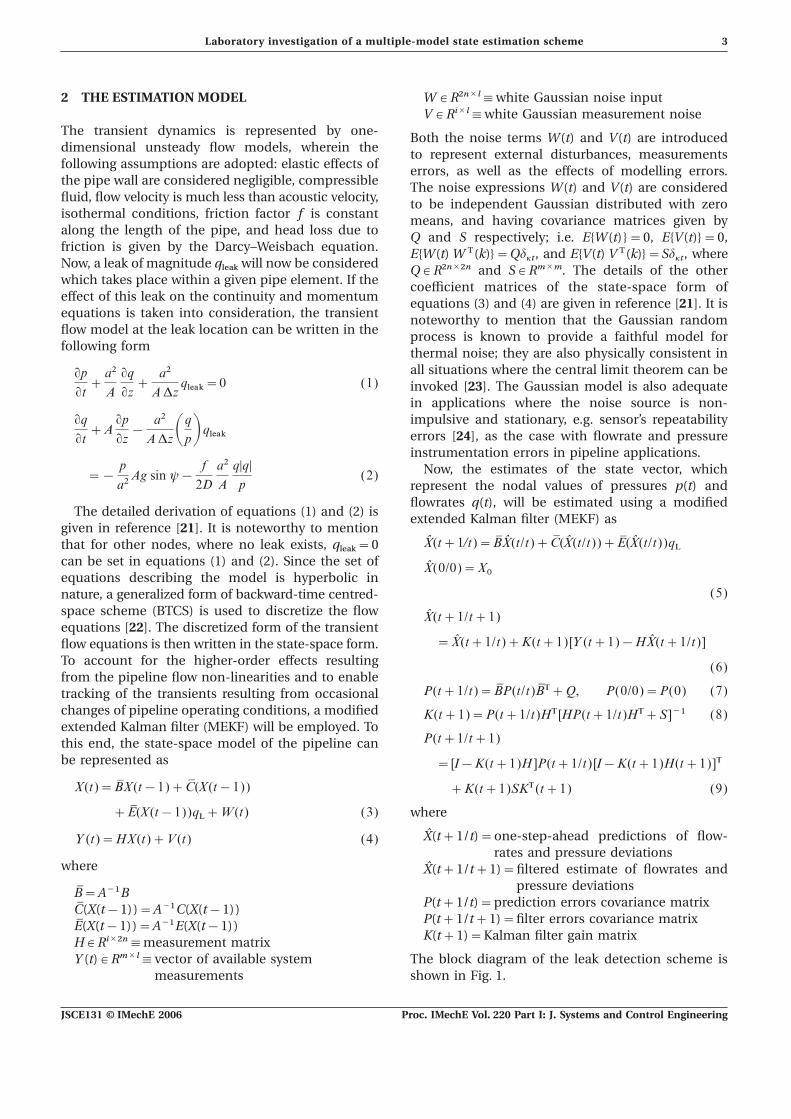
2 THE ESTIMATION MODEL WµR2n×l¬white Gaussian noise inputVµRi×l¬white Gaussian measurement noise
The transient dynamics is represented by one- Both the noise terms W(t) and V(t) are introduceddimensional unsteady flow models, wherein the to represent external disturbances, measurementsfollowing assumptions are adopted: elastic effects of errors, as well as the effects of modelling errors.the pipe wall are considered negligible, compressible The noise expressions W(t) and V(t) are consideredfluid, flow velocity is much less than acoustic velocity, to be independent Gaussian distributed with zeroisothermal conditions, friction factor f is constant means, and having covariance matrices given byalong the length of the pipe, and head loss due to Q and S respectively; i.e. E{W(t)}=0, E{V(t)}=0,friction is given by the Darcy–Weisbach equation. E{W(t) W T(k)}=Qd
kt, and E{V(t) V T(k)}=Sd
kt, where
Now, a leak of magnitude qleak
will now be considered QµR2n×2n and SµRm×m. The details of the otherwhich takes place within a given pipe element. If the coefficient matrices of the state-space form ofeffect of this leak on the continuity and momentum equations (3) and (4) are given in reference [21]. It isequations is taken into consideration, the transient noteworthy to mention that the Gaussian randomflow model at the leak location can be written in the process is known to provide a faithful model forfollowing form thermal noise; they are also physically consistent in
all situations where the central limit theorem can beqpqt+
a2
A
qqqz+
a2
ADzqleak=0 (1) invoked [23]. The Gaussian model is also adequate
in applications where the noise source is non-impulsive and stationary, e.g. sensor’s repeatabilityqq
qt+Aqpqz−
a2
ADzAqpB qleak errors [24], as the case with flowrate and pressureinstrumentation errors in pipeline applications.
Now, the estimates of the state vector, which=−p
a2Ag sin y−
f
2D
a2
A
q|q|p
(2)represent the nodal values of pressures p(t) andflowrates q(t), will be estimated using a modified
The detailed derivation of equations (1) and (2) is extended Kalman filter (MEKF) asgiven in reference [21]. It is noteworthy to mention
X̂(t+1/t)=B9 X̂(t/t)+C9 (X̂(t/t))+E9 (X̂(t/t))qLthat for other nodes, where no leak exists, qleak=0
can be set in equations (1) and (2). Since the set of X̂(0/0)=X0equations describing the model is hyperbolic in
(5)nature, a generalized form of backward-time centred-space scheme (BTCS) is used to discretize the flow X̂(t+1/t+1)equations [22]. The discretized form of the transient
=X̂(t+1/t)+K(t+1)[Y (t+1)−HX̂(t+1/t)]flow equations is then written in the state-space form.To account for the higher-order effects resulting (6)from the pipeline flow non-linearities and to enable
P(t+1/t)=B9P(t/t)B9 T+Q, P(0/0)=P(0) (7)tracking of the transients resulting from occasionalchanges of pipeline operating conditions, a modified K(t+1)=P(t+1/t)HT [HP(t+1/t)HT+S]−1 (8)extended Kalman filter (MEKF) will be employed. To
P(t+1/t+1)this end, the state-space model of the pipeline canbe represented as = [I−K(t+1)H ]P(t+1/t)[I−K(t+1)H(t+1)]T
X(t)=B9X(t−1)+C9 (X(t−1)) +K(t+1)SKT(t+1) (9)
+E9 (X(t−1))qL+W(t) (3) where
X̂(t+1/t)=one-step-ahead predictions of flow-Y (t)=HX(t)+V(t) (4)rates and pressure deviations
where X̂(t+1/t+1)=filtered estimate of flowrates andpressure deviationsB9=A−1B
P(t+1/t)=prediction errors covariance matrixC9 (X(t−1))=A−1C(X(t−1))P(t+1/t+1)=filter errors covariance matrixE9 (X(t−1))=A−1E(X(t−1))K(t+1)=Kalman filter gain matrixHµRi×2n¬measurement matrix
Y (t)µRm×l¬vector of available system The block diagram of the leak detection scheme isshown in Fig. 1.measurements
JSCE131 © IMechE 2006 Proc. IMechE Vol. 220 Part I: J. Systems and Control Engineering

4 Y A Khulief and H E Emara-Schabaik
Fig. 1 Leak detection and isolation scheme
3 THE EXPERIMENTAL PIPELINE SET-UP tank. In this configuration, the pump output is con-nected through a flexible hose, unlike the case of thedirect pump supply, and therefore vibrations due toThe schematic configuration of the experimental
set-up is shown in Fig. 2. The set-up consists of a the pump are eliminated. In addition, a dampingtank (DT) with internal screens is installed before the10 m long 0.5 in pipe, which is supplied by water flow
from the head tank (HT). The outflow from the pipe test pipe in order to smooth out the flow fluctuations.The pump can supply water either to the head tankis at atmospheric pressure and is collected by the
circulation tank (CT). The fluid circuit is closed by or directly to the damping tank, when higherflowrates are desired, as shown in the assembleda centrifugal pump, which draws water from the
circulation tank and feeds the head tank. The leak is laboratory set-up in Fig. 3.The high-speed digitizer (WaveBookTM), which per-implemented by valves, which are located at some
selected locations and operated manually as desired. forms analogue-to-digital conversion, is wired to theparallel port of the PC computer, while its channelsThe leaked water is drained back to the circulation
Fig. 2 Schematic of the experimental set-up
JSCE131 © IMechE 2006Proc. IMechE Vol. 220 Part I: J. Systems and Control Engineering
5Laboratory investigation of a multiple-model state estimation scheme
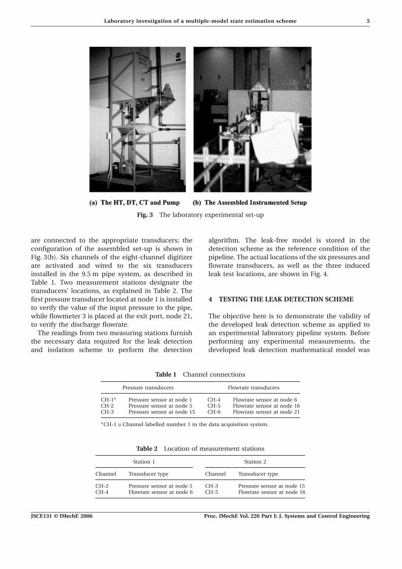
Fig. 3 The laboratory experimental set-up
are connected to the appropriate transducers; the algorithm. The leak-free model is stored in thedetection scheme as the reference condition of theconfiguration of the assembled set-up is shown in
Fig. 3(b). Six channels of the eight-channel digitizer pipeline. The actual locations of the six pressures andflowrate transducers, as well as the three inducedare activated and wired to the six transducers
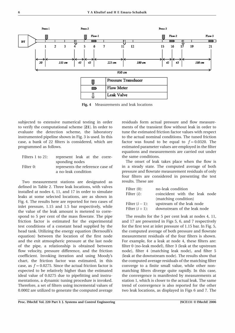
installed in the 9.5 m pipe system, as described in leak test locations, are shown in Fig. 4.Table 1. Two measurement stations designate thetransducers’ locations, as explained in Table 2. Thefirst pressure transducer located at node 1 is installed 4 TESTING THE LEAK DETECTION SCHEMEto verify the value of the input pressure to the pipe,while flowmeter 3 is placed at the exit port, node 21, The objective here is to demonstrate the validity of
the developed leak detection scheme as applied toto verify the discharge flowrate.The readings from two measuring stations furnish an experimental laboratory pipeline system. Before
performing any experimental measurements, thethe necessary data required for the leak detectionand isolation scheme to perform the detection developed leak detection mathematical model was
Table 1 Channel connections
Pressure transducers Flowrate transducers
CH-1* Pressure sensor at node 1 CH-4 Flowrate sensor at node 6CH-2 Pressure sensor at node 5 CH-5 Flowrate sensor at node 16CH-3 Pressure sensor at node 15 CH-6 Flowrate sensor at node 21
*CH-1¬Channel labelled number 1 in the data acquisition system.
Table 2 Location of measurement stations
Station 1 Station 2
Channel Transducer type Channel Transducer type
CH-2 Pressure sensor at node 5 CH-3 Pressure sensor at node 15CH-4 Flowrate sensor at node 6 CH-5 Flowrate sensor at node 16
JSCE131 © IMechE 2006 Proc. IMechE Vol. 220 Part I: J. Systems and Control Engineering
6 Y A Khulief and H E Emara-Schabaik
Fig. 4 Measurements and leak locations
subjected to extensive numerical testing in order residuals form actual pressure and flow measure-ments of the transient flow without leak in order toto verify the computational scheme [21]. In order to
evaluate the detection scheme, the laboratory tune the estimated friction factor values with respectto the actual nominal conditions. The tuned frictioninstrumented pipeline shown in Fig. 3 is used. In this
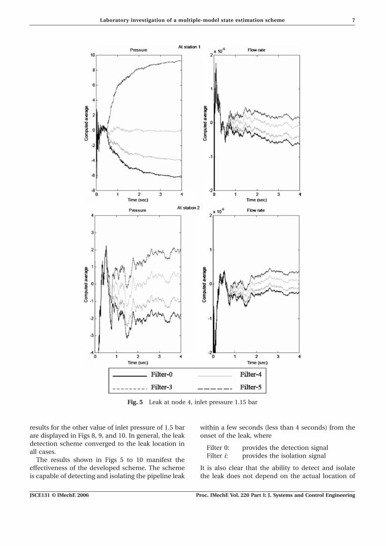
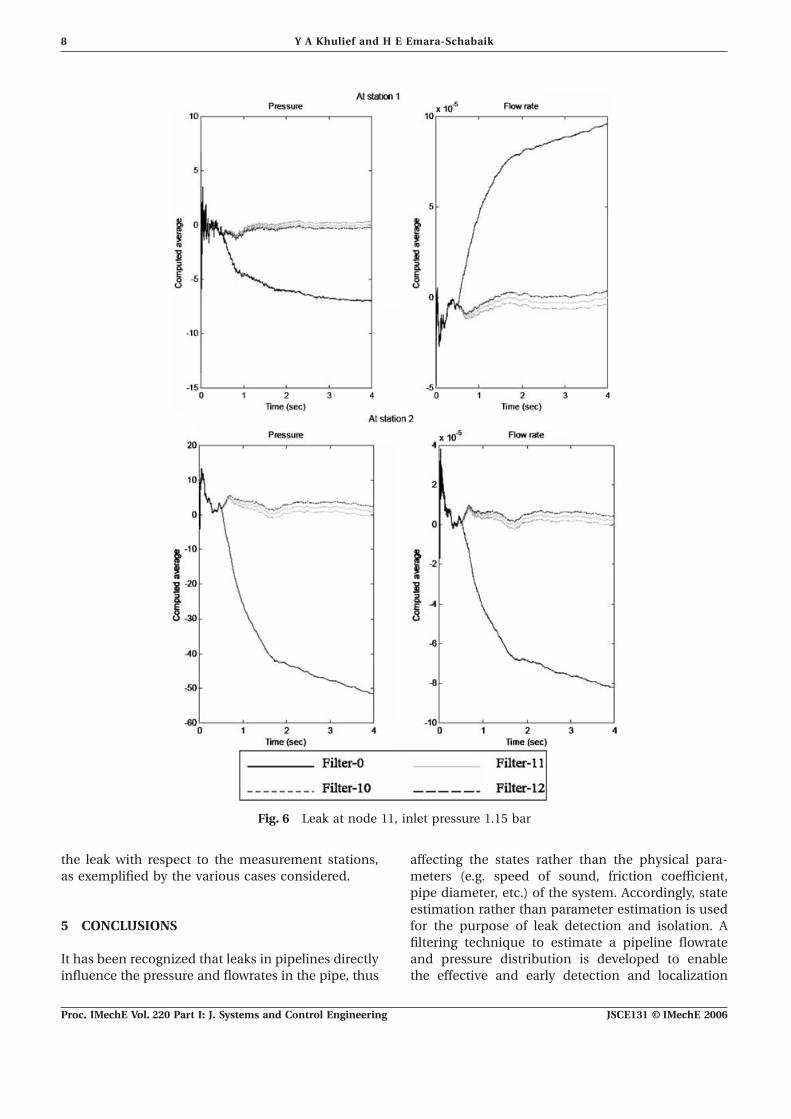
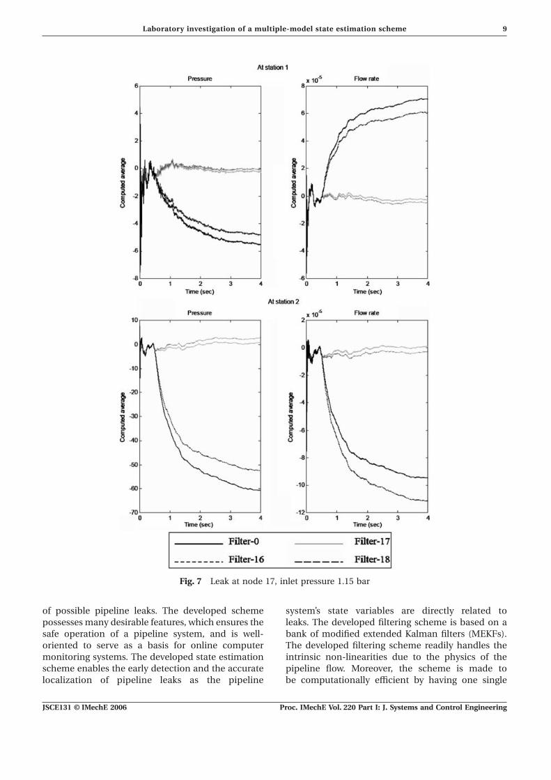
case, a bank of 22 filters is considered, which are factor was found to be equal to f=0.0320. Theestimated parameter values are employed in the filterprogrammed as follows.equations and measurements are carried out underthe same conditions.Filters 1 to 21: represent leak at the corre-
The onset of leak takes place when the flow issponding nodesin a steady state. The computed average of bothFilter 0: represents the reference case ofpressure and flowrate measurement residuals of onlya no-leak conditionfour filters are considered in presenting the testresults. These areTwo measurement stations are designated as
defined in Table 2. Three leak locations, with valves Filter (0): no-leak conditioninstalled at nodes 4, 11, and 17 in order to simulate Filter (i): coincident with the leak nodeleaks at some selected locations, are as shown in (matching condition)Fig. 4. The results here are reported for two cases of Filter (i−1): upstream of the leak nodeinlet pressure, 1.15 and 1.5 bar respectively, while Filter (i+1): downstream of the leak nodethe value of the leak amount is metered to corre-spond to 5 per cent of the mass flowrate. The pipe The results for the 5 per cent leak at nodes 4, 11,
and 17 are presented in Figs 5, 6, and 7 respectivelyfriction factor is estimated for the experimentaltest conditions of a constant head supplied by the for the first test at inlet pressure of 1.15 bar. In Fig. 5,
the computed average of both pressure and flowratehead tank. Utilizing the energy equation (Bernoulli’sequation) between the location of the first node measurement residuals of the four filters is shown.
For example, for a leak at node 4, these filters are:and the exit atmospheric pressure at the last nodeof the pipe, a relationship is obtained between filter 0 (no-leak model), filter 3 (leak at the upstream
node), filter 4 (matching leak node), and filter 5flow velocity, pressure difference, and the frictioncoefficient. Invoking iteration and using Moody’s (leak at the downstream node). The results show that
the computed average residuals of the matching filterchart, the friction factor was estimated, in thiscase, as f=0.0275. Since the actual friction factor is converge to a finite small value, while other non-
matching filters diverge quite rapidly. In this case,expected to be relatively higher than the estimatedideal value of 0.0275 due to pipefitting and instru- the convergence is manifested by measurements at
station 1, which is closer to the actual leak. The samementations, a dynamic tuning procedure is invoked.Therefore, a set of filters using incremental values of trend of convergence is also reported for the other
two leak locations, as displayed in Figs 6 and 7. The0.0002 are utilized to generate the computed average
JSCE131 © IMechE 2006Proc. IMechE Vol. 220 Part I: J. Systems and Control Engineering
7Laboratory investigation of a multiple-model state estimation scheme
Fig. 5 Leak at node 4, inlet pressure 1.15 bar
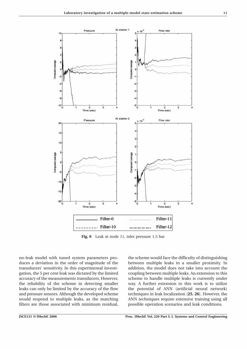
results for the other value of inlet pressure of 1.5 bar within a few seconds (less than 4 seconds) from theonset of the leak, whereare displayed in Figs 8, 9, and 10. In general, the leak
detection scheme converged to the leak location inFilter 0: provides the detection signal
all cases.Filter i: provides the isolation signal
The results shown in Figs 5 to 10 manifest theeffectiveness of the developed scheme. The scheme It is also clear that the ability to detect and isolate
the leak does not depend on the actual location ofis capable of detecting and isolating the pipeline leak
JSCE131 © IMechE 2006 Proc. IMechE Vol. 220 Part I: J. Systems and Control Engineering
8 Y A Khulief and H E Emara-Schabaik
Fig. 6 Leak at node 11, inlet pressure 1.15 bar
the leak with respect to the measurement stations, affecting the states rather than the physical para-meters (e.g. speed of sound, friction coefficient,as exemplified by the various cases considered.pipe diameter, etc.) of the system. Accordingly, stateestimation rather than parameter estimation is usedfor the purpose of leak detection and isolation. A5 CONCLUSIONSfiltering technique to estimate a pipeline flowrateand pressure distribution is developed to enableIt has been recognized that leaks in pipelines directly
influence the pressure and flowrates in the pipe, thus the effective and early detection and localization
JSCE131 © IMechE 2006Proc. IMechE Vol. 220 Part I: J. Systems and Control Engineering
9Laboratory investigation of a multiple-model state estimation scheme
Fig. 7 Leak at node 17, inlet pressure 1.15 bar
of possible pipeline leaks. The developed scheme system’s state variables are directly related toleaks. The developed filtering scheme is based on apossesses many desirable features, which ensures the
safe operation of a pipeline system, and is well- bank of modified extended Kalman filters (MEKFs).The developed filtering scheme readily handles theoriented to serve as a basis for online computer
monitoring systems. The developed state estimation intrinsic non-linearities due to the physics of thepipeline flow. Moreover, the scheme is made toscheme enables the early detection and the accurate
localization of pipeline leaks as the pipeline be computationally efficient by having one single
JSCE131 © IMechE 2006 Proc. IMechE Vol. 220 Part I: J. Systems and Control Engineering

10 Y A Khulief and H E Emara-Schabaik
Fig. 8 Leak at node 4, inlet pressure 1.5 bar
gain sequence for all filters in the bank and also by It should be emphasized, however, that thealgorithm should be supplied with accurate valueshaving such computations done offline. The filtering
scheme is capable of providing accurate estimation of the physical parameters. The algorithm can easilybe tuned from time to time using updated pipe-of the pipeline pressures and flowrates in spite of
the random effects that can emanate from pipe- line parameters to maintain high accuracy of leakdetection and isolation. With regard to parameterline instrument operations, e.g. pumps, valves, and
sensor random errors such as those of flow and tuning, some of the system parameters will bemeasured in real applications, while some will bepressure sensors, as well as random environmental
fluctuations that can induce variability in the calculated from the measured values. The tuningof parameters takes effect when the test of theoperational conditions and parameters.
JSCE131 © IMechE 2006Proc. IMechE Vol. 220 Part I: J. Systems and Control Engineering
11Laboratory investigation of a multiple-model state estimation scheme
Fig. 9 Leak at node 11, inlet pressure 1.5 bar
no-leak model with tuned system parameters pro- the scheme would face the difficulty of distinguishingbetween multiple leaks in a smaller proximity. Induces a deviation in the order of magnitude of the
transducers’ sensitivity. In this experimental investi- addition, the model does not take into account thecoupling between multiple leaks. An extension to thisgation, the 5 per cent leak was dictated by the limited
accuracy of the measurements transducers. However, scheme to handle multiple leaks is currently underway. A further extension to this work is to utilizethe reliability of the scheme in detecting smaller
leaks can only be limited by the accuracy of the flow the potential of ANN (artificial neural network)techniques in leak localization [25, 26]. However, theand pressure sensors. Although the developed scheme
would respond to multiple leaks, as the matching ANN techniques require extensive training using allpossible operation scenarios and leak conditions.filters are those associated with minimum residual,
JSCE131 © IMechE 2006 Proc. IMechE Vol. 220 Part I: J. Systems and Control Engineering

12 Y A Khulief and H E Emara-Schabaik
Fig. 10 Leak at node 17, inlet pressure 1.5 bar
2 Scott, S. L. and Barrufet, M. A. Worldwide assess-ACKNOWLEDGEMENTment of industry leak detection capabilities forsingle and multiphase pipelines. TR 1435-01-99-The authors acknowledge with gratitude the supportCA-31003, Offshore Technology Research Center,provided by King Fahd University of Petroleum andUniversity of Texas at Austin, August 2003.
Minerals. 3 De Read, J. R. Comparison between ultrasonic andmagnetic flux pigs for pipeline inspection. Pipes andPipeline Int., January–February 1987, 7–15.
REFERENCES 4 Liou, J. C. P. and Tian, J. Leak detection: a transientflow simulation approach. Trans. ASME, PipelineEngng, 1994, PD-Vol. 60, 51–58.1 Brones, H. H. and Schaffhaussen, H. European
5 Wilsky, A. S. A survey of design methods for failuremethods of leak detection and location. PipelineIndustry, May 1972, 50–66. detection systems. Automatica, 1976, 12, 601–611.
JSCE131 © IMechE 2006Proc. IMechE Vol. 220 Part I: J. Systems and Control Engineering
13Laboratory investigation of a multiple-model state estimation scheme
6 Siebert, H. A simple method for detection and 17 Loparo, K. A., Buchner, M. R., and Vasudeva, K. S.Leak detection in an experimental heat exchangerlocating leaks in gas pipeline. Process Automn, 1981,
2, 90–95. process: a multiple model approach. IEEE Trans.Autom. Control, 1991, 36, 167–177.7 Isermann, R. Process fault detection based on
modeling and estimation methods – a survey. 18 Poulakis, Z., Valougeorgis, D., and Papadimitriou, C.Leakage detection in water pipe networks usingAutomatica, 1984, 20, 387–404.
8 Billmann, L. and Isermann, R. Leak detection a Bayesian probabilistic framework. ProbabilisticEngng Mechanics, October 2003, 18(4), 315–327.methods for pipelines. Automatica, 1987, 23(3),
381–385. 19 Kingsley, E., Abhulimen, and Susu, A. A. Liquidpipeline leak detection system: model develop-9 Isermann, R. and Freyermuth, B. Process fault
diagnosis based on process model knowledge – ment and numerical simulation. Chem. Engng J.,15 January 2004, 97(1), 47–67.Part I: principles for fault diagnosis with parameter
estimation. J. Dynamic Systems, Measmt, and Control, 20 Verde, C. Accommodation of multi-leak location ina pipeline. Control Engng Practice, August 2005,December 1991, 113, 620–626.
10 Isermann, R. Process fault diagnosis with parameter 13(8), 1071–1078.21 Emara-Shabaik, H. E., Khulief, Y. A., andestimation methods. In Seventh IFAC/IFIP Con-
ference on Digital computer applications, Vienna, Hussaini, I. A non-linear multiple-model stateestimation scheme for pipeline leak detection andAustria, 1985, pp. 51–60.
11 Wang, G., Dong, D., and Fang, C. Leak detection isolation. Proc. Instn Mech. Engrs, Part I: J. Systemsand Control Engineering, 2002, 216(I6), 497–512.for transport pipelines based on autoregressive
modeling. IEEE Trans. Instrum. Measmt, February 22 Emara-Shabaik, H. E., Khulief, Y., and Hussaini, I.Simulation of transient flow in pipelines for com-1993, 42(1), 68–71.
12 Jones, H. L. Failure detection in linear systems. puter-based operations monitoring. Int. J. Numer.Meth. Fluids, 2004, 44, 257–275.PhD Dissertation, Department of Aeronautics and
Astronautics, MIT, Cambridge, Massachusetts, 23 Belsito, S., Lombardi, P., Andreussi, P., andBanerjee, S. Leak detection in liquified gas pipelinesSeptember 1973.
13 Mehra, R. K. and Peschon, J. An innovations by artificial neural networks. Am. Inst. Chem. EngrsJ., 1998, 44(2), 2675–2687.approach to fault detection and diagnosis in dynamic
systems. Automatica, 1971, 7, 637–640. 24 Bentley, J. P. Principles of measurement systems, 3rdedition, 1995 (Longman, London).14 Willsky, A. S. and Jones, H. L. A generalized likeli-
hood ratio approach to the detection and estimation 25 Caputo, A. C. and Pelagagge, P. M. An inverseapproach for piping networks monitoring. J. Lossof jumps in linear systems. IEEE Trans. Autom.
Control, 1976, AC-21, 108–112. Prevention in the Process Industries, November 2002,15(6), 497–505.15 Willsky, A. S. Failure detection in dynamic systems.
AGARD, 1980, 109. 26 Buzzi, S., Conte, E., De Maio, A., and Lops, M.Optimum diversity detection over fading dispersive16 Billmann, L. and Isermann, R. Leak detection
methods for pipelines. Automatica, 1987, 23(3), channels with non-Gaussian noise. IEEE Trans.Signal Processing, 2001, 49(4), 767–776.381–385.
JSCE131 © IMechE 2006 Proc. IMechE Vol. 220 Part I: J. Systems and Control Engineering