CATHODIC PROTECTION OF PIPELINES AND STRUCTURES
53
TMS1595 Cathodic Protection -Pipelines and Steel Structures Standard Technical Specification Printed at 9:56 AM on 11/08/16 Page 1 of 53 C:\Users\100608\AppData\Local\Microsoft\Windows\Temporary Internet Files\Content.Outlook\ATNU1NN6\TMS1595 Cathodic Protection Pipelines and Steel Structures - Standard Technical Specification_Rev1.docx CATHODIC PROTECTION OF PIPELINES AND STRUCTURES TMS1595 Standard Technical Specification
-
Upload
khangminh22 -
Category
Documents
-
view
6 -
download
0
Transcript of CATHODIC PROTECTION OF PIPELINES AND STRUCTURES

TMS1595 Cathodic Protection -Pipelines and Steel Structures Standard Technical Specification
Printed at 9:56 AM on 11/08/16 Page 1 of 53
C:\Users\100608\AppData\Local\Microsoft\Windows\Temporary Internet Files\Content.Outlook\ATNU1NN6\TMS1595 Cathodic Protection
Pipelines and Steel Structures - Standard Technical Specification_Rev1.docx
CATHODIC PROTECTION OF
PIPELINES AND STRUCTURES
TMS1595
Standard Technical Specification

TMS1595 Cathodic Protection -Pipelines and Steel Structures Standard Technical Specification
Printed at 9:56 AM on 11/08/16 Page 2 of 53
C:\Users\100608\AppData\Local\Microsoft\Windows\Temporary Internet Files\Content.Outlook\ATNU1NN6\TMS1595 Cathodic Protection
Pipelines and Steel Structures - Standard Technical Specification_Rev1.docx
REVISION CONTROL
Revision
Number
Date Revision Details Responsible
Officer
0 Jul 2016 First Draft Steve Bourke
1 Aug 2016 Issued for Use – Stakeholder Comments Updated Steve Bourke
DOCUMENT CONSULTATION
Revision
Number
Date Sent Name Comments
Received Incorporated
0 Jul 2016 Gerard Anderson
0 Jul 2016 Mark Davanzo Y Y
0 Jul 2016 Jeff Say Y Y
0 Jul 2016 Kokila Admanathan
0 Jul 2016 Scott Stevens Y Y
0 Jul 2016 Sam Pickett
0 Jul 2016 John Clayton
0 Jul 2016 Scott Adams
0 Jul 2016 John Titmarsh
0 Jul 2016 Steve Walton
0 Jul 2016 Andy Paranagama
0 Jul 2016 Alan Quach
0 Jul 2016 Vaughan Springfield Y Partial
0 Jul 2016 Aed MacPhaidin
0 Jul 2016 Kerry McGovern Y Y
0 Jul 2016 Jose Castineyra
0 Jul 2016 Harald Kemmetmuller
0 Jul 2016 Technical Engineering Group(TEG) Y Y

TMS1595 Cathodic Protection -Pipelines and Steel Structures Standard Technical Specification
Printed at 9:56 AM on 11/08/16 Page 3 of 53
C:\Users\100608\AppData\Local\Microsoft\Windows\Temporary Internet Files\Content.Outlook\ATNU1NN6\TMS1595 Cathodic Protection
Pipelines and Steel Structures - Standard Technical Specification_Rev1.docx
Contents REVISION CONTROL .................................................................................................................................... 2
DOCUMENT CONSULTATION ....................................................................................................................... 2
1 SCOPE .................................................................................................................................................... 6
1.1 DEFINITIONS .............................................................................................................................. 6
1.2 ACRONYMS AND ABBREVIATIONS ........................................................................................... 6
1.3 REFERENCE DOCUMENTS ....................................................................................................... 8
1.4 TYPICAL DESIGN DRAWINGS ................................................................................................... 9
2 STANDARDS & REGULATIONS .......................................................................................................... 10
2.1 AUSTRALIAN STANDARDS ...................................................................................................... 10
2.2 INTERNATIONAL ELECTROTECHNICAL COMMISSION (IEC) STANDARDS .......................... 11
2.3 REGULATIONS ......................................................................................................................... 11
2.4 UNITS AND LANGUAGE ........................................................................................................... 11
2.5 SUB-CONTRACTORS ............................................................................................................... 11
2.6 CONTRACTOR EXCEPTIONS .................................................................................................. 12
2.7 ORDER OF PRECEDENCE ....................................................................................................... 12
3 GENERAL REQUIREMENTS ................................................................................................................ 13
3.1 OPERATING CONDITIONS AND DESIGN LIFE ........................................................................ 13
3.2 SITE CLIMATIC CONDITIONS................................................................................................... 13
3.3 OPERATING REQUIREMENTS ................................................................................................. 14
3.4 SPARE CAPACITY .................................................................................................................... 14
3.5 UTILITY DATA ........................................................................................................................... 14
3.6 WORKMANSHIP AND COMPETENCY OF PERSONNEL .......................................................... 15
3.6.1 Cathodic Protection Technician ................................................................................ 15
3.6.2 Cathodic Protection Technologist.............................................................................. 15
3.6.3 Electrical Tradespersons .......................................................................................... 15
3.6.4 Design Services ....................................................................................................... 15
3.7 MATERIALS AND EQUIPMENT ................................................................................................. 16
3.8 WEATHER AND INGRESS PROTECTION ................................................................................ 17
3.9 PAINTING AND PROTECTIVE COATINGS ............................................................................... 17
3.10 REGULATORY REQUIREMENTS ............................................................................................. 17
4 TECHNICAL REQUIREMENTS ............................................................................................................. 19
4.1 GENERAL .................................................................................................................................. 19
4.2 ANODE GROUND BEDS ........................................................................................................... 19
4.3 SACRIFICIAL ANODE CATHODIC PROTECTION ..................................................................... 20
4.4 IMPRESSED CURRENT CATHODIC PROTECTION ................................................................. 20
4.5 EXTERNAL INFLUENCES ......................................................................................................... 20
4.6 DESIGN PARAMETERS ............................................................................................................ 20
4.7 ASSET PROTECTION TARGETS .............................................................................................. 21
4.8 PIPELINE CATHODIC PROTECTION SYSTEMS ...................................................................... 21
4.8.1 Pipeline Protection Criteria ....................................................................................... 22
4.8.2 Pipeline Temporary Sacrificial Anodes ...................................................................... 22
4.9 GENERAL STRUCTURES CATHODIC PROTECTION SYSTEMS............................................. 22
5 SAFETY IN DESIGN.............................................................................................................................. 23
5.1 SAFETY MANAGEMENT PLAN ................................................................................................. 23
5.2 LOW FREQUENCY INDUCTION ............................................................................................... 23
5.3 EARTH POTENTIAL RISE ......................................................................................................... 24
5.4 CAPACITIVE COUPLING - OVERHEAD HV TRANSMISSION LINES ........................................ 24
5.5 ELECTRICAL ISOLATION ......................................................................................................... 25
5.5.1 Equipment ................................................................................................................ 25
5.5.2 Instrumentation......................................................................................................... 25
5.5.3 Cabling ..................................................................................................................... 25
TMS1595 Cathodic Protection -Pipelines and Steel Structures Standard Technical Specification
Printed at 9:56 AM on 11/08/16 Page 4 of 53
C:\Users\100608\AppData\Local\Microsoft\Windows\Temporary Internet Files\Content.Outlook\ATNU1NN6\TMS1595 Cathodic Protection
Pipelines and Steel Structures - Standard Technical Specification_Rev1.docx
5.6 ANODE BED ENVIRONMENTAL DESIGN CONSIDERATIONS ................................................ 25
5.7 STANDARDISED DESIGN ......................................................................................................... 26
6 MONITORING AND CONTROL ............................................................................................................. 27
6.1 LOCAL INDICATION .................................................................................................................. 27
6.2 REMOTE MONITORING ............................................................................................................ 27
6.3 AUTOMATIC CONTROL ............................................................................................................ 28
7 EQUIPMENT AND INSTALLTION ......................................................................................................... 29
7.1 QUU SUPPLIED MATERIALS .................................................................................................... 29
7.2 CATHODIC PROTECTION SYSTEM ......................................................................................... 29
7.3 UTILITY POWER SUPPLY......................................................................................................... 29
7.4 REGISTRATION ........................................................................................................................ 29
7.5 IMPRESSED CURRENT ANODES ............................................................................................ 29
7.6 EQUIPMENT GLOBAL POSITION CO-ORDINATES.................................................................. 30
7.7 SACRIFICIAL ANODES ............................................................................................................. 30
7.8 TEMPORARY MAGNESIUM ANODES ...................................................................................... 30
7.9 PIPELINE TEST POINTS ........................................................................................................... 30
7.10 FOREIGN TEST POINTS ........................................................................................................... 31
7.11 ABOVE GROUND VALVE STATION CROSS BONDING ........................................................... 32
7.12 CABLES AND CONDUITS ......................................................................................................... 32
7.13 CABLE TERMINATIONS ............................................................................................................ 32
7.14 INSULATING FLANGE KITS ...................................................................................................... 33
7.15 SURGE DIVERTERS ................................................................................................................. 34
7.16 PIPE JOINT CONTINUITY CONNECTIONS............................................................................... 34
7.17 ELECTRICAL ENCLOSURES .................................................................................................... 35
7.18 EQUIPMENT AND CABLE IDENTIFICATION ............................................................................ 35
7.19 WARNING SIGNS ...................................................................................................................... 36
7.20 NAME PLATE ............................................................................................................................ 36
7.21 REMEDIAL PIPELINE WORKS .................................................................................................. 36
7.22 SOLAR POWER SUPPLY .......................................................................................................... 37
8 QUALITY ASSURANCE, INSPECTION AND TESTING ........................................................................ 38
8.1 QUALITY ASSURANCE ............................................................................................................. 38
8.2 INSPECTION AND TESTING ..................................................................................................... 38
8.2.1 Inspection and Test Plan .......................................................................................... 38
8.3 INCOMING EQUIPMENT INSPECTIONS .................................................................................. 39
8.4 CABLE TESTING ....................................................................................................................... 39
8.5 EARTH TESTING ...................................................................................................................... 39
8.6 TEMPORARY ANODES ............................................................................................................. 39
8.7 CONSTRUCTION CONDITION MONITORING .......................................................................... 40
8.8 SITE ACCEPTANCE TESTING .................................................................................................. 40
8.8.1 SAT Plan .................................................................................................................. 40
8.8.2 DCVG Survey ........................................................................................................... 41
8.8.3 SAT Report .............................................................................................................. 42
8.9 PRACTICAL COMPLETION ....................................................................................................... 42
8.10 COMMISSIONING ..................................................................................................................... 42
8.10.1 Commissioning Plan ................................................................................................. 42
8.10.2 Data Collection ......................................................................................................... 43
8.10.3 Commissioning Report ............................................................................................. 43
9 PACKING AND SHIPMENT................................................................................................................... 44
10 DOCUMENTATION ............................................................................................................................... 45
10.1 PRIOR TO AWARD.................................................................................................................... 45
10.2 DOCUMENTATION AFTER CONTRACT AWARD ..................................................................... 45
10.3 DRAWINGS ............................................................................................................................... 45
10.4 DATA SHEETS .......................................................................................................................... 46
TMS1595 Cathodic Protection -Pipelines and Steel Structures Standard Technical Specification
Printed at 9:56 AM on 11/08/16 Page 5 of 53
C:\Users\100608\AppData\Local\Microsoft\Windows\Temporary Internet Files\Content.Outlook\ATNU1NN6\TMS1595 Cathodic Protection
Pipelines and Steel Structures - Standard Technical Specification_Rev1.docx
10.5 REPORTS ................................................................................................................................. 46
10.5.1 Life Cycle Cost Analysis Report ................................................................................ 47
10.5.2 CPS Design Report .................................................................................................. 47
10.5.3 Earth System Design Report .................................................................................... 48
10.5.4 LFI Design Report .................................................................................................... 48
10.5.5 Soil Resistivity Report ............................................................................................... 48
10.5.6 PSA Report .............................................................................................................. 48
10.5.7 Lightning Protection Design Report ........................................................................... 48
10.6 EQUIPMENT LISTS ................................................................................................................... 49
10.7 LABEL AND SIGNAGE SCHEDULE .......................................................................................... 49
10.8 MANUALS ................................................................................................................................. 49
10.9 GENERIC MANUALS ................................................................................................................. 50
10.10 OPERATION AND MAINTENANCE PERSONEL TRAINING ...................................................... 50
11 SPARE PARTS AND SPECIAL TOOLS ................................................................................................ 52
11.1 SPARES .................................................................................................................................... 52
11.2 SPECIAL TOOLS ....................................................................................................................... 52
12 WARRANTIES AND PERFORMANCE GUARANTEES ........................................................................ 53
12.1 PERFORMANCE GUARANTEE ................................................................................................. 53
12.2 WARRANTY AND DEFECT LIABILI Y........................................................................................ 53
TMS1595 Cathodic Protection -Pipelines and Steel Structures Standard Technical Specification
Printed at 9:56 AM on 11/08/16 Page 6 of 53
C:\Users\100608\AppData\Local\Microsoft\Windows\Temporary Internet Files\Content.Outlook\ATNU1NN6\TMS1595 Cathodic Protection
Pipelines and Steel Structures - Standard Technical Specification_Rev1.docx
1 SCOPE
This specification details the technical requirements for design, manufacture, installation, testing and commissioning of Cathodic Protection systems for steel
pipelines and structures. Cathodic Protection reduces the maintenance costs of water supply and sewerage infrastructure by inhibiting corrosion and extends the design life
of metallic infrastructure assets. Both impressed current and sacrificial anode methods
of cathodic protection are included in this document
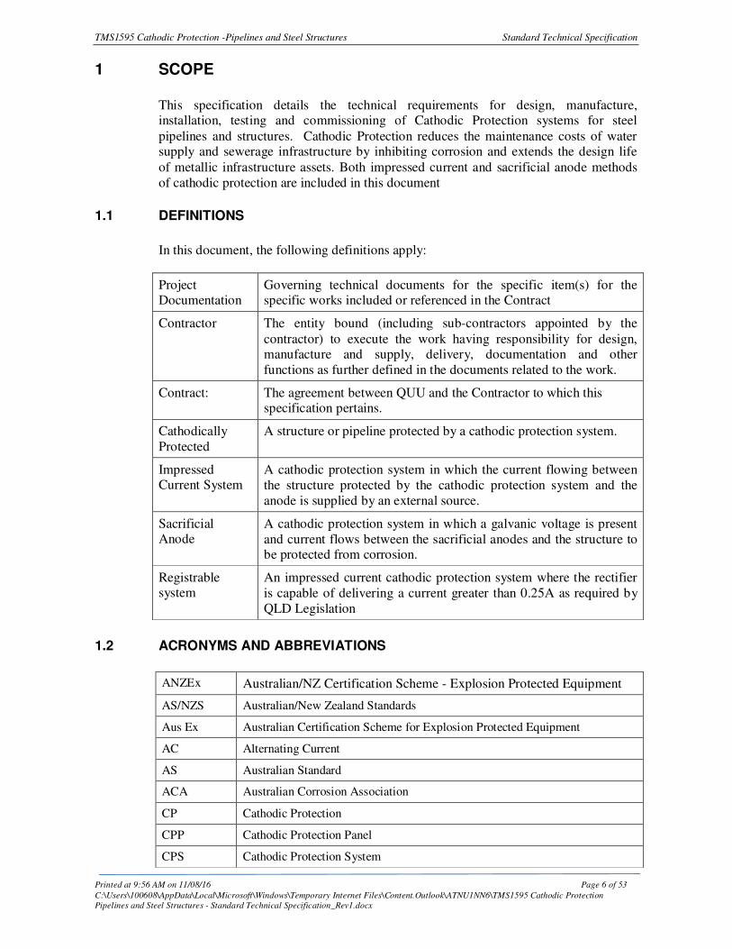
1.1 DEFINITIONS
In this document, the following definitions apply:
Project Documentation
Governing technical documents for the specific item(s) for the specific works included or referenced in the Contract
Contractor The entity bound (including sub-contractors appointed by the
contractor) to execute the work having responsibility for design, manufacture and supply, delivery, documentation and other
functions as further defined in the documents related to the work.
Contract: The agreement between QUU and the Contractor to which this specification pertains.
Cathodically
Protected
A structure or pipeline protected by a cathodic protection system.
Impressed Current System
A cathodic protection system in which the current flowing between
the structure protected by the cathodic protection system and the
anode is supplied by an external source.
Sacrificial Anode
A cathodic protection system in which a galvanic voltage is present
and current flows between the sacrificial anodes and the structure to be protected from corrosion.
Registrable system
An impressed current cathodic protection system where the rectifier
is capable of delivering a current greater than 0.25A as required by
QLD Legislation
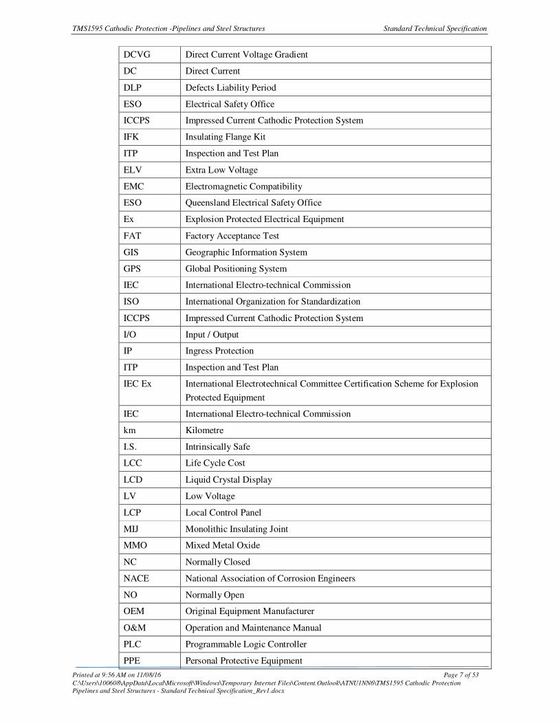
1.2 ACRONYMS AND ABBREVIATIONS
ANZEx Australian/NZ Certification Scheme - Explosion Protected Equipment
AS/NZS Australian/New Zealand Standards
Aus Ex Australian Certification Scheme for Explosion Protected Equipment
AC Alternating Current
AS Australian Standard
ACA Australian Corrosion Association
CP Cathodic Protection
CPP Cathodic Protection Panel
CPS Cathodic Protection System
TMS1595 Cathodic Protection -Pipelines and Steel Structures Standard Technical Specification
Printed at 9:56 AM on 11/08/16 Page 7 of 53
C:\Users\100608\AppData\Local\Microsoft\Windows\Temporary Internet Files\Content.Outlook\ATNU1NN6\TMS1595 Cathodic Protection
Pipelines and Steel Structures - Standard Technical Specification_Rev1.docx
DCVG Direct Current Voltage Gradient
DC Direct Current
DLP Defects Liability Period
ESO Electrical Safety Office
ICCPS Impressed Current Cathodic Protection System
IFK Insulating Flange Kit
ITP Inspection and Test Plan
ELV Extra Low Voltage
EMC Electromagnetic Compatibility
ESO Queensland Electrical Safety Office
Ex Explosion Protected Electrical Equipment
FAT Factory Acceptance Test
GIS Geographic Information System
GPS Global Positioning System
IEC International Electro-technical Commission
ISO International Organization for Standardization
ICCPS Impressed Current Cathodic Protection System
I/O Input / Output
IP Ingress Protection
ITP Inspection and Test Plan
IEC Ex
International Electrotechnical Committee Certification Scheme for Explosion
Protected Equipment
IEC International Electro-technical Commission
km Kilometre
I.S. Intrinsically Safe
LCC Life Cycle Cost
LCD Liquid Crystal Display
LV Low Voltage
LCP Local Control Panel
MIJ Monolithic Insulating Joint
MMO Mixed Metal Oxide
NC Normally Closed
NACE National Association of Corrosion Engineers
NO Normally Open
OEM Original Equipment Manufacturer
O&M Operation and Maintenance Manual
PLC Programmable Logic Controller
PPE Personal Protective Equipment
TMS1595 Cathodic Protection -Pipelines and Steel Structures Standard Technical Specification
Printed at 9:56 AM on 11/08/16 Page 8 of 53
C:\Users\100608\AppData\Local\Microsoft\Windows\Temporary Internet Files\Content.Outlook\ATNU1NN6\TMS1595 Cathodic Protection
Pipelines and Steel Structures - Standard Technical Specification_Rev1.docx
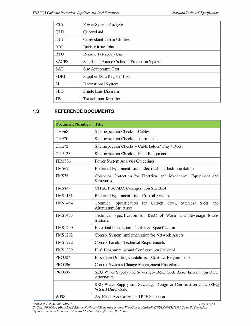
PSA Power System Analysis
QLD Queensland
QUU Queensland Urban Utilities
RRJ Rubber Ring Joint
RTU Remote Telemetry Unit
SACPS Sacrificial Anode Cathodic Protection System
SAT Site Acceptance Test
SDRL Supplier Data Register List
SI International System
SLD Single Line Diagram
TR Transformer Rectifier
1.3 REFERENCE DOCUMENTS
Document Number Title
CHE68 Site Inspection Checks – Cables
CHE70 Site Inspection Checks - Instruments
CHE72 Site Inspection Checks – Cable ladder/ Tray / Ducts
CHE136 Site Inspection Checks – Field Equipment
TEM336 Power System Analysis Guidelines
TMS62 Preferred Equipment List – Electrical and Instrumentation
TMS76 Corrosion Protection for Electrical and Mechanical Equipment and
Structures
TMS849 CITECT SCADA Configuration Standard
TMS1151 Preferred Equipment List – Control Systems
TMS1434 Technical Specification for Carbon Steel, Stainless Steel and
Aluminium Structures
TMS1435 Technical Specification for D&C of Water and Sewerage Mains
Systems
TMS1200 Electrical Installation - Technical Specification
TMS1202 Control System Implementation for Network Assets
TMS1222 Control Panels - Technical Requirements
TMS1229 PLC Programming and Configuration Standard
PRO307 Procedure Drafting Guidelines – Contract Requirements
PRO396 Control Systems Change Management Procedure
PRO395 SEQ Water Supply and Sewerage- D&C Code Asset Information QUU
Addendum
SEQ Water Supply and Sewerage Design & Construction Code (SEQ
WS&S D&C Code)
WI58 Arc Flash Assessment and PPE Selection

TMS1595 Cathodic Protection -Pipelines and Steel Structures Standard Technical Specification
Printed at 9:56 AM on 11/08/16 Page 9 of 53
C:\Users\100608\AppData\Local\Microsoft\Windows\Temporary Internet Files\Content.Outlook\ATNU1NN6\TMS1595 Cathodic Protection
Pipelines and Steel Structures - Standard Technical Specification_Rev1.docx
1.4 TYPICAL DESIGN DRAWINGS
Drawing Number Title
486/4/25-0008-001 Pipeline Cathodic Protection - Isolation Flange Details
486/4/25-0008-002 Pipeline Cathodic Protection – Test Point Details
486/4/6-0022-030 Scour Pit and Cathodic Protection Details
486/4/6-0053-055 CP – Civil and Design Works General Details
486/4/6-0053-056 CP – Civil and Design Works General Details Vertical Anode Beds
486/4/6-0053-070 CP – Civil and Design Works Typical Site Layout
486/4/6-0057-032 Cathodic Protection General Arrangement
486/5/7-0316-025 Cathodic Protection Unit – Construction and Wiring Diagram
Note: The typical drawings may not comply entirely with this specification and are
provided for information only to demonstrate typical design details required. The
Contractor shall produce detail design drawings that comply with the Project
Documentation and this specification.

TMS1595 Cathodic Protection -Pipelines and Steel Structures Standard Technical Specification
Printed at 9:56 AM on 11/08/16 Page 10 of 53
C:\Users\100608\AppData\Local\Microsoft\Windows\Temporary Internet Files\Content.Outlook\ATNU1NN6\TMS1595 Cathodic Protection
Pipelines and Steel Structures - Standard Technical Specification_Rev1.docx
2 STANDARDS & REGULATIONS
All equipment and workmanship shall conform to the most recent requirements of the relevant statutory Local, State and Commonwealth Authorities and current applicable
Australian Standards. Alternatively, where no Australian Standard exists, work shall conform to the most current and applicable International standard.
Where conflict exists between different Codes, Standards or Regulations, the most
onerous conditions of specification shall apply unless accepted otherwise in writing by
QUU.
The Contractor shall not deviate from the provisions of the relevant standard without
first obtaining agreement in writing from QUU.
Particular standards and regulations relevant to the work include but are not necessarily
limited to the following:
2.1 AUSTRALIAN STANDARDS
The equipment shall be designed, manufactured and tested in accordance with the latest
edition of all relevant Australian and International Standards, Codes and Regulations except where modified by this specification.
AS 1768 Lightning Protection
AS 2239 Galvanic (sacrificial) anodes for cathodic protection
AS 2832.1 Cathodic protection of metals Part 1: Pipes and cables
AS 2832.2 Cathodic Protection of Metals, Part 2 Compact buried structures.
AS 2832.3 Cathodic Protection of Metals Part 3: Fixed Immersed Structures.
AS 2832.4 Cathodic Protection of Metals Part 4: Internal Surfaces
AS 2832.5 Cathodic Protection of Metals Part 5: Steel in Concrete Structures.
AS 2885.1 Pipelines Gas & Liquid Petroleum Part 1: Design and construction
AS 2239 Galvanic (sacrificial) anode for cathodic protection
AS 3000 Wiring Rules
AS 3008.1.1 Electrical Installations – Selection of Cables – Cables for Alternating
Voltages up to and Including 0.6/1kV – Typical Australian Installation
Conditions
AS 3010 Electrical Installations - General Sets
AS 3017 Electrical installations—Verification guidelines
AS 3100 Approval and test specification - General requirements for electrical equipment
AS 4827.1 Coating defect surveys for buried pipelines – Direct current voltage gradient (DCVG)
AS 4853 Electrical hazards on metallic pipelines
AS ISO 9001 Quality management systems - requirements

TMS1595 Cathodic Protection -Pipelines and Steel Structures Standard Technical Specification
Printed at 9:56 AM on 11/08/16 Page 11 of 53
C:\Users\100608\AppData\Local\Microsoft\Windows\Temporary Internet Files\Content.Outlook\ATNU1NN6\TMS1595 Cathodic Protection
Pipelines and Steel Structures - Standard Technical Specification_Rev1.docx
AS/NZS 4853 Electrical hazards on metallic pipelines
AS/NZS 5000.1 Electric Cables – Polymeric insulated - For working voltages up to and
including 0.6 / 1 (1.2) kV
AS 60529 Degrees of Protection Provided by Enclosures (IP Code)
AS 61000 Electromagnetic Compatibility (EMC)
2.2 INTERNATIONAL ELECTROTECHNICAL COMMISSION (IEC) STANDARDS
IEC 60050 International Electro-technical Vocabulary
IEC 60228 Conductors of Insulated Cables
IEC 60050 International Electro-technical Vocabulary
IEC 60228 Conductors of Insulated Cables
2.3 REGULATIONS
The current regulations and statutory requirements of the State of Queensland,
Australia, shall be complied with, including:
• Queensland Electricity Act (1994)
• Queensland Electricity Regulations (2006)
• Queensland: Environmental Protection Act - 1994 and Amendment Act - 1997
• Building Code of Australia
• Supply Authority Conditions of Supply and Consumer Metering
• Workplace Health and Safety Regulation (2011)
• Electrical Safety Act 2002 and its latest amendments
• Electrical Safety Regulations 2013
• Professional Engineers Act 2002
• Environmental Protection Act 1994
• Environmental Protection (Water) Policy 1997
2.4 UNITS AND LANGUAGE
AS/ISO 1000 (metric SI system) shall be used. All documentation and correspondence
shall be in the English language.
2.5 SUB-CONTRACTORS
The Contractor shall disclose, at the tender stage, all sub-Contractors or sub-suppliers
they intend to use as part of the equipment package supply. The Contractor shall not
sub-contract any work to any party without the prior written consent of QUU. It shall
remain the Contractor’s responsibility to audit and co-ordinate the performance of their
sub-contractors with inspection reports being disclosed to QUU.

TMS1595 Cathodic Protection -Pipelines and Steel Structures Standard Technical Specification
Printed at 9:56 AM on 11/08/16 Page 12 of 53
C:\Users\100608\AppData\Local\Microsoft\Windows\Temporary Internet Files\Content.Outlook\ATNU1NN6\TMS1595 Cathodic Protection
Pipelines and Steel Structures - Standard Technical Specification_Rev1.docx
All requirements applicable to the Contractor are applicable to sub-contractors or sub-
suppliers. QUU reserves the right to attend the place of manufacturer by any sub-
contractor or sub-supplier engaged to undertake the manufacturing works.
2.6 CONTRACTOR EXCEPTIONS
The Contractor shall be responsible to submit, together with the Tender, a list of
deviations or exceptions to this Specification. In the absence of any exceptions, it will
be construed that the Contractor fully complies with this Specification.
2.7 ORDER OF PRECEDENCE
In the event of any conflict arising between this Specification and other documents
listed herein, refer comments to QUU for clarification before design or fabrication
commences.
The order of precedence that applies is as follows:-
• The Contract or Purchase Order Scope or Work
• Project Data Sheets
• This Specification
• Project Drawings
• International Codes and Standards

TMS1595 Cathodic Protection -Pipelines and Steel Structures Standard Technical Specification
Printed at 9:56 AM on 11/08/16 Page 13 of 53
C:\Users\100608\AppData\Local\Microsoft\Windows\Temporary Internet Files\Content.Outlook\ATNU1NN6\TMS1595 Cathodic Protection
Pipelines and Steel Structures - Standard Technical Specification_Rev1.docx
3 GENERAL REQUIREMENTS
3.1 OPERATING CONDITIONS AND DESIGN LIFE
The equipment shall be designed for minimum design life duration as stated below for
the environment and for the duty specified herein. The equipment shall also be suitable for normal continuous operation with only minimal routine maintenance as specified by
the component manufacturer.
All electrical equipment and instrumentation will be required to operate continuously at
full load for 24 hours per day, 365 days per year under the climatic conditions detailed
in this specification. All equipment shall be designed to perform this duty safely and
without being attended.
Component Minimum Design Life
Anodes 15 years
Transformer Rectifiers 15 years
Soil Sensors 15 years
Test Points 20 years
Cables 20 years
Surge Diverters 15 years
Reference Electrodes 15 years
3.2 SITE CLIMATIC CONDITIONS
All equipment shall be designed and installed for the site conditions defined below:-
Location South East Queensland
Altitude Above mean sea level. 0-300m
Ambient Temperature Minimum -5°C
Maximum (dry bulb) 45°C
Relative Humidity
Minimum 26%
Maximum 100% condensing
Solar Radiation Black bulb design temperature -
minimum mechanical design
temperature for equipment exposed to solar radiation
85°C
Note: Corrosive environments are locations where H2S gas or other corrosive chemicals
and gasses can exist under normal operating conditions and can be both indoor and outdoor areas. This is applicable to all wet wells installations. All areas including inside
air conditioned switch rooms at Sewerage Treatment Plants are considered corrosive environments. All materials installed shall be suitable for the environment.

TMS1595 Cathodic Protection -Pipelines and Steel Structures Standard Technical Specification
Printed at 9:56 AM on 11/08/16 Page 14 of 53
C:\Users\100608\AppData\Local\Microsoft\Windows\Temporary Internet Files\Content.Outlook\ATNU1NN6\TMS1595 Cathodic Protection
Pipelines and Steel Structures - Standard Technical Specification_Rev1.docx
3.3 OPERATING REQUIREMENTS
The equipment ratings shown on the drawings are the required ratings after all derating
factors have been applied.
All equipment shall be selected and installed so that all circuits can operate
simultaneously at the full load rating shown on the drawings at the worst climatic
extreme detailed in Clause 3.2 of this specification.
3.4 SPARE CAPACITY
The CPS shall generally be rated for 25% spare installed capacity over the maximum demand at time of commissioning. There shall be inbuilt spare capacity for increase of
current to allow for:-
• Interference mitigation.
• Operation of the transformer rectifier and associated components at high
ambient temperatures
• Margin for increase up to the registration current value if necessary.
• Operational flexibility
• Protection current to be increased as coating deteriorates. (The DC current demand as stated is a function of the technology of the coating and its condition
or age)
• Additional current output for routine testing tasks (DCVG survey and
interference testing)
Anode beds shall not exceed 70% of design capacity at time of commissioning.
In locations susceptible to stray current sources the CPS shall be rated for at least five
times the stray current determined by CPS current demand calculations, to allow additional contingency for the mitigation of any stray current effects.
3.5 UTILITY DATA
The electrical system will have the following voltage levels:
High Voltage Power Supply 33 kV AC, three phase 3 wire, 50 Hz,
11 kV AC three phase 3 wire 50 Hz,
6.6 kV AC, three phase 3 wire, 50 Hz
3.3 kV AC, three phase 3 wire, 50 Hz
Low Voltage Supplies 3 ph, 4 Wire, 400 Volt +10,-6% 50 Hz ± 2%, MEN
System Voltage Unbalance <5%
Single Phase Power Supplies 230 V AC, +10,-6%, 2 wire, 50Hz ± 2%,
Control Power Supplies: UPS 230 V AC, single phase 2 wire, 50 Hz
Regulated 24 V DC
Special Purpose Power Supplies Regulated 48VDC and 110VDC
TMS1595 Cathodic Protection -Pipelines and Steel Structures Standard Technical Specification
Printed at 9:56 AM on 11/08/16 Page 15 of 53
C:\Users\100608\AppData\Local\Microsoft\Windows\Temporary Internet Files\Content.Outlook\ATNU1NN6\TMS1595 Cathodic Protection
Pipelines and Steel Structures - Standard Technical Specification_Rev1.docx
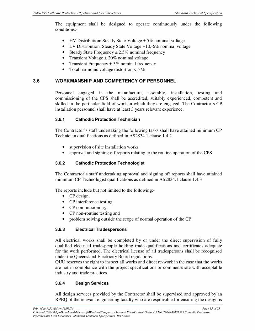
The equipment shall be designed to operate continuously under the following
conditions:-
• HV Distribution: Steady State Voltage ± 5% nominal voltage
• LV Distribution: Steady State Voltage +10,-6% nominal voltage
• Steady State Frequency ± 2.5% nominal frequency
• Transient Voltage ± 20% nominal voltage
• Transient Frequency ± 5% nominal frequency
• Total harmonic voltage distortion < 5 %
3.6 WORKMANSHIP AND COMPETENCY OF PERSONNEL
Personnel engaged in the manufacture, assembly, installation, testing and
commissioning of the CPS shall be accredited, suitably experienced, competent and
skilled in the particular field of work in which they are engaged. The Contractor’s CP
installation personnel shall have at least 3 years relevant experience. 3.6.1 Cathodic Protection Technician
The Contractor’s staff undertaking the following tasks shall have attained minimum CP
Technician qualifications as defined in AS2834.1 clause 1.4.2.
• supervision of site installation works
• approval and signing off reports relating to the routine operation of the CPS 3.6.2 Cathodic Protection Technologist
The Contractor’s staff undertaking approval and signing off reports shall have attained
minimum CP Technologist qualifications as defined in AS2834.1 clause 1.4.3
The reports include but not limited to the following:-
• CP design,
• CP interference testing,
• CP commissioning,
• CP non-routine testing and
• problem solving outside the scope of normal operation of the CP 3.6.3 Electrical Tradespersons
All electrical works shall be completed by or under the direct supervision of fully
qualified electrical tradespeople holding trade qualifications and certificates adequate for the work performed. The electrical license of all tradespersons shall be recognised
under the Queensland Electricity Board regulations. QUU reserves the right to inspect all works and direct re-work in the case that the works
are not in compliance with the project specifications or commensurate with acceptable industry and trade practices.
3.6.4 Design Services
All design services provided by the Contractor shall be supervised and approved by an
RPEQ of the relevant engineering faculty who are responsible for ensuring the design is
TMS1595 Cathodic Protection -Pipelines and Steel Structures Standard Technical Specification
Printed at 9:56 AM on 11/08/16 Page 16 of 53
C:\Users\100608\AppData\Local\Microsoft\Windows\Temporary Internet Files\Content.Outlook\ATNU1NN6\TMS1595 Cathodic Protection
Pipelines and Steel Structures - Standard Technical Specification_Rev1.docx
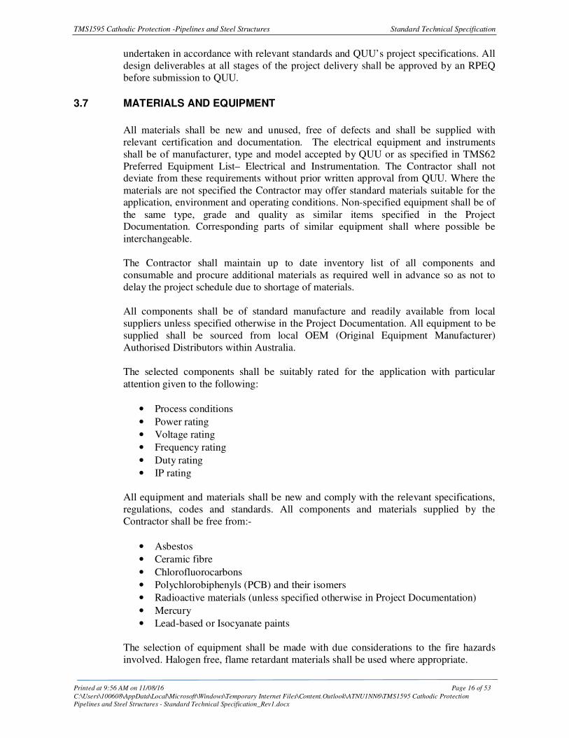
undertaken in accordance with relevant standards and QUU’s project specifications. All
design deliverables at all stages of the project delivery shall be approved by an RPEQ
before submission to QUU.
3.7 MATERIALS AND EQUIPMENT
All materials shall be new and unused, free of defects and shall be supplied with
relevant certification and documentation. The electrical equipment and instruments
shall be of manufacturer, type and model accepted by QUU or as specified in TMS62
Preferred Equipment List– Electrical and Instrumentation. The Contractor shall not deviate from these requirements without prior written approval from QUU. Where the
materials are not specified the Contractor may offer standard materials suitable for the application, environment and operating conditions. Non-specified equipment shall be of
the same type, grade and quality as similar items specified in the Project Documentation. Corresponding parts of similar equipment shall where possible be
interchangeable.
The Contractor shall maintain up to date inventory list of all components and
consumable and procure additional materials as required well in advance so as not to
delay the project schedule due to shortage of materials.
All components shall be of standard manufacture and readily available from local
suppliers unless specified otherwise in the Project Documentation. All equipment to be
supplied shall be sourced from local OEM (Original Equipment Manufacturer)
Authorised Distributors within Australia.
The selected components shall be suitably rated for the application with particular
attention given to the following:
• Process conditions
• Power rating
• Voltage rating
• Frequency rating
• Duty rating
• IP rating
All equipment and materials shall be new and comply with the relevant specifications,
regulations, codes and standards. All components and materials supplied by the
Contractor shall be free from:-
• Asbestos
• Ceramic fibre
• Chlorofluorocarbons
• Polychlorobiphenyls (PCB) and their isomers
• Radioactive materials (unless specified otherwise in Project Documentation)
• Mercury
• Lead-based or Isocyanate paints
The selection of equipment shall be made with due considerations to the fire hazards
involved. Halogen free, flame retardant materials shall be used where appropriate.
TMS1595 Cathodic Protection -Pipelines and Steel Structures Standard Technical Specification
Printed at 9:56 AM on 11/08/16 Page 17 of 53
C:\Users\100608\AppData\Local\Microsoft\Windows\Temporary Internet Files\Content.Outlook\ATNU1NN6\TMS1595 Cathodic Protection
Pipelines and Steel Structures - Standard Technical Specification_Rev1.docx
Where stainless steel has been specified, Grade 316 is the minimum acceptable grade.
Aluminium castings for test points shall be marine grade, corrosion resistant to AS 1874
Grade CC601 and shall be identified on the standard test point drawings.
Steel posts shall be hot dip galavanised.
3.8 WEATHER AND INGRESS PROTECTION
All electrical equipment and enclosures shall be Ingress Protection (IP) rated as specified in the Project Documentation.
Electrical enclosures not directly exposed to the weather or located indoors shall be
minimum IP42 where the enclosure contains components susceptible to damage or failure due to moisture and dust ingress. All outdoor electrical enclosures and
equipment shall be minimum IP56.
3.9 PAINTING AND PROTECTIVE COATINGS
All equipment installed outdoors shall be painted. All equipment surfaces to be painted
shall use the Manufacturer’s standard paint specification. The Contractor shall provide a proposed protective coating specification for the approval of QUU at time of
tender. Where QUU deems the standard painting specification as not adequate, alternative requirements as directed by QUU will be provided by the Contractor.
All metal surfaces of electrical enclosures shall be thoroughly cleaned and degreased to
remove mill scale, rust, grease and dirt. Fabricated structure shall be pickled and then rinsed to remove any trance of acid. The under surface shall be made free from all
imperfections before undertaking finishing coat.
After preparation of the under surface, the panels shall be spray painted with two coats
of epoxy based finish paint. The finished panels shall be oven baked in dust free
atmosphere. Paint finish shall be free from imperfections like pin holes, orange peel-
like finish, run off paint, etc.
3.10 REGULATORY REQUIREMENTS
The design of the CP system shall conform to the Queensland Electrical Safety Regulations. Some of the key points relevant to QUU assets are as summarised below
and this is not an exhaustive list of the Contractor’s obligations:-
1. The maximum open voltage of any ICCPS shall not exceed 50VDC under all
operating conditions and QUU accepts no departures to this requirement.
2. The Contractor must not commence installation works of an ICCPS until the
following conditions have been met by the Contractor:-
• At least 60 days before starting installation, the Contractor must advise all
relevant persons that maybe impacted of the proposed ICCPS to be installed
and allow the relevant persons to examine and comment on the proposed
installation. Relevant person means a person who will, if the CPS is installed,
become a foreign structure owner of the system.
TMS1595 Cathodic Protection -Pipelines and Steel Structures Standard Technical Specification
Printed at 9:56 AM on 11/08/16 Page 18 of 53
C:\Users\100608\AppData\Local\Microsoft\Windows\Temporary Internet Files\Content.Outlook\ATNU1NN6\TMS1595 Cathodic Protection
Pipelines and Steel Structures - Standard Technical Specification_Rev1.docx
• The Contractor shall make all necessary liaisons with the owners of other
structures that may be affected by the ICCPS.
• Interference testing with foreign structures shall be undertaken by the
Contractor in accordance with AS2832.1, Section 8.
• All affected parties shall be notified and interference testing shall be carried
out in strict accordance with the guidelines applicable for Queensland, and the
Electrical Safety Office (ESO) - Queensland Electrolysis Committee.
TMS1595 Cathodic Protection -Pipelines and Steel Structures Standard Technical Specification
Printed at 9:56 AM on 11/08/16 Page 19 of 53
C:\Users\100608\AppData\Local\Microsoft\Windows\Temporary Internet Files\Content.Outlook\ATNU1NN6\TMS1595 Cathodic Protection
Pipelines and Steel Structures - Standard Technical Specification_Rev1.docx
4 TECHNICAL REQUIREMENTS
4.1 GENERAL
A CPS shall be installed on QUU assets where specified in the Project Documentation.
The assets may include mild steel pipelines and structures including water reservoirs, tanks, water supply trunk mains and sewerage rising mains as well as various water
supply and sewerage infrastructure such as pumps, scrapers, gas pipes, flocculators and water booster pumps.
Cathodic protection systems shall be installed on all steel water and sewage rising mains
regardless of corrosion protection coating type or quality. This specification document
applies to the following asset classes:
• Water trunk mains
• Water reservoirs
• Water and sewer pump stations
• Sewerage rising mains
• Pipeline river crossings
• Pipeline railway crossings
• Treatment plant equipment
• Miscellaneous water supply and sewerage infrastructure
Sacrificial anode CPS’s are generally to be installed on all new water and sewerage
pipelines where is more economically feasible than ICCPS. The Contractor shall assess the entire life cycle cost of the CPS when determining if sacrificial or ICCPS is
required. The Contractor shall present the estimated life cycle costs, assumptions and recommended CPS in a Life Cycle Cost Analysis Report. The report must be accepted
by QUU before the Contractor proceeds with the detail design of the proposed CPS.
The CPS shall be designed assuming an end of life asset current density in micro amps per square metre of steel surface determined by the Contractor. The CPS shall provide
full protection of the entire asset and at the location most remote from the anode bed or
rectifier.
Cathodic protection consumables such as anodes beds etc shall be designed and
installed in such a manner as to facilitate ease of access for replacement at the
appropriate time.
4.2 ANODE GROUND BEDS
Anode ground beds shall ideally be of shallow construction located at the depth of
lowest soil resistivity and sufficient distance, nominally within 50 to 100 metres,
perpendicular to the pipeline. CPS ground beds should be located near the pump station
end of each pipeline and generally outside of the pump station site perimeter fence.
Minimum separation between anode ground bed, the pipeline to be protected, and any
foreign buried metallic structure shall be in accordance with the requirements of AS 2832.1. Anode ground beds are preferred to be located on land owned by QUU or road
reserve or council parklands that facilitates ease of vehicle access to the area immediately around the ground bed. Easement for underground cable route is the other
important constraint when determining the ground bed location.
TMS1595 Cathodic Protection -Pipelines and Steel Structures Standard Technical Specification
Printed at 9:56 AM on 11/08/16 Page 20 of 53
C:\Users\100608\AppData\Local\Microsoft\Windows\Temporary Internet Files\Content.Outlook\ATNU1NN6\TMS1595 Cathodic Protection
Pipelines and Steel Structures - Standard Technical Specification_Rev1.docx
4.3 SACRIFICIAL ANODE CATHODIC PROTECTION
Sacrificial anode CPS shall generally be installed on new assets of relatively small size
and which are provided with an approved corrosion protection coating applied.
4.4 IMPRESSED CURRENT CATHODIC PROTECTION
ICCPS is generally required for:-
• large sized new assets
• existing assets without an existing CPS
• where condition of the corrosion protection coating installed is found to be
failing or suspected of being compromised.
ICCPS is not an acceptable substitute for a primary corrosion protective coating system to new assets.
4.5 EXTERNAL INFLUENCES
The Contractor shall prepare a CPS design report that includes observations of the
proposed pipeline path and assessment if any induced voltages will likely be
encountered due to close proximity to other services and particularly power
transmission assets. This shall be assessed by the Contractor for the entire route of the
pipeline.
Additional protection methods shall be provided as required to mitigate the effects of electrical interference from external sources including stray currents and effects from
power transmission structures near the pipeline and from lightning.
Overhead and buried power lines in near vicinity to pipelines generate low frequency induction (LFI) in pipelines. The level of LFI shall be calculated and mitigated in
compliance with AS/NZS 4853. Materials for LFI mitigation shall be supplied and
installed by the Contractor.
4.6 DESIGN PARAMETERS
The following key parameters shall be considered in the design of the CPS:-
• Transformer Rectifier operating current and output voltage
• Loop resistance
• Soil conditions
• Structure polarised electrode potentials
• Regulation of electrode potential versus transformer rectifier output voltage
• Negative electrode potential shift of 300mV from natural potential

TMS1595 Cathodic Protection -Pipelines and Steel Structures Standard Technical Specification
Printed at 9:56 AM on 11/08/16 Page 21 of 53
C:\Users\100608\AppData\Local\Microsoft\Windows\Temporary Internet Files\Content.Outlook\ATNU1NN6\TMS1595 Cathodic Protection
Pipelines and Steel Structures - Standard Technical Specification_Rev1.docx
4.7 ASSET PROTECTION TARGETS
The CPS shall achieve the required asset protection levels for 99% of the time. The
CPS shall achieve the stated availability where the routine maintenance tasks at frequencies recommended by the CPS equipment manufacturers are met.
The asset protection capacity for cathodically protected steel pipes and structures is
classified in below table based on electrode potential surveys.
Protection Levels Polarised Instantaneous Off Electrode Potential Reading *
Negligible -0.65 to –0.70
Very Limited -0.70 to -0.75
Limited -0.75 to –0.80
Good -0.80 to –0.85
Excellent -0.85 to –1.10
Over protected risk of coating damage -1.10 to –1.25
* Reference cell Cu/CuSO4 (mV)
The CPS provided by the Contractor shall attain the “Excellent” level of protection for the required design life of the asset. The CPS must have high reliability and effectively
protect the pipeline and structure from corrosion. This will be achieved by the
following:-
• Meeting the protection criteria specified in this document
• Allowing effective detection of coating defects that do not meet the protection
criteria and correcting protection levels in order to achieve full 100% coverage.
Infrastructure protected by internal CPS shall achieve similar protection target levels as
external CPS.
4.8 PIPELINE CATHODIC PROTECTION SYSTEMS
For pipelines to be protected by a CPS the pipeline shall meet the following conditions:-
• Electrically continuous along the entire length and
• Electrically isolated at the end points from other equipment.
• Intermediate in line isolation joints where required to facilitate testing, mitigate
possible interference and provide future flexibility
The CPS for pipe line assets shall generally consist of the following components:-
• Magnesium or zinc anodes for a sacrificial anode CPS
• Silicon Iron or MMO anodes for impressed current CPS
• CPP containing an AC/DC rectifier
• CP monitoring test points
• Reference Electrodes
• Electrical continuity bonds
• Electrical insulation devices (flange kits)
• Surge diverters

TMS1595 Cathodic Protection -Pipelines and Steel Structures Standard Technical Specification
Printed at 9:56 AM on 11/08/16 Page 22 of 53
C:\Users\100608\AppData\Local\Microsoft\Windows\Temporary Internet Files\Content.Outlook\ATNU1NN6\TMS1595 Cathodic Protection
Pipelines and Steel Structures - Standard Technical Specification_Rev1.docx
• Earthing system including grading rings
4.8.1 Pipeline Protection Criteria
The protection criteria for pipelines shall be in accordance with AS 2832.1. The
protection criteria shall be an instant OFF potential in the range of -850 mV to -1100
mV relative to a copper/copper sulphate reference electrode.
Australian Standard AS4853 nominates the following steady state induced voltage
limits for reducing the risk of corrosion on the pipeline.
• 4 Vac for pipeline buried in soil with resistivity < 25 Ωm
• 10 Vac for pipelines buried in soils with resistivity > 25 Ωm
4.8.2 Pipeline Temporary Sacrificial Anodes
Temporary sacrificial anode CPS shall be applied to pipelines during construction
where specified in the Project Documentation. The temporary sacrificial anodes shall be magnesium alloy anodes connected to the pipeline via cable connections at the test
points. The temporary CP shall be installed on the pipeline within 14 days of
backfilling.
The temporary CPS shall be permanently disconnected and the permanent CPS
energised during commissioning phase. The test points for temporary CPS shall be
placed nominally 500m apart or as shown on the pipeline layout drawings. The actual
location of test points depends on the accessibility, and features along the pipeline route,
as per the requirements of AS 2832.1.
The protection criterion for temporary CPS shall be the same as for permanent CPS.
4.9 GENERAL STRUCTURES CATHODIC PROTECTION SYSTEMS
The protection criteria for steel structures including tanks and vessels shall be in accordance with an instant OFF potential in the range of -850 mV to -1100 mV relative
to a copper/copper sulphate reference electrode.
Sacrificial anode system are generally acceptable for relatively small tanks and vessels
supplied new and with an approved corrosion protective coating as will have low
current demand from the CPS.
ICCPS is generally required for tanks and vessels under the following conditions:-
• large sized tanks and vessels
• approved corrosion protective coating is not provided to all components of the
structure
• retrofitting or refurbishing the CPS to any existing asset with unknown or
suspect condition of the coating system.

TMS1595 Cathodic Protection -Pipelines and Steel Structures Standard Technical Specification
Printed at 9:56 AM on 11/08/16 Page 23 of 53
C:\Users\100608\AppData\Local\Microsoft\Windows\Temporary Internet Files\Content.Outlook\ATNU1NN6\TMS1595 Cathodic Protection
Pipelines and Steel Structures - Standard Technical Specification_Rev1.docx
5 SAFETY IN DESIGN
All CPS equipment shall be designed and installed to minimise any risk due to internal short circuit and to ensure safety to personnel under all operating conditions while
undertaking inspections and maintenance.
The equipment shall meet approved limits for electromagnetic compatibility for
emission and immunity.
5.1 SAFETY MANAGEMENT PLAN
Pipelines and steel structures can be installed in the same or adjacent corridor as power line easements due to increasing urban development, space limitations and other factors.
This has created a hazard due to induced voltages and earth potential rise in the vicinity of QUU assets. Another risk is capacitance coupling of steel pipe work while working
under the power lines. Personnel working on the pipelines and steel structures should be aware of adjacent electrical power systems, overhead powerlines and storm activity
which may influence pipeline voltages at the work site.
The Contractor shall assess the risks associated with these potential voltage excursions
and develop appropriate procedures to ensure personnel safety. The hazards and risk
assessment shall be included in the Safety Management Plan accepted by QUU prior to
the Contractor commencing site works.
These hazards and minimum risk mitigation strategies are addressed in AS/NZS
4853:2000
5.2 LOW FREQUENCY INDUCTION
Pipelines with LFI coupling can develop dangerous levels of longitudinally induced
voltages. As such mild steel electrically continuous pipelines shall be isolated from
other equipment and earthed where pipeline is laid under or in near vicinity of a high
voltage transmission line easement. The earth bonds shall be at both ends of the
electrically continuous pipeline sections in order to ensure that dangerous voltage levels are not induced on the pipeline due to LFI. The maximum length of the pipeline
between insulated joints shall be specified by the Contractor and shown on the detail design drawings.
Earthing is to be implemented using anode beds. An RPEQ shall determine the
maximum required anodes to earth resistance for each anode bed with reference to AS/NZS 4853:2000. The use of copper electrodes for earthing is to be avoided due to
the potential of pipe work corrosion caused by electrolysis.
The Contractor shall ensure the following items are addressed in the CPS design,
installation and testing in order to mitigate the LFI risks:-
• Steel pipework in proximity with overhead high voltage power lines shall comply with the requirements of AS/NZS 4853:2010.
• Safety limits must be in accordance with AS 3859, ‘Effects of current passing through the human body’. Where the public have access, voltage limits must be
to Category A that is limited to 120V. Equipment includes stop valves, bypass
TMS1595 Cathodic Protection -Pipelines and Steel Structures Standard Technical Specification
Printed at 9:56 AM on 11/08/16 Page 24 of 53
C:\Users\100608\AppData\Local\Microsoft\Windows\Temporary Internet Files\Content.Outlook\ATNU1NN6\TMS1595 Cathodic Protection
Pipelines and Steel Structures - Standard Technical Specification_Rev1.docx
valves, air valves, scour valves, CP test points and exposed sections of pipework
across drains or gullies.
• Category B touch voltage limits (up to 1000 V) are only applicable to equipment with restricted public access.
• The Contractor shall carry out a risk assessment in regard to pipelines accessible
to the public.
• The design of the CPS must comply with the applicable regulatory requirements
and the relevant requirements of AS/NZS 3000, AS/NZS 3008.1.1, AS/NZS
5000.1, AS 2374 and AS/NZS 3100.
• When applying CP to pipelines within the vicinity of overhead high voltage
lines and towers, it is essential to refer to a RPEQ Electrical Engineer for
interpretation of the standard and for the subsequent design requirements.
• When a pipeline is excavated for repair, precautions shall be taken to limit the
voltages to Category A.
• Induced voltages on QUU owned assets shall not exceed 50VAC under any
circumstances.
• Location and design of earth beds shall be selected for optimum soil conditions
5.3 EARTH POTENTIAL RISE
Lightning and power fault currents flowing through the earth can cause dangerous touch
and step voltage levels. Lightning strikes on an overhead high voltage line can result in
a power follow discharge to earth. The current flowing to earth will cause the potential
of the earthing system to rise. This can cause rise in potential of structures such as
pipelines buried in the earth and associated valves.
Valve pits within 50 metres of a high tension tower footings shall be designed with a Faraday's Cage or retro fitted with equipotential gradient rings connected to the
pipework in order to protect personnel. To prevent ground voltage potential rise influencing the underground pipe the Contractor shall ensure electrical insulation
between the steel pipe and the ground potential in the vicinity of power line tower
footings. Dedicated pits that do not contain steel member such as steel access ladders
are exempt from this requirement.
Calculations are required to determine if there are any precautions required outside this
50 metre range. This is to protect personnel from dangerous touch or step voltage
potentials caused by earth potential rise during lightning strikes and also for any
subsequent electrical fault current discharge.
5.4 CAPACITIVE COUPLING - OVERHEAD HV TRANSMISSION LINES
The Contractor shall consider the hazard of capacitive coupling when working under overhead HV transmission lines and shall also be considered in the design of the CPS.
Precautions shall be taken with regard to electric charge build up and design shall
comply with AS 4853 for steel pipe work capacitance coupling issues.
The Contractor shall store steel pipes to the side or preferably outside of HV easement and never directly underneath the HV transmission line. The Contractor shall ensure the
HV Transmission Authority’s requirements are met for working clearances from power line conductors.
TMS1595 Cathodic Protection -Pipelines and Steel Structures Standard Technical Specification
Printed at 9:56 AM on 11/08/16 Page 25 of 53
C:\Users\100608\AppData\Local\Microsoft\Windows\Temporary Internet Files\Content.Outlook\ATNU1NN6\TMS1595 Cathodic Protection
Pipelines and Steel Structures - Standard Technical Specification_Rev1.docx
5.5 ELECTRICAL ISOLATION
5.5.1 Equipment
Electrical isolation of below ground equipment from the earthed above ground equipment shall be achieved by the use of insulating gaskets. The insulation shall be
tested before and after the pipe is back filled.
Where necessary, earth connections to cathodically protected pipelines such as at a.c mitigation features shall be made via d.c decoupling devices to ensure cathodic
protection current is not drained to earth.
Consideration must be made where any pipe support or clamp contacts a pipeline with
CP applied, such as the use of dielectric sheets or spacers to isolate the pipeline from the
support or clamp, which may in turn be tied into the facility earthing system.
5.5.2 Instrumentation
All instrumentation that is directly connected to the pipeline shall be treated such that
the pipeline and the CP system do not become electrically continuous with the site earthing system.
All instrument impulse piping that is directly connected to the pipeline shall be insulated with Swagelok dielectric isolating unions, or approved equivalent.
5.5.3 Cabling
Cable armouring where provided shall be electrically isolated by the use of insulating
gland adaptors.
5.6 ANODE BED ENVIRONMENTAL DESIGN CONSIDERATIONS
The installation of anode beds and trenching for underground cables can cause environmental damage and can cause possible interference with other nearby structures.
As such anode beds and cable routes shall be located away from waterways and dense
vegetation to minimise disturbance during installation works. The location for the
anode bed is important to ensure minimal disturbance or destruction of protected
vegetation during initial installation and future remedial works as well as gaining access
for routine inspections and testing.
The Contractor shall ensure adequate soil erosion and sedimentation controls are
implemented during the site works. The Contractor shall provide an Environmental
Impact Report and obtain approval from relevant environmental groups and QUU
Environmental Management Team. Works shall not be conducted within or near a
natural waterway or constructed waterway unless further consultation and approval has been provided by the QUU Environmental Management Team. In addition the
Contractor shall provide consultation with private landowners for approval to access and conduct proposed works where required. The Contractor’s project specific
Environmental Management Plan shall address all risks and controls in place to ensure minimal impact on the local environment.

TMS1595 Cathodic Protection -Pipelines and Steel Structures Standard Technical Specification
Printed at 9:56 AM on 11/08/16 Page 26 of 53
C:\Users\100608\AppData\Local\Microsoft\Windows\Temporary Internet Files\Content.Outlook\ATNU1NN6\TMS1595 Cathodic Protection
Pipelines and Steel Structures - Standard Technical Specification_Rev1.docx
The anode beds shall be operational under extended dry weather or drought conditions.
Provision shall be made for supply of water through breather pipe work where
necessary. Anode beds shall be located in low natural soil resistance areas within
environmental guidelines, in wet soil locations where possible such as adjacent to
creeks.
5.7 STANDARDISED DESIGN
The Contractor shall provide the CPS to a standard and consistent design for the entire
project. The design and equipment supplied shall generally comply with the typical drawings referenced in section 1.4 unless specified otherwise in the Project
Documentation. The Contractor is responsible for the detail design and modifications to QUU’s typical drawings, to suit project specific requirements must be accepted by QUU
prior to Contract award.
The CPS installation shall pose nil hazards to persons accessing as well as operating and maintaining the CPS equipment. Segregation of LV and ELV equipment is highly
important to allow for non-electrical or restricted electrical licenced workers to perform
testing, calibration and operation tasks of the CPS equipment. All persons must be
restricted from accessing live LV equipment.
Persons requiring access to the CPS equipment may not have detail understanding of the
possible electrical hazards. The design and installation of the CPS must eliminate or
make provisions to reduce occurrence of electrical hazards as far as reasonably
practical.
TMS1595 Cathodic Protection -Pipelines and Steel Structures Standard Technical Specification
Printed at 9:56 AM on 11/08/16 Page 27 of 53
C:\Users\100608\AppData\Local\Microsoft\Windows\Temporary Internet Files\Content.Outlook\ATNU1NN6\TMS1595 Cathodic Protection
Pipelines and Steel Structures - Standard Technical Specification_Rev1.docx
6 MONITORING AND CONTROL
6.1 LOCAL INDICATION
The Contractor shall provide local indication of the CPS status. The CPS shall be
provided with instruments and meters for local indication and annunciation of the
following status conditions as a minimum:
• Rectifier DC Amps low/high
• Rectifier DC Voltage low/high
• Power Supply Healthy
6.2 REMOTE MONITORING
The Contractor shall provide remote monitoring of the CPS unless specified otherwise
in the Project Documentation. The pipeline potential at the extremities of the route, and
CPP output current and voltage shall be continuously monitored by QUU’s telemetry
system or alternative network so that a prompt response may be provided for system
problems.
Remote monitoring must be adequate in order to reduce QUU’s requirement to
undertake frequent site visits for routine inspection of the CPS operation The
implementation of a low cost telemetry system combined with provision to connect a
data logger and associated monitoring instruments shall be provided at each CPP and at
the test points located at the extremities of the pipe line.
The following parameters shall be monitored at the CPP:-
• Rectifier DC amps and volts
• Pipeline or structure electrode ‘off’ potential.
• Power Supply Healthy
• CPP General Fault
The Pipeline electrode ‘off’ potential shall be tested twice daily and data logged and
monitored from the test points located at each end of the pipe route and at anode beds.
The existing QUU telemetry network shall be utilised where possible using either
hardwired or low energy wireless device interface to the CPS. Alternative dedicated
new communication networks to the CPS can be utilised and must exhibit high
reliability, advanced network security and have a proven communication interface to
QUU’s central SCADA system. The Contractor shall seek QUU’s acceptance of any
alternative telemetry network solutions at pre-contract award of the project.
The current version of standard PLC code developed for sewerage pumping stations has an option to monitor CPS parameters. The telemetry at present can display the status of
the CPP (power on - off) and the value of the rectifier current output together with high and low alarms associated with the rectifier current. The telemetry system is capable of
monitoring digital status of equipment through volt free contacts as well as analogue signals of 4-20mA DC only. The Contractor shall undertake their own investigations as
TMS1595 Cathodic Protection -Pipelines and Steel Structures Standard Technical Specification
Printed at 9:56 AM on 11/08/16 Page 28 of 53
C:\Users\100608\AppData\Local\Microsoft\Windows\Temporary Internet Files\Content.Outlook\ATNU1NN6\TMS1595 Cathodic Protection
Pipelines and Steel Structures - Standard Technical Specification_Rev1.docx
to the control system spare I/O points and capability for expansion to accommodate the
proposed CPS.
All control system integration works performed by the Contractor shall comply with:-
• TMS1202 Control System Implementation for Network Assets
• TMS849 CITECT SCADA Configuration Standard and
• TMS1229 PLC Programming and Configuration Standard
6.3 AUTOMATIC CONTROL
An automatically controlled rectifier shall be provided by the Contractor unless advised
otherwise in the Project Documentation. The rectifier output shall maintain constant
electrode potentials, regardless of changes in soil conditions.
The Contractor shall provide enhanced electrode potential measurement procedures at
selected test points by combining with soil condition such as:
• Resistivity ρ (µ m)
• pH
• Conductivity (µsiemens)
• Sulphate level mg/L
• Sodium chloride mg/L
• Cations concentration
The Contractor shall provide the equipment data sheets and manufacturer’s product specifications with the bid proposal for all instrumentation and control system
equipment proposed to be supplied under the Contract.

TMS1595 Cathodic Protection -Pipelines and Steel Structures Standard Technical Specification
Printed at 9:56 AM on 11/08/16 Page 29 of 53
C:\Users\100608\AppData\Local\Microsoft\Windows\Temporary Internet Files\Content.Outlook\ATNU1NN6\TMS1595 Cathodic Protection
Pipelines and Steel Structures - Standard Technical Specification_Rev1.docx
7 EQUIPMENT AND INSTALLTION
7.1 QUU SUPPLIED MATERIALS
All materials and equipment required to complete the work to this specification shall be
supplied by the Contractor unless specified otherwise in the Project Documentation.
7.2 CATHODIC PROTECTION SYSTEM
The CPS shall be detailed designed, installed, tested and commissioned by the
Contractor. The equipment shall be installed as per the QUU accepted design drawings.
The equipment shall be preferably located on QUU allocated easements.
The enclosures for CPS electrical equipment can be wall or column mounted as well as
mounted on a concrete pad at ground level in a manner in accordance with industry best
practice and provided with suitable mounting materials and mechanical protection.
7.3 UTILITY POWER SUPPLY
External power in the form of 240 V AC (50Hz) single phase from a QUU owned DB
will generally be available to power the ICCPS where installed in or near existing assets. Where an existing power supply is not in near vicinity the Contractor shall make
all arrangements, negotiations, coordination and costs for provision of new power
supply connections and metering where required with the local power utility.
Unmetered utility power supplies are not preferred and will only be accepted where
agreed with QUU prior to Contract award.
7.4 REGISTRATION
The contractor shall allow for the registration of the CPS with the ESO and all
associated costs and fees. This shall include any costs and works required to achieve registration for foreign structures
7.5 IMPRESSED CURRENT ANODES
Anode ground beds for permanent ICCPS shall comprise of silicone iron anodes either
installed in vertically augured holes or in shallow horizontal trenches.
The number of anodes, orientation and exact location of the anode ground beds as well
as cable routes are shown on the project layout drawings. Anode cable tails shall be
terminated within the anode junction boxes.
Anodes shall be manufactured by a QUU accepted manufacturer with a proven track
record of supplying anodes. The anodes shall be installed as indicated on detailed
installation drawings accepted by QUU. Anodes material shall be randomly sampled
and tested by the Contractor for constituent metal composition before installation.
Testing shall be performed and report provided by an accredited independent third party accepted by QUU.
TMS1595 Cathodic Protection -Pipelines and Steel Structures Standard Technical Specification
Printed at 9:56 AM on 11/08/16 Page 30 of 53
C:\Users\100608\AppData\Local\Microsoft\Windows\Temporary Internet Files\Content.Outlook\ATNU1NN6\TMS1595 Cathodic Protection
Pipelines and Steel Structures - Standard Technical Specification_Rev1.docx
7.6 EQUIPMENT GLOBAL POSITION CO-ORDINATES
The Contractor shall locate all new and existing CPS components using GPS co-
ordinates during installation. GPS co-ordinates shall not be limited to underground equipment such as anode ground beds and associated cabling. The Contractor shall
provide the GPS co-ordinates on the site layout As Built drawings provided to QUU and
shall also register the final installation locations of the CPS equipment with Dial Before
You Dig.
The Contractor shall precisely locate each anode in the ground bed with dimensions
from a reference point shown on the anode ground bed site layout drawings.
All foreign services and assets located during site works in near vicinity of the CPS
installation shall also have GPS co-ordinates provided of the exact location of the asset
or service. All mitigation works requiring equipment to be installed or modified and
foreign test points shall have GPS co-ordinates provided on As Built drawings so
equipment can be positively located in future.
7.7 SACRIFICIAL ANODES
Sacrificial anodes shall be magnesium alloy grade M8 as per AS 2239 with nominal
dimensions 1500 x 50 x 50 mm with a net weight of 8 kg. The anode shall be packaged
in gypsum / bentonite / sodium sulphate backfill in accordance with AS 2239.
Sacrificial anodes shall be tailed with 10 m x 6 mm2 PE / Nylon / PE cable tail.
7.8 TEMPORARY MAGNESIUM ANODES
Pre-packaged M1 alloy grade magnesium anodes shall be installed at nominated test
points on the pipelines to provide temporary protection during pipeline construction
phase and up to commissioning phase of the pipeline permanent CPS. The number of anodes shall be detailed in the CP Design Report provided by the Contractor and exact
locations shown on the site layout drawings.
The details of the temporary anodes shall be provided on a data sheet accepted by QUU and in accordance with AS 2239. The anodes shall be generally installed in shallow
vertically augured holes as indicated on the detailed drawing.
The anodes can also be buried in the pipe trench and backfilled as shown on the project design drawing to ensure good soil contact with the anode. Anode cables shall be
terminated and connected to the pipeline via the test points immediately following
installation, in accordance with the drawings.
Before commissioning of the pipeline permanent CP systems, all temporary anodes
shall be permanently disconnected at the test points and abandoned. Temporary anodes
shall not be removed unless specified otherwise in the Project Documentation.
7.9 PIPELINE TEST POINTS
Test points shall also be installed at the pipeline ends and at anode beds to facilitate condition monitoring of the CPS. Test points shall be provided nominally at 500m
TMS1595 Cathodic Protection -Pipelines and Steel Structures Standard Technical Specification
Printed at 9:56 AM on 11/08/16 Page 31 of 53
C:\Users\100608\AppData\Local\Microsoft\Windows\Temporary Internet Files\Content.Outlook\ATNU1NN6\TMS1595 Cathodic Protection
Pipelines and Steel Structures - Standard Technical Specification_Rev1.docx
intervals along the pipeline, at the locations marked on the alignment sheets. An earth
system test point shall also be provided at each end of the pipeline and additional points
as per the detail design drawings.
A minimum of two cable connections shall be made to the pipeline at each test point
location. Potential monitoring cables shall be minimum 6mm2. Current carrying cables
(including earthing connections) shall be 16 mm2. Cable insulation shall be PE / Nylon /
PE or PVC / Nylon / PVC for termite resistance except for earth cables which are PVC.
CP test point upstands shall not be located within 100 metres of a HV power line tower unless earth grading ring is provided. Test points may be moved up to 200 metres from
their nominated location to facilitate installation, subsequent access during pipeline operation, or the necessary separation from HV power line towers.
Test point upstands shall be located where possible in road reserves, within one metre of
fence lines and at other locations that provide:
• Ease of access for pipeline inspections and maintenance.
• Reduced exposure to damage by animals, vehicles, machinery and foot traffic.
The test points shall be fabricated and installed, and the cables terminated in accordance
with the project drawings and specifications. Test points shall consist of potential measurement and potential/current measurement variants. The Contractor shall provide
a data sheet for each test point type proposed.
Potential monitoring at test points may not adequately reflect the impact of any telluric
effects, or induced currents on the pipeline. Corrosion monitoring resistance probes
shall be installed at the mid-point, at each end of isolated pipeline sections and at
representative low and high soil resistivity locations on the pipeline route unless
specified otherwise in the Project Documentation. Test points shall be equipped with
permanent reference electrodes where indicated on the project installation detail
drawings. The resistance probe shall be of direct burial type suitable for soil
applications as nominated on the test point drawings and data sheet. The reference
electrode shall be of Copper/Copper Sulphate type, suitable for long term burial.
Permanently installed Zinc reference cells are also accepted with factory fitted cable
tail.
The probes shall be sized, positioned and installed in accordance with AS2832.1 in order to ensure effective monitoring of the CPS performance. Mitigation measures shall
be implemented by the Contractor if a reduction in CPS effectiveness is confirmed. The criteria for CPS effectiveness measured via resistance probes shall be in accordance
with AS 2832.1. The probes and reference electrodes shall be installed strictly in accordance with the notes on the installation drawing to ensure correct operation.
7.10 FOREIGN TEST POINTS
Test points at foreign structures and all pipeline crossings with foreign services shall be
installed at the locations indicated on the alignment sheets.
The Contractor shall determine after interference testing if further mitigation measures
are required. These may include the following:-

TMS1595 Cathodic Protection -Pipelines and Steel Structures Standard Technical Specification
Printed at 9:56 AM on 11/08/16 Page 32 of 53
C:\Users\100608\AppData\Local\Microsoft\Windows\Temporary Internet Files\Content.Outlook\ATNU1NN6\TMS1595 Cathodic Protection
Pipelines and Steel Structures - Standard Technical Specification_Rev1.docx
• Adjustment of CPP output parameters for the existing (foreign) CP systems.
• Resistive and/or diode cross bonds between new and existing pipelines, made inside the newly installed foreign crossing test point enclosures.
• Installation of galvanic anodes at the foreign crossing test point.
• Installation of warning signage disclosing any special conditions
7.11 ABOVE GROUND VALVE STATION CROSS BONDING
Where applicable pipeline cross bonds between the buried water pipelines sections that
are part of the same ICCPS shall be performed by termination of cross bonding cables
within appropriately sized cross bonding junction boxes at all above ground valve
stations.
Bonding cables shall be of 35mm² cross sectional area. Bonding junction boxes shall be
located outside of hazardous areas.
The Contractor shall provide insulation of all scour valves as well as off takes and in
line valves on trunk water mains and sewerage rising mains with CPS installed. The first valve (QUU owned asset) on a connection to a trunk line must have insulted flange
joint installed where the trunk line is not a QUU asset.
7.12 CABLES AND CONDUITS
All cables and conduits associated with the CPS shall be designed and installed in
compliance with TMS1200 Electrical Installation Technical Specification. The sizes and
the types of cables shall be detailed on the design drawings and the project cable
schedule. Direct buried cabling is not permitted and all cables routed underground in heavy duty PVC conduits shall be protected from termite attack. A PVC outer cable
sheath shall be provided for mechanical protection if nylon inner sheath is selected for termite resistance.
The Contractor shall provide the cable manufacturer’s data sheet for each cable type
proposed to be installed in the CPS.
All cabling shall meet the requirements of AS/NZS 5000.1.
7.13 CABLE TERMINATIONS
Where tags are not provided all cable to pipeline connections shall be by thermit
welding in accordance with AS2885 and the project design drawings. Thermit welding
charges larger than 15 gram shall not be used.
All pipeline coatings shall be reinstated by the Contractor in accordance with project
coating specifications for below grade line pipe coating repair.
All cable connections shall be primed and wrapped (denso products or equivalent) to
maintain the integrity of the connection. All connections shall be inspected and tested to
confirm the integrity of the connection prior to wrapping.
Connections between earth bars and cables shall be completed using heavy duty copper
crimp type cable lugs bolted to earth bars using stainless steel fixing hardware. All earth

TMS1595 Cathodic Protection -Pipelines and Steel Structures Standard Technical Specification
Printed at 9:56 AM on 11/08/16 Page 33 of 53
C:\Users\100608\AppData\Local\Microsoft\Windows\Temporary Internet Files\Content.Outlook\ATNU1NN6\TMS1595 Cathodic Protection
Pipelines and Steel Structures - Standard Technical Specification_Rev1.docx
bar connections shall be coated with a primer (denso product or equivalent) to protect
against corrosion.
Unless otherwise detailed in the Project Documentation, all above ground cable joints
and connections shall be visible and accessible.
Above ground cables shall be bolted to specifically installed connection tabs connected
to the pipeline or structure as per the project design drawings. Stainless steel nuts, bolts
and washers shall be used for all cable connections external of electrical enclosures.
The CPS operates at a relatively low voltage level and it is essential that all cable
terminations are low resistance. Furthermore the integrity of the cable insulation on all circuits is vital for long term operation. All cabling from anodes, pipelines and reference
cells terminate individually within the adjacent test point boxes as per the project design drawings. Joints in cables are to be avoided and shall only be permitted where a cable
pit at the joint is provided.
7.14 INSULATING FLANGE KITS
Preference is for proprietary connection tags to be provided to each pipe flange face
either side of the Insulating Flange Kit (IFK). The Contractor shall ensure the
connection of cables and surge diverters at locations shown on the detail design
drawings.
There are particular hazards associated with insulated flanges in valve pits. Insulation is
required in order to isolate cathodically protected pipeline from earth and from other
non-protected metallic structures. This creates a safety issue due to the possibility of a
potentially dangerous voltage difference across the valve-insulated flanges. The
following work shall be carried out to mitigate this hazard.
Pipe flanges insulated for cathodic protection shall be in accordance with AS 2832.1
clause 7.7. Where propriety insulated flanges or IFK’s are used, installation shall be in
strict accordance with manufacturer’s specifications.
Buried and accessible bolted insulated flanges shall be electrically isolated at both flanges. The joints shall be fully protected (denso wrapped or other accepted method) to
prevent moisture contact with bare metalwork and the cable connection points immediately after insulation tests have been completed. A test point shall be installed
with a cathode return and a zinc reference cell at the pipes for each side of the flange. Test points shall incorporate a potential equalising earth mat to protect personnel against
dangerous touch voltage level. Temporary earth cables shall be applied to each side of the flange prior to work tasks on the flange that necessitate removal of the insulation.
The IFK’s shall have a minimum dielectric strength of 500 volts / thou (25.4 µm) and
minimum 25,000 psi compressive strength. Bolt sleeves shall be full length with a
minimum dielectric strength of 4000 volts / thou (25.4 µm) and water absorption of 0.8
% or less. Insulating washers shall have a minimum compressive strength of 33,000 psi,
minimum dielectric strength of 500 volts / thou (25.4 µm) and water absorption of 1.6
% or less. Alternative materials must be accepted by QUU before installation.
All anchor blocks and pipe supporting structures (on the buried side of insulating
devices) shall not be in electrical contact with the pipeline, this includes steel

TMS1595 Cathodic Protection -Pipelines and Steel Structures Standard Technical Specification
Printed at 9:56 AM on 11/08/16 Page 34 of 53
C:\Users\100608\AppData\Local\Microsoft\Windows\Temporary Internet Files\Content.Outlook\ATNU1NN6\TMS1595 Cathodic Protection
Pipelines and Steel Structures - Standard Technical Specification_Rev1.docx
reinforcing, casing pipes, steel support structures or related fittings. The methods to
achieve insulation shall be included in the detail installation drawings.
All foreign pipe, cables and metal cable support structures shall be separated from the
pipe by a minimum of 300 mm.
The electrical insulation shall be verified prior to backfilling. The minimum acceptable
insulation shall be stated in the Contractor’s accepted test plan. Test results shall be submitted to QUU for acceptance prior to the IFK being backfilled.
7.15 SURGE DIVERTERS
For protection from lightning strikes, flange insulation kits shall be bridged by a surge
diverter. The surge diverter shall isolate the earthing system from the CPS until the breakdown voltage is exceeded.
Solid state surge diverters also known as polarisation cell replacements or d.c
decoupling devices shall be installed across all IFK’s where indicated on the project
design drawings. The solid state surge diverter proposed must be accepted by QUU and
Contractor shall provide a data sheet and specification for QUU acceptance.
The surge diverter shall be housed in an enclosure and installed as shown in the
drawings and to the manufacturer’s recommendation. Surge diverters can be located in
valve pits and other areas only where the surge diverter installation meets the
manufacturer’s recommendations. Where the flange kits are installed below ground,
surge diverters can be installed within the adjacent test point enclosure. Labels shall be
affixed by the Contractor to the enclosure door and internal panel to identify all items.
Where the solid state surge diverters cannot be practically located outside of a
hazardous area, they shall be provided with, and housed within IEC certified enclosures, suitable for installation in a Zone 2 hazardous area.
The Contractor shall provide detail installation drawings for the IFK’s and surge
diverters. The surge diverter cable tails shall be cut to suit as short as practically possible, and fitted with crimp lugs using a hydraulic crimper. The completed cable /
lug transition shall be sealed with mastic lined heat shrink sleeve or other accepted method.
The surge diverter shall be securely bolted using the supplied mounting brackets to the
proprietary line pipe tags supplied each side of the insulated flange face. The surge
diverter lug shall be placed flat against the proprietary tag. The Contractor shall ensure
that the proprietary line pipe tag has been filed to clean bright metal before connection
of the lug. The completed connection shall be sealed with a QUU accepted moisture
proofing method.
7.16 PIPE JOINT CONTINUITY CONNECTIONS
All RRJ’s shall be provided with proprietary continuity bonding tags at each end of the
pipe joint. Continuity bond cables shall be connected across each RRJ. The Contractor
shall install and test the electrical continuity system. Continuity bonds shall consist of
two (2) off 16 mm2 PE/Nylon/PE cables. Where bonding tags are not provided the
cables shall be thermit welded to the pipeline either side of the RRJ. Pipe coating repair
TMS1595 Cathodic Protection -Pipelines and Steel Structures Standard Technical Specification
Printed at 9:56 AM on 11/08/16 Page 35 of 53
C:\Users\100608\AppData\Local\Microsoft\Windows\Temporary Internet Files\Content.Outlook\ATNU1NN6\TMS1595 Cathodic Protection
Pipelines and Steel Structures - Standard Technical Specification_Rev1.docx
shall use epoxy resin such as Epirez 633 or equivalent accepted by QUU. The cable
connections and all exposed metal surfaces shall be sealed from contact with moisture
to a QUU accepted method.
At non-welded pipe joints, other methods of continuity bonding can be considered
where materials and installation techniques are specified to the pipe manufacturer’s
standard procedures and accepted by QUU.
Electrical continuity of each connection shall be verified prior to backfilling. The
maximum acceptable resistance of each bond shall be 0.01 ohms using a minimum test current of 3 Amps. Test results shall be submitted to QUU prior to the bond being
backfilled.
7.17 ELECTRICAL ENCLOSURES
The CPS electrical enclosures shall be in accordance with TMS1222 Control Panel Technical Specification. A folder holder shall be provided on the interior of the door of
the transformer rectifier enclosure to allow for attaching a copy of the ICCPS licence
certificate. The CPS components shall be contained in dedicated electrical enclosures
and shall not be housed in enclosures or switchboards with other equipment unrelated to
the CPS.
A single phase 240VAC supply to any CPS enclosure shall not be rated in excess of
32Amps and shall have 30mA RCBO at the enclosure or 30mA RCD installed at the
upstream point of supply. A surge arrestor shall be installed in the CPS enclosure on the
load side of the main LV isolator.
Transformer rectifier modules shall be rated in excess of 50°C ambient air temperature to allow for temperature rise in the enclosure.
7.18 EQUIPMENT AND CABLE IDENTIFICATION
All CPS equipment items (external of enclosures), test points, valve pits etc shall have a
unique tagname installed and tag naming convention must be accepted by QUU before
the labels are installed. QUU has a standard tag naming convention for selected
equipment that the Contractor shall follow. Equipment tagnames shall be manufactured
from engraved stainless steel tags and tags fixed to the equipment in a permanent vandal
proof manner. For other equipment labelling requirements refer to TMS1200 Electrical
Installation Technical Specification.
Refer TMS1200 Electrical Installation Technical Specification for tag naming of
cables and cores.
Refer to TMS1222 Control Panel Technical Specification for labelling requirements of
CPP. The GPS coordinates shall be provided on external labels at the CPP enclosure
and test points.
Clearly visible, durable signage shall be permanently inscribed with QUU corporate
logo and contact details. Signage is required at location of anode beds and located as
close as possible to the anode bed.
TMS1595 Cathodic Protection -Pipelines and Steel Structures Standard Technical Specification
Printed at 9:56 AM on 11/08/16 Page 36 of 53
C:\Users\100608\AppData\Local\Microsoft\Windows\Temporary Internet Files\Content.Outlook\ATNU1NN6\TMS1595 Cathodic Protection
Pipelines and Steel Structures - Standard Technical Specification_Rev1.docx
Equipment labels and adequate signage shall be installed by the Contractor where
mitigation works is undertaken on foreign assets or other QUU owned assets outside of
the Contract.
7.19 WARNING SIGNS
Insulated flanges installed in accessible locations such as valve pits, shall incorporate a
permanent ‘Potential High Voltage’ warning sign. This is because there is a possibility
of danger of electrical shock due to:-
• Potential difference across the flanges.
• Potential of either flange to earth if surge diverter is installed
Warning signs shall be provided at surge diverters stating ‘Potential High Voltage - Do Not Disconnect’.
Warning signs shall be provided to pipelines and structures accessible by the public and authorised persons where possibility of personal contact with induced voltage at the
pipeline is present.
Warning signs shall be positioned to ensure they are clearly visible and not obscured by
any other item of equipment. All danger and warning signs shall be in accordance with
AS1319 and shall have zinc-anneal surface protection or equivalent.
7.20 NAME PLATE
An engraved or stamped 316 stainless steel name plate shall be fixed on the
CPP enclosure with the following additional information :-
• Ellipse Tag number
• Manufacturer's name
• Applicable standard
• Model Number
• Serial Number
• Voltage and Current Rating
• GPS Coordinates
The standard nameplate plus a supplementary plate if required shall be provided by
the Contractor.
7.21 REMEDIAL PIPELINE WORKS
When a mild steel water or sewerage main fails, repairs are completed to ensure the pipeline is fully functional. A CPS test point shall be installed to allow for the future
installation of cathodic protection. This allows for preventative maintenance monitoring
of the pipeline as well as preventing further repairs due to corrosion. Sacrificial anode
CPS shall be installed where applicable at time of failure with provision for future
upgrade to an ICCPS.
Equipotential bonds shall be installed at exposed areas of above ground pipes.

TMS1595 Cathodic Protection -Pipelines and Steel Structures Standard Technical Specification
Printed at 9:56 AM on 11/08/16 Page 37 of 53
C:\Users\100608\AppData\Local\Microsoft\Windows\Temporary Internet Files\Content.Outlook\ATNU1NN6\TMS1595 Cathodic Protection
Pipelines and Steel Structures - Standard Technical Specification_Rev1.docx
7.22 SOLAR POWER SUPPLY
Where the cost to provide a utility power supply to an ICCPS is prohibitive the
Contractor shall provide a solar powered solution. The solar power supply control panel shall be designed and manufactured in accordance with TMS1222 Control Panels
Technical Specification.
The solar arrays and batteries shall be capable to provide the maximum demand of the
CPS for three continuous days (72 hours) when solar energy available is minimal such
as heavy cloud cover. Adequate solar arrays and battery charger capacity shall be
provided to recharge the batteries to 90% charge within 10 hours of sunlight while
meeting normal power demand of the CPS. The batteries shall be minimum two
parallel strings and battery sizing calculation provided. The batteries shall be suitable
for minimum 10 year design life at the ambient temperatures experienced inside the
control panel.

TMS1595 Cathodic Protection -Pipelines and Steel Structures Standard Technical Specification
Printed at 9:56 AM on 11/08/16 Page 38 of 53
C:\Users\100608\AppData\Local\Microsoft\Windows\Temporary Internet Files\Content.Outlook\ATNU1NN6\TMS1595 Cathodic Protection
Pipelines and Steel Structures - Standard Technical Specification_Rev1.docx
8 QUALITY ASSURANCE, INSPECTION AND TESTING
The Contractor shall demonstrate that all works comply fully with the specification and all associated Project Documentation.
8.1 QUALITY ASSURANCE
The Contractor shall apply a quality assurance system accredited to ISO 9001:2000 for
all works. The effectiveness of the quality assurance system and the Contractor's
compliance with it shall be subject to monitoring by QUU and in addition, may be
audited following an agreed period of notice.
The Contractor shall submit a quality control program with the bid proposal. The Contractor shall cooperate with QUU inspectors and nominated auditors during all
stages of the works with respect to quality assurance matters.
Components and works shall be inspected and tested in accordance with quality control
and assurance procedures nominated by the Contractor and accepted by QUU. The Contractor shall identify hold points for witness by QUU.
8.2 INSPECTION AND TESTING
QUU shall be permitted at all times free access to all parts of the Contractor's works that
concern execution of the works including on-site workshops and storage facilities.
The Contractor shall supply all test equipment, tools and materials required and shall be fit for purpose, in good working condition and calibrated. Calibration certificates shall
be maintained for all relevant equipment.
8.2.1 Inspection and Test Plan
The Contractor shall include typical Inspection and Test Plans (ITP’s) in the bid
proposal documents. The ITP’s shall list typical inspections and tests proposed for all
elements of the works.
Prior to commencement of the works the ITP’s shall be customised by the Contractor
for the project works and must be submitted for review to QUU. QUU will accept the
ITP’s, which, thereafter, shall form part of the contractual documents. The ITP’s shall
encompass the testing requirements of all relevant standards and statutory/regulatory
requirements.
The Contractor shall be responsible for the planning and execution of all inspections
and tests, with QUU having the right to witness any or all of the inspections or tests.
ITP’s shall be completed and signed off progressively during the execution of the works.
The Contractor shall notify QUU, at least 5 business days in advance, of the date on which any of the inspections or tests nominated as Hold or Witness points on the ITP’s
are due to be carried out.
TMS1595 Cathodic Protection -Pipelines and Steel Structures Standard Technical Specification
Printed at 9:56 AM on 11/08/16 Page 39 of 53
C:\Users\100608\AppData\Local\Microsoft\Windows\Temporary Internet Files\Content.Outlook\ATNU1NN6\TMS1595 Cathodic Protection
Pipelines and Steel Structures - Standard Technical Specification_Rev1.docx
ITP’s and associated checksheets shall be completed for all works to prove it has been
satisfactorily tested to meet all defined requirements whether or not witnessed by
QUU's Representative.
Where appropriate, test checksheets shall state the accepted range of values for all tests
proposed. Tests for which the results are indicated as pass or fail shall be qualified by
the relevant acceptance criteria. For equipment that is buried the relevant tests shall be
undertaken before and after backfilling. QUU will witness and must accept the test
results before back filling is commenced.
The following typical documents outline the minimum content to be completed by the
Contractor where applicable to the site testing and inspection works and this is not intended as a complete list of all check sheets required for a CPS installation:-
• CHE68 Site Inspection Checks – Cables
• CHE70 Site Inspection Checks - Instruments
• CHE72 Site Inspection Checks – Cable ladder/ Tray / Ducts
• CHE136 Site Inspection Checks – Field Equipment
8.3 INCOMING EQUIPMENT INSPECTIONS
Refer TMS1200 Electrical Installation Technical Specification for inspections required to be undertaken by the Contractor on equipment delivered to site and prior to
installation of the equipment.
8.4 CABLE TESTING
Refer TMS1200 Electrical Installation Technical Specification for minimum testing task
of LV and ELV cables.
8.5 EARTH TESTING
Refer TMS1200 Electrical Installation Technical Specification for earth grid testing and testing of equipment equipotential bonding.
8.6 TEMPORARY ANODES
The Contractor shall carry out testing on temporary magnesium anode system at
monthly intervals during the construction and commissioning phase of the project. The
testing shall be carried out as follows;
• Measure pipe potential at all test points against a fresh copper/copper-sulphate
reference electrode using a calibrated digital multimeter with a minimum of ten (10) mega-ohms input impedance.
• Measure the current output of the magnesium anode.
• Measure the open circuit potential of the magnesium anode.
• Measure pipe potential with anode disconnected.
• At certain types of test points measure the on and instantaneous off potential of the probe element. The off potential shall be measured by operating the test
point reed switch with a magnet and shall be read within 0.5 second of the switch opening.
TMS1595 Cathodic Protection -Pipelines and Steel Structures Standard Technical Specification
Printed at 9:56 AM on 11/08/16 Page 40 of 53
C:\Users\100608\AppData\Local\Microsoft\Windows\Temporary Internet Files\Content.Outlook\ATNU1NN6\TMS1595 Cathodic Protection
Pipelines and Steel Structures - Standard Technical Specification_Rev1.docx
• Record all test data on a log sheet, and submit to QUU for review.
• If the off potential is less negative than -0.85 volts promptly inform QUU and commence investigation works to rectify the problem. Additional anodes shall
be installed so that corrosion protection criterion is met. As a result, no section
of the backfilled pipeline will be left unprotected for a period in excess of one
month.
8.7 CONSTRUCTION CONDITION MONITORING
During the construction phase of a pipeline the temporary CPS shall be monitored on
a weekly basis and shall include the following measurements and tasks:-
• measuring the pipeline potential at each accessible point (test points and
exposed pipe ends) against a fresh copper/copper –sulphate reference electrode
using a calibrated digital multimeter with minimum 10 Mega Ohm input
impedance
• Measure the current output of the anode
• Measure the open circuit potential of the anode
• Measure the pipe potential with anode disconnected
• At resistance probe test points measure the instantaneous OFF potential of the
probe element. The OFF potential shall be measured within 0.5 seconds of the
switch contacts opening
The criteria for acceptable protection during construction phase of a pipeline shall be
an OFF potential more negative than -0.85 V relative to a copper sulphate reference
electrode measured at all access test points including exposed pipe ends. The test
results shall be submitted to QUU for review.
8.8 SITE ACCEPTANCE TESTING
8.8.1 SAT Plan
The Contractor shall develop a SAT Plan that clearly defines the logical sequence and
structured testing of the permanent CPS in accordance with the accepted design
documentation and AS2381.1 Section 9. The SAT Plan includes the full complement
of the check sheets, test sheets and the strategy to execute the testing in a safe,
systematic and efficient manner. The plan includes details of test equipment proposed
and shall also include the changeover plan and interface testing to existing CPS where
relevant. The SAT Plan shall be project specific and will require QUU’s acceptance
prior to commencement of the testing.
Permanent operation of the CPS by the Contractor is not permitted before completion
of interference testing as per AS2381.1 section 8 on foreign structures. The proposed
testing methods on foreign structures shall be outlined in the SAT Plan. For a
registrable CPS the Contractor shall perform testing as per AS2832.1 within 90 days
of registering the CPS with the ESO. The Contractor shall perform testing as per
AS2832.1 within 90 days of placing a non-registrable CPS in operation, other than for
TMS1595 Cathodic Protection -Pipelines and Steel Structures Standard Technical Specification
Printed at 9:56 AM on 11/08/16 Page 41 of 53
C:\Users\100608\AppData\Local\Microsoft\Windows\Temporary Internet Files\Content.Outlook\ATNU1NN6\TMS1595 Cathodic Protection
Pipelines and Steel Structures - Standard Technical Specification_Rev1.docx
testing.
Test equipment utilised shall be subjected to a documented and traceable calibration
process to ensure accuracy of the results. This shall also include portable reference
cells utilised during site testing.
Pre-energisation testing shall be undertaken by the Contractor and shall include and
not limited to the following tasks:-
• Continuity checks of all conductors
• Fit test point heads and terminate cabling as required.
• Measure natural potentials of structure or pipeline to a CuSO4 reference
electrode.
• Measure natural potentials of all permanent electrodes to a CuSO4 reference
electrode.
• Inspect equipment for mechanical damage and faults.
• Inspect all isolating devices and surge diverters and perform electrical tests to
confirm functionality. Failed devices shall be replaced prior to commissioning.
• Record results of inspections
• Perform DCVG coating defect survey in accordance with AS 4827.1 and the
Project Specific DCVG Coating Specification and repair defects as required.
Post-energisation testing shall be undertaken by the Contractor and shall include and not
limited to the following tasks:-
• Test for interference currents and voltages.
• Test installed resistance to earth of each anode ground bed.
• Review and confirm all equipment is operating correctly
8.8.2 DCVG Survey
A DCVG survey shall be conducted over the length of the pipeline during the SAT in
accordance with AS4827.1. The DCVG surveyor shall be suitably experienced and
accepted by QUU prior to commencement of the survey. The surveyor shall log all
coating defects identified during the survey.
The Contractor shall excavate and investigate all coating defects > 1 % IR along with
20 % of defects < 1 % IR selected at random by QUU unless specified otherwise in
the Project Documentation. The results of the cause of coating defects shall be
reported within 4 weeks of completion of excavation works.
The CPS design of pipelines shall have permanently installed facilities that allow the
DCVG survey testing of pipe protective coatings to be conducted in an efficient and
effective manner.

TMS1595 Cathodic Protection -Pipelines and Steel Structures Standard Technical Specification
Printed at 9:56 AM on 11/08/16 Page 42 of 53
C:\Users\100608\AppData\Local\Microsoft\Windows\Temporary Internet Files\Content.Outlook\ATNU1NN6\TMS1595 Cathodic Protection
Pipelines and Steel Structures - Standard Technical Specification_Rev1.docx
8.8.3 SAT Report
The Contractor shall provide a written SAT Report at the completion of the SAT. The
report shall contain as a minimum the following:-
• Records for all tests undertake signed by the testing officer
• Installation Check Sheets for cables and CPS components signed by the
inspector
• Photos prior to backfill of underground CPS components including cable
bonds and anode ground beds etc
An accredited corrosion specialist shall approve the SAT Report before the CPS can
be permanently energised and placed into service.
Any proposed departures from the QUU accepted SAT Plan by the Contractor shall
only be permitted where accepted by QUU in writing and all accepted departures must
be clearly identified in the SAT Report.
8.9 PRACTICAL COMPLETION
The Contractor shall meet the following criterion to achieve practical completion of
the CPS installation:-
• Preparation of a searchable database of CPS test stations and facilities
including type, location, special features, pipeline potential, current and
resistance probe readings, in spreadsheet or QUU accepted equivalent format.
The database shall be able to be interrogated to facilitate identification of faults
and problem areas.
• Confirmation that all system components have been installed in accordance
with project documentation
• Complete disconnection of temporary CP system.
• A minimum of 7 days after the last temporary anode is disconnected and prior
to energisation of the permanent CPS, pipeline potentials shall be obtained at
each test station to establish the native state potentials along the pipe route.
• SAT Report accepted by QUU
• DCVG Survey Report accepted by QUU
8.10 COMMISSIONING
8.10.1 Commissioning Plan
The Contractor shall prepare a Commissioning Plan for the permanent CPS and obtain
QUU acceptance of the plan before commencing the commissioning tasks. The system
shall be commissioned in accordance with AS 2832.1 Section 9. The Commissioning
Plan shall meet the following requirements and is not an exhaustive list of all tasks to
be performed by the Contractor:-

TMS1595 Cathodic Protection -Pipelines and Steel Structures Standard Technical Specification
Printed at 9:56 AM on 11/08/16 Page 43 of 53
C:\Users\100608\AppData\Local\Microsoft\Windows\Temporary Internet Files\Content.Outlook\ATNU1NN6\TMS1595 Cathodic Protection
Pipelines and Steel Structures - Standard Technical Specification_Rev1.docx
• Energisation of the complete CPS and record all settings and outputs.
• Record the On and instant off potentials at each test point
• After energisation allow sufficient time for the CPS achieve full polarization
and equilibrium.
• Adjustment of power supply outputs based on selected pipe-to-soil or
structure-to-soil measurements and feedback from other monitoring devices
such as electrical resistance probes.
• Measurement of AC induced voltages at each test point along the pipeline
• In the event that pipelines or structures are subject to telluric current effects,
performance of data logging surveys to ensure compliance with the
requirements of AS 2832.1 Clause 2.2.2.6 (b).
• Interference testing with all foreign structures identified during construction.
This will require liaison, access and coordination with the property owners of
the foreign structures. Interference testing shall be carried out in accordance
with AS 2832.1 Section 8.
• Undertake all works at foreign structures to mitigate interference where
required
8.10.2 Data Collection
During the commissioning phase the Contractor shall collect data to assess the initial
protective coating status and shall include the following variables:
• Magnitude of the protective current
• Loop resistance
• Soil conductivity
• Soil pH
• Soil sulphate concentration
• Pipeline electrode potentials
The procedures for how the information shall be measured and formats of the data to
be presented shall be outlined in the Commissioning Plan.
8.10.3 Commissioning Report
The Contractor shall prepare a written Commissioning Report which includes
inspection and test results from all commissioning activities. The Commissioning
Report shall be submitted to QUU for review. The commissioning phase of the project
is not considered complete until the Commissioning Report is accepted by QUU.
Any equipment that fails an inspection or test during commissioning shall be repaired
or replaced at the Contractor’s expense. All inspections and tests which are affected
by the rework shall be repeated by the Contractor.

TMS1595 Cathodic Protection -Pipelines and Steel Structures Standard Technical Specification
Printed at 9:56 AM on 11/08/16 Page 44 of 53
C:\Users\100608\AppData\Local\Microsoft\Windows\Temporary Internet Files\Content.Outlook\ATNU1NN6\TMS1595 Cathodic Protection
Pipelines and Steel Structures - Standard Technical Specification_Rev1.docx
9 PACKING AND SHIPMENT
The CPS equipment shall be completely assembled for transport, unless otherwise
agreed by QUU. The equipment shall be suitably packaged to prevent damage during
storage, transport, loading and unloading from freight. All exposed openings shall be
suitably sealed for transport. The packaging for all components shall be strong
weatherproofed and suitable for export quality.
The equipment shall fit firmly inside the packaging and be restrained from movement.
Where paintwork or prepared metal may come into contact with the packaging it shall
be protected from abrasion by pads of foam rubber, plastic corrugated cardboard or
other means accepted by QUU. Silica gel or a comparable desiccant shall be provided
to absorb moisture within the waterproof sealed package.
All plug-in equipment such as sensitive electronic components shall be unplugged and
separately packed. They shall be clearly marked for ease of identification at site.
All fixing screws and bolts shall be equipped with shake-proof washers and shall be
lock-nutted or prevented from unscrewing by use of Nylock or similar nuts or, in the
case where this may not be possible, by use of such compounds as Loctite on the
threads.
Particular attention shall be paid to the fixing of door hinges and panels carrying
heavy components. All packages shall be securely labelled with indestructible tags
detailing:
• Client order number
• Equipment number
• Destination
• Gross and net weight.
TMS1595 Cathodic Protection -Pipelines and Steel Structures Standard Technical Specification
Printed at 9:56 AM on 11/08/16 Page 45 of 53
C:\Users\100608\AppData\Local\Microsoft\Windows\Temporary Internet Files\Content.Outlook\ATNU1NN6\TMS1595 Cathodic Protection
Pipelines and Steel Structures - Standard Technical Specification_Rev1.docx
10 DOCUMENTATION
10.1 PRIOR TO AWARD
Prior to Contract award the Contractor shall provide the documentation specified in
the SDRL and the Project Documentation. The Contractor demonstrates their
understanding of the technical documentation required for the project by returning the
SDRL with the bid proposal.
10.2 DOCUMENTATION AFTER CONTRACT AWARD
After the award of the Contract, the Contractor shall supply the documentation
specified in the SDRL and the Project Documentation. The equipment procurement
and manufacture shall not commence until the design documentation has been
accepted by QUU. All the design documentation, at all stages of the project shall be
approved by an RPEQ of the relevant engineering faculty before submission to QUU
for review.
Documentation for the site installation, test and commissioning phase of the project
shall be in accordance with TMS1200 Electrical Installation – Technical Specification.
10.3 DRAWINGS
The Contractor shall submit design drawings detailing the CPS installation. This shall
include but not limited to the following:-
• CPS Equipment Locations
• Equipment General Arrangements(internal and external)
• Schematics
• Cable Block Diagrams
• Cable Routes
• Termination Diagrams
• Equipment Installation Detail
• Circulating Current Path Diagrams
• Mitigation works and equipment required at foreign assets
Where equipment layout drawings are issued by QUU with the Project
Documentation, they shall be used as a guide only; the Contractor shall remain
responsible for the detail design of the equipment and shall produce workshop
drawings.
Drawings shall be submitted in accordance with
• PRO307 Procedure Drafting Guidelines – Contract Requirements
• SEQ Water Supply and Sewerage Design & Construction Code (SEQ WS&S
D&C Code).

TMS1595 Cathodic Protection -Pipelines and Steel Structures Standard Technical Specification
Printed at 9:56 AM on 11/08/16 Page 46 of 53
C:\Users\100608\AppData\Local\Microsoft\Windows\Temporary Internet Files\Content.Outlook\ATNU1NN6\TMS1595 Cathodic Protection
Pipelines and Steel Structures - Standard Technical Specification_Rev1.docx
• PRO395 SEQ Water Supply and Sewerage- D&C Code Asset Information
QUU Addendum
The red line mark-ups of issued for construction drawings shall be approved by an
RPEQ of the relevant faculty and a full set of drawings issued to QUU immediately
after site works is complete.
The Contractor shall provide CAD service to update all design drawings to As Built
status. The As Built back drafted drawings shall be approved by an RPEQ of the
relevant faculty before final issue of the CAD and PDF files to QUU.
Electrical RPEQ approval shall be provided for any drawings containing electrical,
instrumentation and control systems works.
10.4 DATA SHEETS
The Contractor shall provide vendor standard generic data sheets for the following:-
• Test Points(separate datasheet for each type)
• Anodes
• Transformer Rectifier
• Reference Electrodes
• Cables
• IFK’s
• Surge Diverters
Information on the data sheet that is not relevant to the equipment supplied shall be
strike thru text or other methods implemented to identify not applicable information.
10.5 REPORTS
The Contractor shall provide design report and engineering calculations for QUU
acceptance at relevant stages of the project and not limited to the following:-
• CPS Life Cycle Cost Analysis
• CPS Design Report
• Soil Resistivity Test Report
• LFI Report
• PSA Report
All above mentioned reports and calculations shall be approved by an RPEQ of the
relevant engineering faculty and issued for use prior to site installation works
commencing. The reports shall be updated to As Built status and approved by an
RPEQ of the relevant engineering faculty at the completion of the CPS
commissioning. The As Built reports shall capture any modifications to the design
during the installation, test and commissioning phase of the project.
TMS1595 Cathodic Protection -Pipelines and Steel Structures Standard Technical Specification
Printed at 9:56 AM on 11/08/16 Page 47 of 53
C:\Users\100608\AppData\Local\Microsoft\Windows\Temporary Internet Files\Content.Outlook\ATNU1NN6\TMS1595 Cathodic Protection
Pipelines and Steel Structures - Standard Technical Specification_Rev1.docx
10.5.1 Life Cycle Cost Analysis Report
The Contractor shall provide a Life Cycle Cost (LCC) Analysis Report for the CPS
proposed. The report shall outline the cost estimates over the design life of the CPS.
QUU will provide electricity tariff costs and other data including maintenance and
operational costs where readily available. The LCC analysis includes cost for design,
installation, commissioning, operations, maintenance and decommissioning of the
CPS. The options for sacrificial anode CPS and ICCPS shall be considered. The
recommendation shall also address reliability, ease of operability and maintainability
of the CPS as well as ensuring best industry practice for safety of personnel operating
and maintaining the CPS.
10.5.2 CPS Design Report
The Contractor shall provide a CPS Design Report. The report shall be
comprehensive and the following is a check list of the required contents and is not
intended to be an exhaustive list of all required contents:-.
The report shall clearly state the CPS design parameters and typical parameters
include:-
• Initial CP Demand (coating defects) in µA/m2
• Final CP Design current demand in µA/m2
• Design soil resistivity in Ω cm
• Design minimum protected potential: -0.85 V vs. Cu/CuSO4
• Design maximum protected potential: -1.10 V vs. Cu/CuSO4
The CP current demand calculation shall be provided with all references to relevant
standards and assumptions disclosed.
The Anode Selection Calculation shall be provided with all references to relevant
standards and assumptions disclosed.
Site survey report listing all discovered foreign assets above and below ground that
could affect the CPS
Contact details of all foreign asset owners
Contact details of owners of easements for proposed location of anode beds and other
CPS equipment, where easement is not owned by QUU.
Outline mitigation strategies for possible interference associated with HV power line
easements and other foreign structures
Disclose the naming convention adopted for the CPS registration licence. The naming
convention will be advised by QUU.
Specify electrode type, length, material, depth of burial and all other CPS equipment

TMS1595 Cathodic Protection -Pipelines and Steel Structures Standard Technical Specification
Printed at 9:56 AM on 11/08/16 Page 48 of 53
C:\Users\100608\AppData\Local\Microsoft\Windows\Temporary Internet Files\Content.Outlook\ATNU1NN6\TMS1595 Cathodic Protection
Pipelines and Steel Structures - Standard Technical Specification_Rev1.docx
items.
10.5.3 Earth System Design Report
The Contractor shall provide an Earth System Design report addressing step and touch
potentials, induced voltages and capacitance coupling from HV transmission line as
well as how direct and indirect lightning strikes are mitigated. The report shall
include final design, design data, calculation, design methodology and any
assumptions and conclusions.
The HV mitigation earthing shall comply with Australian Standard AS4853 Electrical
hazards on metallic pipelines in conjunction with AS2832.1 Cathodic Protection of
Metals- Buried Pipes and cables.
10.5.4 LFI Design Report
Where assets is in near vicinity of power transmission lines the Contractor shall
provide an LFI Design Report which discloses expected levels of induced voltages
and outline provisions to mitigate LFI. This report can be included with the Earth
System Design Report.
10.5.5 Soil Resistivity Report
The Contractor shall provide soil resistivity test plan and report. Measurements shall
be made using the Wenner 4 pin method as outlined in AS1768. Soils resistivity tests
shall be provided for the intended or existing pipeline route and referenced to the QLD
land survey. For steel structures the soil resistivity shall be measured in the near
vicinity of the structure. The results of site soil testing can be included in the Earth
System Design Report.
10.5.6 PSA Report
A PSA Report shall be provided by the Contractor in accordance with TEM336 PSA
Guidelines. The report shall contain ELV and LV power cable sizing calculations.
The report shall also address the arc flash hazard of all LV enclosures installed by the
Contractor. A Type 5 Arc Flash label is required to be installed where an electrical
enclosure contains single phase 240VAC supply rated less than or equal to 32A and is
protected by a 30mA RCD or RCBO. There is no arc flash hazard calculation
required for enclosures with an Arc Flash Type 5 label.
10.5.7 Lightning Protection Design Report
A Lightning Protection Design Report shall be provided by the Contractor in
accordance with AS1768. The report shall contain a risk assessment as per AS1768
for each structure or area of the works included in the project. The design criteria for
lighting protection and installation requirements are outlined in TMS1200 Electrical
TMS1595 Cathodic Protection -Pipelines and Steel Structures Standard Technical Specification
Printed at 9:56 AM on 11/08/16 Page 49 of 53
C:\Users\100608\AppData\Local\Microsoft\Windows\Temporary Internet Files\Content.Outlook\ATNU1NN6\TMS1595 Cathodic Protection
Pipelines and Steel Structures - Standard Technical Specification_Rev1.docx
Installation Technical Specification.
10.6 EQUIPMENT LISTS
An equipment list shall be provided that details the equipment tagname, equipment
type, manufacturer, model number and quantity of every item of equipment being
supplied under the Contract. This includes all minor equipment such as control relays,
lamps and terminals in the CPS enclosures.
10.7 LABEL AND SIGNAGE SCHEDULE
A label and separate signage schedule shall be provided for all labels and signs
indicating text, text size as well as label and sign overall dimensions, colour, material
and fixing method.
10.8 MANUALS
The Contractor shall provide Operations and Maintenance (O&M) Manuals for all
equipment supplied. This includes two (2) hard copies and one (1) electronic copy in
PDF format on DVD. The O&M manual must be provided within 5 business days
after the site commissioning is completed.
The Contractor shall provide the O&M manuals in compliance with SEQ Water
Supply and Sewerage Design & Construction Code (SEQ WS&S D&C Code). The
hard copy manuals shall be neatly presented in 2 ring binders, where hole punching is
not suitable or the manual is not provided with supports the manual is to be restrained
by use of document holder similar to Magi-clip DK3660 with annotated dividers
separating the different sections
Loose sheets and drawings not forming part of individually bound booklets within the
manual shall be protected in individual plastic pockets. A maximum of two single
sided sheets shall be placed back to back in each pocket, allowing them to be read
without removal from the pockets.
Each folder shall have the following identifying information on the front cover giving
• Project name,
• Contract number and year of installation,
• Company name, address & phone number;
Electronic copy of O&M Manual shall be supplied on CD/DVD and be sorted in
directories that reflect the layout provided in the hard copy manuals.
All files shall be in one of the following formats to allow QUU easily reprint portions
or all of the O&M Manual.
• Adobe Acrobat (*.pdf)

TMS1595 Cathodic Protection -Pipelines and Steel Structures Standard Technical Specification
Printed at 9:56 AM on 11/08/16 Page 50 of 53
C:\Users\100608\AppData\Local\Microsoft\Windows\Temporary Internet Files\Content.Outlook\ATNU1NN6\TMS1595 Cathodic Protection
Pipelines and Steel Structures - Standard Technical Specification_Rev1.docx
• Microsoft Word (*.doc or *.docx)
• Microsoft Excel (*.xls or *.xlsx)
The following minimum information shall be provided in the O&M manuals:-
• Detailed CPS description of operation and maintenance tasks
• Equipment schedule detailing the make, model and number of all separate
items of equipment within the CPS. This shall describe exactly the equipment
installed, including which manufacturer’s options and accessories are included;
• Equipment manufacturer’s maintenance information;
• Routine maintenance schedule of tasks and recommended frequency;
• Complete description of the equipment including all information shown on the
rating plate;
• Details and names of equipment suppliers;
• Drawing list showing number, title and revision;
• As Built drawings including relevant Contract Drawings;
• List of spare parts provided;
• Construction and test records;
• SAT Report(reference only)
• Commissioning Report(reference only) and
• AS3000 Certificate of Compliance
The Contractor shall also provide the condensed O&M manual to be located on site at
each CPP. The manual shall comply with AS2381.1 section 9.6 and be a spiral bound
folder with plastic sleeve envelopes. The manual shall be provided in two hard copies
and also as a PDF file.
10.9 GENERIC MANUALS
Vendor generic manuals shall be modified with strike thru text or highlighted text by
the Contractor to indicate the actual equipment supplied and information contained in
the manual must be specific to the equipment supplied.
10.10 OPERATION AND MAINTENANCE PERSONEL TRAINING
The Contractor shall provide training of site personnel in the operation and
maintenance of the CPS. The training format shall include a hands-on component. In
particular, the training shall include, but is not limited to:
• General layout and location of equipment
• Standard Operating Procedures for the CPS
• Routine maintenance, calibrations, adjustments and inspection requirements
• Response to common faults
• Fault finding techniques
TMS1595 Cathodic Protection -Pipelines and Steel Structures Standard Technical Specification
Printed at 9:56 AM on 11/08/16 Page 51 of 53
C:\Users\100608\AppData\Local\Microsoft\Windows\Temporary Internet Files\Content.Outlook\ATNU1NN6\TMS1595 Cathodic Protection
Pipelines and Steel Structures - Standard Technical Specification_Rev1.docx
Training shall be scheduled to cover all operations and maintenance personnel.
Training shall be provided by a person or persons who have the required knowledge of
the CPS as well as being experienced trainers.
The Contractor shall prepare a Training Manual and obtain QUU’s acceptance of the
manual contents before commencing the training. The Contractor shall provide two
separate training sessions in the case where all QUU’s personnel cannot attend the
first training session.

TMS1595 Cathodic Protection -Pipelines and Steel Structures Standard Technical Specification
Printed at 9:56 AM on 11/08/16 Page 52 of 53
C:\Users\100608\AppData\Local\Microsoft\Windows\Temporary Internet Files\Content.Outlook\ATNU1NN6\TMS1595 Cathodic Protection
Pipelines and Steel Structures - Standard Technical Specification_Rev1.docx
11 SPARE PARTS AND SPECIAL TOOLS
11.1 SPARES
The Contractor shall provide a list of the following spares:
• Commissioning and start-up spares
• Recommended spares list for two years operation
The spares lists shall be itemised and priced with the Tender Proposal. QUU will
advise the Contractor what spares will be procured.
11.2 SPECIAL TOOLS
The Contractor shall list and provide pricing for all necessary special tools, software
licences, programming cables etc that are required to perform routine maintenance,
operation and fault finding on the CPS equipment with the Tender Proposal.
QUU will advise the Contractor what components will be procured
TMS1595 Cathodic Protection -Pipelines and Steel Structures Standard Technical Specification
Printed at 9:56 AM on 11/08/16 Page 53 of 53
C:\Users\100608\AppData\Local\Microsoft\Windows\Temporary Internet Files\Content.Outlook\ATNU1NN6\TMS1595 Cathodic Protection
Pipelines and Steel Structures - Standard Technical Specification_Rev1.docx
12 WARRANTIES AND PERFORMANCE GUARANTEES
12.1 PERFORMANCE GUARANTEE
As per this specification and other requirements noted in the Project Documentation.
12.2 WARRANTY AND DEFECT LIABILI Y
The Contractor shall be responsible for maintenance and surveys of the temporary CPS
during construction phase as well as rectification of defects of the permanent CPS
during the Defects Liability Period (DLP). The DLP period is 12 months form date of
commissioning completion unless specified otherwise in the Project Documentation.
Any defects arising from faulty parts or workmanship during the DLP shall be rectified
at the Contractor’s expense.