CEGB RESEARCH ON BOILER LEAKS AND THEIR ...
15
2.1 94 CEGB RESEARCH ON BOILER LEAKS AND THEIR DETECTION IN SERVICE D.J. HAYES Berkeley Nuclear Laboratories, Berkeley, Gloucestershire, United Kingdom 1. INTRODUCTION The penalty in loss of output to an electricity generation organisa- tion as a consequence of failure to deal effectively with small LMFBR boiler leaks would be large. There is therefore a considerable incentive for these organisations to satisfy themselves that proper provisions are made to ensure that both the incidence and the severity of boiler leaks are minimised. In the UK, responsibility for the research, development and design work for this and indeed for most aspects of future nuclear power plant rests with the UKAEA and NPC; nevertheless as a consequence of its "informed operator" policy the Central Electricity Generating Board has devoted some research effort to this field in recent years. To date, research work has been put in hand with the objective of achieving an understanding of the basic behaviour of boiler leaks. In addition, attention has been given to leak detection by monitoring the sodium for increases in oxygen and hydrogen levels. In both cases leaks into liquid sodium rather than into the gas space have been con- sidered. In the course of the work hydrogen and oxygen meters based on the galvanic cell principle have been constructed and evaluated. The former is a new device which is comparable in performance with hydrogen meters based on the ion pump. The present state of the work is briefly described in this paper. 2. THE BEHAVIOUR OF LEAKS Early experiments in which small quantities of sodium were allowed to react with water and small quantities of water with liquid sodium (Halstead, 1972; Newman et al, 1973), achieved a familiarity with the system and an understanding of some of the phenomena which may be involved. More recently, attention has been concentrated on high temperature corrosion studies of ferritic steels (2j Cr 1 Mo and 9 Cr 1 Mo) and the behaviour of microleaks. A model for erosion by superheated water jets was developed by Pugh (1972). Erosion is ascribed to the collapse of vapour bubbles on the target surface. Support for the model was provided through experiments with superheated water jets on lead and aluminium targets. However, little effect was found with steel targets even when heated close to their melting point owing to rapid cooling at the point of impingement. Experiments were carried out in which boiler steel materials were exposedto aflame produced by boiling sodium vapour in a water vapour atmosphere (Newman and Smith, 1974). The wastage produced was similar to that observed in boiler leak experiments. Since this type of attack was observed when velocities in the combustion region did not exceed 1 tn s~l, it was concluded that the wastage associated with LMFBR boiler leaks is likely to be essentially a corrosion process. A correlation has been derived relating wastage rate to water leak rate from high-pressure boilers (Payne, 1978). It is based on published wastage data and takes account of both target spacing and sodium temperature. A feature is the incorporation of a theoretically- derived scaling law for target spacing. Figure 1 gives the correlation and figures 2 and 3 show wastage rate curves for various temperatures and spacings. It is anticipated that refinements will be incorporated in the wastage correlation as the details of the corrosion processes involved become fully understood. Nevertheless in its present form it may be used for estimating maximum target wastage rates under most conditions of practical interest. 2.2 Microleak Behaviour Experimental work is in progress on the behaviour of leaks which are initially smaller than the range shown in figures 2 and 3, i.e. less than 10-1 gm s~l. The apparatus shown in figure 4 is used to measure how the steam flow rate through leaks varies with time. A feature of the apparatus is the facility for continuous measurement of leak rate in the range 10-5 - lo~l g a"!. Work so far has been with artificial defects which are nominally "round hole" filamentary leaks (Pugh et al, 1974). In practise the two leak geometries shown in figure 5 have been used. Typical test conditions are 400°C sodium and 400°C steam at 13 MPa. Some results are shown in figure 6 (Newman et al, 1978). The loss of material observed at the mouth of the leaks is illustrated in figure 7. These studies are still at an early stage. Further data on microleak behaviour together with physical models of the hydrodynamics and the application of corrosion data are necessary for their full interpretation. Tentative conclusions are that for a given microleak size (flow rate) in ferritic steels: S! 2! Mi
-
Upload
khangminh22 -
Category
Documents
-
view
1 -
download
0
Transcript of CEGB RESEARCH ON BOILER LEAKS AND THEIR ...

2.1 94
CEGB RESEARCHON BOILER LEAKS AND THEIRDETECTION IN SERVICE
D.J. HAYESBerkeley Nuclear Laboratories,Berkeley, Gloucestershire,United Kingdom
1. INTRODUCTION
The penalty in loss of output to an electricity generation organisa-tion as a consequence of failure to deal effectively with small LMFBRboiler leaks would be large. There is therefore a considerable incentivefor these organisations to satisfy themselves that proper provisions aremade to ensure that both the incidence and the severity of boiler leaksare minimised. In the UK, responsibility for the research, developmentand design work for this and indeed for most aspects of future nuclearpower plant rests with the UKAEA and NPC; nevertheless as a consequenceof its "informed operator" policy the Central Electricity GeneratingBoard has devoted some research effort to this field in recent years.
To date, research work has been put in hand with the objectiveof achieving an understanding of the basic behaviour of boiler leaks.In addition, attention has been given to leak detection by monitoringthe sodium for increases in oxygen and hydrogen levels. In both casesleaks into liquid sodium rather than into the gas space have been con-sidered. In the course of the work hydrogen and oxygen meters based onthe galvanic cell principle have been constructed and evaluated. Theformer is a new device which is comparable in performance with hydrogenmeters based on the ion pump.
The present state of the work is briefly described in this paper.
2. THE BEHAVIOUR OF LEAKS
Early experiments in which small quantities of sodium were allowedto react with water and small quantities of water with liquid sodium(Halstead, 1972; Newman et al, 1973), achieved a familiarity with thesystem and an understanding of some of the phenomena which may beinvolved. More recently, attention has been concentrated on hightemperature corrosion studies of ferritic steels (2j Cr 1 Mo and 9 Cr1 Mo) and the behaviour of microleaks.
A model for erosion by superheated water jets was developed byPugh (1972). Erosion is ascribed to the collapse of vapour bubbles onthe target surface. Support for the model was provided throughexperiments with superheated water jets on lead and aluminium targets.However, little effect was found with steel targets even when heatedclose to their melting point owing to rapid cooling at the point ofimpingement.
Experiments were carried out in which boiler steel materials wereexposedto aflame produced by boiling sodium vapour in a water vapouratmosphere (Newman and Smith, 1974). The wastage produced was similarto that observed in boiler leak experiments. Since this type of attackwas observed when velocities in the combustion region did not exceed1 tn s~l, it was concluded that the wastage associated with LMFBR boilerleaks is likely to be essentially a corrosion process.
A correlation has been derived relating wastage rate to waterleak rate from high-pressure boilers (Payne, 1978). It is based onpublished wastage data and takes account of both target spacing andsodium temperature. A feature is the incorporation of a theoretically-derived scaling law for target spacing. Figure 1 gives the correlationand figures 2 and 3 show wastage rate curves for various temperaturesand spacings.
It is anticipated that refinements will be incorporated inthe wastage correlation as the details of the corrosion processesinvolved become fully understood. Nevertheless in its present formit may be used for estimating maximum target wastage rates under mostconditions of practical interest.
2.2 Microleak Behaviour
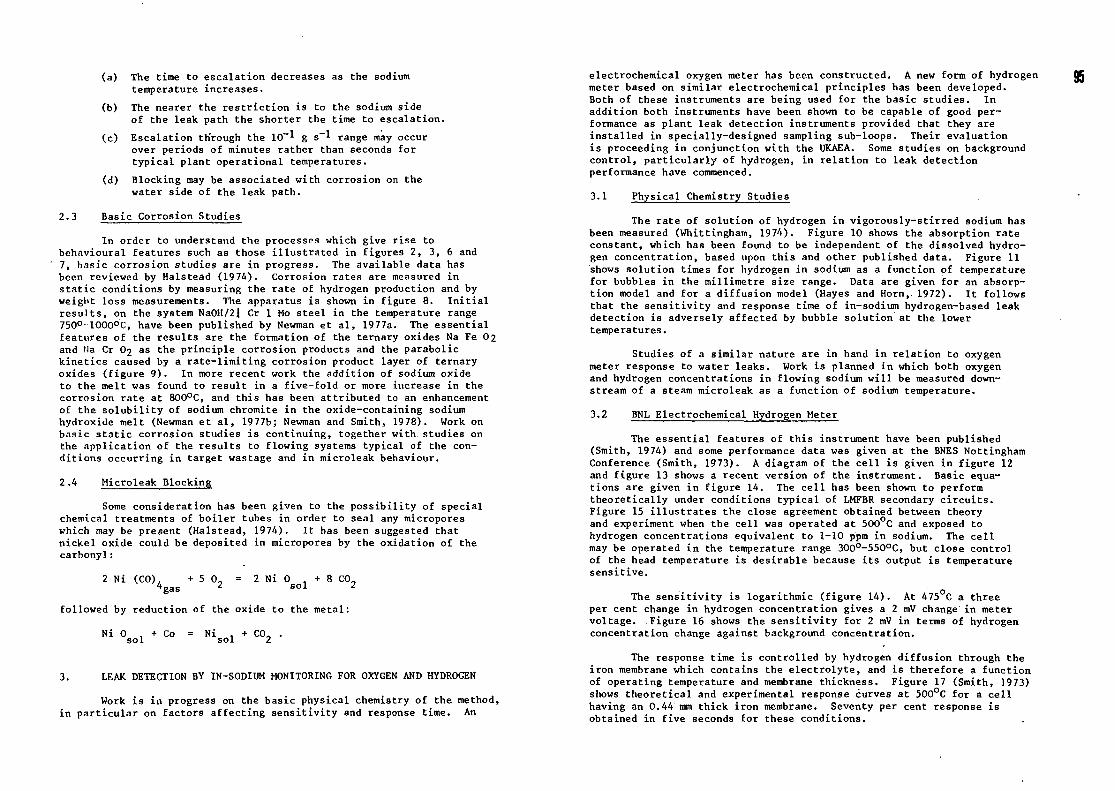
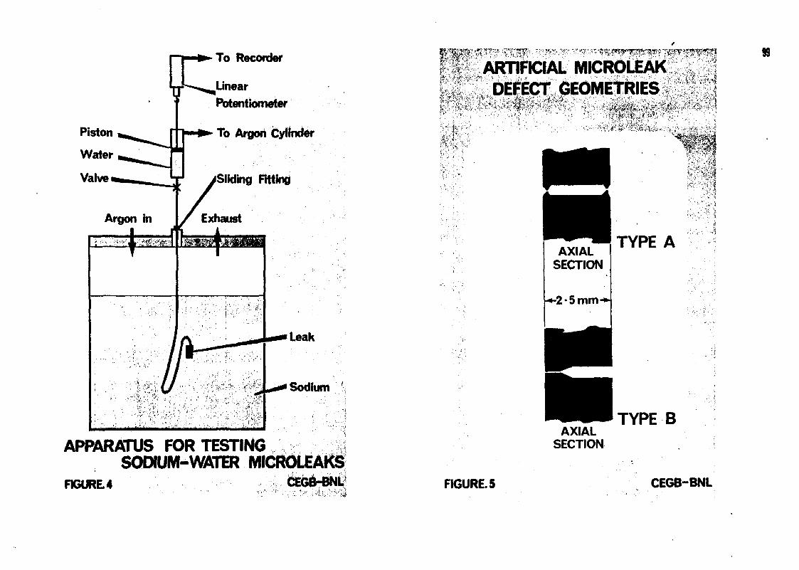
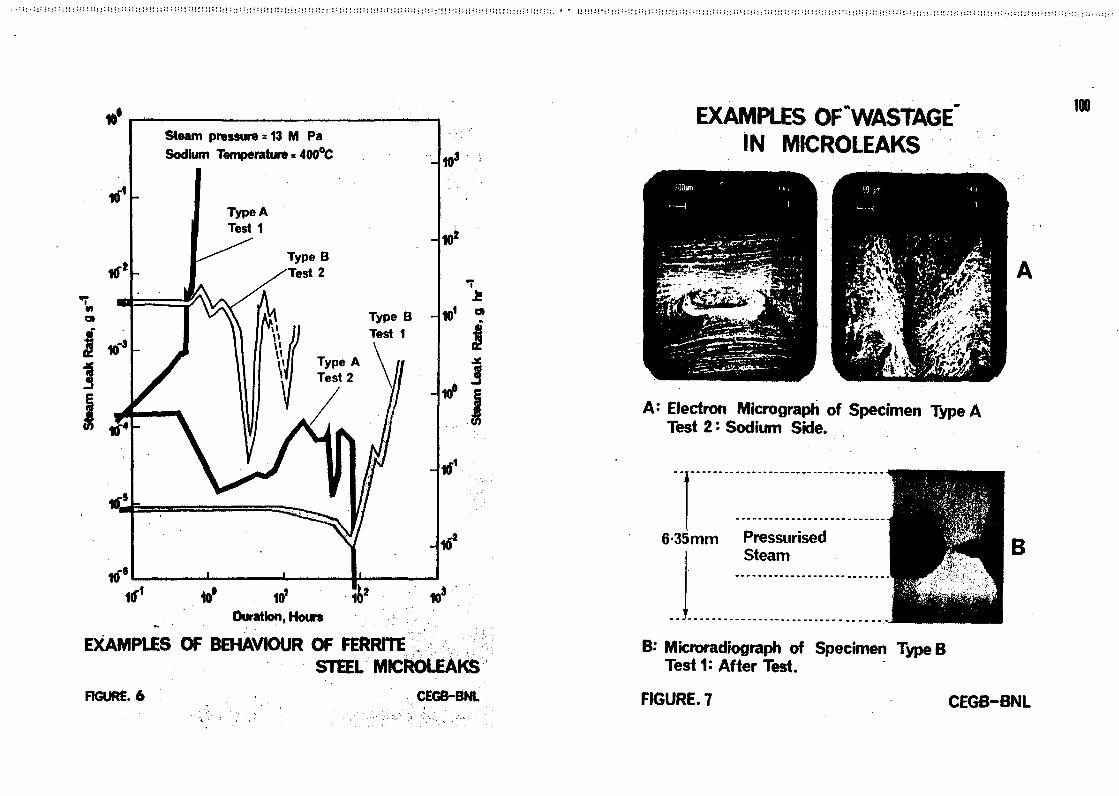
Experimental work is in progress on the behaviour of leaks whichare initially smaller than the range shown in figures 2 and 3, i.e.less than 10-1 gm s~l. The apparatus shown in figure 4 is used tomeasure how the steam flow rate through leaks varies with time. Afeature of the apparatus is the facility for continuous measurement ofleak rate in the range 10-5 - lo~l g a"!. Work so far has been withartificial defects which are nominally "round hole" filamentary leaks(Pugh et al, 1974). In practise the two leak geometries shown infigure 5 have been used. Typical test conditions are 400°C sodium and400°C steam at 13 MPa. Some results are shown in figure 6 (Newman etal, 1978). The loss of material observed at the mouth of the leaks isillustrated in figure 7.
These studies are still at an early stage. Further data onmicroleak behaviour together with physical models of the hydrodynamicsand the application of corrosion data are necessary for their fullinterpretation. Tentative conclusions are that for a given microleaksize (flow rate) in ferritic steels:
S!2!Mi
(a)
(b)
(c)
(d)
The time to escalation decreases as the sodiumtemperature increases.
The nearer the restriction is to the sodium sideof the leak path the shorter the time to escalation.
rv-1 c-1Escalation th'rough the 10" 1 g s A range may occurover periods of minutes rather than seconds fortypical plant operational temperatures.
Blocking may be associated with corrosion on thewater side of the leak path.
2.3 Basic Corrosion Studies
In order to understand the processes which give rise tobehavioural features such as those illustrated in figures 2, 3, 6 and7, basic corrosion studies are in progress. The available data hasbeen reviewed by Halstead (1974). Corrosion rates are measured instatic conditions by measuring the rate of hydrogen production and byweight loss measurements. The apparatus is shown in figure 8. Initialresults, on the system NaOH/2l Cr 1 Mo steel in the temperature range750°-1000°C, have been published by Newman et al, 1977a. The essentialfeatures of the results are the formation of the ternary oxides Na Fe 02and Ha Cr O2 as the principle corrosion products and the parabolickinetics caused by a rate-limiting corrosion product layer of ternaryoxides (figure 9 ) . In more recent work the addition of sodium oxideto the melt was found to result in a five-fold or more increase in thecorrosion rate at 800°C, and this has been attributed to an enhancementof the solubility of sodium chromlte in the oxide-containing sodiumhydroxide melt (Newman et al, 1977b; Newman and Smith, 1978). Work onbasic static corrosion studies is continuing, together with studies onthe application of the results to flowing systems typical of the con-ditions occurring in target wastage and in microleak behaviour.
2.4 Microleak Blocking
Some consideration has been given to the possibility of specialchemical treatments of boiler tubes in order to seal any microporeswhich may be present (Halstead, 1974). It has been suggested thatnickel oxide could be deposited in micropores by the oxidation of thecarbonyl:
2 Ni (CO)"gas
2 Ni 0 , + 8 C0-sol 2
followed by reduction of the oxide to the metal:
Ni 0 , + Cosol N i sol C 02 •
3. LEAK DETECTION BY IN-SODIUM MONITORING FOR OXYGEN AND HYDROGEN
Work is in progress on the basic physical chemistry of the method,in particular on factors affecting sensitivity and response time. An
electrochemical oxygen meter has been constructed. A new form of hydrogenmeter based on similar electrochemical principles has been developed.Both of these instruments are being used for the basic studies. Inaddition both instruments have been shown to be capable of good per-formance as plant leak detection instruments provided that they areinstalled in specially-designed sampling sub-loops. Their evaluationis proceeding in conjunction with the UKAEA. Some studies on backgroundcontrol, particularly of hydrogen, in relation to leak detectionperformance have commenced.
3.1 Physical Chemistry Studies
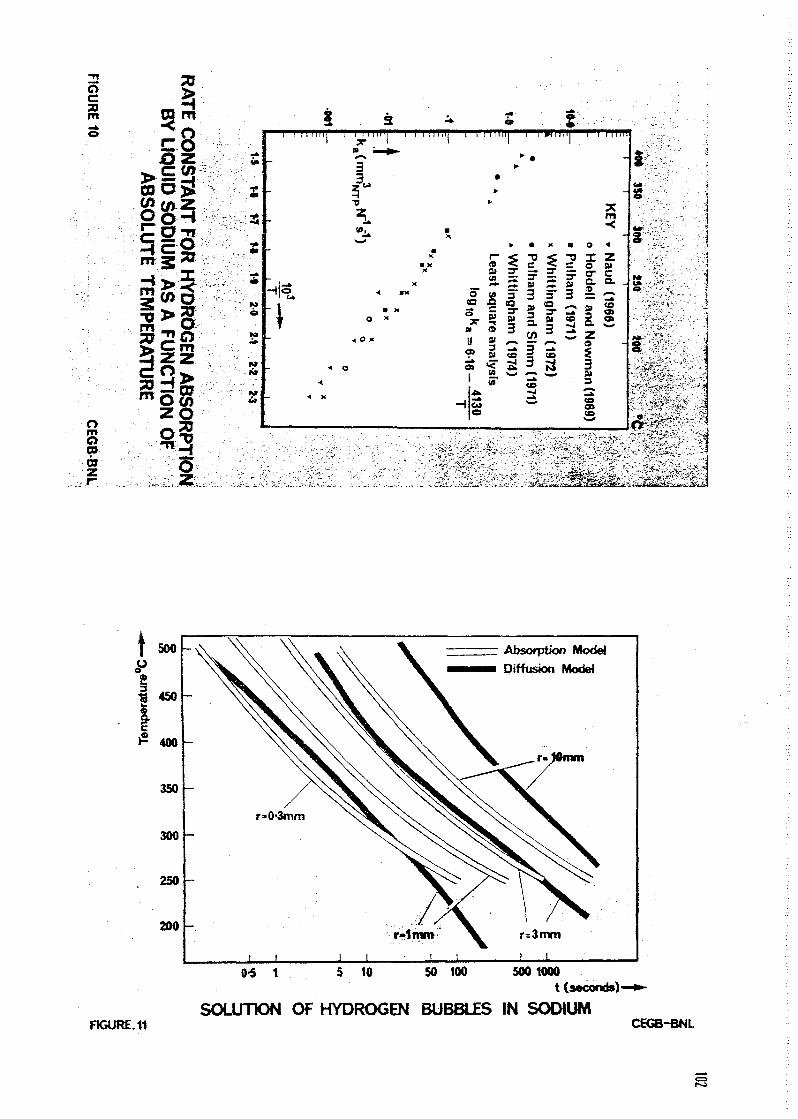
The rate of solution of hydrogen in vigorously-stirred sodium hasbeen measured (Whittingham, 1974). Figure 10 shows the absorption rateconstant, which has been found to be independent of the dissolved hydro-gen concentration, based upon this and other published data. Figure 11shows solution times for hydrogen in sodium as a function of temperaturefor bubbles in the millimetre size range. Data are given for an absorp-tion model and for a diffusion model (Hayes and Horn,. 1972). It followsthat the sensitivity and response time of in-sodium hydrogen-based leakdetection is adversely affected by bubble solution at the lowertemperatures.
Studies of a similar nature are in hand in relation to oxygenmeter response to water leaks. Work is planned in which both oxygenand hydrogen concentrations in flowing sodium will be measured down-stream of a steam microleak as a function of sodium temperature.
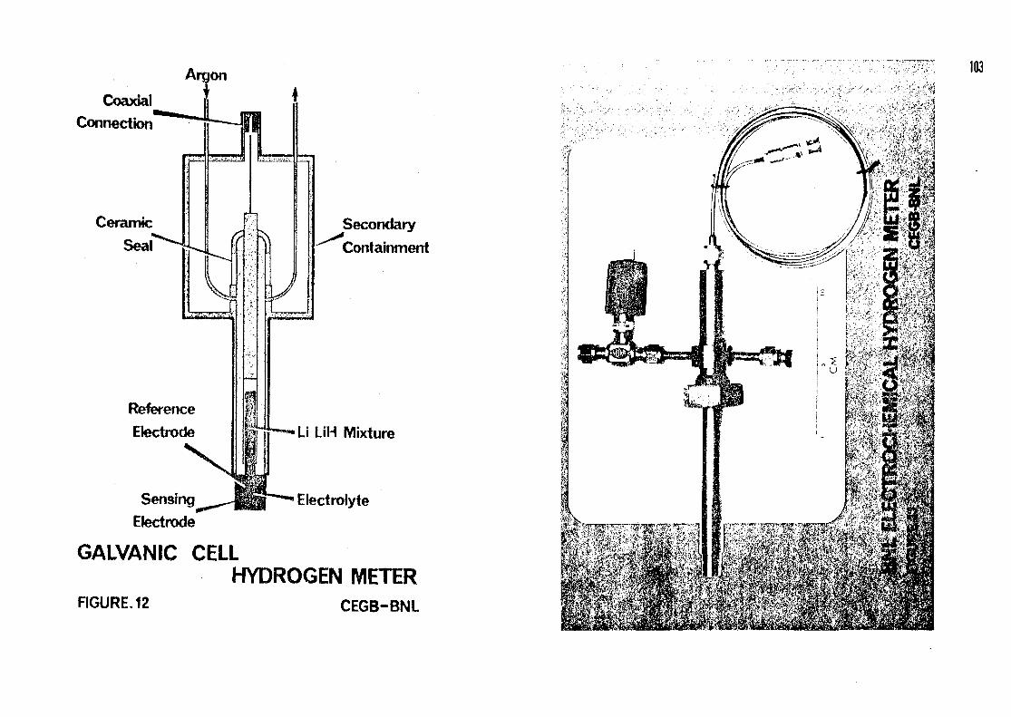
3.2 BNL Electrochemical Hydrogen Meter
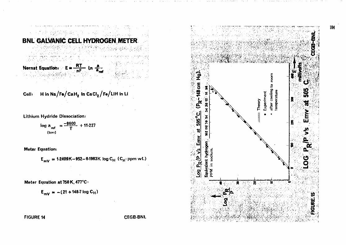
The essential features of this instrument have been published(Smith, 1974) and some performance data was given at the BNES NottinghamConference (Smith, 1973). A diagram of the cell is given in figure 12and figure 13 shows a recent version of the instrument. Basic equa-tions are given in figure 14. The cell has been shown to performtheoretically under conditions typical of LMFBR secondary circuits.Figure 15 illustrates the close agreement obtained between theoryand experiment when the cell was operated at 500°C and exposed tohydrogen concentrations equivalent to 1-10 ppm in sodium. The cellmay be operated in the temperature range 3OO°-55O°C, but close controlof the head temperature is desirable because its output is temperaturesensitive.
The sensitivity is logarithmic (figure 14). At 475°C a threeper cent change in hydrogen concentration gives a 2 mV change in metervoltage. Figure 16 shows the sensitivity for 2 mV in terms of hydrogenconcentration change against background concentration.
The response time is controlled by hydrogen diffusion through theiron membrane which contains the electrolyte, and is therefore a functionof operating temperature and membrane thickness. Figure 17 (Smith, 1973)shows theoretical and experimental response curves at 500°C for a cellhaving an 0.44 mm thick iron membrane. Seventy per cent response isobtained in five seconds for these conditions.
95

3.3 Electrochemical Oxygen Meter
A freeze-seal air reference oxygen meter has been constructedusing a commercially-available thoria 7j wt % yttria electrolytethimble (figures 18 and 19). Basic cell equations are given in figure20. The meter has been calibrated by admission of aliquots of oxygengas into oxygen-free sodium. Typical results are shown in figure 21,(Simm, 1978). Operating the meter at 435°C, it is found that afteran initial 30-day period during which output is a few per cent down,good agreement between theory and calibration measurements isobtained. Lifetimes in excess of two years have been achieved withthis meter in a laboratory sodium rig. The sensitivity of the oxygenmeter on an atom percentage basis is half that of the electrochemicalhydrogen meter but effective sensitivities may be similar for thisdesign when temperature coefficients are taken into account (figure 16).
3.4 Electrochemical Oxygen and Hydrogen Meters as In-Sodium LeakDetectors
Some consideration has been given to the leak detection perform-ance which might be achieved if oxygen and hydrogen galvanic cells wereused together in secondary circuits as an alternative to the in-sodiumkatharometer hydrogen detectors chosen for PFR.
As shown in figure 16, the sensitivity of the electrochemicalinstruments increases with decreasing background levels whereas thekatharometer (Davies et al, 1971) has the opposite characteristics.It has been concluded that with low background levels improved leakdetection performance can be achieved with the electrochemical meters.Figure 22 shows the calculatd sensitivity to water leaks of thesemeters mounted in a 200 Te secondary circuit as a function of timefrom leak initiation. Detection performance corresponds to about 20 gwater ingress. The initial sensitivity is a function of the systemflow rate and is independent of the sodium inventory; in figure 22complete mixing in a 2 Te s~l sodium flow and 100% detector responsehave been assumed.
In practice hydrogen background levels may vary as a consequenceof ingress of corrosion hydrogen through the walls of the boiler tubes.Figure 22 also shows how the electrochemical hydrogen meter detectionperformance would be degraded if the background level were allowedby cycle between 0.1 and 0.2 ppm within a period of a few days. Thistype of background variation could occur if an intermittent hydrogen-trapping system were adopted.
Some consideration has been given to the design of suitablesampling sub-loops for the installation of meters of this type inreactor circuits (Simm and Hayes, 1977).
4. CONCLUSIONS
leaks, with particular emphasis on basic studies related to wastageand self-enlargement, and to leak detection by oxygen and hydrogenmonitoring.
These studies, which are continuing, have led to a betterunderstanding of leak behaviour and effects. A correlation forpredicting maximum wastage rates for ferritic steels under mostconditions of practical interest has been derived.
Advances have been made in understanding the self-enlargementof leaks too small to cause rapid wastage on adjacent material.
Advances have been made in in-sodium instrumentation whichhave application for leak detection and for other purposes.
Whilst it is premature to draw conclusions in relation toboiler leak detection requirements from these studies, it appearsthat there may be advantages in using techniques which increasesensitivity at the expense of response time, such as in-sodiummonitoring for oxygen and hydrogen over several circuit turn-overs.However there is no evidence at this stage to obviate the requirementfor fast detection and passivation to protect against the largerleaks.
ACKNOWLEDGEMENT
This paper is published with the permission of the CentralElectricity Generating Board.
96
To date CEGB Research Division work on LMFBR boiler leaks andassociated problems has concentrated mainly on the behaviour of small
REFERENCES
DAVIES, R.A. et al, 1971, "Detection of sodium water leaks in PFRsecondary heat exchangers". Nuclear Engineering International,pp.493-495.
HALSTEAD, W.D., 1972, CEGB Report RD/L/N166/72.
HALSTEAD, W.D., 1974a, CEGB Report RD/L/N1O/74.
HALSTEAD, W.D., 1974b, CEGB Report RD/L/N16/74.
HAYES, D.J. and HORN, G., 1972, "Leak detection in sodium-heatedboilers", Jnl. BNES li, 41-48*
NEWMAN, R.N. and SMITH, C.A. , 1974, Jnl. Nuc. Mat. J52, 173-183.
NEWMAN, R.N.. SMITH, C.A. and SMITH, R.J., 1977a, "The Corrosion ofSteels in Molten Sodium Hydroxide", Jnl. Electrochem. Soc. Amer. 124(8)1247-52.

WHITT
H
|
n
»-»974CEGB
93
Spor
rr
8
9 *t o
vyiO
Disci
0sure
cd
e»-*etinNo.
SMITH
C.A.
I - *
$
p)N> r-v*> rectr
89"
I'0
a.rtOoore9
3rerr
aocdK ^
ren3*9r"cal
Briti
!l NUC
r-*
re0rt
Ene
S3CO
o<•>letBNE
CO
SMITH
C.A.
r-1
VO^ J
13ape
00
g>9H>
O9f
H«0 .
r£0
r1"
rr0l - »
CO*
2Of TrrH *
309ham
SIMM,
. >
00
Hocrre•oecrr1*CO
- frea.
37420
(a3Cu
^voCD
o
SIMM,
>
03a.H
AYE
CO
a
!_,vo
wr iitiCO3"
"00rrre9n
"0•a
n0rr
O9CO
• «
oCO
PUGH,
?
rr
Oi
vO74,
as•oort
115o
PUGH,
r°̂
p iCO
I f
u
•aON
¥O^
PAYNE
••
J.F.1978
HO
crre
•uccr
CO
3*reo.
"Liqu
i0
Meta
CO
zorrrr9cS
•3
zPI
z, R.N
UGH,
*09a.en
TH,
o
,_^O• s j
UJ
T3
(D
t—•
*
o
2 *, R.N
•
AYNE
J-(0
and
••0
s
A.R
vo
00••
Hoa*re
-occrr-*^ i .
CO3*rea.
1
, R.N•
3
a.CO
2r-tTH,
a
wVO
00
CEG
CO
73(0•oortrr
WO
wz
•
Gener.
fa:ors"
t-1
qndon
tubes
-, Pap
Cd
w
93
rerri
rrH«r>enrrrere
OS
rriQr |
0COrr
JOrer>rrOrt
COrrre0
a
sodiu
3-wate
rt
r|reac
ti
o3•or|OCorrCO
IX)ene
rtate
o.o*
r-*
re0
»
9r h
rer (r t
rrH "
r>cro
reM
ZPI
, R.N
"
pr
&
197
3*
3*rebeh
0VIO
c03O.
ort1oCOr1'
rerel-hr h
reorrCO
Om
PREDICTION OF WASTAGE CAUSED BYLEAKS IN SODIUM-HEATED BOILERS
= 252exp- 0-255 1n 59-8 m 5460
Wastage rate (mm s"1)
Leak rate ( g s 1 )
Leak to target spacing (mm)
Sodium temperature ( °K)

E£
'
Z3
O
, _S IUUJ ) 8|EJ
32
; s g p ,
pC/3
U
2C3
OUJ
O
r~| » To Recorder
Igi-—^LinearPotentiometer
To Argon Cylinder
V >Sliding Fitting
99
Leak
Sodium '
APPARATUS FOR TESTINGSODIUM-WATER MICROLEAKS
ARTIFICIAL MICROLEAKDEFECT GEOMETRIES
AXIALSECTION
TYPE A
AXIALSECTION
TYPE B
FIGURE 4 CEGB-BNL FIGURE. 5 CEGB-BNL
Kf1
at
flf6
Steam pressure = 13 M PaSodium Temperature > 400°C
Kf1 10° 101
103
10*
101
J
*F1
102
Duration, Hours
EXAMPLES OF BEHAVIOUR OF FERRITESTtEL MICROLEAKS
FIGURE. 6 CEGB-BNL
EXAMPLES OF^WASTAGE"IN MICROLEAKS
100
A: Electron Micrograph of Specimen Type ATest 2'Sodium Side.
6-35mm PressurisedSteam
B: Microradiograph of Specimen TypeBTest 1: After Test.
FIGURE. 7 CEGB-BNL

(fi
o00
Results of Basic Corrosion ExperimentsMaterial = 21/4 Cr 1 Mo ferritic steel
Corroding agent: Pure Sodium Hydroxide
Temperature Range: 750°-1000°C
Corrosion Equation :-2Fe+4NaOH-—2NaFeO2 + 2NaH+H2
Rate Constant :-
FIGURE.9
k = 0-604 e " 3 7 0 0 0 (moles H2 mm"2)2 s"1
CEGB-BNL
m
Omoam
2
3S
21sto
MM
§ 3' ' ' M l " | ' '_L | ' ' ' ' "
B ' »
• XX
-*!«, < «"
~ I • x* O x
•4 0 X
* ©
•4
< X
"I ' '
•
o"Q
3attt
«
o
I
1—ABlU)
square
ana
lys
S'"1
1
•
3 "
ingham
(19
74)
*
•
•oc
atm a
nd S
lmi
3
M
3"
ingham
(19
72)
I'I
••ocIh
am
(1971)oIocrcall a
nd N
ew
a>3
t oa»to
• i i n .
-
m<-Zat
a .
(1966)
Is
3
S
500 -
o°
1 450
I 2 400
350
300
250
200
Absorption Model
Diffusion Model
0-5 1 5 10 50 100 500 1000t (Mconds)-
SOLUTION OF HYDROGEN BUBBLES IN SODIUMFK3URE.11 CEG8-BNL
Argon
Coaxial
Connection
103
Secondary
Containment
Reference
Electrode
Sensing
Electrode
Li LiH Mixture
Electrolyte
GALVANIC CELLHYDROGEN METER
FIGURE. 12 CEGB-BNL
104
BNL GALVANIC CELL HYDROGEN METER \yf
Nernst Equation. E « - 5 1 - l« -J
Cell* H in Na/Fs/CaH2 in CaCI2/F«/LiH in Li
Lithium Hydride Dissociation:
log a . = ~ 9 6 0 0 + 11-227rot y(torr)
Meter Equation i
EmV • 12409K-952-01983KlogCH (CH:ppmwt.)
Meter Equation at 750 K, 477°C >
EmV m -(21+1487logCH)
. i1
FIGURE 14 CEGBBNL

SENSITIVITIES OF HYDROGEN AND OXYGEN METERS vs.BACKGROUNDLEVELSft
V
50
100
150
200
Oxygen background: ppm0-5 M 2-0 3-0 5-0
- — * *
Oxygen Meter
sensitivity(1 mV)
\
Galvanic Cell
n sensitivity(2mV)
\
\
FIGURE. 16
0-03 0-05 0-1 0-2 0-3 04Hydrogen background level: ppm
CEGB-BNL
AE fmilHvoHs
22-5
15-0
7-5
Response time at 500°CPR=143-9cmHg.AP=143-4-75-7=67-9cm Hg.
Membrane as semi-infinite plane
No hydrogen loss frominner face of membrane
I I I
10 15Time in seconds
20 25
Response time of Hydrogen Meter at 500°C
"'1
FK3URE17 CEGB-BNL

, 1 * '
ELECTROCHEMICALOXYGENMETER
FIGURE. 18 CEGB-BNL
106
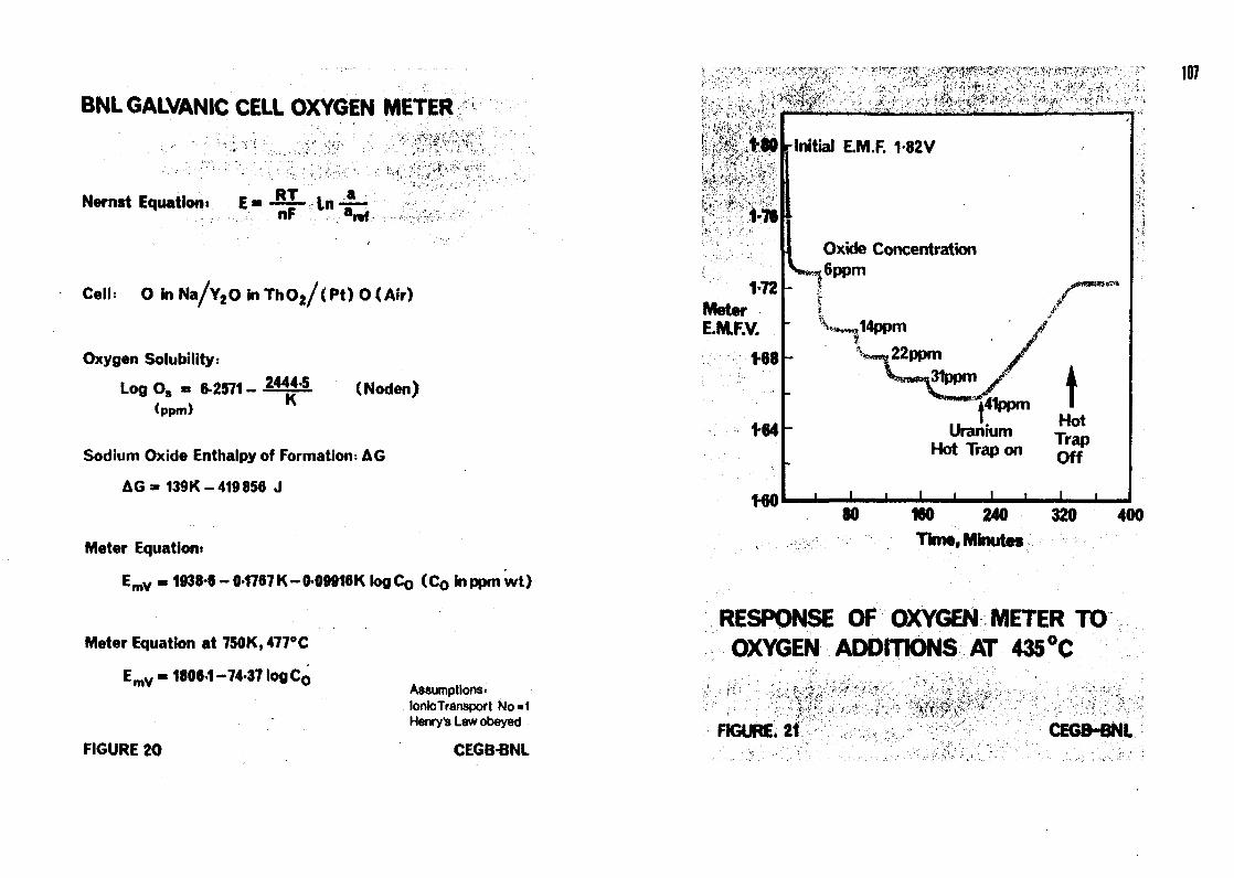
BNL GALVANIC CELL OXYGEN METER
••* r/A-Nernst Equation, E - -~~ In -~-
-.-.-•••-.. n F a i » f
Colli O in Na/Y2 O in Th O 2 / < Pt) O < Air)
Oxygen Solubility:
Log O, • 6-2571 - 2 4 * * S (Noden)(ppm)
Sodium Oxide Enthalpy of Formation: AG
AG= 139K-419856 J
Meter Equation*
EmV « 1938-6- 0-1787 K-0-09916 K logC0 (Co in ppm wt)
Meter Equation at 750K, 477°C
EmV-1806-1-74-37 log Co
FIGURE 20
Assumptions-Ionic Transport No«1Henry's Law obeyed
CEGBBNL
:/T, '' - , ' • > > ' 1
1-18
1-72MeterE.M.F.V.
1-68
1-84
WO
Initial E.M.F. 1-82V
Oxide Concentration
UraniumHot Trap on
HotTrapOff
160 240
Time(
320 400
107
RESPONSE OF OXYGEN METER TOOXYGEN ADDITIONS AT 435 °C
FIGURE. 21 CEGB-BNL

1in
<
CO
uUJ
500
300
200
100
50
30
20
10
• HYOROGEN DETECTION: OippmH,
COLD TRAPPED
> OXYGEN DETECTION: 10ppmO,
f HYDROGEN DETECTION: 0 2ppm H,COLO TRAPPING
Detection levels1 H Meter 2mv
O Meter 1mv
30gHjO LINE
10 20 30 50
TIME BETWEEN LEAK INITIATION AND DETECTION:-MINUTES
POSSIBLE SENSITIVITIES FOR WATER
LEAK DETECTION IN 200 Te CIRCUIT
FIGURE 2 2 CEGBBNL
LMFBR STEAM GENERATORLEAK DETECTION DEVELOPMENTIN THE UNITED STATES
P.M. MAGEE, E.E. GERRELS, D.A- GREENE
General Electric Company,
Sunnyvale, California
J. McKEE
Argonne National Laboratory,
Argonne, Illinois,
United States of America
ABSTRACT
Leak detection for Liquid Metal Fast Breeder Reactor steam generators 1$an important economic factor in the shutdown, repair and restart of a plant.Development of leak detection systems in the U.S. has concentrated on fourareas: (1) chemical (Hg and O2) leak detection meters; (2) acoustic leakdetection/location techniques; (3) investigation of leak behavior (enlarge-ment, damage effects, plugging and unplugging); and (4) data management forplant operations. This paper discusses the status, design aspects, andapplications of leak detection technology for LMFBR plants.
NO !O ;00;
CO i
1.0 INTRODUCTION
Common Liquid Metal Fast Breeder Reactor (LMFBR) steam generator designpractice in the U.S. and in Europe utilizes single wall tubes as a barrierbetween the secondary sodium circuit and the high pressure water/steam circuit.Although thorough material specification, weld development, state-of-the-artinspection techniques and quality control will render the probability of alarge failure of a tube extremely low, the possibility of small defects cannotbe completely eliminated. Experimental work with very small orifices, throughwhich water/steam is injected, indicates that even if such defects are initiallyplugged, they will eventually enlarge and remain open. When water is injectedInto sodium continuously, a sodium/water reaction zone is formed. Should otherheat transfer tubes lie in this zone, Impingement wastage can cause secondaryfailures to occur leading to the possibility of a major sodium/water reaction,and the potential for major damage to the unit. To minimize the possibilityof such an occurrence, a rapid response leak detection system is provided,