Treatment of Gastric Leaks with Coated Self-Expanding Stents after Sleeve Gastrectomy
Upload
independentCategory
view
0download
0
Paper No.
720
UNUSUAL REFINERY BOILER TUBE FAILURES DUE TO CORROSION BY SULFURIC ACID INDUCED BY STEAM LEAKS
D. Lopez-Lopez, A. Wong-Moreno lnstituto de lnvestigaciones EIBctricas,
Internado Palmira, A.P. l-475, C.P. 62000, Cuernavaca, Morelos, Mexico.
ABSTRACT
Corrosion by sulfuric acid in boilers is a low probability event because gas temperature and metal temperature of boiler tubes are high enough to avoid the condensation of sulfuric acid from flue gases. This degradation mechanism is frequently considered as an important cause of air preheaters materials degradation, where flue gases are cooled by heat transfer to the combustion air. Corrosion is associated to the presence of sulfuric acid, which condensates if metal temperature (or gas temperature) is below of the acid dew point. In economizer tubes, sulfuric acid corrosion is an unlikely event because flue gas and tube temperatures are normally over the acid dewpoint.
In this paper, the failure analysis of generator tubes (similar to the economizer of bigger boilers) of two small oil-fired subcritical boilers is reported. It is concluded that sulfuric acid corrosion was the cause of the failure. The sulfuric acid condensation was due to the contact of flue gases containing SO3 with water-steam spray coming from leaks at the interface of rolled tube to the drum.
Considering the information gathered from these two cases studied, an analysis of this failure mechanism is presented including a description of the thermodynamics condition of water leaking from the drum, and an analysis of the factors favouring it.
m: acid dewpoint corrosion, sulfuric acid corrosion, low temperature corrosion, cold end corrosion, economizer, fuel oil, boilers, failure analysis.
Copyright 01998 by NACE International. Requests for permission to publish this manuscript in any form, in part or in whole must be made in writing to NACE International, Conferences Division, P.O. Box 218340, Houston, Texas 77218-8340. The material presented and the views expressed in this paper are solely those of the author(s) and are not necessarily endorsed by the Association. Printed in the U.S.A.

INTRODUCTION
Sulfuric acid corrosion in boilers, also termed “acid dewpoint corrosion”, “low temperature corrosion” or “cold end corrosion” is frequently considered as an important cause of materials degradation of air preheaters if metal temperature is low enough to allow the condensation of sulfuric acid from the flue gas on the tube surface”‘. This corrosion mechanism is associated to the presence of sulfuric acid which condensate if metal temperature (or gas temperature) is below of the acid dewpoint. Sulfuric acid corrosion is an unlikely event in economizer tubes because flue gas temperature is normally over 300 “C and feedwatar to economizer is hot enough to avoid low metal temperature. Only if faedwater temperature is too low, the process can occur and it can be a problem if some feedwater heater are out of operation”’ .
In the case of small subcritical boilers where economizer bank does not exist, generator tubes are operating in the cold end of the boiler Wnilar to those of the economizer of bigger boilers) connecting upper drum with lower drum. In this case, feedwater temperature to generator tubes is practically the saturation temperature (- 275 “C) and low temperature corrosion problems can not normally ba expected.
In the present work, failure of generator tubes of two small oil-fired subcritical boilers where sulfuric acid corrosion was the root cause is reported. The sulfuric acid condensation was related to small water-steam leaks which gave place, as a first stage, to a localized corrosion phenomenon generating small holes. As a second stage, the water-steam leak from a small hde cause an erosion process of neighbors tubes producing their failure.
EXPERIMENTAL PROCEDURES
The present work is focused on the failure analysis of generator tubes of two smell oil-fired subcritical boilers. Figure 1 shows longitudinal scheme of both boilers. Some of their general characteristics ere described in Table I. Both boilers burnt natural gas and residual fuel oil with high sulfur f- 4 wt %I, vanadium (200-300 ppm) and asphaltens (- 20 wt %I content.
Design of both boilers is very similar, as it is shown in Figure 1. Some characteristic features of these boilers that are important to comment in this analysis are:
*A section of upper and lower drum surface is directly exposed to flus gases. *Tubes of the generator bank are connected to the upper and lower drum by s cdd expansion
process through a rdled process. The thickness of drum wall is near to 10 cm.
In both cases, cokection of tube samples for analysis was a difficult task because the limited access to the zone due to the presence of many tubes. In the csse of Boiler 1, secticns from four failed tube were suppked for the analysis and in tha case of Soiler 2, only a section of one failed tube was supplied for analysis (a total of 7 tubes were failed, 3 repaired by direct weM application on pits, 4 canceled).
Conventional failure analysis was carried out with special attention to microprobe analysis of tube deposits and tuba surface. A Zeiss DSM990 Scanning Electron Microscope with KEVEX Delta IV EDX analyzer in one case, and with EDAX Prime90 as EDX analyzer in the other case were used.
720/2
RESULTS
Boiler1
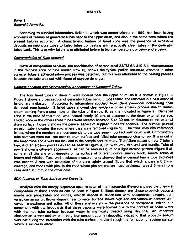
Accordii to supplied information, Boiler 1, which was commissioned in 1989, had been having problems of failures of generator tubes near to the upper drum, and also in the same zone where tha present failures occurred. A characteristic feature of failed zone was the presence of excessive deposits on n&ghbors tubes to failed tubes contrasting with practically clean tubes in the generator tubes bank. This was why failure was attributed before to high temperature corrosion and erosion.
hbterial composition satisfies the specifiiation of carbon steel ASTM SA-2 1 O-A 1. Microstructure in the thinnest zone of tubs eroded (row 6). shows the typical perlitic structure whereas in other zones or tubes a spheroidhation process was detected, but this was attributed to the heating process because the tube was cut with flame of oxyacetylene gun.
ical ADD- Tubes,
The four failed tubes in Boiler 1 were located near the upper drum, as it is shown in Figure 1. Figure 2 shows a cross section of generator tubes bank, 5 tubes failed and removed in a past event of failure are indicated. According to information supplied from plant personnel considering their damaged zone location, 3 failed tubes showed clear evidence of an erosion process due to water- steam coming from a small hole on the tube of the row 9, as it is indicated in Figure 2. Damaged zone in the case of this tube, was located nearly 10 cm. of distance to the drum external surface. Eroded zone in the others three tubes were located between 5 to 30 cm. of distance to the external drum surface. Figure 3 shows the general aspect of supplied tubes for analysis. The number painted on each tube indicates the row where they were removed (Figure 2). The zone with circumferential bands, where the numbers are, corresponds to the tube zone in contact with drum wall. Unfortunately tube samples were cut too near to drum surface and failed tubs correspondii to row 9 was cut in the failed zone and it was not included in the sample sent to study. The failure aspect of row 7 tube is typical of an erosion process as can be seen in Figure 4, i.e. with very thin wall and ductile. Tube of row Q shows a different appearance, as can bs seen in Figure 5: a light erosion pattern (Figure 5-a), some small pits and with deposits on its surface of different cdors, mainly black, several tones of brown and whitish. Tubs wall thickness measurements showed that in general terms tube thickness was near to 3 mm with exception of the zone lightly eroded (figure 5-a) which shows a 0.2 mm wastage, and zones with pits. In the zone where pits are present, tuba thickness was 2.5 mm in orra case and 1.85 mm in the other case.
YpX Analvsis of Tube Surface and De&s&
Analysis with the energy dispersive spectrometer of the microprobe (Kevex) showed the chemical composition of these zones as can be seen in Figure 6. Slack deposit are phosphorus-rich deposits maybe iron phosphates and oxides, whitish deposit is silicon-rich with phosphorus, oxygen, iron, vanadium an sulfur. bown deposit near to metal surface shows high iron and vanadii content with oxygen phosphorus and sulfur. All of these analysis show the presence of pbsphcrus, which is in agreement with the hypothesis that these deposits were formed due to tha contact of boiler water with the hot tube surface because water is chemically treated using NaJ PG. An important observation is that sodium is in very low concentration in deposits, indicating that probably sodium was lost during the interaction with the tube surface, maybe through the formation of sodium sulfate, which is soluble in water.
72013

Figure 7 shows two small pits and two EDX spectra, obtained from the pit center and from the surface near to the pit. It can ba seen that the main compounds are iron, oxygen, phosphorus and small quantities of S, Si and V. Inside the pit there is not silicon, phosphorous concentration diminish and sulfur increase.
A small piece of whitish deposit was detached for analysis. The internal part of it, in contact with tuba surface shows a high sulfur concentration below a phosphorus rich layer, as can be seen in Figure 8. Apparently, sulfur is present as iron sulfate which is reported at the tube deposit interface in cases of acid dewpoint corrosion”‘.
Boiler 2 General Information
Boiler 2 had only one past event of failure in generator tubes, near to upper drum. The tuba was cancelled but no more information was collected about this past case. This boiler was commissioned in 1991.
Damaoe I ocatlon eroscooical ADDearance of Dam& Tubes,
The seven failed tubes of Boiler 2 were located near the lower drum. Damaged zone in four failed tubes was nearly at 10 cm from the external surface of the lower drum. Two failed tubes showed a wide damaged zone from 10 cm to 40 cm to the external surface of the lower drum and only in one failed tube the distance to the lower drum was 40 cm, this was located in row 13, as can ba seen in Figure 1 and Figure 9, which shows failed tube location of the seven tubes. Similar to the case of Boiler 1, according to description supplied from plant personnel considering their damaged zone location, 3 tubes showed clear signals of erosion, and apparently eroded tubas located in row 4 and 5 were eroded by water-steam leak from a small pit in tube of row 4, third column (see Figure 9). First failed tuba by erosion in row 4 (second column) was supplied for analysis but failed zone was not included in the sample. It is difficult to explain the failure of tube in row 13 (not supplied for analysis) due to its position without failed tubes near to it. Figure 10 shows the general aspect of analyzed tuba and Figure 11 shows a detail of this zone. A typical eroded tube surface with brown and dark brown color can ba seen and s black deposit non eroded can be appreciated between both eroded zones. Figure 12 shows another detail of tube surface in a zons with non-eroded black deposit.
EDX Anah& of Tube Surface and Deoosits.
Figure 13 shows qualitative analysis obtained by the energy dispersive x-ray spectrometer (EDAX) of the zones mentioned in the previous paragraph. Eroded dark brown surface shows very high oxygen content with iron sulfur, carbon, phosphorus and vanadium. Eroded brown surface has a very similar composition, but lightly less sulfur and higher iron. Black deposit shows also iron, oxygen, vanadium and sulfur, but as characteristic feature it shows high phosphorus and high carbon content. A small blackish deposit was detached and n its internal surface (near to metal surface) analyzed. EDX spectrum from this zone shows very high ccntent of carbon, silicon, phosphorus, sulfur and calcium. A whitish deposit was observed below a piece of dark deposit. Its analysis shows oxygen, iron and sulfur, probably as iron oxide and sulfate, similar to the high sulfur deposit observed on row 9 tube (figure 8) but with more iron oxide concentration.
72014

DISCUSSION
Macroscopical evidence previously presented indicates that eroded tubes were consequence of a preceding faikrd tuba and the problem is how to explain tubes exhibiting pitting that apparently were failed before tubes failed by erosion. Presence of phosphorus and silicon in tube deposits is indicative that water-steam of the boiler cycle was invdved, also the presence of vanadium and sulfur is indicative that combustion gases were also invdved. Water-steam leaking out from some hole will produce the deposition of phosphorus, silicon and sodium compounds if this flow hit to a hot tube surface, and the flw gas drag by this water-steam flow can explain the presence of vanadium and sulfur. The location of failures near to the external drum surface support the assumption that water- steam leaking from the interface of rdled tubs to drum was the root cause of the failure.
mt Water-steams Frwrj&.&face R&d Tube-Drum
According to information supplied by plant personnel of Soiler 1, each time that the boiler is out of operation for maintenance, an hydrostatic test is carried out and possible water-steam leaks from rolled tube-drum are inspected. Frequently, leaks are detected but they are repaired by a m-rolled process before tha b&r goes in operation again. However, it can occur that some leaks bs produced during start up or during normal operation due to contraction/expansion of the elements caused by temperature changes. In the cass of the Soiler 2, plant personnel had not observad this kind of leaks but hydrostatic test is carried out with water at low pressure.
Thermodvm Cond . . Itron of Water-Steam Leaks
The presence of iron sulfate can be attributed to the presence of sulfuric acid, but this can be produced during maintenance period due to the atmospheric humidity or some water entrance to ths boiler during maintenance period (for example during boiler washing or to misfunctioning of some sootblower valve). Water-steam leaks are not a enough condition to produce acid dew point corrosion. Temperature of leaking fluid must be low enough to condensate sulfuric acid. Water steam leaks become less pressurized and this have a cooling effect, transforming part of the energy to produce steam. Considering as initial thermodynamic condition the water in drum at saturation temperature (see Table I) and considering an adiabatic process with a initial escape velocity negligible, the process can be studied as an isoentalpic process. Considering the atmospheric pressure as the final pressure, water will leak from Boiler 1 drum as a mixture of 64.5 % water - 35.5 % steam at loo or?) .
Analvsis of the Influence of Leak Size.
Preceding analysis shows that temperature of water-steam leaking from the drum is low enough to explain the condensation of sulfuric acid, however, external metal tube temperature is over 3oO“C and gas temperature is too high (- 300°C - 600°C). Then, water entrance to the hot ffue gas or hitting hot tubs surface will vaporize increasing its temperature quickly. Fiiure 14 shows a pictorial analysis of the effect of leak size. Sulfuric acid concentration in the water-steam leaking will be a function of:
* Time to mix water-steam with SO3 , which will be proportional to the drum surface distance and inversely proportional to the leak size.
l Temperature of water-steam flow which will be inversely proportional to the drum surface distance and proportional to the leak size.
If leak size is small then water-steam will vaporize quickly and if some sulfuric acid be formed it will be in very low concentration. Otherwise, if leak size is bigger, tubs surface will be cooled (heat transfer will bs reversed, from inside to cutside of tube), sulfuric acid concentration will be higher and
72015

acid dewpoint corrosion could take place. If leak size is even bigger, water steam erosion will be important and a uoalon ccrrosion process can occur. Under these circumstances, neighbor tubes could be damaged, as is illustrated in Figure 14.
According with this description, small water-steams leaks can exist for long periods without consequence but bigger leaks can cause severe problems.
Drlv detection of fam
Experience taken from these cases show that the failure event is detected when the secondary failures dua to erosion are produced. The primsry failures dua to pitting caused by dewpoint corrosion give place to small water losses, and they are not detected because of the high vdume of water of the boiler cycle. Early detection of these kind of leaks require humidity sensors.
CONCLUSIONS
Considering previous results, is clear that the most probable root cause of failure was acid dewpoint corrosion. This process was induced by water steam leaks at the interface rolled tuba- drum. The failures exhibiting an erosion (or erosion-corrosion) pattern, were a consequence of water steam leaks through pits in tubes which failed before.
ACKNOWLEDGMENTS
Thanks are given to H&or Vadillo R. and personnel of Antonio Dovali Jaime Refinery (PEMEX) and of Pondercel S.A. de C.V. for their valuable cooperation and permission for publishing these results. Authors acknowledge to M. Ramirez de Santiago the support given on the thermodynamical study of water leaking from drum.
REFERENCES
1. R.B. Dooby, W.P. McNsughton, ‘The Anal& snd Mit&ation of Bohr Tube Fakms: Tm and preCth% Vohme 2: Wtu-Touched Tubas”, EPRI Report TR-106261, Juno 1996.
2. D. Lopez LQzsz, A. Wang Moreno, M. Rsmfrez de Ssntisgo, G. Jirn&ez-Nsres, ‘Anilioic de kr caura~ de Falla de Tubos ds Is Csfdsra CB-3 de Is Refiia Antonio Dovsll Jaims”, Report HE/l 2/6649/SER 017/94, septamber 1994.
72016

BOILER 2 fi
BOILER 1
ROW -+ 20 IO 18 17 16 i5 14 13 12 ii IO o 8 7 6 5 4 3 2 i
000000oooooO
l ooooOoo@oo00 ooooooo8
00 0 f~~f_)1~~~1~t~1~~~f~f~f~f~f~I~ J.J.J.J.J.J.J.J.J.J.J
.-..~..-.‘..~..~..~..‘.,......-..~-.,~.~~. 0
’ .:* . . . . _.*. . . *.__a .._.s_...._.. . . . . . . :., ,.: ** :., ;., ,.,., ‘. . . .
::..:: ::..:: ::..::.::.::.... ._.....:: ._. .._.
. FAILED AND REMOVED IN PAST EVENT
.J ,-. ’ . .
FAILED DUE TO WATER-STEAM EROSION FROM TUBE 9
TUBE 9 FAILED DUE TO SULFURIC ACID CORROSION
Fiiure 2. Arrangement of generator tubes of boiler 1, near to upper drum
72Ql7

Fllure 3. Faiiedtubesof boiler 1 supplidforanaiysis.
Figure 4. General appearence of failed row 7 tube of boiler 1.
72018

Figure 5. Fwr views of failad row 9 tuba supplied for analysis. Doas not include failed zone.
72Ql9

BLACK DEPOSIT
P
0 I
FO
I
Fe FO
BROWN DEPOW, NEAR TO METAL SURFACE
FO
1 V
I 0 P
WHITISH DEPOSIT
Si
Figure 6. EDX Spa&a taken from daposits on row 9 tube of boiler 1.
BROWN DEPOSIT INSIDE THE PIT BROWN DEPOSIT NEAR TO THE PIT
P I
Figure 7. 8ewdary electron imags and backscatering ulactron image of pits showed in the lower rectionoffigwa5-b.Spectrrweretakeninsidaapitsndart~butneartothepit.
720/l 0

SULFUR RICH INNER DEPOSIT ZONE PHOSPHORUS RICH EXTERNAL DEPOSIT ZONE
I
Figure 8. Low magnifmtion smmdary ekm0n image and backscattering electron image of a small pieceofdepositdetochedfnwnawhitish~zoneM1row9hrbeofboiierl.Spectra WereobtoinedfKwndepooitincontactwittrtuberurfoceendfromanewtphosphorur-rich leVW.
720/l 1

SOOT BLOWER --u
Row -20 18 18 17 16 15 14 1.3 12 ii 10 9 8 7 6 5 4 3 2 1
oooocBoo@000000000
0oe3ooo000000000
0oclDooo0000000e3
0oooooO00000000
ooooooooooooooo ,'I'f'f-l't-f 'I'f -f'r-l'f'I'f- bJ.J.J.J.J.J.J.J.J.J.J.J.J.J.J , ..~..~.(~.,~.~~.~~.~~.,~.~~.,~.~~.~~.,~.~~. . _.‘. . . ** . . *. :., ,.: ,.,., ‘* . . . . . . . . *. *. ., .. . . ., . . .. . . . . .
:: 7. :: .1’. :: ::..:: ::..:: . . . . . . . .
0 . FAILED DUE TO WATER-STEAM EROSION I ’ , . . .
CB FAILED DUE TO SULFURIC ACID CORROSION
Fgure 9. Arrangemwt of ganaratof tubas of boiler 2, near to lower drum.
Figure 10. Sample of tube supplkd for analysis. Does not include ths failed zone.
720/l 2

Figure 11. Detail of tuba supphI for analysis, showing black deposit between two eroded zones.
Figure 12. Datail of tuba supphi for analysis, showing other aspect of black deposits, a whitish can be appreciated below of a pieca of detached black deposit (left).
720113

OUTERZONEOFBlACKDEPOSlT
3
P
F*
5 V
n .-, h., A ; 2.m ,.oQ IM 8.00 ,000 12.00 1.m
EROSIONED DARK-BROWN ZONE
0
wNERzoMEoFalAcKDEPoslT
0 I
EROSKMED aRow ZONE
0
Figure 13. EDX spectra obtebed from indceted zones of erosioned tube sample of boiler 2 supplied for andyak. Energy scale is in Kev.
I I I BIG LPly
Figure 14. Rctotiel deechption of three different leek conditions at rolled tubedrum interface. It is wnsidered both leak directions, upstream and downstream.
720/l 4
Copyright © 2022 FDOKUMEN