Blanchard Refining Company LLC Galveston Bay Refinery
16
Authored By: John Madden Blanchard Refining Company LLC Galveston Bay Refinery PR-11 Safe Equipment Preparation Doc No.: RSW-000062-GB Rev No: 1 Doc Custodian: Safety Supervisor Refinery Safe Work Procedure Approved By: Von Meeks Date Approved: 11/29/2021 Next Review Date: 11/29/2026 Effective Date: 11/29/2021 Printed 11/30/2021 RSW-000062-GB.docx Page 1 of 16 Printed copies should be used with caution. The user of this document must ensure that the current approved version of the document is used. Table of Contents Purpose ............................................................................................................................................ 2 Scope ............................................................................................................................................... 2 2.3 Out of Scope: 2 Procedure ......................................................................................................................................... 2 3.1 Roles and Responsibilities 2 3.1.1 Owning Department: 2 3.1.2 Engineering Department: 2 3.2 Taking Equipment Out of Service and Initial Blinding 2 3.3 Equipment Decontamination Following Initial Blinding 5 3.4 Returning Equipment to Service 6 3.5 Recommended Techniques 7 3.6 Miscellaneous Information 9 3.7 Equipment Requiring Special Needs 11 Definitions ...................................................................................................................................... 12 References ..................................................................................................................................... 12 Attachments ................................................................................................................................... 13 Revision History ............................................................................................................................. 13 Attachment A: Preparing Equipment in Service for Invasive Work ............................................................. 14 Attachment B: Return Equipment to Service .............................................................................................. 15 Attachment C: Safe Equipment Preparation Examples .............................................................................. 16
-
Upload
khangminh22 -
Category
Documents
-
view
2 -
download
0
Transcript of Blanchard Refining Company LLC Galveston Bay Refinery

Authored By: John Madden
Blanchard Refining Company LLC Galveston Bay Refinery
PR-11 Safe Equipment
Preparation
Doc No.: RSW-000062-GB Rev No: 1
Doc Custodian: Safety Supervisor
Refinery Safe Work Procedure Approved By: Von Meeks Date Approved: 11/29/2021 Next Review Date: 11/29/2026 Effective Date: 11/29/2021
Printed 11/30/2021 RSW-000062-GB.docx Page 1 of 16 Printed copies should be used with caution. The user of this document must ensure that the current approved version of the document is used.
Table of Contents
Purpose ............................................................................................................................................ 2
Scope ............................................................................................................................................... 2 2.3 Out of Scope: 2
Procedure ......................................................................................................................................... 2
3.1 Roles and Responsibilities 2
3.1.1 Owning Department: 2
3.1.2 Engineering Department: 2 3.2 Taking Equipment Out of Service and Initial Blinding 2
3.3 Equipment Decontamination Following Initial Blinding 5
3.4 Returning Equipment to Service 6
3.5 Recommended Techniques 7
3.6 Miscellaneous Information 9
3.7 Equipment Requiring Special Needs 11 Definitions ...................................................................................................................................... 12
References ..................................................................................................................................... 12
Attachments ................................................................................................................................... 13
Revision History ............................................................................................................................. 13
Attachment A: Preparing Equipment in Service for Invasive Work ............................................................. 14
Attachment B: Return Equipment to Service .............................................................................................. 15 Attachment C: Safe Equipment Preparation Examples .............................................................................. 16

Blanchard Refining Company LLC Galveston Bay Refinery Title: PR-11 Safe Equipment Preparation Doc Number: RSW-000062-GB Rev No: 1
Printed 11/30/2021 RSW-000062-GB.docx Page 2 of 16 Printed copies should be used with caution. The user of this document must ensure that the current approved version of the document is used.
Purpose The purpose of this document is to outline the specific requirements necessary to safely remove hydrocarbon and toxic materials from refining process equipment to be opened to atmosphere for entry or other invasive maintenance work, as well as returning the equipment that has been opened to atmosphere back to service. This document should be utilized when developing operating procedures.
Scope 2.1 This document applies to all equipment in hydrocarbon service or equipment which contains other
hazardous materials where there is a risk of personnel exposure to injury.
2.2 Examples of other hazardous materials include, but not limited to:
2.2.1 Acids
2.2.2 Caustics,
2.2.3 Process Chemicals
2.3 Out of Scope:
2.3.1 This document does not apply to
Utilities or other non-hydrocarbon, non-hazardous materials, or
Atmospheric storage tanks.
Procedure 3.1 Roles and Responsibilities
3.1.1 Owning Department:
It is the primary responsibility of the Owning Department to see that all isolation forms are properly filled out, the safe work permit completed and the proper procedures are followed.
A review process must exist during procedure development or during the MOC process to ensure that all tasks involving purging of equipment (vessels, piping, etc.) by any flushing agent can be done safely without exceeding 85% of the Maximum Allowable Working Pressure (MAWP), of all system components. This review may include Technical Service and/or Engineering review of the procedure or MOC.
3.1.2 Engineering Department:
A member of the Engineering Department will review all procedures that have tasks involving purging to ensure the MAWP does not exceed 85% capacity, or all system components, shall not be exceeded during a purge. Reference Pressure Testing of Process Equipment S-25 for specific details.
3.2 Taking Equipment Out of Service and Initial Blinding
3.2.1 When preparing equipment in service for invasive work the following steps must be followed:
Take the equipment off line and isolate from process per refinery specific guidelines and/or procedures.
Execute Initial Decontamination of the equipment using the following methods that apply: draining, purging, steaming, water washing and neutralizing to remove hydrocarbons and contaminants, as required by the specific service.
CAUTION: Using an inert gas or steam is the typical method of purging. If using steam, caution must be taken to prevent employee exposure to hot

Blanchard Refining Company LLC Galveston Bay Refinery Title: PR-11 Safe Equipment Preparation Doc Number: RSW-000062-GB Rev No: 1
Printed 11/30/2021 RSW-000062-GB.docx Page 3 of 16 Printed copies should be used with caution. The user of this document must ensure that the current approved version of the document is used.
steam, vapor, and condensate, as well as the potential to pull a vacuum on the equipment as the purge is reduced for blinding and the equipment cools. If using an inert gas, caution must be used to prevent employee exposure as the atmosphere is intentionally displaced with a non-flammable gas such as nitrogen, rendering the workspace or area around the equipment oxygen deficient and immediately dangerous to life and health. Communication to affected areas should also occur if purging inert gas to the flare as this will impact Net Heating Values.
3.2.2 The following guidelines should be applied for temporary piping, tubing, or hose that is needed to support decontamination:
Temporary piping, tubing, or hoses required for decontamination shall not be connected to the process piping until it is needed. Temporary connections made well before the decontamination begins should be blinded if possible, to provide energy isolation from the process. Refer to GBR EQ-3 Hoses for hose requirements, and Refining Standard for Temporary Connections.
Note: Failure to blind the piping or premature connection could lead to potential leaks, especially if a block valve is relied upon for isolation.
The temporary piping, tubing, or hoses should be designed for the conditions of the permanent piping and equipment at the time of decontamination, taking into consideration temperature, pressure, and material compatibility.
The temporary piping, tubing, or hoses are not intended to be used for anything other than decontamination and must be disconnected as soon as possible after decontamination activities have been completed.
3.2.3 If in acid or caustic service, the equipment (including small diameter tubing) must be neutralized and pH tested prior to beginning work. If it cannot be neutralized, then appropriate PPE must be worn.
3.2.4 Equipment in acid or caustic service that will no longer be used must be neutralized and pH tested prior to being discarded. Note: If blinds are not required, a permit must be issued for the planned work and the rest of this section does not apply.
3.2.5 Initial Blinding:
Prior to installing the tagged blinds, the equipment must be prepared so that the equipment is energy isolated, drained, depressurized, and purged or washed to ensure that as much as practicable of the contaminant is removed prior to the initial blinding. Before installing any primary isolation point blinds complete the following:
Confirm from assigned personnel that the equipment or piping is properly prepared and ready for blinding.
Check to be certain that lines and equipment have been depressurized and drained.
Bleeders or other locations used to confirm the system is depressurized and drained must be verified to be unplugged.
Execute atmospheric testing and confirm that the environment of the equipment or piping circuit is ready to be exposed to oxygen and blinded without a positive purge or breathing air.
If the equipment or piping circuit’s atmosphere cannot be confirmed safe for exposure to oxygen, the equipment must remain under a slight positive pressure with the use of an inert

Blanchard Refining Company LLC Galveston Bay Refinery Title: PR-11 Safe Equipment Preparation Doc Number: RSW-000062-GB Rev No: 1
Printed 11/30/2021 RSW-000062-GB.docx Page 4 of 16 Printed copies should be used with caution. The user of this document must ensure that the current approved version of the document is used.
gas (nitrogen) or steam purge while completing the initial equipment or unit blinding to prevent air from entering the equipment.
Identify required PPE as dictated by the circumstances of the blinding.
CAUTION: Using an inert gas or steam is the typical method of purging while installing blinds. If using steam, caution must be taken to prevent employee exposure to hot steam, vapor, and condensate, as well as the potential to pull a vacuum on the equipment as the purge is reduced for blinding and the equipment cools. If using an inert gas, caution must be used to prevent employee exposure as the atmosphere is intentionally displaced with a non-flammable gas such as nitrogen, rendering the workspace or area around the equipment oxygen deficient and immediately dangerous to life and health.
CAUTION: Extreme caution is advised during installation and removal of blinds on lines connected to a live flare header. Blind installation on the flare header must be done in a manner to minimize the amount of air that can get into the flare header. All blinds on the flare line, unless shut down and gas-free, require fresh air respiratory protection. Refer to PR-27 Live Flare Header Invasive Work Procedure when performing live flare header task.
Test and analyze the worker’s atmosphere at the blinding location.
The blinding location must be tested at the nearest bleeder or vent which is representative of the conditions of the equipment/piping. If the LEL is above 0% for Hot Work or 10% for Cold Work, then a risk assessment and mitigation plan must be in place and documented on the JSA and Safe Work Permit. Mitigations may include, but are not limited to inert gas purge, use of steam, chemical cleaning, PPE, respiratory protection, local ventilation, fire protection, continuous gas testing at the blinding location, elimination of ignition sources, non-sparking tools, etc.
LEL % should not exceed 0% for Hot Work and 10% for Cold Work in the worker’s atmosphere. Cold work may be authorized at levels >10% LEL but <20% LEL provided appropriate mitigations are in place with proper variance.
Note: See Appendix C for specific examples of LEL situations with proper mitigations in place.
If testing cannot be completed, or testing indicates that the exposure is above the PEL, then the appropriate level of PPE must be worn along with proper engineering controls. Reference GBR PPE-5 Respiratory Protection for specific exposure limits and controls.

Blanchard Refining Company LLC Galveston Bay Refinery Title: PR-11 Safe Equipment Preparation Doc Number: RSW-000062-GB Rev No: 1
Printed 11/30/2021 RSW-000062-GB.docx Page 5 of 16 Printed copies should be used with caution. The user of this document must ensure that the current approved version of the document is used.
Note: Do not attempt final equipment steam/purge for equipment entry against block valves. Primary Isolation blinds must be installed to prevent any source of contaminant from entering the equipment during or immediately following purging.
Note: Reference GBR ENV-15 Maintenance Startup, Shutdown, and TAR – Equipment Depressurizing, Degassing, and Emptying Practice for specific LEL requirements when opening equipment to atmosphere.
When blinding in accordance with GBR PR-14 Energy Isolation requirements, Operations/Products Control will direct the Maintenance representatives to the exact blind and gasket location.
At the jobsite, operations will inspect the blinding location prior to blind installation to verify the line has been depressurized and is safe to open. Bleeders used to confirm the system is depressurized must be verified to be unplugged.
Fresh air breathing protection is required whenever there is isolation blinding or initial opening of blinds or vessels that contain an unknown concentration of a toxic or hazardous material. An owning department representative shall notify the blinding crews of what hazards are present in the line and what level of PPE must be worn. The hazards and PPE required shall be documented on the Safe Work Permit.
All ignition sources in the immediate vicinity must be eliminated prior to starting work if piping contains flammable or combustible materials. A cold work Safe Work Permit and the use of non-sparking tools shall be required.
Safe access and egress to elevated lines must be gained through the use of ladders, scaffolds, or mobile equipment that are permitted, constructed, and maintained in accordance with GBR requirements.
3.3 Equipment Decontamination Following Initial Blinding
3.3.1 To execute Final Decontamination, the vessel/confined space must now be purged, steamed, or water washed, etc., as necessary to properly free the vessel of all contaminants. For recommended decontamination methods, see RRD-1323-000 Safe Equipment Preparation Guidelines.
Proper preparation and precautions must be given to:
Removal of liquid product, sludge, and residue,
Controlling escaping gas and vapors in the area,
Controlling all sources of ignition in the area, and
Preventing unauthorized personnel in the area
Verify the atmosphere inside the equipment for percent LEL and contaminants specific to the service. Take the following action depending on the results of the testing:
“IF” gas testing exceeds 0% LEL the decontamination steps must continue.
Note: If further attempts at decontamination do not reduce contaminates to 0% for Hot Work or 10% for Cold Work, then a risk assessment and mitigation plan must be in place and documented on the JSA and Safe Work Permit. Mitigations may include, but are not limited to inert gas purge, use of steam, chemical cleaning, PPE, respiratory protection, local ventilation, fire protection, continuous gas testing at the blinding location,

Blanchard Refining Company LLC Galveston Bay Refinery Title: PR-11 Safe Equipment Preparation Doc Number: RSW-000062-GB Rev No: 1
Printed 11/30/2021 RSW-000062-GB.docx Page 6 of 16 Printed copies should be used with caution. The user of this document must ensure that the current approved version of the document is used.
elimination of ignition sources, etc.
“IF” contaminants test greater than the OSHA Permissible Exposure Limit (PEL), continue the decontamination steps until the contaminants are less than the PEL.
Note: If further attempts at decontamination do not reduce contaminants below their PEL, proceed using proper PPE. Reference GBR PPE-5 Respiratory Protection for specific exposure limits and controls.
Note: Reference GBR ENV-15 Maintenance Startup, Shutdown, and TAR – Equipment Depressurizing, Degassing, and Emptying Practice for specific LEL requirements when opening equipment to atmosphere.
3.4 Returning Equipment to Service
3.4.1 When returning a piece of equipment to hydrocarbon service that was opened to the atmosphere, follow the steps listed below:
Verify the job scope is complete and a proper hand off is done as prescribed for in the work permit process
CAUTION: NEVER purge air into a flare system.
CAUTION: NEVER remove tagged blinds until the equipment or piping circuit is air free.
Remove all blinds within the primary isolation points (confined space and hydrotest blinds).
CAUTION: DO NOT remove any test blinds or confined space entry blinds that are dual purpose blinds and also serve as tagged blinds.
Prior to beginning the air free procedure, all blinding locations, flanges, and manways shall be checked for loose bolts and areas where air can migrate into the system.
Complete a tightness test to ensure all flanges and manways are sealed. The tightness test must always be completed when placing large sections of equipment or process unit in service. It is discretionary when placing smaller pieces of equipment or sections of pipe (such as an exchanger bank, control valve station, etc.) in service.
CAUTION: Precautions shall be taken to not exceed 85% of the Maximum Allowable Work Pressure (MAWP) for the equipment or test system. Reference Pressure Testing of Process Equipment S-25 for specific details.
Air free the equipment or piping circuit by steaming, nitrogen purging, or pulling vacuums, etc., before removing any primary isolation blinds. For recommended methods of air freeing equipment, see RRD-1323-000 Safe Equipment Preparation Guidelines.
Note: When air freeing equipment for blind removal, maintain a slight purge with steam or nitrogen where possible before pulling blinds. Caution must be taken to prevent employee exposure to hot steam vapor or nitrogen. Caution must also be taken to avoid pulling a vacuum and allowing air to re-enter the equipment as the purge is reduced and the equipment cools.
Test the atmosphere inside of the equipment for oxygen. Maintain a slight positive pressure on the equipment during testing.
Take the following action based on results of the testing.

Blanchard Refining Company LLC Galveston Bay Refinery Title: PR-11 Safe Equipment Preparation Doc Number: RSW-000062-GB Rev No: 1
Printed 11/30/2021 RSW-000062-GB.docx Page 7 of 16 Printed copies should be used with caution. The user of this document must ensure that the current approved version of the document is used.
“IF” oxygen tests over 1.0% (10,000 ppm) the air freeing steps must be continued. Check all blinding locations, flanges, and manways for loose bolts and areas where air can migrate into the system.
Once the oxygen is less than 1.0%, maintain a slight purge (positive pressure) with steam or nitrogen while pulling tagged blinds.
Tagged blind removal must be directed so as not to pull blinds in such a fashion that a “chimney” effect is created on any vessel allowing air to be drafted the length of the equipment. This is particularly important when removing vessel and tower blinds.
Note: If the equipment was not blinded, the equipment may now be put back in service and the rest of this section does not apply.
Check the piping “live side” of each blind for accumulation of pressure and potential contaminants and take the following action based on what is found:
“IF” there are contaminants above their PEL and/or LEL or the levels cannot be determined, appropriate PPE must be worn when pulling the blinds.
“IF” the live side pressure cannot be determined, pressure must be assumed to be present when pulling the blinds. This may require a higher level of PPE, fire protection, or other means to address any trapped hydrocarbons.
“IF” pressure is confirmed upstream of the blinds or the pressure is unknown, it should be relieved prior to pulling the blinds.
“IF” the hazard cannot be mitigated through the use of PPE or the pressure is such that the blinds cannot be pulled, the isolation points upstream of the blinds must be checked and/or modified, and the “live side” piping decontaminated, if needed.
“IF” contaminants and pressure at the blinds have been addressed, issue a permit to remove the blinds.
Once all blinds have been removed, retest the equipment’s atmosphere for oxygen. If the oxygen is greater than 1.0%, air free the equipment by steaming, nitrogen purging or pulling vacuums until the oxygen is less that 1.0%.
Return equipment to service per local guidelines and/or owning department procedures.
3.5 Recommended Techniques
CAUTION: Use of steam to hydrocarbon free equipment increases the risk of burns from hot steam and condensate and increases the risk of pulling a vacuum on equipment during cool down.
3.5.1 The following techniques apply when using steam to hydrocarbon-free equipment:
If possible, try to introduce the steam while the vessel is at or near 212 degrees Fahrenheit to keep from having to re-heat the equipment.
Maintain positive pressure on the equipment or system while analyzing for hydrocarbons and contaminants.
Steam out equipment until system is gas free by a LEL meter.
As long as there is light hydrocarbon present in a piece of equipment

Blanchard Refining Company LLC Galveston Bay Refinery Title: PR-11 Safe Equipment Preparation Doc Number: RSW-000062-GB Rev No: 1
Printed 11/30/2021 RSW-000062-GB.docx Page 8 of 16 Printed copies should be used with caution. The user of this document must ensure that the current approved version of the document is used.
(especially a tower or drum) it will be impossible to reach a good outlet vent temperature from steaming. As a rule of thumb you should continue to steam until the outlet vent temperature is above 180oF.
Caution must be exercised when steaming to the flare. Steaming to the flare can create a vacuum on the flare system; so a nitrogen purge or other appropriate measures should be used in conjunction with the steam to avoid pulling a vacuum on the flare header. Communication to affected areas should also occur if purging inert gas to the flare as this will impact Net Heating Values.
Note: Reference GBR ENV-15 Maintenance Startup, Shutdown, and TAR – Equipment Depressurizing, Degassing, and Emptying Practice for specific LEL requirements when opening equipment to atmosphere.
Following an acceptable analysis, for hydrocarbons and contaminants:
Close the drains and plug at grade. Close the drains closest to the sewers first then work your way up the vessel reducing the steam flow to the vessel as you go. This method prevents sewer gas from “sucking” into the vessel should loss of steam flow occur.
Keep vents cracked open to prevent from over pressuring equipment.
Do not go above the lowest pressure relief valve setting.
Adjust steam as needed to avoid pulling a vacuum.
3.5.2 The following applied to using an eductor to hydrocarbon-free equipment:
When clearing equipment containing catalyst such as a hydrotreater or pre-treater where it is impractical to purge with steam, pulling a vacuum on the system once it is liquid hydrocarbon free and depressurized can work well.
Pull three vacuums to a minimum of 25” Hg with hold points of 15 minutes each. Break each vacuum with nitrogen injected into the system as far from the eductor as practical. With minimal N2 pressure on the system, test the release gas at the eductor using lab analysis.
Test the release gas at a point furthest away from where nitrogen is being introduced to determine the PPE required for blinding. A MX6, or equivalent, shall be used for testing LEL in low oxygen atmospheres.
Once you have hydrocarbon freed the equipment or system, take the appropriate measures to address pyrophoric material prior to opening any vessels.
3.5.3 Hydrocarbon testing methods for equipment:
Purged or released gas from equipment can be analyzed by gas chromatography for a wide range of analysis.
Evacuated Bomb – This method can be used as a very reliable method of determining the non-condensable hydrocarbon content of equipment.
LEL Meter- Use caution to not get steam vapors (water vapors) in the test meter as damage may occur or make the reading false. Using a Condensing Coil is a method of testing, which runs the steam vapors from the vent through a cooling coil to condense the steam, which allows for testing the vapor directly above the condensate.

Blanchard Refining Company LLC Galveston Bay Refinery Title: PR-11 Safe Equipment Preparation Doc Number: RSW-000062-GB Rev No: 1
Printed 11/30/2021 RSW-000062-GB.docx Page 9 of 16 Printed copies should be used with caution. The user of this document must ensure that the current approved version of the document is used.
Confirm the O2 content of equipment by lab analysis or by use of a portable oxygen analyzer with a pre-filter.
Note: Testing should be done in accordance with EQ-7 Portable Gas Testing or an operating procedure.
3.6 Miscellaneous Information
3.6.1 LEL testing on equipment purged with nitrogen should always be done using a diffuser or dilution tube to introduce oxygen into the testing equipment. Failure to use a diffuser or dilution tube could give erroneous readings. A Cannonball tester, or equivalent, fit with a dilution or diffuser tube shall be used for testing LEL in low oxygen atmospheres.
3.6.2 The installation of flare blinds should always use the “last in – first out” method so that relief protection is maintained at all times during shutdown, decontamination and return to service.
3.6.3 When installing spacers in blinds, ensure that materials used will not damage the gasket surface. Examples of materials that could lead to damage include brass wedges, cut out gaskets, welding rods, and tubing. A 1/8” opening is necessary for atmospheric testing. A new gasket shall be installed on both sides of the blind.
3.6.4 When preparing LPG equipment (especially towers and exchangers) use fuel gas, nitrogen, water, or heavy hydrocarbons such as alkylate to displace the LPG to storage or flare before trying to steam or nitrogen sweep. Fuel gas or nitrogen will pressure the liquefied LPG out of the system and the remaining fuel gas or nitrogen will be easy to sweep or steam out. When preparing LPG processes where equipment needs to be kept dry, the inert gas purging method is preferred as steaming will result in operational delays due to wet equipment on start up. Steam and the presence of water can also deposit hydrates on the trays that can cause poor performance in high capacity trays.
3.6.5 Water flooding should be considered when possible (equipment designed to handle additional weight), in situations where hydrocarbons may be displaced back into the process leaving only the water to drain. Remember to use nitrogen or steam to break the vacuum when draining the water, do not pull air into the system until you have tested and verified to be hydrocarbon free. This method is especially effective for fin-fans. Consult technical authority prior to using this method.
3.6.6 In some cases pressure pulse purging with nitrogen may be used. Precautions shall be taken to not exceed 85% of the Maximum Allowable Work Pressure (MAWP) for the equipment or test system. Technical review may be necessary prior to using this method.
3.6.7 When preparing for a turnaround and looking at ways to air free lines, some areas may have no bleeders available for purging. Consider installing bleeders at the next opportunity to assist and improve equipment preparation for the turnaround.
3.6.8 In special cases the use of dry ice to stop vaporization of a hydrocarbon, thus removing LEL, may be necessary long enough to get isolation blinds installed. Consult technical authority prior to using this method.
3.6.9 When installing isolation blinds ALWAYS think about how you are going to remove this same blind. This might lead you to use a bleeder blind, consider an alternate valve location to mitigate the leaking valve, or other technique. This is especially true for known leaking valves where blinds are being installed.
3.6.10 The Operations/Products Control Department is solely responsible for the primary isolation blinds and dictates their installation and removal.
3.6.11 Tightness/Leak tests MUST always be performed BEFORE you pull the primary blinds, so as not to create an explosive atmosphere.
3.6.12 Always air free to atmosphere and NEVER air free into the flare system.

Blanchard Refining Company LLC Galveston Bay Refinery Title: PR-11 Safe Equipment Preparation Doc Number: RSW-000062-GB Rev No: 1
Printed 11/30/2021 RSW-000062-GB.docx Page 10 of 16 Printed copies should be used with caution. The user of this document must ensure that the current approved version of the document is used.
3.6.13 Any line break or open flange must adhere to the Minimum Energy Isolation Requirements table found GBR PR 14 Energy Isolation.
3.6.14 All flange breaks must be evaluated for potential environmental impact and mitigated by secondary containment
Note: Reference GBR ENV-15 Maintenance Startup, Shutdown, and TAR – Equipment Depressurizing, Degassing, and Emptying Practice for specific LEL requirements when opening equipment to atmosphere.
3.6.15 When isolating equipment that contains materials that will solidify at ambient temperatures (Resid, Sulfur) special care must be taken to keep the material hot and in a liquid state during the de-inventory and de-pressuring steps. If equipment has already been isolated and cooled down it must be assumed that the bleeders are “set up” and re-heating will be necessary before de-pressuring and de-inventory begins.
Note: Consider using cutter material for Resid. during this de-inventory process.
3.6.16 When isolating equipment with materials containing large amounts of solids (coke, catalyst, etc), special care must be used to ensure that isolation valves do not have solids built up in valve seating area. Before removing the plug or cap, or breaking the line, check the gate valve stem to determine if an abnormal amount of threads are evident in the closed position indicating gate is not fully seated.
Note: X-Raying may assist in this process. Using a double block with bleeders may also lower the risk of leaking valves.
3.6.17 If valves are found to be leaking, the following techniques can be used:
Portable temperature guns can be used to identify leaking valves. In LPG systems a leaking valve will exhibit a decrease in temperature across it. In hot services a leaking valve will exhibit an increase in temperature across it.
If a valve is leaking and on a pump/compressor the pressure will increase to either suction or discharge pressure.
On transmitters utilizing pressure differences between taps, the equalization valve can be opened and closed again – if the high pressure isolation valve is leaking it will drive the transmitter towards the high range; if the low pressure isolation valve is leaking it will drive the transmitter towards the low range.
3.6.18 In the case where a single block valve isolates process material from open-ended lines or equipment, energy isolation is achieved only if NO process material is observed leaking from the process to the atmospheric side of the valve which would create a hazardous atmosphere or condition where harmful levels of flammable or corrosive material exist as verified by appropriate testing.
3.6.19 If energy isolation cannot be completely achieved, the work must not proceed or an ADM-6A GBR Variance Form must be completed by the operating area supervision and acquire all required signatures.
3.6.20 When steaming requires going through equipment that provides cooling such as fin fans or trim coolers, the fans should be off and the cooling water should be drained prior to steaming.
3.6.21 Verify Bleeders are Functional
Verify that all bleeders being used to purge or depressure are actually open.
If using nitrogen or water to purge, pinch and un-pinch the hose while listening for flow.
To verify that the equipment or system is actually depressured, a gauge can

Blanchard Refining Company LLC Galveston Bay Refinery Title: PR-11 Safe Equipment Preparation Doc Number: RSW-000062-GB Rev No: 1
Printed 11/30/2021 RSW-000062-GB.docx Page 11 of 16 Printed copies should be used with caution. The user of this document must ensure that the current approved version of the document is used.
be installed on an alternate bleeder somewhere within the isolated circuit.
If using steam to purge, verify that the steam hose is hot and check the equipment for an increase in temperature.
If steaming/purging to a safe location, visually check the purge exit point for flow. Wear appropriate PPE until LEL/H2S is in acceptable ranges. Barricade as required to prevent personnel exposure.
3.6.22 If Bleeder is Not Functional
If the bleeder is plugged, look for an alternate bleeder location.
Blow back into process with acceptable material (steam, nitrogen, water, etc.).
Use bleeder cleaner tool, or hydraulic pump per procedure. Please refer to PR-16 Rod Out Tool Procedure
3.6.23 Pocketed Piping
Use the lowest points possible as the primary drains in order to minimize the pocketed area.
Displace the hydrocarbon or contaminant using water, steam or nitrogen.
Apply external heat with a steam hose to vaporize material contained in the pocketed section of piping.
Apply Pulse Purging technique (Pressure up and blow down rapidly) do not exceed 85% of the design pressure.
3.6.24 Material Above Auto-Ignition Temperature
Verify isolations and cool down below auto-ignition temperature before doing invasive work When working with Auto-Ignition material, please refer to the Safe Work Permit (PR-3) and for the Invasive Work Risk Assessment Matrix (RAM).
3.7 Equipment Requiring Special Needs
3.7.1 Heaters and Boilers – Heater and boiler fireboxes should be continuously purged with the forced draft fan or steam until blinds are installed. The fuel gas and pilot systems should be blinded as soon as possible.
3.7.2 Break unions to isolate hydrocarbons from vessels or ignition sources. When breaking a union to isolate a line (such as breaking the union on a fuel gas pilot line to a heater) a union plug must be installed in the line.
3.7.3 Turbines – Once a turbine has been isolated it must always be tripped to prevent the turbine from spinning or releasing any stored hazardous energy.
3.7.4 Spark producing Hot Work (e.g. torch cutting, grinder with a cut-off wheel, reciprocating saw) is sometimes required to remove bolts/studs on bolted connections of process equipment. In order to prevent the ignition of flammable or combustible vapors and liquids inside process equipment, the seal on the gasket of the process equipment must be maintained (i.e. replace one old bolt at a time with a new bolt properly torqued). Follow PR-2 (Hot Work policy) when performing hot work.
3.7.5 Four bolt flanges require a new bolt be replaced as each bolt is cut.
Note: On larger pieces of equipment with multiple bolts/studs more than four bolts may be required to maintain the gasket seal. The new bolts must be spaced adequately to maintain the gasket seal during Hot Work removal of the remaining bolts.
Note: Refer to MPC Process Safety Advisory PSA 13-08 (Beaumont Refinery Exchanger

Blanchard Refining Company LLC Galveston Bay Refinery Title: PR-11 Safe Equipment Preparation Doc Number: RSW-000062-GB Rev No: 1
Printed 11/30/2021 RSW-000062-GB.docx Page 12 of 16 Printed copies should be used with caution. The user of this document must ensure that the current approved version of the document is used.
Fire Fatalities) for an industry event with lessons learned that resulted in fatalities while hot cutting bolts of a heat exchanger.
Definitions 4.1 Air Free – The process of removing oxygen from equipment to less than 1% prior to placing it back
in hydrocarbon service.
4.1 Auto-Ignition – Any material or substance that is above the temperature at which it will ignite upon contact with the atmosphere.
4.2 Contaminants – Are materials with the potential for causing injury or illness to exposed personnel. Example: H2S, HF, Benzene, Nitrogen
4.3 Final Decontamination – The removal of any remaining hydrocarbons or contaminants after primary isolation point blinds have been installed in preparation for turnover to maintenance.
4.4 IDLH – Immediately Dangerous to Life and Health
4.5 Initial Decontamination – The removal of bulk oil and hydrocarbons prior to initial blinding.
4.6 Invasive Work – Work that may require exposure to the internals of a vessel, pump, piping, exchanger, or other piece of equipment (especially equipment in hydrocarbon service).
4.7 Live Side – The side of the blind that has the potential build up pressure from a leaking isolation valve. It is also the side of the blind in which work is not occurring.
4.8 Lower Explosive Limit – The lowest concentration of a flammable gas or vapor, expressed by the percentage of the gas or vapor in air by volume, which will burn or explode when an ignition source is present.
4.9 PEL – Permissible Exposure Limit
4.10 PPE – Personal Protective Equipment
4.11 Primary Isolation Point – Primary is the valve, flange, union, or other isolation point where hazardous energy is isolated from a piece of equipment or unit in order to complete initial blinding. These isolations are the first ones made after initial decontamination and the last ones removed prior to starting up the equipment.
4.12 Purging- procedures used to clean/remove equipment of undesirable materials by displacement using a flushing agent. Flushing (purging) agents may include water, steam, nitrogen, compressed air, fuel gas, and/or other hydrocarbons.
4.13 Pyrophoric – a material that spontaneously ignites on exposure to oxygen or oxygen containing species.
References 5.1 MPC RRD-1323-000 Safe Equipment Preparation Guidelines
5.2 GBR ADM-6 Safety Variance and Exception Procedure
5.3 GBR EQ-3 Use of Hoses
5.4 GBR ENV-15 Maintenance, Start-up, and Shutdown (MSS) Activities – Equipment Depressurizing, Degassing, and Emptying
5.5 GBR-HESS-PR-16 Rod Out Tool Procedure
5.6 GBR-HESS- PR-25 Pressure Testing of Process Equipment
5.7 GBR PPE-1 Personal Protective Equipment
Blanchard Refining Company LLC Galveston Bay Refinery Title: PR-11 Safe Equipment Preparation Doc Number: RSW-000062-GB Rev No: 1
Printed 11/30/2021 RSW-000062-GB.docx Page 13 of 16 Printed copies should be used with caution. The user of this document must ensure that the current approved version of the document is used.
5.8 GBR PR-2 Hot Work
5.9 GBR PR-3 Safe Work Permit, Invasive Work (RAM)
5.10 GBR PR-14 Energy Isolation
5.11 GBR PR-27 Live Flare Header Invasive Work
Attachments 6.1 Attachment A: Preparing Equipment in Service for Invasive Work
6.2 Attachment B: Return Equipment to Service
6.3 Attachment C: Safe Equipment Preparation Examples
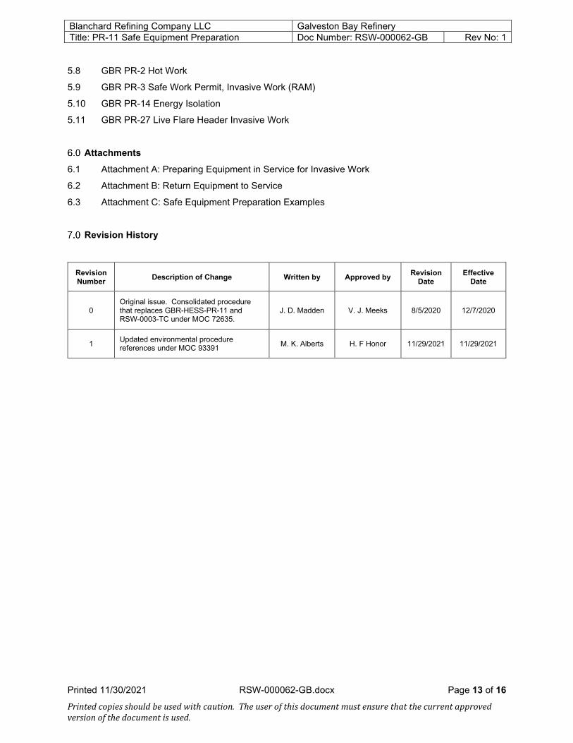
Revision History
Revision Number Description of Change Written by Approved by Revision
Date Effective
Date
0 Original issue. Consolidated procedure that replaces GBR-HESS-PR-11 and RSW-0003-TC under MOC 72635.
J. D. Madden V. J. Meeks 8/5/2020 12/7/2020
1 Updated environmental procedure references under MOC 93391 M. K. Alberts H. F Honor 11/29/2021 11/29/2021

Blanchard Refining Company LLC Galveston Bay Refinery Title: PR-11 Safe Equipment Preparation Doc Number: RSW-000062-GB Rev No: 1
Printed 11/30/2021 RSW-000062-GB.docx Page 14 of 16 Printed copies should be used with caution. The user of this document must ensure that the current approved version of the document is used.
Attachment A: Preparing Equipment in Service for Invasive Work
Complete Bulk Oil, Light Hydrocarbon De-inventory (drain, purge, steam wash, etc.).
Test atmosphere of equipment/piping.
Are contaminants below the PEL and LEL?
Can proper controls be used to mitigate the
hazard(s)?
Perform lockout/tagout and issue permit to install blind tags. (1)
Install blind tags Note: Maintain positive pressure while blinding
Verify atmosphere inside of equipment.Note: Maintain positive pressure on equipment
Are contaminants below the PEL and LEL?
Can proper controls be used to mitigate the
hazards?
Decontaminate equipment (e.g. drain, purge, steam, wash, etc.)
Issue permit authorizing work.
Take equipment out of service and isolate from process.
NO
YESYES
YESYES
NO
NO
NO
(1) If pressure cannot be verified or be lowered, a variance is required.

Blanchard Refining Company LLC Galveston Bay Refinery Title: PR-11 Safe Equipment Preparation Doc Number: RSW-000062-GB Rev No: 1
Printed 11/30/2021 RSW-000062-GB.docx Page 15 of 16 Printed copies should be used with caution. The user of this document must ensure that the current approved version of the document is used.
Attachment B: Return Equipment to Service
Complete equipment punchout and tightness test.
Air free equipment (i.e. purge, steam, pull, vacuums, etc.)
Test atmosphere inside of equipment for oxygen.
Note: Maintain positive pressure on equipment while testing.
Verify repairs are completed and equipment is ready to return to service.
NO
YES
YES
YES
YES
NO
NO
Is oxygen less than 1%?
Is the equipment isolated by blinds?
Check for pressure and contaminants upstream of blinds.
Are contaminants below the PEL?
Are blinds depressured?
Issue permit to pull blinds on equipment. (1)
Remove blinds. Note: Maintain positive pressure while de-
blinding to prevent air from entering.
Test atmosphere inside of equipment for oxygen.
Is oxygen less than 1%?
Air free equipment (i.e. purge, steam, water flood, pull vacuums, etc.)
Return equipment to service per unit operating procedures.
Can PPE be used to mitigate the hazards?
Verify and/or modify upstream isolations
Decontaminate upstream piping.
Can the pressure be addressed?
NO
NONO
YESYES
YESNO
(1) If pressure cannot be verified or be lowered, a variance is required.
• If during blind installation, the block valve on the Live Side of the blind held, a typical blind is installed (Not a bleeder blind), and process conditions have not change, it can be assumed that the valve is still holding and a SP variance is not required to remove the blind
o Employees should still exercise caution, stay out of the line of fire, and if dictated by Ops, PPE requirements may change to include fresh air & other mitigating efforts

Blanchard Refining Company LLC Galveston Bay Refinery Title: PR-11 Safe Equipment Preparation Doc Number: RSW-000062-GB Rev No: 1
Printed 11/30/2021 RSW-000062-GB.docx Page 16 of 16 Printed copies should be used with caution. The user of this document must ensure that the current approved version of the document is used.
Attachment C: Safe Equipment Preparation Examples
Example 2: Process piping needs to have a blind installed. LEL at the nearest bleeder/vent is 30%. In the workers atmosphere, the LEL is 15%. A risk assessment and mitigation plan was completed. An air horn has been set up and the LEL in the workers breathing zone is now less than 10%. Barricades have been established around the venting area to mitigate LEL hazards. A variance will be required since the LEL is at or above 10%.
Example 1: Process piping needs to have a blind installed. LEL at the nearest bleeder/vent is 30%. In the workers atmosphere, the LEL is less than 10%. In this situation the LEL at the nearest bleeder/vent is above the PEL and a risk assessment and mitigation plan with proper controls must be documented on the JSA and Safe Work Permit prior to authorizing work to begin.