REVAMP OF NAPHTHA HYDROTREATING PROCESS IN AN IRANIAN REFINERY
6
Petroleum & Coal ISSN 1337-7027 Available online at www.vurup.sk/pc Petroleum & Coal 51 (1) 45-50, 2009 REVAMP OF NAPHTHA HYDROTREATING PROCESS IN AN IRANIAN REFINERY Sepehr Sadighi 1 , S.Reza Seif Mohaddecy 1 , Omid Ghabouli 1 , Majid Bahmani 2 1 Research Institute of Petroleum Industry, Catalytic Reaction Engineering Department,Catalysis Research Center, www.ripi.ir , E-mail: [email protected] 2 Tarbiat Moalem University, Department of Chemistry, Applied Chemistry Group, Tehran, Iran Received September 3, 2008, accepted January 7, 2009 Abstract Hydrotreating of naphtha (HDS) is one of the important units in crude oil refineries in which compounds such as sulfur, nitrogen, oxygen and metal are removed. A commonly used HDS catalyst is molybdenum–nickel on alumina support. sulfur and nitrogen compounds have been removed with hydrogenation in which hydrogen sulfide and ammonia are produced and then removed by a flash drum. In this paper, naphtha hydrotreating unit of a target refinery in Iran was studied. Design capacity of unit was 12000 BPSD, but because of increasing gasoline demand, the unit capacity was turned on 15000 BPSD. It made many difficulties such as increasing pressure drop of air coolers and corrosion, and decreasing of recycle compressor discharge pressure. To reduce mentioned difficulties, a supplementary flash drum was added to the primary designed separation process. To show the effect of that, the revamped process was simulated by Aspen Plus software. Results confirmed that not only the mentioned problems was removed, but also a considerable energy saving was achieved. Keyword: Naphtha treating; Simulation; Optimization; Aspen plus 1. Introduction Sulfur, nitrogen and metal compounds are the most important pollutants in petroleum cuts and removing these compounds is the primary objective in the refining industry. Hydrotreating processes have been well known since 1933, and a wide range of researches have been conducted in this field throughout the world. Nowadays, a lot of capital investments is inclined in refining industries to produce cleaner middle distillates to meet environmental standards. On the other hand, poisoning of valuable metal catalysts in refinery units and deactivation of them as a result of their contact with such harmful compounds are the major reasons that oblige the hydrotreating of fuels; Furthermore, the toughening trend of environmental regulations and standards in most countries causes a drawback in the export of highly pollutant fuels. There are different methods for hydrotreatment which some of them are shown in table 1. Catalytic naphtha hydrotreatment can simultaneously accomplish desulfurization, denitrogenation, deoxidation, metals elimination and olefin saturation. These reactions are accomplished by the cleavage of C-S, C-N and C-O bonds, then S, N and O are separated from hydrocarbons in H 2 S, NH 3 and H 2 O form; Moreover, the hydrocracking is accomplished as a side reaction. For energy saving and capacity increasing in the hydrotreating units, several projects were done [1,2] . In this paper a hot gas separator was added to separation process before cooling the feed. Then, effects of this revamp on the operating conditions, duty of heat exchanger, utility and qualification of products were studied.
Transcript of REVAMP OF NAPHTHA HYDROTREATING PROCESS IN AN IRANIAN REFINERY
Petroleum & Coal ISSN 1337-7027
Available online at www.vurup.sk/pc Petroleum & Coal 51 (1) 45-50, 2009
REVAMP OF NAPHTHA HYDROTREATING PROCESS IN AN IRANIAN REFINERY
Sepehr Sadighi1, S.Reza Seif Mohaddecy1, Omid Ghabouli1, Majid Bahmani2
1Research Institute of Petroleum Industry, Catalytic Reaction Engineering Department,Catalysis Research Center, www.ripi.ir, E-mail: [email protected] 2Tarbiat Moalem University, Department of Chemistry, Applied Chemistry
Group, Tehran, Iran
Received September 3, 2008, accepted January 7, 2009
Abstract
Hydrotreating of naphtha (HDS) is one of the important units in crude oil refineries in which compounds such as sulfur, nitrogen, oxygen and metal are removed. A commonly used HDS catalyst is molybdenum–nickel on alumina support. sulfur and nitrogen compounds have been removed with hydrogenation in which hydrogen sulfide and ammonia are produced and then removed by a flash drum. In this paper, naphtha hydrotreating unit of a target refinery in Iran was studied. Design capacity of unit was 12000 BPSD, but because of increasing gasoline demand, the unit capacity was turned on 15000 BPSD. It made many difficulties such as increasing pressure drop of air coolers and corrosion, and decreasing of recycle compressor discharge pressure. To reduce mentioned difficulties, a supplementary flash drum was added to the primary designed separation process. To show the effect of that, the revamped process was simulated by Aspen Plus software. Results confirmed that not only the mentioned problems was removed, but also a considerable energy saving was achieved. Keyword: Naphtha treating; Simulation; Optimization; Aspen plus
1. Introduction
Sulfur, nitrogen and metal compounds are the most important pollutants in petroleum cuts and removing these compounds is the primary objective in the refining industry.
Hydrotreating processes have been well known since 1933, and a wide range of researches have been conducted in this field throughout the world. Nowadays, a lot of capital investments is inclined in refining industries to produce cleaner middle distillates to meet environmental standards. On the other hand, poisoning of valuable metal catalysts in refinery units and deactivation of them as a result of their contact with such harmful compounds are the major reasons that oblige the hydrotreating of fuels; Furthermore, the toughening trend of environmental regulations and standards in most countries causes a drawback in the export of highly pollutant fuels. There are different methods for hydrotreatment which some of them are shown in table 1. Catalytic naphtha hydrotreatment can simultaneously accomplish desulfurization, denitrogenation, deoxidation, metals elimination and olefin saturation. These reactions are accomplished by the cleavage of C-S, C-N and C-O bonds, then S, N and O are separated from hydrocarbons in H2S, NH3 and H2O form; Moreover, the hydrocracking is accomplished as a side reaction.
For energy saving and capacity increasing in the hydrotreating units, several projects were done [1,2]. In this paper a hot gas separator was added to separation process before cooling the feed. Then, effects of this revamp on the operating conditions, duty of heat exchanger, utility and qualification of products were studied.
To simulate the understudy unit and to validate the simulation, Aspen plus and Aspen B-jac simulators and plant test runs were used respectively [3, 4]. Table 1. Hydrotreatment processes
Hydrotreatment feedstock Hydrotreatment methods Reforming feedstock, (heavy naphtha) HDS, HDN,HDM Light gasoline HDS, HDM Kerosene HDS Jet fuel HDN, HDS Gas oil HDS, HDN, HDM Residue HDS, HDM Oils HDS, HDN HDS- Hydrodesulfurization, HDN-Hydrodenitrification, HDM-Hydrodematalization
2. Hydrodesulfurization process [1]
Sulfur is one of the pollutants in fossil fuels. It contents in crude oil which may be categorized in the following groups: 1. Free elemental sulfur 2. Mercaptans & tiols (R-SH) 3. Hydrogen sulfide 4. Sulfides 5. Disulfides (R-S-S-R') 6. Poly sulfides (R-Sn-R') 7. Thiophenes and their derivatives such as BT (benzothiophene ) and DBT (dibenzothiphene)
With reference to recent investigations on hydrodesulfurization reactions, it can be understood that sulfur removal from mercaptans, sulfides and disulfides are easily done and free sulfur hydrocarbon and H2S are produced as a result, while thiophenes and particularly benzothiophenic and dibenzothiphenic derivatives are difficult to desufurize. But, if deep hydrodesulfurization of diesel fuel is concerned, removing benzothiohenic and dibenzothiophenic compounds is important. Most of industrial hydrodesulfurization methods are similar, and there are only minor differences in their details.
Hydrodesulfurization unit have some advantages such as: - Sulfur & nitrogen removal to less that 10 ppm - Complete removal of metal compounds from feedstock - Reduction of environmental pollutants - Increase in catalysts age and reduction in poisoning of valuable metal catalyst - Reduction in corrosion of process equipment - Easy treatment of waste water - Simple operation of process unit
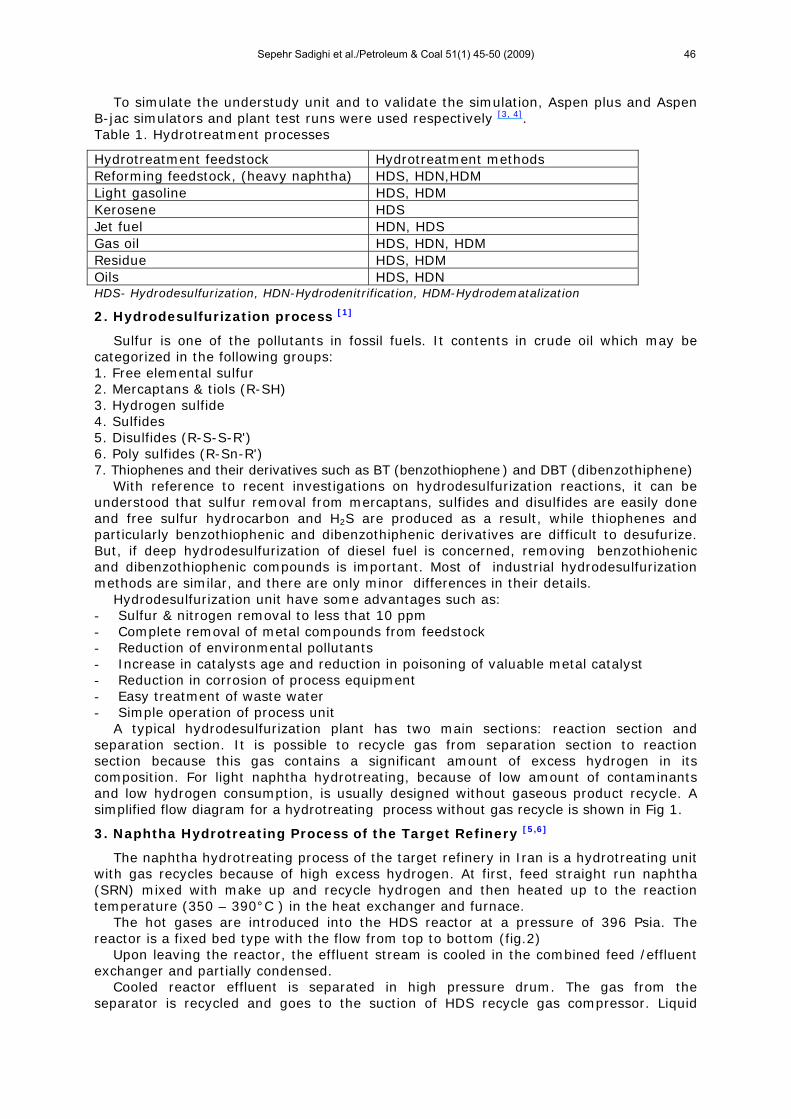
A typical hydrodesulfurization plant has two main sections: reaction section and separation section. It is possible to recycle gas from separation section to reaction section because this gas contains a significant amount of excess hydrogen in its composition. For light naphtha hydrotreating, because of low amount of contaminants and low hydrogen consumption, is usually designed without gaseous product recycle. A simplified flow diagram for a hydrotreating process without gas recycle is shown in Fig 1.
3. Naphtha Hydrotreating Process of the Target Refinery [5,6]
The naphtha hydrotreating process of the target refinery in Iran is a hydrotreating unit with gas recycles because of high excess hydrogen. At first, feed straight run naphtha (SRN) mixed with make up and recycle hydrogen and then heated up to the reaction temperature (350 – 390°C ) in the heat exchanger and furnace.
The hot gases are introduced into the HDS reactor at a pressure of 396 Psia. The reactor is a fixed bed type with the flow from top to bottom (fig.2)
Upon leaving the reactor, the effluent stream is cooled in the combined feed /effluent exchanger and partially condensed.
Cooled reactor effluent is separated in high pressure drum. The gas from the separator is recycled and goes to the suction of HDS recycle gas compressor. Liquid
Sepehr Sadighi et al./Petroleum & Coal 51(1) 45-50 (2009) 46
naphtha before entering stabilizer is preheated by the bottom of stabilizer tower. The purpose of the stabilizer column is to strip out H2S and light hydrocarbons from the treated straight-run naphtha which goes to the other units like catalytic reformer. This product is included lower than 1 ppm wt. water, and 0.5 ppm wt. sulfur and nitrogen components.
The overhead vapors from stabilizer column are partially condensed by air cooled condenser and flows into stabilizer receiver.
Figure 1- Hydrotreatment unit without gaseous product recycle
Figure 2. Hydrotreatment unit with gaseous product recycle
4. Process Simulation
For the simulation of hydrotreating unit, the outlet of the reactor was lumped to real components according to GC analysis data presented in table 2. Then, separation section of the process was simulated based on actual operating conditions and 15000 BPSD of feed flow (Fig 3). To simulate stabilizer and flash drum, Radfrac and Flash2 modules in Aspen plus were used respectively. But, to obtain a rigorous simulation for heat exchangers and air coolers, Aspen-Bjac modules were linked to Aspen plus.
After simulation of naphtha hydrotreating unit which shown in fig 3, to evaluate it, operating data of the target refinery were compared with simulation results which has been presented in table 3. The results confirmed that Aspen-plus and Aspen-Bjac had good capability to simulate separation section of hydrotreating unit and it can be used for evaluation the proposed revamp.
Table 2. Specified feedstock is used for simulation
Column Component Column Component Column Component Column Component 1 NH3 9 i- C5 17 n-C10 25 BENZENE 2 H2S 10 n-C5 18 CYCLO-C5 26 TOLUENE 3 H2 11 i- C6 19 M-CYC-C5 27 ETHYLBENZENE 4 C1 12 n-C6 20 CYCLO-C6 28 AROM-C8 5 C2+ 13 n-C7 21 CYCLO-C7 29 AROM-C9 6 C3+ 14 n-C8 22 CYCLO-C8 30 AROM-C10 7 i- C4 15 n-C9 23 CYCLO-C9 31 H2O 8 n-C4 16 N2 24 CYCL-C10 32 O2
Table 3. Comparison simulation results and actual data
Current conditions (Actual)
Current conditions (Simulation) Variable
Temperature (F ) Temperature (F) Shell outlet in 2E-203 exchanger
115 118
Shell outlet in 2E-204 exchanger
307 307
Tube outlet in 2E-204 exchanger
221 233
Sepehr Sadighi et al./Petroleum & Coal 51(1) 45-50 (2009) 47
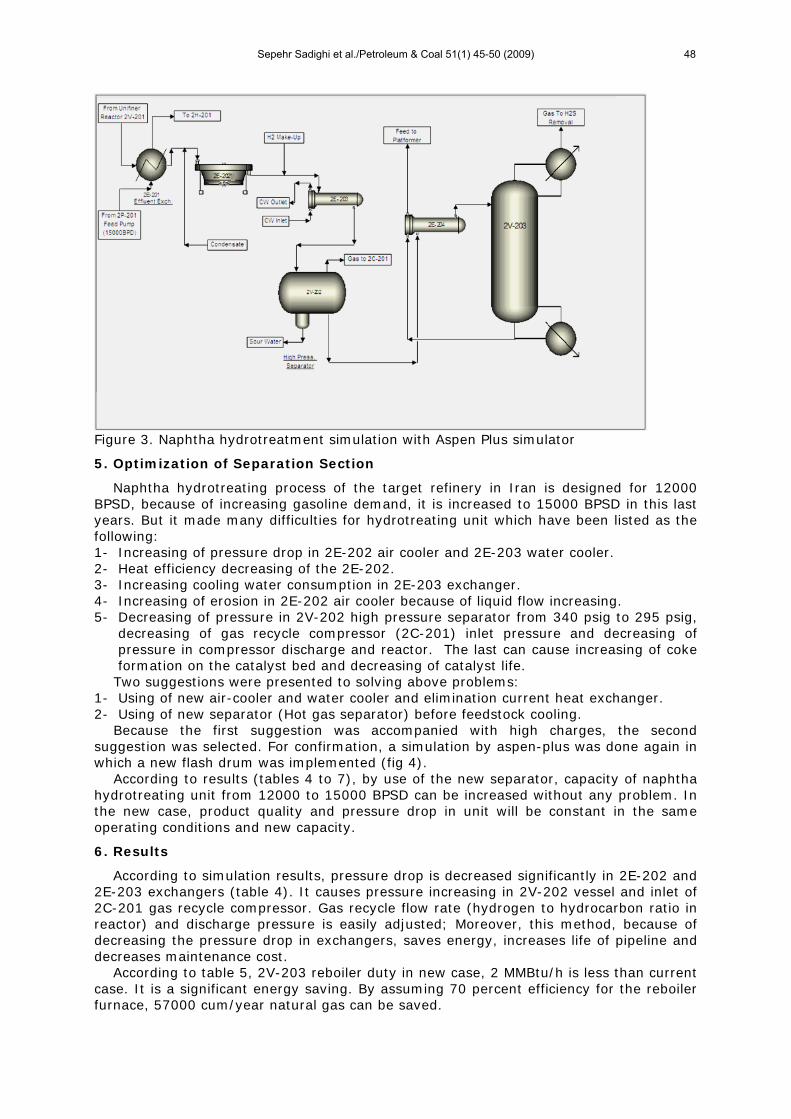
Figure 3. Naphtha hydrotreatment simulation with Aspen Plus simulator
5. Optimization of Separation Section
Naphtha hydrotreating process of the target refinery in Iran is designed for 12000 BPSD, because of increasing gasoline demand, it is increased to 15000 BPSD in this last years. But it made many difficulties for hydrotreating unit which have been listed as the following: 1- Increasing of pressure drop in 2E-202 air cooler and 2E-203 water cooler. 2- Heat efficiency decreasing of the 2E-202. 3- Increasing cooling water consumption in 2E-203 exchanger. 4- Increasing of erosion in 2E-202 air cooler because of liquid flow increasing. 5- Decreasing of pressure in 2V-202 high pressure separator from 340 psig to 295 psig,
decreasing of gas recycle compressor (2C-201) inlet pressure and decreasing of pressure in compressor discharge and reactor. The last can cause increasing of coke formation on the catalyst bed and decreasing of catalyst life.
Two suggestions were presented to solving above problems: 1- Using of new air-cooler and water cooler and elimination current heat exchanger. 2- Using of new separator (Hot gas separator) before feedstock cooling.
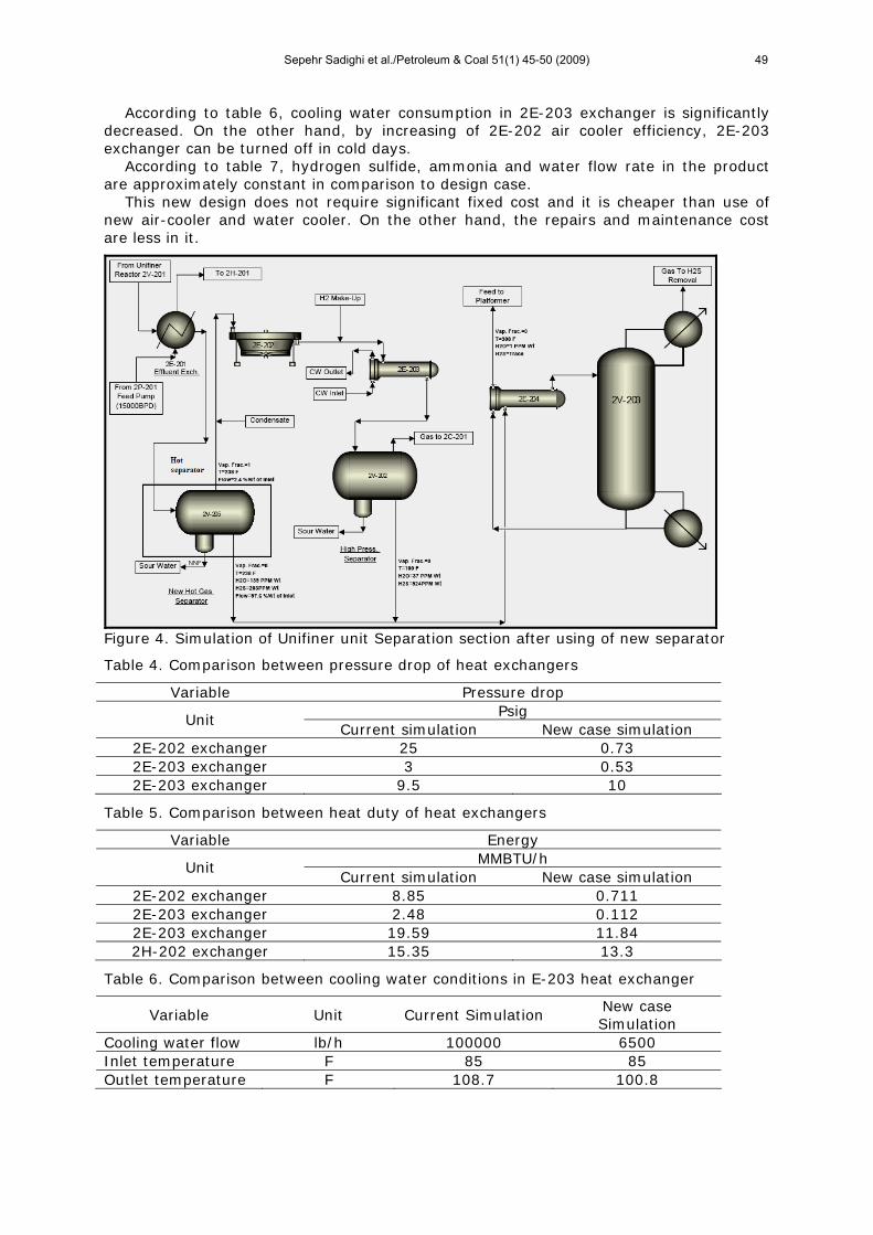
Because the first suggestion was accompanied with high charges, the second suggestion was selected. For confirmation, a simulation by aspen-plus was done again in which a new flash drum was implemented (fig 4).
According to results (tables 4 to 7), by use of the new separator, capacity of naphtha hydrotreating unit from 12000 to 15000 BPSD can be increased without any problem. In the new case, product quality and pressure drop in unit will be constant in the same operating conditions and new capacity.
6. Results
According to simulation results, pressure drop is decreased significantly in 2E-202 and 2E-203 exchangers (table 4). It causes pressure increasing in 2V-202 vessel and inlet of 2C-201 gas recycle compressor. Gas recycle flow rate (hydrogen to hydrocarbon ratio in reactor) and discharge pressure is easily adjusted; Moreover, this method, because of decreasing the pressure drop in exchangers, saves energy, increases life of pipeline and decreases maintenance cost.
According to table 5, 2V-203 reboiler duty in new case, 2 MMBtu/h is less than current case. It is a significant energy saving. By assuming 70 percent efficiency for the reboiler furnace, 57000 cum/year natural gas can be saved.
Sepehr Sadighi et al./Petroleum & Coal 51(1) 45-50 (2009) 48
According to table 6, cooling water consumption in 2E-203 exchanger is significantly decreased. On the other hand, by increasing of 2E-202 air cooler efficiency, 2E-203 exchanger can be turned off in cold days.
According to table 7, hydrogen sulfide, ammonia and water flow rate in the product are approximately constant in comparison to design case.
This new design does not require significant fixed cost and it is cheaper than use of new air-cooler and water cooler. On the other hand, the repairs and maintenance cost are less in it.
Figure 4. Simulation of Unifiner unit Separation section after using of new separator
Table 4. Comparison between pressure drop of heat exchangers
Variable Pressure drop Psig
Unit Current simulation New case simulation
2E-202 exchanger 25 0.73 2E-203 exchanger 3 0.53 2E-203 exchanger 9.5 10
Table 5. Comparison between heat duty of heat exchangers
Variable Energy MMBTU/h
Unit Current simulation New case simulation
2E-202 exchanger 8.85 0.711 2E-203 exchanger 2.48 0.112 2E-203 exchanger 19.59 11.84 2H-202 exchanger 15.35 13.3
Table 6. Comparison between cooling water conditions in E-203 heat exchanger
Variable Unit Current Simulation New case Simulation
Cooling water flow lb/h 100000 6500 Inlet temperature F 85 85 Outlet temperature F 108.7 100.8
Sepehr Sadighi et al./Petroleum & Coal 51(1) 45-50 (2009) 49

Table 7. Comparison between purity of streams
(Outlet product from shell of 2E-204 exchanger ) feed of 2V-203 column New case simulation Current simulation Variable
212 359 H2S concentration (ppm-wt) 0.952 2 NH3 concentration (ppm-wt)
Column bottom stream(2V-203) or Unifier product New case simulation Current simulation Variable
negligible negligible H2S concentration (ppm-wt) negligible negligible NH3 concentration (ppm-wt)
References
[1] Vargas-Villamil, F.D., Marroquin, J.O., de la Pas, C., Rodriguez, E., A Catalytic Distillation Process for Light Gas Oil Hydrodesulfurization., Chemical Engineering and Processing , 43(2004), pp1309-1326.
[2] Companies Find New Value with Refinery-wide Rigorous Simulation Solutions, Hydrocarbon Processing, ERTC 8th Annual Meeting, November 2003, pp 9-10.
[3] De Araujo, A.C.B., Govatsmark, M., Skogestad, S., Application of Plant wide Control to the HAD Process. I-Steady-State Optimization and Self-optimizing Control., Control Engineering Practice, Volume 15, Issue 10, October 2007, pp 1222-1237.
[4] Hou, W., SU, H., HU, Y., CHU, J., Modeling, Simulation and Optimization of a Whole Industrial Catalytic Naphtha Reforming Process on Aspen Plus Platform., Chinese Journal of Chemical engineering, Volume 14, Issue 5, October 2006, Pages 584-591.
[5] Revamp of NHT& Platformer Unit., Tehran North Refinery, Process Data Book, Volume 1, October 2003, Axens Company.
[6] UOP Naphtha Hydrocracking Process, Tehran North Refinery, General Operating Manual, May 1983, Rev.3, UOP Company.
[7] UOP Platforming Process and Chemistry, Tehran North Refinery, Platforming ,pp 11704-11047, Rev.O,A, July 1991, UOP Company.
Sepehr Sadighi et al./Petroleum & Coal 51(1) 45-50 (2009) 50


![Observation of [Al(OH) n (H 2 O) 6- n ] n (MoO 4 ) in hydrotreating catalyst precursors by solid-state 27 Al NMR](https://static.fdokumen.com/doc/165x107/6315130285333559270cfb60/observation-of-aloh-n-h-2-o-6-n-n-moo-4-in-hydrotreating-catalyst-precursors.jpg)