Extraction of metals from spent hydrotreating catalysts: Physico-mechanical pre-treatments and...
10
Journal of Hazardous Materials 192 (2011) 176–185 Contents lists available at ScienceDirect Journal of Hazardous Materials j our na l ho me p age: www.elsevier.com/locate/jhazmat Extraction of metals from spent hydrotreating catalysts: Physico-mechanical pre-treatments and leaching stage Francesco Ferella ∗ , Albena Ognyanova, Ida De Michelis, Giuliana Taglieri, Francesco Vegliò Department of Chemistry, Chemical Engineering and Materials, University of L’Aquila, Monteluco di Roio, 67040 L’Aquila, Italy a r t i c l e i n f o Article history: Received 1 February 2011 Received in revised form 9 April 2011 Accepted 1 May 2011 Available online 10 May 2011 Keywords: NiMo catalyst CoMo catalyst Flotation Attrition Vibrating grinding a b s t r a c t The present paper is focused on physico-mechanical pre-treatments of spent hydrotreating catalysts aimed at concentration of at least one of the valuable metals contained in such secondary raw material. In particular, dry Ni–Mo and Co–Mo as well as wet Ni–Mo catalysts were used. Flotation, grain size separation and attrition processes were tested. After that, a rods vibrating mill and a ball mill were used to ground the catalysts in order to understand the best mechanical pre-treatment before leaching extraction. The results showed that flotation is not able to concentrate any metals due to the presence of coke or other depressant compounds. The particle size separation produces two fractions enriched in Mo and Co when dry Co–Mo catalyst is used, whereas attrition is not suitable as metals are uniformely distributed in rings’ volume. Roasting at 550 ◦ C and vibrating grinding are the most suitable pre-treatments able to produce fractions easily leached by NaOH and H 2 SO 4 after grain size separation. © 2011 Elsevier B.V. All rights reserved. 1. Introduction Catalysts are widely used in petroleum refining and chemical industries; hydrotreating catalysts usually consist of molybdenum (Mo) supported on an alumina or silica carrier together with pro- moters such as cobalt (Co) or nickel (Ni): they enhance removal of undesirable impurities such as sulphur, nitrogen and metals like vanadium (V) in feedstocks by promoting hydrodesulphuriza- tion (HDS), hydrodenitrogenation (HDN) and hydrodemetallization (HDM) reactions [1,2]. The volume of spent hydroprocessing cat- alysts has increased significantly in recent years due to a rapid growth in distillates hydrotreating capacity to meet the increasing demand of ultra-low sulphur fuels, a steady increase in process- ing of heavier feedstock containing greater amount of sulphur and metals and a rapid deactivation with unavailability of reactiva- tion processes for some of the hydroprocessing catalysts. After few cycles of regeneration, catalyst activity may decrease to very low levels and further regeneration may not be economically fea- sible or possible. Among secondary resources, spent catalysts are undoubtedly very important not only for their economic value but also for environmental concerns when disposed off, as they have been classified as hazardous wastes [2,3]. Several hydro- and pyro- metallurgical processes have been proposed for metals recovery ∗ Corresponding author. Tel.: +39 0862 434221; fax: +39 0862 701974. E-mail address: [email protected] (F. Ferella). from spent HDS catalysts. The most important metals recovered from HDS catalysts are Mo, Ni and Co, but Al (20–35 wt%) often represents a co-product which can be valorized avoiding dumping [4,5]. Furthermore, many of these catalysts contain V ranging from 0.5 to even 8 wt%, and this makes treatment of this material more viable. A summary of the most important and recent studies on recov- ery of metals from hydroteating catalyst is reported in Table 1. Recovery of vanadium, when present, is always greater than 90% with respect to the concentration in spent catalysts [4,5]. Since these catalysts contain sulphur, coke and sometimes hydrocarbons like naphtha, a pre-treatment is usually required to oxidize the organic matter. The two-steps process industrially used includes roasting of catalysts in air at 600 ◦ C and a second roast- ing of the resulting material at 600–800 ◦ C in presence of soda ash (Na 2 CO 3 ): the aim is to convert molybdenum and vanadium oxides to soluble sodium molybdate and vanadate [16]. MoO 3 + Na 2 CO 3 → Na 2 MoO 4 + CO 2 (1) V 2 O 5 + Na 2 CO 3 → 2NaVO 3 + CO 2 (2) The roasted material is leached with water at 80–90 ◦ C and atmospheric pressure to dissolve the soluble molybdenum and vanadium compounds. The insoluble Ni–Co-alumina filter cake is treated separately to recover those metals. Sometimes soda ash is directly mixed in a single roasting stage and this results in a greater 0304-3894/$ – see front matter © 2011 Elsevier B.V. All rights reserved. doi:10.1016/j.jhazmat.2011.05.005
Transcript of Extraction of metals from spent hydrotreating catalysts: Physico-mechanical pre-treatments and...

Ep
FD
a
ARRAA
KNCFAV
1
i(molt(agdimtflsuabm
0d
Journal of Hazardous Materials 192 (2011) 176– 185
Contents lists available at ScienceDirect
Journal of Hazardous Materials
j our na l ho me p age: www.elsev ier .com/ locate / jhazmat
xtraction of metals from spent hydrotreating catalysts: Physico-mechanicalre-treatments and leaching stage
rancesco Ferella ∗, Albena Ognyanova, Ida De Michelis, Giuliana Taglieri, Francesco Vegliòepartment of Chemistry, Chemical Engineering and Materials, University of L’Aquila, Monteluco di Roio, 67040 L’Aquila, Italy
r t i c l e i n f o
rticle history:eceived 1 February 2011eceived in revised form 9 April 2011ccepted 1 May 2011vailable online 10 May 2011
a b s t r a c t
The present paper is focused on physico-mechanical pre-treatments of spent hydrotreating catalystsaimed at concentration of at least one of the valuable metals contained in such secondary raw material.In particular, dry Ni–Mo and Co–Mo as well as wet Ni–Mo catalysts were used. Flotation, grain sizeseparation and attrition processes were tested. After that, a rods vibrating mill and a ball mill were used toground the catalysts in order to understand the best mechanical pre-treatment before leaching extraction.
eywords:iMo catalystoMo catalystlotationttritionibrating grinding
The results showed that flotation is not able to concentrate any metals due to the presence of coke orother depressant compounds. The particle size separation produces two fractions enriched in Mo and Cowhen dry Co–Mo catalyst is used, whereas attrition is not suitable as metals are uniformely distributedin rings’ volume. Roasting at 550 ◦C and vibrating grinding are the most suitable pre-treatments able toproduce fractions easily leached by NaOH and H2SO4 after grain size separation.
© 2011 Elsevier B.V. All rights reserved.
. Introduction
Catalysts are widely used in petroleum refining and chemicalndustries; hydrotreating catalysts usually consist of molybdenumMo) supported on an alumina or silica carrier together with pro-
oters such as cobalt (Co) or nickel (Ni): they enhance removalf undesirable impurities such as sulphur, nitrogen and metalsike vanadium (V) in feedstocks by promoting hydrodesulphuriza-ion (HDS), hydrodenitrogenation (HDN) and hydrodemetallizationHDM) reactions [1,2]. The volume of spent hydroprocessing cat-lysts has increased significantly in recent years due to a rapidrowth in distillates hydrotreating capacity to meet the increasingemand of ultra-low sulphur fuels, a steady increase in process-
ng of heavier feedstock containing greater amount of sulphur andetals and a rapid deactivation with unavailability of reactiva-
ion processes for some of the hydroprocessing catalysts. Afterew cycles of regeneration, catalyst activity may decrease to veryow levels and further regeneration may not be economically fea-ible or possible. Among secondary resources, spent catalysts arendoubtedly very important not only for their economic value but
lso for environmental concerns when disposed off, as they haveeen classified as hazardous wastes [2,3]. Several hydro- and pyro-etallurgical processes have been proposed for metals recovery∗ Corresponding author. Tel.: +39 0862 434221; fax: +39 0862 701974.E-mail address: [email protected] (F. Ferella).
304-3894/$ – see front matter © 2011 Elsevier B.V. All rights reserved.oi:10.1016/j.jhazmat.2011.05.005
from spent HDS catalysts. The most important metals recoveredfrom HDS catalysts are Mo, Ni and Co, but Al (20–35 wt%) oftenrepresents a co-product which can be valorized avoiding dumping[4,5]. Furthermore, many of these catalysts contain V ranging from0.5 to even 8 wt%, and this makes treatment of this material moreviable.
A summary of the most important and recent studies on recov-ery of metals from hydroteating catalyst is reported in Table 1.Recovery of vanadium, when present, is always greater than 90%with respect to the concentration in spent catalysts [4,5].
Since these catalysts contain sulphur, coke and sometimeshydrocarbons like naphtha, a pre-treatment is usually required tooxidize the organic matter. The two-steps process industrially usedincludes roasting of catalysts in air at 600 ◦C and a second roast-ing of the resulting material at 600–800 ◦C in presence of soda ash(Na2CO3): the aim is to convert molybdenum and vanadium oxidesto soluble sodium molybdate and vanadate [16].
MoO3 + Na2CO3 → Na2MoO4 + CO2 (1)
V2O5 + Na2CO3 → 2NaVO3 + CO2 (2)
The roasted material is leached with water at 80–90 ◦C and
atmospheric pressure to dissolve the soluble molybdenum andvanadium compounds. The insoluble Ni–Co-alumina filter cake istreated separately to recover those metals. Sometimes soda ash isdirectly mixed in a single roasting stage and this results in a greater
F. Ferella et al. / Journal of Hazardous Materials 192 (2011) 176– 185 177
Table 1Summary of the most important experimental studies carried out on spent hydrotreating catalysts.
Catalyst Pre-treatments Leaching reagents Co recovery, % Mo recovery,%
Ni recovery, % Reference
Co–MoNi–Mo
Roasting (500 ◦C, 5 h) Leaching by H2SO4 9 mol L−1, 90 ◦C, 2 h 98 99 98 [4]
Co–MoNi–Mo
Grinding Fusion with KHSO4 (350–600 ◦C, 0.5-7 h) 87–90 96–99 91–94 [5]
Spent HDS catalyst Washing (H2O) – Na2CO3 or NaOH (85 g L−1) + H2O2 (10 vol%) – 85–97 MoO3 Not measured [6]Drying – Ammonium molybdate precipitationGrinding – Roasting (450 ◦C)
Spent HDS catalyst(NiMo/�-Al2O3)
Washing (acetone) – Na2CO3 (40 g L−1) + H2O2 (6 vol%) – 99.4 MoO3 Not measured [7]
Drying – Carbon adsorptionGrinding – Desorption (NH4OH)
– Roasting (450 ◦C)Spent HDS catalyst
(Co/Ni/Mo–Al2O3)Washing (acetone) – Na2CO3 (30 g L−1) 93% 98 90 [8]
Drying – H2SO4 (6 mol L−1)Roasting (500 ◦C) – Solvent extraction of Al (Cyanex 272)
Spent hydro-refiningcatalyst
– – 600 ◦C air roasting + Na2CO3 (12 wt%) for 30 min Not measured 92 Na2MoO4 Not measured [9]
– Water leaching (90 ◦C)– Chemical treatment– Adsorption/desorption method
Spent hydro-refiningcatalyst
– – 900 ◦C air roasting + NaCl (20 wt%) Not measured 90 Na2MoO4 Not measured [10]
– Water leaching (70–90 ◦C) for 60 min– Chemical treatment
Co–Mo Roasting (450 ◦C, 2 h) Two-steps alkali-acid procedure(1) Alkaline leaching → dissolution of Mo (10 g L−1;NaOH; 80 ◦C; 1/20 S/L)
80 97 80 [11]
Ni–Mo (2) Acidic leaching → dissolution of Co/Ni (10 g L−1;H2SO4; 80 ◦C; 1/20 S/L)
Spent HDS catalyst Heating (300 ◦C,30 min)
– Acidic leaching, 70 ◦C (HNO3/H2SO4/HCl = 2:1:1) – 90 99 [12]
– ElectrolysisSpent HDS catalyst Washing (toluene) Acidic leaching, 50 ◦C
0.5 mol L−1 H2C2O4 + 3 mol L−1 H2O2
– 90 65 [13]
Spent HDS catalyst Heating (400 ◦C, 4 h) – Acidic leaching, 80 ◦C (H2SO4 + H2O2) 81 72 Not measured [14]– Alkaline leaching, 80 ◦C (NaOH + H2O2) + Al
50% S
ct
2
V
tanhibrgdrs
1
precipitation at pH 8Ammonia leaching
residueRoasting with Na2CO3 Water leaching (90 ◦C, 15 min,
onsumption of salt, since sulphur reacts with sodium according tohe reactions:
MoS2 + 6Na2CO3 + 9O2 → 2Na2MoO4 + 4Na2SO4 + 6CO2 (3)
2S3 + 4Na2CO3 + 7O2 → 2NaVO3 + 3Na2SO4 + 4CO2 (4)
Reactions (3) and (4) can be considered as a first step of flue gasreatment (sulphur capture), giving a reduction of the amount of thelkaline reagent during desulphurization stage. However, the preg-ant solution obtained after the water leaching is contaminated byuge amounts of sodium sulphate which can give problems dur-
ng precipitation of Mo and V. Although sodium hydroxide, sodiumicarbonate and sodium sulphate have been used in direct saltoasting, sodium carbonate is the most used due to its lower cost. Aood review on processes currently available for recovery of molyb-enum and vanadium can be found in Zeng and Cheng [17,18]. Theecycling processes can be classified as follows, according to thetages used:
. Acid leaching. There are two main routes to treat spent catalysts:one is direct acid leaching under pressure and high temperature;the other is an acid leaching at atmospheric pressure and tem-perature lower than 100 ◦C after roasting. Untreated catalysts
can also be leached by using an acid medium with one chemicaloxidant such as H2O2 or HNO3. Acid leaching is commonly usedif recovery of all metals from the spent catalyst is required. Ni,Mo, V, Co and alumina dissolve whereas little dissolution of sil-/L) – 91 – [15]
ica can take place. Sulphuric, hydrochloric, nitric or organic acidslike oxalic and citric are used.
2. Basic leaching. Alkali leaching can be used to selectively dissolvemolybdenum and vanadium from spent HDS catalysts. It alsodissolves some aluminum but leaves nickel and cobalt in thesolid residue. In most cases, metal sulphides are oxidized first byroasting; hence, soluble sodium molybdate, vanadate and alumi-nate form and dissolve in leaching solution. There are three mainroutes, including roasting followed by caustic leaching, direct hotcaustic leaching under pressure and caustic/sodium aluminateleaching. Cobalt and/or nickel in solid residue can be extractedby acid. Alternatively, the residue can be sent to smelters orhydrometallurgical plants specialized in separation and recov-ery of nickel and cobalt. However, direct atmospheric leachingespecially at low caustic concentration is not practicable becauseof low extraction of molybdenum and vanadium.
Several methods for separation, purification and recovery ofmolybdenum and vanadium from leach solutions are currentlyused; main techniques include sulphide precipitation, ammoniumsalt precipitation, carbon adsorption, ion exchange and solventextraction [4–11,19–21]. Once nickel and cobalt are extracted fromthe solid residue of the water or alkaline leaching, they can be
recovered by precipitation; however, due to their very similarphysico–chemical properties, a concentrate is obtained only, oth-erwise a solvent extraction stage is required [22–25]. The aim ofthe present paper was to obtain one or more fractions concen-
1 rdous
tohotthits
2
2
ifNsGwtsfbawa4V(
X
wop
ttcbrbRb
2
Cts7a
2
ir(dwd
78 F. Ferella et al. / Journal of Haza
rated in Mo, V, Ni or Co by using mechanical processes typicalf mining industry in order to reduce material that undergoesydrometallurgical processes. Furthermore, influence of two typesf grinding as well as of different particle size was also inves-igated during roasting and leaching. This is the first researchhat studies flotation, attrition and grain size separation of spentydrotreating catalysts before recycling. The present paper gives
nteresting information and results on which pre-treatments arehe most appropriate to maximize extraction yields of leachingtage.
. Materials and methods
.1. Characterization of catalysts
Three different spent HDS catalysts were used in this study:n particular, a Ni–Mo and a Co–Mo black dry catalysts of dif-erent shapes (powder, spheres, cylinders and scraps) and a weti–Mo (Lc-Finer) catalyst consisting of small pieces of cylindrical
hape covered by naphtha. Catalysts were dried in oven (Mod. 780,alli) at 105 ◦C for 24 h until constant weight was reached; then,eight loss was determined by an analytical balance (PE600, Met-
ler). Samples were ground by a lab-ball mill (PM100, Retsch) andcreened to obtain the appropriate particle size of 100–125 �mor further characterizations. Catalyst samples were characterizedy X-ray fluorescence (XRF) (Spectro, Xepos) and X-ray diffractionnalyses (XRD) (X-Pert, Philips); moreover, the powdered samplesere digested by aqua regia (HCl:HNO3 = 3:1) and HF (1 g of cat-
lyst in 20 mL of mixture) in a microwave digestion bomb (Mod.781, Parr Instruments) and the accurate concentration of Ni, Mo,, Co and Al was determined by atomic absorption spectroscopy
AAS) (SpectrAA 240FS, Varian) by using the following equation:
= C · V
1000 · p· 100 (5)
here X is the concentration of metal, wt%; C is the concentrationf metal in solution, mg L−1; V is the final volume of solution, L; and
is the weight of solid sample, g.Sulphur, carbon and hydrogen were measured by an elemen-
al analyzer (2400 Series II, Perkin Elmer). Aluminum representshe main element when acid leaching is carried out; in fact, Aloncentration can reach 18 g L−1 [26]. In this case, Al can easilye precipitated by NH4OH or (NH4)2SO4 at low pHs (2–2.5) andecovered as ammonium alum (NH4Al(SO4)2·12H2O). That salt cane valorized as a secondary product of the recovery process [26].egarding alkaline leaching, concentration of Al is lower but it cane precipitated at pH 8 as Al(OH)3.
.2. Grain size separation
Grain size separation tests were carried out on Ni–Mo ando–Mo samples; 1 kg sample of each catalyst was used in an elec-ric vibrating screen (Set.El, Erimaki) equipped with the followingtandard sieves: 5.6 mm, 3.35 mm, 2 mm, 1 mm, 500 �m, 250 �m,5 �m, and <75 �m. After classification each fraction was weightednd concentration of metals was determined by XRF.
.3. Attrition
The dry Ni–Mo catalyst was subjected to an attrition test tonvestigate whether one or more metals should be recovered byemoval of external layers of rings. A lab-scale attrition grinder
Wemco, 1.5 L cell capacity) was fed by 1 kg of sample and 670 mL ofemineralized water at 1200 rpm. After 20 min the material under-ent wet screening at 208 �m; resulting granular fractions wereried at 105 ◦C for 24 h and weighted, whereas metal content wasMaterials 192 (2011) 176– 185
determined by XRF. The test was repeated by using Lc-Finer (wetNi–Mo) since it consisted on similar small cyclinders and grain sizeseparation does not make sense on untreated sample. Lc-Finer waspreviously dried in oven for 24 h at 105 ◦C to remove naphtha, andfollowed by the attrition test as described before. A pre-treatmentstep like drying or solvent extraction is required otherwise Lc-Finercannot be ground (formation of a malleable paste).
2.4. Flotation
Fifteen froth flotation tests were carried out on Ni–Mo catalystto increase concentration of one or two metals in the concentrate.In fact, flotation is a process widely used to concentrate Mo, Niand Co sulphides from primary ores. The sample was preparedby dry grinding and the resulting material was sieved at 100 �m.An aspirated-air flotation machine (Wemco) equipped with one500 mL tank was fed by 20 g of sample per each test; after 10 minin contact with 250 mL of distilled water the collector was addedas 0.5% (w/w) aqueous solution. After 5 min frother (polypropyleneglycol, Aerofroth 65, Clariant) was added as 1% (w/w) aqueous solu-tion. After 5 min 150 mL of distilled water were added and air wasgenerated by increasing stirring rate to 1200 rpm. Total flotationtime was 10 min. The following commercial collectors were exper-imented: ORFOM CO125, Aerofloat 25, 4-aminothiophenol (ATP),4-aminothiophenol (ATP-SNC2), 2-mercaptobenzothiazole (MBT-DNC1), Aerofloat 242, Aero 3477, Aero 404, Aero thiocarbonilide130, Aeropromoter 710, Aero 801, Flotinor P184, Flotinor SM15,Phosokresol C, Genamin 8R100D. pH was adjusted by NaOH andmeasured by a Mettler Toledo MP220 pH-meter. The two frac-tions recovered after each test were dried at 105 ◦C for 24 h andcharacterized by XRF.
2.5. Preparatory grinding stage
Tests of comminution were carried out using 210 kg of Ni–Moand Co–Mo mixture. Before grinding, the sample was screenedat 5 mm to remove biggest alumina rings and spheres, whichaccounted for 21.5 kg. The feed particle size distribution (PSD) wasdetermined by a horizontal sieve (Electro Flux). The grinding stagewas chosen for optimization of downstream operations for extrac-tion of valuable metals in a future industrial plant, and for thispurpose a vibrating mill (Palla, KHD H. Wedag) and a ball mill (ESM326, Siebtechnik) were used.
2.6. Roasting tests
Some leaching tests of unroasted catalysts by NaOH and H2SO4and different chemical oxidants (H2O2, NaClO, HNO3) performed byauthors demonstated that good extraction yields can be achievedby using H2SO4/HNO3 mixture only, although great amounts ofNOx are produced: thus, a thermal treatment is inevitabile [26].Ground and non-ground samples were roasted at 550 ◦C for 4 h toremove coke, sulphur and any other organic compound using a lab-scale rotary kiln (length 680 mm, diameter 150 mm, speed 3 rpm,Salvis AG). A certain aliquot of these two samples was collectedfor hydrometallurgical tests, whereas the rest underwent furtherroasting in presence of soda ash at 750 ◦C for 1 h. The following setsof pre-treatments were performed:
A1 – Non-ground feed; roasting 550 ◦C, 4 h.B1 – Non-ground feed; roasting 550 ◦C, 4 h; followed by roast-
ing + Na2CO3 750 ◦C, 1 h.A2 – Ground feed; roasting 550 ◦C, 4 h.B2 – Ground feed; roasting 550 ◦C, 4 h; followed by roast-ing + Na2CO3 750 ◦C, 1 h.
F. Ferella et al. / Journal of Hazardous Materials 192 (2011) 176– 185 179
OH 1
AaiS
2
iTafilpVsoHae
E
wso
3
3
CtX
Fig. 1. Experimental plan of leaching trials (concentration: H2SO4 1 mol L−1; Na
A3 – Non-ground feed; roasting 550 ◦C, 4 h + secondary grinding.B3 – Non-ground feed; roasting 550 ◦C, 4 h; followed by roast-ing + Na2CO3 750 ◦C, 1 h + secondary grinding.
ll roasted samples were analized by XRF. During the roasting testst 550 ◦C and 750 ◦C the flue gas was analized by a non-dispersivenfra-red detector to measure SO2, NOx, CO2 and CO (Ultramat 23,iemens).
.7. Leaching tests
Leaching tests were performed in 250 mL screw flasks at 80 ◦Cn a water bath (Dubnoff, ISCO) mechanically stirred at 200 rpm.he solid to liquid ratio (S/L) was selected to be 10% (w/v) forll experiments. Two samples were collected at 30 min and 4 h,ltered and diluted 1:10 in dilute HNO3 solution after acidic
eaching and in distilled water after alkaline leaching to avoidrecipitation of metals during storage. The concentration of Mo,, Co and Al in leach liquors was determined by AAS. In particular,amples roasted at 550 ◦C were screened and underwent alkaliner acidic leaching (set A, see Section 2.6, 1 mol L−1 NaOH, 1 mol L−1
2SO4), whereas those roasted with soda ash underwent screeningnd alkaline or water leaching (set B, 1 mol L−1 NaOH). The wholexperimental plan is shown in Fig. 1.
Extraction yield of each metal was calculated as follows:
Y =(
(C · V/1000 · p)(X/100)
)· 100 (6)
here EY is the extraction yield, %; C is the concentration of metal inolution, mg L−1; V is the final volume of solution, L; p is the weightf solid sample, g; and X is the concentration of metal, wt%.
. Results and discussion
.1. Characterization of samples
Moisture of original samples ranged from 1 to 2% for Ni–Mo ando–Mo. The Lc-Finer sample showed a weight loss close to 13% dueo the naphtha content, whereas the amount of water is negligible.RD spectra are characterized by low counts and this means that
mol L−1; ground and non-ground refer to the catalysts feeding the rotary kiln).
phases are not crystalline. The most probable compounds identifiedby spectra were:
• Ni–Mo: Al2O3–MoS2–Ni2S3–(V0.07Mo0.93)5O14.• Co–Mo: Al2O3–CoMoS4–CoV2O6.• Lc-Finer: Al2O3–Ni3S4–NiV2S4–Mo4O11.
The Lc-Finer’s XRD analysis revealed that molybdenum ispresent as an oxide rather than sulphide (∼65%): this fact was con-firmed by bioleaching tests by means of Fe/S oxidizing bacteriawhere molybdenum follows a dissolution pattern not associatedto sulphides oxidation [27]. XRF and AAS analyses of the threecatalysts are listed in Table 2.
The Ni–Mo and Co–Mo elemental analysis showed the fol-lowing results: S = 6.6–6.8 wt%, C = 6.4–6.9 wt%, H = 1.4–1.7 wt%,where carbon is due to coke deposition during refinery oper-ations. The Lc-Finer analysis showed the following values:S = 5.5 wt%, C = 28.5 wt%, H = 3.5 wt%, where carbon and hydrogenare mainly due to naphtha content. The low heating value (LHV)of Ni–Mo/Co–Mo and Lc-Finer was 3.73 and 13.76 MJ kg−1, respec-tively.
3.2. Grain size separation
3.2.1. Ni–MoResults of the grain size separation tests are listed in Table 3,
where XRF analysis of each fraction is also reported.Around 50% of the Ni–Mo catalyst size is represented by the1
and 2 mm factions, whereas another 12% is retained by the 500 �mscreen. The retained material at 5.6 mm accounts for 17.4% of theincoming material but concentration of Ni, V and Mo is negligiblesince this fraction is composed by big rings where the main compo-nent is alumina. However, there is not a significant concentrationof metals in any grain size, and this means that the active metals forcatalysis are well dispersed in the huge specific area of the rings.
3.2.2. Co–MoThe results of the second separation test carried out on the
Co–Mo catalyst are showed in Table 4.
180 F. Ferella et al. / Journal of Hazardous Materials 192 (2011) 176– 185
Table 2XRF and AAS analysis of the samples.
(wt%, dry basis)
Mo V Ni Co Al Fe S Si P Mg As
Ni–MoXRF 13.4 ± 0.6 1.86 ± 0.6 2.72 ± 0.3 – 22.3 ± 0.5 1.53 5.67 2.59 2.18 1.16 0.23AAS 12.1 ± 0.2 2.50 ± 0.2 3.15 ± 0.1 n.m. 24.3 ± 0.3 n.m. n.m. n.m. n.m. n.m. n.m.
Co–MoXRF 11.7 ± 0.5 0.3 ± 0.1 0.3 ± 0.1 2.7 ± 0.2 22.9 ± 0.4 0.16 6.36 – 0.02 2.31 0.17AAS 12.8 ± 0.3 0.4 ± 0.1 0.2 ± 0.1 2.6 ± 0.1 23.4 ± 0.3 n.m. n.m. n.m. n.m. n.m. n.m.
Lc-FinerXRF 5.3 ± 0.4 7.6 ± 0.4 3.7 ± 0.5 – 20.9 ± 0.5 0.15 7.67 – 0.22 0.41 0.28AAS 4.4 ± 0.1 8.4 ± 0.1 4.5 ± 0.1 n.m. 22.8 ± 0.3 n.m. n.m. n.m. n.m. n.m. n.m.
n.m. = not measured.
Table 3Results of grain size separation of Ni–Mo catalyst.
Screen Retained solid (%) (wt%, dry basis)
Ni Mo V Mg Al Si P S Ca Fe As
5.60 mm 17.4 0.05 0.10 0.07 13.27 29.80 0.11 0.26 0.33 0.36 0.13 0.013.35 mm 7.8 2.31 4.12 2.11 1.21 37.14 1.20 0.33 3.86 0.04 0.25 0.382 mm 25.2 2.61 5.68 2.49 0.89 34.11 1.61 0.61 5.51 0.01 0.27 0.441 mm 25.1 2.68 5.56 2.46 0.78 33.91 1.71 0.68 5.29 0.01 0.29 0.47500 �m 11.9 2.23 4.52 1.96 0.57 22.85 1.75 1.50 3.42 0.11 0.91 0.41250 �m 5.1 2.64 4.51 2.57 0.21 11.55 2.98 4.67 3.69 0.39 2.06 0.5475 �m 5.5 1.57 2.33 1.51 1.16 4.91 4.76 9.42 3.27 1.06 12.37 0.41<75 �m 2.0 1.00 0.84 1.17 1.49 4.38 5.38 10.36 3.10 1.43 17.06 0.34
Table 4Results of grain size separation of Co–Mo catalyst.
Screen Retained solid (%) (wt%, dry basis)
Ni Mo V Co Mg Al Si P S Ca Fe
5.60 mm 25.7 0.02 0.03 0.03 0 13.91 30.49 0 0 0.25 0.38 0.103.35 mm 21.2 1.24 5.70 0.10 0.01 0.36 30.31 0 0 2.25 0 0.092 mm 7.6 2.22 10.57 0.14 0.04 0.37 28.43 0 0.42 4.16 0 0.171 mm 45.0 0.15 17.48 0.30 2.84 0.37 22.75 0 0 6.37 0.08 0.02
500 �m 0.3
6
0gtCfotsts2Cf
TR
250 �m 0.075 �m 0.1 0.92 10.39 0.57 0.9<75 �m 0.1
As it can be noted, the material below 1 mm only accounts for.5% of the total sample weight: hence, the finest fractions wererouped together and analized by XRF. The greatest fraction inerms of weight is that one retained at 1 mm (45%), where Mo ando concentrated to around 17.5 and 2.8%, respectively. The 5.6 mmraction accounts for 25.7% of the total weight, but concentrationf Co and Mo is negligible: this is due to the fact that this frac-ion is composed by big alumina rings. Another interesting resulthows that Co is practically absent in fractions above 1 mm: a pre-reatment flow-sheet of Co–Mo catalyst could expect a grain size
eparation to eliminate the 5.6 mm fraction and another step atmm: the finest fractions (−2 mm) will be used to recover botho and Mo in the hydrometallurgical section, whereas −5.6 + 2 mmractions could undergo leaching for recovery of Mo.
able 5esults of the attrition tests.
Screen Retained solid (wt%) (wt%, dry basis)
Al V
Ni–Mo−0.208 21.8 16.58 1.36
+0.208 78.2 20.98 0.86
Lc-Finer−0.208 32.6 19.50 7.77
+0.208 67.4 21.26 6.37
1.16 11.21 0.86 1.78 3.53 0.42 4.81
3.3. Attrition
XRF analysis of fractions obained by attrition of Ni–Mo and Lc-Finer samples is reported in Table 5, where the most importantelements are listed only.
As it can be inferred from Table 5, no metals were concentratedin any fraction. Thus, this confirms that metals are present in theporous structure of alumina and their concentration is approxi-mately constant in the entire volume.
3.4. Flotation
Results obtained in the flotation tests are shown in Table 6,where pH of conditioning operation, amount of collectors and
Ni Co Mo S
2.01 – 11.08 5.951.97 – 14.74 6.29
3.39 – 5.37 7.753.31 – 5.43 7.58
F. Ferella et al. / Journal of Hazardous Materials 192 (2011) 176– 185 181
Table 6XRF analysis of froth and gangue of seven flotation tests on Ni–Mo.
pH C (kg t−1) FA (g t−1) F (wt%) G (wt%) Mo (wt%) V (wt%) Ni (wt%) Al (wt%) Si (wt%) S (wt%)
F G F G F G F G F G F G
ORFOM CO125 7 4 100 18.4 81.6 4.58 11.21 0.30 0.89 0.86 1.55 80.54 15.38 8.20 1.94 6.09 5.63ATP 10 1 600 5.1 94.9 3.08 9.10 0.29 0.76 1.35 1.96 81.15 14.60 8.10 1.72 6.26 4.21ATP-SNC2 10 4 900 9.7 90.3 2.63 9.41 0.25 0.76 1.05 2.05 82.70 15.44 8.30 1.81 5.60 4.20MBT-DNC1 10 4.2 – 12.6 87.4 2.89 7.78 0.26 0.61 1.21 1.60 81.25 12.38 7.99 1.40 6.83 3.56AEROFLOAT 242 10 4 300 10.3 89.7 3.14 9.68 0.32 0.81 1.28 2.02 82.21 13.79 7.92 1.57 5.75 4.19AERO 3477 10 4 300 16.7 83.3 2.84 11.92 0.33 0.82 1.20 1.20 82.43 17.61 7.99 1.93 5.90 5.20
9.66
C
ftfcn
1Neadtsprefl
AERO 404 10 4.5 300 20.8 79.2 3.52
: collector; FA: foaming agent (frother); F: froth; G: gangue.
rother, quantity and XRF of froth and gangue are listed. Eight ofhe fifteen tests were characterized by weak results in terms ofroth formation; moreover, in some tests the required amount ofollector was huge and scum was not firm: for this reason they areot shown in Table 6.
As previously said, the catalyst was ground and screened at00 �m, that is enough to achieve the degree of liberation for Mo,i or Co sulphides. However, quantities of froth were very lowven for tests shown in Table 6 (maximum 20.8%), whereas themount of collectors was large anyhow (4–5 g t−1). This could beue to the large amount of carbonaceous residues (coke deposi-ion) that strongly inhibit the rising of hydrophobic particles to theurface. Many sulphides like MoS2 are recovered by flotation from
rimary ore bodies, but in this case it may be possible that MoS2epresents a small percentage of the total molybdenum, or otherlements/compounds in spent catalysts act as depressant avoidingotation. At this stage the great consumption of chemicals as wellFig. 2. PSD of feed material and vibrating mil
0.32 0.82 1.52 2.15 81.03 17.93 7.63 2.01 6.29 4.79
as the small quantity of froth do not justify this technology as apre-treatment of spent catalysts.
3.5. Roasting tests
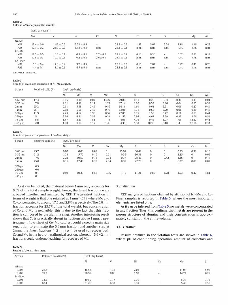
Fig. 2 shows the PSDs of the feeding material of rotary kiln andvibrating mill after different times. As it can be noted, 40% of theincoming material has a size lower than 1 mm.
In general, size reduction by impact forces is predominant in thePalla vibrating mill; after 2 min, 80% of the incoming sample wasreduced below 100 �m, whereas after the same time around 70%of the feed was ground below 100 �m by the ball mill.
As regards roasting tests, XRF analyses of the resulting roasted
samples are listed in Table 7 (see Section 2.6 for conditions).Comparing the results of A1 (non-ground feed, 550 ◦C, 4 h) andA2 (ground feed, 550 ◦C, 4 h), it is clear that the ground materialis better oxidized since the surface area of catalyst is greater and
l products at different operating times.
182 F. Ferella et al. / Journal of Hazardous Materials 192 (2011) 176– 185
Table 7XRF analysis of catalyst after different roasting steps.
Set Weight loss (%) Concentration (wt%)
Al Si P S V Fe Co Ni As Mo
40
17
17
thomt
wti
i(e
A1 19.3 28.80 2.21 1.11 2.A2 22.5 29.32 1.67 0.97 0.B2 5.8 15.22 1.19 0.60 0.
hen the sulphur content is lower (0.17 vs. 2.40%). Considering theigh roasting time, the residual sulphur could be due to sulphidesxidized to sulphate instead of SO2. In the B2 set concentration ofetals decreases because of dilution effect of sodium. Concentra-
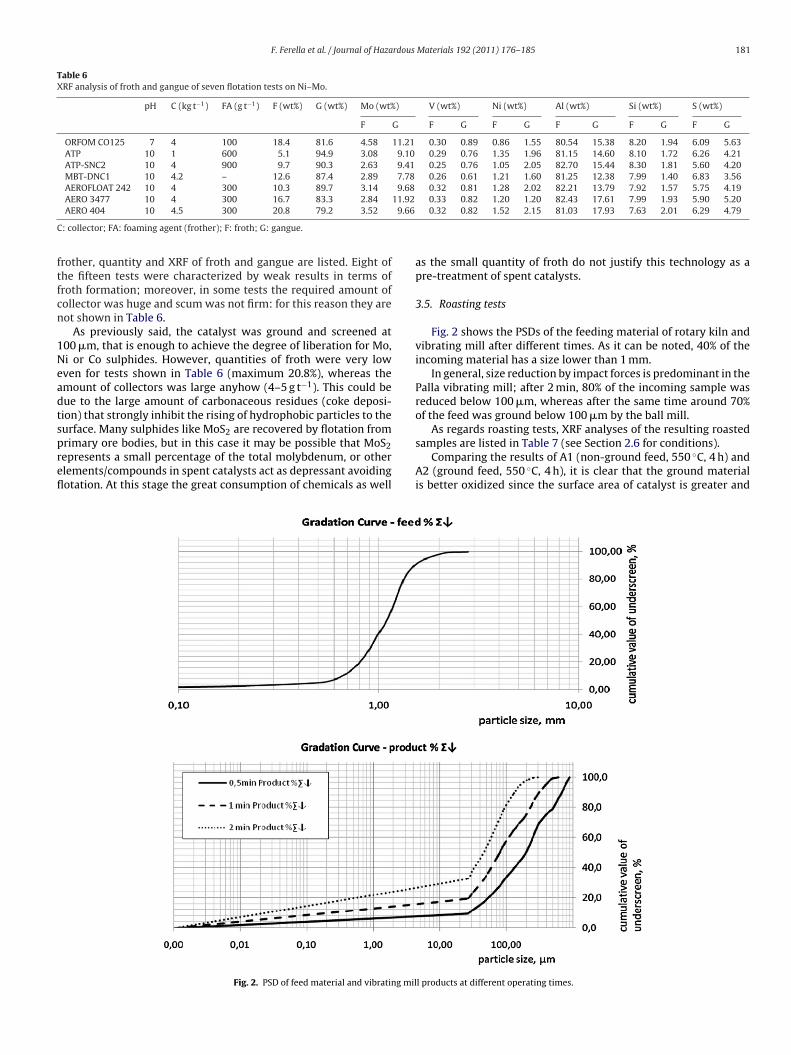
ion of compounds in flue gas is shown in Fig. 3:The stoichiometric amount of Na2CO3 (monohydrate, Merck)
as calculated using reaction (1) and (2) and 30% more was addedo take into account further consumption of Na2CO3 due to remain-ng sulphides from the first roasting.
Fig. 3a and b shows the behaviour of gaseous compounds dur-
ng roasting of Ni–Mo/Co–Mo mixture without (a) and in presenceb) of soda ash (test A2 and B3, respectively; see Section 2.6 forxperimental conditions). In the latter soda ash was added afterFig. 3. Results of flue gas monitoring ((a) ground feed, roasting at 550 ◦C, 4 h and (b)
1.12 0.30 1.77 1.37 0.30 10.681.48 0.30 1.96 1.58 0.39 11.541.34 0.25 1.67 1.42 0.35 10.79
nearly 4 h of roasting at 550 ◦C. Furthermore, the feeding mate-rial was ground (a) and non-ground (b). Other graphs are here notshown. During flow-gas monitoring of case (b), CO and NOx weredetected in very low range (around 1–3 ppm). Maximum produc-tion of SO2 during roasting of non-ground catalysts with soda ashat 550 ◦C corresponds to 230 ppm, whereas in case of ground mate-rial (a) the maximum corresponds to 1000 ppm, then the particlesize is very important in SO2 generation. After addition of soda ash,a prompt increase in CO2 formation occurs due to decompositionof carbonate ions; in Fig. 3b it can be noted that SO2 concentration
strongly decreases with soda ash addition: this is due to remain-ing sulphur when is captured by sodium, according to reactions(3) and (4). In Fig. 3a CO and NOx concentrations (8–12 ppm) arenon-ground feed, roasting at 550 ◦C, 4 h + roasting with Na2CO3 at 750 ◦C, 1 h).

F. Ferella et al. / Journal of Hazardous Materials 192 (2011) 176– 185 183
Fig. 4. Extraction yields at 0.5 h and 4 h by NaOH leaching of roasted catalysts (NaOH 1 mol L−1, pulp density 10% (w/v), 80 ◦C).
after r
atcf
3
i
bismdt
Fig. 5. Extraction yields at 0.5 h and 4 h by NaOH leaching of catalysts
lso greater than those of Fig. 3b, so this leads to the conclusionhat the lower particle size, the higher the production of gaseousompounds; hence, kinetics of oxidations and vanadate/molybdateormation is quicker.
.6. Leaching tests
Results of leaching tests in terms of extraction yields are shownn Figs. 4–7 (see Fig. 1 for experimental conditions).
Fig. 4 shows extraction yields of Mo, V and Al after 0.5 h and 4 hy NaOH leaching of roasted feed. Considering Mo and V extraction,
t is recommended to mill catalysts to −500 �m before the roasting
tage. Wet Ni–Mo catalyst must be roasted before any further treat-ent, because of the presence of naphtha. However, the smallerimension of the rings does not influence so much the roastingime. The results obtained in trial A.1.3 (−2.8 + 2.0 mm) and A.2.2
Fig. 6. Extraction yields at 0.5 h and 4 h by water leaching of catalys
oasting with soda ash (NaOH 1 mol L−1, pulp density 10% (w/v), 80 ◦C).
(−0.5 + 0.2 mm) show that the greatest V and Mo extraction yieldsare 96% and 77%, respectively. Aluminum is not the preferable metalto be leached, because of further purification of leach liquor: Al hasamphoteric nature, so it is partially dissolved in alkaline medium.However, the greatest extraction yield is 20%. As regards Mo, resultsare very similar to those obtained by Park et al. [6,7] (85% by 40 g L−1
NaOH or Na2CO3 + 6 vol% H2O2, 1 h, 20% (w/v) pulp density at roomtemperature). On the contrary, our preliminary tests at 30 ◦C didnot show good extraction yields (<50%) [26]. Angelidis et al. [11]extracted 80–86% of Mo using 10 g L−1 NaOH, a solid to liquid ratioof 5% at 100 ◦C for 2 h. The solid residue of that leaching underwentacid leaching by H2SO4, increasing the total recovery of Mo up to
97%, whereas extraction of Co and Ni was around 80%.In case of roasting with soda ash and leaching by NaOH(Fig. 5), the best extraction yield of V is achieved again with the−2.8 + 2.0 mm fraction (trial B.1.3) whereas 85% of Mo can be
ts after roasting with soda ash (pulp density 10% (w/v), 80 ◦C).
184 F. Ferella et al. / Journal of Hazardous Materials 192 (2011) 176– 185
ted ca
erel
amiBte[(r
Hla(Wmco9haebwmtSrv
•
•
•
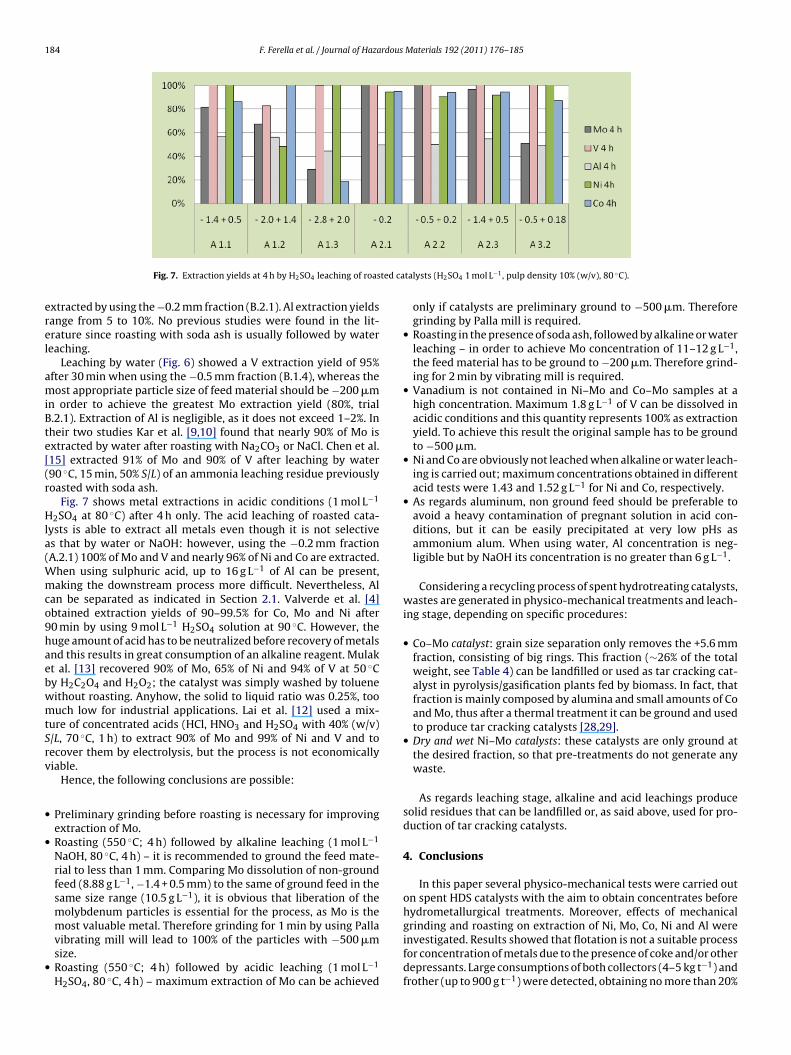
Fig. 7. Extraction yields at 4 h by H2SO4 leaching of roas
xtracted by using the −0.2 mm fraction (B.2.1). Al extraction yieldsange from 5 to 10%. No previous studies were found in the lit-rature since roasting with soda ash is usually followed by watereaching.
Leaching by water (Fig. 6) showed a V extraction yield of 95%fter 30 min when using the −0.5 mm fraction (B.1.4), whereas theost appropriate particle size of feed material should be −200 �m
n order to achieve the greatest Mo extraction yield (80%, trial.2.1). Extraction of Al is negligible, as it does not exceed 1–2%. Inheir two studies Kar et al. [9,10] found that nearly 90% of Mo isxtracted by water after roasting with Na2CO3 or NaCl. Chen et al.15] extracted 91% of Mo and 90% of V after leaching by water90 ◦C, 15 min, 50% S/L) of an ammonia leaching residue previouslyoasted with soda ash.
Fig. 7 shows metal extractions in acidic conditions (1 mol L−1
2SO4 at 80 ◦C) after 4 h only. The acid leaching of roasted cata-ysts is able to extract all metals even though it is not selectives that by water or NaOH: however, using the −0.2 mm fractionA.2.1) 100% of Mo and V and nearly 96% of Ni and Co are extracted.
hen using sulphuric acid, up to 16 g L−1 of Al can be present,aking the downstream process more difficult. Nevertheless, Al
an be separated as indicated in Section 2.1. Valverde et al. [4]btained extraction yields of 90–99.5% for Co, Mo and Ni after0 min by using 9 mol L−1 H2SO4 solution at 90 ◦C. However, theuge amount of acid has to be neutralized before recovery of metalsnd this results in great consumption of an alkaline reagent. Mulakt al. [13] recovered 90% of Mo, 65% of Ni and 94% of V at 50 ◦Cy H2C2O4 and H2O2; the catalyst was simply washed by tolueneithout roasting. Anyhow, the solid to liquid ratio was 0.25%, toouch low for industrial applications. Lai et al. [12] used a mix-
ure of concentrated acids (HCl, HNO3 and H2SO4 with 40% (w/v)/L, 70 ◦C, 1 h) to extract 90% of Mo and 99% of Ni and V and toecover them by electrolysis, but the process is not economicallyiable.
Hence, the following conclusions are possible:
Preliminary grinding before roasting is necessary for improvingextraction of Mo.Roasting (550 ◦C; 4 h) followed by alkaline leaching (1 mol L−1
NaOH, 80 ◦C, 4 h) – it is recommended to ground the feed mate-rial to less than 1 mm. Comparing Mo dissolution of non-groundfeed (8.88 g L−1, −1.4 + 0.5 mm) to the same of ground feed in thesame size range (10.5 g L−1), it is obvious that liberation of themolybdenum particles is essential for the process, as Mo is themost valuable metal. Therefore grinding for 1 min by using Palla
vibrating mill will lead to 100% of the particles with −500 �msize.Roasting (550 ◦C; 4 h) followed by acidic leaching (1 mol L−1H2SO4, 80 ◦C, 4 h) – maximum extraction of Mo can be achieved
talysts (H2SO4 1 mol L−1, pulp density 10% (w/v), 80 ◦C).
only if catalysts are preliminary ground to −500 �m. Thereforegrinding by Palla mill is required.
• Roasting in the presence of soda ash, followed by alkaline or waterleaching – in order to achieve Mo concentration of 11–12 g L−1,the feed material has to be ground to −200 �m. Therefore grind-ing for 2 min by vibrating mill is required.
• Vanadium is not contained in Ni–Mo and Co–Mo samples at ahigh concentration. Maximum 1.8 g L−1 of V can be dissolved inacidic conditions and this quantity represents 100% as extractionyield. To achieve this result the original sample has to be groundto −500 �m.
• Ni and Co are obviously not leached when alkaline or water leach-ing is carried out; maximum concentrations obtained in differentacid tests were 1.43 and 1.52 g L−1 for Ni and Co, respectively.
• As regards aluminum, non ground feed should be preferable toavoid a heavy contamination of pregnant solution in acid con-ditions, but it can be easily precipitated at very low pHs asammonium alum. When using water, Al concentration is neg-ligible but by NaOH its concentration is no greater than 6 g L−1.
Considering a recycling process of spent hydrotreating catalysts,wastes are generated in physico-mechanical treatments and leach-ing stage, depending on specific procedures:
• Co–Mo catalyst: grain size separation only removes the +5.6 mmfraction, consisting of big rings. This fraction (∼26% of the totalweight, see Table 4) can be landfilled or used as tar cracking cat-alyst in pyrolysis/gasification plants fed by biomass. In fact, thatfraction is mainly composed by alumina and small amounts of Coand Mo, thus after a thermal treatment it can be ground and usedto produce tar cracking catalysts [28,29].
• Dry and wet Ni–Mo catalysts: these catalysts are only ground atthe desired fraction, so that pre-treatments do not generate anywaste.
As regards leaching stage, alkaline and acid leachings producesolid residues that can be landfilled or, as said above, used for pro-duction of tar cracking catalysts.
4. Conclusions
In this paper several physico-mechanical tests were carried outon spent HDS catalysts with the aim to obtain concentrates beforehydrometallurgical treatments. Moreover, effects of mechanicalgrinding and roasting on extraction of Ni, Mo, Co, Ni and Al were
investigated. Results showed that flotation is not a suitable processfor concentration of metals due to the presence of coke and/or otherdepressants. Large consumptions of both collectors (4–5 kg t−1) andfrother (up to 900 g t−1) were detected, obtaining no more than 20%
rdous
obosvorfaiwgMofW(iattgtfsrtoo
A
vaaot
R
[
[
[
[
[
[
[
[
[
[
[
[
[
[
[
[
[
[
F. Ferella et al. / Journal of Haza
f froth fraction. No concentrated metal fractions can be obtainedy attrition since active metals are dispersed in the entire volumef rings. The wet Ni–Mo catalyst is the most difficult to handleince complete removal of the layer of naphtha by drying or sol-ent extraction is not possible, and this influences the floatabilityf material. Grain size separation is useful to remove the greatestings in case of dry catalysts, mainly composed by alumina, whereasor Co–Mo it is also possible to produce two fractions enriched in Cond Mo. Further pre-treatments were tested: in particular, roastings required to oxidize the organic fraction and vibrating grinding
as found to be very effective in size reduction. A preliminaryrinding was found to be very important to improve extraction ofo in the leaching stage. As regards alkaline leaching, around 96%
f V can be extracted by NaOH by using roasted feed (−2.8 + 2.0 mmraction) and 85% of Mo (−0.2 m), whereas Al does not exceed 20%.
ater leaching after roasting with soda ash extracted 90% of V−0.5 mm fraction) and nearly 80% of Mo (−0.2 mm). Acid leach-ng by H2SO4 extracted 100% of Mo and V, as well as 96% of Nind Co by using the −0.2 mm fraction. In terms of extraction ishe most effective, although further purification is required due tohe large amount of Al dissolved (50%). Some pre-treatments haveiven better results in terms od leaching extraction than those ofhe literature obtained in the same conditions; other results wasound to be a bit different but this is due to the different catalystamples used in the respective studies. However, comparing theseesults with those of the scientific literature, it can be stated thathe preliminary procedures permitted to maximize the extractionf metals reducing the operating costs, mainly due to consumptionf reagents.
cknowledgements
The authors sincerely acknowledge ORIM S.p.A. (Italy) for pro-iding the catalyst samples, as well as Mr. Marcello Centofantind Ms. Fabiola Ferrante for AAS and XRF analyses. Furthermore,uthors wish to thank KHD Humboldt Wedag GmbH and the Dept.f Metallurgy, University of Aachen (Germany) for the comminu-ion and thermal tests.
eferences
[1] M. Marafi, A. Stanislaus, Spent catalyst waste management: a review. Part I.Developments in hydroprocessing catalyst waste reduction and use, Resour.Conserv. Recy. 52 (2008) 859–873.
[2] M. Marafi, A. Stanislaus, Spent hydroprocessing catalyst management: a review.Part II. Advances in metal recovery and safe disposal methods, Resour. Conserv.Recy. 53 (2008) 1–26.
[3] E. Furimsky, Spent refinery catalysts: environment, safety and utilization, Catal.Today 30 (1996) 223–286.
[4] I.M. Valverde, J.F. Paulino, J.C. Afonso, Hydrometallurgical route to recover
molybdenum, nickel, cobalt and aluminum from spent hydrotreating catalystsin sulphuric acid medium, J. Hazard. Mater. 160 (2008) 310–317.[5] R.G. Busnardo, N.G. Busnardo, G.N. Salvato, J.C. Afonso, Processing of spent NiMoand CoMo/Al2O3 catalysts via fusion with KHSO4, J. Hazard. Mater. 139 (2007)391–398.
[
[
Materials 192 (2011) 176– 185 185
[6] K.H. Park, D. Mohapatra, B.R. Reddy, Selective recovery of molybdenum fromspent HDS catalyst using oxidative soda ash leach/carbon adsorption method,J. Hazard. Mater. 138 (2006) 311–316.
[7] K.H. Park, B.R. Reddy, D. Mohapatra, C.W. Nam, Hydrometallurgical processingand recovery of molybdenum trioxide from spent catalyst, Int. J. Miner. Process.80 (2006) 261–265.
[8] K.H. Park, D. Mohapatra, C.W. Nam, Two stage leaching of activated spent HDScatalyst and solvent extraction of aluminum using organo-phosphinic extrac-tant Cyanex 272, J. Hazard. Mater. 148 (2007) 287–295.
[9] B.B. Kar, P. Datta, V.N. Misra, Spent catalyst: secondary source for molybdenumrecovery, Hydrometallurgy 72 (2004) 87–92.
10] B.B. Kar, B.V.R. Murthy, V.N. Misra, Extraction of molybdenum from spent cat-alyst by salt-roasting, Int. J. Miner. Process. 76 (2005) 143–147.
11] T.N. Angelidis, E. Tourasanidis, E. Marinou, G.A. Stalidis, Selective dissolution ofcritical metals from diesel and naphtha spent hydrodesulphurization catalyst,Resour. Conserv. Recy. 13 (1995) 269–282.
12] Y.C. Lai, W.J. Lee, K.L. Huang, C.M. Wu, Metal recovery from spent hydrodesul-phurization catalyst using a combined acid-leaching and electrolysis process,J. Hazard. Mater. 154 (2008) 588–594.
13] W. Mulak, A. Szymczycha, A. Lesniewicz, W. Zirnicki, Preliminary results of met-als leaching from a spent hydrodesulphurization (HDS) catalyst, Physicochem.Probl. Mi. 40 (2006) 69–76.
14] A. Ognyanova, I. De Michelis, F. Ferella, G. Taglieri, F. Veglio, Metal Extractionfrom spent HDS catalyst by alkaline and acidic leaching, Acta Metall. Slovaca14 (2008) 204–211.
15] Y. Chen, Q.M. Feng, Y.H. Shao, G.F. Zhang, L.M. Ou, Y.P. Lu, Investigations on theextraction of molybdenum and vanadium from ammonia leaching residue ofspent catalyst, Int. J. Miner. Process. 79 (2006) 42–48.
16] Ullmann’s Encyclopedia of Industrial Chemistry, fifth ed., WILEY-VCH, Wein-heim, 1996.
17] L. Zeng, C.Y. Cheng, A literature review of the recovery of molybdenum andvanadium from spent hydrodesulphurization catalysts. Part I: metallurgicalprocesses, Hydrometallurgy 98 (2009) 1–9.
18] L. Zeng, C.Y. Cheng, A literature review of the recovery of molybdenum andvanadium from spent hydrodesulphurization catalysts. Part II: separation andpurification, Hydrometallurgy 98 (2009) 10–20.
19] P. Henry, A. Van Lierde, Selective separation of vanadium from molybdenumby electrochemical ion exchange, Hydrometallurgy 48 (1998) 73–81.
20] J. Hu, X.W. Wang, L.S. Xiao, S.R. Song, B.Q. Zhang, Removal of vanadiumfrom molybdate solution by ion exchange, Hydrometallurgy 95 (2009) 203–206.
21] M.S. Villarreal, B.I. Kharisov, L.M. Torres-Martinez, V.N. Elizondo, Recovery ofvanadium and molybdenum from spent petroleum catalyst of PEMEX, Ind. Eng.Chem. Res. 38 (1999) 4624–4628.
22] K. Huang, Q.W. Li, J. Chen, Recovery of copper, nickel and cobalt from acidicpressure leaching solutions of low-grade sulfide flotation concentrates, Miner.Eng. 20 (2007) 722–728.
23] B.R. Reddy, R.S. Venkateswara, K.H. Park, Solvent extraction separation andrecovery of cobalt and nickel from sulphate medium using mixtures of TOPS99 and TIBPS extractants, Miner. Eng. 22 (2009) 500–505.
24] K. Sarangi, B.R. Reddy, R.P. Das, Extraction studies of cobalt(II) and nickel(II)from chloride solutions using Na-Cyanex 272: separation of Co(II)/Ni(II) by thesodium salts of D2EHPA, PC88A and Cyanex 272 and their mixtures, Hydromet-allurgy 52 (1999) 253–265.
25] P.W. Zhang, K. Inoue, K. Yoshizuka, H. Tsuyama, Extraction and selectivestripping of molybdenum(VI) and vanadium(IV) from sulphuric acid solutioncontaining aluminum(III), cobalt(II), nickel(II) and iron(III) by LIX 63 in ExxsolD80, Hydrometallurgy 41 (1996) 45–53.
26] F. Ferella, Recovery of base metals from spent oil-refining catalysts, Ph.D. thesis,University of L’Aquila, Italy, 2010.
27] F. Beolchini, V. Fonti, F. Ferella, F. Vegliò, Metal recovery from spent refinerycatalysts by means of biotechnological strategies, J. Hazard. Mater. 178 (2010)
529–534.28] B. Dou, J. Gao, X. Sha, S.W. Baek, Catalytic cracking of tar component from high-temperature fuel gas, Appl. Therm. Eng. 23 (2003) 2229–2239.
29] K. Tasaka, T. Furusawa, A. Tsutsumi, Biomass gasification in fluidized bed reac-tor with Co catalyst, Chem. Eng. Sci. 62 (2007) 5558–5563.