La doping effect on TZM alloy oxidation behavior
6
La doping effect on TZM alloy oxidation behavior Fan Yang a , Kuai-She Wang a,⇑ , Ping Hu a , Huan-Cheng He a , Xuan-Qi Kang a , Hua Wang b , Ren-Zhi Liu a,c , Alex A. Volinsky d a School of Metallurgy Engineering, Xi’an University of Architecture and Technology, Xi’an 710055, China b Xi’an Electric Furnace Institute Co., Ltd., Xi’an 710061, China c Jinduicheng Molybdenum Co., Ltd., Xi’an 710068, China d Department of Mechanical Engineering, University of South Florida, Tampa FL 33620, USA article info Article history: Received 11 October 2013 Received in revised form 18 December 2013 Accepted 19 December 2013 Available online 13 January 2014 Keywords: La doping TZM alloy Oxidation behavior Oxidation coating abstract Powder metallurgy methods were utilized to prepare lanthanum-doped (La-TZM) and traditional TZM alloy plates. High temperature oxidation experiments along with the differential thermal analysis were employed to study the oxidation behavior of the two kinds of TZM alloys. An extremely volatile oxide layer was generated on the surface of traditional TZM alloy plates when the oxidation started. Molybde- num oxide volatilization exposed the alloy matrix, which was gradually corroded by oxygen, losing its quality with serious surface degradation. The La-TZM alloy has a more compact structure due to the lan- thanum doping. The minute lanthanum oxide particles are pinned at the grain boundaries and refine the grains. Oxide layer generated on the matrix surface can form a compact coating, which effectively blocks the surface from being corroded by oxidation. The oxidation resistance of La-TZM alloys has been enhanced, expanding its application range. Ó 2014 Elsevier B.V. All rights reserved. 1. Introduction TZM molybdenum alloy contains 0.5–0.8 wt% titanium, 0.08–0.1 wt% zirconium, 0.016–0.02 wt% carbon and molybdenum balance. Molybdenum TZM alloys are highly desirable for a wide range of critical applications due to their high electrical and ther- mal conductivity, strength and creep resistance at elevated tem- peratures, high temperature stability, low coefficient of thermal expansion and excellent corrosion resistance in liquid metals [1–7]. They are widely used in aerospace, power generation, nuclear and fusion reactors, military, industrial and chemical appli- cations, where these alloys are subjected to high temperatures, liquid metal corrosion and other aggressive environments. How- ever, poor high temperature oxidation resistance in the presence of air has restricted TZM alloys practical applications. Research shows that when the temperature is below 400 °C, the oxidation rate of TZM alloys is very low. When the temperature is between 400 °C and 650 °C, the mass gain by oxidation is rapidly increased, generating MoO 2 and other oxides (MoO Z ,2< Z < 3). When temper- ature raises above 650 °C, a sharp decline in mass will happen due to the MoO 3 volatilization [8]. Previous studies have shown that doping lanthanum into tradi- tional TZM alloy can significantly improve its strength and tough- ness [9]. This article investigates the effect of lanthanum doping on the oxidation behavior of TZM alloy plates. 2. Experimental procedure 2.1. Preparation of TZM and La-TZM alloys Based on the design composition, listed in Table 1, two kinds of TZM alloys were prepared: La-doped TZM alloy (#1) and traditional TZM alloy (#2). Adopting the solid–liquid mixing process, stearic acid ethanol solution containing lanthanum ni- trate, was used along with TiH 2 and ZrH 2 powders to obtain lanthanum-doped Mo. By the processes of mixing, ball-milling (using planetary ball milling machine, revolving speed 240 r/min, milling 2 h), vacuum drying (using vacuum drying oven, 70 °C, 4 h), compaction (holding pressure 21 MPa, 5 s) and sintering (pass into protective hydrogen, subsection sintering: 300 °C, 900 °C, 1200 °C heat preservation 2 h respectively, finally sintering on 1900 °C, heat preservation 4 h), both La-TZM and TZM alloy compacts were obtained. La-TZM and TZM alloy plates, 0.5 mm thick, were made by hot-rolling, warm-rolling and caustic washing. The plates were separately cut into 4 pieces, labeled as samples of #1-1, #1-2, #2-1 and #2-2. 2.2. High temperature oxidation experiments During the high temperature oxidation experiments, La-TZM and TZM alloy plates (samples #1-1 and #2-1) were heated at 300 °C, 450 °C, 600 °C, 800 °C, and 1000 °C in the furnace for 10 min, 15 min and 30 min. Electronic balance was used to measure the sample mass (0.01 g accuracy) before and after heating to calculate the samples mass loss. 2.3. Samples characterization JSM-6460LV scanning electron microscope (JEOL, Japan) was used for the sur- face and cross-sectional morphology, and microstructure characterization of the samples after high temperature oxidation. Energy dispersive spectra (EDS) analyzer was used to obtain the surface composition. 0925-8388/$ - see front matter Ó 2014 Elsevier B.V. All rights reserved. http://dx.doi.org/10.1016/j.jallcom.2013.12.270 ⇑ Corresponding author. Tel.: +86 29 82205096; fax: +86 29 82202923. E-mail address: [email protected] (K.-S. Wang). Journal of Alloys and Compounds 593 (2014) 196–201 Contents lists available at ScienceDirect Journal of Alloys and Compounds journal homepage: www.elsevier.com/locate/jalcom
Transcript of La doping effect on TZM alloy oxidation behavior

Journal of Alloys and Compounds 593 (2014) 196–201
Contents lists available at ScienceDirect
Journal of Alloys and Compounds
journal homepage: www.elsevier .com/locate / ja lcom
La doping effect on TZM alloy oxidation behavior
0925-8388/$ - see front matter � 2014 Elsevier B.V. All rights reserved.http://dx.doi.org/10.1016/j.jallcom.2013.12.270
⇑ Corresponding author. Tel.: +86 29 82205096; fax: +86 29 82202923.E-mail address: [email protected] (K.-S. Wang).
Fan Yang a, Kuai-She Wang a,⇑, Ping Hu a, Huan-Cheng He a, Xuan-Qi Kang a, Hua Wang b, Ren-Zhi Liu a,c,Alex A. Volinsky d
a School of Metallurgy Engineering, Xi’an University of Architecture and Technology, Xi’an 710055, Chinab Xi’an Electric Furnace Institute Co., Ltd., Xi’an 710061, Chinac Jinduicheng Molybdenum Co., Ltd., Xi’an 710068, Chinad Department of Mechanical Engineering, University of South Florida, Tampa FL 33620, USA
a r t i c l e i n f o
Article history:Received 11 October 2013Received in revised form 18 December 2013Accepted 19 December 2013Available online 13 January 2014
Keywords:La dopingTZM alloyOxidation behaviorOxidation coating
a b s t r a c t
Powder metallurgy methods were utilized to prepare lanthanum-doped (La-TZM) and traditional TZMalloy plates. High temperature oxidation experiments along with the differential thermal analysis wereemployed to study the oxidation behavior of the two kinds of TZM alloys. An extremely volatile oxidelayer was generated on the surface of traditional TZM alloy plates when the oxidation started. Molybde-num oxide volatilization exposed the alloy matrix, which was gradually corroded by oxygen, losing itsquality with serious surface degradation. The La-TZM alloy has a more compact structure due to the lan-thanum doping. The minute lanthanum oxide particles are pinned at the grain boundaries and refine thegrains. Oxide layer generated on the matrix surface can form a compact coating, which effectively blocksthe surface from being corroded by oxidation. The oxidation resistance of La-TZM alloys has beenenhanced, expanding its application range.
� 2014 Elsevier B.V. All rights reserved.
1. Introduction 2. Experimental procedure
TZM molybdenum alloy contains 0.5–0.8 wt% titanium,0.08–0.1 wt% zirconium, 0.016–0.02 wt% carbon and molybdenumbalance. Molybdenum TZM alloys are highly desirable for a widerange of critical applications due to their high electrical and ther-mal conductivity, strength and creep resistance at elevated tem-peratures, high temperature stability, low coefficient of thermalexpansion and excellent corrosion resistance in liquid metals[1–7]. They are widely used in aerospace, power generation,nuclear and fusion reactors, military, industrial and chemical appli-cations, where these alloys are subjected to high temperatures,liquid metal corrosion and other aggressive environments. How-ever, poor high temperature oxidation resistance in the presenceof air has restricted TZM alloys practical applications. Researchshows that when the temperature is below 400 �C, the oxidationrate of TZM alloys is very low. When the temperature is between400 �C and 650 �C, the mass gain by oxidation is rapidly increased,generating MoO2 and other oxides (MoOZ, 2 < Z < 3). When temper-ature raises above 650 �C, a sharp decline in mass will happen dueto the MoO3 volatilization [8].
Previous studies have shown that doping lanthanum into tradi-tional TZM alloy can significantly improve its strength and tough-ness [9]. This article investigates the effect of lanthanum doping onthe oxidation behavior of TZM alloy plates.
2.1. Preparation of TZM and La-TZM alloys
Based on the design composition, listed in Table 1, two kinds of TZM alloys wereprepared: La-doped TZM alloy (#1) and traditional TZM alloy (#2). Adopting thesolid–liquid mixing process, stearic acid ethanol solution containing lanthanum ni-trate, was used along with TiH2 and ZrH2 powders to obtain lanthanum-doped Mo.By the processes of mixing, ball-milling (using planetary ball milling machine,revolving speed 240 r/min, milling 2 h), vacuum drying (using vacuum drying oven,70 �C, 4 h), compaction (holding pressure 21 MPa, 5 s) and sintering (pass intoprotective hydrogen, subsection sintering: 300 �C, 900 �C, 1200 �C heat preservation2 h respectively, finally sintering on 1900 �C, heat preservation 4 h), both La-TZMand TZM alloy compacts were obtained. La-TZM and TZM alloy plates, 0.5 mm thick,were made by hot-rolling, warm-rolling and caustic washing. The plates wereseparately cut into 4 pieces, labeled as samples of #1-1, #1-2, #2-1 and #2-2.
2.2. High temperature oxidation experiments
During the high temperature oxidation experiments, La-TZM and TZM alloyplates (samples #1-1 and #2-1) were heated at 300 �C, 450 �C, 600 �C, 800 �C, and1000 �C in the furnace for 10 min, 15 min and 30 min. Electronic balance was usedto measure the sample mass (0.01 g accuracy) before and after heating to calculatethe samples mass loss.
2.3. Samples characterization
JSM-6460LV scanning electron microscope (JEOL, Japan) was used for the sur-face and cross-sectional morphology, and microstructure characterization of thesamples after high temperature oxidation. Energy dispersive spectra (EDS) analyzerwas used to obtain the surface composition.

Table 1Composition of TZM alloys (wt%).
Sample Ti Zr C Stearic acid La(NO3)3 Mo
#1 0.5 0.1 0 0.25 1.99 Balance#2 0.5 0.1 0 0.25 0 Balance
F. Yang et al. / Journal of Alloys and Compounds 593 (2014) 196–201 197
2.4. Comprehensive thermal analysis
Differential thermal analysis (DTA) and thermogravimetry (TG) experimentswere conducted with sample #1-2 and #2-2 in air by using the HQC-3 differentialthermal analyzer (Hengjiu Co., Beijing China). The temperature was varied fromroom temperature to 1100 �C with 25 �C/min heating rate. The DTA–TG curves wereused to analyze the thermogravimetric loss and the reaction mechanism.
3. Results and discussion
3.1. Oxidation kinetics of La-TZM and TZM alloys
Fig. 1 shows the oxidation mass loss of La-TZM and TZM alloyplates of the same size, heated for 10 min, 15 min and 30 min usingthe same conditions. There is no mass change of La-TZM and TZMalloy plates under 600 �C, indicating no obvious oxidation. Past600 �C the mass loss increases linearly with temperature. Compar-ing Fig. 1(a), (b) and (c), the oxidation mass loss of TZM alloy platesis always higher than of the La-TZM alloy plates. This indicates thatregardless of the high temperature exposure time, the oxidationmass loss of traditional TZM alloy is always higher than that ofthe La-TZM alloy, i.e. doping with La can considerably suppressesTZM alloys oxidation.
Tables 2 and 3 show the oxidation mass loss of La-TZM and TZMplates kept at 800 �C and 1000 �C for different time. The oxidationmass loss of the two kinds of samples is increasing with the
Fig. 1. Oxidation mass loss of the samples heate
heating time. However, the mass loss of the La-TZM plates is lessthan the TZM alloy plates. For example, at 1000 �C the mass lossof La-TZM plates is 66.8%, 80.7% and 93.8% when heated for 10,15 and 30 min, respectively. La doping can hinder the matrix ero-sion by oxygen during the high-temperature oxidation process,enhancing the oxidation resistance of TZM alloys.
3.2. Oxidation surface characterization of TZM alloy plates
3.2.1. Surface oxidation layer EDS analysisFig. 2 shows the EDS spectra of La-TZM and TZM alloy plates
heated at 800 �C and 1000 �C. The existence of molybdenum oxidecan be detected by calculating the content ratio of O and Mo atoms.In Fig. 2, the percentage ratios of O and Mo atoms on the surface ofLa-TZM and TZM alloy plates are 2.51 and 2.65 after 10 min oxida-tion at 800 �C, respectively. After 30 min at 800 �C, the ratios are2.67 and 2.75, and then after 10 min oxidation at 1000 �C the ratiosare 2.49 and 2.77. After oxidation the content ratios of O and Moatoms in the surface layers of the La-TZM alloy plates are lowerthan the traditional TZM alloy plates, thus there is less MoO3 dueto lower oxygen uptake in the La-TZM alloy. This shows that Ladoping improves TZM alloy oxidation resistance.
3.2.2. Surface morphologyFig. 3 shows SEM images of La-TZM and traditional TZM alloy
plates heated at 800 �C and 1000 �C. Some bright spots are seenin all images of Fig. 3. Combined with the EDS analysis, it is clearthat molybdenum oxides were generated, causing surface electri-cal conductivity reduction. Fig. 3(b) and (d) shows surface corro-sion during the oxidation process in the form of lamellar slices,which obviously expand and fracture. In addition, the defect areaswere oxidized more severely, and after 30 min of oxidation thelamellar molybdenum oxides were broken, causing the matrix to
d for: (a) 10 min, (b) 15 min and (c) 30 min.

Table 2The mass loss of TZM alloy plates at 800 �C.
Heating temperature (�C) Holding time (min) Mass loss (%)
La-TZM #1-1 TZM #2-1
800 10 2 18800 15 24.49 56800 30 40.81 52
Table 3The mass loss of TZM alloy plates at 1000 �C.
Heating temperature (�C) Holding time (min) Mass loss (%)
La-TZM #1-1 TZM #2-1
1000 10 35.42 53.061000 15 56 69.391000 30 91.83 97.95
198 F. Yang et al. / Journal of Alloys and Compounds 593 (2014) 196–201
be corroded even more (Fig. 3(f)). The surface of La-TZM alloyplates gradually corroded at different oxidation time in the formof lamellae. Compared with the traditional TZM alloy, La-TZMslices had less cavity defects in Fig. 3(a), (c) and (e), with only afew expanded slices after 15 min of oxidation at 1000 �C, seen inFig. 3(i).
After 10 min of oxidation at 1000 �C, some flocculent oxides ofmolybdenum appeared on the samples surface in Fig. 3(g) and (h),and then disappeared after 15 min of oxidation, leaving the lamellaroxide layer in Fig. 3(i) and (j). However, for the traditional TZM alloy,
Fig. 2. EDS spectra of the samples oxidized at different temperature and time: (a) La-T800 �C, 30 min; (e) La-TZM, 1000 �C, 10 min; (f) TZM, 1000 �C, 10 min.
the flocculent oxides of molybdenum appeared on the samples sur-face after 15 min of oxidation at 800 �C in Fig. 3(d), and then disap-peared, while the oxide layer fractured after 30 min of oxidation.Flocculent oxides of molybdenum appear on the surface of TZM al-loy plates after 10 min of oxidation at 1000 �C, indicating that tradi-tional TZM alloys are more easily oxidized.
3.2.3. Cross-sectional morphologyFig. 4 shows cross-sectional SEM images of La-TZM and tradi-
tional TZM alloy plates heated at 800 �C and 1000 �C after10 min. As seen in Fig. 4(b) and (d), after 10 min heating at800 �C, the two kinds of alloy plates have thick oxide layer, thusthe loose and lamellar morphology of molybdenum oxides is con-sistent with the surface images in Fig. 3. From these images oncecan see a compact oxide layer between the loose layer and the al-loy matrix. After 10 min oxidation at 1000 �C, the loose and lamel-lar layer disappeared, leaving only the denser previously crackedoxide layer (Fig. 4(e) and (f)).
As seen in Fig. 4(a) and (c), the average thickness of loose oxidelayer of La-TZM and traditional TZM alloy plates is 92 lm and221 lm, respectively. The lamellar oxide layer of the TZM alloyplates is 2–3 times thicker than of the La-TZM alloy plates. FromFig. 4(e) and (f), the compact oxide layer of the La-TZM alloy platesis thicker than of the TZM alloy plates, which also indicates that thetraditional TZM alloys are more easily oxidized.
3.3. Oxidation process analysis
Fig. 5 shows the TG–DTA curves of the La-TZM and the TZM al-loy plates (samples #1-2 and #2-2) after comprehensive thermal
ZM, 800 �C, 10 min; (b) TZM, 800 �C, 10 min; (c) La-TZM, 800 �C, 30 min; (d) TZM,

Fig. 3. SEM images of samples oxidized at different temperature and time: (a) La-TZM, 800 �C, 10 min; (b) TZM, 800 �C, 10 min; (c) La-TZM, 800 �C, 15 min; (d) TZM, 800 �C,15 min; (e) La-TZM, 800 �C, 30 min; (f) TZM, 800 �C, 30 min; (g) La-TZM, 1000 �C, 10 min; (h) TZM, 1000 �C, 10 min; (i) La-TZM, 1000 �C, 15 min; (j) TZM, 1000 �C, 15 min.
F. Yang et al. / Journal of Alloys and Compounds 593 (2014) 196–201 199
analysis experiment. Based on the two TG curves, both sampleshave some gain of mass when heated at low temperatures. Whenheated to 850 �C, an exothermic peak appeared in the correspond-ing DTA curves with the sudden mass loss. Combined with the EDSanalysis, the resultant MoO3 is obviously volatile at this tempera-ture. Comparing Fig. 5(a) and (b), there is a small exothermic peak
at 510 �C, and an obvious steep rise in the TG curve. Based on theknown TZM alloys oxidation kinetics, the oxidation reaction accel-erated at this temperature with MoO3 formation. However, a smallexothermic peak at 460 �C in Fig. 5(b) manifests oxidation reactionaggravation at 460 �C. Comparing the two TG curves, the mass lossis 8.08% when heated at 1100 �C in Fig. 5(a), and 10.58% in Fig. 5(b),

Fig. 4. Cross-sectional SEM images of samples oxidized at 800 �C and 1000 �C after 10 min: (a) (b) La-TZM, 800 �C, 10 min; (c) (d) TZM, 800 �C, 10 min; (e) La-TZM, 1000 �C,10 min; (f) TZM, 1000 �C, 10 min.
Fig. 5. TG–DTA curves of (a) La-TZM alloy and (b) TZM alloy.
200 F. Yang et al. / Journal of Alloys and Compounds 593 (2014) 196–201
indicating that sample #2-2 experienced a more serious volatiliza-tion. Compared with the traditional TZM alloys, La-TZM alloys havebetter oxidation resistance.
3.4. Oxidation mechanism
A protective layer can be formed on the TZM alloy plate surfaceby the 400–800 �C high-temperature oxidation. The protectivelayer is composed of MoO3, MoO2, other alloy oxide elementsand a light-weight reinforced phase. However, increased oxidationtime or temperature cause this layer to expand, fracture and
gradually get volatized, allowing oxygen to corrode the matrix.La-doped TZM alloy microstructure schematic is shown in Fig. 6[1], where due to a mix of the TZM alloy with the lanthanum ni-trate solution, La exists in the form of La2O3 in the alloy. Sincethe La2O3 particles are smaller than the TZM alloy matrix grains,they fill up the spaces along the grain boundaries and pin in thevoids of matrix, allowing for a denser microstructure organization.La element exists in the alloy, forming the second phase that has adispersion strengthening effect, which improves the alloy durabil-ity. There exist lesser voids at surface and grain boundary, so thatoxygen is hard to enter and corrode the matrix. On the other hand,
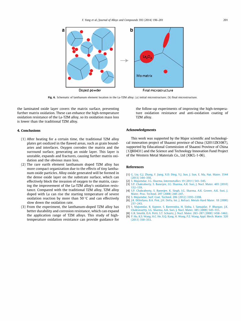
Fig. 6. Schematic of lanthanum element location in the La-TZM alloy: (a) initial microstructure; (b) final microstructure.
F. Yang et al. / Journal of Alloys and Compounds 593 (2014) 196–201 201
the laminated oxide layer covers the matrix surface, preventingfurther matrix oxidation. These can enhance the high-temperatureoxidation resistance of the La-TZM alloy, so its oxidation mass lossis lower than the traditional TZM alloy.
4. Conclusions
(1) After heating for a certain time, the traditional TZM alloyplates get oxidized in the flawed areas, such as grain bound-aries and interfaces. Oxygen corrodes the matrix and thesurround surface, generating an oxide layer. This layer isunstable, expands and fractures, causing further matrix oxi-dation and the obvious mass loss.
(2) The rare earth element lanthanum doped TZM alloy hasmore compact organization due to the effects of tiny lantha-num oxide particles. Alloy oxide generated will be formed inthe dense oxide layer on the substrate surface, which caneffectively block the invasion of oxygen to the matrix, caus-ing the improvement of the La-TZM alloy’s oxidation resis-tance. Compared with the traditional TZM alloy, TZM alloydoped with La can rise the starting temperature of severeoxidation reaction by more than 50 �C and can effectivelyslow down the oxidation rate.
(3) From the experiment, the lanthanum-doped TZM alloy hasbetter durability and corrosion resistance, which can expandthe application range of TZM alloys. This study of high-temperature oxidation resistance can provide guidance for
the follow-up experiments of improving the high-tempera-ture oxidation resistance and anti-oxidation coating ofTZM alloy.
Acknowledgments
This work was supported by the Major scientific and technologi-cal innovation project of Shaanxi province of China (S2011ZK1087),supported by Educational Commission of Shaanxi Province of China(12JK0431) and the Science and Technology Innovation Fund Projectof the Western Metal Materials Co., Ltd (XBCL-1-06).
References
[1] G. Liu, G.J. Zhang, F. Jiang, X.D. Ding, Y.J. Sun, J. Sun, E. Ma, Nat. Mater. 3544(2013) 344–350.
[2] S. Majumdar, I.G. Sharma, Intermetallics 19 (2011) 541–545.[3] S.P. Chakraborty, S. Banerjee, I.G. Sharma, A.K. Suri, J. Nucl. Mater. 403 (2010)
152–159.[4] S.P. Chakraborty, S. Banerjee, K. Singh, I.G. Sharma, A.K. Grover, A.K. Suri, J.
Mater. Proc. Technol. 207 (2008) 240–247.[5] S. Majumdar, Surf. Coat. Technol. 206 (2012) 3393–3398.[6] J.R. DiStefano, B.A. Pint, J.H. DeVa, Int. J. Refract. Metals Hard Mater. 18 (2000)
237–243.[7] S. Majumdar, R. Kapoor, S. Raveendra, H. Sinha, I. Samajdar, P. Bhargav, J.K.
Chakravartty, I.G. Sharma, A.K. Suri, J. Nucl. Mater. 385 (2009) 545–551.[8] G.R. Smolik, D.A. Petti, S.T. Schuetz, J. Nucl. Mater. 283–287 (2000) 1458–1462.[9] P. Hu, K.S. Wang, H.C. He, X.Q. Kang, H. Wang, P.Z. Wang, Appl. Mech. Mater. 320
(2013) 350–353.