Investigation of wear, corrosion and tribocorrosion properties of AZ91 Mg alloy coated by micro arc...
7
Investigation of wear, corrosion and tribocorrosion properties of AZ91 Mg alloy coated by micro arc oxidation process in the different electrolyte solutions Ebru Emine Demirci a, ⁎, Ersin Arslan a , Kadri Vefa Ezirmik a , Özlem Baran b , Yaşar Totik a , İhsan Efeoglu a a Ataturk University, Department of Mechanical Engineering, Faculty of Engineering, Erzurum, Turkey b Erzincan University, Department of Mechanical Engineering, Faculty of Engineering, Erzincan Turkey abstract article info Available online 7 November 2012 Keywords: Mg alloys Micro arc oxidation process Wear resistance Corrosion resistance and tribocorrosion resistance Micro arc oxidation (MAO) is an effective technique to improve the surface properties of light materials by forming ceramic films on the surface. A number of studies have been carried out regarding depositing on Mg and Mg alloys. However, only a few have focused on wear, corrosion or tribocorrosion properties. In this study, the MAO process was carried out on AZ91 Mg alloy in two different electrolyte solutions; namely phosphate–silicate and potassium stannate. The microstructures, morphology and crystallographic structure were analysed using SEM and XRD. The wear, corrosion and tribocorrosion properties of the coatings were investigated using the pin-on-disc wear test, potentiodynamic polarisation test and combining the tribocorrosion test unit, respectively. The results showed that the type of solution has an important role on the wear, corrosion and tribocorrosion resistance of the MAO coating. © 2012 Elsevier B.V. All rights reserved. 1. Introduction Magnesium and its alloys have the lightest and most superior mechanical properties, which means that they are attractive for the automotive, electronics and aerospace industries that require the use of lightweight materials [1–4]. However, due to their chemically active and inferior in corrosion resistance properties, their applica- tions have been limited [1]. Surface coating treatments are necessary to protect them against corrosion, friction, wear and tribocorrosion. Therefore, the surface properties of the alloy must be modified using surface treatment techniques, such as electroless plating [1,5,6], conversion coatings [7,8], anodizing [9,10], solid diffusion [11,12] and laser surface alloying cladding [1,13]. In recent years, thermo chemical processes such as micro arc oxi- dation (MAO) or plasma electrolytic oxidation (PEO) have been widely used to improve the surface problems of Mg and its alloys. This process is an electrochemical surface process in a plasma envi- ronment. To improve the surface properties especially the adhesion resistance of the ceramic oxide layer grown on Mg and its alloys the MAO process has proved to be an appropriate method. The flexibility of this technique, its low cost and environmental friendliness also make it a promising technique for industries. In this study, the MAO process was used to grow oxide layers on AZ91 Mg alloys in different solutions. One of the solutions includes KOH, Na 2 HPO 4 and Na 2 SiO 3 ions and the other solutions include KOH and stannate ions (K 2 SnO 3 ). As the previous studies have shown that KOH, Na 2 HPO 4 and Na 2 SiO 3 ions are used to increase the thickness and the compactness of the layer for that reason the corrosion resistance also increases [4,14,15]. Stannate ions, are known to have a beneficial effect on the corrosion behaviour of Mg alloys [4,16]. After the micro arc oxidation process, the structural analysis of the coatings was performed using X-ray diffraction (XRD) and the surface morphology was examined using SEM. Potentiodynamic polarisation measurements were conducted to determine the corrosion resistance of the oxidised coatings. The wear, corrosion and tribocorrosion prop- erties of the coatings were investigated using the pin-on-disc wear test, potentiodynamic polarisation test and combining tribocorrosion test unit, respectively. This study discusses and compares the effect of these different solutions. 2. Material and methods Mg alloy substrates (Mg Bal., Al 9.1 wt.%, Zn 0.85 wt.%, Mn 0.27 wt.%, Fe 0.02 wt.%, Si 0.05 wt.%, Ni 0.001 wt.%, and Cu 0.004 wt.%) with a diameter of 30 mm and a thickness of 3 mm were used as the base material in this study. Before the MAO treat- ment, the samples were polished using SiC sandpapers with different grain sizes (the roughness Ra value ≈0.1 μm) and they were cleaned with ethanol and pure water. Surface roughness measurements were carried out with a Mitutoya surface profilometer. The MAO process was performed on the Mg alloys using a PEO-15 system produced by Plasma Technology, Ltd. KOH and stannate (K 2 SnO 3 ) (A) and KOH, Na 2 HPO 4 and Na 2 SiO 3 (B) aqueous solutions were used as the electrolyte. An AC power source, in the bipolar mode operating at 400/−30 V, was used to perform the process at Thin Solid Films 528 (2013) 116–122 ⁎ Corresponding author. Tel.: +90 442 2314838; fax: +90 442 2360957. E-mail address: [email protected] (E.E. Demirci). 0040-6090/$ – see front matter © 2012 Elsevier B.V. All rights reserved. http://dx.doi.org/10.1016/j.tsf.2012.07.145 Contents lists available at SciVerse ScienceDirect Thin Solid Films journal homepage: www.elsevier.com/locate/tsf
-
Upload
independent -
Category
Documents
-
view
3 -
download
0
Transcript of Investigation of wear, corrosion and tribocorrosion properties of AZ91 Mg alloy coated by micro arc...

Thin Solid Films 528 (2013) 116–122
Contents lists available at SciVerse ScienceDirect
Thin Solid Films
j ourna l homepage: www.e lsev ie r .com/ locate / ts f
Investigation of wear, corrosion and tribocorrosion properties of AZ91 Mg alloycoated by micro arc oxidation process in the different electrolyte solutions
Ebru Emine Demirci a,⁎, Ersin Arslan a, Kadri Vefa Ezirmik a, Özlem Baran b, Yaşar Totik a, İhsan Efeoglu a
a Ataturk University, Department of Mechanical Engineering, Faculty of Engineering, Erzurum, Turkeyb Erzincan University, Department of Mechanical Engineering, Faculty of Engineering, Erzincan Turkey
⁎ Corresponding author. Tel.: +90 442 2314838; fax:E-mail address: [email protected] (E.E. D
0040-6090/$ – see front matter © 2012 Elsevier B.V. Allhttp://dx.doi.org/10.1016/j.tsf.2012.07.145
a b s t r a c t
a r t i c l e i n f oAvailable online 7 November 2012
Keywords:Mg alloysMicro arc oxidation processWear resistanceCorrosion resistance and tribocorrosionresistance
Micro arc oxidation (MAO) is an effective technique to improve the surface properties of light materials byforming ceramic films on the surface. A number of studies have been carried out regarding depositing onMg and Mg alloys. However, only a few have focused on wear, corrosion or tribocorrosion properties. Inthis study, the MAO process was carried out on AZ91 Mg alloy in two different electrolyte solutions; namelyphosphate–silicate and potassium stannate. The microstructures, morphology and crystallographic structurewere analysed using SEM and XRD. The wear, corrosion and tribocorrosion properties of the coatings wereinvestigated using the pin-on-disc wear test, potentiodynamic polarisation test and combining thetribocorrosion test unit, respectively. The results showed that the type of solution has an important role onthe wear, corrosion and tribocorrosion resistance of the MAO coating.
© 2012 Elsevier B.V. All rights reserved.
1. Introduction
Magnesium and its alloys have the lightest and most superiormechanical properties, which means that they are attractive for theautomotive, electronics and aerospace industries that require theuse of lightweight materials [1–4]. However, due to their chemicallyactive and inferior in corrosion resistance properties, their applica-tions have been limited [1]. Surface coating treatments are necessaryto protect them against corrosion, friction, wear and tribocorrosion.Therefore, the surface properties of the alloy must be modifiedusing surface treatment techniques, such as electroless plating[1,5,6], conversion coatings [7,8], anodizing [9,10], solid diffusion[11,12] and laser surface alloying cladding [1,13].
In recent years, thermo chemical processes such as micro arc oxi-dation (MAO) or plasma electrolytic oxidation (PEO) have beenwidely used to improve the surface problems of Mg and its alloys.This process is an electrochemical surface process in a plasma envi-ronment. To improve the surface properties especially the adhesionresistance of the ceramic oxide layer grown on Mg and its alloys theMAO process has proved to be an appropriate method. The flexibilityof this technique, its low cost and environmental friendliness alsomake it a promising technique for industries.
In this study, the MAO process was used to grow oxide layers onAZ91 Mg alloys in different solutions. One of the solutions includesKOH, Na2HPO4 and Na2SiO3 ions and the other solutions includeKOH and stannate ions (K2SnO3). As the previous studies haveshown that KOH, Na2HPO4 and Na2SiO3 ions are used to increase
+90 442 2360957.emirci).
rights reserved.
the thickness and the compactness of the layer for that reason thecorrosion resistance also increases [4,14,15]. Stannate ions, areknown to have a beneficial effect on the corrosion behaviour of Mgalloys [4,16].
After the micro arc oxidation process, the structural analysis of thecoatings was performed using X-ray diffraction (XRD) and the surfacemorphology was examined using SEM. Potentiodynamic polarisationmeasurements were conducted to determine the corrosion resistanceof the oxidised coatings. The wear, corrosion and tribocorrosion prop-erties of the coatings were investigated using the pin-on-disc weartest, potentiodynamic polarisation test and combining tribocorrosiontest unit, respectively.
This study discusses and compares the effect of these differentsolutions.
2. Material and methods
Mg alloy substrates (Mg Bal., Al 9.1 wt.%, Zn 0.85 wt.%, Mn0.27 wt.%, Fe 0.02 wt.%, Si 0.05 wt.%, Ni 0.001 wt.%, and Cu0.004 wt.%) with a diameter of 30 mm and a thickness of 3 mmwere used as the base material in this study. Before the MAO treat-ment, the samples were polished using SiC sandpapers with differentgrain sizes (the roughness Ra value≈0.1 μm) and they were cleanedwith ethanol and pure water. Surface roughness measurements werecarried out with a Mitutoya surface profilometer.
The MAO process was performed on the Mg alloys using a PEO-15system produced by Plasma Technology, Ltd. KOH and stannate(K2SnO3) (A) and KOH, Na2HPO4 and Na2SiO3 (B) aqueous solutionswere used as the electrolyte. An AC power source, in the bipolarmode operating at 400/−30 V, was used to perform the process at
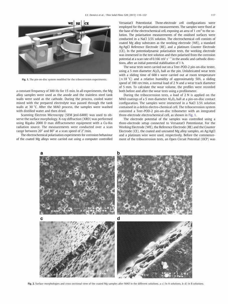
Fig. 1. The pin-on-disc system modified for the tribocorrosion experiments.
117E.E. Demirci et al. / Thin Solid Films 528 (2013) 116–122
a constant frequency of 300 Hz for 15 min. In all experiments, the Mgalloy samples were used as the anode and the stainless steel tankwalls were used as the cathode. During the process, cooled watermixed with the prepared electrolyte was passed through the tankwalls at 30 °C. After the MAO process, the samples were washedwith distilled water and then dried.
Scanning Electron Microscopy (SEM Jeol-6400) was used to ob-serve the surface morphology. X-ray diffraction (XRD) was performedusing Rigaku 2000 D max diffractometer equipment with a Cu-Kαradiation source. The measurements were conducted over a scanrange between 20° and 80° at a scan speed of 2°/min.
The electrochemical polarisation experiments for corrosion behaviourof the coated Mg alloys were carried out using a computer controlled
Fig. 2. Surface morphologies and cross-sectional view of the coated Mg samples
Versastat3 Potentiostat. Three-electrode cell configurations wereemployed for the polarisation measurements. The samples were fixed atthe base of the electrochemical cell, exposing an area of 1 cm2 to the so-lution. The polarisation measurements of the oxidised surfaces wereconducted in a NaCl 3.5% solution. The electrochemical cell consists ofcoated Mg alloy substrates as the working electrode (WE), a standardAg/AgCl Reference Electrode (RE), and a platinum Counter Electrode(CE). In the potentiodynamic polarisation tests, the working electrodewas immersed in the test solution and then polarised from the corrosionpotential at a scan rate of 0.166 mV s−1 in the anodic and cathodic direc-tions, after an initial potential stabilisation of 1 h.
The wear tests were carried out on a Teer-POD-2 pin-on-disc tester,using a 5 mm diameter Al2O3 ball as the pin. Unlubricated wear testswith a sliding time of 600 s were carried out at room temperature(≈18 °C) and a relative humidity of approximately 50%, a slidingspeed of 100 rev/min, a normal load of 2 N and a wear track diameterof 5 mm. To calculate the wear volume, the profiles were recordedboth before and after the wear tests using a profilometer.
During the tribocorrosion tests, a load of 2 N is applied on theMAO coatings of a 5 mm diameter Al2O3 ball at a pin-on-disc contactconfiguration. The samples were immersed in a NaCl 3.5% solutioncontained in a delrin electro-chemical cell. The tribocorrosion systemconsisted a Teer-POD-2 pin-on-disc tribometer with an integratedthree-electrode electrochemical cell, as shown in Fig. 1.
The electrode potential of the samples was controlled using athree-electrode setup connected to Versastat3 Potentiostat. For theWorking Electrode (WE), the Reference Electrode (RE) and the CounterElectrode (CE), the coated and uncoated Mg alloy samples, an Ag/AgCland a platinum wire were used, respectively. Before the commence-ment of the tribocorrosion tests, an Open Circuit Potential (OCP) was
after MAO in the different solutions. a–c) In A solutions, b–d) in B solutions.

Fig. 3. XRD patterns of the coated and uncoated Mg samples.
118 E.E. Demirci et al. / Thin Solid Films 528 (2013) 116–122
applied to the surfaces on which the samples were deposited for 2 min.Next, rubbing commenced by applying a 2 N force with the duration of5 min. At the end of this duration, the force was removed, and then anOCP without rubbing was applied for 2 min.
3. Results and discussion
The surface morphology and cross-sectional images of the Mgalloy obtained from the MAO process at different solutions areshown in Fig. 2. Due to the nature of the MAO process, micro dis-charges may occur depending on base materials with rough surfacecoatings and the largest particles with different sizes [17,18]. Fig. 2aand b clearly indicates circular pores. The pore size and surface pa-rameters of the samples created in different solutions were analysedbased on the changes observed in the SEM images. The sampleoxidised in electrolyte without stannate (B) reveals that the oxide is
Fig. 4. Polarisation curve of the co
continuous and adherent, although it features major porosity [4]. Inthe A solutions, small and more uniformly pores were observed onthe surface of the coatings. Therefore, the porosity lowers at theoxide surface.
Fig. 2 also includes the cross-sectional views of the coatings thatwere created in different solutions. The region between the coatingand the base material was referred to as the transition layer, andthe structure of the MAO coatings grown in three different regionswas analysed. In the A solutions, the film has a thicker and greaterhomogeneous thickness of approximately 5 μm, and contains smallerporosity (Fig. 2c). In the B solutions, the thickness is irregular andbetween 3 and 5 μm whilst the oxide layer contains large pores(Fig. 2d). These results are almost identical to the previous work [4].
The XRD patterns of the coatings grown by MAO in different solu-tions are given in Fig. 3. In the B solutions, XRD analysis suggests thatafter 10 min the oxide is entirely amorphous. According to some
ated and uncoated samples.

Fig. 5. Friction coefficients and wear scar SEM images of samples. a) Uncoated, b) coated in A solutions and c) coated in B solutions.
119E.E. Demirci et al. / Thin Solid Films 528 (2013) 116–122
studies, the crystallisation of MgO occurs after a longer oxidation pe-riod (20 min) under specific experimental conditions [4,19–21]. TheA solutions, which are represented in Fig. 3, reveal the presence ofmagnesium tin hydroxide (MgSn (OH)6) named schoenfliesite and asmall amount of metallic tin [4]. The magnesium oxide phase is alsobelieved to be in the amorphous state. In addition, as is shown inFig. 3, there are SnO2 peaks. The forming reason for the SnO2 peakscan be explained as that SnO3
2− could be uniformly absorbed at thesurface of an anode under an electric field, and decomposed intoSnO2 under the elevated temperature generated by a micro-plasma
discharge. As deposited SnO2 forms film at the surface of an anode[22] and also under the bipolar voltage modes discharge channelsduring the MAO process and a temperature and pressure (2104 °Cand 102 MPa, respectively) can be explained [17,23].
The corrosion behaviour of the oxidised specimens changed withthe uniformity of the coating, surface roughness and the number andthe dimension of the pores on the surface [24]. The effect of themicro-arc oxidation process in the different solutions after corrosiontests is given in Fig. 4. The oxidised sample surfaces in particular formedin B solutions have a more porous structure. The best surface

120 E.E. Demirci et al. / Thin Solid Films 528 (2013) 116–122
morphologywas obtained from the samples that were oxidised in A so-lutions. The samples that are coated in A solutions have a smaller poresize and diameter and thus, the corrosion current density was lower.The corrosion performance ofMAO is related to the surfacemorphologyrather than the surface thickness [25,26]. Solution A makes the oxidelayer dense and the current density of corrosion decrease. The corrosionresistance decreases with the decreasing of the thickness and porosityon the surface. The number of the corroded regions increases, becausethe contact areas between the porous oxide layer and the solutiongrow. The deep splits and the structural discontinuity on the surfaceof the materials which have a high surface roughness expedite thediffusion of the Cl− ions into the coating and decrease the corrosionresistance [25,27].
Fig. 6. Variation of the corrosion potential of the tested samples immersed in 3.5% NaCl solusolutions and c) coated in B solutions.
The polarisation curves indicate that the solutions influenced thecorrosion resistance of the coatings. The Icorr and Ecorr values were de-termined using the Tafel chart. The lowest corrosion current and thehighest corrosion potential values are important for the determinationof the corrosion resistance. According to the experimental results, thesamples which were coated in an A solution showed the highestcorrosion potential and lowest corrosion current. The pores in theseexperiments were observed as having small diameters and uniformdistribution. These results are compatible with those reported in the lit-erature [28,29]. Ma et al. discussed the relationship between the coatingthickness and morphology [30]. The coating constituted a barrier be-tween the substrate and the corrosion environment. The Mg substrateexhibited a passivation tendency with the increase of the corrosion
tion before, during and after rubbing against an Al2O3 ball. a) Uncoated, b) coated in A

Fig. 6 (continued).
121E.E. Demirci et al. / Thin Solid Films 528 (2013) 116–122
current (Icorr). The corrosion current densities are 1×10⁻⁶A/cm2 forthe Mg substrate, 10×10−9A/cm2 and 1 A/cm2 for the oxided samplesin solutions A and B, respectively. The corrosion potentials (Ecorr) are1.8 mV for the Mg substrate, −200 mV and 190 mV for the oxidedsamples in solutions A and B, respectively. It was observed that thecorrosion potential of the coating rose to more respectable values ascompared to the substrate.
Fig. 5 shows a variation of the friction coefficient sliding period forthe Mg alloy substrate and both coatings under atmospheric frictionconditions. The average friction coefficients and the SEM images ofthe samples are shown in Fig. 5. For the Mg alloy substrate, the aver-age friction coefficient is approximately 0.4 (Fig. 5a), and the frictioncoefficient of both coatings is much lower than that of the substrate.The MAO coatings in solutions A and B are 0.3 and 0.5, respectively.The wear tracks of the Mg alloy shown in Fig. 5 are similar with thealloy studied in the previous paper [40,41]. Fig. 5b and c also showsimages of the wear tracks of the coatings in A and B solutions, respec-tively. It is observed that the wear tracks of both the coatings becomeshallow and narrow. This demonstrates that the wear resistance ofthe Mg alloy is improved by the MAO process. The wear tracks ofthe coating that was used in the A solutions appear to contain loosewear debris, which is characterised by a shallow and broad worn re-gion. Whereas the wear tracks of the coating that was used in the Bsolutions are narrow and deep. The micro pores in the wear tracksof the coating that was used in the A solutions are filled with granularwear debris.
Fig. 6 shows the tribocorrosion behaviour of both the coated sam-ples and uncoated sample immersed in 3.5% NaCl solution before,during and after rubbing against an Al2O3 ball. As known, an OpenCircuit Potential (OCP) recorded in tribocorrosion tests is a mixedpotential reflecting the combined state of the unworn material andthe material in the wear track [31]. A galvanic connection betweenworn and unworn parts on the surface is possible [31–35]. Asshown in Fig. 6, the OCP curves consist of three regions; i.e. before,during and after the rubbing. Initially, placing the Al2O3 pin in contactwith the surfaces, the OCP of the Mg alloy substrate and the coatedsamples were monitored for 2 min for stabilisation, as seen at regionI in Fig. 6. After region I, a sudden drop of OCP for both the samples
was observed at the onset of rubbing (region II), as also noted in sim-ilar systems [31,36–38]. The sudden drop in OCP indicates that theprotective passive layer and coating were locally removed. The OCPvalues obtained were −1.575 V, −210 mV and −203 mV for theMg alloy substrate, coated samples in the A solution and coated sam-ples in the B solution, respectively. The drop in OCP value for the Mgalloy substrate was more than the coated samples. At the beginning ofthe region II, the reason of the drop observed at OCP for the Mg sub-strate results from destroying the substrate surface due to their beingchemically active and inferiority in corrosion resistance. In region II,the OCP value for the coated samples continued to fluctuate whilst aslight increase in the OCP value for the Mg substrate was observedduring rubbing. The fluctuations observed in OCP values duringrubbing for both the Mg substrate and coated samples were relatedto the periodic mechanical depassivation and electrochemicalrepassivation events [31]. After rubbing (region III), a low risingOCP level was observed for the Mg coating due to the fact that thecoating did not delaminate, whilst the OCP values of the Mg substratewere increasing immediately at a high rate due to the repassivation.The findings obtained from this study are in agreement with thosein the literature [31,39–41].
4. Conclusion
The following conclusions can be derived from the above resultsand discussion:
• The different solutions are directly affected by the surfacemorphologies.
• The best surface morphologies are found in the samples that arecoated in solution A that contains stannate ions.
• The lowest value of the corrosion current and the highest value ofthe corrosion potential occur in the samples that are coated insolution A that contains stannate ions.
• The highest value of the wear resistant occurs in the samples thatare coated in solution A that contains stannate ions.
• The highest value of the tribocorrosion resistant occurs in thesamples that are coated in solution A that contains stannate ions.
122 E.E. Demirci et al. / Thin Solid Films 528 (2013) 116–122
Acknowledgment
The authors would like to thank the Faculty of Engineering,Department of Mechanical Engineering at Ataturk University.
References
[1] R. Zhang, D.H. An, E. Han, S. Guo, Trans. Nonferrous Met. Soc. China 16 (2006)685.
[2] F.H. Froes, D. Elıezer, E. Aghıon, Sci. Technol. Appl. Magnes. 5 (1998) 30.[3] R.F. Decker, Adv. Mater. Process. 9 (1998) 31.[4] C.E. Barchiche, E. Rocca, J. Hazan, Surf. Coat. Technol. 202 (2008) 4145.[5] J.Z. Lı, Y. Tıan, W.Z.Q. Huang, X. Zhang, Appl. Surf. Sci. 252 (2006) 2839.[6] C.D. Gu, J.S. Lıan, G. He, J.Z.H. Jıang, Q. Jıang, Surf. Coat. Technol. 200 (2006) 5413.[7] C.S. Lın, H.C. Lın, K.M. Lın, W.C. Laı, Corros. Sci. 48 (2006) 93.[8] E.H. Han, Q. Zhou, W.Y. Shan, D.W. Ke, Mater. Sci. Forum 419 (2003) 879.[9] H.F. Guo, M.Z. An, Appl. Surf. Sci. 246 (2005) 229.
[10] S.J. Xıa, R. Yue, R.G. Rateıck Jr., V.I. Bırss, J. Electrochem. Soc. 151 (2004) 179.[11] P. May, K.W. Xu, W.X. Wen, X.P. He, Surf. Coat. Technol. 190 (2005) 165.[12] Q. Zhu L, G.L. Song, Surf. Coat. Technol. 200 (2006) 2834.[13] S.Y. Ln, J.D. Hu, Y. Yang, Z.X. Guo, H.Y. Wang, Appl. Surf. Sci. 252 (2005) 1723.[14] Y. Zhang, C. Yan, Surf. Coat. Technol. 201 (2006) 2381.[15] Y. Ma, X. Nie, D.O. Northwood, H. Hu, Thin Solid Films 494 (2006) 296.[16] H. Huo, Y. Li, F. Wang, Corros. Sci. 46 (2004) 1467.[17] A.L. Yerokhin, X. Nie, A. Leyland, et al., Surf. Coat. Technol. 122 (1999) 73.[18] Y. Ma, Master's Thesis, University of Windsor, Canada, 2005.
[19] H.Y. Hsiao, W.T. Tsai, Surf. Coat. Technol. 190 (2005) 299.[20] H.Y. Hsiao, H.C. Tsung, W.T. Tsai, Surf. Coat. Technol. 199 (2005) 127.[21] C.E. Barchiche, E. Rocca, C. Juers, J. Hazan, J. Steinmetz, Electrochim. Acta 53
(2007) 417.[22] J. He, Q.Z. Caia, F. Xiaob, X.W. Li, A.W. Suna, X. Zhaoa, J. Alloys Compd. 509 (2011) L11.[23] C. Blawert, T.V. Heitmann, W. Dietzel, H.M. Nykyforchyn, M.D. Klapkiv, Surf. Coat.
Technol. 200 (2005) 68.[24] Y. Vangolu, E. Arslan, Y. Totik, E. Demirci, A. Alsaran, Surf. Coat. Technol. 205
(2010) 1764.[25] B. Jiang, T. Xia, H. Shi, N. Lei, Trans. Met. Heat Treat. 262 (2005) 82.[26] M.D. Klapkiv, Mater. Sci. 31 (1995) 4.[27] P. Gupta, G. Tenhundfeld, E.O. Daigle, D. Ryabkov, Surf. Coat. Technol. 201 (2007)
8746.[28] R.N. Kackar, J. Qual. Eng. 17 (1985) 176.[29] M.S. Phadke, Quality Engineering Using Robust Design, PrenticeHall, New Jersey,
1986.[30] F. Ma, G. Li, H. Li, H. Mab, X. Cai, Mater. Lett. 57 (2002) 82.[31] E. Arslan, Y. Totik, I. Efeoglu, Prog. Org. Coat. xxx (2011) (xxx–xxx).[32] J. Garcia, D. Drees, J.P. Celis, Wear 249 (2001) 45.[33] L. Benea, P. Ponthiaux, F. Wenger, J. Galland, D. Hertz, J.Y. Malo,Wear 256 (2004) 948.[34] J. Lidia Benea, Appl. Electrochem. 39 (2009) 1671.[35] S. Rossi, L. Fedrizzi, M. Leoni, P. Scardi, Y. Massiani, Thin Solid Films 350 (1999) 161.[36] T. HarA, H. Asahi, Y. Kaneta, Corrosion 56 (2000) 183.[37] F. Galliano, E. Galvanetto, S. Mischler, D. Landolt, Surf. Coat. Technol. 145 (2001) 121.[38] T.M. Manhabosco, I.L. Muller, Tribol. Lett. 33 (2009) 193.[39] E. Martin, M. Azzi, G.A. Salishchev, J. Szpunar, Tribol. Int. 43 (2010) 918.[40] C. Ma, Y. Milinzhang, X. Xuefengbai, Tribol. Int. 47 (2012) 62.[41] C.X. Ma, Y. Lu, P.P. Sun, Y. Yuan, X.Y. Jing, M.L. Zhang, Surf. Coat. Technol. 287
(2011) 94.