L-LINE AND A-LINE MAINTENANCE MANUAL Models
136
L-LINE AND A-LINE MAINTENANCE MANUAL Models: L7500 L7501 L8500 L8511 L8513 L9500 L9501 L9511 L9513 L9522 A9500 A9522 STI-383-1 (10/08P) Published by Daimler Trucks North America LLC 4747 N. Channel Ave. Portland, OR 97217 Printed in U.S.A.
-
Upload
khangminh22 -
Category
Documents
-
view
0 -
download
0
Transcript of L-LINE AND A-LINE MAINTENANCE MANUAL Models
L-LINE AND A-LINE MAINTENANCE MANUAL
Models: L7500L7501L8500L8511L8513L9500L9501L9511L9513L9522A9500A9522
STI-383-1 (10/08P) Published byDaimler Trucks North America LLC
4747 N. Channel Ave.Portland, OR 97217
Printed in U.S.A.
ForewordScheduled maintenance provides a key element for the safe operation of your vehicle. A propermaintenance program also helps to minimize downtime and to safeguard warranties. Thismaintenance manual provides information necessary for years of safe, reliable, and cost-efficientvehicle operation.
IMPORTANT: The maintenance operations in this manual are not all-inclusive . Alsorefer to other component and body manufacturers’ instructions for specific inspectionand maintenance instructions.
Perform the operations in this maintenance manual at scheduled intervals. Perform the pretripand post-trip inspections, and daily/weekly/monthly maintenance, as outlined in the vehicledriver’s manual. Major components, such as engines, transmissions, and rear axles, are coveredin their own maintenance and operation manuals, that are provided with the vehicle. Perform anymaintenance operations listed at the intervals scheduled in those manuals. Your SterlingDealership has the qualified technicians and equipment to perform this maintenance for you.They can also set up a scheduled maintenance program tailored specifically to your needs.Optionally, they can assist you in learning how to perform these maintenance procedures.
IMPORTANT: Descriptions and specifications in this manual were in effect at the time ofprinting. Daimler Trucks North America LLC reserves the right to discontinue modelsand to change specifications or design at any time without notice and without incurringobligation. Descriptions and specifications contained in this publication provide nowarranty, expressed or implied, and are subject to revision and editions without notice.
Refer to www.Daimler-TrucksNorthAmerica.com and www.SterlingTrucks.com for more informa-tion, or contact Daimler Trucks North America LLC at the address below.
Environmental Concerns and RecommendationsWhenever you see instructions in this manual to discard materials, you should attempt to reclaimand recycle them. To preserve our environment, follow appropriate environmental rules andregulations when disposing of materials.
NOTICE: Parts Replacement ConsiderationsDo not replace suspension, axle, or steering parts (such as springs, wheels, hubs, and steeringgears) with used parts. Used parts may have been subjected to collisions or improper use andhave undetected structural damage.
© 1998–2008 Daimler Trucks North America LLC
All rights reserved. No part of this publication, in whole or in part, may be translated, reproduced,stored in a retrieval system, or transmitted in any form by any means, electronic, mechanical,photocopying, recording, or otherwise, without the prior written permission of Daimler TrucksNorth America LLC. Daimler Trucks North America LLC is a Daimler company.
Daimler Trucks North America LLCService Systems and Documentation (POC-SSD)
P.O. Box 3849Portland, OR 97208–3849

Daimler Trucks North America LLC distributes the following major service publications in paper and electronic(via ServicePro®) formats.
Workshop/ServiceManual
Workshop/service manuals contain service and repair information for all vehiclesystems and components, except for major components such as engines, trans-missions, and rear axles. Each workshop/service manual section is divided intosubjects that can include general information, principles of operation, removal,disassembly, assembly, installation, and specifications.
Maintenance Manual Maintenance manuals contain routine maintenance procedures and intervals forvehicle components and systems. They have information such as lubricationprocedures and tables, fluid replacement procedures, fluid capacities, specifica-tions, and procedures for adjustments and for checking the tightness of fasten-ers. Maintenance manuals do not contain detailed repair or service information.
Driver’s/Operator’sManual
Driver’s/operator’s manuals contain information needed to enhance the driver’sunderstanding of how to operate and care for the vehicle and its components.Each manual contains a chapter that covers pretrip and post-trip inspections,and daily, weekly, and monthly maintenance of vehicle components.Driver’s/operator’s manuals do not contain detailed repair or service information.
Service Bulletins Service bulletins provide the latest service tips, field repairs, product improve-ments, and related information. Some service bulletins are updates to informa-tion in the workshop/service manual. These bulletins take precedence overworkshop/service manual information, until the latter is updated; at that time, thebulletin is usually canceled. The service bulletins manual is available only todealers. When doing service work on a vehicle system or part, check for a validservice bulletin for the latest information on the subject.
IMPORTANT: Before using a particular service bulletin, check the currentservice bulletin validity list to be sure the bulletin is valid.
Parts Technical Bulletins Parts technical bulletins provide information on parts. These bulletins containlists of parts and BOMs needed to do replacement and upgrade procedures.
Web-based repair, service, and parts documentation can be accessed using the following applications on theAccessSterling.com website.
ServicePro ServicePro® provides Web-based access to the most up-to-date versions of thepublications listed above. In addition, the Service Solutions feature provides di-agnostic assistance with Symptoms Search, by connecting to a large knowledgebase gathered from technicians and service personnel. Search results for bothdocuments and service solutions can be narrowed by initially entering vehicleidentification data.
PartsPro PartsPro® is an electronic parts catalog system, showing the specified vehicle’sbuild record.
EZWiring EZWiring™ makes Sterling, Freightliner, Freightliner Custom Chassis Corpora-tion, Thomas Built Buses, and Western Star products’ wiring drawings and float-ing pin lists available online for viewing and printing. EZWiring can also be ac-cessed from within PartsPro.
IntroductionDescriptions of Service Publications
L-Line and A-Line Maintenance Manual, October 2008 I–1

Warranty-related service information available on the AccessSterling.com website includes the following docu-mentation.
Recall Campaigns Recall campaigns cover situations that involve service work or replacement ofparts in connection with a recall notice. These campaigns pertain to matters ofvehicle safety. All recall campaigns are distributed to dealers; customers receivenotices that apply to their vehicles.
Field Service Campaigns Field service campaigns are concerned with non-safety-related service work orreplacement of parts. All field service campaigns are distributed to dealers; cus-tomers receive notices that apply to their vehicles.
IntroductionDescriptions of Service Publications
I–2 L-Line and A-Line Maintenance Manual, October 2008
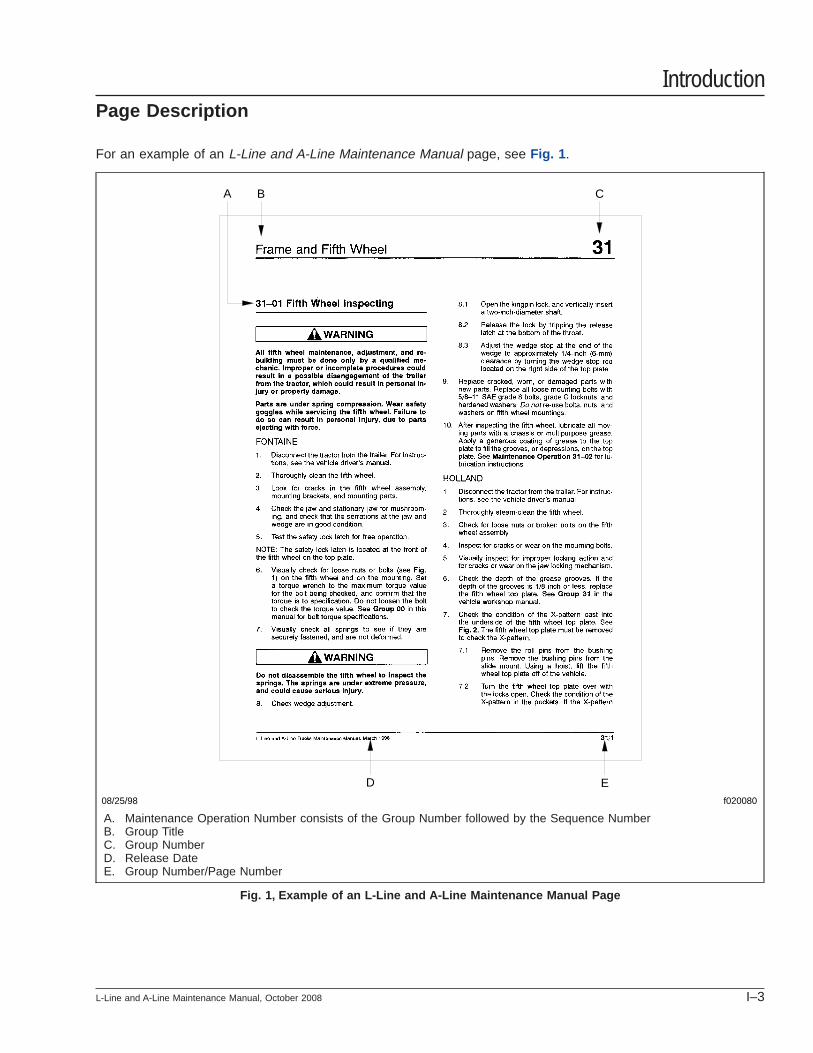
For an example of an L-Line and A-Line Maintenance Manual page, see Fig. 1 .
08/25/98 f020080
A B C
D E
A. Maintenance Operation Number consists of the Group Number followed by the Sequence NumberB. Group TitleC. Group NumberD. Release DateE. Group Number/Page Number
Fig. 1, Example of an L-Line and A-Line Maintenance Manual Page
IntroductionPage Description
L-Line and A-Line Maintenance Manual, October 2008 I–3
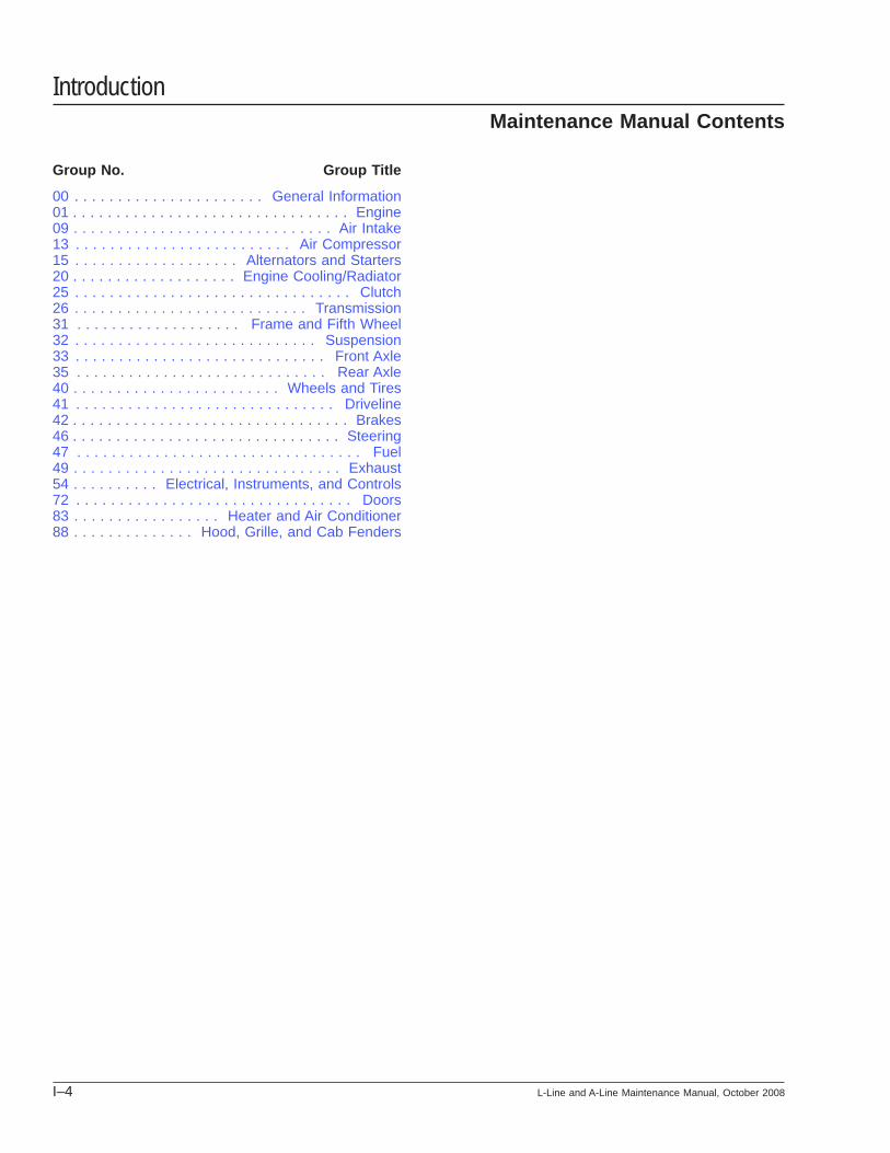
Group No. Group Title
00 . . . . . . . . . . . . . . . . . . . . . . General Information01 . . . . . . . . . . . . . . . . . . . . . . . . . . . . . . . . Engine09 . . . . . . . . . . . . . . . . . . . . . . . . . . . . . . Air Intake13 . . . . . . . . . . . . . . . . . . . . . . . . . Air Compressor15 . . . . . . . . . . . . . . . . . . . Alternators and Starters20 . . . . . . . . . . . . . . . . . . . Engine Cooling/Radiator25 . . . . . . . . . . . . . . . . . . . . . . . . . . . . . . . . Clutch26 . . . . . . . . . . . . . . . . . . . . . . . . . . . Transmission31 . . . . . . . . . . . . . . . . . . . Frame and Fifth Wheel32 . . . . . . . . . . . . . . . . . . . . . . . . . . . . Suspension33 . . . . . . . . . . . . . . . . . . . . . . . . . . . . . Front Axle35 . . . . . . . . . . . . . . . . . . . . . . . . . . . . . Rear Axle40 . . . . . . . . . . . . . . . . . . . . . . . . Wheels and Tires41 . . . . . . . . . . . . . . . . . . . . . . . . . . . . . . Driveline42 . . . . . . . . . . . . . . . . . . . . . . . . . . . . . . . . Brakes46 . . . . . . . . . . . . . . . . . . . . . . . . . . . . . . . Steering47 . . . . . . . . . . . . . . . . . . . . . . . . . . . . . . . . . Fuel49 . . . . . . . . . . . . . . . . . . . . . . . . . . . . . . . Exhaust54 . . . . . . . . . . Electrical, Instruments, and Controls72 . . . . . . . . . . . . . . . . . . . . . . . . . . . . . . . . Doors83 . . . . . . . . . . . . . . . . . Heater and Air Conditioner88 . . . . . . . . . . . . . . Hood, Grille, and Cab Fenders
IntroductionMaintenance Manual Contents
I–4 L-Line and A-Line Maintenance Manual, October 2008
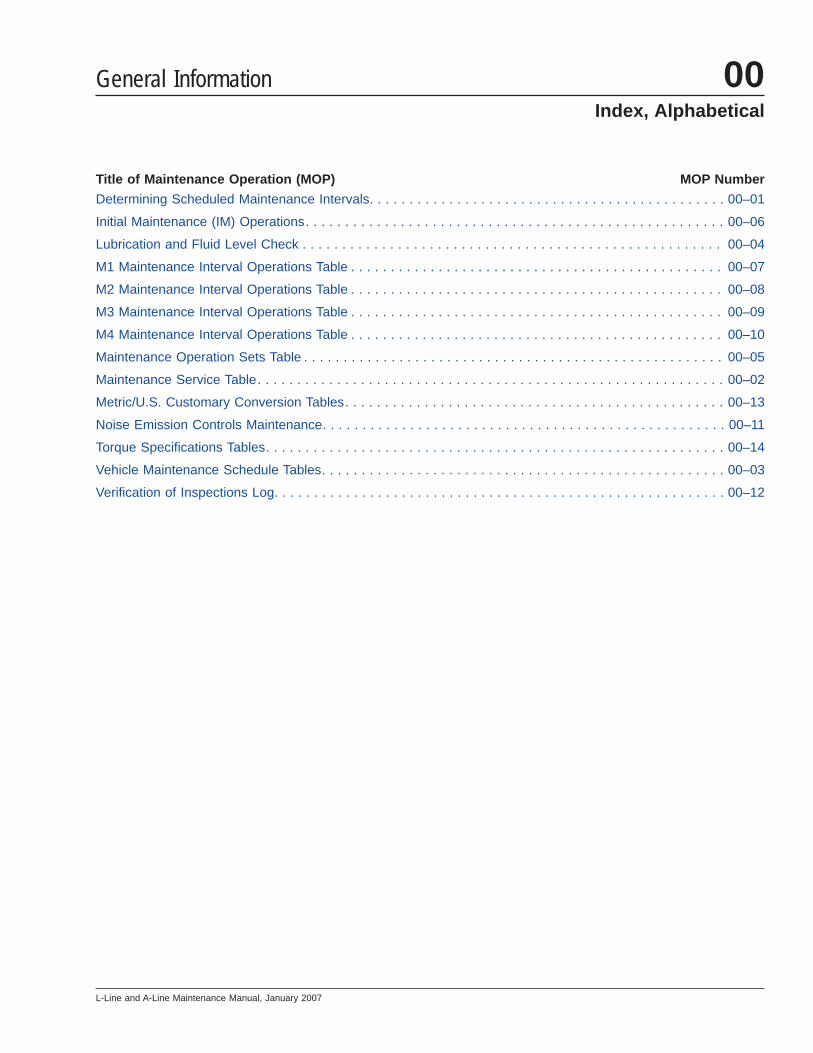
Title of Maintenance Operation (MOP) MOP Number
Determining Scheduled Maintenance Intervals. . . . . . . . . . . . . . . . . . . . . . . . . . . . . . . . . . . . . . . . . . . . . 00–01
Initial Maintenance (IM) Operations. . . . . . . . . . . . . . . . . . . . . . . . . . . . . . . . . . . . . . . . . . . . . . . . . . . . . 00–06
Lubrication and Fluid Level Check . . . . . . . . . . . . . . . . . . . . . . . . . . . . . . . . . . . . . . . . . . . . . . . . . . . . . 00–04
M1 Maintenance Interval Operations Table . . . . . . . . . . . . . . . . . . . . . . . . . . . . . . . . . . . . . . . . . . . . . . . 00–07
M2 Maintenance Interval Operations Table . . . . . . . . . . . . . . . . . . . . . . . . . . . . . . . . . . . . . . . . . . . . . . . 00–08
M3 Maintenance Interval Operations Table . . . . . . . . . . . . . . . . . . . . . . . . . . . . . . . . . . . . . . . . . . . . . . . 00–09
M4 Maintenance Interval Operations Table . . . . . . . . . . . . . . . . . . . . . . . . . . . . . . . . . . . . . . . . . . . . . . . 00–10
Maintenance Operation Sets Table . . . . . . . . . . . . . . . . . . . . . . . . . . . . . . . . . . . . . . . . . . . . . . . . . . . . . 00–05
Maintenance Service Table. . . . . . . . . . . . . . . . . . . . . . . . . . . . . . . . . . . . . . . . . . . . . . . . . . . . . . . . . . . 00–02
Metric/U.S. Customary Conversion Tables. . . . . . . . . . . . . . . . . . . . . . . . . . . . . . . . . . . . . . . . . . . . . . . . 00–13
Noise Emission Controls Maintenance. . . . . . . . . . . . . . . . . . . . . . . . . . . . . . . . . . . . . . . . . . . . . . . . . . . 00–11
Torque Specifications Tables. . . . . . . . . . . . . . . . . . . . . . . . . . . . . . . . . . . . . . . . . . . . . . . . . . . . . . . . . . 00–14
Vehicle Maintenance Schedule Tables. . . . . . . . . . . . . . . . . . . . . . . . . . . . . . . . . . . . . . . . . . . . . . . . . . . 00–03
Verification of Inspections Log. . . . . . . . . . . . . . . . . . . . . . . . . . . . . . . . . . . . . . . . . . . . . . . . . . . . . . . . . 00–12
General Information 00Index, Alphabetical
L-Line and A-Line Maintenance Manual, January 2007

Determining ScheduledMaintenance IntervalsPerforming regular maintenance on your Sterling ve-hicle will help ensure that your Sterling vehicle deliv-ers safe reliable service and optimum performancefor years to come. Failure to follow a regular mainte-nance program can result in inefficient operation andunscheduled down time.
To determine the correct maintenance intervals foryour vehicle you must first determine the type of ser-vice or conditions the vehicle will be operating in.Generally, most vehicles operate under conditionsthat fall within one of the three types of service de-scribed. Before placing your new vehicle in service,determine the type of service (Service Schedule I, II,or III) that applies to the intended use of the vehicle.After determining the vehicle’s type of service, referto the service schedule table or the vehicle mainte-nance schedule table, to determine how often main-tenance should be performed.
When the vehicle reaches the distance given for amaintenance interval, see the "Maintenance IntervalOperations Table" for a list of the maintenance op-erations to be performed at that maintenance inter-val. Use the maintenance operation reference num-bers to find detailed instructions in the manual oneach operation.
Types of ServiceService Schedule I (severe service) applies to ve-hicles that annually travel less than 6000 miles (10000 kilometers) or that operate under severe condi-tions. Examples of Schedule I (severe service) usageinclude: operation on extremely poor roads or wherethere is heavy dust accumulation; constant exposureto extreme hot, cold, salt-air, or other extreme cli-mates; frequent short-distance travel; construction-site operation; city operation (fire truck); or farmoperation.
Service Schedule II (short-haul transport) applies tovehicles that annually travel less than 60,000 miles(100 000 kilometers) and operate under normal con-ditions. Examples of Schedule II (short-haul trans-port) usage are: operation primarily in cities anddensely populated areas; local transport with infre-quent freeway travel; or high percentage of stop-and-go travel.
Service Schedule III (long-haul transport) is for ve-hicles that annually travel more than 60,000 miles(100 000 kilometers) with minimal city or stop-and-gooperation. Examples of Schedule III (long-haul trans-port) usage are: regional delivery that is mostly free-way miles; interstate transport; or any road operationwith high annual mileage.
NOTE: Maintenance instructions in this manualare based on average vehicle use and normaloperating conditions. Unusual vehicle operatingconditions may require service at more frequentintervals.
General Information 00Determining Scheduled Maintenance Intervals: 00–01
L-Line and A-Line Maintenance Manual, January 2007 00/1
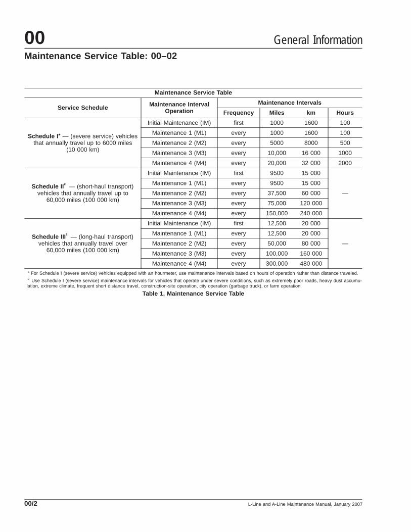
Maintenance Service Table
Service Schedule Maintenance IntervalOperation
Maintenance Intervals
Frequency Miles km Hours
Schedule I * — (severe service) vehiclesthat annually travel up to 6000 miles
(10 000 km)
Initial Maintenance (IM) first 1000 1600 100
Maintenance 1 (M1) every 1000 1600 100
Maintenance 2 (M2) every 5000 8000 500
Maintenance 3 (M3) every 10,000 16 000 1000
Maintenance 4 (M4) every 20,000 32 000 2000
Schedule II † — (short-haul transport)vehicles that annually travel up to
60,000 miles (100 000 km)
Initial Maintenance (IM) first 9500 15 000
—
Maintenance 1 (M1) every 9500 15 000
Maintenance 2 (M2) every 37,500 60 000
Maintenance 3 (M3) every 75,000 120 000
Maintenance 4 (M4) every 150,000 240 000
Schedule III † — (long-haul transport)vehicles that annually travel over
60,000 miles (100 000 km)
Initial Maintenance (IM) first 12,500 20 000
—
Maintenance 1 (M1) every 12,500 20 000
Maintenance 2 (M2) every 50,000 80 000
Maintenance 3 (M3) every 100,000 160 000
Maintenance 4 (M4) every 300,000 480 000* For Schedule I (severe service) vehicles equipped with an hourmeter, use maintenance intervals based on hours of operation rather than distance traveled.† Use Schedule I (severe service) maintenance intervals for vehicles that operate under severe conditions, such as extremely poor roads, heavy dust accumu-
lation, extreme climate, frequent short distance travel, construction-site operation, city operation (garbage truck), or farm operation.
Table 1, Maintenance Service Table
General Information00Maintenance Service Table: 00–02
L-Line and A-Line Maintenance Manual, January 200700/2
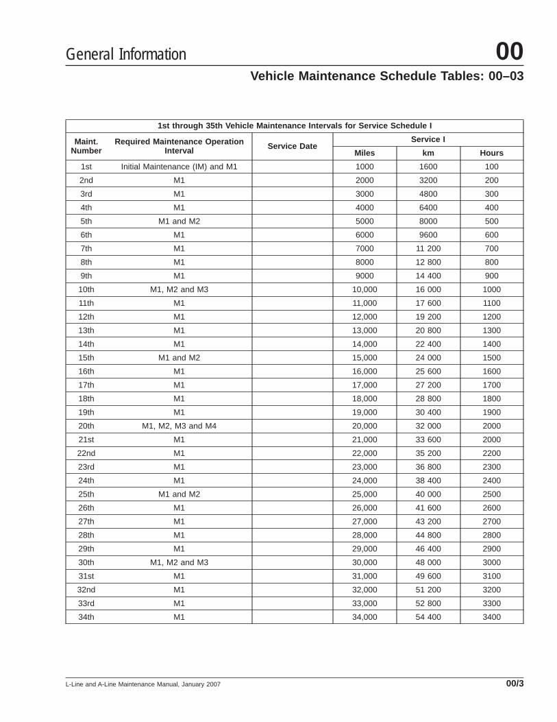
1st through 35th Vehicle Maintenance Intervals for Service Schedule I
Maint.Number
Required Maintenance OperationInterval Service Date
Service I
Miles km Hours
1st Initial Maintenance (IM) and M1 1000 1600 100
2nd M1 2000 3200 200
3rd M1 3000 4800 300
4th M1 4000 6400 400
5th M1 and M2 5000 8000 500
6th M1 6000 9600 600
7th M1 7000 11 200 700
8th M1 8000 12 800 800
9th M1 9000 14 400 900
10th M1, M2 and M3 10,000 16 000 1000
11th M1 11,000 17 600 1100
12th M1 12,000 19 200 1200
13th M1 13,000 20 800 1300
14th M1 14,000 22 400 1400
15th M1 and M2 15,000 24 000 1500
16th M1 16,000 25 600 1600
17th M1 17,000 27 200 1700
18th M1 18,000 28 800 1800
19th M1 19,000 30 400 1900
20th M1, M2, M3 and M4 20,000 32 000 2000
21st M1 21,000 33 600 2000
22nd M1 22,000 35 200 2200
23rd M1 23,000 36 800 2300
24th M1 24,000 38 400 2400
25th M1 and M2 25,000 40 000 2500
26th M1 26,000 41 600 2600
27th M1 27,000 43 200 2700
28th M1 28,000 44 800 2800
29th M1 29,000 46 400 2900
30th M1, M2 and M3 30,000 48 000 3000
31st M1 31,000 49 600 3100
32nd M1 32,000 51 200 3200
33rd M1 33,000 52 800 3300
34th M1 34,000 54 400 3400
General Information 00Vehicle Maintenance Schedule Tables: 00–03
L-Line and A-Line Maintenance Manual, January 2007 00/3

1st through 35th Vehicle Maintenance Intervals for Service Schedule I
Maint.Number
Required Maintenance OperationInterval Service Date
Service I
Miles km Hours
35th M1 and M2 35,000 56 000 3500
Table 2, 1st through 35th Vehicle Maintenance Intervals for Service Schedule I
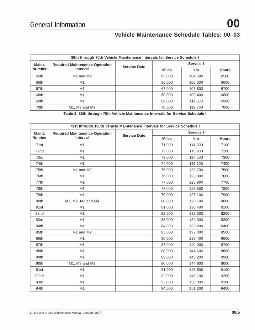
36th through 70th Vehicle Maintenance Intervals for Service Schedule I
Maint.Number
Required Maintenance OperationInterval Service Date
Service I
Miles km Hours
36th M1 36,000 57 600 3600
37th M1 37,000 59 200 3700
38th M1 38,000 60 800 3800
39th M1 39,000 62 400 3900
40th M1, M2, M3 and M4 40,000 64 000 4000
41st M1 41,000 65 600 4100
42nd M1 42,000 67 200 4200
43rd M1 43,000 68 800 4300
44th M1 44,000 70 400 4400
45th M1 and M2 45,000 72 000 4500
46th M1 46,000 73 600 4600
47th M1 47,000 75 200 4700
48th M1 48,000 76 800 4800
49th M1 49,000 78 400 4900
50th M1, M2 and M3 50,000 80 000 5000
51st M1 51,000 82 000 5100
52nd M1 52,000 83 700 5200
53rd M1 53,000 85 300 5300
54th M1 54,000 86 900 5400
55th M1 and M2 55,000 88 500 5500
56th M1 56,000 90 100 5600
57th M1 57,000 91 700 5700
58th M1 58,000 93 300 5800
59th M1 59,000 94 900 5900
60th M1, M2, M3 and M4 60,000 96 500 6000
61st M1 61,000 98 200 6100
62nd M1 62,000 99 800 6200
63rd M1 63,000 101 400 6300
64th M1 64,000 103 000 6400
General Information00Vehicle Maintenance Schedule Tables: 00–03
L-Line and A-Line Maintenance Manual, January 200700/4
36th through 70th Vehicle Maintenance Intervals for Service Schedule I
Maint.Number
Required Maintenance OperationInterval Service Date
Service I
Miles km Hours
65th M1 and M2 65,000 104 600 6500
66th M1 66,000 106 200 6600
67th M1 67,000 107 800 6700
68th M1 68,000 109 400 6800
69th M1 69,000 111 000 6900
70th M1, M2 and M3 70,000 112 700 7000
Table 3, 36th through 70th Vehicle Maintenance Intervals for Service Schedule I
71st through 100th Vehicle Maintenance Intervals for Service Schedule I
Maint.Number
Required Maintenance OperationInterval Service Date
Service I
Miles km Hours
71st M1 71,000 114 300 7100
72nd M1 72,000 115 900 7200
73rd M1 73,000 117 500 7300
74th M1 74,000 119 100 7400
75th M1 and M2 75,000 120 700 7500
76th M1 76,000 122 300 7600
77th M1 77,000 123 900 7700
78th M1 78,000 125 500 7800
79th M1 79,000 127 100 7900
80th M1, M2, M3 and M4 80,000 128 700 8000
81st M1 81,000 130 400 8100
82nd M1 82,000 132 000 8200
83rd M1 83,000 134 000 8300
84th M1 84,000 135 200 8400
85th M1 and M2 85,000 137 000 8500
86th M1 86,000 138 400 8600
87th M1 87,000 140 000 8700
88th M1 88,000 141 600 8800
89th M1 89,000 143 200 8900
90th M1, M2 and M3 90,000 144 800 9000
91st M1 91,000 146 500 9100
92nd M1 92,000 148 100 9200
93rd M1 93,000 150 000 9300
94th M1 94,000 151 300 9400
General Information 00Vehicle Maintenance Schedule Tables: 00–03
L-Line and A-Line Maintenance Manual, January 2007 00/5
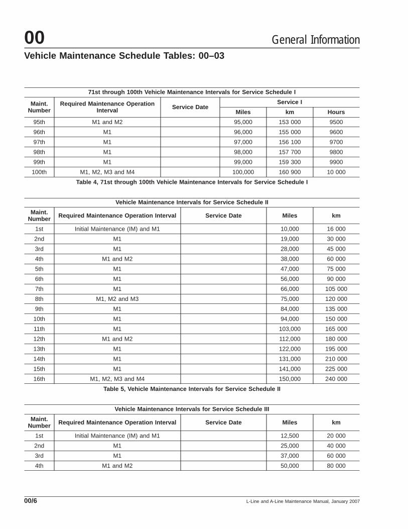
71st through 100th Vehicle Maintenance Intervals for Service Schedule I
Maint.Number
Required Maintenance OperationInterval Service Date
Service I
Miles km Hours
95th M1 and M2 95,000 153 000 9500
96th M1 96,000 155 000 9600
97th M1 97,000 156 100 9700
98th M1 98,000 157 700 9800
99th M1 99,000 159 300 9900
100th M1, M2, M3 and M4 100,000 160 900 10 000
Table 4, 71st through 100th Vehicle Maintenance Intervals for Service Schedule I
Vehicle Maintenance Intervals for Service Schedule II
Maint.Number Required Maintenance Operation Interval Service Date Miles km
1st Initial Maintenance (IM) and M1 10,000 16 000
2nd M1 19,000 30 000
3rd M1 28,000 45 000
4th M1 and M2 38,000 60 000
5th M1 47,000 75 000
6th M1 56,000 90 000
7th M1 66,000 105 000
8th M1, M2 and M3 75,000 120 000
9th M1 84,000 135 000
10th M1 94,000 150 000
11th M1 103,000 165 000
12th M1 and M2 112,000 180 000
13th M1 122,000 195 000
14th M1 131,000 210 000
15th M1 141,000 225 000
16th M1, M2, M3 and M4 150,000 240 000
Table 5, Vehicle Maintenance Intervals for Service Schedule II
Vehicle Maintenance Intervals for Service Schedule III
Maint.Number Required Maintenance Operation Interval Service Date Miles km
1st Initial Maintenance (IM) and M1 12,500 20 000
2nd M1 25,000 40 000
3rd M1 37,000 60 000
4th M1 and M2 50,000 80 000
General Information00Vehicle Maintenance Schedule Tables: 00–03
L-Line and A-Line Maintenance Manual, January 200700/6
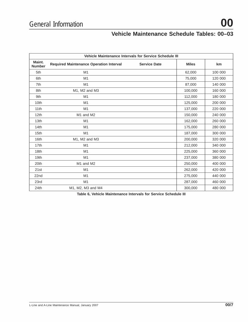
Vehicle Maintenance Intervals for Service Schedule III
Maint.Number Required Maintenance Operation Interval Service Date Miles km
5th M1 62,000 100 000
6th M1 75,000 120 000
7th M1 87,000 140 000
8th M1, M2 and M3 100,000 160 000
9th M1 112,000 180 000
10th M1 125,000 200 000
11th M1 137,000 220 000
12th M1 and M2 150,000 240 000
13th M1 162,000 260 000
14th M1 175,000 280 000
15th M1 187,000 300 000
16th M1, M2 and M3 200,000 320 000
17th M1 212,000 340 000
18th M1 225,000 360 000
19th M1 237,000 380 000
20th M1 and M2 250,000 400 000
21st M1 262,000 420 000
22nd M1 275,000 440 000
23rd M1 287,000 460 000
24th M1, M2, M3 and M4 300,000 480 000
Table 6, Vehicle Maintenance Intervals for Service Schedule III
General Information 00Vehicle Maintenance Schedule Tables: 00–03
L-Line and A-Line Maintenance Manual, January 2007 00/7
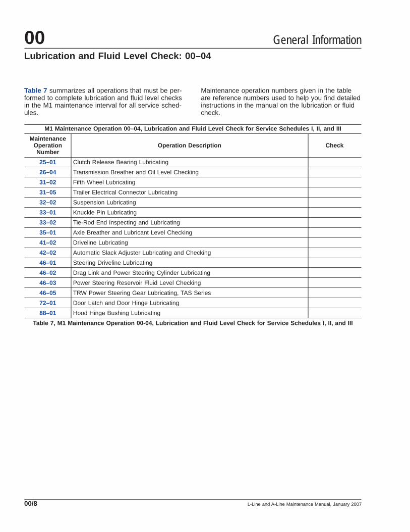
Table 7 summarizes all operations that must be per-formed to complete lubrication and fluid level checksin the M1 maintenance interval for all service sched-ules.
Maintenance operation numbers given in the tableare reference numbers used to help you find detailedinstructions in the manual on the lubrication or fluidcheck.
M1 Maintenance Operation 00–04, Lubrication and Fluid Level Check for Service Schedules I, II, and III
MaintenanceOperationNumber
Operation Description Check
25–01 Clutch Release Bearing Lubricating
26–04 Transmission Breather and Oil Level Checking
31–02 Fifth Wheel Lubricating
31–05 Trailer Electrical Connector Lubricating
32–02 Suspension Lubricating
33–01 Knuckle Pin Lubricating
33–02 Tie-Rod End Inspecting and Lubricating
35–01 Axle Breather and Lubricant Level Checking
41–02 Driveline Lubricating
42–02 Automatic Slack Adjuster Lubricating and Checking
46–01 Steering Driveline Lubricating
46–02 Drag Link and Power Steering Cylinder Lubricating
46–03 Power Steering Reservoir Fluid Level Checking
46–05 TRW Power Steering Gear Lubricating, TAS Series
72–01 Door Latch and Door Hinge Lubricating
88–01 Hood Hinge Bushing Lubricating
Table 7, M1 Maintenance Operation 00-04, Lubrication and Fluid Level Check for Service Schedules I, II, and III
General Information00Lubrication and Fluid Level Check: 00–04
L-Line and A-Line Maintenance Manual, January 200700/8

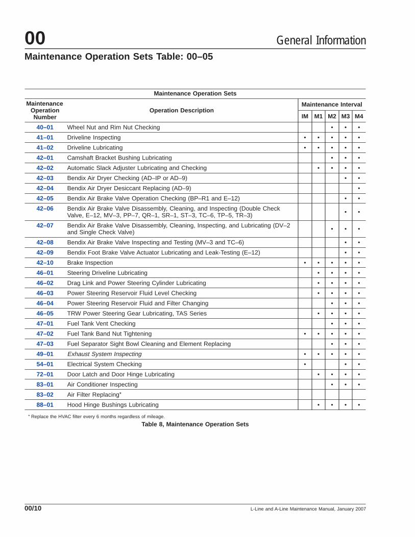
IMPORTANT: At each maintenance operation set, inaddition to the maintenance operations listed in thistable, perform all daily, weekly, and monthly mainte-nance operations listed in Chapter 11, "Pretrip andPost-Trip Inspections and Maintenance" of theL-Line and A-Line Driver’s Manual.
The "Maintenance Operation Number" is a referencenumber matching the text in this manual which pro-
vides detailed instructions on the maintenance opera-tions to be performed.
NOTE: Maintenance operations appearing in italics inthis table are for noise emission control components.
Maintenance Operation Sets
MaintenanceOperationNumber
Operation DescriptionMaintenance Interval
IM M1 M2 M3 M4
01–01 Engine Rear-Support Assembly Checking • •
01–02 Engine Noise Panel Inspecting • •
01–03 Jacobs Engine Brake Wiring Inspecting • • •
01–04 Engine Drive Belt Inspecting • •
09–01 Air Cleaner Element Inspecting and Replacing • •
13–01 Bendix Air Compressor Inspecting • • • •
15–01 Alternator, Battery, and Starter Checking • • •
20–01 Radiator Cap Checking • • •
20–02 Radiator Pressure Flushing and Coolant Changing •
20–03 Fan Drive and Clutch Checking • • •
25–01 Clutch Release Bearing Lubricating • • • •
26–01 Allison Transmission Fluid and Filter Changing •
26–02 Manual Transmission Magnetic Plug Cleaning and Oil Changing • • • •
26–03 Transmission Air Filter/Regulator Checking, and Cleaning or Replacing • • •
26–04 Transmission Breather and Oil Level Checking • • • •
31–01 Fifth Wheel Inspecting • • • •
31–02 Fifth Wheel Lubricating • • • •
31–03 Frame Fastener Torque Checking •
31–04 Holland Fifth Wheel Sliding Mechanism Inspecting • • •
31–05 Trailer Electrical Connector Lubricating • • • • •
32–01 Suspension Inspecting • • • • •
32–02 Suspension Lubricating • • • • •
32–03 Suspension U-Bolt Torque Checking • • •
33–01 Knuckle Pin Lubricating • • • •
33–02 Tie-Rod End Inspecting and Lubricating • • • •
33–03 All-Axle Alignment Checking •
35–01 Axle Breather and Lubricant Level Checking • • • •
35–02 Axle Lubricant Changing, Oil Filter Replacing, and Magnetic Strainer Cleaning • • •
General Information 00Maintenance Operation Sets Table: 00–05
L-Line and A-Line Maintenance Manual, January 2007 00/9
Maintenance Operation Sets
MaintenanceOperationNumber
Operation DescriptionMaintenance Interval
IM M1 M2 M3 M4
40–01 Wheel Nut and Rim Nut Checking • • •
41–01 Driveline Inspecting • • • • •
41–02 Driveline Lubricating • • • • •
42–01 Camshaft Bracket Bushing Lubricating • • •
42–02 Automatic Slack Adjuster Lubricating and Checking • • • •
42–03 Bendix Air Dryer Checking (AD–IP or AD–9) • •
42–04 Bendix Air Dryer Desiccant Replacing (AD–9) •
42–05 Bendix Air Brake Valve Operation Checking (BP–R1 and E–12) • •
42–06 Bendix Air Brake Valve Disassembly, Cleaning, and Inspecting (Double CheckValve, E–12, MV–3, PP–7, QR–1, SR–1, ST–3, TC–6, TP–5, TR–3) • •
42–07 Bendix Air Brake Valve Disassembly, Cleaning, Inspecting, and Lubricating (DV–2and Single Check Valve) • • •
42–08 Bendix Air Brake Valve Inspecting and Testing (MV–3 and TC–6) • •
42–09 Bendix Foot Brake Valve Actuator Lubricating and Leak-Testing (E–12) • •
42–10 Brake Inspection • • • • •
46–01 Steering Driveline Lubricating • • • •
46–02 Drag Link and Power Steering Cylinder Lubricating • • • •
46–03 Power Steering Reservoir Fluid Level Checking • • • •
46–04 Power Steering Reservoir Fluid and Filter Changing • • •
46–05 TRW Power Steering Gear Lubricating, TAS Series • • • •
47–01 Fuel Tank Vent Checking • • •
47–02 Fuel Tank Band Nut Tightening • • • • •
47–03 Fuel Separator Sight Bowl Cleaning and Element Replacing • • •
49–01 Exhaust System Inspecting • • • • •
54–01 Electrical System Checking • • •
72–01 Door Latch and Door Hinge Lubricating • • • •
83–01 Air Conditioner Inspecting • • •
83–02 Air Filter Replacing*
88–01 Hood Hinge Bushings Lubricating • • • •
* Replace the HVAC filter every 6 months regardless of mileage.
Table 8, Maintenance Operation Sets
General Information00Maintenance Operation Sets Table: 00–05
L-Line and A-Line Maintenance Manual, January 200700/10
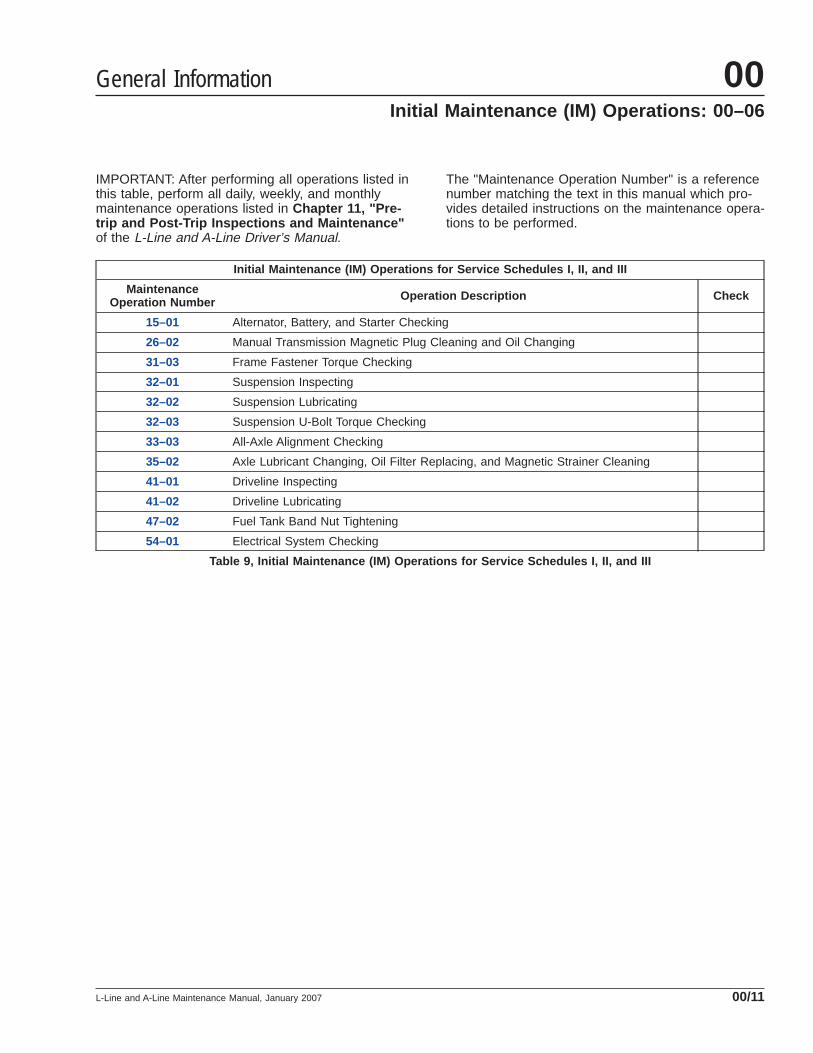
IMPORTANT: After performing all operations listed inthis table, perform all daily, weekly, and monthlymaintenance operations listed in Chapter 11, "Pre-trip and Post-Trip Inspections and Maintenance"of the L-Line and A-Line Driver’s Manual.
The "Maintenance Operation Number" is a referencenumber matching the text in this manual which pro-vides detailed instructions on the maintenance opera-tions to be performed.
Initial Maintenance (IM) Operations for Service Schedules I, II, and III
MaintenanceOperation Number Operation Description Check
15–01 Alternator, Battery, and Starter Checking
26–02 Manual Transmission Magnetic Plug Cleaning and Oil Changing
31–03 Frame Fastener Torque Checking
32–01 Suspension Inspecting
32–02 Suspension Lubricating
32–03 Suspension U-Bolt Torque Checking
33–03 All-Axle Alignment Checking
35–02 Axle Lubricant Changing, Oil Filter Replacing, and Magnetic Strainer Cleaning
41–01 Driveline Inspecting
41–02 Driveline Lubricating
47–02 Fuel Tank Band Nut Tightening
54–01 Electrical System Checking
Table 9, Initial Maintenance (IM) Operations for Service Schedules I, II, and III
General Information 00Initial Maintenance (IM) Operations: 00–06
L-Line and A-Line Maintenance Manual, January 2007 00/11

The "M1 Maintenance Interval Operations" table listsall maintenance operations that are to be performedat the M1 maintenance interval. The "MaintenanceOperation Number" is a reference number matchingthe text in this manual that provides detailed instruc-tions on the maintenance operations to be per-formed.
IMPORTANT: After performing all operations listed inthis table, perform all daily, weekly, and monthlymaintenance operations listed in Chapter 11, "Pre-trip and Post-Trip Inspections and Maintenance"of the L-Line and A-Line Driver’s Manual.
M1 Maintenance Interval Operations for Service Schedules I, II, and III
MaintenanceOperation Number Operation Description Check
00–04 Lubrication and Fluid Level Check (includes the following):
• Clutch Release Bearing Lubricating
• Transmission Breather and Oil Level Checking
• Fifth Wheel Lubricating
• Trailer Electrical Connector Lubricating
• Suspension Lubricating (Front and Rear)
• Knuckle Pin Lubricating
• Tie-Rod End Inspecting and Lubricating
• Axle Breather and Lubricant Level Checking
• Driveline Lubricating
• Automatic Slack Adjuster Lubricating and Checking
• Steering Driveline Lubricating
• Drag Link and Power Steering Cylinder Lubricating
• Power Steering Reservoir Fluid Level Checking
• TRW Power Steering Gear Lubricating, TAS Series
• Door Latch and Door Hinge Lubricating
• Hood Hinge Bushings Lubricating
13–01 Bendix Air Compressor Inspecting
31–01 Fifth Wheel Inspecting
32–01 Suspension Inspecting
41–01 Driveline Inspecting
42–10 Brake Inspecting
47–02 Fuel Tank Band Nut Tightening
49–01 Exhaust System Inspecting
Table 10, M1 Maintenance Interval Operations for Service Schedules I, II, and III
General Information00M1 Maintenance Interval Operations Table: 00–07
L-Line and A-Line Maintenance Manual, January 200700/12
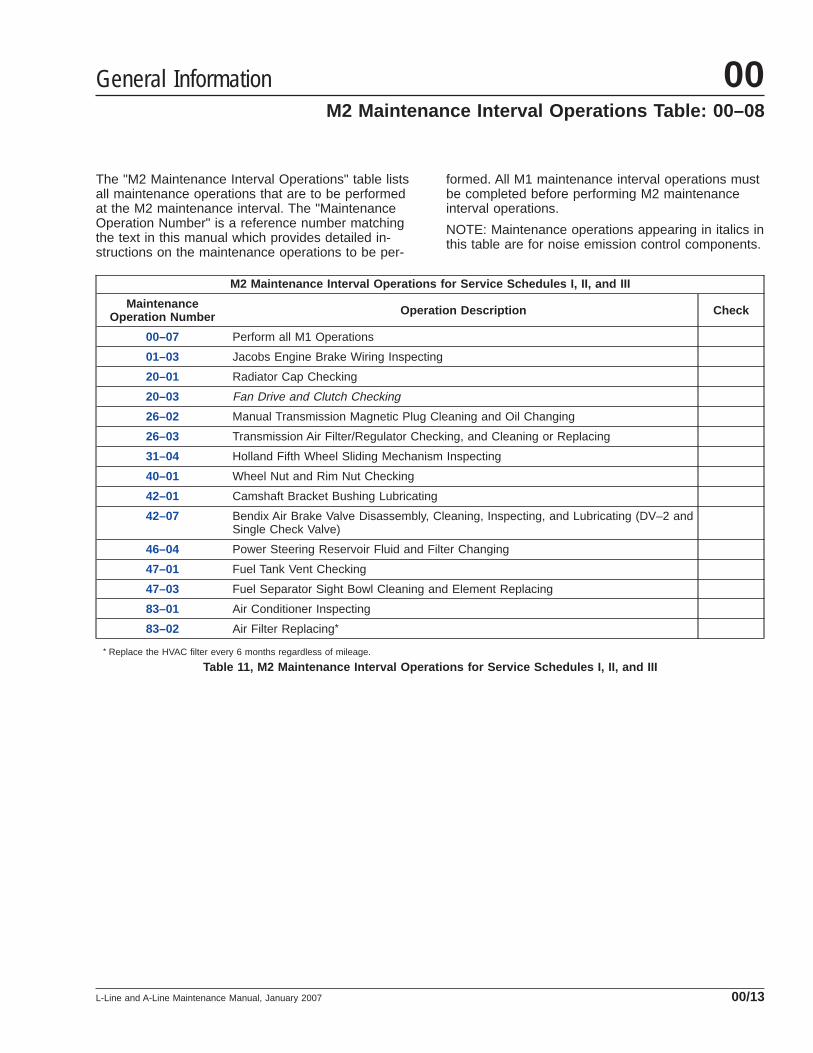
The "M2 Maintenance Interval Operations" table listsall maintenance operations that are to be performedat the M2 maintenance interval. The "MaintenanceOperation Number" is a reference number matchingthe text in this manual which provides detailed in-structions on the maintenance operations to be per-
formed. All M1 maintenance interval operations mustbe completed before performing M2 maintenanceinterval operations.
NOTE: Maintenance operations appearing in italics inthis table are for noise emission control components.
M2 Maintenance Interval Operations for Service Schedules I, II, and III
MaintenanceOperation Number Operation Description Check
00–07 Perform all M1 Operations
01–03 Jacobs Engine Brake Wiring Inspecting
20–01 Radiator Cap Checking
20–03 Fan Drive and Clutch Checking
26–02 Manual Transmission Magnetic Plug Cleaning and Oil Changing
26–03 Transmission Air Filter/Regulator Checking, and Cleaning or Replacing
31–04 Holland Fifth Wheel Sliding Mechanism Inspecting
40–01 Wheel Nut and Rim Nut Checking
42–01 Camshaft Bracket Bushing Lubricating
42–07 Bendix Air Brake Valve Disassembly, Cleaning, Inspecting, and Lubricating (DV–2 andSingle Check Valve)
46–04 Power Steering Reservoir Fluid and Filter Changing
47–01 Fuel Tank Vent Checking
47–03 Fuel Separator Sight Bowl Cleaning and Element Replacing
83–01 Air Conditioner Inspecting
83–02 Air Filter Replacing*
* Replace the HVAC filter every 6 months regardless of mileage.
Table 11, M2 Maintenance Interval Operations for Service Schedules I, II, and III
General Information 00M2 Maintenance Interval Operations Table: 00–08
L-Line and A-Line Maintenance Manual, January 2007 00/13

The "M3 Maintenance Interval Operations" table listsall maintenance operations that are to be performedat the M3 maintenance interval. The "MaintenanceOperation Number" is a reference number matchingthe text in this manual which provides detailed in-structions on the maintenance operations to be per-formed. All maintenance interval operations in M1and M2 must be completed before performing M3maintenance interval operations.
IMPORTANT: After performing all operations listed inthis table, perform all daily, weekly, and monthlymaintenance operations listed in Chapter 11, "Pre-trip and Post-Trip Inspections and Maintenance"of the L-Line and A-Line Driver’s Manual.
NOTE: Maintenance operations appearing in italics inthis table are for noise emission control components.
M3 Maintenance Interval Operations for Service Schedules I, II, and III
MaintenanceOperation Number Operation Description Check
00–08 Perform all M1 Operations
00–09 Perform all M2 Operations
01–01 Engine Rear-Support Assembly Checking
01–02 Engine Noise Panel Inspecting
01–04 Engine Drive Belt Inspecting
09–01 Air Cleaner Element Inspecting and Replacing
15–01 Alternator, Battery, and Starter Checking
32–03 Suspension U-Bolt Torque Checking
35–02 Axle Lubricant Changing, Oil Filter Replacing, and Magnetic Strainer Cleaning
42–03 Bendix Air Dryer Checking (AD–IP or AD–9)
42–05 Bendix Air Brake Valve Operation Checking (BP–R1 and E–12)
42–06 Bendix Air Brake Valve Disassembly, Cleaning, and Inspecting (Double Check Valve,E–12, MV–3, PP–7, QR–1, SR–1, ST–3, TC–6, TP–5, and TR–3)
42–08 Bendix Air Brake Valve Inspecting and Testing (MV–3 and TC–6)
42–09 Bendix Foot Brake Valve Actuator Lubricating and Leak-Testing (E–12)
47–03 Fuel Separator Sight Bowl Cleaning and Element Replacing
54–01 Electrical System Checking
Table 12, M3 Maintenance Interval Operations for Service Schedules I, II, and III
General Information00M3 Maintenance Interval Operations Table: 00–09
L-Line and A-Line Maintenance Manual, January 200700/14

The "M4 Maintenance Interval Operations" table listsall maintenance operations that are to be performedat the M4 maintenance interval. The "MaintenanceOperation Number" is a reference number matchingthe text in this manual which provides detailed in-structions on the maintenance operations to be per-formed. All maintenance interval operations in M1,M2 and M3 must be completed before performing M4maintenance interval operations.
IMPORTANT: After performing all operations listed inthis table, perform all daily, weekly, and monthlymaintenance operations listed in Chapter 11, "Pre-trip and Post-Trip Inspections and Maintenance"of the L-Line and A-Line Driver’s Manual.
M4 Maintenance Interval Operations for Service Schedules I, II, and III
MaintenanceOperation Number Operation Description Check
00–07 Perform all M1 Operations
00–08 Perform all M2 Operations
00–09 Perform all M3 Operations
20–02 Radiator Pressure Flushing and Coolant Changing
26–01 Allison Transmission and Fluid Filter Changing
42–04 Bendix Air Dryer Desiccant Replacing (AD–9)
Table 13, M4 Maintenance Interval Operations for Service Schedules I, II, and III
General Information 00M4 Maintenance Interval Operations Table: 00–10
L-Line and A-Line Maintenance Manual, January 2007 00/15
General Information
Federal Law, Part 205:Transportation Equipment NoiseEmission ControlsPart 205, Transportation Equipment Noise EmissionControls, requires the vehicle manufacturer to fur-nish, with each new vehicle, such written instructionsfor the proper maintenance, use, and repair of thevehicle by the ultimate purchaser to provide reason-able assurance of the elimination or minimization ofnoise-emission-control degradation throughout thelife of the vehicle. In compliance with the law, thenoise emission controls maintenance information ineach applicable group of this manual, in conjunctionwith the vehicle service manual, provides these in-structions to owners.
Recommendations forReplacement PartsReplacement parts used for maintenance or repair ofnoise emission controls should be genuine Sterlingparts. If using other than genuine Sterling parts, theowner should be sure that such parts are warrantedby their manufacturer to be equivalent to genuineSterling parts in performance and durability.
Sterling Noise Emission ControlsWarrantyRefer to the vehicle owner’s warranty informationbook for warranty information concerning noise emis-sion controls.
Tampering With Noise Controls isProhibitedFederal law prohibits the following acts or the caus-ing thereof:
1. The removal or rendering inoperative by any per-son (other than for purposes of maintenance,repair, or replacement) of any device or elementof design incorporated into any new vehicle forthe purpose of noise control, prior to its sale ordelivery to the ultimate purchaser, or while it is inuse.
2. The use of the vehicle after such device or ele-ment of design has been removed or renderedinoperative by any person.
Among those acts presumed to constitute tam-pering are the acts listed below:
A. Removal of engine noise-deadening panels.
B. Removal of cab-tunnel or hood noise-deadening panels.
C. Removal of, or rendering inoperative, the en-gine speed governor so as to allow enginespeed to exceed manufacturer’s specifica-tions.
D. Removal of, or rendering inoperative, the fanclutch, including bypassing the control onany thermostatic fan drive to cause it to op-erate continuously.
E. Removal of the fan shroud.
F. Removal of, or rendering inoperative, ex-haust components, including exhaust pipeclamping.
G. Removal of air intake components.
Maintenance InstructionsScheduled intervals are in the maintenance tables inthis group. "Verification of Inspections Log" (Groups01 and 20, and Group 49) follows, and should befilled in each time noise emission controls on the ve-hicle are maintained or repaired.
General Information00Noise Emission Controls Maintenance: 00–11
L-Line and A-Line Maintenance Manual, January 200700/16
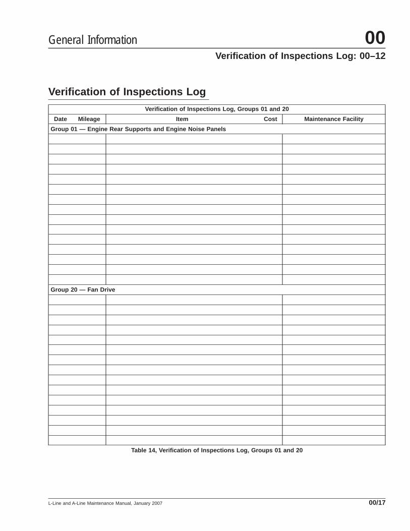
Verification of Inspections LogVerification of Inspections Log, Groups 01 and 20
Date Mileage Item Cost Maintenance Facility
Group 01 — Engine Rear Supports and Engine Noise Panels
Group 20 — Fan Drive
Table 14, Verification of Inspections Log, Groups 01 and 20
General Information 00Verification of Inspections Log: 00–12
L-Line and A-Line Maintenance Manual, January 2007 00/17
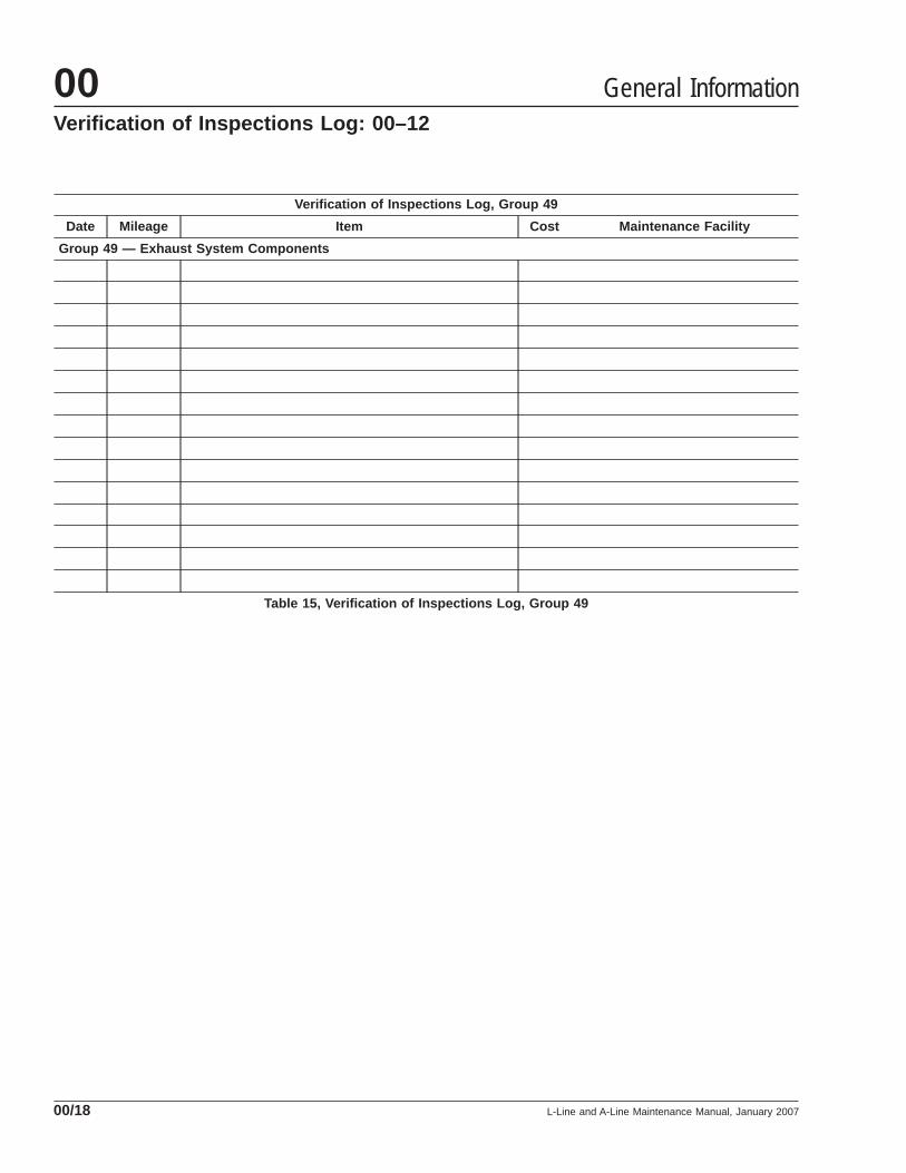
Verification of Inspections Log, Group 49
Date Mileage Item Cost Maintenance Facility
Group 49 — Exhaust System Components
Table 15, Verification of Inspections Log, Group 49
General Information00Verification of Inspections Log: 00–12
L-Line and A-Line Maintenance Manual, January 200700/18

When You Know U.S.Customary
MultiplyBy To Get Metric When You
Know MetricMultiply
By To Get U.S. Customary
Length
inches (in) 25.4 millimeters (mm) 0.03937 inches (in)
inches (in) 2.54 centimeters (cm) 0.3937 inches (in)
feet (ft) 0.3048 meters (m) 3.281 feet (ft)
yards (yd) 0.9144 meters (m) 1.094 yards (yd)
miles (mi) 1.609 kilometers (km) 0.6215 miles (mi)
Area
square inches (in2) 645.16 square millimeters (mm2) 0.00155 square inches (in2)
square inches (in2) 6.452 square centimeters (cm2) 0.155 square inches (in2)
square feet (ft2) 0.0929 square meters (m2) 10.764 square feet (ft2)
Volume
cubic inches (in3) 16387.0 cubic millimeter (mm3) 0.000061 cubic inches (in3)
cubic inches (in3) 16.387 cubic centimeters (cm3) 0.06102 cubic inches (in3)
cubic inches (in3) 0.01639 liters (L) 61.024 cubic inches (in3)
fluid ounces (fl oz) 29.54 milliliters (mL) 0.03381 fluid ounces (fl oz)
pints (pt) 0.47318 liters (L) 2.1134 pints (pt)
quarts (qt) 0.94635 liters (L) 1.0567 quarts (qt)
gallons (gal) 3.7854 liters (L) 0.2642 gallons (gal)
cubic feet (ft3) 28.317 liters (L) 0.03531 cubic feet (ft3)
cubic feet (ft3) 0.02832 cubic meters (m3) 35.315 cubic feet (ft3)
Weight/Force
ounces (av) (oz) 28.35 grams (g) 0.03527 ounces (av) (oz)
pounds (av) (lb) 0.454 kilograms (kg) 2.205 pounds (av) (lb)
U.S. tons (t) 907.18 kilograms (kg) 0.001102 U.S. tons (t)
U.S. tons (t) 0.90718 metric tons (t) 1.1023 U.S. tons (t)
Torque/Work Force
inch–pounds (lbf·in) 11.298 Newton–centimeters (N·cm) 0.08851 inch–pounds (lbf·in)
foot–pounds (lbf·ft) 1.3558 Newton–meters (N·m) 0.7376 foot–pounds (lbf·ft)
Pressure/Vacuum
inches of mercury (inHg) 3.37685 kilo Pascals (kPa) 0.29613 inches of mercury (inHg)
pounds per square inch (psi) 6.895 kilo Pascals (kPa) 0.14503 pounds per square inch (psi)
Table 16, Metric/U.S. Customary Conversion Table
General Information 00Metric/U.S. Customary Conversion Tables: 00–13
L-Line and A-Line Maintenance Manual, January 2007 00/19
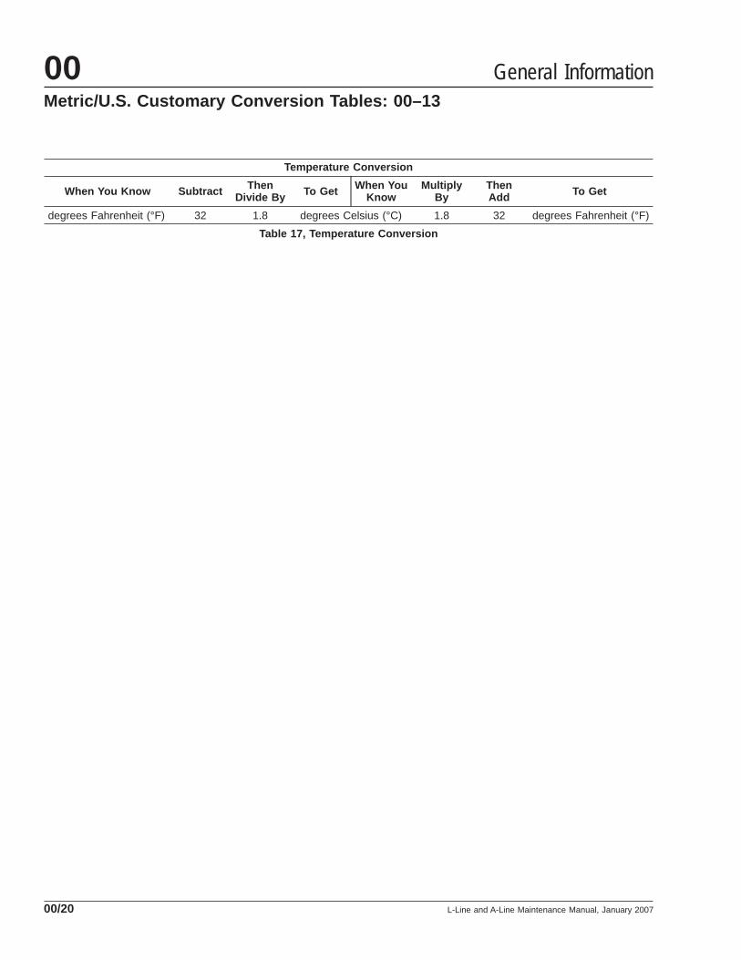
Temperature Conversion
When You Know Subtract ThenDivide By To Get When You
KnowMultiply
ByThenAdd To Get
degrees Fahrenheit (°F) 32 1.8 degrees Celsius (°C) 1.8 32 degrees Fahrenheit (°F)
Table 17, Temperature Conversion
General Information00Metric/U.S. Customary Conversion Tables: 00–13
L-Line and A-Line Maintenance Manual, January 200700/20
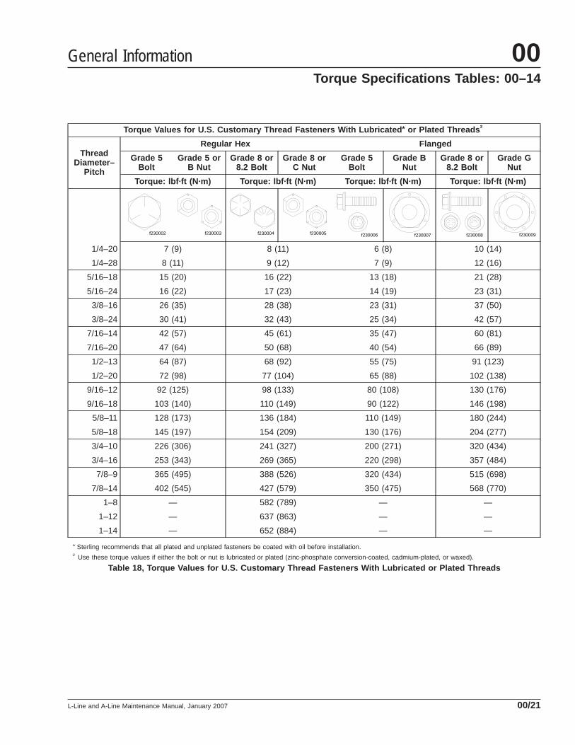
Torque Values for U.S. Customary Thread Fasteners With Lubricated * or Plated Threads †
ThreadDiameter–
Pitch
Regular Hex Flanged
Grade 5Bolt
Grade 5 orB Nut
Grade 8 or8.2 Bolt
Grade 8 orC Nut
Grade 5Bolt
Grade BNut
Grade 8 or8.2 Bolt
Grade GNut
Torque: lbf·ft (N·m) Torque: lbf·ft (N·m) Torque: lbf·ft (N·m) Torque: lbf·ft (N·m)
1/4–20
f230002 f230003 f230004 f230005 f230006 f230007 f230008 f230009
7 (9) 8 (11) 6 (8) 10 (14)
1/4–28 8 (11) 9 (12) 7 (9) 12 (16)
5/16–18 15 (20) 16 (22) 13 (18) 21 (28)
5/16–24 16 (22) 17 (23) 14 (19) 23 (31)
3/8–16 26 (35) 28 (38) 23 (31) 37 (50)
3/8–24 30 (41) 32 (43) 25 (34) 42 (57)
7/16–14 42 (57) 45 (61) 35 (47) 60 (81)
7/16–20 47 (64) 50 (68) 40 (54) 66 (89)
1/2–13 64 (87) 68 (92) 55 (75) 91 (123)
1/2–20 72 (98) 77 (104) 65 (88) 102 (138)
9/16–12 92 (125) 98 (133) 80 (108) 130 (176)
9/16–18 103 (140) 110 (149) 90 (122) 146 (198)
5/8–11 128 (173) 136 (184) 110 (149) 180 (244)
5/8–18 145 (197) 154 (209) 130 (176) 204 (277)
3/4–10 226 (306) 241 (327) 200 (271) 320 (434)
3/4–16 253 (343) 269 (365) 220 (298) 357 (484)
7/8–9 365 (495) 388 (526) 320 (434) 515 (698)
7/8–14 402 (545) 427 (579) 350 (475) 568 (770)
1–8 — 582 (789) — —
1–12 — 637 (863) — —
1–14 — 652 (884) — —
* Sterling recommends that all plated and unplated fasteners be coated with oil before installation.† Use these torque values if either the bolt or nut is lubricated or plated (zinc-phosphate conversion-coated, cadmium-plated, or waxed).
Table 18, Torque Values for U.S. Customary Thread Fasteners With Lubricated or Plated Threads
General Information 00Torque Specifications Tables: 00–14
L-Line and A-Line Maintenance Manual, January 2007 00/21
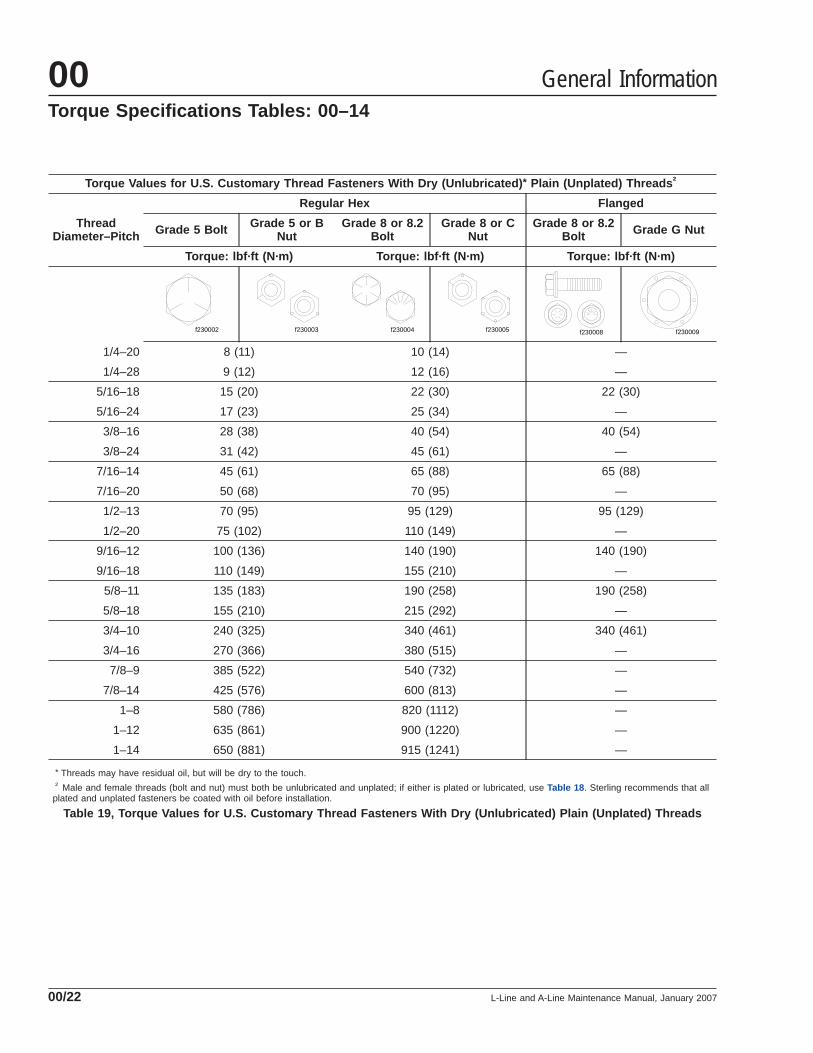
Torque Values for U.S. Customary Thread Fasteners With Dry (Unlubricated) * Plain (Unplated) Threads †
ThreadDiameter–Pitch
Regular Hex Flanged
Grade 5 Bolt Grade 5 or BNut
Grade 8 or 8.2Bolt
Grade 8 or CNut
Grade 8 or 8.2Bolt Grade G Nut
Torque: lbf·ft (N·m) Torque: lbf·ft (N·m) Torque: lbf·ft (N·m)
1/4–20
f230002 f230003 f230004 f230005 f230008 f230009
8 (11) 10 (14) —
1/4–28 9 (12) 12 (16) —
5/16–18 15 (20) 22 (30) 22 (30)
5/16–24 17 (23) 25 (34) —
3/8–16 28 (38) 40 (54) 40 (54)
3/8–24 31 (42) 45 (61) —
7/16–14 45 (61) 65 (88) 65 (88)
7/16–20 50 (68) 70 (95) —
1/2–13 70 (95) 95 (129) 95 (129)
1/2–20 75 (102) 110 (149) —
9/16–12 100 (136) 140 (190) 140 (190)
9/16–18 110 (149) 155 (210) —
5/8–11 135 (183) 190 (258) 190 (258)
5/8–18 155 (210) 215 (292) —
3/4–10 240 (325) 340 (461) 340 (461)
3/4–16 270 (366) 380 (515) —
7/8–9 385 (522) 540 (732) —
7/8–14 425 (576) 600 (813) —
1–8 580 (786) 820 (1112) —
1–12 635 (861) 900 (1220) —
1–14 650 (881) 915 (1241) —
* Threads may have residual oil, but will be dry to the touch.† Male and female threads (bolt and nut) must both be unlubricated and unplated; if either is plated or lubricated, use Table 18 . Sterling recommends that all
plated and unplated fasteners be coated with oil before installation.
Table 19, Torque Values for U.S. Customary Thread Fasteners With Dry (Unlubricated) Plain (Unplated) Threads
General Information00Torque Specifications Tables: 00–14
L-Line and A-Line Maintenance Manual, January 200700/22
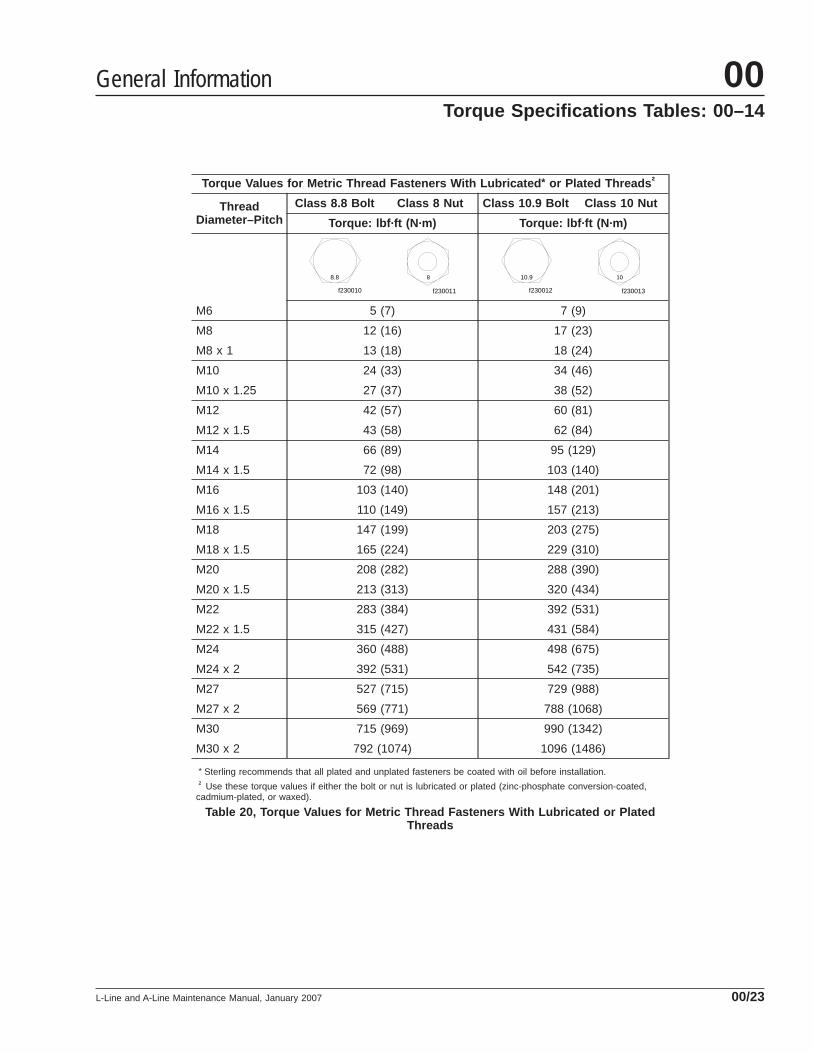
Torque Values for Metric Thread Fasteners With Lubricated * or Plated Threads †
ThreadDiameter–Pitch
Class 8.8 Bolt Class 8 Nut Class 10.9 Bolt Class 10 Nut
Torque: lbf·ft (N·m) Torque: lbf·ft (N·m)
M6
f230010
8.8
f230011
8
f230012
10.9
f230013
10
5 (7) 7 (9)
M8 12 (16) 17 (23)
M8 x 1 13 (18) 18 (24)
M10 24 (33) 34 (46)
M10 x 1.25 27 (37) 38 (52)
M12 42 (57) 60 (81)
M12 x 1.5 43 (58) 62 (84)
M14 66 (89) 95 (129)
M14 x 1.5 72 (98) 103 (140)
M16 103 (140) 148 (201)
M16 x 1.5 110 (149) 157 (213)
M18 147 (199) 203 (275)
M18 x 1.5 165 (224) 229 (310)
M20 208 (282) 288 (390)
M20 x 1.5 213 (313) 320 (434)
M22 283 (384) 392 (531)
M22 x 1.5 315 (427) 431 (584)
M24 360 (488) 498 (675)
M24 x 2 392 (531) 542 (735)
M27 527 (715) 729 (988)
M27 x 2 569 (771) 788 (1068)
M30 715 (969) 990 (1342)
M30 x 2 792 (1074) 1096 (1486)
* Sterling recommends that all plated and unplated fasteners be coated with oil before installation.† Use these torque values if either the bolt or nut is lubricated or plated (zinc-phosphate conversion-coated,
cadmium-plated, or waxed).
Table 20, Torque Values for Metric Thread Fasteners With Lubricated or PlatedThreads
General Information 00Torque Specifications Tables: 00–14
L-Line and A-Line Maintenance Manual, January 2007 00/23
Title of Maintenance Operation (MOP) MOP Number
Engine Drive Belt Inspecting. . . . . . . . . . . . . . . . . . . . . . . . . . . . . . . . . . . . . . . . . . . . . . . . . . . . . . . . . . 01–04
Engine Noise Panel Inspecting (Noise Emission Control). . . . . . . . . . . . . . . . . . . . . . . . . . . . . . . . . . . . . 01–02
Engine Rear-Support Assembly Checking (Noise Emission Control). . . . . . . . . . . . . . . . . . . . . . . . . . . . . 01–01
Jacobs Engine Brake Wiring Inspecting. . . . . . . . . . . . . . . . . . . . . . . . . . . . . . . . . . . . . . . . . . . . . . . . . . 01–03
Engine 01Index, Alphabetical
L-Line and A-Line Maintenance Manual, January 2007
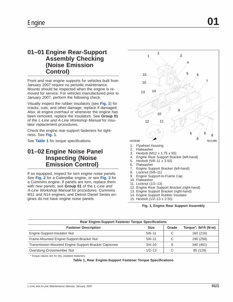
01–01 Engine Rear-SupportAssembly Checking(Noise EmissionControl)
Front and rear engine supports for vehicles built fromJanuary 2007 require no periodic maintenance.Mounts should be inspected when the engine is re-moved for service. For vehicles manufactured prior toJanuary 2007, perform the following check.
Visually inspect the rubber insulators (see Fig. 1 ) forcracks, cuts, and other damage; replace if damaged.Also, at engine overhaul or whenever the engine hasbeen removed, replace the insulators. See Group 01of the L-Line and A-Line Workshop Manual for insu-lator replacement procedures.
Check the engine rear-support fasteners for tight-ness. See Fig. 1 .
See Table 1 for torque specifications.
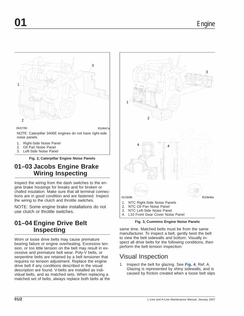
01–02 Engine Noise PanelInspecting (NoiseEmission Control)
If so equipped, inspect for torn engine noise panels.See Fig. 2 for a Caterpillar engine, or see Fig. 3 fora Cummins engine. If panels are torn, replace themwith new panels; see Group 01 of the L-Line andA-Line Workshop Manual for procedures. CumminsM11 and N14 engines, and Detroit Diesel Series en-gines do not have engine noise panels.
Rear Engine-Support Fastener Torque Specifications
Fastener Description Size Grade Torque *: lbf·ft (N·m)
Engine-Support-Insulator Nut 5/8–11 C 160 (216)
Frame-Mounted Engine-Support-Bracket Nut 5/8–11 C 190 (258)
Transmission-Mounted Engine-Support-Bracket Capscrew 3/4–10 8 340 (461)
Overslung Crossmember Nut 1/2–13 C 95 (129)* Torque values are for dry, unplated fasteners.
Table 1, Rear Engine-Support Fastener Torque Specifications
12
3
4
5 6
66
7
88
910
10
1112
13 14
15
10/26/98 f011285
1. Flywheel Housing2. Flatwasher3. Hexbolt (M12 x 1.75 x 55)4. Engine Rear Support Bracket (left-hand)5. Hexbolt (5/8–11 x 3.50)6. Flatwasher7. Engine Support Bracket (left-hand)8. Locknut (5/8–11)9. Engine Support-to-Frame Cap10. Flatwasher11. Locknut (1/2–13)12. Engine Rear Support Bracket (right-hand)13. Engine Support Bracket (right-hand)14. Engine Support Rubber Insulator15. Hexbolt (1/2–13 x 2.50)
Fig. 1, Engine Rear Support Assembly
Engine 01
L-Line and A-Line Maintenance Manual, January 2007 01/1
01–03 Jacobs Engine BrakeWiring Inspecting
Inspect the wiring from the dash switches to the en-gine brake housings for breaks and for broken orchafed insulation. Make sure that all terminal connec-tions are in good condition and are fastened. Inspectthe wiring to the clutch and throttle switches.
NOTE: Some engine brake installations do notuse clutch or throttle switches.
01–04 Engine Drive BeltInspecting
Worn or loose drive belts may cause prematurebearing failure or engine overheating. Excessive ten-sion, or too little tension on the belt may result in ex-cessive and premature belt wear. Poly-V belts, orserpentine belts are retained by a belt tensioner thatrequires no tension adjustment. Replace the enginedrive belt if any conditions described in the visualdescription are found. V-belts are installed as indi-vidual belts, and as matched sets. When replacing amatched set of belts, always replace both belts at the
same time. Matched belts must be from the samemanufacturer. To inspect a belt, gently twist the beltto view the belt sidewalls and bottom. Visually in-spect all drive belts for the following conditions, thenperform the belt tension inspection:
Visual Inspection1. Inspect the belt for glazing. See Fig. 4 , Ref. A.
Glazing is represented by shiny sidewalls, and iscaused by friction created when a loose belt slips
f010647a
1
2
3
05/27/93
NOTE: Caterpillar 3406E engines do not have right-sidenoise panels.
1. Right-Side Noise Panel2. Oil Pan Noise Panel3. Left-Side Noise Panel
Fig. 2, Caterpillar Engine Noise Panels
f010646a
1
2
3
4 4
01/16/96
1. NTC Right-Side Noise Panels2. NTC Oil Pan Noise Panel3. NTC Left-Side Noise Panel4. L10 Front Gear Cover Noise Panel
Fig. 3, Cummins Engine Noise Panels
Engine01
L-Line and A-Line Maintenance Manual, January 200701/2
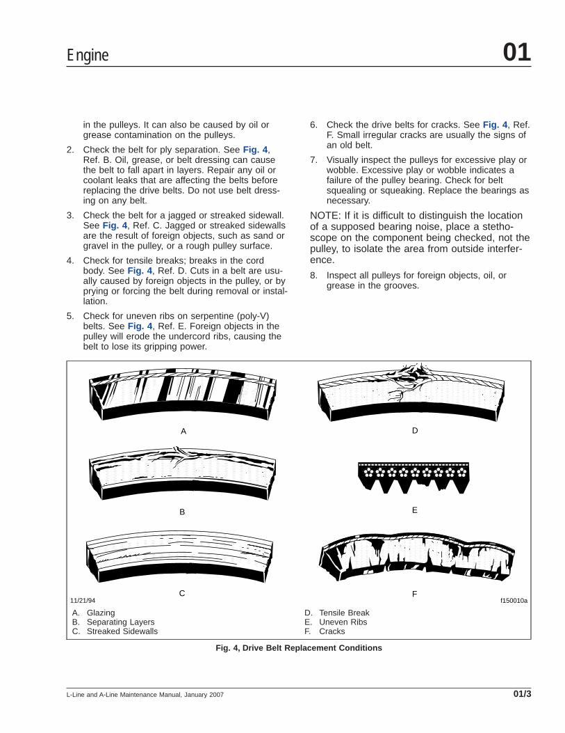
in the pulleys. It can also be caused by oil orgrease contamination on the pulleys.
2. Check the belt for ply separation. See Fig. 4 ,Ref. B. Oil, grease, or belt dressing can causethe belt to fall apart in layers. Repair any oil orcoolant leaks that are affecting the belts beforereplacing the drive belts. Do not use belt dress-ing on any belt.
3. Check the belt for a jagged or streaked sidewall.See Fig. 4 , Ref. C. Jagged or streaked sidewallsare the result of foreign objects, such as sand orgravel in the pulley, or a rough pulley surface.
4. Check for tensile breaks; breaks in the cordbody. See Fig. 4 , Ref. D. Cuts in a belt are usu-ally caused by foreign objects in the pulley, or byprying or forcing the belt during removal or instal-lation.
5. Check for uneven ribs on serpentine (poly-V)belts. See Fig. 4 , Ref. E. Foreign objects in thepulley will erode the undercord ribs, causing thebelt to lose its gripping power.
6. Check the drive belts for cracks. See Fig. 4 , Ref.F. Small irregular cracks are usually the signs ofan old belt.
7. Visually inspect the pulleys for excessive play orwobble. Excessive play or wobble indicates afailure of the pulley bearing. Check for beltsquealing or squeaking. Replace the bearings asnecessary.
NOTE: If it is difficult to distinguish the locationof a supposed bearing noise, place a stetho-scope on the component being checked, not thepulley, to isolate the area from outside interfer-ence.
8. Inspect all pulleys for foreign objects, oil, orgrease in the grooves.
f150010a
A
B
C
D
E
F11/21/94
A. GlazingB. Separating LayersC. Streaked Sidewalls
D. Tensile BreakE. Uneven RibsF. Cracks
Fig. 4, Drive Belt Replacement Conditions
Engine 01
L-Line and A-Line Maintenance Manual, January 2007 01/3

Belt Tension InspectionNOTE: If engine drive belts require adjustment,see Group 01 of the L-Line and A-Line Work-shop Manual.
Threaded-Adjustment Type1. Apply the parking brakes, and chock the tires to
prevent the vehicle from moving.
2. Install a belt tension gauge at the center of thebelt’s longest free-span. Check belt tension. SeeTable 2 for belt tension specifications.
3. If belt tension is not correct, see Group 01 of theL-Line and A-Line Workshop Manual to adjustbelt tension.
Spring-Tension TypeOn belts equipped with a spring tensioner, the belttension is automatically adjusted. Check that the ten-sioner is holding tension on the belt by inserting theend of a breaker bar in the 1/2-inch square hole onthe forward face of the tensioner, and rotating thetensioner down, away from the belt. When thebreaker bar is slowly released, the tensioner shouldreturn to its original position. If not, see Group 01 ofthe L-Line and A-Line Workshop Manual for replace-ment instructions.
Drive Belt Tension
Engine Component Belt Tension: lbf (kg)
Caterpillar C10 (3176) Refrigerant Compressor 80–100 (36–45)
Caterpillar 3406EAlternator and Refrigerant Compressor 40–50 (18–23), per belt
Fan 80–100 (36–45)
Cummins M11
Alternator 90–120 (41–55)
Fan 155–165 (70–75)
Refrigerant Compressor 80–100 (36–45)
Cummins N14
Alternator 40–50 (18–23), per belt
Fan 80–120 (36–55)
Refrigerant Compressor 80–100 (36–45)
Detroit Diesel Series 60Alternator and Refrigerant Compressor 80–100 (36–45), power band
Fan 60–80 (27–36)
Table 2, Drive Belt Tension
Engine01
L-Line and A-Line Maintenance Manual, January 200701/4
Title of Maintenance Operation (MOP) MOP Number
Air Cleaner Element Inspecting and Replacing . . . . . . . . . . . . . . . . . . . . . . . . . . . . . . . . . . . . . . . . . . . . 09–01
Air Intake 09Index, Alphabetical
L-Line and A-Line Maintenance Manual, February 2004
09–01 Air Cleaner ElementInspecting andReplacing
Method 1Replace the air cleaner element at the recommendedinterval or when the air restriction indicator reaches20 inH2O on a vehicle with a Detroit Diesel engine,22 inH2O on a vehicle with an M-B engine, or 25inH2O on a vehicle with a Caterpillar or Cumminsengine. For replacement instructions, see Group 09of the L-Line and A-Line Workshop Manual. Resetthe air restriction indicator.
If the maximum restriction is not reached, record theair restriction value. If the value is higher than theprevious recording, reset the air restriction indicator.If the value is lower than the previous recording, in-spect the air cleaner and air cleaner element forcracks, leaks, or any other damage.
If the air cleaner or air cleaner element is damaged,replace it and reset the air restriction indicator.
Method 2Replace the air cleaner element at the recommendedinterval or when the air restriction indicator reaches20 inH2O on a vehicle with a Detroit Diesel engine,22 inH2O on a vehicle with an M-B engine, or 25inH2O on a vehicle with a Caterpillar or Cumminsengine. For replacement instructions, see Group 09of the L-Line and A-Line Workshop Manual. Resetthe air restriction indicator.
If the maximum restriction is not reached, inspect theair cleaner and air cleaner element for cracks, leaks,or any other damage. If the air cleaner or air cleanerelement is damaged, replace it and reset the air re-striction indicator.
Air Intake 09
L-Line and A-Line Maintenance Manual, February 2004 09/1

Title of Maintenance Operation (MOP) MOP Number
Bendix Air Compressor Inspecting. . . . . . . . . . . . . . . . . . . . . . . . . . . . . . . . . . . . . . . . . . . . . . . . . . . . . . 13–01
Air Compressor 13Index, Alphabetical
L-Line and A-Line Maintenance Manual, October 1999
13–01 Bendix Air CompressorInspecting
Inspect the air intake line, oil supply and return lines,and coolant supply and return hoses for tight connec-tions and general condition. Tighten the connectionsand replace the lines and hoses as needed. If thecompressor air-intake adapter is loose, remove theadapter, replace the adapter gaskets, and securelyinstall the adapter.
Check the cooling fins on the compressor crankcase.Clean the fins if they are clogged with dirt or grease.
Air Compressor 13
L-Line and A-Line Maintenance Manual, October 1999 13/1
Title of Maintenance Operation (MOP) MOP Number
Alternator, Battery, and Starter Connections Check . . . . . . . . . . . . . . . . . . . . . . . . . . . . . . . . . . . . . . . . . 15–01
Alternators and Starters 15Index, Alphabetical
L-Line and A-Line Maintenance Manual, October 2008
15–01 Alternator, Battery, andStarter ConnectionsCheck
WARNINGBatteries generate explosive gas as a by-productof their chemical process. Do not smoke whenworking around batteries. Put out all flames andremove any source of sparks or intense heat inthe vicinity of the battery compartment. Make surethe battery compartment has been completelyvented before disconnecting or connecting thebattery cables.
Battery acid is extremely harmful if splashed inthe eyes or on the skin. Always wear a face shieldand protective clothing when working aroundbatteries.
1. Check the tightness of the alternator bracket fas-teners; tighten the fasteners as needed. Fortorque values, see Group 15 of the L-Line andA-Line Workshop Manual.
2. Check the belt tension of the alternator drivebelt. Use a tension gauge at the belt’s widestspan, and adjust the belt tension if needed. SeeGroup 01 for belt tension specifications. Someengines are equipped with dual alternator belts;always check both belts for correct tension. En-gines equipped with a serpentine or poly-V belthave automatic belt tensioners, and do not re-quire belt tension inspection.
3. Clean and tighten all charging system electricalconnections, including the connections at thestarter B terminal and ground terminal, andwhere the alternator charging cable terminates.
4. Inspect the battery cables for wear, and replaceas needed. Clean the cable connector terminalswith a wire brush. See Group 54 of the L-Lineand A-Line Workshop Manual for troubleshootinginstructions, and for adjustment, repair, or re-placement instructions.
4.1 Clean and tighten the battery groundcable, terminal, and clamps.
4.2 Inspect the retainer assembly or batteryhold-downs and the battery box. Replaceworn or damaged parts. Remove any cor-rosion with a wire brush, and wash with a
weak solution of baking soda and water.Rinse with clean water, and dry. Paint theretainer assembly, if needed to preventrusting.
4.3 Be sure there are no foreign objects,such as stones, bolts, and nuts, in thebattery box.
4.4 After cleaning, connect the cables to thebatteries, and tighten them to the torquespecifications listed on the battery, gener-ally 10 to 15 lbf·ft (14 to 20 N·m).
4.5 Coat the battery terminals with dielectricgrease.
5. Check the alternator wiring for missing insulation,kinks, and heat damage. Replace or repair asneeded.
6. Check the terminals on the battery shut-offswitch and the magnetic switch. Make sure theterminal connections are clean and tight. Coatthe terminal connections with dielectric redenamel after cleaning.
Alternators and Starters 15
L-Line and A-Line Maintenance Manual, October 2008 15/1
Title of Maintenance Operation (MOP) MOP Number
Fan Drive and Fan Clutch Checking (Noise Emission Control) . . . . . . . . . . . . . . . . . . . . . . . . . . . . . . . . . 20–03
Radiator Cap Checking. . . . . . . . . . . . . . . . . . . . . . . . . . . . . . . . . . . . . . . . . . . . . . . . . . . . . . . . . . . . . . 20–01
Radiator Pressure Flushing and Coolant Changing . . . . . . . . . . . . . . . . . . . . . . . . . . . . . . . . . . . . . . . . . 20–02
Engine Cooling/Radiator 20Index, Alphabetical
L-Line and A-Line Maintenance Manual, January 2007

20–01 Radiator Cap Checking
WARNINGDo not remove or loosen the radiator cap until theengine and cooling system have completelycooled. Use extreme care when removing the cap.A sudden release of pressure from removing thecap prior to the system cooling can result in asurge of scalding coolant that could cause seri-ous personal injury.
CAUTIONThe radiator cap currently installed may not be thesame one installed when the vehicle was built. Ifthe radiator cap must be replaced, make sure thatit is the correct cap for the cooling system of thevehicle. Because the radiator cap pressure ratingaffects the operating temperature of the engine,installing an improperly rated radiator cap mayhave adverse effects on the cooling system, andengine operating temperatures. This could causepremature engine wear or damage.
1. Using a radiator-cap tester, check the pressurecap to see if it maintains pressure to within 10percent of the pressure rating marked on thecap. If it doesn’t, replace the cap. Make sure thatthe replacement radiator cap is correctly rated forthe cooling system of the vehicle.
2. There is a second valve in the radiator cap thatopens under vacuum. This prevents the collapseof hoses and other parts that are not internallysupported when the system cools. Inspect thevacuum-relief valve to be sure it is not stuck.
3. Make sure that the cap seals properly on thecoolant filler neck seat, and that the radiator capgasket is not damaged. On vehicles with screwon caps with O-rings, make sure that the O-ringis not cracked or deteriorated. Replace the cap ifthe gasket shows deterioration or damage.
20–02 Radiator PressureFlushing and CoolantChanging
NOTE: For additional instructions on cleaningand flushing the cooling system, see the appli-
cable engine manufacturer’s maintenance andoperation manual.
1. If necessary, remove the aerodynamic coverfrom the front bumper.
2. Drain the radiator as follows:
For a low-flow cooling system, disconnect theradiator bottom tank inlet and outlet hoses, andtighten the radiator cap. Attach the flushing gunnozzle to the outlet hose.
For a high-flow cooling system, disconnect theradiator upper and lower hoses, and tighten theradiator cap. Attach the flushing gun nozzle tothe lower hose.
3. Run the water until the radiator is full.
CAUTIONExcessive pressure can damage the radiator orheater core.
4. Gradually apply air pressure to help dislodgesediment built up in the radiator core. Do notapply more than 15 psi (103 kPa) air pressure tothe radiator. Pressures exceeding 15 psi (103kPa) could damage the radiator core.
5. Shut off the air at the pressure gun nozzle andallow the radiator to refill with water.
6. Repeat the previous two steps until clean waterflows from the radiator.
7. Remove the radiator side tank drain plug andallow the radiator to drain. Install and tighten theside tank drain plug and the radiator outlet pipedrain plug after the radiator has been drained.Do not overtighten the plugs.
8. Connect the hoses. Your hose clamps can beeither T-bolt clamps (see Fig. 1 ) or BreezeConstant-Torque clamps (see Fig. 2 ).
When working with T-bolt type hose clamps,tighten the clamps 55 lbf·in (620 N·cm). Theseclamps are now standard on hoses with an in-side diameter greater than 2 inches (51 mm).
When installing Breeze Constant-Torque hoseclamps, the clamps must be tightened to the cor-rect torque. The screw tip of the clamp must ex-tend about 1/4 inch (6 mm) from the clamp hous-ing, and the Belleville washer stacks must becollapsed almost flat. Use a torque wrench toinstall these hose clamps correctly. Correct in-
Engine Cooling/Radiator 20
L-Line and A-Line Maintenance Manual, January 2007 20/1

stallation torque for Breeze Constant-Torquehose clamps is as follows:
For clamps with a 5/16-inch tightening screwhex: 55 lbf·in (620 N·cm).
For clamps with a 3/8-inch tightening screw hex:90 lbf·in (1020 N·cm).
NOTE: All hose clamps will lose torque afterinstallation due to "compression set." However,when correctly installed, Breeze Constant-Torque clamps will hold enough torque to auto-
matically adjust and keep consistent sealingpressure. During vehicle operation and shut-down, the screw tip may adjust according totemperature and pressure changes. The torquemay need to be adjusted for individual applica-tions.
IMPORTANT: On vehicles with EPA07 compliantengines, the coolant capacity varies dependingon the engine and accessory installation. Afterservicing the cooling system, always verify thatthe coolant level is between the MIN and MAXlines on the surge tank.
9. Fill the radiator with new coolant. See Group20of the L-Line and A-Line Workshop Manual forguidelines. See Table 1 for cooling system ca-pacities for antifreeze protection information. Cer-tain equipment such as fuel heaters, water filters,and auxiliary heaters may increase the coolantcapacity and require additional coolant. The cool-ing system is filled when the coolant levelreaches the MAX line on the surge tank. Sterlingrecommends the use of a precharged and pre-mixed antifreeze when refilling the cooling sys-tem. See Table 2 for a list of some of the pre-charged antifreeze available. Use of anequivalent antifreeze to those listed in the tableis also acceptable. Always check that the anti-freeze used meets Sterling specifications and isat the proper concentration for protection in thevehicle operating area. See Table 3 for anti-freeze protection information. Sterling specifiesthat the antifreeze must be an ethylene glycolsolution that meets GM 6038 M EngineeringStandards or an ethylene glycol solution that hasless than 0.1 percent anhydrous sodium metasili-cate, and meets either GM 1825 M or GM 1899M Engineering Standards. If supplemental cool-ant additives are being used, add the supple-ments to the coolant as necessary. See the cool-ant additive manufacturer’s instructions for thecorrect amount of additive required. Don’t forgetto consider the volume of the supplemental cool-ant additive being added to the system when de-termining the amount of coolant required to refillthe system.
02/28/96 f200326
Fig. 1, T-Bolt Type Hose Clamp
08/15/94 f200286
A B1
A. The screw tip must extend about 1/4 inch (6 mm).B. The Belleville washer stacks must be collapsed
almost flat.1. Tightening Screw Hex
Fig. 2, Breeze Constant-Torque Hose Clamp Installation
Engine Cooling/Radiator20
L-Line and A-Line Maintenance Manual, January 200720/2

Cooling System Capacity (pre-EPA07 engines)
Engine Make Engine ModelRadiator Core and System Capacity *: quarts (liters)
Standard 1050 sq. inch 1300 sq. inch
Caterpillar
All, Except 3306C/3406E 31.0 (29.4) 32.9 (31.2) 34.2 (32.4)
3306C 39.2 (37.2) 41.1 (39.0) 42.4 (40.2)
3406E 45.7 (43.3) 47.6 (45.1) 48.9 (46.3)
Cummins
8.3L 32.3 (30.7) 34.2 (32.5) 35.5 (33.7)
M11 31.4 (28.8) 33.3 (30.6) 34.6 (31.8
N14 40.6 (38.6) 42.5 (40.4) 43.8 (41.6)
Detroit Diesel Series 60 47.3 (44.9) 49.1 (46.7) 50.5 (47.9)* System capacity includes all hoses, fittings, and the heater core. Add 1.8 quarts (1.7 liters) for sleeper units.
Table 1, Cooling System Capacity (pre-EPA07 engines)
Approved Antifreeze
Manufacturer Antifreeze Type
Caterpillar Caterpillar Diesel Engine Antifreeze/Coolant Contains supplement additives. Available as apremixed solution.
Cummins Fleetguard® Compleat Premix Premixed solution with supplement additives
Detroit Diesel Detroit Diesel Power Cool Premixed solution with supplement additives
Old World Industries Fleet Charge™ With supplement additives
Table 2, Approved Antifreeze
Maximum Coolant Protection in °F (°C) at Various Antifreeze Concentrations
CoolingSystem
Capacity:gal (L) *
ETHYLENE-GLYCOL BASE ANTIFREEZE REQUIRED gallons (liters)
2 (8) 3 (11) 4 (15) 5 (19) 6 (23) 7 (26) 8 (30) 9 (34) 10 (38) 11 (42) 12 (45)
10 (38) 16(–9)
4(–16)
–12(–24)
–34(–37)
–62(–52)†
11 (42) 18(–8)
8(–13)
–6(–21)
–23(–31)
–47(–44)
–62(–52)†
12 (45) 19(–7)
10(–12)
0(–18)
–15(–26)
–34(–37)
–57(–49)
13 (49) 21(–6)
13(–11)
3(–16)
–9(–23)
–25(–31)
–45(–43)
–62(–52)†
14 (53) 15(–9)
6(–14)
–5(–19)
–18(–28)
–34(–37)
–54(–48)
15 (57) 16(–9)
8(–13)
0(–18)
–12(–24)
–26(–32)
–43(–42)
–62(–52)†
16 (61) 17(–8)
10(–12)
2(–17)
–8(–22)
–19(–28)
–34(–37)
–52(–47)
–62(–52)†
Engine Cooling/Radiator 20
L-Line and A-Line Maintenance Manual, January 2007 20/3
Maximum Coolant Protection in °F (°C) at Various Antifreeze Concentrations
CoolingSystem
Capacity:gal (L) *
ETHYLENE-GLYCOL BASE ANTIFREEZE REQUIRED gallons (liters)
2 (8) 3 (11) 4 (15) 5 (19) 6 (23) 7 (26) 8 (30) 9 (34) 10 (38) 11 (42) 12 (45)
17 (64) 18(–8)
12(–11)
5(–15)
–4(–20)
–14(–26)
–27(–33)
–42(–41)
–58(–50)
18 (68) 19(–7)
14(–10)
7(–14)
0(–18)
–10(–23)
–21(–29)
–34(–37)
–50(–46)
–62(–52)†
19 (72) 20(–7)
15(–9)
9(–13)
2(–17)
–7(–22)
–16(–27)
–28(–33)
–42(–41)
–56(–49)
20 (76) 16(–9)
10(–12)
4(–16)
–3(–19)
–12(–24)
–22(–30)
–34(–37)
–48(–44)
–62(–52)†
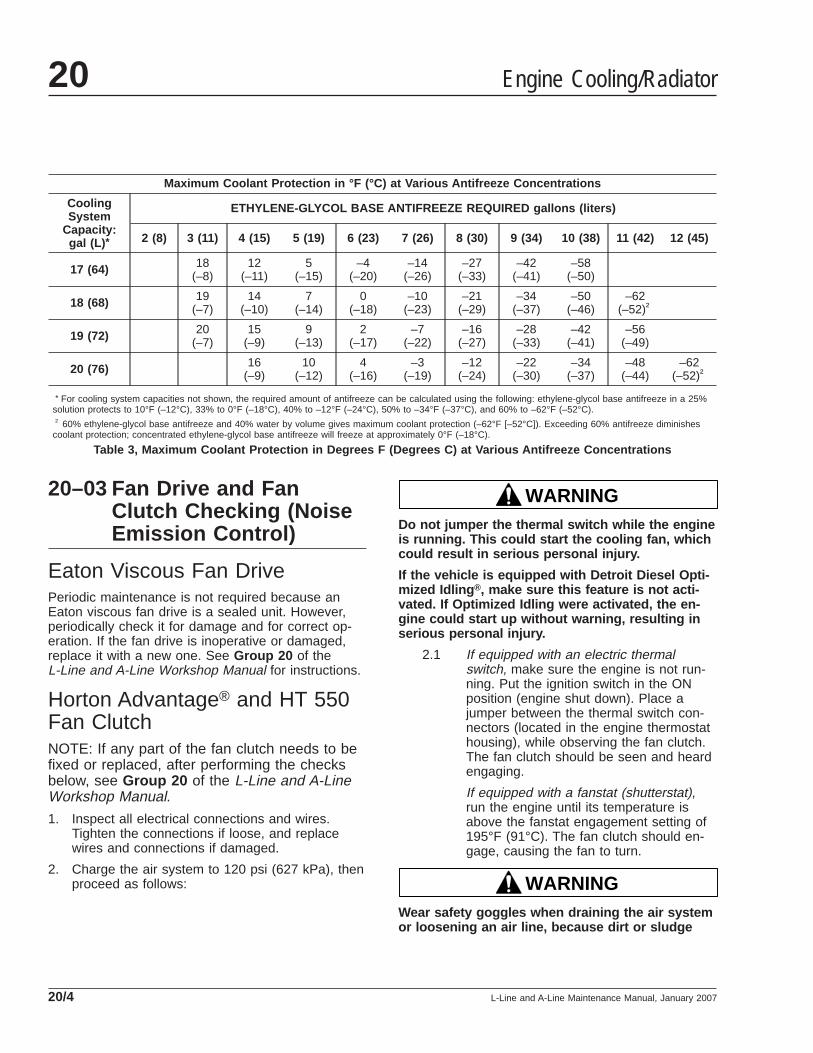
* For cooling system capacities not shown, the required amount of antifreeze can be calculated using the following: ethylene-glycol base antifreeze in a 25%solution protects to 10°F (–12°C), 33% to 0°F (–18°C), 40% to –12°F (–24°C), 50% to –34°F (–37°C), and 60% to –62°F (–52°C).† 60% ethylene-glycol base antifreeze and 40% water by volume gives maximum coolant protection (–62°F [–52°C]). Exceeding 60% antifreeze diminishes
coolant protection; concentrated ethylene-glycol base antifreeze will freeze at approximately 0°F (–18°C).
Table 3, Maximum Coolant Protection in Degrees F (Degrees C) at Various Antifreeze Concentrations
20–03 Fan Drive and FanClutch Checking (NoiseEmission Control)
Eaton Viscous Fan DrivePeriodic maintenance is not required because anEaton viscous fan drive is a sealed unit. However,periodically check it for damage and for correct op-eration. If the fan drive is inoperative or damaged,replace it with a new one. See Group 20 of theL-Line and A-Line Workshop Manual for instructions.
Horton Advantage® and HT 550Fan ClutchNOTE: If any part of the fan clutch needs to befixed or replaced, after performing the checksbelow, see Group 20 of the L-Line and A-LineWorkshop Manual.
1. Inspect all electrical connections and wires.Tighten the connections if loose, and replacewires and connections if damaged.
2. Charge the air system to 120 psi (627 kPa), thenproceed as follows:
WARNINGDo not jumper the thermal switch while the engineis running. This could start the cooling fan, whichcould result in serious personal injury.
If the vehicle is equipped with Detroit Diesel Opti-mized Idling ®, make sure this feature is not acti-vated. If Optimized Idling were activated, the en-gine could start up without warning, resulting inserious personal injury.
2.1 If equipped with an electric thermalswitch, make sure the engine is not run-ning. Put the ignition switch in the ONposition (engine shut down). Place ajumper between the thermal switch con-nectors (located in the engine thermostathousing), while observing the fan clutch.The fan clutch should be seen and heardengaging.
If equipped with a fanstat (shutterstat),run the engine until its temperature isabove the fanstat engagement setting of195°F (91°C). The fan clutch should en-gage, causing the fan to turn.
WARNINGWear safety goggles when draining the air systemor loosening an air line, because dirt or sludge
Engine Cooling/Radiator20
L-Line and A-Line Maintenance Manual, January 200720/4
could fly out at high speeds. Do not direct the air-stream at anyone. Do not disconnect pressurizedhoses, since they may whip as air escapes. Fail-ure to take all necessary precautions could resultin personal injury.
2.2 If the fan clutch does not engage, see ifcompressed air is in the fan clutch actuat-ing air line: With the ignition on, but theengine shut down, slowly loosen the fit-ting that connects the actuating air line tothe fan clutch; do not disconnect the fit-ting. If compressed air escapes, the fanclutch is inoperative and must be re-paired. If no compressed air escapes,replace the solenoid valve or fanstat, asapplicable. Tighten the fitting.
3. Check all air connections for air leaks.
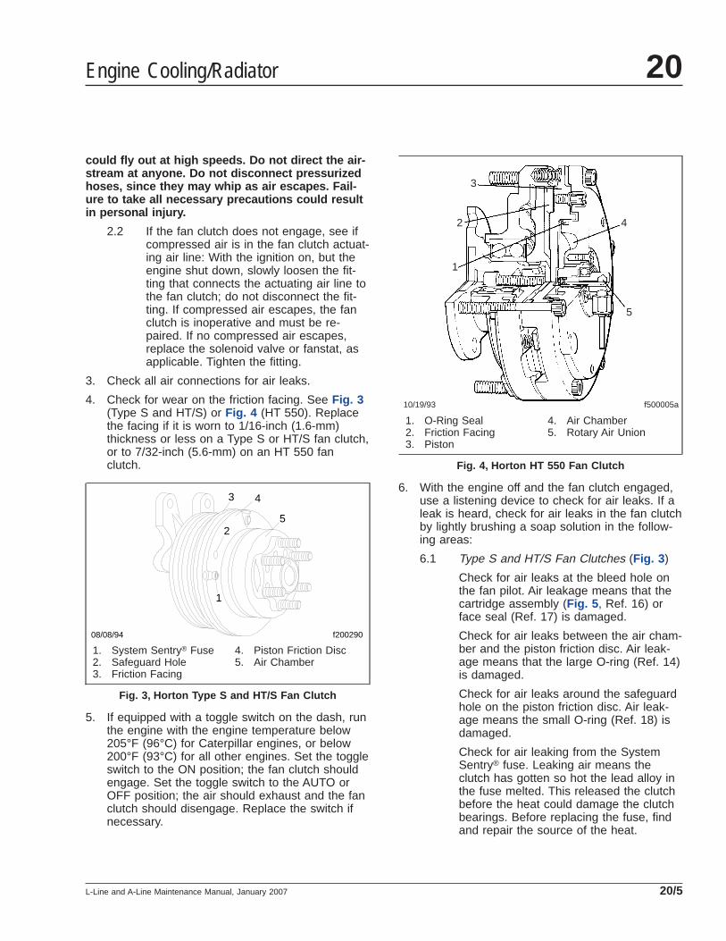
4. Check for wear on the friction facing. See Fig. 3(Type S and HT/S) or Fig. 4 (HT 550). Replacethe facing if it is worn to 1/16-inch (1.6-mm)thickness or less on a Type S or HT/S fan clutch,or to 7/32-inch (5.6-mm) on an HT 550 fanclutch.
5. If equipped with a toggle switch on the dash, runthe engine with the engine temperature below205°F (96°C) for Caterpillar engines, or below200°F (93°C) for all other engines. Set the toggleswitch to the ON position; the fan clutch shouldengage. Set the toggle switch to the AUTO orOFF position; the air should exhaust and the fanclutch should disengage. Replace the switch ifnecessary.
6. With the engine off and the fan clutch engaged,use a listening device to check for air leaks. If aleak is heard, check for air leaks in the fan clutchby lightly brushing a soap solution in the follow-ing areas:
6.1 Type S and HT/S Fan Clutches (Fig. 3 )
Check for air leaks at the bleed hole onthe fan pilot. Air leakage means that thecartridge assembly (Fig. 5 , Ref. 16) orface seal (Ref. 17) is damaged.
Check for air leaks between the air cham-ber and the piston friction disc. Air leak-age means that the large O-ring (Ref. 14)is damaged.
Check for air leaks around the safeguardhole on the piston friction disc. Air leak-age means the small O-ring (Ref. 18) isdamaged.
Check for air leaking from the SystemSentry® fuse. Leaking air means theclutch has gotten so hot the lead alloy inthe fuse melted. This released the clutchbefore the heat could damage the clutchbearings. Before replacing the fuse, findand repair the source of the heat.
f200290
1
2
08/08/94
3 4
5
1. System Sentry® Fuse2. Safeguard Hole3. Friction Facing
4. Piston Friction Disc5. Air Chamber
Fig. 3, Horton Type S and HT/S Fan Clutch
10/19/93 f500005a
1
2
3
4
5
1. O-Ring Seal2. Friction Facing3. Piston
4. Air Chamber5. Rotary Air Union
Fig. 4, Horton HT 550 Fan Clutch
Engine Cooling/Radiator 20
L-Line and A-Line Maintenance Manual, January 2007 20/5
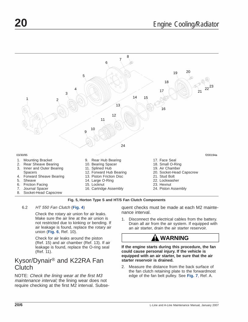
6.2 HT 550 Fan Clutch (Fig. 4 )
Check the rotary air union for air leaks.Make sure the air line at the air union isnot restricted due to kinking or bending. Ifair leakage is found, replace the rotary airunion (Fig. 6 , Ref. 10).
Check for air leaks around the piston(Ref. 15) and air chamber (Ref. 13). If airleakage is found, replace the O-ring seal(Ref. 11).
Kysor/Dynair® and K22RA FanClutchNOTE: Check the lining wear at the first M3maintenance interval; the lining wear does notrequire checking at the first M2 interval. Subse-
quent checks must be made at each M2 mainte-nance interval.
1. Disconnect the electrical cables from the battery.Drain all air from the air system. If equipped withan air starter, drain the air starter reservoir.
WARNINGIf the engine starts during this procedure, the fancould cause personal injury. If the vehicle isequipped with an air starter, be sure that the airstarter reservoir is drained.
2. Measure the distance from the back surface ofthe fan clutch retaining plate to the forwardmostedge of the fan belt pulley. See Fig. 7 , Ref. A.
f200194a
1 2
34
5
67
8
910
1112
13
14 15
16
17
18
19 20
2123
22
24
03/30/95
1. Mounting Bracket2. Rear Sheave Bearing3. Inner and Outer Bearing
Spacers4. Forward Sheave Bearing5. Sheave6. Friction Facing7. Journal Spacer8. Socket-Head Capscrew
9. Rear Hub Bearing10. Bearing Spacer11. Splined Hub12. Forward Hub Bearing13. Piston Friction Disc14. Large O-Ring15. Locknut16. Cartridge Assembly
17. Face Seal18. Small O-Ring19. Air Chamber20. Socket-Head Capscrew21. Stud Bolt22. Lockwasher23. Hexnut24. Piston Assembly
Fig. 5, Horton Type S and HT/S Fan Clutch Components
Engine Cooling/Radiator20
L-Line and A-Line Maintenance Manual, January 200720/6
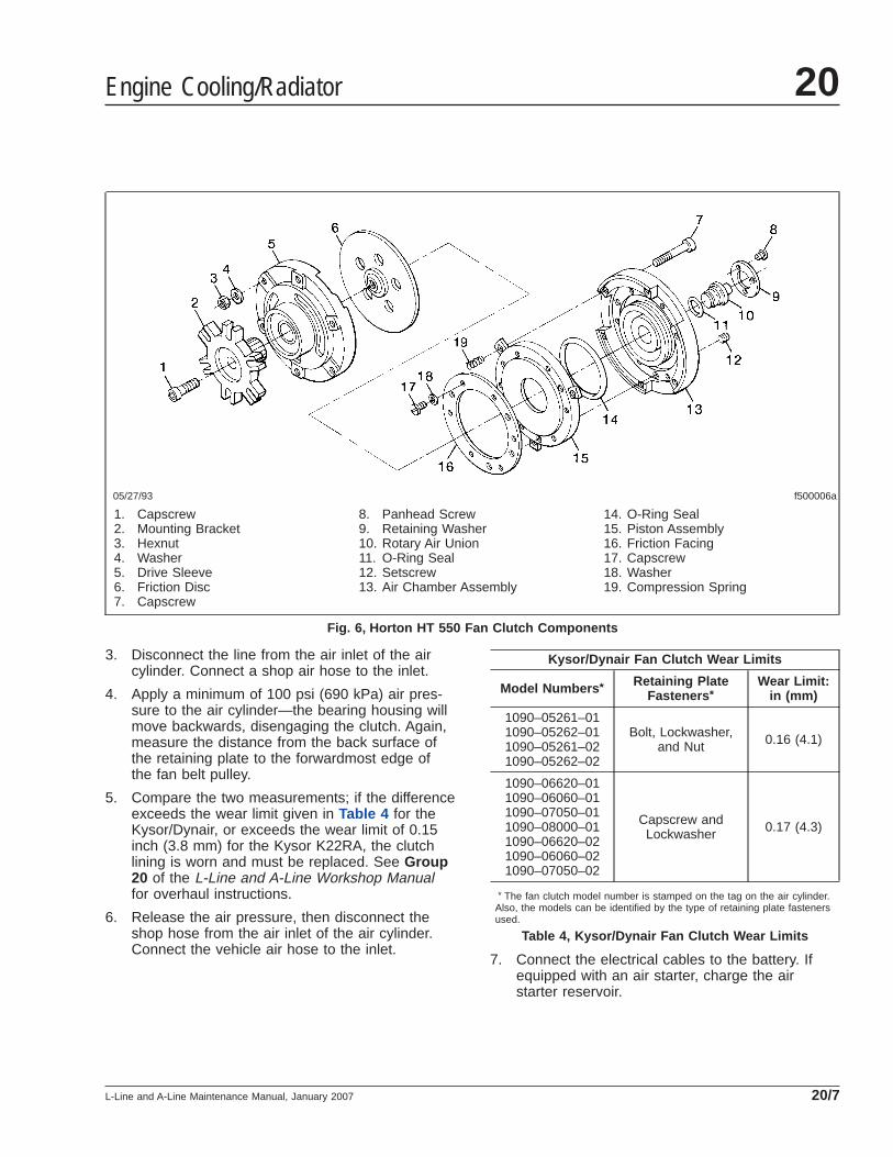
3. Disconnect the line from the air inlet of the aircylinder. Connect a shop air hose to the inlet.
4. Apply a minimum of 100 psi (690 kPa) air pres-sure to the air cylinder—the bearing housing willmove backwards, disengaging the clutch. Again,measure the distance from the back surface ofthe retaining plate to the forwardmost edge ofthe fan belt pulley.
5. Compare the two measurements; if the differenceexceeds the wear limit given in Table 4 for theKysor/Dynair, or exceeds the wear limit of 0.15inch (3.8 mm) for the Kysor K22RA, the clutchlining is worn and must be replaced. See Group20 of the L-Line and A-Line Workshop Manualfor overhaul instructions.
6. Release the air pressure, then disconnect theshop hose from the air inlet of the air cylinder.Connect the vehicle air hose to the inlet.
Kysor/Dynair Fan Clutch Wear Limits
Model Numbers * Retaining PlateFasteners *
Wear Limit:in (mm)
1090–05261–011090–05262–011090–05261–021090–05262–02
Bolt, Lockwasher,and Nut 0.16 (4.1)
1090–06620–011090–06060–011090–07050–011090–08000–011090–06620–021090–06060–021090–07050–02
Capscrew andLockwasher 0.17 (4.3)
* The fan clutch model number is stamped on the tag on the air cylinder.Also, the models can be identified by the type of retaining plate fastenersused.
Table 4, Kysor/Dynair Fan Clutch Wear Limits
7. Connect the electrical cables to the battery. Ifequipped with an air starter, charge the airstarter reservoir.
f500006a05/27/93
1. Capscrew2. Mounting Bracket3. Hexnut4. Washer5. Drive Sleeve6. Friction Disc7. Capscrew
8. Panhead Screw9. Retaining Washer10. Rotary Air Union11. O-Ring Seal12. Setscrew13. Air Chamber Assembly
14. O-Ring Seal15. Piston Assembly16. Friction Facing17. Capscrew18. Washer19. Compression Spring
Fig. 6, Horton HT 550 Fan Clutch Components
Engine Cooling/Radiator 20
L-Line and A-Line Maintenance Manual, January 2007 20/7
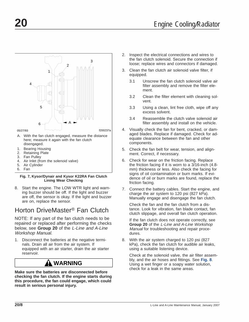
8. Start the engine. The LOW WTR light and warn-ing buzzer should be off. If the light and buzzerare off, the sensor is okay. If the light and buzzerare on, replace the sensor.
Horton DriveMaster® Fan ClutchNOTE: If any part of the fan clutch needs to berepaired or replaced after performing the checksbelow, see Group 20 of the L-Line and A-LineWorkshop Manual.
1. Disconnect the batteries at the negative termi-nals. Drain all air from the air system. Ifequipped with an air starter, drain the air starterreservoir.
WARNINGMake sure the batteries are disconnected beforechecking the fan clutch. If the engine starts duringthis procedure, the fan could engage, which couldresult in serious personal injury.
2. Inspect the electrical connections and wires tothe fan clutch solenoid. Secure the connection ifloose; replace wires and connectors if damaged.
3. Clean the fan clutch air solenoid valve filter, ifequipped.
3.1 Unscrew the fan clutch solenoid valve airfilter assembly and remove the filter ele-ment.
3.2 Clean the filter element with cleaning sol-vent.
3.3 Using a clean, lint free cloth, wipe off anyexcess solvent.
3.4 Reassemble the clutch valve solenoid airfilter assembly and install on the vehicle.
4. Visually check the fan for bent, cracked, or dam-aged blades. Replace if damaged. Check for ad-equate clearance between the fan and othercomponents.
5. Check the fan belt for wear, tension, and align-ment. Correct, if necessary.
6. Check for wear on the friction facing. Replacethe friction facing if it is worn to a 3/16-inch (4.8-mm) thickness or less. Also check the facing forsigns of oil contamination or burn marks. If evi-dence of oil or burn marks are found, replace thefriction facing.
7. Connect the battery cables. Start the engine, andcharge the air system to 120 psi (827 kPa).Manually engage and disengage the fan clutch.
Check the fan and the fan clutch from a dis-tance. Look for vibration, fan blade contact, fanclutch slippage, and overall fan clutch operation.
If the fan clutch does not operate correctly, seeGroup 20 of the L-Line and A-Line WorkshopManual for troubleshooting and repair proce-dures.
8. With the air system charged to 120 psi (827kPa), check the fan clutch for audible air leaks,using a suitable listening device.
Check at the solenoid valve, the air filter assem-bly, and the air hoses and fittings. See Fig. 8 .Using a wet finger or a soapy water solution,check for a leak in the same areas.
f200237a
1
23
4
5
6
05/27/93
A
A. With the fan clutch engaged, measure the distancehere; measure it again with the fan clutchdisengaged.
1. Bearing Housing2. Retaining Plate3. Fan Pulley4. Air Inlet (from the solenoid valve)5. Air Cylinder6. Fan
Fig. 7, Kysor/Dynair and Kysor K22RA Fan ClutchLining Wear Checking
Engine Cooling/Radiator20
L-Line and A-Line Maintenance Manual, January 200720/8
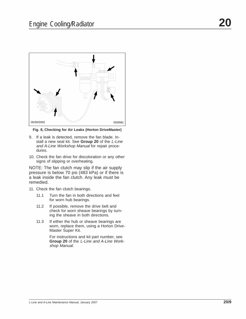
9. If a leak is detected, remove the fan blade. In-stall a new seal kit. See Group 20 of the L-Lineand A-Line Workshop Manual for repair proce-dures.
10. Check the fan drive for discoloration or any othersigns of slipping or overheating.
NOTE: The fan clutch may slip if the air supplypressure is below 70 psi (483 kPa) or if there isa leak inside the fan clutch. Any leak must beremedied.
11. Check the fan clutch bearings.
11.1 Turn the fan in both directions and feelfor worn hub bearings.
11.2 If possible, remove the drive belt andcheck for worn sheave bearings by turn-ing the sheave in both directions.
11.3 If either the hub or sheave bearings areworn, replace them, using a Horton Drive-Master Super Kit.
For instructions and kit part number, seeGroup 20 of the L-Line and A-Line Work-shop Manual.
f20058105/30/2002
Fig. 8, Checking for Air Leaks (Horton DriveMaster)
Engine Cooling/Radiator 20
L-Line and A-Line Maintenance Manual, January 2007 20/9
Title of Maintenance Operation (MOP) MOP Number
Clutch Release Bearing Lubricating. . . . . . . . . . . . . . . . . . . . . . . . . . . . . . . . . . . . . . . . . . . . . . . . . . . . . 25–01
Clutch 25Index, Alphabetical
L-Line and A-Line Maintenance Manual, October 1999

25–01 Clutch Release BearingLubricating
NOTE: For a clutch with a sealed release bear-ing, the release bearing is lubricated at the timeof manufacture and requires no additionalgrease for the life of the bearing. This type ofrelease bearing is not equipped with a greasefitting.
For a clutch with a grease-type release bearing (seeFig. 1 ), wipe the dirt from the grease fitting.
CAUTIONDo not over-lubricate the clutch release bearing.Over-lubrication could contaminate the clutch in-ternally, causing clutch slippage and prematurefailure. Do not use chassis grease or multipurposelubricants.
IMPORTANT: If the release bearing is notequipped with a grease-fitting extension thatextends outside the bell housing, lubricate thebearing with the engine stopped. If equippedwith a grease-fitting extension that does extend
outside the bell housing, lubricate the bearingwith the engine running.
Using a pressure gun and high-temperature greaseonly, lubricate the release bearing at the grease fit-ting until grease starts coming out of the fitting. Donot use chassis lube or multipurpose lubricants.
f250081a05/27/93
Fig. 1, Release Bearing Grease Fitting
Clutch 25
L-Line and A-Line Maintenance Manual, October 1999 25/1

Title of Maintenance Operation (MOP) MOP Number
Allison Transmission Fluid and Filter Changing . . . . . . . . . . . . . . . . . . . . . . . . . . . . . . . . . . . . . . . . . . . . 26–01
Manual Transmission Magnetic Plug Cleaning and Oil Changing . . . . . . . . . . . . . . . . . . . . . . . . . . . . . . . 26–02
Transmission Air Filter/Regulator Checking and Cleaning, or Replacing . . . . . . . . . . . . . . . . . . . . . . . . . . 26–03
Transmission Breather and Oil Level Checking . . . . . . . . . . . . . . . . . . . . . . . . . . . . . . . . . . . . . . . . . . . . 26–04
Transmission 26Index, Alphabetical
L-Line and A-Line Maintenance Manual, June 2000
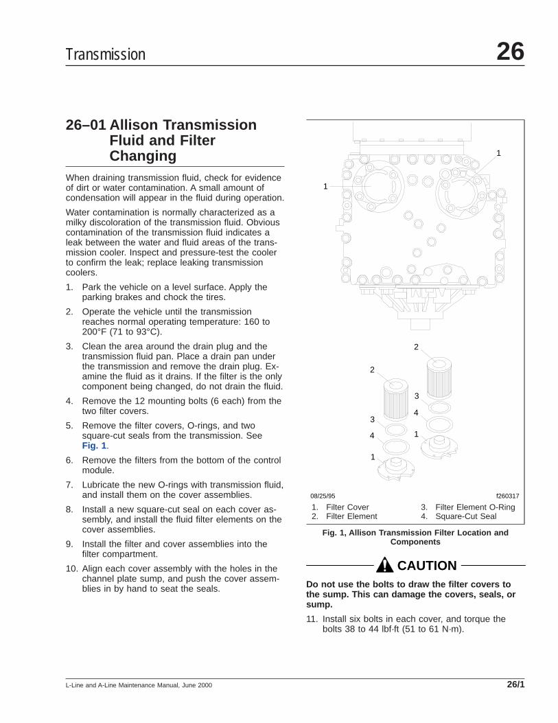
26–01 Allison TransmissionFluid and FilterChanging
When draining transmission fluid, check for evidenceof dirt or water contamination. A small amount ofcondensation will appear in the fluid during operation.
Water contamination is normally characterized as amilky discoloration of the transmission fluid. Obviouscontamination of the transmission fluid indicates aleak between the water and fluid areas of the trans-mission cooler. Inspect and pressure-test the coolerto confirm the leak; replace leaking transmissioncoolers.
1. Park the vehicle on a level surface. Apply theparking brakes and chock the tires.
2. Operate the vehicle until the transmissionreaches normal operating temperature: 160 to200°F (71 to 93°C).
3. Clean the area around the drain plug and thetransmission fluid pan. Place a drain pan underthe transmission and remove the drain plug. Ex-amine the fluid as it drains. If the filter is the onlycomponent being changed, do not drain the fluid.
4. Remove the 12 mounting bolts (6 each) from thetwo filter covers.
5. Remove the filter covers, O-rings, and twosquare-cut seals from the transmission. SeeFig. 1 .
6. Remove the filters from the bottom of the controlmodule.
7. Lubricate the new O-rings with transmission fluid,and install them on the cover assemblies.
8. Install a new square-cut seal on each cover as-sembly, and install the fluid filter elements on thecover assemblies.
9. Install the filter and cover assemblies into thefilter compartment.
10. Align each cover assembly with the holes in thechannel plate sump, and push the cover assem-blies in by hand to seat the seals.
CAUTIONDo not use the bolts to draw the filter covers tothe sump. This can damage the covers, seals, orsump.
11. Install six bolts in each cover, and torque thebolts 38 to 44 lbf·ft (51 to 61 N·m).
1
1
1
1
2
2
3
3
4
4
f26031708/25/95
1. Filter Cover2. Filter Element
3. Filter Element O-Ring4. Square-Cut Seal
Fig. 1, Allison Transmission Filter Location andComponents
Transmission 26
L-Line and A-Line Maintenance Manual, June 2000 26/1

12. Replace the drain plug O-ring, and install thedrain plug. Tighten the drain plug 18 to 24 lbf·ft(25 to 32 N·m).
13. Refill the transmission with fresh Dexron® IIItransmission fluid and check the fluid level.
NOTE: Do not overfill the transmission. Followinstructions in Maintenance Operation 26–04 .
26–02 Manual TransmissionMagnetic Plug Cleaningand Oil Changing
Manual Transmission Oil ChangeIMPORTANT: For all transmissions that are filledwith approved synthetic lubricants, the lubricantmust be changed every 500,000 miles (800 000km). Transmissions with petroleum-based lubri-cants must have the lubricant changed at eachMaintenance 2 (M2) interval. All transmissionswith synthetic or petroleum-based lubricantsmust have the transmission breather checkedand the magnetic plugs cleaned at each M1interval.
NOTE: For vehicles equipped with auxiliarytransmissions, use this procedure to change theauxiliary transmission oil and to check the auxil-iary transmission breather whenever changingthe main transmission oil and checking the maintransmission breather.
1. With the vehicle parked on level ground, applythe parking brakes, and chock the tires. Place alarge drain pan under the transmission.
2. Clean the area around the fill plug, and remove itfrom the side of the case. Remove each drainplug from the bottom of the transmission case.Drain the oil while the transmission is warm.
3. Clean the fill and drain plugs. For magneticplugs, use a piece of key stock or any other con-venient steel slug to short the two magneticpoles and divert the magnetic field.
4. Install and tighten each drain plug 50 lbf·ft (68N·m).
5. Transmission housing breathers must remainclear. A plugged breather could result in pressure
build-up, which could cause oil leakage. If thebreather is plugged, clean or replace it. SeeFig. 2 . Check more often if the vehicle operatesunder very dusty conditions.
IMPORTANT: Do not mix types and brands ofoil, because of possible incompatibility. Do notuse oil additives, friction modifiers, extreme-pressure gear oils, or multiviscosity lubricants.Do not use extreme-pressure additives, such asthose found in multipurpose or rear axle-typelubricants. These additives are not required, andmay create transmission problems. Multipurposeoils have relatively poor oxidation stability, ahigh rate of sludge formation, and a greater ten-dency to react on or corrode steel and bronzeparts.
NOTE: The correct oil capacity is established bythe fill opening.
6. Add oil until it is level with the lower edge of thefill opening. If the transmission has two fill open-ings, add oil to the level of both openings. SeeFig. 3 . See Table 1 for transmission lubricantcapacities, and see Table 2 for approved trans-mission lubricants.
f260007a05/27/93
Fig. 2, Transmission Breather (Fuller shown)
Transmission26
L-Line and A-Line Maintenance Manual, June 200026/2
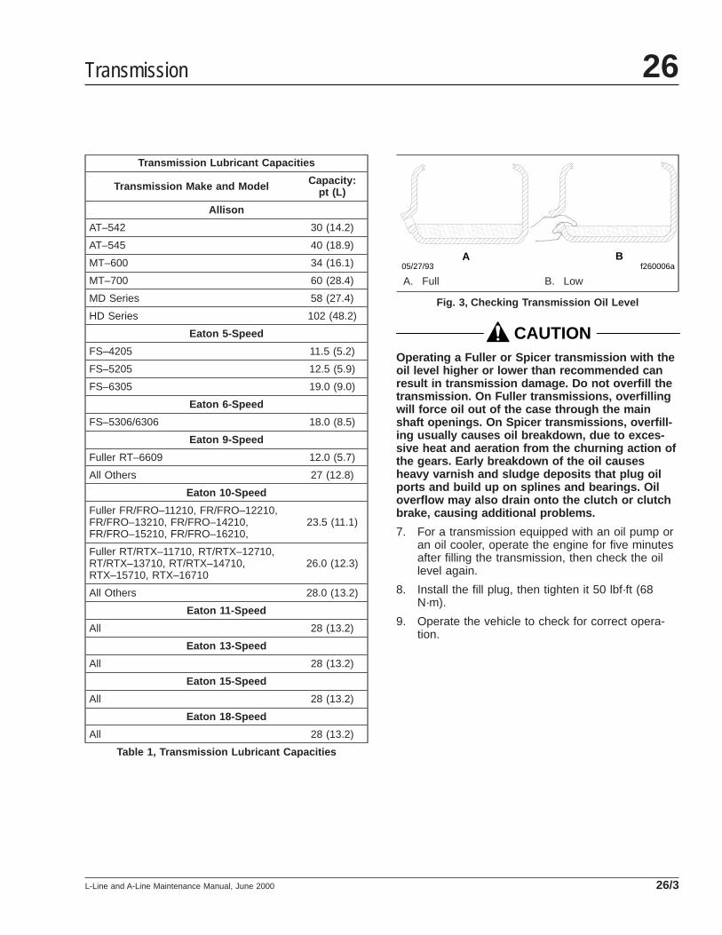
Transmission Lubricant Capacities
Transmission Make and Model Capacity:pt (L)
Allison
AT–542 30 (14.2)
AT–545 40 (18.9)
MT–600 34 (16.1)
MT–700 60 (28.4)
MD Series 58 (27.4)
HD Series 102 (48.2)
Eaton 5-Speed
FS–4205 11.5 (5.2)
FS–5205 12.5 (5.9)
FS–6305 19.0 (9.0)
Eaton 6-Speed
FS–5306/6306 18.0 (8.5)
Eaton 9-Speed
Fuller RT–6609 12.0 (5.7)
All Others 27 (12.8)
Eaton 10-Speed
Fuller FR/FRO–11210, FR/FRO–12210,FR/FRO–13210, FR/FRO–14210,FR/FRO–15210, FR/FRO–16210,
23.5 (11.1)
Fuller RT/RTX–11710, RT/RTX–12710,RT/RTX–13710, RT/RTX–14710,RTX–15710, RTX–16710
26.0 (12.3)
All Others 28.0 (13.2)
Eaton 11-Speed
All 28 (13.2)
Eaton 13-Speed
All 28 (13.2)
Eaton 15-Speed
All 28 (13.2)
Eaton 18-Speed
All 28 (13.2)
Table 1, Transmission Lubricant Capacities
CAUTIONOperating a Fuller or Spicer transmission with theoil level higher or lower than recommended canresult in transmission damage. Do not overfill thetransmission. On Fuller transmissions, overfillingwill force oil out of the case through the mainshaft openings. On Spicer transmissions, overfill-ing usually causes oil breakdown, due to exces-sive heat and aeration from the churning action ofthe gears. Early breakdown of the oil causesheavy varnish and sludge deposits that plug oilports and build up on splines and bearings. Oiloverflow may also drain onto the clutch or clutchbrake, causing additional problems.
7. For a transmission equipped with an oil pump oran oil cooler, operate the engine for five minutesafter filling the transmission, then check the oillevel again.
8. Install the fill plug, then tighten it 50 lbf·ft (68N·m).
9. Operate the vehicle to check for correct opera-tion.
f260006a05/27/93A B
A. Full B. Low
Fig. 3, Checking Transmission Oil Level
Transmission 26
L-Line and A-Line Maintenance Manual, June 2000 26/3
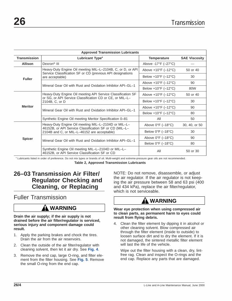
Approved Transmission Lubricants
Transmission Lubricant Type * Temperature SAE Viscosity
Allison Dexron® III Above -17°F (–27°C) —
Fuller
Heavy-Duty Engine Oil meeting MIL–L–2104B, C, or D, or APIService Classification SF or CD (previous API designationsare acceptable)
Above +10°F (–12°C) 50 or 40
Below +10°F (–12°C) 30
Mineral Gear Oil with Rust and Oxidation Inhibitor API–GL–1Above +10°F (–12°C) 90
Below +10°F (–12°C) 80W
Meritor
Heavy-Duty Engine Oil meeting API Service Classification SFor SG, or API Service Classification CD or CE, or MIL–L–2104B, C, or D
Above +10°F (–12°C) 50 or 40
Below +10°F (–12°C) 30
Mineral Gear Oil with Rust and Oxidation Inhibitor API–GL–1Above +10°F (–12°C) 90
Below +10°F (–12°C) 80
Synthetic Engine Oil meeting Meritor Specification 0–81 All 50
Spicer
Heavy-Duty Engine Oil meeting MIL–L–2104D or MIL–L–46152B, or API Service Classification SF or CD (MIL–L–2104B and C, or MIL–L–46152 are acceptable)
Above 0°F (–18°C) 30, 40, or 50
Below 0°F (–18°C) 30
Mineral Gear Oil with Rust and Oxidation Inhibitor API–GL–1Above 0°F (–18°C) 90
Below 0°F (–18°C) 80
Synthetic Engine Oil meeting MIL–L–2104D or MIL–L–46152B, or API Service Classification SF or CD All 50 or 30
* Lubricants listed in order of preference. Do not mix types or brands of oil. Multi-weight and extreme-pressure gear oils are not recommended.
Table 2, Approved Transmission Lubricants
26–03 Transmission Air Filter/Regulator Checking andCleaning, or Replacing
Fuller Transmission
WARNINGDrain the air supply; if the air supply is notdrained before the air filter/regulator is serviced,serious injury and component damage couldresult.
1. Apply the parking brakes and chock the tires.Drain the air from the air reservoirs.
2. Clean the outside of the air filter/regulator withcleaning solvent, then let it air dry. See Fig. 4 .
3. Remove the end cap, large O-ring, and filter ele-ment from the filter housing. See Fig. 5 . Removethe small O-ring from the end cap.
NOTE: Do not remove, disassemble, or adjustthe air regulator. If the air regulator is not keep-ing the air pressure between 58 and 63 psi (400and 434 kPa), replace the air filter/regulator,which is not serviceable.
WARNINGWear eye protection when using compressed airto clean parts, as permanent harm to eyes couldresult from flying debris.
4. Clean the filter element by dipping it in alcohol orother cleaning solvent. Blow compressed airthrough the filter element (inside to outside) toloosen surface dirt and to dry the element. If it isnot damaged, the sintered metallic filter elementwill last the life of the vehicle.
Wipe out the filter housing with a clean, dry, lint-free rag. Clean and inspect the O-rings and theend cap. Replace any parts that are damaged.
Transmission26
L-Line and A-Line Maintenance Manual, June 200026/4
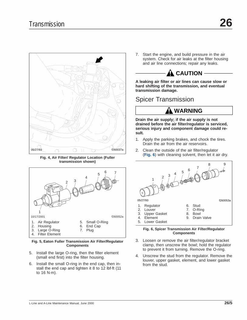
5. Install the large O-ring, then the filter element(small end first) into the filter housing.
6. Install the small O-ring in the end cap, then in-stall the end cap and tighten it 8 to 12 lbf·ft (11to 16 N·m).
7. Start the engine, and build pressure in the airsystem. Check for air leaks at the filter housingand air line connections; repair any leaks.
CAUTIONA leaking air filter or air lines can cause slow orhard shifting of the transmission, and eventualtransmission damage.
Spicer Transmission
WARNINGDrain the air supply; if the air supply is notdrained before the air filter/regulator is serviced,serious injury and component damage could re-sult.
1. Apply the parking brakes, and chock the tires.Drain the air from the air reservoirs.
2. Clean the outside of the air filter/regulator(Fig. 6 ) with cleaning solvent, then let it air dry.
3. Loosen or remove the air filter/regulator bracketclamp, then unscrew the bowl; hold the regulatorto prevent it from turning. Remove the O-ring.
4. Unscrew the stud from the regulator. Remove thelouver, upper gasket, element, and lower gasketfrom the stud.
f260037a05/27/93
Fig. 4, Air Filter/ Regulator Location (Fullertransmission shown)
1
2 34
56 7
f260052a10/17/2001
1. Air Regulator2. Housing3. Large O-Ring4. Filter Element
5. Small O-Ring6. End Cap7. Plug
Fig. 5, Eaton Fuller Transmission Air Filter/RegulatorComponents
12 3 4 5 6
78 9
f260053a05/27/93
1. Regulator2. Louver3. Upper Gasket4. Element5. Lower Gasket
6. Stud7. O-Ring8. Bowl9. Drain Valve
Fig. 6, Spicer Transmission Air Filter/RegulatorComponents
Transmission 26
L-Line and A-Line Maintenance Manual, June 2000 26/5
WARNINGWear eye protection when using compressed airto clean parts, as permanent harm to eyes couldresult from flying debris.
5. Clean and inspect all parts. Use only apetroleum-based solvent to clean the parts. Blowair through the filter element (inside to outside) toloosen surface dirt.
IMPORTANT: After three cleanings, replace thefilter element with a new one.
Do not disassemble the regulator, as it is notrepairable. If the air regulator does not workproperly, replace the unit.
6. Install the lower gasket, the cleaned or new ele-ment, the upper gasket, and the louver, on thestud. Install the element so the large end of theinternal taper (thinnest wall section) is toward thehex on the stud.
7. Install and tighten the stud 5 to 10 lbf·in (60 to100 N·cm).
8. Apply a light coat of Dow Corning DC7 siliconegrease, or an equivalent, to the O-ring seatingsurfaces on the regulator and the bowl.
9. Apply a light, even coat of Molykote "G," or anequivalent, to the bowl threads. Install andtighten the bowl 5 to 10 lbf·in (60 to 100 N·cm).
10. Install and/or tighten the air filter/regulatorbracket clamp.
11. Install and torque the drain valve, if removed, 10to 15 lbf·in (120 to 160 N·cm).
12. Build air pressure in the system, check for leaks,and make any necessary repairs.
Meritor Transmission
WARNINGDrain the air supply; if the air supply is notdrained before the air filter/regulator is serviced,serious injury and component damage could re-sult.
1. Apply the parking brakes, and chock the tires.Drain the air from the air reservoirs.
2. Clean the outside of the air filter/regulator withcleaning solvent, then let it air dry.
3. Remove the end cap from the air filter/regulatorassembly, then inspect the O-rings in the endcap. Replace worn or damaged O-rings.
4. Remove the element from the filter/regulator as-sembly.
5. Inspect the element for oil. If oil is in the ele-ment, replace the element. Inspect the air supplysystem for the source of oil, and service it asneeded.
6. Install the element in the filter/regulator assem-bly.
7. Apply a light coat of Dow Corning DC7 siliconegrease, or an equivalent, to the O-rings in theend cap.
8. Install and tighten the end cap 10 to 15 lbf·ft (14to 20 N·m).
9. Build air pressure in the system, check for leaks,and make any needed repairs.
26–04 Transmission Breatherand Oil Level Checking
NOTE: For vehicles with auxiliary transmissions,use this procedure to check the auxiliary trans-mission oil level and breather whenever check-ing the main transmission oil level and breather.
Breather CheckTransmission housing breathers must remain clear. Aplugged breather could result in pressure build-up,which could cause oil leakage.
If the breather is plugged, clean or replace it. SeeFig. 2 . Check more often if the vehicle operatesunder very dusty conditions.
Allison Transmission
CAUTIONOperating a transmission with the fluid levelhigher or lower than recommended can result intransmission damage. Do not overfill the transmis-sion.
Transmission26
L-Line and A-Line Maintenance Manual, June 200026/6
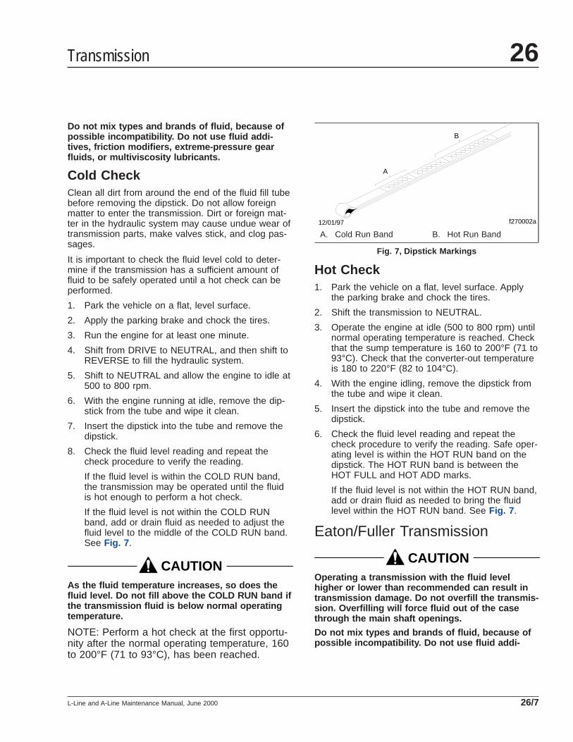
Do not mix types and brands of fluid, because ofpossible incompatibility. Do not use fluid addi-tives, friction modifiers, extreme-pressure gearfluids, or multiviscosity lubricants.
Cold CheckClean all dirt from around the end of the fluid fill tubebefore removing the dipstick. Do not allow foreignmatter to enter the transmission. Dirt or foreign mat-ter in the hydraulic system may cause undue wear oftransmission parts, make valves stick, and clog pas-sages.
It is important to check the fluid level cold to deter-mine if the transmission has a sufficient amount offluid to be safely operated until a hot check can beperformed.
1. Park the vehicle on a flat, level surface.
2. Apply the parking brake and chock the tires.
3. Run the engine for at least one minute.
4. Shift from DRIVE to NEUTRAL, and then shift toREVERSE to fill the hydraulic system.
5. Shift to NEUTRAL and allow the engine to idle at500 to 800 rpm.
6. With the engine running at idle, remove the dip-stick from the tube and wipe it clean.
7. Insert the dipstick into the tube and remove thedipstick.
8. Check the fluid level reading and repeat thecheck procedure to verify the reading.
If the fluid level is within the COLD RUN band,the transmission may be operated until the fluidis hot enough to perform a hot check.
If the fluid level is not within the COLD RUNband, add or drain fluid as needed to adjust thefluid level to the middle of the COLD RUN band.See Fig. 7 .
CAUTIONAs the fluid temperature increases, so does thefluid level. Do not fill above the COLD RUN band ifthe transmission fluid is below normal operatingtemperature.
NOTE: Perform a hot check at the first opportu-nity after the normal operating temperature, 160to 200°F (71 to 93°C), has been reached.
Hot Check1. Park the vehicle on a flat, level surface. Apply
the parking brake and chock the tires.
2. Shift the transmission to NEUTRAL.
3. Operate the engine at idle (500 to 800 rpm) untilnormal operating temperature is reached. Checkthat the sump temperature is 160 to 200°F (71 to93°C). Check that the converter-out temperatureis 180 to 220°F (82 to 104°C).
4. With the engine idling, remove the dipstick fromthe tube and wipe it clean.
5. Insert the dipstick into the tube and remove thedipstick.
6. Check the fluid level reading and repeat thecheck procedure to verify the reading. Safe oper-ating level is within the HOT RUN band on thedipstick. The HOT RUN band is between theHOT FULL and HOT ADD marks.
If the fluid level is not within the HOT RUN band,add or drain fluid as needed to bring the fluidlevel within the HOT RUN band. See Fig. 7 .
Eaton/Fuller Transmission
CAUTIONOperating a transmission with the fluid levelhigher or lower than recommended can result intransmission damage. Do not overfill the transmis-sion. Overfilling will force fluid out of the casethrough the main shaft openings.
Do not mix types and brands of fluid, because ofpossible incompatibility. Do not use fluid addi-
12/01/97
A
B
f270002a
A. Cold Run Band B. Hot Run Band
Fig. 7, Dipstick Markings
Transmission 26
L-Line and A-Line Maintenance Manual, June 2000 26/7

tives, friction modifiers, extreme-pressure gearfluids, or multiviscosity lubricants.
With the transmission at operating temperature, andthe vehicle on a level surface, check the fluid level inthe transmission.
1. Clean the area around the fill plug, and remove itfrom the side of the case.
2. Using your finger or a bent pipe cleaner, see ifthe fluid is level with the fill opening. See Fig. 3 .
3. If the transmission fluid level is low, check thetransmission for leaks, and correct as needed.
4. If needed, add the recommended fluid, until it islevel with the lower edge of the fill opening. SeeTable 2 for approved transmission lubricants.
5. Clean the fill plug, install it in the transmission,then tighten it 50 lbf·ft (68 N·m).
Meritor Transmission
CAUTIONOperating a transmission with the fluid levelhigher or lower than recommended can result intransmission damage. Do not overfill the transmis-sion.
Do not mix types and brands of fluid, because ofpossible incompatibility. Do not use fluid addi-tives, friction modifiers, extreme-pressure gearfluids, or multiviscosity lubricants.
1. Remove the fill plug from the transmission.
2. Insert a finger or pipe cleaner into the transmis-sion.
3. Check that the fluid level is even with the base ofthe fill plug. See Fig. 3 .
The correct fluid capacity is established by the fillopening. If the transmission has two fill plugs,check that the fluid level is consistent at both fillplugs.
4. If the transmission fluid level is low, check thetransmission for leaks, and correct as needed.
5. If needed, add the recommended fluid, until it islevel with the lower edge of the fill opening. SeeTable 2 for approved transmission lubricants.
Transmission26
L-Line and A-Line Maintenance Manual, June 200026/8
Title of Maintenance Operation (MOP) MOP Number
Fifth Wheel Inspecting . . . . . . . . . . . . . . . . . . . . . . . . . . . . . . . . . . . . . . . . . . . . . . . . . . . . . . . . . . . . . . 31–01
Fifth Wheel Lubricating. . . . . . . . . . . . . . . . . . . . . . . . . . . . . . . . . . . . . . . . . . . . . . . . . . . . . . . . . . . . . . 31–02
Frame Fastener Torque Checking. . . . . . . . . . . . . . . . . . . . . . . . . . . . . . . . . . . . . . . . . . . . . . . . . . . . . . 31–03
Holland Fifth Wheel Sliding Mechanism Inspecting . . . . . . . . . . . . . . . . . . . . . . . . . . . . . . . . . . . . . . . . . 31–04
Trailer Electrical Connector Lubricating . . . . . . . . . . . . . . . . . . . . . . . . . . . . . . . . . . . . . . . . . . . . . . . . . . 31-05
Frame and Fifth Wheel 31Index, Alphabetical
L-Line and A-Line Maintenance Manual, January 2007
31–01 Fifth Wheel Inspecting
WARNINGAll fifth wheel maintenance, adjustment, and re-building must be done only by a qualified me-chanic. Improper or incomplete procedures couldresult in a possible disengagement of the trailerfrom the tractor, which could result in personalinjury or property damage.
Parts are under spring compression. Wear safetygoggles while servicing the fifth wheel. Failure todo so can result in personal injury, due to partsejecting with force.
Fontaine1. Disconnect the tractor from the trailer. For in-
structions, see Chapter 10 of the L-Line andA-Line Driver’s Manual.
2. Thoroughly clean the fifth wheel.
3. Look for cracks in the fifth wheel assembly,mounting brackets, and mounting parts.
4. Check the jaw and stationary jaw for mushroom-ing, and check that the serrations at the jaw andwedge are in good condition.
5. Test the safety lock latch for ease of operation.
NOTE: The safety lock latch is located at thefront of the fifth wheel on the top plate.
6. Check for loose nuts or bolts (see Fig. 1 ) on thefifth wheel and on the mounting. Set a torquewrench to the maximum torque value for the boltbeing checked, and confirm that the torque is tospecification. Do not loosen the bolt to check thetorque value. See Group 00 of this manual forbolt torque specifications.
7. Visually check all springs to see if they are se-curely fastened, and are not deformed.
WARNINGDo not disassemble the fifth wheel to inspect thesprings. The springs are under extreme pressure,and could cause serious injury.
8. Check wedge adjustment.
8.1 Open the kingpin lock, and vertically in-sert a 2-inch-diameter shaft.
8.2 Release the lock by tripping the releaselatch at the bottom of the throat.
8.3 Adjust the wedge stop at the end of thewedge to approximately 1/4-inch (6-mm)clearance by turning the wedge stop rodlocated on the right side of the top plate.
9. Replace cracked, worn, or damaged parts withnew parts. Replace all loose mounting bolts with5/8–11 SAE grade 8 bolts, grade C locknuts, andhardened washers. Do not re-use bolts, nuts,and washers on fifth wheel mountings.
10. After inspecting the fifth wheel, lubricate all mov-ing parts with a chassis or multipurpose grease.Apply a generous coating of grease to the topplate to fill the grooves, or depressions, on thetop plate. See Maintenance Operation 31–02for lubrication instructions.
Holland1. Disconnect the tractor from the trailer. For in-
structions, see Chapter 10 of the L-Line andA-Line Driver’s Manual.
2. Thoroughly steamclean the fifth wheel.
3. Check for loose nuts or broken bolts on the fifthwheel assembly.
4. Inspect for cracks or wear on the mounting bolts.
5. Visually inspect for improper locking action, andfor cracks or wear on the jaw locking mecha-nism.
6. Check the depth of the grease grooves. If thedepth of the grooves is 1/8 inch or less, replacethe fifth wheel top plate. See Group 31 of theL-Line and A-Line Workshop Manual.
7. Check the condition of the X-pattern cast into theunderside of the fifth wheel top plate. See Fig. 2 .The fifth wheel top plate must be removed tocheck the X-pattern.
7.1 Remove the roll pins from the bushingpins. Remove the bushing pins from theslide mount. Using a hoist, lift the fifthwheel top plate off of the vehicle.
7.2 Turn the fifth wheel top plate over withthe locks open. Check the condition ofthe X-pattern in the pockets. If theX-pattern is worn away, replace the fifthwheel top plate.
Frame and Fifth Wheel 31
L-Line and A-Line Maintenance Manual, January 2007 31/1

7.3 Install the fifth wheel top plate, bushingpins, and roll pins.
8. Inspect for fatigue or cracked welds.
9. Replace cracked, worn, or damaged parts withnew parts. Replace all loose mounting bolts with5/8–11 SAE grade 8 bolts, grade C locknuts, andhardened washers. Do not re-use bolts, nuts,and washers on fifth wheel mountings.
10. After inspecting the fifth wheel, lubricate all mov-ing parts with a chassis or multipurpose grease.See Maintenance Operation 31–02 for lubrica-tion instructions.
31–02 Fifth Wheel LubricatingTo maintain proper fifth wheel operation, always lubri-cate the fifth wheel after an inspection has beenperformed.
IMPORTANT: Lubricate the fifth wheel:
• After power washing, or steam cleaning;
• If the vehicle operates in harsh conditions suchas salt spray from road surfaces, or in ex-tremely dusty environments;
f31047609/18/95
1
2
3
4
5
67
68
1
9
10
11 123
4
1
2
18
1314
15
1416
17
1
21
21
21
22
23
2324
25
26
20
19
1. 3/16" x 1" Cotter Pin2. Lower Bracket Retainer Pin3. Grease Fitting4. Lower Bracket Pin5. Wedge Stop Rod6. Flatwasher7. Wedge Stop Rod Spring8. Wedge Stop Rod Nut9. Side Release Upper Assembly10. Leaf Spring
11. 1/4–20 x 3/8 Thread-CuttingScrew
12. Step Jaw and Wedge13. Jaw Spring14. 1/4" x 3" Cotter Pin15. Timer16. Wedge Spring17. Pull Handle18. Bumper Handle Spring
19. 1/2–13 x 2 Bumper Pivot Bolt20. Bumper21. Flatwasher22. 5/16" Bumper Pivot Bushing23. 1/2–13 Locknut24. 7/16" Handle Pivot Bushing25. Operating Handle (side-release
only)26. 1/2–13 x 2 Handle Pivot Bolt
Fig. 1, Fontaine H5092 Series Fifth Wheel (Left-Side Release Shown)
Frame and Fifth Wheel31
L-Line and A-Line Maintenance Manual, January 200731/2
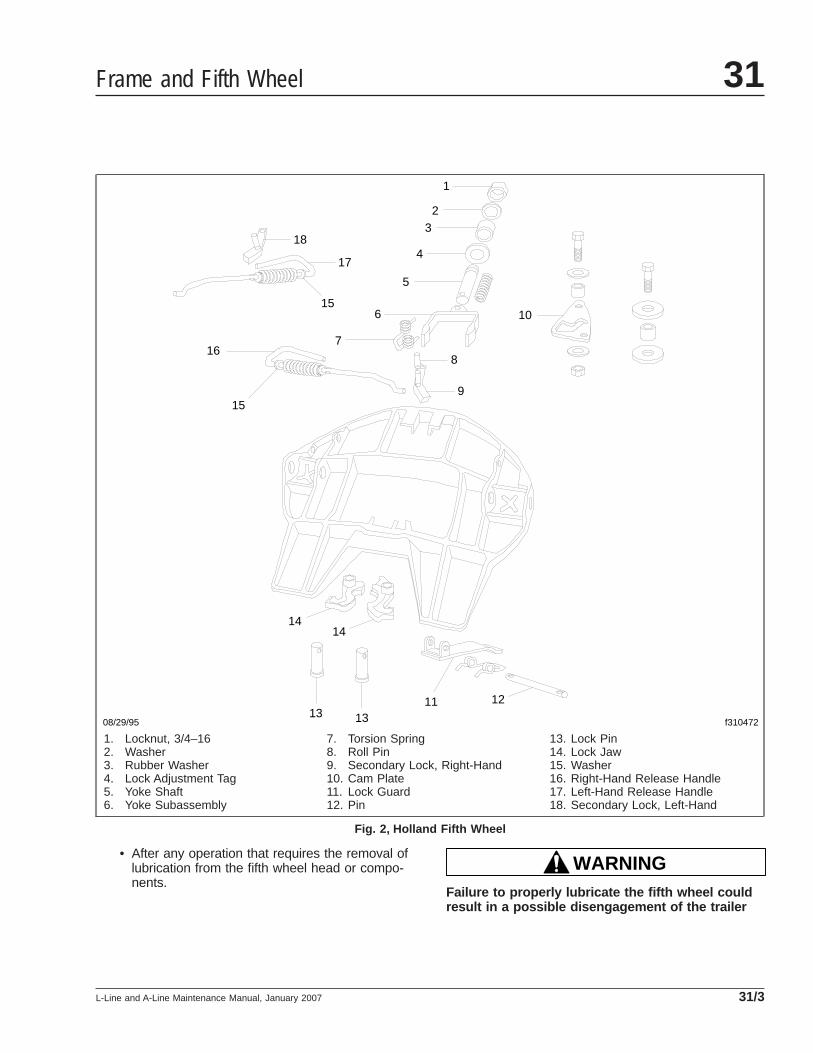
• After any operation that requires the removal oflubrication from the fifth wheel head or compo-nents.
WARNINGFailure to properly lubricate the fifth wheel couldresult in a possible disengagement of the trailer
08/29/95 f310472
121113
1
23
4
5
6 10
8
9
18
17
15
716
15
1414
13
1. Locknut, 3/4–162. Washer3. Rubber Washer4. Lock Adjustment Tag5. Yoke Shaft6. Yoke Subassembly
7. Torsion Spring8. Roll Pin9. Secondary Lock, Right-Hand10. Cam Plate11. Lock Guard12. Pin
13. Lock Pin14. Lock Jaw15. Washer16. Right-Hand Release Handle17. Left-Hand Release Handle18. Secondary Lock, Left-Hand
Fig. 2, Holland Fifth Wheel
Frame and Fifth Wheel 31
L-Line and A-Line Maintenance Manual, January 2007 31/3
from the tractor, which could result in personalinjury or property damage.
FontaineUse a multipurpose extreme pressure (EP) chassisgrease, and lubricate all moving parts on the fifthwheel. When lubricating the top plate at the greasefittings for the bracket bearing area, tilt the top plateforward and backward to evenly distribute thegrease. Using a pry tool, separate the jaw andwedge and lubricate the serrations using a brush todistribute the grease. On slide-mount applications,lubricate the slide rail and tapered wedges forsmooth operation.
Once the moving parts of the fifth wheel are lubri-cated, apply a liberal coating of grease to the topplate and the trailer kingpin plate.
HollandLubricate all moving parts with a multipurpose chas-sis grease. Lubricate the two grease fittings locatedon either side of the top plate with a multipurposechassis grease.
Once the fifth wheel’s moving parts are lubricated,apply a heavy coat of grease to the top plate by di-rect application. On slide-mount applications, lubri-cate the baseplate rails and the plungers for smoothoperation.
31–03 Frame Fastener TorqueChecking
Frame brackets and components secured with Huck-bolt® fasteners do not require a torque check, how-ever, they should be inspected for damage. Framebrackets and components secured with conventionalbolts and nuts are to be checked at Initial Mainte-nance (IM). Check the torque of frame fasteners tooffset the effects of "bedding in" (or seating). Whenchecking torque, torque the nut, not the bolt headwhenever possible. This will give a true torque read-ing by eliminating bolt body friction. When checkingthe torque of frame fasteners, inspect the frame forcracks and other damage. Set a click-type torquewrench to the maximum torque of the fastener youare checking. Apply pressure until the torque wrenchclicks. Do not loosen the bolt to check the torque.
See the applicable torque table in Group 00 fortorque specifications.
CAUTIONMake sure frame fasteners are properly tightened.Continued vehicle operation with loose fastenerscould result in bracket or frame damage.
NOTE: Engine supports on vehicles built fromJanuary 2007 do not require checking.
Inspect and check the fasteners at the followinglocations:
• axle stops
• deck plates
• engine trunnion supports
• equalizer brackets
• exhaust brackets
• fifth wheel legs
• fifth wheel mountings
• frame crossmembers and gussets
• front frame brackets
• front suspension spring brackets
• fuel tank brackets
• radius rods
• rear engine supports
• rear suspension spring brackets
• shock absorbers
• all other frame fasteners
Any component that shows signs of cracking, orother damage must be repaired or replaced. Refer tothe vehicle workshop manual for repair or replace-ment information in the respective section for thecomponent in question.
31–04 Holland Fifth WheelSliding MechanismInspecting
1. Loosen the locking plunger jam nut and turn theadjusting bolt out (counterclockwise). See Fig. 3 .
Frame and Fifth Wheel31
L-Line and A-Line Maintenance Manual, January 200731/4

2. Disengage and engage the locking plungers.Check that the plungers are securely seatedwithout binding. If the locking plungers do notoperate properly, see Group 31 of the L-Lineand A-Line Workshop Manual for adjustment pro-cedures.
3. Turn the adjusting bolt in (clockwise) until it con-tacts the rack. Turn the adjusting bolt an addi-tional 1/2 turn, then securely tighten the lockingnut.
31-05 Trailer ElectricalConnector Lubricating
In some cases, failure of trailer cables occurs due tointrusion of chloride-based road deicing chemicalsinto the trailer connector. Once inside the connector,the chloride-based chemicals corrode the brass ter-minals and create bridging between positive andground terminals.
NOTE: The use of soap is not recommended forcleaning the electrical connector, as somesoaps may increase the corrosion process.
1. Wash out any existing grease, dirt, and corrosionon the trailer connectors with electrical contactcleaner spray.
2. Grease the trailer connector with a lithium-baseddielectric grease.
f310371
1
23
4
11/21/95
1. Rack2. Plunger
3. Pocket4. Plunger Adjusting Bolt
Fig. 3, Locking Plungers
Frame and Fifth Wheel 31
L-Line and A-Line Maintenance Manual, January 2007 31/5

Title of Maintenance Operation (MOP) MOP Number
Suspension Inspecting . . . . . . . . . . . . . . . . . . . . . . . . . . . . . . . . . . . . . . . . . . . . . . . . . . . . . . . . . . . . . . 32–01
Suspension Lubricating. . . . . . . . . . . . . . . . . . . . . . . . . . . . . . . . . . . . . . . . . . . . . . . . . . . . . . . . . . . . . . 32–02
Suspension U-Bolt Torque Checking . . . . . . . . . . . . . . . . . . . . . . . . . . . . . . . . . . . . . . . . . . . . . . . . . . . . 32–03
Suspension 32Index, Alphabetical
L-Line and A-Line Maintenance Manual, April 1999
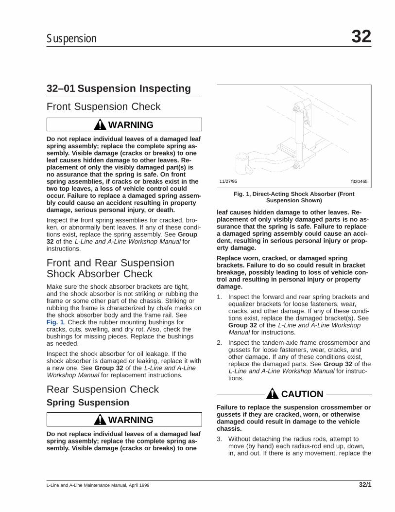
32–01 Suspension Inspecting
Front Suspension Check
WARNINGDo not replace individual leaves of a damaged leafspring assembly; replace the complete spring as-sembly. Visible damage (cracks or breaks) to oneleaf causes hidden damage to other leaves. Re-placement of only the visibly damaged part(s) isno assurance that the spring is safe. On frontspring assemblies, if cracks or breaks exist in thetwo top leaves, a loss of vehicle control couldoccur. Failure to replace a damaged spring assem-bly could cause an accident resulting in propertydamage, serious personal injury, or death.
Inspect the front spring assemblies for cracked, bro-ken, or abnormally bent leaves. If any of these condi-tions exist, replace the spring assembly. See Group32 of the L-Line and A-Line Workshop Manual forinstructions.
Front and Rear SuspensionShock Absorber CheckMake sure the shock absorber brackets are tight,and the shock absorber is not striking or rubbing theframe or some other part of the chassis. Striking orrubbing the frame is characterized by chafe marks onthe shock absorber body and the frame rail. SeeFig. 1 . Check the rubber mounting bushings forcracks, cuts, swelling, and dry rot. Also, check thebushings for missing pieces. Replace the bushingsas needed.
Inspect the shock absorber for oil leakage. If theshock absorber is damaged or leaking, replace it witha new one. See Group 32 of the L-Line and A-LineWorkshop Manual for replacement instructions.
Rear Suspension CheckSpring Suspension
WARNINGDo not replace individual leaves of a damaged leafspring assembly; replace the complete spring as-sembly. Visible damage (cracks or breaks) to one
leaf causes hidden damage to other leaves. Re-placement of only visibly damaged parts is no as-surance that the spring is safe. Failure to replacea damaged spring assembly could cause an acci-dent, resulting in serious personal injury or prop-erty damage.
Replace worn, cracked, or damaged springbrackets. Failure to do so could result in bracketbreakage, possibly leading to loss of vehicle con-trol and resulting in personal injury or propertydamage.
1. Inspect the forward and rear spring brackets andequalizer brackets for loose fasteners, wear,cracks, and other damage. If any of these condi-tions exist, replace the damaged bracket(s). SeeGroup 32 of the L-Line and A-Line WorkshopManual for instructions.
2. Inspect the tandem-axle frame crossmember andgussets for loose fasteners, wear, cracks, andother damage. If any of these conditions exist,replace the damaged parts. See Group 32 of theL-Line and A-Line Workshop Manual for instruc-tions.
CAUTIONFailure to replace the suspension crossmember orgussets if they are cracked, worn, or otherwisedamaged could result in damage to the vehiclechassis.
3. Without detaching the radius rods, attempt tomove (by hand) each radius-rod end up, down,in, and out. If there is any movement, replace the
f32046511/27/95
Fig. 1, Direct-Acting Shock Absorber (FrontSuspension Shown)
Suspension 32
L-Line and A-Line Maintenance Manual, April 1999 32/1

radius rod. If a radius rod needs to be replaced,see Group 32 of the L-Line and A-Line Work-shop Manual for instructions.
4. Inspect the weld seams between the radius rodtube and the shorter bushing tubes. If there arecracks, replace the radius rod. Do not weld theradius rod for any reason.
5. Inspect the rubber bushing ends. See Fig. 2 . Re-place the radius rod for any of the following rea-sons:
• If there are gaps between the rubber bush-ing and the pin or outer steel sleeve.
• If either bushing end contacts a radius rodpin mounting bolt.
• If there are cracks in the bushing.
• If part of the rubber bushing extends be-yond the outer circumference of the outerbushing sleeve.
6. Block up the frame enough to take chassisweight off the springs. Attempt to move theequalizer up and down, using a pry bar betweenthe top of the equalizer and top of the equalizerbracket; apply hand pressure only. See Fig. 3 . Ifmovement at the center of the equalizer exceeds1/8 inch (3 mm), replace the equalizer bushings.See Group 32 of the L-Line and A-Line Work-shop Manual for instructions.
7. With the vehicle unloaded, attempt to move theequalizer side-to-side, using a pry bar betweenthe equalizer and frame rail. Apply hand pressureonly. See Fig. 4 . If clearance between the equal-izer assembly and any frame component or fas-
tener is less than 1/8 inch (3 mm), replace theequalizer bushings. See Group 32 of the L-Lineand A-Line Workshop Manual for instructions.
Hendrickson Spring/Walking BeamSuspension, Models RT, RTE, andRTEA1. Inspect the suspension assembly for loose fas-
teners, wear, cracks, and damage to its compo-nents. Replace the component(s) if any wear,cracks, or damage exist. If any of these condi-
f320021a05/27/93
Fig. 2, Radius Rod Bushings
f320022a05/27/93
1
2
3
A
A. Measure the change in gap at this point.1. Equalizer Bracket2. Equalizer
3. Pry Bar
Fig. 3, Side View of the Equalizer
f320023a05/27/93
1 2
3
4
5
A
A. 1/8 inch (3 mm) Clearance1. Frame Fasteners2. Frame Rail3. Pry Bar
4. Equalizer5. Equalizer Bracket
Fig. 4, Top View of the Equalizer
Suspension32
L-Line and A-Line Maintenance Manual, April 199932/2

tions exist, replace the damaged bracket(s). SeeGroup 32 of the L-Line and A-Line WorkshopManual for instructions.
2. Check for distorted or frayed rubber at the beamend bushings. If the bushings are damaged, re-place them.
3. Check that the ends of the equalizer beam arenot lower in the beam hanger. If the equalizerbeam ends appear lower, use a jack to raiseeach beam end, and check for movement of theinner metal of the rubber end bushing. SeeFig. 5 . Movement cannot be corrected by tight-ening the fastener, because parts could be dam-aged. If there is movement, replace the rubberend bushings and all connecting parts. SeeGroup 32 of the L-Line and A-Line WorkshopManual for instructions.
WARNINGInsufficient beam end fastener torque could causethe beam to separate from the axle. This willcause loss of vehicle control resulting in propertydamage, serious personal injury or death.
4. After repairs to the suspension, check the fas-tener torque after the vehicle has been in servicefor 2500 miles (4000 km). If equipped with theadapter-type beam end connection (see Fig. 6for the three-piece adapter-type beam end con-nection, or Fig. 7 for the two-piece adapter-typebeam end connection), tighten the nut 210 to240 lbf·ft (285 to 325 N·m). If equipped with the
tube-type beam end connection (see Fig. 8 ),tighten the nut 375 to 425 lbf·ft (508 to 576 N·m).Do not overtorque.
f320039a05/27/93
1
2
3
1. Beam Hanger2. Equalizer Beam
3. Jack
Fig. 5, Raising the Hendrickson Suspension Beam End
f320110a05/27/93
1
2
2
3 4
5
NOTE: Do not use the three-piece adapter without theintermediate tube.
1. Nut2. Adapter3. Intermediate Tube
4. Inner Metal of BeamEnd Bushing
5. Beam Hanger
Fig. 6, Three-Piece Adapter-Type Beam End Connection
f320317a
1
2 3
2
4
05/27/93
1. Nut2. Adapter3. Inner Metal of Beam End Bushing4. Beam Hanger
Fig. 7, Two-Piece Adapter-Type Beam End Connection
Suspension 32
L-Line and A-Line Maintenance Manual, April 1999 32/3

5. Without detaching the radius rods, attempt tomove (by hand) each radius-rod end up, down,in, and out. If there is any movement, replace theradius rod. If a radius rod needs to be replaced,see Group 32 of the L-Line and A-Line Work-shop Manual for instructions.
6. Inspect the rubber bushing ends. Replace theradius rod for any of the following reasons:
• If there are gaps between the rubber bush-ing and the pin or outer steel sleeve.
• If either bushing end contacts a radius rodpin mounting bolt.
• If there are cracks in the bushing.
• If part of the rubber bushing extends be-yond the outer circumference of the outerbushing sleeve.
AirLiner Suspension
WARNINGDo not replace individual leaves of a damaged leafspring assembly; replace the complete spring as-sembly. Visible damage (cracks or breaks) to oneleaf causes hidden damage to other leaves. Re-placement of only the visibly damaged part(s) isno assurance that the spring is safe. On frontspring assemblies, if cracks or breaks exist in thetwo top leaves, a loss of vehicle control couldoccur. Failure to replace a damaged spring assem-bly could cause an accident resulting in propertydamage, serious personal injury, or death.
IMPORTANT: Before checking the AirLiner sus-pension height, make sure there is no load onthe chassis, and the trailer is unhitched.
1. Park the vehicle on a level surface, using a lightapplication of the brakes. Do not apply the park-ing brakes. Shift the transmission into neutral,and build the secondary air pressure to at least100 psi (690 kPa). Shut down the engine.
2. Check that the air line support brackets are posi-tioned so the air lines do not rub against any-thing. Reposition any configurations that couldcontact and result in friction or wear. There mustbe at least 1-inch (25-mm) clearance around therubber air spring when inflated. If clearance isless than 1-inch (25-mm), relocate the obstruct-ing parts.
3. Mark the location of the front and rear tires onthe floor, and chock the tires on one axle only.
4. Check the length of the overtravel lever betweenits pivot points. See Fig. 9 , Ref. A.
4.1 If the vehicle is equipped with anadjustable-mount leveling valve, thelength should be 8 inches (203 mm). Ifthe length is incorrect, see Group 32 ofthe L-Line and A-Line Workshop Manualfor adjustment procedures.
4.2 If the vehicle is equipped with a fixed-mount leveling valve, see Group 32 of
f320111a05/27/93
1 1
2
3
1. Nut2. End Tube
3. Beam Hanger
Fig. 8, Tube-Type Beam End Connection
3
4
2
A
05/15/95 f320410
1
5
A. Measure the length of the overtravel lever betweenthese two points.
1. V-Shaped Mark2. Adjustment Locknut3. Overtravel Lever
4. Cotter Pin5. Linkage Rod
Fig. 9, AirLiner Overtravel Lever and Linkage RodMeasurement
Suspension32
L-Line and A-Line Maintenance Manual, April 199932/4
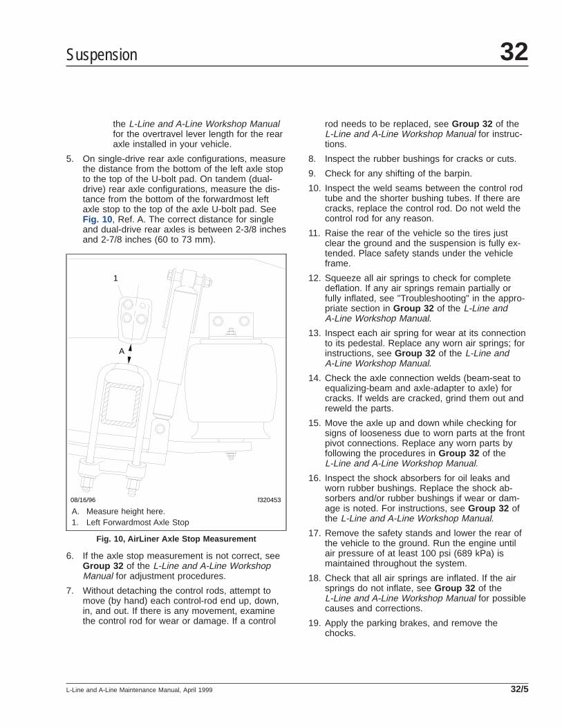
the L-Line and A-Line Workshop Manualfor the overtravel lever length for the rearaxle installed in your vehicle.
5. On single-drive rear axle configurations, measurethe distance from the bottom of the left axle stopto the top of the U-bolt pad. On tandem (dual-drive) rear axle configurations, measure the dis-tance from the bottom of the forwardmost leftaxle stop to the top of the axle U-bolt pad. SeeFig. 10 , Ref. A. The correct distance for singleand dual-drive rear axles is between 2-3/8 inchesand 2-7/8 inches (60 to 73 mm).
6. If the axle stop measurement is not correct, seeGroup 32 of the L-Line and A-Line WorkshopManual for adjustment procedures.
7. Without detaching the control rods, attempt tomove (by hand) each control-rod end up, down,in, and out. If there is any movement, examinethe control rod for wear or damage. If a control
rod needs to be replaced, see Group 32 of theL-Line and A-Line Workshop Manual for instruc-tions.
8. Inspect the rubber bushings for cracks or cuts.
9. Check for any shifting of the barpin.
10. Inspect the weld seams between the control rodtube and the shorter bushing tubes. If there arecracks, replace the control rod. Do not weld thecontrol rod for any reason.
11. Raise the rear of the vehicle so the tires justclear the ground and the suspension is fully ex-tended. Place safety stands under the vehicleframe.
12. Squeeze all air springs to check for completedeflation. If any air springs remain partially orfully inflated, see "Troubleshooting" in the appro-priate section in Group 32 of the L-Line andA-Line Workshop Manual.
13. Inspect each air spring for wear at its connectionto its pedestal. Replace any worn air springs; forinstructions, see Group 32 of the L-Line andA-Line Workshop Manual.
14. Check the axle connection welds (beam-seat toequalizing-beam and axle-adapter to axle) forcracks. If welds are cracked, grind them out andreweld the parts.
15. Move the axle up and down while checking forsigns of looseness due to worn parts at the frontpivot connections. Replace any worn parts byfollowing the procedures in Group 32 of theL-Line and A-Line Workshop Manual.
16. Inspect the shock absorbers for oil leaks andworn rubber bushings. Replace the shock ab-sorbers and/or rubber bushings if wear or dam-age is noted. For instructions, see Group 32 ofthe L-Line and A-Line Workshop Manual.
17. Remove the safety stands and lower the rear ofthe vehicle to the ground. Run the engine untilair pressure of at least 100 psi (689 kPa) ismaintained throughout the system.
18. Check that all air springs are inflated. If the airsprings do not inflate, see Group 32 of theL-Line and A-Line Workshop Manual for possiblecauses and corrections.
19. Apply the parking brakes, and remove thechocks.
08/16/96 f320453
A
1
A. Measure height here.1. Left Forwardmost Axle Stop
Fig. 10, AirLiner Axle Stop Measurement
Suspension 32
L-Line and A-Line Maintenance Manual, April 1999 32/5

Reyco Suspension, 79KB and 179Park the vehicle on level ground and chock the fronttires to prevent the vehicle from moving. Place thetransmission in neutral, and release the parkingbrakes.
1. Check that the torque rod clamps are directedaway from the spring to prevent possible interfer-ence during operation. See Fig. 11 for a Reyco79KB, or Fig. 12 for a Reyco 179.
2. Check the fit of springs to hangers to ensuregood ride characteristics.
3. Check for elongated holes in the suspensioncomponents. See Group 32 of the L-Line andA-Line Workshop Manual for proper repair proce-dures.
4. Check bushing condition. Replace any bushingthat is worn, cracked, dry-rotted, or otherwisedamaged. See Group 32 of the L-Line andA-Line Workshop Manual for bushing removaland installation instructions.
5. Check tire condition. If abnormal wear is found,check and replace all worn or damaged compo-nents, and check suspension alignment. SeeGroup 32 of the L-Line and A-Line WorkshopManual for component removal and installationprocedures, and for suspension alignmentinstructions.
6. Inspect all suspension fasteners for propertorque values. See Group 00 of this manual forproper bolt torque specifications.
Chalmers Walking BeamSuspension, 800 SeriesChock the front tires to prevent the vehicle from mov-ing. Place the transmission in neutral, and releasethe parking brakes before inspecting the Chalmersrear suspension.
Power wash the Chalmers rear suspension, or cleanit with a hard-bristle brush before performing a visualinspection.
1. Visually inspect the rubber bushings for cracks orother damage.
Try to move the torque rod ends using yourhands only, and check for any free-play. If free-play is felt, replace the torque rod end bushing.Do not use a pry bar to check for free-play. Use
of a pry bar may lead to premature bushing re-placement.
2. Lift the rear of the vehicle and support the frameon jack stands to unload the suspension compo-nents. The vehicle is lifted high enough when thebeam ends are off of the saddles. All jack standsmust be of sufficient strength and rigidity tosafely support the vehicle. Do not perform anywork on or around a vehicle that is supportedsolely by a lifting device.
Visually inspect the walking beam for cracks orother damage. If damage is found, replace thewalking beam.
Keep the vehicle supported by the jack standsfor the next operation.
3. Manipulate the walking beam so that a microme-ter, vernier, or dial caliper may be used to deter-mine the wear area thickness on the bottomface. See Fig. 13 . Measurements should betaken a minimum of 1/2 inch (13 mm) from thebeam flange edges to eliminate any edge wearthat may have occurred. Subtract the wear areathickness (Fig. 13 , Ref. B) from the thickness atthe non-wear area (Fig. 13 , Ref. A) to determinethe amount of wear.
If the beams show any wear greater than 0.062inch (1.5 mm), a Chalmers wear plate must beinstalled, or the walking beam must be replaced.
4. Rotate the restrictor cans 360 degrees and visu-ally inspect the cans for cracks, severe corro-sion, and distortion. If any of these conditions arepresent, or the restrictor can is missing, replacethe restrictor can.
WARNINGReplace all cracked or missing restrictor cans.Failure to do so could lead to loss of vehicle con-trol, which could result in property damage, seri-ous personal injury, or death. Vehicles withcracked or missing restrictor cans may be drivenslowly to the nearest workshop for restrictor canreplacement.
Hendrickson Walking BeamSuspension, RS Series1. Inspect the frame-hanger-to-frame attaching fas-
teners for the proper torque. See Group 00 ofthis manual for torque specifications.
Suspension32
L-Line and A-Line Maintenance Manual, April 199932/6

WARNINGBe sure that fasteners are torqued correctly. Fas-teners that do not provide a tightly clamped jointbetween the frame and the hanger can cause pre-mature fracture of the frame hanger, separation ofcomponents, loss of vehicle control, and possiblepersonal injury or property damage.
01/04/96 f320488
12
1
1. Torque Rod Clamp 2. Torque Rod
Fig. 11, Reyco 79KB Torque Rod Clamp Position
01/16/96 f320503
1
12
1. Torque Rod Clamp 2. Torque Rod
Fig. 12, Reyco 179 Torque Rod Clamp Position
09/27/95 f320432
1
A
B
A. Non-Wear Area B. Wear Area1. Walking Beam
Fig. 13, Walking Beam End Wear Thickness
Suspension 32
L-Line and A-Line Maintenance Manual, April 1999 32/7

2. Visually inspect each frame hanger for any evi-dence of cracks in the vertical mounting flange.See Fig. 14 .
3. Visually inspect each frame hanger for evidenceof cracks in the horizontal mounting flange adja-cent to the vertical drive pin area. See Fig. 15 .
4. Visually inspect each frame hanger for severerust on the horizontal mounting flange adjacentto the vertical drive pin area. See Fig. 16 .
5. Inspect the load cushions for cuts and swelling.See Fig. 17 . Cushions cut by the retaining lips ofthe saddles or frame hangers indicate the cush-ions may not be the correct hardness or configu-ration for the vehicle operation.
6. Inspect the lower side of the vertical drive bush-ings for evidence of torn or shredded rubber.Check that the concave washers are installedwith the lips pointing downward.
7. Inspect the saddles and saddle cap fasteners forwear. The allowable thrust washer wear in alumi-num saddles is up to 3/16 inch (4.8 mm) into thesaddles as measured at the top of the thrustwasher diameter. Check that the locknuts aretorqued to specification to prevent wear of thebeam center bushings into the legs of the
saddles. See Group 00 of this manual for torquespecifications.
Hendrickson Suspension, RT2 andRTE2 Series1. Park the vehicle on a level surface, apply the
parking brakes, and chock the front tires.
Raise the rear of the vehicle until the rear wheelsare suspended in the air, then support the ve-hicle with safety stands.
2. Check the torque of the number-one springhanger (double-lock-bolt design) lock bolt nuts. Ifa loose connection has caused pin hole wear,replace the hanger.
3. Inspect the pin hole in the outboard leg of thenumber one spring hanger (draw-key design) forwear or elongation.
WARNINGWear at this point requires hanger replacement, orpremature fracture of the spring hanger pin mayoccur, with possible separation of components
09/15/95 f320419
1
2
1. Frame Rail2. Crack In Inspection Area
Fig. 14, Hendrickson RS Series Vertical MountingFlange
09/15/95 f320420
1
1. Crack In Inspection Area
Fig. 15, Hendrickson RS Series Horizontal MountingFlange
Suspension32
L-Line and A-Line Maintenance Manual, April 199932/8
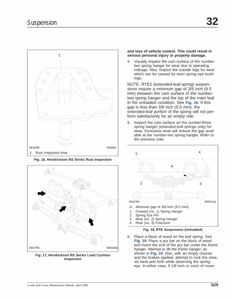
and loss of vehicle control. This could result inserious personal injury or property damage.
4. Visually inspect the cam surface of the number-two spring hanger for wear due to operatingmileage. Also, inspect the outside legs for wearwhich can be caused by worn spring eye bush-ings.
NOTE: RTE2 (extended-leaf-spring) suspen-sions require a minimum gap of 3/8 inch (9.5mm) between the cam surface of the number-two spring hanger and the top of the main leafin the unloaded condition. See Fig. 18 . If thisgap is less than 3/8 inch (9.5 mm), theextended-leaf portion of the spring will not per-form satisfactorily for an empty ride.
5. Inspect the cam surface on the number-threespring hanger (extended-leaf-springs only) forwear. Excessive wear will reduce the gap avail-able at the number-two spring hanger. Refer tothe previous note.
6. Place a block of wood on the leaf spring. SeeFig. 19 . Place a pry bar on the block of woodand insert the end of the pry bar under the framehanger. Attempt to lift the frame hanger, asshown in Fig. 19 . Also, with an empty chassisand the brakes applied, attempt to rock the chas-sis back and forth while observing the springeye. In either case, if 1/8 inch or more of move-
09/15/95 f320421
1
1. Rust Inspection Area
Fig. 16, Hendrickson RS Series Rust Inspection
f320318a05/27/93
Fig. 17, Hendrickson RS Series Load CushionInspection
f320112a05/27/93
1
2 3
4
A
A. Minimum gap of 3/8 inch (9.5 mm).1. Forward (no. 1) Spring Hanger2. Spring Eye Pin3. Rear (no. 2) Spring Hanger4. Rear (no. 3) Extension
Fig. 18, RTE Suspension (Unloaded)
Suspension 32
L-Line and A-Line Maintenance Manual, April 1999 32/9
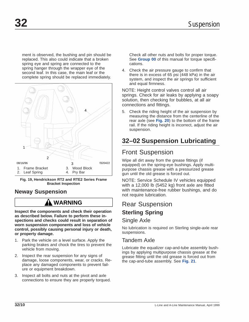
ment is observed, the bushing and pin should bereplaced. This also could indicate that a brokenspring eye and spring are connected to thespring hanger through the wrapper eye of thesecond leaf. In this case, the main leaf or thecomplete spring should be replaced immediately.
Neway Suspension
WARNINGInspect the components and check their operationas described below. Failure to perform these in-spections and checks could result in separation ofworn suspension components and loss of vehiclecontrol, possibly causing personal injury or death,or property damage.
1. Park the vehicle on a level surface. Apply theparking brakes and chock the tires to prevent thevehicle from moving.
2. Inspect the rear suspension for any signs ofdamage, loose components, wear, or cracks. Re-place any damaged components to prevent fail-ure or equipment breakdown.
3. Inspect all bolts and nuts at the pivot and axleconnections to ensure they are properly torqued.
Check all other nuts and bolts for proper torque.See Group 00 of this manual for torque specifi-cations.
4. Check the air pressure gauge to confirm thatthere is in excess of 65 psi (448 kPa) in the airsystem, and inspect the air springs for sufficientand equal firmness.
NOTE: Height control valves control all airsprings. Check for air leaks by applying a soapysolution, then checking for bubbles, at all airconnections and fittings.
5. Check the riding height of the air suspension bymeasuring the distance from the centerline of therear axle (see Fig. 20 ) to the bottom of the framerail. If the riding height is incorrect, adjust the airsuspension.
32–02 Suspension Lubricating
Front SuspensionWipe all dirt away from the grease fittings (ifequipped) on the spring-eye bushings. Apply multi-purpose chassis grease with a pressurized greasegun until the old grease is forced out.
NOTE: Service Schedule IV vehicles equippedwith a 12,000 lb (5452 kg) front axle are fittedwith maintenance-free rubber bushings, and donot require lubrication.
Rear SuspensionSterling SpringSingle AxleNo lubrication is required on Sterling single-axle rearsuspensions.
Tandem AxleLubricate the equalizer cap-and-tube assembly bush-ings by applying multipurpose chassis grease at thegrease fitting until the old grease is forced out fromthe cap-and-tube assembly. See Fig. 21 .
1
2
3
4
f32042208/16/96
1. Frame Bracket2. Leaf Spring
3. Wood Block4. Pry Bar
Fig. 19, Hendrickson RT2 and RTE2 Series FrameBracket Inspection
Suspension32
L-Line and A-Line Maintenance Manual, April 199932/10
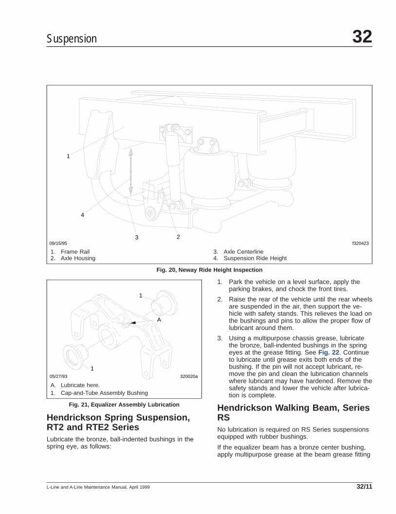
Hendrickson Spring Suspension,RT2 and RTE2 SeriesLubricate the bronze, ball-indented bushings in thespring eye, as follows:
1. Park the vehicle on a level surface, apply theparking brakes, and chock the front tires.
2. Raise the rear of the vehicle until the rear wheelsare suspended in the air, then support the ve-hicle with safety stands. This relieves the load onthe bushings and pins to allow the proper flow oflubricant around them.
3. Using a multipurpose chassis grease, lubricatethe bronze, ball-indented bushings in the springeyes at the grease fitting. See Fig. 22 . Continueto lubricate until grease exits both ends of thebushing. If the pin will not accept lubricant, re-move the pin and clean the lubrication channelswhere lubricant may have hardened. Remove thesafety stands and lower the vehicle after lubrica-tion is complete.
Hendrickson Walking Beam, SeriesRSNo lubrication is required on RS Series suspensionsequipped with rubber bushings.
If the equalizer beam has a bronze center bushing,apply multipurpose grease at the beam grease fitting
09/15/95 f320423
1
4
3 2
1. Frame Rail2. Axle Housing
3. Axle Centerline4. Suspension Ride Height
Fig. 20, Neway Ride Height Inspection
320020a05/27/93
1
1
A
A. Lubricate here.1. Cap-and-Tube Assembly Bushing
Fig. 21, Equalizer Assembly Lubrication
Suspension 32
L-Line and A-Line Maintenance Manual, April 1999 32/11
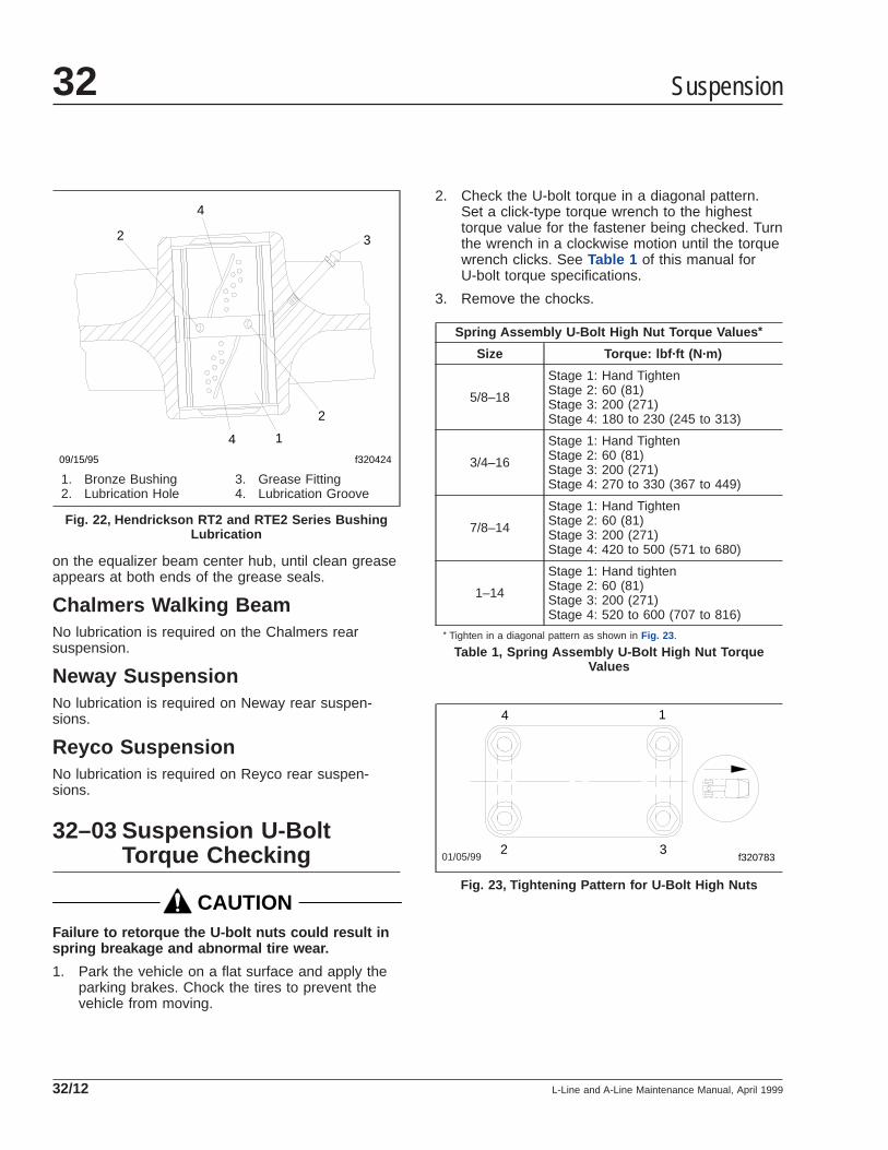
on the equalizer beam center hub, until clean greaseappears at both ends of the grease seals.
Chalmers Walking BeamNo lubrication is required on the Chalmers rearsuspension.
Neway SuspensionNo lubrication is required on Neway rear suspen-sions.
Reyco SuspensionNo lubrication is required on Reyco rear suspen-sions.
32–03 Suspension U-BoltTorque Checking
CAUTIONFailure to retorque the U-bolt nuts could result inspring breakage and abnormal tire wear.
1. Park the vehicle on a flat surface and apply theparking brakes. Chock the tires to prevent thevehicle from moving.
2. Check the U-bolt torque in a diagonal pattern.Set a click-type torque wrench to the highesttorque value for the fastener being checked. Turnthe wrench in a clockwise motion until the torquewrench clicks. See Table 1 of this manual forU-bolt torque specifications.
3. Remove the chocks.
Spring Assembly U-Bolt High Nut Torque Values *
Size Torque: lbf·ft (N·m)
5/8–18
Stage 1: Hand TightenStage 2: 60 (81)Stage 3: 200 (271)Stage 4: 180 to 230 (245 to 313)
3/4–16
Stage 1: Hand TightenStage 2: 60 (81)Stage 3: 200 (271)Stage 4: 270 to 330 (367 to 449)
7/8–14
Stage 1: Hand TightenStage 2: 60 (81)Stage 3: 200 (271)Stage 4: 420 to 500 (571 to 680)
1–14
Stage 1: Hand tightenStage 2: 60 (81)Stage 3: 200 (271)Stage 4: 520 to 600 (707 to 816)
* Tighten in a diagonal pattern as shown in Fig. 23 .
Table 1, Spring Assembly U-Bolt High Nut TorqueValues
09/15/95 f320424
1
2
2 3
4
4
1. Bronze Bushing2. Lubrication Hole
3. Grease Fitting4. Lubrication Groove
Fig. 22, Hendrickson RT2 and RTE2 Series BushingLubrication
01/05/99 f320783
1
2 3
4
Fig. 23, Tightening Pattern for U-Bolt High Nuts
Suspension32
L-Line and A-Line Maintenance Manual, April 199932/12
Title of Maintenance Operation (MOP) MOP Number
All-Axle Alignment Checking . . . . . . . . . . . . . . . . . . . . . . . . . . . . . . . . . . . . . . . . . . . . . . . . . . . . . . . . . . 33–03
Knuckle Pin Lubricating . . . . . . . . . . . . . . . . . . . . . . . . . . . . . . . . . . . . . . . . . . . . . . . . . . . . . . . . . . . . . 33–01
Tie Rod End Inspecting and Lubricating . . . . . . . . . . . . . . . . . . . . . . . . . . . . . . . . . . . . . . . . . . . . . . . . . 33–02
Front Axle 33Index, Alphabetical
L-Line and A-Line Maintenance Manual, June 2001
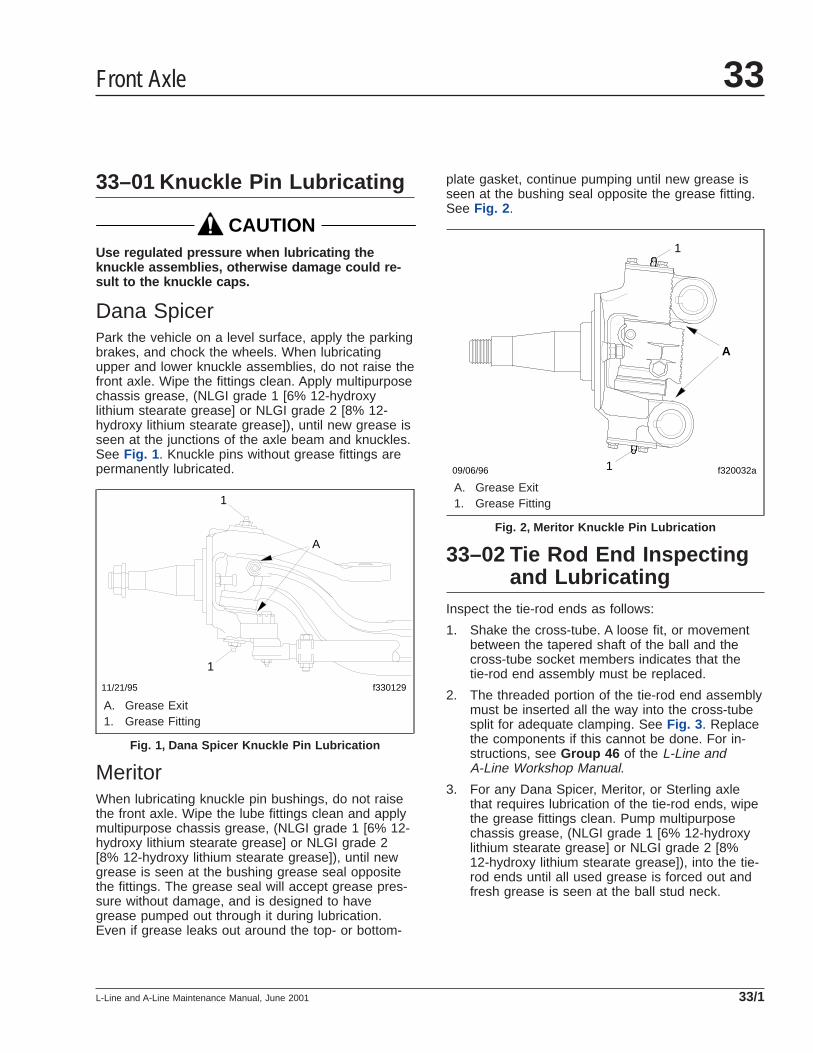
33–01 Knuckle Pin Lubricating
CAUTIONUse regulated pressure when lubricating theknuckle assemblies, otherwise damage could re-sult to the knuckle caps.
Dana SpicerPark the vehicle on a level surface, apply the parkingbrakes, and chock the wheels. When lubricatingupper and lower knuckle assemblies, do not raise thefront axle. Wipe the fittings clean. Apply multipurposechassis grease, (NLGI grade 1 [6% 12-hydroxylithium stearate grease] or NLGI grade 2 [8% 12-hydroxy lithium stearate grease]), until new grease isseen at the junctions of the axle beam and knuckles.See Fig. 1 . Knuckle pins without grease fittings arepermanently lubricated.
MeritorWhen lubricating knuckle pin bushings, do not raisethe front axle. Wipe the lube fittings clean and applymultipurpose chassis grease, (NLGI grade 1 [6% 12-hydroxy lithium stearate grease] or NLGI grade 2[8% 12-hydroxy lithium stearate grease]), until newgrease is seen at the bushing grease seal oppositethe fittings. The grease seal will accept grease pres-sure without damage, and is designed to havegrease pumped out through it during lubrication.Even if grease leaks out around the top- or bottom-
plate gasket, continue pumping until new grease isseen at the bushing seal opposite the grease fitting.See Fig. 2 .
33–02 Tie Rod End Inspectingand Lubricating
Inspect the tie-rod ends as follows:
1. Shake the cross-tube. A loose fit, or movementbetween the tapered shaft of the ball and thecross-tube socket members indicates that thetie-rod end assembly must be replaced.
2. The threaded portion of the tie-rod end assemblymust be inserted all the way into the cross-tubesplit for adequate clamping. See Fig. 3 . Replacethe components if this cannot be done. For in-structions, see Group 46 of the L-Line andA-Line Workshop Manual.
3. For any Dana Spicer, Meritor, or Sterling axlethat requires lubrication of the tie-rod ends, wipethe grease fittings clean. Pump multipurposechassis grease, (NLGI grade 1 [6% 12-hydroxylithium stearate grease] or NLGI grade 2 [8%12-hydroxy lithium stearate grease]), into the tie-rod ends until all used grease is forced out andfresh grease is seen at the ball stud neck.
11/21/95 f330129
1
1
A
A. Grease Exit1. Grease Fitting
Fig. 1, Dana Spicer Knuckle Pin Lubrication
09/06/96 f320032a
A
1
1
A. Grease Exit1. Grease Fitting
Fig. 2, Meritor Knuckle Pin Lubrication
Front Axle 33
L-Line and A-Line Maintenance Manual, June 2001 33/1
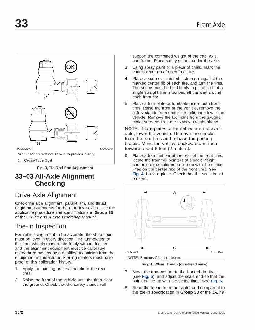
33–03 All-Axle AlignmentChecking
Drive Axle AlignmentCheck the axle alignment, parallelism, and thrustangle measurements for the rear drive axles. Use theapplicable procedure and specifications in Group 35of the L-Line and A-Line Workshop Manual.
Toe-In InspectionFor vehicle alignment to be accurate, the shop floormust be level in every direction. The turn-plates forthe front wheels must rotate freely without friction,and the alignment equipment must be calibratedevery three months by a qualified technician from theequipment manufacturer. Sterling dealers must haveproof of this calibration history.
1. Apply the parking brakes and chock the reartires.
2. Raise the front of the vehicle until the tires clearthe ground. Check that the safety stands will
support the combined weight of the cab, axle,and frame. Place safety stands under the axle.
3. Using spray paint or a piece of chalk, mark theentire center rib of each front tire.
4. Place a scribe or pointed instrument against themarked center rib of each tire, and turn the tires.The scribe must be held firmly in place so that asingle straight line is scribed all the way aroundeach front tire.
5. Place a turn-plate or turntable under both fronttires. Raise the front of the vehicle, remove thesafety stands from under the axle, then lower thevehicle. Remove the lock-pins from the gauges;make sure the tires are exactly straight ahead.
NOTE: If turn-plates or turntables are not avail-able, lower the vehicle. Remove the chocksfrom the rear tires and release the parkingbrakes. Move the vehicle backward and thenforward about 6 feet (2 meters).
6. Place a trammel bar at the rear of the front tires;locate the trammel pointers at spindle height,and adjust the pointers to line up with the scribelines on the center ribs of the front tires. SeeFig. 4 . Lock in place. Check that the scale is seton zero.
7. Move the trammel bar to the front of the tires(see Fig. 5 ), and adjust the scale end so that thepointers line up with the scribe lines. See Fig. 6 .
8. Read the toe-in from the scale, and compare it tothe toe-in specification in Group 33 of the L-Line
f320033a
1
OK
OK
02/27/2007
NOTE: Pinch bolt not shown to provide clarity.
1. Cross-Tube Split
Fig. 3, Tie-Rod End Adjustment
A
Bf330082a08/29/94
NOTE: B minus A equals toe-in.
Fig. 4, Wheel Toe-In (overhead view)
Front Axle33
L-Line and A-Line Maintenance Manual, June 200133/2

and A-Line Workshop Manual. If corrections areneeded, see Group 33 of the L-Line and A-LineWorkshop Manual for instructions on adjustingthe toe-in.
f330014a08/30/94
Fig. 5, Trammel Bar Positioning
f400100a08/30/94
Fig. 6, Setting the Trammel Bar Pointers
Front Axle 33
L-Line and A-Line Maintenance Manual, June 2001 33/3
Title of Maintenance Operation (MOP) MOP Number
Axle Breather and Lubricant Level Checking . . . . . . . . . . . . . . . . . . . . . . . . . . . . . . . . . . . . . . . . . . . . . . 35–01
Axle Lubricant Changing, Oil Filter Replacing and Magnetic Strainer Cleaning . . . . . . . . . . . . . . . . . . . . . 35–02
Rear Axle 35Index, Alphabetical
L-Line and A-Line Maintenance Manual, August 2003
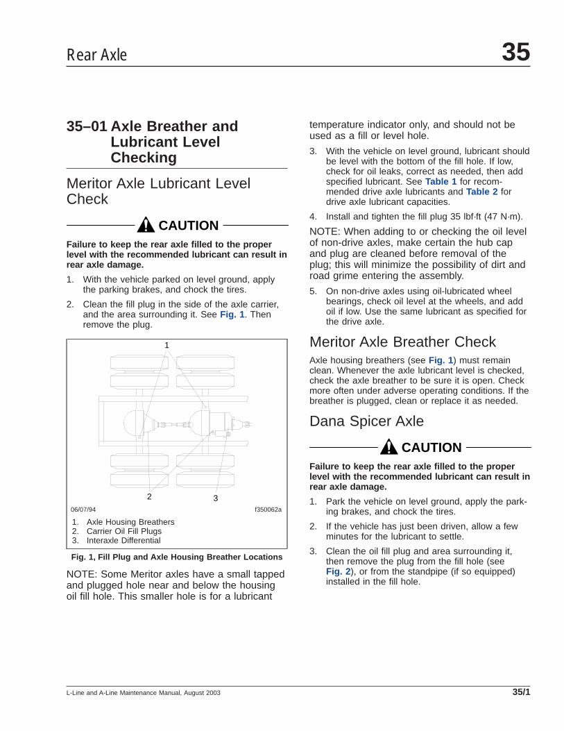
35–01 Axle Breather andLubricant LevelChecking
Meritor Axle Lubricant LevelCheck
CAUTIONFailure to keep the rear axle filled to the properlevel with the recommended lubricant can result inrear axle damage.
1. With the vehicle parked on level ground, applythe parking brakes, and chock the tires.
2. Clean the fill plug in the side of the axle carrier,and the area surrounding it. See Fig. 1 . Thenremove the plug.
NOTE: Some Meritor axles have a small tappedand plugged hole near and below the housingoil fill hole. This smaller hole is for a lubricant
temperature indicator only, and should not beused as a fill or level hole.
3. With the vehicle on level ground, lubricant shouldbe level with the bottom of the fill hole. If low,check for oil leaks, correct as needed, then addspecified lubricant. See Table 1 for recom-mended drive axle lubricants and Table 2 fordrive axle lubricant capacities.
4. Install and tighten the fill plug 35 lbf·ft (47 N·m).
NOTE: When adding to or checking the oil levelof non-drive axles, make certain the hub capand plug are cleaned before removal of theplug; this will minimize the possibility of dirt androad grime entering the assembly.
5. On non-drive axles using oil-lubricated wheelbearings, check oil level at the wheels, and addoil if low. Use the same lubricant as specified forthe drive axle.
Meritor Axle Breather CheckAxle housing breathers (see Fig. 1 ) must remainclean. Whenever the axle lubricant level is checked,check the axle breather to be sure it is open. Checkmore often under adverse operating conditions. If thebreather is plugged, clean or replace it as needed.
Dana Spicer Axle
CAUTIONFailure to keep the rear axle filled to the properlevel with the recommended lubricant can result inrear axle damage.
1. Park the vehicle on level ground, apply the park-ing brakes, and chock the tires.
2. If the vehicle has just been driven, allow a fewminutes for the lubricant to settle.
3. Clean the oil fill plug and area surrounding it,then remove the plug from the fill hole (seeFig. 2 ), or from the standpipe (if so equipped)installed in the fill hole.
06/07/94 f350062a
1
2 3
1. Axle Housing Breathers2. Carrier Oil Fill Plugs3. Interaxle Differential
Fig. 1, Fill Plug and Axle Housing Breather Locations
Rear Axle 35
L-Line and A-Line Maintenance Manual, August 2003 35/1
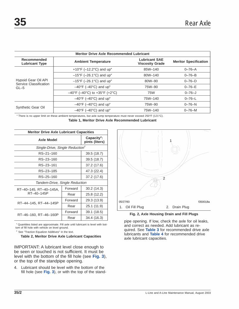
Meritor Drive Axle Recommended Lubricant
RecommendedLubricant Type Ambient Temperature Lubricant SAE
Viscosity Grade Meritor Specification
Hypoid Gear Oil APIService ClassificationGL–5
+10°F (–12.2°C) and up* 85W–140 0–76–A
–15°F (–26.1°C) and up* 80W–140 0–76–B
–15°F (–26.1°C) and up* 80W–90 0–76–D
–40°F (–40°C) and up* 75W–90 0–76–E
–40°F (–40°C) to +35°F (+2°C) 75W 0–76–J
–40°F (–40°C) and up* 75W–140 0–76–L
Synthetic Gear Oil–40°F (–40°C) and up* 75W–90 0–76–N
–40°F (–40°C) and up* 75W–140 0–76–M* There is no upper limit on these ambient temperatures, but axle sump temperature must never exceed 250°F (121°C).
Table 1, Meritor Drive Axle Recommended Lubricant
Meritor Drive Axle Lubricant Capacities
Axle Model Capacity *:pints (liters)
Single-Drive, Single Reduction†
RS–21–160 39.5 (18.7)
RS–23–160 39.5 (18.7)
RS–23–161 37.2 (17.6)
RS–23–185 47.3 (22.4)
RS–25–160 37.2 (17.6)
Tandem-Drive, Single Reduction
RT–40–145, RT–40–145A,RT–40–145P
Forward 30.2 (14.3)
Rear 25.8 (12.2)
RT–44–145, RT–44–145PForward 29.3 (13.9)
Rear 25.1 (11.9)
RT–46–160, RT–46–160PForward 39.1 (18.5)
Rear 34.4 (16.3)
* Quantities listed are approximate. Fill axle until lubricant is level with bot-tom of fill hole with vehicle on level ground.† See "Traction Equalizer Additives" in the text.
Table 2, Meritor Drive Axle Lubricant Capacities
IMPORTANT: A lubricant level close enough tobe seen or touched is not sufficient. It must belevel with the bottom of the fill hole (see Fig. 3 ),or the top of the standpipe opening.
4. Lubricant should be level with the bottom of thefill hole (see Fig. 3 ), or with the top of the stand-
pipe opening. If low, check the axle for oil leaks,and correct as needed. Add lubricant as re-quired. See Table 3 for recommended drive axlelubricants and Table 4 for recommended driveaxle lubricant capacities.
f350018a05/27/93
1
2
1. Oil Fill Plug 2. Drain Plug
Fig. 2, Axle Housing Drain and Fill Plugs
Rear Axle35
L-Line and A-Line Maintenance Manual, August 200335/2

Dana Spicer Drive Axle Recommended Lubricant
Lubricant Type ConditionLubricant SAE
ViscosityGrade
Eaton® Roadranger®
Synthetic Drive AxleLubricants, orEquivalent withMilitary SpecificationMIL–L–2105D
Over-the-RoadService 75W–90
Off-HighwayEquipment, orUnder ExtraHeavy Loads
80W–140
Table 3, Dana Spicer Drive Axle RecommendedLubricant
Dana Spicer Drive Axle Lubricant Capacities
Axle Type Axle Model Capacity *:pints (liters)
Single-Drive-Axle Installation
SingleReduction
23080S, 23080D 40 (18.9)
23105S, 23105D 48 (22.7)
Dual-Drive-Axle Installation
SingleReduction
DD404, DD404–P 31 (14.7)†
DS404, DS404–P 39 (18.5)†
DS461–P 43 (20.3)†
Dual Range(2-Speed)
DT402, 402–P 34 (16.1)†
DT451–P 39 (18.5)†
DT461–P 43 (20.3)†
Dana Spicer Drive Axle Lubricant Capacities
Axle Type Axle Model Capacity *:pints (liters)
DoubleReduction
DP451–P 34 (16.1)†
DP461–P 43 (20.3)†
* Quantities listed are approximate. Fill axle until lubricant is level with bot-tom of fill hole with vehicle on level ground.† Add 2 pints (1 L) of additional lubricant to the power divider.
Table 4, Dana Spicer Drive Axle Lubricant Capacities
IMPORTANT: Axle housing breathers (seeFig. 4 ) must remain clean and unclogged. Al-ways check the axle breather whenever check-ing lubricant level. Ensure that it is open andunclogged. Check the breather more frequentlyunder adverse operating conditions. If thebreather is plugged or damaged, clean or re-place it as needed.
5. Install and tighten the fill plug 40 to 60 lbf·ft (54to 81 N·m).
6. For a two-speed axle with a shift unit, check thelubricant level of the shift unit; see elsewhere inthis maintenance operation for the shift unit lubri-cant level inspection procedure.
7. Remove the chocks from the tires.
f350061a
A
B
06/07/94
A. Correct (lube level at bottom of fill hole)B. Incorrect (lub level below fill hole)
Fig. 3, Axle Lubricant Level Inspection
f350002a
1
2 3
06/07/94
1. Axle Housing Breather2. Fill Plug3. Temperature Indicator Plug
Fig. 4, Dana Spicer Axle Housing Breather
Rear Axle 35
L-Line and A-Line Maintenance Manual, August 2003 35/3
35–02 Axle LubricantChanging, Oil FilterReplacing and MagneticStrainer Cleaning
Meritor Axle Lubricant Changeand Oil Filter ReplacementAxle Lubricant Change-IntervalInformationA regular schedule for changing axle lubricant in aparticular vehicle and operation can be accuratelydetermined by analysis of oil samples taken from theassembly at specific intervals or mileages. The finalschedule recommended may, for economic reasons,be correlated with lubricant changes governed byclimatic conditions and magnetic plug maintenance.Lubricant changes should be made as climatic tem-peratures demand, regardless of vehicle mileage orestablished change schedule.
Normal operating temperature of compounded lubri-cants during the summer season is approximately160° to 220°F (71° to 104°C). Chemicals and addi-tives that give these lubricants increased load-carrying capacity, oxidize faster at temperaturesabove 220°F (104°C), contributing to more rapid lu-bricant deterioration. For this reason, lubricants ofthis type, that operate continuously at high tempera-tures, must be changed more frequently to realizethe inherent advantages they offer.
CAUTIONFailure to change the axle lubricant at more fre-quent intervals, when adverse operating condi-tions require, could result in axle damage.
Traction Equalizer AdditivesSingle drive axles equipped with traction equalizersmay require a "limited-slip friction modifier" to correcta slip-stick condition. Meritor’s experience shows thatthe following additives (friction modifiers) performadequately:
A. For all GL–5 gear oils (mineral oil or synthetic)other than Mobil, add any of the following (1.6ounces [35 mL] of additive for each pint [0.5 L] oflube capacity):
• Elco No. 2 Friction Modifier (Elco Corpora-tion)
• Lubrizol No. 6178 (Lubrizol Corporation)
• Hi–Tec E–336 (Edwin Cooper, Inc.)
• Equa–Torque No. 2411 (Sta-Lube Corpora-tion)
• Equa–Torque No. 2414 (Sta-Lube Corpora-tion)
B. For Mobilube HD (mineral oil) and Mobilube SHC(synthetic) use Mobil No. 204 (Mobil Oil Corpora-tion). Add 1.1 ounces [23 mL] of additive foreach pint [0.5 L] of lube capacity.
IMPORTANT: These friction modifiers generallydeteriorate faster than conventional extreme-pressure additives, so the lubricant changeschedule must be shortened when using theseadditives. The traction equalizer additive (andrecommended drive axle lubricant) must bechanged at the Maintenance 2 (M2) interval,instead of the Maintenance 3 (M3) interval asrecommended in the "Maintenance OperationSets Table," (see Group 00 in this manual), foraxles that require only those lubricants recom-mended in Table 1 .
Axle Lubricant and Oil FilterReplacement Procedure1. With the vehicle parked on level ground, apply
the parking brakes, and chock the tires.
2. Remove the axle carrier fill plug (see Fig. 1 ),then remove the drain plug at the bottom of thehousing and completely drain the lubricant whilethe unit is warm. Allow sufficient time for all oldlubricant to drain. On tandem drive axles, it isalso necessary to remove the plug at the bottomof the interaxle differential housing to drain thelubricant.
3. If so equipped, replace the axle oil filter.
IMPORTANT: When the drive unit isequipped with an oil filter, the filter should bereplaced every time the oil is changed.
3.1 To remove the filter from the helical gearcover, remove only the two relief valvecover stud nuts and washers, then lift off
Rear Axle35
L-Line and A-Line Maintenance Manual, August 200335/4
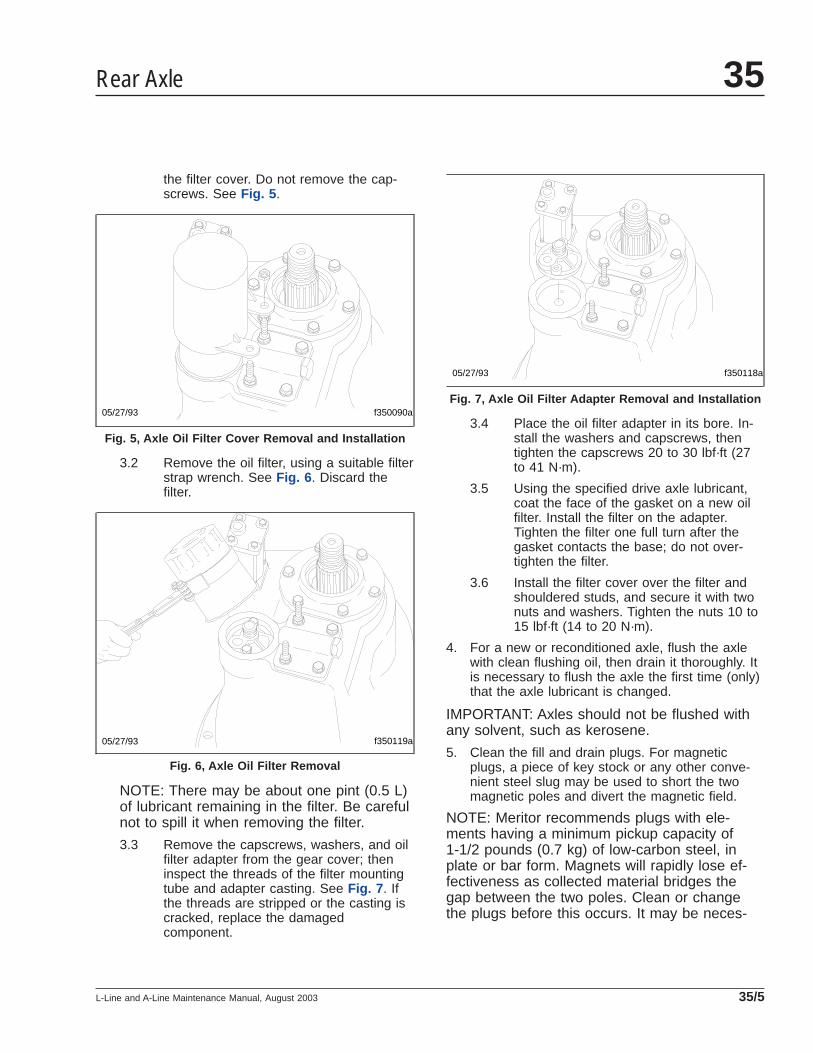
the filter cover. Do not remove the cap-screws. See Fig. 5 .
3.2 Remove the oil filter, using a suitable filterstrap wrench. See Fig. 6 . Discard thefilter.
NOTE: There may be about one pint (0.5 L)of lubricant remaining in the filter. Be carefulnot to spill it when removing the filter.
3.3 Remove the capscrews, washers, and oilfilter adapter from the gear cover; theninspect the threads of the filter mountingtube and adapter casting. See Fig. 7 . Ifthe threads are stripped or the casting iscracked, replace the damagedcomponent.
3.4 Place the oil filter adapter in its bore. In-stall the washers and capscrews, thentighten the capscrews 20 to 30 lbf·ft (27to 41 N·m).
3.5 Using the specified drive axle lubricant,coat the face of the gasket on a new oilfilter. Install the filter on the adapter.Tighten the filter one full turn after thegasket contacts the base; do not over-tighten the filter.
3.6 Install the filter cover over the filter andshouldered studs, and secure it with twonuts and washers. Tighten the nuts 10 to15 lbf·ft (14 to 20 N·m).
4. For a new or reconditioned axle, flush the axlewith clean flushing oil, then drain it thoroughly. Itis necessary to flush the axle the first time (only)that the axle lubricant is changed.
IMPORTANT: Axles should not be flushed withany solvent, such as kerosene.
5. Clean the fill and drain plugs. For magneticplugs, a piece of key stock or any other conve-nient steel slug may be used to short the twomagnetic poles and divert the magnetic field.
NOTE: Meritor recommends plugs with ele-ments having a minimum pickup capacity of1-1/2 pounds (0.7 kg) of low-carbon steel, inplate or bar form. Magnets will rapidly lose ef-fectiveness as collected material bridges thegap between the two poles. Clean or changethe plugs before this occurs. It may be neces-
f350090a05/27/93
Fig. 5, Axle Oil Filter Cover Removal and Installation
f350119a05/27/93
Fig. 6, Axle Oil Filter Removal
05/27/93 f350118a
Fig. 7, Axle Oil Filter Adapter Removal and Installation
Rear Axle 35
L-Line and A-Line Maintenance Manual, August 2003 35/5
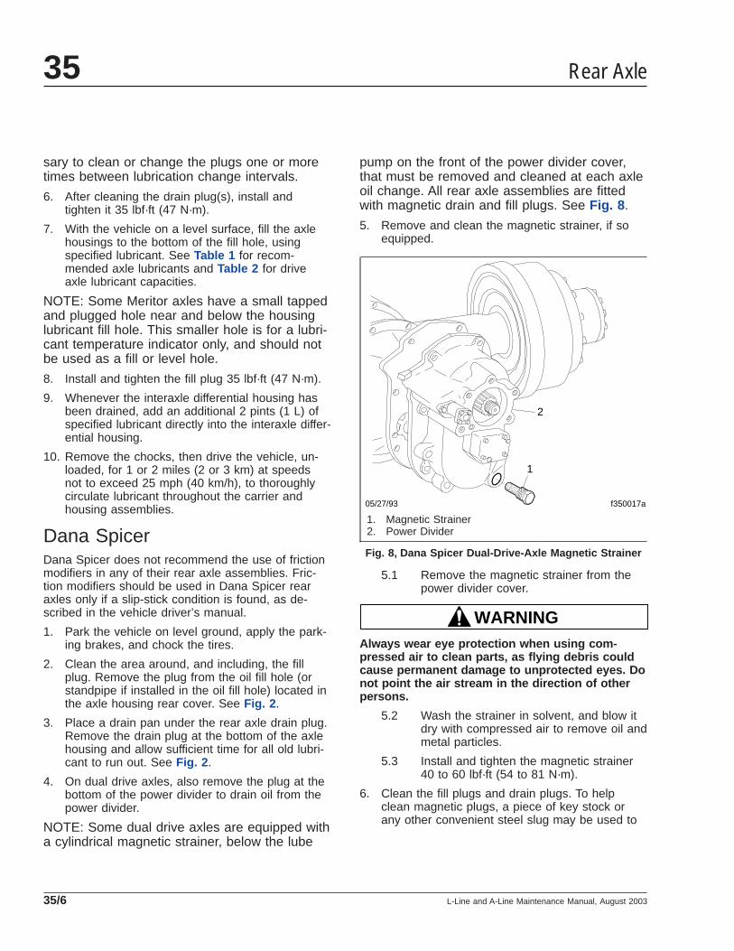
sary to clean or change the plugs one or moretimes between lubrication change intervals.
6. After cleaning the drain plug(s), install andtighten it 35 lbf·ft (47 N·m).
7. With the vehicle on a level surface, fill the axlehousings to the bottom of the fill hole, usingspecified lubricant. See Table 1 for recom-mended axle lubricants and Table 2 for driveaxle lubricant capacities.
NOTE: Some Meritor axles have a small tappedand plugged hole near and below the housinglubricant fill hole. This smaller hole is for a lubri-cant temperature indicator only, and should notbe used as a fill or level hole.
8. Install and tighten the fill plug 35 lbf·ft (47 N·m).
9. Whenever the interaxle differential housing hasbeen drained, add an additional 2 pints (1 L) ofspecified lubricant directly into the interaxle differ-ential housing.
10. Remove the chocks, then drive the vehicle, un-loaded, for 1 or 2 miles (2 or 3 km) at speedsnot to exceed 25 mph (40 km/h), to thoroughlycirculate lubricant throughout the carrier andhousing assemblies.
Dana SpicerDana Spicer does not recommend the use of frictionmodifiers in any of their rear axle assemblies. Fric-tion modifiers should be used in Dana Spicer rearaxles only if a slip-stick condition is found, as de-scribed in the vehicle driver’s manual.
1. Park the vehicle on level ground, apply the park-ing brakes, and chock the tires.
2. Clean the area around, and including, the fillplug. Remove the plug from the oil fill hole (orstandpipe if installed in the oil fill hole) located inthe axle housing rear cover. See Fig. 2 .
3. Place a drain pan under the rear axle drain plug.Remove the drain plug at the bottom of the axlehousing and allow sufficient time for all old lubri-cant to run out. See Fig. 2 .
4. On dual drive axles, also remove the plug at thebottom of the power divider to drain oil from thepower divider.
NOTE: Some dual drive axles are equipped witha cylindrical magnetic strainer, below the lube
pump on the front of the power divider cover,that must be removed and cleaned at each axleoil change. All rear axle assemblies are fittedwith magnetic drain and fill plugs. See Fig. 8 .
5. Remove and clean the magnetic strainer, if soequipped.
5.1 Remove the magnetic strainer from thepower divider cover.
WARNINGAlways wear eye protection when using com-pressed air to clean parts, as flying debris couldcause permanent damage to unprotected eyes. Donot point the air stream in the direction of otherpersons.
5.2 Wash the strainer in solvent, and blow itdry with compressed air to remove oil andmetal particles.
5.3 Install and tighten the magnetic strainer40 to 60 lbf·ft (54 to 81 N·m).
6. Clean the fill plugs and drain plugs. To helpclean magnetic plugs, a piece of key stock orany other convenient steel slug may be used to
f350017a
1
2
05/27/93
1. Magnetic Strainer2. Power Divider
Fig. 8, Dana Spicer Dual-Drive-Axle Magnetic Strainer
Rear Axle35
L-Line and A-Line Maintenance Manual, August 200335/6
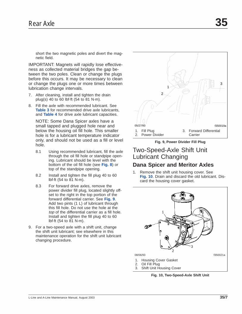
short the two magnetic poles and divert the mag-netic field.
IMPORTANT: Magnets will rapidly lose effective-ness as collected material bridges the gap be-tween the two poles. Clean or change the plugsbefore this occurs. It may be necessary to cleanor change the plugs one or more times betweenlubrication change intervals.
7. After cleaning, install and tighten the drainplug(s) 40 to 60 lbf·ft (54 to 81 N·m).
8. Fill the axle with recommended lubricant. SeeTable 3 for recommended drive axle lubricants,and Table 4 for drive axle lubricant capacities.
NOTE: Some Dana Spicer axles have asmall tapped and plugged hole near andbelow the housing oil fill hole. This smallerhole is for a lubricant temperature indicatoronly, and should not be used as a fill or levelhole.
8.1 Using recommended lubricant, fill the axlethrough the oil fill hole or standpipe open-ing. Lubricant should be level with thebottom of the oil fill hole (see Fig. 8 ) ortop of the standpipe opening.
8.2 Install and tighten the fill plug 40 to 60lbf·ft (54 to 81 N·m).
8.3 For forward drive axles, remove thepower divider fill plug, located slightly off-set to the right in the top portion of theforward differential carrier. See Fig. 9 .Add two pints (1 L) of lubricant throughthis fill hole. Do not use the hole at thetop of the differential carrier as a fill hole.Install and tighten the fill plug 40 to 60lbf·ft (54 to 81 N·m).
9. For a two-speed axle with a shift unit, changethe shift unit lubricant; see elsewhere in thismaintenance operation for the shift unit lubricantchanging procedure.
Two-Speed-Axle Shift UnitLubricant ChangingDana Spicer and Meritor Axles1. Remove the shift unit housing cover. See
Fig. 10 . Drain and discard the old lubricant. Dis-card the housing cover gasket.
f350019a
1
05/27/93
2
3
1. Fill Plug2. Power Divider
3. Forward DifferentialCarrier
Fig. 9, Power Divider Fill Plug
f350021a 08/06/93
1
2 3
1. Housing Cover Gasket2. Oil Fill Plug3. Shift Unit Housing Cover
Fig. 10, Two-Speed-Axle Shift Unit
Rear Axle 35
L-Line and A-Line Maintenance Manual, August 2003 35/7
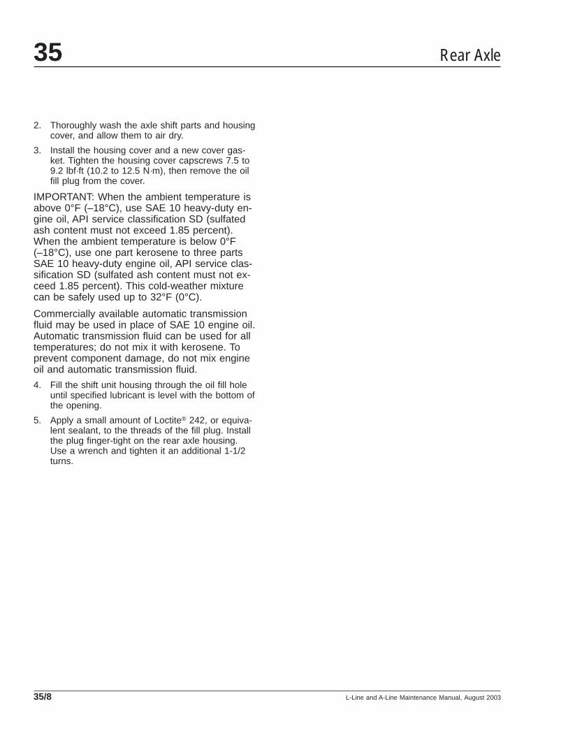
2. Thoroughly wash the axle shift parts and housingcover, and allow them to air dry.
3. Install the housing cover and a new cover gas-ket. Tighten the housing cover capscrews 7.5 to9.2 lbf·ft (10.2 to 12.5 N·m), then remove the oilfill plug from the cover.
IMPORTANT: When the ambient temperature isabove 0°F (–18°C), use SAE 10 heavy-duty en-gine oil, API service classification SD (sulfatedash content must not exceed 1.85 percent).When the ambient temperature is below 0°F(–18°C), use one part kerosene to three partsSAE 10 heavy-duty engine oil, API service clas-sification SD (sulfated ash content must not ex-ceed 1.85 percent). This cold-weather mixturecan be safely used up to 32°F (0°C).
Commercially available automatic transmissionfluid may be used in place of SAE 10 engine oil.Automatic transmission fluid can be used for alltemperatures; do not mix it with kerosene. Toprevent component damage, do not mix engineoil and automatic transmission fluid.
4. Fill the shift unit housing through the oil fill holeuntil specified lubricant is level with the bottom ofthe opening.
5. Apply a small amount of Loctite® 242, or equiva-lent sealant, to the threads of the fill plug. Installthe plug finger-tight on the rear axle housing.Use a wrench and tighten it an additional 1-1/2turns.
Rear Axle35
L-Line and A-Line Maintenance Manual, August 200335/8
Title of Maintenance Operation (MOP) MOP Number
Wheel Nut and Rim Nut Checking. . . . . . . . . . . . . . . . . . . . . . . . . . . . . . . . . . . . . . . . . . . . . . . . . . . . . . 40–01
Wheels and Tires 40Index, Alphabetical
L-Line and A-Line Maintenance Manual, October 1999
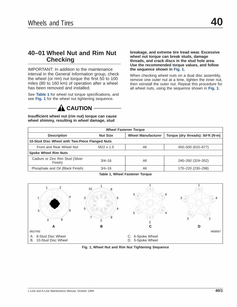
40–01 Wheel Nut and Rim NutChecking
IMPORTANT: In addition to the maintenanceinterval in the General Information group, checkthe wheel (or rim) nut torque the first 50 to 100miles (80 to 160 km) of operation after a wheelhas been removed and installed.
See Table 1 for wheel nut torque specifications, andsee Fig. 1 for the wheel nut tightening sequence.
CAUTIONInsufficient wheel nut (rim nut) torque can causewheel shimmy, resulting in wheel damage, stud
breakage, and extreme tire tread wear. Excessivewheel nut torque can break studs, damagethreads, and crack discs in the stud hole area.Use the recommended torque values, and followthe sequence shown in Fig. 1.
When checking wheel nuts on a dual disc assembly,remove one outer nut at a time, tighten the inner nut,then reinstall the outer nut. Repeat this procedure forall wheel nuts, using the sequence shown in Fig. 1 .
Wheel Fastener Torque
Description Nut Size Wheel Manufacturer Torque (dry threads): lbf·ft (N·m)
10-Stud Disc Wheel with Two-Piece Flanged Nuts
Front and Rear Wheel Nut M22 x 1.5 All 450–500 (610–677)
Spoke Wheel Rim Nuts
Cadium or Zinc Rim Stud (SilverFinish) 3/4–16 All 240–260 (324–352)
Phosphate and Oil (Black Finish) 3/4–16 All 170–220 (230–298)
Table 1, Wheel Fastener Torque
1
2
3
45
6
7
8
9
101
2
3
45
6
1
2
3 4
5
f40005705/27/93
1 2
3
4
5 6
7
8
A B C D
A. 8-Stud Disc WheelB. 10-Stud Disc Wheel
C. 6-Spoke WheelD. 5-Spoke Wheel
Fig. 1, Wheel Nut and Rim Nut Tightening Sequence
Wheels and Tires 40
L-Line and A-Line Maintenance Manual, October 1999 40/1
Title of Maintenance Operation (MOP) MOP Number
Driveline Inspecting . . . . . . . . . . . . . . . . . . . . . . . . . . . . . . . . . . . . . . . . . . . . . . . . . . . . . . . . . . . . . . . . 41–01
Driveline Lubricating. . . . . . . . . . . . . . . . . . . . . . . . . . . . . . . . . . . . . . . . . . . . . . . . . . . . . . . . . . . . . . . . 41–02
Driveline 41Index, Alphabetical
L-Line and A-Line Maintenance Manual, October 1999
41–01 Driveline InspectingBefore lubricating driveline U-joints and slip joints,proceed as follows:
CAUTIONDo not over-tighten bearing-cap capscrews oryoke-strap capscrews. Due to the extreme loadoccurring at high-speed rotation, a loose or bro-ken capscrew at any point in the driveline willweaken the driveline connection, which couldeventually result in serious vehicle damage.
1. For each full-round driveline yoke with thread-locking capscrews, tighten the bearing-cap cap-screws.
For each half-round driveline yoke, tighten theyoke-strap capscrews. See Fig. 1 , Ref. 6.
Tighten all U-joint bearing cap fasteners to thetorque values given in Table 1 .
Fastener Torque Values
Description Size Torque: lbf·ft (N·m)
Yoke-Strap Capscrew 1/2–20 130 (176)
Bearing-Cap Capscrew
5/16–24 24 (33)
3/8–24 37 (50)
7/16–20 60 (81)
Table 1, Fastener Torque Values
2. Check each input and output end yoke (seeFig. 1 ) for cracks and looseness. Replacecracked yokes.
If any end yoke can be moved in or out on itsshaft, or can be rocked on its shaft, disconnectthe driveshaft and U-joint from the end yoke.Check the drive component’s shaft seal for leak-age or other visible damage that may have beencaused by the loose yoke. Replace the seal ifneeded, then tighten the end yoke nut. Fortorque values, see Group 41 of the L-Line andA-Line Workshop Manual. If the end yoke is stillloose after tightening the yoke nut, replace theyoke and yoke nut.
Replace the prevailing torque locknut (end yokenut) if it was removed for end yoke replacement,seal replacement, or any other reason.
3. Check U-joint assemblies for wear by attemptingto move the driveshaft up and down, and fromside-to-side. If movement of the U-joint cross inthe bearings can be felt or seen, replace thecomplete U-joint.
4. Check the midship bearing and mounting forlooseness and deterioration by attempting tomove the driveshaft up and down, and from side-to-side. If the bearing is loose on its shaft, or itrattles, replace it. If the bearing mount is looseon the frame, tighten the mounting bolt nuts tothe applicable torque value in the torque tablesin Group 00 of this manual. Replace the midshipbearing assembly if the rubber cushion is dete-riorated or oil-soaked.
5. Check slip joints for spline wear by attempting tobend the sleeve yoke and splined shaft back andforth. See Fig. 2 . If radial looseness is greaterthan 0.007 inch (0.18 mm), replace both thesleeve yoke and the splined shaft.
6. Visually examine the driveshaft tubes for dents,bends, twists, or other damage. If any tube ap-pears to be damaged, remove the driveshaft andcheck the run-out on the tube. If the tube is notstraight (and cannot be straightened within 0.015inch [0.38 mm] on the slip-joint-seal surface ofthe splined shaft, 0.020 inch [0.51 mm] on thetube 3 inches [76 mm] from the front and rearwelds, and 0.025 inch [0.635 mm] at the centerof the tube), replace the tube. See Fig. 3 .
If the driveshaft tube requires straightening orreplacement, balance the repaired driveshaft be-fore installing it.
7. Examine the driveshaft for evidence of missingbalance weights, and for build-up of foreign ma-terial. Remove any foreign material. If there isany evidence that balance weights are missing,remove the driveshaft and have it balanced.
8. For driveshafts with slip joints, check to be surethe yoke plug is not loose or missing. See Fig. 4 ,Ref. 2. Repair or replace the yoke plug asneeded. If the yoke plug is missing, the splinedshaft may be hitting the plug and knocking it out;contact your Regional Service Office for assis-tance in determining the correct driveshaftlength.
Driveline 41
L-Line and A-Line Maintenance Manual, October 1999 41/1
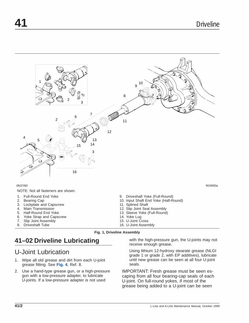
41–02 Driveline Lubricating
U-Joint Lubrication1. Wipe all old grease and dirt from each U-joint
grease fitting. See Fig. 4 , Ref. 8.
2. Use a hand-type grease gun, or a high-pressuregun with a low-pressure adapter, to lubricateU-joints. If a low-pressure adapter is not used
with the high-pressure gun, the U-joints may notreceive enough grease.
Using lithium 12-hydroxy stearate grease (NLGIgrade 1 or grade 2, with EP additives), lubricateuntil new grease can be seen at all four U-jointseals.
IMPORTANT: Fresh grease must be seen es-caping from all four bearing-cap seals of eachU-joint. On full-round yokes, if most of thegrease being added to a U-joint can be seen
45
2
7
8
910
11
12
1314
3
15
16
23
1
6
05/27/93 f410032a
NOTE: Not all fasteners are shown.
1. Full-Round End Yoke2. Bearing Cap3. Lockplate and Capscrew4. Main Transmission5. Half-Round End Yoke6. Yoke Strap and Capscrew7. Slip Joint Assembly8. Driveshaft Tube
9. Driveshaft Yoke (Full-Round)10. Input Shaft End Yoke (Half-Round)11. Splined Shaft12. Slip Joint Seal Assembly13. Sleeve Yoke (Full-Round)14. Yoke Lug15. U-Joint Cross16. U-Joint Assembly
Fig. 1, Driveline Assembly
Driveline41
L-Line and A-Line Maintenance Manual, October 199941/2
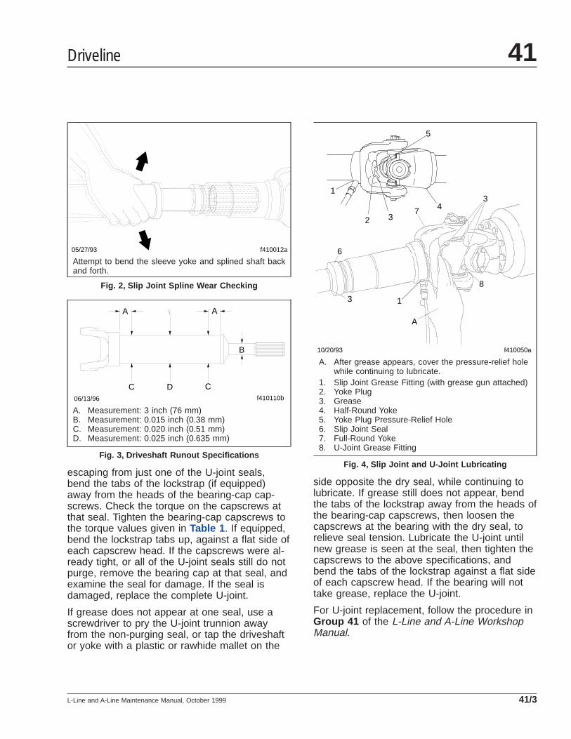
escaping from just one of the U-joint seals,bend the tabs of the lockstrap (if equipped)away from the heads of the bearing-cap cap-screws. Check the torque on the capscrews atthat seal. Tighten the bearing-cap capscrews tothe torque values given in Table 1 . If equipped,bend the lockstrap tabs up, against a flat side ofeach capscrew head. If the capscrews were al-ready tight, or all of the U-joint seals still do notpurge, remove the bearing cap at that seal, andexamine the seal for damage. If the seal isdamaged, replace the complete U-joint.
If grease does not appear at one seal, use ascrewdriver to pry the U-joint trunnion awayfrom the non-purging seal, or tap the driveshaftor yoke with a plastic or rawhide mallet on the
side opposite the dry seal, while continuing tolubricate. If grease still does not appear, bendthe tabs of the lockstrap away from the heads ofthe bearing-cap capscrews, then loosen thecapscrews at the bearing with the dry seal, torelieve seal tension. Lubricate the U-joint untilnew grease is seen at the seal, then tighten thecapscrews to the above specifications, andbend the tabs of the lockstrap against a flat sideof each capscrew head. If the bearing will nottake grease, replace the U-joint.
For U-joint replacement, follow the procedure inGroup 41 of the L-Line and A-Line WorkshopManual.
f410012a05/27/93
Attempt to bend the sleeve yoke and splined shaft backand forth.
Fig. 2, Slip Joint Spline Wear Checking
f410110b06/13/96
A A
B
C CD
A. Measurement: 3 inch (76 mm)B. Measurement: 0.015 inch (0.38 mm)C. Measurement: 0.020 inch (0.51 mm)D. Measurement: 0.025 inch (0.635 mm)
Fig. 3, Driveshaft Runout Specifications
f410050a 10/20/93
1
1
2 3
3
3 4
5
6
7
8
A
A. After grease appears, cover the pressure-relief holewhile continuing to lubricate.
1. Slip Joint Grease Fitting (with grease gun attached)2. Yoke Plug3. Grease4. Half-Round Yoke5. Yoke Plug Pressure-Relief Hole6. Slip Joint Seal7. Full-Round Yoke8. U-Joint Grease Fitting
Fig. 4, Slip Joint and U-Joint Lubricating
Driveline 41
L-Line and A-Line Maintenance Manual, October 1999 41/3

3. Check the purged grease. If it appears rusty,gritty, or burned, replace the U-joint.
4. Wipe the purged grease from the seals, and anyexcess grease from the grease fitting.
Slip Joint Spline Lubrication1. Wipe all old grease and dirt from the slip joint
grease fitting. See Fig. 4 , Ref. 1.
2. Use a hand-type grease gun or a high-pressuregun with a low-pressure adapter, to lubricate theslip joint. Add multipurpose chassis grease(lithium 12-hydroxy stearate, NLGI grade 1 orgrade 2, with EP additives) until it appears at thepressure-relief hole in the yoke plug. Then coverthe relief hole with your finger, while continuingto apply gun pressure until new grease appearsat the slip joint seal. See Fig. 4 . This ensurescomplete lubrication of the splines.
3. Wipe the purged grease from the pressure-reliefhole and slip joint seal, and any excess greasefrom the grease fitting.
Driveline41
L-Line and A-Line Maintenance Manual, October 199941/4

Title of Maintenance Operation (MOP) MOP Number
Automatic Slack Adjuster Lubricating and Checking. . . . . . . . . . . . . . . . . . . . . . . . . . . . . . . . . . . . . . . . . 42–02
Bendix Air Brake Valve Disassembly, Cleaning, Inspecting, and Lubricating(DV–2 and Single Check Valve). . . . . . . . . . . . . . . . . . . . . . . . . . . . . . . . . . . . . . . . . . . . . . . . . . . . . . . 42–07
Bendix Air Brake Valve Disassembly, Cleaning, and Inspecting (Double CheckValve, E–12, MV–3, PP–7, QR–1, SR–1, ST–3, TC–7, TP–5, and TR–3). . . . . . . . . . . . . . . . . . . . . . . . . 42–06
Bendix Air Brake Valve Inspecting and Testing (MV–3 and TC–6). . . . . . . . . . . . . . . . . . . . . . . . . . . . . . . 42–08
Bendix Air Brake Valve Operation Checking (BP–R1 and E–12). . . . . . . . . . . . . . . . . . . . . . . . . . . . . . . . 42–05
Bendix Air Dryer Checking (AD–IP or AD–9) . . . . . . . . . . . . . . . . . . . . . . . . . . . . . . . . . . . . . . . . . . . . . . 42–03
Bendix Air Dryer Desiccant Replacing (AD–9) . . . . . . . . . . . . . . . . . . . . . . . . . . . . . . . . . . . . . . . . . . . . . 42–04
Bendix Foot Brake Valve Actuator Lubricating and Leak Testing (E–12) . . . . . . . . . . . . . . . . . . . . . . . . . . 42–09
Brake Inspection . . . . . . . . . . . . . . . . . . . . . . . . . . . . . . . . . . . . . . . . . . . . . . . . . . . . . . . . . . . . . . . . . . 42–10
Camshaft Bracket Bushing Lubricating . . . . . . . . . . . . . . . . . . . . . . . . . . . . . . . . . . . . . . . . . . . . . . . . . . 42–01
Brakes 42Index, Alphabetical
L-Line and A-Line Maintenance Manual, January 2008
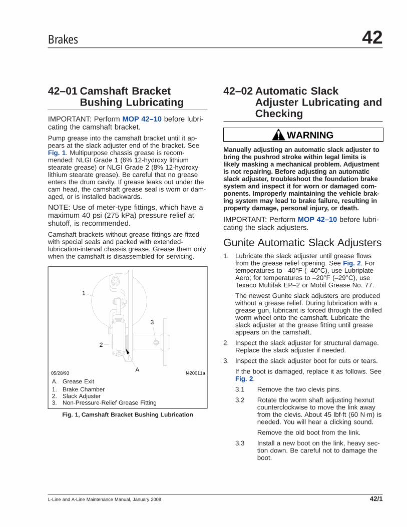
42–01 Camshaft BracketBushing Lubricating
IMPORTANT: Perform MOP 42–10 before lubri-cating the camshaft bracket.
Pump grease into the camshaft bracket until it ap-pears at the slack adjuster end of the bracket. SeeFig. 1 . Multipurpose chassis grease is recom-mended: NLGI Grade 1 (6% 12-hydroxy lithiumstearate grease) or NLGI Grade 2 (8% 12-hydroxylithium stearate grease). Be careful that no greaseenters the drum cavity. If grease leaks out under thecam head, the camshaft grease seal is worn or dam-aged, or is installed backwards.
NOTE: Use of meter-type fittings, which have amaximum 40 psi (275 kPa) pressure relief atshutoff, is recommended.
Camshaft brackets without grease fittings are fittedwith special seals and packed with extended-lubrication-interval chassis grease. Grease them onlywhen the camshaft is disassembled for servicing.
42–02 Automatic SlackAdjuster Lubricating andChecking
WARNINGManually adjusting an automatic slack adjuster tobring the pushrod stroke within legal limits islikely masking a mechanical problem. Adjustmentis not repairing. Before adjusting an automaticslack adjuster, troubleshoot the foundation brakesystem and inspect it for worn or damaged com-ponents. Improperly maintaining the vehicle brak-ing system may lead to brake failure, resulting inproperty damage, personal injury, or death.
IMPORTANT: Perform MOP 42–10 before lubri-cating the slack adjusters.
Gunite Automatic Slack Adjusters1. Lubricate the slack adjuster until grease flows
from the grease relief opening. See Fig. 2 . Fortemperatures to –40°F (–40°C), use LubriplateAero; for temperatures to –20°F (–29°C), useTexaco Multifak EP–2 or Mobil Grease No. 77.
The newest Gunite slack adjusters are producedwithout a grease relief. During lubrication with agrease gun, lubricant is forced through the drilledworm wheel onto the camshaft. Lubricate theslack adjuster at the grease fitting until greaseappears on the camshaft.
2. Inspect the slack adjuster for structural damage.Replace the slack adjuster if needed.
3. Inspect the slack adjuster boot for cuts or tears.
If the boot is damaged, replace it as follows. SeeFig. 2 .
3.1 Remove the two clevis pins.
3.2 Rotate the worm shaft adjusting hexnutcounterclockwise to move the link awayfrom the clevis. About 45 lbf·ft (60 N·m) isneeded. You will hear a clicking sound.
Remove the old boot from the link.
3.3 Install a new boot on the link, heavy sec-tion down. Be careful not to damage theboot.
f420011a05/28/93
1
2
3
A
A. Grease Exit1. Brake Chamber2. Slack Adjuster3. Non-Pressure-Relief Grease Fitting
Fig. 1, Camshaft Bracket Bushing Lubrication
Brakes 42
L-Line and A-Line Maintenance Manual, January 2008 42/1
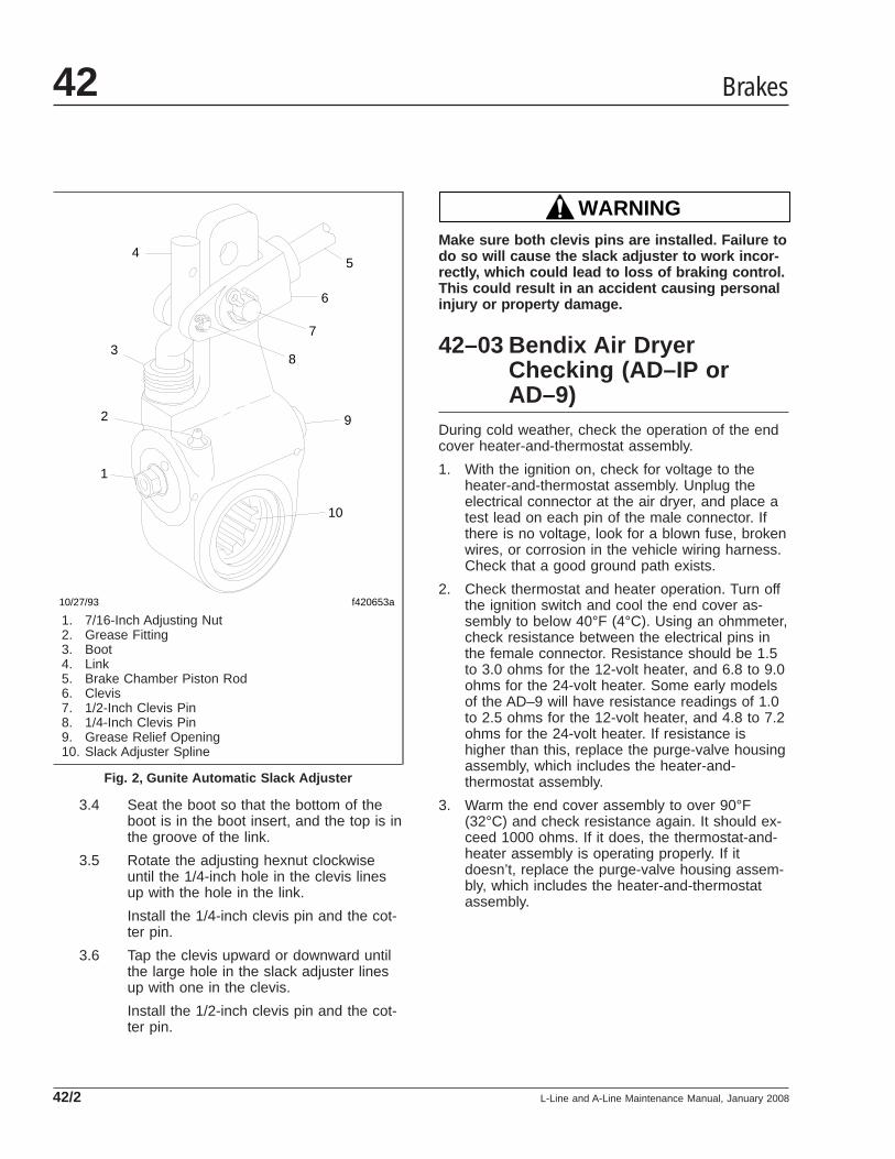
3.4 Seat the boot so that the bottom of theboot is in the boot insert, and the top is inthe groove of the link.
3.5 Rotate the adjusting hexnut clockwiseuntil the 1/4-inch hole in the clevis linesup with the hole in the link.
Install the 1/4-inch clevis pin and the cot-ter pin.
3.6 Tap the clevis upward or downward untilthe large hole in the slack adjuster linesup with one in the clevis.
Install the 1/2-inch clevis pin and the cot-ter pin.
WARNINGMake sure both clevis pins are installed. Failure todo so will cause the slack adjuster to work incor-rectly, which could lead to loss of braking control.This could result in an accident causing personalinjury or property damage.
42–03 Bendix Air DryerChecking (AD–IP orAD–9)
During cold weather, check the operation of the endcover heater-and-thermostat assembly.
1. With the ignition on, check for voltage to theheater-and-thermostat assembly. Unplug theelectrical connector at the air dryer, and place atest lead on each pin of the male connector. Ifthere is no voltage, look for a blown fuse, brokenwires, or corrosion in the vehicle wiring harness.Check that a good ground path exists.
2. Check thermostat and heater operation. Turn offthe ignition switch and cool the end cover as-sembly to below 40°F (4°C). Using an ohmmeter,check resistance between the electrical pins inthe female connector. Resistance should be 1.5to 3.0 ohms for the 12-volt heater, and 6.8 to 9.0ohms for the 24-volt heater. Some early modelsof the AD–9 will have resistance readings of 1.0to 2.5 ohms for the 12-volt heater, and 4.8 to 7.2ohms for the 24-volt heater. If resistance ishigher than this, replace the purge-valve housingassembly, which includes the heater-and-thermostat assembly.
3. Warm the end cover assembly to over 90°F(32°C) and check resistance again. It should ex-ceed 1000 ohms. If it does, the thermostat-and-heater assembly is operating properly. If itdoesn’t, replace the purge-valve housing assem-bly, which includes the heater-and-thermostatassembly.
f420653a
1
2
3
45
6
7
8
10
9
10/27/93
1. 7/16-Inch Adjusting Nut2. Grease Fitting3. Boot4. Link5. Brake Chamber Piston Rod6. Clevis7. 1/2-Inch Clevis Pin8. 1/4-Inch Clevis Pin9. Grease Relief Opening10. Slack Adjuster Spline
Fig. 2, Gunite Automatic Slack Adjuster
Brakes42
L-Line and A-Line Maintenance Manual, January 200842/2
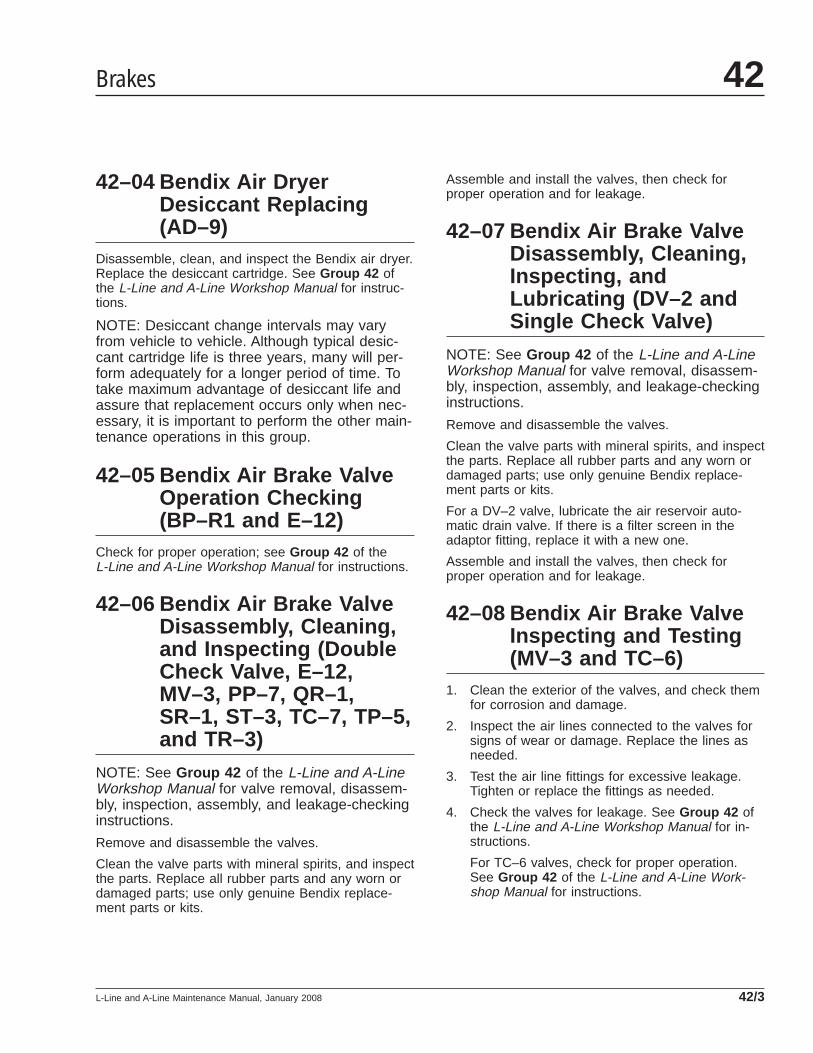
42–04 Bendix Air DryerDesiccant Replacing(AD–9)
Disassemble, clean, and inspect the Bendix air dryer.Replace the desiccant cartridge. See Group 42 ofthe L-Line and A-Line Workshop Manual for instruc-tions.
NOTE: Desiccant change intervals may varyfrom vehicle to vehicle. Although typical desic-cant cartridge life is three years, many will per-form adequately for a longer period of time. Totake maximum advantage of desiccant life andassure that replacement occurs only when nec-essary, it is important to perform the other main-tenance operations in this group.
42–05 Bendix Air Brake ValveOperation Checking(BP–R1 and E–12)
Check for proper operation; see Group 42 of theL-Line and A-Line Workshop Manual for instructions.
42–06 Bendix Air Brake ValveDisassembly, Cleaning,and Inspecting (DoubleCheck Valve, E–12,MV–3, PP–7, QR–1,SR–1, ST–3, TC–7, TP–5,and TR–3)
NOTE: See Group 42 of the L-Line and A-LineWorkshop Manual for valve removal, disassem-bly, inspection, assembly, and leakage-checkinginstructions.
Remove and disassemble the valves.
Clean the valve parts with mineral spirits, and inspectthe parts. Replace all rubber parts and any worn ordamaged parts; use only genuine Bendix replace-ment parts or kits.
Assemble and install the valves, then check forproper operation and for leakage.
42–07 Bendix Air Brake ValveDisassembly, Cleaning,Inspecting, andLubricating (DV–2 andSingle Check Valve)
NOTE: See Group 42 of the L-Line and A-LineWorkshop Manual for valve removal, disassem-bly, inspection, assembly, and leakage-checkinginstructions.
Remove and disassemble the valves.
Clean the valve parts with mineral spirits, and inspectthe parts. Replace all rubber parts and any worn ordamaged parts; use only genuine Bendix replace-ment parts or kits.
For a DV–2 valve, lubricate the air reservoir auto-matic drain valve. If there is a filter screen in theadaptor fitting, replace it with a new one.
Assemble and install the valves, then check forproper operation and for leakage.
42–08 Bendix Air Brake ValveInspecting and Testing(MV–3 and TC–6)
1. Clean the exterior of the valves, and check themfor corrosion and damage.
2. Inspect the air lines connected to the valves forsigns of wear or damage. Replace the lines asneeded.
3. Test the air line fittings for excessive leakage.Tighten or replace the fittings as needed.
4. Check the valves for leakage. See Group 42 ofthe L-Line and A-Line Workshop Manual for in-structions.
For TC–6 valves, check for proper operation.See Group 42 of the L-Line and A-Line Work-shop Manual for instructions.
Brakes 42
L-Line and A-Line Maintenance Manual, January 2008 42/3
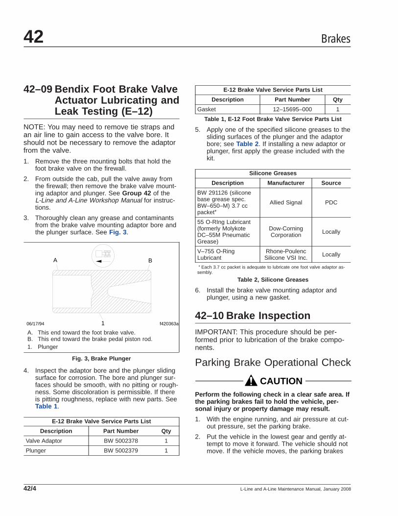
42–09 Bendix Foot Brake ValveActuator Lubricating andLeak Testing (E–12)
NOTE: You may need to remove tie straps andan air line to gain access to the valve bore. Itshould not be necessary to remove the adaptorfrom the valve.
1. Remove the three mounting bolts that hold thefoot brake valve on the firewall.
2. From outside the cab, pull the valve away fromthe firewall; then remove the brake valve mount-ing adaptor and plunger. See Group 42 of theL-Line and A-Line Workshop Manual for instruc-tions.
3. Thoroughly clean any grease and contaminantsfrom the brake valve mounting adaptor bore andthe plunger surface. See Fig. 3 .
4. Inspect the adaptor bore and the plunger slidingsurface for corrosion. The bore and plunger sur-faces should be smooth, with no pitting or rough-ness. Some discoloration is permissible. If thereis pitting roughness, replace with new parts. SeeTable 1 .
E-12 Brake Valve Service Parts List
Description Part Number Qty
Valve Adaptor BW 5002378 1
Plunger BW 5002379 1
E-12 Brake Valve Service Parts List
Description Part Number Qty
Gasket 12–15695–000 1
Table 1, E-12 Foot Brake Valve Service Parts List
5. Apply one of the specified silicone greases to thesliding surfaces of the plunger and the adaptorbore; see Table 2 . If installing a new adaptor orplunger, first apply the grease included with thekit.
Silicone Greases
Description Manufacturer Source
BW 291126 (siliconebase grease spec.BW–650–M) 3.7 ccpacket*
Allied Signal PDC
55 O-RIng Lubricant(formerly MolykoteDC–55M PneumaticGrease)
Dow-CorningCorporation Locally
V–755 O-RingLubricant
Rhone-PoulencSilicone VSI Inc. Locally
* Each 3.7 cc packet is adequate to lubricate one foot valve adaptor as-sembly.
Table 2, Silicone Greases
6. Install the brake valve mounting adaptor andplunger, using a new gasket.
42–10 Brake InspectionIMPORTANT: This procedure should be per-formed prior to lubrication of the brake compo-nents.
Parking Brake Operational Check
CAUTIONPerform the following check in a clear safe area. Ifthe parking brakes fail to hold the vehicle, per-sonal injury or property damage may result.
1. With the engine running, and air pressure at cut-out pressure, set the parking brake.
2. Put the vehicle in the lowest gear and gently at-tempt to move it forward. The vehicle should notmove. If the vehicle moves, the parking brakes
f420363a1
A B
06/17/94
A. This end toward the foot brake valve.B. This end toward the brake pedal piston rod.1. Plunger
Fig. 3, Brake Plunger
Brakes42
L-Line and A-Line Maintenance Manual, January 200842/4
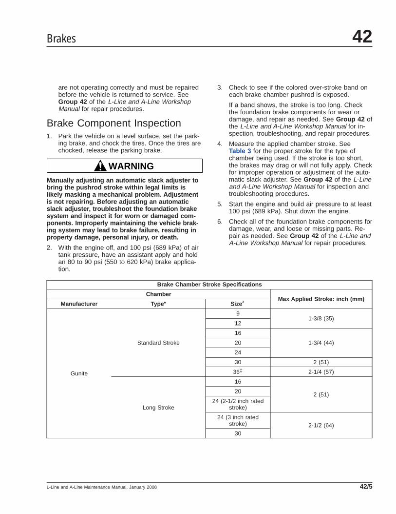
are not operating correctly and must be repairedbefore the vehicle is returned to service. SeeGroup 42 of the L-Line and A-Line WorkshopManual for repair procedures.
Brake Component Inspection1. Park the vehicle on a level surface, set the park-
ing brake, and chock the tires. Once the tires arechocked, release the parking brake.
WARNINGManually adjusting an automatic slack adjuster tobring the pushrod stroke within legal limits islikely masking a mechanical problem. Adjustmentis not repairing. Before adjusting an automaticslack adjuster, troubleshoot the foundation brakesystem and inspect it for worn or damaged com-ponents. Improperly maintaining the vehicle brak-ing system may lead to brake failure, resulting inproperty damage, personal injury, or death.
2. With the engine off, and 100 psi (689 kPa) of airtank pressure, have an assistant apply and holdan 80 to 90 psi (550 to 620 kPa) brake applica-tion.
3. Check to see if the colored over-stroke band oneach brake chamber pushrod is exposed.
If a band shows, the stroke is too long. Checkthe foundation brake components for wear ordamage, and repair as needed. See Group 42 ofthe L-Line and A-Line Workshop Manual for in-spection, troubleshooting, and repair procedures.
4. Measure the applied chamber stroke. SeeTable 3 for the proper stroke for the type ofchamber being used. If the stroke is too short,the brakes may drag or will not fully apply. Checkfor improper operation or adjustment of the auto-matic slack adjuster. See Group 42 of the L-Lineand A-Line Workshop Manual for inspection andtroubleshooting procedures.
5. Start the engine and build air pressure to at least100 psi (689 kPa). Shut down the engine.
6. Check all of the foundation brake components fordamage, wear, and loose or missing parts. Re-pair as needed. See Group 42 of the L-Line andA-Line Workshop Manual for repair procedures.
Brake Chamber Stroke Specifications
ChamberMax Applied Stroke: inch (mm)
Manufacturer Type * Size†
Gunite
Standard Stroke
91-3/8 (35)
12
16
1-3/4 (44)20
24
30 2 (51)
36‡ 2-1/4 (57)
Long Stroke
16
2 (51)20
24 (2-1/2 inch ratedstroke)
24 (3 inch ratedstroke) 2-1/2 (64)
30
Brakes 42
L-Line and A-Line Maintenance Manual, January 2008 42/5

Brake Chamber Stroke Specifications
ChamberMax Applied Stroke: inch (mm)
Manufacturer Type * Size†
Haldex
Standard Stroke
12 1-3/8 (35)
16
1-3/4 (44)20
24
2-1/2-Inch Extended Stroke 24 2 (51)
3-Inch Extended Stroke 24 2-1/2 (64)
Standard Stroke 30 2 (51)
Long Stroke 30 2-1/2 (64)
Meritor
Standard Stroke
9Less than 1-1/2 (38)
12
16Less than 1-3/4 (44)
20
24 Less than 1-7/8 (48)
Long Stroke 24Less than 2 (51)
Standard Stroke 30
Dana Spicer Long Stroke
16L
2 (51)20L
24L
24LS2-1/2 (64)
30LS
* Long stroke design is indicated by a tag, or embossing, on the brake chamber.† Specifications are relative to a brake application with 80 to 90 psi (550 to 620 kPa) air pressure in the brake chambers.‡ If type 36 chamber is used, slack length should be less than 6 inches.
Table 3, Brake Chamber Stroke Specifications
Brakes42
L-Line and A-Line Maintenance Manual, January 200842/6
Title of Maintenance Operation (MOP) MOP Number
Drag Link and Power Steering Cylinder Lubricating . . . . . . . . . . . . . . . . . . . . . . . . . . . . . . . . . . . . . . . . . 46–02
Power Steering Reservoir Fluid Level Checking. . . . . . . . . . . . . . . . . . . . . . . . . . . . . . . . . . . . . . . . . . . . 46–03
Power Steering Reservoir Fluid and Filter Changing . . . . . . . . . . . . . . . . . . . . . . . . . . . . . . . . . . . . . . . . 46–04
Steering Driveline Lubricating . . . . . . . . . . . . . . . . . . . . . . . . . . . . . . . . . . . . . . . . . . . . . . . . . . . . . . . . . 46–01
TRW Power Steering Gear Lubricating, TAS Series. . . . . . . . . . . . . . . . . . . . . . . . . . . . . . . . . . . . . . . . . 46–05
Steering 46Index, Alphabetical
L-Line and A-Line Maintenance Manual, July 2004
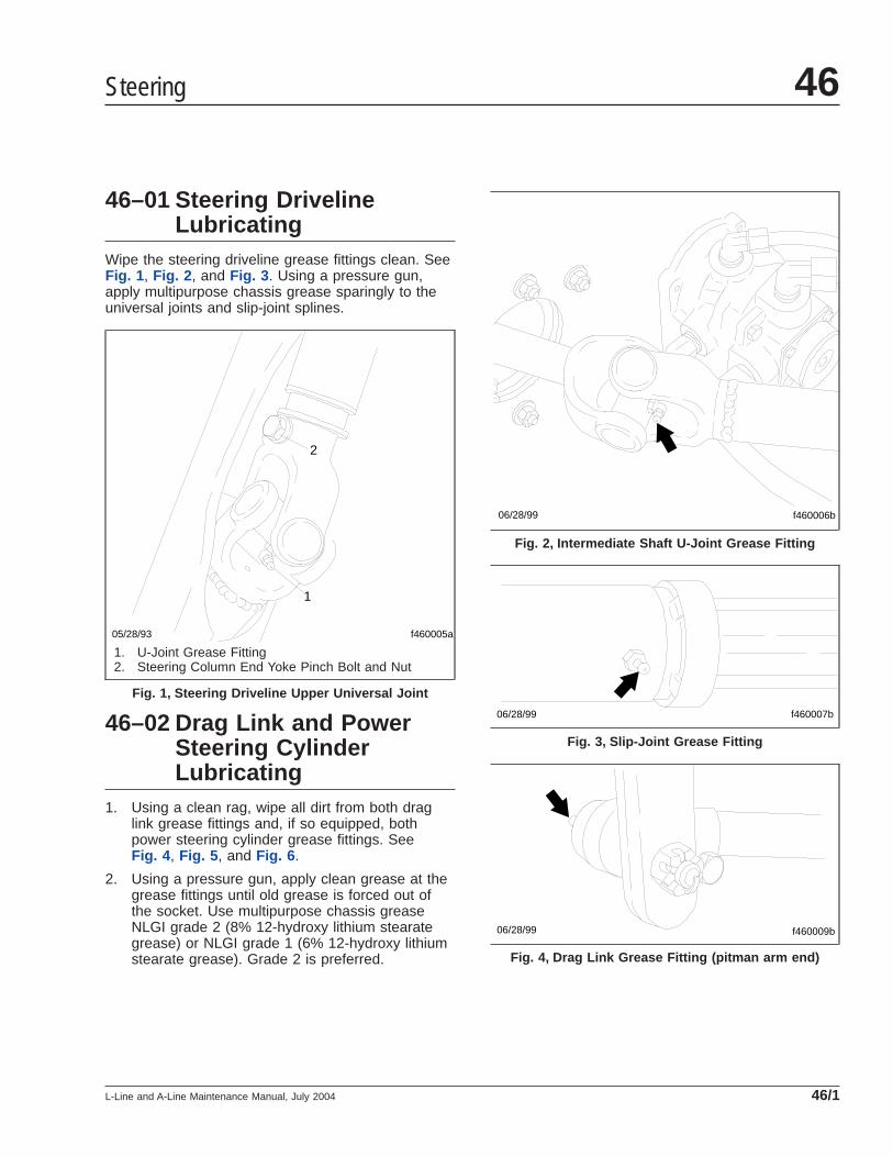
46–01 Steering DrivelineLubricating
Wipe the steering driveline grease fittings clean. SeeFig. 1 , Fig. 2 , and Fig. 3 . Using a pressure gun,apply multipurpose chassis grease sparingly to theuniversal joints and slip-joint splines.
46–02 Drag Link and PowerSteering CylinderLubricating
1. Using a clean rag, wipe all dirt from both draglink grease fittings and, if so equipped, bothpower steering cylinder grease fittings. SeeFig. 4 , Fig. 5 , and Fig. 6 .
2. Using a pressure gun, apply clean grease at thegrease fittings until old grease is forced out ofthe socket. Use multipurpose chassis greaseNLGI grade 2 (8% 12-hydroxy lithium stearategrease) or NLGI grade 1 (6% 12-hydroxy lithiumstearate grease). Grade 2 is preferred.
f460005a
1
2
05/28/93
1. U-Joint Grease Fitting2. Steering Column End Yoke Pinch Bolt and Nut
Fig. 1, Steering Driveline Upper Universal Joint
f460006b06/28/99
Fig. 2, Intermediate Shaft U-Joint Grease Fitting
f460007b06/28/99
Fig. 3, Slip-Joint Grease Fitting
06/28/99 f460009b
Fig. 4, Drag Link Grease Fitting (pitman arm end)
Steering 46
L-Line and A-Line Maintenance Manual, July 2004 46/1

46–03 Power SteeringReservoir Fluid LevelChecking
Metal Ventra Reservoir1. Turn off the engine, apply the parking brakes,
and chock the tires.
2. Open the hood.
3. Clean around the power steering reservoir fill capwith a clean rag, then remove the dipstick.
WARNINGFill only with approved clean fluid. Do not mixfluid types. Any mixture or any unapproved fluidcould lead to seal deterioration and leaks. Fluidleakage could cause loss of power steering assist,possibly resulting in personal injury and propertydamage.
4. With the power steering fluid at operating tem-perature, check the fluid level on the dipstick. Ifbelow the ADD mark, add enough fluid to bringthe level up to the FULL mark on the dipstick.Use Dexron® III automatic transmission fluid(ATF) in the power steering reservoir.
5. Install the fill cap on the power steering reservoir.
6. Close the hood, and remove the chocks from thetires.
Nelson ReservoirNOTE: If the power steering reservoir in the ve-hicle looks like the reservoir shown in Fig. 7 ,use the following procedure.
1. Turn off the engine, apply the parking brakes,and chock the tires.
2. Open the hood.
3. With the engine cool, the level should be be-tween MIN COLD and MAX HOT lines with theengine off. Add or remove fluid as necessary tobring the fluid level to the line between the MINCOLD and MAX HOT lines. Use only Dexron® IIIautomatic transmission fluid.
4. With the engine hot, the fluid level should be atthe MAX HOT line with the engine off. Add or
f460010b06/28/99
Fig. 5, Drag Link Grease Fitting (axle steering arm end)
06/28/99 f460048a
Fig. 6, Power Steering Cylinder Grease Fitting (axlesteering arm end)
Steering46
L-Line and A-Line Maintenance Manual, July 200446/2
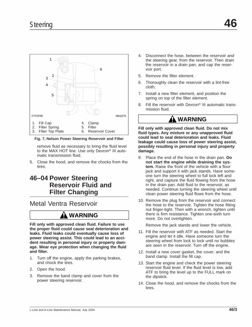
remove fluid as necessary to bring the fluid levelto the MAX HOT line. Use only Dexron® III auto-matic transmission fluid.
5. Close the hood, and remove the chocks from thetires.
46–04 Power SteeringReservoir Fluid andFilter Changing
Metal Ventra Reservoir
WARNINGFill only with approved clean fluid. Failure to usethe proper fluid could cause seal deterioration andleaks. Fluid leaks could eventually cause loss ofpower steering assist. This could lead to an acci-dent resulting in personal injury or property dam-age. Wear eye protection when changing the fluidand filter.
1. Turn off the engine, apply the parking brakes,and chock the tires.
2. Open the hood.
3. Remove the band clamp and cover from thepower steering reservoir.
4. Disconnect the hose, between the reservoir andthe steering gear, from the reservoir. Then drainthe reservoir in a drain pan, and cap the reser-voir port.
5. Remove the filter element.
6. Thoroughly clean the reservoir with a lint-freecloth.
7. Install a new filter element, and position thespring on top of the filter element.
8. Fill the reservoir with Dexron® III automatic trans-mission fluid.
WARNINGFill only with approved clean fluid. Do not mixfluid types. Any mixture or any unapproved fluidcould lead to seal deterioration and leaks. Fluidleakage could cause loss of power steering assist,possibly resulting in personal injury and propertydamage.
9. Place the end of the hose in the drain pan. Donot start the engine while draining the sys-tem. Raise the front of the vehicle with a floorjack and support it with jack stands. Have some-one turn the steering wheel to full lock left andright, and capture the fluid flowing from the hosein the drain pan. Add fluid to the reservoir, asneeded. Continue turning the steering wheel untilclean power steering fluid flows from the hose.
10. Remove the plug from the reservoir and connectthe hose to the reservoir. Tighten the hose fittingnut finger-tight. Then with a wrench, tighten untilthere is firm resistance. Tighten one-sixth turnmore. Do not overtighten.
Remove the jack stands and lower the vehicle.
11. Fill the reservoir with ATF as needed. Start theengine and let it idle. Have someone turn thesteering wheel from lock to lock until no bubblesare seen in the reservoir. Turn off the engine.
12. Install a new cover gasket, the cover, and theband clamp. Install the fill cap.
13. Start the engine and check the power steeringreservoir fluid level. If the fluid level is low, addATF to bring the level up to the FULL mark onthe dipstick.
14. Close the hood, and remove the chocks from thetires.
07/09/98 f461670
1
2
4
5
6
3
1. Fill Cap2. Filter Spring3. Filter Top Plate
4. Clamp5. Filter6. Reservoir Cover
Fig. 7, Nelson Power Steering Reservoir and Filter
Steering 46
L-Line and A-Line Maintenance Manual, July 2004 46/3
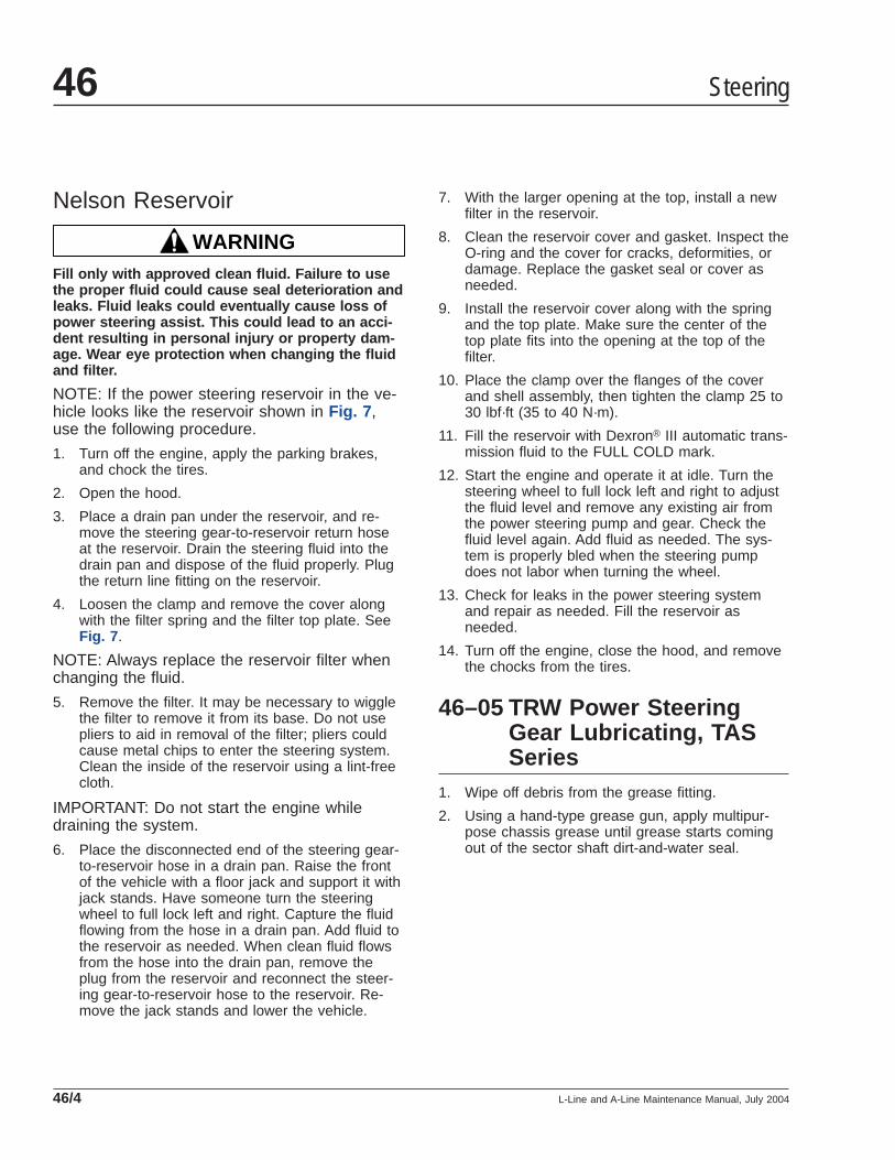
Nelson Reservoir
WARNINGFill only with approved clean fluid. Failure to usethe proper fluid could cause seal deterioration andleaks. Fluid leaks could eventually cause loss ofpower steering assist. This could lead to an acci-dent resulting in personal injury or property dam-age. Wear eye protection when changing the fluidand filter.
NOTE: If the power steering reservoir in the ve-hicle looks like the reservoir shown in Fig. 7 ,use the following procedure.
1. Turn off the engine, apply the parking brakes,and chock the tires.
2. Open the hood.
3. Place a drain pan under the reservoir, and re-move the steering gear-to-reservoir return hoseat the reservoir. Drain the steering fluid into thedrain pan and dispose of the fluid properly. Plugthe return line fitting on the reservoir.
4. Loosen the clamp and remove the cover alongwith the filter spring and the filter top plate. SeeFig. 7 .
NOTE: Always replace the reservoir filter whenchanging the fluid.
5. Remove the filter. It may be necessary to wigglethe filter to remove it from its base. Do not usepliers to aid in removal of the filter; pliers couldcause metal chips to enter the steering system.Clean the inside of the reservoir using a lint-freecloth.
IMPORTANT: Do not start the engine whiledraining the system.
6. Place the disconnected end of the steering gear-to-reservoir hose in a drain pan. Raise the frontof the vehicle with a floor jack and support it withjack stands. Have someone turn the steeringwheel to full lock left and right. Capture the fluidflowing from the hose in a drain pan. Add fluid tothe reservoir as needed. When clean fluid flowsfrom the hose into the drain pan, remove theplug from the reservoir and reconnect the steer-ing gear-to-reservoir hose to the reservoir. Re-move the jack stands and lower the vehicle.
7. With the larger opening at the top, install a newfilter in the reservoir.
8. Clean the reservoir cover and gasket. Inspect theO-ring and the cover for cracks, deformities, ordamage. Replace the gasket seal or cover asneeded.
9. Install the reservoir cover along with the springand the top plate. Make sure the center of thetop plate fits into the opening at the top of thefilter.
10. Place the clamp over the flanges of the coverand shell assembly, then tighten the clamp 25 to30 lbf·ft (35 to 40 N·m).
11. Fill the reservoir with Dexron® III automatic trans-mission fluid to the FULL COLD mark.
12. Start the engine and operate it at idle. Turn thesteering wheel to full lock left and right to adjustthe fluid level and remove any existing air fromthe power steering pump and gear. Check thefluid level again. Add fluid as needed. The sys-tem is properly bled when the steering pumpdoes not labor when turning the wheel.
13. Check for leaks in the power steering systemand repair as needed. Fill the reservoir asneeded.
14. Turn off the engine, close the hood, and removethe chocks from the tires.
46–05 TRW Power SteeringGear Lubricating, TASSeries
1. Wipe off debris from the grease fitting.
2. Using a hand-type grease gun, apply multipur-pose chassis grease until grease starts comingout of the sector shaft dirt-and-water seal.
Steering46
L-Line and A-Line Maintenance Manual, July 200446/4

Title of Maintenance Operation (MOP) MOP Number
Fuel Separator Sight Bowl Cleaning and Element Replacing . . . . . . . . . . . . . . . . . . . . . . . . . . . . . . . . . . 47–03
Fuel Tank Band Nut Tightening. . . . . . . . . . . . . . . . . . . . . . . . . . . . . . . . . . . . . . . . . . . . . . . . . . . . . . . . 47–02
Fuel Tank Vent Checking . . . . . . . . . . . . . . . . . . . . . . . . . . . . . . . . . . . . . . . . . . . . . . . . . . . . . . . . . . . . 47–01
Fuel 47Index, Alphabetical
L-Line and A-Line Maintenance Manual, October 1999
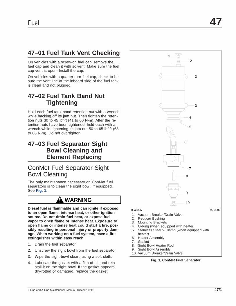
47–01 Fuel Tank Vent CheckingOn vehicles with a screw-on fuel cap, remove thefuel cap and clean it with solvent. Make sure the fuelcap vent is open. Install the cap.
On vehicles with a quarter-turn fuel cap, check to besure the vent line at the inboard side of the fuel tankis clean and not plugged.
47–02 Fuel Tank Band NutTightening
Hold each fuel tank band retention nut with a wrenchwhile backing off its jam nut. Then tighten the reten-tion nuts 30 to 45 lbf·ft (41 to 60 N·m). After the re-tention nuts have been tightened, hold each with awrench while tightening its jam nut 50 to 65 lbf·ft (68to 88 N·m). Do not overtighten.
47–03 Fuel Separator SightBowl Cleaning andElement Replacing
ConMet Fuel Separator SightBowl CleaningThe only maintenance necessary on ConMet fuelseparators is to clean the sight bowl, if equipped.See Fig. 1 .
WARNINGDiesel fuel is flammable and can ignite if exposedto an open flame, intense heat, or other ignitionsource. Do not drain fuel near, or expose fuelvapor to open flame or intense heat. Exposure toopen flame or intense heat could start a fire, pos-sibly resulting in personal injury or property dam-age. When working on a fuel system, have a fireextinguisher within easy reach.
1. Drain the fuel separator.
2. Unscrew the sight bowl from the fuel separator.
3. Wipe the sight bowl clean, using a soft cloth.
4. Lubricate the gasket with a film of oil, and rein-stall it on the sight bowl. If the gasket appearsdry-rotted or damaged, replace the gasket.
08/25/95 f470146
10
9
8
7
6
5
4
3
3
21
1. Vacuum Breaker/Drain Valve2. Reducer Bushing3. Mounting Brackets4. O-Ring (when equipped with heater)5. Stainless Steel V-Clamp (when equipped with
heater)6. Heater Assembly7. Gasket8. Sight Bowl Heater Rod9. Sight Bowl Assembly10. Vacuum Breaker/Drain Valve
Fig. 1, ConMet Fuel Separator
Fuel 47
L-Line and A-Line Maintenance Manual, October 1999 47/1
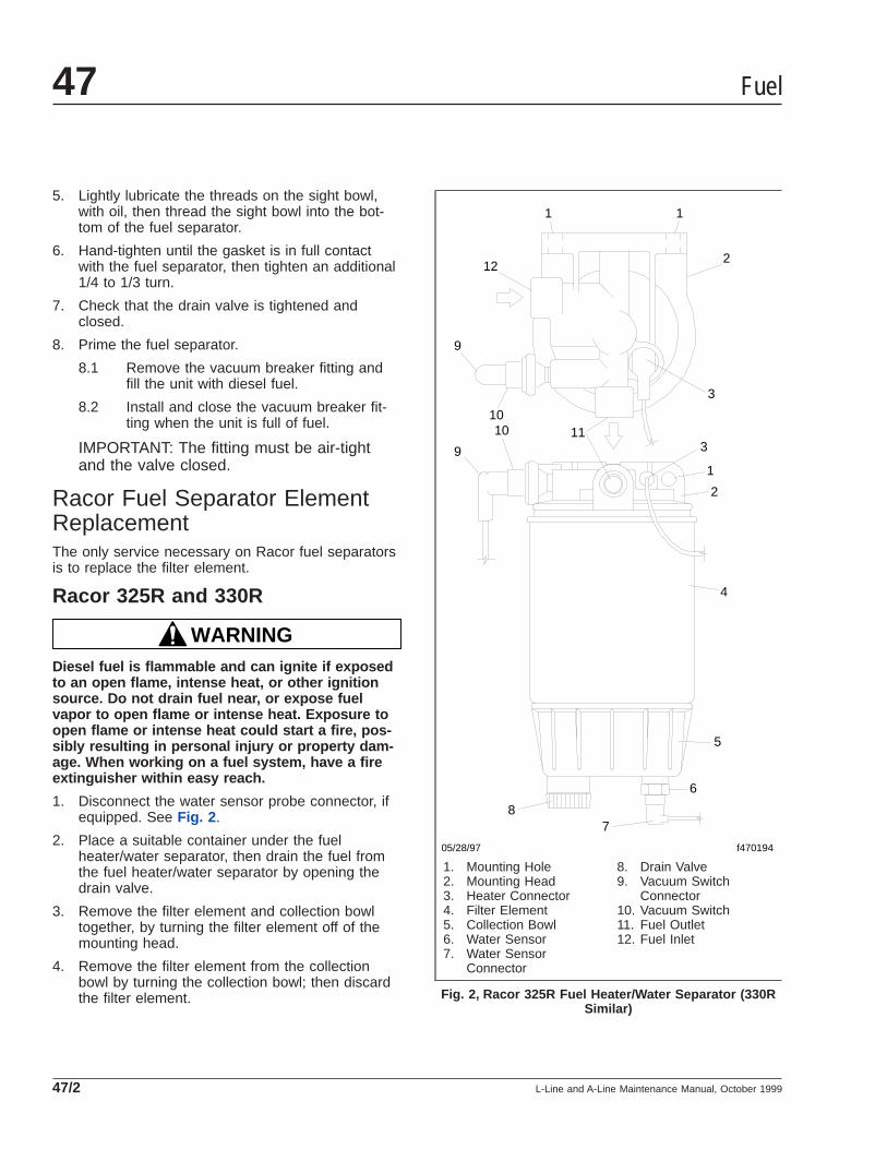
5. Lightly lubricate the threads on the sight bowl,with oil, then thread the sight bowl into the bot-tom of the fuel separator.
6. Hand-tighten until the gasket is in full contactwith the fuel separator, then tighten an additional1/4 to 1/3 turn.
7. Check that the drain valve is tightened andclosed.
8. Prime the fuel separator.
8.1 Remove the vacuum breaker fitting andfill the unit with diesel fuel.
8.2 Install and close the vacuum breaker fit-ting when the unit is full of fuel.
IMPORTANT: The fitting must be air-tightand the valve closed.
Racor Fuel Separator ElementReplacementThe only service necessary on Racor fuel separatorsis to replace the filter element.
Racor 325R and 330R
WARNINGDiesel fuel is flammable and can ignite if exposedto an open flame, intense heat, or other ignitionsource. Do not drain fuel near, or expose fuelvapor to open flame or intense heat. Exposure toopen flame or intense heat could start a fire, pos-sibly resulting in personal injury or property dam-age. When working on a fuel system, have a fireextinguisher within easy reach.
1. Disconnect the water sensor probe connector, ifequipped. See Fig. 2 .
2. Place a suitable container under the fuelheater/water separator, then drain the fuel fromthe fuel heater/water separator by opening thedrain valve.
3. Remove the filter element and collection bowltogether, by turning the filter element off of themounting head.
4. Remove the filter element from the collectionbowl by turning the collection bowl; then discardthe filter element.
05/28/97 f470194
1 1
2
3
12
9
1010 11
39
1
2
4
5
6
78
1. Mounting Hole2. Mounting Head3. Heater Connector4. Filter Element5. Collection Bowl6. Water Sensor7. Water Sensor
Connector
8. Drain Valve9. Vacuum Switch
Connector10. Vacuum Switch11. Fuel Outlet12. Fuel Inlet
Fig. 2, Racor 325R Fuel Heater/Water Separator (330RSimilar)
Fuel47
L-Line and A-Line Maintenance Manual, October 199947/2
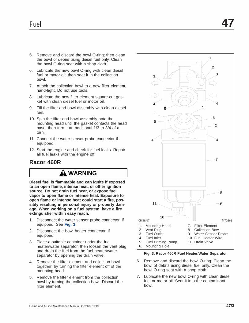
5. Remove and discard the bowl O-ring; then cleanthe bowl of debris using diesel fuel only. Cleanthe bowl O-ring seat with a shop cloth.
6. Lubricate the new bowl O-ring with clean dieselfuel or motor oil; then seat it in the collectionbowl.
7. Attach the collection bowl to a new filter element,hand-tight. Do not use tools.
8. Lubricate the new filter element square-cut gas-ket with clean diesel fuel or motor oil.
9. Fill the filter and bowl assembly with clean dieselfuel.
10. Spin the filter and bowl assembly onto themounting head until the gasket contacts the headbase; then turn it an additional 1/3 to 3/4 of aturn.
11. Connect the water sensor probe connector ifequipped.
12. Start the engine and check for fuel leaks. Repairall fuel leaks with the engine off.
Racor 460R
WARNINGDiesel fuel is flammable and can ignite if exposedto an open flame, intense heat, or other ignitionsource. Do not drain fuel near, or expose fuelvapor to open flame or intense heat. Exposure toopen flame or intense heat could start a fire, pos-sibly resulting in personal injury or property dam-age. When working on a fuel system, have a fireextinguisher within easy reach.
1. Disconnect the water sensor probe connector, ifequipped. See Fig. 3 .
2. Disconnect the bowl heater connector, ifequipped.
3. Place a suitable container under the fuelheater/water separator, then loosen the vent plugand drain the fuel from the fuel heater/waterseparator by opening the drain valve.
4. Remove the filter element and collection bowltogether, by turning the filter element off of themounting head.
5. Remove the filter element from the collectionbowl by turning the collection bowl. Discard thefilter element.
6. Remove and discard the bowl O-ring. Clean thebowl of debris using diesel fuel only. Clean thebowl O-ring seat with a shop cloth.
7. Lubricate the new bowl O-ring with clean dieselfuel or motor oil. Seat it into the contaminantbowl.
05/28/97 f470261
1
2
33
445 5
1
66
7
8
9
10
11
44
2
1. Mounting Head2. Vent Plug3. Fuel Outlet4. Fuel Inlet5. Fuel Priming Pump6. Mounting Hole
7. Filter Element8. Collection Bowl9. Water Sensor Probe10. Fuel Heater Wire11. Drain Valve
Fig. 3, Racor 460R Fuel Heater/Water Separator
Fuel 47
L-Line and A-Line Maintenance Manual, October 1999 47/3
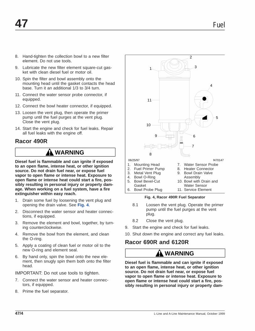
8. Hand-tighten the collection bowl to a new filterelement. Do not use tools.
9. Lubricate the new filter element square-cut gas-ket with clean diesel fuel or motor oil.
10. Spin the filter and bowl assembly onto themounting head until the gasket contacts the headbase. Turn it an additional 1/3 to 3/4 turn.
11. Connect the water sensor probe connector, ifequipped.
12. Connect the bowl heater connector, if equipped.
13. Loosen the vent plug, then operate the primerpump until the fuel purges at the vent plug.Close the vent plug.
14. Start the engine and check for fuel leaks. Repairall fuel leaks with the engine off.
Racor 490R
WARNINGDiesel fuel is flammable and can ignite if exposedto an open flame, intense heat, or other ignitionsource. Do not drain fuel near, or expose fuelvapor to open flame or intense heat. Exposure toopen flame or intense heat could start a fire, pos-sibly resulting in personal injury or property dam-age. When working on a fuel system, have a fireextinguisher within easy reach.
1. Drain some fuel by loosening the vent plug andopening the drain valve. See Fig. 4 .
2. Disconnect the water sensor and heater connec-tions, if equipped.
3. Remove the element and bowl, together, by turn-ing counterclockwise.
4. Remove the bowl from the element, and cleanthe O-ring.
5. Apply a coating of clean fuel or motor oil to thenew O-ring and element seal.
6. By hand only, spin the bowl onto the new ele-ment, then snugly spin them both onto the filterhead.
IMPORTANT: Do not use tools to tighten.
7. Connect the water sensor and heater connec-tors, if equipped.
8. Prime the fuel separator.
8.1 Loosen the vent plug. Operate the primerpump until the fuel purges at the ventplug.
8.2 Close the vent plug.
9. Start the engine and check for fuel leaks.
10. Shut down the engine and correct any fuel leaks.
Racor 690R and 6120R
WARNINGDiesel fuel is flammable and can ignite if exposedto an open flame, intense heat, or other ignitionsource. Do not drain fuel near, or expose fuelvapor to open flame or intense heat. Exposure toopen flame or intense heat could start a fire, pos-sibly resulting in personal injury or property dam-
5
4
31
2
06/25/97 f470147
6
7
11
10
9
8
1. Mounting Head2. Fuel Primer Pump3. Metal Vent Plug4. Bowl O-Ring5. Bowl Bevel-Cut
Gasket6. Bowl Probe Plug
7. Water Sensor Probe8. Heater Connector9. Bowl Drain Valve
Assembly10. Bowl with Drain and
Water Sensor11. Service Element
Fig. 4, Racor 490R Fuel Separator
Fuel47
L-Line and A-Line Maintenance Manual, October 199947/4
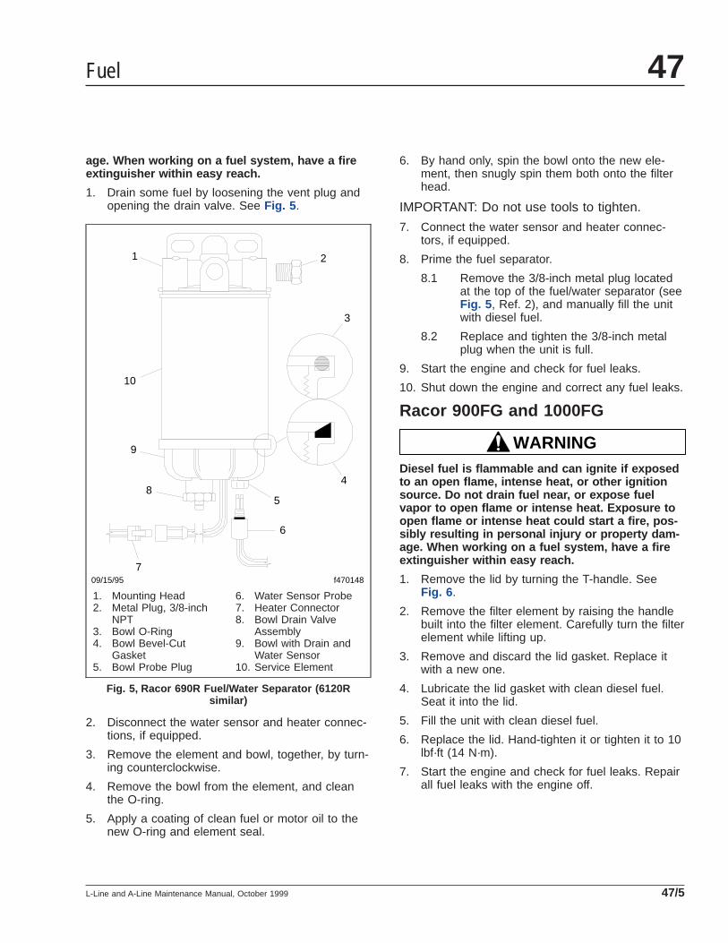
age. When working on a fuel system, have a fireextinguisher within easy reach.
1. Drain some fuel by loosening the vent plug andopening the drain valve. See Fig. 5 .
2. Disconnect the water sensor and heater connec-tions, if equipped.
3. Remove the element and bowl, together, by turn-ing counterclockwise.
4. Remove the bowl from the element, and cleanthe O-ring.
5. Apply a coating of clean fuel or motor oil to thenew O-ring and element seal.
6. By hand only, spin the bowl onto the new ele-ment, then snugly spin them both onto the filterhead.
IMPORTANT: Do not use tools to tighten.
7. Connect the water sensor and heater connec-tors, if equipped.
8. Prime the fuel separator.
8.1 Remove the 3/8-inch metal plug locatedat the top of the fuel/water separator (seeFig. 5 , Ref. 2), and manually fill the unitwith diesel fuel.
8.2 Replace and tighten the 3/8-inch metalplug when the unit is full.
9. Start the engine and check for fuel leaks.
10. Shut down the engine and correct any fuel leaks.
Racor 900FG and 1000FG
WARNINGDiesel fuel is flammable and can ignite if exposedto an open flame, intense heat, or other ignitionsource. Do not drain fuel near, or expose fuelvapor to open flame or intense heat. Exposure toopen flame or intense heat could start a fire, pos-sibly resulting in personal injury or property dam-age. When working on a fuel system, have a fireextinguisher within easy reach.
1. Remove the lid by turning the T-handle. SeeFig. 6 .
2. Remove the filter element by raising the handlebuilt into the filter element. Carefully turn the filterelement while lifting up.
3. Remove and discard the lid gasket. Replace itwith a new one.
4. Lubricate the lid gasket with clean diesel fuel.Seat it into the lid.
5. Fill the unit with clean diesel fuel.
6. Replace the lid. Hand-tighten it or tighten it to 10lbf·ft (14 N·m).
7. Start the engine and check for fuel leaks. Repairall fuel leaks with the engine off.
09/15/95 f470148
1 2
3
4
10
9
7
8
6
5
1. Mounting Head2. Metal Plug, 3/8-inch
NPT3. Bowl O-Ring4. Bowl Bevel-Cut
Gasket5. Bowl Probe Plug
6. Water Sensor Probe7. Heater Connector8. Bowl Drain Valve
Assembly9. Bowl with Drain and
Water Sensor10. Service Element
Fig. 5, Racor 690R Fuel/Water Separator (6120Rsimilar)
Fuel 47
L-Line and A-Line Maintenance Manual, October 1999 47/5
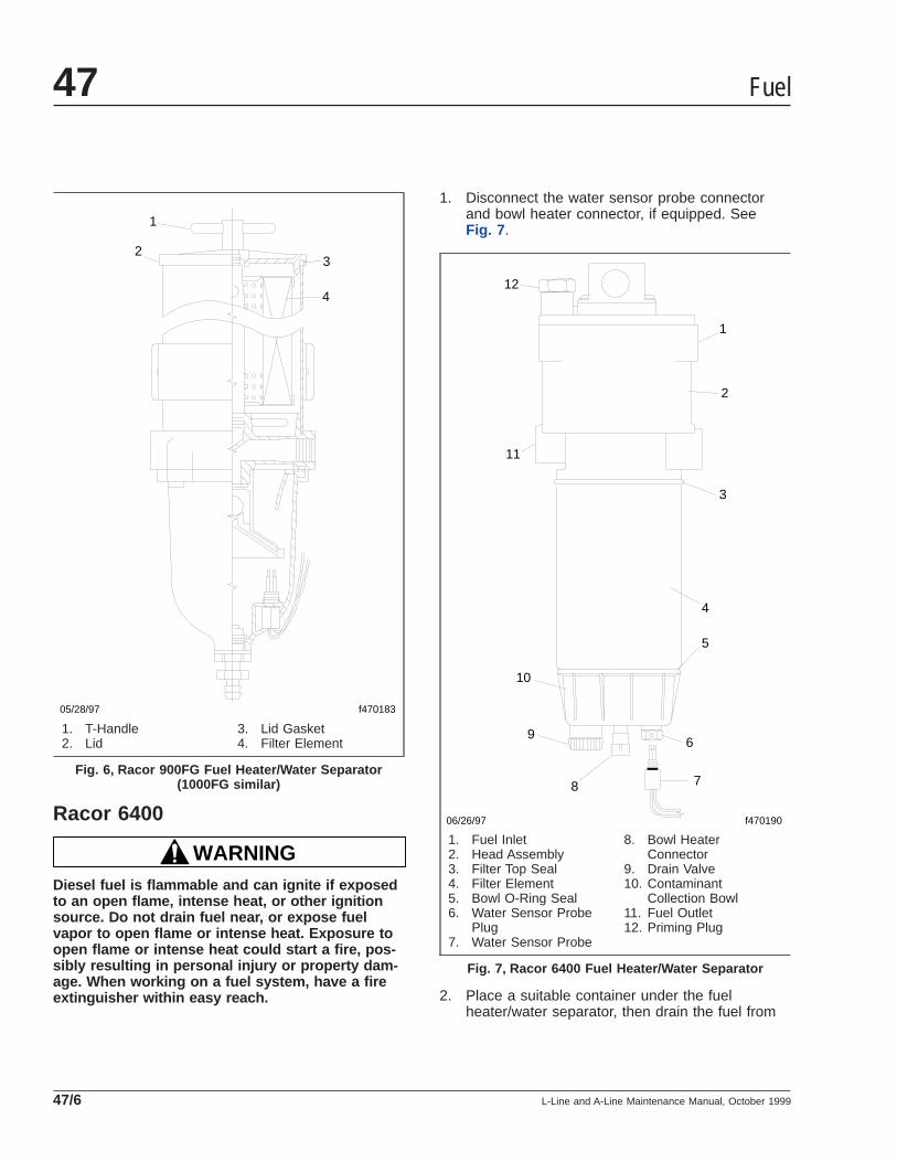
Racor 6400
WARNINGDiesel fuel is flammable and can ignite if exposedto an open flame, intense heat, or other ignitionsource. Do not drain fuel near, or expose fuelvapor to open flame or intense heat. Exposure toopen flame or intense heat could start a fire, pos-sibly resulting in personal injury or property dam-age. When working on a fuel system, have a fireextinguisher within easy reach.
1. Disconnect the water sensor probe connectorand bowl heater connector, if equipped. SeeFig. 7 .
2. Place a suitable container under the fuelheater/water separator, then drain the fuel from
05/28/97
1
2
f470183
3
4
1. T-Handle2. Lid
3. Lid Gasket4. Filter Element
Fig. 6, Racor 900FG Fuel Heater/Water Separator(1000FG similar)
06/26/97 f470190
11
1
2
3
10
4
5
6
78
9
12
1. Fuel Inlet2. Head Assembly3. Filter Top Seal4. Filter Element5. Bowl O-Ring Seal6. Water Sensor Probe
Plug7. Water Sensor Probe
8. Bowl HeaterConnector
9. Drain Valve10. Contaminant
Collection Bowl11. Fuel Outlet12. Priming Plug
Fig. 7, Racor 6400 Fuel Heater/Water Separator
Fuel47
L-Line and A-Line Maintenance Manual, October 199947/6
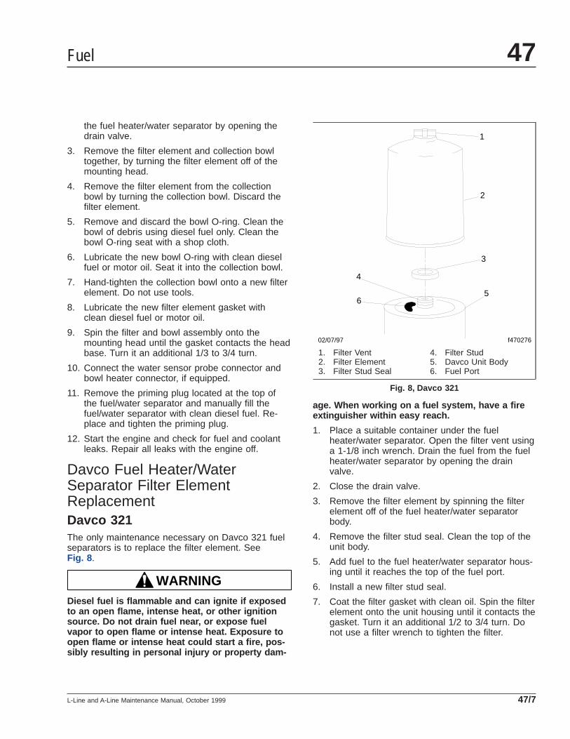
the fuel heater/water separator by opening thedrain valve.
3. Remove the filter element and collection bowltogether, by turning the filter element off of themounting head.
4. Remove the filter element from the collectionbowl by turning the collection bowl. Discard thefilter element.
5. Remove and discard the bowl O-ring. Clean thebowl of debris using diesel fuel only. Clean thebowl O-ring seat with a shop cloth.
6. Lubricate the new bowl O-ring with clean dieselfuel or motor oil. Seat it into the collection bowl.
7. Hand-tighten the collection bowl onto a new filterelement. Do not use tools.
8. Lubricate the new filter element gasket withclean diesel fuel or motor oil.
9. Spin the filter and bowl assembly onto themounting head until the gasket contacts the headbase. Turn it an additional 1/3 to 3/4 turn.
10. Connect the water sensor probe connector andbowl heater connector, if equipped.
11. Remove the priming plug located at the top ofthe fuel/water separator and manually fill thefuel/water separator with clean diesel fuel. Re-place and tighten the priming plug.
12. Start the engine and check for fuel and coolantleaks. Repair all leaks with the engine off.
Davco Fuel Heater/WaterSeparator Filter ElementReplacementDavco 321The only maintenance necessary on Davco 321 fuelseparators is to replace the filter element. SeeFig. 8 .
WARNINGDiesel fuel is flammable and can ignite if exposedto an open flame, intense heat, or other ignitionsource. Do not drain fuel near, or expose fuelvapor to open flame or intense heat. Exposure toopen flame or intense heat could start a fire, pos-sibly resulting in personal injury or property dam-
age. When working on a fuel system, have a fireextinguisher within easy reach.
1. Place a suitable container under the fuelheater/water separator. Open the filter vent usinga 1-1/8 inch wrench. Drain the fuel from the fuelheater/water separator by opening the drainvalve.
2. Close the drain valve.
3. Remove the filter element by spinning the filterelement off of the fuel heater/water separatorbody.
4. Remove the filter stud seal. Clean the top of theunit body.
5. Add fuel to the fuel heater/water separator hous-ing until it reaches the top of the fuel port.
6. Install a new filter stud seal.
7. Coat the filter gasket with clean oil. Spin the filterelement onto the unit housing until it contacts thegasket. Turn it an additional 1/2 to 3/4 turn. Donot use a filter wrench to tighten the filter.
02/07/97 f470276
1
2
3
4
65
1. Filter Vent2. Filter Element3. Filter Stud Seal
4. Filter Stud5. Davco Unit Body6. Fuel Port
Fig. 8, Davco 321
Fuel 47
L-Line and A-Line Maintenance Manual, October 1999 47/7
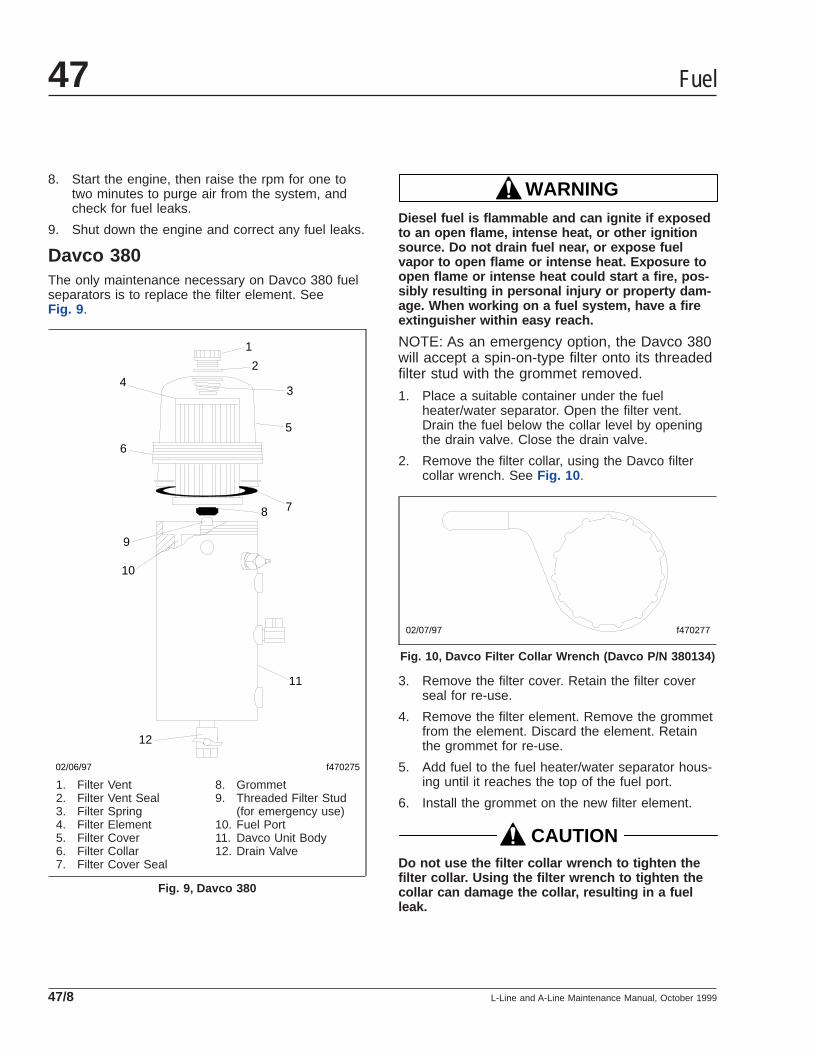
8. Start the engine, then raise the rpm for one totwo minutes to purge air from the system, andcheck for fuel leaks.
9. Shut down the engine and correct any fuel leaks.
Davco 380The only maintenance necessary on Davco 380 fuelseparators is to replace the filter element. SeeFig. 9 .
WARNINGDiesel fuel is flammable and can ignite if exposedto an open flame, intense heat, or other ignitionsource. Do not drain fuel near, or expose fuelvapor to open flame or intense heat. Exposure toopen flame or intense heat could start a fire, pos-sibly resulting in personal injury or property dam-age. When working on a fuel system, have a fireextinguisher within easy reach.
NOTE: As an emergency option, the Davco 380will accept a spin-on-type filter onto its threadedfilter stud with the grommet removed.
1. Place a suitable container under the fuelheater/water separator. Open the filter vent.Drain the fuel below the collar level by openingthe drain valve. Close the drain valve.
2. Remove the filter collar, using the Davco filtercollar wrench. See Fig. 10 .
3. Remove the filter cover. Retain the filter coverseal for re-use.
4. Remove the filter element. Remove the grommetfrom the element. Discard the element. Retainthe grommet for re-use.
5. Add fuel to the fuel heater/water separator hous-ing until it reaches the top of the fuel port.
6. Install the grommet on the new filter element.
CAUTIONDo not use the filter collar wrench to tighten thefilter collar. Using the filter wrench to tighten thecollar can damage the collar, resulting in a fuelleak.
02/06/97
1
2
3
5
4
6
78
9
10
11
12
f470275
1. Filter Vent2. Filter Vent Seal3. Filter Spring4. Filter Element5. Filter Cover6. Filter Collar7. Filter Cover Seal
8. Grommet9. Threaded Filter Stud
(for emergency use)10. Fuel Port11. Davco Unit Body12. Drain Valve
Fig. 9, Davco 380
02/07/97 f470277
Fig. 10, Davco Filter Collar Wrench (Davco P/N 380134)
Fuel47
L-Line and A-Line Maintenance Manual, October 199947/8
7. Install the filter element, filter cover and coverseal, and filter collar. Hand-tighten the filter col-lar.
8. Remove the filter vent. Fill with fuel until fuel isabout one inch above the collar. Replace the fil-ter vent.
9. Start the engine, then raise the rpm for oneminute to purge air from the system, and checkfor fuel leaks.
10. Shut down the engine and correct any fuel leaks.
Fuel 47
L-Line and A-Line Maintenance Manual, October 1999 47/9
Title of Maintenance Operation (MOP) MOP Number
Exhaust System Inspecting (Noise Emission Control). . . . . . . . . . . . . . . . . . . . . . . . . . . . . . . . . . . . . . . . 49–01
Exhaust 49Index, Alphabetical
L-Line and A-Line Maintenance Manual, January 2007
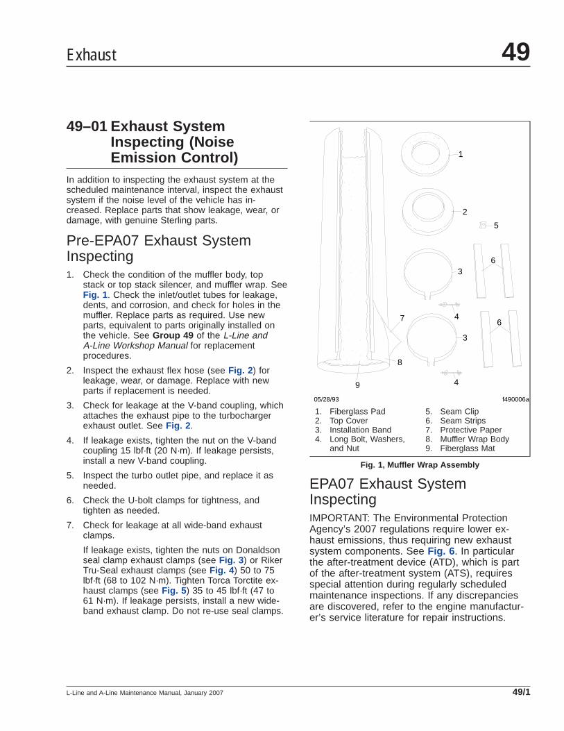
49–01 Exhaust SystemInspecting (NoiseEmission Control)
In addition to inspecting the exhaust system at thescheduled maintenance interval, inspect the exhaustsystem if the noise level of the vehicle has in-creased. Replace parts that show leakage, wear, ordamage, with genuine Sterling parts.
Pre-EPA07 Exhaust SystemInspecting1. Check the condition of the muffler body, top
stack or top stack silencer, and muffler wrap. SeeFig. 1 . Check the inlet/outlet tubes for leakage,dents, and corrosion, and check for holes in themuffler. Replace parts as required. Use newparts, equivalent to parts originally installed onthe vehicle. See Group 49 of the L-Line andA-Line Workshop Manual for replacementprocedures.
2. Inspect the exhaust flex hose (see Fig. 2 ) forleakage, wear, or damage. Replace with newparts if replacement is needed.
3. Check for leakage at the V-band coupling, whichattaches the exhaust pipe to the turbochargerexhaust outlet. See Fig. 2 .
4. If leakage exists, tighten the nut on the V-bandcoupling 15 lbf·ft (20 N·m). If leakage persists,install a new V-band coupling.
5. Inspect the turbo outlet pipe, and replace it asneeded.
6. Check the U-bolt clamps for tightness, andtighten as needed.
7. Check for leakage at all wide-band exhaustclamps.
If leakage exists, tighten the nuts on Donaldsonseal clamp exhaust clamps (see Fig. 3 ) or RikerTru-Seal exhaust clamps (see Fig. 4 ) 50 to 75lbf·ft (68 to 102 N·m). Tighten Torca Torctite ex-haust clamps (see Fig. 5 ) 35 to 45 lbf·ft (47 to61 N·m). If leakage persists, install a new wide-band exhaust clamp. Do not re-use seal clamps.
EPA07 Exhaust SystemInspectingIMPORTANT: The Environmental ProtectionAgency’s 2007 regulations require lower ex-haust emissions, thus requiring new exhaustsystem components. See Fig. 6 . In particularthe after-treatment device (ATD), which is partof the after-treatment system (ATS), requiresspecial attention during regularly scheduledmaintenance inspections. If any discrepanciesare discovered, refer to the engine manufactur-er’s service literature for repair instructions.
f490006a
1
2
3
4
4
3
6
6
5
7
9
8
05/28/93
1. Fiberglass Pad2. Top Cover3. Installation Band4. Long Bolt, Washers,
and Nut
5. Seam Clip6. Seam Strips7. Protective Paper8. Muffler Wrap Body9. Fiberglass Mat
Fig. 1, Muffler Wrap Assembly
Exhaust 49
L-Line and A-Line Maintenance Manual, January 2007 49/1
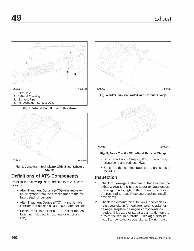
Definitions of ATS ComponentsRefer to the following list of definitions of ATS com-ponents.
• After-Treatment System (ATS)—the entire ex-haust system from the turbocharger to the ex-haust stack or tail pipe.
• After-Treatment Device (ATD)—a muffler-likecanister that houses a DPF, DOC, and sensors.
• Diesel Particulate Filter (DPF)—a filter that col-lects and holds particulate matter (soot andash).
• Diesel Oxidation Catalyst (DOC)—oxidizes hy-drocarbons and reduces NOx.
• Sensors—detect temperatures and pressures inthe ATS.
Inspection1. Check for leakage at the clamp that attaches the
exhaust pipe to the turbocharger exhaust outlet.If leakage exists, tighten the nut on the clamp tothe required torque. If leakage persists, install anew clamp.
2. Check the exhaust pipe, bellows, and each ex-haust seal clamp for leakage, wear, cracks, ordamage. Replace damaged components asneeded. If leakage exists at a clamp, tighten thenuts to the required torque. If leakage persists,install a new exhaust seal clamp. Do not reuse
f490024a
1
2
3
06/01/93
4
1. Flex Hose2. V-Band Coupling3. Exhaust Pipe4. Turbocharger Exhaust Outlet
Fig. 2, V-Band Coupling and Flex Hose
f490025a05/28/93
Fig. 3, Donaldson Seal Clamp Wide-Band ExhaustClamp
f490023a05/28/93
Fig. 4, Riker Tru-Seal Wide-Band Exhaust Clamp
f490005a10/05/94
Fig. 5, Torca Torctite Wide-Band Exhaust Clamp
Exhaust49
L-Line and A-Line Maintenance Manual, January 200749/2
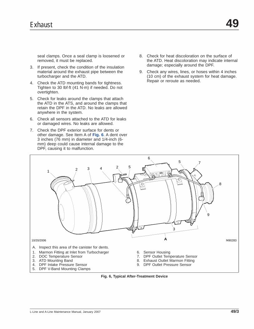
seal clamps. Once a seal clamp is loosened orremoved, it must be replaced.
3. If present, check the condition of the insulationmaterial around the exhaust pipe between theturbocharger and the ATD.
4. Check the ATD mounting bands for tightness.Tighten to 30 lbf·ft (41 N·m) if needed. Do notovertighten.
5. Check for leaks around the clamps that attachthe ATD in the ATS, and around the clamps thatretain the DPF in the ATD. No leaks are allowedanywhere in the system.
6. Check all sensors attached to the ATD for leaksor damaged wires. No leaks are allowed.
7. Check the DPF exterior surface for dents orother damage. See Item A of Fig. 6 . A dent over3 inches (76 mm) in diameter and 1/4-inch (6-mm) deep could cause internal damage to theDPF, causing it to malfunction.
8. Check for heat discoloration on the surface ofthe ATD. Heat discoloration may indicate internaldamage; especially around the DPF.
9. Check any wires, lines, or hoses within 4 inches(10 cm) of the exhaust system for heat damage.Repair or reroute as needed.
f490283
1 22 5
65 7
8
9
3
3
4
10/20/2006 A
A. Inspect this area of the canister for dents.1. Marmon Fitting at Inlet from Turbocharger2. DOC Temperature Sensor3. ATD Mounting Band4. DPF Intake Pressure Sensor5. DPF V-Band Mounting Clamps
6. Sensor Housing7. DPF Outlet Temperature Sensor8. Exhaust Outlet Marmon Fitting9. DPF Outlet Pressure Sensor
Fig. 6, Typical After-Treatment Device
Exhaust 49
L-Line and A-Line Maintenance Manual, January 2007 49/3
Title of Maintenance Operation (MOP) MOP Number
Electrical System Checking. . . . . . . . . . . . . . . . . . . . . . . . . . . . . . . . . . . . . . . . . . . . . . . . . . . . . . . . . . . 54–01
Electrical, Instruments, and Controls 54Index, Alphabetical
L-Line and A-Line Maintenance Manual, October 1999
54–01 Electrical SystemChecking
Cab InteriorInspect the wiring and electrical connections at theelectrical mounting plate, cab-to-chassis interfaceconnectors, cab-to-engine interface connectors, maincab-power and cab-ground studs, and electrical junc-tion blocks.
Check all wiring for chafing, kinks, and discoloredinsulation. Find the cause of any problems, then re-pair, replace, or reroute wires as needed.
Check that all relays are firmly seated in their mount-ing plates.
Check the tightness of the connections on the electri-cal junction block(s), main cab-power stud, and cab-ground stud, as equipped.
Install all of the removed panels.
Chassis1. Check the main chassis wiring harness. Check
the wiring insulation for damage from chafing orheat. Also check for kinks. Reroute, repair, orreplace wires as needed.
CAUTIONDo not use flat-strip aluminum tie straps for hold-ing electrical wiring. The sharp edges on these tiestraps may cause breaks in the wire insulation,allowing the aluminum tie strap to make contactwith the wire. This could cause a short circuit anddamage to the wiring.
2. Check all tie straps for breakage and damage.Replace any broken or cracked tie straps.
3. Check the wires of all sensors on or near theengine. Make sure no wires are closer than 6inches (15 cm) to hot surfaces. If any are, andcan not be rerouted, make sure they are pro-tected by heat shields. Check that sensor con-nectors are tight, clean, and undamaged.
4. On engines with electronic controls, check thewiring and connectors on the computer units.
Electrical, Instruments, and Controls 54
L-Line and A-Line Maintenance Manual, October 1999 54/1
Title of Maintenance Operation (MOP) MOP Number
Door Latch and Door Hinge Lubricating. . . . . . . . . . . . . . . . . . . . . . . . . . . . . . . . . . . . . . . . . . . . . . . . . . 72–01
Doors 72Index, Alphabetical
L-Line and A-Line Maintenance Manual, October 1999
72–01 Door Latch and DoorHinge Lubricating
Apply a few drops of light engine oil to the door latchmechanism to reduce noise and wear. Wipe off ex-cess oil. This includes baggage doors, ventilatordoors, and the oil-check door.
Lubricate door hinges every six months. In addition,lubricate new door hinges at installation. Lubricatethe hinges by spraying them with a light coating ofsilicone lubricant such as WD–40® or an equivalent.
Doors 72
L-Line and A-Line Maintenance Manual, October 1999 72/1
Title of Maintenance Operation (MOP) MOP Number
Air Conditioner Inspecting. . . . . . . . . . . . . . . . . . . . . . . . . . . . . . . . . . . . . . . . . . . . . . . . . . . . . . . . . . . . 83–01
Air Filter Replacing. . . . . . . . . . . . . . . . . . . . . . . . . . . . . . . . . . . . . . . . . . . . . . . . . . . . . . . . . . . . . . . . . 83–02
Heater and Air Conditioner 83Index, Alphabetical
L-Line and A-Line Maintenance Manual, January 2008
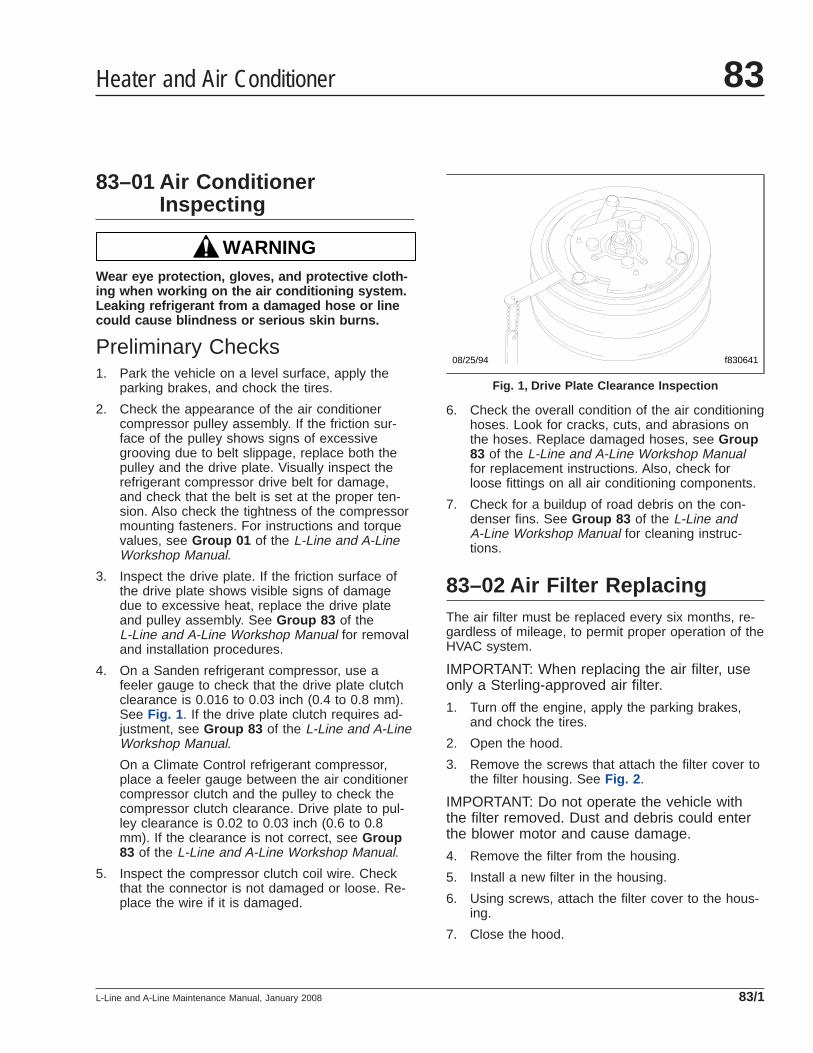
83–01 Air ConditionerInspecting
WARNINGWear eye protection, gloves, and protective cloth-ing when working on the air conditioning system.Leaking refrigerant from a damaged hose or linecould cause blindness or serious skin burns.
Preliminary Checks1. Park the vehicle on a level surface, apply the
parking brakes, and chock the tires.
2. Check the appearance of the air conditionercompressor pulley assembly. If the friction sur-face of the pulley shows signs of excessivegrooving due to belt slippage, replace both thepulley and the drive plate. Visually inspect therefrigerant compressor drive belt for damage,and check that the belt is set at the proper ten-sion. Also check the tightness of the compressormounting fasteners. For instructions and torquevalues, see Group 01 of the L-Line and A-LineWorkshop Manual.
3. Inspect the drive plate. If the friction surface ofthe drive plate shows visible signs of damagedue to excessive heat, replace the drive plateand pulley assembly. See Group 83 of theL-Line and A-Line Workshop Manual for removaland installation procedures.
4. On a Sanden refrigerant compressor, use afeeler gauge to check that the drive plate clutchclearance is 0.016 to 0.03 inch (0.4 to 0.8 mm).See Fig. 1 . If the drive plate clutch requires ad-justment, see Group 83 of the L-Line and A-LineWorkshop Manual.
On a Climate Control refrigerant compressor,place a feeler gauge between the air conditionercompressor clutch and the pulley to check thecompressor clutch clearance. Drive plate to pul-ley clearance is 0.02 to 0.03 inch (0.6 to 0.8mm). If the clearance is not correct, see Group83 of the L-Line and A-Line Workshop Manual.
5. Inspect the compressor clutch coil wire. Checkthat the connector is not damaged or loose. Re-place the wire if it is damaged.
6. Check the overall condition of the air conditioninghoses. Look for cracks, cuts, and abrasions onthe hoses. Replace damaged hoses, see Group83 of the L-Line and A-Line Workshop Manualfor replacement instructions. Also, check forloose fittings on all air conditioning components.
7. Check for a buildup of road debris on the con-denser fins. See Group 83 of the L-Line andA-Line Workshop Manual for cleaning instruc-tions.
83–02 Air Filter ReplacingThe air filter must be replaced every six months, re-gardless of mileage, to permit proper operation of theHVAC system.
IMPORTANT: When replacing the air filter, useonly a Sterling-approved air filter.
1. Turn off the engine, apply the parking brakes,and chock the tires.
2. Open the hood.
3. Remove the screws that attach the filter cover tothe filter housing. See Fig. 2 .
IMPORTANT: Do not operate the vehicle withthe filter removed. Dust and debris could enterthe blower motor and cause damage.
4. Remove the filter from the housing.
5. Install a new filter in the housing.
6. Using screws, attach the filter cover to the hous-ing.
7. Close the hood.
08/25/94 f830641
Fig. 1, Drive Plate Clearance Inspection
Heater and Air Conditioner 83
L-Line and A-Line Maintenance Manual, January 2008 83/1
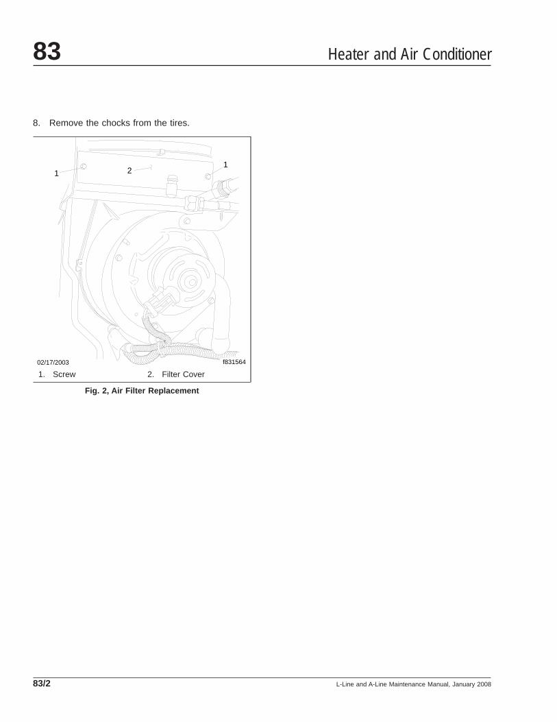
8. Remove the chocks from the tires.
02/17/2003 f831564
11
2
1. Screw 2. Filter Cover
Fig. 2, Air Filter Replacement
Heater and Air Conditioner83
L-Line and A-Line Maintenance Manual, January 200883/2
Title of Maintenance Operation (MOP) MOP Number
Hood Hinge Bushings Lubricating . . . . . . . . . . . . . . . . . . . . . . . . . . . . . . . . . . . . . . . . . . . . . . . . . . . . . . 88–01
Hood 88Index, Alphabetical
L-Line and A-Line Maintenance Manual, October 1999

88–01 Hood Hinge BushingsLubricating
Lubricate the hood hinge bushings at the zerk fit-tings, using multi-purpose chassis grease. Use ahand-type grease gun, or a high-pressure gun with alow-pressure adapter.
Hood 88
L-Line and A-Line Maintenance Manual, October 1999 88/1