Kontron Short Description ® ETX® Eval-Board
16
➤ Kontron Short Description ➤ ETX® Eval-Board Document Revision 117
-
Upload
khangminh22 -
Category
Documents
-
view
0 -
download
0
Transcript of Kontron Short Description ® ETX® Eval-Board

� Kontron Short Description
� ETX® Eval-Board Document Revision 117

This page intentionally left blank

Table of Contents
Kontron Short Description ETX® Eval-Board
iii
Table of Contents
1 User Information........................................................................................................ 4
1.1 About This Document .........................................................................................4 1.2 Copyright Notice ...............................................................................................4 1.3 Trademarks ......................................................................................................4 1.4 Standards ........................................................................................................4 1.5 Warranty .........................................................................................................4 1.6 Technical Support..............................................................................................5
2 Short description........................................................................................................ 6
3 Connector locations .................................................................................................... 7
4 Connector pinout........................................................................................................ 8
4.1 Overview .........................................................................................................8 4.1.1 LCD Connector (JILI)..........................................................................................9 4.1.2 LCD Connector (JIDI) .........................................................................................9 4.1.3 Floppy (from ETX® onboard Super I/O controller) ..................................................10 4.1.4 Feature connector ...........................................................................................10 4.1.5 IrDA connector ............................................................................................... 11 4.1.6 Video out connector (only supported with special BIOS) ......................................... 11 4.1.7 Sound JUMPtec connector................................................................................. 11
5 Super I/O controller on the ETX®-Eval ..........................................................................12
6 Hardware Monitor......................................................................................................13
7 Port80 POST Code.......................................................................................................14
7.1 What is POST? ................................................................................................. 14 7.2 What are POST codes?.......................................................................................14
8 Battery Information...................................................................................................15
9 Document history ......................................................................................................16

1 User Information
Kontron Short Description ETX® Eval-Board
4
1 User Information
1.1 About This Document This document provides information about products from Kontron Embedded Modules GmbH and/or its subsidiaries. No warranty of suitability, purpose, or fitness is implied. While every attempt has been made to ensure that the information in this document is accurate, the information contained within is supplied “as-is” and is subject to change without notice.
For the circuits, descriptions and tables indicated, Kontron assumes no responsibility as far as patents or other rights of third parties are concerned.
1.2 Copyright Notice Copyright © 2003-2007 Kontron Embedded Modules GmbH
All rights reserved. No part of this document may be reproduced, transmitted, transcribed, stored in a retrieval system, or translated into any language or computer language, in any form or by any means (electronic, mechanical, photocopying, recording, or otherwise), without the express written permission of Kontron Embedded Modules GmbH.
DIMM-PC®, PISA®, ETX®, ETXexpress® , X-board®, DIMM-IO® and DIMM-BUS® are trademarks or registered trademarks of Kontron Embedded Modules GmbH. Kontron is trademark or registered trademark of Kontron AG.
1.3 Trademarks The following lists the trademarks of components used in this board.
� IBM, XT, AT, PS/2 and Personal System/2 are trademarks of International Business Machines Corp.
� Microsoft is a registered trademark of Microsoft Corp.
� Intel is a registered trademark of Intel Corp.
� All other products and trademarks mentioned in this manual are trademarks of their respective owners.
1.4 Standards Kontron Embedded Modules GmbH is certified to ISO 9000 standards.
1.5 Warranty This Kontron Embedded Modules GmbH product is warranted against defects in material and workmanship for the warranty period from the date of shipment. During the warranty period, Kontron Embedded Modules GmbH will at its discretion decide to repair or replace defective products.
Within the warranty period, the repair of products is free of charge as long as warranty conditions are observed.

1 User Information
Kontron Short Description ETX® Eval-Board
5
The warranty does not apply to defects resulting from improper or inadequate maintenance or handling by the buyer, unauthorized modification or misuse, operation outside of the product’s environmental specifications or improper installation or maintenance.
Kontron Embedded Modules GmbH will not be responsible for any defects or damages to other products not supplied by Kontron Embedded Modules GmbH that are caused by a faulty Kontron Embedded Modules GmbH product.
1.6 Technical Support Technicians and engineers from Kontron Embedded Modules GmbH and/or its subsidiaries are available for technical support. We are committed to making our product easy to use and will help you use our products in your systems.
Before contacting Kontron Embedded Modules GmbH technical support, please consult our Web site at http://www.kontron-emea.com/emd for the latest product documentation, utilities, and drivers. If the information does not help solve the problem, contact us by telephone or email.
Asia Europe North/South America Kontron Asia Inc. Kontron Embedded Modules GmbH Kontron America
4F, No.415, Ti-Ding Blvd., NeiHu District,
Taipei 114, Taiwan
Brunnwiesenstr. 16 94469 Deggendorf – Germany
14118 Stowe Drive Poway, CA 92064-7147
Tel: +886 2 2799 2789 Tel: +49 (0) 991-37024-0 Tel: +1 (888) 294 4558 Fax: + 886 2 2799 7399 Fax: +49 (0) 991-37024-333 Fax: +1 (858) 677 0898
mailto:[email protected] mailto:[email protected] mailto:[email protected]

2 Short description
Kontron Short Description ETX® Eval-Board
6
2 Short description The following short description is intended to convey a brief overall view of the components. Installation alternatives are depicted herein. Only special non-standard PC functions are explained, as information of all other interfaces is commonly available.

3 Connector locations
Kontron Short Description ETX® Eval-Board
7
3 Connector locations

4 Connector pinout
Kontron Short Description ETX® Eval-Board
8
4 Connector pinout
4.1 Overview Note that pin 1 is marked on the bottom of ETX® evaluation board with a quadratic pad.
Pin# LCD JILI (LVDS)
JIDI (digital) Floppy (ETX®) Feature IrDA Video Out Sound
1 LTGIO0 VSYNC GND VCC_UL NC Y/R SNDR
2 LCDDO0 R0 DENSEL GPE2# NC GND GND 3 LCDDO1 R1 GND BATLOW# IRTX C/G SNDL 4 DIGON DIGON NC GPE1# GND GND AUXAR
5 LCDDO2 R2 GND RSMRST# IRRX COMP/B MIC 6 LCDDO3 R3 NC EXTSMI VCC GND AUXAL 7 BIASON HSYNC GND SERIRQ NC SYNC
8 LCDDO4 R4 INDEX# GPCS# FIR GND 9 LCDDO5 R5 GND I2DAT 10 GND GND NC SMBALRT#
11 LCDDO6 G0 GND I2CLK 12 LCDDO7 G1 DRV SMBDATA 13 GND GND GND SMBCLK
14 LCDDO8 G2 NC EXT_PRG 15 LCDDO9 G3 GND ROMKBCS# 16 JILI_DAT JILI_DAT MOT BATT
17 LCDDO10 G4 GND KBINH 18 LCDDO11 G5 DIR# GND 19 JILI_CLK JILI_CLK GND PWGIN
20 LCDDO12 B0 STEP# GND 21 LCDDO13 B1 GND PWRBTN# 22 DETECT# DETECT# WDATA# GND
23 LCDDO14 B2 GND HLEDR 24 LCDDO15 B3 WGATE# Resistor 330Ω to VCC 25 GND GND GND
26 LCDDO16 B4 TRK0# 27 LCDDO17 B5 GND 28 GND GND WP#
29 LCDDO18 SHFCLK GND 30 LCDDO19 EN RDATA# 31 VCC VCC GND 32 VCC VCC HDSEL#
33 VCC VCC GND 34 VCC VCC DSKCHG# 35 BLON# BLON#
36 GND GND 37 GND GND 38 +12V +12V
39 +12V +12V 40 +12V +12V

4 Connector pinout
Kontron Short Description ETX® Eval-Board
9
4.1.1 LCD Connector (JILI) LCD Connector (JILI) BIASON Controls panel contrast voltage.
DIGON Controls panel digital power.
BLON# Controls backlight power.
LTGIO0 General purpose I/O pin; not used by JILI interface.
JILI_DAT, JILI_CLK I 2 C interface for panel parameter EEPROM. This EEPROM is mounted on the LVDS receiver. The data in the EEPROM allows the ETX® module to automatically set the proper timing parameters for a specific LCD panel.
DETECT# Panel hot-plug detection. Implementation of this pin is optional. See the specific ETX® module product manual for details.
LCDDO0..19 LCD data output pins LVDS support.
Pin Name LVDS signal Channel LCDDO0 Txout0- first LCDDO1 Txout0+ first LCDDO2 Txout1- first
LCDDO3 Txout1+ first LCDDO4 Txout2- first LCDDO5 Txout2+ first
LCDDO6 Txclk- first LCDDO7 Txclk+ first LCDDO8 Txout3- first
LCDDO9 Txout3+ first LCDDO10 Txout0- second LCDDO11 Txout0+ second
LCDDO12 Txout1- second LCDDO13 Txout1+ second LCDDO14 Txout2- second
LCDDO15 Txout2+ second LCDDO16 Txclk- second LCDDO17 Txclk+ second
LCDDO18 Txout3- second LCDDO19 Txout3+ second
4.1.2 LCD Connector (JIDI) LCD Connector (JIDI) R[0..5], G[0..5], B[0..5] Parallel digital signals for red, green and blue pixel data.
HSYNC Horizontal Sync: This output supplies the horizontal synchronization pulse for flat panels. This signal is named LP (Line Pulse) in some flat panel literature.
VSYNC Vertical Sync: This output supplies the vertical synchronization pulse for flat panels. This signal is named FLM (First Line Marker) in some flat panel literature.
DE Data enable signal. Usage depends on display type.
SHCLK Panel data clock signal.
Note: Depending on the specific ETX® module, LVDS (JILI) or digital (JIDI) LCD signals are supported. At this time
only the ETX®-LX (Article Number: 18027-0000-50-1) supports optional digital LCD signals (JIDI).
4 Connector pinout
Kontron Short Description ETX® Eval-Board
10
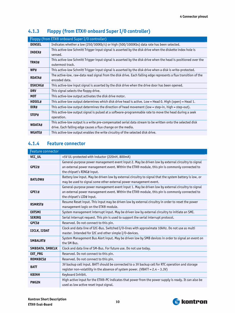
4.1.3 Floppy (from ETX® onboard Super I/O controller) Floppy (from ETX® onboard Super I/O controller) DENSEL Indicates whether a low (250/300Kb/s) or high (500/1000Kbs) data rate has been selected.
INDEX# This active-low Schmitt Trigger input signal is asserted by the disk drive when the diskette index hole is sensed.
TRK0# This active-low Schmitt Trigger input signal is asserted by the disk drive when the head is positioned over the outermost track.
WP# This active-low Schmitt Trigger input signal is asserted by the disk drive when a disk is write-protected.
RDATA# The active-low, raw-data read signal from the disk drive. Each falling edge represents a flux transition of the encoded data.
DSKCHG# This active-low input signal is asserted by the disk drive when the drive door has been opened.
DRV This signal selects the floppy drive.
MOT This active-low output activates the disk drive motor.
HDSEL# This active-low output determines which disk drive head is active. Low = Head 0. High (open) = Head 1.
DIR# This active-low output determines the direction of head movement (low = step-in, high = step-out).
STEP# This active-low output signal is pulsed at a software-programmable rate to move the head during a seek operation.
WDATA# This active-low output is a write pre-compensated serial data stream to be written onto the selected disk drive. Each falling edge causes a flux change on the media.
WGATE# This active-low output enables the write circuitry of the selected disk drive.
4.1.4 Feature connector Feature connector VCC_UL +5V UL-protected with inductor (220nH, 800mA)
GPE2# General-purpose power management event input 2. May be driven low by external circuitry to signal an external power management event. Within the ETX® module, this pin is commonly connected to the chipset’s RING# input.
BATLOW# Battery low input. May be driven low by external circuitry to signal that the system battery is low, or may be used to signal some other external power management event.
GPE1# General-purpose power management event input 1. May be driven low by external circuitry to signal an external power management event. Within the ETX® module, this pin is commonly connected to the chipset’s LID# input.
RSMRST# Resume Reset input. This input may be driven low by external circuitry in order to reset the power management logic on the ETX® module.
EXTSMI System management interrupt input. May be driven low by external circuitry to initiate an SMI.
SERIRQ Serial interrupt request. This pin is used to support the serial interrupt protocol.
GPCS# Reserved. Do not connect to this pin.
I2CLK, I2DAT Clock and data line of I2C-Bus. Switched I/O-lines with approximate 10kHz. Do not use as multi master. Intended for I2C and other simple I/O-devices.
SMBALRT# System Management Bus Alert input. May be driven low by SMB devices in order to signal an event on the SM Bus.
SMBDATA, SMBCLK Clock and data line of SM-Bus. For future use. Do not use today.
EXT_PRG Reserved. Do not connect to this pin.
ROMKBCS# Reserved. Do not connect to this pin.
BATT 3V backup cell input. BATT should be connected to a 3V backup cell for RTC operation and storage register non-volatility in the absence of system power. (VBATT = 2.4 – 3.3V)
KBINH Keyboard Inhibit.
PWGIN High active input for the ETX®-PC indicates that power from the power supply is ready. It can also be used as low active reset input signal.

4 Connector pinout
Kontron Short Description ETX® Eval-Board
11
PWRBTN# Power Button Input. This input is used to support the ACPI Power Button function.
HLEDR Low active output signal, which indicates activity on IDE interfaces.
4.1.5 IrDA connector IrDA connector IRTX, IRRX Infrared transmit and receive pin.
FIR Reserved. Do not connect to this pin.
4.1.6 Video out connector (only supported with special BIOS) Video out connector (only supported with special BIOS)
SYNC
Composite Sync for SCART PAL TVs that use the EURO AV Connector. It is fed to the “Video In” pin of this connector to provide a signal that the TV can overlay the RGB data onto. This pin may also be used as a general I/O pin for controlling video switch, or for the other Internal timing signals including Hsync, Vsync, etc..
Y DAC Output: outputs either Y (Luminance) for S-Video or Red for RGB Video (SCART).
C DAC Output: outputs either C (Colour/Chrominance) for S-Video, or Green for RGB Video.
COMP DAC Output: outputs either Composite Video, or Blue for RGB Video.
4.1.7 Sound JUMPtec connector Sound JUMPtec connector SNDL Line-level stereo output left. This pin can drive a 5k Ohm AC load.
SNDR Line-level stereo output right. This pin can drive a 5k Ohm AC load.
AUXAL Auxiliary A input left. Normally intended for connection to an internal or external CD-ROM analog output.
AUXAR Auxiliary A input right. Normally intended for connection to an internal or external CD-ROM analog output.
MIC Microphone input.
ASGND Analog ground for sound controller.

5 Super I/O controller on the ETX®-Eval
Kontron Short Description ETX® Eval-Board
12
5 Super I/O controller on the ETX®-Eval The support of this controller is integrated in all ETX® BIOS’s. Additional interfaces like serial ports (COM3 and COM4), parallel port (LPT2) and floppy interface can be controlled this way.
Please check the Application Note JAP0033 and the ETX® eval schematics, available on our web site, for design-in example.

6 Hardware Monitor
Kontron Short Description ETX® Eval-Board
13
6 Hardware Monitor The ETX® eval also integrates a Winbond W83782D IC for Hardware Monitoring. The IC can be used to monitor several critical hardware parameters of the system including power supply voltages, fan speeds, and temperatures, which are very important for a high-end computer systems to maintain stability and work properly.
The W83782 is connected to the SMBus of the ETX® module and can be used with common Hardware Monitoring Software.
Please note that not every ETX® board supports the SMBus. For information about SMBus please check the corresponding manual.

7 Port80 POST Code
Kontron Short Description ETX® Eval-Board
14
7 Port80 POST Code
7.1 What is POST? POST is an acronym for Power On Self Test. POST is the traditional name for the routines that the BIOS uses to test and initialize the devices on your system when the PC is powered on until the OS is started.
7.2 What are POST codes? Each POST routine is assigned a POST code, a unique number which is sent to I/O port 080h before the routine is executed. If the computer hangs during POST, a computer technician can locate the problem by finding the last value written to IO port 080h. Lists of POST codes and associated POST test and initialization routines for PhoenixBIOS v4 are available on: http://www.phoenix.com/resources/bios-postcode1.pdf

8 Battery Information
Kontron Short Description ETX® Eval-Board
15
8 Battery Information English:
CAUTION! Danger of explosion if battery is incorrectly replaced. Replace only with the same or equivalent type recommended by the manufacturer. Dispose of used batteries according to the manufacturer’s instructions.
Deutsch:
VORSICHT! Explosionsgefahr bei unsachgemäßem Austausch der Batterie. Ersatz nur durch den selben oder einen vom Hersteller empfohlenen gleichwertigen Typ. Entsorgung gebrauchter Batterien nach Angaben des Herstellers.
French:
ATTENTION! Risque d’explosion avec l’échange inadéquat de la batterie. Remplacement seulement par le �xpl ou un type �xplosion� recommandé par le producteur. L’évacuation des batteries �xplos conformément à des indications du fabricant.
Danish:
ADVARSEL ! Lithiumbatteri – Eksplosionsfare ved fejlagtig Håndtering. Udskifting må kun ske med batteri af �xpl �xplosion og type. Lever det brugte batteri tilbage til leverand∅ren.
Finnish:
VAROITUS ! Paristo voi rãjãhtãã, jos se on virheellisesti asennettu. Vaihda paristo ainoastaan laltevalmistajan suosittelmaan tyyppiln. Havita kaytetty paristo valmistajan ohjeiden mukaisesti.
Spanish:
Precaución ! Peligro de �xplosion si la batería se sustituye incorrectamente. Sustituya solamente por el mismo o tipo equivalente recomendado por el fabricante. Disponga las baterías usadas según las instrucciones del fabricante.
Note: The battery of this product is not considered to be accessible by the end user. Therefore the safety instructions are only given in English, German, French, Danish, Finish and Spanish language. If the battery of this product however is accessible by the end user, it is in the responsibility of the Kontron customer to give the corresponding safety instructions in the required language(s).

9 Document history
Kontron Short Description ETX® Eval-Board
16
9 Document history date doc. Name doc. Rev. author action 05.07.00 ADA8K110.DOC 1.0 R. Barth short description created, first release
13.09.01 ADA8K111.DOC 1.1 M. Hofmeister changes to new PCB board revision 1.4, new ETX®(R) spec 2.6
13.11.01 ADA8K112.DOC 1.2 M. Hofmeister removed jumper J2 for different Ethernet controllers 27.06.02 ADA8K113.DOC 1.3 D. Gunter Updated connector location drawing
05.09.02 ADA8K114.DOC 1.4 C. Hoch/D. Gunter
Added POSTcode, Super I/O and Hw. Monitoring chapter. English proofreading.
22.10.03 ADA8K115.DOC 1.5 D. Gunter Added battery disposal information. 10.01.07 ADA8K116.doc 1.6 C. Stadler Updated connector location drawing
16.05.07 ADA8K117.doc 1.7 U. Geisler Updated to new Kontron Style