J-Web User Guide for SRX Series Devices - Juniper Networks
1023
J-Web User Guide for SRX Series Devices Published 2021-09-23
-
Upload
khangminh22 -
Category
Documents
-
view
4 -
download
0
Transcript of J-Web User Guide for SRX Series Devices - Juniper Networks

J-Web User Guide for SRX Series Devices
Published
2021-09-23

Juniper Networks, Inc.1133 Innovation WaySunnyvale, California 94089USA408-745-2000www.juniper.net
Juniper Networks, the Juniper Networks logo, Juniper, and Junos are registered trademarks of Juniper Networks, Inc.in the United States and other countries. All other trademarks, service marks, registered marks, or registered servicemarks are the property of their respective owners.
Juniper Networks assumes no responsibility for any inaccuracies in this document. Juniper Networks reserves the rightto change, modify, transfer, or otherwise revise this publication without notice.
J-Web User Guide for SRX Series DevicesCopyright © 2021 Juniper Networks, Inc. All rights reserved.
The information in this document is current as of the date on the title page.
YEAR 2000 NOTICE
Juniper Networks hardware and software products are Year 2000 compliant. Junos OS has no known time-relatedlimitations through the year 2038. However, the NTP application is known to have some difficulty in the year 2036.
END USER LICENSE AGREEMENT
The Juniper Networks product that is the subject of this technical documentation consists of (or is intended for usewith) Juniper Networks software. Use of such software is subject to the terms and conditions of the End User LicenseAgreement ("EULA") posted at https://support.juniper.net/support/eula/. By downloading, installing or using suchsoftware, you agree to the terms and conditions of that EULA.
ii

Table of Contents
About This Guide | xxv
1 Juniper Web Device Manager
Getting Started | 2
Juniper Web Device Manager Overview | 2
What is J-Web? | 2
Benefits of J-Web | 2
Start J-Web | 3
Prerequisites for Using J-Web | 3
Log On to J-Web | 4
Configure SRX Devices Using the J-Web Setup Wizard | 5
J-Web First Look | 28
Explore J-Web | 29
J-Web Launch Pad | 29
J-Web Top Pane | 30
J-Web Side Pane | 33
J-Web Main Pane | 35
J-Web Workflow Wizards | 38
Summary | 39
2 Add SRX Device to Security Director Cloud
Add an SRX Series Device to Juniper Security Director Cloud | 41
3 Dashboard
J-Web Dashboard | 44
Dashboard Overview | 44
What is J-Web Dashboard | 44
Work with Widgets | 45
4 Monitor
Network | 54
Monitor Interfaces | 54
iii

Monitor DHCP Server Bindings | 55
Monitor IPsec VPN | 57
Logs | 63
Monitor Session | 63
Monitor Threats | 67
Monitor Web Filtering | 71
Monitor ATP | 74
Monitor VPN | 78
Monitor All Events | 81
Monitor Alarms | 87
Maps and Charts | 89
Monitor Traffic Map | 89
Monitor Threats Map | 92
Monitor Applications | 99
Monitor Users | 103
Statistics | 105
Monitor Threat Prevention | 105
Monitor VPN Phase I | 106
Monitor VPN Phase II | 108
Reports | 111
About Reports Page | 111
Overview | 112
Threat Assessment Report | 117
Application and User Usage | 117
Top Talkers | 118
IPS Threat Environment | 118
Viruses Blocked | 119
URL Report | 119
Virus: Top Blocked | 119
iv

Top Firewall Events | 119
Top Firewall Deny Destinations | 120
Top Firewall Denies | 120
Top IPS Events | 120
Top Anti-spam Detected | 120
Top Screen Attackers | 120
Top Screen Victims | 120
Top Screen Hits | 120
Top Firewall Rules | 120
Top Firewall Deny Sources | 120
Top IPS Attack Sources | 120
Top IPS Attack Destinations | 121
Top IPS Rules | 121
Top Web Apps | 121
Top Applications Blocked | 121
Top URLs by User | 121
Top Source Zone by Volume | 121
Top Applications by User | 121
Top Botnet Threats By Source Address via IDP Logs | 122
Top Botnet Threats by Destination Address via IDP Logs | 122
Top Botnet Threats by Threat Severity via IDP Logs | 122
Top Malware Threats by Source Address via IDP Logs | 122
Top Malware Threats by Destination Address via IDP Logs | 122
Top Malware Threats by Threat Severity via IDP Logs | 123
Top Blocked Applications via Webfilter Logs | 123
Top Permitted Application Subcategories by Volume via Webfilter Logs | 123
Top Permitted Application Subcategories by Count via Webfilter Logs | 123
5 Device Administration
Basic Settings | 126
Configure Basic Settings | 126
Cluster Management | 147
Configure Cluster (HA) Setup | 147
About the Cluster Configuration Page | 163
Edit Node Settings | 166
v

Add an HA Cluster Interface | 167
Edit an HA Cluster Interface | 169
Delete HA Cluster Interface | 169
Add a Redundancy Group | 170
Edit a Redundancy Group | 172
Delete Redundancy Group | 173
User Management | 174
About the User Management Page | 174
Add a User | 178
Edit a User | 180
Delete User | 180
Multi Tenancy—Resource Profiles | 181
About the Resource Profiles Page | 181
Global Settings | 183
Add a Resource Profile | 184
Edit a Resource Profile | 188
Delete Resource Profile | 189
Multi Tenancy—Interconnect Ports | 190
About the Interconnect Ports Page | 190
Add a LT Logical Interface | 192
Edit a LT Logical Interface | 199
Delete Logical Interface | 199
Search for Text in an Interconnect Ports Table | 199
Multi Tenancy—Logical Systems | 201
About the Logical Systems Page | 201
Add a Logical System | 203
vi

Edit a Logical System | 215
Delete Logical System | 215
Search Text in Logical Systems Table | 216
Multi Tenancy—Tenants | 217
About the Tenants Page | 217
Add a Tenant | 219
Edit a Tenant | 227
Delete Tenant | 227
Search Text in Tenants Table | 228
Certificate Management—Device Certificates | 229
About the Device Certificates Page | 229
Import a Device Certificate | 231
Export a Device Certificate | 232
Add a Device Certificate | 233
Delete Device Certificate | 236
View Details of a Device Certificate | 237
Search Text in the Device Certificates Table | 241
Certificate Management—Trusted Certificate Authority | 242
About the Trusted Certificate Authority Page | 242
Generate Default Trusted Certificate Authorities | 244
Enroll a CA Certificate | 245
Import a CA Certificate | 246
Add a Certificate Authority Profile | 247
Edit a Certificate Authority Profile | 252
Delete Certificate Authority Profile | 252
Search Text in the Trusted Certificate Authority Table | 253
vii

Certificate Management—Certificate Authority Group | 255
About the Certificate Authority Group Page | 255
Import a Trusted CA Group | 256
Add a CA Group | 257
Edit a CA Group | 258
Delete CA Group | 259
Search Text in the Certificate Authority Group Table | 259
License Management | 261
Manage Your Licenses | 261
About License Management Page | 261
Add License | 262
Delete Installed Licenses | 263
Update Installed Licenses | 263
Update Trial Licenses | 263
Display License Keys | 263
Download License Keys | 264
Software Feature Licenses | 264
ATP Management | 266
Enroll Your Device with Juniper ATP Cloud | 266
About the Diagnostics Page | 270
Operations | 272
Maintain Files | 272
About Files Page | 272
Clean Up Files | 272
Download and Delete Files | 273
Delete Backup JUNOS Package | 275
Maintain Reboot Schedule | 276
Maintain System Snapshots | 278
Software Management | 280
Upload Software Packages | 280
viii

Install Software Packages | 281
Rollback Software Package Version | 282
Configuration Management | 284
Manage Upload Configuration Files | 284
Manage Configuration History | 285
Manage Rescue Configuration | 289
Alarm Management | 290
Monitor Chassis Alarm | 290
About Chassis Alarm Page | 290
Create Chassis Alarm Definition | 290
Edit Chassis Alarm Definition | 295
Monitor System Alarm | 296
About System Alarm Page | 296
Create System Alarm Configuration | 296
Edit System Alarm Configuration | 300
RPM | 301
Setup RPM | 301
View RPM | 312
Tools | 318
Troubleshoot Ping Host | 318
About Ping Host Page | 318
Troubleshoot Ping MPLS | 323
About Ping MPLS Page | 323
Troubleshoot Traceroute | 328
About Traceroute Page | 329
Troubleshoot Packet Capture | 333
About Packet Capture Page | 333
Access CLI | 341
About CLI Terminal Page | 341
ix

View CLI Configuration | 343
About CLI Viewer Page | 343
Edit CLI Configuration | 344
About CLI Editor Page | 344
Point and Click CLI | 345
About Point and Click CLI Page | 345
Reset Configuration | 354
Configure Setup Wizard | 354
6 Network
Connectivity—Ports | 379
About the Ports Page | 379
Add a Logical Interface | 383
Edit a Logical Interface | 391
Delete Logical Interface | 391
Connectivity—VLAN | 392
About the VLAN Page | 392
Add a VLAN | 394
Edit a VLAN | 396
Delete VLAN | 397
Assign an Interface to VLAN | 397
Connectivity—Link Aggregation | 399
About the Link Aggregation Page | 399
Link Aggregation Global Settings | 401
Add a Logical Interface to Link Aggregation | 402
Add a Link Aggregation | 403
Edit an Aggregated Interface | 406
Delete Link Aggregation | 406
x

Search for Text in the Link Aggregation Table | 407
Connectivity—PPPoE | 408
Configure PPPoE | 408
Connectivity—Wireless LAN | 410
About the Settings Page | 410
Create an Access Point | 412
Edit an Access Point | 413
Delete Access Point | 414
Create an Access Point Radio Setting | 414
Edit an Access Point Radio Setting | 418
Delete Access Point Radio Settings | 418
DHCP Client | 420
About the DHCP Client Page | 420
Add DHCP Client Information | 421
Delete DHCP Client Information | 423
DHCP Server | 424
About the DHCP Server Page | 424
Add a DHCP Pool | 426
Edit a DHCP Pool | 431
Delete DHCP Pool | 431
DHCP Groups Global Settings | 432
Add a DHCP Group | 432
Edit a DHCP Group | 433
Delete DHCP Group | 434
Firewall Filters—IPv4 | 435
About the IPv4 Page | 435
xi

Add IPv4 Firewall Filters | 436
Firewall Filters—IPv6 | 454
About the IPv6 Page | 454
Add IPv6 Firewall Filters | 455
Firewall Filters—Assign to Interfaces | 471
About the Assign to Interfaces Page | 471
NAT Policies | 473
About the NAT Policies Page | 473
Create a Source NAT | 475
Edit a Source NAT | 481
Delete Source NAT | 482
NAT Pools | 483
About the NAT Pools Page | 483
Global Options | 485
Create a Source NAT Pool | 486
Edit a Source NAT Pool | 490
Delete Source NAT Pool | 491
Add a Destination NAT Pool | 491
Edit a Destination NAT Pool | 493
Delete Destination NAT Pool | 493
Destination NAT | 494
About the Destination Page | 494
Add a Destination Rule Set | 496
Edit a Destination Rule Set | 499
Delete Destination Rule Set | 499
Static NAT | 501
About the Static Page | 501
xii

Add a Static Rule Set | 504
Edit a Static Rule Set | 507
Delete Static Rule Set | 507
NAT Proxy ARP/ND | 509
About the Proxy ARP/ND Page | 509
Add a Proxy ARP | 510
Edit a Proxy ARP | 512
Delete a Proxy ARP | 512
Add a Proxy ND | 513
Edit a Proxy ND | 514
Delete Proxy ND | 514
Static Routing | 516
About the Static Routing Page | 516
Add a Static Route | 517
Edit a Static Route | 519
Delete Static Route | 519
RIP Routing | 520
About the RIP Page | 520
Add a RIP Instance | 522
Edit a RIP Instance | 524
Delete RIP Instance | 524
Edit RIP Global Settings | 525
Delete RIP Global Settings | 529
OSPF Routing | 530
About the OSPF Page | 530
Add an OSPF | 532
xiii

Edit an OSPF | 541
Delete OSPF | 542
BGP Routing | 543
About the BGP Page | 543
Add a BGP Group | 547
Edit a BGP Group | 553
Delete a BGP Group | 554
Edit Global Information | 554
Routing Instances | 560
About the Routing Instances Page | 560
Add a Routing Instance | 562
Edit a Routing Instance | 563
Delete Routing Instance | 564
Routing—Policies | 565
About the Policies Page | 565
Global Options | 567
Add a Policy | 569
Clone a Policy | 581
Edit a Policy | 582
Delete Policy | 582
Test a Policy | 583
Routing—Forwarding Mode | 584
About the Forwarding Mode Page | 584
CoS—Value Aliases | 586
About the Value Aliases Page | 586
Add a Code Point Alias | 587
xiv

Edit a Code Point Alias | 588
Delete Code Point Alias | 589
CoS—Forwarding Classes | 590
About the Forwarding Classes Page | 590
Add a Forwarding Class | 591
Edit a Forwarding Class | 592
Delete Forwarding Class | 592
CoS Classifiers | 594
About the Classifiers Page | 594
Add a Classifier | 596
Edit a Classifier | 598
Delete Classifier | 598
CoS—Rewrite Rules | 599
About the Rewrite Rules Page | 599
Add a Rewrite Rule | 600
Edit a Rewrite Rule | 602
Delete Rewrite Rule | 602
CoS—Schedulers | 604
About the Schedulers Page | 604
Add a Scheduler | 605
Edit a Scheduler | 607
Delete Scheduler | 608
CoS—Scheduler Maps | 609
About the Scheduler Maps Page | 609
Add a Scheduler Map | 610
Edit a Scheduler Map | 611
xv

Delete Scheduler Map | 612
CoS—Drop Profile | 613
About the Drop Profile Page | 613
Add a Drop Profile | 614
Edit a Drop Profile | 616
Delete Drop Profile | 616
CoS—Virtual Channel Groups | 617
About the Virtual Channel Groups Page | 617
Add a Virtual Channel | 618
Edit a Virtual Channel | 620
Delete Virtual Channel | 620
CoS—Assign To Interface | 621
About the Assign To Interface Page | 621
Edit a Port | 623
Add a Logical Interface | 624
Edit a Logical Interface | 625
Delete Logical Interface | 626
Application QoS | 627
About the Application QoS Page | 627
Add an Application QoS Profile | 630
Edit an Application QoS Profile | 632
Clone an Application QoS Profile | 633
Delete Application QoS Profile | 633
Add a Rate Limiter Profile | 634
Edit a Rate Limiter Profile | 635
Clone a Rate Limiter Profile | 635
xvi

Delete Rate Limiter Profile | 636
IPsec VPN | 637
About the IPsec VPN Page | 637
IPsec VPN Global Settings | 640
Create a Site-to-Site VPN | 643
Create a Remote Access VPN—Juniper Secure Connect | 662
Create a Remote Access VPN—NCP Exclusive Client | 683
Edit an IPsec VPN | 697
Delete an IPsec VPN | 699
Manual Key VPN | 700
About the Manual Key VPN Page | 700
Add a Manual Key VPN | 701
Edit a Manual Key VPN | 704
Delete Manual Key VPN | 705
Dynamic VPN | 706
About the Dynamic VPN Page | 706
Global Settings | 708
IPsec Template | 710
Add a Dynamic VPN | 711
Edit a Dynamic VPN | 713
Delete Dynamic VPN | 713
7 Security Policies and Objects
Security Policies | 715
About the Security Policies Page | 715
Global Options | 721
Add a Rule | 724
xvii

Clone a Rule | 739
Edit a Rule | 739
Delete Rules | 740
Zones/Screens | 741
About the Zones/Screens Page | 741
Add a Zone | 743
Edit a Zone | 746
Delete Zone | 746
Add a Screen | 747
Edit a Screen | 759
Delete Screen | 760
Zone Addresses | 761
About the Zone Addresses Page | 761
Add Zone Addresses | 763
Clone Zone Addresses | 765
Edit Zone Addresses | 766
Delete Zone Addresses | 766
Search Text in a Zone Addresses Table | 767
Global Addresses | 768
About the Global Addresses Page | 768
Add an Address Book | 769
Edit an Address Book | 773
Delete Address Book | 773
Services | 774
About the Services Page | 774
Add a Custom Application | 776
xviii

Edit a Custom Application | 779
Delete Custom Application | 780
Add an Application Group | 780
Edit an Application Group | 781
Delete Application Group | 782
Dynamic Applications | 783
About the Dynamic Applications Page | 783
Global Settings | 786
Add Application Signatures | 791
Clone Application Signatures | 796
Add Application Signatures Group | 797
Edit Application Signatures | 798
Delete Application Signatures | 799
Search Text in an Application Signatures Table | 800
Application Tracking | 801
About the Application Tracking Page | 801
Schedules | 803
About the Schedules Page | 803
Add a Schedule | 805
Clone a Schedule | 807
Edit a Schedule | 808
Delete Schedule | 808
Search Text in Schedules Table | 809
Proxy Profiles | 810
About the Proxy Profiles Page | 810
Add a Proxy Profile | 812
xix

Edit a Proxy Profile | 813
Delete Proxy Profile | 813
8 Security Services
UTM Default Configuration | 817
About the Default Configuration Page | 817
Edit a Default Configuration | 819
Delete Default Configuration | 819
UTM Antivirus Profiles | 821
About the Antivirus Profiles Page | 821
Add an Antivirus Profile | 823
Clone an Antivirus Profile | 829
Edit an Antivirus Profile | 830
Delete Antivirus Profile | 830
UTM Web Filtering Profiles | 832
About the Web Filtering Profiles Page | 832
Add a Web Filtering Profile | 834
Clone a Web Filtering Profile | 840
Edit a Web Filtering Profile | 841
Delete Web Filtering Profile | 842
UTM Web Filtering Category Update | 843
About the Category Update Page | 843
Category Update Settings | 845
Download and Install Settings | 848
UTM Antispam Profiles | 849
About the Antispam Profiles Page | 849
Add an Antispam Profile | 851
Clone an Antispam Profile | 853
xx

Edit an Antispam Profile | 853
Delete Antispam Profile | 854
UTM Content Filtering Profiles | 855
About the Content Filtering Profiles Page | 855
Add a Content Filtering Profile | 857
Clone a Content Filtering Profile | 862
Edit a Content Filtering Profile | 862
Delete Content Filtering Profile | 863
UTM Custom Objects | 864
About the Custom Objects Page | 864
Add a MIME Pattern List | 868
Add a File Extension List | 869
Add a Protocol Command List | 870
Add a URL Pattern List | 871
Add a URL Category List | 872
Add a Custom Message List | 873
Clone Custom Objects | 874
Edit Custom Objects | 875
Delete Custom Objects | 876
UTM Policies | 878
About the UTM Policies Page | 878
Add a UTM Policy | 880
Clone a UTM Policy | 883
Edit a UTM Policy | 884
Delete UTM Policy | 884
IPS Signature Update | 886
xxi

About the Signature Update Page | 886
Download an IPS Signature | 887
Install an IPS Signature | 888
Check Status of the IPS Signature | 889
IPS Signature Download Setting | 890
IPS Sensor | 893
About the Sensor Page | 893
IPS Policy | 902
About the Policy Page | 902
IDP Policy Template | 904
Check Status of the IDP Policy | 905
Add an IDP Policy | 906
Clone an IDP Policy | 910
Edit an IDP Policy | 911
Delete IDP Policy | 911
ALG | 913
About the ALG Page | 913
Advanced Threat Prevention | 926
About the Advanced Threat Prevention Page | 926
Add a Threat Prevention Policy | 928
Edit a Threat Prevention Policy | 930
Delete Threat Prevention Policy | 930
SSL Initiation Profiles | 931
About the SSL Initiation Profile Page | 931
Add an SSL Initiation Profile | 933
Edit an SSL Initiation Profile | 937
xxii

Delete SSL Initiation Profile | 937
SSL Proxy Profiles | 938
About the SSL Proxy Page | 938
Add an SSL Proxy Profile | 941
Clone an SSL Proxy Profile | 949
Edit an SSL Proxy Profile | 950
Delete SSL Proxy Profile | 950
Firewall Authentication—Access Profile | 952
About the Access Profile Page | 952
Add an Access Profile | 954
Edit an Access Profile | 960
Delete an Access Profile | 960
Firewall Authentication—Address Pools | 961
About the Address Pools Page | 961
Add an Address Pool | 963
Edit an Address Pool | 965
Delete Address Pool | 965
Search for Text in an Address Pools Table | 966
Firewall Authentication Settings | 967
About the Authentication Settings Page | 967
Firewall Authentication—UAC Settings | 970
About the UAC Settings Page | 970
Firewall Authentication—Active Directory | 974
About the Active Directory Page | 974
Firewall Authentication—Local Authentication | 980
About the Local Authentication Page | 980
Add a Local Auth Entry | 981
xxiii

Delete a Local Auth Entry | 982
Firewall Authentication—Authentication Priority | 983
About the Authentication Priority Page | 983
Firewall Authentication—Identity Management | 985
About the Identity Management Page | 985
Add an Identity Management Profile | 986
Edit an Identity Management Profile | 990
Delete Identity Management Profile | 991
ICAP Redirect | 992
About the ICAP Redirect Profile Page | 992
Add an ICAP Redirect Profile | 994
Edit an ICAP Redirect Profile | 997
Delete ICAP Redirect Profile | 998
xxiv

About This Guide
Use this guide to understand the Junos Web Device Manager, its capabilities, and features.
xxv

1PART
Juniper Web Device Manager
Getting Started | 2

CHAPTER 1
Getting Started
IN THIS CHAPTER
Juniper Web Device Manager Overview | 2
Start J-Web | 3
Explore J-Web | 29
Juniper Web Device Manager Overview
IN THIS SECTION
What is J-Web? | 2
Benefits of J-Web | 2
What is J-Web?
Juniper Networks SRX Series Services Gateways are shipped with the Juniper Networks Junos operatingsystem (Junos OS) preinstalled.
Junos OS has the following primary user interfaces:
• Juniper Web Device Manager (J-Web) GUI
• Junos OS CLI
The J-Web interface allows you to monitor, configure, troubleshoot, and manage your device by meansof a Web browser enabled with HTTP over Secure Sockets Layer (HTTPS) by default.
Benefits of J-Web
• Provides a simple user interface that enables new users to quickly become proficient.
2

• Enables effective threat management while producing detailed data access and user activity reports.An action-oriented design enables the network administrator to detect threats across the network asthey occur, quickly block the traffic going to or coming from a specific region, and apply immediateremedial action with a single click.
• Enables administrators to assess the effectiveness of each firewall rule and quickly identify theunused rules, which results in better management of the firewall environment.
RELATED DOCUMENTATION
Start J-Web | 3
Explore J-Web | 29
Start J-Web
IN THIS SECTION
Prerequisites for Using J-Web | 3
Log On to J-Web | 4
Configure SRX Devices Using the J-Web Setup Wizard | 5
J-Web First Look | 28
Prerequisites for Using J-Web
To access the J-Web interface for all platforms, your management device requires the followingsoftware:
• Supported browsers—Mozilla Firefox, Google Chrome, and Microsoft Internet Explorer.
NOTE: By default, you establish a J-Web session through an HTTPS-enabled Web browser.
• Language support— English-version browsers.
3

Log On to J-Web
To log into the J-Web interface:
1. Connect the network port of your device to the Ethernet port on the management device (laptop orPC), using an RJ-45 cable.
NOTE: Following are the networks that you can use for your respective device:
• For SRX300 and SRX320 devices, use network ports numbered 0/1 through 0/6.
• For SRX550M, use network ports numbered 0/1 through 0/5.
• For other SRX devices, use the management port labelled MGMT.
2. Ensure that the management device acquires an IP address from the device.
NOTE: The services gateway functions as a DHCP server and will assign an IP address to themanagement device. This is applicable only for SRX300 line of devices and SRX550M devices.If an IP address is not assigned to the management device, manually configure an IP address.
3. Open a browser and enter https://<IP address> in the address bar.
Where, <IP address> is the IP address of the SRX Series device.
4
The J-Web Setup Wizard page opens. See Figure 1 on page 5.
Figure 1: Setup Wizard Page
Configure SRX Devices Using the J-Web Setup Wizard
Using the Setup wizard, you can perform step-by-step configuration of a services gateway that cansecurely pass traffic.
You can choose one of the following setup modes to configure the services gateway:
• Standalone mode—Configure your SRX Series device to operate in a standalone mode. In this mode,you can configure basic settings such as device credentials, time, management interface, zones andinterfaces, and DNS servers and default gateways.
• Cluster (HA) mode—Configure your SRX Series device to operate in a cluster (HA) mode. In thecluster mode, a pair of devices are connected together and configured to operate like a single node,providing device, interface, and service level redundancy.
NOTE: You cannot configure Standalone or Passive mode when your device is in the HAmode.
5
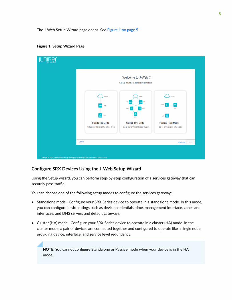
• Passive (Tap) mode—Configure your SRX Series device to operate in a TAP mode. TAP mode allowsyou to passively monitor traffic flows across a network. If IPS is enabled, then the TAP mode inspectsthe incoming and outgoing traffic to detect the number of threats.
NOTE: SRX5000 line of devices, SRX4600, and vSRX devices does not support the passivemode configuration.
To help guide you through the process, the wizard:
• Determines which configuration tasks to present to you based on your selections.
• Flags any missing required configuration when you attempt to leave a page.
To configure SRX Devices using the J-Web Setup wizard:
1. Select the configuration mode that you want to setup and click Start.
The Setup Wizard page appears.
NOTE: If you do not want to perform the initial configuration, then:
a. Click Skip Setup.
6

The J-Web Device Password screen appears. See Figure 2 on page 7
Figure 2: Device Password
b. Enter the root password.
c. Click OK.
The password is committed to the device and the J-Web login page appears.
d. Enter the username and password again and click Log In.
The J-Web application window appears.
NOTE: You can choose Device Administration > Reset Configuration through the J-Web menu to configure the SRX device.
2. For standalone mode and passive (Tap) mode, complete the configuration according to the guidelinesprovided in Table 1 on page 8.
NOTE:
7

• If you select Cluster (HA) Mode, for the configuration information see "Configure Cluster(HA) Setup" on page 147.
• In the Setup wizard, root password is mandatory, and all the other options are optional. Inthe passive mode, management interface, Tap interface, and services are mandatory.
3. Review the configuration details. If you want to change the configuration, click Edit Configuration,else click Finish.
Wait till the configuration is committed. A successful message is displayed once the entireconfiguration is committed to the device.
NOTE:
• If the commit fails, J-Web displays you the error message received from CLI and youremain on the wizard’s last page. Check over your configuration and make changes asnecessary so that the commit succeeds.
• For SRX300 line of devices and SRX550M devices in passive mode, an additional messagewill be displayed about the device reboot if you have enabled Juniper ATP Cloud orSecurity Intelligence services. For other SRX devices, the device will not reboot.
4. Read if any instructions are available and then click Open J-Web Login Page.
The J-Web Login page appears.
5. Enter the root username and password and click Log In.
Launch Pad screen appears until the J-Web UI is loaded.
Table 1: Setup Wizard Configuration
Field Action
Device Credentials
System Identity
8

Table 1: Setup Wizard Configuration (Continued)
Field Action
Device name Enter a hostname.
You can use alphanumeric characters, specialcharacters such as the underscore (_), the hyphen (-), orthe period (.); the maximum length is 255 characters.
Root Account
Username Displays the root user.
NOTE: We recommend that you do not use root useraccount as a best practice to manage your devices.
Password Enter a password.
You can use alphanumeric characters and specialcharacters; the minimum length is six characters.
SSH for root user Enable this option to allow the root login (to the device)using SSH.
Admin Account
Username Enter the admin username to manage the device.
Password Enter the admin password.
Time
Time
Time zone Select a time zone from the list.
9

Table 1: Setup Wizard Configuration (Continued)
Field Action
Time source Select either NTP server, computer time, or Manual toconfigure the system time:
• NTP Server > NTP servers—Select the NTP server inthe Available column and move to the selectedcolumn using the right arrow. Once the system isconnected to the network, the system time issynced with the NTP server time.
In addition, to add a new NTP server, click + andenter a hostname or IP address of the NTP serverand click OK.
NOTE: If you want to add more NTP servers, go toDevice Administration > Basic Settings > Date &Time Details through the J-Web menu.
• Computer Time > Computer time—Deviceautomatically synchronizes with your computertime only during the setup.
• Manual > Date and time—Select the date and time(in MM-DD-YYYY and HH:MM:SS 24-hour format)to configure the system time manually.
Management Interface
Management Interface
NOTE: If you change the management IP address and click Next, a warning message appears on theManagement Interface page that you need to use the new management IP address to log in to J-Webbecause you may lose the connectivity to J-Web.
10

Table 1: Setup Wizard Configuration (Continued)
Field Action
Management interface Select an interface from the list.
If fxp0 port is your device’s management port, then thefxp0 port is displayed. You can change it as required oryou can select None and proceed to the next page.
NOTE:
• You can choose the revenue port as managementport if your device does not support the fxp0 port.Revenue ports are all ports except fxp0 and em0.
• If you are in the Standalone mode, you can chooseNone for the management interface and click Nextto proceed to the next screen.
• If you are in the Passive (Tap) mode, it is mandatoryto configure a management port. J-Web needs amanagement port for viewing generated report.
IPv4
NOTE: Click email to self to get the newly configured IPv4 or IPv6 address to your inbox. This isuseful if you lose connectivity when you change the management IP address to another network.
Management address Enter a valid IPv4 address for the managementinterface.
NOTE: If fxp0 port is your device’s management port,then the fxp0 port’s default IP address is displayed. Youcan change it if required.
Management subnet mask Enter a subnet mask for the IPv4 address.
If you have changed the management address, use thenew IP address to access J-Web.
11

Table 1: Setup Wizard Configuration (Continued)
Field Action
Static route Enter an IPv4 address for the static route to route tothe other network devices.
Static route subnet mask Enter a subnet mask for the static route IPv4 address.
Next hop gateway Enter a valid IPv4 address for the next hop.
IPv6
Management access Enter a valid IPv6 address for the managementinterface.
Management subnet prefix Enter a subnet prefix length for the IPv6 address.
Static route Enter an IPv6 address for the static route if required toreach the device through the management interface.
Static route subnet prefix Enter a subnet prefix length for the static route IPv6address.
Next hop gateway Enter a valid IPv6 address for the next hop.
Access Protocols
NOTE: This option is available for all the ports except fxp0.
HTTPS This option is enabled by default.
SSH This option is enabled by default.
Ping Enable this option for ping service.
12

Table 1: Setup Wizard Configuration (Continued)
Field Action
DHCP Enable this option for DHCP service.
NETCONF Enable this option for NETCONF service.
Zones & Interfaces
Security Policy
NOTE: This option is available only for the Standalone mode. For the Passive (Tap) mode, this option isavailable under Tap Settings.
From Zone Name of the source zone. In the standalone mode,permits all traffic from the trust zone.
To Zone Name of the destination zone. In standalone mode,permits all traffic from the trust zone to the untrustzone.
Source Name of the source address (not the IP address) of apolicy.
Destination Name of the destination address.
Application Name of a preconfigured or custom application of thepolicy match.
Action Action taken when a match occurs as specified in thepolicy.
Zones
—Displays the available trust and untrust zones configuration.
13

Table 1: Setup Wizard Configuration (Continued)
Field Action
Trust Zone Interfaces
NOTE: This option is available only for the Standalone mode.
Add Trust Zone Interface Click + to add trust zone interface. For moreinformation on the fields, see Table 2 on page 20.
Edit Trust Zone Interface Select an interface and click the pencil icon at the rightcorner of the table to modify the configuration.
Delete Trust Zone Interface Select an interface and click the delete icon at the topright corner of the table.
A confirmation window appears. Click Yes to delete theselected interface or click No to discard.
Search Trust Zone Interface Click the search icon at the right corner of the table toquickly locate a zone or an interface.
Detailed View Trust Zone Interface Hover over the interface name and click the DetailedView icon to view the zone and interface details.
Trust Zone Interfaces—Zone Level Settings
Zone name View the trust zone name populated from your devicefactory default settings.
NOTE: For standalone mode, trust and untrust zonesare created by default even if these zones are notavailable in the factory default settings.
Description Enter the description for trust zone.
14

Table 1: Setup Wizard Configuration (Continued)
Field Action
System services Enable this option for the types of traffic that can reachthe device on a particular interface.
By default, this option is enabled. You can disable ifrequired.
Protocols Enable this option to configure the device to performstateful network traffic filtering on network packetsusing network traffic protocols (for example, TCP andUDP).
By default, this option is enabled. You can disable ifrequired.
Application tracking Enable this option to collect byte, packet, and durationstatistics for application flows in the specified zone.
Source identity log Enable this option for the device to log the useridentity information based on the source zoneconfigured in the security policy.
Untrust Zone Interfaces
Add Untrust Zone Interface Click + to add untrust zone interface. For moreinformation on the fields, see Table 3 on page 27.
Edit Untrust Zone Interface Select an interface and click the pencil icon at the rightcorner of the table to modify the configuration.
Delete Untrust Zone Interface Select an interface and click the delete icon at the topright corner of the table.
A confirmation window appears. Click Yes to delete theselected interface or click No to discard.
15

Table 1: Setup Wizard Configuration (Continued)
Field Action
Search Untrust Zone Interface Click the search icon at the right corner of the table toquickly locate a zone or an interface.
Detailed View Untrust Zone Interface Hover over the interface name and click the DetailedView icon to view the zone and interface details.
Untrust Zone Interfaces—Zone Level Settings
Zone name View the untrust zone name populated from yourdevice factory default settings.
NOTE: For standalone mode, trust and untrust zonesare created by default even if these zones are notavailable in the factory default settings.
Description Enter the description for untrust zone.
Application tracking Enable this option to collect byte, packet, and durationstatistics for application flows in the specified zone.
Source identity log Enable this option for the device to log the useridentity information based on the source zoneconfigured in the security policy.
DNS Servers & Default Gateways
DNS Servers
DNS server 1 Enter the IPv4 or IPv6 address of the primary DNS.
DNS server 2 Enter the IPv4 or IPv6 address of the secondary DNS.
Default Gateway
16

Table 1: Setup Wizard Configuration (Continued)
Field Action
Default gateway (IPv4) Enter the IPv4 address of the next possible destinationfor any network.
Default gateway (IPv6) Enter the IPv6 address of the next possible destinationfor any network.
Tap Settings
NOTE: This option is available only for the Passive (Tap) mode.
Tap Settings
Tap interface Select the interface from the list.
IP-IP tunnel inspection Enable this option for the SRX Series device to inspectpass through traffic over an IP-IP tunnel.
GRE tunnel inspection Enable this option for the SRX Series device to inspectpass through traffic over a GRE tunnel.
Security Policy & Advanced Services
NOTE: Your device must have internet connectivity to use IPS, Web filtering, Juniper ATP Cloud, andSecurity threat intelligence services.
From Zone Name of the source zone. In the Tap mode, permits alltraffic from the tap zone.
To Zone Name of the destination zone. In the Tap mode,permits all traffic from the TAP zone to the TAP zone.
Source Name of the source address (not the IP address) of apolicy.
17

Table 1: Setup Wizard Configuration (Continued)
Field Action
Destination Name of the destination address.
Application Name of a preconfigured or custom application of thepolicy match.
Action Action taken when a match occurs as specified in thepolicy.
UTM
UTM Enable this option for configuring UTM services.
License Enter UTM license key and click Install License to add anew license.
NOTE:
• Use a blank line to separate multiple license keys.
• To use UTM services, your device must haveinternet connectivity from a revenue interface.
UTM type Select an option to configure UTM features:
• Web Filtering
• Antivirus
• Antispam
18

Table 1: Setup Wizard Configuration (Continued)
Field Action
Web filtering type Select an option:
• Enhanced—Specifies that the Juniper EnhancedWeb filtering intercepts the HTTP and the HTTPSrequests and sends the HTTP URL or the HTTPSsource IP to the Websense ThreatSeeker Cloud(TSC).
• Local—Specifies the local profile type.
IPS
IPS Enable this option to install the IPS signatures.
License Enter the license key and click Install License to add anew license.
NOTE: The installation process may take few minutes.
IPS signature Click Browse to navigate to the IPS signature packagefolder and select it. Click Install to install the selectedIPS signature package.
NOTE: You can download the IPS signature offlinepackage at https://support.juniper.net/support/downloads/.
ATP Cloud
ATP Cloud Enable this option to use Juniper ATP Cloud services.
NOTE: After the Juniper ATP Cloud configuration ispushed, only the SRX300 line of devices and SRX550Mdevices are rebooted. Your device must have internetconnectivity to enable Juniper ATP Cloud enrollmentprocess through J-Web.
19

Table 1: Setup Wizard Configuration (Continued)
Field Action
Security Intelligence
Security intelligence Enable this option to use Security intelligence services.
NOTE: After the Security Intelligence configuration ispushed, only the SRX300 line of devices and SRX550Mdevices are rebooted. Your device must have internetconnectivity to enable Juniper ATP Cloud enrollmentprocess through J-Web.
User Firewall
User Firewall Enable this option to use user firewall services.
Domain name Enter a domain name for Active Directory.
Domain controller Enter domain controller IP address.
Username Enter a username for administrator privilege.
Password Enter a password for administrator privilege.
Table 2: Add Trust Zone
Field Action
General
20
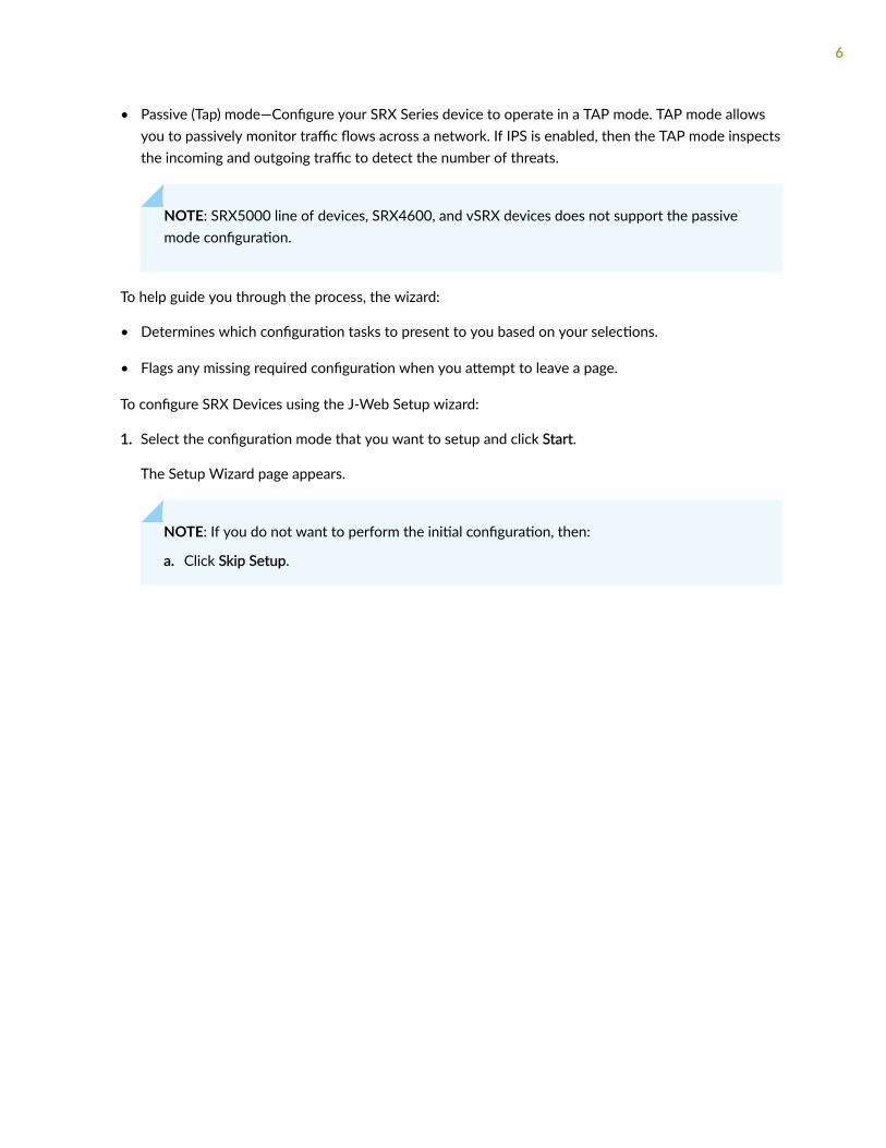
Table 2: Add Trust Zone (Continued)
Field Action
Type (family) • Select Switching. Fields for switching interface are:
NOTE: This option will be available for only SRX300 line ofdevices, SRX550M, and SRX1500 devices. For SRX5000 lineof devices, SRX4100, SRX4200, SRX4600, and vSRX devices,the Type (family) field is not available.
• IRB interface Unit—Enter the IRB unit.
• Description—Enter the description for the interface.
• Select Routing. Fields for routing interface are:
For SRX5000 line of devices, SRX4100, SRX4200, SRX4600,and vSRX devices, the Type (family) field is not available.
• Interface—Select an option from list.
• Interface unit—Enter the Inet unit.
NOTE: VLAN tagging is enabled automatically if theinterface unit is higher than zero.
• Description—Enter the description for the interface.
• VLAN ID—Enter the VLAN ID.
NOTE: VLAN ID is mandatory if the interface unit ishigher than zero.
Interfaces Select an interface from the Available column and move it to theSelected column.
NOTE: This option is available only for the Switching family type.
VLAN
NOTE: This option is available only for the Switching family type.
Name Enter a unique name for the VLAN.
21

Table 2: Add Trust Zone (Continued)
Field Action
VLAN ID Enter the VLAN ID.
IPv4
IPv4 address Enter a valid IPv4 address for the switching or the routinginterface.
Subnet mask Enter a subnet mask for the IPv4 address.
IPv6
IPv6 address Enter a valid IPv6 address for the switching or the routinginterface.
Subnet prefix Enter a subnet prefix for the IPv6 address.
DHCP Local Server
DHCP local server Enable this option to configure the switch to function as anextended DHCP local server.
Pool name Enter the DHCP pool name.
Pool start address Enter the starting IPv4 address of the DHCP server pool addressrange. This address must be within the IPv4 network.
Pool end address Enter the ending IPv4 address of the DHCP server pool addressrange. This address must be within the IPv4 network.
NOTE: This address must be greater than the address specifiedin Pool start address.
22

Table 2: Add Trust Zone (Continued)
Field Action
Propagate settings from Select an option from the list. Propagation of TCP/IP settings(such as, DNS and gateway address) received on the deviceinterface acting as DHCP client.
Services & Protocols
23

Table 2: Add Trust Zone (Continued)
Field Action
System Services Select system services from the list in the Available column andthen click the right arrow to move it to the Selected column.
The available options are:
• all—Specify all system services.
• any-service—Specify services on entire port range.
• appqoe—Specify the APPQOE active probe service.
• bootp—Specify the Bootp and dhcp relay agent service.
• dhcp—Specify the Dynamic Host Configuration Protocol.
• dhcpv6—Enable Dynamic Host Configuration Protocol forIPV6.
• dns—Specify the DNS service.
• finger—Specify the finger service.
• ftp—Specify the FTP protocol.
• http—Specify the Web management using HTTP.
• https—Specify the Web management using HTTP secured bySSL.
• ident-reset—Specify the send back TCP RST IDENT requestfor port 113.
• ike—Specify the Internet key exchange.
• lsping—Specify the Label Switched Path ping service.
• netconf—Specify the NETCONF Service.
• ntp—Specify the network time protocol.
• ping—Specify the internet control message protocol.
• r2cp—Enable Radio-Router Control Protocol.
24

Table 2: Add Trust Zone (Continued)
Field Action
• reverse-ssh—Specify the reverse SSH Service.
• reverse-telnet—Specify the reverse telnet Service.
• rlogin—Specify the Rlogin service
• rpm—Specify the Real-time performance monitoring.
• rsh—Specify the Rsh service.
• snmp—Specify the Simple Network Management Protocol.
• snmp-trap—Specify the Simple Network ManagementProtocol trap.
• ssh—Specify the SSH service.
• tcp—encap-Specify the TCP encapsulation service.
• telnet—Specify the Telnet service.
• tftp—Specify the TFTP
• traceroute—Specify the traceroute service.
• webapi-clear-text—Specify the Webapi service using http.
• webapi-ssl—Specify the Webapi service using HTTP securedby SSL.
• xnm-clear-text—Specify the JUNOScript API for unencryptedtraffic over TCP.
• xnm-ssl—Specify the JUNOScript API Service over SSL.
25

Table 2: Add Trust Zone (Continued)
Field Action
Protocols Select protocols from the list in the Available column and thenclick the right arrow to move it to the Selected column.
The available options are:
• all—Specifies all protocol.
• bfd—Bidirectional Forwarding Detection.
• bgp—Border Gateway Protocol.
• dvmrp—Distance Vector Multicast Routing Protocol.
• igmp—Internet Group Management Protocol.
• ldp—Label Distribution Protocol.
• msdp—Multicast Source Discovery Protocol.
• nhrp- Next Hop Resolution Protocol.
• ospf—Open shortest path first.
• ospf3—Open shortest path first version 3.
• pgm—Pragmatic General Multicast.
• pim—Protocol Independent Multicast.
• rip—Routing Information Protocol.
• ripng—Routing Information Protocol next generation.
• router-discovery—Router Discovery.
• rsvp—Resource Reservation Protocol.
• sap—Session Announcement Protocol.
• vrrp—Virtual Router Redundancy Protocol.
26

Table 3: Add Untrust Zone
Field Action
General
Interface Select an interface from the list.
Interface unit Enter the interface unit value.
VLAN ID Enter the VLAN ID.
NOTE: VLAN ID is mandatory if the interface unitis higher than zero.
Description Enter the description for the interface.
Address Mode Select an address mode for the interface. Theavailable options are DHCP Client, PPPoE (PAP),PPPoE (CHAP) and Static IP.
NOTE: PPPoE (PAP) and PPPoE (CHAP) are notsupported for SRX5000 line of devices and if anyof the devices are in passive mode.
Username Enter a username for PPPoE (PAP) or PPPoE(CHAP) authentication.
Password Enter a password for PPPoE (PAP) or PPPoE(CHAP) authentication.
IPv4
NOTE: This option is available only for the Static IP address mode.
IPv4 Address Enter a valid IPv4 address for the interface.
27

Table 3: Add Untrust Zone (Continued)
Field Action
Subnet Mask Enter a subnet mask for the IPv4 address.
IPv6
NOTE: This option is available only for the Static IP address mode.
IPv6 Address Enter a valid IPv6 address for the interface.
Subnet Prefix Enter a subnet prefix for the IPv6 address.
Services & Protocols
System Services Select system services from the list in theAvailable column and then click the right arrow tomove it to the Selected column.
Protocols Select protocols from the list in the Availablecolumn and then click the right arrow to move itto the Selected column.
J-Web First Look
Each page of the J-Web interface is divided into the following panes (see Figure 3 on page 29):
• Launch pad—Displays high level details of the system identification, active users, and interface status.
• Top pane—Displays identifying information and links.
• Side pane—Displays subtasks of the Dashboard, Monitor, Device Administration, Network, SecurityPolicies and Objects, Security Services, and VPN tasks currently displayed in the main pane. Click anitem to access it in the main pane.
28

• Main pane—Location where you monitor, configure, view or generate reports, and administrate theJuniper Networks device by entering information in text boxes, making selections, and clickingbuttons.
Figure 3: J-Web First Look
Explore J-Web
IN THIS SECTION
J-Web Launch Pad | 29
J-Web Top Pane | 30
J-Web Side Pane | 33
J-Web Main Pane | 35
J-Web Workflow Wizards | 38
Summary | 39
J-Web Launch Pad
After you successfully login to J-Web GUI, J-Web launch pad appears.
The launch pad provides a quick view of:
• Device information such as model number, serial number, hostname, software version, system time,and system up time.
• Number of active users using the device.
29

• State of the device physical interfaces: Up or Down.
The launch pad closes automatically once the application is loaded in the background. You do not havethe option to manually close or refresh the launch pad.
NOTE:
• Launch pad is not displayed in the factory default settings.
• Launch pad is displayed for all users.
Figure 4 on page 30 shows the launch pad screen and its elements.
Figure 4: J-Web launch Pad Screen
J-Web Top Pane
For a more personal, helpful, and user experience, Juniper Networks has provided some aids within theJ-Web GUI. Table 4 on page 31 provides the details of the J-Web top pane elements.
30

Table 4: J-Web Top Pane Elements
Element Description
Banner Location—The gray bar at the top ofthe screen.
You can access device details,feedback button, commit options, aprofile management access menu,and a help button.
Device details Location—To the upper right of thebanner.
Provides details of the device youhave accessed.
Feedback Button Location—To the right of the devicedetails.
You can provide feedback(mailto:[email protected])if you are having an issue with theproduct.
Commit Configuration Menu Location—To the right of theFeedback button.
Provides options to commit,compare, confirm, discard, orcommit the changes in yourpreferred way.
31

Table 4: J-Web Top Pane Elements (Continued)
Element Description
User Functions Menu Location—To the right of theCommit Configuration button.
A head-and-shoulders icon and afield showing the logged in usertype. Clicking your username or thedown arrow button, logs you out ofJ-Web interface.
Help Button Location—To the right of the UserFunctions menu.
Access to the online Help center andthe Getting Started Guide areavailable by clicking the right-mosticon on the banner, shaped like aquestion mark. The help centerincludes access to a list of supportedweb browsers, user interfaceassistance, as well as links totechnical support and full J-Webdocumentation.
Mode Location—To the right of the devicedetails.
Provides the setup mode detailswhether your device is in thestandard, chassis cluster (HA), orpassive mode.
32

Table 4: J-Web Top Pane Elements (Continued)
Element Description
Tenant or Logical System Username Location—To the left of the devicedetails.
Displays the name of the tenantuser or logical system user whenroot user enters as a Tenant or alogical systems. Click on theusername and select Exit to go backto the root user role.
J-Web Side Pane
J-Web presents you a security-focused administrator with a tabbed interface.
The following tabs across the side pane of the J-Web GUI provide workspaces in which an administratorcan perform specific tasks:
• Dashboard—The Dashboard is the main page for J-Web. You can customize the workspace in yourDashboard by adding widgets from the carousel. The placement of, and settings within, widgets aresaved so that anything from device information to firewall event information or from top blockedviruses to live threat maps can be unique for each user. Once you decide on the widgets that youwant to see, you can minimize the carousel to regain some screen space.
NOTE: By default, the selected widgets are displayed every time you login to J-Web.
33

Figure 5 on page 34 shows an example of the J-Web Dashboard tab.
Figure 5: J-Web Dashboard Tab
• Monitor—The Monitor tab provides a workspace in which graphical representations of networktraffic, firewall events, live threats, and network user data are available. There is also detailed data foralerts and alarms information. In this workspace, you can review the detailed information needed tounderstand what is happening to the managed security devices and traffic in your network.
Figure 6 on page 34 shows an example of the J-Web Monitor tab.
Figure 6: J-Web Monitor Tab
• Configure—The highlighted workspace in Figure 7 on page 35 is where all of the SRX Series deviceconfiguration happens. You can configure the following features for managing your network security:
34

• Device Administration—Such as basic settings, user management, certificate management, licensemanagement, ATP management, operations, software management, configuration management,alarm management, RPM, tools, and reset configuration.
• Network—Such as connectivity, DHCP, firewall filters, NAT, routing, Class of Services (CoS), andApplication QoS.
• Security policies and objects—Such as security policies, zones/screens, zone and global addresses,services, dynamic applications, application tracking, schedules, and proxy profiles.
• Security services—Such as UTM, IPS, ALG, ATP, SSL profiles, firewall authentication, and ICAPredirect.
• VPN—Such as IPsec VPN, manual key VPN, and dynamic VPN.
Figure 7 on page 35 shows an example of the J-Web configuration menus.
Figure 7: J-Web Configure Menus
J-Web Main Pane
The main workspace of J-Web takes up the remainder of the browser window just below the Bannerand next to the side pane. Table 5 on page 36 shows a sample of navigation, customization, and helpicons in the main pane of the J-Web GUI.
35

Table 5: J-Web Main Pane Elements
Element Description
Breadcrumbs Location—Upper left part of main screen.Not visible on the Dashboard.
Trace your location in the GUI. Thebreadcrumbs provide a path back to one ofthe five tabs: Dashboard, Monitor,Configure, Reports, and Administration.
Info Tips Location—Various places around the GUI.
Hover your mouse over any availablequestion mark icon for quick pop-upguidance.
Show/Hide Columns Location—Upper right corner of sometabular display windows such as the AddressPools tab, Rules tab, and so on.
In tabular displays, you can choose whichcolumns are visible by clicking the icon andthen selecting the check boxes on the menu.
Table Search Location—Upper right corner of tabularviews.
You can click the magnifying glass icon,within large tabular views, to search forspecific text within any of the visible fieldsin the display.
36

Table 5: J-Web Main Pane Elements (Continued)
Element Description
Item Selector Search Location—Within the fields.
You can use a search text box to selectitems for inclusion in a rule or policy.
Advanced Search Location—Above the table grid.
The search includes the logical operators aspart of the filter string. In the search textbox, when you hover over the icon, itdisplays an example filter condition. Whenyou start entering the search string, the iconindicates whether the filter string is valid ornot.
NOTE: Press Spacebar to add an ANDoperator or OR operator to the searchstring. Press backspace at any point of timewhile entering a search criteria, only onecharacter is deleted.
Filter Location—Upper right corner of tabularviews.
You can click the filter icon to select anyvalue from a list for category andsubcategory columns. The grid is reloadedwith the filtered category and subcategory.
37

Table 5: J-Web Main Pane Elements (Continued)
Element Description
Success message Location—At the top of the main pane.
A message is displayed with this icon tostate that your task is successful.
Information message Location—At the top of the main pane.
A message is displayed with this icon tostate you have some pending actions, butyou can continue with the task.
Alert message Location—At the top of the main pane.
A message is displayed with this icon tostate you have some pending actions whichyou must complete to proceed with therequired task.
Warning message Location—At the top of the main pane.
A message is displayed with this icon tostate you have some pending actions whichyou must complete else you cannot proceedwith the required task.
J-Web Workflow Wizards
J-Web contains assisting workflow wizards that guide you through some of its security functions. Theseinclude Setup wizard, Chassis Cluster wizard, PPPoE wizard, and NAT wizard. These wizards help youwith a guided setup and helps you in performing step-by-step configuration of a services gateway thatcan securely pass traffic.
NOTE: PPPoE and NAT Wizards are available only in the SRX300 line of devices and SRX550Mdevices.
38

Summary
J-Web is a GUI approach that aims to provide a graphical framework to help you visualize and manageyour SRX Series devices more easily.
39

2PART
Add SRX Device to Security DirectorCloud
Add an SRX Series Device to Juniper Security Director Cloud | 41
Add an SRX Series Device to Juniper SecurityDirector Cloud
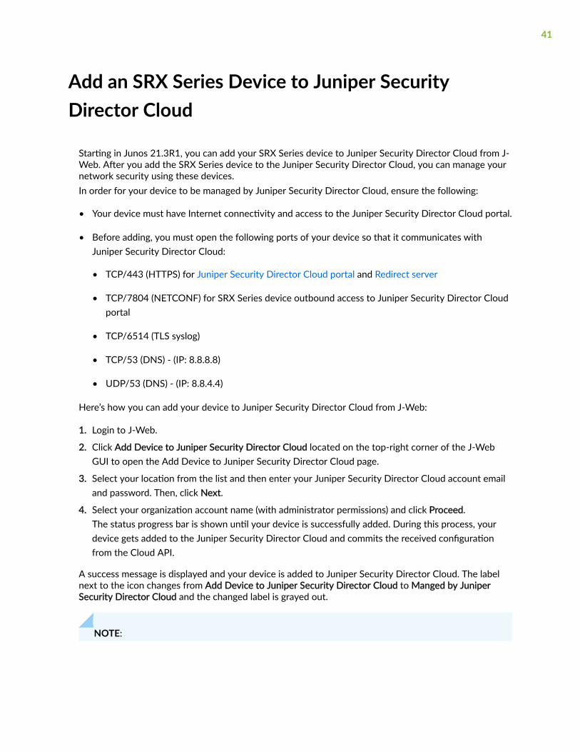
Starting in Junos 21.3R1, you can add your SRX Series device to Juniper Security Director Cloud from J-Web. After you add the SRX Series device to the Juniper Security Director Cloud, you can manage yournetwork security using these devices.In order for your device to be managed by Juniper Security Director Cloud, ensure the following:
• Your device must have Internet connectivity and access to the Juniper Security Director Cloud portal.
• Before adding, you must open the following ports of your device so that it communicates withJuniper Security Director Cloud:
• TCP/443 (HTTPS) for Juniper Security Director Cloud portal and Redirect server
• TCP/7804 (NETCONF) for SRX Series device outbound access to Juniper Security Director Cloudportal
• TCP/6514 (TLS syslog)
• TCP/53 (DNS) - (IP: 8.8.8.8)
• UDP/53 (DNS) - (IP: 8.8.4.4)
Here’s how you can add your device to Juniper Security Director Cloud from J-Web:
1. Login to J-Web.
2. Click Add Device to Juniper Security Director Cloud located on the top-right corner of the J-WebGUI to open the Add Device to Juniper Security Director Cloud page.
3. Select your location from the list and then enter your Juniper Security Director Cloud account emailand password. Then, click Next.
4. Select your organization account name (with administrator permissions) and click Proceed.The status progress bar is shown until your device is successfully added. During this process, yourdevice gets added to the Juniper Security Director Cloud and commits the received configurationfrom the Cloud API.
A success message is displayed and your device is added to Juniper Security Director Cloud. The labelnext to the icon changes from Add Device to Juniper Security Director Cloud to Manged by JuniperSecurity Director Cloud and the changed label is grayed out.
NOTE:
41

• When you have logged into the J-Web and remove your device from Juniper SecurityDirector Cloud, J-Web still displays the status as Manged by Juniper Security Director Cloud.Log in to J-Web again to see the label changed to Add Device to Juniper Security DirectorCloud.
• If there are any network issues between the SRX Series device and Juniper Security DirectorCloud, J-Web still displays the status as Manged by Juniper Security Director Cloud.
Once added, you can see your device on the Device Management > Devices page when you log into theJuniper Security Director Cloud portal. You can only delete your device from Juniper Security DirectorCloud and not from the J-Web GUI. To remove the device, select your device on the Devices page andclick the delete icon.
RELATED DOCUMENTATION
Dashboard Overview | 44
42

3PART
Dashboard
J-Web Dashboard | 44

CHAPTER 2
J-Web Dashboard
IN THIS CHAPTER
Dashboard Overview | 44
Dashboard Overview
IN THIS SECTION
What is J-Web Dashboard | 44
Work with Widgets | 45
What is J-Web Dashboard
The J-Web dashboard provides a unified overview of the system and network status retrieved from SRXSeries devices.
To use the dashboard at the top-level menu, select Dashboard. By default, the Dashboard page displaysall the widget thumbnails.
44
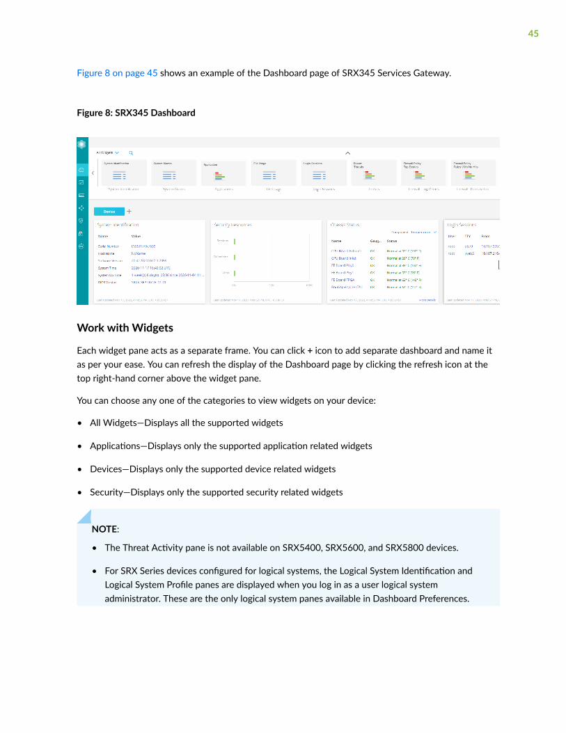
Figure 8 on page 45 shows an example of the Dashboard page of SRX345 Services Gateway.
Figure 8: SRX345 Dashboard
Work with Widgets
Each widget pane acts as a separate frame. You can click + icon to add separate dashboard and name itas per your ease. You can refresh the display of the Dashboard page by clicking the refresh icon at thetop right-hand corner above the widget pane.
You can choose any one of the categories to view widgets on your device:
• All Widgets—Displays all the supported widgets
• Applications—Displays only the supported application related widgets
• Devices—Displays only the supported device related widgets
• Security—Displays only the supported security related widgets
NOTE:
• The Threat Activity pane is not available on SRX5400, SRX5600, and SRX5800 devices.
• For SRX Series devices configured for logical systems, the Logical System Identification andLogical System Profile panes are displayed when you log in as a user logical systemadministrator. These are the only logical system panes available in Dashboard Preferences.
45

• If the rescue configuration is not set, the set rescue configuration link directs you to theDevice Administration > Configuration Management > Rescue page to set the rescueconfiguration.
To use a widget on the Dashboard:
1. Drag the widgets from the palette or thumbnail container to your dashboard.
When you add more widgets on the J-Web Dashboard, you can observe high CPU usage on theRouting Engine for a short span of time on every refresh. We recommend that you use four widgetsfor lower CPU consumption.
2. Mouse over the top of each widget to minimize, refresh, and close by using the respective icons.
NOTE: The dashlet data is refreshed every minute by default. You cannot manually configurethe refresh interval of the dashlet. If the data is not aged in the cache, data loads from thecache during the dashlet refresh. If the data is aged, it is retrieved from the device during thenext refresh interval cycle.
Table 6 on page 46 provides the dashboard widgets options based on the selected device.
Table 6: Dashboard Widgets Options
Field Description
System Alarms Provides the received time, severity, description of the alarms and theaction to be taken.
System Identification Provides system details such as serial number of the software,hostname, software version, BIOS version, system uptime, and systemtime.
Login Sessions Provides the user credentials, login time, idle time, and host.
46

Table 6: Dashboard Widgets Options (Continued)
Field Description
File Usage Provides current space requirements for log, temporary, crash, anddatabase files. Click Maintain to download or delete some or all ofthese files.
NOTE: File Usage widget supports RE3 line cards for SRX5000 line ofdevices.
Applications Displays top 10 applications based on sessions or bandwidth.
Threats Displays top 10 IPS sources, antispam sources, and antivirus name,sorted by count.
Resource Utilization Provides a graphical representation of the CPU, memory, and storageused for both the data and the control planes. The CPU control alsoshows the load average value for 1 minute when you mouse over CPUControl.
NOTE: Resource Utilization widget supports RE3 line cards forSRX5000 line of devices.
Firewall: Top Denies Displays top requests denied by the firewall based on their source IPaddresses, sorted by count.
Firewall Policy: Rules WithNo Hits
Displays firewall policies with the most rules not hit, sorted by count.
Threat Activity Provides the most current threats received on the device.
Firewall: Top Events Displays all top 10 firewall events of the network traffic, sorted bycount.
IDP: Top Events Displays top 10 IDP events grouped by event-type, sorted by count.
47

Table 6: Dashboard Widgets Options (Continued)
Field Description
Signal Strength Displays the signal strength of the device.
Interface: Most DroppedPackets
Displays top 5 interfaces based on the CLI response; top-count willincrease to 10.
Interface: Most Sessions Displays top 10 interfaces with most sessions.
IP: Top Destinations Displays top 10 destination-address, sorted by count or volume.
IP: Top Sources Displays top 10 source-address of the network traffic, sorted by countor volume.
Virus: Top Blocked Displays top 10 blocked viruses, sorted by count.
Zones: Top Bandwidth byPackets
Displays top 10 zones with maximum throughput rate in packets.
Web Filtering: Top WebBlocked
Displays top 5 Web Blocked based on the CLI response.
Web Filtering: Top SourceAddress
Displays top 4 Source Address Web Filter based on the CLI response.
Web Filtering: TopDestination Address
Displays top 4 Destination Address Web Filter based on the CLIresponse.
Application & Users: HighRisk Applications BlockedPer User
Displays top 4 High Risk Applications Blocked per user based on theCLI response.
48

Table 6: Dashboard Widgets Options (Continued)
Field Description
Application & Users: HighRisk Applications AllowedPer User
Displays High Risk Applications allowed per user.
Security Resources Provides the maximum, configured, and activated number of sessions,firewall/VPN policies, and IPsec VPNs.
Content Filtering: TopContent Filters
Displays top 10 Protocol, Reason, and Source-address.
Web Filtering: Top WebCategories
Displays top 10 Web categories, Security risk, Productivity loss, Legal-liability and Blocked.
Threat Monitoring Displays top Malwares identified, Threats and Infected categories.
Top Users of High RiskApplications by Volume/Count
Displays top users of High Risk Applications by volume.
Application & Users: TopCategories
Displays top 4 Categories of Application & Users sorted by count andvolume.
Application & Users: TopUsers
Displays top 4 Users sorted by count and volume.
Application & Users: TopIPs
Displays top 4 IPs of Application & Users sorted by count and volume.
Application & Users: TopHigh Risk Applications
Displays top 4 High Risk Applications sorted by risk, count and volume.
49

Table 6: Dashboard Widgets Options (Continued)
Field Description
Antispam: Top SourceAddress
Displays top 4 Antispam group by source address and sorted by count.
Application & Users:Application Usage byCategory/Type
Displays top 5 Application Usage by Category group.
Application & Users: Userswith the Most CriticalApplication Usage
Displays top 5 Users with the Most Critical Application Usage volume.
Storage Usage Displays used and available storage and usage information about othersystem components.
Logical SystemIdentification
Provides the logical system name, the security profile assigned to thelogical system, the software version, and the system time.
Logical System Profile Displays the types of resources that are allocated to the user logicalsystem, the number of resources used and reserved, and the maximumnumber of resources allowed.
Threat Maps: Virus Displays last one hour data.
Click More Details to view antivirus event logs at Monitor > Logs >Threats.
Threat Maps: IPS Displays last one hour data.
Click More Details to view IPS event logs at Monitor > Logs > Threats.
NAT - Top SourceTranslation Hits
Displays the top 10 source translation hits.
Click More Details to view source NAT logs at Monitor > Logs > AllEvents.
50
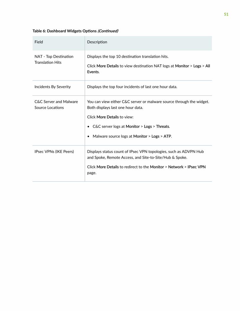
Table 6: Dashboard Widgets Options (Continued)
Field Description
NAT - Top DestinationTranslation Hits
Displays the top 10 destination translation hits.
Click More Details to view destination NAT logs at Monitor > Logs > AllEvents.
Incidents By Severity Displays the top four incidents of last one hour data.
C&C Server and MalwareSource Locations
You can view either C&C server or malware source through the widget.Both displays last one hour data.
Click More Details to view:
• C&C server logs at Monitor > Logs > Threats.
• Malware source logs at Monitor > Logs > ATP.
IPsec VPNs (IKE Peers) Displays status count of IPsec VPN topologies, such as ADVPN Huband Spoke, Remote Access, and Site-to-Site/Hub & Spoke.
Click More Details to redirect to the Monitor > Network > IPsec VPNpage.
51

Table 6: Dashboard Widgets Options (Continued)
Field Description
VPN Monitoring Displays the total number of IPsec VPNs (Total VPNs for All VPNs andtotal remote users for Remote Access). All VPNs option includes Site toSite, Hub & Spoke, ADVPN Hub, and ADVPN spoke. Remote Accessincludes Juniper Secure Connect and NCP Exclusive Entry Client.
Widget pane also displays the VPNs status with a color code:
• Up (Green)—IKE and IPsec SA are up.
• Down (Red)—IKE and IPsec are not operationally up.
• Partially Up (Amber)—Either IKE or IPsec SA is up or one or fewtraffic selectors are up.
Click More Details available on the widget pane to redirect to theMonitor > Network > IPsec VPN page.
On the widget pane, for the All VPNs option, each configured IPsecVPN is represented as an individual tunnel icon or box.
On the widget pane, for the Remote Access option, each IKE SAscorresponding to the configured IPsec VPN is represented as anindividual tunnel icon or box. If there are no IKE SAs for the VPN, thena single box is shown as down.
When you hover over the box, widget displays VPN tunnel details suchas Remote gateway, VPN name, IKE status, IPsec status, local IP, andremote IP. Click More Details to redirect to the Monitor > Network >IPsec VPN page with the VPN name filtered.
52

4PART
Monitor
Network | 54
Logs | 63
Maps and Charts | 89
Statistics | 105
Reports | 111

CHAPTER 3
Network
IN THIS CHAPTER
Monitor Interfaces | 54
Monitor DHCP Server Bindings | 55
Monitor IPsec VPN | 57
Monitor Interfaces
You are here: Monitor > Network > Interfaces.
Use this page to view general information about all physical and logical interfaces for a device.
Table 7 on page 54 describes the fields on the Interfaces page.
Table 7: Fields on the Interfaces Page
Field Description
Show Interfaces Select All or any particular slot to show theinterface details.
View Details Displays extensive statistics about the selectedinterface, including its general status, trafficinformation, IP address, I/O errors, class-of-service data, and statistics.
Clear Statistics Clears the statistics for the selected interface.
54
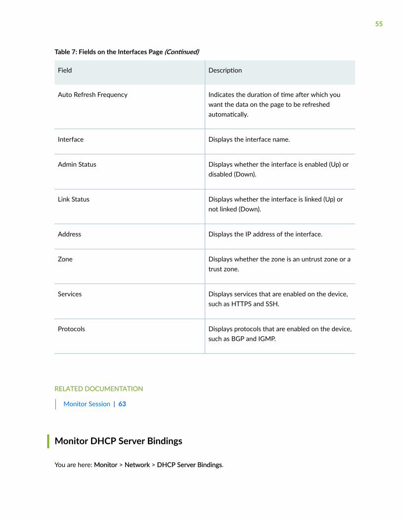
Table 7: Fields on the Interfaces Page (Continued)
Field Description
Auto Refresh Frequency Indicates the duration of time after which youwant the data on the page to be refreshedautomatically.
Interface Displays the interface name.
Admin Status Displays whether the interface is enabled (Up) ordisabled (Down).
Link Status Displays whether the interface is linked (Up) ornot linked (Down).
Address Displays the IP address of the interface.
Zone Displays whether the zone is an untrust zone or atrust zone.
Services Displays services that are enabled on the device,such as HTTPS and SSH.
Protocols Displays protocols that are enabled on the device,such as BGP and IGMP.
RELATED DOCUMENTATION
Monitor Session | 63
Monitor DHCP Server Bindings
You are here: Monitor > Network > DHCP Server Bindings.
55

Use this page to view information about dynamic and static DHCP leases, conflicts, pools, and statistics.
Table 8 on page 56 describes the fields on the DHCP Server Bindings page.
Table 8: Fields on the DHCP Server Bindings Page
Field Description
Routing Instance Select the routing instance name.
DHCP InterfaceDetails
Displays the interface on which the DHCP server is configured.
Clear Clears all or selected binding information.
Client IP Address Displays the IP address of the DHCP client.
MAC Address Displays the MAC address of the DHCP server.
State State of the address binding table on the extended DHCP local server:
• BOUND—Client has an active IP address lease.
• FORCE RENEW—Client has received the FORCE RENEW message fromthe server.
• INIT—Initial state.
• RELEASE—Client is releasing the IP address lease.
• RENEWING—Client is sending a request to renew the IP address lease.
• REQUESTING—Client is requesting a DHCP server.
• SELECTING—Client is receiving offers from DHCP servers.
Lease TimeRemaining
Displays the time (in hours and minutes) at which the lease expires.
DHCP Interface Displays the interface on which the request was received.
56

Table 8: Fields on the DHCP Server Bindings Page (Continued)
Field Description
Session ID Displays the Session ID of the subscriber session.
RELATED DOCUMENTATION
About Reports Page | 111
Monitor IPsec VPN
You are here: Monitor > Network > IPsec VPN.
Use the monitoring functionality to view information of IKE, IPsec configuration, Security Associations(SA), and Statistics in a tabular format that includes sortable columns. A VPN provides a means by whichremote computers communicate securely across a public WAN such as the Internet. IPsec VPN is aprotocol that consist set of standards used to establish a VPN connection.
Table 9 on page 57 describes the fields on the IPsec VPN page.
Table 9: Fields on the IPsec VPN Page
Field Description
IPsec Statistics list menu Displays summary of the global IPsec VPN orselected IPsec VPN statistics.
57

Table 9: Fields on the IPsec VPN Page (Continued)
Field Description
Clear SA list menu Displays the options Clear All SAs or ClearSelected SA to clear SAs.
If you choose Clear All SAs, then you can selectClear All IKE SAs, Clear All IPsec SAs, or Clear AllIKE & IPsec SAs.
If you choose Clear Selected SAs, then you canselect Clear Selected IKE SA, Clear Selected IPsecSA, or Clear Selected IKE & IPsec SA.
Refresh icon Click refresh icon to get latest operational data.
NOTE: The configuration data is fetched fromcache. Any changes to the CLI will be fetchedonly after you commit it and click Monitor >Network > IPsec VPN to refresh the page and getthe latest configuration data.
Search You can search and filter either the remotegateway or the VPN name.
Remote Gateway Displays gateway name of the remote system.
IKE Status Displays if IKE is up or down.
Local IP Displays the external interface, IP address, andport of the local peer so that its remote peer cancommunicate with it.
Remote IP Displays the IP address and port of the remotepeer.
NOTE: The remote IP displays only when the IKEis up.
58

Table 9: Fields on the IPsec VPN Page (Continued)
Field Description
VPN Name Displays IPsec VPN name.
TS/Proxy ID Status Displays information and status (up or down) ofthe traffic selector or the proxy ID that arenegotiated between the peers.
IPsec Soft Life Displays the soft lifetime (in seconds) whichindicates that the IPsec key management systemthat the SA is about to expire.
IKE Index Displays index number for a particular IKE SA.
IPsec Index Displays index number for a particular IPsec SA.
Topology Displays the topology deployment for an IPsecVPN. For example: Site to Site/Hub & Spoke orRemote Access VPN.
IKE Proposal Lists algorithms negotiated with the remote peer.
IPsec Proposal Lists protocols and algorithms negotiated withthe remote peer.
Authentication Type Display if the preshared key or certificate basedis used by the Virtual Private network (VPN).
DPD Displays dead peer detection (DPD) method usedby devices to verify the current existence andavailability of IPsec peers.
59

Table 9: Fields on the IPsec VPN Page (Continued)
Field Description
Role Displays whether the device is an initiator or aresponder.
IKE Initiator Cookie Random number, called a cookie, which is sent tothe remote node when the IKE negotiation istriggered.
IKE Responder Cookie Random number generated by the remote nodeand sent back to the initiator as a verificationthat the packets are received.
IKE Life Lifetime (in seconds) of an IKE SA.
Range: 180 through 86,400. Default is 3600.
Mode Negotiation method agreed upon by the twoIPsec endpoints, or peers, used to exchangeinformation. Each exchange type determines thenumber of messages and the payload types thateach message contains. The modes or exchangetypes are:
• Main—The exchange is done with sixmessages. This mode, or exchange type,encrypts the payload, protecting the identityof the neighbor. Displays the authenticationmethod used: preshared keys or certificate.
• Aggressive—The exchange is done with threemessages. This mode, or exchange type, doesnot encrypt the payload, leaving the identityof the neighbor unprotected.
Peer IKE-ID Displays the IKE IDs for the local or remotedevices.
60

Table 9: Fields on the IPsec VPN Page (Continued)
Field Description
Remote Access Displays the remote access URL.
NOTE: This option is applicable only for theremote access VPN with Juniper Secure Connect(JSC).
Remote User Displays the remote IKE identity to exchangewith the destination peer to establishcommunication.
DNS Displays the IP addresses for a primary and asecondary DNS servers.
WINS Displays the IP addresses for a primary and asecondary WINS servers.
Inbound SPI Displays security parameter index (SPI) value toauthenticate incoming traffic coming from thepeer.
Outbound SPI Displays algorithms, keys, or SPI values todecrypt and to authenticate outbound traffic tothe peer.
IPsec Hard Life Displays number of seconds until the SA expires.
IPsec Lifesize Displays the lifesize remaining specifies the usagelimits in kilobytes. If no lifesize is specified, itshows unlimited.
61

RELATED DOCUMENTATION
Monitor Session | 63
62

CHAPTER 4
Logs
IN THIS CHAPTER
Monitor Session | 63
Monitor Threats | 67
Monitor Web Filtering | 71
Monitor ATP | 74
Monitor VPN | 78
Monitor All Events | 81
Monitor Alarms | 87
Monitor Session
You are here: Monitor > Logs > Session.
Use the monitoring functionality to view the firewall events or sessions that occurred during the timeperiod specified.
NOTE: Session page is available on all the SRX Series devices except the SRX5000 line ofdevices.
Table 10 on page 64 describes the fields on the Session page.
63

Table 10: Fields on the Session Page
Field Description
Last Select the time from the list to view the activity that you are most interestedin. Once you select the time, all the data presented in your view refreshesautomatically.
You can also use Customize to set a custom date and click Apply to view thespecified session logs.
Refresh Click the refresh icon to get the latest session information.
Show Hide Columns The three vertical dots represents this icon.
Enables you to show or hide a column in the grid.
Export to CSV You can export the session data to a comma-separated value (.csv) file.
Select the three vertical dots on the right-side of the page and then clickExport to CSV. The CSV file is downloaded to your local machine. You candownload only maximum of 100 sessions data.
Filter Criteria Use the filter text box present above the table grid. The search includes thelogical operators as part of the filter string. In the filter text box, when youhover over the icon, it displays an example filter condition. When you startentering the search string, the icon indicates whether the filter string is validor not.
X Click X to clear your search filter.
Save Filter Click Save Filter to save filters after you specify the filtering criteria.
To save a filter:
1. Enter the filter criteria you are looking for in the advanced search box.
2. Click Save Filter.
3. Enter a name for the filter and click the tick icon to save it.
64

Table 10: Fields on the Session Page (Continued)
Field Description
Load Filter Displays the saved filters list.
Hover over the saved filter name to view the query expression. You can deletethe saved filter using the delete icon.
View Details When you hover over the PCAP file, a Detailed View icon appears before thePCAP file. Click the icon to view the log details on the Detailed Log Viewpage.
Click on the download icon in the Detailed Log View page to download thepacket capture file of an unknown application traffic. The session ID availablein the file name identifies the PCAP file.
NOTE: If the files are not available, the download fails and you will receive anerror message.
PCAP Click on the download icon to download the packet capture (PCAP) file of anunknown application traffic. The download icon appears only if a packetcaptured for the session log type close.
The session ID available in the file name identifies the PCAP file.
NOTE: If the files are not available, the download fails and you will receive anerror message.
Time Displays the time when the log was received.
Log Type Displays the log type.
Source Zone Displays the source zone of the session.
Source IP Displays the source IP address from where the session occurred.
User Displays the username from whom the session log is generated.
65

Table 10: Fields on the Session Page (Continued)
Field Description
Destination Zone Displays the destination zone of the session.
Destination IP Displays the destination IP of the session occurred.
Destination Port Displays the destination port of the session.
Application Displays the application name from which the session logs are generated.
Action Displays the action taken for the event: warning, allow, and block.
Policy Displays the destination country of the log.
Bandwidth Displays the bandwidth utilization for the session.
NAT Source IP Displays the translated (or natted) source IP address. It can contain an IPv4 oran IPv6 addresses.
NAT Source Port Displays the translated source port.
NAT Destination IP Displays the translated (also called natted) destination IP address.
NAT DestinationPort
Displays the translated destination port.
Protocol ID Displays the protocol ID in the log.
Session ID Displays the traffic session ID of the log.
Interface Displays the interface of the session.
66

Table 10: Fields on the Session Page (Continued)
Field Description
Closure Reason Displays the reason for the log generation. For example, a connection teardown may have an associated reason such as authentication failed.
Packets From Client Displays the number of packets received from the client.
Bytes From Client Displays the number of bytes received from the client.
Packets From Server Displays the number of packets received from the server.
Bytes From Server Displays the number of bytes received from the server.
Elapsed Time Displays the time elapsed since the last time interval began.
Source Port Displays the port number of the source.
RELATED DOCUMENTATION
Monitor Threats | 67
Monitor Threats
You are here: Monitor > Logs > Threats.
Use the monitoring functionality to view the security threats. Threats are defined as any IPS, screen,security intelligence, antivirus, content filtering, or antispam.
NOTE: Threat page is available on all the SRX Series devices except the SRX5000 line of devices.
Table 11 on page 68 describes the fields on the Threats page.
67

Table 11: Fields on the Threats Page
Field Description
Last Select the time from the list to view the activity that you are most interestedin. Once the time is selected, all of the data presented in your view isrefreshed automatically.
You can also use Customize to set a custom date and click Apply to view thespecified threats.
Refresh Click the refresh icon to get the latest threat information.
Show Hide Columns This icon is represented by three vertical dots.
Enables you to show or hide a column in the grid.
Export to CSV You can export the threats data to a comma-separated value (.csv) file.
Select the three vertical dots on the right-side of the page and click Export toCSV. The CSV file is downloaded to your local machine. You can downloadonly maximum of 100 sessions data.
Filter Criteria Use the filter text box present above the table grid. The search includes thelogical operators as part of the filter string. In the filter text box, when youhover over the icon, it displays an example filter condition. When you startentering the search string, the icon indicates whether the filter string is validor not.
X Click X to clear your search filter.
Save Filter Click Save Filter to save filters after you specify the filtering criteria.
To save a filter:
1. Enter the filter criteria you are looking for in the advanced search box.
2. Click Save Filter.
3. Enter a name for the filter and click the tick icon to save it.
68

Table 11: Fields on the Threats Page (Continued)
Field Description
Load Filter Displays the saved filters list.
Hover over the saved filter name to view the query expression. You can deletethe saved filter using the delete icon.
Time Displays the time when the threats log was received.
Log Type Displays the threats log type. For example, IPS, Antivirus, Antispam, and so on.
Name Displays the name of the event.
Severity Displays the severity of the threat.
Source Zone Displays the source zone of the threats.
Source IP Displays the source IP address from where the threats log occurred.
Source Port Displays the port number of the source.
User Displays the username from whom the threat log is generated.
Destination Zone Displays the destination zone of the threats.
Destination IP Displays the destination IP of the threats occurred.
Destination Port Displays the port number of the destination.
Application Displays the nested application or application name from which the threatsare generated.
69

Table 11: Fields on the Threats Page (Continued)
Field Description
Action Displays the action taken from the threats.
Session ID Displays the traffic session ID of the threats.
Closure Reason Displays the reason for the session closure.
Profile Displays the threat profile name.
Category Displays the threat category.
URL Displays the accessed URL name that triggered the event.
Object Displays the object name of the threats.
Destination Interface Displays the interface name of the destination.
Source Interface Displays the interface name of the source.
Policy Displays the policy name that triggered the threats log.
Rule Displays the rule name of the threats log.
Protocol Displays the protocol ID in the threats log.
CVE-ID Displays the Common Vulnerabilities and Exposures (CVE) identifiersinformation for the threat.
Elapsed Time Displays the time elapsed since the last time interval began.
70
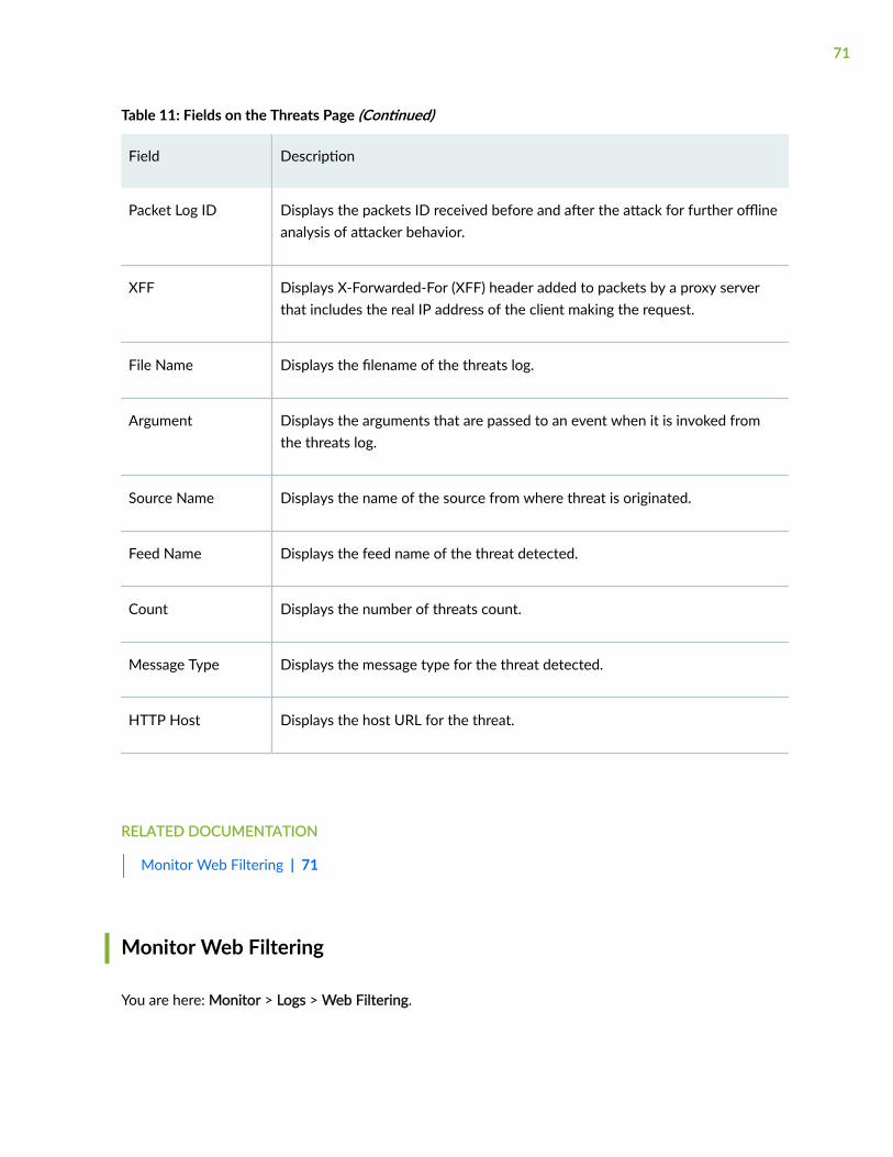
Table 11: Fields on the Threats Page (Continued)
Field Description
Packet Log ID Displays the packets ID received before and after the attack for further offlineanalysis of attacker behavior.
XFF Displays X-Forwarded-For (XFF) header added to packets by a proxy serverthat includes the real IP address of the client making the request.
File Name Displays the filename of the threats log.
Argument Displays the arguments that are passed to an event when it is invoked fromthe threats log.
Source Name Displays the name of the source from where threat is originated.
Feed Name Displays the feed name of the threat detected.
Count Displays the number of threats count.
Message Type Displays the message type for the threat detected.
HTTP Host Displays the host URL for the threat.
RELATED DOCUMENTATION
Monitor Web Filtering | 71
Monitor Web Filtering
You are here: Monitor > Logs > Web Filtering.
71

Use this page to view information about the Web filtering events based on web filtering policies, filteroptions, and grid elements of Web filtering events.
NOTE: Web Filtering page is available on all the SRX Series devices except the SRX5000 line ofdevices.
Table 12 on page 72 describes the fields on the Web Filtering page.
Table 12: Fields on the Web Filtering Page
Field Description
Last Select the time from the list to view the activity that you are most interestedin. Once the time is selected, all of the data presented in your view is refreshedautomatically.
You can also use Customize to set a custom date and click Apply to view thespecified Web filtering event logs.
Refresh Click the refresh icon to get the latest Web filtering event information.
Show Hide Columns This icon is represented by three vertical dots.
Enables you to show or hide a column in the grid.
Export to CSV You can export the Web filtering event data to a comma-separated value (.csv)file.
Select the three vertical dots on the right-side of the page and click Export toCSV. The CSV file is downloaded to your local machine. You can download onlymaximum of 100 sessions data.
Filter Criteria Use the filter text box present above the table grid. The search includes thelogical operators as part of the filter string. In the filter text box, when youhover over the icon, it displays an example filter condition. When you startentering the search string, the icon indicates whether the filter string is valid ornot.
72

Table 12: Fields on the Web Filtering Page (Continued)
Field Description
X Click X to clear your search filter.
Save Filter Click Save Filter to save filters after you specify the filtering criteria.
To save a filter:
1. Enter the filter criteria you are looking for in the advanced search box.
2. Click Save Filter.
3. Enter a name for the filter and click the tick icon to save it.
Load Filter Displays the saved filters list.
Hover over the saved filter name to view the query expression. You can deletethe saved filter using the delete icon.
Time Displays the time when the Web filtering event log was received.
Log Type Displays the Web filtering event log type.
Source Zone Displays the source zone of the Web filtering event.
Source IP Displays the source IP address from where the Web filtering event occurred.
User Displays the username from whom the Web filtering event log is generated.
Destination Zone Displays the destination zone of the Web filtering event.
Destination IP Displays the destination IP of the Web filtering event occurred.
Destination Port Displays the destination port of the Web filtering event.
73

Table 12: Fields on the Web Filtering Page (Continued)
Field Description
Application Displays the application name for which the Web filtering event logs aregenerated.
Action Displays the action taken for the event: deny, permit, or redirect.
Session ID Displays the traffic session ID of the Web filtering event log.
Closure Reason Displays the reason for the Web filtering event log generation closure.
URL Category Risk Displays the Web filtering URL risk level.
Profile Displays the Web filtering profile name.
Category Displays the Web filtering URL category.
URL Displays the accessed URL name that triggered the event.
Obj Displays the object name of the Web filtering event log.
RELATED DOCUMENTATION
Monitor ATP | 74
Monitor ATP
You are here: Monitor > Logs > ATP.
Use the monitoring functionality to view the ATP page. Analyzing the Juniper ATP logs yieldsinformation such as malware name, action taken, infected host, source of an attack, and destination ofan attack.
74

NOTE: ATP page is available on all the SRX Series devices except the SRX5000 line of devices.
Table 13 on page 75 describes the fields on the ATP page.
Table 13: Fields on the ATP Page
Field Description
Last Select the time from the list to view the activity that you are most interestedin. Once the time is selected, all of the data presented in your view is refreshedautomatically.
You can also use Customize to set a custom date and click Apply to view thespecified ATP logs.
Refresh Click the refresh icon to get the latest ATP log information.
Show Hide Columns This icon is represented by three vertical dots.
Enables you to show or hide a column in the grid.
Export to CSV You can export the ATP log data to a comma-separated value (.csv) file.
Select the three vertical dots on the right-side of the page and click Export toCSV. The CSV file is downloaded to your local machine. You can download onlymaximum of 100 ATP log data.
Filter Criteria Use the filter text box present above the table grid. The search includes thelogical operators as part of the filter string. In the filter text box, when youhover over the icon, it displays an example filter condition. When you startentering the search string, the icon indicates whether the filter string is valid ornot.
X Click X to clear your search filters.
75

Table 13: Fields on the ATP Page (Continued)
Field Description
Save Filter Click Save Filter to save filters after you specify the filtering criteria.
To save a filter:
1. Enter the filter criteria you are looking for in the advanced search box.
2. Click Save Filter.
3. Enter a name for the filter and click the tick icon to save it.
Load Filter Displays the saved filters list.
Hover over the saved filter name to view the query expression. You can deletethe saved filter using the delete icon.
Time Displays the time when the ATP log was received.
Log Type Displays the ATP log type: Action, Malware event, SMTP action, and IMAPaction.
Source Zone Displays the source zone of the ATP log.
Source IP Displays the source IP address from where the ATP log occurred.
Source Port Displays the port number of the source.
User Displays the username who downloaded the possible malware.
Destination Zone Displays the destination zone of the ATP log.
Destination IP Displays the destination IP of the ATP log occurred.
Destination Port Displays the destination port of the ATP log.
76

Table 13: Fields on the ATP Page (Continued)
Field Description
Application Displays the application name from which the ATP logs are generated.
Action Displays the action taken from the event: log, permit, and log and permit.
Session ID Displays the session ID of the ATP log.
Policy Displays the name of policy that enforced this action.
List Hit Displays the number of times the C&C server has attempted to contact hostson your network.
URL Displays the accessed URL name that triggered the event.
Sample SHA256 Displays the SHA-256 hash value of the downloaded file.
File Hash Lookup Displays the hash of the file sent for matching against known malware.
File Name Displays the name of the file, including the extension.
Protocol Displays the protocol that the C&C server used to attempt communication.
File Category Displays the type of file. Examples: PDF, executable, document.
Hostname Displays the hostname of device that downloaded the possible malware.
Verdict Number Displays the a score or threat level for a file.
Malware Info Displays the malware name or brief description.
77

Table 13: Fields on the ATP Page (Continued)
Field Description
Send To Displays the email address.
Send From Displays the email address.
Tenant ID Displays the internal unique identifier.
RELATED DOCUMENTATION
Monitor VPN | 78
Monitor VPN
You are here: Monitor > Logs > VPN.
Use the monitoring functionality to view comprehensive stream log details of VPN in a tabular formatthat includes sortable columns. A VPN provides a means by which remote computers communicatesecurely across a public WAN such as the Internet.
NOTE: VPN page is available on all the SRX Series devices except the SRX5000 line of devices.
Table 14 on page 79 describes the fields on the VPN page.
78

Table 14: Fields on the VPN Page
Field Description
Last Select the time from the list to view the activity that you are most interested in.Once the time is selected, all of the data presented in your view is refreshedautomatically.
You can also use Customize to set a custom date and click Apply to view thespecified VPN events.
Refresh Click the refresh icon at the top right corner to display the fresh content.
Show HideColumns
This icon is represented by three vertical dots.
Enables you to show or hide a column in the grid.
Export to CSV You can export the VPN data to a comma-separated value (.csv) file.
Select the three vertical dots on the right-side of the page and click Export toCSV. The CSV file is downloaded to your local machine. You can download onlymaximum of 100 VPN data.
Filter Criteria Use the filter text box present above the table grid. The search includes thelogical operators as part of the filter string. In the filter text box, when youhover over the icon, it displays an example filter condition. When you startentering the search string, the icon indicates whether the filter string is valid ornot.
X Click X to clear your search filter.
Save Filter Click Save Filter to save filters after you specify the filtering criteria.
To save a filter:
1. Enter the filter criteria you are looking for in the advanced search box.
2. Click Save Filter.
3. Enter a name for the filter and click the tick icon to save it.
79
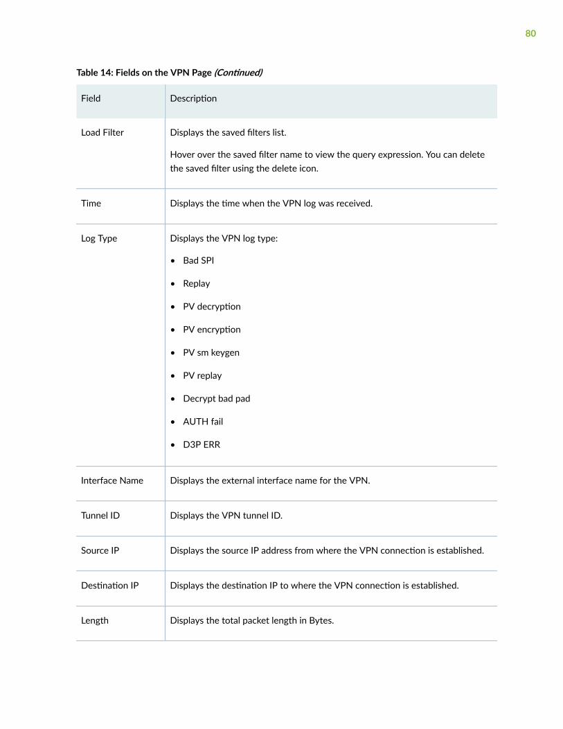
Table 14: Fields on the VPN Page (Continued)
Field Description
Load Filter Displays the saved filters list.
Hover over the saved filter name to view the query expression. You can deletethe saved filter using the delete icon.
Time Displays the time when the VPN log was received.
Log Type Displays the VPN log type:
• Bad SPI
• Replay
• PV decryption
• PV encryption
• PV sm keygen
• PV replay
• Decrypt bad pad
• AUTH fail
• D3P ERR
Interface Name Displays the external interface name for the VPN.
Tunnel ID Displays the VPN tunnel ID.
Source IP Displays the source IP address from where the VPN connection is established.
Destination IP Displays the destination IP to where the VPN connection is established.
Length Displays the total packet length in Bytes.
80

Table 14: Fields on the VPN Page (Continued)
Field Description
Type Displays the VPN type: ESP or AH protocol.
Index Displays the index number of the IKE SA.
Sequence Number Displays the sequence number of the packets sent for the VPN event.
Message Displays the error message for the VPN event.
RELATED DOCUMENTATION
Monitor All Events | 81
Monitor All Events
You are here: Monitor > Logs > All Events.
Use this page to view event details associated with session, content filtering, antispam, antivirus, IPS,screen, security intelligence, Web filtering, ATP, and VPN.
NOTE: All Events page is available on all the SRX Series devices except the SRX5000 line ofdevices.
Table 15 on page 82 describes the fields on the All Events page.
81

Table 15: Fields on the All Events Page
Field Description
Last Select the time from the list to view the activity that you are most interestedin. Once the time is selected, all of the data presented in your view isrefreshed automatically.
You can also use Customize to set a custom date and click Apply to view thespecified event logs.
Refresh Click the refresh icon to get the latest event information.
Show Hide Columns This icon is represented by three vertical dots.
Enables you to show or hide a column in the grid.
Export to CSV You can export the event data to a comma-separated value (.csv) file.
Select the three vertical dots on the right-side of the page and click Export toCSV. The CSV file is downloaded to your local machine. You can downloadonly maximum of 100 event data.
Filter Criteria Use the filter text box present above the table grid. The search includes thelogical operators as part of the filter string. In the filter text box, when youhover over the icon, it displays an example filter condition. When you startentering the search string, the icon indicates whether the filter string is validor not.
X Click X to clear your search filter.
Save Filter Click Save Filter to save filters after you specify the filtering criteria.
To save a filter:
1. Enter the filter criteria you are looking for in the advanced search box.
2. Click Save Filter.
3. Enter a name for the filter and click the tick icon to save it.
82

Table 15: Fields on the All Events Page (Continued)
Field Description
Load Filter Displays the saved filters list.
Hover over the saved filter name to view the query expression. You candelete the saved filter using the delete icon.
Time Displays the time when the event log was received.
Log Type Displays the event log type.
Source Zone Displays the source zone of the event.
Source IP Displays the source IP address from where the event occurred.
Destination Zone Displays the destination zone of the event.
Destination IP Displays the destination IP of the event occurred.
Destination Port Displays the destination port of the event.
Application Displays the application name for which the event logs are generated.
Action Displays the action taken for the event: warning, allow, and block.
Policy Displays the destination country of the event log.
NAT Source IP Displays the translated (or natted) source IP address. It can contain IPv4 orIPv6 addresses.
NAT Source Port Displays the translated source port.
83

Table 15: Fields on the All Events Page (Continued)
Field Description
NAT Destination IP Displays the translated (also called natted) destination IP address.
NAT Destination Port Displays the translated destination port.
Protocol Displays the protocol ID in the event log.
Session ID Displays the traffic session ID of the event log.
User Displays the username from whom the event log is generated.
Source Interface Displays the source interface of the event log.
Destination Interface Displays the destination interface of the event log.
Closure Reason Displays the reason for the log generation. For example, a connection teardown may have an associated reason such as authentication failed.
Packets From Client Displays the number of packets received from the client.
Bytes From Client Displays the number of bytes received from the client.
Packets From Server Displays the number of packets received from the server.
Bytes From Server Displays the number of bytes received from the server.
Elapsed Time Displays the time elapsed since the last time interval began.
Source Port Displays the port number of the source.
84

Table 15: Fields on the All Events Page (Continued)
Field Description
Sequence Number Displays the sequence number of the packets sent.
Message Type Displays the message type for the event detected.
Count Displays the number of events count.
Severity Displays the severity of the threat.
CVE-ID Displays the Common Vulnerabilities and Exposures (CVE) identifiersinformation.
Packet log ID Displays the packets ID received before and after the attack for further offlineanalysis of attacker behavior.
XFF Displays the X-Forwarded-For (XFF) header added to packets by a proxyserver that includes the real IP address of the client making the request.
Profile Displays the event profile name.
File Name Displays the filename of the event log.
Argument Displays the arguments that are passed from the event log.
Message Displays the message ID for negotiation.
Bandwidth Displays the bandwidth utilization for the event log.
Malware Info Displays the malware name or brief description.
Hostname Displays the hostname of device that downloaded the possible malware.
85

Table 15: Fields on the All Events Page (Continued)
Field Description
File Category Displays the type of file. Examples: PDF, executable, document.
Verdict Number Displays the a score or threat level for a file.
List Hit Displays the number of times the C&C server has attempted to contact hostson your network.
File Hash Lookup Displays the hash of the file sent for matching against known malware.
Sample SHA256 Displays the SHA-256 hash value of the downloaded file.
File Name Displays the name of the file, including the extension.
URL Displays the accessed URL name that triggered the event.
Send To Displays the email address.
Send From Displays the email address.
Category Displays the threat/event category.
Object Displays the object name of the event log.
URL Category Risk Displays the Web filtering URL category risk level.
Virus Name Displays the detected virus name.
Source Name Displays the name of the source from where event is originated.
86

Table 15: Fields on the All Events Page (Continued)
Field Description
Feed Name Displays the feed name of the event detected.
Rule Displays the rule name of the threats/events log.
Length Displays the total packet length in Bytes
Type Displays the event type.
Index Displays the index number of the IKE SA.
RELATED DOCUMENTATION
Monitor Alarms | 87
Monitor Alarms
You are here: Monitor > Logs > Alarms.
Use this page to view the alarms details such as time, severity, type, and descriptions of the alarm.
Table 16 on page 87 describes the fields on the Alarms page.
Table 16: Fields on the Alarms Page
Field Description
Show HideColumns icon
Enables you to show or hide a column in the grid.
87

Table 16: Fields on the Alarms Page (Continued)
Field Description
Filter Criteria Enter or select the criteria or parameter on which you want to construct the filterstatement.
• Type—Type of alarm: System, Chassis, or All.
• Severity—Severity class of the alarm: Minor or Major.
• Description—Description of the alarm.
Click X to clear the search entries.
Time Displays the date and time that the alarm was registered.
Type Specifies the type of alarm to monitor:
• System—System alarms include FRU detection alarms (power suppliesremoved, for instance).
• Chassis—Chassis alarms indicate environmental alarms such as temperature.
• All—Indicates to display all the types of alarms.
Severity Specifies the alarm severity that you want to monitor
• Major—A major (red) alarm condition requires immediate action.
• Minor—A minor (yellow) condition requires monitoring and maintenance.
• All—Indicates to display all the severities.
Description Displays the brief synopsis of the alarms you want to monitor.
RELATED DOCUMENTATION
Monitor Traffic Map | 89
88

CHAPTER 5
Maps and Charts
IN THIS CHAPTER
Monitor Traffic Map | 89
Monitor Threats Map | 92
Monitor Applications | 99
Monitor Users | 103
Monitor Traffic Map
IN THIS SECTION
Field Descriptions | 90
Tasks You Can Perform | 92
You are here: Monitor > Maps and Charts > Traffic Map.
NOTE: Traffic Map page is available on all the SRX Series devices except the SRX5000 line ofdevices.
Starting in Junos OS release 20.4R1, J-Web supports monitoring traffic through a map. Use this page tovisualize inbound and outbound traffic between geographic regions. You can click or hover over thebubble to view more details on the inbound or outbound traffic. The size of the bubble indicates thesession count or the bandwidth utilization for a traffic. Traffic with unknown geographical IP addressesand private IP addresses are displayed as question mark icon and lock icon, respectively.
89

NOTE: To view the data on the Traffic Map page, ensure that security logging is enabled. If not,go to Device Administration > Basic Settings > Security Logging and enable Stream mode Loggingand On-box reporting.
Application Risk Category
The color code of the bubble indicates the risk associated with the application. Table 17 on page 90shows the application risk categories and the risk values.
Table 17: Application Risk Category and Risk Value
Application Risk Category Risk Value
Critical >=5
High >=4 and <5
Unsafe >=3 and <4
Moderate >=2 and <3
Low >=0 and <2
You can calculate the average risk value using the following formula:
Average risk value for a country = Application risk total / Session count total
Field Descriptions
Table 18 on page 91 displays the fields of the Traffic Map page.
90

Table 18: Fields on the Traffic Map Page
Field Description
By Volume Displays the bandwidth utilization. This is the default value.
By Session Displays the total number of traffic sessions.
Inbound Traffic Displays the traffic coming through the device from the source countries.
Outbound Traffic Displays the traffic goes through the device to the destination countries. This isthe default value.
Top Sources Displays the top 10, 20 (default value), or 50 source countries with the followingdetails:
• Country—Displays the country name.
• Risk level—Displays the risk level category. For example, low, critical, unsafe.
• Avg. risk—Displays the average risk count.
• Sessions or Bandwidth—Displays the session count or bandwidth utilization.
Top Destinations Displays the top 10, 20 (default value), or 50 destination countries with thefollowing details:
• Country—Displays the country name.
• Risk level—Displays the risk level category. For example, low, critical, unsafe.
• Avg. risk—Displays the average risk count.
• Sessions or Bandwidth—Displays the session count or bandwidth utilization.
View Data Displays the traffic data for the defined time interval. By default, traffic data forthe last hour is displayed. You can select the predefined time interval or clickCustomize to customize the time interval by entering date and time.
91

Table 18: Fields on the Traffic Map Page (Continued)
Field Description
Search Enter the country name for which you want to view the data and click the searchicon. You can view the country flags before the country names. Click on thecountry name to view its data.
Tasks You Can Perform
You can perform the following tasks from this page:
• Zoom in and out of the page—Click the zoom in (+) and zoom out (–) icons to zoom in and out of thepage.
• Refresh the data on the page—Click the refresh icon available below the zoom out icon.
• Pan the page—Click and drag the mouse to pan the page.
• View country-specific details—Hover over the bubble to view the country specific details.
Release History Table
Release Description
20.4R1 Starting in Junos OS release 20.4R1, J-Web supports monitoring traffic through a map.
RELATED DOCUMENTATION
Monitor Threats Map | 92
Monitor Threats Map
IN THIS SECTION
Field Descriptions | 93
Threat Types | 94
92

Tasks You Can Perform | 96
You are here: Monitor > Maps and Charts > Threats Map.
NOTE: Threats Map page is available on all the SRX Series devices except the SRX5000 line ofdevices.
Use this page to visualize incoming and outgoing threats between geographic regions. You can viewblocked and allowed threat events based on feeds from intrusion prevention systems (IPS), antivirus,antispam engines, Juniper ATP Cloud, and screen options. You can also click a specific geographicallocation to view the event count and the top five inbound and outbound IP addresses.
NOTE: To view the data on the Threats Map (Live) page, ensure that:
• Security logging is enabled. If not, go to Device Administration > Basic Settings > SecurityLogging and enable Stream mode Logging.
• Required firewall policy is configured on the device.
• Required licenses are configured for IPS and antivirus.
• Your device is enrolled to the Juniper ATP Cloud server.
The threat data is displayed starting from 12:00 AM (midnight) up to the current time (in your time zone)on that day and is updated every 30 seconds. The current date and time are displayed at the top rightand a legend is displayed at the bottom left of the page.
If a threat occurs when you are viewing the page, an animation shows the country from which the threatoriginated (source) and the country in which the threat occurred (destination).
NOTE: Threats with unknown geographical IP addresses and private IP addresses are displayedas UNKNOWN_COUNTRY.
Field Descriptions
Table 19 on page 94 displays the fields of the Threats Map (Live) page.
93
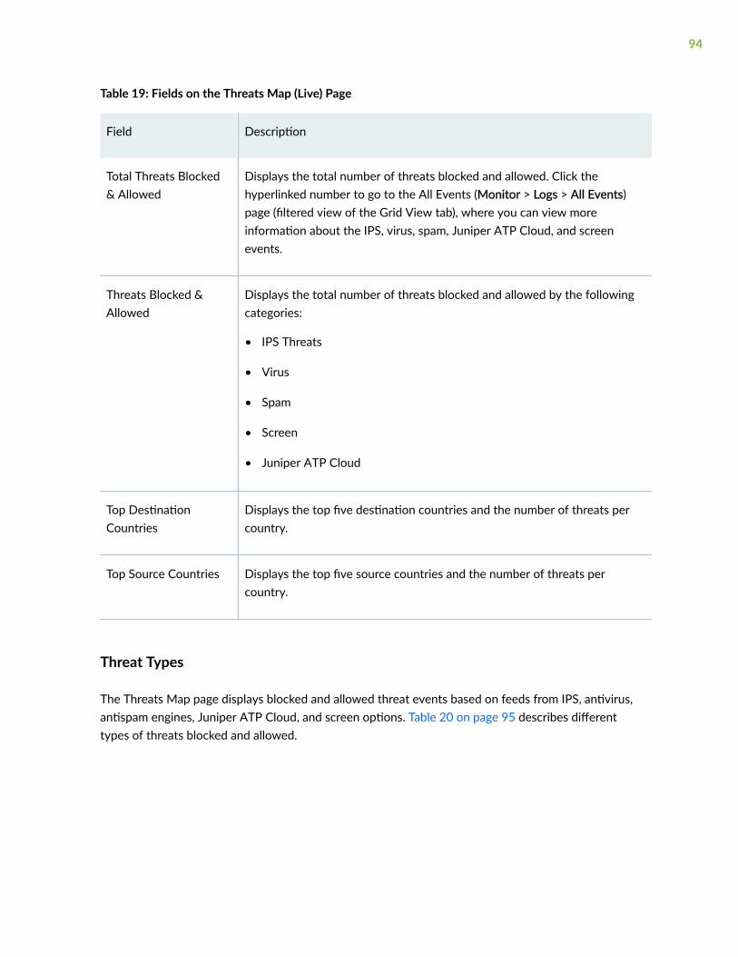
Table 19: Fields on the Threats Map (Live) Page
Field Description
Total Threats Blocked& Allowed
Displays the total number of threats blocked and allowed. Click thehyperlinked number to go to the All Events (Monitor > Logs > All Events)page (filtered view of the Grid View tab), where you can view moreinformation about the IPS, virus, spam, Juniper ATP Cloud, and screenevents.
Threats Blocked &Allowed
Displays the total number of threats blocked and allowed by the followingcategories:
• IPS Threats
• Virus
• Spam
• Screen
• Juniper ATP Cloud
Top DestinationCountries
Displays the top five destination countries and the number of threats percountry.
Top Source Countries Displays the top five source countries and the number of threats percountry.
Threat Types
The Threats Map page displays blocked and allowed threat events based on feeds from IPS, antivirus,antispam engines, Juniper ATP Cloud, and screen options. Table 20 on page 95 describes differenttypes of threats blocked and allowed.
94

Table 20: Types of Threats
Attack Description
IPS threatevents
Intrusion detection and prevention (IDP) attacks detected by the IDP module.
The information reported about the attack (displayed on the IPS (Monitor > Logs >Threats page) includes information about:
• Specific events names
• Specific event names with either source or destination country
Virus Virus attacks detected by the antivirus engine.
The information reported about the attack (displayed on the Antivirus (Monitor > Logs> Threats page) includes information about:
• Specific events names
• Specific event names with either source or destination country
Spam E-mail spam that is detected based on the blacklist spam e-mails.
The information reported about the attack (displayed on the Antispam (Monitor > Logs> Threats page) includes information about:
• Specific events names
• Specific event names with source country
JuniperATP Cloud
Events that are detected based on Juniper ATP Cloud policies.
The information reported about the attack (displayed on the Screen (Monitor > Logs >ATP page) includes information about:
• Specific events names
• Specific event names with either source or destination country
95

Table 20: Types of Threats (Continued)
Attack Description
Screen Events that are detected based on screen options.
The information reported about the attack (displayed on the Screen (Monitor > Logs >Threats page) includes information about:
• Specific events names
• Specific event names with either source or destination country
Tasks You Can Perform
You can perform the following tasks from this page:
• Toggle between updating the data and allowing live updates—Click the Pause icon to stop the pagefrom updating the threat map data and to stop animations. Click the Play icon to update the pagedata and resume animations.
• Zoom in and out of the page—Click the zoom in (+) and zoom out (–) icons to zoom in and out of thepage.
• Pan the page—Click and drag the mouse to pan the page.
• View country-specific details:
• Click a country on the threat map to view threat information specific to that country. A Country-Name pop-up appears displaying country-specific information.
• Click View Details in the Country-Name pop-up to view additional details. The Country-Name(Details) panel appears.
Table 21 on page 96 provides more details on the country-specific threat information.
Table 21: Country-Specific Threat Information
Field Description
Displayed in Country-Name pop-up
96

Table 21: Country-Specific Threat Information (Continued)
Field Description
Number of threatevents Threat Eventssince 12:00 am
Displays the total number of threat events (inbound and outbound) sincemidnight for that country.
Inbound (Number ofthreat events)
Displays the total number of inbound threats for the country and the IPaddress and the number of events for that IP address for the top fiveinbound events.
Click View All to view all the destination IP address with threat events count.
Outbound (Number ofthreat events)
Displays the total number of outbound threats for the country and the IPaddress and the number of events for that IP address for the top fiveoutbound events.
Click View All to view all the source IP address with threat events count.
View Details—Displayed in Country-Name (Details) panel
Number of threatevents Threat Eventssince 12:00 am
Displays the total number of threat events (inbound and outbound) sincemidnight for that country.
97

Table 21: Country-Specific Threat Information (Continued)
Field Description
Number of InboundEvents
Displays the total number of inbound threats for the country and the numberof inbound threat events for each of the following categories:
• IPS Threats
• Virus
• Spam
• Screen
• Juniper ATP Cloud
Click Top 5 IP Addresses (Inbound) to view the IP address and the number ofevents for that IP address for the top five inbound events.
Click View All IP Addresses to view all the destination IP addresses andnumber of events for that IP address.
NOTE: You can view or select View All IP Addresses only after you click Top5 IP Addresses (Inbound).
98

Table 21: Country-Specific Threat Information (Continued)
Field Description
Number of OutboundEvents
Displays the total number of outbound threats for the country and thenumber of outbound threat events for each of the following categories:
• IPS Threats
• Virus
• Spam
• Screen
• Juniper ATP Cloud
Click Top 5 IP Addresses (Outbound) to view the IP address and the numberof events for that IP address for the top five outbound events.
Click View All IP Addresses to view all the source IP addresses and numberof events for that IP address.
NOTE: You can view or select View All IP Addresses only after you click Top5 IP Addresses (Outbound).
RELATED DOCUMENTATION
Monitor Applications | 99
Monitor Applications
You are here: Monitor > Maps and Charts > Applications.
Use this page to view information about bandwidth consumption, session establishment, and risksassociated with your applications. Analyzing your network applications yields useful securitymanagement information, such as abnormal applications that can lead to data loss, bandwidth hogging,time-consuming applications, and personal applications that can elevate business risks.
99

NOTE: Applications page is available on all the SRX Series devices except the SRX5000 line ofdevices.
NOTE: To view the data on the Applications page, ensure that:
• On-box traffic logging and reporting is enabled. If not, go to Device Administration > BasicSettings > Security Logging, enable Stream mode Logging and On-box Reporting.
• Logging is enabled for a matching traffic firewall policy. If not, go to Security Policies &Objects > Security Policies and enable Logging options under Rule Options.
• Application tracking is enabled for a security zone. If not, go to Security Policies & Objects >Zones/Screens and enable Application Tracking in the Add Zone page.
You can select either the Grid View tab or the Chart View tab to view your data:
• Grid View—View the comprehensive details of applications in a tabular format that includes sortablecolumns. You can group the applications using Top users by volume, Top apps by volume, timespan,username, and so on. The table includes information such as the application name, volume, users andso on. Table 22 on page 100 describes the fields on the Grid View page.
• Chart View—View a brief summary of all the applications. It shows the top 50 applicationsconsuming maximum bandwidth in your network. The data is presented graphically as a bubblegraph, heat map, or zoomable bubble graph. Table 23 on page 102 describes the widgets on theChart View page.
Table 22: Applications—Fields on the Grid View Page
Field Description
Top Users By Volume Top users of the application; sorted by bandwidth consumption.
Top Apps By Volume Top applications, such as Amazon, Facebook, and so on of the networktraffic; sorted by bandwidth consumption.
Top Category By Volume Top category, such as web, infrastructure, and so on of the application;sorted by bandwidth consumption.
100

Table 22: Applications—Fields on the Grid View Page (Continued)
Field Description
Top Characteristics ByVolume
Top behavioral characteristics, such as prone to misuse, bandwidthconsumer, and so on of the application.
Sessions By Risk Number of events/sessions received; grouped by risk.
Time Span Allows you to select a time period. Click Custom to select a preferreddate.
View App Logs Enables you to view the application logs.
Search Enables you to search a particular content from the data.
Application Name Name of the application, such as Amazon, Facebook, and so on.
Risk Level Risk associated with the application: critical, high, unsafe, moderate, low,and unknown.
Users Total number of users accessing the application.
Volume Bandwidth used by the application.
Total Sessions Total number of application sessions.
Category Category of the application, such as web, infrastructure, and so on.
Sub-Category Subcategory of the application. For example, social networking, news,and advertisements.
NOTE: There can be many sub-categories for a single category. Forexample, if the Category is Multimedia, it can have sub-categories asVideo-streaming and Audio-streaming and so on.
101

Table 22: Applications—Fields on the Grid View Page (Continued)
Field Description
Characteristics Characteristics of the application. For example, prone to misuse,bandwidth consumer, capable of tunneling.
NOTE: There can be many characteristics displayed by a commaseparator. For example, characteristics can be displayed as Support FileTransfer, Loss of Productivity, Bandwidth.
Table 23: Applications—Widgets on the Chart View Page
Field Description
Top 50 Applications Displays the top 50 application consuming maximum bandwidth in yournetwork.
The data is presented graphically as a bubble graph, heat map, or zoomablebubble graph.
Show By Allows you to reorder the bubble graph by bandwidth or by number of sessionsfrom the drop down.
If Bandwidth is selected, the size of the bubble depends on the bandwidthused. Whereas, if Number of Session is selected, the size of the bubble dependsupon the number of sessions.
Time Span Allows you to select a time. Click Custom to select a preferred date.
Group By Allows you to group the bubble graph by bandwidth or by number of sessionsfrom the drop down based on risk or categories.
RELATED DOCUMENTATION
Monitor Users | 103
102

Monitor Users
You are here: Monitor > Maps and Charts > Users.
Use this page to view information about top users accessing high bandwidth-consuming applicationsand establishing higher number of sessions on your network. Based on this information, networkadministrators can control the user by rate-limit a device that is accessing applications which consumelarge bandwidth or create maximum traffic.
NOTE: Users page is available on all the SRX Series devices except the SRX5000 line of devices.
You can select either the Grid View tab or the Chart View tab to view your data:
• Grid View—View the comprehensive details of users in a tabular format that includes sortablecolumns. You can group the users using Top users by volume, Top apps by volume, timespan,username etc. The table includes information such as the username, volume, top users by volumeand so on. Table 24 on page 103 describes the fields on the Grid View page.
• Chart View—View a brief summary of all the users. It shows the top 50 users consuming maximumbandwidth in your network. The data is presented graphically as a bubble graph, heat map, orzoomable bubble graph. Table 25 on page 104 describes the widgets on the Chart View page.
Table 24: Users—Fields on the Grid View Page
Field Description
Top Users By Volume Top users of the application; sorted by bandwidth consumption.
Top Apps By Volume Top applications, such as Amazon, Facebook, and so on of the network traffic;sorted by bandwidth consumption.
Time Span Allows you to select a time period. Click Custom to select a preferred date.
Username Name of a user.
Volume Bandwidth consumption of the user.
103

Table 24: Users—Fields on the Grid View Page (Continued)
Field Description
Total Sessions Total number of user sessions.
Applications All the applications used by a user for the time range.
Search Enables you to search a particular content from the data.
Table 25: Users—Widgets on the Chart View Page
Field Description
Top 50 Users Displays the top 50 users consuming maximum bandwidth in your network.
The data is presented graphically as a bubble graph, heat map, or zoomable bubblegraph.
Show By Allows you to reorder the bubble graph by bandwidth or by number of sessions fromthe drop down.
If Bandwidth is selected, the size of the bubble depends on the bandwidth used.Whereas, if Number of Session is selected, the size of the bubble depends upon thenumber of sessions.
Time Span Allows you to select a time. Click Custom to select a preferred date.
RELATED DOCUMENTATION
Monitor Threat Prevention | 105
104

CHAPTER 6
Statistics
IN THIS CHAPTER
Monitor Threat Prevention | 105
Monitor VPN Phase I | 106
Monitor VPN Phase II | 108
Monitor Threat Prevention
You are here: Monitor > Statistics > Threat Prevention.
Use this page to verify the statistics of advanced-anti-malware sessions and security Intelligencesessions.
Table 26 on page 105 describes the fields on the Threat Prevention page.
Table 26: Fields on the Threat Prevention Page
Field Description
Advanced Anti Malware Session Statistics
Sessions The following options are available:
• TOTAL—Specify the TOTAL Session.
• HTTP—Specify the HTTP Session.
• HTTPS—Specify the HTTP Session.
• SMTP—Specify the simple mail transfer protocol session.
• SMTPS—Specify SMTPS session.
105

Table 26: Fields on the Threat Prevention Page (Continued)
Field Description
Clear Statistics Clear the statistics.
Graph Shows the anti-malware session statistics.
Security Intelligence Session Statistics
Profiles Select a profile from the list.
Sessions The following options are available:
• TOTAL—Displays the identification number of the Services Processing Unit.
• PERMIT—Specify the permitted session.
• BLOCK-DROP—Specify the block drop.
• BLOCK-CLOSE—Specify the block close.
• CLOSE-REDIRECT—Specify the closure of the redirect session.
Clear Statistics Clear the statistics.
RELATED DOCUMENTATION
Monitor VPN Phase I | 106
Monitor VPN Phase I
You are here: Monitor > Statistics > Phase I.
Use this page to view information related to IKE security associations.
Table 27 on page 107 describes the fields on the Phase I page.
106

Table 27: Fields on the Phase I Page
Field Description
IKE Security Associations
Refresh Interval(sec)
Indicates the duration of time after which you want the data on the page to berefreshed.
Refresh Click the refresh icon at the top right corner to display the fresh content.
Clear IKE SA Clears all the IKE SA numbers on the display.
SA Index Index number of a SA.
Remote Address IP address of the destination peer with which the local peer communicates.
State State of the IKE security associations:
• DOWN—SA has not been negotiated with the peer.
• UP—SA has been negotiated with the peer.
Initiator Cookie Random number, called a cookie, which is sent to the remote node when the IKEnegotiation is triggered.
ResponderCookie
Random number generated by the remote node and sent back to the initiator as averification that the packets were received.
NOTE: A cookie is aimed at protecting the computing resources from attackwithout spending excessive CPU resources to determine the cookie’sauthenticity.
107

Table 27: Fields on the Phase I Page (Continued)
Field Description
Mode Negotiation method agreed upon by the two IPsec endpoints, or peers, used toexchange information. Each exchange type determines the number of messagesand the payload types that are contained in each message. The modes, orexchange types, are:
• Main—The exchange is done with six messages. This mode, or exchange type,encrypts the payload, protecting the identity of the neighbor. Theauthentication method used is displayed: preshared keys or certificate.
• Aggressive—The exchange is done with three messages. This mode, orexchange type, does not encrypt the payload, leaving the identity of theneighbor unprotected.
RELATED DOCUMENTATION
Monitor VPN Phase II | 108
Monitor VPN Phase II
You are here: Monitor > Statistics > Phase II.
Use this page to view IPsec statistics and information related to IPsec security associations.
Table 28 on page 108 describes the fields on the Phase II page.
Table 28: Fields on the Phase II Page
Field Description
Statistics
Refresh interval (sec) Indicates the duration of time after which you want the data on the page to berefreshed.
108

Table 28: Fields on the Phase II Page (Continued)
Field Description
Refresh Click the refresh icon at the top right corner to display the fresh content.
Clear Clears all the data on the display page.
IPsec Statistics
—Provides details of the IPsec statistics.
Counter Displays the ESP (encrypted and decrypted bytes), AH (input and output), anderrors statistics.
Value Displays the values for the respective statistics.
IPsec SA
IPsec Security Associations
ID Index number of the SA.
Gateway/Port IP address of the remote gateway/port.
Algorithm Cryptography scheme used to secure exchanges between peers during the IKEPhase II negotiations:
• An authentication algorithm used to authenticate exchanges between thepeers. Options are hmac-md5-95 or hmac-sha1-96.
SPI Security parameter index (SPI) identifier. A SA is uniquely identified by an SPI.Each entry includes the name of the VPN, the remote gateway address, theSPIs for each direction, the encryption and authentication algorithms, andkeys. The peer gateways each have two SAs, one resulting from each of thetwo phases of negotiation: Phase I and Phase II.
109

Table 28: Fields on the Phase II Page (Continued)
Field Description
Life The lifetime of the SA, after which it expires, expressed either in seconds orkilobytes.
Monitoring Specifies if VPN-Liveliness Monitoring has been enabled/disabled. Enabled - 'U ', Disabled- '—'
Vsys Specifies the root system.
RELATED DOCUMENTATION
Monitor DHCP Server Bindings | 55
110

CHAPTER 7
Reports
IN THIS CHAPTER
About Reports Page | 111
About Reports Page
IN THIS SECTION
Overview | 112
Threat Assessment Report | 117
Application and User Usage | 117
Top Talkers | 118
IPS Threat Environment | 118
Viruses Blocked | 119
URL Report | 119
Virus: Top Blocked | 119
Top Firewall Events | 119
Top Firewall Deny Destinations | 120
Top Firewall Denies | 120
Top IPS Events | 120
Top Anti-spam Detected | 120
Top Screen Attackers | 120
Top Screen Victims | 120
Top Screen Hits | 120
Top Firewall Rules | 120
Top Firewall Deny Sources | 120
111

Top IPS Attack Sources | 120
Top IPS Attack Destinations | 121
Top IPS Rules | 121
Top Web Apps | 121
Top Applications Blocked | 121
Top URLs by User | 121
Top Source Zone by Volume | 121
Top Applications by User | 121
Top Botnet Threats By Source Address via IDP Logs | 122
Top Botnet Threats by Destination Address via IDP Logs | 122
Top Botnet Threats by Threat Severity via IDP Logs | 122
Top Malware Threats by Source Address via IDP Logs | 122
Top Malware Threats by Destination Address via IDP Logs | 122
Top Malware Threats by Threat Severity via IDP Logs | 123
Top Blocked Applications via Webfilter Logs | 123
Top Permitted Application Subcategories by Volume via Webfilter Logs | 123
Top Permitted Application Subcategories by Count via Webfilter Logs | 123
Overview
IN THIS SECTION
Generate Reports | 115
You are here: Monitor > Reports.
Use the Reports menu to generate reports on demand. There are several predefined reports listed in thispage, see Table 29 on page 113. The generated report is displayed in HTML format. You can groupmultiple reports and generate a consolidated report.
112

NOTE: Reports page is available on all the SRX Series devices except the SRX5000 line ofdevices.
Logical system and tenant support the reports listed in Table 29 on page 113 only for SRX1500,SRX4100, SRX4200, and SRX4600.
Table 29: Predefined Group Reports and Supported Users
Report Name Root Logical SystemUsers
Tenant UsersSupport
Threat Assessment Report Yes Yes Yes
Application and User Usage Yes Yes Yes
Top Talkers Yes Yes Yes
IPS Threat Environment Yes Yes No
URL Report Yes Yes Yes
Viruses Blocked Yes Yes No
Virus: Top Blocked Yes Yes No
Top Firewall Events Yes Yes Yes
Top Firewall Deny Destinations Yes Yes Yes
Top Firewall Denies Yes Yes Yes
Top IPS Events Yes Yes No
113

Table 29: Predefined Group Reports and Supported Users (Continued)
Report Name Root Logical SystemUsers
Tenant UsersSupport
Top Anti-spam Detected Yes Yes No
Top Screen Attackers Yes Yes Yes
Top Screen Victims Yes Yes Yes
Top Screen Hits Yes Yes Yes
Top Firewall Rules Yes Yes Yes
Top Firewall Deny Sources Yes Yes Yes
Top IPS Attack Sources Yes Yes Yes
Top IPS Attack Destinations Yes Yes No
Top IPS Rules Yes Yes No
Top Web Apps Yes Yes No
Top Applications Blocked Yes Yes No
Top URLs by User Yes Yes No
Top Source Zone by Volume Yes Yes Yes
Top Applications by User Yes Yes Yes
114

Table 29: Predefined Group Reports and Supported Users (Continued)
Report Name Root Logical SystemUsers
Tenant UsersSupport
Top Botnet Threats By Source Address via IDPLogs
Yes Yes No
Top Botnet Threats by Destination Address viaIDP Logs
Yes Yes No
Top Botnet Threats by Threat Severity via IDPLogs
Yes Yes No
Top Malware Threats by Source Address via IDPLogs
Yes Yes No
Top Malware Threats by Destination Address viaIDP Logs
Yes Yes No
Top Malware Threats by Threat Severity via IDPLogs
Yes Yes No
Top Blocked Applications via Webfilter Logs Yes Yes No
Top Permitted Application Subcategories byVolume via Webfilter Logs
Yes Yes No
Top Permitted Application Subcategories byCount via Webfilter Logs
Yes Yes No
Generate Reports
To generate a report:
1. Click Reports.
115

2. Select the predefined report name and click Generate Report.
The Report Title window appears.
NOTE: You can select single or multiple report names or all the predefined report names andgenerate a consolidated report. But you cannot generate group and individual reports at thesame time.
3. Complete the configuration according to the guidelines provided in Table 30 on page 116.
4. Click Save to save the generated report in the desired location.
A reported is generated. The report includes, the time when it was generated, the table of contents,and the result (a bar graph, a tabular format, and so on). If there is no data available, the reportshows, No data to display.
Table 30: Generate Report Settings
Field Action
Name Enter a name of the report. Maximum 60 characters.
Customer Name Enter a customer name. Default value is Juniper.
Description Enter a description of the report.
Show Top Use the up and down arrow to select the number of records to display in thereport.
Show Details Select an option from the list:
• Top Selected—Displays only the top selected details in the report.
• All—Displays all the details in the report.
NOTE: It may take a while to generate reports, depending on the device datasize.
Time Span Select a predefined time span from the list for the report.
116

Table 30: Generate Report Settings (Continued)
Field Action
From Specify a start date and time (in MM/DD/YYYY and HH:MM:SS 12-hour orAM/PM formats) to start the report generation.
NOTE: This option is available when you choose Custom for Time Span.
To Specify a start date and time (in MM/DD/YYYY and HH:MM:SS 12-hour orAM/PM formats) to stop the report generation.
NOTE: This option is available when you choose Custom for Time Span.
Sorting Options
Show Details Click the arrow next to Sorting Options and select one of the options from the list:
• Largest To Smallest—Display reports from largest to smallest details.
• Smallest To Largest—Display reports from smallest to largest details.
Threat Assessment Report
Threat Assessment report contains the following content:
• Executive Summary
• Application Risk Assessment
• Threat & Malware Assessment
• User and Web Access Assessment
The Threat Assessment report displays a new Filename column in the Malware downloaded by Usertable. This column helps to identify the malware filename.
Application and User Usage
Application and User Usage report contains the following content:
• Top High Risk Applications by Bandwidth
• Top High Risk Applications By Count
117

• Top Categories By Bandwidth
• Top Applications By Bandwidth
• Top Categories By Count
• Top Applications By Count
• Top Users Of High Risk Applications By Bandwidth
• Top Users By Bandwidth
• High Risk Applications Allowed Per User
• High Risk Applications Blocked Per User
Top Talkers
Top Talkers report contains the following content:
• Top Source IPs by Bandwidth
• Top Destination IPs by Bandwidth
• Top Source IPs by Session
• Top Destination IPs by Session
• Top Users By Bandwidth
• Top Users By Count
IPS Threat Environment
IPS Threat Environment report contains the following content:
• IPS Attacks by Severity Over Time
• Total IPS Attacks by Severity
• Top IPS Categories Blocked
• Top IPS Attacks Blocked
• Top Targeted Hosts by IP
• Top Targeted Hosts by User
118

NOTE: IPS Threat Environment report is not supported for tenant users.
Viruses Blocked
Viruses Blocked report contains the following content:
• Total Viruses Blocked Over Time
• Top Viruses Blocked
NOTE: Viruses Blocked is not supported for tenant users.
URL Report
URL Report contains the following content:
• Top URLs by Bandwidth
• Top URLs by Count
• Top URL Categories by Bandwidth
• Top URL Categories by Count
• Total URLs Blocked Over Time
• Top Blocked URLs
• Top Blocked URL Categories by Count
• Users With Most Blocked URLs
Virus: Top Blocked
Virus: Top Blocked report contains Virus: Top Blocked content.
NOTE: Virus: Top Blocked is not supported for tenant users.
Top Firewall Events
Top Firewall Events report contains Top Firewall Events.
119

Top Firewall Deny Destinations
Top Firewall Deny Destinations report contains Top Firewall Deny Destinations.
Top Firewall Denies
Top Firewall Denies report contains Top Firewall Denies.
Top IPS Events
Top IPS Events report contains Top IPS Events.
NOTE: Top IPS Events is not supported for tenant users.
Top Anti-spam Detected
Top Anti-Spam Detected report Top Anti-spam Detected.
NOTE: Top Anti-spam Detected is not supported for tenant users.
Top Screen Attackers
Top Screen Attackers report contains Top Screen Attackers.
Top Screen Victims
Top Screen Victims report contains Top Screen Victims.
Top Screen Hits
Top Screen Hits report contains Top Screen Hits.
Top Firewall Rules
Top Firewall Rules report contains Top Firewall Rules.
Top Firewall Deny Sources
Top Firewall Deny Sources report contains Top Firewall Deny Sources.
Top IPS Attack Sources
Top IPS Attack Sources report contains Top IPS Attack Sources.
120

Top IPS Attack Destinations
Top IPS Attack Destinations report contains Top IPS Attack Destinations.
NOTE: Top IPS Attack Destinations is not supported for tenant users.
Top IPS Rules
Top IPS Rules report contains Top IPS Rules.
NOTE: Top IPS Rules is not supported for tenant users.
Top Web Apps
Top Web Apps report contains Top Web Apps.
NOTE: Top Web Apps is not supported for tenant users.
Top Applications Blocked
Top Applications Blocked report contains Top Applications Blocked.
NOTE: Top Applications Blocked is not supported for tenant users.
Top URLs by User
Top URLs by User report contains Top URLs by User.
NOTE: Top URLs by User is not supported for tenant users.
Top Source Zone by Volume
Top Source Zone by Volume report contains Top Source Zone by Volume.
Top Applications by User
Top Applications by User report contains Top Applications by User.
121

Top Botnet Threats By Source Address via IDP Logs
Top Botnet Threats By Source Address via IDP Logs report contains Top Botnet Threats By SourceAddress via IDP Logs.
NOTE: Top Botnet Threats By Source Address via IDP Logs is not supported for tenant users.
Top Botnet Threats by Destination Address via IDP Logs
Top Botnet Threats by Destination Address via IDP Logs report contains Top Botnet Threats byDestination Address via IDP Logs.
NOTE: Top Botnet Threats by Destination Address via IDP Logs is not supported for tenantusers.
Top Botnet Threats by Threat Severity via IDP Logs
Top Botnet Threats by Threat Severity via IDP Logs report contains Top Botnet Threats by ThreatSeverity via IDP Logs.
NOTE: Top Botnet Threats by Threat Severity via IDP Logs is not supported for tenant users.
Top Malware Threats by Source Address via IDP Logs
Top Malware Threats by Source Address via IDP Logs report contains Top Malware Threats by SourceAddress via IDP Logs.
NOTE: Top Malware Threats by Source Address via IDP Logs is not supported for tenant users.
Top Malware Threats by Destination Address via IDP Logs
Top Malware Threats by Destination Address via IDP Logs report contains Top Malware Threats byDestination Address via IDP Logs.
NOTE: Top Malware Threats by Destination Address via IDP Logs is not supported for tenantusers.
122

Top Malware Threats by Threat Severity via IDP Logs
Top Malware Threats by Threat Severity via IDP Logs report contains Top Malware Threats by ThreatSeverity via IDP Logs.
NOTE: Top Malware Threats by Threat Severity via IDP Logs is not supported for tenant users.
Top Blocked Applications via Webfilter Logs
Top Blocked Applications via Webfilter Logs report contains Top Blocked Applications via Webfilter Logs.
NOTE: Top Blocked Applications via Webfilter Logs is not supported for tenant users.
Top Permitted Application Subcategories by Volume via Webfilter Logs
Top Permitted Application Subcategories by Volume via Webfilter Logs report contains Top PermittedApplication Subcategories by Volume via Webfilter Logs.
NOTE: Top Permitted Application Subcategories by Volume via Webfilter Logs is not supportedfor tenant users.
Top Permitted Application Subcategories by Count via Webfilter Logs
Top Permitted Application Subcategories by Count via Webfilter Logs report contains Top PermittedApplication Subcategories by Count via Webfilter Logs.
NOTE: Top Permitted Application Subcategories by Count via Webfilter Logs is not supported fortenant users.
123

5PART
Device Administration
Basic Settings | 126
Cluster Management | 147
User Management | 174
Multi Tenancy—Resource Profiles | 181
Multi Tenancy—Interconnect Ports | 190
Multi Tenancy—Logical Systems | 201
Multi Tenancy—Tenants | 217
Certificate Management—Device Certificates | 229
Certificate Management—Trusted Certificate Authority | 242
Certificate Management—Certificate Authority Group | 255
License Management | 261
ATP Management | 266
Operations | 272
Software Management | 280
Configuration Management | 284
Alarm Management | 290
RPM | 301
Tools | 318
Reset Configuration | 354


CHAPTER 8
Basic Settings
IN THIS CHAPTER
Configure Basic Settings | 126
Configure Basic Settings
You are here: Device Administration > Basic Settings.
Use this page to configure your device basic settings.
You can do the following:
• Save—Saves all the basic settings configuration and returns to the main configuration page.
NOTE: For all the configuration options under Basic Settings:
• Tool tip on the right-side represents different icons for notifications, validation errors, andsuccessful configuration.
• When you make a configuration change and navigate to a different page without saving it,a pop-up message is displayed to save the configuration.
• Cancel—Cancels all your entries and returns to the main configuration page.
• Commit—Commits all the basic settings configuration and returns to the main configuration page.
• Expand all—Click the arrow pointing outwards icon to expand all the options.
• Collapse all—Click the arrow pointing inwards to collapse or hide all the options.
Table 31 on page 127 describes the fields on the Basic Settings page.
126

Table 31: Fields on the Basic Settings Page
Field Action
System Identity
Hostname Enter a hostname for the device.
Domain name Enter a domain name to specify the network orsubnetwork to which the device belongs.
Root password Enter a password for the root user.
NOTE: After you have defined a root password,that password is required when you log in to theJ-Web or the CLI.
Confirm root password Re-enter the password to confirm.
127

Table 31: Fields on the Basic Settings Page (Continued)
Field Action
DNS servers Select an option to specify the DNS serversettings:
• To specify a server that the device can use toresolve hostnames into addresses:
1. Click + at the top right side of the DNSServers table.
2. Enter an IPv4 address of the server.
3. Click the tick mark to save the changes.Else, click the cancel (X) icon to discard thechanges.
• To edit an existing DNS server hostname:
1. Select a DNS server hostname that youwant to edit.
2. Click the pencil icon at the top right side ofthe DNS Servers table or right-click on thehostname and edit the IPv4 address.
3. Click the tick mark to save the changes.Else, click the cancel (X) icon to discard thechanges.
• To remove an existing DNS server hostname,select it and click the delete icon at the topright side of the DNS Servers table or right-click on the hostname and delete it.
128

Table 31: Fields on the Basic Settings Page (Continued)
Field Action
Domain search Select an option:
• To add a domain name:
1. Click + at the top right side of the DomainSearch table.
2. Enter a domain name.
The string must contain an alphanumericcharacter and can include underscores,hyphen, slash and dot. No spaces allowed.
3. Click the tick mark to save the changes.Else, click the cancel (X) icon to discard thechanges.
• To edit an existing domain name:
1. Select a domain name that you want toedit.
2. Click the pencil icon at the top right side ofthe Domain Search table or right-click onthe domain name and edit the name.
3. Click the tick mark to save the changes.Else, click the cancel (X) icon to discard thechanges.
• To remove an existing domain name, select itand click the delete icon at the top right side ofthe Domain Search table or right-click on thename and delete it.
Time
Time zone Select the time zone from the list in which therouter resides.
129

Table 31: Fields on the Basic Settings Page (Continued)
Field Action
Time source Select an option from the list to set the systemtime:
NTP Servers—Synchronizes the system time withthe NTP server that you select. Click one of thefollowing options:
• Add—Click + to add an NTP server. Then, enterthe NTP server name, key, and RoutingInstance. Select an option from the list forVersion and Prefer.
• Edit—Select an existing NTP server that youwant to edit and click the pencil icon availableat the upper right of the NTP Server table. Youcan also right-click on the NTP server and clickEdit Row. Then, edit the key and version andclick the tick mark.
• Delete—Select an existing NTP server that youwant to delete and click the delete iconavailable at the upper right of the NTP Servertable. You can also right-click on the NTPserver and click Delete Row. Click Yes todelete the selected server.
Computer—Uses the computer that you arecurrently logged into to determine the systemtime for the device.
NOTE: When you select this option, the PC timethat will be used is displayed in the Current Date& Time field.
130

Table 31: Fields on the Basic Settings Page (Continued)
Field Action
Manual—Enables you to manually select the dateand time for the device.
Set the date and time using the calendar pick tooland time fields.
NOTE: After you configure the time manually, thesession will expire. Log in to J-Web.
Device date & time Displays the device date and time.
Current date & time Displays the current date and time.
Management and Loopback Address
Management address Enter IPv4 address for the device.
Subnet Enter subnet of the IPv4 address.
Loopback address Enter IP address and subnet for the loopbackaddress.
NOTE: If the SRX device does not have adedicated management port (fxp0), thenLoopback Address and Subnet are the onlyoptions available for the management accessconfiguration.
Subnet Enter the address, for example, 255.255.255.0.You can also specify the address prefix.
Specifies the range of logical addresses within theaddress space that is assigned to an organization.
131

Table 31: Fields on the Basic Settings Page (Continued)
Field Action
Default gateway Enter the default gateway address for IPv4.
System Services
Telnet Select this option to enable telnet.
SSH Select this option to enable SSH connections.
FTP Select this option to enable FTP for secure filetransfer.
NETCONF Select this option to enable NETCONFconnections.
Junoscript over SSL Select this option to enable Junoscriptconnections over SSL.
Junoscript certificate Select the local certificate for SSL from the list.
Interface Select the interface in order of your preferenceand click on the left arrow/right arrow to add.
HTTPS Select this option to enable HTTPS connectionsettings.
Interface Select the interface in order of your preferenceand click on the left arrow/right arrow to add.
132

Table 31: Fields on the Basic Settings Page (Continued)
Field Action
HTTPS certificate Specifies the certificate that you want to use tosecure the connection from the HTTPScertificates list when you enable HTTPs.
Select the HTTPS certificate from the list.
PKI certificate Select the PKI certificate for HTTPS from the list.
NOTE: This option is available only if you selectpki-local-certificate in the HTTPS Certificateoptions.
Local certificate Select the local certificate for HTTPS from the list.
NOTE: This option is available only if you selectlocal-certificate in the HTTPS Certificate options.
Web API Select to enable Web API configuration.
Client Select to enable client for the Web API.
Hostname Provides the address of permitted HTTP/HTTPSrequest originators.
To add, click + and enter the IPv4 address of thepermitted HTTP/HTTPS request originator andclick tick mark to save the changes.
To delete, select the hostname and click thedelete icon. Then, click Yes to delete it.
HTTP Select to enable unencrypted HTTP connectionsettings.
133

Table 31: Fields on the Basic Settings Page (Continued)
Field Action
HTTP port Click top or bottom arrows to select the TCPports for incoming HTTP connections.
HTTPs Select to enable encrypted HTTPS connectionsettings.
HTTPS port Click top or bottom arrows to select the TCPports for incoming HTTP connections.
134

Table 31: Fields on the Basic Settings Page (Continued)
Field Action
Certificate type Select to specify the certificate that you want touse to secure the connection from the HTTPScertificates list when you enable HTTPs for WebAPI:
• Default—Selects the default system generatedcertificate.
• PKI Certificate—Select a PKI certificate fromthe list for HTTPS of Web API.
• File Path:
• File Path—Click Browse and select acertificate from your desired location. Orclick Upload and upload the selectedcertificate.
• Certificate—Displays the file path of theuploaded certificate.
• Certificate Key:
• Browse—Click and select the certificatekey from your desired location.
• Upload—Click and upload the selectedcertificate key.
• Certificate Key—Displays the file path ofthe uploaded certificate key.
User Select this option to enable user credentials.
Name Enter a username.
Password Enter the user password.
135

Table 31: Fields on the Basic Settings Page (Continued)
Field Action
REST API Enable this option to allow RPC execution overHTTP(S) connection.
Explorer Select this option to enable REST API explorer.
Control Select this option to enable control the REST APIprocess.
Allowed sources Provides the source IP address.
Click + and enter the IPv4 address of the source.Then, click tick mark.
To delete, select an existing address and click thedelete icon. Then, click Yes to delete it.
Connection limit Click top or bottom arrows to select the numberof simultaneous connections.
HTTP Select to enable unencrypted HTTP connectionsfor REST API.
Address Click + and enter the IPv4 address for theincoming connections for HTTP of REST API.Then, click tick mark to add it.
To delete, select an existing address and click thedelete icon. Then, click Yes to delete it.
Port Click top or bottom arrows to select the HTTPport to accept HTTP connections for REST API.
NOTE: The default port for HTTP of REST API is3000.
136

Table 31: Fields on the Basic Settings Page (Continued)
Field Action
HTTPS Select to enable encrypted HTTPS connectionsfor REST API.
Address Click + and enter the IPv4 address for theincoming connections for HTTPS of REST API.Then, click tick mark to add it.
To delete, select an existing address and click thedelete icon. Then, click Yes to delete it.
Cipher list Select the Cipher suites in order of yourpreference and click on the left arrow or rightarrow to add.
Port Click top or bottom arrows to select the HTTPSport to accept the HTTPS connection of RESTAPI.
NOTE: The default port for HTTPS of REST API is3443.
Server certificate Select server certificate from the list. See "Importa Device Certificate" on page 231 to import adevice certificate.
137

Table 31: Fields on the Basic Settings Page (Continued)
Field Action
CA Profile Select the certificate authority profile for HTTPSof REST API from the list.
To create Certificate Authority inline:
• Click Create Certificate Authority Profile.
• Enter the following details:
• CA Profile *—Enter the CA profile name.
• CA Identifier *—Enter the CA identifier.
• File Path on Device for Certificate:
• Browse—Click and select the certificatefrom your desired location.
• Upload—Click and upload the selectedcertificate.
• File Path on Device for Certificate—Displays the file path of the selectedcertificate.
• Click OK.
Security Logging
Stream mode logging Select this option to enable logging.
NOTE: The Enable Traffic Logs option is availablefor user logical system and tenants.
UTC timestamp Select this option to enable UTC Timestamp forsecurity log timestamps.
138

Table 31: Fields on the Basic Settings Page (Continued)
Field Action
Log on Select one of the log on types for logging.
• Source Address—Select this option to enterthe source IP address.
• Source Interface—Select this option to select asource interface from the list.
IP address Enter the source IP address.
NOTE: This option is available if you select the logon type as Source Address.
Format Specifies the format in which the logs are stored.
Select a format in which the logs are stored fromthe list.
• binary—Binary encoded text to conserveresources.
• SD-Syslog—Structured system log file.
• Syslog—Traditional system log file.
By default, None logging format is selected.
139

Table 31: Fields on the Basic Settings Page (Continued)
Field Action
Transport protocol Select an option from the list to specify the typeof logging transport protocol:
• TCP—Select this option to set the transportprotocol to TCP.
• UDP—Select this option to set the transportprotocol to UDP.
• TLS—Select this option to set the transportprotocol to TLS.
By default, None is selected.
Connections Select the TCP or TLS connections for loggingusing up and down arrows.
NOTE: This option is available if you select thetransport protocol option as TCP or TLS.
TLS profile Select a TLS profile from the list.
NOTE: This option is available if you select thetransport protocol option as TLS.
140

Table 31: Fields on the Basic Settings Page (Continued)
Field Action
Syslog server Enables you to configure syslog servers. You canconfigure a maximum of three syslog servers.
Perform one of the following tasks:
1. To create syslog server, click +, enter thefollowing details and then click OK.
• Name—Enter the name of the new streamconfiguration.
• Save At—Select the location from the list tosave the stream.
• Type—Select a format in which the logs arestored from the list.
The log types are:
• Structure
• Standard
• Web
• Host—Enter the IP address for the streamhost name.
2. To edit an existing syslog server, select it andclick the pencil icon. Then, edit the savingmode, streaming type, and host in the EditSyslog page and click OK.
3. To delete an existing syslog server, select it andclick the delete icon.
On-box reporting Enable this option to generate on-box reports.
NOTE: We recommend you use Stream modelogging to syslog server.
141

Table 31: Fields on the Basic Settings Page (Continued)
Field Action
SNMP
Contact information Enter any contact information for theadministrator of the system (such as name andphone number).
System description Enter any information that describes the system.
Local engine ID Enter the MAC address of Ethernet managementport 0.
Specifies the administratively unique identifier ofan SNMPv3 engine for system identification. Thelocal engine ID contains a prefix and a suffix. Theprefix is formatted according to specificationsdefined in RFC 3411. The suffix is defined by thelocal engine ID. Generally, the local engine IDsuffix is the MAC address of Ethernetmanagement port 0.
System location Enter any location information for the system (labname or rack name, for example).
System name override Specifies the option to override the systemhostname.
Enter the name of the system.
142

Table 31: Fields on the Basic Settings Page (Continued)
Field Action
Community Specifies the name and authorization for theSNMP community.
• Click +.
• Enter the name of the community beingadded.
• Select the desired authorization (either read-only or read-write) from the list.
Click tick mark.
Trap groups
Name Click + to add a trap group.
Enter the SNMP trap group being configured.
Categories Select trap categories to add to the trap groupbeing configured. The options available are:
• Authentication
• Chassis
• Configuration
• Link
• Remote operations
• RMON alarm
• Routing
• Startup
• CRRP events
143

Table 31: Fields on the Basic Settings Page (Continued)
Field Action
Targets Specifies one or more IP addresses that specifythe systems to receive SNMP traps that aregenerated by the trap group being configured.
Click +, enter the target IP address for SNMP trapgroup, and click tick mark.
Health monitoring Enable the option to check the SNMP healthmonitor on the device. The health monitorperiodically checks the following key indicators ofdevice health:
• Percentage of file storage used
• Percentage of Routing Engine CPU used
• Percentage of Routing Engine memory used
• Percentage of memory used for each systemprocess
• Percentage of CPU used by the forwardingprocess
• Percentage of memory used for temporarystorage by the forwarding process
Interval Specifies the sampling frequency interval, inseconds, over which the key health indicators aresampled and compared with the rising and fallingthresholds. For example, if you configure theinterval as 100 seconds, the values are checkedevery 100 seconds.
Select a value from 1 through 24855. The defaultvalue is 300 seconds.
144

Table 31: Fields on the Basic Settings Page (Continued)
Field Action
Rising threshold Specifies the value at which you want SNMP togenerate an event (trap and system log message)when the value of a sampled indicator isincreasing. For example, if the rising threshold is90, SNMP generates an event when the value ofany key indicator reaches or exceeds 90 seconds.
Select a value from 1 through 100. The defaultvalue is 90 seconds.
Falling threshold Specifies a value at which you want SNMP togenerate an event (trap and system log message)when the value of a sampled indicator isdecreasing. For example, if the falling threshold is80, SNMP generates an event when the value ofany key indicator falls back to 80 seconds or less.
Select a value 0 through 100. The default value is80 seconds.
Redundant PSU
NOTE: SRX380 devices support power supply redundancy for power management.
Power Supply 0 Displays if the power supply is present or not.
Power Supply 1 Displays if the redundant power supply is presentor not.
PSU Redundancy Enable this option to manage power on theSRX380 device.
NOTE: This option is available only when thedevice is in the standalone mode.
145

RELATED DOCUMENTATION
Configure Setup Wizard | 354
146

CHAPTER 9
Cluster Management
IN THIS CHAPTER
Configure Cluster (HA) Setup | 147
About the Cluster Configuration Page | 163
Edit Node Settings | 166
Add an HA Cluster Interface | 167
Edit an HA Cluster Interface | 169
Delete HA Cluster Interface | 169
Add a Redundancy Group | 170
Edit a Redundancy Group | 172
Delete Redundancy Group | 173
Configure Cluster (HA) Setup
Before you begin:
• Establish a chassis cluster connection between the two units, ensure that you have physical access toboth the devices.
• You must configure the two devices separately.
• Your other unit must be on the same hardware and software version as the current unit.
• Note that both units are erased and rebooted, after which all existing data is irretrievable. You havethe option to save a backup copy of your configuration before rebooting.
You are here: Device Administration > Cluster Management > Cluster Configuration.
The Junos OS provides high availability on SRX Series device by using chassis clustering. SRX SeriesServices Gateways can be configured to operate in cluster mode, where a pair of devices can beconnected together and configured to operate like a single node, providing device, interface, and servicelevel redundancy.
147
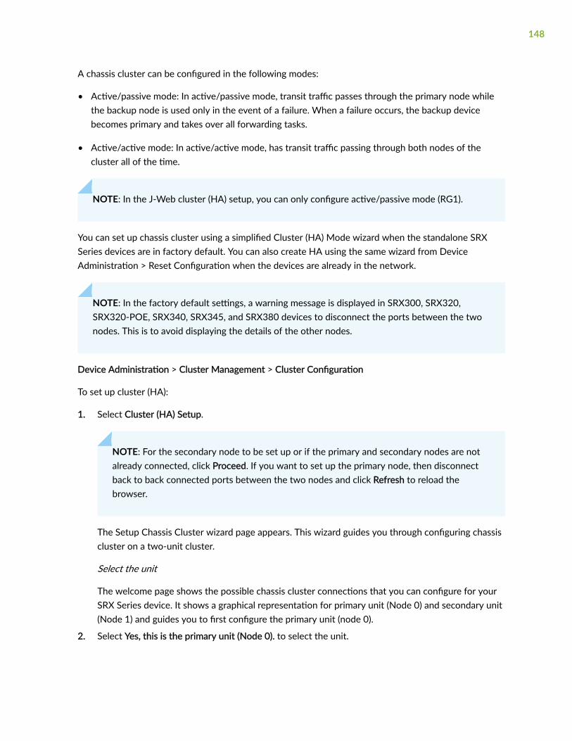
A chassis cluster can be configured in the following modes:
• Active/passive mode: In active/passive mode, transit traffic passes through the primary node whilethe backup node is used only in the event of a failure. When a failure occurs, the backup devicebecomes primary and takes over all forwarding tasks.
• Active/active mode: In active/active mode, has transit traffic passing through both nodes of thecluster all of the time.
NOTE: In the J-Web cluster (HA) setup, you can only configure active/passive mode (RG1).
You can set up chassis cluster using a simplified Cluster (HA) Mode wizard when the standalone SRXSeries devices are in factory default. You can also create HA using the same wizard from DeviceAdministration > Reset Configuration when the devices are already in the network.
NOTE: In the factory default settings, a warning message is displayed in SRX300, SRX320,SRX320-POE, SRX340, SRX345, and SRX380 devices to disconnect the ports between the twonodes. This is to avoid displaying the details of the other nodes.
Device Administration > Cluster Management > Cluster Configuration
To set up cluster (HA):
1. Select Cluster (HA) Setup.
NOTE: For the secondary node to be set up or if the primary and secondary nodes are notalready connected, click Proceed. If you want to set up the primary node, then disconnectback to back connected ports between the two nodes and click Refresh to reload thebrowser.
The Setup Chassis Cluster wizard page appears. This wizard guides you through configuring chassiscluster on a two-unit cluster.
Select the unit
The welcome page shows the possible chassis cluster connections that you can configure for yourSRX Series device. It shows a graphical representation for primary unit (Node 0) and secondary unit(Node 1) and guides you to first configure the primary unit (node 0).
2. Select Yes, this is the primary unit (Node 0). to select the unit.
148

NOTE: If you have already configured the primary node settings, then select No, this is thesecondary unit (Node 1) and follow the instructions from Step "8" on page 153.
3. Click Next.
4. To configure the primary unit, complete the configuration according to the guidelines provided inTable 32 on page 149.
Table 32: Primary Unit Configuration
Field Description Action
System Identity
Node 0 Cluster ID Specifies the number bywhich a cluster is identified.
Enter a number from 1through 255. By default, 1 isassigned.
Node 0 Priority Specifies the device priorityfor being elected to be theprimary device in the VRRPgroup.
Enter a number from 1through 255. By default, 200 isassigned.
Node 1 Priority Specifies the device priorityfor being elected to be theprimary device in the VRRPgroup.
Enter a number from 1through 255. By default, 100 isassigned.
Node 0 Host Name Specifies the device hostname of the node 0.
By default, host name isassigned. For example,SRX1500-01.
Node 1 Host Name Specifies the device hostname of the node 1.
By default, host name isassigned. For example,SRX1500-02.
Allow root user SSH login Allows users to log in to thedevice as root through SSH.
Enable this option.
149

Table 32: Primary Unit Configuration (Continued)
Field Description Action
Management Interface
IPv4 Address
NOTE: Make a note of the IPv4 address as you need it to access the settings after you committhe configuration.
Node 0 Management IPv4 Specifies the managementIPv4 address of node 0.
Enter a valid IPv4 address forthe management interface.
Node 0 Subnet Mask Specifies subnet mask forIPv4 address.
Enter a subnet mask for theIPv4 address.
Node 1 Management IPv4 Specifies the managementIPv4 address of node 1.
Enter a valid IPv4 address forthe management interface.
Node 1 Subnet Mask Specifies subnet mask forIPv4 address.
Enter a subnet mask for theIPv4 address.
Static Route IP Defines how to route to theother network devices.
Enter an IPv4 address for thestatic route.
Static Route Subnet Specifies the subnet for thestatic route IPv4 address.
Enter a subnet mask for thestatic route IPv4 address.
Next Hop IPv4 Specifies next hop gatewayfor the IPv4 address.
Enter a valid IPv4 address forthe next hop.
IPv6 Address (Optional)
Node 0 Management IPv6 Specifies the managementIPv6 address of node 0.
Enter a valid IPv6 address forthe management interface.
150
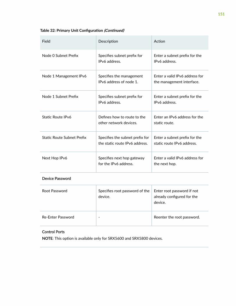
Table 32: Primary Unit Configuration (Continued)
Field Description Action
Node 0 Subnet Prefix Specifies subnet prefix forIPv6 address.
Enter a subnet prefix for theIPv6 address.
Node 1 Management IPv6 Specifies the managementIPv6 address of node 1.
Enter a valid IPv6 address forthe management interface.
Node 1 Subnet Prefix Specifies subnet prefix forIPv6 address.
Enter a subnet prefix for theIPv6 address.
Static Route IPv6 Defines how to route to theother network devices.
Enter an IPv6 address for thestatic route.
Static Route Subnet Prefix Specifies the subnet prefix forthe static route IPv6 address.
Enter a subnet prefix for thestatic route IPv6 address.
Next Hop IPv6 Specifies next hop gatewayfor the IPv6 address.
Enter a valid IPv6 address forthe next hop.
Device Password
Root Password Specifies root password of thedevice.
Enter root password if notalready configured for thedevice.
Re-Enter Password - Reenter the root password.
Control Ports
NOTE: This option is available only for SRX5600 and SRX5800 devices.
151

Table 32: Primary Unit Configuration (Continued)
Field Description Action
Dual Link Provides redundant link forfailover.
By default, this option isdisabled.
Once you enable this option,the following fields appear:
• Link 1
• Node 0 FPC—Select anoption from the list.
• Node 0 Port—Select anoption from the list.
• Node 1 FPC.
• Node 1 Port.
• Link 2 (Optional)
• Node 0 FPC—Select anoption from the list.
• Node 0 Port—Select anoption from the list.
• Node 1 FPC.
• Node 1 Port.
Node 0 FPC Specifies FPC slot number onwhich to configure the controlport.
Select an option from the list.
Node 0 Port Specifies port number onwhich to configure the controlport.
Select an option from the list.
152

Table 32: Primary Unit Configuration (Continued)
Field Description Action
Node 1 FPC Optional. Specifies FPC slotnumber on which to configurethe control port.
Select an option from the list.
Node 1 Port Optional. Specifies portnumber on which to configurethe control port.
Select an option from the list.
Save Backup (Optional)
Save Backup (to client) Saves backup of the currentconfiguration to the clientlocal machine.
NOTE: When restarting theprimary unit, J-Web deletesthe existing configuration toconfigure chassis cluster.Therefore, it is recommendedthat you save a backup file ofyour current settings beforecommitting the newconfiguration.
Enable the option to save thebackup file of your settings.
5. Click Reboot and Continue to restart the primary unit to configure chassis cluster.
6. After rebooting the primary unit (node 0), connect to the management port of the secondary unit toswitch to the secondary unit.
7. Click Refresh if the management IP address of the secondary unit is same as the existing devicedefault IP address. If not, open a new browser with the new secondary device IP address.
8. To configure the secondary unit, complete the configuration according to the guidelines provided inTable 33 on page 154.
153

Table 33: Secondary Unit Configuration
Field Description Action
Secondary Unit Information
Cluster ID Specifies the number bywhich a cluster is identified.
NOTE: Cluster ID must besame for both primary andsecondary units.
Enter a number from 1through 255. By default, 1 isassigned.
Device Password
Root Password Specifies root password of thedevice.
Enter new root password.
Re-Enter Password - Reenter the root password.
Control Ports
NOTE: This option is available only for SRX5600 and SRX5800 devices.
154

Table 33: Secondary Unit Configuration (Continued)
Field Description Action
Dual Link Provides redundant link forfailover.
By default, this option isdisabled.
Once you enable dual linkoption, the following fieldsappear:
• Link 1
• Node 0 FPC—Select anoption from the list.
• Node 0 Port—Select anoption from the list.
• Node 1 FPC.
• Node 1 Port.
• Link 2 (Optional)
• Node 0 FPC—Select anoption from the list.
• Node 0 Port—Select anoption from the list.
• Node 1 FPC.
• Node 1 Port.
Node 0 FPC Specifies FPC slot number onwhich to configure the controlport.
Select an option from the list.
Node 0 Port Specifies port number onwhich to configure the controlport.
Select an option from the list.
155

Table 33: Secondary Unit Configuration (Continued)
Field Description Action
Node 1 FPC Optional. Specifies FPC slotnumber on which to configurethe control port.
Select an option from the list.
Node 1 Port Optional. Specifies portnumber on which to configurethe control port.
Select an option from the list.
Save Backup (Optional)
Save Backup (to client) Saves backup of the currentconfiguration to the clientlocal machine.
NOTE: When restarting thesecondary unit, J-Web deletesthe existing configuration toconfigure chassis cluster.Therefore, it is recommendedthat you save a backup file ofyour current settings beforecommitting the newconfiguration.
Enable the option to save thebackup file of your settings.
9. Click Reboot and Continue to restart the secondary unit to configure chassis cluster.
10. After rebooting the secondary unit (node 1), launch the J-Web UI using primary unit managementIP address.
11. Navigate to Cluster Management > Cluster (HA) Setup.
The Cluster Wizard page will open and displays the Cluster Status step.
NOTE:
156

• J-Web uses show chassis cluster status to verify control link status. Number on the linksignifies if it is single (1) or dual links (2).
The control and fabric link status colors are as follows:
• Green—Indicates that the links are up.
• Red—Indicates that the links are down.
• Orange—Indicates that one of the dual links is up.
• Grey—Indicates that the fabric link is not configured.
• If chassis cluster is not connected, then the connection is failed and all possible failurereasons will be displayed. For information on troubleshooting tips, see JuniperKnowledge Search.
• You can configure fabric link only after the chassis cluster is formed. For the first timeconfiguration, the chassis status displays as The fabric ports links is not yetconfigured.
12. To configure fabric link, complete the configuration according to the guidelines provided in Table 34on page 157.
Table 34: Fabric Link Configuration
Field Description Action
Fabric Link Details
Dual Link Provides redundant link forfailover.
Enable this option.
Link 1
Fabric 0 Specifies the fabric port linkfor node 0.
Select an interface from thelist.
Fabric 1 Specifies the fabric port linkfor node 1.
-
Link 2 (Optional)
157

Table 34: Fabric Link Configuration (Continued)
Field Description Action
Fabric 0 Specifies the secondary fabricport link for node 0.
Select an interface from thelist.
Fabric 1 Specifies the secondary fabricport link for node 1.
-
13. Click Configure Link.
14. Click Next.
15. To add redundant Ethernet (reth) interface, click + and complete the configuration according to theguidelines provided in Table 35 on page 158.
NOTE: You can also use the pencil icon to edit the reth interface and delete icon to deletethe reth interfaces.
Table 35: Add Reth Interface
Field Description Action
RETH Name Specifies the reth interface name. Enter a name for rethinterface.
Node 0 Interfaces Specifies the list of Node 0 interfaces. Select an interfacefrom the Availablecolumn and move it tothe Selected column.
Node 1 Specifies the Node 1 interfaces based on thenode 0 interfaces.
-
Advance Settings
158

Table 35: Add Reth Interface (Continued)
Field Description Action
LACP Configuration Optional. Configure Link Aggregation ControlProtocol (LACP).
-
LACP Mode Optional. Specifies the LACP mode.
Available options are:
• active—Initiate transmission of LACP packets.
• passive—Respond to LACP packets.
• periodic—Interval for periodic transmission ofLACP packets.
Select an option fromthe list.
Periodicity Optional. Specifies the interval at which theinterfaces on the remote side of the link transmitlink aggregation control protocol data units(PDUs).
Available options are:
• fast—Transmit link aggregation control PDUsevery second.
• slow—Transmit link aggregation control PDUsevery 30 seconds.
Select an option fromthe list.
Description Optional. Specifies the description for LACP. Enter a description.
VLAN Tagging Optional. Specifies whether or not to enableVLAN tagging.
Enable this option.
Redundancy Group Specifies the number of the redundancy groupthat the reth interface belongs to.
-
16. Click Save.
Virtual reth interface is created.
159

17. To add a logical interface to the new virtual reth interfaces, complete the configuration according tothe guidelines provided in Table 36 on page 160.
Table 36: Add Reth Logical Interface
Field Description Action
General
Reth Interface Name Specifies the name of the rethinterface.
Enter a name for the rethinterface.
Logical Interface Unit Specifies the logical interfaceunit.
Enter the logical interface unit.
Description Specifies the description ofthe reth interface.
Enter the description.
VLAN ID Optional. Specifies the VLANID.
Enter the VLAN ID.
IPv4 Address
IPv4 Address Specifies the IPv4 address. Click + and enter a valid IPaddress.
Subnet Mask Specifies the subnet mask forIPv4 address.
Enter a valid subnet mask.
IPv6 Address (Optional)
IPv6 Address Specifies the IPv6 address. Enter a valid IP address.
Prefix Length Specifies the number of bitsset in the subnet mask.
Enter the prefix length.
18. Click OK.
160

19. To configure zones, complete the configuration according to the guidelines provided in Table 37 onpage 161.
NOTE:
• With factory default configuration, trust and untrust zones are displayed by default.
• You can edit the security zone, add new zones, and delete the newly added zones. Youwill receive an error message while committing if you try to delete a default zone. This isbecause, the default zones are referenced in the security policies.
• You can also edit zone description, application tracking, source identity log, interfaces,system services, protocols, and traffic control options.
Table 37: Create Zones
Field Description Action
General Information
Name Specifies the name of the zone. Enter a name for the zone.
Description Specifies a description for the zone. Enter a description for thezone.
ApplicationTracking
Enables application tracking (AppTrack) tocollect statistics for the application usage onthe device, and when the session closes
Enable this option.
Source IdentityLog
Specifies the source-identity-log parameteras part of the configuration for a zone toenable it to trigger user identity loggingwhen that zone is used as the source zone(from-zone) in a security policy.
Enable this option.
Interfaces
161

Table 37: Create Zones (Continued)
Field Description Action
Interfaces Specifies the list of reth interfaces available. Select an interface from theAvailable column and move itto the Selected column.
System Services
Except Drops the selected services. Enable this option if youwant to drop the selectedservices.
Services Specify the types of incoming systemservice traffic that can reach the device forall interfaces in a zone.
Select a service from theAvailable column and move itto the Selected column.
Protocols
Except Drops the selected protocols. Enable this option if youwant to drop the selectedprotocols.
Protocols Specify the types of routing protocol trafficthat can reach the device on a per-interfacebasis.
Select a protocol from theAvailable column and move itto the Selected column.
Traffic Control Options
TCP Reset Specifies the device to send a TCP segmentwith the RST (reset) flag set to 1 (one) inresponse to a TCP segment with any flagother than SYN set and that does not belongto an existing session.
Enable this option.
20. Click OK.
21. Click Finish.
162

A cluster setup success message appears.
If you click the Cluster (HA) Setup menu again, a cluster setup success message appears, and youcan click Cluster Configuration to view and edit the chassis cluster configuration.
NOTE: If the chassis cluster configuration fails after you click Finish, then edit theconfiguration as required and commit the changes again.
RELATED DOCUMENTATION
About the Cluster Configuration Page | 163
About the Cluster Configuration Page
IN THIS SECTION
Tasks You Can Perform | 163
Field Descriptions | 164
You are here: Device Administration > Cluster Configuration.
Use this page to add, edit, or delete chassis cluster configuration.
Tasks You Can Perform
You can perform the following tasks from this page:
• Edit Node settings. See "Edit Node Settings" on page 166.
• Add an HA cluster interface. See "Add an HA Cluster Interface" on page 167.
• Edit an HA cluster interface. See "Edit an HA Cluster Interface" on page 169.
• Delete HA cluster interface. See "Delete HA Cluster Interface" on page 169.
• Add a redundancy group. See "Add a Redundancy Group" on page 170.
163

• Edit a redundancy group. See "Edit a Redundancy Group" on page 172.
• Delete redundancy group. See "Delete Redundancy Group" on page 173.
Field Descriptions
Table 38 on page 164 and Table 39 on page 164 describes the fields on the Cluster Configuration page.
Table 38: Fields on the Node Settings Page
Field Description
Node ID Displays the node ID.
Cluster ID Displays the cluster ID configured for the node.
Host Name Displays the name of the node.
Backup Router Displays the IP address used while booting.
Management Interface Displays the management interface of the node.
IP Address Displays the management IP address of the node.
Status Displays the state of the redundancy group.
• Primary–Redundancy group is active.
• Secondary–Redundancy group is passive.
Table 39: Fields on the HA Cluster Settings Page
Field Action
Interfaces
164

Table 39: Fields on the HA Cluster Settings Page (Continued)
Field Action
Global Settings To configure the global settings:
1. Click Global Settings at the upper right side of the Interfaces table.
The Global Settings window appears.
2. Enter the number of redundant Ethernet (reth) interfaces allowed.
Range is 1 through 128.
3. Click OK to save the changes. If you want to discard your changes, clickCancel.
Name Displays the physical interface name.
Member Interfaces/IPAddress
Displays the member interface name or IP address configured for aninterface.
Redundancy Group Displays the redundancy group.
Redundancy Group
Group Displays the redundancy group identification number.
Preempt Displays the selected Preempt option.
• True–Primary role can be preempted based on priority.
• False–Primary role cannot be preempt based on priority.
Gratuitous ARP Count Displays the number of gratuitous ARP requests that a newly electedprimary device in a chassis cluster sends out to announce its presence to theother network devices.
165

Table 39: Fields on the HA Cluster Settings Page (Continued)
Field Action
Node Priority Displays the assigned priority for the redundancy group on that node. Theeligible node with the highest priority is elected as primary for the redundantgroup.
Edit Node Settings
You are here: Device Administration > Cluster Configuration.
To edit node settings:
1. Select a node setting that you want to edit on the Cluster Configuration page.
2. Click the pencil icon available on the upper right side of the page.
The Edit Node Settings page appears with editable fields.
Table 40: Fields on the Edit Node Settings Page
Field Description
Node Settings
Host Name Enter the name of the host.
Backup Router Enter the backup router address to be used during failover.
Destination
IP Enter the destination IP address.
Click + to add the destination IP address or select an existing IP address and click Xto delete it.
Interface
166

Table 40: Fields on the Edit Node Settings Page (Continued)
Field Description
Interface Select an interface available for the router from the list.
NOTE: You can add and edit two interfaces for each fabric link.
IP Enter the interface IP address.
Add Click + to add the interface.
Delete Select one or more existing interfaces and click X to delete it.
RELATED DOCUMENTATION
About the Cluster Configuration Page | 163
Add an HA Cluster Interface
You are here: Device Administration > Cluster Configuration.
To add an HA cluster interface:
1. Click + on the upper right side of the Cluster Configuration page.
The Add HA Cluster Interface page appears.
2. Complete the configuration according to the guidelines provided in Table 41 on page 167.
3. Click OK to save the changes. If you want to discard your changes, click Cancel.
Table 41: Fields on the Add HA Cluster Interface Page
Field Action
Fabric Link
167

Table 41: Fields on the Add HA Cluster Interface Page (Continued)
Field Action
Fabric Link 0 (fab0)
Interface Enter the interface IP address for fabric link 0 and click + to add it.
Select an existing interface and click X to delete the interface.
Fabric Link 1 (fab1)
Interface Enter the interface IP address for fabric link 1 and click + to add it.
Select an existing interface and click X to delete the interface.
Redundant Ethernet
Interface Enter the logical interface. This specifies a logical interface consisting of twophysical Ethernet interfaces, one on each chassis.
IP Enter redundant Ethernet IP address.
Redundancy Group Select one of the redundancy group from the list. Else, enter a redundancygroup.
lacp Select an option from list:
• active—Initiate transmission of LACP packets.
• passive—Respond to LACP packets.
periodic Select an option from list for periodic transmission of LACP packets. Theoptions are fast or slow.
+ Click + to add the redundant Ethernet configuration.
168

Table 41: Fields on the Add HA Cluster Interface Page (Continued)
Field Action
X Select one or more existing redundant Ethernet configurations and click X todelete it.
RELATED DOCUMENTATION
Edit an HA Cluster Interface | 169
Delete HA Cluster Interface | 169
Add a Redundancy Group | 170
Edit an HA Cluster Interface
You are here: Device Administration > Cluster Configuration.
To edit a HA cluster interface:
1. Select an existing HA cluster interface that you want to edit on the Cluster Configuration page.
2. Click the pencil icon available on the upper right side of the page.
The Edit HA Cluster Interface page appears with editable fields. For more information on the options,see "Add an HA Cluster Interface" on page 167.
3. Click Save to save the changes or click Cancel to discard the changes.
RELATED DOCUMENTATION
About the Cluster Configuration Page | 163
Delete HA Cluster Interface | 169
Delete HA Cluster Interface
You are here: Device Administration > Cluster Configuration.
169

To delete HA cluster interface:
1. Select one or more existing HA cluster interfaces that you want to edit on the Cluster Configurationpage.
2. Click the delete icon available on the upper right side of the page.
3. Click Yes to delete or click No to retain the HA cluster interface.
RELATED DOCUMENTATION
Add an HA Cluster Interface | 167
Edit an HA Cluster Interface | 169
Add a Redundancy Group
You are here: Device Administration > Cluster Configuration.
To add a redundancy group:
1. Click + on the upper right side of the Cluster Configuration page.
The Add Redundancy Group page appears.
2. Complete the configuration according to the guidelines provided in Table 42 on page 170.
3. Click OK to save the changes. If you want to discard your changes, click Cancel.
Table 42: Fields on the Add Redundancy Group Page
Field Action
Redundancy Group Enter the redundancy group name.
Allow preemption ofprimaryship
Select the check box to allow a node with a better priority to initiate afailover for a redundancy group.
NOTE: By default, this feature is disabled. When disabled, a node with abetter priority does not initiate a redundancy group failover (unless someother factor, such as faulty network connectivity identified for monitoredinterfaces, causes a failover).
170

Table 42: Fields on the Add Redundancy Group Page (Continued)
Field Action
Gratuitous ARPCount
Enter a value. The range is 1 through 16. The default is 4.
This specifies the number of gratuitous Address Resolution Protocol requeststhat a newly elected primary sends out on the active redundant Ethernetinterface child links to notify network devices of a change in primary role onthe redundant Ethernet interface links.
node0 priority Enter the node priority number as 0 for a redundancy group.
node1 priority Enter the node priority number as 1 for a redundancy group.
Interface Monitor
Interface Select an interface from the list.
Weight Enter a value to specify the weight for the interface to be monitored. Therange is from 1 through 125.
+ Click + to add the interface monitor configuration.
X Select one or more existing interfaces and click X to delete them.
IP Monitoring
Weight Enter a value to specify the weight for IP monitoring. The range is 0 through225.
Threshold Enter a value to specify the global threshold for IP monitoring. The range is 0through 225.
Retry Count Enter a value to specify the number of retries needed to declare reachabilityfailure. The range is 5 through 15.
171

Table 42: Fields on the Add Redundancy Group Page (Continued)
Field Action
Retry Interval Enter a value to specify the time interval in seconds between retries. Therange is 1 through 30.
IPv4 Addresses to be monitored
IP Enter an IPv4 address to be monitored for reachability.
You select an existing IP address and can click X to delete it.
Weight Enter a value to specify the weight for the redundancy group interface to bemonitored.
Interface Enter a value to specify the logical interface to monitor this IP address
Secondary IP Address Enter the secondary IP address for monitoring packets on a secondary link.
+ Click + to add the IPv4 Addresses to be monitored configuration.
RELATED DOCUMENTATION
Edit a Redundancy Group | 172
Delete Redundancy Group | 173
About the Cluster Configuration Page | 163
Edit a Redundancy Group
You are here: Device Administration > Cluster Configuration.
To edit a redundancy group:
1. Select an existing redundancy group that you want to edit on the Cluster Configuration page.
172
2. Click the pencil icon available on the upper right side of the page.
The Edit Redundancy Group page appears with editable fields. For more information on the options,see "Add a Redundancy Group" on page 170.
3. Click Save to save the changes or click Cancel to discard the changes.
RELATED DOCUMENTATION
Delete Redundancy Group | 173
About the Cluster Configuration Page | 163
Delete Redundancy Group
You are here: Device Administration > Cluster Configuration.
To delete redundancy groups:
1. Select one or more existing redundancy groups that you want to edit on the Cluster Configurationpage.
2. Click the delete icon available on the upper right side of the page.
3. Click Yes to delete or click No to retain the redundancy group.
RELATED DOCUMENTATION
Add a Redundancy Group | 170
Edit a Redundancy Group | 172
173

CHAPTER 10
User Management
IN THIS CHAPTER
About the User Management Page | 174
Add a User | 178
Edit a User | 180
Delete User | 180
About the User Management Page
IN THIS SECTION
Tasks You Can Perform | 174
Field Descriptions | 175
You are here: Device Administration > User Management.
Using this page, you can configure user details, authentication methods, and passwords.
Tasks You Can Perform
You can perform the following tasks from this page:
• Add a user. See "Add a User" on page 178.
• Edit a user. See "Edit a User" on page 180.
• Delete a user. See "Delete User" on page 180.
174

Field Descriptions
Table 43 on page 175 describes the fields on the User Management page.
Table 43: Fields on the User Management Page
Field Description
User Details
User Details Provides the users details to the device’s localdatabase. The options available are:
• Add
• Edit
• Delete
• Search
• Filter
Authentication Methods
Authentication Method And Order Enable authentication methods and drag anddrop to change the authentication order. Theoptions available are:
• Password
• RADIUS Servers
• TACACS+Servers
RADIUS Servers
175

Table 43: Fields on the User Management Page (Continued)
Field Description
RADIUS Servers Specifies the details of RADIUS servers.
Click Configure.
To add a new RADIUS server, click +. Then enterthe details specified below and click OK.
• IP Address—Enter the server’s 32–bit IPaddress.
• Password—Enter the secret password for theserver.
• Confirm Password—Re-enter the secretpassword for the server.
• Server Port—Enter an appropriate port.
• Source Address—Enter the source IP addressof the server.
• Time out—Specify the amount of time (inseconds) the device should wait for a responsefrom the server.
• Retry Attempts—Specify the number of timesthat the server should try to verify the user’scredentials.
To delete an existing RADIUS server, select it andclick Delete.
TACACS
176

Table 43: Fields on the User Management Page (Continued)
Field Description
TACACS Servers Specifies the details of TACACS servers.
Click Configure.
To add a new TACACS server, click +. Then enterthe details specified below and click OK.
• IP Address—Enter the server’s 32–bit IPaddress.
• Password—Enter the secret password for theserver.
• Confirm Password—Re-enter the secretpassword for the server.
• Server Port—Enter an appropriate port.
• Source IP Address—Enter the source IPaddress of the server.
• Time out—Specify the amount of time (inseconds) the device should wait for a responsefrom the server.
To delete an existing TACACS server, select it andclick Delete.
Password Settings
NOTE: J-Web interface does not support configuring the number of characters by which the newpassword should be different from the existing password.
Minimum Reuse Click top or bottom arrow to specify theminimum number of old passwords that you wantto use. Range: 1-20.
177

Table 43: Fields on the User Management Page (Continued)
Field Description
Maximum Lifetime Click top or bottom arrow to specify themaximum lifetime of your password in days.Range: 30-365.
Minimum Lifetime Click top or bottom arrow to specify theminimum lifetime of your password in days.Range: 1-30.
RELATED DOCUMENTATION
Add a User | 178
Edit a User | 180
Delete User | 180
Add a User
You are here: Device Administration > User Management.
To add a user:
1. Click the add icon (+) on the upper right side of the User Details page.
The Create User page appears.
2. Complete the configuration according to the guidelines provided in Table 44 on page 178.
3. Click OK to save the changes. If you want to discard your changes, click Cancel.
Table 44: Fields on the Add User Page
Field Description
Username Enter a unique name for the user. Do not include spaces, colons, or commas inthe username.
178

Table 44: Fields on the Add User Page (Continued)
Field Description
Login ID Enter a unique ID for the user.
Range: 100 through 64000.
Full Name Enter the user’s full name. If the full name contains spaces, enclose it in quotationmarks. Do not include colons or commas.
Password Enter a login password for the user. The login password must meet the followingcriteria:
• The password must be at least 6 characters long.
• You can include most character classes in a password (alphabetic, numeric,and special characters), except control characters.
Confirmpassword
Reenter the login password for the user.
Role Select the user’s access privilege from the following options:
• super-user
• operator
• read-only
• unauthorized
• lsys
• tenant
RELATED DOCUMENTATION
About the User Management Page | 174
Edit a User | 180
179

Delete User | 180
Edit a User
You are here: Device Administration > User Management.
To edit a user:
1. Select an existing user profile that you want to edit on the User Profiles page.
2. Click the pencil icon available on the upper right side of the page.
The Edit User page appears with editable fields. For more information on the options, see "Add aUser" on page 178.
3. Click Save to save the changes or click Cancel to discard the changes.
RELATED DOCUMENTATION
About the User Management Page | 174
Add a User | 178
Edit a User | 180
Delete User
You are here: Device Administration > User Management.
To delete users:
1. Select one or more users that you want to delete from the User Profile page.
2. Click the delete icon available on the upper right side of the page.
3. Click Yes to delete or click No to retain the profile.
RELATED DOCUMENTATION
About the User Management Page | 174
Add a User | 178
Edit a User | 180
180

CHAPTER 11
Multi Tenancy—Resource Profiles
IN THIS CHAPTER
About the Resource Profiles Page | 181
Global Settings | 183
Add a Resource Profile | 184
Edit a Resource Profile | 188
Delete Resource Profile | 189
About the Resource Profiles Page
IN THIS SECTION
Tasks You Can Perform | 181
Field Descriptions | 183
You are here: Device Administration > Multi Tenancy > Resource Profiles.
NOTE: This menu is supported for only SRX4000 line of devices, SRX5000 line of devices andSRX1500 devices.
You can view Resource profile for logical systems. Resource profiles are mandatory for creating logicalsystems.
Tasks You Can Perform
You can perform the following tasks from this page:
181

• Global Settings. See "Global Settings" on page 183.
• Create a resource profile. See "Add a Resource Profile" on page 184.
• Edit a resource profile. See "Edit a Resource Profile" on page 188.
• Delete a resource profile. See "Delete Resource Profile" on page 189.
• View the details of a resource profile—To do this, select the resource profile for which you want toview the details and follow the available options:
• Click More and select Detailed View.
• Right-click on the selected resource profile and select Detailed View.
• Mouse over to the left of the selected resource profile and click Detailed View.
• Filter the resource profiles based on select criteria. To do this, select the filter icon at the top right-hand corner of the Resource Profiles table. The columns in the grid change to accept filter options.Type the filter options; the table displays only the data that fits the filtering criteria.
• Show or hide columns in the resource profiles table. To do this, click the Show Hide Columns icon inthe top right corner of the Resource Profiles table and select the options you want to view ordeselect the options you want to hide on the page.
• Advance search for resource profiles. To do this, use the search text box present above the table grid.The search includes the logical operators as part of the filter string. In the search text box, when youhover over the icon, it displays an example filter condition. When you start entering the search string,the icon indicates whether the filter string is valid or not.
NOTE: You can search only the resource profile name.
For an advanced search:
1. Enter the search string in the text box.
Based on your input, a list of items from the filter context menu appears.
2. Select a value from the list and then select a valid operator based on which you want to performthe advanced search operation.
NOTE: Press Spacebar to add an AND operator or OR operator to the search string. Pressbackspace at any point of time while entering a search criteria, only one character isdeleted.
182

3. Press Enter to display the search results in the grid.
Field Descriptions
Table 45 on page 183 describes the fields on the Resource Profiles page.
Table 45: Fields on the Resource Profiles Page
Field Description
Profile Name Displays the resource (security) profile names.
Configured Resource Displays the configured resource(s).
Logical Systems/Tenants Displays the logical system or tenants created.
RELATED DOCUMENTATION
Global Settings | 183
Add a Resource Profile | 184
Edit a Resource Profile | 188
Delete Resource Profile | 189
Global Settings
You are here: Device Administration > Multi Tenancy > Resource Profiles.
To add global settings:
1. Click the Global Settings on the upper right side of the Resource Profiles page.
The Global Settings page appears.
2. Complete the configuration according to the guidelines provided in Table 46 on page 184.
3. Click OK to save the changes. If you want to discard your changes, click Cancel.
183

Table 46: Fields on the Global Settings page
Field Action
Enable CPUlimit
Enable or disable the CPU limit.
CPU Target Specify the targeted CPU utilization allowed for the whole system (0 through 100percent).
Set a CPU target. You can enable disable this option to set the value. This will beapplicable to all the logical system resource profiles. If you set 50 % here, then noneof the profile(s) can have a value more than this and all the profiles should share this50% of the CPU.
RELATED DOCUMENTATION
About the Resource Profiles Page | 181
Add a Resource Profile | 184
Edit a Resource Profile | 188
Delete Resource Profile | 189
Add a Resource Profile
You are here: Device Administration > Multi Tenancy > Resource Profiles.
To add a resource profile:
1. Click the add icon (+) on the upper right side of the Resource Profile page.
The Add Resource Profile page appears.
2. Complete the configuration according to the guidelines provided in Table 47 on page 185.
3. Click OK to save the changes. If you want to discard your changes, click Cancel.
184

Table 47: Fields on the Add Resource Profile Page
Field Description
General
Profile Name Enter a name of the security profile.
The string must contain an alphanumeric character and can includeunderscores; no spaces allowed; 31 characters maximum.
IPS Policy Select the IPS policy from the list.
Resource Allocation
nat-pat-portnum Specify the maximum quantity and the reserved quantity of ports for thelogical system as part of its security profile.
dslite-softwire-initiator
Specify the number of IPv6 dual-stack lite (DS-Lite) softwire initiators that canconnect to the softwire concentrator configured in either a user logical systemor the primary logical system.
cpu Specify the percentage of CPU utilization that is always available to a logicalsystem.
appfw-rule Specify the number of application firewall rule configurations that a primaryadministrator can configure for a primary logical system or user logical systemwhen the security profile is bound to the logical systems.
nat-interface-port-ol
Specify the number of application firewall rule set configurations that a primaryadministrator can configure for a primary logical system or user logical systemwhen the security profile is bound to the logical systems.
nat-rule-referenced-prefix
Specify the security NAT interface port overloading the quota of a logicalsystem.
185

Table 47: Fields on the Add Resource Profile Page (Continued)
Field Description
nat-port-ol-ipnumber
Specify the number of NAT port overloading IP number configurations thatuser logical system administrators and primary logical system administratorscan configure for their logical systems if the security profile is bound to thelogical systems.
nat-cone-binding Specify the number of NAT cone binding configurations that user logicalsystem administrators and primary logical system administrators can configurefor their logical systems if the security profile is bound to the logical systems.
nat-static-rule Specify the number of NAT static rule configurations that user logical systemadministrators and primary logical system administrators can configure for theirlogical systems if the security profile is bound to the logical systems.
nat-destination-rule Specify the number of NAT destination rule configurations that user logicalsystem administrators and primary logical system administrators can configurefor their logical systems if the security profile is bound to the logical systems.
nat-source-rule Specify the NAT source rule configurations that user logical systemadministrators and primary logical system administrators can configure for theirlogical systems if the security profile is bound to the logical systems.
nat-nopat-address Specify the number of NAT without port address translation configurationsthat user logical system administrators and primary logical systemadministrators can configure for their logical systems if the security profile isbound to the logical systems.
nat-pat-address Specify the number of NAT with port address translation (PAT) configurationsthat user logical system administrators and primary logical systemadministrators can configure for their logical systems if the security profile isbound to the logical systems.
186

Table 47: Fields on the Add Resource Profile Page (Continued)
Field Description
nat-destination-pool
Specify the number of NAT destination pool configurations that user logicalsystem administrators and primary logical system administrators can configurefor their logical systems if the security profile is bound to the logical systems.
nat-source-pool Specify the NAT source pool configurations that user logical systemadministrators and primary logical system administrators can configure for theirlogical systems if the security profile is bound to the logical systems.
flow-gate Specify the number of flow gates, also known as pinholes that user logicalsystem administrators and primary logical system administrators can configurefor their logical systems if the security profile is bound to the logical systems.
flow-session Specify the number of flow sessions that user logical system administrators andprimary logical system administrators can configure for their logical systems ifthe security profile is bound to the logical systems.
policy Specify the number of security policies with a count that user logical systemadministrators and primary logical system administrators can configure for theirlogical systems if the security profile is bound to the logical systems.
security-log-stream-number
Specify the security log stream number.
scheduler Specify the number of schedulers that user logical system administrators andprimary logical system administrators can configure for their logical systems ifthe security profile is bound to the logical systems.
zone Specify the zones that user logical system administrators and primary logicalsystem administrators can configure for their logical systems if the securityprofile is bound to the logical systems.
187
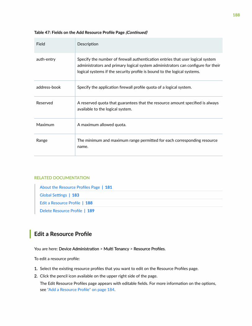
Table 47: Fields on the Add Resource Profile Page (Continued)
Field Description
auth-entry Specify the number of firewall authentication entries that user logical systemadministrators and primary logical system administrators can configure for theirlogical systems if the security profile is bound to the logical systems.
address-book Specify the application firewall profile quota of a logical system.
Reserved A reserved quota that guarantees that the resource amount specified is alwaysavailable to the logical system.
Maximum A maximum allowed quota.
Range The minimum and maximum range permitted for each corresponding resourcename.
RELATED DOCUMENTATION
About the Resource Profiles Page | 181
Global Settings | 183
Edit a Resource Profile | 188
Delete Resource Profile | 189
Edit a Resource Profile
You are here: Device Administration > Multi Tenancy > Resource Profiles.
To edit a resource profile:
1. Select the existing resource profiles that you want to edit on the Resource Profiles page.
2. Click the pencil icon available on the upper right side of the page.
The Edit Resource Profiles page appears with editable fields. For more information on the options,see "Add a Resource Profile" on page 184.
188

3. Click OK to save the changes.
RELATED DOCUMENTATION
About the Resource Profiles Page | 181
Global Settings | 183
Add a Resource Profile | 184
Delete Resource Profile | 189
Delete Resource Profile
You are here: Device Administration > Multi Tenancy > Resource Profile.
To delete Resource Profiles:
1. Select the resource profiles that you want to delete on the Resource Profiles page.
2. Click the delete icon available on the upper right side of the page.
3. Click Yes to delete or click No to retain the profile.
RELATED DOCUMENTATION
About the Resource Profiles Page | 181
Global Settings | 183
Add a Resource Profile | 184
Edit a Resource Profile | 188
189

CHAPTER 12
Multi Tenancy—Interconnect Ports
IN THIS CHAPTER
About the Interconnect Ports Page | 190
Add a LT Logical Interface | 192
Edit a LT Logical Interface | 199
Delete Logical Interface | 199
Search for Text in an Interconnect Ports Table | 199
About the Interconnect Ports Page
IN THIS SECTION
Tasks You Can Perform | 190
Field Descriptions | 191
You are here: Device Administration > Multi Tenancy > Interconnect Ports.
On SRX Series Services Gateways, the logical tunnel interface is used to interconnect logical systems.Use this page to interconnect logical system that serves as an internal virtual private LAN service (VPLS)switch connecting one logical system on the device to another.
NOTE: This menu is available only for SRX4000 line of devices and SRX5000 line of devices.
Tasks You Can Perform
You can perform the following tasks from this page:
190

• Create a LT Logical Interface. See "Add a LT Logical Interface" on page 192.
• Edit a LT Logical Interface. See "Edit a LT Logical Interface" on page 199.
• Delete an Interconnect Interface. See "Delete Logical Interface" on page 199.
• Search for Text in an Interconnect Ports table. See "Search for Text in an Interconnect Ports Table" onpage 199.
Field Descriptions
Table 48 on page 191 describes the fields on the Interconnect ports page.
Table 48: Fields on the Interconnect Ports Page
Field Description
Interface Displays the interface name. Logical interfaces configured under thisinterface appear in a collapsible list under the physical interface.
Link Status Displays the operational status of the link. Status can be either Up or Down.
IP Addresses Displays the configured IP addresses. Multiple IP addresses configured onone logical interface are displayed in a collapsible list under the logicalinterface.
Encapsulation Displays the mode of encapsulation. Encapsulation is the process of takingdata from one protocol and translating it into another protocol, so the datacan continue across a network. It can from the following points:
• Ethernet
• Frame Relay
• Ethernet VPLS
Ethernet and Frame Relay are used if logical tunnel interfaces connectedbetween two logical systems. Ethernet VPLS will be used on logical tunnelinterface which is connecting VPLS switch to logical system.
191

Table 48: Fields on the Interconnect Ports Page (Continued)
Field Description
LSYS/Tenant/VPLSSwitch
Displays the name of the logical system or the name of VPLS Switch.
Peer Interface Displays the peer details.
Peer Encapsulation Displays the peer encapsulation mode.
Peer LSYS/VPLSSwitch
Displays the name of the peer logical system and VPLS Switch.
Type Displays the type for logical interface—Logical System, Tenant, or VPLSSwitch.
RELATED DOCUMENTATION
Add a LT Logical Interface | 192
Add a LT Logical Interface
You are here: Device Administration > Multi Tenancy > Interconnect Ports.
To add a LT logical interface:
1. Click the add icon (+) available on the upper right side of the Interconnect Ports page.
The Create LT Logical Interface page appears.
2. Complete the configuration according to the guidelines provided in Table 49 on page 193.
3. Click OK to save the changes. If you want to discard your changes, click Cancel.
If you click OK, a new LT logical interface with the provided configuration is created.
Table 49 on page 193 provides guidelines on using the fields on the Create LT Logical Interface page.
192
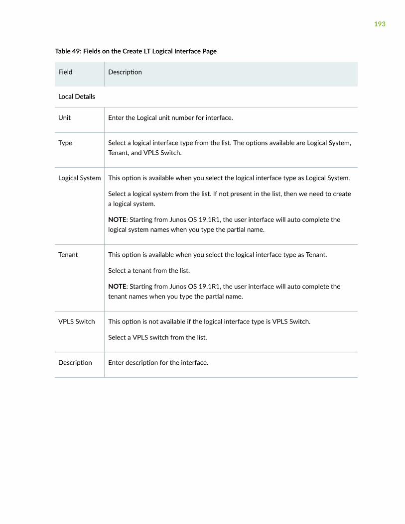
Table 49: Fields on the Create LT Logical Interface Page
Field Description
Local Details
Unit Enter the Logical unit number for interface.
Type Select a logical interface type from the list. The options available are Logical System,Tenant, and VPLS Switch.
Logical System This option is available when you select the logical interface type as Logical System.
Select a logical system from the list. If not present in the list, then we need to createa logical system.
NOTE: Starting from Junos OS 19.1R1, the user interface will auto complete thelogical system names when you type the partial name.
Tenant This option is available when you select the logical interface type as Tenant.
Select a tenant from the list.
NOTE: Starting from Junos OS 19.1R1, the user interface will auto complete thetenant names when you type the partial name.
VPLS Switch This option is not available if the logical interface type is VPLS Switch.
Select a VPLS switch from the list.
Description Enter description for the interface.
193

Table 49: Fields on the Create LT Logical Interface Page (Continued)
Field Description
IPv4 Address NOTE: This option is not available if the logical interface type is VPLS Switch.
Specify the IPv4 address.
To add an IPv4 address:
1. Click + at the upper right of the IPv4 Address table.
2. Enter the following details:
• IPv4 address—Enter an IPv4 address. IP Addresses added here would be usedas interconnect IP.
• Prefix Length—Enter the prefix length. This specifies the number of bits set inthe subnet mask.
3. Click the tick mark to add the IPv4 address or click X to discard the changes.
To edit an IPv4 address:
1. Select an existing IPv4 address and click the pencil icon at the upper right of theIPv4 Address table.
2. Edit the IPv4 address and prefix length.
3. Click the tick mark to add the IPv4 address or click X to discard the changes.
To delete an IPv4 address:
1. Select one or more existing IPv4 addresses and click the delete icon at the upperright of the IPv4 Address table.
2. Click OK to delete the IPv4 address. If you want to discard the changes, clickCancel.
194

Table 49: Fields on the Create LT Logical Interface Page (Continued)
Field Description
IPv6 Address NOTE: This option is not available if the logical interface type is VPLS Switch.
Specify the IPv6 address.
To add an IPv6 address:
1. Click + at the upper right of the IPv6 Address table.
2. Enter the following details:
• IPv6 address—Enter an IPv6 address. IP Addresses added here would be usedas interconnect IP.
• Prefix Length—Enter the prefix length. This specifies the number of bits set inthe subnet mask.
3. Click the tick mark to add the IPv6 address or click X to discard the changes.
To edit an IPv6 address:
1. Select an existing IPv6 address and click the pencil icon at the upper right of theIPv6 Address table.
2. Edit the IPv6 address and prefix length.
3. Click the tick mark to add the IPv6 address or click X to discard the changes.
To delete an IPv6 address:
1. Select one or more existing IPv6 addresses and click the delete icon at the upperright of the IPv6 Address table.
2. Click OK to delete the IPv6 address. If you want to discard the changes, clickCancel.
Peer Details
195

Table 49: Fields on the Create LT Logical Interface Page (Continued)
Field Description
Type Select any one of the connection types from the list:
• Logical system
• Tenant
• VPLS Switch
Logical System This option is available when you select the connection type as Logical System.
Select a logical system from the list. If not present in the list, then we need to createa logical system.
Tenant This option is available when you select the connection type as Tenant.
Select a tenant from the list.
VPLS Switch This option is available when you select the connection type as VPLS Switch.
Select a VPLS switch from the list.
Unit Enter the peering logical system unit number.
Description Specify the interface description.
Enter description for the interface.
196

Table 49: Fields on the Create LT Logical Interface Page (Continued)
Field Description
IPv4 Address NOTE: This option is not available if the logical interface type is VPLS Switch.
Specify the IPv4 address.
To add an IPv4 address:
1. Click + at the upper right of the IPv4 Address table.
2. Enter the following details:
• IPv4 address—Enter an IPv4 address. IP Addresses added here would be usedas interconnect IP.
• Prefix Length—Enter the prefix length. This specifies the number of bits set inthe subnet mask.
3. Click the tick mark to add the IPv4 address or click X to discard the changes.
To edit an IPv4 address:
1. Select an existing IPv4 address and click the pencil icon at the upper right of theIPv4 Address table.
2. Edit the IPv4 address and prefix length.
3. Click the tick mark to add the IPv4 address or click X to discard the changes.
To delete an IPv4 address:
1. Select one or more existing IPv4 addresses and click the delete icon at the upperright of the IPv4 Address table.
2. Click OK to delete the IPv4 address. If you want to discard the changes, clickCancel.
197

Table 49: Fields on the Create LT Logical Interface Page (Continued)
Field Description
IPv6 Address NOTE: This option is not available if the logical interface type is VPLS Switch.
Specify the IPv6 address.
To add an IPv6 address:
1. Click + at the upper right of the IPv6 Address table.
2. Enter the following details:
• IPv6 address—Enter an IPv6 address. IP Addresses added here would be usedas interconnect IP.
• Prefix Length—Enter the prefix length. This specifies the number of bits set inthe subnet mask.
3. Click the tick mark to add the IPv6 address or click X to discard the changes.
To edit an IPv6 address:
1. Select an existing IPv6 address and click the pencil icon at the upper right of theIPv6 Address table.
2. Edit the IPv6 address and prefix length.
3. Click the tick mark to add the IPv6 address or click X to discard the changes.
To delete an IPv6 address:
1. Select one or more existing IPv6 addresses and click the delete icon at the upperright of the IPv6 Address table.
2. Click OK to delete the IPv6 address. If you want to discard the changes, clickCancel.
RELATED DOCUMENTATION
Edit a LT Logical Interface | 199
198

Edit a LT Logical Interface
You are here: Device Administration > Multi Tenancy > Interconnect Ports.
To edit a LT logical interface:
1. Select an existing logical interface that you want to edit on the Interconnect Ports page.
2. Click the pencil icon available on the upper right side of the page.
The Edit LT Logical Interface page appears with editable fields. For more information on the fields,see "Add a LT Logical Interface" on page 192.
3. Click OK to save the changes or click Cancel to discard the changes.
RELATED DOCUMENTATION
Delete Logical Interface | 199
Delete Logical Interface
You are here: Device Administration > Multi Tenancy > Interconnect Ports.
To delete a logical interface:
1. Select one or more the logical interfaces that you want to delete on the Interconnect Ports page.
2. Click the delete icon available on the upper right side of the page.
3. Click Yes to delete or click No to retain the logical interface.
RELATED DOCUMENTATION
Search for Text in an Interconnect Ports Table | 199
Search for Text in an Interconnect Ports Table
You are here: Device Administration > Multi Tenancy > Interconnect Ports.
You can use the search icon in the top right corner of the Interconnect Ports page to search for textcontaining letters and special characters on that page.
199

To search for text:
1. Click the search icon and enter partial text or full text of the keyword in the search bar.
The search results are displayed.
2. Click X next to a search keyword or click Clear All to clear the search results.
RELATED DOCUMENTATION
About the Interconnect Ports Page | 190
200

CHAPTER 13
Multi Tenancy—Logical Systems
IN THIS CHAPTER
About the Logical Systems Page | 201
Add a Logical System | 203
Edit a Logical System | 215
Delete Logical System | 215
Search Text in Logical Systems Table | 216
About the Logical Systems Page
IN THIS SECTION
Tasks You Can Perform | 201
Field Descriptions | 202
You are here: Device Administration > Multi Tenancy > Logical Systems.
NOTE: This menu is supported for only SRX4000 line of devices, SRX5000 line of devices andSRX1500 devices.
Use this page to view, add, and delete Logical System.
Tasks You Can Perform
You can perform the following tasks from this page:
201

• Create a logical system. See "Add a Logical System" on page 203.
• Edit a logical system. See "Edit a Logical System" on page 215.
• Delete a logical system. See "Delete Logical System" on page 215.
• Search for Text in a logical system table. See "Search Text in Logical Systems Table" on page 216.
• View the details of the logical systems—To do this, select the logical systems for which you want toview the details and follow the available options:
• Click More and select Detailed View.
• Right-click on the selected tenant and select Detailed View.
• Mouse over to the left of the selected tenant and click Detailed View.
• Filter the logical systems based on select criteria. To do this, select the filter icon at the top right-hand corner of the logical systems table. The columns in the grid change to accept filter options. Typethe filter options; the table displays only the data that fits the filtering criteria.
• Show or hide columns in the logical systems table. To do this, click the Show Hide Columns icon inthe top right corner of the logical systems table and select the options you want to view or deselectthe options you want to hide on the page.
• Root users can switch to Logical system context. To do this, click Enter LSYS on the upper right of thetable. See Table 51 on page 203.
Field Descriptions
Table 50 on page 202 describes the fields on the Logical Systems page.
Table 50: Fields on the Logical Systems Page
Field Description
Name Displays the name of the logical system.
Resource Profile Displays the name of the resource profile.
Users Displays the logical system admin and users.
Assigned Interfaces Displays the assigned logical interfaces.
202
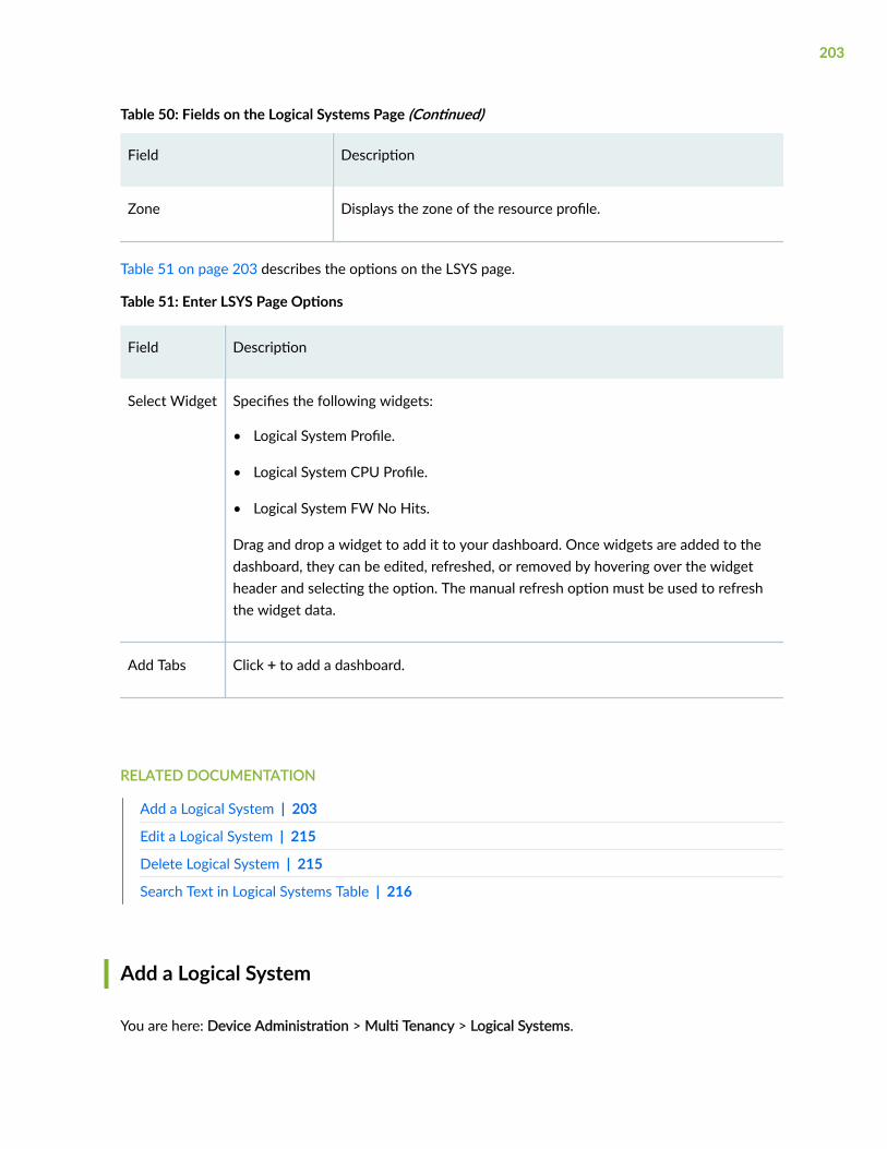
Table 50: Fields on the Logical Systems Page (Continued)
Field Description
Zone Displays the zone of the resource profile.
Table 51 on page 203 describes the options on the LSYS page.
Table 51: Enter LSYS Page Options
Field Description
Select Widget Specifies the following widgets:
• Logical System Profile.
• Logical System CPU Profile.
• Logical System FW No Hits.
Drag and drop a widget to add it to your dashboard. Once widgets are added to thedashboard, they can be edited, refreshed, or removed by hovering over the widgetheader and selecting the option. The manual refresh option must be used to refreshthe widget data.
Add Tabs Click + to add a dashboard.
RELATED DOCUMENTATION
Add a Logical System | 203
Edit a Logical System | 215
Delete Logical System | 215
Search Text in Logical Systems Table | 216
Add a Logical System
You are here: Device Administration > Multi Tenancy > Logical Systems.
203

To add a logical system:
1. Click the add icon (+) on the upper right side of the Logical Systems page.
The Create Logical Systems page appears.
2. Complete the configuration according to the guidelines provided in Table 52 on page 204.
3. Click Finish to save the changes. If you want to discard your changes, click Cancel.
Table 52: Fields on the Add Logical Systems Page
Field Description
General Details
Name Enter a logical system name of a selected Resource Profile. Only oneResource Profile can be selected, per logical system.
The string must contain alphanumeric characters, colons, periods, dashes,and underscores. No spaces are allowed; maximum length is 63 characters.
Logical System Resource Profile
Click one:
• Add icon (+)—Adds Resource Profiles.
• Edit icon (/)—Edits the selected Resource Profiles.
• Delete icon (X)—Deletes the selected Resource Profiles.
• Search icon—Enables you to search a Resource Profile in the grid.
• Filter icon —Enables you to filter the selected option in the grid.
• Show Hide Column Filter icon—Enables you to show or hide a column in the grid.
Profile Name Enter a name of the security profile.
The string must contain an alphanumeric character and can includeunderscores; no spaces allowed; 31 characters maximum.
IPS Policy Select an IPS policy from the list.
204
Table 52: Fields on the Add Logical Systems Page (Continued)
Field Description
Resource Allocation
205

Table 52: Fields on the Add Logical Systems Page (Continued)
Field Description
Resource Name Displays the resource name.
• nat-pat-portnum—Specify the maximum quantity and the reservedquantity of ports for the logical system as part of its security profile.
• dslite-softwire-initiator—Specify the number of IPv6 dual-stack lite (DS-Lite) softwire initiators that can connect to the softwire concentratorconfigured in either a user logical system or the primary logical system.
• cpu—Specify the percentage of CPU utilization that is always availableto a logical system.
• appfw-rule—Specify the number of application firewall ruleconfigurations that a primary administrator can configure for a primarylogical system or user logical system when the security profile is boundto the logical systems.
• nat-interface-port-ol—Specify the number of application firewall rule setconfigurations that a primary administrator can configure for a primarylogical system or user logical system when the security profile is boundto the logical systems.
• nat-rule-referenced-prefix—Specify the security NAT interface portoverloading the quota of a logical system.
• nat-port-ol-ipnumber—Specify the number of NAT port overloading IPnumber configurations that user logical system administrators andprimary logical system administrators can configure for their logicalsystems if the security profile is bound to the logical systems.
• nat-cone-binding—Specify the number of NAT cone bindingconfigurations that user logical system administrators and primarylogical system administrators can configure for their logical systems ifthe security profile is bound to the logical systems.
• nat-static-rule—Specify the number of NAT static rule configurationsthat user logical system administrators and primary logical systemadministrators can configure for their logical systems if the securityprofile is bound to the logical systems.
206

Table 52: Fields on the Add Logical Systems Page (Continued)
Field Description
• nat-destination-rule—Specify the number of NAT destination ruleconfigurations that user logical system administrators and primarylogical system administrators can configure for their logical systems ifthe security profile is bound to the logical systems.
• nat-source-rule—Specify the NAT source rule configurations that userlogical system administrators and primary logical system administratorscan configure for their logical systems if the security profile is bound tothe logical systems.
• nat-nopat-address—Specify the number of NAT without port addresstranslation configurations that user logical system administrators andprimary logical system administrators can configure for their logicalsystems if the security profile is bound to the logical systems.
• nat-pat-address—Specify the number of NAT with port addresstranslation (PAT) configurations that user logical system administratorsand primary logical system administrators can configure for their logicalsystems if the security profile is bound to the logical systems.
• nat-destination-pool—Specify the number of NAT destination poolconfigurations that user logical system administrators and primarylogical system administrators can configure for their logical systems ifthe security profile is bound to the logical systems.
• nat-source-pool—Specify the NAT source pool configurations that userlogical system administrators and primary logical system administratorscan configure for their logical systems if the security profile is bound tothe logical systems.
• flow-gate—Specify the number of flow gates, also known as pinholesthat user logical system administrators and primary logical systemadministrators can configure for their logical systems if the securityprofile is bound to the logical systems.
• flow-session—Specify the number of flow sessions that user logicalsystem administrators and primary logical system administrators canconfigure for their logical systems if the security profile is bound to thelogical systems.
207

Table 52: Fields on the Add Logical Systems Page (Continued)
Field Description
• policy—Specify the number of security policies with a count that userlogical system administrators and primary logical system administratorscan configure for their logical systems if the security profile is bound tothe logical systems.
• security-log-stream-number—Specify the Security log stream numberquota of a logical system.
• scheduler—Specify the number of schedulers that user logical systemadministrators and primary logical system administrators can configurefor their logical systems if the security profile is bound to the logicalsystems.
• zone—Specify the zones that user logical system administrators andprimary logical system administrators can configure for their logicalsystems if the security profile is bound to the logical systems.
• auth-entry—Specify the number of firewall authentication entries thatuser logical system administrators and primary logical systemadministrators can configure for their logical systems if the securityprofile is bound to the logical systems.
• address-book—Specify the entries in the address book. Address bookentries can include any combination of IPv4 addresses, IPv6 addresses,DNS names, wildcard addresses, and address range.
Range Display range for each resource.
Edit Select a resource and click on the pencil icon to edit Reserved andMaximum fields.
Reserved Specify reserved quota that guarantees that the resource amount specifiedis always available to the logical system.
Maximum Specify the maximum allowed quota.
208

Table 52: Fields on the Add Logical Systems Page (Continued)
Field Description
IPS Max Sessions Enter maximum number of sessions. Use up and down arrow keys toincrease or decrease the number.
Users
Click one:
• Add icon (+)—Create users.
• Edit icon (/)—Edit the selected users.
• Delete icon (X)—Delete the selected users.
Create-Edit users
Username Enter a username.
Maximum length is 64 characters.
Role • Logical System Administrator
• Read only Access User
NOTE: LSYS Read Only user can only view the options but cannotmodify them.
Password Enter a password for the user which is more than 6 characters but less than128 characters.
Confirm Password Re-enter the new password to confirm.
209

Table 52: Fields on the Add Logical Systems Page (Continued)
Field Description
Interfaces
Click One:
• Enable/Disable —Enable or disable the physical interface.
• Add icon (+)—Add logical interfaces.
• Edit icon (/)—Edit the selected users.
• Delete icon (X)—Delete the selected users.
Create-Edit logical interfaces
General
Physical Interface Name Displays the name of the Physical Interface.
Logical Interface Unit Enter the logical Interface Unit
Description Enter the description.
VLAN ID Enter the VLAN ID. VLAN ID is mandatory.
IPV4 Address
IPV4 Address Click + and enter a valid IP address.
Subnet Mask Enter a valid subnet mask.
Delete Select the IPv4 address and click the delete icon to delete the address.
IPV6 Address
210

Table 52: Fields on the Add Logical Systems Page (Continued)
Field Description
IPV6 Address Enter a valid IP address.
Subnet Mask Enter a valid subnet mask.
Delete Select the IPv6 address and click the delete icon to delete the address.
Zones
Click One:
• Add icon (+)—Create security zones.
• Edit icon (/)—Edit the selected security zones.
• Delete icon (X)—Delete the selected security zone.
• Search icon—Search for a security zone.
Create-Edit Security Zones
General
Name Enter a valid name of the zone.
Description Enter a description of the zone.
Application Tracking Enables the application tracking support.
Source Identity Log Enable source identity log for this zone.
Interfaces Select an interface from the Available column and move it to Selectedcolumn.
Selected interfaces Displays the selected interfaces.
211

Table 52: Fields on the Add Logical Systems Page (Continued)
Field Description
System Services Select system services from the following options:
NOTE: Select the Except check box to allow services other than theselected services.
• all—Specify all system services.
• any-service—Specify services on entire port range.
• appqoe—Specify the APPQOE active probe service.
• bootp—Specify the Bootp and dhcp relay agent service.
• dhcp—Specify the Dynamic Host Configuration Protocol.
• dhcpv6—Enable Dynamic Host Configuration Protocol for IPV6.
• dns—Specify the DNS service.
• finger—Specify the finger service.
• ftp—Specify the FTP protocol.
• http—Specify the web management using HTTP.
• https—Specify the web management using HTTP secured by SSL.
• ident-reset—Specify the send back TCP RST IDENT request for port113.
• ike—Specify the Internet key exchange.
• lsping—Specify the Label Switched Path ping service.
• netconf—Specify the NETCONF Service.
• ntp—Specify the network time protocol service.
• ping—Specify the internet control message protocol.
• r2cp—Enable Radio-Router Control Protocol service.
• reverse-ssh—Specify the reverse SSH Service.
212

Table 52: Fields on the Add Logical Systems Page (Continued)
Field Description
• reverse-telnet—Specify the reverse telnet Service.
• rlogin—Specify the Rlogin service
• rpm—Specify the Real-time performance monitoring.
• rsh—Specify the Rsh service.
• snmp—Specify the Simple Network Management Protocol Service.
• snmp-trap—Specify the Simple Network Management Protocol trap.
• ssh—Specify the SSH service.
• tcp-encap—Specify the TCP encapsulation service.
• telnet—Specify the Telnet service.
• tftp—Specify the TFTP
• traceroute—Specify the traceroute service.
• webapi-clear-text—Specify the Webapi service using http.
• webapi-ssl—Specify the Webapi service using HTTP secured by SSL.
• xnm-clear-text—Specify the JUNOScript API for unencrypted trafficover TCP.
• xnm-ssl—Specify the JUNOScript API Service over SSL.
213

Table 52: Fields on the Add Logical Systems Page (Continued)
Field Description
Protocols Select a protocol from the following options:
NOTE: Select the Except check box to allow protocols other than theselected protocols.
• bfd—Bidirectional Forwarding Detection.
• bgp—Broder Gateway protocol.
• dvmrp—Distance Vector Multicast Routing Protocol.
• igmp—Internet group management protocol.
• ldp— label Distribution Protocol.
• msdp—Multicast source discovery protocol.
• nhrp—Next Hop Resolution Protocol.
• ospf—Open shortest path first.
• ospf3—Open shortest path first version 3.
• pgm—Pragmatic General Multicast.
• pim—Protocol independent multicast.
• rip—Routing information protocol.
• ripng—Routing information protocol next generation.
• router-discovery—Router Discovery.
• rsvp—Resource reservation protocol.
• sap—Session Announcement Protocol.
• vrrp—Virtual Router redundancy protocol.
Traffic Control Options Enable this option to send RST for NON-SYN packet not matching TCPsession.
214

RELATED DOCUMENTATION
About the Logical Systems Page | 201
Add a Logical System | 203
Edit a Logical System | 215
Delete Logical System | 215
Search Text in Logical Systems Table | 216
Edit a Logical System
You are here: Device Administration > Multi Tenancy > Logical Systems.
To edit a logical system profile:
1. Select the existing logical system profile that you want to edit on the Logical System Profile page.
2. Click the pencil icon available on the upper right side of the page.
The Edit a Logical System Profile page appears with editable fields. For more information on theoptions, see "Add a Logical System" on page 203.
3. Click OK to save the changes.
RELATED DOCUMENTATION
About the Logical Systems Page | 201
Add a Logical System | 203
Delete Logical System | 215
Search Text in Logical Systems Table | 216
Delete Logical System
You are here: Device Administration > Multi Tenancy > Logical Systems.
To delete logical system:
1. Select the logical system that you want to delete on the Logical System page.
2. Click the delete icon available on the upper right side of the page.
3. Click Yes to delete or click No to retain the profile.
215

RELATED DOCUMENTATION
About the Logical Systems Page | 201
Add a Logical System | 203
Edit a Logical System | 215
Search Text in Logical Systems Table | 216
Search Text in Logical Systems Table
You are here: Device Administration > Multi Tenancy > Logical Systems.
You can use the search icon in the top right corner of a page to search for text containing letters andspecial characters on that page.
To search for text:
1. Click the search icon and enter a partial text or full text of the keyword in the search bar and execute.
The search results are displayed.
2. Click X next to a search keyword or click Clear All to clear the search results.
RELATED DOCUMENTATION
About the Logical Systems Page | 201
Add a Logical System | 203
Edit a Logical System | 215
Delete Logical System | 215
216

CHAPTER 14
Multi Tenancy—Tenants
IN THIS CHAPTER
About the Tenants Page | 217
Add a Tenant | 219
Edit a Tenant | 227
Delete Tenant | 227
Search Text in Tenants Table | 228
About the Tenants Page
IN THIS SECTION
Tasks You Can Perform | 217
Field Descriptions | 218
You are here: Device Administration > Multi Tenancy > Tenants.
You can use this page to add, view, and delete Tenants.
NOTE: This menu is supported for only SRX4000 line of devices, SRX5000 line of devices andSRX1500 devices.
Tasks You Can Perform
You can perform the following tasks from this page:
• Create a tenant. See "Add a Tenant" on page 219.
217

• Edit a tenant. See "Edit a Tenant" on page 227.
• Delete a tenant. See "Delete Tenant" on page 227.
• Search for Text in a tenants table. See "Search Text in Tenants Table" on page 228.
• View the details of the tenants—To do this, select the tenant for which you want to view the detailsand follow the available options:
• Click More and select Detailed View.
• Right-click on the selected tenant and select Detailed View.
• Mouse over to the left of the selected tenant and click Detailed View.
• Filter the tenant based on select criteria. To do this, select the filter icon at the top right-hand cornerof the tenant table. The columns in the grid change to accept filter options. Type the filter options;the table displays only the data that fits the filtering criteria.
• Show or hide columns in the tenant table. To do this, click the Show Hide Columns icon in the topright corner of the tenant table and select the options you want to view or deselect the options youwant to hide on the page.
Field Descriptions
Table 53 on page 218 describes the fields on the Tenants page.
Table 53: Fields on the Tenants Page
Field Description
Name Displays the name of the tenant system.
Resource Profile Displays the name of the resource profile.
Users Displays the tenant system admin and users, and its associated permissions.
Assigned Interfaces Displays the assigned logical interfaces.
Zones Displays the zones for the tenant.
218
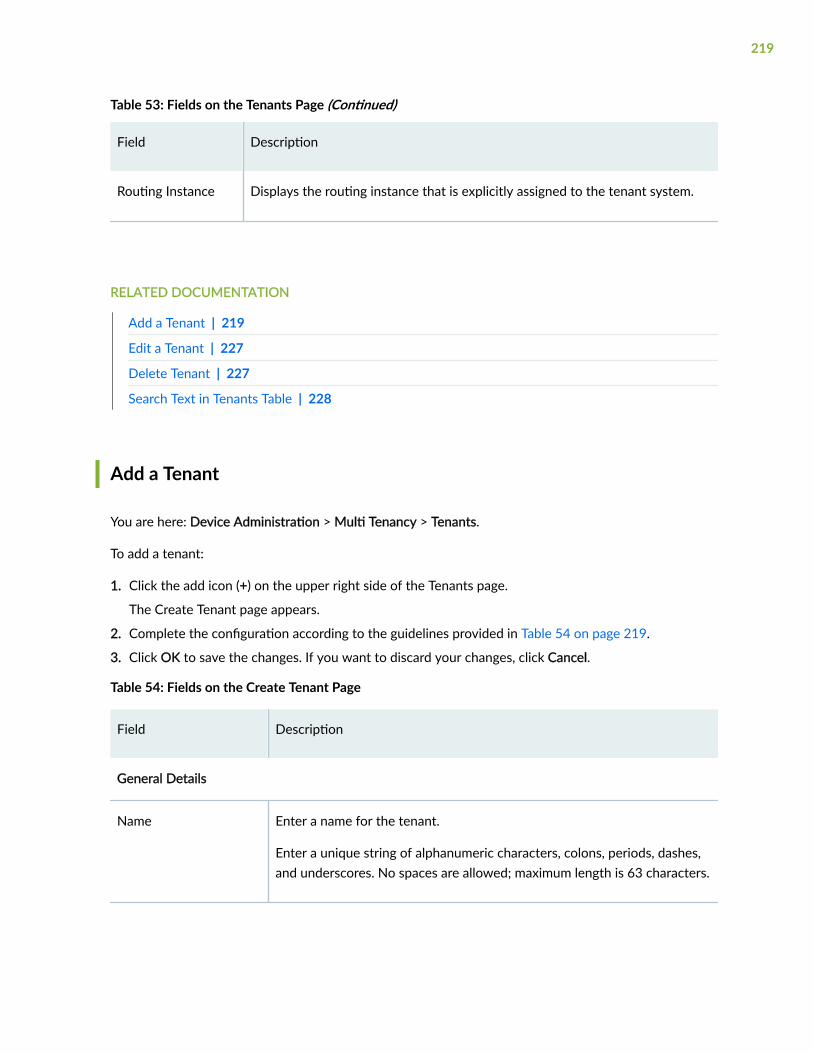
Table 53: Fields on the Tenants Page (Continued)
Field Description
Routing Instance Displays the routing instance that is explicitly assigned to the tenant system.
RELATED DOCUMENTATION
Add a Tenant | 219
Edit a Tenant | 227
Delete Tenant | 227
Search Text in Tenants Table | 228
Add a Tenant
You are here: Device Administration > Multi Tenancy > Tenants.
To add a tenant:
1. Click the add icon (+) on the upper right side of the Tenants page.
The Create Tenant page appears.
2. Complete the configuration according to the guidelines provided in Table 54 on page 219.
3. Click OK to save the changes. If you want to discard your changes, click Cancel.
Table 54: Fields on the Create Tenant Page
Field Description
General Details
Name Enter a name for the tenant.
Enter a unique string of alphanumeric characters, colons, periods, dashes,and underscores. No spaces are allowed; maximum length is 63 characters.
219

Table 54: Fields on the Create Tenant Page (Continued)
Field Description
Routing Instance By default, the tenant name is taken as the routing instance name.
Tenant Resource Profile
Profile Name Displays the name of the resource profile.
Configured Resources Displays the resources and its reserved or maximum quantity assigned forthis resource profile.
Logical Systems/Tenants Displays other logical systems and/or tenants using this resource profile.
Click one:
• Add icon (+)—Adds resource profiles.
• Edit icon (/)—Edits the selected resource profiles.
• Search icon—Enables you to search a resource profile in the grid.
• Filter icon—Enables you to filter the selected option in the grid.
• Show Hide Column Filter icon—Enables you to show or hide a column in the grid.
Create-Edit Tenant Resource Profile
See "Add a Resource Profile" on page 184 for details on creating and editing resource profile.
User Details
You can define tenant administrators and users.
Click one:
• Add icon (+)—Create users.
• Edit icon (/)—Edit the selected users.
• Delete icon—Delete the selected users.
220

Table 54: Fields on the Create Tenant Page (Continued)
Field Description
Create-Edit users
Username Enter a username.
Maximum length is 64 characters.
Role Select an option from the list to specify the role of the user:
• Tenant Administrator
• Read only Access User
NOTE: Logical system or tenant Read Only user can only view theoptions but cannot modify them.
Password Specify the password for the user.
Confirm Password Confirm the password.
Assign Interfaces
Only one logical interface can be part of one tenant, whereas a tenant can have multiple logicalinterfaces.
Click One:
• Enable/Disable —Enable or disable the physical interface.
• Add icon (+)—Add logical interfaces.
• Edit icon (/)—Edit the selected users.
• Delete icon—Delete the selected users.
Create-Edit logical interfaces
General
221

Table 54: Fields on the Create Tenant Page (Continued)
Field Description
Physical Interface Name Displays the name of the Physical Interface.
Logical Interface Unit Enter the logical interface unit.
Description Enter the description.
VLAN ID Enter the VLAN ID. VLAN ID is mandatory.
IPV4 Address
IPV4 Address Click + and enter a valid IP address.
Subnet Mask Enter a valid subnet mask.
Delete Select the IPv4 address and click the delete icon to delete the address.
IPV6 Address
IPV6 Address Enter a valid IP address.
Subnet Mask Enter a valid subnet mask.
Delete Select the IPv6 address and click the delete icon to delete the address.
222

Table 54: Fields on the Create Tenant Page (Continued)
Field Description
Zone Configuration
Click One:
• Add icon (+) — Create security zones.
• Edit icon (/) —Edit the selected security zones.
• Delete icon (X)—Delete the selected security zone.
• Search - Search for a security zone.
Create-Edit Security Zones
General
Name Enter a valid name of the zone.
Description Enter a description of the zone.
Application Tracking Enables the application tracking support.
Source Identity Log Enable source identity log for this zone.
Interfaces Select an interface from the Available column and move it to Selectedcolumn.
Selected interfaces Displays the selected interfaces.
223

Table 54: Fields on the Create Tenant Page (Continued)
Field Description
System Services Options Select system services from the following options:
NOTE: Select the Except check box to allow services other than theselected services.
• all—Specify all system services.
• any-service—Specify services on entire port range.
• appqoe—Specify the APPQOE active probe service.
• bootp—Specify the Bootp and dhcp relay agent service.
• dhcp—Specify the Dynamic Host Configuration Protocol.
• dhcpv6—Enable Dynamic Host Configuration Protocol for IPV6.
• dns—Specify the DNS service.
• finger—Specify the finger service.
• ftp—Specify the FTP protocol.
• http—Specify the web management using HTTP.
• https—Specify the web management using HTTP secured by SSL.
• ident-reset—Specify the send back TCP RST IDENT request for port113.
• ike—Specify the Internet key exchange.
• lsping—Specify the Label Switched Path ping service.
• netconf—Specify the NETCONF Service.
• ntp—Specify the network time protocol service.
• ping—Specify the internet control message protocol.
• r2cp—Enable Radio-Router Control Protocol service.
• reverse-ssh—Specify the reverse SSH Service.
224

Table 54: Fields on the Create Tenant Page (Continued)
Field Description
• reverse-telnet—Specify the reverse telnet Service.
• rlogin—Specify the Rlogin service
• rpm—Specify the Real-time performance monitoring.
• rsh—Specify the Rsh service.
• snmp—Specify the Simple Network Management Protocol Service.
• snmp-trap—Specify the Simple Network Management Protocol trap.
• ssh—Specify the SSH service.
• tcp-encap—Specify the TCP encapsulation service.
• telnet—Specify the Telnet service.
• tftp—Specify the TFTP
• traceroute—Specify the traceroute service.
• webapi-clear-text—Specify the Webapi service using http.
• webapi-ssl—Specify the Webapi service using HTTP secured by SSL.
• xnm-clear-text—Specify the JUNOScript API for unencrypted trafficover TCP.
• xnm-ssl—Specify the JUNOScript API Service over SSL.
225

Table 54: Fields on the Create Tenant Page (Continued)
Field Description
Protocols Select a protocol from the following options:
NOTE: Select the Except check box to allow protocols other than theselected protocols.
• bfd—Bidirectional Forwarding Detection.
• bgp—Broder Gateway protocol.
• dvmrp—Distance Vector Multicast Routing Protocol.
• igmp—Internet group management protocol.
• ldp—label Distribution Protocol.
• msdp—Multicast source discovery protocol.
• nhrp—Next Hop Resolution Protocol.
• ospf—Open shortest path first.
• ospf3—Open shortest path first version 3.
• pgm—Pragmatic General Multicast.
• pim—Protocol independent multicast.
• rip—Routing information protocol.
• ripng—Routing information protocol next generation.
• router-discovery—Router Discovery.
• rsvp—Resource reservation protocol.
• sap—Session Announcement Protocol.
• vrrp—Virtual Router redundancy protocol.
Traffic Control Options Enable this option to send RST for NON-SYN packet not matching TCPsession.
226

RELATED DOCUMENTATION
About the Tenants Page | 217
Edit a Tenant | 227
Delete Tenant | 227
Search Text in Tenants Table | 228
Edit a Tenant
You are here: Device Administration > Multi Tenancy > Tenants.
To edit a tenant:
1. Select the existing tenant that you want to edit on the Tenants page.
2. Click the pencil icon available on the upper right side of the page.
The Edit a Tenant page appears with editable fields. For more information on the options, see "Add aTenant" on page 219.
3. Click OK to save the changes.
RELATED DOCUMENTATION
About the Tenants Page | 217
Add a Tenant | 219
Delete Tenant | 227
Search Text in Tenants Table | 228
Delete Tenant
You are here: Device Administration > Multi Tenancy > Tenants.
To delete tenants:
1. Select the tenants that you want to delete on the Tenants page.
2. Click the delete icon available on the upper right side of the page.
3. Click Yes to delete or click No to retain the profile.
227

RELATED DOCUMENTATION
About the Tenants Page | 217
Add a Tenant | 219
Edit a Tenant | 227
Search Text in Tenants Table | 228
Search Text in Tenants Table
You are here: Device Administration > Multi Tenancy > Tenants.
You can use the search icon in the top right corner of a page to search for text containing letters andspecial characters on that page.
To search for text:
1. Click the search icon and enter a partial text or full text of the keyword in the search bar and execute.
The search results are displayed.
2. Click X next to a search keyword or click Clear All to clear the search results.
RELATED DOCUMENTATION
About the Tenants Page | 217
Add a Tenant | 219
Edit a Tenant | 227
Delete Tenant | 227
228
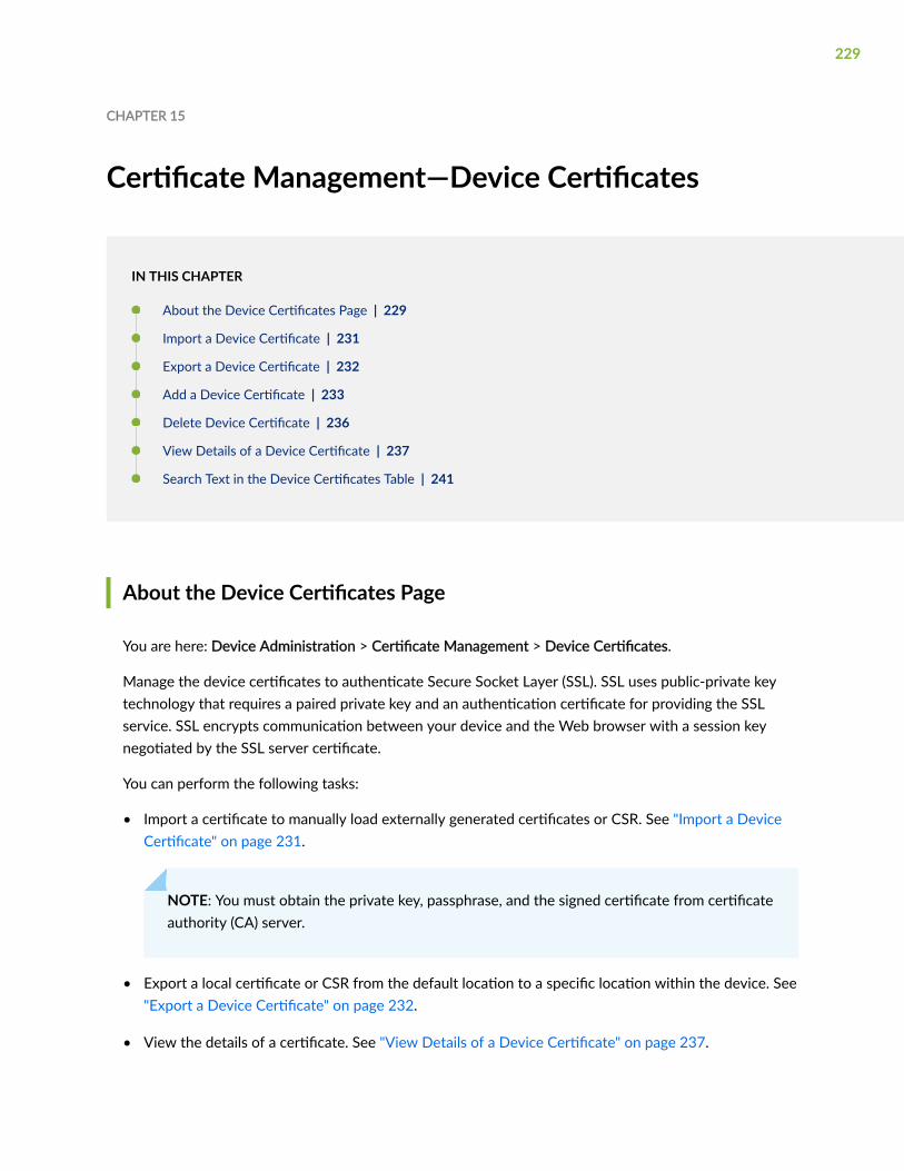
CHAPTER 15
Certificate Management—Device Certificates
IN THIS CHAPTER
About the Device Certificates Page | 229
Import a Device Certificate | 231
Export a Device Certificate | 232
Add a Device Certificate | 233
Delete Device Certificate | 236
View Details of a Device Certificate | 237
Search Text in the Device Certificates Table | 241
About the Device Certificates Page
You are here: Device Administration > Certificate Management > Device Certificates.
Manage the device certificates to authenticate Secure Socket Layer (SSL). SSL uses public-private keytechnology that requires a paired private key and an authentication certificate for providing the SSLservice. SSL encrypts communication between your device and the Web browser with a session keynegotiated by the SSL server certificate.
You can perform the following tasks:
• Import a certificate to manually load externally generated certificates or CSR. See "Import a DeviceCertificate" on page 231.
NOTE: You must obtain the private key, passphrase, and the signed certificate from certificateauthority (CA) server.
• Export a local certificate or CSR from the default location to a specific location within the device. See"Export a Device Certificate" on page 232.
• View the details of a certificate. See "View Details of a Device Certificate" on page 237.
229
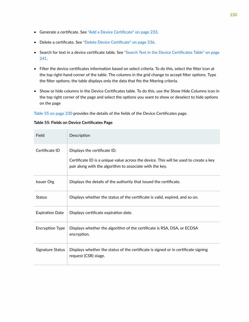
• Generate a certificate. See "Add a Device Certificate" on page 233.
• Delete a certificate. See "Delete Device Certificate" on page 236.
• Search for text in a device certificate table. See "Search Text in the Device Certificates Table" on page241.
• Filter the device certificates information based on select criteria. To do this, select the filter icon atthe top right-hand corner of the table. The columns in the grid change to accept filter options. Typethe filter options; the table displays only the data that fits the filtering criteria.
• Show or hide columns in the Device Certificates table. To do this, use the Show Hide Columns icon inthe top right corner of the page and select the options you want to show or deselect to hide optionson the page
Table 55 on page 230 provides the details of the fields of the Device Certificates page.
Table 55: Fields on Device Certificates Page
Field Description
Certificate ID Displays the certificate ID.
Certificate ID is a unique value across the device. This will be used to create a keypair along with the algorithm to associate with the key.
Issuer Org Displays the details of the authority that issued the certificate.
Status Displays whether the status of the certificate is valid, expired, and so on.
Expiration Date Displays certificate expiration date.
Encryption Type Displays whether the algorithm of the certificate is RSA, DSA, or ECDSAencryption.
Signature Status Displays whether the status of the certificate is signed or in certificate signingrequest (CSR) stage.
230

Import a Device Certificate
To import a device certificate:
1. Select Device Administration > Certificate Management > Device Certificates.
2. Click Import.
The Import Certificate page appears.
3. Complete the configuration according to the guidelines provided in Table 56 on page 231.
4. Click OK to import the certificate.
You are taken to the Device Certificates page. If the certificate content that you imported is validatedsuccessfully, a confirmation message is displayed; if not, an error message is displayed.
After importing a certificate, you can use it when you create an SSL proxy profile and for IPsec VPNpeers authentication.
5. Click Cancel to cancel your entries and returns to the Device Certificates page.
Table 56: Fields on the Import Certificate Page
Field Action
Type Select an option to specify whether the certificate that you are importing isan Externally Generated Certificate or a CSR.
Certificate ID Enter a unique value for the certificate ID for an externally generatedcertificate.
Select an option from the list to specify the certificate ID for a CSR.
File path forCertificate
Click Browse to navigate to the path from where you want to import thecertificate.
File path for PrivateKey
Click Browse to navigate to the path from where you want to import theprivate key.
Passphrase Enter the passphrase used to protect the private key or key pair of thecertificate file.
231

RELATED DOCUMENTATION
About the Device Certificates Page | 229
Export a Device Certificate | 232
Add a Device Certificate | 233
Delete Device Certificate | 236
View Details of a Device Certificate | 237
Search Text in the Device Certificates Table | 241
Export a Device Certificate
To export a device certificate:
1. Select Device Administration > Certificate Management > Device Certificates.
2. Click Export.
The Export Certificate page appears.
3. Complete the configuration according to the guidelines provided in Table 57 on page 232.
4. Click OK to export the certificate.
Once you save or download the exported file(s), a confirmation message is displayed; if not, an errormessage is displayed.
Table 57: Fields on the Export Certificate Page
Field Action
Type Select an option from the list to specify whether the certificate that you areexporting is a Local Certificate or a CSR.
Certification Name Select an option from the list for the local certificate name.
Certificate ID This option is available only for CSR.
Select an option from the list for the CSR certificate ID.
Format Select an option from the list to specify whether the exporting certificate formatis Privacy-Enhanced Mail (PEM) or Distinguished Encoding Rules (DER).
232

Table 57: Fields on the Export Certificate Page (Continued)
Field Action
Key Pair Enable or disable exporting key pair of a certificate.
Passphrase Enter the passphrase to protect the private key or key pair of the certificate file.
RELATED DOCUMENTATION
About the Device Certificates Page | 229
Import a Device Certificate | 231
Add a Device Certificate | 233
Delete Device Certificate | 236
View Details of a Device Certificate | 237
Search Text in the Device Certificates Table | 241
Add a Device Certificate
To add a device certificate:
1. Select Device Administration > Certificate Management > Device Certificates.
2. Click the add icon (+).
The Generate Certificate page appears.
3. Complete the configuration according to the guidelines provided in Table 58 on page 233.
4. Click OK to save the changes. If you want to discard your changes, click Cancel instead.
If you click OK, a new certificate with the provided configuration is created.
Table 58: Fields on the Generate Certificate Page
Field Action
Certificate Details
233

Table 58: Fields on the Generate Certificate Page (Continued)
Field Action
Certificate Type Select one of the certificate types from the list that you want to generate:
• Local Self-Signed—Allows for use of SSL-based (Secure Sockets Layer)services without requiring that the user or administrator to undertakethe considerable task of obtaining an identity certificate signed by aCA. Self-signed certificates are usually used for internal purpose.
• Local Certificate—Validates the identity of the security device. A localcertificate imports or references an SSL certificate.
CA Profile Name This option is available for a local certificate.
Select one of the CA profile name from the list or click Create to add a CAProfile. For details on adding a CA profile, see the table in the Adding aCertificate Authority Profile section.
Certificate ID Enter a unique value for the certificate ID.
Encryption Type Select one of the types of encryption from the list:
• RSA Encryption
• DSA Encryption
NOTE: The certificate cannot be used in SSL Proxy profile if it isgenerated using type DSA.
• ECDSA Encryption
Key Size Select one of the key sizes from the list:
• RSA encryption supports 1024 bits, 2048 bits, or 4096 bits.
• DSA encryption supports 1024 bits, 2048 bits, or 4096 bits.
• ECDSA encryption supports 256 bits, 384 bits, or 521 bits.
Subject (Minimum of one field required)
234
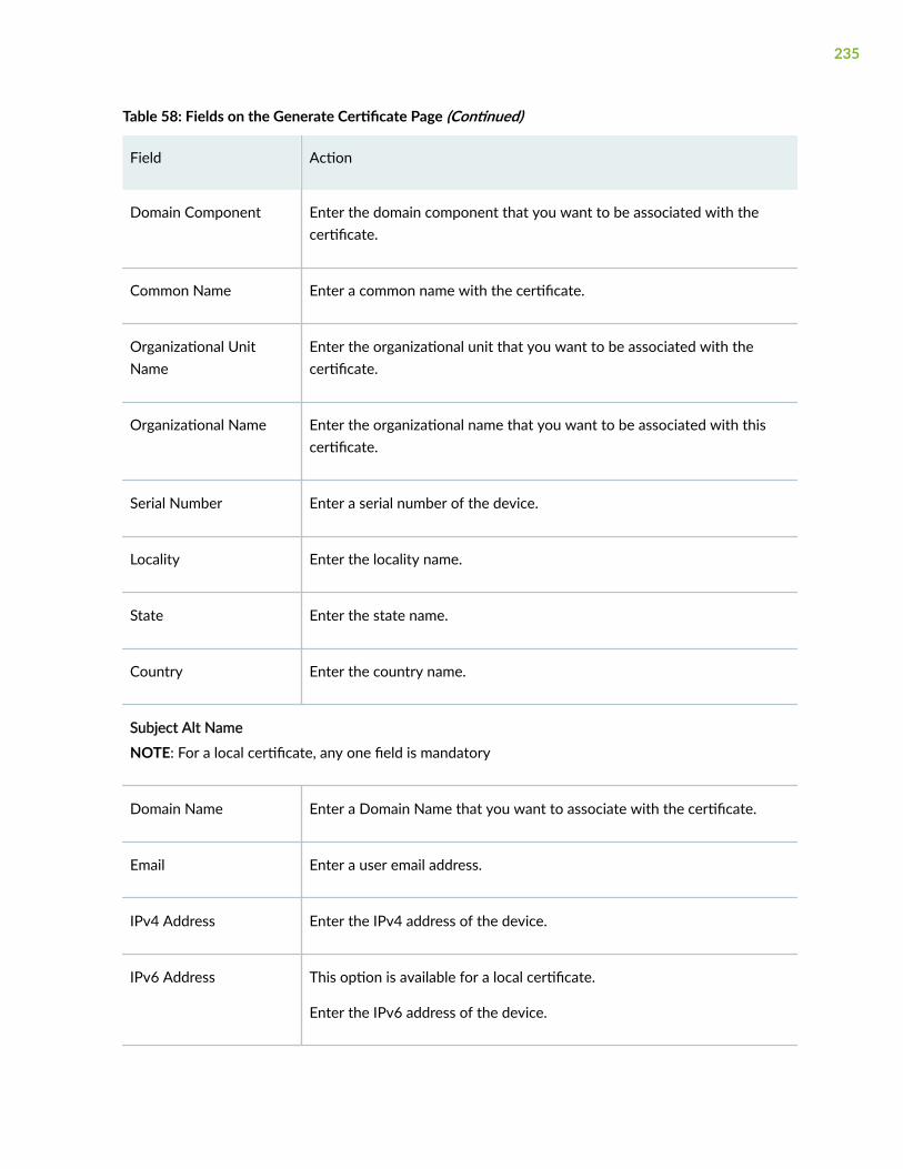
Table 58: Fields on the Generate Certificate Page (Continued)
Field Action
Domain Component Enter the domain component that you want to be associated with thecertificate.
Common Name Enter a common name with the certificate.
Organizational UnitName
Enter the organizational unit that you want to be associated with thecertificate.
Organizational Name Enter the organizational name that you want to be associated with thiscertificate.
Serial Number Enter a serial number of the device.
Locality Enter the locality name.
State Enter the state name.
Country Enter the country name.
Subject Alt Name
NOTE: For a local certificate, any one field is mandatory
Domain Name Enter a Domain Name that you want to associate with the certificate.
Email Enter a user email address.
IPv4 Address Enter the IPv4 address of the device.
IPv6 Address This option is available for a local certificate.
Enter the IPv6 address of the device.
235

Table 58: Fields on the Generate Certificate Page (Continued)
Field Action
Advanced
Digest Select the digest from the list:
• For local Self-signed certificate (RSA/DSA/ECDSA) options are: None,SHA-1 digests, or SHA-256 digests.
• For local certificate options are:
• RSA/DSA: None, SHA-1 digests, or SHA-256 digests
• ECDSA: None, SHA-256 digests, or SHA-384 digests.
Signing Certificate Enable or disable specifies that the certificate is used to sign othercertificates.
RELATED DOCUMENTATION
About the Device Certificates Page | 229
Import a Device Certificate | 231
Export a Device Certificate | 232
Delete Device Certificate | 236
View Details of a Device Certificate | 237
Search Text in the Device Certificates Table | 241
Delete Device Certificate
To delete a device certificate:
1. Select Device Administration > Certificate Management > Device Certificates.
2. Select the certificate you want to delete.
3. On the upper right side of the Device Certificates page, click the delete icon to delete.
A confirmation window appears.
236

4. Click Yes to delete.
RELATED DOCUMENTATION
About the Device Certificates Page | 229
Import a Device Certificate | 231
Export a Device Certificate | 232
Add a Device Certificate | 233
View Details of a Device Certificate | 237
Search Text in the Device Certificates Table | 241
View Details of a Device Certificate
To view the details of a device certificate:
1. Select Device Administration > Certificate Management > Device Certificates.
2. Select an existing certificate.
3. Select More > Detailed View.
The View Certificate page appears with the details of the certificate.
NOTE: When you hover over the certificate ID, a Detailed View icon appears before thecertificate ID. You can also use this icon to view the certificate details.
4. Click OK after viewing the certificate details.
Table 59 on page 237 provides the field details of the certificate on the View Certificate page.
Table 59: Fields on the View Certificate Page
Field Action
Certificate Details
Certificate ID Displays the certificate ID.
237

Table 59: Fields on the View Certificate Page (Continued)
Field Action
Certificate Version Displays the certificate revision number.
Certificate Type Displays the certificate type. For example, Signed.
Encryption Type Displays the encryption type. For example, RSA.
Key Size Displays the key size of the encryption type.
Serial Number Displays the unique serial number of the certificate.
Subject
Domain Component Displays the domain component associated with the certificate.
Common Name Displays the common name associated with the certificate.
Organizational Unit Name Displays the organizational unit associated with the certificate.
Organizational Name Displays the organizational name associated with this certificate.
Serial Number Displays the serial number of the device.
Locality Displays the locality name.
State Displays the state name.
Country Displays the country name.
Subject Alt Name
238

Table 59: Fields on the View Certificate Page (Continued)
Field Action
Domain Name Displays the Fully Qualified Domain Name (FQDN).
Email Displays the email ID of the certificate holder.
IPv4 Address Displays the IPv4 address.
IPv6 Address Displays the IPv6 address.
Issuer Information
Common Name Displays the issuer common name associated with the certificate.
Domain Component Displays the issuer domain component associated with the certificate.
Organization Name Displays the issuer organizational name.
Organization Unit Name Displays the issuer organizational unit.
Locality Name Displays the issuer locality name.
State or Province Name Displays the issuer state or region name.
Validity
Not Before Displays the start time when the certificate becomes valid.
Not After Displays the end time when the certificate becomes invalid.
Auto Re Enrollment
239

Table 59: Fields on the View Certificate Page (Continued)
Field Action
Status Displays whether the auto re enrollment is enabled or disabled.
Next Trigger Time Displays the how long auto-reenrollment should be initiated beforeexpiration.
Fingerprint
MD5 Displays the MD5 fingerprints to identify the certificate.
SHA1 Displays the SHA-1 fingerprints to identify the certificate.
Signature Algorithm
Algorithm Displays whether the signature algorithm is SHA-1, SHA-256, orSHA-384 digest.
Distribution CRL
URL Displays the URL of the certificate revocation list (CRL) server.
LDAP Displays the name of the location from which the CRL is retrievedthrough Lightweight Directory Access Protocol (LDAP).
Authority Information Access OCSP
URL Displays the URL of the Online Certificate Status Protocol (OCSP) server.
RELATED DOCUMENTATION
About the Device Certificates Page | 229
Import a Device Certificate | 231
240

Export a Device Certificate | 232
Add a Device Certificate | 233
Delete Device Certificate | 236
Search Text in the Device Certificates Table | 241
Search Text in the Device Certificates Table
You are here: Device Administration > Certificate Management > Device Certificates.
You can use the search icon in the top right corner of a page to search for text containing letters andspecial characters on that page.
To search for text:
1. Enter partial text or full text of the keyword in the search bar and click the search icon.
The search results are displayed.
2. Click X next to a search keyword or click Clear All to clear the search results.
RELATED DOCUMENTATION
About the Device Certificates Page | 229
Import a Device Certificate | 231
Export a Device Certificate | 232
Add a Device Certificate | 233
Delete Device Certificate | 236
View Details of a Device Certificate | 237
241

CHAPTER 16
Certificate Management—Trusted CertificateAuthority
IN THIS CHAPTER
About the Trusted Certificate Authority Page | 242
Generate Default Trusted Certificate Authorities | 244
Enroll a CA Certificate | 245
Import a CA Certificate | 246
Add a Certificate Authority Profile | 247
Edit a Certificate Authority Profile | 252
Delete Certificate Authority Profile | 252
Search Text in the Trusted Certificate Authority Table | 253
About the Trusted Certificate Authority Page
You are here: Device Administration > Certificate Management > Trusted Certificate Authority.
SSL forward proxy ensures secure transmission of data between a client and a server. Beforeestablishing a secure connection, SSL forward proxy checks certificate authority (CA) certificates toverify signatures on server certificates. For this reason, a reasonable list of trusted CA certificates isrequired to effectively authenticate servers.
You can perform the following tasks:
• Generate a default trusted CAs. See "Generate Default Trusted Certificate Authorities" on page 244.
• Enroll a CA certificate using the Simple Certificate Enrollment Process (SCEP) or CertificateManagement Protocol (CMPv2). With SCEP or CMPv2, you can configure Juniper Network device toobtain a local certificate online and start the online enrollment for the specified certificate ID. See"Enroll a CA Certificate" on page 245.
242

• Import a CA certificate to manually load CA certificates and CRL. See "Import a CA Certificate" onpage 246.
• Add a CA profile. See "Add a Certificate Authority Profile" on page 247.
• Edit a CA profile. See "Edit a Certificate Authority Profile" on page 252.
• Delete a CA profile. See "Delete Certificate Authority Profile" on page 252.
• Search for text in a Trusted Certificate Authority table. See "Search Text in the Trusted CertificateAuthority Table" on page 253.
• Filter the trusted CA information based on select criteria. To do this, select the filter icon at the topright-hand corner of the table. The columns in the grid change to accept filter options. Type the filteroptions; the table displays only the data that fits the filtering criteria.
• Show or hide columns in the trusted CA table. To do this, use the Show Hide Columns icon in the topright corner of the page and select the options you want to show or deselect to hide options on thepage.
Table 60 on page 243 provides the details of the fields of the Trusted Certificate Authority Page.
Table 60: Fields on Trusted Certificate Authority Page
Field Description
CA Profile Displays the name of the CA profile.
Certificate ID Displays the CA certificate ID.
Issuer Org Displays the issuer organizational name.
243

Table 60: Fields on Trusted Certificate Authority Page (Continued)
Field Description
Status Displays the status of the CA certificate.
For example:
• Valid.
• Expires in number of day(s).
• Expired.
• Download Required. This status is for a CAprofile with manual enrollment.
• Enrollment Required. This status is for a CAprofile with automatic enrollment.
Expiration Date Displays CA certificate expiration date.
Encryption Type Displays whether the algorithm of the certificateis RSA, DSA, or ECDSA encryption.
Generate Default Trusted Certificate Authorities
You are here: Device Administration > Certificate Management > Trusted Certificate Authority.
For SSL forward proxy, you need to load trusted CA certificates on your system. By default, Junos OSprovides a list of trusted CA certificates that include default certificates used by common browsers. Togenerate default Trusted CA profiles with default name as Local, click Generate Default Trusted CAs andthen click Continue. This process may take several minutes.
RELATED DOCUMENTATION
About the Trusted Certificate Authority Page | 242
Enroll a CA Certificate | 245
244

Import a CA Certificate | 246
Add a Certificate Authority Profile | 247
Edit a Certificate Authority Profile | 252
Delete Certificate Authority Profile | 252
Search Text in the Trusted Certificate Authority Table | 253
Enroll a CA Certificate
You are here: Device Administration > Certificate Management > Trusted Certificate Authority.
To enroll a trusted CA certificate:
1. Click Enroll.
The Enroll CA Certificate page appears.
2. Complete the configuration according to the guidelines provided in Table 61 on page 245.
3. Click OK to enroll the CA certificate.
Table 61: Fields on the Enroll CA Certificate Page
Field Action
CA Profile Name Select a CA profile name from the list that you want to enroll.
Protocol Select a protocol from the list for the CA certificate that you want to enroll.
• SCEP—Simple Certificate Enrollment Protocol (SCEP)
• CMPV2—Certificate Management Protocol version 2 (CMPv2)
NOTE: The following fields are available only if you select CMPv2 protocol. All the fields aremandatory.
CA Secret Enter the out-of-band secret value received from the CA server.
CA Reference Enter the out-of-band reference value received from the CA server.
245

Table 61: Fields on the Enroll CA Certificate Page (Continued)
Field Action
CA Dn Enter the distinguished name (DN) of the CA enrolling the EE certificate.
NOTE: This optional parameter is mandatory if the CA certificate is not alreadyenrolled. If the CA certificate is already enrolled, the subject DN is extracted fromthe CA certificate.
Certificate Details Click Add to generate a new certificate inline.
RELATED DOCUMENTATION
About the Trusted Certificate Authority Page | 242
Generate Default Trusted Certificate Authorities | 244
Enroll a CA Certificate | 245
Add a Certificate Authority Profile | 247
Edit a Certificate Authority Profile | 252
Delete Certificate Authority Profile | 252
Search Text in the Trusted Certificate Authority Table | 253
Import a CA Certificate
You are here: Device Administration > Certificate Management > Trusted Certificate Authority.
To import a CA certificate:
1. Click Import.
The Import CA Certificate page appears.
2. Complete the configuration according to the guidelines provided in Table 62 on page 247.
3. Click OK to import the CA certificate.
You are taken to the Trusted Certificate Authority page. If the CA certificate content that youimported is validated successfully, a confirmation message is displayed; if not, an error message isdisplayed.
246

Table 62: Fields on the Import CA Certificate Page
Field Action
CA Profile Name Select a CA profile name from the list that you want to import.
File path for CA Certificate Click Browse to navigate to the path from where you want to import theCA certificate.
File path for CRL Click Browse to navigate to the path from where you want to import theCertificate Revocation List (CRL).
Add a Certificate Authority Profile
You are here: Device Administration > Certificate Management > Trusted Certificate Authority.
To add a Certificate Authority (CA) profile:
1. Click the add icon (+).
The Add CA Profile page appears.
2. Complete the configuration according to the guidelines provided in Table 63 on page 247.
3. Click OK to save the changes. If you want to discard your changes, click Cancel instead.
If you click OK, a new CA profile with the provided configuration is created.
Table 63: Fields on the Add CA Profile Page
Field Action
Profile Details
CA Profile Name Enter a unique CA profile name.
CA Identity Enter a CA identity name.
247

Table 63: Fields on the Add CA Profile Page (Continued)
Field Action
Revocation Check Select an option from the list:
• Disable—Disables verification of status of digital certificates.
• OCSP—Online Certificate Status Protocol (OCSP) checks the revocationstatus of a certificate.
• CRL—A CRL is a time-stamped list identifying revoked certificates, whichis signed by a CA and made available to the participating IPsec peers on aregular periodic basis.
URL For OCSP, enter HTTP addresses for OCSP responders.
For CRL, enter the name of the location from which to retrieve the CRLthrough HTTP or Lightweight Directory Access Protocol (LDAP).
On ConnectionFailure
Enable this option to skip the revocation check if the OCSP responder is notreachable.
NOTE: This option is applicable only for OCSP.
Disable ResponderRevocation Check
Enable this option to disable revocation check for the CA certificate receivedin an OCSP response.
NOTE: This option is applicable only for OCSP.
Accept UnknownStatus
When set to enable, accepts the certificate with unknown status.
NOTE: This option is applicable only for OCSP.
Nonce Payload Disable the option—Explicitly disable the sending of a nonce payload.
Enable the option—Enable the sending of a nonce payload. This is the default.
NOTE: This option is applicable only for OCSP.
248

Table 63: Fields on the Add CA Profile Page (Continued)
Field Action
CRL Refresh Interval Enter the time interval (in hours) between CRL updates.
Range: 0 through 8784 hours.
NOTE: This option is applicable only for CRL.
Password Enter the password for authentication with the server.
Disable on DownloadFailure
Enable this option to override the default behavior and permit certificateverification even if the CRL fails to download.
NOTE: This option is applicable only for CRL.
Enrollment
CA Certificate Select an option whether you want to enroll the CA certificate manually orautomatically.
File path forCertificate
Click Browse to navigate to the path from where you want to enroll the CAcertificate.
URL Enter the URL from where you want to enroll the CA certificateautomatically.
Retry Number of enrollment retry attempts before terminating. Range: 0 - 1080.
Retry-interval Interval in seconds between the enrollment retries. Range: 0 - 3600.
Advanced
Administrator Enter an administrator e-mail address to which the certificate request is sent.
249

Table 63: Fields on the Add CA Profile Page (Continued)
Field Action
Source Address Enter a source IPv4 or IPv6 address to be used instead of the IP address ofthe egress interface for communications with external servers.
Auto Re Enrollment Enable this option to request that the issuing CA replace a certificate beforeits specified expiration date.
Re Generate Key Pair Enable this option to automatically generate a new key pair when auto-reenrolling a device certificate.
Protocol Select an option from the list: Simple Certificate Enrollment Protocol (SCEP)or Certificate Management Protocol version 2 (CMPv2).
Challenge Password Enter the challenge password used by the certificate authority (CA) forcertificate enrollment and revocation. This challenge password must be thesame used when the certificate was originally configured.
Trigger Time Enter the percentage for the reenroll trigger time before expiration.
Range: 1 through 99 percent
Digest Select an option from the list: None, SHA-1 digest (default), or MD5-digest.
NOTE: This option is applicable only when you select SCEP protocol.
Encryption Select an option from the list: None, DES, DES 3.
NOTE: This option is applicable only when you select SCEP protocol.
Routing Instance Select an option from the list of configured routing instances.
250

Table 63: Fields on the Add CA Profile Page (Continued)
Field Action
Proxy Profile Select an option from the list. Or
To create a new proxy profile inline:
1. Click Create.
Create Proxy Profile page appears.
2. Enter the following details:
• Profile Name—Enter a unique proxy profile name.
• Connection Type:
• Server IP—Enter the IP address of the server.
• Host Name—Enter the host name.
• Port Number—Select the port number by using top/down arrows.
Range: 0 through 65535
3. Click OK.
RELATED DOCUMENTATION
About the Trusted Certificate Authority Page | 242
Generate Default Trusted Certificate Authorities | 244
Enroll a CA Certificate | 245
Import a CA Certificate | 246
Edit a Certificate Authority Profile | 252
Delete Certificate Authority Profile | 252
Search Text in the Trusted Certificate Authority Table | 253
251

Edit a Certificate Authority Profile
You are here: Device Administration > Certificate Management > Trusted Certificate Authority.
To edit a Certificate Authority (CA) profile:
1. Select a CA profile.
2. On the upper right side of the Trusted Certificate Authority page, click the pencil icon.
See "Add a Certificate Authority Profile" on page 247 for the options available for editing on the EditCA Profile page.
NOTE: When you select a CA profile to edit, you cannot edit the following fields:
• CA Profile Name
• Revocation Check
• Enrollment > CA Certificate
• Advanced > Auto Re Enrollment
• Advanced > Protocol
3. Click OK
RELATED DOCUMENTATION
About the Trusted Certificate Authority Page | 242
Generate Default Trusted Certificate Authorities | 244
Enroll a CA Certificate | 245
Import a CA Certificate | 246
Add a Certificate Authority Profile | 247
Delete Certificate Authority Profile | 252
Search Text in the Trusted Certificate Authority Table | 253
Delete Certificate Authority Profile
You are here: Device Administration > Certificate Management > Trusted Certificate Authority.
252

To delete a Certificate Authority (CA) profile:
1. Select a CA profile.
2. On the upper right side of the Trusted Certificate Authority page, click the delete icon to delete.
A confirmation window appears.
3. Click Yes to delete.
RELATED DOCUMENTATION
About the Trusted Certificate Authority Page | 242
Generate Default Trusted Certificate Authorities | 244
Enroll a CA Certificate | 245
Import a CA Certificate | 246
Add a Certificate Authority Profile | 247
Edit a Certificate Authority Profile | 252
Search Text in the Trusted Certificate Authority Table | 253
Search Text in the Trusted Certificate Authority Table
You are here: Device Administration > Certificate Management > Trusted Certificate Authority.
You can use the search icon in the top right corner of a page to search for text containing letters andspecial characters on that page.
To search for text:
1. Enter partial text or full text of the keyword in the search bar and click the search icon.
The search results are displayed.
2. Click X next to a search keyword or click Clear All to clear the search results.
RELATED DOCUMENTATION
About the Trusted Certificate Authority Page | 242
Generate Default Trusted Certificate Authorities | 244
Enroll a CA Certificate | 245
Import a CA Certificate | 246
253

Add a Certificate Authority Profile | 247
Edit a Certificate Authority Profile | 252
Delete Certificate Authority Profile | 252
254

CHAPTER 17
Certificate Management—Certificate AuthorityGroup
IN THIS CHAPTER
About the Certificate Authority Group Page | 255
Import a Trusted CA Group | 256
Add a CA Group | 257
Edit a CA Group | 258
Delete CA Group | 259
Search Text in the Certificate Authority Group Table | 259
About the Certificate Authority Group Page
You are here: Device Administration > Certificate Management > Trusted Certificate Authority.
Multiple CA profiles can be grouped in one trusted CA group for a given topology. The CA group can beused either in SSL or IPsec.
SSL forward proxy ensures secure transmission of data between a client and a server. Beforeestablishing a secure connection, SSL forward proxy checks certificate authority (CA) certificates toverify signatures on server certificates. For this reason, a reasonable list of trusted CA certificates isrequired to effectively authenticate servers.
You can perform the following tasks:
• Import a CA group to manually load the CA group. See "Import a Trusted CA Group" on page 256.
• Add a CA group. See "Add a CA Group" on page 257.
NOTE: You can group up to maximum of 20 CA profiles in a single trusted CA group. Aminimum of one CA profile is a must to create a trusted CA group.
255

• Edit a CA group. See "Edit a CA Group" on page 258.
• Delete a CA group. See "Delete CA Group" on page 259.
• Search for text in a CA group table. See "Search Text in the Certificate Authority Group Table" onpage 259.
• Filter the CA group information based on select criteria. To do this, select the filter icon at the topright-hand corner of the table. The columns in the grid change to accept filter options. Type the filteroptions; the table displays only the data that fits the filtering criteria.
• Show or hide columns in the CA group table. To do this, use the Show Hide Columns icon in the topright corner of the page and select the options you want to show or deselect to hide options on thepage.
Table 64 on page 256 provides the details of the fields of the Certificate Authority Group Page.
Table 64: Fields on Certificate Authority Group Page
Field Description
Group Name Displays a Name for the CA profile group.
CA Profiles Displays the name of CA profiles.
Used For Displays whether the CA profile group is used for IPsec VPN or for SSL proxy.
Import a Trusted CA Group
You are here: Device Administration > Certificate Management > Trusted Certificate Authority.
To import a trusted CA group:
1. Click Import.
The Import Trusted CA Group page appears.
2. Complete the configuration according to the guidelines provided in Table 65 on page 257.
3. Click OK to import the CA group.
You are taken to the Certificate Authority Group page. If the CA group content that you imported isvalidated successfully, a confirmation message is displayed; if not, an error message is displayed.
256

After importing a CA profile group, you can use it when you create an SSL proxy.
Table 65: Fields on the Import Trusted CA Group Page
Field Action
CA Group Name Enter the name of a CA group.
File path for CA Group Click Browse to navigate to the path from where you want to import the CAgroup.
NOTE: Only .pem format is supported.
RELATED DOCUMENTATION
About the Certificate Authority Group Page | 255
Add a CA Group | 257
Edit a CA Group | 258
Delete CA Group | 259
Search Text in the Certificate Authority Group Table | 259
Add a CA Group
You are here: Device Administration > Certificate Management > Trusted Certificate Authority.
To add a CA group:
1. Click the add icon (+).
The Add CA Group page appears.
2. Complete the configuration according to the guidelines provided in Table 66 on page 258.
3. Click OK to save the changes. If you want to discard your changes, click Cancel instead.
If you click OK, a new CA group with the provided configuration is created.
After added a CA group, you can use it for IPsec VPN.
257

Table 66: Fields on the Add CA Group Page
Field Action
CA Group Name Enter a unique CA group name.
CA Profiles Select a CA profile name from the list in the Available column and then click theright arrow to move it to the Selected column.
NOTE: You can add up to maximum of 20 CA profiles per trusted CA group.
RELATED DOCUMENTATION
About the Certificate Authority Group Page | 255
Import a Trusted CA Group | 256
Edit a CA Group | 258
Delete CA Group | 259
Search Text in the Certificate Authority Group Table | 259
Edit a CA Group
You are here: Device Administration > Certificate Management > Trusted Certificate Authority.
To edit a CA group:
1. Select a CA group.
2. On the upper right side of the Certificate Authority Group page, click the pencil icon.
See "Add a CA Group" on page 257 for the options available for editing on the Edit CA Group page.
3. Click OK
RELATED DOCUMENTATION
About the Certificate Authority Group Page | 255
Import a Trusted CA Group | 256
Add a CA Group | 257
258

Delete CA Group | 259
Search Text in the Certificate Authority Group Table | 259
Delete CA Group
You are here: Device Administration > Certificate Management > Trusted Certificate Authority.
To delete a CA group:
1. Select a CA group.
2. On the upper right side of the Certificate Authority Group page, click the delete icon to delete.
A confirmation window appears.
3. Click Yes to delete.
RELATED DOCUMENTATION
About the Certificate Authority Group Page | 255
Import a Trusted CA Group | 256
Add a CA Group | 257
Edit a CA Group | 258
Search Text in the Certificate Authority Group Table | 259
Search Text in the Certificate Authority Group Table
You are here: Device Administration > Certificate Management > Trusted Certificate Authority.
You can use the search icon in the top right corner of a page to search for text containing letters andspecial characters on that page.
To search for text:
1. Enter partial text or full text of the keyword in the search bar and click the search icon.
The search results are displayed.
2. Click X next to a search keyword or click Clear All to clear the search results.
259

RELATED DOCUMENTATION
About the Certificate Authority Group Page | 255
Import a Trusted CA Group | 256
Add a CA Group | 257
Edit a CA Group | 258
Delete CA Group | 259
260

CHAPTER 18
License Management
IN THIS CHAPTER
Manage Your Licenses | 261
Manage Your Licenses
IN THIS SECTION
About License Management Page | 261
Add License | 262
Delete Installed Licenses | 263
Update Installed Licenses | 263
Update Trial Licenses | 263
Display License Keys | 263
Download License Keys | 264
Software Feature Licenses | 264
About License Management Page
You are here: Device Administration > License Management.
You can add a new license key, delete one or more license keys, update, or download license keys.
Table 67 on page 262 describes the fields on the License Management page.
261
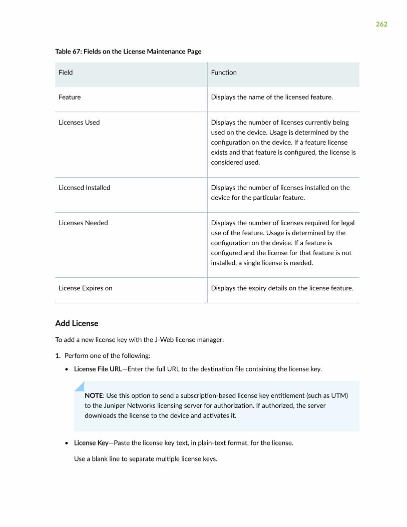
Table 67: Fields on the License Maintenance Page
Field Function
Feature Displays the name of the licensed feature.
Licenses Used Displays the number of licenses currently beingused on the device. Usage is determined by theconfiguration on the device. If a feature licenseexists and that feature is configured, the license isconsidered used.
Licensed Installed Displays the number of licenses installed on thedevice for the particular feature.
Licenses Needed Displays the number of licenses required for legaluse of the feature. Usage is determined by theconfiguration on the device. If a feature isconfigured and the license for that feature is notinstalled, a single license is needed.
License Expires on Displays the expiry details on the license feature.
Add License
To add a new license key with the J-Web license manager:
1. Perform one of the following:
• License File URL—Enter the full URL to the destination file containing the license key.
NOTE: Use this option to send a subscription-based license key entitlement (such as UTM)to the Juniper Networks licensing server for authorization. If authorized, the serverdownloads the license to the device and activates it.
• License Key—Paste the license key text, in plain-text format, for the license.
Use a blank line to separate multiple license keys.
262

NOTE: Use this option to activate a perpetual license directly on the device. (Most featurelicenses are perpetual.)
2. Click OK to add the license key or click Cancel to return to the License Management page.
Delete Installed Licenses
To delete one or more license keys with the J-Web license manager:
1. Select the check box of the license or licenses you want to delete.
2. Click Delete.
NOTE: If you have deleted the SRX100 Memory Upgrade license, the device rebootsimmediately and comes back up as a low-memory device.
3. Click OK to delete the selected license or licenses or click Cancel to return to the LicenseManagement page.
Update Installed Licenses
To send license update to the License Management Server (LMS):
1. Click Update.
The Update Licenses page appears.
2. Click OK to send license update to LMS.
Update Trial Licenses
To send license update to the LMS and to update the trail licenses:
1. Click Update Trial.
The Update Trial Licenses page appears.
2. Click OK to update the trail licenses.
Display License Keys
To display the license keys installed on the device with the J-Web license manager:
1. Click Display Keys to view all of the license keys installed on the device.
2. Click Back to return to the License Management page.
263

Download License Keys
Downloads the license keys installed on the device with the J-Web license manager.
1. Click Download Keys to download all of the license keys installed on the device to a single file.
2. Select Save it to disk and specify the file to which the license keys are to be written.
Software Feature Licenses
Each feature license is tied to exactly one software feature, and that license is valid for exactly onedevice. Table 68 on page 264 describes the Junos OS features that require licenses.
Table 68: Junos OS Services Feature Licenses
Junos OS LicenseRequirements
Device
Feature JSeries
SRX100
SRX210
SRX220
SRX240
SRX650
SRX1000Line
SRX3000Line
SRX5000Line
Access Manager X X
BGP Route Reflectors X X X X
Dynamic VPN X X X X X
IDP Signature Update X X * X * X * X * X X X X
Application SignatureUpdate (ApplicationIdentification) X X X
Juniper-KasperskyAnti-Virus X X X X X X
Juniper-Sophos Anti-Spam X X X X X X
264

Table 68: Junos OS Services Feature Licenses (Continued)
Junos OS LicenseRequirements
Device
Feature JSeries
SRX100
SRX210
SRX220
SRX240
SRX650
SRX1000Line
SRX3000Line
SRX5000Line
Juniper-WebsenseIntegrated WebFiltering X X X X X X
SRX100 MemoryUpgrade X
UTM X X * X * X
RELATED DOCUMENTATION
Enroll Your Device with Juniper ATP Cloud | 266
265

CHAPTER 19
ATP Management
IN THIS CHAPTER
Enroll Your Device with Juniper ATP Cloud | 266
About the Diagnostics Page | 270
Enroll Your Device with Juniper ATP Cloud
Before enrolling a device:
• Ensure that you have a Juniper ATP Cloud account with an associated license (free, basic, orpremium) to configure a Juniper ATP Cloud realm. The license controls the features of the JuniperATP Cloud. For more information on the Juniper ATP Cloud account, see Registering a JuniperAdvanced Threat Prevention Cloud Account.
• Decide which region the realm you create will cover because you must select a region when youconfigure a realm.
• Ensure the device is registered in the ATP cloud portal.
• In the CLI mode, configure set security forwarding-process enhanced-services-mode on your SRX300,SRX320, SRX340, SRX345, and SRX550M devices to open ports and get the device ready tocommunicate with ATP cloud.
• ATP cloud requires that both your Routing Engine (control plane) and Packet Forwarding Engine (dataplane) can connect to the Internet.
• ATP cloud requires the following ports to be open on the SRX Series device: 80, 8080, and 443.
You are here: Device Administration > ATP Management > Enrollment.
Use this page to enroll your SRX device with Juniper Advanced Threat Prevention Cloud (Juniper ATPCloud).
Juniper ATP Cloud is a cloud-based threat identification and prevention solution. It protects your devicefrom malware and sophisticated cyber threats by inspecting e-mail and web traffic for advanced threats.
266

Juniper ATP Cloud integrates with the SRX Series devices to simplify its deployment and enhance theanti-threat capabilities of the SRX device.
ATP uses a Junos OS operation (op) script to help you configure your SRX Series device to connect tothe ATP cloud service.
The Junos OS operation (op) script performs the following tasks:
• Downloads and installs certificate authority (CAs) licenses onto your SRX Series device.
• Creates local certificates and enrolls them with the cloud server.
• Performs basic ATP cloud configuration on the SRX Series device.
• Establishes a secure connection to the cloud server.
To enroll your device with Juniper ATP Cloud from J-Web:
1. Proxy Profile Configuration (Optional)
a. Select an option in the Proxy Profile list and proceed with Step "2" on page 268.
NOTE:
• The list displays the existing proxy profiles that you have created using the ProxyProfile page (Security Policies & Objects > Proxy Profiles).
• The SRX device and Juniper ATP Cloud communicates through the proxy server if aproxy profile is configured. Otherwise, they directly communicate with each other.
b. Or click Create Proxy to create a proxy profile.
The Create Proxy Profile page appears.
c. Complete the configuration by using the guidelines in Table 69 on page 268.
d. Click OK.
A new proxy profile is created.
e. Click Apply Proxy.
Applying proxy enables the SRX device and Juniper ATP Cloud to communicate through the proxyserver.
267

Table 69: Fields on the Create Proxy Profile Page
Field Action
Profile Name Enter a name for the proxy profile.
Connection Type Select the connection type server from the list that proxy profile uses:
• Server IP—Enter the IP address of the proxy server.
• Host Name—Enter the name of the proxy server.
Port Number Select a port number for the proxy profile. Range is 0 to 65535.
2. Enroll SRX Device with ATP Cloud
a. Click Enroll.
The ATP Cloud Enrollment page appears.
NOTE: If there are any existing configuration changes, a message appears for you tocommit the changes and then to proceed with the enrollment process.
b. Complete the configuration by using the guidelines in Table 70 on page 269.
c. Click OK.
The SRX device enrollment progress, successful message, or any errors will be shown at the endof the ATP Cloud Enrollment page.
NOTE:
• A new realm is created if you have enabled Create New Realm and then the SRX deviceis enrolled to Juniper ATP Cloud. If there is any existing enrollment for the same SRXdevice, CLI sends the data to Juniper ATP Cloud portal to do the duplicate validationduring the enrollment process. You cannot check for the duplicate validation through J-Web.
• Click Diagnostics to troubleshoot any enrollment errors.
268

• Click UnEnroll if you wish to disenroll your device from ATP
Table 70: Fields on the ATP Cloud Enrollment Page
Field Description
Create New Realm By default, this option will be disabled if you have an ATP Cloudaccount with an associated license.
Enable this option to add a new realm if you do not have an ATPCloud account with an associated license.
Location Select a region of the world from the list.
Email Enter your E-mail address.
Password Enter a unique string at least eight characters long. It mustinclude both uppercase letters, lowercase letters, and at least onenumber. It can also include special characters. No spaces areallowed and you cannot use the same sequence of characters thatare in your e-mail address.
Confirm Password Reenter the password.
Company Name Enter a company name to enroll into the realm. A company namecan only contain alphanumeric characters, special characters(underscore and dash).
Realm Enter a name for the security realm. This should be a name that ismeaningful to your organization. A realm name can only containalphanumeric characters and the dash symbol. Once created, thisname cannot be changed.
269

About the Diagnostics Page
You are here: Device Administration > ATP Management > Diagnostics.
Use this page to diagnose and verify threat prevention.
Table 71 on page 270 describes the fields on the Diagnostics page.
Table 71: Fields on the Diagnostics Page
Field Description
Diagnostics
ATP Diagnostics Select an option from the list to diagnose.
Diagnostics Logs Displays the diagnostic logs for the selected option.
Run Diagnostics Enables you to see the diagnostics of a certain region.
Check Connectivity
Check Click Check to verify the connectivity.
Server Details
Server hostname Specify the host name of the server.
Server realm Specifies the name of a server realm.
Server port Specify the server port number.
Connection Plane
Connection time Specify the connection time of the server.
270
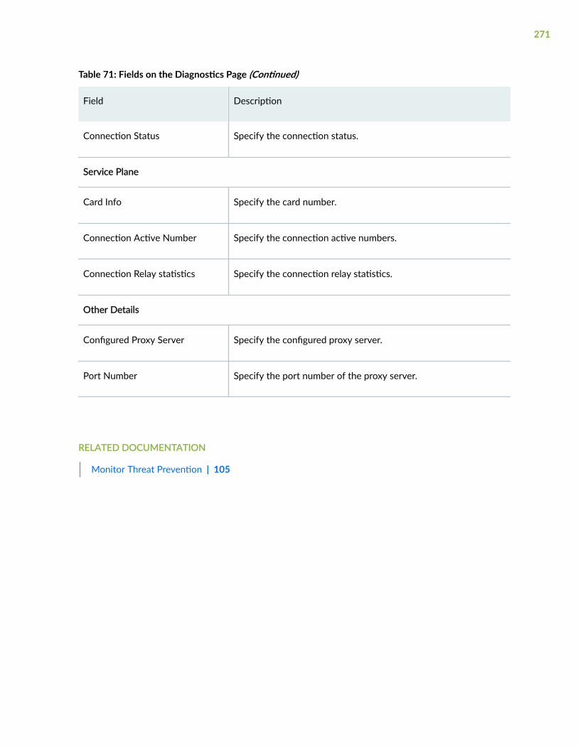
Table 71: Fields on the Diagnostics Page (Continued)
Field Description
Connection Status Specify the connection status.
Service Plane
Card Info Specify the card number.
Connection Active Number Specify the connection active numbers.
Connection Relay statistics Specify the connection relay statistics.
Other Details
Configured Proxy Server Specify the configured proxy server.
Port Number Specify the port number of the proxy server.
RELATED DOCUMENTATION
Monitor Threat Prevention | 105
271

CHAPTER 20
Operations
IN THIS CHAPTER
Maintain Files | 272
Maintain Reboot Schedule | 276
Maintain System Snapshots | 278
Maintain Files
IN THIS SECTION
About Files Page | 272
Clean Up Files | 272
Download and Delete Files | 273
Delete Backup JUNOS Package | 275
About Files Page
You are here: Device Administration > Operations > Files.
You can clean up files, download, or delete files and delete the JUNOS Package backup.
Clean Up Files
To maintain files:
1. Click Clean Up Files.
The device will perform the following tasks:
272

• Rotates log files—Indicates all information in the current log files is archived and fresh log files arecreated.
• Deletes log files in /var/log—Indicates any files that are not currently being written to are deleted.
• Deletes temporary files in /var/tmp—Indicates any files that have not been accessed within twodays are deleted.
• Deletes all crash files in /var/crash—Indicates any core files that the device has written during anerror are deleted.
• Deletes all software images (*.tgz files) in /var/sw/pkg—Indicates any software image copied tothis directory during software upgrades are deleted.
The J-Web interface displays the files that you can delete and the amount of space that will be freedon the file system.
2. Click one:
• OK—Deletes the files and returns to the Files page.
• Cancel—Cancels your entries and returns to the Files page.
Download and Delete Files
Table 72 on page 273 provides the maintenance options to download and delete files.
Table 72: Download and Delete Files Maintenance Options
File Type Function
Log Files Lists the log files located in the /var/log directoryon the device.
Select an option:
• Delete—Deletes files.
• Download—Downloads files.
273

Table 72: Download and Delete Files Maintenance Options (Continued)
File Type Function
Temporary Files Lists the temporary files located in the /var/tmpdirectory on the device.
Select an option:
• Delete—Deletes files.
• Download—Downloads files.
Jailed Temporary Files Lists the jailed temporary files located inthe /var/jail/tmp directory on the device.
Select an option:
• Delete—Deletes files.
• Download—Downloads files.
Old JUNOS Software Lists the software images located inthe /var/sw/pkg (*.tgz files) directory on thedevice.
Select an option:
• Delete—Deletes files.
• Download—Downloads files.
Crash (Core) File Lists the core files located in the /var/crashdirectory on the device.
Select an option:
• Delete—Deletes files.
• Download—Downloads files.
274

Table 72: Download and Delete Files Maintenance Options (Continued)
File Type Function
Database Files Lists the database files located in the /var/dbdirectory on the device.
Select an option:
• Delete—Deletes files.
• Download—Downloads files.
Delete Backup JUNOS Package
Table 73 on page 275 provides the maintenance options to delete the JUNOS Package backup.
Table 73: Delete Backup JUNOS Package Files Maintenance Options
Field Function
Delete backup Junos package Reviews the backup image information listed.
Click Delete backup JUNOS package and thenselect an option.
NOTE: The Delete backup option is hidden if therouter is in dual-root partitioning scheme
The available options are:
• OK—Deletes the backup image and returns tothe Files page.
• Cancel—Cancels the deletion of the backupimage and returns to the Files page.
SEE ALSO
Maintain Reboot Schedule | 276
Maintain System Snapshots | 278
275

Maintain Reboot Schedule
You are here: Device Administration > Operations > Reboot.
You can schedule reboot or halt the system using options such as reboot Immediately, reboot in, rebootwith the system time, or halt immediately.
NOTE: A halted system can only be accessed from the system console port.
To reboot or halt the system:
1. Complete the configuration according to the guidelines provided in Table 74 on page 276.
Table 74: Reboot Schedule Maintenance Options
Field Action
Reboot Immediately Select this option to reboot the deviceimmediately.
Reboot in number of minutes Select this option to reboot the device after thespecified number of minutes from the currenttime.
Reboot when the system time is hour:minute Select this option to reboot the device at theabsolute time that you specify, on the currentday. Select a two-digit hour in 24-hour formatand a two-digit minute.
Halt Immediately
NOTE: This option is not available in SRX4600device.
Select this option to stop the deviceimmediately. After the software has stopped,you can access the device through the consoleport only.
276

Table 74: Reboot Schedule Maintenance Options (Continued)
Field Action
Reboot From Media
NOTE: This option is not available in SRX4600device.
Choose the boot device from the Reboot FromMedia list:
• internal—Reboots from the internal media(default).
• usb—Reboots from the USB storage device.
Message Type a message to be displayed to the user onthe device before the reboot occurs.
2. Click Schedule.
Schedules a reboot based on the scheduled configuration.
3. The J-Web interface requests confirmation to perform the reboot or to halt.
Click OK to confirm to reboot or alt the system or click Cancel to return to the Reboot page.
NOTE:
• If the reboot is scheduled to occur immediately, the device reboots. You cannot access J-Web until the device has restarted and the boot sequence is complete. After the reboot iscomplete, refresh the browser window to display the J-Web login page.
• If the reboot is scheduled to occur in the future, the Reboot page displays the time untilreboot. You have the option to cancel the request by clicking Cancel Reboot on the J-Webinterface Reboot page.
• If the device is halted, all software processes stop and you can access the device throughthe console port only. Reboot the device by pressing any key on the keyboard.
• If you cannot connect to the device through the console port, shut down the device bypressing and holding the power button on the front panel until the POWER LED turns off.After the device has shut down, you can power on the device by pressing the powerbutton again. The POWER LED lights during startup and remains steadily green when thedevice is operating normally.
277

RELATED DOCUMENTATION
Maintain System Snapshots | 278
Maintain System Snapshots
You are here: Device Administration > Operations > Snapshot.
You can configure boot devices to replace primary boot device or to act as a backup boot device.
The snapshot process copies the current system software, along with the current and rescueconfigurations, to alternate media. Optionally, you can copy only the factory and rescue configurations.
To maintain the system snapshots, you create a snapshot of the running system software and save thesnapshot to an alternate media.
1. Complete the configuration according to the guidelines provided in Table 75 on page 278.
2. Click Snapshot.
Creates a boot device on an alternate media.
3. Click OK to perform the system snapshot to a media or click Cancel to return to the Snapshot page.
Table 75: Snapshot Maintenance Options
Field Function
Target Media Specifies the boot device to copy the snapshotto.
NOTE: You cannot copy software to the activeboot device.
Select an option for a boot device that is notthe active boot device:
• internal—Copies software to the internalmedia.
• usb—Copies software to the deviceconnected to the USB port.
278

Table 75: Snapshot Maintenance Options (Continued)
Field Function
Partition Partitions the media. This process is usuallynecessary for boot devices that do not alreadyhave software installed on them.
Select the check box.
Factory Copies only the default files that were loadedon the internal media when it was shipped fromthe factory, plus the rescue configuration if onehas been set.
Select the check box.
NOTE: After a boot device is created with thedefault factory configuration, it can operateonly in an internal media slot.
RELATED DOCUMENTATION
Upload Software Packages | 280
Install Software Packages | 281
Rollback Software Package Version | 282
279

CHAPTER 21
Software Management
IN THIS CHAPTER
Upload Software Packages | 280
Install Software Packages | 281
Rollback Software Package Version | 282
Upload Software Packages
You are here: Device Administration > Software Management > Upload Package.
You can upload a software package file to the device for installation.
To upload software packages:
1. Complete the configuration according to the guidelines provided in Table 76 on page 280.
Table 76: Upload Package Maintenance Options
Field Action
File to Upload Enter the location of the software package onthe local system or click Choose File to navigateto the location.
Reboot If Required Select the check box to automatically rebootwhen the upgrade is complete.
Do not save backup Select the check box so that backup copy of thecurrent Junos OS package is not saved.
280

Table 76: Upload Package Maintenance Options (Continued)
Field Action
Format and re-partition the media beforeinstallation
NOTE: This option is not available for SRX4600devices.
Select the check box to format the internalmedia with dual-root partitioning.
2. Click Upload and Install Package.
The software is activated after the device has rebooted.
RELATED DOCUMENTATION
Install Software Packages | 281
Rollback Software Package Version | 282
Install Software Packages
You are here: Device Administration > Software Management > Install Package.
You can install a software package from a remote server.
To install software packages:
1. Complete the configuration according to the guidelines provided in Table 77 on page 281.
Table 77: Install Package Maintenance Options
Field Action
Package Location Enter the full address of the software packagelocation on the FTP or HTTP server. Forexample, use one of the following formats:
ftp://hostname/pathname/package-name
http://hostname/pathname/package-name
281

Table 77: Install Package Maintenance Options (Continued)
Field Action
User Enter the username to use on a remote server.
Password Enter the password to use on a remote server.
Reboot If Required Select the check box to automatically rebootwhen the upgrade is complete.
Do not save backup Select the check box so that backup copy of thecurrent Junos OS package is not saved.
Format and re-partition the media beforeinstallation
Select the check box to format the internalmedia with dual-root partitioning.
2. Click Fetch and Install Package.
The software is activated after the device reboots.
RELATED DOCUMENTATION
Rollback Software Package Version | 282
Rollback Software Package Version
You are here: Device Administration > Software Management > Rollback.
You can rollback to the previously installed version of the device software.
To rollback software package version:
1. Click Rollback to rollback to the previous version of the software.
NOTE: You cannot stop the process once the rollback operation is requested.
282

2. Reboot the device when the rollback process is complete and for the new software to take effect. Toreboot, perform the steps in "Maintain Reboot Schedule" on page 276.
NOTE: To rollback to an earlier version, follow the procedure for upgrading, using thesoftware image labeled with the appropriate release.
RELATED DOCUMENTATION
Upload Software Packages | 280
Install Software Packages | 281
283

CHAPTER 22
Configuration Management
IN THIS CHAPTER
Manage Upload Configuration Files | 284
Manage Configuration History | 285
Manage Rescue Configuration | 289
Manage Upload Configuration Files
You are here: Device Administration > Configuration Management > Upload.
You can compare two configuration files, download a configuration file to your local system, or roll backthe configuration to any of the previous versions stored on the device.
To manage upload configuration files:
1. Enter the absolute path and filename in the File to Upload box.
NOTE: You can also click Browse to navigate to the file location and select it.
2. Click Upload and Commit to upload and commit the configuration.
The device checks the configuration for the correct syntax before committing it.
NOTE: The file configuration replaces the existing configuration and continues the upload andcommit process. If any errors occur when the file is loading or committing, J-Web displays theerror and restores the previous configuration.
RELATED DOCUMENTATION
Manage Configuration History | 285
284

Manage Rescue Configuration | 289
Manage Configuration History
You are here: Device Administration > Configuration Management > History.
You can view configuration history and database information about users editing the configurationdatabase.
To manage configuration history:
1. Complete the configuration according to the guidelines provided in Table 78 on page 285.
Table 78: History Maintenance Options
Field Function
Number Indicates the version of the configuration file.
To view a configuration, click the versionnumber.
Date/Time Indicates the date and time the configurationwas committed.
User Indicates the name of the user who committedthe configuration.
285
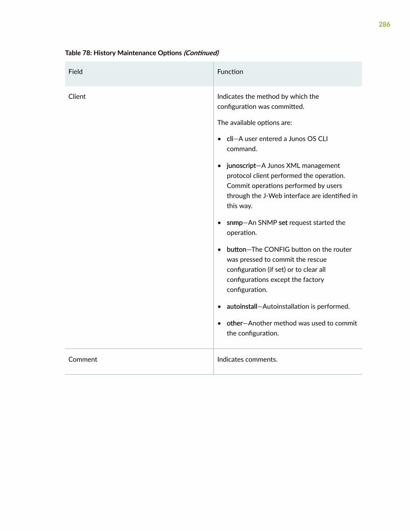
Table 78: History Maintenance Options (Continued)
Field Function
Client Indicates the method by which theconfiguration was committed.
The available options are:
• cli—A user entered a Junos OS CLIcommand.
• junoscript—A Junos XML managementprotocol client performed the operation.Commit operations performed by usersthrough the J-Web interface are identified inthis way.
• snmp—An SNMP set request started theoperation.
• button—The CONFIG button on the routerwas pressed to commit the rescueconfiguration (if set) or to clear allconfigurations except the factoryconfiguration.
• autoinstall—Autoinstallation is performed.
• other—Another method was used to committhe configuration.
Comment Indicates comments.
286

Table 78: History Maintenance Options (Continued)
Field Function
Log Message Indicates the method used to edit theconfiguration.
• Imported via paste—Configuration wasedited and loaded with the DeviceAdministration > Tools > CLI Editor option.
• Imported upload [filename]—Configurationwas uploaded with the DeviceAdministration > Configuration Management> Upload option.
• Modified via quick-configuration—Configuration was modified with thespecified version of the J-Web userinterface.
• Rolled back via user-interface—Configuration was rolled back to a previousversion through the user interface specifiedby user-interface, which can be WebInterface or CLI.
287
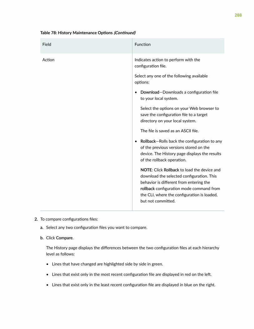
Table 78: History Maintenance Options (Continued)
Field Function
Action Indicates action to perform with theconfiguration file.
Select any one of the following availableoptions:
• Download—Downloads a configuration fileto your local system.
Select the options on your Web browser tosave the configuration file to a targetdirectory on your local system.
The file is saved as an ASCII file.
• Rollback—Rolls back the configuration to anyof the previous versions stored on thedevice. The History page displays the resultsof the rollback operation.
NOTE: Click Rollback to load the device anddownload the selected configuration. Thisbehavior is different from entering therollback configuration mode command fromthe CLI, where the configuration is loaded,but not committed.
2. To compare configurations files:
a. Select any two configuration files you want to compare.
b. Click Compare.
The History page displays the differences between the two configuration files at each hierarchylevel as follows:
• Lines that have changed are highlighted side by side in green.
• Lines that exist only in the most recent configuration file are displayed in red on the left.
• Lines that exist only in the least recent configuration file are displayed in blue on the right.
288

RELATED DOCUMENTATION
Manage Rescue Configuration | 289
Manage Upload Configuration Files | 284
Manage Rescue Configuration
You are here: Device Administration > Configuration Management > Rescue.
If you inadvertently commit a configuration that denies management access, the only recourse may beto connect the console. Alternatively, you can rescue configuration that allows the management accessto the device.
To load and commit the rescue configuration, press and immediately release the Config button on thechassis.
You can set or delete the rescue configuration.
To set or delete rescue configuration:
Click one:
• View rescue configuration—Displays the current rescue configuration (if it exists).
• Set rescue configuration—Sets the current running configuration as the rescue configuration. ClickOK to confirm or Cancel to return to the Rescue page.
• Delete rescue configuration—Deletes the current rescue configuration. Click OK to confirm or Cancelto return to the Rescue page.
RELATED DOCUMENTATION
Manage Your Licenses | 261
Manage Device Certificates
289

CHAPTER 23
Alarm Management
IN THIS CHAPTER
Monitor Chassis Alarm | 290
Monitor System Alarm | 296
Monitor Chassis Alarm
IN THIS SECTION
About Chassis Alarm Page | 290
Create Chassis Alarm Definition | 290
Edit Chassis Alarm Definition | 295
About Chassis Alarm Page
You are here: Device Administration > Alarm Management > Chassis Alarm.
You can create a chassis alarm definition by selecting various options such as DS1, Ethernet, andintegrated service, and so on.
Create Chassis Alarm Definition
To create Chassis Alarm Definition:
1. Enter the information specified in Table 79 on page 291 to create Chassis Alarm Definition.
290
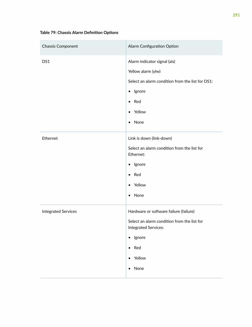
Table 79: Chassis Alarm Definition Options
Chassis Component Alarm Configuration Option
DS1 Alarm indicator signal (ais)
Yellow alarm (ylw)
Select an alarm condition from the list for DS1:
• Ignore
• Red
• Yellow
• None
Ethernet Link is down (link-down)
Select an alarm condition from the list forEthernet:
• Ignore
• Red
• Yellow
• None
Integrated Services Hardware or software failure (failure)
Select an alarm condition from the list forIntegrated Services:
• Ignore
• Red
• Yellow
• None
291

Table 79: Chassis Alarm Definition Options (Continued)
Chassis Component Alarm Configuration Option
Management Ethernet Link is down (link-down)
Select an alarm condition from the list forManagement Ethernet:
• Ignore
• Red
• Yellow
• None
Optical Transport Network Optical channelData Unit (OTN ODU)
Backward defect indication (odu-bdi)
Payload type mismatch (odu-ptim)
Trail trace identifier mismatch (odu-ttim)
Select an alarm condition from the list for OTNODU:
• Ignore
• Red
• Yellow
• None
292

Table 79: Chassis Alarm Definition Options (Continued)
Chassis Component Alarm Configuration Option
Optical Transport Network Optical channelTransport Unit (OTN OTU)
Loss of frame (oc-lof)
Loss of multiframe (oc-lom)
Loss of signal (oc-los)
Backward defect indication (oc-bdi)
Forward error correction excessive FEC errors(out-fec-excessive-errs)
Incoming alignment error (out-iae)
Trail trace identifier mismatch (out-ttim)
Wavelength-Lock (Wavelength Lock)
Select a alarm condition from the list for OTNOTU:
• Ignore
• Red
• Yellow
• None
293

Table 79: Chassis Alarm Definition Options (Continued)
Chassis Component Alarm Configuration Option
Serial Clear-to-send (CTS) signal absent (cts-absent)
Data carrier detect (DCD) signal absent (dcd-absent)
Data set ready (DSR) signal absent (dsr absent)
Loss of receive clock (loss-of-rx-clock)
Loss of transmit clock (loss-of-tx-clock)
Select an alarm condition from the list for Serial:
• Ignore
• Red
• Yellow
• None
Services Services module hardware down (hw-down)
Services link down (linkdown)
Services module held in reset (pic-hold-reset)
Services module reset (pic-reset)
Receive errors (rx-errors)
Services module software down (sw-down)
Transmit errors (tx-errors)
Select an alarm condition from the list for Services:
• Ignore
• Red
• Yellow
• None
294

Table 79: Chassis Alarm Definition Options (Continued)
Chassis Component Alarm Configuration Option
DS3 Alarm indication signal (ais)
Excessive number of zeros (exz)
Far-end receive failure (ferf)
Idle alarm (idle)
Line code violation (lcv)
Loss of frame (lof)
Loss of signal (los)
Phase-locked loop out of lock (pll)
Yellow alarm (ylw)
Select an alarm condition from the list for DS3:
• Ignore
• Red
• Yellow
• None
2. Click OK to create Chassis Alarm Definition.
The Chassis Alarm Definition page appears.
3. Click Cancel to cancel your entries and returns to the Chassis Alarm Definition page.
Edit Chassis Alarm Definition
To edit Chassis Alarm Definition:
1. Click the pencil icon on the upper right side of the Chassis Alarm Definition page.
See Table 79 on page 291 for the options available for editing the Chassis Alarm Definition page.
2. Click OK.
295

RELATED DOCUMENTATION
Monitor System Alarm | 296
Monitor System Alarm
IN THIS SECTION
About System Alarm Page | 296
Create System Alarm Configuration | 296
Edit System Alarm Configuration | 300
About System Alarm Page
You are here: Device Administration > Alarm Management > System Alarm.
You can enable system login alarm login classes. The configured Login Classes will display system alarmswhile logging in.
Create System Alarm Configuration
To create System Alarm Configuration:
1. Enter the information specified in Table 80 on page 296 to create System Alarm Configuration.
Table 80: RPM Information Troubleshooting Options
Field Function
Currently Running Tests
Graph Click the Graph link to display the graph (if it is notalready displayed) or to update the graph for aparticular test.
Owner Configured owner name of the RPM test.
296

Table 80: RPM Information Troubleshooting Options (Continued)
Field Function
Test Name Configured name of the RPM test.
Probe Type Type of RPM probe configured for the specifiedtest. Following are valid probe types:
• http-get
• http-get-metadata
• icmp-ping
• icmp-ping-timestamp
• tcp-ping
• udp-ping
Target Address IP address or URL of the remote server that isbeing probed by the RPM test.
Source Address Explicitly configured source address that isincluded in the probe packet headers.
If no source address is configured, the RPM probepackets use the outgoing interface as the sourceaddress, and the Source Address field is empty.
Minimum RTT Shortest round-trip time from the J Series deviceto the remote server, as measured over the courseof the test.
Maximum RTT Longest round-trip time from the J Series device tothe remote server, as measured over the course ofthe test.
297

Table 80: RPM Information Troubleshooting Options (Continued)
Field Function
Average RTT Average round-trip time from the J Series deviceto the remote server, as measured over the courseof the test.
Standard Deviation RTT Standard deviation of round-trip times from the JSeries device to the remote server, as measuredover the course of the test.
Probes Sent Total number of probes sent over the course of thetest.
Loss Percentage Percentage of probes sent for which a responsewas not received.
Round-Trip Time for a Probe
Samples Total number of probes used for the data set.
The J Series device maintains records of the mostrecent 50 probes for each configured test. These50 probes are used to generate RPM statistics fora particular test.
Earliest Sample System time when the first probe in the samplewas received.
Latest Sample System time when the last probe in the samplewas received.
Mean Value Average round-trip time for the 50-probe sample.
Standard Deviation Standard deviation of the round-trip times for the50-probe sample.
298

Table 80: RPM Information Troubleshooting Options (Continued)
Field Function
Lowest Value Shortest round-trip time from the device to theremote server, as measured over the 50-probesample.
Time of Lowest Sample System time when the lowest value in the 50-probe sample was received.
Highest Value Longest round-trip time from the J Series device tothe remote server, as measured over the 50-probesample.
Time of Highest Sample System time when the highest value in the 50-probe sample was received.
Cumulative Jitter for a Probe
Samples Total number of probes used for the data set.
The J Series device maintains records of the mostrecent 50 probes for each configured test. These50 probes are used to generate RPM statistics fora particular test.
Earliest Sample System time when the first probe in the samplewas received.
Latest Sample System time when the last probe in the samplewas received.
Mean Value Average jitter for the 50-probe sample.
Standard Deviation Standard deviation of the jitter values for the 50-probe sample.
299

Table 80: RPM Information Troubleshooting Options (Continued)
Field Function
Lowest Value Smallest jitter value, as measured over the 50-probe sample.
Time of Lowest Sample System time when the lowest value in the 50-probe sample was received.
Highest Value Highest jitter value, as measured over the 50-probe sample.
Time of Highest Sample System time when the highest jitter value in the50-probe sample was received.
2. Click OK to create System Alarm Configuration.
System Alarm Configuration page appears.
3. Click Cancel to cancel your entries and returns to the System Alarm Configuration page.
Edit System Alarm Configuration
To edit System Alarm Configuration:
1. Click the pencil icon on the upper right side of the System Alarm Configuration page.
See Table 80 on page 296 for the options available for editing the System Alarm Configuration page.
2. Click OK.
SEE ALSO
Monitor Chassis Alarm | 290
300
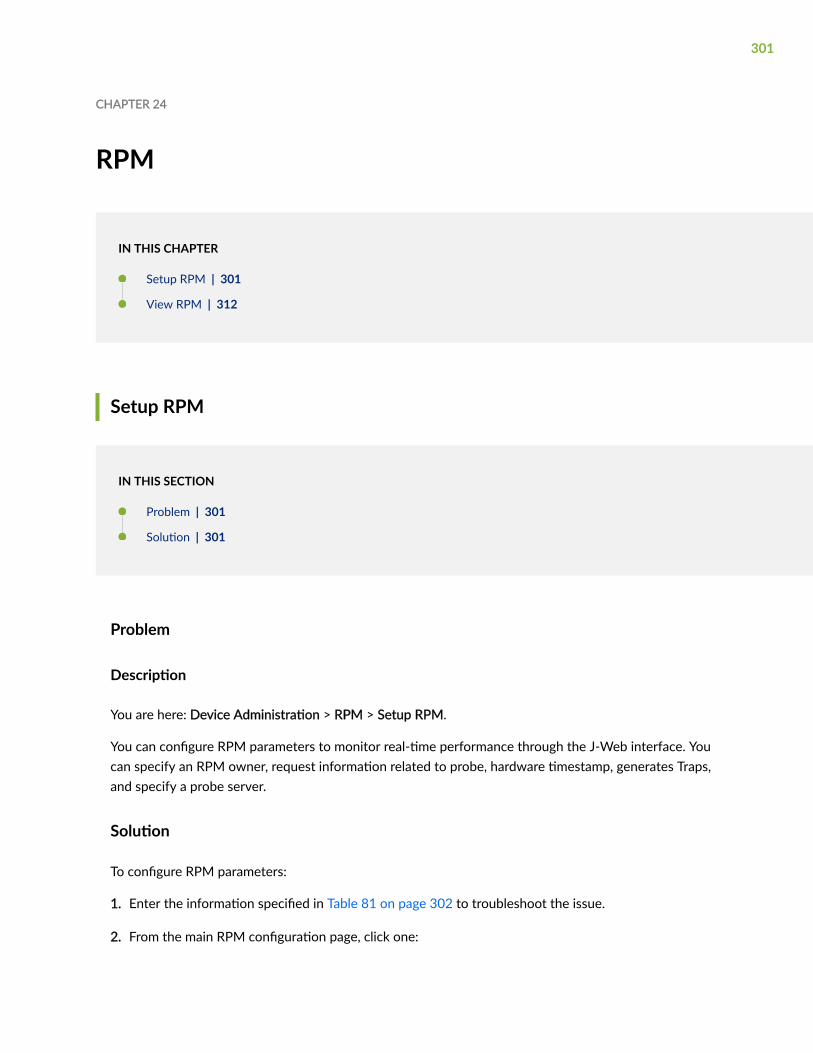
CHAPTER 24
RPM
IN THIS CHAPTER
Setup RPM | 301
View RPM | 312
Setup RPM
IN THIS SECTION
Problem | 301
Solution | 301
Problem
Description
You are here: Device Administration > RPM > Setup RPM.
You can configure RPM parameters to monitor real-time performance through the J-Web interface. Youcan specify an RPM owner, request information related to probe, hardware timestamp, generates Traps,and specify a probe server.
Solution
To configure RPM parameters:
1. Enter the information specified in Table 81 on page 302 to troubleshoot the issue.
2. From the main RPM configuration page, click one:
301

• Apply—Applies the configuration and stays on the RPM configuration page.
• OK—Applies the configuration and returns to the RPM configuration page.
• Cancel—Cancels your entries and returns to the RPM configuration page.
Table 81: RPM Setup Troubleshooting Options
Field Function
Probe Owners
Identification
Owner Name Specifies an RPM owner for which one or more RPMtests are configured. In most implementations, theowner name identifies a network on which a set oftests is being run (a particular customer, forexample).
Type the name of the RPM owner.
Performance Probe Tests
Identification
Test name Specifies a unique name to identify the RPM test.
Type the name of the RPM test.
Target (Address or URL) Specifies an IP address or a URL of a probe target.
Type the IP address, in dotted decimal notation, orthe URL of the probe target. If the target is a URL,type a fully formed URL that includes http://.
302

Table 81: RPM Setup Troubleshooting Options (Continued)
Field Function
Source Address Specifies an IP address to be used as the probesource address.
Type the source address to be used for the probe. Ifthe source IP address is not one of the device'sassigned addresses, the packet uses the outgoinginterface's address as its source.
Routing Instance Specifies a routing instance over which the probe issent.
Type the routing instance name. The routinginstance applies only to probes of type icmp andicmp-timestamp. The default routing instance isinet.0.
History Size Specifies the number of probe results saved in theprobe history.
Type a number between 0 and 255. The defaulthistory size is 50 probes.
Request Information
303

Table 81: RPM Setup Troubleshooting Options (Continued)
Field Function
Probe Type Specifies the type of probe to send as part of thetest.
Select the desired probe type from the list:
• http-get
• http-get-metadata
• icmp-ping
• icmp-ping-timestamp
• tcp-ping
• udp-ping
Interval Specifies the wait time (in seconds) between eachprobe transmission.
Type a number between 1 and 255 (seconds).
Test Interval Specifies the wait time (in seconds) between tests.
Type a number between 0 and 86400 (seconds).
Probe Count Specifies the total number of probes to be sent foreach test.
Type a number between 1 and 15.
Moving Average Size Specifies the number of samples used for a movingaverage.
Type a number between 0 and 225.
304

Table 81: RPM Setup Troubleshooting Options (Continued)
Field Function
Destination Port Specifies the TCP or UDP port to which probes aresent.
To use TCP or UDP probes, you must configure theremote server as a probe receiver. Both the probeserver and the remote server must be JuniperNetworks devices configured to receive and transmitRPM probes on the same TCP or UDP port.
Type the number 7—a standard TCP or UDP portnumber—or a port number from 49152 through65535.
DSCP Bits Specifies the Differentiated Services code point(DSCP) bits. This value must be a valid 6-bit pattern.The default is 000000.
Type a valid 6-bit pattern.
Data Size Specifies the size of the data portion of the ICMPprobes.
Type a size (in bytes) between 0 and 65507.
Data Fill Specifies the contents of the data portion of theICMP probes.
Type a hexadecimal value between 1 and 800h touse as the contents of the ICMP probe data.
Hardware Timestamp
One Way Hardware Timestamp Specifies the hardware timestamps for one-waymeasurements.
To enable one-way timestamping, select the checkbox.
305

Table 81: RPM Setup Troubleshooting Options (Continued)
Field Function
Hardware Timestamp Specifies timestamping of RPM probe messages. Youcan timestamp the following RPM probes to improvethe measurement of latency or jitter:
• ICMP ping
• ICMP ping timestamp
• UDP ping—destination port UDP-ECHO (port 7)only
• UDP ping timestamp—destination port UDP-ECHO (port 7) only
To enable timestamping, select the check box.
Destination Interface Specifies the name of an output interface for probes.
Select the interface from the list.
Maximum Probe Thresholds
Successive Lost Probes Specifies the total number of probes that must belost successively to trigger a probe failure andgenerate a system log message.
Type a number between 0 and 15.
Lost Probes Specifies the total number of probes that must belost to trigger a probe failure and generate a systemlog message.
Type a number between 0 and 15.
306

Table 81: RPM Setup Troubleshooting Options (Continued)
Field Function
Round Trip Time Specifies the total round-trip time (in microseconds),from the device to the remote server, that triggers aprobe failure and generates a system log message.
Type a number between 0 and 60,000,000(microseconds).
Jitter Specifies the total jitter (in microseconds) for a testthat triggers a probe failure and generates a systemlog message.
Type a number between 0 and 60,000,000(microseconds).
Standard Deviation Specifies the maximum allowable standard deviation(in microseconds) for a test, which, if exceeded,triggers a probe failure and generates a system logmessage.
Type a number between 0 and 60,000,000(microseconds).
Egress Time Specifies the total one-way time (in microseconds),from the device to the remote server, that triggers aprobe failure and generates a system log message.
Type a number between 0 and 60,000,000(microseconds).
Ingress Time Specifies the total one-way time (in microseconds),from the remote server to the device, that triggers aprobe failure and generates a system log message.
Type a number between 0 and 60,000,000(microseconds)
307
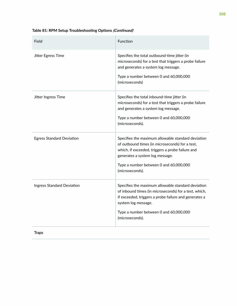
Table 81: RPM Setup Troubleshooting Options (Continued)
Field Function
Jitter Egress Time Specifies the total outbound-time jitter (inmicroseconds) for a test that triggers a probe failureand generates a system log message.
Type a number between 0 and 60,000,000(microseconds)
Jitter Ingress Time Specifies the total inbound-time jitter (inmicroseconds) for a test that triggers a probe failureand generates a system log message.
Type a number between 0 and 60,000,000(microseconds).
Egress Standard Deviation Specifies the maximum allowable standard deviationof outbound times (in microseconds) for a test,which, if exceeded, triggers a probe failure andgenerates a system log message.
Type a number between 0 and 60,000,000(microseconds).
Ingress Standard Deviation Specifies the maximum allowable standard deviationof inbound times (in microseconds) for a test, which,if exceeded, triggers a probe failure and generates asystem log message.
Type a number between 0 and 60,000,000(microseconds).
Traps
308
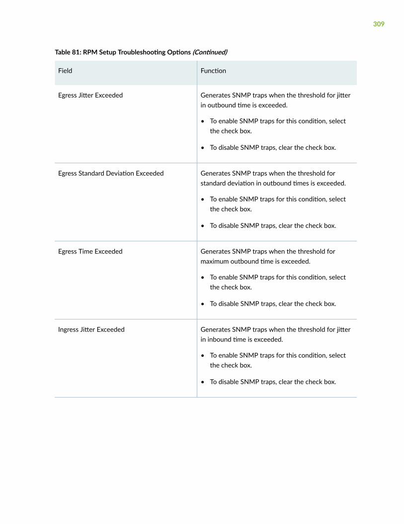
Table 81: RPM Setup Troubleshooting Options (Continued)
Field Function
Egress Jitter Exceeded Generates SNMP traps when the threshold for jitterin outbound time is exceeded.
• To enable SNMP traps for this condition, selectthe check box.
• To disable SNMP traps, clear the check box.
Egress Standard Deviation Exceeded Generates SNMP traps when the threshold forstandard deviation in outbound times is exceeded.
• To enable SNMP traps for this condition, selectthe check box.
• To disable SNMP traps, clear the check box.
Egress Time Exceeded Generates SNMP traps when the threshold formaximum outbound time is exceeded.
• To enable SNMP traps for this condition, selectthe check box.
• To disable SNMP traps, clear the check box.
Ingress Jitter Exceeded Generates SNMP traps when the threshold for jitterin inbound time is exceeded.
• To enable SNMP traps for this condition, selectthe check box.
• To disable SNMP traps, clear the check box.
309
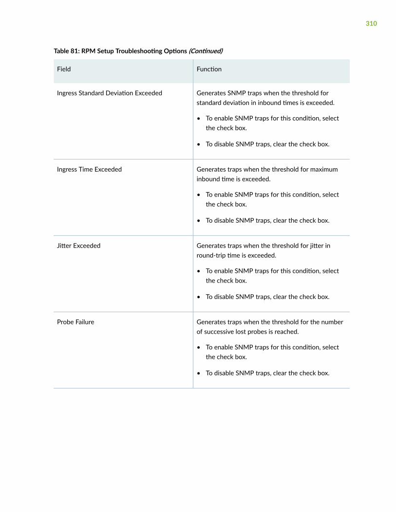
Table 81: RPM Setup Troubleshooting Options (Continued)
Field Function
Ingress Standard Deviation Exceeded Generates SNMP traps when the threshold forstandard deviation in inbound times is exceeded.
• To enable SNMP traps for this condition, selectthe check box.
• To disable SNMP traps, clear the check box.
Ingress Time Exceeded Generates traps when the threshold for maximuminbound time is exceeded.
• To enable SNMP traps for this condition, selectthe check box.
• To disable SNMP traps, clear the check box.
Jitter Exceeded Generates traps when the threshold for jitter inround-trip time is exceeded.
• To enable SNMP traps for this condition, selectthe check box.
• To disable SNMP traps, clear the check box.
Probe Failure Generates traps when the threshold for the numberof successive lost probes is reached.
• To enable SNMP traps for this condition, selectthe check box.
• To disable SNMP traps, clear the check box.
310

Table 81: RPM Setup Troubleshooting Options (Continued)
Field Function
RTT Exceeded Generates traps when the threshold for maximumround-trip time is exceeded.
• To enable SNMP traps for this condition, selectthe check box.
• To disable SNMP traps, clear the check box.
Standard Deviation Exceeded Generates traps when the threshold for standarddeviation in round-trip times is exceeded.
• To enable SNMP traps for this condition, selectthe check box.
• To disable SNMP traps, clear the check box.
Test Completion Generates traps when a test is completed.
• To enable SNMP traps for this condition, selectthe check box.
• To disable SNMP traps, clear the check box.
Test Failure Generates traps when the threshold for the totalnumber of lost probes is reached.
• To enable SNMP traps for this condition, selectthe check box.
• To disable SNMP traps, clear the check box.
Maximum Number of Concurrent Probes
Maximum Number of Concurrent Probes Specifies the maximum number of concurrentprobes allowed.
Type a number between 1 and 500.
311

Table 81: RPM Setup Troubleshooting Options (Continued)
Field Function
Probe Server
TCP Probe Server Specifies the port on which the device is to receiveand transmit TCP probes.
Type number 7, or a port number from 49160through 65535.
UDP Probe Server Specifies the port on which the device is to receiveand transmit UDP probes.
Type number 7, or a port number from 49160through 65535.
RELATED DOCUMENTATION
View RPM | 312
View RPM
IN THIS SECTION
Problem | 312
Solution | 313
Problem
Description
You are here: Device Administration > RPM > View RPM.
312

You can configure the RPM probes, to view the RPM statistics and to ensure that the device isconfigured to receive and transmit TCP and UDP RPM probes on correct ports.
You can view the RPM configuration to verify the following information:
• The RPM configuration is within the expected values.
• The RPM probes are functioning and the RPM statistics are within expected values.
• The device is configured to receive and transmit TCP and UDP RPM probes on the correct ports.
In addition to the RPM statistics for each RPM test, the J-Web interface displays the round-trip timesand cumulative jitter graphically. In the graphs, the round-trip time and jitter values are plotted as afunction of the system time. Large spikes in round-trip time or jitter indicate a slower outbound (egress)or inbound (ingress) time for the probe sent at that particular time.
Solution
To view RPM information:
1. Enter the information specified in Table 82 on page 313.
Table 82: RPM Information Troubleshooting Options
Field Function
Currently Running Tests
Graph Click the Graph link to display the graph (if it is notalready displayed) or to update the graph for aparticular test.
Owner Configured owner name of the RPM test.
Test Name Configured name of the RPM test.
313
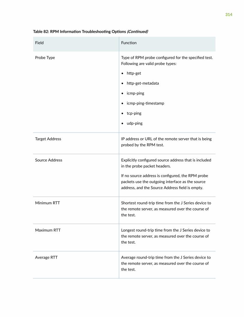
Table 82: RPM Information Troubleshooting Options (Continued)
Field Function
Probe Type Type of RPM probe configured for the specified test.Following are valid probe types:
• http-get
• http-get-metadata
• icmp-ping
• icmp-ping-timestamp
• tcp-ping
• udp-ping
Target Address IP address or URL of the remote server that is beingprobed by the RPM test.
Source Address Explicitly configured source address that is includedin the probe packet headers.
If no source address is configured, the RPM probepackets use the outgoing interface as the sourceaddress, and the Source Address field is empty.
Minimum RTT Shortest round-trip time from the J Series device tothe remote server, as measured over the course ofthe test.
Maximum RTT Longest round-trip time from the J Series device tothe remote server, as measured over the course ofthe test.
Average RTT Average round-trip time from the J Series device tothe remote server, as measured over the course ofthe test.
314

Table 82: RPM Information Troubleshooting Options (Continued)
Field Function
Standard Deviation RTT Standard deviation of round-trip times from the JSeries device to the remote server, as measured overthe course of the test.
Probes Sent Total number of probes sent over the course of thetest.
Loss Percentage Percentage of probes sent for which a response wasnot received.
Round-Trip Time for a Probe
Samples Total number of probes used for the data set.
The J Series device maintains records of the mostrecent 50 probes for each configured test. These 50probes are used to generate RPM statistics for aparticular test.
Earliest Sample System time when the first probe in the sample wasreceived.
Latest Sample System time when the last probe in the sample wasreceived.
Mean Value Average round-trip time for the 50-probe sample.
Standard Deviation Standard deviation of the round-trip times for the50-probe sample.
Lowest Value Shortest round-trip time from the device to theremote server, as measured over the 50-probesample.
315

Table 82: RPM Information Troubleshooting Options (Continued)
Field Function
Time of Lowest Sample System time when the lowest value in the 50-probesample was received.
Highest Value Longest round-trip time from the J Series device tothe remote server, as measured over the 50-probesample.
Time of Highest Sample System time when the highest value in the 50-probesample was received.
Cumulative Jitter for a Probe
Samples Total number of probes used for the data set.
The J Series device maintains records of the mostrecent 50 probes for each configured test. These 50probes are used to generate RPM statistics for aparticular test.
Earliest Sample System time when the first probe in the sample wasreceived.
Latest Sample System time when the last probe in the sample wasreceived.
Mean Value Average jitter for the 50-probe sample.
Standard Deviation Standard deviation of the jitter values for the 50-probe sample.
Lowest Value Smallest jitter value, as measured over the 50-probesample.
316

Table 82: RPM Information Troubleshooting Options (Continued)
Field Function
Time of Lowest Sample System time when the lowest value in the 50-probesample was received.
Highest Value Highest jitter value, as measured over the 50-probesample.
Time of Highest Sample System time when the highest jitter value in the 50-probe sample was received.
RELATED DOCUMENTATION
Setup RPM | 301
317

CHAPTER 25
Tools
IN THIS CHAPTER
Troubleshoot Ping Host | 318
Troubleshoot Ping MPLS | 323
Troubleshoot Traceroute | 328
Troubleshoot Packet Capture | 333
Access CLI | 341
View CLI Configuration | 343
Edit CLI Configuration | 344
Point and Click CLI | 345
Troubleshoot Ping Host
IN THIS SECTION
About Ping Host Page | 318
About Ping Host Page
You are here: Device Administration > Tools > Ping Host.
The ping diagnostic tool sends a series of ICMP "echo request" packets to the specified remote host.
The receipt of such packets will usually result in the remote host replying with an ICMP "echo response."Note that some hosts are configured not to respond to ICMP "echo requests," so a lack of responsesdoes not necessarily represent a connectivity problem. Also, some firewalls block the ICMP packet typesthat ping uses, so you may find that you are not able to ping outside your local network.
You can ping a host to verify that the host can be reached over the network or not.
318

To use the ping host tool:
1. Enter the information specified in Table 83 on page 319 to troubleshoot the issue.
The Remote Host field is the only required field.
2. Click the expand icon next to Advanced options.
3. Click Start.
The results of the ping operation are displayed in Table 84 on page 321. If no options are specified,each ping response is in the following format:
bytes bytes from ip-address: icmp_seq=number ttl=number time=time
4. Click OK to stop the ping operation before it is complete.
Table 83: Ping Host Troubleshooting Options
Field Action
Remote Host Type the hostname or IP address of the host to ping.
Advanced Options
Don't ResolveAddresses
• To suppress the display of the hop hostnames along t the path, select thecheck box.
• To display the hop hostnames along the path, clear the check box.
Interface From the list, select the interface on which ping requests are sent. If you selectany, the ping requests are sent on all interfaces.
Count From the list, select the number of ping requests to send.
Don't Fragment • To set the don't fragment (DF) bit in the IP header of the ping request packet,select the check box.
• To clear the DF bit in the IP header of the ping request packet, clear thecheck box.
319

Table 83: Ping Host Troubleshooting Options (Continued)
Field Action
Record Route • To record and display the path of the packet, select the check box.
• To suppress the recording and display of the path of the packet, clear thecheck box.
Type-of-Service From the list, select the decimal value of the ToS in the IP header of the pingrequest packet.
Routing Instance From the list, select the routing instance name for the ping attempt.
Interval From the list, select the interval in seconds, between the transmission of eachping request.
Packet Size Type the size, in bytes, of the packet. The size can be from 0 through 65468. Thedevice adds 8 bytes to the size of the ICMP header.
Source Address Type the source IP address of the ping request packet.
Time-to-Live From the list, select the TTL hop count for the ping request packet.
Bypass Routing • To bypass the routing table and send the ping requests to hosts on thespecified interface only, select the check box.
• To route the ping requests using the routing table, clear the check box.
If the routing table is not used, ping requests are sent only to hosts on theinterface specified in the Interface box. If the host is not on that interface,ping responses are not sent.
320

Table 84: Ping Host Results and Output Summary
Field Function
bytes bytes from ip-address • bytes—Size of ping response packet, which is equal to the valueyou entered in the Packet Size box, plus 8.
• ip-address—IP address of destination host that sent the pingresponse packet.
icmp_seq=0
icmp_seq=number
time—Sequence Number field of the ping response packet. You canuse this value to match the ping response to the corresponding pingrequest.
ttl=number number—TTL hop-count value of the ping response packet.
time=time time—Total time between the sending of the ping request packet andthe receiving of the ping response packet, in milliseconds. This value isalso called round-trip time.
number packets transmitted number—Number of ping requests (probes) sent to host.
number packets received number—Number of ping responses received from host.
percentage packet loss percentage—Number of ping responses divided by the number of pingrequests, specified as a percentage.
round-trip min/avg/max/stddev = min-time/avg-time/max-time/std-dev ms
• min-time—Minimum round-trip time (see time=time field in thistable).
• avg-time—Average round-trip time.
• max-time—Maximum round-trip time.
• std-dev—Standard deviation of the round-trip times.
321

Table 84: Ping Host Results and Output Summary (Continued)
Field Function
Output = Packet loss of 100percent
If the device does not receive ping responses from the destinationhost (the output shows a packet loss of 100 percent), one of thefollowing explanations might apply:
• The host is not operational.
• There are network connectivity problems between the device andthe host.
• The host might be configured to ignore ICMP echo requests.
• The host might be configured with a firewall filter that blocks ICMPecho requests or ICMP echo responses.
• The size of the ICMP echo request packet exceeds the MTU of ahost along the path.
• The value you selected in the TTL box was less than the number ofhops in the path to the host, in which case the host might replywith an ICMP error message.
For more information about ICMP, see RFC 792, Internet ControlMessage Protocol.
RELATED DOCUMENTATION
Troubleshoot Ping MPLS | 323
Troubleshoot Traceroute | 328
Troubleshoot Packet Capture | 333
322

Troubleshoot Ping MPLS
IN THIS SECTION
About Ping MPLS Page | 323
About Ping MPLS Page
You are here: Device Administration > Tools > Ping MPLS.
You can send variations of ICMP "echo request" packets to the specified MPLS endpoint.
To use the ping MPLS tool:
1. Click the expand icon next to the ping MPLS option you want to use.
2. Enter information specified in Table 85 on page 323 to troubleshoot the issue.
3. Click Start.
The results of the ping operation are displayed in Table 86 on page 327.
4. Click OK to stop the ping operation before it is complete.
Table 85: Ping MPLS Troubleshooting Options
Field Action
Ping RSVP-signaled LSP
LSP Name Type the name of the LSP to ping.
Source Address Type the source IP address of the ping request packet—a valid addressconfigured on a J Series device interface.
Count From the list, select the number of ping requests to send. The default is5 requests.
323
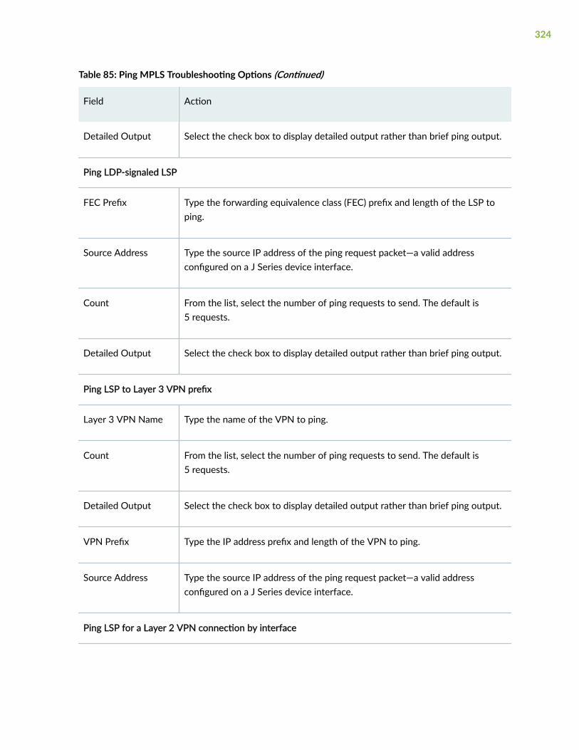
Table 85: Ping MPLS Troubleshooting Options (Continued)
Field Action
Detailed Output Select the check box to display detailed output rather than brief ping output.
Ping LDP-signaled LSP
FEC Prefix Type the forwarding equivalence class (FEC) prefix and length of the LSP toping.
Source Address Type the source IP address of the ping request packet—a valid addressconfigured on a J Series device interface.
Count From the list, select the number of ping requests to send. The default is5 requests.
Detailed Output Select the check box to display detailed output rather than brief ping output.
Ping LSP to Layer 3 VPN prefix
Layer 3 VPN Name Type the name of the VPN to ping.
Count From the list, select the number of ping requests to send. The default is5 requests.
Detailed Output Select the check box to display detailed output rather than brief ping output.
VPN Prefix Type the IP address prefix and length of the VPN to ping.
Source Address Type the source IP address of the ping request packet—a valid addressconfigured on a J Series device interface.
Ping LSP for a Layer 2 VPN connection by interface
324

Table 85: Ping MPLS Troubleshooting Options (Continued)
Field Action
Interface From the list, select the J Series device interface on which ping requests aresent. If you select any, the ping requests are sent on all interfaces.
(See the interface naming conventions in the Junos OS InterfacesConfiguration Guide for Security Devices.)
Source Address Type the source IP address of the ping request packet—a valid addressconfigured on a J series device interface.
Count From the list, select the number of ping requests to send. The default is5 requests.
Detailed Output Select the check box to display detailed output rather than brief ping output.
Ping LSP for a Layer 2 VPN connection by instance
Layer 2VPN Name Type the name of the Layer 2 VPN to ping.
Remote Site Identifier Type the remote site identifier of the Layer 2 VPN to ping.
Source Address Type the source IP address of the ping request packet—a valid addressconfigured on a J Series device interface.
Local Site Identifier Type the local site identifier of the Layer 2 VPN to ping.
Count From the list, select the number of ping requests to send. The default is5 requests.
Detailed Output Select the check box to display detailed output rather than brief ping output.
Ping LSP to a Layer 2 circuit remote site by interface
325

Table 85: Ping MPLS Troubleshooting Options (Continued)
Field Action
Interface From the list, select the J Series device interface on which ping requests aresent. If you select any, the ping requests are sent on all interfaces.
Source Address Type the source IP address of the ping request packet—a valid addressconfigured on a J Series device interface.
Count From the list, select the number of ping requests to send. The default is5 requests.
Detailed Output Select the check box to display detailed output rather than brief ping output.
Ping LSP to a Layer 2 circuit remote site by VCI
Remote Neighbor Type the IP address of the remote neighbor (PE router) within the virtualcircuit to ping.
Circuit Identifier Type the virtual circuit identifier for the Layer 2 circuit.
Source Address Type the source IP address of the ping request packet—a valid addressconfigured on a J Series device interface.
Count From the list, select the number of ping requests to send.
Detailed Output Select the check box to display detailed output rather than brief ping output.
Ping endpoint of LSP
VPN Prefix Type either the LDP FEC prefix and length or the RSVP LSP endpoint addressfor the LSP to ping.
326

Table 85: Ping MPLS Troubleshooting Options (Continued)
Field Action
Source Address Type the source IP address of the ping request packet—a valid addressconfigured on a J Series device interface.
Count From the list, select the number of ping requests to send.
Detailed Output Select the check box to display detailed output rather than brief ping output.
Table 86: Ping MPLS Results and Output Summary
Field Function
Exclamation point (!) Echo reply was received.
Period (.) Echo reply was not received within the timeout period.
x Echo reply was received with an error code. Errored packets are not countedin the received packets count and are accounted for separately.
number packetstransmitted
number—Number of ping requests (probes) sent to a host.
number packetsreceived
number—Number of ping responses received from a host.
percentage packetloss
percentage—Number of ping responses divided by the number of pingrequests, specified as a percentage.
time For Layer 2 circuits only, the number of milliseconds required for the pingpacket to reach the destination. This value is approximate, because thepacket has to reach the Routing Engine.
327

Table 86: Ping MPLS Results and Output Summary (Continued)
Field Function
Output = Packet lossof 100 percent
If the device does not receive ping responses from the destination host (theoutput shows a packet loss of 100 percent), one of the followingexplanations might apply:
• The host is not operational.
• There are network connectivity problems between the device and thehost.
• The host might be configured to ignore echo requests.
• The host might be configured with a firewall filter that blocks echorequests or echo responses.
• The size of the echo request packet exceeds the MTU of a host along thepath.
• The outbound node at the remote endpoint is not configured to handleMPLS packets.
• The remote endpoint's loopback address is not configured to 127.0.0.1.
RELATED DOCUMENTATION
Troubleshoot Traceroute | 328
Troubleshoot Packet Capture | 333
Troubleshoot Traceroute
IN THIS SECTION
About Traceroute Page | 329
328

About Traceroute Page
You are here: Device Administration > Tools > Traceroute.
The traceroute diagnostic tool uses a series of packets crafted to elicit an ICMP "time exceeded"messages from intermediate points in the network between your device and the specified host.
The time-to-live for a packet is decremented each time the packet is routed, so traceroute generallyreceives at least one "time exceeded" response from each waypoint. Traceroute starts with a packet witha time-to-live value of one, and increments the time to live for subsequent packets, thereby constructinga rudimentary map of the path between hosts.
Use this page to display a list of routers between the device and a specified destination host.
To use the traceroute tool:
1. Click the expand icon next to Advanced options.
2. Enter information in the Traceroute page as described in Table 87 on page 329.
The Remote Host field is the only required field.
3. Click Start.
The results of the traceroute operation are displayed in Table 88 on page 331. If no options arespecified, each line of the traceroute display is in the following format:
hop-number host (ip-address) [as-number]time1 time2 time3
The device sends a total of three traceroute packets to each router along the path and displays theround-trip time for each traceroute operation. If the device times out before receiving a TimeExceeded message, an asterisk (*) is displayed for that round-trip time.
4. Click OK to stop the traceroute operation before it is complete.
Table 87: Ping Traceroute Troubleshooting Options
Field Action
Remote Host Type the hostname or IP address of the destination host of the traceroute.
Advanced Options
329

Table 87: Ping Traceroute Troubleshooting Options (Continued)
Field Action
Don't ResolveAddresses
• To suppress the display of the hop hostnames along the path, select thecheck box.
• To display the hop hostnames along the path, clear the check box.
Interface From the list, select the interface on which traceroute packets are sent. If youselect any, the traceroute requests are sent on all interfaces.
Time-to-Live From the list, select the time-to-live (TTL) hop count for the traceroute requestpacket.
Type-of-Service From the list, select the decimal value of the type-of-service (ToS) value toinclude in the IP header of the traceroute request packet.
Resolve ASNumbers
• To display the autonomous system (AS) number of each intermediate hopbetween the device and the destination host, select the check box.
• To suppress the display of the AS number of each intermediate hop betweenthe device and the destination host, clear the check box.
Routing Instance From the list, select the routing instance name for the ping attempt.
Gateway Type the gateway IP address to route through.
Source Address Type the source IP address of the outgoing traceroute packets.
330

Table 87: Ping Traceroute Troubleshooting Options (Continued)
Field Action
Bypass Routing • To bypass the routing table and send the traceroute packets to hosts on thespecified interface only, select the check box.
• To route the traceroute packets by means of the routing table, clear the checkbox.
If the routing table is not used, traceroute packets are sent only to hosts onthe interface specified in the Interface box. If the host is not on that interface,traceroute responses are not sent.
Table 88: Ping Traceroute Results and Output Summary
Field Function
Ping Traceroute Results and Output Summary
hop-number Number of the hop (router) along the path.
host Hostname, if available, or IP address of the router.
To suppress the display of the hostname, select the Don't Resolve Addressescheck box.
ip-address IP address of the router.
as-number AS number of the router.
time1 Round-trip time between the sending of the first traceroute packet and thereceiving of the corresponding Time Exceeded packet from that particularrouter.
time2 Round-trip time between the sending of the second traceroute packet and thereceiving of the corresponding Time Exceeded packet from that particularrouter.
331

Table 88: Ping Traceroute Results and Output Summary (Continued)
Field Function
time3 Round-trip time between the sending of the third traceroute packet and thereceiving of the corresponding Time Exceeded packet from that particularrouter.
Output = Completepath to thedestination host notdisplayed
If the device does not display the complete path to the destination host, one ofthe following explanations might apply:
• The host is not operational.
• There are network connectivity problems between the device and the host.
• The host, or a router along the path, might be configured to ignore ICMPtraceroute messages.
• The host, or a router along the path, might be configured with a firewallfilter that blocks ICMP traceroute requests or ICMP time exceededresponses.
• The value you selected in the Time Exceeded box was less than the numberof hops in the path to the host. In this case, the host might reply with anICMP error message.
For more information about ICMP, see RFC 792, Internet Control MessageProtocol.
RELATED DOCUMENTATION
Troubleshoot Packet Capture | 333
332

Troubleshoot Packet Capture
IN THIS SECTION
About Packet Capture Page | 333
About Packet Capture Page
You are here: Device Administration > Tools > Packet Capture.
You can quickly capture and analyze router control traffic on a device.
The packet capture diagnostic tool allows inspection of control traffic (not transient traffic). Thesummary of each decoded packet is displayed as it is captured. Captured packets are written to a PCAPfile which can be downloaded.
NOTE: Starting in Junos OS Release 19.3R1, J-Web supports RE3 line cards for SRX5000 line ofdevices.
To use J-Web packet capture:
1. Enter the information specified in Table 89 on page 334 to troubleshoot the issue.
2. Save the captured packets to a file or specify other advanced options by clicking the expand iconnext to Advanced options.
3. Click Start.
The captured packet headers are decoded and displayed in the Packet Capture display as specified inTable 90 on page 339.
4. Click one:
• Stop Capturing—Stops capturing the packets and stays on the same page while the decodedpacket headers are being displayed.
• OK—Stops capturing packets and returns to the Packet Capture page.
333
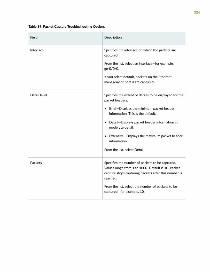
Table 89: Packet Capture Troubleshooting Options
Field Description
Interface Specifies the interface on which the packets arecaptured.
From the list, select an interface—for example,ge-0/0/0.
If you select default, packets on the Ethernetmanagement port 0 are captured.
Detail level Specifies the extent of details to be displayed for thepacket headers.
• Brief—Displays the minimum packet headerinformation. This is the default.
• Detail—Displays packet header information inmoderate detail.
• Extensive—Displays the maximum packet headerinformation.
From the list, select Detail.
Packets Specifies the number of packets to be captured.Values range from 1 to 1000. Default is 10. Packetcapture stops capturing packets after this number isreached.
From the list, select the number of packets to becaptured—for example, 10.
334

Table 89: Packet Capture Troubleshooting Options (Continued)
Field Description
Addresses Specifies the addresses to be matched for capturingthe packets using a combination of the followingparameters:
• Direction—Matches the packet headers for IPaddress, hostname, or network address of thesource, destination, or both.
• Type—Specifies if packet headers are matched forhost address or network address.
You can add multiple entries to refine the matchcriteria for addresses.
Select address-matching criteria. For example:
1. From the Direction list, select source.
2. From the Type list, select host.
3. In the Address box, type 10.1.40.48.
4. Click Add.
Protocols Matches the protocol for which packets arecaptured. You can choose to capture TCP, UDP, orICMP packets or a combination of TCP, UDP, andICMP packets.
From the list, select a protocol—for example:
1. Select a protocol from the list.
2. Click Add.
335

Table 89: Packet Capture Troubleshooting Options (Continued)
Field Description
Ports Matches the packet headers containing the specifiedsource or destination TCP or UDP port number orport name.
Select a direction and a port. For example:
1. From the Direction list, select src.
2. In the Port box, type 23.
3. Click Add.
Advanced Options
Absolute TCP Sequence Displays the absolute TCP sequence numbers forthe packet headers.
• To display absolute TCP sequence numbers in thepacket headers, select this check box.
• To stop displaying absolute TCP sequencenumbers in the packet headers, clear this checkbox.
Layer 2 Headers Displays the link-layer packet headers.
• To include link-layer packet headers whilecapturing packets, select this check box.
• To exclude link-layer packet headers whilecapturing packets, clear this check box.
336

Table 89: Packet Capture Troubleshooting Options (Continued)
Field Description
Non-Promiscuous Does not place the interface in promiscuous modeso that the interface reads only packets addressed toit.
In promiscuous mode, the interface reads everypacket that reaches it.
• To read all packets that reach the interface, selectthis check box.
• To read only packets addressed to the interface,clear this check box.
Display Hex Displays packet headers, except link-layer headers,in hexadecimal format.
• To display the packet headers in hexadecimalformat, select this check box.
• To stop displaying the packet headers inhexadecimal format, clear this check box.
Display ASCII and Hex Displays packet headers in hexadecimal and ASCIIformats.
• To display the packet headers in ASCII andhexadecimal formats, select this check box.
• To stop displaying the packet headers in ASCIIand hexadecimal formats, clear this check box.
337

Table 89: Packet Capture Troubleshooting Options (Continued)
Field Description
Header Expression Specifies the match condition for the packets to becaptured.
The match conditions you specify for Addresses,Protocols, and Ports are displayed in expressionformat in this field.
Enter match conditions directly in this field inexpression format or modify the expressioncomposed from the match conditions you specifiedfor Addresses, Protocols, and Ports. If you changethe match conditions specified for Addresses,Protocols, and Ports again, packet captureoverwrites your changes with the new matchconditions.
Packet Size Specifies the number of bytes to be displayed foreach packet. If a packet header exceeds this size, thedisplay is truncated for the packet header. Thedefault value is 96 bytes.
Type the number of bytes you want to capture foreach packet header—for example, 256.
Don't Resolve Addresses Specifies that IP addresses are not to be resolvedinto hostnames in the packet headers displayed.
• To prevent packet capture from resolving IPaddresses to hostnames, select this check box.
• To resolve IP addresses into hostnames, clear thischeck box.
338
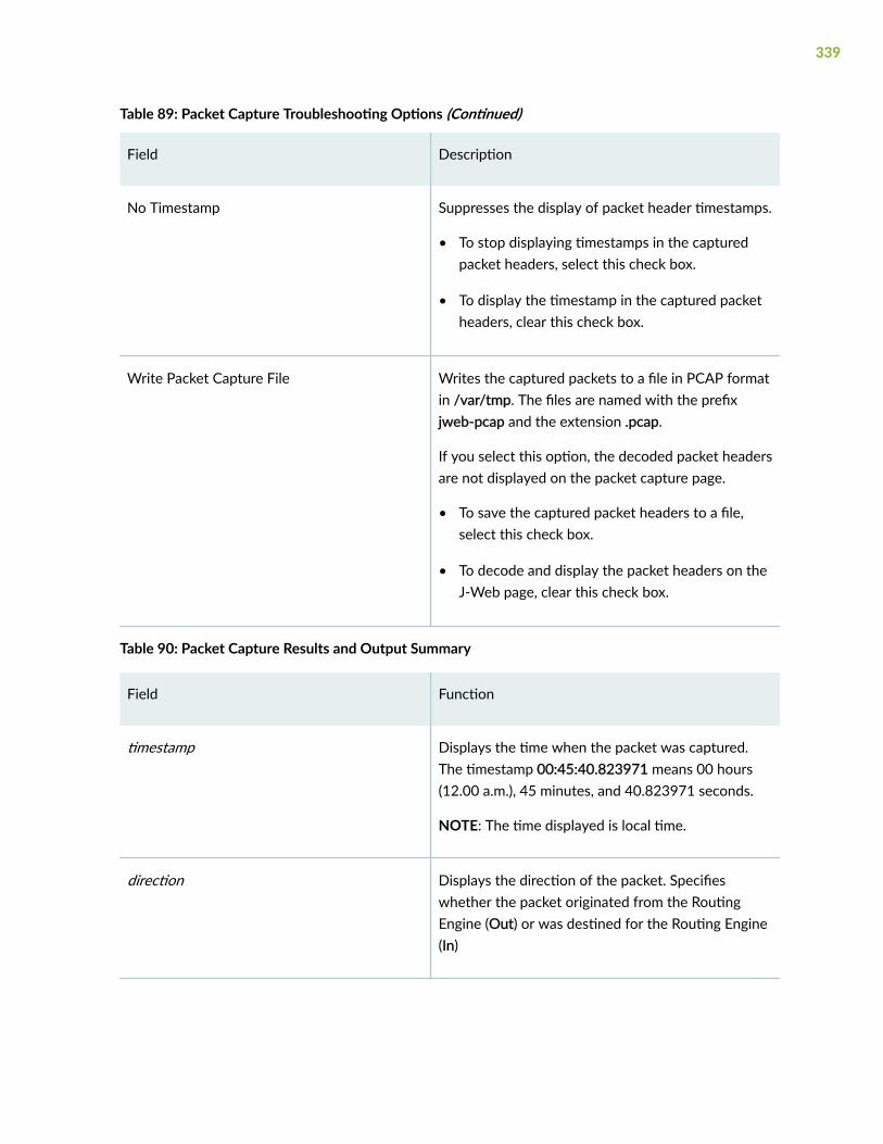
Table 89: Packet Capture Troubleshooting Options (Continued)
Field Description
No Timestamp Suppresses the display of packet header timestamps.
• To stop displaying timestamps in the capturedpacket headers, select this check box.
• To display the timestamp in the captured packetheaders, clear this check box.
Write Packet Capture File Writes the captured packets to a file in PCAP formatin /var/tmp. The files are named with the prefixjweb-pcap and the extension .pcap.
If you select this option, the decoded packet headersare not displayed on the packet capture page.
• To save the captured packet headers to a file,select this check box.
• To decode and display the packet headers on theJ-Web page, clear this check box.
Table 90: Packet Capture Results and Output Summary
Field Function
timestamp Displays the time when the packet was captured.The timestamp 00:45:40.823971 means 00 hours(12.00 a.m.), 45 minutes, and 40.823971 seconds.
NOTE: The time displayed is local time.
direction Displays the direction of the packet. Specifieswhether the packet originated from the RoutingEngine (Out) or was destined for the Routing Engine(In)
339

Table 90: Packet Capture Results and Output Summary (Continued)
Field Function
protocol Displays the protocol for the packet.
In the sample output, IP indicates the Layer 3protocol.
source address Displays the hostname, if available, or IP address andthe port number of the packet's origin. If the Don'tResolve Addresses check box is selected, only the IPaddress of the source is displayed.
NOTE: When a string is defined for the port, thepacket capture output displays the string instead ofthe port number.
destination address Displays the hostname, if available, or IP address ofthe packet's destination with the port number. If theDon't Resolve Addresses check box is selected, onlythe IP address of the destination and the port aredisplayed.
NOTE: When a string is defined for the port, thepacket capture output displays the string instead ofthe port number.
protocol Displays the protocol for the packet.
In the sample output, TCP indicates the Layer 4protocol.
data size Displays the size of the packet (in bytes).
Release History Table
Release Description
19.3R1 Starting in Junos OS Release 19.3R1, J-Web supports RE3 line cards for SRX5000 line of devices.
340

RELATED DOCUMENTATION
Troubleshoot Traceroute | 328
Access CLI
IN THIS SECTION
About CLI Terminal Page | 341
About CLI Terminal Page
IN THIS SECTION
CLI Terminal Requirements | 341
CLI Overview | 342
You are here: Device Administration > Tools > CLI Terminal.
The Junos CLI provides a set of commands for monitoring and configuring a routing platform. Use thispage to access Junos OS CLI through J-Web interface.
This topic includes the following sections:
CLI Terminal Requirements
To access the CLI through the J-Web interface, your management device requires the following features:
• SSH access—Secure shell (SSH) provides a secured method of logging in to the routing platform toencrypt traffic so that it is not intercepted. If SSH is not enabled on your system, the CLI terminalpage displays an error and provides a link to the Set Up Quick Configuration page where you canenable SSH.
• Java applet support—Your Web browser must support Java applets.
341

• JRE installed on the client—Java Runtime Environment (JRE) version 1.4 or later must be installed onyour system to run Java applications. Download the latest JRE version from the Java Softwarewebsite http://www.java.com/. Installing JRE installs Java plug-ins, which once installed, loadautomatically and transparently to render Java applets.
NOTE: The CLI terminal is supported on JRE version 1.4 or later only.
CLI Overview
The Junos OS CLI uses industry-standard tools and utilities to provide a set of commands for monitoringand configuring a routing platform. You type commands on a line and press Enter to execute them. TheCLI provides online command Help, command completion, and Emacs-style keyboard sequences formoving around on the command line and scrolling through a buffer of recently executed commands.
The commands in the CLI are organized hierarchically, with commands that perform a similar functiongrouped together under the same level. For example, all commands that display information about thedevice system and system software are grouped under the show command, and all commands thatdisplay information about the routing table are grouped under the show route command. Thehierarchical organization results in commands that have a regular syntax and provides the followingfeatures that simplify CLI use:
• Consistent command names—Commands that provide the same type of function have the samename, regardless of the portion of the software they are operating on. For example, all showcommands display software information and statistics, and all clear commands erase various types ofsystem information.
• Lists and short descriptions of available commands—Information about available commands isprovided at each level of the CLI command hierarchy. If you type a question mark (?) at any level, yousee a list of the available commands along with a short description of each command.
• Command completion—Command completion for command names (keywords) and command optionsis also available at each level of the hierarchy. In the CLI terminal, you can perform one of thefollowing actions to complete a command:
• Enter a partial command name followed immediately by a question mark (with no interveningspace) to see a list of commands that match the partial name you typed.
• Press the Spacebar to complete a command or option that you have partially typed. If the partiallytyped letters begin a string that uniquely identifies a command, the complete command nameappears. Otherwise, a prompt indicates that you have entered an ambiguous command, and thepossible completions are displayed.
The Tab key option is currently not available on the CLI terminal.
342

The CLI has two modes:
• Operational mode—Complete set of commands to control the CLI environment, monitor andtroubleshoot network connectivity, manage the device, and enter configuration mode.
• Configuration mode—Complete set of commands to configure the device.
For more information about the Junos OS CLI, see the Junos OS CLI User Guide.
RELATED DOCUMENTATION
View CLI Configuration | 343
View CLI Configuration
IN THIS SECTION
About CLI Viewer Page | 343
About CLI Viewer Page
You are here: Device Administration > Tools > CLI Viewer.
You can view current configuration running on the device.
NOTE:
• The configuration statements appear in a fixed order irrespective of the order in which youconfigured the routing platform. The top of the configuration displays a timestamp indicatingwhen the configuration was last changed and the current version.
• Each level in the hierarchy is indented to indicate each statement's relative position in thehierarchy. Each level is generally set off with braces, using an open brace ({) at the beginningof each hierarchy level and a closing brace (}) at the end. If the statement at a hierarchy level isempty, the braces are not displayed. Each leaf statement ends with a semicolon (;), as doesthe last statement in the hierarchy.
343

• The indented representation is used when the configuration is displayed or saved as an ASCIIfile. However, when you load an ASCII configuration file, the format of the file is not so strict.The braces and semicolons are required, but the indention and use of new lines are notrequired in ASCII configuration files.
• Uncommitted configuration changes will also be listed.
To save, commit, or cancel the current configuration:
1. Click one:
• OK—Saves the configuration and returns to the CLI Viewer page.
• Commit Options > Commit—Commits the configuration and returns to the CLI Viewer page.
• Cancel—Cancels your entries and returns to the CLI Viewer page.
RELATED DOCUMENTATION
Edit CLI Configuration | 344
Edit CLI Configuration
IN THIS SECTION
About CLI Editor Page | 344
About CLI Editor Page
You are here: Device Administration > Tools > CLI Editor.
You can configure all routing platform services that you can configure from the Junos CLI prompt.
To edit the CLI configuration:
1. Navigate to the hierarchy level you want to edit. Edit the candidate configuration using standard texteditor operations—insert lines (with the Enter key), delete lines, modify, copy, and paste text.
344

2. Click Commit to load and commit the configuration. This saves the edited configuration, whichreplaces the existing configuration. The device checks the configuration for the correct syntax beforecommitting it. If any errors occur when the configuration is loading or committed, they are displayedand the previous configuration is restored.
3. Click one:
• OK—Saves the configuration and returns to the CLI Editor page.
• Commit Options>Commit—Commits the configuration and returns to the CLI Editor page.
• Cancel—Cancels your entries and returns to the CLI Editor page.
NOTE: When you edit the ASCII configuration file, you can add comments of one or morelines. Comments must precede the statement they are associated with. If you place thecomments in other places in the file, such as on the same line after a statement or on aseparate line following a statement, they are removed when you click Commit. Commentsmust begin and end with special characters. For more information, see the Junos OS CLI UserGuide.
RELATED DOCUMENTATION
Point and Click CLI | 345
Point and Click CLI
IN THIS SECTION
About Point and Click CLI Page | 345
About Point and Click CLI Page
You are here: Device Administration > Tools > Point and Click CLI.
You can edit configuration on a series of pages of clickable options.
345

1. To edit the configuration on a series of pages of clickable options that step you through thehierarchy, enter the information specified in Table 91 on page 347. Table 92 on page 347 lists key J-Web configuration editor tasks and their functions.
NOTE: Options changes for each device. For a device, if a feature is not yet configured, youhave the option to first configure the feature. If the feature is already configured, you havethe option to edit or delete the feature on that particular device.
2. Click one:
• Refresh—Refreshes and updates the display with any changes to the configuration made by otherusers.
• Commit—Verifies edits and applies them to the current configuration file running on the device.
• Discard—Removes edits applied to, or deletes existing statements or identifiers from, thecandidate configuration.
3. Click one:
• OK—Saves the configuration and returns to the main configuration page.
• Commit Options>Commit—Commits the configuration and returns to the main configurationpage.
• Cancel—Cancels your entries and returns to the main configuration page.
346

Table 91: Point and Click Configuration Details
Field Description
Configuration Specifies that you can edit the selected configurationon a series of pages of clickable options that stepyou through the hierarchy.
Click an option:
• Expand all—Expands the hierarchy of allstatements.
• Hide all—Hides the hierarchy of all statements.
• (+)—Expands an individual statement in thehierarchy.
• (–)—Hides an individual statement in thehierarchy.
Table 92: J-Web Configuration Editor Page Details
Field Function
Access Specifies that you can edit or delete access and userauthentication methods to the device. The optionsavailable are:
• Configure—Configures the feature.
• Edit—Edits the feature.
• Delete—Deletes the feature.
Accounting options Specifies that you can configure accounting optionssuch as log data about basic system operations andservices on the device. The option available is:
• Configure—Configures the feature.
347

Table 92: J-Web Configuration Editor Page Details (Continued)
Field Function
Applications Specifies that you can edit or delete applicationsfunctions of the Junos OS and their properties on thedevice. The options available are:
• Edit—Edits the feature
• Delete—Deletes the feature.
Chassis Specifies that you can configure alarms and otherchassis properties on the device. The option availableis:
• Configure—Configures the feature.
• Edit—Edits the feature.
• Delete—Deletes the feature.
Class of service Specifies that you can edit or delete the Class-of-Service feature. The options available are:
• Edit—Edits the feature
• Delete—Deletes the feature.
Ethernet switching options Specifies that you can configure Ethernet switchingoptions on the device. The option available is:
• Configure—Configures the feature.
Event options Specifies that you can configure diagnostic eventpolicies and actions associated with each policy. Theoption available is:
• Configure—Configures the feature.
348

Table 92: J-Web Configuration Editor Page Details (Continued)
Field Function
Firewall Specifies that you can configure stateless firewallfilters—also known as ACLs—on the device. Theoption available is:
• Configure—Configures the feature.
Forwarding options Specifies that you can configure forwarding optionprotocols, including flow monitoring, accountingproperties, and packet capture. The option availableis:
• Configure—Configures the feature.
Interfaces Specifies that you can edit or delete interfaces on thedevice. The options available are:
• Edit—Edits the feature.
• Delete—Deletes the feature.
Multicast snooping options Specifies that you can configure multicast snoopingoptions. The option available is:
• Configure—Configures the feature.
Poe Specifies that you can edit or delete Power overEthernet options on the device. The options availableare:
• Edit—Edits the feature.
• Delete—Deletes the feature.
349

Table 92: J-Web Configuration Editor Page Details (Continued)
Field Function
Policy options Specifies that you can configure routing policies thatcontrol information from routing protocols that thedevice imports into its routing table and exports to itsneighbors. The option available is:
• Configure—Configures the feature.
Protocols Specifies that you can edit or delete routingprotocols, including Intermediate System-to-Intermediate System (IS-IS), OSPF, RIP, RoutingInformation Protocol Next Generation (RIPng), andBGP. The options available are:
• Edit—Edits the feature.
• Delete—Deletes the feature.
Routing instances Specifies that you can configure a hierarchy toconfigure routing instances. The options available re:
• Configure—Configures the feature.
Routing options Specifies that you can edit or delete protocol-independent routing properties. The options availableare:
• Edit—Edits the feature.
• Delete—Deletes the feature.
Schedulers Specifies that you can determine the day and timewhen security policies are in effect. The optionavailable is:
• Configure—Configures the feature.
350

Table 92: J-Web Configuration Editor Page Details (Continued)
Field Function
Security Specifies that you can edit or delete the rules for thetransit traffic and the actions that need to take placeon the traffic as it passes through the firewall; and tomonitor the traffic attempting to cross from onesecurity zone to another. The options available are:
• Edit—Edits the feature.
• Delete—Deletes the feature.
Services Specifies that you can configure real-timeperformance monitoring (RPM) on the device. Theoption available is:
• Configure—Configures the feature.
• Edit—Edits the feature.
• Delete—Deletes the feature.
Smtp Specifies that you can configure Simple Mail TransferProtocol. The option available is:
• Configure—Configures the feature.
Snmp Specifies that you can configure Simple NetworkManagement Protocol for monitoring routeroperation and performance. The option available is:
• Configure—Configures the feature.
351

Table 92: J-Web Configuration Editor Page Details (Continued)
Field Function
System Specifies that you can edit or delete systemmanagement functions, including the device’shostname, address, and domain name; the addressesof the DNS servers; user login accounts, includinguser authentication and the root-level user account;time zones and NTP properties; and properties of thedevice’s auxiliary and console ports. The optionsavailable are:
• Edit—Edits the feature.
• Delete—Deletes the feature.
Vlans Specifies that you can edit or delete a virtual LAN.The options available are:
• Edit—Edits the feature.
• Delete—Deletes the feature.
Wlan Specifies that you can configure a wireless local areanetwork. The option available is:
• Configure—Configures the feature.
Access profile
Access profile name Enter the access profile name.
Advanced
Add new entry Click Add new entry to add a new identifier.
352

RELATED DOCUMENTATION
Edit CLI Configuration | 344
353

CHAPTER 26
Reset Configuration
IN THIS CHAPTER
Configure Setup Wizard | 354
Configure Setup Wizard
You are here: Device Administration > Reset Configuration.
Using the Setup wizard, you can perform step-by-step configuration of a services gateway that cansecurely pass traffic.
NOTE: You can also configure the setup modes in the factory default settings. Connect yourmanagement device (laptop or PC) to the SRX device in factory default settings, the J-Web Setupwizard will appear. For more information on the Setup wizard in the factory default settings, see"Start J-Web" on page 3.
You can choose one of the following setup modes to configure the services gateway:
NOTE: Click Cancel to exit the mode selection window.
• Standalone mode—Configure your SRX Series device to operate in a standalone mode. In this mode,you can configure basic settings such as device credentials, time, management interface, zones andinterfaces, and DNS servers and default gateways.
• Cluster (HA) mode—Configure your SRX Series device to operate in a cluster (HA) mode. In thecluster mode, a pair of devices are connected together and configured to operate like a single node,providing device, interface, and service level redundancy.
354

NOTE: You cannot configure Standalone or Passive mode when your device is in the HAmode.
• Passive (Tap) mode—Configure your SRX Series device to operate in a TAP mode. TAP mode allowsyou to passively monitor traffic flows across a network. If IPS is enabled, then the TAP mode inspectsthe incoming and outgoing traffic to detect the number of threats.
NOTE: SRX5000 line of devices, SRX4600, and vSRX devices does not support the passivemode configuration.
To help guide you through the process, the wizard:
• Determines which configuration tasks to present to you based on your selections.
• Flags any missing required configuration when you attempt to leave a page.
To configure SRX Devices using the J-Web Setup wizard:
1. Click Reset.
2. Click Proceed to Launch to launch the Setup Wizard.
NOTE:
For the Standalone and the Passive (Tap) modes, launching the Setup wizard resets the deviceto the factory default configuration after saving a backup of the current committedconfiguration to the local file system. If you click Cancel during the setup, the device rollsback to its previous committed state.
3. Select the mode you want to setup and click Start.
4. For the Standalone mode and Passive (Tap) mode, complete the configuration according to theguidelines provided in Table 93 on page 356 through Table 95 on page 375.
NOTE:
• If you select Cluster (HA) Mode, for the configuration information see "Configure Cluster(HA) Setup" on page 147.
• In the Setup wizard, root password is mandatory, and all the other options are optional. Inthe passive mode, management interface, Tap interface, and services are mandatory.
5. Click Finish.
355

A successful message appears, and the device configuration mode of your choice is set up.
NOTE:
• Once the configuration is complete, the entire configuration is committed to the deviceand a successful message appears. If the commit fails, the CLI displays an error messageand you remain at the wizard’s last page. If required, you can change the configurationuntil the commit is successful.
• For SRX300 line of devices and SRX550M devices, an additional message will be displayedabout the device reboot if you have enabled Juniper ATP Cloud or Security Intelligenceservices. For other SRX devices, the device will not reboot.
Table 93: Setup Wizard Configuration
Field Action
Device Credentials
System Identity
Device name Enter a hostname.
You can use alphanumeric characters, specialcharacters such as the underscore (_), the hyphen (-), orthe period (.); the maximum length is 255 characters.
Root Account
Username Displays the root user.
NOTE: We recommend that you do not use root useraccount as a best practice to manage your devices.
Password Enter a password.
You can use alphanumeric characters and specialcharacters; the minimum length is six characters.
356

Table 93: Setup Wizard Configuration (Continued)
Field Action
SSH for root user Enable this option to allow the root login (to the device)using SSH.
Admin Account
Username Enter the admin username to manage the device.
Password Enter the admin password.
Time
Time
Time zone Select a time zone from the list.
357

Table 93: Setup Wizard Configuration (Continued)
Field Action
Time source Select either NTP server, computer time, or Manual toconfigure the system time:
• NTP Server > NTP servers—Select the NTP server inthe Available column and move to the selectedcolumn using the right arrow. Once the system isconnected to the network, the system time issynced with the NTP server time.
In addition, to add a new NTP server, click + andenter a hostname or IP address of the NTP serverand click OK.
NOTE: If you want to add more NTP servers, go toDevice Administration > Basic Settings > Date &Time Details through the J-Web menu.
• Computer Time > Computer time—Deviceautomatically synchronizes with your computertime only during the setup.
• Manual > Date and time—Select the date and time(in MM-DD-YYYY and HH:MM:SS 24-hour format)to configure the system time manually.
Management Interface
Management Interface
NOTE: If you change the management IP address and click Next, a warning message appears on theManagement Interface page that you need to use the new management IP address to log in to J-Webbecause you may lose the connectivity to J-Web.
358

Table 93: Setup Wizard Configuration (Continued)
Field Action
Management interface Select an interface from the list.
If fxp0 port is your device’s management port, then thefxp0 port is displayed. You can change it as required oryou can select None and proceed to the next page.
NOTE:
• You can choose the revenue port as managementport if your device does not support the fxp0 port.Revenue ports are all ports except fxp0 and em0.
• If you are in the Standalone mode, you can chooseNone for the management interface and click Nextto proceed to the next screen.
• If you are in the Passive (Tap) mode, it is mandatoryto configure a management port. J-Web needs amanagement port for viewing generated report.
IPv4
NOTE: Click email to self to get the newly configured IPv4 or IPv6 address to your inbox. This isuseful if you lose connectivity when you change the management IP address to another network.
Management address Enter a valid IPv4 address for the managementinterface.
NOTE: If fxp0 port is your device’s management port,then the fxp0 port’s default IP address is displayed. Youcan change it if required.
Management subnet mask Enter a subnet mask for the IPv4 address.
If you have changed the management address, use thenew IP address to access J-Web.
359

Table 93: Setup Wizard Configuration (Continued)
Field Action
Static route Enter an IPv4 address for the static route to route tothe other network devices.
Static route subnet mask Enter a subnet mask for the static route IPv4 address.
Next hop gateway Enter a valid IPv4 address for the next hop.
IPv6
Management access Enter a valid IPv6 address for the managementinterface.
Management subnet prefix Enter a subnet prefix length for the IPv6 address.
Static route Enter an IPv6 address for the static route if required toreach the device through the management interface.
Static route subnet prefix Enter a subnet prefix length for the static route IPv6address.
Next hop gateway Enter a valid IPv6 address for the next hop.
Access Protocols
NOTE: This option is available for all the ports except fxp0.
HTTPS This option is enabled by default.
SSH This option is enabled by default.
Ping Enable this option for ping service.
360

Table 93: Setup Wizard Configuration (Continued)
Field Action
DHCP Enable this option for DHCP service.
NETCONF Enable this option for NETCONF service.
Zones & Interfaces
Security Policy
NOTE: This option is available only for the Standalone mode. For the Passive (Tap) mode, this option isavailable under Tap Settings.
From Zone Name of the source zone. In the standalone mode,permits all traffic from the trust zone.
To Zone Name of the destination zone. In standalone mode,permits all traffic from the trust zone to the untrustzone.
Source Name of the source address (not the IP address) of apolicy.
Destination Name of the destination address.
Application Name of a preconfigured or custom application of thepolicy match.
Action Action taken when a match occurs as specified in thepolicy.
Zones
—Displays the available trust and untrust zones configuration.
361

Table 93: Setup Wizard Configuration (Continued)
Field Action
Trust Zone Interfaces
NOTE: This option is available only for the Standalone mode.
Add Trust Zone Interface Click + to add trust zone interface. For moreinformation on the fields, see Table 94 on page 368.
Edit Trust Zone Interface Select an interface and click the pencil icon at the rightcorner of the table to modify the configuration.
Delete Trust Zone Interface Select an interface and click the delete icon at the topright corner of the table.
A confirmation window appears. Click Yes to delete theselected interface or click No to discard.
Search Trust Zone Interface Click the search icon at the right corner of the table toquickly locate a zone or an interface.
Detailed View Trust Zone Interface Hover over the interface name and click the DetailedView icon to view the zone and interface details.
Trust Zone Interfaces—Zone Level Settings
Zone name View the trust zone name populated from your devicefactory default settings.
NOTE: For standalone mode, trust and untrust zonesare created by default even if these zones are notavailable in the factory default settings.
Description Enter the description for trust zone.
362

Table 93: Setup Wizard Configuration (Continued)
Field Action
System services Enable this option for the types of traffic that can reachthe device on a particular interface.
By default, this option is enabled. You can disable ifrequired.
Protocols Enable this option to configure the device to performstateful network traffic filtering on network packetsusing network traffic protocols (for example, TCP andUDP).
By default, this option is enabled. You can disable ifrequired.
Application tracking Enable this option to collect byte, packet, and durationstatistics for application flows in the specified zone.
Source identity log Enable this option for the device to log the useridentity information based on the source zoneconfigured in the security policy.
Untrust Zone Interfaces
Add Untrust Zone Interface Click + to add untrust zone interface. For moreinformation on the fields, see Table 95 on page 375.
Edit Untrust Zone Interface Select an interface and click the pencil icon at the rightcorner of the table to modify the configuration.
Delete Untrust Zone Interface Select an interface and click the delete icon at the topright corner of the table.
A confirmation window appears. Click Yes to delete theselected interface or click No to discard.
363

Table 93: Setup Wizard Configuration (Continued)
Field Action
Search Untrust Zone Interface Click the search icon at the right corner of the table toquickly locate a zone or an interface.
Detailed View Untrust Zone Interface Hover over the interface name and click the DetailedView icon to view the zone and interface details.
Untrust Zone Interfaces—Zone Level Settings
Zone name View the untrust zone name populated from yourdevice factory default settings.
NOTE: For standalone mode, trust and untrust zonesare created by default even if these zones are notavailable in the factory default settings.
Description Enter the description for untrust zone.
Application tracking Enable this option to collect byte, packet, and durationstatistics for application flows in the specified zone.
Source identity log Enable this option for the device to log the useridentity information based on the source zoneconfigured in the security policy.
DNS Servers & Default Gateways
DNS Servers
DNS server 1 Enter the IPv4 or IPv6 address of the primary DNS.
DNS server 2 Enter the IPv4 or IPv6 address of the secondary DNS.
Default Gateway
364
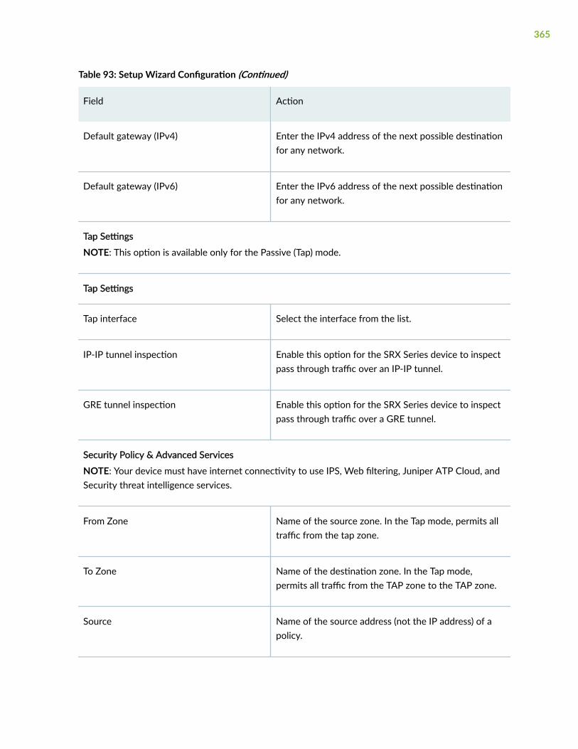
Table 93: Setup Wizard Configuration (Continued)
Field Action
Default gateway (IPv4) Enter the IPv4 address of the next possible destinationfor any network.
Default gateway (IPv6) Enter the IPv6 address of the next possible destinationfor any network.
Tap Settings
NOTE: This option is available only for the Passive (Tap) mode.
Tap Settings
Tap interface Select the interface from the list.
IP-IP tunnel inspection Enable this option for the SRX Series device to inspectpass through traffic over an IP-IP tunnel.
GRE tunnel inspection Enable this option for the SRX Series device to inspectpass through traffic over a GRE tunnel.
Security Policy & Advanced Services
NOTE: Your device must have internet connectivity to use IPS, Web filtering, Juniper ATP Cloud, andSecurity threat intelligence services.
From Zone Name of the source zone. In the Tap mode, permits alltraffic from the tap zone.
To Zone Name of the destination zone. In the Tap mode,permits all traffic from the TAP zone to the TAP zone.
Source Name of the source address (not the IP address) of apolicy.
365

Table 93: Setup Wizard Configuration (Continued)
Field Action
Destination Name of the destination address.
Application Name of a preconfigured or custom application of thepolicy match.
Action Action taken when a match occurs as specified in thepolicy.
UTM
UTM Enable this option for configuring UTM services.
License Enter UTM license key and click Install License to add anew license.
NOTE:
• Use a blank line to separate multiple license keys.
• To use UTM services, your device must haveinternet connectivity from a revenue interface.
UTM type Select an option to configure UTM features:
• Web Filtering
• Antivirus
• Antispam
366

Table 93: Setup Wizard Configuration (Continued)
Field Action
Web filtering type Select an option:
• Enhanced—Specifies that the Juniper EnhancedWeb filtering intercepts the HTTP and the HTTPSrequests and sends the HTTP URL or the HTTPSsource IP to the Websense ThreatSeeker Cloud(TSC).
• Local—Specifies the local profile type.
IPS
IPS Enable this option to install the IPS signatures.
License Enter the license key and click Install License to add anew license.
NOTE: The installation process may take few minutes.
IPS signature Click Browse to navigate to the IPS signature packagefolder and select it. Click Install to install the selectedIPS signature package.
NOTE: You can download the IPS signature offlinepackage at https://support.juniper.net/support/downloads/.
ATP Cloud
ATP Cloud Enable this option to use Juniper ATP Cloud services.
NOTE: After the Juniper ATP Cloud configuration ispushed, only the SRX300 line of devices and SRX550Mdevices are rebooted. Your device must have internetconnectivity to enable Juniper ATP Cloud enrollmentprocess through J-Web.
367

Table 93: Setup Wizard Configuration (Continued)
Field Action
Security Intelligence
Security intelligence Enable this option to use Security intelligence services.
NOTE: After the Security Intelligence configuration ispushed, only the SRX300 line of devices and SRX550Mdevices are rebooted. Your device must have internetconnectivity to enable Juniper ATP Cloud enrollmentprocess through J-Web.
User Firewall
User Firewall Enable this option to use user firewall services.
Domain name Enter a domain name for Active Directory.
Domain controller Enter domain controller IP address.
Username Enter a username for administrator privilege.
Password Enter a password for administrator privilege.
Table 94: Add Trust Zone
Field Action
General
368

Table 94: Add Trust Zone (Continued)
Field Action
Type (family) • Select Switching. Fields for switching interface are:
NOTE: This option will be available for only SRX300 line ofdevices, SRX550M, and SRX1500 devices. For SRX5000 lineof devices, SRX4100, SRX4200, SRX4600, and vSRX devices,the Type (family) field is not available.
• IRB interface Unit—Enter the IRB unit.
• Description—Enter the description for the interface.
• Select Routing. Fields for routing interface are:
For SRX5000 line of devices, SRX4100, SRX4200, SRX4600,and vSRX devices, the Type (family) field is not available.
• Interface—Select an option from list.
• Interface unit—Enter the Inet unit.
NOTE: VLAN tagging is enabled automatically if theinterface unit is higher than zero.
• Description—Enter the description for the interface.
• VLAN ID—Enter the VLAN ID.
NOTE: VLAN ID is mandatory if the interface unit ishigher than zero.
Interfaces Select an interface from the Available column and move it to theSelected column.
NOTE: This option is available only for the Switching family type.
VLAN
NOTE: This option is available only for the Switching family type.
Name Enter a unique name for the VLAN.
369

Table 94: Add Trust Zone (Continued)
Field Action
VLAN ID Enter the VLAN ID.
IPv4
IPv4 address Enter a valid IPv4 address for the switching or the routinginterface.
Subnet mask Enter a subnet mask for the IPv4 address.
IPv6
IPv6 address Enter a valid IPv6 address for the switching or the routinginterface.
Subnet prefix Enter a subnet prefix for the IPv6 address.
DHCP Local Server
DHCP local server Enable this option to configure the switch to function as anextended DHCP local server.
Pool name Enter the DHCP pool name.
Pool start address Enter the starting IPv4 address of the DHCP server pool addressrange. This address must be within the IPv4 network.
Pool end address Enter the ending IPv4 address of the DHCP server pool addressrange. This address must be within the IPv4 network.
NOTE: This address must be greater than the address specifiedin Pool start address.
370

Table 94: Add Trust Zone (Continued)
Field Action
Propagate settings from Select an option from the list. Propagation of TCP/IP settings(such as, DNS and gateway address) received on the deviceinterface acting as DHCP client.
Services & Protocols
371

Table 94: Add Trust Zone (Continued)
Field Action
System Services Select system services from the list in the Available column andthen click the right arrow to move it to the Selected column.
The available options are:
• all—Specify all system services.
• any-service—Specify services on entire port range.
• appqoe—Specify the APPQOE active probe service.
• bootp—Specify the Bootp and dhcp relay agent service.
• dhcp—Specify the Dynamic Host Configuration Protocol.
• dhcpv6—Enable Dynamic Host Configuration Protocol forIPV6.
• dns—Specify the DNS service.
• finger—Specify the finger service.
• ftp—Specify the FTP protocol.
• http—Specify the Web management using HTTP.
• https—Specify the Web management using HTTP secured bySSL.
• ident-reset—Specify the send back TCP RST IDENT requestfor port 113.
• ike—Specify the Internet key exchange.
• lsping—Specify the Label Switched Path ping service.
• netconf—Specify the NETCONF Service.
• ntp—Specify the network time protocol.
• ping—Specify the internet control message protocol.
• r2cp—Enable Radio-Router Control Protocol.
372

Table 94: Add Trust Zone (Continued)
Field Action
• reverse-ssh—Specify the reverse SSH Service.
• reverse-telnet—Specify the reverse telnet Service.
• rlogin—Specify the Rlogin service
• rpm—Specify the Real-time performance monitoring.
• rsh—Specify the Rsh service.
• snmp—Specify the Simple Network Management Protocol.
• snmp-trap—Specify the Simple Network ManagementProtocol trap.
• ssh—Specify the SSH service.
• tcp—encap-Specify the TCP encapsulation service.
• telnet—Specify the Telnet service.
• tftp—Specify the TFTP
• traceroute—Specify the traceroute service.
• webapi-clear-text—Specify the Webapi service using http.
• webapi-ssl—Specify the Webapi service using HTTP securedby SSL.
• xnm-clear-text—Specify the JUNOScript API for unencryptedtraffic over TCP.
• xnm-ssl—Specify the JUNOScript API Service over SSL.
373

Table 94: Add Trust Zone (Continued)
Field Action
Protocols Select protocols from the list in the Available column and thenclick the right arrow to move it to the Selected column.
The available options are:
• all—Specifies all protocol.
• bfd—Bidirectional Forwarding Detection.
• bgp—Border Gateway Protocol.
• dvmrp—Distance Vector Multicast Routing Protocol.
• igmp—Internet Group Management Protocol.
• ldp—Label Distribution Protocol.
• msdp—Multicast Source Discovery Protocol.
• nhrp- Next Hop Resolution Protocol.
• ospf—Open shortest path first.
• ospf3—Open shortest path first version 3.
• pgm—Pragmatic General Multicast.
• pim—Protocol Independent Multicast.
• rip—Routing Information Protocol.
• ripng—Routing Information Protocol next generation.
• router-discovery—Router Discovery.
• rsvp—Resource Reservation Protocol.
• sap—Session Announcement Protocol.
• vrrp—Virtual Router Redundancy Protocol.
374

Table 95: Add Untrust Zone
Field Action
General
Interface Select an interface from the list.
Interface unit Enter the interface unit value.
VLAN ID Enter the VLAN ID.
NOTE: VLAN ID is mandatory if the interface unitis higher than zero.
Description Enter the description for the interface.
Address Mode Select an address mode for the interface. Theavailable options are DHCP Client, PPPoE (PAP),PPPoE (CHAP) and Static IP.
NOTE: PPPoE (PAP) and PPPoE (CHAP) are notsupported for SRX5000 line of devices and if anyof the devices are in passive mode.
Username Enter a username for PPPoE (PAP) or PPPoE(CHAP) authentication.
Password Enter a password for PPPoE (PAP) or PPPoE(CHAP) authentication.
IPv4
NOTE: This option is available only for the Static IP address mode.
IPv4 Address Enter a valid IPv4 address for the interface.
375
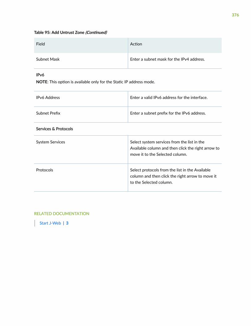
Table 95: Add Untrust Zone (Continued)
Field Action
Subnet Mask Enter a subnet mask for the IPv4 address.
IPv6
NOTE: This option is available only for the Static IP address mode.
IPv6 Address Enter a valid IPv6 address for the interface.
Subnet Prefix Enter a subnet prefix for the IPv6 address.
Services & Protocols
System Services Select system services from the list in theAvailable column and then click the right arrow tomove it to the Selected column.
Protocols Select protocols from the list in the Availablecolumn and then click the right arrow to move itto the Selected column.
RELATED DOCUMENTATION
Start J-Web | 3
376

6PART
Network
Connectivity—Ports | 379
Connectivity—VLAN | 392
Connectivity—Link Aggregation | 399
Connectivity—PPPoE | 408
Connectivity—Wireless LAN | 410
DHCP Client | 420
DHCP Server | 424
Firewall Filters—IPv4 | 435
Firewall Filters—IPv6 | 454
Firewall Filters—Assign to Interfaces | 471
NAT Policies | 473
NAT Pools | 483
Destination NAT | 494
Static NAT | 501
NAT Proxy ARP/ND | 509
Static Routing | 516
RIP Routing | 520
OSPF Routing | 530
BGP Routing | 543
Routing Instances | 560

Routing—Policies | 565
Routing—Forwarding Mode | 584
CoS—Value Aliases | 586
CoS—Forwarding Classes | 590
CoS Classifiers | 594
CoS—Rewrite Rules | 599
CoS—Schedulers | 604
CoS—Scheduler Maps | 609
CoS—Drop Profile | 613
CoS—Virtual Channel Groups | 617
CoS—Assign To Interface | 621
Application QoS | 627
IPsec VPN | 637
Manual Key VPN | 700
Dynamic VPN | 706

CHAPTER 27
Connectivity—Ports
IN THIS CHAPTER
About the Ports Page | 379
Add a Logical Interface | 383
Edit a Logical Interface | 391
Delete Logical Interface | 391
About the Ports Page
IN THIS SECTION
Tasks You Can Perform | 379
Field Descriptions | 380
You are here: Network > Connectivity > Ports.
Use this page to view or configure the logical interfaces to switch to L2 or L3 mode. You can view theinterfaces in the ways of interface type, interface state, or zone association.
Tasks You Can Perform
You can perform the following tasks from this page:
• Add a logical interface. See "Add a Logical Interface" on page 383.
• Edit a logical interface. See "Edit a Logical Interface" on page 391.
• Delete a logical interface. See "Delete Logical Interface" on page 391.
379

Field Descriptions
Table 96 on page 380 describes the fields to view interface configuration on the ports page.
NOTE:
• J-Web supports IOC4 line cards for SRX5000 line of devices. You can also view the sub-portsdetails configured on any or all ports of the SRX5K-IOC4-MRATE line card.
• J-Web supports Wi–Fi Mini-PIM for SRX320, SRX340, SRX345, and SRX550M devices. Thephysical interface for the Wi-Fi Mini-PIM uses the name wl-x/0/0, where x identifies the sloton the services gateway where the Mini-PIM is installed.
You can also configure the wl-x/0/0 interface when adding a zone at Security Policies &Objects > Zones/Screens.
Table 96: View Interface Configuration Details on the Ports Page
Field Action
Filter Select an option from the list to view the interfaces configuration details. The availableoptions are:
• Interface Type—Select an option to display the list of interfaces available on thedevice.
• Interface State—Select an option to display the interfaces state of the device. Theoptions are:
• Admin Up
• Link Up
• Admin Up & Link Down
• Admin Down
• Zone Association—Select an option to display the list of available security zones.
Go Displays the list of interfaces based on the interface type, interface state, or zoneassociation that you have used to filter the interface information.
380
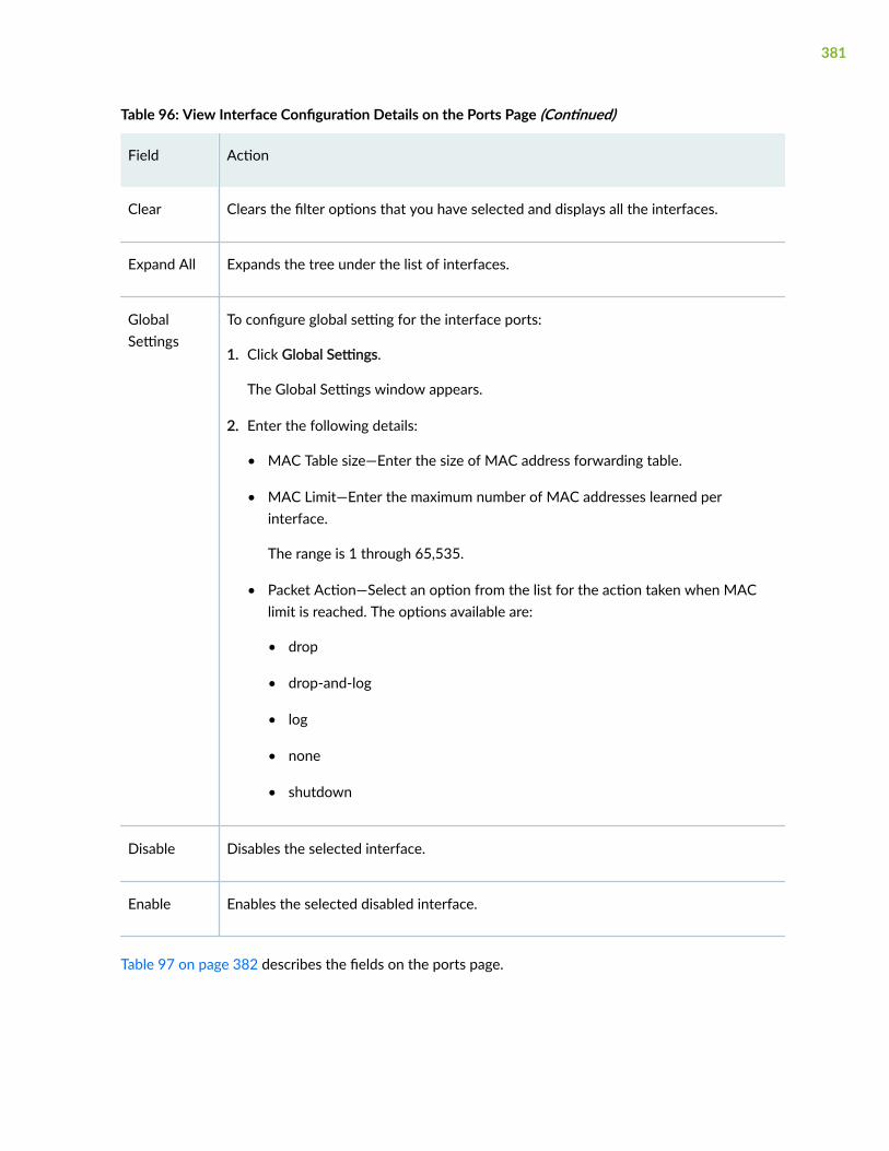
Table 96: View Interface Configuration Details on the Ports Page (Continued)
Field Action
Clear Clears the filter options that you have selected and displays all the interfaces.
Expand All Expands the tree under the list of interfaces.
GlobalSettings
To configure global setting for the interface ports:
1. Click Global Settings.
The Global Settings window appears.
2. Enter the following details:
• MAC Table size—Enter the size of MAC address forwarding table.
• MAC Limit—Enter the maximum number of MAC addresses learned perinterface.
The range is 1 through 65,535.
• Packet Action—Select an option from the list for the action taken when MAClimit is reached. The options available are:
• drop
• drop-and-log
• log
• none
• shutdown
Disable Disables the selected interface.
Enable Enables the selected disabled interface.
Table 97 on page 382 describes the fields on the ports page.
381

Table 97: Fields on the Ports Page
Field Description
Interface Displays the interface name.
Logical interfaces configured under this interface appear in a collapsible listunder the physical interface.
Admin status Displays the administrative status of the interface. Status can be either Up orDown.
Link Status Displays the operational status of the link. Status can be either Up or Down.
IP Address Displays the configured IP addresses.
Multiple IP addresses configured on one logical interface are displayed in acollapsible list under the logical interface.
Zone Displays the security zone with which this interface is associated.
Logical System/Tenant Display the statistics information for the specified logical system or tenant.
MTU Displays the maximum transmission unit value for this physical interface.
Speed Displays the Interface speed (10 Mbps, 100 Mbps, 1 Gbps, or Auto).
Link Mode Displays the link mode status for this interface. Status can be Active, Passive,or None.
Auto Negotiation Displays the auto negotiation status of the interface. Status can be eitherEnabled or Disabled.
Media Type Displays the media type of the operating modes (copper or fiber) for the 2-Port 10 Gigabit Ethernet XPIM.
382

RELATED DOCUMENTATION
Add a Logical Interface | 383
Add a Logical Interface
You are here: Network > Connectivity > Ports.
To add a logical interface:
1. Select an interface and click the add icon (+) available on the upper right side of the Ports page.
The Add Interface page appears.
2. Complete the configuration according to the guidelines provided in Table 98 on page 383.
3. Click OK to save the changes. If you want to discard your changes, click Cancel instead.
If you click OK, a new logical interface with the provided configuration is created.
Table 98 on page 383 provides guidelines on using the fields on the Add Interface page.
Table 98: Fields on the Add Interface Page
Field Description
General
Unit Enter the logical unit number.
Description Enter the description for the interface.
Vlan Id Enter the VLAN ID
Multi Tenancy Type Select an option from the list:
• None
• Logical System
• Tenant
383

Table 98: Fields on the Add Interface Page (Continued)
Field Description
Logical System Select a logical system from the list.
NOTE: This option is available when you select the multitenancy type aslogical system.
Tenant Select a tenant from the list.
NOTE: This option is available when you select the multitenancy type astenant.
Zone Select a zone form the list.
Protocol (family)
IPv4 Address
IPv4 Address/DHCPconfiguration
Select the check box to enable this option.
Enable DHCP Select this option to enable Dynamic Host Configuration Protocol (DHCP).
384

Table 98: Fields on the Add Interface Page (Continued)
Field Description
Enable addressconfiguration
Select this option to add IPv4 address.
To add IPv4 address:
1. Click +.
2. Enter the following details:
• IPv4 Address—Enter an IPv4 address.
• Web Auth—Click Configure and enable the options, Enable Http,Enable Https, and Redirect to Https. Then, click OK to save changes.
• ARP—Click Edit.
In the ARP Address page, click + and enter the IPv4 Address, MACAddress, and select Publish.
Click OK to save the changes.
IPv6 Address
IPv6 Address/DHCPconfiguration
Select the check box to enable this option.
NOTE: Not available for IRB interface
Enable DHCP Select this option to enable DHCP.
Enable addressconfiguration
Select this option to add IPv6 address.
To add IPv6 address:
1. Click +.
2. Enter an IPv6 address.
Ethernet Switching
385
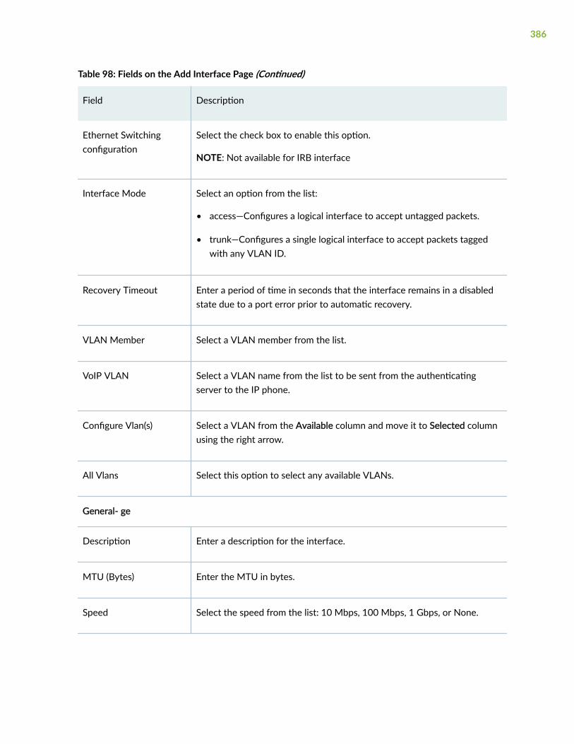
Table 98: Fields on the Add Interface Page (Continued)
Field Description
Ethernet Switchingconfiguration
Select the check box to enable this option.
NOTE: Not available for IRB interface
Interface Mode Select an option from the list:
• access—Configures a logical interface to accept untagged packets.
• trunk—Configures a single logical interface to accept packets taggedwith any VLAN ID.
Recovery Timeout Enter a period of time in seconds that the interface remains in a disabledstate due to a port error prior to automatic recovery.
VLAN Member Select a VLAN member from the list.
VoIP VLAN Select a VLAN name from the list to be sent from the authenticatingserver to the IP phone.
Configure Vlan(s) Select a VLAN from the Available column and move it to Selected columnusing the right arrow.
All Vlans Select this option to select any available VLANs.
General- ge
Description Enter a description for the interface.
MTU (Bytes) Enter the MTU in bytes.
Speed Select the speed from the list: 10 Mbps, 100 Mbps, 1 Gbps, or None.
386

Table 98: Fields on the Add Interface Page (Continued)
Field Description
Link Mode Select the link mode from the list: Half Duplex, Full Duplex, and None.
Loopback Select this option if you want the interface to loop back.
Flow Control Select this option to enable flow control, which regulates the flow ofpackets from the router to the remote side of the connection.
Enable Auto Negotiation Select this option to enable autonegotiation.
Enable Per UnitScheduler
Select this option to enable the association of scheduler maps with logicalinterfaces.
Enable Vlan Tagging Select this option to enable the reception and transmission of 802.1QVLAN-tagged frames on the interface.
Source MAC Filter
Add Click + and enter the MAC address to assign it to the interface.
Delete Select a MAC address and click X.
MAC Limit Enter a value for MAC addresses to be associated with a VLAN.
Range: 1 through 131071.
387

Table 98: Fields on the Add Interface Page (Continued)
Field Description
Packet Action Select an option from the list:
• drop—Drop packets with new source MAC addresses, and do not learnthe new source MAC addresses.
• drop-and-log—Drop packets with new source MAC addresses, andgenerate an alarm, an SNMP trap, or a system log entry
• log—Hold packets with new source MAC addresses, and generate analarm, an SNMP trap, or a system log entry.
• none—Forward packets with new source MAC addresses and learn thenew source MAC address.
• shutdown—Disable the specified interface, and generate an alarm, anSNMP trap, or a system log entry.
General- lt
Unit Enter a logical unit number.
Encapsulation Select an option from the list:
• Ethernet
• Ethernet-VPLS
Peer Unit Enter a peer unit number.
Multi Tenancy Type Select an option from the list:
• None
• Logical System
• Tenant
388

Table 98: Fields on the Add Interface Page (Continued)
Field Description
Logical System Select a logical system from the list.
NOTE: This option is available when you select the multitenancy type aslogical system.
Tenant Select a tenant from the list.
NOTE: This option is available when you select the multitenancy type astenant.
IP Address Click Add and enter an IP address.
Select an IP address and click Delete to delete the selected IP address.
st0
Tunnel Interface st0 Enter the logical unit number.
Zone Select a zone from the list.
Description Enter the description for the interface.
Unnumbered Select this option to fetch interface from which an unnumbered interfaceborrows an IPv4 address.
Numbered Select this option to fetch interface from which a numbered interfaceborrows an IPv4 or IPv6 address.
IPv4 Address Enter an IPv4 address.
IPv4 Subnet Mask Enter a subnet mask for the IPv4 address.
389

Table 98: Fields on the Add Interface Page (Continued)
Field Description
IPv6 Address Enter an IPv4 address.
IPv6 Subnet Mask Enter a subnet mask for the IPv6 address.
Multipoint
St InterfaceConfiguration
Select the check box to enable this option.
Automatic Select this option to automatically fetch next hop tunnel address.
Manual Click + to add next hop tunnel address and VPN name.
Select an existing next hop address and click X to delete it.
Routing Protocols
Enable Routing Protocols Select an option:
• all—Select this option to enable all protocols routing on the routingdevice.
• OSPF—Select this option to enable OSPF routing on the routingdevice.
• BGP—Select this option to enable BGP routing on the routing device.
• RIP—Select this option to enable RIP routing on the routing device.
RELATED DOCUMENTATION
Edit a Logical Interface | 391
Delete Logical Interface | 391
390

Edit a Logical Interface
You are here: Network > Connectivity > Ports.
To edit a logical interface:
1. Select an existing logical interface that you want to edit on the Ports page.
2. Click the pencil icon available on the upper right side of the page.
The interface options appear with editable fields. For more information on the options, see "Add aLogical Interface" on page 383.
3. Click OK.
RELATED DOCUMENTATION
Delete Logical Interface | 391
Delete Logical Interface
You are here: Network > Connectivity > Ports.
To delete a logical interface:
1. Select a logical interface that you want to delete from the Ports page.
2. Click the delete icon (X) available on the upper right side of the page.
A confirmation window appears.
3. Click Yes to delete or click No.
RELATED DOCUMENTATION
Add a Logical Interface | 383
Edit a Logical Interface | 391
391

CHAPTER 28
Connectivity—VLAN
IN THIS CHAPTER
About the VLAN Page | 392
Add a VLAN | 394
Edit a VLAN | 396
Delete VLAN | 397
Assign an Interface to VLAN | 397
About the VLAN Page
IN THIS SECTION
Tasks You Can Perform | 392
Field Descriptions | 393
You are here: Network > Connectivity > VLAN.
Use this page to view, add, and remove VLAN configuration details.
Tasks You Can Perform
You can perform the following tasks from this page:
• Add a VLAN. See "Add a VLAN" on page 394.
• Edit a VLAN. See "Edit a VLAN" on page 396.
• Delete a VLAN. See "Delete VLAN" on page 397.
392

• Assign Interface. See "Assign an Interface to VLAN" on page 397.
• Show or hide columns in the VLAN table. To do this, use the Show Hide Columns icon in the top rightcorner of the page and select the options you want to show or deselect to hide options on the page.
• Advanced search for a VLAN. To do this, use the search text box present above the table grid. Thesearch includes the logical operators as part of the filter string. In the search text box, when youhover over the icon, it displays an example filter condition. When you start entering the search string,the icon indicates whether the filter string is valid or not.
For an advanced search:
1. Enter the search string in the text box.
Based on your input, a list of items from the filter context menu appears.
2. Select a value from the list and then select a valid operator based on which you want to performthe advanced search operation.
NOTE: Press Spacebar to add an AND operator or OR operator to the search string. Pressbackspace at any point of time while entering a search criteria, only one character isdeleted.
3. Press Enter to display the search results in the grid.
Field Descriptions
Table 99 on page 393 describes the fields on the VLAN page.
Table 99: VLAN Configuration Page
Field Function
VLAN Name Displays the name for the VLAN.
VLAN ID/List Displays the identifier or list for the VLAN.
Interface Assigned Displays the interfaces assigned for the VLAN.
Description Displays a brief description for the VLAN.
393

RELATED DOCUMENTATION
Add a VLAN | 394
Add a VLAN
You are here: Network > Connectivity > VLAN.
To add a VLAN:
1. Click the add icon (+) available on the upper right side of the VLAN page.
The Add VLAN page appears.
2. Complete the configuration according to the guidelines provided in Table 100 on page 394.
3. Click OK to save the changes. If you want to discard your changes, click Cancel.
Table 100 on page 394 provides guidelines on using the fields on the Add VLAN page.
Table 100: Fields on the Add VLAN Page
Field Description
VLAN Details
VLAN Name Enter a unique name for the VLAN.
NOTE: The VLAN text field is disabled when vlan-tagging is not enabled.
VLAN ID Type Select a type of VLAN ID.
The available options are:
• Single
• Range
VLAN ID Enter a unique identification number for the VLAN from 1 through 4094. If no valueis specified, the default is 1.
Description Enter a brief description for the VLAN.
394

Table 100: Fields on the Add VLAN Page (Continued)
Field Description
Advanced Settings (optional)
L2 Interfaces Enter the interfaces to be associated with the VLAN.
The available options are as follows:
• Add—Click + to add the MAC address and L2 interface details.
• Edit—Click the pencil icon to edit the selected interface.
• Remove—Select the interface or interfaces that you do not want associated withthe VLAN.
Filter
Input Filter To apply an input firewall filter to an interface, select the firewall filter from the list.
Output Filter To apply an output firewall filter to an interface, select the firewall filter from the list.
IPv4 Address
NOTE: This option is available only when you select VLAN ID type as Single.
IPv4 Address Enter the IPv4 address of the VLAN.
Subnet Enter the range of logical addresses within the address space that is assigned to anorganization. For example, 255.255.255.0.
You can also specify the address prefix.
395

Table 100: Fields on the Add VLAN Page (Continued)
Field Description
IP Address Enter the IP address of the VLAN.
The available options are as follows:
• Add—Click + to add the IP address, MAC address, and L2 interface details.
• Edit—Click the pencil icon to edit the selected IPv4 address.
• Delete—Select the IPv4 address or addresses that you do not want associatedwith the VLAN.
IPv6 Address
NOTE: This option is available only when you select VLAN ID type as Single.
IPv6 Address Enter the IPv6 address of the VLAN.
Prefix Select the destination prefix of the VLAN.
RELATED DOCUMENTATION
Edit a VLAN | 396
Edit a VLAN
You are here: Network > Connectivity > VLAN.
To edit a VLAN:
1. Select an existing VLAN that you want to edit on the VLAN page.
2. Click the pencil icon available on the upper right side of the page.
The Edit VLAN page appears with editable fields. For more information on the options, see "Add aVLAN" on page 394.
3. Click OK to save the changes.
396

RELATED DOCUMENTATION
Delete VLAN | 397
Delete VLAN
You are here: Network > Connectivity > VLAN.
To delete a VLAN:
1. Select one or more VLANs that you want to delete on the VLAN page.
2. Click the delete icon available on the upper right side of the page.
3. Click Yes to delete or click No to retain the profile.
RELATED DOCUMENTATION
Assign an Interface to VLAN | 397
Assign an Interface to VLAN
You are here: Network > Connectivity > VLAN.
To assign an interface to VLAN:
1. Select a VLAN.
2. Click Assign Interface on the right side of the VLAN page.
The Assign Interfaces page appears.
3. Complete the configuration according to the guidelines provided in Table 101 on page 397.
4. Click OK to save the changes. If you want to discard your changes, click Cancel.
Table 101: Fields on the Assign Interfaces Page
Field Description
VLAN Name Displays the name of the VLAN for which you want to assign the interface.
397

Table 101: Fields on the Assign Interfaces Page (Continued)
Field Description
VLAN ID Displays the ID of the selected VLAN.
Description Displays the description of the selected VLAN.
Interfaces Select the interfaces in the Available column and use the right arrow to move themto the Selected column.
VoIP Interfaces Select the VoIP interfaces in the Available column and use the right arrow to movethem to the Selected column.
RELATED DOCUMENTATION
Add a VLAN | 394
398

CHAPTER 29
Connectivity—Link Aggregation
IN THIS CHAPTER
About the Link Aggregation Page | 399
Link Aggregation Global Settings | 401
Add a Logical Interface to Link Aggregation | 402
Add a Link Aggregation | 403
Edit an Aggregated Interface | 406
Delete Link Aggregation | 406
Search for Text in the Link Aggregation Table | 407
About the Link Aggregation Page
IN THIS SECTION
Tasks You Can Perform | 399
Field Descriptions | 400
You are here: Network > Connectivity > Link Aggregation.
Use this page to view, add, and remove link aggregation configuration details.
Tasks You Can Perform
You can perform the following tasks from this page:
• Global Settings. See "Link Aggregation Global Settings" on page 401.
• Add Logical Interface. See "Add a Logical Interface to Link Aggregation" on page 402.
399

• Enable/Disable LACP link-protection. To do this, select a link aggregation and click Enable/Disableavailable at the upper right side of the Link Aggregation table.
• Add Link Aggregation. See "Add a Link Aggregation" on page 403.
• Edit Link Aggregation. See "Edit an Aggregated Interface" on page 406.
• Delete Link Aggregation. See "Delete Link Aggregation" on page 406.
• Search for text in a link aggregation table. See "Search for Text in the Link Aggregation Table" on page407.
• Show or hide columns in the Link Aggregation table. To do this, use the Show Hide Columns icon inthe top right corner of the page and select the options you want to show or deselect to hide optionson the page.
Field Descriptions
Table 102 on page 400 describes the fields on the Link Aggregation page.
Table 102: Fields on the Link Aggregation Page
Field Description
Name Displays the name of the select LAG.
Link Status Displays whether the interface is linked (Up) or not linked (Down).
Admin Status Displays whether the interface is up or down.
Interfaces Displays the name of the aggregated interface.
VLAN ID Displays the Virtual LAN identifier value for IEEE 802.1Q VLAN tags (0.4094).
IP Address Displays the IP address associated with the interface.
VLAN Tagging Type Displays whether the interface is enabled with VLAN-tagging, Flexible VLANTagging, or Flexible VLAN Tagging along with native VLAN ID.
400

Table 102: Fields on the Link Aggregation Page (Continued)
Field Description
Enabled/Disabled Displays whether the LACP link-protection is enabled or disabled.
Description Provides a description of the LAG.
RELATED DOCUMENTATION
Link Aggregation Global Settings | 401
Link Aggregation Global Settings
You are here: Network > Connectivity > Link Aggregation.
To add link aggregation global settings:
Complete the configuration according to the guidelines provided in Table 103 on page 401.
Table 103: Fields on the Link Aggregation Global Settings page
Field Action
General
Device count Enter the device count. By default, J-Web displays the device count as thesame number of created aggregated Ethernet interfaces.
Range: 1 through 128.
Link Aggregation Control Protocol (LACP)
NOTE: This option is not available for SRX5000 line of devices.
401

Table 103: Fields on the Link Aggregation Global Settings page (Continued)
Field Action
System priority Click the arrow button to select the priority level that you want to associatewith the LAG.
Link protection mode Select one of the following options:
• Revertive—Enable to switch to a better priority link (if one is available).
• Non-revertive—Disable the ability to switch to a better priority link (if oneis available) once a link is established as active and collection distribution isenabled.
RELATED DOCUMENTATION
Add a Logical Interface to Link Aggregation | 402
Add a Logical Interface to Link Aggregation
You are here: Network > Connectivity > Link Aggregation.
To add an interface to link aggregation:
1. Select an aggregated interface.
2. Click Add Logical Interface on the right side of the Link Aggregation page.
The Add Logical Interface page appears.
3. Complete the configuration according to the guidelines provided in Table 104 on page 402.
4. Click OK to save the changes. If you want to discard your changes, click Cancel.
Table 104: Fields on the Add Logical Interface Page
Field Action
General
402

Table 104: Fields on the Add Logical Interface Page (Continued)
Field Action
AE interface name Displays aggregated interface name.
Logical interface unit Enter the logical interface unit.
Description Enter the description.
VLAN ID Enter the VLAN ID. VLAN ID is mandatory.
IPv4 Address
IPv4 Address Click + and enter a valid IPv4 address.
Subnet Mask Enter a valid subnet mask for IPv4 address.
IPv6 Address
IPv6 Address Click + and enter a valid IPv6 address.
Subnet Mask Enter a valid subnet mask for IPv6 address.
RELATED DOCUMENTATION
Add a Link Aggregation | 403
Add a Link Aggregation
You are here: Network > Connectivity > Link Aggregation.
To add a link aggregation:
403

1. Click the add icon (+) on the upper right side of the Link Aggregation page.
The Create Link Aggregation page appears.
2. Complete the configuration according to the guidelines provided in Table 105 on page 404.
3. Click OK to save the changes. If you want to discard your changes, click Cancel.
Table 105: Fields on the Create Link Aggregation Page
Field Action
General
Name Enter the aggregated interface name. The name should be in aeX format. WhereX is a number.
NOTE: If an aggregated interface already exists, then the field is displayed asread-only.
Description Enter a description for the LAG.
Interfaces Select the interface available for aggregation and move to Selected column usingright arrow.
NOTE: Only interfaces that are configured with the same speed can be selectedtogether for a LAG.
VLAN taggingtype
Select one of the following VLAN tagging type:
• None
• VLAN Tagging—Receive and forward single-tag frames, dual-tag frames, or amixture of single-tag and dual-tag frames.
• Flexible VLAN Tagging—Simultaneously supports transmission of 802.1QVLAN single-tag and dual-tag frames on logical interfaces on the sameEthernet port.
NOTE: When you edit from None to VLAN tagging or Flexible VLAN tagging orvice versa, all the logical interfaces of the selected interface are deleted.
404

Table 105: Fields on the Create Link Aggregation Page (Continued)
Field Action
Native VLAN ID VLAN identifier to associate with untagged packets received on the physicalinterface.
Range: 0 through 4094.
Link Aggregation Control Protocol (LACP)
LACP mode Select a mode in which Link Aggregation Control Protocol packets are exchangedbetween the interfaces. The modes are:
• Active—Indicates that the interface initiates transmission of LACP packets
• Passive—Indicates that the interface only responds to LACP packets.
Periodic Select a periodic transmissions of link aggregation control PDUs occur at differenttransmission rate. The options available are:
• Fast—Transmit link aggregation control PDUs every second.
• Slow—Transmit link aggregation control PDUs every 30 seconds.
System priority Click the arrow button to select the priority level that you want to associate withthe LAG.
Link protection Enable or disable the option to protect the link.
NOTE: You can configure only two member links for an aggregated Ethernetinterface, that is, one active and one standby.
Link protectionmode
Select one of the following options:
• Revertive—Enable to switch to a better priority link (if one is available).
• Non-revertive—Disable the ability to switch to a better priority link (if one isavailable) once a link is established as active and collection distribution isenabled.
405

RELATED DOCUMENTATION
Edit an Aggregated Interface | 406
Edit an Aggregated Interface
You are here: Network > Connectivity > Link Aggregation.
To edit an aggregated interface:
1. Select an existing aggregated interface that you want to edit on the Aggregated Interface page.
2. Click the pencil icon available on the upper right side of the page.
The edit Aggregated Interface page appears with editable fields. For more information on theoptions, see "Add a Link Aggregation" on page 403.
3. Click OK to save the changes or click Cancel to discard the changes.
RELATED DOCUMENTATION
Delete Link Aggregation | 406
Delete Link Aggregation
You are here: Network > Connectivity > Link Aggregation.
To delete link aggregation:
1. Select one or more aggregated interfaces that you want to delete on the Link Aggregation page.
2. Click the delete icon available on the upper right side of the page.
3. Click Yes to delete or click No to retain the profile.
RELATED DOCUMENTATION
About the Link Aggregation Page | 399
406
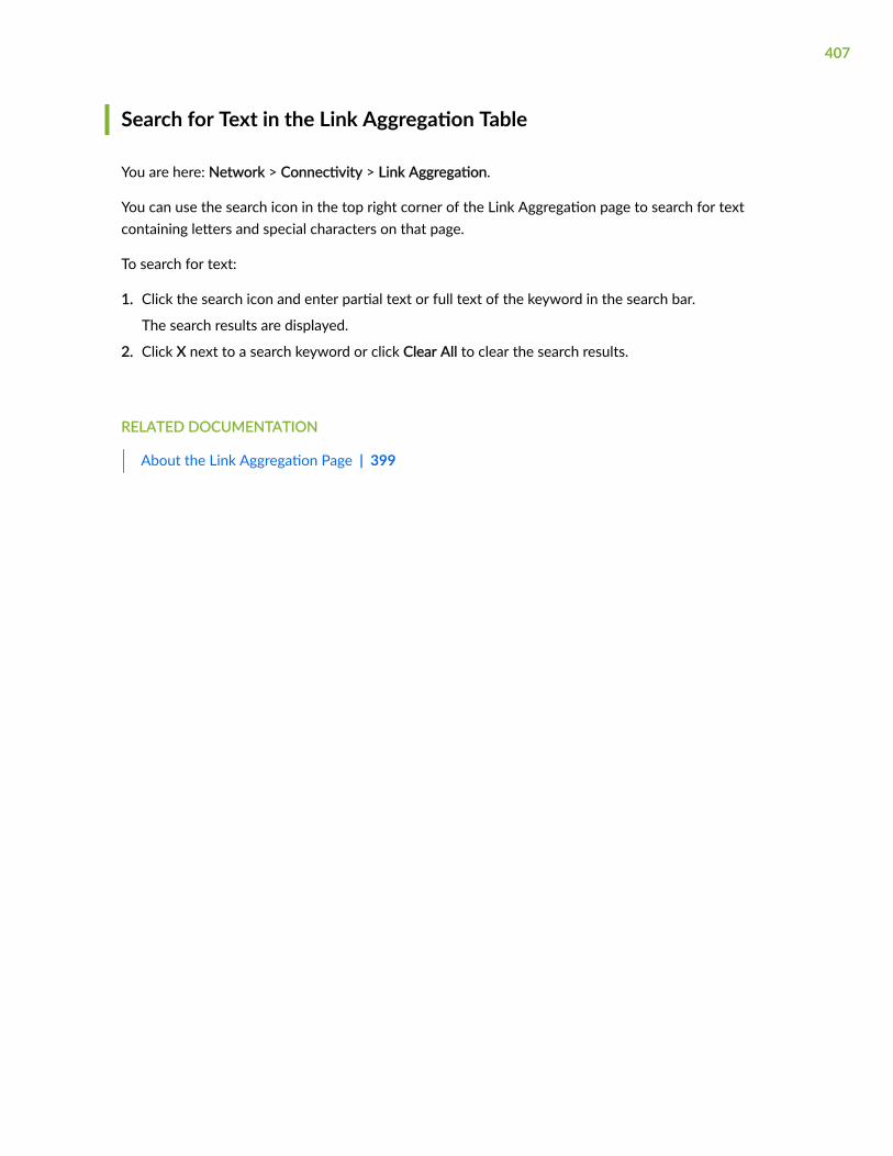
Search for Text in the Link Aggregation Table
You are here: Network > Connectivity > Link Aggregation.
You can use the search icon in the top right corner of the Link Aggregation page to search for textcontaining letters and special characters on that page.
To search for text:
1. Click the search icon and enter partial text or full text of the keyword in the search bar.
The search results are displayed.
2. Click X next to a search keyword or click Clear All to clear the search results.
RELATED DOCUMENTATION
About the Link Aggregation Page | 399
407

CHAPTER 30
Connectivity—PPPoE
IN THIS CHAPTER
Configure PPPoE | 408
Configure PPPoE
NOTE: This menu is available only for SRX300 lines of devices and SRX550M device.
You are here: Network > Connectivity > PPPoE.
PPPoE connects multiple hosts on an Ethernet LAN to a remote site through a single customer premisesequipment (CPE) device (Juniper Networks device).
Use the configure PPPoE tasks to configure the PPPoE connection. The PPPoE wizard guides you to setup a PPPoE client over the Ethernet connection.
NOTE: On all branch SRX Series devices, the PPPoE wizard has the following limitations:
• While you use the load and save functionality, the port details are not saved in the client file.
• The Non Wizard connection option cannot be edited or deleted through the wizard. Use theCLI to edit or delete the connections.
• The PPPoE wizard cannot be launched if the backend file is corrupted.
• The PPPoE wizard cannot be loaded from the client file if non-wizard connections share thesame units.
• The PPPoE wizard cannot load the saved file from one platform to another platform.
408

• There is no backward compatibility between PPPoE wizard Phase 2 to PPPoE wizard Phase 1.As a result, the PPPoE connection from Phase 2 will not be shown in Phase 1 when youdowngrade to an earlier release.
RELATED DOCUMENTATION
Configure VPN
409

CHAPTER 31
Connectivity—Wireless LAN
IN THIS CHAPTER
About the Settings Page | 410
Create an Access Point | 412
Edit an Access Point | 413
Delete Access Point | 414
Create an Access Point Radio Setting | 414
Edit an Access Point Radio Setting | 418
Delete Access Point Radio Settings | 418
About the Settings Page
IN THIS SECTION
Tasks You Can Perform | 411
Field Descriptions | 411
You are here: Network > Connectivity > Wireless LAN > Settings.
Use this page to configure wireless LAN settings.
NOTE: Starting in Junos OS Release 20.1R1, J-Web supports SRX380 devices. You can configurethe SRX380 device supported wireless LAN settings.
410

Tasks You Can Perform
You can perform the following tasks from this page:
• Create an access point. See "Create an Access Point" on page 412.
• Edit an access point. See "Edit an Access Point" on page 413.
• Delete an access point. See "Delete Access Point" on page 414.
• Create access point radio settings. See "Create an Access Point Radio Setting" on page 414.
• Edit access point radio settings. See "Edit an Access Point Radio Setting" on page 418.
• Delete access point radio settings. See "Delete Access Point Radio Settings" on page 418.
Field Descriptions
Table 106 on page 411 describes the fields on the Settings page.
Table 106: Fields on the Settings Page
Field Description
Access Point Name Displays the access point name.
Description Displays the description for the access point.
WL Interface Displays the wireless LAN interface name.
Location Displays the location of the access point.
MAC Address Displays the MAC address.
Country Displays the country of the access point.
411

Release History Table
Release Description
20.1R1 Starting in Junos OS Release 20.1R1, J-Web supports SRX380 devices. You can configure the SRX380device supported wireless LAN settings.
RELATED DOCUMENTATION
Create an Access Point | 412
Create an Access Point
You are here: Network > Connectivity > Wireless LAN > Settings.
To create an access point:
1. Click the add icon (+) on the upper right side of the Settings page.
The Create Access Point Configuration page appears.
2. Complete the configuration according to the guidelines provided in Table 107 on page 412.
3. Click OK to save the changes.
An access point is created.
If you want to discard your changes, click Cancel.
Table 107: : Fields on the Create Access Point Configuration Page
Field Action
Basic Settings
Name Enter a unique name for the access point.
Description Enter the description for the access point.
Interface Select a wireless LAN interface from the list.
412

Table 107: : Fields on the Create Access Point Configuration Page (Continued)
Field Action
Location Enter the location of the access point.
MAC Address Enter the MAC address.
Access Point Options
Country Select a country of the access point from the list.
RELATED DOCUMENTATION
About the Settings Page | 410
Edit an Access Point | 413
Delete Access Point | 414
Create an Access Point Radio Setting | 414
Edit an Access Point
You are here: Network > Connectivity > Wireless LAN > Settings.
To edit an access point:
1. Select an existing access point that you want to edit on the Settings page.
2. Click the pencil icon on the upper right side of the page.
The Edit Access Point Configuration page appears with editable fields. For more information on theoptions, see "Create an Access Point" on page 412.
3. Click OK to save the changes.
RELATED DOCUMENTATION
About the Settings Page | 410
Delete Access Point | 414
413

Delete Access Point
You are here: Network > Connectivity > Wireless LAN > Settings.
To delete an access point:
1. Select an existing access point that you want to delete on the Settings page.
2. Click the delete icon on the upper right side of the page.
3. Click Yes to delete the access point or click No to retain the access point.
RELATED DOCUMENTATION
About the Settings Page | 410
Create an Access Point | 412
Edit an Access Point | 413
Create an Access Point Radio Setting
You are here: Network > Connectivity > Wireless LAN > Settings.
To create an access point radio setting:
1. Click the add icon (+) on the upper right side of the Radio Settings table.
The Create Access Point Radio Settings page appears.
2. Complete the configuration according to the guidelines provided in Table 108 on page 414.
3. Click OK to save the changes.
The access point radio settings are created.
If you want to discard your changes, click Cancel.
Table 108: Fields on the Create Access Point Radio Settings Page
Field Action
Radio
Radio Type Select a radio type from the list.
414

Table 108: Fields on the Create Access Point Radio Settings Page (Continued)
Field Action
Radio State Select the radio state to enable.
415

Table 108: Fields on the Create Access Point Radio Settings Page (Continued)
Field Action
Virtual Access Points To add a virtual access point:
1. Click Add.
The Create VAP Configuration page appears.
2. Enter the following details:
Basic Settings:
• VAP ID—Enter a value using up or down arrows.
• Description—Enter a description for the virtual access points.
• SSID—Enter a unique name to broadcast from access points.
• VLAN ID—Enter a VLAN identifier (VID) using up or down arrows.
• Download Limit (Kbps)—Enter a value using up or down arrows.
• Upload Limit (Kbps)—Enter a value using up or down arrows.
• Broadcast SSID—Select No to disable.
• Maximum Stations—Enter a value using up or down arrows.
• Station Isolation—Select the check box to enable.
Security:
• Security—Select an option from the list.
• If you have selected WPA Personal, enter the following details:
• WPA Version—Select an option from the list.
• Cipher Suites—Select an option from the list.
• WPA Shared Key—Enter a value for the key.
• Key Type—Select an option from the list.
416

Table 108: Fields on the Create Access Point Radio Settings Page (Continued)
Field Action
• If you have selected WPA Enterprise, enter the following details:
• WPA Version—Select an option from the list.
• Cipher Suites—Select an option from the list.
• Radius Server IP—Enter IP address for the radio server.
• Radius Port—Enter a value using up or down arrows.
• Radius Key—Enter a value for the key.
Station MAC Filter:
• Allowed ListMAC Address—Enter a MAC address that you want to allow and clickAdd to add the address in the MAC addresses list.
Select the MAC address click Delete to remove it.
• Deny ListMAC Address—Enter a MAC address that you want to block and clickAdd to add the address in the MAC addresses list.
Select the MAC address click Delete to remove it.
3. Click OK to save VAP configuration.
Select the virtual access point and click Edit or Delete icons to edit or removeit.
Radio Settings—Radio Options
Mode Select a radio mode option from the list.
Channel Number Select a channel number for radio from the list.
Channel Bandwidth Select a channel bandwidth for radio from the list.
417

Table 108: Fields on the Create Access Point Radio Settings Page (Continued)
Field Action
Transmit Power Enter a value for radio transmit power using up or down arrows.
RELATED DOCUMENTATION
About the Settings Page | 410
Edit an Access Point Radio Setting | 418
Delete Access Point Radio Settings | 418
Edit an Access Point Radio Setting
You are here: Network > Connectivity > Wireless LAN > Settings.
To edit an access point radio settings:
1. Select an existing access point radio setting that you want to edit on the Settings page.
2. Click the edit icon on the upper right side of the Radio Settings table.
The Edit Access Point Radio Settings page appears with editable fields. For more information on theoptions, see "Create an Access Point Radio Setting" on page 414.
3. Click OK to save the changes.
RELATED DOCUMENTATION
About the Settings Page | 410
Delete Access Point Radio Settings | 418
Delete Access Point Radio Settings
You are here: Network > Connectivity > Wireless LAN > Settings.
To delete an access point radio setting:
418

1. Select an existing access point radio setting that you want to delete on the Settings page.
2. Click the delete icon available on the upper right side of the Radio Settings table.
3. Click Yes to delete the access point radio settings or click No to retain the access point radio settings.
RELATED DOCUMENTATION
About the Settings Page | 410
Create an Access Point Radio Setting | 414
Edit an Access Point Radio Setting | 418
419

CHAPTER 32
DHCP Client
IN THIS CHAPTER
About the DHCP Client Page | 420
Add DHCP Client Information | 421
Delete DHCP Client Information | 423
About the DHCP Client Page
IN THIS SECTION
Tasks You Can Perform | 420
Field Descriptions | 420
You are here: Network > DHCP > DHCP Client.
Use this page to view, add, and remove link aggregation configuration details.
Tasks You Can Perform
You can perform the following tasks from this page:
• Create DHCP client information. See "Add DHCP Client Information" on page 421.
• Delete DHCP client information. See "Delete DHCP Client Information" on page 423.
Field Descriptions
Table 109 on page 421 describes the fields on the DHCP Client page.
420

Table 109: Fields on the DHCP Client Page
Field Description
Interface Name Displays the interface name.
DHCP Client Identifier Displays the name of the client used by the DHCP server to index itsdatabase of address bindings.
Server Displays the DHCP server address.
Lease Time Displays the time in seconds, to negotiate and exchange DHCP messages.
Add Adds a new DHCP client configuration.
Delete Deletes the selected DHCP client configuration.
RELATED DOCUMENTATION
Add DHCP Client Information | 421
Add DHCP Client Information
You are here: Network > DHCP > DHCP Client.
To add DHCP Client information:
1. Click Add on the DHCP Client page.
The DHCP Client Information page appears.
2. Complete the configuration according to the guidelines provided in Table 110 on page 422.
3. Click OK to save the changes. If you want to discard your changes, click Cancel.
421

Table 110: Fields on the DHCP Client Information Page
Field Action
DHCP Client Information
Interface Enter the name of the interface on which to configure the DHCP client.
Client Identifier Specifies the name of the client used by the DHCP server to index itsdatabase of address bindings.
Select an option from the list:
• ASCII— ASCII client.
• Hexadecimal—Hexadecimal client.
Lease Time Enter a value from 60 through 2,147,483,647.
Specifies the time in seconds, to negotiate and exchange DHCP messages.
RetransmissionAttempt
Enter a value from 0 through 6. The default value is 4.
Specifies the number of attempts the router is allowed to retransmit aDHCP packet fallback.
DHCP Server Address Enter the IPv4 address of the DHCP server.
Specifies the preferred DHCP server that the DHCP clients contact withDHCP queries.
Vendor Class ID Enter the vendor class ID numbers.
Specifies the vendor class identity number for the DHCP client.
Update Server Select the check box to enable the propagation of TCP/IP settings on thespecified interface (if it is acting as a DHCP client) to the DHCP server thatis configured on the router.
422

RELATED DOCUMENTATION
Delete DHCP Client Information | 423
Delete DHCP Client Information
You are here: Network > DHCP > DHCP Client.
To delete a DHCP Client Information:
1. Select a DHCP Client that you want to delete on the DHCP Client page.
2. Click Delete available on the DHCP Client page.
3. Click Yes to delete or click No to retain the profile.
RELATED DOCUMENTATION
About the DHCP Client Page | 420
Add DHCP Client Information | 421
423

CHAPTER 33
DHCP Server
IN THIS CHAPTER
About the DHCP Server Page | 424
Add a DHCP Pool | 426
Edit a DHCP Pool | 431
Delete DHCP Pool | 431
DHCP Groups Global Settings | 432
Add a DHCP Group | 432
Edit a DHCP Group | 433
Delete DHCP Group | 434
About the DHCP Server Page
IN THIS SECTION
Tasks You Can Perform | 424
Field Descriptions | 425
You are here: Network > DHCP > DHCP Server.
Use this page to view, add, and remove DHCP server configuration details.
Tasks You Can Perform
You can perform the following tasks from this page:
• Add a DHCP Pool. See "Add a DHCP Pool" on page 426.
424

• Edit a DHCP Pool. See "Edit a DHCP Pool" on page 431.
• Delete a DHCP Pool. See "Delete DHCP Pool" on page 431.
• Configure DHCP group global settings. See "DHCP Groups Global Settings" on page 432.
• Add a DHCP group. See "Add a DHCP Group" on page 432.
• Edit a DHCP group. See "Edit a DHCP Group" on page 433.
• Delete a DHCP group. See "Delete DHCP Group" on page 434.
Field Descriptions
Table 111 on page 425 describes the fields on the DHCP Server page.
Table 111: Fields on the DHCP Server Page
Field Description
Routing Instance Displays the name of the routing instance selected for DHCP server.
DHCP Pools
Pool Name Displays the name of the source pool.
Network Addresses Displays the IP address in the pool.
Routing Instance Displays the name of the routing instance selected.
DHCP Groups
Global Settings Specifies the global settings of DHCP server.
Group name Specifies the source name of the group.
Interfaces Displays name of the interfaces selected.
425

Table 111: Fields on the DHCP Server Page (Continued)
Field Description
Routing Instance Displays the name of the routing instance selected.
DHCP Address range for pool
Address Range Name Specify the name of the address assignment pool.
Address Range (Low) Specifies the lowest address in the IP address pool range.
Address Range (High) Specifies the highest address in the IP address pool range.
DHCP Static Bindings for pool
Host Name Specifies the name of the client for the static binding.
MAC Address Specifies the client MAC address.
Fixed IP Address Specifies the IP address to reserve for the client.
RELATED DOCUMENTATION
Add a DHCP Pool | 426
Add a DHCP Pool
You are here: Network > DHCP > DHCP Server.
To add a DHCP Pool:
1. Click the add icon (+) on the upper right side of the DHCP Pools table.
The Add DHCP Pool page appears.
2. Complete the configuration according to the guidelines provided in Table 112 on page 427.
426

3. Click OK to save the changes. If you want to discard your changes, click Cancel.
Table 112 on page 427 describes the Add DHCP Pool Page.
Table 112: Fields on the Add DHCP Pool Page.
Field Action
General
Pool Name Enter a name for DHCP pool.
Routing Instance Select a routing instance from the list.
Network Addresses Enter the following details:
• IP Address—Enter an IP address.
• Subnet Mask—Enter a subnet mask for the IP address.
DHCP Pool Attributes
Click DHCP Attributes to add DHCP pool attributes. After configuring the attributes, click OK to savethe changes.
Pool Name Displays the DHCP pool name.
Domain Name Enter the domain name to be assigned to the address pool.
Server Identifier Enter the name of the server identifier to assign to the DHCP client in theaddress pool.
Netbios Node Type Select a NetBIOS node type from the list. This is equivalent to DHCPoption 46.
Next Server Enter the IP address of the next DHCP server that the clients need tocontact.
427

Table 112: Fields on the Add DHCP Pool Page. (Continued)
Field Action
Propagate Settings Select an interface from the list.
Specifies the name of the interface on the router through which theresolved DHCP queries are propagated to the DHCP pool.
TFTP Server Enter the IP address of the TFTP server.
Maximum Lease Time(Secs)
Enter a from value 60 through 1,209,600.
Specifies the maximum length of time in seconds, a client can hold a lease.(Dynamic BOOTP lease lengths can exceed this maximum time.)
Boot File Enter the path and filename of the initial boot file to be used by the client.
Boot Server Enter the IP address or hostname of the TFTP server that provides theinitial boot file to the client.
Grace Period (Secs) Enter a number of seconds the lease is retained.
range is 0 through 4,294,967,295. By default, 0 is no grace period.
DNS Name Servers Specifies the DNS name to assign to the DHCP client in the address pool.
Click any one of the following:
• +—Adds the DNS name in the address pool.
• Click the pencil icon to edit a selected DNS name in the address pool.
• X—Deletes the DNS name in the address pool.
428

Table 112: Fields on the Add DHCP Pool Page. (Continued)
Field Action
WINS Servers Specifies the WINS servers to assign to the DHCP client in the addresspool.
Click any one of the following:
• +—Adds WINS servers to the address pool.
• Click the pencil icon to edit a selected WINS server in the address pool.
• X—Deletes the WINS servers in the address pool.
Gateway Routers Specifies the gateway router to assign client in the address pool.
Click any one of the following:
• +—Adds the gateway router to the address pool.
• Click the pencil icon to edit a selected gateway router in the addresspool.
• X—Deletes the gateway router in the address pool.
Options Click + to add DHCP option.
Enter the following details:
• Code—Type a number.
• Type—Select a type from the list that corresponds to the code.
• Value—Type a valid option value based on the type.
You can select the DHCP option and click the pencil icon to edit or click Xto delete the DHCP options.
429

Table 112: Fields on the Add DHCP Pool Page. (Continued)
Field Action
Option-82 Device inserts DHCP option 82 (also known as the DHCP relay agentinformation option) information.
Enter the following details:
• Circuit Identifier—Enter circuit ID to identify the circuit (interface orVLAN) on the switching device on which the request was received.
• Ranges—Enter a value for the circuit ID.
• Remote Identifier—Enter remote ID to identify the remote host.
• Ranges—Enter a value for the remote ID.
Address Range
Click + to add address range. After configuring the attributes, click OK to save the changes.
Selected an address range and click the pencil icon to edit it or click X to delete it.
Name Enter the address range name.
Low Enter an IP address that is part of the subnet specified in Address Poolsubnet.
High Enter an IP address that is part of the subnet specified in Address PoolSubnet. This address must be greater than the address specified inAddress Range Low.
Static Bindings
Click + to add DHCP static bindings. After configuring the attributes, click OK to save the changes.
Selected a DHCP static binding and click the pencil icon to edit it or click X to delete it.
Host Name Enter the hostname to assign the DHCP client to the MAC address.
430

Table 112: Fields on the Add DHCP Pool Page. (Continued)
Field Action
Mac Address Enter the MAC address of the DHCP client.
Fixed IP Address Enter the fixed address to assign the DHCP client to the MAC address.
RELATED DOCUMENTATION
Edit a DHCP Pool | 431
Edit a DHCP Pool
You are here: Network > DHCP > DHCP Server.
To edit a DHCP Pool:
1. Select an existing DHCP Pool that you want to edit on the DHCP Server page.
2. Click the pencil icon available on the upper right side of the DHCP Pools table.
The Edit DHCP Pool page appears. You can edit the network addresses. For more information on theoptions, see "Add a DHCP Pool" on page 426.
3. Click OK to save the changes.
RELATED DOCUMENTATION
Delete DHCP Pool | 431
Delete DHCP Pool
You are here: Network > DHCP > DHCP Server.
To delete a DHCP Pool:
1. Select a DHCP Pool that you want to delete on the DHCP Server page.
431

2. Click the delete icon available on the upper right side of the DHCP Pools table.
3. Click Yes to delete or click No to retain the profile.
RELATED DOCUMENTATION
DHCP Groups Global Settings | 432
DHCP Groups Global Settings
You are here: Network > DHCP > DHCP Server.
To configure DHCP groups global settings:
1. Click Global Settings available on the upper right side of the DHCP Groups table.
The DHCP Global Configuration page appears.
2. Select the options available in the Available column and move them to Selected column using thearrow to configure the order of the DHCP pool match.
3. Click OK to save the changes or click Cancel to discard the changes.
RELATED DOCUMENTATION
Add a DHCP Group | 432
Edit a DHCP Group | 433
Delete DHCP Group | 434
Add a DHCP Group
You are here: Network > DHCP > DHCP Server.
To add a DHCP Group:
1. Click the add icon (+) on the upper right side of the DHCP Groups table.
The Add DHCP Group page appears.
2. Complete the configuration according to the guidelines provided in Table 113 on page 433.
3. Click OK to save the changes. If you want to discard your changes, click Cancel.
Table 113 on page 433 describes the fields on the Add DHCP Group.
432

Table 113: Fields on the Add DHCP Group Page
Field Action
Group Name Enter a name for the DHCP group.
Routing Instance Select a routing instance from the list.
Interfaces Select the interfaces available in the Available column and move them to Selectedcolumn using the right arrow.
RELATED DOCUMENTATION
Edit a DHCP Group | 433
Delete DHCP Group | 434
DHCP Groups Global Settings | 432
Edit a DHCP Group
You are here: Network > DHCP > DHCP Server.
To edit a DHCP group:
1. Select an existing DHCP group that you want to edit on the DHCP Server page.
2. Click the pencil icon available on the upper right side of the DHCP Groups table.
The Edit DHCP Group page appears with editable fields. For more information on the options, see"Add a DHCP Group" on page 432.
3. Click OK to save the changes.
RELATED DOCUMENTATION
DHCP Groups Global Settings | 432
Add a DHCP Group | 432
Delete DHCP Group | 434
433

Delete DHCP Group
You are here: Network > DHCP > DHCP Server.
To delete a DHCP group:
1. Select a DHCP group that you want to delete on the DHCP Server page.
2. Click the delete icon available on the upper right side of the DHCP Groups table.
3. Click Yes to delete or click No to retain the profile.
RELATED DOCUMENTATION
DHCP Groups Global Settings | 432
Add a DHCP Group | 432
Edit a DHCP Group | 433
434

CHAPTER 34
Firewall Filters—IPv4
IN THIS CHAPTER
About the IPv4 Page | 435
Add IPv4 Firewall Filters | 436
About the IPv4 Page
IN THIS SECTION
Tasks You Can Perform | 435
Field Descriptions | 435
You are here: Network > Firewall Filters > IPV4.
Use this page to configure IPv4 firewall filters.
Tasks You Can Perform
You can perform the following task from this page:
• Add an IPv4 firewall filter. See "Add IPv4 Firewall Filters" on page 436.
Field Descriptions
Table 114 on page 436 describes the fields on the IPv4 page.
435

Table 114: Fields on the IPv4 Page
Field Description
IPv4 Filter Summary
Filter Name Displays the name of the filter and when expanded, lists the terms attached to the filter.
Add New IPv4 Filter
Filter Name Searches for existing filters by filter name.
Term Name Searches for existing terms by term name.
Location Specifies the position of the new filter.
RELATED DOCUMENTATION
Add IPv4 Firewall Filters | 436
Add IPv4 Firewall Filters
You are here: Network > Firewall Filters > IPV4.
To add an IPV4 firewall filter:
1. Complete the configuration according to the guidelines provided in Table 115 on page 437 and Table116 on page 439.
2. Click Add available in the Add New IPv4 Filter section.
A new IPv4 Firewall Filter is created.
3. Click OK to save the changes. If you want to discard your changes, click Cancel.
436

Table 115: Fields on the Add IPv4 Firewall Filter Page
Field Action
IPv4 Filter Summary
Actioncolumn
Select an option.
The options available are:
• To move an item upward—Locate the item and click the up arrow from the samerow.
• To move an item downward—Locate the item and click the down arrow from thesame row.
• To delete an item—Locate the item and click the X from the same row.
Filter Name Displays the name of the filter and when expanded, lists the terms attached to thefilter.
Displays the match conditions and actions that are set for each term.
Allows you to add more terms to a filter or modify filter terms.
The options available are:
• To display the terms added to a filter—Click the plus sign next to the filter name.This also displays the match conditions and actions set for the term.
• To edit a filter—Click the filter name. To edit a term, click the name of the term.
Search
IPv4 FilterName
Enter the existing filter name.
The options available are:
• To find a specific filter—Enter the name of the filter in the Filter Name box.
• To list all filters with a common prefix or suffix—Use the wildcard character (*)when you enter the name of the filter. For example, te* lists all filters with a namestarting with the characters te.
437

Table 115: Fields on the Add IPv4 Firewall Filter Page (Continued)
Field Action
IPv4 TermName
Enter the existing terms by term name.
The options available are:
• To find a specific term—Enter the name of the term in the Term Name box.
• To list all terms with a common prefix or suffix—Use the wildcard character (*)when typing the name of the term. For example, ra* lists all terms with a namestarting with the characters ra .
Number ofItems toDisplay
Enter the number of filters or terms to display on one page. Select the number ofitems to be displayed on one page.
Add New IPv4 Filter
Filter Name Enter the existing filter name.
The options available are:
• To find a specific filter—Enter the name of the filter in the Filter Name box.
• To list all filters with a common prefix or suffix—Use the wildcard character (*)when you enter the name of the filter. For example, te* lists all filters with a namestarting with the characters te.
Term Name Enter the existing terms by term name.
The options available are:
• To find a specific term—Enter the name of the term in the Term Name box.
• To list all terms with a common prefix or suffix—Use the wildcard character (*)when typing the name of the term. For example, ra* lists all terms with a namestarting with the characters ra .
438

Table 115: Fields on the Add IPv4 Firewall Filter Page (Continued)
Field Action
Location Positions the new filter in one of the following locations:
• After Final IPv4 Filter—At the end of all filters.
• After IPv4 Filter—After a specified filter.
Before IPv4 Filter—Before a specified filter.
Add Adds a new filter name. Opens the term summary page for this filter allowing you toadd new terms to this filter.
Add New IPv4 Term
Location Positions the new term in one of the following locations:
• After Final IPv4 Filter—At the end of all term.
• After IPv4 Filter—After a specified term.
Before IPv4 Filter—Before a specified term.
Add Opens the Filter Term page allowing you to define the match conditions and theaction for this term.
Table 116: Fields on the Match Criteria for IPv4 Firewall Filter
Field Action
Match Source
439

Table 116: Fields on the Match Criteria for IPv4 Firewall Filter (Continued)
Field Action
SourceAddress
Enter IP source addresses to be included in, or excluded from, the match condition.Allows you to remove source IP addresses from the match condition.
If you have more than 25 addresses, this field displays a link that allows you to easilyscroll through pages, change the order of addresses, and also search for them.
The options available are:
• Add—To include the address in the match condition.
• Except—To exclude the address from the match condition and then select Add -To include the address in the match condition.
• Delete—To remove an IP source address from the match condition.
Enter an IP source address and prefix length and select an option.
Source PrefixList
Enter source prefix lists, which you have already defined, to be included in thematch condition. Allows you to remove a prefix list from the match condition.
Select an option:
• Add—To include a predefined source prefix list in the match condition, type theprefix list name.
• Except—To exclude the prefix list from the match condition and then select Add—To include the prefix list in the match condition.
• Delete—To remove a prefix list from the match condition.
440

Table 116: Fields on the Match Criteria for IPv4 Firewall Filter (Continued)
Field Action
Source Port Enter the source port type to be included in, or excluded from, the match condition.Allows you to remove a source port type from the match condition.
NOTE: This match condition does not check the protocol type being used on theport. Make sure to specify the protocol type (TCP or UDP) match condition in thesame term.
The options available are:
• Add—To include the port in the match condition.
• Except—To exclude the port from the match condition and then select Add—Toinclude the port in the match condition.
• Delete—To remove a port from the match condition.
Select the port from the port name list; enter the port name, number, or range andthen select an option.
Match Destination
DestinationAddress
Enter destination addresses to be included in, or excluded from, the matchcondition. Allows you to remove a destination IP address from the match condition.
If you have more than 25 addresses, this field displays a link that allows you to easilyscroll through pages, change the order of addresses, and also search for them.
The options available are:
• Add—To include the address in the match condition.
• Except—To exclude the address from the match condition and then select Add—To include the address in the match condition.
• Delete—To remove an IP address from the match condition.
Enter an IP destination address and prefix length and select an option.
441

Table 116: Fields on the Match Criteria for IPv4 Firewall Filter (Continued)
Field Action
DestinationPrefix List
Enter destination prefix lists, which you have already defined, to be included in thematch condition. Allows you to remove a prefix list from the match condition.
Select an option:
• Add—To include a predefined destination prefix list, enter the prefix list name.
• Except—To exclude the prefix list from the match condition and then select Add—To include the prefix list in the match condition.
• Delete—To remove a prefix list from the match condition.
DestinationPort
Enter destination port types to be included in, or excluded from, the matchcondition. Allows you to remove a destination port type from the match condition.
NOTE: This match condition does not check the protocol type being used on theport. Make sure to specify the protocol type (TCP or UDP) match condition in thesame term.
The options available are:
• Add—To include the port in the match condition.
• Except—To exclude the port from the match condition and then select Add—Toinclude the port in the match condition.
• Delete—To remove a port type from the match condition.
Select the port from the port name list; enter the port name, number, or range; andthen select an option.
Match Source or Destination
442

Table 116: Fields on the Match Criteria for IPv4 Firewall Filter (Continued)
Field Action
Address Enter IP addresses to be included in, or excluded from, the match condition for asource or destination. Allows you to remove an IP address from the matchcondition.
If you have more than 25 addresses, this field displays a link that allows you to easilyscroll through pages, change the order of addresses and also search for them.
NOTE: This address match condition cannot be specified in conjunction with thesource address or destination address match conditions in the same term.
The options available are:
• Add—To include the address in the match condition.
• Except—To exclude the address from the match condition and then select Add—To include the address in the match condition.
• Delete—To remove an IP address from the match condition.
Enter an IP destination address and prefix length and select an option.
Prefix List Enter prefix lists, which you have already defined, to be included in the matchcondition for a source or destination. Allows you to remove a prefix list from thematch condition.
NOTE: This prefix list match condition cannot be specified in conjunction with thesource prefix list or destination prefix list match conditions in the same term.
Select an option:
• Add—To include a predefined destination prefix list, type the prefix list name.
• Delete—To remove a prefix list from the match condition.
443

Table 116: Fields on the Match Criteria for IPv4 Firewall Filter (Continued)
Field Action
Port Enter a port type to be included in, or excluded from, a match condition for a sourceor destination. Allows you to remove a destination port type from the matchcondition.
NOTE: This match condition does not check the protocol type being used on theport. Make sure to specify the protocol type (TCP or UDP) match condition in thesame term.
Also, this port match condition cannot be specified in conjunction with the sourceport or destination port match conditions in the same term.
The options available are:
• Add—To include the port in the match condition.
• Except—To exclude the port from the match condition and then select Add—Toinclude the port in the match condition.
• Delete—To remove a port type from the match condition.
Select the port from the port name list; enter the port name, number, or range; andthen select an option.
Match Interface
Interface Enter interfaces to be included in a match condition. Allows you to remove aninterface from the match condition.
The options available are:
• Add—To include an interface in a match condition.
• Delete—To remove an interface from the match condition.
Select a name from the interface name list or Enter the interface name and select anoption.
444

Table 116: Fields on the Match Criteria for IPv4 Firewall Filter (Continued)
Field Action
Interface Set Enter interface sets, which you have already defined, to be included in a matchcondition. Allows you to remove an interface set from the match condition.
The options available are:
• Add—To include the group in the match condition.
• Delete—To remove an interface group from the match condition.
Enter the interface set name and select an option.
InterfaceGroup
Enter interface groups, which you have already defined, to be included in, orexcluded from, a match condition. Allows you to remove an interface group from thematch condition.
The options available are:
• Add—To include the port in the match condition.
• Except—To exclude the port from the match condition and then select Add—Toinclude the port in the match condition.
• Delete— To remove a port type from the match condition.
Enter the name of the group and select an option.
Match Packet and Network
First Fragment Select the check box.
Matches the first fragment of a fragmented packet.
Is Fragment Select the check box.
Matches trailing fragments (all but the first fragment) of a fragmented packet.
Fragment Flags Enter fragmentation flags to be included in the match condition.
Enter a text or numeric string defining the flag.
445
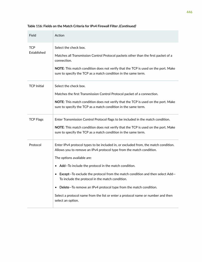
Table 116: Fields on the Match Criteria for IPv4 Firewall Filter (Continued)
Field Action
TCPEstablished
Select the check box.
Matches all Transmission Control Protocol packets other than the first packet of aconnection.
NOTE: This match condition does not verify that the TCP is used on the port. Makesure to specify the TCP as a match condition in the same term.
TCP Initial Select the check box.
Matches the first Transmission Control Protocol packet of a connection.
NOTE: This match condition does not verify that the TCP is used on the port. Makesure to specify the TCP as a match condition in the same term.
TCP Flags Enter Transmission Control Protocol flags to be included in the match condition.
NOTE: This match condition does not verify that the TCP is used on the port. Makesure to specify the TCP as a match condition in the same term.
Protocol Enter IPv4 protocol types to be included in, or excluded from, the match condition.Allows you to remove an IPv4 protocol type from the match condition.
The options available are:
• Add—To include the protocol in the match condition.
• Except—To exclude the protocol from the match condition and then select Add—To include the protocol in the match condition.
• Delete—To remove an IPv4 protocol type from the match condition.
Select a protocol name from the list or enter a protocol name or number and thenselect an option.
446

Table 116: Fields on the Match Criteria for IPv4 Firewall Filter (Continued)
Field Action
ICMP Type Select a packet type from the list or enter a packet type name or number and thenselect an option.
NOTE: This protocol does not verify that ICMP is used on the port. Make sure tospecify an ICMP type match condition in the same term.
The options available are:
• Add—To include the packet type in the match condition.
• Except—To exclude the packet type from the match condition and then select.
Add—To include the packet type in the match condition.
• Delete—To remove an ICMP packet type from the match condition.
ICMP Code Select a packet code from the list or enter the packet code as text or a number andselect an option.
NOTE: The ICMP code is dependent on the ICMP type. Make sure to specify anICMP type match condition in the same term.
The options available are:
• Add—To include the packet type in the match condition.
• Except—To exclude the packet type from the match condition and then select
Add—To include the packet type in the match condition.
• Delete—To remove an ICMP packet type from the match condition.
447

Table 116: Fields on the Match Criteria for IPv4 Firewall Filter (Continued)
Field Action
FragmentOffset
Enter a fragment offset number or range and then select an option.
The options available are:
• Add—To include the offset in the match condition.
• Except—To exclude the offset from the match condition and then select Add—Toinclude the offset in the match condition.
• Delete—To remove a fragment offset value from the match condition.
Precedence Enter IP precedence to be included in, or excluded from, the match condition.Allows you to remove an IP precedence entry from the match condition.
The options available are:
• Add—To include the precedence in the match condition.
• Except—To exclude the precedence from the match condition and then select
Add—To include the precedence in the match condition.
• Delete—To remove an IP precedence from the match condition.
DSCP Select DSCP from the list; or enter the DSCP value as a keyword, a decimal integerfrom 0 through 7, or a binary string; and then select an option.
The options available are:
• Add—To include the DSCP in the match condition.
• Except—To exclude the DSCP from the match condition and then select Add—Toinclude the DSCP in the match condition.
• Delete—To remove a DSCP from the match condition.
448

Table 116: Fields on the Match Criteria for IPv4 Firewall Filter (Continued)
Field Action
TTL Enter an IPv4 TTL value by entering a number from 1 through 255 and select anoption.
NOTE: This option is not available in SRX5600 device.
The options available are:
• Add—To include the TTL in the match condition.
• Except—To exclude the TTL from the match condition and then select Add—Toinclude the TTL in the match condition .
• Delete—To remove an IPv4 TTL type from the match condition.
Packet Length Specify a packet length, enter a value or range.
Select an option.
The options available are:
• Add—To include the packet length in the match condition.
• Except—To exclude the packet length from the match condition and then select
Add—To include the packet length in the match condition.
• Delete—To remove a packet length value from the match condition.
ForwardingClass
Specify a forwarding class by selecting a forwarding class from the list or entering aforwarding class, and then select an option.
The options available are:
• Add—To include the forwarding class in the match condition.
• Except—To exclude the forwarding class from the match condition and thenselect
Add—To include the forwarding class in the match condition.
• Delete—To remove a forwarding class from the match condition.
449

Table 116: Fields on the Match Criteria for IPv4 Firewall Filter (Continued)
Field Action
IP Options Enter option by selecting an IP option from the list or entering a text or numericstring identifying the option, and then select an option.
The options available are:
• Add—To include the IP option in the match condition.
• Except—To exclude the IP option from the match condition and then select Add—To include the IP option in the match condition.
• Delete—To remove an IP option from the match condition.
IPsec ESP SPI Enter an ESP SPI value by entering a binary, hexadecimal, or decimal SPI value orrange, and then select an option.
The options available are:
• Add—To include the value in the match condition.
• Except—To exclude the value from the match condition and then select Add—Toinclude the value in the match condition.
• Delete—To remove an ESP SPI value from the match condition.
Action
Nothing Select Nothing.
Specifies that no action is performed. By default, a packet is accepted if it meets thematch conditions of the term, and packets that do not match any conditions in thefirewall filter are dropped.
Accept Select Accept.
Accepts a packet that meets the match conditions of the term.
450

Table 116: Fields on the Match Criteria for IPv4 Firewall Filter (Continued)
Field Action
Discard Select Discard.
Discards a packet that meets the match conditions of the term. Names a discardcollector for packets.
Reject Select Reject and then select a message type from the reason list.
Rejects a packet that meets the match conditions of the term and returns a rejectionmessage. Allows you to specify a message type that denotes the reason the packetwas rejected.
NOTE: To log and sample rejected packets, specify log and sample action modifiersin conjunction with this action.
Next Term Select Next Term.
Evaluates a packet with the next term in the filter if the packet meets the matchconditions in this term. This action makes sure that the next term is used forevaluation even when the packet matches the conditions of a term. When thisaction is not specified, the filter stops evaluating the packet after it matches theconditions of a term and takes the associated action.
RoutingInstance
Accepts a packet that meets the match conditions, and forwards it to the specifiedrouting instance.
Select Routing Instance and enter the routing instance name in the box next toRouting Instance.
Action Modifiers
ForwardingClass
Classifies the packet as a specific forwarding class.
Select Forwarding Class from the list.
451

Table 116: Fields on the Match Criteria for IPv4 Firewall Filter (Continued)
Field Action
Count Counts the packets passing this term. Allows you to name a counter that is specificto this filter. This means that every time a packet transits any interface that uses thisfilter, it increments the specified counter.
Select Count and enter a 24-character string containing letters, numbers, orhyphens to specify a counter name.
VirtualChannel
Enter a string identifying the virtual channel.
NOTE: This option is not available in SRX345 of devices.
Prefix Action Enter the prefix action.
NOTE: This option is not available in SRX4100 and SRX345 devices.
Log Select Log.
Logs the packet header information in the routing engine.
Syslog Select Syslog.
Records packet information in the system log.
Port Mirror Select Port Mirror.
Port mirrors the packet.
NOTE: This option is not available in SRX5600 and SRX345 devices.
Loss Priority Sets the loss priority of the packet. This is the priority of dropping a packet before itis sent, and it affects the scheduling priority of the packet.
Select the range of priority from the list.
452

RELATED DOCUMENTATION
About the IPv4 Page | 435
453

CHAPTER 35
Firewall Filters—IPv6
IN THIS CHAPTER
About the IPv6 Page | 454
Add IPv6 Firewall Filters | 455
About the IPv6 Page
IN THIS SECTION
Tasks You Can Perform | 454
Field Descriptions | 454
You are here: Network > Firewall Filters > IPV6.
Use this page to configure IPv6 firewall filter.
Tasks You Can Perform
You can perform the following task from this page:
• Add an IPv6 Firewall Filters. See "Add IPv6 Firewall Filters" on page 455.
Field Descriptions
Table 117 on page 455 describes the fields on IPv6 page.
454

Table 117: Fields on the IPv6 Page
Field Description
IPv6 Filter Summary
Filter Name Displays the name of the filter and when expanded, lists the terms attached to the filter.
Add New IPv6 Filter
Filter Name Searches for existing filters by filter name.
Term Name Searches for existing terms by term name.
Location Specifies the position of the new filter.
RELATED DOCUMENTATION
Add IPv6 Firewall Filters | 455
Add IPv6 Firewall Filters
You are here: Network > Firewall Filters > IPV6.
To add an IPV6 firewall filter:
1. Complete the configuration according to the guidelines provided in Table 118 on page 456 and Table119 on page 459.
2. Click Add available in the Add New IPv6 Filter section.
A new IPv6 Firewall Filter is created.
3. Click OK to save the changes. If you want to discard your changes, click Cancel.
Table 118 on page 456 describes the fields on the Add IPv6 page.
455
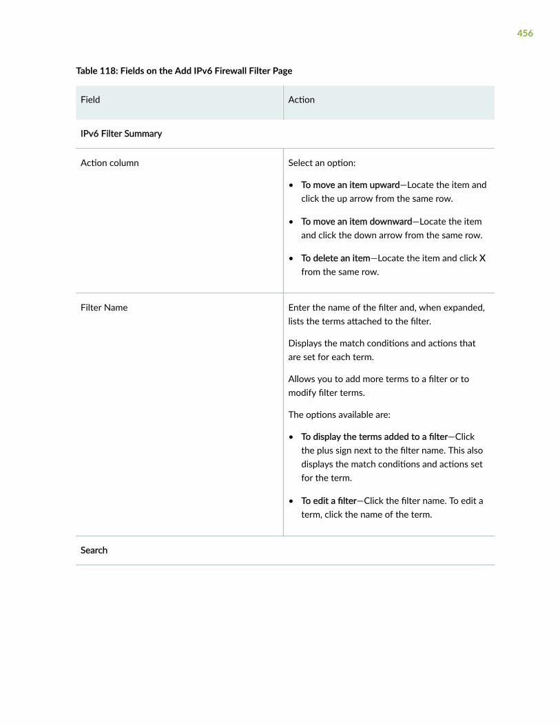
Table 118: Fields on the Add IPv6 Firewall Filter Page
Field Action
IPv6 Filter Summary
Action column Select an option:
• To move an item upward—Locate the item andclick the up arrow from the same row.
• To move an item downward—Locate the itemand click the down arrow from the same row.
• To delete an item—Locate the item and click Xfrom the same row.
Filter Name Enter the name of the filter and, when expanded,lists the terms attached to the filter.
Displays the match conditions and actions thatare set for each term.
Allows you to add more terms to a filter or tomodify filter terms.
The options available are:
• To display the terms added to a filter—Clickthe plus sign next to the filter name. This alsodisplays the match conditions and actions setfor the term.
• To edit a filter—Click the filter name. To edit aterm, click the name of the term.
Search
456

Table 118: Fields on the Add IPv6 Firewall Filter Page (Continued)
Field Action
Filter Name Searches for existing filters by filter name.
The options available are:
• To find a specific filter—Enter the name of thefilter in the Filter Name box.
• To list all filters with a common prefix or suffix—Use the wildcard character (*) when youenter the name of the filter. For example, te*lists all filters with a name starting with thecharacters te.
Term Name Searches for existing terms by name.
The options available are:
• To find a specific term—Enter the name of theterm in the Term Name box.
• To list all terms with a common prefix or suffix—Use the wildcard character (*) when typingthe name of the term. For example, ra* lists allterms with a name starting with the charactersra.
Number of Items to Display Specifies the number of filters or terms to displayon one page. Selects the number of items to bedisplayed on one page.
Add New IPv6 Filter
457

Table 118: Fields on the Add IPv6 Firewall Filter Page (Continued)
Field Action
Filter Name Enter the name of the filter and when expanded,lists the terms attached to the filter.
Displays the match conditions and actions thatare set for each term.
Allows you to add more terms to a filter or modifyfilter terms.
Select an option:
• To display the terms added to a filter—Clickthe plus sign next to the filter name. This alsodisplays the match conditions and actions setfor the term.
• To edit a filter—Click the filter name. To edit aterm, click the name of the term.
Term Name Searches for existing terms by term name.
Select an option:
• To find a specific term—Enter the name of theterm in the Term Name box.
• To list all terms with a common prefix or suffix—Use the wildcard character (*) when typingthe name of the term. For example, ra* lists allterms with a name starting with the charactersra.
Location Positions the new filter in one of the followinglocations:
• After Final IPv4 Filter—At the end of all filters.
• After IPv6 Filter—After a specified filter.
Before IPv6 Filter—Before a specified filter.
458

Table 118: Fields on the Add IPv6 Firewall Filter Page (Continued)
Field Action
Add Click Add.
Opens the Filter Term page allowing you to definethe match conditions and the action for this term.
Add New IPv6 Term
Location Positions the new filter in one of the followinglocations:
• After Final IPv4 Filter—At the end of all filters.
• After IPv6 Filter—After a specified filter.
Before IPv6 Filter—Before a specified filter.
Add Click Add.
Opens the Filter Term page allowing you to definethe match conditions and the action for this term.
Table 119: Fields on the Match Criteria for IPv6 Firewall Filter
Field Action
Match Source
459

Table 119: Fields on the Match Criteria for IPv6 Firewall Filter (Continued)
Field Action
SourceAddress
Specifies IP source addresses to be included in, or excluded from, the matchcondition. Allows you to remove source IP addresses from the match condition.
If you have more than 25 addresses, this field displays a link that allows you to easilyscroll through pages, change the order of addresses, and also search for them.
Enter an IP source address and prefix length, and select an option:
• Add—To include the address in the match condition.
• Except—To exclude the address from the match condition and then select Add -To include the address in the match condition.
• Delete—To remove an IP source address from the match condition.
Source PrefixList
Specifies source prefix lists, which you have already defined, to be included in thematch condition. Allows you to remove a prefix list from the match condition.
Select an option:
• Add—To include a predefined source prefix list in the match condition, type theprefix list name.
• Delete—To remove a prefix list from the match condition.
460

Table 119: Fields on the Match Criteria for IPv6 Firewall Filter (Continued)
Field Action
Source Port Specifies the source port type to be included in, or excluded from, the matchcondition. Allows you to remove a source port type from the match condition.
NOTE: This match condition does not check the protocol type being used on theport. Make sure to specify the protocol type (TCP or UDP) match condition in thesame term.
Select the port from the port name list; enter the port name, number, or range andthen select an option:
• Add—To include the port in the match condition.
• Except—To exclude the port from the match condition and then select Add—Toinclude the port in the match condition.
• Delete—To remove a port from the match condition.
Match Destination
DestinationAddress
Specifies destination addresses to be included in, or excluded from, the matchcondition. Allows you to remove a destination IP address from the match condition.
If you have more than 25 addresses, this field displays a link that allows you to easilyscroll through pages, change the order of addresses, and also search for them.
Enter an IP destination address and prefix length and select an option:
• Add—To include the address in the match condition.
• Except—To exclude the address from the match condition and then select Add—To include the address in the match condition.
• Delete—To remove an IP address from the match condition.
461

Table 119: Fields on the Match Criteria for IPv6 Firewall Filter (Continued)
Field Action
DestinationPrefix List
Specifies destination prefix lists, which you have already defined, to be included inthe match condition. Allows you to remove a prefix list from the match condition.
Select an option:
• Add—To include a predefined destination prefix list, enter the prefix list name.
• Delete—To remove a prefix list from the match condition.
DestinationPort
Specifies destination port types to be included in, or excluded from, the matchcondition. Allows you to remove a destination port type from the match condition.
NOTE: This match condition does not check the protocol type being used on theport. Make sure to specify the protocol type (TCP or UDP) match condition in thesame term.
Select the port from the port name list; enter the port name, number, or range; andthen select an option:
• Add—To include the port in the match condition.
• Except—To exclude the port from the match condition and then select Add—Toinclude the port in the match condition.
• Delete—To remove a port type from the match condition.
Match Source or Destination
462

Table 119: Fields on the Match Criteria for IPv6 Firewall Filter (Continued)
Field Action
Address Specifies IP addresses to be included in, or excluded from, the match condition for asource or destination. Allows you to remove an IP address from the matchcondition.
If you have more than 25 addresses, this field displays a link that allows you to easilyscroll through pages, change the order of addresses and also search for them.
NOTE: This address match condition cannot be specified in conjunction with thesource address or destination address match conditions in the same term.
Enter an IP destination address and prefix length and select an option:
• Add—To include the address in the match condition.
• Except—To exclude the address from the match condition and then select Add—To include the address in the match condition.
• Delete—To remove an IP address from the match condition.
Prefix List Specifies prefix lists, which you have already defined, to be included in the matchcondition for a source or destination. Allows you to remove a prefix list from thematch condition.
NOTE: This prefix list match condition cannot be specified in conjunction with thesource prefix list or destination prefix list match conditions in the same term.
Select an option:
• Add—To include a predefined destination prefix list, type the prefix list name.
• Delete—To remove a prefix list from the match condition.
463

Table 119: Fields on the Match Criteria for IPv6 Firewall Filter (Continued)
Field Action
Port Specifies a port type to be included in, or excluded from, a match condition for asource or destination. Allows you to remove a destination port type from the matchcondition.
NOTE: This match condition does not check the protocol type being used on theport. Make sure to specify the protocol type (TCP or UDP) match condition in thesame term.
Also, this port match condition cannot be specified in conjunction with the sourceport or destination port match conditions in the same term.
Select the port from the port name list; enter the port name, number, or range; andthen select an option:
• Add—To include the port in the match condition.
• Except—To exclude the port from the match condition and then select Add—Toinclude the port in the match condition.
• Delete—To remove a port type from the match condition.
Match Interface
Interface Specifies interfaces to be included in a match condition. Allows you to remove aninterface from the match condition.
Select a name from the interface name list or Enter the interface name and select anoption:
• Add—To include an interface in a match condition.
• Delete—To remove an interface from the match condition.
464

Table 119: Fields on the Match Criteria for IPv6 Firewall Filter (Continued)
Field Action
Interface Set Specifies interface sets, which you have already defined, to be included in a matchcondition. Allows you to remove an interface set from the match condition.
Enter the interface set name and select an option:
• Add—To include the group in the match condition.
• Delete—To remove an interface group from the match condition.
InterfaceGroup
Specifies interface groups, which you have already defined, to be included in, orexcluded from, a match condition. Allows you to remove an interface group from thematch condition.
Enter the name of the group and select an option:
• Add—To include the port in the match condition.
• Except—To exclude the port from the match condition and then select Add—Toinclude the port in the match condition.
• Delete—To remove a port type from the match condition.
Match Packet and Network
TCPEstablished
Matches all Transmission Control Protocol packets other than the first packet of aconnection.
NOTE: This match condition does not verify that the TCP is used on the port. Makesure to specify the TCP as a match condition in the same term.
Select the check box.
TCP Initial Matches the first Transmission Control Protocol packet of a connection.
NOTE: This match condition does not verify that the TCP is used on the port. Makesure to specify the TCP as a match condition in the same term.
Select the check box.
465

Table 119: Fields on the Match Criteria for IPv6 Firewall Filter (Continued)
Field Action
TCP Flags Specifies Transmission Control Protocol flags to be included in the match condition.
NOTE: This match condition does not verify that the TCP is used on the port. Makesure to specify the TCP as a match condition in the same term.
Enter a text or numeric string defining the flag.
Next Header Specifies IPv6 protocol types to be included in, or excluded from, the matchcondition. Allows you to remove an IPv6 protocol type from the match condition.
Select a protocol name from the list or enter a protocol name or number and thenselect an option:
• Add—To include the protocol in the match condition.
• Except—To exclude the protocol from the match condition and then select Add—To include the protocol in the match condition.
• Delete—To remove an IPv6 protocol type from the match condition.
ICMP Type Specifies ICMP packet types to be included in, or excluded from, the matchcondition. Allows you to remove an ICMP packet type from the match condition.
NOTE: This protocol does not verify that ICMP is used on the port. Make sure tospecify an ICMP type match condition in the same term.
Select a packet type from the list or enter a packet type name or number and thenselect an option:
• Add—To include the packet type in the match condition.
• Except—To exclude the packet type from the match condition and then select.
Add—To include the packet type in the match condition.
• Delete—To remove an ICMP packet type from the match condition.
466

Table 119: Fields on the Match Criteria for IPv6 Firewall Filter (Continued)
Field Action
ICMP Code Specifies the ICMP code to be included in, or excluded from, the match condition.Allows you to remove an ICMP code from the match condition.
NOTE: The ICMP code is dependent on the ICMP type. Make sure to specify anICMP type match condition in the same term.
Select a packet code from the list or enter the packet code as text or a number andselect an option:
• Add—To include the packet type in the match condition.
• Except—To exclude the packet type from the match condition and then select
Add—To include the packet type in the match condition.
• Delete—To remove an ICMP packet type from the match condition.
Traffic Class Specifies the traffic class to be included in, or excluded from, the match condition.Allows you to remove a traffic class value from the match condition.
The options available are:
• Add—To include the traffic class in the match condition.
• Except—To exclude the traffic class from the match condition and then select
Add—To include the traffic class in the match condition.
• Delete—To remove a traffic class value from the match condition.
467

Table 119: Fields on the Match Criteria for IPv6 Firewall Filter (Continued)
Field Action
Packet Length Specifies the length of received packets, in bytes, to be included in, or excludedfrom, the match condition. Allows you to remove a packet length value from thematch condition.
Specify a packet length, enter a value or range.
Select an option:
• Add—To include the packet length in the match condition.
• Except—To exclude the packet length from the match condition and then select
Add—To include the packet length in the match condition.
• Delete—To remove a packet length value from the match condition.
ForwardingClass
Specifies forwarding classes to be included in, or excluded from, the matchcondition. Allows you to a remove forwarding class entry from the match condition.
Specify a forwarding class by selecting a forwarding class from the list or entering aforwarding class, and then select an option:
• Add—To include the forwarding class in the match condition.
• Except—To exclude the forwarding class from the match condition and thenselect
Add—To include the forwarding class in the match condition.
• Delete—To remove a forwarding class from the match condition.
Action
Nothing Select Nothing.
Specifies that no action is performed. By default, a packet is accepted if it meets thematch conditions of the term, and packets that do not match any conditions in thefirewall filter are dropped.
468
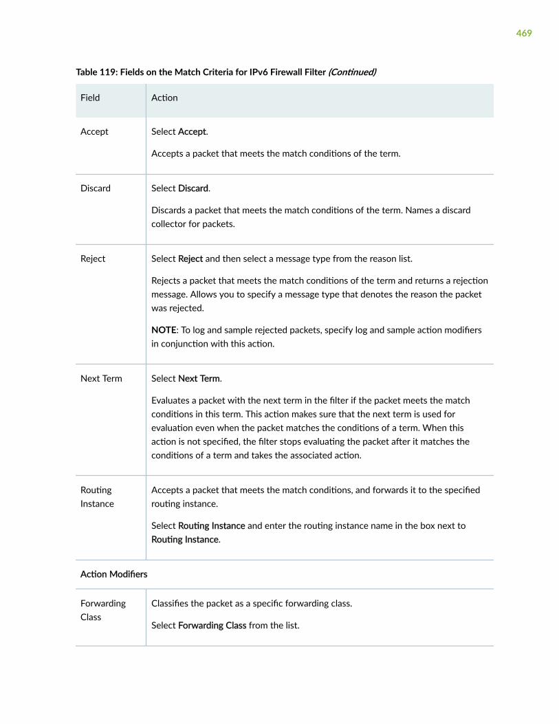
Table 119: Fields on the Match Criteria for IPv6 Firewall Filter (Continued)
Field Action
Accept Select Accept.
Accepts a packet that meets the match conditions of the term.
Discard Select Discard.
Discards a packet that meets the match conditions of the term. Names a discardcollector for packets.
Reject Select Reject and then select a message type from the reason list.
Rejects a packet that meets the match conditions of the term and returns a rejectionmessage. Allows you to specify a message type that denotes the reason the packetwas rejected.
NOTE: To log and sample rejected packets, specify log and sample action modifiersin conjunction with this action.
Next Term Select Next Term.
Evaluates a packet with the next term in the filter if the packet meets the matchconditions in this term. This action makes sure that the next term is used forevaluation even when the packet matches the conditions of a term. When thisaction is not specified, the filter stops evaluating the packet after it matches theconditions of a term and takes the associated action.
RoutingInstance
Accepts a packet that meets the match conditions, and forwards it to the specifiedrouting instance.
Select Routing Instance and enter the routing instance name in the box next toRouting Instance.
Action Modifiers
ForwardingClass
Classifies the packet as a specific forwarding class.
Select Forwarding Class from the list.
469

Table 119: Fields on the Match Criteria for IPv6 Firewall Filter (Continued)
Field Action
Count Counts the packets passing this term. Allows you to name a counter that is specificto this filter. This means that every time a packet transits any interface that uses thisfilter, it increments the specified counter.
Select Count and enter a 24-character string containing letters, numbers, orhyphens to specify a counter name.
Log Select Log.
Logs the packet header information in the routing engine.
Syslog Select Syslog.
Records packet information in the system log.
Loss Priority Sets the loss priority of the packet. This is the priority of dropping a packet before itis sent, and it affects the scheduling priority of the packet.
Select the range of priority from the list.
RELATED DOCUMENTATION
About the IPv6 Page | 454
470

CHAPTER 36
Firewall Filters—Assign to Interfaces
IN THIS CHAPTER
About the Assign to Interfaces Page | 471
About the Assign to Interfaces Page
IN THIS SECTION
Field Descriptions | 471
You are here: You are here: Network > Firewall Filters > Assign To Interfaces.
Use this page to configure interface for firewall filters.
Field Descriptions
Table 120 on page 472 describes the fields on the Assign Interfaces page.
471
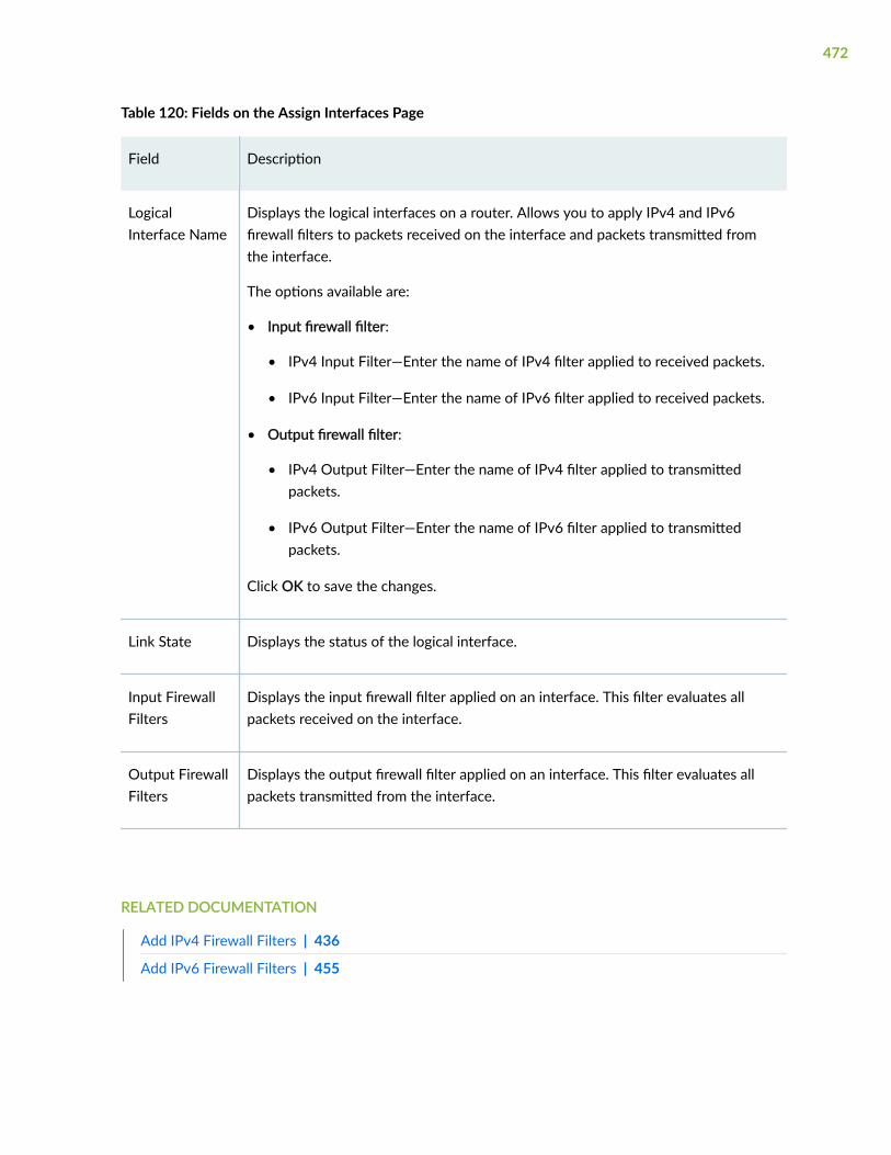
Table 120: Fields on the Assign Interfaces Page
Field Description
LogicalInterface Name
Displays the logical interfaces on a router. Allows you to apply IPv4 and IPv6firewall filters to packets received on the interface and packets transmitted fromthe interface.
The options available are:
• Input firewall filter:
• IPv4 Input Filter—Enter the name of IPv4 filter applied to received packets.
• IPv6 Input Filter—Enter the name of IPv6 filter applied to received packets.
• Output firewall filter:
• IPv4 Output Filter—Enter the name of IPv4 filter applied to transmittedpackets.
• IPv6 Output Filter—Enter the name of IPv6 filter applied to transmittedpackets.
Click OK to save the changes.
Link State Displays the status of the logical interface.
Input FirewallFilters
Displays the input firewall filter applied on an interface. This filter evaluates allpackets received on the interface.
Output FirewallFilters
Displays the output firewall filter applied on an interface. This filter evaluates allpackets transmitted from the interface.
RELATED DOCUMENTATION
Add IPv4 Firewall Filters | 436
Add IPv6 Firewall Filters | 455
472

CHAPTER 37
NAT Policies
IN THIS CHAPTER
About the NAT Policies Page | 473
Create a Source NAT | 475
Edit a Source NAT | 481
Delete Source NAT | 482
About the NAT Policies Page
IN THIS SECTION
Tasks You Can Perform | 474
Field Descriptions | 474
You are here: Network > NAT > Policies.
Network Address Translation (NAT) is a form of network masquerading where you can hide devicesbetween the zones or interfaces. A trust zone is a segment of the network where security measures areapplied. It is usually assigned to the internal LAN. An untrust zone is the Internet. NAT modifies the IPaddresses of the packets moving between the trust and untrust zones.
Whenever a packet arrives at the NAT device, the device performs a translation on the packet’s IPaddress by rewriting it with an IP address that was specified for external use. After translation, thepacket appears to have originated from the gateway rather than from the original device within thenetwork. This helps you hide internal IP addresses from the other networks and keep your networksecure.
Use this page to configure source, destination, and static NAT.
473

Tasks You Can Perform
You can perform the following tasks from this page:
• Create a source NAT. See "Create a Source NAT" on page 475.
• Edit a source NAT. See "Edit a Source NAT" on page 481.
• Delete a source NAT. See "Delete Source NAT" on page 482.
• View destination NAT rules. For more information on destination NAT, see "About the DestinationPage" on page 494.
• View static NAT rules. For more information on static NAT, see "About the Static Page" on page 501.
Field Descriptions
Table 121 on page 474 describes the fields on the NAT Policies Page.
Table 121: Fields on the NAT Policies Page.
Field Description
Seq Displays the sequence number of rules in a context. Drag and drop the policieswithin the same context to reorder your NAT policy among the existingpolicies.
Hits Displays the number of hits the rule has encountered.
Rule Name Displays the rule name.
NAT Type Displays whether the NAT is source, destination, or static.
Source Ingress Displays the source ingress type. For example: zone, interface, or routinginstance.
Source Address Displays the match source address of the NAT policy.
Source Port Displays the match source port of the NAT policy.
474

Table 121: Fields on the NAT Policies Page. (Continued)
Field Description
Destination Egress Displays the match destination egress type. For example: zone, interface, orrouting instance.
Destination Address Displays the match destination address of the NAT policy.
Destination Port Displays the match destination port of the NAT policy.
Applications Displays the match application for the NAT policy.
Protocol Displays the match IP protocol for the NAT policy.
Actions Displays the action of the NAT policy.
Description Displays the description for the NAT policy.
Create a Source NAT
You are here: Network > NAT > Policies.
To create a source NAT:
1. Click Create > Source NAT on the upper right-side of the Policies page.
The inline creation fields will appear.
2. Complete the configuration according to the guidelines provided in Table 122 on page 476.
3. Click the tick icon on the right-side of the row once done with the configuration.
475

Table 122: Fields on the Policies Page—Create Source NAT
Field Description
Rule Name >Name
Enter a unique source NAT rule name.
Source Ingress
Select Sources
Source ingresstype
Select an option from the list for ingress traffic that originates from inside thenetwork:
• Zone
• Interface
• Routing Instance
Zone Select the source zones in the Available column and use the right arrow to movethem to the Selected column.
NOTE: This option is available only if you select source ingress type as Zone.
Interface Select the source interfaces in the Available column and use the right arrow tomove them to the Selected column.
NOTE: This option is available only if you select source ingress type as Interface.
Routing instance Select the source routing instances in the Available column and use the rightarrow to move them to the Selected column.
NOTE: This option is available only if you select source ingress type as RoutingInstance.
476

Table 122: Fields on the Policies Page—Create Source NAT (Continued)
Field Description
Addresses Select the source addresses in the Available column and use the right arrow tomove them to the Selected column.
To create a new address:
1. Click +.
The Create Address page appears.
2. Enter the following details:
• Name—Optional. Enter a unique name for source address.
• Description—Enter the description for source address.
• Host IP—Enter IPv4 or IPv6 host address.
Ports/Port range Click + to enter port number or port range (for example, 1-5) with minimum andmaximum values for source.
Range: 0 through 65535.
To edit a port number or port range, select it and click the pencil icon.
To delete a port number or port range, select it and click the delete icon.
Destination Egress
Select Destination
Destinationegress type
Select an option from the list for outgoing traffic that originates from inside ofthe device network:
• Zone
• Interface
• Routing Instance
477

Table 122: Fields on the Policies Page—Create Source NAT (Continued)
Field Description
Zone Select the destination zones in the Available column and use the right arrow tomove them to the Selected column.
NOTE: This option is available only if you select destination egress type as Zone.
Interface Select the destination interfaces in the Available column and use the right arrowto move them to the Selected column.
NOTE: This option is available only if you select destination egress type asInterface.
Routing instance Select the destination routing instances in the Available column and use the rightarrow to move them to the Selected column.
NOTE: This option is available only if you select destination egress type asRouting Instance.
Addresses Select the destination addresses in the Available column and use the right arrowto move them to the Selected column.
To create a new address:
1. Click +.
The Create Address page appears.
2. Enter the following details:
• Name—Optional. Enter a unique name for destination address.
• Description—Enter the description for destination address.
• Host IP—Enter IPv4 or IPv6 host address.
478

Table 122: Fields on the Policies Page—Create Source NAT (Continued)
Field Description
Ports/Port range Click + to enter port number or port range (for example, 1-5) with minimum andmaximum values for destination.
Range: 0 through 65535.
To edit a port number or port range, select it and click the pencil icon.
To delete a port number or port range, select it and click the delete icon.
Applications
Select Applications
Applications Select an application option:
• Any—Any applications you want to associate with the NAT policy.
• Specific—Select the applications in the Available column and use the rightarrow to move them to the Selected column.
• None—No applications selected to associate with the NAT policy.
Protocols
Select Protocols
Protocols Select the protocols in the Available column and use the right arrow to movethem to the Selected column.
Add Protocol Click + and enter a protocol number to associate with the NAT policy.
Range is 0 through 255.
Actions
Actions
479

Table 122: Fields on the Policies Page—Create Source NAT (Continued)
Field Description
Translation type Select an option:
• None—No translation is performed for the incoming traffic.
• Interface—Performs interface-based translations on the source traffic.
• Pool—Performs pool-based translations on the source traffic.
Source pool Select a source pool from the list.
Click Add New to create a new source NAT pool. For more information on fieldoptions, see "Create a Source NAT Pool" on page 486.
Persistent Enable this option for mapping all requests from the same internal transportaddress to the same reflexive transport address.
Persistent NATtype
Select an option from the list:
• any-remote-host—All requests from a specific internal IP address and port aremapped to the same reflexive transport address. Any external host can send apacket to the internal host by sending the packet to the reflexive transportaddress.
• target-host—All requests from a specific internal IP address and port aremapped to the same reflexive transport address. An external host can send apacket to an internal host by sending the packet to the reflexive transportaddress. The internal host must have previously sent a packet to the externalhosts IP address.
• target-host-port—All requests from a specific internal IP address and port aremapped to the same reflexive transport address. An external host can send apacket to an internal host by sending the packet to the reflexive transportaddress. The internal host must have previously sent a packet to the externalhosts IP address and port.
480

Table 122: Fields on the Policies Page—Create Source NAT (Continued)
Field Description
Inactivity timeout Enter the amount of time that the persistent NAT binding remains in the sitesmemory when all the sessions of the binding entry have ended.
Range is 60 through 7200 seconds.
Maximum sessionnumber
Enter the maximum number of sessions with which a persistent NAT binding canbe associated.
Range is 8 through 65536
Description Enter the description for the source NAT.
RELATED DOCUMENTATION
Edit a Source NAT | 481
Delete Source NAT | 482
Edit a Source NAT
You are here: Network > NAT > Policies.
To edit a source NAT:
1. Double-click an existing source NAT that you want to edit on the Policies page.
2. Complete the configuration according to the guidelines provided in "Create a Source NAT" on page475.
3. Click the tick icon on the right-side of the row once done with the configuration.
RELATED DOCUMENTATION
Delete Source NAT | 482
481

Delete Source NAT
You are here: Network > NAT > Policies.
To delete a source NAT:
1. Select one or more source NATs that you want to delete on the Policies page.
2. Click the delete icon available on the upper right-side of the page.
A confirmation message window appears.
3. Click Yes to delete or click No to retain the source NAT.
RELATED DOCUMENTATION
Create a Source NAT | 475
Edit a Source NAT | 481
482

CHAPTER 38
NAT Pools
IN THIS CHAPTER
About the NAT Pools Page | 483
Global Options | 485
Create a Source NAT Pool | 486
Edit a Source NAT Pool | 490
Delete Source NAT Pool | 491
Add a Destination NAT Pool | 491
Edit a Destination NAT Pool | 493
Delete Destination NAT Pool | 493
About the NAT Pools Page
IN THIS SECTION
Tasks You Can Perform | 484
Field Descriptions | 484
You are here: Network > NAT > Pools.
A NAT pool is a set of IP addresses that you can define and use for translation. NAT policies performaddress translation by translating internal IP addresses to the addresses in these pools. Unlike staticNAT, where there is a one-to-one mapping that includes destination IP address translation in onedirection and source IP address translation in the reverse direction, with source NAT, you translate theoriginal source IP address to an IP address in the address pool. With destination NAT, you translate theoriginal destination address to an IP address in the address pool.
Use this page to configure source and destination NAT pools.
483

Tasks You Can Perform
You can perform the following tasks from this page:
• Add a global option. See "Global Options" on page 485.
• Create a source NAT pool. See "Create a Source NAT Pool" on page 486.
• Edit a source NAT pool. See "Edit a Source NAT Pool" on page 490.
• Delete a source NAT pool. See "Delete Source NAT Pool" on page 491.
• Add a destination NAT pool. See "Add a Destination NAT Pool" on page 491.
• Edit a destination NAT pool. See "Edit a Destination NAT Pool" on page 493.
• Delete a destination NAT pool. See "Delete Destination NAT Pool" on page 493.
Field Descriptions
Table 123 on page 484 describes the fields on the NAT Pools Page.
Table 123: Fields on the NAT Pools Page.
Field Description
Pool Name Displays the NAT pool name.
Pool Type Displays whether the NAT pool is either source or destination.
Pool Address Displays the NAT pool address.
Proxy ARP/ND Displays the Address Resolution Protocol (ARP) proxy or Neighbor DiscoveryProtocol (NDP) proxy for the NAT pool.
Description Displays the description for the NAT pool.
484

Global Options
You are here: Network > NAT > Pools.
To add global options for a NAT pool:
1. Click the Global Options available on the upper right side of the page.
The Global Options page appears.
2. Complete the configuration according to the guidelines provided in Table 124 on page 485.
3. Click OK to save the changes.
Table 124: Fields on the Global Options Page
Field Action
Persistent address Enable this option to ensure that the same IP address is assigned from thesource NAT pool to a specific host for multiple concurrent sessions.
Port randomization Enable port randomization. The device performs NAT translation choosing theIP address by round robin, then chooses the port used for that IP address byrandomization.
Interface portoverloading
Enable this option to set the port range for NAT interface overload mapping. Italso allows you to block a specific port from being used in interface overloadmapping.
Overloading factor Enter a value for the port overloading capacity for the source NAT interface.
For example, if overloading factor is set to 2, and it is multiplied by a maximumport capacity of 63,486, the port overloading threshold is 126,972. If theconfigured setting exceeds the maximum port capacity of the interface, anerror message is generated during the configuration commit.
RELATED DOCUMENTATION
About the NAT Pools Page | 483
Create a Source NAT Pool | 486
Add a Destination NAT Pool | 491
485

Create a Source NAT Pool
You are here: Network > NAT > Pools.
To add a source NAT pool:
1. Click Create > Source NAT Pool on the upper right side of the Pools page.
The Create Source NAT Pool page appears.
2. Complete the configuration according to the guidelines provided in Table 125 on page 486.
3. Click OK to save the changes. If you want to discard your changes, click Cancel.
Table 125 on page 486 describes the fields on the Create Source NAT Pool page.
Table 125: Fields on the Create Source NAT Pool Page
Field Description
Name Enter a unique string of alphanumeric characters, hyphens and underscores;maximum length 63-character.
Description Enter a description for the source NAT pool.
Basic
Routing instance Select a routing instance from the list.
486

Table 125: Fields on the Create Source NAT Pool Page (Continued)
Field Description
Pool addresses Select the source NAT pool addresses in the Available column and the use theright arrow to move them to the Selected column.
To add a new pool address:
1. Click +.
The Add Pool Address page appears.
2. Enter the following details:
• Name—Enter a name for the pool address.
• Description—Enter a description for the pool address.
• Pool address type—Select either IP address or address range for the pool.
• IP address—Enter IPv4 or IPv6 address of the host.
NOTE: This option is available only when you select IP address as pooladdress type.
• Start Address—Enter the starting range of IPv4 or IPv6 address for thesource NAT pool.
NOTE: This option is available only when you select Address Range aspool address type.
• End Address—Enter the ending range of IPv4 or IPv6 address for thesource NAT pool.
NOTE: This option is available only when you select Address Range aspool address type.
Advanced
Port Translation
487

Table 125: Fields on the Create Source NAT Pool Page (Continued)
Field Description
Port translation Select a port translation option from the list:
• No Translation
• Translation with port range—Port range from low to high. Range is 1024through 65535.
• Translation with port overloading factor—Port overloading capacity for thesource NAT interface.
Shared Address Enable this option to map many-to-one external IP addresses. This increasesNAT resources and improves traffic.
NOTE: This option is available only when you select No Translation.
Host address base Enter IPv4 or IPv6 address used as the host address base.
For example, if the host address base is 198.51.100.30 and the NAT pool usesthe range 203.0.113.10 to 203.0.113.20, then 198.51.100.30 translates to203.0.113.10, 198.51.100.31 translates to 203.0.113.11, and so on.
Port range from Enter the lower limit of the port range.
Range: 1024 through 65535.
NOTE: This option is available only when you select Translation with port range.
Port range to Enter the upper limit of the port range.
Range: 1024 through 65535.
NOTE: This option is available only when you select Translation with port range.
488

Table 125: Fields on the Create Source NAT Pool Page (Continued)
Field Description
Overloading factor Enter the port overloading factor value.
Range: 2 through 32.
NOTE: This option is available only when you select Translation with portoverloading factor.
Address pooling Specifies that multiple internal IP addresses can be mapped to the same externalIP address. Use this option only when the source NAT pool is configured with noport translation.
Paired Select this option to use in source NAT pools with port translation forapplications that require all sessions associated with one internal IP address tobe translated to the same external IP address for multiple sessions.
NOTE: This option is available only when you enable Address Pooling.
Non-paired Select this option to use in source NAT pools without port translation forassigning IP addresses using a round-robin fashion.
NOTE: This option is available only when you enable Address Pooling.
Overflow pooltype
Specify a source pool to use when the current address pool is exhausted:
• None—No support for overflow.
• Interface—Allow the interface to support overflow.
• Pool—Name of the source address pool.
NOTE: This option is available only when you select No Translation.
Overflow pool Select a source address pool from the list.
Utilization Alarm
489

Table 125: Fields on the Create Source NAT Pool Page (Continued)
Field Description
Upper threshold Enter an upper threshold percentage for pool address utilization at which anSNMP trap is triggered.
Range: 50 through 100.
Lower threshold Enter a lower threshold percentage for pool address utilization at which anSNMP trap is triggered.
Range: 40 through 100.
NOTE: This option can be set only if you configure the upper threshold value.
RELATED DOCUMENTATION
About the NAT Pools Page | 483
Edit a Source NAT Pool | 490
Delete Source NAT Pool | 491
Edit a Source NAT Pool
You are here: Network > NAT > Pools.
To edit a source NAT pool:
1. Select an existing source NAT pool that you want to edit on the Pools page.
2. Click the pencil icon available on the upper right side of the page.
The Edit Source NAT Pool page appears with editable fields. For more information on the options,see "Create a Source NAT Pool" on page 486.
3. Click OK to save the changes.
RELATED DOCUMENTATION
Delete Source NAT Pool | 491
490

Delete Source NAT Pool
You are here: Network > NAT > Pools.
To delete a source NAT pool:
1. Select one or more source NAT pools that you want to delete on the Pools page.
2. Click the delete icon available on the upper right side of the page.
A confirmation message window appears.
3. Click Yes to delete or click No to retain the profile.
RELATED DOCUMENTATION
About the NAT Pools Page | 483
Create a Source NAT Pool | 486
Edit a Source NAT Pool | 490
Add a Destination NAT Pool
You are here: Network > NAT > Pools.
To add a destination NAT pool:
1. Click Create > Destination NAT Pool on the upper right side of the Pools page.
The Create Destination NAT Pool page appears.
2. Complete the configuration according to the guidelines provided in Table 126 on page 491.
3. Click OK to save the changes. If you want to discard your changes, click Cancel.
Table 126 on page 491 describes the fields on the Create Destination NAT Pool page.
Table 126: Fields on the Create Destination NAT Pool Page
Field Action
Name Enter the destination pool name.
Description Enter a description for the destination pool.
491

Table 126: Fields on the Create Destination NAT Pool Page (Continued)
Field Action
Routing instance Select a routing instance from the list.
Pool address type Select one of the following pool address type:
• Address & Port—Translate destination IP address or addresses and portnumber(s) to a specific IP address and one port number.
• Address Range—Translate a range of destination IP addresses to another rangeof IP addresses. This mapping is one-to-one.
Pool address Enter IPv4 or IPv6 address for destination pool.
NOTE: This option is available only when you select Address & Port as pooladdress type.
Pool port Enter a destination port value.
Range: 0 through 65535.
NOTE: This option is available only when you select Address & Port as pooladdress type.
Start address Enter starting address (IPv4 or IPv6) of the destination address range.
NOTE: This option is available only when you select Address Range as pooladdress type.
End address Enter ending address (IPv4 or IPv6) of the destination address range.
NOTE: This option is available only when you select Address Range as pooladdress type.
RELATED DOCUMENTATION
Edit a Destination NAT Pool | 493
492

Delete Destination NAT Pool | 493
About the NAT Pools Page | 483
Create a Source NAT Pool | 486
Edit a Destination NAT Pool
You are here: Network > NAT > Pools.
To edit a destination NAT pool:
1. Select an existing destination NAT pool that you want to edit on the Pools page.
2. Click the pencil icon available on the upper right side of the page.
The Edit Destination NAT Pool page appears with editable fields. For more information on theoptions, see "Add a Destination NAT Pool" on page 491.
3. Click OK to save the changes.
RELATED DOCUMENTATION
Delete Destination NAT Pool | 493
About the NAT Pools Page | 483
Delete Destination NAT Pool
You are here: Network > NAT > Pools.
To delete a destination NAT pool:
1. Select one or more destination NAT pools that you want to delete on the Pools page.
2. Click the delete icon available on the upper right side of the page.
3. Click Yes to delete or click No to retain the profile.
RELATED DOCUMENTATION
Add a Destination NAT Pool | 491
Edit a Destination NAT Pool | 493
493

CHAPTER 39
Destination NAT
IN THIS CHAPTER
About the Destination Page | 494
Add a Destination Rule Set | 496
Edit a Destination Rule Set | 499
Delete Destination Rule Set | 499
About the Destination Page
IN THIS SECTION
Tasks You Can Perform | 494
Field Descriptions | 495
You are here: Network > NAT > Destination.
Use this page to add, edit, or delete destination NAT configurations.
Tasks You Can Perform
You can perform the following tasks from this page:
• Add a Destination Rule Set. See "Add a Destination Rule Set" on page 496.
• Edit a Destination Rule Set. See "Edit a Destination Rule Set" on page 499.
• Delete a Destination Rule Set. See "Delete Destination Rule Set" on page 499.
494

Field Descriptions
Table 127 on page 495 describes the fields on the Destination Page.
Table 127: Fields on the Destination Page.
Field Description
Destination NAT Rule Set
From Displays the destination NAT sort options from which the packets flow.
The options available are:
• Routing Instance
• Zone
• Interface
Filter Displays the filter option.
Name Displays the name of the destination NAT rule set.
From Displays the name of the routing instance/zone/interface from which thepackets flow.
Rule Displays the name of the rule in the selected destination NAT rule set.
Description Displays a description of the destination NAT rule set.
Rules in Selected Rule-Set
Rule Name Displays the name of the rule in the selected destination NAT rule set.
Match Source Displays the match source address.
Match Destination Displays the match destination address.
495

Table 127: Fields on the Destination Page. (Continued)
Field Description
Match IP Protocol Displays the match IP protocol.
Match Destination Port Displays the match destination port.
Action Displays the action of the rule in the selected rule set.
Upper Threshold Displays upper threshold at which an SNMP trap is triggered.
Lower Threshold Displays lower threshold at which an SNMP trap is triggered.
Description Displays a description of the rule in the selected destination NAT rule set.
RELATED DOCUMENTATION
Add a Destination Rule Set | 496
Add a Destination Rule Set
You are here: Network > NAT > Destination.
To add a destination Rule Set:
1. Click the add icon (+) on the upper right side of the Destination page.
The Add Rule Set page appears.
2. Complete the configuration according to the guidelines provided in Table 128 on page 497.
3. Click OK to save the changes. If you want to discard your changes, click Cancel.
Table 128 on page 497 describes the fields on the Add Rule Set page.
496

Table 128: Fields on the Add Rule Set page.
Field Action
Add Rule Set
Rule Set Name Enter the rule set name.
Rule Set Description Enter a description for the rule set.
From Specifies the filter options. Select an option:
• Routing Instance
• Zone
• Interface
Select the routing instances/zones/interfaces in the Available column and theuse the right arrow to move them to the Selected column.
Add Rule
Rule Name Enter the rule name.
Rule Description Enter a description for the rule.
Match
Source Address Search and select the source addresses in the Available column and the use theright arrow to move them to the Selected column.
You can also enter a source address in the New text box in the Selectedcolumn and click Add to add the source address to the lower pane of theSelected column.
Destination Address Enter the destination IP address.
497
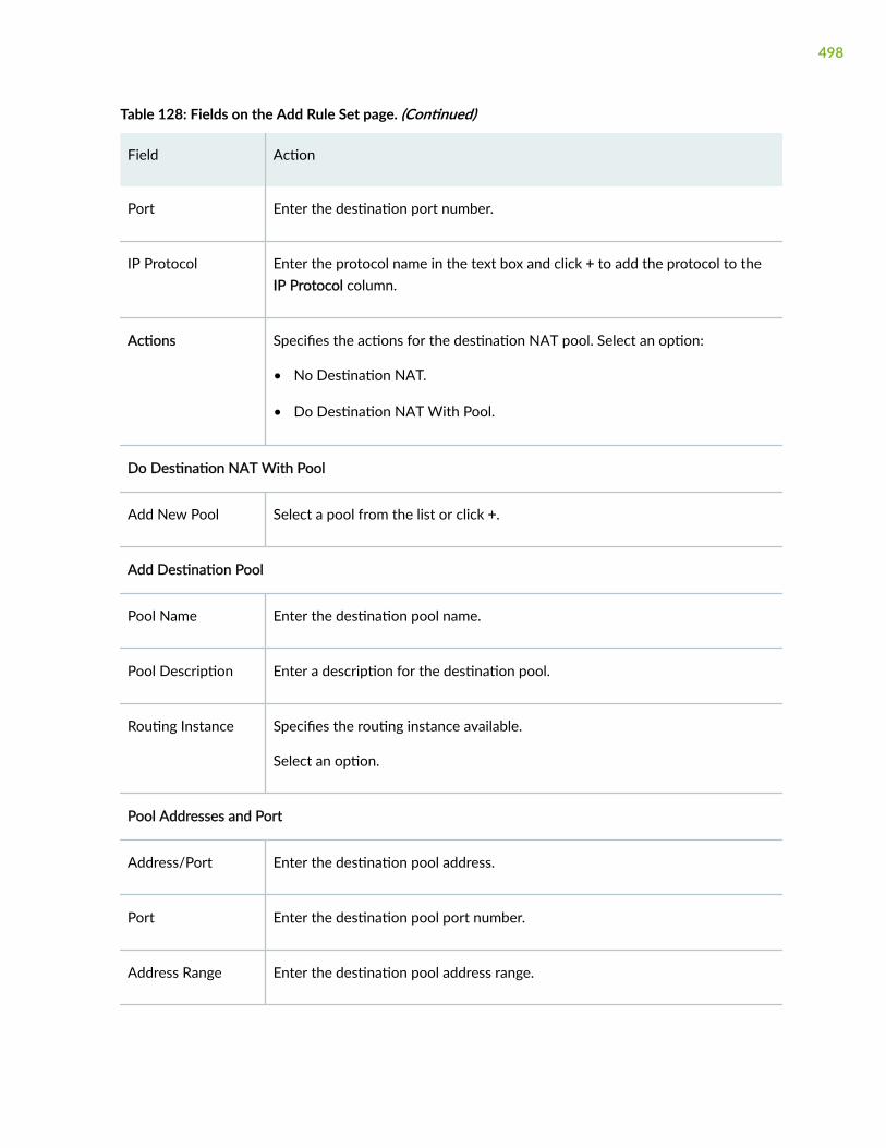
Table 128: Fields on the Add Rule Set page. (Continued)
Field Action
Port Enter the destination port number.
IP Protocol Enter the protocol name in the text box and click + to add the protocol to theIP Protocol column.
Actions Specifies the actions for the destination NAT pool. Select an option:
• No Destination NAT.
• Do Destination NAT With Pool.
Do Destination NAT With Pool
Add New Pool Select a pool from the list or click +.
Add Destination Pool
Pool Name Enter the destination pool name.
Pool Description Enter a description for the destination pool.
Routing Instance Specifies the routing instance available.
Select an option.
Pool Addresses and Port
Address/Port Enter the destination pool address.
Port Enter the destination pool port number.
Address Range Enter the destination pool address range.
498

Table 128: Fields on the Add Rule Set page. (Continued)
Field Action
Upper Threshold Enter upper threshold at which an SNMP trap is triggered. Session count hitalarm range: 1 through 4294967295
Lower Threshold Enter lower threshold at which an SNMP trap is triggered. Rule session countalarm range: 1 through 4294967295
RELATED DOCUMENTATION
Edit a Destination Rule Set | 499
Edit a Destination Rule Set
You are here: Network > NAT > Destination.
To edit a destination rule set:
1. Select an existing destination rule set that you want to edit on the Destination page.
2. Click the pencil icon available on the upper right side of the page.
The Edit Rule Set page appears with editable fields. For more information on the options, see "Add aDestination Rule Set" on page 496.
3. Click OK to save the changes.
RELATED DOCUMENTATION
Delete Destination Rule Set | 499
Delete Destination Rule Set
You are here: Network > NAT > Destination.
To delete destination rule set:
499

1. Select one or more destination rule sets that you want to delete on Destination page.
2. Click the delete icon available on the upper right side of the page.
3. Click Yes to delete or click No to retain the profile.
RELATED DOCUMENTATION
Add a Destination NAT Pool | 491
500

CHAPTER 40
Static NAT
IN THIS CHAPTER
About the Static Page | 501
Add a Static Rule Set | 504
Edit a Static Rule Set | 507
Delete Static Rule Set | 507
About the Static Page
IN THIS SECTION
Tasks You Can Perform | 501
Field Descriptions | 502
You are here: Network > NAT > Static.
Use tis page to configure static NAT.
Tasks You Can Perform
You can perform the following tasks from this page:
• Add a static rule set and rules to it. See "Add a Static Rule Set" on page 504.
• Edit a static rule set and its rules. See "Edit a Static Rule Set" on page 507.
• Delete a static rule set and its rules. See "Delete Static Rule Set" on page 507.
• Move the rules in the rules table. To do this, select a rule which you want to move and select thefollowing options according to your choice:
501

• Move Up—Enables you to move the rule up in the list.
• Move Down—Enables you to move the rule down in the list.
• Move to Top—Enables you to move the rule to top of the list
• Move to Bottom—Enables you to move the rule to the bottom of the list
Field Descriptions
Table 129 on page 502 describes the fields on the Static page.
Table 129: Fields on the Static Page
Field Description
Static NAT Rule Set
From Displays the destination NAT sort options from which the packets flow.
The options available are:
• Routing Instance
• Zone
• Interface
Filter Displays the filter options.
Name Displays the name of the static NAT rule set.
From Displays the name of the routing instance, zone, or interface from which thepackets flow.
Rule Displays the name of the rule in the selected static NAT rule set.
Description Displays a description of the static NAT rule set.
Rules in Selected Rule-Set
502

Table 129: Fields on the Static Page (Continued)
Field Description
Rule Name Displays the name of the routing instance, zone, or interface to which thepacket flows.
Source Addresses Displays the source address to match the rule.
Source Ports Displays the source port number.
Destination Addresses Displays the destination address to match the rule.
Destination Ports Displays the destination port number.
Prefix Displays the static IP address prefix.
Mapped Port Displays the destination port or port range to allow static NAT to map ports.
Upper Threshold Displays the upper threshold value of the at which an SNMP trap istriggered.
Lower Threshold Displays the lower threshold value of the at which an SNMP trap is triggered.
Description Displays the description of the rule in the selected static NAT rule set.
RELATED DOCUMENTATION
Add a Static Rule Set | 504
Edit a Static Rule Set | 507
Delete Static Rule Set | 507
503

Add a Static Rule Set
You are here: Network > NAT > Static.
To add a static rule set:
1. Click the add icon (+) on the upper right side of the Static page.
The Add Rule Set page appears.
2. Complete the configuration according to the guidelines provided in Table 130 on page 504.
3. Click OK to save the changes. If you want to discard your changes, click Cancel.
Table 130: Fields on the Add Static Rule Set Page
Field Action
Rule Set Name Enter a rule set name.
Rule SetDescription
Enter a description for the rule set.
From Select a filter option from the list:
• Routing Instance
• Zone
• Interface
Select the routing instances, zones, or interfaces in the Available column and usethe right arrow to move them to the Selected column.
Rules
Rules Specifies the rules added to the selected static rule set.
504
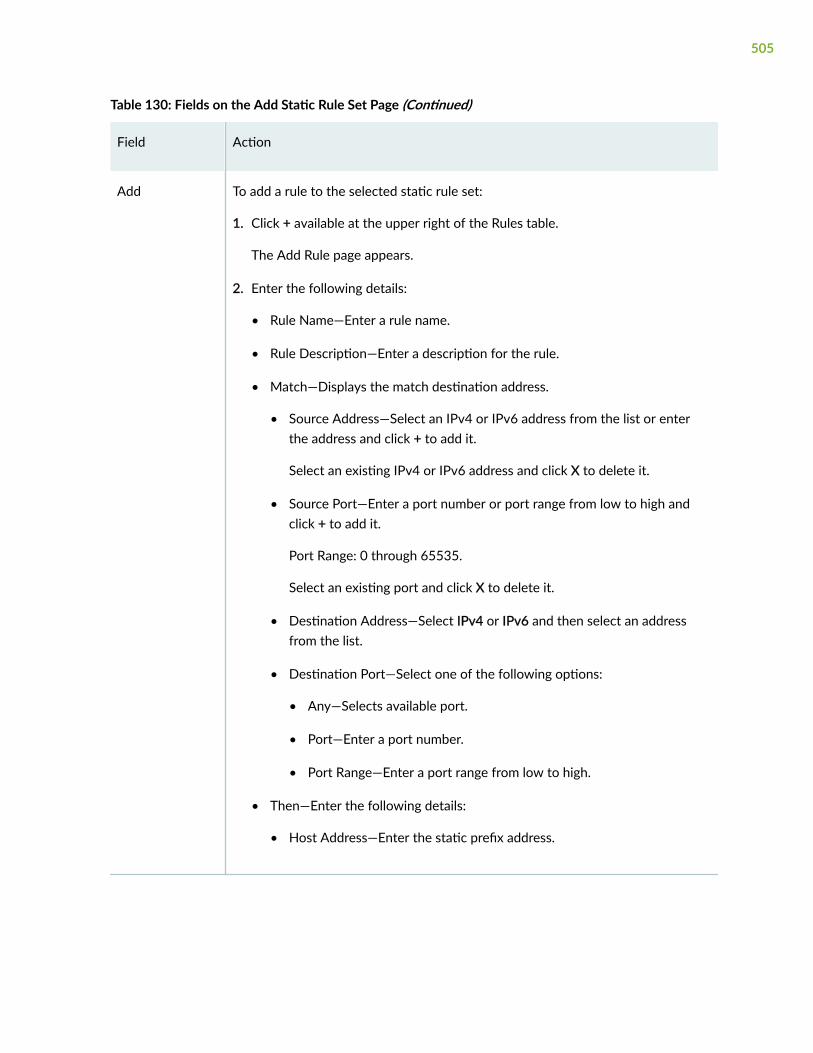
Table 130: Fields on the Add Static Rule Set Page (Continued)
Field Action
Add To add a rule to the selected static rule set:
1. Click + available at the upper right of the Rules table.
The Add Rule page appears.
2. Enter the following details:
• Rule Name—Enter a rule name.
• Rule Description—Enter a description for the rule.
• Match—Displays the match destination address.
• Source Address—Select an IPv4 or IPv6 address from the list or enterthe address and click + to add it.
Select an existing IPv4 or IPv6 address and click X to delete it.
• Source Port—Enter a port number or port range from low to high andclick + to add it.
Port Range: 0 through 65535.
Select an existing port and click X to delete it.
• Destination Address—Select IPv4 or IPv6 and then select an addressfrom the list.
• Destination Port—Select one of the following options:
• Any—Selects available port.
• Port—Enter a port number.
• Port Range—Enter a port range from low to high.
• Then—Enter the following details:
• Host Address—Enter the static prefix address.
505

Table 130: Fields on the Add Static Rule Set Page (Continued)
Field Action
NOTE: You can select Translate to ipv4 address if you have selectedIPv6 in the destination address.
• Mapped Port—Select one of the following options:
• Any—Selects available port.
• Port—Enter a port number.
• Port Range—Enter a port range from low to high.
• Routing Instance—Select a routing instance from the list.
• Upper Threshold—Enter an upper threshold value at which an SNMPtrap is triggered.
Range: 1 through 4294967295.
• Lower Threshold—Enter a lower threshold value at which an SNMP trapis triggered.
Range: 1 through 4294967295.
NOTE: This option can be set only if you configure the upper thresholdvalue.
3. Click OK to save the changes. If you want to discard your changes, clickCancel.
Edit Select an existing rule and click the edit icon at the top right corner of the Rulestable.
The Edit Interface page appears with editable fields.
Delete Select an interface and click the delete icon at the top right corner of the Rulestable.
A confirmation window appears. Click Yes to delete the selected interface or clickNo to discard.
506

RELATED DOCUMENTATION
About the Static Page | 501
Edit a Static Rule Set | 507
Delete Static Rule Set | 507
Edit a Static Rule Set
You are here: Network > NAT > Static.
To edit a static rule set and its rules:
1. Select an existing static rule set that you want to edit on the Static page.
2. Click the pencil icon available on the upper right side of the Static page.
The Edit Static Rule Set page appears with editable fields. For more information on the options, see"Add a Static Rule Set" on page 504.
NOTE: Alternatively, you can select the rule directly and click the pencil icon available on theupper right side of the Rules table to edit a rule for the selected rule set.
3. Click OK to save the changes.
RELATED DOCUMENTATION
About the Static Page | 501
Add a Static Rule Set | 504
Delete Static Rule Set | 507
Delete Static Rule Set
You are here: Network > NAT > Static.
To delete a static rule set and its rules:
1. Select one or more static rules sets that you want to delete on the Static page.
2. Click the delete icon available on the upper right side of the page.
A confirmation window appears.
507

NOTE: Alternatively, you can select the rule directly and click the delete (X) icon available onthe upper right side of the Rules table to delete a rule for the selected rule set.
3. Click Yes to delete or click No to retain the profile.
RELATED DOCUMENTATION
About the Static Page | 501
Add a Static Rule Set | 504
Edit a Static Rule Set | 507
508

CHAPTER 41
NAT Proxy ARP/ND
IN THIS CHAPTER
About the Proxy ARP/ND Page | 509
Add a Proxy ARP | 510
Edit a Proxy ARP | 512
Delete a Proxy ARP | 512
Add a Proxy ND | 513
Edit a Proxy ND | 514
Delete Proxy ND | 514
About the Proxy ARP/ND Page
IN THIS SECTION
Tasks You Can Perform | 509
Field Descriptions | 510
You are here: Network > NAT > Proxy ARP/ND.
You can add, edit, and delete proxy ARP or proxy ND configurations.
Tasks You Can Perform
You can perform the following tasks from this page:
• Add a proxy ARP. See "Add a Proxy ARP" on page 510.
• Edit a proxy ARP. See "Edit a Proxy ARP" on page 512.
509

• Delete a proxy ARP. See "Delete a Proxy ARP" on page 512.
• Create a proxy ND. See "Add a Proxy ND" on page 513.
• Edit a proxy ND. See "Edit a Proxy ND" on page 514.
• Delete a proxy ND. See "Delete Proxy ND" on page 514.
• Launch NAT wizard. To do this, click Launch Wizard option at the right side of the page. The NATwizard leads you through the basic required steps to configure NAT for the SRX Series securitydevice.
Field Descriptions
Table 131 on page 510 describes the fields on the Proxy ARP/ND Configuration page.
Table 131: Fields on the Proxy ARP/ND Configuration Page
Field Description
Interface Displays the interface type.
Address Displays the IPv4 or IPv6 address.
RELATED DOCUMENTATION
Add a Proxy ARP | 510
Edit a Proxy ARP | 512
Delete a Proxy ARP | 512
Add a Proxy ND | 513
Edit a Proxy ND | 514
Delete Proxy ND | 514
Add a Proxy ARP
You are here: Network > NAT > Proxy ARP/ND.
510

To add a proxy ARP:
1. Click the add icon (+) on the upper right side of the proxy ARP/ND page.
Select the Proxy ARP page. The Add Proxy ARP page appears.
2. Complete the configuration according to the guidelines provided in Table 132 on page 511.
3. Click OK to save the changes. If you want to discard your changes, click Cancel.
Table 132: Fields on the Add Proxy ARP Page
Field Action
Interface Enter the interface type. Select an option:
• ge-0/0/0.0
• ge-0/0/2.0
• lo0.0
• vlan0.0
Addresses Dislays the proxy ARP IP address.
Click Delete to deleted the proxy ARP address.
IPv4 Address/Range
Enter the source IP address range and the end IP address that the device canbe assigned to.
Click + to add to the addresses.
RELATED DOCUMENTATION
About the Proxy ARP/ND Page | 509
Edit a Proxy ARP | 512
Delete a Proxy ARP | 512
Add a Proxy ND | 513
Edit a Proxy ND | 514
Delete Proxy ND | 514
511

Edit a Proxy ARP
You are here: Network > NAT > Proxy ARP/ND.
To edit a proxy ARP:
1. Select an existing proxy ARP that you want to edit on the Proxy ARP/ND page.
2. Click the pencil icon available on the upper right side of the page.
The Edit Proxy ARP page appears with editable fields. For more information on the options, see "Adda Proxy ARP" on page 510.
3. Click OK to save the changes or click Cancel to discard the changes.
RELATED DOCUMENTATION
About the Proxy ARP/ND Page | 509
Add a Proxy ARP | 510
Delete a Proxy ARP | 512
Add a Proxy ND | 513
Edit a Proxy ND | 514
Delete Proxy ND | 514
Delete a Proxy ARP
You are here: Network > NAT > Proxy ARP/ND.
To delete proxy ARP:
1. Select one or more proxy ARPs that you want to delete on the Proxy ARP page.
2. Click the delete icon available on the upper right side of the page.
3. Click Yes to delete or click No to retain the profile.
RELATED DOCUMENTATION
About the Proxy ARP/ND Page | 509
Add a Proxy ARP | 510
Edit a Proxy ARP | 512
512

Add a Proxy ND | 513
Edit a Proxy ND | 514
Delete Proxy ND | 514
Add a Proxy ND
You are here: Network > NAT > Proxy ARP/ND.
To add a proxy ND:
1. Click the add icon (+) on the upper right side of the proxy ARP/ND page.
The Add Proxy ND page appears.
2. Complete the configuration according to the guidelines provided in Table 133 on page 513.
3. Click OK to save the changes. If you want to discard your changes, click Cancel.
Table 133: Fields on the Add Proxy ND Page
Field Action
Interface Enter the interface type. Select an option:
• ge-0/0/0.0
• ge-0/0/1.0
• ge-0/0/3.0
• lo0.0
Addresses Displays the proxy ND IP address.
Click Delete to deleted the proxy ND address.
IPv6 Address/Range
Enter the source IPv6 address range and the end IPv6 address that the devicecan be assigned to.
Click + to add to the addresses.
513

RELATED DOCUMENTATION
About the Proxy ARP/ND Page | 509
Add a Proxy ARP | 510
Edit a Proxy ARP | 512
Delete a Proxy ARP | 512
Edit a Proxy ND | 514
Delete Proxy ND | 514
Edit a Proxy ND
You are here: Network > NAT > Proxy ARP/ND.
To edit a proxy ND:
1. Select an existing proxy ND that you want to edit on the Proxy ARP/ND page.
2. Click the pencil icon available on the upper right side of the page.
The Edit Proxy ND page appears with editable fields. For more information on the options, see "Adda Proxy ND" on page 513.
3. Click OK to save the changes or click Cancel to discard the changes.
RELATED DOCUMENTATION
About the Proxy ARP/ND Page | 509
Add a Proxy ARP | 510
Edit a Proxy ARP | 512
Delete a Proxy ARP | 512
Add a Proxy ND | 513
Delete Proxy ND | 514
Delete Proxy ND
You are here: Network > NAT > Proxy ARP/ND.
To delete a proxy ND:
514

1. Select one or more proxy NDs that you want to delete on the Proxy ND page.
2. Click the delete icon available on the upper right side of the page.
3. Click Yes to delete or click No to retain the profile.
RELATED DOCUMENTATION
About the Proxy ARP/ND Page | 509
Add a Proxy ARP | 510
Edit a Proxy ARP | 512
Delete a Proxy ARP | 512
Add a Proxy ND | 513
Edit a Proxy ND | 514
515

CHAPTER 42
Static Routing
IN THIS CHAPTER
About the Static Routing Page | 516
Add a Static Route | 517
Edit a Static Route | 519
Delete Static Route | 519
About the Static Routing Page
IN THIS SECTION
Tasks You Can Perform | 516
Field Descriptions | 517
You are here: Network > Routing > Static Routing.
Use this page to view, add, and remove link aggregation configuration details.
Tasks You Can Perform
You can perform the following tasks from this page:
• Add a static route. See "Add a Static Route" on page 517.
• Edit a static route. See "Edit a Static Route" on page 519.
• Delete a static route. See "Delete Static Route" on page 519.
516
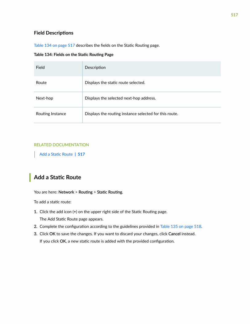
Field Descriptions
Table 134 on page 517 describes the fields on the Static Routing page.
Table 134: Fields on the Static Routing Page
Field Description
Route Displays the static route selected.
Next-hop Displays the selected next-hop address.
Routing Instance Displays the routing instance selected for this route.
RELATED DOCUMENTATION
Add a Static Route | 517
Add a Static Route
You are here: Network > Routing > Static Routing.
To add a static route:
1. Click the add icon (+) on the upper right side of the Static Routing page.
The Add Static Route page appears.
2. Complete the configuration according to the guidelines provided in Table 135 on page 518.
3. Click OK to save the changes. If you want to discard your changes, click Cancel instead.
If you click OK, a new static route is added with the provided configuration.
517
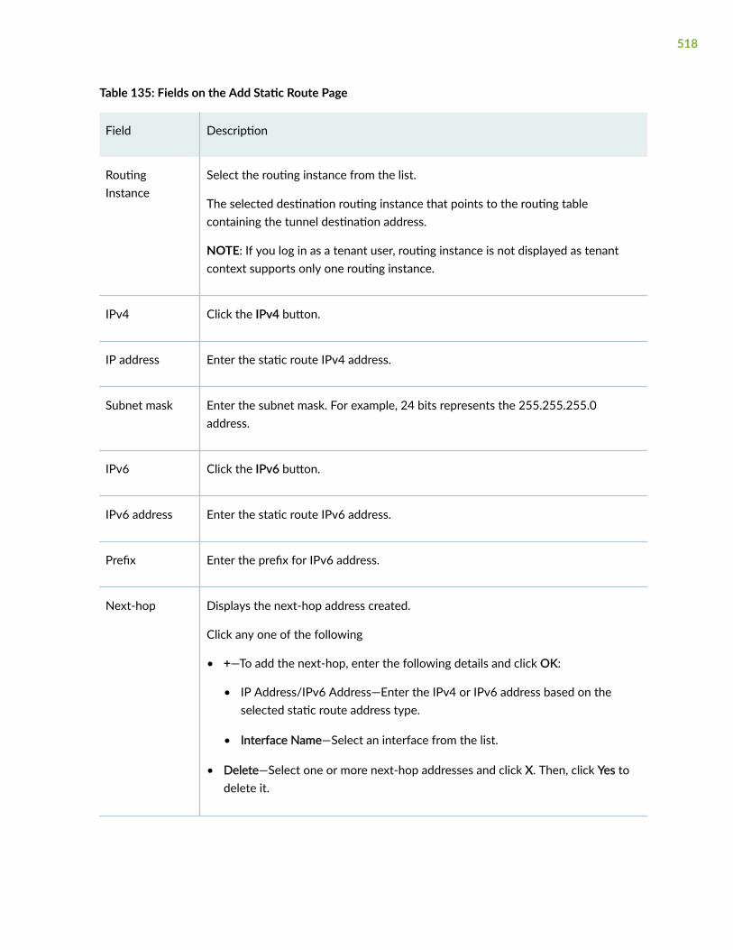
Table 135: Fields on the Add Static Route Page
Field Description
RoutingInstance
Select the routing instance from the list.
The selected destination routing instance that points to the routing tablecontaining the tunnel destination address.
NOTE: If you log in as a tenant user, routing instance is not displayed as tenantcontext supports only one routing instance.
IPv4 Click the IPv4 button.
IP address Enter the static route IPv4 address.
Subnet mask Enter the subnet mask. For example, 24 bits represents the 255.255.255.0address.
IPv6 Click the IPv6 button.
IPv6 address Enter the static route IPv6 address.
Prefix Enter the prefix for IPv6 address.
Next-hop Displays the next-hop address created.
Click any one of the following
• +—To add the next-hop, enter the following details and click OK:
• IP Address/IPv6 Address—Enter the IPv4 or IPv6 address based on theselected static route address type.
• Interface Name—Select an interface from the list.
• Delete—Select one or more next-hop addresses and click X. Then, click Yes todelete it.
518

RELATED DOCUMENTATION
Edit a Static Route | 519
Edit a Static Route
You are here: Network > Routing > Static Routing.
To edit a static route:
1. Select the existing static route that you want to edit on the Static Routing page.
2. Click the pencil icon available on the upper right side of the Static Routing page.
The Edit Static Route page appears with editable fields. For more information on the options, see"Add a Static Route" on page 517.
3. Click OK to save the changes.
RELATED DOCUMENTATION
Delete Static Route | 519
Delete Static Route
You are here: Network > Routing > Static Routing.
To delete a static route:
1. Select the existing static route that you want to delete on the Static Routing page.
2. Click the delete icon available on the upper right side of the Static Routing page.
A confirmation window appears.
3. Click Yes to delete or click No.
RELATED DOCUMENTATION
About the Static Routing Page | 516
519

CHAPTER 43
RIP Routing
IN THIS CHAPTER
About the RIP Page | 520
Add a RIP Instance | 522
Edit a RIP Instance | 524
Delete RIP Instance | 524
Edit RIP Global Settings | 525
Delete RIP Global Settings | 529
About the RIP Page
IN THIS SECTION
Tasks You Can Perform | 520
Field Descriptions | 521
You are here: Network > Routing > RIP.
Use this page to configure RIP.
Tasks You Can Perform
You can perform the following tasks from this page:
• Add a RIP instance. See "Add a RIP Instance" on page 522.
• Edit a RIP instance. See "Edit a RIP Instance" on page 524.
• Delete a RIP instance. See "Delete RIP Instance" on page 524.
520

• Edit RIP global settings. See "Edit RIP Global Settings" on page 525.
• Delete RIP global settings. See "Delete RIP Global Settings" on page 529.
Field Descriptions
Table 136 on page 521 describes the fields on the RIP page.
Table 136: Fields on the RIP Page
Field Description
Routing Instance Select a routing instance from the list.
RIP Instances
RIP Instances Displays the RIP instance selected.
Neighbors Displays the neighbors selected.
Routing Instance Displays the routing instance.
Export Policies Displays the export policies selected.
Import Policies Displays the import policies selected.
Preference Displays the preference selected.
Update Interval Displays the update interval selected.
Metric-out Displays the metric-out value selected.
RIP Global Settings
Name Displays the name of the RIP.
521

Table 136: Fields on the RIP Page (Continued)
Field Description
Value Displays the values for RIP.
RELATED DOCUMENTATION
Add a RIP Instance | 522
Add a RIP Instance
You are here: Network > Routing > RIP.
To add a RIP instance:
1. Click the add icon (+) on the upper right side of the RIP page.
The Add page appears.
2. Complete the configuration according to the guidelines provided in Table 137 on page 522.
3. Click OK to save the changes. If you want to discard your changes, click Cancel instead.
If you click OK, a new RIP instance is added with the provided configuration.
Table 137: Fields on the Add Page
Field Action
General
Routing Instance Select a routing instance from the list to display only the default routing instanceor all routing instances.
RIP Instance Name Enter the RIP instance name.
Preference Enter the preference of the external routes learned by RIP as compared to thoselearned from other routing protocols.
522

Table 137: Fields on the Add Page (Continued)
Field Action
Metric out Enter the metric value to add to routes transmitted to the neighbor.
Update Interval Enter the update time interval to periodically send out routes learned by RIP toneighbors.
Route Timeout Enter the route timeout interval for RIP.
Policy
Import Policy Specifies one or more policies to control which routes learned from an area areused to generate summary link-state advertisements (LSAs) into other areas.
Click one of the following options:
• +—Adds an import policy.
• Move up arrow—Moves the selected policy up the list of policies.
• Move down arrow—Moves the selected policy down the list of policies.
• X—Removes an import policy.
Export Policy Specifies one or more policies to control which summary LSAs are flooded intoan area.
Click one of the following options:
• +—Adds an export policy.
• Move up arrow—Moves the selected policy up the list of policies.
• Move down arrow—Moves the selected policy down the list of policies.
• X—Removes an export policy.
Neighbor
Displays the RIP-enabled interfaces, its port, metric-in, and update interval.
523

Table 137: Fields on the Add Page (Continued)
Field Action
Associate Select interface(s) to associate with the RIP.
Select the box next to the interface name to enable RIP on an interface.
Click the edit icon to modify one or more selected interfaces settings.
NOTE: Only logical interfaces for RIP are displayed.
RELATED DOCUMENTATION
Edit a RIP Instance | 524
Edit a RIP Instance
You are here: Network > Routing > RIP.
To edit a RIP instance:
1. Select the existing logical system profile that you want to edit on the RIP page.
2. Click the pencil icon available on the upper right side of the RIP page.
The Edit page appears with editable fields. For more information on the options, see "Add a RIPInstance" on page 522.
3. Click OK to save the changes.
RELATED DOCUMENTATION
Delete RIP Instance | 524
Delete RIP Instance
You are here: Network > Routing > RIP.
524

To delete a RIP instance:
1. Select the existing logical system profile that you want to delete on the RIP page.
2. Click the delete icon available on the upper right side of the RIP page.
A confirmation window appears.
3. Click Yes to delete or click No.
RELATED DOCUMENTATION
Edit RIP Global Settings | 525
Edit RIP Global Settings
You are here: Network > Routing > RIP.
To edit RIP global settings:
1. Click the pencil icon on the upper right side of the RIP Global Settings table.
The Edit RIP Global Settings page appears.
2. Complete the configuration according to the guidelines provided in Table 138 on page 525.
3. Click OK to save the changes. If you want to discard your changes, click Cancel.
Table 138: Fields on the Edit RIP Global Settings Page
Field Action
General
Send Select a RIP send options from the list:
• Broadcast
• Multicast
• None
• Version-1
525

Table 138: Fields on the Edit RIP Global Settings Page (Continued)
Field Action
Receive Select a RIP receive options from the list:
• Both
• None
• Version-1
• Version-2
Route timeout (sec) Enter the route timeout interval value for RIP.
Update interval (sec) Enter the update time interval value to periodically send out routes learned byRIP to neighbors.
Hold timeout (sec) Enter the hold timeout interval period for which the expired route is retained inthe routing table before being removed.
Metric in Enter the metric-in value to add to incoming routes when advertising into RIProutes that were learned from other protocols.
RIB Group Select a routing table group to install RIP routes into multiple routing tables.
Message size Enter the number of route entries to be included in every RIP update message.
526
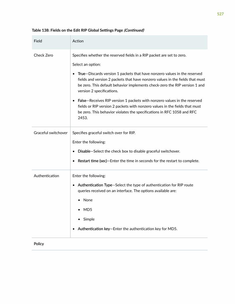
Table 138: Fields on the Edit RIP Global Settings Page (Continued)
Field Action
Check Zero Specifies whether the reserved fields in a RIP packet are set to zero.
Select an option:
• True—Discards version 1 packets that have nonzero values in the reservedfields and version 2 packets that have nonzero values in the fields that mustbe zero. This default behavior implements check-zero the RIP version 1 andversion 2 specifications.
• False—Receives RIP version 1 packets with nonzero values in the reservedfields or RIP version 2 packets with nonzero values in the fields that mustbe zero. This behavior violates the specifications in RFC 1058 and RFC2453.
Graceful switchover Specifies graceful switch over for RIP.
Enter the following:
• Disable—Select the check box to disable graceful switchover.
• Restart time (sec)—Enter the time in seconds for the restart to complete.
Authentication Enter the following:
• Authentication Type—Select the type of authentication for RIP routequeries received on an interface. The options available are:
• None
• MD5
• Simple
• Authentication key—Enter the authentication key for MD5.
Policy
527

Table 138: Fields on the Edit RIP Global Settings Page (Continued)
Field Action
Import Policy Specifies one or more policies to routes being imported into the local routingdevice from the neighbors.
Click one of the following options:
• +—Adds an import policy.
• Move up arrow—Moves the selected policy up the list of policies.
• Move down arrow—Moves the selected policy down the list of policies.
• X—Removes an import policy.
Trace Options
File Name Enter the filename to receive the output of the trace operation.
Number of Files Enter the maximum number of trace files.
File Size Enter the maximum size for each trace file.
World-readable Specifies whether or not the trace file can be read by any user or not.
Select an option:
• True—Allows any user to read the file.
• False—Restricts all users being able to read the file.
Flags Select one or more flags from the Available Flags column and move it to theConfigured Flags column using the arrow.
RELATED DOCUMENTATION
Delete RIP Global Settings | 529
528

Delete RIP Global Settings
You are here: Network > Routing > RIP.
To delete RIP global settings:
1. Select an information that you want to delete on the RIP Global settings table.
2. Click the delete icon available on the upper right side of the RIP Global settings table.
A confirmation window appears.
3. Click Yes to delete or click No.
RELATED DOCUMENTATION
About the RIP Page | 520
529
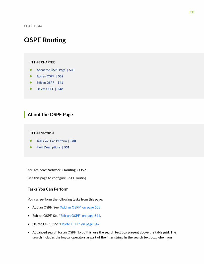
CHAPTER 44
OSPF Routing
IN THIS CHAPTER
About the OSPF Page | 530
Add an OSPF | 532
Edit an OSPF | 541
Delete OSPF | 542
About the OSPF Page
IN THIS SECTION
Tasks You Can Perform | 530
Field Descriptions | 531
You are here: Network > Routing > OSPF.
Use this page to configure OSPF routing.
Tasks You Can Perform
You can perform the following tasks from this page:
• Add an OSPF. See "Add an OSPF" on page 532.
• Edit an OSPF. See "Edit an OSPF" on page 541.
• Delete OSPF. See "Delete OSPF" on page 542.
• Advanced search for an OSPF. To do this, use the search text box present above the table grid. Thesearch includes the logical operators as part of the filter string. In the search text box, when you
530

hover over the icon, it displays an example filter condition. When you start entering the search string,the icon indicates whether the filter string is valid or not.
For an advanced search:
1. Enter the search string in the text box.
Based on your input, a list of items from the filter context menu appears.
2. Select a value from the list and then select a valid operator based on which you want to performthe advanced search operation.
NOTE: Press Spacebar to add an AND operator or OR operator to the search string. Pressbackspace at any point of time while entering a search criteria, only one character isdeleted.
3. Press Enter to display the search results in the grid.
• Show or hide columns in the OSPF table. To do this, click the Show Hide Columns icon in the topright corner of the OSPF table and select the options you want to view or deselect the options youwant to hide on the page.
Field Descriptions
Table 139 on page 531 describes the fields on the OSPF page.
Table 139: Fields on the OSPF Page
Field Description
Filter Select an instance for OSPF from the list.
Area ID Displays the area ID selected.
Area Type Displays the area type selected.
Member Interfaces Displays the member interface selected.
531

Table 139: Fields on the OSPF Page (Continued)
Field Description
Version Displays the version of the interface selected (OSPF for IPv4 and OSPFv3 forIPv6).
Routing Instance Displays the routing instance of the interface selected.
NOTE: This option is not available for tenant users.
Import Policy Displays the import policy selected.
NOTE: This option is not available for tenant users.
Export Policy Displays the export policy selected.
NOTE: This option is not available for tenant users.
RELATED DOCUMENTATION
Add an OSPF | 532
Add an OSPF
You are here: Network > Routing > OSPF.
To add an OSPF routing:
1. Click the add icon (+) on the upper right side of the OSPF page.
The Create OSPF page appears.
2. Complete the configuration according to the guidelines provided in Table 140 on page 533.
3. Click OK to save the changes. If you want to discard your changes, click Cancel instead.
If you click OK, a new OSPF routing is added with the provided configuration.
532

Table 140: Fields on the Add an OSPF Page
Field Action
Basic Settings
Routing Instance Select the routing instance from the list or create a new routing instanceinline.
NOTE: This option is not available for tenant users.
To add a new routing instance inline:
1. Click Add.
The Create Routing Instance page appears.
2. Enter the following details:
• General Settings
• Name—Enter a unique name for the routing instance that containsa corresponding IP unicast table; no special characters are allowedand the keyword default cannot be used.
• Description—Enter a description for the routing instance. Werecommend that you enter a maximum of 255 characters.
• Instance Type—Select a type of routing instance from the list:
• Virtual Router—Used for non-VPN related applications.
• VPLS—This instance is applicable only for root or super admin.This option will not be applicable for LSYS admin. Interfaceswith Encapsulation Ethernet-VPLS will be listed when VPLSinstance type is selected.
• Interfaces—Select one or more interfaces to associate with therouting instance from the Available column and move it to theSelected column using arrow.
To search for specific interface, click the search icon and enter partialtext or full text of the keyword in the search bar.
3. Click OK to save changes.
533

Table 140: Fields on the Add an OSPF Page (Continued)
Field Action
Routing Options
Router ID Enter the ID of the routing device.
Traffic Engineering
NOTE: This option isnot available forOSPFv3.
Enable this option if you want the traffic to be managed or engineered.
Area Details
Area Id Specifies the uniquely identified area within its AS.
Type a 32-bit numeric identifier for the area.
Type an integer or select and edit the value.
If you enter an integer, the value is converted to a 32-bit equivalent. Forexample, if you enter 3, the value assigned to the area is 0.0.0.3.
534

Table 140: Fields on the Add an OSPF Page (Continued)
Field Action
Area Range Displays a range of IP addresses for the summary link state advertisements(LSAs) to be sent within an area.
Select an option:
1. To add an area range form:
a. Click +.
The Create Area Range Form page appears.
b. Enter the following details:
• Area Range—Enter the area range address.
NOTE: For OSPF, enter an IPv4 address and for OSPFv3 enter anIPv6 address.
• Subnet mask—Enter the subnet mask area address.
NOTE: This option is available only for IPv4 address.
• Override metric—Select a value to override the metric for the IPaddress range.
Range: 1025 through 65534.
c. Select Restrict Advertisements of this area range to specify that theroutes contained within a summary must not be displayed.
d. Select Enforce exact match for advertisements of this area range tospecify that the summary of a route must be advertised only when anexact match is made within the configured summary range.
e. Click OK.
2. To edit the selected are range:
a. Select the existing area range.
b. Click the pencil icon to edit the selected area range.
535

Table 140: Fields on the Add an OSPF Page (Continued)
Field Action
The Edit Area Range Form page appears with editable fields.
c. Click OK to save the changes.
3. To delete an area range:
a. Select the area range that you want to delete.
b. Click the delete icon.
A confirmation message appears.
c. Click Yes to delete the selected area range.
Version Select the version of the OSPF:
• ospf—Enables OSPF routing on the routing device.
• ospf3—Enables OSPFv3 routing on the routing device.
Area Type
NOTE: This option isnot applicable for areazero.
Specifies the type of OSPF area.
Select an option from the list:
• None—A regular OSPF area, including the backbone area.
• stub—A stub area.
• nssa—A not-so-stubby area (NSSA).
No Summaries (TotallyStubby area)
NOTE: This option isapplicable for non-zeroarea and it is notapplicable for areazero.
Enable or disable the summaries.
NOTE: This option can be configured when area-type is nssa or stub.
536

Table 140: Fields on the Add an OSPF Page (Continued)
Field Action
Virtual Link
NOTE: This option isapplicable for area zeroand it is not applicablefor non-zero area.
Select whether you want the virtual link to be established. If you selectvirtual link to be created, then enter the Neighbor ID and Transit area.Transit area is the area that has virtual link connecting two or more ABRsattached to this area.
Interface Details
Select Interface Select one or more interfaces to associate with the routing instance fromthe Available column and move it to the Selected column using arrow.
Interface type Specifies the interfaces to be associated with the OSPF configuration.
Select an option from the list:
• None—No interface.
• nbma—Non broadcast multiaccess (NBMA) interface.
NOTE: This option is not available for OSPFv3.
• p2mp—Point-to-multipoint interface.
• p2p—Point-to-point interface.
• p2mp-over-lan—Point-to-multipoint over LAN mode.
NOTE: This option is not available for OSPF.
Interface Metric Type the metric that you want for measuring the interface.
Passive mode Enable this option for the passive mode.
NOTE: You can enable this option only if Secondary option is disabled andvice-versa.
Advanced
537

Table 140: Fields on the Add an OSPF Page (Continued)
Field Action
Bidirectional ForwardDetection
Enable this option for the bidirectional forward detection (BFD) protocolversion that you want to detect.
If you enable, enter the following details:
• BFD Version—Select the bidirectional forward detection version formthe list:
• None—No BFD version is used.
• automatic—Autodetects the BFD protocol version.
• BFD Version 0—Uses BFD protocol version 0.
• BFD Version 1—Uses BFD protocol version 1.
• Minimum Interval—Enter the minimum interval value for BFD inmilliseconds. Range: 1 through 255,000.
• Minimum Receive Interval—Enter the minimum receive interval value.Range: 1 through 255,000.
IPsec securityassociation
Select a number of one of the security associations from the list.
By default, no security keys are configured.
NOTE: You can configure this option only if Secondary option is disabledand vice-versa.
Link protection Enable this option. Creates a backup loop-free alternate path to the primarynext hop for all destination routes that traverse the protected interface.
NOTE: You can either enable Link protection or Node Link protection at atime. For example, if you enable Link protection, then Node Link protectionis automatically disabled.
538

Table 140: Fields on the Add an OSPF Page (Continued)
Field Action
Node Link protection Enable this option. Creates an alternate loop-free path to the primary nexthop for all destination routes that traverse a protected interface.
NOTE: You can either enable Link protection or Node Link protection at atime. For example, if you enable Link protection, then Node Link protectionis automatically disabled.
Secondary Enable this option. Specifies an interface to belong to another OSPF area.
NOTE: You can enable this option only if Passive Mode is disabled andIPsec security association is not configured and vice-versa.
Authentication
NOTE: This option isnot available forOSPFv3.
Select an authentication key (password) from the list:
• None
• md5
• simplepassword
MD5 AuthenticationKey
NOTE: This option isnot available forOSPFv3.
Specifies an MD5 authentication key (password).
Click + and enter the following details:
• MD5 ID—MD5 key identifier. Range: 0 through 255.
• Key—One or more MD5 key strings.
The MD5 key values can be from 1 through 16 characters long.Characters can include ASCII strings. If you include spaces, enclose allcharacters in quotation marks (“ ”).
• Start Time—MD5 start time.
Then, click tick mark to save the changes.
539

Table 140: Fields on the Add an OSPF Page (Continued)
Field Action
Simple Password
NOTE: This option isnot available forOSPFv3.
Enter a simple authentication key (password).
Advanced Settings
Policy
NOTE: This option is not available for tenant users.
Import Policy Specifies one or more policies to control which routes learned from an areaare used to generate summary link-state advertisements (LSAs) into otherareas.
Click one of the following options:
• +—Adds an import policy.
• Move up—Moves the selected policy up the list of policies.
• Move down—Moves the selected policy up the list of policies down.
• X—Removes the import policy.
Export Policy Specifies one or more policies to control which summary LSAs are floodedinto an area.
Click one of the following options:
• +—Adds an import policy.
• Move up—Moves the selected policy up the list of policies.
• Move down—Moves the selected policy up the list of policies down.
• X—Removes the import policy.
Trace Options
540

Table 140: Fields on the Add an OSPF Page (Continued)
Field Action
File Name Enter the name of the file to receive the output of the trace operation.
Number of files Enter the maximum number of trace files.
File Size Enter the maximum size for each trace file.
World Readable Enable this option to allow any user to read the file.
Disable this option to prevent all users from reading the file.
Flags Specifies the trace operation to be performed.
Select one or more flags in the Available column and move them to theSelected column using the right arrow.
RELATED DOCUMENTATION
Edit an OSPF | 541
Edit an OSPF
You are here: Network > Routing > OSPF.
To edit an OSPF routing:
1. Select an existing OSPF routing that you want to edit on the OSPF page.
2. Click the pencil icon available on the upper right side of the OSPF page.
The Create OSPF page appears with editable fields. For more information on the options, see "Addan OSPF" on page 532.
3. Click OK to save the changes.
541

RELATED DOCUMENTATION
Delete OSPF | 542
Delete OSPF
You are here: Network > Routing > OSPF.
To delete an OSPF routing:
1. Select an existing OSPF routing that you want to delete on the OSPF page.
2. Click the delete icon available on the upper right side of the OSPF page.
A confirmation window appears.
3. Click Yes to delete or click No.
RELATED DOCUMENTATION
About the OSPF Page | 530
542

CHAPTER 45
BGP Routing
IN THIS CHAPTER
About the BGP Page | 543
Add a BGP Group | 547
Edit a BGP Group | 553
Delete a BGP Group | 554
Edit Global Information | 554
About the BGP Page
IN THIS SECTION
Tasks You Can Perform | 543
Field Descriptions | 544
You are here: Network > Routing > BGP.
Use this page to configure BGP routing.
Tasks You Can Perform
You can perform the following tasks from this page:
• Create a routing instance. See "Add a BGP Group" on page 547.
• Edit a routing instance. See "Edit a BGP Group" on page 553.
• Delete a routing instance. See "Delete a BGP Group" on page 554.
543

• Disable group information. To do this, select an existing group information and click Disable.
• Edit global information. See "Edit Global Information" on page 554.
• Disable global information. To do this, select an existing global information and click Disable.
Field Descriptions
Table 141 on page 544 describes the fields on the BGP page.
Table 141: Fields on the BGP Page
Field Description
Routing Instance
NOTE: If you log in as atenant user, the RoutingInstance is not displayed astenant context supports onlyone routing instance.
Select routing instances from the list. Example: default or all routinginstances.
Group Name Displays the name of the group.
Status Displays the status of the group.
Peer ASN Displays the peer ASN.
Type Displays the group type.
Dynamic Peers Displays the dynamic peers selected.
Static Peers Displays the static peers selected.
Routing Instance Displays the routing instance selected.
544

Table 141: Fields on the BGP Page (Continued)
Field Description
Import Policy Displays the import policy selected.
NOTE: If you log in as a tenant user, Routing Instance, Import Policy,and Export Policy are not displayed.
Export Policy Displays the export policy selected.
NOTE: If you log in as a tenant user, Routing Instance, Import Policy,and Export Policy are not displayed.
Global Information
The global information values corresponding to the routing instance that you selected will bedisplayed in the Global Information section. Based on the routing instance that you select, the valuesin the Global information.
Edit Edits the Global settings which lists the following fields. See "EditGlobal Information" on page 554.
545

Table 141: Fields on the BGP Page (Continued)
Field Description
Name Displays the following names:
• Router Identifier—Specifies the routing device’s IP address.
• BGP Status—Enables or disables BGP.
• Router ASN—Specifies the routing device’s AS number.
• Preference—Specifies the route preference.
• Confederation—Specifies the routing device’s confederation ASnumber.
NOTE: If you log in as a tenant user, Confederation is notdisplayed.
• Confederation Members—Specifies the AS numbers for theconfederation members.
NOTE: If you log in as a tenant user, Confederation Members is notdisplayed.
• Description—Specifies the text description of the global, group, orneighbor configuration.
• Import Policy—Specifies one or more routing policies for routesbeing imported into the routing table from BGP.
NOTE: If you log in as a tenant user, Import Policy is not displayed.
• Export Policy—Specifies one or more policies to routes beingexported from the routing table into BGP.
NOTE: If you log in as a tenant user, Export Policy is not displayed.
RELATED DOCUMENTATION
Add a BGP Group | 547
546
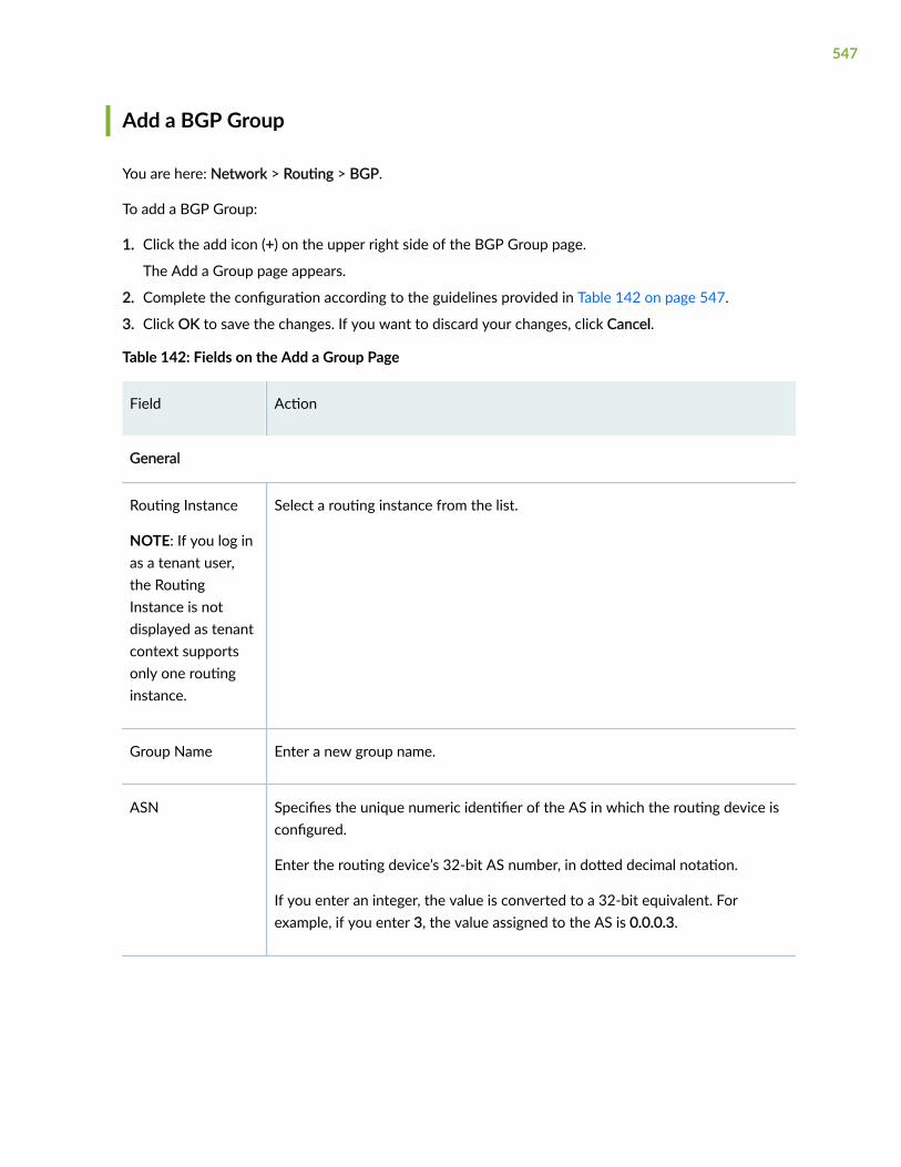
Add a BGP Group
You are here: Network > Routing > BGP.
To add a BGP Group:
1. Click the add icon (+) on the upper right side of the BGP Group page.
The Add a Group page appears.
2. Complete the configuration according to the guidelines provided in Table 142 on page 547.
3. Click OK to save the changes. If you want to discard your changes, click Cancel.
Table 142: Fields on the Add a Group Page
Field Action
General
Routing Instance
NOTE: If you log inas a tenant user,the RoutingInstance is notdisplayed as tenantcontext supportsonly one routinginstance.
Select a routing instance from the list.
Group Name Enter a new group name.
ASN Specifies the unique numeric identifier of the AS in which the routing device isconfigured.
Enter the routing device’s 32-bit AS number, in dotted decimal notation.
If you enter an integer, the value is converted to a 32-bit equivalent. Forexample, if you enter 3, the value assigned to the AS is 0.0.0.3.
547

Table 142: Fields on the Add a Group Page (Continued)
Field Action
Preference Enter the degree of preference value for an external route.
The route with the highest local preference value is preferred.
Cluster Id Enter the IPv6 or IPv4 address to be used as the cluster identifier.
The cluster identifier is used by the route reflector cluster in an internal BGPgroup.
Description Enter the text description for the global, group, or neighbor configuration.
Damping Select the check box to enable route flap damping.
Advertise InactiveRoutes
Select the check box to enable advertising of inactive routes.
Advertise Peer ASRoutes
Select the check box to advertising of peer AS routes.
Neighbors
548

Table 142: Fields on the Add a Group Page (Continued)
Field Action
Dynamic Neighbors Configures a dynamic neighbor (peer).
Select one of the following options:
1. To add a dynamic neighbor:
a. Click +.
The Add Dynamic Neighbor window appears.
b. Select one of the following options in the Addresses field:
• All
• IPv4
• IPv6
c. Enter the following details if you select IPv4 in the Addresses field:
• IP Address—Enter the IPv4 address for dynamic neighbor.
• Subnet Mask—Enter the subnet mask for the IPv4 address.
d. Enter the following details if you select IPv6 in the Addresses field:
• IPv6 Address—Enter the IPv6 address for dynamic neighbor.
• Prefix—Enter the prefix length using up and down arrows for the IPv6address.
e. Click OK to save changes.
2. To edit a dynamic neighbor:
a. Select the existing dynamic neighbor address.
b. Click the pencil icon to edit the selected dynamic neighbor address.
The Edit Dynamic Neighbor window appears with editable fields.
c. Click OK to save changes.
549

Table 142: Fields on the Add a Group Page (Continued)
Field Action
3. To delete a dynamic neighbor:
a. Select the existing dynamic neighbor address.
b. Click the delete icon (X) to delete the selected dynamic neighbor address.
550

Table 142: Fields on the Add a Group Page (Continued)
Field Action
Static Neighbors Configures a static neighbor (peer).
Select one of the following options:
1. To add a static neighbor:
a. Click +.
The Add Static Neighbor window appears.
b. Enter the following details:
• Addresses—Select IPv4 or IPv6.
• IP Address—Enter the IPv4 address for static neighbor.
• Local Address—Enter the IP address for static neighbor.
• Preference—Enter the preference value for an external route. Theroute with the highest local preference value is preferred.
• Description—Enter a description.
• Hold Time—Enter the hold timeout interval period.
• Out Delay—Enter the output delay time.
Range: 0 through 65,535 seconds.
• Passive—Select the check box to enable the device to be passive. Therouting device will wait for the peer to issue an open request before amessage is sent.
• As Override—Select the check box to replace all occurrences of thepeer AS number in the AS path with its own AS number beforeadvertising the route to the peer.
• Import Policy—Select one of the following options:
551

Table 142: Fields on the Add a Group Page (Continued)
Field Action
• +—Adds an import policy.
• Move up—Moves the selected policy up the list of policies.
• Move down—Moves the selected policy down.
• X—Removes an import policy.
• Export Policy—Select one of the following options:
• +—Adds an import policy.
• Move up—Moves the selected policy up the list of policies.
• Move down—Moves the selected policy down.
• X—Removes an import policy.
c. Click OK to save changes.
2. To edit a static neighbor:
a. Select the existing static neighbor address.
b. Click the pencil icon to edit the selected static neighbor address.
The Edit Static Neighbor window appears with editable fields.
c. Click OK to save changes.
3. To delete a static neighbor:
a. Select the existing static neighbor address.
b. Click the delete icon (X) to delete the selected static neighbor address.
Policies Tab
552

Table 142: Fields on the Add a Group Page (Continued)
Field Action
Import Policy Specifies one or more routing policies for routes being imported into therouting table from BGP.
Select one of the following options:
• +—Adds an import policy.
• Move up—Moves the selected policy up the list of policies.
• Move down—Moves the selected policy down.
• X—Removes an import policy.
Export Policy Specifies one or more policies to routes being exported from the routing tableinto BGP.
Select one of the following options:
• +—Adds an import policy.
• Move up—Moves the selected policy up the list of policies.
• Move down—Moves the selected policy down.
• X—Removes an import policy.
RELATED DOCUMENTATION
Edit a BGP Group | 553
Edit a BGP Group
You are here: Network > Routing > BGP.
To edit a BGP group :
1. Select an existing BGP group that you want to edit on the BGP page.
553
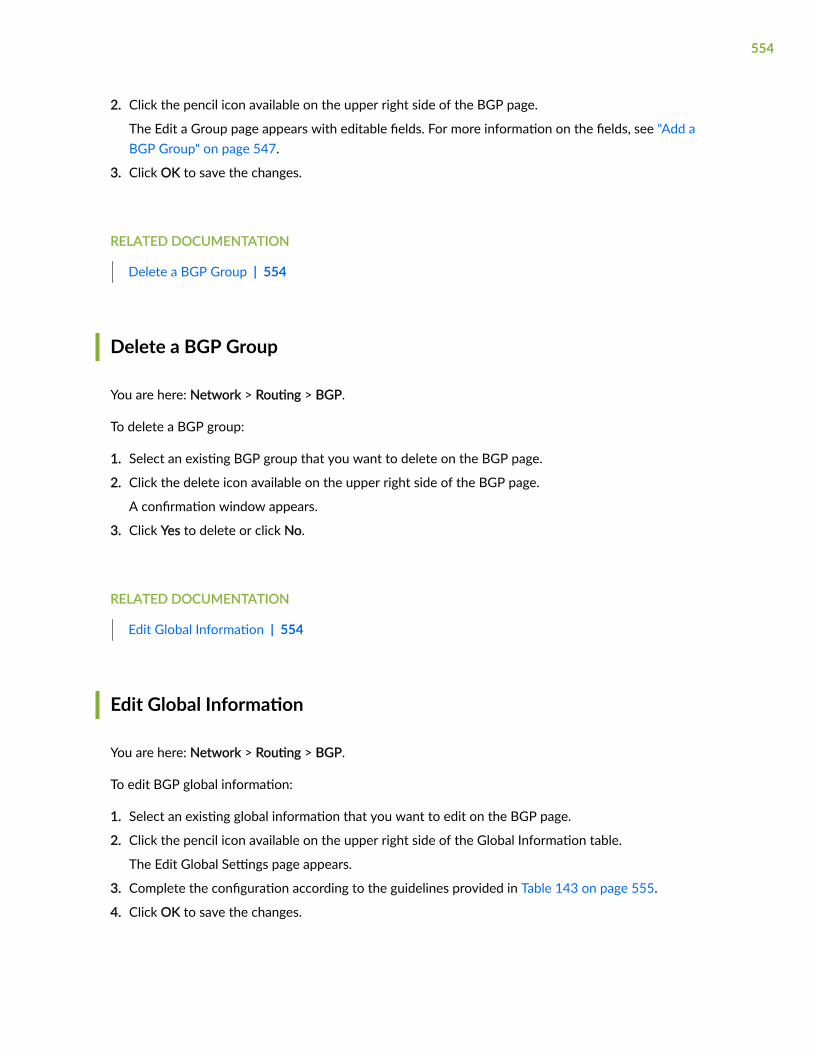
2. Click the pencil icon available on the upper right side of the BGP page.
The Edit a Group page appears with editable fields. For more information on the fields, see "Add aBGP Group" on page 547.
3. Click OK to save the changes.
RELATED DOCUMENTATION
Delete a BGP Group | 554
Delete a BGP Group
You are here: Network > Routing > BGP.
To delete a BGP group:
1. Select an existing BGP group that you want to delete on the BGP page.
2. Click the delete icon available on the upper right side of the BGP page.
A confirmation window appears.
3. Click Yes to delete or click No.
RELATED DOCUMENTATION
Edit Global Information | 554
Edit Global Information
You are here: Network > Routing > BGP.
To edit BGP global information:
1. Select an existing global information that you want to edit on the BGP page.
2. Click the pencil icon available on the upper right side of the Global Information table.
The Edit Global Settings page appears.
3. Complete the configuration according to the guidelines provided in Table 143 on page 555.
4. Click OK to save the changes.
554

Table 143: Fields on the Edit Global Settings Page
Field Action
General
Router ASN Enter the router ASN value.
Router Identifier Enter the router identification IP address.
BGP Status Select an option from the list: Enable or Disable.
Preference Enter the degree of preference value for an external route.
The route with the highest local preference value is preferred.
Description Enter the description.
ConfederationNumber
Enter the router confederation ASN value.
555

Table 143: Fields on the Edit Global Settings Page (Continued)
Field Action
ConfederationMembers
Specifies the AS numbers for the confederation members.
Select one of the following options:
1. To add a member ASN:
a. Click +.
The Confederation Members window appears.
b. Enter member ASN value in the Member ASN field.
c. Click OK to save changes.
2. To edit a member ASN:
a. Select an existing member ASN value and click the pencil icon.
The Confederation Members window appears.
b. Edit member ASN value in the Member ASN field.
c. Click OK to save changes.
3. To delete a member ASN:
a. Select an existing member ASN value.
The Confederation Members window appears.
b. Click the delete icon to delete the member ASN value.
Advance Options
Keep Route Specifies whether routes learned from a BGP peer must be retained in therouting table even if they contain an AS number that was exported from thelocal AS.
Select All or None to configure keep routes.
556

Table 143: Fields on the Edit Global Settings Page (Continued)
Field Action
TCP MSS Enter the maximum segment size (MSS) for the TCP connection.
Range: 1 through 4096.
MTU Discovery Select the check box to enable MTU discovery.
Remove Private ASN Select the check box to enable removal of private ASNs.
Graceful Restart Enter the following details:
• Restart Time—Enter the period of time after which a restart is expectedto be complete.
• Stale Routes Time—Enter the maximum time that stale routes are keptduring restart.
Multihop Specifies the maximum time-to-live (TTL) value for the TTL in the IP headerof BGP packets.
Enter the following details:
• Nexthop Change—Select the check box to allow unconnected third-partynext hops.
• TTL—Enter a TTL value.
Authentication Enter the following details:
• Authentication Algorithm—Select an option from the list: None, MD5, orSHA1.
• Authentication Key—Enter an MD5 authentication key (password). Thisoption is available if you select MD5 as authentication algorithm.
Policies Tab
NOTE: If you log in as a tenant user, Policy tab is not displayed.
557

Table 143: Fields on the Edit Global Settings Page (Continued)
Field Action
Import Policy Applies one or more policies to routes being imported into the local routingdevice from the neighbors.
Select one of the following options:
• +—Adds an import policy.
• Move up—Moves the selected policy up the list of policies.
• Move down—Moves the selected policy down.
• X—Removes an import policy.
Export Policy Specifies one or more policies to control which summary LSAs are floodedinto an area.
Select one of the following options:
• +—Adds an import policy.
• Move up—Moves the selected policy up the list of policies.
• Move down—Moves the selected policy down.
• X—Removes an import policy.
Trace Options Tab
File Name Enter the name of the file to receive the output of the trace operation.
Number of Files Enter the maximum number of trace files.
File Size Enter the maximum size for each trace file.
558

Table 143: Fields on the Edit Global Settings Page (Continued)
Field Action
World Readable Specifies whether the trace file can be read by any user.
Select an option:
• True—Allows any user to read the file.
• False—Prevents all users from reading.
Flags Select one or more flags from the Available Flags column and move it to theConfigured Flags column using the arrow.
RELATED DOCUMENTATION
About the BGP Page | 543
559

CHAPTER 46
Routing Instances
IN THIS CHAPTER
About the Routing Instances Page | 560
Add a Routing Instance | 562
Edit a Routing Instance | 563
Delete Routing Instance | 564
About the Routing Instances Page
IN THIS SECTION
Tasks You Can Perform | 560
Field Descriptions | 561
You are here: Network > Routing > Routing Instances.
Use this page to configure routing instances.
Tasks You Can Perform
You can perform the following tasks from this page:
• Create a routing instance. See "Add a Routing Instance" on page 562.
• Edit a routing instance. See "Edit a Routing Instance" on page 563.
• Delete a routing instance. See "Delete Routing Instance" on page 564.
560

• Show or hide columns in the Routing Instance table. To do this, use the Show Hide Columns icon inthe top right corner of the page and select the options you want to show or deselect to hide optionson the page.
• Advance search for a routing instance. To do this, use the search text box present above the tablegrid. The search includes the logical operators as part of the filter string. In the search text box, whenyou hover over the icon, it displays an example filter condition. When you start entering the searchstring, the icon indicates whether the filter string is valid or not.
For an advanced search:
1. Enter the search string in the text box.
Based on your input, a list of items from the filter context menu appears.
2. Select a value from the list and then select a valid operator based on which you want to performthe advanced search operation.
NOTE: Press Spacebar to add an AND operator or OR operator to the search string. Pressbackspace at any point of time while entering a search criteria, only one character isdeleted.
3. Press Enter to display the search results in the grid.
Field Descriptions
Table 144 on page 561 describes the fields on the Routing Instances page.
Table 144: Fields on the Routing Instances Page
Field Description
Name Name of the routing instance.
Type Identifies the routing instance type.
Assigned Interfaces Displays the selected interfaces assigned to the routing instance.
Description Displays the description of the routing instances.
561

RELATED DOCUMENTATION
Add a Routing Instance | 562
Add a Routing Instance
You are here: Network > Routing > Routing Instances.
To add a routing interface:
1. Click the add icon (+) available on the upper right side of the Routing Instances page.
The Create Routing Instance page appears.
2. Complete the configuration according to the guidelines provided in Table 145 on page 562.
3. Click OK to save the changes. If you want to discard your changes, click Cancel instead.
If you click OK, a new routing instance is added with the provided configuration.
Table 145: Fields on the Add Routing Instance
Field Description
General Settings
Name Enter a unique name for the routing instance that contains a corresponding IP unicasttable; no special characters are allowed and the keyword default cannot be used.
Description Enter a description for the routing instance. We recommend that you enter amaximum of 255 characters.
Instance Type Select the type of routing instance from the list:
• Virtual Router—Used for non-VPN related applications.
• VPLS—This instance is applicable only for root or super admin. This option will notbe applicable for LSYS admin. Interfaces with Encapsulation Ethernet-VPLS will belisted when VPLS instance type is selected.
562
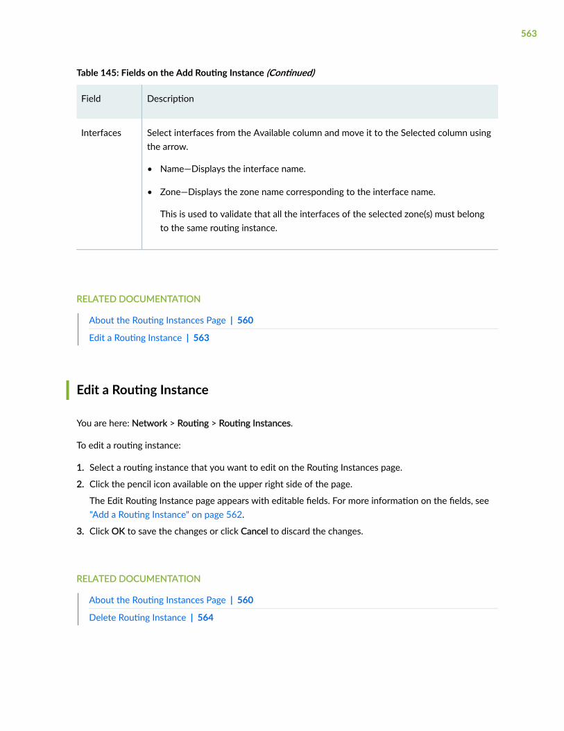
Table 145: Fields on the Add Routing Instance (Continued)
Field Description
Interfaces Select interfaces from the Available column and move it to the Selected column usingthe arrow.
• Name—Displays the interface name.
• Zone—Displays the zone name corresponding to the interface name.
This is used to validate that all the interfaces of the selected zone(s) must belongto the same routing instance.
RELATED DOCUMENTATION
About the Routing Instances Page | 560
Edit a Routing Instance | 563
Edit a Routing Instance
You are here: Network > Routing > Routing Instances.
To edit a routing instance:
1. Select a routing instance that you want to edit on the Routing Instances page.
2. Click the pencil icon available on the upper right side of the page.
The Edit Routing Instance page appears with editable fields. For more information on the fields, see"Add a Routing Instance" on page 562.
3. Click OK to save the changes or click Cancel to discard the changes.
RELATED DOCUMENTATION
About the Routing Instances Page | 560
Delete Routing Instance | 564
563

Delete Routing Instance
You are here: Network > Routing > Routing Instances.
To delete a routing instance:
1. Select one or more routing instance that you want to delete on the Routing Instances page.
2. Click the delete icon available on the upper right side of the page.
A confirmation window appears.
3. Click Yes to delete or click No.
RELATED DOCUMENTATION
About the Routing Instances Page | 560
Add a Routing Instance | 562
Edit a Routing Instance | 563
564
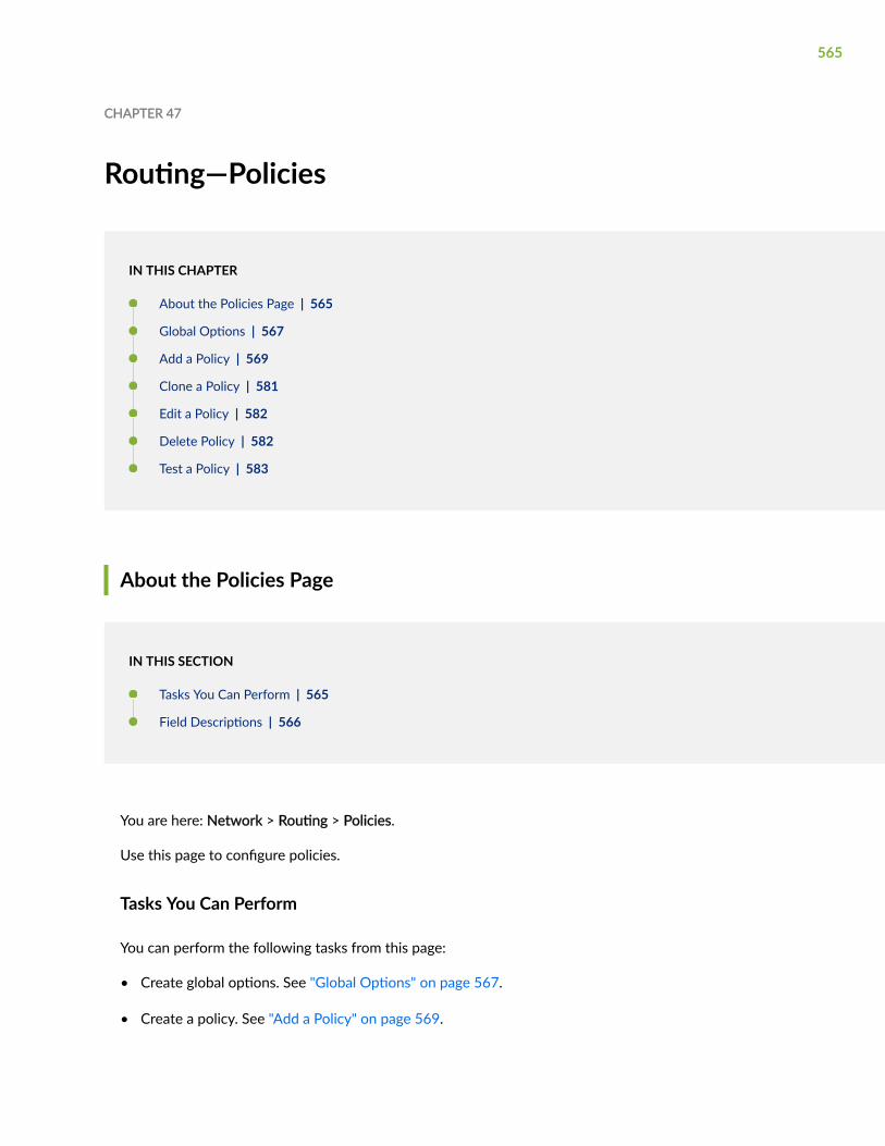
CHAPTER 47
Routing—Policies
IN THIS CHAPTER
About the Policies Page | 565
Global Options | 567
Add a Policy | 569
Clone a Policy | 581
Edit a Policy | 582
Delete Policy | 582
Test a Policy | 583
About the Policies Page
IN THIS SECTION
Tasks You Can Perform | 565
Field Descriptions | 566
You are here: Network > Routing > Policies.
Use this page to configure policies.
Tasks You Can Perform
You can perform the following tasks from this page:
• Create global options. See "Global Options" on page 567.
• Create a policy. See "Add a Policy" on page 569.
565

• Clone a policy. See "Clone a Policy" on page 581.
• Edit a policy. See "Edit a Policy" on page 582.
• Delete a policy. See "Delete Policy" on page 582.
• Term Up—Moves a term up in a selected list policies configuration.
• Term Down—Moves a term down in a selected list policies configuration.
• Test a policy. See "Test a Policy" on page 583.
Field Descriptions
Table 146 on page 566 describes the fields on the Policies page.
Table 146: Fields on the Policies Page
Field Description
Name Displays the name of the policy.
From: Prefix Displays the policy prefix.
From: Protocol Displays the selected source protocol.
From: Interface or Address Displays the selected source interface or IP address.
To: Protocol Displays the source destination protocol.
To: Interface or Address Displays the selected interface or address.
Action Displays the selected action.
Move To Displays if the action is to move to next policy or term.
566
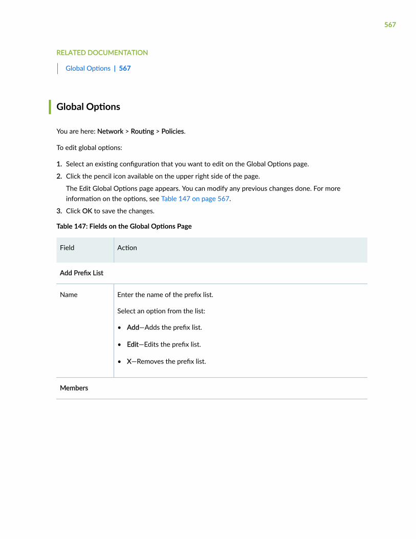
RELATED DOCUMENTATION
Global Options | 567
Global Options
You are here: Network > Routing > Policies.
To edit global options:
1. Select an existing configuration that you want to edit on the Global Options page.
2. Click the pencil icon available on the upper right side of the page.
The Edit Global Options page appears. You can modify any previous changes done. For moreinformation on the options, see Table 147 on page 567.
3. Click OK to save the changes.
Table 147: Fields on the Global Options Page
Field Action
Add Prefix List
Name Enter the name of the prefix list.
Select an option from the list:
• Add—Adds the prefix list.
• Edit—Edits the prefix list.
• X—Removes the prefix list.
Members
567

Table 147: Fields on the Global Options Page (Continued)
Field Action
IP Address To add prefix list members:
1. Click +.
The Add Prefix List Members page appears.
2. Enter the following details:
• IP Address—Enter the prefix list IP address.
• Subnet Mask—Enter the subnet mask IP address
3. Click OK to save changes.
Click the pencil icon to edit the IP address. You can click X to delete the IP address.
As Path
As Path Click + to add As path.
As Path Name—Enter the name of the As path.
Regular Expression—Enter the regular expression of the As path.
Click the pencil icon to edit the As path. You can click X to delete the As path.
BGP Community
BGP Community Click + to add a BGP community.
Name—Enter the BGP community name.
Click the pencil icon to edit the As path. You can click X to delete the As path.
Members Click + to add a BGP community member.
Community ID—Enter the BGP community ID.
568

RELATED DOCUMENTATION
Add a Policy | 569
Add a Policy
You are here: Network > Routing > Policies.
To add a policy:
1. Click + > New on the right side of the Policies page.
The Add Policy page appears.
2. Complete the configuration according to the guidelines provided in Table 148 on page 569.
3. Click OK to save the changes. If you want to discard your changes, click Cancel instead.
If you click OK, a new policy is added with the provided configuration.
Table 148: Fields on the Policy Page
Field Description
Policy Name Enter the policy name.
Terms Click one of the following:
• +—Adds the term.
• Edit—Edits the term.
• X—Deletes the term,
Add Term
Term Name Enter the term name.
Source
Family Select a family protocol address from the list.
569

Table 148: Fields on the Policy Page (Continued)
Field Description
RoutingInstance
Select a routing instance from the list.
RIB Select a routing table from the list.
Preference Enter a preference value for the route.
Metric Enter the metric value.
You can specify up to four metric values.
570

Table 148: Fields on the Policy Page (Continued)
Field Description
Interface Specifies the name or IP address of one or more routing device interfaces. Do notuse this qualifier with protocols that are not interface-specific, such as internal BGP(IBGP).
Choose one of the following options:
1. To add an interface
a. Click + and select Interface.
The Available Interfaces page appears.
b. Select an interface from the list and click OK.
The selected interface is added.
2. To add an IP address
a. Click + and select Address.
The Add IP Address page appears.
b. Enter IP address from the list and click OK.
The selected IP address is added.
3. To delete an interface or an IP address:
a. Select an existing interface or address from Interfaces.
b. Click X.
The selected interface or IP address is deleted.
571
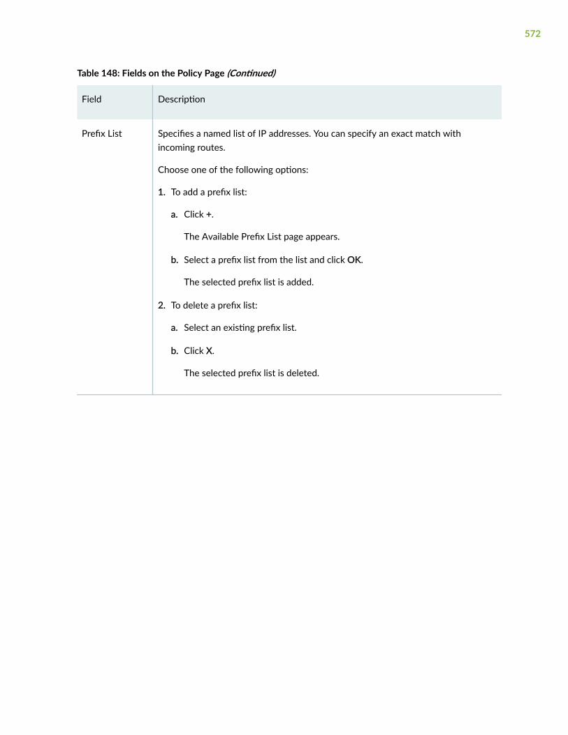
Table 148: Fields on the Policy Page (Continued)
Field Description
Prefix List Specifies a named list of IP addresses. You can specify an exact match withincoming routes.
Choose one of the following options:
1. To add a prefix list:
a. Click +.
The Available Prefix List page appears.
b. Select a prefix list from the list and click OK.
The selected prefix list is added.
2. To delete a prefix list:
a. Select an existing prefix list.
b. Click X.
The selected prefix list is deleted.
572

Table 148: Fields on the Policy Page (Continued)
Field Description
Protocol Specifies the name of the protocol from which the route was learned or to whichthe route is being advertised.
Choose one of the following options:
1. To add a protocol:
a. Click +.
The Available Protocols page appears.
b. Select a protocol from the list and click OK.
The selected protocol is added.
2. To delete a protocol:
a. Select an existing protocol.
b. Click X.
The selected protocol is deleted.
Policy Specifies the name of a policy to evaluate as a subroutine.
Choose one of the following options:
1. To add a policy:
a. Click +.
The Available Policies page appears.
b. Select a policy from the list and click OK.
The selected policy is added.
2. To delete a policy:
a. Select an existing policy.
b. Click X.
The selected policy is deleted.
573

Table 148: Fields on the Policy Page (Continued)
Field Description
More Click More for advanced configuration options for policies.
The More Options page appears.
Click OK to save changes after the configuration is complete.
More Options
OSPF Area ID Enter the IP address for the area identifier.
BGP Origin Select a value from the list to specify the origin of the AS path information.
LocalPreference
Type a BGP local preference value.
AS Path Specifies the name of an AS path regular expression.
Choose one of the following options:
1. To add an As path:
a. Click +.
The Available AS Paths page appears.
b. Select an As path from the list and click OK.
The selected As path is added.
2. To delete an As path:
a. Select an existing As path.
b. Click X.
The selected As path is deleted.
574

Table 148: Fields on the Policy Page (Continued)
Field Description
Route Enter the following details:
• External—Select the check box to enable external routing.
• OSPF Type—Select an OSPF type from the list.
Community Specifies the name of one or more communities.
Choose one of the following options:
1. To add a community:
a. Click +.
The Available Communities page appears.
b. Select a community from the list and click OK.
The selected community is added.
2. To delete a community:
a. Select an existing community.
b. Click X.
The selected community is deleted.
Destination
Family Select a value for address family protocol from the list.
RoutingInstance
Select a routing instance from the list.
RIB Select a name of a routing table from the list.
Preference Type a preference value for the route.
575

Table 148: Fields on the Policy Page (Continued)
Field Description
Metric Type a metric value.
Interface Specifies the name or IP address of one or more routing device interfaces. Do notuse this qualifier with protocols that are not interface-specific, such as internal BGP(IBGP).
Choose one of the following options:
1. To add an interface:
a. Click + and select Interface.
The Available Interfaces page appears.
b. Select an interface from the list and click OK.
The selected interface is added.
2. To add an IP address:
a. Click + and select Address.
The Add IP Address page appears.
b. Enter IP address from the list and click OK.
The selected IP address is added.
3. To delete an interface or an IP address:
a. Select an existing interface or address from Interfaces.
b. Click X.
The selected interface or IP address is deleted.
576

Table 148: Fields on the Policy Page (Continued)
Field Description
Protocol Specifies the name of the protocol from which the route was learned or to whichthe route is being advertised.
Choose one of the following options:
1. To add a protocol:
a. Click +.
The Available Protocols page appears.
b. Select a protocol from the list and click OK.
The selected protocol is added.
2. To delete a protocol:
a. Select an existing protocol.
b. Click X.
The selected protocol is deleted.
Policy Displays the name of the policy.
Choose one of the following options:
1. To add a policy:
a. Click +.
The Available Policies page appears.
b. Select a policy from the list and click OK.
The selected policy is added.
2. To delete a policy:
a. Select an existing policy.
b. Click X.
The selected policy is deleted.
577

Table 148: Fields on the Policy Page (Continued)
Field Description
More Click More for advanced configuration options for policies.
The More Options page appears.
Click OK to save changes after the configuration is complete.
Action
Action Select an action value from the list.
Default Action Select a value from the list.
Specifies that any action that is intrinsic to the protocol is overridden. This action isalso non terminating so that various policy terms can be evaluated before thepolicy is terminated.
Next Select a value from the list.
Specifies the default control action if a match occurs, and there are no furtherterms in the current routing policy.
Priority Select a value from the list.
Specifies a priority for prefixes included in an OSPF import policy. Prefixes learnedthrough OSPF are installed in the routing table based on the priority assigned tothe prefixes.
BGP Origin Select a value from the list.
Specifies the BGP origin attribute.
578

Table 148: Fields on the Policy Page (Continued)
Field Description
AS PathPrepend
Enter AS path prepend value.
Affixes an AS number at the beginning of the AS path. AS numbers are added afterthe local AS number has been added to the path. This action adds an AS number toAS sequences only, not to AS sets. If the existing AS path begins with aconfederation sequence or set, the affixed AS number is placed within aconfederation sequence. Otherwise, the affixed AS number is placed with a nonconfederation sequence.
AS Path Expand Enter the following details:
• Type—Select the type and type a value.
Extracts the last AS number in the existing AS path and affixes that AS numberto the beginning of the AS path n times, where n is a number from 1 through32. The AS number is added before the local AS number has been added to thepath. This action adds AS numbers to AS sequences only, not to AS sets. If theexisting AS path begins with a confederation sequence or set, the affixed ASnumbers are placed within a confederation sequence. Otherwise, the affixed ASnumbers are placed within a non confederation sequence. This option istypically used in non-IBGP export policies.
• Value—Enter the As path value.
Preference Enter the following details:
• Action—Select the preference action and type a value.
• Value—Enter the preference value.
LocalPreference
Enter the following details:
• Action—Select the preference action and type a value.
• Value—Enter the preference value.
579

Table 148: Fields on the Policy Page (Continued)
Field Description
Load BalancePer Packet
Select the check box to enable this option.
Specifies that all next-hop addresses in the forwarding table must be installed andhave the forwarding table perform per-packet load balancing. This policy actionallows you to optimize VPLS traffic flows across multiple paths.
Tag Enter the following details:
• Action—Select the action and type a value.
Changes the metric (MED) value by the specified negative or positive offset.This action is useful only in an external BGP (EBGP) export policy.
• Value—Enter the tag value.
Metric Enter the following details:
• Action—Select the action and type a value.
Specifies the tag value. The tag action sets the 32-bit tag field in OSPF externallink-state advertisement (LSA) packets.
• Value—Enter the metric value.
Route Enter the following details:
• External—Select the check box to enable this option.
• OSPF Type—Select an option from the list.
580

Table 148: Fields on the Policy Page (Continued)
Field Description
Class of Service Enter the following details:
• Class—Select None from the list.
Specifies the class-of-service parameters to be applied to routes installed intothe routing table.
• Source Class—Enter the source class.
Specifies that the value entered here maintains the packet counts for a routepassing through your network, based on the source address.
• Destination Class—Enter the destination class.
Specifies the value entered here maintains packet counts for a route passingthrough your network, based on the destination address in the packet.
• Forwarding Class—Enter the forwarding class.
Specifies that the value of queue number entered here maintains packet countsfor a route passing through your network, based on the internal queue numberassigned in the packet.
RELATED DOCUMENTATION
Clone a Policy | 581
Clone a Policy
You are here: Network > Routing > Policies.
To clone a policy:
1. Select a policy that you want to clone and select Clone from the More link.
The Clone Policy page appears with editable fields. For more information on the fields, see "Add aPolicy" on page 569.
2. Click OK to save the changes. If you want to discard your changes, click Cancel.
581

RELATED DOCUMENTATION
Edit a Policy | 582
Edit a Policy
You are here: Network > Routing > Policies.
To edit a policy:
1. Select a policy that you want to edit on the Policies page.
2. Click the pencil icon available on the upper right side of the Policies page.
The Edit Policy page appears with editable fields. For more information on the options, see "Add aPolicy" on page 569.
3. Click OK to save the changes.
RELATED DOCUMENTATION
Delete Policy | 582
Delete Policy
You are here: Network > Routing > Policies.
To delete a policy configuration:
1. Select one or more policies that you want to delete from the Policies page.
2. Click the delete icon available on the upper right side of the Policies page.
A confirmation window appears.
3. Click Yes to delete or click No.
RELATED DOCUMENTATION
Test a Policy | 583
582

Test a Policy
You are here: Network > Routing > Policies.
To test a policy:
1. Select a policy you want to test.
2. Click Test Policy at the upper right side of the Policies page.
The Test Policy page appears.
3. Click Start to test the policy.
You can click Generate Report to get the test reports.
RELATED DOCUMENTATION
Add a Policy | 569
Edit a Policy | 582
Delete Policy | 582
583

CHAPTER 48
Routing—Forwarding Mode
IN THIS CHAPTER
About the Forwarding Mode Page | 584
About the Forwarding Mode Page
IN THIS SECTION
Field Descriptions | 584
You are here: Network > Routing > Forwarding Mode.
Use this page to view the forwarding configuration details.
Field Descriptions
Table 149 on page 585 describes the fields on the Forwarding Mode page.
Once the configuration is complete, click Save to save the changes or click Cancel to discard thechanges.
584

Table 149: Fields on the Forwarding Mode Page
Field Description
Family IPv6 Supports IPv6 protocol traffic, including Routing Information Protocolfor IPv6 (RIPng).
Select an option from the list:
• None
• drop—Drop IPv6 packets.
• flow-based—Perform flow-based packet forwarding.
• packet-based—Perform simple packet forwarding.
NOTE: For SRX5000 line of devices, only drop and flow-basedoptions are available.
Family ISO
NOTE: This option is notavailable for SRX5000 line ofdevices.
Supports IS-IS traffic.
Select an option from the list:
• None
• packet-based
Family MPLS
NOTE: This option is notavailable for SRX5000 line ofdevices.
Supports MPLS traffic.
Select an option from the list:
• None
• flow-based
• packet-based
585

CHAPTER 49
CoS—Value Aliases
IN THIS CHAPTER
About the Value Aliases Page | 586
Add a Code Point Alias | 587
Edit a Code Point Alias | 588
Delete Code Point Alias | 589
About the Value Aliases Page
IN THIS SECTION
Tasks You Can Perform | 586
Field Descriptions | 587
You are here: Network > Class of Service(CoS) > Value Aliases.
Use this page to view, add, and remove value aliases details.
Tasks You Can Perform
You can perform the following tasks from this page:
• Add a code point alias. See "Add a Code Point Alias" on page 587.
• Edit a code point alias. See "Edit a Code Point Alias" on page 588.
• Delete a code point alias. See "Delete Code Point Alias" on page 589.
586

Field Descriptions
Table 150 on page 587 describes the fields on the Value Alias page.
Table 150: Fields on the Value Alias Page
Field Description
Aliasname
Displays the name given to CoS values. For example, af11 or be.
Alias type Displays the code point type.
The following types of code points are supported:
• DSCP—Defines aliases for Differentiated Services code point (DSCP) for IPv4 values.You can refer to these aliases when you configure classes and define classifiers.
• DSCP-IPv6—Defines aliases for DSCP IPv6 values. You can refer to these aliaseswhen you configure classes and define classifiers.
• EXP—Defines aliases for MPLS experimental (EXP) bits. You can map MPLS EXP bitsto the device forwarding classes.
• inet-precedence—Defines aliases for IPv4 precedence values. Precedence values aremodified in the IPv4 TOS field and mapped to values that correspond to levels ofservice.
CoS Valuebits
Displays the CoS value for which an alias is defined.
NOTE: Changing this value alters the behavior of all classifiers that refer to this alias.
RELATED DOCUMENTATION
Add a Code Point Alias | 587
Add a Code Point Alias
You are here: Network > Class of Service(CoS) > Value Aliases.
587

To add a code point alias:
1. Click the add icon (+) available on the right side of the Value Aliases page.
The Add Code Point Alias page appears.
2. Complete the configuration according to the guidelines provided in Table 151 on page 588.
3. Click OK to save the changes. If you want to discard your changes, click Cancel.
Table 151: Fields on the Add Code Point Alias Page
Field Description
Code point name Enter a name for the CoS point alias.
Code point type Select a code point type from the list.
Code point value bits Select a COS value for which an alias is defined.
RELATED DOCUMENTATION
Edit a Code Point Alias | 588
Edit a Code Point Alias
You are here: Network > Class of Service(CoS) > Value Aliases.
To edit a code point alias:
1. Select a code point alias that you want to edit on the Value Aliases page.
2. Click the pencil icon available on the upper right side of the Value Aliases page.
The Code Point options appears with editable fields. For more information on the options, see "Add aCode Point Alias" on page 587.
3. Click OK to save the changes.
RELATED DOCUMENTATION
Delete Code Point Alias | 589
588

Delete Code Point Alias
You are here: Network > Class of Service(CoS) > Value Aliases.
To delete a code point alias:
1. Select a code point alias that you want to delete on the Value Aliases page.
2. Click the delete icon available on the upper right side of the Value Aliases page.
A confirmation window appears.
3. Click Yes to delete or click No.
RELATED DOCUMENTATION
About the Value Aliases Page | 586
589

CHAPTER 50
CoS—Forwarding Classes
IN THIS CHAPTER
About the Forwarding Classes Page | 590
Add a Forwarding Class | 591
Edit a Forwarding Class | 592
Delete Forwarding Class | 592
About the Forwarding Classes Page
IN THIS SECTION
Tasks You Can Perform | 590
Field Descriptions | 591
You are here: Network > Class of Service(CoS) > Forwarding Classes.
Use this page to view, add, and delete Forwarding Classes.
Tasks You Can Perform
You can perform the following tasks from this page:
• Add a forwarding class. See "Add a Forwarding Class" on page 591.
• Edit a forwarding class. See "Edit a Forwarding Class" on page 592.
• Delete forwarding class. See "Delete Forwarding Class" on page 592.
590

Field Descriptions
Table 152 on page 591 describes the fields on the Forwarding Classes page.
Table 152: Fields on the Forwarding Classes Page
Field Description
Forwarding classname
Displays the forwarding class name assigned to the internal queue number.
By default, four forwarding classes are assigned to queue numbers: 0 (best-effort), 1 (assured-forwarding), 5 (expedited-forwarding), and 7 (network-connect).
Queue number Displays the internal queue numbers to which forwarding classes areassigned.
By default, if a packet is not classified, it is assigned to the class associatedwith queue 0. You can have more than one forwarding class assigned to aqueue number.
Queue characteristics Displays the queue characteristics, for example, video or voice.
RELATED DOCUMENTATION
Add a Forwarding Class | 591
Add a Forwarding Class
You are here: Network > Class of Service(CoS) > Forwarding Classes.
To add a forwarding class:
1. Click the add icon (+) available on the right side of the Forwarding Class page.
The Add Forwarding Class page appears.
2. Complete the configuration according to the guidelines provided in Table 153 on page 592.
3. Click OK to save the changes. If you want to discard your changes, click Cancel.
591

Table 153: Fields on the Add Forwarding Class page
Field Description
Queue number Select the internal queue number to which a forwarding class is assigned.
Forwarding class name Enter the forwarding class name assigned to the internal queue number.
RELATED DOCUMENTATION
Edit a Forwarding Class | 592
Edit a Forwarding Class
You are here: Network > Class of Service(CoS) > Forwarding Classes.
To edit a forwarding class:
1. Select an existing forwarding class that you want to edit on the Forwarding Classes page.
2. Click the pencil icon available on the upper right side of the Forwarding Classes page.
The Edit Forwarding Class options appears with editable fields. For more information on the options,see "Add a Forwarding Class" on page 591 for options available for editing.
3. Click OK to save the changes.
RELATED DOCUMENTATION
Delete Forwarding Class | 592
Delete Forwarding Class
You are here: Network > Class of Service(CoS) > Forwarding Classes.
To delete a forwarding class:
1. Select an existing forwarding class that you want to delete on the Forwarding Classes page.
592
2. Click the delete icon available on the upper right side of the Forwarding Classes page.
A confirmation window appears.
3. Click Yes to delete or click No.
RELATED DOCUMENTATION
About the Forwarding Classes Page | 590
593

CHAPTER 51
CoS Classifiers
IN THIS CHAPTER
About the Classifiers Page | 594
Add a Classifier | 596
Edit a Classifier | 598
Delete Classifier | 598
About the Classifiers Page
IN THIS SECTION
Tasks You Can Perform | 594
Field Descriptions | 595
You are here: Network > Class of Service(CoS) > Classifiers.
Use this page to view, add, and delete Classifier Page configuration.
Tasks You Can Perform
You can perform the following tasks from this page:
• Add a classifier. See "Add a Classifier" on page 596.
• Edit a classifier. See "Edit a Classifier" on page 598.
• Delete classifier. See "Delete Classifier" on page 598.
594

Field Descriptions
Table 154 on page 595 describes the fields on the Classifiers page.
Table 154: Fields on the Classifiers Page
Field Description
Classifier name Displays the name of a classifier.
Classifier type Displays the classifier type.
The following type of classifiers are available:
• dscp—Differentiated Services code point classifier for IPv4.
• dscp-ipv6—Differentiated Services code point classifier for IPv6 (default andcompatibility).
NOTE: This option is not available on SRX4000 lines of devices.
• exp—MPLS experimental (EXP) bits classifier
NOTE: This option is not available on SRX4000 lines of devices andSRX5000 lines of devices.
• ieee-802.1—IEEE-802.1 classifier
• ieee-802.1ad—IEEE-802.1ad classifier
NOTE: This option is not available on SRX4000 lines of devices.
• inet-precedence—IPv4 precedence classifier (default and compatibility)
Details of classifiers
Incoming codepoint
Displays CoS values and the aliases to which the forwarding class and losspriority are mapped.
Forwarding classname
Displays forwarding class names that are assigned to specific CoS values andaliases of a classifier.
595

Table 154: Fields on the Classifiers Page (Continued)
Field Description
Loss priority Displays loss priorities that are assigned to specific CoS values and aliases of aclassifier.
RELATED DOCUMENTATION
Add a Classifier | 596
Add a Classifier
You are here: Network > Class of Service(CoS) > Classifiers.
To add a classifier:
1. Click the add icon (+) available on the right side of the Classifiers page.
The Add Classifier page appears.
2. Complete the configuration according to the guidelines provided in Table 155 on page 596.
3. Click OK to save the changes. If you want to discard your changes, click Cancel.
Table 155: Fields on the Add Classifier Page
Field Description
Classifier name Enter the classifier name.
596

Table 155: Fields on the Add Classifier Page (Continued)
Field Description
Classifier type Select a classifier type from the list.
• dscp—Differentiated Services code point classifier for IPv4.
• dscp-ipv6—Differentiated Services code point classifier for IPv6 (default andcompatibility).
NOTE: This option is not available on SRX4000 lines of devices.
• exp—MPLS experimental (EXP) bits classifier
NOTE: This option is not available on SRX4000 lines of devices and SRX5000lines of devices.
• ieee-802.1—IEEE-802.1 classifier
• ieee-802.1ad—IEEE-802.1ad classifier
NOTE: This option is not available on SRX4000 lines of devices.
• inet-precedence—IPv4 precedence classifier (default and compatibility)
Code pointmapping
Specifies the code point mapping created.
The available options are as follows:
• Add—Click + to add a code point mapping.
• Edit—Click pencil icon to edit the selected code point mapping.
• Delete—Deletes the code point mapping.
Code point Select the CoS value in bits and the alias of a classifier from the list.
Forwarding class Select the forwarding class for the specified CoS value and alias from the list.
Loss priority Select the loss priority for the specified CoS value and alias from the list.
597

RELATED DOCUMENTATION
Edit a Classifier | 598
Edit a Classifier
You are here: Network > Class of Service(CoS) > Classifiers.
To edit a classifier:
1. Select an existing classifier configuration that you want to edit on the Classifiers page.
2. Click the pencil icon available on the upper right side of the Classifiers page.
The Edit Classifiers page appears with editable fields. For more information on the options, see "Adda Classifier" on page 596.
3. Click OK to save the changes.
RELATED DOCUMENTATION
Delete Classifier | 598
Delete Classifier
You are here: Network > Class of Service(CoS) > Classifiers.
To delete a classifier:
1. Select a classifier that you want to delete on the Classifiers Page.
2. Click the delete icon available on the upper right side of the Classifiers page.
A confirmation window appears.
3. Click Yes to delete or click No to retain the profile.
RELATED DOCUMENTATION
About the Classifiers Page | 594
598

CHAPTER 52
CoS—Rewrite Rules
IN THIS CHAPTER
About the Rewrite Rules Page | 599
Add a Rewrite Rule | 600
Edit a Rewrite Rule | 602
Delete Rewrite Rule | 602
About the Rewrite Rules Page
IN THIS SECTION
Tasks You Can Perform | 599
Field Descriptions | 600
You are here: Network > Class of Service(CoS) > Rewrite Rules.
Use this page to add, edit, or delete rewrite rule configurations.
Tasks You Can Perform
You can perform the following tasks from this page:
• Add a rewrite rule. See "Add a Rewrite Rule" on page 600.
• Edit a rewrite rule. See "Edit a Rewrite Rule" on page 602.
• Delete rewrite rule. See "Delete Rewrite Rule" on page 602.
599

Field Descriptions
Table 156 on page 600 describes the fields on the Rewrite Rules page.
Table 156: Fields on the Rewrite Rules Page
Field Description
Rewrite rule name Displays the names of defined rewrite rules.
Rewrite rule type Displays the rewrite rule type.
Code Point Details
Egress/Outgoing Code point Displays the CoS values and aliases that a specific rewrite rule has setfor a specific forwarding class and loss priority.
Forwarding class name Displays the forwarding classes associated with a specific rewrite rule.
Loss priority Displays the loss priority values associated with a specific rewrite rule.
RELATED DOCUMENTATION
Add a Rewrite Rule | 600
Add a Rewrite Rule
You are here: Network > Class of Service(CoS) > Rewrite Rules.
To add a rule configuration:
1. Click the add icon (+) available on the right side of the Forwarding Class page.
The Add Rewrite Rule page appears.
2. Complete the configuration according to the guidelines provided in Table 157 on page 601.
3. Click OK to save the changes. If you want to discard your changes, click Cancel.
600
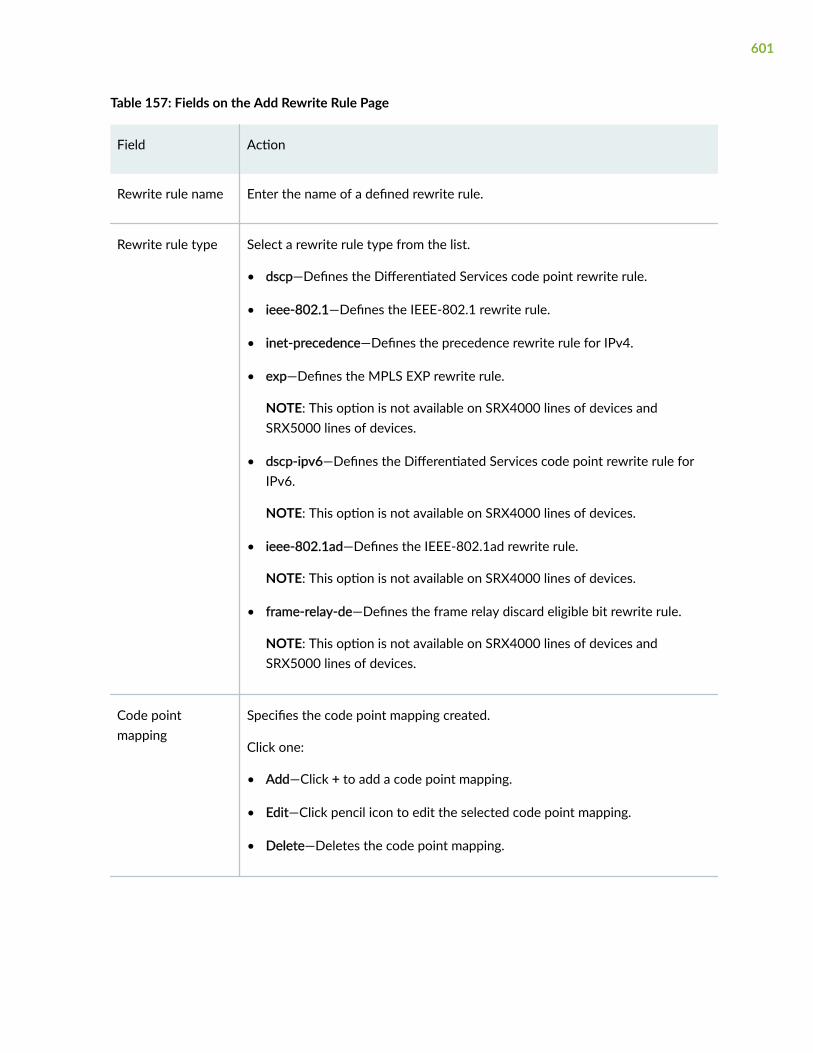
Table 157: Fields on the Add Rewrite Rule Page
Field Action
Rewrite rule name Enter the name of a defined rewrite rule.
Rewrite rule type Select a rewrite rule type from the list.
• dscp—Defines the Differentiated Services code point rewrite rule.
• ieee-802.1—Defines the IEEE-802.1 rewrite rule.
• inet-precedence—Defines the precedence rewrite rule for IPv4.
• exp—Defines the MPLS EXP rewrite rule.
NOTE: This option is not available on SRX4000 lines of devices andSRX5000 lines of devices.
• dscp-ipv6—Defines the Differentiated Services code point rewrite rule forIPv6.
NOTE: This option is not available on SRX4000 lines of devices.
• ieee-802.1ad—Defines the IEEE-802.1ad rewrite rule.
NOTE: This option is not available on SRX4000 lines of devices.
• frame-relay-de—Defines the frame relay discard eligible bit rewrite rule.
NOTE: This option is not available on SRX4000 lines of devices andSRX5000 lines of devices.
Code pointmapping
Specifies the code point mapping created.
Click one:
• Add—Click + to add a code point mapping.
• Edit—Click pencil icon to edit the selected code point mapping.
• Delete—Deletes the code point mapping.
601

Table 157: Fields on the Add Rewrite Rule Page (Continued)
Field Action
Egress/OutgoingCode point
Select a CoS value and alias from the list.
Forwarding class Select the forwarding class of the rewrite rule from the list.
Loss priority Select the loss priority of the rewrite rule from the list.
RELATED DOCUMENTATION
Edit a Rewrite Rule | 602
Edit a Rewrite Rule
You are here: Network > Class of Service(CoS) > Rewrite Rules.
To edit a rewrite rule:
1. Select an existing rule configuration you want to edit on the Rewrite Rules page.
2. Click the pencil icon available on the upper right side of the Rewrite Rules page.
The Edit Rewrite Rule page appears with editable fields. For more information on the options, see"Add a Rewrite Rule" on page 600.
3. Click OK to save the changes.
RELATED DOCUMENTATION
Delete Rewrite Rule | 602
Delete Rewrite Rule
You are here: Network > Class of Service(CoS) > Rewrite Rules.
602

To delete a rewrite rule:
1. Select an existing rule configuration you want to delete on the Rewrite Rules page.
2. Click the delete icon available on the upper right side of the Rewrite Rules page.
A confirmation window appears.
3. Click Yes to delete or click No to retain the previous configuration.
RELATED DOCUMENTATION
About the Rewrite Rules Page | 599
603

CHAPTER 53
CoS—Schedulers
IN THIS CHAPTER
About the Schedulers Page | 604
Add a Scheduler | 605
Edit a Scheduler | 607
Delete Scheduler | 608
About the Schedulers Page
IN THIS SECTION
Tasks You Can Perform | 604
Field Descriptions | 605
You are here: Network > Class of Service(CoS) > Schedulers.
Use this page to add, edit or delete configuration of schedulers and enable or disable global settings.
Tasks You Can Perform
You can perform the following tasks from this page:
• Add a scheduler. See "Add a Scheduler" on page 605.
• Edit a scheduler. See "Edit a Scheduler" on page 607.
• Delete scheduler. See "Delete Scheduler" on page 608.
604

Field Descriptions
Table 158 on page 605 describes the fields on the Schedulers page.
Table 158: Fields on the Schedulers Page
Field Description
Schedulers Global Setting
Enable Non Strict Priority Applies non-strict priority policy to all the schedulers.
Schedulers Configuration
Scheduler name Displays the names of defined schedulers.
Scheduler priority Displays the scheduler transmission priority, which determines the orderin which an output interface transmits traffic from the queues.
Details of scheduler
Name Displays the scheduler name.
Value Displays the CoS value.
RELATED DOCUMENTATION
Add a Scheduler | 605
Add a Scheduler
You are here: Network > Class of Service(CoS) > Schedulers.
To add a scheduler:
1. Click the add icon (+) available on the right side of the Scheduler page.
605

The Add Scheduler page appears.
2. Complete the configuration according to the guidelines provided in Table 159 on page 606.
3. Click OK to save the changes. If you want to discard your changes, click Cancel.
Table 159: Fields on the Add Scheduler Page
Field Action
Schedulername
Enter the scheduler name.
Schedulerpriority
Select an option from the list:
• high—Packets in this queue have high priority.
• low—Packets in this queue are transmitted last.
• medium-low—Packets in this queue have medium-low priority.
• medium-high—Packets in this queue have medium-high priority.
• strict-high—Packets in this queue are transmitted first.
Buffer size Select an option from the list:
• exact—Exact buffer size.
• percent—Percentage of the total buffer. Select and type an integer from 1 through100.
• remainder—Remaining available buffer size.
• temporal—Temporal value in microseconds.
Shaping rate Enter the minimum bandwidth allocated to a queue.
Select an option from the list:
• rate—Shaping rate as an absolute number of bits per second. Select and type aninteger from 3200 through 160,000,000,000 bits per second.
• percent—Shaping rate as a percentage. Select and type an integer from 0 through100.
606

Table 159: Fields on the Add Scheduler Page (Continued)
Field Action
Transmit rate Enter the transmission rate of a scheduler.
Select an option from the list:
• rate—Transmit rate. Select and type an integer from 3200 through160,000,000,000 bits per second.
• exact—Exact transmit rate.
• percent—Percentage of transmission capacity. Select and type an integer from 1through 100.
• remainder—Remaining transmission capacity.
RELATED DOCUMENTATION
Edit a Scheduler | 607
Edit a Scheduler
You are here: Network > Class of Service(CoS) > Schedulers.
To edit a scheduler:
1. Select an existing scheduler that you want to edit on the Schedulers page.
2. Click the pencil icon available on the upper right side of the Schedulers page.
The Edit Scheduler appears with editable fields. For more information on the options, see "Add aScheduler" on page 605.
3. Click OK to save the changes.
RELATED DOCUMENTATION
Delete Scheduler | 608
607

Delete Scheduler
You are here: Network > Class of Service(CoS) > Schedulers.
To delete a scheduler:
1. Select an existing scheduler that you want to delete on the Schedulers page.
2. Click the delete icon available on the upper right side of the Schedulers page.
A confirmation window appears.
3. Click Yes to delete or click No.
RELATED DOCUMENTATION
About the Schedulers Page | 604
608
CHAPTER 54
CoS—Scheduler Maps
IN THIS CHAPTER
About the Scheduler Maps Page | 609
Add a Scheduler Map | 610
Edit a Scheduler Map | 611
Delete Scheduler Map | 612
About the Scheduler Maps Page
IN THIS SECTION
Tasks You Can Perform | 609
Field Descriptions | 610
You are here: Network > Class of Service(CoS) > Scheduler Maps.
Use this page to add, edit, or delete schedulers maps configurations.
Tasks You Can Perform
You can perform the following tasks from this page:
• Add a scheduler map. See "Add a Scheduler Map" on page 610.
• Edit a scheduler map. See "Edit a Scheduler Map" on page 611.
• Delete a scheduler map. See "Delete Scheduler Map" on page 612.
609

Field Descriptions
Table 160 on page 610 describes the fields on the Scheduler Maps page.
Table 160: Fields on the Scheduler Maps Page
Field Description
Scheduler map name Displays the names of defined scheduler maps. Scheduler maps link schedulersto forwarding classes.
Schedulers Displays the schedulers assigned for each map.
Forwarding classes Displays the forwarding classes assigned for each map.
Details of Schedulers
Name Displays the scheduler assigned to the selected scheduler map.
Value Displays the CoS values.
RELATED DOCUMENTATION
Add a Scheduler Map | 610
Add a Scheduler Map
You are here: Network > Class of Service(CoS) > Scheduler Maps.
To add a scheduler map:
1. Click the add icon (+) available on the right side of the Scheduler Map page.
The Add Scheduler Map page appears.
2. Complete the configuration according to the guidelines provided in Table 161 on page 611.
3. Click OK to save the changes. If you want to discard your changes, click Cancel.
610

Table 161: Fields on the Add Scheduler Map Page
Field Action
Scheduler map name Enter a name for the scheduler map.
best-effort Select an option from the list.
Specifies no service profile. Loss priority is typically not carried in a CoS value.
expedited-forwarding Select an option from the list.
Specifies end-to-end service with low loss, low latency, low jitter, and assuredbandwidth.
assured-forwarding Select an option from the list.
Specifies the group of defined values.
network-control Select an option from the list.
Specifies CoS packet forwarding class of high priority.
RELATED DOCUMENTATION
Edit a Scheduler Map | 611
Edit a Scheduler Map
You are here: Network > Class of Service(CoS) > Scheduler Maps.
To edit a scheduler map:
1. Select an existing scheduler map that you want to edit on the Schedulers page.
2. Click the pencil icon available on the upper right side of the Schedulers page.
The Edit Scheduler Map page appears with editable fields. For more information on the options, see"Add a Scheduler Map" on page 610.
611

3. Click OK to save the changes.
RELATED DOCUMENTATION
Delete Scheduler Map | 612
Delete Scheduler Map
You are here: Network > Class of Service(CoS) > Scheduler Maps.
To delete a scheduler map:
1. Select an existing scheduler map that you want to delete on the Schedulers page.
2. Click the delete icon available on the upper right side of the Schedulers page.
A confirmation window appears.
3. Click Yes to delete or click No.
RELATED DOCUMENTATION
About the Scheduler Maps Page | 609
612
CHAPTER 55
CoS—Drop Profile
IN THIS CHAPTER
About the Drop Profile Page | 613
Add a Drop Profile | 614
Edit a Drop Profile | 616
Delete Drop Profile | 616
About the Drop Profile Page
IN THIS SECTION
Tasks You Can Perform | 613
Field Descriptions | 614
You are here: Network > Class of Service(CoS) > Drop Profile.
Use this page to configure drop profiles.
Tasks You Can Perform
You can perform the following tasks from this page:
• Add a drop profile. See "Add a Drop Profile" on page 614.
• Edit a drop profile. See "Edit a Drop Profile" on page 616.
• Delete a drop profile. See "Delete Drop Profile" on page 616.
613

Field Descriptions
Table 162 on page 614 describes the fields on the Drop Profile page.
Table 162: Fields on the Drop Profile Page
Field Description
Drop profile name Displays the configured random early detection (RED) drop profile names.
Profile type Displays whether a RED drop profile type is interpolated or segmented.
Data points Displays information about the data point types.
RELATED DOCUMENTATION
About the Drop Profile Page | 613
Add a Drop Profile
You are here: Network > Class of Service(CoS) > Drop Profile.
To add a drop profile:
1. Click the add icon (+) available on the right side of the Drop Profile page.
The Add Drop Profile page appears.
2. Complete the configuration according to the guidelines provided in Table 163 on page 614.
3. Click OK to save the changes. If you want to discard your changes, click Cancel.
Table 163: Fields on the Add Drop Profile Page
Field Action
Drop ProfileName
Enter a drop profile name.
614

Table 163: Fields on the Add Drop Profile Page (Continued)
Field Action
Interpolated Select the option to specify whether the value pairs are interpolated to produce asmooth profile.
Segmented Select the option to specify whether the value pairs are represented by linefragments, which connect each data point on the graph to produce a segmentedprofile.
Data point To add a data point:
1. Click +.
The Add Data Point page appears.
2. Enter the following details:
• Fill Level—Enter a percentage value for queue buffer fullness for the X-coordinate. For example, 95.
• Drop Probability—Enter a percentage value for drop probability for the Y-coordinate. For example, 85.
3. Click OK to save changes.
To edit a data point:
1. Select the existing data point and click the pencil icon.
The Edit Data Point page appears.
2. Enter a percentage value for Drop Probability.
3. Click OK to save changes.
To delete a data point, select the existing data point and click the delete (X) icon.Then, click Yes to delete it.
RELATED DOCUMENTATION
Edit a Drop Profile | 616
615
Edit a Drop Profile
You are here: Network > Class of Service(CoS) > Drop Profile.
To edit a drop profile:
1. Select an existing drop profile that you want to edit on the Drop Profile page.
2. Click the pencil icon available on the upper right side of the Drop Profile page.
The Edit Drop Profile page appears with editable fields. For more information on the options, see"Add a Drop Profile" on page 614.
3. Click OK to save the changes.
RELATED DOCUMENTATION
Delete Drop Profile | 616
Delete Drop Profile
You are here: Network > Class of Service(CoS) > Drop Profile.
To delete a drop profile:
1. Select an existing drop profile that you want to delete on the Drop Profile page.
2. Click the delete icon available on the upper right side of the Drop Profile page.
A confirmation window appears.
3. Click Yes to delete or click No.
RELATED DOCUMENTATION
About the Drop Profile Page | 613
616

CHAPTER 56
CoS—Virtual Channel Groups
IN THIS CHAPTER
About the Virtual Channel Groups Page | 617
Add a Virtual Channel | 618
Edit a Virtual Channel | 620
Delete Virtual Channel | 620
About the Virtual Channel Groups Page
IN THIS SECTION
Tasks You Can Perform | 617
Field Descriptions | 618
You are here: Network > Class of Service(CoS) > Virtual Channel Groups.
NOTE: This menu is not available for SRX4000 line of devices and SRX5000 line of devices.
Use this page to configure virtual channel group.
Tasks You Can Perform
You can perform the following tasks from this page:
• Add a virtual channel. See "Add a Virtual Channel" on page 618.
• Edit a virtual channel. See "Edit a Virtual Channel" on page 620.
617

• Delete a virtual channel. See "Delete Virtual Channel" on page 620.
Field Descriptions
Table 164 on page 618 describes the fields on the Virtual Channel Groups page.
Table 164: Fields on the Virtual Channel Groups Page
Field Description
Virtual Channel Group Name Displays the name of defined virtual channel groups.
Virtual Channel Name Displays the name of defined virtual channels.
Default Displays the default virtual channel of a group marking.
Scheduler Map Displays the scheduler map assigned to a particular virtual channel.
Shaping Rate Displays the shaping rate configured for a virtual channel.
RELATED DOCUMENTATION
Add a Virtual Channel | 618
Add a Virtual Channel
You are here: Network > Class of Service(CoS) > Virtual Channel Groups.
NOTE: This menu is not available for SRX4000 line of devices and SRX5000 line of devices.
To add a virtual channel to the virtual channel group:
1. Click Add on the Virtual Channel page.
The Virtual Channel Information page appears.
618

2. Complete the configuration according to the guidelines provided in Table 165 on page 619.
3. Click OK to save the changes. If you want to discard your changes, click Cancel.
Table 165: Fields on the Virtual Channel Information Page
Field Action
VirtualChannel Name
Select a predefined name from the list or enter a new virtual channel name.
Scheduler Map Select a scheduler map from the list.
Specifies a predefined scheduler map to assign to a virtual channel. The schedulermaps associate schedulers with forwarding classes.
Shaping Rate Enter the shaping rate for a virtual channel.
Configuring a shaping rate is optional. If no shaping rate is configured, a virtualchannel without a shaper can use the full logical interface bandwidth. The optionsavailable are:
Select an option from the list:
• Unconfigured—Select the option for no shaping rate.
• Absolute Rate—Configures a shaping rate as an absolute number of bits persecond.
Range: 3200 through 320000000000.
• Percent—Configures a shaping rate as a percentage.
Range: 0 through 100.
RELATED DOCUMENTATION
Edit a Virtual Channel | 620
619

Edit a Virtual Channel
You are here: Network > Class of Service(CoS) > Virtual Channel Groups.
NOTE: This menu is not available for SRX4000 line of devices and SRX5000 line of devices.
To edit a virtual channel in the virtual channel group:
1. Click on the existing virtual channel name that you want to edit on the Virtual Channel Groups page.
The Virtual Channel Information page appears with editable fields. For more information on theoptions, see "Add a Virtual Channel" on page 618.
2. Click OK to save the changes.
RELATED DOCUMENTATION
Delete Virtual Channel | 620
Delete Virtual Channel
You are here: Network > Class of Service(CoS) > Virtual Channel Groups.
NOTE: This menu is not available for SRX4000 line of devices and SRX5000 line of devices.
To delete a virtual channel:
1. Select an existing virtual channel name that you want to delete on the Virtual Channel Groups page.
2. Click Delete on the Virtual Channel Groups page.
RELATED DOCUMENTATION
About the Virtual Channel Groups Page | 617
620

CHAPTER 57
CoS—Assign To Interface
IN THIS CHAPTER
About the Assign To Interface Page | 621
Edit a Port | 623
Add a Logical Interface | 624
Edit a Logical Interface | 625
Delete Logical Interface | 626
About the Assign To Interface Page
IN THIS SECTION
Tasks You Can Perform | 621
Field Descriptions | 622
You are here: Network > Class of Service(CoS) > Assign To Interface.
Use this page to add, edit, or delete interface configuration.
Tasks You Can Perform
You can perform the following tasks from this page:
• Edit a port. See "Edit a Port" on page 623.
• Add a Logical Interface. See "Add a Logical Interface" on page 624.
• Edit a Logical Interface. See "Edit a Logical Interface" on page 625.
621

• Delete Logical Interface. See "Delete Logical Interface" on page 626.
Field Descriptions
Table 166 on page 622 describes the fields on the Assign To Interface page.
Table 166: Fields on the Assign To Interface Page
Field Description
Port Displays the port and interface name.
Scheduler map Displays the predefined scheduler maps for the physicalinterface.
Details of Logical Interfaces
Unit Displays the name of a logical interface.
Forwarding class Displays the forwarding classes assigned to a particular interface.
Scheduler map Displays the scheduler maps assigned to a particular interface.
Virtual channel group Displays the virtual channel groups assigned to a particularinterface.
Classifier[dscp,dscpv6,exp,inet] Displays the classifiers assigned to a particular interface—forexample, information about DSCP and DSCPv6, EXP, and IPv4(inet precedence) classifiers.
Rewrite rule[dscp,dscpv6,exp,inet] Displays the rewrite rules assigned to a particular interface—forexample, information about Differentiated Services Code Point(DSCP and DSCPv6), EXP, and IPv4 (inet precedence) rewriterules.
622

RELATED DOCUMENTATION
Edit a Port | 623
Edit a Port
You are here: Network > Class of Service(CoS) > Assign To Interface.
To edit a port:
1. Select an existing port profile that you want to edit on the Assign To Interface page.
2. The Edit page appears with editable fields. For more information on the options, see Table 167 onpage 623.
3. Click OK to save the changes.
Table 167: Fields on the Edit Port Page
Field Action
Interface Name Displays the selected interface name.
Associate system defaultscheduler map
Select Associate system default scheduler map.
Specifies that you can associate the system default scheduler map withthe selected interface.
Select the scheduler map Select Select the scheduler map and select a value from the list.
Specifies the scheduler map to the selected interface.
RELATED DOCUMENTATION
Add a Logical Interface | 624
623

Add a Logical Interface
You are here: Network > Class of Service(CoS) > Assign To Interface.
To add a logical interface:
1. Click the add icon (+) available on the right side of the Logical Interface page.
The Add Logical Interface page appears.
2. Complete the configuration according to the guidelines provided in Table 168 on page 624.
3. Click OK to save the changes. If you want to discard your changes, click Cancel.
Table 168: Fields on the Add Logical Interface
Field Action
Unit Enter a logical interface name.
Scheduler map Select a scheduler map from the list.
Forwarding class Select a forwarding class from the list.
Virtual channel group Select a virtual channel group from the list.
Classifiers
dscp Select a classifier DSCP value from the list.
Specifies the Differentiated Services Code Point of the classifier type assignedto a particular interface.
dscp v6 Select a classifier DSCPv6 value from the list.
Specifies the Differentiated Services Code Point version 6 of the classifiertype assigned to a particular interface.
exp Select an EXP classifier value from the list.
Specifies the EXP classifier type assigned to a particular interface.
624

Table 168: Fields on the Add Logical Interface (Continued)
Field Action
inet precedence Select an IPv4 precedence classifier value from the list.
Specifies the IPv4 precedence classifier type assigned to a particular interface.
Rewrite rules
dscp Select a rewrite rule DSCP value from the list.
Specifies the Differentiated Services Code Point of the rewrite rule typeassigned to a particular interface
dscp v6 Select a rewrite rule DSCPv6 value from the list.
Specifies the Differentiated Services Code Point version 6 of the rewrite ruletype assigned to a particular interface.
exp Select an EXP rewrite rule value from the list.
Specifies the EXP rewrite rule type assigned to a particular interface.
inet precedence Select an IPv4 precedence rewrite rule value from the list.
Specifies the IPv4 precedence rewrite rule type assigned to a particularinterface.
RELATED DOCUMENTATION
Edit a Logical Interface | 625
Edit a Logical Interface
You are here: Network > Class of Service(CoS) > Assign To Interface.
To edit a logical interface:
625

1. Select an existing logical interface that you want to edit on the Logical Interface page.
2. Click the pencil icon available on the upper right side of the Logical Interface page.
The Edit Logical Interface page appears with editable fields. For more information on the options, see"Add a Logical Interface" on page 624.
3. Click OK to save the changes.
RELATED DOCUMENTATION
Delete Logical Interface | 626
Delete Logical Interface
You are here: Network > Class of Service(CoS) > Assign To Interface.
To delete a logical interface:
1. Select an existing logical interface that you want to delete on the Logical Interface page.
2. Click the delete icon available on the upper right side of the Logical Interface page.
A confirmation window appears.
3. Click Yes to delete or click No.
RELATED DOCUMENTATION
About the Assign To Interface Page | 621
626

CHAPTER 58
Application QoS
IN THIS CHAPTER
About the Application QoS Page | 627
Add an Application QoS Profile | 630
Edit an Application QoS Profile | 632
Clone an Application QoS Profile | 633
Delete Application QoS Profile | 633
Add a Rate Limiter Profile | 634
Edit a Rate Limiter Profile | 635
Clone a Rate Limiter Profile | 635
Delete Rate Limiter Profile | 636
About the Application QoS Page
IN THIS SECTION
Tasks You Can Perform | 628
Field Descriptions | 629
You are here: Network > Application QoS.
Application quality of service (AppQoS) provides the ability to prioritize and meter application traffic toprovide better service to business-critical or high-priority application traffic.
The AppQoS feature expands the capability of Junos OS class of service (CoS) to include marking DSCPvalues based on Layer-7 application types, honoring application-based traffic through loss priority
627

settings, and controlling transfer rates on egress Physical Interface Cards (PICs) based on Layer-7application types.
Use this page to add, edit, clone, and delete an AppQoS profile and a rate limiter profile.
Tasks You Can Perform
You can perform the following tasks from this page:
• Add an AppQoS profile. See "Add an Application QoS Profile" on page 630.
• Edit an AppQoS profile. See "Edit an Application QoS Profile" on page 632.
• Clone an AppQoS profile. See "Clone an Application QoS Profile" on page 633.
• Delete AppQoS profile. See "Delete Application QoS Profile" on page 633.
• Add a rate limiter profile. See "Add a Rate Limiter Profile" on page 634.
• Edit a rate limiter profile. See "Edit a Rate Limiter Profile" on page 635.
• Clone a rate limiter profile. See "Clone a Rate Limiter Profile" on page 635.
• Delete rate limiter profile. See "Delete Rate Limiter Profile" on page 636.
• Show or hide columns in the AppQoS Profile or Rate Limiter Profile table. To do this, click Show HideColumns icon in the top right corner of the page and select the columns you want to display ordeselect to hide columns on the page.
• Advanced search for an AppQoS or rate limiter profile. To do this, use the search text box presentabove the table grid. The search includes the logical operators as part of the filter string. An examplefilter condition is displayed in the search text box when you hover over the Search icon. When youstart entering the search string, the icon indicates whether the filter string is valid or not.
For an advanced search:
1. Enter the search string in the text box.
Based on your input, a list of items from the filter context menu appears.
2. Select a value from the list and then select a valid operator based on which you want to performthe advanced search operation.
NOTE: Press Spacebar to add an AND operator or OR operator to the search string. Pressbackspace to delete a character of the search string.
628

3. Press Enter to display the search results in the grid.
Field Descriptions
Table 169 on page 629 describes the fields on the Application QoS page.
Table 169: Fields on the Application QoS Page
Field Description
AppQoS Profile
Name Displays the AppQoS profile name.
Traffic Direction Displays whether the traffic direction is client-to-server and server-to-client.
NOTE: If the same rate limiter profile is associated with client-to-serverand server-to-client traffic, then Both status will be displayed.
Rate Limiter Displays the rate limiter profile name.
Forwarding Class Displays the forwarding class name.
Rate Limiter Profile
Name Displays the rate limiter profile name.
Maximum Bandwidth Displays the maximum bandwidth (in Mbps) to be transmitted for therate limiter.
Maximum Burst Size Displays maximum burst size (in MB) to be transferred in a single burstor time-slice.
Associated AppQoS Profile Displays the AppQoS profile name associated with the rate limiterprofile.
629

Add an Application QoS Profile
You are here: Network > Application QoS.
To add an AppQoS profile:
1. Click the add icon (+) on the upper right side of the Application QoS page.
The Add AppQoS Profile page appears.
2. Complete the configuration according to the guidelines provided in Table 170 on page 630 throughTable 171 on page 631.
3. Click OK to save the changes. If you want to discard your changes, click Cancel.
Table 170: Fields on the Add AppQoS Profile Page
Field Action
Name Enter a name for the AppQoS profile. The name must be a string beginning with aletter or underscore and consisting of letters, numbers, dashes and underscores,and length should be maximum 53 characters.
Rate Limiter
Traffic Direction
Client to Server Select a rate limiter from the list to be associated with client-to-server traffic forthis application.
Click Add New to add a new rate limiter profile. For more information on creatinga new rate limiter, see "Add a Rate Limiter Profile" on page 634.
Server to Client Select a rate limiter from the list to be associated with server-to-client traffic forthis application.
Click Add New to add a new rate limiter profile. For fields information, see "Add aRate Limiter Profile" on page 634.
630

Table 170: Fields on the Add AppQoS Profile Page (Continued)
Field Action
Action Select one of the following actions to configure the AppQoS rules:
• Drop—Drops out-of-profile packets.
• Loss Priority High—Elevates the loss priority to maximum.
NOTE: This option is not supported for SRX4600 and SRX5000 line of devices.
QoS Marking
DSCP Select an option from the list to mark Differentiated Services code point (DSCP)alias or bit map with matching applications to establish the output queue.
Forwarding Class Select an option from the list to mark the AppQoS class with matchingapplications.
Click Add New to add a new forwarding class. For more information in adding anew forwarding class, see Table 171 on page 631.
NOTE: Add New is not supported for the logical systems and tenants. You canonly select the predefined value.
Packet LossPriority
Select an option from the list to mark loss priority with matching applications.
Possible values are none, high, low, medium-high, and medium-low. A high losspriority means that there is an 80% chance of packet loss in congestion.
Logs Enable this option to log AppQoS events.
Table 171: Fields on the Add Forwarding Class page
Field Action
Name Enter a name for the forwarding class.
631

Table 171: Fields on the Add Forwarding Class page (Continued)
Field Action
Queue Number Enter an output queue number to associate with the forwarding class.
Range is 0 through 7.
Priority Select the forwarding class queuing priority from the list.
RELATED DOCUMENTATION
About the Application QoS Page | 627
Edit an Application QoS Profile | 632
Clone an Application QoS Profile | 633
Delete Application QoS Profile | 633
Edit an Application QoS Profile
You are here: Network > Application QoS.
To edit an AppQoS profile:
1. Select an existing AppQoS profile that you want to edit on the Application QoS page.
2. Click the pencil icon available on the upper right-side of the page.
The Edit AppQoS Profile page appears with editable fields. For more information on editing the fields,see "Add an Application QoS Profile" on page 630.
3. Click OK to save the changes or click Cancel to discard the changes.
RELATED DOCUMENTATION
About the Application QoS Page | 627
Clone an Application QoS Profile | 633
Delete Application QoS Profile | 633
632

Clone an Application QoS Profile
You are here: Network > Application QoS.
To clone an AppQoS profile:
1. Select an existing AppQoS profile that you want to clone on the Application QoS page.
2. Click More > Clone available on the upper right-side of the page.
The Clone AppQoS Profile page appears with editable fields. For more information on editing thefields, see "Add an Application QoS Profile" on page 630.
3. Click OK to save the changes or click Cancel to discard the changes.
RELATED DOCUMENTATION
About the Application QoS Page | 627
Edit an Application QoS Profile | 632
Delete Application QoS Profile | 633
Delete Application QoS Profile
You are here: Network > Application QoS.
To delete AppQoS profiles:
1. Select one or more AppQoS profiles that you want to delete on the Application QoS page.
2. Click the delete icon available on the upper right side of the page.
3. Click Yes to delete the selected AppQoS profiles or click No to retain the profiles.
RELATED DOCUMENTATION
About the Application QoS Page | 627
Add an Application QoS Profile | 630
Edit an Application QoS Profile | 632
Clone an Application QoS Profile | 633
633

Add a Rate Limiter Profile
You are here: Network > Application QoS.
To add a rate limiter profile:
1. Click the add icon (+) on the upper right side of the Application QoS page.
The Add Rate Limiter Profile page appears.
2. Complete the configuration according to the guidelines provided in Table 172 on page 634.
3. Click OK to save the changes. If you want to discard your changes, click Cancel.
Table 172: Fields on the Add Rate Limiter Profile Page
Field Action
Name Enter a name for the rate limiter profile. It is applied in AppQoS rules to sharedevice resources based on quality-of-service requirements.
Name must be a string beginning with a letter or underscore and consisting ofletters, numbers, dashes and underscores and length should be maximum 63characters.
MaximumBandwidth
Enter the maximum bandwidth to be transmitted in Mbps, for this rate limiter. Youcan provision up to 10240 Mbps of bandwidth among multiple rate limiters toshare the resource proportionally.
Range is 64 kbps through 10240 Mbps.
Maximum BurstSize
Enter the maximum burst size (in MB) to be transferred in a single burst or time-slice. This limit ensures that a high-priority transmission does not keep a lowerpriority transmission from transmitting.
Range is 1 byte through 1280 MB.
RELATED DOCUMENTATION
About the Application QoS Page | 627
Edit a Rate Limiter Profile | 635
Clone a Rate Limiter Profile | 635
634
Delete Rate Limiter Profile | 636
Edit a Rate Limiter Profile
You are here: Network > Application QoS.
To edit a rate limiter profile:
1. Select an existing rate limiter profile that you want to edit on the Application QoS page.
2. Click the pencil icon available on the upper right-side of the page.
The Edit Rate Limiter Profile page appears with editable fields. For more information on editing thefields, see "Add a Rate Limiter Profile" on page 634.
3. Click OK to save the changes or click Cancel to discard the changes.
RELATED DOCUMENTATION
About the Application QoS Page | 627
Clone a Rate Limiter Profile | 635
Delete Rate Limiter Profile | 636
Clone a Rate Limiter Profile
You are here: Network > Application QoS.
To clone a rate limiter profile:
1. Select an existing rate limiter profile that you want to clone on the Application QoS page.
2. Click More > Clone available on the upper right-side of the page.
The Clone Rate Limiter Profile page appears with editable fields. For more information on editing thefields, see "Add a Rate Limiter Profile" on page 634.
3. Click OK to save the changes or click Cancel to discard the changes.
RELATED DOCUMENTATION
About the Application QoS Page | 627
Edit a Rate Limiter Profile | 635
635

Delete Rate Limiter Profile | 636
Delete Rate Limiter Profile
You are here: Network > Application QoS.
To delete rate limiter profiles:
1. Select one or more rate limiter profiles that you want to delete on the Application QoS page.
2. Click the delete icon available on the upper right side of the page.
3. Click Yes to delete rate limiter profiles or click No to retain the profiles.
RELATED DOCUMENTATION
About the Application QoS Page | 627
Add a Rate Limiter Profile | 634
Edit a Rate Limiter Profile | 635
Clone a Rate Limiter Profile | 635
636

CHAPTER 59
IPsec VPN
IN THIS CHAPTER
About the IPsec VPN Page | 637
IPsec VPN Global Settings | 640
Create a Site-to-Site VPN | 643
Create a Remote Access VPN—Juniper Secure Connect | 662
Create a Remote Access VPN—NCP Exclusive Client | 683
Edit an IPsec VPN | 697
Delete an IPsec VPN | 699
About the IPsec VPN Page
IN THIS SECTION
Tasks You Can Perform | 637
Field Descriptions | 638
You are here: Network > VPN > IPsec VPN.
A VPN is a private network that uses a public network to connect two or more remote sites. Instead ofusing dedicated connections between networks, VPNs use virtual connections routed (tunneled)through public networks. IPsec VPN is a protocol, consists of set of standards used to establish a VPNconnection. Use this page to configure IPsec VPN.
Tasks You Can Perform
You can perform the following tasks from this page:
637

• Configure IPsec VPN global settings. See "IPsec VPN Global Settings" on page 640.
• Create a Site-to-Site VPN. See "Create a Site-to-Site VPN" on page 643.
• Create a remote access VPN. See "Create a Remote Access VPN—Juniper Secure Connect" on page662 and "Create a Remote Access VPN—NCP Exclusive Client" on page 683.
• Edit an IPsec VPN configuration. See "Edit an IPsec VPN" on page 697.
• Delete an IPsec VPN configuration. See "Delete an IPsec VPN" on page 699.
• Show or hide columns in the IPsec VPN table. To do this, click the Show Hide Columns icon in thetop right corner of the page and select the columns you want to display or deselect to hide columnson the page.
• Advance search for an IPsec VPN. To do this, use the search text box present above the table grid.The search includes the logical operators as part of the filter string. An example filter condition isdisplayed in the search text box when you hover over the Search icon. When you start entering thesearch string, the icon indicates whether the filter string is valid or not.
For an advanced search:
1. Enter the search string in the text box.
Based on your input, a list of items from the filter context menu appears.
2. Select a value from the list and choose a valid operator for your advanced search.
NOTE: Press Spacebar to add an AND operator or OR operator to the search string. Pressbackspace to delete a character of the search string.
3. Press Enter to display the search results in the grid.
Field Descriptions
Table 173 on page 638 describes the fields on the IPsec VPN page.
Table 173: Fields on the IPsec VPN Page
Field Description
Name Displays the name of the IPsec VPN.
638

Table 173: Fields on the IPsec VPN Page (Continued)
Field Description
IKE Status Displays the Phase I Internet Key Exchange (IKE) status.
VPN Topology Displays the name of the VPN topology:
• Site to Site VPN—Connects two sites in an organization together and allowssecure communications between the sites.
• Remote Access VPN—Allows a user who is working at home or traveling toconnect to the corporate office and its resources. This topology is sometimesreferred to as an end-to-site tunnel.
The options available are Remote Access VPN (Juniper Secure Connect) andRemote Access VPN (NCP Exclusive Client).
• Other topologies which are displayed and you cannot add or edit are:
• Dynamic VPN—The dynamic VPN feature simplifies remote access byenabling users to create IPsec VPN tunnels without having to manuallyconfigure settings on their PCs or laptops. This feature is supported onSRX300, SRX320, SRX340, SRX345, and SRX550HM devices.
• Hub-and-spoke VPNs—Connects branch offices to the corporate office inan enterprise network. You can also use this topology to connect spokestogether by sending traffic through the hub.
• ADVPN Hub—Auto Discovery VPN (ADVPN) dynamically establishes VPNtunnels between spokes to avoid routing traffic through the Hub.
• ADVPN Spoke—Allows the spokes to establish a shortcut tunnel betweenpeers.
Dead PeerDetection
Displays if the dead peer detection (DPD) is enabled or disabled.
Routing Mode Displays the name of the routing mode to send traffic to the IPsec VPN.
639

Table 173: Fields on the IPsec VPN Page (Continued)
Field Description
Remote Access Displays the remote URL or address.
NOTE: This option is applicable only for Remote Access VPNs (Juniper SecureConnect).
RELATED DOCUMENTATION
Create a Site-to-Site VPN | 643
Edit an IPsec VPN | 697
Delete an IPsec VPN | 699
IPsec VPN Global Settings
IN THIS SECTION
Field Descriptions | 640
You are here: Network > VPN > IPsec VPN.
Use this page to view or add the VPN global configuration details. Click Global settings on the IPsecVPN page.
Field Descriptions
Table 174 on page 641 describes the fields on the Global Settings page.
640
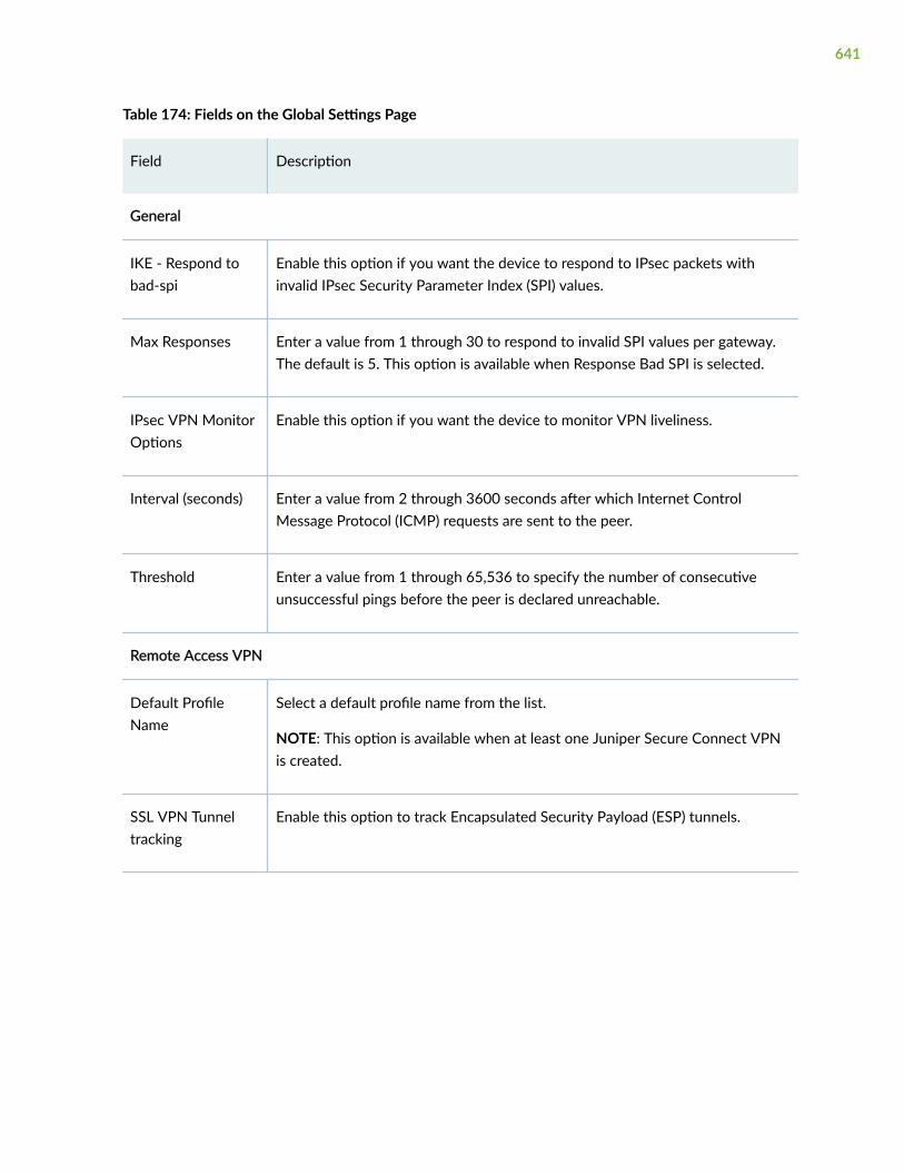
Table 174: Fields on the Global Settings Page
Field Description
General
IKE - Respond tobad-spi
Enable this option if you want the device to respond to IPsec packets withinvalid IPsec Security Parameter Index (SPI) values.
Max Responses Enter a value from 1 through 30 to respond to invalid SPI values per gateway.The default is 5. This option is available when Response Bad SPI is selected.
IPsec VPN MonitorOptions
Enable this option if you want the device to monitor VPN liveliness.
Interval (seconds) Enter a value from 2 through 3600 seconds after which Internet ControlMessage Protocol (ICMP) requests are sent to the peer.
Threshold Enter a value from 1 through 65,536 to specify the number of consecutiveunsuccessful pings before the peer is declared unreachable.
Remote Access VPN
Default ProfileName
Select a default profile name from the list.
NOTE: This option is available when at least one Juniper Secure Connect VPNis created.
SSL VPN Tunneltracking
Enable this option to track Encapsulated Security Payload (ESP) tunnels.
641

Table 174: Fields on the Global Settings Page (Continued)
Field Description
SSL VPN Profiles Lists the SSL VPN profiles.
NOTE: This option displays associated IPsec VPNs when at least one JuniperSecure Connect VPN is created.
To add a new SSL VPN profile:
1. Click +.
The Add SSL VPN Profile page appears.
2. Enter the following details:
• Name—Enter the name for an SSL VPN profile.
• Logging—Enable this option to log for SSL VPN.
• SSL Termination Profile—Select an SSL termination profile from the list.
To add a new SSL termination profile:
a. Click Add.
The Create SSL Termination Profile page appears.
b. Enter the following details:
• Name—Enter a name for the SSL termination profile.
• Server Certificate—Select a server certificate from the list.
To add a certificate, click Add. For more information on adding adevice certificate, see "Add a Device Certificate" on page 233.
To import a certificate, click Import. For more information onimporting a device certificate, see "Import a Device Certificate" onpage 231.
• Click OK.
642

Table 174: Fields on the Global Settings Page (Continued)
Field Description
c. Click OK.
3. Click OK.
To edit an SSL termination profile, select the profile you want to edit and clickon the pencil icon.
To delete an SSL termination profile, select the profile you want to delete andclick on the delete icon.
Internal SA
Internal SA Keys Enter the encryption key. You must ensure that the manual encryption key is inASCII text and 24 characters long; otherwise, the configuration will result in acommit failure.
NOTE: This option is available only for SRX5000 line of devices, SRX4100,SRX4200, SRX4600 devices, and vSRX.
RELATED DOCUMENTATION
About the IPsec VPN Page | 637
Edit an IPsec VPN | 697
Delete an IPsec VPN | 699
Create a Site-to-Site VPN
You are here: Network > VPN > IPsec VPN.
To create a site-to-site VPN:
1. Click Create VPN and select Site to Site on the upper right side of the IPsec VPN page.
The Create Site to Site VPN page appears.
643

2. Complete the configuration according to the guidelines provided in Table 175 on page 644 throughTable 180 on page 656.
The VPN connectivity will change from grey to blue line in the topology to show that theconfiguration is complete.
3. Click Save to save the changes.
If you want to discard your changes, click Cancel.
Table 175: Fields on the Create IPsec VPN Page
Field Action
Name Enter a name for the VPN.
Description Enter a description. This description will be usedfor the IKE and IPsec proposals and policies.During edit, the IPsec policy description will bedisplayed and updated.
Routing Mode Select the routing mode to which this VPN willbe associated:
• Traffic Selector (Auto Route Insertion)
• Static Routing
• Dynamic Routing – OSPF
• Dynamic Routing – BGP
For each topology, J-Web auto generates therelevant CLIs. Traffic Selector is the default mode.
644

Table 175: Fields on the Create IPsec VPN Page (Continued)
Field Action
Authentication Method Select an authentication method from the listthat the device uses to authenticate the source ofInternet Key Exchange (IKE) messages:
• Certificate Based—Types of digital signatures,which are certificates that confirm the identityof the certificate holder.
The following are the authentication methodsfor a certificate based:
• rsa-signatures—Specifies that a public keyalgorithm, which supports encryption anddigital signatures, is used.
• dsa-signatures—Specifies that the DigitalSignature Algorithm (DSA) is used.
• ecdsa-signatures-256—Specifies that theElliptic Curve DSA (ECDSA) using the 256-bit elliptic curve secp256r1, as specified inthe Federal Information ProcessingStandard (FIPS) Digital Signature Standard(DSS) 186-3, is used.
• ecdsa-signatures-384—Specifies that theECDSA using the 384-bit elliptic curvesecp384r1, as specified in the FIPS DSS186-3, is used.
• ecdsa-signatures-521—Specifies that theECDSA using the 521-bit elliptic curvesecp521r1 is used.
NOTE: ecdsa-signatures-521 supports onlySRX5000 line of devices with SPC3 cardand junos-ike package installed.
645

Table 175: Fields on the Create IPsec VPN Page (Continued)
Field Action
• Pre-shared Key (default method)—Specifiesthat a preshared key, which is a secret keyshared between the two peers, is used duringauthentication to identify the peers to eachother. The same key must be configured foreach peer. This is the default method.
Auto-create Firewall Policy If you select Yes, a firewall policy is automaticallybetween internal zone and tunnel interface zonewith local protected networks as source addressand remote protected networks as destinationaddress.
Another firewall policy will be created visa-versa.
If you choose No, you don’t have a firewall policyoption. You need to manually create the requiredfirewall policy to make this VPN work.
NOTE: If you do not want to auto-create afirewall policy in the VPN workflow, then theprotected network is hidden for dynamic routingin both local and remote gateway.
Remote Gateway Displays the remote gateway icon in thetopology. Click the icon to configure the remotegateway.
The gateway identifies the remote peer with theIPsec VPN peers and defines the appropriateparameters for that IPsec VPN.
For fields information, see Table 176 on page647.
646

Table 175: Fields on the Create IPsec VPN Page (Continued)
Field Action
Local Gateway Displays the local gateway icon in the topology.Click the icon to configure the local gateway.
For fields information, see Table 178 on page650.
IKE and IPsec Settings Configure the custom IKE or IPsec proposal andthe custom IPsec proposal with recommendedalgorithms or values.
For fields information, see Table 180 on page656.
NOTE:
• J-Web supports only one custom IKE proposaland does not support the predefinedproposal-set. Upon edit and save, J-Webdeletes the predefined proposal set ifconfigured.
• On the remote gateway of the VPN tunnel,you must configure the same custom proposaland policy.
• Upon edit, J-Web shows the first custom IKEand IPsec proposal when more than onecustom proposal is configured.
Table 176: Fields on the Remote Gateway Page
Field Action
Gateway is behind NAT If enabled, the configured external IP address(IPv4 or IPv6) is referred to as the NAT device IPaddress.
647

Table 176: Fields on the Remote Gateway Page (Continued)
Field Action
IKE Identity Select an option from the list to configure remoteidentity.
Host name Enter a remote host name.
IPv4 Address Enter a remote IPv4 address.
IPv6 Address Enter a remote IPv6 address.
Key ID Enter a Key ID.
E-mail Address Enter an e-mail address.
External IP Address Enter the peer IPv4 or IPv6 address. You cancreate one primary peer network with up to fourbackups.
You must enter one IPv4 or IPv6 address or youcan enter up to five IP addresses separated bycomma.
648

Table 176: Fields on the Remote Gateway Page (Continued)
Field Action
Protected Networks When you select a routing mode, lists all theglobal address(es).
Select the addresses from the Available columnand then click the right arrow to move it to theSelected column.
When the routing mode is:
• Traffic Selector—The IP addresses will be usedas remote IP in traffic selector configuration.
• Static Routing:
• Static route will be configured for theselected global address(es).
• The tunnel interface (st0.x) of the localgateway will be used as the next-hop.
• Dynamic Routing—Default value is any. Youcan also select specific global address(es). Theselected value is configured as destinationaddress in the firewall policy.
Add Click +.
The Create Global Address page appears. SeeTable 177 on page 649 for fields information.
Table 177: Fields on the Create Global Address Page
Field Action
Name Enter a unique string that must begin with analphanumeric character and can include colons,periods, dashes, and underscores; no spacesallowed; 63-character maximum.
649

Table 177: Fields on the Create Global Address Page (Continued)
Field Action
IP Type Select IPv4 or IPv6.
IPv4 IPv4 Address—Enter a valid IPv4 address.
Subnet—Enter the subnet for IPv4 address.
IPv6 IPv6 Address—Enter a valid IPv6 address.
Subnet Prefix—Enter a subnet mask for thenetwork range. Once entered, the value isvalidated.
Table 178: Fields on the Local Gateway Page
Field Action
Gateway is behind NAT Enable this option when the local gateway isbehind a NAT device.
IKE Identity Select an option from the list to configure localidentity. When Gateway is behind NAT isenabled, you can configure an IPv4 or IPv6address to reference the NAT device.
Host name Enter a host name.
NOTE: This option is available only if Gateway isbehind NAT is disabled.
IPv4 Address Enter an IPv4 address.
IPv6 Address Enter an IPv6 address.
650

Table 178: Fields on the Local Gateway Page (Continued)
Field Action
Key ID Enter a Key ID.
NOTE: This option is available only if Gateway isbehind NAT is disabled.
E-mail Address Enter an E-mail address.
NOTE: This option is available only if Gateway isbehind NAT is disabled.
External Interface Select an outgoing interface from the list for IKEnegotiations.
The list contains all available IP addresses if morethan one IP address is configured to the specifiedinterface. The selected IP address will beconfigured as the local address under the IKEgateway.
Tunnel Interface Select an interface from the list to bind it to thetunnel interface (route-based VPN).
Click Add to add a new interface. The CreateTunnel Interface page appears. See Table 179 onpage 655.
Router ID Enter the routing device’s IP address.
NOTE: This option is available if the routingmode is Dynamic Routing - OSPF or BGP.
651

Table 178: Fields on the Local Gateway Page (Continued)
Field Action
Area ID Enter an area ID within the range of 0 to4,294,967,295, where the tunnel interfaces ofthis VPN need to be configured.
NOTE: This option is available if the routingmode is Dynamic Routing - OSPF.
Tunnel Interface Passive Enable this option to bypass traffic of the usualactive IP checks.
NOTE: This option is available if the routingmode is Dynamic Routing - OSPF.
ASN Enter the routing device’s AS number.
Use a number assigned to you by the NIC. Range:1 through 4,294,967,295 (232 – 1) in plain-number format for 4-byte AS numbers.
NOTE: This option is available if the routingmode is Dynamic Routing - BGP.
Neighbor ID Enter IP address of a neighboring router.
NOTE: This option is available if the routingmode is Dynamic Routing - BGP.
BGP Group Type Select the type of BGP peer group from the list:
• external—External group, which allows inter-AS BGP routing.
• internal—Internal group, which allows intra-ASBGP routing.
NOTE: This option is available if the routingmode is Dynamic Routing - BGP.
652
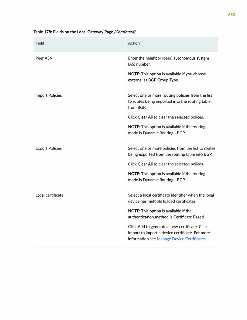
Table 178: Fields on the Local Gateway Page (Continued)
Field Action
Peer ASN Enter the neighbor (peer) autonomous system(AS) number.
NOTE: This option is available if you chooseexternal as BGP Group Type.
Import Policies Select one or more routing policies from the listto routes being imported into the routing tablefrom BGP.
Click Clear All to clear the selected polices.
NOTE: This option is available if the routingmode is Dynamic Routing - BGP.
Export Policies Select one or more policies from the list to routesbeing exported from the routing table into BGP.
Click Clear All to clear the selected polices.
NOTE: This option is available if the routingmode is Dynamic Routing - BGP.
Local certificate Select a local certificate identifier when the localdevice has multiple loaded certificates.
NOTE: This option is available if theauthentication method is Certificate Based.
Click Add to generate a new certificate. ClickImport to import a device certificate. For moreinformation see Manage Device Certificates.
653

Table 178: Fields on the Local Gateway Page (Continued)
Field Action
Trusted CA/Group Select the certificate authority (CA) profile fromlist to associate it with the local certificate.
NOTE: This option is available if theauthentication method is Certificate Based.
Click Add to add a new CA profile. For moreinformation see Manage Trusted CertificateAuthority.
Pre-shared Key Enter the value of the preshared key. The key canbe one of the following:
• ascii-text—ASCII text key.
• hexadecimal—Hexadecimal key.
NOTE: This option is available if theauthentication method is Pre-shared Key.
Protected Networks Click +. The Create Protected Networks pageappears.
Create Protected Networks
Zone Select a security zone from the list that will beused as a source zone in the firewall policy.
Global Address Select the addresses from the Available columnand then click the right arrow to move it to theSelected column.
Add Click Add.
The Create Global Address page appears. SeeTable 177 on page 649.
654

Table 178: Fields on the Local Gateway Page (Continued)
Field Action
Edit Select the protected network you want to editand click on the pencil icon.
The Edit Global Address page appears witheditable fields.
Delete Select the protected network you want to editand click on the delete icon.
The confirmation message pops up.
Click Yes to delete.
Table 179: Fields on the Create Tunnel Interface Page
Field Action
Interface Unit Enter the logical unit number.
Description Enter a description for the logical interface.
Zone Select a zone for the logical interface from the listto use as a source zone in the firewall policy.
Click Add to add a new zone. Enter zone nameand description and click OK on the CreateSecurity Zone page.
Routing Instance Select a routing instance from the list.
IPv4
NOTE: This option is available only if you select routing mode as Dynamic Routing - OSPF or BGP.
IPv4 Address Enter a valid IPv4 address.
655

Table 179: Fields on the Create Tunnel Interface Page (Continued)
Field Action
Subnet Prefix Enter a subnet mask for the IPv4 address.
IPv6
NOTE: This option is available only if you select routing mode as Dynamic Routing - OSPF or BGP.
IPv6 Address Enter a valid IPv6 address.
Subnet Prefix Enter a subnet mask for the network range. Onceentered, the value is validated.
Table 180: IKE and IPsec Settings
Field Action
IKE Settings
IKE Version Select the required IKE version, either v1 or v2 to negotiate dynamic securityassociations (SAs) for IPsec.
Default value is v2.
IKE Mode Select the IKE policy mode from the list:
• aggressive—Take half the number of messages of main mode, has lessnegotiation power, and does not provide identity protection.
• main—Use six messages, in three peer-to-peer exchanges, to establish theIKE SA. These three steps include the IKE SA negotiation, a Diffie-Hellmanexchange, and authentication of the peer. Also provides identity protection.
EncryptionAlgorithm
Select the appropriate encryption mechanism from the list.
Default value is aes-256-gcm.
656
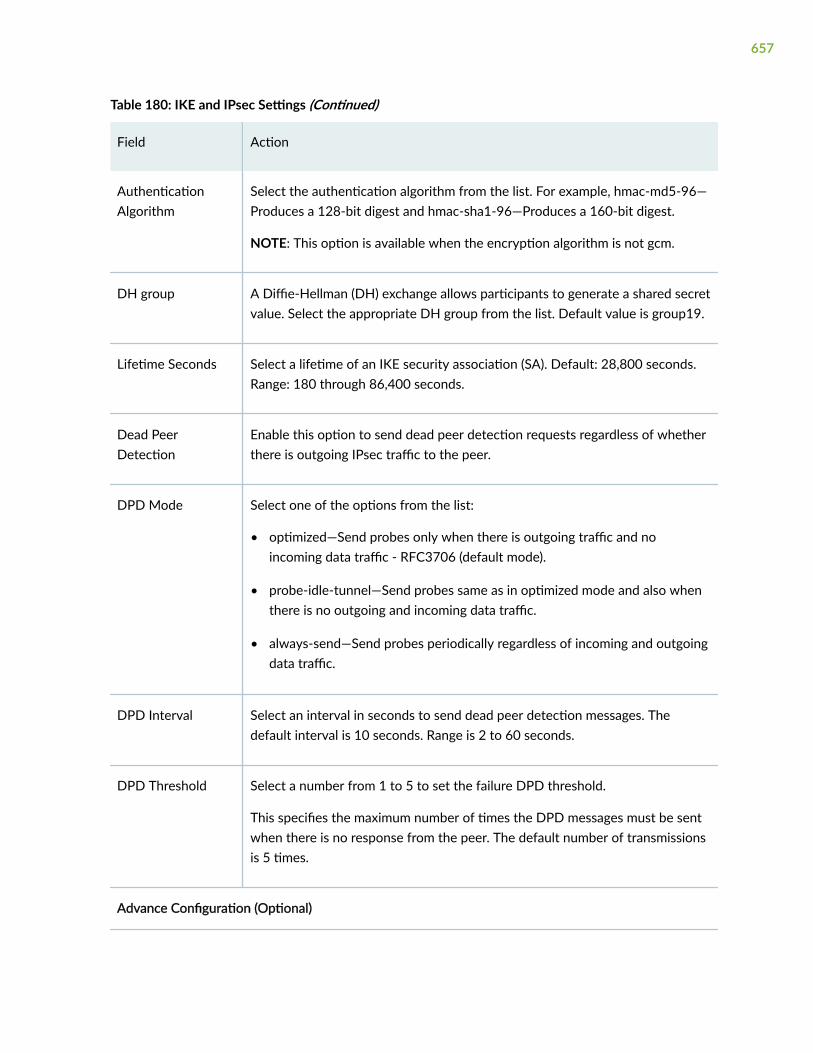
Table 180: IKE and IPsec Settings (Continued)
Field Action
AuthenticationAlgorithm
Select the authentication algorithm from the list. For example, hmac-md5-96—Produces a 128-bit digest and hmac-sha1-96—Produces a 160-bit digest.
NOTE: This option is available when the encryption algorithm is not gcm.
DH group A Diffie-Hellman (DH) exchange allows participants to generate a shared secretvalue. Select the appropriate DH group from the list. Default value is group19.
Lifetime Seconds Select a lifetime of an IKE security association (SA). Default: 28,800 seconds.Range: 180 through 86,400 seconds.
Dead PeerDetection
Enable this option to send dead peer detection requests regardless of whetherthere is outgoing IPsec traffic to the peer.
DPD Mode Select one of the options from the list:
• optimized—Send probes only when there is outgoing traffic and noincoming data traffic - RFC3706 (default mode).
• probe-idle-tunnel—Send probes same as in optimized mode and also whenthere is no outgoing and incoming data traffic.
• always-send—Send probes periodically regardless of incoming and outgoingdata traffic.
DPD Interval Select an interval in seconds to send dead peer detection messages. Thedefault interval is 10 seconds. Range is 2 to 60 seconds.
DPD Threshold Select a number from 1 to 5 to set the failure DPD threshold.
This specifies the maximum number of times the DPD messages must be sentwhen there is no response from the peer. The default number of transmissionsis 5 times.
Advance Configuration (Optional)
657

Table 180: IKE and IPsec Settings (Continued)
Field Action
General IKE ID Enable this option to accept peer IKE ID.
IKEv2 Re-authentication
Configure the reauthentication frequency to trigger a new IKEv2reauthentication.
IKEv2 Re-fragmentation
This option is enabled by default.
IKEv2 Re-fragmentSize
Select the maximum size, in bytes, of an IKEv2 message before it is split intofragments.
The size applies to both IPv4 and IPv6 messages. Range: 570 to 1320 bytes.
Default values are:
• IPv4 messages—576 bytes.
• IPv6 messages—1280 bytes.
NAT-T Enable this option for IPsec traffic to pass through a NAT device.
NAT-T is an IKE phase 1 algorithm that is used when trying to establish a VPNconnection between two gateway devices, where there is a NAT device infront of one of the SRX Series devices.
NAT Keep Alive Select appropriate keepalive interval in seconds. Range: 1 to 300.
If the VPN is expected to have large periods of inactivity, you can configurekeepalive values to generate artificial traffic to keep the session active on theNAT devices.
IPsec Settings
Protocol Select either Encapsulation Security Protocol (ESP) or Authentication Header(AH) protocol from the list to establish VPN. Default value is ESP.
658

Table 180: IKE and IPsec Settings (Continued)
Field Action
EncryptionAlgorithm
Select the encryption method. Default value is aes-256-gcm.
NOTE: This option is available only for the ESP protocol.
AuthenticationAlgorithm
Select the IPsec authentication algorithm from the list. For example, hmac-md5-96—Produces a 128-bit digest and hmac-sha1-96—Produces a 160-bitdigest.
NOTE: This option is available when the encryption algorithm is not gcm.
Perfect ForwardSecrecy
Select Perfect Forward Secrecy (PFS) from the list. The device uses this methodto generate the encryption key. Default value is group19.
PFS generates each new encryption key independently from the previous key.The higher numbered groups provide more security, but require moreprocessing time.
NOTE: group15, group16, and group21 support only the SRX5000 line ofdevices with an SPC3 card and junos-ike package installed.
Lifetime Seconds Select the lifetime (in seconds) of an IPsec security association (SA). When theSA expires, it is replaced by a new SA and security parameter index (SPI) orterminated. Default is 3,600 seconds. Range: 180 through 86,400 seconds.
Lifetime Kilobytes Select the lifetime (in kilobytes) of an IPsec SA. Default is 128kb. Range: 64through 4294967294.
Establish Tunnel Enable this option to establish the IPsec tunnel. IKE is activated immediately(default value) after a VPN is configured and the configuration changes arecommitted.
Advanced Configuration
659
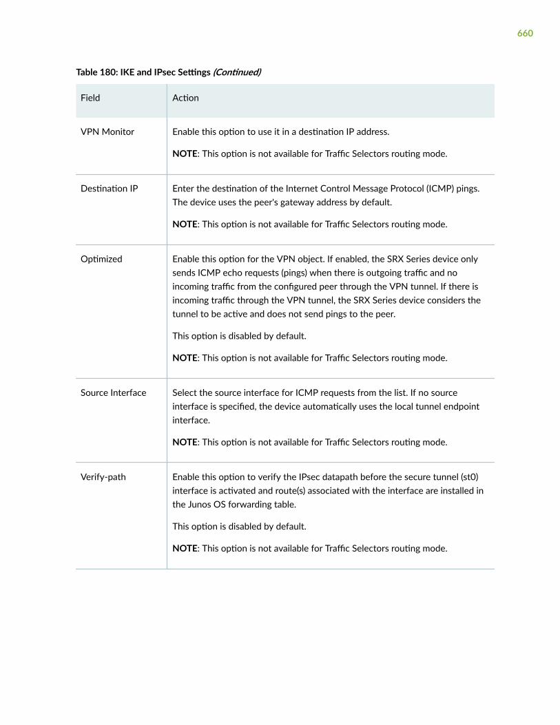
Table 180: IKE and IPsec Settings (Continued)
Field Action
VPN Monitor Enable this option to use it in a destination IP address.
NOTE: This option is not available for Traffic Selectors routing mode.
Destination IP Enter the destination of the Internet Control Message Protocol (ICMP) pings.The device uses the peer's gateway address by default.
NOTE: This option is not available for Traffic Selectors routing mode.
Optimized Enable this option for the VPN object. If enabled, the SRX Series device onlysends ICMP echo requests (pings) when there is outgoing traffic and noincoming traffic from the configured peer through the VPN tunnel. If there isincoming traffic through the VPN tunnel, the SRX Series device considers thetunnel to be active and does not send pings to the peer.
This option is disabled by default.
NOTE: This option is not available for Traffic Selectors routing mode.
Source Interface Select the source interface for ICMP requests from the list. If no sourceinterface is specified, the device automatically uses the local tunnel endpointinterface.
NOTE: This option is not available for Traffic Selectors routing mode.
Verify-path Enable this option to verify the IPsec datapath before the secure tunnel (st0)interface is activated and route(s) associated with the interface are installed inthe Junos OS forwarding table.
This option is disabled by default.
NOTE: This option is not available for Traffic Selectors routing mode.
660

Table 180: IKE and IPsec Settings (Continued)
Field Action
Destination IP Enter the destination IP address. Original, untranslated IP address of the peertunnel endpoint that is behind a NAT device. This IP address must not be theNAT translated IP address. This option is required if the peer tunnel endpoint isbehind a NAT device. The verify-path ICMP request is sent to this IP addressso that the peer can generate an ICMP response.
NOTE: This option is not available for Traffic Selectors routing mode.
Packet size Enter the size of the packet that is used to verify an IPsec datapath before thest0 interface is brought up. Range: 64 to 1350 bytes. Default value is 64 bytes.
NOTE: This option is not available for Traffic Selectors routing mode.
Anti Replay IPsec protects against VPN attack by using a sequence of numbers built intothe IPsec packet—the system does not accept a packet with the samesequence number.
This option is enabled by default. The Anti-Replay checks the sequencenumbers and enforce the check, rather than just ignoring the sequencenumbers.
Disable Anti-Replay if there is an error with the IPsec mechanism that results inout-of-order packets, which prevents proper functionality.
Install Interval Select the maximum number of seconds to allow for the installation of arekeyed outbound security association (SA) on the device. Select a value from1 to 10.
Idle Time Select the idle time interval. The sessions and their corresponding translationstime out after a certain period of time if no traffic is received. Range is 60 to999999 seconds.
661

Table 180: IKE and IPsec Settings (Continued)
Field Action
DF Bit Select how the device handles the Don't Fragment (DF) bit in the outer header:
• clear—Clear (disable) the DF bit from the outer header. This is the default.
• copy—Copy the DF bit to the outer header.
• set—Set (enable) the DF bit in the outer header.
Copy Outer DSCP This option enabled by default. This enables copying of Differentiated ServicesCode Point (DSCP) (outer DSCP+ECN) from the outer IP header encryptedpacket to the inner IP header plain text message on the decryption path.Enabling this feature, after IPsec decryption, clear text packets can follow theinner CoS (DSCP+ECN) rules.
RELATED DOCUMENTATION
About the IPsec VPN Page | 637
IPsec VPN Global Settings | 640
Edit an IPsec VPN | 697
Delete an IPsec VPN | 699
Create a Remote Access VPN—Juniper Secure Connect
You are here: Network > VPN > IPsec VPN.
Juniper Secure Connect is Juniper’s client-based SSL-VPN solution that offers secure connectivity foryour network resources.
Juniper Secure Connect provides secure remote access for the users to connect to the corporatenetworks and resources remotely using the Internet. Juniper Secure Connect downloads theconfiguration from SRX Services devices and chooses the most effective transport protocols duringconnection establishment to deliver a great administrator and user experience.
To create a remote access VPN for Juniper secure connect:
662

1. Choose Create VPN > Remote Access > Juniper Secure Connect on the upper right-side of the IPsecVPN page.
The Create Remote Access (Juniper Secure Connect) page appears.
2. Complete the configuration according to the guidelines provided in Table 181 on page 663 throughTable 186 on page 678.
The VPN connectivity will change from grey to blue line in the topology to show that theconfiguration is complete.
3. Click Save to complete Secure Connect VPN Configuration and associated policy if you have selectedthe auto policy creation option.
If you want to discard your changes, click Cancel.
Table 181: Fields on the Create Remote Access (Juniper Secure Connect) Page
Field Action
Name Enter a name for the remote access connection.This name will be displayed as the end usersrealm name in the Juniper Secure Connect Client.
Description Enter a description. This description will be usedfor the IKE and IPsec proposals, policies, remoteaccess profile, client configuration, and NAT ruleset.
During edit the IPsec policy description will bedisplayed. IPsec policy and remote access profiledescriptions will be updated.
Routing Mode This option is disabled for the remote access.
Default mode is Traffic Selector (Auto RouteInsertion).
663

Table 181: Fields on the Create Remote Access (Juniper Secure Connect) Page (Continued)
Field Action
Authentication Method Select an authentication method from the listthat the device uses to authenticate the source ofInternet Key Exchange (IKE) messages:
• Pre-shared Key (default method)—Specifiesthat a preshared key, which is a secret keyshared between the two peers, is used duringauthentication to identify the peers with eachother. The same key must be configured foreach peer. This is the default method.
• Certificate Based—Specifies the type of digitalsignatures, which are certificates that confirmthe identity of the certificate holder.
The supported signature is rsa-signatures. rsa-signatures specifies that a public keyalgorithm, which supports encryption anddigital signatures, is used.
Auto-create Firewall Policy If you select Yes, a firewall policy is automaticallycreated between internal zone and tunnelinterface zone with local protected networks assource address and remote protected networksas destination address.
Another firewall policy will be created visa-versa.
If you choose No, you don’t have a firewall policyoption. You need to manually create the requiredfirewall policy to make this VPN work.
NOTE: If you do not want to auto-create afirewall policy in the VPN workflow, then theprotected network is hidden for dynamic routingin both local and remote gateway.
664

Table 181: Fields on the Create Remote Access (Juniper Secure Connect) Page (Continued)
Field Action
Remote User Displays the remote user icon in the topology.Click the icon to configure the Juniper SecureConnect client settings.
For more information on the fields, see Table 182on page 666.
NOTE: The J-Web UI displays the remote user'sURL once local gateway is configured.
Local Gateway Displays the local gateway icon in the topology.Click the icon to configure the local gateway.
For more information on the fields, see Table 183on page 671.
IKE and IPsec Settings Configure the custom IKE or IPsec proposal andthe custom IPsec proposal with recommendedalgorithms or values.
For more information on the fields, see Table 186on page 678.
NOTE:
• J-Web supports only one custom IKE proposaland does not support the predefinedproposal-set. Upon edit and save, J-Webdeletes the predefined proposal set ifconfigured.
• On the remote gateway of the VPN tunnel,you must configure the same custom proposaland policy.
• Upon edit, J-Web shows the first custom IKEand IPsec proposal when more than onecustom proposal is configured.
665

Table 182: Fields on the Remote User Page
Field Action
Default Profile Enable this option to use the configured VPNname as remote access default profile.
NOTE:
• This option is not available if the defaultprofile is configured.
• You must enable the default profile. If notenabled, configure the default profile underVPN > IPsec VPN > Global Settings > RemoteAccess VPN.
Connection Mode Select one of the following options from the listto establish the Juniper Secure Connect clientconnection:
• Manual—You need manually connect to theVPN tunnel every time you log in.
• Always—You are automatically connected tothe VPN tunnel every time you log in.
The default connection mode is Manual.
SSL VPN Enable this option to establish SSL VPNconnection from the Juniper Secure ConnectClient to the SRX Series device.
By default, this option is enabled.
NOTE: This is a fallback option when IPsec portsare not reachable.
666

Table 182: Fields on the Remote User Page (Continued)
Field Action
Biometric authentication Enable this option to authenticate the clientsystem using unique configured methods.
An authentication prompt is displayed when youconnect in the client system. The VPNconnection will only be initiated after successfulauthentication through the method configuredfor Windows Hello (fingerprint recognition, facerecognition, PIN entry, and so on).
Windows Hello must be preconfigured on theclient system if the Biometric authenticationoption is enabled.
Dead Peer Detection Enable the dead peer detection (DPD) option toallow the Juniper Secure Connect client to detectif the SRX Series device is reachable.
Disable this option to allow the Juniper SecureConnect client to detect till the SRX Series deviceconnection reachability is restored.
This option is enabled by default.
DPD Interval Enter the amount of time that the peer waits fortraffic from its destination peer before sending adead-peer-detection (DPD) request packet. TheRange is 2 through 60 seconds and default is 60seconds.
DPD Threshold Enter the maximum number of unsuccessful deadpeer detection (DPD) requests to be sent beforethe peer is considered unavailable. The Range is 1through 5 and default is 5.
667

Table 182: Fields on the Remote User Page (Continued)
Field Action
Certificates Enable Certificates to configure certificateoptions on Secure Client Connect.
NOTE: This option is available only if you selectthe Certificate Based authentication method.
Expiry Warning Enable this option to display the certificate expirywarning on the Secure Connect Client.
This option is enabled by default.
NOTE: This option is available only if you enableCertificates.
Warning Interval Enter the interval (days) at which the warning tobe displayed.
Range is 1 through 90. Default value is 60.
NOTE: This option is available only if you enableCertificates.
Pin Req Per Connection Enable this option to enter the certificate pin onvery connection.
This option is enabled by default.
NOTE: This option is available only if you enableCertificates.
668

Table 182: Fields on the Remote User Page (Continued)
Field Action
EAP-TLS Enable this option for the authentication process.IKEv2 requires EAP for user authentication. SRXSeries device cannot act as an EAP server. Anexternal RADIUS server must be used for IKEv2EAP to do the EAP authentication. SRX will act asa pass-through authenticator relaying EAPmessages between the Juniper Secure Connectclient and the RADIUS server.
This option is enabled by default.
NOTE: This option is available only if you selectthe Certificate Based authentication method.
Windows Logon Enable this option to provide users to securelylog on to the Windows domain before logging onto the Windows system. The client supportsdomain logon using a credential service providerafter establishing a VPN connection to thecompany network.
Domain Name Enter the system domain name on to which theUsers Machine logs.
Mode Select one of the following options from the listto log on to Windows domain.
• Manual—You must manually enter your logondata on the Windows logon screen.
• Automatic—The client software transfers thedata entered here to the Microsoft logoninterface (Credential Provider) without youraction.
669

Table 182: Fields on the Remote User Page (Continued)
Field Action
Disconnect at Logoff Enable this option to shut down the connectionwhen the system switches to hibernation orstandby mode. When the system resumes fromhibernation or standby mode the connection hasto be re-established.
Flush Credential at Logoff Enable this option to delete username andpassword from the cache. You must reenter theusername and password.
Lead Time Duration Enter the lead time duration to initialize timebetween network logon and domain logon.
After the connection is set up, the Windowslogon will only be executed after the initializationtime set here has elapsed.
EAP Authentication Enable this option to execute EAP authenticationprior to the destination dialog in the credentialprovider. Then, system will ask for the necessaryPIN, regardless of whether EAP will be requiredfor subsequent dial-in.
If this option is disabled, then EAP authenticationwill be executed after the destination selection.
Auto Dialog Open Enable this option to select whether a dialogshould open automatically for connectionestablishment to a remote domain.
If this option is disabled, then the password andPIN for the client will only be queried after theWindows logon.
670

Table 183: Fields on the Local Gateway Page
Field Action
Gateway is behind NAT Enable this option when the local gateway isbehind a NAT device.
NAT IP Address Enter the public (NAT) IP address of the SRXSeries device.
NOTE: This option is available only whenGateway is behind NAT is enabled. You canconfigure an IPv4 address to reference the NATdevice.
IKE ID This field is mandatory. Enter the IKE ID in theformat [email protected].
External Interface Select an outgoing interface from the list forwhich the client will connect to.
The list contains all available IP addresses if morethan one IPv4 address is configured to thespecified interface. The selected IP address willbe configured as the local address under the IKEgateway.
Tunnel Interface Select an interface from the list for the client toconnect to.
Click Add to add a new interface. The CreateTunnel Interface page appears. For moreinformation on creating a new tunnel interface,see Table 184 on page 676.
Click Edit to edit the selected tunnel interface.
671

Table 183: Fields on the Local Gateway Page (Continued)
Field Action
Pre-shared Key Enter one of the following values of thepreshared key:
• ascii-text—ASCII text key.
• hexadecimal—Hexadecimal key.
NOTE: This option is available if theauthentication method is Pre-shared Key.
Local certificate Select a local certificate from the list.
Local certificate lists only the RSA certificates.
To add a certificate, click Add. For moreinformation on adding a device certificate, see"Add a Device Certificate" on page 233.
To import a certificate, click Import. For moreinformation on importing a device certificate, see"Import a Device Certificate" on page 231.
NOTE: This option is available if theauthentication method is Certificated Based.
Trusted CA/Group Select a trusted Certificate Authority/groupprofile from the list.
To add a CA profile, click Add CA Profile. Formore information on adding a CA profile, see"Add a Certificate Authority Profile" on page 247.
NOTE: This option is available if theauthentication method is Certificated Based.
672

Table 183: Fields on the Local Gateway Page (Continued)
Field Action
User Authentication This field is mandatory. Select the authenticationprofile from the list that will be used toauthenticate user accessing the remote accessVPN.
Click Add to create a new Profile. For moreinformation on creating a new access profile, see"Add an Access Profile" on page 954.
673

Table 183: Fields on the Local Gateway Page (Continued)
Field Action
SSL VPN Profile Select the SSL VPN Profile from the list that willbe used to terminate the remote accessconnections.
To create a new SSL VPN profile:
1. Click Add.
2. Enter the following details:
• Name—Enter the name for an SSL VPNprofile.
• Logging—Enable this option to log for SSLVPN.
• SSL Termination Profile—Select an SSLtermination profile from the list.
To add a new SSL termination profile:
a. Click Add.
The Create SSL Termination Profilepage appears.
b. Enter the following details:
• Name—Enter a name for the SSLtermination profile.
• Server Certificate—Select a servercertificate from the list.
To add a certificate, click Add. Formore information on adding a device
674
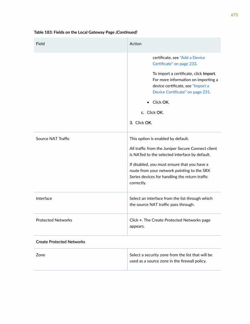
Table 183: Fields on the Local Gateway Page (Continued)
Field Action
certificate, see "Add a DeviceCertificate" on page 233.
To import a certificate, click Import.For more information on importing adevice certificate, see "Import aDevice Certificate" on page 231.
• Click OK.
c. Click OK.
3. Click OK.
Source NAT Traffic This option is enabled by default.
All traffic from the Juniper Secure Connect clientis NATed to the selected interface by default.
If disabled, you must ensure that you have aroute from your network pointing to the SRXSeries devices for handling the return trafficcorrectly.
Interface Select an interface from the list through whichthe source NAT traffic pass through.
Protected Networks Click +. The Create Protected Networks pageappears.
Create Protected Networks
Zone Select a security zone from the list that will beused as a source zone in the firewall policy.
675

Table 183: Fields on the Local Gateway Page (Continued)
Field Action
Global Address Select the addresses from the Available columnand then click the right arrow to move it to theSelected column.
Click Add to select the networks the Client canconnect to.
The Create Global Address page appears. Formore information on the fields, see Table 185 onpage 677.
Edit Select the protected network you want to editand click on the pencil icon.
The Edit Protected Networks page appears witheditable fields.
Delete Select the protected network you want to editand click on the delete icon.
The confirmation message pops up.
Click Yes to delete the protected network.
Table 184: Fields on the Create Tunnel Interface Page
Field Action
Interface Unit Enter the logical unit number.
Description Enter a description for the logical interface.
676

Table 184: Fields on the Create Tunnel Interface Page (Continued)
Field Action
Zone Select a zone from the list to add it to the tunnelinterface.
This zone is used in the auto-creation of thefirewall policy.
Click Add to add a new zone. Enter zone nameand description and click OK on the CreateSecurity Zone page.
Routing Instance Select a routing instance from the list.
NOTE: The default routing instance, primary,refers to the main inet.0 routing table in thelogical system.
Table 185: Fields on the Create Global Address Page
Field Action
Name Enter a name for the global address. The name must be a unique string that mustbegin with an alphanumeric character and can include colons, periods, dashes, andunderscores; no spaces allowed; 63-character maximum.
IP Type Select IPv4.
IPv4
IPv4 Address Enter a valid IPv4 address.
Subnet Enter the subnet for IPv4 address.
677

Table 186: IKE and IPsec Settings
Field Action
IKE Settings
NOTE: The following parameters are generated automatically and are not displayed in the J-Web UI:
• If the authentication method is Pre-Shared Key, the IKE version is v1, ike-user-type is shared-ike-id, and mode is Aggressive.
• If the authentication method is Certificate Based, the IKE version is v2, ike-user-type is shared-ike-id, and mode is Main.
Encryption Algorithm Select the appropriate encryption mechanism from the list.
Default value is AES-CBC 256-bit.
AuthenticationAlgorithm
Select the authentication algorithm from the list. For example, SHA 256-bit.
DH group A Diffie-Hellman (DH) exchange allows participants to generate a sharedsecret value. Select the appropriate DH group from the list. Default valueis group19.
Lifetime Seconds Select a lifetime duration (in seconds) of an IKE security association (SA).
Default value is 28,800 seconds. Range: 180 through 86,400 seconds.
Dead Peer Detection Enable this option to send dead peer detection requests regardless ofwhether there is outgoing IPsec traffic to the peer.
678

Table 186: IKE and IPsec Settings (Continued)
Field Action
DPD Mode Select one of the options from the list:
• optimized—Send probes only when there is outgoing traffic and noincoming data traffic - RFC3706 (default mode).
• probe-idle-tunnel—Send probes same as in optimized mode and alsowhen there is no outgoing and incoming data traffic.
• always-send—Send probes periodically regardless of incoming andoutgoing data traffic.
DPD Interval Select an interval (in seconds) to send dead peer detection messages. Thedefault interval is 10 seconds. Range is 2 to 60 seconds.
DPD Threshold Select a number from 1 to 5 to set the failure DPD threshold.
This specifies the maximum number of times the DPD messages must besent when there is no response from the peer. The default number oftransmissions is 5 times.
Advance Configuration (Optional)
NAT-T Enable this option for IPsec traffic to pass through a NAT device.
NAT-T is an IKE phase 1 algorithm that is used when trying to establish aVPN connection between two gateway devices, where there is a NATdevice in front of one of the SRX Series devices.
NAT Keep Alive Select appropriate keepalive interval in seconds. Range: 1 to 300.
If the VPN is expected to have large periods of inactivity, you canconfigure keepalive values to generate artificial traffic to keep the sessionactive on the NAT devices.
679

Table 186: IKE and IPsec Settings (Continued)
Field Action
IKE Connection Limit Enter the number of concurrent connections that the VPN profilesupports.
Range is 1 through 4294967295.
When the maximum number of connections is reached, no more remoteaccess user (VPN) endpoints attempting to access an IPsec VPN can beginInternet Key Exchange (IKE) negotiations.
IKEv2 Fragmentation This option is enabled by default. IKEv2 fragmentation splits a large IKEv2message into a set of smaller ones so that there is no fragmentation at theIP level. Fragmentation takes place before the original message isencrypted and authenticated, so that each fragment is separatelyencrypted and authenticated.
NOTE: This option is available if the authentication method is CertificatedBased.
IKEv2 Fragment Size Select the maximum size, in bytes, of an IKEv2 message before it is splitinto fragments.
The size applies to IPv4 message. Range: 570 to 1320 bytes.
Default value is 576 bytes.
NOTE: This option is available if the authentication method is CertificatedBased.
IPsec Settings
NOTE: The authentication method is Pre-Shared Key or Certificate Based, it automatically generatesprotocol as ESP.
Encryption Algorithm Select the encryption method. Default value is AES-GCM 256-bit.
680
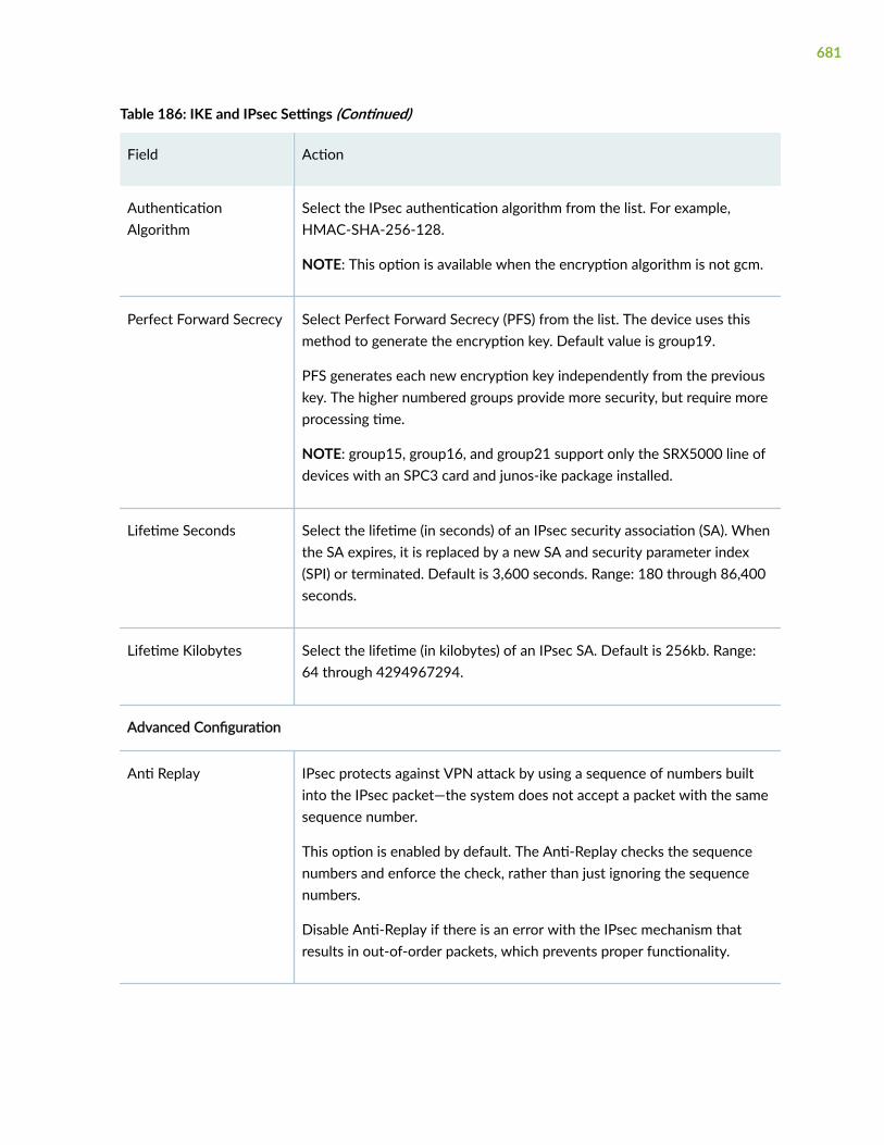
Table 186: IKE and IPsec Settings (Continued)
Field Action
AuthenticationAlgorithm
Select the IPsec authentication algorithm from the list. For example,HMAC-SHA-256-128.
NOTE: This option is available when the encryption algorithm is not gcm.
Perfect Forward Secrecy Select Perfect Forward Secrecy (PFS) from the list. The device uses thismethod to generate the encryption key. Default value is group19.
PFS generates each new encryption key independently from the previouskey. The higher numbered groups provide more security, but require moreprocessing time.
NOTE: group15, group16, and group21 support only the SRX5000 line ofdevices with an SPC3 card and junos-ike package installed.
Lifetime Seconds Select the lifetime (in seconds) of an IPsec security association (SA). Whenthe SA expires, it is replaced by a new SA and security parameter index(SPI) or terminated. Default is 3,600 seconds. Range: 180 through 86,400seconds.
Lifetime Kilobytes Select the lifetime (in kilobytes) of an IPsec SA. Default is 256kb. Range:64 through 4294967294.
Advanced Configuration
Anti Replay IPsec protects against VPN attack by using a sequence of numbers builtinto the IPsec packet—the system does not accept a packet with the samesequence number.
This option is enabled by default. The Anti-Replay checks the sequencenumbers and enforce the check, rather than just ignoring the sequencenumbers.
Disable Anti-Replay if there is an error with the IPsec mechanism thatresults in out-of-order packets, which prevents proper functionality.
681

Table 186: IKE and IPsec Settings (Continued)
Field Action
Install Interval Select the maximum number of seconds to allow for the installation of arekeyed outbound security association (SA) on the device. Select a valuefrom 1 to 10 seconds.
Idle Time Select the idle time interval. The sessions and their correspondingtranslations time out after a certain period of time if no traffic is received.Range is 60 to 999999 seconds.
DF Bit Select how the device handles the Don't Fragment (DF) bit in the outerheader:
• clear—Clear (disable) the DF bit from the outer header. This is thedefault.
• copy—Copy the DF bit to the outer header.
• set—Set (enable) the DF bit in the outer header.
Copy Outer DSCP This option enabled by default. This enables copying of DifferentiatedServices Code Point (DSCP) (outer DSCP+ECN) from the outer IP headerencrypted packet to the inner IP header plain text message on thedecryption path. Enabling this feature, after IPsec decryption, clear textpackets can follow the inner CoS (DSCP+ECN) rules.
RELATED DOCUMENTATION
About the IPsec VPN Page | 637
IPsec VPN Global Settings | 640
Edit an IPsec VPN | 697
Delete an IPsec VPN | 699
682

Create a Remote Access VPN—NCP Exclusive Client
You are here: Network > VPN > IPsec VPN.
The NCP Exclusive Remote Access Client is part of the NCP Exclusive Remote Access solution forJuniper SRX Series Gateways. The VPN client is only available with NCP Exclusive Remote AccessManagement. Use the NCP Exclusive Client to establish secure, IPsec-based data links from any locationwhen connected with SRX Series Gateways.
To create a remote access VPN for Juniper secure connect:
1. Choose Create VPN > Remote Access > NCP Exclusive Client on the upper right-side of the IPsecVPN page.
The Create Remote Access (NCP Exclusive Client) page appears.
2. Complete the configuration according to the guidelines provided in Table 187 on page 683 throughTable 191 on page 693.
The VPN connectivity will change from grey to blue line in the topology to show that theconfiguration is complete.
3. Click Save to save the changes.
If you want to discard your changes, click Cancel.
Table 187: Fields on the Create Remote Access (NCP Exclusive Client) Page
Field Action
Name Enter a name for the remote access connection.This name will be displayed as the end usersconnection name in the NCP exclusive client.
Description Enter a description. This description will be usedfor the IKE and IPsec proposals, policies, remoteaccess profile, client configuration, and NAT ruleset.
During edit the IPsec policy description will bedisplayed. IPsec policy and remote access profiledescriptions will be updated.
683

Table 187: Fields on the Create Remote Access (NCP Exclusive Client) Page (Continued)
Field Action
Routing Mode This option is disabled for the remote access.
Default mode is Traffic Selector (Auto RouteInsertion).
Authentication Method Select an authentication method from the listthat the device uses to authenticate the source ofInternet Key Exchange (IKE) messages:
• Pre-shared Key (default method)—Specifiesthat a preshared key, which is a secret keyshared between the two peers, is used duringauthentication to identify the peers with eachother. The same key must be configured foreach peer. This is the default method.
• Certificate Based—Types of digital signatures,which are certificates that confirm the identityof the certificate holder.
The supported signature is rsa-signatures. rsa-signatures specifies that a public keyalgorithm, which supports encryption anddigital signatures, is used.
684

Table 187: Fields on the Create Remote Access (NCP Exclusive Client) Page (Continued)
Field Action
Auto-create Firewall Policy If you select Yes, a firewall policy is automaticallycreated between internal zone and tunnelinterface zone with local protected networks assource address and remote protected networksas destination address.
Another firewall policy will be created visa-versa.
If you choose No, you don’t have a firewall policyoption. You need to manually create the requiredfirewall policy to make this VPN work.
NOTE: If you do not want to auto-create afirewall policy in the VPN workflow, then theprotected network is hidden for dynamic routingin both local and remote gateway.
Remote User Displays the remote user icon in the topology.
This option is disabled.
Local Gateway Displays the local gateway icon in the topology.Click the icon to configure the local gateway.
For more information on the fields, see Table 188on page 686.
685

Table 187: Fields on the Create Remote Access (NCP Exclusive Client) Page (Continued)
Field Action
IKE and IPsec Settings Configure the custom IKE or IPsec proposal andthe custom IPsec proposal with recommendedalgorithms or values.
For more information on the fields, see Table 191on page 693.
NOTE:
• J-Web supports only one custom IKE proposaland does not support the predefinedproposal-set. Upon edit and save, J-Webdeletes the predefined proposal set ifconfigured.
• On the remote gateway of the VPN tunnel,you must configure the same custom proposaland policy.
• Upon edit, J-Web shows the first custom IKEand IPsec proposal when more than onecustom proposal is configured.
Table 188: Fields on the Local Gateway Page
Field Action
Gateway is behind NAT Enable this option when the local gateway isbehind a NAT device.
NAT IP Address Enter the public (NAT) IP address of the SRXSeries device.
NOTE: This option is available only whenGateway is behind NAT is enabled. You canconfigure an IPv4 address to reference the NATdevice.
686

Table 188: Fields on the Local Gateway Page (Continued)
Field Action
IKE ID This field is mandatory. Enter the IKE ID in theformat [email protected].
External Interface Select an outgoing interface from the list forwhich the client will connect to.
The list contains all available IP addresses if morethan one IPv4 address is configured to thespecified interface. The selected IP address willbe configured as the local address under the IKEgateway.
Tunnel Interface Select an interface from the list for the client toconnect to.
Click Add to add a new interface. The CreateTunnel Interface page appears. For moreinformation on creating a new tunnel interface,see Table 189 on page 691.
Click Edit to edit the selected tunnel interface.
Pre-shared Key Enter one of the following values of thepreshared key:
• ascii-text—ASCII text key.
• hexadecimal—Hexadecimal key.
NOTE: This option is available if theauthentication method is Pre-shared Key.
687

Table 188: Fields on the Local Gateway Page (Continued)
Field Action
Local certificate Select a local certificate from the list.
Local certificate lists only the RSA certificates.
To add a certificate, click Add. For moreinformation on adding a device certificate, see"Add a Device Certificate" on page 233.
To import a certificate, click Import. For moreinformation on importing a device certificate, see"Import a Device Certificate" on page 231.
NOTE: This option is available if theauthentication method is Certificated Based.
Trusted CA/Group Select a trusted Certificate Authority/groupprofile from the list.
To add a CA profile, click Add CA Profile. Formore information on adding a CA profile, see"Add a Certificate Authority Profile" on page 247.
NOTE: This option is available if theauthentication method is Certificated Based.
User Authentication This field is mandatory. Select the authenticationprofile from the list that will be used toauthenticate user accessing the remote accessVPN.
Click Add to create a new Profile. For moreinformation on creating a new access profile, see"Add an Access Profile" on page 954.
688

Table 188: Fields on the Local Gateway Page (Continued)
Field Action
SSL VPN Profile Select the SSL VPN Profile from the list that willbe used to terminate the remote accessconnections.
To create a new SSL VPN profile:
1. Click Add.
2. Enter the following details:
• Name—Enter the name for an SSL VPNprofile.
• Logging—Enable this option to log for SSLVPN.
• SSL Termination Profile—Select an SSLtermination profile from the list.
To add a new SSL termination profile:
a. Click Add.
b. Enter the following details:
• Name—Enter a name for the SSLtermination profile.
• Server Certificate—Select a servercertificate from the list.
To add a certificate, click Add. Formore information on adding a devicecertificate, see "Add a DeviceCertificate" on page 233.
689

Table 188: Fields on the Local Gateway Page (Continued)
Field Action
To import a certificate, click Import.For more information on importing adevice certificate, see "Import aDevice Certificate" on page 231.
• Click OK.
c. Click OK.
3. Click OK.
Source NAT Traffic This option is enabled by default.
All traffic from the Juniper Secure Connect clientis NATed to the selected interface by default.
If disabled, you must ensure that you have aroute from your network pointing to the SRXSeries devices for handling the return trafficcorrectly.
Interface Select an interface from the list through whichthe source NAT traffic pass through.
Protected Networks Click +. The Create Protected Networks pageappears.
Create Protected Networks
Zone Select a security zone from the list that will beused as a source zone in the firewall policy.
690
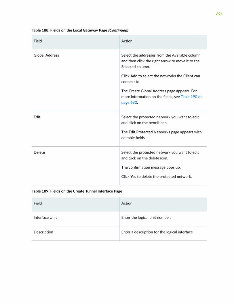
Table 188: Fields on the Local Gateway Page (Continued)
Field Action
Global Address Select the addresses from the Available columnand then click the right arrow to move it to theSelected column.
Click Add to select the networks the Client canconnect to.
The Create Global Address page appears. Formore information on the fields, see Table 190 onpage 692.
Edit Select the protected network you want to editand click on the pencil icon.
The Edit Protected Networks page appears witheditable fields.
Delete Select the protected network you want to editand click on the delete icon.
The confirmation message pops up.
Click Yes to delete the protected network.
Table 189: Fields on the Create Tunnel Interface Page
Field Action
Interface Unit Enter the logical unit number.
Description Enter a description for the logical interface.
691

Table 189: Fields on the Create Tunnel Interface Page (Continued)
Field Action
Zone Select a zone from the list to add it to the tunnelinterface.
This zone is used in the auto-creation of thefirewall policy.
Click Add to add a new zone. Enter zone nameand description and click OK on the CreateSecurity Zone page.
Routing Instance Select a routing instance from the list.
NOTE: The default routing instance, primary,refers to the main inet.0 routing table in thelogical system.
Table 190: Fields on the Create Global Address Page
Field Action
Name Enter a name for the global address. The name must be a unique string that mustbegin with an alphanumeric character and can include colons, periods, dashes, andunderscores; no spaces allowed; 63-character maximum.
IP Type Select IPv4.
IPv4
IPv4 Address Enter a valid IPv4 address.
Subnet Enter the subnet for IPv4 address.
692

Table 191: IKE and IPsec Settings
Field Action
IKE Settings
NOTE: The following parameters are generated automatically and are not displayed in the J-Web UI:
• If the authentication method is Pre-Shared Key, the IKE version is 1, ike-user-type is shared-ike-id,and mode is Aggressive.
• If the authentication method is Certificate Based, the IKE version is 2, ike-user-type is group-ike-id,and mode is Main.
Encryption Algorithm Select the appropriate encryption mechanism from the list.
Default value is AES-CBC 256-bit.
AuthenticationAlgorithm
Select the authentication algorithm from the list. For example, SHA 256-bit.
DH group A Diffie-Hellman (DH) exchange allows participants to generate a sharedsecret value. Select the appropriate DH group from the list. Default value isgroup19.
Lifetime Seconds Select a lifetime duration (in seconds) of an IKE security association (SA).
Default value is 28,800 seconds. Range: 180 through 86,400 seconds.
Dead Peer Detection Enable this option to send dead peer detection requests regardless ofwhether there is outgoing IPsec traffic to the peer.
693

Table 191: IKE and IPsec Settings (Continued)
Field Action
DPD Mode Select one of the options from the list:
• optimized—Send probes only when there is outgoing traffic and noincoming data traffic - RFC3706 (default mode).
• probe-idle-tunnel—Send probes same as in optimized mode and alsowhen there is no outgoing and incoming data traffic.
• always-send—Send probes periodically regardless of incoming andoutgoing data traffic.
DPD Interval Select an interval (in seconds) to send dead peer detection messages. Thedefault interval is 10 seconds. Range is 2 to 60 seconds.
DPD Threshold Select a number from 1 to 5 to set the failure DPD threshold.
This specifies the maximum number of times the DPD messages must besent when there is no response from the peer. The default number oftransmissions is 5 times.
Advance Configuration (Optional)
NAT-T Enable this option for IPsec traffic to pass through a NAT device.
NAT-T is an IKE phase 1 algorithm that is used when trying to establish aVPN connection between two gateway devices, where there is a NATdevice in front of one of the SRX Series devices.
NAT Keep Alive Select appropriate keepalive interval in seconds. Range: 1 to 300.
If the VPN is expected to have large periods of inactivity, you can configurekeepalive values to generate artificial traffic to keep the session active onthe NAT devices.
694

Table 191: IKE and IPsec Settings (Continued)
Field Action
IKE Connection Limit Enter the number of concurrent connections that the VPN profile supports.
Range is 1 through 4294967295.
When the maximum number of connections is reached, no more remoteaccess user (VPN) endpoints attempting to access an IPsec VPN can beginInternet Key Exchange (IKE) negotiations.
IKEv2 Fragmentation This option is enabled by default. IKEv2 fragmentation splits a large IKEv2message into a set of smaller ones so that there is no fragmentation at theIP level. Fragmentation takes place before the original message isencrypted and authenticated, so that each fragment is separatelyencrypted and authenticated.
NOTE: This option is available if the authentication method is CertificatedBased.
IKEv2 Fragment Size Select the maximum size, in bytes, of an IKEv2 message before it is splitinto fragments.
The size applies to IPv4 message. Range: 570 to 1320 bytes.
Default value is 576 bytes.
NOTE: This option is available if the authentication method is CertificatedBased.
IPsec Settings
Encryption Algorithm Select the encryption method. Default value is AES-GCM 256-bit.
AuthenticationAlgorithm
Select the IPsec authentication algorithm from the list. For example,HMAC-SHA-256-128.
NOTE: This option is available when the encryption algorithm is not gcm.
695

Table 191: IKE and IPsec Settings (Continued)
Field Action
Perfect ForwardSecrecy
Select Perfect Forward Secrecy (PFS) from the list. The device uses thismethod to generate the encryption key. Default value is group19.
PFS generates each new encryption key independently from the previouskey. The higher numbered groups provide more security, but require moreprocessing time.
NOTE: group15, group16, and group21 support only the SRX5000 line ofdevices with an SPC3 card and junos-ike package installed.
Lifetime Seconds Select the lifetime (in seconds) of an IPsec security association (SA). Whenthe SA expires, it is replaced by a new SA and security parameter index(SPI) or terminated. Default is 3,600 seconds. Range: 180 through 86,400seconds.
Lifetime Kilobytes Select the lifetime (in kilobytes) of an IPsec SA. Default is 256kb. Range: 64through 4294967294.
Advanced Configuration
Anti Replay IPsec protects against VPN attack by using a sequence of numbers builtinto the IPsec packet—the system does not accept a packet with the samesequence number.
This option is enabled by default. The Anti-Replay checks the sequencenumbers and enforce the check, rather than just ignoring the sequencenumbers.
Disable Anti-Replay if there is an error with the IPsec mechanism thatresults in out-of-order packets, which prevents proper functionality.
Install Interval Select the maximum number of seconds to allow for the installation of arekeyed outbound security association (SA) on the device. Select a valuefrom 1 to 10.
696

Table 191: IKE and IPsec Settings (Continued)
Field Action
Idle Time Select the idle time interval. The sessions and their correspondingtranslations time out after a certain period of time if no traffic is received.Range is 60 to 999999 seconds.
DF Bit Select how the device handles the Don't Fragment (DF) bit in the outerheader:
• clear—Clear (disable) the DF bit from the outer header. This is thedefault.
• copy—Copy the DF bit to the outer header.
• set—Set (enable) the DF bit in the outer header.
Copy Outer DSCP This option enabled by default. This enables copying of DifferentiatedServices Code Point (DSCP) (outer DSCP+ECN) from the outer IP headerencrypted packet to the inner IP header plain text message on thedecryption path. Enabling this feature, after IPsec decryption, clear textpackets can follow the inner CoS (DSCP+ECN) rules.
RELATED DOCUMENTATION
About the IPsec VPN Page | 637
IPsec VPN Global Settings | 640
Edit an IPsec VPN | 697
Delete an IPsec VPN | 699
Edit an IPsec VPN
You are here: Network > VPN > IPsec VPN.
You can edit any of the following IPsec VPNs:
• Site-to-Site VPN
697

• Remote Access VPN (Juniper Secure Connect)
• Remote Access VPN (NCP Exclusive Client)
To edit IPsec VPN:
NOTE:
• When the IKE status is up and if you edit the IPsec VPN, the topology diagram is shown ingreen.
• All local gateway protected networks will form traffic selectors with all remote gatewayprotected networks and vice-versa.
1. Select an existing IPsec VPN configuration that you want to edit on the IPsec VPN page.
2. Click the pencil icon available on the upper right-side of the page.
The edit page for the selected IPsec VPN page appears with editable fields. You can modify anyprevious changes done to Site-to-Site VPN, Remote Access VPN (Juniper Secure Connect), andRemote Access VPN (NCP Exclusive Client).
3. Click OK to save the changes. If you want to discard your changes, click Cancel.
NOTE:
• During edit, Auto-create Firewall Policy and Gateway behind NAT options are not supported.Gateway behind NAT is supported only for remote access VPN.
• The Source NAT Traffic option is only supported when creating remote access VPN. Duringedit, this option is not supported.
• For Site-to-Site VPN, when the routing mode is Traffic Selector, the traffic selector creates thecomplete mesh between the local and remote addresses.
RELATED DOCUMENTATION
Create a Site-to-Site VPN | 643
Create a Remote Access VPN—Juniper Secure Connect | 662
Create a Remote Access VPN—NCP Exclusive Client | 683
Delete an IPsec VPN | 699
698

Delete an IPsec VPN
You are here: Network > VPN > IPsec VPN.
You can delete any of the VPN topologies.
To delete any IPsec VPN configurations:
1. Select existing an IPsec VPN configuration(s) that you want to delete on the IPsec VPN page.
2. Click the delete icon available on the upper right-side of the page.
The Confirm Delete window appears.
NOTE:
• For Site-to-Site VPN, only the associated IPsec VPN routing configuration such as staticroute or OSPF is deleted.
• Remote Access VPN default profile will be deleted only if the deleting VPN is configuredas default profile. You need to configure the default profile under VPN > IPsec VPN >Global Settings > Remote Access VPN.
3. Click Yes to delete or click No to retain the configuration.
RELATED DOCUMENTATION
About the IPsec VPN Page | 637
IPsec VPN Global Settings | 640
Create a Site-to-Site VPN | 643
Edit an IPsec VPN | 697
699

CHAPTER 60
Manual Key VPN
IN THIS CHAPTER
About the Manual Key VPN Page | 700
Add a Manual Key VPN | 701
Edit a Manual Key VPN | 704
Delete Manual Key VPN | 705
About the Manual Key VPN Page
IN THIS SECTION
Tasks You Can Perform | 700
Field Descriptions | 701
You are here: Network > VPN > Manual Key VPN.
Use this page to configure manual key VPN.
Tasks You Can Perform
You can perform the following tasks from this page:
• Add a manual key VPN. See "Add a Manual Key VPN" on page 701.
• Edit a manual key VPN. See "Edit a Manual Key VPN" on page 704.
• Delete a manual key VPN. See "Delete Manual Key VPN" on page 705.
700

Field Descriptions
Table 192 on page 701 describes the fields on the Manual Key VPN page.
Table 192: Fields on the Manual Key VPN Page
Field Description
Name Displays the name of the manual tunnel.
Gateway Displays the selected gateway.
Bind Interface Displays the tunnel interface to which the route-based VPN is bound.
Df Bit Displays the DF bit in the outer header.
RELATED DOCUMENTATION
Add a Manual Key VPN | 701
Edit a Manual Key VPN | 704
Delete Manual Key VPN | 705
Add a Manual Key VPN
You are here: Network > VPN > Manual Key VPN.
To add a manual key VPN:
1. Click the add icon (+) on the upper right side of the Manual Key VPN page.
The Add Manual Key VPN page appears.
2. Complete the configuration according to the guidelines provided in Table 193 on page 702.
3. Click OK to save the changes. If you want to discard your changes, click Cancel.
701

Table 193: Fields on the Manual Key VPN Configuration Page
Field Action
VPN Manual Key
VPN Name Enter the VPN name for the IPsec tunnel.
Remote Gateway Enter the name for the remote gateway.
External Interface Select an interface from the list.
Protocol Select an option from the list to specify the types of protocols available forconfiguration:
• ESP
• AH
SPI Enter a SPI value.
Range: 256 through 16639.
Bind to tunnelinterface
Select an interface from the list to which the route-based VPN is bound.
Do not fragment bit Select an option from the list to specify how the device handles the DF bit inthe outer header.
• clear—Clear (disable) the DF bit from the outer header. This is the default.
• Set—Set the DF bit to the outer header.
• copy—Copy the DF bit to the outer header.
Enable VPN Monitor Select this option to configure VPN monitoring.
Destination IP Enter an IP address for the destination peer.
702

Table 193: Fields on the Manual Key VPN Configuration Page (Continued)
Field Action
Optimized Select the check box to enable optimization for the device to use trafficpatterns as evidence of peer liveliness. If enabled, ICMP requests aresuppressed. This feature is disabled by default.
Source Interface Enter a source interface for ICMP requests (VPN monitoring “hellos”). If nosource interface is specified, the device automatically uses the local tunnelendpoint interface.
Key Values
Authentication
Algorithm Specifies the hash algorithm that authenticates packet data. Select a hashalgorithm from the list:
• hmac-md5-96—Produces a 128-bit digest.
• hmac-sha1-96—Produces a 160-bit digest.
• hmac-sha-256-128
ASCII Text Select the ASCII Text option, and enter the key in the appropriate format.
Hexadecimal Select the Hexadecimal option, and enter the key in the appropriate format.
Encryption
703

Table 193: Fields on the Manual Key VPN Configuration Page (Continued)
Field Action
Encryption Specifies the supported Internet Key Exchange (IKE) proposals. Select anoption from the list:
• 3des-cbc—3DES-CBC encryption algorithm.
• aes-128-cbc—AES-CBC 128-bit encryption algorithm.
• aes-192-cbc—AES-CBC 192-bit encryption algorithm.
• aes-256-cbc—AES-CBC 256-bit encryption algorithm.
• des-cbc—DES-CBC encryption algorithm.
ASCII Text Enable this option and enter the key in the appropriate format.
Hexadecimal Enable this option and enter the key in the appropriate format.
RELATED DOCUMENTATION
About the Manual Key VPN Page | 700
Edit a Manual Key VPN | 704
Delete Manual Key VPN | 705
Edit a Manual Key VPN
You are here: Network > VPN > Manual Key VPN.
To edit a manual key VPN:
1. Select the existing manual key VPN that you want to edit on the Manual Key VPN page.
2. Click the pencil icon available on the upper right side of the page.
The Edit a Manual Key VPN page appears with editable fields. For more information on the options,see "Add a Manual Key VPN" on page 701.
3. Click OK to save the changes.
704

RELATED DOCUMENTATION
About the Manual Key VPN Page | 700
Add a Manual Key VPN | 701
Delete Manual Key VPN | 705
Delete Manual Key VPN
You are here: Network > VPN > Manual Key VPN.
To delete a manual key VPN:
1. Select a manual key VPN that you want to delete on the Manual Key VPN page.
2. Click the delete icon available on the upper right side of the page.
3. Click Yes to delete or click No to retain the profile.
RELATED DOCUMENTATION
About the Manual Key VPN Page | 700
Add a Manual Key VPN | 701
Edit a Manual Key VPN | 704
705

CHAPTER 61
Dynamic VPN
IN THIS CHAPTER
About the Dynamic VPN Page | 706
Global Settings | 708
IPsec Template | 710
Add a Dynamic VPN | 711
Edit a Dynamic VPN | 713
Delete Dynamic VPN | 713
About the Dynamic VPN Page
IN THIS SECTION
Tasks You Can Perform | 706
Field Descriptions | 707
You are here: Network > VPN > Dynamic VPN.
You can view and add, edit, or delete dynamic VPN global configuration options.
NOTE: This menu is available only for SRX300 line of devices and SRX550M devices.
Tasks You Can Perform
You can perform the following tasks from this page:
706

• Configure global settings. See "Global Settings" on page 708.
• Add DVPN IPsec template. See "IPsec Template" on page 710.
• Add a dynamic VPN. See "Add a Dynamic VPN" on page 711.
• Edit a dynamic VPN. See "Edit a Dynamic VPN" on page 713.
• Delete dynamic VPN. See "Delete Dynamic VPN" on page 713.
• Launch VPN wizard. To do this, click Launch Wizard available on the upper right corner of theDynamic VPN table. Follow the guided steps to configure the VPN wizard.
Field Descriptions
Table 194 on page 707 describes the fields on the Dynamic VPN page.
Table 194: Fields on the Dynamic VPN Page
Field Description
Access Profile Select a previously created access profile from the list displayed in GlobalSettings.
Specify the access profile to use for Extended Authentication for remote userstrying to download the Access Manager.
NOTE: This Access Profile option does not control authentication for VPNsessions. For more information, see Add a Gateway and Add a VPN.
Client VPNs Create a client configuration for the dynamic VPN feature.
Name Enter a name for dynamic VPN.
User Enter an username. Specifies the list of users who can use this clientconfiguration.
IP Address Enter an IP address and netmask for the users.
IPsec VPN Select a previously configured IKE AutoKey configuration from the list.
707

Table 194: Fields on the Dynamic VPN Page (Continued)
Field Description
Remote ProtectedResources
Enter an IP address and netmask of a resource behind the firewall. Traffic to thespecified resource will go through the VPN tunnel and therefore will beprotected by the firewall’s security policies.
RELATED DOCUMENTATION
Global Settings | 708
Edit a Dynamic VPN | 713
Delete Dynamic VPN | 713
Global Settings
You are here: VPN > Dynamic VPN.
To add global settings:
1. Click Global Settings on the upper right side of the Resource Profiles page.
The DVPN - Global Settings page appears.
2. Complete the configuration according to the guidelines provided in Table 195 on page 708.
3. Click OK to save the changes. If you want to discard your changes, click Cancel.
Table 195: Fields on the Global Settings page
Field Action
Access Profile Select an access profile from the list to use for Extended Authentication forremote users trying to download the Access Manager.
Address Profile Settings
Address Pool Select an address pool from the list
708

Table 195: Fields on the Global Settings page (Continued)
Field Action
+ Click + to add a new address pool.
The New Address Pool page appears.
New Address Pool
Name Enter a name for address pool.
Network Address Enter the network prefix for the address pool for IPv4 or IPv6 addresses.
Address Ranges
+ Click + to add the address range for DVPN.
Address Range Name Enter an address range name.
Lower Limit Enter the lower boundary for the IPv4 or IPv6 address range.
High Limit Enter the upper boundary for the IPv4 or IPv6 address range.
X Click X to delete the address ranges of DVPN.
XAUTH Attributes
Primary DNS Sever Enter the primary DNS IP address.
Secondary DNS Sever Enter the secondary DNS IP address.
Primary WINS Sever Enter the primary WINS IP address.
Secondary WINS Sever Enter the secondary WINS IP address.
709

RELATED DOCUMENTATION
About the Dynamic VPN Page | 706
IPsec Template | 710
Add a Dynamic VPN | 711
IPsec Template
You are here: VPN > Dynamic VPN.
To add a dynamic VPN IPsec template:
1. Click IPsec Template on the upper right side of the Dynamic VPN page.
The DVPN IPsec Template page appears.
2. Complete the configuration according to the guidelines provided in Table 196 on page 710.
3. Click OK to save the changes. If you want to discard your changes, click Cancel.
Table 196: Fields on the DVPN IPsec Template Page
Field Action
Clone IPsec from DVPN template
Name Displays the name of the cloned DVPN template.
Preshared Key Enter the authorization key.
IKE ID Specify the IKE IDs for the DVPN.
External Interface Select the external interface from the list.
RELATED DOCUMENTATION
About the Dynamic VPN Page | 706
Global Settings | 708
Add a Dynamic VPN | 711
710

Add a Dynamic VPN
You are here: Network > VPN > Dynamic VPN.
To add a dynamic VPN:
1. Click the add icon (+) on the upper right side of the Dynamic VPN page.
The Add DVPN page appears.
2. Complete the configuration according to the guidelines provided in Table 197 on page 711.
3. Click OK to save the changes. If you want to discard your changes, click Cancel.
Table 197: Fields on the DVPN Page
Field Action
Name Enter the name of the client configuration.
IPsec VPN Select a previously configured IKE AutoKeyconfiguration from the list to use whenestablishing the VPN tunnel.
Access Users
Local Users in Profile Specifies the list of users who can use this clientconfiguration.
Select the users and click on the arrow button tomove to copy to DVPN.
NOTE: The server does not validate the namesthat you enter here, but the names must be thenames that the users use to log in to the devicewhen downloading the client.
Users in DVPN Specifies the list of users copied from the localusers in profile or the newly added users.
Username Enter a username.
711

Table 197: Fields on the DVPN Page (Continued)
Field Action
Password Enter a password for the username.
IP Enter an IP address for the user.
+ Click + and select Add to DVPN or Add to Bothto add the user to either in Users in DVPN or toboth DVPN and Local Users in Profile.
Remote Protected Resources Enter an IP address and net mask and click +.Specifies the IP address and net mask of aresource behind the firewall. Traffic to thespecified resource will go through the VPN tunneland therefore will be protected by the firewall’ssecurity policies.
NOTE: The device does not validate that theIP/net mask combination that you enter herematches up with your security policies.
Remote Exceptions Enter an IP address and net mask and click +.Specifies the IP address and net mask ofexceptions to the remote protected resources list.
RELATED DOCUMENTATION
About the Dynamic VPN Page | 706
Edit a Dynamic VPN | 713
Delete Dynamic VPN | 713
712

Edit a Dynamic VPN
You are here: Network > VPN > Dynamic VPN.
To edit a dynamic VPN setting:
1. Select the existing a dynamic VPN settings policy that you want to edit on the Dynamic VPN page.
2. Click the pencil icon available on the upper right side of the page.
The Edit DVPN page appears with editable fields. For more information on the options, see "Add aDynamic VPN" on page 711.
3. Click OK to save the changes.
RELATED DOCUMENTATION
About the Dynamic VPN Page | 706
Global Settings | 708
IPsec Template | 710
Add a Dynamic VPN | 711
Delete Dynamic VPN
You are here: Network > VPN > Dynamic VPN.
To delete a dynamic VPN:
1. Select a dynamic VPN policy that you want to delete on the Dynamic VPN page.
2. Click the delete icon available on the upper right side of the page.
3. Click Yes to delete or click No to retain the profile.
RELATED DOCUMENTATION
About the Dynamic VPN Page | 706
Global Settings | 708
IPsec Template | 710
Add a Dynamic VPN | 711
Edit a Dynamic VPN | 713
713

7PART
Security Policies and Objects
Security Policies | 715
Zones/Screens | 741
Zone Addresses | 761
Global Addresses | 768
Services | 774
Dynamic Applications | 783
Application Tracking | 801
Schedules | 803
Proxy Profiles | 810

CHAPTER 62
Security Policies
IN THIS CHAPTER
About the Security Policies Page | 715
Global Options | 721
Add a Rule | 724
Clone a Rule | 739
Edit a Rule | 739
Delete Rules | 740
About the Security Policies Page
IN THIS SECTION
Tasks You Can Perform | 716
Field Descriptions | 719
You are here: Security Policies & Objects > Security Policies.
Use this page to get a high-level view of your firewall policy rules settings. The security policy appliesthe security rules to the transit traffic within a context (from-zone to to-zone). The traffic is classified bymatching its source and destination zones, the source and destination addresses, and the applicationthat the traffic carries in its protocol headers with the policy database in the data plane.
Using a global policy, you can regulate traffic with addresses and applications, regardless of their securityzones, by referencing user-defined addresses or the predefined address “any.” These addresses can spanmultiple security zones.
715

Tasks You Can Perform
You can perform the following tasks from this page:
• Add Global Options. See "Global Options" on page 721.
• Add a Rule. See "Add a Rule" on page 724.
• Edit a Rule. See "Edit a Rule" on page 739.
• Clone a Rule. See "Clone a Rule" on page 739.
• Delete a Rule. See "Delete Rules" on page 740.
• To save the rules configuration, click Save.
• To delete the rules configuration, click Discard.
• Drag and drop the rules within a zone context. To do this, select the rule you want to place in adifferent sequence number within a zone context, drag and drop it using the cursor.
NOTE: If you drag and drop a rule outside the zone context, J-Web will display a warningmessage that you cannot move the rule into another zone context.
• Advanced search for policy rule. To do this, use the search text box present above the table grid. Thesearch includes the logical operators as part of the filter string. An example filter condition isdisplayed in the search text box when you hover over the Search icon. When you start entering thesearch string, the icon indicates whether the filter string is valid or not.
For an advanced search:
1. Enter the search string in the text box.
Based on your input, a list of items from the filter context menu appears.
2. Select a value from the list and then select a valid operator based on which you want to performthe advanced search operation.
NOTE: Press Spacebar to add an AND operator or OR operator to the search string. Pressbackspace to delete a character of the search string.
3. Press Enter to display the search results in the grid.
The supported search scenarios and its examples are as follows:
716

1. Logical operators:
• AND operator for multiple parameters
Example: Name = Rule1 AND Dynamic Application = Malware
• OR operator for same and different parameters
Example for same parameters: Name = Rule1 OR Name = Rule2
Example for different parameters: Name = Rule1 OR Dynamic Application = Malware
• Combination of AND and OR operators
Example: Name = Rule1 AND (Dynamic Application = Malware OR Action = Reject)
• Comma (,) separated value
Example: Name = Rule1, Rule2
• != operator for single parameter
Example: Name != Rule1
2. Dynamic applications or service objects with matching characters of Junos
When you search for the matching characters of Junos, such as, jun, un, nos, and os, the resultdisplays all the matched objects but without junos prefix. For example, if the configured dynamicapplication is junos:01NET, the search for dynamic applications with jun characters display only01NET.
3. Saved policy rules
When you add or edit a rule, click Save to save the configuration. To search for this savedconfiguration, you must wait for the device to synchronize the configuration.
• Show or hide columns in the policy rule table. To do this, click Show Hide Columns icon in the topright corner of the policy rule table and select the columns you want to display or deselect thecolumns you want to hide on the page.
Table 198 on page 718 describes few more options on Rules.
717
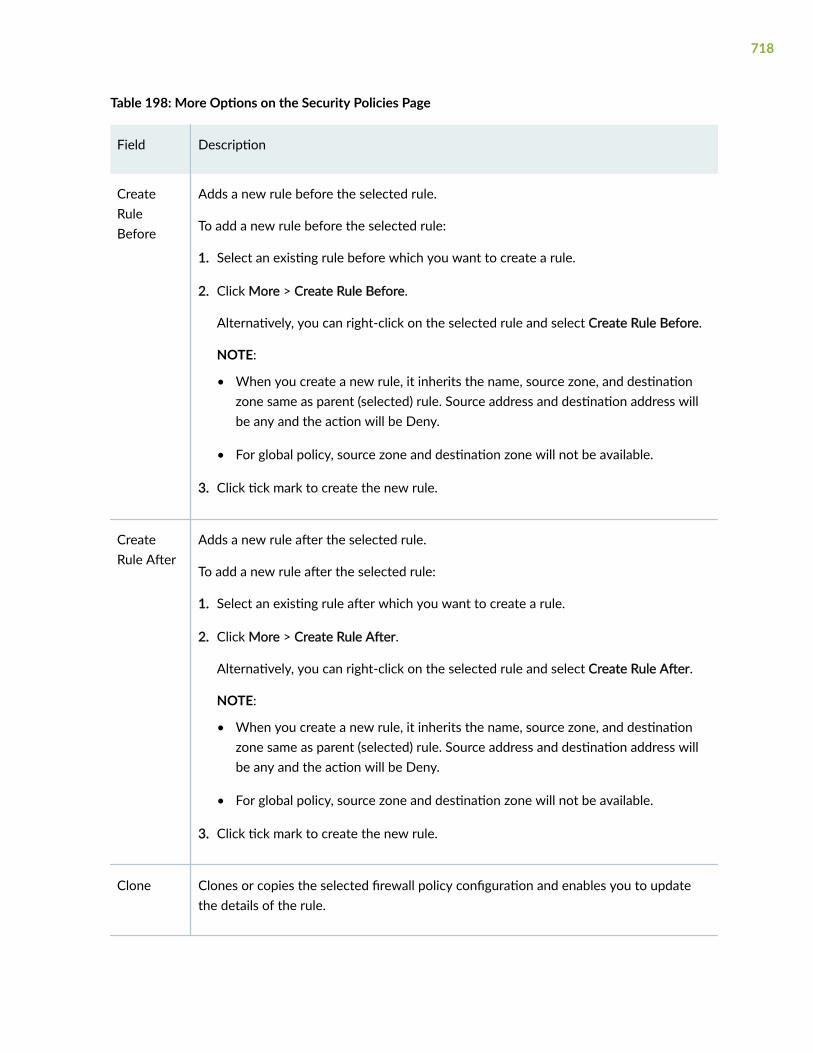
Table 198: More Options on the Security Policies Page
Field Description
CreateRuleBefore
Adds a new rule before the selected rule.
To add a new rule before the selected rule:
1. Select an existing rule before which you want to create a rule.
2. Click More > Create Rule Before.
Alternatively, you can right-click on the selected rule and select Create Rule Before.
NOTE:
• When you create a new rule, it inherits the name, source zone, and destinationzone same as parent (selected) rule. Source address and destination address willbe any and the action will be Deny.
• For global policy, source zone and destination zone will not be available.
3. Click tick mark to create the new rule.
CreateRule After
Adds a new rule after the selected rule.
To add a new rule after the selected rule:
1. Select an existing rule after which you want to create a rule.
2. Click More > Create Rule After.
Alternatively, you can right-click on the selected rule and select Create Rule After.
NOTE:
• When you create a new rule, it inherits the name, source zone, and destinationzone same as parent (selected) rule. Source address and destination address willbe any and the action will be Deny.
• For global policy, source zone and destination zone will not be available.
3. Click tick mark to create the new rule.
Clone Clones or copies the selected firewall policy configuration and enables you to updatethe details of the rule.
718
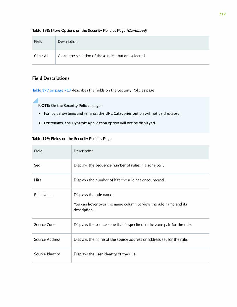
Table 198: More Options on the Security Policies Page (Continued)
Field Description
Clear All Clears the selection of those rules that are selected.
Field Descriptions
Table 199 on page 719 describes the fields on the Security Policies page.
NOTE: On the Security Policies page:
• For logical systems and tenants, the URL Categories option will not be displayed.
• For tenants, the Dynamic Application option will not be displayed.
Table 199: Fields on the Security Policies Page
Field Description
Seq Displays the sequence number of rules in a zone pair.
Hits Displays the number of hits the rule has encountered.
Rule Name Displays the rule name.
You can hover over the name column to view the rule name and itsdescription.
Source Zone Displays the source zone that is specified in the zone pair for the rule.
Source Address Displays the name of the source address or address set for the rule.
Source Identity Displays the user identity of the rule.
719
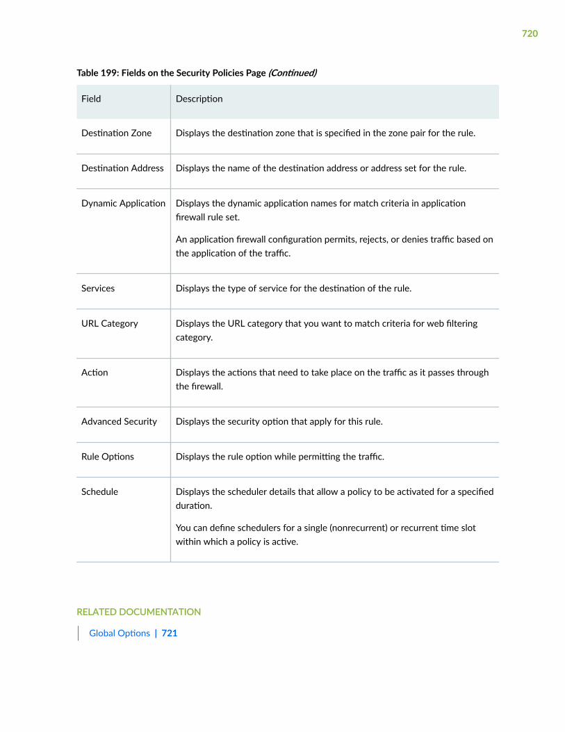
Table 199: Fields on the Security Policies Page (Continued)
Field Description
Destination Zone Displays the destination zone that is specified in the zone pair for the rule.
Destination Address Displays the name of the destination address or address set for the rule.
Dynamic Application Displays the dynamic application names for match criteria in applicationfirewall rule set.
An application firewall configuration permits, rejects, or denies traffic based onthe application of the traffic.
Services Displays the type of service for the destination of the rule.
URL Category Displays the URL category that you want to match criteria for web filteringcategory.
Action Displays the actions that need to take place on the traffic as it passes throughthe firewall.
Advanced Security Displays the security option that apply for this rule.
Rule Options Displays the rule option while permitting the traffic.
Schedule Displays the scheduler details that allow a policy to be activated for a specifiedduration.
You can define schedulers for a single (nonrecurrent) or recurrent time slotwithin which a policy is active.
RELATED DOCUMENTATION
Global Options | 721
720

Global Options
You are here: Security Policies & Objects > Security Policies.
To add global options:
1. Click Global Options available on the upper right side of the Security Policies page.
The Global Options page appears.
2. Complete the configuration according to the guidelines provided in Table 200 on page 721.
3. Click OK to save the changes. If you want to discard your changes, click Cancel.
Table 200 on page 721 describes the fields on the Global Options page.
Table 200: Fields on the Global Options Page
Field Action
Pre-id Default Policy
Session Timeout
ICMP Enter the timeout value for ICMP sessions ranging from 4 through 86400seconds.
ICMP6 Enter the timeout value for ICMP6 sessions ranging from 4 through 86400seconds.
OSPF Enter the timeout value for OSPF sessions ranging from 4 through 86400seconds.
TCP Enter the timeout value for TCP sessions ranging from 4 through 86400seconds.
UDP Enter the timeout value for UDP sessions ranging from 4 through 86400seconds.
Others Enter the timeout value for other sessions ranging from 4 through 86400seconds.
721

Table 200: Fields on the Global Options Page (Continued)
Field Action
Logging
Session Initiate Enable this option to start logging at the beginning of a session.
WARNING: Configuring session-init logging for the pre-id-default-policycan generate a large number of logs.
Session Close Enable this option to start logging at the closure of a session.
NOTE: Configuring session-close logging ensures that the SRX devicegenerates the security logs if a flow is unable to leave the pre-id-default-policy.
Flow
Aggressive Session Aging
NOTE: This option is not supported for logical systems and tenants.
Early Ageout Enter a value from 1 through 65,535 seconds. The default value is 20seconds.
Specifies the amount of time before the device aggressively ages out asession from its session table.
Low watermark Enter a value from 0 through 100 percent. The default value is 100 percent.
Specifies the percentage of session table capacity at which the aggressiveaging-out process ends.
High watermark Enter a value from 0 through 100 percent. The default value is 100 percent.
Specifies the percentage of session table capacity at which the aggressiveaging-out process begins.
SYN Flood Protection
722

Table 200: Fields on the Global Options Page (Continued)
Field Action
SYN Flood Protection Enable this option to defend against SYN attacks.
Mode Select one of the following options:
• Cookie—Uses a cryptographic hash to generate a unique Initial SequenceNumber (ISN). This is enabled by default.
• Proxy—Uses a proxy to handle the SYN attack.
TCP MSS
All TCP Packets Enter a maximum segment size value from 64 through 65,535 to override allTCP packets for network traffic.
Packets enteringIPsec Tunnel
Enter a maximum segment size value from 64 through 65,535 bytes tooverride all packets entering an IPsec tunnel. The default value is 1320 bytes.
GRE Packets enteringIPsec Tunnel
Enter a maximum segment size value from 64 through 65,535 bytes tooverride all generic routing encapsulation packets entering an IPsec tunnel.The default value is 1320 bytes.
GRE Packets exitingIPsec Tunnel
Enter a maximum segment size value from 64 through 65,535 bytes tooverride all generic routing encapsulation packets exiting an IPsec tunnel.The default value is 1320 bytes.
TCP Session
Sequence numbercheck
By default, this option is enabled to check sequence numbers in TCPsegments during stateful inspections. The device monitors the sequencenumbers in TCP segments.
723

Table 200: Fields on the Global Options Page (Continued)
Field Action
SYN flag check By default, this option is enabled to check the TCP SYN bit before creating asession. The device checks that the SYN bit is set in the first packet of asession. If it is not set, the device drops the packet.
RELATED DOCUMENTATION
Add a Rule | 724
Add a Rule
You are here: Security Policies & Objects > Security Policies.
NOTE: To reference the UTM policies and the AppQoS profiles in a security policy rules, createUTM polices and AppQoS profiles before creating or editing security policy rules if required. Tocreate UTM policies, go to Security Services > UTM > UTM Policies and to create AppQoSprofiles, go to Network > Application QoS.
To add a rule:
1. Click the add icon (+) on the upper right side of the Security Policies page.
The inline editable fields will appear.
2. Complete the configuration according to the guidelines provided in Table 201 on page 725.
3. Click the tick icon on the right-side of the row once done with the configuration.
NOTE: Scroll back the horizontal bar if the inline tick and the cancel icons are not availablewhen creating a new rule.
4. Click Save to save the changes or click Discard to discard the changes.
724

NOTE: You must perform Step "3" on page 724 and Step "4" on page 724 before performingany further actions in the J-Web UI.
Table 201: Fields on the Security Policies Page
Field Action
Rule Name Enter a name for the new rule or policy.
Rule Description Enter a description for the security policy.
Global Policy Enable this option to specify that the policy defined is a global policy andzones are not required.
Source Zone To add sources:
1. Click +.
The Select Sources page appears.
2. Enter the following details:
• Zone—Select the source zone from the list to which you want the ruleto be associated.
• Addresses—Select any or Specific.
To select a specific address, select the addresses from the Availablecolumn and then click the right arrow to move it to the Selectedcolumn. You can select Exclude Selected to exclude the selectedaddress from the list.
To create a new address, click +. The Create Address page appears. Formore information on fields, see Table 202 on page 734.
• Source identity—Select the user identity from the Available column andthen click the right arrow to move it to the Selected column.
To create a source identity, click +. Enter a new username or identity inthe Create Source Identity page and click OK.
725

Table 201: Fields on the Security Policies Page (Continued)
Field Action
Destination Zone To add a destination:
1. Click +.
The Select Destination page appears.
2. Enter the following details:
• Zone—Select the destination zone from the list to which you want therule to be associated.
• Addresses—Select any or Specific.
To select a specific address, select the addresses from the Availablecolumn and then click the right arrow to move it to the Selectedcolumn. You can select Exclude Selected to exclude the selectedaddress from the list.
To create a new address, click +. For more information on fields, seeTable 202 on page 734.
NOTE:
• Dynamic applications—Select Any, Specific, or None.
NOTE: The Dynamic Applications option is not supported for tenants.
To select a specific application, select the application from theAvailable column and then click the right arrow to move it to theSelected column.
NOTE: The select all check box is only available when you search forspecific dynamic applications.
To create a new application, click +. The Create Application Signaturepage appears. For more information on fields, see "Add ApplicationSignatures" on page 791.
NOTE: For logical systems, you cannot create a dynamic applicationinline.
726

Table 201: Fields on the Security Policies Page (Continued)
Field Action
• Services—Select Any, Specific, or None.
To select a specific service, select the service from the Availablecolumn and then click the right arrow to move it to the Selectedcolumn.
To create a new service, click +. The Create Service page appears. Formore information on fields, see Table 203 on page 734.
• URL category—Select any, Specific, or None to match criteria for a webfiltering category.
To select a specific URL category, select the URL category from theAvailable column and then click the right arrow to move it to theSelected column.
NOTE: This option is not available for logical systems and tenants.
Action Select an action to take when traffic matches the criteria:
• Permit—Allows packet to pass through the firewall.
• Deny—Block and drop the packet, but do not send notification back to thesource.
• Reject—Block and drop the packet and send a notice to the source host.
727

Table 201: Fields on the Security Policies Page (Continued)
Field Action
Advanced Services
Click +. The Select Advanced Services page appears.
NOTE:
• When the action is Reject:
• You can configure only the SSL Proxy and Redirect Profile options.
• You can configure only the SSL Proxy option if the dynamic application is None.
• Advanced Security option is not supported for logical systems and tenants.
• When the action is Permit:
• For logical systems, only IPS, IPS policy, UTM, threat prevention policy, ICAP redirect profile,and AppQOS options are supported.
• For tenant systems, only threat prevention policy and AppQOS are supported.
SSL proxy Select the SSL proxy policy to associate with this rule from the list.
UTM Select the UTM policy you want to associate with this rule from the list. Thelist displays all the UTM policies available.
If you want to create a new UTM policy, click Add New. The Create UTMPolicies page appears. For more information on creating a new UTM policy,see "Add a UTM Policy" on page 880.
IPS policy Select the IPS policy from the list.
Threat preventionpolicy
Select the configured threat prevention policy from the list.
ICAP redirect profile Select the configured ICAP redirect profile name from the list.
728

Table 201: Fields on the Security Policies Page (Continued)
Field Action
IPsec VPN Select the IPsec VPN tunnel from the list.
NOTE: If you select Dynamic applications in the destination, IPsec VPNoption is not supported.
Pair policy name Enter the name of the policy with the same IPsec VPN in the oppositedirection to create a pair policy.
NOTE: If you select Dynamic applications in the destination, Pair Policy Nameoption is not supported.
Application QoSprofile
Select the configured AppQoS profile from the list.
If you want to create a new AppQoS profile, click Add New. The Add AppQoSProfile page appears. For more information on creating a new AppQoS profile,see "Add an Application QoS Profile" on page 630.
Packet capture Enable to capture unknown application traffic specific to a security policyrule.
By default, this option is disabled. Once enabled, you can view the packetcapture (PCAP) file details or download the PCAP file on the Monitor > Log >Sessions page.
Rule Options
Click on Rule Options. The SELECT RULE OPTIONS page appears.
Logging
Session initiate Enable this option to log an event when a session is created.
Session close Enable this option to log an event when the session closes.
729

Table 201: Fields on the Security Policies Page (Continued)
Field Action
Count Enable this option to collect statistics of the number of packets, bytes, andsessions that pass through the firewall with this policy.
Specifies statistical counts. An alarm is triggered whenever traffic exceedsspecified packet and byte thresholds.
NOTE: Alarm threshold fields are disabled if Enable Count is not enabled.
Authentication
NOTE:
• If you select Dynamic applications in the destination, Authentication option is not supported.
• This option is not supported for logical systems and tenant systems.
Push auth entry toJIMS
Enable this option to push authentication entries from firewall authentication,that are in auth-success state, to Juniper Identity Management Server (JIMS).This will enable the SRX device to query JIMS to get IP/user mapping anddevice information.
This is not a mandatory option. You can select it when at least one domain isconfigured on local Active Directory or configure identity management.
Type Select the firewall authentication type from the list. The options available are:None, Pass-through, User-firewall, and Web-authentication.
Access profile Select an access profile from the list.
NOTE: This option is not supported if you select the authentication type asWeb-authentication.
Client name Enter the client username or client user group name.
NOTE: This option is not supported if you select the authentication type asUser-firewall.
730

Table 201: Fields on the Security Policies Page (Continued)
Field Action
Domain Select a domain name that must be in a client name from the list.
NOTE: This option is supported only if you select the authentication type asUser-firewall.
Web redirect (http) Enable this option to redirect HTTP requests to the device’s internalwebserver by sending a redirect HTTP response to the client system toreconnect to the webserver for user authentication.
NOTE: This option is not supported if you select the authentication type asWeb-authentication.
Captive portal Enable this option to redirect a client HTTP or HTTPS request to the internalHTTPS webserver of the device. The HTTPS client requests are redirectedwhen SSL termination profile is configured.
NOTE: This option is not supported if you select the authentication type asWeb-authentication.
Interface Select an interface for the webserver where the client HTTP or HTTPSrequest is redirected.
NOTE: You cannot edit this once the policy is created. To edit the interface,go to Network > Connectivity > Interfaces.
IPv4 address Enter IPv4 address of the webserver where the client HTTP or HTTPSrequest is redirected.
NOTE: You cannot edit this once the policy is created. To edit the interface,go to Network > Connectivity > Interfaces.
731

Table 201: Fields on the Security Policies Page (Continued)
Field Action
SSL terminationprofile
Select an SSL termination profile from the list which contains the SSLterminated connection settings. SSL termination is a process where the SRXSeries device acts as an SSL proxy server, terminates the SSL session from theclient.
To add a new SSL termination profile:
1. Click Add.
The Create SSL Termination Profile page appears.
2. Enter the following details:
• Name—Enter SSL termination profile name; 63-character maximum.
• Server certificate—Select a server certificate from the list that is usedto authenticate the server identity.
To add a certificate, click Add. For more information on adding a devicecertificate, see "Add a Device Certificate" on page 233.
To import a certificate, click Import. For more information on importinga device certificate, see, "Import a Device Certificate" on page 231.
Auth only browser Enable this option to drop non-browser HTTP traffic to allow for captiveportal to be presented to unauthenticated users who request access using abrowser.
NOTE: This option is not supported if you select the authentication type asWeb-authentication.
User agents Enter a user-agent value which is used to verify that the user’s browser trafficis HTTP/HTTPS traffic.
NOTE: This option is not supported if you select the authentication type asWeb-authentication.
Advanced Settings
732

Table 201: Fields on the Security Policies Page (Continued)
Field Action
Destination addresstranslation
Select the action to be taken on a destination address translation from thelist. The options available are: None, Drop Translated, and Drop Untranslated.
Redirect options Select a redirect action from the list. The options available are: None, RedirectWx, and Reverse Redirect Wx.
NOTE: This option is not supported for SRX5000 line of devices.
TCP Session Options
Sequence numbercheck
Enable or disable checking of sequence numbers in TCP segments duringstateful inspections at policy rule level. By default, the check happens at theglobal level. To avoid commit failure, turn off Sequence number check underGlobal Options > Flow > TCP Session.
SYN flag check Enable or disable the checking of the TCP SYN bit before creating a session atpolicy rule level. By default, the check happens at the global level. To avoidcommit failure, turn off SYN flag check under Global Options > Flow > TCPSession.
Schedule
Schedule Click Schedule and select one of the configured schedules from the list.
To add a new schedule, click Add New Schedule. The Add New Schedulepage appears. For more information on creating a new schedule, see Table204 on page 736.
733

Table 202: Fields on the Create Address Page
Field Action
Name Enter a name for the address. The name must be a unique string that must begin withan alphanumeric character and can include colons, periods, dashes, and underscores;no spaces allowed; 63-character maximum.
IP type Select IPv4 or IPv6.
IPv4
IPv4 address Enter a valid IPv4 address.
Subnet Enter a subnet mask for the IPv4 address.
IPv6
IPv6 address Enter a valid IPv6 address.
Subnet prefix Enter a subnet prefix for the IPv6 address.
Table 203: Fields on the Create Service Page
Field Action
Global Settings
Name Enter a unique name for the application.
Description Enter description of the application.
Applicationprotocol
Select an option from the list for application protocol.
734

Table 203: Fields on the Create Service Page (Continued)
Field Action
Match IP protocol Select an option from the list to match IP protocol.
Source port Select an option from the list for source port.
Destination port Select an option from the list for destination port.
ICMP type Select an option from the list for ICMP message type.
ICMP code Select an option from the list for ICMP message code.
RPC programnumbers
Enter a value for RPC program numbers.
The format of the value must be W or X-Y. Where, W, X, and Y are integersbetween 0 and 65535.
Inactivity timeout Select an option from the list for application specific inactivity timeout.
UUID Enter a value for DCE RPC objects.
NOTE: The format of the value must be12345678-1234-1234-1234-123456789012.
Custom applicationgroup
Select an application set name from the list.
Terms
Click +. The Create Term page appears.
Name Enter a name for the term.
ALG Select an option from the list for ALG.
735

Table 203: Fields on the Create Service Page (Continued)
Field Action
Match IP protocol Select an option from the list to match IP protocol.
Source port Select an option from the list for source port.
Destination port Select an option from the list for destination port.
ICMP type Select an option from the list for ICMP message type.
ICMP code Select an option from the list for ICMP message code.
RPC programnumbers
Enter a value for RPC program numbers.
NOTE: The format of the value must be W or X-Y. Where, W, X, and Y areintegers between 0 and 65535.
Inactivity timeout Select an option from the list for application specific inactivity timeout.
UUID Enter a value for DCE RPC objects.
NOTE: The format of the value must be12345678-1234-1234-1234-123456789012.
Table 204: Fields on the Add New Schedule Page
Field Action
Name Enter the name for the schedule.
Description Enter a description for the schedule.
736

Table 204: Fields on the Add New Schedule Page (Continued)
Field Action
Repeats Select an option from the list to repeat the schedule:
• Never
• Daily
• Weekly
All Day Enable this option to schedule an event for an entire day.
This option is available only for Never and Daily repeat type schedule.
Start date Select the schedule start date in the YYYY-MM-DD format.
This option is available only for Never repeat type schedule.
Stop date Select the schedule stop date in the YYYY-MM-DD format.
This option is available only for Never repeat type schedule.
Start time Enter the start time for the schedule in HH:MM:SS 24 hours format.
This option is available only for Daily repeat type schedule.
Stop time Enter the end time for the schedule in HH:MM:SS 24 hours format.
This option is available only for Daily repeat type schedule.
737

Table 204: Fields on the Add New Schedule Page (Continued)
Field Action
Repeat on Select the days and time on which you want to repeat the schedule.
To set time for the selected day(s):
1. Click Set Time or Set Time to Selected Days.
The Set Time to Selected Days page appears.
2. Enter the following details:
• Name—Displays the day(s) you have selected.
• All day—Enable this option for the event to run for the entire day.
• Start time—Enter the start time in HH:MM:SS 24 hours format.
• Stop time—Enter the stop time in HH:MM:SS 24 hours format.
3. Click OK to save changes.
This option is available only for Weekly repeat type schedule.
Schedule criteria Select any of the following options:
• Schedule Never Stops—Schedule can be active forever (recurrent), but only asspecified by the daily or weekly schedule.
• Schedule Specify Window—Schedule can be active during a single time slot, asspecified by a start date and a stop date.
Enter the following details:
• Schedule starts—Enter the schedule start date in the YYYY-MM-DD format.
• Schedule ends—Enter the schedule start date in the YYYY-MM-DD format.
This option is available only for Daily and Weekly repeat type schedule.
RELATED DOCUMENTATION
Edit a Rule | 739
738

Clone a Rule | 739
Clone a Rule
You are here: Security Policies & Objects > Security Policies.
To clone a rule:
1. Select a rule that you want to clone on the Security Policies page.
2. Click More > Clone available on the upper right-side of the page.
The Security Policies page appears with inline editable fields. For more information on editing thefields, see "Add a Rule" on page 724.
3. Click OK to save the changes or click Cancel to discard the changes.
A cloned rule is created for the selected rule. By default, the name of the cloned rule is in the format:<rule name>_clone.
RELATED DOCUMENTATION
Delete Rules | 740
Edit a Rule
You are here: Security Policies & Objects > Security Policies.
To edit a rule:
1. Select an existing rule configuration that you want to edit on the Security Policies page.
2. Click the pencil icon available on the upper right-side of the page.
The Security Policies page appears with inline editable fields. For more information on editing thefields, see "Add a Rule" on page 724.
3. Click OK to save the changes.
RELATED DOCUMENTATION
Delete Rules | 740
739

Delete Rules
You are here: Security Policies & Objects > Security Policies.
To delete a rule:
1. Select one or more rules that you want to delete on the Security Policies page.
2. Click the delete icon available on the upper right-side of the page.
3. Click Yes to delete the rules or click No to retain the rules.
RELATED DOCUMENTATION
About the Security Policies Page | 715
740

CHAPTER 63
Zones/Screens
IN THIS CHAPTER
About the Zones/Screens Page | 741
Add a Zone | 743
Edit a Zone | 746
Delete Zone | 746
Add a Screen | 747
Edit a Screen | 759
Delete Screen | 760
About the Zones/Screens Page
IN THIS SECTION
Tasks You Can Perform | 741
Field Descriptions | 742
You are here: Security Policies & Objects > Zones/Screens.
Use this page to configure zones and screens.
Tasks You Can Perform
You can perform the following tasks from this page:
• Add a Zone. See "Add a Zone" on page 743.
• Edit a Zone. See "Edit a Zone" on page 746.
741

• Delete Zone. See "Delete Zone" on page 746.
• Add a Screen. See "Add a Screen" on page 747.
• Edit a Screen. See "Edit a Screen" on page 759.
• Delete Screen. See "Delete Screen" on page 760.
Field Descriptions
Table 205 on page 742 describes the fields on Zones/Screens page.
Table 205: Fields on Zones/Screens Page
Field Description
Zone List
Zone name Displays the name of the zone.
Type Displays the type of zone.
Host-inbound Services Displays the services that permit inbound traffic.
Host-inbound Protocols Displays the protocol that permit inbound traffic.
Interfaces Displays the interfaces that are part of this zone.
Screen Displays name of the option objects applied to the zone.
Description Displays a description of the zone.
Screen List
Screen name Displays the name of the screen object.
Type Displays the type of screen.
742

Table 205: Fields on Zones/Screens Page (Continued)
Field Description
Description Displays a description of the screen.
RELATED DOCUMENTATION
Add a Zone | 743
Add a Zone
You are here: Security Policies & Objects > Zones/Screens.
To add a zone:
1. Click the add icon (+) on the upper right side of the Zone List page.
The Add Zone page appears.
2. Complete the configuration according to the guidelines provided in Table 206 on page 743.
3. Click OK to save the changes. If you want to discard your changes, click Cancel.
Table 206: Fields on the Add Zone page
Field Action
Main
Zone name Enter a name for the zone.
Zone description Enter a description for the zone.
Zone type Select a zone type: Security or Functional.
743

Table 206: Fields on the Add Zone page (Continued)
Field Action
ApplicationTracking
Select the check box to enable application tracking support for the zone.
Source IdentityLog
Select the check box to enable it to trigger user identity logging when that zone isused as the source zone (from-zone) in a security policy.
Traffic ControlOptions
Enter the following details:
• Send RST for Non Matching Session—Select the check box to enable thisoption.
Specifies that when the reset feature is enabled, the system sends a TCPsegment with the RESET flag set when traffic arrives. This does not match anexisting session and does not have the Synchronize flag set.
• Binding Screen—Select a binding screen from the list.
NOTE: If you have already configured screens, the list shows the screen namesand allows you to select or delete a screen.
Interfaces Select interfaces from the Available column and move it to the Selected columnusing the arrow to include in the security zone.
Starting in Junos OS Release 19.4R1, J-Web supports Wi–Fi Mini-PIM forSRX320, SRX340, SRX345, and SRX550M devices. The physical interface for theWi-Fi Mini-PIM uses the name wl-x/0/0, where x identifies the slot on theservices gateway where the Mini-PIM is installed.
Host inbound traffic - Zone
744

Table 206: Fields on the Add Zone page (Continued)
Field Action
Protocols Specifies the protocols that permit inbound traffic of the selected type to betransmitted to hosts within the zone.
Select the protocols from the Available column and move it to the Selectedcolumn using the right arrow.
Select all to permit all protocols.
NOTE: To deselect protocols, select the protocols in the Selected column andthen use the left arrow to move them to the Available column.
Services Specifies the interface services that permit inbound traffic of the selected type tobe transmitted to hosts within the zone.
Select the services from the Available column and move it to the Selected columnusing the right arrow.
Select all to permit all services.
NOTE: To deselect services, select the services in the Selected column and thenuse the left arrow to move them to the Available column.
Host inbound traffic - Interface
SelectedInterfaces
Displays the list of selected interfaces.
InterfaceServices
Specifies the interfaced services that permit inbound traffic from the selectedinterface to be transmitted to hosts within the zone.
Select the interface services from the Available column and move it to theSelected column using the right arrow. Select all to permit all interface services.
NOTE: If you select multiple interfaces, the existing interface services andprotocols are cleared and are applied to the selected interfaces.
745

Table 206: Fields on the Add Zone page (Continued)
Field Action
InterfaceProtocols
Specifies the interfaced protocols that permit inbound traffic from the selectedinterface to be transmitted to hosts within the zone.
Select the interface protocols from the Available column and move it to theSelected column using the right arrow. Select all to permit all interface protocols.
RELATED DOCUMENTATION
Edit a Zone | 746
Edit a Zone
You are here: Security Policies & Objects > Zones/Screens.
To edit a zone:
1. Select an existing zone configuration that you want to edit on the Zones/Screens page.
2. Click the pencil icon available on the upper right side of the Zone List page.
The Edit Zone page appears with editable fields. For more information on the options, see "Add aZone" on page 743.
3. Click OK to save the changes.
RELATED DOCUMENTATION
Delete Zone | 746
Delete Zone
You are here: Security Policies & Objects > Zones/Screens.
To delete a zone:
746

1. Select a zone that you want to delete on the Zones/Screens page.
2. Click the delete icon available on the upper right side of the Zone List page.
A confirmation window appears.
3. Click Yes to delete or click No to retain the profile.
RELATED DOCUMENTATION
Add a Screen | 747
Add a Screen
You are here: Security Policies & Objects > Zones/Screens.
To add a screen:
1. Click the add icon (+) on the upper right side of the Screen List page.
The Add Screen page appears.
2. Complete the configuration according to the guidelines provided in Table 207 on page 747.
3. Click OK to save the changes. If you want to discard your changes, click Cancel.
Table 207 on page 747 describes the fields on the Add Screen page.
Table 207: Fields on the Add Screen Page
Field Action
Main
Screen name Enter a name for the screen object.
Screen description Enter a description for the screen object.
Generate alarmswithout droppingpacket
Select the check box to enable this feature.
747

Table 207: Fields on the Add Screen Page (Continued)
Field Action
IP spoofing Select the check box to enable this feature.
Specifies that you can enable IP address spoofing. IP spoofing is when a falsesource address is inserted in the packet header to make the packet appear tocome from a trusted source.
IP sweep Select the check box to enable this feature.
Specifies the number of ICMP address sweeps. An IP address sweep can occurwith the intent of triggering responses from active hosts.
Threshold Enter the time interval for an IP sweep.
NOTE: If a remote host sends ICMP traffic to 10 addresses within this interval,an IP address sweep attack is flagged and further ICMP packets from the remotehost are rejected.
Range: 1000 through 1000000 microseconds. The default value is 5000microseconds.
Port scan Select the check box to enable this feature.
Specifies the number of TCP port scans. The purpose of this attack is to scan theavailable services in the hopes that at least one port will respond, thusidentifying a service to target.
Threshold Enter the time interval for a TCP port scan.
NOTE: If a remote host scans 10 ports within this interval, a port scan attack isflagged and further packets from the remote host are rejected.
Range: 1000 through 1000000 microseconds. The default value is 5000microseconds.
MS-WindowsDefense
WinNuke attack protection—Select the check box to enable this feature.
NOTE: WinNuke is a DoS attack targeting any computer on the Internet runningWindows operating system.
748

Table 207: Fields on the Add Screen Page (Continued)
Field Action
IPv6 Check Enter the following details:
• Malformed IPv6—Select this check box to enable the IPv6 malformed headerintrusion detection service (IDS) option.
• Malformed ICMPv6—Select this check box to enable the ICMPv6 malformedIDS option.
Denial of Service
Land attackprotection
Select the check box to enable this feature.
NOTE: Land attacks occur when an attacker sends spoofed SYN packetscontaining the IP address of the victim as both the destination and source IPaddress.
Teardrop attackprotection
Select the check box to enable this feature.
NOTE: Teardrop attacks exploit the reassembly of fragmented IP packets.
ICMP fragmentprotection
Select the check box to enable this feature.
NOTE: ICMP packets contain very short messages. There is no legitimate reasonfor ICMP packets to be fragmented.
Ping of deathattack protection
Select the check box to enable this feature.
NOTE: A ping of death occurs when IP packets are sent that exceed themaximum legal length (65,535 bytes).
Large size ICMPpacket protection
Select the check box to enable this feature.
Block fragmenttraffic
Select the check box to enable this feature.
749

Table 207: Fields on the Add Screen Page (Continued)
Field Action
SYN-ACK-ACKproxy protection
Select the check box to enable this feature.
Threshold Enter the threshold value for SYN-ACK-ACK proxy protection.
NOTE: The range is from 1 through 250000 sessions. The default value is 512sessions.
Anomalies
750

Table 207: Fields on the Add Screen Page (Continued)
Field Action
IP Enter the following details:
• Bad option—Select the check box to specify the number of bad optionscounter.
• Security—Select the check box to enable the method for hosts to sendsecurity.
• Unknown protocol—Select the check box to enable the IP address withsecurity option.
• Strict source route—Select the check box to enable the complete route list fora packet to take on its journey from source to destination.
• Source route—Select the check box to enable this feature.
Specifies the number of IP addresses of the devices set at the source that anIP transmission is allowed to take on its way to its destination.
• Timestamp—Select the check box to enable the time recorded (in UTC) wheneach network device receives the packet during its trip from the point oforigin to its destination.
• Stream—Select the check box to enable a method for the 16-bit SATNETstream identifier to be carried through networks that do not supportstreaming.
• Loose source route—Select the check box to enable a partial route list for apacket to take on its journey from source to destination.
• Record route—Select the check box to enable that IP addresses of networkdevices along the path that the IP packet travels can be recorded.
751

Table 207: Fields on the Add Screen Page (Continued)
Field Action
TCP Enter the following details:
• SYN Fragment Protection—Select the check box to enable the number of TCPSYN fragments.
• SYN and FIN Flags Set Protection—Select the check box to enable thenumber of TCP SYN and FIN flags.
NOTE: When you enable this option, Junos OS checks if the SYN and FINflags are set in TCP headers. If it discovers such a header, it drops the packet.
• FIN Flag Without ACK Flag Set Protection—Select the check box to enablethe number of TCP FIN flags set without an ACK flag set.
• TCP Packet Without Flag Set Protection—Select the check box to enable thenumber of TCP headers without flags set.
NOTE: A normal TCP segment header has at least one flag control set.
Flood Defense
Limit sessionsfrom the samesource
Enter the range within which the sessions are limited from the same source IP.
Range: 1 through 50000 sessions.
Limit sessionsfrom the samedestination
Enter the range within which the sessions are limited from the same destinationIP. The range is from 1 through 50000 sessions.
Range: 1 through 8000000 sessions per second. The default value is 128sessions.
ICMP floodprotection
Select the check box to enable the Internet Control Message Protocol (ICMP)flood counter.
NOTE: An ICMP flood typically occurs when ICMP echo requests use allresources in responding, such that valid network traffic can no longer beprocessed.
752
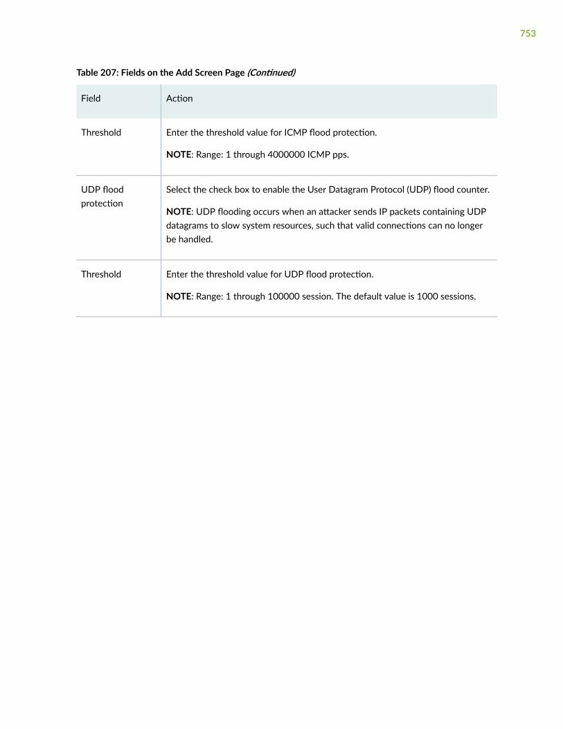
Table 207: Fields on the Add Screen Page (Continued)
Field Action
Threshold Enter the threshold value for ICMP flood protection.
NOTE: Range: 1 through 4000000 ICMP pps.
UDP floodprotection
Select the check box to enable the User Datagram Protocol (UDP) flood counter.
NOTE: UDP flooding occurs when an attacker sends IP packets containing UDPdatagrams to slow system resources, such that valid connections can no longerbe handled.
Threshold Enter the threshold value for UDP flood protection.
NOTE: Range: 1 through 100000 session. The default value is 1000 sessions.
753

Table 207: Fields on the Add Screen Page (Continued)
Field Action
UDP allowlist 1. Click Select.
The UDP Allowlist window appears.
2. Click + to add IP addresses that you wish to allowlist.
The Add Allowlist window appears.
3. Enter the following details:
• Name—Enter a Name to identify the group of IP addresses.
• IPv4/IPv6 Address—Enter IPv4 or IPv6 address.
• IPv4/IPv6 Address(es)—Lists the address that you have entered.
NOTE: You can select the IP address and click X to delete it.
4. Click OK to save the changes.
5. Select the allowlist name in the UDP Allowlist page that you associated withthe group of IP addresses that you entered in the Add Allowlist window fromthe Available column and move it to the Selected column using the rightarrow.
6. Click OK to save the changes.
NOTE:
• The UDP Allowlist option is enabled only if you select UDP flood protection.
• The allowlist that you created in the UDP Allowlist window will be available inthe TCP Allowlist window also for selection.
To edit an allowlist in the UDP Allowlist page, select the allowlist name and clickon the pencil icon.
To delete an allowlist in the UDP Allowlist page, select the allowlist name andclick on the delete icon.
754

Table 207: Fields on the Add Screen Page (Continued)
Field Action
SYN floodprotection
Select the check box to enable all the threshold and ager timeout options.
Specifies that SYN flooding occurs when a host becomes so overwhelmed bySYN segments initiating incomplete connection requests that it can no longerprocess legitimate connection requests.
755

Table 207: Fields on the Add Screen Page (Continued)
Field Action
TCP allowlist 1. Click Select.
The TCP Allowlist window appears.
2. Click + to add IP addresses that you wish to allowist.
The Add Allowlist window appears.
3. Enter the following details:
• Name—Enter a Name to identify the group of IP addresses.
• IPv4/IPv6 Address—Enter IPv4 or IPv6 address.
• IPv4/IPv6 Address(es)—Lists the address that you have entered.
NOTE: You can select the IP address and click X to delete it.
4. Click OK to save the changes.
5. Select the allowlist name in the TCP Allowlist page that you associated withthe group of IP addresses that you entered in the Add Allowlist window fromthe Available column and move it to the Selected column using the rightarrow.
6. Click OK to save the changes.
NOTE:
• The TCP Allowlist option is enabled only if you select SYN flood protection.
• The allowlist that you created in the TCP allowlist window will be available inthe UDP Allowlist window also for selection.
To edit a allowlist in the TCP Allowlist page, select the allowlist name and clickon the pencil icon.
To delete a allowlist in the TCP Allowlist page, select the allowlist name and clickon the delete icon.
756

Table 207: Fields on the Add Screen Page (Continued)
Field Action
Attack threshold Enter a value to specify the number of SYN packets per second required totrigger the SYN proxy mechanism.
NOTE: Range: 1 through 1000000 proxied requests per second. The defaultattack threshold value is 625 pps.
Alarm threshold Enter a value to specify the number of half-complete proxy connections persecond at which the device makes entries in the event alarm log.
NOTE: Range: 1 through 1000000 segments per second. The default alarmthreshold value is 250 pps.
Source threshold Enter a value to specify the number of SYN segments received per second froma single source IP address (regardless of the destination IP address and portnumber), before the device begins dropping connection requests from thatsource.
NOTE: Range: 4 through 1000000 segments per second. The default sourcethreshold value is 25 pps.
Destinationthreshold
Enter a value to specify the number of SYN segments received per second for asingle destination IP address before the device begins dropping connectionrequests to that destination. If a protected host runs multiple services, you mightwant to set a threshold based only on destination IP address, regardless of thedestination port number.
NOTE: Range: 4 through 1000000 segments per second. The default destinationthreshold value is 0 pps.
Ager timeout Enter a value to specify the maximum length of time before a half-completedconnection is dropped from the queue. You can decrease the timeout value untilyou see any connections dropped during normal traffic conditions.
Range: 1 through 50 seconds. The default value is 20 seconds.
NOTE: 20 seconds is a reasonable length of time to hold incomplete connectionrequests.
757

Table 207: Fields on the Add Screen Page (Continued)
Field Action
IPv6 EXT Header
PredefinedHeader Type
Configure the following screen options:
• Hop-by-Hop header—Select an option from the list and enter the value andclick + to add it.
To delete, select one or more headers and click X.
• Destination header—Select an option from the list and enter the value andclick + to add it.
To delete, select one or more headers and click X.
Routing header Select the check box to enable the IPv6 routing header screen option.
ESP header Select the check box to enable the IPv6 Encapsulating Security Payload headerscreen option.
No-Next header Select the check box to enable the IPv6 no next header screen option.
Mobility header Select the check box to enable the IPv6 mobility header screen option.
Fragment header Select the check box to enable the IPv6 fragment header screen option.
AH header Select the check box to enable the IPv6 Authentication Header screen option.
Shim6 header Select the check box to enable the IPv6 shim header screen option.
HIP header Select the check box to enable the IPv6 Host Identify Protocol header screenoption.
758

Table 207: Fields on the Add Screen Page (Continued)
Field Action
Customer DefinedHeader Type
Enter a value to define the type of header range and click + to add it.
Range: 0 through 255.
To delete, select one or more header types and click X.
IPv6 ext headerlimit
Enter a value to set the number of IPv6 extension headers that can pass throughthe screen.
Range: 0 through 32.
Apply to Zones
Apply to Zones Select zones from the Available column and move them to the Selected columnusing the right arrow.
RELATED DOCUMENTATION
Edit a Screen | 759
Edit a Screen
You are here: Security Policies & Objects > Zones/Screens.
To edit a screen:
1. Select an existing screen that you want to edit on the Zones/Screens page.
2. Click the pencil icon available on the upper right side of the Screen List page.
The Edit Screen page appears with editable fields. For more information on the options, see "Add aScreen" on page 747.
3. Click OK to save the changes.
759

RELATED DOCUMENTATION
Delete Screen | 760
Delete Screen
You are here: Security Policies & Objects > Zones/Screens.
To delete a screen:
1. Select a screen that you want to delete on the Zones/Screens page.
2. Click the delete icon available on the upper right side of the Screen List page.
3. Click Yes to delete or click No to retain the profile.
RELATED DOCUMENTATION
About the Zones/Screens Page | 741
760

CHAPTER 64
Zone Addresses
IN THIS CHAPTER
About the Zone Addresses Page | 761
Add Zone Addresses | 763
Clone Zone Addresses | 765
Edit Zone Addresses | 766
Delete Zone Addresses | 766
Search Text in a Zone Addresses Table | 767
About the Zone Addresses Page
IN THIS SECTION
Tasks You Can Perform | 761
Field Descriptions | 762
You are here: Security Policies & Objects > Zone Addresses.
Use this page to configure zone address or address set.
Tasks You Can Perform
You can perform the following tasks from this page:
• Add addresses or address sets. See "Add Zone Addresses" on page 763.
• Edit addresses or address sets. See "Edit Zone Addresses" on page 766.
• Delete addresses or address sets. See "Delete Zone Addresses" on page 766.
761

• Clone addresses or address sets. See "Clone Zone Addresses" on page 765.
• View the details of addresses or address sets—To do this, select the address or address set for whichyou want to view the details and follow the available options:
• Click More and select Detailed View.
• Click the detailed view icon available to the left of the selected address or address set.
• Deselect the selected address or address set. To do this, click More and select Clear All Selections.
• Search text in the Addresses table. See "Search Text in a Zone Addresses Table" on page 767.
• Show or hide columns in the Web filtering profiles table. To do this, click the Show Hide Columnsicon in the top right corner of the Web filtering profiles table and select the options you want to viewor deselect the options you want to hide on the page.
Field Descriptions
Table 208 on page 762 describes the fields on the Zone Addresses page.
Table 208: Fields on the Zone Addresses Page
Field Description
Addresses
Zone Displays the zone name to which the address is applied.
Name Displays the address name.
Type Displays the selected address type.
IP Address Displays the IP address of the zone address.
Description Displays the description of the address.
Address Sets
Zone Displays the zone name to which the address set is applied.
762

Table 208: Fields on the Zone Addresses Page (Continued)
Field Description
Name Displays the address sets name.
Type Displays the selected address type.
Address List Displays the preexisting addresses that should be included from the address set.
Address Set List Displays the preexisting addresses that should be included from the list.
Description Displays the description of the address set.
RELATED DOCUMENTATION
Add Zone Addresses | 763
Add Zone Addresses
You are here: Security Policies & Objects > Zone Addresses.
To create a zone address or address set:
1. Click the add icon (+) on the upper right side of the Zone Addresses page.
The Create Addresses page appears.
2. Complete the configuration according to the guidelines provided in Table 209 on page 763.
3. Click OK to save the changes. If you want to discard your changes, click Cancel.
Table 209: Fields on the Create Addresses Page
Field Action
Object Type Select an option from the list: Address or Address Group.
763

Table 209: Fields on the Create Addresses Page (Continued)
Field Action
Addresses or Address Sets
Zone Select a zone from the list to which the address is applied.
Name Enter the address name.
Description Enter the description for the address.
Type Select an option from the list: Host, Range, or DNS host.
Host IP Enter the IPv4 or IPv6 address.
NOTE: This option is available if you have selected Host type.
Start Address Enter the start IPv4 or IPv6 address.
NOTE: This option is available if you have selected Range type.
End Address Enter the end IPv4 or IPv6 address.
NOTE: This option is available if you have selected Range type.
DNS Name Enter a domain hostname.
The string must include alphanumeric characters, periods, dashes, no spaces areallowed and must end with an alphanumeric character.
NOTE: This option is available if you have selected DNS Host type.
Address Sets Displays the address set name. Select the address set.
Create Address Set Enter the address set name and click + to add the address set in the AddressSets.
764

Table 209: Fields on the Create Addresses Page (Continued)
Field Action
Address Set Name Enter a name for address set.
NOTE: This option is available if you have selected Address Group for Objecttype.
Description Enter a description for address set.
NOTE: This option is available if you have selected Address Group for Objecttype.
Address List Specifies which of the preexisting addresses should be included or excludedfrom the address set.
Select the addresses from the list in the Available column and then click theright arrow to move it to the Selected column.
NOTE: This option is available if you have selected Address Group for Objecttype.
RELATED DOCUMENTATION
Edit Zone Addresses | 766
Clone Zone Addresses
You are here: Security Policies & Objects > Zone Addresses.
To clone a zone address or address set:
1. Select an existing zone address or address set that you want to clone and select Clone from the Morelink.
2. Click the pencil icon available on the upper right side of the Zone Addresses page.
The Clone Addresses page appears with editable fields. For more information on the options, see"Add Zone Addresses" on page 763.
765

3. Click OK to save the changes.
RELATED DOCUMENTATION
Delete Zone Addresses | 766
Edit Zone Addresses
You are here: Security Policies & Objects > Zone Addresses.
To edit a zone address or address set:
1. Select an existing zone address or address set that you want to edit on the Zone Addresses page.
2. Click the pencil icon available on the upper right side of the Zone Addresses page.
The Edit Addresses page appears with editable fields. For more information on the options, see "AddZone Addresses" on page 763.
3. Click OK to save the changes.
RELATED DOCUMENTATION
Delete Zone Addresses | 766
Delete Zone Addresses
You are here: Security Policies & Objects > Zone Addresses.
To delete a zone address or address set:
1. Select a zone address or address set that you want to delete on the Zone Addresses page.
2. Click the delete icon available on the upper right side of the Zone Addresses page.
A confirmation window appears.
3. Click Yes to delete or click No to retain the profile.
RELATED DOCUMENTATION
Search Text in a Zone Addresses Table | 767
766

Search Text in a Zone Addresses Table
You are here: Security Policies & Objects > Zone Addresses.
You can use the search icon in the top right corner of the Zone Addresses page to search for textcontaining letters and special characters on that page.
To search for text:
1. Click the search icon and enter partial text or full text of the keyword in the search bar.
The search results are displayed.
2. Click X next to a search keyword or click Clear All to clear the search results.
RELATED DOCUMENTATION
About the Zone Addresses Page | 761
767

CHAPTER 65
Global Addresses
IN THIS CHAPTER
About the Global Addresses Page | 768
Add an Address Book | 769
Edit an Address Book | 773
Delete Address Book | 773
About the Global Addresses Page
IN THIS SECTION
Tasks You Can Perform | 768
Field Descriptions | 769
You are here: Security Policies & Objects > Global Addresses.
Use this page to configure global address books for security policies.
Tasks You Can Perform
You can perform the following tasks from this page:
• Add an Address Book. See "Add an Address Book" on page 769.
• Edit an Address Book. See "Edit an Address Book" on page 773.
• Delete an Address Book. See "Delete Address Book" on page 773.
768

• Upgrade the old zone-based address book to global address books. To do this, click Upgrade availableon the right-side corner of the Global Addresses table. Click Yes to proceed with the upgrade toglobal address books and click OK.
Field Descriptions
Table 210 on page 769 describes the fields on the Global Addresses Page.
Table 210: Fields on the Global Addresses Page
Field Description
Address Book Name Displays the address book name.
Attached Zone Displays the name of the zone that is attached to the address book.
Global Displays information about the predefined address book.
The global address book is available by default to all security zones. Youdo not need to attach a security zone to the global address book.
Address/Address-SetName
Displays the addresses and address sets associated with the selectedaddress book.
Address Value Displays the IP address.
Address-Set Members Displays the addresses in an address set.
RELATED DOCUMENTATION
Add an Address Book | 769
Add an Address Book
You are here: Security Policies & Objects > Global Addresses.
769
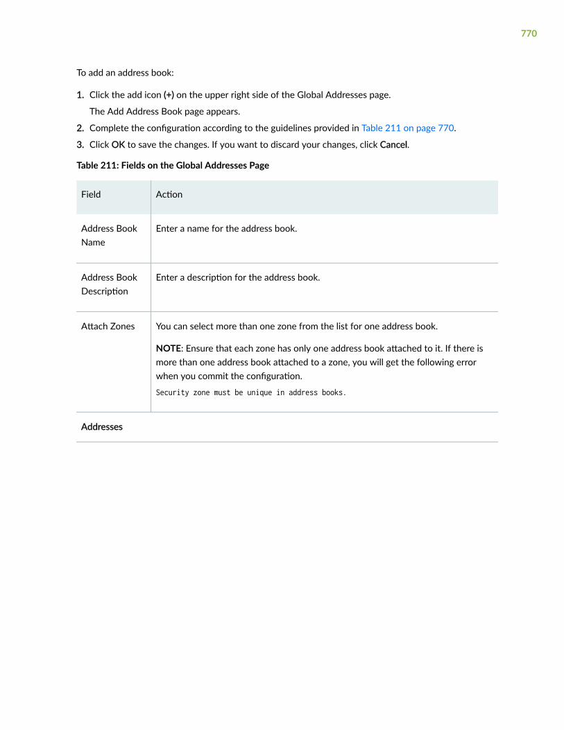
To add an address book:
1. Click the add icon (+) on the upper right side of the Global Addresses page.
The Add Address Book page appears.
2. Complete the configuration according to the guidelines provided in Table 211 on page 770.
3. Click OK to save the changes. If you want to discard your changes, click Cancel.
Table 211: Fields on the Global Addresses Page
Field Action
Address BookName
Enter a name for the address book.
Address BookDescription
Enter a description for the address book.
Attach Zones You can select more than one zone from the list for one address book.
NOTE: Ensure that each zone has only one address book attached to it. If there ismore than one address book attached to a zone, you will get the following errorwhen you commit the configuration.
Security zone must be unique in address books.
Addresses
770

Table 211: Fields on the Global Addresses Page (Continued)
Field Action
+ To add an address:
1. Click + available at the upper right side of the Addresses table.
The Add Address page appears.
2. Enter the following details:
• Address Name—Enter a name for the address.
• Description—Enter a description for the address.
• Address Type—Select one of the following address types from the list:
• IP Address
• Wildcard Address
• Domain Name
• Ranged Address
• Value—Enter an address that matches the selected address type.
3. Click OK to save the changes.
Edit To edit an address:
1. Select an existing address and click the pencil icon available at the upper rightside of the Addresses table.
The Add Address page appears with editable fields.
2. Click OK to save the changes.
Delete Select an existing address and click the delete (X) icon available at the upper rightside of the Addresses table to delete it.
Address Set
771

Table 211: Fields on the Global Addresses Page (Continued)
Field Action
+ To add an address set:
1. Click + available at the upper right side of the Addresses table.
The Add Address Set page appears.
2. Enter the following details:
• Address Set Name—Enter a name for the address set.
• Description—Enter a description for the address set.
• Address List—Select the address from the list in the Available column andthen click the right arrow to move it to the Selected column.
Specifies which of the preexisting addresses should be included or excludedfrom the address set.
• Address Set List—Select the address sets from the list in the Availablecolumn and then click the right arrow to move it to the Selected column.
Specifies which of the preexisting address sets should be included orexcluded from the list.
3. Click OK to save the changes.
Edit To edit an address set:
1. Select an existing address and click the pencil icon available at the upper rightside of the Address Set table.
The Add Address Set page appears with editable fields.
2. Click OK to save the changes.
Delete Select an existing address set and click the delete (X) icon available at the upperright side of the Address Set table to delete it.
772

RELATED DOCUMENTATION
Edit an Address Book | 773
Edit an Address Book
You are here: Security Policies & Objects > Global Addresses.
To edit an address book:
1. Select an existing address book that you want to edit on the Global Addresses page.
2. Click the pencil icon available on the upper right side of the Global Addresses page.
The Edit Address Book page appears with editable fields. For more information on the options, see"Add an Address Book" on page 769.
3. Click OK to save the changes.
RELATED DOCUMENTATION
Delete Address Book | 773
Delete Address Book
You are here: Security Policies & Objects > Global Addresses.
To delete an address book:
1. Select an existing address book that you want to delete on the Global Addresses page.
2. Click the delete icon available on the upper right side of the Global Addresses page.
A confirmation window appears.
3. Click Yes to delete or click No to retain the profile.
RELATED DOCUMENTATION
About the Global Addresses Page | 768
773

CHAPTER 66
Services
IN THIS CHAPTER
About the Services Page | 774
Add a Custom Application | 776
Edit a Custom Application | 779
Delete Custom Application | 780
Add an Application Group | 780
Edit an Application Group | 781
Delete Application Group | 782
About the Services Page
IN THIS SECTION
Tasks You Can Perform | 774
Field Descriptions | 775
You are here: Security Policies & Objects > Services.
Use services in policies to manage applications across devices.
Tasks You Can Perform
You can perform the following tasks from this page:
• Add a custom application. See "Add a Custom Application" on page 776.
• Edit a custom application. See "Edit a Custom Application" on page 779.
774

• Delete custom application. See "Delete Custom Application" on page 780.
• Add an application group. See "Add an Application Group" on page 780.
• Edit an application group. See "Edit an Application Group" on page 781.
• Delete an application group. See "Delete Application Group" on page 782.
Field Descriptions
Table 212 on page 775 describes the fields on the Services Page.
Table 212: Fields on the Services Page
Field Description
Custom-Applications
Application Name Displays the custom application name.
Application Description Displays a description of the custom application.
Application-Protocol Displays the custom application protocol.
IP-Protocol Displays the custom network protocol.
Source-Port Displays the custom source port identifier.
Destination-Port Displays the custom destination port identifier.
Pre-defined Applications
Application Name Displays the predefined application name.
Application-Protocol Displays the predefined application protocol.
IP-Protocol Displays the predefined network protocol.
775

Table 212: Fields on the Services Page (Continued)
Field Description
Source-Port Displays the predefined source port identifier.
Destination-Port Displays the predefined destination port identifier.
Application Group
Application Group Name Displays the application group name.
Members Displays members in the set.
Description Displays a description of the application group.
RELATED DOCUMENTATION
Add a Custom Application | 776
Add a Custom Application
You are here: Security Policies & Objects > Services.
To add a custom application:
1. Click the Custom-Applications tab.
2. Click the add icon (+) on the upper right side of the Services page.
The Add an Application page appears.
3. Complete the configuration according to the guidelines provided in Table 213 on page 777.
4. Click OK to save the changes. If you want to discard your changes, click Cancel.
776

Table 213: Fields on the Add an Application Page
Field Action
Global
Application Name Enter a custom application name.
Application Description Enter a description for the custom application.
Application-protocol Select a custom application protocol from the list.
Match IP protocol Select a custom network protocol from the list.
Destination Port Select a custom destination port identifier from the list.
Source Port Select a custom source port identifier from the list.
Inactivity-timeout Enter a value from 4 through 86400.
Specifies the length of time (in seconds) that the application is inactivebefore it times out.
RPC-program-number Enter a remote procedure call value from 0 through 65535.
Match ICMP message code Select an Internet Control Message Protocol (ICMP) message code valuefrom the list.
Match ICMP message type Select an Internet Control Message Protocol message type value fromthe list.
UUID Enter a universal unique identifier (UUID).
777

Table 213: Fields on the Add an Application Page (Continued)
Field Action
Application Group Select an option from the list.
Specifies the set to which this application belongs.
Terms
Add Click +.
The Add new term page appears.
Term Name Enter an application term name.
ALG Select an option from the list.
Specifies the Application Layer Gateway (ALG) for the applicationprotocol.
Match IP protocol Select a network protocol from the list.
Destination Port Enter the destination port identifier.
Source Port Specifies the source port identifier.
Inactivity-timeout Enter a value from 4 through 86400.
Specifies the length of time (in seconds) that the application is inactivebefore it times out.
RPC-program-number Enter a remote procedure call value from 0 through 65535.
Match ICMP message code Select an ICMP message code value from the list.
Match ICMP message type Select an ICMP message type value from the list.
778

Table 213: Fields on the Add an Application Page (Continued)
Field Action
UUID Select an option from the list.
Specifies the set to which this application belongs.
Edit Select a term and click the pencil icon at the right corner of the table tomodify the configuration.
Delete Select a term and click the delete (X) icon at the right corner of the tableto delete the selected term.
RELATED DOCUMENTATION
Edit a Custom Application | 779
Edit a Custom Application
You are here: Security Policies & Objects > Services.
To edit a custom application:
1. Click the Custom-Applications tab.
2. Select an existing application that you want to edit on the Services page.
3. Click the pencil icon available on the upper right side of the Services page.
The Edit an Application page appears with editable fields. For more information on the options, see"Add a Custom Application" on page 776.
4. Click OK to save the changes.
RELATED DOCUMENTATION
Delete Custom Application | 780
779
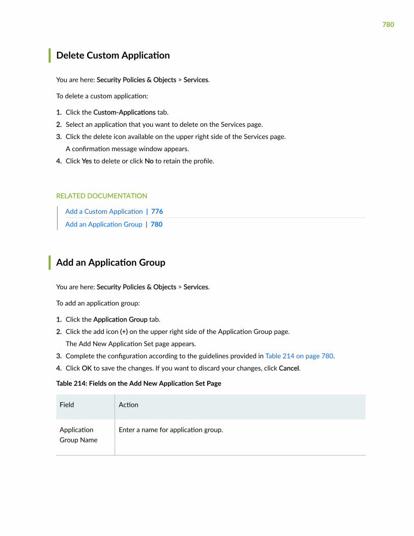
Delete Custom Application
You are here: Security Policies & Objects > Services.
To delete a custom application:
1. Click the Custom-Applications tab.
2. Select an application that you want to delete on the Services page.
3. Click the delete icon available on the upper right side of the Services page.
A confirmation message window appears.
4. Click Yes to delete or click No to retain the profile.
RELATED DOCUMENTATION
Add a Custom Application | 776
Add an Application Group | 780
Add an Application Group
You are here: Security Policies & Objects > Services.
To add an application group:
1. Click the Application Group tab.
2. Click the add icon (+) on the upper right side of the Application Group page.
The Add New Application Set page appears.
3. Complete the configuration according to the guidelines provided in Table 214 on page 780.
4. Click OK to save the changes. If you want to discard your changes, click Cancel.
Table 214: Fields on the Add New Application Set Page
Field Action
ApplicationGroup Name
Enter a name for application group.
780
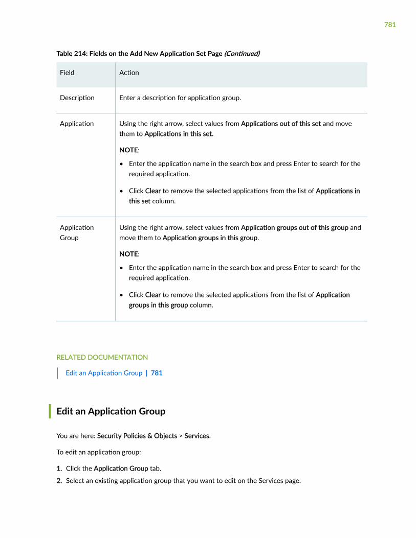
Table 214: Fields on the Add New Application Set Page (Continued)
Field Action
Description Enter a description for application group.
Application Using the right arrow, select values from Applications out of this set and movethem to Applications in this set.
NOTE:
• Enter the application name in the search box and press Enter to search for therequired application.
• Click Clear to remove the selected applications from the list of Applications inthis set column.
ApplicationGroup
Using the right arrow, select values from Application groups out of this group andmove them to Application groups in this group.
NOTE:
• Enter the application name in the search box and press Enter to search for therequired application.
• Click Clear to remove the selected applications from the list of Applicationgroups in this group column.
RELATED DOCUMENTATION
Edit an Application Group | 781
Edit an Application Group
You are here: Security Policies & Objects > Services.
To edit an application group:
1. Click the Application Group tab.
2. Select an existing application group that you want to edit on the Services page.
781

3. Click the pencil icon available on the upper right side of the Services page.
The Edit Application Set page appears with editable fields. For more information on the options, see"Add an Application Group" on page 780.
4. Click OK to save the changes.
RELATED DOCUMENTATION
Delete Application Group | 782
Delete Application Group
You are here: Security Policies & Objects > Services.
To delete an application group:
1. Click the Application Group tab.
2. Select an application group name that you want to delete on the Services page.
3. Click the delete icon available on the upper right side of the Services page.
A confirmation message window appears.
4. Click Yes to delete or click No to retain the profile.
RELATED DOCUMENTATION
About the Services Page | 774
782

CHAPTER 67
Dynamic Applications
IN THIS CHAPTER
About the Dynamic Applications Page | 783
Global Settings | 786
Add Application Signatures | 791
Clone Application Signatures | 796
Add Application Signatures Group | 797
Edit Application Signatures | 798
Delete Application Signatures | 799
Search Text in an Application Signatures Table | 800
About the Dynamic Applications Page
IN THIS SECTION
Tasks You Can Perform | 784
Field Descriptions | 785
You are here: Security Policies & Objects > Dynamic Applications.
Use this page to create, modify, clone, and delete application signature groups. You can view the detailsof predefined application signatures that are already downloaded.
All enabled and disabled application signatures on the device are displayed in a grid format. A messageOnce a new custom application signature is created or modified, the configuration is committedimmediately to the device. is displayed at the top of the page.
783

A status message is displayed just above the grid. It shows the version number of the installedapplication, the latest version available, and whether you have downloaded or installed an applicationpackage.
Installed application package version : 0 | Latest version 3207 available | No application package is downloaded yet
NOTE: If you successfully download an application package, the Install button is displayed. If yousuccessfully install a downloaded application package, an Uninstall button is displayed.
Tasks You Can Perform
You can perform the following tasks from this page:
• Global Settings. See "Global Settings" on page 786.
• Create application signatures. See "Add Application Signatures" on page 791.
• Create application signatures group. See "Add Application Signatures Group" on page 797.
• Edit application signatures. See "Edit Application Signatures" on page 798.
• Delete application signatures. See "Delete Application Signatures" on page 799.
• Clone application signatures. See "Clone Application Signatures" on page 796.
• Search text in an application signature. See "Search Text in an Application Signatures Table" on page800.
• View the details of application signatures—To do this, select the application signature for which youwant to view the details and follow the available options:
• Click More and select Detailed View.
• Right-click on the selected application signature profile and select Detailed View.
• Mouse over to the left of the selected application signature and click Detailed View.
• Filter the application signatures based on select criteria. To do this, select the filter icon at the topright-hand corner of the application signatures table. The columns in the grid change to accept filteroptions. Type the filter options; the table displays only the data that fits the filtering criteria.
784

• Show or hide columns in the application signature profiles table. To do this, click the Show HideColumns icon in the top right corner of the application signatures table and select the options youwant to view or deselect the options you want to hide on the page.
• Download—Manually downloads the latest or predefined application signature package.
• More—Clone an existing application signature package, create group, or configure the page to show adetailed view.
• Create Group—Create a new application signature or application signatures group.
• Uninstall—Removes application signatures that are currently installed on your device.
On SRX1400, SRX3400, SRX3600, SRX5600, and SRX5800 devices, specify the type of signature touninstall. Choose one of the uninstall options:
• Customized—Uninstalls all customized application signatures on your device. This option does notuninstall predefined application signatures.
• Predefined—Uninstalls all predefined application signatures on your device. This option does notuninstall any customized applications.
• All—Uninstalls all customized and predefined application signatures on your device.
Field Descriptions
Table 215 on page 785 describes the fields on the Application Signatures page.
Table 215: Fields on the Application Signatures Page
Field Description
Name Displays the application signature name.
Object Type Displays the application signature object type.
Category Specifies the category of the application signature.
Subcategory Specifies the subcategory of the application signature.
Risk Displays the risk as critical, high, moderate, low, or unsafe.
785

Table 215: Fields on the Application Signatures Page (Continued)
Field Description
Characteristic Specifies the characteristic of the application signature.
Predefined or Custom Displays the predefined or custom application signatures and settings that areconfigured on your device.
Status Displays the status of the application signature.
RELATED DOCUMENTATION
Global Settings | 786
Add Application Signatures | 791
Add Application Signatures Group | 797
Edit Application Signatures | 798
Delete Application Signatures | 799
Clone Application Signatures | 796
Search Text in an Application Signatures Table | 800
Global Settings
You are here: Security Policies & Objects > Dynamic Applications.
To add global settings:
1. Click the Global Settings on the upper right side of the Application Signatures page.
The Global Settings page appears.
2. Complete the configuration according to the guidelines provided in Table 216 on page 787.
3. Click OK to save the changes. If you want to discard your changes, click Cancel.
786

Table 216: Fields on the Global Settings Option Page
Field Action
General
Custom ApplicationByte Limit
Select the byte limit in the range 0 through 10000. This helps inunderstanding when to stop the identification of custom applications.
Micro Applications Enable micro-application detection in application identification and thenuse them as matching criteria in a security policy.
Download
Specifies the URL from where you can download the signature package, set up a schedule forautomatic downloads of the latest predefined application signature package.
URL Enter the URL for the application package for downloading.
Proxy Profile To create a proxy profile:
1. Click Create Profile.
2. Enter the following details:
• Profile Name—Enter a valid profile name.
• Connection type—Select any one option from the following:
• Server IP—Enter the server IP address.
• Host Name—Enter the host name.
• Port number—Enter the port number in the range 0 through 65535.Default port number is 80.
3. Click OK to save the changes. If you want to discard your changes, clickCancel.
Automatic Update Enable this option to schedule download and update.
787
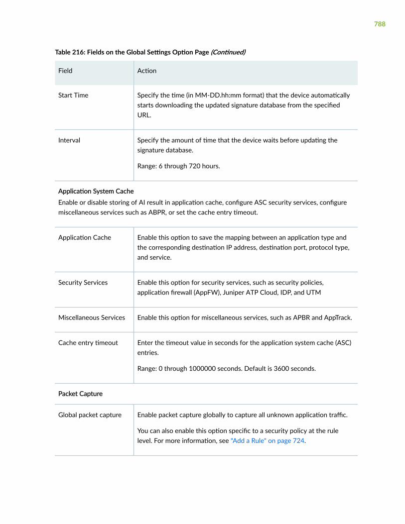
Table 216: Fields on the Global Settings Option Page (Continued)
Field Action
Start Time Specify the time (in MM-DD.hh:mm format) that the device automaticallystarts downloading the updated signature database from the specifiedURL.
Interval Specify the amount of time that the device waits before updating thesignature database.
Range: 6 through 720 hours.
Application System Cache
Enable or disable storing of AI result in application cache, configure ASC security services, configuremiscellaneous services such as ABPR, or set the cache entry timeout.
Application Cache Enable this option to save the mapping between an application type andthe corresponding destination IP address, destination port, protocol type,and service.
Security Services Enable this option for security services, such as security policies,application firewall (AppFW), Juniper ATP Cloud, IDP, and UTM
Miscellaneous Services Enable this option for miscellaneous services, such as APBR and AppTrack.
Cache entry timeout Enter the timeout value in seconds for the application system cache (ASC)entries.
Range: 0 through 1000000 seconds. Default is 3600 seconds.
Packet Capture
Global packet capture Enable packet capture globally to capture all unknown application traffic.
You can also enable this option specific to a security policy at the rulelevel. For more information, see "Add a Rule" on page 724.
788

Table 216: Fields on the Global Settings Option Page (Continued)
Field Action
Aggressive mode Enable to capture all traffic before AppID classifies the applications. In thismode, the system captures all application traffic regardless of theapplication system cache (ASC) entry. Packet capture starts for the firstpacket of the first session.
Exclude inconclusivetraffic
Disable packet capture of inconclusive traffic. This option is available whenyou enable the Aggressive mode option.
This option disables the packet capture for the following sessions:
• Sessions closed before the application identification or classificationcompletes.
• Sessions not classified even though they reach the maximum packetcapture limit.
If you do not configure this option, by default, the system captures packetsfor inconclusive sessions.
Advanced
Maximum packets Maximum number of UDP packets per session.
Range: 1 through 1000. Default is 10 packets.
Maximum bytes Maximum number of TCP bytes per session. For TCP sessions, the countincludes the actual payload data length and excludes IP/TCP headers forthe maximum bytes limit.
Range: 40 through 1,073,741,824. Default is 6000 bytes.
Maximum files Maximum number of unique packet capture files to create before theoldest file is overwritten by a new file created.
Range: 1 through 2500. Default is 100.
789

Table 216: Fields on the Global Settings Option Page (Continued)
Field Action
Maximum storage Maximum disk space (bytes) that can be used in the Routing Engine forpacket capture files.
Range: 1 through 4096 MB. Default is 50 MB.
Maximum memory Maximum memory limit for deep packet inspection (DPI).
Range: 1 KB through maximum bytes (depending on the available space onthe device).
Packet capture interval Timeout value in minutes to avoid repetitive capture of same traffic. Afterthis interval, the system continues to capture newer packet details forunknown applications until the capture limit is reached.
Range: 1 through 525,600 minutes. Default is 1440 minutes (24 hours).
Repeat traffic capture Number of repetitive captures of same traffic. Use this option to limit thenumber of times the same traffic can be repeatedly captured before thecache entry times out.
Range: 1 through 1000. Default is 5.
Release History Table
Release Description
20.2R1 Starting in Junos OS Release 20.2R1, Custom Application Byte Limit option is supported.
RELATED DOCUMENTATION
About the Dynamic Applications Page | 783
Add Application Signatures | 791
Add Application Signatures Group | 797
Edit Application Signatures | 798
Delete Application Signatures | 799
790

Clone Application Signatures | 796
Search Text in an Application Signatures Table | 800
Add Application Signatures
You are here: Security Policies & Objects > Dynamic Applications.
To add an application signature:
1. Click Create > Signature on the upper right side of the Dynamic Applications page.
The Create Application Signatures page appears.
2. Complete the configuration according to the guidelines provided in Table 217 on page 791.
3. Click OK to save the changes. If you want to discard your changes, click Cancel.
Table 217: Fields on the Add Application Signatures Page
Field Action
Name Enter the application signature name.
Description Enter the application signature description.
Order Enter the order of the custom application.
Lower order has higher priority.
The range is 1 through 50,000.
791

Table 217: Fields on the Add Application Signatures Page (Continued)
Field Action
Priority Enter the priority over other signature applications.
Select an option from the list:
• High
• Low
Starting in Junos OS Release 20.2R1, by default, the priority for the customapplication is set to Low. This allows a predefined application to takeprecedence. If you want to override a predefined application, you must set thepriority to High.
Risk Enter the risk as critical, high, moderate, low, or unsafe.
ApplicationIdentification matchcriteria
Select one or more options from the list:
• ICMP Mapping
• IP Protocol Mapping
• Address Mapping
• L7 Signature
ICMP Mapping Select a value from the list.
• ICMP Type—Select the numeric value of an ICMP type. The type identifiesthe ICMP message, such as Unassigned or Destination Unreachable.
The range is from 0 through 254.
• Select the numeric value of an ICMP code. The code field provides furtherinformation (such as RFCs) about the associated type field.
The range is from 0 through 254.
792

Table 217: Fields on the Add Application Signatures Page (Continued)
Field Action
IP Protocol Mapping Select the numeric value of an ICMP type. The type identifies the ICMPmessage, such as Unassigned or Destination Unreachable.
The range is from 0 through 254.
Address Mapping To add a new address mapping:
1. Click Add.
The Add Address Mapping page appears.
Enter the following details:
• Name—Enter the name of the address mapping.
• IP Address—Enter an IPv4 or IPv6 address.
• CIDR Range—Enter an IPv4 or IPV6 address prefix for classless IPaddressing.
• TCP Port range—Enter the TCP port range for the application.
• UDP Port Range—Enter the UDP port range for the application.
2. Click the pencil icon at the top right side of the Address Mapping table.Then, edit the address mapping and click OK.
3. To delete an existing Address Mapping, select it and click the delete icon orright-click on it and click Delete.
L7 Signature
Cacheable Set this option to True only when L7 signatures are configured in a customsignature. This option is not supported for address-based, IP protocol-based,and ICMP-based custom application signatures.
793

Table 217: Fields on the Add Application Signatures Page (Continued)
Field Action
Add L7 Signature Click Add L7 Signature list and select an option from the following:
• Over HTTP
• Over SSL
• Over TCP
• Over UDP
The Add Signature page appears.
Add Signature
Over Protocol Displays the signature that matches the application protocol.
Example: HTTP
Signature Name Enter a unique name that is a string of alphanumeric characters, colons,periods, dashes, and underscores. No spaces are allowed and the maximumlength is 63 characters.
Port Range Enter the port range for the application.
Range is 0-65535.
Add Members
Custom signatures can contain multiple members that define attributes of an application. Thesupported member name range is m01 through m15.
+ Click + to create a member.
794

Table 217: Fields on the Add Application Signatures Page (Continued)
Field Action
Context (OverHTTP)
Select the service-specific context from the following list:
• http-get-url-parsed-param-parsed
• http-header-content-type
• http-header-cookie
• http-header-host
• http-header-user-agent
• http-post-url-parsed-param-parsed
• http-post-variable-parsed
• http-url-parsed
• http-url-parsed-param-parsed
Context (Over SSL) Select the service-specific context as ssl-server-name.
Context (Over TCP) Select the service-specific context as stream.
Context (Over UDP) Select the service-specific context as stream.
Direction Select the direction of the packet flow to match the signature:
• any—The direction of the packet flow can either be from the client-side tothe server-side or from the server-side to the client-side.
• client-to-server—The direction of packet flow is from the client-side to theserver-side.
• server-to-client—The direction of packet flow is from the server-side to theclient-side.
795

Table 217: Fields on the Add Application Signatures Page (Continued)
Field Action
Depth Enter the maximum number of bytes to check for context match. Use the bytelimit for AppID to identify custom application pattern for applications runningover TCP or UDP or Layer 7 applications.
Range is 1 through 8000. The Depth is set to 1000 by default, if not explicitlyconfigured.
NOTE: Starting in Junos OS Release 20.2R1, Depth option is supported.
Pattern Enter the deterministic finite automaton (DFA) pattern matched the context.The DFA pattern specifies the pattern to be matched for the signature. Themaximum length is 128.
Release History Table
Release Description
20.2R1 Starting in Junos OS Release 20.2R1, Depth option is supported.
RELATED DOCUMENTATION
About the Dynamic Applications Page | 783
Global Settings | 786
Add Application Signatures Group | 797
Edit Application Signatures | 798
Delete Application Signatures | 799
Clone Application Signatures | 796
Search Text in an Application Signatures Table | 800
Clone Application Signatures
You are here: Security Policies & Objects > Dynamic Applications.
796

To clone an application signature:
1. Select the application signature profile that you want to clone and select Clone from the More link.
NOTE: Alternatively, you can right-click on the selected application signature profile andselect Clone.
The Clone Application Signature page appears with editable fields. For more information on thefields, see "Add Application Signatures" on page 791.
2. Click OK to save the changes. If you want to discard your changes, click Cancel.
RELATED DOCUMENTATION
About the Dynamic Applications Page | 783
Global Settings | 786
Add Application Signatures | 791
Add Application Signatures Group | 797
Edit Application Signatures | 798
Delete Application Signatures | 799
Search Text in an Application Signatures Table | 800
Add Application Signatures Group
You are here: Security Policies & Objects > Dynamic Applications.
To add an application signature group:
1. Click Create > Signature Group on the upper right side of the Dynamic Applications page. You canalso click More and select Create Group.
The Create Application Signature Group page appears.
2. Complete the configuration according to the guidelines provided in Table 218 on page 798.
3. Click OK to save the changes. If you want to discard your changes, click Cancel.
797

Table 218: Fields on the Add Application Signature Group Page
Field Action
Name Enter the application signature group name.
GroupMembers
Enter the add or remove applications associated with the application signature group.
Click one of the following options:
• Add—Click + to create an application signature group.
• Delete—Select an existing application signature group that you want to delete andclick the delete icon available at the upper right of the application signature grouptable.
• Detailed View—Hover over the application signature group name and click theDetailed View icon to view the signature group.
You can also click More and select Detailed View for the selected signature group.
RELATED DOCUMENTATION
About the Dynamic Applications Page | 783
Edit Application Signatures | 798
Delete Application Signatures | 799
Clone Application Signatures | 796
Search Text in an Application Signatures Table | 800
Edit Application Signatures
You are here: Security Policies & Objects > Dynamic Applications.
To edit an application signature:
1. Select an existing application signature that you want to edit on the Dynamic Applications page.
2. Click the pencil icon available on the upper right side of the page.
798

The Edit Application Signatures page appears with editable fields. For more information on theoptions, see "Add Application Signatures" on page 791.
3. Click OK to save the changes.
RELATED DOCUMENTATION
About the Dynamic Applications Page | 783
Global Settings | 786
Add Application Signatures | 791
Add Application Signatures Group | 797
Add Application Signatures Group | 797
Delete Application Signatures | 799
Clone Application Signatures | 796
Search Text in an Application Signatures Table | 800
Delete Application Signatures
You are here: Security Policies & Objects > Dynamic Applications.
To delete application signatures:
1. Select an application signature that you want to delete on the Dynamic Applications page.
2. Click the delete icon available on the upper right side of the page.
3. Click Yes to delete or click No to retain the profile.
RELATED DOCUMENTATION
About the Dynamic Applications Page | 783
Global Settings | 786
Add Application Signatures | 791
Add Application Signatures Group | 797
Edit Application Signatures | 798
Clone Application Signatures | 796
Search Text in an Application Signatures Table | 800
799

Search Text in an Application Signatures Table
You are here: Security Policies & Objects > Dynamic Applications.
You can use the search icon in the top right corner of the Dynamic Applications page to search for textcontaining letters and special characters on that page.
To search for text:
1. Click the search icon and enter partial text or full text of the keyword in the search bar.
The search results are displayed.
2. Click X next to a search keyword or click Clear All to clear the search results.
RELATED DOCUMENTATION
About the Dynamic Applications Page | 783
Global Settings | 786
Add Application Signatures | 791
Add Application Signatures Group | 797
Edit Application Signatures | 798
Delete Application Signatures | 799
Clone Application Signatures | 796
800
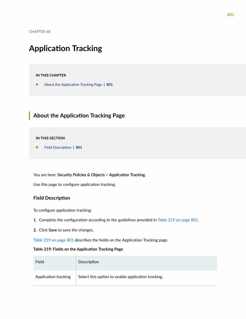
CHAPTER 68
Application Tracking
IN THIS CHAPTER
About the Application Tracking Page | 801
About the Application Tracking Page
IN THIS SECTION
Field Description | 801
You are here: Security Policies & Objects > Application Tracking.
Use this page to configure application tracking.
Field Description
To configure application tracking:
1. Complete the configuration according to the guidelines provided in Table 219 on page 801.
2. Click Save to save the changes.
Table 219 on page 801 describes the fields on the Application Tracking page.
Table 219: Fields on the Application Tracking Page
Field Description
Application tracking Select this option to enable application tracking.
801

Table 219: Fields on the Application Tracking Page (Continued)
Field Description
Logging Type Select an option:
• Log as session(s) created—Generates a log message when a session iscreated. By default, this option is disabled.
• Delay logging first session—Enables you to specify the length of time thatmust pass before the first log message is created. The default is 1 minute.
First Update Interval(min)
Use the up/down arrow to set the interval time.
Session UpdateInterval (min)
Use the up/down arrow to set the interval time.
Application TrackingBy Zone
Lists the available zones.
• To enable application tracking, select the zone and click the right arrow tomove it to the tracking enabled list.
• To disable application tracking, select the zone and then click the leftarrow to move the zone back into the available list.
RELATED DOCUMENTATION
About the Address Pools Page | 961
802
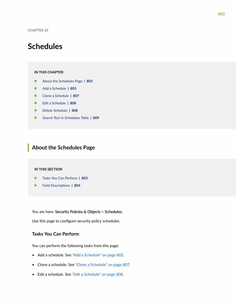
CHAPTER 69
Schedules
IN THIS CHAPTER
About the Schedules Page | 803
Add a Schedule | 805
Clone a Schedule | 807
Edit a Schedule | 808
Delete Schedule | 808
Search Text in Schedules Table | 809
About the Schedules Page
IN THIS SECTION
Tasks You Can Perform | 803
Field Descriptions | 804
You are here: Security Policies & Objects > Schedules.
Use this page to configure security policy schedules.
Tasks You Can Perform
You can perform the following tasks from this page:
• Add a schedule. See "Add a Schedule" on page 805.
• Clone a schedule. See "Clone a Schedule" on page 807.
• Edit a schedule. See "Edit a Schedule" on page 808.
803

• Delete a schedule. See "Delete Schedule" on page 808.
• View the details of schedules—To do this, select the schedule for which you want to view the detailsand follow the available options:
• Click More and select Detailed View.
• Right-click on the selected custom object and select Detailed View.
• Mouse over to the left of the selected custom object and click Detailed View.
• Deselect the selected schedules. To do this, click More and select Clear All Selections.
• Search text in the Schedules table. See "Search Text in Schedules Table" on page 809.
• Show or hide columns in the Schedules table. To do this, click the Show Hide Columns icon in the topright corner of the Schedules table and select the options you want to view or deselect the optionsyou want to hide on the page.
Field Descriptions
Table 220 on page 804 describes the fields on the Schedules Page.
Table 220: Fields on the Schedules Page
Field Description
Name Displays the name of the policy schedule.
Description Displays a description of the policy schedule.
Start Date Displays the start date for the first day.
End Date Displays the stop date for the first day.
Second Start Date Displays the start date for the second day.
Second End Date Displays the stop date for the second day.
804

Table 220: Fields on the Schedules Page (Continued)
Field Description
Schedules On expanding, displays the days of the schedule, exclusion days if any, and thestart and end time of the schedule.
RELATED DOCUMENTATION
Add a Schedule | 805
Add a Schedule
You are here: Security Policies & Objects > Schedules.
To add a schedule:
1. Click the add icon (+) on the upper right side of the Schedules page.
The Create Schedule page appears.
2. Complete the configuration according to the guidelines provided in Table 221 on page 805.
3. Click OK to save the changes. If you want to discard your changes, click Cancel.
Table 221: Fields on the Create Schedule Page
Field Action
General
Name Enter the name of the scheduler.
Description Enter a description for the scheduler.
Dates
805

Table 221: Fields on the Create Schedule Page (Continued)
Field Action
Start Date Select the start date for the first day from the calendar and select the time in AM,PM, or 24 ours format.
Stop Date Select the stop date for the first day from the calendar and select the time in AM,PM, or 24 ours format.
Second Start Date Select the start date for the second day from the calendar and select the time inAM, PM, or 24 ours format.
Second End Date Select the stop date for the second day from the calendar and select the time inAM, PM, or 24 ours format.
Time Ranges
Time Ranges Select the check box to specify the time range.
806

Table 221: Fields on the Create Schedule Page (Continued)
Field Action
Daily Options 1. Click on the day to specify the time for a particular day.
The Specify Time for <Selected Day> page appears.
NOTE: Click Specify the same time for all days to configure the same timeoptions to all days.
2. Select an option for time:
• All Day—Specifies time options for an entire day.
• Exclude Day—Excludes a specific day.
• Time Ranges—Enter time ranges for the selected day:
• Start Time—Enter the first day start time in HH:MM:SS and select AM,PM, or 24 hours format.
• End Time—Enter the first day end time first day in HH:MM:SS andselect AM, PM, or 24 hours format.
• Second Start Time—Click + and enter the second day start time inHH:MM:SS, and then select AM, PM, or 24 hours format.
• Second End Time—Enter the second day end time in HH:MM:SS andselect AM, PM, or 24 hours format.
NOTE: Click X to delete the second day start and end time.
3. Click OK to save changes.
RELATED DOCUMENTATION
Edit a Schedule | 808
Clone a Schedule
You are here: Security Policies & Objects > Schedules.
807

To clone a schedule:
1. Select a schedule that you want to clone and select Clone from the More link.
The Clone Schedule page appears with editable fields. For more information on the fields, see "Add aSchedule" on page 805.
NOTE: Alternatively, you can right-click on the selected schedule and select Clone.
2. Click OK to save the changes. If you want to discard your changes, click Cancel.
RELATED DOCUMENTATION
Edit a Schedule | 808
Edit a Schedule
You are here: Security Policies & Objects > Schedules.
To edit a schedule:
1. Select an existing schedule that you want to edit on the Schedules page.
2. Click the pencil icon available on the upper right side of the Schedules page.
The Edit Schedules page appears with editable fields. For more information on the options, see "Adda Schedule" on page 805.
3. Click OK to save the changes or click Cancel to discard the changes.
RELATED DOCUMENTATION
Delete Schedule | 808
Delete Schedule
You are here: Security Policies & Objects > Schedules.
To delete a schedule:
1. Select a schedule that you want to delete on the Schedules page.
808

2. Click the delete icon available on the upper right side of the Schedules page.
A confirmation window appears.
3. Click Yes to delete or click No to retain the profile.
RELATED DOCUMENTATION
Search Text in Schedules Table | 809
Search Text in Schedules Table
You are here: Security Policies & Objects > Schedules.
You can use the search icon in the top right corner of the Schedules page to search for text containingletters and special characters on that page.
To search for text:
1. Click the search icon and enter partial text or full text of the keyword in the search bar.
The search results are displayed.
2. Click X next to a search keyword or click Clear All to clear the search results.
RELATED DOCUMENTATION
About the Schedules Page | 803
809

CHAPTER 70
Proxy Profiles
IN THIS CHAPTER
About the Proxy Profiles Page | 810
Add a Proxy Profile | 812
Edit a Proxy Profile | 813
Delete Proxy Profile | 813
About the Proxy Profiles Page
IN THIS SECTION
Tasks You Can Perform | 810
Field Descriptions | 811
You are here: Security Policies & Objects > Proxy Profiles.
Use this page to configure the proxy profiles.
Tasks You Can Perform
You can perform the following tasks from this page:
• Add a proxy profile. See "Add a Proxy Profile" on page 812.
• Edit a proxy profile. See "Edit a Proxy Profile" on page 813.
• Delete a proxy profile. See "Delete Proxy Profile" on page 813.
810

• Filter the proxy profile based on select criteria. To do this, select the filter icon at the top right-handcorner of the Proxy Profiles table. The columns in the grid change to accept filter options. Type thefilter options; the table displays only the data that fits the filtering criteria.
• Show or hide columns in the Proxy Profiles table. To do this, click the Show Hide Columns icon in thetop right corner of the Proxy Profiles table and select the options you want to view or deselect theoptions you want to hide on the page.
• Advanced search for proxy profiles. To do this, use the search text box present above the table grid.The search includes the logical operators as part of the filter string. In the search text box, when youhover over the icon, it displays an example filter condition. When you start entering the search string,the icon indicates whether the filter string is valid or not.
For an advanced search:
1. Enter the search string in the text box.
Based on your input, a list of items from the filter context menu appears.
2. Select a value from the list and then select a valid operator based on which you want to performthe advanced search operation.
NOTE: Press Spacebar to add an AND operator or OR operator to the search string. Pressbackspace at any point of time while entering a search criteria, only one character isdeleted.
3. Press Enter to display the search results in the grid.
Field Descriptions
Table 222 on page 811 describes the fields on the Proxy Profiles Page.
Table 222: Fields on the Proxy Profiles Page
Field Description
Profile Name Displays the name of the proxy profile.
Server IP / Host Name Displays the connection type used by the proxy profile.
811

Table 222: Fields on the Proxy Profiles Page (Continued)
Field Description
Port Number Displays the port number.
RELATED DOCUMENTATION
Add a Proxy Profile | 812
Add a Proxy Profile
You are here: Security Policies & Objects > Proxy Profiles.
To add a proxy profile:
1. Click the add icon (+) on the upper right side of the Proxy Profiles page.
The Create Proxy Profile page appears.
2. Complete the configuration according to the guidelines provided in Table 223 on page 812.
3. Click OK to save the changes. If you want to discard your changes, click Cancel.
Table 223 on page 812 describes the fields on the Create Proxy Profile Page.
Table 223: Fields on the Create Proxy Profile Page
Field Action
Profile Name Enter a name of the proxy profile.
Connection Type Select the type of connection used by the proxy profile:
• Server IP—Enter the server IP address.
• Host Name—Enter a hostname.
812

Table 223: Fields on the Create Proxy Profile Page (Continued)
Field Action
Port Number Enter the port number used by the proxy profile.
Range: 0 through 65535.
RELATED DOCUMENTATION
Edit a Proxy Profile | 813
Edit a Proxy Profile
You are here: Security Policies & Objects > Proxy Profiles.
To edit a proxy profile:
1. Select an existing proxy profile that you want to edit on the Proxy Profiles page.
2. Click the pencil icon available on the upper right side of the Proxy Profiles page.
The Edit Proxy Profile page appears with editable fields. For more information on the options, see"Add a Proxy Profile" on page 812.
3. Click OK to save the changes.
RELATED DOCUMENTATION
Delete Proxy Profile | 813
Delete Proxy Profile
You are here: Security Policies & Objects > Proxy Profiles.
To delete a proxy profile:
1. Select a proxy profile that you want to delete on the Proxy Profiles page.
2. Click the delete icon available on the upper right side of the Proxy Profiles page.
813

A confirmation window appears.
3. Click Yes to delete or click No to retain the profile.
RELATED DOCUMENTATION
Add a Proxy Profile | 812
Edit a Proxy Profile | 813
814

8PART
Security Services
UTM Default Configuration | 817
UTM Antivirus Profiles | 821
UTM Web Filtering Profiles | 832
UTM Web Filtering Category Update | 843
UTM Antispam Profiles | 849
UTM Content Filtering Profiles | 855
UTM Custom Objects | 864
UTM Policies | 878
IPS Signature Update | 886
IPS Sensor | 893
IPS Policy | 902
ALG | 913
Advanced Threat Prevention | 926
SSL Initiation Profiles | 931
SSL Proxy Profiles | 938
Firewall Authentication—Access Profile | 952
Firewall Authentication—Address Pools | 961
Firewall Authentication Settings | 967
Firewall Authentication—UAC Settings | 970
Firewall Authentication—Active Directory | 974

Firewall Authentication—Local Authentication | 980
Firewall Authentication—Authentication Priority | 983
Firewall Authentication—Identity Management | 985
ICAP Redirect | 992

CHAPTER 71
UTM Default Configuration
IN THIS CHAPTER
About the Default Configuration Page | 817
Edit a Default Configuration | 819
Delete Default Configuration | 819
About the Default Configuration Page
IN THIS SECTION
Tasks You Can Perform | 818
Field Descriptions | 818
You are here: Security Services > UTM > Default Configuration.
The Default Configuration page describes the security features of Unified Treat Management (UTM).
This default configuration will be used, if there are multiple UTM policies present in the potential list.The global configuration will be used till the exact match is found in the potential list.
The following security features are parts of UTM default configuration:
• Antivirus—Antivirus is an in-the-cloud antivirus solution. The virus pattern and malware database arelocated on external servers maintained by Sophos (Sophos Extensible List) servers.
• Web Filtering—Web filtering lets you to manage Internet usage by preventing access to inappropriateWeb content.
• Antispam—This feature examines transmitted messages to identify any e-mail spam.
817

• Content Filtering—This feature blocks or permits certain types of traffic based on the MIME type, fileextension, protocol command, and embedded object type.
Tasks You Can Perform
You can perform the following tasks from this page:
• View the collapsed or expanded details of the UTM default configuration options. To do this, selectany one of the UTM default configurations and click Expand All or Collapse All available on the upperright side of the page.
• Edit a default configuration. See "Edit a Default Configuration" on page 819.
• Delete a default configuration. See "Delete Default Configuration" on page 819.
Field Descriptions
Table 224 on page 818 describes the fields on the Default Configuration page.
Table 224: Fields on the Default Configuration Page
Field Function
Anti-Virus Displays the configured antivirus. You can edit theconfigured antivirus.
Web Filtering Displays the configured Web filtering. You can edit theconfigured web filtering.
Anti-Spam Displays the configured antispam. You can edit theconfigured antispam.
Content Filtering Displays the configured content filtering. You can editthe configured content filtering.
RELATED DOCUMENTATION
Edit a Default Configuration | 819
Delete Default Configuration | 819
818

Edit a Default Configuration
You are here: Security Services > UTM > Default Configuration.
You can edit all of the following UTM default configurations:
• Antivirus
• Web filtering
• Antispam
• Content filtering
To edit a default configuration:
1. Select any of the existing UTM default configurations that you want to edit on the DefaultConfiguration page.
2. Click the pencil icon available on the upper right side of the page.
The edit page for the selected default configuration appears with editable fields. You can modify anyprevious changes done to Antivirus, Web Filtering, Antispam, and Content Filtering.
3. Click OK to save the changes.
RELATED DOCUMENTATION
About the Default Configuration Page | 817
Delete Default Configuration | 819
Delete Default Configuration
You are here: Security Services > UTM > Default Configuration.
You can delete all of the following UTM default configurations:
• Antivirus
• Web filtering
• Antispam
• Content filtering
To delete an individual default configuration:
819

1. Select any of the existing UTM default configurations that you want to delete on the DefaultConfiguration page.
2. Click the delete icon available on the upper right side of the page.
The Confirm Delete window appears.
NOTE: You can only delete the configured data and not the junos-default configuration.
3. Click Yes to delete or click No to retain the profile.
To delete all the default configuration at the same time:
1. Click Delete All Default Configurations available on the upper right side of the page.
The Confirm Delete window appears.
NOTE: You can only delete the configured data and not the junos-default configuration.
2. Click Yes to delete or click No to retain the profile.
RELATED DOCUMENTATION
About the Default Configuration Page | 817
Edit a Default Configuration | 819
820

CHAPTER 72
UTM Antivirus Profiles
IN THIS CHAPTER
About the Antivirus Profiles Page | 821
Add an Antivirus Profile | 823
Clone an Antivirus Profile | 829
Edit an Antivirus Profile | 830
Delete Antivirus Profile | 830
About the Antivirus Profiles Page
IN THIS SECTION
Tasks You Can Perform | 821
Field Descriptions | 822
You are here: Security Services > UTM > Antivirus Profiles.
Use this page to configure antivirus.
Tasks You Can Perform
You can perform the following tasks from this page:
• Add an antivirus profile. See "Add an Antivirus Profile" on page 823.
• Clone an antivirus profile. See "Clone an Antivirus Profile" on page 829.
• Edit an antivirus profile. See "Edit an Antivirus Profile" on page 830.
821

• Delete antivirus profile. See "Delete Antivirus Profile" on page 830.
• View the details of an antivirus profile—To do this, select the antivirus profile for which you want toview the details and follow the available options:
• Click More and select Detailed View.
• Right-click on the selected antivirus profile and select Detailed View.
• Mouse over to the left of the selected antivirus profile and click Detailed View.
• Advanced search for antivirus profiles. To do this, use the search text box present above the tablegrid. The search includes the logical operators as part of the filter string. In the search text box, whenyou hover over the icon, it displays an example filter condition. When you start entering the searchstring, the icon indicates whether the filter string is valid or not.
For an advanced search:
1. Enter the search string in the text box.
Based on your input, a list of items from the filter context menu appears.
2. Select a value from the list and then select a valid operator based on which you want to performthe advanced search operation.
NOTE: Press Spacebar to add an AND operator or OR operator to the search string. Pressbackspace at any point of time while entering a search criteria, only one character isdeleted.
3. Press Enter to display the search results in the grid.
• Filter the antivirus profiles based on select criteria. To do this, select the filter icon at the top right-hand corner of the antivirus profiles table. The columns in the grid change to accept filter options.Type the filter options; the table displays only the data that fits the filtering criteria.
• Show or hide columns in the antivirus profiles table. To do this, click the Show Hide Columns icon inthe top right corner of the antivirus profiles table and select the options you want to view or deselectthe options you want to hide on the page.
Field Descriptions
Table 225 on page 823 describes the fields on the Antivirus Profiles page.
822

Table 225: Fields on the Antivirus Profiles Page
Field Function
Name Displays the unique name of the antispam profile.
URL Allowlist Specifies a unique customized list of all URLs or IPaddresses for a given category that are to be bypassedfor scanning.
Default Action Displays the default fallback action taken when theantivirus system encounters errors.
RELATED DOCUMENTATION
Add an Antivirus Profile | 823
Edit an Antivirus Profile | 830
Delete Antivirus Profile | 830
Add an Antivirus Profile
You are here: Security Services > UTM > Antivirus Profiles.
To add an antivirus profile:
1. Click the add icon (+) available on the upper right side of the Antivirus Profiles page.
The Create Antivirus Profiles wizard appears, displaying brief instructions about creating an antivirusprofile.
2. Click Next to navigate to the next page.
3. Complete the configuration according to the guidelines provided in Table 226 on page 824.
4. Click Finish.
The Summary page is displayed with the configurations you have made.
5. Review the settings, and if you need to make any modifications, click the Edit link or the Back button.
6. Click OK to save the changes. If you want to discard your changes, click Cancel.
823

A new antivirus profile is created. You can assign this antivirus profile to a UTM policy. Within theUTM policy, you can apply either the same or different antivirus profiles to the Web, file transfer andE-mail traffic.
Table 226: Fields on the Create Antivirus Profile Page
Field Function
General
Name Enter a unique name for the antivirus profile.
The maximum length is 29 characters.
URL Allowlist Select the customized object from the list for a givencategory that are to be bypassed for scanning.
MIME Allowlist
824
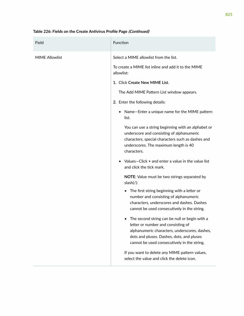
Table 226: Fields on the Create Antivirus Profile Page (Continued)
Field Function
MIME Allowlist Select a MIME allowlist from the list.
To create a MIME list inline and add it to the MIMEallowlist:
1. Click Create New MIME List.
The Add MIME Pattern List window appears.
2. Enter the following details:
• Name—Enter a unique name for the MIME patternlist.
You can use a string beginning with an alphabet orunderscore and consisting of alphanumericcharacters, special characters such as dashes andunderscores. The maximum length is 40characters.
• Values—Click + and enter a value in the value listand click the tick mark.
NOTE: Value must be two strings separated byslash(/):
• The first string beginning with a letter ornumber and consisting of alphanumericcharacters, underscores and dashes. Dashescannot be used consecutively in the string.
• The second string can be null or begin with aletter or number and consisting ofalphanumeric characters, underscores, dashes,dots and pluses. Dashes, dots, and plusescannot be used consecutively in the string.
If you want to delete any MIME pattern values,select the value and click the delete icon.
825

Table 226: Fields on the Create Antivirus Profile Page (Continued)
Field Function
3. Click OK.
A new MIME list is created and added to the MIMEallowlist.
Exception MIME Allowlist Select an exception MIME allowlist from the list.
Click Create New MIME list to create and add a MIMEpattern list inline.
Fallback Options
Fallback options are used when the antivirus system experiences errors and must fall back to one ofthe previously configured actions to either deny (block) or permit the object.
Content Size Select Block or Log and Permit.
If the content size exceeds a set limit, the content iseither passed or blocked. The default action is Block.
Engine Error Select Block or Log and Permit to specify whether thescan engine should be blocked (default) or logged andpermitted if it is not ready during certain processes. Forexample, while the signature database is loading.
Trickling Timeout Select Block or Log and Permit to specify whether thetime taken to scan should be blocked (default) or loggedand permitted if the scan process exceeds the timeoutsetting in the antivirus profile.
Out of Resources Select Block or Log and Permit to specify whether theresource constraints should be blocked (default) orlogged and permitted if the error is received during virusscanning.
826

Table 226: Fields on the Create Antivirus Profile Page (Continued)
Field Function
Decompress Layer Select Block or Log and Permit to specify whether thenumber of layers of nested compressed files that theinternal antivirus scanner can decompress before theexecution of the virus scan. The default action is Block.
Too many Requests Select an option to specify whether the number ofmessages should be blocked (default) or logged andpermitted if the messages received concurrently exceedsthe device limits.
Default Action Select a default action to take when an error occurs;Block or Log and Permit.
Notification Options
Use the notification options to configure a method of notifying the user when a fallback occurs or avirus is detected.
Fallback Deny
Notify Mail Sender Select this option to configure e-mail notifications tonotify the administrator about the errors returned byeither the scan engine or the scan manager when afallback action occurs.
Notification Type Select None, Protocol, or Message from the list to specifythe type of notification sent when a fallback option ofdeny is triggered.
Custom Message Subject Enter the subject line text for your custom message forthe fallback deny notification.
The maximum character length is 255.
827

Table 226: Fields on the Create Antivirus Profile Page (Continued)
Field Function
Custom Message Enter the customized message text for the fallback denynotification.
The maximum character length is 512.
Fallback Non-Deny
Notify Mail Recipient Select this option to configure E-mail notifications tonotify the recipient when a fallback e-mail optionwithout a deny action is triggered.
Custom Message Subject Enter the subject line for your custom message for thefallback non-deny notification.
The maximum character length is 255.
Custom Message Enter the customized message text for the fallback non-deny notification.
The maximum character length is 512.
Virus Detection
Notify Mail Sender Select this option to configure E-mail notifications tonotify the administrator when a virus is detected.
Notification Type Specifies the type of notification to be sent when a virusis detected.
Select None, Protocol, or Message from the list to specifythe type of notification sent when a virus is detected.
828

Table 226: Fields on the Create Antivirus Profile Page (Continued)
Field Function
Custom Message Subject Enter the subject line text for your custom message forthe virus detection notification.
The maximum character length is 255.
Custom Message Enter the customized message text for the virusdetection notification.
The maximum character length is 512.
RELATED DOCUMENTATION
About the Antivirus Profiles Page | 821
Edit an Antivirus Profile | 830
Delete Antivirus Profile | 830
Clone an Antivirus Profile
You are here: Security Services > UTM > Antivirus Profiles.
To clone an antivirus profile:
1. Select an antivirus profile that you want to clone and select Clone from the More link.
NOTE: Alternatively, you can right-click on the selected antivirus profile and select Clone.
The Clone Antivirus Profiles page appears with editable fields. For more information on the options,see "Add an Antivirus Profile" on page 823.
2. Click OK to save the changes.
A cloned antivirus profile is created for the selected antivirus profile. By default, the name of thecloned antivirus profile is in the format: <Antivirus profile name>_clone.
829

RELATED DOCUMENTATION
About the Antivirus Profiles Page | 821
Edit an Antivirus Profile | 830
Delete Antivirus Profile | 830
Edit an Antivirus Profile
You are here: Security Services > UTM > Antivirus Profiles.
To edit an antivirus profile:
1. Select an existing antivirus profile that you want to edit on the Antivirus Profiles page.
2. Click the pencil icon available on the upper right side of the page.
The Edit Antivirus Profiles page appears with editable fields. For more information on the options,see "Add an Antivirus Profile" on page 823.
NOTE: Alternatively, you can right-click on the selected antivirus profile and select EditAntivirus Profiles.
3. Click OK to save the changes.
RELATED DOCUMENTATION
About the Antivirus Profiles Page | 821
Edit an Antivirus Profile | 830
Delete Antivirus Profile | 830
Delete Antivirus Profile
You are here: Security Services > UTM > Antivirus Profiles.
To delete an antivirus profile:
1. Select an antivirus profile that you want to delete on the Antivirus Profiles page.
2. Click the delete icon available on the upper right side of the page.
830

NOTE: Alternatively, you can right-click on the selected antivirus profile and select DeleteAntivirus Profiles.
3. Click Yes to delete or click No to retain the profile.
RELATED DOCUMENTATION
About the Antivirus Profiles Page | 821
Add an Antivirus Profile | 823
Edit an Antivirus Profile | 830
831

CHAPTER 73
UTM Web Filtering Profiles
IN THIS CHAPTER
About the Web Filtering Profiles Page | 832
Add a Web Filtering Profile | 834
Clone a Web Filtering Profile | 840
Edit a Web Filtering Profile | 841
Delete Web Filtering Profile | 842
About the Web Filtering Profiles Page
IN THIS SECTION
Tasks You Can Perform | 832
Field Descriptions | 834
You are here: Security Services > UTM > Web Filtering Profiles.
Use this page to manage Internet usage by preventing access to inappropriate Web content.
A Web filtering profile defines a set of permissions and actions to take based on Web connectionspredefined by website categories. In addition, you can create custom URL categories and URL patternlists during this process.
For an example use case, see Allow or Block Websites by Using J-Web Integrated UTM Web Filtering.
Tasks You Can Perform
You can perform the following tasks from this page:
832

• Add a Web filtering profile. See "Add a Web Filtering Profile" on page 834.
• Edit a Web filtering profile. See "Edit a Web Filtering Profile" on page 841.
• Clone a Web filtering profile. See "Clone a Web Filtering Profile" on page 840.
• Delete a Web filtering profile. See "Delete Web Filtering Profile" on page 842.
• Filter the Web filtering profiles based on select criteria. To do this, select the filter icon at the topright-hand corner of the Web filtering profiles table. The columns in the grid change to accept filteroptions. Type the filter options; the table displays only the data that fits the filtering criteria.
• Show or hide columns in the Web filtering profiles table. To do this, click the Show Hide Columnsicon in the top right corner of the Web filtering profiles table and select the columns you want toview or deselect the columns you want to hide on the page.
• View the details of a Web filtering profile—To do this, select the Web filtering profile for which youwant to view the details and follow the available options:
• Click More and select Detailed View.
• Right-click on the selected Web filtering profile and select Detailed View.
• Mouse over to the left of the selected Web filtering profile and click Detailed View.
• Advanced search for Web filtering profiles. To do this, use the search text box present above thetable grid. The search includes the logical operators as part of the filter string. An example filtercondition is displayed in the search text box when you hover over the Search icon. When you startentering the search string, the icon indicates whether the filter string is valid or not.
For an advanced search:
1. Enter the search string in the text box.
Based on your input, a list of items from the filter context menu appears.
2. Select a value from the list and then select a valid operator based on which you want to performthe advanced search operation.
NOTE: Press Spacebar to add an AND operator or OR operator to the search string. Pressbackspace to delete a character of the search string.
3. Press Enter to display the search results in the grid.
833

Field Descriptions
Table 227 on page 834 describes the fields on the Web filtering page.
Table 227: Fields on the Web Filtering Page
Field Action
Name Displays the name for the Web filtering profile.
Profile type Displays the type of profile based on the filtering type selected.
Default action Displays the default action to be taken for the web filtering profile.
Timeout Displays the time interval to wait before the connection to the server is closed.
RELATED DOCUMENTATION
Add a Web Filtering Profile | 834
Edit a Web Filtering Profile | 841
Delete Web Filtering Profile | 842
Add a Web Filtering Profile
You are here: Security Services > UTM > Web Filtering Profiles.
To create a new web filtering profile:
1. Click the add icon (+) available on the upper right side of the Web Filtering Profiles page.
The Create Web Filtering Profiles page appears.
2. Complete the configuration according to the guidelines provided in Table 228 on page 835 throughTable 230 on page 839.
3. Click Finish to save the changes or click Back to go to the previous tab. If you want to discard yourchanges, click Cancel.
If you click Finish, a new web filtering profile is created.
834

Table 228: Fields on the General tab
Field Action
Name Enter a name for the Web filtering profile.
The maximum length is 29 characters.
Timeout Enter a timeout value to wait for a response from the Websense server.
The maximum value is 1800 seconds. Default value is 15 seconds.
Engine type Select an engine type for Web filtering:
The available options are
• Juniper Enhanced—Specifies that the Juniper Enhanced Web filtering interceptsthe HTTP and the HTTPS requests and sends the HTTP URL or the HTTPSsource IP to the Websense ThreatSeeker Cloud (TSC).
• Websense Redirect—Specifies that the Web filtering module intercepts an HTTPrequest. The URL in the request is then sent to the external Websense serverwhich makes a permit or a deny decision.
• Local—Specifies that the Web filtering module intercepts URLs and makes apermit or deny decision locally.
NOTE: The default value is Juniper Enhanced.
Safe search Enable a safe search solution to ensure that the embedded objects such as imageson the URLs received from the search engines are safe and that no undesirablecontent is returned to the client.
NOTE: This option is available only for the Juniper Enhanced engine type. Bydefault, this option is enabled.
Account Enter the user account associated with the Websense Web filtering profile.
NOTE: This option is available only for the Websense Redirect engine type.
835

Table 228: Fields on the General tab (Continued)
Field Action
Server Enter the hostname or IP address for the Websense server.
NOTE: This option is available only for the Websense Redirect engine type.
Port Enter the port number for communicating with the Websense server.
The default port is 15868.
NOTE: This option is available only for the Websense Redirect engine type.
Sockets Enter the number of sockets used for communication between the client and theserver.
The default value is 8.
NOTE: This option is available only for the Websense Redirect engine type.
Custom BlockMessage/URL
Specify the redirect URL or a custom message to be sent when HTTP requests areblocked.
Maximum length is 512 characters.
CustomQuarantineMessage
Define a custom message to allow or deny access to a blocked site based on a userresponse to the message.
Maximum length is 512 characters.
NOTE: This option is available only for the Juniper Enhanced and the Local enginetypes.
Base Filter Select a predefined base filter, which has default actions for all categories, for Webfiltering.
Click Clear All to discard the changes.
NOTE: This option is available only for the Juniper Enhanced engine type.
836

Table 229: Fields on the URL Categories Tab
Field Action
Applyactions
To apply actions that the device must take for the selected category:
1. Click Apply Actions.
The Apply Actions page appears.
2. Enter the following details:
• Action—Select an action for the URL category from the list. The options arePermit, Log and Permit, Block or Quarantine.
• Custom Message—Select a custom message for the URL category.
NOTE:
• This option is applicable only when the action is Block or Quarantine.
• Click Clear all to clear the custom message.
To add a custom message list inline:
a. Click Create New.
b. Enter the following details:
• Name—Enter a unique name for the custom message list.
Special characters such as hyphen, underscore, !, @, $, *, + are allowed.The maximum length is 29 characters.
• Type—Select an option from the list. The options are Redirect URL orUser Message.
• Content—Enter a content for the custom message list. The maximumlength is 512 characters.
c. Click OK to add a new custom message list. Else, click Cancel.
3. Click OK to apply actions for the category. Else, click Cancel.
837

Table 229: Fields on the URL Categories Tab (Continued)
Field Action
Create To add a new URL category:
1. Click +.
The Select URL Categories page appears.
2. Select one or more predefined and custom URL categories to apply to the list.
The Name column displays the list of URL categories to choose from.
Click the search icon in the top right corner of the table to search for any particularURL category in the list.
3. Enter the following details:
• Action—Select an action for the URL category from the list. The optionsavailable are Permit, Log and Permit, Block, and Quarantine.
NOTE: The default action is Log and Permit.
• Custom Message—Select a custom message for the URL category.
NOTE:
• This option is applicable only when the action is Block or Quarantine.
• Click Clear all to clear the custom message.
• Click Create New to add a custom message list inline.
4. Click OK to save the changes. If you want to discard your changes, click Cancel.
Delete Select a URL category that you want to delete and click the delete icon in the topright corner of the table
Search Click the search icon in the top right corner of the table and the URL category youwant to search.
Categoryname
Displays the URL category names.
Select one or more categories from the list.
838
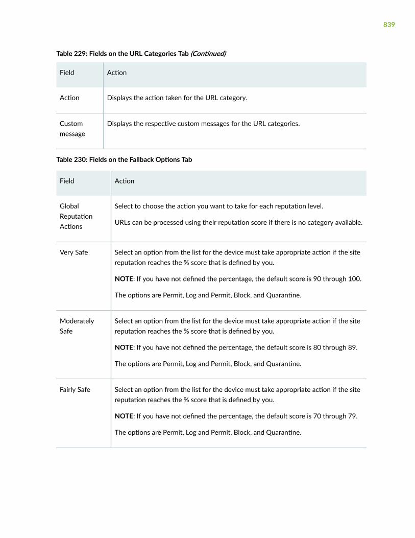
Table 229: Fields on the URL Categories Tab (Continued)
Field Action
Action Displays the action taken for the URL category.
Custommessage
Displays the respective custom messages for the URL categories.
Table 230: Fields on the Fallback Options Tab
Field Action
GlobalReputationActions
Select to choose the action you want to take for each reputation level.
URLs can be processed using their reputation score if there is no category available.
Very Safe Select an option from the list for the device must take appropriate action if the sitereputation reaches the % score that is defined by you.
NOTE: If you have not defined the percentage, the default score is 90 through 100.
The options are Permit, Log and Permit, Block, and Quarantine.
ModeratelySafe
Select an option from the list for the device must take appropriate action if the sitereputation reaches the % score that is defined by you.
NOTE: If you have not defined the percentage, the default score is 80 through 89.
The options are Permit, Log and Permit, Block, and Quarantine.
Fairly Safe Select an option from the list for the device must take appropriate action if the sitereputation reaches the % score that is defined by you.
NOTE: If you have not defined the percentage, the default score is 70 through 79.
The options are Permit, Log and Permit, Block, and Quarantine.
839

Table 230: Fields on the Fallback Options Tab (Continued)
Field Action
Suspicious Select an option from the list for the device must take appropriate action if the sitereputation reaches the % score that is defined by you.
NOTE: If you have not defined the percentage, the default score is 60 through 69.
The options are Permit, Log and Permit, Block, and Quarantine.
Harmful Select an option from the list for the device must take appropriate action if the sitereputation reaches the % score that is defined by you.
NOTE: If you have not defined the percentage, the default score is 50 through 59.
The options are Permit, Log and Permit, Block, and Quarantine.
Default Action Select an option from the list for the actions to be taken for URL categories with noassigned action and for uncategorized URLs.
The options are Permit, Log and Permit, Block, and Quarantine.
Fallback Action Select an option from the list. The options are Log and Permit and Block.
Use this option when the ThreatSeeker Websense Cloud servers are unreachable. Atimeout occurs for requests to ThreatSeeker Cloud.
RELATED DOCUMENTATION
About the Web Filtering Profiles Page | 832
Clone a Web Filtering Profile | 840
Edit a Web Filtering Profile | 841
Delete Web Filtering Profile | 842
Clone a Web Filtering Profile
You are here: Security Services > UTM > Web Filtering Profiles.
840

To clone a Web filtering profile:
1. Select a Web filtering profile that you want to clone and select Clone from the More link.
NOTE: Alternatively, you can right-click on the selected Web filtering profile and select Clone.
The Clone Web Filtering Profiles page appears with editable fields. For more information on theoptions, see "Add a Web Filtering Profile" on page 834.
2. Click OK to save the changes.
A cloned Web filtering profile is created for the selected Web filtering profile. By default, the name ofthe cloned Web filtering profile is in the format: <Web filtering profile name>_clone.
RELATED DOCUMENTATION
About the Web Filtering Profiles Page | 832
Add a Web Filtering Profile | 834
Edit a Web Filtering Profile | 841
Delete Web Filtering Profile | 842
Edit a Web Filtering Profile
You are here: Security Services > UTM > Web Filtering Profiles.
To edit a Web filtering profile:
1. Select a Web filtering profile that you want to edit on the Web Filtering page.
2. Click the pencil icon available on the upper right side of the page.
The Edit Web Filtering Profiles page appears with editable fields. For more information on theoptions, see "Add a Web Filtering Profile" on page 834.
3. Click OK to save the changes or click Cancel to discard the changes.
RELATED DOCUMENTATION
About the Web Filtering Profiles Page | 832
Add a Web Filtering Profile | 834
Clone a Web Filtering Profile | 840
841

Delete Web Filtering Profile | 842
Delete Web Filtering Profile
You are here: Security Services > UTM > Web Filtering Profiles.
To delete Web filtering profiles:
1. Select one or more Web filtering profiles that you want to delete from the Web Filtering page.
2. Click the delete icon available on the upper right side of the page.
A confirmation window appears.
3. Click Yes to delete or click No to retain the profile.
RELATED DOCUMENTATION
About the Web Filtering Profiles Page | 832
Add a Web Filtering Profile | 834
Clone a Web Filtering Profile | 840
Edit a Web Filtering Profile | 841
842
CHAPTER 74
UTM Web Filtering Category Update
IN THIS CHAPTER
About the Category Update Page | 843
Category Update Settings | 845
Download and Install Settings | 848
About the Category Update Page
IN THIS SECTION
Tasks You Can Perform | 844
Field Descriptions | 844
You are here: Security Services > UTM > Web Filtering Category Update.
Use the Category Update page to download and install a new Juniper Enhanced Web Filtering (EWF)category. You can also use the predefined base filter and all categories in the base filter have defaultactions.
A base filter is an object that contains a category action pair for all categories defined in the categoryfile. predefined base filters, defined in a category file, are supported for individual EWF categories. EachEWF category has a default action in a base filter, which is attached to the user profile to act as a backupfilter. If the categories are not configured in the user profile, then the base filter takes the action.
NOTE: If you have not installed the UTM license or if the license has expired, J-Web promptsyou to install license to proceed with configuring the Category Update page. J-Web also providesthe License Management page link for you to install the license on your device.
843

Tasks You Can Perform
You can perform the following tasks from this page:
• Configure URL settings and automatically download and install the category packages. See "CategoryUpdate Settings" on page 845.
• Download a category package manually and install it on SRX Series devices with an EWF license. See"Download and Install Settings" on page 848.
• Install a category file. To do this, click Install on the Category Update page to install the alreadydownloaded category.
• Uninstall categories. To do this, select an existing category and click Uninstall on the CategoryUpdate page.
NOTE: The Uninstall option appears only when there is an installed version of the categorypackage.
• Search a category name. To do this, enter the category name that you want to find and click thesearch icon in the top right corner of the Category Update page or above the base filters table.
• Show or hide columns in the base filters table. To do this, click the Show Hide Columns icon in thetop right corner of the base filters table and select the options you want to view or deselect theoptions you want to hide on the page.
Field Descriptions
Table 231 on page 844 describes the fields on the Category Update page.
Table 231: Fields on the Category Update Page
Field Description
Base Filters Select a predefined base filter for your category.
Installed Versions Displays the number of category package installed version.
Check Latest Opens a new browser page and displays the latest list of EWF category files.
844

Table 231: Fields on the Category Update Page (Continued)
Field Description
Download Completed Displays the number of downloads completed status.
Name Displays the category name of the base filter.
Action Displays the action for each of the categories in the base filter.
RELATED DOCUMENTATION
Category Update Settings | 845
Download and Install Settings | 848
Category Update Settings
You are here: Security Services > UTM > Web Filtering Category Update.
Use this page to configure the URL to download, routing instances, proxy profiles, and auto-downloadsettings.
To configure the category update settings:
1. Click Settings.
The Settings page appears.
2. Complete the configuration according to the guidelines provided in Table 232 on page 845.
3. Click OK to save the changes. If you want to discard your changes, click Cancel.
Table 232: Fields on the Settings Page
Field Action
DownloadURL
Enter the URL from where you want to download a category file.
845

Table 232: Fields on the Settings Page (Continued)
Field Action
RoutingInstance
Select an option from the list of configured routing instances or you can create anew routing instance inline.
To create a new routing instance inline:
1. Click Create.
The Create Routing Instance page appears.
2. Enter the following details:
General Settings:
• Name—Enter a unique name for the routing instance that contains acorresponding IP unicast table; no special characters are allowed and thekeyword default cannot be used.
• Description—Enter a description for the routing instance. We recommend thatyou enter a maximum of 255 characters.
• Instance Type—Select the type of routing instance from the list:
• Virtual Router—Used for non-VPN related applications.
• VPLS—Lists the interfaces with Encapsulation Ethernet-VPLS.
NOTE: This instance is applicable only for root or super admin. This optionwill not be applicable for Logical system admin.
Interfaces—Select interfaces from the Available column and move it to theSelected column.
• Name—Displays the interface name.
• Zone—Displays the zone name corresponding to the interface name.
3. Click OK.
846

Table 232: Fields on the Settings Page (Continued)
Field Action
Proxy Profile Select an option from the list of configured proxy profiles or you can create a newproxy profile inline.
To create a new proxy profile inline:
1. Click Create.
The Create Proxy Profile page appears.
2. Enter the following details:
• Profile Name—Enter a unique proxy profile name.
• Connection Type:
• Server IP—Enter the IP address of the server.
• Host Name—Enter the host name.
• Port Number—Select the port number by using top or down arrows.
Range: 0 through 65535
3. Click OK.
AutoDownload
Enable this option to automatically detect a newer version of the UTM category file.If a newer version of UTM category is available, J-Web automatically downloads thefile and installs it on your device.
Start Time Specify a date and time (in MM/DD/YYYY and HH:MM:SS formats) to initiateautomatic download and installation process for the category file.
Interval (Hrs) Enter a time interval to download and check install category file.
Range is 1 through 336.
847

RELATED DOCUMENTATION
About the Category Update Page | 843
Download and Install Settings | 848
Download and Install Settings
You are here: Security Services > UTM > Web Filtering Category Update.
Use this page to download or download and install URL category packages on your device.
To download and install URL category packages:
1. Click Download.
The Download and Install Settings page appears.
2. Complete the configuration according to the guidelines provided in Table 233 on page 848.
3. Click OK to download the package. If you want to cancel the download, click Cancel.
If you have not selected the Download and Install option, then the package is only downloaded. Youcan install the package at a later time using Install available on the Category Update page.
If you have selected the Download and Install option, J-Web downloads the package and installs theURL categories on the SRX Series devices with an EWF license.
Table 233: Fields on the Download and Install Settings Page
Field Action
Version Select the latest version option or specify an available version number.
Download and Install Enable this option if you want to install the categories after downloadingthem.
RELATED DOCUMENTATION
About the Category Update Page | 843
Category Update Settings | 845
848

CHAPTER 75
UTM Antispam Profiles
IN THIS CHAPTER
About the Antispam Profiles Page | 849
Add an Antispam Profile | 851
Clone an Antispam Profile | 853
Edit an Antispam Profile | 853
Delete Antispam Profile | 854
About the Antispam Profiles Page
IN THIS SECTION
Tasks You Can Perform | 849
Field Descriptions | 850
You are here: Security Services > UTM > Antispam Profiles.
Use the Antispam Profiles page to view and manage antispam profiles. An antispam profile is used toexamine transmitted e-mail messages to identify e-mail spam by using a constantly updated spam blocklist.
Tasks You Can Perform
You can perform the following tasks from this page:
• Create an antispam profile. See "Add an Antispam Profile" on page 851.
• Edit an antispam profile. See "Edit an Antispam Profile" on page 853.
849

• Delete an antispam profile. See "Delete Antispam Profile" on page 854.
• Clone an antispam profile. See "Clone an Antispam Profile" on page 853
• View the details of an antispam profile—To do this, select the antispam profile for which you want toview the details and follow the available options:
• Click More and select Detailed View.
• Right-click on the selected antispam profile and select Detailed View.
• Mouse over to the left of the selected antispam profile and click Detailed View.
• Advanced search for antispam profiles. To do this, use the search text box present above the tablegrid. The search includes the logical operators as part of the filter string. In the search text box, whenyou hover over the icon, it displays an example filter condition. When you start entering the searchstring, the icon indicates whether the filter string is valid or not.
For an advanced search:
1. Enter the search string in the text box.
Based on your input, a list of items from the filter context menu appears.
2. Select a value from the list and then select a valid operator based on which you want to performthe advanced search operation.
NOTE: Press Spacebar to add an AND operator or OR operator to the search string. Pressbackspace at any point of time while entering a search criteria, only one character isdeleted.
3. Press Enter to display the search results in the grid.
• Filter the antispam profiles based on select criteria. To do this, select the filter icon at the top right-hand corner of the antispam profiles table. The columns in the grid change to accept filter options.Type the filter options; the table displays only the data that fits the filtering criteria.
• Show or hide columns in the antispam profiles table. To do this, click the Show Hide Columns icon inthe top right corner of the antispam profiles table and select the options you want to view ordeselect the options you want to hide on the page.
Field Descriptions
Table 234 on page 851 describes the fields on the Antispam Profiles page.
850

Table 234: Fields on the Antispam Profiles Page
Field Description
Name Name of the antispam profile.
Sophos Blocklist Indicates whether Sophos Blocklist is enabled (server-based filtering) or disabled(local filtering).
Action Action to be taken when spam is detected.
Custom Tag Custom-defined tag that identifies an e-mail message as spam.
RELATED DOCUMENTATION
Add an Antispam Profile | 851
Clone an Antispam Profile | 853
Edit an Antispam Profile | 853
Delete Antispam Profile | 854
Add an Antispam Profile
You are here: Security Services > UTM > Antispam Profiles.
To add an antispam profile:
1. Click the add icon (+) on the upper right side of the Antispam Profiles page.
The Create Antispam Profiles page appears.
2. Complete the configuration according to the guidelines provided in Table 235 on page 852.
3. Click OK to save the changes. If you want to discard your changes, click Cancel.
851

Table 235: Fields on the Create Antispam Profiles Page
Field Action
General Information
Name Enter a unique name for your antispam profile.
Sophos Blocklist Enable this option to use server-based spam filtering. By default, this option isenabled.
NOTE: If you disable this option, then local spam filtering is used.
Action
Default Action Select an option to be taken when a spam message is detected. The optionsavailable are:
• Tag E-Mail Subject Line—Adds a custom string at the beginning of the subject ofthe e-mail.
• Tag SMTP Header—Adds a custom string to the e-mail header.
• Block E-Mail—Blocks the spam e-mail.
• None—No action taken.
Custom Tag Enter a custom string for identifying a message as spam. By default, the deviceuses ***SPAM***.
RELATED DOCUMENTATION
About the Antispam Profiles Page | 849
Clone an Antispam Profile | 853
Edit an Antispam Profile | 853
Delete Antispam Profile | 854
852
Clone an Antispam Profile
You are here: Security Services > UTM > Antispam Profiles.
To clone an antispam profile:
1. Select an antispam profile that you want to clone and select Clone from the More link.
NOTE: Alternatively, you can right-click on the selected antispam profile and select Clone.
The Clone Antispam Profiles page appears with editable fields. For more information on the fields,see "Add an Antispam Profile" on page 851.
2. Click OK to save the changes.
A cloned antispam profile is created for the selected antispam profile. By default, the name of thecloned antispam profile is in the format: <Antispam profile name>_clone.
RELATED DOCUMENTATION
About the Antispam Profiles Page | 849
Add an Antispam Profile | 851
Edit an Antispam Profile | 853
Delete Antispam Profile | 854
Edit an Antispam Profile
You are here: Security Services > UTM > Antispam Profiles.
To edit an antispam profile:
1. Select an existing antispam profile that you want to edit on the Antispam Profiles page.
2. Click the pencil icon available on the upper right side of the page.
The Edit Antispam Profiles page appears. You can modify any previous changes done to SophosBlocklist, Default Action, and Custom Tag for the selected antispam profile. For more information onthe options, see "Add an Antispam Profile" on page 851.
3. Click OK to save the changes.
853

RELATED DOCUMENTATION
About the Antispam Profiles Page | 849
Add an Antispam Profile | 851
Clone an Antispam Profile | 853
Delete Antispam Profile | 854
Delete Antispam Profile
You are here: Security Services > UTM > Antispam Profiles.
To delete antispam profiles:
1. Select one or more antispam profiles that you want to delete on the Antispam Profiles page.
2. Click the delete icon available on the upper right side of the page.
3. Click Yes to delete or click No to retain the profile.
RELATED DOCUMENTATION
About the Antispam Profiles Page | 849
Add an Antispam Profile | 851
Clone an Antispam Profile | 853
Edit an Antispam Profile | 853
854

CHAPTER 76
UTM Content Filtering Profiles
IN THIS CHAPTER
About the Content Filtering Profiles Page | 855
Add a Content Filtering Profile | 857
Clone a Content Filtering Profile | 862
Edit a Content Filtering Profile | 862
Delete Content Filtering Profile | 863
About the Content Filtering Profiles Page
IN THIS SECTION
Tasks You Can Perform | 855
Field Descriptions | 856
You are here: Security Services > UTM > Content Filtering Profiles.
Use this page to configure content filtering.
Tasks You Can Perform
You can perform the following tasks from this page:
• Add a content filtering profile. See "Add a Content Filtering Profile" on page 857.
• Clone a content filtering profile. See "Clone a Content Filtering Profile" on page 862
• Edit a content filtering profile. See "Edit a Content Filtering Profile" on page 862.
855

• Delete a content filtering profile. See "Delete Content Filtering Profile" on page 863.
• View the details of a content filtering profile—To do this, select the content filtering profile for whichyou want to view the details and follow the available options:
• Click More and select Detailed View.
• Right-click on the selected content filtering profile and select Detailed View.
• Mouse over to the left of the selected content filtering profile and click Detailed View.
• Advanced search for content filtering profiles. To do this, use the search text box present above thetable grid. The search includes the logical operators as part of the filter string. In the search text box,when you hover over the icon, it displays an example filter condition. When you start entering thesearch string, the icon indicates whether the filter string is valid or not.
For an advanced search:
1. Enter the search string in the text box.
Based on your input, a list of items from the filter context menu appears.
2. Select a value from the list and then select a valid operator based on which you want to performthe advanced search operation.
NOTE: Press Spacebar to add an AND operator or OR operator to the search string. Pressbackspace at any point of time while entering a search criteria, only one character isdeleted.
3. Press Enter to display the search results in the grid.
• Filter the content filtering profiles based on select criteria. To do this, select the filter icon at the topright-hand corner of the content filtering profiles table. The columns in the grid change to acceptfilter options. Type the filter options; the table displays only the data that fits the filtering criteria.
• Show or hide columns in the content filtering profiles table. To do this, click the Show Hide Columnsicon in the top right corner of the content filtering profiles table and select the options you want toview or deselect the options you want to hide on the page.
Field Descriptions
Table 236 on page 857 describes the fields on the Content Filtering Profiles page.
856

Table 236: Fields on the Content Filtering Profiles Page
Field Description
Name Displays the unique name of the content filtering profile.
Permit Command List Displays the permitted protocol command name.
Block Command List Displays the blocked protocol command.
Notification Type Displays the notification type opted.
RELATED DOCUMENTATION
Add a Content Filtering Profile | 857
Edit a Content Filtering Profile | 862
Delete Content Filtering Profile | 863
Add a Content Filtering Profile
You are here: Security Services > UTM > Content Filtering Profiles.
To add a content filtering profile:
1. Click the add icon (+) on the upper right side of the Content Filtering Profiles page.
The Create Content Filtering page appears.
2. Complete the configuration according to the guidelines provided in Table 237 on page 858.
3. Click Finish.
The Summary page is displayed with the configurations you have made.
4. Review the settings, and if you need to make any modifications, click the Edit link or the Back button.
5. Click OK to save the changes. If you want to discard your changes, click Cancel.
A new content filter profile is created.
857

Table 237: Fields on the Create Content Filtering Profiles Page
Field Action
General - General Information
Name Enter a unique name for the content filtering profile.
Notification Options
Notification MailSender
Select the Notify Mail Sender check box to send an e-mail when a virus isdetected and a content block is triggered.
Notification Type Select the None, Protocol Only, or Message options from the list to specify thetype of notification sent when a content block is triggered.
CustomNotificationMessage
Specifies the customized message text for the content-block notification.
Enter the text for this custom notification message (if you are using one).
Protocol Commands
858
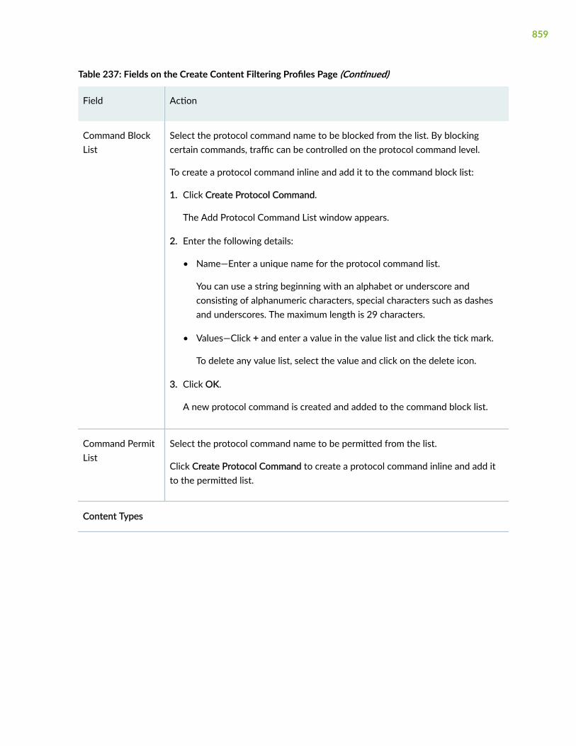
Table 237: Fields on the Create Content Filtering Profiles Page (Continued)
Field Action
Command BlockList
Select the protocol command name to be blocked from the list. By blockingcertain commands, traffic can be controlled on the protocol command level.
To create a protocol command inline and add it to the command block list:
1. Click Create Protocol Command.
The Add Protocol Command List window appears.
2. Enter the following details:
• Name—Enter a unique name for the protocol command list.
You can use a string beginning with an alphabet or underscore andconsisting of alphanumeric characters, special characters such as dashesand underscores. The maximum length is 29 characters.
• Values—Click + and enter a value in the value list and click the tick mark.
To delete any value list, select the value and click on the delete icon.
3. Click OK.
A new protocol command is created and added to the command block list.
Command PermitList
Select the protocol command name to be permitted from the list.
Click Create Protocol Command to create a protocol command inline and add itto the permitted list.
Content Types
859

Table 237: Fields on the Create Content Filtering Profiles Page (Continued)
Field Action
Block ContentType
Select the content type you want to block.
The available options are:
• ActiveX
• Windows executables (.exe)
• HTTP Cookie
• Java Applet
• ZIP files
File Extensions
Extension BlockList
Select an extension from the list that you want to block.
To create a file extension inline and add it to the extension block list:
1. Click Create File Extensions.
The Add File Extension List window appears.
2. Enter the following details:
• Name—Enter a unique name for the file extension list.
You can use a string beginning with an alphabet or underscore andconsisting of alphanumeric characters, special characters such as dashesand underscores. The maximum length is 29 characters.
• Values—Select one or more values in the Available Column and move it tothe Selected Column using the right arrow.
3. Click OK.
A new file extension is created and added to the extension block list.
MIME Types
860

Table 237: Fields on the Create Content Filtering Profiles Page (Continued)
Field Action
MIME Block List Select the MIME type from the list.
To create a MIME list inline and add it to the MIME block list:
1. Click Create MIME List.
The Add MIME Pattern List window appears.
2. Enter the following details:
• Name—Enter an unique name for the MIME pattern list.
You can use a string beginning with an alphabet or underscore andconsisting of alphanumeric characters, special characters such as dashesand underscores. The maximum length is 40 characters.
• Values—Click + and enter a value in the value list and click the tick mark.
To delete any value list, select the value and click on the delete icon.
3. Click OK.
A new MIME list is created and added to the MIME block list.
MIME Permit List Select the MIME type from the list.
Click Create MIME List to create a MIME list inline and add it to the MIMEpermit list.
RELATED DOCUMENTATION
About the Content Filtering Profiles Page | 855
Edit a Content Filtering Profile | 862
Delete Content Filtering Profile | 863
861

Clone a Content Filtering Profile
You are here: Security Services > UTM > Content Filtering Profiles.
To clone a content filtering profile:
1. Select a content filtering profile that you want to clone and select Clone from the More link.
NOTE: Alternatively, you can right-click on the selected content filtering profile and selectClone.
The Clone Content Filtering Profiles page appears with editable fields. For more information on thefields, see "Add a Content Filtering Profile" on page 857.
2. Click OK to save the changes.
A cloned content filtering profile is created for the selected content filtering profile. By default, thename of the cloned content filtering profile is in the format: <Content filtering profile name>_clone.
RELATED DOCUMENTATION
About the Content Filtering Profiles Page | 855
Edit a Content Filtering Profile | 862
Delete Content Filtering Profile | 863
Edit a Content Filtering Profile
You are here: Security Services > UTM > Content Filtering Profiles.
To edit a content filtering profile:
1. Select an existing content filtering profile that you want to edit on the Content Filtering profiles page.
2. Click the pencil icon available on the upper right side of the page.
The Edit Content Filtering Profiles page appears with editable fields. For more information on theoptions, see "Add a Content Filtering Profile" on page 857.
NOTE: Alternatively, you can right-click on the selected content filtering profile and selectEdit Profile.
862

3. Click OK to save the changes.
RELATED DOCUMENTATION
About the Content Filtering Profiles Page | 855
Add a Content Filtering Profile | 857
Delete Content Filtering Profile | 863
Delete Content Filtering Profile
You are here: Security Services > UTM > Content Filtering Profiles.
To delete a content filtering profile:
1. Select a content filtering profile that you want to delete on the Content Filtering Profiles page.
2. Click the delete icon available on the upper right side of the page.
NOTE: Alternatively, you can right-click on the selected content filtering profile and selectDelete Profile.
3. Click Yes to delete or click No to retain the profile.
RELATED DOCUMENTATION
About the Content Filtering Profiles Page | 855
Add a Content Filtering Profile | 857
Edit a Content Filtering Profile | 862
863
CHAPTER 77
UTM Custom Objects
IN THIS CHAPTER
About the Custom Objects Page | 864
Add a MIME Pattern List | 868
Add a File Extension List | 869
Add a Protocol Command List | 870
Add a URL Pattern List | 871
Add a URL Category List | 872
Add a Custom Message List | 873
Clone Custom Objects | 874
Edit Custom Objects | 875
Delete Custom Objects | 876
About the Custom Objects Page
IN THIS SECTION
Tasks You Can Perform | 865
Field Descriptions | 866
You are here: Security Services > UTM > Custom Objects.
Use the Custom Objects page to define your own objects for URL filtering, antivirus filtering, andcontent filtering.
864

Tasks You Can Perform
You can perform the following tasks from this page:
• Add a MIME pattern list. See "Add a MIME Pattern List" on page 868.
• Add a file extension list. See "Add a File Extension List" on page 869.
• Add a protocol command list. See "Add a Protocol Command List" on page 870.
• Add an URL pattern list. See "Add a URL Pattern List" on page 871.
• Add an URL category list. See "Add a URL Category List" on page 872.
• Add a custom message list. See "Add a Custom Message List" on page 873.
• Edit custom objects. See "Edit Custom Objects" on page 875.
• Delete custom objects. See "Delete Custom Objects" on page 876.
• Clone custom objects. See "Clone Custom Objects" on page 874
• View the details of custom objects—To do this, select the custom object for which you want to viewthe details and follow the available options:
• Click More and select Detailed View.
• Right-click on the selected custom object and select Detailed View.
• Mouse over to the left of the selected custom object and click Detailed View.
• Filter the custom objects based on select criteria. To do this, select the filter icon at the top right-hand corner of the custom objects table. The columns in the grid change to accept filter options.Type the filter options; the table displays only the data that fits the filtering criteria.
• Show or hide columns in the custom objects table. To do this, click the Show Hide Columns icon inthe top right corner of the custom objects table and select the options you want to view or deselectthe options you want to hide on the page.
• Advance search for custom objects. To do this, use the search text box present above the table grid.The search includes the logical operators as part of the filter string. In the search text box, when youhover over the icon, it displays an example filter condition. When you start entering the search string,the icon indicates whether the filter string is valid or not.
For an advanced search:
1. Enter the search string in the text box.
Based on your input, a list of items from the filter context menu appears.
865

2. Select a value from the list and then select a valid operator based on which you want to performthe advanced search operation.
NOTE: Press Spacebar to add an AND operator or OR operator to the search string. Pressbackspace at any point of time while entering a search criteria, only one character isdeleted.
3. Press Enter to display the search results in the grid.
Field Descriptions
Table 238 on page 866 describes the fields on the Custom Objects page.
Table 238: Fields on the Custom Objects Page
Field Description
MIME Pattern List
Name Displays the user-defined name or a predefined MIME pattern name.
Value Displays the user-defined value or a predefined MIME pattern value.
Filename Extension List
Name Displays the user-defined name or a predefined file extension name.
Value Displays the user-defined value or a predefined file extension value.
Protocol Command List
Name Displays only the user-defined protocol command names.
Value Displays only the user-defined protocol command values.
URL Pattern List
866
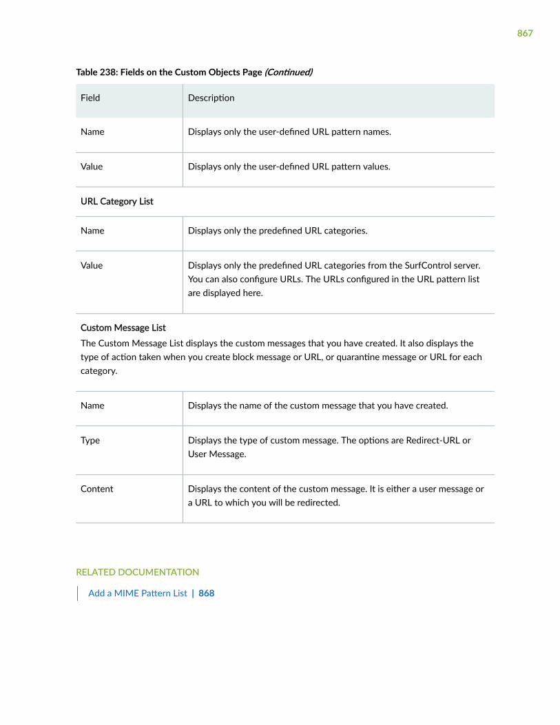
Table 238: Fields on the Custom Objects Page (Continued)
Field Description
Name Displays only the user-defined URL pattern names.
Value Displays only the user-defined URL pattern values.
URL Category List
Name Displays only the predefined URL categories.
Value Displays only the predefined URL categories from the SurfControl server.You can also configure URLs. The URLs configured in the URL pattern listare displayed here.
Custom Message List
The Custom Message List displays the custom messages that you have created. It also displays thetype of action taken when you create block message or URL, or quarantine message or URL for eachcategory.
Name Displays the name of the custom message that you have created.
Type Displays the type of custom message. The options are Redirect-URL orUser Message.
Content Displays the content of the custom message. It is either a user message ora URL to which you will be redirected.
RELATED DOCUMENTATION
Add a MIME Pattern List | 868
867

Add a MIME Pattern List
You are here: Security Services > UTM > Custom Objects.
To add a MIME pattern list:
1. Click the MIME Pattern List tab.
2. Click the add icon (+) on the upper right side of the MIME Pattern List tab.
The Add MIME Pattern List page appears.
3. Complete the configuration according to the guidelines provided in Table 239 on page 868.
4. Click OK to save the changes. If you want to discard your changes, click Cancel.
Table 239: Fields on the Add MIME Pattern List Page
Field Action
Name Enter a name for the MIME pattern list.
You can use a string beginning with a letter or underscore and consisting of alphanumericcharacters, special characters such as dashes and underscores. The maximum length is 40characters.
Value To add a MIME pattern value:
1. Click +.
2. Enter the MIME pattern value in the Value List.
NOTE: Value must be two strings separated by slash(/):
• The first string beginning with a letter or number and consisting of alphanumericcharacters, underscores and dashes. Dashes cannot be shown continuously in thestring.
• The second string can be null or begin with a letter or number and consisting ofalphanumeric characters, underscores, dashes, dots and pluses. Dashes, dots, andpluses cannot be shown continuously in the string.
3. Click the tick mark.
If you want to delete any MIME pattern values, select the value and click the delete icon.
868

RELATED DOCUMENTATION
Clone Custom Objects | 874
Edit Custom Objects | 875
Delete Custom Objects | 876
Add a File Extension List
You are here: Security Services > UTM > Custom Objects.
To add a file extension list:
1. Click the File Extension List tab.
2. Click the add icon (+) on the upper right side of the File Extension List tab.
The Add File Extension List page appears.
3. Complete the configuration according to the guidelines provided in Table 240 on page 869.
4. Click OK to save the changes. If you want to discard your changes, click Cancel.
Table 240: Fields on the Add File Extension List Page
Field Action
Name Enter a name for the file extension list.
You can use a string beginning with a letter or underscore and consisting of alphanumericcharacters, special characters such as dashes and underscores. The maximum length is 29characters.
Value Select values from the list in the Available column to associate it with the file extension nameand then click the right arrow to move it to the Selected column.
RELATED DOCUMENTATION
Clone Custom Objects | 874
Edit Custom Objects | 875
Delete Custom Objects | 876
869

Add a Protocol Command List
You are here: Security Services > UTM > Custom Objects.
To add a protocol command list:
1. Click the Protocol Command List tab.
2. Click the add icon (+) on the upper right side of the Protocol Command List tab.
The Add Protocol Command List page appears.
3. Complete the configuration according to the guidelines provided in Table 241 on page 870.
4. Click OK to save the changes. If you want to discard your changes, click Cancel.
Table 241: Fields on the Add Protocol Command List Page
Field Action
Name Enter a name for the protocol command list.
You can use a string beginning with a letter or underscore and consisting of alphanumericcharacters, special characters such as dashes and underscores. The maximum length is 29characters.
Value To add a protocol command value:
1. Click +.
2. Enter the protocol command value in the Value List.
3. Click the tick mark.
If you want to delete any protocol command values, select the value and click the delete icon.
RELATED DOCUMENTATION
Clone Custom Objects | 874
Edit Custom Objects | 875
Delete Custom Objects | 876
870

Add a URL Pattern List
You are here: Security Services > UTM > Custom Objects.
To add a URL pattern list:
1. Click the URL Pattern List tab.
2. Click the add icon (+) on the upper right side of the URL Pattern List tab.
The Add URL Pattern List page appears.
3. Complete the configuration according to the guidelines provided in Table 242 on page 871.
4. Click OK to save the changes. If you want to discard your changes, click Cancel.
Table 242: Fields on the Add URL Pattern List Page
Field Action
Name Enter a name for the URL pattern list.
You can use a string beginning with a letter or underscore and consisting of alphanumericcharacters, special characters such as dashes and underscores. The maximum length is 29characters.
NOTE: Multiple URLs are supported in a pattern.
Value To add a URL pattern value:
1. Click +.
2. Enter the URL pattern value in the Value List.
3. Click the tick mark.
If you want to delete any URL pattern values, select the value and click the delete icon.
RELATED DOCUMENTATION
Clone Custom Objects | 874
Edit Custom Objects | 875
Delete Custom Objects | 876
871

Add a URL Category List
You are here: Security Services > UTM > Custom Objects.
To add a URL category list:
1. Click the URL Category List tab.
2. Click the add icon (+) on the upper right side of the URL Category List tab.
The Add URL Category List page appears.
3. Complete the configuration according to the guidelines provided in Table 243 on page 872.
4. Click OK to save the changes. If you want to discard your changes, click Cancel.
Table 243 on page 872 provides guidelines on using the fields on the Add URL Category List page.
Table 243: Fields on the Add URL Category List Page
Field Action
Name Enter a name for the URL category list.
You can use a string beginning with a letter or underscore and consisting of alphanumericcharacters, special characters such as dashes and underscores. The maximum length is 59characters.
872

Table 243: Fields on the Add URL Category List Page (Continued)
Field Action
Value Select values from the list in the Available column to associate it with the URL category listname and then click the right arrow to move it to the Selected column.
To add a new URL pattern inline:
1. Click Create New URL Pattern.
The Add URL Pattern List page appears.
2. Enter a URL pattern name.
You can use a string beginning with a letter or underscore and consisting of alphanumericcharacters, special characters such as dashes and underscores. The maximum length is 29characters.
3. Click + to add a URL pattern value.
4. Enter the URL pattern value in the Value List.
5. Click the tick mark.
6. Optional. If you want to delete any URL pattern values, select the value and click thedelete icon.
7. Click OK to save the changes.
RELATED DOCUMENTATION
Clone Custom Objects | 874
Edit Custom Objects | 875
Delete Custom Objects | 876
Add a Custom Message List
You are here: Security Services > UTM > Custom Objects.
To add a custom message list:
873

1. Click the Custom Message List tab.
2. Click the add icon (+) on the upper right side of the Custom Message List tab.
The Add Custom Message List page appears.
3. Complete the configuration according to the guidelines provided in Table 244 on page 874.
4. Click OK to save the changes. If you want to discard your changes, click Cancel.
Table 244: Fields on the Add Custom Message List Page
Field Action
Name Enter a name for the custom message list.
You can use a string beginning with a letter or underscore and consisting of alphanumericcharacters, special characters such as dashes and underscores. The maximum length is 59characters.
Type Select an option:
• Redirect URL—Specifies custom redirect URL server.
• User Message—Specifies that website access has been blocked by an organization'saccess policy.
Content Enter content of the custom message; maximum length is 1024 characters. It is either auser message or a URL to which you will be redirected.
RELATED DOCUMENTATION
Clone Custom Objects | 874
Edit Custom Objects | 875
Delete Custom Objects | 876
Clone Custom Objects
You are here: Security Services > UTM > Custom Objects.
You can clone all of the following custom objects:
874

• MIME pattern list
• File extension list
• Protocol command list
• URL pattern list
• URL category list
• Custom message list
To clone a custom object:
1. Right-click any of the custom objects and select Clone. You can also select Clone from the More link.
The clone page for the selected custom object appears with editable fields.
2. Make the required changes in the editable fields.
3. Click OK to save the changes.
A cloned custom object is created for the selected custom objects. By default, the name of thecloned custom objects is in the format: <custom objects name>_clone.
RELATED DOCUMENTATION
Add a MIME Pattern List | 868
Add a File Extension List | 869
Add a Protocol Command List | 870
Add a URL Pattern List | 871
Add a URL Category List | 872
Add a Custom Message List | 873
Edit Custom Objects
You are here: Security Services > UTM > Custom Objects.
You can edit all of the following custom objects:
• MIME pattern list
• File extension list
• Protocol command list
875

• URL pattern list
• URL category list
• Custom message list
To edit a custom objects:
1. Select any of the existing custom objects that you want to edit on the Custom Objects page.
2. Click the pencil icon available on the upper right side of the page.
The edit page for the selected custom object appears with editable fields. You can modify theparameters of the custom object as required.
3. Click OK to save the changes. If you want to discard your changes, click Cancel.
RELATED DOCUMENTATION
Add a MIME Pattern List | 868
Add a File Extension List | 869
Add a Protocol Command List | 870
Add a URL Pattern List | 871
Add a URL Category List | 872
Add a Custom Message List | 873
Delete Custom Objects
You are here: Security Services > UTM > Custom Objects.
You can delete all of the following custom objects:
• MIME pattern list
• File extension list
• Protocol command list
• URL pattern list
• URL category list
• Custom message list
To delete a custom object:
876

1. Select any of the existing custom objects that you want to delete from the Custom Objects page.
2. Click the delete icon available on the upper right side of the page.
3. Click Yes to delete or click No to retain the selected custom object.
RELATED DOCUMENTATION
About the Custom Objects Page | 864
Clone Custom Objects | 874
Edit Custom Objects | 875
877

CHAPTER 78
UTM Policies
IN THIS CHAPTER
About the UTM Policies Page | 878
Add a UTM Policy | 880
Clone a UTM Policy | 883
Edit a UTM Policy | 884
Delete UTM Policy | 884
About the UTM Policies Page
IN THIS SECTION
Tasks You Can Perform | 878
Field Descriptions | 879
You are here: Security Services > UTM > UTM Policies.
Use this page to configure UTM Policies.
Tasks You Can Perform
You can perform the following tasks from this page:
• Create a UTM policy. See "Add a UTM Policy" on page 880.
• Clone a UTM policy. See "Clone a UTM Policy" on page 883.
• Edit a UTM policy. See "Edit a UTM Policy" on page 884.
878

• Delete a UTM policy. See "Delete UTM Policy" on page 884.
• View the details of a UTM policy—To do this, select the UTM policy for which you want to view thedetails and select any of the following options:
• Click More and select Detailed View.
• Right-click on the selected UTM policy and select Detailed View.
• Mouse over to the left of the selected UTM policy and click Detailed View.
• Advanced search for UTM policy. To do this, use the search text box present above the table grid.The search includes the logical operators as part of the filter string. In the search text box, when youhover over the icon, it displays an example filter condition. When you start entering the search string,the icon indicates whether the filter string is valid or not.
For an advanced search:
1. Enter the search string in the text box.
Based on your input, a list of items from the filter context menu appears.
2. Select a value from the list and then select a valid operator based on which you want to performthe advanced search operation.
NOTE: Press Spacebar to add an AND operator or OR operator to the search string. Pressbackspace at any point of time while entering a search criteria, only one character isdeleted.
3. Press Enter to display the search results in the grid.
• Show or hide columns in the UTM policy table. To do this, click the Show Hide Columns icon in thetop right corner of the UTM policies table and select the options you want to view or deselect theoptions you want to hide on the page.
Field Descriptions
Table 245 on page 880 describes the fields on the UTM policy page.
879

Table 245: Fields on the UTM Policy Page
Field Description
Name Displays the UTM policy name.
Antivirus Displays the antivirus profile.
Web Filtering Displays the Web filtering profile.
Antispam Displays the antispam profile.
Content Filtering Displays the content filtering profiles.
RELATED DOCUMENTATION
Add a UTM Policy | 880
Add a UTM Policy
You are here: Security Services > UTM > UTM Policies.
To add a UTM policy:
1. Click the add icon (+) on the upper right side of the UTM Policy page.
The Create UTM Policies page appears.
2. Complete the configuration according to the guidelines provided in Table 246 on page 881.
3. Click Finish.
The Summary page is displayed with the configurations you have made.
4. Review the settings, and if you need to make any modifications, click the Edit link or the Back button.
5. Click OK to save the changes. If you want to discard your changes, click Cancel.
A UTM policy is created.
880

Table 246: Fields on the Create UTM Policies Page
Field Action
General—General Information
Name Enter a UTM policy name.
Antivirus—Antivirus Profiles by Traffic Protocol
Apply to all protocols Select the check box to apply the default profile to all protocols such asHTTP, FTP, IMAP, SMTP, and POP3.
If you do not select the check box, you can apply different profiles todifferent protocols.
HTTP Select an option from the list to specify the UTM policy for the HTTPprotocol to be scanned.
FTP Upload Select an option from the list to specify the UTM policy for the FTP protocolto be scanned.
FTP Download Select an option from the list to specify the UTM policy for the FTP protocolto be scanned.
IMAP Select an option from the list to specify the UTM policy for the IMAPprotocol to be scanned.
SMTP Select an option from the list to specify the UTM policy for the SMTPprotocol to be scanned.
POP3 Select an option from the list to specify the UTM policy for the POP3protocol to be scanned.
Create Another Profile Click Create Another Profile to create an antivirus profile inline. For moreinformation on the fields, see "Add an Antivirus Profile" on page 823.
881

Table 246: Fields on the Create UTM Policies Page (Continued)
Field Action
Web Filterings—Web Filtering Profiles by Traffic Protocol
HTTP Select an option from the list to specify the UTM policy for the HTTPprotocol to be scanned.
Create Another Profile Click Create Another Profile to create Web filtering profile inline. For moreinformation on the fields, see "Add a Web Filtering Profile" on page 834.
Antispam—Antispam Profiles by Traffic Protocol
SMTP profile Select an option from the list to specify the UTM policy for the SMTPprotocol to be scanned.
Create Another Profile Click Create Another Profile to create antispam profile inline. For moreinformation on the fields, see "Add an Antispam Profile" on page 851.
Content Filtering—Content Filtering Profiles by Traffic Protocol
Apply to all protocols Select the check box to apply the default profile to all protocols such asHTTP, FTP, IMAP, SMTP, and POP3.
If you do not select the check box, you can apply different profiles todifferent protocols.
HTTP Select an option from the list to specify the UTM policy for the HTTPprotocol to be scanned.
FTP Upload Select an option from the list to specify the UTM policy for the FTP protocolto be scanned.
FTP Download Select an option from the list to specify the UTM policy for the FTP protocolto be scanned.
882

Table 246: Fields on the Create UTM Policies Page (Continued)
Field Action
IMAP Select an option from the list to specify the UTM policy for the IMAPprotocol to be scanned.
SMTP Select an option from the list to specify the UTM policy for the SMTPprotocol to be scanned.
POP3 Select an option from the list to specify the UTM policy for the POP3protocol to be scanned.
Create Another Profile Click Create Another Profile to create content filtering Profile inline. Formore information on the fields, see "Add a Content Filtering Profile" on page857.
RELATED DOCUMENTATION
About the UTM Policies Page | 878
Clone a UTM Policy | 883
Edit a UTM Policy | 884
Delete UTM Policy | 884
Clone a UTM Policy
You are here: Security Services > UTM > UTM Policies.
To clone a UTM policy:
1. Select a UTM policy that you want to clone and select Clone from the More link.
NOTE: Alternatively, you can right-click on the selected UTM policy and select Clone.
883

The Clone UTM Policies page appears with editable fields. For more information on the fields, see"Add a UTM Policy" on page 880.
2. Click OK to save the changes.
A cloned UTM policy is created for the selected UTM policy. By default, the name of the cloned UTMpolicy is in the format: <UTM policy name>_clone.
RELATED DOCUMENTATION
About the UTM Policies Page | 878
Edit a UTM Policy | 884
Delete UTM Policy | 884
Edit a UTM Policy
You are here: Security Services > UTM > UTM Policies.
To edit a UTM policy:
1. Select an existing UTM policy that you want to edit on the UTM Policy page.
2. Click the pencil icon available on the upper right side of the page.
The Edit UTM Policy page appears with editable fields. For more information on the options, see"Add a UTM Policy" on page 880.
NOTE: Alternatively, you can right-click on the selected UTM policy and select Edit Policy.
3. Click OK to save the changes.
RELATED DOCUMENTATION
About the UTM Policies Page | 878
Delete UTM Policy | 884
Delete UTM Policy
You are here: Security Services > UTM > UTM Policies.
884

To delete a UTM policy:
1. Select a UTM policy that you want to delete on the UTM Policy page.
2. Click the delete icon available on the upper right side of the page.
NOTE: Alternatively, you can right-click on the selected UTM policy and select Delete Policy.
3. Click Yes to delete or click No to retain the profile.
RELATED DOCUMENTATION
About the UTM Policies Page | 878
Clone a UTM Policy | 883
Add a UTM Policy | 880
885
CHAPTER 79
IPS Signature Update
IN THIS CHAPTER
About the Signature Update Page | 886
Download an IPS Signature | 887
Install an IPS Signature | 888
Check Status of the IPS Signature | 889
IPS Signature Download Setting | 890
About the Signature Update Page
IN THIS SECTION
Tasks You Can Perform | 886
Field Descriptions | 887
You are here: Security Services > IPS > Signature Update.
You can download, install, and check status of the latest version of signature database from the securityserver.
Tasks You Can Perform
You can perform the following tasks from this page:
• Download an IPS signature. See "Download an IPS Signature" on page 887.
• Install an IPS signature. See "Install an IPS Signature" on page 888.
• Check status of the IPS signature. See "Check Status of the IPS Signature" on page 889.
886

• IPS signature download setting. See "IPS Signature Download Setting" on page 890.
Field Descriptions
Table 247 on page 887 describes the fields on the IPS signature page.
Table 247: Fields on the IPS Signature Page
Field Description
Name Displays the field values for install or download operation.
Value Displays the install or download status of the operation.
RELATED DOCUMENTATION
Download an IPS Signature | 887
Install an IPS Signature | 888
Check Status of the IPS Signature | 889
IPS Signature Download Setting | 890
Download an IPS Signature
You are here: Security Services > IPS > Signature Update.
To download an IPS signature:
1. Click Download on the upper right side of the Signature Update page.
The Security Package Manual Download page appears.
2. Complete the configuration according to the guidelines provided in Table 248 on page 888.
3. Click OK to download the package. If you want to cancel the download, click Cancel.
887

Table 248: Fields on the Security Package Manual Download Page
Field Action
URL Specifies the predefined default URL used by the device to download the signaturedatabase.
Version Select the version from the list to specify the version number of the security packagefrom the portal.
Full Package Select the check box to enable the device to download the latest security package withthe full set of attack signature tables from the portal.
NOTE:
• It takes approximately one minute to retrieve the latest available version for download fromthe security server.
• To configure URL, click Download Setting.
RELATED DOCUMENTATION
About the Signature Update Page | 886
Install an IPS Signature | 888
Check Status of the IPS Signature | 889
IPS Signature Download Setting | 890
Install an IPS Signature
You are here: Security Services > IPS > Signature Update.
To download an IPS signature:
1. Click Install on the upper right side of the IPS Signature page.
The Install Signature page appears.
888

2. Complete the configuration according to the guidelines provided in Table 249 on page 889.
3. Click Installl to install the package. If you want to cancel the install, click Cancel.
Table 249: Fields on the Install Configuration Page
Field Action
Do not set to active afterinstalled
Select the check box to specify whether or not to activate theinstalled security package.
Install Click Install to install the existing signature database.
RELATED DOCUMENTATION
About the Signature Update Page | 886
Download an IPS Signature | 887
Check Status of the IPS Signature | 889
IPS Signature Download Setting | 890
Check Status of the IPS Signature
You are here: Security Services > IPS > Signature Update.
To check status of an IPS signature:
1. Click Check Status on the upper right side of the IPS Signature page.
The Check Status page appears.
2. Complete the configuration according to the guidelines provided in Table 250 on page 890.
3. Click OK.
889

Table 250: Fields on the Check Status Page
Field Action
Download Status Shows the security package download status in the message box.
Select Download Status from the Check Status list.
Install Status Shows the security package install status in the message box.
Select Install Status from the Check Status list.
RELATED DOCUMENTATION
About the Signature Update Page | 886
Download an IPS Signature | 887
Install an IPS Signature | 888
IPS Signature Download Setting | 890
IPS Signature Download Setting
You are here: Security Services > IPS > Signature Update.
To set the parameters of automatic download an IPS signature:
1. Click Download Setting on the upper right side of the IPS Signature page.
The Security Package Download Setting page appears.
2. Complete the configuration according to the guidelines provided in Table 251 on page 890.
3. Click OK to set the parameters. If you want to cancel the settings, click Cancel.
Table 251: Fields on the Download Setting Page
Field Action
URL Setting
890

Table 251: Fields on the Download Setting Page (Continued)
Field Action
URL Enter a URL to specify the URL to be used by the device to download thesignature database.
NOTE: The default URL is https://services.netscreen.com/cgi-bin/index.cgi.
Proxy Profile Select an option from the list or create a new proxy profile inline.
To create a new proxy profile inline:
1. Click Create.
Create Proxy Profile page appears.
2. Enter the following details:
• Profile Name—Enter a unique proxy profile name.
• Connection Type:
• Server IP—Enter the IP address of the server.
• Host Name—Enter the host name.
• Port Number—Select the port number by using top/down arrows.
Range: 0 through 65535.
3. Click OK.
Auto Download Setting
Interval Enter an integer to specify the time interval for automatic download.
Start Time Specifies that the latest policy templates are to be installed from the portal.
Enter a time value in YYYY-MM-DD HH:MM:SS format.
Enable ScheduleUpdate
Select the check box to activate automatic download settings.
891

Table 251: Fields on the Download Setting Page (Continued)
Field Action
Reset Setting Click Reset Setting to reset the values.
RELATED DOCUMENTATION
About the Signature Update Page | 886
Download an IPS Signature | 887
Install an IPS Signature | 888
Check Status of the IPS Signature | 889
892

CHAPTER 80
IPS Sensor
IN THIS CHAPTER
About the Sensor Page | 893
About the Sensor Page
IN THIS SECTION
Field Descriptions | 893
You are here: Security Services > IPS > Sensor.
You can configure sensor settings to limit the number of sessions running application identification andalso to limit memory usage for application identification.
Field Descriptions
Table 252 on page 893 describes the fields on the Sensor page.
Table 252: Fields on the Sensor Page
Field Description
Basic Settings Select to configure basic IPS sensor settings.
IDP Protection Mode
893

Table 252: Fields on the Sensor Page (Continued)
Field Description
Protection Mode Select an option to specify the inspection parameters for efficientinspection of traffic in the device. The options available are:
• DataCenter—Disables all STC traffic inspection.
• Datacenter Full—Disables all STC traffic inspection.
• Perimeter—Inspects all STC (Server To Client) traffic.
• Perimeter Full—Inspects all STC traffic.
Intelligent Inspection
IDP By Pass Enable or disable the IDP Intelligent Bypass option.
IDP By Pass CPUThreshold
Enter the threshold value.
Range: 0 through 99. Default value: 85.
IDP By Pass CPUTolerance
Enter the CPU tolerance value.
Range: 1 through 99. Default value: 5.
894

Table 252: Fields on the Sensor Page (Continued)
Field Description
Intelligent Inspection Enable or disable this option.
If you enable this option, enter the following details:
• Ignore Content Decompression— Enable this option to enable payloadcontent decompression.
• Signature Severity—Select the severity level of the attack from the listthat the signature will report for IDP processing. The available optionsare minor, major, and critical.
NOTE: Click Clear All to clear all the selected severity values.
• Protocols—Select the protocols from the list that needs to be processedin Intelligent Inspection mode.
NOTE: Click Clear All to clear all the selected protocols.
• CPU Threshold (%)—Enter the value of CPU usage threshold percentagefor intelligent inspection.
Range: 0 through 99 percent.
• CPU Tolerance (%)—Enter the value of CPU usage tolerance percentagefor intelligent inspection.
Range: 1 through 99 percent.
• Memory Tolerance—Enter the value of memory tolerance percentage forintelligent inspection.
Range: 1 through 100 percent.
• Free Memory Threshold—Enter the value of free memory thresholdpercentage for intelligent inspection.
Range: 1 through 100 percent.
• Session Bytes Depth—Enter the value of session bytes scanning depth.
Range: 1 through 1000000 bytes.
895

Table 252: Fields on the Sensor Page (Continued)
Field Description
Memory LowerThreshold
Enter the memory lower threshold limit percentage.
Range: 1 through 100.
Memory UpperThreshold
Enter the memory upper threshold limit percentage.
Range: 1 through 100.
Flow
Drop On Limit Enable this option to specify the dropped connections on exceedingresource limits.
Drop On Failover Enable this option to specify the dropped traffic on HA failover sessions.
Drop If No PolicyLoaded
Enable this option to specify all the dropped traffic till IDP policy getsloaded.
Packet Log
NOTE: Starting in Junos OS Release 19.2R1, Packet Log configuration is available.
IP Address Enter the IP address of the destination host to send packet log.
Port Enter the UDP port number.
Range: 0 through 65535.
Source Address Enter the source IP address used to transport packet log to a host.
Advanced Settings
IDP Flow
896

Table 252: Fields on the Sensor Page (Continued)
Field Description
Log Errors Enable this option to specify if the flow errors have to be logged.
Select an option from the list.
Flow FIFO Max Size Enter a value to specify the maximum FIFO size.
Range: : 1 through 65535. Default value is 1.
Hash Table Size Enter a value to specify the hash table size.
Range: 1024 through 1,000,000. Default value is 1024.
Max Timers Poll Ticks Enter a value to specify the maximum amount of time at which the timerticks at a regular interval.
Range: 0 through 1000 ticks. Default value is 1000 ticks.
Reject Timeout Enter a value to specify the amount of time in milliseconds within which aresponse must be received.
Range: 1 through 65,535 seconds. Default value is 300 seconds.
Global
Enable All Qmodules Select an option from the list to specify all the qmodules of the globalrulebase IDP security policy are enabled.
Enable Packet Pool Select an option from the list to specify the packet pool is enabled to beused when the current pool is exhausted.
Policy Lookup Cache Select an option from the list to specify the cache is enabled to accelerateIDP policy lookup.
897
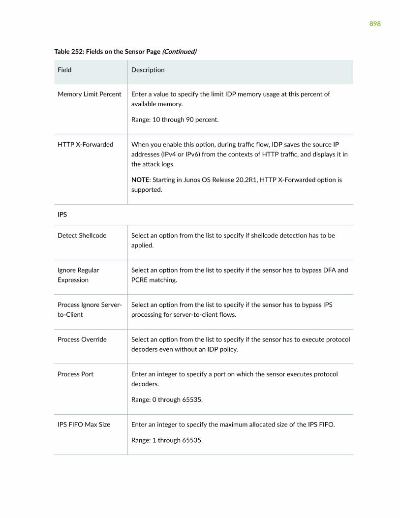
Table 252: Fields on the Sensor Page (Continued)
Field Description
Memory Limit Percent Enter a value to specify the limit IDP memory usage at this percent ofavailable memory.
Range: 10 through 90 percent.
HTTP X-Forwarded When you enable this option, during traffic flow, IDP saves the source IPaddresses (IPv4 or IPv6) from the contexts of HTTP traffic, and displays it inthe attack logs.
NOTE: Starting in Junos OS Release 20.2R1, HTTP X-Forwarded option issupported.
IPS
Detect Shellcode Select an option from the list to specify if shellcode detection has to beapplied.
Ignore RegularExpression
Select an option from the list to specify if the sensor has to bypass DFA andPCRE matching.
Process Ignore Server-to-Client
Select an option from the list to specify if the sensor has to bypass IPSprocessing for server-to-client flows.
Process Override Select an option from the list to specify if the sensor has to execute protocoldecoders even without an IDP policy.
Process Port Enter an integer to specify a port on which the sensor executes protocoldecoders.
Range: 0 through 65535.
IPS FIFO Max Size Enter an integer to specify the maximum allocated size of the IPS FIFO.
Range: 1 through 65535.
898

Table 252: Fields on the Sensor Page (Continued)
Field Description
Minimum LogSupercade
Enter an integer to specify the minimum number of logs to trigger thesignature hierarchy feature.
Range: 0 through 65535.
Log
Cache Size Enter a value to specify the size in bytes for each user’s log cache.
Disable Suppression Enable this option to specify if the log suppression has to be disabled.
Include DestinationAddress
Select an option from the list to specify if combine log records for eventswith a matching source address.
Max Logs Operate Enter a value to specify the maximum number of logs on which logsuppression can operate. Range is 255 through 65536.
Max Time Report Enter a value to specify the time (seconds) after which suppressed logs willbe reported. IDP reports suppressed logs after 5 seconds by default.
Start Log Enter a value to specify the number of log occurrences after which logsuppression begins. Log suppression begins with the first occurrence bydefault.
Range is 1 through 128.
Reassembler
Ignore MemoryOverflow
Select an option from the list to specify if the user has to allow per-flowmemory to go out of limit.
Ignore ReassemblyMemory Overflow
Select an option from the list to specify if the user has to allow per-flowreassembly memory to go out of limit.
899

Table 252: Fields on the Sensor Page (Continued)
Field Description
Ignore ReassemblyOverflow
Enable this option to specify the TCP reassembler to ignore the globalreassembly overflow to prevent the dropping of application traffic.
Max Flow Memory Enter an integer to specify the maximum per-flow memory for TCPreassembly in kilobytes.
Range: 64 through 4,294,967,295 kilobytes.
Max Packet Memory Enter an integer to specify the maximum packet memory for TCPreassembly in kilobytes.
Range: 64 through 4,294,967,295 kilobytes
Max Synacks Queued Enter an integer to specify the maximum limit for queuing Syn/Ack packetswith different SEQ numbers.
Range: 0 through 5
Packet Log
Max Sessions Enter an integer to specify the maximum number of sessions activelyconducting pre-attack packet captures on a device at one time.
Range: 1 through 100 percent
Total Memory Enter an integer to specify the maximum amount of memory to be allocatedto packet capture for the device.
Range: 1 through 100 percent
Detectors Click + and enter the following fields.
Protocol Select the name of the protocol from the list to enable or disable thedetector.
900

Table 252: Fields on the Sensor Page (Continued)
Field Description
Tunable Name Select the name of the specific tunable parameter from the list to enable ordisable the protocol detector for each of the services.
Tunable Value Enter the protocol value of the specific tunable parameter to enable ordisable the protocol detector for each of the services.
Range: 0 to 4294967295
Release History Table
Release Description
20.2R1 Starting in Junos OS Release 20.2R1, HTTP X-Forwarded option is supported.
19.2R1 Starting in Junos OS Release 19.2R1, Packet Log configuration is available.
RELATED DOCUMENTATION
About the Policy Page | 902
901

CHAPTER 81
IPS Policy
IN THIS CHAPTER
About the Policy Page | 902
IDP Policy Template | 904
Check Status of the IDP Policy | 905
Add an IDP Policy | 906
Clone an IDP Policy | 910
Edit an IDP Policy | 911
Delete IDP Policy | 911
About the Policy Page
IN THIS SECTION
Tasks You Can Perform | 902
Field Descriptions | 903
You are here: Security Services > IPS > Policy.
Use this page to configure IPS policies.
Tasks You Can Perform
You can perform the following tasks from this page:
• Download, install, load and unload a template. See "IDP Policy Template" on page 904.
• Check status of the IDP policy. See "Check Status of the IDP Policy" on page 905.
902

• Set an IPS policy as default policy. To do this, select an existing IPS policy and click Set Default.
• Create an IDP policy. See "Add an IDP Policy" on page 906.
• Edit an IDP policy. See "Edit an IDP Policy" on page 911.
• Delete an IDP policy. See "Delete IDP Policy" on page 911.
• Clone an IDP policy. See "Clone an IDP Policy" on page 910.
Field Descriptions
Table 253 on page 903 describes the fields on the IDP policy page.
Table 253: Fields on the IDP Policy Page
Field Description
Policy List
NOTE: IDP policies that are created by root users in root-logical-system are not displayed in securityprofile advanced settings if you have logged in as a logical system user.
Name Displays the IDP policy name.
Type Displays the IDP policy type.
IPS Rule Number Displays the number of rule-based IP profiles that areconfigured.
Exempt Rule Number Displays the number of rule-based exempt profiles that areconfigured.
Rulebase-IPS Displays the IPS rulebase to detect attacks based on statefulsignature and protocol anomalies.
Rulebase-Exempt Displays the exempt rulebase to skip detection of a set ofattacks in certain traffic.
903

Release History Table
Release Description
18.3R1 IDP policies that are created by root users in root-logical-system are not displayed in security profileadvanced settings if you have logged in as a logical system user.
RELATED DOCUMENTATION
IDP Policy Template | 904
Check Status of the IDP Policy | 905
Add an IDP Policy | 906
Edit an IDP Policy | 911
Delete IDP Policy | 911
Clone an IDP Policy | 910
IDP Policy Template
You are here: Security Services > IPS > Policy.
To download, install, load, and unload an IDP policy template:
1. Click Template on the upper right side of the Policy page.
The IDP policy template options appear.
2. Table 254 on page 905 describes the fields on the IDP Policy Template page.
3. Click OK to save the changes. If you want to discard your changes, click Cancel.
904

Table 254: Template Details
Field Action
Download Template Downloads a template from the server.
NOTE:
• New template will overwrite existing predefined policies. Click OK to installthe new template.
• To configure URL, navigate to Security > IPS > Signature Update and clickDownload Setting.
Install Template Installs the template to the router.
Load Template Loads the predefined policies to the policy list.
Unload Template Unloads the predefined policies from the policy list.
RELATED DOCUMENTATION
About the Policy Page | 902
Check Status of the IDP Policy | 905
Add an IDP Policy | 906
Edit an IDP Policy | 911
Delete IDP Policy | 911
Clone an IDP Policy | 910
Check Status of the IDP Policy
You are here: Security Services > IPS > Policy.
To check status of the IDP policy:
1. Click Check Status on the upper right side of the Policy page.
905

The Check Status option appears.
2. Table 255 on page 906 describes the fields on the IDP Policy Check Status page.
3. Click OK to save the changes. If you want to discard your changes, click Cancel.
Table 255: Check Status Details
Field Action
Download Status Displays downloads status information from the Check Status list.
Install Status Displays installs status information from the Check Status list.
RELATED DOCUMENTATION
About the Policy Page | 902
IDP Policy Template | 904
Add an IDP Policy | 906
Edit an IDP Policy | 911
Delete IDP Policy | 911
Clone an IDP Policy | 910
Add an IDP Policy
You are here: Security Services > IPS > Policy.
To add an IDP policy:
1. Click the add icon (+) on the upper right side of the Policy page.
The Add IDP Policy page appears.
2. Complete the configuration according to the guidelines provided in Table 256 on page 907.
3. Click OK to save the changes. If you want to discard your changes, click Cancel.
906

Table 256: Fields on the Add IDP Policy Page
Field Action
Policy Name Enter the name of the IPS policy.
IPS Rule Specifies the IPS rule created.
Select an option form the list:
• Add—Adds a new IPS rule.
• Edit—Edits the selected IPS rule.
• Delete—Deletes the selected record.
• Move—Organize rows. Select Move up, Move down, Move to top, or Moveto down.
Basic
Policy Name Displays the name of the IDP policy.
Rule Name Enter a rule name.
Rule Description Enter the description for the rule.
Action Select a rule action from the list to specify the list of all the rule actions forIDP to take when the monitored traffic matches the attack objects specified inthe rules.
Application Specifies the list of one or multiple configured applications.
Select the applications to be matched.
907

Table 256: Fields on the Add IDP Policy Page (Continued)
Field Action
Attack Type Specifies the attack type that you do not want the device to match in themonitored network traffic. The options available are:
• Predefined Attacks
• Predefined Attack Groups
Select an option from the list and click the right arrow to match an attackobject or attack group to the rule.
Category Select a category from the list to specify the category used for scrutinizingrules of sets.
Severity Select a severity level from the list to specify the rule severity levels in loggingto support better organization and presentation of log records on the logserver.
Direction Select a direction level from the list to specify the direction of network trafficyou want the device to monitor for attacks.
Search Enables you to search a specific data from the list.
Advanced
NOTE: This tab is not available for Rulebase exempt.
IP Action Specifies the action that IDP takes against future connections that use thesame IP address.
Select an IP action from the list.
IP Target Select an IP target from the list.
908

Table 256: Fields on the Add IDP Policy Page (Continued)
Field Action
Timeout Specifies the number of seconds the IP action should remain effective beforenew sessions are initiated within that specified timeout value.
Enter the timeout value, in seconds. The maximum value is 65,535 seconds.
Log IP Action Select the check box to specify whether or not the log attacks are enabled tocreate a log record that appears in the log viewer.
Enable AttackLogging
Select the check box to specify whether or not the configuring attack loggingalert is enabled.
Set Alert Flag Select the check box to specify whether or not an alert flag is set.
Severity Select an option from the list to specify the rule severity level.
Terminal Select the check box to specify whether or not the terminal rule flag is set.
Match
From Zone Select the match criteria for the source zone for each rule.
To Zone Select the match criteria for the destination zone for each rule.
Source Address Select the zone exceptions for the from-zone and source address for each rule.The options available are:
• Match—Matches the from-zone and source address/address sets to therule.
• Except—Enables the exception criteria.
909

Table 256: Fields on the Add IDP Policy Page (Continued)
Field Action
Destination Address Select the zone exceptions for the to-zone and destination address for eachrule. The options available are:
• Match—Matches the from-zone and destination address/address sets tothe rule.
• Except—Enables the exception criteria.
RELATED DOCUMENTATION
About the Policy Page | 902
IDP Policy Template | 904
Check Status of the IDP Policy | 905
Edit an IDP Policy | 911
Delete IDP Policy | 911
Clone an IDP Policy | 910
Clone an IDP Policy
You are here: Security Services > IPS > Policy.
To clone an IDP policy:
1. Select an IDP policy that you want to clone and click Clone on the upper right side of the page.
NOTE: Alternatively, you can right-click on the selected IDP policy and select Clone.
The Clone IDP Policy page appears with editable fields. For more information on the fields, see "Addan IDP Policy" on page 906.
2. Click OK to save the changes. If you want to discard your changes, click Cancel.
910

RELATED DOCUMENTATION
About the Policy Page | 902
IDP Policy Template | 904
Check Status of the IDP Policy | 905
Add an IDP Policy | 906
Edit an IDP Policy | 911
Delete IDP Policy | 911
Edit an IDP Policy
You are here: Security Services > IPS > Policy.
To edit an IDP policy:
1. Select an existing IDP policy that you want to edit on the IPS Policy page.
2. Click the pencil icon available on the upper right side of the page.
The Edit IDP Policy page appears with editable fields. For more information on the options, see "Addan IDP Policy" on page 906.
3. Click OK to save the changes.
RELATED DOCUMENTATION
About the Policy Page | 902
IDP Policy Template | 904
Check Status of the IDP Policy | 905
Add an IDP Policy | 906
Delete IDP Policy | 911
Clone an IDP Policy | 910
Delete IDP Policy
You are here: Security Services > IPS > Policy.
To delete an IDP policy:
911

1. Select an IDP policy that you want to delete on the IPS Policy page.
2. Click the delete icon available on the upper right side of the page.
3. Click Yes to delete or click No to retain the profile.
RELATED DOCUMENTATION
About the Policy Page | 902
IDP Policy Template | 904
Check Status of the IDP Policy | 905
Add an IDP Policy | 906
Edit an IDP Policy | 911
Clone an IDP Policy | 910
912

CHAPTER 82
ALG
IN THIS CHAPTER
About the ALG Page | 913
About the ALG Page
IN THIS SECTION
Field Descriptions | 913
You are here: Security Services > ALG.
Use this page to configure Application Layer Gateway (ALG).
Field Descriptions
Table 257 on page 913 describes the fields on the ALG page.
Once the configuration is complete, click OK to save the changes or click Reset to revert back thechanges.
Table 257: Fields on the ALG Page
Field Description
Main
913

Table 257: Fields on the ALG Page (Continued)
Field Description
Enable PPTP Select the check box to enable the Point-to-Point Tunneling Protocol (PPTP) forALG.
PPTP is a Layer 2 protocol that tunnels PPP data across TCP/IP networks. ThePPTP client is freely available on Windows systems and is widely deployed forbuilding VPNs.
Enable RSH Select the check box to enable RSH for ALG.
The RSH ALG handles TCP packets destined for port 514 and processes the RSHport command. The RSH ALG performs NAT on the port in the port command andopens gates as necessary.
Enable RTSP Select the check box to enable the Real-Time Streaming Protocol (RTSP) for ALG.
Enable SQL Select the check box to enable Structured Query Language (SQL) for ALG.
The SQLNET ALG processes SQL TNS response frames from the server side. Itparses the packet and looks for the (HOST=ipaddress), (PORT=port) pattern andperforms NAT and gate opening on the client side for the TCP data channel.
Enable TALK Select the check box to enable the TALK protocol for ALG.
The TALK protocol uses UDP port 517 and port 518 for control-channelconnections. The talk program consists of a server and a client. The server handlesclient notifications and helps to establish talk sessions. There are two types of talkservers: ntalk and talkd. The TALK ALG processes packets of both ntalk and talkdformats. It also performs NAT and gate opening as necessary.
Enable TFTP Select the check box to enable the Trivial File Transfer Protocol (TFTP) for ALG.
The TFTP ALG processes TFTP packets that initiate a request and opens a gate toallow return packets from the reverse direction to the port that sends the request.
DNS
914

Table 257: Fields on the ALG Page (Continued)
Field Description
Enable DNS Select the check box to enable the domain name system (DNS) for ALG.
The DNS ALG monitors DNS query and reply packets and closes the session if theDNS flag indicates the packet is a reply message.
Doctoring Select one of the following options:
• Sanity Check—Performs only DNS ALG sanity checks.
• None—Disables all DNS ALG doctoring.
MaximumMessage length
Select a number to specify the maximum DNS message length.
Range: 512 through 8192 bytes.
Enable Oversizemessage drop.
Select the check box to enable oversize message drop.
FTP
Enable FTP Select the check box to enable the File Transfer Protocol (FTP) for ALG.
The FTP ALG monitors PORT, PASV, and 227 commands. It performs NetworkAddress Translation (NAT) on IP/port in the message and gate opening on thedevice as necessary. The FTP ALG supports FTP put and FTP get commandblocking. When FTP_NO_PUT or FTP_NO_GET is set in the policy, the FTP ALGsends back a blocking command and closes the associated opened gate when itdetects an FTP STOR or FTP RETR command.
Enable allowmismatch IPaddress
Select the check box to allow any mismatch in IP address.
Enable FTPsExtension
Select the check box to enable secure FTP and FTP SSL protocols.
915

Table 257: Fields on the ALG Page (Continued)
Field Description
Enable lineBreak Extension
Select the check box to enable line-break-extension.
This option will enable the FTP ALG to recognize the LF as line break in addition tothe standard CR+LF (carriage return, followed by line feed).
H323
Enable H323 Select the check box to enable the H.323 ALG.
916
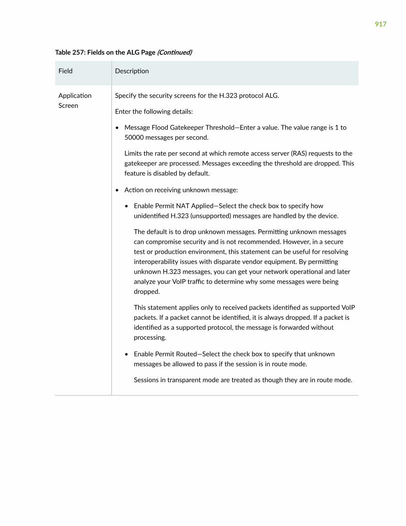
Table 257: Fields on the ALG Page (Continued)
Field Description
ApplicationScreen
Specify the security screens for the H.323 protocol ALG.
Enter the following details:
• Message Flood Gatekeeper Threshold—Enter a value. The value range is 1 to50000 messages per second.
Limits the rate per second at which remote access server (RAS) requests to thegatekeeper are processed. Messages exceeding the threshold are dropped. Thisfeature is disabled by default.
• Action on receiving unknown message:
• Enable Permit NAT Applied—Select the check box to specify howunidentified H.323 (unsupported) messages are handled by the device.
The default is to drop unknown messages. Permitting unknown messagescan compromise security and is not recommended. However, in a securetest or production environment, this statement can be useful for resolvinginteroperability issues with disparate vendor equipment. By permittingunknown H.323 messages, you can get your network operational and lateranalyze your VoIP traffic to determine why some messages were beingdropped.
This statement applies only to received packets identified as supported VoIPpackets. If a packet cannot be identified, it is always dropped. If a packet isidentified as a supported protocol, the message is forwarded withoutprocessing.
• Enable Permit Routed—Select the check box to specify that unknownmessages be allowed to pass if the session is in route mode.
Sessions in transparent mode are treated as though they are in route mode.
917
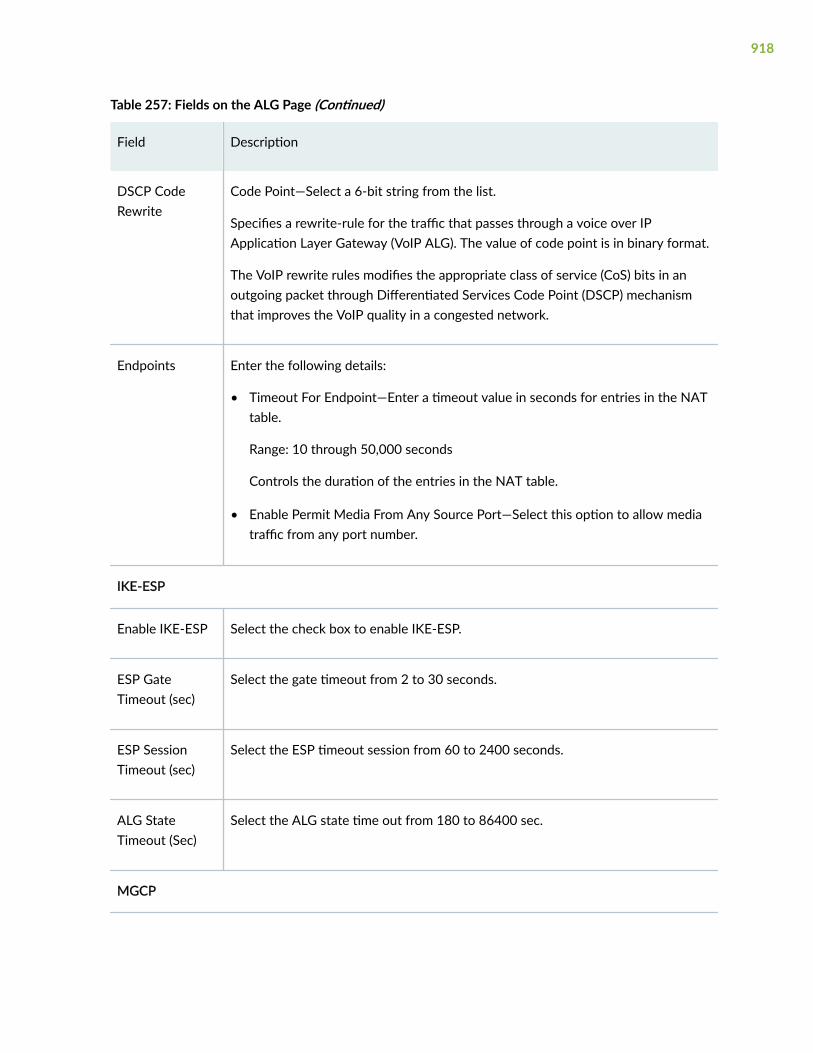
Table 257: Fields on the ALG Page (Continued)
Field Description
DSCP CodeRewrite
Code Point—Select a 6-bit string from the list.
Specifies a rewrite-rule for the traffic that passes through a voice over IPApplication Layer Gateway (VoIP ALG). The value of code point is in binary format.
The VoIP rewrite rules modifies the appropriate class of service (CoS) bits in anoutgoing packet through Differentiated Services Code Point (DSCP) mechanismthat improves the VoIP quality in a congested network.
Endpoints Enter the following details:
• Timeout For Endpoint—Enter a timeout value in seconds for entries in the NATtable.
Range: 10 through 50,000 seconds
Controls the duration of the entries in the NAT table.
• Enable Permit Media From Any Source Port—Select this option to allow mediatraffic from any port number.
IKE-ESP
Enable IKE-ESP Select the check box to enable IKE-ESP.
ESP GateTimeout (sec)
Select the gate timeout from 2 to 30 seconds.
ESP SessionTimeout (sec)
Select the ESP timeout session from 60 to 2400 seconds.
ALG StateTimeout (Sec)
Select the ALG state time out from 180 to 86400 sec.
MGCP
918

Table 257: Fields on the ALG Page (Continued)
Field Description
Enable MGCP Select the check box to enable the Media Gateway Control Protocol (MGCP).
Inactive MediaTimeout
Select a value to specify the maximum amount of time that the temporaryopenings in the firewall (pinholes) remain open for media if no activity is detected.range is from 10 through 2,550 seconds.
Specifies the maximum time (in seconds) a call can remain active without anymedia (RTP or RTCP) traffic within a group. Each time an RTP or RTCP packetoccurs within a call, this timeout resets. When the period of inactivity exceeds thissetting, the temporary openings (pinholes) in the firewall MGCP ALG opened formedia are closed. The default setting is 120 seconds; the range is from 10 to 2550seconds. Note that, upon timeout, while resources for media (sessions andpinholes) are removed, the call is not terminated.
Maximum CallDuration
Select a value from 3 through 720 minutes.
Sets the maximum length of a call. When a call exceeds this parameter setting, theMGCP ALG tears down the call and releases the media sessions. The defaultsetting is 720 minutes; the range is from 3 to 720 minutes.
TransactionTimeout
Enter a value from 3 through 50 seconds to specify
Specifies a timeout value for MGCP transactions. A transaction is a signalingmessage, for example, a NTFY from the gateway to the call agent or a 200 OKfrom the call agent to the gateway. The device tracks these transactions and clearsthem when they time out.
919

Table 257: Fields on the ALG Page (Continued)
Field Description
ApplicationScreen
Enter the following details:
• Message Flood Threshold—Enter a value from 2 through 50,000 seconds permedia gateway.
Limits the rate per second at which message requests to the Media Gatewayare processed. Messages exceeding the threshold are dropped by the MediaGateway Control Protocol (MGCP). This feature is disabled by default.
• Connection Flood Threshold—Enter a value from 2 through 10,000.
Limits the number of new connection requests allowed per Media Gateway(MG) per second. Messages exceeding the ALG.
• Action On Receiving Unknown Message—Enter any of the following:
• Enable Permit NAT Applied—Select the check box to specify howunidentified MGCP messages are handled by the Juniper Networks device.
The default is to drop unknown (unsupported) messages. Permittingunknown messages can compromise security and is not recommended.However, in a secure test or production environment, this statement can beuseful for resolving interoperability issues with disparate vendor equipment.By permitting unknown MGCP (unsupported) messages, you can get yournetwork operational and later analyze your VoIP traffic to determine whysome messages were being dropped.
• Enable Permit Routed—Select the check box.
Specifies that unknown messages be allowed to pass if the session is inroute mode. (Sessions in transparent mode are treated as route mode.)
DSCP CodeRewrite
Specifies a code-point alias or bit set to apply to a forwarding class for a rewriterule.
Code Point—Enter a six-bit DSCP code point value.
MSRPC
920

Table 257: Fields on the ALG Page (Continued)
Field Description
Enable MSRPC Select the check box to enable the MSRPC.
Provides a method for a program running on one host to call procedures in aprogram running on another host. Because of the large number of RPC servicesand the need to broadcast, the transport address of an RPC service is dynamicallynegotiated based on the service program's Universal Unique IDentifier (UUID). Thespecific UUID is mapped to a transport address.
Maximum GroupUsage (%)
Select the group usage % from 10 to 100%.
Map EntryTimeout (min)
Select the map entry timeout session from 5 to 4320 minutes.
SCCP
Enable SCCP Select the check box to enable the Skinny Client Control Protocol.
Inactive MediaTimeout
Select a value from 10 through 600 seconds.
Indicates the maximum length of time (in seconds) a call can remain active withoutany media (RTP or RTCP) traffic within a group. Each time an RTP or RTCP packetoccurs within a call, this timeout resets. When the period of inactivity exceeds thissetting, the gates opened for media are closed.
ApplicationScreen
Call Flood Threshold—Select a value from 2 through 1,000.
Protects SCCP ALG clients from flood attacks by limiting the number of calls theyattempt to process.
921

Table 257: Fields on the ALG Page (Continued)
Field Description
Action OnReceivingUnknownMessages
• Enable Permit NAT Applied—Select the check box.
Specifies how unidentified SCCP messages are handled by the device. Thedefault is to drop unknown (unsupported) messages. Permitting unknownmessages can compromise security and is not recommended. However, in asecure test or production environment, this statement can be useful forresolving interoperability issues with disparate vendor equipment. Bypermitting unknown SCCP (unsupported) messages, you can get your networkoperational and later analyze your VoIP traffic to determine why somemessages were being dropped.
This statement applies only to received packets identified as supported VoIPpackets. If a packet cannot be identified, it is always dropped. If a packet isidentified as a supported protocol, the message is forwarded withoutprocessing.
• Enable Permit Routed—Select the check box.
Specifies that unknown messages be allowed to pass if the session is in routemode. (Sessions in transparent mode are treated as though they are in routemode.)
DSCP CodeRewrite
Code Point—Enter a six-bit DSCP code point value.
SIP
Enable SIP Select the check box to enable Session Initiation Protocol (SIP).
Enable RetainHold Resource
Select the check box to enable whether the device frees media resources for a SIP,even when a media stream is placed on hold.
By default, media stream resources are released when the media stream is held.
922

Table 257: Fields on the ALG Page (Continued)
Field Description
Maximum CallDuration
Select a value from 3 through 720 minutes.
Sets the absolute maximum length of a call. When a call exceeds this parametersetting, the SIP ALG tears down the call and releases the media sessions. Thedefault setting is 720 minutes, the range is from 3 to 720 minutes.
C Timeout Select a value from 3 through 10 minutes.
Specifies the INVITE transaction timeout at the proxy, in minutes; the default is 3.Because the SIP ALG is in the middle, instead of using the INVITE transactiontimer value B (which is (64 * T1) = 32 seconds), the SIP ALG gets its timer valuefrom the proxy.
T4 Interval Select a value from 5 through 10 seconds.
Specifies the maximum time a message remains in the network. The default is 5seconds; the range is 5 through 10 seconds. Because many SIP timers scale withthe T4-Interval (as described in RFC 3261), when you change the value of the T4-Interval timer, those SIP timers also are adjusted.
Inactive MediaTimeout
Select a value from 10 through 2,550 seconds.
Specifies the maximum time (in seconds) a call can remain active without anymedia (RTP or RTCP) traffic within a group. Each time an RTP or RTCP packetoccurs within a call, this timeout resets. When the period of inactivity exceeds thissetting, the temporary openings (pinholes) in the firewall SIP ALG opened formedia are closed. The default setting is 120 seconds; the range is 10 through 2550seconds. Note that, upon timeout, while resources for media (sessions andpinholes) are removed, the call is not terminated.
T1 Interval Select a value from 500 through 5000 milliseconds.
Specifies the round-trip time estimate, in seconds, of a transaction betweenendpoints. The default is 500 milliseconds. Because many SIP timers scale with theT1-Interval (as described in RFC 3261), when you change the value of the T1-Interval timer, those SIP timers also are adjusted.
923

Table 257: Fields on the ALG Page (Continued)
Field Description
ApplicationScreen
Action On Receiving Unknown Message:
• Enable Permit NAT Applied—Select the check box to enable handlingunidentified SIP messages by the device.
This statement applies only to received packets identified as supported VoIPpackets. If a packet cannot be identified, it is always dropped. If a packet isidentified as a supported protocol, the message is forwarded withoutprocessing.
• Enable Permit Routed—Select the check box to enable to allow unknownmessages to pass if the session is in route mode. (Sessions in transparent modeare treated as route mode.)
Protect Options • SIP Invite Attack Table Entry Timeout—Enter a value from 1 through 3,600seconds.
Specifies the time (in seconds) to make an attack table entry for each INVITE,which is listed in the application screen.
• Enable Attack Protection—Select one of the options: All Servers, SelectedServers, or None.
Protects servers against INVITE attacks. Configures the SIP application screento protect the server at some or all destination IP addresses against INVITEattacks.
When you select Selected Servers, enter the destination IP address and click +.You can select the destination IP address and click X to delete it.
DSCP CodeRewrite
Code Point—Enter a six-bit DSCP code point value.
SUNRPC
924

Table 257: Fields on the ALG Page (Continued)
Field Description
Enable SUNRPC Select the check box to enable SUNRPC.
Because of the large number of RPC services and the need to broadcast, thetransport address of an RPC service is dynamically negotiated based on theservice's program number and version number. Several binding protocols aredefined for mapping the RPC program number and version number to a transportaddress.
Maximum GroupUsage (%)
Select the maximum group usage % from 10 to 100%.
Map EntryTimeout
Select the map entry timeout session from 5 to 4320 minutes.
925

CHAPTER 83
Advanced Threat Prevention
IN THIS CHAPTER
About the Advanced Threat Prevention Page | 926
Add a Threat Prevention Policy | 928
Edit a Threat Prevention Policy | 930
Delete Threat Prevention Policy | 930
About the Advanced Threat Prevention Page
IN THIS SECTION
Tasks You Can Perform | 926
Field Descriptions | 927
You are here: Security Services > Advanced Threat Prevention.
You can view and configure threat prevention policies. Threat prevention policies provide protection andmonitoring for configured threat profiles, including command and control server, infected hosts, andmalware. Using threat intelligence feeds in policies, ingress and egress traffic is monitored for suspiciouscontent and behavior.
Tasks You Can Perform
You can perform the following tasks from this page:
• Create a threat prevention policy. See "Add a Threat Prevention Policy" on page 928.
• Edit a threat prevention policy. See "Edit a Threat Prevention Policy" on page 930.
926

• Delete a threat prevention policy. See "Delete Threat Prevention Policy" on page 930.
• Filter the threat prevention policies based on select criteria. To do this, select the filter icon at the topright-hand corner of the Threat Prevention Policies table. The columns in the grid change to acceptfilter options. Type the filter options; the table displays only the data that fits the filtering criteria.
• Show or hide columns in the Threat Prevention Policies table. To do this, use the Show Hide Columnsicon in the top right corner of the page and select the options you want to show or deselect to hideoptions on the page.
• Advance search for threat prevention policies. To do this, use the search text box present above thetable grid. The search includes the logical operators as part of the filter string. In the search text box,when you hover over the icon, it displays an example filter condition. When you start entering thesearch string, the icon indicates whether the filter string is valid or not.
For an advanced search:
1. Enter the search string in the text box.
Based on your input, a list of items from the filter context menu appears.
2. Select a value from the list and then select a valid operator based on which you want to performthe advanced search operation.
NOTE: Press Spacebar to add an AND operator or OR operator to the search string. Pressbackspace at any point of time while entering a search criteria, only one character isdeleted.
3. Press Enter to display the search results in the grid.
Field Descriptions
Table 258 on page 927 describes the fields on the Threat Prevention Policies page.
Table 258: Fields on the Threat Prevention Policies Page
Field Description
Name Enter a threat prevention policy name.
Name must begin with an alphanumeric character; dashes and underscores areallowed; cannot exceed 63 characters.
927

Table 258: Fields on the Threat Prevention Policies Page (Continued)
Field Description
C&C Server Displays the range value of threat score set for this policy on a C&C server. A C&Cprofile would provide information on C&C servers that have attempted to contactand compromise hosts on your network. If the threat score of a feed is between thisrange, the feed will be blocked or permitted based on the threat score.
Infected Host Displays the range value of threat score set for this policy if . An infected hostprofile would provide information on compromised hosts and their associated threatlevels.
Malware HTTP A malware profile would provide information on files downloaded by hosts andfound to be suspicious based on known signatures or URLs.
Malware SMTP A malware profile would provide information on files downloaded by hosts andfound to be suspicious based on known signatures or URLs.
Log All traffic is logged by default. Use the pulldown to narrow the types of traffic to belogged.
Description Enter a description for the threat prevention policy.
RELATED DOCUMENTATION
Add a Threat Prevention Policy | 928
Edit a Threat Prevention Policy | 930
Delete Threat Prevention Policy | 930
Add a Threat Prevention Policy
You are here: Security Services > Advanced Threat Prevention.
To add a threat prevention policy:
928

1. Click the add icon (+) on the upper right side of the Threat Prevention Policy page.
The Create Threat Prevention Policy page appears.
2. Complete the configuration according to the guidelines provided in Table 259 on page 929.
3. Click OK to save the changes. If you want to discard your changes, click Cancel.
Table 259: Fields on the Create Threat Prevention Policy Page
Field Action
Name Displays the threat prevention policy name.
Description Displays the threat prevention policy description.
Profiles
Include C&C profile in policy Select the check box.
Include infected host profile in policy Select the check box.
Include malware profile in policy Select the check box.
Log Setting
Log Setting Select an option from the list. The available options are:
• Log all traffic
• Log only blocked traffic
• Do not log any traffic
RELATED DOCUMENTATION
About the Advanced Threat Prevention Page | 926
Edit a Threat Prevention Policy | 930
Delete Threat Prevention Policy | 930
929

Edit a Threat Prevention Policy
You are here: Security Services > Advanced Threat Prevention.
To edit a threat prevention policy:
1. Select the existing a threat prevention that you want to edit on the Threat Prevention Policies page.
2. Click the pencil icon available on the upper right side of the page.
The Edit a Threat Prevention page appears with editable fields. For more information on the options,see "Add a Threat Prevention Policy" on page 928.
3. Click OK to save the changes.
RELATED DOCUMENTATION
About the Advanced Threat Prevention Page | 926
Add a Threat Prevention Policy | 928
Delete Threat Prevention Policy | 930
Delete Threat Prevention Policy
You are here: Security Services > Advanced Threat Prevention.
To delete a threat prevention policy:
1. Select a threat prevention policy that you want to delete on the Threat Prevention Policies page.
2. Click the delete icon available on the upper right side of the page.
3. Click Yes to delete or click No to retain the profile.
RELATED DOCUMENTATION
About the Advanced Threat Prevention Page | 926
Add a Threat Prevention Policy | 928
Edit a Threat Prevention Policy | 930
930

CHAPTER 84
SSL Initiation Profiles
IN THIS CHAPTER
About the SSL Initiation Profile Page | 931
Add an SSL Initiation Profile | 933
Edit an SSL Initiation Profile | 937
Delete SSL Initiation Profile | 937
About the SSL Initiation Profile Page
IN THIS SECTION
Tasks You Can Perform | 931
Field Descriptions | 932
You are here: Security Services > SSL Profiles > SSL Initiation.
You can configure SSL Initiation profiles.
Tasks You Can Perform
You can perform the following tasks from this page:
• Add an SSL initiation profile. See "Add an SSL Initiation Profile" on page 933.
• Edit an SSL initiation profile. See "Edit an SSL Initiation Profile" on page 937.
• Delete SSL initiation profile. See "Delete SSL Initiation Profile" on page 937.
931

• Show or hide columns in the SSL Initiation Profile table. To do this, use the Show Hide Columns iconin the top right corner of the page and select the options you want to show or deselect to hideoptions on the page.
• Advance search for SSL initiation profile. To do this, use the search text box present above the tablegrid. The search includes the logical operators as part of the filter string. In the search text box, whenyou hover over the icon, it displays an example filter condition. When you start entering the searchstring, the icon indicates whether the filter string is valid or not.
For an advanced search:
1. Enter the search string in the text box.
Based on your input, a list of items from the filter context menu appears.
2. Select a value from the list and then select a valid operator based on which you want to performthe advanced search operation.
NOTE: Press Spacebar to add an AND operator or OR operator to the search string. Pressbackspace at any point of time while entering a search criteria, only one character isdeleted.
3. Press Enter to display the search results in the grid.
Field Descriptions
Table 260 on page 932 describes the fields on the SSL Initiation Profile page.
Table 260: Fields on the SSL Initiation Profile Page
Field Description
Name Displays the name of the SSL initiation profile.
Flow Tracing Displays whether flow trace is enabled or disabled for troubleshootingpolicy-related issues.
Protocol Version Displays the accepted protocol SSL version.
932

Table 260: Fields on the SSL Initiation Profile Page (Continued)
Field Description
Preferred Cipher Displays the preferred cipher which the SSH server uses to performencryption and decryption function.
Session Cache Displays whether SSL session cache is enabled or not.
Server AuthenticationFailure
Displays the action that will be performed if errors are encounteredduring the server certificate verification process (such as CA signatureverification failure, self-signed certificates, and certificate expiry).
Certificate Revocation Displays the criterion for certificate revocation for the SSL initiationprofile.
RELATED DOCUMENTATION
Add an SSL Initiation Profile | 933
Edit an SSL Initiation Profile | 937
Delete SSL Initiation Profile | 937
Add an SSL Initiation Profile
You are here: Security Services > SSL Profiles > SSL Initiation.
To add an SSL initiation profile:
1. Click the add icon (+) on the upper right side of the SSL Initiation Profile page.
The Create SSL Initiation Profile page appears.
2. Complete the configuration according to the guidelines provided in Table 261 on page 934.
3. Click OK to save the changes. If you want to discard your changes, click Cancel.
933

Table 261: Fields on the Create SSL Initiation Profile Page
Field Action
General Information
Name Enter a unique name of the SSL initiation profile.
The string must consist of alphanumericcharacters, colons, periods, dashes, andunderscores. No spaces are allowed; maximumlength is 63 characters.
Flow Tracing Select this option to enable flow trace fortroubleshooting policy-related issues for thisprofile.
Protocol Version Specifies the accepted protocol SSL version.
Select the protocol from the list: None, All, TSLv1,TSLv1.1, or TSLv1.2.
Preferred Cipher Specify the cipher depending on their keystrength. Select a preferred cipher from the list:
• Custom—Configure custom cipher suite andorder of preference.
• Medium—Use ciphers with key strength of128 bits or greater.
• Strong—Use ciphers with key strength of 168bits or greater.
• Weak—Use ciphers with key strength of 40bits or greater.
Custom Ciphers Select one or more Ciphers from the list.
Click Clear All to clear the selected ciphers fromthe list.
934

Table 261: Fields on the Create SSL Initiation Profile Page (Continued)
Field Action
Session Cache Select this option to enable SSL session cache.
Certificate
Trusted CA Select the trusted certificate authority profilefrom the list.
Specify the set of ciphers the SSH server can useto perform encryption and decryption functions.If this option is not configured, the server acceptsany supported suite that is available.
Client Certificate Specify a client certificate that is required toeffectively authenticate the client.
Select the appropriate client certificate from thelist.
• None
• SSLRP_Automation_Cert_2
• SSLFP_Automation_Cert_1
• SSLRP_Automation_Cert_1
• SSLFP_Automation_Cert_2
• SSL2
Actions
935

Table 261: Fields on the Create SSL Initiation Profile Page (Continued)
Field Action
Server Authentication Failure Select this option to ignore server authenticationcompletely.
In this case, SSL forward proxy ignores errorsencountered during the server certificateverification process (such as CA signatureverification failure, self-signed certificates, andcertificate expiry).
We do not recommend this option forauthentication, because configuring it results inwebsites not being authenticated at all. However,you can use this option to effectively identify theroot cause for dropped SSL sessions.
CRL Validation Enable this option to disable CRL validation.
Action Select an action from the list if CRL info is notpresent:
• None
• Allow
• Drop
Hold Instruction Code Select Ignore if you want to keep the instructioncode on hold for this profile.
RELATED DOCUMENTATION
About the SSL Initiation Profile Page | 931
Edit an SSL Initiation Profile | 937
Delete SSL Initiation Profile | 937
936

Edit an SSL Initiation Profile
You are here: Security Services > SSL Profiles > SSL Initiation.
To edit an SSL initiation profile:
1. Select the existing SSL initiation profile that you want to edit on the SSL Initiation Profile page.
2. Click the pencil icon available on the upper right side of the page.
The Edit an SSL Initiation Profile page appears with editable fields. For more information on theoptions, see "Add an SSL Initiation Profile" on page 933.
3. Click OK to save the changes.
RELATED DOCUMENTATION
About the SSL Initiation Profile Page | 931
Add an SSL Initiation Profile | 933
Delete SSL Initiation Profile | 937
Delete SSL Initiation Profile
You are here: Security Services > SSL Profiles > SSL Initiation.
To delete an SSL initiation profile:
1. Select an SSL initiation profile that you want to delete on the SSL Initiation Profile page.
2. Click the delete icon available on the upper right side of the page.
3. Click Yes to delete or click No to retain the profile.
RELATED DOCUMENTATION
About the SSL Initiation Profile Page | 931
Add an SSL Initiation Profile | 933
Edit an SSL Initiation Profile | 937
937

CHAPTER 85
SSL Proxy Profiles
IN THIS CHAPTER
About the SSL Proxy Page | 938
Add an SSL Proxy Profile | 941
Clone an SSL Proxy Profile | 949
Edit an SSL Proxy Profile | 950
Delete SSL Proxy Profile | 950
About the SSL Proxy Page
IN THIS SECTION
Tasks You Can Perform | 938
Field Descriptions | 939
You are here: Security Services > SSL Profiles > SSL Proxy.
You can create, add, edit, and delete SSL proxy or global policy configurations.
Tasks You Can Perform
You can perform the following tasks from this page:
• Configure global policy. To do this, click Global Config at the upper right of the table and enter thesession cache timeout in seconds.
• Add an SSL proxy profile. See "Add an SSL Proxy Profile" on page 941.
• Edit na SSL proxy profile. See "Edit an SSL Proxy Profile" on page 950.
938

• Delete SSL proxy profile. See "Delete SSL Proxy Profile" on page 950.
• Clone an SSL proxy profile. See "Clone an SSL Proxy Profile" on page 949.
• View the details of an SSL proxy profile—To do this, select the SSL proxy profile for which you wantto view the details and follow the available options:
• Click More and select Detailed View.
• Right-click on the selected SSL proxy profile and select Detailed View.
• Mouse over to the left of the selected SSL proxy profile and click Detailed View.
• Deselect the selected SSL proxy profiles. To do this, click More and select Clear All Selections.
• Show or hide columns in the SSL Proxy Profiles table. To do this, click the Show Hide Columns icon inthe top right corner of the custom objects table and select the options you want to view or deselectthe options you want to hide on the page.
• Advance search for SSL proxy profiles. To do this, use the search text box present above the tablegrid. The search includes the logical operators as part of the filter string. In the search text box, whenyou hover over the icon, it displays an example filter condition. When you start entering the searchstring, the icon indicates whether the filter string is valid or not.
For an advanced search:
1. Enter the search string in the text box.
Based on your input, a list of items from the filter context menu appears.
2. Select a value from the list and then select a valid operator based on which you want to performthe advanced search operation.
NOTE: Press Spacebar to add an AND operator or OR operator to the search string. Pressbackspace at any point of time while entering a search criteria, only one character isdeleted.
3. Press Enter to display the search results in the grid.
Field Descriptions
Table 262 on page 940 describes the fields on the SSL Proxy page.
939
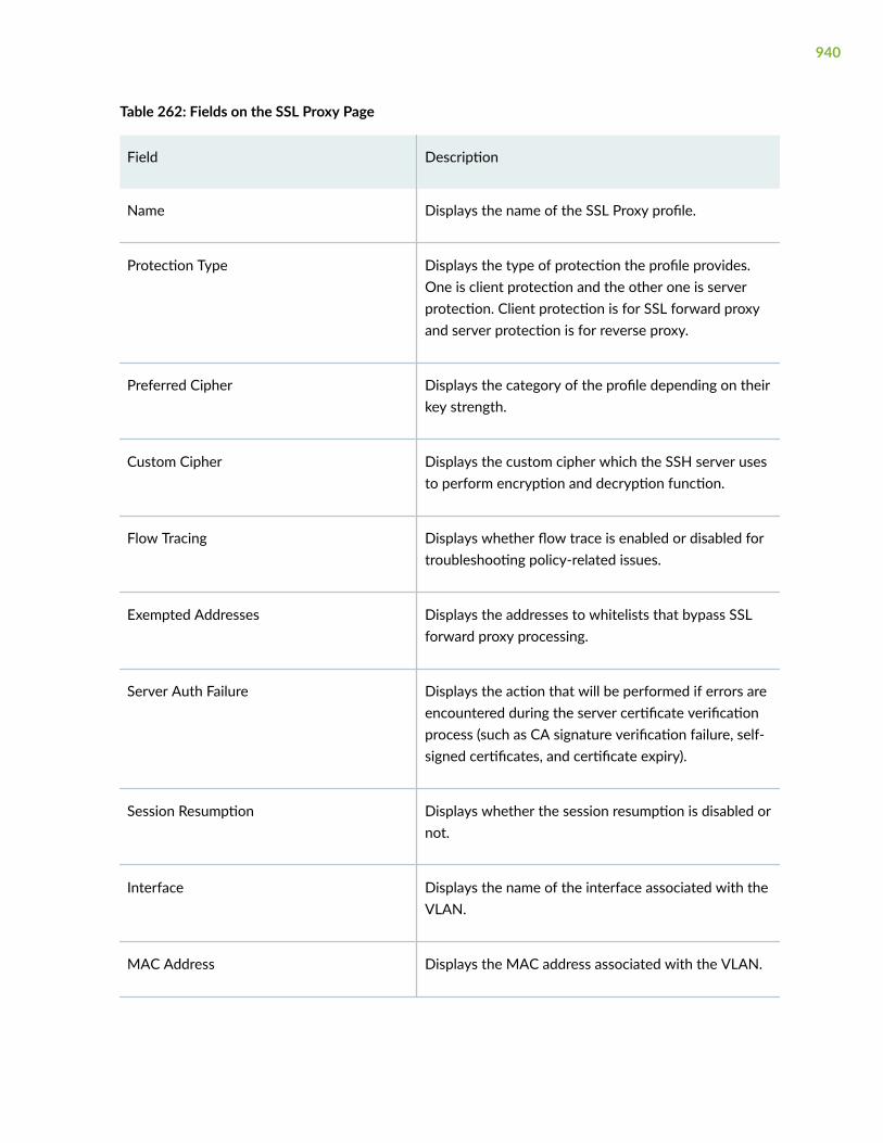
Table 262: Fields on the SSL Proxy Page
Field Description
Name Displays the name of the SSL Proxy profile.
Protection Type Displays the type of protection the profile provides.One is client protection and the other one is serverprotection. Client protection is for SSL forward proxyand server protection is for reverse proxy.
Preferred Cipher Displays the category of the profile depending on theirkey strength.
Custom Cipher Displays the custom cipher which the SSH server usesto perform encryption and decryption function.
Flow Tracing Displays whether flow trace is enabled or disabled fortroubleshooting policy-related issues.
Exempted Addresses Displays the addresses to whitelists that bypass SSLforward proxy processing.
Server Auth Failure Displays the action that will be performed if errors areencountered during the server certificate verificationprocess (such as CA signature verification failure, self-signed certificates, and certificate expiry).
Session Resumption Displays whether the session resumption is disabled ornot.
Interface Displays the name of the interface associated with theVLAN.
MAC Address Displays the MAC address associated with the VLAN.
940

RELATED DOCUMENTATION
Add an SSL Proxy Profile | 941
Add an SSL Proxy Profile
You are here: Security Services > SSL Profiles > SSL Proxy.
To add an SSL proxy profile:
1. Click the add icon (+) on the upper right side of the SSL Proxy Profile page.
The Create SSL Proxy Profile page appears.
2. Complete the configuration according to the guidelines provided in Table 263 on page 941.
3. Click OK to save the changes. If you want to discard your changes, click Cancel.
Table 263: Fields on the Create SSL Proxy Profile Page
Field Action
General Information
Name Enter a name of the SSL proxy profile.
The string must contain alphanumeric characters,colons, periods, dashes, and underscores. Nospaces are allowed; maximum length is 63characters.
941

Table 263: Fields on the Create SSL Proxy Profile Page (Continued)
Field Action
Preferred Cipher Specifies the cipher depending on their keystrength. Select a preferred cipher from the list:
• Medium—Use ciphers with key strength of128 bits or greater.
• Strong—Use ciphers with key strength of 168bits or greater.
• Weak—Use ciphers with key strength of 40bits or greater.
• Custom—Configure custom cipher suite andorder of preference.
942

Table 263: Fields on the Create SSL Proxy Profile Page (Continued)
Field Action
Custom Ciphers Specifies the set of ciphers the SSH server canuse to perform encryption and decryptionfunctions. If this option is not configured, theserver accepts any supported suite that isavailable.
Select the set of ciphers from the list:
1. rsa-with-RC4-128-md5—RSA, 128-bit RC4,MD5 hash
2. rsa-with-RC4-128-sha—RSA, 128-bit RC4,SHA hash
3. rsa-with-des-cbc-sha—RSA, DES/CBC, SHAhash
4. rsa-with-3DES-ede-cbc-sha—RSA, 3DESEDE/CBC, SHA hash
5. rsa-with-aes-128-cbc-sha—RSA, 128-bitAES/CBC, SHA hash
6. rsa-with-aes-256-cbc-sha—RSA, 256-bitAES/CBC, SHA hash
7. rsa-export-with-rc4-40-md5—RSA-export,40-bit RC4, MD5 hash
8. rsa-export-with-des40-cbc-sha—RSA-export, 40-bit DES/CBC, SHA hash
9. rsa-with-aes-256-gcm-sha384—RSA, 256-bit AES/GCM, SHA384 hash
10. rsa-with-aes-256-cbc-sha256—RSA, 256-bitAES/CBC, SHA256 hash
11. rsa-with-aes-128-gcm-sha256—RSA, 128-bit AES/GCM, SHA256 hash
943
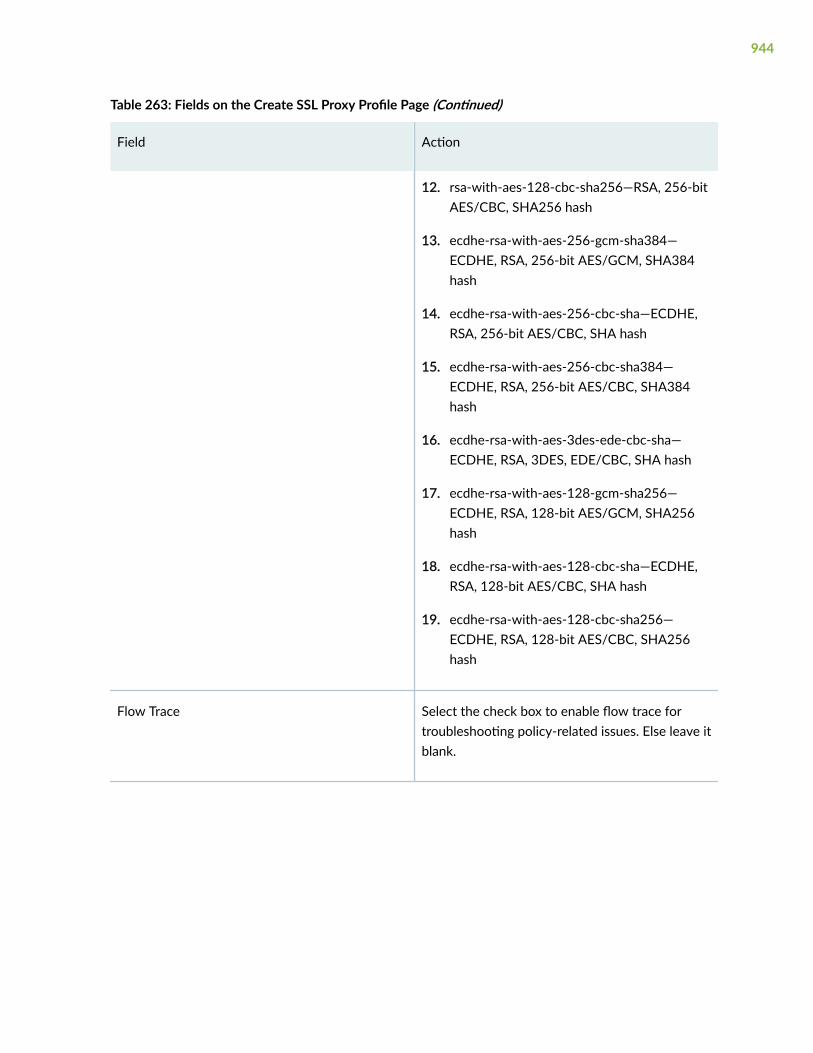
Table 263: Fields on the Create SSL Proxy Profile Page (Continued)
Field Action
12. rsa-with-aes-128-cbc-sha256—RSA, 256-bitAES/CBC, SHA256 hash
13. ecdhe-rsa-with-aes-256-gcm-sha384—ECDHE, RSA, 256-bit AES/GCM, SHA384hash
14. ecdhe-rsa-with-aes-256-cbc-sha—ECDHE,RSA, 256-bit AES/CBC, SHA hash
15. ecdhe-rsa-with-aes-256-cbc-sha384—ECDHE, RSA, 256-bit AES/CBC, SHA384hash
16. ecdhe-rsa-with-aes-3des-ede-cbc-sha—ECDHE, RSA, 3DES, EDE/CBC, SHA hash
17. ecdhe-rsa-with-aes-128-gcm-sha256—ECDHE, RSA, 128-bit AES/GCM, SHA256hash
18. ecdhe-rsa-with-aes-128-cbc-sha—ECDHE,RSA, 128-bit AES/CBC, SHA hash
19. ecdhe-rsa-with-aes-128-cbc-sha256—ECDHE, RSA, 128-bit AES/CBC, SHA256hash
Flow Trace Select the check box to enable flow trace fortroubleshooting policy-related issues. Else leave itblank.
944

Table 263: Fields on the Create SSL Proxy Profile Page (Continued)
Field Action
Certificate Type Specifies whether the certificate that you want toassociate with this profile is a root CA or servercertificate. Server certificate is used for SSLreverse proxy. If you choose server certificate,the trusted CA, CRL, and server auth failureoptions will not be available. For forward proxyprofile, choose the root CA
In a public key infrastructure (PKI) hierarchy, theroot CA is at the top of the trust path. The rootCA identifies the server certificate as a trustedcertificate.
Certificate Select the certificate that you want to associatewith this SSL proxy profile from the list.
Specifies the certificate that you created in theAdministration > Certificate Management page ofJ-Web. In a public key infrastructure (PKI)hierarchy, the CA is at the top of the trust path.The CA identifies the server certificate as atrusted certificate.
Trusted Certificate Authorities Select the trusted CA that are available on thedevice from the following options: All, None,Select specific.
If you choose Select specific, you need to selectthe Certificate Authorities from the Availablecolumn and move it to the Selected column.
945

Table 263: Fields on the Create SSL Proxy Profile Page (Continued)
Field Action
Exempted Addresses Specifies addresses to create whitelists thatbypass SSL forward proxy processing.
Select the addresses from the from the Availablecolumn and move it to the Selected column.
Because SSL encryption and decryption arecomplicated and expensive procedures, networkadministrators can selectively bypass SSL proxyprocessing for some sessions. Such sessionsmostly include connections and transactions withtrusted servers or domains with which networkadministrators are very familiar. There are alsolegal requirements to exempt financial andbanking sites. Such exemptions are achieved byconfiguring the IP addresses or domain names ofthe servers under whitelists.
Exempted URL Categories Specifies URL categories to create whitelists thatbypass SSL forward proxy processing.
Select URL categories from the from theAvailable column and move it to the Selectedcolumn.
These URL categories are exempted during SSLinspection. Only the predefined URL categoriescan be selected for the exemption.
Actions
946

Table 263: Fields on the Create SSL Proxy Profile Page (Continued)
Field Action
Server Auth Failure Select the check box to ignore serverauthentication completely.
In this case, SSL forward proxy ignores errorsencountered during the server certificateverification process (such as CA signatureverification failure, self-signed certificates, andcertificate expiry).
We do not recommend this option forauthentication, because configuring it results inwebsites not being authenticated at all. However,you can use this option to effectively identify theroot cause for dropped SSL sessions.
Session Resumption Select the check box if you do not want sessionresumption.
To improve throughput and still maintain anappropriate level of security, SSL sessionresumption provides a session cachingmechanism so that session information, such asthe pre-master secret key and agreed-uponciphers, can be cached for both the client andserver.
Logging Select an option from the list to generate logs.
You can choose to log All events, Warning, Info,Errors, or different sessions (whitelisted, Allowed,Dropped, or Ignored).
947
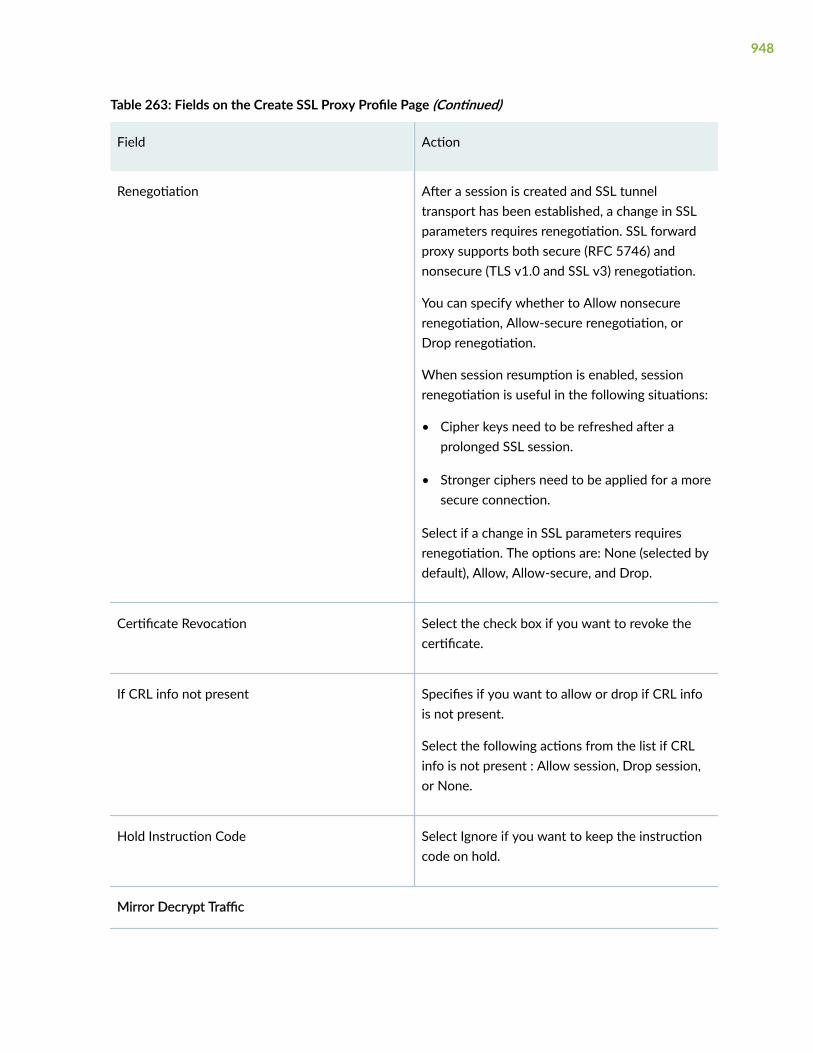
Table 263: Fields on the Create SSL Proxy Profile Page (Continued)
Field Action
Renegotiation After a session is created and SSL tunneltransport has been established, a change in SSLparameters requires renegotiation. SSL forwardproxy supports both secure (RFC 5746) andnonsecure (TLS v1.0 and SSL v3) renegotiation.
You can specify whether to Allow nonsecurerenegotiation, Allow-secure renegotiation, orDrop renegotiation.
When session resumption is enabled, sessionrenegotiation is useful in the following situations:
• Cipher keys need to be refreshed after aprolonged SSL session.
• Stronger ciphers need to be applied for a moresecure connection.
Select if a change in SSL parameters requiresrenegotiation. The options are: None (selected bydefault), Allow, Allow-secure, and Drop.
Certificate Revocation Select the check box if you want to revoke thecertificate.
If CRL info not present Specifies if you want to allow or drop if CRL infois not present.
Select the following actions from the list if CRLinfo is not present : Allow session, Drop session,or None.
Hold Instruction Code Select Ignore if you want to keep the instructioncode on hold.
Mirror Decrypt Traffic
948

Table 263: Fields on the Create SSL Proxy Profile Page (Continued)
Field Action
Interface Select an SSL decryption port mirroring interfacefrom the list. This is an Ethernet interface on SRXSeries device through which the copy of the SSLdecrypted traffic is forwarded to a mirror port.
Only after Security Policies Enforcement Select the check box to enable forwarding thecopy of the decrypted traffic to the externalmirror traffic collector after enforcing the Layer 7security services through a security policy.
MAC Address Enter the MAC address of the external mirrortraffic collector port.
RELATED DOCUMENTATION
About the SSL Proxy Page | 938
Edit an SSL Proxy Profile | 950
Delete SSL Proxy Profile | 950
Clone an SSL Proxy Profile | 949
Clone an SSL Proxy Profile
You are here: Security Services > SSL Profiles > SSL Proxy.
To clone an SSL proxy profile:
1. Select an SSL Proxy profile that you want to clone and select Clone from the More link.
NOTE: Alternatively, you can right-click on the selected SSL Proxy profile and select Clone.
949

The Clone SSL Proxy Profile page appears with editable fields. For more information on the options,see "Add an SSL Proxy Profile" on page 941.
2. Click OK to save the changes or click Cancel to discard the changes.
RELATED DOCUMENTATION
About the SSL Proxy Page | 938
Edit an SSL Proxy Profile | 950
Delete SSL Proxy Profile | 950
Edit an SSL Proxy Profile
You are here: Security Services > SSL Profiles > SSL Proxy.
To edit an SSL proxy profile:
1. Select the existing SSL proxy profile that you want to edit on the SSL Proxy Profile page.
2. Click the pencil icon available on the upper right side of the page.
The Update SSL Initiation Profile page appears with editable fields. For more information on theoptions, see "Add an SSL Proxy Profile" on page 941.
3. Click OK to save the changes.
RELATED DOCUMENTATION
About the SSL Proxy Page | 938
Delete SSL Proxy Profile | 950
Clone an SSL Proxy Profile | 949
Delete SSL Proxy Profile
You are here: Security Services > SSL Profiles > SSL Proxy.
To delete SSL proxy profile:
1. Select one or more SSL proxy profiles that you want to delete on the SSL Proxy page.
2. Click the delete icon available on the upper right side of the page.
950
3. Click Yes to delete or click No to retain the profile.
RELATED DOCUMENTATION
About the SSL Proxy Page | 938
Add an SSL Proxy Profile | 941
Edit an SSL Proxy Profile | 950
Clone an SSL Proxy Profile | 949
951

CHAPTER 86
Firewall Authentication—Access Profile
IN THIS CHAPTER
About the Access Profile Page | 952
Add an Access Profile | 954
Edit an Access Profile | 960
Delete an Access Profile | 960
About the Access Profile Page
IN THIS SECTION
Tasks You Can Perform | 952
Field Descriptions | 953
You are here: Security Services > Firewall Authentication > Access Profile.
Use this page to configure Access Profile. Access profiles enable you to define the authentication andaccounting servers and their priorities.
Tasks You Can Perform
You can perform the following tasks from this page:
• Create an access profile. See "Add an Access Profile" on page 954.
• Edit an access profile. See "Edit an Access Profile" on page 960.
• Delete an access profile. See "Delete an Access Profile" on page 960.
952

• View the details of the Access profile—To do this, select the Access profile for which you want toview the details and follow the available options:
• Click More and select Detailed View.
• Right-click on the selected Access profile and select Detailed View.
• Mouse over to the left of the selected Access profiles and click Detailed View.
• Show or hide columns in the Access Profile table. To do this, click Show Hide Columns icon in the topright corner of the Access Profiles table and select the columns you want to display or deselect thecolumns you want to hide on the page.
• Advance search for Access profile. To do this, use the search text box present above the table grid.The search includes the logical operators as part of the filter string. An example filter condition isdisplayed in the search text box when you hover over the Search icon. When you start entering thesearch string, the icon indicates whether the filter string is valid or not.
For an advanced search:
1. Enter the search string in the text box.
Based on your input, a list of items from the filter context menu appears.
2. Select a value from the list and then select a valid operator based on which you want to performthe advanced search operation.
NOTE: Press Spacebar to add an AND operator or OR operator to the search string. Pressbackspace to delete a character of the search string.
3. Press Enter to display the search results in the grid.
Field Descriptions
Table 264 on page 953 describes the fields on the Access Profile page.
Table 264: Fields on the Access Profile Page
Field Description
Profile Name Displays the name of an access profile.
953

Table 264: Fields on the Access Profile Page (Continued)
Field Description
Order 1 Shows the order in which Junos OS tries different authentication methods whenverifying that a client can access the devices.
Order 2 Shows the next authentication method if the authentication method included inthe authentication order option is not available, or if the authentication is availablebut returns a reject response.
Local Users Displays the usernames that are created for accessing the application.
LDAP Servers Displays the IP address of the LDAP authentication server.
RADIUS Servers Displays the RADIUS server configuration.
RELATED DOCUMENTATION
Add an Access Profile | 954
Edit an Access Profile | 960
Delete an Access Profile | 960
Add an Access Profile
You are here: Security Services > Firewall Authentication > Access Profile.
To add an access profile:
1. Click the add icon (+) on the upper right-side of the Access Profile page.
The Create Access Profile page appears.
2. Complete the configuration according to the guidelines provided in Table 265 on page 955.
3. Click OK to save the changes. If you want to discard your changes, click Cancel.
954

Table 265: Fields on the Access Profile Page
Field Description
Access ProfileName
Enter a name for the access profile. The name must be a unique string ofalphanumeric characters, colons, periods, dashes, and underscores. Maximumlength is 64 characters.
AddressAssignment
Select an address pool from the list that can be used by different clientapplications.
Click Create Address Pool to add a new address pool. For more information oncreating a new address pool, see "Add an Address Pool" on page 963.
Authentication
Local Select Local to configure local authentication services.
To create a new local authentication user:
1. Click +.
The Create Local Authentication User page appears.
2. Enter the following details:
• Username—Enter the user name of the user requesting access.
• Password—Enter the user password.
• XAUTH IP Address—Enter the IPv4 address for the client.
• Group—Enter the group name to store several user accounts together.
3. Click OK to save changes.
To edit, select the local authentication user configuration and click the pencilicon.
To delete, select the local authentication user configuration and click the deleteicon.
955

Table 265: Fields on the Access Profile Page (Continued)
Field Description
RADIUS Select RADIUS to configure RADIUS authentication services.
To create a new RADIUS server:
1. Click +.
The Create RADIUS Server page appears.
2. Enter the following details:
• Address—Enter the IPv4 or IPv6 address of the RADIUS server.
• Secret—Enter the secret password to access the RADIUS server.
• Port—Enter the port number on which to contact the RADIUS server.
Range is 1 through 65535. Default is 1812.
• Retry—Enter the number of retries that a device can attempt to contact aRADIUS server.
Range is 1 through 100 seconds.
• Routing Instance—Select the routing instance from the list for managingthe routing instance.
• Source Address—Enter a source IP address configured on one of thedevice’s interfaces.
• Timeout—Enter the amount of time that the local device waits to receive aresponse from a RADIUS authentication server.
Range is 1 through 1000 seconds.
3. Click OK to save changes.
To edit, select the RADIUS server configuration and click the pencil icon.
To delete, select the RADIUS server configuration and click the delete icon.
956

Table 265: Fields on the Access Profile Page (Continued)
Field Description
LDAP Select LDAP to configure LDAP authentication services.
To create a new LDAP server:
1. Click +.
The Create LDAP Server page appears.
2. Enter the following details:
• Address—Enter the IPv4 or IPv6 address of the LDAP server.
• Port—Enter the port number on which to contact the LDAP server.
Range is 1 through 65535. Default is 389.
• Retry—Enter the number of retries that a device can attempt to contact anLDAP server.
Range is 1 through 10 seconds.
• Routing Instance—Select the routing instance from the list for managingthe routing instance.
• Source Address—Enter a source IP address configured on one of thedevice’s interfaces.
• Timeout—Enter the amount of time that the local device waits to receive aresponse from an LDAP authentication server.
Range is 3 through 90.
3. Click OK to save changes.
To edit, select the LDAP server configuration and click the pencil icon.
To delete, select the LDAP server configuration and click the delete icon.
LDAP Options
957
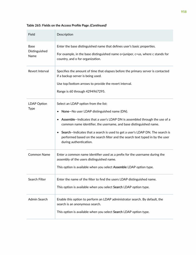
Table 265: Fields on the Access Profile Page (Continued)
Field Description
BaseDistinguishedName
Enter the base distinguished name that defines user’s basic properties.
For example, in the base distinguished name o=juniper, c=us, where c stands forcountry, and o for organization.
Revert Interval Specifies the amount of time that elapses before the primary server is contactedif a backup server is being used.
Use top/bottom arrows to provide the revert interval.
Range is 60 through 4294967295.
LDAP OptionType
Select an LDAP option from the list:
• None—No user LDAP distinguished name (DN).
• Assemble—Indicates that a user’s LDAP DN is assembled through the use of acommon name identifier, the username, and base distinguished name.
• Search—Indicates that a search is used to get a user's LDAP DN. The search isperformed based on the search filter and the search text typed in by the userduring authentication.
Common Name Enter a common name identifier used as a prefix for the username during theassembly of the users distinguished name.
This option is available when you select Assemble LDAP option type.
Search Filter Enter the name of the filter to find the users LDAP distinguished name.
This option is available when you select Search LDAP option type.
Admin Search Enable this option to perform an LDAP administrator search. By default, thesearch is an anonymous search.
This option is available when you select Search LDAP option type.
958

Table 265: Fields on the Access Profile Page (Continued)
Field Description
DistinguishedName
Enter the distinguished name of an administrative user. The distinguished name isused in the bind for performing the LDAP search.
This option is available when you select Admin Search is enabled.
Secret Enter the plain-text password for the administrative user.
This option is available when you select Admin Search is enabled.
Authentication Order
Order 1 Select one or more of the following authentication methods:
• NONE—No authentication for the specified user.
• Local—Use local authentication services.
• LDAP—Use LDAP. The SRX device uses this protocol to get user and groupinformation necessary to implement the integrated user firewall feature.
• Radius—Use RADIUS authentication services.
If RADIUS servers fail to respond or return a reject response, try localauthentication, because it is explicitly configured in the authentication order.
Order 2 Select the authentication method from the list.
RELATED DOCUMENTATION
About the Access Profile Page | 952
Edit an Access Profile | 960
Delete an Access Profile | 960
959

Edit an Access Profile
You are here: Security Services > Firewall Authentication > Access Profile.
To edit an access profile:
1. Select an existing access profile that you want to edit on the Access Profile page.
2. Click the pencil icon available on the upper right-side of the page.
The Edit Access Profiles page appears with editable fields. For more information on editing the fields,see "Add an Access Profile" on page 954.
3. Click OK to save the changes or click Cancel to discard the changes.
RELATED DOCUMENTATION
About the Access Profile Page | 952
Add an Access Profile | 954
Delete an Access Profile | 960
Delete an Access Profile
You are here: Security Services > Firewall Authentication > Access Profile.
To delete an access profile:
1. Select an access profile that you want to delete on the Access Profiles page.
2. Click the delete icon available on the upper right-side of the page.
3. Click Yes to delete access profiles or click No to retain access profiles.
RELATED DOCUMENTATION
About the Access Profile Page | 952
Add an Access Profile | 954
Edit an Access Profile | 960
960

CHAPTER 87
Firewall Authentication—Address Pools
IN THIS CHAPTER
About the Address Pools Page | 961
Add an Address Pool | 963
Edit an Address Pool | 965
Delete Address Pool | 965
Search for Text in an Address Pools Table | 966
About the Address Pools Page
IN THIS SECTION
Tasks You Can Perform | 961
Field Descriptions | 962
You are here: Security Services > Firewall Authentication > Address Pools.
Use this page to get configure Address Pools.
Tasks You Can Perform
You can perform the following tasks from this page:
• Add Address Pool. See "Add an Address Pool" on page 963.
• Edit Address Pool. See "Edit an Address Pool" on page 965.
• Delete Address Pool. See "Delete Address Pool" on page 965.
961
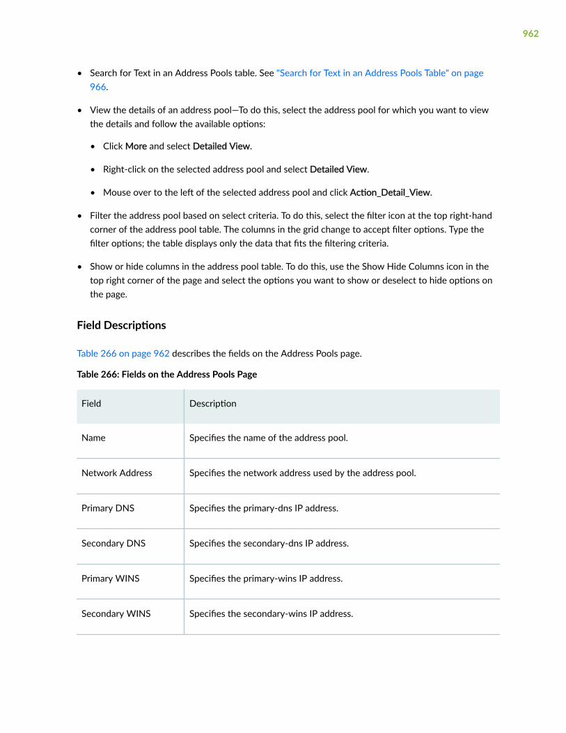
• Search for Text in an Address Pools table. See "Search for Text in an Address Pools Table" on page966.
• View the details of an address pool—To do this, select the address pool for which you want to viewthe details and follow the available options:
• Click More and select Detailed View.
• Right-click on the selected address pool and select Detailed View.
• Mouse over to the left of the selected address pool and click Action_Detail_View.
• Filter the address pool based on select criteria. To do this, select the filter icon at the top right-handcorner of the address pool table. The columns in the grid change to accept filter options. Type thefilter options; the table displays only the data that fits the filtering criteria.
• Show or hide columns in the address pool table. To do this, use the Show Hide Columns icon in thetop right corner of the page and select the options you want to show or deselect to hide options onthe page.
Field Descriptions
Table 266 on page 962 describes the fields on the Address Pools page.
Table 266: Fields on the Address Pools Page
Field Description
Name Specifies the name of the address pool.
Network Address Specifies the network address used by the address pool.
Primary DNS Specifies the primary-dns IP address.
Secondary DNS Specifies the secondary-dns IP address.
Primary WINS Specifies the primary-wins IP address.
Secondary WINS Specifies the secondary-wins IP address.
962

Table 266: Fields on the Address Pools Page (Continued)
Field Description
Address Range Specifies the name of the address range.
RELATED DOCUMENTATION
Add an Address Pool | 963
Edit an Address Pool | 965
Delete Address Pool | 965
Search for Text in an Address Pools Table | 966
Add an Address Pool
You are here: Security Services > Firewall Authentication > Address Pools.
To add an address pool:
1. Click the add icon (+) on the upper right side of the Address Pools page.
The Create Address Pool page appears.
2. Complete the configuration according to the guidelines provided in Table 267 on page 963.
3. Click OK to save the changes. If you want to discard your changes, click Cancel.
Table 267: Fields on the Create Address Pool Page
Field Description
General
Pool Name Enter the address pool name.
Network Address Enter an IPv4 address for the address pool.
XAUTH Attributes
963

Table 267: Fields on the Create Address Pool Page (Continued)
Field Description
Primary DNS Server Enter the primary-dns IPv4 address.
Secondary DNS Server Enter the secondary-dns IPv4 address.
Primary WINS Server Enter the primary-wins IPv4 address.
Secondary WINS Server Enter the secondary-wins IPv4 address.
Address Ranges
Add Click + to add a new address range for the address pool.
Name Enter a name for the IP address range.
Lower Limit Enter the lower limit of the address range.
High Limit Enter the upper limit of the address range.
Delete Click the delete icon to delete the address range for the address pool.
RELATED DOCUMENTATION
About the Address Pools Page | 961
Edit an Address Pool | 965
Delete Address Pool | 965
Search for Text in an Address Pools Table | 966
964

Edit an Address Pool
You are here: Security Services > Firewall Authentication > Address Pools.
To edit an address pool:
1. Select an existing address pool that you want to edit on the Address Pools page.
2. Click the pencil icon available on the upper right side of the page.
The Edit Address Pool page appears with editable fields. For more information on the options, see"Add an Address Pool" on page 963.
3. Click OK to save the changes.
RELATED DOCUMENTATION
About the Address Pools Page | 961
Add an Address Pool | 963
Delete Address Pool | 965
Search for Text in an Address Pools Table | 966
Delete Address Pool
You are here: Security Services > Firewall Authentication > Address Pools.
To delete an address pool:
1. Select an address pool that you want to delete on the Address Pools page.
2. Click the delete icon available on the upper right side of the page.
3. Click Yes to delete or click No to retain the profile.
RELATED DOCUMENTATION
About the Address Pools Page | 961
Add an Address Pool | 963
Edit an Address Pool | 965
Search for Text in an Address Pools Table | 966
965

Search for Text in an Address Pools Table
You are here: Security Services > Firewall Authentication > Address Pools.
You can use the search icon in the top right corner of the Address Pools page to search for textcontaining letters and special characters on that page.
To search for text:
1. Click the search icon and enter partial text or full text of the keyword in the search bar.
The search results are displayed.
2. Click X next to a search keyword or click Clear All to clear the search results.
RELATED DOCUMENTATION
About the Address Pools Page | 961
Add an Address Pool | 963
Edit an Address Pool | 965
Delete Address Pool | 965
966

CHAPTER 88
Firewall Authentication Settings
IN THIS CHAPTER
About the Authentication Settings Page | 967
About the Authentication Settings Page
IN THIS SECTION
Field Description | 967
You are here: Security Services > Firewall Authentication > Authentication Settings.
Use this page to configure firewall authentication. You can click the arrow pointing outwards icon toexpand all the options or click the arrow pointing inwards to collapse or hide all the options.
To edit this page, configure minimum one access profile under Security Services > FirewallAuthentication > Access Profile.
Field Description
To configure a firewall authentication:
1. Complete the configuration according to the guidelines provided in Table 268 on page 968.
2. Click Save to save the changes.
Table 268 on page 968 describes the fields on the Firewall Authentication page.
967

Table 268: Fields on the Firewall Authentication Page
Field Description
Pass-through Settings
Default Profile Select a profile from the list that the policies use to authenticate users.
FTP Banners
Login Displays the login prompt for users logging in using FTP.
Maximum characters are 250.
Success Displays a successful login prompt for users logging in using FTP.
Maximum characters are 250.
Fail Displays failed login prompt for users logging in using FTP.
Maximum characters are 250.
Telnet Banners
Login Displays the login prompt for users logging in using telnet.
Maximum characters are 250.
Success Displays a successful login prompt for users logging in using telnet.
Maximum characters are 250.
Fail Displays failed login prompt for users logging in using telnet.
Maximum characters are 250.
HTTP Banner
Login Displays the login prompt for users logging in using HTTP.
968

Table 268: Fields on the Firewall Authentication Page (Continued)
Field Description
Success Displays a successful login prompt for users logging in using HTTP.
Fail Displays failed login prompt for users logging in using HTTP.
Web-auth-settings
Default Profile Select a profile that the policies use to authenticate users.
Success Displays a successful login prompt for users logging in using Web authenticationbanner.
Logo Image Upload
Logo File Indicates an image to be chosen for the Web authentication logo.
NOTE: For the good logo image, the image format must be in .gif and the resolutionmust be 172x65.
Browse Click the button to navigate to the logo image on the user's local disk.
Sync Click the button to sync the logo image.
Restore Click the button to restore the Web authentication logo.
RELATED DOCUMENTATION
About the UAC Settings Page | 970
969
CHAPTER 89
Firewall Authentication—UAC Settings
IN THIS CHAPTER
About the UAC Settings Page | 970
About the UAC Settings Page
IN THIS SECTION
Field Description | 970
You are here: Security Services > Firewall Authentication > UAC Settings.
Use this page to configure UAC Settings.
Field Description
To configure UAC settings:
1. Complete the configuration according to the guidelines provided in Table 269 on page 970.
2. Click Save to save the changes.
Table 269 on page 970 describes the fields on the UAC Setting page.
Table 269: Fields on the UAC Setting Page
Field Description
Global Settings
970

Table 269: Fields on the UAC Setting Page (Continued)
Field Description
CertificateVerification
Determines whether server certificate verification is required when initiating aconnection between a device and an Access Control Service in a UACconfiguration.
Select the following options from the list:
• None—Certificate verification is not required.
• Optional—Certificate verification is not required. If the CA certificate is notspecified in the ca-profile option, the commit check passes and no warning isissued.
• Required—Certificate verification is required. If the CA certificate is notspecified in the ca-profile option, an error message is displayed, and thecommit check fails. Use this option to ensure strict security.
• Warning—Certificate verification is not required. A warning message isdisplayed during commit check if the CA certificate is not specified in the ca-profile option.
Interval Specifies the value in seconds that the device should expect to receive aheartbeat signal from the IC Series device.
Enter the heartbeat interval in seconds. Range: 1 through 9999.
Test Only Mode Allows all traffic and log enforcement result.
Enable the Test Only Mode option.
Timeout Specifies (in seconds) that the device should wait to get a heartbeat responsefrom an IC Series UAC Appliance.
Enter the timeout in seconds. Range: 2 through 10000.
Timeout Action Specifies the action to be performed when a timeout occurs and the devicecannot connect to an Infranet Enforcer.
Select the timeout action from the list.
971

Table 269: Fields on the UAC Setting Page (Continued)
Field Description
Infranet Controller
Infranet Controller Click + to add an infranet controller.
Click pencil icon to edit a selected infranet controller.
Click delete icon to delete the selected infranet controller.
Name Enter a name for the Infranet Controller.
IP address Enter an IP address for the Infranet Controller.
Interface Select an interface used for the Infranet Controller.
Interface Enter the password to use for the Infranet Controller
CA Profiles Select a CA from the list in the CA Profiles column and then click the right arrowto move them to the Selected column.
NOTE: To deselect a CA, select the CA in the Selected column and then click theleft arrow to move them to the CA Profiles column.
Port Specifies the port number to be associated with this Infranet Controller for datatraffic.
Enter a value from 1 through 65,535.
Server CertificateSubject
Enter the server certificate subject name of the Infranet Controller certificate tomatch.
Captive Portal
972

Table 269: Fields on the UAC Setting Page (Continued)
Field Description
Captive Portal Specifies the preconfigured security policy for captive portal on the Junos OSEnforcer.
Click + to add a captive portal.
Click pencil icon to edit a selected captive portal.
Click delete icon to delete the selected captive portal.
Name Enter a name for the captive portal.
Redirect Traffic Select a traffic type to be redirected.
Redirect URL Enter the URL to which the captive portal should be directed.
RELATED DOCUMENTATION
About the Application Tracking Page | 801
973

CHAPTER 90
Firewall Authentication—Active Directory
IN THIS CHAPTER
About the Active Directory Page | 974
About the Active Directory Page
You are here: Security Services > Firewall Authentication > Active Directory.
You can configure Active directory.
Table 270 on page 974 describes the fields on the Active Directory page.
Table 270: Fields on the Active Directory Page
Field Description
General Information
General
No on DemandProbe
Enable the manual on-demand probing of a domain PC as an alternate methodfor the SRX Series device to retrieve address-to-user mapping information.
Timeout
974
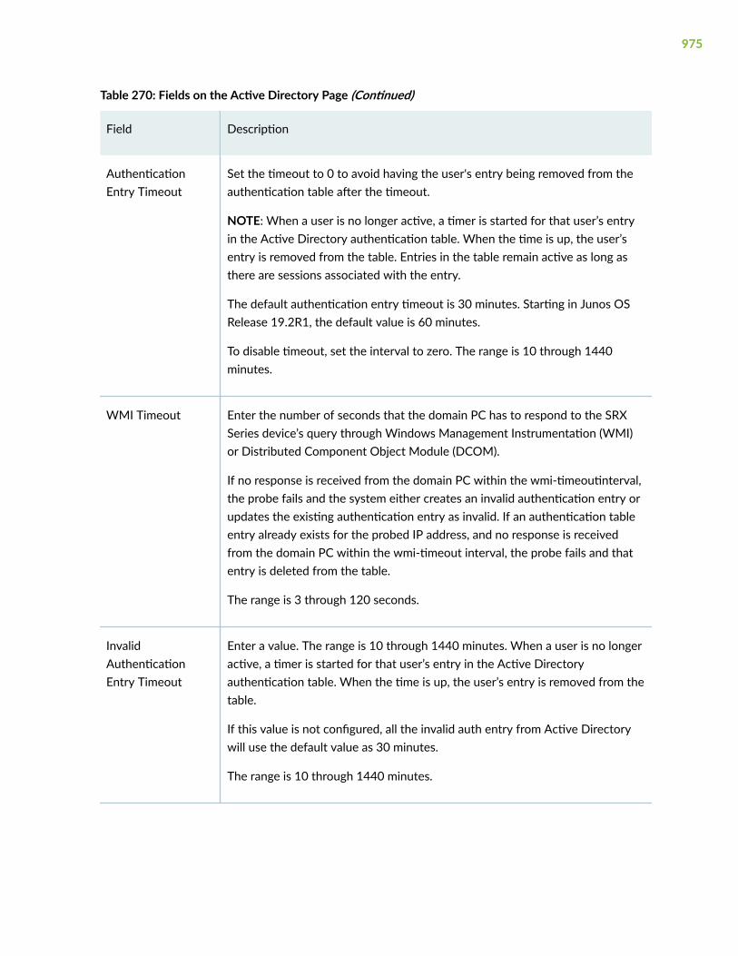
Table 270: Fields on the Active Directory Page (Continued)
Field Description
AuthenticationEntry Timeout
Set the timeout to 0 to avoid having the user's entry being removed from theauthentication table after the timeout.
NOTE: When a user is no longer active, a timer is started for that user’s entryin the Active Directory authentication table. When the time is up, the user’sentry is removed from the table. Entries in the table remain active as long asthere are sessions associated with the entry.
The default authentication entry timeout is 30 minutes. Starting in Junos OSRelease 19.2R1, the default value is 60 minutes.
To disable timeout, set the interval to zero. The range is 10 through 1440minutes.
WMI Timeout Enter the number of seconds that the domain PC has to respond to the SRXSeries device’s query through Windows Management Instrumentation (WMI)or Distributed Component Object Module (DCOM).
If no response is received from the domain PC within the wmi-timeoutinterval,the probe fails and the system either creates an invalid authentication entry orupdates the existing authentication entry as invalid. If an authentication tableentry already exists for the probed IP address, and no response is receivedfrom the domain PC within the wmi-timeout interval, the probe fails and thatentry is deleted from the table.
The range is 3 through 120 seconds.
InvalidAuthenticationEntry Timeout
Enter a value. The range is 10 through 1440 minutes. When a user is no longeractive, a timer is started for that user’s entry in the Active Directoryauthentication table. When the time is up, the user’s entry is removed from thetable.
If this value is not configured, all the invalid auth entry from Active Directorywill use the default value as 30 minutes.
The range is 10 through 1440 minutes.
975

Table 270: Fields on the Active Directory Page (Continued)
Field Description
FirewallAuthenticationForced Timeout
Enter a value. The range is 10 through 1440 minutes. This is the firewallauthentication fallback time. Set the timeout to 0 to avoid having the user'sentry being removed from the authentication table after the timeout.
Filter
Include Enable to include IP addresses from the Available column.
Click the Add icon (+) to create a new IP address and add it as either include orexclude from monitoring.
Click the Delete icon to delete a new IP address and add it as either include orexclude from monitoring.
Exclude Enable to exclude IP addresses from the Available column.
Click the Add icon (+) to create a new IP address and add it as either include orexclude from monitoring.
Click the Delete icon to delete a new IP address and add it as either include orexclude from monitoring.
Domain Settings
Test Click Test to check the Domain Connection status.
test:Status page appears and displays the status.
976

Table 270: Fields on the Active Directory Page (Continued)
Field Description
+ Click + to add a domain.
The Add Domain page appears.
NOTE:
• Starting in Junos OS Release 19.2R1, for SRX4200, SRX1500, SRX550M,and vSRX devices, and for the SRX5000 and SRX3000 lines of devices, youcan configure the integrated user firewall in a maximum of two domains. Forthe other SRX Series devices, you can create only one domain.
You can select the pencil icon to edit the domain or select delete icon todelete the domain.
General
Domain Name Enter the name of the domain.
The range for the domain name is 1 through 64 characters.
Username Enter the password for the Active Directory account password.
The range for the username is 1 through 64 characters. Example: admin
Password Enter the username for the Active Directory account name.
The range for the password is 1 through 128 characters. Example: A$BC123
Domain Controller(s)
DomainController(s)
Click the add icon (+) to add domain controller settings.
• Domain Controller Name—Enter the domain controller name. Name canrange from 1 through 64 characters.
You can configure up to maximum of 10 domain controllers.
• IP Address—Enter the IP address of the domain controller.
977

Table 270: Fields on the Active Directory Page (Continued)
Field Description
User Group Mapping (LDAP)
User GroupMapping (LDAP)
Click the add icon (+):
• IP Address—Enter the IP address of the LDAP server. If no address isspecified, the system uses one of the configured Active Directory domaincontrollers.
• Port—Enter the port number of the LDAP server. If no port number isspecified, the system uses port 389 for plaintext or port 636 for encryptedtext.
Default value is port 443.
Base DistinguishName
Enter the LDAP base distinguished name (DN).
Example: DC=example,DC=net
Username Enter the username of the LDAP account. If no username is specified, thesystem will use the configured domain controller’s username.
Password Enter the password for the account. If no password is specified, the systemuses the configured domain controller’s password.
Use SSL Enable Secure Sockets Layer (SSL) to ensure secure transmission with theLDAP server. Disabled by default, then the password is sent in plaintext.
AuthenticationAlgorithm
Enable this option to specify the algorithm used while the SRX Series devicecommunicates with the LDAP server. By default, simple is selected to configuresimple(plaintext) authentication mode.
IP User Mapping
978

Table 270: Fields on the Active Directory Page (Continued)
Field Description
Discovery Method(WMI)
Enable the method of discovering IP address-to-user mappings.
WMI—Windows Management Instrumentation (WMI) is the discovery methodused to access the domain controller. This option should be enabled only forinternal hosts or trusted hosts.
Event Log ScanningInterval
Enter the scanning interval at which the SRX Series device scans the event logon the domain controller. The range is 5 through 60 seconds.
Default value is 60 seconds.
Initial Event LogTimeSpan
Enter the time of the earliest event log on the domain controller that the SRXSeries device will initially scan. This scan applies to the initial deployment only.After WMIC and the user identification start working, the SRX Series devicescans only the latest event log.
The range is 1 through 168 hours. Default value is 1 hour.
Release History Table
Release Description
19.2R1 Starting in Junos OS Release 19.2R1, the default value is 60 minutes.
19.2R1 Starting in Junos OS Release 19.2R1, for SRX4200, SRX1500, SRX550M, and vSRX devices, and for theSRX5000 and SRX3000 lines of devices, you can configure the integrated user firewall in a maximum oftwo domains. For the other SRX Series devices, you can create only one domain.
RELATED DOCUMENTATION
About the Authentication Priority Page | 983
979

CHAPTER 91
Firewall Authentication—Local Authentication
IN THIS CHAPTER
About the Local Authentication Page | 980
Add a Local Auth Entry | 981
Delete a Local Auth Entry | 982
About the Local Authentication Page
IN THIS SECTION
Tasks You Can Perform | 980
Field Descriptions | 981
You are here: Security Services > Firewall Authentication > Local Authentication.
Use this page to enable or disable authentication priority configuration options.
Tasks You Can Perform
You can perform the following tasks from this page:
• Create a local auth entry. See "Add a Local Auth Entry" on page 981.
• Delete a local auth entry. See "Delete a Local Auth Entry" on page 982.
• Clear all the local auth entry. To do this, select the local auth entries you want to clear and click ClearAll at the top right of the table.
980

Field Descriptions
Table 271 on page 981 describes the fields on the Local Auth page.
Table 271: Fields on the Local Auth Page
Field Description
Filter by Displays the local authentication configuration based on the selected filter.
IP Displays the IP address.
Username Displays the name of the user.
Role Name Displays the list of roles assigned to the username.
Search Select the filter you want and enter your inputs based on the filter type. Then, click thesearch icon to display the output based on your selected filter.
RELATED DOCUMENTATION
Add a Local Auth Entry | 981
Delete a Local Auth Entry | 982
Add a Local Auth Entry
You are here: Security Services > Firewall Authentication > Local Authentication.
To add a local auth entry:
1. Click the add icon (+) on the upper right side of the Local Auth page.
The Add Local Auth Entry page appears.
2. Complete the configuration according to the guidelines provided in Table 272 on page 982.
3. Click OK to save the changes. If you want to discard your changes, click Cancel.
981

Table 272: Fields on the Add Local Auth Page
Field Action
IP Address Enter an IP address for the local authentication.
Username Enter a username for the local authentication.
Role List Enter roles for the local authentication entry. Enter the role and click + to add a role.
To delete a role, select the role and click the delete (X) icon.
To edit a role, hover over the role name and click the pencil icon.
NOTE: You can configure only maximum of 200 roles for a local authentication entry.
RELATED DOCUMENTATION
About the Local Authentication Page | 980
Delete a Local Auth Entry | 982
Delete a Local Auth Entry
You are here: Security Services > Firewall Authentication > Local Authentication.
To delete a local auth entry:
1. Select a local auth entry that you want to delete on the Local Auth Entry page.
2. Click the delete icon available on the upper right side of the page.
3. Click Yes to delete or click No to retain the profile.
RELATED DOCUMENTATION
About the Local Authentication Page | 980
Add a Local Auth Entry | 981
982

CHAPTER 92
Firewall Authentication—Authentication Priority
IN THIS CHAPTER
About the Authentication Priority Page | 983
About the Authentication Priority Page
You are here: Security Services > Firewall Authentication > Authentication Priority.
Use this page to enable or disable authentication priority configuration options.
Table 273 on page 983 describes the fields on the Auth Priority page.
Table 273: Fields on the Auth Priority Page
Field Description
Enable localauthentication
Select the Enable local authentication check box to enable localauthentication.
Priority Enter a priority value (1 through 65,535) in the Priority field.
NOTE: The default local authentication priority value is 100.
Enable firewallauthentication
Select the check box to enable firewall authentication.
Priority Enter a priority value (1 through 65,535) in the Priority field.
NOTE: The default firewall authentication priority value is 150.
983

Table 273: Fields on the Auth Priority Page (Continued)
Field Description
Enable unified accesscontrol
Select the check box to enable UAC authentication.
Priority Enter a priority value (1 through 65,535) in the Priority field.
NOTE: The default local authentication priority value is 200.
Enable active directory Select the check box to enable UAC authentication.
Priority Enter a priority value (1 through 65,535) in the Priority field.
NOTE: The default local authentication priority value is 125.
OK Click OK to save the configuration changes.
Reset Click Reset to set the priority values and enable options to the defaultconfiguration.
RELATED DOCUMENTATION
About the Local Authentication Page | 980
984

CHAPTER 93
Firewall Authentication—Identity Management
IN THIS CHAPTER
About the Identity Management Page | 985
Add an Identity Management Profile | 986
Edit an Identity Management Profile | 990
Delete Identity Management Profile | 991
About the Identity Management Page
IN THIS SECTION
Tasks You Can Perform | 985
You are here: Security Services > Firewall Authentication > Identity Management.
You can add, edit or delete the identity management profiles. You can also view the connection status ofthis SRX device with the Juniper Identity Management Services (JIMS).
Tasks You Can Perform
You can perform the following tasks from this page:
• Add an identity management profile. See "Add an Identity Management Profile" on page 986.
• Edit an identity management profile. See "Edit an Identity Management Profile" on page 990.
• Delete an identity management profile. See "Delete Identity Management Profile" on page 991.
985

RELATED DOCUMENTATION
Add an Identity Management Profile | 986
Add an Identity Management Profile
You are here: Security Services > Firewall Authentication > Identity Management.
To add an identity management profile:
1. Click Configure on the identity management page.
The Configure Identity Management Profile page appears.
2. Complete the configuration according to the guidelines provided in Table 274 on page 986.
3. Click Finish to save the changes. If you want to discard your changes, click Cancel.
Table 274: Fields on the Configure Identity Management Profile Page
Field Action
General Information
General Information Connection for Primary and Secondary Identity.
Connection Type Select a connection type from the list. Theoptions available are: HTTPS and HTTP.
Port Enter the port number or press up or down arrowto either increment or decrement the portnumber. The default value is 443.
Primary IP Address Enter a primary IP address of JIMS server.
Primary CA Certificate Specifies the primary certificate of the JIMS. SRXdevice will use it to verify JIMS’s certificate forSSL connection.
Select Upload CA certificate to device or specifythe path of the file on device.
986

Table 274: Fields on the Configure Identity Management Profile Page (Continued)
Field Action
Primary CA Certificate file upload Enables you to locate and upload the CAcertificate.
Click Browse to locate the CA certificate on yourdevice and click Upload the selected CAcertificate.
Primary CA Certificate file path Enter a file path of the primary CA certificate.
Primary Client ID Enter a primary client ID of the SRX device toobtain access token. It must be consistent withthe configuration of the API client created onJIMS.
Primary Client Secret Enter a password which enables you to accessthe primary identity management server.
Specifies the client secret of the SRX device toobtain access token. It must be consistent withthe configuration of the API client created onJIMS.
Secondary Identity Management Server Enables a secondary JIMS server, its IP address,CA certificate, client ID, and client secret.
NOTE: If you enable, the Secondary IP Address,Secondary CA Certificate file upload, SecondaryClient ID, Secondary Client Secret rows aredisplayed. Enter the IP address of the secondaryserver, browse and upload the secondary CAcertificate, enter the secondary client ID andsecret in the respective fields.
987
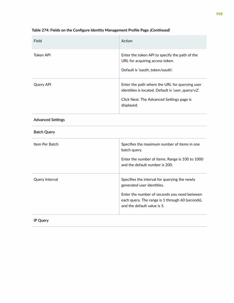
Table 274: Fields on the Configure Identity Management Profile Page (Continued)
Field Action
Token API Enter the token API to specify the path of theURL for acquiring access token.
Default is ’oauth_token/oauth’.
Query API Enter the path where the URL for querying useridentities is located. Default is ‘user_query/v2’.
Click Next. The Advanced Settings page isdisplayed.
Advanced Settings
Batch Query
Item Per Batch Specifies the maximum number of items in onebatch query.
Enter the number of items. Range is 100 to 1000and the default number is 200.
Query Interval Specifies the interval for querying the newlygenerated user identities.
Enter the number of seconds you need betweeneach query. The range is 1 through 60 (seconds),and the default value is 5.
IP Query
988
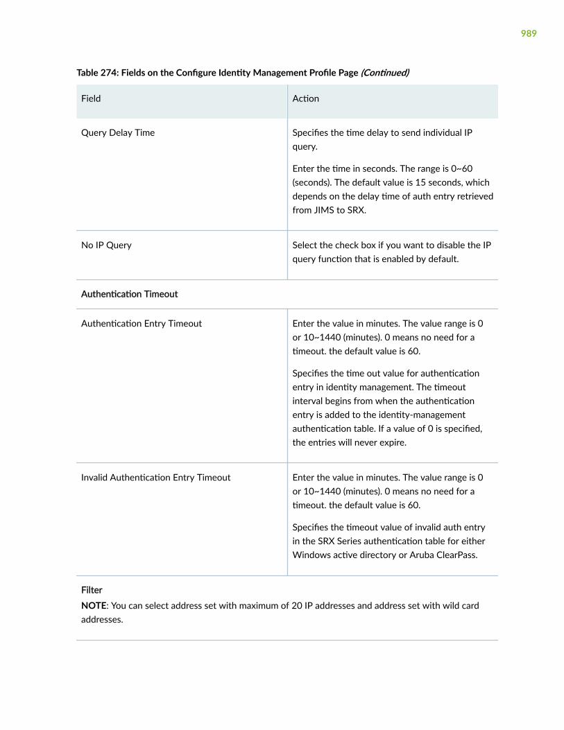
Table 274: Fields on the Configure Identity Management Profile Page (Continued)
Field Action
Query Delay Time Specifies the time delay to send individual IPquery.
Enter the time in seconds. The range is 0~60(seconds). The default value is 15 seconds, whichdepends on the delay time of auth entry retrievedfrom JIMS to SRX.
No IP Query Select the check box if you want to disable the IPquery function that is enabled by default.
Authentication Timeout
Authentication Entry Timeout Enter the value in minutes. The value range is 0or 10~1440 (minutes). 0 means no need for atimeout. the default value is 60.
Specifies the time out value for authenticationentry in identity management. The timeoutinterval begins from when the authenticationentry is added to the identity-managementauthentication table. If a value of 0 is specified,the entries will never expire.
Invalid Authentication Entry Timeout Enter the value in minutes. The value range is 0or 10~1440 (minutes). 0 means no need for atimeout. the default value is 60.
Specifies the timeout value of invalid auth entryin the SRX Series authentication table for eitherWindows active directory or Aruba ClearPass.
Filter
NOTE: You can select address set with maximum of 20 IP addresses and address set with wild cardaddresses.
989

Table 274: Fields on the Configure Identity Management Profile Page (Continued)
Field Action
Include IP Address Book Select an IP address book from the predefinedaddress book in which an address set must beselected as IP filter.
Include IP Address Set Specifies the predefined address set selected asIP filter.
Select an IP address set from the list.
To add a new address set for the IP address book,click Add New Address Set.
Exclude IP Address Book Select an IP address book that you want identitymanagement profile to exclude.
Exclude IP Address Set Select the predefined address set that you wantidentity management profile to exclude.
Filter to Domain Enter one or more active directory domains, tothe SRX Series device. You can specify up totwenty domain names for the filter.
RELATED DOCUMENTATION
About the Identity Management Page | 985
Edit an Identity Management Profile | 990
Delete Identity Management Profile | 991
Edit an Identity Management Profile
You are here: Security Services > Firewall Authentication > Identity Management.
990

To edit an identity management profile:
1. Select the existing identity management profile that you want to edit on the Identity Managementpage.
2. Click the pencil icon available on the upper right side of the page.
The Edit an Identity Management Profile page appears with editable fields. For more information onthe options, see "Add an Identity Management Profile" on page 986.
3. Click OK to save the changes.
RELATED DOCUMENTATION
About the Identity Management Page | 985
Add an Identity Management Profile | 986
Delete Identity Management Profile | 991
Delete Identity Management Profile
You are here: Security Services > Firewall Authentication > Identity Management.
To delete identity management profile:
1. Select an identity management profile that you want to delete on the Identity Management page.
2. Click the delete icon available on the upper right side of the page.
3. Click Yes to delete or click No to retain the profile.
RELATED DOCUMENTATION
About the Identity Management Page | 985
Add an Identity Management Profile | 986
Edit an Identity Management Profile | 990
991

CHAPTER 94
ICAP Redirect
IN THIS CHAPTER
About the ICAP Redirect Profile Page | 992
Add an ICAP Redirect Profile | 994
Edit an ICAP Redirect Profile | 997
Delete ICAP Redirect Profile | 998
About the ICAP Redirect Profile Page
IN THIS SECTION
Tasks You Can Perform | 992
Field Descriptions | 993
You are here: Security Services > ICAP Redirect.
You can configure ICAP Redirect Profile.
Tasks You Can Perform
You can perform the following tasks from this page:
• Create an ICAP redirect profile. See "Add an ICAP Redirect Profile" on page 994.
• Edit an ICAP redirect profile. See "Edit an ICAP Redirect Profile" on page 997.
• Delete an ICAP redirect profile. See "Delete ICAP Redirect Profile" on page 998.
992

• Filter the ICAP redirect profiles based on select criteria. To do this, select the filter icon at the topright-hand corner of the ICAP redirect profiles table. The columns in the grid change to accept filteroptions. Type the filter options; the table displays only the data that fits the filtering criteria.
• Show or hide columns in the ICAP redirect profiles table. To do this, click the Show Hide Columnsicon in the top right corner of the ICAP redirect profiles table and select the options you want toview or deselect the options you want to hide on the page.
• Advance search for ICAP redirect profiles. To do this, use the search text box present above the tablegrid. The search includes the logical operators as part of the filter string. In the search text box, whenyou hover over the icon, it displays an example filter condition. When you start entering the searchstring, the icon indicates whether the filter string is valid or not.
For an advanced search:
1. Enter the search string in the text box.
Based on your input, a list of items from the filter context menu appears.
2. Select a value from the list and then select a valid operator based on which you want to performthe advanced search operation.
NOTE: Press Spacebar to add an AND operator or OR operator to the search string. Pressbackspace at any point of time while entering a search criteria, only one character isdeleted.
3. Press Enter to display the search results in the grid.
Field Descriptions
Table 275 on page 993 describes the fields on the ICAP Redirect Profile page.
Table 275: Fields on the ICAP Redirect Profile Page
Field Description
Name Displays the ICAP Service profile name.
Timeout Displays the server response timeout in milliseconds.
993

Table 275: Fields on the ICAP Redirect Profile Page (Continued)
Field Description
Server Displays the ICAP Redirection Server.
Fallback Option Specifies the request timeout action when the request is sent to the server.
HTTP Redirect Enables redirect service on HTTP request/HTTP response.
RELATED DOCUMENTATION
Add an ICAP Redirect Profile | 994
Edit an ICAP Redirect Profile | 997
Delete ICAP Redirect Profile | 998
Add an ICAP Redirect Profile
You are here: Security Services > ICAP Redirect.
To add an ICAP redirect profile:
1. Click the add icon (+) on the upper right side of the ICAP Redirect Profiles page.
The Create ICAP Redirect Profile page appears.
2. Complete the configuration according to the guidelines provided in Table 276 on page 994.
3. Click OK to save the changes. If you want to discard your changes, click Cancel.
Table 276: Fields on the Create ICAP Redirect Profile Page
Field Action
Name Enter a unique ICAP Service profile name. The string must containalphanumeric characters, colons, periods, dashes, and underscores. No spacesare allowed; maximum length is 63 characters.
994

Table 276: Fields on the Create ICAP Redirect Profile Page (Continued)
Field Action
Timeout Enter the server response timeout in milliseconds. The range is between 100milliseconds to 50000 milliseconds.
HTTP Redirect Option
Request Select to enable redirect service on HTTP request.
Response Select to enable redirect service on HTTP response.
ICAP Server
You can configure ICAP Redirection server by the following options:
Add—Create an ICAP Redirect server. Enter information as specified in Table 277 on page 996.
Edit—Edit an ICAP Redirect server configuration. Enter information as specified in Table 277 on page996.
Fallback Option
Timeout Action Select the timeout action from the list. The available options are: None, Permit,Log Permit, and Block.
Connectivity Action Select the connectivity action from the list that the request cannot be sent outdue to connection issues.
Default Action Select a default action from the list to be taken when there are scenarios otherthan the above two mentioned ones.
995

Table 277: Fields on the Create ICAP Redirect Server Page
Field Action
Name Enter an ICAP Redirect server name.
The string must contain alphanumeric characters, colons, periods, dashes, andunderscores. No spaces are allowed; maximum length is 63 characters.
Host Type* Select Name or IP address.
Host Enter the host name or host IP address depending on what host type youchoose.
Port Specifies the port in the server. This is the server listening post and the defaultport will be reached according to protocol defined.
Enter the port number. The range is 1025 through 65534.
Sockets Specifies the number of connections to be created.
Enter the number of connections. The range is 1 through 64.
Authentication
Authorization Type Specifies the type of authentication.
Credentials Type Select the credential type as ASCII or Base64.
Based on the Credential Type that you choose, enter the ASCII string orBase64 string.
URL
Request MOD Enter the reqmod uri that can be configured for ICAP server only.
Response MOD Enter the respmod uri that can be configured for ICAP server only.
996

Table 277: Fields on the Create ICAP Redirect Server Page (Continued)
Field Action
Routing Instance Specifies the virtual router that is used for launching.
Select a routing instance from the list.
SSL Initiation Profile Select an SSL initiation profile from the list.
RELATED DOCUMENTATION
About the ICAP Redirect Profile Page | 992
Edit an ICAP Redirect Profile | 997
Delete ICAP Redirect Profile | 998
Edit an ICAP Redirect Profile
You are here: Security Services > ICAP Redirect.
To edit an ICAP redirect profile:
1. Select the existing ICAP redirect profile that you want to edit on the ICAP Redirect page.
2. Click the pencil icon available on the upper right side of the page.
The Edit ICAP Redirect Profile page appears with editable fields. For more information on theoptions, see "Add an ICAP Redirect Profile" on page 994.
3. Click OK to save the changes.
RELATED DOCUMENTATION
About the ICAP Redirect Profile Page | 992
Delete ICAP Redirect Profile | 998
997

Delete ICAP Redirect Profile
You are here: Security Services > ICAP Redirect.
To delete ICAP redirect profile:
1. Select one or more ICAP redirect profile that you want to delete on the ICAP Redirect page.
2. Click the delete icon available on the upper right side of the page.
3. Click Yes to delete or click No to retain the profile.
RELATED DOCUMENTATION
About the ICAP Redirect Profile Page | 992
Add an ICAP Redirect Profile | 994
Edit an ICAP Redirect Profile | 997
998