Proactive Quality Guidance for Model Evolution in Model Libraries
Upload
khangminh22Category
view
3download
0
MEDICAL FILM PROCESSOR
MODEL SRX-101A
SERVICE MANUAL (NEW CPU BOARD)
1051/1052/1069, #20001~
SERVICE MANUAL (OLD CPU BOARD)
1051/1052/1069, ~#20000
SERVICE MANUAL
MODEL SRX-101ASERVICE MANUAL
No. 26-2, Nishishinjuku 1-chome, Shinjuku-ku, Tokyo 163-0512, Japan
4TH EDITION MAY 2004
CODE NO. 1051CODE NO. 1052CODE NO. 1069

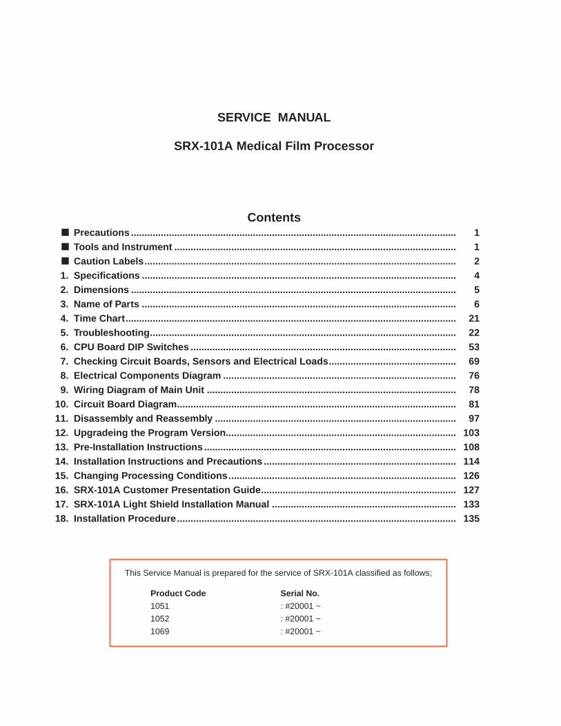
SERVICE MANUAL
SRX-101A Medical Film Processor
Contents Precautions ........................................................................................................................ 1 Tools and Instrument ........................................................................................................ 1 Caution Labels................................................................................................................... 21. Specifications .................................................................................................................... 42. Dimensions ........................................................................................................................ 53. Name of Parts .................................................................................................................... 64. Time Chart.......................................................................................................................... 215. Troubleshooting................................................................................................................. 226. CPU Board DIP Switches .................................................................................................. 537. Checking Circuit Boards, Sensors and Electrical Loads............................................... 698. Electrical Components Diagram ...................................................................................... 769. Wiring Diagram of Main Unit ............................................................................................ 78
10. Circuit Board Diagram....................................................................................................... 8111. Disassembly and Reassembly ......................................................................................... 9712. Upgradeing the Program Version..................................................................................... 10313. Pre-Installation Instructions ............................................................................................. 10814. Installation Instructions and Precautions ....................................................................... 11415. Changing Processing Conditions.................................................................................... 12616. SRX-101A Customer Presentation Guide........................................................................ 12717. SRX-101A Light Shield Installation Manual .................................................................... 13318. Installation Procedure....................................................................................................... 135
This Service Manual is prepared for the service of SRX-101A classified as follows;
Product Code Serial No.
1051 : #20001 ~
1052 : #20001 ~
1069 : #20001 ~

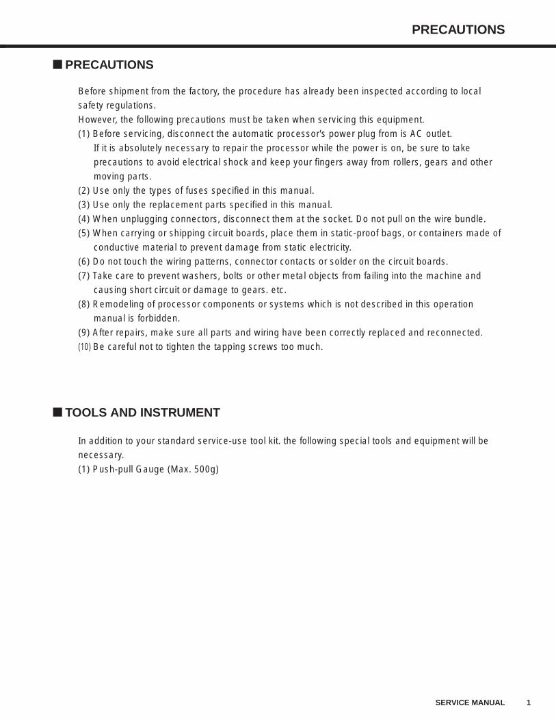
PRECAUTIONS
1SERVICE MANUAL
PRECAUTIONS
Before shipment from the factory, the procedure has already been inspected according to local
safety regulations.
However, the following precautions must be taken when servicing this equipment.
(1) Before servicing, disconnect the automatic processor's power plug from is AC outlet.
If it is absolutely necessary to repair the processor while the power is on, be sure to take
precautions to avoid electrical shock and keep your fingers away from rollers, gears and other
moving parts.
(2) Use only the types of fuses specified in this manual.
(3) Use only the replacement parts specified in this manual.
(4) When unplugging connectors, disconnect them at the socket. Do not pull on the wire bundle.
(5) When carrying or shipping circuit boards, place them in static-proof bags, or containers made of
conductive material to prevent damage from static electricity.
(6) Do not touch the wiring patterns, connector contacts or solder on the circuit boards.
(7) Take care to prevent washers, bolts or other metal objects from failing into the machine and
causing short circuit or damage to gears. etc.
(8) Remodeling of processor components or systems which is not described in this operation
manual is forbidden.
(9) After repairs, make sure all parts and wiring have been correctly replaced and reconnected.
(10) Be careful not to tighten the tapping screws too much.
TOOLS AND INSTRUMENT
In addition to your standard service-use tool kit. the following special tools and equipment will be
necessary.
(1) Push-pull Gauge (Max. 500g)
2 SERVICE MANUAL
CAUTION LABEL
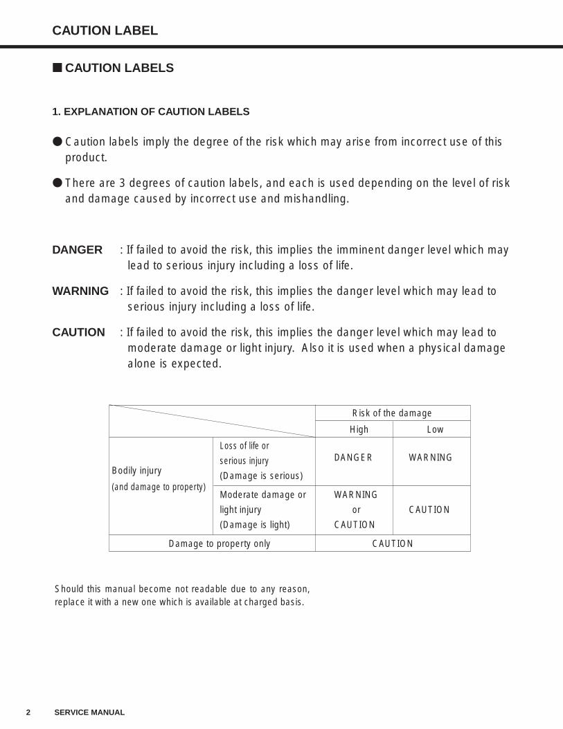
Caution labels imply the degree of the risk which may arise from incorrect use of thisproduct.
There are 3 degrees of caution labels, and each is used depending on the level of riskand damage caused by incorrect use and mishandling.
DANGER : If failed to avoid the risk, this implies the imminent danger level which may lead to serious injury including a loss of life.
WARNING : If failed to avoid the risk, this implies the danger level which may lead to serious injury including a loss of life.
CAUTION : If failed to avoid the risk, this implies the danger level which may lead to moderate damage or light injury. Also it is used when a physical damage alone is expected.
Risk of the damage
High Low
Loss of life or DANGER WARNING
Bodily injuryserious injury
(and damage to property)(Damage is serious)
Moderate damage or WARNING
light injury or CAUTION
(Damage is light) CAUTION
Damage to property only CAUTION
Should this manual become not readable due to any reason,replace it with a new one which is available at charged basis.
1. EXPLANATION OF CAUTION LABELS
CAUTION LABELS
3SERVICE MANUAL
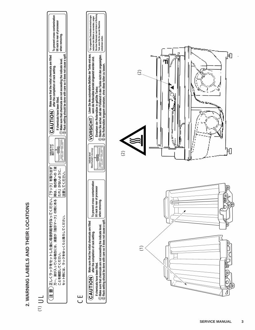
(1)
2. W
AR
NIN
G L
AB
EL
S A
ND
TH
EIR
LO
CA
TIO
NS
UL
CE
(2)
(2)
(1)
4 SERVICE MANUAL
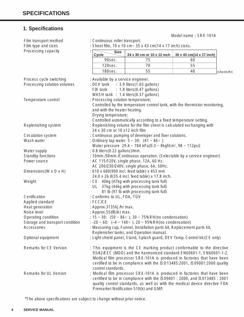
SPECIFICATIONS
Model name : SRX-101AFilm transport method : Continuous roller transport.Film type and sizes : Sheet film, 10 x 10 cm~ 35 x 43 cm(14 x 17 inch) sizes.Processing capacity :
Process cycle switching : Available by a service engineer.Processing solution volumes : DEV tank : 3.9 liters(1.03 gallons)
FIX tank : 1.8 liters(0.47 gallons)WASH tank : 1.4 liters(0.37 gallons)
Temperature control : Processing solution temperature;Controlled by the temperature control tank, with the thermistor monitoring, and with the heater heating.Drying temperature;Controlled automatically according to a fixed temperature setting.
Replenishing system : Replenishing volume for the film sheet is calculated exchanging with 24 x 30 cm or 10 x12 inch film
Circulation system : Continuous pumping of developer and fixer solutions.Wash water : Ordinary tap water 5 ~ 30:(41 ~ 86<)
Water pressure 29.4 ~ 784 kPa(0.3 ~ 8kgf/cm2, 98 ~ 112psi)Water supply : 0.8 liters(0.22 gallons)/min.Standby functions : 10min./30min./Continuous operation. (Selectable by a service engineer)Power source : AC 115/120V, single phase, 12A, 60 Hz.
AC 200/230/240V, single phase, 6A, 50Hz.Dimensions(W x D x H) : 610 x 680(900 incl. feed table) x 453 mm
24.0 x 26.8(35.4 incl. feed table) x 17.8 inch.Weight : CE 40kg (47kg with processing tank full)
UL 37kg (44kg with processing tank full)81 lb (97 lb with processing tank full)
Certification : Conforms to UL, FDA, TÜVApplied standard : FCC/CEHeat generation : Approx.3135kJ/hr max.Noise level : Approx.55dB(A) max.Operating condition : 15 ~ 30:(59 ~ 86<), 30 ~ 75%RH(no condensation)Storage and transport condition : -20 ~ 60:(--4 ~ 140<), 20 ~ 95%RH(no condensation)Accessories : Measuring cup, Funnel, Installation parts kit, Replacement parts kit,
Replenisher tanks, and Operation manual.Optional equipment : Light shield panel, Stand, Splash guard, DEV Temp. Control kit.(CE only)
Remarks for CE Version : This equipment is the CE marking product conformable to the directive93/42/EEC (MDD) and the harmonized standard EN60601-1, EN60601-1-2.Medical film processor SRX-101A is produced in factories that have beencertified to be in compliance with the ISO13485:2001, IS09001:2000 qualitycontrol standards.
Remarks for UL Version : Medical film processor SRX-101A is produced in factories that have beencertified to be in compliance with the IS09001 : 2000, and IS013485 : 2001quality control standards, as well as with the medical device directive FDAPremarket Notification 510(k) and GMP.
*The above specifications are subject to change without prior notice.
SizeCycle 24 x 30 cm or 10 x 12 inch 35 x 43 cm(14 x 17 inch)
90sec. 75 60120sec. 70 55180sec. 55 40 (sheets/hr)
1. Specifications
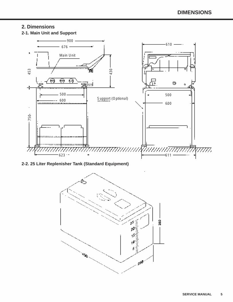
DIMENSIONS
5SERVICE MANUAL
2. Dimensions2-1. Main Unit and Support
2-2. 25 Liter Replenisher Tank (Standard Equipment)
900610
500
600
611
676
500
453
750
430
600
623
Main Unit
Support (Optional)
6 SERVICE MANUAL
NAME OF PARTS
3-2. Main Unit (Left Side View)
Power Breaker
Power Cord
Wash Water Drainage Hose(larger diameter than other hoses)
Fixer Drainage Hose(red)
Fixer Supply Hose (red)
Binding Tape
Electrical Components Housing
Developer Supply Hose (yellow)
Developer Drainage Hose (yellow)
Overflow Drainage Hose
Right Side Panel
Film Exit
Top Cover
Level Adjustable Leg
Control Panel
Feed Tray
Feed Tray Cover
Fixer Drainage Valve Developer Drainage Valve
Water Supply Hose
Wash Water Drainage Valve
Left Side Panel
3-1. Main Unit (Front View)
3. Name of Parts
NAME OF PARTS
7SERVICE MANUAL
3-4. Control Panel
3-3. Main Unit (Rear View)
RUNREADY
RUN
Drier Section Cover
Back Panel
"RUN" LampLights up when the [RUN] SW ispressed. Will automatically go out ifno film has been inserted for 8 hoursafter the "READY" LAMP lamp wenton. Will light up again when the[RUN] SW is pressed.
"READY" LampLights up when the temperatures ofthe processing chemicals and heaterare at their preset values. Film maybe inserted for processing wheneverthis lamp is on.
[Repl.](Replenishment) SWPress and hold down this switch forabout 5 seconds to begin the supplyof processing chemicals to the tanksat a rate of 3P per second. Duringreplenishment, "READY" LAMP lampwill change to flashing.
[RUN] SWPress this switch to start and stopfilm processing.
RUN SW LampIndicates that the SRX-101A iselectrically powered.
8 SERVICE MANUAL
NAME OF PARTS
Different ON-OFF patterns shown by the "RUN" and "READY" lamps on the control panel indicate different operatingconditions. The following is a listing of all the possibilities and the conditions they indicate.
"RUN" and "READY" LAMP Lamps ON-OFF Patterns
OFF
OFF
ON
ON
ON
OFF
OFF
Flashing(Pattern 1)
OFF
Flashing(Pattern 2)
ON
Flashing(Pattern 1)
OFF
Flashing(Pattern 1)
ON
RUN
READY
RUN
READY
RUN
READY
RUN
READY
RUN
READY
RUN
READY
RUN
READY
RUN
READY
Flashing(Pattern 2)
ON-OFF Pattern Operating Condition LED Pattern
All operations shut down
Normal operation
(Operating temperature OK)
Normal operation
(Operating temperature LOW)
Preparing for supplying
chemical solutions
([Repl.] SW ON for 5 sec.)
Supplying chemical
solutions
Manual replenishment
Drive motor error
Dry Temperature error
Pattern 1
0.50.5ON OFF
Pattern 2
0.70.10.1
0.1
Pattern 2
0.70.10.1
0.1
Pattern 1
0.50.5ON OFF
Pattern 1
0.50.5ON OFF
RUN
READY
RUN
READY
Flashing(Pattern 1)
ON
Flashing(Pattern 1)
ON
DEV Temperature error
Film Sensor error
Pattern 1
0.50.5ON OFF
Pattern 1
0.50.5ON OFF
Buzzer Sound Pattern
0.50.5
ON OFF
1.00.1 0.1
0.1 0.1 0.1
0.1 0.1
1.00.1 0.1
0.1 0.1
0.1
1.00.1
1.00.1
NAME OF PARTS
9SERVICE MANUAL
3-5. Main Unit (Top View)
Wash Water TankDrive Shaft
Fixer Tank
Developer Tank
Rack HandlesRack Handles
Developing RackStarter Solution InletFix/Wash Rack
10 SERVICE MANUAL
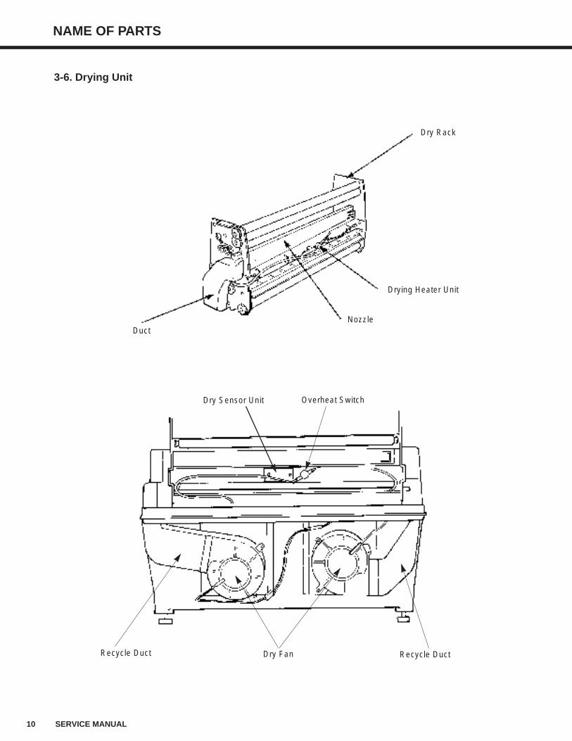
NAME OF PARTS
Dry Rack
Drying Heater Unit
DuctNozzle
Overheat Switch
Recycle Duct Dry Fan Recycle Duct
Dry Sensor Unit
3-6. Drying Unit
NAME OF PARTS
11SERVICE MANUAL
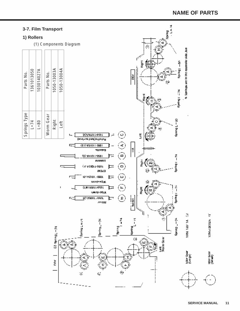
Spr
ings
Typ
eP
arts
No.
L=74
1361
0130
50
L=80
1030
1402
7A
Wor
m G
ear
Par
ts N
o.
Rig
ht10
50-1
3003
A
Left
1050
-130
04A
3-7. Film Transport
1) Rollers
(1) Components Diagram
12 SERVICE MANUAL
NAME OF PARTS
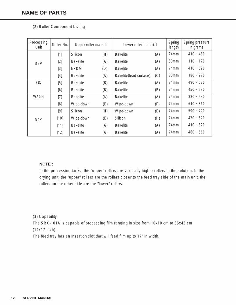
(2) Roller Component Listing
NOTE :
In the processing tanks, the "upper" rollers are vertically higher rollers in the solution. In the
drying unit, the "upper" rollers are the rollers closer to the feed tray side of the main unit. the
rollers on the other side are the "lower" rollers.
(3) Capability
The SRX-101A is capable of processing film ranging in size from 10x10 cm to 35x43 cm
(14x17 inch).
The feed tray has an insertion slot that will feed film up to 17" in width.
ProcessingUnit
DEV
FIX
WASH
DRY
Upper roller material
Silicon (H)
Bakelite (A)
EPDM (D)
Bakelite (A)
Bakelite (B)
Bakelite (B)
Bakelite (A)
Wipe-down (E)
Silicon (H)
Wipe-down (E)
Bakelite (A)
Bakelite (A)
Lower roller material
Bakelite (A)
Bakelite (A)
Bakelite (A)
Bakelite(lead surface) (C)
Bakelite (A)
Bakelite (B)
Bakelite (A)
Wipe-down (F)
Wipe-down (E)
Silicon (H)
Bakelite (A)
Bakelite (A)
Roller No.
[1]
[2]
[3]
[4]
[5]
[6]
[7]
[8]
[9]
[10]
[11]
[12]
Springlength
74mm
80mm
74mm
80mm
74mm
74mm
74mm
74mm
74mm
74mm
74mm
74mm
Spring pressurein grams
410 ~ 480
110 ~ 170
410 ~ 520
180 ~ 270
490 ~ 530
450 ~ 530
330 ~ 530
610 ~ 860
590 ~ 720
470 ~ 620
410 ~ 520
460 ~ 560
NAME OF PARTS
13SERVICE MANUAL
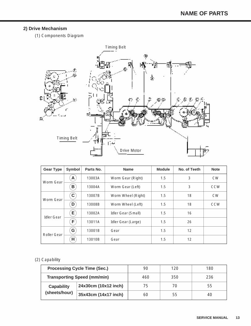
2) Drive Mechanism
(1) Components Diagram
(2) Capability
Timing Belt
Timing Belt
Drive Motor
Gear Type Symbol Parts No. Name Module No. of Teeth Note
Worm GearA 13003A Worm Gear (Right) 1.5 3 CW
B 13004A Worm Gear (Left) 1.5 3 CCW
Worm GearC 13007B Worm Wheel (Right) 1.5 18 CW
D 13008B Worm Wheel (Left) 1.5 18 CCW
Idler GearE 13002A Idler Gear (Small) 1.5 16
F 13011A Idler Gear (Large) 1.5 26
Roller GearG 13001B Gear 1.5 12
H 13010B Gear 1.5 12
Processing Cycle Time (Sec.) 90 120 180
Transporting Speed (mm/min) 460 350 236
Capability 24x30cm (10x12 inch) 75 70 55
(sheets/hour) 35x43cm (14x17 inch) 60 55 40
14 SERVICE MANUAL
NAME OF PARTS
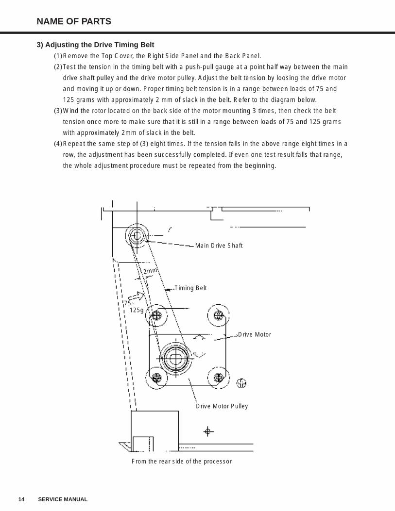
3) Adjusting the Drive Timing Belt
(1)Remove the Top Cover, the Right Side Panel and the Back Panel.
(2)Test the tension in the timing belt with a push-pull gauge at a point half way between the main
drive shaft pulley and the drive motor pulley. Adjust the belt tension by loosing the drive motor
and moving it up or down. Proper timing belt tension is in a range between loads of 75 and
125 grams with approximately 2 mm of slack in the belt. Refer to the diagram below.
(3)Wind the rotor located on the back side of the motor mounting 3 times, then check the belt
tension once more to make sure that it is still in a range between loads of 75 and 125 grams
with approximately 2mm of slack in the belt.
(4)Repeat the same step of (3) eight times. If the tension falls in the above range eight times in a
row, the adjustment has been successfully completed. If even one test result falls that range,
the whole adjustment procedure must be repeated from the beginning.
Main Drive Shaft
Timing Belt
Drive Motor
Drive Motor Pulley
2mm
75~125g
From the rear side of the processor
NAME OF PARTS
15SERVICE MANUAL
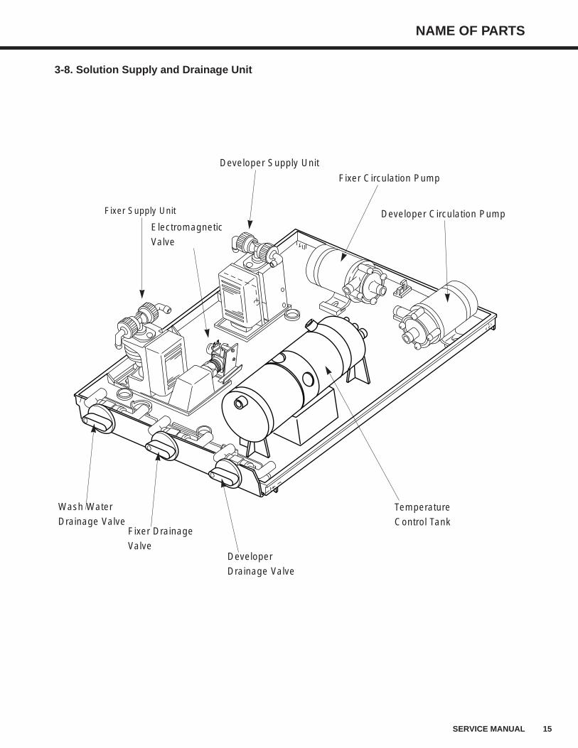
Temperature
Control Tank
Developer
Drainage Valve
Electromagnetic
Valve
Fixer Drainage
Valve
Wash Water
Drainage Valve
Fixer Circulation Pump
Developer Supply Unit
Fixer Supply Unit Developer Circulation Pump
3-8. Solution Supply and Drainage Unit
16 SERVICE MANUAL
NAME OF PARTS
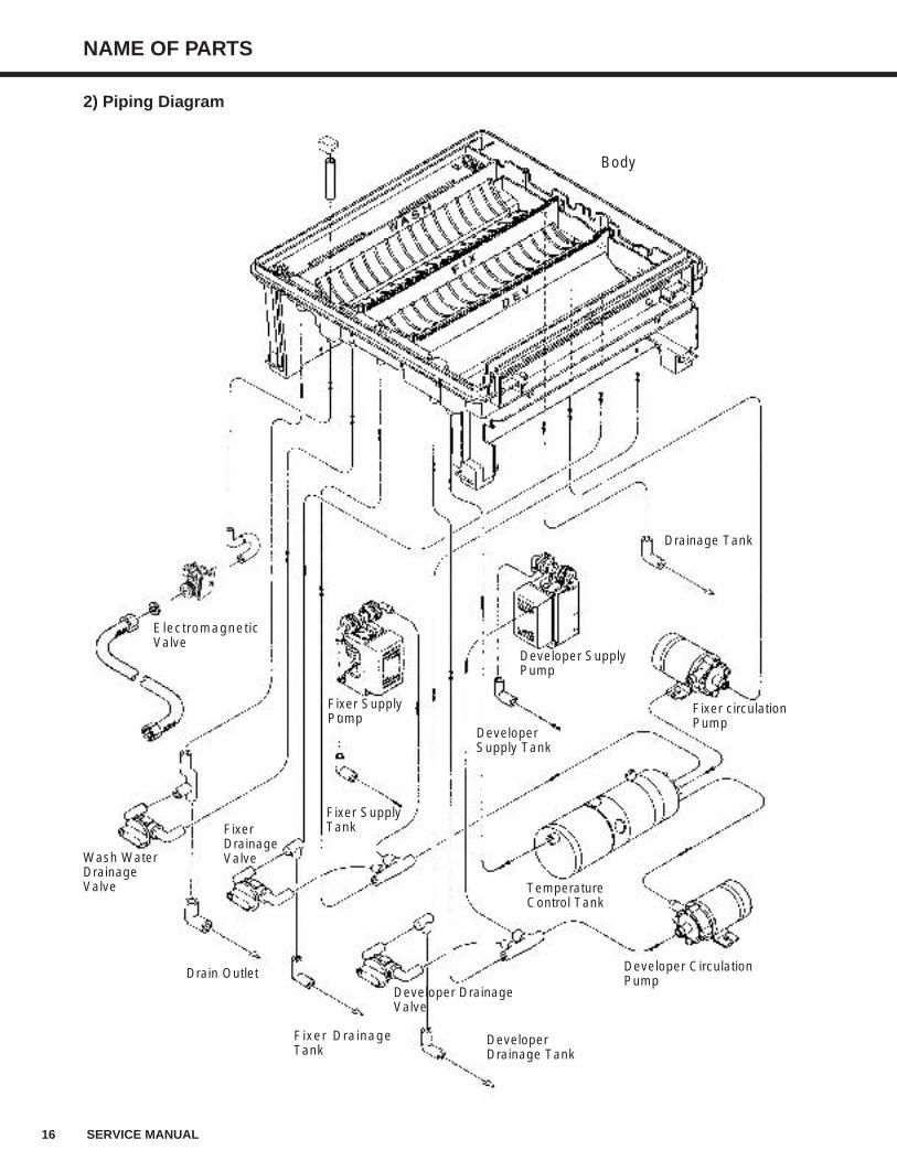
2) Piping Diagram
Body
ElectromagneticValve
Fixer SupplyPump
Developer SupplyPump
Fixer circulationPump
Temperature Control Tank
Developer Circulation Pump
Developer DrainageValve
Wash WaterDrainageValve
Drainage Tank
Fixer SupplyTank
Drain Outlet
Fixer DrainageTank
DeveloperDrainage Tank
DeveloperSupply Tank
Fixer DrainageValve
NAME OF PARTS
17SERVICE MANUAL
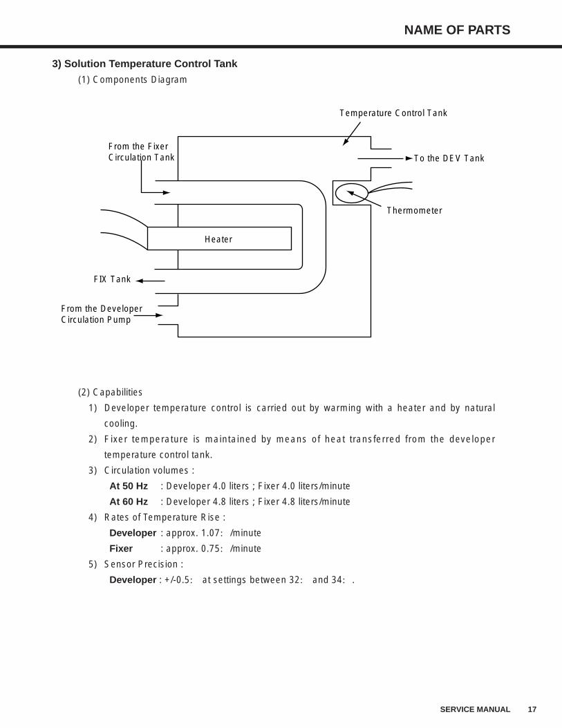
3) Solution Temperature Control Tank
(1) Components Diagram
(2) Capabilities
1) Developer temperature control is carried out by warming with a heater and by natural
cooling.
2) Fixer temperature is maintained by means of heat transferred from the developer
temperature control tank.
3) Circulation volumes :
At 50 Hz : Developer 4.0 liters ; Fixer 4.0 liters/minute
At 60 Hz : Developer 4.8 liters ; Fixer 4.8 liters/minute
4) Rates of Temperature Rise :
Developer : approx. 1.07:/minute
Fixer : approx. 0.75:/minute
5) Sensor Precision :
Developer : +/-0.5: at settings between 32: and 34:.
From the FixerCirculation Tank
FIX Tank
From the Developer Circulation Pump
Temperature Control Tank
To the DEV Tank
Thermometer
Heater
18 SERVICE MANUAL
NAME OF PARTS
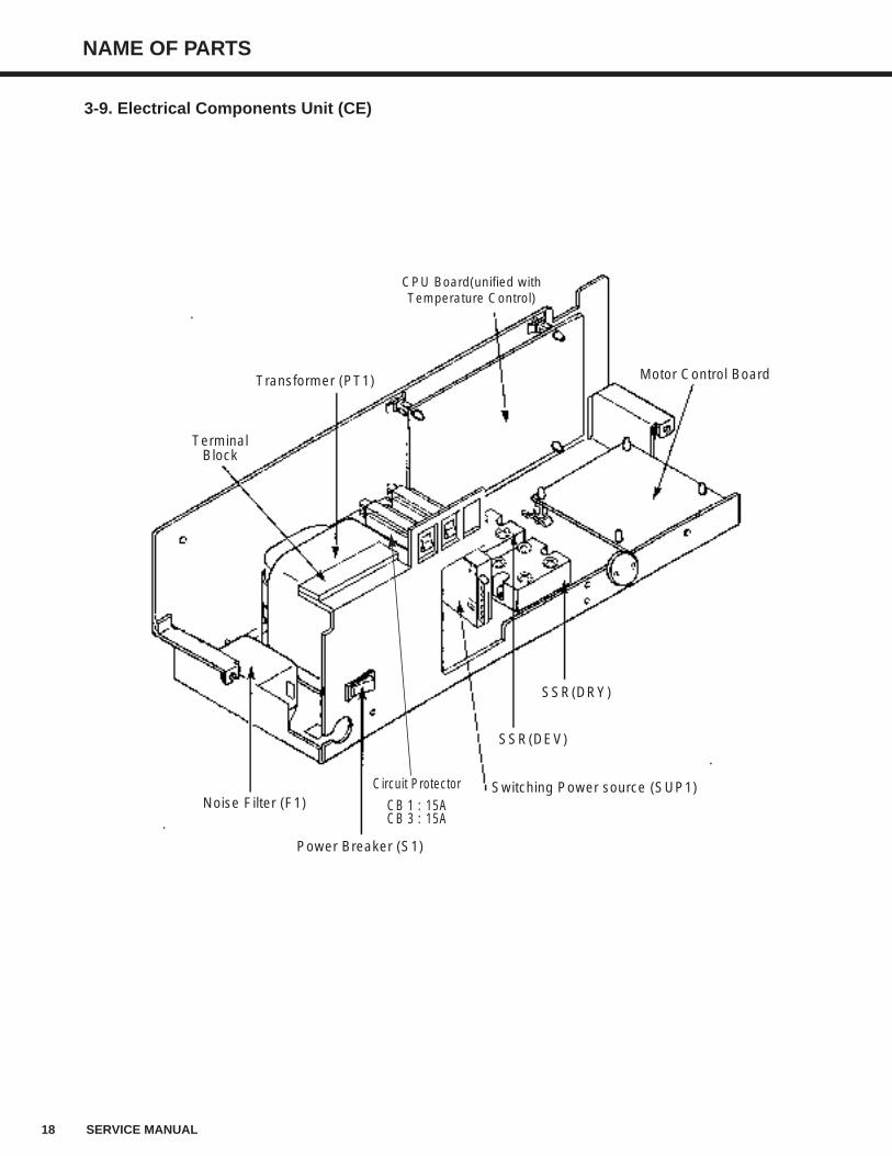
Transformer (PT1)
TerminalBlock
Power Breaker (S1)
CPU Board(unified withTemperature Control)
Circuit Protector
CB 1 : 15ACB 3 : 15A
SSR(DEV)
Switching Power source (SUP1)
SSR(DRY)
Noise Filter (F1)
Motor Control Board
3-9. Electrical Components Unit (CE)
NAME OF PARTS
19SERVICE MANUAL
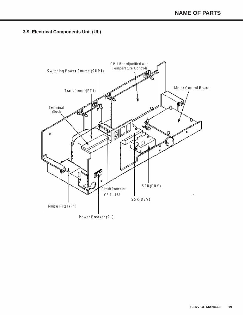
3-9. Electrical Components Unit (UL)
Transformer(PT1)
TerminalBlock
Switching Power Source (SUP1)
Power Breaker (S1)
CPU Board(unified withTemperature Control)
Circuit Protector
CB 1 : 15ASSR(DEV)
SSR(DRY)
Noise Filter (F1)
Motor Control Board
20 SERVICE MANUAL
NAME OF PARTS
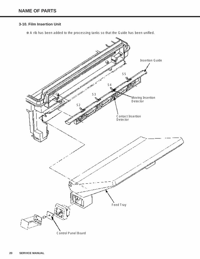
A rib has been added to the processing tanks so that the Guide has been unified.
Insertion Guide
Moving InsertionDetector
Contact InsertionDetector
Feed Tray
Control Panel Board
3-10. Film Insertion Unit
S5
S4
S3
S2
NAME OF PARTS
21SERVICE MANUAL
4. Time Chart (In normal functioning)
1) T1 is one of the three standby options : 10 minutes, 30 minutes, or 0minute (continuous operation).Ex. : When a film is inserted while a 10 minutes' standby interval, a 10 minutes' timer is reset. Then after the film is ejected, the T1 repeats 5 minutes ON and 10 minutes OFF alternately.
2) The various for T2 (duration of high speed rotation of the motor after the film detection is turned off)and T3 (duration from detection of the trailing edge of film to alarm ON) are listed below :
(unit : second)3) The time in the chart is valid at the 50 Hz. ( ) is at the 60 Hz.4) For each hour after [RUN] SW ON during which no film is processed, one 24 x 30cm(10 x 12inch)
replenish amount of processing solution will be supplied to each tank. (The timer is reset after FilmInsertion Detection ON.)
5) Drying heater preheating will begin if the temperature is below 80: at [RUN] SW ON.6) Initial solution replenish will not be carried out if the [RUN] SW is pressed ON within 4 hours after
[RUN] SW OFF.7) Initial solution replenish (developer ; 26.7 sec(22.2 sec ; 60 Hz)(two 24 x 30cm(10 x 12inch) Sheets
equivalent) ; fixer solution : 23.3 sec (19.4 sec : 60 Hz)[one 24 x 30cm(10 x 12inch) Sheet equivalent]will be carried out if the [RUN] SW is pressed ON more than 4 hours after [RUN] SW OFF.
8) Even if DEV and DRY is ready, "READY" lamp doesn't lit at least 15 minutes.9) Shutdown will occur automatically if film isn't inserted for more 8 hours after "READY" lamp ON.
"RUN" Lamp
"READY" Lamp
READY Signal
Drive Motor
DEV CirculationPump
FIX CirculationPump
DEV Supply Pump
FIX Supply Pump
DEV Heater
DRY Heater
Alarm
ElectromagneticValve
Pump to refill water
Drying Fan
Input
1h15min
53.3s(44.4s)46.7s
(38.9s)
13minPreheating
2min
8min
24s(20s)
60s(50s)
min5
5min
1.5s
60s
T3
(Optional)
13.3s(11.1s)
23.3s(19.4s)
13.3s(11.1s)
23.3s(19.4s)
3min
30min(Rapid Transfer)
2min
T1
( )
Notes :
Pow
er B
reak
er O
N
[RU
N] S
W O
N
DR
Y T
empe
ratu
re O
K
DE
V T
empe
ratu
re L
OW
DR
Y T
empe
ratu
re O
KD
EV
Tem
pera
ture
LO
W
DE
V T
empe
ratu
re H
IGH
(+
2:)
Film
Inse
rtio
n D
etec
tion
ON
DE
V T
empe
ratu
re O
K24
x30c
m(1
0 x
12in
ch)
Are
a
Film
Inse
rtio
n D
etec
tion
OF
F
DR
Y T
empe
ratu
re O
K
DE
V T
empe
ratu
re L
OW
DE
V T
empe
ratu
re H
IGH
(+2:
)D
RY
Tem
pera
ture
LO
WD
EV
Tem
pera
ture
LO
W
[RU
N] S
W O
FF
Pow
er B
reak
er O
FF
Cycle Time T2110150
220
14.06.3
5.0
T390
120
180
T2
22S
ER
VIC
E M
AN
UA
L
TR
OU
BL
E S
HO
OT
ING
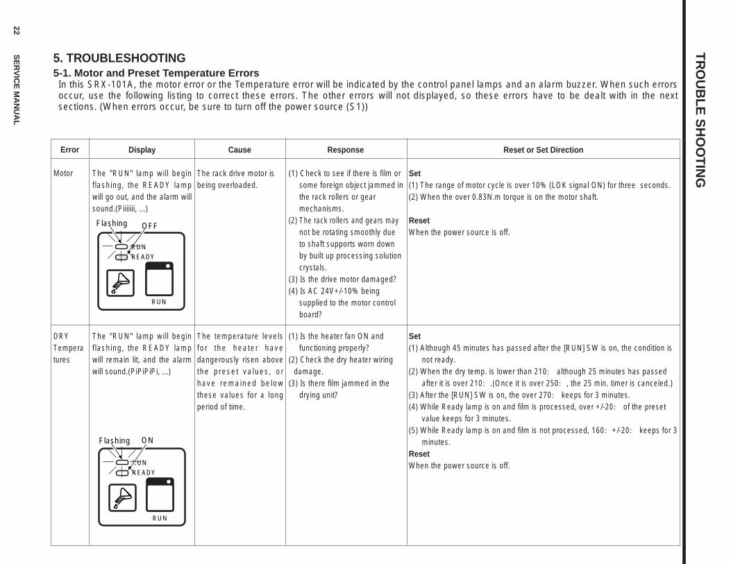
5. TROUBLESHOOTING5-1. Motor and Preset Temperature Errors In this SRX-101A, the motor error or the Temperature error will be indicated by the control panel lamps and an alarm buzzer. When such errorsoccur, use the following listing to correct these errors. The other errors will not displayed, so these errors have to be dealt with in the nextsections. (When errors occur, be sure to turn off the power source (S1))
Error
Motor
DRYTemperatures
Display
The "RUN" lamp will beginflashing, the READY lampwill go out, and the alarm willsound.(Piiiiiii, ...)
The "RUN" lamp will beginflashing, the READY lampwill remain lit, and the alarmwill sound.(PiPiPiPi, ...)
Cause
The rack drive motor isbeing overloaded.
The temperature levelsfor the heater havedangerously risen abovethe preset values, orhave remained belowthese values for a longperiod of time.
Response
(1) Check to see if there is film or some foreign object jammed in the rack rollers or gear mechanisms.
(2) The rack rollers and gears may not be rotating smoothly due to shaft supports worn down by built up processing solution crystals.
(3) Is the drive motor damaged?(4) Is AC 24V+/-10% being
supplied to the motor control board?
Reset or Set Direction
Set(1) The range of motor cycle is over 10% (LOK signal ON) for three seconds.(2) When the over 0.83N.m torque is on the motor shaft.
ResetWhen the power source is off.
Set (1) Although 45 minutes has passed after the [RUN] SW is on, the condition is
not ready.(2) When the dry temp. is lower than 210: although 25 minutes has passed
after it is over 210:.(Once it is over 250:, the 25 min. timer is canceled.)(3) After the [RUN] SW is on, the over 270: keeps for 3 minutes.(4) While Ready lamp is on and film is processed, over +/-20: of the preset
value keeps for 3 minutes.(5) While Ready lamp is on and film is not processed, 160:+/-20: keeps for 3
minutes.ResetWhen the power source is off.
(1) Is the heater fan ON and functioning properly?
(2) Check the dry heater wiringdamage.
(3) Is there film jammed in the drying unit?
RUNREADY
RUN
Flashing ON
READY
Flashing OFF
RUN
RUN
TR
OU
BL
E S
HO
OT
ING
23S
ER
VIC
E M
AN
UA
L
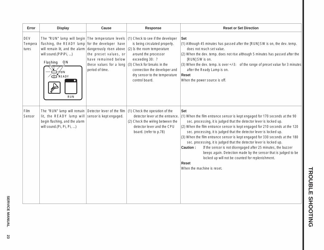
Error
DEVTemperatures
FilmSensor
Display
The "RUN" lamp will beginflashing, the READY lampwill remain lit, and the alarmwill sound.(PiPiPi, ...)
The "RUN" lamp will remainlit, the READY lamp wil lbegin flashing, and the alarmwill sound.(Pi, Pi, Pi, ...)
Cause
The temperature levelsfor the developer havedangerously risen abovethe preset values, orhave remained belowthese values for a longperiod of time.
Detector lever of the filmsensor is kept engaged.
Response
(1) Check to see if the developer is being circulated properly.
(2) Is the room temperature around the processor exceeding 30:?
(3) Check for breaks in the connection the developer and dry sensor to the temperature control board.
Reset or Set Direction
Set (1) Although 45 minutes has passed after the [RUN] SW is on, the dev. temp.
does not reach set value.(2) When the dev. temp. does not rise although 5 minutes has passed after the
[RUN] SW is on.(3) When the dev. temp. is over +/-3: of the range of preset value for 3 minutes
after the Ready Lamp is on.ResetWhen the power source is off.
Set (1) When the film entrance sensor is kept engaged for 170 seconds at the 90
sec. processing, it is judged that the detector lever is locked up.(2) When the film entrance sensor is kept engaged for 210 seconds at the 120
sec. processing, it is judged that the detector lever is locked up. (3) When the film entrance sensor is kept engaged for 330 seconds at the 180
sec. processing, it is judged that the detector lever is locked up.Caution : If the sensor is not disengaged after 25 minutes, the buzzer
beeps again. Detection made by the sensor that is judged to belocked up will not be counted for replenishment.
ResetWhen the machine is reset.
(1) Check the operation of thedetector lever at the entrance.
(2) Check the wiring between thedetector lever and the CPUboard. (refer to p.78)
RUNREADY
RUN
Flashing ON
24 SERVICE MANUAL
TROUBLE SHOOTING
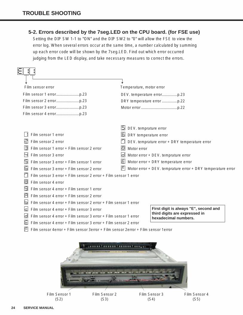
5-2. Errors described by the 7seg.LED on the CPU board. (for FSE use)Setting the DIP SW 1-1 to "ON" and the DIP SW2 to "0" will allow the FSE to view the
error log. When several errors occur at the same time, a number calculated by summing
up each error code will be shown by the 7seg.LED. Find out which error occurred
judging from the LED display, and take necessary measures to correct the errors.
Film Sensor 1(S2)
Film Sensor 2(S3)
Film Sensor 3(S4)
Film Sensor 4(S5)
Film sensor 1 error
Film sensor error
First digit is always "E", second andthird digits are expressed inhexadecimal numbers.
Temperature, motor error
Film sensor 1 error + Film sensor 2 error
Film sensor 3 error
Film sensor 2 error
Film sensor 4 error
Film sensor 3 error + Film sensor 2 error
Film sensor 3 error + Film sensor 1 error
Film sensor 3 error + Film sensor 2 error + Film sensor 1 error
Film sensor 4 error + Film sensor 1 error
Motor error
DRY temperature error
DEV. temprature error
DEV. temprature error + DRY temperature error
Film sensor 4 error + Film sensor 3 error + Film sensor 1 error
Film sensor 4 error + Film sensor 2 error + Film sensor 1 error
Film sensor 4 error + Film sensor 2 error
Film sensor 4 error + Film sensor 3 error
Film sensor 4 error + Film sensor 3 error + Film sensor 2 error
Film sensor 4error + Film sensor 3error + Film sensor 2error + Film sensor 1error
Motor error + DEV. temprature error
Motor error + DRY temperature error
Motor error + DEV. temprature error + DRY temperature error
Film sensor 1 error.....................p.23
Film sensor 2 error.....................p.23
Film sensor 3 error.....................p.23
Film sensor 4 error.....................p.23
DEV. temperature error..............p.23
DRY temperature error ..............p.22
Motor error .................................p.22
TROUBLE SHOOTING
25SERVICE MANUAL
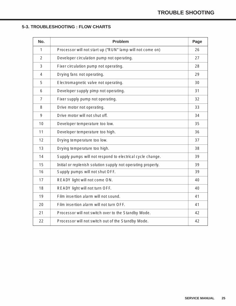
5-3. TROUBLESHOOTING : FLOW CHARTS
No. Problem Page
1 Processor will not start up ("RUN" lamp will not come on) 26
2 Developer circulation pump not operating. 27
3 Fixer circulation pump not operating. 28
4 Drying fans not operating. 29
5 Electromagnetic valve not operating. 30
6 Developer supply pimp not operating. 31
7 Fixer supply pump not operating. 32
8 Drive motor not operating. 33
9 Drive motor will not shut off. 34
10 Developer temperature too low. 35
11 Developer temperature too high. 36
12 Drying temperature too low. 37
13 Drying temperature too high. 38
14 Supply pumps will not respond to electrical cycle change. 39
15 Initial or replenish solution supply not operating properly. 39
16 Supply pumps will not shut OFF. 39
17 READY light will not come ON. 40
18 READY light will not turn OFF. 40
19 Film insertion alarm will not sound. 41
20 Film insertion alarm will not turn OFF. 41
21 Processor will not switch over to the Standby Mode. 42
22 Processor will not switch out of the Standby Mode. 42
26 SERVICE MANUAL
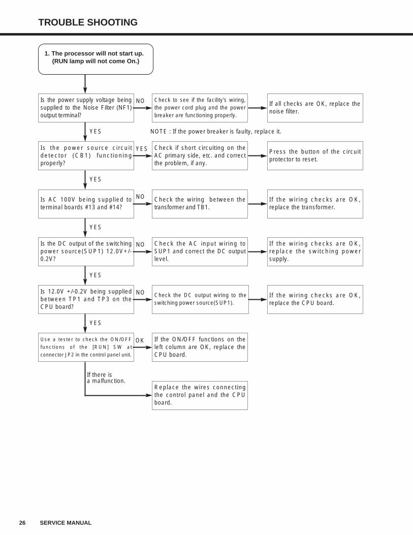
TROUBLE SHOOTING
1. The processor will not start up.(RUN lamp will not come On.)
Is the power supply voltage beingsupplied to the Noise Filter (NF1)output terminal?
Is the power source circuitdetector (CB1) functioningproperly?
Is AC 100V being supplied toterminal boards #13 and #14?
Is the DC output of the switchingpower source(SUP1) 12.0V+/-0.2V?
Is 12.0V +/-0.2V being suppliedbetween TP1 and TP3 on theCPU board?
Use a tester to check the ON/OFF
functions of the [RUN] SW at
connector JP2 in the control panel unit.
Check to see if the facility's wiring,the power cord plug and the powerbreaker are functioning properly.
Check if short circuiting on theAC primary side, etc. and correctthe problem, if any.
Check the wiring between thetransformer and TB1.
Check the AC input wiring toSUP1 and correct the DC outputlevel.
Check the DC output wiring to theswitching power source(SUP1).
If the ON/OFF functions on theleft column are OK, replace theCPU board.
Replace the wires connectingthe control panel and the CPUboard.
If all checks are OK, replace thenoise filter.
Press the button of the circuitprotector to reset.
If the wiring checks are OK,replace the transformer.
If the wiring checks are OK,replace the switching powersupply.
If the wiring checks are OK,replace the CPU board.
YES
YES
YES
YES
YES
If there is a malfunction.
NO
YES
NO
NO
NO
NOTE : If the power breaker is faulty, replace it.
OK
TROUBLE SHOOTING
27SERVICE MANUAL
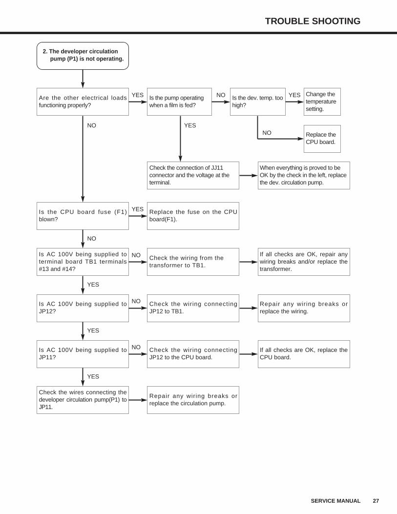
2. The developer circulationpump (P1) is not operating.
Are the other electrical loadsfunctioning properly?
Is the CPU board fuse (F1)blown?
Is AC 100V being supplied toterminal board TB1 terminals#13 and #14?
Is AC 100V being supplied toJP12?
Is AC 100V being supplied toJP11?
Check the wires connecting thedeveloper circulation pump(P1) toJP11.
Is the pump operatingwhen a film is fed?
Replace the fuse on the CPUboard(F1).
Check the wiring from thetransformer to TB1.
Check the wiring connectingJP12 to TB1.
Check the wiring connectingJP12 to the CPU board.
Repair any wiring breaks orreplace the circulation pump.
If all checks are OK, repair anywiring breaks and/or replace thetransformer.
Repair any wiring breaks orreplace the wiring.
If all checks are OK, replace theCPU board.
NO
NO
YES
YES
YES
YES
YES
NO
NO
NO
Is the dev. temp. toohigh?
Change thetemperaturesetting.
NO YES
Check the connection of JJ11connector and the voltage at theterminal.
Replace theCPU board.
When everything is proved to beOK by the check in the left, replacethe dev. circulation pump.
NOYES
28 SERVICE MANUAL
TROUBLE SHOOTING
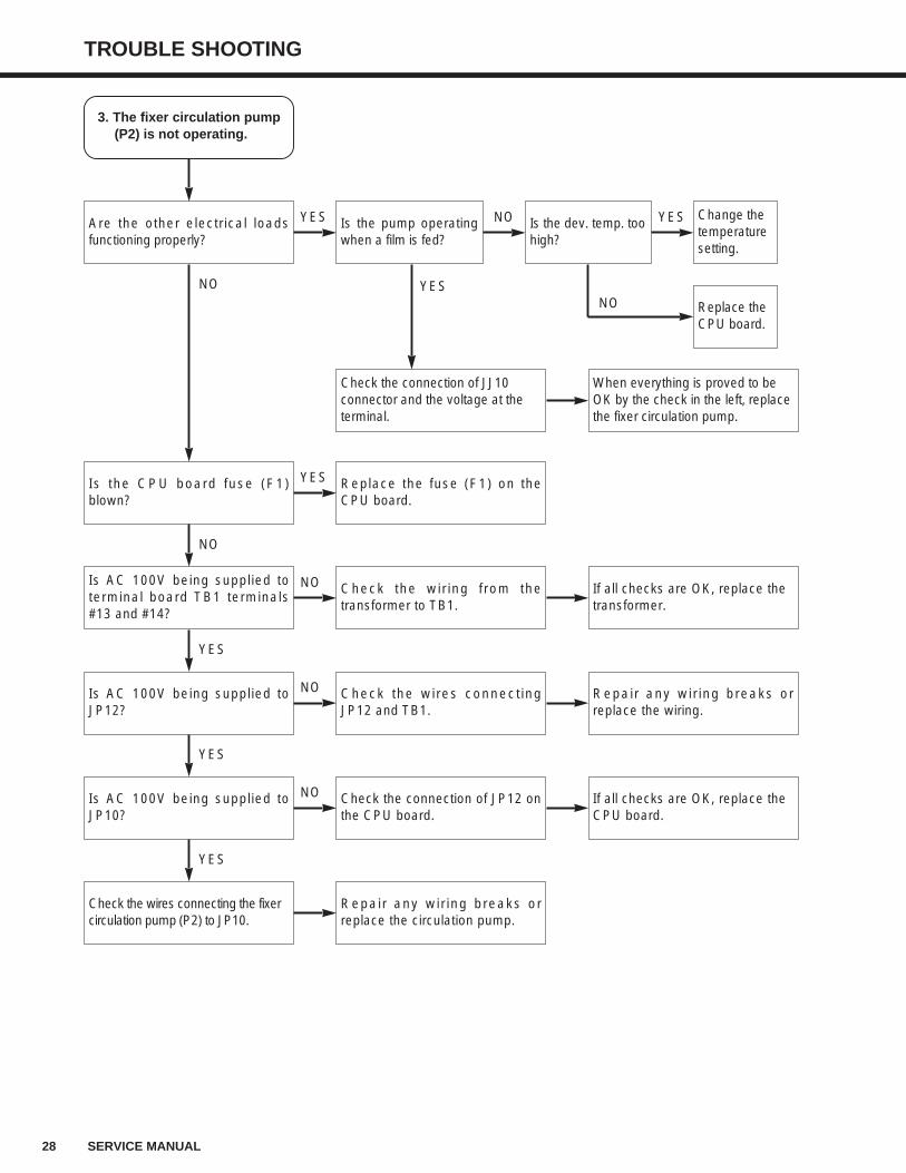
3. The fixer circulation pump(P2) is not operating.
Are the other electrical loadsfunctioning properly?
Is the CPU board fuse (F1)blown?
Is AC 100V being supplied toterminal board TB1 terminals#13 and #14?
Is AC 100V being supplied toJP12?
Is AC 100V being supplied toJP10?
Check the wires connecting the fixer circulation pump (P2) to JP10.
Replace the fuse (F1) on theCPU board.
Check the wiring from thetransformer to TB1.
Check the wires connectingJP12 and TB1.
Check the connection of JP12 onthe CPU board.
Repair any wiring breaks orreplace the circulation pump.
If all checks are OK, replace the transformer.
Repair any wiring breaks orreplace the wiring.
If all checks are OK, replace the CPU board.
NO
NO
YES
YES
YES
YES
YES
NO
NO
NO
Is the pump operatingwhen a film is fed?
Is the dev. temp. toohigh?
Change thetemperaturesetting.
NO YES
Check the connection of JJ10connector and the voltage at theterminal.
Replace theCPU board.
When everything is proved to beOK by the check in the left, replacethe fixer circulation pump.
NOYES
TROUBLE SHOOTING
29SERVICE MANUAL
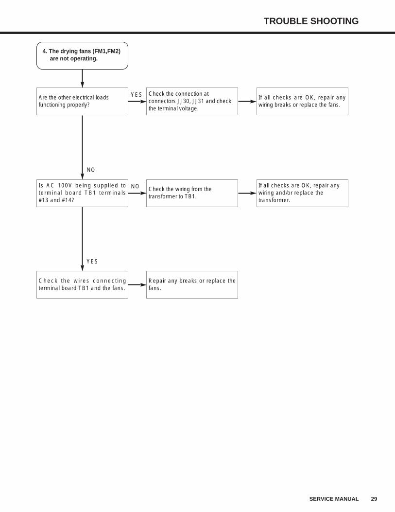
4. The drying fans (FM1,FM2)are not operating.
Are the other electrical loads functioning properly?
Is AC 100V being supplied toterminal board TB1 terminals#13 and #14?
Check the wires connectingterminal board TB1 and the fans.
Check the connection atconnectors JJ30, JJ31 and checkthe terminal voltage.
Check the wiring from thetransformer to TB1.
Repair any breaks or replace thefans.
If all checks are OK, repair anywiring breaks or replace the fans.
If all checks are OK, repair anywiring and/or replace thetransformer.
NO
YES
YES
NO
30 SERVICE MANUAL
TROUBLE SHOOTING
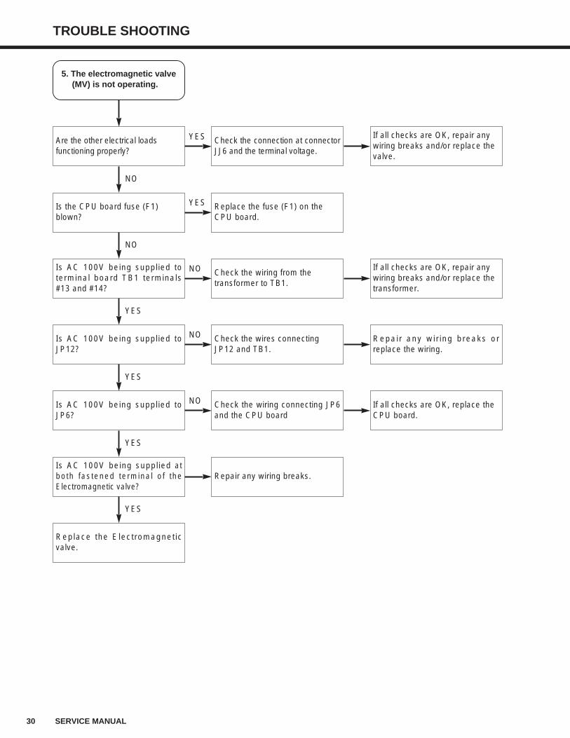
5. The electromagnetic valve(MV) is not operating.
Are the other electrical loads functioning properly?
Is the CPU board fuse (F1) blown?
Is AC 100V being supplied toterminal board TB1 terminals#13 and #14?
Is AC 100V being supplied toJP12?
Is AC 100V being supplied toJP6?
Is AC 100V being supplied atboth fastened terminal of theElectromagnetic valve?
Check the connection at connectorJJ6 and the terminal voltage.
Replace the fuse (F1) on the CPU board.
Check the wiring from the transformer to TB1.
Check the wires connecting JP12 and TB1.
Check the wiring connecting JP6and the CPU board
Repair any wiring breaks.
If all checks are OK, repair any wiring breaks and/or replace the valve.
If all checks are OK, repair any wiring breaks and/or replace the transformer.
Repair any wiring breaks orreplace the wiring.
If all checks are OK, replace the CPU board.
NO
NO
YES
YES
YES
Replace the Electromagneticvalve.
YES
YES
YES
NO
NO
NO
TROUBLE SHOOTING
31SERVICE MANUAL
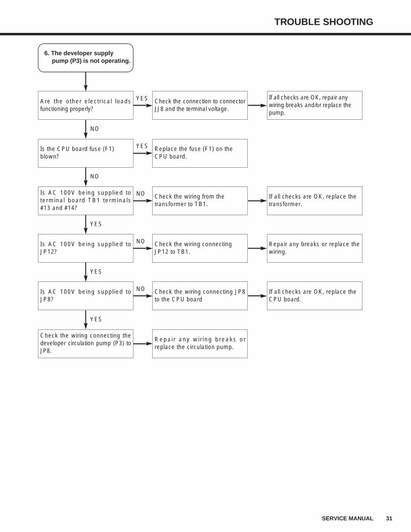
6. The developer supplypump (P3) is not operating.
Are the other electrical loadsfunctioning properly?
Is the CPU board fuse (F1) blown?
Is AC 100V being supplied toterminal board TB1 terminals#13 and #14?
Is AC 100V being supplied toJP12?
Is AC 100V being supplied toJP8?
Check the wiring connecting thedeveloper circulation pump (P3) toJP8.
Check the connection to connectorJJ8 and the terminal voltage.
Replace the fuse (F1) on the CPU board.
Check the wiring from the transformer to TB1.
Check the wiring connecting JP12 to TB1.
Check the wiring connecting JP8to the CPU board
Repair any wiring breaks orreplace the circulation pump.
If all checks are OK, repair any wiring breaks and/or replace the pump.
If all checks are OK, replace the transformer.
Repair any breaks or replace thewiring.
If all checks are OK, replace the CPU board.
NO
NO
YES
YES
YES
YES
YES
NO
NO
NO
32 SERVICE MANUAL
TROUBLE SHOOTING
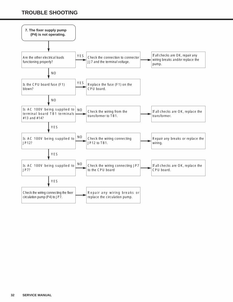
7. The fixer supply pump(P4) is not operating.
Are the other electrical loads functioning properly?
Is the CPU board fuse (F1) blown?
Is AC 100V being supplied toterminal board TB1 terminals#13 and #14?
Is AC 100V being supplied toJP12?
Is AC 100V being supplied toJP7?
Check the wiring connecting the fixer circulation pump (P4) to JP7.
Check the connection to connectorJJ7 and the terminal voltage.
Replace the fuse (F1) on the CPU board.
Check the wiring from the transformer to TB1.
Check the wiring connecting JP12 to TB1.
Check the wiring connecting JP7to the CPU board
Repair any wiring breaks orreplace the circulation pump.
If all checks are OK, repair any wiring breaks and/or replace the pump.
If all checks are OK, replace the transformer.
Repair any breaks or replace thewiring.
If all checks are OK, replace the CPU board.
NO
NO
YES
YES
YES
YES
YES
NO
NO
NO
TROUBLE SHOOTING
33SERVICE MANUAL
8. The drive motor (M1) isnot operating.
Is AC 24V being supplied betweenJP24 #1 and #2.
Is the CPU board fuse (F1) blown?
Is DC 5V being supplied betweenJP25 #1 and #5.
Is JP26 properly connected?
Is DC 5V being supplied between JP26 #1 (GND) and #6?
Replace the motor control board and check to see if the motor is operating normally?
Check the wiring connecting JP24to the transformer's secondaryside.
Replace the fuse.
Check the wiring and connectorsto the CPU board.
Connect JP26 properly.
Replace the motor control board.
Replace only the motor control board.
If all checks are are OK, replacethe transformer.
If all checks are OK, replace the CPU board.
YES
NO
YES
YES
YES
NO
YES
NO
NO
NO
Replace only the motor and see if normal operation is resumed?
Replace only the motor.
NO
YES
Replace both the motor and the motor control board.
NO
YES
34 SERVICE MANUAL
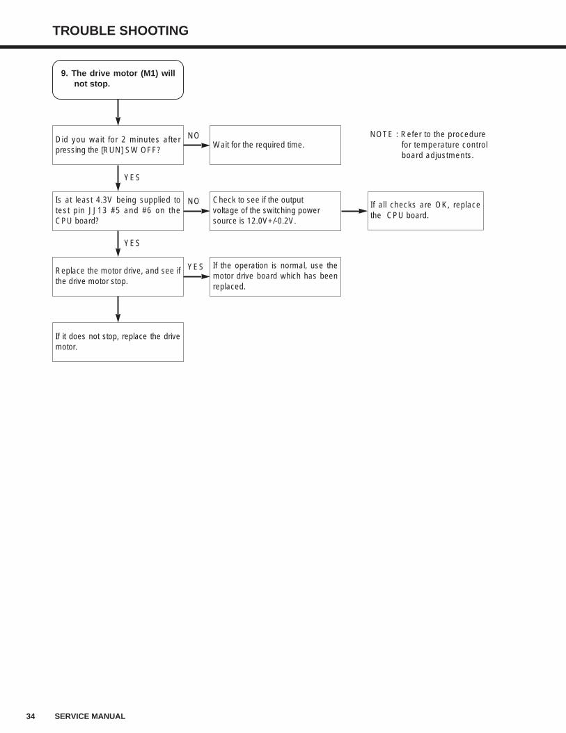
TROUBLE SHOOTING
9. The drive motor (M1) willnot stop.
Did you wait for 2 minutes afterpressing the [RUN] SW OFF?
Is at least 4.3V being supplied totest pin JJ13 #5 and #6 on theCPU board?
Replace the motor drive, and see ifthe drive motor stop.
If it does not stop, replace the drivemotor.
Wait for the required time.
Check to see if the output voltage of the switching power source is 12.0V+/-0.2V.
If the operation is normal, use themotor drive board which has beenreplaced.
NOTE : Refer to the procedure for temperature control board adjustments.
If all checks are OK, replacethe CPU board.
YES
YES
NO
NO
YES
TROUBLE SHOOTING
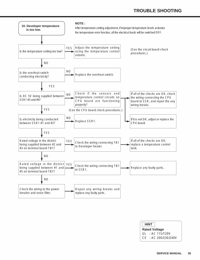
35SERVICE MANUAL
10. Developer temperatureis too low.
Is the temperature setting too low?
Is the overheat switch conducting electricity?
Is DC 5V being supplied betweenSSR1 #3 and #4?
Is electricity being conducted between SSR1 #1 and #2?
Rated voltage in the districtbeing supplied between #2 and#3 on terminal board TB1?
Rated voltage in the districtbeing supplied between #1 and#5 on terminal board TB1?
Adjust the temperature setting using the temperature control volume.
NOTE :
After temperature setting adjustment, if improper temperature levels activates
the temperature error function, all the electrical loads will be switched OFF.
Replace the overheat switch.
Check if the sensors and temperature control circuits on CPU board are functioning properly?
Replace SSR1.
Check the wiring connecting TB1to Developer heater.
Check the wiring connecting TB1to SSR1.
(See the circuit board check procedures.)
If all of the checks are OK, checkthe wiring connecting the CPU board to SSR, and repair the anywiring breaks.
If it is not OK, adjust or replace the CPU board.
If all of the checks are OK, replace a temperature control tank.
Replace any faulty parts.
NO
YES
YES
YES
NO
YES
NO
NO
NO
YES
Check the wiring to the power breaker and noise filter.
Repair any wiring breaks andreplace any faulty parts.
NO
YES
(See the CPU board check procedures.)
Rated VoltageUL : AC 115/120VCE : AC 200/230/240V
HINT
36 SERVICE MANUAL
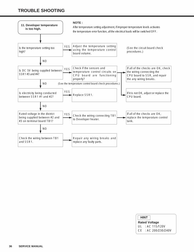
TROUBLE SHOOTING
If all of the checks are OK, checkthe wiring connecting the CPU board to SSR, and repair the any wiring breaks.
If it is not OK, adjust or replace the CPU board.
11. Developer temperatureis too high.
Is the temperature setting too high?
Is DC 5V being supplied betweenSSR1 #3 and #4?
Is electricity being conducted between SSR1 #1 and #2?
Rated voltage in the districtbeing supplied between #2 and#3 on terminal board TB1?
Check the wiring between TB1 and SSR1.
Adjust the temperature settingusing the temperature controlboard volume.
NOTE :
After temperature setting adjustment, if improper temperature levels activates
the temperature error function, all the electrical loads will be switched OFF.
Check if the sensors and temperature control circuits onCPU board are functioningproperly?
Replace SSR1.
Check the wiring connecting TB1to Developer heater.
Repair any wiring breaks andreplace any faulty parts.
(See the circuit board check procedures.)
If all of the checks are OK, replace the temperature control tank.
NO
NO
NO
NO
YES
YES
YES
YES
(See the temperature control board check procedures.)
Rated VoltageUL : AC 115/120VCE : AC 200/230/240V
HINT
TROUBLE SHOOTING
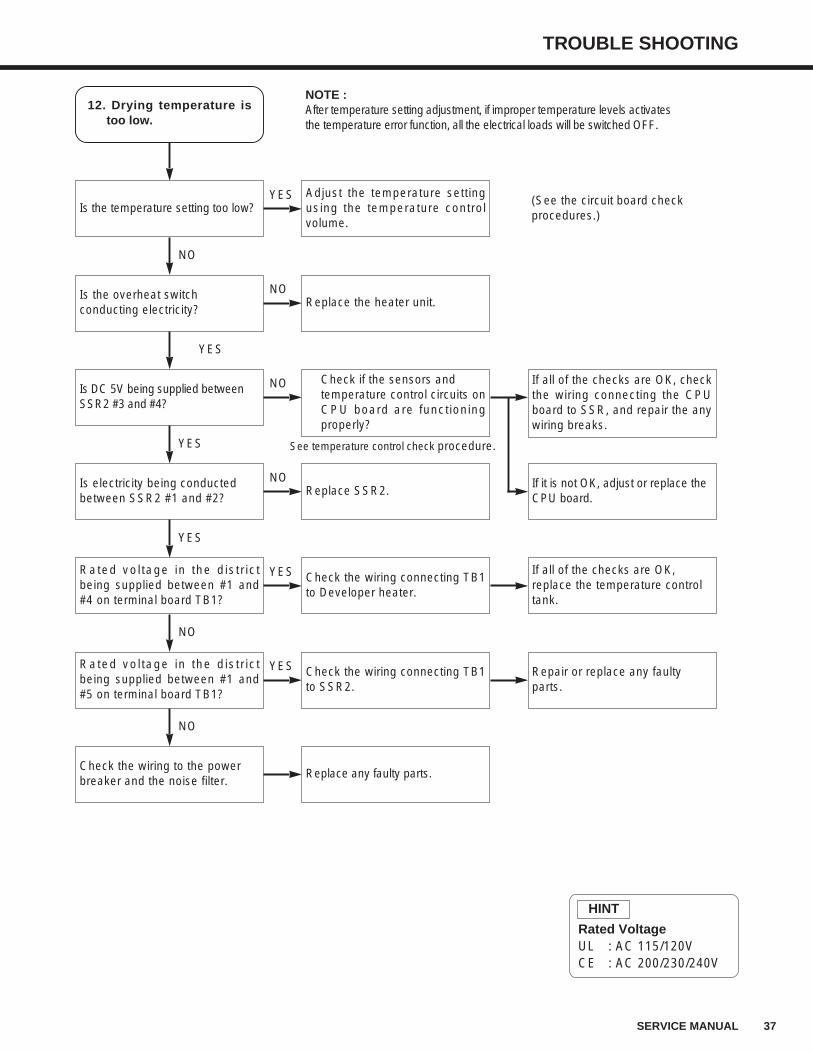
37SERVICE MANUAL
Rated VoltageUL : AC 115/120VCE : AC 200/230/240V
HINT
12. Drying temperature istoo low.
Is the temperature setting too low?
Is the overheat switch conducting electricity?
Is DC 5V being supplied between SSR2 #3 and #4?
Is electricity being conducted between SSR2 #1 and #2?
Rated voltage in the districtbeing supplied between #1 and#4 on terminal board TB1?
Rated voltage in the districtbeing supplied between #1 and#5 on terminal board TB1?
Adjust the temperature settingusing the temperature controlvolume.
NOTE :After temperature setting adjustment, if improper temperature levels activates the temperature error function, all the electrical loads will be switched OFF.
Replace the heater unit.
Check if the sensors and temperature control circuits onCPU board are functioningproperly?
Replace SSR2.
Check the wiring connecting TB1to Developer heater.
Check the wiring connecting TB1to SSR2.
(See the circuit board check procedures.)
If all of the checks are OK, checkthe wiring connecting the CPUboard to SSR, and repair the anywiring breaks.
If it is not OK, adjust or replace the CPU board.
If all of the checks are OK, replace the temperature control tank.
Repair or replace any faulty parts.
NO
YES
YES
YES
NO
YES
NO
NO
NO
YES
Check the wiring to the power breaker and the noise filter.
Replace any faulty parts.
NO
YES
See temperature control check procedure.
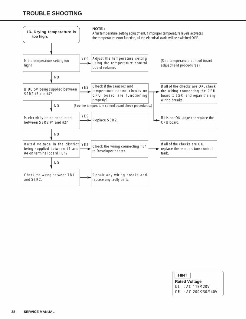
38 SERVICE MANUAL
TROUBLE SHOOTING
If all of the checks are OK, checkthe wiring connecting the CPUboard to SSR, and repair the anywiring breaks.
If it is not OK, adjust or replace the CPU board.
13. Drying temperature istoo high.
Is the temperature setting too high?
Is DC 5V being supplied between SSR2 #3 and #4?
Is electricity being conducted between SSR2 #1 and #2?
Rated voltage in the districtbeing supplied between #1 and#4 on terminal board TB1?
Check the wiring between TB1 and SSR2.
Adjust the temperature settingusing the temperature controlboard volume.
NOTE :After temperature setting adjustment, if improper temperature levels activates the temperature error function, all the electrical loads will be switched OFF.
Check if the sensors and temperature control circuits onCPU board are functioningproperly?
Replace SSR2.
Check the wiring connecting TB1to Developer heater.
Repair any wiring breaks andreplace any faulty parts.
(See temperature control board adjustment procedures)
If all of the checks are OK, replace the temperature control tank.
NO
NO
NO
NO
YES
YES
YES
YES
(See the temperature control board check procedures.)
Rated VoltageUL : AC 115/120VCE : AC 200/230/240V
HINT
TROUBLE SHOOTING
39SERVICE MANUAL
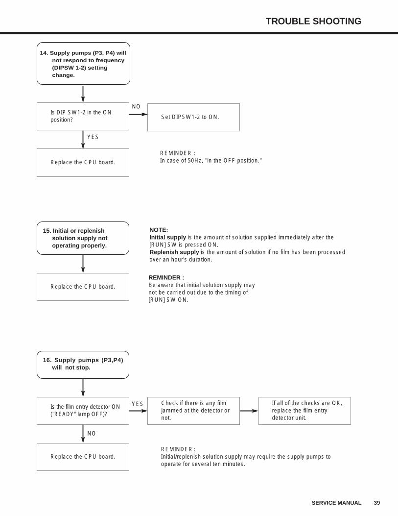
14. Supply pumps (P3, P4) willnot respond to frequency(DIPSW 1-2) settingchange.
Is DIP SW1-2 in the ON position?
Replace the CPU board.
Set DIPSW1-2 to ON.
YES
NO
16. Supply pumps (P3,P4)will not stop.
Is the film entry detector ON ("READY" lamp OFF)?
Replace the CPU board.
Check if there is any film jammed at the detector or not.
REMINDER:Initial/replenish solution supply may require the supply pumps to operate for several ten minutes.
If all of the checks are OK, replace the film entry detector unit.
NO
YES
15. Initial or replenishsolution supply notoperating properly.
Replace the CPU board.
REMINDER :Be aware that initial solution supply maynot be carried out due to the timing of[RUN] SW ON.
NOTE: Initial supply is the amount of solution supplied immediately after the[RUN] SW is pressed ON. Replenish supply is the amount of solution if no film has been processedover an hour's duration.
REMINDER : In case of 50Hz, "in the OFF position."
40 SERVICE MANUAL
TROUBLE SHOOTING
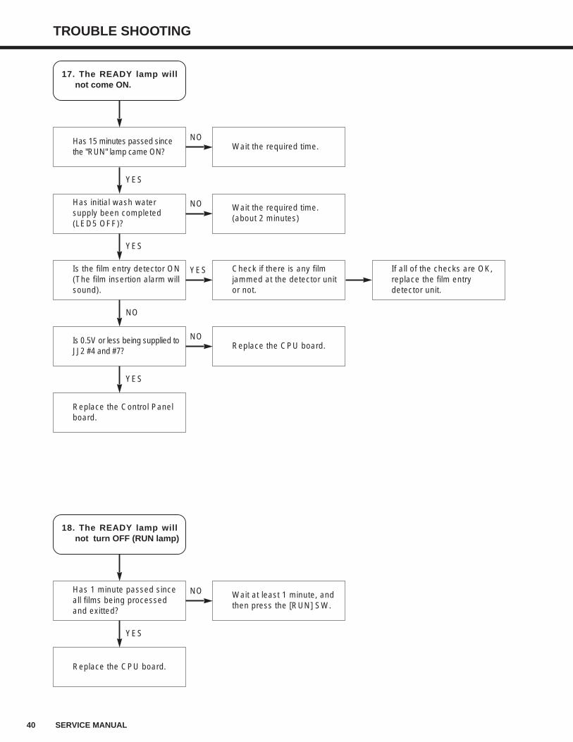
17. The READY lamp willnot come ON.
Has 15 minutes passed since the "RUN" lamp came ON?
Has initial wash water supply been completed (LED5 OFF)?
Wait the required time.
YES
NO
Is the film entry detector ON (The film insertion alarm will sound).
Wait the required time.(about 2 minutes)
YES
NO
Is 0.5V or less being supplied to JJ2 #4 and #7?
Check if there is any film jammed at the detector unit or not.
If all of the checks are OK, replace the film entry detector unit.
NO
YES
Replace the Control Panel board.
Replace the CPU board.
YES
NO
18. The READY lamp willnot turn OFF (RUN lamp)
Has 1 minute passed since all films being processed and exitted?
Replace the CPU board.
Wait at least 1 minute, and then press the [RUN] SW.
YES
NO
TROUBLE SHOOTING
41SERVICE MANUAL
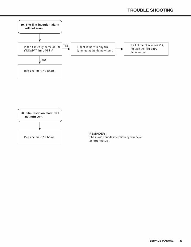
19. The film insertion alarmwill not sound.
Is the film entry detector ON ("READY" lamp OFF)?
Replace the CPU board.
Check if there is any film jammed at the detector unit.
If all of the checks are OK, replace the film entry detector unit.
NO
YES
20. Film insertion alarm willnot turn OFF.
Replace the CPU board.REMINDER :The alarm sounds intermittently wheneveran error occurs.
42 SERVICE MANUAL
TROUBLE SHOOTING
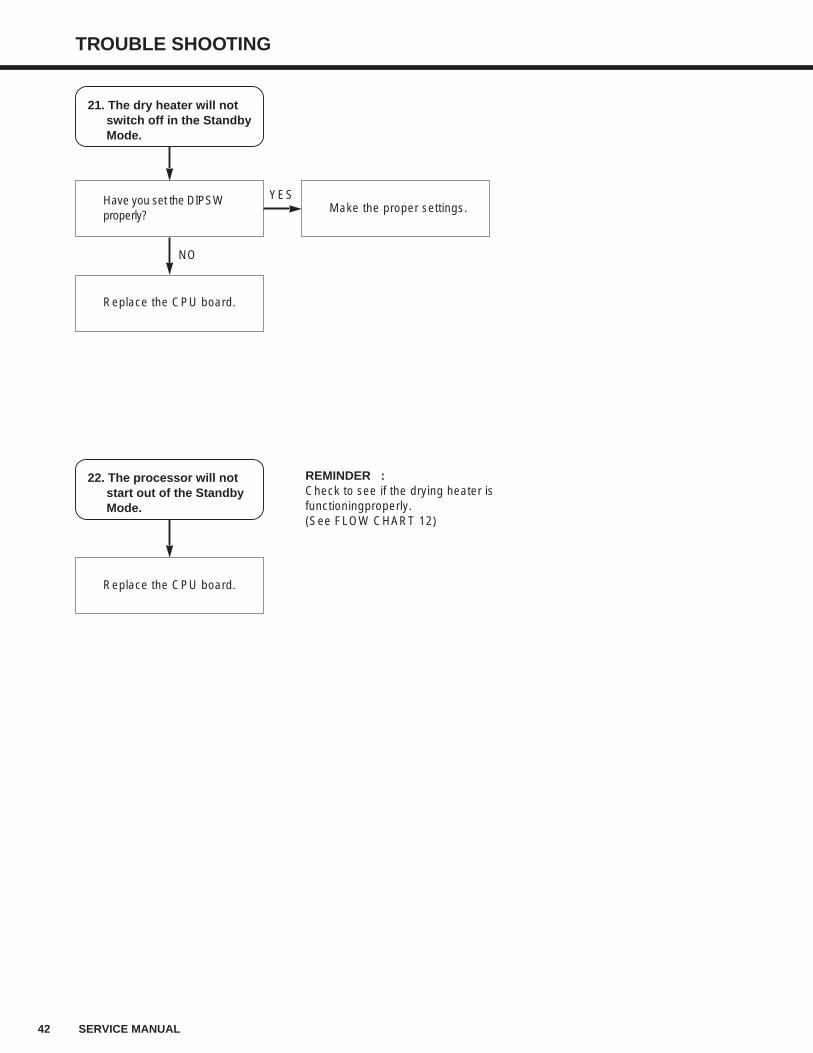
21. The dry heater will notswitch off in the StandbyMode.
Have you set the DIPSW properly?
Replace the CPU board.
Make the proper settings.
NO
YES
22. The processor will notstart out of the StandbyMode.
Replace the CPU board.
REMINDER :Check to see if the drying heater isfunctioningproperly.(See FLOW CHART 12)
TROUBLE SHOOTING
43SERVICE MANUAL
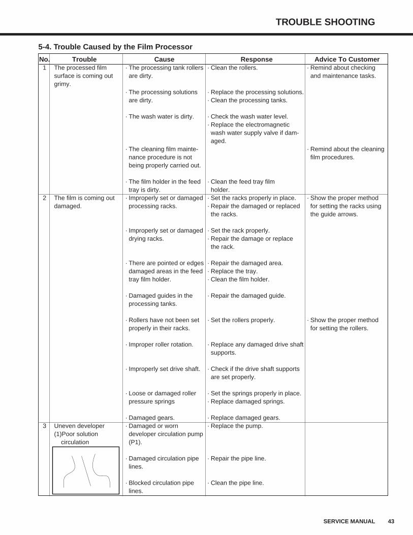
5-4. Trouble Caused by the Film Processor
No. Trouble Cause Response Advice To Customer1 The processed film · The processing tank rollers · Clean the rollers. · Remind about checking
surface is coming out are dirty. and maintenance tasks.grimy.
· The processing solutions · Replace the processing solutions.are dirty. · Clean the processing tanks.
· The wash water is dirty. · Check the wash water level.· Replace the electromagneticwash water supply valve if dam-aged.
· The cleaning film mainte- · Remind about the cleaningnance procedure is not film procedures.being properly carried out.
· The film holder in the feed · Clean the feed tray filmtray is dirty. holder.
2 The film is coming out · Improperly set or damaged · Set the racks properly in place. · Show the proper methoddamaged. processing racks. · Repair the damaged or replaced for setting the racks using
the racks. the guide arrows.
· Improperly set or damaged · Set the rack properly.drying racks. · Repair the damage or replace
the rack.
· There are pointed or edges · Repair the damaged area.damaged areas in the feed · Replace the tray.tray film holder. · Clean the film holder.
· Damaged guides in the · Repair the damaged guide.processing tanks.
· Rollers have not been set · Set the rollers properly. · Show the proper methodproperly in their racks. for setting the rollers.
· Improper roller rotation. · Replace any damaged drive shaftsupports.
· Improperly set drive shaft. · Check if the drive shaft supportsare set properly.
· Loose or damaged roller · Set the springs properly in place.pressure springs · Replace damaged springs.
· Damaged gears. · Replace damaged gears.3 Uneven developer · Damaged or worn · Replace the pump.
(1)Poor solution developer circulation pumpcirculation (P1).
· Damaged circulation pipe · Repair the pipe line.lines.
· Blocked circulation pipe · Clean the pipe line.lines.
44 SERVICE MANUAL
TROUBLE SHOOTING
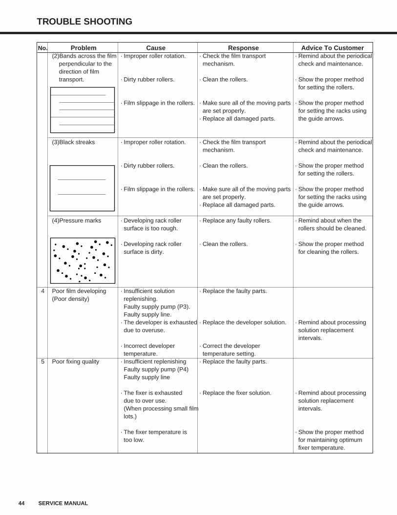
No. Problem Cause Response Advice To Customer(2)Bands across the film · Improper roller rotation. · Check the film transport · Remind about the periodical
perpendicular to the mechanism. check and maintenance.direction of film transport. · Dirty rubber rollers. · Clean the rollers. · Show the proper method
for setting the rollers.
· Film slippage in the rollers. · Make sure all of the moving parts · Show the proper method are set properly. for setting the racks using
· Replace all damaged parts. the guide arrows.
(3)Black streaks · Improper roller rotation. · Check the film transport · Remind about the periodicalmechanism. check and maintenance.
· Dirty rubber rollers. · Clean the rollers. · Show the proper methodfor setting the rollers.
· Film slippage in the rollers. · Make sure all of the moving parts · Show the proper methodare set properly. for setting the racks using
· Replace all damaged parts. the guide arrows.
(4)Pressure marks · Developing rack roller · Replace any faulty rollers. · Remind about when thesurface is too rough. rollers should be cleaned.
· Developing rack roller · Clean the rollers. · Show the proper methodsurface is dirty. for cleaning the rollers.
4 Poor film developing · Insufficient solution · Replace the faulty parts.(Poor density) replenishing.
Faulty supply pump (P3).Faulty supply line.
· The developer is exhausted · Replace the developer solution. · Remind about processingdue to overuse. solution replacement
intervals.· Incorrect developer · Correct the developer temperature. temperature setting.
5 Poor fixing quality · Insufficient replenishing · Replace the faulty parts.Faulty supply pump (P4)Faulty supply line
· The fixer is exhausted · Replace the fixer solution. · Remind about processingdue to over use. solution replacement(When processing small film intervals.lots.)
· The fixer temperature is · Show the proper methodtoo low. for maintaining optimum
fixer temperature.
TROUBLE SHOOTING
45SERVICE MANUAL
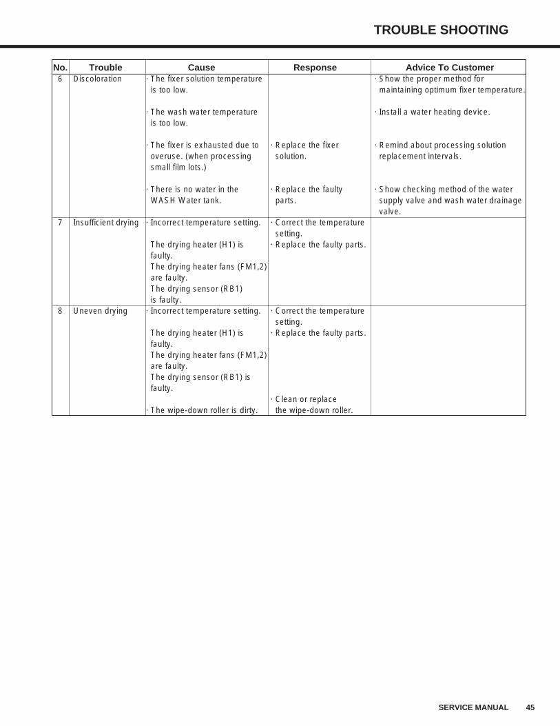
No. Trouble Cause Response Advice To Customer6 Discoloration · The fixer solution temperature · Show the proper method for
is too low. maintaining optimum fixer temperature.
· The wash water temperature · Install a water heating device.is too low.
· The fixer is exhausted due to · Replace the fixer · Remind about processing solutionoveruse. (when processing solution. replacement intervals.small film lots.)
· There is no water in the · Replace the faulty · Show checking method of the water WASH Water tank. parts. supply valve and wash water drainage
valve.7 Insufficient drying · Incorrect temperature setting. · Correct the temperature
setting.The drying heater (H1) is · Replace the faulty parts.faulty.The drying heater fans (FM1,2)are faulty.The drying sensor (RB1)is faulty.
8 Uneven drying · Incorrect temperature setting. · Correct the temperaturesetting.
The drying heater (H1) is · Replace the faulty parts.faulty.The drying heater fans (FM1,2)are faulty.The drying sensor (RB1) isfaulty.
· Clean or replace· The wipe-down roller is dirty. the wipe-down roller.
46 SERVICE MANUAL
TROUBLE SHOOTING
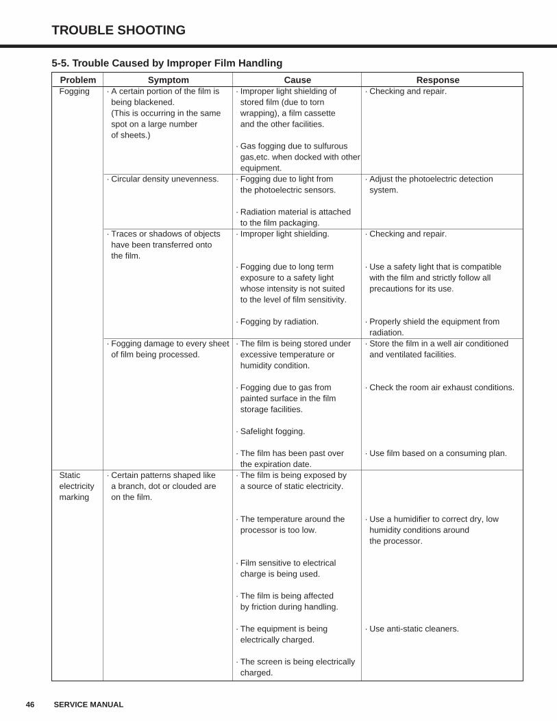
5-5. Trouble Caused by Improper Film Handling
Problem Symptom Cause ResponseFogging · A certain portion of the film is · Improper light shielding of · Checking and repair.
being blackened. stored film (due to torn (This is occurring in the same wrapping), a film cassette spot on a large number and the other facilities.of sheets.)
· Gas fogging due to sulfurousgas,etc. when docked with otherequipment.
· Circular density unevenness. · Fogging due to light from · Adjust the photoelectric detection the photoelectric sensors. system.
· Radiation material is attachedto the film packaging.
· Traces or shadows of objects · Improper light shielding. · Checking and repair.have been transferred ontothe film.
· Fogging due to long term · Use a safety light that is compatibleexposure to a safety light with the film and strictly follow allwhose intensity is not suited precautions for its use.to the level of film sensitivity.
· Fogging by radiation. · Properly shield the equipment fromradiation.
· Fogging damage to every sheet · The film is being stored under · Store the film in a well air conditionedof film being processed. excessive temperature or and ventilated facilities.
humidity condition.
· Fogging due to gas from · Check the room air exhaust conditions.painted surface in the film storage facilities.
· Safelight fogging.
· The film has been past over · Use film based on a consuming plan.the expiration date.
Static · Certain patterns shaped like · The film is being exposed byelectricity a branch, dot or clouded are a source of static electricity.marking on the film.
· The temperature around the · Use a humidifier to correct dry, lowprocessor is too low. humidity conditions around
the processor.
· Film sensitive to electricalcharge is being used.
· The film is being affectedby friction during handling.
· The equipment is being · Use anti-static cleaners.electrically charged.
· The screen is being electricallycharged.
TROUBLE SHOOTING
47SERVICE MANUAL
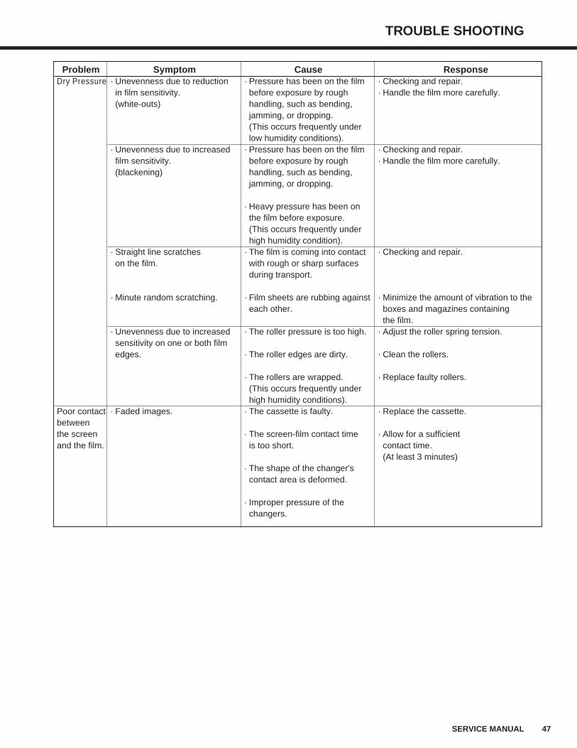
Problem Symptom Cause ResponseDry Pressure · Unevenness due to reduction · Pressure has been on the film · Checking and repair.
in film sensitivity. before exposure by rough · Handle the film more carefully.(white-outs) handling, such as bending,
jamming, or dropping.(This occurs frequently underlow humidity conditions).
· Unevenness due to increased · Pressure has been on the film · Checking and repair.film sensitivity. before exposure by rough · Handle the film more carefully.(blackening) handling, such as bending,
jamming, or dropping.
· Heavy pressure has been onthe film before exposure.(This occurs frequently underhigh humidity condition).
· Straight line scratches · The film is coming into contact · Checking and repair.on the film. with rough or sharp surfaces
during transport.
· Minute random scratching. · Film sheets are rubbing against · Minimize the amount of vibration to theeach other. boxes and magazines containing
the film.· Unevenness due to increased · The roller pressure is too high. · Adjust the roller spring tension.sensitivity on one or both filmedges. · The roller edges are dirty. · Clean the rollers.
· The rollers are wrapped. · Replace faulty rollers.(This occurs frequently underhigh humidity conditions).
Poor contact · Faded images. · The cassette is faulty. · Replace the cassette.betweenthe screen · The screen-film contact time · Allow for a sufficientand the film. is too short. contact time.
(At least 3 minutes)· The shape of the changer'scontact area is deformed.
· Improper pressure of thechangers.
48 SERVICE MANUAL
TROUBLE SHOOTING
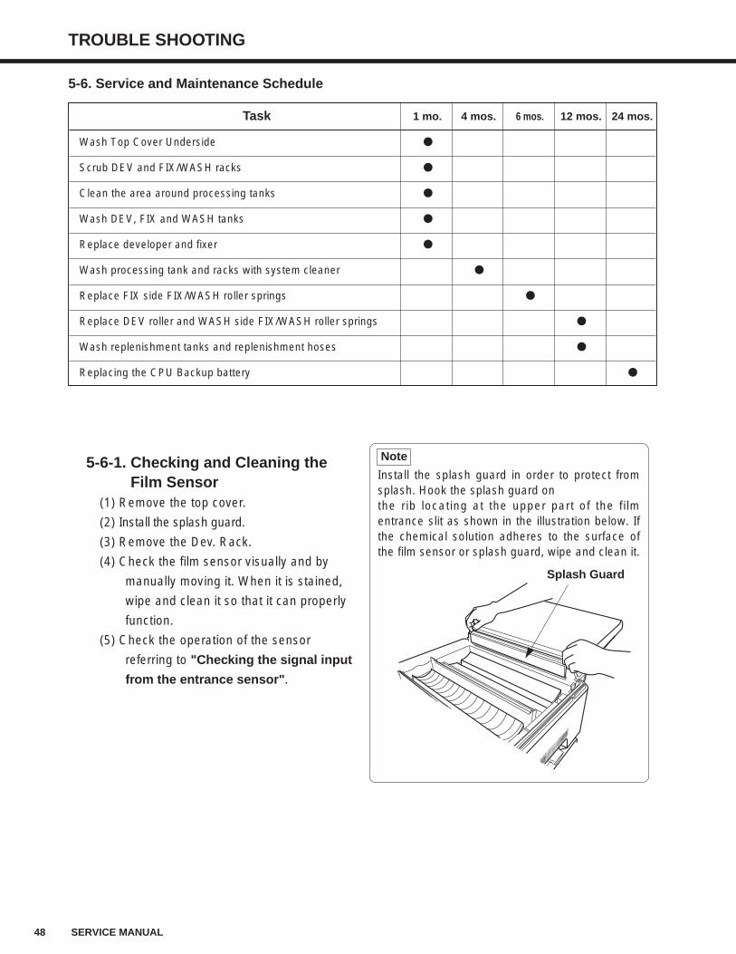
5-6. Service and Maintenance Schedule
Task 1 mo. 4 mos. 6 mos. 12 mos. 24 mos.
Wash Top Cover Underside
Scrub DEV and FIX/WASH racks
Clean the area around processing tanks
Wash DEV, FIX and WASH tanks
Replace developer and fixer
Wash processing tank and racks with system cleaner
Replace FIX side FIX/WASH roller springs
Replace DEV roller and WASH side FIX/WASH roller springs
Wash replenishment tanks and replenishment hoses
Replacing the CPU Backup battery
5-6-1. Checking and Cleaning theFilm Sensor
(1) Remove the top cover.
(2) Install the splash guard.
(3) Remove the Dev. Rack.
(4) Check the film sensor visually and by
manually moving it. When it is stained,
wipe and clean it so that it can properly
function.
(5) Check the operation of the sensor
referring to "Checking the signal input
from the entrance sensor".
Install the splash guard in order to protect fromsplash. Hook the splash guard on the rib locating at the upper part of the filmentrance slit as shown in the illustration below. Ifthe chemical solution adheres to the surface ofthe film sensor or splash guard, wipe and clean it.
Note
Splash Guard
TROUBLE SHOOTING
49SERVICE MANUAL
5-6-2. Cleaning the Drier Nozzle and Rollers of the Drier Rack(1) Remove the top cover.
(2) Remove the Drier Rack cover.
(refer to "11-1. Removing the Drier Cover", p.98.)
(3) Remove the drier nozzle to wash and clean in the water, and dry it afterward.
(4) Wipe the drier rollers with a water-damped cloth.
(refer to p.13 for the location of parts and to p.11 for material)
- Because the drying unit is heated hot while the processor is in operation, wait for a while to
let the unit cool down before you start cleaning.
- Bakelite roller and film guide are likely to get scratched. Do not use the scrubbing brush
made of nylon because it may cause scratches.
Caution
50 SERVICE MANUAL
TROUBLE SHOOTING
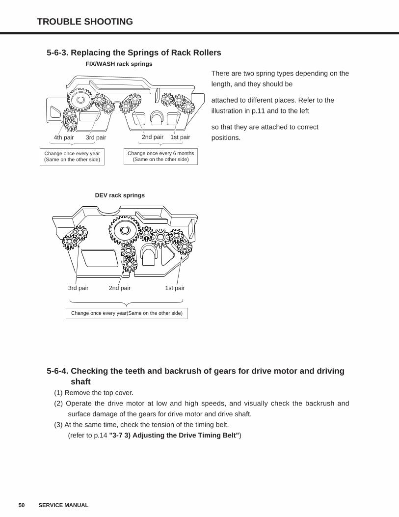
There are two spring types depending on the
length, and they should be
attached to different places. Refer to the
illustration in p.11 and to the left
so that they are attached to correct
positions.
5-6-3. Replacing the Springs of Rack Rollers
5-6-4. Checking the teeth and backrush of gears for drive motor and drivingshaft
(1) Remove the top cover.
(2) Operate the drive motor at low and high speeds, and visually check the backrush and
surface damage of the gears for drive motor and drive shaft.
(3) At the same time, check the tension of the timing belt.
(refer to p.14 "3-7 3) Adjusting the Drive Timing Belt")
DEV rack springs
3rd pair 1st pair2nd pair
Change once every year(Same on the other side)
FIX/WASH rack springs
4th pair
Change once every year(Same on the other side)
1st pair2nd pair3rd pair
Change once every 6 months(Same on the other side)
TROUBLE SHOOTING
51SERVICE MANUAL
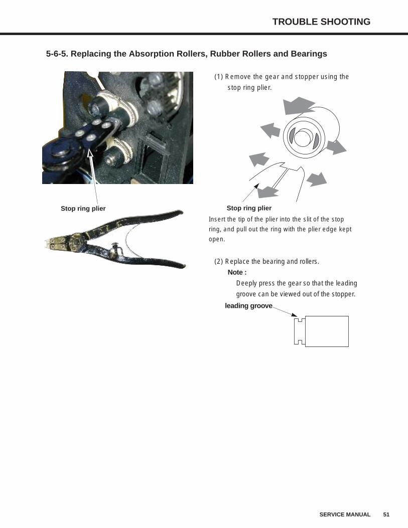
5-6-5. Replacing the Absorption Rollers, Rubber Rollers and Bearings
(1) Remove the gear and stopper using the
stop ring plier.
(2) Replace the bearing and rollers.
Note :
Deeply press the gear so that the leading
groove can be viewed out of the stopper.
Stop ring plier
leading groove
Stop ring plier
Insert the tip of the plier into the slit of the stop
ring, and pull out the ring with the plier edge kept
open.
52 SERVICE MANUAL
TROUBLE SHOOTING
5-6-6. Cleaning the Dev Rack and DEV Tank with a System CleanerScrubbing the rack rollers with cold or warm water will not completely remove the
crystallized processing solutions or built-up gelatin and silver solving out from the film. It is
necessary to wash both the DEV rack and tank with a system cleaner(option) every three
months.
(1) Remove the top cover.
(2) Install a splash guard.
(3) Open the DEV drainage valve. After the DEV tank is emptied, close the valve.
(4) Use a beaker to fill the tank with water.
(5) Press the [RUN] SW and let the processor operate for about 5 minutes.
(6) Open the DEV drainage valve. After the DEV tank is emptied, close the valve.
(7) Fill the tank with a diluted system cleaner.
Press the RUN button and let the processor operate for about 30 minutes.
- Dilute the system cleaner at the rate of Cleaner(conc.) : Water = 1:7
- Because the cleaner is strongly acidic, neutralize the exhausted solution using alkaline
such as sodium hydrate, etc. when disposing of.
Note: Follow the instructions written on the package for other notes.
(8) Open the DEV drainage valve. After the DEV tank is emptied, close the valve.
(9) Fill the tank with water. Press the [RUN] SW and let the processor operate for 5 minutes.
(10) Repeat step (8) through (9).
(11) Remove the DEV rack, and wash it in water.
(12) Open the DEV drainage valve. After the DEV tank is emptied, close the valve.
(13) Install the DEV rack.
(14) Install the splash guard.
(15) Fill the tank with a starting solution, and add a starter solution.
(16) Install the top cover.
Processing chemical may be supplied into the processing tank depending on the timing of the [RUN]SW being pressed. This will not adversary affect the performance of the system cleaner.
Note
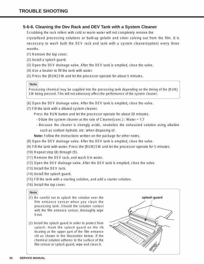
(1) Be careful not to splash the solution over thefilm entrance sensor when you clean theprocessing tank. Should the solution contactwith the film entrance sensor, thoroughly wipeit out.
(2) Install the splash guard in order to protect fromsplash. Hook the splash guard on the riblocating at the upper part of the film entranceslit as shown in the illustration below. If thechemical solution adheres to the surface of thefilm sensor or splash guard, wipe and clean it.
Note
splash guard
CPU BOARD DIP SWITCHES
53SERVICE MANUAL
6. CPU Board DIP Switches
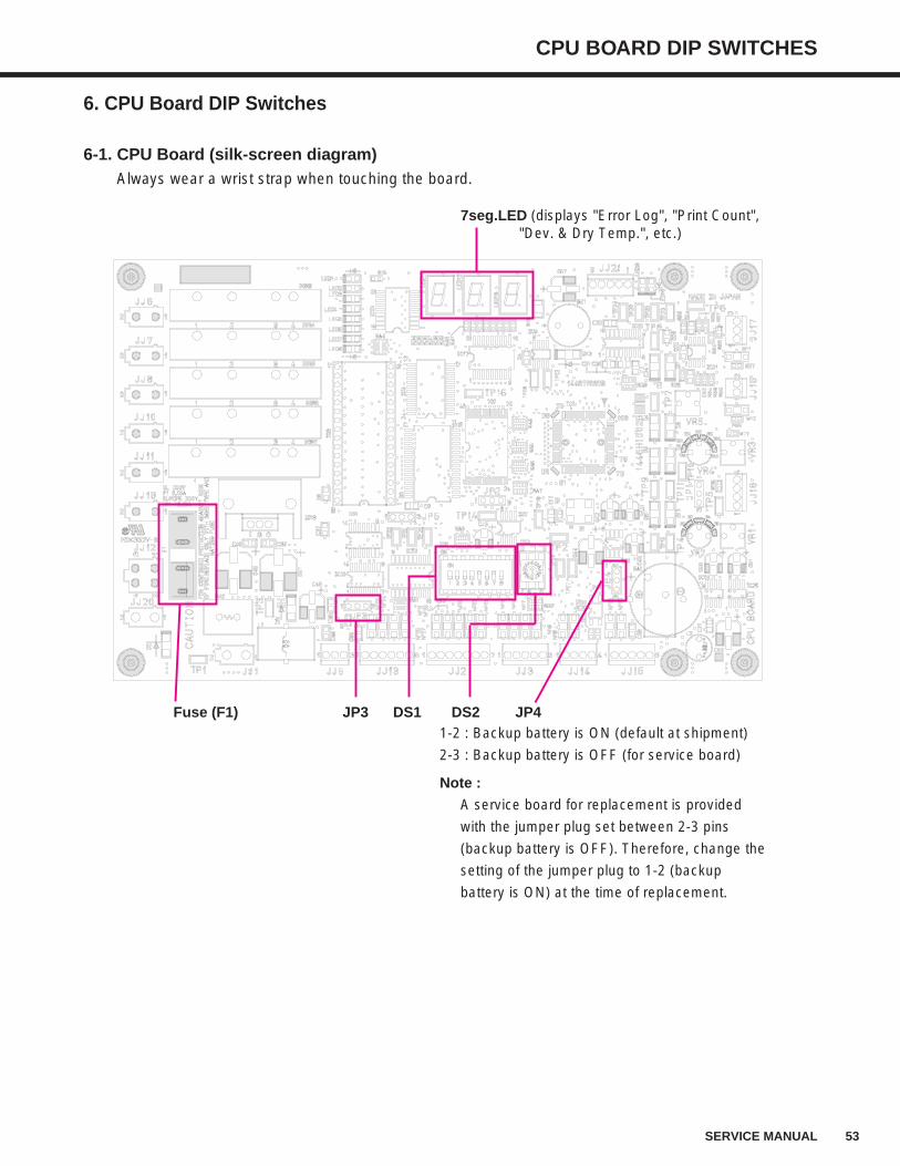
6-1. CPU Board (silk-screen diagram)Always wear a wrist strap when touching the board.
JP4Fuse (F1)
7seg.LED (displays "Error Log", "Print Count","Dev. & Dry Temp.", etc.)
1-2 : Backup battery is ON (default at shipment)
2-3 : Backup battery is OFF (for service board)
Note :
A service board for replacement is provided
with the jumper plug set between 2-3 pins
(backup battery is OFF). Therefore, change the
setting of the jumper plug to 1-2 (backup
battery is ON) at the time of replacement.
JP3 DS1 DS2
54 SERVICE MANUAL
CPU BOARD DIP SWITCHES
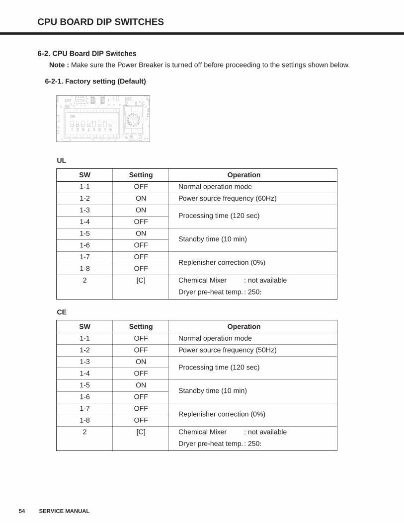
6-2. CPU Board DIP Switches
Note : Make sure the Power Breaker is turned off before proceeding to the settings shown below.
6-2-1. Factory setting (Default)
SW Setting Operation
1-1 OFF Normal operation mode
1-2 ON Power source frequency (60Hz)
1-3 ONProcessing time (120 sec)
1-4 OFF
1-5 ONStandby time (10 min)
1-6 OFF
1-7 OFFReplenisher correction (0%)
1-8 OFF
2 [C] Chemical Mixer : not available
Dryer pre-heat temp. : 250:
SW Setting Operation
1-1 OFF Normal operation mode
1-2 OFF Power source frequency (50Hz)
1-3 ONProcessing time (120 sec)
1-4 OFF
1-5 ONStandby time (10 min)
1-6 OFF
1-7 OFFReplenisher correction (0%)
1-8 OFF
2 [C] Chemical Mixer : not available
Dryer pre-heat temp. : 250:
UL
CE
CPU BOARD DIP SWITCHES
55SERVICE MANUAL
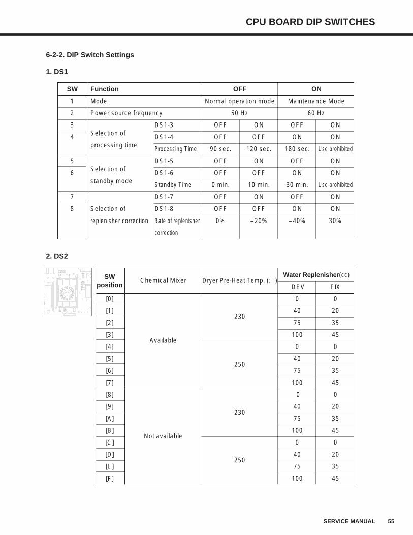
6-2-2. DIP Switch Settings
1. DS1
2. DS2
SW Function OFF ON
1 Mode Normal operation mode Maintenance Mode
2 Power source frequency 50 Hz 60 Hz
3 DS1-3 OFF ON OFF ON
4 Selection of DS1-4 OFF OFF ON ONprocessing time Processing Time 90 sec. 120 sec. 180 sec. Use prohibited
5 DS1-5 OFF ON OFF ON
6 Selection of DS1-6 OFF OFF ON ONstandby mode Standby Time 0 min. 10 min. 30 min. Use prohibited
7 DS1-7 OFF ON OFF ON
8 Selection of DS1-8 OFF OFF ON ON
replenisher correction Rate of replenisher 0% -20% -40% 30%
correction
SW Chemical Mixer Dryer Pre-Heat Temp. (:)Water Replenisher(cc)
position DEV FIX
[0] 0 0
[1]230
40 20
[2] 75 35
[3]Available
100 45
[4] 0 0
[5]250
40 20
[6] 75 35
[7] 100 45
[8] 0 0
[9]230
40 20
[A] 75 35
[B]Not available
100 45
[C] 0 0
[D]250
40 20
[E] 75 35
[F] 100 45
56 SERVICE MANUAL
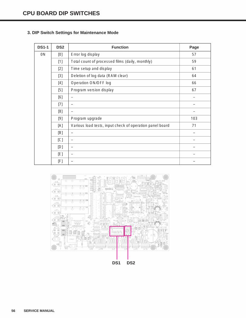
CPU BOARD DIP SWITCHES
DS1-1 DS2 Function Page
0N [0] Error log display 57
[1] Total count of processed films (daily, monthly) 59
[2] Time setup and display 61
[3] Deletion of log data (RAM clear) 64
[4] Operation ON/OFF log 66
[5] Program version display 67
[6] – –
[7] – –
[8] – –
[9] Program upgrade 103
[A] Various load tests, input check of operation panel board 71
[B] – –
[C] – –
[D] – –
[E] – –
[F] – –
3. DIP Switch Settings for Maintenance Mode
DS1 DS2
CPU BOARD DIP SWITCHES
57SERVICE MANUAL
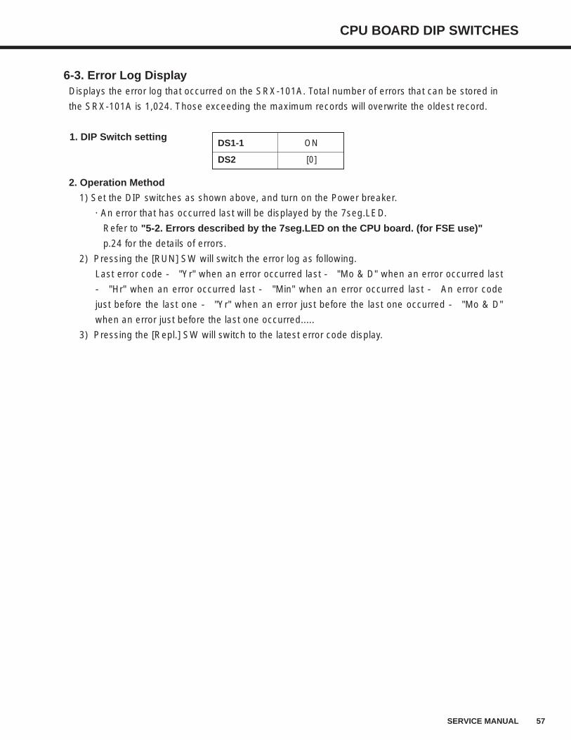
6-3. Error Log DisplayDisplays the error log that occurred on the SRX-101A. Total number of errors that can be stored in
the SRX-101A is 1,024. Those exceeding the maximum records will overwrite the oldest record.
1. DIP Switch setting
2. Operation Method
1) Set the DIP switches as shown above, and turn on the Power breaker.
· An error that has occurred last will be displayed by the 7seg.LED.
Refer to "5-2. Errors described by the 7seg.LED on the CPU board. (for FSE use)"
p.24 for the details of errors.
2) Pressing the [RUN] SW will switch the error log as following.
Last error code → "Yr" when an error occurred last → "Mo & D" when an error occurred last
→ "Hr" when an error occurred last → "Min" when an error occurred last → An error code
just before the last one → "Yr" when an error just before the last one occurred → "Mo & D"
when an error just before the last one occurred.....
3) Pressing the [Repl.] SW will switch to the latest error code display.
DS1-1 ON
DS2 [0]
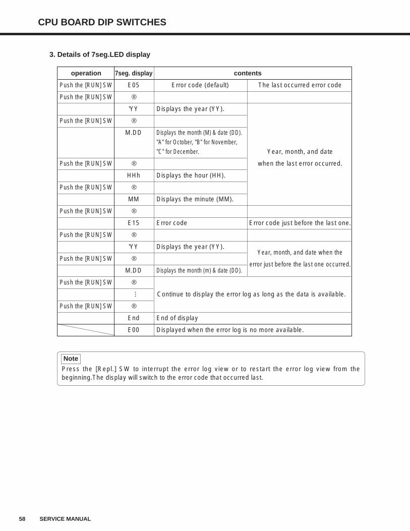
3. Details of 7seg.LED display
58 SERVICE MANUAL
CPU BOARD DIP SWITCHES
operation 7seg. display contents
Push the [RUN] SW E05 Error code (default) The last occurred error code
Push the [RUN] SW ↓
'YY Displays the year (YY).
Push the [RUN] SW ↓
M.DD Displays the month (M) & date (DD)."A" for October, "B" for November,"C" for December. Year, month, and date
Push the [RUN] SW ↓ when the last error occurred.
HHh Displays the hour (HH).
Push the [RUN] SW ↓
MM Displays the minute (MM).
Push the [RUN] SW ↓
E15 Error code Error code just before the last one.
Push the [RUN] SW ↓
'YY Displays the year (YY).Year, month, and date when the
Push the [RUN] SW ↓error just before the last one occurred.
M.DD Displays the month (m) & date (DD).
Push the [RUN] SW ↓
Continue to display the error log as long as the data is available.
Push the [RUN] SW ↓
End End of display
E00 Displayed when the error log is no more available.
...
Press the [Repl.] SW to interrupt the error log view or to restart the error log view from thebeginning.The display will switch to the error code that occurred last.
Note
CPU BOARD DIP SWITCHES
59SERVICE MANUAL
6-4. Process Count LogDisplays either per day or per month the total film count that has been processed by the SRX-
101A. Maximum number of processed film count, which the SRX-101A can record is 7,936 totaling
both daily and monthly counts. Those exceeding the maximum records will overwrite the oldest
record.
1. DIP Switch setting
2. Operation Method
1) Set the DIP switches as shown above, and turn on the Power breaker.
· "Month & Date" of the daily total will be shown by the 7seg.LED.
2-1) Pressing the [RUN] SW will switch to the daily total mode. Pressing the button further will
switch the mode as follows;
· "Month & Date" of the day on which the film was processed last. → Total counts of the day
on which the film was processed last. → "Month & Date" of the day just before the film
was processed last. → ...and so on in order.
· Pressing the [RUN] SW when the monthly total mode is in effect will switch to the daily total
mode, and displays the "Month & Date" of the day on which the film was processed last.
2-2) Pressing the [Repl.] SW will switch to the monthly total mode. Pressing the button further
will switch the mode as follows;
· "Year & Month" of the month on which the film was processed last. → Total counts of the
month on which the film was processed last. → "Month & Date" of the month just before
the film was processed last. → ...and so on in order.
· Pressing the [Repl.] SW when the daily total mode is in effect will switch to the monthly total
mode, and displays the "Year & Month" of the day on which the film was processed last.
3. Details of 7seg.LED display
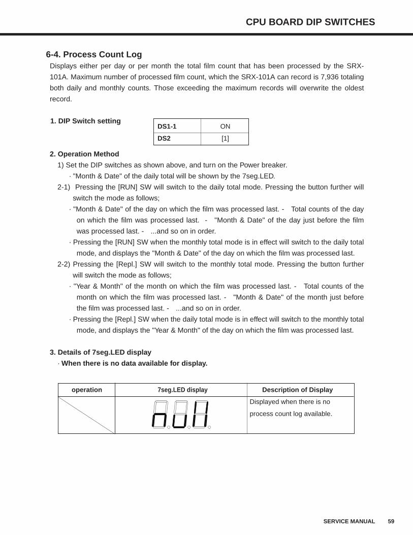
· When there is no data available for display.
DS1-1 ON
DS2 [1]
operation 7seg.LED display Description of Display
Displayed when there is no
process count log available.
60 SERVICE MANUAL
CPU BOARD DIP SWITCHES
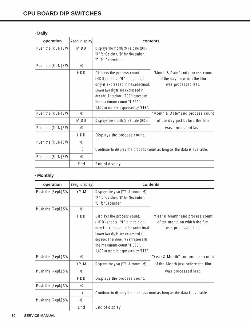
operation 7seg. display contents
Push the [RUN] SW M.DD Displays the month (M) & date (DD)."A" for October, "B" for November, "C" for December.
Push the [RUN] SW ↓
HDD Displays the process count. "Month & Date" and process count(HDD) sheets. "H" in third digit of the day on which the filmonly is expressed in hexadecimal. was processed last.Lower two digits are expressed in decade. Therefore, "F99" representsthe maximum count "1,599".1,600 or more is expressed by "FFF".
Push the [RUN] SW ↓ "Month & Date" and process count
M.DD Displays the month (m) & date (DD). of the day just before the film
Push the [RUN] SW ↓ was processed last.
HDD Displays the process count.
Push the [RUN] SW ↓
Continue to display the process count as long as the data is available.
Push the [RUN] SW ↓
End End of display
operation 7seg. display contents
Push the [Repl.] SW YY.M Displays the year (YY) & month (M)."A" for October, "B" for November, "C" for December.
Push the [Repl.] SW ↓
HDD Displays the process count. "Year & Month" and process count(HDD) sheets. "H" in third digit of the month on which the filmonly is expressed in hexadecimal. was processed last.Lower two digits are expressed in decade. Therefore, "F99" representsthe maximum count "1,599".1,600 or more is expressed by "FFF".
Push the [Repl.] SW ↓ "Year & Month" and process count
YY.M Displays the year (YY) & month (M). of the Month just before the film
Push the [Repl.] SW ↓ was processed last.
HDD Displays the process count.
Push the [Repl.] SW ↓
Continue to display the process count as long as the data is available.
Push the [Repl.] SW ↓
End End of display
· Daily
· Monthly
......
CPU BOARD DIP SWITCHES
61SERVICE MANUAL
6-5. Time Setup & DisplaySets time and display of the SRX-101A’s internal clock. The time set here will be used to specify
time for each event in the log and displayed together with the events.
1. DIP Switch setting
2. Operation Method
1) Set the DIP switches as shown above, and turn on the [Power] breaker.
· “Year” of the time display mode is displayed by the 7seg.LED.
2) Time display mode
· Each time when the [Repl.] SW is pressed;
"Year" display → "Month" display → "Date" display → "Hour" display → "Minute"
display → "Second" display → "Year" display → repeats in order.
· Each time when the [RUN] SW is pressed;
"Year" display → "Second" display → "Minute" display → "Hour" display → "Date"
display → "Month" display → "Year" display → repeats in order.
3) Changing the time display mode to time setup mode
Pressing the [RUN] SW and [Repl..] button simultaneously will allow the display "c00" to
blink.
Keep pressing the two buttons for three seconds or more will change the display from
blinking to continuous display, and releasing your fingers off the buttons will enter the
"Time Setup" mode.
Releasing your fingers off the buttons within three seconds will not enter the “Time Setup”
mode, and it stays in the “Time Display” mode.
4) Time Setup Mode
· Change the set item using the [Repl.] SW;
"Year" data change → "Month" data change → "Date" data change → "Hour" data
change → "Minute" data change → "Second" data change → returns to "Time Display"
mode
· Displayed value can be changed using the [RUN] SW.
DS1-1 ON
DS2 [2]
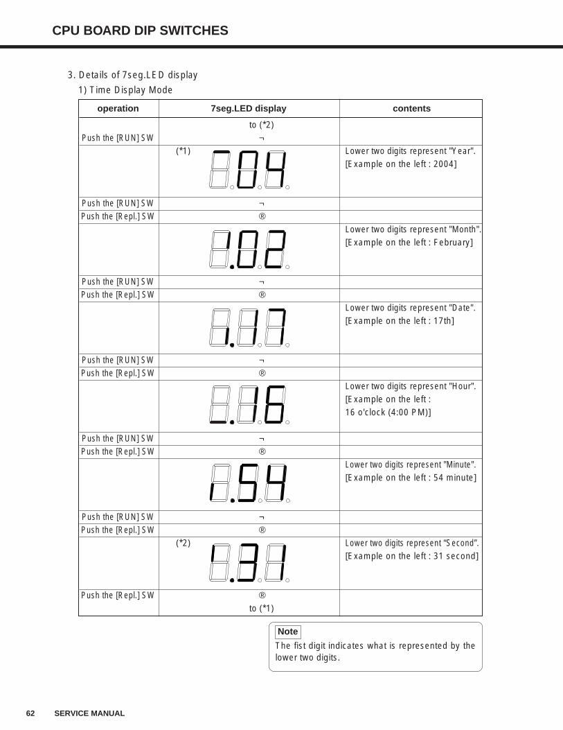
62 SERVICE MANUAL
CPU BOARD DIP SWITCHES
3. Details of 7seg.LED display
1) Time Display Mode
operation 7seg.LED display contents
to (*2)Push the [RUN] SW ↑
(*1) Lower two digits represent "Year".[Example on the left : 2004]
Push the [RUN] SW ↑Push the [Repl.] SW ↓
Lower two digits represent "Month".[Example on the left : February]
Push the [RUN] SW ↑Push the [Repl.] SW ↓
Lower two digits represent "Date".[Example on the left : 17th]
Push the [RUN] SW ↑Push the [Repl.] SW ↓
Lower two digits represent "Hour".[Example on the left : 16 o'clock (4:00 PM)]
Push the [RUN] SW ↑Push the [Repl.] SW ↓
Lower two digits represent "Minute".[Example on the left : 54 minute]
Push the [RUN] SW ↑Push the [Repl.] SW ↓
(*2) Lower two digits represent “Second”.[Example on the left : 31 second]
Push the [Repl.] SW ↓to (*1)
The fist digit indicates what is represented by thelower two digits.
Note
CPU BOARD DIP SWITCHES
63SERVICE MANUAL
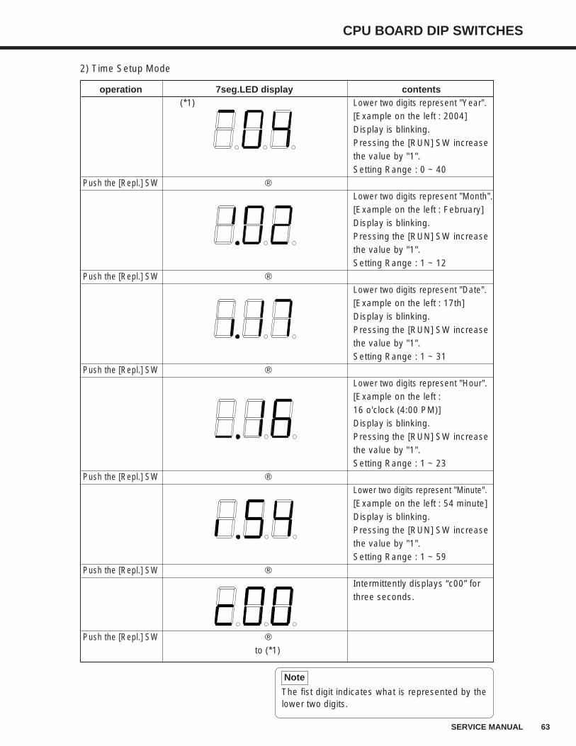
2) Time Setup Mode
operation 7seg.LED display contents(*1) Lower two digits represent "Year".
[Example on the left : 2004]Display is blinking.Pressing the [RUN] SW increase the value by "1".Setting Range : 0 ~ 40
Push the [Repl.] SW ↓Lower two digits represent "Month".[Example on the left : February]Display is blinking.Pressing the [RUN] SW increase the value by "1".Setting Range : 1 ~ 12
Push the [Repl.] SW ↓Lower two digits represent "Date".[Example on the left : 17th]Display is blinking.Pressing the [RUN] SW increase the value by "1".Setting Range : 1 ~ 31
Push the [Repl.] SW ↓Lower two digits represent "Hour".[Example on the left :16 o'clock (4:00 PM)]Display is blinking.Pressing the [RUN] SW increase the value by "1".Setting Range : 1 ~ 23
Push the [Repl.] SW ↓Lower two digits represent "Minute".[Example on the left : 54 minute]Display is blinking.Pressing the [RUN] SW increase the value by "1".Setting Range : 1 ~ 59
Push the [Repl.] SW ↓Intermittently displays “c00” for three seconds.
Push the [Repl.] SW ↓to (*1)
The fist digit indicates what is represented by thelower two digits.
Note
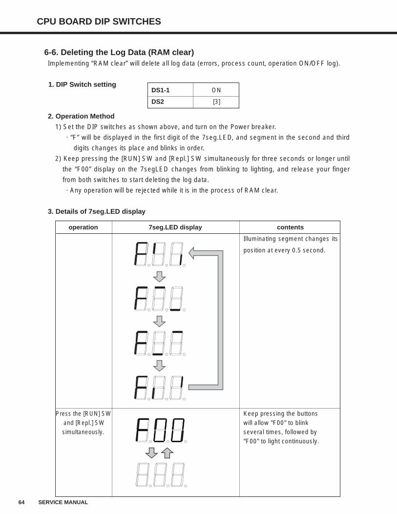
64 SERVICE MANUAL
CPU BOARD DIP SWITCHES
6-6. Deleting the Log Data (RAM clear)Implementing “RAM clear” will delete all log data (errors, process count, operation ON/OFF log).
1. DIP Switch setting
2. Operation Method
1) Set the DIP switches as shown above, and turn on the Power breaker.
· “F” will be displayed in the first digit of the 7seg.LED, and segment in the second and third
digits changes its place and blinks in order.
2) Keep pressing the [RUN] SW and [Repl.] SW simultaneously for three seconds or longer until
the “F00” display on the 7segLED changes from blinking to lighting, and release your finger
from both switches to start deleting the log data.
· Any operation will be rejected while it is in the process of RAM clear.
3. Details of 7seg.LED display
operation 7seg.LED display contents
Illuminating segment changes its
position at every 0.5 second.
Press the [RUN] SW Keep pressing the buttons and [Repl.] SW will allow "F00" to blink simultaneously. several times, followed by
"F00" to light continuously.
DS1-1 ON
DS2 [3]
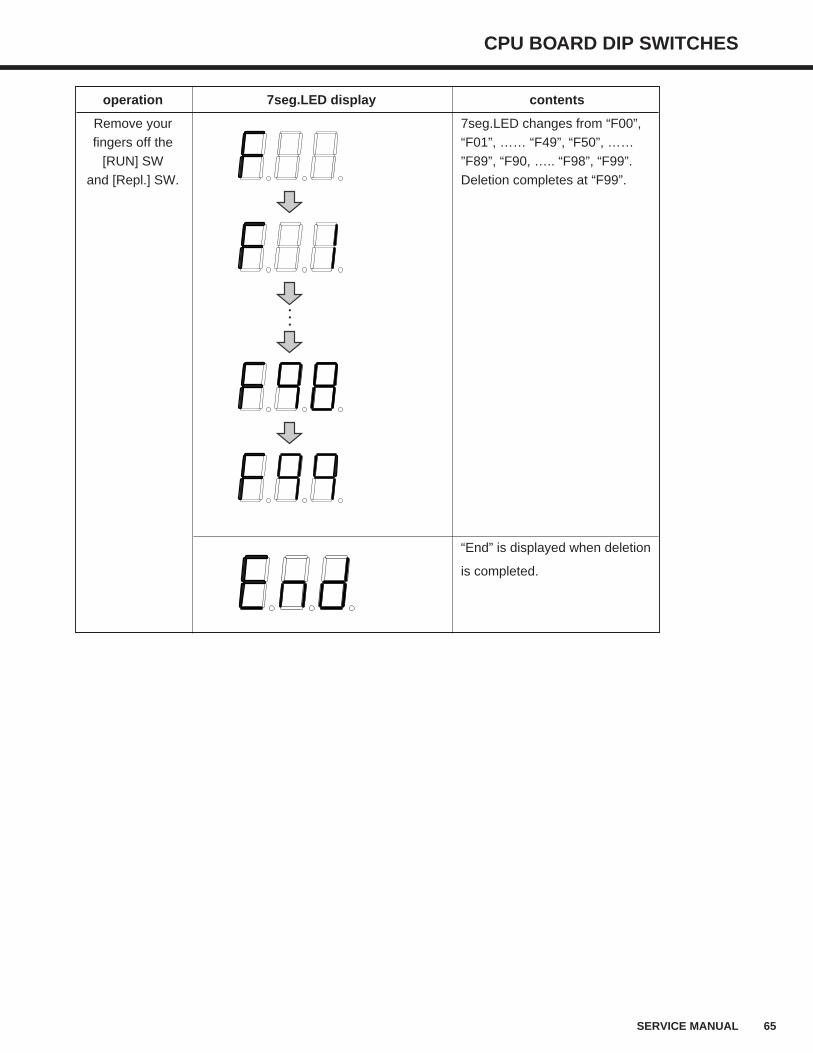
CPU BOARD DIP SWITCHES
65SERVICE MANUAL
operation 7seg.LED display contents
Remove your 7seg.LED changes from “F00”, fingers off the “F01”, …… “F49”, “F50”, ……
[RUN] SW ”F89”, “F90, ….. “F98”, “F99”. and [Repl.] SW. Deletion completes at “F99”.
“End” is displayed when deletion
is completed.
66 SERVICE MANUAL
CPU BOARD DIP SWITCHES
6-7. Operation ON/OFF LogLog data for date and time when the [RUN] SW of SRX-101A is turned off or on will be displayed.
Total count of operation ON/OFF of the SRX-101A is 8,192. Those exceeding the maximum count
for operation ON/OFF will overwrite the oldest log in order.
1. DIP Switch setting
2. Operation Method
1) Set the DIP switches as shown above, and turn on the Power breaker.
· The latest status of the SRX-101A (Pon = Power ON, Pof = Power OFF) will be displayed by
the 7seg.LED.
2) Every time when the [RUN] SW is pressed ;
· Operation ON or OFF data just before the latest → Operation ON or OFF data two times before the
latest → Operation ON or OFF data three times before the latest...Will be displayed in order.
3) Pressing the [Repl.] SW will return to the latest operation ON or OFF data.
3. Details of 7seg.LED display
operation 7seg. display contents
Push the [Repl.] SW Pon Displays the status or (operation ON or OFF)
PoFPush the [RUN] SW ↓
'YY Displays the year (YY).
Push the [RUN] SW ↓
Displays the month (M) & date (DD). Information for the latest operation M.DD “A” for October, “B” for November, ON or OFF, and its time and
“C” for December. date (YY/MM/DD).
Push the [RUN] SW ↓
HHh Displays the hour (HH).
Push the [RUN] SW ↓
MM- Displays the minute (MM).
Push the [RUN] SW ↓
-SS Displays the second (SS).
Push the [RUN] SW ↓
Pon Displays the status Information for the operation ON or (operation ON or OFF) or OFF just before the latest, and
PoF its time and date (YY/MM/DD).
Push the [RUN] SW ↓
Continues to display as long as the data is available.
Push the [RUN] SW ↓
End End of display
Poo Displayed when there is no log data available.
DS1-1 ON
DS2 [4]
...
CPU BOARD DIP SWITCHES
67SERVICE MANUAL
6-8. Display of Program VersionDisplays the program version that is incorporated in the SRX-101A.
1. DIP Switch setting
2. Operation Method
1) Set the DIP switches as shown above, and turn on the Power breaker.
· Date when the program was edited will be displayed in scroll by the 7seg.LED.
2) Pressing the [Repl.] SW will horizontally scroll and display the version number.
3) Pressing the [RUN] SW will horizontally scroll and display the date of program edition.
3. Details of 7seg.LED display
operation 7seg.LED display contents
Push the [Repl.] SW n.mm _roo Displays the version number of the program.
(n.mm) : Version, (oo) : Revision
Push the [RUN] SW YYYY. MM.DD Displays the date of program edition.
(YYYY) : Year, (MM) : Month, (DD) : Day
DS1-1 ON
DS2 [5]
68 SERVICE MANUAL
CPU BOARD DIP SWITCHES
6-9. Dry/Dev Temperature DisplayDisplays the Dry and Dev temperatures currently detected in the SRX-101A.
1. Operation Method
1) Turn on the [Power] breaker under the normal operation mode (DS1-1 : OFF).
· Current dry temperature will be displayed by the 7seg.LED.
2) Every time when the [Repl.] SW is pressed, “Current Dev. Temp.” and “Current Dry Temp.”
are alternately displayed.
2. Details of 7seg.LED display
operation 7seg.LED display contents
Push the [Repl.] SW AAA Displays the current Dry temp (AAA).
Push the [Repl.] SW ↓
BB.B Displays the current Dev temp (BB.B).
Push the [Repl.] SW ↓
(repeats)
...
CHECKING CIRCUIT BOARDS, SENSORS AND ELECTRICAL LOADS
69SERVICE MANUAL
7. Checking Circuit Boards, Sensors and Electrical LoadsREMINDER : After performing each check and related adjustment, switch the power breaker
OFF, then back ON again.
7-1. Circuit Boards
Board Circuit Check Points Correct Voltage Adjustment Point
Power source circuitTP1-TP3(GND) DC12.0±0.2V VR for switching power supply.
TP2-TP3(GND) DC 5.0±0.2V None(replace when out of adjustment)
CPU Reset circuit TP14-TP3(GND) DC 5.0±0.2V None(replace when out of adjustment)
board VREF for A/D conversion TP4-TP11(AGND) DC 4.5±0.05V None(replace when out of adjustment)
Power source circuit TP5-TP11(AGND) DC 5.0±0.05V None(replace when out of adjustment)
for temp. TP6-TP11(AGND) DC 5.0±0.05V None(replace when out of adjustment)
TP1 TP3 TP14 TP2
TP6
TP11TP5
TP4
CPU Board
Switching
Power Source
(SUP1)
COMPONENTS SIDE
UL CE
VR
OUTPUT
INPUT
VR
INPUTOUTPUT
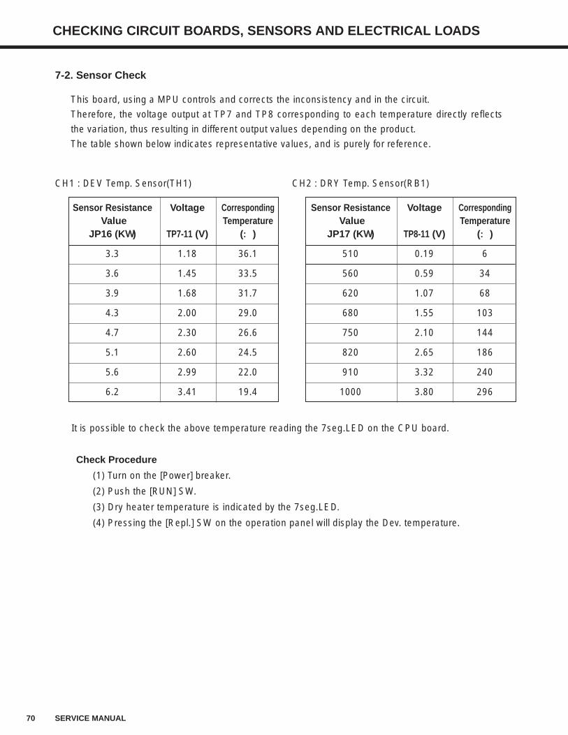
70 SERVICE MANUAL
CHECKING CIRCUIT BOARDS, SENSORS AND ELECTRICAL LOADS
7-2. Sensor Check
This board, using a MPU controls and corrects the inconsistency and in the circuit.
Therefore, the voltage output at TP7 and TP8 corresponding to each temperature directly reflects
the variation, thus resulting in different output values depending on the product.
The table shown below indicates representative values, and is purely for reference.
CH1 : DEV Temp. Sensor(TH1) CH2 : DRY Temp. Sensor(RB1)
It is possible to check the above temperature reading the 7seg.LED on the CPU board.
Check Procedure
(1) Turn on the [Power] breaker.
(2) Push the [RUN] SW.
(3) Dry heater temperature is indicated by the 7seg.LED.
(4) Pressing the [Repl.] SW on the operation panel will display the Dev. temperature.
Sensor Resistance Voltage CorrespondingValue Temperature
JP16 (KΩΩ) TP7-11 (V) (::)
3.3 1.18 36.1
3.6 1.45 33.5
3.9 1.68 31.7
4.3 2.00 29.0
4.7 2.30 26.6
5.1 2.60 24.5
5.6 2.99 22.0
6.2 3.41 19.4
Sensor Resistance Voltage CorrespondingValue Temperature
JP17 (KΩΩ) TP8-11 (V) (::)
510 0.19 6
560 0.59 34
620 1.07 68
680 1.55 103
750 2.10 144
820 2.65 186
910 3.32 240
1000 3.80 296
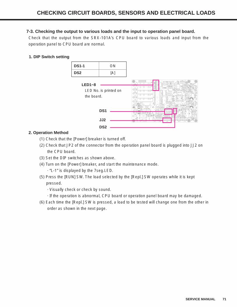
71SERVICE MANUAL
CHECKING CIRCUIT BOARDS, SENSORS AND ELECTRICAL LOADS
7-3. Checking the output to various loads and the input to operation panel board. Check that the output from the SRX-101A’s CPU board to various loads and input from the
operation panel to CPU board are normal.
1. DIP Switch setting
2. Operation Method
(1) Check that the [Power] breaker is turned off.
(2) Check that JP2 of the connector from the operation panel board is plugged into JJ2 on
the CPU board.
(3) Set the DIP switches as shown above.
(4) Turn on the [Power] breaker, and start the maintenance mode.
· “L-1” is displayed by the 7seg.LED.
(5) Press the [RUN] SW. The load selected by the [Repl.] SW operates while it is kept
pressed.
· Visually check or check by sound.
· If the operation is abnormal, CPU board or operation panel board may be damaged.
(6) Each time the [Repl.] SW is pressed, a load to be tested will change one from the other in
order as shown in the next page.
DS1-1 ON
DS2 [A]
LED1~8
LED No. is printed on
the board.
JJ2
DS1
DS2
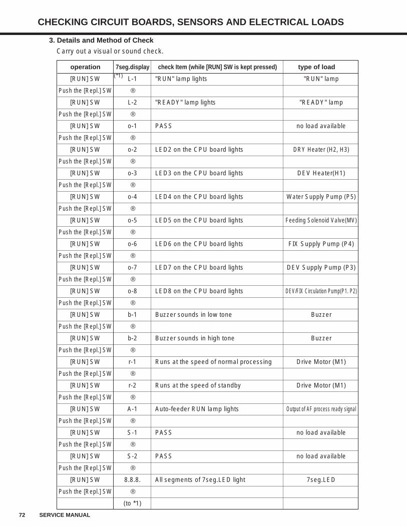
72 SERVICE MANUAL
CHECKING CIRCUIT BOARDS, SENSORS AND ELECTRICAL LOADS
operation 7seg.display check Item (while [RUN] SW is kept pressed) type of load
[RUN] SW L-1 "RUN" lamp lights "RUN" lamp
Push the [Repl.] SW ↓
[RUN] SW L-2 "READY" lamp lights "READY" lamp
Push the [Repl.] SW ↓
[RUN] SW o-1 PASS no load available
Push the [Repl.] SW ↓
[RUN] SW o-2 LED2 on the CPU board lights DRY Heater (H2, H3)
Push the [Repl.] SW ↓
[RUN] SW o-3 LED3 on the CPU board lights DEV Heater(H1)
Push the [Repl.] SW ↓
[RUN] SW o-4 LED4 on the CPU board lights Water Supply Pump (P5)
Push the [Repl.] SW ↓
[RUN] SW o-5 LED5 on the CPU board lights Feeding Solenoid Valve(MV)
Push the [Repl.] SW ↓
[RUN] SW o-6 LED6 on the CPU board lights FIX Supply Pump (P4)
Push the [Repl.] SW ↓
[RUN] SW o-7 LED7 on the CPU board lights DEV Supply Pump (P3)
Push the [Repl.] SW ↓
[RUN] SW o-8 LED8 on the CPU board lights DEV/FIX Circulation Pump(P1. P2)
Push the [Repl.] SW ↓
[RUN] SW b-1 Buzzer sounds in low tone Buzzer
Push the [Repl.] SW ↓
[RUN] SW b-2 Buzzer sounds in high tone Buzzer
Push the [Repl.] SW ↓
[RUN] SW r-1 Runs at the speed of normal processing Drive Motor (M1)
Push the [Repl.] SW ↓
[RUN] SW r-2 Runs at the speed of standby Drive Motor (M1)
Push the [Repl.] SW ↓
[RUN] SW A-1 Auto-feeder RUN lamp lights Output of AF process ready signal
Push the [Repl.] SW ↓
[RUN] SW S-1 PASS no load available
Push the [Repl.] SW ↓
[RUN] SW S-2 PASS no load available
Push the [Repl.] SW ↓
[RUN] SW 8.8.8. All segments of 7seg.LED light 7seg.LED
Push the [Repl.] SW ↓
(to *1)
3. Details and Method of Check
Carry out a visual or sound check.
(*1)
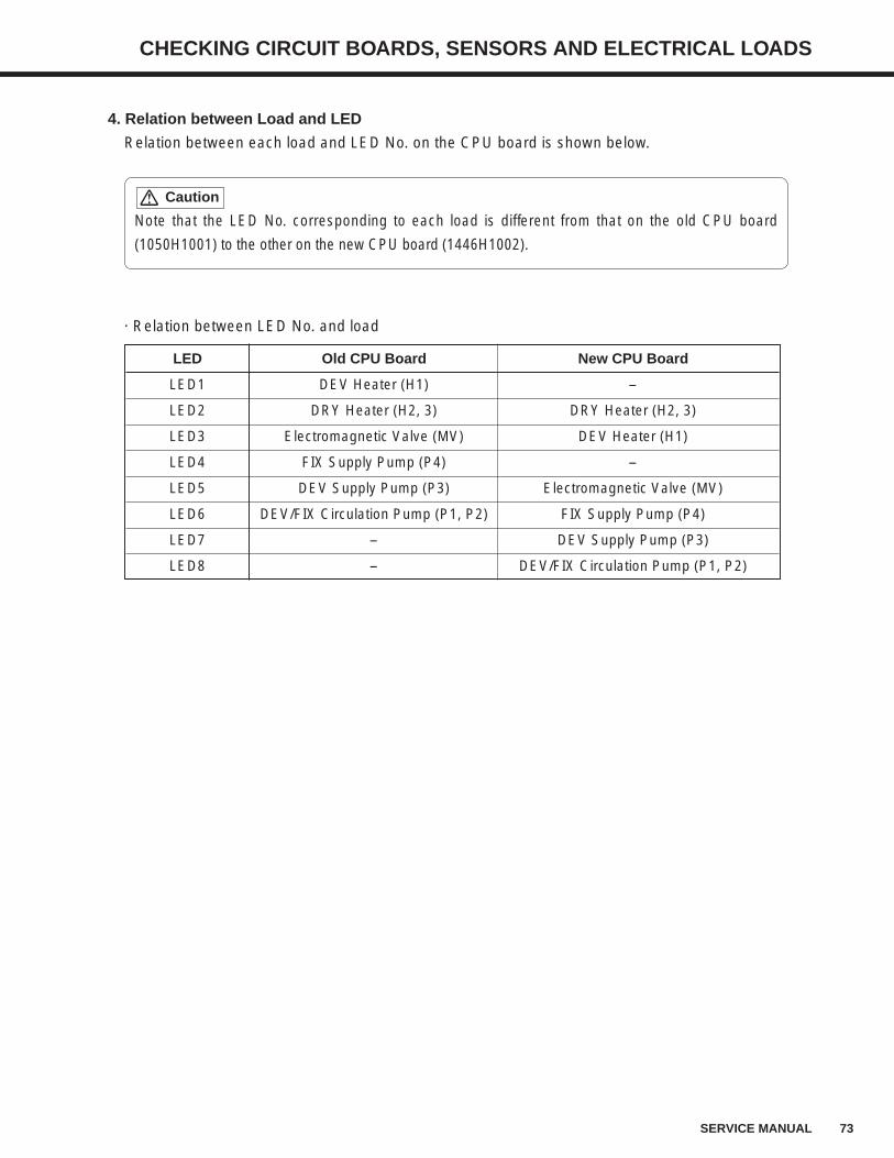
73SERVICE MANUAL
CHECKING CIRCUIT BOARDS, SENSORS AND ELECTRICAL LOADS
4. Relation between Load and LED
Relation between each load and LED No. on the CPU board is shown below.
Note that the LED No. corresponding to each load is different from that on the old CPU board
(1050H1001) to the other on the new CPU board (1446H1002).
Caution
LED Old CPU Board New CPU Board
LED1 DEV Heater (H1) -
LED2 DRY Heater (H2, 3) DRY Heater (H2, 3)
LED3 Electromagnetic Valve (MV) DEV Heater (H1)
LED4 FIX Supply Pump (P4) -
LED5 DEV Supply Pump (P3) Electromagnetic Valve (MV)
LED6 DEV/FIX Circulation Pump (P1, P2) FIX Supply Pump (P4)
LED7 - DEV Supply Pump (P3)
LED8 - DEV/FIX Circulation Pump (P1, P2)
· Relation between LED No. and load
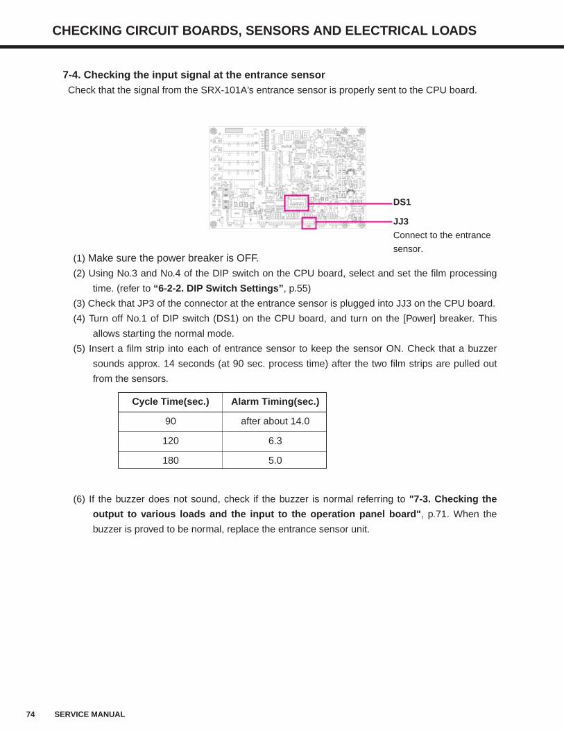
74 SERVICE MANUAL
CHECKING CIRCUIT BOARDS, SENSORS AND ELECTRICAL LOADS
(1) Make sure the power breaker is OFF.(2) Using No.3 and No.4 of the DIP switch on the CPU board, select and set the film processing
time. (refer to “6-2-2. DIP Switch Settings”, p.55)
(3) Check that JP3 of the connector at the entrance sensor is plugged into JJ3 on the CPU board.
(4) Turn off No.1 of DIP switch (DS1) on the CPU board, and turn on the [Power] breaker. This
allows starting the normal mode.
(5) Insert a film strip into each of entrance sensor to keep the sensor ON. Check that a buzzer
sounds approx. 14 seconds (at 90 sec. process time) after the two film strips are pulled out
from the sensors.
(6) If the buzzer does not sound, check if the buzzer is normal referring to "7-3. Checking the
output to various loads and the input to the operation panel board", p.71. When the
buzzer is proved to be normal, replace the entrance sensor unit.
7-4. Checking the input signal at the entrance sensorCheck that the signal from the SRX-101A’s entrance sensor is properly sent to the CPU board.
Cycle Time(sec.) Alarm Timing(sec.)
90 after about 14.0
120 6.3
180 5.0
DS1
JJ3
Connect to the entrance
sensor.
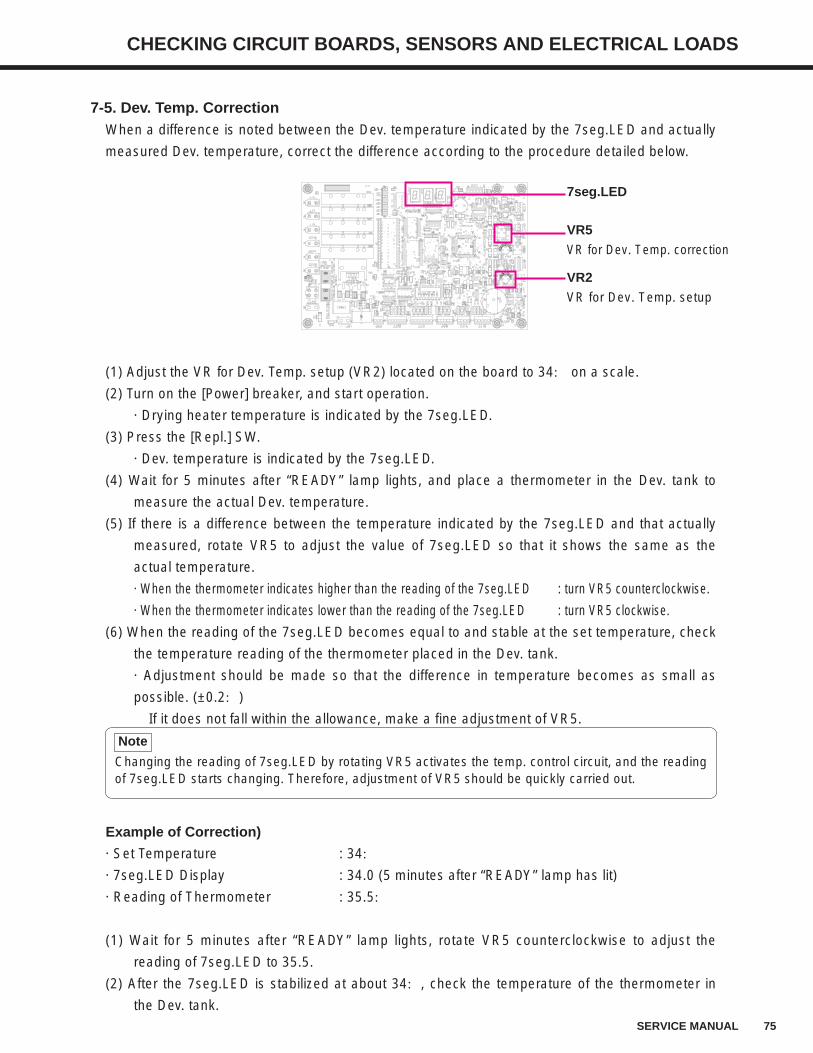
75SERVICE MANUAL
CHECKING CIRCUIT BOARDS, SENSORS AND ELECTRICAL LOADS
7-5. Dev. Temp. CorrectionWhen a difference is noted between the Dev. temperature indicated by the 7seg.LED and actually
measured Dev. temperature, correct the difference according to the procedure detailed below.
Changing the reading of 7seg.LED by rotating VR5 activates the temp. control circuit, and the readingof 7seg.LED starts changing. Therefore, adjustment of VR5 should be quickly carried out.
Note
(1) Adjust the VR for Dev. Temp. setup (VR2) located on the board to 34: on a scale.
(2) Turn on the [Power] breaker, and start operation.
· Drying heater temperature is indicated by the 7seg.LED.
(3) Press the [Repl.] SW.
· Dev. temperature is indicated by the 7seg.LED.
(4) Wait for 5 minutes after “READY” lamp lights, and place a thermometer in the Dev. tank to
measure the actual Dev. temperature.
(5) If there is a difference between the temperature indicated by the 7seg.LED and that actually
measured, rotate VR5 to adjust the value of 7seg.LED so that it shows the same as the
actual temperature.
· When the thermometer indicates higher than the reading of the 7seg.LED : turn VR5 counterclockwise.
· When the thermometer indicates lower than the reading of the 7seg.LED : turn VR5 clockwise.
(6) When the reading of the 7seg.LED becomes equal to and stable at the set temperature, check
the temperature reading of the thermometer placed in the Dev. tank.
· Adjustment should be made so that the difference in temperature becomes as small as
possible. (±0.2:)
If it does not fall within the allowance, make a fine adjustment of VR5.
VR5
VR for Dev. Temp. correction
VR2
VR for Dev. Temp. setup
7seg.LED
Example of Correction)
· Set Temperature : 34:
· 7seg.LED Display : 34.0 (5 minutes after “READY” lamp has lit)
· Reading of Thermometer : 35.5:
(1) Wait for 5 minutes after “READY” lamp lights, rotate VR5 counterclockwise to adjust the
reading of 7seg.LED to 35.5.
(2) After the 7seg.LED is stabilized at about 34:, check the temperature of the thermometer in
the Dev. tank.
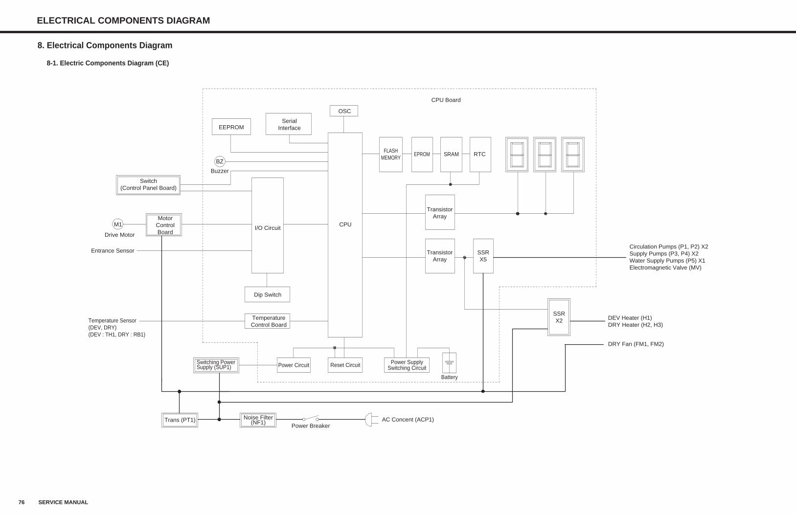
76 SERVICE MANUAL
ELECTRICAL COMPONENTS DIAGRAM
EEPROMSerial
Interface
OSC
CPU Board
RTCSRAMEPROMFLASH
MEMORY
CPU
TransistorArray
TransistorArray
SSRX5
SSRX2
DRY Fan (FM1, FM2)
DEV Heater (H1)DRY Heater (H2, H3)
Battery
Reset Circuit Power SupplySwitching CircuitPower CircuitSwitching Power
Supply (SUP1)
Trans (PT1) Noise Filter(NF1)
Power BreakerAC Concent (ACP1)
Buzzer
BZ
I/O Circuit
Dip Switch
TemperatureControl Board
MotorControlBoard
Switch(Control Panel Board)
M1
Drive Motor
Temperature Sensor(DEV, DRY)(DEV : TH1, DRY : RB1)
Circulation Pumps (P1, P2) X2Supply Pumps (P3, P4) X2Water Supply Pumps (P5) X1Electromagnetic Valve (MV)
Entrance Sensor
8. Electrical Components Diagram
8-1. Electric Components Diagram (CE)
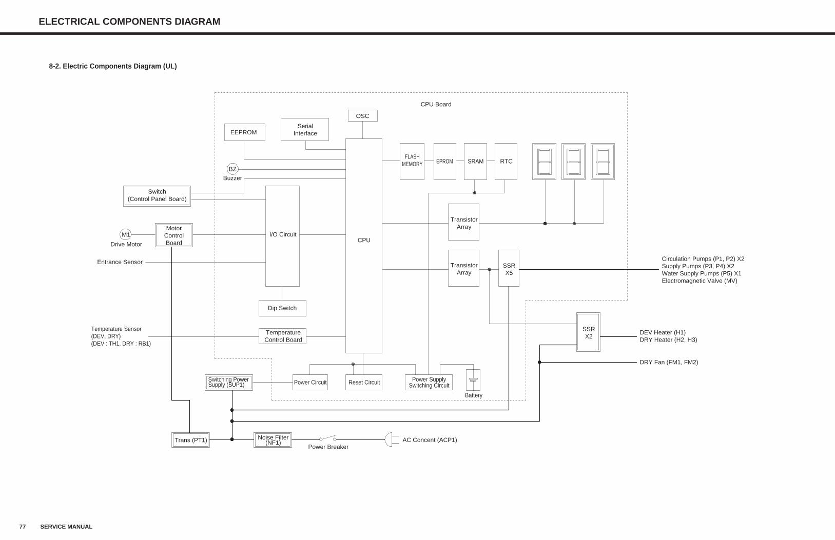
77 SERVICE MANUAL
ELECTRICAL COMPONENTS DIAGRAM
SerialInterface
OSC
CPU
MotorControlBoard
M1
Drive Motor
Buzzer
EEPROM
FLASHMEMORY EPROM SRAM RTC
CPU Board
TransistorArray
TransistorArray
SSRX5
SSRX2
DEV Heater (H1)DRY Heater (H2, H3)
DRY Fan (FM1, FM2)
Trans (PT1) Noise Filter(NF1)
Power BreakerAC Concent (ACP1)
Reset CircuitPower CircuitSwitching PowerSupply (SUP1)
Battery
Temperature Sensor(DEV, DRY)(DEV : TH1, DRY : RB1)
BZ
Dip Switch
I/O Circuit
TemperatureControl Board
Circulation Pumps (P1, P2) X2Supply Pumps (P3, P4) X2Water Supply Pumps (P5) X1Electromagnetic Valve (MV)
Switch(Control Panel Board)
Entrance Sensor
Power SupplySwitching Circuit
8-2. Electric Components Diagram (UL)
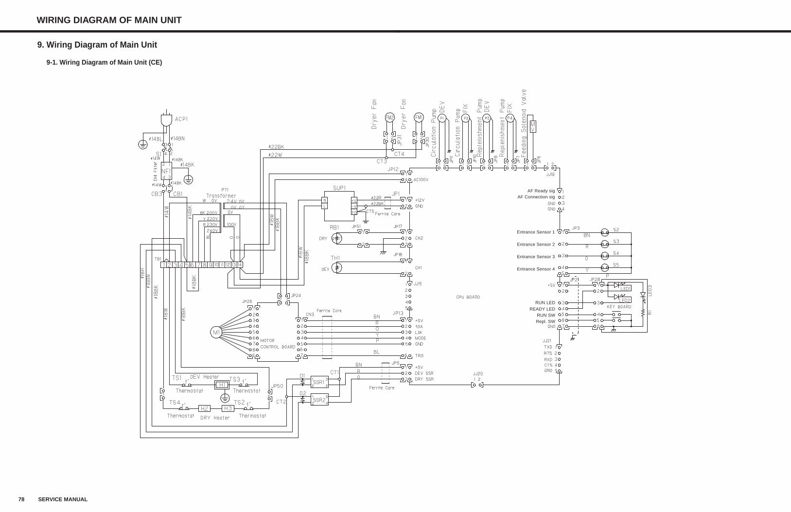
Entrance Sensor 1
Entrance Sensor 2
Entrance Sensor 3
Entrance Sensor 4
RUN LED
READY LEDRUN SWRepl. SW
AF Ready sigAF Connection sig
9. Wiring Diagram of Main Unit
9-1. Wiring Diagram of Main Unit (CE)
78 SERVICE MANUAL
WIRING DIAGRAM OF MAIN UNIT
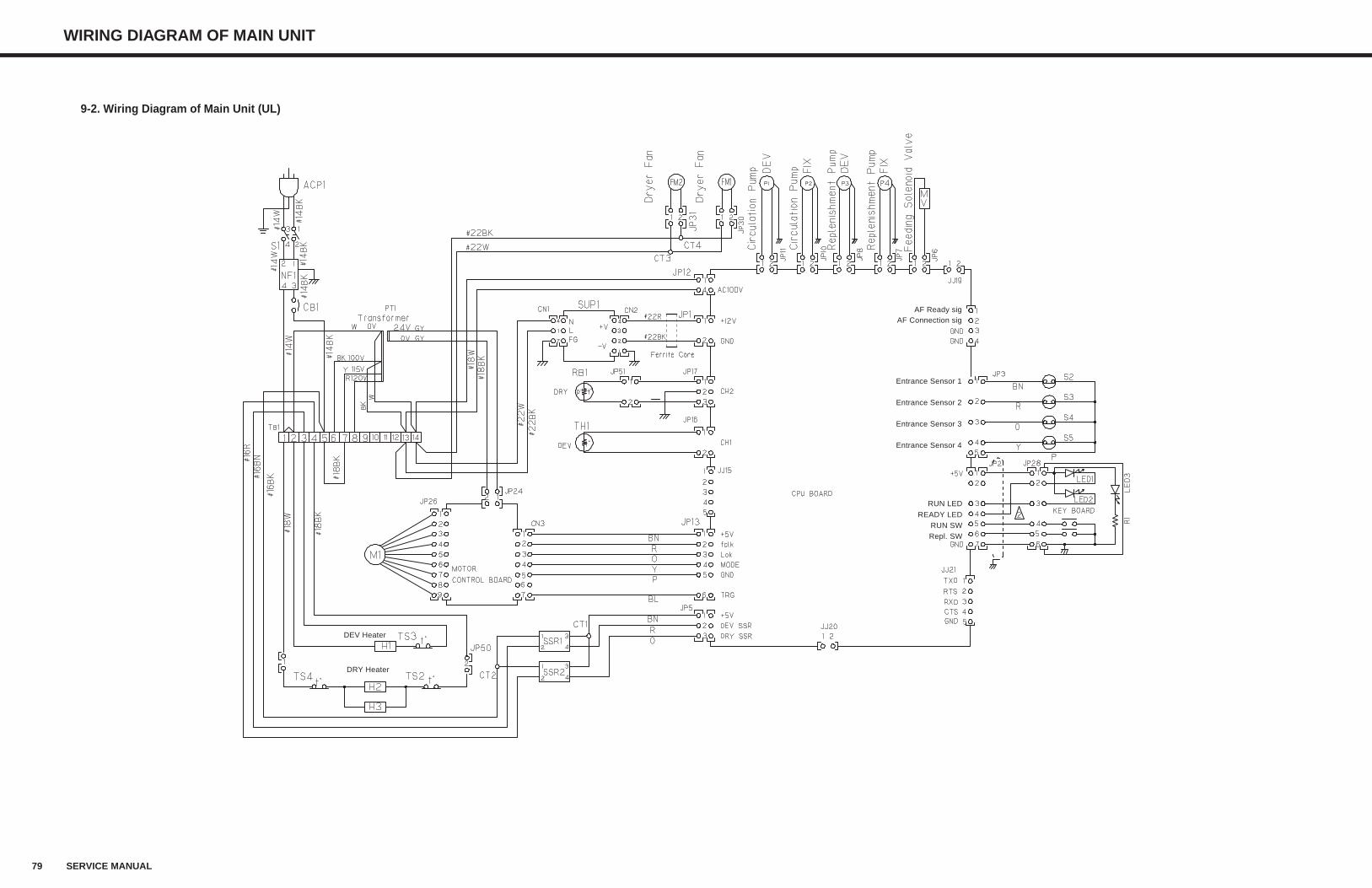
Entrance Sensor 1
Entrance Sensor 2
Entrance Sensor 3
Entrance Sensor 4
RUN LED
READY LEDRUN SWRepl. SW
AF Ready sigAF Connection sig
DEV Heater
DRY Heater
79 SERVICE MANUAL
WIRING DIAGRAM OF MAIN UNIT
9-2. Wiring Diagram of Main Unit (UL)
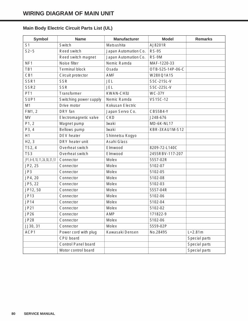
Main Body Electric Circuit Parts List (UL)
Symbol Name Manufacturer Model Remarks
S1 Switch Matsushita AJ8201R
S2~5 Reed switch Japan Automation Co. RS-9S
Reed switch magnet Japan Automation Co. RS-9M
NF1 Noise filter Nemic Ramda MAF-1220-33
TB1 Terminal block Osada OTB-525-14P-06-C
CB1 Circuit protector AMF W28XQ1A15
SSR1 SSR JEL S5C-215L-V
SSR2 SSR JEL S5C-225L-V
PT1 Transformer KWAN-CHIU WC-37Y
SUP1 Switching power supply Nemic Ramda VS15C-12
M1 Drive motor Kokusan Electric
FM1, 2 DRY fan Japan Servo Co. CB55B4-Y
MV Electromagnetic valve CKD J248-676
P1, 2 Magnet pump Iwaki MD-6K-NL17
P3, 4 Bellows pump Iwaki KBR-3XAU1M-S12
H1 DEV heater Shinnetsu Kogyo
H2, 3 DRY heater unit Asahi Glass
TS2, 4 Overheat switch Elmwood 8209-72-L140C
TS3 Overheat switch Elmwood 2455RBV-117-207
JP1, 6~8, 10, 11, 24, 30, 31, 51 Connector Molex 5557-02R
JP2, 25 Connector Molex 5102-07
JP3 Connector Molex 5102-05
JP4, 20 Connector Molex 5102-08
JP5, 22 Connector Molex 5102-03
JP12, 50 Connector Molex 5557-04R
JP13 Connector Molex 5102-06
JP14 Connector Molex 5102-04
JP21 Connector Molex 5102-02
JP26 Connector AMP 171822-9
JP28 Connector Molex 5102-06
JJ30, 31 Connector Molex 5559-02P
ACP1 Power cord with plug Kawasaki Densen No.28495 L=2.81m
CPU board Special parts
Control Panel board Special parts
Motor control board Special parts
80 SERVICE MANUAL
WIRING DIAGRAM OF MAIN UNIT
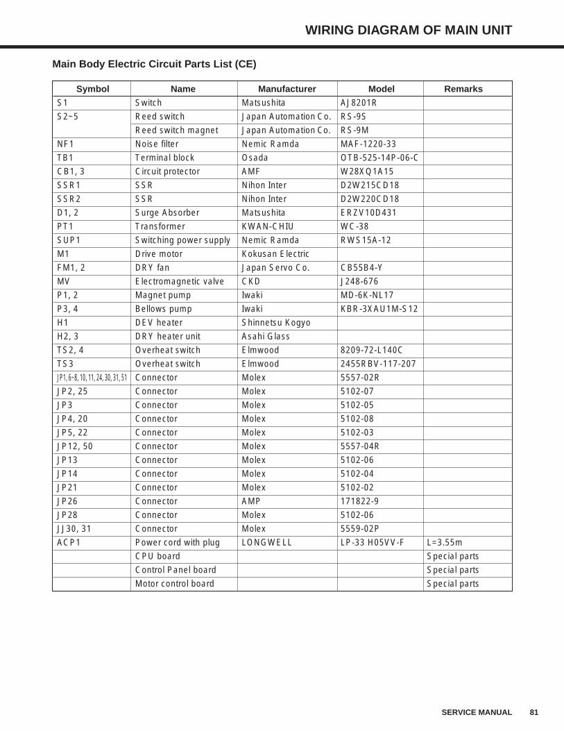
WIRING DIAGRAM OF MAIN UNIT
81SERVICE MANUAL
Main Body Electric Circuit Parts List (CE)
Symbol Name Manufacturer Model Remarks
S1 Switch Matsushita AJ8201R
S2~5 Reed switch Japan Automation Co. RS-9S
Reed switch magnet Japan Automation Co. RS-9M
NF1 Noise filter Nemic Ramda MAF-1220-33
TB1 Terminal block Osada OTB-525-14P-06-C
CB1, 3 Circuit protector AMF W28XQ1A15
SSR1 SSR Nihon Inter D2W215CD18
SSR2 SSR Nihon Inter D2W220CD18
D1, 2 Surge Absorber Matsushita ERZV10D431
PT1 Transformer KWAN-CHIU WC-38
SUP1 Switching power supply Nemic Ramda RWS15A-12
M1 Drive motor Kokusan Electric
FM1, 2 DRY fan Japan Servo Co. CB55B4-Y
MV Electromagnetic valve CKD J248-676
P1, 2 Magnet pump Iwaki MD-6K-NL17
P3, 4 Bellows pump Iwaki KBR-3XAU1M-S12
H1 DEV heater Shinnetsu Kogyo
H2, 3 DRY heater unit Asahi Glass
TS2, 4 Overheat switch Elmwood 8209-72-L140C
TS3 Overheat switch Elmwood 2455RBV-117-207
JP1, 6~8, 10, 11, 24, 30, 31, 51 Connector Molex 5557-02R
JP2, 25 Connector Molex 5102-07
JP3 Connector Molex 5102-05
JP4, 20 Connector Molex 5102-08
JP5, 22 Connector Molex 5102-03
JP12, 50 Connector Molex 5557-04R
JP13 Connector Molex 5102-06
JP14 Connector Molex 5102-04
JP21 Connector Molex 5102-02
JP26 Connector AMP 171822-9
JP28 Connector Molex 5102-06
JJ30, 31 Connector Molex 5559-02P
ACP1 Power cord with plug LONGWELL LP-33 H05VV-F L=3.55m
CPU board Special parts
Control Panel board Special parts
Motor control board Special parts
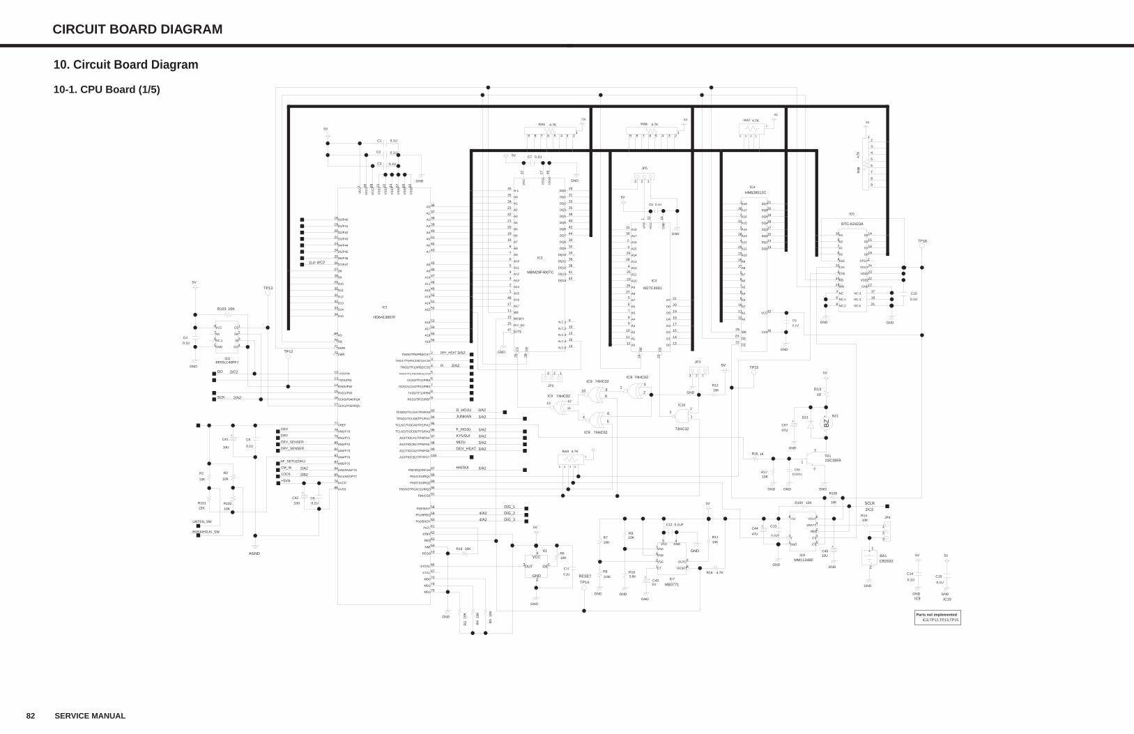
82 SERVICE MANUAL
CIRCUIT BOARD DIAGRAM
10. Circuit Board Diagram
10-1. CPU Board (1/5)
DIG_1
4/A2 DIG_2
4/A2 DIG_3
3/A2JUNKAN
3/A2F_HOJU
3/A2KYUSUI
3/A2MIZU
4/C2D.P
2/A2DI
3/A2HAISUI
TP12
GND
47U
C57
0.1UFC12
10KR9
3.6KR10
3.6K
R8
10K
R3
10K
R5
10K
R7
0.1U
C11
0.1U
C4
0.1UC8
10R13
0.1U
C10
0.1U
C6
0.1UC2
JP5
3 2 1
JP2
123
0.1UC7
X1
2
3 1
4
5V
5V
5V
GND GND
GND
GNDGND
GND
GNDGND
GND
JP3
3 2 1
5V
GND
0.1UF
C13
10U
C42
GND
10UC45
GND
1UC43
GND
GND
GNDGND
0.1U
C14
JP4
3
2
1
0.1U
C15
5V
74HC02IC9
5
64
74HC02IC9
11
1213
74HC02IC9
2
31
74HC32
IC10
1
23
10K
R4
5VTP15
TP16
TP13
CR2032BA1
2
1
5V
5V
10U
C41
0.1U
C5
GND
GND
5V
GND
5V
GNDGND
5V5V5V
4.7KRA5
9 8 7 6 5 4 3 21
4.7K
RA8
9
8
7
6
5
4
3
21
5V
4.7KRA6
9 8 7 6 5 4 3 21
47U
C44
BZ1D13
0.1U
C9
0.022U
C56
GND GND
3/A2D_HOJU
10K
R11
4.7KR18
DRY_SENSER
DEV_SENSER
DRY
DEV
2/A2CM_IN
2/B2LOCK
3/A2DRY_HEAT
1KR16
10KR104
22K
R101
10K
R102
10K
R2
+5VA
2SC2859TR1
1
2
3
4.7KRA7
1
2345
2/A2SCK
10K
R12
10KR17
R1410K
10K
R105
AGND
AF_SETUZOKU
3/A2DEV_HEAT
HM628512C
IC4
8
26
3
1
32
16
20
19
21
17
13
14
15
18
25
27
30
2
31
28
4
23
5
6
7
9
10
11
12
29
24
22
UNTEN_SW
10K
R1
BOEKIHOJU_SW
10KR19
10KR6
M27C4001
IC3
2224
13
14
15
17
18
19
20
21
12
11
10
9
8
7
6
5
27
26
23
25
4
28
29
3
2
30
31
1 32 16
MB3771
IC7
45
3
8
7
6
2
1
0.1UC1
0.1UC3
10KR103
BR93LC46RFJIC6
3
1
7
6
5
2
8
4
2/C2DO
4.7KRA9
1
2345
74HC02IC9
8
910
RTC-62423A
IC5
6
173
18
218
13
11
2
22
23
24
1
12
14
15
16
19
20
4
10
9
7
5
MM1134BFIC8
8
7
6
5
4
3
2
1
MBM29F400TC
IC2
45
25
24
23
22
21
20
19
18
8
7
6
5
4
3
2
1
48
17
47
15
12
11
16
43
41
39
36
34
32
30
44
42
40
38
35
33
31
29
2826
27 4637
13
10
9
14
HD6413007F
IC1
2
73
1 92
88
87
3
4
34
33
32
31
30
29
27
28
26
63
62
100
99
98
97
96
95
94
93
75
74
66
10
64
60
61
59
58
9
90
89
8
7
6
5
56
55
54
52
53
51
50
49
48
47
46
45
43
42
41
40
39
38
37
36
86
76
83
84
77
85
82
81
80
79
78
17
16
15
14
13
12
72
71
70
69
25
24
23
21
20
19
18
65574422116835
91
67
SCLR
2/C2
RESET
TP14
+
VCC
OEOUT
GND
+
+
+
+
-
+
+
+-
BZ
CE
OE
WE
A0
A1
A2
A3
A5
A6
A7
A10
A12
A13
A15
A16
A17
A8
A11
DQ4
DQ2
DQ1
DQ0
DQ3
DQ5
DQ6
VSS
VCC
A18
A14
A9
A4
DQ7
GND
VC
C
VP
P
A18
A17
A16
A15
A14
A13
A12
A11
A10
A9
A8
A7
A6
A5
A4
A3
A2
A1
A0
D7
D6
D5
D4
D3
D2
D1
D0
OE
CE
CT
VSC
VSB
VSA
RESET
OUTC
VCC GND
CS
DI
DOGND
NC.1
SK
VCC
NC
A0
A1
A2
A3
ALE
CS1
D0
D1
D2
D3
GND
STD.P
VCC1
VDD1
VDD2
CS0
RD
WR
NC.3
NC.4
NC.5NC.2
NC.1
NC
GND
RES
CS
VBATT
CS
VOUT
Y
+5V
N.C.5
N.C.1
N.C.2
N.C.3
VC
C
VS
S2
VS
S1
CE
OE
DQ0
DQ1
DQ2
DQ3
DQ4
DQ5
DQ6
DQ7
DQ8
DQ9
DQ10
DQ11
DQ12
DQ13
DQ14
N.C.4
WE
RESET
RY/_BY
BYTE
A17
A16
A15
A14
A13
A12
A11
A10
A9
A8
A7
A6
A5
A4
A3
A2
A1
A0
A-1
XTAL
P84/CS0
VC
C1
VC
C2
VS
S1
VS
S2
VS
S3
VS
S4
VS
S5
D0/P40
D1/P41
D2/P42
D3/P43
D4/P44
D5/P45
D6/P46
AS
RD
HWR
LWR
TXD0/P90
TXD1/P91
RXD0/P92
RXD1/P93
SCK0/P94/IRQ4
SCK1/P95/IRQ5
AN0/P70
AN1/P71
AN2/P72
AN3/P73
AN4/P74
DA1/AN7/P77
VREF
DA0/AN6/P76
AN5/P75
AVCC
AVSS
A0
A1
A2
A3
A4
A5
A6
A7
A8
A9
A10
A11
A12
A13
A14
A16
A15
A17
A18
A19
TMIO3/TP11/PB3/DREQ1/CS4
UCAS/TP12/PB4
SCK2/LCAS/TP13/PB5
TXD2/TP14/PB6
P82/CS2/IRQ2
P83/ADTRG/CS1/IRQ3
RXD2/TP15/PB7
P60/WAIT
P61/BREQ
P67/
P62/BACK
NMI
RESO
EXTAL
MD1
MD2
TENDO/TCLKA/TP0/PA0
TEND1/TCLKB/TP1/PA1
TCLKC/TIOCA0/TP2/PA2
TCLKD/TIOCB0/TP3/PA3
A23/TIOCA1/TP4/PA4
A22/TIOCB1/TP5/PA5
A21/TIOCA2/TP6/PA6
A20/TIOCB2/TP7/PA7
STBY
RES
D7/P47
D9
D8
D10
D11
D12
D13
D14
D15
TMO2/TP10/PB2/CS5
TMIO1/TP9/PB1/DREQ0/CS6
P80/IRQ0/RFSH
P81/CS3/IRQ1
VS
S6
VC
C
MD0
TMO0/TP8/PB0/CS7
IC9 IC10
IC3,TP12,TP13,TP15Parts not implemented
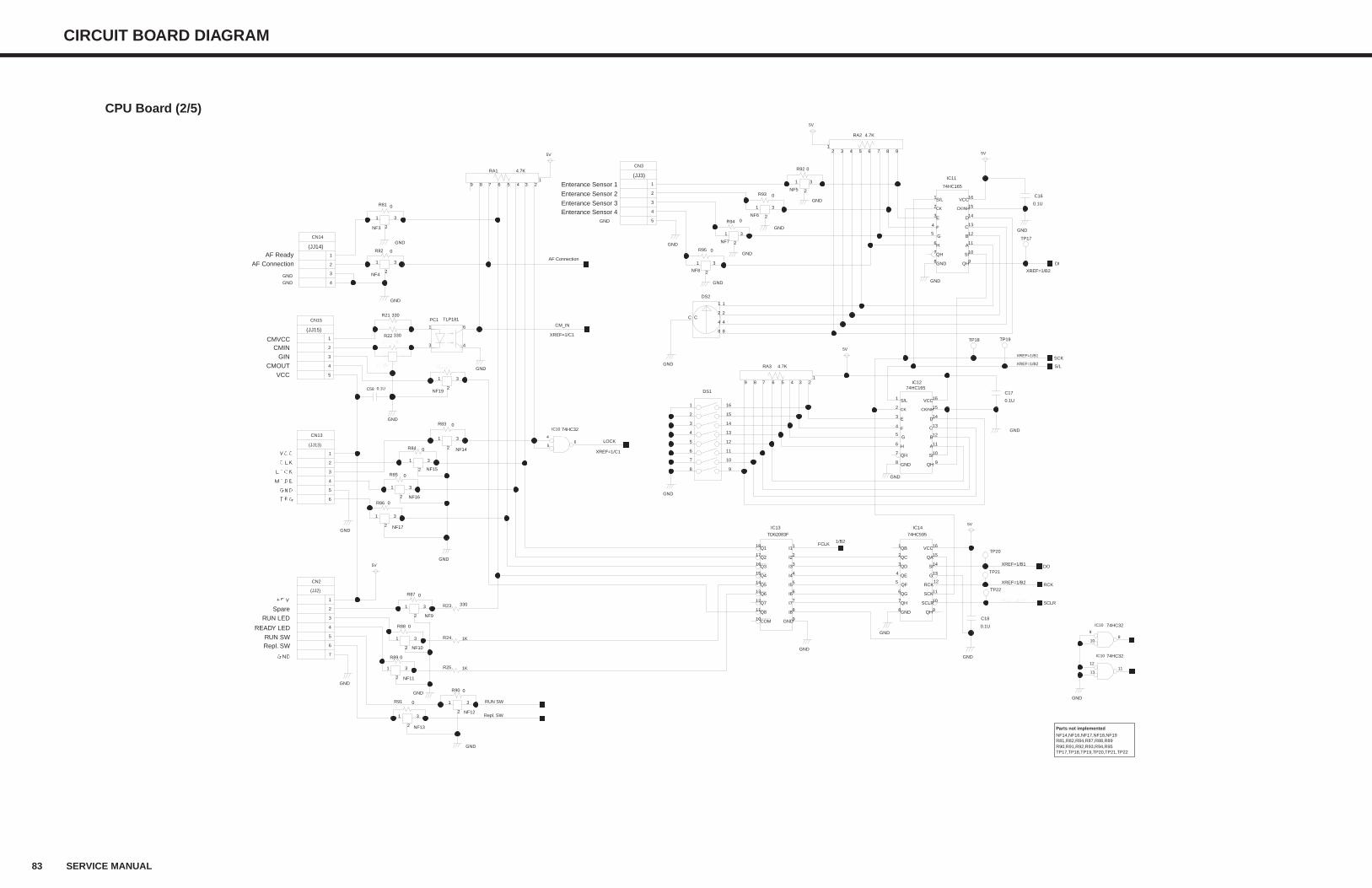
83 SERVICE MANUAL
CIRCUIT BOARD DIAGRAM
CPU Board (2/5)
NF18NF18
3
2
1
GND
0R110R110
0R111R111
GND
XREF=1/C2XREF=1/C2 SCLR
XREF=1/B2 RCK
XREF=1/B1 DO
XREF=1/B2S/L
XREF=1/B2
DI
NF3
3
2
1
NF4
3
2
1
330R21
NF17
3
2
1
RUN SW
NF14
3
2
1
NF16
3
2
1
330R23
1KR25
1KR24
NF9
3
2
1
NF10
3
2
1
NF11
3
2
1
NF12
3
2
1
NF13
3
2
1
0R94
NF5
3
2
1
0R92
0R95
0R93
DS1
3
8 9
10
11
12
13
14
15
16
7
6
5
4
2
1
NF6
3
2
1
NF15
3
2
1
0R85
0R86
0R91
0R90
0R89
0R87
0R88
GND
GND
GND
GND
GND
0.1U
C17
GND
GND
GND
GND
GND
GND
GND
GND
GND NF7
3
2
1
GND
NF8
3
2
1
0.1U
C16
GND
0R81
0R82
AF Connection
TP17
TP19TP18
TP20
TP21
TP22
0.1U
C18
GND
GND
5V
5V
5V
5V
5V
5V
GND
GND
4.7KRA3
9 8 7 6 5 4 3 21
74HC32IC10
5
46
GND
74HC32IC10
13
1211
4.7KRA1
9 8 7 6 5 4 3 21
4.7KRA2
987654321
GND
Repl. SW
XREF=1/C1
LOCK
1/B2FCLK
NF19
3
2
1
0.1UC58
330R22 XREF=1/C1
CM_IN
CN14
4
2
1
3
CN15
3
1
2
4
5
TLP181PC1
3
6
4
1
0R84
CN13
3
1
2
4
5
6
0R83
CN2
7
6
5
4
3
2
1
XREF=1/B1SCK
74HC595
IC14
16
15
14
13
12
11
10
98
7
6
5
4
3
2
1
TD62083F
IC13
1
2
3
4
5
6
7
8
9
18
17
16
15
14
13
12
11
10
CN3
3
1
2
4
5
74HC165IC12
16
15
14
13
12
11
10
98
7
6
5
4
3
2
1
74HC165
IC11
16
15
14
13
12
11
10
98
7
6
5
4
3
2
1
74HC32IC10
10
98
DS2
4
8
1
C2
GND
QA
QB
QC
QD
QE
QF
QG
QH
QH'
RCK
SCK
SI
G
VCC
SCLR
COM
Q8
Q7
Q6
Q5
Q4
Q3
Q2
Q1
GND
I8
I7
I6
I5
I4
I3
I2
I1
S/L
CK
E
F
G
H
QH
GND QH
SI
A
B
C
D
CKINH
VCC
S/L
CK
E
F
G
H
QH
GND QH
SI
A
B
C
D
CKINH
VCC
2C
1
8
4
GND
GND
GND
(JJ14)
(JJ15)
(JJ13)
(JJ2)
(JJ3)
NF14,NF16,NF17,NF18,NF19R81,R82,R84,R87,R88,R89R90,R91,R92,R93,R94,R95TP17,TP18,TP19,TP20,TP21,TP22
Parts not implemented
AF ReadyAF Connection
CMVCC
READY LED
RUN SWRepl. SW
RUN LEDSpare
CMINGIN
CMOUTVCC
Enterance Sensor 1
Enterance Sensor 2
Enterance Sensor 3Enterance Sensor 4
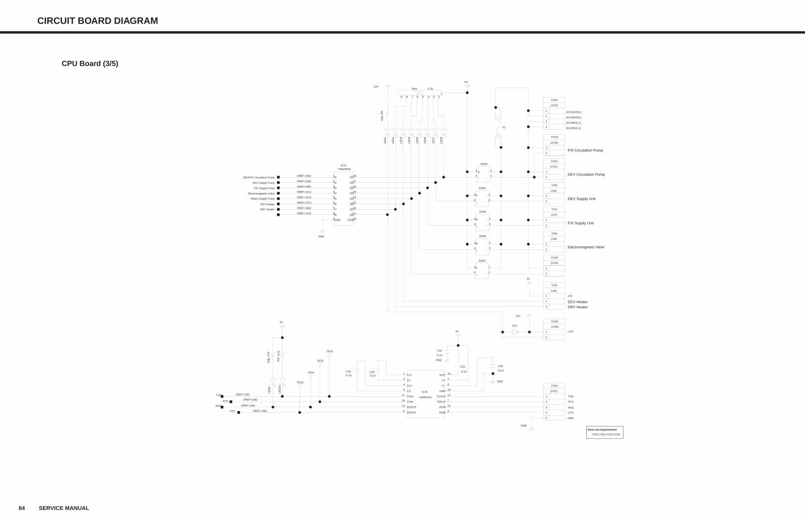
84 SERVICE MANUAL
CIRCUIT BOARD DIAGRAM
CPU Board (3/5)
XREF=1/B1RXD
XREF=1/B2CTS
GND
LED
10
LED
9
LED
5
LED
4
LED
3
LED
7
LED
8
LED
6
4.7KRA4
9 8 7 6 5 4 3 21
F1
LED
1
LED
2
10K
R15
GND
GND
4.7K
R27
4.7K
R26
SSR4
3
2
1
4
SSR5
3
2
1
4
SSR6
3
2
1
4
TP23
TP24
TP25
TP26
5V
12V
12V
5V
5V
5VD12
XREF=1/B2RTS
0.1UC30
0.1UC31
0.1U
C32
0.1U
C34
0.1U
C33
GND
XREF=1/B2DEV/FIX Circulation Pump
XREF=1/B2DEV Supply Pump
XREF=1/B2FIX Supply Pump
XREF=1/C2Electromagnetic Valve
XREF=1/C2Water Supply Pump
XREF=1/C2DEV Heater
XREF=1/B2DRY Heater
XREF=1/C2
XREF=1/B1TXD
CN21
3
1
2
4
5
CN20
2
1
CN5
1
2
3
CN19
2
1
CN6
2
1
CN7
2
1
CN8
2
1
CN11
2
1
CN10
2
1
CN12
4
2
1
3
TD62083FIC15
1
2
3
4
5
6
7
8
9
18
17
16
15
14
13
12
11
10
ADM232A
IC16
1
8
13
7
14
9
12
11
10
16
6
2
155
4
3
SSR7
3
2
1
4
SSR3
3
2
1
4
COM
Q8
Q7
Q6
Q5
Q4
Q3
Q2
Q1
GND
I8
I7
I6
I5
I4
I3
I2
I1
C1-
C2+
C2- GND
V+
V-
VCC
T2IN
T1IN
R1OUT
R2OUT
T1OUT
T2OUT
R1IN
R2IN
C1+
-
+
-
+
-
+
-
+
AC100V(N1)
AC100V(L1)
AC100V(L1)
AC100V(N1)
+5V
+12V
TXD
RXD
GND
+-
RTS
CTS
(JJ21)
(JJ20)
(JJ5)
(JJ19)
(JJ6)
(JJ7)
(JJ8)
(JJ11)
(JJ10)
(JJ12)
TP23,TP24,TP25,TP26
Parts not implemented
DEV Heater
Electromagnetic Valve
FIX Supply Unit
DEV Supply Unit
DEV Circulation Pump
FIX Circulation Pump
DRY Heater
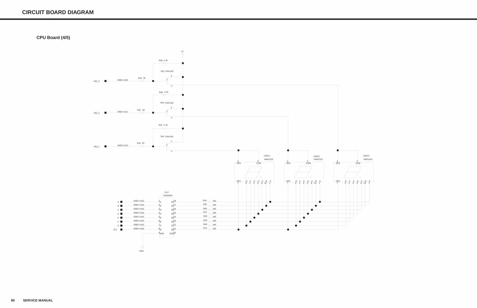
85 SERVICE MANUAL
CIRCUIT BOARD DIAGRAM
CPU Board (4/5)
XREF=1/A2D.P
XREF=1/A2G
XREF=1/A2F
XREF=1/A2E
XREF=1/A2D
XREF=1/A2C
XREF=1/A2B
XREF=1/A2A
XREF=1/C2DIG_2
XREF=1/C2DIG_1
NAR131S
LED13
6 9
110854237
NAR131S
LED12
6 9
110854237
TR3
1
2
3
TR5
1
2
3
NAR131S
LED11
6 9
110854237
TR4
1
2
3
4.7KR28
4.7KR30
4.7KR32
330R34
330R35
330R36
330R37
330R38
330R39
330R40
330R41
2KR29
2KR31
2KR33
5V
GND
XREF=1/D2DIG_3
TD62083F
IC17
1
2
3
4
5
6
7
8
9
18
17
16
15
14
13
12
11
10
DPC G F E D C B A
COMDPA
DPC G F E D C B A
COMDPA
2SA1162
2SA1162
DPC G F E D C B A
COMDPA
2SA1162
COM
Q8
Q7
Q6
Q5
Q4
Q3
Q2
Q1
GND
I8
I7
I6
I5
I4
I3
I2
I1
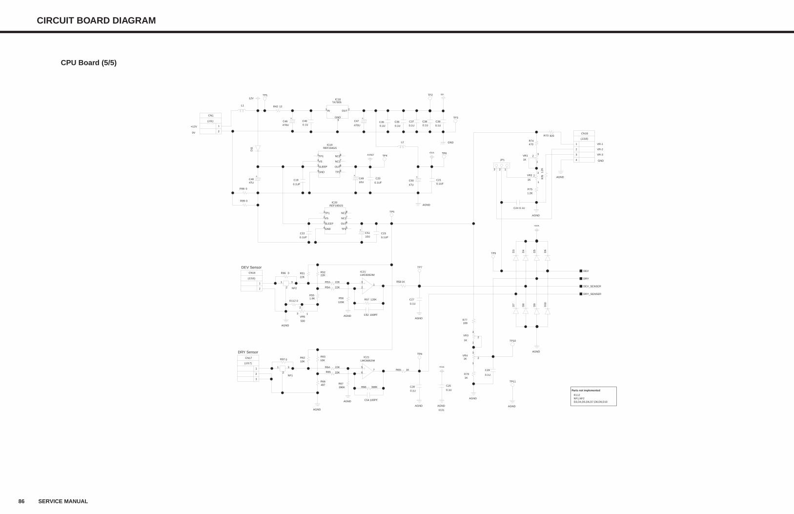
86 SERVICE MANUAL
CIRCUIT BOARD DIAGRAM
CPU Board (5/5)
TP10
470R74
100PFC52
22KR54
22KR51
22KR52
1.8KR55
22KR53
100PFC54
22KR65
10KR62
10KR63
487R66
22KR64
390KR68
1KR69
0.1UC40
0.1UC35
470UC46
470U
C47
0.1U
C360.1U
C370.1UC38
0.1U
C28
100R77
0.1U
C39
NF1
3
2
1
JP1
3 2 1
0.1UC24
820R73
47UC48
0.1UF
C20C210.1UF
TP3
TP4
TP9
NF2
3
2
1
TP6
TP1
0.1UF
C22
0.1UF
C19
47U
C5010UC49
C23
0.1UF10UC51
TP5
0.1U
C25
0.1U
C27
TP2
TP11
TP7
5V
12V
L2
AGND
AGND
AGND
AGND
AGND
AGND
AGND
AGND
AGND
REF194GSIC19
6
1
4
3
8
5
72
REF195GSIC20
6
1
4
3
8
5
72
D3
D4
D5
D6
D9
D10
D7
AGND
GND
AGND
D11
390KR67
120K
R56
AGND
1KR58
D8
DEV
DEV_SENSER
TP8
DRY
0R96
1.2K
R75
1.2K
R76
AGND
VR5
500
2
3 1
120KR570R112
0.1U
C29
TA7805IC18
3
1 2
CN1
2
1
L1
0R97
1KR79
CN18
4
2
1
3
LMC6062IMIC21
13
2
CN16
2
1
CN17
1
2
3
VR41K 2
3
1
1K
VR2 23
1
1K
VR1 23
1
VR3
1K2
3
1
R42 12
R99 0
R98 0
LMC6062IMIC21
75
6
DRY_SENSER
+ +
+
+5VA
AVREF+5VA
+
+
+
VS
TP1
SLEEP
NC2
OUT
NC1
TP2GND
VS
TP1
SLEEP
NC2
OUT
NC1
TP2GND
OUTIN
GND
+5VA
0V
IC21
(JJ1)
(JJ16)
(JJ17)
(JJ18)
VR-1
VR-2
VR-3
GND
+12V
R112NF1,NF2D3,D4,D5,D6,D7,D8,D9,D10
Parts not implemented
DEV Sensor
DRY Sensor
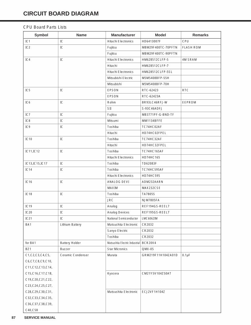
87 SERVICE MANUAL
CIRCUIT BOARD DIAGRAM
Symbol Name Manufacturer Model Remarks
IC1 IC Hitachi Electronics HD6413007F CPU
IC2 IC Fujitsu MBM29F400TC-70PFTN FLASH ROM
Fujitsu MBM29F400TC-90PFTN
IC4 IC Hitachi Electronics HM628512CLFP-5 4M SRAM
Hitachi HM628512CLFP-7
Hitachi Electronics HM628512CLFP-5SL
Mitsubishi Electric M5M5408BFP-55H
Mitsubishi M5M5408BFP-70H
IC5 IC EPSON RTC-62423 RTC
EPSON RTC-62423A
IC6 IC Rohm BR93LC46RFJ-W EEPROM
SII S-93C46ADFJ
IC7 IC Fujitsu MB3771PF-G-BND-TF
IC8 IC Mitsumi MM1134BFFE
IC9 IC Toshiba TC74HC02AF
Hitachi HD74HC02FPEL
IC10 IC Toshiba TC74HC32AF
Hitachi HD74HC32FPEL
IC11,IC12 IC Toshiba TC74HC165AF
Hitachi Electronics HD74HC165
IC13,IC15,IC17 IC Toshiba TD62083F
IC14 IC Toshiba TC74HC595AF
Hitachi Electronics HD74HC595
IC16 IC ANALOG DEVI ADM232AARN
MAXIM MAX232CSE
IC18 IC Toshiba TA7805S
JRC NJM7805FA
IC19 IC Analog REF194GS-REEL7
IC20 IC Analog Devices REF195GS-REEL7
IC21 IC National Semiconductor LMC6062IM
BA1 Lithium Battery Matsushita Electronic CR2032
Sanyo Electric CR2032
Toshiba CR2032
for BA1 Battery Holder Matsushita Electric Industrial BCR20V4
BZ1 Buzzer Star Micronics QMX-05
C1,C2,C3,C4,C5, Ceramic Condenser Murata GRM219F11H104ZA01D 0.1µF
C6,C7,C8,C9,C10,
C11,C12,C13,C14,
C15,C16,C17,C18, Kyocera CM21Y5V104Z50AT
C19,C20,C21,C22,
C23,C24,C25,C27,
C28,C29,C30,C31, Matsushita Electronic ECJ2VF1H104Z
C32,C33,C34,C35,
C36,C37,C38,C39,
C40,C58
CPU Board Parts Lists
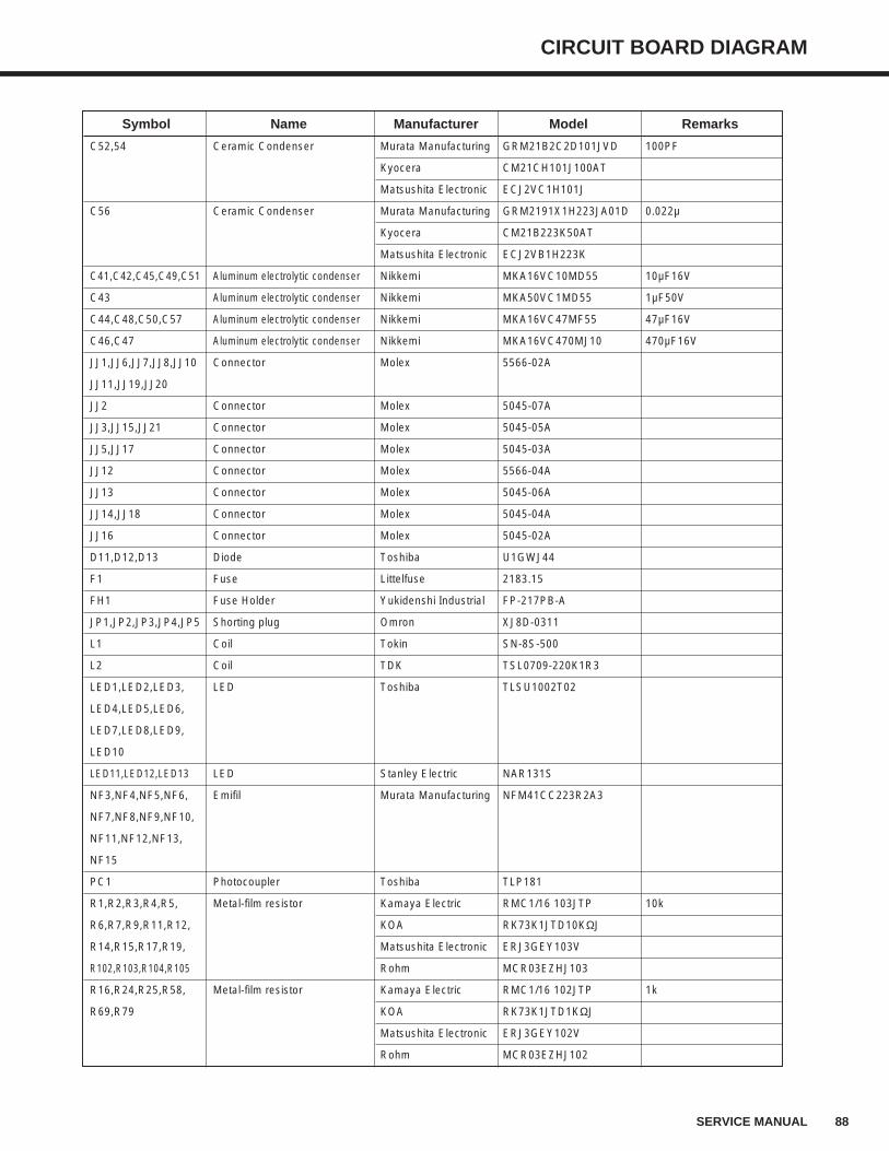
CIRCUIT BOARD DIAGRAM
88SERVICE MANUAL
Symbol Name Manufacturer Model Remarks
C52,54 Ceramic Condenser Murata Manufacturing GRM21B2C2D101JVD 100PF
Kyocera CM21CH101J100AT
Matsushita Electronic ECJ2VC1H101J
C56 Ceramic Condenser Murata Manufacturing GRM2191X1H223JA01D 0.022µ
Kyocera CM21B223K50AT
Matsushita Electronic ECJ2VB1H223K
C41,C42,C45,C49,C51 Aluminum electrolytic condenser Nikkemi MKA16VC10MD55 10µF16V
C43 Aluminum electrolytic condenser Nikkemi MKA50VC1MD55 1µF50V
C44,C48,C50,C57 Aluminum electrolytic condenser Nikkemi MKA16VC47MF55 47µF16V
C46,C47 Aluminum electrolytic condenser Nikkemi MKA16VC470MJ10 470µF16V
JJ1,JJ6,JJ7,JJ8,JJ10 Connector Molex 5566-02A
JJ11,JJ19,JJ20
JJ2 Connector Molex 5045-07A
JJ3,JJ15,JJ21 Connector Molex 5045-05A
JJ5,JJ17 Connector Molex 5045-03A
JJ12 Connector Molex 5566-04A
JJ13 Connector Molex 5045-06A
JJ14,JJ18 Connector Molex 5045-04A
JJ16 Connector Molex 5045-02A
D11,D12,D13 Diode Toshiba U1GWJ44
F1 Fuse Littelfuse 2183.15
FH1 Fuse Holder Yukidenshi Industrial FP-217PB-A
JP1,JP2,JP3,JP4,JP5 Shorting plug Omron XJ8D-0311
L1 Coil Tokin SN-8S-500
L2 Coil TDK TSL0709-220K1R3
LED1,LED2,LED3, LED Toshiba TLSU1002T02
LED4,LED5,LED6,
LED7,LED8,LED9,
LED10
LED11,LED12,LED13 LED Stanley Electric NAR131S
NF3,NF4,NF5,NF6, Emifil Murata Manufacturing NFM41CC223R2A3
NF7,NF8,NF9,NF10,
NF11,NF12,NF13,
NF15
PC1 Photocoupler Toshiba TLP181
R1,R2,R3,R4,R5, Metal-film resistor Kamaya Electric RMC1/16 103JTP 10k
R6,R7,R9,R11,R12, KOA RK73K1JTD10KΩJ
R14,R15,R17,R19, Matsushita Electronic ERJ3GEY103V
R102,R103,R104,R105 Rohm MCR03EZHJ103
R16,R24,R25,R58, Metal-film resistor Kamaya Electric RMC1/16 102JTP 1k
R69,R79 KOA RK73K1JTD1KΩJ
Matsushita Electronic ERJ3GEY102V
Rohm MCR03EZHJ102
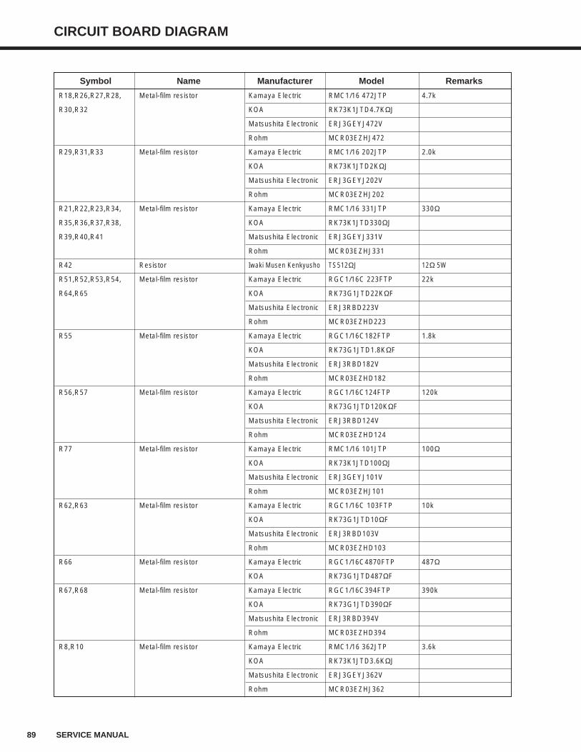
89 SERVICE MANUAL
CIRCUIT BOARD DIAGRAM
Symbol Name Manufacturer Model Remarks
R18,R26,R27,R28, Metal-film resistor Kamaya Electric RMC1/16 472JTP 4.7k
R30,R32 KOA RK73K1JTD4.7KΩJ
Matsushita Electronic ERJ3GEYJ472V
Rohm MCR03EZHJ472
R29,R31,R33 Metal-film resistor Kamaya Electric RMC1/16 202JTP 2.0k
KOA RK73K1JTD2KΩJ
Matsushita Electronic ERJ3GEYJ202V
Rohm MCR03EZHJ202
R21,R22,R23,R34, Metal-film resistor Kamaya Electric RMC1/16 331JTP 330Ω
R35,R36,R37,R38, KOA RK73K1JTD330ΩJ
R39,R40,R41 Matsushita Electronic ERJ3GEYJ331V
Rohm MCR03EZHJ331
R42 Resistor Iwaki Musen Kenkyusho TS512ΩJ 12Ω 5W
R51,R52,R53,R54, Metal-film resistor Kamaya Electric RGC1/16C 223FTP 22k
R64,R65 KOA RK73G1JTD22KΩF
Matsushita Electronic ERJ3RBD223V
Rohm MCR03EZHD223
R55 Metal-film resistor Kamaya Electric RGC1/16C182FTP 1.8k
KOA RK73G1JTD1.8KΩF
Matsushita Electronic ERJ3RBD182V
Rohm MCR03EZHD182
R56,R57 Metal-film resistor Kamaya Electric RGC1/16C124FTP 120k
KOA RK73G1JTD120KΩF
Matsushita Electronic ERJ3RBD124V
Rohm MCR03EZHD124
R77 Metal-film resistor Kamaya Electric RMC1/16 101JTP 100Ω
KOA RK73K1JTD100ΩJ
Matsushita Electronic ERJ3GEYJ101V
Rohm MCR03EZHJ101
R62,R63 Metal-film resistor Kamaya Electric RGC1/16C 103FTP 10k
KOA RK73G1JTD10ΩF
Matsushita Electronic ERJ3RBD103V
Rohm MCR03EZHD103
R66 Metal-film resistor Kamaya Electric RGC1/16C4870FTP 487Ω
KOA RK73G1JTD487ΩF
R67,R68 Metal-film resistor Kamaya Electric RGC1/16C394FTP 390k
KOA RK73G1JTD390ΩF
Matsushita Electronic ERJ3RBD394V
Rohm MCR03EZHD394
R8,R10 Metal-film resistor Kamaya Electric RMC1/16 362JTP 3.6k
KOA RK73K1JTD3.6KΩJ
Matsushita Electronic ERJ3GEYJ362V
Rohm MCR03EZHJ362

CIRCUIT BOARD DIAGRAM
90SERVICE MANUAL
Symbol Name Manufacturer Model Remarks
R13 Metal-film resistor Kamaya Electric RMC1/4 100JTP 10Ω 1/4W
KOA RK73K2ETD10ΩJ
Matsushita Electronic ERJ14YJ100U
Rohm MCR25JZHJ100
R73 Metal-film resistor Kamaya Electric RMC1/16 821JTP 820Ω
KOA RK73K1JTD820ΩJ
Matsushita Electronic ERJ3GEYJ821V
Rohm MCR03EZHJ821
R75,R76 Metal-film resistor Kamaya Electric RMC1/16 122JTP 1.2k
KOA RK73K1JTD1.2KΩJ
Matsushita Electronic ERJ3GEYJ122V
Rohm MCR03EZHJ122
R74 Metal-film resistor Kamaya Electric RMC1/16 471JTP 470Ω
KOA RK73K1JTD470ΩJ
Matsushita Electronic ERJ3GEYJ471V
Rohm MCR03EZHJ471
R83,R85,R86,R96,R97, Metal-film resistor Kamaya Electric RMC1/16 JPTP 0Ω
R98,R99,R110,R111 KOA RK73Z1JTD
Matsushita Electronic ERJ3GEY0R00V
Rohm MCR03EZHJ000
R101 Metal-film resistor Kamaya Electric RMC1/16 223JTP 22K
KOA RK73K1JTD22KΩJ
Matsushita Electronic ERJ3GEYJ223V
Rohm MCR03EZHJ223
RA1,RA2,A3,RA4, Resistor array Kamaya Electric RAC168U 472JCTP 4.7kX8
RA5,RA6,RA8
RA7,RA9 Resistor array Kamaya Electric RAC164N 472JATP 4.7kX4
SSR3,SSR4,SSR5, SSR Nippon Inter D2W202LD18
SSR6,SSR7 Matsushita Electronic AQ80139-G01
DS1 DIP Switch OMRON A6S-8104
DS2 DIP Switch Copal Electronics SA7050A
TP1,TP2,TP3,TP4, Check Terminal Mac Eight HK-2-G
TP5,TP6,TP7,TP8,
TP9,TP10,TP11,TP14,
TP16
TR1 Transistor Toshiba 2SC2859
TR3,TR4,TR5 Transistor Toshiba 2SA1162
VR1,VR3 Semi-fixed resistor Copal Electronics CT-6P1KΩ 1KΩ
VR2,VR4 Semi-fixed resistor Copal Electronics RJ-6P102J 1KΩ
VR5 Semi-fixed resistor Copal Electronics CT-6P500Ω 500Ω
X1 Crystal oscillator EPSON SG-8002CA-PHB-7.3728
IC Socket OMRON XR2A-3211-N IC3
Heat sink Ryosan OSH-2440-SPL IC18
Heat radiator rubber Shin-Etsu Chemical TC-30AG IC18
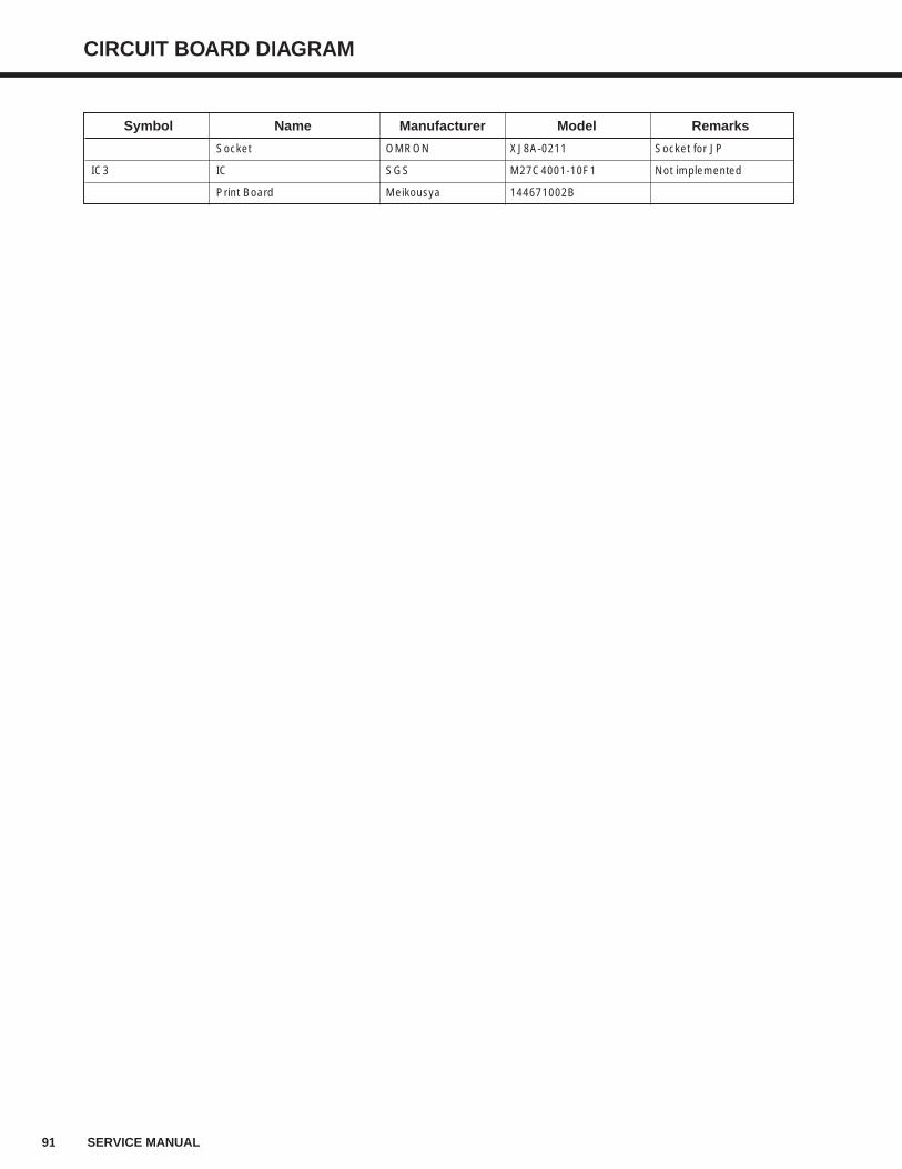
91 SERVICE MANUAL
CIRCUIT BOARD DIAGRAM
Symbol Name Manufacturer Model Remarks
Socket OMRON XJ8A-0211 Socket for JP
IC3 IC SGS M27C4001-10F1 Not implemented
Print Board Meikousya 144671002B
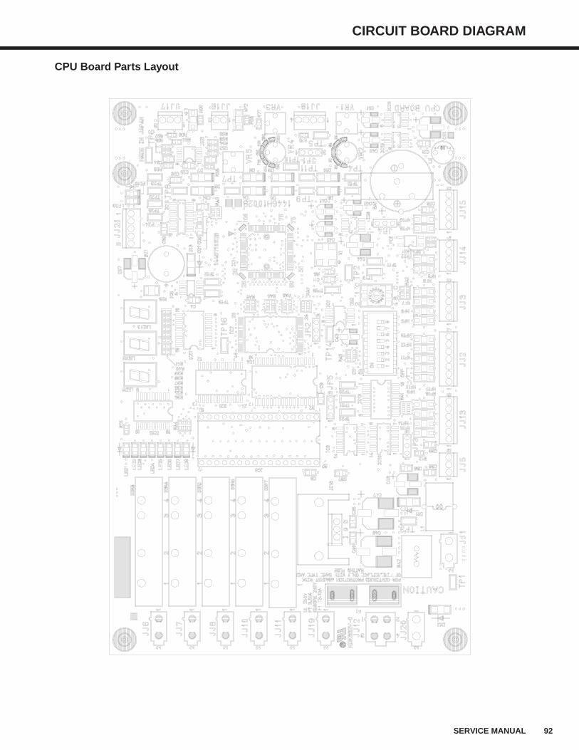
CIRCUIT BOARD DIAGRAM
92SERVICE MANUAL
CPU Board Parts Layout
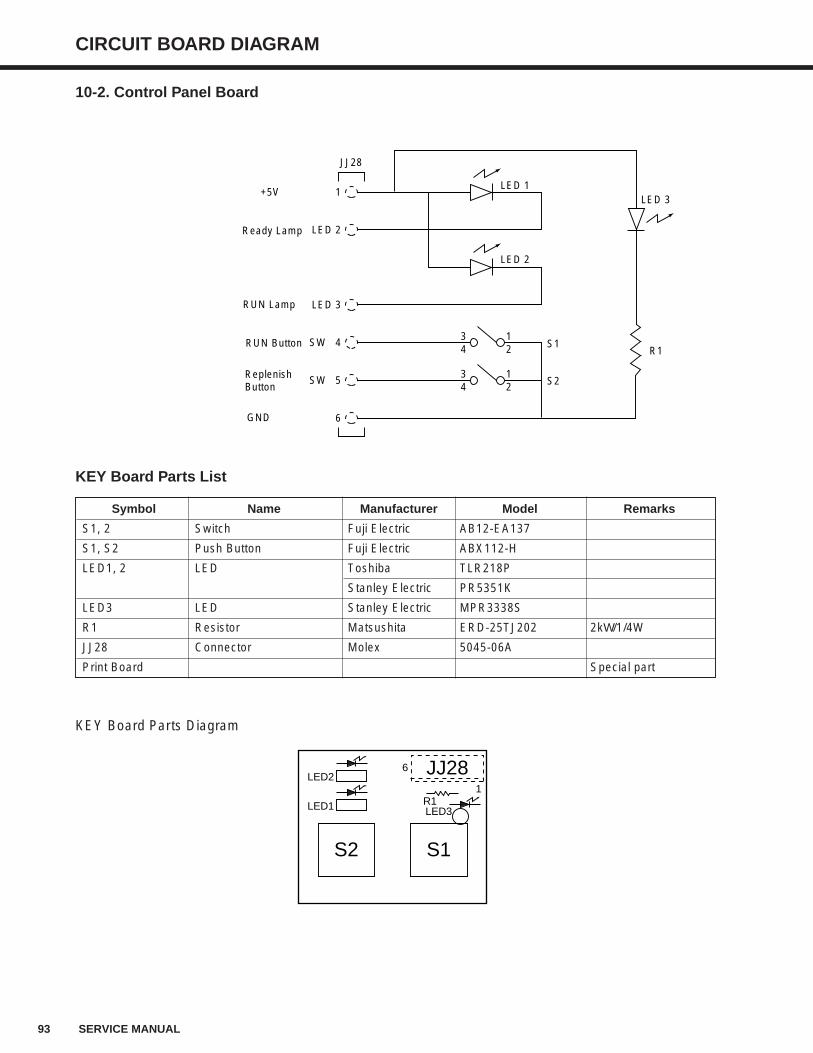
93 SERVICE MANUAL
CIRCUIT BOARD DIAGRAM
10-2. Control Panel Board
KEY Board Parts List
KEY Board Parts Diagram
Symbol Name Manufacturer Model Remarks
S1, 2 Switch Fuji Electric AB12-EA137
S1, S2 Push Button Fuji Electric ABX112-H
LED1, 2 LED Toshiba TLR218P
Stanley Electric PR5351K
LED3 LED Stanley Electric MPR3338S
R1 Resistor Matsushita ERD-25TJ202 2kΩ/1/4W
JJ28 Connector Molex 5045-06A
Print Board Special part
LED2
LED1 LED3
6
S2 S1
R11
JJ28
1+5V
JJ28
LED 2Ready Lamp
LED 3RUN Lamp
SW 4RUN Button
SW 5ReplenishButton
6GND
LED 1
LED 2
LED 3
R1S1
S2
34
12
34
12

94 SERVICE MANUAL
CIRCUIT BOARD DIAGRAM
10-3. Motor Control Board
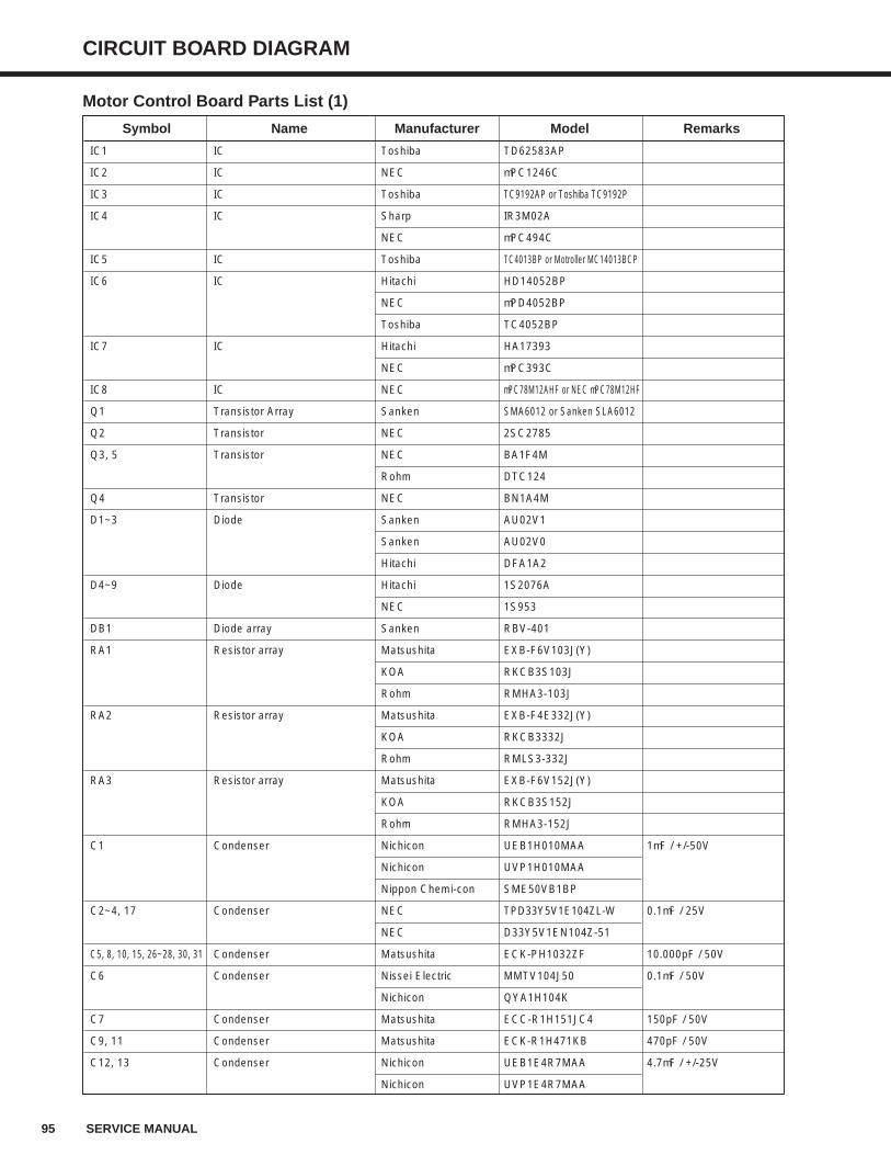
95 SERVICE MANUAL
CIRCUIT BOARD DIAGRAM
Motor Control Board Parts List (1)
Symbol Name Manufacturer Model Remarks
IC1 IC Toshiba TD62583AP
IC2 IC NEC µPC1246C
IC3 IC Toshiba TC9192AP or Toshiba TC9192P
IC4 IC Sharp IR3M02A
NEC µPC494C
IC5 IC Toshiba TC4013BP or Motroller MC14013BCP
IC6 IC Hitachi HD14052BP
NEC µPD4052BP
Toshiba TC4052BP
IC7 IC Hitachi HA17393
NEC µPC393C
IC8 IC NEC µPC78M12AHF or NEC µPC78M12HF
Q1 Transistor Array Sanken SMA6012 or Sanken SLA6012
Q2 Transistor NEC 2SC2785
Q3, 5 Transistor NEC BA1F4M
Rohm DTC124
Q4 Transistor NEC BN1A4M
D1~3 Diode Sanken AU02V1
Sanken AU02V0
Hitachi DFA1A2
D4~9 Diode Hitachi 1S2076A
NEC 1S953
DB1 Diode array Sanken RBV-401
RA1 Resistor array Matsushita EXB-F6V103J(Y)
KOA RKCB3S103J
Rohm RMHA3-103J
RA2 Resistor array Matsushita EXB-F4E332J(Y)
KOA RKCB3332J
Rohm RMLS3-332J
RA3 Resistor array Matsushita EXB-F6V152J(Y)
KOA RKCB3S152J
Rohm RMHA3-152J
C1 Condenser Nichicon UEB1H010MAA 1µF / +/-50V
Nichicon UVP1H010MAA
Nippon Chemi-con SME50VB1BP
C2~4, 17 Condenser NEC TPD33Y5V1E104ZL-W 0.1µF / 25V
NEC D33Y5V1EN104Z-51
C5, 8, 10, 15, 26~28, 30, 31 Condenser Matsushita ECK-PH1032ZF 10.000pF / 50V
C6 Condenser Nissei Electric MMTV104J50 0.1µF / 50V
Nichicon QYA1H104K
C7 Condenser Matsushita ECC-R1H151JC4 150pF / 50V
C9, 11 Condenser Matsushita ECK-R1H471KB 470pF / 50V
C12, 13 Condenser Nichicon UEB1E4R7MAA 4.7µF / +/-25V
Nichicon UVP1E4R7MAA
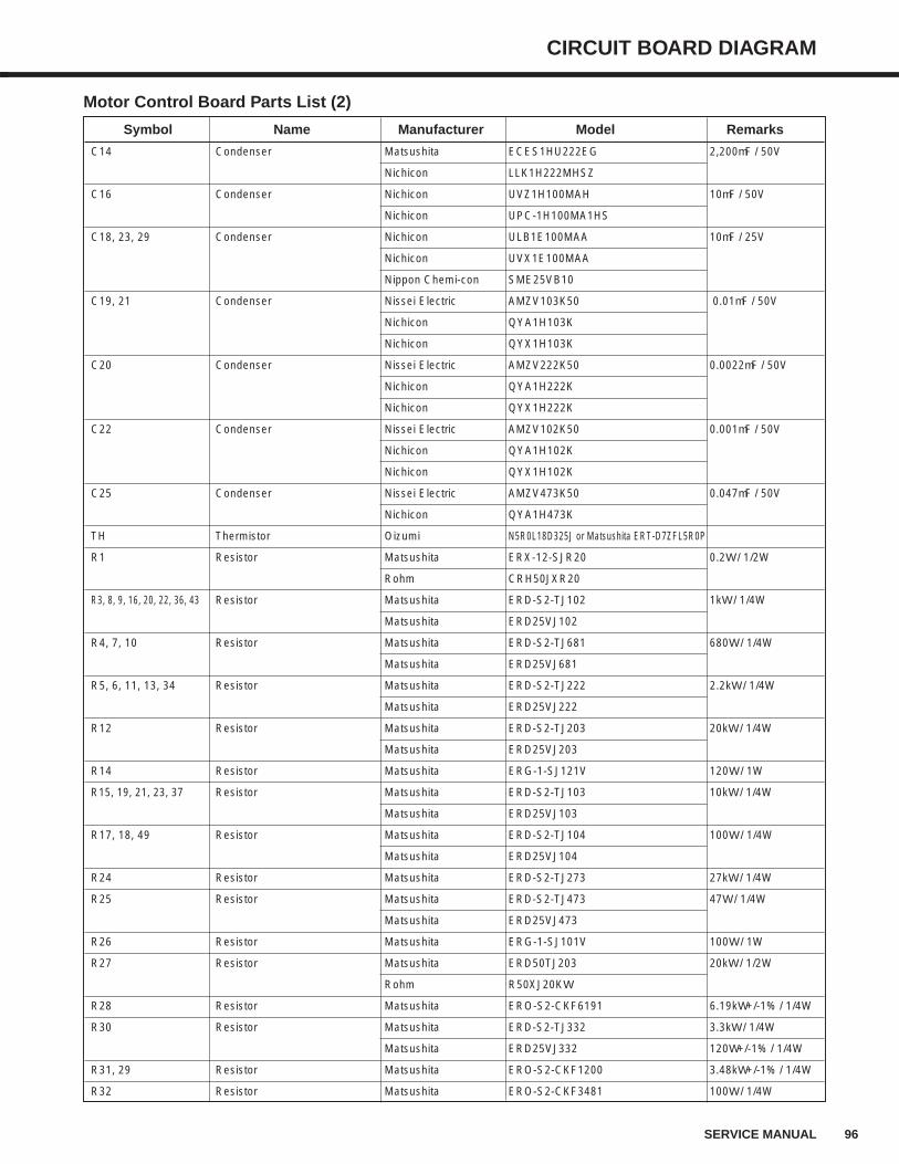
96SERVICE MANUAL
CIRCUIT BOARD DIAGRAM
Motor Control Board Parts List (2)
Symbol Name Manufacturer Model Remarks
C14 Condenser Matsushita ECES1HU222EG 2,200µF / 50V
Nichicon LLK1H222MHSZ
C16 Condenser Nichicon UVZ1H100MAH 10µF / 50V
Nichicon UPC-1H100MA1HS
C18, 23, 29 Condenser Nichicon ULB1E100MAA 10µF / 25V
Nichicon UVX1E100MAA
Nippon Chemi-con SME25VB10
C19, 21 Condenser Nissei Electric AMZV103K50 0.01µF / 50V
Nichicon QYA1H103K
Nichicon QYX1H103K
C20 Condenser Nissei Electric AMZV222K50 0.0022µF / 50V
Nichicon QYA1H222K
Nichicon QYX1H222K
C22 Condenser Nissei Electric AMZV102K50 0.001µF / 50V
Nichicon QYA1H102K
Nichicon QYX1H102K
C25 Condenser Nissei Electric AMZV473K50 0.047µF / 50V
Nichicon QYA1H473K
TH Thermistor Oizumi N5R0L18D325J or Matsushita ERT-D7ZFL5R0P
R1 Resistor Matsushita ERX-12-SJR20 0.2Ω / 1/2W
Rohm CRH50JXR20
R3, 8, 9, 16, 20, 22, 36, 43 Resistor Matsushita ERD-S2-TJ102 1kΩ / 1/4W
Matsushita ERD25VJ102
R4, 7, 10 Resistor Matsushita ERD-S2-TJ681 680Ω / 1/4W
Matsushita ERD25VJ681
R5, 6, 11, 13, 34 Resistor Matsushita ERD-S2-TJ222 2.2kΩ / 1/4W
Matsushita ERD25VJ222
R12 Resistor Matsushita ERD-S2-TJ203 20kΩ / 1/4W
Matsushita ERD25VJ203
R14 Resistor Matsushita ERG-1-SJ121V 120Ω / 1W
R15, 19, 21, 23, 37 Resistor Matsushita ERD-S2-TJ103 10kΩ / 1/4W
Matsushita ERD25VJ103
R17, 18, 49 Resistor Matsushita ERD-S2-TJ104 100Ω / 1/4W
Matsushita ERD25VJ104
R24 Resistor Matsushita ERD-S2-TJ273 27kΩ / 1/4W
R25 Resistor Matsushita ERD-S2-TJ473 47Ω / 1/4W
Matsushita ERD25VJ473
R26 Resistor Matsushita ERG-1-SJ101V 100Ω / 1W
R27 Resistor Matsushita ERD50TJ203 20kΩ / 1/2W
Rohm R50XJ20KΩ
R28 Resistor Matsushita ERO-S2-CKF6191 6.19kΩ+/-1% / 1/4W
R30 Resistor Matsushita ERD-S2-TJ332 3.3kΩ / 1/4W
Matsushita ERD25VJ332 120Ω+/-1% / 1/4W
R31, 29 Resistor Matsushita ERO-S2-CKF1200 3.48kΩ+/-1% / 1/4W
R32 Resistor Matsushita ERO-S2-CKF3481 100Ω / 1/4W
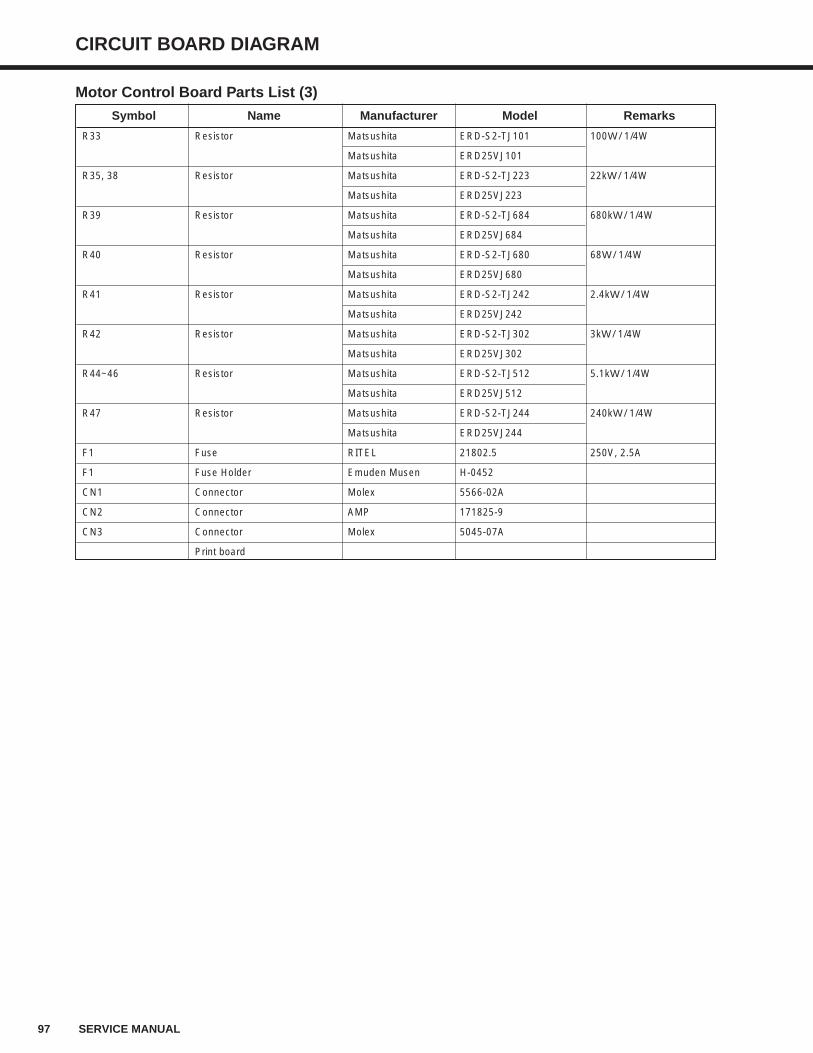
97 SERVICE MANUAL
Motor Control Board Parts List (3)
Symbol Name Manufacturer Model Remarks
R33 Resistor Matsushita ERD-S2-TJ101 100Ω / 1/4W
Matsushita ERD25VJ101
R35, 38 Resistor Matsushita ERD-S2-TJ223 22kΩ / 1/4W
Matsushita ERD25VJ223
R39 Resistor Matsushita ERD-S2-TJ684 680kΩ / 1/4W
Matsushita ERD25VJ684
R40 Resistor Matsushita ERD-S2-TJ680 68Ω / 1/4W
Matsushita ERD25VJ680
R41 Resistor Matsushita ERD-S2-TJ242 2.4kΩ / 1/4W
Matsushita ERD25VJ242
R42 Resistor Matsushita ERD-S2-TJ302 3kΩ / 1/4W
Matsushita ERD25VJ302
R44~46 Resistor Matsushita ERD-S2-TJ512 5.1kΩ / 1/4W
Matsushita ERD25VJ512
R47 Resistor Matsushita ERD-S2-TJ244 240kΩ / 1/4W
Matsushita ERD25VJ244
F1 Fuse RITEL 21802.5 250V, 2.5A
F1 Fuse Holder Emuden Musen H-0452
CN1 Connector Molex 5566-02A
CN2 Connector AMP 171825-9
CN3 Connector Molex 5045-07A
Print board
CIRCUIT BOARD DIAGRAM
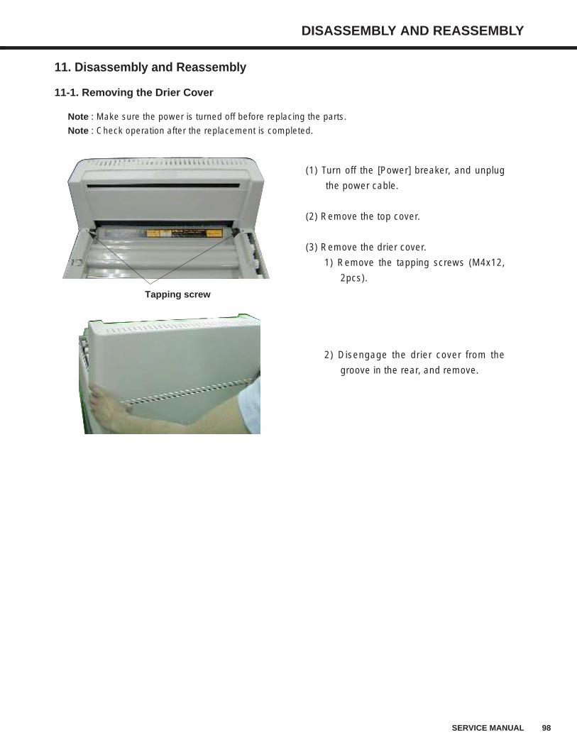
98SERVICE MANUAL
DISASSEMBLY AND REASSEMBLY
11. Disassembly and Reassembly
11-1. Removing the Drier Cover
(1) Turn off the [Power] breaker, and unplug
the power cable.
(2) Remove the top cover.
(3) Remove the drier cover.
1) Remove the tapping screws (M4x12,
2pcs).
2) Disengage the drier cover from the
groove in the rear, and remove.
Tapping screw
Note : Make sure the power is turned off before replacing the parts.
Note : Check operation after the replacement is completed.
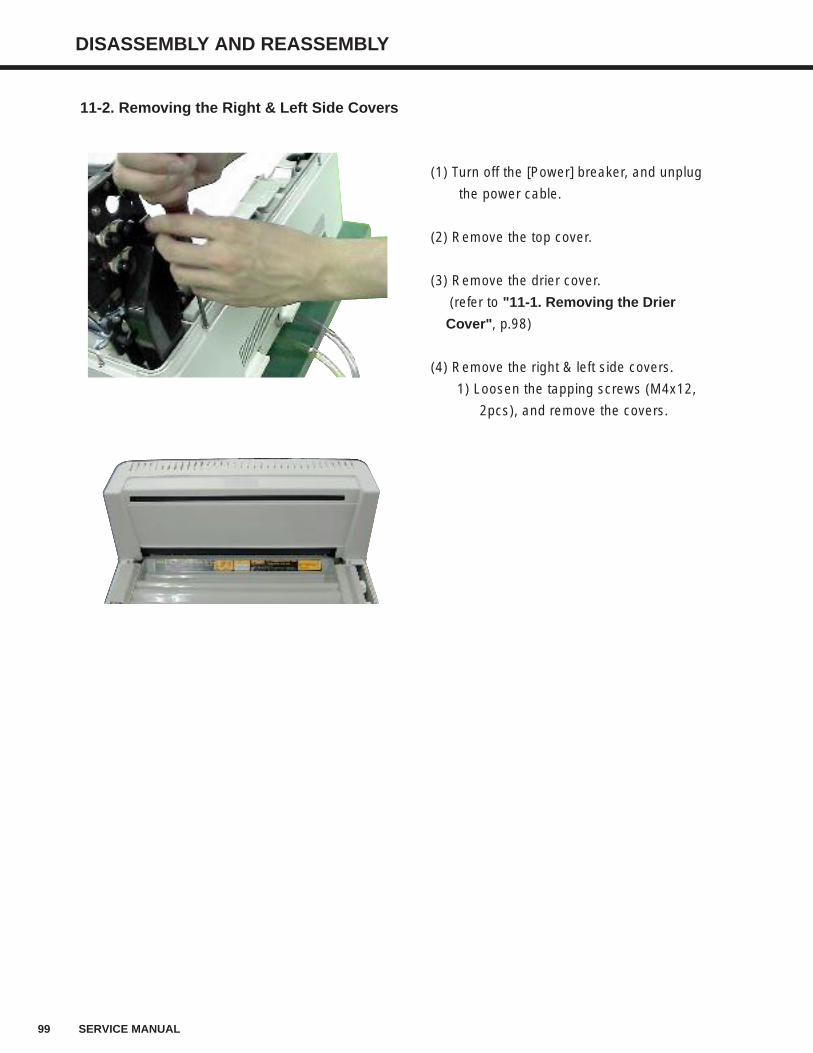
99 SERVICE MANUAL
DISASSEMBLY AND REASSEMBLY
11-2. Removing the Right & Left Side Covers
(1) Turn off the [Power] breaker, and unplug
the power cable.
(2) Remove the top cover.
(3) Remove the drier cover.
(refer to "11-1. Removing the Drier
Cover", p.98)
(4) Remove the right & left side covers.
1) Loosen the tapping screws (M4x12,
2pcs), and remove the covers.
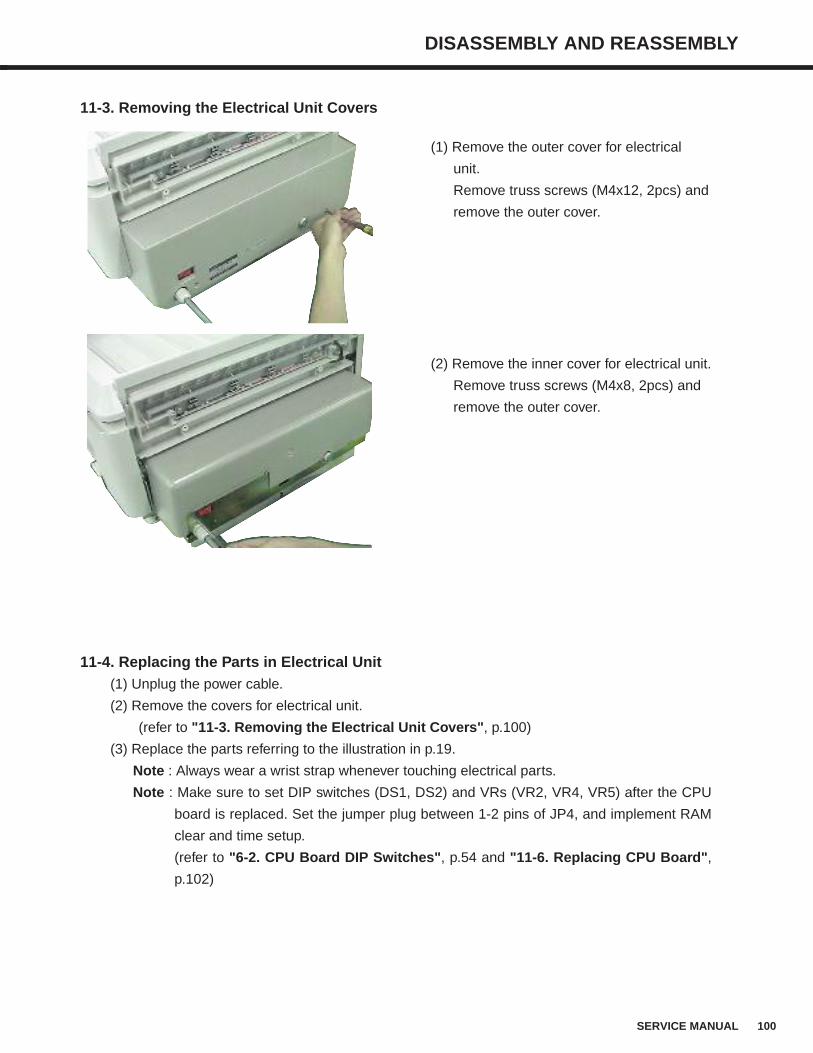
100SERVICE MANUAL
DISASSEMBLY AND REASSEMBLY
11-3. Removing the Electrical Unit Covers
(1) Remove the outer cover for electrical
unit.
Remove truss screws (M4x12, 2pcs) and
remove the outer cover.
(2) Remove the inner cover for electrical unit.
Remove truss screws (M4x8, 2pcs) and
remove the outer cover.
11-4. Replacing the Parts in Electrical Unit(1) Unplug the power cable.
(2) Remove the covers for electrical unit.
(refer to "11-3. Removing the Electrical Unit Covers", p.100)
(3) Replace the parts referring to the illustration in p.19.
Note : Always wear a wrist strap whenever touching electrical parts.
Note : Make sure to set DIP switches (DS1, DS2) and VRs (VR2, VR4, VR5) after the CPU
board is replaced. Set the jumper plug between 1-2 pins of JP4, and implement RAM
clear and time setup.
(refer to "6-2. CPU Board DIP Switches", p.54 and "11-6. Replacing CPU Board",
p.102)
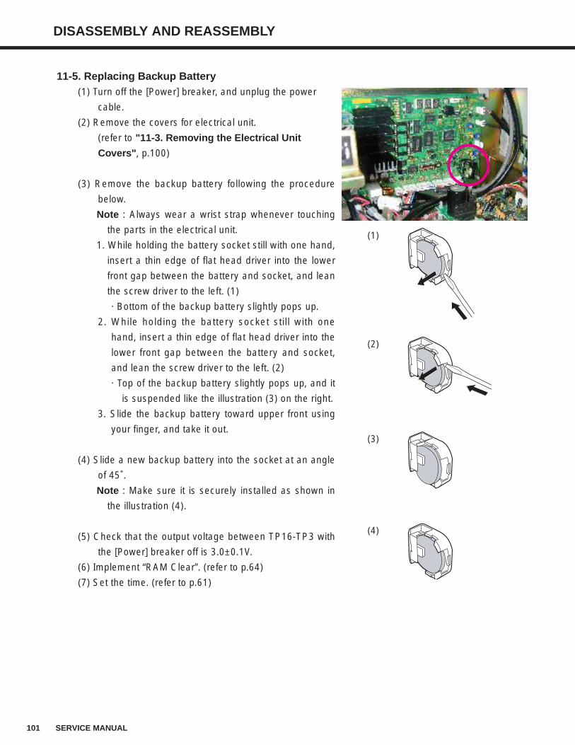
101 SERVICE MANUAL
DISASSEMBLY AND REASSEMBLY
11-5. Replacing Backup Battery(1) Turn off the [Power] breaker, and unplug the power
cable.
(2) Remove the covers for electrical unit.
(refer to "11-3. Removing the Electrical Unit
Covers", p.100)
(3) Remove the backup battery following the procedure
below.
Note : Always wear a wrist strap whenever touching
the parts in the electrical unit.
1. While holding the battery socket still with one hand,
insert a thin edge of flat head driver into the lower
front gap between the battery and socket, and lean
the screw driver to the left. (1)
· Bottom of the backup battery slightly pops up.
2. While holding the battery socket still with one
hand, insert a thin edge of flat head driver into the
lower front gap between the battery and socket,
and lean the screw driver to the left. (2)
· Top of the backup battery slightly pops up, and it
is suspended like the illustration (3) on the right.
3. Slide the backup battery toward upper front using
your finger, and take it out.
(4) Slide a new backup battery into the socket at an angle
of 45˚.
Note : Make sure it is securely installed as shown in
the illustration (4).
(5) Check that the output voltage between TP16-TP3 with
the [Power] breaker off is 3.0±0.1V.
(6) Implement “RAM Clear”. (refer to p.64)
(7) Set the time. (refer to p.61)
(1)
(2)
(4)
(3)
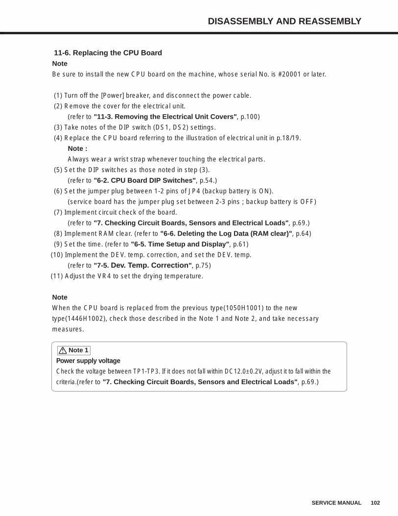
102SERVICE MANUAL
DISASSEMBLY AND REASSEMBLY
11-6. Replacing the CPU BoardNote
Be sure to install the new CPU board on the machine, whose serial No. is #20001 or later.
(1) Turn off the [Power] breaker, and disconnect the power cable.
(2) Remove the cover for the electrical unit.
(refer to "11-3. Removing the Electrical Unit Covers", p.100)
(3) Take notes of the DIP switch (DS1, DS2) settings.
(4) Replace the CPU board referring to the illustration of electrical unit in p.18/19.
Note :
Always wear a wrist strap whenever touching the electrical parts.
(5) Set the DIP switches as those noted in step (3).
(refer to "6-2. CPU Board DIP Switches", p.54.)
(6) Set the jumper plug between 1-2 pins of JP4 (backup battery is ON).
(service board has the jumper plug set between 2-3 pins ; backup battery is OFF)
(7) Implement circuit check of the board.
(refer to "7. Checking Circuit Boards, Sensors and Electrical Loads", p.69.)
(8) Implement RAM clear. (refer to "6-6. Deleting the Log Data (RAM clear)", p.64)
(9) Set the time. (refer to "6-5. Time Setup and Display", p.61)
(10) Implement the DEV. temp. correction, and set the DEV. temp.
(refer to "7-5. Dev. Temp. Correction", p.75)
(11) Adjust the VR4 to set the drying temperature.
Note
When the CPU board is replaced from the previous type(1050H1001) to the new
type(1446H1002), check those described in the Note 1 and Note 2, and take necessary
measures.
Power supply voltage
Check the voltage between TP1-TP3. If it does not fall within DC12.0±0.2V, adjust it to fall within the
criteria.(refer to "7. Checking Circuit Boards, Sensors and Electrical Loads", p.69.)
Note 1
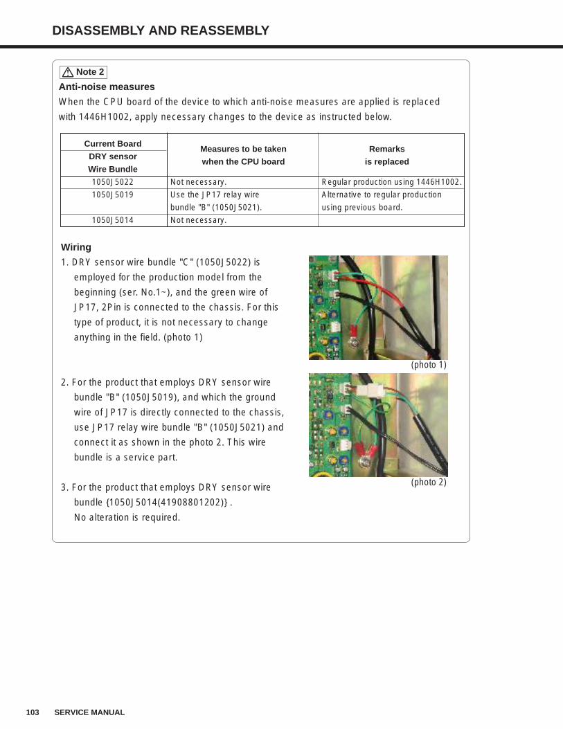
103 SERVICE MANUAL
DISASSEMBLY AND REASSEMBLY
Anti-noise measures
When the CPU board of the device to which anti-noise measures are applied is replaced
with 1446H1002, apply necessary changes to the device as instructed below.
Note 2
Wiring
1. DRY sensor wire bundle "C" (1050J5022) is
employed for the production model from the
beginning (ser. No.1~), and the green wire of
JP17, 2Pin is connected to the chassis. For this
type of product, it is not necessary to change
anything in the field. (photo 1)
2. For the product that employs DRY sensor wire
bundle "B" (1050J5019), and which the ground
wire of JP17 is directly connected to the chassis,
use JP17 relay wire bundle "B" (1050J5021) and
connect it as shown in the photo 2. This wire
bundle is a service part.
3. For the product that employs DRY sensor wire
bundle 1050J5014(41908801202) .
No alteration is required.
(photo 1)
(photo 2)
Current BoardMeasures to be taken Remarks
DRY sensorwhen the CPU board is replaced
Wire Bundle
1050J5022 Not necessary. Regular production using 1446H1002.
1050J5019 Use the JP17 relay wire Alternative to regular production
bundle "B" (1050J5021). using previous board.
1050J5014 Not necessary.
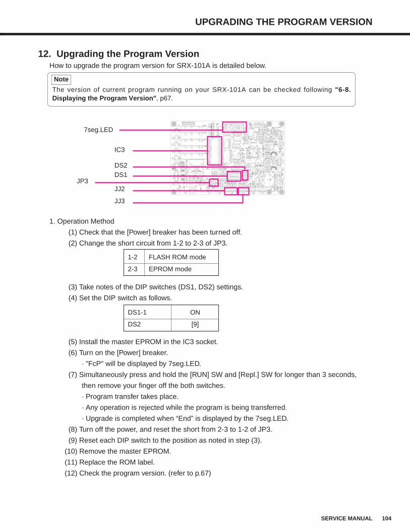
1. Operation Method
(1) Check that the [Power] breaker has been turned off.
(2) Change the short circuit from 1-2 to 2-3 of JP3.
(3) Take notes of the DIP switches (DS1, DS2) settings.
(4) Set the DIP switch as follows.
(5) Install the master EPROM in the IC3 socket.
(6) Turn on the [Power] breaker.
· "FcP" will be displayed by 7seg.LED.
(7) Simultaneously press and hold the [RUN] SW and [Repl.] SW for longer than 3 seconds,
then remove your finger off the both switches.
· Program transfer takes place.
· Any operation is rejected while the program is being transferred.
· Upgrade is completed when “End” is displayed by the 7seg.LED.
(8) Turn off the power, and reset the short from 2-3 to 1-2 of JP3.
(9) Reset each DIP switch to the position as noted in step (3).
(10) Remove the master EPROM.
(11) Replace the ROM label.
(12) Check the program version. (refer to p.67)
UPGRADING THE PROGRAM VERSION
104SERVICE MANUAL
12. Upgrading the Program VersionHow to upgrade the program version for SRX-101A is detailed below.
7seg.LED
DS1DS2
The version of current program running on your SRX-101A can be checked following "6-8.Displaying the Program Version", p67.
Note
JJ2
JJ3
JP3
IC3
1-2 FLASH ROM mode
2-3 EPROM mode
DS1-1 ON
DS2 [9]
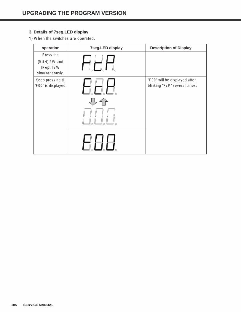
105 SERVICE MANUAL
UPGRADING THE PROGRAM VERSION
3. Details of 7seg.LED display
1) When the switches are operated.
operation 7seg.LED display Description of Display
Press the
[RUN] SW and [Repl.] SW
simultaneously.
Keep pressing till "F00" will be displayed after "F00" is displayed. blinking "FcP" several times.
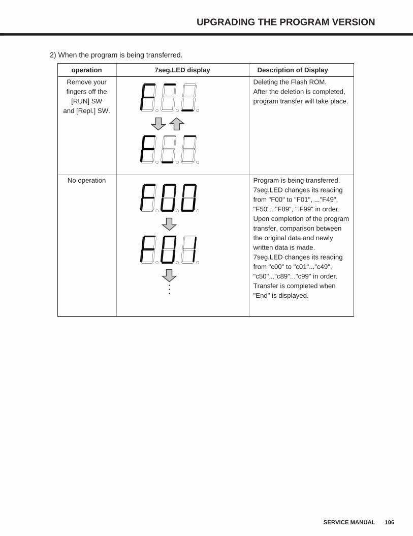
106SERVICE MANUAL
UPGRADING THE PROGRAM VERSION
2) When the program is being transferred.
operation 7seg.LED display Description of Display
Remove your Deleting the Flash ROM.fingers off the After the deletion is completed,
[RUN] SW program transfer will take place.and [Repl.] SW.
No operation Program is being transferred.7seg.LED changes its readingfrom "F00" to "F01", ..."F49","F50"..."F89", ".F99" in order. Upon completion of the programtransfer, comparison betweenthe original data and newlywritten data is made.7seg.LED changes its readingfrom "c00" to "c01"..."c49","c50"..."c89"..."c99" in order.Transfer is completed when"End" is displayed.
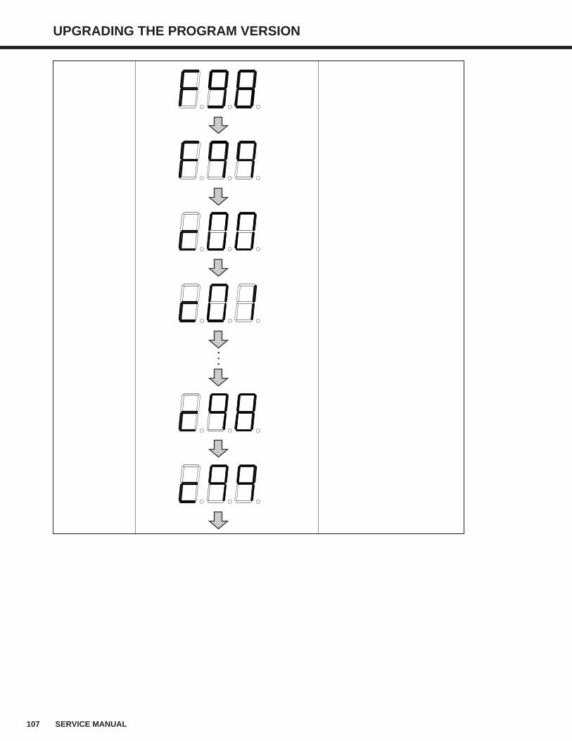
107 SERVICE MANUAL
UPGRADING THE PROGRAM VERSION
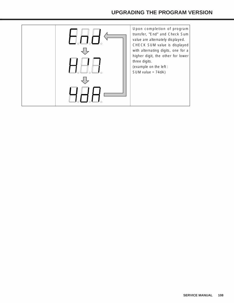
108SERVICE MANUAL
UPGRADING THE PROGRAM VERSION
Upon completion of programtransfer, "End" and Check Sumvalue are alternately displayed. CHECK SUM value is displayedwith alternating digits, one for ahigher digit, the other for lowerthree digits.(example on the left : SUM value = 74dA)
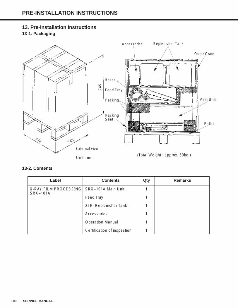
109 SERVICE MANUAL
PRE-INSTALLATION INSTRUCTIONS
13. Pre-Installation Instructions13-1. Packaging
Unit : mm
13-2. Contents
Label Contents Qty Remarks
X-RAY FILM PROCESSING SRX–101A Main Unit 1SRX–101A
Feed Tray 1
25R Replenisher Tank 1
Accessories 1
Operation Manual 1
Certification of inspection 1
External view
745
745930
Replenisher Tank
(Total Weight : approx. 60kg.)
Accessories
Outer Crate
Main Unit
Pallet
Hoses
Feed Tray
Packing
PackingSeat
110SERVICE MANUAL
PRE-INSTALLATION INSTRUCTIONS
13-3. Package Contents Verification
Before installing the SRX-101A, make sure to check the main unit and accessory equipment for
any missing parts or damage during transportation.
(1) Check to see if the model name and numbers printed on the outside of the package
correspond to what the customer ordered.
(2) Check if there is any extraordinary damage to the outside of the package.
(3) Open the package while following the precautions outline in the next section.
(4) Check if there is any missing parts by matching the contents of the package with the
packing list provided.
(5) Check all the parts for any external damage.
NOTE :
If there are any missing parts or damage, notify your technical representative immediately.
13-4. Precautions ti Take When Opening the Package
(1) At least two persons are needed to hand-carry the SRX-101A.
(2) Be careful when cutting the bands away from the package.
They have been bound tightly and could cause injury when released.
(3) The racks have been wrapped in plastic sheets.
There is cushioning material between the racks and processing tanks.
Remove carefully and dispose of all these materials before beginning installation.
13-5. Opening the Package
(1) Use scissors to cut the bands.
(2) Cut the top of the outer crate open with a utility knife.
(3) Lift the box of accessories up and out over the top of the crate.
This package contains the replenisher tank and other accessories.
(4) Lift the outer crate up and over the main unit.
(5) Remove the Feed Tray.
(6) Unload the Main Unit from the pallet.
At least two persons are necessary to lift and transport the processor.
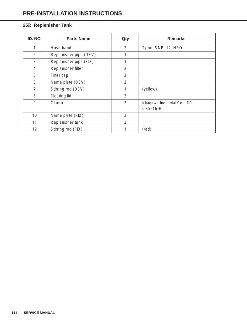
111 SERVICE MANUAL
PRE-INSTALLATION INSTRUCTIONS
25RR Replenisher Tank
ID. NO. Parts Name Qty Remarks
1 Hose band 2 Tyton. SNP–12–HSO
2 Replenisher pipe (DEV) 1
3 Replenisher pipe (FIX) 1
4 Replenisher filter 2
5 Filter cap 2
6 Name plate (DEV) 2
7 Stirring rod (DEV) 1 (yellow)
8 Floating lid 2
9 Clamp 2 Kitagawa Industrial Co. LTD.CKS-16-H
10 Name plate (FIX) 2
11 Replenisher tank 2
12 Stirring rod (FIX) 1 (red)
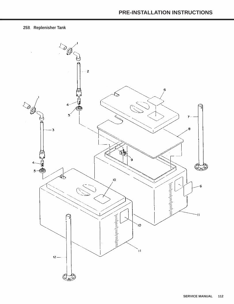
112SERVICE MANUAL
PRE-INSTALLATION INSTRUCTIONS
25RR Replenisher Tank
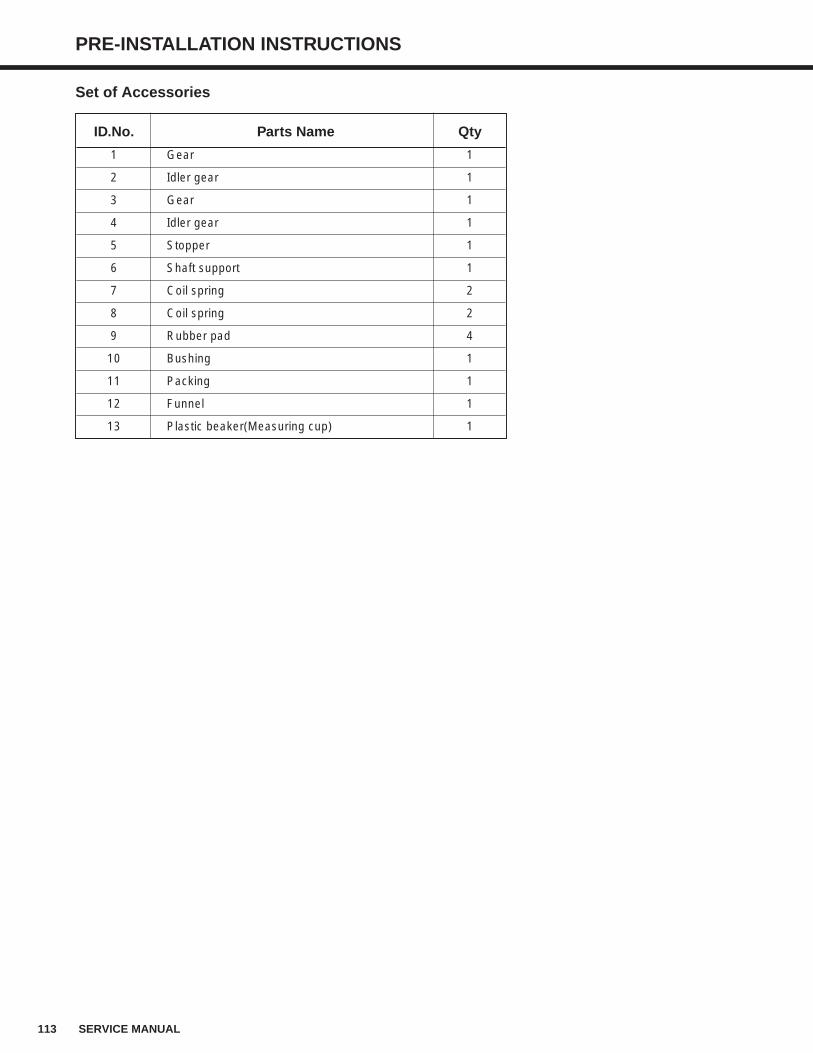
113 SERVICE MANUAL
PRE-INSTALLATION INSTRUCTIONS
Set of Accessories
ID.No. Parts Name Qty
1 Gear 1
2 Idler gear 1
3 Gear 1
4 Idler gear 1
5 Stopper 1
6 Shaft support 1
7 Coil spring 2
8 Coil spring 2
9 Rubber pad 4
10 Bushing 1
11 Packing 1
12 Funnel 1
13 Plastic beaker(Measuring cup) 1
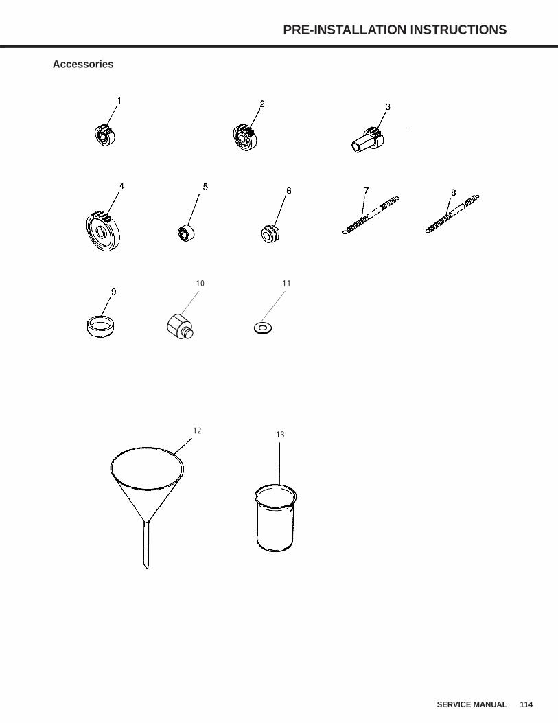
114SERVICE MANUAL
PRE-INSTALLATION INSTRUCTIONS
Accessories
10 11
12 13
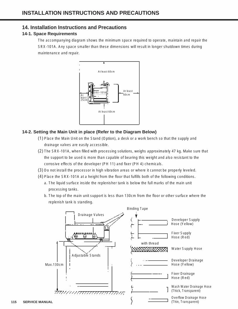
115 SERVICE MANUAL
INSTALLATION INSTRUCTIONS AND PRECAUTIONS
14. Installation Instructions and Precautions14-1. Space Requirements
The accompanying diagram shows the minimum space required to operate, maintain and repair the
SRX-101A. Any space smaller than these dimensions will result in longer shutdown times during
maintenance and repair.
14-2. Setting the Main Unit in place (Refer to the Diagram Below)(1) Place the Main Unit on the Stand (Option), a desk or a work bench so that the supply and
drainage valves are easily accessible.
(2) The SRX-101A, when filled with processing solutions, weighs approximately 47 kg. Make sure that
the support to be used is more than capable of bearing this weight and also resistant to the
corrosive effects of the developer (PH 11) and fixer (PH 4) chemicals.
(3) Do not install the processor in high vibration areas or where it cannot be properly leveled.
(4) Place the SRX-101A at a height from the floor that fulfills both of the following conditions.
a. The liquid surface inside the replenisher tank is below the full marks of the main unit
processing tanks.
b. The top of the main unit support is less than 130cm from the floor or other surface where the
replenish tank is standing.
At least 60cm
At least 60cm
At least 60cm
SRX–101AAt least 25cm
Drainage Valves
Adjustable Stands
Max.130cm
Binding Tape
Developer Supply Hose (Yellow)
Fixer Supply Hose (Red)
Developer Drainage Hose (Yellow)
Fixer Drainage Hose (Red)
Wash Water Drainage Hose(Thick, Transparent)
Overflow Drainage Hose(Thin, Transparent)
Water Supply Hose
with thread
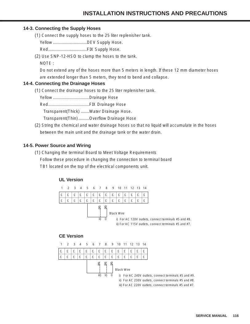
116SERVICE MANUAL
INSTALLATION INSTRUCTIONS AND PRECAUTIONS
14-3. Connecting the Supply Hoses
(1) Connect the supply hoses to the 25 liter replenisher tank.
Yellow ............................DEV Supply Hose.
Red................................FIX Supply Hose.
(2) Use SNP-12-HSO to clamp the hoses to the tank.
NOTE :
Do not extend any of the hoses more than 5 meters in length. If these 12 mm diameter hoses
are extended longer than 5 meters, they tend to bend and collapse.
14-4. Connecting the Drainage Hoses
(1) Connect the drainage hoses to the 25 liter replenisher tank.
Yellow ..............................Drainage Hose
Red..................................FIX Drainage Hose
Transparent(Thick) .......Water Drainage Hose.
Transparent(Thin) .........Overflow Drainage Hose
(2) String the chemical and water drainage hoses so that no liquid will accumulate in the hoses
between the main unit and the drainage tank or the water drain.
14-5. Power Source and Wiring
(1) Changing the terminal Board to Meet Voltage Requirements
Follow these procedure in changing the connection to terminal board
TB1 located on the top of the electrical components unit.
£ £ £ £ £ £ £ £ £ £ £ £ £ £
£ £ £ £ £ £ £ £ £ £ £ £ £ £
1 2 3 4 5 6 7 8 9 10 11 12 13 14
Black Wire
ii) i) i) For AC 120V outlets, connect terminals #5 and #8.
ii) For AC 115V outlets, connect terminals #5 and #7.
gg
£ £ £ £ £ £ £ £ £ £ £ £ £ £
£ £ £ £ £ £ £ £ £ £ £ £ £ £
1 2 3 4 5 6 7 8 9 10 11 12 13 14
Black Wire
ii) i) i) For AC 240V outlets, connect terminals #5 and #9.
ii) For AC 230V outlets, connect terminals #5 and #8.
iii) For AC 220V outlets, connect terminals #5 and #7.
gg
iii)
g
UL Version
CE Version
117 SERVICE MANUAL
INSTALLATION INSTRUCTIONS AND PRECAUTIONS
(2) Select an electrical outlet that is equal to or above the required current and voltage to operate
the processor and use this outlet for the SRX-101A only.
Insufficient current to the processor may cause overheating and/or smoking.
(3) The power source voltage to the processor should be within a range of +/-10% of the specified
requirement. The frequency (Hz) value should be within a range of +/-2.5% of the specified
requirements.
(4) Lay the power cord so that it is clear of foot traffic, sharp objects and other equipment.
Damaged plugs and cords may cause the processor to overheat and/or smoke.
(5) To prevent overheating or smoking, do not connect the processor to table top outlets, junction
cords or junction outlets.
(6) The power cord provided as standard equipment is 2.6 meters in length. If an extension is
needed, use only legally specified (product liability standard) extension cords. Sub-standard
extension cords may cause the processor to overheat or smoke.
(7) To prevent electrocution accidents, properly ground the SRX-101A. To avoid the possibility of
explosions or electrocution, do not attempt to ground the processor to any of the following
objects.
Gas pipes
Lightening rods
Telephone ground wires
Any water line or spigot not permitted by your local water department.
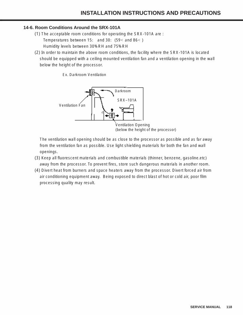
118SERVICE MANUAL
INSTALLATION INSTRUCTIONS AND PRECAUTIONS
14-6. Room Conditions Around the SRX-101A(1) The acceptable room conditions for operating the SRX-101A are :
Temperatures between 15: and 30:(59<and 86<)
Humidity levels between 30%RH and 75%RH
(2) In order to maintain the above room conditions, the facility where the SRX-101A is located
should be equipped with a ceiling mounted ventilation fan and a ventilation opening in the wall
below the height of the processor.
The ventilation wall opening should be as close to the processor as possible and as far away
from the ventilation fan as possible. Use light shielding materials for both the fan and wall
openings.
(3) Keep all fluorescent materials and combustible materials (thinner, benzene, gasoline.etc)
away from the processor. To prevent fires, store such dangerous materials in another room.
(4) Divert heat from burners and space heaters away from the processor. Divert forced air from
air conditioning equipment away. Being exposed to direct blast of hot or cold air, poor film
processing quality may result.
Ex. Darkroom Ventilation
Ventilation Fan
Darkroom
Ventilation Opening(below the height of the processor)
SRX–101A
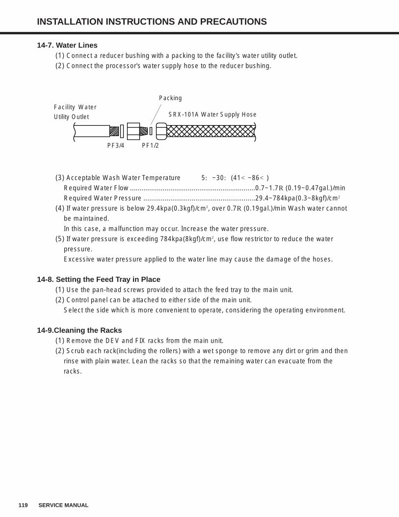
119 SERVICE MANUAL
INSTALLATION INSTRUCTIONS AND PRECAUTIONS
14-7. Water Lines(1) Connect a reducer bushing with a packing to the facility's water utility outlet.
(2) Connect the processor's water supply hose to the reducer bushing.
(3) Acceptable Wash Water Temperature 5:~30:(41<~86<)
Required Water Flow .................................................................0.7~1.7R(0.19~0.47gal.)/min
Required Water Pressure ..........................................................29.4~784kpa(0.3~8kgf)/cm2
(4) If water pressure is below 29.4kpa(0.3kgf)/cm2, over 0.7R(0.19gal.)/min Wash water cannot
be maintained.
In this case, a malfunction may occur. Increase the water pressure.
(5) If water pressure is exceeding 784kpa(8kgf)/cm2, use flow restrictor to reduce the water
pressure.
Excessive water pressure applied to the water line may cause the damage of the hoses.
14-8. Setting the Feed Tray in Place(1) Use the pan-head screws provided to attach the feed tray to the main unit.
(2) Control panel can be attached to either side of the main unit.
Select the side which is more convenient to operate, considering the operating environment.
14-9.Cleaning the Racks(1) Remove the DEV and FIX racks from the main unit.
(2) Scrub each rack(including the rollers) with a wet sponge to remove any dirt or grim and then
rinse with plain water. Lean the racks so that the remaining water can evacuate from the
racks.
Packing
SRX-101A Water Supply HoseFacility Water
Utility Outlet
PF3/4 PF1/2
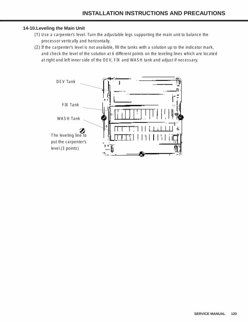
120SERVICE MANUAL
INSTALLATION INSTRUCTIONS AND PRECAUTIONS
14-10.Leveling the Main Unit(1) Use a carpenter's level. Turn the adjustable legs supporting the main unit to balance the
processor vertically and horizontally.
(2) If the carpenter's level is not available, fill the tanks with a solution up to the indicator mark,
and check the level of the solution at 6 different points on the leveling lines which are located
at right and left inner side of the DEV, FIX and WASH tank and adjust if necessary.
DEV Tank
FIX Tank
WASH Tank
The leveling line to
put the carpenter's
level.(3 points)
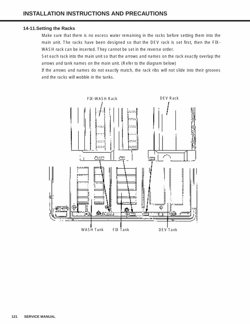
121 SERVICE MANUAL
INSTALLATION INSTRUCTIONS AND PRECAUTIONS
14-11.Setting the Racks
Make sure that there is no excess water remaining in the racks before setting them into the
main unit. The racks have been designed so that the DEV rack is set first, then the FIX-
WASH rack can be inserted. They cannot be set in the reverse order.
Set each rack into the main unit so that the arrows and names on the rack exactly overlap the
arrows and tank names on the main unit. (Refer to the diagram below)
If the arrows and names do not exactly match, the rack ribs will not slide into their grooves
and the racks will wobble in the tanks.
FIX-WASH Rack DEV Rack
WASH Tank FIX Tank DEV Tank
WASH FIX DEV
DEVFIXWASH
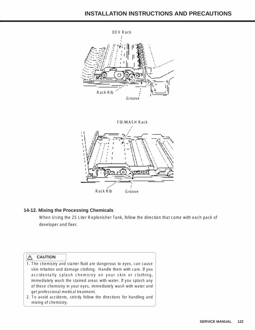
122SERVICE MANUAL
INSTALLATION INSTRUCTIONS AND PRECAUTIONS
14-12. Mixing the Processing Chemicals
When Using the 25 Liter Replenisher Tank, follow the direction that come with each pack of
developer and fixer.
1. The chemistry and starter fluid are dangerous to eyes, can causeskin irritation and damage clothing. Handle them with care. If youaccidentally splash chemistry on your skin or clothing,immediately wash the stained areas with water. If you splash anyof these chemistry in your eyes, immediately wash with water andget professional medical treatment.
2. To avoid accidents, strictly follow the directions for handling andmixing of chemistry.
CAUTION
DEV Rack
GrooveRack Rib
FIX/WASH Rack
GrooveRack Rib
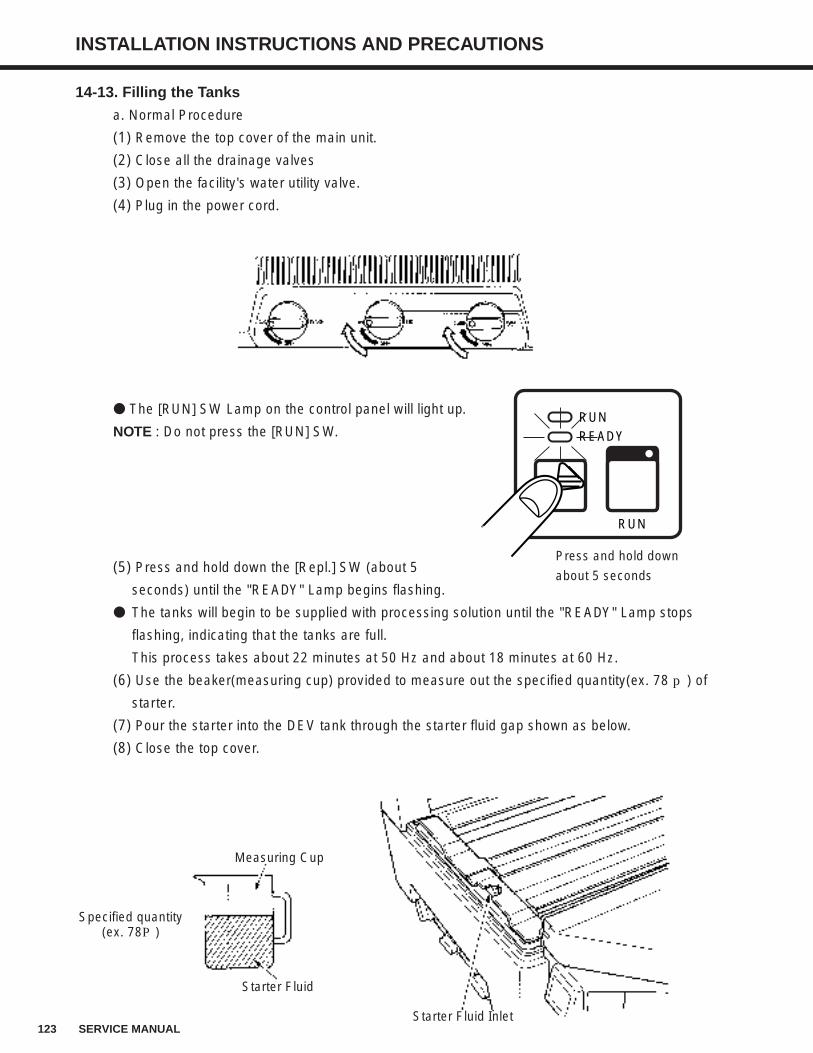
123 SERVICE MANUAL
INSTALLATION INSTRUCTIONS AND PRECAUTIONS
14-13. Filling the Tanks
a. Normal Procedure
(1) Remove the top cover of the main unit.
(2) Close all the drainage valves
(3) Open the facility's water utility valve.
(4) Plug in the power cord.
The [RUN] SW Lamp on the control panel will light up.
NOTE : Do not press the [RUN] SW.
(5) Press and hold down the [Repl.] SW (about 5
seconds) until the "READY" Lamp begins flashing.
The tanks will begin to be supplied with processing solution until the "READY" Lamp stops
flashing, indicating that the tanks are full.
This process takes about 22 minutes at 50 Hz and about 18 minutes at 60 Hz.
(6) Use the beaker(measuring cup) provided to measure out the specified quantity(ex. 78 p) of
starter.
(7) Pour the starter into the DEV tank through the starter fluid gap shown as below.
(8) Close the top cover.
Starter Fluid
Measuring Cup
Specified quantity(ex. 78P)
Starter Fluid Inlet
RUNREADY
RUN
Press and hold down
about 5 seconds
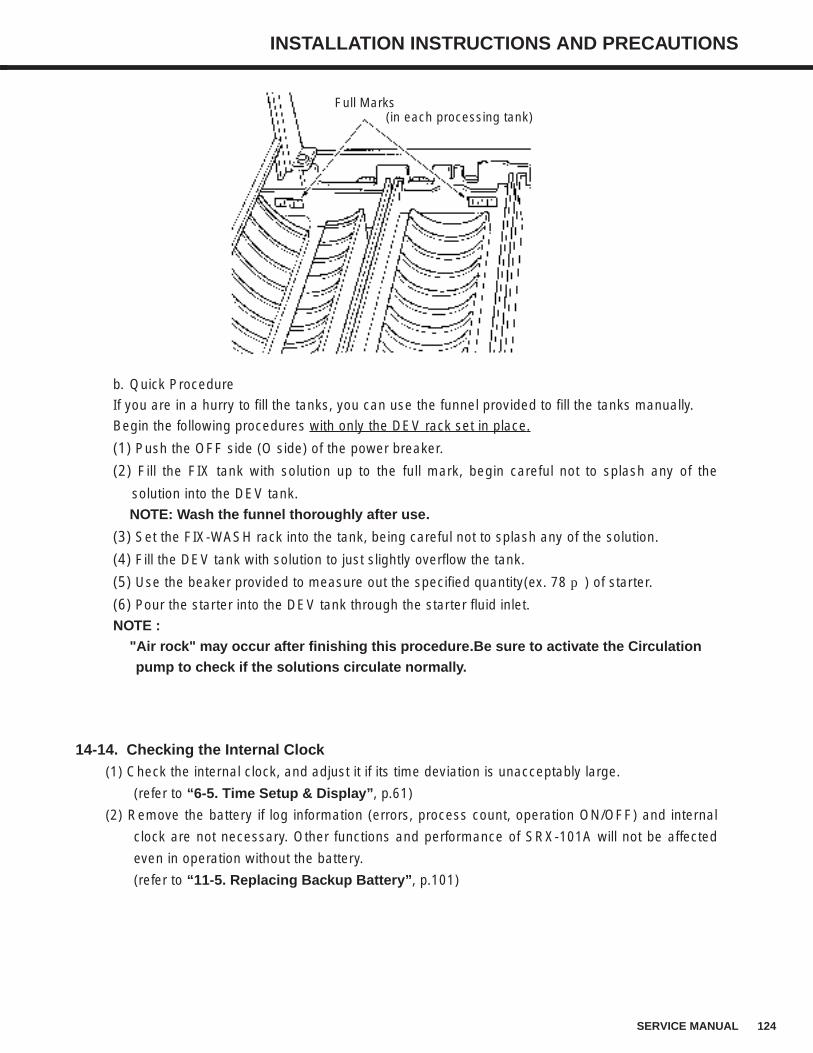
124SERVICE MANUAL
INSTALLATION INSTRUCTIONS AND PRECAUTIONS
b. Quick Procedure
If you are in a hurry to fill the tanks, you can use the funnel provided to fill the tanks manually.
Begin the following procedures with only the DEV rack set in place.
(1) Push the OFF side (O side) of the power breaker.
(2) Fill the FIX tank with solution up to the full mark, begin careful not to splash any of the
solution into the DEV tank.
NOTE: Wash the funnel thoroughly after use.
(3) Set the FIX-WASH rack into the tank, being careful not to splash any of the solution.
(4) Fill the DEV tank with solution to just slightly overflow the tank.
(5) Use the beaker provided to measure out the specified quantity(ex. 78 p) of starter.
(6) Pour the starter into the DEV tank through the starter fluid inlet.
NOTE :"Air rock" may occur after finishing this procedure.Be sure to activate the Circulationpump to check if the solutions circulate normally.
14-14. Checking the Internal Clock(1) Check the internal clock, and adjust it if its time deviation is unacceptably large.
(refer to “6-5. Time Setup & Display”, p.61)
(2) Remove the battery if log information (errors, process count, operation ON/OFF) and internal
clock are not necessary. Other functions and performance of SRX-101A will not be affected
even in operation without the battery.
(refer to “11-5. Replacing Backup Battery”, p.101)
Full Marks(in each processing tank)
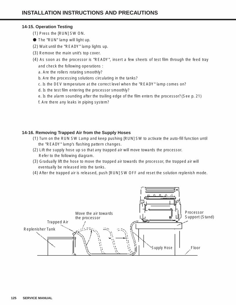
125 SERVICE MANUAL
INSTALLATION INSTRUCTIONS AND PRECAUTIONS
14-16. Removing Trapped Air from the Supply Hoses(1) Turn on the RUN SW Lamp and keep pushing [RUN] SW to activate the auto-fill function until
the "READY" lamp's flashing pattern changes.(2) Lift the supply hose up so that any trapped air will move towards the processor.
Refer to the following diagram.(3) Gradually lift the hose to move the trapped air towards the processor, the trapped air will
eventually be released into the tanks.(4) After the trapped air is released, push [RUN] SW OFF and reset the solution replenish mode.
Supply Hose Floor
ProcessorSupport (Stand)
Move the air towards the processor
Replenisher Tank
Trapped Air
14-15. Operation Testing
(1) Press the [RUN] SW ON.
The "RUN" lamp will light up.
(2) Wait until the "READY" lamp lights up.
(3) Remove the main unit's top cover.
(4) As soon as the processor is "READY", insert a few sheets of test film through the feed tray
and check the following operations :
a. Are the rollers rotating smoothly?
b. Are the processing solutions circulating in the tanks?
c. Is the DEV temperature at the correct level when the "READY" lamp comes on?
d. Is the test film entering the processor smoothly?
e. Is the alarm sounding after the trailing edge of the film enters the processor?(See p. 21)
f. Are there any leaks in piping system?
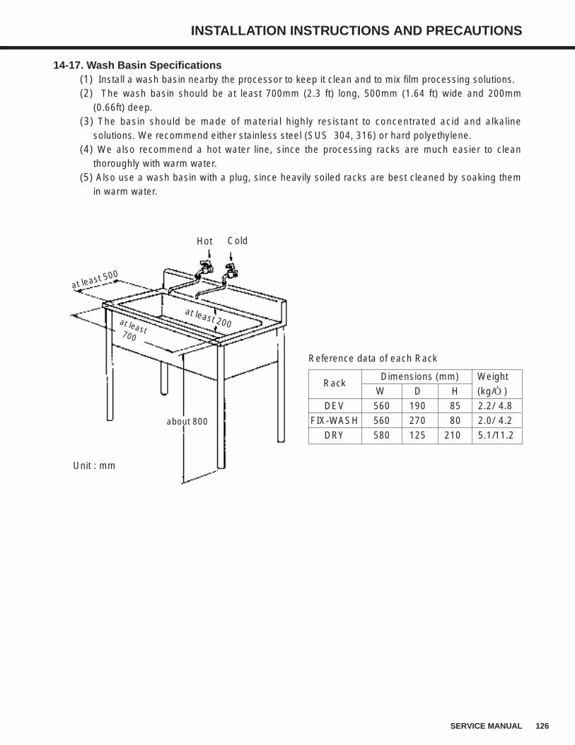
126SERVICE MANUAL
INSTALLATION INSTRUCTIONS AND PRECAUTIONS
14-17. Wash Basin Specifications(1) Install a wash basin nearby the processor to keep it clean and to mix film processing solutions.(2) The wash basin should be at least 700mm (2.3 ft) long, 500mm (1.64 ft) wide and 200mm
(0.66ft) deep.(3) The basin should be made of material highly resistant to concentrated acid and alkaline
solutions. We recommend either stainless steel (SUS 304, 316) or hard polyethylene.(4) We also recommend a hot water line, since the processing racks are much easier to clean
thoroughly with warm water.(5) Also use a wash basin with a plug, since heavily soiled racks are best cleaned by soaking them
in warm water.
ColdHot
Unit : mm
Reference data of each Rack
at least 500
at least 200at least700
about 800
Rack
DEV
FIX-WASH
DRY
Dimensions (mm) Weight
W D H (kg/Ò)
560 190 85 2.2/ 4.8
560 270 80 2.0/ 4.2
580 125 210 5.1/11.2
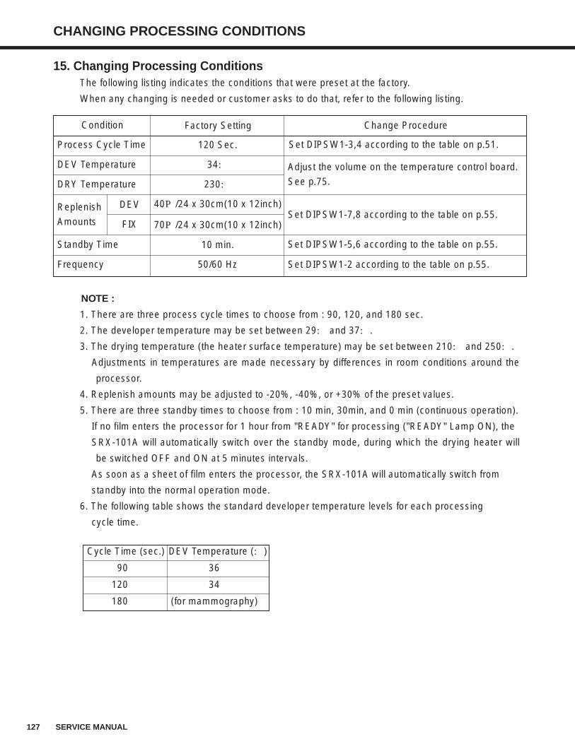
127 SERVICE MANUAL
CHANGING PROCESSING CONDITIONS
15. Changing Processing ConditionsThe following listing indicates the conditions that were preset at the factory.
When any changing is needed or customer asks to do that, refer to the following listing.
NOTE :
1. There are three process cycle times to choose from : 90, 120, and 180 sec.
2. The developer temperature may be set between 29: and 37:.
3. The drying temperature (the heater surface temperature) may be set between 210: and 250:.
Adjustments in temperatures are made necessary by differences in room conditions around the
processor.
4. Replenish amounts may be adjusted to -20%, -40%, or +30% of the preset values.
5. There are three standby times to choose from : 10 min, 30min, and 0 min (continuous operation).
If no film enters the processor for 1 hour from "READY" for processing ("READY" Lamp ON), the
SRX-101A will automatically switch over the standby mode, during which the drying heater will
be switched OFF and ON at 5 minutes intervals.
As soon as a sheet of film enters the processor, the SRX-101A will automatically switch from
standby into the normal operation mode.
6. The following table shows the standard developer temperature levels for each processing
cycle time.
Cycle Time (sec.) DEV Temperature (:)
90 36
120 34
180 (for mammography)
Condition Factory Setting Change Procedure
Set DIPSW1-3,4 according to the table on p.51.
Adjust the volume on the temperature control board.
See p.75.
Set DIPSW1-7,8 according to the table on p.55.
Set DIPSW1-5,6 according to the table on p.55.
Set DIPSW1-2 according to the table on p.55.
120 Sec.
34:
230:
40P/24 x 30cm(10 x 12inch)
70P/24 x 30cm(10 x 12inch)
10 min.
50/60 Hz
Process Cycle Time
DEV Temperature
DRY Temperature
Standby Time
Frequency
DEV
FIX
Replenish
Amounts
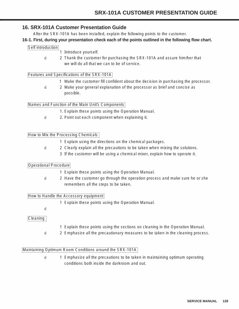
128SERVICE MANUAL
SRX-101A CUSTOMER PRESENTATION GUIDE
16. SRX-101A Customer Presentation GuideAfter the SRX-101A has been installed, explain the following points to the customer.
16-1. First, during your presentation check each of the points outlined in the following flow chart.
1 Introduce yourself.d 2 Thank the customer for purchasing the SRX-101A and assure him/her that
we will do all that we can to be of service.
1 Make the customer fill confident about the decision in purchasing the processor.d 2 Make your general explanation of the processor as brief and concise as
possible.
1. Explain these points using the Operation Manual.
d 2. Point out each component when explaining it.
1 Explain using the directions on the chemical packages.
d 2 Clearly explain all the precautions to be taken when mixing the solutions.
3 If the customer will be using a chemical mixer, explain how to operate it.
1 Explain these points using the Operation Manual.
d 2 Have the customer go through the operation process and make sure he or she
remembers all the steps to be taken.
1 Explain these points using the Operation Manual.
d
1 Explain these points using the sections on cleaning in the Operation Manual.
d 2 Emphasize all the precautionary measures to be taken in the cleaning process.
d 1 Emphasize all the precautions to be taken in maintaining optimum operating
conditions both inside the darkroom and out.
Self introduction
Features and Specifications of the SRX-101A
Names and Function of the Main Unit's Components
Operational Procedure
How to Handle the Accessory equipment
How to Mix the Processing Chemicals
Cleaning
Maintaining Optimum Room Conditions around the SRX-101A
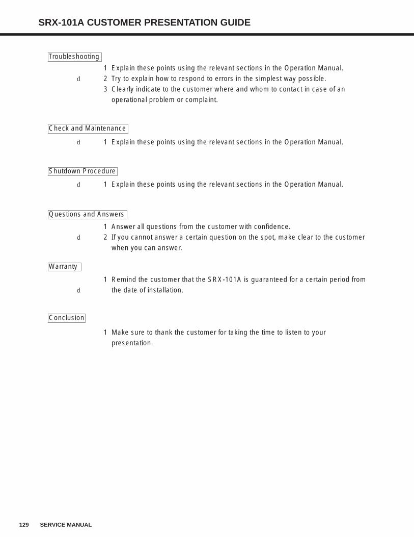
129 SERVICE MANUAL
SRX-101A CUSTOMER PRESENTATION GUIDE
1 Explain these points using the relevant sections in the Operation Manual.
d 2 Try to explain how to respond to errors in the simplest way possible.
3 Clearly indicate to the customer where and whom to contact in case of an
operational problem or complaint.
d 1 Explain these points using the relevant sections in the Operation Manual.
d 1 Explain these points using the relevant sections in the Operation Manual.
1 Answer all questions from the customer with confidence.
d 2 If you cannot answer a certain question on the spot, make clear to the customer
when you can answer.
1 Remind the customer that the SRX-101A is guaranteed for a certain period from
d the date of installation.
1 Make sure to thank the customer for taking the time to listen to your
presentation.
Questions and Answers
Warranty
Conclusion
Troubleshooting
Check and Maintenance
Shutdown Procedure
130SERVICE MANUAL
SRX-101A CUSTOMER PRESENTATION GUIDE
16-2. Make Sure of the Following Points Before Your Presentation to the Customer.(1) Is this the first time the customer has purchased an automatic film processor?
Is the SRX-101A a replacement processor?
If it is being purchased for the first time, give a more detailed presentation.
If it is a replacement processor, first check the type of processor that was used previously.
Then give your presentation so that the customer understand the similarities and differences
between operating the previous processor and running the SRX-101A.
(2) If the SRX-101A is a replacement processor, make sure that you are familiar with the features
of the previously used model; for example, its processing speeds and solution temperature
levels. (Always keep in mind ways to maintain the film processing conditions that the
customer has become used to.)
(3) Check beforehand the space where the SRX-101A is to be installed, as well as the operating
environment (exhaust devices, temperature/humidity conditions, etc.) Also check to see if
there is a suitable place for electrically grounding the main unit.
(4) Check beforehand the processing speeds, film and sensitized paper the customer intends to
use.
(5) Find out the approximate number of film sheets that will be processed each day. Then
calculate the amount of processing chemicals and film that will be needed, so that
insufficiencies in supply will not arise during operation.
(6) Check beforehand to see that the processing chemicals and the film to be used are
compatible.Caution the customer concerning any incompatible combinations. Make sure that
you explain clearly the reason why the incompatible materials cannot be used together.
(7) Read the catalogues and Operation Manual and understand the specifications and features
of the SRX-101A thoroughly before giving your presentation.
16-3. Explaining How to Use the SRX-101AGive your presentation using the SRX-101A operation manual.
(1) Self Introduction1. Introduce yourself.2. Thank the customer for purchasing the SRX-101A and let him/her know that we will do
all that it can to be of service.
(2) Features and Specifications
1. Explain the features and specifications of the processor.• Emphasize the special features of the SRX-101A and make the customer feel confident
his/her facility has made the right decision in purchasing this particular processor.• Make sure to mention that the SRX-101A is a state-of-the-art medical film processor, the
best available.
(3) Names and Functions of the Main Unit's Components1. Explain the main unit's components.2. Include in your presentation an explanation of the processor's special features in relation
to the components.
131 SERVICE MANUAL
SRX-101A CUSTOMER PRESENTATION GUIDE
3. Point out each component as you explain it.
4. Study the Operation Manual thoroughly so that you can answer any questions correctly
and informatively.
• If by chance there is a question that you cannot answer immediately, make sure to
inform the customer when you will have an answer ready.
16-4. How to Mix the Processing Chemicals1. Explain how to mix the developer and fixer replenisher solutions using the replenish tanks.
• Go through the directions printed on the chemical packages.
• Explain clearly the differences between the developer and fixer replenisher solutions, so
that the customer will not confuse them during operation.
• Explain the mixing procedure along with the following precautions :
a) Do not reverse the steps in the developer replenisher (Chemical A, Chemical B
Chemical C) mixing procedure.
b) Do not reverse the steps in the fixer replenisher (Chemical A, Chemical B) mixing
procedure.
c) Mix the chemicals thoroughly.
d) Use only the amount of water specified on the package.
e) Explain what measures to take if processing solution comes into contact with the skin
or eyes.
2. If the customer will use a chemical mixer, explain its features and operating procedures.
• More and more customers are using chemical mixers these days. So it is a good idea to
become familiar with their features and operation.
16-5. Operational Procedures1. Explain how to operate the SRX-101A.
• Be sure to explain these points using the Operation Manual.
• Demonstrate how to switch both the building's power breaker and the main unit power
switch ON and OFF. Have the customer actually perform this procedure until he/she
remembers all the steps involved.
• Make certain that the processor's initial settings are correct.
• Explain the operational procedures in the following order, emphasizing how to use the
control panel on the main unit.
a) Take this opportunity to recheck the cycle time and processing conditions you set
during installation.
b) How to select the standby modes.
c) How to supply replenisher and processing solution.
d) Other procedures.
• Explain what film sizes and types are compatible with the SRX-101A.
• After the processing solution temperatures have reached their operational levels, run a
few sheets of already developed 24x30cm(10x12inch) film through the processor
and explain how the film is transported.
• Explain how to insert single-face emulsion film.
132SERVICE MANUAL
SRX-101A CUSTOMER PRESENTATION GUIDE
16-6. How to Handle the Accessory Equipment
1. If the customer has chosen to use any optional accessory equipment, explain how it
functions in relation to the SRX-101A.
• Explain these points using the Operating Manual.
2. Explain how to hook up optional equipment.
• If no option will be used, make your presentation as concise and brief as possible.
16-7. Cleaning
1. Explain all the points necessary in keeping the SRX-101A clean.
• Explain these points using the Operation Manual.
2. Explain the differences between the way of cleaning the bakelite rollers that are required to
be done everyday, once a week, once a month, and once every three months.
16-8. Maintaining Optimum Room Conditions around the SRX-101A.
1. Explain clearly all the precautions to take in maintaining optimum operating conditions
around the processor.
• Using an air circulation fan.
• How to use the solution recycling tanks.
• Checking the main unit exhaust.
• Checking the room temperature and humidity around the processor.
16-9. Troubleshooting
1. Explain the troubleshooting procedures.
• Explain these points using the relevant sections in the Operation Manual.
• Explain the measures to be taken for every error that may occur.
• Show the easiest ways of troubleshooting.
• Clearly indicate to the customer where and whom to contact in case of an operational
problem or complaint.
• Explain the content of the free-of-change after-service schedule that you intend to follow.
16-10. Maintenance
1. Using the Operation Manual, explain how to maintain the processor st optimum operating
conditions.
• Make sure to impress on the customer how important these periodical maintenance
checks are in preventing operational errors.
16-11. Shutdown Procedure1. Explain the maintenance checks that should be carried out when the processor is shut
down.2. Explain these points using the relevant sections in Operation Manual.
133 SERVICE MANUAL
SRX-101A CUSTOMER PRESENTATION GUIDE
16-12. Questions and Answers
1. Answer all questions from the customer with confidence.
2. If you cannot answer a certain question on the spot, make clear to the customer when you
will have an answer ready.
16-13. The Warranty
1. After installation and check have been completed, refer the customer to the clause in the
warranty that says," The SRX-101A has been handled over to you on this date,......,
installed and checked properly with all its components and parts in optimum working
condition."
• If for some reason the processor cannot be handed over to the customer under the
above stipulations, explain the details and relate when it will be ready to be handed
over.
Make sure that the customer agrees to these conditions.
16-14. Conclusion
1. Urge the customer the read the Operation Manual over thoroughly before trying to operate
the SRX-101A.
• Make sure that the customer knows where and whom to contact if there is something
unclear in the Operation Manual.
2. Make the customer feel confident about operating the processor easily and safe.
3. Thank the customer for taking the time to listen to your presentation.
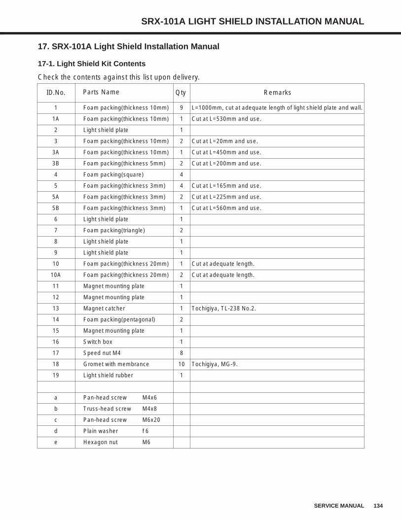
134SERVICE MANUAL
SRX-101A LIGHT SHIELD INSTALLATION MANUAL
17. SRX-101A Light Shield Installation Manual
17-1. Light Shield Kit Contents
Check the contents against this list upon delivery.
ID.No. Qty RemarksParts Name
1 Foam packing(thickness 10mm) 9 L=1000mm, cut at adequate length of light shield plate and wall.
1A Foam packing(thickness 10mm) 1 Cut at L=530mm and use.
2 Light shield plate 1
3 Foam packing(thickness 10mm) 2 Cut at L=20mm and use.
3A Foam packing(thickness 10mm) 1 Cut at L=450mm and use.
3B Foam packing(thickness 5mm) 2 Cut at L=200mm and use.
4 Foam packing(square) 4
5 Foam packing(thickness 3mm) 4 Cut at L=165mm and use.
5A Foam packing(thickness 3mm) 2 Cut at L=225mm and use.
5B Foam packing(thickness 3mm) 1 Cut at L=560mm and use.
6 Light shield plate 1
7 Foam packing(triangle) 2
8 Light shield plate 1
9 Light shield plate 1
10 Foam packing(thickness 20mm) 1 Cut at adequate length.
10A Foam packing(thickness 20mm) 2 Cut at adequate length.
11 Magnet mounting plate 1
12 Magnet mounting plate 1
13 Magnet catcher 1 Tochigiya, TL-238 No.2.
14 Foam packing(pentagonal) 2
15 Magnet mounting plate 1
16 Switch box 1
17 Speed nut M4 8
18 Gromet with membrance 10 Tochigiya, MG-9.
19 Light shield rubber 1
a Pan-head screw M4x6
b Truss-head screw M4x8
c Pan-head screw M6x20
d Plain washer φ6
e Hexagon nut M6
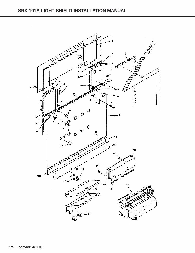
135 SERVICE MANUAL
SRX-101A LIGHT SHIELD INSTALLATION MANUAL
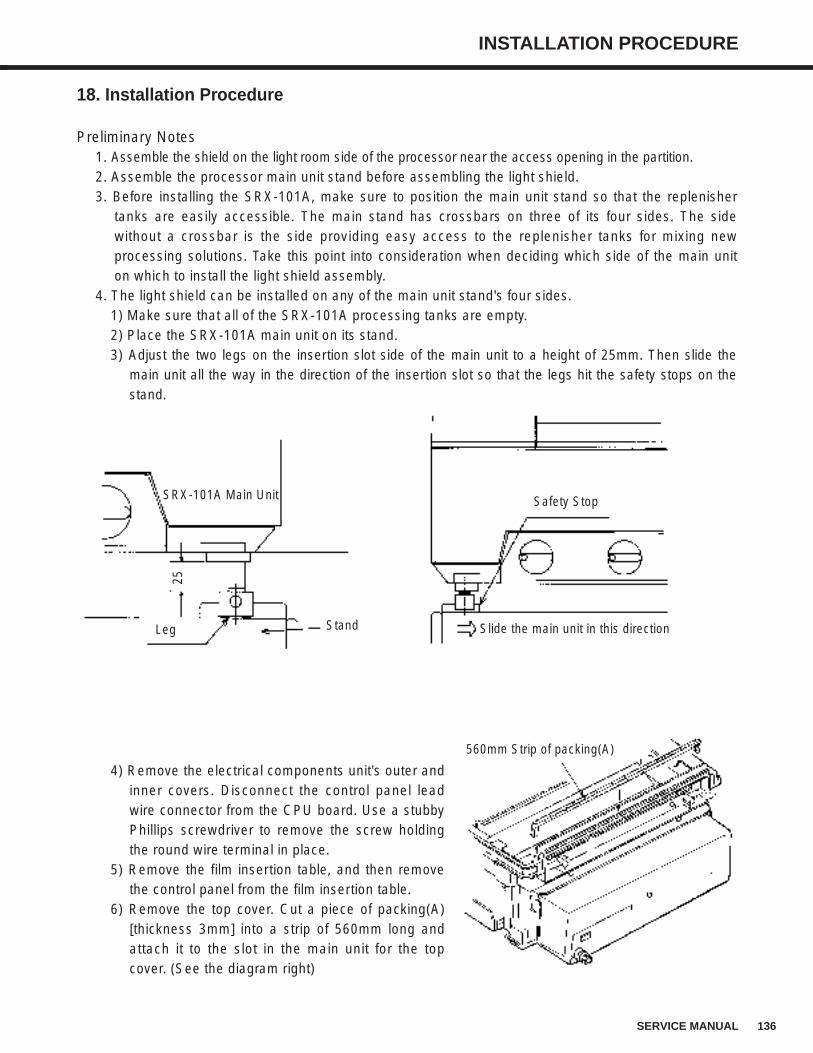
136SERVICE MANUAL
INSTALLATION PROCEDURE
18. Installation Procedure
Preliminary Notes1. Assemble the shield on the light room side of the processor near the access opening in the partition.2. Assemble the processor main unit stand before assembling the light shield.3. Before installing the SRX-101A, make sure to position the main unit stand so that the replenisher
tanks are easily accessible. The main stand has crossbars on three of its four sides. The sidewithout a crossbar is the side providing easy access to the replenisher tanks for mixing newprocessing solutions. Take this point into consideration when deciding which side of the main uniton which to install the light shield assembly.
4. The light shield can be installed on any of the main unit stand's four sides.1) Make sure that all of the SRX-101A processing tanks are empty.2) Place the SRX-101A main unit on its stand.3) Adjust the two legs on the insertion slot side of the main unit to a height of 25mm. Then slide the
main unit all the way in the direction of the insertion slot so that the legs hit the safety stops on thestand.
4) Remove the electrical components unit's outer andinner covers. Disconnect the control panel leadwire connector from the CPU board. Use a stubbyPhillips screwdriver to remove the screw holdingthe round wire terminal in place.
5) Remove the film insertion table, and then removethe control panel from the film insertion table.
6) Remove the top cover. Cut a piece of packing(A)[thickness 3mm] into a strip of 560mm long andattach it to the slot in the main unit for the topcover. (See the diagram right)
Slide the main unit in this direction
Safety StopSRX-101A Main Unit
StandLeg
25
560mm Strip of packing(A)
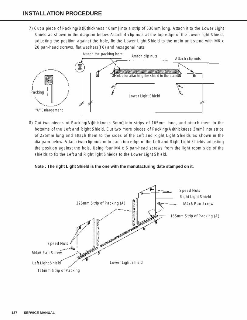
137 SERVICE MANUAL
INSTALLATION PROCEDURE
7) Cut a piece of Packing(D)[0thickness 10mm] into a strip of 530mm long. Attach it to the Lower Light
Shield as shown in the diagram below. Attach 4 clip nuts at the top edge of the Lower light Shield,
adjusting the position against the hole, fix the Lower Light Shield to the main unit stand with M6 x
20 pan-head screws, flat washers(φ6) and hexagonal nuts.
8) Cut two pieces of Packing(A)[thickness 3mm] into strips of 165mm long, and attach them to the
bottoms of the Left and Right Shield. Cut two more pieces of Packing(A)[thickness 3mm] into strips
of 225mm long and attach them to the sides of the Left and Right Light Shields as shown in the
diagram below. Attach two clip nuts onto each top edge of the Left and Right Light Shields adjusting
the position against the hole. Using four M4 x 6 pan-head screws from the light room side of the
shields to fix the Left and Right light Shields to the Lower Light Shield.
Note : The right Light Shield is the one with the manufacturing date stamped on it.
Packing
"A" Enlargement
Lower Light Shield
Holes for attaching the shield to the stand
Attach clip nutsAttach the packing here Attach clip nuts
Speed Nuts
Right Light Shield
M4x6 Pan Screw
165mm Strip of Packing (A)
225mm Strip of Packing (A)
Speed Nuts
M4x6 Pan Screw
Left Light Shield
166mm Strip of Packing
Lower Light Shield
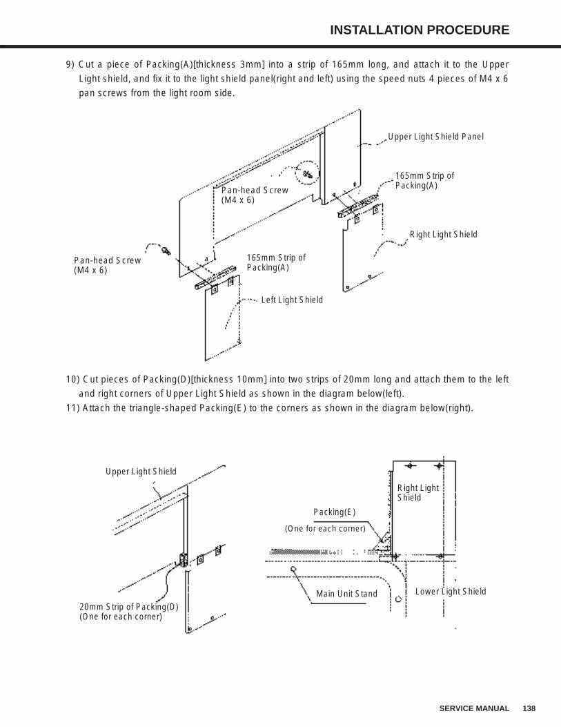
138SERVICE MANUAL
INSTALLATION PROCEDURE
9) Cut a piece of Packing(A)[thickness 3mm] into a strip of 165mm long, and attach it to the Upper
Light shield, and fix it to the light shield panel(right and left) using the speed nuts 4 pieces of M4 x 6
pan screws from the light room side.
10) Cut pieces of Packing(D)[thickness 10mm] into two strips of 20mm long and attach them to the left
and right corners of Upper Light Shield as shown in the diagram below(left).
11) Attach the triangle-shaped Packing(E) to the corners as shown in the diagram below(right).
Pan-head Screw(M4 x 6)
Pan-head Screw(M4 x 6)
165mm Strip ofPacking(A)
165mm Strip ofPacking(A)
Left Light Shield
Right Light Shield
Upper Light Shield Panel
20mm Strip of Packing(D)(One for each corner)
Lower Light Shield
Right Light Shield
Upper Light Shield
Main Unit Stand
Packing(E)
(One for each corner)
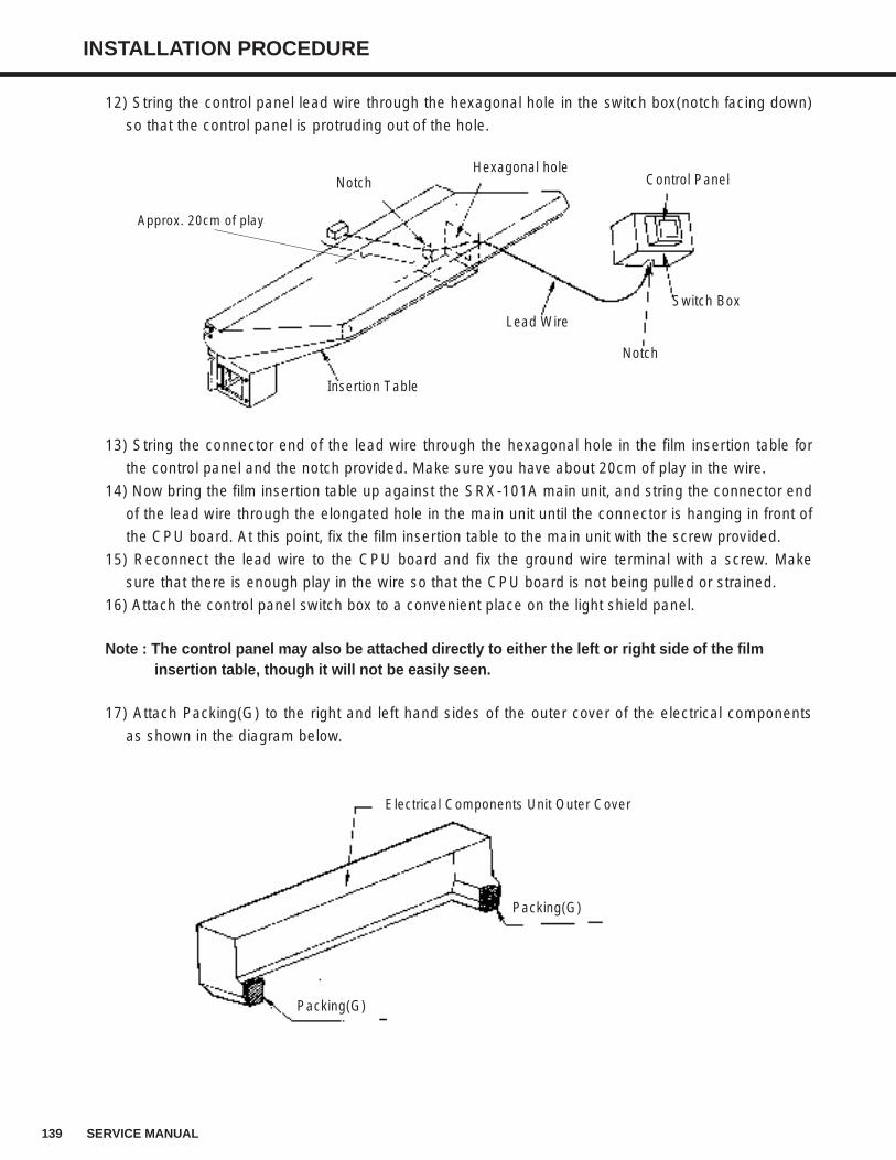
139 SERVICE MANUAL
INSTALLATION PROCEDURE
12) String the control panel lead wire through the hexagonal hole in the switch box(notch facing down)
so that the control panel is protruding out of the hole.
13) String the connector end of the lead wire through the hexagonal hole in the film insertion table for
the control panel and the notch provided. Make sure you have about 20cm of play in the wire.
14) Now bring the film insertion table up against the SRX-101A main unit, and string the connector end
of the lead wire through the elongated hole in the main unit until the connector is hanging in front of
the CPU board. At this point, fix the film insertion table to the main unit with the screw provided.
15) Reconnect the lead wire to the CPU board and fix the ground wire terminal with a screw. Make
sure that there is enough play in the wire so that the CPU board is not being pulled or strained.
16) Attach the control panel switch box to a convenient place on the light shield panel.
Note : The control panel may also be attached directly to either the left or right side of the film insertion table, though it will not be easily seen.
17) Attach Packing(G) to the right and left hand sides of the outer cover of the electrical components
as shown in the diagram below.
Insertion Table
Lead Wire
Notch
Switch Box
Control PanelHexagonal hole
Notch
Approx. 20cm of play
Electrical Components Unit Outer Cover
Packing(G)
Packing(G)
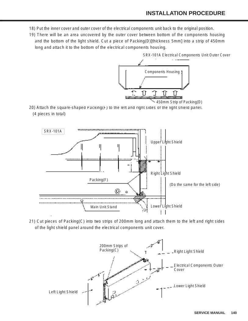
140SERVICE MANUAL
INSTALLATION PROCEDURE
18) Put the inner cover and outer cover of the electrical components unit back to the original position.
19) There will be an area uncovered by the outer cover between bottom of the components housing
and the bottom of the light shield. Cut a piece of Packing(D)[thickness 5mm] into a strip of 450mm
long and attach it to the bottom of the electrical components housing.
20) Attach the square-shaped Packing(F) to the left and right sides of the light shield panel.
(4 pieces in total)
21) Cut pieces of Packing(C) into two strips of 200mm long and attach them to the left and right sides
of the light shield panel around the electrical components unit cover.
SRX-101A Electrical Components Unit Outer Cover
Components Housing
450mm Strip of Packing(D)
Upper Light Shield
Right Light Shield
Lower Light Shield
Packing(F)
Main Unit Stand
(Do the same for the left side)
SRX-101A
Right Light Shield
Electrical Components OuterCover
Lower Light Shield
200mm Strips ofPacking(C)
Left Light Shield
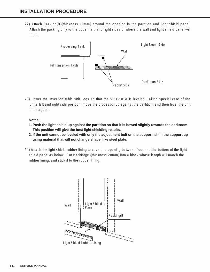
141 SERVICE MANUAL
INSTALLATION PROCEDURE
22) Attach Packing(D)[thickness 10mm] around the opening in the partition and light shield panel.
Attach the packing only to the upper, left, and right sides of where the wall and light shield panel will
meet.
23) Lower the insertion table side legs so that the SRX-101A is leveled. Taking special care of the
unit's left and right side position, move the processor up against the partition, and then level the unit
once again.
Notes : 1. Push the light shield up against the partition so that it is bowed slightly towards the darkroom.
This position will give the best light shielding results.2. If the unit cannot be leveled with only the adjustment bolt on the support, shim the support up
using material that will not change shape, like steel plate.
24) Attach the light shield rubber lining to cover the opening between floor and the bottom of the light
shield panel as below. Cut Packing(B)[thickness 20mm] into a block whose length will match the
rubber lining, and stick it to the rubber lining.
Packing(D)Darkroom Side
Film Insertion Table
Processing Tank Light Room Side
Wall
Light Shield Rubber Lining
Wall Light ShieldPanel
Packing(B)
Wall
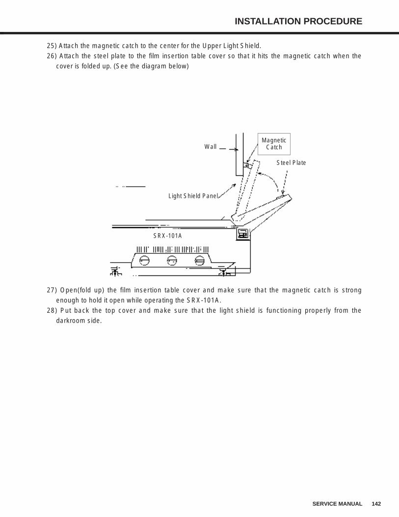
142SERVICE MANUAL
INSTALLATION PROCEDURE
25) Attach the magnetic catch to the center for the Upper Light Shield.
26) Attach the steel plate to the film insertion table cover so that it hits the magnetic catch when the
cover is folded up. (See the diagram below)
27) Open(fold up) the film insertion table cover and make sure that the magnetic catch is strong
enough to hold it open while operating the SRX-101A.
28) Put back the top cover and make sure that the light shield is functioning properly from the
darkroom side.
Magnetic Catch
Light Shield Panel
Wall
Steel Plate
SRX-101A
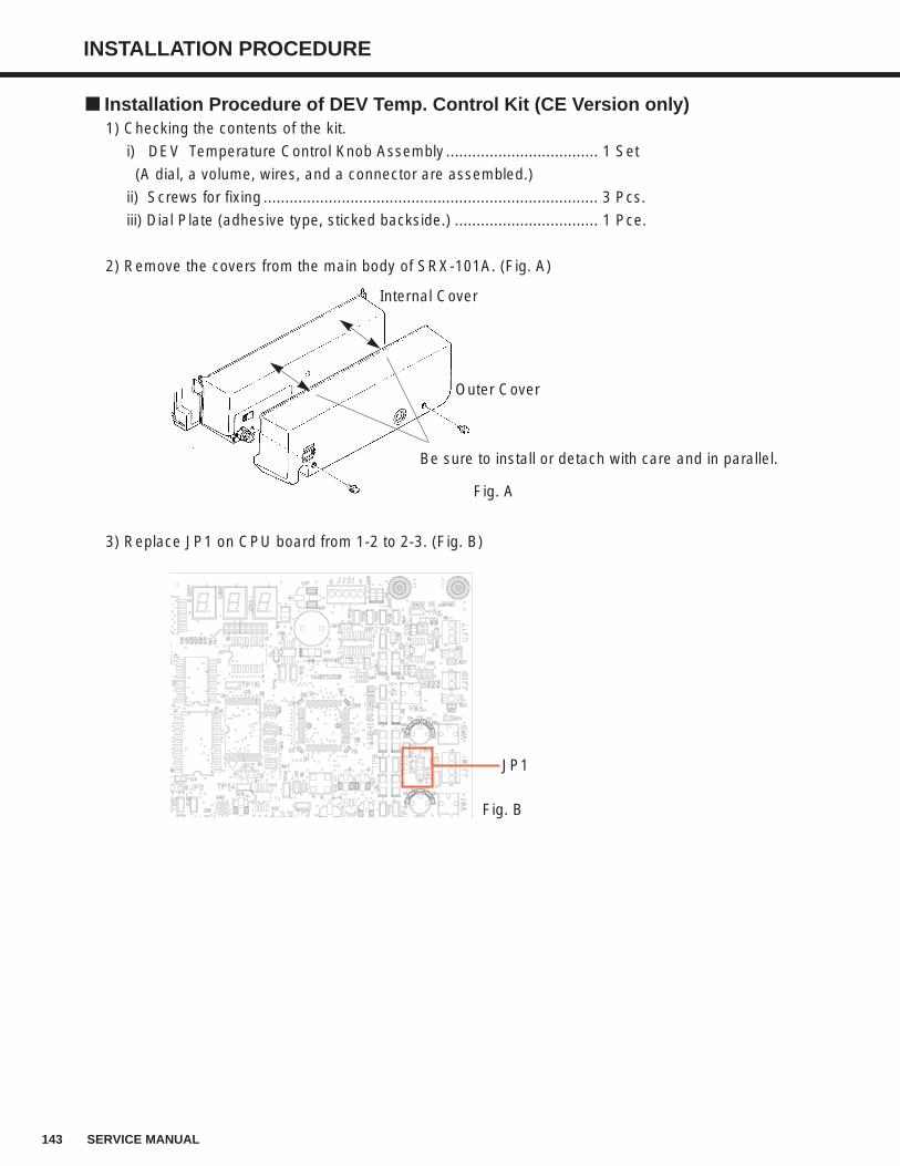
143 SERVICE MANUAL
INSTALLATION PROCEDURE
Installation Procedure of DEV Temp. Control Kit (CE Version only)1) Checking the contents of the kit.
i) DEV Temperature Control Knob Assembly ................................... 1 Set
(A dial, a volume, wires, and a connector are assembled.)
ii) Screws for fixing ............................................................................. 3 Pcs.
iii) Dial Plate (adhesive type, sticked backside.) ................................. 1 Pce.
2) Remove the covers from the main body of SRX-101A. (Fig. A)
3) Replace JP1 on CPU board from 1-2 to 2-3. (Fig. B)
Internal Cover
Outer Cover
Be sure to install or detach with care and in parallel.
Fig. A
Fig. B
JP1
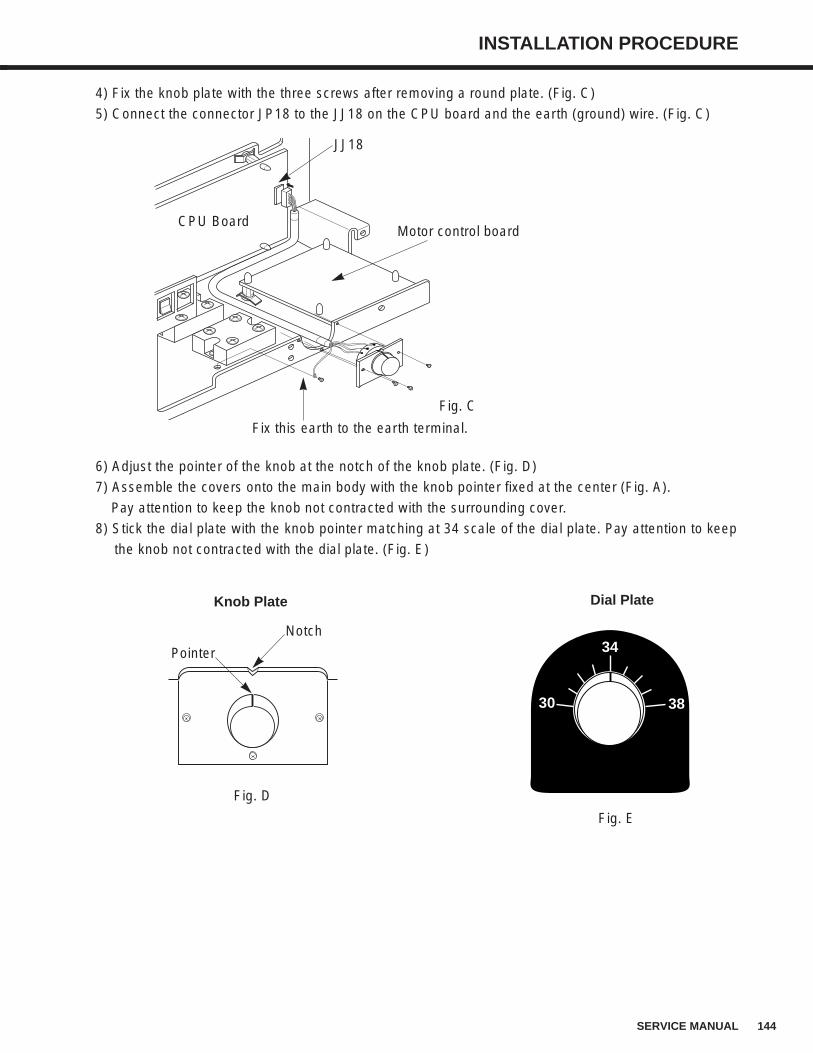
144SERVICE MANUAL
INSTALLATION PROCEDURE
4) Fix the knob plate with the three screws after removing a round plate. (Fig. C)
5) Connect the connector JP18 to the JJ18 on the CPU board and the earth (ground) wire. (Fig. C)
6) Adjust the pointer of the knob at the notch of the knob plate. (Fig. D)
7) Assemble the covers onto the main body with the knob pointer fixed at the center (Fig. A).
Pay attention to keep the knob not contracted with the surrounding cover.
8) Stick the dial plate with the knob pointer matching at 34 scale of the dial plate. Pay attention to keep
the knob not contracted with the dial plate. (Fig. E)
Fig. C
CPU Board
JJ18
Fix this earth to the earth terminal.
Dial Plate
Motor control board
Pointer
Notch
Knob Plate
34
3830
Fig. E
Fig. D
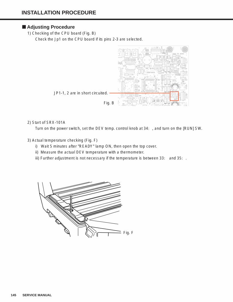
145 SERVICE MANUAL
INSTALLATION PROCEDURE
Adjusting Procedure1) Checking of the CPU board (Fig. B)
Check the Jp1 on the CPU board if its pins 2-3 are selected.
2) Start of SRX-101A
Turn on the power switch, set the DEV temp. control knob at 34:, and turn on the [RUN] SW.
3) Actual temperature checking (Fig. F)
i) Wait 5 minutes after "READY" lamp ON, then open the top cover.
ii) Measure the actual DEV temperature with a thermometer.
iii) Further adjustment is not necessary if the temperature is between 33: and 35:.
JP1-1, 2 are in short circuited.
Fig. B
Fig. F
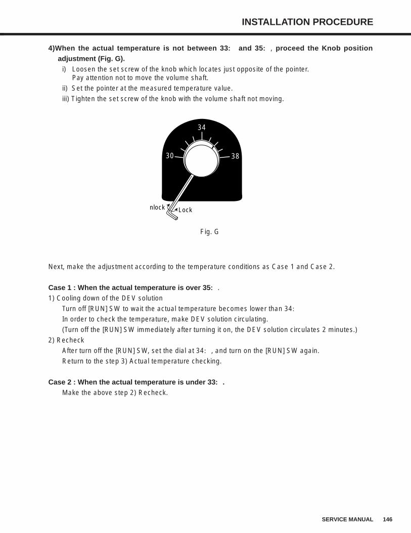
146SERVICE MANUAL
INSTALLATION PROCEDURE
4)When the actual temperature is not between 33:: and 35::, proceed the Knob positionadjustment (Fig. G).
i) Loosen the set screw of the knob which locates just opposite of the pointer.Pay attention not to move the volume shaft.
ii) Set the pointer at the measured temperature value.
iii) Tighten the set screw of the knob with the volume shaft not moving.
Next, make the adjustment according to the temperature conditions as Case 1 and Case 2.
Case 1 : When the actual temperature is over 35::.
1) Cooling down of the DEV solution
Turn off [RUN] SW to wait the actual temperature becomes lower than 34:
In order to check the temperature, make DEV solution circulating.
(Turn off the [RUN] SW immediately after turning it on, the DEV solution circulates 2 minutes.)
2) Recheck
After turn off the [RUN] SW, set the dial at 34:, and turn on the [RUN] SW again.
Return to the step 3) Actual temperature checking.
Case 2 : When the actual temperature is under 33::.Make the above step 2) Recheck.
34
3830
LockUnlock
Fig. G

1051-55030 C
0405TE
Copyright © 2022 FDOKUMEN