Ion channel recordings on an injection-molded polymer chip
10
PAPER Cite this: Lab Chip, 2013, 13, 4784 Received 25th June 2013, Accepted 23rd September 2013 DOI: 10.1039/c3lc50760b www.rsc.org/loc Ion channel recordings on an injection-molded polymer chip† Simone Tanzi, a Marco Matteucci, a Thomas Lehrmann Christiansen, a Søren Friis, b Mette Thylstrup Christensen, b Joergen Garnaes, c Sandra Wilson, b Jonatan Kutchinsky b and Rafael Taboryski* a In this paper, we demonstrate recordings of the ion channel activity across the cell membrane in a biological cell by employing the so-called patch clamping technique on an injection-molded polymer microfluidic device. The find- ings will allow direct recordings of ion channel activity to be made using the cheapest materials and production platform to date and with the potential for very high throughput. The employment of cornered apertures for cell capture allowed the fabrication of devices without through holes and via a scheme comprising master origination by dry etching in a silicon substrate, electroplating in nickel and injection molding of the final part. The most critical device parameters were identified as the length of the patching capillary and the very low surface roughness on the inside of the capillary. The cross-sectional shape of the orifice was found to be less critical, as both rectangular and semicircular profiles seemed to have almost the same ability to form tight seals with cells with negligible leak currents. The devices were functionally tested using human embryonic kidney cells expressing voltage-gated sodium channels (Na v 1.7) and benchmarked against a commercial state-of-the-art system for automated ion chan- nel recordings. These experiments considered current–voltage (IV) relationships for activation and inactivation of the Na v 1.7 channels and their sensitivity to a local anesthetic, lidocaine. Both IVs and lidocaine dose–response curves obtained from the injection-molded polymer device were in good agreement with data obtained from the commercial system. Introduction The patch clamping technique was introduced in 1976 by Neher and Sakmann 1 and has become the accepted stan- dard for fundamental studies of ion channel proteins and the discovery of drugs that affect them. Ion channels play a central role in the excitability of nerves and muscles; they underlie the heartbeat, muscle contractions and brain activ- ity as well as many other basic physiological actions. 2 Ion channels are macromolecular pores with the ability to regu- late the movement of ions across the otherwise impermeable cell membrane. 2 Ion channels are also involved in a diverse range of disorders and pathological conditions, called channelopathies. 3,4 Mutations in ion channel genes have been associated with diseases such as cystic fibrosis, hypertension, ataxia, arrhythmia and several types of epilepsy. 4,5 In pharmacology, ion channels repre- sent highly attractive targets for drug discovery with an esti- mated market of US $12 billion. 6,7 Despite their enormous potential as druggable targets, the use of ion channels for drug discovery has been well behind the expectation, mainly due to the lack of adequate screening technology. 8 Conventional manual patch clamping delivers high information content, but it is a complex technique that requires skilled personnel and suffers from extremely low throughput, while, on the other hand, all indirect screening methods suffer from low specificity and, thus, the associated risk of generating false negative or positive results. 8,9 With the promise of removing this trade-off, the first automated parallel patch clamping system (APC) was made available in 2003. 10 Since then, 5 companies (Molecular Devices, Sophion Bioscience, Nanion, Cytocentric, and Fluxion) have entered the market, establishing APC as an essential technology for secondary screening, lead optimization and cardiac safety a Department of Micro- and Nanotechnology, Technical University of Denmark, Building 345E, DK-2800 Kongens Lyngby, Denmark. E-mail: [email protected] b Sophion Bioscience A/S, Baltorpvej 154, DK-2750 Ballerup, Denmark c Danish Fundamental Metrology, Matematiktorvet, Building 307, DK-2800 Kongens Lyngby, Denmark † Electronic supplementary information (ESI) available: Description of the leak current subtraction applied to the raw data obtained from the polymer devices; description of the simulation for the perfusion of lidocaine from one of the lateral channels into the deep channel during the dose–response experiments; description of the fabrication process (table and illustrations); description of the challenges faced during the development of the presented polymer device (and figures). See DOI: 10.1039/c3lc50760b 4784 | Lab Chip, 2013, 13, 4784–4793 This journal is © The Royal Society of Chemistry 2013 Lab on a Chip
Transcript of Ion channel recordings on an injection-molded polymer chip
Lab on a Chip
PAPER
aDepartment of Micro- and Nanotechnology, Technical University of Denmark,
Building 345E, DK-2800 Kongens Lyngby, Denmark.
E-mail: [email protected] Sophion Bioscience A/S, Baltorpvej 154, DK-2750 Ballerup, Denmarkc Danish Fundamental Metrology, Matematiktorvet, Building 307, DK-2800
Kongens Lyngby, Denmark
† Electronic supplementary information (ESI) available: Description of the leakcurrent subtraction applied to the raw data obtained from the polymer devices;description of the simulation for the perfusion of lidocaine from one of thelateral channels into the deep channel during the dose–response experiments;description of the fabrication process (table and illustrations); description ofthe challenges faced during the development of the presented polymer device(and figures). See DOI: 10.1039/c3lc50760b
4784 | Lab Chip, 2013, 13, 4784–4793 This journal is © The Ro
Cite this: Lab Chip, 2013, 13, 4784
Received 25th June 2013,Accepted 23rd September 2013
DOI: 10.1039/c3lc50760b
www.rsc.org/loc
Ion channel recordings on an injection-moldedpolymer chip†
Simone Tanzi,a Marco Matteucci,a Thomas Lehrmann Christiansen,a Søren Friis,b
Mette Thylstrup Christensen,b Joergen Garnaes,c Sandra Wilson,b
Jonatan Kutchinskyb and Rafael Taboryski*a
In this paper, we demonstrate recordings of the ion channel activity across the cell membrane in a biological cell
by employing the so-called patch clamping technique on an injection-molded polymer microfluidic device. The find-
ings will allow direct recordings of ion channel activity to be made using the cheapest materials and production
platform to date and with the potential for very high throughput. The employment of cornered apertures for cell
capture allowed the fabrication of devices without through holes and via a scheme comprising master origination
by dry etching in a silicon substrate, electroplating in nickel and injection molding of the final part. The most critical
device parameters were identified as the length of the patching capillary and the very low surface roughness on
the inside of the capillary. The cross-sectional shape of the orifice was found to be less critical, as both rectangular
and semicircular profiles seemed to have almost the same ability to form tight seals with cells with negligible leak
currents. The devices were functionally tested using human embryonic kidney cells expressing voltage-gated
sodium channels (Nav1.7) and benchmarked against a commercial state-of-the-art system for automated ion chan-
nel recordings. These experiments considered current–voltage (IV) relationships for activation and inactivation of
the Nav1.7 channels and their sensitivity to a local anesthetic, lidocaine. Both IVs and lidocaine dose–response
curves obtained from the injection-molded polymer device were in good agreement with data obtained from the
commercial system.
Introduction
The patch clamping technique was introduced in 1976 byNeher and Sakmann1 and has become the accepted stan-dard for fundamental studies of ion channel proteins andthe discovery of drugs that affect them. Ion channels play acentral role in the excitability of nerves and muscles; theyunderlie the heartbeat, muscle contractions and brain activ-ity as well as many other basic physiological actions.2 Ionchannels are macromolecular pores with the ability to regu-late the movement of ions across the otherwise
impermeable cell membrane.2 Ion channels are alsoinvolved in a diverse range of disorders and pathologicalconditions, called channelopathies.3,4 Mutations in ionchannel genes have been associated with diseases such ascystic fibrosis, hypertension, ataxia, arrhythmia and severaltypes of epilepsy.4,5 In pharmacology, ion channels repre-sent highly attractive targets for drug discovery with an esti-mated market of US $12 billion.6,7
Despite their enormous potential as druggable targets, theuse of ion channels for drug discovery has been well behindthe expectation, mainly due to the lack of adequate screeningtechnology.8 Conventional manual patch clamping delivershigh information content, but it is a complex technique thatrequires skilled personnel and suffers from extremely lowthroughput, while, on the other hand, all indirect screeningmethods suffer from low specificity and, thus, the associatedrisk of generating false negative or positive results.8,9 Withthe promise of removing this trade-off, the first automatedparallel patch clamping system (APC) was made available in2003.10 Since then, 5 companies (Molecular Devices, SophionBioscience, Nanion, Cytocentric, and Fluxion) have enteredthe market, establishing APC as an essential technology forsecondary screening, lead optimization and cardiac safety
yal Society of Chemistry 2013

Lab on a Chip Paper
testing.11 Performances of the different systems have beendiscussed in a few reviews.11–14 APC systems replace the useof conventional glass micropipettes with single-use, dispos-able devices fabricated using materials such as quartz15 andsilicon/silicon dioxide.16 The majority of the available plat-forms share the so-called planar approach, where cells insuspension are blindly positioned by suction onto micro-apertures made as through holes in thin membranes.15
Alternatively, a lateral approach has been proposed, wheresuspended cells are trapped at lateral apertures generated atthe junction of two microfluidic channels.17
The ability to form a high electrical resistance seal, pref-erably in the order of GΩ (the so-called gigaseal) betweenthe aperture and the biological cell membrane, and the fab-rication of such micro-sized through holes in thin sub-strates (10–20 μm) are the two most relevant benchmarks.These constraints have traditionally narrowed the range ofusable materials and technologies to almost exclusivelymicromachining of silicon and glass, at least for commer-cial use.
The use of polymeric substrates has also been widely investi-gated, and planar microfluidic chips have been demonstratedin hybrid polydimethylsiloxane–polyimide (PDMS–PI),18
polyimide,19 oxygen plasma-treated PDMS20,21 and polyethyleneglycol (PEG)–SU-8 mixture.22 Unfortunately, all the aforemen-tioned polymer devices have so far failed to deliver relevantelectrophysiological results. It has been more or less implicitlybelieved in the community that silicon oxide surfaces possess aunique surface chemistry for forming gigaseals, essentiallythrough van der Waals interactions.23–25 The interactionbetween lipid membranes and other surfaces is, however, com-plicated and only poorly understood and, thus, leaves someleverage for challenging the uniqueness of these surfaces26–30
by employing polymers. Ionescu-Zanetti et al. implemented lat-eral junctions in a microfluidic device fabricated by casting ofpolydimethylsiloxane (PDMS).17,31 In 2009, this device was even-tually commercialized by Fluxion, and it remains the only APCsystem relying on cornered apertures to date.32
Looking at all of the commercially available APC systems,the manufacturing cost per device is still prohibitive forestablishing APC as a routine technique.33 Of the two mate-rials employed nowadays, silicon remains extremely costly topurchase and machine, while PDMS is less suitable for massproduction. Moreover, PDMS has issues when used for bio-logical applications such as high permeability for small mole-cules, non-cross-linked oligomers, and surface diffusion oflow molecular weight chains.34
The aim of this work is to propose a method for massiveproduction of extremely cheap APC systems withoutcompromising functionality. The trick lies in understandingthe requirements to form tight seals between thermoplasticpolymers and the cells. By shaping apertures that allow for aconsiderably larger effective interface area between low-energy polymer surfaces and the cell membrane, we demon-strate the formation of gigaseals, enabling high-quality ionchannel recordings. The proposed device consists of only two
This journal is © The Royal Society of Chemistry 2013
parts: an injection-molded part in TOPAS cyclic olefin copoly-mer (COC) comprising the microfluidics and a polymer filmof the same polymer grade, which is thermally bonded to theinjection-molded part.35 For comparison, the commerciallyavailable QPlate™ from Sophion Bioscience comprises severalmaterials, thermoplastic polymer, elastomer, ceramic, glass,and silicon. Moreover, TOPAS has none of the previouslymentioned limitations of PDMS. Furthermore, the materialsand fabrication platform fulfills all the requirements forcheap manufacturing in terms of “design for manufacturabil-ity”, “economy of scale” and production yield, and it avoidsall drawbacks typical of prototyping methods.36 After an ini-tial investment in master mold origination, injection moldingdelivers a cost per part that exponentially decreases with thenumber of parts, becoming the cheapest technology whenproduction is greater than ~10 000 units.36 After assemblyinto chips, the systems were tested with HEK cells expressingNav1.7, a voltage-gated sodium channel appropriate forbenchmarking studies. Experiments were designed to explorecurrent–voltage (IV) relationships for activation and inactiva-tion of Nav1.7 channels and their sensitivity to a local anes-thetic, lidocaine. Both IVs and lidocaine dose–responsecurves obtained from the injection-molded polymer devicewere benchmarked against the commercially availableQPatch™ system from Sophion Bioscience. In the followingsection, we provide the details of the device layout and func-tionality, benchmarking tests against existing state-of-the-artmethods, and finally a surface topology characterization ofthe patching capillaries.
Materials and methodsDevice fabrication
Chips were manufactured according to the methods recentlyreported by some of the same authors,37 which in brief con-sist of lithography, dry etching of the silicon, electroplatingin nickel and injection molding of the polymer parts. Twoetching processes were employed to form the patching capil-laries: Bosch reactive ion etching for sample A and continu-ous reactive ion etching for sample B. This was to obtain,respectively, rectangular and semicircular profiles. However,in order to replicate patch clamping orifices smaller than thelateral apertures demonstrated for cell trapping,37 the overallprocess was partially modified. Silicon oxide used as maskingmaterial was replaced by standard photoresist, while a thinlayer of oxide was applied after the first etching step to pre-vent damage to the patching channels during the rest of theprocess. Fabrication was then completed by alternating wetetching steps and oxidation in order to smooth the surfacesaround the patching orifices. Details of the full process aregiven in the ESI.† Parts were molded from COC (TOPAS 5013,Advanced Polymers GmbH). A 100 μm thick extruded poly-mer film (TOPAS 5013F-04, Advanced Polymers ExtrusionLab) was used as a cover lid. The two parts were bonded byUV-assisted thermal bonding.35
Lab Chip, 2013, 13, 4784–4793 | 4785
Lab on a ChipPaper
Cell culture
Human embryonic kidney 293 cells (HEK 293) expressingthe subtype of the voltage-gated sodium channel Nav1.7were provided by Scottish Biomedical Ltd. The cells weregrown and maintained under standard culture conditions at37 °C and 5% CO2. The cells were cultured in T175 cultureflasks (Nunc A/S) to a maximum 80% confluence in high-glucose Dulbecco's modified Eagle's medium (DMEM,Sigma-Aldrich D0819) supplemented with 10% fetal bovineserum (FBS, Sigma-Aldrich F2442), 2 μg ml−1 blasticidin S(Sigma-Aldrich 15205) and 600 μg ml−1 geneticin (Sigma-Aldrich G8168). The cells were sub-cultured for two weeksbefore reaching a stable growth pattern and then used inthe experiments. For sub-culture, the culture medium wasremoved and the cells were washed with phosphate-bufferedsaline (PBS) without calcium chloride and magnesium chlo-ride (Sigma-Aldrich D8537). Trypsin/EDTA (Sigma-AldrichT4174) was added to the culture flask, and the flask wasincubated at 37 °C for 2 minutes. The medium was addedto the flask, and the cells were re-suspended and placed ina new mother flask. Directly before experiments, the culturemedium was removed and the cells were washed withPBS without calcium chloride and magnesium chloride.Detachin (VWR) was added to the culture flask, and theflask was incubated at 37 °C for 5 minutes or until the cellsshowed a round shape indicating detachment from the flasksurfaces. The cells were re-suspended in serum-free CHOmedium (Sigma-Aldrich C5467) supplemented with 25 mMHEPES (Sigma-Aldrich H0887), 100 μg ml−1 penicillin/strep-tomycin (Sigma-Aldrich P4333) and 0.04 mg ml−1 soybeantrypsin inhibitor (Sigma-Aldrich T6522). Cell density and via-bility were determined by diluting an aliquot 1 : 2 in Trypanblue (Sigma-Aldrich T8154) and performing a cell countusing the dye exclusion method in a hemocytometer. Cellconcentration in the suspension was 2–3 M ml−1.
Solutions and compounds
The intracellular electrolyte solution contained (in mM):135 CsF, 1/5 ethylene glycol tetraacetic acid (EGTA)/CsOH,10 mM HEPES and 10 NaCl. The pH was adjusted to 7.3 withKOH and osmolarity to 320 mOsm with sucrose. The extracel-lular electrolyte solution contained (in mM): 1 CaCl2, 1 MgCl2,5 HEPES, 3 KCl, 140 NaCl, 0.1 CdCl2 and 20 TEA–Cl. The pHwas adjusted to 7.3 with NaOH and osmolarity to 320 mOsmwith sucrose. All chemicals were purchased from Sigma-Aldrich. Both solutions were stored in a fridge at 4 °C andvacuum degassed for 20 minutes before use. Lidocaine hydro-chloride monohydrate (Sigma-Aldrich L5647) was dissolvedin dimethyl sulfoxide (DMSO) to give a 100 mM stock solu-tion kept in the freezer. Subsequent dilutions were performedin an extracellular electrolyte solution.
Instrumentation
Recordings were carried out using a HEKA Patch Clamp EPC9 amplifier (HEKA Electronics) at room temperature. Pulse
4786 | Lab Chip, 2013, 13, 4784–4793
software (v 8.53, HEKA Electronics) was used for data acquisi-tion. The device was mounted into a customized aluminumbox and positioned on the stage of an Olympus IX70 invertedmicroscope. The two inlet ports connected to the recordingpatching channel were connected to two reservoirs filledwith electrolyte solution and from them to a custom-madepressure controller and controlled with Labview software(National Instruments). Electrodes were electrically connectedto the EPC9 head stage mounted on the customized alu-minum box, and the chip resistance could be monitored byapplying a 10 mV test square pulse for 10 ms. Before celltrapping, a positive pressure of 3–5 mbar was applied to thepatching channel to prevent aperture contamination. A cellwas captured at the hole after applying suction (negativepressure of 400 mbar) to the patching channel. The amplifieroffset potential was zeroed prior to patching the cell, and theholding potential was held at −90 mV. Response currentswere sampled at 10 kHz and filtered at 2.9 kHz with a 4-poleBessel filter. The experiments on the QPatch™ were set upusing standard assay settings. In brief, cells were positionedwith a negative pressure of −100 mbar until a gigaseal wasformed. The cell membrane was then ruptured with a nega-tive pressure pulse of −250 mbar in order to get electricalaccess to the cell membrane. During this process, the offsetpotential, the chip capacitance and the cell capacitance werecanceled out. The actual experiment protocol with therelevant voltage protocols and compound additions wasprogrammed in the Sophion Assay Software, and it was exe-cuted after whole-cell formation was established. QPatch™
data were sampled at 10 kHz and filtered with an 8-poleBessel filter at 3 kHz.
Whole-cell recordings
Once the cells were trapped, a suction of −400 mbar wasapplied for about 20 seconds and then reduced to −30 mbar.The resistance across the aperture was continuously monitoredby applying a 10 mV pulse for 10 ms. At this stage, the resis-tance was typically between 100 and 200 MΩ. Some of the cellsshowed whole-cell configuration immediately after patching.Otherwise, the whole-cell configuration was achieved by apply-ing combined suction pulses (from −30 mbar to −400 mbar)and electrical pulses. Achievement of whole-cell configurationwas verified by depolarizing the cell. Eventually, the cellsreached whole-cell configuration and the resistance graduallyincreased over minutes during the experiments.
Voltage protocols
For IV relationship experiments, a protocol with incremen-tal steps of +10 mV from −90 mV to +70 mV of 1000 msduration was used. Steady-state inactivation was investi-gated at +10 mV for 100 ms after the 1000 ms pre-pulse.Each incremental sweep took place with 5 second intervals.For concentration–response experiments, two consecutivedepolarizations to +0 mV, respectively of 100 ms and 20 msduration from a holding potential of −100 mV were used.
This journal is © The Royal Society of Chemistry 2013
Lab on a Chip Paper
The two depolarizations were spaced out by 15 ms at theholding potential.
Results and discussion
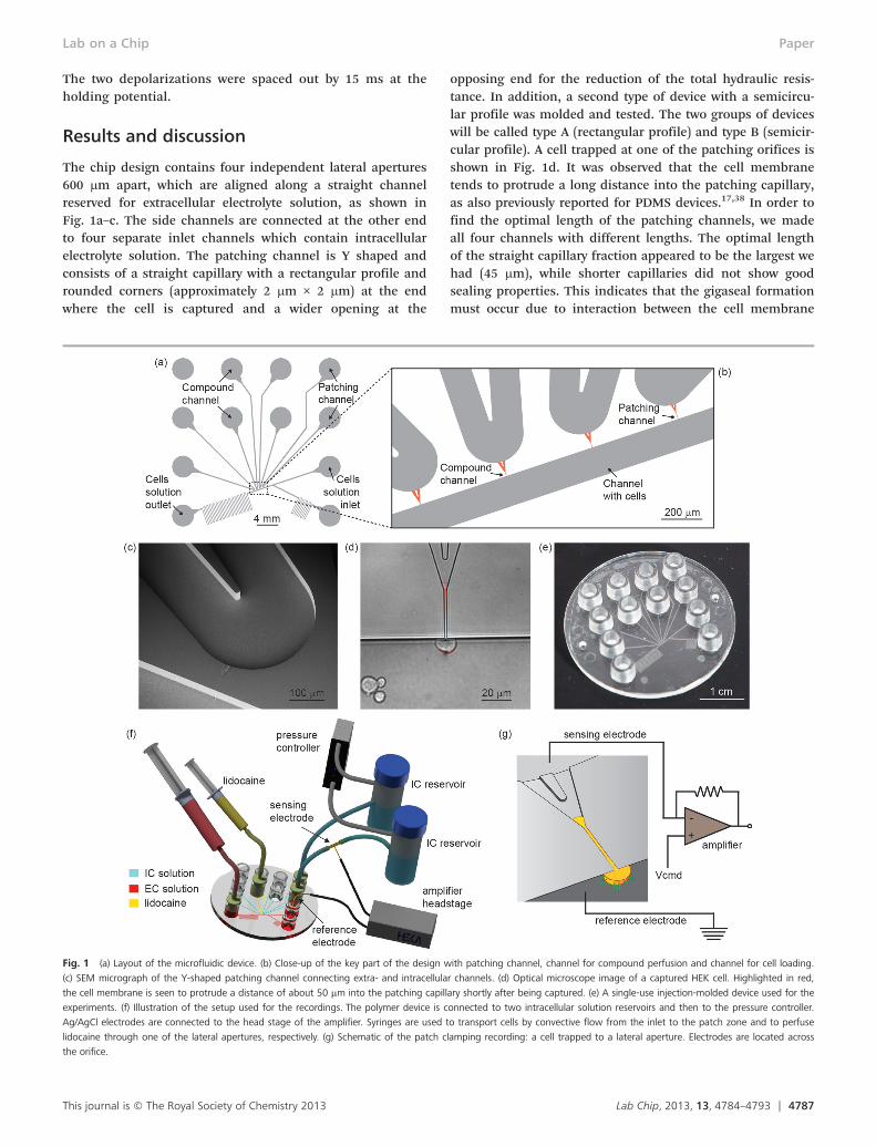
The chip design contains four independent lateral apertures600 μm apart, which are aligned along a straight channelreserved for extracellular electrolyte solution, as shown inFig. 1a–c. The side channels are connected at the other endto four separate inlet channels which contain intracellularelectrolyte solution. The patching channel is Y shaped andconsists of a straight capillary with a rectangular profile androunded corners (approximately 2 μm × 2 μm) at the endwhere the cell is captured and a wider opening at the
Fig. 1 (a) Layout of the microfluidic device. (b) Close-up of the key part of the design w
(c) SEM micrograph of the Y-shaped patching channel connecting extra- and intracellula
the cell membrane is seen to protrude a distance of about 50 μm into the patching capill
experiments. (f) Illustration of the setup used for the recordings. The polymer device is c
Ag/AgCl electrodes are connected to the head stage of the amplifier. Syringes are used t
lidocaine through one of the lateral apertures, respectively. (g) Schematic of the patch c
the orifice.
This journal is © The Royal Society of Chemistry 2013
opposing end for the reduction of the total hydraulic resis-tance. In addition, a second type of device with a semicircu-lar profile was molded and tested. The two groups of deviceswill be called type A (rectangular profile) and type B (semicir-cular profile). A cell trapped at one of the patching orifices isshown in Fig. 1d. It was observed that the cell membranetends to protrude a long distance into the patching capillary,as also previously reported for PDMS devices.17,38 In order tofind the optimal length of the patching channels, we madeall four channels with different lengths. The optimal lengthof the straight capillary fraction appeared to be the largest wehad (45 μm), while shorter capillaries did not show goodsealing properties. This indicates that the gigaseal formationmust occur due to interaction between the cell membrane
ith patching channel, channel for compound perfusion and channel for cell loading.
r channels. (d) Optical microscope image of a captured HEK cell. Highlighted in red,
ary shortly after being captured. (e) A single-use injection-molded device used for the
onnected to two intracellular solution reservoirs and then to the pressure controller.
o transport cells by convective flow from the inlet to the patch zone and to perfuse
lamping recording: a cell trapped to a lateral aperture. Electrodes are located across
Lab Chip, 2013, 13, 4784–4793 | 4787

Lab on a ChipPaper
and the polymer along the whole length of the patching cap-illary and not only in the proximity of the orifice.
Our customized polymer chip, 50 mm in diameter and2 mm in thickness, contained 12 Luer fittings39 used to inter-face the microfluidic network. A single-use injection-moldeddevice is shown in Fig. 1e. Prior to experiments, the devicewas primed with the electrolyte solutions. First, the capillarywas filled with an intracellular solution, and then, the cellcarrier channel was filled with an extracellular solution. Therecording channel was connected to an external pressure con-troller, and reservoirs with the intracellular solution wereemployed to prevent the formation of air bubbles whenapplying suction. Ag/AgCl electrodes positioned across therecording channel and connected to the amplifier ensuredelectrical connection, as shown in Fig. 1f–g.
Cells were introduced into the inlet port and transportedby the convective flow induced by a syringe. Before trappingone of the cells, a slight positive pressure was applied to thepatching channel to prevent contamination of the aperture.Conveniently, one of the unused patching capillaries couldbe used for perfusion of lidocaine by using a syringeconnected to the corresponding Luer port. During perfusion,the estimated average flow velocity in the carrier channel wasapproximately 1 mm s−1, and the average flow rate in the per-fusion channel was estimated to be about 20% higher thanthe flow rate in the carrier channel. The lateral flow wasapplied for less than 10 seconds. A COMSOL® simulation,shown in Fig. 2, supports the premise that 100% of the lido-caine in solution was successfully delivered to the cell. Thesimulation considered a worst case scenario of lidocainediffusion when a high lidocaine concentration of 1 mMwas perfused.
As previously reported,37 injection molding enables highreplication accuracy of micro- and nano-features. Fig. 3a–cshows SEM micrographs of the orifice formed at the junc-tion between the patching channel and the carrier channelof a polymer device after the three main steps of the fabri-cation process: etching, electroplating and molding. Theuniformity of the patching channels was confirmed for sev-eral devices by the narrow range of chip resistances; theresistances were measured across the 45 μm long patchingcapillaries with the presence of only the electrolyte
Fig. 2 Lidocaine (1 mM) delivery to the cell being patched, simulated in
COMSOL®. A lateral flow (in red) perfused into the flow in the carrier channel (in
blue). The simulation accounted for lidocaine diffusion in the extracellular solution. A
sectional view across the channel shows how the concentration corresponds to
100% in the proximity of the cell.
4788 | Lab Chip, 2013, 13, 4784–4793
solutions. This was 9.4 ± 1.1 MΩ (mean ± standard devia-tion, n = 33) for type A devices and 10.5 ± 0.7 MΩ (n = 14)for type B devices. The devices with semicircular profile(type B) had a slightly larger chip resistance as expectedfrom their smaller cross-sectional area. Both devices showedcomparable resistance variation. Since the chip resistance ismainly a function of the capillary geometry, its variation isa good indication of variations in channel geometry.40 Thechip resistances are comparable to those reported byIonescu-Zanetti17 and Chen;38 however, the variation is sig-nificantly smaller, indicating a better reproducibility of thepresent method. However, the chip resistance is signifi-cantly higher than the typical 2–4 MΩ access resistancereported for planar patch clamping devices where the holesare tapered on the back side.41 In addition, the parasiticchip capacitance, that ideally should be as low as possible,was monitored. This was 11.5 ± 0.5 pF for both devices Aand B. This capacitance was presumably dominated by theparasitic capacitance of external wiring, as a much lowerestimated capacitance of about 10 fF can be obtained forthe chip itself by employing a simple model of a pair ofparallel wires, being effectively 150 μm long segments ofthe 50 μm deep micro-channels, separated by a gap of 100 μm(the length of the Y-shaped patching channel), and the dielec-tric constant of TOPAS (εr = 2.35). For comparison, the chipcapacitances for the measurement plates for the QPatch™ are55 ± 5 pF.
In order to test the devices, whole-cell recordings wereperformed with human embryonic kidney (HEK) cells. Of47 cells captured, 19 cells (40% of the total) allowed forwhole-cell access with seal resistance of at least 100 MΩ, andof those, 7 (15%) were gigaseals. A success rate of 15% is thusattributed to our experiments. The rest of the cells showedeither no whole-cell achievement or seal resistance below100 MΩ. More precisely, tests were carried out on devices bothhaving patching capillaries with rectangular (type A, n = 33)and semicircular (type B, n = 14) profiles. As shown in Table 1,both device types showed very similar sealing capability andability to achieve the whole-cell configuration in a range ofseal resistances. Both profiles also have similar gigaseal fre-quencies. The exact confidence interval for gigaseal frequencywas calculated using the Clopper–Pearson method42 and isgiven at a confidence level of 90%. The confidence intervalsfor gigaseal frequency were also comparable for the two pro-files. During cell experiments, it was noted that high-resistance seals could only be achieved on longer channels,and shorter channels were also tested with cells, but they allfailed to deliver quality seals (data not reported). Importantly,for the 45 μm long channels, each cell showing a seal resis-tance above 250 MΩ also allowed for whole-cell recordings. Itwas observed that tight seals appeared gradually after thewhole-cell configuration was established, eventually reachinggigaseal during a period of 10–20 minutes. Achievement ofthe whole-cell configuration was verified by activation ofsodium currents through a depolarization of the cell mem-brane. Seals had an average lifetime of 30 minutes.
This journal is © The Royal Society of Chemistry 2013
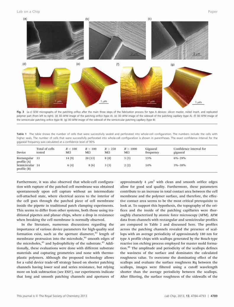
Fig. 3 (a–c) SEM micrographs of the patching orifice after the main three steps of the fabrication process for type A devices: silicon master, nickel insert, and replicated
polymer part (from left to right). (d) 3D AFM image of the patching orifice (type A). (e) 3D AFM image of the sidewall of the patching capillary (type A). (f) 3D AFM image of
the semicircular patching orifice (type B). (g) 3D AFM image of the sidewall of the semicircular patching capillary (type B).
Table 1 The table shows the number of cells that were successfully sealed and perforated into whole-cell configuration. The numbers include the cells withhigher seals. The number of cells that were successfully perforated into whole-cell configuration is shown in parentheses. The exact confidence interval for thegigaseal frequency was calculated at a confidence level of 90%
DeviceTotal of cellstested
R < 100MΩ
R > 100MΩ
R > 250MΩ
R > 1000MΩ
Gigasealfrequency
Confidence interval forgigaseal
Rectangularprofile (A)
33 14 (9) 20 (13) 8 (8) 5 (5) 15% 6%–29%
Semicircularprofile (B)
14 6 (4) 8 (6) 3 (3) 2 (2) 14% 3%–38%
Lab on a Chip Paper
Furthermore, it was also observed that whole-cell configura-tion with rupture of the patched cell membrane was obtainedspontaneously upon cell capture without an intermediatecell-attached state, where electrical access to the interior ofthe cell goes through the patched piece of cell membraneinside the pipette in traditional patch clamping experiments.This seems to differ from other systems, both those using tra-ditional pipettes and planar chips, where a drop in resistancewhen breaking the cell membrane is normally observed.
In the literature, numerous discussions regarding theimportance of various device parameters for high-quality sealformation exist, such as the aperture diameter,43 length ofmembrane protrusion into the microhole,44 smooth edges ofthe microholes,45 and hydrophilicity of the substrate.43 Addi-tionally, these evaluations were done with different substratematerials and capturing geometries and none with thermo-plastic polymers. Although the proposed technology allowsfor a valid device trade-off strategy based on shorter patchingchannels having lower seal and series resistance, but relyingmore on leak subtraction (see ESI†), our experiments indicatethat long and smooth patching channels and apertures of
This journal is © The Royal Society of Chemistry 2013
approximately 4 μm2 with clean and smooth orifice edgesallow for good seal quality. Furthermore, these parameterscontribute to an increase in total contact area between the cellmembrane and the polymer surface, and therefore, the effec-tive contact area seems to be the most critical prerequisite tolook at. To support this hypothesis, the topography of the ori-fices and the inside of the patching capillaries were thor-oughly characterized by atomic force microscopy (AFM). AFMdata from channels with rectangular and semicircular profilesare compared in Table 2 and discussed here. The profilesacross the patching channels revealed the presence of scal-lops with an average periodicity of approximately 180 nm fortype A profile chips with scallops generated by the Bosch-typereactive ion etching process employed for master mold forma-tion.46 The amplitude and periodicity of the scallops definesthe waviness of the surface and dominates the calculatedroughness value. To overcome the dominating effect of thescallops and evaluate the surface roughness Rq between thescallops, images were filtered using a cutoff wavelengthshorter than the average periodicity between the scallops.After filtering, the surface roughness of the sidewalls of the
Lab Chip, 2013, 13, 4784–4793 | 4789
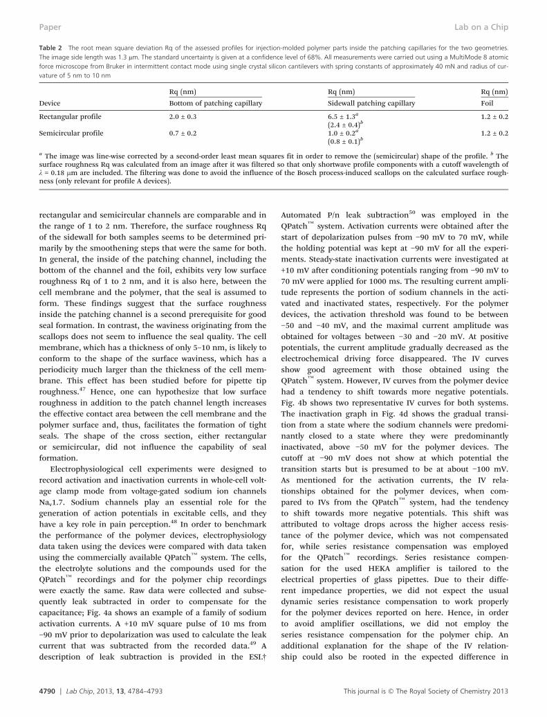
Table 2 The root mean square deviation Rq of the assessed profiles for injection-molded polymer parts inside the patching capillaries for the two geometries.The image side length was 1.3 μm. The standard uncertainty is given at a confidence level of 68%. All measurements were carried out using a MultiMode 8 atomicforce microscope from Bruker in intermittent contact mode using single crystal silicon cantilevers with spring constants of approximately 40 mN and radius of cur-vature of 5 nm to 10 nm
Device
Rq (nm) Rq (nm) Rq (nm)
Bottom of patching capillary Sidewall patching capillary Foil
Rectangular profile 2.0 ± 0.3 6.5 ± 1.3a 1.2 ± 0.2(2.4 ± 0.4)b
Semicircular profile 0.7 ± 0.2 1.0 ± 0.2a 1.2 ± 0.2(0.8 ± 0.1)b
a The image was line-wise corrected by a second-order least mean squares fit in order to remove the (semicircular) shape of the profile. b Thesurface roughness Rq was calculated from an image after it was filtered so that only shortwave profile components with a cutoff wavelength ofλ = 0.18 μm are included. The filtering was done to avoid the influence of the Bosch process-induced scallops on the calculated surface rough-ness (only relevant for profile A devices).
Lab on a ChipPaper
rectangular and semicircular channels are comparable and inthe range of 1 to 2 nm. Therefore, the surface roughness Rqof the sidewall for both samples seems to be determined pri-marily by the smoothening steps that were the same for both.In general, the inside of the patching channel, including thebottom of the channel and the foil, exhibits very low surfaceroughness Rq of 1 to 2 nm, and it is also here, between thecell membrane and the polymer, that the seal is assumed toform. These findings suggest that the surface roughnessinside the patching channel is a second prerequisite for goodseal formation. In contrast, the waviness originating from thescallops does not seem to influence the seal quality. The cellmembrane, which has a thickness of only 5–10 nm, is likely toconform to the shape of the surface waviness, which has aperiodicity much larger than the thickness of the cell mem-brane. This effect has been studied before for pipette tiproughness.47 Hence, one can hypothesize that low surfaceroughness in addition to the patch channel length increasesthe effective contact area between the cell membrane and thepolymer surface and, thus, facilitates the formation of tightseals. The shape of the cross section, either rectangularor semicircular, did not influence the capability of sealformation.
Electrophysiological cell experiments were designed torecord activation and inactivation currents in whole-cell volt-age clamp mode from voltage-gated sodium ion channelsNav1.7. Sodium channels play an essential role for thegeneration of action potentials in excitable cells, and theyhave a key role in pain perception.48 In order to benchmarkthe performance of the polymer devices, electrophysiologydata taken using the devices were compared with data takenusing the commercially available QPatch™ system. The cells,the electrolyte solutions and the compounds used for theQPatch™ recordings and for the polymer chip recordingswere exactly the same. Raw data were collected and subse-quently leak subtracted in order to compensate for thecapacitance; Fig. 4a shows an example of a family of sodiumactivation currents. A +10 mV square pulse of 10 ms from−90 mV prior to depolarization was used to calculate the leakcurrent that was subtracted from the recorded data.49 Adescription of leak subtraction is provided in the ESI.†
4790 | Lab Chip, 2013, 13, 4784–4793
Automated P/n leak subtraction50 was employed in theQPatch™ system. Activation currents were obtained after thestart of depolarization pulses from −90 mV to 70 mV, whilethe holding potential was kept at −90 mV for all the experi-ments. Steady-state inactivation currents were investigated at+10 mV after conditioning potentials ranging from −90 mV to70 mV were applied for 1000 ms. The resulting current ampli-tude represents the portion of sodium channels in the acti-vated and inactivated states, respectively. For the polymerdevices, the activation threshold was found to be between−50 and −40 mV, and the maximal current amplitude wasobtained for voltages between −30 and −20 mV. At positivepotentials, the current amplitude gradually decreased as theelectrochemical driving force disappeared. The IV curvesshow good agreement with those obtained using theQPatch™ system. However, IV curves from the polymer devicehad a tendency to shift towards more negative potentials.Fig. 4b shows two representative IV curves for both systems.The inactivation graph in Fig. 4d shows the gradual transi-tion from a state where the sodium channels were predomi-nantly closed to a state where they were predominantlyinactivated, above −50 mV for the polymer devices. Thecutoff at −90 mV does not show at which potential thetransition starts but is presumed to be at about −100 mV.As mentioned for the activation currents, the IV rela-tionships obtained for the polymer devices, when com-pared to IVs from the QPatch™ system, had the tendencyto shift towards more negative potentials. This shift wasattributed to voltage drops across the higher access resis-tance of the polymer device, which was not compensatedfor, while series resistance compensation was employedfor the QPatch™ recordings. Series resistance compen-sation for the used HEKA amplifier is tailored to theelectrical properties of glass pipettes. Due to their diffe-rent impedance properties, we did not expect the usualdynamic series resistance compensation to work properlyfor the polymer devices reported on here. Hence, in orderto avoid amplifier oscillations, we did not employ theseries resistance compensation for the polymer chip. Anadditional explanation for the shape of the IV relation-ship could also be rooted in the expected difference in
This journal is © The Royal Society of Chemistry 2013
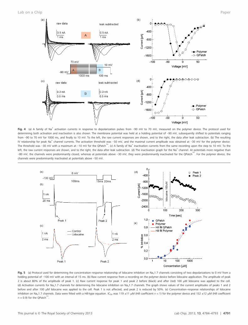
Fig. 5 (a) Protocol used for determining the concentration–response relationship of lidocaine inhibition on Nav1.7 channels consisting of two depolarizations to 0 mV from a
holding potential of −100 mV with an interval of 15 ms. (b) Raw current response from a recording on the polymer device before lidocaine application. The amplitude of peak
2 is about 80% of the amplitude of peak 1. (c) Raw current response for peak 1 and peak 2 before (black) and after (red) 100 μM lidocaine was applied to the cell.
(d) Activation currents for Nav1.7 channels for determining the lidocaine inhibition on Nav1.7 channels. The graph shows values of the current amplitudes of peaks 1 and 2
before and after 100 μM lidocaine was applied to the cell. Peak 1 is not affected, and peak 2 is reduced by 50%. (e) Concentration–response relationships of lidocaine
inhibition on Nav1.7 channels. Data were fitted with a Hill-type equation. IC50 was 119 ±11 μM (Hill coefficient n = 1) for the polymer device and 152 ±12 μM (Hill coefficient
n = 0.9) for the QPatch™.
Fig. 4 (a) A family of Na+activation currents in response to depolarization pulses from −90 mV to 70 mV, measured on the polymer device. The protocol used for
determining both activation and inactivation is also shown. The membrane potential was held at a holding potential of −90 mV, subsequently shifted to potentials ranging
from −90 to 70 mV for 1000 ms, and finally to 10 mV. To the left, the raw current responses are shown, and to the right, the data after leak subtraction. (b) The resulting
IV relationship for peak Na+channel currents. The activation threshold was −50 mV, and the maximal current amplitude was obtained at −30 mV for the polymer device.
The threshold was −30 mV with a maximum at −10 mV for the QPatch™. (c) A family of Na
+inactivation currents from the same recording upon the step to 10 mV. To the
left, the raw current responses are shown, and to the right, the data after leak subtraction. (d) The inactivation graph for the Na+channel. At potentials more negative than
−80 mV, the channels were predominantly closed, whereas at potentials above −30 mV, they were predominantly inactivated for the QPatch™. For the polymer device, the
channels were predominantly inactivated at potentials above −50 mV.
Lab on a Chip Paper
Lab Chip, 2013, 13, 4784–4793 | 4791This journal is © The Royal Society of Chemistry 2013

Lab on a ChipPaper
the mechanical state of the cell membrane in the poly-mer chip and the QPatch™. Such effects are known tocause shifting of the IV relationships.51 As we shall seein the following, this difference did not influence thepharmacological studies.
Dose–response experiments were carried out to furtherbenchmark the polymer device with a pharmacological appli-cation. Lidocaine inhibition of whole-cell sodium currentswas explored in voltage-clamped mode by application of lido-caine concentrations ranging from 30 μM to 1 mM. Theability of lidocaine to bind to sodium channels is statedependent, as lidocaine binds to the sodium channel in theinactivated state only.52 To explore state dependency, the cellwas depolarized twice at 0 mV for 100 ms and 20 ms, respec-tively, from a holding potential of −100 mV with a temporalseparation of 15 ms, see Fig. 5a. Depolarization was repeatedevery 5 seconds. Lidocaine response was studied at the startof the second pulse after the resting interval, during whichonly a portion of the sodium channels was able to recoverfrom inactivation. Fig. 5b shows a typical recording in theabsence of compound where the activation peak 2 was about80% of the size of the activation peak 1, used as a reference.When lidocaine was applied, reference peak 1 exhibited acurrent that was almost unchanged, while peak 2 was sub-stantially reduced. Fig. 5c shows activation currents from thesame cell before and after 100 μM lidocaine was delivered tothe cell. The current–time relationship for the peak sodiumcurrents recorded in response to the first (empty circle) andthe second (full circle) depolarization is shown in Fig. 5d.Inhibition is plotted against lidocaine concentration inFig. 5e. The amplitudes of sodium currents immediately priorto lidocaine application were set to 100%. Complete inhibi-tion was observed at 1 mM lidocaine, while the inhibitionwas only 20% at 30 μM lidocaine which was also the lowestconcentration applied. From Fig. 5d, it can be observed thatthe inhibition produced by lidocaine was reversible within60 seconds after its perfusion was stopped. For the polymerdevice, the half-blocking concentration IC50 was 119 ± 11 μM.This value is in excellent agreement with the IC50 of 152 ±11 μM found with the QPatch™. The Hill coefficients werealso very similar for the two systems.
Conclusions
We have demonstrated electrophysiological recordings on aninjection-molded polymer device platform for the first time.The results demonstrate that polymer APC devices can pro-vide whole-cell current responses from voltage-gated sodiumchannels and permit accurate analysis of drug potency forstate-dependent inhibitors such as for the local anestheticlidocaine. Moreover, the devices exhibit excellent data qualitywhen benchmarked against the commercially availableQPatch™ system. Formation of gigaseals (15% of the totalcells) between the polymer surfaces and the cell membraneswas achieved by making patching capillaries that allowed fora large sealing area. The length of the patching channel
4792 | Lab Chip, 2013, 13, 4784–4793
together with the low surface roughness on the inside of thepatching capillaries were identified as the most importantparameters for good seal formation. We attribute this obser-vation to indicate that a large effective sealing area betweenthe cell membrane and the polymer surface is required toobtain tight seals. Most likely, the exceptionally large sealingarea required for the polymer patching channels when com-pared to silica-based channels is necessary to assist sealingdue to slow van der Waals type interactions between the rela-tively low-energy polymer surface and the cell membrane.However, the long patching channels pose an engineeringchallenge for proper series resistance compensation whencompared to traditional glass pipette recordings. Finally, wehave successfully combined the simplicity of lateral corneredapertures with the use of injection molding to demonstratethe most cost-effective production and materials platform forAPC systems to date. The technological readiness level of thereported material and production platform is high, while thespecific design of the intra- and extracellular channels(Fig. 1a) is only aimed at prototyping. Thus, the Y-shapedpatching channel constitutes the only essential feature of ourmicrofluidic design, and channels for extra- and intracellularelectrolyte solutions could be designed differently for a muchsmaller unit footprint. For maintaining exactly the samefunctionality per functional chip unit, six inlet/outlet wellswould still be required. However, if we allow shared cell andcompound inlets, one chip unit will require only four ports.
Acknowledgements
We gratefully acknowledge financial support from the DanishAdvanced Technology Foundation through the AdvancedTechnology Project PILOC (grant no. 061-2010-1) and fromthe Danish Council for Strategic Research through the Strate-gic Research Center PolyNano (grant no. 10-092322/DSF).
References
1 E. Neher and B. Sakmann, Nature, 1976, 260, 799–802.
2 B. Hille, Ion Channels of Excitable Membranes, SinauerAssociates, Inc., Sunderland, MA, USA, 2001.3 F. Lehmann-Horn and K. Jurkat-Rott, Physiol. Rev., 1999, 79,
1317–1372.4 M. Ackerman and D. Clapham, N. Engl. J. Med., 1997, 336,
1575–1586.5 F. Ashcroft, Nature, 2006, 440, 440–447.
6 J. P. Overington, B. Al-Lazikani and A. L. Hopkins, Nat. Rev.Drug Discovery, 2006, 5, 993–996.7 A. Wickenden, B. Priest and G. Erdemli, Future Med. Chem.,
2012, 4, 661–679.8 J. Xu, X. Wang, B. Ensign, M. Li, L. Wu, A. Guia and J. Xu,
Drug Discovery Today, 2001, 6, 1278–1287.9 W. Zheng, R. Spencer and L. Kiss, Assay Drug Dev. Technol.,
2004, 2, 543–552.
This journal is © The Royal Society of Chemistry 2013
Lab on a Chip Paper
10 J. Xu, A. Guia, D. Rothwarf, M. Huang, K. Sithiphong,
J. Ouang, G. Tao, X. Wang and L. Wu, Assay Drug Dev.Technol., 2003, 1, 675–684.11 J. Dunlop, M. Bowlby, R. Peri, D. Vasilyev and R. Arias,
Nat. Rev. Drug Discovery, 2008, 7, 358–368.12 C. Wood, C. Williams and G. Waldron, Drug Discovery
Today, 2004, 9, 434–441.13 C. Farre, M. George, A. Bruggemann and N. Fertig,
Drug Discovery Today: Technol., 2008, 5, e23–e28.14 C. Farre and N. Fertig, Expert Opin. Drug Discovery, 2012, 7,
515–524.15 N. Fertig, R. Blick and J. Behrends, Biophys. J., 2002, 82,
3056–3062.16 M. Asmild, N. Oswald, K. Krzywkowski, S. Friis, R. Jacobsen,
D. Reuter, R. Taboryski, J. Kutchinsky, R. Vestergaard,R. Schroder, C. Sorensen, M. Bech, M. Korsgaard andN. Willumsen, Recept. Channels, 2003, 9, 49–58.17 C. Ionescu-Zanetti, R. Shaw, J. Seo, Y. Jan, L. Jan and L. Lee,
Proc. Natl. Acad. Sci. U. S. A., 2005, 102, 9112–9117.18 D. Martinez, C. Py, M. W. Denhoff, M. Martina, R. Monette,
T. Comas, C. Luk, N. Syed and G. Mealing, Biomed.Microdevices, 2010, 12, 977–985.19 A. Stett, V. Bucher, C. Burkhardt, U. Weber and W. Nisch,
Med. Biol. Eng. Comput., 2003, 41, 233–240.20 K. Klemic, J. Klemic, M. Reed and F. Sigworth, Biosens.
Bioelectron., 2002, 17, 597–604.21 X. Li, K. Klemic, M. Reed and F. Sigworth, Nano Lett.,
2006, 6, 815–819.22 B. Xu, Z. Liu, Y. Lee, A. Mak and M. Yang, Sens. Actuators, A,
2011, 166, 219–225.23 T. M. Suchyna, V. S. Markin and F. Sachs, Biophys. J.,
2009, 97, 738–747.24 C. Miller, Biophys. J., 2009, 97, 687–687.
25 A. Priel, Z. Gil, V. T. Moy, K. L. Magleby and S. D. Silberberg,Biophys. J., 2007, 92, 3893–3900.26 J. Israelachvili and H. Wennerstrom, Nature, 1996, 379,
219–225.27 M. Schulz, A. Olubummo and W. H. Binder, Soft Matter,
2012, 8, 4849–4864.28 V. Tandon, S. K. Bhagavatula and B. J. Kirby, Electrophoresis,
2009, 30, 2656–2667.29 V. Tandon, S. K. Bhagavatula, W. C. Nelson and B. J. Kirby,
Electrophoresis, 2008, 29, 1092–1101.30 V. Tandon and B. J. Kirby, Electrophoresis, 2008, 29,
1102–1114.31 J. Seo, C. Ionescu-Zanetti, J. Diamond, R. Lal and L. Lee,
Appl. Phys. Lett., 2004, 84, 1973–1975.
This journal is © The Royal Society of Chemistry 2013
32 A. P. Golden, N. Li, Q. Chen, T. Lee, T. Nevill, X. Cao,
J. Johnson, G. Erdemli, C. Ionescu-Zanetti, L. Urban andM. Holmqvist, Assay Drug Dev. Technol., 2011, 9, 608–619.33 B. Fermini, Top. Med. Chem., 2008, 3, 1–25.
34 E. Berthier, E. W. K. Young and D. Beebe, Lab Chip,2012, 12, 1224–1237.35 M. Matteucci, T. L. Christiansen, S. Tanzi, P. F. Ostergaard,
S. T. Larsen and R. Taboryski, Microelectron. Eng., 2013, 111,294–298.
36 H. Becker, Lab Chip, 2009, 9, 2759–2762.
37 S. Tanzi, P. F. Ostergaard, M. Matteucci, T. L. Christiansen,J. Cech, R. Marie and R. Taboryski, J. Micromech. Microeng.,2012, 22, 115008.
38 C. Chen and A. Folch, Lab Chip, 2006, 6, 1338–1345.
39 K. O. Andresen, M. Hansen, M. Matschuk, S. T. Jepsen,H. S. Sorensen, P. Utko, D. Selmeczi, T. S. Hansen,N. B. Larsen, N. Rozlosnik and R. Taboryski, J. Micromech.Microeng., 2010, 20, 055010.
40 W. Ong, K. Tang, A. Agarwal, R. Nagarajan, L. Luo and
L. Yobas, Lab Chip, 2007, 7, 1357–1366.41 J. Kutchinsky, S. Friis, M. Asmild, R. Taboryski,
S. Pedersen, R. Vestergaard, R. Jacobsen, K. Krzywkowski,R. Schroder, T. Ljungstrom, N. Helix, C. Sorensen, M. Bechand N. Willumsen, Assay Drug Dev. Technol., 2003, 1,685–693.42 C. J. Clopper and E. S. Pearson, Biometrika, 1934, 26,
404–413.43 K. Klemic, J. Klemic, M. Reed and F. Sigworth, Biosens.
Bioelectron., 2002, 17, 597–604.44 T. Sordel, F. Kermarrec, Y. Sinquin, I. Fonteille, M. Labeau,
F. Sauter-Starace, C. Pudda, F. d. Crecy, F. Chatelain,M. D. Waard, C. Arnoult and N. Picollet-D'hahan,Biomaterials, 2010, 31, 7398–7410.45 F. Sigworth and K. Klemic, Biophys. J., 2002, 82, 2831–2832.
46 R. Abdolvand and F. Ayazi, Sens. Actuators, A, 2008, 144,109–116.47 M. Malboubi, Y. Gu and K. Jiang, Microelectron. Eng.,
2010, 87, 778–781.48 F. Yu and W. Catterall, Genome Biol., 2003, 4, 207.
49 J. Dempster, in, ed. Anonymous, Academic Press, London,2001, pp. 172–225.50 F. Bezanilla and C. M. Armstrong, J. Gen. Physiol., 1977, 70,
549–566.51 D. Schmidt and R. MacKinnon, Proc. Natl. Acad. Sci. U. S. A.,
2008, 105, 19276–19281, DOI: 10.1073/pnas.0810187105.52 B. Bean, C. Cohen and R. Tsien, J. Gen. Physiol., 1983, 81,
613–642.
Lab Chip, 2013, 13, 4784–4793 | 4793