Spectra RMS Molded Case Circuit Breakers Application and ...
60
I Spectra RMS Molded Case Circuit Breakers Application and Selection c axressa,
-
Upload
khangminh22 -
Category
Documents
-
view
0 -
download
0
Transcript of Spectra RMS Molded Case Circuit Breakers Application and ...
I
Spectra RMSMolded Case Circuit BreakersApplication and Selection
c
axressa,
Courtesy of NationalSwitchgear.com

INTRODUCINGTHEFIRSTBREAKER LINEWITHUNIVERSALACCESSORIES.GE’S NEWSPECTRA RMSCIRCUITBREAKERSWITH
TM
0
Tableof P _ _its
2-3FeaturesStandard and CurrentLimitingCircuit BreakersMag-Break® MotorCircuit ProtectorsMolded Case SwitchesAccessories-Internal-ExternalElectrical Data-GeneralStandards-Selection Criteria•Amp Ratings•Current Rating
Factors•Examples•Interrupting Ratings 38-40•Interrupting Factors•Time-Current Curve
ChartsRelated PublicationsOutline DrawingsSTDA Flange Handles &Operating MechanismsGuide Form Specifications
4-10 1
*3
11-12 :%
y- !i%13-14 m15-25 m
•. .- .a$
16-191:120-25
26-41 *26-27 m28-41 ?!
28-29 mmm%mm330-35 aSI
36-37 # 141
Cl
42-44 FT45 i
si46-58li30 iis59 m60 i
$
Courtesy of NationalSwitchgear.com
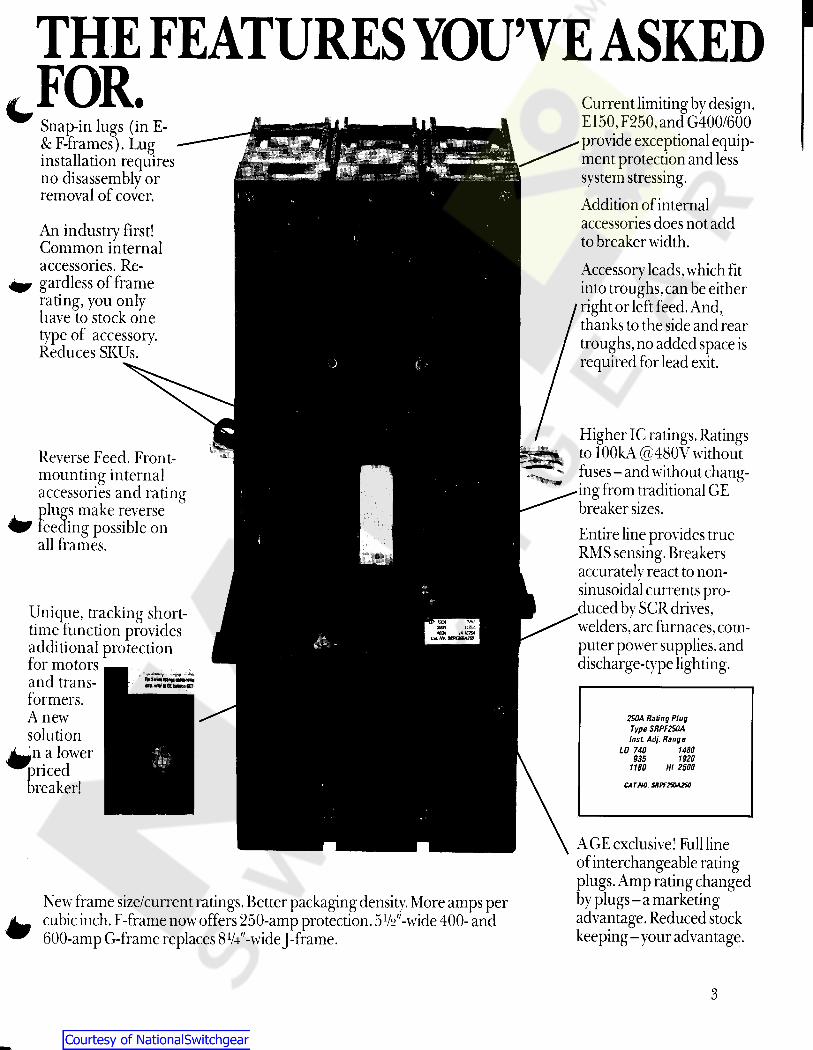
THE FEATURESYOU’VEASKEDFOR. Current limiting by design.
E150, F250, and G400/600provide exceptional equip-ment protection and lesssystem stressing.Addition of internalaccessories does not addto breaker width.Accessory leads, which fitinto troughs,can be eitherright or left feed. And,thanks to the side and reartroughs, noadded space isrequired for lead exit.
C Snap-in lugs (in E-& F-frames). Luginstallation requiresno disassembly orremoval of cover.
An industry first!Common internalaccessories. Re-gardless of framerating, you onlyhave to stock onetype of accessory.Reduces SKUs.
Higher IC ratings. Ratingsto lOOkA @480V withoutfuses-and without chang-ingfrom traditional GEbreaker sizes.Entire line provides trueRMSsensing. Breakersaccuratelv react to non-J
sinusoidal currents pro-duced by SCR drives,welders,arc furnaces,com-puter power supplies,anddischarge-type lighting.
Reverse Feed. Front-mounting internalaccessories and ratingplugs make reverse
Wf feeding possible onall frames.
Unique, tracking short-time function providesadditional protectionfor motorsand trans-formers.Anewsolution
j^n a lower^pricedbreaker!
F WOA smWSA
4£OA in ternC*L Ha. sxpfTsaxne
3m
a******mm
250A Rating PlugType SRPF250AInst Adj. Range
LO 740 14801920935
1180 HI 2500
CATHO. SAPf2S0A2S0
AGE exclusive! Full lineof interchangeable ratingDlugs. Amp ratingchanged)y plugs-a marketingadvantage.Reduced stockkeeping-your advantage.
New frame size/current ratings. Better packaging density. More amps percubic inch. F-frame nowoffers 250-amp protection.5V2"-wide 400- and600-amp G-frame replaces 8V4"-wideJ-frame.
y
3
Courtesy of NationalSwitchgear.com
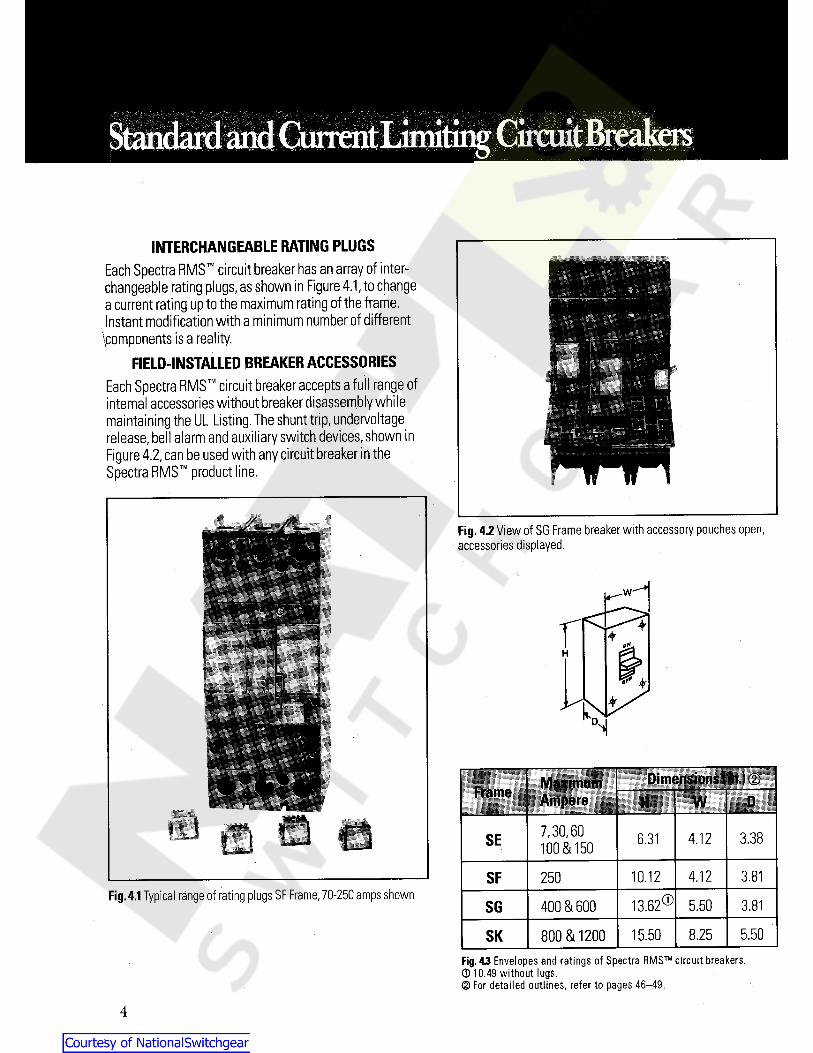
INTERCHANGEABLE RATING PLUGSEach Spectra RMS circuit breaker has an array of inter-changeable rating plugs,as shown in Figure 4.1,to changea current rating up to the maximum rating of the frame.Instant modification with a minimum number of different
^components is a reality.FIELD-INSTALLED BREAKER ACCESSORIES
Each Spectra RMS circuit breaker accepts a full range ofinternal accessories without breaker disassembly whilemaintaining the UL Listing. The shunt trip,undervoltagerelease,bel alarm and auxiliary switch devices,shown inFigure 4.2,can be used with any circuit breaker in theSpectra RMS product line.
Fig. 4.2 View of SG Frame breaker with accessory pouches openaccessories displayed.
w
*+H
&**NDimensions fin.) (2)Maximum
AmpereFrame W IH7,30,60100 & 150 3.384.12SE 6.31
10.12 4.12SF 3.81250Fig.4.1Typical range of rating plugs SF Frame,70-250 amps shown
13.62®400 & 600 5.50SG 3.81
5.50800 & 1200 15.50 8.25SKFig. 43 Envelopes and ratings of Spectra RMS circuit breakers.0 10.49 without lugs.0 For detailed outlines, refer to pages 46-49.
4
Courtesy of NationalSwitchgear.com
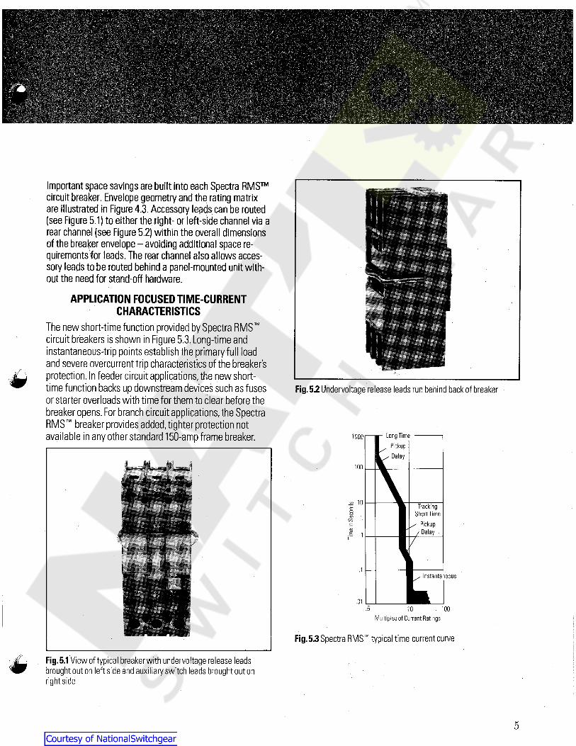
Important space savings arebuilt into each Spectra RMScircuit breaker. Envelope geometry and the rating matrixare illustrated in Figure 4.3. Accessory leads can be routed(see Figure 5.1) to either the right- or left-side channel via arear channel (see Figure 5.2) within the overall dimensionsof the breaker envelope-avoiding additional space re-quirementsfor leads. The rear channel also allows acces-sory leads tobe routed behind a panel-mounted unit with-out the need for stand-off hardware.
APPLICATION FOCUSEDTIME-CURRENTCHARACTERISTICS
The new short-time function provided by Spectra RMScircuit breakers is shown in Figure 5.3.Long-time andinstantaneous-trip points establish the primary full loadand severe overcurrent trip characteristics of the breakersprotection. In feeder circuit applications,the new short-time function backs up downstream devices such as fusesor starter overloads with time for them to clear before thebreaker opens. For branch circuit applications, the SpectraRMS breaker provides added,tighter protection notavailable in any other standard150-amp frame breaker.
TM
Fig.5.2 Undervoltage release leads run behind back of breaker
LongTime, Pickup
^ Delay
1000
100
-S 10 TrackingShort Time
/ Pickup/ Delay
coCD
COc:CD
i 1p 7
.1Instantaneous
.01.5 . 100
Multiples of Current Ratings10
Fig.5.3 Spectra RMS typical time-current curvex-' Fig.5.1 View of typical breaker with under voltage release leads
brought out on left side and auxiliary switch leads brought out onrightside
5
Courtesy of NationalSwitchgear.com
ircuitBreakers
1000HIGHER INTERRUPTING CAPACITIESModern power distribution systems require higher IC(Interrupting Capacity) protective devices. Each SpectraRMS circuit breaker is available in three IC ranges:25 kA (25,000 amps),65 kA and100 kA,rms,symmetrical,at 480 Vac.The neyv SE-Frame is also available with an ICof 14 kA,rms,symmetrical.
Interrupting capacity ratings are detailed in Tables39.1 and 40.1,pages 39 and 40.
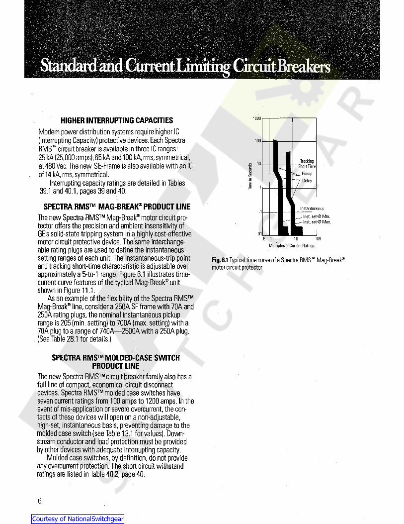
SPECTRA RMS MAG-BREAK"0 PRODUCT LINEThe new Spectra RMS Mag-Break® motor circuit pro-tector offers the precision and ambient insensitivity ofGE's solid-state tripping system in a highly cost-effectivemotor circuit protective device.The same interchange-able rating plugs are used to define the instantaneoussetting ranges of each unit. The instantaneous-trip pointand tracking short-time characteristic is adjustable overapproximately a 5-to-1 range. Figure 6.1 illustrates time-current curve features of the typical Mag-Break® unitshown in Figure 11.1.
As an example of the flexibility of the Spectra RMSMag-Break® line,consider a 250A SF frame with 70A and250A rating plugs, the nominal instantaneous pickuprange is 205 (min. setting) to 700A (max. setting) with a70A plug to a range of 740A—2500A with a 250A plug.(See Table 28.1 for details.)
100
TrackingShort Time
^ Pickup7 Delay
8 10co
cn
P 7
Instantaneous.1Inst, set @ Min.Inst, set @ Max.
.01100.5 1 10
Multiples of Current Ratings
Fig.6.1 Typical time curve of a Spectra RMS Mag-Break®
motor circuit protector
TM
SPECTRA RMS MOLDED-CASE SWITCHPRODUCT LINE
The new Spectra RMS circuit breaker family also has afull line of compact,economical circuit disconnectdevices. Spectra RMS molded case switches haveseven current ratings from 100 amps to 1200 amps. In theevent of mis-application or severe overcurrent, the con-tacts of these devices will open on a non-adjustable,high-set, instantaneous basis, preventing damage to themolded case switch (see Table 13.1 for values). Down-stream conductor and load protection must be providedby other devices with adequate interrupting capacity.
Molded case switches,by definition, do not provideany overcurrent protection. The short circuit withstandratings are listed in Table 40.2, page 40.
6
Courtesy of NationalSwitchgear.com
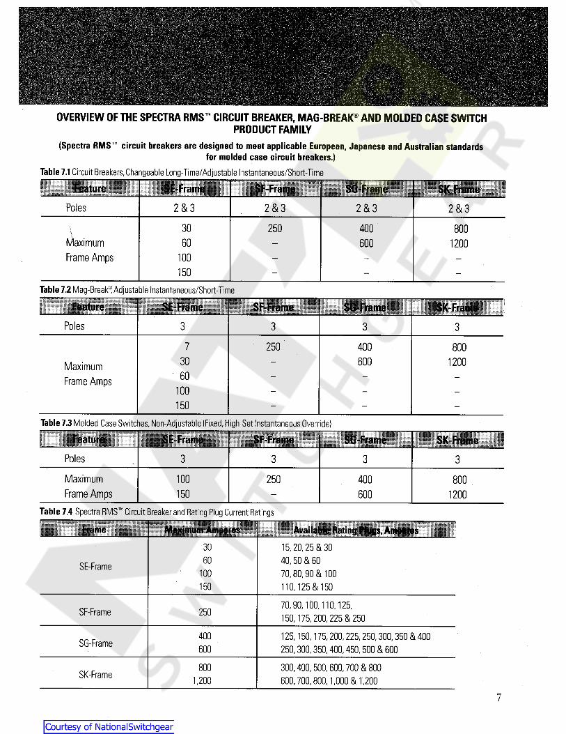
OVERVIEW OF THE SPECTRA RMS CIRCUIT BREAKER, MAG-BREAK® AND MOLDED CASE SWITCHPRODUCT FAMILY
(Spectra RMS circuit breakers are designed to meet applicable European, Japanese and Australian standardsfor molded case circuit breakers.)
Table 7.1 Circuit Breakers,Changeable Long-Time/Adjustable Instantaneous/Short-Time
Feature SE-Frame jy-Frame SG-Frame SK-FramePoles 2 & 3 2 & 3 2 & 3 2 & 3
30 250 400 800\MaximumFrame Amps
60 600 1200100150
Table 7.2Mag-Break® Adjustable Instantaneous/Short-Time
sill SE-Frame SF-Frame SG-Frame SK-FramePoles 3 3 3 3
7 250 400 80030 600 1200Maximum
Frame Amps 60100150
Table 7.3 Molded Case Switches,Non-Adjustable (Fixed,High-Set Instantaneous Override)
Feature SE-Frame SG-Frame SK-FramePoles 3 3 3 3
MaximumFrame Amps
100 250 400 800150 600 1200
Table 7.4 Spectra BMS Circuit Breaker and Bating Plug Current Ratings
Frame Available Rating Plugs, Amperes15, 20, 25 & 3040, 50 & 6070, 80, 90 & 100110,125 & 150
;i :: ;; ; ; :: i :: i1; r ; Ibiiii
3060SE-Frame
100150
70, 90, 100, 110,125,150, 175, 200, 225 & 250SF-Frame 250
400 125, 150, 175, 200, 225, 250, 300, 350 8t 400250, 300, 350, 400, 450, 500 8i 600SG-Frame 600
800 300, 400, 500, 600, 700 8( 800600,700, 800, 1,000 8( 1,200SK-Frame 1,200
7
Courtesy of NationalSwitchgear.com
THE SPECTRA RMS RATING PLUG CONCEPTAll Spectra RMS circuit breakers use a UL Listed inter-changeable rating plug to establish or change the long-time trip point of the circuit breaker. The adjusting knobat the front of the circuit breaker enables the user toadjust the instantaneous-trip setting and the short-timeportion of the brekker's time-current curve.The ratingplug operates as a ratioing circuit for the breaker's inter-nal current sensors. The instantaneous pickup range is inmultiples of the installed rating plug.
The key advantage of the Spectra RMS rating-plugconcept is the flexibi ity of interchangeable rating plugsacross the permissible current ratings of a given circuitbreaker frame. Since the installed rating plug establishesthe amp rating of the breaker, the installer must verify theadequacy of the connected cable and/or bus bar ampaci-ty. The National Electrical Code allows cable size to bematched to the amp rating established by the rating plug.
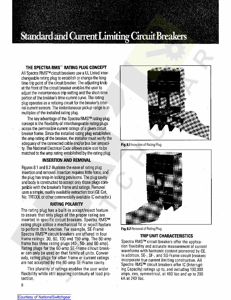
INSERTION AND REMOVALFigures 8.1 and 8.2 illustrate the ease of rating pluginsertion and removal. Insertion requires little force,andthe plug has snap-in locking provisions.The plug cavityand body is constructed to accept only those plugs com-patible with the breaker's frame and ratings. Removaluses a simple, readily available extraction tool (GE Cat.No. TRFOOL or other commercially available IC extractor.)
RATING POLARITYThe rating plug has a built-in accept/reject featureto assure that only plugs of the proper rating areinserted in specific circuit breakers. Spectra RMSrating plugs utilize a mechanical fit or reject featureto perform this function. For example, SE-FrameSpectra RMS circuit breakers are offered in fourframe ratings: 30, 60, 100 and 150 amp. The 60-ampframe has three rating plugs (40-, 50- and 60-amp .Rating plugs for the 60-amp SE-Frame circuit break-er can only be used on that family of units. Conver-sely, rating plugs for other frame or current ratingsare not accepted by the 60-amp SE-Frame cavity.
This plurality of ratings enables the user widerflexibility while still assuring continuity of load pro-tection.
Fig.8.1 Insertion of Hating Plug
TM
Fig.8.2 Removal of Rating Plug
TRIP UNIT CHARACTERISTICSSpectra RMS circuit breakers offer the applica-tion flexibility and accurate measurement of currentwaveforms with harmonic content pioneered by GE.In addition, SE-, SF-, and SG-Frame circuit breakersincorporate true current limiting construction. AllSpectra RMS circuit breakers offer IC (Interrupt-ing Capacity) ratings up to, and including 100,000amps, rms, symmetrical, at 480 Vac and up to 200kA at 240 Vac.
8
Courtesy of NationalSwitchgear.com
5®m
ismsm
mmmy
Long TimeI Pickup
Delay
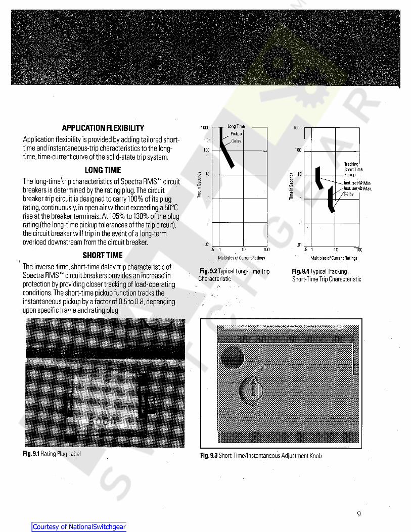
APPLICATIONFLEXIBILITYApplication flexibility is provided by adding tailored short-time and instantaneous-trip characteristics to the long-time,time-current curve of the solid-state trip system.
LONG TIMEThe long-timetrip characteristics of Spectra RMS circuitbreakers is determined by the rating plug.The circuitbreaker trip circuit is designed to carry 100% of its plugrating,continuously,in open air without exceeding a 50°Crise at the breaker terminals. At 105% to 130% of the plugrating (the long-time pickup tolerances of the trip circuit)the circuit breaker will trip in the event of a long-termoverload downstream from the circuit breaker.
SHORT TIMEThe inverse-time, short-time delay trip characteristic ofSpectra RMS circuit breakers provides an increase inprotection by providing closer tracking of load-operatingconditions. The short-time pickup function tracks theinstantaneous pickup by a factor of 0.5 to 0.8,dependingupon specific frame and rating plug.
10001000
100100
TrackingA Short Timefl- Pickup
^ ~~ —— Inst. $et @ Min.W A /Inst, set ® Max.
/Delay
1-8 10-8 10c
a oCD CDC/3 CO£= eCD CDE Ei= 1
7
.1.1i
.01 .01.5 1 0 10010 100.5 1
Multiples of Current Ratings Multiples of Current Ratings
Fig.9.2 Typical Long-Time TripCharacteristic
Fig.9.4 Typical TrackingShort-Time Trip Characteristic
• . *
Fig.9.1 Rating Plug Label Fig.9.3 Short-Time/lnstantaneous Adjustment Knob
9
Courtesy of NationalSwitchgear.com

1000INSTANTANEOUSThe trip setting adjustment knob of Spectra RMS circuitbreakers controls the settings of both short-time andinstantaneous-trip characteristics. When the adjustmentknob is set in its "Max." position,the breaker will nomi-nally trip ori\instantaneously at between 10 times to 13times (depending uponbreaker frame) its long-time triprating (i.e., rating plug amp rating). This provides suffi-cient margin to override load inrush (e g.,motor trans-
former, etc.) current.The nominal instantaneous pickup values, in amps,
are listed on each rating plug,as shown in Figure 9.1.Figure 10.1 shows the typical adjustability of instanta-
neous settings.
100
-g 10o
GO
£ 1
S BH Instantaneous|| B.— Inst. set @ Mfn.
Inst, set @ Max.,1
.01100.5 1 10
Multiples of Current RatingsSPECTRA RMS CURRENT LIMITING
CONSTRUCTIONSpectra RMS circuit breakers continue the GE standardof rugged construction and the use of heavy silver-alloycontacts.The low physical mass of the circuit contact armsin SE-,SF-, and SG-Frame Spectra RMS circuit breakers,coupled with a reverse current loop,provide a true currentlimiting function without compromising breaker life orperformance.
When short-circuit current flows through the lowerand upper contact arms of the circuit breaker,a strongmagnetic field is produced by the fault current.Since thefields are opposing, forces proportional to the square ofthe current act to force the two contact arms apart.Thehigher the fault current,the higher the contact separationforces.During maximum fault conditions,contact separa-tion typically occurs within a quarter of one cycle,and thearc is fully quenched within eight milliseconds. 6
Peak let-through current, illustrated in Figure 10.2, isheld to less than 45% of the maximum available peak faultcurrent,resulting in tremendous reduction in the energy ashort-circuit delivers to both conductors and connectedloads.
Fig.10.1Typical Instantaneous Adjustment
Available Peak Current- 223.5 kAVoltage- 485 V
Power Factor- 18.1%/v— Peak let thru-37.7 kA
V2 cycle
— Peak let thru- 29.8 kA
Peak let thru- 17.3 kA
Fig.10.2 Typical Current Limiting Performance
For specific SE, SF and SG UL listed current limitingcircuit breaker frames refer to Table 39.1.
10
Courtesy of NationalSwitchgear.com

SPECTRA RMS MAG-BREAK® MOTORCIRCUIT PROTECTORS
Interchangeable Rating Plug.Spectra RMSMag-Break® motor circuit protectors use the same snap-inrating plugs as fully configured (long-time trip function)Spectra RMS circuit breakers. Each rating plug definesthe range Of instantaneous-trip settings available to thecircuit breaker through its trip setting adjustment.Trip Setting Adjustment. The solid-state instantaneous-trip circuitry of the Spectra RMS Mag-Break® motorcircuit protectors has a single,multi-position adjustmentat the front of each breaker.Changes in settings vary theinstantaneous-trip and tracking short-time characteristics.The Mag-Break® motor circuit protectors differ from a fullyconfigured circuit breaker by providing only an instantane-
ous and tracking short-time trip function.Accessory Pockets. Spectra RMS Mag-Break®
motor circuit protectors have the same accessory pocketsand use the same internal accessories as Spectra RMScircuit breakers. This important capability allows fieldmodification of Mag-Break® units with shunt trip, under-voltage release,bell alarm, or auxiliary switch acces-
sories, in any combination,without affecting UL Listingstatus.
SPECTRA RMS RATING PLUGSUse of the same UL Listed interchangeable rating plugsfor both Mag-Break® and fully configured Spectra RMScircuit breakers expands the flexibility of the entire SpectraRMS family of products.The advantages of interchange-able rating plugs with Spectra RMS circuit breakers areinherent to Spectra RMS Mag-Break® units,which per-mit wider ranges of motor ratings to be protected by agiven breaker frame size.
SPECTRA RMS MAG-BREAK® TRIP UNITCHARACTERISTICS
Spectra RMS Mag-Break® motor circuit protectors pro-
vide positive,reliable, and cost-effective instantaneous,with short-time tracking,overcurrent protection to thosecircuits where long-time overload protection is supplied bythermal or solid-state overload devices.
MOTOR CIRCUIT SHORT-CIRCUIT PROTECTION
TM
TMWhen a squirrel-cage induction motor is first energized,ahigh value of magnetizing inrush current flows for the firstfew cycles,followed by a substantially reduced currentflow while the motor accelerates to its rated speed.Typi-cally,the magnetizing inrush current may be 10 times ratedfull-load current for normal efficiency motors and as highas 14 times rated full-load current for high-efficiencymotors prior to the first five to eight cycles. Magnetizinginrush cuirent is followed by a "locked rotor" cuirentof 5 to 6 times rated full-load cuirent during the 0.1- to10-second acceleration phase — with current rapidlydeclining to full load amperes as the motor nears ratedspeed.
Optimum instantaneous protection would have atwo-tiered tripping characteristic. A high value of currentwould be tolerated for a few cycles, followed by a lower,sustained trip setting.
That is exactly what is found in the Mag-Break®
tripping characteristic.Use of this two-tiered time-current curve prevents
nuisance tripping due to magnetizing inrush current,with-
out compromising superior short-circuitprotection duringmotor acceleration as indicated in Figure 13.1.
Fig. 11.1 SE150 Spectra RMS Mag-Break® Motor Circuit Protector
11
Courtesy of NationalSwitchgear.com
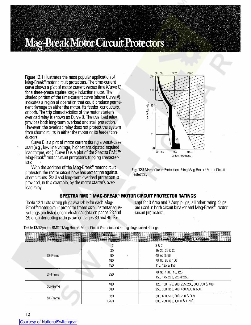
50 100 1000 10000Figure 12.1 illustrates the most popular application ofMag-Break® motor circuit protectors. The time-currentcurve shows a plot of motor current versus time (Curve C)for a three-phase squirrel cage induction motor. Theshaded portion of the time-current curve (above Curve A)indicates a region of operation that could produce perma-nent damage fo either the motor, its feeder conductors,or both. The trip characteristics of the motor starter'soverload relay is shown as Curve B. The overload relayprovides both long-term overload and stall protection.However, the overload relay does not protect the systemfrom short circuits in either the motor or its feeder con-ductors.
Curve C is a plot of motor current during a worst-casestart (e g., low line voltage,highest anticipated requiredload torque, etc.). Curve D is a plot of the Spectra RMSMag-Break® motor circuit protector's tripping characteristic.
With the addition of the Mag-Break® motor circuitprotector, the motor circuit now has protection againstshort circuits. Stall and long-term overload protection isDrovided, in this example,by the motor starter's over-oad relay.
1000
100
f 10oCDtocCDE
0.1
.01TM 50 100 1000
Current in Amperes10000
Fig. 12.1Motor Circuit Protection Using Mag-Break® Motor CircuitProtectors
SPECTRA RMS MAG-BREAK® MOTOR CIRCUIT PROTECTOR RATINGScept for 3 Amp and 7 Amp plugs,all other rating plugsare used in both circuit breaker and Mag-Break® motorcircuit protectors.
Table 12.1 lists rating plugs available for each Mag-
Break® motor circuit protector frame size. Instantaneous-settings are listed under electrical data on pages 28 and29 and interrupting ratings are on pages 39 and 40. Ex-
Table 12.1Spectra RMS Mag-Break® Motor Circuit Protector and Rating Plug Current RatingsCircuit Breaker
FrameMaximum
Frame Amperes Available Rating Plugs, Amperes3 & 7715, 20,25. & 3040, 50 & 6070, 80,90 8t 100110,125 & 150
30SE-Frame 60
100150
70, 90, 100, 110,125150, 175, 200, 225 8( 250
SF-Frame 250
125, 150,175, 200, 225, 250, 300, 350 & 400250, 300,350, 400, 450,500 & 600
400SG-Frame600
300, 400, 500, 600, 700 & 800600, 700, 800, 1,000 8t 1,200
800SK-Frame1,200
12
Courtesy of NationalSwitchgear.com

MOLDED CASE SWITCHConstruction. The family traditions of ruggedness anddependability are continued in the Spectra RMS moldedcase switch line.These units provide a circuit disconnectfunction using the compactness of molded case circuitbreaker construction.The operating handle actuates allthree poles of the switch using the same common trip barof Spectra RMS circuit breakers and Mag-Break® units.Termination Lugs. Snap-in termination lugs used withSE- and SF-Frame Spectra RMS circuit breakers are usedinterchangeably in Spectra RMS molded case switches.SG- and SK-Frame molded case switches use the samebolt-on termination lugs used with Spectra RMS circuitbreakers.External Accessories. The full range of external circuitbreaker accessories offered for use with Spectra RMScircuit breakers and Mag-Break® motor circuit protectors,are available for molded case switches. Figure 13.1shows a Spectra RMS molded case switch. In addition,plug-in bases,motor-operated mechanisms,mechanicalinterlocks,and the full complement of external handleoperators (STDA,TDR, and TDM) are available for usewith Spectra RMS molded case switches.Fixed-Trip Setting. The Spectra RMS molded caseswitches are equipped with a fixed Hi-set instantaneoustrip setting whose values are shown in Table 13.1
TM
Fig. 13.1 Spectra RMS"1 Molded Case Switch
Table 13.1 Spectra RMS Molded-Case Switch Fixed Trip Setting
Fixed Trip SettingRMS AmperesNominal± 20%
Molded CaseSwitch Frame Rating
100SE-Frame 2,100150
SF-Frame 250 2,450400 5,600
SG-Frame6,000600
800 12,750SK-Frame
12,6001,200
13
Courtesy of NationalSwitchgear.com
SPECTRA RMS MOLDED CASE SWITCHAPPLICATIONS )Molded Case Circuit Breaker
Molded case switches are inherently horsepower-rated.By virtue of the UL489 six-times-rated current overloadtest they can be used as motor circuit disconnects whereoverload and\short-circuit protection are provided by otherprotective devices.
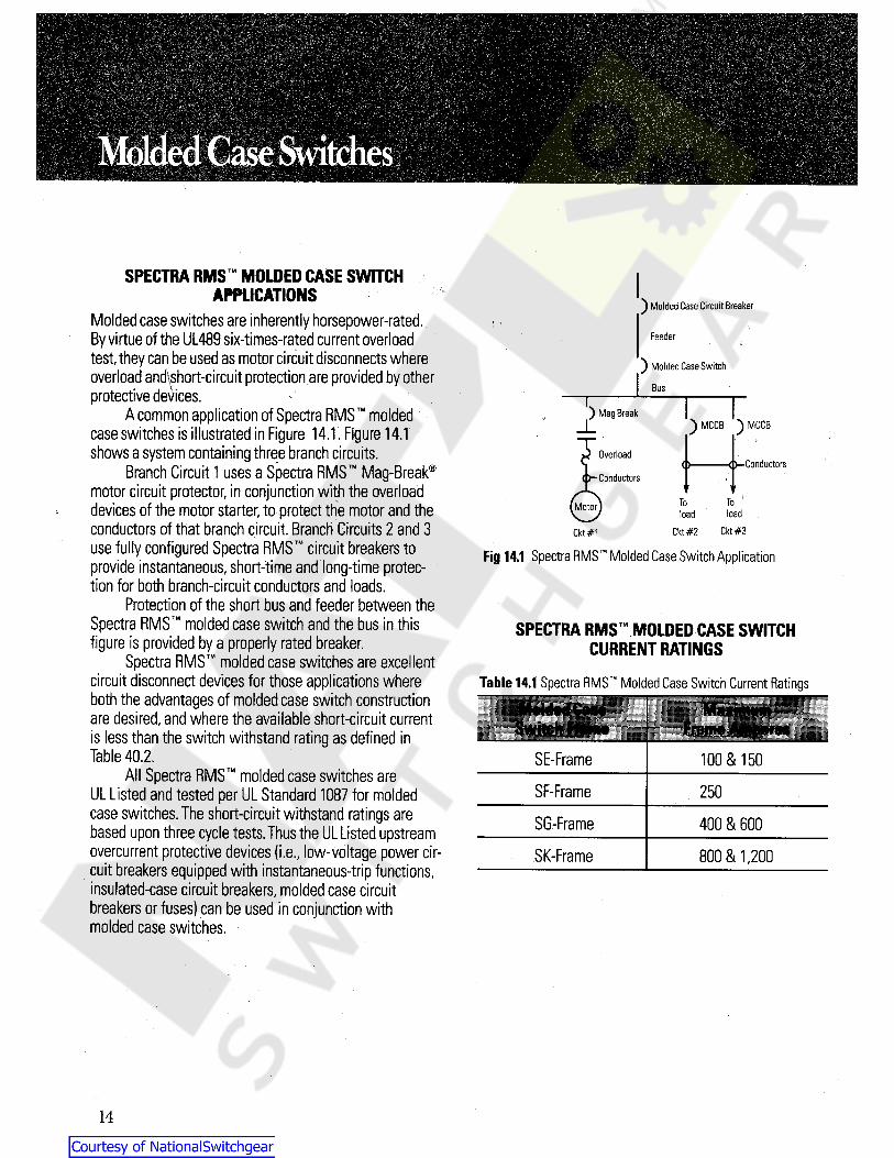
A common application of Spectra RMS moldedcase switches is illustrated in Figure 14.1. Figure 14.1shows a system containing three branch circuits.
Branch Circuit 1 uses a Spectra RMS Mag-Break®
motor circuit protector, in conjunction with the overloaddevices of the motor starter, to protect the motor and theconductors of that branch circuit. Branch Circuits 2 and 3use fully configured Spectra RMS circuit breakers toprovide instantaneous, short-time and long-time protec-tion for both branch-circuit conductors and loads.
Protection of the short bus and feeder between theSpectra RMS molded case switch and the bus in thisfigure is provided by a properly rated breaker.
Spectra RMS molded case switches are excellentcircuit disconnect devices for those applications whereboth the advantages of molded case switch constructionare desired,and where the available short-circuit currentis less than the switch withstand rating as defined inTable 40.2.
Feeder
) Molded Case Switch
BusT) Mag Break
) MCCB ) MCCB
Overload< >-Conductors
Conductors
ToToMotor loadloadCkt #2 Ckt #3Ckt #1
Fig 14.1 Spectra RMS Molded Case Switch Application
SPECTRA RMS MOLDED CASE SWITCHCURRENT RATINGS
Table 14.1 Spectra RMS Molded Case Switch Current Ratings
SE-Frame 100 & 150All Spectra RMS molded case switches are
UL Listed and tested per UL Standard 1087 for moldedcase switches.The short-circuit withstand ratings arebased upon three cycle tests.Thus the UL Listed upstreamovercurrent protective devices (i.e„ low-voltage power cir-cuit breakers equipped with instantaneous-trip functions,insulated-case circuit breakers,molded case circuitbreakers or fuses) can be used in conjunction withmolded case switches.
SF-Frame 250
SG-Frame 400 & 600
SK-Frame 800 & 1,200
14
Courtesy of NationalSwitchgear.com
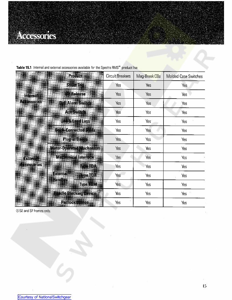
Table 15.1 Internal and external accessories available for the Spectra RMS product line
Circuit BreakersProduct Mag-Break CBs Molded Case Switches
Shunt Trip Yes Yes Yes
UV Release Yes Yes YesInternalAccessories
i
Bell Alarm Switch Yes Yes Yes
YesAux Switch Yes Yes
Line & Load Lugs Yes Yes Yes
Back-Connected Studs Yes Yes Yes
Plug-in Bases Yes Yes Yes
Motor-Operated Mechanism Yes Yes Yes
Mechanical Interlock Yes Yes YesExternalAccessories Type TDA Yes Yes Yes
ExternalHandles
Type TDR YesYes Yes
Type TDM Yes Yes YesCDHandle Blocking Device Yes Yes Yes
i
Padlock Device YesYes Yes
® SE and SF frames only.
15
Courtesy of NationalSwitchgear.com
fetyr-
latassmmm
3 I . , 11«« -3 - : ; V : 3 3:,33
SHUNT TRIPThe shunt trip is used to trip (open) the circuit breaker byremote control.Spectra RMS shunt trips are UL Listed forfield installation,meeting UL requirements for operation at55% of rated ac voltage and 75% of rated dc voltage foruse on ground fault systems.
Spectra RMS Shunt Trips are common to all circuitbreakers and switches in the Spectra RMS productfamily.
Spectra RMS internal accessories are common toall products in the Spectra RMS product family, includ-ing circuit breakers,Mag-Break® motor circuit protectors,and molded case switches. They are interchangeable be-tween frame sizes, i.e., the 24 Vdc/24 Vhc shunt trip -SAST3-can be installed in any of the four basic framesfrom the type SE150 to the type SK1200. In addition,Spectra RMS internal accessories are designed to beinstalled in pockets accessible fromthe front of the cir-cuit breaker. For remote tripping of breaker,use with momentary
close contact. Not recommended for use with latchingrelay contact since electronics in Shunt Trip will pulsepower to the coil if continuously energized,and breakertripping upon reclosure will be delayed1-2 seconds atrated control voltage. Note: Overcurrent tripping is notaffected, as is shown in Fig. 5.3.
If maintained (latching relay) contact must be usedand delayed shunt tripping is not acceptable,use bellalarm in series with control power for SE150 and SF250frames and auxiliary switch for SG600 and SK1200breakers.
NO DISASSEMBLY OF THE CIRCUIT BREAKER CASEIS REQUIRED.
These unique characteristics — interchangeability,commonality, and installation without violation of caseintegrity-provide the user with the optimum combinationof reliability, standardization and parts reduction. ALLSPECTRA RMS ACCESSORIES ARE UL LISTED FORFIELD INSTALLATION.
The left-hand circuit breaker accessory pocket ac-cepts either a shunt trip or an undervoltage release, plus abell alarm. The right-hand pocket is used for auxiliaryswitches. All accessories are supplied with 36-inch long,# 18AWG 105°C 300V minimum insulated leads. Sideand rear wire channels allow accessory leads to beled to the left, right, or back of the breaker within thedimensions of the breaker envelope.
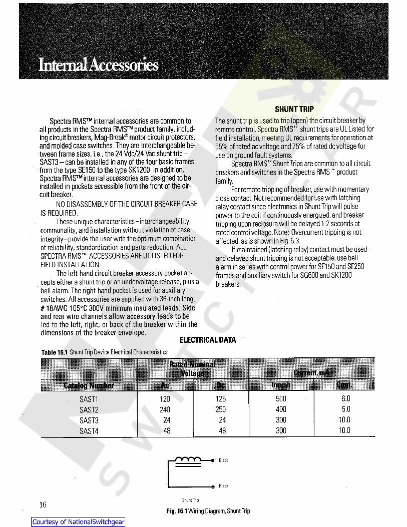
ELECTRICAL DATATable 16.1 Shunt Trip Device Electrical Characteristics
E . ««•>
Current,mAr\St
Catalog Number Cont.InrushAc6.0500SAST1 120 125
400 5.0SAST2SAST3SAST4
240 25024 300 10.02448 300 10.048
Black
Black
Shunt Trip16
Fig. 16.1Wiring Diagram,Shunt Trip
Courtesy of NationalSwitchgear.com
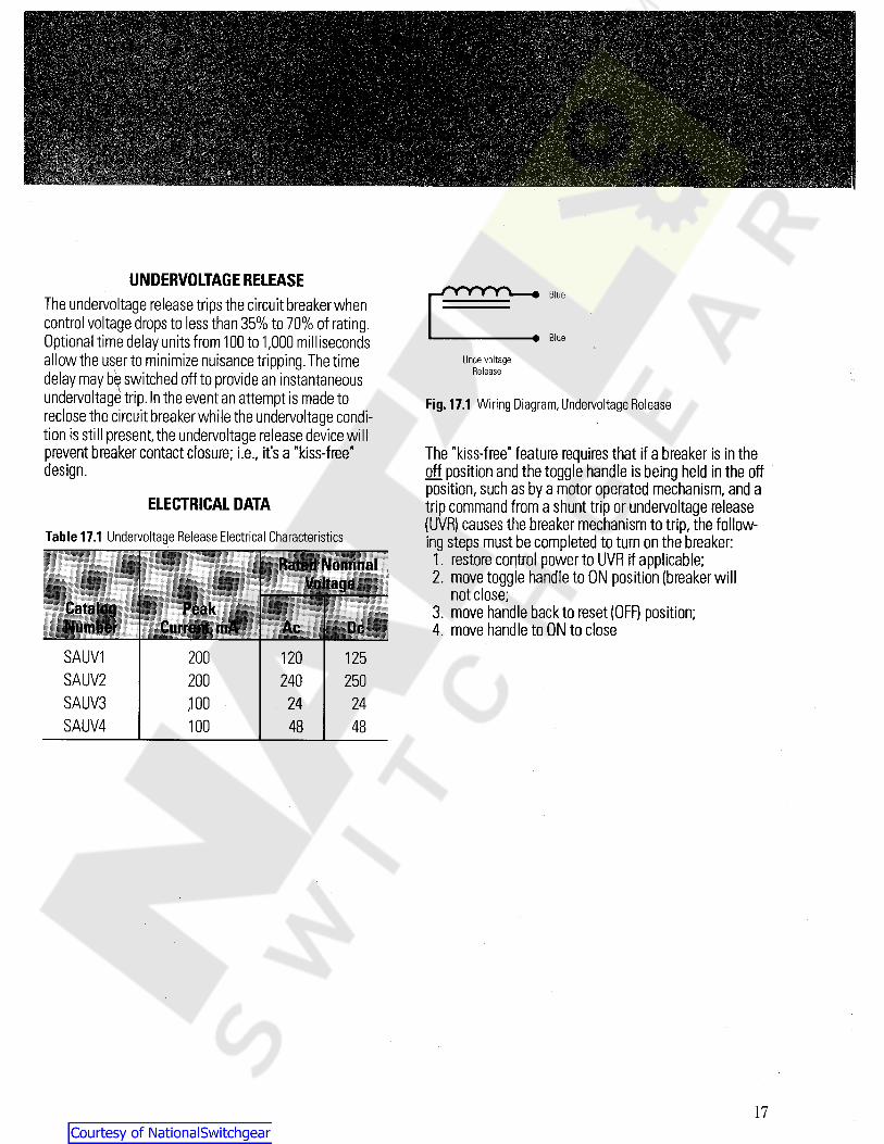
UNDERVOLTAGE RELEASEThe undervoltage release trips the circuit breaker whencontrol voltage drops to less than 35% to 70% of rating.Optional time delay units from 100 to 1,000 millisecondsallow the user to minimize nuisance tripping.The timedelay may bp switched off to provide an instantaneousundervoltage trip. In the event an attempt is made toreclose the circuit breaker while the undervoltage condi-tion is still present, the undervoltage release device willprevent breaker contact closure; i.e., it's a “kiss-free"design.
Blue
# Blue
UndervoltageRelease
Fig. 17.1 Wiring Diagram,Undervoltage Release
The “kiss-free" feature requires that if a breaker is in theoff position and the toggle handle is being held in the offposition, such as by a motor operated mechanism,and atrip command from a shunt trip or undervoltage release(UVR) causes the breaker mechanism to trip, the follow-ing steps must be completed to turn on the breaker;1. restore control power to UVR if applicable;2. move toggle handle to ON position (breaker will
not close;3. move handle back to reset (OFF) position;4. move handle to ON to close
ELECTRICAL DATA
Table 17.1 Undervoltage Release Electrical Characteristics
Rated Nominal
CatalogNumber
MlCurrent,mA Ac 91
SAUV1SAUV2SAUV3SAUV4
200 120 125200 240 250,100 24 24100 48 48
17
Courtesy of NationalSwitchgear.com
. ; .IntemalAccessories
*rt '-.£ ’ "‘ *! ’>•.' -,\ -;,.'
K- ^.ivra •*S^S&SiiticSI®
sr.' f :
; ;
^ >HV '
My
»s*i£ yt)
\:5:.o
;v?-v>•>*,^7i: >.*:~: vJMm}.K£"I
v. iMSv
W&fitspi}K<
1« s«
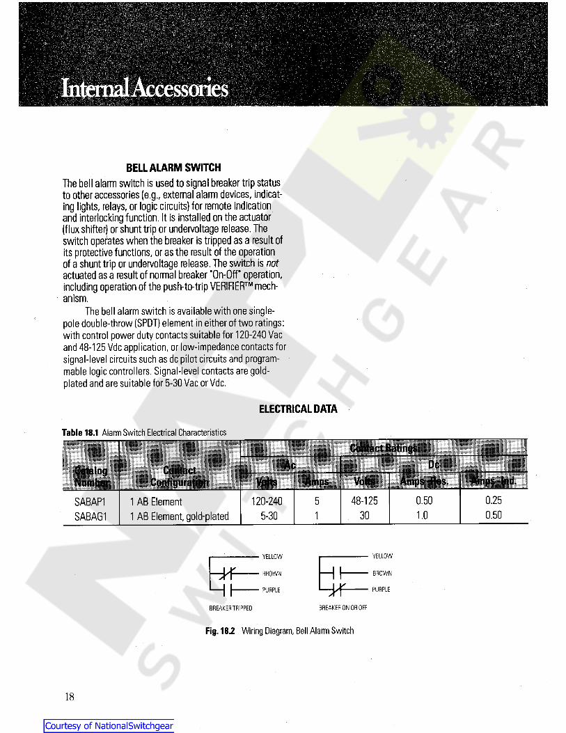
BELL ALARM SWITCHThe bell alarm switch is used to signal breaker trip statusto other accessories (e.g.,external alarm devices, indicat-ing lights, relays, or logic circuits) for remote indicationand interlocking function. It is installed on the actuator(flux shifter) or shunt trip or undervoltage release. Theswitch operates when the breaker is tripped as a result ofits protective functions, or as the result of the operationof a shunt trip or undervoltage release. The switch is notactuated as a result of normal breaker "On-Off” operation,including operation of the push-to-trip VERIFIER mech-
anism.The bell alarm switch is available with one single-
pole double-throw (SPDT) element in either of two ratings:with control power duty contacts suitable for 120-240 Vacand 48-125 Vdc application, or low-impedance contacts forsignal-level circuits such as dc pilot circuits and program-mable logic controllers. Signal-level contacts are gold-plated and are suitable for 5-30 Vac or Vdc.
?
ELECTRICAL DATA
Table 18.1 Alarm Switch Electrical Characteristicso 58
':S':.-' j •"
(|lilhi ill- DcAcContact
V; - *jjjpS
Volts Amps -Amps -Res,Volts AmpsJ
0.250.5048-1251 AB Element1 AB Element, gold-plated
120-240 5SABAP1SABAG1 0.5030 1.05-30 1
YELLOWYELLOW
HIHf BROWNBROWN
HfHI PURPLEPURPLE
BREAKER ON OR OFFBREAKER TRIPPED
Fig. 18.2 Wiring Diagram, Bell Alarm Switch
18
Courtesy of NationalSwitchgear.com
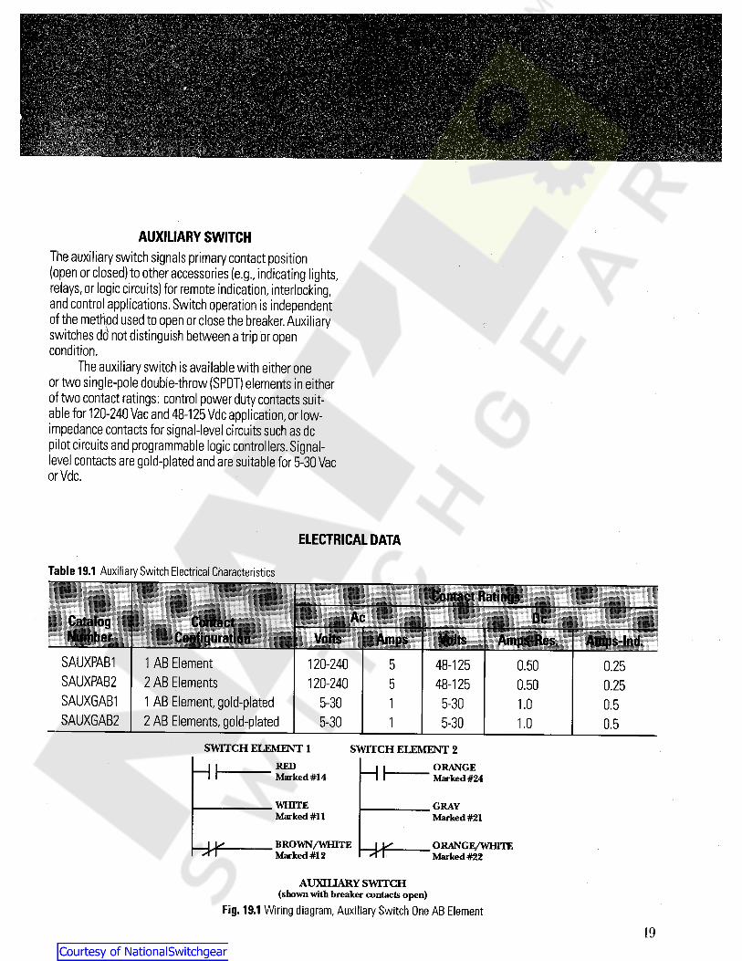
AUXILIARY SWITCHThe auxiliary switch signals primary contact position(open or closed) to other accessories (e.g.,indicating lights,relays,or logic circuits) for remote indication, interlocking,and control applications. Switch operation is independentof the method used to open or close the breaker.Auxiliaryswitches do not distinguish between a trip or opencondition.
The auxiliary switch is available with either oneor two single-pole double-throw (SPDT) elements in eitherof two contact ratings: control power duty contacts suit-able for 120-240 Vac and 48-125 Vdc application,or low-impedance contacts for signal-level circuits such as dcDilot circuits and programmable logic controllers.Signal-evel contacts are gold-plated and are suitable for 5-30 Vac
or Vdc.
ELECTRICAL DATA
Table 19.1 Auxiliary Switch Electrical Characteristics. ...
Contact Ratings: -
Ac DcContactConfiguration y illAmps Volts Amp$-Re&er
:'
SAUXPAB1SAUXPAB2SAUXGAB1SAUXGAB2
1 AB Element2 AB Elements1 AB Element, gold-plated2 AB Elements, gold-plated
120-240120-240
48-12548-125
5 0.50 0.255 0.50 0.25
5-30 5-30 1.0 0.515-30 5-30 1.01 0.5
SWITCH ELEMENT 1 SWITCH ELEMENT 2RED ORANGE
Marked #24Marked #14
WHITEMarked #11
GRAYMarked #21
BROWN/WHITEMarked #12
ORANGE/WHITEMarked #22bH*
AUXILIARY SWITCH(shown with breaker contacts open)
Fig. 19.1 Wiring diagram, Auxiliary Switch One AB Element
19
Courtesy of NationalSwitchgear.com
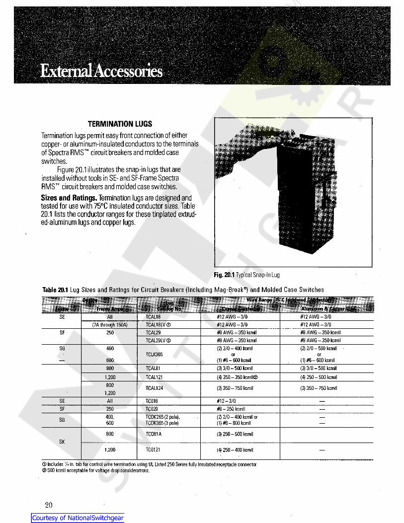
TERMINATION LUGSTermination lugs permit easy front connection of eithercopper- or aluminum-insulated conductors to the terminalsof Spectra RMS circuit breakers and molded caseswitches.
Figure 20.1illustrates the snap-in lugs that areinstalled without tools in SE- and SF-Frame SpectraRMS circuit breakers and molded case switches.Sizes and Ratings.Termination lugs are designed andtested for use with 75°C insulated conductor sizes. Table20.1 lists the conductor ranges for these tinplated extrud-ed-aluminum lugs and copper lugs.
Fig. 20.1 Typical Snap-In Lug
Table 20.1 Lug Sizes and Ratings for Circuit Breakers (Including Mag-Break®) and Molded Case SwitchesWire flange C75PC insulated ConductorJDevice tug
Catalog No. Aluminum& Copper CladFrame Frame Amps Copper Conductor#12 AWG-3/0
I#12 AWG-3/0SE All TCAL18
#12 AWG-3/0 #12 AWG-3/0(7A through 150A) TCAL18LV ©SF #8 AWG-350 kcmil #8 AWG-350 kcmil250 TCAL29
TCAL29LV(D #8 AWG-350 kcmil #8 AWG-350 kcmil(2) 2/0-400 kcmil (2) 2/0-500 kcmilSG 400
TCLK365 or or(1) #6-600 kcmil (1) #6-600 kcmil600(3) 3/0-500 kcmil (3) 3/0-500 kcmilTCAL81800
1,200 TCAL121 (4) 250-350 kcmil© (4) 250-500 kcmil800 TCAL124 (3) 350-750 kcmil (3) 350-750 kcmil
1,200SE #12-3/0All TC018SF 250 TC029 #8-350 kcmil
(2) 2/0- 400 kcmil or(1) #6-600 kcmil
400, TCOK265 (2 pole),TCOK365 (3 pole)SG 600
800 TC081A (3) 250-500 kcmilSK
TC01211,200 (4) 250-400 kcmil
<D Includes 1A in. tab for control wire termination using UL Listed 250 Series fully insulated receptacle connectord> 500 kcmil acceptable for voltage drop considerations.
20
Courtesy of NationalSwitchgear.com

BACK-CONNECTED STUDSBack-connected studs are used when panel mounting (ofthe protective device),quick removal,and cabling or bus-sing behind the panel is required. A mounting sub-base isprovided that mates with the Spectra RMS circuitbreaker or molded case switch and the studs. Each stud isof sufficient length to accommodate panel thicknessesfrom 0.25 inches (6mm) to one inch (25mm).Sizes and Ratings.Table 21.1 lists the back-connectedstuds available for the complete line of Spectra RMS cir-cuit breakers, including Mag-Break® devices and moldedcase switches. These studs are field-installed.
Fig. 21.1 Back-Connected Studs
Table 21.1Back-Connected Line and Load Studs
Length,Back of Device CatalogNumber - ~Frame Max. Amps Inches Short/Longillimeters
SE 50 22%2
413/32
Short70.6 TEF1Long112.0 TEF2
31%2
52%2
Short150 86.5 TEF3Long TEF4147.0
ShortSF 250 22%2
531/32
TFK169.0Long TFK2151.5
SG 213/16600 Short SGBCS171.4
6Vi B SGBCS2Long153.7
51/2800 139.7 TKM11SK
TKM121,200 203.08
21
Courtesy of NationalSwitchgear.com

PLUG-IN MOUNTING BASESPlug-in mounting bases provide the user with anotheroption for quick changeout of breaker and switchassemblies without disturbing power connections.Twoplug-in bases (one for each terminal end) are required foreach protective device.
An optional mounting plate is supplied at no addi-tional charge when ordered with a pair of mountingbases, and provides three important functions. Theplate locates and supports the line and load baseassemblies, provides a convenient means to mount theentire assembly to a metal structure, and serves as adeadfront barrier.
Each plug-in base assembly contains all of themounting hardware necessary to mount the base to eitherend of the circuit breaker or molded case switch.Electricalspacing between adjacent terminals is provided by alter-nate long-short-long (LSL) or short-long-short (SLS) termi-nal assemblies.Fully configured Spectra RMS circuitbreakers are available in two-pole configurations-withthe center pole missing. Consequently,base assemblies fortwo-pole breakers are either short-open-short (SOS) orlong-open-long (LOL). SE-,SF-,and SK-Frames use horizon-
tal studs (suffix PD1 or PD2),while SG-Frames use verticalstuds (suffix PC1 or PC2).
When breakers or switches are mounted side byside,it is important to plan for adjacent outside poles of
the two devices to have a long-short or short-long configu-ration,so that adequate electrical spacing is providedbetween adjacent devices.
Fig. 22.1 Plug-In Mounting Base
Sizes and Ratings.Table 22.1lists sizes and ratings of theplug-in base assemblies.There are two basic stud configu-rations, PD1 and PD2. PD1 always has two short outsidestud terminals (either short-long-short (SLS), or short-open-
short (SOS)).PD2 always has two long outside termina s(either long-short-long (LSL),or long-open-long (LOL)).
Table 22.1 Plug-In Mounting Base
__ - -tud Configurations
DIM
Plug-In Mounting " - Optional MountingPlate
kerm
Horizontal iNo. of CatalogBreakerType
SE150
P Catalog NumberPM sr. - " . .. j . • i:t
!
TE13PD1.2 TMP1LSLSLS3150TF22PD1,2TF23PD1,2
TMP2SOS LOL2SF250250 LSLSLS3SGPC1.2©SGPC1.2©
SLS LSLSG400SG600
3 SMP3600 SLS LSL3TK83PD1A,2A TMP4SLS LSLSK1200 3800TK123PD1A,2A TMP4SLS LSLSK1200 31,200
3)Vertical stud orientation.
22
Courtesy of NationalSwitchgear.com

MOTOR-OPERATED MECHANISMS (MOM)The MOM function uses an ac or dc motor-driven mecha-nism to produce rapid closing or opening. No physical mod-ification of the breaker or switch is needed to add theMOM. The MOM operator slips over the operating handleof the cirpit breaker or molded case switch.The MOMcover cart, be lifted to manually open or close the breaker orswitch. Visual indication of the "On-Off"status appears onthe mechanism cover.
Figure 23.1shows an SF-Frame motor operator.
Table 23.1Motor-Operated Mechanisms,Ratings and Electrical DataCuntrol Power Operating Time
SecondsAmpsDeviceFrame
CatalogNumber
OpeningReset
RecommendedFuseVoltage Inrush Running Closing
120 Vac 10.5 5SEMOM1
125 Vdc 13.5 4 1 AmpTime Delay
SEM0M2 240 Vac 6.5 3SE 0.15 0.13
SEMOM8 24 Vdc 31 15.5 2 AmpTime Delay
SEMOM9 48 Vdc 20 7
120 Vac 10.5 5SFM0M1
125 Vdc 13.5 4 1 AmpTime Delay
SFM0M2 240 Vac 6.5 3SF 0.15 0.13
SFM0M8 24 Vac 31 15.5 2 AmpTime Delay
SFMOM9 48 Vdc 20 7.0
13.5120 Vac 8.5Fig. 23.1Motor-Operated Mechanism for an SF-Frame Spectra RMSCircuit Breaker
TM SGMOM1125 Vdc 13.5 4.5
FACE-MOUNTED MECHANICAL INTERLOCKS 240 Vac 36.5SGM0M2SG 0.25 0.20Mechanical interlocks are available for all Spectra RMS
circuit breakers and molded case switches. The function ofthe mechanical interlock is to positively assure that twoadjacent'devices in an assembly cannot both be in their"On" (i.e.,closed) position at the same time.However,bothdevices can be "Off" (i.e.,open or tripped) at the sametime.
TM 250 Vdc 8 2.5
SGM0M8 24 Vdc 33 19.5
SGMOM9 48 Vdc 22 8.5
120 Vac 14 7.5SKM0M1
125 Vdc 18 5 3 AmpTime DelayThese interlocks are useful whenever control or
safety requirements dictate an either-or energized condi-tion downstream of the two protective devices.
240 Vac 7 3.5SKMOM2
250 Vdc 8.5 2.5SK 0.3 0.2
8 AmpTime Delay
SKMOM8 24 Vdc 50 30Table 23.2 Mechanical Interlock (Face mounted)Adapter Kit-Required when
usinij handle operator (TDM)
or motor operator.Order separately
3 AmpTime Delay
Face-mountedinterlockCat. No.
SKMOM9 48 Vdc 32.5 15Spectra RMS “
Breaker Type© All ac control power may be either 50 Hz or 60 Hz.i
SE150, SF250 SEFFMI SEFFMIAKSG600 SGFMI SGFMIAK ©SK1200 SKFMI SKFMIAK
n o© Compatible with motor operator only. Cat. no. SGFMI cannotbe used with handle operator.
40
Courtesy of NationalSwitchgear.com
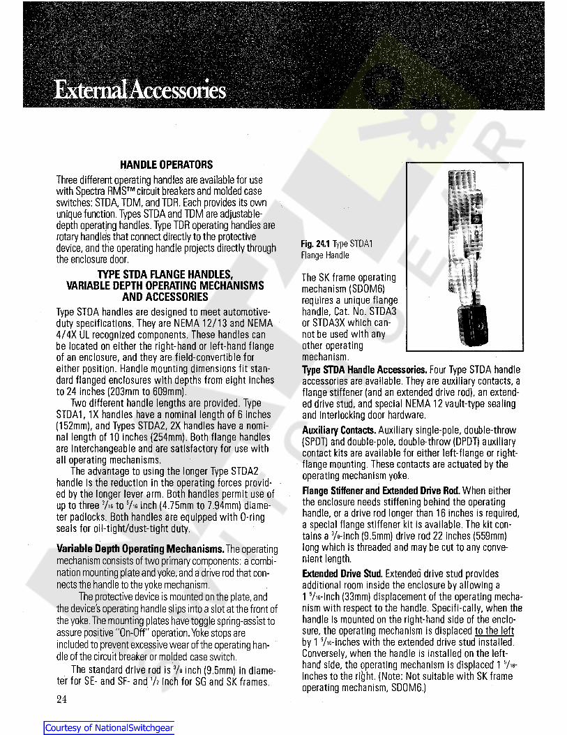
HANDLE OPERATORSThree different operating handles are available for usewith Spectra RMS circuit breakers and molded caseswitches: STDA,TDM, and TDR. Each provides its ownunique function. Types STDA and TDM are adjustable-depth operating handles. Type TDR operating handles arerotary handle5? that connect directly to the protectivedevice,and the operating handle projects directly throughthe enclosure door.
Fig. 24.1 Type STDA1Flange Handle
TYPE STDA FLANGE HANDLES,VARIABLE DEPTH OPERATING MECHANISMS
AND ACCESSORIESType STDA handles are designed to meet automotive-duty specifications. They are NEMA 12/13 and NEMA4/4X UL recognized components. These handles canbe located on either the right-hand or left-hand flangeof an enclosure, and they are field-convertible foreither position. Handle mounting dimensions fit stan-dard flanged enclosures with depths from eight inchesto 24 inches (203mm to 609mm).
Two different handle lengths are provided. TypeSTDA1, 1X handles have a nominal length of 6 inches(152mm), and Types STDA2, 2X handles have a nomi-nal length of 10 inches 254mm). Both flange handlesare interchangeable and are satisfactory for use withall operating mechanisms.
The advantage to using the longer Type STDA2handle is the reduction in the operating forces provid- •
ed by the longer lever arm. Both handles permit use ofup to three 7« to Vie inch (4.75mm to 7.94mm) diame-ter padlocks. Both handles are equipped with O-ringseals for oil-tight/dust-tight duty.
The SK frame operatingmechanism (SD0M6)requires a unique flangehandle, Cat. No. STDA3or STDA3X which can-not be used with anyother operatingmechanism.Type STDA Handle Accessories. Four Type STDA handleaccessories are available. They are auxiliary contacts, aflange stiffener (and an extended drive rod), an extend-ed drive stud, and special NEMA 12 vault-type sealingand interlocking door hardware.Auxiliary Contacts. Auxiliary single-pole, double-throw(SPDT) and double-pole, double-throw (DPDT) auxiliarycontact kits are available for either left-flange or right-flange mounting. These contacts are actuated by theoperating mechanism yoke.Flange Stiffener and Extended Drive Rod. When eitherthe enclosure needs stiffening behind the operatinghandle, or a drive rod longer than 16 inches is required,a special flange stiffener kit is available. The kit con-tains a Vs-inch (9.5mm) drive rod 22 inches (559mm)long which is threaded and may be cut to any conve-nient length.Extended Drive Stud. Extended drive stud providesadditional room inside the enclosure by allowing a1 Vis-inch (33mm) displacement of the operating mecha-nism with respect to the handle. Specifi-cally, when thehandle is mounted on the right-hand side of the enclo-sure, the operating mechanism is displaced to the leftby 1 Vis-inches with the extended drive stud installed.Conversely, when the handle is installed on the left-hand side, the operating mechanism is displaced 15/ie-inches to the right. (Note: Not suitable with SK frameoperating mechanism, SD0M6.)
Variable Depth Operating Mechanisms.The operatingmechanism consists of two primary components: a combi-nation mounting plate and yoke,and a drive rod that con-nects the handle to the yoke mechanism.
The protective device is mounted on the plate,andthe devices operating handle slips into a slot at the front ofthe yoke.The mounting plates have toggle spring-assist toassure positive "On-Off" operation. Yoke stops areincluded to prevent excessive wear of the operating han-dle of the circuit breaker or molded case switch.
The standard drive rod is Vs inch (9.5mm) in diame-ter for SE- and SF- and 72 inch for SG and SK frames.24
Courtesy of NationalSwitchgear.com

TYPE TDR INTEGRAL HANDLE MECHANISMType TDR handles are designed for direct mounting to theSpectra RMS circuit breaker or molded case switchoperating handle. A door ring on the handle projectsthrough a mating hole on the front of the enclosure door.Type TDR handles are suitable for use with shallow depthNEMA 1,NEMA 12,or NEMA 12K enclosures.Rotarymotion of the handle opens or closes the protective device.
Figure 27.1 shows a Type TDR handle mounted to anSE-Frame Spectra RMS circuit breaker,mounted verti-cally.Different handles are used for vertical and horizontalmounting of the protective device. An interlock kit is availa-ble to mate with the door ring of the type TDR handle andprovides an interlock function between protective deviceand enclosure door. A gasket kit is also available to limitthe intrusion of dust and dirt into the enclosure through thespace between the door ring on the protective device andthe hole in the enclosure door.This gasket kit is requiredfor NEMA 12 and NEMA 12K applications.
Vault-Type Interlocking Door Hardware. Type TDV doorhardware kits are available to permit interlocking with aSTDA handle. Kits are designed for doors having a nomi-nal depth of 3A inch (19mm). The interlocking functionrequires use of a screwdriver to release interlocking andpermit door opening. Normally, the flange handle andoperating mechanism cannot be placed in the "ON"(energized) position unless the enclosure door and doorhardware is closed. Kits are available for both NEMA12/13 and NEMA 4/ 4X applications.
When enclosure doors are 40 inches (1,016mm) longor longer, a third point latch is recommended and avail-able.
TYPE TDM DOOR-MOUNTED HANDLES ANDVARIABLE DEPTH OPERATING MECHANISMS
Type TDM handles and mechanisms are designed for door-mounting of a rotary operating handle.Shafts of variouslengths connect directly to a sliding plate assembly thatfits over the "On-Off" handle of the Spectra RMS circuitbreaker or molded case switch. Rotation of the handlecauses up and down (or right and left,for horizontallymounted protective devices) motion of the device togglehandle,which closes or opens the device.Handles.TDM door-mounted handles accommodate upto three padlocks.There are two basic handle styles.BothTH1 and TH2 handles are designed for NEMA 1,3R,and12 enclosures.TH2 handles are longer than TH1 to providemore torque for SG- and SK-Frame devices.When NEMA4 or 4X enclosures are required, handle Cat. No. THCH45is available (for all size devices).Operating Mechanisms,Including Shafts.The TypeTDM operating mechanism attaches to the face of theSpectra RMS circuit breaker or molded case switch. Asmentioned earlier, the protective device may be mountedeither vertically or horizontally. Shafts are cut by the userto the length required for the specific application.Replacement Handle Gaskets.There are two sets ofreplacement neoprene gaskets for NEMA 3R,12,and 12Kenclosures.One set is for Cat.No.TH1 handles ( SE- andSF-Frame devices),and the other for Cat. No.TH2 handles(SG- and SK-Frame devices).
•fai($)i
/
23 l 'T5,'
Fig. 25.1 Type TDR Integral Handle Mechanism
25
Courtesy of NationalSwitchgear.com

INTRODUCTION Functions. A circuit breaker inherently protects circuitsduring short-circuit and overload conditions by automati-cally opening itsprotected electrical circuitwithout theuse of fuses.When the circuit breaker opens to clear ashort-circuit or a sustained overload condition, its "toggle"handle moves to the "Tripped" position (midway between"On" and "Off" positions), indicating the circuit breakerhas automatically opened. Once the overload or short cir-cuit has been corrected,the circuit breaker can be closedby simply moving the toggle handle first into the "Reset"(fully "Off") position,and then into the "On" position.Circuit Breaker Advantages. There are several advan-tages to using circuit breakers as protective devices. Onekey advantage to circuit breakers over fusible elements isthat an overcurrent on one pole of a multipole deviceactuates a common trip bar that trips all poles simultane-ously. Consequently,"single phasing" a three-phase loadis not possible when a circuit breaker opens,while it ispossible with fusible devices.Molded case circuit break-ers utilize "trip-free" construction.Atrip-free device is onethat cannot be forced into the closed or "On" positionwhen a tripping action is present as the result of an abnor-mal condition. If an attempt is made to manually close acircuit breakers toggle handle while an overcurrent condi-tion exists in the protected circuit,the circuit breaker willopen,even if the toggle handle is held in the "On" position.
Protective Function-Circuit Breakers. Spectra RMST''circuit breakers are not intended to replace running over-load,unbalanced voltage or special-purpose protectionprovided by other motor-protective equipment such asoverload relays and motor-temperature sensing devices.However,Spectra RMS circuit breakers can be used toprovide motor overload and overcurrent protection fororanch circuits containing infrequently started induction orsynchronous motors.
Spectra RMS molded case circuit breakers meetUL Standard 489 covering "Branch Circuit and ServiceCircuit Breakers"; NEMA Standard AB-1 — Molded CaseCircuit Breakers; IEC Standard 947-2,Circuit Breakers(Low-Voltage Switchgear and Controlgear), and applicableCanadian and Japanese Standards.
The Electrical Data section of this manual is intended toassist those responsible for the selection and applicationof circuit protective devices in making the proper choicesof Spectra RMS circuit breakers and molded caseswitches.Because Spectra RMS devices are true inter-national products,attention is given to the selection proce-dures associated with American,Canadian,and IECStandards.
Electrical Data is presented in a sequence that fol-lows the steps necessary to make the selection of theprotective device that matches system and equipment re-quirements.
Fig. 26.1The Spectra RMS Circuit Breaker Family
General
MOLDED CASE CIRCUIT BREAKERSMolded case circuit breakers are circuit protective devicesthat perform two primary functions: 1) manual switching toopen and close a circuit by means of a toggle handle; and2) automatic opening of the circuit under short-circuit and/or sustained overload conditions.
26
Courtesy of NationalSwitchgear.com
UL Standard vs. 100% Rated Spectra RMS circuit break-ers are classified as “standard-rated' devices with option-al 100 percent rated versioins availiable in the SG and SKframes. UL Standard 489 makes provisions for two cate-goreis of circuit breakers, "UL Standard-rated' and 'UL100 percent rated". The basis for UL Standard-rated circuitbreakers is as follows:Mounted in Free Air. Circuit breakers are tested to carry100 percent of nameplate current rating, continouosly,when mounted in free air at 25°C (77°F) and cable perTable 31.1,Page 31. However, they are not applied in thismanner.Mounted in an Enclosure. Spectra RMS enclosed circuitbreakers are rated to carry 100 percent of nameplate cur-rent rating, intermittently (three hours, maximum), and 80percent, tontinuously, with the enclosure in a 25°C ambi-ent and cabled per table 31.1, Page 31.Group-Mounted. Group-mounted circuit breakers may re-quire derating of the circuit breakers and cable in roomambients other than 25°C and with cable other than listedin Table 31.1, Page 31.
"100 percent" breakers will carry full rated currentcontinuously, enclosed, provided the enclosure meetsminimum size and ventilation (if specified) requirements.IEC Equivalent to UL Standard Rated Circuit Breakers. IECStandard 947-2 lists three current ratings: "conventionalfree air thermal current, (!«.) "; "conventional enclosed ther-mal current (M"; and "rated current ( In)." IEC procedurescall for an eight-hour test. Consequently, when a stan-dard-rated circuit breaker is mounted in free air at 25°Cand with the cabling of Table 31.1, Page 31, the breaker'sconventional free air thermal current may be consideredto be 100 percent of nameplate current. Enclosed circuitabreakers cabled per Table 31.1 and mounted in 25°Croom am-bient may be considered to have a conventionalenclosed thermal current of 80 percent of nameplate cur-rent. Group-mounted circuit breakers may require addition-al derating to reflect actual room ambient and cabling.
Rated current (h) is equal to the free air thermal cur-rent (l»>) and is the same as the rated current for circuitbreakers described in the technical data of this publica-tion. Specifically, rated current per UL489 and rated cur-rent per IEC947-2 are equivalent terms.
MOLDED CASE SWITCHESMolded case switches are used as circuit-disconnectdevices where overload and short-circuit protection forthe relevant circuit is provided by other devices. Because
these switches are tested to meet a six-times ratedcurrent overload requirement they are useful as dis-connects in motor circuits and are horsepower rated.
Spectra RMS molded case switches are de-signed to meet and are tested in accordance with ULStandard 1087, specifically covering molded caseswitches.
STANDARDS AND REFERENCESUnderwriters' Laboratories
UL Standard 489, Branch Circuit and ServiceCircuit Breakers: and UL Standard 1087,Molded Case Switches. Order from Ul Publi-cations Stock, 333 Pfingston Road, Northbrook,IL 60062.
National Electrical Manufacturers Association (NEMA)NEMA Standard AB-1, Molded Case CircuitBreakers. Order from NEMA Publications, 155East 44th Street, New York, NY 10017.
Institute of Electrical and Electronics Engineers ( IEEE)IEEE Standard No. 45, Recommended Practicesfor Electrical Installation on Shipboard. Orderfrom IEEE Service Ctr., 445 Hoes Lane,Piscataway, NJ 08854.
National Electrical Code ( NEC)1993 Edition. Order from NFPA, BatterymarchPark, Quincy, MA 02269.
International Electrotechnical Commission (IEC)IEC Standard 947-2, Low-Voltage Switchgearand Controlgear, Part 2, Circuit Breakers. Orderfrom Bureau Central de la Commission Electro-technique Internationale, 3 ruede Varemble,Geneva, Switzerland.
Canadian Standards Association ( CSA)CSA Standard 22.2 No. 5, Service Entrance andBranch Circuit Breakers. Order from CSA, 178Rexdale Blvd., Rexdale (Toronto), Ontarios,Canada M9W1R3.
Japanese Industries Standard (JISC)JISC Standard 8370, Low Voltage Switchgearand Controlgear, Circuit Breakers.
Verband Deutscher Electrotechniker (VDE)(Association of German Electrical Engineers)VDE Specificaktion 0660, Low VoltageSwitchgear and Control Gear , Circuit Breakers.
Approved by the city of New York,Bureau of Electrical Control 27
Courtesy of NationalSwitchgear.com
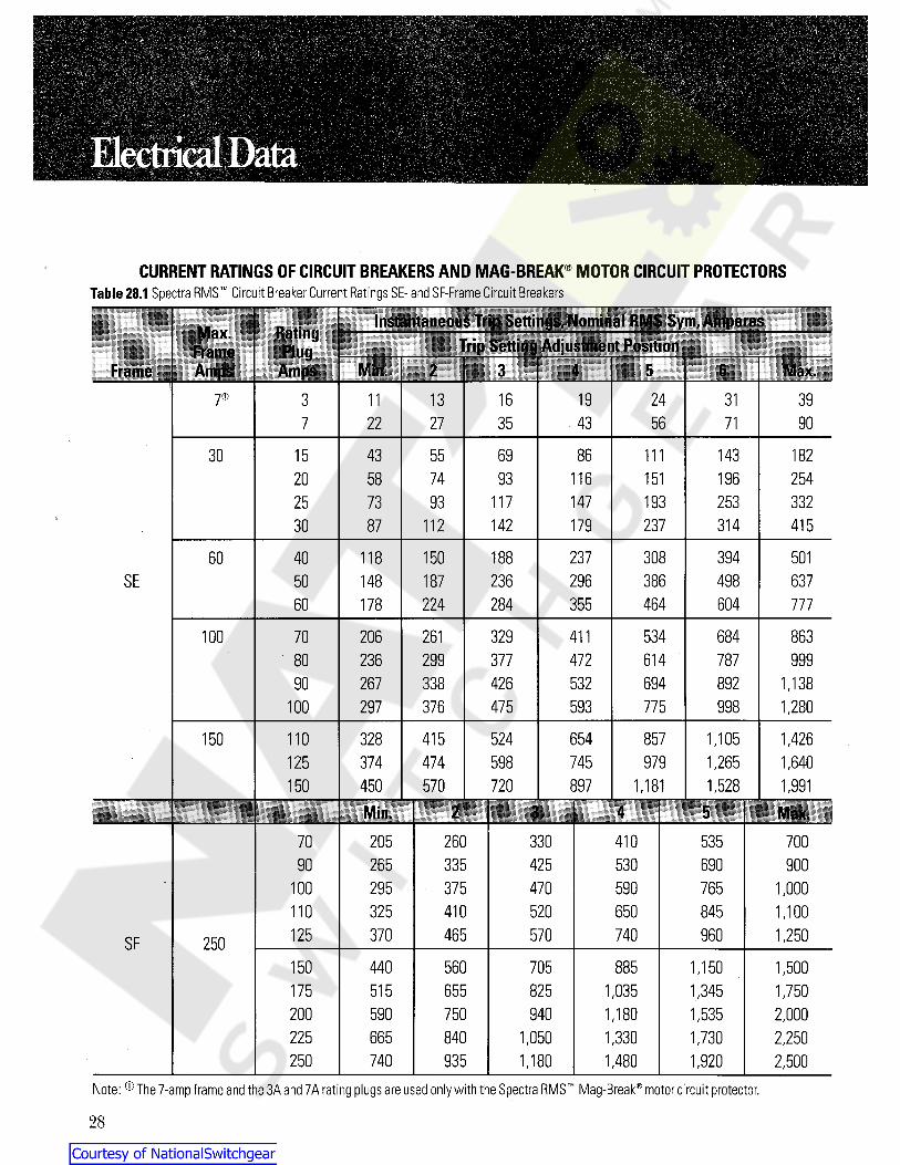
CURRENT RATINGS OF CIRCUIT BREAKERS AND MAG-BREAK® MOTOR CIRCUIT PROTECTORSTable 28.1 Spectra RMS Circuit Breaker Current Ratings SE- and SF-Frame Circuit Breakers
Instantaneous Trip Settings,Nominal RMS Sym,AmperesMax.Frame!Amos
RatingTrip Setting Adjustment Positionfii
Min. 1 5 Max.RMS Amos 2 I 67® 13 16 19 24 31 393
43 56 9022 27 35 717
86 143 18230 43 55 69 1111558 93 116 151 196 25420 74
193 253 33225 73 93 117 147237 31430 87 112 142 179 415
237 308 394 50160 40 118 150 188SE 296 386 498 63750 148 187 236
60 178 224 284 355 464 604 777
206 261 329 411 534 684 863100 70377 472 614 787 99980 236 299
532 694 89290 267 338 426 1,138100 297 376 475 593 775 998 1,280
857150 110 328 524 654 1,105 1,426415598 979 1,265 1,640125 374 474 745
150 450 570 720 897 1,181 1,528 1,991IMin. 2 « 5 Max.
205 260 330 410 53570 70090 265 335 425 530 690 900
375 470 590100 295 765 1,000110 325 410 520 650 845 1,100125 370 465 570 740 960 1,250SF 250150 440 560 705 885 1,150 1,500
655 825175 515 1,035 1,345 1,750200 590 750 940 1,180 1,535 2,000225 665 840 1,050 1,330 1,730 2,250250 740 935 1,180 1,480 1,920 2,500
Note: ® The 7-amp frame and the 3A and 7A rating plugs are used only with the Spectra RMS Mag-Break® motor circuit protector.
28
Courtesy of NationalSwitchgear.com
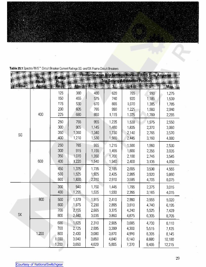
Table 29.1 Spectra RMS Circuit Breaker Current Ratings SG- and SK-Frame Circuit Breakers
Instantaneous Trip Settings,Nominal RMS Syni, AmperesMax.FrameAmps
RatingTrip Setting Adjustment PositionPlug
Frame Amps Max.Min. 2 3 4 5125 380 480 620 765 990 1,275150 575 920455 740 1,185 1,530175 670530 865 1,070 1,385 1,785200 605 765 990 1,225 1,580 2,040
400 225 680 860 1,375 1,7801,115 2,295250 955 1,530755 1,235 1,975 2,550300 905 1,8351,145 1,480 2,370 3,060350 1,060 1,340 2,1401,730 2,765 3,570SG400 1,210 1,530 1,980 2,445 3,160 4,080
250 765 965 1,215 1,500 1,960 2,530300 915 1,155 1,8001,455 2,355 3,035350 1,070 1,350 2,1001,700 2,745 3,545
600 400 1,220 1,540 2,4001,940 3,135 4,050450 1,375 1,735 2,185 2,695 3,530 4,555500 1,525 1,925 2,425 2,995 3,920 5,060600 1,830 2,310 2,910 3,595 4,705 6,075
300 1,150940 1,7951,445 2,375 3,015400 1,255 1,535 1,930 2,395 3,165 4,015
800 500 1,570 1,915 2,9902,410 3,955 5,020600 1,875 2,290 3,6102,895 4,740 6,195700 2,155 2,665 3,375 4,240 5,525 7,420
SK 800 3,0352,440 3,860 4,875 6,305 8,705
600 2,310 3,6851,825 2,905 4,730 6,110700 2,6952,125 3,390 4,300 5,515 7,125
1,200 800 2,430 3,080 3,870 4,910 6,305 8,1453,8501,000 3,040 4,840 6,140 8,880 10,180
12,2151,200 4,6203,650 5,805 7,370 9,455
29
Courtesy of NationalSwitchgear.com

Table 30.1 Spectra RMS Molded Case Switch Current RatingsThree-Pole,600-Vac
CABLE SIZEThe thermal design of a circuit breaker takes into accountthe ability of line and load cables to act as heat sinks.ULStandard 489 has assigned specific cable sizes for eachcurrent rating. Generally,these assignments are coordi-nated with specific conductor temperature ratings.Increasing a conductor’s temperature rating has the sameeffect as decreasing both the cross sectional area of theconductor and its ability to conduct heat. Figure 30.1 illus-trates the effect of changing cable size upon the current-carrying ability of the circuit breaker or molded caseswitch.
:SwitchFrame mMaximumFrame Ampere
100 and 150
mi tiHI|
SEDASE1
SF SFDA 250\
SG SGDA 400 and 600
SKDASK 800 and1,200
FACTORS AFFECTING CURRENT RATINGSOF INSTALLED DEVICES
There are seven application factors that need to be consid-ered in the selection of the current ratings of molded casecircuit breakers and switches.These are: 1) the size of thecable used in the line and load connections,2) the actualinstalled ambient temperature,3) the system operating fre-quency,4) the altitude of the installation,5) the type ofloading of the protected circuit,6) the design safety factor,and 7) derating for continuous loading, if applicable.
The following simple relationship combines theseseven application factors into one equation:
L = l a x A x B x C x D x E x F x GWhere: lp = Circuit breaker frame amp rating
la = Actual load current in ampsA = Cable size factorB = Ambient temperature rating factorC = Frequency rating factorD = Altitude rating factorE = Load class rating factorF = Safety factorG = Intermittent/continuous duty
rating factorExamples of how these selection factors are used
are shown on Pages 36 and 37.
% Change in current carrying ability
.I’m + 50%+ 25%
E -S^ CJ 0rated
conductor200% of ratedconductor size
0 3 w
!* -25%- 50%
Fig. 30.1Effects of Changing Load and Line Conductor Sizes
30
Courtesy of NationalSwitchgear.com
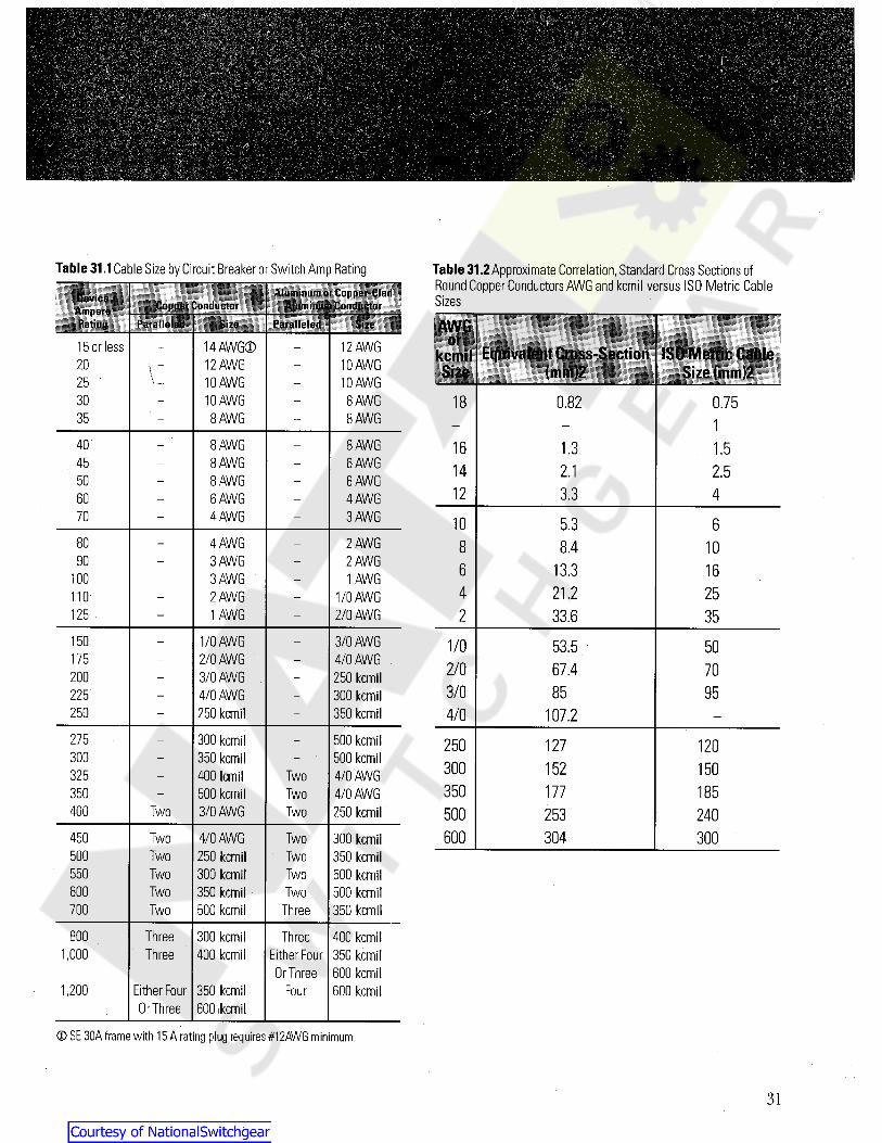
Table 31.1Cable Size by Circuit Breaker or Switch Amp Rating Table 31.2Approximate Correlation,Standard Cross Sections ofRound Copper Conductors AWG and kcmil versus ISO Metric CableSizesAluminum oi Cuppci-Cl.ul
Aluminum CuiiiluciurDuviruAmpereRutimi
Cnppur Cnmlm.tor
AWGSizeParalleled Size Piirullulud 1^’-nmrasTi or12 AWG10 AWG10 AWG
8 AWG8 AWG
14 AWG®12 AWG10 AWG10 AWG
8 AWG
15 or less Equivalent Cross-Section(mm)2
ISO Metric CableSize (mm)2
kcmilSize20
\ _250.8230 18 0.75
35 18 AWG6 AWG6 AWG4 AWG3 AWG
8 AWG8 AWG8 AWG6 AWG4 AWG
40 16 1.3 1.545 2.114 2.550
12 3.3 46070 10 5.3 6
4 AWG3 AWG3 AWG2 AWG1 AWG
2 AWG2 AWG1 AWG
1/0 AWG2/0 AWG
80 8 8.4 1090 6 13.3 16100
21.24 2511033.62125 35
3/0 AWG4/0 AWG .
250 kcmil300 kcmil350 kcmil
1/0 AWG2/0 AWG3/0 AWG4/0 AWG250 kcmil
150 1/0 53.5 50175 2/0 67.4 70200
3/0 85 95225250 4/0 107.2275 300 kcmil
350 kcmil400 lemil500 kcmil3/0 AWG
500 kcmil500 kcmil4/0 AWG4/0 AWG250 kcmil
250 127 120300
300 152 150325 Two350 177 185350 Two
Two400 Two 500 253 240600 304 300Two450 4/0 AWG
250 kcmil300 kcmil350 kcmil500 kcmil
Two 300 kcmil350 kcmil500 kcmil500 kcmil350 kcmil
Two500 TwoTwo550 TwoTwo600 TwoTwo700 Three
ThreeThree
800 300 kcmil400 kcmil
ThreeEither Four
Or Three
400 kcmil350 kcmil600 kcmil600 kcmil
1,000
Either FourOr Three
350 kcmil600 ikemil
1,200 Four
® SE 30A frame with 15 A rating plug requires #12AWG minimum.
31
Courtesy of NationalSwitchgear.com
ii
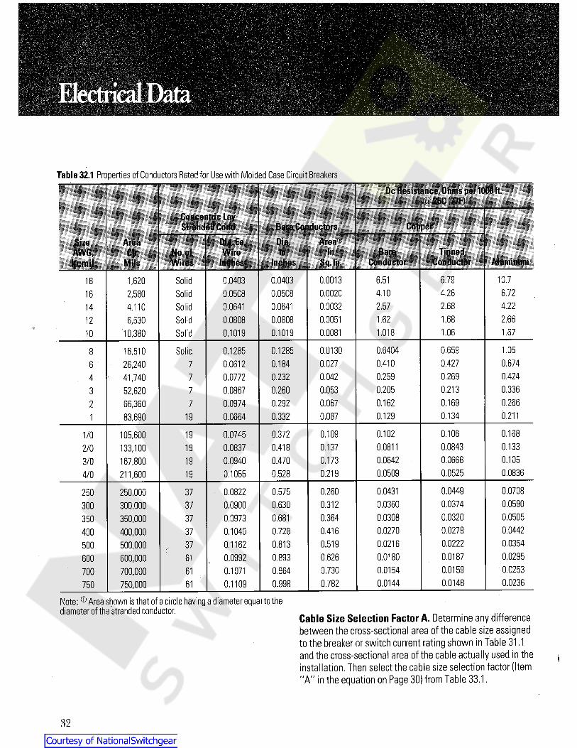
Table 32.1 Properties of Conductors Rated for Use with Molded Case Circuit BreakersDc Resistance,Ohms per 1000 ft.
25C (77FIConcentric LayStranded Cond. Bare Conductors Copper
Dia.SizeAWG,kcmil
Area Dia.Ea.Wire
Inches
AreaCir. Tinned
ConductorNo.ofWires
In In BareConductorInches Sq. ln. AluminumMils
Solid 0.04030.05080.06410.08080.1019
6.791,620 0.04030.0508
0.00130.00200.00320.00510.0081
6.51 10.718Solid2,580 4.10 4.26 6.7216Solid 2.680.0641 2.57 4.2214 4,110Solid6,530 0.0808
0.10191.62 1.68 2.6612
Solid10,380 1.018 1.06 1.6710
Solid 0.1285 0.0130 0.6404 0.659 1.058 16,51026,24041,74052,62066,36083,690
0.12850.06120.07720.08670.09740.0664
0.184 0.027 0.410 0.427 0.6746 70.2690.232 0.042 0.259 0.424740.2130.260 0.053 0.205 0.3363 70.1690.292 0.067 0.162 0.266720.1340.332 0.087 0.129 0.2111910.106 0.16819 0.372 0.109 0.1021/0 105.600
133,100167,800211.600
0.07450.08370.09400.1055
0.08430.06680.0525
0.13319 0.418 0.137 0.08110.0642 •
0.0509
2/00.470 0.10519 0.1733/0
0.083619 0.528 0.2194/00.04490.03740.03200.02780.02220.01870.01590.0148
0.07080.05900.05050.04420.03540.02950.02530.0236
0.260 0.04310.03600.03080.02700.02160.01800.01540.0144
0.575250,000300,000350,000400,000500,000600,000700,000750,000
37 0.08220.09000.09730.10400.11620.09920.10710.1109
2500.630 0.312300 370.681 0.364373500.728 0.416374000.813 0.519375000.893 0.626616000.964 0.730617000.998 0.78261750
Note: ® Area shown is that of a circle having a diameter equal to thediameter of the strandedconductor.
Cable Size Selection Factor A. Determine any differencebetween the cross-sectional area of the cable size assignedto the breaker or switch current rating shown in Table 31.1and the cross-sectional area of the cable actually used in theinstallation. Then select the cable size selection factor (Item"A” in the equation on Page 30) from Table 33.1.
32
Courtesy of NationalSwitchgear.com
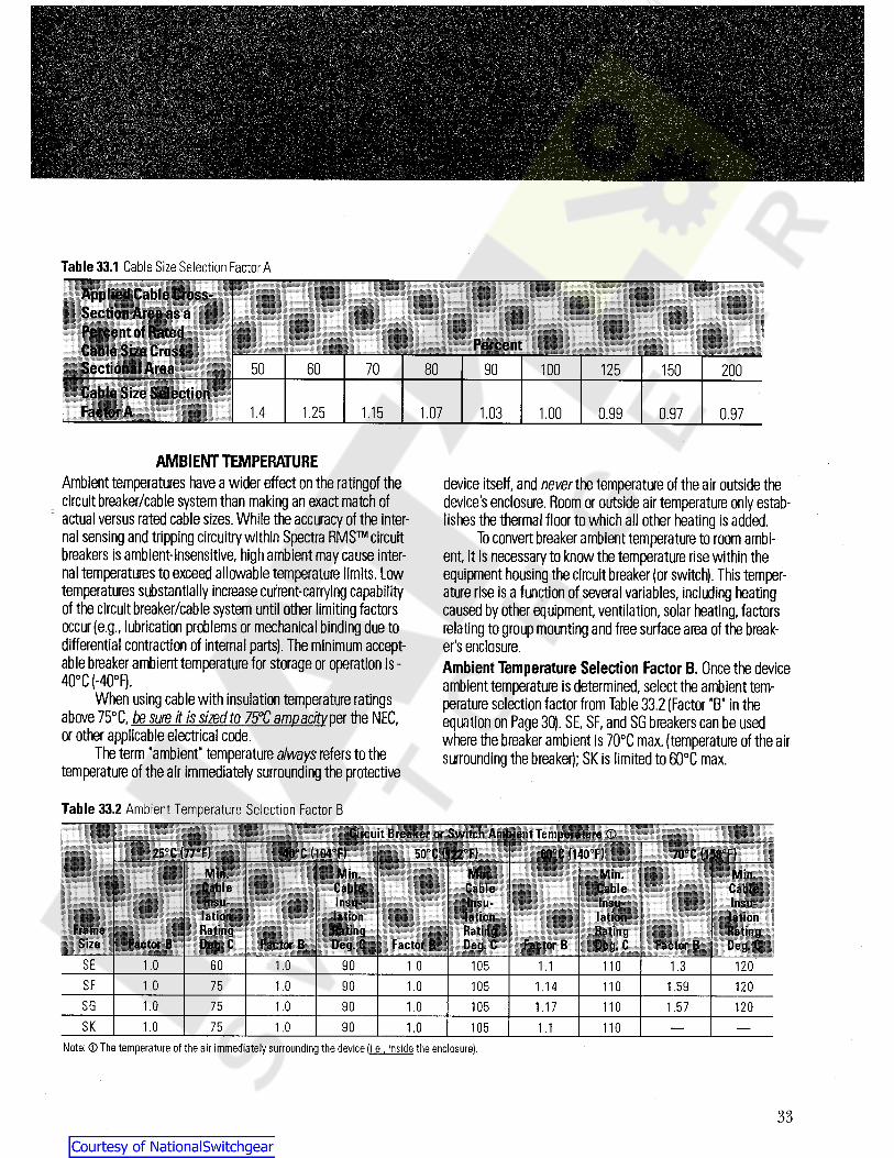
Table 33.1 Cable Size Selection Factor A
Applied Cable Cross-Section Area as aPercent of RatedCable Size Cross-Sectional Area
Percent50 7060 80 90 100 150125 200
Cable Size SelectionFactor A 1.4 1.25 1.15 1.07 1.00 0.971.03 0.99 0.97
AMBIENT TEMPERATUREAmbient temperatures have a wider effect on the ratingof thecircuitbreaker/cable systemthan making an exact match ofactual versus rated cable sizes. While the accuracy of the inter-nal sensing and tripping circuitry within Spectra RMS circuitbreakers is ambient-insensitive, high ambient may cause inter-nal temperatures to exceed allowable temperature limits. Lowtemperatures substantially increase current-carrying capabilityof the circuit breaker/cable system until other limiting factorsoccur (e.g., lubrication problems or mechanical binding due todifferential contraction of internal parts). The minimum accept-able breaker ambient temperature for storage or operation is -40°C (-40°F).
When using cable with insulation temperature ratingsabove 75°C, be sure it is sized to 75°C ampacity per the NEC,or other applicable electrical code.
The term 'ambient” temperature always refers to thetemperature of the air immediately surrounding the protective
device itself, and never the temperature of the air outside thedevice's enclosure.Room or outside air temperature only estab-lishes the thermal floor to which all other heating is added.
To convert breaker ambient temperature to room ambi-ent, it is necessary to know the temperature rise within theequipment housing the circuit breaker (or switch). This temper-ature rise is a function of several variables, including heatingcaused by other equipment,ventilation, solar heating, factorsrelating to group mounting and free surface area of the break-er's enclosure.Ambient Temperature Selection Factor B. Once the deviceambient temperature is determined, select the ambient tem-perature selection factor from Table 33.2 (Factor "B" in theequation on Page 30). SE, SF, and SG breakers can be usedwhere the breaker ambient is 70°C max. (temperature of the airsurrounding the breaker); SK is limited to 60°C max.
Table 33.2 Ambient Temperature Selection Factor BCircuit Breaker or Switch Ambient Temperature 0
6(FC|14(TF) 70 C (158 F)25 C 177 F) 40 C (104 F) 50 C (122 F)
Min.CableInsu-lationRatingDeg. C
Min.CableInsu-lationRating
Factor B 1 Deg. C
Min.Cable
||li||||l!j|||l!|||l lijjBlililllll|||JI[||jj||lationRating
Factor B Deg. C Factor B
Min.CableInsu-lationRatingDeg. C
Min.CableInsu-lation ;RatingDeg. C Factor B
FrameSii u Factor BSE 1.0 1.3 1201.0 60 1.0 90 105 1.1 110SF 1.59 1201.0 1.0 1.0 105 11090 1.1475SG 1201.0 1.0 1.0 105 110 1.5790 1.1775SK 1.0 1.0 1.0 11090 105 1.175
Note: © The temperature of the air immediately surrounding the device fi .e. , inside the enclosure).
33
Courtesy of NationalSwitchgear.com
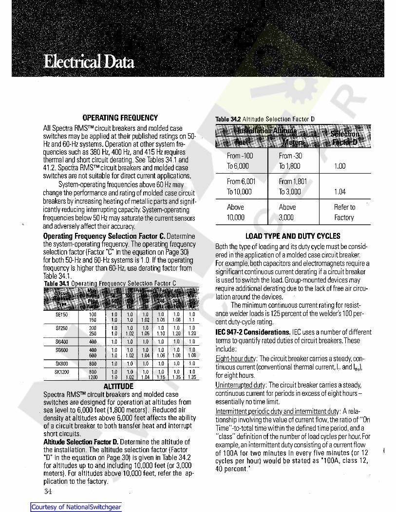
OPERATING FREQUENCY Table 34.2 Altitude Selection Factor DAll Spectra RMS circuit breakers and molded caseswitches maybe applied at their published ratings on 50-Hz and 60-Hz systems. Operation at other system fre-quencies such as 380 Hz, 400 Hz, and 415 Hz requiresthermal and short circuit derating. See Tables 34.1 and41.2. Spectra RMS circuit breakers and molded caseswitches are not suitable for direct current applications.
System-operating frequencies above 60 Hz maychange the performance and rating of molded case circuitbreakers by increasing heating of metallic parts and signif-icantly reducing interrupting capacity.System-operatingfrequencies below 50 Hz may saturate the current sensorsand adversely affect their accuracy.Operating Frequency Selection Factor C. Determinethe system-operating frequency. The operating frequencyselection factor (Factor "C" in the equation on Page 30)for both 50-Hz and 60-Hz systems is 1.0. If the operatingfrequency is higher than 60-Hz, use derating factor fromTable 34.1.Table 34.1 Operating Frequency Selection Factor C
Installation Altitude SelectionFactor DFeet Meters
From -100To 6,000
From -30To 1,800 1.00
From 6,001To 10,000
From 1,801To 3,000 1.04
Above10,000
Above3,000
Refer toFactory
LOAD TYPE AND DUTY CYCLESBoth the type of loading and its duty cycle must be consid-ered in the application of a molded case circuit breaker.For example,both capacitors and electromagnets require asignificant continuous current derating if a circuit breakeris used to switch the load. Group-mounted devices mayrequire additional derating due to the lack of free air circu-lation around the devices.
The minimum continuous current rating for resist-ance welder loads is 125 percent of the welders 100 per-cent duty-cycle rating.IEC 947-2 Considerations. IEC uses a number of differentterms to quantify rated duties of circuit breakers.Theseinclude:Eight-hour duty: The circuit breaker carries a steady,con-tinuous current (conventional thermal current, llh and I,J,for eight hours.Uninterrupted duty: The circuit breaker carries a steady,continuous current for periods in excess of eight hours —essentially no time limit.Intermittent periodic duty and intermittent duty: A rela-tionship involving the value of current flow,the ratio of "OnTime"-to-total time within the defined time period,and a"class" definition of the number of load cycles per hour. Forexample,an intermittent duty consisting of a current flowof 100A for two minutes in every five minutes ( or 12cycles per hour) would be stated as "100A, class 12,40 percent."
C (Frequency) Factor_atMaxCircuitBreaker 20(P150- 300- 400-Rating 100-
415Plug 60 120 180 240 360Type HzHz Hz Hz HzAmps Hz1.0 1.0 1.0 1.0SE150 100 1.0 1.0
1.0 1.02 1.05 1.08150 1.0 1.11.0 1.0SF250 200 1.0 1.0 1.0 1.0
1.201.0 1.02 1.05 1.10 1.202501.0 1.0 1.0SG400 400 1.0 1.0 1.0
1.0SG600 1.0 1.0 1.0 1.0400 1.01.08 1.081.0 1.02 1.04 1.06600
1.0SK800 1.0 1.0 1.0 1.0800 1.01.0 1.0 1.0SK1200 800 1.0 1.0 1.0
1.351.02 1.04 1.351200 1.0 1.15
ALTITUDESpectra RMS circuit breakers and molded caseswitches are designed for operation at altitudes fromsea level to 6,000 feet (1,800 meters). Reduced airdensity at altitudes above 6,000 feet affects the abilityof a circuit breaker to both transfer heat and interruptshort circuits.Altitude Selection Factor D. Determine the altitude ofthe installation. The altitude selection factor (Factor"D" in the equation on Page 30) is given in Table 34.2for altitudes up to and inc uding 10,000 feet (or 3,000meters). For altitudes above 10,000 feet, refer the ap-plication to the factory.34
Courtesy of NationalSwitchgear.com

INTERMITTENT/CONTINUOUSDUTY RATING FACTOR
In those applications governed by UL rules and theNational Electrical Code (NEC),an additional rating factoris necessary for standard-rated circuit breakers.This factordifferentiates between continuous and intermittent duty.
When a circuit breaker is installed in an intermittentduty application, the duty rating factor is 1.00. Intermittentduty is defined as operation under rated load for a periodof not more than three hours, followed by a period of no-load operation,followed by a period of rest.The time peri-ods of no load and rest are undefined by the NEC.Someauthorities suggest the use of a three-hour period of no-load operation after the three-hour,full-load operationmeets the intent of the term "intermittent."
Continuous duty generally means operation withoutanytime limit whatsoever.However, for purposes of ratedmolded-case circuit breakers,operation at rated loads forperiods of time in excess of three hours is considered con-tinuous duty.The duty rating factor for Spectra RMS cir-cuit breakers,as standard-rated devices, in continuousduty applications,is 1.25.
Duty Rating Factor G. Table 35.2 lists the duty rating factor(Factor G in the equation on Page 30).
As a general rule, refer all eight-hour andintermittent duty applications using IEC rules to GEfor assistance and concurrence with rating selection.Load Class Selection Factor E.Table 35.1 lists six differ-ent load class factors. A specific load may involve morethan one of these’-factors.For example,a group-mountedcircuit breaker may be responsible for the branch circuitprotection of a single-motor (with normal duty). In this typeof application,the load class selection factors in Table 35.1would be multiplied (i.e.,group-mount factor x single-motor (normal duty) factor = 1.1 x 1.5,or 1.65).The totalload class selection factor is Factor E in the equation onPage 30.
It is important to emphasize here that molded casecircuit breakers are intended to act as protection forinsulated cable.When a circuit breaker will be applied toprotect equipment,prudent engineering practices call forobtaining factory review and concurrence with theselection of the specific protective device.
Table 35.1Total Load Class Selection Factor E ®
Group-Mount(ill
'12 or morebreakers)
AllSwitching
Electro-magnets
Single-Motor BMIICIICIRCUIT Protection
Normal Duty)
Single-Motor BranchCircuit Protection
iHeavyDuty!
OtherNormoliLoads
SwitchingCapacitors
41.5 1.25 ©
Notes: © The total load class Factor E is the product of all the load classfactors that apply to the circuit under consideration.
® Refer to NEC Article 430, Part B for conductor and circuit breakerframe sizing.
Table 35.2 Duty Rating FactorContinuous Duty
(Operation at constant loadfor more than three hours)
Intermittent Duty(Operation at constant load
for three hours,or less)SelectionFactor GSAFETY FACTOR
A safety factor is used to provide a design margin betweenthe rating limit of a circuit breaker and the derived operat-ing current calculated using all of the selection factorsdescribed in the equation on Page 30.
A safety factor of 10 percent is recommended to pre-vent nuisance tripping.Safety Factor F. A safety factor of 10 percent is equivalentto a current rating multiplier of 1.10.
1.25 1.00
35
Courtesy of NationalSwitchgear.com
ElectricalData
SELECTION OF CIRCUIT BREAKERCURRENT RATING
There are basically two different situations present in mak-
ing the selection of circuit breaker current rating.The firstis where the circuit breaker is assigned to protect insulatedcable that Ipas been selected by a competent authority.The secondis where a number of factors,such as altitude,motor loads,high-ambient temperatures,etc.,are involved.Wire and Cable Protection. One of the primary functionsof molded case circuit breakers is to protect insulated wireand cable from sustained overloads and short circuits.TheNational Electrical Code (NEC) requires that conductors beprotected in accordance with their ampacities. A series oftables found in Article 310 defines ampacities for a numberof different conditions.Exceptions are listed in Article 310for specific applications,inc uding protection of motor-circuit conductors.
When the size and type of conductors are specifiedby a competent authority (e.g.,an electrical consultingengineer), it is only necessary to select a standard ratingmatching the ampacity of the conductor; the NEC permitsthe use of the next higher standard rating-with somespecific exceptions.Equipment Protection and Other Special Conditions.When only load current is known,or where one or morespecial conditions exist (e.g.,use of smaller-than-assignedcable,group mounting,high-ambient temperatures,special-duty cycles,equipment protection,etc.),use of theequation on Page 30 is required to determine the currentrating of the suitable circuit breaker.This equation isrepeated here for ease of use.
Ip = l a x A x B x C x D x E x F x GWhere: lp = Circuit breaker current rating in amps
la = Actual load current in ampsA = Cable size factorB = Ambient temperature rating factorC = Frequency rating factorD = Altitude rating factorE = Load class rating factorF = Safety factorG = Duty rating factor
Example: Step 1. Determine Actual Load Current.Determine the actual current of the circuit by adding thecontinuous load current for each load component of thetotal circuit to be protected by the circuit breaker.
When an intermittent load is involved,a derived rmsload current is used as the actual load current.The timeperiod to be used in calculating rms current is a function ofcircuit breaker frame amps.The assigned time period isequal to one-tenth of the breaker frame ampere rating, inminutes. For example,anSE100 breaker would have a timeperiod of 10 minutes,and an SF250 breaker would have atime period of 25 minutes.Example Data: An air-conditioning compressor cycles onand off at a maximum rate of four times per hour and hasthe following load characteristics:1.Full load current2.Locked rotor (starting) current3. Acceleration (starting) time4.Off time between starts5. Duty cycle
62A248A6 sec (0.1 min)5 min0.1 min start,9.9 minrun,5 min off,cyclerepeats
36
Courtesy of NationalSwitchgear.com
Using an SE100 breaker,calculate rms current duringworst 10-minute period.This would be one Start and Runperiod of this example.
through F must be equal to or greater than1.25 forstandard-rated devices (such as Spectra RMS circuitbreakers).Step 4. Select Circuit Breaker Frame and Rating Plug.Compute circuit breaker frame amp rating for the applica-tion by multiplying actual current by each of the factorsdetermined in Step 3. Select circuit breaker frame. Sizethe rating plug to the actual load current,U,not the calcu-
lated IP.
V(Ltart)2 (Tstart) + (IJ2 (TJ
'srms Ttotal
(248)2 (0.1) + (62)2 (9.9) Second Example:rms 10 Example data:
1. Circuit voltage 480-Vac,3-phase,60-Hz120-amp, rms,continuous23kA,rms symmetricalGroup-mounted,panelboard,30circuits total
Ls = 66.5A 2.Loading (computer power supply)
3. Available short-circuit currentUsing an SF250 breaker,calculate rms current during a25-minute period.This consists of two starts, one 5-minuteoff period and two 9.9-minute run periods. 4.Mounting
V5. Conductor equal to device rating6. Ambient inside box7.No appreciable harmonics8.AltitudeCalculation:!p = l a x A x B x C x D x E x F x G= 120 amps X 1.0 X 1.OX 1.0 X 1.04 X 1.1 X 1.1 X 1.25= 188.76 ampsCalculated rating = 188.76 amps. Select 250Aframe.Selection: Select an SF-Frame Spectra RMS circuitbreaker frame. Select a 125 amp rating plug. Catalognumber of circuit breaker is SFHA36AT0250 and ratingplug would be SRPF250A125 which is the next higherstandard ampere rating for the actual 120 amp load.Note: Since this is a continuous load,cables should besized to 1.25 times the load or 150A which requires (1)1/0 75°C copper per phase.
{2[(248)2(0.1)]} + {2[(62.2)2(9.9)]}40°C,orlessrms 25
7,200 ftlrms = 59.6 amps
Step 2. Estimate Breaker Frame Size. Using either theactual current or the calculated rms current,whichever isgreater,estimate the frame size required for the applica-tion. Record the estimate for use in completing Step 3.Step 3. Determine Breaker Selection Factors A through F.Determine the selection factors described on Pages 30through 35,and substitute in the formula for determinationof lp,circuit breaker current rating. For those applicationsunder the jurisdiction of the NEC,the product of Factors B
37
Courtesy of NationalSwitchgear.com
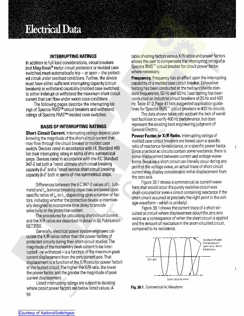
INTERRUPTING RATINGSIn addition to full load considerations, circuit breakers(not Mag-Break® motor circuit protectors or molded caseswitches) must automatically trip- or open-the protect-ed circuit under overload conditions. Further, the devicemust have either sufficient interrupting capacity (circuitbreakers) or,withstand capability (molded case switches)to either interrupt or withstand the maximum short-circuitcurrent that can flow under worst-case conditions.
The following pages describe the interrupting rat-ings of Spectra RMS circuit breakers and withstandratings of Spectra RMS molded case switches.
table of rating factors versus X/R ratios and power factorsallows the user to compensate the interrupting rating of aSpectra RMS circuit breakerfor circuit powerfactor,where necessary.Frequency. Frequency has an effect upon the interruptingcapability of a moldedcase circuit breaker.Exhaustivetesting has been conducted at the two worldwide stan-dard frequencies,50 Hz and 60 Hz.Less testing has beenconducted on industrial circuit breakers at 25 Hz and 400Hz.Table 41.2,Page 41 lists suggested application guide-lines for Spectra RMS circuit breakers in 400 Hz circuits.
The data shown takes into account the lack of worldtest facilities to verify 400 Hz performance,but doesrepresent the existing best engineering judgment ofGeneral Electric.Power Factor,or X/R Ratio. Interrupting ratings ofmolded case circuit breakers are based upon a specificratio of reactance-to-resistance,or a specific power factor.Since practical ac circuits contain some reactance, there issome displacement between current and voltage wave-forms.Because a short circuit can literally occur during anypoint of the voltage wave,an actual trace of short-circuitcurrent may display considerable initial displacement fromthe zero axis.
Figure 38.1 shows a symmetrical ac current wave-
form that would occur if a purely resistive circuit wasshort-circuited (or even a circuit containing reactance if theshort circuit occurred at precisely the right point in the volt-age waveform-which is unlikely).
Figure 39.1shows the current trace of a short-cir-cuited ac circuit where displacement about the zero axisexists as a consequence of when the short circuit is appliedand the amount of reactance in the short-circuited circuit,compared to its resistance.
BASIS OF INTERRUPTING RATINGSShort-Circuit Current. Interrupting ratings depend uponknowing the magnitude of the short-circuit current thatmay flow through the circuit breaker or molded caseswitch. Devices rated in accordance with UL Standard 489list their interrupting rating in terms of rms symmetricalamps. Devices rated in accordance with the IEC Standard947-2 list both a "rated ultimate short-circuit breakingcapacity (leu)" and a "rated service short-circuit breakingcapacity (lcs)“ both in terms of rms symmetrical amps.
Differences between the IEC 947-2 values of lcu (ulti-mate) and !cs (service) breaking capacities are based uponspecific ratios of lcs-to-lcu,depending upon a number of fac-
tors,including whether the protective device is intention-
ally designed to incorporate time delay to provideselectivity to the protection system.
The procedures for calculating short-circuit currentand the X/R ratios are described in detail in GE PublicationGET3550.
Generally,electrical power system engineers cal-culate the X/R ratios rather than the power factors ofprotected circuits during their short-circuit studies.Themagnitude of the momentary peak current to be inter-rupted-or withstood- is a function of the maximum peakcurrent displacement from the zero current axis.Thatdisplacement is a function of the X/R ratio (or power factor)of the faulted circuit.The higher the X/R ratio,the lowerthe power factor,and the greater the magnitude of peakcurrent displacement.
Listed interrupting ratings are subject to deratingwhere circuit power factors are below listed values. A
Envelopes of peaksof sine wave aresymmetricalaboutthe zero axis.
Zero axis
Symmetrical ac wave
Fig. 38.1. Symmetrical Ac Waveform
38
Courtesy of NationalSwitchgear.com
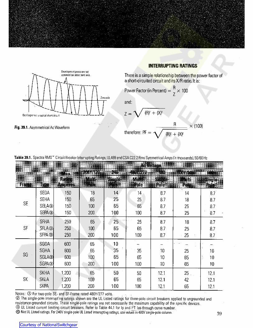
INTERRUPTING RATINGSEnvelopes of peaks are notsymmetrical about zero axis. There is a simple relationship between the power factor of
a short-circuited circuit and itsX/R ratio.It is:
|x 100Power Factor (in Percent) =Zero axis
and:
z = \/ (R)2 + (X)2Oscillogram of a typical short circuit
R x (100)Fig. 39.1. Asymmetrical Ac Waveform
\/ (R)2 + (X)2therefore: PF =
Table 39.1. Spectra RMS Circuit Breaker Interrupting Ratings,UL489 and CSA C22.2 Rms Symmetrical Amps (in thousands),50/60 Hz
Ac Voltage208Y/12Q 240 — 480 600Y/34&" IHP:Max.
RatingAmperes
SinglerMulti- Multi- Single- Multi Single-Pole -Frame Type Pole Pole® Pole
SEDA 14150 18 14 8.7 14 8.7SEHA 25150 65 25 8.7 18 8.7
SE SELA®SEPA ®
65150 100 65 8.7 25 8.7100150 200 100 8.7 25 8.7
SFHA 250 2565 25 8.7 18 8.7SF SFLA®
SFPA ®250 100 65 65 8.7 25 8.7250 200 100 8.7100 25 8.7
SGDA 10600 65SGHA 35600 65 1035 25 10
SG SGLA®SGPA®
65600 100 65 10 1065100600 200 100 •10 65 10
SKHA 1,200 5065 12.150 25 . 12.1SK SKLA 65.1,200 100 65 12.1 42 12.1
SKPA 1,200 100200 100 12.1 65 12.1Notes: © For two-pole SE- and SF-Frame rated 480Y/277 volts.© The single-pole interrupting ratings shown are the UL Listed ratings for three-pole circuit breakers applied to ungrounded andresistance-grounded circuits. These single-pole ratings are not necessarily the maximum capability of the specific devices.® UL Listed current limiting circuit breakers. Refer to Table 44.1 for Ip and l2T let-through curve number.© Not UL Listed ratings. For 240V single-pole UL Listed interrupting ratings, use values in 480V single-pole column. 39
Courtesy of NationalSwitchgear.com
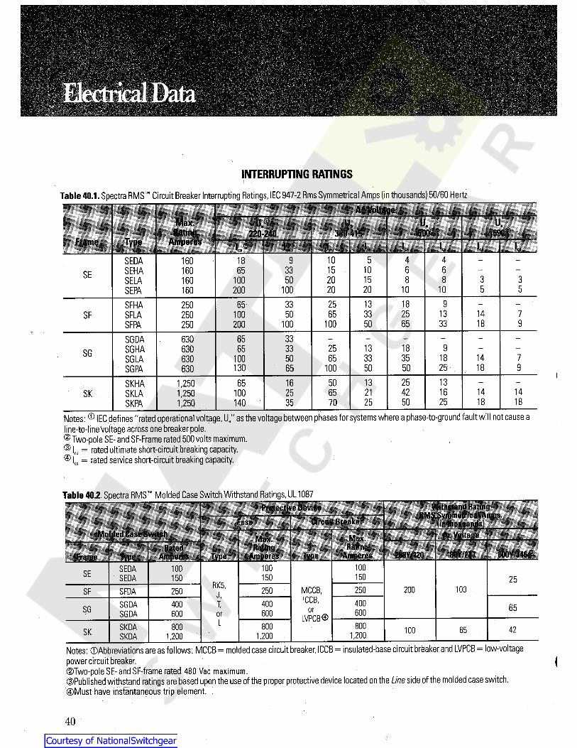
INTERRUPTING RATINGS
Table 40.1. Spectra RMS Circuit Breaker Interrupting Ratings,IEC 947-2 Rms Symmetrical Amps (in thousands) 50/60 HertzAc Voltage
u;Max. U„ U.U,Rating
Amperes500*220-240 380-415 690
Frame Type l c * I.* L L L I c s5SEDA 160 18 9 10 4 4
1033 15 6 6SEHA 160 65SE 15SELA 160 100 50 20 8 8 3 320160 200 100 20 10 5 5SEPA 10
933 25 13 18SFHA 250 6533 13SF 100 50 65 25 14 7SFLA 25050100 100 65 33 18 9SFPA 250 200
33SGDA 630 6513 18 933 25SGHA 630 65SG 1833 35 14 7630 100 50 65SGLA
130 65 50 25 18 9100 50SGPA 63013 1316 50 251,250 65SKHA21 42 16 14 141,250 100 25 65SK SKLA25 50 25 18 18351,250 140 70SKPA
Notes: ® IEC defines "rated operational voltage,Ue" as the voltage between phases for systems where a phase-to-ground fault will not cause aline-to-line voltage across one breaker pole.© Two-pole SE- and SF-Frame rated 500 volts maximum.® lcu = rated ultimate short-circuit breaking capacity.® lcs = ratedservice short-circuit breakingcapacity.
Table 40.2. Spectra RMS Molded Case Switch Withstand Ratings,UL 1087Withstand Rating
RMS Symmetrical Amps,
(in thousands)
Protective DeviceCircuit BreakerFuse
Molded Case Switch Ac VoltageMax.Rating
Amperes
Max.RatingRated
600Y.-346 -480Y/277208Y/120TypeAmperes100100SEDA 100SE 150150SEDA 150 25RK5, 100250 200MCCB,250 :SF 250SFDA Jr ICCB, 400X 400400SGDA 65SG or 600600SGDA 600 or LVPCB ®L 800800SKDA 800 4265100SK, 1,2001,2001,200SKDA
Notes: ®Abbreviations are as follows: MCCB= molded case circuit breaker, ICCB= insulated-base circuit breaker and LVPCB= low-voltagepower circuit breaker.©Two-pole SE- and SF-frame rated 480 Vac maximum.©Published withstand ratings are based upon the use of the proper protective device located on the Line side of the molded case switch.©Must have instantaneous trip element, i
(
40
Courtesy of NationalSwitchgear.com
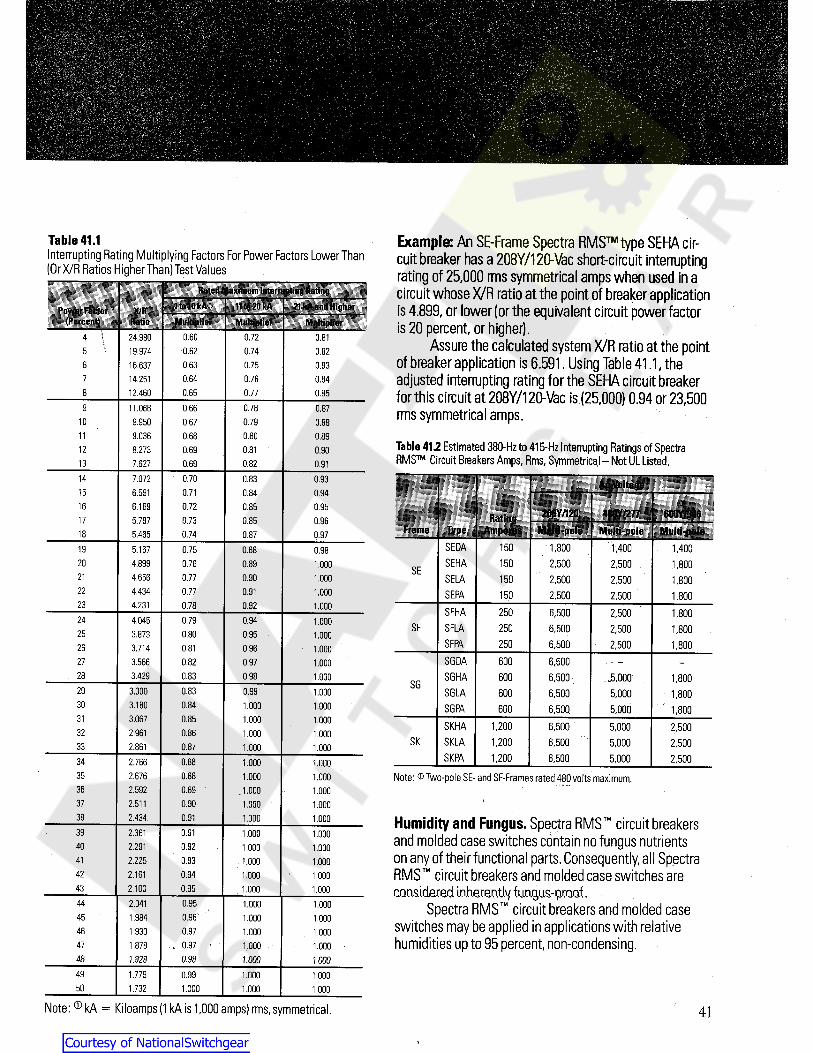
Example: An SE-Frame Spectra RMS type SEHA cir-cuit breaker has a 208Y/120-Vac short-circuit interruptingrating of 25,000 rms symmetrical amps when used in acircuit whose X/R ratio at the point of breaker applicationis 4.899, or lower (or the equivalent circuit power factoris 20 percent, or higher).
Assure the calculated system X/R ratio at the pointof breaker application is 6.591. Using Table 41.1, theadjusted interrupting rating for the SEHA circuit breakerfor this circuit at 208Y/120-Vac is (25,000) 0.94 or 23,500rms symmetrical amps.
Table 412 Estimated 380-Hzto 415-Hz Interrupting Ratings of SpectraRMS Circuit Breakers Amps, Rms, Symmetrical-Not UL Listed.
Table 41.1Interrupting Rating Multiplying Factors For Power Factors Lower Than(Or X/R Ratios Higher Than) Test Values
Rated Maximum Interrupting Rating11to 20 kA 21kA and HigherItolOkA sPower Factor
(Percent)X/R
Ratio Multiplier Multiplier Multiplier4 \ 0.60 0.72 0.8124.980
19.97416.63714.25112.460
\ 0.740.62 0.8250.63 0.75 0.836
0.760.64 0.8470.65 0.77 0.858
0.78 0.879 0.6611.0660.79 0.8810 9.950 0.670.800.68 0.8911 9.0360.81 ' 0.9012 8.273 0.690.8213 7.627 0.69 0.91
0.70 0.83 0.9314 7.072 Ac Voltage0.716.591 0.84 0.94150.72 0.85 0.9516 6.169 208Y/120 480Y/277 60QY/346Rating
Amperes i0.73 0.85 0.9617 5.797Frame Type Multi-pole Multi-pole Multi-pole0.7418 5.465 0.87 0.97
SEDA 1,800150 1,400 1,4000.75 0.8819 5.167 0.98SEHA 150 2,500 2,500 1,8000.8920 4.899 0.76 1.000 SESELA21 4.656 0.77 0.90 150 2,5001.000 2,500 1,800
22 4.434 0.77 0.91 1.000 SEPA 150 2,500 2,500 1,80023 4.231 0.78 0.92 1.000 SFHA 250 6,500 2,500 1,8000.79 0.9424 4.045 1.000 SF SFLA 250 6,500 2,500 1,8000.950.8025 3.873 1.000
SFPA 250 6,500 2;500 1,8000.9626 3.714 0.81 1.000SGDA 600 6,5000.82 0.9727 3.566 1.000SGHA 600 6,500 3,0000.98 1,80028 3.429 0.83 1.000
SG0.83 0.99 SGLA29 3.300 600 6,500 5,0001.000 1,8000.8430 3.180 1.000 1.000 SGPA 600 6,500 5,000 1,8000.8531 3.067 1.000 1.000 SKHA 1,200 6,500 5,000 2,5000.8632 2.961 1.000 1.000 SK SKLA 5,0001,200 6,500 2,50033 0.872.861 1.000 1.000
SKPA 1,200 6,500 5,000 2,5000.8834 2.766 1.000 1.000Note: ® Two-poleSE- and SF-Frames rated 480 volts maximum.0.8835 2.676 1.000 1.000
36 2.592 0.89 1.000 1.00037 0.902.511 1.000 1.00038 2.434 0.91 1.000 1.000 Humidity and Fungus. Spectra RMS circuit breakers
and molded case switches contain no fungus nutrientson any of their functional parts.Consequently,all SpectraRMS circuit breakers and molded case switches areconsidered. inherently fu.mju&-pcQQf.
Spectra RMS circuit breakers and molded caseswitches may be applied in applications with relativehumidities up to 95 percent,non-condensing.
0.9139 2.361 1.000 1.0000.9240 2.291 1,000 1.0000.9341 2.225 1.000 1.000
42 0.942.161 1.000 1.00043 2.100 0.95 1.000 1.000
0.9544 2.041 1.000 1.0000.96 1.00045 1.984 1.0000.9746 1.930 1.000 1.0000.971.878 1.00047 1.0000.9848 1.828 1000 1000
49 1.779 0.99 1.000 1.00050 1.732 1.000 1.000 1.000
Note: ® kA = Kiloamps (1 kA is 1,000 amps) rms, symmetrical. 41
Courtesy of NationalSwitchgear.com
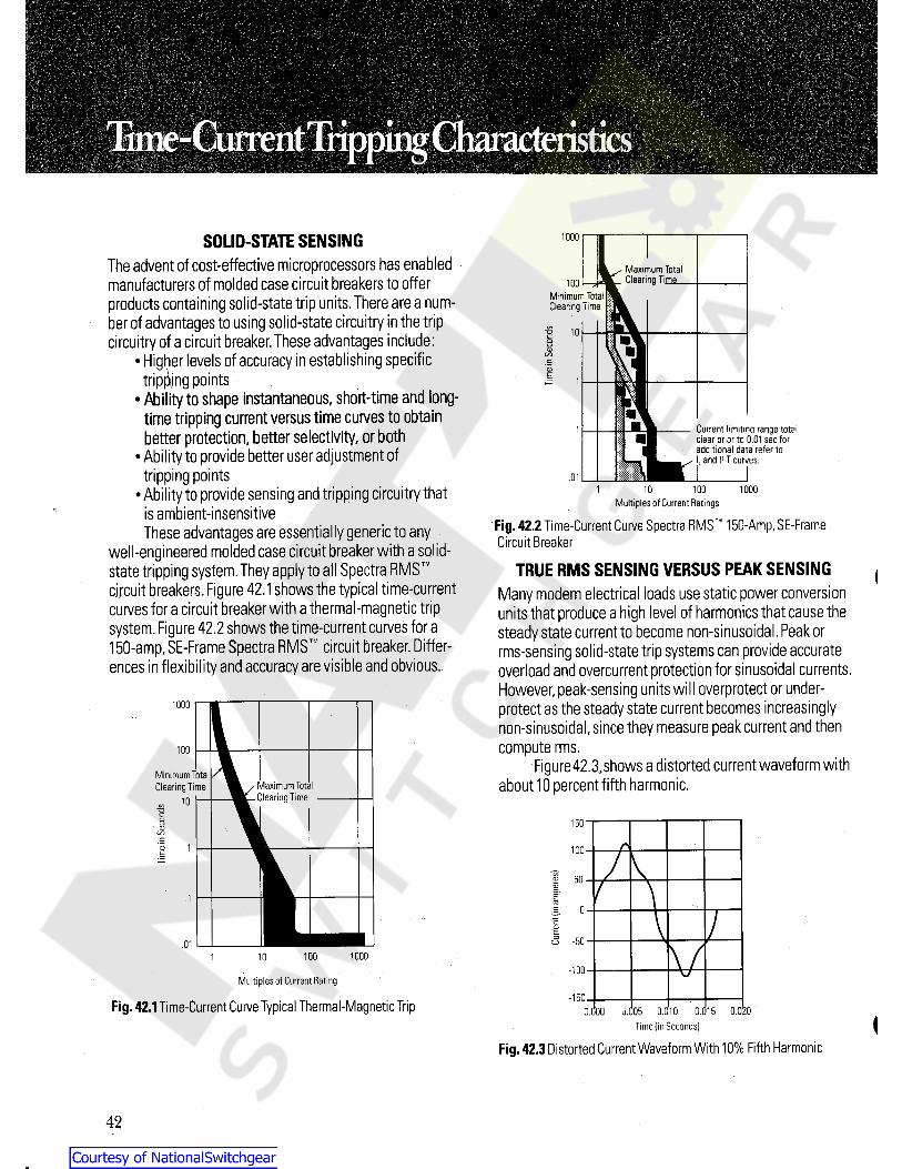
;•
SOLID-STATE SENSINGThe advent of cost-effective microprocessors has enabledmanufacturers of molded case circuit breakers to offeroroducts containing solid-state trip units.There are a num-oer of advantages to using solid-state circuitry in the tripcircuitry of a circuit breaker.These advantages include:
•Higher levels of accuracy in establishing specifictriplingpoints
•Ability to shape instantaneous, short-time and long-time tripping current versus time curves to obtainbetter protection, better selectivity, or both
•Ability to provide better user adjustment oftrippingpoints
•Abi ity to provide sensing and tripping circuitry thatis ambient-insensitiveThese advantages are essentially generic to any
well-engineered molded case circuit breaker with a solid-state tripping system.They apply to all Spectra RMScircuit breakers.Figure 42.1shows the typical time-currentcurves for a circuit breaker with a thermal-magnetic tripsystem.Figure 42.2 shows the time-current curves for a150-amp,SE-Frame Spectra RMS circuit breaker. Differ-ences in flexibility and accuracy are visible and obvious.
1000
Maximum TotalClearing Time100
Minimum Total1Clearing TimeI
1I 10 trso
V!©C/3e03E
\ m\
w10
Current limiting range totalclear prior to 0.01 sectoradditional data refer to. and P T curves.
. 1
.01100 1000
Multiples of Current Ratings>4
Fig. 42.2 Time-Current Curve Spectra RMS 150-Amp,SE-FrameCircuit Breaker
TRUE RMS SENSING VERSUS PEAK SENSINGMany modern electrical loads use static power conversionunits that produce a high level of harmonics that cause thesteady state current to become non-sinusoidal.Peak orrms-sensing solid-state trip systems can provide accurateoverload and overcurrent protection for sinusoidal currents.However,peak-sensing units will overprotect or under-protect as the steady state current becomes increasinglynon-sinusoidal,since they measure peak current and thencompute rms.
Figure42.3,shows a distorted current waveform withabout 10 percent fifthharmonic.
I
1000
100
MinimumTotalClearing Time Vlaximum Total
Clearing Time10to
co 15003
COc
1© 100E
to£ 50ETO
0.5
/c£
<5 -50.01 V100 10001 10-100
Multiples of Current Rating-150Fig. 42.1Time-Current Curve Typical Thermal-Magnetic Trip 0.000 J.005 0.010 0.015 0.020
Time (in Seconds)
Fig. 42.3 Distorted Current Waveform With10% Fifth Harmonic<
42
Courtesy of NationalSwitchgear.com
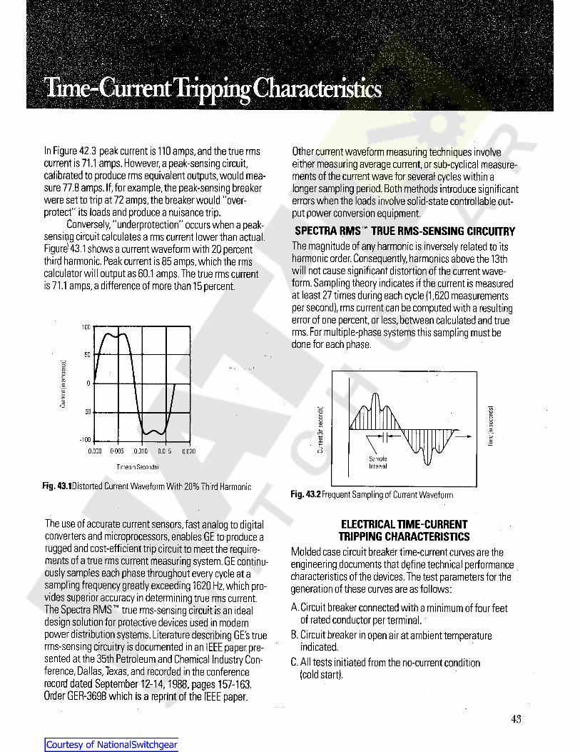
;
-
;
Other current waveform measuring techniques involveeither measuring average current,or sub-cyclical measure-ments of the current wave for several cycles within alonger sampling period.Both methods introduce significanterrors when the loads involve solid-state controllable out-put power conversion equipment.SPECTRA RMS TRUE RMS-SENSING CIRCUITRY
The magnitude of any harmonic is inversely related to itsharmonic order. Consequently,harmonics above the 13thwill not cause significant distortion of the current wave-form. Sampling theory indicates if the current is measuredat least 27 times during each cycle (1,620 measurementsper second),rms current canbe computed with a resultingerror of one percent,or less,between calculated and truerms.For multiple-phase systems this sampling must bedone for each phase.
In Figure 42.3 peak current is 110 amps,and the true rmscurrent is 71.1 amps. However,a peak-sensing circuit,calibrated to produce rms equivalent outputs,would mea-sure 77.8 amps.If,for example,the peak-sensing breakerwere set to trip at 72 amps,the breaker would "over-protect" its loads and produce a nuisance trip.
Conversely,"underprotection" occurs when a peak-sensipg circuit calculates a rms current lower than actual.Figure- 43.1shows a current waveform with 20 percentthird harmonic.Peak current is 85 amps,which the rmscalculator will output as 60.1 amps.The true rms currentis 71.1 amps,a difference of more than15 percent.
100
CO<Da>CLECDC
/T\CD
Cl
/TV JKC_5 coco -o-a
\ coc
oCDCO
CDCO
cC
If CDE2?
\ir u/3 \i/0.000 0.005 0.010 0.015 0.020 oSampleIntervalTime (in Seconds)
Fig. 43.1Distorted Current Waveform With 20% Third HarmonicFig. 43.2Frequent Sampling of Current Waveform
ELECTRICAL TIME-CURRENTTRIPPING CHARACTERISTICS
Molded case circuit breaker time-current curves are theengineering documents that define technical performancecharacteristics of the devices.The test parameters for thegeneration of these curves are as follows:
The use of accurate current sensors, fast analog to digitalconverters and microprocessors,enables GE to produce arugged and cost-efficient trip circuit to meet the require-ments of a true rms current measuring system.GE continu-ously samples each phase throughout every cycle at asampling frequency greatly exceeding 1620 Hz,which pro-vides superior accuracy in determining true rms current.The Spectra RMS true rms-sensing circuit is an idealdesign solution for protective devices used in modernpower distribution systems. Literature describing GE's true B. Circuit breaker in open air at ambient temperaturerms-sensing circuitry is documented inan IEEE paper pre- indicated,sented at the 35th Petroleum and Chemical Industry Con-ference,Dallas,Texas,and recorded in the conferencerecord dated September 12-14,1988,pages 157-163.Order GER-3698 which is a reprint of the EEE paper.
A. Circuit breaker connected with a minimum of four feetof rated conductor per terminal. '
C. All tests initiated from the no-current condition(cold start).
43
Courtesy of NationalSwitchgear.com

Information provided on the time-current curve includesthe following:
1.Product family type2. Specific device type3. Amp ratings covered on curve4. Overcurrent characteristics- long-time,short-time,
instantaneous,etc.5. Maximum total clearing time6.Maximum and minimum temperature limits7.Frequenby ratings8. Voltage ratings9. Specific trip unit ratings
10.Trip unit adjustment ranges11.TolerancesCurrent in multiples of rating plug are shown on the topand bottom horizontal axis,with time in seconds on theTable 44.1
vertical axis. Approximate minimum and maximum clear-ing time is readily determined from the characteristicscurves.For example,an SFLA,3-phase,480-volt breakerequipped with a 100-amp rating plug and instantaneousset at high (reference curve K215-173) under a sustainedoverload of 200 amps (2 times trip rating) reading up tocurve from the horizontal axis,will clear within 50 secondsto 120 seconds. Curve also shows that this breaker will tripinstantaneously,when set at 'Max.',at current values greaterthan 12 times breaker rating plug rating. This instantaneousclearing time with no intentionally introduced time delay,ranges up to 0.025 seconds as shown on curve.
Tripping characteristics meet National ElectricalManufacturers Association (NEMA AB-1) Underwriters'Laboratories, Inc. standards (489), CSA, IEC, and JIS.
TIME-CURRENT CURVE INDEXLetThrough Curve Numberr-current Curve NumberBreaker
;h:ir.i i11!il -un- Mu1
Circir""— Mag-Break - l2T IPRatingPlugFramelType:: i
K215-204K215-200K215-200K215-202K215-202
K215-205K215-201K215-201K215-203K215-203
K215-181K215-182K215-183K215-184K215-185K215-186K215-187K215-188K215-189
SE 3,77K215-165K215-166K215-167K215-168K215-169K215-170K215-171K215-172
SE 15,2030SE 30 25,30SE 40,5060SE 60 60SE 70,80100 K215-196
K215-196K215-196K215-196
K215-197K215-197K215-197K215-197
SE 90,100110,125
100SE 150SE 150 150
K215-179 K215-180K215-190K215-173SF 70,90,100,110,125,150,175,200,225,250
250
K215-199K215-199K215-199K215-199K215-199
K215-198K215-198K215-198K215-198K215-198
K215-191K215-174SG 125,150,175,200,225,250,300,350,400250,300,350,
400,450,500,600
400
K215-192K215-175SG 600
K215-193K215-194K215-195
K215-176K215-177K215-178
SK 300,400,500,600700,800
600,700, 8001000,1200
800SK 800SK 1200
44
Courtesy of NationalSwitchgear.com
PROCUREMENT DRAWINGSThese are 11 x 17 inch outline drawings with a blank
title block suitable for OEM use as a purchased part drawing.Order from GE ED&C, P.0. Box 2913,Bloomington, IL 61702-2913, Attention: Distribution Services.SE150 Frame .SF250 Frame .SG6D0 FrameSK1200 Frame
OUTLINE DRAWINGSOrder from:GE ED&CP.O. Box 2913Bloomington, IL 61702-2913Attn: Distribution Services
GEM-2877GEM-2878GEM-2879GEM-2880
Other Reference PublicationsSpectra RMS Circuit BreakersBuy Log CatalogShort-Circuit Calculations
GEA-1H 884GEP— 1 fOOGET-3550
Installation InstructionsSpectra RMS Circuit Breakers —SE- and SF-FrameSpectra RMS Circuit Breaker —SK-FrameInternal Accessories-Shunt Trip & UVRSE and SF Motor-OperatorSK Motor-OperatorRating plugs for Spectra Series RMSCircuit BreakersInternal Accessories-Aux. Sw &Beil AlarmExternal Accessory-SF-Frame LugExternal Accessory-SE-Frame LugSE and SF Rotary (TDR) handle operatorSG back connected studsSF line suppressorSE and SF Face mounted interlockSpectra RMS Circuit BreakerSG-FrameSG Motor-OperatorSE, SF, SG and SK STDA variable depthoperating mechanismsSE and SF Face mounted interlockadapter kitSE and SF TDM operating mechanismand handleSKTDM operating mechanism andhandleSG TDM operating mechanism andhandle
GEH — 5591
GEH-5592
GEH — 5551GEH — 5613GEH — 5614GEH — 5549 TM
GEH —5593
GEJ-3045GEJ-3051GEH-5609GEH — 5608GEH-5620GEH — 5615GEH — 5663
GEH —5657GEH — 5684
GEH — 5688
GEH — 5611
GEH — 5612
GEH — 5653
45
Courtesy of NationalSwitchgear.com

OutlineDrawings
SE150FRAME
C OF MOUNTING HOLES.72 [18.3] 4.88 [124.0]
2.68 [68.1].88 [22.4]- .90 [22.9]
B A\ © 4,Ti OFBRKRDIMS TO
'/4-28ROLL TAP
HOLES4.12 MAX
[104.8]n © TO n 1.38s \< [35.1]
il^sysr
flL_.S
TRIP BUTTON 0 4*
t4- 2.61 [66.3] .116 DIA.015 x 90°C'SINKv 4 CIRCUIT BREAKER
MOUNTING HOLES.224 [5.89] DIA.375 [8.53] DIA C'BORE3.66 [93.0]
2.78 [70.6] 2.31 [58.7 ]REF
6.51 [165.4].57 [14.5] x .42 [10.7]APPROXIMATE AVAILABLECONTACT AREA ON TOPOF STRAP
15.5® OFF 1.3° TRIPPED18° RESET'.54 [13.7] X .42 [10.7]
APPROXIMATE AVAILABLECONTACT AREA ON TOP
OF STRAP
•9.8° ONA 1.00 [25.4]
ni
LTT
JU 4.10
\3.38 3.62s. [104.1]\ /[85.9] 3.19 [91.9]— V4-28 UNF-2B' ROLL TAPDP:3.19 [81.0]2.55Ic OF[61.0] .81R
1.73 . i iHANDLE ± [64.8][15.5R] APIVOT.86 .86.75.75[43.9]
I [21.8] [19.0] [19.0] [21.8]l y-.33 [8.4]
sT / T F£ OF*4— 42 [10.7] MAX WIDTH OF STRAPSBRKR — 1.74
[44.2].54 [13.7] X .42 [10.7]APPROXIMATE AVAILABLE
CONTACT AREA ON BOTTOMOF STRAP
.81 [20.6] X .42 [10.7]APPROXIMATE AVAILABLECONTACT AREA ON BOTTOMOF STRAP
.19 [4.8] REF
NOTE:1.DIMENSIONS IN BRACKETSARE IN MILLIMETERS.
’/4-28 UNF-2B• ROLL TAP
[ MAX. TORQUE40 LB-IN ] BOTH ENOS
2.78 [70.6]
.51 [13.0]
.952 [24.18] .69 [17.5]
£HANDLE PIVOT
—.82 [20.8]
£ OF '/4-28 ROLL TAP HOLES5.25 [133.4].53 [13.5]' REF-4 CIRCUIT BREAKERMOUNTING HOLES..224 [5.69] DIA.37519.53] C'BORE
OPTIONAL .79 [20.1]6.31 [160.3]
A 2.81 [71.4]LUG DATA1.16 [29.5]-jCATALOG NUMBER: TCAL18, TCA118LV .79 [20.1] 1.12 [28.4|—i
WIRE RANGE: #12 - 3/0 CU / AL T 2.81 [71.4]1TORQUE: #12, #10 35 LB-IN#8- #3 100 LB-IN#2- 3/0 150 LB-IN
# nT .69117.5]£1.38 [35.1]
Twz?OPERATING FORCES #
28 LB (12.7 Kg)TRIPPED TO MAX RESET .41 [10.41-11.34 [34.0]
13 LB (5.9 Kg)OFF TO ON 1.85 [47.0]
ON TO OFF 14 LB (6.4 Kg)
2.55 [64.811.09 [27.7]
4.88 [124.0]
46 DOOR CUT-OUT
Courtesy of NationalSwitchgear.com
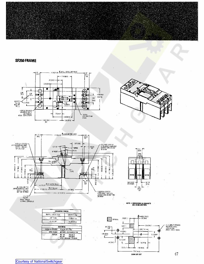
SF250FRAME
tOF V,6-18 ROLL TAP HOLES.87 8.38 [212.91 .87122.11 [22.1]REF2.88 [68.1)
.93123.6)
2.28 [57.9]\ &f i e ;t)»l2.06 i1.38 © 4.125 MAX
[104.78]
[52.31 y [35.1]i 1.38t tT I (35.1)a»i»DIMS TO
5/.6-18ROLL TAP
HOLES
' 2.75 [69.8I TRIP T7« ‘8UTT0N1 [+)>]
4 CIRCUIT BREAKERMOUNTING HOLES.224 [5.69] DIA.438 [11.131 DIA C’BORE
1.75 (44.4] .116 DIA.015 x 90° C’SINK2 PLCS3.66 (93.0] -I
- 2.28 (57.9) . —5.06 [128.5]REF
frOF MOUNTING HOLESI— 1.19 7.751198.8] 1.19 -[30.2] [30.2]REF
1 1.97 [50.0].98 [24.9] X .58 [17.3]APPROXIMATE AVAILABLE
CONTACT AREA ONTOP OF STRAP
.97 [24.6] X .68 [17.3]APPROXIMATE AVAILABLECONTACTAREA ON TOPOF STRAP
.31 [7.9]15.5° OFF1.3° TRIPPED
9.8° ONREF 1.00
[25.4]T"18° RESET m72k y i " u \ /
-ft \| MU
I
a 1 § £“ g & P TT 5i2 1 COS i s 55
* ' 3 s £
o?IIs =»g I s.6 1 R S 5 s iI[15.5 R]i l l
CO £1 cvj * R
1 ^1 a i11 ii i<f
5/16-18a MAX WIDTH — HOF STRAPS
.68 TYPaROLLS 117.3)TAP a£ OF HANDLE PIVOT5.03 [127.8]1.02.98 [24.9] x .68 [17.3]
APPROXIMATE AVAILABLECONTACT AREA ONBOTTOM OF STRAP
$ OF BREAKER [25.9]5.06 [128.5] 3.88 [98.6] TYP1.16 [29.5] X .68 [17.3]APPROXIMATE AVAILABLECONTACT AREA ON BOTTOMOF STRAP
— 10.12 (257.0)
5/16-18 '
ROLL TAP[ MAX. TORQUE90 LB-IN.IBOTH ENDS
NOTE:1.DIMENSIONS IN BRACKETSARE INMILLIMETERS.
OPERATING FORCESTRIPPED TO MAX RESET 28 LB [12.7 Kg) IHANDLE PIVOT
- .82 [20.8].79 [20.1]OFF TO ON 13 LB [5.9 Kg)OPTIONAL
ON TO OFF 14 LB (6.4 Kg)
REF-4 CIRCUIT BREAKERMOUNTING HOLES.224 [5.89] DIA.438 [11.13] DIA C’BORE
1 3.91 [99.3].79 [20.1].69 [17.51-LUG DATATYP T 2.81 [71.4] -HCATALOG NUMBER. TCAL29. TCAL29LV T 1.10 [29.5] TWIRE FIANCE: #8 AWG-350 kcmll CU / AL
1.38 [35.1) 1.12128.4)TORQUE #8- #4#3- #1#1/0-350 kcmll 275 LB-IN
150 LB-IN200 LB-IN TYPi 1
1.34 [34.0]
r
V,i.41 [10.41-1 1.85 [47.0|
1.09 [27.7] 2.55 [64.8]
— 7.75 [196.8] -DOOR CUT-OUT 47
Courtesy of NationalSwitchgear.com
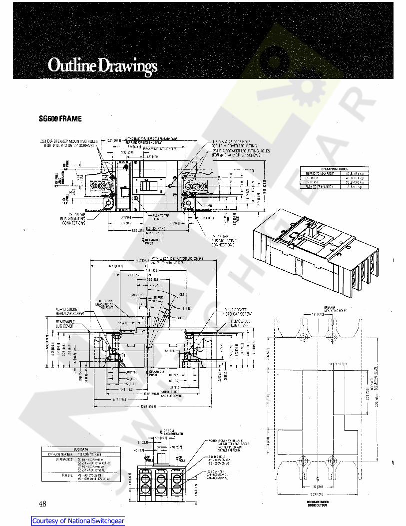
SG600FRAME
WITH 331A1770G2 BUS COVERS BOTH ENDS(SUPPLIED FOR LINE END ONLY)
7751196-81 BREAKER MOUNTING HOLES ^
10.31 [261.9].261 DIA BREAKER MOUNTING HOLES(FOR #10, #12 OR W' SCREWS)
.116 DIA X .25 DEEP HOLEFOR TRIM COVER MOUNTING- .261 DIA BREAKER MOUNTING HOLES(FOR #10, #12 OR W' SCREWS)
3.30 (83.8]1.87 (47 5]
UJ ap
S2 44- OPERATING FORCESt 7
£ \
<2-1 TRIPPED TO MAX RESET 40 LB ( 18.1 Kg]ia sSea (S^ Zeeo<ea
B £± — OFF TO ON 40 LB (18.1 Kg)ai J-S -lsFT5? o ON TO OFF 30 LB (13.6 Kg)sea .Ccfrri eg«*- PUSH-TO-TRIP BUTTON 3 LB (1.4 Kg)IIT L.
W O ‘F- to ” _ iriT - £T S a
s 8 <i>UJ
4* ,125R T CM\non
TV2-13 TARBUS MOUNTING
CONNECTIONS
OPUSH TO TRIP.40 DIA a!.77 [19.6J -
3.73 [94.7 ].359 [9.12]
.41 [10.4|BUS MOUNTING8.62 [218.9]CONNECTIONS
V2-13 TARBUS MOUNTINGCONNECTIONS
OF HANDLEPIVOT
WITH LUGS AND 331A1770G1 LUG COVERS13.62 [345.9](SUPPLIED WITH LUG KITS) )
/6.23 (158.2!
7.12 [180.8]2.98 [75.7]
3.50 [88.9]
4-1.17 [29.7 ]
(WAX RESET!ALL FORCES
MEASURED ATTHIS POINT BREAKER
MOUNTING HOLES19 [4.8]V2-13 SOCKETHEAD CAP SCREW
Vz-13 SOCKETHEAD CAP SCREW
REMOVABLELUG COVER
1.81 [46.0].38 [9.7 ]f n nn nn nREMOVABLE
LUG COVER.17 (4.3] I 1 I U I I U I I II IV
\J . [- _
\ M• s - ') \7 /m SBfn T
" \ 1 /TM/FT ! r s 1t u T 705C-5 1 \1\T s i l l
S § I 3° § S 2 2 I= 22 £ § * ® 5?* FTCO
CO1.56 [39.6] —| U“)CM
'J- <*> ri o <-i CMLHA § 3 gI l l li£ i * nSift-i I1 1 1 1 s i ln .71 [18.0]i
I £2T L- OF HANDLEPIVOT
.70 [17.81.62 [15 7]
—1.22 [31.014.46 [113.3] —
o.87122.1]
.62115.7]a =»
s s £
57 mS1.23 [31.2]WITHOUT LUGS O
10.09 [256.31 AND LUG COVERS RCsi
<LO05in
CD5.73 [145.5]P**H unCO12.62 (320.5!
i OF POLEAND BREAKER
1.81 [45.0] 5NOTE: SHOWN WITH LUG KITCAT. NO. TCLK 365 (3-P0LE)(NOT SUPPLIED WITHCIRCUIT BREAKER)
.91 [23.1| £2S.91 [23.11LUG DATA .45 [11.4| iCATALOG NUMBER TCLK 265. TCLK365 t 4' '4.844 DIA HOLE
#8-400MCM CU#6-500MCM AL
WIRERANGE (1) #8^ 600 kemil or( 2) 2/0 - 400 kcmil CU or(1) #6- 600 Kemil or( 2) 2/0 - 500 kcmil AL
ROLE \/~~
F/ \ -t// \ ^ - / \
> \ \C&T) ( \.922 DIA HOLE2/0-600MCM CU2/0-600MCM AL
*1 t )i rTORQUE: #8 - #3 275 LB-INn - 600 kcmil 375 LB- IN 0 u u<oco u L J U
© 1.93 (49 0]
5.00 [127.01
48 RECOMMENDEDDOOR CUTOUT
Courtesy of NationalSwitchgear.com
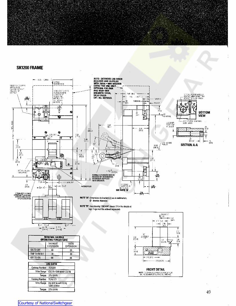
pp.... , vX :
> V . -’, '. . V; . .V fvM&f ~ "
SK1200FRAME
NOTE: EXTENDED LUG COVERREQUIRED AND SUPPLIEDWITH 100KA •480V BREAKER(SKPA) THIS END ONLY.OPTIONAL FOR 65KAAND SOKA* 480VBREAKERS (SKHA,SKLA) ORDERCAT. NO. SKPSHLD.
8 25 - [209 6 ]OF POLE-AND BREAKER
K88 (47 8| X 1 62 [41.1|APPROXIMATEAVAILABLE CONTACTAREA ON TOPOF STRAP.
r “1
.39 [9.911 MTG HOLES
.75 [19.0 j t C BORE
.56 [14 2 ] DEEP
.73 [18.5]THKMATERIAL SEESECTION A-A(4) HOLES
7 09 [180115 50 [139.7 - -[
1.12 [28.41 MAX 0 AVAILABLECONTACT AREA FOR BOTTOMCONNECTION ( BOTH ENDS )
II
1.31 [33.31! 1.06 (26.9)-a 33I .58 )14 21(8.41 m%I 1.94ji1 [49.31 BOHOMu
I.88 . JQ « OF-TERMINAL
[22 4| VIEW/4— 1/2-13 TAPPED TERMINALS
(BOTH ENDS)COUJ LUG COVER
KNOCK OUT.81 [20.6J 0
o10.42rtr
.48[264.7![12.2!3.5019.50 s5
[88.9! i[495.31$$OOJCO
/3.00 [7.6.21
1.50 s-l 7 00— [177.81unC^J
138.11 8415 50121.31iT .73[393.7 ]1 ON
^ OF HANDLE [18.51SECTION A-A19.7 PIVOT11623.95 r 1295 2) ,[100.31 57 -4£.! f189
6.31|48 Of O[160.3]1 4.373 50188 9 ] [111.01103
4.12|26 2|
± [104.6 ] .77[19.61I £%°FINSTANTANEOUS
ADJUSTMENT TERMINALHANDLE EXTENSION MAY BEROTATED 90° OR REMOVED.
i EXTENSION SUPPLIED— WITH BREAXER.
Ie —i 1.94» m w83 i[22.4!
J T2.75 |69 8|TVPLUG COVER
(USED ONBOTH ENDS)
SEE NOTE *B’
/625 1.061.62 [41.}J RATING PLUG[ 15.881 wr- SI [20.6]/ —ffll1.75 f44.45) X 157 [40.0)
APPROXIMATE AVAILABLECONTACT AREA ON TOP
Of C/T CONDUCTOR NOTE "A": Dimensions inbrackets ( ] are m millimeters.0 denotes diameter.
NOTE “B”: See drawing 139C4967 sheets 3 &4 for details oflugs.Lugs must be orderedseparately.
OF HANDLEIPIVOT1.90[48.3I— 3.12 ( 79 2)
156
^OF POLE
La- 2i7 5^[69.8]
H O P P O L E [ 38 612.75[69.8] f
2.12[53.81OFfHANDLEJfcrNOMINAL HANDLE
OPERATING FORCES (LBS)4.07 PMJT[103.41 1.29.41R!- [32.81110.4 R)
WITHOUTEXTENSION
WITH TEXTENSION mm1.71ONTO OFF 40 20 [43.41TRIP TO RESET 178 39
3.45 [87.61OFF TO ON 88 445.53 [140.51
LUG DATACatalog Number TCAL81 FRONT DETAILWire Range (3) 3/0-500 kemil CU/AL NOTE: RECOMMENDED FRONT COVER CUT-OUT
.06 [1.5) CLEARANCE ALLOWED ALL AROUND.Torque 375 LB-INCatalog Number TCAL121
Wire Range (4}-500 kemil CU/AL1200 A Max
Torque 375 LB-1N49
Courtesy of NationalSwitchgear.com

OutlineDrawingsO
Plug-In Bases (4) "J" BREAKERMOUNTING HOLES
(4) MOUNTING HOLES WITH C'BOREFOR .31 HEX. HEAD BOLTS
(FURNISHED BY CUSTOMER)
MOUNTING PANEL .38 THK. MAX(FURNISHED BY CUSTOMER)
.59u—1.50—».75-
(4) .38 HOLES IO /2m 7j
</ }S s so §5 S
l' **tu< > o » II5 rJis. to<I3 o - =3^o o
\* 1.0 — 1.81—-II>
"'7 LONG STRAPINSULATION
1.81 - .50
•—1.42AA•—1.31 •— 1.50—«
SE150. SF250BREAKER
.38—qF (SHORT STUDS) »
iG (LONG STUOS)
c B - H •75-DRILLING PLAN FOR MOUNTING PANEL c E.69
\ D2 POLE-CENTER POLE OMITTED NOTE: HORIZONTAL STUDS AS SHOWN FOR
VERTICAL STUDS. ROTATE CU STUDS90', OTHERWISE SAME AS HORIZONTAL.
Dimensions In InchesBreaker Type E F H JA B C D G
SE150 2.63 4.86 5.25 6.63 4.09 4.16 6.84 .88 #8-32 TAP5.75 7.25 8.38 9.75 5.50 4.66 7.66 #10*32 TAPSF250 1.00
SE150 and SF250 Lines-PLUG-IN BASEM?T'LSSFCREWS 5.4815.63
[397.0]'T [139.2]
PAN•MOUNTING
HOLES
1.811.8114.15[359.4]' [46.0][46.0]'
6.52 ~
f »fat 5.515.26[133.6]
[165.6] + 1.20 5.01[30.5] [127.3] [140.0]IJ 1.81CAT. NO. SMP3
PLUG-iN BASEMOUNTING PAN .OPTIONAL
3.62llI [46.0] [91.9]I I III II im » I®ll J G FRAME -BREAKER 9 9 TMOUNTING
HARDWAREFURNISHED
6.91 3.20PLUG-IN-BASE[175.5] [81.3]4.04
[102.6]'4.04[102.6]'
4.54[115.3]' £PLUG-IN BASE
MOUNTING HOLES I(4)3/B" x1/t BON6ATEO HOLES TORQUE(30 IN-LBS)
TYP15.63 -0-0- -o-o- f14.63 CLAMP 4.88
[124.0]13.15 4.25[108.0]r 4.04 —i ri.oo
TYP 1.811.81-o-o- [46.0][46.0]'
.33TYP .50 TYP,53 DIA[13.5 DIA]i 1.05t0 ~[26.7] K [26.7]Tt 3.12 NOTE:
DIMENSIONS IN BRACKETS l lARE IN MILLIMETERS
5.615.50 1.81 5.23iTYP t .06 RIft 1n.50 TYP
.143.38 5.20 3.38 —1 ^.69.19 R
8 PLACES1.33 SG600 Line
MOUNTING PANEL.38 THICK MAX.'FURNISHED BY CUSTOMER)(4) MOUNTING HOLES WITH C’BORE
F0f^31 HEX. HEAD BOLTS(FURNISHED BY CUSTOMER) 2.00 1.41 "D" THICKNESS
r .69 HOLEr (2) .56 HOLES
2.88-i -2.88 1.50-(4) .31-18 TAPBREAKER MOUNTINGHOLES \
-1.411.41COro.50 T 1 3ECD 4-f-fr iT 1.00
d!i sI OxJ
I iT cd I .
III! r- +-SLO LO 3•1.19 \ T1Oxl u.Oxl
LO\ I(4) .31 HOLES(4) .44 HOLES
U—7.62 —J r.v2.00 —• oV ioj .8811.62 3E1.31- LO 13E Oxl.88-f14.25 -.53Oxl I— 2.88—“uDRILLING PLAN FOR MOUNTING PANEL 7.62 LONG STRAINSULATION
33.94— 6.3111,62 - - 1.94J14.25D Thickness BREAKERSK1200 LINE
Amperes 10.58 (LONG STUDS)15.50
.44800ANOTE: HORIZONTAL STUDS AS SHOWN.3 POLE AS SHOWN
2 POLE CENTER POLE OMITTED.621200A rnhi /rnTin A I OTI ino nnTATr PI i PTI morun vcm IUML o i uuo nuIMI C UU O I UUO
90° OTHERWISE SAME AS HORIZONTAL.SK1200 Line50
Courtesy of NationalSwitchgear.com

Back-Connected Studs BKR IS REMOVABLE FROMFRONT OF PANEL BYRE-MOVING MTG. SCRS. INB/C STUDS.
FOR PANELS OVER T'THK ANDNOT MORE THAN 2" THK, C’BOREREAR OF PANEL .875 DIA. & DEEPENOUGH TO MAINTAIN 1" THICKNESS.
TA
ETHDS\
r
L-i-J<>
SE150Line D *>
C-LONG INSUL. TUBEAND CLAMP NUT
A-’SHORT INSUL TUBEB
*-CLAMP NUT
! fIi=77Z
PHENOLIC RISER«.5 MIN,
1. MAXNOTE:-WHEN ASSEMBLING STUDS TO PANEL
OR BREAKER A SHORTAND A LONGSTUD MUST BE ASSEMBLED TO BEADJACENT TO EACH OTHER IN ORDERTO MAINTAIN PROPER UNDERWRITERSCLEARANCE BETWEEN POLES ONEITHER 250V. OR 600V.CIRCUITS.
THEREFORE, WHEN ORDERING STUDSAN EQUAL QUANTITY OF BOTH STUDSSHOULD BE ORDERED.
.0312AIR GAP BETWEENBKR AND CUSTOMER'SPANEL.
STUD. CAT. RATING & LENGTH A B C D ETEF1 15-50A SHORT 1.06 2.75 14-20TEF2 15-50A LONG 2.56 1/4-204.38TEF3 60-150A SHORT 1.25 3.375 3/8-16TEF4 60-150A LONG 3/8-163.62 5.75
/4-20 x 1" LG. SCR.' .25 LK. WASH.
.25 PLAIN WASH..25 MIN. -1" MAX PANEL THICK.
3.697 .38 x 1" HEX.72- .44
aaSF250Line 1/2-13
THD.
2.69 *>
5.94— *•
51
Courtesy of NationalSwitchgear.com
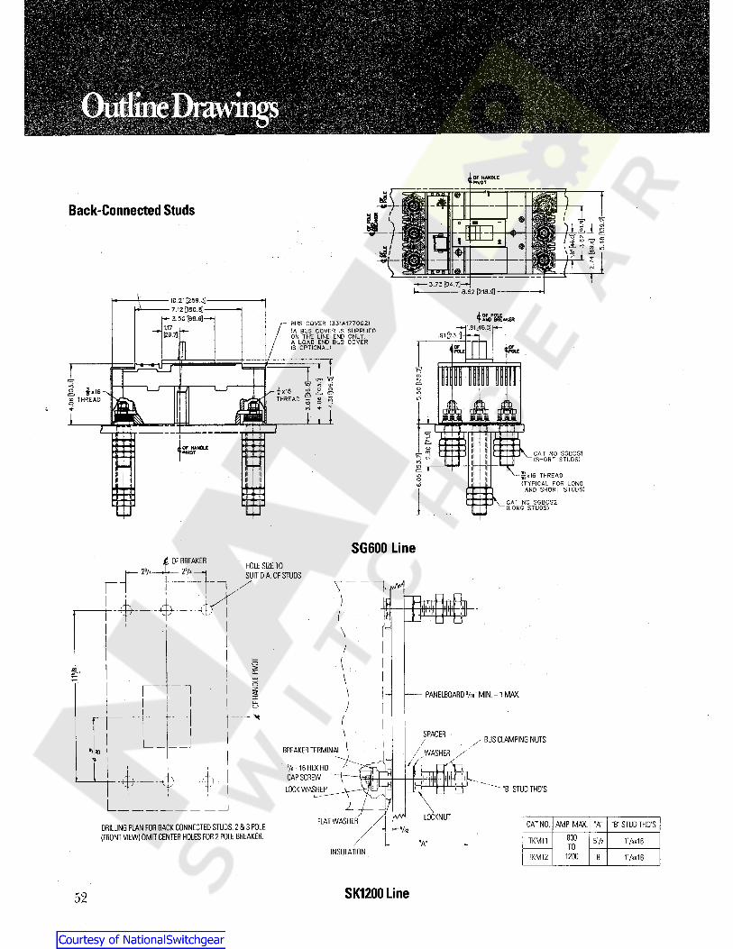
Mii ‘;M!•A-ffi' «1As
'*41 o-
OudineDrawings :iA,
m
OF HANDLE' tPWOT
T
Back-Connected Studs /© r ’o?a
c . 2 s ® 5l A OT *
1 8
^10
\ Ev-r>a nj
©H OHT3.73 [94.7]-
6.62 [218.9]i — 10.21[259.3]—— 7.12[150.8]— 3.50[88.9]-—\4OF POLE
AND BREAKERBUS COVER (331A1770G2)( A BUS COVER IS SUPPLIEDON THE LINE END ONLY.A LOAD END BUS COVERIS OPTIONAL )
1.81[46.0]1.17[29.7] .91[23.1]
*P0LI l«JLEmtf =>
» 7=7O)
>o•f 'co' ®
^ E5 o «n •+ T
.=J
*o ix!6THREAD
oiE fx16 -xg THREAD
nin
1 liI MiaIfin ]f II IImm\
mmw«immi
i\ «M »1 1 HII I D• OF HANDLE
* ‘PIVOTo V CAT NO SGBCS1
(SHORT STUDS)T7 w*
M iin '
F^-gx16 THREAD
(TYPICAL FOR LONGAND SHORT STUDS)
CAT NO SGBCS2(LONG STUDS)
P 1)!fi o
in
eSG600 Line
(. OF BREAKER23/4 —--— 23/4 —1 HOLE SIZE TO
SUIT DiA. OF STUDSV uv
=ffi=f\/
(o>£\
I 1< PANELBOARD Vie" MIN.-1 MAX.xu_
/(\ SPACER BUS CLAMPING NUTSlBREAKER TERMINAL*> <0 / ^
WASHER3/s - 16 HEX HDCAPSCREW
LOCK WASHER
i
A.- “t n "B" STUD THD’Su-
AAAA* LOCKNUTFLAT WASHER CAT NO. AMP. MAX. "A" "B“ STUD THD'SDRILLING PLAN FOR BACK CONNECTED STUDS. 2 & 3 POLE.
(FRONT VIEW) OMIT CENTER HOLES FOR 2 POLE BREAKER. *-S/32800TKM11 5Vz 11/8X16"A" TOINSULATION 1200TKM12 8 178X16
SK1200 Line52
Courtesy of NationalSwitchgear.com

Motor-Operated Mechanisms
10.12[257.0]
6.31[160.3]- WINDOW OPENINGr- WINDOW OPENING
\ \l o i nQ.75 .75 b==0 * 0[19.0] [19.0]4.12 o© B•e e 0]r[104.6] 4. 21
1o O O U[104.6]n iIGf
L?_Tm o O {0 0I1.68 1.680 n: <?_ 0o[42.7] [42.7] rt=.! ©f
2.58 —4 F— .50 I— .501.90[65.5] [12.7][48.3] [12.7]
UNIT OPEN FORMANUAL OPERATION UNIT OPEN FOR -
MANUAL OPERATIONUNIT CLOSED & READYFOR OPERATION UNIT CLOSED & READY
FOR OPERATIONq=g q=Q.21 —- .21LATCH RELEASE
BUTTON[5.3] .15[5.3] [3.8]
T T11.323.2910.653.59 [287.5][83.6][270,5][91.2] 3.84 10.54[97.5] [267.7]n 9.87, lLATCH RELEASE
BUTTON[250.7]
ifTT— vTs UYf 1.36— 2.73 7.656.98 [34.5][69.3] [194.3][177.3] l
fi- llii H
f \TSE BREAKER 1.82
.75 [46.2]SF BREAKER[19.0].72 4.88 —-[124.0] *[18.3]
MOUNTING HARDWARE(FURNISHED)
MOUNTING HARDWARE(FURNISHED)
- 6.51[165.4] 1.187.75
[196.8] [30.0]
NOTE: DIMENSIONS IN BRACKETS[ ] ARE IN MILLIMETERS
SE150Line SF25Q Line
53
Courtesy of NationalSwitchgear.com

Motor-Operated Mechanisms
UNIT IN OPENPOSITION FOR
MANUAL OPERATION.75 PULL LATCH'
HANDLE UPTO OPEN
[19,0] 3.38 rBREAKER MOUNTINGHOLES
[85.9]^WINDOW OPENING'
i / 5.48[139.2]
tE LUC COVERi UNIT IN CLOSEDPOSITION READYFOR OPERATION
1.815.48 4.91[139.2] [124.7] [46.0]
I * 14.85 14.47[377.2] [367.5] LUG COVER
3 n SSLOF BREAKERft M.O.M.
/ i.75[19.0] 7.64
[194.1] 6205.7]
T7.75 T7[196.8]; 4.08[103.6]
3.8110.13 INSTRUCTION LABEL [96.8] ![257.3]13.62[345.9] I 11—7f'5'
MOUNTING HARDWAREFURNISHED
#10-32 THREADEDSTUD SIZE
7.75[196.8] 1.812.93
[74.4] [46.0]13.62[345.9j
14.23[361.4]
SC CIRCUITBREAKER £ BREAKER MOUNTING
HOLES
SG600 Line
WINDOW OPENING PULL LATCH HANDLEUP TO OPEN /
.75 UNIT IN OPEN POSITIONFOR MANUAL OPERATION[19.0] <L OF BREAKER
MOUNTING HOLES1.00 1.56[25.4] [39.6] UNITIN CLOSED
POSITION READYFOR OPERATION
INSTRUCTIONLABELliILH /I W .15
[3.8]f t OF BREAKER J8£3& M.O.M. [480.8] r 3.27
4- [83.1]5.77 —[146.6] T
18.62o [472.9]a [arr LUG COVER (OPTIONAL
ON SOME CATALOG NC-rrr
1.23- 9.251.64 I ![31.2] [235.0] 5.38[41.7] i[136.7]
8.42[213.9] i i/ I i1
15.50 T[393.7]SK CIRCUITBREAKER19.50 MOUNTING HARDWARE
FURNISHED1.06
[495.3] .62 - [26.9][15.7] 14.25
[362.0]16.15[410.2]
NOTE: DIMENSIONS IN BRACKETS[ ] ARE IN MILLIMETERS
19.50[495.3]
SK1200 Line
54
Courtesy of NationalSwitchgear.com
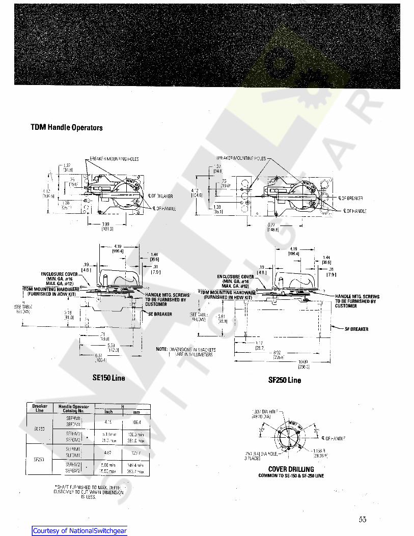
TDM Handle Operators
BREAKER MOUNTING HOLESBREAKER MOUNTING HOLESr- 1.37r* I -37
[34.8][34.8]\ C\ ©
75.75[19.0] [19.0]
4.12412[104.6]<t OF BREAKER OF BREAKER[104.6] I I zi1.38
1.389 <i OF HANDLE[35.1] <t OF HANDLE0^ l --^/1 [35.1]d
5.773.99[146.6][101.3]
4.19 4.19(106.4| (106.41' 1.44(36.6) 1.44
^ [36.6J.19.19..31
.31( 4 .8 ) ( 4 .8 I[ 7 .9 ] 17.91ENCLOSURE COVER(MIN. GA. #16MAX. GA. #12)
ENCLOSURE COVER(MIN. GA. #16MAX. GA. #12) n‘TDM MOUNTING HARDWARE-
j (FURNISHED IN HOW KIT) TDM MOUNTING HARDWARE -(FURNISHED IN HDW KIT) HANDLE MTG. SCREWS
TO BE FURNISHED BYCUSTOMER
HANDLE MTG. SCREWSTO BE FURNISHED BYCUSTOMER
5V , ‘ JItI r'vyiJrYH W
(SEE TABLEBELOW) H iJ SE BREAKER3.19 (SEE TABLE
BELOW) 3.81[81.0] u H i [96.8]i , it t
SFBREAKERi n
ij. /
[18.0]1.175.59 [29.7]NOTE: DIMENSIONS IN BRACKETS
[ j ARE IN MILLIMETERS142.0] 8.92i
[226.6]- 6.5110.09[165.4)[256.3]
SE150Line SF250Line
Breaker Handle OperatorCatalog No. 1.937 DIA HOLE
[49.20 DIA]Line Inch mm
SEFHM1SEF0M 1 4.19 106.4
a30° 30°SE150 \\\SEFHM2
SEF0M25.13 min15.0 max
130.3 min381.0 max OF HANDLE7\
1.156 R[29.36 R]
SEFHM1SEF0M1 .25016.4] DIA HOLE,
3 PLACES4.87 123.7
SF250SEFHM2SEFGM2
5.88 min15.50 max
149.4 min393.7 max COVER DRILLING
COMMON TO SE-150 & SF-250 LINE
*SHAFT FURNISHED TO MAX. DEPTH.CUSTOMER TO CUT WHEN DIMENSION
IS LESS.f
55
Courtesy of NationalSwitchgear.com

OutlineDrawings8.00
1203.2 ]
2.06152.3 ]
CoF HANDLETDM HANDLE OPERATOR'
MECHANISM
TOM Handle Operators •ENCLOSURE COVER(MIN. CA.F16
MAX. CA.»1212.780 HOLE
[?0 60] \TDM MOUNTING
HARDWARE(FURNISHED)
nn r\W
l AifBREAKER MOUNTING
HOLES30° 30°HANDLE MOUNTING
HARDWARE (FURNISHED. BY CUSTOMER)S.flS(FIXEDD&*TH)
114.9J15.63MAX (VARIABLE DEPTH)
[397.01)5.63MM.(VARIABLE DEPTH)
(143.0)
.42
[10.7]JL$3?r Ti —1¥n 1.69 R 26 0 * 003 DiA.
[6 6 0]1.915.46 I CLOF BREAKERl r HANDLE
[42.9 R] 3 HOLES
[138.7] M
¥ .62 COVER PRILLING
T [15.7]H Hi
lT1.38 CAT.NO. REMARKS7.75 [35,] SG BREAKER - 13.62[196.8] WITH HANDLESGHM2[345.9]’
SGOM2 WITHOUT HANDLE
SG600 Line SGHM1 WITH HANDLEWITHOUT HANDLESGOM1
o2.75[69.81
8.25[209.6] l C OF BREAKER
HANDLE
2.78 DIA HOLE[70.6 DIA]
o
BREAKER MOUNTING HOLES1.81[46.0] 30°H- 4.37 1[111-0] t 1
111.61 \[294.9]
14.25 1.69 R[362.0] [42.9 R ]
8.00[203.2) 2.06 .265 (67.3] ± .003 DIA,
3 HOLES152.3]ENCLOSURE COVER(MIN. GA. #16,MAX. GA. #12)
TDM HANDLE OPERATORMECHANISM
COVER DRILLINGAAA
HANDLE MOUNTING HARDWARE(FURNISHED BY CUSTOMER)TDM MOUNTING HARDWARE
(FURNISHED) ^CAT. NO. REMARKSiLmI'I£OF SKHM1 WITH HANDLE
HANOLE
(SEE TABLE SK BREAKER-BELOW)
U
SK0M1 WITHOUT HANDLE
1 1
LUG COVER(OPTIONAL)15.51 NOTE: DIMENSIONS IN BRACKETS
[ ] ARE IN MILLIMETERS*>* [394.0]
SK1200 LinehHandle Operator
Catalog No.BreakerLine Inch mm
SKHM1SK0M1
187.57.38
SK1200182.6 min436.6 max
SKHM2SK0M2
7.19 min17.19 max
•SHAFT FURNISHED TO MAX. DEPTH.CUSTOMER TO CUT WHEN DIMENSION
IS LESS.
56
Courtesy of NationalSwitchgear.com
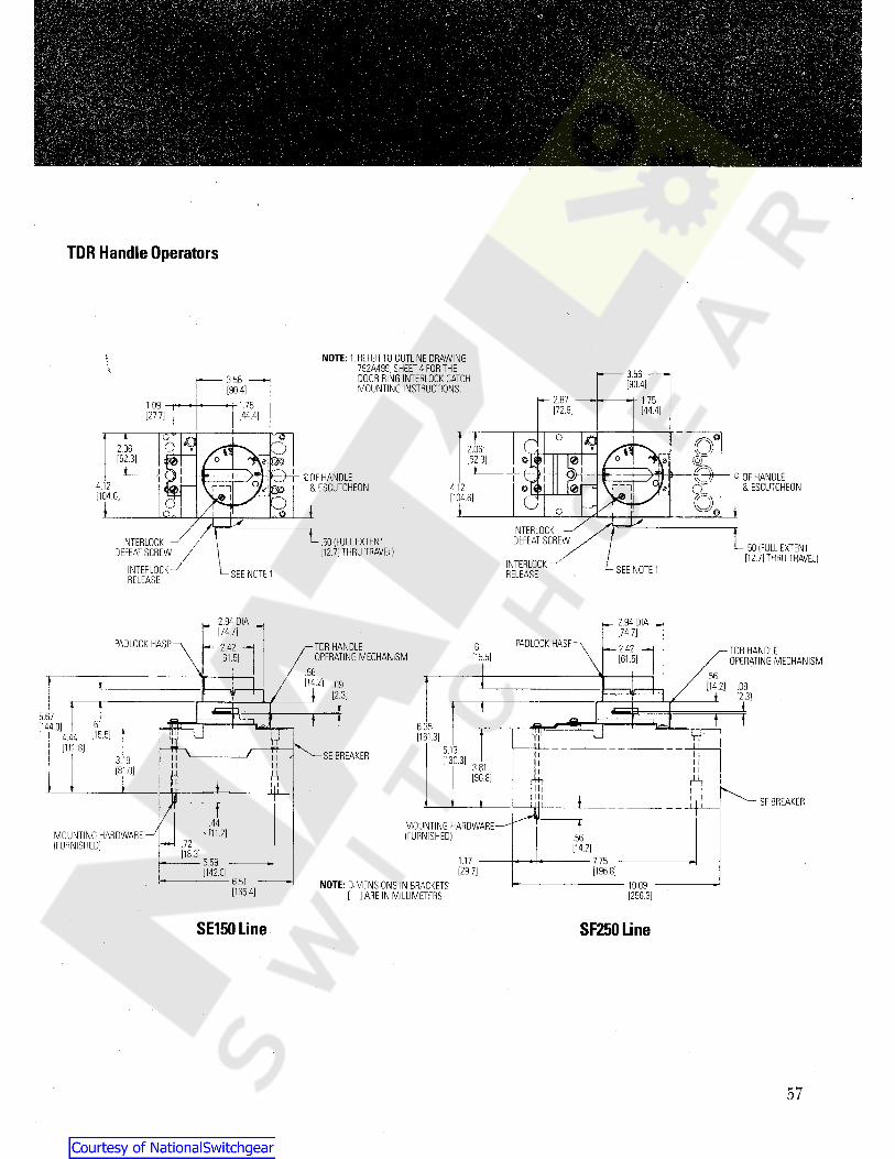
TDR Handle Operators
NOTE: 1. REFER TO OUTLINE DRAWING792A499, SHEET 4 FOR THEDOOR RING INTERLOCK CATCHMOUNTING INSTRUCTIONS.
\ 3.56 —H3.56 —H [90.4][90.4]h- 2.87 1.751.09 1.75 [72.9] [44.4][27.7] [44.4]
T CTr O o CJO D0od2.06 2.06 |5V[52.3] O [O[52.3] 0 o
MO I £0F HANDLE& ESCUTCHEON
o
0i 1>S,0 -ej Q OF HANDLE& ESCUTCHEON4.12 &4.12 0[O 0f= l 11 1 *][104.6] [104.6] GOo1 ii o QO-
INTERLOCKDEFEAT SCREW LL .50 (FULL EXTENT
[12.7] THRU TRAVEL)INTERLOCK
DEFEAT SCREW .50 (FULL EXTENT[12.7] THRU TRAVEL)INTERLOCK
RELEASE SEE NOTE 1INTERLOCKRELEASE SEE NOTE 1
^2.94 DIA _
H*. 2.94 DIA H[74.7] [74.7]PADLOCK HASPPADLOCK HASP TDR HANDLE
OPERATING MECHANISM.612.42 -H h— 2.42 -M TDR HANDLE
OPERATING MECHANISM[15.5][61.5] [61.5].56 .56[14.2] 09l [2-3]
[14.2] .09[2.3]iTI ia5.67 } f f T.61[144.0] 6.35 r ~r[15.5] [161.3]4.44 ‘n*Win: 8] 5.13 II l iSE BREAKER11 [130.3]3.19 11 3.81[81.0] AH [96.8] rk1 i
i SFBREAKERi xT.44 fMOUNTING HARDWARE
(FURNISHED)' n1.2]MOUNTING HARDWARE(FURNISHED)
.56k72 [14.2][18.3]1.17 7.755.59[29.7] [196.8][142.0]
6.51 NOTE: DIMENSIONS IN BRACKETS[ ] ARE IN MILLIMETERS
10.09[165.4] [256.3]
SE150Line SF250 Line
57
Courtesy of NationalSwitchgear.com

j>
•. 'I-
TDR Handle Operators
13.614.75[345.8]
\ [120.65].098.15V D!A[2.39] .59r[207.0][15.06]T5.97 j
[151.6] 'L- - JjyJlgjgJgL.JTrrjr. 1.73LUG COVERr© [43.9]7.43i f=i !
^4 LUG COVER[188.7] J5.821.81 1.81 *
[46.0]O 5.44 [147.8][46.0] 2, 11
r - :4 4.08i [138.1] 11i 11 [103.6]7!Z> i 11
W Wty1
OF HANDLE MOUNTING BOLTSG CIRCUIT BREAKERC BREAKERMOUNTING HOLES — 4.36
[110.7] 7.75[196.8]
SG600 Line
8.43 (REFS PADLOCK HASP[214.1j2.97 8.43 2.85 HANDLE
EXTENSIONMOUNTING BRACKET-[2) PLACES(FURNISHED)
[75.4] (214.1] [72.4] j- 6 29 DiAI [159.8] /4.22
[107.2] INTERLOCKDEFEAT SCREW
BREAKER MOUNTINGHOLES, 4 PLACES
7r MOUNTING HARDWARE(FURNISHED)
TDR HANDLE/ OPERATING MECHANISM
/~.530[13.46!
y
MOUNTING HARDWARE(FURNISHED)
1.04 — i—.32[26.4][8.1]
12.56o o [319.0]9.38
O [238.31ii8.25 OF HANDLE
AND ESCUTCHEON[209.6] T \
4.13 f^LUG COVER(OPTIONAL )
[104.9]i1 s. o
A
L £ OF BREAKERiMOUNTING HOLE..85 [21.6]
(FULL EXTENTTHRU TRAVEL)
INTERLOCK RELEASE X(t OF BREAKERMOUNTING$ 0F HANDLE
ESCUTCHEONSEE NOTE 1 14.25 HOLE[362.0]
19.50( 495.3]NOTE: DIMENSIONS IN BRACKETS
[ ] ARE IN MILLIMETERS
SK1200 Line58
Courtesy of NationalSwitchgear.com
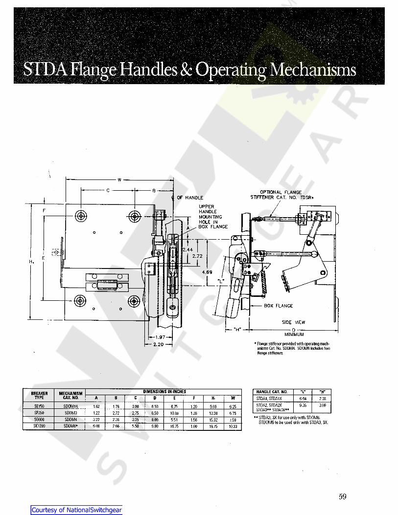
i
g MechanismsSID^Hinge Handles& Operatm
i\
W
C B OPTIONAL FLANGESTIFFENER CAT. NO. TDSR*V OF HANDLEI
UPPERHANDLEMOUNTINGHOLE INBOX FLANGE
F
)tA
o o \ £5 ~ hfi2.44SB i
2.72O1H,00
4.69 00U u v i - tOl JOn
BOX FLANGEo oI
SIDE VIEW"H" D
MINIMUM1.97* Flange stiffener provided with operating mech-
anisms Cat. No. SD0M4. SD0M6 includes twoflange stiffeners.
2.20
DIMENSIONS IN INCHES HANDLE CAT. NO. "L" "H**BREAKER MECHANISMCAT.NO.TYPE E WA B C D F Hi STDAI,STDA1X 6.04 2.38
STDA2, STDA2XSTDA3** STDA3X**
9.38 3.00SE150 SD0M1A 1.78 3.00 6.75 1.20 6.251.62 6.50 9.69SF250 SD0M3 2,72 2,75 10.88 6.751,22 6.50 1.38 13.38
**STDA3,3X for use only with SD0M6.STD0M6 to be used only with STDA3, 3X.SG600 S00M4 2.383.22 3.35 8.00 5.51 1.56 15.32 7.59
SK1200 SD0M6* 2.66 5.50 9.00 16.75 1.00 18.75 10.336.00
59
Courtesy of NationalSwitchgear.com
Guide FormSpecifications400A, 600A, and 1200A. In addition a 7A instantaneous-onlyframe shall be available. Rating plugs shall cover all standardampere ratings from one frame's maximum ampere ratingdown to the next lower frame ampere rating. A frame shallreject a rating plug not intended for use in it. Mag-Break® orequal breakers shall use the same rating plugs for 15A through1200A ratings as the Spectra RMS circuitbreakers and shalladditionally have 3A and 7A plugs for the 7A frame.
The circuit breaker frames shall employ high-strength,
molded-polyester, glass-reinforced cases and covers. Thebreaker frame shall have legible, tamper-proof nameplatescontaining catalog number; maximum frame ampere rating;maximum voltage ratings and interrupting ratings in accor-dance with UL Standard 489, International ElectrotechnicalCommission (IEC) Standard 947.2 and Japanese IndustrialStandard (JIS) No. C8370; terminal lug catalog number, torquerequirements and cable insulation rating and wire ranges; therating plug type; and Underwriters" Laboratories, Inc. Listingmark (or Component Recognition symbol in the case of Mag-
Break® instantaneous-only breakers). The IEC short-circuit rat-ings shall containboth service (Ics) and ultimate (leu) values.
All breaker frame sizes shall have a Verifier or equal toprovide an external means for manually tripping the breakerand exercising the mechanism and trip latch member.
Internal accessories shall be UL Listed for field installationand shall not require circuit breaker cover removal. All internalaccessories sha I be common the SE150, SF250, SG600, andSK1200 frame sizes. Shunt trips, undervoltage releases, auxil-iary switches and bell alarms shall be available and shallinstall from the front of the circuit breaker, instantaneous-onlybreaker or molded case switch.
External accessories, such as motor-operated mecha-
nisms, various handle operators, plug-in base assemblies,back-connected studs, shall be UL Listed for field installationon circuit breakers (including instantaneous-only circuit break-
ers) and moldedcase switches.
All molded case circuit breakers shall have an over-center,toggle handle-operated, trip-free mechanism with quick-make,quick-break action independent of the speed of the togglehandle operation. The designs shall provide common trippingof all poles. The escutcheon area of the breaker cover shallhave molded-in "ON" and "OFF" markings and corresponding"I" and "0" (for "ON" and "OFF" respectively) internationalmarkings.
All molded case circuit breakers shall be GE SpectraRMS or equql with digital solid-state, ambient insensitivetripping. All fraVnes from 30A to 1200A shall use field-
installed, UL Listed rating plugs to establish(or change) theampere rating and shall be suitable for reverse feed (i.e., noline/load markings). The digital microprocessor trip systemshall be applicable for 50 hertz through 400 hertz systems. Itshall accurately sense sinusoidal and non-sinusoidal currentwaveforms (fundamental through the thirteenth harmonicorder on a 60 hertz base) by continuously sampling each phasethroughout every cycle.
All breaker frame sizes (SE150, SF250, SG600 andSKI200) shall have a single, customer-adjustable, instanta-
neous pickup knob to set the instantaneous response for allpoles, n addition, there shall be a short time pickup setting atapproximately 50 to 80 percent of the instantaneous pickup.
(Where) ( If) required, instantaneous-only breakers shall beSpectra RMS Mag-Break® motor circuit protectors or equalemploying the same features as the molded case breakers,except with the long-time (thermal) response omitted. Thetracking short-time function and common rating plugs shallbe provided on the instantaneous-only breakers.
Moldedcase switches (where) (if) required, shall have afixed, high-set instantaneous pickup set below the poppinglevel of the contacts. The short circuit withstand ratings shallbe 100kA @ 480 Vac and 25k (minimum) @ 600 Vac whenprotected by any UL Listed circuit breaker or fuse of equalor lesser ampere rating.
Circuit breakers and instantaneous-only breakers shallhave frame sizes as follows: 30A, 60A, 100A, 150A, 250A,
GE Electrical Distribution& Control
General Electric Company41 Woodford AvenuePlainville, CT 06062© 1994 General Electric CompanyGET-7002C 0294 BL
Courtesy of NationalSwitchgear.com