Low voltage circuit breakers - LS Electric
100
Technical Manual Low voltage circuit breakers Meta Solution
-
Upload
khangminh22 -
Category
Documents
-
view
14 -
download
0
Transcript of Low voltage circuit breakers - LS Electric
Technical Manual
Low voltage circuit breakers
Meta Solution
Upgrade of Meta-MEC series
… series low voltage circuit breakers
A-1
B-1
C-1
D-1
E-1
F-1
G-1
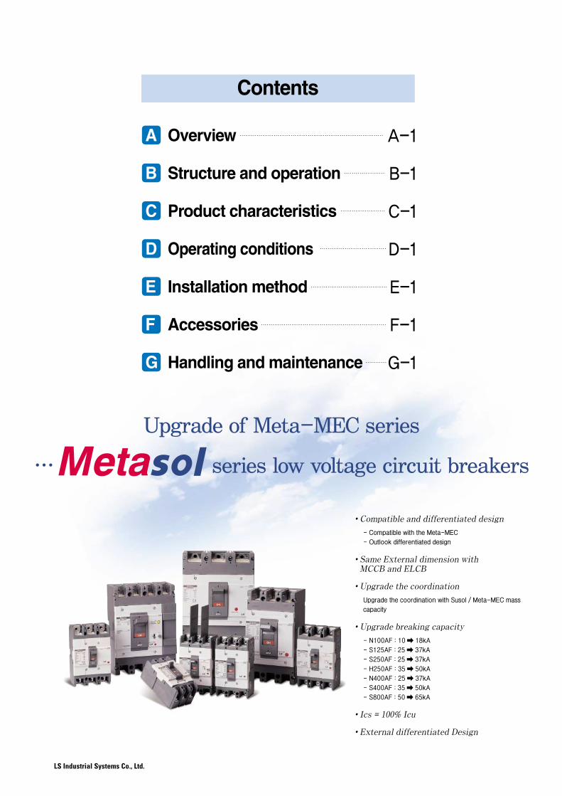
A Overview
B Structure and operation
C Product characteristics
D Operating conditions
E Installation method
F Accessories
G Handling and maintenance
Contents
�Compatible and differentiated design
- Compatible with the Meta-MEC
- Outlook differentiated design
�Same External dimension withMCCB and ELCB
�Upgrade the coordination
Upgrade the coordination with Susol / Meta-MEC mass
capacity
�Upgrade breaking capacity
- N100AF : 10 � 18kA
- S125AF : 25 � 37kA
- S250AF : 25 � 37kA
- H250AF : 35 � 50kA
- N400AF : 25 � 37kA
- S400AF : 35 � 50kA
- S800AF : 50 � 65kA
�Ics = 100% Icu
�External differentiated Design
A. Overview
A-2
A-3
A-4
A-6
A-14
1. Standard and Approvals
2. Metasol series characteristics
3. Externals and inscriptions
4. Ratings
5. Line-up and body structure
A-1
Metasol MCCB/ELCB Technical Manual
Metasol MCCB/ELCB Technical Manual

A
A-2
Overview
1. Standard and Approvals
The Metasol series MCCB and ELCB meet the following international standards
��IEC 60947-1Low-voltage switchgear and controlgear - Part 1: General rules
��IEC 60947-2Low-voltage switchgear and controlgear - Part 2: Circuit-breakers
Metasol circuit breakers have obtained the certificates below and under certain circumstances,the certificates can be provided.
�CB Certificate (KEMA - IEC 60947)�Test report (KEMA)
CE mark
The CE mark shows that the manufacturer meets all the essential requirements of the relevant European directive to affixthe CE mark on the product.By affixing the CE mark, it shows that the manufacturer meets all the requirements including those of the productvaluation process, and authorized representative's intentions.
A-3
2. Metasol series characteristics
A
Metasol MCCB/ELCB Technical Manual
Metasol MCCB/ELCB Technical Manual
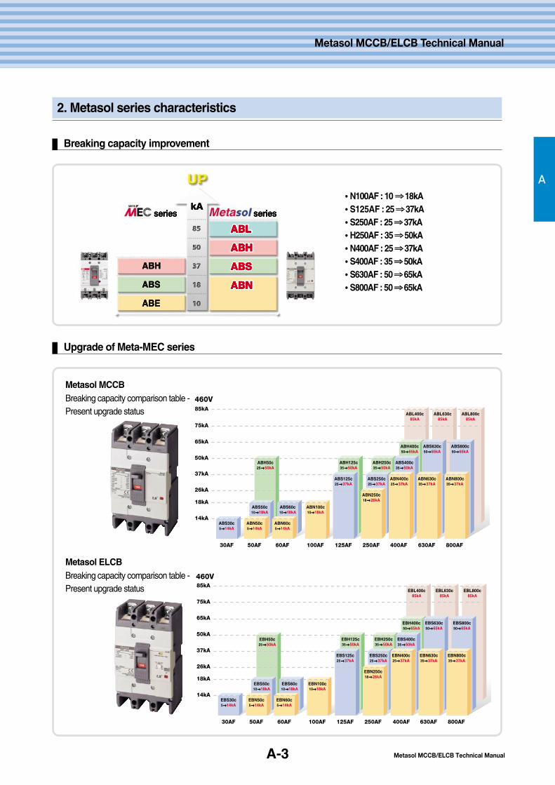
Breaking capacity improvement
Upgrade of Meta-MEC series
��N100AF : 10 ⇒⇒18kA��S125AF : 25 ⇒⇒37kA��S250AF : 25 ⇒⇒37kA��H250AF : 35 ⇒⇒50kA��N400AF : 25 ⇒⇒37kA��S400AF : 35 ⇒⇒50kA��S630AF : 50 ⇒⇒65kA��S800AF : 50 ⇒⇒65kA
60AF
ABH125c35�50kA
ABS125c25�37kA
30AF
14kA
50AF 100AF 125AF 250AF 400AF 630AF 800AF
ABS30c5�14kA
ABH50c25�50kA
ABS50c10�18kA
ABN50c5�14kA
ABS60c10�18kA
ABN100c10�18kA
ABH250c35�50kA
ABS250c25�37kA
ABN250c18�26kA
ABN60c5�14kA
18kA
37kA
26kA
50kA
65kA
75kA
ABL400c85kA
ABH400c50�65kA
ABS400c35�50kA
ABN400c25�37kA
ABL630c85kA
ABS630c50�65kA
ABN630c35�37kA
ABL800c85kA
ABS800c50�65kA
ABN800c35�37kA
85kA
460V
60AF
EBH125c35�50kA
EBS125c25�37kA
30AF 50AF 100AF 125AF 250AF 400AF 630AF 800AF
EBS30c5�14kA
EBH50c25�50kA
EBS50c10�18kA
EBN50c5�14kA
EBS60c10�18kA
EBN100c10�18kA
EBH250c35�50kA
EBS250c25�37kA
EBL400c85kA
EBN250c18�26kA
EBH400c50�65kA
EBS400c35�50kA
EBN400c25�37kA
EBL630c85kA
EBS630c50�65kA
EBN630c35�37kA
EBL800c85kA
EBS800c50�65kA
EBN800c35�37kA
EBN60c5�14kA
18kA
37kA
50kA
65kA
75kA
85kA
14kA
26kA
460V
Metasol MCCBBreaking capacity comparison table -Present upgrade status
Metasol ELCBBreaking capacity comparison table -Present upgrade status
A-4
Overview
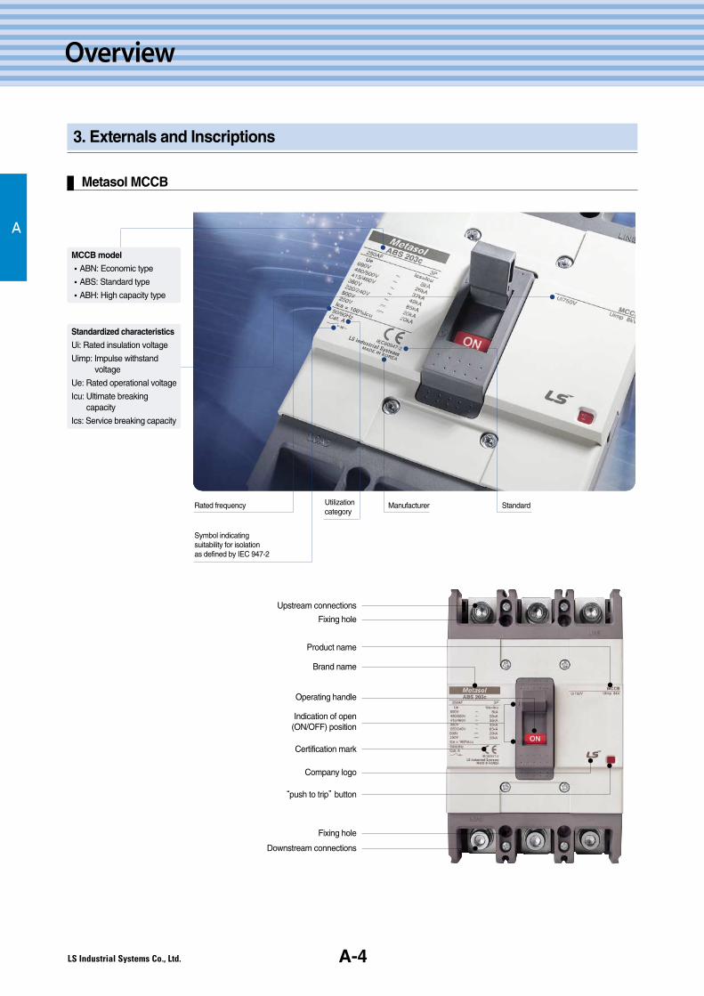
3. Externals and Inscriptions
Metasol MCCB
A
Product name
Upstream connections
Certification mark
Brand name
Operating handle
Indication of open(ON/OFF) position
“push to trip”button
Company logo
Fixing hole
Fixing hole
Downstream connections
Rated frequency Utilizationcategory
Manufacturer Standard
Symbol indicating suitability for isolation as defined by IEC 947-2
MCCB model
�ABN: Economic type
�ABS: Standard type
�ABH: High capacity type
Standardized characteristics
Ui: Rated insulation voltage
Uimp: Impulse withstand voltage
Ue: Rated operational voltage
Icu: Ultimate breaking capacity
Ics: Service breaking capacity
Metasol MCCB/ELCB Technical ManualA-5
A
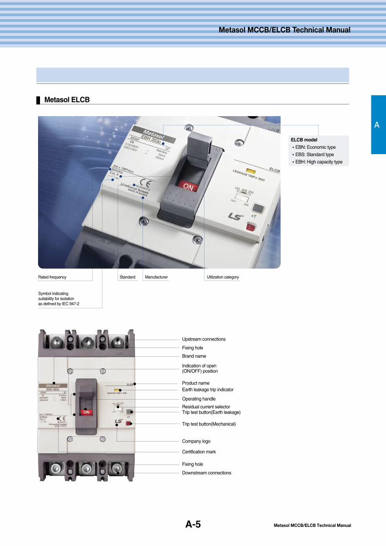
Metasol ELCB
Fixing hole
Product name
Upstream connections
Certification mark
Brand name
Operating handle
Indication of open(ON/OFF) position
Trip test button(Mechanical)
Trip test button(Earth leakage)
Company logo
Fixing hole
Downstream connections
Residual current selector
Earth leakage trip indicator
Metasol MCCB/ELCB Technical Manual
Rated frequency Standard Manufacturer Utilization category
Symbol indicating suitability for isolation as defined by IEC 947-2
ELCB model
�EBN: Economic type
�EBS: Standard type
�EBH: High capacity type
A-6
Overview
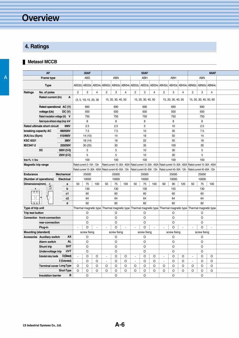
4. Ratings
Metasol MCCB
AAF
Frame type
Type
Ratings No. of poles
Rated current (In) A
Rated operational AC (V)
voltage (Ue) DC (V)
Rated insulation voltage (Ui) V
Rated impulse withstand voltage (Uimp) kV
Rated ultimate short circuit 690V
breaking capacity AC 480/500V
(KA) Icu (Sym) 415/460V
KSC 8321 380V
IIEC947-2 220/250V
DC 500V (3극극)
250V (2극극)
Ics=% ×× Icu
Magnetic trip range
Endurance Mechanical
(Number of operations) Electrical
Dimensions(mm) a
b
c1
c2
d
Type of trip unit
Trip test button
Connection front-connection
rear-connection
Plug-in
Mounting (standard)
Accessories Auxiliary switch
Alarm switch
Shunt trip
Undervoltage trip
Extended rotary handle
Terminal cover
Insulation barrier
30AF
ABS
ABS32c ABS33c ABS34c
2 3 4
(3, 5, 10) 15, 20, 30
690
500
750
8
2.5
7.5
14 (10)
18 (14)
30 (25)
5
5
100
Rated current 3~10A : 12In
Rated current 15~30A : 400A
25000
10000
50 75 100
130
60
64
82
Thermal magnetic type
O
O
O
- O -
screw fixing
O
O
O
O
- O O
- O O
O O O
O O O
O
ABN
ABN52c ABN53c ABN54c
2 3 4
15, 20, 30, 40, 50
690
500
750
8
2.5
7.5
14
18
30
5
5
100
Rated current 15~30A : 400A
Rated current 40~50A : 12In
25000
10000
50 75 100
130
60
64
82
Thermal magnetic type
O
O
O
- O -
screw fixing
O
O
O
O
- O O
- O O
O O O
O O O
O
50AF
ABH
ABS52c ABS53c ABS54c
2 3 4
15, 20, 30, 40, 50
690
500
750
8
5
10
18
22
35
10
10
100
Rated current 15~30A : 400A
Rated current 40~50A : 12In
25000
10000
50 75 100
130
60
64
82
Thermal magnetic type
O
O
O
- O -
screw fixing
O
O
O
O
- O O
- O O
O O O
O O O
O
ABH
ABH52c ABH53c ABH54c
2 3 4
15, 20, 30, 40, 50
690
500
750
8
10
35
50
50
100
30
30
100
Rated current 15~30A : 400A
Rated current 40~50A : 12In
25000
10000
60 90 120
155
60
64
82
Thermal magnetic type
O
O
O
- O -
screw fixing
O
O
O
O
- O O
- O O
O O O
O O O
O
60AF
ABN
ABN62c ABN63c ABN64c
2 3 4
15, 20, 30, 40, 50, 60
690
500
750
8
2.5
7.5
14
18
30
5
5
100
Rated current 15~30A : 400A
Rated current 40~60A : 12In
25000
10000
50 75 100
130
60
64
82
Thermal magnetic type
O
O
O
- O -
screw fixing
O
O
O
O
- O O
- O O
O O O
O O O
O
AX
AL
SHT
UVT
D (Direct)
E (Extended)
LongType
ShortType
B
a
b
dc2c1

Metasol MCCB/ELCB Technical ManualA-7
A
Metasol MCCB/ELCB Technical Manual
ABS
ABS62c ABS63c ABS64c
2 3 4
15, 20, 30, 40, 50, 60
690
500
750
8
5
10
18
22
35
10
10
100
Rated current 15~30A : 400A
Rated current 40~60A : 12In
25000
10000
50 75 100
130
60
64
82
Thermal magnetic type
O
O
O
- O -
screw fixing
O
O
O
O
- O O
- O O
O O O
O O O
O
100AF
ABN
ABN102c ABN103c ABN104c
2 3 4
15, 20, 30, 40, 50, 60,
75, 100
690
500
750
8
5
10
18
22
35
10
10
100
Rated current 15~30A : 400A
Rated current 40~100A : 12In
25000
10000
50 75 100
130
60
64
82
Thermal magnetic type
O
O
O
- O -
screw fixing
O
O
O
O
- O O
- O O
O O O
O O O
O
ABS
ABS102c ABS103c ABS104c
2 3 4
15, 20, 30, 40, 50,
60, 75, 100, 125
690
500
750
8
8
26
37
42
85
20
20
100
Rated current 15~30A : 400A
Rated current 40~125A : 12In
25000
10000
60 90 120
155
60
64
82
Thermal magnetic type
O
O
O
- O -
screw fixing
O
O
O
O
- O O
- O O
O O O
O O O
O
ABH
ABH102c ABH103c ABH104c
2 3 4
15, 20, 30, 40, 50,
60, 75, 100, 125
690
500
750
8
10
35
50
50
100
30
30
100
Rated current 15~30A : 400A
Rated current 40~125A : 12In
25000
10000
60 90 120
155
60
64
82
Thermal magnetic type
O
O
O
- O -
screw fixing
O
O
O
O
- O O
- O O
O O O
O O O
O
ABN
ABN202c ABN203c ABN204c
2 3 4
100, 125, 150, 175,
200, 225, 250
690
500
750
8
8
18
26
30
65
10
10
100
12In
20000
5000
105 140
165
60
64
87
Thermal magnetic type
O
O
O
- O -
screw fixing
O
O
O
O
O O O
O O O
O O O
O O O
O
250AF
ABS
ABS202c ABS203c ABS204c
2 3 4
100, 125, 150, 175,
200, 225, 250
690
500
750
8
8
26
37
42
85
20
20
100
12In
20000
5000
105 140
165
60
64
87
Thermal magnetic type
O
O
O
- O -
screw fixing
O
O
O
O
O O O
O O O
O O O
O O O
O
ABH
ABH202c ABH203c ABH204c
2 3 4
100, 125, 150, 175,
200, 225, 250
690
500
750
8
10
35
50
50
100
30
30
100
12In
20000
5000
105 140
165
60
64
87
Thermal magnetic type
O
O
O
- O -
screw fixing
O
O
O
O
O O O
O O O
O O O
O O O
O
112255AAFF
A-8
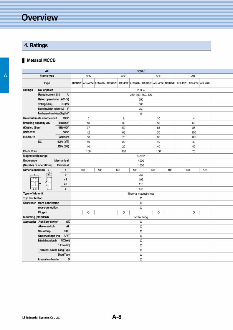
Overview
4. Ratings
Metasol MCCB
AAF
Frame type
Type
Ratings No. of poles
Rated current (In) A
Rated operational AC (V)
voltage (Ue) DC (V)
Rated insulation voltage (Ui) V
Rated impulse withstand voltage (Uimp) kV
Rated ultimate short circuit 690V
breaking capacity AC 480/500V
(KA) Icu (Sym) 415/460V
KSC 8321 380V
IIEC947-2 220/250V
DC 500V (3극극)
250V (2극극)
Ics=% ×× Icu
Magnetic trip range
Endurance Mechanical
(Number of operations) Electrical
Dimensions(mm) a
b
c1
c2
d
Type of trip unit
Trip test button
Connection front-connection
rear-connection
Plug-in
Mounting (standard)
Accessories Auxiliary switch
Alarm switch
Shunt trip
Undervoltage trip
Extended rotary handle
Terminal cover
Insulation barrier
440000AAFF
AX
AL
SHT
UVT
N (Direct)
E (Extended)
LongType
ShortType
B
a
b
dc2c1
ABN ABS ABH ABL
ABN402c ABN403c ABN404c ABS402c ABS403c ABS404c ABH402c ABH403c ABH404c ABL402c ABL403c ABL404c
2, 3, 4
250, 300, 350, 400
690
500
750
8
5 8 10 4
18 35 50 65
37 50 65 85
42 65 70 100
50 75 85 125
10 20 40 40
10 20 40 40
100 100 100 75
8~12In
4000
1000
140 185 140 185 140 185 140 185
257
109
113
145
Thermal magnetic type
O
O
O
O O O O
screw fixing
O
O
O
O
O
O
O
O
O

A-9
A
Metasol MCCB/ELCB Technical Manual
Metasol MCCB/ELCB Technical Manual
663300AAFF 880000AAFF
ABN ABS ABL
ABN602c ABN603c ABN604c ABS602c ABS603c ABS604c ABL602c ABL603c ABL604c
2, 3, 4
500, 630
690
500
750
8
8 10 14
25 45 65
37 65 85
45 75 100
50 85 125
10 20 40
10 20 40
100 100 75
8~12In
2500
500
210 280 210 280 210 280
280
109
113
145
Thermal magnetic type
O
O
O
O O O
screw fixing
O
O
O
O
O
O
O
O
O
ABN ABS ABL
ABN802c ABN803c ABN804c ABS802c ABS803c ABS804c ABL802c ABL803c ABL804c
2, 3, 4
700, 800
690
500
750
8
8 10 14
25 45 65
37 65 85
45 75 100
50 85 125
10 20 40
10 20 40
100 100 75
8~12In
2500
500
210 280 210 280 210 280
280
109
113
145
Thermal magnetic type
O
O
O
O O O
screw fixing
O
O
O
O
O
O
O
O
O
A-10
Overview
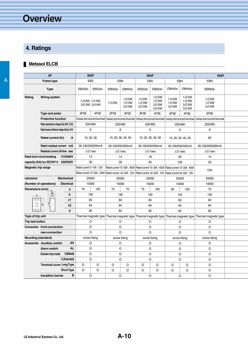
4. Ratings
Metasol ELCB
AAF
Frame type
Type
Rating Wiring system
Type and poles
Protective function
Rated operational voltage (Ue) AC (V)
Rated impulse withstand voltage (Uimp) kV
Rated current (In) A
Rated residual current mA
Residual current off-time sec
Rated short circuit breaking 415/460V
capacity (KA) Icu IEC947-2 220/250V
Magnetic trip range
ndurance Mechanical
(Number of operations) Electrical
Dimensions (mm) a
b
c1
c2
d
Type of trip unit
Trip test button
Connection front-connection
rear-connection
Mounting (standard)
Accessories Auxiliary switch
Alarm switch
Extended rotary handle
Terminal cover
Insulation barrier
30AF
EBS
EBS33c EBS34c
3P3E 4P3E
Overload, short circuit and Ground fault
220/460
6
15, 20, 30
30,100/200/500mA
≤0.1sec
14
30
Rated current 3~10A : 12In
Rated current 15~30A : 400A
25000
10000
75 100
130
60
64
82
Thermal magnetic type
O
O
O
screw fixing
O
O
O
O
O O
O O
O
EBN
EBN52c EBN53c
2P2E 3P3E
Overload, short circuit and Ground fault
220/460
6
15, 20, 30, 40, 50
30,100/200/500mA
≤0.1sec
14
30
Rated current 15~30A : 400A
Rated current 40~50A : 12In
25000
10000
75 75
130
60
64
82
Thermal magnetic type
O
O
O
screw fixing
O
O
O
O
O O
O O
O
50AF
EBS
EBS53c EBS54c
3P3E 4P3E
Overload, short circuit and Ground fault
220/460
6
15, 20, 30, 40, 50
30,100/200/500mA
≤0.1sec
18
35
Rated current 15~30A : 400A
Rated current 40~50A : 12In
25000
10000
75 100
130
60
64
82
Thermal magnetic type
O
O
O
screw fixing
O
O
O
O
O O
O O
O
EBH
EBH53c EBH54c
3P3E 4P3E
Overload, short circuit and Ground fault
220/460
6
15, 20, 30, 40, 50
30,100/200/500mA
≤0.1sec
50
100
Rated current 15~30A : 400A
Rated current 40~50A : 12In
25000
10000
90 120
155
60
64
82
Thermal magnetic type
O
O
O
screw fixing
O
O
O
O
O O
O O
O
60AF
EBN
EBN63c
3P3E
Overload, short circuit and Ground fault
220/460
6
60
30,100/200/500mA
≤0.1sec
14
30
12In
25000
10000
75
130
60
64
82
Thermal magnetic type
O
O
O
screw fixing
O
O
O
O
O
O
O
AX
AL
D (Direct)
E (Extended)
LongType
ShortType
B
1∅2W, 1∅3W, 3∅3W, 3∅4W
1∅2W, 1∅2W 1∅3W 3∅3W
1∅2W 1∅3W 3∅3W
1∅2W 1∅3W 3∅3W3∅4W
1∅2W 1∅3W 3∅3W
1∅2W 1∅3W 3∅3W3∅4W
1∅2W 1∅3W 3∅3W
a
b
dc2c1

Metasol MCCB/ELCB Technical ManualA-11
A
Metasol MCCB/ELCB Technical Manual
EBS
EBS63c EBS64c
3P3E 4P3E
Overload, short circuit and Ground faul
220/460
6
60
30,100/200/500mA
≤0.1sec
18
35
12In
25000
10000
75 100
130
60
64
82
Thermal magnetic type
O
O
O
screw fixing
O
O
O
O
O O
O O
O
100AF
EBN
EBN102c EBN103c EBN104c
2P2E 3P3E 4P3E
Overload, short circuit and Ground faul
220/460
6
60, 75, 100
30,100/200/500mA
≤0.1sec
18
35
Rated current 15~30A : 400A
Rated current 40~100A : 12In
25000
10000
75 75 100
130
60
64
82
Thermal magnetic type
O
O
O
screw fixing
O
O
O
O
O O O
O O O
O
EBS
EBS103c EBS104c
3P3E 4P3E
Overload, short circuit and Ground faul
220/460
6
15, 20, 30, 40, 50,
60, 75, 100, 125
30,100/200/500mA
≤0.1sec
37
85
Rated current 15~30A : 400A
Rated current 40~125A : 12In
25000
10000
90 120
155
60
64
82
Thermal magnetic type
O
O
O
screw fixing
O
O
O
O
O O
O O
O
EBH
EBH103c EBH104c
3P3E 4P3E
Overload, short circuit and Ground faul
220/460
6
15, 20, 30, 40, 50,
60, 75, 100, 125
30,100/200/500mA
≤0.1sec
50
100
Rated current 15~30A : 400A
Rated current 40~100A : 12In
25000
10000
90 120
155
60
64
82
Thermal magnetic type
O
O
O
screw fixing
O
O
O
O
O O
O O
O
EBN
EBN202c EBN203c
2P2E 3P3E
Overload, short circuit and Ground faul
220/460
6
100, 125, 150, 175,
200, 225, 250
30,100/200/500mA
≤0.1sec
25
65
2In
20000
5000
105
165
60
64
87
Thermal magnetic type
O
O
O
screw fixing
O
O
O
O
O O
O O
O
250AF
EBS
EBS203c EBS204c
3P3E 4P3E
Overload, short circuit and Ground faul
220/460
6
100, 125, 150, 175,
200, 225, 250
30,100/200/500mA
≤0.1sec
37
85
12In
20000
5000
105 140
165
60
64
87
Thermal magnetic type
O
O
O
screw fixing
O
O
O
O
O O
O O
O
EBH
EBH203c EBH204c
3P3E 4P3E
Overload, short circuit and Ground faul
220/460
6
100, 125, 150, 175,
200, 225, 250
30,100/200/500mA
≤0.1sec
50
100
12In
20000
5000
105 140
165
60
64
87
Thermal magnetic type
O
O
O
screw fixing
O
O
O
O
O O
O O
O
125AF
1∅2W 1∅3W 3∅3W
1∅2W 1∅3W 3∅3W3∅4W
1∅2W 1∅2W 1∅3W 3∅3W
1∅2W 1∅3W 3∅3W3∅4W
1∅2W 1∅3W 3∅3W
1∅2W 1∅3W 3∅3W3∅4W
1∅2W 1∅3W 3∅3W
1∅2W 1∅3W 3∅3W3∅4W
1∅2W 1∅2W 1∅3W 3∅3W
1∅2W 1∅3W 3∅3W
1∅2W 1∅3W 3∅3W3∅4W
1∅2W 1∅3W 3∅3W
1∅2W 1∅3W 3∅3W3∅4W
A-12
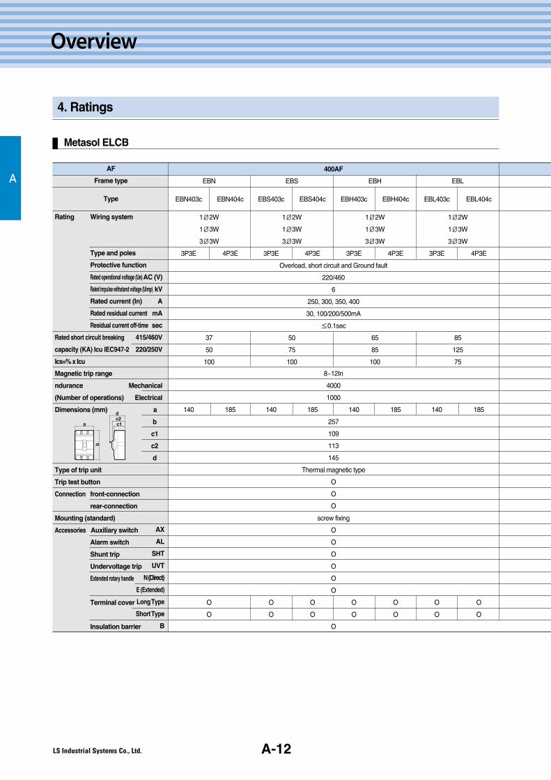
Overview
4. Ratings
Metasol ELCB
AAF
Frame type
Type
Rating Wiring system
Type and poles
Protective function
Rated operational voltage (Ue) AC (V)
Rated impulse withstand voltage (Uimp) kV
Rated current (In) A
Rated residual current mA
Residual current off-time sec
Rated short circuit breaking 415/460V
capacity (KA) Icu IEC947-2 220/250V
Ics=% x Icu
Magnetic trip range
ndurance Mechanical
(Number of operations) Electrical
Dimensions (mm) a
b
c1
c2
d
Type of trip unit
Trip test button
Connection front-connection
rear-connection
Mounting (standard)
Accessories Auxiliary switch
Alarm switch
Shunt trip
Undervoltage trip
Extended rotary handle
Terminal cover
Insulation barrier
400AF
EBN EBS EBH EBL
EBN403c EBN404c EBS403c EBS404c EBH403c EBH404c EBL403c EBL404c
1∅2W 1∅2W 1∅2W 1∅2W
1∅3W 1∅3W 1∅3W 1∅3W
3∅3W 3∅3W 3∅3W 3∅3W
3P3E 4P3E 3P3E 4P3E 3P3E 4P3E 3P3E 4P3E
Overload, short circuit and Ground fault
220/460
6
250, 300, 350, 400
30, 100/200/500mA
≤0.1sec
37 50 65 85
50 75 85 125
100 100 100 75
8~12In
4000
1000
140 185 140 185 140 185 140 185
257
109
113
145
Thermal magnetic type
O
O
O
screw fixing
O
O
O
O
O
O
O O O O O O O
O O O O O O O
O
AX
AL
SHT
UVT
N (Direct)
E (Extended)
LongType
ShortType
B
a
b
dc2c1

A-13
A
Metasol MCCB/ELCB Technical Manual
Metasol MCCB/ELCB Technical Manual
EBN EBS EBL
EBN603c EBS603c EBL603c
1∅2W 1∅2W 1∅2W
1∅3W 1∅3W 1∅3W
3∅3W 3∅3W 3∅3W
3P3E 3P3E 3P3E
Overload, short circuit and Ground fault
220/460
6
500, 630
30, 100/200/500mA
≤0.1sec
37 65 85
50 85 125
100 100 75
8~12In
2500
500
210 210 210
280
109
113
145
Thermal magnetic type
O
O
O
screw fixing
O
O
O
O
O
O
O O O O O
O O O O O
O
EBN EBS EBL
EBN803c EBS803c EBL803c
1∅2W 1∅2W 1∅2W
1∅3W 1∅3W 1∅3W
3∅3W 3∅3W 3∅3W
3P3E 3P3E 3P3E
Overload, short circuit and Ground fault
220/460
6
700, 800
30, 100/200/500mA
≤0.1sec
37 65 85
50 85 125
100 100 75
8~12In
2500
500
210 210 210
280
109
113
145
Thermal magnetic type
O
O
O
screw fixing
O
O
O
O
O
O
O O O O O
O O O O O
O
630AF 800AF

A-14
Overview
5. Line-up and body structure
A
Breaking capacity
30AFAFType 50AF 60AF 100AF 125AF 250AF
Metasol MCCB
ABN
ABS
ABH
ABS60c18kA
ABN60c14kA
ABN100c18kA
ABS30c14kA
ABS50c18kA
ABN50c14kA
ABH50c50kA
ABH125c50kA
ABS125c37kA
ABH250c50kA
ABS250c37kA
ABN250c26kA
Metasol ELCB
30AFAFType 50AF 60AF 100AF 125AF 250AF
EBN
EBS
EBH
EBS60c18kA
EBN60c14kA
EBN100c18kA
EBS30c14kA
EBS50c18kA
EBN50c14kA
EBH50c50kA
EBH125c50kA
EBS125c37kA
EBH250c50kA
EBS250c37kA
EBN250c26kA
400AFAFType 630AF 800AF
ABN
ABS
ABH
ABN630c37kA
ABN400c37kA
ABL
ABN800c37kA
ABS630c65kA
ABS400c50kA
ABS800c65kA
ABH400c65kA
ABL630c85kA
ABL400c85kA
ABL800c85kA
400AFAFType 630AF 800AF
EBN
EBS
EBH
EBN630c37kA
EBN400c37kA
EBL
EBN800c37kA
EBS630c65kA
EBS400c50kA
EBS800c65kA
EBH400c65kA
EBL630c85kA
EBL400c85kA
EBL800c85kA
System overview (MCCB/ELCB)
� Breaker (MCCB/ELCB)
� Internal auxiliaries
� Plug-in kit
� Rotary handle (direct)
� Rotary handle (direct, key lock)
� Rotary handle (extended)
� Rear terminal
� Terminal cover (Short, Long)
� Insulation barrier
�
��
�
�
�
�
�
�
�
�
�
B.Structure and operating
B-2
B-4
B-11
B-12
1. Basic functions of the MCCB
and ELCB
2. Structure of MCCB and ELCB
3. Metasol MCCB's operation
and position description
4. Metasol ELCB's operation
and position description
B-1
Metasol MCCB/ELCB Technical Manual
Metasol MCCB/ELCB Technical Manual

B-2
Structure and operation
1. Basic functions of the MCCB and ELCB
B
The basic functions of MCCB
By isolating the circuit from the fault current, MCCB can prevent load handling equipment damage and accidents likefire by isolating circuits.
1. Accident protection (instantaneous operation)When a faulty large current flows, the MCCB isolates the circuit instantly. This is called instantaneous operation.
2. Overload protection (time-delay)If the current flows constantly exceed the rated current, the electric wire can heat up and cause a fire.Before the temperature of a wire reaches a dangerous level, the MCCB isolates the circuit. This is a time-delayedfeature.
3. Motor trip inactive operationIf there is motor on the circuit, when it trips, a large current which is above the tripping current will flow.At this time if the MCCB trips, it's a fault. The MCCB should not trip from the current surge from a motor.
▶ The MCCB's function depends on the three above mentioned conditions.

Metasol MCCB/ELCB Technical ManualB-3
B
The basic function of an ELCB
1. The necessity of ELCBsIn respect to human lives and property, concerns for electrical shock accidents are increasing in the construction andelectrical construction industries, as well as in regular houses, buildings, schools , public buildings and the places withlegal ELCB installation obligations are increasing. ELCBs not only protect from electrical shock accidents but also canprevent fire caused by electric leakage. Generally electric leakage is very little compared to the overload current so anMCCB or fuse cannot prevent an earth leakage accident. An ELCB is needed to detect such small amounts of currentleakage.
2. Earth leakage accident protection
1) Electric shock accidentsIf the current leakage occurs through the human body, it will pass through to the ground and when it exceedsmaximum tolerance, it can cause death. Other electrical accidents are usually limited to damaging electric facilities butearth leakage can electrocute people, especially with low voltage circuits. When these circuits are accessible to people,attention to safety is necessary.
2) Leakage current fireIf the current leakage flows close to construction materials like wood, Styrofoam or flammables, the current leakage firecan occur because of Joule heat. It's said a leakage current of a few amperes is enough to cause a fire.
3) Arc faultsGrounding often occurs with arc faults. The center of the arc has a high temperature, around 10,000℃, which cannotbe compared with Joule heat. Even with a low ground current, electric facilities can be damaged by these faults. Bigaccidents caused by this are reported in and outside of Korea.The most famous example of such an accident is a large apartment accident in New York in 1964. An arc faultcontinued for one second and it totally destroyed the switchboard and two 5000A main power lines melting andvaporizing them. In the meantime about 10,000 households could not use water, electricity or elevators. If we neglectarc faults like these, the effects will gradually increase and damage buildings, plants, equipment and in the worst caseharm people. For these reasons it is important to detect arc faults ASAP and deal with them properly.
In addition to the features of the MCCB, the ELCB offers protection against earth leakage. This means protection fromelectrocution for people, current leakage protection and arc fault protection.
Metasol MCCB/ELCB Technical Manual
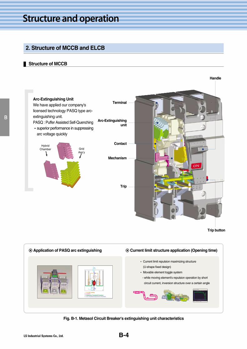
2. Structure of MCCB and ELCB
B-4
Structure and operation
B
Structure of MCCB
Fig. B-1. Metasol Circuit Breaker's extinguishing unit characteristics
Arc-Extinguishing UnitWe have applied our company'slicensed technology PASQ type arc-extinguishing unit.PASQ : Puffer Assisted Self-Quenching�superior performance in suppressing
arc voltage quickly
◉◉ Application of PASQ arc extinguishing
� Current limit repulsion maximizing structure
(U-shape fixed design)
� Movable element toggle system
- while moving element's repulsion operation by short
circuit current, inversion structure over a certain angle
◉◉ Current limit structure application (Opening time)
HybridChamber Grid
Ass’y
→→ →→
Handle
Terminal
Contact
Mechanism
Arc-Extinguishingunit
Trip
Trip button
Metasol MCCB/ELCB Technical ManualB-5
B
Structure of ELCB
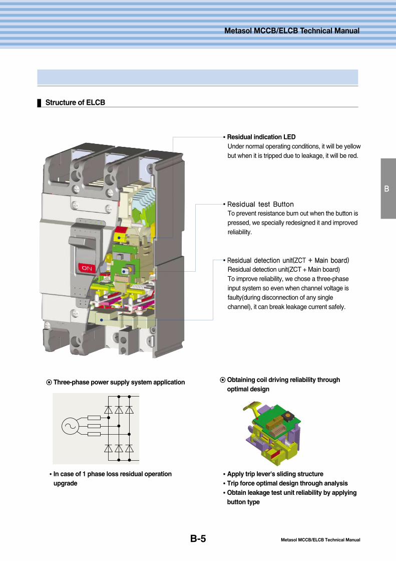
��Residual indication LEDUnder normal operating conditions, it will be yellowbut when it is tripped due to leakage, it will be red.
��RReessiidduuaall tteesstt BBuuttttoonn
To prevent resistance burn out when the button ispressed, we specially redesigned it and improvedreliability.
��RReessiidduuaall ddeetteeccttiioonn uunniitt((ZZCCTT ++ MMaaiinn bbooaarrdd))
Residual detection unit(ZCT + Main board)To improve reliability, we chose a three-phaseinput system so even when channel voltage isfaulty(during disconnection of any singlechannel), it can break leakage current safely.
◉◉ Three-phase power supply system application ◉◉ Obtaining coil driving reliability throughoptimal design
��In case of 1 phase loss residual operationupgrade
��Apply trip lever's sliding structure��Trip force optimal design through analysis��Obtain leakage test unit reliability by applying
button type
Metasol MCCB/ELCB Technical Manual
2. Structure of MCCB and ELCB
B-6
Structure and operation
B
Switch
1. Dividing switch by ON and OFFSwitch performs on and off switching by transferring manual manipulation force to moving contact and it has twodifferent types, Quick Make and Slow Make.
(1) Quick Make is an operation which drives the switch spring by operating the handle ON and OFF then inverts theinternal toggle link which switches the moving contact rapidly connected to the poly pole in common. Because itswitches regardless of the operator's handle operating speed, it's called "Quick Make".Because of resistance against melting and fusion, and load breaking characteristics by ON and OFF switching aresuperior, relatively big circuit breakers are also adopting this operation device.
(2) Slow Make is an operation which inverts the Toggle Link by operating the handle ON and OFF and switches thecontact.The contact's switch speed is decided by the handle operating speed and it's called "Slow Make", but overcurrent tripping operations happen separately from the handle operating and after tripping is over, it resetsautomatically. So this operation is used to make operate simple for the small frame(circuit breaker for panel boardetc.) with a relatively low rated current which general consumers use.
2. Switch operation[Fig.B-2] shows ON, OFF and TRIP position. When the handle moves from ON to OFF, the main spring passes thetoggle link's dead point and at this time, the breaking operating happens rapidly. Also it happens in the same way fromOFF to ON.Automatic tripping by over current makes the bracket rotate with over current elements(bimetal, electromagnet, O.D.P.)etc.'s action and supports cradle of trip structure. By exceeding the dead point with the toggle link's spring action, thecontact will automatically be opened very fast. While it's tripping, the handle stays in the middle of ON and OFFpositions and it means over current voltage has been tripped. Additionally, the automatic tripping action is structured as"Trip-Free", so even though the handle is held on the ON side, if over current flows, contact point's opening operationwill not be interrupted.Because each pole has to be insulated electrically in a poly pole's circuit breaker, it should be isolated from the caseand the contact is fixed to common cross bar by insulation. The cross bar is connected to mechanism units soconcurrent opening and concurrent break are possible.
Contact units
Fixed contacts and moving contacts are the MCCB's most important parts and in extreme conditions will be appliedduring opening and closing.The material for a contact point should have below three conditions.
�High resistance against melting and fusion
�Low contact resistance
�High durability
For the material of MCCB's contact, silver tungsten or silver oxidized cadmium are used in the right place and this givesthe contact points maximum durability, increasing breaking capacity and possible size miniaturization.
Metasol MCCB/ELCB Technical ManualB-7
B
600.0
500.0
400.0
300.0
200.0
100.0
0.00.00E+00 4.00E+06 3.00E+06 1.20E+07 1.60E+07 2.00E+07
Life
Str
ess
Am
plitu
de (
MP
a)
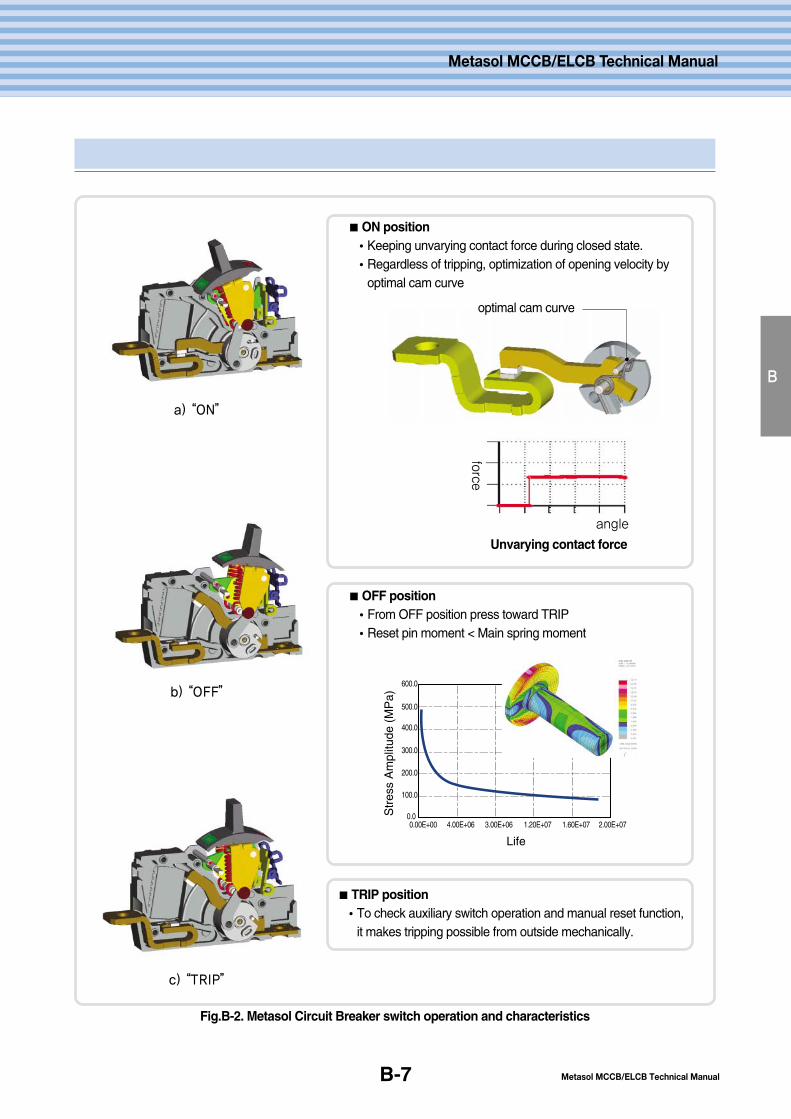
Fig.B-2. Metasol Circuit Breaker switch operation and characteristics
a) “ON”
b) “OFF”
c) “TRIP”
ON position�Keeping unvarying contact force during closed state.�Regardless of tripping, optimization of opening velocity by
optimal cam curve
OFF position�From OFF position press toward TRIP�Reset pin moment < Main spring moment
optimal cam curve
angle
force
Unvarying contact force
TRIP position�To check auxiliary switch operation and manual reset function,
it makes tripping possible from outside mechanically.
Metasol MCCB/ELCB Technical Manual
2. Structure of MCCB and ELCB
B-8
Structure and operation
B
Overcurrent trip devices
Overcurrent trip devices are divided by thermal-magnetic types, hydraulic-magnetic types and electronic types byoperation principal.
Thermal-Magnetic Type is used in the Metasol Circuit Breakers.
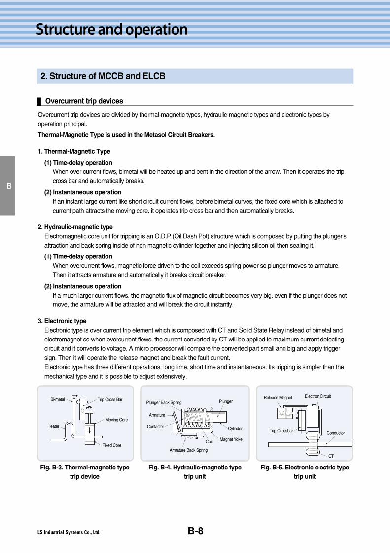
1. Thermal-Magnetic Type
(1) Time-delay operationWhen over current flows, bimetal will be heated up and bent in the direction of the arrow. Then it operates the tripcross bar and automatically breaks.
(2) Instantaneous operationIf an instant large current like short circuit current flows, before bimetal curves, the fixed core which is attached tocurrent path attracts the moving core, it operates trip cross bar and then automatically breaks.
2. Hydraulic-magnetic typeElectromagnetic core unit for tripping is an O.D.P.(Oil Dash Pot) structure which is composed by putting the plunger'sattraction and back spring inside of non magnetic cylinder together and injecting silicon oil then sealing it.
(1) Time-delay operationWhen overcurrent flows, magnetic force driven to the coil exceeds spring power so plunger moves to armature.Then it attracts armature and automatically it breaks circuit breaker.
(2) Instantaneous operationIf a much larger current flows, the magnetic flux of magnetic circuit becomes very big, even if the plunger does notmove, the armature will be attracted and will break the circuit instantly.
3. Electronic typeElectronic type is over current trip element which is composed with CT and Solid State Relay instead of bimetal andelectromagnet so when overcurrent flows, the current converted by CT will be applied to maximum current detectingcircuit and it converts to voltage. A micro processor will compare the converted part small and big and apply triggersign. Then it will operate the release magnet and break the fault current.Electronic type has three different operations, long time, short time and instantaneous. Its tripping is simpler than themechanical type and it is possible to adjust extensively.
Bi-metal
Heater
Trip Cross Bar
Moving Core
Fixed Core
Plunger Back Spring
Armature
Armature Back Spring
Coil Magnet Yoke
Cylinder
Plunger
ContactorTrip Crossbar
CT
Release Magnet Electron Circuit
Conductor
Fig. B-3. Thermal-magnetic typetrip device
Fig. B-4. Hydraulic-magnetic type trip unit
Fig. B-5. Electronic electric typetrip unit
Metasol MCCB/ELCB Technical ManualB-9
B
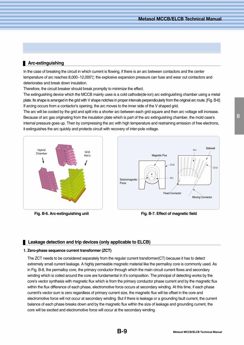
Arc-extinguishing
In the case of breaking the circuit in which current is flowing, if there is an arc between contactors and the centertemperature of arc reaches 8,000~12,000℃ the explosive expansion pressure can fuse and wear out contactors anddeteriorates and break down insulation.Therefore, the circuit breaker should break promptly to minimize the effect.The extinguishing device which the MCCB mainly uses is a cold cathode(de-ion) arc extinguishing chamber using a metalplate. Its shape is arranged in the grid with V shape notches in proper intervals perpendicularly from the original arc route. [Fig. B-6] If arcing occurs from a contactor's opening, the arc moves to the inner side of the V shaped grid. The arc will be cooled by the grid and split into a shorter arc between each grid square and then arc voltage will increase.Because of arc gas originating from the insulation plate which is part of the arc extinguishing chamber, the mold case'sinternal pressure goes up. Then by compressing the arc with high temperature and restraining emission of free electrons,it extinguishes the arc quickly and protects circuit with recovery of inter-pole voltage.
GridGrid
Arc
Arc
Magnetic Flux
ElectromagneticForce
Fixed ConnectorMoving Connector
Sidewall
Fig. B-6. Arc-extinguishing unit Fig. B-7. Effect of magnetic field
HybridChamber Grid
Ass’y
Leakage detection and trip devices (only applicable to ELCB)
1. Zero-phase sequence current transformer (ZCT)
The ZCT needs to be considered separately from the regular current transformer(CT) because it has to detectextremely small current leakage. A highly permeable magnetic material like the permalloy core is commonly used. Asin Fig. B-8, the permalloy core, the primary conductor through which the main circuit current flows and secondarywinding which is coiled around the core are fundamental in it’s composition. The principal of detecting works by thecore's vector synthesis with magnetic flux which is from the primary conductor phase current and by the magnetic fluxwithin the flux difference of each phase, electromotive force occurs at secondary winding. At this time, if each phasecurrent's vector sum is zero regardless of primary current size, the magnetic flux will be offset in the core andelectromotive force will not occur at secondary winding. But if there is leakage or a grounding fault current, the currentbalance of each phase breaks down and by the magnetic flux within the size of leakage and grounding current, thecore will be excited and electromotive force will occur at the secondary winding.
→→ →→
Metasol MCCB/ELCB Technical Manual
2. Structure of MCCB and ELCB
B-10
Structure and operation
B
Leakage detection and trip devices (only applicable to ELCB)
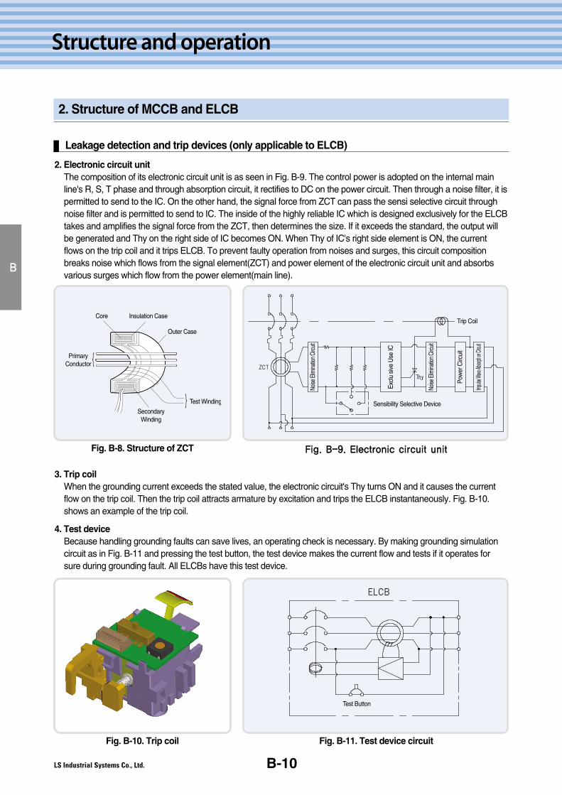
2. Electronic circuit unitThe composition of its electronic circuit unit is as seen in Fig. B-9. The control power is adopted on the internal mainline's R, S, T phase and through absorption circuit, it rectifies to DC on the power circuit. Then through a noise filter, it ispermitted to send to the IC. On the other hand, the signal force from ZCT can pass the sensi selective circuit throughnoise filter and is permitted to send to IC. The inside of the highly reliable IC which is designed exclusively for the ELCBtakes and amplifies the signal force from the ZCT, then determines the size. If it exceeds the standard, the output willbe generated and Thy on the right side of IC becomes ON. When Thy of IC's right side element is ON, the currentflows on the trip coil and it trips ELCB. To prevent faulty operation from noises and surges, this circuit compositionbreaks noise which flows from the signal element(ZCT) and power element of the electronic circuit unit and absorbsvarious surges which flow from the power element(main line).
ZCT
Noise
Elim
inatio
n Circ
uit
Noise
Elim
inatio
n Circ
uit
Excl
u si
ve U
se IC
Trip Coil
Pow
er C
ircui
t
Impuls
e Wave
Absor
pti on
Circui
t
Sensibility Selective Device
Core Insulation Case
Outer Case
PrimaryConductor
SecondaryWinding
Test Winding
Fig. B-8. Structure of ZCT FFiigg.. BB--99.. EElleeccttrroonniicc cciirrccuuiitt uunniitt
3. Trip coilWhen the grounding current exceeds the stated value, the electronic circuit's Thy turns ON and it causes the currentflow on the trip coil. Then the trip coil attracts armature by excitation and trips the ELCB instantaneously. Fig. B-10.shows an example of the trip coil.
4. Test deviceBecause handling grounding faults can save lives, an operating check is necessary. By making grounding simulationcircuit as in Fig. B-11 and pressing the test button, the test device makes the current flow and tests if it operates forsure during grounding fault. All ELCBs have this test device.
ELCB
Test Button
Fig. B-10. Trip coil Fig. B-11. Test device circuit

Metasol MCCB/ELCB Technical ManualB-11
B
3. Metasol MCCB's operation and position description
On position
�Closed circuit position (switch on)
�Move the handle to the top, ON position to apply power.
�Red ON sign will appear.
ON
Off position
� Open position (switch off)
� Move the handle to the bottom, OFF position to cut the power.
� Green OFF sign will appear.
Trip position
� When the handle is in the trip position, first move
the handle to the OFF position and then to the ON position to close the circuit.
� When the circuit breaker is ON position, if you press trip button, the circuit
will be opened and the handle will be moved to the middle, trip position.
Verify the main contact position
� The Metasol circuit breakers are suitable for insulation defined by IEC 60947.
� When the handle is in the OFF position, the main terminal is always open.
� The OFF position is the only completely safe position and it is the open position which switches equipment OFF. And
this is entirely your responsibility.
OFF
TRIP
Metasol MCCB/ELCB Technical Manual
4. Metasol ELCB's operation and position description
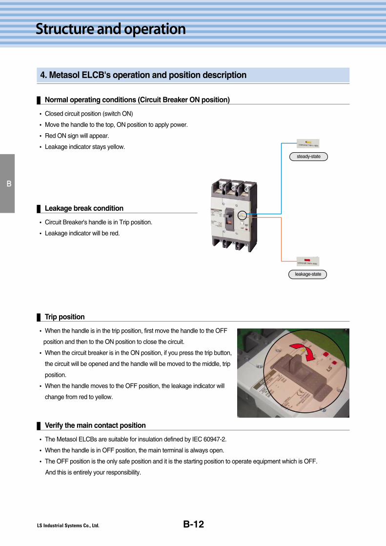
Normal operating conditions (Circuit Breaker ON position)
B-12
Structure and operation
� Closed circuit position (switch ON)
� Move the handle to the top, ON position to apply power.
� Red ON sign will appear.
� Leakage indicator stays yellow.
B
Leakage break condition
� Circuit Breaker's handle is in Trip position.
� Leakage indicator will be red.
Trip position
� When the handle is in the trip position, first move the handle to the OFF
position and then to the ON position to close the circuit.
� When the circuit breaker is in the ON position, if you press the trip button,
the circuit will be opened and the handle will be moved to the middle, trip
position.
� When the handle moves to the OFF position, the leakage indicator will
change from red to yellow.
Verify the main contact position
� The Metasol ELCBs are suitable for insulation defined by IEC 60947-2.
� When the handle is in OFF position, the main terminal is always open.
� The OFF position is the only safe position and it is the starting position to operate equipment which is OFF.
And this is entirely your responsibility.
steady-state
leakage-state

C.Productcharacteristics
C-2
C-5
C-8
C-11
1. 100AF Product characteristics
2. 125AF Product characteristics
3. 250AF Product characteristics
4. 400~800AF Product characteristics
C-1
Metasol MCCB/ELCB Technical Manual
Metasol MCCB/ELCB Technical Manual
C-2
Product characteristics
1. 100AF Product characteristics
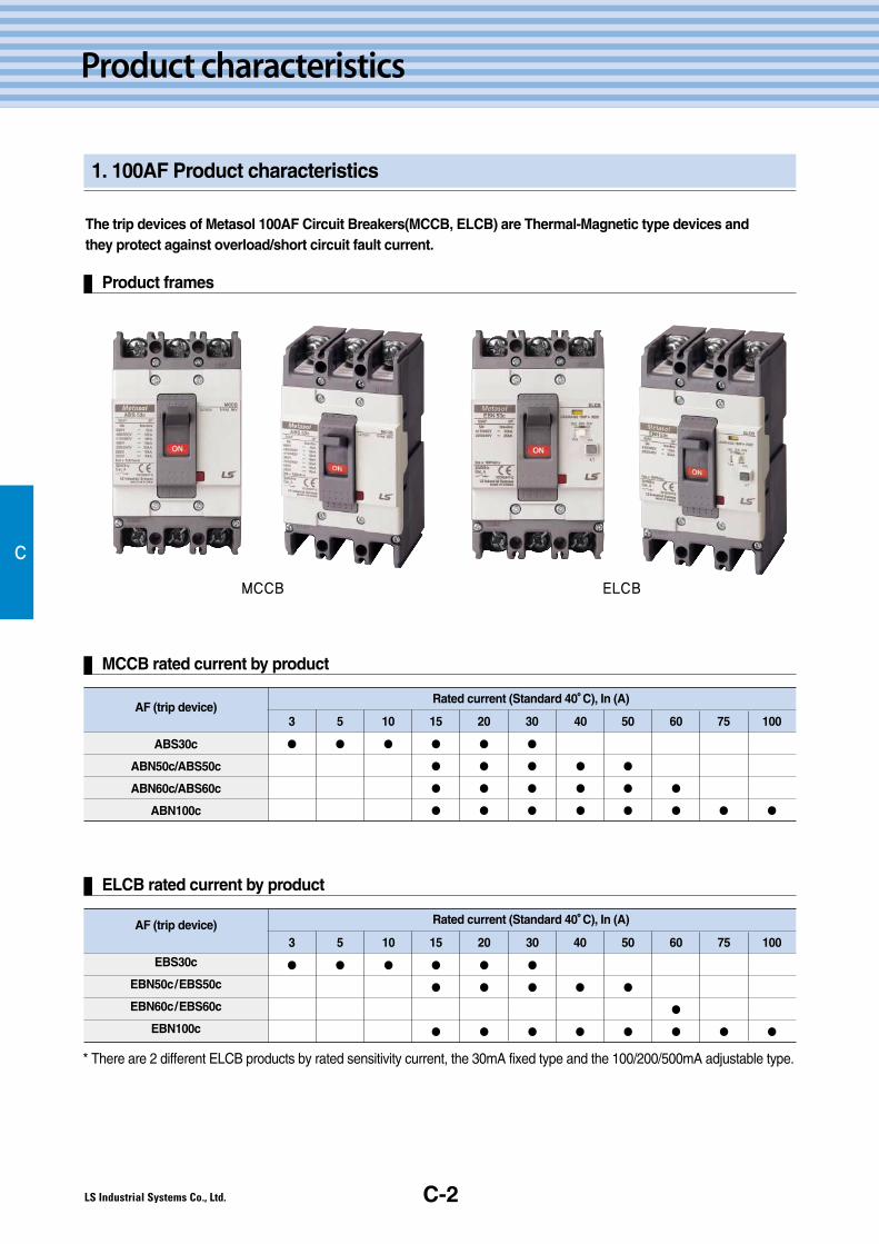
The trip devices of Metasol 100AF Circuit Breakers(MCCB, ELCB) are Thermal-Magnetic type devices andthey protect against overload/short circuit fault current.
Product frames
MCCB rated current by product
C
MCCB ELCB
AF (trip device)
ABS30c
ABN50c/ABS50c
ABN60c/ABS60c
ABN100c
Rated current (Standard 40��C), In (A)
15
●
●
●
●
10
●
5
●
3
●
20
●
●
●
●
30
●
●
●
●
40
●
●
●
50
●
●
●
60
●
●
75
●
100
●
* There are 2 different ELCB products by rated sensitivity current, the 30mA fixed type and the 100/200/500mA adjustable type.
ELCB rated current by product
AF (trip device)
EBS30c
EBN50c/EBS50c
EBN60c/EBS60c
EBN100c
Rated current (Standard 40��C), In (A)
15
●
●
●
10
●
5
●
3
●
20
●
●
●
30
●
●
●
40
●
●
50
●
●
60
●
●
75
●
100
●
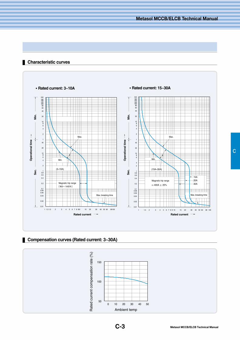
C-3
Characteristic curves
Compensation curves (Rated current: 3~30A)
C
Metasol MCCB/ELCB Technical Manual
Metasol MCCB/ELCB Technical Manual
Ambient tempRat
ed c
urre
nt c
ompe
nsat
ion
rate
(%
)
Min
.
Min
.
Sec
.
Sec
.
Op
erat
ion
al ti
me
Op
erat
ion
al ti
me
Max. Max.
Min. Min.
Magnetic trip rangeMagnetic trip range
Max. breaking time Max. breaking time
Rated current Rated current
��Rated current: 3~10A ��Rated current: 15~30A
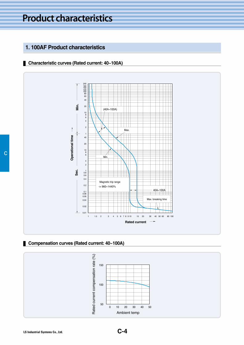
C-4
Product characteristics
1. 100AF Product characteristics
C
Characteristic curves (Rated current: 40~100A)
Compensation curves (Rated current: 40~100A)
Metasol MCCB/ELCB Technical ManualC-5
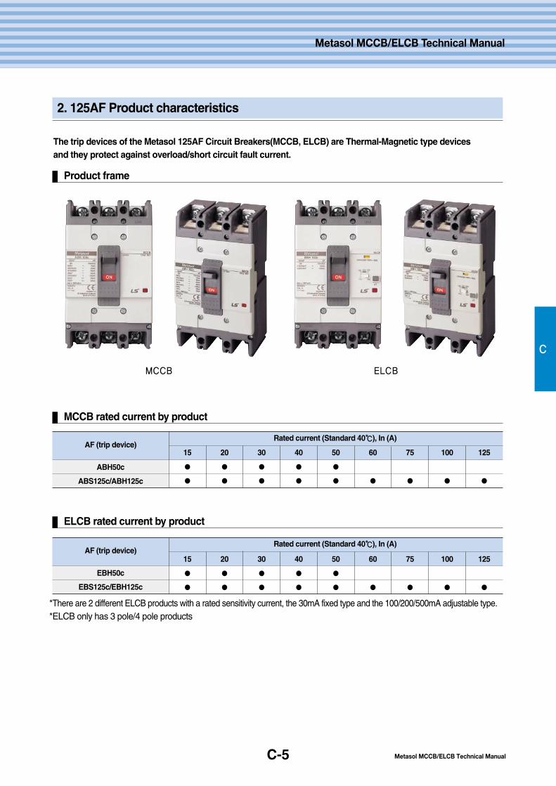
2. 125AF Product characteristics
C
The trip devices of the Metasol 125AF Circuit Breakers(MCCB, ELCB) are Thermal-Magnetic type devicesand they protect against overload/short circuit fault current.
Product frame
MCCB ELCB
MCCB rated current by product
AF (trip device)
ABH50c
ABS125c/ABH125c
Rated current (Standard 40℃℃), In (A)
15
●
●
20
●
●
30
●
●
40
●
●
50
●
●
60
●
75
●
100
●
125
●
*There are 2 different ELCB products with a rated sensitivity current, the 30mA fixed type and the 100/200/500mA adjustable type.*ELCB only has 3 pole/4 pole products
ELCB rated current by product
AF (trip device)
EBH50c
EBS125c/EBH125c
Rated current (Standard 40℃℃), In (A)
15
●
●
20
●
●
30
●
●
40
●
●
50
●
●
60
●
75
●
100
●
125
●
Metasol MCCB/ELCB Technical Manual

C-6
Product characteristics
2. 125AF Product characteristics
Characteristic curves (Rated current: 15~30A, 40~100A)
C
Compensation curves (Rated current: 15~30A, 40~100A)
15A~30A
40A~100A
150
100
500 10 20 30 40 50
Ambient tempRat
ed c
urre
nt c
ompe
nsat
ion
rate
(%
)
240180150
1008060
40
20
40
20
1086
4
2
1086
4
2
1
1
1 2 3 4 5 6 7 8 9 10 15 20 30 40 50 60 80 1001.5
0.80.6
0.4
0.2
0.10.080.06
0.04
0.02
0.01
120
(15A~30A)
(40A~100A)
15A20A
30A40~100A
-> 960~1440% -> Min. 400A ± 20%
Min
.S
ec.
Op
erat
ion
al ti
me
Max.
Min.
Magnetic trip range
Max. breaking time
Rated current
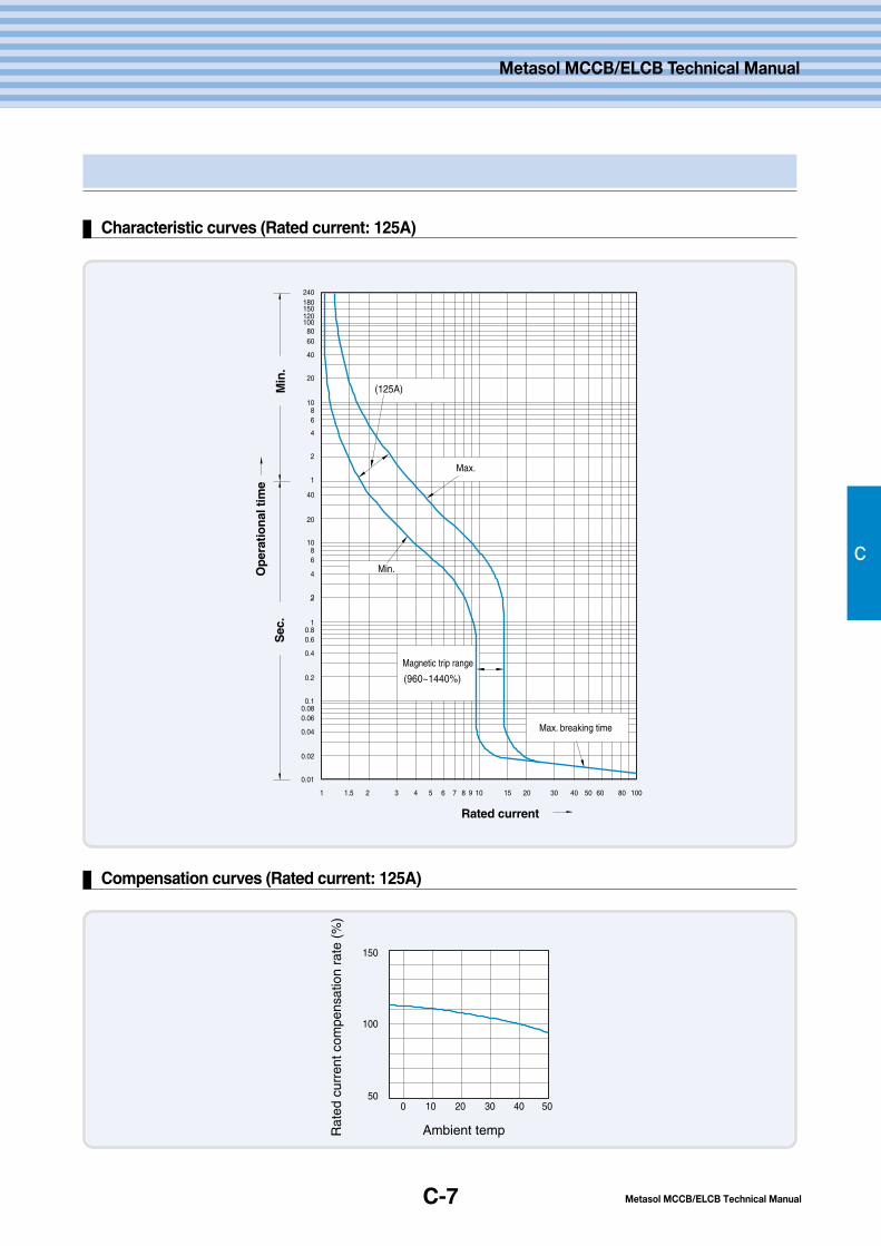
C-7
Characteristic curves (Rated current: 125A)
C
Metasol MCCB/ELCB Technical Manual
Metasol MCCB/ELCB Technical Manual
Compensation curves (Rated current: 125A)
150
100
500 10 20 30 40 50
Ambient tempRat
ed c
urre
nt c
ompe
nsat
ion
rate
(%
)
240180150
1008060
40
20
40
20
1086
4
2
1086
4
2
1
1
1 2 3 4 5 6 7 8 9 10 15 20 30 40 50 60 80 1001.5
0.80.6
0.4
0.2
0.10.080.06
0.04
0.02
0.01
120
(125A)
(960~1440%)
Min
.S
ec.
Op
erat
ion
al ti
me
Max.
Min.
Magnetic trip range
Max. breaking time
Rated current
C-8
Product characteristics
3. 250AF Product characteristics
C
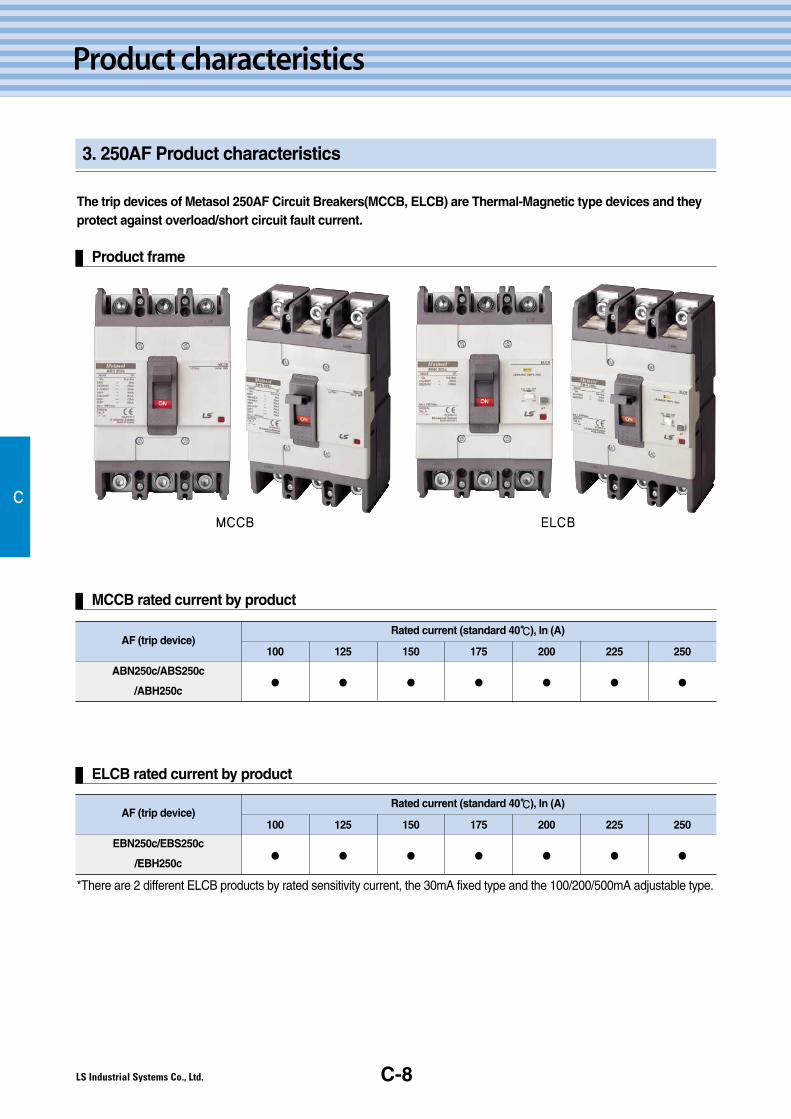
The trip devices of Metasol 250AF Circuit Breakers(MCCB, ELCB) are Thermal-Magnetic type devices and theyprotect against overload/short circuit fault current.
Product frame
MCCB ELCB
MCCB rated current by product
AF (trip device)
ABN250c/ABS250c
/ABH250c
Rated current (standard 40℃℃), In (A)
100
●
125
●
150
●
175
●
200
●
225
●
250
●
AF (trip device)
EBN250c/EBS250c
/EBH250c
Rated current (standard 40℃℃), In (A)
100
●
125
●
150
●
175
●
200
●
225
●
250
●
ELCB rated current by product
*There are 2 different ELCB products by rated sensitivity current, the 30mA fixed type and the 100/200/500mA adjustable type.

C-9
Characteristic curves (Rated current: 100~225A)
C
Metasol MCCB/ELCB Technical Manual
Metasol MCCB/ELCB Technical Manual
Compensation curves (Rated current: 100~225A)
150
100
500 10 20 30 40 50
Ambient tempRat
ed c
urre
nt c
ompe
nsat
ion
rate
(%
)

C-10
Product Characteristics
C
3. 250AF Product characteristics
Characteristic curves (Rated current: 250A)
Compensation curves (Rated current: 250A)
150
100
500 10 20 30 40 50
Ambient tempRat
ed c
urre
nt c
ompe
nsat
ion
rate
(%
)
240180150
1008060
40
20
40
20
1086
4
2
1086
4
2
1
1
1 2 3 4 5 6 7 8 9 10 15 20 30 40 50 60 80 1001.5
0.80.6
0.4
0.2
0.10.080.06
0.04
0.02
0.01
120
(960~1440%)
Min
.S
ec.
Op
erat
ion
al ti
me
Max.
Min.
Magnetic trip range
Max. breaking time
Rated current
C-11
4. 400~800AF Product characteristics
C
Metasol MCCB/ELCB Technical Manual
Metasol MCCB/ELCB Technical Manual
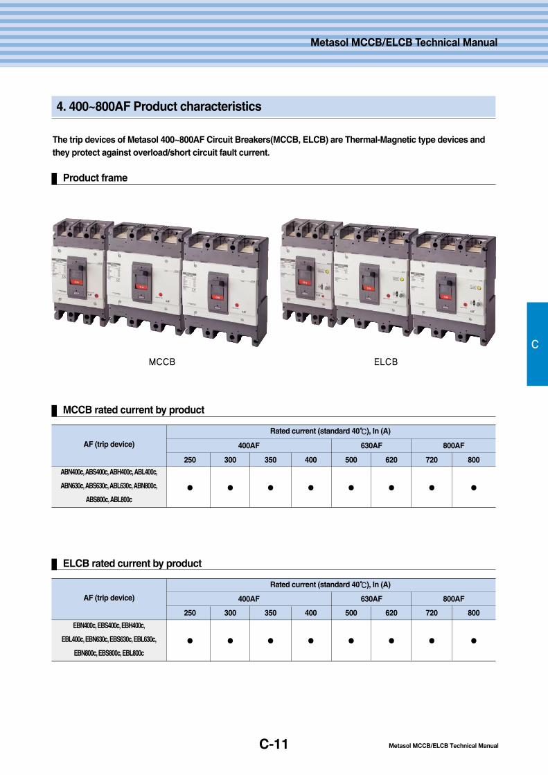
The trip devices of Metasol 400~800AF Circuit Breakers(MCCB, ELCB) are Thermal-Magnetic type devices andthey protect against overload/short circuit fault current.
Product frame
MCCB ELCB
MCCB rated current by product
AF (trip device)
ABN400c, ABS400c, ABH400c, ABL400c,
ABN630c, ABS630c, ABL630c, ABN800c,
ABS800c, ABL800c
Rated current (standard 40℃℃), In (A)
250
●
300
●
350
●
400
●
500
●
620
●
720
●
800
●
400AF 630AF 800AF
ELCB rated current by product
AF (trip device)
EBN400c, EBS400c, EBH400c,
EBL400c, EBN630c, EBS630c, EBL630c,
EBN800c, EBS800c, EBL800c
Rated current (standard 40℃℃), In (A)
250
●
300
●
350
●
400
●
500
●
620
●
720
●
800
●
400AF 630AF 800AF
C-12
Product characteristics
C
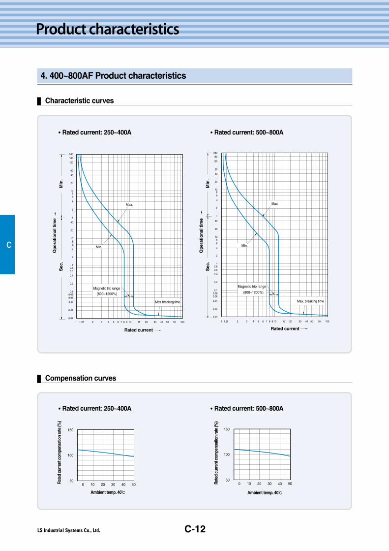
Characteristic curves
Compensation curves
��Rated current: 250~400A
��Rated current: 250~400A
��Rated current: 500~800A
��Rated current: 500~800A
Min
.S
ec.
Op
erat
ion
al ti
me
Max.
Min.
Max. breaking time
Rated current
Magnetic trip range
1
0.1
0.2
0.4
0.60.8
1
2
4
68
10
20
40
1
2
4
68
10
20
40
60
120
180
240
0.01
0.02
0.04
0.060.08
1.25 2 3 4 5 6 7 8 9 10 15 20 30 40 50 70 100
(800~1200%)
Min
.S
ec.
Op
erat
ion
al ti
me
Max.
Min.
Max. breaking time
Rated current
Magnetic trip range
0 10 20 30 40 5050
150
100
Rate
d cu
rrent
com
pens
atio
n ra
te (%
)
Ambient temp. 40℃
50
100
150
0 10 20 504030Rate
d cu
rrent
com
pens
atio
n ra
te (%
)
Ambient temp. 40℃
4. 400~800AF Product characteristics
D.Operatingconditions
D-2
D-3
D-5
1. Standard usage environment
2. Special usage environment
3. Usage conditions involving
vibration and impact
D-1
Metasol MCCB/ELCB Technical Manual
Metasol MCCB/ELCB Technical Manual

D-2
Operating conditions
1. Standard usage environment
Standard usage environment for Metasol MCCB
Depending on different environment conditions, MCCB's functions(short circuit and overload protection), durability andinsulation efficiency can be effected a lot so it should be installed under precise conditions. Especially circuit breakerswhich use a thermal-magnetic type trip unit change characteristics depending on the temperature so when you use them,you have to adjust their rated current.
1) Ambient temperature: -5℃~+40℃ (average over 24hr should not exceed 35℃.)2) Relative humidity: within 45~85%3) Altitude: below 2,000m (when it's over 1,000m, you might consider adjusting air pressure by doing a humidity and voltage test.)4) Places without excessive steam, oil, smoke, dust, salinity and corrosive materials.
D
■ If standard circuit breaker used at temperatures over 40℃, try to use theadjusted current by temperature from the catalogue.
■ Insulation resistance and electric efficiency might drop under high humidity.
■ Electric current flow switch, tripping and short circuit breaking will stillfunction at -20℃.
■ Passing through an extremely cold area around -40℃or storage is no problem.■ When you use thermal-magnetic type trip unit, it’ s set for 40℃ so it
might change characteristics.
■ When the breaker is stored in an environment with excessive dust or humidity,it is strongly recommended to use a dust cover and/or dehumidifier.
■ Excessive vibration may cause trips, breaks in connections or damage tomechanical devices.
■ If it is left ON or OFF for a long time, it is good to switch the overloadcurrent regularly.
■ In environments containing corrosive gas, it is necessary to put thedevice in a sealed protective structure.

D-3
2. Special usage environment
In case of temperatures over 40℃℃
D
Metasol MCCB/ELCB Technical Manual
Metasol MCCB/ELCB Technical Manual
Because the temperature of MCCB's parts is the sum of increased temperature from current flow and environmenttemperature, when the environment temperature is over 40℃, current flow needs to be reduced so the MCCB's insulationtemperature doesn't exceed permissible temperature.Standard temperature of the Metasol circuit breaker is up to 40℃ so when it's higher temperature, rated current needs tobe lowered as specified in the current rating adjustment table.
Metasol MCCB current rating adjustment by temperature table
Ampere
Frame
30
50
60
100
125
250
400
630
800
Circuit breaker type
ABS30c
ABN50c, ABS50c
ABN60c, ABS60c
ABN100c
ABH50c, ABS125c, ABH125c
ABN200c, ABS200c, ABH250c
Rated
current351015203040506075100125150175200225250250300350400500630700800
10℃℃351015203040506075100125150175200225250250300350400500630700800
20℃℃351015203040506075100125150175200225250250300350400500630700800
30℃℃351015203040506075100125150175200225250250300350400500630700800
40℃℃351015203040506075100125150175200225250250300350400500630700800
45℃℃35101519293949587397121145169193217241246295345394492621689788
50℃℃3591419283847567194116140163186209233242291339388485611679776
55℃℃3491318273645556891107128150171193214238287332381477602668764
Current rating adjustment by temperature table (A)
ABN400c, ABS400cABH400c, ABL400c
ABN630c, ABS630c, ABL630c
ABN800c, ABS800c, ABL800c
Metasol ELCB current rating adjustment by temperature table
Ampere
Frame
30
50
60
100
125
250
400
630
800
Circuit breaker type
EBS30c
EBN50c, EBS50c
EBN60c, EBS60c
EBN100c
EBH50c, EBS125c, EBH125c
EBN200c, EBS200c,EBH250c
Rated
current15203040506075100125150175200225250250300350400500630700800
10℃℃15203040506075100125150175200225250250300350400500630700800
20℃℃15203040506075100125150175200225250250300350400500630700800
30℃℃15203040506075100125150175200225250250300350400500630700800
40℃℃15203040506075100125150175200225250250300350400500630700800
45℃℃1519293949587397121145169193217241246295345394492621689788
50℃℃1519283847567194116140163186209233242291339388485611679776
55℃℃1518273645556891107128150171193214238287332381477602668764
Current rating adjustment by temperature table (A)
EBN400c, EBS400cEBH400c, EBL400c
EBN630c, EBS630c, EBL630c
EBN800c, EBS800c, EBL800c
D-4
Operating conditions
2. Special usage environment
In Case of temperatures below -5℃℃
Because the MCCB cannot ignore the effect of inside metal parts and insulation delicate character against lowtemperature and mechanical parts lubricating oil viscosity change, it's necessary not to let the temperature go downextremely using a space heater etc. Also in case of a Thermal type trip unit, it tends to change its characteristic to bedifficult to operate so it needs to be adjusted to verify the level of protection.The MCCB's electric current flow switch, tripping and short circuit breaking will still function at -20℃ but to prevent theeffects from low temperature as much as possible, it is recommended to install a space heater etc. Also when it'stransported or passing through extremely cold area up to -40℃, it won't take serious damage but to minimize the effect ofdelicate character, MCCB’s switch needs to be in OFF or Tripposition.
High humidity condition (relative humidity over 85%)
Using the MCCB in places with high humidity can cause a decrease in insulation and an increase in mechanism accessories'corrosion so it's necessary to install a moisture proof structure inside or perform frequent repair inspections. Also In case ofinstalling an MCCB inside of sealed structure, due to equipment operation and interruption etc., the inside temperature ofswitchboard and panel board will change rapidly and it can cause condensation so a space heater needs to be installed inside.
Conditions with existing corrosive gas
Because silver or silver alloy is used for MCCB's contact point's material, when it contacts corrosive gas, corrosive film willbe formatted on the contact surface and then there will be a possibility of contact point's contacting fault. But becausecorrosive film tends to come off easily mechanically, when there are a lot of makes and breaks(switches), it's not aparticular problem. But if there is infrequent switching, care must be taken to switch it regularly. With corrosive gas, thelead wire etc. of MCCB's moving contact can be corroded and hardened, then they can easily cause disconnection.To prevent this, silver plating is effective so if it is used in high density of corrosive gas condition, it is necessary to use theMCCB with a silver plated lead line which increases resistance against corrosion.
Conditions with existing explosive gas
In principle an MCCB which switches current should not be installed in this dangerous place.
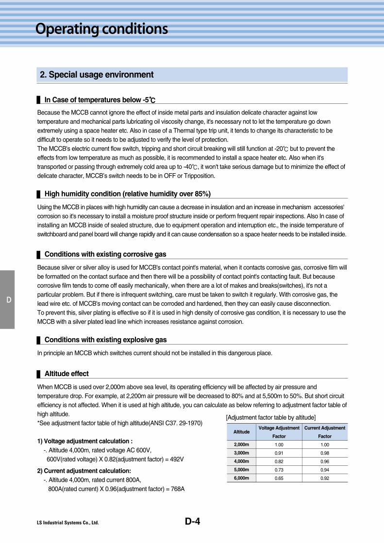
Altitude effect
When MCCB is used over 2,000m above sea level, its operating efficiency will be affected by air pressure andtemperature drop. For example, at 2,200m air pressure will be decreased to 80% and at 5,500m to 50%. But short circuitefficiency is not affected. When it is used at high altitude, you can calculate as below referring to adjustment factor table ofhigh altitude.*See adjustment factor table of high altitude(ANSI C37. 29-1970)
1) Voltage adjustment calculation :-. Altitude 4,000m, rated voltage AC 600V,600V(rated voltage) X 0.82(adjustment factor) = 492V
2) Current adjustment calculation:-. Altitude 4,000m, rated current 800A,
800A(rated current) X 0.96(adjustment factor) = 768A
D
Altitude
2,000m
3,000m
4,000m
5,000m
6,000m
Voltage Adjustment
Factor
1.00
0.91
0.82
0.73
0.65
Current Adjustment
Factor
1.00
0.98
0.96
0.94
0.92
[Adjustment factor table by altitude]
D-5
3. Usage conditions involving vibration and impact
Effect of vibration and impact
D
Metasol MCCB/ELCB Technical Manual
Metasol MCCB/ELCB Technical Manual
Excessive vibration and impact to the circuit breaker can cause safety problems of dynamic intensity, current flow andoperation characteristic which results in damage and loss. It is necessary to consider these environmental stresses whenchoosing the circuit breaker. These stresses occur from vibration during transporting, self impact while operating theswitch and the effect of nearby devices. The standard for electrical devices' standard vibration and impact resistance isspecified in the [small electric devices vibrating test] etc. and we are testing MCCB's vibration and impact resistance inaccordance with this standard for these conditions.
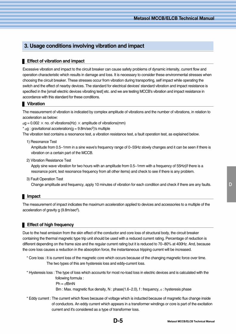
Vibration
The measurement of vibration is indicated by complex amplitude of vibrations and the number of vibrations, in relation toacceleration as below:αg = 0.002 × no. of vibrations(Hz) × amplitude of vibrations(mm)* αg : gravitational acceleration(g = 9.8m/sec2)'s multipleThe vibration test contains a resonance test, a vibration resistance test, a fault operation test, as explained below.
1) Resonance TestAmplitude from 0.5~1mm in a sine wave's frequency range of 0~55Hz slowly changes and it can be seen if there isvibration on a certain part of the MCCB.
2) Vibration Resistance TestApply sine wave vibration for two hours with an amplitude from 0.5~1mm with a frequency of 55Hz(if there is aresonance point, test resonance frequency from all other items) and check to see if there is any problem.
3) Fault Operation TestChange amplitude and frequency, apply 10 minutes of vibration for each condition and check if there are any faults.
Impact
The measurement of impact indicates the maximum acceleration applied to devices and accessories to a multiple of theacceleration of gravity g (9.8m/sec2).
Effect of high frequency
Due to the heat emission from the skin effect of the conductor and core loss of structural body, the circuit breakercontaining the thermal magnetic type trip unit should be used with a reduced current rating. Percentage of reduction isdifferent depending on the frame size and the regular current rating but it is reduced to 70~80% at 400Hz. And, becausethe core loss causes a reduction in the absorption force, the instantaneous tripping current will be increased.
* Core loss : It is current loss of the magnetic core which occurs because of the changing magnetic force over time.The two types of this are hysteresis loss and eddy-current loss.
* Hysteresis loss : The type of loss which accounts for most no-load loss in electric devices and is calculated with thefollowing formula :Ph = σfBmNBm : Max. magnetic flux density, N : phase(1.6~2.0), f : frequency, σ: hysteresis phase
* Eddy current : The current which flows because of voltage which is inducted because of magnetic flux change insideof conductors. An eddy current which appears in a transformer windings or core is part of the excitationcurrent and it's considered as a type of transformer loss.
D-6
Operating conditions
3. Usage environments involving vibration and impact
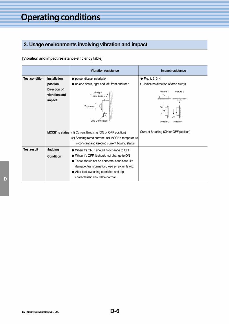
[Vibration and impact resistance efficiency table]
D
Test condition
Test result
Installation
position
Direction of
vibration and
impact
MCCB’’s status
Judging
Condition
Vibration resistance
● perpendicular installation
● up and down, right and left, front and rear
(1) Current Breaking (ON or OFF position)
(2) Sending rated current until MCCB's temperature
is constant and keeping current flowing status
● When it's ON, it should not change to OFF
● When it's OFF, it should not change to ON
● There should not be abnormal conditions like
damage, transformation, lose screw units etc.
● After test, switching operation and trip
characteristic should be normal.
Impact resistance
● Fig. 1, 2, 3, 4
(→indicates direction of drop away)
Current Breaking (ON or OFF position)
Left-right,
Front-back
Top-down
Line Connection
Picture 1
Picture 3 Picture 4
Picture 2
ON
ON
E.E-2
E-3
E-7
E-8
E-9
E-11
E-13
E-16
E-17
E-18
E-24
1. Precautions for safe use
2. Installation method of 100AF
3. Installation method of 125AF
4. Installation method of 250AF
5. Installation method of 400AF
6. Installation method of 630/800AF
7. Insulation distance
8. Connection
9. Back type installation
10. Plug-in installation
11. Standard accessories by type of product
E-1
Metasol MCCB/ELCB Technical Manual
Metasol MCCB/ELCB Technical Manual
Installationmethod
E-2
Installation method
1. Precautions for safe use
E
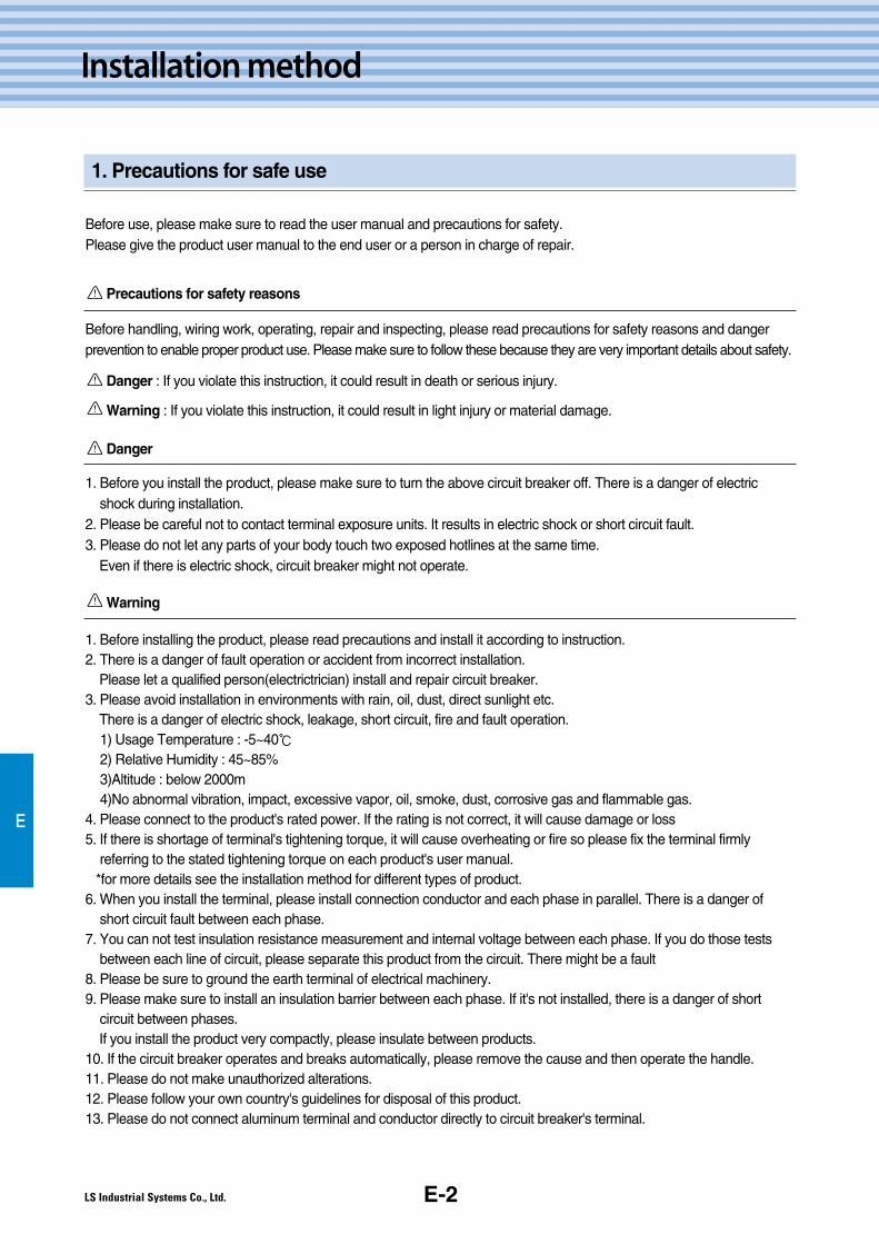
Before use, please make sure to read the user manual and precautions for safety.Please give the product user manual to the end user or a person in charge of repair.
Precautions for safety reasons
Before handling, wiring work, operating, repair and inspecting, please read precautions for safety reasons and dangerprevention to enable proper product use. Please make sure to follow these because they are very important details about safety.
Danger : If you violate this instruction, it could result in death or serious injury.
Warning : If you violate this instruction, it could result in light injury or material damage.
Danger
1. Before you install the product, please make sure to turn the above circuit breaker off. There is a danger of electricshock during installation.
2. Please be careful not to contact terminal exposure units. It results in electric shock or short circuit fault.3. Please do not let any parts of your body touch two exposed hotlines at the same time.
Even if there is electric shock, circuit breaker might not operate.
Warning
1. Before installing the product, please read precautions and install it according to instruction.2. There is a danger of fault operation or accident from incorrect installation.
Please let a qualified person(electrictrician) install and repair circuit breaker.3. Please avoid installation in environments with rain, oil, dust, direct sunlight etc.
There is a danger of electric shock, leakage, short circuit, fire and fault operation.1) Usage Temperature : -5~40℃2) Relative Humidity : 45~85%3)Altitude : below 2000m4)No abnormal vibration, impact, excessive vapor, oil, smoke, dust, corrosive gas and flammable gas.
4. Please connect to the product's rated power. If the rating is not correct, it will cause damage or loss5. If there is shortage of terminal's tightening torque, it will cause overheating or fire so please fix the terminal firmly
referring to the stated tightening torque on each product's user manual.*for more details see the installation method for different types of product.
6. When you install the terminal, please install connection conductor and each phase in parallel. There is a danger ofshort circuit fault between each phase.
7. You can not test insulation resistance measurement and internal voltage between each phase. If you do those testsbetween each line of circuit, please separate this product from the circuit. There might be a fault
8. Please be sure to ground the earth terminal of electrical machinery.9. Please make sure to install an insulation barrier between each phase. If it's not installed, there is a danger of short
circuit between phases.If you install the product very compactly, please insulate between products.
10. If the circuit breaker operates and breaks automatically, please remove the cause and then operate the handle.11. Please do not make unauthorized alterations.12. Please follow your own country's guidelines for disposal of this product.13. Please do not connect aluminum terminal and conductor directly to circuit breaker's terminal.

E-3
2. Installation method of 100AF
Installation of 100AF circuit breaker
1. When the circuit breaker is to be installed, place it perpendicular as Fig. 1, so when you look at it from the front or side, it maintains a
90°angle. Then use proper installation screws for the circuit breaker which were offered with the product and install it as shown in Fig 3.
2. When the circuit breaker is to be installed, it needs to be installed to maintain the insulation distance with metal
conductor as in Fig. 2.
*The unit of measurement in the Fig. is mm.
3. When you install products very closely as in Fig. 2, you need to install a barrier between them.
*According to a type of product, you can purchase insulation barriers additionally.
E
Metasol MCCB/ELCB Technical Manual
Metasol MCCB/ELCB Technical Manual
If 100AF circuit breaker is to be installed, it can be installed as below.
90
90
Fig. 2
50
25
50
M4 × 60
Fig. 1
Fig. 3
* In the case of installing products very closely, abarrier has to be inserted between products.
M4 or∅5 M4 or∅5 M4 or∅5
110.
5
110.
5
110.
5
25 25
LC LC
LC LC
LC
LC
2P 3P 4P
E-4
Installation method
2. Installation method of 100AF
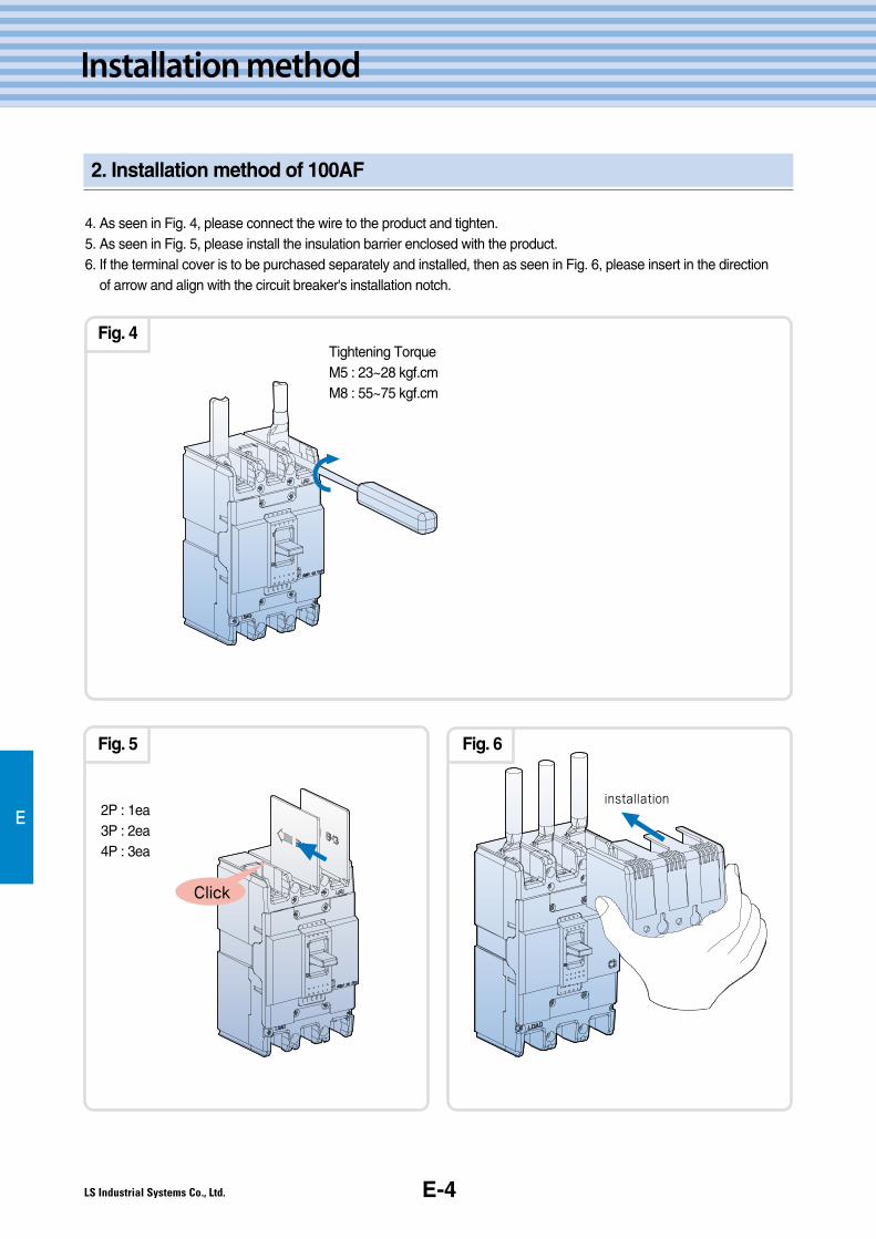
4. As seen in Fig. 4, please connect the wire to the product and tighten.5. As seen in Fig. 5, please install the insulation barrier enclosed with the product.6. If the terminal cover is to be purchased separately and installed, then as seen in Fig. 6, please insert in the direction
of arrow and align with the circuit breaker's installation notch.
E 2P : 1ea3P : 2ea4P : 3ea
Tightening TorqueM5 : 23~28 kgf.cmM8 : 55~75 kgf.cm
installation
Click
Fig. 4
Fig. 5 Fig. 6
Metasol MCCB/ELCB Technical ManualE-5
3. Installation method of 125AF
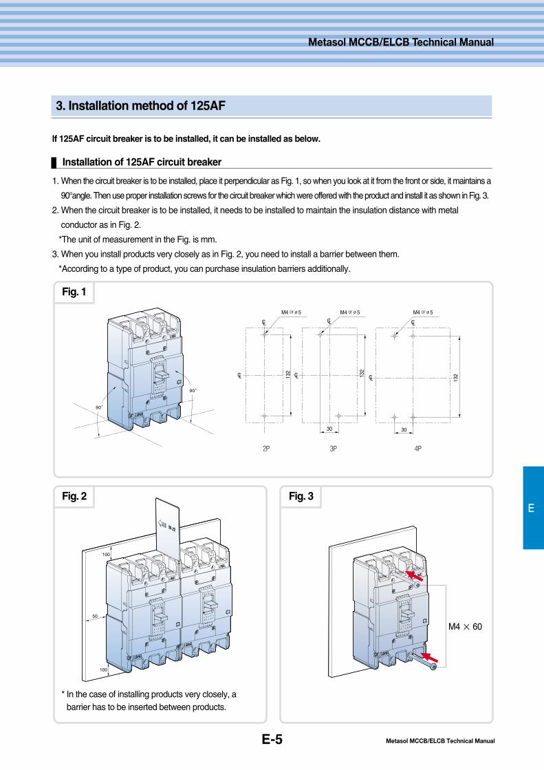
If 125AF circuit breaker is to be installed, it can be installed as below.
E
Installation of 125AF circuit breaker
1. When the circuit breaker is to be installed, place it perpendicular as Fig. 1, so when you look at it from the front or side, it maintains a
90°angle. Then use proper installation screws for the circuit breaker which were offered with the product and install it as shown in Fig. 3.
2. When the circuit breaker is to be installed, it needs to be installed to maintain the insulation distance with metal
conductor as in Fig. 2.
*The unit of measurement in the Fig. is mm.
3. When you install products very closely as in Fig. 2, you need to install a barrier between them.
*According to a type of product, you can purchase insulation barriers additionally.
90
90
100
50
100
Fig. 1
Fig. 2 Fig. 3
M4 × 60
* In the case of installing products very closely, abarrier has to be inserted between products.
Metasol MCCB/ELCB Technical Manual
LC LC LC
LCLCLC
30
132
30
13213
2
M4 or∅5 M4 or∅5 M4 or∅5
2P 3P 4P
E-6
Installation method
3. Installation Method of 125AF
E
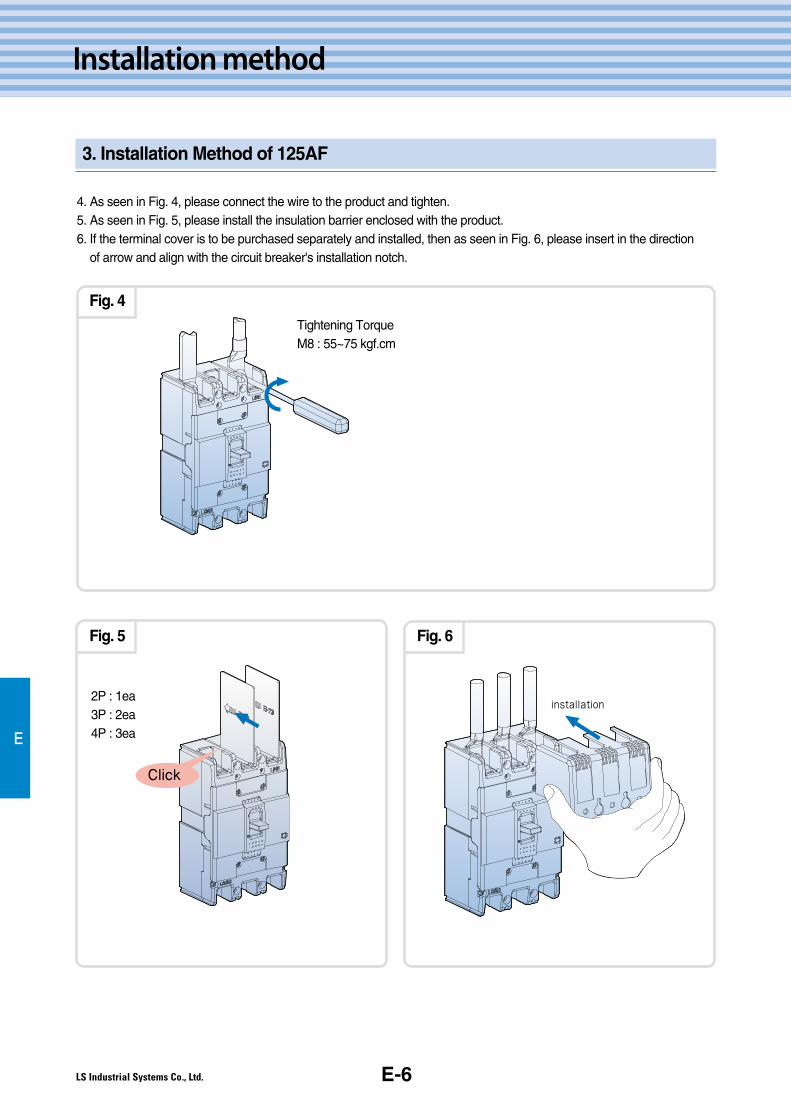
4. As seen in Fig. 4, please connect the wire to the product and tighten.5. As seen in Fig. 5, please install the insulation barrier enclosed with the product.6. If the terminal cover is to be purchased separately and installed, then as seen in Fig. 6, please insert in the direction
of arrow and align with the circuit breaker's installation notch.
2P : 1ea3P : 2ea4P : 3ea
Tightening TorqueM8 : 55~75 kgf.cm
installation
Click
Fig. 4
Fig. 5 Fig. 6

Metasol MCCB/ELCB Technical ManualE-7
4. Installation Method of 250AF
E
If 250AF circuit breaker is to be installed, it can be installed as below.
Installation of 250AF circuit
1. When the circuit breaker is to be installed, place it perpendicular as Fig. 1, so when you look at it from the front or side, it maintains a
90°angle. Then use proper installation screws for the circuit breaker which were offered with the product and install it as shown in Fig. 3.
2. When the circuit breaker is to be installed, it needs to be installed to maintain the insulation distance with metal
conductor as in Fig. 2.
*The unit of measurement in the Fig. is mm.
3. When you install products very closely as in Fig. 2, you need to install a barrier between them.
*According to a type of product, you can purchase insulation barriers additionally.
90
90
100
50
100
Fig. 1
Fig. 2 Fig. 3
M4 × 55
* In the case of installing products very closely, abarrier has to be inserted between products.
Metasol MCCB/ELCB Technical Manual
CL
LCLC
126
126
35 35 35
M4 or∅5 M4 or∅5
2, 3P 4P

E-8
Installation Method
E
4. Installation method of 250AF
4. As seen in Fig. 4, please connect the wire to the product and tighten.5. As seen in Fig. 5, please install the insulation barrier enclosed with the product.6. If the terminal cover is to be purchased separately and installed, then as seen in Fig. 6, please insert in the direction of
arrow and align with the circuit breaker's installation notch.
2P : 1ea3P : 2ea4P : 3ea
Tightening Torque80 ~ 130Kgf�cm
installation
Click
Fig. 4
Fig. 5 Fig. 6

E-9
E
Metasol MCCB/ELCB Technical Manual
Metasol MCCB/ELCB Technical Manual
5. Installation Method of 400AF
If 400AF circuit breaker is to be installed, it can be installed as below.
Installation of 400AF circuit
1. When the circuit breaker is to be installed, place it perpendicular as Fig. 1, so when you look at it from the front or side, it maintains a
90°angle. Then use proper installation screws for the circuit breaker which were offered with the product and install it as shown in Fig. 3.
2. When the circuit breaker is to be installed, it needs to be installed to maintain the insulation distance with metal
conductor as in Fig. 2.
*The unit of measurement in the Fig. is mm.
3. When you install products very closely as in Fig. 2, you need to install a barrier between them.
*According to a type of product, you can purchase insulation barriers additionally.
90
90
100
80
100
Fig. 1
Fig. 2 Fig. 3
M6 × 100
* In the case of installing products very closely, abarrier has to be inserted between products.
LC
LC LC
CL
44
215
215
44
M5 or∅6 M5 or∅6
2, 3P 4P
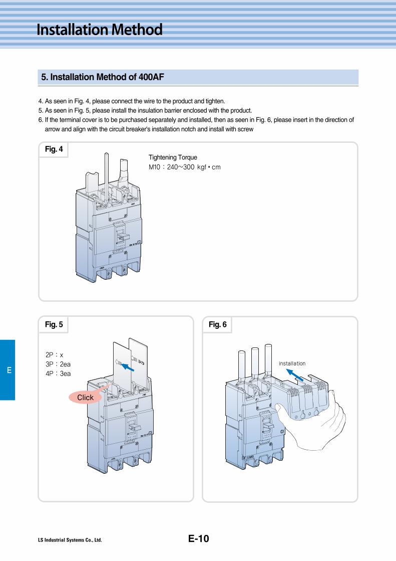
E-10
Installation Method
E
5. Installation Method of 400AF
4. As seen in Fig. 4, please connect the wire to the product and tighten.5. As seen in Fig. 5, please install the insulation barrier enclosed with the product.6. If the terminal cover is to be purchased separately and installed, then as seen in Fig. 6, please insert in the direction of
arrow and align with the circuit breaker's installation notch and install with screw
2P : x
3P : 2ea
4P : 3ea
Tightening TorqueM10 : 240~300 kgf�cm
installation
Click
Fig. 4
Fig. 5 Fig. 6

E-11
E
Metasol MCCB/ELCB Technical Manual
Metasol MCCB/ELCB Technical Manual
6. Installation Method of 630/800AF
If 630/800AF circuit breaker is to be installed, it can be installed as below.
Installation of 630/800AF circuit
1. When the circuit breaker is to be installed, place it perpendicular as Fig. 1, so when you look at it from the front or side, it maintains a
90°angle. Then use proper installation screws for the circuit breaker which were offered with the product and install it as shown in Fig. 3.
2. When the circuit breaker is to be installed, it needs to be installed to maintain the insulation distance with metal
conductor as in Fig. 2.
*The unit of measurement in the Fig. is mm.
3. When you install products very closely as in Fig. 2, you need to install a barrier between them.
*According to a type of product, you can purchase insulation barriers additionally.
90
90
100
80
100
Fig. 1
Fig. 2 Fig. 3
M6 × 100
* In the case of installing products very closely, abarrier has to be inserted between products.
M6
70 70 70
243
243
M6LCLC
LC LC
2, 3P 4P
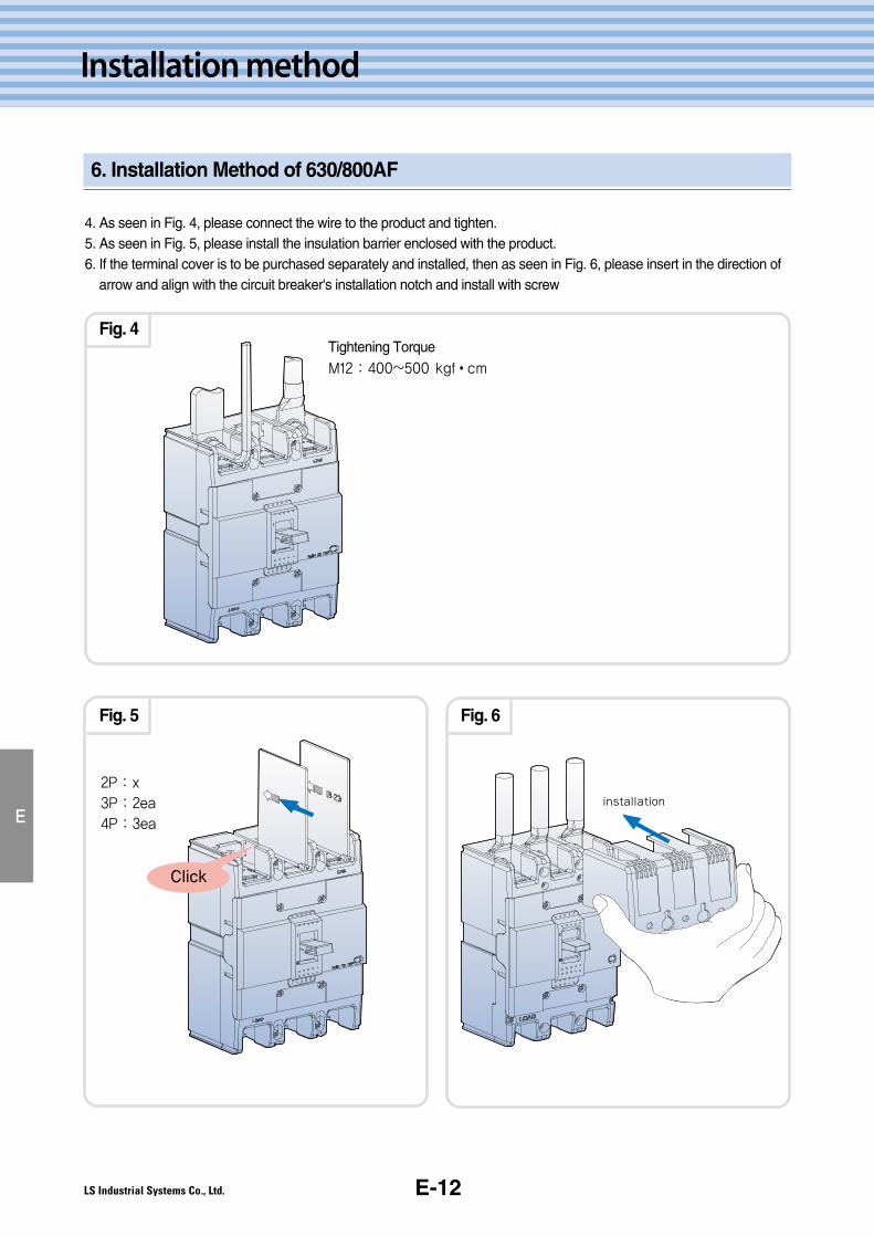
E-12
Installation method
6. Installation Method of 630/800AF
E
4. As seen in Fig. 4, please connect the wire to the product and tighten.5. As seen in Fig. 5, please install the insulation barrier enclosed with the product.6. If the terminal cover is to be purchased separately and installed, then as seen in Fig. 6, please insert in the direction of
arrow and align with the circuit breaker's installation notch and install with screw
2P : x
3P : 2ea
4P : 3ea
Tightening TorqueM12 : 400~500 kgf�cm
installation
Click
Fig. 4
Fig. 5 Fig. 6
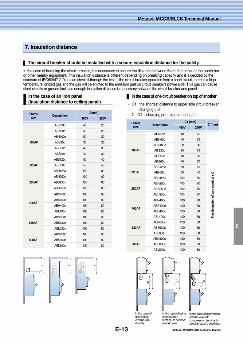
E-13
7. Insulation distance
The circuit breaker should be installed with a secure insulation distance for the safety.
E
Metasol MCCB/ELCB Technical Manual
Metasol MCCB/ELCB Technical Manual
In the case of installing the circuit breaker, it is necessary to secure the distance between them, the panel or the booth baror other nearby equipment. This insulation distance is different depending on breaking capacity and it is decided by thestandard of IEC60947-2. You can check it through the test. If the circuit breaker operates from a short circuit, there is a hightemperature ionized gas and the gas will be emitted to the emission part on circuit breaker's power side. This gas can causeshort circuits or ground faults so enough insulation distance is necessary between the circuit breaker and panel.
� C1 : the shortest distance to upper side circuit breakercharging unit
� C : C1 + charging part exposure length
In the case of an iron panel (Insulation distance to ceiling panel)
In the case of one circuit breaker on top of another
C1
C1
C1
C C C
AF
A A
in the case ofconnectingelectric wiredirectly
in the case of usingcompressionterminal to connectelectric wire
in the case of connectingelectric wire withcompression terminal tocircuit breaker's booth bar
100AF
125AF
250AF
ABN400c 100 80
400AFABS400c 100 80
ABH400c 100 80
ABL400c 100 80
ABN630c 100 80
630AF ABS630c 100 80
ABL630c 100 80
ABN800c 100 80
800AF ABS800c 100 80
ABL800c 100 80
Framesize
DescriptionA(mm)
460V 250V
ABN50c
ABN60c
ABN100c
ABS30c
ABS50c
ABS60c
ABS125c
ABH50c
ABH125c
ABN250c
ABS250c
ABH250c
40
40
50
30
40
40
50
50
100
100
100
100
25
25
30
25
30
30
40
40
80
80
80
80
100AF
125AF
250AF
ABN400c 100 80
400AFABS400c 100 80
ABH400c 100 80
ABL400c 100 80
ABN630c 100 80
630AF ABS630c 100 80
ABL630c 100 80
ABN800c 100 80
800AF ABS800c 100 80
ABL800c 100 80
Framesize
The
dim
ensi
onof
bare
cond
uct+
C1
Description C (mm)C1 (mm)
460V 250V
ABN50c
ABN60c
ABN100c
ABS30c
ABS50c
ABS60c
ABS125c
ABH50c
ABH125c
ABN250c
ABS250c
ABH250c
40
40
50
30
40
40
50
50
100
100
100
100
25
25
30
25
30
30
40
40
80
80
80
80
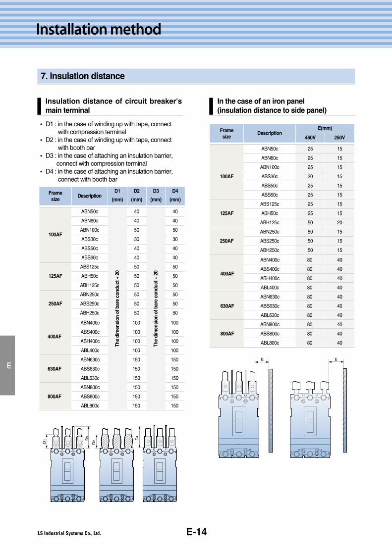
E-14
Installation method
7. Insulation distance
E
Insulation distance of circuit breaker'smain terminal
� D1 : in the case of winding up with tape, connectwith compression terminal
� D2 : in the case of winding up with tape, connectwith booth bar
� D3 : in the case of attaching an insulation barrier,connect with compression terminal
� D4 : in the case of attaching an insulation barrier,connect with booth bar
In the case of an iron panel (insulation distance to side panel)
D1 D
3
D2 D
4
100AF
125AF
250AF
ABN400c 100 100
400AFABS400c 100 100
ABH400c 100 100
ABL400c 100 100
ABN630c 150 150
630AF ABS630c 150 150
ABL630c 150 150
ABN800c 150 150
800AF ABS800c 150 150
ABL800c 150 150
Framesize
DescriptionD1
(mm)
D2
(mm)
D3
(mm)
D4
(mm)
ABN50c
ABN60c
ABN100c
ABS30c
ABS50c
ABS60c
ABS125c
ABH50c
ABH125c
ABN250c
ABS250c
ABH250c
The
dim
ensi
onof
bare
cond
uct+
20
The
dim
ensi
onof
bare
cond
uct+
20
40
40
50
30
40
40
50
50
50
50
50
50
40
40
50
30
40
40
50
50
50
50
50
50
E E
100AF
125AF
250AF
ABN400c 80 40
400AFABS400c 80 40
ABH400c 80 40
ABL400c 80 40
ABN630c 80 40
630AF ABS630c 80 40
ABL630c 80 40
ABN800c 80 40
800AF ABS800c 80 40
ABL800c 80 40
Framesize
DescriptionE(mm)
460V 250V
ABN50c
ABN60c
ABN100c
ABS30c
ABS50c
ABS60c
ABS125c
ABH50c
ABH125c
ABN250c
ABS250c
ABH250c
25
25
25
20
25
25
25
25
50
50
50
50
15
15
15
15
15
15
15
15
20
15
15
15
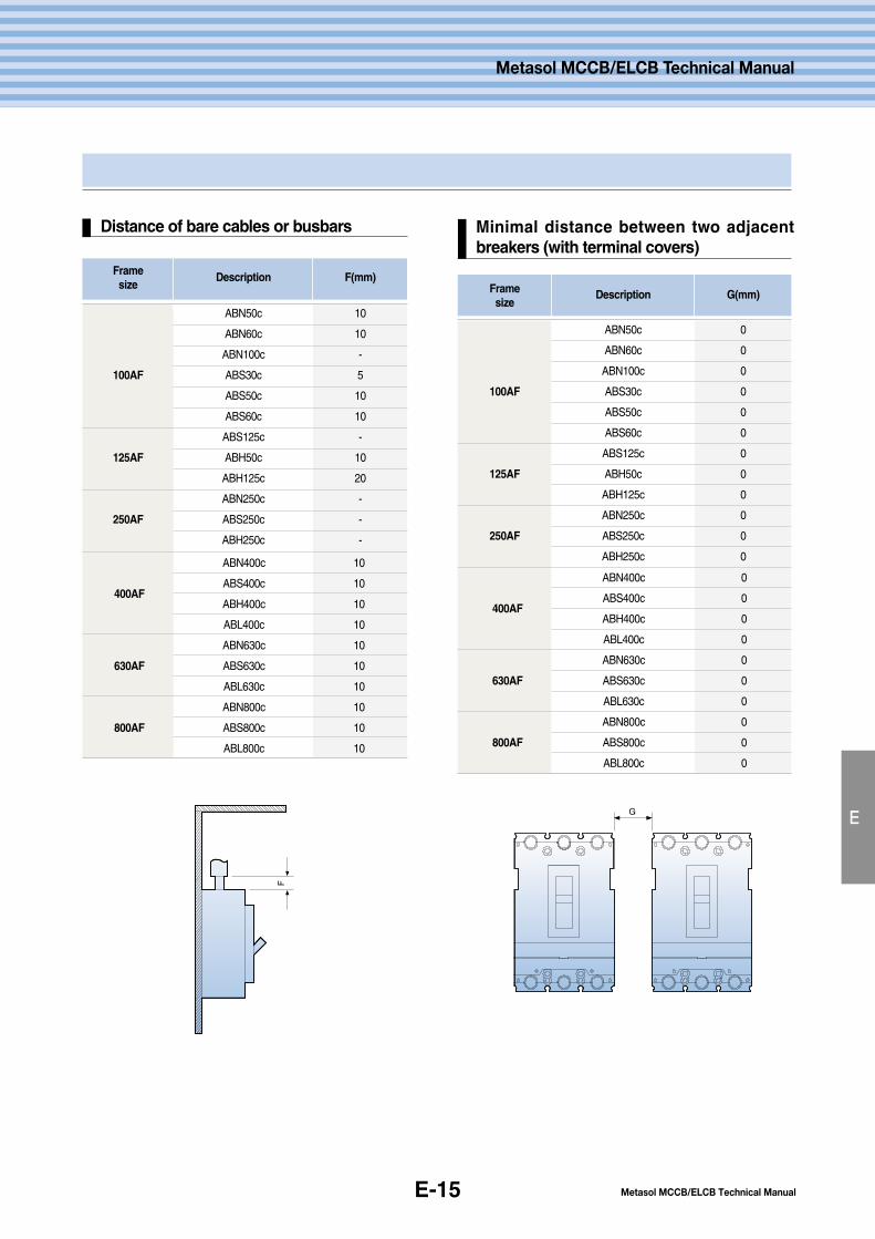
E-15
E
Metasol MCCB/ELCB Technical Manual
Metasol MCCB/ELCB Technical Manual
Distance of bare cables or busbars Minimal distance between two adjacentbreakers (with terminal covers)
F
G
100AF
125AF
250AF
Framesize
Description F(mm)
ABN50c
ABN60c
ABN100c
ABS30c
ABS50c
ABS60c
ABS125c
ABH50c
ABH125c
ABN250c
ABS250c
ABH250c
10
10
-
5
10
10
-
10
20
-
-
-
ABN400c 10
400AFABS400c 10
ABH400c 10
ABL400c 10
ABN630c 10
630AF ABS630c 10
ABL630c 10
ABN800c 10
800AF ABS800c 10
ABL800c 10
100AF
125AF
250AF
ABN400c 0
400AFABS400c 0
ABH400c 0
ABL400c 0
ABN630c 0
630AF ABS630c 0
ABL630c 0
ABN800c 0
800AF ABS800c 0
ABL800c 0
Framesize
Description G(mm)
ABN50c
ABN60c
ABN100c
ABS30c
ABS50c
ABS60c
ABS125c
ABH50c
ABH125c
ABN250c
ABS250c
ABH250c
0
0
0
0
0
0
0
0
0
0
0
0

E-16
Installation method
E
E-16
8. Connection
Connection
18
7.5
8.2
M5×14
24 12.512.57
∅5.5
7
∅5.5
18
7.5
8.2
M8×14
2415 15
7
∅9 ∅9
7
18
108
M8×14
24
28
21
M8×20
24
16 168
∅9 ∅9
8
25 2510
∅9 ∅9
10
ABN 100c
ABH 125c
ABH 250c
400AF
630AF
800AF
M8 : 80 ~ 130
M10 : 240~300
M12 : 400~500
Terminal(mm)
Tightening torque
(kgf∙∙cm)
Conductor
(mm)Frame type
[15~50A]
[60~100A]
M8 : 55 ~ 75
M5 : 23 ~ 28
M8 : 55 ~ 75
[15~50A]
[60~100A]
30
13
29
M10×L30 37
M12×35
11
29
44 34.5
10.5
44
∅14
29.5
12.5
∅10
.5
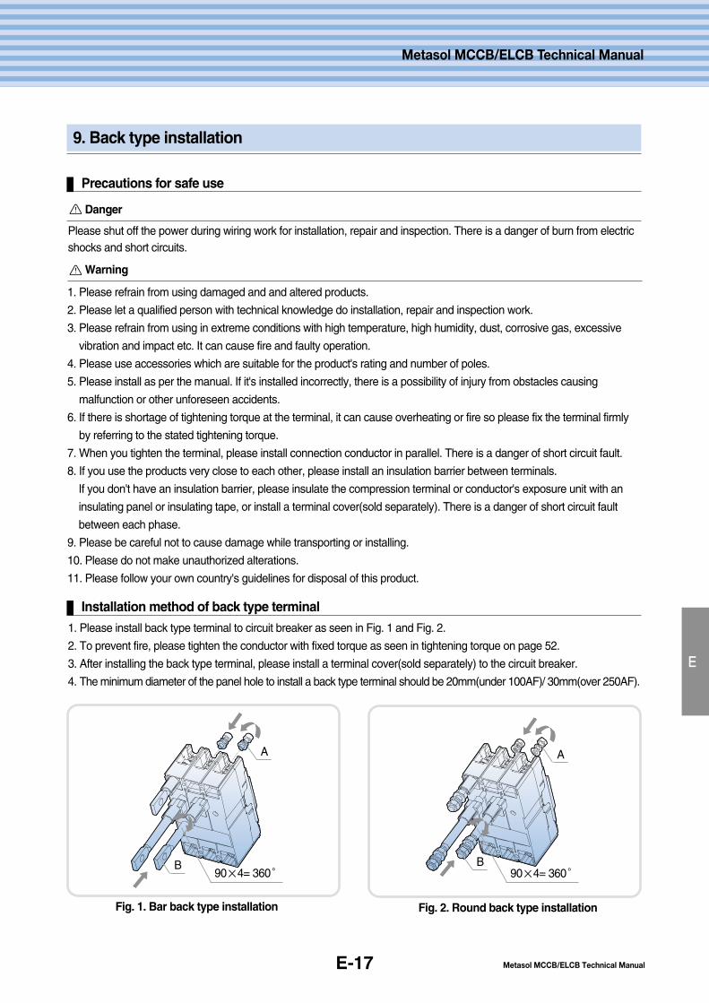
E-17
9. Back type installation
Precautions for safe use
E
Metasol MCCB/ELCB Technical Manual
Metasol MCCB/ELCB Technical Manual
Danger
Installation method of back type terminal
Fig. 1. Bar back type installation
A
Please shut off the power during wiring work for installation, repair and inspection. There is a danger of burn from electricshocks and short circuits.
1. Please refrain from using damaged and and altered products.
2. Please let a qualified person with technical knowledge do installation, repair and inspection work.
3. Please refrain from using in extreme conditions with high temperature, high humidity, dust, corrosive gas, excessive
vibration and impact etc. It can cause fire and faulty operation.
4. Please use accessories which are suitable for the product's rating and number of poles.
5. Please install as per the manual. If it's installed incorrectly, there is a possibility of injury from obstacles causing
malfunction or other unforeseen accidents.
6. If there is shortage of tightening torque at the terminal, it can cause overheating or fire so please fix the terminal firmly
by referring to the stated tightening torque.
7. When you tighten the terminal, please install connection conductor in parallel. There is a danger of short circuit fault.
8. If you use the products very close to each other, please install an insulation barrier between terminals.
If you don't have an insulation barrier, please insulate the compression terminal or conductor's exposure unit with an
insulating panel or insulating tape, or install a terminal cover(sold separately). There is a danger of short circuit fault
between each phase.
9. Please be careful not to cause damage while transporting or installing.
10. Please do not make unauthorized alterations.
11. Please follow your own country's guidelines for disposal of this product.
Warning
1. Please install back type terminal to circuit breaker as seen in Fig. 1 and Fig. 2.
2. To prevent fire, please tighten the conductor with fixed torque as seen in tightening torque on page 52.
3. After installing the back type terminal, please install a terminal cover(sold separately) to the circuit breaker.
4. The minimum diameter of the panel hole to install a back type terminal should be 20mm(under 100AF)/ 30mm(over 250AF).
B90×4= 360°
A
B90×4= 360°
Fig. 2. Round back type installation
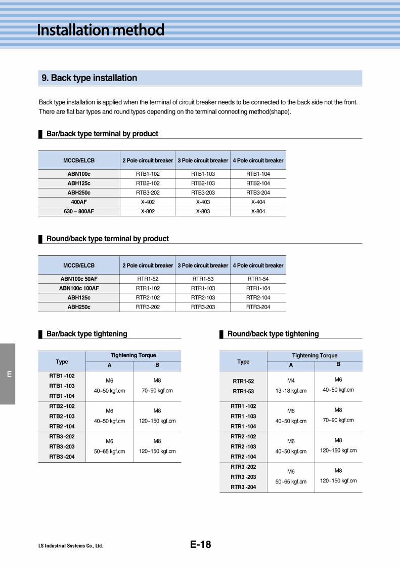
E-18
Installation method
9. Back type installation
Back type installation is applied when the terminal of circuit breaker needs to be connected to the back side not the front.There are flat bar types and round types depending on the terminal connecting method(shape).
E
Bar/back type terminal by product
Type
RTB1 -102
RTB1 -103
RTB1 -104
RTB2 -102
RTB2 -103
RTB2 -104
RTB3 -202
RTB3 -203
RTB3 -204
Tightening Torque
A
M6
40~50 kgf.cm
M6
40~50 kgf.cm
M6
50~65 kgf.cm
B
M8
70~90 kgf.cm
M8
120~150 kgf.cm
M8
120~150 kgf.cm
MCCB/ELCB
ABN100c
ABH125c
ABH250c
400AF
630 ~ 800AF
2 Pole circuit breaker
RTB1-102
RTB2-102
RTB3-202
X-402
X-802
3 Pole circuit breaker
RTB1-103
RTB2-103
RTB3-203
X-403
X-803
4 Pole circuit breaker
RTB1-104
RTB2-104
RTB3-204
X-404
X-804
Round/back type terminal by product
Bar/back type tightening Round/back type tightening
MCCB/ELCB
ABN100c 50AF
ABN100c 100AF
ABH125c
ABH250c
2 Pole circuit breaker
RTR1-52
RTR1-102
RTR2-102
RTR3-202
3 Pole circuit breaker
RTR1-53
RTR1-103
RTR2-103
RTR3-203
4 Pole circuit breaker
RTR1-54
RTR1-104
RTR2-104
RTR3-204
Type
RTR1-52
RTR1-53
RTR1 -102
RTR1 -103
RTR1 -104
RTR2 -102
RTR2 -103
RTR2 -104
RTR3 -202
RTR3 -203
RTR3 -204
Tightening Torque
A
M4
13~18 kgf.cm
M6
40~50 kgf.cm
M6
40~50 kgf.cm
M6
50~65 kgf.cm
B
M6
40~50 kgf.cm
M8
70~90 kgf.cm
M8
120~150 kgf.cm
M8
120~150 kgf.cm
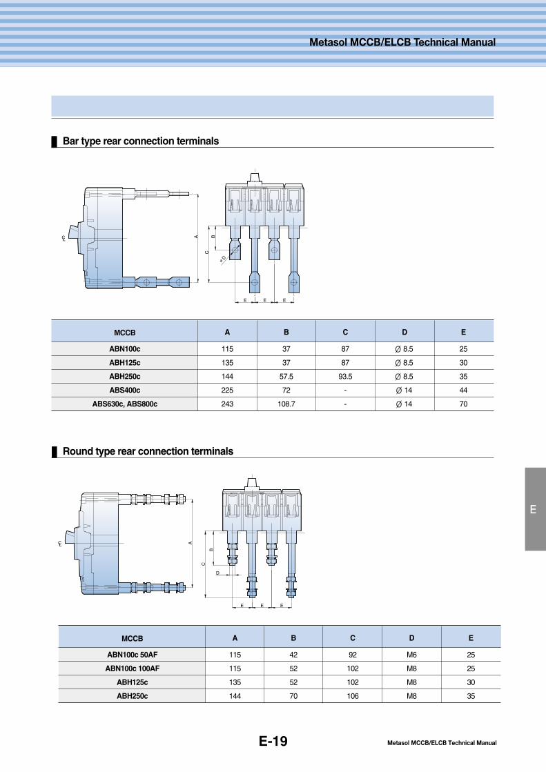
E-19
E
Metasol MCCB/ELCB Technical Manual
Metasol MCCB/ELCB Technical Manual
Bar type rear connection terminals
Round type rear connection terminals
CL A BC
∅D
E E E
CL A
B
E E
C
D
E
MCCB
ABN100c
ABH125c
ABH250c
ABS400c
ABS630c, ABS800c
A
115
135
144
225
243
B
37
37
57.5
72
108.7
C
87
87
93.5
-
-
D
∅ 8.5
∅ 8.5
∅ 8.5
∅ 14
∅ 14
E
25
30
35
44
70
MCCB
ABN100c 50AF
ABN100c 100AF
ABH125c
ABH250c
A
115
115
135
144
B
42
52
52
70
C
92
102
102
106
D
M6
M8
M8
M8
E
25
25
30
35
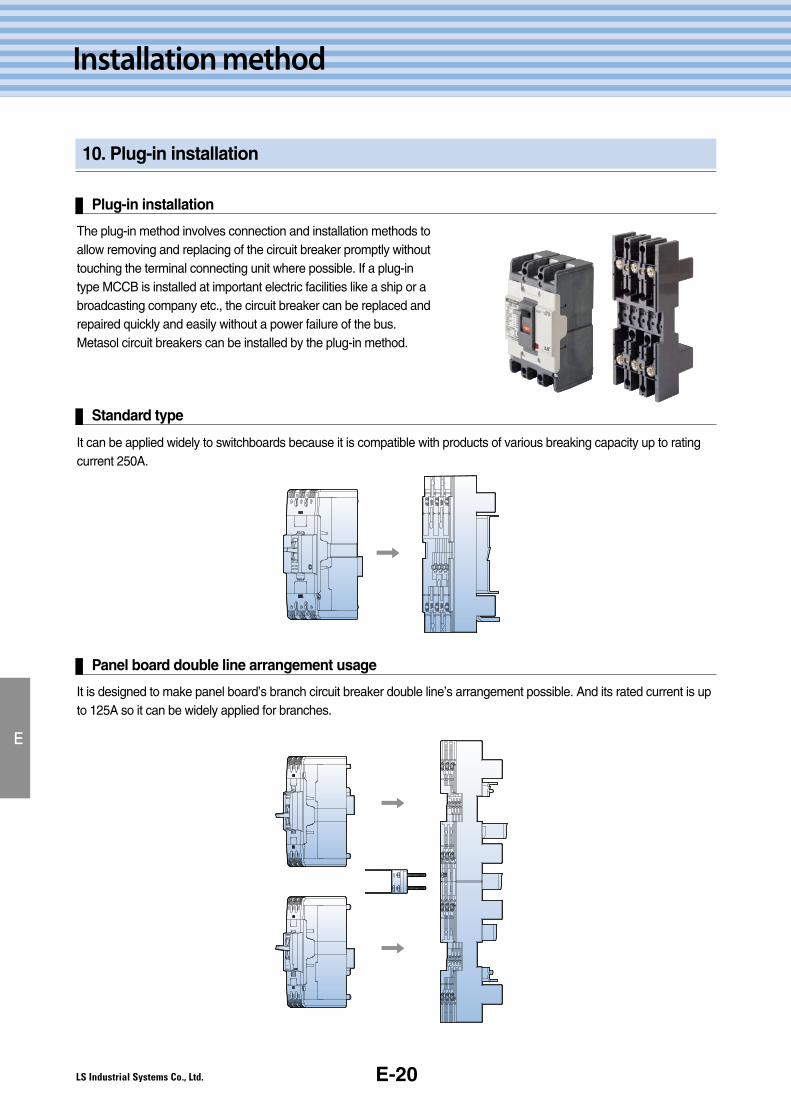
E-20
Installation method
10. Plug-in installation
Plug-in installation
E
The plug-in method involves connection and installation methods toallow removing and replacing of the circuit breaker promptly withouttouching the terminal connecting unit where possible. If a plug-intype MCCB is installed at important electric facilities like a ship or abroadcasting company etc., the circuit breaker can be replaced andrepaired quickly and easily without a power failure of the bus.Metasol circuit breakers can be installed by the plug-in method.
Standard type
It can be applied widely to switchboards because it is compatible with products of various breaking capacity up to ratingcurrent 250A.
Panel board double line arrangement usage
It is designed to make panel board’s branch circuit breaker double line’s arrangement possible. And its rated current is upto 125A so it can be widely applied for branches.
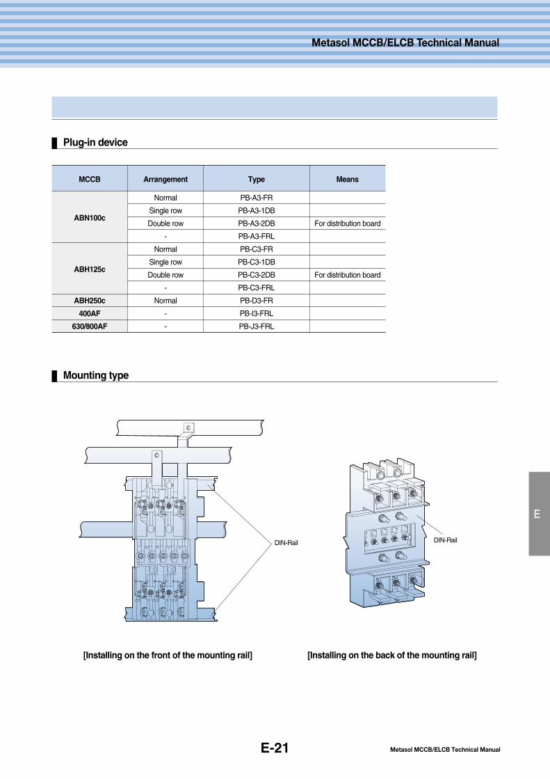
E-21
Plug-in device
E
Metasol MCCB/ELCB Technical Manual
Metasol MCCB/ELCB Technical Manual
Mounting type
[Installing on the front of the mounting rail]
DIN-Rail DIN-Rail
[Installing on the back of the mounting rail]
MCCB
ABN100c
ABH125c
ABH250c
400AF
630/800AF
Arrangement
Normal
Single row
Double row
-
Normal
Single row
Double row
-
Normal
-
-
Type
PB-A3-FR
PB-A3-1DB
PB-A3-2DB
PB-A3-FRL
PB-C3-FR
PB-C3-1DB
PB-C3-2DB
PB-C3-FRL
PB-D3-FR
PB-I3-FRL
PB-J3-FRL
Means
For distribution board
For distribution board
E-22
Installation method
10. Plug-in installation
Precautions for safe use of Plug-in device
E
Precautions for Safety Reasons
Before handling, wiring work, operating, repair and inspecting, please read precautions for safety reasons and then use
the product correctly. Please make sure to follow these precautions because they are very important details about safety.
Danger : If you violate this instruction, it can result in death or serious injury.
Warning : If you violate this instruction, it can result in light injury or material damage.
Before you use, please make sure to read the user manual and precautions for safety.Please give the product user manual to the end user or a person in charge of repair.
Danger
1. Before you install the product, please make sure to turn the above circuit breaker off. There is a danger of electricshock during installation.
2. Please be careful not to contact terminal exposure units. It can result in electric shock or short circuit fault.3. Please do not let any parts of your body touch two exposed hotlines at the same time.
Even if there is an electric shock, the circuit breaker might not operate.
1. Before installing the product, please read precautions and install it accordingly.2. There is a danger of fault operation or accident from incorrect installation.
Please let a qualified person(electrician) install and repair the circuit breaker.3. Please avoid installation in environments with rain, oil, dust, direct sunlight etc. There is a danger of electric shock,
leakage, short circuit, fire and fault operation.1) Usage Temperature : -5~40° 2) Relative Humidity : 45~85% 3)Altitude : below 2000m4)Avoid abnormal vibration, impact, excessive vapor, oil, smoke, dust, corrosive gas and flammable gas.
4. Please connect to the power which is suitable for the product's rated voltage and current. If the rated voltage andcurrent are not correct, it can cause damage or loss.
5. If there is shortage of tightening torque at the terminal, it can cause overheating or fire so please fix the terminal firmlyreferring to the stated tightening torque on each product's user manual.
6. When you assemble the terminal, please install the connection conductor and each phase in parallel. There is adanger of short circuit faults between each phase.
7. Please be careful not to damage the unit while transporting and installing.8. Please follow your own country's guidelines for disposal of this product.9. Please do not connect aluminum terminal and conductor directly to circuit breaker's terminal. It will cause corrosion and heating.10. Please do not make unauthorized alterations.
Warning
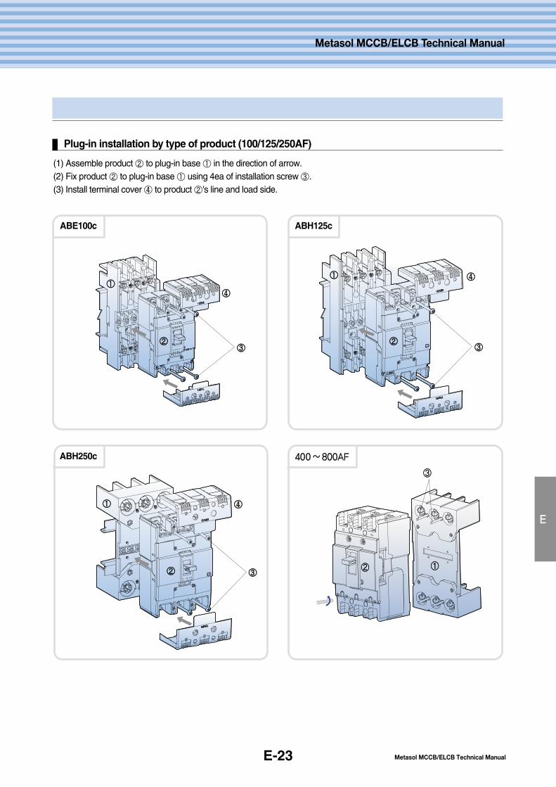
E-23
Plug-in installation by type of product (100/125/250AF)
E
Metasol MCCB/ELCB Technical Manual
Metasol MCCB/ELCB Technical Manual
(1) Assemble product ② to plug-in base ① in the direction of arrow.(2) Fix product ② to plug-in base ① using 4ea of installation screw ③.(3) Install terminal cover ④ to product ②'s line and load side.
ABE100c
ABH250c
ABH125c
①①①①
①①
②②
②②②②
③③
③③③③
④④
④④
④④
③③
440000~~880000AAFF
①①②②
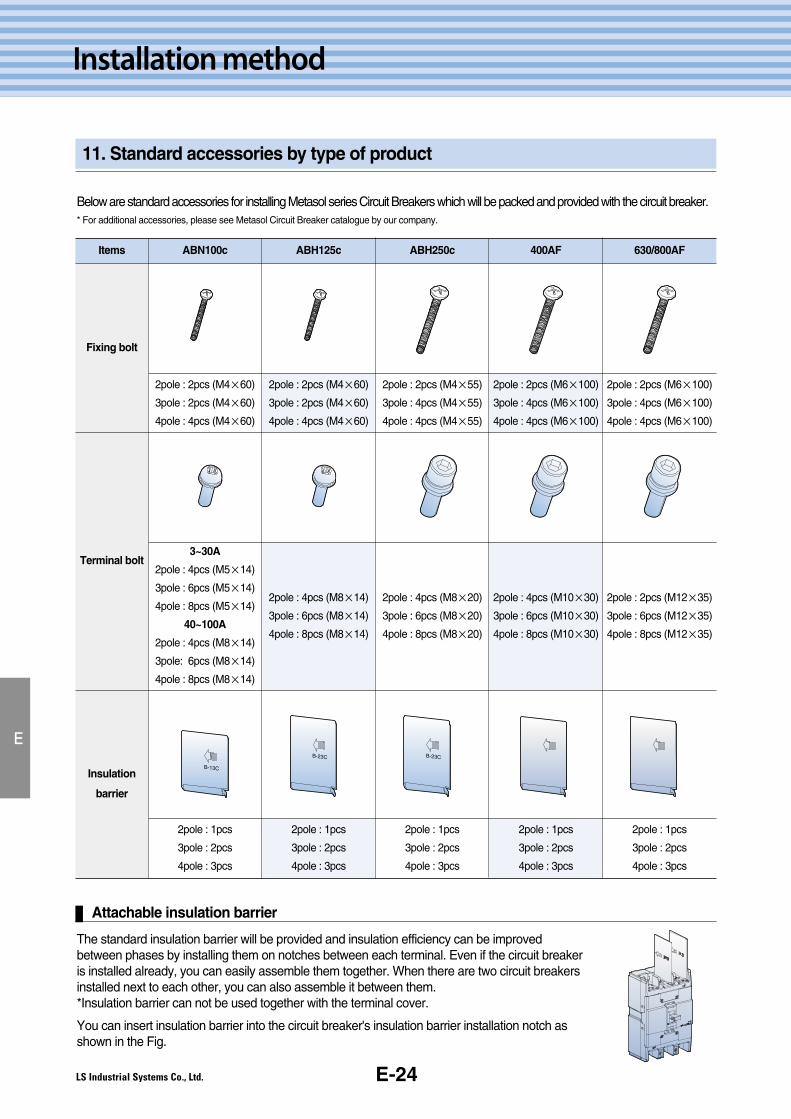
E-24
Installation method
11. Standard accessories by type of product
E
Attachable insulation barrier
Below are standard accessories for installing Metasol series Circuit Breakers which will be packed and provided with the circuit breaker.* For additional accessories, please see Metasol Circuit Breaker catalogue by our company.
The standard insulation barrier will be provided and insulation efficiency can be improvedbetween phases by installing them on notches between each terminal. Even if the circuit breakeris installed already, you can easily assemble them together. When there are two circuit breakersinstalled next to each other, you can also assemble it between them.*Insulation barrier can not be used together with the terminal cover.
You can insert insulation barrier into the circuit breaker's insulation barrier installation notch asshown in the Fig.
Items 630/800AF400AFABH250cABH125cABN100c
Fixing bolt
Terminal bolt
Insulation
barrier
B-13C
B-23C B-23C
2pole : 2pcs (M6×100)
3pole : 4pcs (M6×100)
4pole : 4pcs (M6×100)
2pole : 2pcs (M6×100)
3pole : 4pcs (M6×100)
4pole : 4pcs (M6×100)
2pole : 2pcs (M4×55)
3pole : 4pcs (M4×55)
4pole : 4pcs (M4×55)
2pole : 2pcs (M4×60)
3pole : 2pcs (M4×60)
4pole : 4pcs (M4×60)
2pole : 2pcs (M4×60)
3pole : 2pcs (M4×60)
4pole : 4pcs (M4×60)
2pole : 1pcs
3pole : 2pcs
4pole : 3pcs
2pole : 1pcs
3pole : 2pcs
4pole : 3pcs
2pole : 1pcs
3pole : 2pcs
4pole : 3pcs
2pole : 1pcs
3pole : 2pcs
4pole : 3pcs
2pole : 1pcs
3pole : 2pcs
4pole : 3pcs
3~30A
2pole : 4pcs (M5×14)
3pole : 6pcs (M5×14)
4pole : 8pcs (M5×14)
40~100A
2pole : 4pcs (M8×14)
3pole: 6pcs (M8×14)
4pole : 8pcs (M8×14)
2pole : 4pcs (M8×14)
3pole : 6pcs (M8×14)
4pole : 8pcs (M8×14)
2pole : 4pcs (M8×20)
3pole : 6pcs (M8×20)
4pole : 8pcs (M8×20)
2pole : 4pcs (M10×30)
3pole : 6pcs (M10×30)
4pole : 8pcs (M10×30)
2pole : 2pcs (M12×35)
3pole : 6pcs (M12×35)
4pole : 8pcs (M12×35)
F. Accessories
F-2
F-7
F-11
1. Internal accessories
2. Rotary handle
3. Terminal cover
F-1 Metasol MCCB/ELCB Technical Manual
Metasol MCCB/ELCB Technical Manual
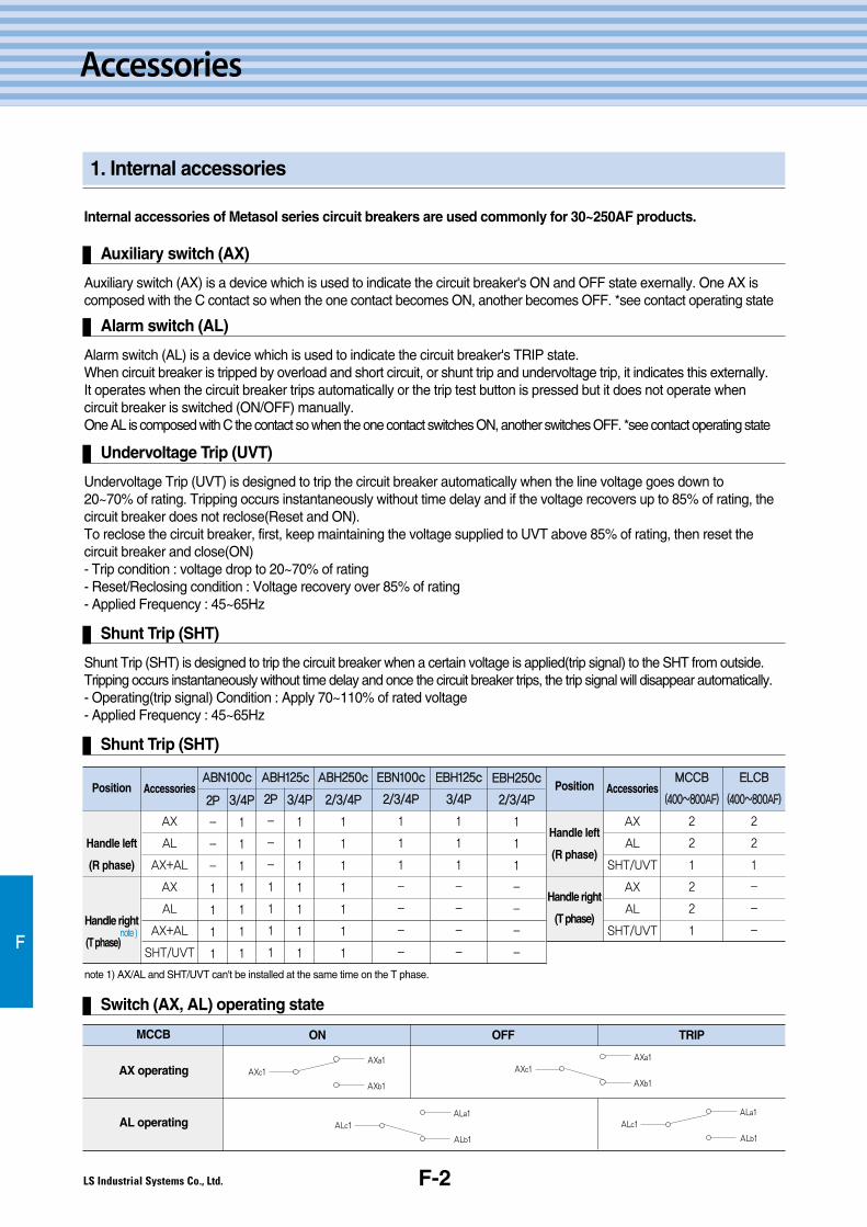
F-2
Accessories
1. Internal accessories
F
Internal accessories of Metasol series circuit breakers are used commonly for 30~250AF products.
Auxiliary switch (AX)
Auxiliary switch (AX) is a device which is used to indicate the circuit breaker's ON and OFF state exernally. One AX iscomposed with the C contact so when the one contact becomes ON, another becomes OFF. *see contact operating state
Alarm switch (AL)
Alarm switch (AL) is a device which is used to indicate the circuit breaker's TRIP state.When circuit breaker is tripped by overload and short circuit, or shunt trip and undervoltage trip, it indicates this externally.It operates when the circuit breaker trips automatically or the trip test button is pressed but it does not operate whencircuit breaker is switched (ON/OFF) manually.One AL is composed with C the contact so when the one contact switches ON, another switches OFF. *see contact operating state
Undervoltage Trip (UVT)
Undervoltage Trip (UVT) is designed to trip the circuit breaker automatically when the line voltage goes down to20~70% of rating. Tripping occurs instantaneously without time delay and if the voltage recovers up to 85% of rating, thecircuit breaker does not reclose(Reset and ON).To reclose the circuit breaker, first, keep maintaining the voltage supplied to UVT above 85% of rating, then reset thecircuit breaker and close(ON)- Trip condition : voltage drop to 20~70% of rating- Reset/Reclosing condition : Voltage recovery over 85% of rating- Applied Frequency : 45~65Hz
Shunt Trip (SHT)
Shunt Trip (SHT)
Shunt Trip (SHT) is designed to trip the circuit breaker when a certain voltage is applied(trip signal) to the SHT from outside.Tripping occurs instantaneously without time delay and once the circuit breaker trips, the trip signal will disappear automatically.- Operating(trip signal) Condition : Apply 70~110% of rated voltage- Applied Frequency : 45~65Hz
Switch (AX, AL) operating state
ON OFF TRIP
AX operating
AL operating
MCCB
Position
Handle left
(R phase)
Handle right
(T phase)note )
Accessories
AX
AL
AX+AL
AX
AL
AX+AL
SHT/UVT
Position
Handle left
(R phase)
Handle right
(T phase)
Accessories
AX
AL
SHT/UVT
AX
AL
SHT/UVT
AABBNN110000cc
22PP
-
-
-
1
1
1
1
33//44PP
1
1
1
1
1
1
1
22PP
-
-
-
1
1
1
1
33//44PP
1
1
1
1
1
1
1
22//33//44PP
1
1
1
1
1
1
1
AABBHH112255cc AABBHH225500cc EEBBNN110000cc
22//33//44PP
1
1
1
-
-
-
-
MMCCCCBB
((440000~~880000AAFF))
2
2
1
2
2
1
EELLCCBB
((440000~~880000AAFF))
2
2
1
-
-
-
EEBBHH112255cc
33//44PP
1
1
1
-
-
-
-
EEBBHH225500cc
22//33//44PP
1
1
1
-
-
-
-
note 1) AX/AL and SHT/UVT can't be installed at the same time on the T phase.
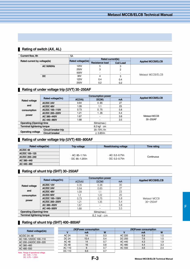
Metasol MCCB/ELCB Technical ManualF-3
F
Metasol MCCB/ELCB Technical Manual
Rating of switch (AX, AL)
Current flow, lth 55AA
Rated current by voltage(le)
AC 50/60Hz
DC
Operating (Opening) timeTerminal tightening torque
Operating voltageCircuit breaker tripCircuit breaker
Rated voltage(Ue)
125V250V500V30V125V250V
Applied MCCB/ELCB
Metasol MCCB/ELCB
Rated current(le)Resistance load
53-4
0.40.2
Coil Load32-3
0.40.2
Rating of under voltage trip (UVT) 400~800AF
Rating of under voltage trip (UVT) 30~250AF
Rated voltage(Vn)
AC/DC 24VAC/DC 48VAC/DC 100~110VAC/DC 200~220VAC 380~440VAC 440~480V
Rated voltage
and
consumption
power
Applied MCCB/ELCB
Metasol MCCB30~250AF
Consumption powerDC(W)0 .651.1
0 .751 .35
--
AC(VA)0.641.090.731.211.671.68
50ms(max.)8.2 kgf∙cm20~70% Vn≥ 0.85Vn
mA27235.85.43.83.5
Operating (Opening) timeTerminal tightening torque
Rating of shunt trip (SHT) 30~250AF
Rating of shunt trip (SHT) 400~800AF
Rated voltage(Vn)
AC/DC 12VAC/DC 24VAC/DC 48VAC/DC 60VAC/DC 100~130VAC/DC 200~250VAC 380~450VAC 440~500V
Rated voltage
and
consumption
power
Applied MCCB/ELCB
Metasol MCCB
30~250AF
Consumption powerDDCC((WW))
0.36
0.65
1.1
1.22
0.75
1.35
-
-
AACC((VVAA))
0.35
0.64
1.09
1.2
0.73
1.21
1.67
1.68
50ms(max.)8.2 kgf∙cm
mmAA
30
27
23
20
5.8
5.4
3.8
3.5
Rated voltage(Ue) Trip voltage Reset/closing voltage Time ratingAC/DC 48AC/DC 100~125AC/DC 200~240AC 380~440AC 440~480
∙AC: 0.2~0.7Vn∙DC: 0.2~0.7Vn
∙AC: 85~1.1Vn∙DC: 85~1.25Vn
Continuous
Note: Range of operational voltage AC: 0.85 ~ 1.1VnDC: 0.75 ~ 1.25Vn
Rated voltage(Ue)(W)Power consumption
V mA W(W)Power consumption
V mA WAC/DC 24~48AC 100~125/DC 100~110AC 200~240/DC 200~220AC 380~460AC 480~550
AC 24 14 0.3DC 24 15.4 0.4AC 48 14 0.7DC 48 16 0.8AC 110 6 0.7DC 110 6.6 0.7
AC 220 6.8 1.5DC 200 7.6 1.5AC 440 4.3 1.9AC 480 4.4 3.3AC 550 4.6 2.4

F
1. Internal accessories
F-4
Accessories
Precautions for Safe Use of Auxiliary switch (AX) / Alarm switch (AL)
1. Before you install accessories, please make sure to turn the circuit breaker off. There is a danger of electric shock during installation.
(1) Before installing and using the Auxiliary switch(AX) and Alarm switch(AL), please be sure to read the user manual.(2) Please let qualified people install and repair them. Do not install anything other than authorized devices.(3) Before handling, wiring work, operating, repair and inspecting, please read precautions for safety reasons and
danger prevention then use the product as directed.
Danger : If you violate these instructions, it may result in death or serious injury.Warning : If you violate these instructions, it may result in light injury or material damage.
Danger
1. Before installing the product, please read precautions and install it according to instructions.2. Please give this user manual to the end user or the person in charge of repairs.3. If you apply excessive strength to each hook unit during assembly, it's easy for them to be damaged.
Warning
Precautions for Safe Use of Undervoltage Trip (UVT) / Shunt Trip (SHT)
1. Before you install accessories, please make sure to turn the above circuit breaker off.
(1) Before installing and using the Undervoltage Trip(UVT) and Shunt Trip(SHT), please make sure to read the usermanual.
(2) Please let qualified people install and repair them. Do not install anything other than authorized devices.(3) Before handling, wiring work, operating, repair and inspecting, please read precautions for safety reasons and danger
prevention then use the product as directed.(4) Please make sure to follow these instructions because they are very important details about safety.
Danger : If you violate this instruction, it results in death or serious injury.Warning : If you violate this instruction, it results in light injury or material damage.
Danger
1. Before you assemble accessories, please thoroughly check the circuit breaker.2. If you apply excessive strength to any hook unit during assembling, it's easy to damage them.3. Please do not operate the handle when the power isn't applied to undervoltage trip device.
Warning
Installation method of internal accessories
(1) Before you install an auxiliary / alarm switch, please check if the handle of Metasol MCCB is set on the trip position.Please press trip button to the tripped position(see Fig.1).
(2) Please remove the 4 screws and open the auxiliary cover.(3) As shown on Fig. 2-1, press accessories into installation location which is on the right or left side of Metasol MCCB
until you here click sound.(4) When it's a block type, assemble it on the side of the main device as shown in Fig. 2-2 then tighten the designated
electric wire to the terminal with a gauge of 1.13Nm(12kgf.cm)*The electric wire is connected to the accessories on wire type of auxiliary switch(AX) / alarm switch(AL).
(5) Close the auxiliary cover and tighten the screws. Please tighten ABE100c model with gauge of 0.83Nm(8.2kgf.cm),ABH125c and ABH250c models with gauge of 1.13Nm(12kgf.cm).
(6) Before you use, please ensure smooth operation.*AX/AL and SHT/UVT can't be installed at the same time on the T phase.*SHT and UVT can not be used at the same time.

Metasol MCCB/ELCB Technical ManualF-5
F
Open the Aux Cover
②
①
AX, AL
SHT/UVT *Caution : Damage on line when Assembling
*Position HANDLE to ‘ON’when mounting SHT/UVT
TERMINAL BLOCK
②
①
*Removing
12kgf cm(1.13N∙m)
15kgf cm(1.48N∙m)
1
2-2
3 4
2-1
ClickClick
Metasol MCCB/ELCB Technical Manual
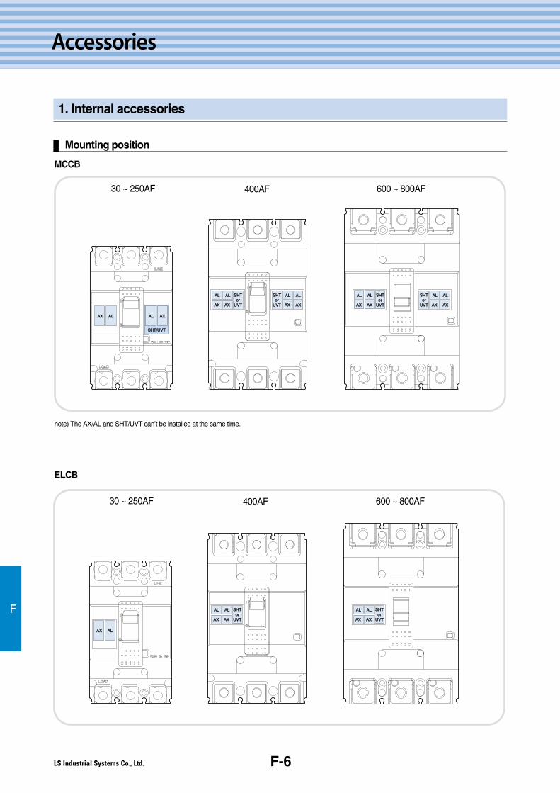
F-6
Accessories
1. Internal accessories
F
Mounting position
AXAX ALAL ALAL AXAX
SHT/UVTSHT/UVT
AX AL
AXAX AXAX AXAX AXAX
ALAL ALAL ALAL ALALSHTSHToror
UVTUVT
SHTSHToror
UVTUVT AXAX AXAX AXAX AXAX
ALAL ALAL ALAL ALALSHTSHToror
UVTUVT
AX AX
AL AL SHTor
UVT AX AX
AL AL SHTor
UVT
SHTSHToror
UVTUVT
MCCB
note) The AX/AL and SHT/UVT can’t be installed at the same time.
30 ~ 250AF 400AF 600 ~ 800AF
ELCB
AX AL AL AX
SHT/UVT
AXAX ALAL
AX AX AX AX
AL AL AL ALSHTor
UVT
SHTor
UVT AX AX AX AX
AL AL AL ALSHTor
UVT
AXAX AXAX
ALAL ALAL SHTSHToror
UVTUVT AXAX AXAX
ALAL ALAL SHTSHToror
UVTUVT
SHTor
UVT
30 ~ 250AF 400AF 600 ~ 800AF

Metasol MCCB/ELCB Technical ManualF-7
F
2. Rotary handle
Rotary handle
A rotary handle is a device which can check a circuit breaker's position(ON, OFF, TRIP) and operates even when thepanel door is closed. They are categorized by the location where the handle is attached.
1. Direct Rotary Handle(D-Handle): Attached directly to circuit breaker.2. Extended Rotary Handle(E-Handle): The length between the circuit breaker and panel door is long enough to install the
handle on the panel door.
Basically, an external lock is installed on the loop of handle so it can't be locked to ON or OFF. And for a direct rotaryhandle, a built-in key lock type is available separately.
Handles by type of product
LINE
LOAD
DH-Type DHK-Type Additional accessories
S-Type L-Type R-Type
ON
LINE LOAD LINELOAD
ON
ON
The shape of direct rotary handles and components
Types of direct rotary handles by Metasol MCCB's installation form
Metasol MCCB/ELCB Technical Manual
Direct typeDirect type
Extended typeBreaker type
(Key lock) MCCB ELCB
DH100 DHK100 EH100ABN50c/60c/100c EBN50c/60c/100c
ABS30c/50c/60c EBS30c/50c/60c
DH125 DHK125 EH125ABS125c EBS125c
ABH50c/125c EBH50c/125c
DH250 DHK250 EH250ABN250c, ABS250c EBN250c, EBS250c
ABH250c EBH250
N-70 - E-70U ABN/S/H/L400c EBN/S/H/L400c
N-80 - E-80U ABN/S/L630c/800c EBN/S/L630c/800c
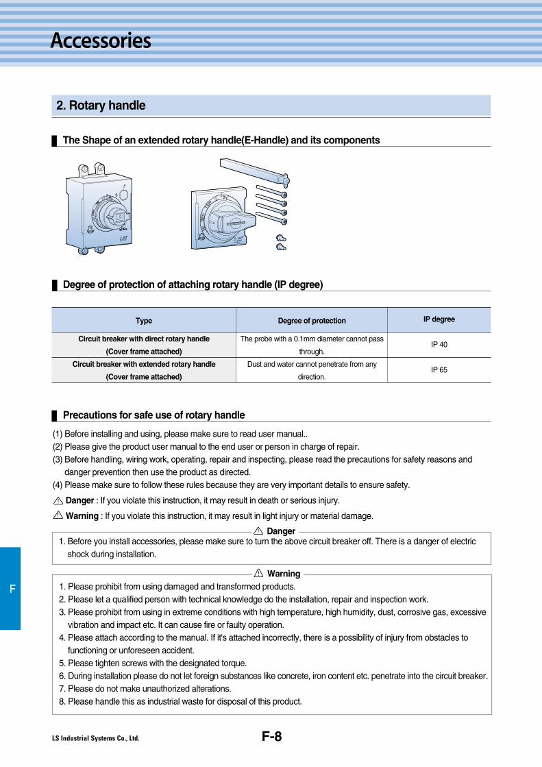
F-8
Accessories
2. Rotary handle
F
Degree of protection of attaching rotary handle (IP degree)
Type
Circuit breaker with direct rotary handle
(Cover frame attached)
Circuit breaker with extended rotary handle
(Cover frame attached)
Degree of protection
The probe with a 0.1mm diameter cannot pass
through.
Dust and water cannot penetrate from any
direction.
IP degree
IP 40
IP 65
Precautions for safe use of rotary handle
1. Before you install accessories, please make sure to turn the above circuit breaker off. There is a danger of electricshock during installation.
(1) Before installing and using, please make sure to read user manual..(2) Please give the product user manual to the end user or person in charge of repair.(3) Before handling, wiring work, operating, repair and inspecting, please read the precautions for safety reasons and
danger prevention then use the product as directed.(4) Please make sure to follow these rules because they are very important details to ensure safety.
Danger : If you violate this instruction, it may result in death or serious injury.
Warning : If you violate this instruction, it may result in light injury or material damage.
Danger
1. Please prohibit from using damaged and transformed products.2. Please let a qualified person with technical knowledge do the installation, repair and inspection work.3. Please prohibit from using in extreme conditions with high temperature, high humidity, dust, corrosive gas, excessive
vibration and impact etc. It can cause fire or faulty operation.4. Please attach according to the manual. If it's attached incorrectly, there is a possibility of injury from obstacles to
functioning or unforeseen accident.5. Please tighten screws with the designated torque.6. During installation please do not let foreign substances like concrete, iron content etc. penetrate into the circuit breaker.7. Please do not make unauthorized alterations.8. Please handle this as industrial waste for disposal of this product.
Warning
The Shape of an extended rotary handle(E-Handle) and its components
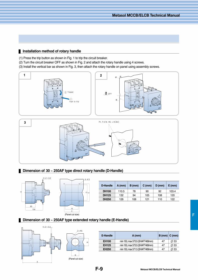
Metasol MCCB/ELCB Technical ManualF-9
F
Installation method of rotary handle
(1) Press the trip button as shown in Fig. 1 to trip the circuit breaker.(2) Turn the circuit breaker OFF as shown in Fig. 2 and attach the rotary handle using 4 screws.(3) Install the vertical bar as shown in Fig. 3, then attach the rotary handle on panel using assembly screws.
PH, P.S/W, M5, L14(2EA)
1
2
Push to trip
TrippedOFF
1
3
2
Dimension of 30 ~ 250AF type direct rotary handle (D-Handle)
Dimension of 30 ~ 250AF type extended rotary handle (E-Handle)
D-Handle
DH100DH125DH250
A (mm)
110.5132126
B (mm)
7894108
C (mm)
90105121
D (mm)
92108110
E (mm)
103.4120122
D E
B
C
4-∅5
104
60
A
t1.2~3.2
B
2-∅6
B
t1.2~3.2
A
℃ E-Handle
EH100EH125EH250
A (mm)
min 150, max 573.5 (SHAFT469mm)min 150, max 573.5 (SHAFT469mm)min 150, max 571.5 (SHAFT469mm)
B (mm)
474747
C (mm)
∅ 53∅ 53∅ 53
Metasol MCCB/ELCB Technical Manual
(Panel cut size)
(Panel cut size)
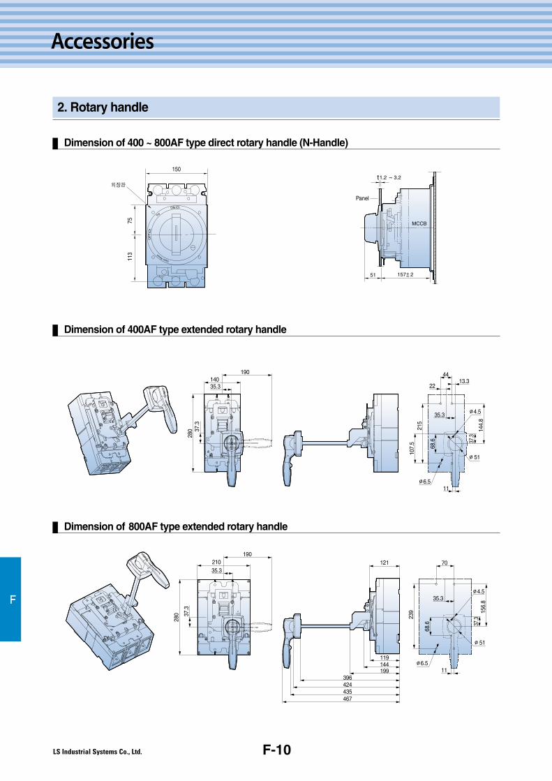
F-10
Accessories
2. Rotary handle
Dimension of 400 ~ 800AF type direct rotary handle (N-Handle)
F
Dimension of 400AF type extended rotary handle
Dimension of 800AF type extended rotary handle
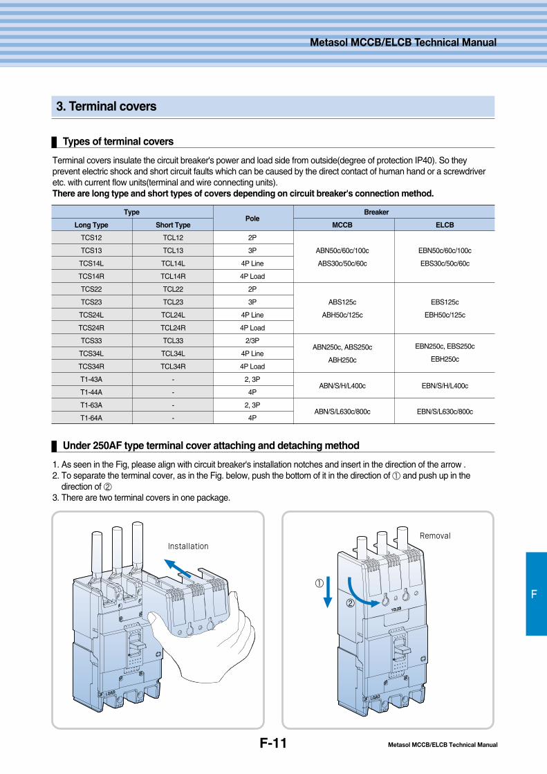
F-11
3. Terminal covers
Types of terminal covers
F
Metasol MCCB/ELCB Technical Manual
Metasol MCCB/ELCB Technical Manual
Terminal covers insulate the circuit breaker's power and load side from outside(degree of protection IP40). So theyprevent electric shock and short circuit faults which can be caused by the direct contact of human hand or a screwdriveretc. with current flow units(terminal and wire connecting units).There are long type and short types of covers depending on circuit breaker's connection method.
Under 250AF type terminal cover attaching and detaching method
1. As seen in the Fig, please align with circuit breaker's installation notches and insert in the direction of the arrow .2. To separate the terminal cover, as in the Fig. below, push the bottom of it in the direction of ① and push up in the
direction of ②3. There are two terminal covers in one package.
InstallationRemoval
②
①
TypePole
Breaker
Long Type Short Type MCCB ELCB
TCS12 TCL12 2P
TCS13 TCL13 3P ABN50c/60c/100c EBN50c/60c/100c
TCS14L TCL14L 4P Line ABS30c/50c/60c EBS30c/50c/60c
TCS14R TCL14R 4P Load
TCS22 TCL22 2P
TCS23 TCL23 3P ABS125c EBS125c
TCS24L TCL24L 4P Line ABH50c/125c EBH50c/125c
TCS24R TCL24R 4P Load
TCS33 TCL33 2/3PABN250c, ABS250c EBN250c, EBS250c
TCS34L TCL34L 4P LineABH250c EBH250c
TCS34R TCL34R 4P Load
T1-43A - 2, 3PABN/S/H/L400c EBN/S/H/L400c
T1-44A - 4P
T1-63A - 2, 3PABN/S/L630c/800c EBN/S/L630c/800c
T1-64A - 4P

G.Handling andmaintenance
G-2
G-3
G-7
1. Conditions for transport and
Storage
2. Maintenance and inspection
3. Precautions for ELCB's circuit
connecting
G-1
Handling and Maintenance
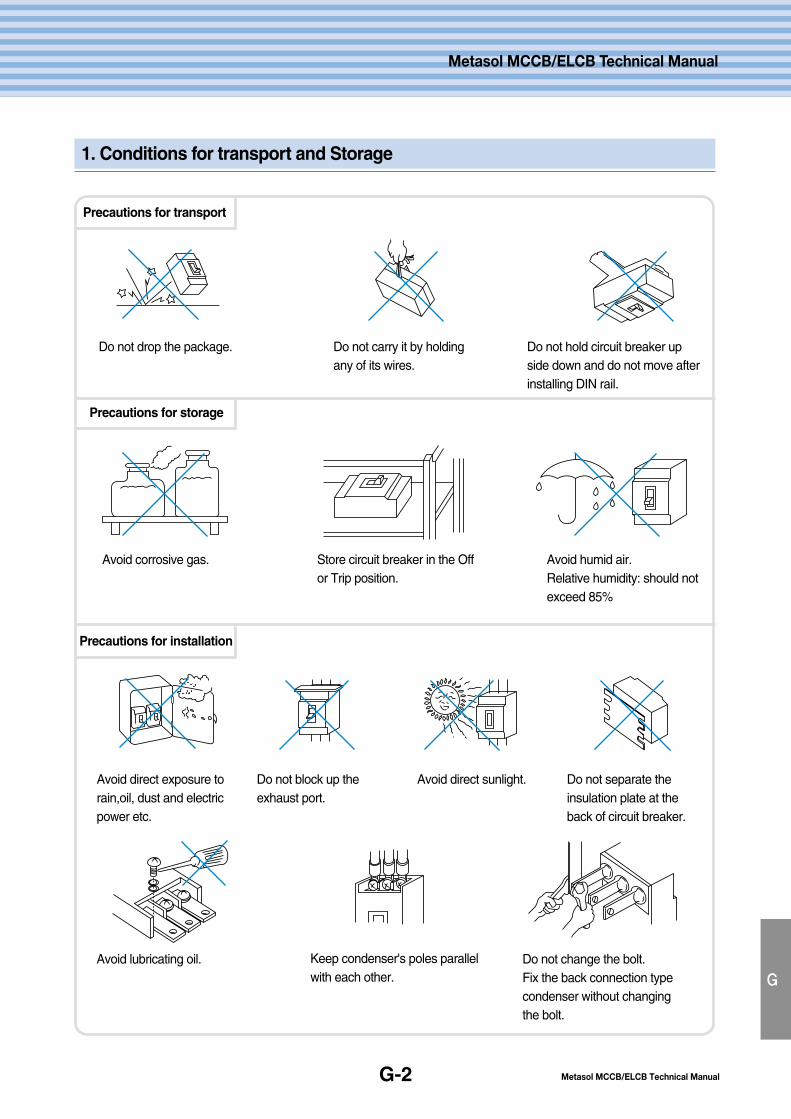
G-2
1. Conditions for transport and Storage
G
Metasol MCCB/ELCB Technical Manual
Metasol MCCB/ELCB Technical Manual
Avoid corrosive gas.
Do not drop the package.
Avoid direct exposure torain,oil, dust and electricpower etc.
Do not block up theexhaust port.
Avoid direct sunlight. Do not separate theinsulation plate at theback of circuit breaker.
Do not carry it by holdingany of its wires.
Do not hold circuit breaker upside down and do not move afterinstalling DIN rail.
Store circuit breaker in the Offor Trip position.
Avoid humid air.Relative humidity: should notexceed 85%
Avoid lubricating oil. Keep condenser's poles parallelwith each other.
Do not change the bolt. Fix the back connection typecondenser without changing the bolt.
Precautions for transport
Precautions for storage
Precautions for installation
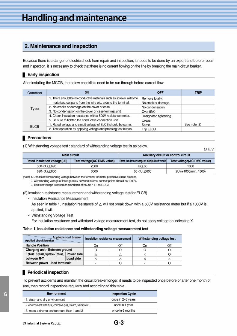
G-3
Handling and maintenance
2. Maintenance and inspection
G
Because there is a danger of electric shock from repair and inspection, it needs to be done by an expert and before repairand inspection, it is necessary to check that there is no current flowing on the line by breaking the main circuit beaker.
Early inspection
After installing the MCCB, the below checklists need to be run through before current flow.
Precautions
(1) Withstanding voltage test : standard of withstanding voltage test is as below.
(note) 1. Don't test withstanding voltage between the terminal for motor protective circuit breaker.2. Withstanding voltage of leakage relay between internal contact points should be 1000V.3. This test voltage is based on standards of K60947-4-1 9.3.3.4.3.
(2) Insulation resistance measurement and withstanding voltage test(for ELCB)� Insulation Resistance Measurement
As seen in table 1, insulation resistance of △ will not break down with a 500V resistance meter but if a 1000V isapplied, it will.
� Withstanding Voltage TestFor insulation resistance and withstand voltage measurement test, do not apply voltage on indicating X.
ON OFF TRIPCCoommmmoonn
TTyyppee
EELLCCBB
1. There should be no conductive materials such as screws, airbornematerials, cut parts from the wire etc. around the terminal.
2. No cracks or damage on the cover or case.3. No condensation on the cover or case terminal unit.4. Check insulation resistance with a 500V resistance meter.5. Be sure to tighten the conductive connection unit.1. Rated voltage and circuit voltage of ELCB should be same.2. Test operation by applying voltage and pressing test button..
Remove totally.No crack or damage.No condensation.Over 5MΪ
Designated tighteningtorque.Same.Trip ELCB.
See note (2)
Main circuit Auxiliary circuit or control circuit
Rated insulation voltage[Ui]
300<Ui≤690
690<Ui≤800
Test voltage(AC RMS value)
2500
3000
Test voltage(AC RMS value)
1000
2Uis+1000(min. 1500)
Rated insulation voltage of manipulated vircuit
Ui≤60
60<Ui≤600
[Unit : V]
Table 1. Insulation resistance and withstanding voltage measurement test
Applied circuit breakerApplied circuit breaker
Insulation resistance measurement Withstanding voltage test
Handle PositionCharging unit - Between groundR phase - S phase, S phase - Tphase, Power sidebetween R-T Load sideBetween power - load terminals
OnO△
△
-
OffO△
△
O
OnO×
×
-
OffOO×
O
Periodical inspection
To prevent accidents and maintain the circuit breaker longer, it needs to be inspected once before or after one month ofuse, then record inspections regularly and according to this table.
Environment Inspection Cycle
1. clean and dry environment
2. environment with dust, corrosive gas, steam, salinity etc.
3. more extreme environment than 1 and 2
once in 2~3 years
once in 1 year
once in 6 months
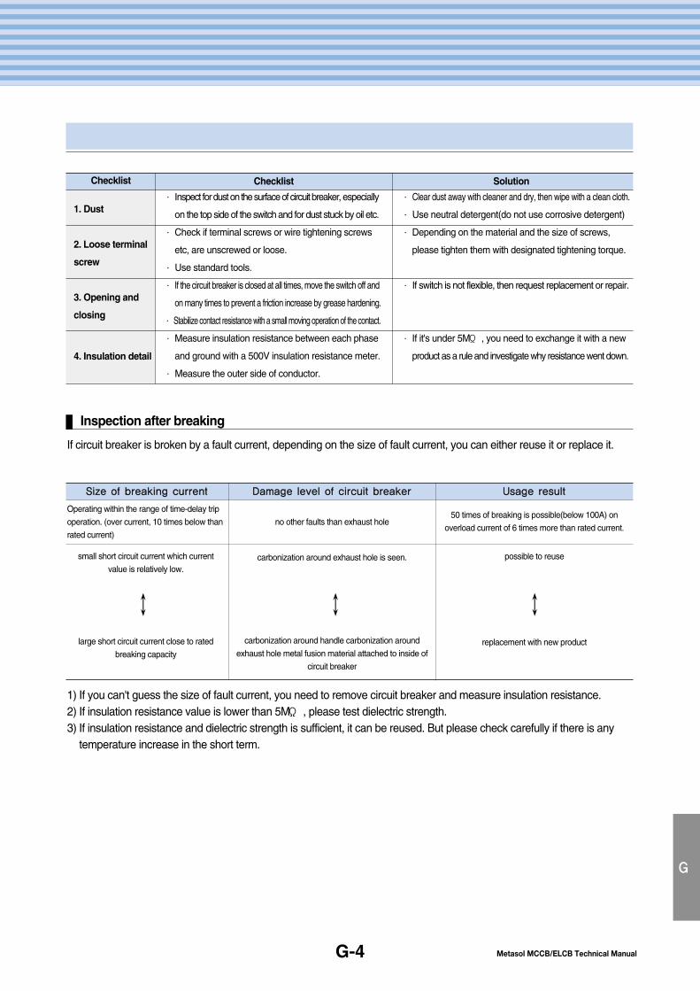
Metasol MCCB/ELCB Technical Manual
Metasol MCCB/ELCB Technical Manual
G-4
G
Inspection after breaking
If circuit breaker is broken by a fault current, depending on the size of fault current, you can either reuse it or replace it.
1) If you can't guess the size of fault current, you need to remove circuit breaker and measure insulation resistance.2) If insulation resistance value is lower than 5MΪ , please test dielectric strength.3) If insulation resistance and dielectric strength is sufficient, it can be reused. But please check carefully if there is any
temperature increase in the short term.
Checklist Checklist Solution
1. Dust
2. Loose terminal
screw
3. Opening and
closing
4. Insulation detail
∙ Inspect for dust on the surface of circuit breaker, especially
on the top side of the switch and for dust stuck by oil etc.
∙ Check if terminal screws or wire tightening screws
etc, are unscrewed or loose.
∙ Use standard tools.
∙ If the circuit breaker is closed at all times, move the switch off and
on many times to prevent a friction increase by grease hardening.
∙ Stabilize contact resistance with a small moving operation of the contact.
∙ Measure insulation resistance between each phase
and ground with a 500V insulation resistance meter.
∙ Measure the outer side of conductor.
∙ Clear dust away with cleaner and dry, then wipe with a clean cloth.
∙ Use neutral detergent(do not use corrosive detergent)
∙ Depending on the material and the size of screws,
please tighten them with designated tightening torque.
∙ If switch is not flexible, then request replacement or repair.
∙ If it's under 5MΪ , you need to exchange it with a new
product as a rule and investigate why resistance went down.
SSiizzee ooff bbrreeaakkiinngg ccuurrrreenntt DDaammaaggee lleevveell ooff cciirrccuuiitt bbrreeaakkeerr UUssaaggee rreessuulltt
Operating within the range of time-delay trip
operation. (over current, 10 times below than
rated current)
small short circuit current which current
value is relatively low.
large short circuit current close to rated
breaking capacity
no other faults than exhaust hole
carbonization around exhaust hole is seen.
carbonization around handle carbonization around
exhaust hole metal fusion material attached to inside of
circuit breaker
50 times of breaking is possible(below 100A) on
overload current of 6 times more than rated current.
possible to reuse
replacement with new product
↕ ↕ ↕
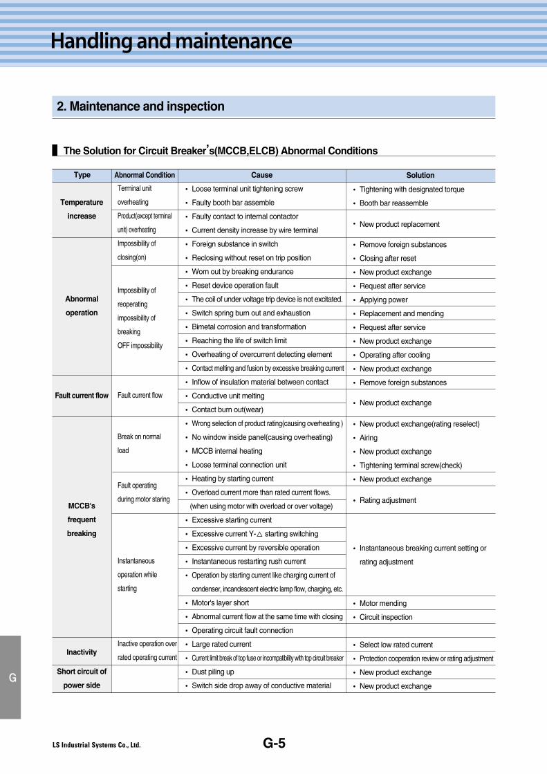
G-5
Handling and maintenance
2. Maintenance and inspection
G
The Solution for Circuit Breaker’s(MCCB,ELCB) Abnormal Conditions
Type Abnormal Condition Cause Solution
Temperature
increase
Abnormal
operation
Fault current flow
MCCB's
frequent
breaking
Inactivity
Short circuit of
power side
Terminal unit
overheating
Product(except terminal
unit) overheating
Impossibility of
closing(on)
Impossibility of
reoperating
impossibility of
breaking
OFF impossibility
Fault current flow
Break on normal
load
Fault operating
during motor staring
Instantaneous
operation while
starting
Inactive operation over
rated operating current
� Loose terminal unit tightening screw
� Faulty booth bar assemble
� Faulty contact to internal contactor
� Current density increase by wire terminal
� Foreign substance in switch
� Reclosing without reset on trip position
� Worn out by breaking endurance
� Reset device operation fault
� The coil of under voltage trip device is not excitated.
� Switch spring burn out and exhaustion
� Bimetal corrosion and transformation
� Reaching the life of switch limit
� Overheating of overcurrent detecting element
� Contact melting and fusion by excessive breaking current
� Inflow of insulation material between contact
� Conductive unit melting
� Contact burn out(wear)
� Wrong selection of product rating(causing overheating )
� No window inside panel(causing overheating)
� MCCB internal heating
� Loose terminal connection unit
� Heating by starting current
� Overload current more than rated current flows.
(when using motor with overload or over voltage)
� Excessive starting current
� Excessive current Y-△ starting switching
� Excessive current by reversible operation
� Instantaneous restarting rush current
� Operation by starting current like charging current of
condenser, incandescent electric lamp flow, charging, etc.
� Motor's layer short
� Abnormal current flow at the same time with closing
� Operating circuit fault connection
� Large rated current
� Current limit break of top fuse or incompatibility with top circuit breaker
� Dust piling up
� Switch side drop away of conductive material
� Tightening with designated torque
� Booth bar reassemble
� New product replacement
� Remove foreign substances
� Closing after reset
� New product exchange
� Request after service
� Applying power
� Replacement and mending
� Request after service
� New product exchange
� Operating after cooling
� New product exchange
� Remove foreign substances
� New product exchange
� New product exchange(rating reselect)
� Airing
� New product exchange
� Tightening terminal screw(check)
� New product exchange
� Rating adjustment
� Instantaneous breaking current setting or
rating adjustment
� Motor mending
� Circuit inspection
� Select low rated current
� Protection cooperation review or rating adjustment
� New product exchange
� New product exchange
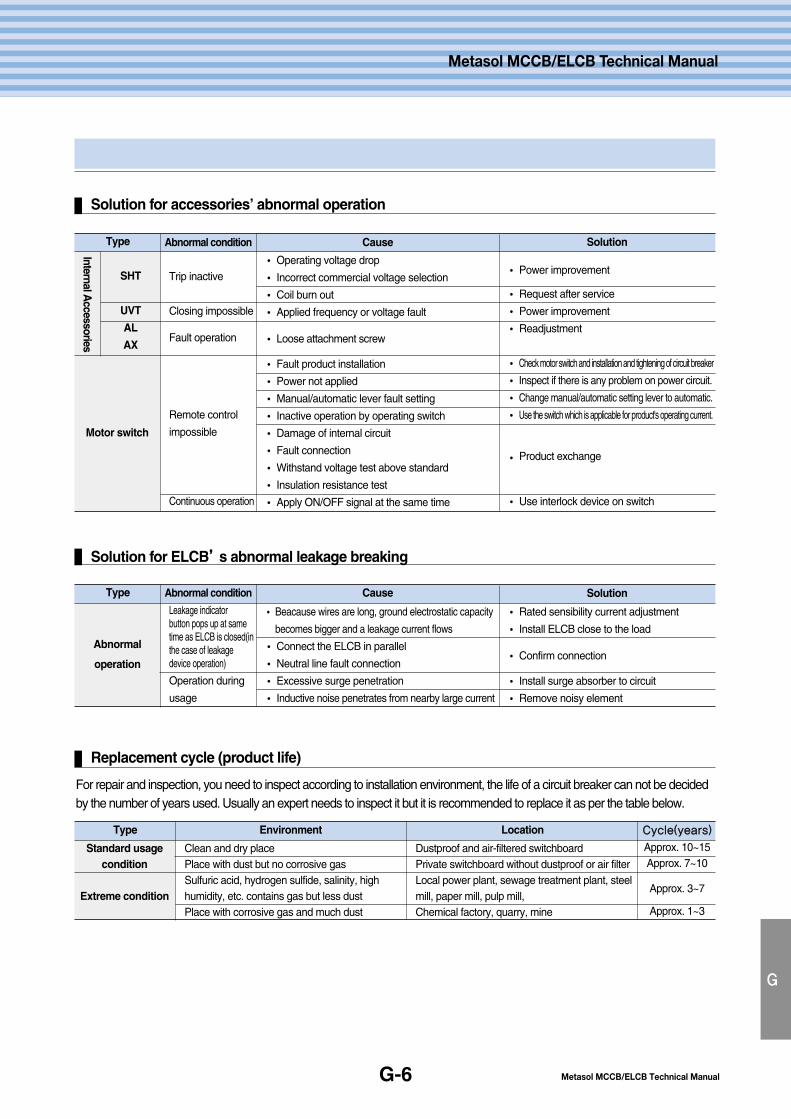
Metasol MCCB/ELCB Technical ManualG-6
G
Metasol MCCB/ELCB Technical Manual
Solution for accessories’ abnormal operation
Type Abnormal condition Cause Solution
InternalAccessories
SHT
UVT
AL
AX
Motor switch
Trip inactive
Closing impossible
Fault operation
Remote control
impossible
Continuous operation
� Operating voltage drop
� Incorrect commercial voltage selection
� Coil burn out
� Applied frequency or voltage fault
� Loose attachment screw
� Fault product installation
� Power not applied
� Manual/automatic lever fault setting
� Inactive operation by operating switch
� Damage of internal circuit
� Fault connection
� Withstand voltage test above standard
� Insulation resistance test
� Apply ON/OFF signal at the same time
� Power improvement
� Request after service
� Power improvement
� Readjustment
� Check motor switch and installation and tightening of circuit breaker
� Inspect if there is any problem on power circuit.
� Change manual/automatic setting lever to automatic.
� Use the switch which is applicable for product's operating current.
� Product exchange
� Use interlock device on switch
Solution for ELCB’’s abnormal leakage breaking
Type Abnormal condition Cause Solution
Abnormal
operation
Leakage indicatorbutton pops up at sametime as ELCB is closed(inthe case of leakagedevice operation)
Operation during
usage
� Beacause wires are long, ground electrostatic capacity
becomes bigger and a leakage current flows
� Connect the ELCB in parallel
� Neutral line fault connection
� Excessive surge penetration
� Inductive noise penetrates from nearby large current
� Rated sensibility current adjustment
� Install ELCB close to the load
� Confirm connection
� Install surge absorber to circuit
� Remove noisy element
Replacement cycle (product life)
For repair and inspection, you need to inspect according to installation environment, the life of a circuit breaker can not be decidedby the number of years used. Usually an expert needs to inspect it but it is recommended to replace it as per the table below.
Type Environment Location CCyyccllee((yyeeaarrss))
Standard usagecondition
Extreme condition
Clean and dry placePlace with dust but no corrosive gasSulfuric acid, hydrogen sulfide, salinity, highhumidity, etc. contains gas but less dustPlace with corrosive gas and much dust
Dustproof and air-filtered switchboardPrivate switchboard without dustproof or air filterLocal power plant, sewage treatment plant, steelmill, paper mill, pulp mill,Chemical factory, quarry, mine
Approx. 10~15Approx. 7~10
Approx. 3~7
Approx. 1~3
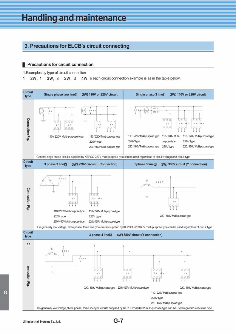
G-7
Handling and maintenance
3. Precautions for ELCB's circuit connecting
G
Precautions for circuit connection
1.Examples by type of circuit connection1Ø 2W, 1Ø 3W, 3Ø 3W, 3Ø 4W’s each circuit connection example is as in the table below.
110V 220V
2P 3P 2P 3P
110V
110V220V
2p or 3p 2p or 3p3P
220V
380V
2p or 3p3P 3P3P
220V
2p or 3p3P
380V
3P
•110 / 220V Multi-purpose type •110 / 220V Multi-purpose type
•220V type
•220 / 460V Multi-purpose type
•110 / 220V Multi-purpose type
•220V type
•220 / 460V Multi-purpose type
•110 / 220V Multi-
purpose type
•220V type
•110 / 220V Multi-purpose type
•220V type
•220 / 460V Multi-purpose type
•110 / 220V Multi-purpose type
•220V type
•220 / 460V Multi-purpose type
•110 / 220V Multi-purpose type
•220V type
•220 / 460V Multi-purpose type
•220 / 460V Multi-purpose type
•220 / 460V Multi-purpose type•220 / 460V Multi-purpose type
•110 / 220V Multi-purpose type
•220V type
•220 / 460V Multi-purpose type
•220 / 460V Multi-purpose type
Circuittype ①①Single phase two line((11ØØ 22WW)) 110V or 220V circuit ②② Single phase 3 line((11ØØ 33WW)) 110V or 220V circuit
③③ 3 phase 3 line((33ØØ 33WW)) 220V circuit(△△Connection)
General singe phase circuits supplied by KEPCO 220V multi-purpose type can be used regardless of circuit voltage and circuit type
On generally low voltage, three phase, three line type circuits supplied by KEPCO 220/460V multi-purpose type can be used regardless of circuit type
On generally low voltage, three phase, three line type circuits supplied by KEPCO 220/460V multi-purpose type can be used regardless of circuit type
④④ 3phase 3 line((33ØØ 33WW)) 380V circuit (Y connection)
⑤⑤ 3 phase 4 line((33ØØ 44WW)) 380V circuit (Y connection)
Circuittype
Circuittype
Connection
Fig.C
onnectionFig.
Connection
Fig.
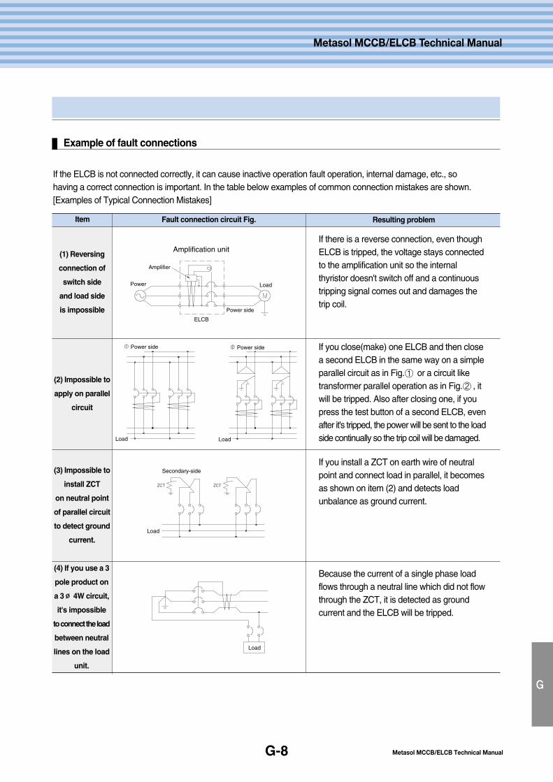
Metasol MCCB/ELCB Technical ManualG-8
G
Metasol MCCB/ELCB Technical Manual
Example of fault connections
If the ELCB is not connected correctly, it can cause inactive operation fault operation, internal damage, etc., sohaving a correct connection is important. In the table below examples of common connection mistakes are shown.[Examples of Typical Connection Mistakes]
Amplification unit
Power Load
Power side
ELCB
Amplifier
① ②
Load Load
Power side Power side
ZCT ZCT
Load
Secondary-side
Load
If there is a reverse connection, even thoughELCB is tripped, the voltage stays connectedto the amplification unit so the internalthyristor doesn't switch off and a continuoustripping signal comes out and damages thetrip coil.
If you close(make) one ELCB and then closea second ELCB in the same way on a simpleparallel circuit as in Fig. ① or a circuit liketransformer parallel operation as in Fig. ② , itwill be tripped. Also after closing one, if youpress the test button of a second ELCB, evenafter it's tripped, the power will be sent to the loadside continually so the trip coil will be damaged.
If you install a ZCT on earth wire of neutralpoint and connect load in parallel, it becomesas shown on item (2) and detects loadunbalance as ground current.
Because the current of a single phase loadflows through a neutral line which did not flowthrough the ZCT, it is detected as groundcurrent and the ELCB will be tripped.
Item Fault connection circuit Fig. Resulting problem
(1) Reversing
connection of
switch side
and load side
is impossible
(2) Impossible to
apply on parallel
circuit
(3) Impossible to
install ZCT
on neutral point
of parallel circuit
to detect ground
current.
(4) If you use a 3
pole product on
a 3∅∅ 4W circuit,
it's impossible
to connect the load
between neutral
lines on the load
unit.
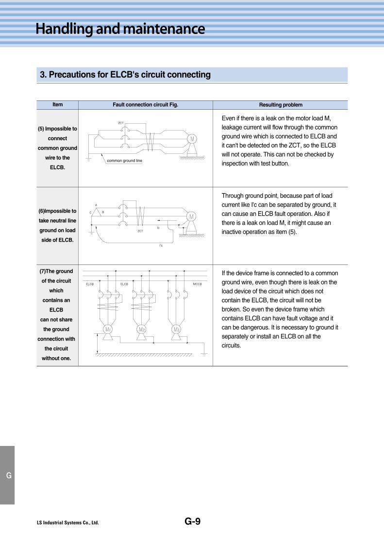
G-9
Handling and maintenance
3. Precautions for ELCB's circuit connecting
G
ZCT
common ground line
ZCT
A
BC
Ic
I'c
ELCB ELCB MCCB
Even if there is a leak on the motor load M,leakage current will flow through the commonground wire which is connected to ELCB andit can't be detected on the ZCT, so the ELCBwill not operate. This can not be checked byinspection with test button.
Through ground point, because part of loadcurrent like I'c can be separated by ground, itcan cause an ELCB fault operation. Also ifthere is a leak on load M, it might cause aninactive operation as item (5).
If the device frame is connected to a commonground wire, even though there is leak on theload device of the circuit which does notcontain the ELCB, the circuit will not bebroken. So even the device frame whichcontains ELCB can have fault voltage and itcan be dangerous. It is necessary to ground itseparately or install an ELCB on all thecircuits.
Item Fault connection circuit Fig. Resulting problem
(5) Impossible to
connect
common ground
wire to the
ELCB.
(6)Impossible to
take neutral line
ground on load
side of ELCB.
(7)The ground
of the circuit
which
contains an
ELCB
can not share
the ground
connection with
the circuit
without one.
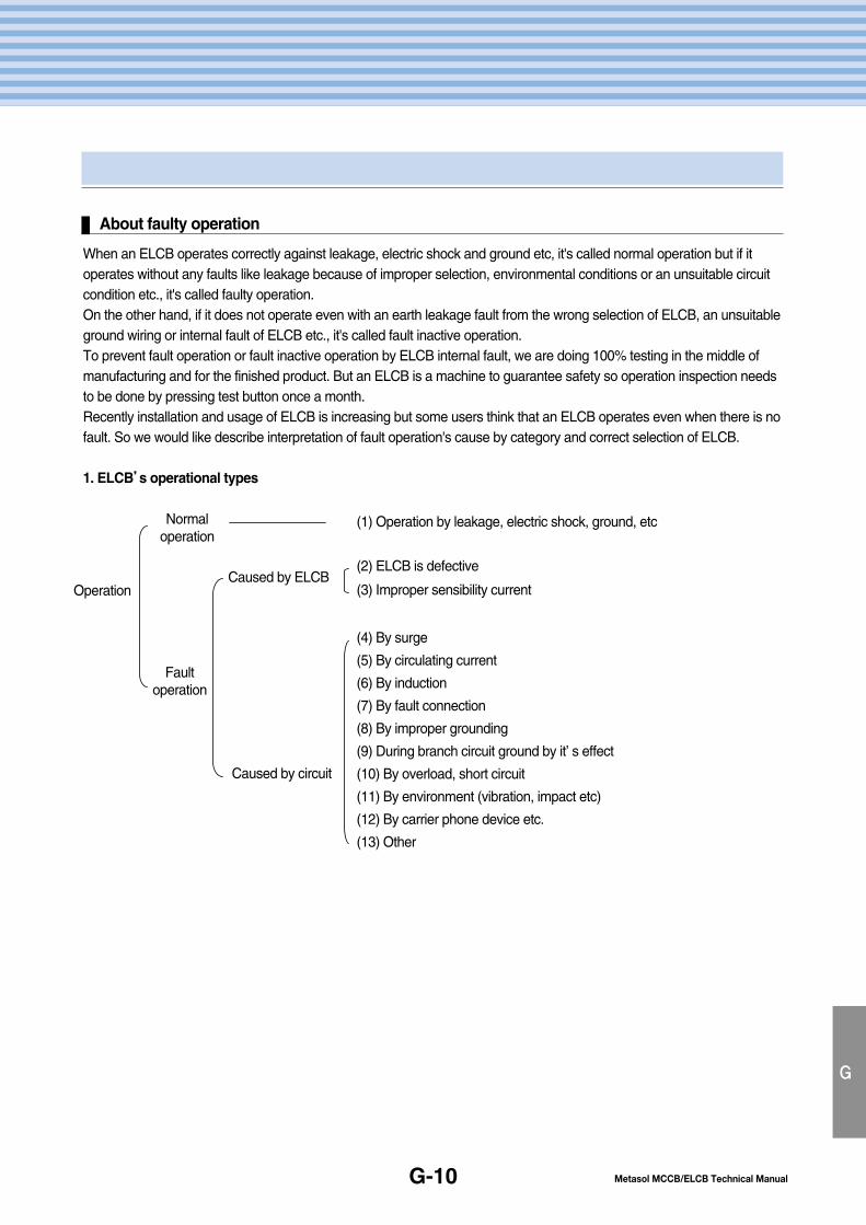
Metasol MCCB/ELCB Technical Manual
Metasol MCCB/ELCB Technical Manual
G-10
G
About faulty operation
When an ELCB operates correctly against leakage, electric shock and ground etc, it's called normal operation but if itoperates without any faults like leakage because of improper selection, environmental conditions or an unsuitable circuitcondition etc., it's called faulty operation.On the other hand, if it does not operate even with an earth leakage fault from the wrong selection of ELCB, an unsuitableground wiring or internal fault of ELCB etc., it's called fault inactive operation.To prevent fault operation or fault inactive operation by ELCB internal fault, we are doing 100% testing in the middle ofmanufacturing and for the finished product. But an ELCB is a machine to guarantee safety so operation inspection needsto be done by pressing test button once a month.Recently installation and usage of ELCB is increasing but some users think that an ELCB operates even when there is nofault. So we would like describe interpretation of fault operation's cause by category and correct selection of ELCB.
1. ELCB’’s operational types
(1) Operation by leakage, electric shock, ground, etc
(2) ELCB is defective
(3) Improper sensibility current
(4) By surge
(5) By circulating current
(6) By induction
(7) By fault connection
(8) By improper grounding
(9) During branch circuit ground by it’ s effect
(10) By overload, short circuit
(11) By environment (vibration, impact etc)
(12) By carrier phone device etc.
(13) Other
Caused by ELCBOperation
Normaloperation
Faultoperation
Caused by circuit
G-11
Handling and maintenance
3. Precautions for ELCB's circuit connecting
G
2. Contents of Operation
(1) Normal OperationIt is an ELCB operation according to its installation purpose and main operating reasons are as below.1. Insulation deterioration of machinery … Things which use water like washing machine etc. or having big impactlike a press etc.2. Insulation deterioration of wiring … temporary line's connecting unit or terminal3. Careless construction … ground by cable damage during construction or breaking of wire etc.4. Careless handling … electric shock ground by flooding or ground by damage etc.
(2) Fault of ELCB∙∙ There could be a fault by components' fire corrosion but fault by leakage detecting unit is very small.∙∙ There is a case of closing fault from a worn out trip coil unit or switch unit.∙∙ Besides the fault, if the balance characteristic is bad(low), it can be operated by the motor starting currentWhen the characteristic of the ZCT used for the ELCB is bad or the magnetic shield effect of the ZCT is not good,the ZCT balance characteristic gets lower from the effect of residual current. So as grounding occurs when amotor’s starting current(arrangement of full load current) flows, there could be a fault operation from anelectromotive force on a ZCT’s secondary winding. The effect of residual current gets bigger when the bus current isbigger, so it's necessary to be careful on the circuit where the load current is big. The ZCT residual characteristicchanges depending on the insulation material, conductor arranging position, winding etc. but with a regular circuit,this should not cause the fault operation. Using a bad quality ZCT core or not having enough ZCT shield effect cancause a fault operation so the ZCT core material of the LS circuit breaker is Permalloy, which uses nickel as its mainelement and its residual current characteristic is great.So the effect of the residual current is very small and even with a 1000A current, there is no fault operation.In the case of load from an unbalanced current, theoretically the ELCB does not operate but if a ZCT with abad residual current characteristic is used, it could cause a fault operation. If there is a fault operation when the motor starts or there is unbalanced load, it can be assumed that this happensbecause the ZCT balance characteristic from residual current characteristic is bad. So it is necessary to use theproduct with a trustworthy brand name.
(3) Unsuitable sensibility currentIt operates when the sensibility current of ELCB is more sensitive than the firm leakage current of the circuit. So thisis a selection problem. The leakage current of the circuit is mostly from the ground electrostatic capacity of the wirebut an electric furnace or heater's insulation resistance decreases under high temperature, so it can be difficult tofind the reason oof an ELCB's operation. Also the reason why its important to be careful with leakage current of circuit is that not only firm leakage currentduring normal condition but also excessive ground leakage current during switching or starting, can operate theELCB as well.Because the electric potential range of winding is different during starting and operating, excessive leakage currentduring starting can occur through electrostatic capacity for the winding frame. If electrostatic capacity for the ground of a ground of load device or distribution line is big, even under normalconditions, a big zero phase-sequence component current flows. And this can exceed the ELCB's rated inactiveoperation current then cause the operation. This happens generally when one ELCB protects with many combinedbrand circuit against ground.Also if the electrostatic capacity gets bigger, it's easy to have a fault operation during load circuit switching, so toprevent electric shock of low voltage circuit, it's recommended to install an ELCB on each branch circuit.
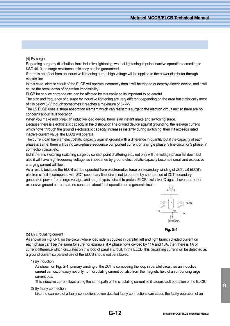
Metasol MCCB/ELCB Technical ManualG-12
G
Metasol MCCB/ELCB Technical Manual
(4) By surgeRegarding surge by distribution line's inductive lightening; we test lightening impulse inactive operation according toKSC 4613, so surge resistance efficiency can be guaranteed.If there is an effect from an inductive lightening surge, high voltage will be applied to the power distributor throughelectric line.In this case, electric circuit of the ELCB will operate incorrectly then it will be tripped or destroy electric device, and it willcause the break down of operation impossibility.ELCB for service entrance etc. can be affected by this easily so its important to be careful.The size and frequency of a surge by inductive lightening are very different depending on the area but statistically mostof it is below 5kV though sometimes it reaches a maximum of 6~7kV.The LS ELCB uses a surge absorption element which can resist this surge to the electron circuit unit so there are noconcerns about fault operation.When you make and break an inductive load device, there is an instant make and switching surge.Because there is electrostatic capacity in the distribution line or load device against grounding, the leakage currentwhich flows through the ground electrostatic capacity increases instantly during switching, then if it exceeds ratedinactive current value, the ELCB will operate.The current can have an electrostatic capacity against ground with a difference in quantity but if the capacity of eachphase is same, there will be no zero-phase-sequence component current on a single phase, 3 line circuit or 3 phase, Yconnection circuit etc.But if there is switching switching surge by contact point chattering etc., not only will the voltage phase fall down butalso it will have high frequency voltage, so impedance by ground electrostatic capacity becomes small and excessivecharging current will flow.As a result, because the ELCB can be operated from electromotive force on secondary winding of ZCT, LS ELCB'selectron circuit is composed with ZCT secondary filter circuit not to operate by short period of ZCT secondarygeneration power from surge voltage, and surge bypass circuit to protect ELCB exclusive IC against over current orexcessive ground current. are no concerns about fault operation on a general circuit.
(5) By circulating currentAs shown on Fig. G-1, on the circuit where load side is coupled in parallel, left and right branch divided current oneach phase can't be the same for sure, for example, if A phase flows divided by 11A and 10A, then there is 1A ofcurrent difference which circulates on this loop of parallel circuit. In the ELCB, this circulating current will be detected asa ground current so parallel use of the ELCB should not be allowed.
1) By inductionAs shown on Fig. G-1, primary winding of the ZCT is composing the loop in parallel circuit, so an inductivecurrent can occur easily not only from circulating current but also from the magnetic field of a surrounding largecurrent bus.This inductive current flows along the same path of the circulating current so it causes fault operation of the ELCB.
2) By faulty connectionLike the example of a faulty connection, seven detailed faulty connections can cause the faulty operation of an
A B
1A
11A10A
9A
20ALoad
ELCB
Fig. G-1
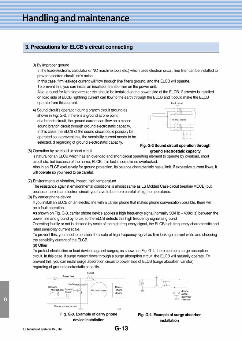
G-13
Handling and maintenance
3. Precautions for ELCB's circuit connecting
G
3) By Improper groundIn the load(electronic calculator or NC machine tools etc.) which uses electron circuit, line filter can be installed toprevent electron circuit unit's noise.In this case, firm leakage current will flow through line filter's ground, and the ELCB will operate.To prevent this, you can install an insulation transformer on the power unit.Also, ground for lightning arrester etc. should be installed on the power side of the ELCB. If arrester is installedon load side of ELCB, lightning current can flow to the earth through the ELCB and it could make the ELCBoperate from this current.
4) Sound circuit's operation during branch circuit ground as shown in Fig. G-2, if there is a ground at one point of a branch circuit, the ground current can flow on a closed sound branch circuit through ground electrostatic capacity. In this case, the ELCB of the sound circuit could possibly be operated so to prevent this, the sensibility current needs to be selected. d regarding of ground electrostatic capacity.
(6) Operation by overload or short circuitis natural for an ELCB which has an overload and short circuit operating element to operate by overload, shortcircuit etc. but because of the name, ELCB, this fact is sometimes overlooked.Also in an ELCB exclusively for ground protection, its balance characteristic has a limit. If excessive current flows, itwill operate so you need to be careful.
(7) Environments of vibration, impact, high temperatureThe resistance against environmental conditions is almost same as LS Molded Case circuit breaker(MCCB) butbecause there is an electron circuit, you have to be more careful of high temperatures.
(8) By carrier phone deviceIf you install an ELCB on an electric line with a carrier phone that makes phone conversation possible, there willbe a fault operation.As shown on Fig. G-3, carrier phone device applies a high frequency signal(normally 50kHz ~ 400kHz) between thepower line and ground by force, so the ELCB detects this high frequency signal as groundOperating faultily or not is decided by scale of the high frequency signal, the ELCB high frequency characteristic andrated sensibility current scale.To prevent this, you need to consider the scale of high frequency signal as firm leakage current while and choosingthe sensibility current of the ELCB.(9) OtherTo protect electric line or load devices against surges, as shown on Fig. G-4, there can be a surge absorptioncircuit. In this case, if surge current flows through a surge absorption circuit, the ELCB will naturally operate. Toprevent this, you can install surge absorption circuit to power side of ELCB (surge absorber, varistor)regarding of ground electrostatic capacity.
Fault circuit
Normal circuit
Fig. G-2 Sound circuit operation throughground electrostatic capacity
Fig. G-3. Example of carry phonedevice installation
Fig. G-4. Example of surgy absorberinstallation
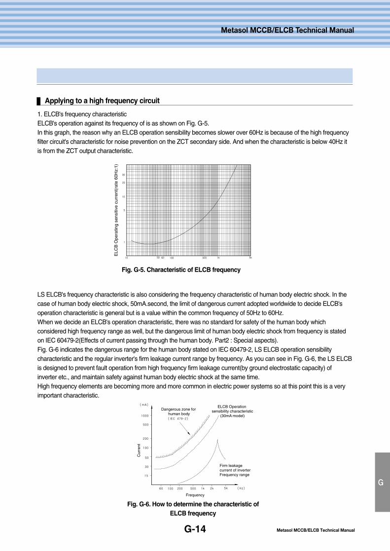
Metasol MCCB/ELCB Technical ManualG-14
G
Metasol MCCB/ELCB Technical Manual
Applying to a high frequency circuit
1. ELCB's frequency characteristicELCB's operation against its frequency of is as shown on Fig. G-5.In this graph, the reason why an ELCB operation sensibility becomes slower over 60Hz is because of the high frequencyfilter circuit's characteristic for noise prevention on the ZCT secondary side. And when the characteristic is below 40Hz itis from the ZCT output characteristic.
LS ELCB's frequency characteristic is also considering the frequency characteristic of human body electric shock. In thecase of human body electric shock, 50mA.second, the limit of dangerous current adopted worldwide to decide ELCB'soperation characteristic is general but is a value within the common frequency of 50Hz to 60Hz.When we decide an ELCB's operation characteristic, there was no standard for safety of the human body whichconsidered high frequency range as well, but the dangerous limit of human body electric shock from frequency is statedon IEC 60479-2(Effects of current passing through the human body. Part2 : Special aspects).Fig. G-6 indicates the dangerous range for the human body stated on IEC 60479-2, LS ELCB operation sensibilitycharacteristic and the regular inverter's firm leakage current range by frequency. As you can see in Fig. G-6, the LS ELCBis designed to prevent fault operation from high frequency firm leakage current(by ground electrostatic capacity) ofinverter etc., and maintain safety against human body electric shock at the same time.High frequency elements are becoming more and more common in electric power systems so at this point this is a veryimportant characteristic.
30
20
10
5
1
10 50 60 100 500 1k 5k
ELC
B O
pera
ting
sens
itive
cur
rent
(rat
e 60
Hz:
1)
(mA)
1000
500
200
100
50
30
15
60 100 200 500 1k 2k 5k (Hz)
(IEC 479-2)
Cur
rent
Frequency
Dangerous zone for human body
ELCB Operation sensibility characteristic
(30mA model)
Firm leakagecurrent of inverterFrequency range
Fig. G-5. Characteristic of ELCB frequency
Fig. G-6. How to determine the characteristic ofELCB frequency
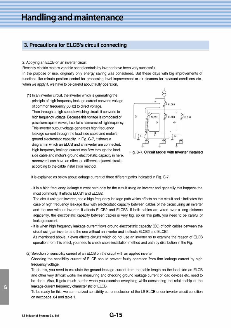
G-15
Handling and maintenance
3. Precautions for ELCB's circuit connecting
G
(1) In an inverter circuit, the inverter which is generating theprinciple of high frequency leakage current converts voltageof common frequency(60Hz) to direct voltage.Then through a high speed switching circuit, it converts tohigh frequency voltage. Because this voltage is composed ofpulse form square waves, it contains harmonics of high frequency.This inverter output voltage generates high frequencyleakage current through the load side cable and motor'sground electrostatic capacity. In Fig. G-7, it shows adiagram in which an ELCB and an inverter are connected.High frequency leakage current can flow through the loadside cable and motor's ground electrostatic capacity in here,moreover it can have an effect on different adjacent circuitsaccording to the cable installation method.
2. Applying an ELCB on an inverter circuitRecently electric motor's variable speed controls by inverter have been very successful.In the purpose of use, originally only energy saving was considered. But these days with big improvements offunctions like minute position control for processing level improvement or air cleaners for pleasant conditions etc.,when we apply it, we have to be careful about faulty operation.
It is explained as below about leakage current of three different paths indicated in Fig. G-7.
- It is a high frequency leakage current path only for the circuit using an inverter and generally this happens themost commonly. It effects ELCB1 and ELCB2.
- The circuit using an inverter, has a high frequency leakage path which effects on this circuit and it indicates thecase of high frequency leakage flow with electrostatic capacity between cables of the circuit using an inverterand the one without inverter. It affects ELCB2 and ELCB3. If both cables are wired over a long distanceadjacently, the electrostatic capacity between cables is very big, so on this path, you need to be careful ofleakage current.
- It is when high frequency leakage current flows ground electrostatic capacity (C0) of both cables between thecircuit using an inverter and the one without an inverter and it effects ELCB2 and ELCB4.As mentioned above, it even effects circuits which do not use an inverter so to examine the reason of ELCBoperation from this effect, you need to check cable installation method and path by distribution in the Fig.
(2) Selection of sensibility current of an ELCB on the circuit with an applied inverterChoosing the sensibility current of ELCB should prevent faulty operation from firm leakage current by highfrequency voltage.To do this, you need to calculate the ground leakage current from the cable length on the load side an ELCBand other very difficult works like measuring and checking ground leakage current of load devices etc. need tobe done. Also, it gets much harder when you examine everything while considering the relationship of theleakage current frequency characteristic of ELCB.To be ready for this, we summarized sensibility current selection of the LS ELCB under inverter circuit conditionon next page, 84 and table 1.
Fig. G-7. Circuit Model with Inverter Installed
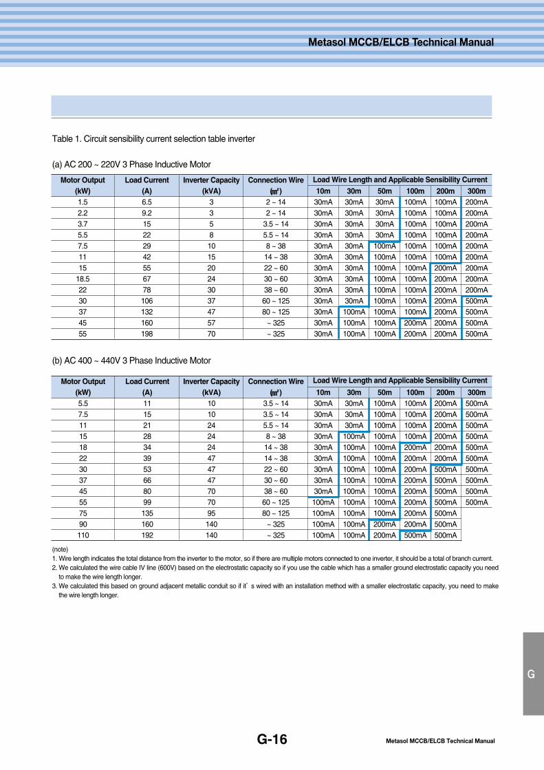
Metasol MCCB/ELCB Technical ManualG-16
G
Metasol MCCB/ELCB Technical Manual
Table 1. Circuit sensibility current selection table inverter
(a) AC 200 ~ 220V 3 Phase Inductive Motor
(b) AC 400 ~ 440V 3 Phase Inductive Motor
Motor Output(kW)1.52.23.75.57.51115
18.52230374555
Load Current(A)6.59.215222942556778106132160198
Inverter Capacity(kVA)
3358101520243037475770
Connection Wire(㎟㎟ )
2 ~ 142 ~ 14
3.5 ~ 145.5 ~ 148 ~ 3814 ~ 3822 ~ 6030 ~ 6038 ~ 6060 ~ 12580 ~ 125
~ 325~ 325
10m30mA30mA30mA30mA30mA30mA30mA30mA30mA30mA30mA30mA30mA
30m30mA30mA30mA30mA30mA30mA30mA30mA30mA30mA100mA100mA100mA
50m30mA30mA30mA30mA100mA100mA100mA100mA100mA100mA100mA100mA100mA
100m100mA100mA100mA100mA100mA100mA100mA100mA100mA100mA100mA200mA200mA
200m100mA100mA100mA100mA100mA100mA200mA200mA200mA200mA200mA200mA200mA
300m200mA200mA200mA200mA200mA200mA200mA200mA200mA500mA500mA500mA500mA
Load Wire Length and Applicable Sensibility Current
Motor Output(kW)5.57.511151822303745557590110
Load Current(A)11152128343953668099135160192
Inverter Capacity(kVA)
1010242424474747707095140140
Connection Wire(㎟㎟ )
3.5 ~ 143.5 ~ 145.5 ~ 148 ~ 3814 ~ 3814 ~ 3822 ~ 6030 ~ 6038 ~ 6060 ~ 12580 ~ 125
~ 325~ 325
10m30mA30mA30mA30mA30mA30mA30mA30mA30mA100mA100mA100mA100mA
30m30mA30mA30mA100mA100mA100mA100mA100mA100mA100mA100mA100mA100mA
50m100mA100mA100mA100mA100mA100mA100mA100mA100mA100mA100mA200mA200mA
100m100mA100mA100mA100mA200mA200mA200mA200mA200mA200mA200mA200mA500mA
200m200mA200mA200mA200mA200mA200mA500mA500mA500mA500mA500mA500mA500mA
300m500mA500mA500mA500mA500mA500mA500mA500mA500mA500mA
Load Wire Length and Applicable Sensibility Current
(note)1. Wire length indicates the total distance from the inverter to the motor, so if there are multiple motors connected to one inverter, it should be a total of branch current.2. We calculated the wire cable IV line (600V) based on the electrostatic capacity so if you use the cable which has a smaller ground electrostatic capacity you need
to make the wire length longer.3. We calculated this based on ground adjacent metallic conduit so if it’s wired with an installation method with a smaller electrostatic capacity, you need to make
the wire length longer.
MMeemmoo
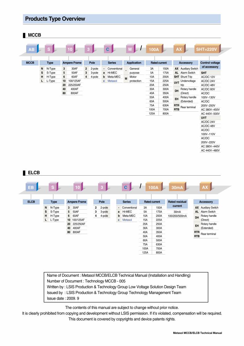
Metasol MCCB/ELCB Technical Manual
Products Type Overview
The contents of this manual are subject to change without prior notice.It is clearly prohibited from copying and development without LSIS permission. If it’s violated, compensation will be required.
This document is covered by copyrights and device patents rights.
Name of Document : Metasol MCCB/ELCB Technical Manual (Installation and Handling)Number of Document : Technology MCCB - 005Written by : LSIS Production & Technology Group Low Voltage Solution Design TeamIssued by : LSIS Production & Technology Group Technology Management TeamIssue date : 2009. 9
AB S 10 3 C M 100A AX SHT=220V
EB S 10 3 C 100A 30mA AX
MCCB
ELCB
MCCB Type
N N-TypeS S-TypeH H-TypeL L-Type
Type
N N-TypeS S-TypeH H-TypeL L-Type
Ampere Frame Pole
2 2-pole3 3-pole4 4-pole
Series
- Conventionala Hi-MECb Meta-MECc Metasol
Application
-General purpose
MMotor protection
Accessory
AX Auxiliary SwitchAL Alarm Switch
SHT Shunt Trip
UVTUndervoltage trip
DHRotary handle (Direct)
EHRotary handle (Extended)
RTRRear terminal
RTB
Control voltageof accessory
SHTAC/DC 12VAC/DC 24VAC/DC 48VAC/DC 60VAC/DC100V~130VAC/DC200V~250VAC 380V~450VAC 440V~500VUVTAC/DC 24VAC/DC 48VAC/DC100V~110VAC/DC200V~220VAC 380V~440VAC 440V~480V
ELCB Ampere Frame Pole
2 2-pole3 3-pole4 4-pole
Series
- Conventionala Hi-MECb Meta-MECc Metasol
Accessory
AX Auxiliary SwitchAL Alarm Switch
DHRotary handle (Direct)
EHRotary handle (Extended)
RTRRear terminal
RTB
Rated residualcurrent
30mA100/200/500mA
Rated current
3A5A10A15A20A30A40A50A60A75A100A125A
150A175A200A225A250A300A350A400A500A630A700A800A
Rated current
3A5A10A15A20A30A40A50A60A75A100A125A
150A175A200A225A250A300A350A400A500A630A700A800A
3 30AF5 50AF6 60AF10 100/125AF20 225/250AF40 400AF80 800AF
3 30AF5 50AF6 60AF10 100/125AF20 225/250AF40 400AF80 800AF

www.lsis.bizⓒ 2008.10 LS Industrial Systems Co.,Ltd. All rights reserved.
Specifications in this catalog are subject to change without notice due to continuous product development and improvement.
�� HEAD OFFICELS Tower 1026-6, Hogye-dong, Dongan-gu, Anyang-si, Gyeonggi-do 431-848, Korea
Tel. (82-2)2034-4887, 4873, 4148Fax. (82-2)2034-4648
�� CHEONG-JU PLANTCheong-Ju Plant #1, Song Jung Dong, Hung Duk Ku,Cheong Ju, 361-720, Korea
2009. 09 Low voltage circuit breakers (E) 2008. 10/(02) 2009. 09 Printed in Korea STAFF
�LS Industrial Systems (Middle East) FZE ��Dubai, U.A.E. Address: LOB 19 JAFZA VIEW TOWER Room 205, Jebel Ali Freezone P.O. Box 114216, Dubai, United Arab EmiratesTel: 971-4-886 5360 Fax: 971-4-886-5361 e-mail: [email protected]
�Dalian LS Industrial Systems Co., Ltd. ��Dalian, ChinaAddress: No.15, Liaohexi 3-Road, Economic and Technical Development zone, Dalian 116600, ChinaTel: 86-411-8273-7777 Fax: 86-411-8730-7560 e-mail: [email protected]
�LS Industrial Systems (Wuxi) Co., Ltd. ��Wuxi, ChinaAddress: 102-A , National High & New Tech Industrial Development Area, Wuxi, Jiangsu, 214028, P.R.ChinaTel: 86-510-8534-6666 Fax: 86-510-522-4078 e-mail: [email protected]
�LS-VINA Industrial Systems Co., Ltd. ��Hanoi, VietnamAddress: Nguyen Khe - Dong Anh - Ha Noi - Viet NamTel: 84-4-882-0222 Fax: 84-4-882-0220 e-mail: [email protected]
�LS-VINA Industrial Systems Co., Ltd. ��Hochiminh , VietnamAddress: 41 Nguyen Thi Minh Khai Str. Yoco Bldg 4th Floor, Hochiminh City, VietnamTel: 84-8-3822-7941 Fax: 84-8-3822-7942 e-mail: [email protected]
�LS Industrial Systems Tokyo Office ��Tokyo, JapanAddress: 16FL, Higashi-Kan, Akasaka Twin Tower 17-22, 2-chome, Akasaka, Minato-ku Tokyo 107-8470, JapanTel: 81-3-3582-9128 Fax: 81-3-3582-2667 e-mail: [email protected]
�LS Industrial Systems Shanghai Office ��Shanghai, ChinaAddress: Room E-G, 12th Floor Huamin Empire Plaza, No.726, West Yan'an Road Shanghai 200050, P.R. ChinaTel: 86-21-5237-9977 (609) Fax: 89-21-5237-7191 e-mail: [email protected]
�LS Industrial Systems Beijing Office ��Beijing, ChinaAddress: B-Tower 17FL.Beijing Global Trade Center B/D. No.36, BeiSanHuanDong-Lu, DongCheng-District,Beijing 100013, P.R. ChinaTel: 86-10-5825-6025,7 Fax: 86-10-5825-6026 e-mail: [email protected]
�LS Industrial Systems Guangzhou Office ��Guangzhou, ChinaAddress: Room 1403,14F,New Poly Tower,2 Zhongshan Liu Road,Guangzhou, P.R. ChinaTel: 86-20-8326-6764 Fax: 86-20-8326-6287 e-mail: [email protected]
�LS Industrial Systems Chengdu Office ��Chengdu, ChinaAddress: Room 1701 17Floor, huanminhanjun internationnal Building, No1 Fuxing Road Chengdu, 610041, P.R. ChinaTel: 86-28-8670-3101 Fax: 86-28-8670-3203 e-mail: [email protected]
�LS Industrial Systems Qingdao Office ��Qingdao, ChinaAddress: 7B40,Haixin Guangchang Shenye Building B, No.9, Shandong Road Qingdao 26600, P.R. ChinaTel: 86-532-8501-6568 Fax: 86-532-583-3793 e-mail: [email protected]
��Global Network
�� For your safety, please read user's manual thoroughly before operating.
�� Contact the nearest authorized service facility for examination, repair, or adjustment.
�� Please contact a qualified service technician when you need maintenance.Do not disassemble or repair by yourself!
�� Any maintenance and inspection shall be performed by the personnel having expertise concerned.Safety Instructions