Catalogue 2019 Circuit breakers and switch-disconnectors from ...
190
Compact NS Catalogue 2019 Circuit breakers and switch-disconnectors from 630b to 3200 A schneider-electric.com ● WEB3 cat.2018
-
Upload
khangminh22 -
Category
Documents
-
view
1 -
download
0
Transcript of Catalogue 2019 Circuit breakers and switch-disconnectors from ...

Compact NS
Catalogue 2019Circuit breakers and switch-disconnectorsfrom 630b to 3200 A
schneider-electric.com
WEB3 cat.2018
Dell
Typewriter
CÔNG TY CỔ PHẦN THIẾT BỊ ĐIỆN HOÀNG PHƯƠNG ĐC: Số 30, ngõ 88, phố Võ Thị Sáu, P.Thanh Nhàn, Q.Hai Bà Trưng, TP. Hà Nội MST: 0106798886 Tel: 024.3215.1322 Website: Hoangphuong.com.vn Phone: 0944.240.317 / 0975.123.698 / 0961.008.858 Email: [email protected]

Green Premium is the only label that allows you to effectively develop and promote an environmental policy whilst preserving your business efficiency. This ecolabel guarantees compliance with up-to-date environmental regulations, but it does more than this.
Discover what we mean by green …
Check your products!
Schneider Electric’s Green Premium ecolabel is committed to offering transparency, by disclosing extensive and reliable information related to the environmental impact of its products:
RoHSSchneider Electric products are subject to RoHS requirements at a worldwide level, even for the many products that are not required to comply with the terms of the regulation. Compliance certificates are available for products that fulfil the criteria of this European initiative, which aims to eliminate hazardous substances.
REAChSchneider Electric applies the strict REACh regulation on its products at a worldwide level, and discloses extensive information concerning the presence of SVHC (Substances of Very High Concern) in all of its products.
PEP: Product Environmental ProfileSchneider Electric publishes complete set of environmental data, including carbon footprint and energy consumption data for each of the lifecycle phases on all of its products, in compliance with the ISO 14025 PEP ecopassport program. PEP is especially useful for monitoring, controlling, saving energy, and/or reducing carbon emissions.
EoLI: End of Life InstructionsAvailable at the click of a button, these instructions provide:• Recyclability rates for Schneider Electric products.• Guidance to mitigate personnel hazards during the dismantling of
products and before recycling operations.• Parts identification for recycling or for selective treatment, to mitigate
environmental hazards/ incompatibility with standard recycling processes.
Endorsing eco-friendly products in the industry
Green PremiumTM
Over 75% of Schneider Electric manufactured products have been awarded the Green Premium ecolabel

Compact NSMolded case circuit breakersThe world is becoming more electric, digitized and decarbonized. Our digitized LV products are powered by innovation at every level enabling enhanced connectivity, real-time operations and smart analytics. They bring improved safety and security. They help you to improve reliability and performance – and to prepare for the future of power distribution.
Compact is an integral part of EcoStruxure™ Power – Schneider’s open, interoperable, IoT-enabled system architecture. Through this platform, we deliver enhanced value around safety, reliability, efficiency, sustainability, and connectivity for our customers. We leverage technologies in IoT, mobility, sensing, cloud, analytics, and cybersecurity to deliver Innovation at Every Level. This includes Connected Products, Edge Control, and Apps, Analytics & Services. EcoStruxure has been deployed in 450,000+ installations, with the support of 9,000 system integrators, connecting over 1 billion devices.
The launch of Schneider Electric Compact NS in 1994 revolutionized the world of molded case circuit breakers and benefits from 60 years of experience and leadership in industrial circuit breakers.
As well as offering proven performance, flexibility and reliability, the Compact NS sets the standard in most applications: buildings, windturbine, solar, genset, data center, healthcare, marine and infrastructure and decrease your energy consumption thanks to very low power dissipation.
Equipped with the Micrologic control units, Compact NS630b to 3200 A circuit breakers offer built-in power and energy metering in addition to electrical measurement and analysis functions.
The communication option makes it possible to control power consumption, simplify maintenance and improve operating comfort.
A wide range of optimized auxiliaries and accessories is available to meet the needs of protection of AC installations, generator protection, motor protection, switch-disconnectors, source changeover switch function and specific offers available for DC applications up to 1000 V.
Today, the Compact NS range remains the international reference in the molded-case, circuit breaker market.
schneider-electric.com/compactns

schneider-electric.com/compactnsII | Compact NS
Win more projects and deliver the best solution for your customers
• Enhance power availability with total control of selectivity and power management with advanced trip unit.
• Optimize panel cost with cascading; the Compact NS technology covers all your needs from 630 to 3200 A, with a breaking capacity from 50 to 200 kA.
• Equipped with electronic control units, the Compact NS circuit breakers ensure protection and measurement of your electrical installation.
• Provide efficiency to your customer with small size and multi-ways of installation and highly immune protection system insensitive to disturbances (IEC 60947-2 Annex F).
More than 10 years of long-felt techniques and technologies ahead quite simple and convenient.
The Compact NS range covers all ratings from 630 to 3200 A
Compact NS630b to 1600
• Compact NS from 630 to 1600 A, fixed or withdrawable, front or rear connection, manual operating mechanism or motor mechanism. A 200 kA breaking performance completes the Compact NS range
Compact NS1600b to 3200
• Compact NS from 1600 to 3200 A, fixed, front connection, with manual operating mechanism
In (A)
Compact NS630b to 1600
Manual
Type N – 50 kA
630 800 1000 1250 1600 2000 2500 3200
Compact NS630b to 1600
Electrical
Compact NS1600b to 3200
Manual
Type H – 70 kA
Type L – 150 kA
Type LB – 200 kA
Type N – 50 kA
Type H – 70 kA
Type L – 150 kA
Type N – 70 kA
Type H – 85 kA
I design electrical solutions
Standards
Compact NS circuit breakers and auxiliaries comply with:
• IEC/EN 60947-1: General rules
• IEC/EN 60947-2: Circuit-breakers
• IEC/EN 60947-3: Switch-disconnectors
• IEC/EN 60947-4-1: Contactors and motor-starters
• IEC/EN 60947-5-1: Control circuit devices
The Masterpact and Compact range Circuirt breakers, switch-disconnectors and source changeover are the best choice for all standards and specific applications.
> Compact INS/INV
LVPED213024EN
> Source-changeover systems
LVPED216028EN
> Complementary technical information
LVPED308005EN
> Compact NSXm/NSX
LVPED217032EN
> Masterpact MTZ
LVPED216026EN

schneider-electric.com/compactns Compact NS | III
I build and install electrical equipment
Make your business more profitable
Gain space in your switchboard
• The Compact NS range is available in 2 sizes only in order to homogenize installation dimensions (volume, depth, pole pitch).
• Easy to select and to order with new Schneider Electric™ online tools.
Gain time, the installation is facilitated
• More space to connect your cables.
• Withdrawable version also available.

schneider-electric.com/compactnsIV | Compact NS
Optimize your solution
• Minimum distances (safety clearance) between 2 circuit breakers are reduced thanks to the arc chute filters.
• A solution for all your applications: – generator protection – motor protection up to 750 kW with coordination between breakers
and contactors (coordination type 1 and type 2) – source-changeover.
• Best combination of size (small depth), performance with no derating up to 65 °C (vertical connection) and flexible mounting options.
• Ensure continuity of service:
– Total control of selectivity for the whole Schneider Electric circuit breakers range from moulded circuit breaker to air circuit breaker
– High withstand of the devices to various envrionmental stresses.
• Bring flexibility to your installation: Interchangeable trip units, standardized accessories, adjustable rating and scalable indication and control functions.
I design and build machines
CAF1CAF2CAO1CAO2
OF1OF2OF3SDMN or MX
SDECOM
Manually operated device.
SDEOF3OF2OF1
MN or MX
COM
Electrically operated device.
CD2CD1
CT1
CE3CE2CE1
Withdrawable device.
Installation
Fixed device
Withdrawable device

schneider-electric.com/compactns Compact NS | V
I operate and manage my installation
Ensure continuity of service
• Electrical energy is available, prevent nuisance power outages using total control of selectivity.
Monitor your power
• Power consumption is optimized with on-site, real-time monitoring and control, plus online energy management services
• Maintenance is simplified
• Installation is scalable
• Using Compact NS will decrease permanent consumption with lower power dissipations.
I operate my installation

schneider-electric.com/compactnsVI | Compact NS
Architecture overview
Ethernet-ready Smart PanelsEthernet-ready Smart Panels enable electrical distribution control and expertise. ‘Protect’ - ’Measure’ - ’Connect’ are the 3 pillars of their technology.
PB11
9232
.eps
Electrical protection is at the core of Smart PanelReliable and high-performance technology is present in every breaker and every residual current device.
1- Protect
Keeping a close eye on energy flowsThe switchboard plays a key role in capturing building-related data, by gathering the critical protection and metering components.
2- Measure
Give a voice to the panelSafe Ethernet network data transmission is now part of the intrinsic design of protection and metering devices
3- Connect
4- Act

schneider-electric.com/compactns Compact NS | VII
Architecture overview
Future savings, peace-of-mind Access to Smart Panel status, values, is essential for taking advantages of monitoring and management services, locally or remotely.
Act in small/medium buildingswith FDM 128, Com’X 510, Power View, EcoStruxure™ Facility Expert
DD
3859
19.a
i
DB4
2305
6.ai
Increasing maintenance efficiency p Operate preventive maintenance tools
p Follow maintenance & planning
p Provide business owner instant access to maintenance reports
Distance management with EcoStruxure™ Facility Expert on Smartphone, tablet, PC
Optimizing energy-efficiency p Visualize, record energy consumption and WAGES.
p Comply with regulation .
PB11
1801
-60.
eps
Electrical device monitoring and control with FDM 128, locally
Improving continuity of service p Get instant notifications
p Manage with assets-maintenance platform
p Get and analyze data for quick crisis-recovery
DD
3859
18.a
i
Com’X 510 web pages direct display, or Cloud based pages from other devices with Power View.

schneider-electric.com/compactnsVIII | Compact NS
Monitoring electrical network p Observe voltage disturbances, harmonics on graphics. p Read power factor.
Managing equipment & key assets p Check operating status, faults on custom
on-line diagrams.
Accounting energy p Record power meter data on dashboards. p Allocate energy consumption with costs. p Follow conservation goals.
Act in large non-critical buildingswith EcoStruxure™ Energy Expert
Monitoring Power quality p Be alerted of equipment affected by power quality issue. p Compare power quality against industry standards. p Collect facts for future discussion with Utility.
Analysing Power Events p Speed up downtime crisis recovery p Determine incident root cause, events sequence. p Troubleshoot power quality issues.
Analysing Energy Performance p Evaluate building energy saving performance; p Identify underperforming loads; p Analyze Energy Conservation Measures (ECMs)
according ISO50001 program.
Act in large critical buildingswith EcoStruxure™ Power Monitoring Expert [1]
[1] EcoStruxure™ Power Monitoring Expert, http://pmedemo.biz/web/ ID: demo & Password: demo
DB4
2565
7.ai
DB4
2565
8.ai
DB4
2565
9.ai
DB4
2566
0.ai
DB4
2566
1.ai
DB4
2533
4.ai
Architecture overview
Day-to-day energy management >> Power availability & quality, energy performance For simply dealing with building user’s needs and energy constraints. EcoStruxure™ Building Management provides electrical management, monitoring and energy accounting.Energy decisions are often crucial in large critical buildings, they must be informed. EcoStruxure™ Power Monitoring Expert (software for PC) collects Smart Panels values to provide expert analysis.

1
A
B
C
D
E
F
Compact NS630b to 3200
Functions and characteristics
Installation recommendations
Dimensions and connection
Electrical diagrams
Additional characteristics
Catalogue numbers and order form
Gen
eral
con
tent
s

2
Micrologic 5.0 E
40
100%
%
delay
short time
tsd(s)
long time
alarm
tr(s)
setting
.4.5.6
.7.8 .9
.95
.98
1
Ir
x In
.512
48 12
1620
at 6 Ir24
x Ir
22.5
34 5
68
10
Isd
1.5on I
2t
.2
.4 .4
.1
.3
.10
I i
x In
3
4
8
off2
.3
instantaneous
.26
15
1012
menu
NS 1200 H
Ui 1000V Uimp 12kV
Ics = 100% Icu
IEC 947-2
UTE VDE BS CEI UNE NEMA
Ue(V)220/240
480/690
Icu(kA)10085
Uimp 8kV
Ipush ON
OOFF
discharged
35210
Opush OFFor
DB4
2128
2.ep
s
Micrologic 5.0 E
40
100%
%
delay
short time
tsd(s)
long time
alarm
tr(s)
setting
.4.5.6
.7.8 .9
.95
.98
1
Ir
x In
.512
48 12
1620
at 6 Ir24
x Ir
22.5
34 5
68
10
Isd
1.5on I
2t
.2
.4 .4
.1
.3
.10
I i
x In
3
4
8
off2
.3
instantaneous
.26
15
1012
menu
NS 1200 H
Ui 1000V Uimp 12kV
Ics = 100% Icu
IEC 947-2
UTE VDE BS CEI UNE NEMA
Ue(V)220/240
480/690
Icu(kA)10085
Uimp 8kV
DB4
0391
6.ep
sD
B403
917.
eps
Micrologic 5.0 E
40
100%
%
delay
short time
tsd(s)
long time
alarm
tr(s)
setting
.4.5.6
.7.8 .9
.95
.98
1
Ir
x In
.512
48 12
1620
at 6 Ir24
x Ir
22.5
34 5
68
10
Isd
1.5on I
2t
.2
.4 .4
.1
.3
.10
I i
x In
3
4
8
off2
.3
instantaneous
.26
15
1012
menu
NS 1200 H
Ui 1000V Uimp 12kV
Ics = 100% Icu
IEC 947-2
UTE VDE BS CEI UNE NEMA
Ue(V)220/240
480/690
Icu(kA)10085
Uimp 8kV
DB4
0391
8.ep
s
Ipush ON
OOFF
discharged
35210
Opush OFFor
NS 1200 H
Ui 1000V Uimp 12kV
Ics = 100% Icu
IEC 947-2
UTE VDE BS CEI UNE NEMA
Ue(V)220/240
480/690
Icu(kA)10085
Uimp 8kV
DB4
2128
4.ep
s
Ipush ON
O OFF
discharged
35210
Opush OFF
Ipush ON
O OFF
discharged
35210
Opush OFF
N R
DB4
1992
8.ep
s
Earth-leakage > page A-45
Service connection
Control and isolation using switch-disconnectors > page A-46
Source-changeover systems > page A-52
Protection of LV distribution systems > pages A-2 et A-25
Protection for: b distribution systems supplied by
transformers b distribution systems supplied by engine
generator sets b long cables in IT and TN systems.
When combined with a motor starter, Compact NS circuit breakers protect the cables and the starter against short-circuits. Equipped with an electronic trip unit, Compact NS circuit breakers also protect the cables, starter and motor against overloads.
To ensure a continuous supply of power, some electrical installations are connected to two power sources:
b a source "S1" b a source "S2" to supply the installation when
the source "S1" is not available.A mechanical and/or electrical interlocking system between two circuit breakers or switch-disconnectors avoids all risk of parallel connection of the sources during switching.
A switch-disconnector version of Compact NS circuit breakers exists for circuit control and isolation.All the additional functions may be combined with the basic switch-disconnector function, including:
b earth-leakage protection b motor mechanism.
Additional earth-leakage protection protects life and property against the risks of faulty insulation in the installation.
Compact NS service connection circuit breakers are specially designed for the service-connection function:
b lead seals and locking systems b tripping curves certified by utilities b fast overload curves to limit the power
supplied, etc.
Protection of motors feeders (AC 220/690 V) > page A-44
Installation : b in power switchboards.
All circuit breakers in the Compact NS range offer positive contact indication and are suitable for isolation in compliance with standards IEC 60947-1 and 2.
The exceptional current-limiting capacity of Compact NS circuit breakers automatically ensures type-2 coordination with the motor starter, in compliance with standard IEC 60947-4-1.
Depending on the circuit breaker, earth-leakage protection is provided by:
b using a specific Micrologic control unit b using a Vigirex relay and separate toroids.
Compact INV switch-disconnectors offering visible break (see the corresponding catalogue) can be combined with Compact NS circuit breakers to constitute the various types of service connections and meet the needs of all installation configurations.
For information on other switch-disconnector ranges, see the Compact INS/INV (offering positive contact indication and visible break) and Fupact (fuse switch) catalogues.
A source-changeover system can be: b manual with mechanical device interlocking b remote controlled with mechanical and/or
electrical device interlocking b automatic by adding a controller to manage
switching from one source to the other on the basis of external parameters.
(See Source-changeover catalogue for dimensions, connections and electrical drawings).
Compact NS, even more applications...Presentation - Applications www.schneider-electric.com

3
PB10
4839
_ME.
eps
PB11
1801
-32_
r.eps
PB10
4831
_ME.
eps
They can be combined with the FDM121 switchboard display unit to provide all the functions of a Power Meter as well as operating assistance.
Power Meter functions > page A-18
PB11
9233
.eps
PB11
1801
-19_
r.eps
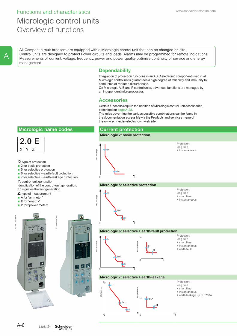
All Compact circuit breakers are equipped with a Micrologic control unit that can be changed on site. Control units are designed to protect Power circuits and loads. Alarms may be programmed for remote indications.In addition to protection functions, Micrologic S/A/E/P control units offer all the functions of Power Meter products as well as operating-assistance for the circuit breaker.
Operating-assistance functions > page A-20Integration of measurement functions provides operators with operating assistance functions including alarms tripped by user-selected measurement values, time-stamped event tables and histories, and maintenance indicators.
Switchboard-display unit functions > page A-21 The main measurements can be read on the built-in screen of Micrologic 2 / 5 / 6 / 7 trip units. They can also be displayed on the FDM switchboard display unit along with pop-up windows signalling the main alarms.
Communication > page A-28
scre
en 2
b.ep
s Compact NS equipped with Micrologic provide communication capabilities. Simple RJ45 cords connect to a Modbus interface module.
b IFM: Modbus interface module. b IFE: Ethernet interface module. b I/O application module. b Ecoreach software.
PB11
9234
.eps
PB11
9112
.eps
PB11
9111
.eps
Presentation - Functionswww.schneider-electric.com

4
IntroductionGeneral characteristics for NS630b to 3200 range
Presentation
Compliance with standardsCompact NS circuit breakers and auxiliaries comply with the following:
b international recommendations: v IEC 60947-1 - general rules v IEC 60947-2 - circuit breakers v IEC 60947-3 - switches, disconnectors, switch-disconnectors, etc. v IEC 60947-4 - contactors and motor starters v IEC 60947-5.1 and following - control circuit devices and switching elements;
automatic control components b European (EN 60947-1 and EN 60947-2) and the corresponding national
standards: v France NF v Germany VDE v U.K. BS v Australia AS v Italy CEI b the specifications of the marine classification companies (Veritas, Lloyd’s Register
of Shipping, Det Norske Veritas, etc.) b French standard NF C 79-130 and the recommendations issued by the CNOMO
organisation for the protection of machine tools.For U.S. UL, Canadian CSA, Mexican NOM and Japanese JIS standards, please consult us.Pollution degreeCompact NS circuit breakers are certified for operation in pollution-degree 3 environments as defined by IEC standard 60947 (industrial environments).TropicalisationCompact NS circuit breakers have successfully passed the tests prescribed by the following standards for extreme atmospheric conditions:
b IEC 60068-2-1 - dry cold (-55 °C) b IEC 60068-2-2 - dry heat (+85 °C) b IEC 60068-2-30 - damp heat (95 % relative humidity at 55 °C) b IEC 60068-2-52 - salt mist (severity level 2).
Environmental protectionCompact NS circuit breakers take into account important concerns for environmental protection. Most components are recyclable and the parts of Compact NS630b to NS3200 circuit breakers are marked as specified in applicable standards.Ambient temperature
b Compact NS circuit breakers may be used between -25 °C and +70 °C. For temperatures higher than 40 °C (65 °C for circuit breakers used to protect motor feeders), devices must be derated as indicated in the documentation.
b circuit-breakers should be put into service under normal ambient operating-temperature conditions. Exceptionally, the circuit breaker may be put into service when the ambient temperature is between -35 °C and -25 °C.the permissible storage-temperature range for Compact NS circuit breakers in the original packing is -50 °C [1] to +85 °C.SelectivityAs standard, the Compact NS range ensures selectivity between two circuit breakers positioned in series in an installation.
CB2
CB1
DB4
2454
9.ep
s
[1] -40 °C for Micrologic control units with an LCD screen.
IEC 60947-2
Ui 800 V Uimp 8 kV
Icw 19.2kA / 1s cat B
NS1600 H
Ue (V)
Compact
Icu(kA) Ics(kA)
220/240 a 70 37380/415 a 70 37440 a 65 37500/525 a 50 30660/690 a 42 22
50/60Hz
DB4
2130
6.ep
s
Electrically operated Compact NS circuit breaker.
IEC 60947-2
Ui 800 V Uimp 8 kV
Icw 19.2kA / 1s cat B
NS1600 H
Ue (V)
Compact
Icu(kA) Ics(kA)
220/240 a 85 37380/415 a 70 37440 a 65 37500/525 a 50 30660/690 a 42 22
50/60Hz
DB4
2130
7.ep
s
Manually operated Compact NS circuit breaker.
Standardised characteristics indicated on the rating plate:Ui: rated insulation voltageUimp: rated impulse withstand voltageIcu: ultimate breaking capacity, for various values of the rated operational voltage Uecat: utilisation categoryIcw: rated short-time withstand currentIcs: service breaking capacity In: rated current
suitable for isolation
www.schneider-electric.com

5
IntroductionGeneral characteristics for NS630b to 3200 range
Presentation
Positive contact indicationAll Compact NS circuit breakers are suitable for isolation as defined in IEC standard 60947-2:
b the isolation position corresponds to the O (OFF) position b the operating handle cannot indicate the "OFF" position unless the contacts are
effectively open b padlocks may not be installed unless the contacts are open.
Installation of a rotary handle or a motor mechanism does not alter the reliability of the position-indication system.The isolation function is certified by tests guaranteeing:
b the mechanical reliability of the position indication system b the absence of leakage currents b overvoltage withstand capacity between upstream and downstream connections.
Installation in class II switchboardsAll Compact NS circuit breakers are class II front face devices. They may be installed through the door of class II switchboards (as per IEC standard 60664), without downgrading switchboard insulation. Installation requires no special operations, even when the circuit breaker is equipped with a rotary handle or a motor mechanism.Degree of protectionAs per standards IEC 60529 (IP degree of protection) and EN 50102 (IK degree of protection against external mechanical impacts).
Bare circuit breaker with terminal shields
DB1
2801
5.ep
s
With toggle IP40 IK07
DB1
2801
6.ep
s
With direct rotary handle IP40 IK07standard / VDE
Circuit breaker installed in a switchboard
DB1
2801
7.ep
s
With toggle IP40 IK07
DB1
2801
8.ep
s
With direct rotary handle standard / VDE MCCCNOMO
IP40
IP435IP547
IK07
tripped
reset
DB1
2801
9.ep
s
With extended rotary handle IP55 IK08
DB4
0183
1.ep
s
www.schneider-electric.com

6
Protection of distribution systemsOverview of solutions
Presentation
Protection of distribution systems means protection of: b systems supplied by a transformer b systems supplied by an engine generator set b long cables in IT and TN systems.
DB4
1764
2.ep
s
Ipush ON
O OFF
discharged
35210
Opush OFF
DB4
2584
1.ep
s
G
DB4
1764
3.ep
s
Power distributionSelection of circuit breakers from 630 to 3200 A page A-2Rated current (A) 630 800 1000 1250 1600
Compact NS630b NS800 NS1000 NS1250 NS1600
PB10
4839
_ME.
eps
PB10
4831
_ME.
eps
Breaking capacity(kA rms)380/415 V
N 50 50 50 50 50H 70 70 70 70 70L 150 150 150 - -LB [1] 200 200 - - -
Rated current (A) 1600 2000 2500 3200Compact NS1600b NS2000 NS2500 NS3200
PB10
4843
.eps
Breaking capacity(kA rms)380/415 V
N 70 70 70H 85 85 85
Accompanying control units up to 3200 A page A-20
Micrologic electronic control units may be used on all Compact NS630b to NS3200 circuit breakers and can be changed on site.[1] Only for manual operated version.
DB1
2802
3.ep
s
www.schneider-electric.com

A-1
A
Compact NS630b to 3200
Functions and characteristics
Protection of distribution systemsCompact NS circuit breakers from 630b up to 3200 A................................................A-2
Micrologic control units Overview of functions ...................................................................................................A-6For Compact NS630b to 3200 ......................................................................................A-8Micrologic A "ammeter"...............................................................................................A-10Micrologic E “energy” .................................................................................................A-12
Micrologic control unitsMicrologic P "power" ..................................................................................................A-14
Power Meter functionsMicrologic A/E/P control unit with COM option (BCM ULP) and COM Ethernet gateway .......................................................................................A-18
Operating-assistance functionsMicrologic A/E/P control unit with COM option (BCM ULP) .......................................A-20
Switchboard-display functionsMicrologic A/E/P control unit with COM option (BCM ULP) .......................................A-21Micrologic A/E/P control unit with COM Ethernet gateway ........................................A-23
Protection of distribution systemsMicrologic control units for Compact NS630b to 3200 ..............................................A-25
Power supplies .............................................................................................A-26
Enerlin’X communication systemProducts overview ......................................................................................................A-28
CommunicationCommunication wiring system ....................................................................................A-30Overview of functions .................................................................................................A-31COM option in Compact .............................................................................................A-32Communication architecture .......................................................................................A-33
IFE Ethernet interface ................................................................................A-34
IFM Modbus communication interface ................................................A-36
Connection of the IFE to a fixed or drawout Compact NS ...........A-38
Connection of the IFM to a fixed or drawout Compact NS ..........A-39
I/O application module ..............................................................................A-40
Electrical Asset Manager Configuration Engineering tool ...........A-42
Motor protectionOverview of solutions .................................................................................................A-44
Earth-leakage protectionOverview of solutions .................................................................................................A-45
Control and isolationOverview of solutions .................................................................................................A-46
Control and disconnectionCompact NS630bNA to 1600NA switch-disconnectors ............................................A-48Compact NS1600bNA to 3200NA switch-disconnectors ..........................................A-50
Source-changeover systemsPresentation ................................................................................................................A-52Manual source-changeover systems .........................................................................A-53
Electrical interlockingIVE unit ........................................................................................................................A-54Remote-operated systems .........................................................................................A-55
Source-changeover systemsAssociated controllers ................................................................................................A-56
Electrical and mechanical accessoriesCompact NS630b to 1600 (fixed version) ..................................................................A-58Compact NS630b to 1600 (withdrawable version) ....................................................A-59Compact NS630b to 1600 ..........................................................................................A-60Compact NS1600b to 3200 (fixed version) ................................................................A-77Compact NS1600b to 3200 ........................................................................................A-78
www.schneider-electric.com

A-2
www.schneider-electric.comFunctions and characteristics
Protection of distribution systemsCompact NS circuit breakers from 630b up to 3200 A
PB10
4842
.eps
Compact NS800L.
Compact circuit breakers NS630b NS800 NS1000 NS1250 NS1600 NS1600b NS2000 NS2500 NS3200Number of poles 3, 4 3, 4 3, 4 3, 4 3, 4Control manual toggle
direct or extended rotary handle -
electric (except LB) -
Type of circuit breaker N H L LB N H L N H N H N HConnections fixed front connection -
rear connection - -
front connection with bare cables - - - - - - -
withdrawable (on chassis) front connection - -
rear connection - -
Electrical characteristics as per IEC 60947-2 and EN 60947-2Rated current (A) In 50 °C 630 800 1000 1250 1600 1600 2000 2500 3200
65 °C [1] 630 800 1000 1250 1510 1550 1900 2500 2970Rated insulation voltage (V) Ui 800 800 800 800 800Rated impulse withstand voltage (kV) Uimp 8 8 8 8 8Rated operational voltage (V) Ue AC 50/60
Hz690 690 690 690 690
PB10
4831
_ME.
eps
Compact NS1600H.
Type of circuit breaker N H L LB N H L N H N H N HUltimate breaking capacity (kA rms)
Manual lcu AC 50/60 Hz
220/240 V 85 85 150 200 85 85 150 85 85 85 85 85 125380/415 V 50 70 150 200 50 70 150 50 70 50 70 70 85440 V 50 65 130 200 50 65 130 50 65 50 65 65 85500/525 V 40 50 100 100 40 50 100 40 50 40 50 65 -660/690 V 30 42 - 75 30 42 - 30 42 30 42 65 -
lcs AC 50/60 Hz
220/240 V 50 50 150 200 50 52 150 50 52 37 37 65 94380/415 V 50 50 150 200 50 52 150 50 52 37 37 52 64440 V 50 50 130 200 50 48 130 50 48 37 37 65 64500/525 V 40 40 100 100 40 37 100 40 37 30 30 65 -660/690 V 30 30 - 75 30 31 - 30 31 22 22 65 -
Electrical lcu AC 50/60 Hz
220/240 V 50 70 150 - 50 70 150 50 70 50 70 -380/415 V 50 70 150 - 50 70 150 50 70 50 70440 V 50 65 130 - 50 65 130 50 65 50 65500/525 V 40 50 100 - 40 50 100 40 50 40 50660/690 V 30 42 - - 30 42 - 30 42 30 42
lcs AC 50/60 Hz
220/240 V 37 37 150 - 37 37 150 37 37 37 37 -380/415 V 37 37 150 - 37 37 150 37 37 37 37440 V 37 37 130 - 37 37 130 37 37 37 37500/525 V 30 30 100 - 30 30 100 30 30 30 30660/690 V 22 22 - - 22 22 - 22 22 22 22
PB10
4843
.eps
Short-time withstand current (kA rms) lcw AC 50/60 Hz
1 s 19.2 19.2 - - 19.2 19.2 - 19.2 19.2 19.2 19.2 -3 s - - - - - - - - - - - 32
Integrated instantaneous protection kA peak ±10 % 40 40 - - 40 40 - 40 40 40 40 130Suitability for isolationUtilisation category B B A A B B A B B B B BDurability (C-O cycles)
mechanical 10000 10000 10000 10000 5000electrical
440 V In/2 6000 6000 4000 4000 6000 6000 4000 5000 5000 3000In 5000 5000 3000 3000 5000 5000 3000 4000 2000 2000
690 V In/2 4000 4000 3000 3000 4000 4000 3000 3000 2000 2000In 2000 2000 2000 2000 2000 2000 2000 2000 1000 1000
Pollution degree 3 3 3 3 3
Compact NS2000H.[1] 65 °C with vertical connections. See the temperature derating tables for other types of connections.
A

A-3
www.schneider-electric.com Functions and characteristics
A
Protection of distribution systemsCompact NS circuit breakers from 630b up to 3200 A
PB10
4842
.eps
Compact NS800L.
Compact circuit breakers NS630b NS800 NS1000 NS1250 NS1600 NS1600b NS2000 NS2500 NS3200Number of poles 3, 4 3, 4 3, 4 3, 4 3, 4Control manual toggle
direct or extended rotary handle -
electric (except LB) -
Type of circuit breaker N H L LB N H L N H N H N HConnections fixed front connection -
rear connection - -
front connection with bare cables - - - - - - -
withdrawable (on chassis) front connection - -
rear connection - -
Electrical characteristics as per IEC 60947-2 and EN 60947-2Rated current (A) In 50 °C 630 800 1000 1250 1600 1600 2000 2500 3200
65 °C [1] 630 800 1000 1250 1510 1550 1900 2500 2970Rated insulation voltage (V) Ui 800 800 800 800 800Rated impulse withstand voltage (kV) Uimp 8 8 8 8 8Rated operational voltage (V) Ue AC 50/60
Hz690 690 690 690 690
PB10
4831
_ME.
eps
Compact NS1600H.
Type of circuit breaker N H L LB N H L N H N H N HUltimate breaking capacity (kA rms)
Manual lcu AC 50/60 Hz
220/240 V 85 85 150 200 85 85 150 85 85 85 85 85 125380/415 V 50 70 150 200 50 70 150 50 70 50 70 70 85440 V 50 65 130 200 50 65 130 50 65 50 65 65 85500/525 V 40 50 100 100 40 50 100 40 50 40 50 65 -660/690 V 30 42 - 75 30 42 - 30 42 30 42 65 -
lcs AC 50/60 Hz
220/240 V 50 50 150 200 50 52 150 50 52 37 37 65 94380/415 V 50 50 150 200 50 52 150 50 52 37 37 52 64440 V 50 50 130 200 50 48 130 50 48 37 37 65 64500/525 V 40 40 100 100 40 37 100 40 37 30 30 65 -660/690 V 30 30 - 75 30 31 - 30 31 22 22 65 -
Electrical lcu AC 50/60 Hz
220/240 V 50 70 150 - 50 70 150 50 70 50 70 -380/415 V 50 70 150 - 50 70 150 50 70 50 70440 V 50 65 130 - 50 65 130 50 65 50 65500/525 V 40 50 100 - 40 50 100 40 50 40 50660/690 V 30 42 - - 30 42 - 30 42 30 42
lcs AC 50/60 Hz
220/240 V 37 37 150 - 37 37 150 37 37 37 37 -380/415 V 37 37 150 - 37 37 150 37 37 37 37440 V 37 37 130 - 37 37 130 37 37 37 37500/525 V 30 30 100 - 30 30 100 30 30 30 30660/690 V 22 22 - - 22 22 - 22 22 22 22
PB10
4843
.eps
Short-time withstand current (kA rms) lcw AC 50/60 Hz
1 s 19.2 19.2 - - 19.2 19.2 - 19.2 19.2 19.2 19.2 -3 s - - - - - - - - - - - 32
Integrated instantaneous protection kA peak ±10 % 40 40 - - 40 40 - 40 40 40 40 130Suitability for isolationUtilisation category B B A A B B A B B B B BDurability (C-O cycles)
mechanical 10000 10000 10000 10000 5000electrical
440 V In/2 6000 6000 4000 4000 6000 6000 4000 5000 5000 3000In 5000 5000 3000 3000 5000 5000 3000 4000 2000 2000
690 V In/2 4000 4000 3000 3000 4000 4000 3000 3000 2000 2000In 2000 2000 2000 2000 2000 2000 2000 2000 1000 1000
Pollution degree 3 3 3 3 3
Compact NS2000H.[1] 65 °C with vertical connections. See the temperature derating tables for other types of connections.

A-4
www.schneider-electric.comFunctions and characteristics
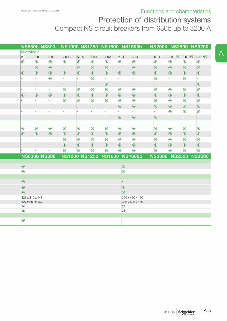
Compact circuit breakers NS630b NS800 NS1000 NS1250 NS1600 NS1600b NS2000 NS2500 NS3200Protection and measurements MicrologicInterchangeable control units 2.0 5.0 6.0 2.0 A 5.0 A 6.0 A 7.0 A 2.0 E 5.0 E 6.0 E 5.0 P [1] 6.0 P [1] 7.0 P [1]
Overload protection long time Ir (In x …)
Short-circuit protection short time Isd (Ir x …) - - -
instantaneous Ii (In x …)
Earth-fault protection lg (In x …) - - - - - - - - -
Residual earth-leakage protection I∆n - - - - - - - - - - -
Zone selective interlocking ZSI - - -
Protection of the fourth pole
Current measurements - - -
Power measurements - - - - - - -
Advanced protection - - - - - - - - - -
Quick view - - - - - - - - - -
Remote communication by busDevice-status indication
Device remote operation [2]
Transmission of settings - - -
Indication and identification of protection devices and alarms - - -
Transmission of measured current values - - -
Compact circuit breakers NS630b NS800 NS1000 NS1250 NS1600 NS1600b NS2000 NS2500 NS3200Additional indication and control auxiliariesIndication contacts
Voltage releases MX shunt release/MN undervoltage release
InstallationAccessories terminal extensions and spreaders -
terminal shields and interphase barriers
escutcheons
Dimensions fixed devices, front connections (mm) 3P 327 x 210 x 147 350 x 420 x 160H x W x D 4P 327 x 280 x 147 350 x 535 x 160Weight fixed devices, front connections (kg) 3P 14 24
4P 18 36Source changeover system (see section on "source changeover systems")Manual, remote-operated and automatic source changeover systems
-
[1] Except 1600b-3200.[2] With NS630b...NS1600, remote operation is possible with electrically operated device.
With NS1600...NS3200, remote operation is not possible.
Protection of distribution systemsCompact NS circuit breakers from 630b up to 3200 A
Electrically operated device.
PB10
4831
_ME.
eps
A
A-5
www.schneider-electric.com Functions and characteristics
ACompact circuit breakers NS630b NS800 NS1000 NS1250 NS1600 NS1600b NS2000 NS2500 NS3200Protection and measurements MicrologicInterchangeable control units 2.0 5.0 6.0 2.0 A 5.0 A 6.0 A 7.0 A 2.0 E 5.0 E 6.0 E 5.0 P [1] 6.0 P [1] 7.0 P [1]
Overload protection long time Ir (In x …)
Short-circuit protection short time Isd (Ir x …) - - -
instantaneous Ii (In x …)
Earth-fault protection lg (In x …) - - - - - - - - -
Residual earth-leakage protection I∆n - - - - - - - - - - -
Zone selective interlocking ZSI - - -
Protection of the fourth pole
Current measurements - - -
Power measurements - - - - - - -
Advanced protection - - - - - - - - - -
Quick view - - - - - - - - - -
Remote communication by busDevice-status indication
Device remote operation [2]
Transmission of settings - - -
Indication and identification of protection devices and alarms - - -
Transmission of measured current values - - -
Compact circuit breakers NS630b NS800 NS1000 NS1250 NS1600 NS1600b NS2000 NS2500 NS3200Additional indication and control auxiliariesIndication contacts
Voltage releases MX shunt release/MN undervoltage release
InstallationAccessories terminal extensions and spreaders -
terminal shields and interphase barriers
escutcheons
Dimensions fixed devices, front connections (mm) 3P 327 x 210 x 147 350 x 420 x 160H x W x D 4P 327 x 280 x 147 350 x 535 x 160Weight fixed devices, front connections (kg) 3P 14 24
4P 18 36Source changeover system (see section on "source changeover systems")Manual, remote-operated and automatic source changeover systems
-
[1] Except 1600b-3200.[2] With NS630b...NS1600, remote operation is possible with electrically operated device.
With NS1600...NS3200, remote operation is not possible.
Protection of distribution systemsCompact NS circuit breakers from 630b up to 3200 A
A-6
www.schneider-electric.comFunctions and characteristics
DependabilityIntegration of protection functions in an ASIC electronic component used in all Micrologic control units guarantees a high degree of reliability and immunity to conducted or radiated disturbances.On Micrologic A, E and P control units, advanced functions are managed by an independent microprocessor.
AccessoriesCertain functions require the addition of Micrologic control unit accessories, described on page A-28.The rules governing the various possible combinations can be found in the documentation accessible via the Products and services menu of the www.schneider-electric.com web site.
Micrologic without measurement
Measurements and programmable protection
A: ammeter b I1, I2, I3, IN, Iearth-fault, Iearth-leakage and maximeter for these measurements b fault indications b settings in amperes and in seconds.
E: Energy b incorporates all the rms
measurements of Micrologic A, plus voltage, power factor, power and energy metering measurements.
v calculates the current demand value
v "Quickview" function for the automatic cyclical display of the most useful values (as standard or by selection).
P: A + power meter + programmable protection b measurements of V, A, W, VAR, VA, Wh, VARh, VAh,
Hz, Vpeak, Apeak, power factor and maximeters and minimeters
b IDMTL long-time protection, minimum and maximum voltage and frequency, voltage and current imbalance, phase sequence, reverse power
b load shedding and reconnection depending on power or current
b measurements of interrupted currents, differentiated fault indications, maintenance indications, event histories and time-stamping, etc.
Micrologic name codes Current protectionMicrologic 2: basic protection
2.0 EX Y Z
DB1
2802
4.ep
s
Protection:long time + instantaneous
2.0 Micrologic 2.0
.4.5.6
.7.8
.9.95.98
1
x Ir
22.5
3 4 56
8101.5
setting
Isd
.512
48
121620
instantaneous
long timealarmIr tr
(s)
x In at 6 Ir24
DB1
2837
2.ep
s
2.0 A Micrologic 2.0 A
40
100%
%
menu
long timealarm
instantaneous
.4.5.6
.7.8
.9.95.98
1
Ir
x In .512
48
121620
tr(s)
at 6 Ir24
x Ir
22.5
3 45
6
1.5
setting
Isd
810
DB1
2829
0.ep
s
2.0 E Micrologic 2.0 E
40
100%
%
menu
long timealarm
instantaneous
.4.5.6
.7.8
.9.95.98
1
Ir
x In .512
48
121620
tr(s)
at 6 Ir24
x Ir
22.5
3 45
6
1.5
setting
Isd
810
DB1
2830
2.ep
s
X: type of protection b 2 for basic protection b 5 for selective protection b 6 for selective + earth-fault protection b 7 for selective + earth-leakage protection.
Y: control-unit generationIdentification of the control-unit generation.“0” signifies the first generation.Z: type of measurement
b A for “ammeter” b E for “energy” b P for “power meter”
Micrologic 5: selective protection
DB1
2802
5.ep
s
Protection: long time + short time + instantaneous
5.0 Micrologic 5.0
setting delay
short timeI itsd
(s)
long timealarm
x In
34
68
101215
off2
.4.5.6
.7.8
.9.95.98
1
Ir
x In
x Ir
22.5
34 5
68
10
Isd
1.5
.512
48
121620
tr(s)
at 6 Ir24
on I2t
.2
.3.4 .4
.1
.2.3
.10
instantaneous
DB1
2837
4.ep
s
5.0 A Micrologic 5.0 A
40
100%
%
menu
delay
short timetsd(s)
long timealarmtr
(s)
setting
.4.5.6
.7.8
.9.95.98
1
Ir
x In .512
4 8 121620
at 6 Ir24
x Ir
22.5
3 4 568
10
Isd
1.5on I2t
.2
.4 .4
.1
.3
.10
I i
x In
3
4
8
off2
.3
instantaneous
.26
15
1012
DB1
2829
9.ep
s
5.0 E Micrologic 5.0 E
40
100%
%
delay
short timetsd(s)
long timealarmtr
(s)
setting
.4.5.6
.7.8
.9.95.98
1
Ir
x In .512
4 8 121620
at 6 Ir24
x Ir
22.5
3 4 568
10
Isd
1.5on I2t
.2
.4 .4
.1
.3
.10
I i
x In
3
4
8
off2
.3
instantaneous
.26
15
1012
menu
DB1
2830
6.ep
s
5.0 P Micrologic 5.0 P
delaysettingx Ir
22.5
34 5
68
10
Isd
1.5
.4.5.6
.7.8
.9.95.98
1
short timeI itsd
(s)
on I2t
.2
.3.4 .4
.1
.2.3
.10off
instantaneous
long timealarmIr
x In .512
48
121620
tr(s)
@ 6 Ir24
x In
test
2
410
3
6 8
1215
off
4260AN 1 2 3
100
50
0
DB1
2830
8.ep
s
PB10
0772
R-3
2.ep
s
PB10
6351
A32.
eps
Micrologic 6: selective + earth-fault protection
DB1
2802
5.ep
s
DB1
2802
7.ep
s
Protection: long time + short time + instantaneous + earth fault
6.0 Micrologic 6.0
delay
short time
on I2t
.2
.3.4 .4
.1
.2
.10
long timealarm
ground fault
setting
4
test
.4.5.6
.7.8
.9.95.98
1
Ir
x In .512
48
121620
tr(s)
at 6 Ir24
x Ir
22.5
3 4 568
10
Isd
1.5
tsd(s)
x In
3
68 10
1215
off2
BC
D E FGH
I
Ig
Aon I
2t
.2
.3.4 .4
.1
.2.3
.10off
tg(s)
.1
.3instantaneous
I i
DB1
2828
6.ep
s
6.0 A Micrologic 6.0 A
40
100%
%
menu
delay
short time
on I2t
.2
.3.4 .4
.1
.2
.10
long timealarm
ground fault
setting
4
test
.4.5.6
.7.8
.9.95.98
1
Ir
x In .512
48
121620
tr(s)
at 6 Ir24
x Ir
22.5
3 4 568
10
Isd
1.5
tsd(s)
x In
3
68 10
1215
off2
BC
D E FGH
I
Ig
Aon I
2t
.2
.3.4 .4
.1
.2.3
.10off
tg(s)
.1
.3instantaneous
I i
DB1
2830
0.ep
s
6.0 E Micrologic 6.0 E
40
100%
%
delay
short time
on I2t
.2
.3.4 .4
.1
.2
.10
long timealarm
ground fault
setting
4
test
.4.5.6
.7.8
.9.95.98
1
Ir
x In .512
48
121620
tr(s)
at 6 Ir24
x Ir
22.5
3 4 568
10
Isd
1.5
tsd(s)
x In
3
68 10
1215
off2
BC
D E FGH
I
Ig
Aon I2t
.2
.3.4 .4
.1
.2.3
.10off
tg(s)
.1
.3instantaneous
I i
menu
DB1
2830
7.ep
s
6.0 P Micrologic 6.0 P
.4.5.6
.7.8
.9.95.98
1
delay
short timeI itsd
(s)
on I2t
.2
.3.4 .4
.1
.2.3
.10off
instantaneous
long timealarmIr
x In
ground fault
BC
DE F
GH
J
Ig tg(s)
on I2t
.2
.3.4 .4
.1
.2.3
.10off
A
settingx Ir
22.5
3 4 568
10
Isd
1.5
.512
48
121620
tr(s)
@ 6 Ir24
x In
test
2
410
3
6 8
1215
off
4260AN 1 2 3
100
50
0
DB1
2830
9.ep
s
Micrologic 7: selective + earth-leakage
DB1
2802
5.ep
s
DB1
2804
5.ep
s
Protection: long time + short time + instantaneous + earth leakage up to 3200A
7.0 A Micrologic 7.0 A
40
100%
%
menu
.98
delay
short time
off
long timealarm
setting
earth leakage
test
.4.5.6
.7.8
.9.95
1
Ir
x In
tr(s)
.512
48
121620
at 6 Ir24
x Ir
22.5
34 5
68
10
Isd
1.5
tsd(s)
on I2t
.2
.3.4 .4
.1
.2.3
.10
x In
34
6 8 1012
15off2
12
35 7
1020
30.5
I∆n
800
∆I
60
140
230 350
instantaneousI i
DB1
2830
1.ep
s
7.0 P Micrologic 7.0 P
.4.5.6
.7.8
.9.95.98
1
delay
short timeI itsd
(s)
on I2t
.2
.3.4 .4
.1
.2.3
.10off
instantaneous
long timealarmIr
x In
settingx Ir
22.5
34 5
68
10
Isd
1.5
.512
48
121620
tr(s)
@ 6 Ir24
800
earth leakage
12
35 7
1020
30
∆t(ms)
60.5
140
230 350
I∆n(A)
x In
test
2
410
3
6 8
12
15off
4260AN 1 2 3
100
50
0
DB1
2832
1.ep
s
Micrologic control units Overview of functions
All Compact circuit breakers are equipped with a Micrologic control unit that can be changed on site.Control units are designed to protect Power circuits and loads. Alarms may be programmed for remote indications.Measurements of current, voltage, frequency, power and power quality optimise continuity of service and energy management.
A

A-7
www.schneider-electric.com Functions and characteristics
A
DependabilityIntegration of protection functions in an ASIC electronic component used in all Micrologic control units guarantees a high degree of reliability and immunity to conducted or radiated disturbances.On Micrologic A, E and P control units, advanced functions are managed by an independent microprocessor.
AccessoriesCertain functions require the addition of Micrologic control unit accessories, described on page A-28.The rules governing the various possible combinations can be found in the documentation accessible via the Products and services menu of the www.schneider-electric.com web site.
Micrologic without measurement
Measurements and programmable protection
A: ammeter b I1, I2, I3, IN, Iearth-fault, Iearth-leakage and maximeter for these measurements b fault indications b settings in amperes and in seconds.
E: Energy b incorporates all the rms
measurements of Micrologic A, plus voltage, power factor, power and energy metering measurements.
v calculates the current demand value
v "Quickview" function for the automatic cyclical display of the most useful values (as standard or by selection).
P: A + power meter + programmable protection b measurements of V, A, W, VAR, VA, Wh, VARh, VAh,
Hz, Vpeak, Apeak, power factor and maximeters and minimeters
b IDMTL long-time protection, minimum and maximum voltage and frequency, voltage and current imbalance, phase sequence, reverse power
b load shedding and reconnection depending on power or current
b measurements of interrupted currents, differentiated fault indications, maintenance indications, event histories and time-stamping, etc.
Micrologic name codes Current protectionMicrologic 2: basic protection
2.0 EX Y Z
DB1
2802
4.ep
s
Protection:long time + instantaneous
2.0 Micrologic 2.0
.4.5.6
.7.8
.9.95.98
1
x Ir
22.5
3 4 56
8101.5
setting
Isd
.512
48
121620
instantaneous
long timealarmIr tr
(s)
x In at 6 Ir24
DB1
2837
2.ep
s
2.0 A Micrologic 2.0 A
40
100%
%
menu
long timealarm
instantaneous
.4.5.6
.7.8
.9.95.98
1
Ir
x In .512
48
121620
tr(s)
at 6 Ir24
x Ir
22.5
3 45
6
1.5
setting
Isd
810
DB1
2829
0.ep
s
2.0 E Micrologic 2.0 E
40
100%
%
menu
long timealarm
instantaneous
.4.5.6
.7.8
.9.95.98
1
Ir
x In .512
48
121620
tr(s)
at 6 Ir24
x Ir
22.5
3 45
6
1.5
setting
Isd
810
DB1
2830
2.ep
s
X: type of protection b 2 for basic protection b 5 for selective protection b 6 for selective + earth-fault protection b 7 for selective + earth-leakage protection.
Y: control-unit generationIdentification of the control-unit generation.“0” signifies the first generation.Z: type of measurement
b A for “ammeter” b E for “energy” b P for “power meter”
Micrologic 5: selective protection
DB1
2802
5.ep
s
Protection: long time + short time + instantaneous
5.0 Micrologic 5.0
setting delay
short timeI itsd
(s)
long timealarm
x In
34
68
101215
off2
.4.5.6
.7.8
.9.95.98
1
Ir
x In
x Ir
22.5
34 5
68
10
Isd
1.5
.512
48
121620
tr(s)
at 6 Ir24
on I2t
.2
.3.4 .4
.1
.2.3
.10
instantaneous
DB1
2837
4.ep
s
5.0 A Micrologic 5.0 A
40
100%
%
menu
delay
short timetsd(s)
long timealarmtr
(s)
setting
.4.5.6
.7.8
.9.95.98
1
Ir
x In .512
4 8 121620
at 6 Ir24
x Ir
22.5
3 4 568
10
Isd
1.5on I2t
.2
.4 .4
.1
.3
.10
I i
x In
3
4
8
off2
.3
instantaneous
.26
15
1012
DB1
2829
9.ep
s
5.0 E Micrologic 5.0 E
40
100%
%
delay
short timetsd(s)
long timealarmtr
(s)
setting
.4.5.6
.7.8
.9.95.98
1
Ir
x In .512
4 8 121620
at 6 Ir24
x Ir
22.5
3 4 568
10
Isd
1.5on I2t
.2
.4 .4
.1
.3
.10
I i
x In
3
4
8
off2
.3
instantaneous
.26
15
1012
menu
DB1
2830
6.ep
s
5.0 P Micrologic 5.0 P
delaysettingx Ir
22.5
34 5
68
10
Isd
1.5
.4.5.6
.7.8
.9.95.98
1
short timeI itsd
(s)
on I2t
.2
.3.4 .4
.1
.2.3
.10off
instantaneous
long timealarmIr
x In .512
48
121620
tr(s)
@ 6 Ir24
x In
test
2
410
3
6 8
1215
off
4260AN 1 2 3
100
50
0
DB1
2830
8.ep
s
PB10
0772
R-3
2.ep
s
PB10
6351
A32.
eps
Micrologic 6: selective + earth-fault protection
DB1
2802
5.ep
s
DB1
2802
7.ep
s
Protection: long time + short time + instantaneous + earth fault
6.0 Micrologic 6.0
delay
short time
on I2t
.2
.3.4 .4
.1
.2
.10
long timealarm
ground fault
setting
4
test
.4.5.6
.7.8
.9.95.98
1
Ir
x In .512
48
121620
tr(s)
at 6 Ir24
x Ir
22.5
3 4 568
10
Isd
1.5
tsd(s)
x In
3
68 10
1215
off2
BC
D E FGH
I
Ig
Aon I
2t
.2
.3.4 .4
.1
.2.3
.10off
tg(s)
.1
.3instantaneous
I i
DB1
2828
6.ep
s
6.0 A Micrologic 6.0 A
40
100%
%
menu
delay
short time
on I2t
.2
.3.4 .4
.1
.2
.10
long timealarm
ground fault
setting
4
test
.4.5.6
.7.8
.9.95.98
1
Ir
x In .512
48
121620
tr(s)
at 6 Ir24
x Ir
22.5
3 4 568
10
Isd
1.5
tsd(s)
x In
3
68 10
1215
off2
BC
D E FGH
I
Ig
Aon I
2t
.2
.3.4 .4
.1
.2.3
.10off
tg(s)
.1
.3instantaneous
I i
DB1
2830
0.ep
s
6.0 E Micrologic 6.0 E
40
100%
%
delay
short time
on I2t
.2
.3.4 .4
.1
.2
.10
long timealarm
ground fault
setting
4
test
.4.5.6
.7.8
.9.95.98
1
Ir
x In .512
48
121620
tr(s)
at 6 Ir24
x Ir
22.5
3 4 568
10
Isd
1.5
tsd(s)
x In
3
68 10
1215
off2
BC
D E FGH
I
Ig
Aon I2t
.2
.3.4 .4
.1
.2.3
.10off
tg(s)
.1
.3instantaneous
I i
menu
DB1
2830
7.ep
s
6.0 P Micrologic 6.0 P
.4.5.6
.7.8
.9.95.98
1
delay
short timeI itsd
(s)
on I2t
.2
.3.4 .4
.1
.2.3
.10off
instantaneous
long timealarmIr
x In
ground fault
BC
DE F
GH
J
Ig tg(s)
on I2t
.2
.3.4 .4
.1
.2.3
.10off
A
settingx Ir
22.5
3 4 568
10
Isd
1.5
.512
48
121620
tr(s)
@ 6 Ir24
x In
test
2
410
3
6 8
1215
off
4260AN 1 2 3
100
50
0
DB1
2830
9.ep
s
Micrologic 7: selective + earth-leakage
DB1
2802
5.ep
s
DB1
2804
5.ep
s
Protection: long time + short time + instantaneous + earth leakage up to 3200A
7.0 A Micrologic 7.0 A
40
100%
%
menu
.98
delay
short time
off
long timealarm
setting
earth leakage
test
.4.5.6
.7.8
.9.95
1
Ir
x In
tr(s)
.512
48
121620
at 6 Ir24
x Ir
22.5
34 5
68
10
Isd
1.5
tsd(s)
on I2t
.2
.3.4 .4
.1
.2.3
.10
x In
34
6 8 1012
15off2
12
35 7
1020
30.5
I∆n
800
∆I
60
140
230 350
instantaneousI i
DB1
2830
1.ep
s
7.0 P Micrologic 7.0 P
.4.5.6
.7.8
.9.95.98
1
delay
short timeI itsd
(s)
on I2t
.2
.3.4 .4
.1
.2.3
.10off
instantaneous
long timealarmIr
x In
settingx Ir
22.5
34 5
68
10
Isd
1.5
.512
48
121620
tr(s)
@ 6 Ir24
800
earth leakage
12
35 7
1020
30
∆t(ms)
60.5
140
230 350
I∆n(A)
x In
test
2
410
3
6 8
12
15off
4260AN 1 2 3
100
50
0
DB1
2832
1.ep
s
Micrologic control units Overview of functions
A-8
www.schneider-electric.comFunctions and characteristics
Micrologic control unitsFor Compact NS630b to 3200
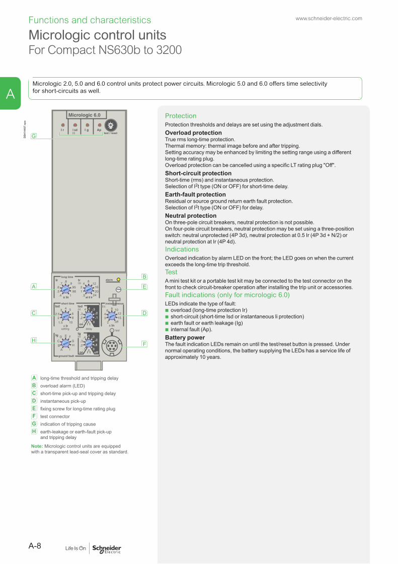
Micrologic 2.0, 5.0 and 6.0 control units protect power circuits. Micrologic 5.0 and 6.0 offers time selectivity for short-circuits as well.
ProtectionProtection thresholds and delays are set using the adjustment dials.Overload protectionTrue rms long-time protection.Thermal memory: thermal image before and after tripping.Setting accuracy may be enhanced by limiting the setting range using a different long-time rating plug.Overload protection can be cancelled using a specific LT rating plug "Off".Short-circuit protectionShort-time (rms) and instantaneous protection.Selection of I2t type (ON or OFF) for short-time delay.Earth-fault protectionResidual or source ground return earth fault protection.Selection of I2t type (ON or OFF) for delay.Neutral protectionOn three-pole circuit breakers, neutral protection is not possible.On four-pole circuit breakers, neutral protection may be set using a three-position switch: neutral unprotected (4P 3d), neutral protection at 0.5 Ir (4P 3d + N/2) or neutral protection at Ir (4P 4d).IndicationsOverload indication by alarm LED on the front; the LED goes on when the current exceeds the long-time trip threshold.TestA mini test kit or a portable test kit may be connected to the test connector on the front to check circuit-breaker operation after installing the trip unit or accessories.Fault indications (only for micrologic 6.0)LEDs indicate the type of fault:
b overload (long-time protection Ir) b short-circuit (short-time Isd or instantaneous li protection) b earth fault or earth leakage (Ig) b internal fault (Ap).
Battery powerThe fault indication LEDs remain on until the test/reset button is pressed. Under normal operating conditions, the battery supplying the LEDs has a service life of approximately 10 years.
Micrologic 6.0
delay
short time
on I2t
.2
.3.4 .4
.1
.2
.10
long timealarm
ground fault
setting
4
test
.4.5.6
.7.8
.9.95.98
1
Ir
x In .512
48
121620
tr(s)
at 6 Ir24
x Ir
22.5
3 4 568
10
Isd
1.5
tsd(s)
x In
3
68 10
1215
off2
BC
D E FGH
I
Ig
Aon I
2t
.2
.3.4 .4
.1
.2.3
.10off
tg(s)
.1
.3instantaneous
I i
A
C
H
G
B
E
D
F
DB4
1448
7.ep
s
A long-time threshold and tripping delayB overload alarm (LED)C short-time pick-up and tripping delayD instantaneous pick-upE fixing screw for long-time rating plugF test connectorG indication of tripping causeH earth-leakage or earth-fault pick-up
and tripping delay
Note: Micrologic control units are equipped with a transparent lead-seal cover as standard.
A
A-9
www.schneider-electric.com Functions and characteristics
A
Micrologic control unitsFor Compact NS630b to 3200
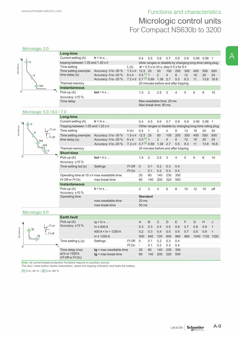
Micrologic 2.0Long-time
DB4
1908
8.ep
s
Current setting (A) Ir = In x … 0.4 0.5 0.6 0.7 0.8 0.9 0.95 0.98 1tripping between 1.05 and 1.20 x Ir other ranges or disable by changing long-time rating plugTime setting tr (s) tr = 0.5 s to 24 s, step 0.5 s for 6 IrTime setting exemple: time delay (s)
Accuracy: 0 to -30 % 1.5 x Ir 12.5 25 50 100 200 300 400 500 600Accuracy: 0 to -20 % 6 x Ir 0.5 [1] 1 2 4 8 12 16 20 24Accuracy: 0 to -20 % 7.2 x Ir 0.7 [2] 0.69 1.38 2.7 5.5 8.3 11 13.8 16.6
Thermal memory 20 minutes before and after trippingInstantaneousPick-up (A) Isd = Ir x … 1.5 2 2.5 3 4 5 6 8 10Accuracy: ±10 %Time delay Max resettable time: 20 ms
Max break time: 80 ms
Micrologic 5.0 / 6.0 / 7.0Long-time
DB4
1908
9.ep
s
Current setting (A) Ir = In x … 0.4 0.5 0.6 0.7 0.8 0.9 0.95 0.98 1Tripping between 1.05 and 1.20 x Ir Other ranges or disable by changing long-time rating plug Time setting tr (s) 0.5 1 2 4 8 12 16 20 24Time setting exemple: Accuracy: 0 to -30 % 1.5 x Ir 12.5 25 50 100 200 300 400 500 600time delay (s) Accuracy: 0 to -20 % 6 x Ir 0.5 [1] 1 2 4 8 12 16 20 24
Accuracy: 0 to -20 % 7.2 x Ir 0.7 [2] 0.69 1.38 2.7 5.5 8.3 11 13.8 16.6Thermal memory 20 minutes before and after trippingShort-timePick-up (A) Isd = Ir x … 1.5 2 2.5 3 4 5 6 8 10Accuracy: ±10 %Time setting tsd (s) Settings I2t Off 0 0.1 0.2 0.3 0.4
I2t On - 0.1 0.2 0.3 0.4Operating time at 10 x Ir max resettable time 20 80 140 230 350I2t Off or I2t On max break time 80 140 200 320 500InstantaneousPick-up (A)Accuracy: ±10 %
Ii = In x … 2 3 4 6 8 10 12 15 off
Operating time Standardmax resettable time 20 msmax break time 50 ms
Micrologic 6.0 Earth fault
DB4
1909
0.ep
s
Pick-up (A)Accuracy: ±10 %
Ig = In x … A B C D E F G H JIn y 400 A 0.3 0.3 0.4 0.5 0.6 0.7 0.8 0.9 1400 A < In < 1250 A 0.2 0.3 0.4 0.5 0.6 0.7 0.8 0.9 1In u 1250 A 500 640 720 800 880 960 1040 1120 1200
Time setting tg (s) Settings I2t Off 0 0.1 0.2 0.3 0.4I2t On - 0.1 0.2 0.3 0.4
Time delay (ms) at In or 1200 A (I2t Off or I2t On)
tg = max resettable time 20 80 140 230 350tg = max break time 80 140 200 320 500
Note: all current-based protection functions require no auxiliary source. The test / reset button resets maximeters, clears the tripping indication and tests the battery.
[1] 0 to -40 % - [2] 0 to -60 %

A-10
www.schneider-electric.comFunctions and characteristics
Micrologic control unitsMicrologic A "ammeter"
Micrologic A control units protect power circuits. They also offer measurements, display, communication and current maximeters. Version 6 provides earth-fault protection, version 7 provides earth-leakage protection.
"Ammeter" measurementsMicrologic A control units measure the true (rms) value of currents.They provide continuous current measurements from 0.2 to 1.2 In and are accurate to within 1.5 % (including the sensors).A digital LCD screen continuously displays the most heavily loaded phase (Imax) or displays the I1, I2, I3, IN, Ig,I∆n, stored-current (maximeter) and setting values by successively pressing the navigation button.The optional external power supply makes it possible to display currents < 20 % In.Below 0.1 In, measurements are not significant. Between 0.1and 0.2 In, accuracy changes linearly from 4 % to 1.5 %.Communication option (COM)In conjunction with the communication option, the control unit transmits the following:
b settings b all "ammeter" measurements b tripping causes b maximeter readings.
ProtectionProtection thresholds and delays are set using the adjustment dials.Overload protectionTrue rms long-time protection.Thermal memory: thermal image before and after tripping.Setting accuracy may be enhanced by limiting the setting range using a different long-time rating plug.Overload protection can be cancelled using a specific LT rating plug "Off".Short-circuit protectionShort-time (rms) and instantaneous protection.Selection of I2t type (ON or OFF) for short-time delay.Earth-fault protectionResidual or source ground return earth fault protection.Selection of I2t type (ON or OFF) for delay.Residual earth-leakage protection (Vigi).Operation without an external power supply. q Protected against nuisance tripping. k DC-component withstand class A up to 10 A.Neutral protectionOn three-pole circuit breakers, neutral protection is not possible.On four-pole circuit breakers, neutral protection may be set using a three-position switch: neutral unprotected (4P 3d), neutral protection at 0.5 Ir (4P 3d + N/2), neutral protection at Ir (4P 4d).Zone selective interlocking (ZSI)A ZSI terminal block may be used to interconnect a number of control units to provide total selectivity for short-time and earth-fault protection, without a delay before tripping.Overload alarmA yellow alarm LED goes on when the current exceeds the long-time trip threshold.Fault indicationsLEDs indicate the type of fault:
b overload (long-time protection Ir) b short-circuit (short-time Isd or instantaneous li protection) b earth fault or earth leakage (Ig or I∆n) b internal fault (Ap).
Battery powerThe fault indication LEDs remain on until the test/reset button is pressed. Under normal operating conditions, the battery supplying the LEDs has a service life of approximately 10 years.TestA mini test kit or a portable test kit may be connected to the test connector on the front to check circuit-breaker operation. For Micrologic 6.0 A and 7.0 A control units, the operation of earth-fault or earth-leakage protection can be checked by pressing the test button located above the test connector.
A
C
E
J
I
K
L
B
G
D
F
H
M
DB1
2803
3.ep
s
A long-time threshold and tripping delayB overload alarm (LED) at 1.125 IrC short-time pick-up and tripping delayD instantaneous pick-upE earth-leakage or earth-fault pick-up and tripping delayF earth-leakage or earth-fault test buttonG long-time rating plug screwH test connectorI lamp test, reset and battery testJ indication of tripping causeK digital displayL three-phase bargraph and ammeterM navigation buttons
Note: Micrologic A control units come with a transparent lead-seal cover as standard.
A

A-11
www.schneider-electric.com Functions and characteristics
A
Micrologic control unitsMicrologic A "ammeter"
Micrologic 2.0 ALong-time ANSI Code 49
DB4
1908
8.ep
s
Current setting (A) Ir = In x … 0.4 0.5 0.6 0.7 0.8 0.9 0.95 0.98 1Other ranges or disable by changing long-time rating plug
Time setting exemple: time delay (s)
tr (s) 0.5 1 2 4 8 12 16 20 24Accuracy: 0 to -30 % 1.5 x Ir 12.5 25 50 100 200 300 400 500 600Accuracy: 0 to -20 % 6 x Ir 0.7[1] 1 2 4 8 12 16 20 24Accuracy: 0 to -20 % 7.2 x Ir 0.7[2] 0.69 1.38 2.7 5.5 8.3 11 13.8 16.6
Thermal memory 20 minutes before and after trippingInstantaneous ANSI Code 50Pick-up (A) Isd = Ir x … 1.5 2 2.5 3 4 5 6 8 10Accuracy: ±10 %Time delay Max resettable time: 20 ms
Max break time: 80 msMicrologic 5.0 / 6.0 / 7.0 A
Long-time ANSI Code 49
DB4
1908
9.ep
s
Current setting (A) Ir = In x … 0.4 0.5 0.6 0.7 0.8 0.9 0.95 0.98 1Tripping between 1.05 and 1.20 x Ir Other ranges or disable by changing long-time
rating plug Time setting exemple: time delay (s)
tr (s) 0.5 1 2 4 8 12 16 20 24Accuracy: 0 to -30 % 1.5 x Ir 12.5 25 50 100 200 300 400 500 600Accuracy: 0 to -20 % 6 x Ir 0.7[1] 1 2 4 8 12 16 20 24Accuracy: 0 to -20 % 7.2 x Ir 0.7[2] 0.69 1.38 2.7 5.5 8.3 11 13.8 16.6
Thermal memory 20 minutes before and after trippingShort-time ANSI Code 51Pick-up (A) Isd = Ir x … 1.5 2 2.5 3 4 5 6 8 10Accuracy: ±10 %Time setting tsd (s) Settings I2t Off 0 0.1 0.2 0.3 0.4
I2t On - 0.1 0.2 0.3 0.4Operating time at 10 x Ir tsd (max resettable time) 20 80 140 230 350I2t Off or I2t On tsd (max break time) 80 140 200 320 500Instantaneous ANSI Code 50Pick-up (A)Accuracy: ±10 %
Ii = In x … 2 3 4 6 8 10 12 15 off
Operating time max resettable time 20 msmax break time 50 ms
Micrologic 6.0 AEarth fault ANSI Code 51N
DB4
1909
0.ep
s
Pick-up (A) Ig = In x … A B C D E F G H JAccuracy: ±10 % In y 400 A 0.3 0.3 0.4 0.5 0.6 0.7 0.8 0.9 1
400 A < In < 1250 A 0.2 0.3 0.4 0.5 0.6 0.7 0.8 0.9 1In u 1250 A 500 640 720 800 880 960 1040 1120 1200
Time setting tg (s) Settings I2t Off 0 0.1 0.2 0.3 0.4I2t On - 0.1 0.2 0.3 0.4
Time delay (ms) at In or 1200 A (I2t Off or I2t On)
tg = max resettable time 20 80 140 230 350tg = max break time 80 140 200 320 500
Micrologic 7.0 AResidual earth leakage (Vigi) ANSI Code 51G
DB4
1909
1.ep
s
Sensitivity (A) IΔn 0.5 1 2 3 5 7 10 20 30Accuracy: 0 to -20 % Time delay Δt (ms) Settings 60 140 230 350 800
max resettable time 60 140 230 350 800max break time 140 200 320 500 1000
Micrologic 5.0 / 6.0 / 7.0 AAmmeterInstantaneous currents I1, I2, I3, IN 0.2 x In to 1.2 x In ±1.5 %
Ig (6.0 A) 0.2 x In to In ±10 %IΔn (7.0 A) 0 to 30 A ±1.5 %
Current maximeters of I1, I2, I3, IN 0.2 x In to 1.2 x In ±1.5 %Note: all current-based protection functions require no auxiliary source. The test / reset button resets maximeters, clears the tripping indication and tests the battery.[1] 0 to -40 % - [2] 0 to -60 %

A-12
www.schneider-electric.comFunctions and characteristics
Micrologic control unitsMicrologic E “energy”
Micrologic E control units protect power circuits. They also offer measurements, display, communication and current maximeters. Version 6 provides earth-fault protection.
"Energy meter" measurementsIn addition to the ammeter measurements of Micrologic AMicrologic E control units measure and display:
b current demand b voltages: phase to phase, phase to neutral, average [1] and unbalanced [1]
b instantaneous power: P, Q, S b power factor: PF b power demand: P demand b energy: Ep, Eq [1], Es [1].
Accuracy of active energy Ep is 2 % (including the sensors). The range of measurement is the same as current with Micrologic A, depending of an external power supply module (24 V DC).Communication option (COM)In conjunction with the communication option, the control unit transmits the following:
b settings b all "ammeter" and "energy" measurements b enable connection to FDM128 b tripping causes b maximeter / minimeter readings.
ProtectionProtection thresholds and delays are set using the adjustment dials.Overload protectionTrue rms long-time protection.Thermal memory: thermal image before and after tripping.Setting accuracy may be enhanced by limiting the setting range using a different long-time rating plug. Overload protection can be cancelled using a specific LT rating plug "Off".Short-circuit protectionShort-time (rms) and instantaneous protection. Selection of I2t type (ON or OFF) for short-time delay.Earth-fault protectionResidual or source ground return earth fault protection.Selection of I2t type (ON or OFF) for delay.Neutral protectionOn three-pole circuit breakers, neutral protection is not possible.On four-pole circuit breakers, neutral protection may be set using a three-position switch: neutral unprotected (4P 3d), neutral protection at 0.5 Ir (4P 3d + N/2), neutral protection at Ir (4P 4d).Zone selective interlocking (ZSI)A ZSI terminal block may be used to interconnect a number of control units to provide total selectivity for short-time and earth-fault protection, without a delay before tripping.Overload alarmA yellow alarm LED goes on when the current exceeds the long-time trip threshold.
Fault indicationsLEDs indicate the type of fault:
b overload (long-time protection Ir) b short-circuit (short-time Isd or instantaneous li protection) b earth fault (Ig) b internal fault (Ap).
Trip historyThe trip history displays the list of the last 10 trips. For each trip, the following indications are recorded and displayed:
b the tripping cause: Ir, Isd, li, Ig or Auto-protection (Ap) trips b the date and time of the trip (requires communication option).
Battery powerThe fault indication LEDs remain on until the test/reset button is pressed. Under normal operating conditions, the battery supplying the LEDs has a service life of approximately 10 years.TestA mini test kit or a portable test kit may be connected to the test connector on the front to check circuit-breaker operation. For Micrologic 6.0 E control units, the operation of earth-fault or earth-leakage protection can be checked by pressing the test button located above the test connector.
J
N
O
A
C
E
B
L
K
I
G
D
H
F
M
DB1
2803
8.ep
s
A long-time threshold and tripping delayB overload alarm (LED) at 1.125 IrC short-time pick-up and tripping delayD instantaneous pick-upE earth-leakage or earth-fault pick-up and tripping delayF earth-leakage or earth-fault test buttonG long-time rating plug screwH test connectorI lamp test, reset and battery testJ indication of tripping causeK digital displayL three-phase bargraph and ammeterM navigation button "quick View" (only with Micrologic E)N navigation button to view menu contentsO navigation button to change menu
[1] Display on FDM121 only.
Note: Micrologic E control units come with a transparent lead-seal cover as standard.
A

A-13
www.schneider-electric.com Functions and characteristics
A
Micrologic control unitsMicrologic E “energy”
Micrologic 2.0 ELong-time ANSI Code 49
DB4
1908
8.ep
s
Current setting (A) Ir = In x … 0.4 0.5 0.6 0.7 0.8 0.9 0.95 0.98 1Other ranges or disable by changing long-time rating plug
Time setting exemple: time delay (s)
tr (s) 0.5 1 2 4 8 12 16 20 24Accuracy: 0 to -30 % 1.5 x Ir 12.5 25 50 100 200 300 400 500 600Accuracy: 0 to -20 % 6 x Ir 0.7[1] 1 2 4 8 12 16 20 24Accuracy: 0 to -20 % 7.2 x Ir 0.7[2] 0.69 1.38 2.7 5.5 8.3 11 13.8 16.6
Thermal memory 20 minutes before and after trippingInstantaneous ANSI Code 50Pick-up (A) Isd = Ir x … 1.5 2 2.5 3 4 5 6 8 10Accuracy: ±10 %Time delay Max resettable time: 20 ms
Max break time: 80 ms
Micrologic 5.0 / 6.0 ELong-time ANSI Code 49
DB4
1908
9.ep
s
Current setting (A) Ir = In x … 0.4 0.5 0.6 0.7 0.8 0.9 0.95 0.98 1Tripping between 1.05 and 1.20 x Ir Other ranges or disable by changing long-time
rating plug Time setting exemple: time delay (s)
tr (s) 0.5 1 2 4 8 12 16 20 24Accuracy: 0 to -30 % 1.5 x Ir 12.5 25 50 100 200 300 400 500 600Accuracy: 0 to -20 % 6 x Ir 0.7[1] 1 2 4 8 12 16 20 24Accuracy: 0 to -20 % 7.2 x Ir 0.7[2] 0.69 1.38 2.7 5.5 8.3 11 13.8 16.6
Thermal memory 20 minutes before and after trippingShort-time ANSI Code 51Pick-up (A) Isd = Ir x … 1.5 2 2.5 3 4 5 6 8 10Accuracy: ±10 %Time setting tsd (s) Settings I2t Off 0 0.1 0.2 0.3 0.4
I2t On - 0.1 0.2 0.3 0.4Operating time at 10 x Ir tsd (max resettable time) 20 80 140 230 350I2t Off or I2t On tsd (max break time) 80 140 200 320 500Instantaneous ANSI Code 50Pick-up (A)Accuracy: ±10 %
Ii = In x … 2 3 4 6 8 10 12 15 off
Operating time max resettable time 20 msmax break time 50 ms
Micrologic 6.0 EEarth fault ANSI Code 51N
DB4
1909
0.ep
s
Pick-up (A) Ig = In x … A B C D E F G H JAccuracy: ±10 % In y 400 A 0.3 0.3 0.4 0.5 0.6 0.7 0.8 0.9 1
400 A < In < 1250 A 0.2 0.3 0.4 0.5 0.6 0.7 0.8 0.9 1In u 1250 A 500 640 720 800 880 960 1040 1120 1200
Time setting tg (s) Settings I2t Off 0 0.1 0.2 0.3 0.4I2t On - 0.1 0.2 0.3 0.4
Time delay (ms) at In or 1200 A (I2t Off or I2t On)
tg = max resettable time 20 80 140 230 350tg = max break time 80 140 200 320 500
Micrologic 5.0 / 6.0 / 7.0 EEnergyInstantaneous currents I1, I2, I3, IN 0.2 x In to 1.2 x In ±1.5 %
Ig (6.0 E) 0.2 x In to In ±10 %Current maximeters of I1, I2, I3, IN 0.2 x In to 1.2 x In ±1.5 %Demand currents of I1, I2, I3, Ig
0.2 x In to 1.2 x In ±1.5 %
Voltages V12, V23, V31, V1N, V2N, V3N 100 to 690 V ±0.5 %Active power P 30 to 2000 kW ±2 %Power factor PF 0 to 1 ±2 %Demand power P demand 30 to 2000 kW ±2 %Active energy Ep -1010 GWh to 1010 GWh ±2 %
Note: all current-based protection functions require no auxiliary source. The test / reset button resets maximeters, clears the tripping indication and tests the battery.[1] 0 to -40 % - [2] 0 to -60 %

A-14
www.schneider-electric.comFunctions and characteristics
Micrologic control unitsMicrologic P "power"
Micrologic P control units include all the functions offered by Micrologic A. In addition, they measure voltages and calculate power and energy values. They also offer new protection functions based on currents, voltages, frequency and power reinforce load protection in real time.
ProtectionProtection settings The adjustable protection functions are identical to those of Micrologic A (overloads, short-circuits, earth-fault and earth-leakage protection).Fine adjustmentWithin the range determined by the adjustment dial, fine adjustment of thresholds (to within one ampere) and time delays (to within one second) is possible on the keypad or remotely using the COM option.IDMTL (Inverse Definite Minimum Time Lag) settingCoordination with fuse-type or medium-voltage protection systems is optimised by adjusting the slope of the overload-protection curve. This setting also ensures better operation of this protection function with certain loads.Neutral protectionOn three-pole circuit breakers, neutral protection may be set using the keypad or remotely using the COM option, to one of four positions: neutral unprotected (4P 3d), neutral protection at 0.5 Ir (4P 3d + N/2), neutral protection at Ir (4P 4d) and neutral protection at 1.6 Ir (4P 3d + 1.6N). Neutral protection at 1.6 Ir is used when the neutral conductor is twice the size of the phase conductors (major load imbalance, high level of third order harmonics).On four-pole circuit breakers, neutral protection may be set using a three-position switch or the keypad: neutral unprotected (4P 3d), neutral protection at 0.5 Ir (4P 3d + N/2), neutral protection at Ir (4P 4d). Neutral protection produces no effect if the long-time curve is set to one of the IDMTL protection settings.Programmable alarms and other protectionDepending on the thresholds and time delays set using the keypad or remotely using the COM option, the Micrologic P control unit monitors currents and voltage, power, frequency and the phase sequence. Each threshold overrun is signalled remotely via the COM option. Each threshold overrun may be combined with tripping (protection) or an indication carried out by an optional I/O module (alarm), or both (protection and alarm).Load shedding and reconnectionLoad shedding and reconnection parameters may be set according to the power or the current flowing through the circuit breaker. Load shedding is carried out by a supervisor via the COM option or by I/O application module.Indication option via I/O application moduleI/O application module may be used to signal threshold overruns or status changes. They can be programmed using the COM option (BCM ULP) and Ecoreach software.Communication option (COM)The communication option may be used to:
b remotely read and set parameters for the protection functions b transmit all the calculated indicators and measurements b signal the causes of tripping and alarms b consult the history files and the maintenance-indicator register b maximeter reset.
An event log and a maintenance register, stored in control-unit memory but not available locally, may be accessed in addition via the COM option (BCM ULP).
J
K
I
L
AA
C
E
P
ONNM
B
G
D
F
H
DB1
2804
2.ep
s
A long-time current setting and tripping delayB overload signal (LED)C short-time pick-up and tripping delayD instantaneous pick-upE earth-leakage or earth-fault pick-up and tripping delayF earth-leakage or earth-fault test buttonG long-time rating plug screwH test connectorI lamp + battery test and indications resetJ indication of tripping causeK high-resolution screenL measurement displayM maintenance indicatorsN navigation buttonsO navigation buttonsP hole for settings lockout pin on cover
Note: Micrologic P control units come with a non-transparent lead-seal cover as standard.
A

A-15
www.schneider-electric.com Functions and characteristics
A
Micrologic 5.0 / 6.0 / 7.0 P (Protection)Long-time ANSI Code 49
DB4
2522
1.ep
s
Current setting (A) Ir = In x … 0.4 0.5 0.6 0.7 0.8 0.9 0.95 0.98 1Tripping between 1.05 and 1.20 x Ir Other ranges or disable by changing long-time rating plug Time setting exemple: time delay (s) IDMTL (EIT)
tr (s) 0.5 1 2 4 8 12 16 20 24Accuracy: 0 to -30 % 1.5 x Ir 12.5 25 50 100 200 300 400 500 600Accuracy: 0 to -20 % 6 x Ir 0.7[1] 1 2 4 8 12 16 20 24Accuracy: 0 to -20 % 7.2 x Ir 0.7[2] 0.69 1.38 2.7 5.5 8.3 11 13.8 16.6
IDMTL setting Curve slope SIT VIT EIT HVFuse DTThermal memory 20 minutes before and after trippingShort-time ANSI Code 51Pick-up (A) Isd = Ir x … 1.5 2 2.5 3 4 5 6 8 10Accuracy: ±10 %Time setting tsd (s) Settings I2t Off 0 0.1 0.2 0.3 0.4
I2t On - 0.1 0.2 0.3 0.4Operating time at 10 x Ir tsd (max resettable time) 20 80 140 230 350I2t Off or I2t On tsd (max break time) 80 140 200 320 500Instantaneous ANSI Code 50Pick-up (A)Accuracy: ±10 %
Ii = In x … 2 3 4 6 8 10 12 15 off
Operating time max resettable time 20 msmax break time 50 ms
Micrologic 6.0 P (Protection)Earth fault ANSI Code 51N
DB4
1909
0.ep
s
Pick-up (A) Ig = In x … A B C D E F G H JAccuracy: ±10 % In y 400 A 0.3 0.3 0.4 0.5 0.6 0.7 0.8 0.9 1
400 A < In < 1250 A 0.2 0.3 0.4 0.5 0.6 0.7 0.8 0.9 1In u 1250 A 500 640 720 800 880 960 1040 1120 1200
Time setting tg (s) Settings I2t Off 0 0.1 0.2 0.3 0.4I2t On - 0.1 0.2 0.3 0.4
Time delay (ms) at In or 1200 A (I2t Off or I2t On)
tg = max resettable time 20 80 140 230 350tg = max break time 80 140 200 320 500
Micrologic 7.0 P (Protection)
DB4
1909
1.ep
s
Residual earth leakage (Vigi) ANSI Code 51GSensitivity (A) IΔn 0.5 1 2 3 5 7 10 20 30Accuracy: 0 to -20 % Time delay Δt (ms) Settings 60 140 230 350 800
max resettable time 60 140 230 350 800max break time 140 200 320 500 1000
Micrologic 5.0 / 6.0 / 7.0 P (Alarms and other protection)
DB4
2522
3.ep
s Current ANSI Code 46 Threshold DelayCurrent unbalance Iunbalance 0.05 to 0.6 Iaverage 1 to 40 sMax. demand current Imax demand : I1, I2, I3, IN 0.2 In to In 15 to 1500 sEarth fault alarm
It 10 to 100 % In [3] 1 to 10 sVoltage ANSI CodeVoltage unbalance Uunbalance 47 2 to 30 % x Uaverage 1 to 40 sMinimum voltage Umin 27 100 to Umax between phases 1.2 to 10 sMaximum voltage [4] Umax 59 Umin to 1200 between phases 1.2 to 10 sPower
Reverse power rP 32P 5 to 500 kW 0.2 to 20 sFrequencyMinimum frequency Fmin 81L 45 to Fmax 1.2 to 5 sMaximum frequency Fmax 81H Fmin to 440 Hz 1.2 to 5 sPhase sequenceSequence (alarm) ΔØ Ø1/2/3 or Ø1/3/2 0.3 s
Micrologic 5.0 / 6.0 / 7.0 P (Load shedding and reconnection)
DB4
2522
2.ep
s Measured value Threshold DelayCurrent I 0.5 to 1 Ir per phases 20 % tr to 80 % trPower P 200 kW to 10 MW 10 to 3600 s
Micrologic 5.0 / 6.0 / 7.0 P (Power)Type of measurements Range AccuracyCurrent maximeters of I1, I2, I3, IN 0.2 x In to 1.2 x In ± 1.5 %Volatges V12, V23, V31, V1N, V2N, V3N 100 to 690 V ± 0.5 %Power factor PF 0 to 1 ± 2 %Frequency (Hz) 0.1 %
[1] 0 to -40 % - [2] 0 to -60 % - [3] In y 400 A 30 % 400 A < In < 1250 A 20 % In y 1250 A 10 % - [4] For 690 V applications, a step-down transformer must be used if the voltage exceeds the nominal value of 690 V by more than 10 %.Note: all current-based protection functions require no auxiliary source.Voltage-based protection functions are connected to AC power via a voltage measurement input built into the circuit breaker.

A-16
www.schneider-electric.comFunctions and characteristics
Micrologic control unitsMicrologic P "power"
MeasurementsThe Micrologic P control unit calculates in real time all the electrical values (V, A, W, VAR, VA, Wh, VARh, VAh, Hz), power factors and cosj factors.The Micrologic P control unit also calculates demand current and demand power over an adjustable time period. Each measurement is associated with a minimeter and a maximeter.In the event of tripping on a fault, the interrupted current is stored. The optional external power supply makes it possible to display the value with the circuit breaker open or not supplied.Instantaneous valuesThe value displayed on the screen is refreshed every second. Minimum and maximum values of measurements are stored in memory (minimeters and maximeters).
CurrentsI rms A 1 2 3 N
A E-fault E-leakageI max rms A 1 2 3 N
A E-fault E-leakageVoltages
U rms V 12 23 31V rms V 1N 2N 3NU average rms V (U12 + U23 + U31) / 3U unbalance %Power, energy
P active, Q reactive, S apparent W, Var, VA TotalsE active, E reactive, E apparent Wh, VARh,
VAhTotals consumed - suppliedTotals consumedTotals supplied
Power factor PF TotalFrequencies
F Hz
Demand meteringThe demand is calculated over a fixed or sliding time window that may be programmed from 5 to 60 minutes. According to the contract signed with the power supplier, an indicator associated with a load shedding function makes it possible to avoid or minimise the costs of overrunning the subscribed power. Maximum demand values are systematically stored and time stamped (maximeter).Currents
I demand A 1 2 3 NA E-fault E-leakage
I max demand A 1 2 3 NA E-fault E-leakage
PowerP, Q, S demand W, Var, VA TotalsP, Q, S max demand W, Var, VA Totals
Minimeters and maximetersOnly the current and power maximeters may be displayed on the screen.Time-stampingTime-stamping is activated as soon as time is set manually or by a supervisor.No external power supply module is required (max. drift of 1 hour per year).
ResetAn individual reset, via the keypad or remotely, acts on alarms, minimum and maximum data, peak values, the counters and the indicators.
Additional measurements accessible with the COM option (BCM ULP)Some measured or calculated values are only accessible with the COM communication option:
b I peak / 2, (I1 + I2 + I3)/3, I unbalance b load level in % Ir b total power factor.
The maximeters and minimeters are available only via the COM option (BCM ULP) for use with a supervisor.
Additional infoAccuracy of measurements (including sensors):
b voltage (V) 0.5 % b current (A) 1.5 % b frequency (Hz) 0.1 % b power (W) and energy (Wh) 2 %.
DB1
0113
3.ep
s
Default display.
DB1
0113
4.ep
s
Display of a maximum current.
DB1
0113
3.ep
s
DB1
0113
3.ep
s
Display of a voltage. Display of a power.
DB1
0113
7.ep
s
Display of a frequency.
DB1
0113
8.ep
s
Display of a demand power.
scre
en 2
b.ep
s
PME software.
A

A-17
www.schneider-electric.com Functions and characteristics
A
Micrologic control unitsMicrologic P "power"
Histories and maintenance indicatorsThe last ten trips and alarms are recorded in two separate history files that may be displayed on the screen:
b tripping history: v type of fault v date and time v values measured at the time of tripping (interrupted current, etc.) b alarm history: v type of alarm v date and time v values measured at the time of the alarm.
All the other events are recorded in a third history file which is only accessible through the communication network.
b Event log history (only accessible through the communication network) v modifications to settings and parameters v counter resets v system faults v fallback position v thermal self-protection v loss of time v overrun of wear indicators v test-kit connections v etc.
Note: all the events are time stampled: time-stamping is activated as soon as time is set manually or by a supervisor. No external power supply module is required (max. drift of 1 hour per year).
Maintenance indicators with COM option (BCM ULP)A number of maintenance indicators may be called up on the screen to better plan for device maintenance:
b contact wear b operation counter: v cumulative total v total since last reset.
Additional maintenance indicators are also available through the COM network, and can be used as an aid in troubleshooting:
b highest current measured b number of test-kit connections b number of trips in operating mode and in test mode.
Additional technical characteristicsSafetyMeasurement functions are independent of the protection functions. The high-accuracy measurement module operates independently of the protection module.
Simplicity and multi-languageNavigation from one display to another is intuitive. The six buttons on the keypad provide access to the menus and easy selection of values. When the setting cover is closed, the keypad may no longer be used to access the protection settings, but still provides access to the displays for measurements, histories, indicators, etc.Micrologic is also multi-language, including the following languages: English, Spanish, Portuguese, Russian, Chinese, French, German...
Intelligent measurementMeasurement-calculation mode:
b energies are calculated on the basis of the instantaneous power values, in two manners:
v the traditional mode where only positive (consumed) energies are considered v the signed mode where the positive (consumed) and negative (supplied) energies
are considered separately b measurement functions implement the new “zero blind time” concept which consists
in continuously measuring signals at a high sampling rate. The traditional “blind window” used to process samples no longer exists. This method ensures accurate energy calculations even for highly variable loads (welding machines, robots, etc.).
Always poweredAll current-based protection functions require no auxiliary source. Voltage-based protection functions are connected to AC power via a voltage measurement input built into the circuit breaker.
Stored informationThe fine setting adjustments, the last 100 events and the maintenance register remain in the control-unit memory even when power is lost.
DB1
1704
1.ep
s
Display of a tripping history.
DB1
0114
0.ep
s
Display after tripping.

A-18
www.schneider-electric.comFunctions and characteristics
Power Meter functionsMicrologic A/E/P control unit with COM option (BCM ULP) and COM Ethernet gateway
In addition to protection functions, Micrologic A/E/P control units offer all the functions of Power Meter products as well as operating-assistance for the circuit breaker.
Micrologic A/E/P measurement functions are made possible by Micrologic intelligence and the accuracy of the sensors. They are handled by a microprocessor that operates independent of protection functions.
DisplayFDM121 display unit (one to one)The FDM121 switchboard display unit can be connected to a COM option (BCM ULP) using a breaker ULP cord to display all measurements on a screen [1]. The result is a veritable 96 x 96 mm Power Meter.The FMD121 display unit requires a 24 V DC power supply. The COM option (BCM ULP) unit is supplied by the same power supply via the breaker ULP cord connecting it to the FDM121.[1] See page A-28.
FDM128 display unit (one to eight)Using an IFE Ethernet interface for LV breakers.For all FDM, in addition to the information displayed on the Micrologic LCD, the FDM screen shows demand, power quality and maximeter/minimeter values along with histories and maintenance indicators.
MeasurementsInstantaneous rms measurementsThe Micrologic continuously display the RMS value of the highest current of the three phases and neutral (Imax). The navigation buttons can be used to scroll through the main measurements.In the event of a fault trip, the trip cause is displayed.The Micrologic A measures phase, neutral, ground fault currents.The Micrologic E offers voltage, power, Power Factor, measurements in addition to the measurements provided by Micrologic A.The Micrologic P offer frequency, cos.φ in addition to the measurements provided by Micrologic E.Maximeters / minimetersEvery instantaneous measurement provided by Micrologic A or E can be associated with a maximeter/minimeter. The maximeters for the highest current of the 3 phases and neutral, the demand current and power can be reset via the FDM display unit or the communication system.Energy meteringThe Micrologic E/P also measures the energy consumed since the last reset of the meter. The active energy meter can be reset via Micrologic keypad or the FDM display unit or the communication system.Demand and maximum demand valuesMicrologic E/P also calculates demand current and power values. These calculations can be made using a block or sliding interval that can be set from 5 to 60 minutes in steps of 1 minute. The window can be synchronised with a signal sent via the communication system. Whatever the calculation method, the calculated values can be recovered on a PC via Modbus communication. Ordinary spreadsheet software can be used to provide trend curves and forecasts based on this data. They will provide a basis for load shedding and reconnection operations used to adjust consumption to the subscribed power.
FDM121
Quick viewMeteringControl
OK
ServicesAlarms
Main menu
DB4
3251
6.ep
s
20.12.2011 12:00:05
S1-1 - Lighting/Level1
Quick view
Measures
Alarm history
Control
Maintenance
ESC 1/7
Quick view Open Auto
I1 A000Ir A000
20.12.2011 12:00:05
S1-1 - Lighting/Level1
Measures
Alarm history
Control
Maintenance
ESC 1/7
Quick view Open Auto
I1 A000Ir A000
DB4
1764
0.ep
s
FDM121 display: navigation.
FDM128 display: navigation.
FDM121
179 A
888
I2
I 1/11
186 A
I1
10 A
IN184 A
I3
225 A 225 A
225 A 225 ADB4
3251
7.ep
s
20.12.2011 12:00:05
S1-1 - Lighting/Level1
Quick view
Measures
Alarm history
Control
Maintenance
ESC
I1 AI2 AI3 AIN A
431385426
2
EPQSU-VI
Measures
1/10
I Current
20.12.2011 12:00:05
S1-1 - Lighting/Level1
Quick view
Alarm history
Control
Maintenance
ESC
I1 AI2 AI3 AIN A
431385426
2
EPQSU-VI
Measures
1/10
I CurrentI Current
DB4
1440
0.ep
s
FDM121 display: current.
FDM128 display: current.
FDM121
225 A0I 1/11
I1= 186 A0
I2= 179 A225 A
225 A0I3= 184 A
0IN= 10 A
225 A
DB4
3251
8.ep
s
20.12.2011 12:00:05
S1-1 - Lighting/Level1
Quick view
Measures
Alarm history
Control
Maintenance
ESC
V12 VV23 VV31 V
406415409
1/10
EPQSU-VIVL-LMeasures
20.12.2011 12:00:05
S1-1 - Lighting/Level1
Quick view
Alarm history
Control
Maintenance
ESC
V12 VV23 VV31 V
406415409
1/10
EPQSU-VIVL LVL-LMeasures
DB4
1440
1.ep
s
FDM121 display: voltage.
FDM128 display: voltage.
FDM121
Ptot 109 kW
85 kVAr
138 kVA
Qtot
Stot
P Q S 6/8
DB4
3251
9.ep
s
20.12.2011 12:00:05
S1-1 - Lighting/Level1
Quick view
Measures
Alarm history
Control
Maintenance
ESC
Ptot kWQtot kVAr
12713
Stot kVA129
1/12
EPQSU-VIPQSMeasures
20.12.2011 12:00:05
S1-1 - Lighting/Level1
Quick view
Alarm history
Control
Maintenance
ESC
Ptot kWQtot kVAr
12713
Stot kVA129
1/12
EPQSU-VIPQSPQSMeasures
DB4
1440
2.ep
s
FDM121 display: power.
FDM128 display: power.
FDM121
Ep 15 kwh
12 kVArh
20 kVAh
Eq
Es
Energy 7/8
DB4
3252
0.ep
s
20.12.2011 12:00:05
S1-1 - Lighting/Level1
Quick view
Measures
Alarm history
Control
Maintenance
ESC
EpIn kWhEpOut kWh
16545
EPQSU-VIE cumul
1/3
Measures Reset
20.12.2011 12:00:05
S1-1 - Lighting/Level1
Quick view
Alarm history
Control
Maintenance
ESC
EpIn kWhEpOut kWh
16545
EPQSU-VIE cumulE cumul
1/3
Measures Reset
DB4
1440
3.ep
s
FDM121 display: consumption.
FDM128 display: consumption.
Examples of measurement screens on the FDM121 display unit.
A

A-19
www.schneider-electric.com Functions and characteristics
A
PB10
4842
.eps
PB11
9233
.eps
PB10
6351
A13.
eps
Micrologic A/E/P integrated Power Meter functions Type DisplayA/E P Micrologic
LCDFDM display
Display of protection settingsPick-ups (A) and delays
All settings can be displayed Ir, tr, Isd, tsd, Ii, Ig, tg A/E P -
MeasurementsInstantaneous rms measurementsCurrents (A) Phases and neutral I1, I2, I3, IN A/E P
Average of phases Iavg = (I1 + I2 + I3) / 3 A/E P -Highest current of the 3 phases and neutral
Imax of I1, I2, I3, IN A/E P
Ground fault (Micrologic 6) % Ig (pick-up setting) A/E P
Current unbalance between phases
% Iavg - /E P -
Voltages (V) Phase-to-phase V12, V23, V31 - /E P
Phase-to-neutral V1N, V2N, V3N - /E P
Average of phase-to-phase voltages
Vavg = (V12 + V23 + V31) / 3 - /E P -
Average of phase-to-neutral voltages
Vavg = (V1N + V2N + V3N) / 3
- /E P -
Ph-Ph and Ph-N voltage unbalance
% Vavg and % Vavg - /E P -
Phase sequence 1-2-3, 1-3-2 - / - P [3]
Frequency (Hz) Power system f - / - P
Power Active (kW) P, total - /E P
P, per phase - /E P [2]
Reactive (kVAR) Q, total - /E P
Q, per phase - / - P
Apparent (kVA) S, total - /E P
S, per phase - / - P
Power Factor PF, total - /E P
PF, per phase - / - P
Cos.φ Cos.φ, total - / - P
Cos.φ, per phase - / - P
Maximeters / minimetersAssociated with instantaneous rms measurements
Reset via FDM display unit and Micrologic keypad
A/E P
Energy meteringEnergy Active (kW), reactive (kVARh),
apparent (kVAh)Total since last reset - /E P
Demand and maximum demand valuesDemand current (A)
Phases and neutral Present value on the selected window
- /E P
Maximum demand since last reset
- /E P [2]
Demand power Active (kWh), reactive (kVAR), apparent (kVA)
Present value on the selected window
- /E P
Maximum demand since last reset
- /E P [2]
Calculation window Sliding, fixed or com-synchronised
Adjustable from 5 to 60 minutes in 1 minute steps [1]
- /E P - -
[1] Available via the communication system only.[2] Available for Micrologic P only.[3] FDM121 only.
Power Meter functionsMicrologic A/E/P control unit with COM option (BCM ULP)
and COM Ethernet gateway
PB11
1801
-32_
r_1.
eps
PB10
4831
_ME.
eps

A-20
www.schneider-electric.comFunctions and characteristics
Operating-assistance functionsMicrologic A/E/P control unit with COM option (BCM ULP)
Histories b Trip indications in clear text in a number of user-selectable languages. b Time-stamping: date and time of trip.
Maintenance indicatorsMicrologic control unit have indicators for, among others, the number of operating cycles, contact wear P, load profile and operating times (operating hours counter) of the Masterpact circuit breaker. It is possible to assign an alarm to the operating cycle counter to plan maintenance.The various indicators can be used together with the trip histories to analyse the level of stresses the device has been subjected to.
Management of installed devicesEach circuit breaker equipped with a COM option (BCM ULP) can be identified via the communication system:
b serial number b firmware version b hardware version b device name assigned by the user.
This information together with the previously described indications provides a clear view of the installed devices.
Micrologic A/E/P operating assistance functions Type Display
A/E P Micrologic LCD
FDM121 display
Operating assistanceTrip historyTrips Cause of tripping Ir, Isd, Ii, Ig, IΔn - /E PMaintenance indicatorsCounter Mechanical cycles Assignable
to an alarm A/E P -
Electrical cycles Assignable to an alarm A/E P -
Hours Total operating time (hours) [1] A/E P - -
Indicator Contact wear % - / - P -
Load profile
Hours at different load levels
% of hours in four current ranges: 0-49 % In, 50-79 % In, 80-89 % In and u 90 % In
A /E P -
[1] Also available via the communication system.
Additional technical characteristicsContact wear Each time Compact opens, the Micrologic P trip unit measures the interrupted current and increments the contact-wear indicator as a function of the interrupted current, according to test results stored in memory. Breaking under normal load conditions results in a very slight increment. The indicator value may be read on the FDM121 display. It provides an estimation of contact wear calculated on the basis of the cumulative forces affecting the circuit breaker. When the indicator reaches 100 %, it is advised to inspect the circuit breaker to ensure the availability of the protected equipment.Circuit breaker load profileMicrologic A/E/P calculates the load profile of the circuit breaker protecting a load circuit. The profile indicates the percentage of the total operating time at four current levels (% of breaker In):
b 0 to 49 % In b 50 to 79 % In b 80 to 89 % In b u 90 % In.
This information can be used to optimise use of the protected equipment or to plan ahead for extensions.
A

A-21
www.schneider-electric.com Functions and characteristics
A
Switchboard-display functionsMicrologic A/E/P control unit with COM option (BCM ULP)
Micrologic measurement capabilities come into full play with the FDM121 switchboard display. It connects to COM option (BCM ULP) via a breaker ULP cord and displays Micrologic information. The result is a true integrated unit combining a circuit breaker and a Power Meter. Additional operating assistance functions can also be displayed.
FDM121 switchboard displayAn FDM121 switchboard display unit can be connected to a ULP IMU using a prefabricated cord to display all measurements, alarms, histories and event tables, maintenance indicators, management of installed devices on a screen. The result is a veritable 96 x 96 mm Power Meter. The FMD121 display unit requires a 24 V DC power supply.The FDM121 is a switchboard display unit that can be integrated in the Compact NSX100 to 630 A, Powerpact H/J/L/P/R, Compact NS or Masterpact systems. It uses the sensors and processing capacity of the Micrologic trip unit. It is easy to use and requires no special software or settings. It is immediately operational when connected to the Compact NSX by a simple cord. Also, it provides monitoring and control with the use of the I/O application module, the motor mecanism module, or the Breaker Status module.The FDM121 is a large display, but requires very little depth. The anti-glare graphic screen is backlit for very easy reading even under poor ambient lighting and at sharp angles.Display of Micrologic measurements and alarmsThe FDM121 is intended to display Micrologic 5 / 6 measurements, alarms and operating information. It cannot be used to modify the protection settings. Measurements may be easily accessed via a menu. All user-defined alarms are automatically displayed. The display mode depends on the priority level selected during alarm set-up:
b high priority: a pop-up window displays the time-stamped description of the alarm and the orange LED flashes b medium priority: the orange "Alarm" LED goes steady on b low priority: no display on the screen.
All faults resulting in a trip automatically produce a high-priority alarm, without any special settings required. In all cases, the alarm history is updated. Micrologic saves the information in its non-volatile memory in the event of an FDM121 power failure.Status indications and remote controlWhen the circuit breaker is equipped with the Breaker Status Module, the FDM121 display can also be used to view circuit breaker status conditions:
b O/F: ON/OFF b SD: trip indication b SDE: Fault-trip indication (overload, short-circuit, ground fault).
When the circuit breaker system is equipped with the I/O application module, the FDM121 can monitor and control: b craddle management b circuit breaker operation b light and load control b custom application.
When the circuit breaker system is equipped with the motor mechanism module, the FDM121 offers remote closing and opening control.Main characteristics
b 96 x 96 x 30 mm screen requiring 10 mm behind the door (or 20 mm when the 24 V power supply connector is used). b White backlighting. b Wide viewing angle: vertical ±60°, horizontal ±30°. b High resolution: excellent reading of graphic symbols. b Alarm LED: flashing orange for alarm pick-up, steady orange after operator reset if alarm condition persists. b Operating temperature range -10 °C to +55 °C. b CE / UL / CSA marking (pending). b 24 V DC power supply, with tolerances 24 V -20 % (19.2 V) to 24 V +10 % (26.4 V). When the FDM121 is
connected to the communication network, the 24 V DC can be supplied by the communication system wiring system. b Consumption 40 mA.
MountingThe FDM121 is easily installed in a switchboard.
b Standard door cut-out 92 x 92 mm. b Attached using clips.
To avoid a cut-out in the door, an accessory is available for surface mounting by drilling only two 22 mm diameter holes.The FDM121 degree of protection is IP54 in front. IP54 is maintained after switchboard mounting by using the supplied gasket during installation. ConnectionThe FDM121 is equipped with:
b a 24 V DC terminal block: v plug-in type with 2 wire inputs per point for easy daisy-chaining v power supply range of 24 V DC -20 % (19.2 V) to 24 V DC +10 % (26.4 V).
A 24 V DC type auxiliary power supply must be connected to a single point on the ULP system. The FDM121 display unit has a 2-point screw connector on the rear panel of the module for this purpose. The ULP module to which the auxiliary power supply is connected distributes the supply via the ULP cable to all the ULP modules connected to the system and therefore also to Micrologic.
b two RJ45 jacks.
PB11
9233
.eps
FDM121 display.
PB10
3807
-32.
eps
Surface mount accessory.
PB11
9235
.eps
Connection with FDM121 display unit.

A-22
www.schneider-electric.comFunctions and characteristics
Switchboard-display functionsMicrologic A/E/P control unit with COM option (BCM ULP)
The Micrologic connects to the internal communication terminal block on the Masterpact via the breaker ULP cord. Connection to one of the RJ45 connectors on the FDM121 automatically establishes communication between the Micrologic and the FDM121 and supplies power to the Micrologic measurement functions.When the second connector is not used, it must be fitted with a line terminator.NavigationFive buttons are used for intuitive and fast navigation.The “Context” button may be used to select the type of display (digital, bargraph, analogue).The user can select the display language (Chinese, English, French, German, Italian, Portuguese, Spanish, etc.).ScreensMain menuWhen powered up, the FDM121 screen automatically displays the ON/OFF status of the device.
Quick view Alarms Metering Services Control
When not in use, the screen is not backlit. Backlighting can be activated by pressing one of the buttons. It goes off after 3 minutes.Fast access to essential information
b "Quick view" provides access to five screens that display a summary of essential operating information (I, U, f, P, E, THD, circuit breaker On / Off).Access to detailed information
b "Metering" can be used to display the measurement data (I, U-V, f, P, Q, S, E, THD, PF) with the corresponding min/max values.
b Alarms displays active alarms and the alarm history. b Services provides access to the operation counters, energy and maximeter reset b function, maintenance indicators, identification of modules connected to the internal bus and FDM121 internal
settings (language, contrast, etc.).Communication components and FDM121 connections
DB4
3253
0.ep
sB’ / R
x + D1
A’ / Rx - D
0
B / Tx + D1
A / Tx - D0
0 V
24 V
E1
Red Black Blue
E2 E3 E4 E5 E6
Customer terminal block
White
B’ / Rx + D
1
A’ / Rx - D
0
B / Tx + D1
A / Tx - D0
0 V
24 V
E1
Red Black Blue
E2 E3 E4 E5 E6
Customer terminal block
White
D
E
FC
Test
24 V DC
IFM
Ethernet
LV434002
Enerlin'X IFE
24 V DC
IFE
OR
B
D
E
FC
A
A Modbus networkB Ethernet networkC Breaker ULP cord
D FDM121 displayE ULP terminationF ULP cable
Connections b Compact NS is connected to the ULP devices (FDM121 display, IFM, IFE or I/O application module) unit via the
breaker ULP cord. v cord available in three lengths: 0.35 m, 1.3 m, 3 m and 5 m. v lengths up to 10 m possible using extensions.
FDM121
179 A
888
I2
I 1/11
186 A
I1
10 A
IN184 A
I3
225 A 225 A
225 A 225 A
1 2 3 4 5 6
DB4
3252
1.ep
s
1 escape2 down3 ok4 up5 context6 alarm LED
FDM121
Product ID 2/8
SN 3N114850015TRV00911PN
Version V1.0.9
MaintenanceModule
DB4
3252
2.ep
s
Product identification.
FDM121
Ep 15 kwh
12 kVArh
20 kVAh
Eq
Es
Energy 7/8
DB4
3252
0.ep
s
Metering: meter.FDM121
P Q S
OK
EF PF COS
Metering
V L-L V L-N
DB4
3252
3.ep
s
Metering: sub-menu. FDM121
Load Prole0...49% 19466Hours
50..79% 0Hours
80..89% 0Hours
90.100% 0Hours
DB4
3252
4.ep
s
Services.
A

A-23
www.schneider-electric.com Functions and characteristics
A
Switchboard-display functionsMicrologic A/E/P control unit with COM Ethernet gateway
Micrologic measurement capabilities come into full play with the FDM128 switchboard display. It connects to Ethernet communication via RJ45 port and displays Micrologic information. The result is a true integrated unit combining a circuit breaker and a Power Meter. Additional operating assistance functions can also be displayed.
FDM128 switchboard displayThe FDM128 is an intelligent Ethernet display. It collects the data from up to 8 devices via Ethernet network.The FDM128 switchboard display unit can be connected to a Micrologic COM option (BCM ULP via IFE). It uses the sensors and processing capacity of the Micrologic control unit. It is easy to use and requires no special software or settings. The FDM128 is a large display, but requires very little depth. The anti-glare graphic screen is backlit for very easy reading even under poor ambient lighting and at sharp angles. FDM128 switchboard display is designed to manage up to 8 devices (Masterpact, Compact NS, Compact NSX or Smartlink).Display of Micrologic measurements and tripsThe FDM128 is intended to display Micrologic A/E/P measurements, trips and operating information. It cannot be used to modify the protection settings.Measurements may be easily accessed via a menu. Trips are automatically displayed. A pop-up window displays the time-stamped description of the trip.Status indicationsWhen the circuit breaker is equipped with the Breaker Status Command Module (BSCM) and NSX cord, the FDM128 display can also be used to view circuit breaker status conditions:
b O/F: ON/OFF b SDE: Fault-trip indication (overload, short-circuit, ground fault) b CE, CD, CT cradle management with I/O application module.
Remote controlWhen the circuit breaker is equipped with the COM option (BCM ULP) (including its kit for connection to communication voltage releases), the FDM128 display can also be used to control (open/close) the circuit breaker. Two operating mode are available:
b local mode : open/close commands are enabled from FDM128 while disable from communication network b remote mode : open/close commands are disabled from FDM128 while, enabled from communication network.
Main characteristics b 115.2 x 86.4 mm with 5.7" QVGA display 320 x 240 pixels. b Color TFT LCD, LED backlight. b Wide viewing angle: vertical ±80°, horizontal ±70°. b High resolution: excellent reading of graphic symbols. b Operating temperature range -10 °C to +55 °C. b CE / UL / CSA marking (pending). b 24 V DC power supply, with tolerances 24 V (limit 20.4 - 28.8 V DC). b Consumption y 6.8 W.
MountingThe FDM128 is easily installed in a switchboard.
b Standard door hole Ø 22 mm.The FDM128 degree of protection is IP65 in front and IP54. ConnectionThe FDM128 is equipped with:
b a 24 V DC terminal block: v power supply range of 24 V DC (limit 20.4 - 28.8 V DC). The FDM128 display unit has a 2-point screw
connector on the rear panel of the module for this purpose. b One RJ45 Ethernet jacks.
The Micrologic connects to the internal communication terminal block on the Masterpact via the breaker ULP cord and Ethernet connection through IFE.
PB11
1801
-32_
r.eps
FDM128 display.
PB11
1802
-32_
r.eps
Surface mount accessory.
PB11
1805
-32_
r.eps

A-24
www.schneider-electric.comFunctions and characteristics
Switchboard-display functionsMicrologic A/E/P control unit with COM Ethernet gateway
NavigationTouch screen is used for intuitive and fast navigation. The user can select the display language (Chinese, English, French, German, Italian, Portuguese, Spanish, etc.).ScreensMain menu
Quick view Alarms
Metering Maintenance.
Control
When not in use, the screen is automatically shifted to low back-lighting.Fast access to essential information
b “Quick view” provides access to five screens that display a summary of essential operating information (I, U, f, P, E, THD, circuit breaker On / Off).Access to detailed information
b "Metering" can be used to display the measurement data (I, U-V, f, P, Q, S, E, THD, PF) with the corresponding min/max values.
b Alarms displays the trip history. b Services provides access to the operation counters, energy and maximeter reset
function, maintenance indicators, identification of modules connected to the internal bus and FDM128 internal settings (language, contrast, etc.).
20.12.2011 12:00:05
S1-1 - Lighting/Level1
Quick view
Measures
Alarm history
Control
Maintenance
ESC
Maintenance
3/3
OperationTrip SDEClose command
Product ID Information Reset allCounter
xxxxxxxxx
20.12.2011 12:00:05
S1-1 - Lighting/Level1
Quick view
Measures
Alarm history
Control
ESC
Maintenance
3/3
OperationTrip SDEClose command
Product ID Information Reset allCounterCounter
xxxxxxxxx
DB4
1440
5.ep
s
20.12.2011 12:00:05
S1-1 - Lighting/Level1
Quick view
Measures
Alarm history
Control
Maintenance
ESC
Energy
Ep kWhEq kVArhEs kVAh
11 318257
13 815
6/7
Quick view
20.12.2011 12:00:05
S1-1 - Lighting/Level1
Measures
Alarm history
Control
Maintenance
ESC
Energy
Ep kWhEq kVArhEs kVAh
11 318257
13 815
6/7
Quick viewDB4
1440
7.ep
s
Product identification. Metering: meter.
20.12.2011 12:00:05
S1-1 - Lighting/Level1
Quick view
Measures
Alarm history
Control
Maintenance
ESC
Maintenance
0 to 49%50 to 79%80 to 89%
2/3
90 to 100%
Product ID Information Reset allLoad profile
20.12.2011 12:00:05
S1-1 - Lighting/Level1
Quick view
Measures
Alarm history
Control
ESC
Maintenance
0 to 49%50 to 79%80 to 89%
2/3
90 to 100%
Product ID Information Reset allLoad profileLoad profile
DB4
1440
8.ep
s
Services.
A

A-25
www.schneider-electric.com Functions and characteristics
A
Protection of distribution systemsMicrologic control units for Compact NS630b to 3200
External sensorsExternal sensor for earth-fault and neutral protectionThe sensors, used with the 3P circuit breakers, are installed on the neutral conductor for:
b neutral protection (with Micrologic P) b residual type earth-fault protection (with Micrologic A, E and P).
The rating of the sensor (CT) must be compatible with the rating of the circuit breaker:
b NS630b to 1600 A - 400/1600 CT b NS1600b to 3200 A - 1000/4000 CT.
Rectangular sensor for earth-leakage protectionThe sensor is installed around the busbars (phases + neutral) to detect the zero-phase sequence current required for the earth-leakage protection. Rectangular sensors are available in two sizes.Inside dimensions (mm)
b 280 x 115 up to 1600 A for Compact NS630b to 1600 A (L1) b 470 x 160 up to 3200 A for Compact NS1600b to 3200 A (L2).
External sensor for source ground return protectionThe sensor is installed around the connection of the transformer neutral point to earth and connects to the Micrologic 6.0 control unit via an MDGF module to provide the source ground return (SGR) protection.Long-time rating plugFour interchangeable plugs may be used to limit the long-time threshold setting range for higher accuracy. The time delay settings indicated on the plugs are for an overload of 6 Ir (for further details, see the characteristics on page A-13 and page A-17).As standard, control units are equipped with the 0.4 to 1 plug.
Setting rangesStandard Ir = In x… 0.4 0.5 0.6 0.7 0.8 0.9 0.95 0.98 1Low-setting option Ir = In x… 0.4 0.45 0.50 0.55 0.60 0.65 0.70 0.75 0.8High-setting option Ir = In x… 0.80 0.82 0.85 0.88 0.90 0.92 0.95 0.98 1Off plug No long-time protection (Ir = In for Isd setting)Important: long-time rating plugs must always be removed before carrying out insulation or dielectric withstand tests.
Battery moduleThe battery module maintains display operation and communication with the supervisor if the power supply to the Micrologic control unit is interrupted. It is installed in series between the Micrologic control unit and the AD module.Characteristics
b Battery run-time: 4 hours (approximately). b Mounted on vertical backplate or symmetrical rail.
Spare partsLead-seal coversA lead-seal cover controls access to the adjustment dials.When the cover is closed:
b it is impossible to modify settings using the keypad unless the settings lockout pin on the cover is removed
b the test connector remains accessible b the test button for the earth-fault and earth-leakage protection function remains
accessible.Characteristics
b Transparent cover for basic Micrologic and Micrologic A, E control units. b Non-transparent cover for Micrologic P control units.
Spare batteryA battery supplies power to the LEDs identifying the tripping causes. Battery service life is approximately ten years.A test button on the front of the control unit is used to check the battery condition. The battery may be replaced on site when discharged.
DB1
2805
0.ep
s
External sensor (CT).
0594
76_S
E.ep
s
External sensor for earth leakage protection.
PB10
0773
-32.
eps
Long-time rating plug.
PB10
0771
-24.
eps
Battery module.
PB10
0775
-32.
eps
Lead-seal cover.

A-26
www.schneider-electric.comFunctions and characteristics
Power suppliesPB
1008
37-6
8.ep
s
Portable test kit.
Test equipmentHand-held test kitThe hand-held mini test kit may be used to:
b check operation of the control unit and the tripping and pole-opening system by sending a signal simulating a short-circuit
b supply power to the control units for settings via the keypad when the circuit breaker is open (Micrologic P control units).Power source: standard LR6-AA battery.Full function test kitThe test kit can be used alone or with a supporting personal computer.The test kit without PC may be used to check:
b the mechanical operation of the circuit breaker b the electrical continuity of the connection between the circuit breaker and
the control unit b operation of the control unit: v display of settings v automatic and manual tests on protection functions v test on the zone-selective interlocking (ZSI) function v inhibition of the earth-fault protection v inhibition of the thermal memory.
The test kit with PC offers in addition: b the test report (software available on request).
External 24 V DC power-supply module (AD)The external power-supply module makes it possible:
b to use the display even if the circuit breaker is open or not supplied (for the exact conditions of use, see the “electrical diagrams” part of this catalogue)
b to display fault currents after tripping b to modify settings when the circuit breaker is open (OFF position)
An external 24 V DC power supply is required for installation with communication, whatever the type of trip unit.This module is not designed to power on 24 V DC voltage releases and electric motor mechanism.This module powers both the control unit and the M2C programmable contacts.We recommended using the AD power supply due to its low stray primary secondary capacitance. Good operation of the Micrologic control unit in noisy environment is not guaranteed with other power supplies.If the COM option is used, a second dedicated power supply shall be used.
Characteristics b Power supply AC-to-DC or DC-to-DC b Output voltage: 24 V DC ±5 %. b Output current: 1 A. b DIN rail or platine Fixing with Acti9 form factor b Conducted emissions power line: class B per EN 61000-6-3.
LV45
4444
.eps
External 24 V DC power supply module (AD)
A

A-27
www.schneider-electric.com Functions and characteristics
A
Power supplies
24 V DC Universal Phaseo™ ABL8 power suppliesThe Universal Phaseo ABL8 RPS 24050 and ABL8 RPS 24030 power supplies can be connected phase-to-neutral or phase-to-phase.They deliver a voltage that is precise to 3 %, whatever the load and whatever the value of the AC supply, within the ranges 85 to 132 V AC and 170 to 550 V AC.The Universal Phaseo ABL8 powers:
b circuit breaker communication module and interface.
Characteristics b Power supply AC-to-DC. b Network frequency: 50/60 Hz (±5 %). b Output voltage: 24 V DC ±3%. b Output current: 3 or 5 A. b DIN rail or platine Fixing. b Conducted emissions power line: class B per EN 61000-6-3.
To assist cooling there must be sufficient clearance around the Universal range Phaseo power supplies:
b 50 mm above and below b 10 mm on the side.
ABL8RPSpppp Module AD Over Voltage Category Cat I per VDE 0106-1 Cat IV per IEC 62477-1 (AC
model)Cat III per IEC 62477-1 (DC model)Cat III per UL 61010-1
Degree of pollution as per IEC 60664-1
2 3
Input supply voltage AC 100…120 V AC and 200…500 V AC
110/130 or 200/240 V AC
Input supply voltage DC N/A 24/30 or 48/60 or 100/125 V DC
Dielectric Input/Output 4 kV rms -1 mn. 3 kV rms - 1 mn. (110/130 V AC and 200/240 V AC model)3 kV rms - 1 mn. (110/125 V DC model)2 kV rms - 1 mn. (24/30 V DC and 48/60 V DC model)
Input/Ground 3.5 kV rms -1 mn. 3 kV rms - 1 mn.Ouput /Ground 0,5 kV rms - 1 mn. 1.5 kV rms - 1 mn.
Temperature b 50 °C b 60 °C with 80 % of the rated current maximum
70°C
Output current 3 A (ABL8RPS24030) 5 A (ABL8RPS24050)
1 A
Inrush current for 2 ms < 30 A < 20 ARipple 200 mV peak-peak 200 mV peak-peakOutput voltage limits 24 to 28.8 V DC 22.8 to 25.2 V DC
Protection degree IP20 IP4x front face / IP2x terminals / IP3x other
Note: For the applications requiring an over voltage category higher than 2, a surge arrester shall be associated to ABL8 RPS power supplies. The iQuick20prd type 2 surge arrester is recommended.
ABL8 RPS power supply
PF10
6349
SE_A
BL8R
PS24
050.
eps

A-28
www.schneider-electric.comFunctions and characteristics
Enerlin’X communication systemProducts overview
Ethernet has become the universal link between switchboards, computers and communication devices inside the building. The large amount of information which can be transferred makes the connection of Enerlin'X digital system to hosted web services of Schneider Electric a reality. More advantages are offered to integrators thanks to configuration web pages available remotely or on the local Ethernet network.
Modbus SL is the most widely used communication protocol in industrial networks. It operates in master-slave mode. The devices (slaves) communicate one after the other with a gateway (master).
Enerlin'X communication system provides access to status, electrical values and devices control using Ethernet and Modbus SL communication protocols.
DB4
0668
9-55
.eps
DB4
0668
8-30
2.ep
s
A
B
C
F
F
D E E E E
H
G
G
H
Main switchboard
Module SL
Compact NS
+ Micrologic
Ethernet
Compact + Micrologic
ULPModbusEthernet
Hard wiredSigle Wireless IEEE 802.15.4
Final distribution switchboard
Internet
Energy Server
A

A-29
www.schneider-electric.com Functions and characteristics
A
Enerlin’X communication systemProducts overview
Enerlin'X digital devices and displaysName Function Port Inputs Outputs Cial. Ref.
(to device) (to server)
A
Com'X 210 Energy data logger + Ethernet Gateway
Ethernet Modbus Master, Zigbee (to wireless meters)
Ethernet cable + WiFi
64 devices: 6 binary 2 analog 32 Modbus devices + other Ethernet devices (Modbus TCP)
- EBX210
Com'X 51024 V DC + PoE
Energy server + Ethernet Gateway
- EBX510
B
FDM128 Ethernet LCD colour touch screen
- Ethernet - LV434128
CFDM121 LCD display
for circuit breakerULP - 1 circuit breaker - TRV00121
D
IFE Switchboard server
Switchboard server
Modbus Master & ULP
Ethernet 20 circuit breakers
- LV434002
IFE interface
Ethernet interface for circuit breakers
ULP Ethernet 1 circuit breaker - LV434001
E
IFM Modbus interface for circuit breaker
ULP Modbus Slave 1 circuit breaker - LV434000
F
I/O Input/Output application module for circuit breaker
ULP ULP 6 binary 1 analog(PT100 sensor)
3 LV434063
G
Acti 9 Smartlink SI B Ethernet wireless
Ethernet server for I/O and Modbus slave devices
Modbus Master & Wireless to PowerTag
Ethernet 14 binary 2 analog
7 A9XMZA08
H
Acti 9 Smartlink Modbus slave
Modbus interface with Input/Output functions
- Modbus Slave 22 binary 11 A9XMSB11
Ethernet Gateway or Interface: routes an internal traffic (ULP or other protocole) to the Internet, the outgoing messages are coded with Modbus TCPIP protocol.
Server (Switchboard, Energy): routes the internal traffic to the Internet. Other complementary functions such as data logging and storage. Provides devices status and energy trends on internal web pages...

A-30
www.schneider-electric.comFunctions and characteristics
CommunicationCommunication wiring system
PB11
9237
.eps
A BCM ULP: Breaker Communication Module with ULP port L IFE: Ethernet interface LV434001 or LV434002
M External 24 V DC power supply module
N IFM: Modbus-SL interface LV434000
O Com'X 210
P ULP cable 0.3 m0.6 m1 m2 m3 m5 m
TRV00803TRV00806TRV00810TRV00820TRV00830TRV00850
Q NSX cord 0.35 m1.3 m3 m
LV434200LV434201LV434202
Ethernet Modbus ULP 24 V DC
B Micrologic control unit
C Breaker ULP cord 0.35 m1.3 m3 m5 m
LV434195LV434196LV434197LV434198
D Modbus cable
E Ethernet cable
F FDM121: Front Display Module TRV00121
G FDM128: Front Display Module LV434128
H Smartlink A9XMSB11
I Acti9
J ULP line terminators TRV00880
K I/O (Input/Output) application module LV434063
Wiring system ULPThe wiring system is designed for low-voltage power switchboards. Installation requires no tools or special skills.The prefabricated wiring ensures both data transmission (Modbus protocol) and 24 V DC power distribution for the communications modules on the Micrologic control units.
E
A
B
C
J
H
I
M
K P L N D
O
G
F
Q
P
G
A
K
L
A

A-31
www.schneider-electric.com Functions and characteristics
A
CommunicationOverview of functions
Four functional levels The Compact can be integrated into a Modbus communication environment. There are four possible functional levels that can be combined.
Switch-disconnectors
Circuit breaker
Status indicationsON/OFF (O/F) S A E PSpring charged CH S A E PReady to close S A E PFault-trip SDE S A E PConnected / disconnected / test positionCE/CD/CT (I/O application module only)
S A E PS A E P
Controls MX open release S A E PClosing release S A E PMeasurements
Instantaneous measurement information A E PAveraged measurement information E PMaximeter / minimeter A E PEnergy metering E PDemand for current and power E PPower qualityOperating assistance
Protection and alarm settings A E PHistories A E PTime stamped event tables A E PMaintenance indicators A E P
Modbus principleThe Modbus RS 485 (RTU protocol) system is an open bus on which communicating Modbus devices (Compact NS with Modbus COM, Power Meter PM700, PM800, Sepam, Vigilohm, Compact NSX, etc.) are installed. All types of PLCs and microcomputers may be connected to the bus.
AddressesThe Modbus communication parameters (address, baud rate, parity) are entered using the keypad on the Micrologic A, E, P, H. For a switch-disconnector, it is necessary to use the Electrical Asset Manager or RSU (Remote Setting Utility) Micrologic utility.
Number of devicesThe maximum number of devices that may be connected to the Modbus bus depends on the type of device (Compact with Modbus COM, PM700, PM800, Sepam, Vigilohm, Compact NSX, etc.), the baud rate (19200 is recommended), the volume of data exchanged and the desired response time. The RS 485 physical layer offers up to 32 connection points on the bus (1 master, 31 slaves).A fixed device requires only one connection point (communication module on the device). A drawout device uses two connection points (communication modules on the device and on the chassis).The number must never exceed 31 fixed devices or 15 drawout devices.
Length of busThe maximum recommended length for the Modbus bus is 1200 meters.
Bus power sourceA 24 V DC power supply is required (less than 20 % ripple, insulation class II).Ethernet principle
Ethernet is a data link and physical layer protocol defined by IEEE 802 10 and 100 Mbps specifications that connects computer or other Ethernet devices. Ethernet is an asynchronous Carrier Sense Multiple Access with Collision detection (referred as CSMA/CD) protocol. Carrier Sense means that the hosts can detect whether the medium (coaxial cable) is idle or busy. Multiple Access means that multiple hosts can be connected to the common medium. Collision Detection means a host detects whether its transmission has collided with the transmission of another host (or hosts).IFE Ethernet interface can be connected to a PC or a laptop over Ethernet. The maximum length of Ethernet cable is 100 meters. IFE Ethernet interface + gateway provides a Modbus TCP/IP gateway over Ethernet to enable Modbus TCP communication from a Modbus TCP master to any Modbus slave devices connected to it. The maximum active Modbus TCP client connection is twelve.IFE Ethernet interface has an embedded web server (web page).The Modbus RS 485 (RTU protocol) system is an open bus on which communicating Modbus devices (Compact NS with Modbus COM, Power Meter PM700, PM800, Sepam, Vigilohm, Compact NSX, etc.) are installed. All types of PLCs and microcomputers may be connected to the bus.
PB10
4863
.eps
S: Micrologic without measurement.A: Micrologic with ammeterE: Micrologic "Energy"P: Micrologic "Power"
Note: see the description of the Micrologic control units for further details on protection and alarms, measurements, waveform capture, histories, logs and maintenance indicators.

A-32
www.schneider-electric.comFunctions and characteristics
Communication COM option in Compact
All the Compact devices can be fitted with the communication function thanks to the COM option. Compact uses the Ethernet or Modbus communications protocol for full compatibility with the supervision management systems.Eco COM is limited to the transmission of metering data and status. It is not used to communicate controls.
For fixed devices, the COM option is made up of: b a BCM ULP module, installed behind the Micrologic control unit and supplied with
its set of sensors (OF, SDE, PF and CH micro switches) its kit for connection to communicating voltage releases and its COM terminal block (inputs E1 to E6)
b IFM, this module required for connection to the network, contains the Modbus address (1 to 99) declared by the user via the two dials in front. It automatically adapts (baud rate, parity) to the Modbus network in which it is installed.Or
b IFE, the Ethernet interface for LV circuit breaker enables an intelligent modular unit (IMU), for example a Compact NS circuit breaker to be connected to an Ethernet network. Each circuit breaker has its own IFE and a corresponding IP address.
For drawout devices, the COM option is made up of: b a BCM ULP module, installed behind the Micrologic control unit and supplied with
its set of sensors (OF, SDE, PF and CH micro switches) its kit for connection to communicating voltage releases and its COM terminal block (inputs E1 to E6).
b IFM, this module required for connection to the network, contains the Modbus address (1 to 99) declared by the user via the two dials in front. It automatically adapts (baud rate, parity) to the Modbus network in which it is installed.Or
b IFE, the Ethernet interface for LV circuit breaker enables an intelligent modular unit (IMU), for example a Compact NS circuit breaker to be connected to an Ethernet network. Each circuit breaker has its own IFE and a corresponding IP address.
b I/O (Input/Output) application module for LV breaker, the I/O application module is delivered with withdrawable devices ordered with the COM option, for cradle management. It must be installed on a DIN rail near the device. It must be connected to the ULP system and to the position contacts (CD, CT, CE) that transmit the position of the device in the cradle. BCM ULP moduleThis module is independent of the control unit. It receives and transmits information on the communication network. An infra-red link transmits data between the control unit and the communication module.Consumption: 30 mA, 24 V.XF and MX1 communicating voltage releasesThe XF and MX1 communicating voltage releases are equipped for connection to the “device” communication module.The remote-tripping function (MX2 or MN) are independent of the communication option. They are not equipped for connection to the “device” communication module.
PB10
6674
-20.
eps
BCM ULP.
PB11
9234
.eps
I/O application module.
A

A-33
www.schneider-electric.com Functions and characteristics
A
Communication Communication architecture
Electrical operatedFixed device Drawout devices
Test
LV434002
Enerlin'X IFE
ULP system
or
ModbusEthernet
A
I J
G
BD1
DB4
2456
3.ep
s
+24VDC
13
O1
+
I1
24VDC
I2I3
I4I5
I6
C
C
C
1423
2433
34T1 T2
O2
O3
A1
LV434063
IO
I1
A1
O1
O2
O3I2I3
I4I5
I6
APP
or
ModbusEthernet
A
C
G
I
E
B
H
Test
LV434002
Enerlin'X IFE
J K
DB4
3253
2.ep
s
+24VDC
13
O1
+
I1
24VDC
I2I3
I4I5
I6
C
C
C
1423
2433 34
T1 T2
O2
O3
A1
LV434063
IO
I1
A1
O1
O2
O3I2I3
I4I5
I6
APP
or
ModbusEthernet
A
C
G
I
EB
D2
H
F
Test
LV434002
Enerlin'X IFE
J K
DB4
3253
3.ep
s
Manually operated fixed device Manually operated withdrawable device Electrically operated withdrawable device
A BCM ULPB OF, SDE ... microswitchesC COM terminal block (E1 to E6)D1 Manually operated device : no
communicating voltage releases or MX or MN (in option)
D2 Electrically operated device MX or MN (closing release included in motor mechanism)
E CE, CD and CT contacts
F Motor mechanism (MCH)G Breaker ULP cordH I/O application moduleI ULP cableJ IFE moduleK IFM module

A-34
www.schneider-electric.comFunctions and characteristics
IFE Ethernet interface
IFE interface, IFE interface + gateway descriptionIntroductionThe IFE interface and IFE interface + gateway enable LV circuit breakers as Masterpact, Compact NSX or Powerpact to be connected to an Ethernet network. IFE interface: ref. LV434001Provides an Ethernet access to a single LV circuit breaker.Function Interface - one circuit breaker is connected to the IFE interface via its ULP port.IFE interface + gateway: ref. LV434002 Provides an Ethernet access to one or several LV circuit breakers.Functions
b Interface - one circuit breaker is connected to the IFE interface via its ULP port. b Gateway: several circuit breakers on a Modbus network are connected via
the IFE interface + gateway master Modbus port.IFE interface, IFE interface + gateway features
b Dual 10/100 Mbps Ethernet port for simple daisy chain connection. b Device profile web service for discovery of the IFE interface, IFE interface +
gateway on the LAN. b ULP compliant for localization of the IFE interface in the switchboard. b Ethernet interface for Compact, Masterpact and Powerpact circuit breakers. b Gateway for Modbus-SL connected devices (IFE interface + gateway only). b Embedded set-up web pages. b Embedded monitoring web pages. b Embedded control web pages. b Built-in e-mail alarm notification.
MountingThe IFE interface, IFE interface + gateway are DIN rail mounting devices. A stacking accessory enables the user to connect several IFMs (ULP to Modbus interfaces) to an IFE interface + gateway without additional wiring.24 V DC power supplyThe IFE interface, IFE interface + gateway must always be supplied with 24 V DC. The IFMs stacked to an IFE interface + gateway are supplied by the IFE interface + gateway, thus it is not necessary to supply them separately. It is recommended to use an UL listed and recognized limited voltage/limited current or a class 2 power supply with a 24 V DC, 3 A maximum.IFE interface, IFE interface + gateway firmware updateThe firmware can be updated using:
b FTP b Ecoreach software.
Required circuit breaker communication modulesThe connection to IFE interface or IFE interface + gateway requires a communication module embedded into the circuit breaker:
b Compact NS: BCM ULP communication module. b Withdrawable Compact NS: BCM ULP and its respective I/O (Input/Output)
application module. All connection configurations for Compact NS require the breaker ULP cord. The insulated NSX cord is mandatory for system voltages greater than 480 V AC. When the second ULP RJ45 connector is not used, it must be closed with an ULP terminator (TRV00880).Network communication interfaceCharacteristic Value
Type of interface module Modbus RTU, RS485 serial connectionModbus TCP/IP Ethernet
Transmission Modbus RS485 Transfer rate: 9,600...19,200 Baud Medium Double shielded twisted pairImpedance 120 Ω
Ethernet Transfer rate : 10/100 MbpsMedium STP, Cat5e, straight cable
Structure Type Modbus, EthernetMethod Master/Slave
Device type Modbus MasterEthernet Server
Turnaround time Modbus 10 msEthernet 1 ms
Maximum length of cable Modbus 1000 mEthernet 100 m
Type of bus connector Modbus 4-pin connectorEthernet RJ45 (Shielded)
PB11
9112
.eps
IFE interface, ref.: LV434001
PB11
9113
.eps
IFE interface + gateway, ref.: LV434002
DB4
0674
3.ep
s
A

A-35
www.schneider-electric.com Functions and characteristics
A
IFE Ethernet interface
General characteristicsEnvironmental characteristics
Conforming to standards UL 508, UL 60950, IEC 60950, 60947-6-2Certification cUIUs, GOST, FCC, CEAmbient temperature -20 to +70 °C (-4 to +158 °F)Relative humidity 5–85 %Level of pollution Level 3Flame resistance ULV0Mechanical characteristics
Shock resistance 1000 m/s2Resistance to sinusoidal vibrations -5 Hz < f < 8.4 HzElectrical characteristics
Resistance to electromagnetic discharge
Conforming to IEC/EN 61000-4-3
Immunity to radiated fields 10 V/mImmunity to surges Conforming to IEC/EN 61000-4-5Consumption 120 mA at 24 V inputPhysical characteristics
Dimensions 72 x 105 x 71 mm (2.83 x 4.13 x 2.79 in.)Mounting DIN railWeight 182.5 g (0.41 lb)Degree of protection of the installed IO
b On the front panel (wall mounted enclosure): IP4x
b Connectors: IP2x b Other parts: IP3x
Connections Screw type terminal blocksTechnical characteristics - 24 V DC power supply
Power supply type Regulated switch typeRated power 72 WInput voltage 100–120 V AC for single phase
200–500 V AC phase-to-phasePFC filter With IEC 61000-3-2Output voltage 24 V DCPower supply out current 3 A
Note: it is recommended to use an UL listed/UL listed recognized limited voltage/Limited current or a class 2 power supply with a 24 V DC, 3 A maximum.
IFE web page descriptionMonitoring web page
Real time data 67Device loggingControl web page
Single device controlDiagnostics web page
StatisticsDevice informationIMU informationRead device registersCommunication checkMaitenance web page
Maintenance logMaintenance countersSetup web page
Device localization/nameEthernet configuration (dual port)IP configurationModbus TCP/IP filteringSerial portDate and timeE-mail server configurationAlarms to be e-mailedDevice listDevice loggingDevice log exportSNMP parametersDocumentation linksPreferencesAdvanced services controlUser accountsWeb page access
A Ethernet 1 and Ethernet 2 communication port. B 24 V DC power supply terminal block.C Ethernet communication LEDs:
yellow: 10 Mb green: 100 Mb.
D Module status LED: steady off: no power steady green: device operational steady red: major fault flashing green: standby flashing red: minor fault flashing green/red: self-test.
E Network status LED: steady off: no power/no valid IP address steady green: connected, valid IP address steady orange: default IP address steady red: duplicated IP address flashing green/red: self-test.
F Sealable transparent cover.G QR code to product information. H ULP status LED.I Test button (with cover closed). J Locking pad.K Modbus traffic status LED (LV434002 only).L Device name label.M ULP ports.
24VDC
ETH1 ETH2
A B
DB4
1923
0.ep
s
ETH1 ETH2
Modbus-SL
LV434001
ETH1 LK/10-100/ACT
ETH2 LK/10-100/ACT
Module Status
Network Status
R
Enerlin'X IFEIFE-XX.YY.ZZ (factory set)
T
J K L
H GI
C
D
F
E
DB4
2573
2_1.
eps
M
DB4
2573
3.ep
s

A-36
www.schneider-electric.comFunctions and characteristics
IFM Modbus communication interface
IFM Modbus communication interface.Ref.: LV434000.
PB11
9111
.eps
FunctionIFM - Modbus communication interface - is required for connecting Masterpact or Compact NS and NSX to Modbus network whenever the circuit breaker has an ULP port (Universal Logic Plug). The port is available on BCM ULP for Masterpact range and BSCM module for Compact range.Note: IFM is defined as an IMU (Intelligent Modular Unit) in the ULP connection System documentation.
Once connected to IFM, the circuit breaker is considered as a slave by the Modbus master. Its electrical values, alarm status, open/close signals car be monitored or controlled by a Programmable Logic Controller or any other system.
CharacteristicsULP port2 RJ45 sockets, internal parallel wiring.
b Connection of a single circuit breaker (eventually via its I/O application module). b An ULP line terminator or FDM121 display unit must be connected
to the second RJ45 ULP socket.The RJ45 sockets deliver a 24 V DC supply fed from the Modbus socket.Built-in test function, for checking the correct connection to the circuit breaker and FDM121 display unit.Modbus slave port
b Modbus SL RJ45 port - RJ45 connector ensures fast and reliable wiring. b Lateral socket, for Din-rail stackable connector.
Both top and lateral sockets are internally parallel wired. b Multiple IFM can be stacked, thus sharing a common power supply and Modbus
line without individual wiring. b On the front face: v Modbus address setting (1 to 99): 2 coded rotary switches v Modbus locking pad: enables or disable the circuit breaker remote control
and modification of IFM parameters. b Self adjusting communication format (Baud rate, parity).
24 V DC power supply b Screw clamp terminal block v High electrical insulation between Modbus and 24 V DC connectors + separated
lines ensure improved communication robustness.
x10
COM
1234
0
5
9876
x1
1234
0
5
9876
Modbus0V 24V
COM
1ED
C
F
A B
G
HIJ
DB4
2455
8.ep
s
A Modbus SL RJ45 port. B 0-24 V DC power supplyC Modbus address switches.D Modbus traffic LED.E Modbus locking pad.
F ULP activity LED.G Test button.H Mechanical lock.I ULP RJ45 connectors.J Stacking accessory connection.
A

A-37
www.schneider-electric.com Functions and characteristics
A
IFM Modbus communication interface
Technical characteristics
IFM Modbus communication interfaceDimensions 18 x 73 x 90 mmMaximum number of stacked IFM 12Degree of protection of the installed module
Part projecting beyond the escutcheon
IP4x
Other module parts IP3xConnectors IP2x
Operating temperature
-25...+70 °C
Power supply voltage
24 V DC -20 %/+10 % (19.2...26.4 V DC)
Consumption Typical 21 mA/24 V DC at 20 °CMaximum 30 mA/19.2 V DC at 60 °C
CertificationCE IEC/EN 60947-1UL UL 508 - Industrial Control EquipmentCSA No. 142-M1987 - Process Control
Equipment b CAN/CSA C22.2 No. 0-M91 -
General requirements - Canadian Electrical Code Part
b CAN/CSA C22.2 No. 14-05 - Industrial Control Equipment
Recommended IFM installationStaking IFM
DB4
2456
7.ep
s
Test
TestTest
DB4
2455
9.ep
s
Stacking accessories Up to 12 stacked IFM
Stacking an IFE interface + gateway with IFM
DB4
2455
6.ep
s
Test
Test
Test
Test
Test
Test
LV434002
Enerlin'X IFE

A-38
www.schneider-electric.comFunctions and characteristics
Connection of the IFE to a fixed or drawout Compact NS
Connect the IFE to a fixed manual operated Compact NS or circuit breaker using the breaker ULP cord
Connect the IFE to a drawout Compact NS or circuit breaker using the breaker ULP cord
Ethernet
LV434002
Enerlin'X IFE
24 Vdc
A
B
C
D
E
DB4
2455
7.ep
s
+24VDC
13
O1
+
I1
24VDC
I2I3
I4I5
I6
C
C
C
1423
2433 34
T1 T2
O2
O3
A1
LV434063
IO
I1
A1
O1
O2
O3I2I3
I4I5
I6
APP
Ethernet
LV434002
Enerlin'X IFE
24 Vdc
A
B
C
D
E
F
G
K
J
HI
DB4
3253
4.ep
s
A IFE Ethernet interface for LV circuit breakerB Breaker ULP cordC Fixed terminal blockD BCM ULP communication moduleE Fixed electrically operated circuit breaker
A IFE Ethernet interface for LV circuit breakerB ULP cableC Breaker ULP cordD Circuit breaker disconnected position contact (CD)E Circuit breaker cradleF BCM ULP communication moduleG Drawout circuit breakerH Drawout terminal blockI Circuit breaker connected position contact (CE)J Circuit breaker test position contact (CT)K I/O (Input/Output) application module for LV circuit breaker
A

A-39
www.schneider-electric.com Functions and characteristics
A
Connection of the IFM to a fixed or drawout Compact NS
Modbus interface module IFMFunctionsThis module, required for connection to the network, contains the Modbus address (1 to 99) declared by the user via the two dials in front. It automatically adapts (baud rate, parity) to the Modbus network in which it is installed. It is equipped with a lock-out switch to enable or disable operations involving writing to Micrologic, i.e. reset, counter reset, setting modifications, device opening and closing commands, etc.There is a built-in test function to check the connections of the Modbus interface module with the Micrologic and FDM121 display unit.MountingThe module is mounted on a DIN rail. A number of modules may be clipped one next to the other. For this, a stacking accessory is available for fast clip-connection of both the Modbus link and the 24 V DC supply.The Modbus interface module supplies 24 V DC to the corresponding Micrologic, FDM121 display and BSCM module. Module consumption is 60 mA / 24 V DC.
DB4
2456
8.ep
s
Mounting with stacking accessory.
Test
Test
Test
x10
COM
1234
0
5
9876
x1
1234
0
5
9876
Test EFG
A
BCD
DB4
2456
4.ep
s
A Five-point Modbus and 24 V DC connectorB Two Modbus address dials (1 to 99)C Modbus traffic LEDD Lock-out to disable writing to the NSXE Test LEDF Test buttonG Two connectors for RJ45 cable
Connect the IFM to a fixed manual operated Compact NS or circuit breaker using the breaker ULP cord
Connect the IFM to a drawout Compact NS or circuit breaker using the breaker ULP cord
+24VDC
13
O1
+
I1
24VDC
I2I3
I4I5
I6
C
C
C
1423
2433
34T1 T2
O2
O3
A1
LV434063
IO
I1
A1
O1
O2
O3I2I3
I4I5
I6
APP
TestA
B
C
D
E
F
G
K
J
HI
Modbus
DB4
3253
5.ep
s
Test
B
C
D
E
A
Modbus
DB4
2586
4.ep
s
A IFM Ethernet interface for LV circuit breakerB ULP cableC Breaker ULP cordD Circuit breaker disconnected position
contact (CD)E Circuit breaker cradle
F BCM ULP communication moduleG Drawout circuit breakerH Drawout terminal blockI Circuit breaker connected position contact (CE)J Circuit breaker test position contact (CT)K I/O (Input/Output) application module for LV
circuit breaker
A IFM Ethernet interface for LV circuit breakerB Breaker ULP cordC Fixed terminal blockD BCM ULP communication moduleE Fixed electrically operated circuit breaker

A-40
www.schneider-electric.comFunctions and characteristics
I/O application module
I/O application module descriptionDescriptionThe I/O (Input/Output) application module for LV breaker is part of an ULP system with built-in functionalities and applications to enhance the application needs. The ULP system architecture can be built without any restrictions using the wide range of circuit breakers.The I/O application module is compliant with the ULP system specifications. Two I/O application module can be connected in the same ULP network.
The ranges of LV circuit breakers enhanced by the I/O application module are: b Masterpact b Compact NS1600b-3200 b Compact NS630b-1600 b Compact NSX100-630 A.
I/O (Input/Output) application module for LV breaker resourcesThe I/O application module module ressources are:
b 6 digital inputs that are self powered for either NO and NC dry contact or pulse counter
b 3 digital outputs that are bistable relay (5 A maximum) b 1 analog input for Pt100 temperature sensor.
Pre-defined applicationsPre-defined application adds new functions to the IMU in a simple way:
b selection by the application rotary switch on the I/O application module, defining the application with pre-defined input/output assignment and wiring diagram.
b no additional setting with the Ecoreach software required.The resources not assigned to the pre-defined application are free for additional user-defined applications:
b cradle management b breaker operation b light and load control b custom.
User-defined applicationsUser-defined applications are processed by the I/O application module in addition to the pre-defined application selected.The user-defined applications are available depending on:
b the pre-defined application selected b the I/O application module resources (inputs and outputs) not used by the
application.The resources required by user-defined applications are assigned using the Ecoreach software:
b protection b control b energy management b monitoring.
MountingThe I/O application module is a DIN rail mounting device.
Application rotary switchThe application rotary switch enables the selection of the pre-defined application. It has 9 positions and each position is assigned to a pre-defined application. The factory set position of the switch is pre-defined application 1. Setting locking padThe setting locking pad on the front panel of the I/O application module enables the setting of the I/O application module by the Ecoreach software.
1APP
2
3
4 5 6
7
89
DB4
1957
8.ep
sD
B419
579.
eps
DB4
1958
0.ep
s
PB11
9234
.eps
I/O application module
A

A-41
www.schneider-electric.com Functions and characteristics
A
I/O application module
General characteristicsEnvironmental characteristics
Conforming to standards UL 508, UL 60950, IED 60950, 60947-6-2Certification cUIUs, GOST, FCC, CEAmbient temperature -20 to +70 °C (-4 to +158 °F)Relative humidity 5–85 %Level of pollution Level 3Flame resistance ULV0Mechanical characteristics
Shock resistance 1000 m/s2Resistance to sinusoidal vibrations
-5 Hz < f < 8.4 Hz
Electrical characteristicsResistance to electromagnetic discharge
Conforming to IEC/EN 61000-4-3
Immunity to radiated fields 10 V/mImmunity to surges Conforming to IEC/EN 61000-4-5Consumption 165 mAPhysical characteristics
Dimensions 71.7 x 116 x 70.6 mm (2.83 x 4.56 x 2.78 in.)Mounting DIN railWeight 229.5 g (0.51 lb)Degree of protection of the installed I/O application module
On the front panel (wall mounted enclosure): IP4xIO parts: IP3xConnectors: IP2x
Connections Screw type terminal blocksTechnical characteristics - 24 V DC power supply
Power supply type Regulated switch typeRated power 72 WInput voltage 100–120 V AC for single phase
200–500 V AC phase-to-phasePFC filter With IEC 61000-3-2Output voltage 24 V DCPower supply out current 3 ANote: it is recommended to use an UL listed/UL listed recognized limited voltage/Limited current or a class 2 power supply with a 24 V DC, 3 A maximum.Digital inputs
Digital input type Self powered digital input with current limitations as per IEC 61131-2 type 2 standards (7 mA)
Input limit values at state 1 (close)
19.8–25.2 V DC, 6.1–8.8 mA
Input limit values at state 0 (open)
0–19.8 V DC, 0 mA
Maximum cable length 10 m (33 ft)Note: for a length greater than 10 m (33 ft) and up to 300 m (1,000 ft), it is mandatory to use a shielded twisted cable. The shield cable is connected to the I/O functional ground of the I/O application module.Digital outputs
Digital output type Bistable relayRated load 5 A at 250 V ACRated carry current 5 AMaximum switching voltage 380 V AC, 125 V DCMaximum switch current 5 AMaximum switching power 1250 VA, 150 WMinimum permissible load 10 mA at 5 V DCContact resistance 30 mΩMaximum operating frequency
18000 operations/hr (Mechanical)1800 operations/hr (Electrical)
Digital output relay protection by an external fuse
External fuse of 5 A or less
Maximum cable length 10 m (33 ft)Analog inputs
The I/O application module analog input can be connected to a Pt100 temperature sensorRange -30 to 200 °C -22 to 392 °FAccuracy ±2 °C from -30 to 20 °C ±3.6 °F from -22 to 68 °F
±1 °C from 20 to 140 °C ±1.8 °F from 68 to 284 °F±2 °C from 140 to 200 °C ±3.6 °F from 284 to 392 °F
Refresh interval 5 s 5 s
A 24 V DC power supply terminal block.B Digital input terminal block: 6 inputs,
3 commons and 1 shield.C 6 input status LEDs.D Analog input status LED.E 3 output status LEDs.F I/O application module identification labels.G Sealable transparent cover.H Analog input terminal block.I Digital output terminal blocks.J ULP status LED.K Test/reset button (accessible with cover closed).L Setting locking pad.M Application rotary switch: 1 to 9.N Switch for I/O addressing (I/O 1 or I/O 2).O ULP connectors.
[1] 250 V AC OVC 2 according IEC/EN 60947-2 . For OVC 3 and 4 surge arresters are required on the polarizing voltage of the output contacts.
I1 I2 I3 I4 I5 I6C C C
A B
DB4
1923
3.ep
s
13O1 O2 O3 A1
I1 I2 I3 I4 I5 I6C C C
14 23 24 33 34 T1 T2
24VDC
1APP
23
4 5 678
9
I1 AI
O1
O2
O3
I2
I3
I4
I5
I6
LV434063IO
T
C
DEFG
MLKJ
HI
DB4
3253
6.ep
s
13 14 23 24 33 34 T1
12
T2
NO
DB4
1923
5.ep
s

A-42
www.schneider-electric.comFunctions and characteristics
Electrical Asset Manager Configuration Engineering toolC
aptu
re1b
.eps
Cap
ture
2b.e
psC
aptu
re3b
.eps
Cap
ture
4b.e
ps
IntroductionElectrical Asset Manager is a software application that helps the user to manage a project as part of designing, testing, site commissioning, and maintenance of the project life cycle. It enables the user to prepare the settings of the devices offline (without connecting to the device) and configure them when connected with the devices. Also it provides lot of other value added features for the user to manage the project such as, safe repository in cloud, attach artifacts to each device or at the project level, organize devices in switchboard wise, manage a hierarchical structure of the installation etc.
Compatible devices (configuration and device management)Electrical Asset Manager is compatible with the following devices:
b Compact NSX100-630 (IEC) b PowerPactTM (UL) circuit breaker b Compact NS630b-3200 (IEC) b Masterpact (IEC and UL) circuit breaker b Acti9 Smartlink. b Compatible devices (Device Management in the project) b Switch disconnectors (Compact NSX, Masterpact & PowerPact Family) b Third party devices.
References: Electrical Asset Manager software package can be downloaded from our website www.schneider-electric.com.
FeaturesElectrical Asset Manager supersedes the Schneider Electric customer engineering tools such as Remote setting Utility (RSU) and Remote Control Utility (RCU) with additional features.Electrical Asset Manager supports the connection of Schneider Electric communicable devices to:
b create projects by device discovery, selection of devices, and import Bill of Material (BOM)
b monitor the status of protection and I/O status b read information (alarms, measurements, parameters) b check protection selectivity between two devices b upload and download of configuration or settings in batch mode to multiple
devices. b carry out commands and tests b generate and print device settings report and communication test report b manage multiple devices with electrical and communication hierarchy model b manage artifacts (project documents) b check consistency in settings between devices on a communication network b compare configuration settings between PC and device (online) b download latest firmware.
Electrical Asset Manager enables the user to avail the advanced features of the software once the project is saved in Schneider Electric cloud.
A
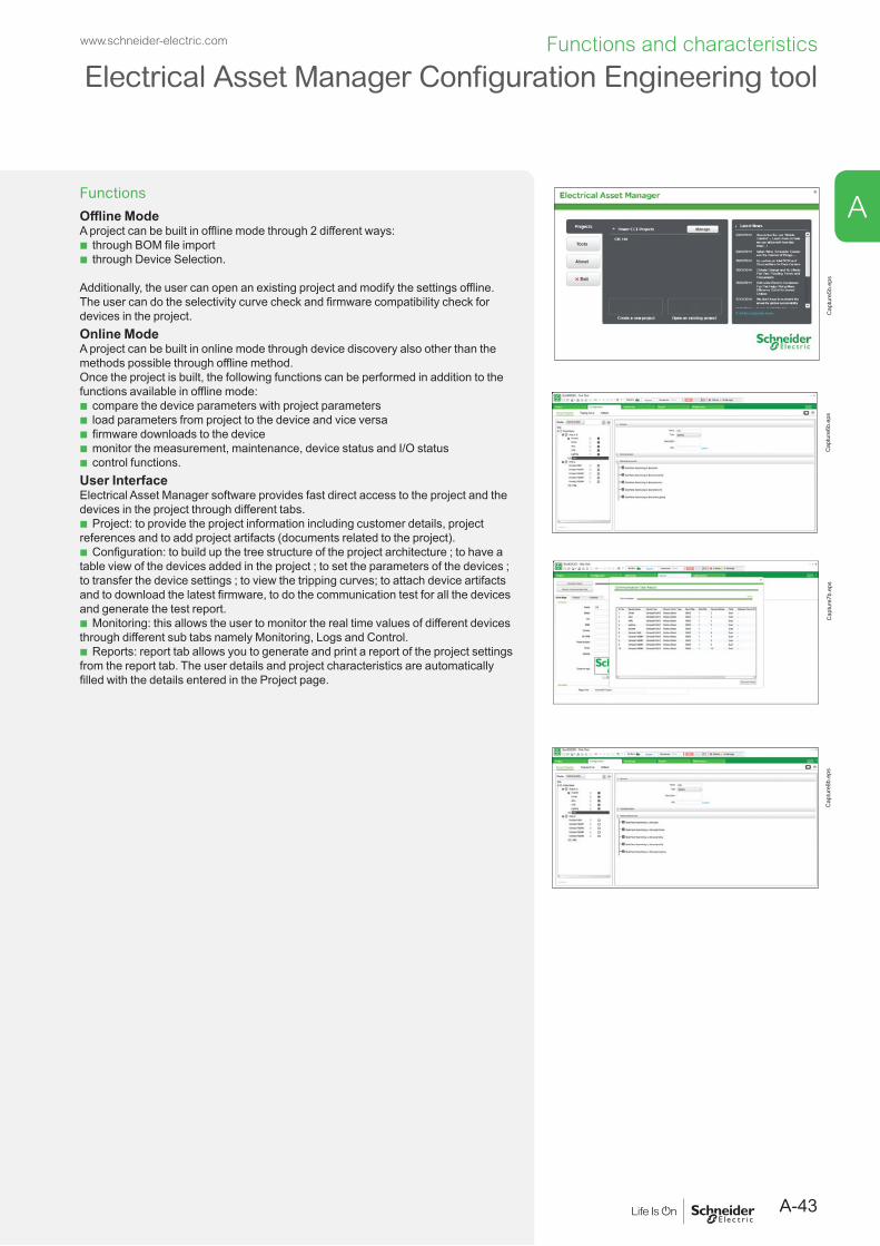
A-43
www.schneider-electric.com Functions and characteristics
A
Electrical Asset Manager Configuration Engineering tool
FunctionsOffline ModeA project can be built in offline mode through 2 different ways:
b through BOM file import b through Device Selection.
Additionally, the user can open an existing project and modify the settings offline. The user can do the selectivity curve check and firmware compatibility check for devices in the project. Online Mode A project can be built in online mode through device discovery also other than the methods possible through offline method. Once the project is built, the following functions can be performed in addition to the functions available in offline mode:
b compare the device parameters with project parameters b load parameters from project to the device and vice versa b firmware downloads to the device b monitor the measurement, maintenance, device status and I/O status b control functions.
User InterfaceElectrical Asset Manager software provides fast direct access to the project and the devices in the project through different tabs.
b Project: to provide the project information including customer details, project references and to add project artifacts (documents related to the project).
b Configuration: to build up the tree structure of the project architecture ; to have a table view of the devices added in the project ; to set the parameters of the devices ; to transfer the device settings ; to view the tripping curves; to attach device artifacts and to download the latest firmware, to do the communication test for all the devices and generate the test report.
b Monitoring: this allows the user to monitor the real time values of different devices through different sub tabs namely Monitoring, Logs and Control.
b Reports: report tab allows you to generate and print a report of the project settings from the report tab. The user details and project characteristics are automatically filled with the details entered in the Project page.
Cap
ture
5b.e
psC
aptu
re6b
.eps
Cap
ture
7b.e
psC
aptu
re8b
.eps

A-44
www.schneider-electric.comFunctions and characteristics
Motor protectionOverview of solutions
The circuit breakers presented here provide protection against short circuits and are suitable for isolation as defined by standard IEC 60947-2. For complete protection of the motor and its control device, overload protection may be provided by either the circuit breaker or a separate Schneider Electric thermal relay. The control device may be of the direct on-line type (with or without reversing) or of the “star-delta” type. Combinations are governed by standard IEC 60947-4.1.
Motor protection up to 750 kWMotor rating (kW) 160…750
Compact NS630b to 1600
PB10
4839
_ME.
eps
Breaking N 50capacity (kA rms) H 70380/415 V L 150
General circuit breaker characteristics page A-12Compact NS630b to 1600 circuit breakers equipped with Micrologic control units are the same as those for distribution systems.Accompanying control units page A-20
Micrologic electronic control units may be used on all Compact NS630b to 1600 circuit breakers.Micrologic 2.0 A and 5.0 A electronic control units provide protection against short-circuits and overloads. Micrologic 7.0 A provides the same protection functions, plus earth-leakage protection.
Protection coordination (as defined by IEC 60947-4)Whatever the power of the motor, the coordination between the circuit breaker, contactor and relay can be of either type 1 or 2.Selection depends on operational requirements concerning continuity of service and the technical skills of servicing personnel.All type 2 have been tested under the conditions defined by standards and they are certified ASEFA/LOVAG.Selection of a trip unit or Micrologic control unitP (kW) (400 V, 50 Hz)Ir (A)
0.371.5
18.540
5.512 50
3780 100 160 200
110220
160320
250500 800
5601000
7501350
1.12.5
CompactNS630b … NS1600
Micrologic 2.0 A / 5.0 A / 6.0 A / 7.0 A
Micrologic 2.0 E / 5.0 E / 6.0 EDB1
2805
6.ep
s
DB1
2805
5.ep
s
A

A-45
www.schneider-electric.com Functions and characteristics
A
Earth-leakage protectionOverview of solutions
Earth-leakage protection is obtained by:b installing a Micrologic 7.0 A control unit (Compact NS630b to 3200).b using a Vigirex relay and separate sensors (all Compact circuit breakers).
Circuit breakers equipped with a control unit offering integrated earth-leakage protection and an external rectangular sensor
Rated current (A)630...1600 1600...3200
Compact NS630b to 1000 N/L NS1250 and 1600 N
Compact NS1600b to 3200
PB10
4844
_ME.
eps
PB10
4831
_ME.
eps
PB10
4845
_ME.
eps
General circuit breaker characteristics page A-12Compact NS630b to 3200 circuit breakers are presented in the “Protection of distribution systems” section.Accompanying control units page A-22
Micrologic 7.0 A electronic control units offer earth-leakage protection as standard.
Earth-leakage protection using a Vigirex relayEarth-leakage relay Separate toroids Rectangular sensors
PB10
0435
-35_
SE_R
.eps
0594
76_S
E.ep
s
Compact circuit breaker + Vigirex relay combinationVigirex relays may be used to add external earth-leakage protection to Compact NS circuit breakers. The circuit breakers must be equipped with an MN or MX voltage release. Vigirex relays are very useful when special time-delay or tripping-threshold values are required, or when there are major installation constraints (circuit breaker already installed and connected, limited space available, etc.).Vigirex-relay characteristics:
b rectangular sensors up to 3200 A b 50/60/400 Hz distribution systems.
Options: b trip alarm by a fail-safe contact b pre-alarm LED and contact, etc.
Compliance with standards: b IEC 60947-2, annex M b IEC/EN 60755: general requirements for residual current operated protective devices b IEC/EN 6100-4-2 to 4-6: immunity tests b CISPR11: radio-frequency radiated and conducted emission tests b UL1053 and CSA22.2 No. 144 for RH10, RH21 and RH99 relays at supply voltages up to and including 220/240 V.

A-46
www.schneider-electric.comFunctions and characteristics
Control and isolationOverview of solutions
Circuit breaker-
disconnector
Switch-disconnector
Standardised symbols
LV devices
Acti 9 NG125 Easypact Compact NS Masterpact MTZ1 Micrologic Compact INS Compact INV Fupact INF
Compact NSX
Compact NSX DC
Compact NS
Masterpact MTZ2 Masterpact NW DC
Compact INS/INV
Source-changeover Fupact ISFT
Fupact ISFL
Final distribution enclosure for commercial applications
Main power distribution board for commercial applications
Main power distribution board for industrial applications
Note: adjacent to or built into the machine.
DB4
2581
8.ep
s
A

A-47
www.schneider-electric.com Functions and characteristics
A
Control and isolationOverview of solutions
Compact switch-disconnectors are used to control and isolate electrical distribution circuits. In addition to these basic functions, other functions for safety, remote control and convenience include:b earth-leakage protectionb auxiliary MN/MX releasesb remote operation.Compact switch-disconnectors may be interlocked with another Compact switch-disconnector or circuit breaker to constitute a source-changeover system.
PB10
4837
.eps
Compact NS1600NA manual switch-disconnector.
PB10
6359
.eps
Compact NS1600NA electrical switch-disconnector.

A-48
www.schneider-electric.comFunctions and characteristics
Control and disconnectionCompact NS630bNA to 1600NA switch-disconnectors
Compact switch-disconnectors NS630bNA NS800NA NS1000NA NS1250NA NS1600NA
PB10
4837
_1.e
ps
Compact NS1600NA manual switch-disconnector.
Number of poles 3, 4 3, 4 3, 4 3, 4 3, 4Control manual toggle
direct or extended rotary handle
electric
Connections fixed front connection
rear connection
withdrawable (on chassis) front connection
rear connection
Electrical characteristics as per IEC 60947-3 and EN 60947-3Conventional thermal current (A)
Ith 60 °C 630 800 1000 1250 1600
Rated insulation voltage (V) Ui 800 800 800 800 800Rated impulse withstand voltage (kV) Uimp 8 8 8 8 8Rated operational voltage (V) Ue AC 50/60 Hz 690 690 690 690 690Rated operational current le AC 50/60 Hz AC23A AC23A AC23A AC23A AC23A
220/240 V 630 800 1000 1250 1600380/415 V 630 800 1000 1250 1600440/480 V 630 800 1000 1250 1600500/525 V 630 800 1000 1250 1600660/690 V 630 800 1000 1250 1600
PB10
6359
_1.e
ps
Compact NS1600NA electrical switch-disconnector.
Short-circuit making capacity
lcm (kA peak) 52 52 52 52 52
Short-time withstand current
lcw (kA rms) 0.5 s 25 25 25 25 2520 s 4 4 4 4 4
Suitability for isolation
Durability (C-O cycles) mechanical 10000 10000 10000 10000 10000electrical AC 440 V AC23A/In 2000 2000 2000 2000 1000
Positive contact indication
Pollution degree 3 3 3 3 3Protection
Add-on earth-leakage protection combination with Vigirex relay
Additional indication and control auxiliariesIndication contacts
Voltage releases MX shunt release
MN undervoltage release
Remote communication by busDevice status indications (communicating auxiliary contacts)
Device remote operation (communicating motor mechanism)
InstallationAccessories terminal extensions and spreaders
terminal shields and interphase barriers
escutcheons
Dimensions (mm) fixed 3P 327 x 210 x 147W x H x D 4P 327 x 280 x 147Weight (kg) fixed 3P 14
4P 18Source-changeover system (see section "on source-changeover systems")
Manual source-changeover systems, remote-operated and automatic
Installation standards require upstream protection.
A

A-49
www.schneider-electric.com Functions and characteristics
A
Control and disconnectionCompact NS630bNA to 1600NA switch-disconnectors
Compact switch-disconnectors NS630bNA NS800NA NS1000NA NS1250NA NS1600NA
PB10
4837
_1.e
ps
Compact NS1600NA manual switch-disconnector.
Number of poles 3, 4 3, 4 3, 4 3, 4 3, 4Control manual toggle
direct or extended rotary handle
electric
Connections fixed front connection
rear connection
withdrawable (on chassis) front connection
rear connection
Electrical characteristics as per IEC 60947-3 and EN 60947-3Conventional thermal current (A)
Ith 60 °C 630 800 1000 1250 1600
Rated insulation voltage (V) Ui 800 800 800 800 800Rated impulse withstand voltage (kV) Uimp 8 8 8 8 8Rated operational voltage (V) Ue AC 50/60 Hz 690 690 690 690 690Rated operational current le AC 50/60 Hz AC23A AC23A AC23A AC23A AC23A
220/240 V 630 800 1000 1250 1600380/415 V 630 800 1000 1250 1600440/480 V 630 800 1000 1250 1600500/525 V 630 800 1000 1250 1600660/690 V 630 800 1000 1250 1600
PB10
6359
_1.e
ps
Compact NS1600NA electrical switch-disconnector.
Short-circuit making capacity
lcm (kA peak) 52 52 52 52 52
Short-time withstand current
lcw (kA rms) 0.5 s 25 25 25 25 2520 s 4 4 4 4 4
Suitability for isolation
Durability (C-O cycles) mechanical 10000 10000 10000 10000 10000electrical AC 440 V AC23A/In 2000 2000 2000 2000 1000
Positive contact indication
Pollution degree 3 3 3 3 3Protection
Add-on earth-leakage protection combination with Vigirex relay
Additional indication and control auxiliariesIndication contacts
Voltage releases MX shunt release
MN undervoltage release
Remote communication by busDevice status indications (communicating auxiliary contacts)
Device remote operation (communicating motor mechanism)
InstallationAccessories terminal extensions and spreaders
terminal shields and interphase barriers
escutcheons
Dimensions (mm) fixed 3P 327 x 210 x 147W x H x D 4P 327 x 280 x 147Weight (kg) fixed 3P 14
4P 18Source-changeover system (see section "on source-changeover systems")
Manual source-changeover systems, remote-operated and automatic

A-50
www.schneider-electric.comFunctions and characteristics
Control and disconnectionCompact NS1600bNA to 3200NA switch-disconnectors
Compact switch-disconnectors NS1600bNA NS2000NA NS2500NA NS3200NANumber of poles 3, 4 3, 4 3, 4 3, 4Control manual toggle
direct or extended rotary handle - - - -electric - - - -
Connections fixed front connection
rear connection - - - -withdrawable (on chassis) front connection - - - -
rear connection - - - -
PB10
4838
.eps
Electrical characteristics as per IEC 60947-3 and EN 60947-3Conventional thermal current (A) Ith 60 °C 1600 2000 2500 3200Rated insulation voltage (V) Ui 800 800 800 800Rated impulse withstand voltage (kV) Uimp 8 8 8 8Rated operational voltage (V) Ue AC 50/60 Hz 690 690 690 690Rated operational current le AC 50/60 Hz AC23A AC23A AC23A AC23A
220/240 V 1600 2000 2500 3200380/415 V 1600 2000 2500 3200440/480 V 1600 2000 2500 3200500/525 V 1600 2000 2500 3200660/690 V 1600 2000 2500 3200
Short-circuit making capacity lcm (kA peak) 135 135 135 135Short-time withstand current lcw (kA rms) 3 s 32 32 32 32Integrated instantaneous protection (kA peak ±10 %) 130 130 130 130Suitability for isolation
Compact NS2000NA. Durability (C-O cycles) mechanical 6000 6000 6000 6000electrical AC 440 V AC23A/In 1000 1000 1000 1000
Positive contact indication
Pollution degree 3 3 3 3
Protection Add-on earth-leakage protection combination with Vigirex relay
Additional indication and control auxiliariesIndication contacts
Voltage releases MX shunt release
MN undervoltage release
InstallationAccessories escutcheons
Dimensions (mm) fixed 3P 350 x 420 x 160W x H x D 4P 350 x 535 x 160Weight (kg) fixed 3P 23
4P 36Source-changeover system (see section "on source-changeover systems")
Manual source-changeover systems, remote-operated and automatic -
Installation standards require upstream protection. However, Compact NS1600b to 3200NA switch-disconnectors are self-protected for all currents higher than 130 kA peak.A

A-51
www.schneider-electric.com Functions and characteristics
A
Control and disconnectionCompact NS1600bNA to 3200NA switch-disconnectors
Compact switch-disconnectors NS1600bNA NS2000NA NS2500NA NS3200NANumber of poles 3, 4 3, 4 3, 4 3, 4Control manual toggle
direct or extended rotary handle - - - -electric - - - -
Connections fixed front connection
rear connection - - - -withdrawable (on chassis) front connection - - - -
rear connection - - - -
PB10
4838
.eps
Electrical characteristics as per IEC 60947-3 and EN 60947-3Conventional thermal current (A) Ith 60 °C 1600 2000 2500 3200Rated insulation voltage (V) Ui 800 800 800 800Rated impulse withstand voltage (kV) Uimp 8 8 8 8Rated operational voltage (V) Ue AC 50/60 Hz 690 690 690 690Rated operational current le AC 50/60 Hz AC23A AC23A AC23A AC23A
220/240 V 1600 2000 2500 3200380/415 V 1600 2000 2500 3200440/480 V 1600 2000 2500 3200500/525 V 1600 2000 2500 3200660/690 V 1600 2000 2500 3200
Short-circuit making capacity lcm (kA peak) 135 135 135 135Short-time withstand current lcw (kA rms) 3 s 32 32 32 32Integrated instantaneous protection (kA peak ±10 %) 130 130 130 130Suitability for isolation
Compact NS2000NA. Durability (C-O cycles) mechanical 6000 6000 6000 6000electrical AC 440 V AC23A/In 1000 1000 1000 1000
Positive contact indication
Pollution degree 3 3 3 3
Protection Add-on earth-leakage protection combination with Vigirex relay
Additional indication and control auxiliariesIndication contacts
Voltage releases MX shunt release
MN undervoltage release
InstallationAccessories escutcheons
Dimensions (mm) fixed 3P 350 x 420 x 160W x H x D 4P 350 x 535 x 160Weight (kg) fixed 3P 23
4P 36Source-changeover system (see section "on source-changeover systems")
Manual source-changeover systems, remote-operated and automatic -

A-52
www.schneider-electric.comFunctions and characteristics
Source-changeover systemsPresentation
PB19
1613
-50.
eps
P109
832-
104.
eps
6558
7-11
7.ep
s
Some installations use two supply sources to counter the temporary loss of the main supply. A source-changeover system is required to safely switch between the two sources.The replacement source can be a generator set or another network.
Manual source-changeover system or MTSE (Manual Transfer Switching Equipment) The simplest way to switch the load. It is controlled manually by an operator. The time required to switch from the S1 source to S2 source is variable.System2 or 3 mechanically interlocked circuit breakers or 2 switch-disconnectors.ApplicationsSmall commercial buildings and small and medium industrial activities where the need for continuity of service is significant but not a priority.
Automatic source-changeover system or ATSE (Automatic Transfer Switching Equipment)An automatic controller may be added to a remote operated source-changeover system. It is possible to automatically control source transfer according to programmed (dedicated controllers) or programmable (PLC) operating modes. These solutions ensure optimum energy management.The time required to switch from the S1 source to S2 source is fixed.System2 or 3 circuit breakers linked by an electrical interlocking system. A mechanical interlocking system protects also against incorrect manual operations, with an automatic control system (dedicated controllers).ApplicationsLarge infrastructures, industry, critical buildings & process where the continuity of service is a priority.
Remote source-changeover system or RTSE (Remote Transfer Switching Equipment)In this case, no direct human intervention is required. The time required to switch from the S1 source to S2 source is fixed.System2 or 3 circuit breakers linked by an electrical interlocking system. A mechanical interlocking system protects also against incorrect manual operations. In this case is necessary to add a PLC controller not dedicated for source-changeover application.ApplicationsIndustry & Infrastructure where continuity of service requirements are meaningful but not a priority.
A

A-53
www.schneider-electric.com Functions and characteristics
A
Source-changeover systemsManual source-changeover systems
A manual source-changeover system can be installed on two to three manually-operated circuit breakers or switch-disconnectors. Interlocking is mechanical. Interlocks prevent connection to both sources at the same time, even momentarily.
Interlocking of two devices with rotary handlesThe rotary handles are padlocked with the devices in the OFF position. The mechanism inhibits the two devices being closed at the same time, but does allow for both to be open (OFF) at the same time.Combinations of "Normal" and "Replacement" devicesAll Compact NS630b to 1600 circuit breakers and switch-disconnectors with rotary handles can be interlocked. Interlocking of a Compact NS630b with a Compact NS630b to 1600 is not possible.Interlocking of a number of devices using keylocks (captive keys)Interlocking uses two identical keylocks with a single key. This solution enables interlocking between two devices that are physically distant or that have significantly different characteristics, for example between a low and a medium-voltage device, or between Compact NS circuit breakers and switch-disconnectors.A system of wall-mounted units with captive keys makes possible a large number of combinations between many devices.Combinations of Normal and Replacement devicesAll Compact NS630b to 1600 circuit breakers and switch-disconnectors with rotary handles or motor mechanisms can be interlocked.Interlocking of two Compact NS630b to 1600 devices using connecting rodsThe two devices must be mounted one above the other (either 2 fixed or 2 withdrawable/drawout devices).InstallationThis function requires:
b an adaptation fixture on the right side of each circuit breaker or switch-disconnector b a set of connecting rods with no-slip adjustments.
The adaptation fixtures, connecting rods and circuit breakers or switch-disconnectors are supplied separately, ready for assembly by the customer.The maximum vertical distance between the fixing planes is 900 mm.Possible combinations of "S1" and "S2" source circuit breakersCombinaison are possible between Compact devices and between Compact NS devices with Masterpact MTZ devices.Interlocking of two Compact NS630b to 1600 devices using cablesFor cable interlocking, the circuit breakers may be mounted one above the other or side-by-side.The interlocked devices may be fixed or drawout, three-pole or four-pole, and have different ratings and sizes.InstallationThis function requires:
b an adaptation fixture on the right side of each device b a set of cables with no-slip adjustments.
The maximum distance between the fixing planes (vertical or horizontal) is 2000 mm.
Possible combinations of "S1" and "S2" source circuit breakersSource "S1" Source "S2"
NS630b to NS1600
NT06 to NT16
NW08 to NW40
NW40b to NW63
NS630b to NS1600 -
PB11
3831
.eps
Interlocking with keylocks.
PB11
3832
.eps
Interlocking of two devices with rotary handles.
Opush OFF
Ipush ON
O OFF
discharged
Opush OFF
Ipush ON
O OFF
discharged
DB1
2846
5.ep
s
Opush OFF
Ipush ON
O OFF
discharged
Opush OFF
Ipush ON
O OFF
discharged
DB4
1764
1.ep
s
Interlocking with connecting rods.
Interlocking with cables.

A-54
www.schneider-electric.comFunctions and characteristics
Electrical interlockingIVE unit
Electrical interlocking is used with a mechanical interlocking system. Morover, the relays controlling the closing order to the "S1" and "S2" circuit breakers must be mechanically and/or electrically interlocked to prevent them from giving simultaneous closing commands.
Electrical interlocking is carried out by an electrical control device.For Compact NS630b to NS1600, this function can be implemented in one of two ways:
b using the IVE unit b by an electrician based on the diagrams in accordance with the chapter
"Electric diagrams" source-changeover system.Characteristics of the IVE unit
b External connection terminal block: v inputs: circuit breaker control signals v outputs: status of the SDE contacts on the "S1" and "S2" source circuit breakers. b 2 connectors for the two “S1” and “S2” source circuit breakers: v inputs:
- status of the OF contacts on each circuit breaker (ON or OFF) - status of the SDE contacts on the “S1” and “S2” source circuit breakers
v outputs: power supply for operating mechanisms. b Control voltage: v 24 to 250 V DC v 48 to 415 V 50/60 Hz - 440 V 60 Hz.
The IVE unit control voltage must be same as that of the circuit breaker operating mechanisms.
PB11
9174
_48.
eps
IVE unit.For Compact NS630b to NS1600, each circuit breaker must be equipped with:
b a motor mechanism b an available OF contact b a CE connected-position contact (carriage switch) on withdrawable circuit breakers b an SDE contact.
Standard configuration for Compact NS
Types of mechanical interlocking
Possible combinations
Typical electrical diagrams
Diagram no.
2 devices
DB4
2456
9.ep
s
QN QR Compact NS630b to 1600:0 0 b electrical interlocking
with lockout after fault:0 1 v Permanent replacement
source (with IVE)51201183 [1]
0 1 v with emergency off by shunt release MX
51201184 [1]
v with emergency off by undervoltage release MN
51201185 [1]
[1] See catalogue "Source changeover systems", ref. LVPED211022EN.
PB10
4831
_ME.
eps
A

A-55
www.schneider-electric.com Functions and characteristics
A
Electrical interlockingRemote-operated systems
Source-changeover system with a controllerIn this case, changeovers between the "Normal" and "Replacement" sources under predefined conditions are initiated by a Schneider Electric controller.
A
PB10
0857
_16_
SE.e
ps
DB4
0381
0R.e
ps
B
Control plate. Controller.Switching between sources can be automated by adding:A ACP control plateB BA or UA controller, or an electrical system provided by the installer for NS630b to
1600. Electrical system example: part no. 51156904 and 51156904 in the source-changeover system catalogue.
Opush OFF
Ipush ON
O OFF
discharged
Opush OFF
Ipush ON
O OFF
discharged
DB1
2846
5.ep
s
Opush OFF
Ipush ON
O OFF
discharged
Opush OFF
Ipush ON
O OFF
discharged
DB4
1764
1.ep
s
Interlocking by rods. Interlocking by cables.
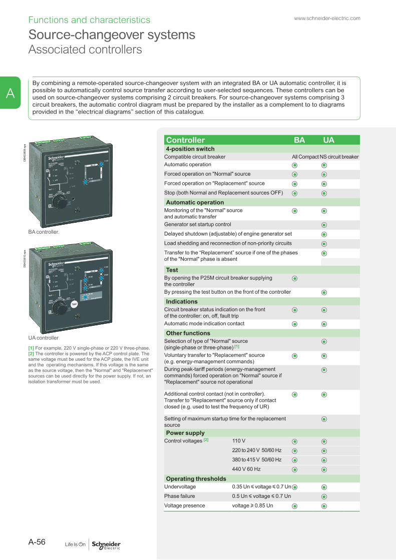
A-56
www.schneider-electric.comFunctions and characteristics
Source-changeover systemsAssociated controllers
By combining a remote-operated source-changeover system with an integrated BA or UA automatic controller, it is possible to automatically control source transfer according to user-selected sequences. These controllers can be used on source-changeover systems comprising 2 circuit breakers. For source-changeover systems comprising 3 circuit breakers, the automatic control diagram must be prepared by the installer as a complement to to diagrams provided in the “electrical diagrams” section of this catalogue.
Controller BA UA4-position switch
Compatible circuit breaker All Compact NS circuit breakerAutomatic operation
Forced operation on "Normal" source
Forced operation on "Replacement" source
Stop (both Normal and Replacement sources OFF)
Automatic operationMonitoring of the "Normal" source and automatic transferGenerator set startup control
Delayed shutdown (adjustable) of engine generator set
Load shedding and reconnection of non-priority circuits
Transfer to the “Replacement” source if one of the phases of the "Normal" phase is absent
TestBy opening the P25M circuit breaker supplying the controller By pressing the test button on the front of the controller
IndicationsCircuit breaker status indication on the front of the controller: on, off, fault tripAutomatic mode indication contact
Other functionsSelection of type of "Normal" source(single-phase or three-phase) [1]
Voluntary transfer to "Replacement" source(e.g. energy-management commands)During peak-tariff periods (energy-management commands) forced operation on "Normal" source if "Replacement" source not operational
Additional control contact (not in controller).Transfer to "Replacement" source only if contact closed (e.g. used to test the frequency of UR)
Setting of maximum startup time for the replacement sourcePower supply
Control voltages [2] 110 V
220 to 240 V 50/60 Hz
380 to 415 V 50/60 Hz
440 V 60 Hz
Operating thresholdsUndervoltage 0.35 Un y voltage y 0.7 Un
Phase failure 0.5 Un y voltage y 0.7 Un
Voltage presence voltage u 0.85 Un
DB4
0380
9.ep
s
BA controller.
DB4
0381
0.ep
s
UA controller
[1] For example, 220 V single-phase or 220 V three-phase.[2] The controller is powered by the ACP control plate. The same voltage must be used for the ACP plate, the IVE unit and the operating mechanisms. If this voltage is the same as the source voltage, then the "Normal" and "Replacement" sources can be used directly for the power supply. If not, an isolation transformer must be used.
A

A-57
www.schneider-electric.com Functions and characteristics
A
Source-changeover systemsAssociated controllers
Controller BA UAIP degree of protection (EN 60529) and IK degree of protection against external mechanical impacts (EN 50102)
Front IP40
Side IP30
Connectors IP20
Front IK07
Characteristics of output contacts (dry, volt-free contacts)Rated thermal current (A) 8Minimum load 10 mA at 12 VOutput contacts: Position of the Auto/Stop switchLoad shedding and reconnection order
Generator set start order
AC DCUtilisation category (IEC 60947-5-1) AC12 AC13 AC14 AC15 DC12 DC13Operational current (A) 24 V 8 7 5 6 8 2
48 V 8 7 5 5 2 -110 V 8 6 4 4 0.6 -220/240 V 8 6 4 3 - -250 V - - - - 0.4 -380/415 V 5 - - - - -440 V 4 - - - - -660/690 V - - - - - -

A-58
www.schneider-electric.comFunctions and characteristics
Electrical and mechanical accessoriesCompact NS630b to 1600 (fixed version)
G
F
D
Micr ologic 5.0 E
40
100%
%
delay
shor t tim e tsd(s)
long tim e
alarm
tr(s)
setting
.4.5.6
.7.8 .9
.95
.981
Ir
x In
.512
48 12
1620
at 6 Ir24
x Ir
22.5
34 5
68
10
Isd
1.5on I
2t.2
.4 .4
.1
.3
.10
I i
x In
34
8
off2.3
instantaneous
.26
15
1012
menu
NS 1200 H
Ui 1000V Uimp 12kV
Ics = 100% Icu
IEC 947-2
UTE VDE BS CEI UNE NEMA
Ue(V)220/240
480/690
Icu(kA)10085
Uimp 8kV
Ipush ON
O OFF
discharged
35210
Opush OFF
B C
B
E
A
A1 A3
A2 D1
D2C1
E1
C2
E2
B
H
H1
H2
B
I
I on
deppirt
teser
0 OFF
tripped
reset
I1
I2I on
deppirt
teser
0 OFF
G1 G2 G3
G4 G5
Electrical control withmixed connection
Manual control withrear connection
Manual control withfront connection
E3
Test
LV434002
Enerlin'X IFE
DB4
3253
7.ep
s
A1 Terminal extension for cables with lugsA2 Vertical connection adapterA3 SpreaderB Interphase barriersC1 SpreaderC2 Rear connectorsD1 Sealable terminal shieldD2 Connection kit for connectors
E1 Auxiliary contactE2 Voltage releaseE3 Communications moduleF EscutcheonG1 I/OG2 IFEG3 IFMG4 FDM121
G5 FDM128H1 Connection kit for connectorsH2 Sealable terminal shieldI1 Extended rotary handleI2 Direct rotary handle
A
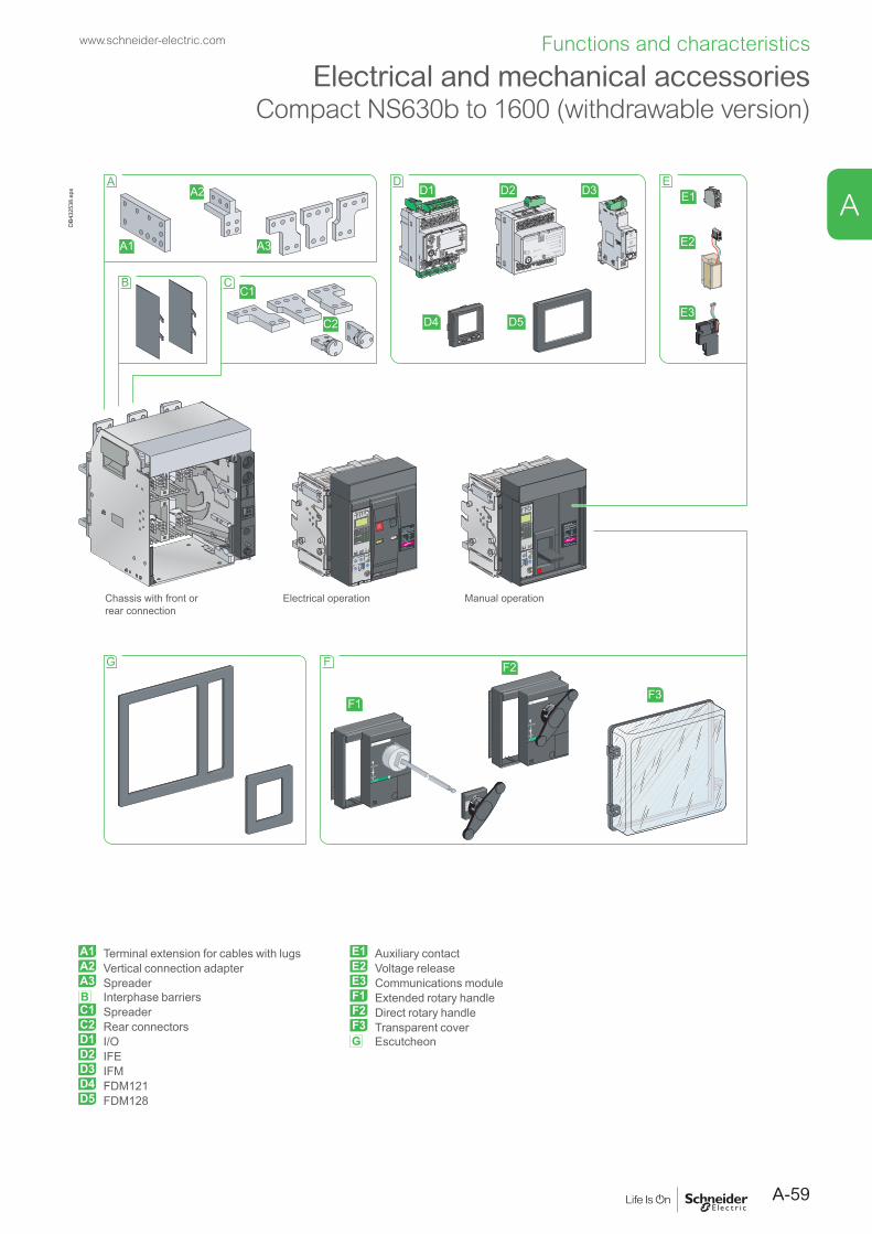
A-59
www.schneider-electric.com Functions and characteristics
A
Electrical and mechanical accessoriesCompact NS630b to 1600 (withdrawable version)
Micr ologic 5.0 E
40
100%
%
delay
shor t tim e tsd(s)
long tim e
alarm
tr(s)
setting
.4.5.6
.7.8 .9
.95
.981
Ir
x In
.512
48 12
1620
at 6 Ir24
x Ir
22.5
34 5
68
10
Isd
1.5on I
2t.2
.4 .4
.1
.3
.10
I i
x In
34
8
off2.3
instantaneous
.26
15
1012
menu
NS 1200 H
Ui 1000V Uimp 12kV
Ics = 100% Icu
IEC 947-2
UTE VDE BS CEI UNE NEMA
Ue(V)220/240
480/690
Icu(kA)10085
Uimp 8kVNS 1200 H
Ui 1000V Uimp 12kV
Ics = 100% Icu
IEC 947-2
UTE VDE BS CEI UNE NEMA
Ue(V)220/240
480/690
Icu(kA)10085
Uimp 8kV
Ipush ON
O OFF
discharged
35210
Opush OFF
Micr ologic 5.0 E
40
100%
%
delay
shor t tim e tsd(s)
long tim e
alarm
tr(s)
setting
.4.5.6
.7.8 .9
.95
.981
Ir
x In
.512
48 12
1620
at 6 Ir24
x Ir
22.5
34 5
68
10
Isd
1.5on I
2t.2
.4 .4
.1
.3
.10
I i
x In
34
8
off2.3
instantaneous
.26
15
1012
menu
Chassis with front orrear connection
Electrical operation Manual operation
B CC1
C2
A
A1 A3
A2D
D1 D2 D3
D4 D5
Test
LV434002
Enerlin'X IFE
EE1
E2
E3
F
F1
F2
F3
I on
deppirt
teser
0 OFF
tripped
reset
I on
deppirt
teser
0 OFF
G
DB4
3253
8.ep
s
A1 Terminal extension for cables with lugsA2 Vertical connection adapterA3 SpreaderB Interphase barriersC1 SpreaderC2 Rear connectorsD1 I/OD2 IFED3 IFMD4 FDM121D5 FDM128
E1 Auxiliary contactE2 Voltage releaseE3 Communications moduleF1 Extended rotary handleF2 Direct rotary handleF3 Transparent coverG Escutcheon

A-60
www.schneider-electric.comFunctions and characteristics
Electrical and mechanical accessoriesCompact NS630b to 1600
The withdrawable configuration makes it possible to: b extract and/or rapidly replace the circuit breaker without having to touch connections; b allow for the addition of future circuits at a later date.
InstallationFixed configurationCompact NS630b to 1600 circuit breakers may be installed vertically, horizontally or flat on their back.
DB1
2806
3.ep
s
DB1
2806
4.ep
s
Mounting on a backplate. Mounting on rails.
Withdrawable configurationCompact NS630b to 1600 circuit breakers should be installed vertically only.
DB1
2806
5.ep
s
DB1
2806
6.ep
s
Mounting on a backplate. Rear mounting on rails.
DB1
2806
7.ep
s
DB1
2806
8.ep
s
Device on mounting plate. Device on rails.
PB10
6360
r-50_
1.ep
s
PB10
4831
_ME_
1.ep
s
Manually operated fixed Compact NS800.
Electrically operated fixed Compact NS1600.
DB1
2803
4.ep
s05
9782
N_I_5
0_SE
_ME_
1.eps
Electrically operated withdrawable Compact NS800H.
DB1
2806
9.ep
s
A

A-61
www.schneider-electric.com Functions and characteristics
A
Electrical and mechanical accessoriesCompact NS630b to 1600
The device may be in one of four positions on the chassis: b connected position. The power circuits and auxiliary contacts are all connected b test position. The power circuits are disconnected. The auxiliary contacts are still connected and the device can be
operated electrically b disconnected position. The power circuits and auxiliary contacts are all disconnected, however the device is still
mounted on the chassis. It can be operated manually (ON, OFF, "push to trip"). b removed position. All circuits are disconnected. The device simply rests on the chassis rails and can be removed.
DB1
2807
0.ep
s
Connected Test Disconnected RemovedThe multifunctional chassis for Compact NS630b to 1600 devices is particularly suited for incoming circuit breakers. Features include:
b device connection and disconnection through a door, using a crank that can be stored in the chassis
b three positions (connected, test and disconnected) that are indicated: v locally by a position indicator v remotely by carriage switches (3 for the connected position, 2 for the disconnected
position and 1 for the test position) b circuit breaker ON/OFF commands through a switchboard front panel.
LockingThere are extensive locking possibilities:
b chassis locking in connected, disconnected and test positions using three padlocks and two keylocks, on the switchboard front panel
b door interlock (inhibits door opening with breaker in connected position) b racking interlock (inhibits racking with door open) b locking in each of the connected, disconnected and test positions during device
connection or disconnection. Continuation to the next position requires pressing a release button to free the crank.Other safety functionMismatch protection ensures that a circuit breaker is installed only in a chassis with compatible characteristics.
A
B
C
DEF
GHIJ
DB1
2807
1.ep
s
A Mismatch protectionB Door interlockC Racking interlockD Keylock lockingE Padlock lockingF Position indicatorG Chassis front plate (accessible with cubicle door closed)H Crank entryI Reset buttonJ Crank storage

A-62
www.schneider-electric.comFunctions and characteristics
Electrical and mechanical accessoriesCompact NS630b to 1600
Types of connectionFixed deviceFront connections (N, L) Connection by:
bars bare cables (except L) cables with lugs
DB1
2807
7.ep
s
DB1
2807
2.ep
s
DB1
2807
3.ep
s
DB1
2807
4.ep
s
DB1
2807
5.ep
s
DB1
2807
6.ep
s
Rear connections (N, L, LB) Connection by:Horizontal: Vertical: bars cables with lugs
DB1
2807
8.ep
s
DB1
2807
9.ep
s
DB1
2807
2.ep
s
DB1
2807
4.ep
sD
B128
080.
eps
Simply turn a horizontal rear connector 90° to make it a vertical connector.Combination of front and rear connections (N, L)
Connection by:
bars bare cables (except L) cables with lugs
DB1
2808
1.ep
s
DB1
2808
2.ep
s
DB1
2807
2.ep
s
DB1
2807
3.ep
s
DB1
2807
4.ep
s
DB1
2807
5.ep
s
DB1
2807
6.ep
s
Withdrawable deviceFront connections Connection by:
bars cables with lugs
DB1
2808
3.ep
s
DB1
2807
2.ep
s
DB1
2807
4.ep
sD
B128
076.
eps
Rear connections Connection by:bars cables with lugs
DB1
2808
4.ep
s
DB1
2807
2.ep
s
DB1
2807
4.ep
sD
B128
080.
eps
A

A-63
www.schneider-electric.com Functions and characteristics
AConnections accessories
Type of accessories For Compact NS630b to NS1600Fixed: Withdrawable:Front connection Rear connection Front connection Rear connection
Vertical-connection adapters
DB1
2808
5.ep
s
[1]
N, H, L - N, L, LB -
Set of bare-cable connectors and terminal shields for ratings y 1250 A
DB1
2808
6.ep
s
N, H - - -
Cable lug adapters
DB1
2808
7.ep
s
[1]
N, H, L N, H, L, LB N, H, L, LB N, H, L, LB
Interphase barriers
DB1
2808
8.ep
s
DB4
2586
6.ep
s
N, H, L, LB N, H, L, LB - N, H, L, LB
[2] [3]
Spreaders
DB1
2808
9.ep
s
[1]
N, H, L N, H, L, LB N, H, L, LB N, H, L, LB
Connection shield
DB1
2809
0.ep
s
N, H, L - - -
Safety shutters with locking by padlocks (IP20)
DB1
2809
1.ep
s
- - N, H, L, LB(standard)
N, H, L, LB(standard)
Arc chute screen
DB1
2809
2.ep
s
[4]
N, H, L - - -
[1] Spreaders, vertical connection adapters and cable lugs adapters are not compatible with voltages u 500 V. [2] Mandatory for voltages u 500 V unless using the bare-cable connector + terminal shield kit.[3] Mandatory for fixed devices with L and LB performance levels, whatever the voltage.[4] Mandatory for fixed front-connection versions with vertical connection adapters oriented towards the front.
To ensure performance and isolation, depending on the type of circuit breaker (N, H, L, LB) and type of connection, certain isolation accessories are mandatory.

A-64
www.schneider-electric.comFunctions and characteristics
Electrical and mechanical accessoriesCompact NS630b to 1600
Front connection of fixed devices BarsFixed, front-connection Compact NS630b to 1600 devices are equipped with terminals comprising captive screws for direct connection of bars.Other connection possibilities for bars include vertical-connection adapters for edgewise bars and spreaders to increase the pole pitch to 95 mm.If the vertical connection adapters are front oriented, then it is mandatory to install the arc chute screen in order to comply with the safety clearances.
DB1
2809
8.ep
s
DB1
2809
9.ep
s
DB1
2810
0.ep
s
Spreaders.
DB1
2810
1.ep
s
DB1
2810
2.ep
s
DB1
2809
7.ep
s
Vertical-connection adapters.
Bare cablesSpecial sets of connectors and terminal shields may be used to connect up to four 240 mm2 copper or aluminium cables for each phase. Bare cable connection is possible for ratings up to and including 1250 A.
DB1
2810
3.ep
s
4-cable connectors.
DB1
2810
4.ep
s
Cables with lugsCable lug adapters are combined with the vertical-connection adapters.One to four cables with crimped lugs (y 300 mm2) may be connected.To ensure stability, spacers must be positioned between the terminal extensions.If the cable lug adapters are installed over the top of the arc chute chambers, then it is mandatory to install the arc chute screen in order to comply with the safety clearances.
DB1
2810
5.ep
s
Cable lug adapters.
DB4
0391
0.ep
s
DB1
2810
7.ep
s
DB4
0391
1.ep
s
DB1
2809
3.ep
s
DB1
2809
4.ep
s
DB1
2809
5.ep
sD
B128
096.
eps
A

A-65
www.schneider-electric.com Functions and characteristics
A
Electrical and mechanical accessoriesCompact NS630b to 1600
Rear connection of fixed devicesBarsFixed, rear-connection Compact NS630b to 1600 devices equipped with horizontal or vertical connectors may be directly connected to flat or edgewise bars, depending on the position of the connectors.Spreaders are available to increase the pole pitch to 95 mm.
DB1
2810
0.ep
s
Spreaders.
DB1
2811
0.ep
s
DB1
2811
1.ep
s
DB1
2811
2.ep
s
Cables with lugsCable lug adapters enable connection of one to four cables with crimped lugs (y 300 mm2).To ensure stability, spacers must be positioned between the terminal extensions.
DB1
2810
5.ep
s
Cable lug adapters.
DB1
2811
3.ep
s
DB1
2811
4.ep
s
DB1
2810
9.ep
s
DB4
0391
2.ep
s
DB1
2809
6.ep
s

A-66
www.schneider-electric.comFunctions and characteristics
Electrical and mechanical accessoriesCompact NS630b to 1600
Front connection of withdrawable devicesBarsWithdrawable, front-connection Compact NS630b to 1600 devices are suitable for direct connection of bars. Other connection possibilities for bars include vertical-connection adapters for edgewise bars and spreaders to increase the pole pitch to 95 mm.
DB1
2809
7.ep
s
DB1
2810
0.ep
s
Vertical-connection adapters. Spreaders.
DB1
2811
5.ep
s
DB1
2811
6.ep
s
DB1
2811
7.ep
s
Cables with lugsCable lug adapters enable connection of one to four cables with crimped lugs (y 300 mm2).To ensure stability, spacers must be positioned between the terminal extensions.
DB1
2810
5.ep
s
Cable lug adapters.
DB1
2811
8.ep
s
DB1
2811
9.ep
s
DB1
2812
0.ep
s
DB1
2809
4.ep
s
DB1
2809
6.ep
s
A

A-67
www.schneider-electric.com Functions and characteristics
A
Electrical and mechanical accessoriesCompact NS630b to 1600
Rear connection of withdrawable devicesBarsWithdrawable, rear-connection Compact NS630b to 1600 devices equipped with horizontal or vertical connectors may be directly connected to flat or edge-wise bars, depending on the position of the connectors.Spreaders are available to increase the pole pitch to 95 mm.
DB1
2810
0.ep
s
Spreaders.
DB1
2812
2.ep
s
DB1
2812
3.ep
s
DB1
2812
4.ep
s
Cables with lugsCable lug adapters enable connection of one to four cables with crimped lugs (y 300 mm2).To ensure stability, spacers must be positioned between the terminal extensions.
DB1
2810
5.ep
s
Cable lug adapters.
DB1
2812
5.ep
s
DB1
2812
6.ep
s
DB1
2809
6.ep
s
DB1
2812
1.ep
s
DB1
2809
4.ep
s

A-68
www.schneider-electric.comFunctions and characteristics
Electrical and mechanical accessoriesCompact NS630b to 1600
Insulation of live partsConnection shieldMounted on fixed, front-connection devices, this shield insulates power-connection points, particularly when cables with lugs are used
DB1
2812
7.ep
s
Connection shield.Interphase barriersThese barriers are flexible insulated partitions used to reinforce isolation of connection points in installations with busbars, whether insulated or not.Barriers are installed vertically between front or rear connection terminals.They are mandatory for voltages u 500 V for both fixed and withdrawable products and for L and LB types, whatever the voltage.
DB1
2812
8.ep
s
DB1
2812
9.ep
s
D
B128
130.
eps
Interphase barriers for fixed device, front connection.
Interphase barriers for fixed device, rear connection.
Interphase barriers for withdrawable device, rear connection.
Safety shutters (standard)Mounted on the chassis, the safety shutters automatically block access to the disconnecting contact cluster when the device is in the disconnected or test positions (degree of protection IP20). When the device is removed from its chassis, no live parts are accessible.The shutters can be padlocked (padlock not supplied) to:
b prevent connection of the device b lock the shutters in the closed position.
DB1
2813
1.ep
s
Safety shutters.
PB10
4833
_1.e
ps
Compact NS equipped with connection shield.
A

A-69
www.schneider-electric.com Functions and characteristics
A
Electrical and mechanical accessoriesCompact NS630b to 1600
Connection of electrical auxiliariesFixed devicesConnections are made directly to the auxiliaries once the front has been removed. Wires exit the circuit breaker through a knock-out in the top.
DB4
2457
9.ep
s
Withdrawable devicesAuxiliary circuits are connected to terminal blocks located in the top part of the chassis.The auxiliary terminal block is made up of a fixed and moving part. The two parts are in contact when the device is in the test and connected positions.
DB4
2457
0.ep
s
CAF1CAF2CAO1CAO2
OF1OF2OF3SDMN or MX
SDECOM
DB4
2457
3.ep
s
Manually operated device.
SDEOF3OF2OF1
MN or MX
COM
DB4
2457
2.ep
sElectrically operated device.
CD2CD1
CT1
CE3CE2CE1
DB4
2457
1.ep
s
Withdrawable device.

A-70
www.schneider-electric.comFunctions and characteristics
Electrical and mechanical accessoriesCompact NS630b to 1600
All the auxiliary contacts opposite are also available in "low-level" versions capable of switching very low loads (e.g. for the control of PLCs or electronic circuits).
Indication contacts
Contacts installed in the deviceChangeover contacts are used to remote circuit breaker status information and can thus be used for indications, electrical locking, relaying, etc. They comply with the IEC 60947-5 international recommendation.Functions
b OF (ON/OFF) - indicates the position of the main circuit breaker contacts b SD (trip indication) - indicates that the circuit breaker has tripped due to: v an overload v a short-circuit v an earth-leakage fault. v operation of a voltage release v operation of the "push to trip" button v disconnection when the device is ON.
Returns to de-energised state when the circuit breaker is reset. b SDE (fault indication) - indicates that the circuit breaker has tripped due to: v an overload v a short-circuit v an earth-leakage fault.
Returns to de-energised state when the circuit breaker is reset. b CAF / CAO (early-make or early-break function) - indicates the position of the
rotary handle. Used in particular for advanced opening of safety trip devices (early break) or to energise a control device prior to circuit breaker closing (early make).Installation
b OF, SD and SDE functions - a single type of contact provides all these different indication functions, depending on where it is inserted in the device. The contacts clip into slots behind the front cover of the circuit breaker
b CAF / CAO function - the contact fits into the rotary-handle unit (direct or extended).
Electrical characteristics of the OF/SD/SDE/CAF/CAO auxiliary contactsContacts Standard Low level
Rated thermal current (A) 6 5Minimum load 100 mA at 24 V 1 mA at 4 V Utilisation cat. (IEC 60947-5-1) AC12 AC15 DC12 DC14 AC12 AC15 DC12 DC14Operationalcurrent (A)
24 V 6 6 6 1 5 3 5 148 V 6 6 2.5 0.2 5 3 2.5 0.2110 V 6 5 0.6 0.05 5 2.5 0.6 0.05220/240 V 6 4 - - 5 2 - -250 V - - 0.3 0.03 5 - 0.3 0.03380/440 V 6 2 - - 5 1.5 - -480 V 6 1.5 - - 5 1 - -660/690 V 6 0.1 - - - - - -
Connected, disconnected, test position carriage switchesA single type of changeover contact can be mounted optionally on the chassis to indicate, depending on the slot where it is installed:
b the connected (CE) position b the disconnected (CD) position. This position is indicated when the required
clearance for isolation of the power and auxiliary circuits is reached b the test (CT) position. In this position, the power circuits are disconnected and the
auxiliary circuits are connected.Installation
b contacts for the connected (CE), disconnected (CD) and test (CT) positions clip into the upper front section of the chassis.
Electrical characteristics of the CE/CD/CT auxiliary contactsContacts Standard Low level
Rated thermal current (A) 8 5Minimum load 100 mA at 24 V 2 mA at 15 V Utilisation cat. (IEC 60947-5-1) AC12 AC15 DC12 DC14 AC12 AC15 DC12 DC14Operationalcurrent (A)
24 V 8 6 2.5 1 5 3 5 148 V 8 6 2.5 0.2 5 3 2.5 0.2110 V 8 5 0.8 0.05 5 2.5 0.8 0.05220/240 V 8 4 - - 5 2 - -250 V - - 0.3 0.03 5 - 0.3 0.03380/440 V 8 3 - - 5 1.5 - -660/690 V 6 0.1 - - - - - -
0545
49-1
8.ep
s
OF, SD and SDE changeover contacts.
0564
56.e
ps
Carriage switches for connected (CE), disconnected (CD) and test (CT) positions.
A

A-71
www.schneider-electric.com Functions and characteristics
A
Electrical and mechanical accessoriesCompact NS630b to 1600
Rotary handlesThere are two types of rotary handle:
b direct rotary handle b extended rotary handle.
There are two models: b standard with a black handle b VDE with a red handle and yellow front for machine-tool control.
Direct rotary handleDegree of protection IP40, IK07.The direct rotary handle maintains:
b visibility of and access to trip unit settings b suitability for isolation b indication of the three positions O (OFF), I (ON) and tripped b access to the "push to trip" button b circuit breaker locking capability in the OFF position by one to three padlocks,
shackle diameter 5 to 8 mm (not supplied).It replaces the circuit breaker front cover.Accessories transform the standard direct rotary handle for the following situations:
b a higher degree of protection (IP43, IK07) b machine-tool control, complying with CNOMO E03.81.501, IP54, IK07.
Extended rotary handleDegree of protection IP55, IK07.This handle makes it possible to operate circuit breakers installed at the back of switchboards, from the switchboard front.It maintains:
b suitability for isolation b indication of the three positions O (OFF), I (ON) and tripped b access to trip unit settings, when the switchboard door is open b circuit breaker locking capability in the OFF position by one to three padlocks,
shackle diameter 5 to 8 mm (not supplied).The door cannot be opened if the circuit breaker is ON or locked.The extended rotary handle is made up of:
b a unit that replaces the front cover of the circuit breaker (secured by screws) b an assembly (handle and front plate) on the door that is always secured in the
same position, whether the circuit breaker is installed vertically or horizontally b an extension shaft that must be adjusted to the distance. The min/max distance
between the back of circuit breaker and door is 218/605 mm.
PB10
4828
_1.e
ps
Compact NS with a direct rotary handle.
PB10
4829
_ME.
eps
Compact NS with an extended rotary handle.

A-72
www.schneider-electric.comFunctions and characteristics
Electrical and mechanical accessoriesCompact NS630b to 1600
Manually operated circuit breakers may be equipped with an MX shunt release, an MN undervoltage release or a delayed undervoltage release (MN + delay unit).Electrically operated circuit breakers are equipped as standard with a remote-operating mechanism to remotely open or close the circuit breaker. An MX shunt release or an MN undervoltage release (instantaneous or delayed) may be added.
Remote trippingThis function opens the circuit breaker via an electrical order. It is made up of:
b a shunt release (2nd MX) b or an undervoltage release MN b or a delayed undervoltage release MN + delay unit.
These releases (2nd MX or MN) cannot be operated by the communication bus.The delay unit, installed outside the circuit breaker, may be disabled by an emergency OFF button to obtain instantaneous opening of the circuit breaker.Wiring diagram for the remote-tripping function
C2
C1
MX
Openingorder
DB1
2813
7.ep
s Openingorder
D2
D1
MN
DB1
2813
8.ep
s
MN
D2
D1
10 12
3 6
Delayedopeningorder
Instantaneousopeningorder
Delayunit
DB1
2813
9.ep
s
Voltage releases 2nd MXWhen energised, the 2nd MX voltage release instantaneously opens the circuit breaker. A continuous supply of power to the 2nd MX locks the circuit breaker in the OFF position. The MX release instantaneously opens the circuit breaker when energised, the minimum duration of the pulse operating order must be 200 ms. The MX release locks the circuit breaker in OFF position if the order is maintained (except for MX "communicating" releases).Characteristics
Power supply V AC 50/60 Hz 24 - 48 - 100/130 - 200/250 - 277 - 380/480V DC 12 - 24/30 - 48/60 - 100/130 - 200/250
Operating threshold 0.7 to 1.1 UnPermanent locking function 0.85 to 1.1 UnConsumption (VA or W) pick-up: 200 (200 ms) hold: 4.5Circuit breaker response time at Un 50 ms ±10
Instantaneous voltage releases MNThe MN release instantaneously opens the circuit breaker when its supply voltage drops to a value between 35 % and 70 % of its rated voltage. If there is no supply on the release, it is impossible to close the circuit breaker, either manually or electrically. Any attempt to close the circuit breaker has no effect on the main contacts. Circuit breaker closing is enabled again when the supply voltage of the release returns to 85 % of its rated value.Characteristics
Power supply V AC 50/60 Hz 24 - 48 - 100/130 - 200/250 - 380/480V DC 24/30 - 48/60 - 100/130 - 200/250
Operatingthreshold
opening 0.35 to 0.7 Unclosing 0.85 Un
Consumption (VA or W) pick-up: 200 (200 ms) hold: 4.5MN consumption with delay unit (VA or W) pick-up: 400 (200 ms) hold: 4.5Circuit breaker response time at Un 90 ms ±5
MN delay unitsTo eliminate circuit breaker nuisance tripping during short voltage dips, operation of the MN release can be delayed. This function is achieved by adding an external delay unit in the MN voltage-release circuit. Two versions are available, adjustable and non-adjustable.Characteristics
Power supply non-adjustable 100/130 - 200/250V AC 50-60 Hz /DC adjustable 48/60 - 100/130 - 200/250 - 380/480Operating threshold opening 0.35 to 0.7 Un
closing 0.85 UnConsumption of delay unit alone (VA or W) pick-up: 200 (200 ms) hold: 4.5Circuit breaker response time at Un non-adjustable 0.25 s
adjustable 0.5 s - 1 s - 1.5 s - 3 s
PB10
6360
r-50_
1.ep
s
Fixed Compact NS800.
PB10
4831
_ME_
1.ep
s
Fixed Compact NS1600.
0564
21.e
ps
MX voltage release.
A

A-73
www.schneider-electric.com Functions and characteristics
A
Electrical and mechanical accessoriesCompact NS630b to 1600
Electrically operated circuit breakerThe motor mechanism module is used to remotely open and close the circuit breaker. It is made up of a spring-charging motor equipped with an opening release and a closing release.An electrical operation function is generally combined with:
b device ON/OFF indication OF b "fault-trip" indication SDE.
Motor mechanism modulePower supply V AC 50/60 Hz 48/60 - 100/130 - 200/240 - 277 - 380/415
V DC 24/30 - 48/60 - 100/125 - 200/250 Operating threshold 0.85 to 1.1 UnConsumption (VA or W) 180Motor overcurrent 2 to 3 In for 0.1 secondCharging time maximum 4 secondsOperating frequency maximum 3 cycles per minuteElectrical closing orderThe release remotely closes the circuit breaker if the spring mechanism is charged.Release electrical characteristics are identical to those of an MX release (see above), the operating threshold is from 0.85 to 1.1 Un and the circuit breaker response time at Un is 60 ms ±10.The Compact NS electrical operation function can be used to implement a synchro-coupling system.Electrical opening orderThe release instantaneously opens the circuit breaker when energised. The supply can be impulse-type or maintained.Release electrical characteristics are identical to those of an MX release (see above).Note: whether the operating order is maintened or automatically disconnected (pulse-type), "communicating" releases ("bus" solution with "COM" communication option) always have an impulse-type action (see diagram).
Electrically operated circuit breakers are equipped as standard with a motor mechanism module. Two solutions are available for electrical operation:b a point-to-point solutionb a bus solution with the COM communication option.
PB10
4831
_ME_
1.ep
s
Electrically operated Compact NS circuit breaker.
Wiring diagram of a point-to-point electrical operation solution Wiring diagram of a bus-type electrical operation solution
12 14
11
OF1
82 84
81
SDE
B4
A1
A2A4
ClosedOpenFaultClosingorder
Openingorder
Motormechanismmodule
DB4
2457
7.ep
s
200 ms min. for MXD
B424
576.
eps
A2 B4
A1
A4
OF
COM
SDE
Closingorder
Openingorder
Supervisor
Motormechanismmodule
DB4
2457
8.ep
s
In the event of simultaneous opening and closing orders, the mechanism discharges without any movement of the main contacts.In the event of maintained opening and closing orders, the standard electrical operation solution provides an anti-pumping function by blocking the main contacts in open position.

A-74
www.schneider-electric.comFunctions and characteristics
Electrical and mechanical accessoriesCompact NS630b to 1600
Locking on manually operated devicesLocking in the OFF position guarantees isolation as per IEC 60947-2.Padlocking systems can receive up to three padlocks with shackle diameters ranging from 5 to 8 mm (padlocks not supplied).Control device Function Means Required
accessoriesToggle lock in
b OFF position padlock removable device b OFF or ON position padlock fixed device
Direct rotary handle lock in b OFF position padlock
b OFF or ON position keylock locking device + keylock
CNOMO direct rotary handle
lock in b OFF position padlock
Extended rotary handle
lock in OFF position, padlockdoor opening prevented keylock keylock
Locking in ON position does not prevent the device from tripping in the event of a fault or remote tripping order.
Locking on electrically operated devices
Ipush ON
O OFF
discharged
0 1 2 5 3
Opush OFF
A
B
C
D
E
FG
H
DB1
2814
2.ep
s
A reset of mechanical trip indicator
B OFF pushbuttonC OFF position lockingD ON pushbuttonE springs charged
indicationF pushbutton lockingG contact position indicationH operation counter
Pushbutton locking VBPThe transparent cover blocks access to the pushbuttons used to open and close the device.It is possible to independently lock the opening OFF button and the closing ON button.The pushbuttons may be locked using either:
b padlocks (not supplied), 5 to 8 mm b lead seal b two screws.
Device locking in the OFF position VCPO by padlocks, VSPO by keylocksThe circuit breaker is locked in the OFF position by physically maintaining the opening pushbutton pressed down:
b using padlocks in standard (one to three padlocks, not supplied) b using a keylock (supplied).
Keys may be removed only when locking is effective (Profalux or Ronis type locks). The keylocks are available in any of the following configurations:
b one keylock b one keylock mounted on the device + one identical keylock supplied separately for
interlocking with another device.A locking kit (without lock) is available for installation of a keylock (Ronis, Profalux, Kirk or Castell).
PB10
4830
_ME_
r_1.
eps
Toggle locked by removable padlocking device.
PB10
4828
_ME_
r_1.
eps
Rotary handle locked by a keylock.
PB10
0811
A-32
.eps
PB10
0810
A-32
.eps
Access to pushbuttons protected by transparent cover.
Pushbutton locking using a padlock.
PB10
0812
A-32
.eps
PB10
4365
A-32
.eps
OFF position locking using padlocks.
OFF position locking using a keylock and padlocks.
A

A-75
www.schneider-electric.com Functions and characteristics
A
Electrical and mechanical accessoriesCompact NS630b to 1600
Chassis locking
A
B
C
DEF
GHIJ
DB1
2807
1.ep
s
A mismatch protectionB door interlockC racking interlockD keylock lockingE padlock lockingF position indicatorG chassis front plate
(accessible with cubicle door closed)
H crank entryI reset buttonJ crank storage
"Disconnected" position locking by padlocks (standard) or keylocks (VSPD option)Mounted on the chassis and accessible with the door closed, these devices lock the circuit breaker in the disconnected position in two manners:
b using padlocks (standard), up to three padlocks (not supplied) b using keylocks (optional), one or two different keylocks are available.
Profalux and Ronis keylocks are available in different options: b one keylock b one keylock mounted on the device + one identical keylock supplied separately,
using the same key, for interlocking with another device b one (or two) keylocks mounted on the device + one (or two) identical keylocks
supplied separately, for interlocking with another device.A locking kit (without locks) is available for installation of one or two keylocks (Ronis, Profalux, Kirk or Castell).“Connected”, “disconnected” and “test” position lockingThe connected, disconnected and test positions are shown by an indicator and are mechanically indexed.The racking crank blocks when the exact position is obtained. A release button is used to free it.As standard, the circuit breaker can be locked only in "disconnected position". On request, the locking system may be modified to lock the circuit breaker in any of the three positions: "connected", "disconnected" or "test".Door interlock catch VPECMounted on the right or left-hand side of the chassis, this device inhibits opening of the cubicle door when the circuit breaker is in connected or test position. It the breaker is put in the connected position with the door open, the door may be closed without having to disconnect the circuit breaker.Racking interlock VPOCThis device prevents insertion of the crank when the cubicle door is open (device cannot be connected).Mismatch protection VDCMismatch protection ensures that a circuit breaker is installed only in a chassis with compatible characteristics. It is made up of two parts (one on the chassis and one on the circuit breaker) offering twenty different combinations that the user may select.
PB10
4366
A32.
eps
PB10
4367
A34.
eps
"Disconnected" position locking by padlocks.
"Disconnected" position locking by keylocks.
PB10
4352
A32.
eps
Door interlock.
PB10
4368
A32.
eps
Racking interlock.
PB10
0815
-32R
_SE.
eps
Mismatch protection.

A-76
www.schneider-electric.comFunctions and characteristics
Electrical and mechanical accessoriesCompact NS630b to 1600
Other accessoriesAuxiliary terminal shield (CB)Optional equipment mounted on the chassis, the shield prevents access to the terminal block of the electrical auxiliaries.Operation counter (CDM)The operation counter sums the number of operating cycles and is visible on the front panel. This option is mandatory for Source-changeover systems and only compatible with electrically operated devices.Escutcheon (CDP)Optional equipment mounted on the door of the cubicle, the escutcheon increases the degree of protection to IP40. It is available in fixed and withdrawable versions.Transparent cover (CCP) for escutcheonOptional equipment mounted on the escutcheon, the cover is hinged and secured by a screw. It increases the degree of protection to IP54 and the degree of protection against mechanical impacts to IK10. It may be used for withdrawable devices only.Blanking plate (OP) for escutcheonUsed with the escutcheon, this option closes off the door cutout of a cubicle not yet equipped with a device. It may be used with the escutcheon for both fixed and withdrawable devices.
PB10
4740
-32.
eps
Auxiliary terminal shield.
PB10
4382
A32.
eps
Operation counter.
DB1
2814
4.ep
s
Escutcheon.
DB1
2814
5.ep
s
Transparent cover.
DB1
2814
6.ep
s
Blanking plate.
A

A-77
www.schneider-electric.com Functions and characteristics
A
Electrical and mechanical accessoriesCompact NS1600b to 3200 (fixed version)
D
E
B
A
C
ABA2
OFF
OFF
OFF
OFF
Micrologic 5.0 E
40
100%
%
delay
short time tsd(s)
long time
alarm
tr(s)
setting
.4.5.6
.7.8 .9
.95
.981
Ir
x In.5
12
48 12
1620
at 6 Ir24
x Ir
22.5
34 5
68
10
Isd
1.5on I
2t.2
.4 .4
.1
.3
.10
I i
x In
34
8
off2.3
instantaneous
.26
15
1012
menu
Micrologic 5.0 E
40
100%
%
delay
short time tsd(s)
long time
alarm
tr(s)
setting
.4.5.6
.7.8 .9
.95
.981
Ir
x In.5
12
48 12
1620
at 6 Ir24
x Ir
22.5
34 5
68
10
Isd
1.5on I
2t.2
.4 .4
.1
.3
.10
I i
x In
34
8
off2.3
instantaneous
.26
15
1012
menu
C1
E1 E2 E3 E4 E5
C2
C3
Circuit breakerNS1600b / 2500
Circuit breakerNS3200
Test
LV434002
Enerlin'X IFE
DB4
3253
9.ep
s
A Vertical-connection adaptersB Interphase barriersC1 Auxiliary contactC2 Voltage releaseC3 Communications moduleD Escutcheon
E1 I/OE2 IFEE3 IFME4 FDM121E5 FDM128

A-78
www.schneider-electric.comFunctions and characteristics
Electrical and mechanical accessoriesCompact NS1600b to 3200
Installation
Fixed circuit breakersCompact NS1600b to 3200 circuit breakers should be installed vertically only.
FFO
O FF
DB1
2815
1.ep
s
Mounting on rails.
Connection
Front connectionNS1600 to 2500 NS3200
FFO
FFO
DB1
2815
3.ep
s
FFO
FFO
DB1
2815
4.ep
s
BarsBars may be directly connected to the terminals of Compact NS1600b to 3200 circuit breakers.NS1600b to 2500
OFF
OFF
DB1
2815
6.ep
s
NS1600b to 2500 with connection for vertical-connection adapters or NS3200
O FF
FO F
DB1
2815
8.ep
s
OFF
OFF
DB1
2815
9.ep
s
PB10
6366
_L81
.eps
Fixed Compact NS.
DB1
2806
9.ep
sD
B128
155.
eps
DB1
2815
7.ep
s
A

A-79
www.schneider-electric.com Functions and characteristics
A
Electrical and mechanical accessoriesCompact NS1600b to 3200
All the auxiliary contacts opposite are also available in "low-level" versions capable of switching very low loads (e.g. for the control of PLCs or electronic circuits).
Indication contactsContacts installed in the deviceChangeover contacts are used to remote circuit breaker status information and can thus be used for indications, electrical locking, relaying, etc.They comply with the IEC 60947-5 international recommendation.Functions
b OF (ON/OFF) - indicates the position of the main circuit breaker contacts b SD (trip indication) - indicates that the circuit breaker has tripped due to: v an overload v a short-circuit v an earth-leakage fault v operation of a voltage release v operation of the "push to trip" button b Returns to de-energised state when the circuit breaker is reset.
SDE (fault indication) - indicates that the circuit breaker has tripped due to: v an overload v a short-circuit v an earth-leakage fault.
Returns to de-energised state when the circuit breaker is reset.Installation
b OF, SD and SDE functions - a single type of contact provides all these different indication functions, depending on the position where it is inserted in the device. The contacts clip into slots behind the front cover of the circuit breaker.Electrical characteristics of the OF/SD/SDE auxiliary contactsContacts Standard Low level
Rated thermal current (A) 6 5Minimum load 100 mA at 24 V 1 mA at 4 VUtilisation cat. (IEC 60947-5-1) AC12 AC15 DC12 DC14 AC12 AC15 DC12 DC14Operationalcurrent (A)
24 V 6 6 6 1 5 3 5 148 V 6 6 2.5 0.2 5 3 2.5 0.2110 V 6 5 0.6 0.05 5 2.5 0.6 0.05220/240 V 6 4 - - 5 2 - -250 V - - 0.3 0.03 5 - 0.3 0.03380/440 V 6 2 - - 5 1.5 - -480 V 6 1.5 - - 5 1 - -660/690 V 6 0.1 - - - - - -
0545
49-1
8.ep
s
OF, SD and SDE changeover contacts.

A-80
www.schneider-electric.comFunctions and characteristics
Electrical and mechanical accessoriesCompact NS1600b to 3200
Compact NS1600b to 3200 circuit breakers may be equipped with an MX shunt release, an MN undervoltage release or a delayed undervoltage release (MNR = MN + delay unit).
Remote trippingThis function opens the circuit breaker via an electrical order. It is made up of:
b a shunt release 2nd MX b or an undervoltage release MN b or a delayed undervoltage release MNR = MN + delay unit.
These releases (2nd MX or MN) cannot be operated by the communication bus.The delay unit, installed outside the circuit breaker, may be disabled by an emergency OFF button to obtain instantaneous opening of the circuit breaker.Wiring diagram for the remote-tripping function
C2
C1
MX
Openingorder
DB1
2813
7.ep
s
Openingorder
D2
D1
MN
DB1
2813
8.ep
s
MN
D2
D1
10 12
3 6
Delayedopeningorder
Instantaneousopeningorder
Delayunit
DB1
2813
9.ep
s
Voltage releases 2nd MXWhen energised, the 2nd MX voltage release instantaneously opens the circuit breaker. A continuous supply of power to the 2nd MX locks the circuit breaker in the OFF position.Characteristics
Power supply V AC 50/60 Hz 24 - 48 - 100/130 - 200/250 - 277 - 380/480V DC 12 - 24/30 - 48/60 - 100/130 - 200/250
Operating threshold 0.7 to 1.1 UnPermanent locking function 0.85 to 1.1 UnConsumption (VA or W) pick-up: 200 (80 ms) hold: 4.5Circuit breaker response time at Un 50 ms ±10Instantaneous voltage releases MNThe MN release instantaneously opens the circuit breaker when its supply voltage drops to a value between 35 % and 70 % of its rated voltage. If there is no supply on the release, it is impossible to close the circuit breaker, either manually or electrically. Any attempt to close the circuit breaker has no effect on the main contacts. Circuit breaker closing is enabled again when the supply voltage of the release returns to 85 % of its rated value.Characteristics
Power supply V AC 50/60 Hz 24 - 48 - 100/130 - 200/250 - 380/480V DC 24/30 - 48/60 - 100/130 - 200/250
Operating threshold
opening 0.35 to 0.7 Unclosing 0.85 Un
Consumption (VA or W) pick-up: 200 (200 ms) hold: 4.5MN consumption with delay unit (VA or W) pick-up: 400 (200 ms) hold: 4.5Circuit breaker response time at Un 90 ms ±5 MN delay unitsTo eliminate circuit breaker nuisance tripping during short voltage dips, operation of the MN release can be delayed. This function is achieved by adding an external delay unit in the MN voltage-release circuit. Two versions are available, adjustable and non-adjustable.Characteristics
Power supply V AC 50-60 Hz /DC non-adjustable 100/130 - 200/250adjustable 48/60 - 100/130 - 200/250 - 380/480
Operating threshold opening 0.35 to 0.7 Unclosing 0.85 Un
Consumption of delay unit alone (VA or W) pick-up: 200 (200 ms) hold: 4.5
Circuit breaker response time at Un non-adjustable 0.25 sadjustable 0.5 s - 0.9 s - 1.5 s - 3 s
0564
21.e
ps
MX voltage release
A

A-81
www.schneider-electric.com Functions and characteristics
A
Electrical and mechanical accessoriesCompact NS1600b to 3200
Device lockingLocking in the OFF position guarantees isolation as per IEC 60947-2.Padlocking systems can receive up to three padlocks with shackle diameters ranging from 5 to 8 mm (padlocks not supplied).Control device Function Means Required
accessoriesToggle lock in OFF position padlock removable
devicelock in OFF or ONposition
padlock fixed device
Interphase barriersThese barriers are flexible insulated partitions used to reinforce isolation of connection points in installations with busbars, whether insulated or not.Barriers are installed vertically between front connection terminals.
Escutcheon CDPOptional equipment mounted on the door of the cubicle, the escutcheon increases the degree of protection to IP40.
PB10
4836
_ME_
1.ep
s
Compact NS with toggle locked using a fixed device and padlocks.
PB10
4835
_ME_
1.ep
s
Compact NS with toggle locked using a removable device and padlocks.
DB1
2812
8.ep
s
Interphase barriers.
DB1
2816
1.ep
s
Escutcheon.


B-1
Compact NS630b to 3200
Installation recommendations
Operating conditions ...................................................................................B-2
Installation in switchboardsPower supply and weights ...........................................................................................B-3Safety clearances and minimum distances .................................................................B-4Installation example ......................................................................................................B-5
Door interlock for Compact NS630b to 1600 ......................................B-6
Control wiring..................................................................................................B-7
Temperature deratingCompact NS devices equipped with electronic trip units ...........................................B-8
Power dissipation / ResistanceCompact NS devices equipped with electronic trip units ...........................................B-9
B
www.schneider-electric.com

B-2
www.schneider-electric.comInstallation recommendations
B
Operating conditions
Compact circuit breakers have been tested for operation in industrial atmospheres. It is recommended that the equipment be cooled or heated to the proper operating temperature and kept free of excessive vibration and dust.
Altitude deratingAltitude does not significantly affect circuit-breaker characteristics up to 2000 m. Above this altitude, it is necessary to take into account the decrease in the dielectric strength and cooling capacity of air.The following table gives the corrections to be applied for altitudes above 2000 metres. The breaking capacities remain unchanged.
Compact NS630b to 3200 Altitude (m) 2000 3000 4000 5000Impulse withstand voltage Uimp (kV) 8 7.1 6.4 5.6Rated insulation voltage (Ui) 800 710 635 560Maximum rated operationnal voltage 50/60 Hz Ue (V)
690 690 635 560
Rated current 40 °C 1 x In 0.99 x In
0.96 x In
0.94 x In
Intermediate values may be obtained by interpolation.
VibrationsCompact NS devices resist electromagnetic or mechanical vibrations.Tests are carried out in compliance with standard IEC 60068-2-6 for the levels required by merchant-marine inspection organisations (Veritas, Lloyd’s, etc.):
b 2 V 13.2 Hz: amplitude ±1 mm b 13.2 V 100 Hz: constant acceleration 0.7 g.
Excessive vibration may cause tripping, breaks in connections or damage to mechanical parts.
Electromagnetic disturbancesCompact NS devices are protected against:
b overvoltages caused by devices that generate electromagnetic disturbances b overvoltages caused by an atmospheric disturbances or by a distribution-system
outage (e.g. failure of a lighting system) b devices emitting radio waves (radios, walkie-talkies, radar, etc.) b electrostatic discharges produced by users.
Compact NS devices have successfully passed the electromagnetic-compatibility tests (EMC) defined by the following international standards:
b IEC 60947-2, appendix F b IEC 60947-2, appendix B (trip units with Vigi earth-leakage function).
The above tests guarantee that: b no nuisance tripping occurs b tripping times are respected.
DB4
1912
0.ep
sD
B419
119.
eps
DB4
1912
1.ep
s

B-3
www.schneider-electric.com Installation recommendations
B
Installation in switchboardsPower supply and weights
Power supplyCompact NS circuit breakers can be supplied from either the top or the bottom without any reduction in performance. This capability facilitates connection when installed in a switchboard.Weights
Circuit breaker
Chassis
NS630b to 1600 manual operation 3P 14 14
4P 18 18
NS630b to 1600 electrical operation 3P 14 16
4P 18 21
NS1600b to 3200 3P 24 -
4P 36 -The table above presents the weights (in kg) of the circuit breakers and the main accesories, which must be summed to obtain the total weight of complete configurations.
DB4
2458
8.ep
s

B-4
www.schneider-electric.comInstallation recommendations
B
Installation in switchboardsSafety clearances and minimum distances
General rulesWhen installing a circuit breaker, minimum distances (safety clearances) must be maintained between the device and panels, bars and other protection devices installed nearby. These distances, which depend on the ultimate breaking capacity, are defined by tests carried out in accordance with standard IEC 60947-2.If installation conformity is not checked by type tests, it is also necessary to:
b use insulated bars for circuit-breaker connections b block off the busbars using insulating screens.
Compact NS630b to 3200 (fixed devices)
F146.5
A (*)
DB4
2458
7.ep
s
A (*) BB
DB4
2458
2.ep
s
[1] An overhead clearance of 50 mm is required to remove the arc chutes.
Insulated parts Metal parts Live partsNS630b to 1600
A 0 120 180B 0 10 60NS1600b to 3200
A 50 170 230B 0 10 60Compact NS630b to 1600 (withdrawable devices)
F
40180
A
DB4
2458
6.ep
s
B BC C
DB4
2458
5.ep
s
Insulated parts Metal parts Live partsA 0 0 30B 10 10 60C 0 0 30F Datum

B-5
www.schneider-electric.com Installation recommendations
B
Painted sheetmetal
DB4
2458
3.ep
s
Connection by cables with lugs, devices with terminal shields.
Connection by insulated bars, devices with terminal shields.
Rear connection devices with terminal shields.
Direct connection by bare cables, devices with terminal shields.
Installation in switchboardsInstallation example
Minimum dimensions (mm) ACompact circuit breaker
NS630b-1600 250NS1600b-3200 300

B-6
www.schneider-electric.comInstallation recommendations
B
Door interlock for Compact NS630b to 1600
Mounted on the left or right-hand side of the chassis, this locking device prevents opening of the door if the circuit breaker is in the connected or test positions. If the circuit breaker was connected with the door open, the door may be closed without having to disconnect the circuit breaker.
(2) (1)
Y
X
2
11.5
61
DB4
2458
1.ep
s
Dimensions (mm)Type (1) (2)
NS630b to 1600 (3P) 135 168NS630b to 1600 (4P) 205 168
Device in the connected or test positionsDoor locked
5
F
23
Door
DB4
2459
1.ep
s
Device in the disconnected positionDoor not locked
DB4
2458
4.ep
s
Note: The door interlock may be mounted on either the left or right-hand side of the chassis.F Datum

B-7
www.schneider-electric.com Installation recommendations
B
Control wiring
Wiring of voltage releasesDuring pick-up, the power consumed is approximately 150 to 200 VA. For low control voltages (12, 24, 48 V), maximum cable lengths are imposed by the voltage and the cross-sectional area of cables.
Recommended maximum cable lengths (meter)12 V 24 V 48 V2.5 mm2
1.5 mm2
2.5 mm2
1.5 mm2
2.5 mm2
1.5 mm2
MN U source 100 % – – 58 35 280 165U source 85 % – – 16 10 75 45
MX-XF U source 100 % 21 12 115 70 550 330U source 85 % 10 6 75 44 350 210
Note: the indicated length is that of each of the two wires.
24 V DC power-supply moduleExternal 24 V DC power-supply module for Micrologic (F1-, F2+)
b It is recommended to use the AD power supply due to its low stray primary-secondary capacitance. Good operation of the Micrologic Trip Unit in noisy environment is not guaranteed with other power supplies.
b The dedicated AD power supplies shall be used only for the Micrologic trip units. If the COM option is used, a second dedicated power supply shall be used.
b The consumption of a Micrologic Trip Unit is approximately 100mA. b For Micrologics control units alone, a number of 10 devices can be connected to the same AD power supply. Add
other AD power supply for more than 10 Micrologics. b If the installation is shared between several panels, one AD power supply shall be added for each panel. b AD power supply dedicated to Micrologics trip units shall not be connected to earth. (F1-, F2+).
External 24 V DC power supply for Communication bus b A dedicated 24 V DC power supply shall be used for the communication devices. b Do not connect the positive terminal (E1) to earth. b The negative terminal (E2) can be connected to earth. b A number of communication modules (BCM, IFE, IFM, I/O, FDM…) can be connected to the same 24 V DC
power supply. Refer bellow the devices consumption table to avoid exceeding the maximum current delivered by the 24 V DC power supply.ULP module consumptionThe table below lists the ULP module consumption.Module Typical Consumption
(24 V DC at 20 °C / 68 °F)Maximum Consumption (19.2 V DC at 60 °C / 140 °F)
BCM ULP for Masterpact and Compact NS
40 mA 65 mA
Micrologic 5 or 6 trip unit for Compact NSX circuit breakers
30 mA 55 mA
BSCM for Compact NSX circuit breakers 9 mA 15 mA2-wire RS 485 isolated repeater 15 mA 19 mAFDM121 display for LV circuit breaker 21 mA 30 mAIFM Modbus-SL interface for LV circuit breaker
21 mA 30 mA
IFE Ethernet interface for LV circuit breaker
120 mA 3 A (with gateway)
I/O input/output interface module for LV circuit breaker
165 mA 420 mA
Maintenance module 0 mA (the maintenance module has its own power supply)
0 mA (the maintenance module has its own power supply)
Installation recommendation b The 24 V DC wires (output of the 24 V DC power supply) shall be twist together. b The 24 V DC wires (output of the 24 V DC power supply) must cross all power cables perpendicularly. b The technical characteristics of the external 24 V DC power-supply module for Micrologic control units are
indicated on page A-28.
Note: wiring of ZSI: it is recommended to use twisted shielded cable. The shield must be connected to earth at both ends.

B-8
www.schneider-electric.comInstallation recommendations
BCompact NS630b to NS1600 [1]
The table below indicates the maximum rated-current value for each type of connection, depending on the ambient temperature.For mixed connections, use the same derating values as for horizontal connections.Version Fixed deviceConnection Front or horizontal rear Vertical reartemp. Ti [2] 40 45 50 55 60 65 70 40 45 50 55 60 65 70
NS630b N/L 630 630 630 630 630 630 630 630 630 630 630 630 630 630NS800 N/L 800 800 800 800 800 800 800 800 800 800 800 800 800 800NS1000 N/L 1000 1000 1000 1000 1000 1000 1000 1000 1000 1000 1000 1000 1000 1000NS1250 N 1250 1250 1250 1250 1250 1240 1090 1250 1250 1250 1250 1250 1250 1180NS1600 N 1600 1600 1560 1510 1470 1420 1360 1600 1600 1600 1600 1600 1510 1460
Version Withdrawable deviceConnection Front or horizontal rear Vertical reartemp. Ti [2] 40 45 50 55 60 65 70 40 45 50 55 60 65 70
NS630b N/L 630 630 630 630 630 630 630 630 630 630 630 630 630 630NS800 N/L 800 800 800 800 800 800 800 800 800 800 800 800 800 800NS1000 N/L 1000 1000 1000 1000 1000 1000 920 1000 1000 1000 1000 1000 1000 990NS1250 N 1250 1250 1250 1250 1250 1170 1000 1250 1250 1250 1250 1250 1250 1090NS1600 N 1600 1600 1520 1480 1430 1330 1160 1600 1600 1600 1560 1510 1420 1250
Compact NS1600b to 3200Version Fixed deviceConnection Front or horizontal rear Vertical reartemp. Ti [2] 40 45 50 55 60 65 70 40 45 50 55 60 65 70
NS1600b N 1600 1600 1600 1600 1500 1450 1400 1600 1600 1600 1600 1600 1550 1500NS2000 N 2000 2000 2000 2000 1900 1800 1700 2000 2000 2000 2000 2000 1900 1800NS2500 N 2500 2500 2500 2500 2500 2500 2500 2500 2500 2500 2500 2500 2500 2500NS3200 N - - - - - - - 3200 3200 3200 3180 3080 2970 2860[1] For a circuit breaker mounted in horizontal position, the derating to be applied is equivalent to that of a front or horizontal rear connected circuit breaker.[2] Ti: temperature around the circuit breaker and its connections.
Temperature deratingCompact NS devices equipped with electronic trip units
Compact circuit breakers have been tested for operation in industrial atmospheres. It is recommended that the equipment be cooled or heated to the proper operating temperature and kept free of excessive vibration and dust.

B-9
www.schneider-electric.com Installation recommendations
B
Power dissipation / ResistanceCompact NS devices equipped with electronic trip units
The values indicated in the tables opposite are typical values.Power dissipated per pole (P/pole) in Watts (W)The value indicated in the table is the power dissipated at IN, 50/60 Hz, for a three-pole or four-pole circuit breaker (these values can be higher than the power calculated on the basis of the pole resistance). Measurement and calculation of the dissipated power are carried out in compliance with the recommendations of Annex G of standard IEC 60947-2.Resistance per pole (R/pole) in milliohms (mΩ)The value of the resistance per pole is provided as a general indication for a new device.The value of the contact resistance must be determined on the basis of the measured voltage drop, in accordance with the manufacturer’s test procedure (expert card ABT no. FE 05e).Note: this measurement is not sufficient to determine the quality of the contacts, i.e. the capacity of the circuit breaker to carry its rated current.
Compact NS630b to 1600Version Fixed device
N L LBR/pole P/pole R/pole P/pole R/pole P/pole
NS630b 0.026 10 0.039 15 0.056 15NS800 0.026 15 0.039 20 0.056 20NS1000 0.026 22 0.039 34NS1250 0.026 44NS1600 0.026 74
Version Withdrawable deviceN L LBR/pole P/pole R/pole P/pole R/pole P/pole
NS630b 0.038 19 0.072 34 0.086 34NS800 0.038 30 0.072 40 0.086 40NS1000 0.038 50 0.072 77NS1250 0.036 84NS1600 0.036 154
Compact NS1600b to 3200Version Fixed device
NR/pole P/pole
NS1600b 0.019 84NS2000 0.013 84NS2500 0.008 100NS3200 0.008 227


C-1
Compact NS630b to 3200
Dimensions and connection
Compact NS630b to 1600 (fixed version)Dimensions .................................................................................................................. C-2Mounting ...................................................................................................................... C-3Front-panel cutouts ...................................................................................................... C-4Rotary handle ............................................................................................................... C-5
Compact NS630b to 1600 (withdrawable version)Dimensions, mounting and cutouts ............................................................................. C-6Rotary handle ............................................................................................................... C-7
Compact NS1600b to 3200 (fixed version)Dimensions .................................................................................................................. C-8
Compact NS630b to 3200External modules ......................................................................................................... C-9
FDM121 switchboard display .................................................................C-13
FDM128 switchboard display .................................................................C-14
Accessories NS630b to 3200 .................................................................C-15
Compact NS630b to 1600 (fixed version)Bars ............................................................................................................................ C-16Cables with lugs and bare cables ............................................................................. C-19
Compact NS630b to 1600 (withdrawable versions)Bars ............................................................................................................................ C-20Cables with lugs ......................................................................................................... C-22
Compact NS1600b to 3200 (fixed version) ........................................C-23
Power connections for Compact NS630b to 1600Recommended drilling dimensions ........................................................................... C-24
Power connections for Compact NS1600b to 3200Recommended drilling dimensions ........................................................................... C-25
Power connections for Compact NS630b to 3200 ..........................C-26Sizing of bars ............................................................................................................ C-28
C
www.schneider-electric.com

C-2
Compact NS630b to 1600 (fixed version)Dimensions
Manual control
Front connection (N, L)
F
254
508
107.5205
163.5
327
(1)
Z
X
DB4
2467
8.ep
s
99.5
200
99.5 (3P)169.5 (4P)
100
Y
XX
DB4
2467
7.ep
s
[1] Terminal shields are optional.
Rear connection (N, L, LB)
F
205 14
92.5113
107.5140.5146.5
Z
XX
DB4
2467
6.ep
s
210
105
94
105105 (3P)175 (4P)
188
123
3570
117
234
123
Y
X
DB4
2467
5.ep
s
Electrical control
Front and rear connection (N, L, LB)
F
210
182175.5
107.5
Z
X
DB4
2468
4.ep
s
105
94
105105 (3P)175 (4P)
188
123
99.599.5 (3P)169.5 (4P)
3570
117
234
100
200
123
Y
X
DB4
2467
4.ep
s
F : Datum.Note: Dimensions for front and rear connection on electrically operated devices are identical to those for manually operated devices.
www.schneider-electric.comDimensions and connection
C

C-3
Compact NS630b to 1600 (fixed version)Mounting
Front connection
On backplate On railsY
X
99.5 (3P)169.5 (4P) 99.5
100
4 Ø6.5
200
DB4
2467
3.ep
s Y
X
99.5 (3P)169.5 (4P) 99.5
100
4 Ø6.5
200
DB4
2467
2.ep
s
Rear connection
On backplate On rails
100
200
4 R304 Ø5.5
75
99.599.5 (3P)169.5 (4P)
Y
X
200 (3P)270 (4P)
7560
60
DB4
2459
3.ep
s
35
234
7070(4P)
Y
X
4 Ø6.5 (3P)6 Ø6.5 (4P)
107
107 117
DB4
2459
2.ep
s
Note: Mounting parameters for electrically operated devices are identical to those for manually operated devices.X and Y are the symmetry planes for a 3-pole device Z is the back plane of the device.
www.schneider-electric.com Dimensions and connection
C

C-4
Compact NS630b to 1600 (fixed version)Front-panel cutouts
Toggle control
(C)(B)(A)
150(2)
F
124 mini(1) (2)
107.5140.5146.5
Z
X
DB4
2467
1.ep
s
Door cutout
216 (1)266 (2)
194 mini (3P)264 mini (4P) 194 mini
108 (1)133 (2)
97 (1)122 (2)
194 (1)244 (2)
Y
XD
B424
635.
eps 194 mini (3P)
264 mini (4P) 194 mini
100.5 (1)
201(1)
90.5 (1)181 (1)
Y
X
DB4
2463
4.ep
s
F : Datum.[1] Without escutcheon.[2] With escutcheon.
119 (1)144 (2)
194 mini (3P)264 mini (4P) 194 mini
95.5 (1)108 (2)
35.5 (1)60.5 (2)71 (1)
121 (2)
Y
XX
DB4
2463
3.ep
s
Electrical control
Door cutout A
(A)
F
150 mini(1) (2)
107.5175.5182
Z
X
DB4
2463
2.ep
s
216 (1)266 (2)
194 mini (3P)264 mini (4P) 194 mini
108 (1)133 (2)
97 (1)122 (2)
194 (1)244 (2)
Y
X
DB4
2463
5.ep
s
F : Datum.[1] Without escutcheon.[2] With escutcheon.
BA
www.schneider-electric.comDimensions and connection
C

C-5
Compact NS630b to 1600 (fixed version)Rotary handle
Direct rotary handle
Dimensions
(D)
(B)
(A)
F229.5
195
172.5 mini(1)
124 mini(1) (2)
107.5140.5146.6
175.5
Z
X
141.1 mini
DB4
2468
3.ep
s
R80
60°
60°
25
24
Y
XD
B424
631.
eps
Door cutoutA B D
216 (1)266 (2)
194 mini (3P)264 mini (4P) 194 mini
108 (1)133 (2)
97 (1)122 (2)
194 (1)244 (2)
Y
X
DB4
2463
5.ep
s
201 (1)
194 mini
90.5 (1)181 (1)
100.5 (1)
X
Y
DB4
2463
0.ep
s
201 (1)
194 mini (3P)264 mini (4P) 194 mini
90.5 (1)130 (1)
100.5 (1)
Y
X
DB4
2462
9.ep
s
[1] Without escutcheon.[2] With escutcheon.
Extended rotary handle
Dimensions Door cutout
F231.5 mini605.5 maxi
212.5
Z
X
DB4
2462
8.ep
s
R100
60°
60°
25
24
Y
X
DB4
2462
7.ep
s Y
X
DB4
2462
6.ep
s
F : Datum. Note: X and Y are the symmetry planes for a 3-pole device Z is the back plane of the device.
www.schneider-electric.com Dimensions and connection
C

C-6
Compact NS630b to 1600 (withdrawable version)Dimensions, mounting and cutouts
Dimensions
Manual control Electrical control
210mini
70 (*)
60 mini
569
F
X
DB4
2462
5.ep
s 210mini
46
60 mini
545.5
F
X
[1]
DB4
2462
4.ep
s
90
94188
160.5127.5 (3P)197.5 (4P)
123
199
90 (3P)160 (4P)
Y
X
DB4
2462
3.ep
s
[1] Withdrawable position
Mounting
Bottom mounting on base plate or rails Vertical on uprights or backplate
F
25100
24
231216
X
DB4
2462
2.ep
s Y
F
DB4
2462
1.ep
s
Y
X
DB4
2462
0.ep
s
Cutouts
Door cutout Rear panel cutout
259303
170 mini (3P)240 mini (4P) 230 mini
109130.8
161183 259
307
Y
X[1][2]
[1]
[1]
[2]
[2]
[1][2]
DB4
2461
9.ep
s
117234
102.5102.5 (3P)172.5 (4P)
Y
X
DB4
2461
8.ep
s
[1] Without escutcheon.[2] With escutcheon.
F : Datum. Note: X and Y are the symmetry planes for a 3-pole device.
www.schneider-electric.comDimensions and connection
C

C-7
Compact NS630b to 1600 (withdrawable version)Rotary handle
Direct rotary handle
Dimensions
136
210mini
93
60 mini
5
F
X
[1]DB4
2461
7.ep
s
R80
25
60°
2460°
Y
X
DB4
2461
6.ep
s
[1] Withdrawable position.
Door cutout
161183259
307
259303
170 mini (3P)240 mini (4P) 230 mini
109130.8
Y
X
[1][2]
[1]
[2]
[1]
[2][1]
[2]
DB4
2461
1.ep
s
[1] Without escutcheon.[2] With escutcheon.
Extended rotary handle
Dimensions Door cutout
207 mini447 maxi
F
17
X
DB4
2461
0.ep
s
A66974E
R200
60°
60°
25
24
Y
X
DB4
2460
9.ep
s
Y
X
DB4
2460
8.ep
s
Note: X and Y are the symmetry planes for a 3-pole device.
www.schneider-electric.com Dimensions and connection
C

C-8
Compact NS1600b to 3200 (fixed version)Dimensions
Dimensions
165
330
132
368
162.5168.5
F
18.5
222.5
(C)(B)(A) 132 mini
38.5
Z
X
DB4
2460
7.ep
s
Y
X
DB4
2460
6.ep
s
Door cutout (A, B, C)
A B
346 (1)397 (2)
216 (1)267 (2)
108 (1)133.5 (2)
173 (1)198.5 (2)
Y
X
DB4
2460
5.ep
s
332
201
100.5
166
Y
X
DB4
2460
4.ep
s
C Mounting on rails
119
146
73
95.9
Y
X
DB4
2460
3.ep
s
Y
X
4 Ø12
75
150
195195 (3P)310 (4P)
DB4
2460
2.ep
s
F : Datum.[1] Without escutcheon.[2] With escutcheon. Note: X and Y are the symmetry planes for a 3-pole device.
www.schneider-electric.comDimensions and connection
C

C-9
Compact NS630b to 3200External modules
Control-wire connections to terminal block
8
S : 0.6 mm²
S : 2.5 mm²
DB1
2821
7.ep
s
Ø3.5
DB4
2460
1.ep
s
Only one wire per terminal.
External power-supply module (AD)
2 Ø4
82
G3G4
Output
LN
AC/DC Power supply
LVA454444
Input: 200/240V
0.25A50/60Hz
Output: 24VDC
1A
High level Overvoltage(OVC4)
90
67.5 108
DB4
2199
6.ai
Battery module (BAT)
2 Ø660
61
73
75112
DB4
2199
7.ai
Chassis communication moduleModbus
+
+
CCM modbus
uaeséR
krowte
N
Fault
Com.
Address
sync.
dleihs’B’A B A
’B’A B A
ruet cno jsiD
rekaerB
+
ECD
CTC
45
5458
90DB4
1765
1.ep
s
www.schneider-electric.com Dimensions and connection
C

C-10
Compact NS630b to 3200External modules
I/O (Input/Output) application module
DB4
3254
0.ep
s
13O1 O2 O3 A1
I1 I2 I3 I4 I5 I6C C C
14 23 24 33 34 T1 T2
24VDC
1APP
23
4 5 678
9
I1 AI
O1
O2
O3
I2
I3
I4
I5
I6
LV434063IO
T
72
DB4
1670
0.ep
s
92
63.6
4584.8 115
71
IFM - Modbus-SL interface
DB4
2570
2.ep
s
18
29
DB4
2570
3.ep
s
4590
109
66
73
IFE - Ethernet interface
DB4
2583
3.ep
s
ETH1 ETH2
R
Modbus-SL
LV434002
ETH1 LK/10-100/ACT
ETH2 LK/10-100/ACT
Module Status
Network Status
Enerlin'X IFEIFE-XX.YY.ZZ (factory set)
T
72
DB4
1669
8.ep
s
71
63.6
4584.8
92105
Com’X 210/510
144
3
Com’X 210
DB4
3254
1.ep
s
90
63
45 10685
69
DB4
1707
7.ep
s
www.schneider-electric.comDimensions and connection
C

C-11
Compact NS630b to 3200External modules
External sensor for neutral
400/1600 A (NS630b to 1600)
177208
35 76
4 Ø14
DB1
2822
8.ep
s
1000/4000 A (NS1600b to 3200)8 Ø14
12744
44 44174
295
DB1
2822
9.ep
s
Installation400/1600 (NS630b to NS1600) 1000/4000 A (NS1600b to NS3200)
DB1
2823
0.ep
s
DB1
2823
1.ep
s
www.schneider-electric.com Dimensions and connection
C

C-12
Rectangular sensor for earth leakage protection (Vigi)
280 x 115 mm window4 Ø9
280362
233216
197115
381
71D
B128
233.
eps
DB1
2823
2.ep
s
470 x 160 mm window8 Ø9
572
281
72470456
146160
242263
552
DB1
2823
5.ep
s
DB1
2823
4.ep
s
Busbars I y 1600 A I y 3200 AWindow (mm) 280 x 115 470 x 160Weight (kg) 14 18
Busbars path
280 x 115 mm window Busbars spaced 70 mm centre-to-centre
470 x 160 mm window Busbars spaced 115 mm centre-to-centre
DB1
2823
6.ep
s
M1 M2 M3
DB1
2823
7.ep
s
2 bars 50 x 10 4 bars 100 x 5
DB1
2823
8.ep
s
M1 M2 M3
DB1
2823
9.ep
s
2 bars 100 x 5 4 bars 125 x 5
Compact NS630b to 3200External modules
www.schneider-electric.comDimensions and connection
C

C-13
FDM121 switchboard display
Dimensions
DB4
3254
2.ep
s
Y
X96
96
FDM121
DB4
3254
3.ep
s
Mounting
Through panel
DB4
3254
4.ep
s
X
2320.710.6
Z
DB4
2461
2.ep
s
Y
X92+ 0.80
92+ 0.80
DB4
2467
9.ep
s
On panel
DB4
3254
5.ep
s
DB1
1527
0.ep
s
3715
Z
X
DB4
2468
1.ep
s
Connector (optional).
Y
X
33+1.5-
32+0.5-
19
16.5
1320
17
99.3
99.3
+0.3- 2 Ø22.5
2 Ø22.5
DB4
3254
6.ep
s
www.schneider-electric.com Dimensions and connection
C

C-14
FDM128 switchboard display
Dimensions
DB4
1670
3.ep
s
163
129 X
Y
DB4
2461
5.ep
s
Mounting
On panel
DB4
1670
4.ep
s
39
30.617.5
1.5...6
X
DB4
2461
4.ep
s
100
DB4
1673
8.ep
s
100
100
100100
DB4
1673
9.ep
s
Ø 22,5+0-0,30
30+0-0,20
X
Y
DB4
2461
3.ep
s
www.schneider-electric.comDimensions and connection
C

C-15
Accessories NS630b to 3200
Escutcheon
NS630b to NS1600 (fixed control)A C
(C)(A)
X
DB4
2460
0.ep
s
275
27
27253
Y
X
DB4
2459
9.ep
s
27
154
27131
Y
X
DB4
2459
8.ep
s
NS630b to NS1600 (withdrawable control)
X
DB4
2459
7.ep
s
313
27
2727317
13
Y
X
DB4
2459
6.ep
s
NS1600b to NS3200 (fixed control)
X
DB4
2459
5.ep
s
27
202.5
275
137.5
27405
Y
X
DB4
2459
4.ep
s
www.schneider-electric.com Dimensions and connection
C

C-16
Compact NS630b to 1600 (fixed version)Bars
Horizontal rear connection
DB1
2824
7.ep
s
E479
04A
15
15
67.5
67.5
123
123
43.5
31
Z
X
F
DB4
2471
6.ep
s
N
707070
Y
DB4
2471
9.ep
s
44
25 9.5 12.5
12.5
2 Ø11
60DB1
2824
9.ep
s
Vertical rear connection
DB1
2825
0.ep
s
F
43.5
31
97
97
Z
X
DB4
2471
5.ep
s
N
70707015
View A
YD
B424
718.
eps
44
25
9.512.5
12.5
2 Ø11
60
DB1
2825
2.ep
s
View A detail.
Front connection
DB1
2825
3.ep
s
129
129163.5
F
163.5
16.5
Z
X
DB4
3210
1.ep
s
N
707070
View A
30
Y
DB4
2471
3.ep
s
Top terminal Bottom terminal
259.5
44
152 screws M10
15
9.52544
152 screws M10
15
DB1
2825
6.ep
s
View A detail.
F : Datum.
Note: Recommended connection screws: M10 class 8.8. Tightening torque: 50 Nm with contact washer.
www.schneider-electric.comDimensions and connection
C

C-17
Compact NS630b to 1600 (fixed version)Bars
Front connection with spreaders
DB1
2825
7.ep
s
181
181
F
31.5
196
196
Z
X
DB4
2471
2.ep
s
7070
25
15
25
View AY
DB4
2471
1.ep
s
N
70 70 70
12.5 12.5
95 95 95
15View A
Y
DB4
2471
0.ep
s
Rear connection with spreaders
DB1
2826
1.ep
s
15
52.5
82.5
123
123
98
15
83
FZ
X
DB4
2470
9.ep
s 70 7095 95
Y
DB4
2470
8.ep
s
N
7070 70
12.5 12.5
95 95 95
Y
DB4
2470
7.ep
s
Spreader detailMiddle left or middle right spreader for 4P
Middle spreader for 3P Left or right spreader for 4P Left or right spreader for 3P
DB1
2826
5.ep
s
DB1
2826
6.ep
s
DB1
2826
7.ep
s
DB1
2826
8.ep
s
View A detail.
F : Datum.
Note: X and Y are the symmetry planes for a 3-pole device.
www.schneider-electric.com Dimensions and connection
C

C-18
Front connection with vertical-connection adapters
DB1
2826
9.ep
s
200
200
430
1062.5
Z
X
F
DB4
2470
6.ep
s
N
15707070
View A
Y
DB4
2471
7.ep
sD
B128
271.
eps
View A detail.
F : Datum.
Note: [1] two mounting possibilities for vertical-connection adapters (pitch 21 mm).Recommended connection screws: M10 class 8.8.Tightening torque: 50 Nm with contact washer.
Compact NS630b to 1600 (fixed version)Bars
www.schneider-electric.comDimensions and connection
C

C-19
Compact NS630b to 1600 (fixed version)Cables with lugs and bare cables
Front connection with vertical-connection adapters and cable-lug adapters
DB1
2827
2.ep
s
200
200
250
10150
250
15
15
530
Z
X
F
DB4
2470
5.ep
s
15N
707070
View A
Y
DB4
2470
4.ep
sD
B128
275.
eps
View A detail.
Lugs
DB1
2827
6.ep
s
Ø20.5 : 240 mm²Ø23 : 300 mm²
25
DB1
2827
7.ep
s
Ø10
31
89.5
11.5
DB1
2827
8.ep
s
Fixed circuit breaker with 4-cable bare-cable connectors (240 mm²)
DB1
2827
9.ep
s
F
398
16.5
199
199
3561
206.5
206.5
413
Z
X
DB4
2470
3.ep
s
N
707070
Y
DB4
2470
2.ep
sD
B128
282.
eps
F : Datum.
www.schneider-electric.com Dimensions and connection
C

C-20
Compact NS630b to 1600 (withdrawable versions)Bars
Horizontal rear connection
DB1
2828
3.ep
s
267.5F
15
67.5
114
49
15
67.5228X
DB4
2470
1.ep
s
N
707070
Y
DB4
2470
0.ep
s
44
25 9.5 12.5
12.5
2 Ø11
60DB1
2824
9.ep
s
Vertical rear connection
DB1
2828
7.ep
s
267.5F
97
49
97
X
DB4
2469
9.ep
s
N
7015
70 70
View A
Y
DB4
2469
8.ep
s
44
25
9.512.5
12.5
2 Ø11
60
DB1
2825
2.ep
s
View A detail.
Front connection
DB1
2829
1.ep
s
235
171
12.5
12.5
336
140
15
X
F
DB4
2469
7.ep
s
N
70 70 70 View A
Y
DB4
2469
6.ep
s
Top terminal Bottom terminal
DB1
2829
4.ep
s
View A detail.
F : Datum.Note: Recommended connection screws: M10 class 8.8. Tightening torque: 50 Nm with contact washer.
www.schneider-electric.comDimensions and connection
C

C-21
Compact NS630b to 1600 (withdrawable versions)Bars
Front connection with spreaders
DB1
2829
5.ep
s
250
223
207192
238
X
F
DB4
2469
5.ep
s 707095 95
View A
Y
DB4
2469
4.ep
s
N
70707095 95 95
12.512.5View A
Y
DB4
2469
3.ep
s
Spreader detailMiddle left or middle right spreader for 4P
Middle spreader for 3P Left or right spreader for 4P Left or right spreader for 3P
DB1
2826
5.ep
s
View A detail.
DB1
2826
6.ep
s
DB1
2826
7.ep
s
DB1
2826
8.ep
s
F : Datum.
www.schneider-electric.com Dimensions and connection
C

C-22
Compact NS630b to 1600 (withdrawable versions) Cables with lugs
Front connection with vertical-connection adapters and cable-lug adapters
DB1
2830
3.ep
s
193.5
50
292
583
15
15
71
171
140
71
50
261
21
21
X
F
DB4
2469
2.ep
s
N
7015
15
70 70View A
Y
DB4
2469
1.ep
sD
B128
275.
eps
View A detail.
Lugs
DB1
2827
6.ep
s
Ø20.5 : 240 mm²Ø23 : 300 mm²
25
DB1
2827
7.ep
s
Ø10
31
89.5
11.5
DB1
2827
8.ep
s
F : Datum.Note: X and Y are the symmetry planes for a 3-pole device. Recommended connection screws: M10 class 8.8. Tightening torque: 50 Nm with contact washer.
www.schneider-electric.comDimensions and connection
C

C-23
Compact NS1600b to 3200 (fixed version)
Front connection (NS1600b to 2500)
OFF
OFF
DB1
2831
0.ep
s
150165
20
165150
Z
X
F
DB4
2469
0.ep
s
115 115 115
NView A
Y
DB4
2468
9.ep
sD
B128
313.
eps
View A detail.
Front connection with vertical-connection adapters (NS1600b to 2500)
OFF
OFF
DB4
1814
5.ep
s
25
230
230
142.5
142.5
40
Z
X
F
DB4
2468
8.ep
s
115115115
N
80 80 80 80
View AY
DB4
2468
5.ep
sD
B128
317.
eps
View A detail.
Front connection (NS3200)
OFF
OFF
DB4
1814
6.ep
s
4025
230
230
142.5
142.5
Z
X
F
DB4
2468
7.ep
s
N
115 115 115
View AY
DB4
2468
6.ep
sD
B128
317.
eps
View A detail.
F : Datum.Note: Recommended connection screws: M10 class 8.8. Tightening torque: 50 Nm with contact washer.
www.schneider-electric.com Dimensions and connection
C
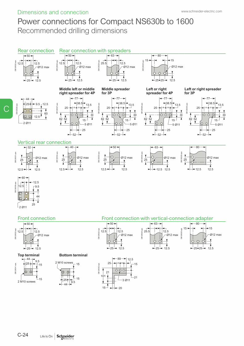
C-24
Power connections for Compact NS630b to 1600Recommended drilling dimensions
Rear connection Rear connection with spreaders
DB1
2832
2.ep
s
DB1
2832
2.ep
s
DB1
2832
4.ep
s
DB1
2832
5.ep
s
Middle left or middle right spreader for 4P
Middle spreader for 3P
Left or right spreader for 4P
Left or right spreader for 3P
44
25 9.5 12.5
12.5
2 Ø11
60DB1
2832
6.ep
s
DB1
2832
7.ep
s
DB1
2832
8.ep
s
DB1
2832
9.ep
s
DB1
2833
0.ep
s
Vertical rear connection
DB1
2833
1.ep
s
DB1
2833
2.ep
s
DB1
2833
3.ep
s
DB1
2833
4.ep
s
DB1
2833
5.ep
s
44
25
9.512.5
12.5
2 Ø11
60
DB1
2833
6.ep
s
Front connection Front connection with vertical-connection adapter
DB1
2832
2.ep
s
DB1
2832
2.ep
s
DB1
2832
4.ep
s
DB1
2832
5.ep
s
Top terminal Bottom terminal
259.5
44
152 M10 screws
15
9.52544
152 M10 screws
15
DB1
2834
1.ep
s
DB1
2834
2.ep
s
www.schneider-electric.comDimensions and connection
C

C-25
Power connections for Compact NS1600b to 3200Recommended drilling dimensions
Front connection (NS1600b to 2500)
DB1
2832
2.ep
s
DB1
2832
4.ep
s
DB1
2832
5.ep
s
DB1
2834
6.ep
s
Front connection with vertical-connection adapter (NS1600b to 2500)
DB1
2834
7.ep
s
DB1
2834
8.ep
s
DB1
2834
9.ep
s
DB1
2835
0.ep
s
DB1
2835
1.ep
s
Front connection (NS3200)
DB1
2834
9.ep
s
DB1
2835
0.ep
s
DB1
2835
1.ep
s
www.schneider-electric.com Dimensions and connection
C

C-26
Power connections for Compact NS630b to 3200
Conductor materials and electrodynamic stressesCompact circuit breakers can be connected indifferently with bare-copper, tinned-copper and tinned-aluminium conductors (flexible or rigid bars, cables).In the event of a short-circuit, thermal and electrodynamic stresses will be exerted on the conductors. They must therefore be correctly sized and maintained in place using supports.Electrical connection points on all types of devices (switch-disconnectors, contactors, circuit breakers, etc.) should not be used for mechanical support.Any partition between upstream and downstream connections of the device must be made of non-magnetic material.Ties for flexible bars and cablesThe table below indicates the maximum distance between ties depending on the prospective short-circuit current.The maximum distance between ties attached to the switchboard frame is 400 mm.
Type of tie "Panduit" tiesWidth: 4.5 mmMaximum load: 22 kgColour: white
"Sarel" tiesWidth: 9 mmMaximum load: 90 kgColour: black
Maximum distancebetween ties (mm)
200 100 50 350 200 100 70 50 (double ties)
Short-circuitcurrent (kA rms)
10 15 20 20 27 35 45 100
Note: For cables u 50 mm2, use 9 mm-wide ties.
B
E
DB1
2835
6.ep
s
C
E
DB1
2835
7.ep
s
Connection of barsBars must be adjusted to ensure correct positioning on the terminals before bolting (B).Bars must rest on a support firmly attached to the switchboard frame, such that the circuit breaker terminals do not bear any weight (C).
Electrodynamic forcesThe first spacer between bars must be positioned within a maximum distance (see table below) of the connection point to the circuit breaker. This distance is calculated to resist the electrodynamic stresses exerted between the bars of each phase during a short-circuit.
Maximum distance A between the circuit breaker connection and the first spacer between bars, depending on the short-circuit current
Isc (kA) 30 50 65 80 100 150Distance (mm) 350 300 250 150 150 150
B C
DB1
2835
9.ep
s
DB4
2472
0.ep
s
DB4
2472
2.ep
s
B
DB4
2472
1.ep
s
www.schneider-electric.comDimensions and connection
C

C-27
Power connections for Compact NS630b to 3200
ConnectionsThe quality of bar connections depends, among other things, on the tightening torques used for the nuts and bolts. Over-tightening may have the same consequences as under-tightening.The correct tightening torques for the connection of bars to the circuit breaker terminals are indicated in the table below.The values below are for copper bars (Cu ETP-NFA51-100) and steel nuts and bolts (class 8.8). The same values apply to AGS-T52 quality aluminium bars (French standard NFA 02-104 and American National Standard H-35-1).Examples of bar connections
DB1
2836
2.ep
s
DB1
2836
3.ep
s
DB1
2836
4.ep
s
Tightening torque for barsRated diameter (mm)
Drilling (mm) diameter
Tightening torque (Nm) with flat or grower washers
Tightening torque (Nm) with contact or split washers
10 11 37.5 50Bar drillingExamples
DB1
2836
5.ep
s
DB1
2836
6.ep
s
DB1
2836
7.ep
s
Insulation distance
X
DB1
2836
8.ep
s
Dimensions (mm)Utilisation voltage X minimum
Ui y 600 V 8 mmUi y 1000 V 14 mm
Bar bendingBars must be bent according to the table below. A tighter bend may cause cracks.
e
r
DB1
2836
9.ep
s
Dimensions (mm)e Radius r
Minimum Recommended5 5 7.510 15 18 to 20
4 532
6
1
DB1
2836
1.ep
s
1 terminal screws, factory tightened to 13 Nm2 circuit breaker terminal3 bars4 bolt5 washer6z nut
www.schneider-electric.com Dimensions and connection
C

C-28
Power connections for Compact NS630b to 3200Sizing of bars
The following tables are based on the following assumptions: b maximum permissible temperature of bars is 100 °C b Ti: temperature around the circuit breaker and its connections b busbars made of copper and not painted.
Note: The values presented in the tables are the result of trials and theoretical calculations on the basis of the assumptions mentioned above. These tables are intended as an aid in designing connections, however, the actual values must be confirmed by tests on the installation.
Front or horizontal rear connections
DB1
2837
0.ep
s
Compact Maximum service current
Ti: 40 °C Ti: 50 °C Ti: 60 °CNumber of bars Number of bars Number of bars5 mm thick
10 mm thick
5 mm thick
10 mm thick
5 mm thick
10 mm thick
NS630b 400 2b.30 x 5 1b.30 x 10 2b.30 x 5 1b.30 x 10 2b.30 x 5 1b.30 x 10NS630b 630 2b.40 x 5 1b.40 x 10 2b.40 x 5 1b.40 x 10 2b.40 x 5 1b.40 x 10NS800 800 2b.50 x 5 1b.50 x 10 2b.50 x 5 1b.50 x 10 2b.50 x 5 1b.63 x 10NS1000 1000 3b.50 x 5 1b.63 x 10 3b.50 x 5 2b.50 x 10 3b.63 x 5 2b.50 x 10NS1250 1250 3b.50 x 5 2b.40 x 10 3b.50 x 5 2b.50 x 10 3b.63 x 5 2b.50 x 10
2b.80 x 5 2b.40 x 10 2b.80 x 5NS1600/ 1600b
1400 2b.80 x 5 2b.40 x 10 2b.80 x 5 2b.50 x 10 3b.80 x 5 2b.63 x 10
NS1600/ 1600b
1600 3b.80 x 5 2b.63 x 10 3b.80 x 5 2b.63 x 10 3b.80 x 5 3b.50 x 10
NS2000 1800 3b.80 x 5 2b.63 x 10 3b.80 x 5 2b.63 x 10 3b.100 x 5 2b.80 x 10NS2000 2000 3b.100 x 5 2b.80 x 10 3b.100 x 5 2b.80 x 10 3b.100 x 5 3b.63 x 10NS2500 2200 3b.100 x 5 2b.80 x 10 3b.100 x 5 2b.80 x 10 4b.80 x 5 2b.100 x 10NS2500 2500 4b.100 x 5 2b.100 x 10 4b.100 x 5 2b.100 x 10 4b.100 x 5 3b.80 x 10NS3200 2800 4b.100 x 5 3b.80 x 10 4b.100 x 5 3b.80 x 10 5b.100 x 5 3b.100 x 10NS3200 3000 5b.100 x 5 3b.80 x 10 6b.100 x 5 3b.100 x 10 8b.100 x 5 4b.80 x 10NS3200 3200 6b.100 x 5 3b.100 x 10 8b.100 x 5 3b.100 x 10 4b.100 x 10
Note: With Compact NS630b to NS1600, it is recommended to use 50 mm wideness bars (see "Recommended busbars drilling").
www.schneider-electric.comDimensions and connection
C

C-29
Power connections for Compact NS630b to 3200Sizing of bars
Vertical rear connections
DB1
2837
1.ep
s
Compact Maximum service current
Ti: 40 °C Ti: 50 °C Ti: 60 °CNumber of bars Number of bars Number of bars5 mm thick
10 mm thick
5 mm thick
10 mm thick
5 mm thick
10 mm thick
NS630b 400 2b.30 x 5 1b.30 x 10 2b.30 x 5 1b.30 x 10 2b.30 x 5 1b.30 x 10NS630b 630 2b.40 x 5 1b.40 x 10 2b.40 x 5 1b.40 x 10 2b.40 x 5 1b.40 x 10NS800 800 2b.50 x 5 1b.50 x 10 2b.50 x 5 1b.50 x 10 2b.50 x 5 1b.50 x 10NS1000 1000 2b.50 x 5 1b.50 x 10 2b.50 x 5 1b.50 x 10 2b.63 x 5 1b.63 x 10NS1250 1250 2b.63 x 5 1b.63 x 10 3b.50 x 5 2b.40 x 10 3b.50 x 5 2b.40 x 10NS1600 1400 2b.80 x 5 1b.80 x 10 2b.80 x 5 2b.50 x 10 3b.63 x 5 2b.50 x 10NS1600 1600 3b.63 x 5 2b.50 x 10 3b.63 x 5 2b.50 x 10 3b.80 x 5 2b.63 x 10NS2000 2000 3b.100 x 5 2b.63 x 10 3b.100 x 5 2b.63 x 10 3b.100 x 5 2b.80 x 10NS2500 2500 4b.100 x 5 2b.80 x 10 4b.100 x 5 2b.80 x 10 4b.100 x 5 3b.80 x 10NS3200 3200 6b.100 x 5 3b.100 x 10 6b.100 x 5 3b.100 x 10 4b.100 x 10
www.schneider-electric.com Dimensions and connection
C


D-1
Compact NS630b to 3200
Electrical diagrams
Compact NS630b to 1600Fixed circuit breakers .................................................................................................. D-2Withdrawable circuit breakers ..................................................................................... D-4
Compact NS1600b to 3200Fixed circuit breakers .................................................................................................. D-6
Compact NS630b to 3200Earth-fault and earth-leakage protectionNeutral protection Zone selective interlocking .......................................................................................... D-8
Compact NS630b to 3200Communication .......................................................................................................... D-10
Fixed, electrically operated Compact NS630b to 3200Connection to the communication interface module ................................................ D-11Connection to the I/O application module and communication interface module ... D-12
Compact NS630b to 3200Connection of the 24 V DC external power supply AD module ............................... D-13
www.schneider-electric.com
D

D-2
Compact NS630b to 1600Fixed circuit breakers
Power Control unit Remote operation
Power Upstream cb Downstream cb
24 V DC
Q
Micrologic
M1
M2
T3 F2+
T2
T1/M
3
T4/F
1
VN Z1 Z2 Z3 Z4 Z5
Z1 Z2 Z3 Z4 Z5 Z1 Z2 Z3 Z4 Z5
L2 L3L1N
DB4
3210
2.ep
s
or
AT BPO BPF
MN MX
D2
A2A4 B4C2
D1 1A1C
Motor-mechanismmodule
DB4
2473
8.ep
s
Basic A E P Control unitE1-E6 communication
Z1-Z5 zone selective interlocking:Z1 = ZSI OUT SOURCEZ2 = ZSI OUT ; Z3 = ZSI IN SOURCEZ4 = ZSI IN ST (short time)Z5 = ZSI IN GF (earth fault)M1 = Vigi module input(Micrologic 7)
T1, T2, T3, T4 = external neutral;
M2, M3 = Vigi module input (Micrologic 7)F2+, F1– external 24 V DC power supplyVN external voltage connector (must be connected to the neutral with a 3P circuit breaker)
E : energy
A : digital ammeter.
P : A + power meter + additional protection.
Remote operationM : undervoltage releaseorMX: shunt release
Motor-mechanism module [1]
A4: electrical opening orderA2: electrical closing orderB4, A1: power supply for control devices and gear motor
[1] Spring-charging motor 440/480 V AC (380 V motor + additional resistor)
A1CN2 a - 440/480 V
A2A4
CN1 a - 440/480 V
Motor-mechanismmodule
DB4
2473
3.ep
s
The diagram is shown with circuits de-energised, all devices open, connected and charged and relays in the normal position.
www.schneider-electric.comElectrical diagrams
D

D-3
Compact NS630b to 1600Fixed circuit breakers
Indication contacts Terminal-block marking (manual operation)
OpenFaultFaultClosed ClosedOpen
OF3
31 21 11 81 91 511
512
524
522
514
534
542
544
92 9432 34 22 24 12 14 82 84 532
521
531
541
OF2 OF1 SDE SD CAF2 CAF1 CAO1CAO2
DB1
2837
5.ep
s
Blac
kBr
own
Yello
wW
hite
E6 E5 E4 E3 E2 E1
Z1 Z2 Z3 Z4 Z5M1M2M3
T1 T2 T3F1T4
F2
MN/MX
D2/C2
D1/C1
CAO2CAO1CAF2CAF1
524
522
521
514
512
511
544
542
541
534
532
531
84
SDE
82
81
OF111 12 14
OF221 22 24
OF331 32 34
SD91 92 94
Blue
Red
DB4
2473
7.ep
s
Indication contacts Terminal-block marking (electrical operation)OF3 / OF2 / OF1: indication contacts
SDE: fault-trip indication contact (short-circuit, overload, earth fault)
SD: trip indication contact (manual operation)
CAF2/CAF1: early-make contact (rotary handle)
CAO2 / CAO1: early-break contact (rotary handle)
E6 E5 E4 E3 E2 E1MN/MX
D2/C2
D1/C1Z1 Z2 Z3 Z4 Z5
M1M2M3T1 T2 T3
F1T4
F2
A1A2A4B4
SDE OF3 OF2 OF1
81
82
84
31
32
34
21
22
24
11
12
14
Blac
kBr
own
Yello
wW
hite
Blue
Red
DB4
2473
6.ep
s
www.schneider-electric.com Electrical diagrams
D

D-4
Compact NS630b to 1600Withdrawable circuit breakers
Power Control unit Remote operation
Power Upstream cb Downstream cb
24 V DC
Q
Micrologic
M1
M2
T3 F2+
T2
T1/M
3
T4/F
1
VN Z1 Z2 Z3 Z4 Z5
Z1 Z2 Z3 Z4 Z5 Z1 Z2 Z3 Z4 Z5
L2 L3L1N
DB4
2473
5.ep
s
orD
21D
AT
MN
BPO
A2A4
BPF
1AB4
MX
C2
1C
Motor-mechanismmodule
DB4
2473
4.ep
s
Terminal-block marking Control unit Remote operationCom UC1 UC2 UC3 CAF2 MN / MX MT2 MT1
/E5 E6 Z5 M1 M2 M3 F2+ 544 D2 C2 A4 A2
E3 E4 Z3 Z4 T3 T4 VN 542 B4 /
E1 E2 Z1 Z2 T1 T2 F1 – 541 D1 C1 A1
Basic A E P Control unitCom: E1-E6 communication
UC1: Z1-Z5 zone selective interlocking:Z1 = ZSI OUT SOURCEZ2 = ZSI OUT; Z3 ZSI IN SOURCEZ4 = ZSI IN ST (short time)Z5 = ZSI IN GF (earth fault)
M1 = Vigi module input(Micrologic 7)
UC2: T1, T2, T3, T4 = external neutral;M2, M3 = Vigi module input (Micrologic 7)
UC3: F2+, F1- external 24 V DC power supplyVN external voltage connector (must be connected to the neutral with a 3P circuit breaker)
Remote operationMN: undervoltage releaseorMX: shunt release
Motor-mechanism moduleMT2: A4 : electrical opening order
MT1: A2 : electrical closing order B4, A1 : power supply for control devices and gear motor (MCH)
A : digital ammeter.
P : A + power meter + additional protection.
The diagram is shown with circuits de-energised, all devices open, connected and charged and relays in the normal position.
www.schneider-electric.comElectrical diagrams
D

D-5
Compact NS630b to 1600Withdrawable circuit breakers
Indication contacts Carriage switches
OF3 OF2 OF1
OpenFaultFaultClosed ClosedOpen
SDE SD CAF2 CAF1 CAO1CAO2
512
524
522
514
534
542
544
92 9432 34 22 24 12 14 82 84 532
31 21 11 81 91 511
521
531
541
DB1
2838
1.ep
s
814
822
824
811
821
812
CD2 CD1
Disconnected
DB1
2815
0.ep
s
Connected
331
321
311
332
322
312
314
334
324
CE3 CE2 CE1
DB1
2838
2.ep
s
Test
911
912
914
CT1
DB1
2818
8.ep
s
Indication contacts Carriage switchesCAF2 CAF1 SDE SD CAO2 CAO1 OF3 OF2 OF1 CD2 CD1 CE3 CE2 CE1 CT1
544 534 84 94 524 514 34 24 14 824 814 334 324 314 914
542 532 82 92 522 512 32 22 12 822 812 332 322 312 912
541 531 81 91 521 511 31 21 11 821 811 331 321 311 911
Indication contacts Carriage switchesOF3 / OF2 / OF1: indication contacts
SDE: fault-trip indication contact (short-circuit, overload, earth fault)
SD: trip indication contact (manual operation)
CAF2/CAF1: early-make contact (rotary handle)
CAO2 / CAO1: early-break contact (rotary handle)
CD2: disconnected CD1: position
CE3: connected CE2: position CE1
CT1: test position
Legend Connected (only one wire per connection point).
www.schneider-electric.com Electrical diagrams
D

D-6
Compact NS1600b to 3200Fixed circuit breakers
Power Control unit Remote operation
Power Upstream cb Downstream cb
24 V DC
Q
Micrologic
M1
M2
T3 F2+
T2
T1/M
3
T4/F
1
Z1 Z2 Z3 Z4 Z5
Z1 Z2 Z3 Z4 Z5 Z1 Z2 Z3 Z4 Z5
L2 L3L1N
DB4
2472
9.ep
s
or
AT
MN MX
D2
C2
D1 1C
DB4
2472
8.ep
s
– (basic) A E Control unitE1-E6 communication
Z1-Z5 zone selective interlocking:Z1 = ZSI OUT SOURCEZ2 = ZSI OUT ; Z3 = ZSI IN SOURCEZ4 = ZSI IN ST (short time)Z5 = ZSI IN GF (earth fault)M1 = Vigi module input (Micrologic 7)T1, T2, T3, T4 = external neutral;M2, M3 = Vigi module input (Micrologic 7)F2+, F1- external 24 V DC power supply
Remote operationMN: undervoltage releaseorMX: shunt release
– : basic Micrologic control unit.
A: digital ammeter.
The diagram is shown with circuits de-energised, all devices open, connected and charged and relays in the normal position.
www.schneider-electric.comElectrical diagrams
D

D-7
Compact NS1600b to 3200Fixed circuit breakers
Indication contacts Terminal-block marking
FaultFaultClosedOpen
OF3 OF2 OF1 SDE SD
32 34 22 24 12 14 82 84 92 94
31 21 11 81 91
DB1
2839
2.ep
s E6 E5 E4 E3 E2 E1MN/MX
D2/C2
D1/C1OF1
11 12 14
OF221 22 24
OF331 32 34
SD91 92 94
84
SDE
82
81
Z1 Z2 Z3 Z4 Z5M1M2M3
T1 T2 T3F1T4
F2
DB4
2472
7.ep
s
Indication contactsOF3 / OF2 / OF1: ON / OFF indication contacts
SDE: fault-trip indication contact (short-circuit, overload, earth fault)
SD: trip indication contact
www.schneider-electric.com Electrical diagrams
D

D-8
Compact NS630b to 3200Earth-fault and earth-leakage protection Neutral protection Zone selective interlockingExternal sensor (CT) for residual earth-fault protection
Connection of current-transformer secondary circuit for external neutral Compact equipped with a Micrologic 6 A/E/P [1]:
b shielded cable with 2 twisted pairs b T1 twisted with T2 b maximum length 4 meters b cable cross-sectional area 0.4 to 1.5 mm2 b recommended cable: Belden 9552 or equivalent.
For proper wiring of neutral CT, refer to instruction Bulletin 48041-082-03 shipped with it. Do not remove Micrologic factory-installed jumper between T1 and T2 unless neutral CT is connected. If supply is via the top, follow the shematics. If supply is via the bottom, control wiring is identical; for the power wiring, H1 is connected to the source side, H2 to the load side. For four-pole versions, for residual earth-fault protection, the current transformer for the external neutral is not necessary. Connection for signal VN is required only for power measurements (3 Ø, 4 wires, 4CTs).
[1] Only for NS630b to 1600.
Shield Drain
DB4
2472
6.ep
s
External transformer for source ground return (SGR) earth-fault protection
Connection of the secondary circuitCompact equipped with a Micrologic 6 A/E/P [1]:
unshielded cable with 1 twisted pair b maximum length 150 metres b cable cross-sectional area 0.4 to 1.5 mm2
b recommended cable: Belden 9409 or equivalent.
[1] Only for NS630b to 1600.
Q
Micrologic 6
PE
X1
X2 814
111012 5 6 7
13
931
H1
H2MiDGF module
M1
M2 T3 F2+
T2T1
/M3
T4/F
1
Z1 Z2 Z3 Z4 Z5
DB4
2473
2.ep
s
www.schneider-electric.comElectrical diagrams
D

D-9
Earth-leakage protectionConnection of the rectangular-sensor secondary circuitCompact equipped with a Micrologic 7 A/P: use the cable shipped with the rectangular sensor.
Micrologic 7
4Z3Z2Z1Z 5Z
I
Q
M1M2
M3
U
M1
M2 T3 F2+
T2T1
/M3
T4/F
1
L2 L3L1N
DB4
2473
1.ep
s
Neutral protection b three pole circuit breaker: v neutral protection is impossible with Micrologic A,E v with Micrologic P, an external neutral transformer is necessary; the connection diagram is the same as for residual earth-fault protection. b four pole circuit breaker: v Compact equipped with Micrologic A,E,P v the current transformer for external neutral is not necessary.
Zone selective interlockingZone-selective interlocking is used to reduce the electrodynamic forces exerted on the installation by shortening the time required to clear faults, while maintaining time selectivity between the various devices.A pilot wire interconnects a number of circuit breakers equipped with Micrologic A/E/P control units, as illustrated in the diagram above.The control unit detecting a fault sends a signal upstream and checks for a signal arriving from downstream. If there is a signal from downstream, the circuit breaker remains closed for the full duration of its tripping delay. If there is no signal from downstream, the circuit breaker opens immediately, regardless of the tripping-delay setting.Fault 1.Only circuit breaker A detects the fault. Because it receives no signal from downstream, it immediately opens in spite of its tripping delay set to 0.3.Fault 2.Circuit breakers A and B detect the fault. Circuit breaker A receives a signal from B and remains closed for the full duration of its tripping delay set to 0.3. Circuit breaker B does not receive a signal from downstream and opens immediately, in spite of its tripping delay set to 0.2.Wiring
b Maximum impedance: 2.7 Ω / 300 m. b Capacity of connectors: 0.4 to 2.5 mm2.
b Wires: single or multicore. b Maximum lenght: 3000 m. b Limits to device interconnection: v the common ZSI - OUT (Z1) and the output ZSI - OUT
(Z2) can be connected to a maximum of 10 upstream device
v a maximum of 100 downstream devices may be connected to the common ZSI - IN (Z3) and to an input ZSI - IN CR ( Z4) or GF (Z5).
Downstreamcircuit break
Fault 1
Fault 2
Upstreamcircuit break tsd = 0.3
tsd = 0.2
A
B
DB4
2473
0.ep
s
Compact NS630b to 3200Earth-fault and earth-leakage protection
Neutral protection Zone selective interlocking
www.schneider-electric.com Electrical diagrams
D

D-10
Connection of circuit breakers to the Modbus communication network
F1
F1
F2
F2
F3
F3
F4CH
PF
SD
XFX1
X2N/
C42C
esDE2
XN/ T2
DE1C3
C2
C2
C1
AF1
T1
A01A02
+24VDC
13
O1
+
I1
24VDC
I2I3
I4I5
I6
C
C
C
1423
2433
34T1 T2
O2
O3
A1
LV434063
IO
I1
A1
O1
O2
O3I2I3
I4I5
I6
APP
+24VDC
13
O1
+
I1
24VDC
I2I3
I4I5
I6
C
C
C
1423
2433
34T1 T2
O2
O3
A1
LV434063
IO
I1
A1
O1
O2
O3I2I3
I4I5
I6
APP
Test
Test
LV434002
Enerlin'X IFE
Modbus
L
Enerlin'X IFE
LV434001
Enerlin'X IFE
24 V DC
24 V DC
24 V DC
Ethernet
DC
E
F
F G H H
C
B
A A A
KK
K
L L L M M
K
K
J
I I
I I I
I
+24VDC
13
O1
+
I1
24VDC
I2I3
I4I5
I6
C
C
C
1423
2433
34T1 T2
O2
O3
A1
LV434063
IO
I1
A1
O1
O2
O3I2I3
I4I5
I6
APP
DB4
3254
7.ep
s
K ULP cable
L Breaker ULP cord
M NSX cord
Ethernet
Modbus
A FDM121 (TRV00121) E I/O application module (LV434063) I ULP termination (TRV00880)
B IFE master (LV434002) F Masterpact MTZ1/MTZ2 J FDM128 (LV434128)
C IFE (LV434001) G Compact NS630b-3200 N Modbus Termination [1]
(VW3A8306DRC)D IFM (LV434000) H Compact NSX
[1] Modbus termination is mandatory, see ULP system user guide TRV99101.
Compact NS630b to 3200 Communication
www.schneider-electric.comElectrical diagrams
D

D-11
Fixed, electrically operated Compact NS630b to 3200Connection to the communication interface module
B’ / Rx + D
1
A’ / Rx - D
0
B / Tx + D1
A / Tx - D0
0 V
24 VE1
Red
Breaker ULP cord
Black Blue
E2 E3 E4 E5 E6
Customer terminal block
White
ColorRed E1Black E2White E5Blue E6
24 V0 VHL
Ethernet
ULP TerminationULP Termination
LV434002
Enerlin'X IFE
24 V DC
IFMIFE
Test
24 V DC
OR
DB4
3254
8.ep
s
www.schneider-electric.com Electrical diagrams
D

D-12
Withdrawable Compact NS630b to 3200Connection to the I/O application module and communication interface module
ColorRed E1Black E2White E5Blue E6
24 V0 VHL
B’ / Rx + D
1
A’ / Rx - D
0
B / Tx + D1
A / Tx - D0
0 V
24 VE1
Red Black Blue
E2 E3 E4 E5 E6
White
Customer terminal block
Ethernet
OR
ULP cable
ULP Termination
FDM121
BreakerULP cord
ULP Termination
LV434002
Enerlin'X IFE
24 V DC
IFM IFE
Test
24 V DC
+24VDC
13
O1
+
I1
24VDC
I2I3
I4I5
I6
C
C
C
1423
2433
34T1 T2
O2
O3
A1
LV434063
IO
I1
A1
O1
O2
O3I2I3
I4I5
I6
APP
I/O application module
DB4
3254
9.ep
swww.schneider-electric.comElectrical diagrams
D

D-13
Compact NS630b to 320024 V DC external power supply AD module
110/240 V AC24/125 V DC
DB4
3261
1.ep
s
b With Micrologic, it is recommended to connect 24 V DC external power supply (AD module) to the Micrologic control unit (F1- F2+) in order
v to keep available the display and the energy metering, even if Current < 20 % In. v to use the display even if the circuit breaker is open or not supplied (for the exact
conditions of use, see the “electrical diagrams” part of this catalogue) v to display fault currents after tripping v to modify settings when the circuit breaker is open (OFF position). b The same 24 V DC external power supply can be used for the micrologic control
unit and the communication devices (IFE, IFM, I/O, FDM). b The 24 V DC external power supply (AD module) for the Micrologic control unit
(F1- F2+) is not required for basic protections LSIG. b The 24 V DC external power supply for the BCM ULP communication module
(E1-E2) is required. The same 24 V DC external power supply can be used for the communication devices (IFE, IFM, I/O, FDM).
b If the 24 V DC external power supply (AD module) is used to supply Micrologic control unit, this power supply shall be used only for supplying Micrologic control unit and M2C.
b The dedicated AD power supply shall be used only for the Micrologic trip unit. If the COM option is used, a second dedicated 24 V DC external power supply shall be used.
Note: case of using the 24 V DC external power supply (AD module), maximum cable length between 24 V DC (G1, G2) and the control unit (F1-, F2+) must not exceed 10 meters. The internal voltage taps are connected to the bottom side of the circuit breaker. An external voltage taps are possible using the PTE option: b With this option, the internal voltage taps are disconnected and the voltage taps are connected to terminals VN, V1, V2, V3. b The PTE option is required for voltages less than 220 V and greater than 690 V (in which case a voltage transformer is compulsory). For three-pole devices, the system is supplied with terminal VN connected only to the control unit. b When the PTE option is implemented, the voltage measurement input must be protected against short-circuits. Installed as close as possible to the busbars, this protection function is ensured by a P25M circuit breaker (1 A rating) with an auxiliary contact (cat. no. 21104 and 21117). b This voltage measurement input is reserved exclusively for the control unit and must not ever be used to supply other circuits outside the switchboard.
ConnectionThe maximum length for each conductor supplying power to the trip unit module is 10 m.Do not ground F2+, F1-, or power supply output:
b the positive terminal (F2+) on the trip unit must not be connected to earth ground b the negative terminal (F1-) on the trip unit must not be connected to earth ground b the output terminals (- and +) of the 24 V DC power supply must not be grounded.
Reduce electromagnetic interference: b the input and output wires of the 24 V DC power supply must be physically
separated as much as possible b the 24 V DC wires (output of the 24 V DC power supply) shall be twisted together b the 24 V DC wires (output of the 24 V DC power supply) must cross all power
cables perpendicularly b power supply conductors must be cut to length. Do not loop excess conductor.
www.schneider-electric.com Electrical diagrams
D


E-1
Compact NS630b to 3200
Additional characteristics
Tripping curvesCompact NS630b to 3200 ............................................................................................E-2
Current-limiting curves ................................................................................ E-3
www.schneider-electric.com
E

E-2
Tripping curvesCompact NS630b to 3200
Micrologic electronic control units
Micrologic 2.0 Micrologic 5.0, 6.0, 7.0
DB4
2474
4.ep
s
DB4
2474
3.ep
s
Options for Micrologic electronic control units
Earth-fault protection (Micrologic 6.0)
0.40.30.20.10
I²t ON
I²t OFF
DB4
2474
2.ep
s
[1]
Ig = In x… A B C D E F G H JIn < 400 A 0.3 0.3 0.4 0.5 0.6 0.7 0.8 0.9 1400 A y In y 1200 A 0.2 0.3 0.4 0.5 0.6 0.7 0.8 0.9 1In > 1200 A 500 640 720 800 880 960 1040 1120 1200
www.schneider-electric.comAdditional characteristics
E

E-3
Current-limiting curves
The limiting capacity of a circuit breaker is its aptitude to limit short-circuit currents.
Ics = 100 % IcuThe exceptional limiting capacity of the Compact NS range greatly reduces the forces created by fault currents in devices.The result is a major increase in breaking performance. In particular, the service breaking capacity Ics is equal to 100 % of Icu for limitor circuit breaker.The Ics value, defined by IEC standard 60947-2, is guaranteed by tests comprising the following operations:
b break three times consecutively a fault current equal to 100 % of Icu b check that the device continues to function normally: v it conducts the rated current without abnormal temperature rise v protection functions perform within the limits specified by the standard v suitability for isolation is not impaired.
Longer service life of electrical installationsCurrent-limiting circuit breakers greatly reduce the negative effects of short-circuits on installations.Thermal effectsLess temperature rise in conductors, therefore longer service life for cables.Mechanical effectsReduced electrodynamic forces, therefore less risk of electrical contacts or busbars being deformed or broken.Electromagnetic effectsLess disturbances for measuring devices located near electrical circuits.Economy by means of cascadingCascading is a technique directly derived from current limiting. Circuit breakers with breaking capacities less than the prospective short-circuit current may be installed downstream of a limiting circuit breaker. The breaking capacity is reinforced by the limiting capacity of the upstream device.It follows that substantial savings can be made on downstream equipment and enclosures.Current-limiting curvesThe current-limiting capacity of a circuit breaker is expressed by two curves which are a function of the prospective short-circuit current (the current which would flow if no protection devices were installed):
b the actual peak current (limited current), b thermal stress (A2s), i.e. the energy dissipated by the short-circuit in a conductor
with a resistance of 1 Ω.ExampleWhat is the real value of a 200 kA rms prospective short-circuit (i.e. 440 kA peak) limited by an NS630bLB upstream ?Answer: 70 kA peak (see next page).
(t)
ProspectiveIsc peak
(Isc)
Prospectivecurrent
ProspectiveIsc
Limited Iscpeak
Actualcurrent
LimitedIsc
DB4
2474
1.ep
s
The exceptional limiting capacity of the Compact NS range is due to the rotating double-break technique (very rapid natural repulsion of contacts and the appearance of two arc voltages in-series with a very steep wave front).
www.schneider-electric.com Additional characteristics
E

E-4
Current-limiting curves
Current-limiting curvesVoltage 400/440 V AC (1) Voltage 660/690 V ACLimited short-circuit current (k peak) Limited short-circuit current (k peak)
kÂ
NS630bLNS800LNS1000L
NS630bHNS800HNS1000HNS1250HNS1600HNS630bN
NS800NNS1000NNS1250NNS1600N
NS630bLBNS800LB
NSX630L R
R
SH
NF LS
HN
FB
NSX400
NSX250NSX100NSX160
DB4
2474
0.ep
s
kÂ
NS1600bNNS2000NNS2500NNS3200N
NS630bLNS800LNS1000L
NS630bHNS800HNS1000HNS1250HNS1600HNS630bN
NS800NNS1000NNS1250NNS1600N
NS630bLBNS800LB NSX630
L
L
NSX400
NSX250NSX100NSX160
S
S
H
F, N
F
R
R
HB1
HB1
HB2
HB2
N, H
DB4
2473
9.ep
s
Rated short-circuit current (kA rms) Rated short-circuit current (kA rms)
Thermal-stress curvesVoltage 400/440 V AC [1] Voltage 660/690 V ACLimited energy Limited energy
NS630bHNS800HNS1000HNS1250HNS1600H
NS630bNNS800NNS1000NNS1250NNS1600N
NS630bLBNS800LB
NS1000LNS630bLNS800L
B
NSX630NSX400
NSX250NSX100NSX160
LSHF N
L R
R
SHF N
DB4
1993
1.ep
s
NS1600bNNS2000NNS2500NNS3200N
NS630bLNS800LNS1000L
NS630bHNS800HNS1000HNS1250HNS1600H
NS630bNNS800NNS1000NNS1250NNS1600N
NS630bLBNS800LB
N, H
HNSX630NSX400
NSX250NSX100NSX160
L
L
S
S
F, N
F
R
R
HB1
HB1
HB2
HB2
DB4
1993
2.ep
s
Rated short-circuit current (kA rms) Rated short-circuit current (kA rms)
[1] Valid for 480 V Nema.
www.schneider-electric.comAdditional characteristics
E

F-1
Catalogue numbers and order forms
Compact NS630b to 3200
NS630b to NS1600 fixed manually operatedComplete device ...........................................................................................................F-2Device based on separate components ......................................................................F-4
NS630b to NS1600 fixed electrically operatedDevice based on separate components ......................................................................F-5
NS630b to NS1600 manually operated withdrawable devicesDevice based on separate components ......................................................................F-6
NS630b to NS1600 electrically operated withdrawable devicesDevice based on separate components ......................................................................F-7
Accessories for NS630b to NS1600 fixed devices ............................F-8
Accessories for NS630b to NS1600 withdrawable devices ...........F-9
Accessories for NS630b to NS1600 fixed and withdrawable devices ............................................................ F-11Mechanical interlocking ..............................................................................................F-12
Communication option for NS630b to NS1600 fixed and withdrawable devices ............................................................ F-13
NS1600b to NS3200 fixed, front-connected, manually operated device .............................................................................................................. F-14
Accessories for NS1600b to NS3200 .................................................. F-15
Spare parts: NS630b to NS1600 fixed circuit breakerConnection ..................................................................................................................F-16Electrical auxiliaries and installation accessories.......................................................F-17Micrologic control unit, external sensor......................................................................F-18Locking and accessories ............................................................................................F-19
Spare parts: NS630b to NS1600 fixed and withdrawable circuit breakerMechanical interlocking for source changeover ........................................................F-20
Spare parts: NS630b to NS1600 withdrawable circuit breakerConnection ..................................................................................................................F-21Electrical auxiliaries .....................................................................................................F-22Installation accessories ...............................................................................................F-23Micrologic control unit, external sensor......................................................................F-24Locking and accessories ............................................................................................F-25Chassis locking and accessories Mechanical interlocking for source changeover ..F-26
Spare parts: NS630b to NS1600 fixed or withdrawable circuit breakerInstructions ..................................................................................................................F-27
Spare parts: Communication bus accessories, monitoring and control, ethernet gateway ......................................................................... F-28
Spare parts: Compact NS1600b to 3200Connection, locking and installation accessories ......................................................F-29Micrologic control unit, external sensor......................................................................F-30
Order form: Compact NS630b to NS3200Circuit breakers and switch-disconnectors ................................................................F-31
www.schneider-electric.com
F

F-2
F
NS630b to NS1600 fixed manually operatedComplete device
Front-connected circuit breaker with Micrologic 2.0 control unit
DB1
2840
5.ep
s
Compact NS type NIcu = 50 kA at 220/415 V 3P 4PNS630b 33460 33463NS800 33466 33469NS1000 33472 33475NS1250 33478 33480NS1600 33482 33484Compact NS type H
Icu = 70 kA at 220/415 V 3P 4PNS630b 33461 33464NS800 33467 33470NS1000 33473 33476NS1250 33479 33481NS1600 33483 33485Compact NS type L
Icu = 150 kA at 220/415 V 3P 4PNS630b 33462 33465NS800 33468 33471NS1000 33474 33477
Front-connected circuit breaker with Micrologic 5.0 control unit
DB1
2840
5.ep
s
Compact NS type NIcu = 50 kA at 220/415 V 3P 4PNS630b 33546 33549NS800 33552 33555NS1000 33558 33561NS1250 33564 33566NS1600 33568 33570Compact NS type H
Icu = 70 kA at 220/415 V 3P 4PNS630b 33547 33550NS800 33553 33556NS1000 33559 33562NS1250 33565 33567NS1600 33569 33571Compact NS type L
Icu = 150 kA at 220/415 V 3P 4PNS630b 33548 33551NS800 33554 33557NS1000 33560 33563
Front-connected circuit breaker with Micrologic 6.0 control unit
DB1
2840
3.ep
s
Compact NS type NIcu = 50 kA at 220/415 V 3P 4PNS630b 33886 33888NS800 33893 33896NS1000 33909 33917NS1250 33919 33923NS1600 33925 33927Compact NS type H
Icu = 70 kA at 220/415 V 3P 4PNS630b 33887 33889NS800 33894 33901NS1000 33916 33918NS1250 33922 33924NS1600 33926 33928
www.schneider-electric.comCatalogue numbers
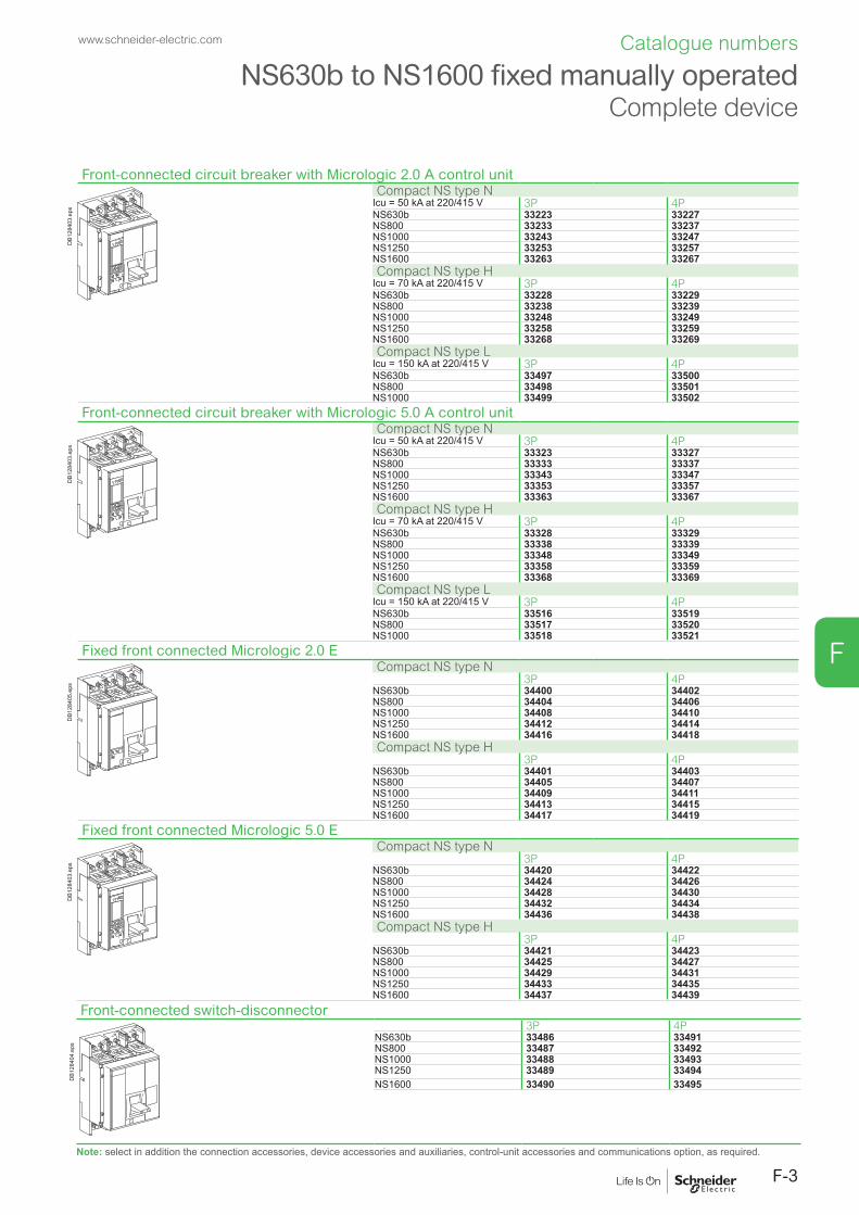
F-3
F
Front-connected circuit breaker with Micrologic 2.0 A control unit
DB1
2840
3.ep
s
Compact NS type NIcu = 50 kA at 220/415 V 3P 4PNS630b 33223 33227NS800 33233 33237NS1000 33243 33247NS1250 33253 33257NS1600 33263 33267Compact NS type H
Icu = 70 kA at 220/415 V 3P 4PNS630b 33228 33229NS800 33238 33239NS1000 33248 33249NS1250 33258 33259NS1600 33268 33269Compact NS type L
Icu = 150 kA at 220/415 V 3P 4PNS630b 33497 33500NS800 33498 33501NS1000 33499 33502
Front-connected circuit breaker with Micrologic 5.0 A control unit
DB1
2840
3.ep
s
Compact NS type NIcu = 50 kA at 220/415 V 3P 4PNS630b 33323 33327NS800 33333 33337NS1000 33343 33347NS1250 33353 33357NS1600 33363 33367Compact NS type H
Icu = 70 kA at 220/415 V 3P 4PNS630b 33328 33329NS800 33338 33339NS1000 33348 33349NS1250 33358 33359NS1600 33368 33369Compact NS type L
Icu = 150 kA at 220/415 V 3P 4PNS630b 33516 33519NS800 33517 33520NS1000 33518 33521
Fixed front connected Micrologic 2.0 E
DB1
2840
5.ep
s
Compact NS type N3P 4P
NS630b 34400 34402NS800 34404 34406NS1000 34408 34410NS1250 34412 34414NS1600 34416 34418Compact NS type H
3P 4PNS630b 34401 34403NS800 34405 34407NS1000 34409 34411NS1250 34413 34415NS1600 34417 34419
Fixed front connected Micrologic 5.0 E
DB1
2840
3.ep
s
Compact NS type N3P 4P
NS630b 34420 34422NS800 34424 34426NS1000 34428 34430NS1250 34432 34434NS1600 34436 34438Compact NS type H
3P 4PNS630b 34421 34423NS800 34425 34427NS1000 34429 34431NS1250 34433 34435NS1600 34437 34439
Front-connected switch-disconnector
DB1
2840
4.ep
s
3P 4PNS630b 33486 33491NS800 33487 33492NS1000 33488 33493NS1250 33489 33494NS1600 33490 33495
Note: select in addition the connection accessories, device accessories and auxiliaries, control-unit accessories and communications option, as required.
NS630b to NS1600 fixed manually operatedComplete device
www.schneider-electric.com Catalogue numbers

F-4
F
NS630b to NS1600 fixed manually operatedDevice based on separate components
Basic circuit breaker
DB1
2840
7.ep
s
Compact NS type NIcu = 50 kA at 220/415 V 3P 4PNS630b 33220 33224NS800 33230 33234NS1000 33240 33244NS1250 33250 33254NS1600 33260 33264Compact NS type H
Icu = 70 kA at 220/415 V 3P 4PNS630b 33221 33225NS800 33231 33235NS1000 33241 33245NS1250 33251 33255NS1600 33261 33265Compact NS type L
Icu = 150 kA at 220/415 V 3P 4PNS630b 33222 33226NS800 33232 33236NS1000 33242 33246Compact NS type LB
Icu = 200 kA at 400/415 V 3P 4PNS630b 48952 48955NS800 48953 48956Micrologic control unitsWithout "measurement"
3P/4PMicrologic 2.0 basic protection 33504Micrologic 5.0 selective protection 33511Micrologic 6.0 selective + earth-fault protection 33515
"ammeter" A3P/4P
Micrologic 2.0 A basic protection 33505Micrologic 5.0 A selective protection 33512Micrologic 6.0 A selective + earth-fault protection 33513Micrologic 7.0 A selective + earth-leakage protection 33514
"energy" E [1]
3P/4PMicrologic 2.0 E basic protection 33535Micrologic 5.0 E selective protection 33537Micrologic 6.0 E selective + earth-fault protection 33539
"power meter" P [1]
3P/4P[2] In case of an installation 3P + Neutral, please add ENVT device ref. 65317 (see page F-13).
Micrologic 5.0 P selective protection 65290Micrologic 6.0 P selective + earth-fault protection 65291Micrologic 7.0 P selective + earth-leakage protection 65292
Basic switch-disconnector
DB1
2840
8.ep
s
Compact NS type NA3P 4P
NS630b 33420 33421NS800 33422 33423NS1000 33424 33425NS1250 33426 33427NS1600 33428 33429
Connections for circuit breakers and switch-disconnectors
DB1
2840
9.ep
s
Front connection3P 4P
630-1000 A - NA/N/H Top 33598 33608Bottom 33599 33609
1250 A - NA/N/H630-1000 A - L
Top 33600 33610Bottom 33601 33611
1600 A - NA/N/H Top 33602 33612Bottom 33603 33613
Rear connection3P 4P
Vertical NA/N/H/L/LB Top 33604 33614Bottom 33605 33615
HorizontalNA/N/H/L/LB
Top 33606 33616Bottom 33607 33617
Note: to order a complete device, order:b a basic circuit breaker and a Micrologic control unit, or a basic switch disconnector. b connections. b accessories (for the device, the connection, the control unit) and communication option as required.
www.schneider-electric.comCatalogue numbers

F-5
F
Basic circuit breaker
Opush OFF
Ipush ON
O OFF
discharged
Opush OFF
Ipush ON
O OFF
discharged
DB4
2475
3.ep
s
Compact NS type NIcu = 50 kA at 220/415 V 3P 4PNS630b 33270 33274NS800 33280 33284NS1000 33290 33294NS1250 33300 33304NS1600 33310 33314Compact NS type H
Icu = 70 kA at 220/415 V 3P 4PNS630b 33271 33275NS800 33281 33285NS1000 33291 33295NS1250 33301 33305
Note: the characteristics of the motor mechanism module for electrical operation are specified separately by selecting a part number from the table at the bottom of this page.
NS1600 33311 33315Compact NS type L
Icu = 150 kA at 220/415V 3P 4P
[1] In case of an installation 3P + Neutral, please add ENVT device ref. 65317 (see page F-13).
NS630b 33272 33276NS800 33282 33286NS1000 33292 33296Micrologic control unitsWithout "measurement"
3P/4PMicrologic 2.0 basic protection 33504Micrologic 5.0 selective protection 33511Micrologic 6.0 selective + earth-fault protection 33515"ammeter" A
3P/4PMicrologic 2.0 A basic protection 33505Micrologic 5.0 A selective protection 33512Micrologic 6.0 A selective + earth-fault protection 33513Micrologic 7.0 A selective + earth-leakage protection 33514"energy" E [1]
3P/4PMicrologic 2.0 E basic protection 33535Micrologic 5.0 E selective protection 33537Micrologic 6.0 E selective + earth-fault protection 33539 "power meter" P [1]
3P/4PMicrologic 5.0 P selective protection 65290Micrologic 6.0 P selective + earth-fault protection 65291Micrologic 7.0 P selective + earth-leakage protection 65292
Basic switch-disconnector
Opush OFF
Ipush ON
O OFF
discharged
Opush OFF
Ipush ON
O OFF
discharged
DB4
2475
2.ep
s
Compact NS type NA3P 4P
NS630b 33440 33441NS800 33442 33443NS1000 33444 33445NS1250 33446 33447NS1600 33448 33449Note: the characteristics of the motor mechanism module for electrical operation are specified separately by selecting a part number from the table at the bottom of this page.
Connections for circuit breakers and switch-disconnectors
DB1
2840
9.ep
s
Front connection3P 4P
630-1000 A - NA/N/H Top 33598 33608Bottom 33599 33609
1250 A - NA/N/H630-1000 A - L
Top 33600 33610Bottom 33601 33611
1600 A - NA/N/H Top 33602 33612Bottom 33603 33613
Rear connectionVertical NA/N/H/L Top 33604 33614
Bottom 33605 33615HorizontalNA/N/H/L
Top 33606 33616Bottom 33607 33617
Motor mechanism module AC 50/60 Hz DC
U
DB4
2475
4.ep
s
Standard Communicating Standard Communicating48 V 33691 [2] 33698 [2] 24/30 V 33690 [2] 33697 [2]
100/130 V 33687 [2] 33694 [2] 48/60 V 33691 [2] 33698 [2]
220/240 V 33688 [2] 33695 [2] 100/130 V 33692 [2] 33699 [2]
380/415 V 33689 [2] 33696 [2] 200/250 V 33693 [2] 33700 [2]
Note: to order a complete device, order:b a basic circuit breaker and a Micrologic control unit, or a basic switch disconnector. b connections. b accessories (for the device, the connection, the control unit) and communication option as required. [2] Consult us.
NS630b to NS1600 fixed electrically operatedDevice based on separate components
www.schneider-electric.com Catalogue numbers

F-6
F
NS630b to NS1600 manually operated withdrawable devicesDevice based on separate componentsBasic circuit breaker
DB4
2475
1.ep
s
Compact NS type NIcu = 50 kA at 220/415 V 3P 4PNS630b 33320 33324NS800 33330 33334NS1000 33340 33344NS1250 33350 33354NS1600 33360 33364Compact NS type H
Icu = 70 kA at 220/415 V 3P 4PNS630b 33321 33325NS800 33331 33335NS1000 33341 33345NS1250 33351 33355NS1600 33361 33365Compact NS type L
Icu = 150 kA at 220/415 V 3P 4PNS630b 33322 33326NS800 33332 33336NS1000 33342 33346Compact NS type LB
Icu = 200 kA at 400/415 V 3P 4PNS630b 48967 48971NS800 48968 48972Micrologic control unitsWithout "measurement"
3P/4PMicrologic 2.0 basic protection 33504Micrologic 5.0 selective protection 33511Micrologic 6.0 selective + earth-fault protection 33515"ammeter" A
3P/4PMicrologic 2.0 A basic protection 33525Micrologic 5.0 A selective protection 33532Micrologic 6.0 A selective + earth-fault protection 33533Micrologic 7.0 A selective + earth-leakage protection 33534"energy" E [1]
3P/4PMicrologic 2.0 E basic protection 33536Micrologic 5.0 E selective protection 33538Micrologic 6.0 E selective + earth-fault protection 33540"power meter" P [1]
3P/4P[1] In case of an installation 3P + Neutral, please add ENVT device ref. 65316 (see page F-13).
Micrologic 5.0 P selective protection 65293Micrologic 6.0 P selective + earth-fault protection 65294Micrologic 7.0 P selective + earth-leakage protection 65295
Basic switch-disconnector
DB4
2475
0.ep
s
Compact NS type NA3P 4P
NS630b 33430 33431NS800 33432 33433NS1000 33434 33435NS1250 33436 33437NS1600 33438 33439
Basic chassis and connections
DB1
2841
5.ep
s
Chassis3P 4P
630-1250 A - NA/N/H 33722 337251600 A - NA/N/H630/800 A - LB630-1000 A - L
33723 33726
+ connection 3P 4P
DB1
2841
6.ep
s
Front connectionTop NA/N/H/L/LB 33727 33733Bottom NA/N/H/L/LB 33728 33734Rear connection
Vertical NA/N/H/L/LB Top 33729 33735
DB1
2841
7.ep
s Bottom 33730 33736HorizontalNA/N/H/L/LB
Top 33731 33737Bottom 33732 33738
Note: to order a complete device, order:b a basic circuit breaker and a Micrologic control unit, or a basic switch disconnector. b chassis and connections. b accessories (for the device, the connection, the control unit) and communication option as required.
www.schneider-electric.comCatalogue numbers

F-7
F
Basic circuit breaker
Opush OFF
Ipush ON
O OFF
discharged
Opush OFF
Ipush ON
O OFF
discharged
DB4
2474
9.ep
s
Compact NS type NIcu = 50 kA at 220/415 V 3P 4PNS630b 33370 33374NS800 33380 33384NS1000 33390 33394NS1250 33400 33404NS1600 33410 33414Compact NS type H
Icu = 70 kA at 220/415 V 3P 4PNS630b 33371 33375NS800 33381 33385NS1000 33391 33395
Note: the characteristics of the motor mechanism module for electrical operation are specified separately by selecting a part number from the table at the bottom of this page.
NS1250 33401 33405NS1600 33411 33415Compact NS type L
Icu = 150 kA at 220/415 V 3P 4P
[1] In case of an installation 3P + Neutral, please add ENVTdevice ref. 65316 (see page F-13).
NS630b 33372 33376NS800 33382 33386NS1000 33392 33396Micrologic control unitsWithout "measurement"
3P/4PMicrologic 2.0 basic protection 33504Micrologic 5.0 selective protection 33511Micrologic 6.0 selective + earth-fault protection 33515"ammeter" A
3P/4PMicrologic 2.0 A basic protection 33525Micrologic 5.0 A selective protection 33532Micrologic 6.0 A selective + earth-fault protection 33533Micrologic 7.0 A selective + earth-leakage protection 33534"energy" E [1]
3P/4PMicrologic 2.0 E basic protection 33536Micrologic 5.0 E selective protection 33538Micrologic 6.0 E selective + earth-fault protection 33540"power meter" P [1]
3P/4PMicrologic 5.0 P selective protection 65293Micrologic 6.0 P selective + earth-fault protection 65294Micrologic 7.0 P selective + earth-leakage protection 65295
Basic switch-disconnector
Opush OFF
Ipush ON
O OFF
discharged
Opush OFF
Ipush ON
O OFF
discharged
DB4
2474
8.ep
s
Compact NS type NA3P 4P
NS630b 33450 33451NS800 33452 33453NS1000 33454 33455NS1250 33456 33457NS1600 33458 33459Note: the characteristics of the motor mechanism module for electrical operation are specified separately by selecting a part number from the table at the bottom of this page.
Chassis and connections
DB1
2841
5.ep
s
Chassis3P 4P
630-1250 A - NA/N/H 33722 337251600 A - NA/N/H630-1000 A - L
33723 33726
+ connection 3P 4P
Front connection
DB1
2841
6.ep
s Top NA/N/H/L 33727 33733Bottom NA/N/H/L 33728 33734Rear connection
Vertical NA/N/H/L Top 33729 33735
DB1
2841
7.ep
s Bottom 33730 33736Horizontal NA/N/H/L
Top 33731 33737Bottom 33732 33738
Motor mechanism module AC 50/60 Hz DC
U
DB4
2475
4.ep
s
Standard Communicating Standard Communicating48 V 33831 [2] 33838 [2] 24/30 V 33830 [2] 33837 [2]
100/130 V 33827 [2] 33834 [2] 48/60 V 33831 [2] 33838 [2]
220/240 V 33828 [2] 33835 [2] 100/130 V 33832 [2] 33839 [2]
380/415 V 33829 [2] 33836 [2] 200/250 V 33833 [2] 33840 [2]
Note: to order a complete device, order: b a basic circuit breaker and a Micrologic control unit, or a basic switch disconnector. b chassis and connections.b accessories (for the device, the connection, the control unit) and communication option as required.[2] Consult us.
NS630b to NS1600 electrically operated withdrawable devices
Device based on separate components
www.schneider-electric.com Catalogue numbers

F-8
F
Accessories for NS630b to NS1600 fixed devices
Connection accessories Front connection Rear connectionBare-cable connectors + 1 connector shield for 4 cables (240 mm²)
DB1
2842
0.ep
s 3P (3 parts) 336404P (4 parts) 33641
1 long connection shield
DB1
2842
1.ep
s 3P 336284P 33629
Vertical-connection adapters
DB12
8422
.eps 3P (3 parts) 33642
4P (4 parts) 33643
Cable lug adapters
DB1
2842
3.ep
s 3P (3 parts) 33644 336444P (4 parts) 33645 33645
Cable lug kits
DB1
2842
4.ep
s 240 mm2 3P (6 lug kit) 33013 330134P (8 lug kit) 33014 33014
300 mm2 3P (6 lug kit) 33015 330154P (8 lug kit) 33016 33016
Interphase barriers
DB1
2842
5.ep
s
DB1
2844
6.ep
s
3P/4P top (3 parts) 33646 336483P/4P bottom (3 parts) 33646 33648
Arc chute screen
DB1
2842
6.ep
s
3P 649074P 33597
Brackets for mounting on a horizontal surface 3P/4P (2 parts) 64908Spreaders
DB1
2842
7.ep
s 3P 33622 336224P 33623 33623
Electrical auxiliaries Indication contacts
DB1
2842
8.ep
s 6 A - 240 V Low level OF, ON/OFF indication contacts 33108 33109SD, trip indication contact for manually operated devices 33004 33008SDE, fault indication contact operated devices 33011 33012Up to 3 OF, 1 SD and 1 SDE can be connected (the SDE contact is standard for electrically operated devices).
Instantaneous voltage releases
DB1
2842
9.ep
s
MX MNDelay unit R (non-adjustable) Rr (adjustable)
12 V DC 3365824/30 V DC, 24 V AC 33659 3366848/60 V DC, 48 V AC 33660 33669 48/60 V AC/DC 33680100/130 V AC/DC 33661 33670 100/130 V AC/DC 33684 33681200/250 V AC/DC 33662 33671 200/250 V AC/DC 33685 33682277 V AC 33663380/480 V AC 33664 33673 380/480 V AC/DC 33683
Installation accessories
DB1
2843
0.ep
s
DB1
2843
1.ep
s
Escutcheon (small cut-out) for manually operated device with toggle 33717
Escutcheon for: device with toggle (large cutout), - device with rotary handle, - electrically operated device
33718
ref. 33717 ref. 33718
Blanking plate
DB1
2843
2.ep
s
33858
www.schneider-electric.comCatalogue numbers

F-9
F
Accessories for NS630b to NS1600 withdrawable devices
Connection accessories Front connection Rear connectionVertical-connection adapters
DB1
2842
2.ep
s 3P (3 parts) 336424P (4 parts) 33643
Cable lug adapters
DB1
2842
3.ep
s 3P (3 parts) 33644 336444P (4 parts) 33645 33645
Cable lug kits
DB1
2842
4.ep
s 240 mm2 3P (6 lug kit) 33013 330134P (8 lug kit) 33014 33014
300 mm2 3P (6 lug kit) 33015 330154P (8 lug kit) 33016 33016
Interphase barriers
DB1
2843
3.ep
s 3P/4P (3 parts) 33768
Spreaders
DB1
2842
7.ep
s 3P (3 parts) 33622 336224P (4 parts) 33623 33623
Chassis accessoriesAuxiliary terminal shield (CB)
DB1
2843
4.ep
s 3P 337634P 33764
Safety shutters (VO) as standard
DB1
2843
5.ep
s
3P 337654P 33766
Electrical auxiliariesOF ON/OFF indication contacts
DB1
2843
6.ep
s
6 A - 240 V Low level OF, ON/OFF indication contacts 33801 33804SD, trip indication contact for manually operated devices 33800 33803SDE, fault indication contact operated devices 33799 33802Up to 3 OF, 1 SD and 1 SDE can be connected (the SDE contact is standard for electrically operated devices)
CE, CD, CT carriage switches6 A - 240 V Low level
DB1
2843
7.ep
s
Connected position NO/NC contact (up to 3 CE) 33751 33754Disconnected position NO/NC (up to 2 CD) 33753 33756Test position NO/NC contact (up to 1 CT) 33752 33755Spare parts (up to 3 CE, 1 CT, 2 CD per device) 33170 33171
Instantaneous voltage releases
DB1
2843
9.ep
s
MX MNDelay unit R (non-adjustable) Rr (adjustable)
12 V DC 3380924/30 V DC, 24 V AC 33810 3381948/60 V DC, 48 V AC 33811 33820 48/60 V AC/DC 33680100/130 V AC/DC 33812 33821 100/130 V AC/DC 33684 33681200/250 V AC/DC 33813 33822 200/250 V AC/DC 33685 33682277 V AC 33814380/480 V AC 33815 33824 380/480 V AC/DC 33683
Auxiliary terminals for chassis alone3 wire terminal (30 parts) 470716 wire terminal (10 parts) 47072Jumpers (10 parts) 47900
www.schneider-electric.com Catalogue numbers

F-10
F
Chassis lockingKeylocking in disconnected position
DB4
2474
7.ep
s
By Profalux keylocksProfalux 1 lock with 1 key + adaptation kit 64909
2 locks 1 key + adaptation kit 649102 locks 2 different keys + adaptation kit 64911
1 keylock Profalux (without adaptation kit):identical key not identified combination 33173identical key identified 215470 combination 33174identical key identified 215471 combination 33175
By Ronis keylocksRonis 1 lock with 1 key + adaptation kit 64912
2 locks 1 key + adaptation kit 649132 locks 2 different keys + adaptation kit 64914
1 keylock Ronis (without adaptation kit):identical key not identified combination 33189identical key identified EL24135 combination 33190identical key identified EL24153 combination 33191identical key identified EL24315 combination 33192
Optional disconnected/test/connected position locking 33779Adaptation kit (without keylock):
adaptation kit Profalux 33769adaptation kit Ronis 33770adaptation kit Castell 33771adaptation kit Kirk 33772
Door interlock
DB4
2474
6.ep
s
Right side of chassis (VPECD) 33786Left side of chassis (VPECG) 33787
Racking interlock (VPOC)
DB4
2474
5.ep
s
33788
Mismatch protection (VDC)
DB1
2844
3.ep
s 33767
Installation accessoriesEscutcheon
DB1
2843
0.ep
s
33857
Transparent cover for escutcheon
DB1
2844
5.ep
s
33859
Blanking plate
DB1
2843
2.ep
s
33858
Accessories for NS630b to NS1600 withdrawable devices
www.schneider-electric.comCatalogue numbers

F-11
F
Accessories for NS630b to NS1600 fixed and withdrawable devices
Locking for manually operated devicesRemovable toggle locking system
DB1
2844
8.ep
s Locking by 3 padlocks 44936
Fixed toggle locking system
DB1
2844
9.ep
s Locking by 3 padlocks 32631
Rotary handle for manually operated devicesDevices with direct rotary handles
I on
tripped
reset
0 OFF
DB1
2845
0.ep
s
Handle and front Black handle and black front 33863Red handle and yellow front 33864
Conversion accessory CNOMO 33866Locking by keylocks Ronis Profalux
OFF position 33870 33869OFF and ON positions 33872 33871
Keylock kit (without keylocks) 33868 33868Mechanical interlocking
DB1
2845
1.ep
s
For 2 devices with extended rotary handles 33890
Devices with extended rotary handles
I on
tripped
reset
ION
tripped
OFF
0
reset
0 OFF
DB1
2845
2.ep
s
Handle and front Black handle and black front 33878Red handle and yellow front 33879Telescopic (for chassis-mounted devices) 33880
Control accessories Fixed Withdrawable
DB1
2845
3.ep
s 2 advanced indication contacts (6 A - 240 V)Early break 33882 33884Early make 33883 33885
Locking and accessories for electrically operated devicesPushbutton locking
DB1
2845
4.ep
s
By transparent cover + padlocks 33897
Locking in OFF positionBy padlocks + BPFE support
VCPO 47514
DB1
2845
5.ep
s
By Profalux keylocksProfalux 1 lock with 1 key + adaptation kit 33902
2 locks 1 key + adaptation kit 339041 keylock Profalux (without adaptation kit):
identical key not identified combination 33173identical key identified 215470 combination 33174identical key identified 215471 combination 33175
By Ronis keylocks + BPFE supportRonis 1 lock with 1 key + adaptation kit 33903
2 locks 1 key + adaptation kit 339051 keylock Ronis (without adaptation kit):
identical key not identified combination 33189identical key identified EL24135 combination 33190identical key identified EL24153 combination 33191identical key identified EL24315 combination 33192
Adaptation kit (without keylock):adaptation kit Profalux 33898adaptation kit Ronis 33899adaptation kit Kirk 47517adaptation kit Castell 47518
Operation counter CDM
00399
DB1
2845
6.ep
s Operation counter CDM 33895
www.schneider-electric.com Catalogue numbers

F-12
F
Mechanical interlocking for source changeoverInterlocking using connecting rods for Compact electrically operated devices
Opush OFF
Ipush ON
O OFF
discharged
Opush OFF
Ipush ON
O OFF
discharged
DB1
2846
5.ep
s
Complete assembly with 2 adaptation fixtures + rods2 Compact fixed devices 339102 Compact withdrawable devices 33913
Interlocking using cables for Compact electrically operated devices
Opush OFF
Ipush ON
O OFF
discharged
Opush OFF
Ipush ON
O OFF
discharged
DB4
1764
1.ep
s
Complete assembly with 2 adaptation fixtures + cables2 Compact fixed devices 339112 Compact withdrawable devices 339141 Compact fixed + 1 Compact withdrawable device 33915
Accessories for NS630b to 1600 fixed and withdrawable devicesMechanical interlocking
www.schneider-electric.comCatalogue numbers

F-13
F
Communication options
DB4
2586
8.ep
s
LV434002
Enerlin'X IFE
IFE Ethernet interface for LV breaker
LV434001
Ethernet interface for LV breakers and gateway
LV434002
TestDB4
2570
6.ep
s
IFM Modbus-SL interface module LV434000
DB4
3255
0.ep
s
+24VDC
13
O1
+
I1
24VDC
I2I3
I4I5
I6
C
C
C
1423
2433
34T1 T2
O2
O3
A1
LV434063
IO
I1
A1
O1
O2
O3I2I3
I4I5
I6
APP
I/O application module LV434063
DB4
2475
6.ep
s
For fixed devicesManually operated Electrically operated
COM (BCM-ULP) 33702 33708Eco COM module (BCM-ULP) 33703 33709For drawout devicesBreaker + chassis
Manually operated Electrically operatedCOM (BCM-ULP) 33842 33848Eco COM module (BCM-ULP) 33714 33713
Accessories for Micrologic control unitsLong-time rating plug (enhanced accuracy by limiting the setting range)
.4.5.6
.7.8 .9
.95
.98
1.5
12
48 12
16
20
24
long time
alarm
Ir
tr(s)
x In@ 6 Ir
DB1
2845
8.ep
s
Standard 0.4 to 1 x Ir 33542Low setting 0.4 to 0.8 x Ir 33543High setting 0.8 to 1 x Ir 33544Without long-time protection OFF 33545
External Neutral Voltage TapFor Micrologic E and P - 3P + Neutral installation
Connection kit to neutral for Micrologic P on fixed version 65317Connection kit to neutral for Micrologic P on drawout version 65316
External sensorsExternal sensor for neutral + earth-fault protection (TCE)
DB1
2845
9.ep
s
CT rating: 400/1600 A 33576
Rectangular sensor for earth-leakage protection
DB1
2610
0.ep
s
Inside dimensions (mm) Ie (A)280 x 115 1600 33573
Source ground return (SGR) earth fault protection
DB12
8460
.eps External sensor (SGR) 33579
MDGF summing module 48891
External power supply module (AD)
G3G4
Output
LN
DB4
3260
8.ep
s 24/30 V DC LV45444048/60 V DC LV454441100/125 V DC LV454442110/130 V AC LV454443200/240 V AC LV454444
Test equipmentMini test kit
DB12
8463
.eps Hand held test kit (HHTK) 33594
Portable test kit
DB1
2846
4.ep
s
Full function test kit (FFTK) 33595Test report edition come from FFTK 34559FFTK test cable 2 pin for STR trip unit 34560FFTK test cable 7 pin for Micrologic trip unit 33590
Communication option for NS630b to NS1600 fixed and withdrawable devices
www.schneider-electric.com Catalogue numbers

F-14
F
NS1600b to NS3200 fixed, front-connected, manually operated device
Circuit breaker
OFF
OFF
DB1
2846
7.ep
s
Compact NS type NIcu = 85/70 kA to 220/415 V 3P 4PNS1600b 34000 34003NS2000 34006 34009NS2500 34012 34015NS3200 34018 34021Compact NS type H
Icu = 125/85 kA to 220/415 V 3P 4PNS1600b 34001 34004NS2000 34007 34010NS2500 34013 34016NS3200 34019 34022Micrologic control unitsWithout "measurement"
3P/4PMicrologic 2.0 basic protection 33504Micrologic 5.0 selective protection 33511Micrologic 6.0 selective + earth-fault protection 33515"ammeter" A
3P/4PMicrologic 2.0 A basic protection 33505Micrologic 5.0 A selective protection 33512Micrologic 6.0 A selective + earth-fault protection 33513Micrologic 7.0 A selective + earth-leakage protection 33514"energy" E
3P/4PMicrologic 2.0 E basic protection 33535Micrologic 5.0 E selective protection 33537Micrologic 6.0 E selective + earth-fault protection 33539
Switch-disconnector
OFF
OFF
DB1
2846
8.ep
s
Compact NS type NA3P 4P
NS1600b 34024 34025NS2000 34027 34028NS2500 34030 34031NS3200 34033 34034
Optional vertical connection adaptor
DB1
2832
3.ep
s
1600/2500 A 3P (3 parts) 339754P (4 parts) 33976
Note: standard for 3200 A.
Electrical auxiliaries Indication contacts
DB1
2842
8.ep
s
6 A - 240 V Low level OF, ON/OFF indication contacts 33108 33109SD, trip indication contact for manually operated devices 33004 33008SDE, fault indication contact operated devices 33011 33012Up to 3 OF, 1 SD and 1 SDE can be connected
Instantaneous voltage releases
DB1
2842
9.ep
s
MX MNDelay unit R (non-adjustable) Rr (adjustable)
12 V DC 3365824/30 V DC, 24 V AC 33659 3366848/60 V DC, 48 V AC 33660 33669 48/60 V AC/DC 33680100/130 V AC/DC 33661 33670 100/130 V AC/DC 33684 33681200/250 V AC/DC 33662 33671 200/250 V AC/DC 33685 33682277 V AC 33663380/480 V AC 33664 33673 380/480 V AC/DC 33683
LockingRemovable toggle locking system
DB1
2844
8.ep
s Locking by 3 padlocks 33996
Fixed toggle locking system
DB1
2844
9.ep
s Locking by 3 padlocks 32631
www.schneider-electric.comCatalogue numbers
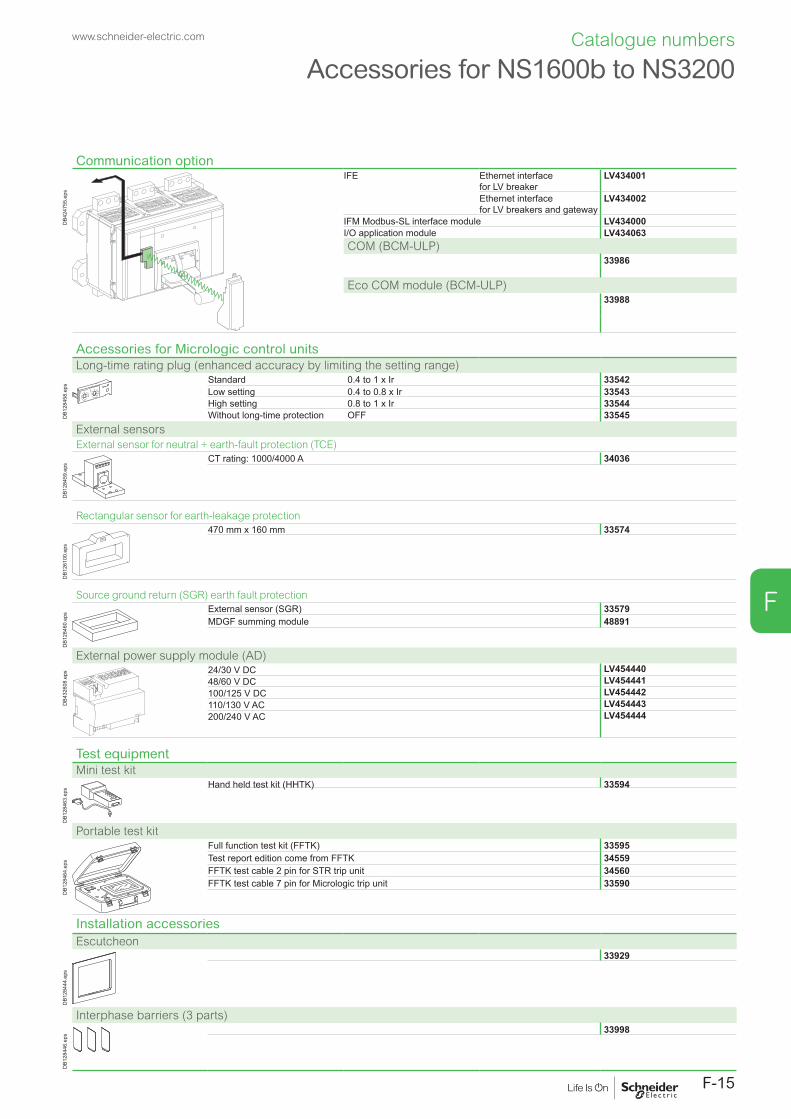
F-15
F
Accessories for NS1600b to NS3200
Communication option
OFF
OFF
DB4
2475
5.ep
s
IFE Ethernet interface for LV breaker
LV434001
Ethernet interface for LV breakers and gateway
LV434002
IFM Modbus-SL interface module LV434000I/O application module LV434063COM (BCM-ULP)
33986
Eco COM module (BCM-ULP)33988
Accessories for Micrologic control unitsLong-time rating plug (enhanced accuracy by limiting the setting range)
.4.5.6
.7.8 .9
.95
.98
1.5
12
48 12
16
20
24
long time
alarm
Ir
tr(s)
x In@ 6 Ir
DB1
2845
8.ep
s
Standard 0.4 to 1 x Ir 33542Low setting 0.4 to 0.8 x Ir 33543High setting 0.8 to 1 x Ir 33544Without long-time protection OFF 33545
External sensorsExternal sensor for neutral + earth-fault protection (TCE)
DB1
2845
9.ep
s
CT rating: 1000/4000 A 34036
Rectangular sensor for earth-leakage protection
DB1
2610
0.ep
s
470 mm x 160 mm 33574
Source ground return (SGR) earth fault protection
DB1
2846
0.ep
s External sensor (SGR) 33579MDGF summing module 48891
External power supply module (AD)
G3G4
Output
LN
DB4
3260
8.ep
s 24/30 V DC LV45444048/60 V DC LV454441100/125 V DC LV454442110/130 V AC LV454443200/240 V AC LV454444
Test equipmentMini test kit
DB1
2846
3.ep
s Hand held test kit (HHTK) 33594
Portable test kit
DB1
2846
4.ep
s
Full function test kit (FFTK) 33595Test report edition come from FFTK 34559FFTK test cable 2 pin for STR trip unit 34560FFTK test cable 7 pin for Micrologic trip unit 33590
Installation accessoriesEscutcheon
DB1
2844
4.ep
s
33929
Interphase barriers (3 parts)
DB1
2844
6.ep
s
33998
www.schneider-electric.com Catalogue numbers

F-16
F
Spare parts: NS630b to NS1600 fixed circuit breakerConnection
Connections for circuit breakers and switch-disconnectors
DB4
0144
1.ep
s
Front connection / Replacement kit (3 or 4 parts)3P
630/1000 A - N Top 33598 33608Bottom 33599 33609
1250 A - N Top 33600 33610630-1000 A - L Bottom 33601 33611630/800 A - LB1600 A - N Top 33602 33612
Bottom 33603 33613Rear connection / Replacement kit (3 or 4 parts)
DB4
0144
2.ep
s 3P 4PVertical and horizontal (top or bottom) 33584 33585Installation manual 33148
Connection accessories Bare-cable connectors + 1 connector shield for 4 cables (240 mm²)
DB1
2842
0.ep
s 3P 336404P 33641Installation manual 33148
1 long connection shield / 1 part
DB1
2842
1.ep
s 3P 336284P 33629
Vertical-connection adapters / Replacement kit (3 or 4 parts)
DB1
2842
2.ep
s 3P 336424P 33643Installation manual 33148
Cable lug adapters / Replacement kit (3 or 4 parts)
DB1
2842
3.ep
s 3P 336444P 33645Installation manual 33148
Interphase barriers / Replacement kit (3 parts)
DB1
2844
6.ep
s Front connection3P/4P top/bottom 33646Installation manual 33148
DB1
2842
5.ep
s Rear connection3P/4P top/bottom 33648Installation manual 33148
Arc chute screen / 1 part
DB12
8426
.eps 3P 64907
4P 33597Installation manual 33148
Brackets for mounting on a horizontal surface (2 parts)
DB1
0103
2.ep
s
3P/4P 64908
Spreaders / Replacement kit (3 or 4 parts)
DB1
2842
7.ep
s 3P 336224P 33623Installation manual 33148
Cable lug kits / Replacement kit (6 or 8 parts)
DB1
2842
4.ep
s
240 mm² 3P (6 lug kit) 330134P (8 lug kit) 33014
300 mm² 3P (6 lug kit) 330154P (8 lug kit) 33016
Installation manual 33148
www.schneider-electric.comCatalogue numbers

F-17
F
Installation accessories / 1 part
DB1
2814
3.ep
s
Escutcheon (small cut-out) for manually operated device with toggle 33717
DB1
2843
1.ep
s
Escutcheon for: 33718- device with toggle (large cutout)- device with rotary handle- electrically operated device
Blanking plate / 1 part
DB1
2843
2.ep
s
Blanking plate 33858
Installation manual 33148Toggle extension / 1 part
DB1
2844
7.ep
s Toggle extension 46996
DB4
1992
4.ep
s
Additional toggle extension 33195
Spare parts: NS630b to NS1600 fixed circuit breakerElectrical auxiliaries and installation accessories
Electrical auxiliaries Indication contact / 1 part
DB1
2842
8.ep
s
6 A - 240 V Low levelOF, ON/OFF indication contacts 29450 29452SD trip indication contact for manually operated devices 29450 29452SDE fault indication contact operated devices 29450 29452Up to 3 OF, 1 SD and 1 SDE can be connected (the SDE contact is standard for electrically operated devices).Installation manual 33148
Remote tripping / 1 part
DB1
2842
9.ep
s
MX MNDelay unit R (non-adjustable) Rr (adjustable)
12 V DC 3365824/30 V DC, 24 V AC 33659 3366848/60 V DC, 48 V AC 33660 33669 48/60 V AC/DC 33680100/130 V AC/DC 33661 33670 100/130 V AC/DC 33684 33681200/250 V AC/DC 33662 33671 200/250 V AC/DC 33685 33682277 V AC 33663380/480 V AC 33664 33673 380/480 V AC/DC 33683Installation manual 33149
www.schneider-electric.com Catalogue numbers

F-18
F
Spare parts: NS630b to NS1600 fixed circuit breakerMicrologic control unit, external sensor
Replacement parts for Micrologic control unitsLong-time rating plug (limits setting range for higher accuracy) / 1 part
.4.5.6
.7.8 .9
.95
.98
1.5
12
48 12
16
20
24
long time
alarm
Ir
tr(s)
x In@ 6 Ir
DB1
2845
8.ep
s
Standard 0.4 at 1 x Ir 33542Low-setting option 0.4 at 0.8 x Ir 33543High-setting option 0.8 at 1 x Ir 33544Without long-time protection off 33545
Battery + cover
DB1
2835
3.ep
s
Battery (1 part) 33593Cover (1 part) For Micrologic A, E 33592
For Micrologic P 47067
Communication option
DB4
1741
5.ep
s
IFE Ethernet interface for LV breaker LV434001Ethernet interface for LV breakers and gateway LV434002
DB1
1144
1.ep
s
IFM Modbus-SL interface module LV434000
DB4
3255
0.ep
s
+24VDC
13
O1
+
I1
24VDC
I2I3
I4I5
I6
C
C
C
1423
2433
34T1 T2
O2
O3
A1
LV434063
IO
I1
A1
O1
O2
O3I2I3
I4I5
I6
APP
I/O application module LV434063
User guide IFE DOCA0084EN-00User guide I/O application module DOCA0055EN-00
External sensorsExternal sensor for neutral + earth-fault protection (TCE) / 1 part
DB1
2845
9.ep
s
CT rating: 400/1600 A 33576
Rectangular sensors
DB1
2610
0.ep
s
Inside dimensions (mm) Ie (A)280 x 115 1600 33573
Source ground return (SGR) earth-fault protection / 1 part
DB1
2846
0.ep
s
External sensor (SGR) 33579MDGF summing module 48891
External power supply module (AD) / 1 part)
G3G4
Output
LN
DB4
3260
8.ep
s 24-30 V DC LV45444048-60 V DC LV454441100-125 V DC LV454442110-130 V AC LV454443200-240 V AC LV454444
Test equipments / 1 part
DB1
2846
4.ep
s
Hand held test kit (HHTK) 33594Full function test kit (FFTK) 33595Test report edition come from FFTK 34559FFTK test cable 2 pin for STR trip unit 34560FFTK test cable 7 pin for Micrologic trip unit 33590
www.schneider-electric.comCatalogue numbers
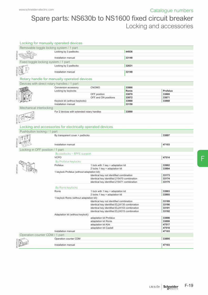
F-19
F
Spare parts: NS630b to NS1600 fixed circuit breakerLocking and accessories
Locking for manually operated devicesRemovable toggle locking system / 1 part
DB1
2844
8.ep
s Locking by 3 padlocks 44936
Installation manual 33148Fixed toggle locking system / 1 part
DB1
2844
9.ep
s
Locking by 3 padlocks 32631
Installation manual 33148
Rotary handle for manually operated devicesDevices with direct rotary handles / 1 part
DB1
2835
2.ep
s
Conversion accessory CNOMO 33866Locking by keylocks Ronis Profalux
OFF position 33870 33869OFF and ON positions 33872 33871
Keylock kit (without keylocks) 33868 33868Installation manual 33150
Mechanical interlocking
DB1
2845
1.ep
s
For 2 devices with extended rotary handles 33890
Locking and accessories for electrically operated devicesPushbutton locking / 1 part
DB1
2845
4.ep
s
By transparent cover + padlocks 33897
Installation manual 47103
Locking in OFF position / 1 partBy padlocks + BPFE support
VCPO 47514
DB1
2845
5.ep
s
By Profalux keylocksProfalux 1 lock with 1 key + adaptation kit 33902
2 locks 1 key + adaptation kit 339041 keylock Profalux (without adaptation kit):
identical key not identified combination 33173identical key identified 215470 combination 33174identical key identified 215471 combination 33175
By Ronis keylocksRonis 1 lock with 1 key + adaptation kit 33903
2 locks 1 key + adaptation kit 339051 keylock Ronis (without adaptation kit):
identical key not identified combination 33189identical key identified EL24135 combination 33190identical key identified EL24153 combination 33191identical key identified EL24315 combination 33192
Adaptation kit (without keylock):adaptation kit Profalux 33898adaptation kit Ronis 33899adaptation kit Kirk 47517adaptation kit Castell 47518
Installation manual 47103Operation counter CDM / 1 part
00399
DB1
2845
6.ep
s Operation counter CDM 33895
Installation manual 47103
www.schneider-electric.com Catalogue numbers

F-20
F
Spare parts: NS630b to NS1600 fixed and withdrawable circuit breakerMechanical interlocking for source changeoverMechanical interlocking for source changeoverInterlocking using connecting rods for Compact electrically operated devices
Opush OFF
Ipush ON
O OFF
discharged
Opush OFF
Ipush ON
O OFF
discharged
DB1
2846
5.ep
s
Complete assembly with 2 adaptation fixtures + rods2 Compact fixed devicesNote: the installation manual is enclosed.
33910
Interlocking using cables for Compact electrically operated devices
Opush OFF
Ipush ON
O OFF
discharged
Opush OFF
Ipush ON
O OFF
discharged
DB1
2846
6.ep
s
Complete assembly with 2 adaptation fixtures + cables2 Compact fixed devices 339111 Compact fixed + 1 Compact withdrawable deviceNote: the installation manual is enclosed.
33915
www.schneider-electric.comCatalogue numbers

F-21
F
Spare parts: NS630b to NS1600 withdrawable circuit breaker
ConnectionConnection
DB1
2841
6.ep
s
3P 4PFront connection / Replacement kit (6 or 8 parts)
Top and bottom 33588 33589
Rear connection / Replacement kit (4 or 6 parts)
DB1
2841
7.ep
s
DB4
0144
4.ep
s Vertical and horizontal 33586 33587
Vert. mounting. Horiz. mounting. Installation manual 33149
Connection accessoriesVertical connection adapters for front-connected chassis / Replacement kit (3 or 4 parts)
DB1
2842
2.ep
s 3P 336424P 33643Installation manual 33149
Cable lug adapters for front-connected chassis / Replacement kit (3 or 4 parts)
DB1
2842
3.ep
s 3P 336444P 33645Installation manual 33149
Interphase barriers for rear-connected chassis / Replacement kit (3 parts)
DB1
2843
3.ep
s 3P/4P 33768
Installation manual 33149
Spreaders for front-connected and rear-connected chassis / Replacement kit (3 or 4 parts)
DB1
2842
7.ep
s 3P 336224P 33623Installation manual 33149
Cable lug kits / Replacement kit (6 or 8 parts)
DB1
2842
4.ep
s 240 mm² 3P (6 lug kit) 330134P (8 lug kit) 33014
300 mm² 3P (6 lug kit) 330154P (8 lug kit) 33016
Installation manual 33149
Chassis accessoriesAuxiliary terminal shield (CB) / 1 part
DB1
2843
4.ep
s 3P 337634P 33764Installation manual 33149
Safety shutters (VO) / 1 part
DB4
0144
5.ep
s
3P 337654P 33766Installation manual 47104
Clusters
DB4
0144
6.ep
s
1 disconnecting contact cluster for chassis (see table below) (1 part) 64906
Table : number of clusters required for the different chassis modelsChassis rating (A) Compact NS - 3P Compact NS - 4P
NA - N L NA - N L630 12 18 16 24800 12 18 16 241000 12 18 16 241250 12 161600 18 24Note: the minimum order is 6 parts.
DB4
1799
0.ep
s
DB4
1800
7.ep
s
Set of 2 clusters fitters for 2 and 3 clusters 47554
www.schneider-electric.com Catalogue numbers

F-22
F
Spare parts: NS630b to NS1600 withdrawable circuit breakerElectrical auxiliariesElectrical auxiliariesSD trip indication contact for manually operated devices / 1 part
DB1
2843
6.ep
s
6 A - 240 V Low levelOF, ON/OFF indication contacts 33801 33804SD trip indication contact for manually operated devices 33800 33803SDE fault indication contact operated devices 33799 33802Up to 3 OF, 1 SD and 1 SDE can be connected (the SDE contact is standard for electrically operated devices).Installation manual 47103
CE, CD, CT carriage switches / 1 part
DB1
2843
7.ep
s
6 A - 240 V Low levelConnected position NO/NC contact (up to 3 CE) 33751 33754Disconnected position NO/NC (up to 2 CD) 33753 33756Test position NO/NC contact (up to 1 CT) 33752 33755Spare parts (up to 3 CE, 1 CT, 2 CD per device) 33170 33171Installation manual 47104
Instantaneous voltage releases / 1 part
DB1
2842
9.ep
s
MX MNDelay unit R (non-adjustable) Rr (adjustable)
12 V DC 3365824/30 V DC, 24 V AC 33659 3366848/60 V DC, 48 V AC 33660 33669 48/60 V AC/DC 33680100/130 V AC/DC 33661 33670 100/130 V AC/DC 33684 33681200/250 V AC/DC 33662 33671 200/250 V AC/DC 33685 33682277 V AC 33663380/480 V AC 33664 33673 380/480 V AC/DC 33683Installation manual 47103
Auxiliaries terminal for chassis
DB1
2835
4.ep
s
DB4
0144
8.ep
s
3 wire terminal block (1 part) 330986 wire terminal block (1 part) 33099Jumpers (10 parts) 47900Installation manual 47103
3 wires. 6 wires.
www.schneider-electric.comCatalogue numbers

F-23
F
Spare parts: NS630b to NS1600 withdrawable circuit breaker
Installation accessoriesInstallation accessoriesEscutcheon / 1 part
DB1
2843
0.ep
s
33857
Transparent cover for escutcheon / 1 part
DB1
2844
5.ep
s
33859
Blanking plate / 1 part
DB1
2843
2.ep
s
33858
www.schneider-electric.com Catalogue numbers

F-24
F
Spare parts: NS630b to NS1600 withdrawable circuit breakerMicrologic control unit, external sensorReplacement parts for Micrologic control unitsLong-time rating plug (limits setting range for higher accuracy) / 1 part
.4.5.6
.7.8 .9
.95
.98
1.5
12
48 12
16
20
24
long time
alarm
Ir
tr(s)
x In@ 6 Ir
DB1
2845
8.ep
s Standard 0.4 at 1 x Ir 33542Low-setting option 0.4 at 0.8 x Ir 33543High-setting option 0.8 at 1 x Ir 33544Without long-time protection off 33545
Battery + cover
DB1
2835
3.ep
s
Battery (1 part) 33593Cover (1 part) For Micrologic A, E 33592
For Micrologic P 47067
Communication option
DB4
2586
8.ep
s
LV434002
Enerlin'X IFE
IFE Ethernet interface for LV breaker LV434001Ethernet interface for LV breakers and gateway LV434002
TestDB4
2570
6.ep
s
IFM Modbus-SL interface module LV434000
DB4
3255
0.ep
s
+24VDC
13
O1
+
I1
24VDC
I2I3
I4I5
I6
C
C
C
1423
2433
34T1 T2
O2
O3
A1
LV434063
IO
I1
A1
O1
O2
O3I2I3
I4I5
I6
APP
I/O application module LV434063
User guide IFE DOCA0084EN-00User guide I/O application module DOCA0055EN-00
External sensorsExternal sensor for neutral + earth-fault protection (TCE) / 1 part
DB1
2845
9.ep
s
CT rating: 400/1600 A 33576
Source ground return (SGR) earth-fault protection + Vigi cable / 1 part
DB1
2846
0.ep
s External sensor (SGR) 33579MDGF summing module 48891
Rectangular sensors
DB1
2610
0.ep
s
Inside dimensions (mm) Ie (A)280 x 115 1600 33573
External power supply module (AD) / 1 part
G3G4
Output
LN
DB4
3260
8.ep
s 24-30 V DC LV45444048-60 V DC LV454441100-125 V DC LV454442110-130 V AC LV454443200-240 V AC LV454444
Test equipments / 1 part
DB1
2846
4.ep
s
Hand held test kit (HHTK) 33594Full function test kit (FFTK) 33595Test report edition come from FFTK 34559FFTK test cable 2 pin for STR trip unit 34560FFTK test cable 7 pin for Micrologic trip unit 33590
www.schneider-electric.comCatalogue numbers

F-25
F
Spare parts: NS630b to NS1600 withdrawable circuit breaker
Locking and accessoriesLocking for manually operated devicesRemovable toggle locking system / 1 part
DB1
2844
8.ep
s Locking by 3 padlocks 44936
Installation manual 33148
Fixed toggle locking system / 1 part
DB1
2844
9.ep
s Locking by 3 padlocks 32631
Installation manual 33148
Rotary handle for manually operated devicesDevices with direct rotary handles / 1 part
DB1
2835
2.ep
s
Conversion accessory CNOMO 33866Locking by keylocks Ronis Profalux
OFF position 33870 33869OFF and ON positions 33872 33871
Keylock kit (without keylocks) 33868 33868Installation manual 33150
Mechanical interlocking
DB1
2845
1.ep
s
For 2 devices with extended rotary handles 33890
Locking and accessories for electrically operated devicesPushbutton locking / 1 part
DB1
2845
4.ep
s
By transparent cover + padlocks 33897
Installation manual 47103
Locking in OFF position / 1 partBy padlocks + BPFE supportVCPO 47514
DB1
2845
5.ep
s
By Profalux keylocksProfalux 1 lock with 1 key + adaptation kit 33902
2 locks 1 key + adaptation kit 339041 keylock Profalux (without adaptation kit):
identical key not identified combination 33173identical key identified 215470 combination 33174identical key identified 215471 combination 33175
By Ronis keylocksRonis 1 lock with 1 key + adaptation kit 33903
2 locks 1 key + adaptation kit 339051 keylock Ronis (without adaptation kit):
identical key not identified combination 33189identical key identified EL24135 combination 33190identical key identified EL24153 combination 33191identical key identified EL24315 combination 33192
Adaptation kit (without keylock):adaptation kit Profalux 33898adaptation kit Ronis 33899
adaptation kit Kirk 47517 adaptation kit Castell 47518Installation manual 47103
Operation counter CDM / 1 part
00399
DB1
2845
6.ep
s
Operation counter CDM / 1 part 33895
Installation manual 47103
www.schneider-electric.com Catalogue numbers

F-26
F
Spare parts: NS630b to NS1600 withdrawable circuit breakerChassis locking and accessories Mechanical interlocking for source changeoverChassis lockingKeylocking in disconnected position / 1 part
DB4
2475
9.ep
s
By Profalux keylocksProfalux 1 lock with 1 key + adaptation kit 64909
2 locks 1 key + adaptation kit 649102 locks 2 different keys + adaptation kit 64911
1 keylock Profalux (without adaptation kit):
identical key not identified combination 33173identical key identified 215470 combination 33174identical key identified 215471 combination 33175
By Ronis keylocksRonis 1 lock with 1 key + adaptation kit 64912
2 locks 1 key + adaptation kit 649132 locks 2 different keys + adaptation kit 64914
1 keylock Ronis (without adaptation kit):
identical key not identified combination 33189identical key identified EL24135 combination 33190identical key identified EL24153 combination 33191identical key identified EL24315 combination 33192
Adaptation kit (without keylock):
adaptation kit Profalux 33769adaptation kit Ronis 33770
adaptation kit Castell 33771 adaptation kit Kirk 33772
Door interlock / 1 part
DB4
2475
8.ep
s
Right and left side of chassis (VPECD or VPECG) 33172
Installation manual 47104
Racking interlock (VPOC) / 1 part
DB4
2475
7.ep
s
33788
Installation manual 47104
Mismatch protection (VDC) / 1 part
DB1
2844
3.ep
s 33767
Installation manual 47104
Mechanical interlocking for source changeoverInterlocking using connecting rods for Compact electrically operated devices
Opush OFF
Ipush ON
O OFF
discharged
Opush OFF
Ipush ON
O OFF
discharged
DB1
2846
5.ep
s
Complete assembly with 2 adaptation fixtures + rods2 Compact withdrawable devices 33913Note: the installation manual is enclosed.
Interlocking using cables for Compact electrically operated devices
Opush OFF
Ipush ON
O OFF
discharged
Opush OFF
Ipush ON
O OFF
discharged
DB1
2846
6.ep
s
Complete assembly with 2 adaptation fixtures + cables2 Compact fixed devices 339141 Compact fixed + 1 Compact withdrawable device 33915Note: the installation manual is enclosed.
www.schneider-electric.comCatalogue numbers

F-27
F
Spare parts: NS630b to NS1600 fixed or withdrawable circuit breaker
InstructionsInstructions
Chassis accessories 47104Circuit breaker accessories Manual 33148
Electrical 33149Fixed and drawout circuit breaker Manual 33148
Electrical 33149NS630b user manual French 33159
English 33160Micrologic user manual 20/50 (French) 33076
20/50 (English) 330772A/7A (French) 330792A/7A (English) 330802E/6E (French) 330792E/6E (English) 330805P/7P (French) 330825P/7P (English) 33083
Modbus communication notice for manual 33088
www.schneider-electric.com Catalogue numbers

F-28
F
Spare parts: Communication bus accessories, monitoring and control, ethernet gateway
Communication options
DB4
2586
8.ep
s
LV434002
Enerlin'X IFE
IFE Ethernet interface for LV breaker LV434001Ethernet interface for LV breakers and gateway
LV434002
TestDB4
2570
6.ep
s
IFM Modbus-SL interface module LV434000
DB4
3255
0.ep
s
+24VDC
13
O1
+
I1
24VDC
I2I3
I4I5
I6
C
C
C
1423
2433
34T1 T2
O2
O3
A1
LV434063
IO
I1
A1
O1
O2
O3I2I3
I4I5
I6
APP
I/O application module LV434063
Monitoring and controlULP display module [1]
DB4
3255
1.ep
s
Switchboard front display module FDM121 TRV00121FDM mounting accessory (diameter 22 mm)
TRV00128
Ethernet display module
DB4
1748
9.ep
s
Switchboard front display module FDM128 LV434128
ULP wiring accessories
DB1
2798
5.ep
s
Breaker ULP cord L = 0.35 m LV434195Breaker ULP cord L = 1.3 m LV434196Breaker ULP cord L = 3 m LV434197Breaker ULP cord L = 5 m LV434198
DB4
3258
4.ai
10 Modbus line terminators VW3A8306DRC [2]
LV43
4211
.ai
Connector Modbus adaptor LV434211
DB1
1562
3.ep
s 5 RJ45 connectors female/female TRV00870
DB1
1144
4.ep
s 10 ULP line terminators TRV00880
DB1
1144
5.ep
s
10 RJ45/RJ45 male cord L = 0.3 m TRV0080310 RJ45/RJ45 male cord L = 0.6 m TRV008065 RJ45/RJ45 male cord L = 1 m TRV008105 RJ45/RJ45 male cord L = 2 m TRV008205 RJ45/RJ45 male cord L = 3 m TRV008301 RJ45/RJ45 male cord L = 5 m TRV00850
[1] For measurement display with Micrologic A, E, P.[2] www.schneider-electric.com.
www.schneider-electric.comCatalogue numbers

F-29
F
Spare parts: Compact NS1600b to 3200Connection, locking and installation accessories
Optional vertical connection adaptor / Replacement kit (3 or 4 parts)
DB1
2832
3.ep
s
1600/2500/3200 A 3P 339754P 33976
Installation manual 33969
Electrical auxiliaries Indication contacts (1 part)
DB1
2842
8.ep
s OF, SD, SDE 6 A - 240 V 29450Low level 29452
Note: up to 3 OF, 1 SD and 1 SDE can be connected.Installation manual 33969
Instantaneous voltage releases (1 part)
DB1
2842
9.ep
s
MX MNDelay unit R (non-adjustable) Rr (adjustable)
12 V DC 3365824/30 V DC, 24 V AC 33659 3366848/60 V DC, 48 V AC 33660 33669 48/60 V AC/DC 33680100/130 V AC/DC 33661 33670 100/130 V AC/DC 33684 33681200/250 V AC/DC 33662 33671 200/250 V AC/DC 33685 33682277 V AC 33663380/480 V AC 33664 33673 380/480 V AC/DC 33683Installation manual 33969
LockingRemovable toggle locking system / 1 part
DB1
2844
8.ep
s Locking by 3 padlocks 33996
Installation manual 33969
Fixed toggle locking system / 1 part
DB1
2844
9.ep
s Locking by 3 padlocks 32631
Installation manual 33969
Installation accessoriesEscutcheon / 1 part
DB1
2844
4.ep
s
33929
Interphase barriers / 3 parts
DB1
2844
6.ep
s 33998
Installation manual 33969
Toggle extension / 1 part
OFF
OFF
DB1
2833
8.ep
s
NS3200 toggle extension for replacement 33997
Installation manual 33969
www.schneider-electric.com Catalogue numbers

F-30
F
Spare parts: Compact NS1600b to 3200Micrologic control unit, external sensor
Accessories for Micrologic control unitsLong-time rating plug (enhanced accuracy by limiting the setting range) / 1 part
.4.5.6
.7.8 .9
.95
.98
1.5
12
48 12
16
20
24
long time
alarm
Ir
tr(s)
x In@ 6 Ir
DB1
2845
8.ep
s Standard 0.4 to 1 x Ir 33542Low setting 0.4 to 0.8 x Ir 33543High setting 0.8 to 1 x Ir 33544Without long-time protection OFF 33545
External sensorsExternal sensor for neutral + earth-fault protection (TCE) / 1 part
DB1
2845
9.ep
s
CT rating: 1000/4000 A 34036
Source ground return (SGR) earth-fault protection + Vigi cable / 1 part
DB1
2846
0.ep
s External sensor (SGR) 33579MDGF summing module 48891
Rectangular sensors
DB1
2610
0.ep
s
Inside dimensions (mm) Ie (A)470 x 160 3200 33574
External power supply module (AD) / 1 part
G3G4
Output
LN
DB4
3260
8.ep
s 24-30 V DC LV45444048-60 V DC LV454441100-125 V DC LV454442110-130 V AC LV454443200-240 V AC LV454444
Test equipments / 1 part
DB1
2846
4.ep
s
Hand held test kit (HHTK) 33594Full function test kit (FFTK) 33595Test report edition come from FFTK 34559FFTK test cable 2 pin for STR trip unit 34560FFTK test cable 7 pin for Micrologic trip unit 33590
www.schneider-electric.comCatalogue numbers

F-31
F
Order form: Compact NS630b to NS3200Circuit breakers and switch-disconnectors
Name of customer: .................................................................. Address for delivery: ................................................................
Requested delivery date: .........................................................
Customer order no.: .................................................................
To indicate your choices, check the applicable square boxes
and enter the appropriate information in the rectangles
Circuit breaker or switch-disconnectorCompact type NS630b to NS1600
NS1600b to NS3200Rating ACircuit breaker N, H, L, LBSwitch-disconnector NANumber of poles 3 or 4Device NS630b/3200 Fixed
NS630b/1600 Withdr. with chassisWithdr. without chassis(moving part only)
Chassis alone without connections
Micrologic control unitBasic protection 2.0 5.0 6.0A - ammeter
2.0 5.0 6.0 7.0E - energy
2.0 5.0 6.0P - poweronly for NS630b/1600 5.0 6.0 7.0AD - external power-supply module VENVT - External Neutral Voltage Tap (3P + N and Micrologic E or P)TCE - external sensor (CT) for neutral protectionRectangular sensor NS630b/1600 280 x 115 mmfor earth-leakage protection NS1600b/3200 470 x 160 mmTCW - external sensor for SGR protectionLR - long-time rating plug Standard 0.4 to 1 Ir
Low setting 0.4 to 0.8 IrHight setting 0.8 to 1 IrLT OFF
CommunicationCOM moduleDevice (BCM-ULP)
with Ethernet interface Cradle management with I/O application module (Chassis)
with Ethernet interface + Gateway
with Modbus interface
Eco COM module Device (BCM-ULP)
with Ethernet interface
with Ethernet interface + Gatewaywith Modbus interface
Front Display Module Mounting accessories(FDM121)Breaker ULP Cord
L = 0.35 mL = 1.3 mL = 3 mL = 5 m
NS630b/1600 connectionHorizontal rear connections Top BottomVertical rear connections Top BottomFront connections Top Bottom4 x 240v bare cable connectors + shields NS - FC fixedLong connection shields NS - FC fixedVertical-connection adapters NS - FC fixed,
withdr.Cable-lug adapters NS - FC fixed,
withdr.Arc chute screen NS - FC fixedInterphase barriers NS - FC fixed, withdrawableSpreaders NS - FC fixed, withdrawable
NS1600b/3200 connectionFront connections NS - FC fixedVertical connection adaptor optional for NS1600b/2500
(standard for NS3200)
Indication contactsNS630b/3200 SD trip indication (maximum 1) (only for manually operated devices)
6 A-240 V AC qty Low level qtySDE fault-trip indication (maximum 1)(SDE integrated in electrically operated devices)6 A-240 V AC qty Low level qtyOF ON/OFF indication contacts (maximum 3)6 A-240 V AC qty Low level qty
NS630b/1600 Carriage switches(possible combinations: 3 CE, 2 CD, 1 CT)
CE - "connected" position 6 A-240 V AC qty Low level qtyCD - "disconnected" position 6 A-240 V AC qty Low level qtyCT - "test" position 6 A-240 V AC qty Low level qty
I/O application module
Auxiliary terminals for chassis alone Jumpers (set of 10)
3-wire terminal (30 parts) 6-wire terminal (10 parts)
Remote operationElectrical operation Standard Communicating(NS630b/1600) Power supply AC DC VVoltage releases MX AC DC V
MN AC DC VMN delay unit Ajustable Non ajustable
Rotary handles for NS630b/1600 fixed and withdrawable deviceDirect Black Red on yellow front
CNOMO conversion access.Extended Black Red on yellow front
Telescopic handle for withdrawable deviceIndication auxiliary 6 A-240 V AC 2 early-make switches
2 early-break switches
LockingToggle (1 to 3 padlocks) Removable system Fixed systemRotary handle OFF position ON and OFF positionsusing a keylock Ronis 1351B.500 Profalux KS5 B24 D4Z(NS630b/1600) Keylock kit (without keylock)For electrically VBP - ON/OFF pushbutton lockingoperated devices (by transparent cover +padlocks(NS630b/1600) OFF position locking:
VCPO - by padlocksVSPO - by keylocks:Keylock kit (w/o keylock) Profalux Ronis1 keylock Profalux Ronis2 identical keylocks, 1 key Profalux Ronis
Chassis locking in "disconnected" position:VSPD - by keylocks Keylock kit (w/o keylock) Profalux Ronis
Kirk Castell1 keylock Profalux Ronis2 identical keylocks, 1 key Profalux Ronis2 keylocks, different keys Profalux RonisOptional connected/disconnected/test position locking
VPEC - door interlock On right-hand side of chassisOn left-hand side of chassis
VPOC - racking interlockVDC - mismatch protection
AccessoriesVO - safety shutters on chassis NS - withdrawable as standardCDM - mechanical operation counterCDP - escutcheonCP - transparent cover for escutcheonOP - blanking plate for escutcheonMounting brackets for fixed NS for mounting on horizontal planeTest kits Mini test kit Portable test kit
Micrologic control unit functions:2.0: basic protection (long time + inst.)5.0: selective protection (long time + short time + inst.)6.0: selective + earth-fault protection (long time + short time + inst. + earth-fault)7.0: selective + earth-leakage protection (long time + short time + inst. + earth-leakage)
www.schneider-electric.com Order form


Schneider Electric Industries SAS
35, rue Joseph MonierCS 3032392506 Rueil Malmaison Cedex France
RCS Nanterre 954 503 439Capital social 896 313 776 €www.schneider-electric.com
© 2018 - Schneider Electric. All Rights Reserved.All trademarks are owned by Schneider Electric Industries SAS or its affiliated companies.
LVPED211021EN WEB3 cat.2018