Influenza dei trattamenti termici sulla propagazione della cricca di fatica in una lega Ti-6Al-4V
Upload
independentCategory
view
0download
0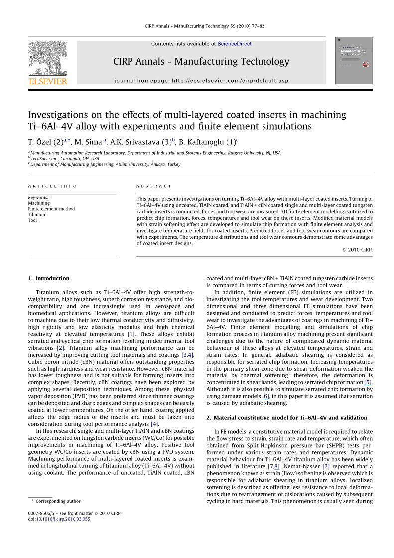
CIRP Annals - Manufacturing Technology 59 (2010) 77–82
Contents lists available at ScienceDirect
CIRP Annals - Manufacturing Technology
journal homepage: http: / /ees.elsevier.com/cirp/default .asp
Investigations on the effects of multi-layered coated inserts in machiningTi–6Al–4V alloy with experiments and finite element simulations
T. Ozel (2)a,*, M. Sima a, A.K. Srivastava (3)b, B. Kaftanoglu (1)c
a Manufacturing Automation Research Laboratory, Department of Industrial and Systems Engineering, Rutgers University, NJ, USAb TechSolve Inc., Cincinnati, OH, USAc Department of Manufacturing Engineering, Atilim University, Ankara, Turkey
A R T I C L E I N F O
Keywords:
Machining
Finite element method
Titanium
Tool
A B S T R A C T
This paper presents investigations on turning Ti–6Al–4V alloy with multi-layer coated inserts. Turning of
Ti–6Al–4V using uncoated, TiAlN coated, and TiAlN + cBN coated single and multi-layer coated tungsten
carbide inserts is conducted, forces and tool wear are measured. 3D finite element modelling is utilized to
predict chip formation, forces, temperatures and tool wear on these inserts. Modified material models
with strain softening effect are developed to simulate chip formation with finite element analysis and
investigate temperature fields for coated inserts. Predicted forces and tool wear contours are compared
with experiments. The temperature distributions and tool wear contours demonstrate some advantages
of coated insert designs.
� 2010 CIRP.
1. Introduction
Titanium alloys such as Ti–6Al–4V offer high strength-to-weight ratio, high toughness, superb corrosion resistance, and bio-compatibility and are increasingly used in aerospace andbiomedical applications. However, titanium alloys are difficultto machine due to their low thermal conductivity and diffusivity,high rigidity and low elasticity modulus and high chemicalreactivity at elevated temperatures [1]. These alloys exhibitserrated and cyclical chip formation resulting in detrimental toolvibrations [2]. Titanium alloy machining performance can beincreased by improving cutting tool materials and coatings [3,4].Cubic boron nitride (cBN) material offers outstanding propertiessuch as high hardness and wear resistance. However, cBN materialhas lower toughness and is not suitable for forming inserts intocomplex shapes. Recently, cBN coatings have been explored byapplying several deposition techniques. Among these, physicalvapor deposition (PVD) has been preferred since thinner coatingscan be deposited and sharp edges and complex shapes can be easilycoated at lower temperatures. On the other hand, coating appliedaffects the edge radius of the inserts and must be taken intoconsideration during tool performance analysis [4].
In this research, single and multi-layer TiAlN and cBN coatingsare experimented on tungsten carbide inserts (WC/Co) for possibleimprovements in machining of Ti–6Al–4V alloy. Positive toolgeometry WC/Co inserts are coated by cBN using a PVD system.Machining performance of multi-layered coated inserts is exam-ined in longitudinal turning of titanium alloy (Ti–6Al–4V) withoutusing coolant. The performance of uncoated, TiAlN coated, cBN
* Corresponding author.
0007-8506/$ – see front matter � 2010 CIRP.
doi:10.1016/j.cirp.2010.03.055
coated and multi-layer cBN + TiAlN coated tungsten carbide insertsis compared in terms of cutting forces and tool wear.
In addition, finite element (FE) simulations are utilized ininvestigating the tool temperatures and wear development. Twodimensional and three dimensional FE simulations have beendesigned and conducted to predict forces, temperatures and toolwear to investigate the advantages of coatings in machining of Ti–6Al–4V. Finite element modelling and simulations of chipformation process in titanium alloy machining present significantchallenges due to the nature of complicated dynamic materialbehaviour of these alloys at elevated temperatures, strain andstrain rates. In general, adiabatic shearing is considered asresponsible for serrated chip formation. Increasing temperaturesin the primary shear zone due to shear deformation weaken thematerial by thermal softening; therefore, the deformation isconcentrated in shear bands, leading to serrated chip formation [5].Although it is also possible to simulate serrated chip formation byusing damage models [6], in this paper it is assumed that serrationis caused by adiabatic shearing.
2. Material constitutive model for Ti–6Al–4V and validation
In FE models, a constitutive material model is required to relatethe flow stress to strain, strain rate and temperature, which oftenobtained from Split-Hopkinson pressure bar (SHPB) tests per-formed under various strain rates and temperatures. Dynamicmaterial behaviour for Ti–6Al–4V titanium alloy has been widelypublished in literature [7,8]. Nemat-Nasser [7] reported that aphenomenon known as strain (flow) softening is observed which isresponsible for adiabatic shearing in titanium alloys. Localizedsoftening is described as offering less resistance to local deforma-tions due to rearrangement of dislocations caused by subsequentcycling in hard materials. This phenomenon is usually seen during
T. Ozel et al. / CIRP Annals - Manufacturing Technology 59 (2010) 77–8278
an increase in strain beyond a critical strain value. Specifically, Leeand Lin [8] investigated temperature and strain-rate sensitivity ofTi–6Al–4V and presented flow stress data at temperatures from 20to 1100 8C and strain rates ranging from 800 up to 3300 s�1. Theyused The Johnson-Cook (JC) material model to represent their flowstress data. However, their model did not include temperature-dependent strain softening effect.
2.1. Modified material model
A modification to the JC model is offered to include strain (flow)softening effects at elevated temperatures as proposed by Calamazet al. [9]. In this study, further modifications to the strain hardeningpart of the JC model by including strain softening at higher strainvalues and thermal softening part are proposed and the model isgiven in Eq. (1). In this model, the influence of strain, strain rate,temperature and temperature-dependent strain softening on theflow stress is defined by four multiplicative terms.
s ¼ Aþ Ben 1
expðeaÞ
� �� �1þ C ln
ee0
� �
1� T � T0
Tm � T0
� �m� �Dþ ð1� DÞ tan h
1
ðeþ pÞr� �s� �� � (1)
where D ¼ 1� ðT=TmÞd; p ¼ ðT=TmÞb, s is flow stress, e is truestrain, e is true strain rate, e0 is reference true strain, and T, Tm, T0
are work, material melting and ambient temperatures respec-tively.
Table 1Mechanical and thermo-physical properties of work and tool materials and friction va
Ti–6Al–4V W
E(T) [MPa] 0.7412*T + 113375 5.6
a(T) [mm mm�1 8C�1] 3.10�9*T + 7.10�6 4.7
l(T) [W m�1 8C�1] 7.039e0.0011*T 55
cp(T) [N mm�2 8C�1] 2.24e0.0007*T 0.0
Fig. 1. Comparison of measured and s
The experimental flow stress data by Lee and Lin [8] has beentaken as the base for this modified material model. The mostoptimum set of model parameters that was identified with inverseanalysis are; A = 782.7 MPa, B = 498.4 MPa, n = 0.28, C = 0.028,m = 1.0, a = 2, s = 0.05, r = 2, d = 1, b = 5. The details of thismethodology are outlined in the work by Ozel et al. [10].
2.2. Orthogonal cutting tests
Orthogonal turning of Ti–6Al–4V titanium alloy tubes (50.8 mmin diameter and 3.175 mm in thickness) have been performedusing uncoated and TiAlN coated tungsten carbide (WC/Co) cuttingtools in a rigid CNC turning centre at TechSolve Inc. The cuttingforces were measured with a force dynamometer and high-speeddata acquisition devices. The experiments have been conductedusing tool holders with 08 and 58 rake angle (g) at a cutting speed ofvc = 120 m/min and three different feeds (f = 0.075, 0.1, 0.125 mm/rev). Images of micro-chip geometries were captured with opticaldigital microscopy.
2.3. 2D finite element simulations and validation
Finite element model is developed using updated Lagrangian(DEFORM-2D) software in which chip separation from workpieceis achieved with continuous remeshing. A plane-strain coupledthermo-mechanical analysis was performed. In these simulations,serrated chip formation process is simulated from the incipient tothe steady-state by using adiabatic shearing based on strain (flow)softening elasto-viscoplastic work material assumption. The
lues used in FE simulations.
C/Co (Ti,Al)N cBN
e5 6.0e5 6.52e5
e�6 9.4e�6 5.2e�6
0.0081*T + 11.95 100
005*T + 2.07 0.0003*T + 0.57 3.26
imulated serrated chip geometry.
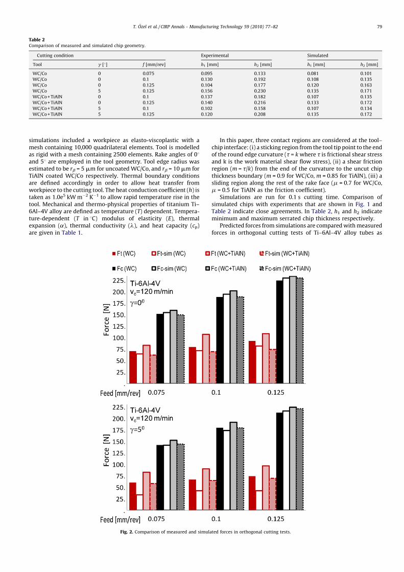
Table 2Comparison of measured and simulated chip geometry.
Cutting condition Experimental Simulated
Tool g [8] f [mm/rev] h1 [mm] h2 [mm] h1 [mm] h2 [mm]
WC/Co 0 0.075 0.095 0.133 0.081 0.101
WC/Co 0 0.1 0.130 0.192 0.108 0.135
WC/Co 0 0.125 0.104 0.177 0.120 0.163
WC/Co 5 0.125 0.156 0.230 0.135 0.171
WC/Co + TiAlN 0 0.1 0.137 0.182 0.107 0.135
WC/Co + TiAlN 0 0.125 0.140 0.216 0.133 0.172
WC/Co + TiAlN 5 0.1 0.102 0.158 0.107 0.134
WC/Co + TiAlN 5 0.125 0.120 0.208 0.135 0.172
T. Ozel et al. / CIRP Annals - Manufacturing Technology 59 (2010) 77–82 79
simulations included a workpiece as elasto-viscoplastic with amesh containing 10,000 quadrilateral elements. Tool is modelledas rigid with a mesh containing 2500 elements. Rake angles of 08and 58 are employed in the tool geometry. Tool edge radius wasestimated to be rb = 5 mm for uncoated WC/Co, and rb = 10 mm forTiAlN coated WC/Co respectively. Thermal boundary conditionsare defined accordingly in order to allow heat transfer fromworkpiece to the cutting tool. The heat conduction coefficient (h) istaken as 1.0e5 kW m�2 K�1 to allow rapid temperature rise in thetool. Mechanical and thermo-physical properties of titanium Ti–6Al–4V alloy are defined as temperature (T) dependent. Tempera-ture-dependent (T in 8C) modulus of elasticity (E), thermalexpansion (a), thermal conductivity (l), and heat capacity (cp)are given in Table 1.
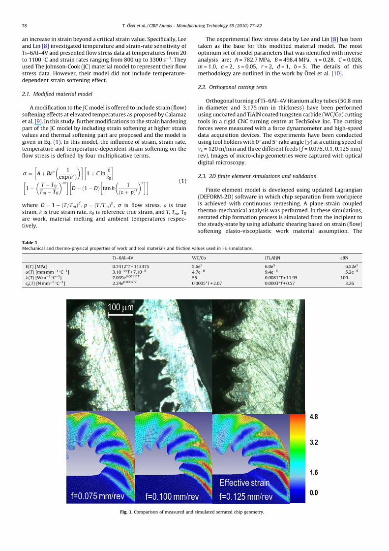
Fig. 2. Comparison of measured and simula
In this paper, three contact regions are considered at the tool–chip interface: (i) a sticking region from the tool tip point to the endof the round edge curvature (t = k where t is frictional shear stressand k is the work material shear flow stress), (ii) a shear frictionregion (m = t/k) from the end of the curvature to the uncut chipthickness boundary (m = 0.9 for WC/Co, m = 0.85 for TiAlN), (iii) asliding region along the rest of the rake face (m = 0.7 for WC/Co,m = 0.5 for TiAlN as the friction coefficient).
Simulations are run for 0.1 s cutting time. Comparison ofsimulated chips with experiments that are shown in Fig. 1 andTable 2 indicate close agreements. In Table 2, h1 and h2 indicateminimum and maximum serrated chip thickness respectively.
Predicted forces from simulations are compared with measuredforces in orthogonal cutting tests of Ti–6Al–4V alloy tubes as
ted forces in orthogonal cutting tests.
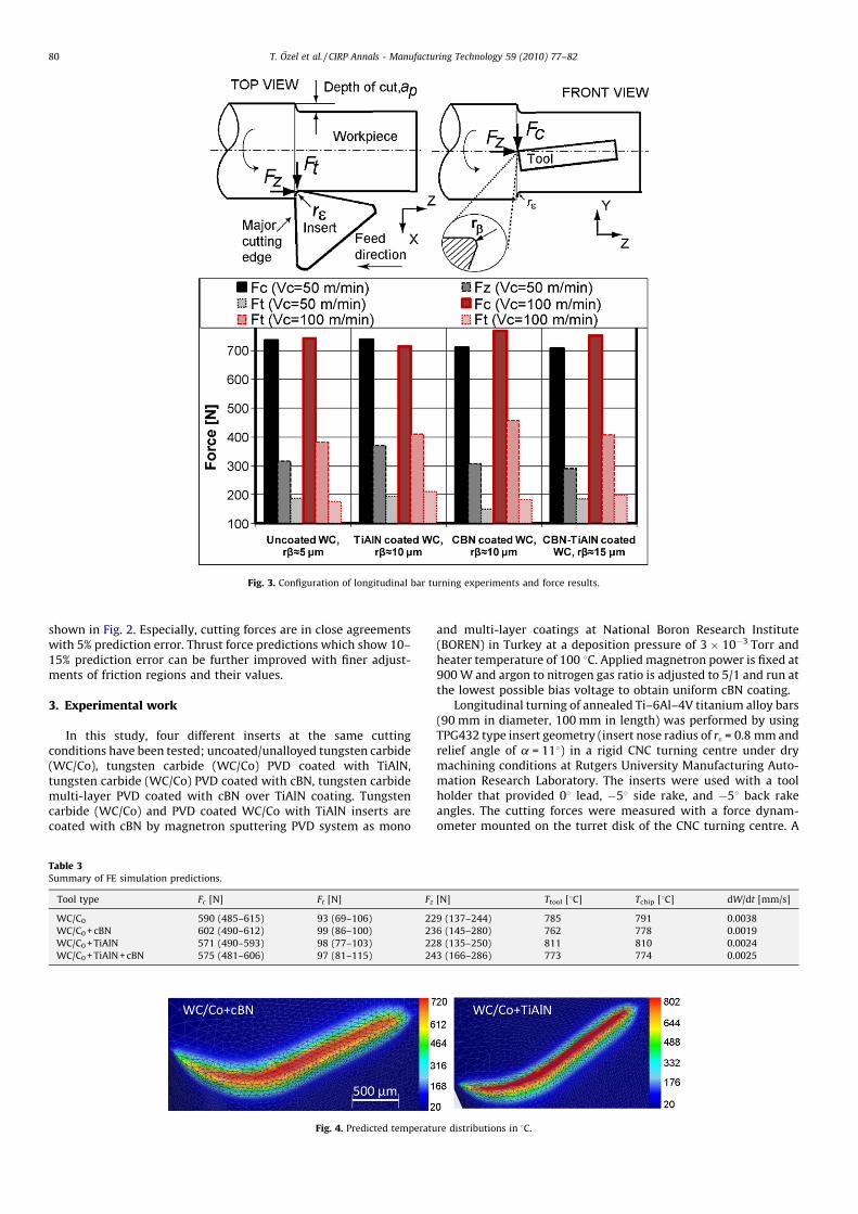
Fig. 3. Configuration of longitudinal bar turning experiments and force results.
T. Ozel et al. / CIRP Annals - Manufacturing Technology 59 (2010) 77–8280
shown in Fig. 2. Especially, cutting forces are in close agreementswith 5% prediction error. Thrust force predictions which show 10–15% prediction error can be further improved with finer adjust-ments of friction regions and their values.
3. Experimental work
In this study, four different inserts at the same cuttingconditions have been tested; uncoated/unalloyed tungsten carbide(WC/Co), tungsten carbide (WC/Co) PVD coated with TiAlN,tungsten carbide (WC/Co) PVD coated with cBN, tungsten carbidemulti-layer PVD coated with cBN over TiAlN coating. Tungstencarbide (WC/Co) and PVD coated WC/Co with TiAlN inserts arecoated with cBN by magnetron sputtering PVD system as mono
Table 3Summary of FE simulation predictions.
Tool type Fc [N] Ft [N] Fz
WC/C0 590 (485–615) 93 (69–106) 22
WC/C0 + cBN 602 (490–612) 99 (86–100) 23
WC/C0 + TiAlN 571 (490–593) 98 (77–103) 22
WC/C0 + TiAlN + cBN 575 (481–606) 97 (81–115) 24
Fig. 4. Predicted temperatu
and multi-layer coatings at National Boron Research Institute(BOREN) in Turkey at a deposition pressure of 3 � 10�3 Torr andheater temperature of 100 8C. Applied magnetron power is fixed at900 W and argon to nitrogen gas ratio is adjusted to 5/1 and run atthe lowest possible bias voltage to obtain uniform cBN coating.
Longitudinal turning of annealed Ti–6Al–4V titanium alloy bars(90 mm in diameter, 100 mm in length) was performed by usingTPG432 type insert geometry (insert nose radius of re = 0.8 mm andrelief angle of a = 118) in a rigid CNC turning centre under drymachining conditions at Rutgers University Manufacturing Auto-mation Research Laboratory. The inserts were used with a toolholder that provided 08 lead, �58 side rake, and �58 back rakeangles. The cutting forces were measured with a force dynam-ometer mounted on the turret disk of the CNC turning centre. A
[N] Ttool [8C] Tchip [8C] dW/dt [mm/s]
9 (137–244) 785 791 0.0038
6 (145–280) 762 778 0.0019
8 (135–250) 811 810 0.0024
3 (166–286) 773 774 0.0025
re distributions in 8C.
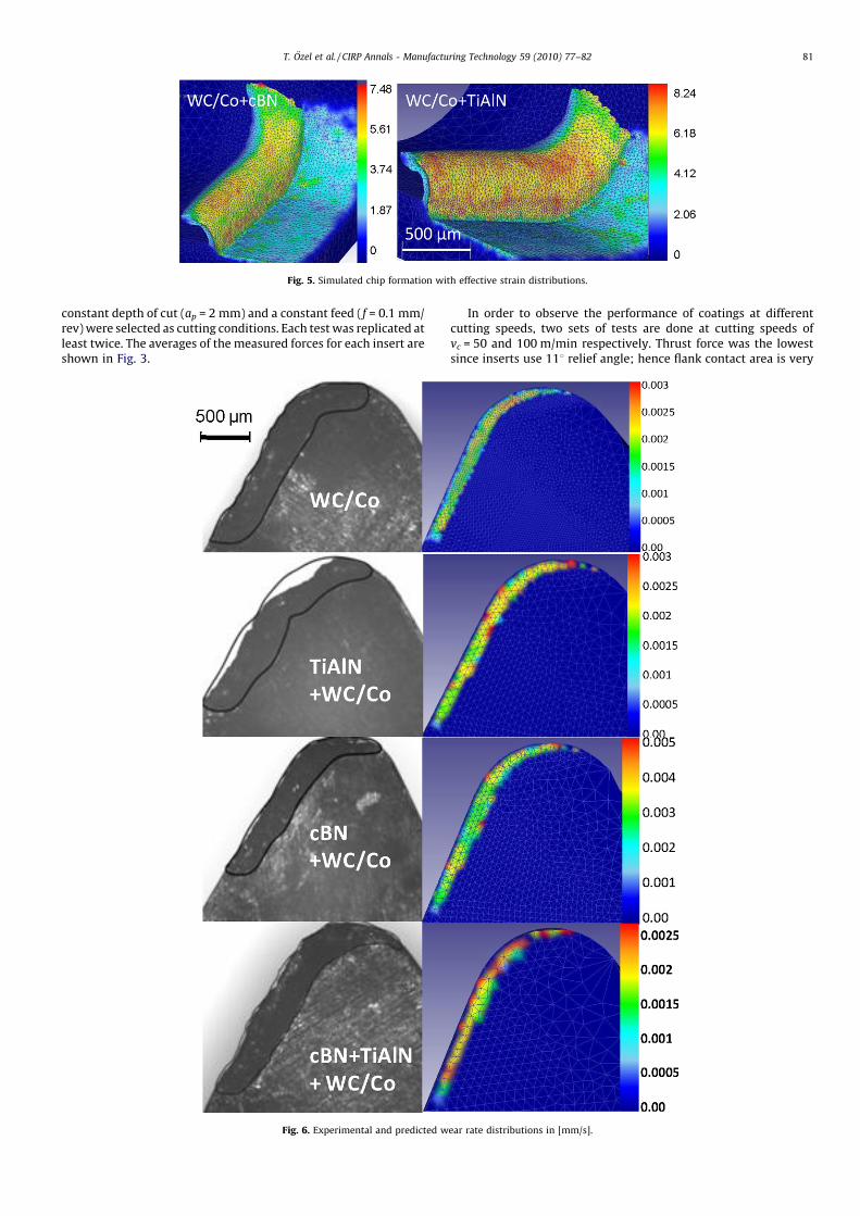
Fig. 5. Simulated chip formation with effective strain distributions.
T. Ozel et al. / CIRP Annals - Manufacturing Technology 59 (2010) 77–82 81
constant depth of cut (ap = 2 mm) and a constant feed (f = 0.1 mm/rev) were selected as cutting conditions. Each test was replicated atleast twice. The averages of the measured forces for each insert areshown in Fig. 3.
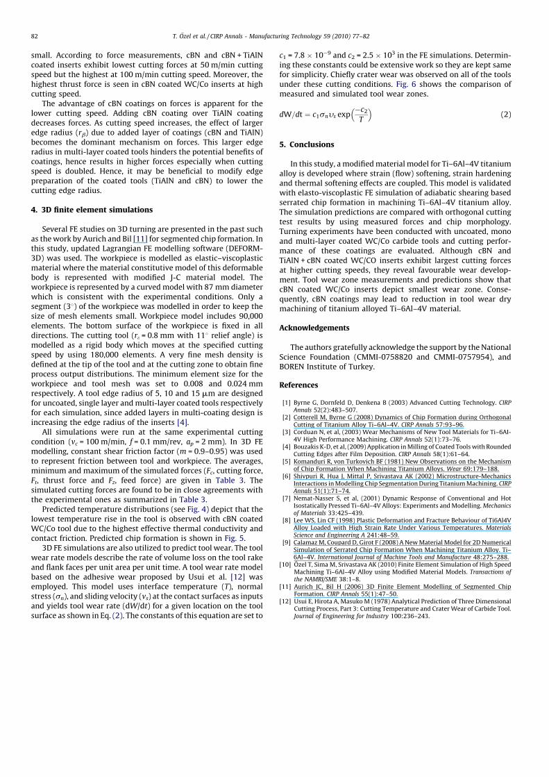
Fig. 6. Experimental and predicted w
In order to observe the performance of coatings at differentcutting speeds, two sets of tests are done at cutting speeds ofvc = 50 and 100 m/min respectively. Thrust force was the lowestsince inserts use 118 relief angle; hence flank contact area is very
ear rate distributions in [mm/s].
T. Ozel et al. / CIRP Annals - Manufacturing Technology 59 (2010) 77–8282
small. According to force measurements, cBN and cBN + TiAlNcoated inserts exhibit lowest cutting forces at 50 m/min cuttingspeed but the highest at 100 m/min cutting speed. Moreover, thehighest thrust force is seen in cBN coated WC/Co inserts at highcutting speed.
The advantage of cBN coatings on forces is apparent for thelower cutting speed. Adding cBN coating over TiAlN coatingdecreases forces. As cutting speed increases, the effect of largeredge radius (rb) due to added layer of coatings (cBN and TiAlN)becomes the dominant mechanism on forces. This larger edgeradius in multi-layer coated tools hinders the potential benefits ofcoatings, hence results in higher forces especially when cuttingspeed is doubled. Hence, it may be beneficial to modify edgepreparation of the coated tools (TiAlN and cBN) to lower thecutting edge radius.
4. 3D finite element simulations
Several FE studies on 3D turning are presented in the past suchas the work by Aurich and Bil [11] for segmented chip formation. Inthis study, updated Lagrangian FE modelling software (DEFORM-3D) was used. The workpiece is modelled as elastic–viscoplasticmaterial where the material constitutive model of this deformablebody is represented with modified J-C material model. Theworkpiece is represented by a curved model with 87 mm diameterwhich is consistent with the experimental conditions. Only asegment (38) of the workpiece was modelled in order to keep thesize of mesh elements small. Workpiece model includes 90,000elements. The bottom surface of the workpiece is fixed in alldirections. The cutting tool (re = 0.8 mm with 118 relief angle) ismodelled as a rigid body which moves at the specified cuttingspeed by using 180,000 elements. A very fine mesh density isdefined at the tip of the tool and at the cutting zone to obtain fineprocess output distributions. The minimum element size for theworkpiece and tool mesh was set to 0.008 and 0.024 mmrespectively. A tool edge radius of 5, 10 and 15 mm are designedfor uncoated, single layer and multi-layer coated tools respectivelyfor each simulation, since added layers in multi-coating design isincreasing the edge radius of the inserts [4].
All simulations were run at the same experimental cuttingcondition (vc = 100 m/min, f = 0.1 mm/rev, ap = 2 mm). In 3D FEmodelling, constant shear friction factor (m = 0.9–0.95) was usedto represent friction between tool and workpiece. The averages,minimum and maximum of the simulated forces (Fc, cutting force,Ft, thrust force and Fz, feed force) are given in Table 3. Thesimulated cutting forces are found to be in close agreements withthe experimental ones as summarized in Table 3.
Predicted temperature distributions (see Fig. 4) depict that thelowest temperature rise in the tool is observed with cBN coatedWC/Co tool due to the highest effective thermal conductivity andcontact friction. Predicted chip formation is shown in Fig. 5.
3D FE simulations are also utilized to predict tool wear. The toolwear rate models describe the rate of volume loss on the tool rakeand flank faces per unit area per unit time. A tool wear rate modelbased on the adhesive wear proposed by Usui et al. [12] wasemployed. This model uses interface temperature (T), normalstress (sn), and sliding velocity (vs) at the contact surfaces as inputsand yields tool wear rate (dW/dt) for a given location on the toolsurface as shown in Eq. (2). The constants of this equation are set to
c1 = 7.8 � 10�9 and c2 = 2.5 � 103 in the FE simulations. Determin-ing these constants could be extensive work so they are kept samefor simplicity. Chiefly crater wear was observed on all of the toolsunder these cutting conditions. Fig. 6 shows the comparison ofmeasured and simulated tool wear zones.
dW=dt ¼ c1snys exp�c2
T
� �(2)
5. Conclusions
In this study, a modified material model for Ti–6Al–4V titaniumalloy is developed where strain (flow) softening, strain hardeningand thermal softening effects are coupled. This model is validatedwith elasto-viscoplastic FE simulation of adiabatic shearing basedserrated chip formation in machining Ti–6Al–4V titanium alloy.The simulation predictions are compared with orthogonal cuttingtest results by using measured forces and chip morphology.Turning experiments have been conducted with uncoated, monoand multi-layer coated WC/Co carbide tools and cutting perfor-mance of these coatings are evaluated. Although cBN andTiAlN + cBN coated WC/CO inserts exhibit largest cutting forcesat higher cutting speeds, they reveal favourable wear develop-ment. Tool wear zone measurements and predictions show thatcBN coated WC/Co inserts depict smallest wear zone. Conse-quently, cBN coatings may lead to reduction in tool wear drymachining of titanium alloyed Ti–6Al–4V material.
Acknowledgements
The authors gratefully acknowledge the support by the NationalScience Foundation (CMMI-0758820 and CMMI-0757954), andBOREN Institute of Turkey.
References
[1] Byrne G, Dornfeld D, Denkena B (2003) Advanced Cutting Technology. CIRPAnnals 52(2):483–507.
[2] Cotterell M, Byrne G (2008) Dynamics of Chip Formation during OrthogonalCutting of Titanium Alloy Ti–6Al–4V. CIRP Annals 57:93–96.
[3] Corduan N, et al, (2003) Wear Mechanisms of New Tool Materials for Ti–6AI-4V High Performance Machining. CIRP Annals 52(1):73–76.
[4] Bouzakis K-D, et al, (2009) Application in Milling of Coated Tools with RoundedCutting Edges after Film Deposition. CIRP Annals 58(1):61–64.
[5] Komanduri R, von Turkovich BF (1981) New Observations on the Mechanismof Chip Formation When Machining Titanium Alloys. Wear 69:179–188.
[6] Shivpuri R, Hua J, Mittal P, Srivastava AK (2002) Microstructure-MechanicsInteractions in Modelling Chip Segmentation During Titanium Machining. CIRPAnnals 51(1):71–74.
[7] Nemat-Nasser S, et al, (2001) Dynamic Response of Conventional and HotIsostatically Pressed Ti–6Al–4V Alloys: Experiments and Modelling. Mechanicsof Materials 33:425–439.
[8] Lee WS, Lin CF (1998) Plastic Deformation and Fracture Behaviour of Ti6Al4VAlloy Loaded with High Strain Rate Under Various Temperatures. MaterialsScience and Engineering A 241:48–59.
[9] Calamaz M, Coupard D, Girot F (2008) A New Material Model for 2D NumericalSimulation of Serrated Chip Formation When Machining Titanium Alloy. Ti–6Al–4V. International Journal of Machine Tools and Manufacture 48:275–288.
[10] Ozel T, Sima M, Srivastava AK (2010) Finite Element Simulation of High SpeedMachining Ti–6Al–4V Alloy using Modified Material Models. Transactions ofthe NAMRI/SME 38:1–8.
[11] Aurich JC, Bil H (2006) 3D Finite Element Modelling of Segmented ChipFormation. CIRP Annals 55(1):47–50.
[12] Usui E, Hirota A, Masuko M (1978) Analytical Prediction of Three DimensionalCutting Process, Part 3: Cutting Temperature and Crater Wear of Carbide Tool.Journal of Engineering for Industry 100:236–243.
Copyright © 2022 FDOKUMEN