Surface engineering to improve the durability and lubricity of Ti-6Al-4V alloy
10
Wear 271 (2011) 2006–2015 Contents lists available at ScienceDirect Wear j o ur nal ho me p age: www.elsevier.com/locate/wear Surface engineering to improve the durability and lubricity of Ti–6Al–4V alloy D.G. Bansal a , O.L. Eryilmaz b , P.J. Blau a,∗ a Materials Science and Technology Division, Oak Ridge National Laboratory, Oak Ridge, TN 37831-6063, USA b Energy Systems Division ES-212, Argonne National Laboratory, 9700 South Cass Avenue, Argonne, IL 60439, USA a r t i c l e i n f o Article history: Received 10 September 2010 Received in revised form 22 November 2010 Accepted 23 November 2010 Keywords: Titanium Surface engineering Friction Wear Diffusion treatments Hard coatings a b s t r a c t The fuel efficiency of ground vehicles, like heavy trucks, can be improved by reducing engine weight. While primarily known for its use in aerospace structures, titanium alloy Ti–6Al–4V has the potential to replace heavier steel in certain friction and wear-critical diesel engine components like connecting rods, intake valves, movable turbocharger vanes, and pistons. While Ti–6Al–4V exhibits excellent corrosion resistance, good fatigue strength, and acceptable fracture toughness, it has poor sliding characteris- tics. Titanium alloys have a propensity to fail by galling, and often exhibit high and unstable friction coefficients. In the current work, selected surface engineering techniques were compared to determine which best enhance the tribological performance of Ti–6Al–4V alloy and another alloy, 60Ni–40Ti. Can- didate treatments included diffusion treatments, hard coatings (TiN and CrN), a soft coating (Cu–Ni–In), titanium-matrix TiB 2 in situ-formed composite, and shot peening. Diffusion treatments included oxygen diffusion, nitriding, and carburizing. In addition to studying the effects of individual surface engineering approaches, some were combined in an attempt to maximize their effects, but at the same time retain the mechanical properties of the titanium alloy achieved by proper heat treatment. Both dry and lubri- cated friction and wear tests were conducted using ASTM G133 (linearly reciprocating ball-on-flat). The ball specimens were AISI 52100 bearing steel. Lubricated tests were performed in engine-conditioned diesel engine oil. Test coupons were characterized using microindentation, stylus and optical interfer- ometry, and metallographic examination. Surface engineering methods significantly improved the wear performance of Ti–6Al–4V alloy, but their relative rankings varied significantly between oil-lubricated and non-lubricated conditions. © 2011 Elsevier B.V. All rights reserved. 1. Introduction Due to their corrosion resistance, good fatigue strength, and acceptable fracture toughness, titanium alloys are being widely used in orthopaedic and dental implants [1], the chemical pro- cess industry [2] and automotive and aerospace structural parts [3–5]. Titanium demonstrates poor tribological properties mainly because it is susceptible to failure by galling and high and unsta- ble friction coefficients against common bearing materials [6,7]. Therefore, a variety of surface treatments and coatings have been developed for use with titanium and its alloys [8–10]. Surface engi- neering, in the present context, is defined as any process that aims to improve the functionality of a solid surface by altering its geometric form (shape, texture, or roughness), its chemical Notice: Research sponsored by the U.S. Department of Energy, Assistant Secretary for Energy Efficiency and Renewable Energy, Office of Vehicle Technologies, as part of the Propulsion Materials Program, under contract DE-AC05-00OR22725 with UT- Battelle, LLC. ∗ Corresponding author. Tel.: +1 865 574 5377; fax: +1 865 574 4913. E-mail address: [email protected] (P.J. Blau). composition, or the microstructure of the materials of which it is composed. Several approaches to surface engineering titanium are discussed in this paper. Budinski [6] studied galling, wear, fretting and abrasion perfor- mance of commercially pure titanium and Ti–6Al–4V alloy (hereon referred to as Ti64) against several counterfaces. He recommended anodizing the surface to reduce wear of titanium. Dong et al. [11] studied the effect of thermal oxidation (TO) (600–850 ◦ C) on the wear performance of Ti–6Al–4V alloy against 709M40 steel under rolling-sliding conditions both with and without lubrication. They found that the wear resistance of Ti64 increased by at least two orders of magnitude after TO under lubricated conditions. They also found that TO also improves the electrochemical corrosion resistance of Ti64. Dong and Li [12] have developed a process for deep-case hardening of Ti64 with a case depth of around 300 m thus improving its load bearing capacity. Wiklund and Hutchings [7] compared the frictional and galling behaviour of TO treated Ti64 with other surface treatments like diamond-like carbon coatings (DLC), and TiN (PVD, EB and AE) coatings and found that galling resistance of TO is comparable to that of DLC. Qu et al. [13] reported that oxygen diffusion treatment of Ti64 facilitates the reactivity of zinc-dialkyl-dithiophosphate (ZDDP) in the lubricant and improves 0043-1648/$ – see front matter © 2011 Elsevier B.V. All rights reserved. doi:10.1016/j.wear.2010.11.021
-
Upload
independent -
Category
Documents
-
view
5 -
download
0
Transcript of Surface engineering to improve the durability and lubricity of Ti-6Al-4V alloy
S
Da
b
a
ARR2A
KTSFWDH
1
auc[bbTdnai
foB
0d
Wear 271 (2011) 2006– 2015
Contents lists available at ScienceDirect
Wear
j o ur nal ho me p age: www.elsev ier .com/ locate /wear
urface engineering to improve the durability and lubricity of Ti–6Al–4V alloy�
.G. Bansala, O.L. Eryilmazb, P.J. Blaua,∗
Materials Science and Technology Division, Oak Ridge National Laboratory, Oak Ridge, TN 37831-6063, USAEnergy Systems Division ES-212, Argonne National Laboratory, 9700 South Cass Avenue, Argonne, IL 60439, USA
r t i c l e i n f o
rticle history:eceived 10 September 2010eceived in revised form2 November 2010ccepted 23 November 2010
eywords:itaniumurface engineeringrictionear
iffusion treatmentsard coatings
a b s t r a c t
The fuel efficiency of ground vehicles, like heavy trucks, can be improved by reducing engine weight.While primarily known for its use in aerospace structures, titanium alloy Ti–6Al–4V has the potential toreplace heavier steel in certain friction and wear-critical diesel engine components like connecting rods,intake valves, movable turbocharger vanes, and pistons. While Ti–6Al–4V exhibits excellent corrosionresistance, good fatigue strength, and acceptable fracture toughness, it has poor sliding characteris-tics. Titanium alloys have a propensity to fail by galling, and often exhibit high and unstable frictioncoefficients. In the current work, selected surface engineering techniques were compared to determinewhich best enhance the tribological performance of Ti–6Al–4V alloy and another alloy, 60Ni–40Ti. Can-didate treatments included diffusion treatments, hard coatings (TiN and CrN), a soft coating (Cu–Ni–In),titanium-matrix TiB2 in situ-formed composite, and shot peening. Diffusion treatments included oxygendiffusion, nitriding, and carburizing. In addition to studying the effects of individual surface engineeringapproaches, some were combined in an attempt to maximize their effects, but at the same time retain
the mechanical properties of the titanium alloy achieved by proper heat treatment. Both dry and lubri-cated friction and wear tests were conducted using ASTM G133 (linearly reciprocating ball-on-flat). Theball specimens were AISI 52100 bearing steel. Lubricated tests were performed in engine-conditioneddiesel engine oil. Test coupons were characterized using microindentation, stylus and optical interfer-ometry, and metallographic examination. Surface engineering methods significantly improved the wearperformance of Ti–6Al–4V alloy, but their relative rankings varied significantly between oil-lubricatedtions
and non-lubricated condi. Introduction
Due to their corrosion resistance, good fatigue strength, andcceptable fracture toughness, titanium alloys are being widelysed in orthopaedic and dental implants [1], the chemical pro-ess industry [2] and automotive and aerospace structural parts3–5]. Titanium demonstrates poor tribological properties mainlyecause it is susceptible to failure by galling and high and unsta-le friction coefficients against common bearing materials [6,7].herefore, a variety of surface treatments and coatings have been
eveloped for use with titanium and its alloys [8–10]. Surface engi-eering, in the present context, is defined as any process thatims to improve the functionality of a solid surface by alteringts geometric form (shape, texture, or roughness), its chemical� Notice: Research sponsored by the U.S. Department of Energy, Assistant Secretaryor Energy Efficiency and Renewable Energy, Office of Vehicle Technologies, as partf the Propulsion Materials Program, under contract DE-AC05-00OR22725 with UT-attelle, LLC.∗ Corresponding author. Tel.: +1 865 574 5377; fax: +1 865 574 4913.
E-mail address: [email protected] (P.J. Blau).
043-1648/$ – see front matter © 2011 Elsevier B.V. All rights reserved.oi:10.1016/j.wear.2010.11.021
.© 2011 Elsevier B.V. All rights reserved.
composition, or the microstructure of the materials of which it iscomposed. Several approaches to surface engineering titanium arediscussed in this paper.
Budinski [6] studied galling, wear, fretting and abrasion perfor-mance of commercially pure titanium and Ti–6Al–4V alloy (hereonreferred to as Ti64) against several counterfaces. He recommendedanodizing the surface to reduce wear of titanium. Dong et al. [11]studied the effect of thermal oxidation (TO) (600–850 ◦C) on thewear performance of Ti–6Al–4V alloy against 709M40 steel underrolling-sliding conditions both with and without lubrication. Theyfound that the wear resistance of Ti64 increased by at least twoorders of magnitude after TO under lubricated conditions. Theyalso found that TO also improves the electrochemical corrosionresistance of Ti64. Dong and Li [12] have developed a process fordeep-case hardening of Ti64 with a case depth of around 300 �mthus improving its load bearing capacity. Wiklund and Hutchings[7] compared the frictional and galling behaviour of TO treated Ti64
with other surface treatments like diamond-like carbon coatings(DLC), and TiN (PVD, EB and AE) coatings and found that gallingresistance of TO is comparable to that of DLC. Qu et al. [13] reportedthat oxygen diffusion treatment of Ti64 facilitates the reactivity ofzinc-dialkyl-dithiophosphate (ZDDP) in the lubricant and improves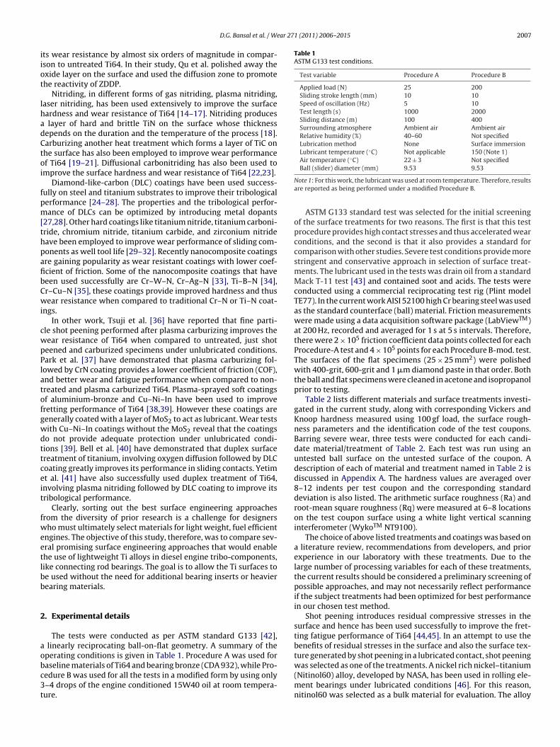
ear 271 (2011) 2006– 2015 2007
iiot
lhadCtoi
fpm[thpafibCwi
cwpPlatofgwdttceit
fweetlbb
2
aobc3t
Table 1ASTM G133 test conditions.
Test variable Procedure A Procedure B
Applied load (N) 25 200Sliding stroke length (mm) 10 10Speed of oscillation (Hz) 5 10Test length (s) 1000 2000Sliding distance (m) 100 400Surrounding atmosphere Ambient air Ambient airRelative humidity (%) 40–60 Not specifiedLubrication method None Surface immersionLubricant temperature (◦C) Not applicable 150 (Note 1)Air temperature (◦C) 22 ± 3 Not specified
D.G. Bansal et al. / W
ts wear resistance by almost six orders of magnitude in compar-son to untreated Ti64. In their study, Qu et al. polished away thexide layer on the surface and used the diffusion zone to promotehe reactivity of ZDDP.
Nitriding, in different forms of gas nitriding, plasma nitriding,aser nitriding, has been used extensively to improve the surfaceardness and wear resistance of Ti64 [14–17]. Nitriding produces
layer of hard and brittle TiN on the surface whose thicknessepends on the duration and the temperature of the process [18].arburizing another heat treatment which forms a layer of TiC onhe surface has also been employed to improve wear performancef Ti64 [19–21]. Diffusional carbonitriding has also been used tomprove the surface hardness and wear resistance of Ti64 [22,23].
Diamond-like-carbon (DLC) coatings have been used success-ully on steel and titanium substrates to improve their tribologicalerformance [24–28]. The properties and the tribological perfor-ance of DLCs can be optimized by introducing metal dopants
27,28]. Other hard coatings like titanium nitride, titanium carboni-ride, chromium nitride, titanium carbide, and zirconium nitrideave been employed to improve wear performance of sliding com-onents as well tool life [29–32]. Recently nanocomposite coatingsre gaining popularity as wear resistant coatings with lower coef-cient of friction. Some of the nanocomposite coatings that haveeen used successfully are Cr–W–N, Cr–Ag–N [33], Ti–B–N [34],r–Cu–N [35], these coatings provide improved hardness and thusear resistance when compared to traditional Cr–N or Ti–N coat-
ngs.In other work, Tsuji et al. [36] have reported that fine parti-
le shot peening performed after plasma carburizing improves theear resistance of Ti64 when compared to untreated, just shoteened and carburized specimens under unlubricated conditions.ark et al. [37] have demonstrated that plasma carburizing fol-owed by CrN coating provides a lower coefficient of friction (COF),nd better wear and fatigue performance when compared to non-reated and plasma carburized Ti64. Plasma-sprayed soft coatingsf aluminium-bronze and Cu–Ni–In have been used to improveretting performance of Ti64 [38,39]. However these coatings areenerally coated with a layer of MoS2 to act as lubricant. Wear testsith Cu–Ni–In coatings without the MoS2 reveal that the coatingso not provide adequate protection under unlubricated condi-ions [39]. Bell et al. [40] have demonstrated that duplex surfacereatment of titanium, involving oxygen diffusion followed by DLCoating greatly improves its performance in sliding contacts. Yetimt al. [41] have also successfully used duplex treatment of Ti64,nvolving plasma nitriding followed by DLC coating to improve itsribological performance.
Clearly, sorting out the best surface engineering approachesrom the diversity of prior research is a challenge for designersho must ultimately select materials for light weight, fuel efficient
ngines. The objective of this study, therefore, was to compare sev-ral promising surface engineering approaches that would enablehe use of lightweight Ti alloys in diesel engine tribo-components,ike connecting rod bearings. The goal is to allow the Ti surfaces toe used without the need for additional bearing inserts or heavierearing materials.
. Experimental details
The tests were conducted as per ASTM standard G133 [42], linearly reciprocating ball-on-flat geometry. A summary of the
perating conditions is given in Table 1. Procedure A was used foraseline materials of Ti64 and bearing bronze (CDA 932), while Pro-edure B was used for all the tests in a modified form by using only–4 drops of the engine conditioned 15W40 oil at room tempera-ure.Ball (slider) diameter (mm) 9.53 9.53
Note 1: For this work, the lubricant was used at room temperature. Therefore, resultsare reported as being performed under a modified Procedure B.
ASTM G133 standard test was selected for the initial screeningof the surface treatments for two reasons. The first is that this testprocedure provides high contact stresses and thus accelerated wearconditions, and the second is that it also provides a standard forcomparison with other studies. Severe test conditions provide morestringent and conservative approach in selection of surface treat-ments. The lubricant used in the tests was drain oil from a standardMack T-11 test [43] and contained soot and acids. The tests wereconducted using a commercial reciprocating test rig (Plint modelTE77). In the current work AISI 52100 high Cr bearing steel was usedas the standard counterface (ball) material. Friction measurementswere made using a data acquisition software package (LabViewTM)at 200 Hz, recorded and averaged for 1 s at 5 s intervals. Therefore,there were 2 × 10⁵ friction coefficient data points collected for eachProcedure-A test and 4 × 10⁵ points for each Procedure B-mod. test.The surfaces of the flat specimens (25 × 25 mm2) were polishedwith 400-grit, 600-grit and 1 �m diamond paste in that order. Boththe ball and flat specimens were cleaned in acetone and isopropanolprior to testing.
Table 2 lists different materials and surface treatments investi-gated in the current study, along with corresponding Vickers andKnoop hardness measured using 100 gf load, the surface rough-ness parameters and the identification code of the test coupons.Barring severe wear, three tests were conducted for each candi-date material/treatment of Table 2. Each test was run using anuntested ball surface on the untested surface of the coupon. Adescription of each of material and treatment named in Table 2 isdiscussed in Appendix A. The hardness values are averaged over8–12 indents per test coupon and the corresponding standarddeviation is also listed. The arithmetic surface roughness (Ra) androot-mean square roughness (Rq) were measured at 6–8 locationson the test coupon surface using a white light vertical scanninginterferometer (WykoTM NT9100).
The choice of above listed treatments and coatings was based ona literature review, recommendations from developers, and priorexperience in our laboratory with these treatments. Due to thelarge number of processing variables for each of these treatments,the current results should be considered a preliminary screening ofpossible approaches, and may not necessarily reflect performanceif the subject treatments had been optimized for best performancein our chosen test method.
Shot peening introduces residual compressive stresses in thesurface and hence has been used successfully to improve the fret-ting fatigue performance of Ti64 [44,45]. In an attempt to use thebenefits of residual stresses in the surface and also the surface tex-
ture generated by shot peening in a lubricated contact, shot peeningwas selected as one of the treatments. A nickel rich nickel–titanium(Nitinol60) alloy, developed by NASA, has been used in rolling ele-ment bearings under lubricated conditions [46]. For this reason,nitinol60 was selected as a bulk material for evaluation. The alloy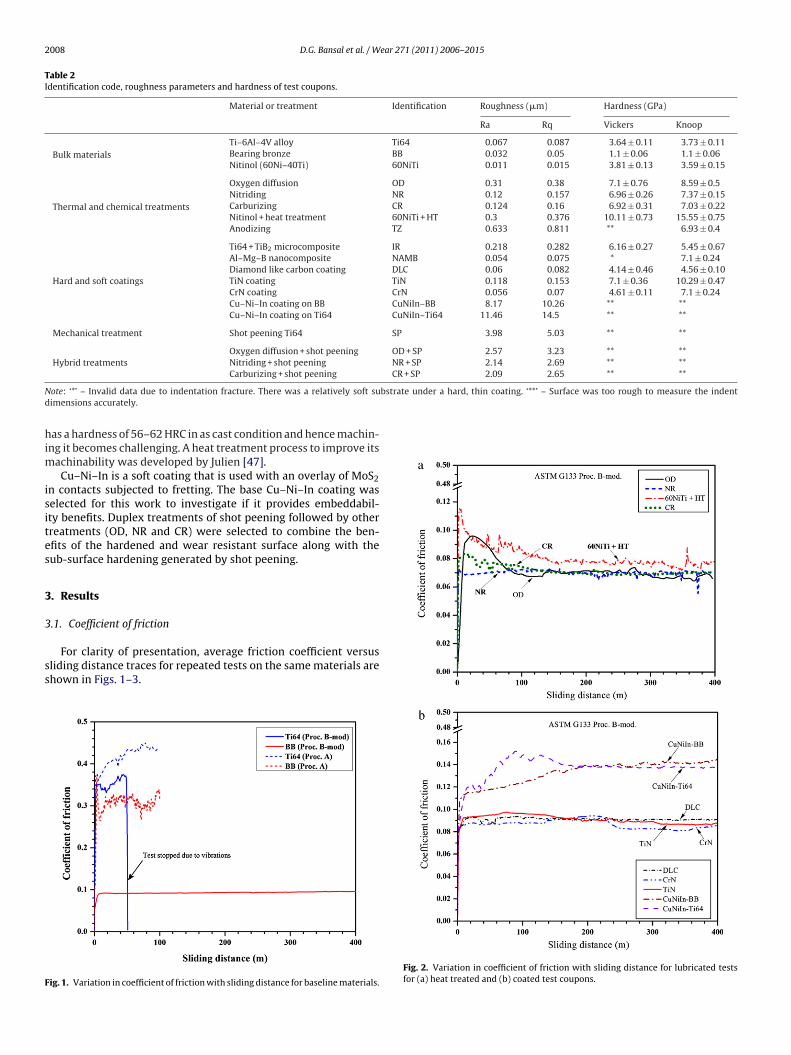
2008 D.G. Bansal et al. / Wear 271 (2011) 2006– 2015
Table 2Identification code, roughness parameters and hardness of test coupons.
Material or treatment Identification Roughness (�m) Hardness (GPa)
Ra Rq Vickers Knoop
Bulk materialsTi–6Al–4V alloy Ti64 0.067 0.087 3.64 ± 0.11 3.73 ± 0.11Bearing bronze BB 0.032 0.05 1.1 ± 0.06 1.1 ± 0.06Nitinol (60Ni–40Ti) 60NiTi 0.011 0.015 3.81 ± 0.13 3.59 ± 0.15
Thermal and chemical treatments
Oxygen diffusion OD 0.31 0.38 7.1 ± 0.76 8.59 ± 0.5Nitriding NR 0.12 0.157 6.96 ± 0.26 7.37 ± 0.15Carburizing CR 0.124 0.16 6.92 ± 0.31 7.03 ± 0.22Nitinol + heat treatment 60NiTi + HT 0.3 0.376 10.11 ± 0.73 15.55 ± 0.75Anodizing TZ 0.633 0.811 ** 6.93 ± 0.4
Hard and soft coatings
Ti64 + TiB2 microcomposite IR 0.218 0.282 6.16 ± 0.27 5.45 ± 0.67Al–Mg–B nanocomposite NAMB 0.054 0.075 * 7.1 ± 0.24Diamond like carbon coating DLC 0.06 0.082 4.14 ± 0.46 4.56 ± 0.10TiN coating TiN 0.118 0.153 7.1 ± 0.36 10.29 ± 0.47CrN coating CrN 0.056 0.07 4.61 ± 0.11 7.1 ± 0.24Cu–Ni–In coating on BB CuNiIn–BB 8.17 10.26 ** **Cu–Ni–In coating on Ti64 CuNiIn–Ti64 11.46 14.5 ** **
Mechanical treatment Shot peening Ti64 SP 3.98 5.03 ** **
Hybrid treatmentsOxygen diffusion + shot peening OD + SP 2.57 3.23 ** **Nitriding + shot peening NR + SP 2.14 2.69 ** **
CR + SP 2.09 2.65 ** **
N bstrate under a hard, thin coating. ‘**’ – Surface was too rough to measure the indentd
him
isites
3
3
ss
F
Carburizing + shot peening
ote: ‘*’ – Invalid data due to indentation fracture. There was a relatively soft suimensions accurately.
as a hardness of 56–62 HRC in as cast condition and hence machin-ng it becomes challenging. A heat treatment process to improve its
achinability was developed by Julien [47].Cu–Ni–In is a soft coating that is used with an overlay of MoS2
n contacts subjected to fretting. The base Cu–Ni–In coating waselected for this work to investigate if it provides embeddabil-ty benefits. Duplex treatments of shot peening followed by otherreatments (OD, NR and CR) were selected to combine the ben-fits of the hardened and wear resistant surface along with theub-surface hardening generated by shot peening.
. Results
.1. Coefficient of friction
For clarity of presentation, average friction coefficient versusliding distance traces for repeated tests on the same materials arehown in Figs. 1–3.
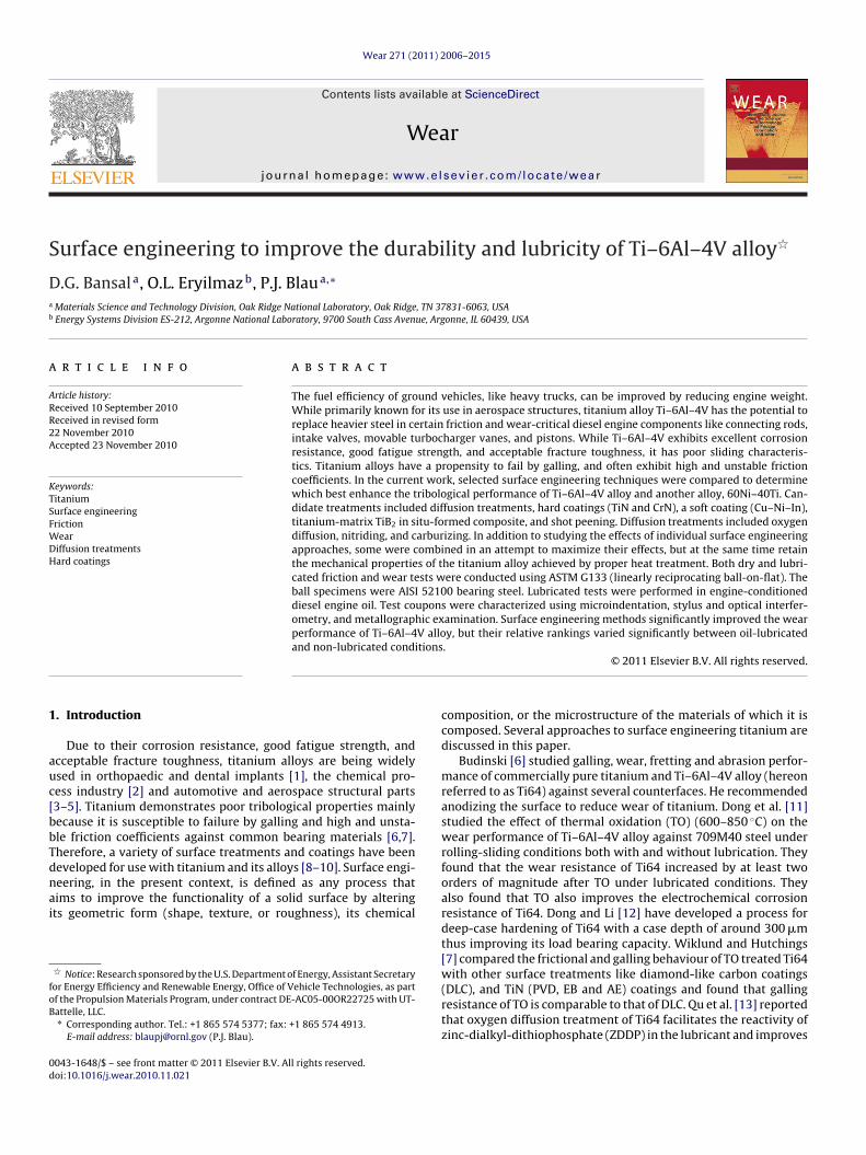
ig. 1. Variation in coefficient of friction with sliding distance for baseline materials.
Fig. 2. Variation in coefficient of friction with sliding distance for lubricated testsfor (a) heat treated and (b) coated test coupons.
D.G. Bansal et al. / Wear 27
Fc
fAutrp
lBy
dctTooToitottstcaatnFtdt
60NiTi specimens (60NiTi + HT) shows the largest wear on both thecoupon and the ball. Since the wear volume of the coupons is orders
TS
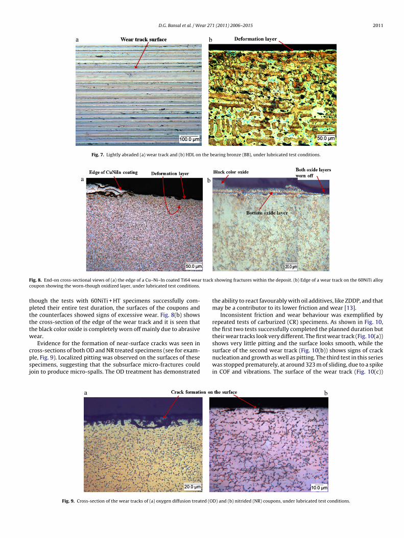
ig. 3. Summary of coefficient of friction for all the treatments under lubricated testonditions.
Fig. 1 illustrates the variation in COF over the sliding distanceor the baseline materials Ti64 and BB under non-lubricated (Proc.) and lubricated (Proc. B-mod) conditions. For the tests with Ti64nder Proc. B-mod, all three tests were stopped prematurely dueo high COF and vibrations, and hence only one representative testesult is plotted, for all other cases the average of all 3 test runs islotted.
It is seen that BB gives lower COF under lubricated and non-ubricated conditions as compared to Ti64. For the lubricated testsB yields a steady friction coefficient of around 0.096, while Ti64ields a much higher COF of around 0.36.
Fig. 2(a) and (b) present the variation in COF over the slidingistance for the heat treated (Fig. 2(a)) and coated (Fig. 2(b)) testoupons respectively. Tests that were prematurely terminated dueo high friction or vibration are not plotted. For the carburized (CR)i64 specimens, the first two tests were successful, but the thirdne failed due to a sudden spike in friction. Hence the average ofnly two tests is plotted. From Fig. 2(a) it is seen that the nitridedi64 (NR) specimens yield the lowest COF over the entire durationf sliding. OD and CR treated specimens exhibit higher COF at thenitial stage of sliding of around 0.096 and 0.083 respectively, but ashe sliding progresses the COF decreases and settles around a valuef 0.072. The heat treated Nitinol (60NiTi + HT) specimen exhibitedhe highest COF at the initial stage of around 0.115 but it decreaseso a value around 0.082 as the sliding progresses. Among the coatedpecimens (Fig. 2(b)), the hard coatings DLC, TiN and CrN providehe lower COF in the range of 0.085–0.092. The COF for Cu–Ni–Inoated bearing bronze (CuNiIn–BB) shows an increasing trend forlmost the first half of the sliding duration but then settles around
value of 0.14. For Cu–Ni–In coated Ti64 (CuNiIn–Ti64) the secondest failed prematurely due to high vibrations and hence it wasot repeated for the third time. The COF trace for CuNiIn–Ti64 inig. 2(b) is for the only successful test of that material. It is seen
hat COF shows an increasing trend for the first quarter of the slidinguration reaching a peak value of 0.148 and then it starts decreasingo finally stabilize around 0.137.able 3ummary of wear volumes under non-lubricated test conditions.
Sliding pair Wear volume of coupon (mm3)
Ti64–52100 steel 1.16
CDA 932 BB–52100 steel 0.897
1 (2011) 2006– 2015 2009
Fig. 3 summarizes the average/maximum coefficients of frictionfor all the treatments under lubricated test conditions. For the suc-cessful tests, the values plotted here are the average, of the averagecoefficients of friction over the course of sliding, of the three tests.For the treatments for which even one of the tests failed the finalvalue of COF (before the test was stopped) is plotted.
For ranking purposes, when all three tests of a given treat-ment completed the entire sliding duration at COF < 0.15, they wereconsidered successful. For longevity of the bearing contact andbetter performance, operation in mixed to full film lubrication ispreferred, although intermittent operation in the boundary filmregime might occur during start-up. A cut-off value of 0.15 for theCOF was selected based on the need for components to operate notworse than under boundary lubrication conditions, whose typicalCOF range is ∼0.05–0.15.
Tests with anodized (TZ) and shot peened (SP) specimens startedwith high COF (greater than 0.36) and hence the tests were termi-nated at once. The same trend was observed for OD + SP and CR + SPtreated specimens. For nitrided + shot peened specimens (NR + SP),five tests were run. Of these, two completed the entire test durationwhile three failed. Hence for NR + SP case the maximum of final COFamong three failed tests is plotted.
3.2. Wear measurement
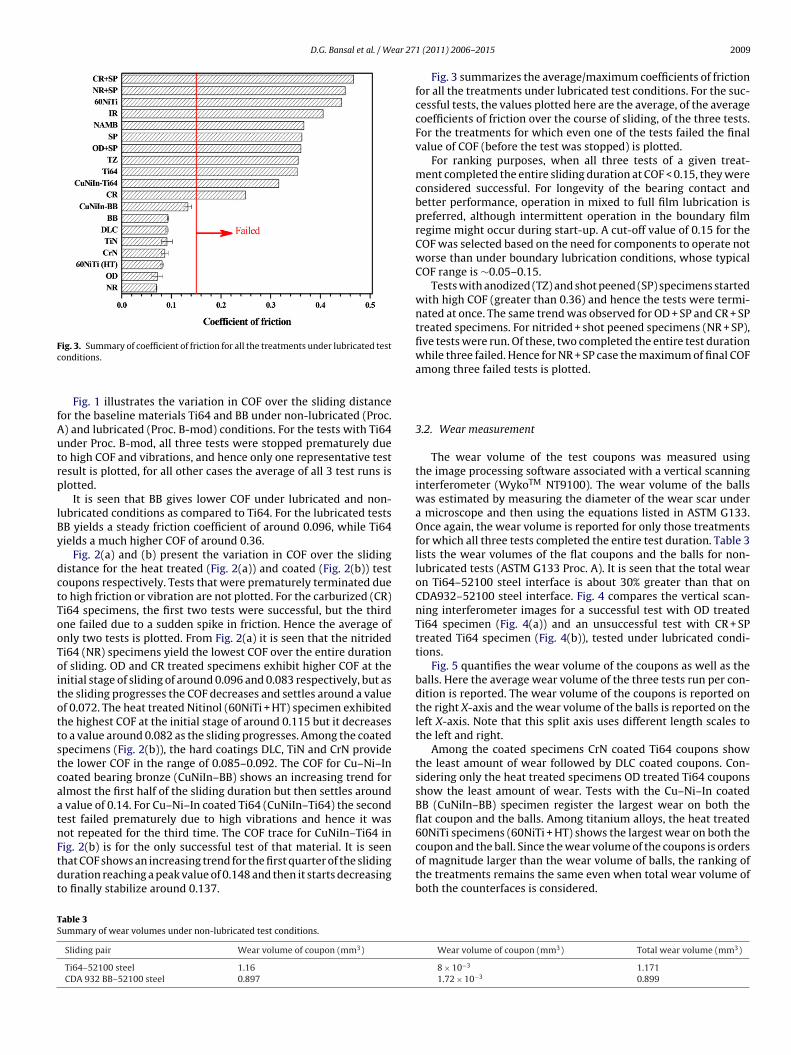
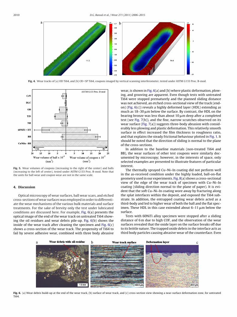
The wear volume of the test coupons was measured usingthe image processing software associated with a vertical scanninginterferometer (WykoTM NT9100). The wear volume of the ballswas estimated by measuring the diameter of the wear scar undera microscope and then using the equations listed in ASTM G133.Once again, the wear volume is reported for only those treatmentsfor which all three tests completed the entire test duration. Table 3lists the wear volumes of the flat coupons and the balls for non-lubricated tests (ASTM G133 Proc. A). It is seen that the total wearon Ti64–52100 steel interface is about 30% greater than that onCDA932–52100 steel interface. Fig. 4 compares the vertical scan-ning interferometer images for a successful test with OD treatedTi64 specimen (Fig. 4(a)) and an unsuccessful test with CR + SPtreated Ti64 specimen (Fig. 4(b)), tested under lubricated condi-tions.
Fig. 5 quantifies the wear volume of the coupons as well as theballs. Here the average wear volume of the three tests run per con-dition is reported. The wear volume of the coupons is reported onthe right X-axis and the wear volume of the balls is reported on theleft X-axis. Note that this split axis uses different length scales tothe left and right.
Among the coated specimens CrN coated Ti64 coupons showthe least amount of wear followed by DLC coated coupons. Con-sidering only the heat treated specimens OD treated Ti64 couponsshow the least amount of wear. Tests with the Cu–Ni–In coatedBB (CuNiIn–BB) specimen register the largest wear on both theflat coupon and the balls. Among titanium alloys, the heat treated
of magnitude larger than the wear volume of balls, the ranking ofthe treatments remains the same even when total wear volume ofboth the counterfaces is considered.
Wear volume of coupon (mm3) Total wear volume (mm3)
8 × 10⁻³ 1.1711.72 × 10−3 0.899
2010 D.G. Bansal et al. / Wear 271 (2011) 2006– 2015
Fig. 4. Wear tracks of (a) OD Ti64, and (b) CR + SP Ti64, coupons imaged by v
F(t
4
catcoiisf
Tests with 60NiTi alloy specimen were stopped after a sliding
FT
ig. 5. Wear volumes of coupons (increasing to the right of the center) and ballsincreasing to the left of center), tested under ASTM G133 Proc. B-mod. Note thathe units for ball wear and coupon wear are not in the same scale.
. Discussion
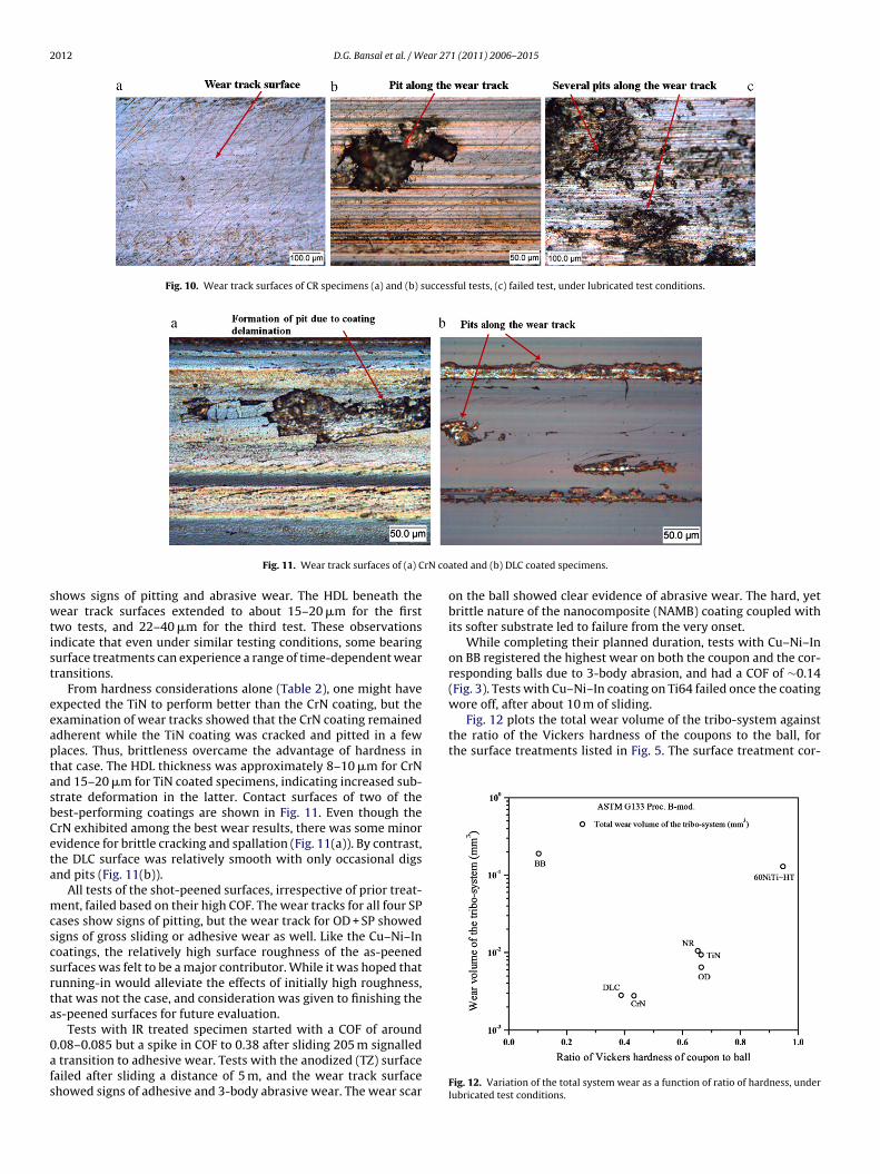
Optical microscopy of wear surfaces, ball wear scars, and etchedross-sections of wear surfaces was employed in order to differenti-te the wear mechanisms of the various bulk materials and surfacereatments. For the sake of brevity only the test under lubricatedonditions are discussed here. For example, Fig. 6(a) presents theptical image of the end of the wear track on untreated Ti64 show-
ng the oil residues and wear debris pile-up. Fig. 6(b) shows thenside of the wear track after cleaning the specimen and Fig. 6(c)hows a cross-section of the wear track. The propensity of Ti64 toail by severe adhesive wear, combined with three body abrasiveig. 6. (a) Wear debris build-up at the end of the wear track, (b) surface of wear track, ai64.
ertical scanning interferometer, tested under ASTM G133 Proc. B-mod.
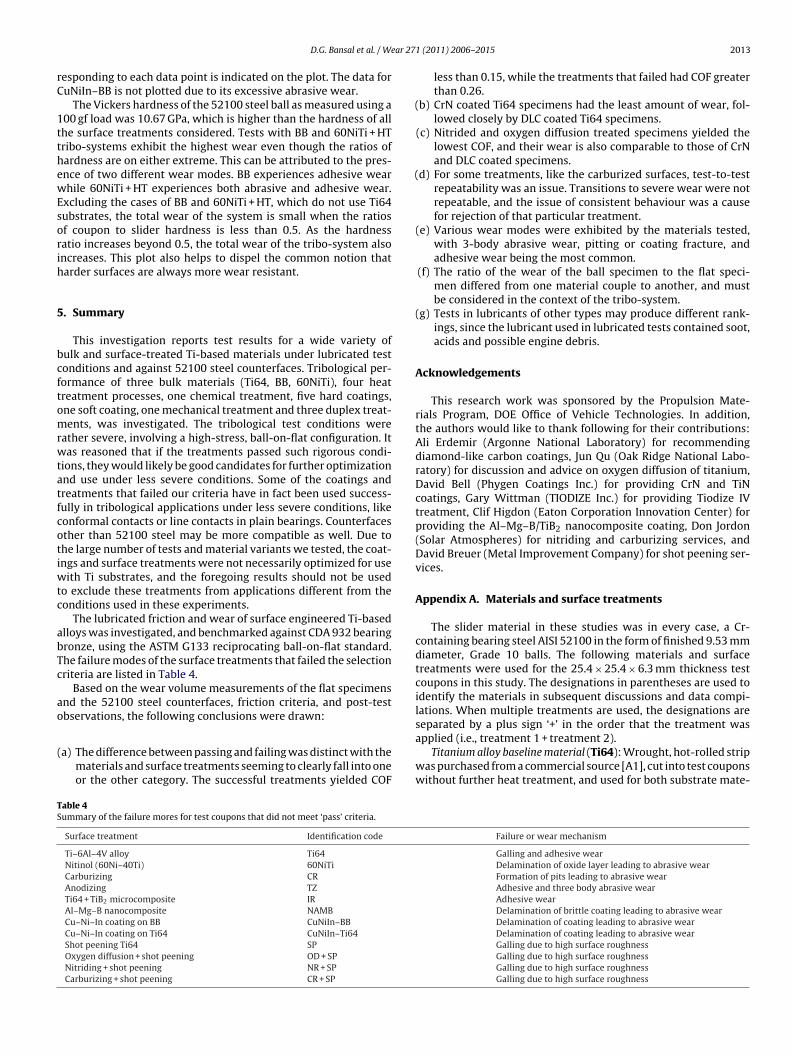
wear, is shown in Fig. 6(a) and (b) where plastic deformation, plow-ing, and grooving are apparent. Even though tests with untreatedTi64 were stopped prematurely and the planned sliding distancewas not achieved, an etched cross-sectional view of the track (end-on) (Fig. 6(c)) reveals a highly deformed layer (HDL) extending asmuch as 18–30 �m below the surface. By contrast, the HDL on thebearing bronze was less than about 10 �m deep after a completedtest (see Fig. 7(b)), and the fine, narrow scratches observed on itswear surface (Fig. 7(a)) suggests three-body abrasion with consid-erably less plowing and plastic deformation. This relatively smoothsurface in effect increased the film thickness to roughness ratio,and that explains the steady frictional behaviour plotted in Fig. 1. Itshould be noted that the direction of sliding is normal to the planeof the cross-sections.
In addition to the baseline materials (non-treated Ti64 andBB), the wear surfaces of other test coupons were similarly doc-umented by microscopy; however, in the interests of space, onlyselected examples are presented to illustrate features of particularinterest.
The thermally sprayed Cu–Ni–In coating did not perform wellin the as-received condition under the highly loaded, ball-on-flatgeometry used in our experiments. Fig. 8(a) shows a cross-sectionalview of the edge of the wear track of specimen with Cu–Ni–Incoating (sliding direction normal to the plane of paper). It is evi-dent that the soft Cu–Ni–In coating wore away by fracturing alongthe splat interfaces within the deposit, and exposed the Ti64 sub-strate. In addition, the entrapped coating wear debris acted as athird-body and led to higher wear of both the ball and the flat spec-imen. These HDL in this case extended about 6–11 �m below thesurface.
distance of 6 m due to high COF, and the observation of the wearsurfaces revealed that the oxide layer on the surface breaks off dueto its brittle nature. The trapped oxide debris in the interface acts asthird body particles causing abrasive wear of the counterface. Even
nd (c) cross-section view showing a near-surface deformation zone, for untreated
D.G. Bansal et al. / Wear 271 (2011) 2006– 2015 2011
Fig. 7. Lightly abraded (a) wear track and (b) HDL on the bearing bronze (BB), under lubricated test conditions.
F r trackc
tptttw
cpsj
ig. 8. End-on cross-sectional views of (a) the edge of a Cu–Ni–In coated Ti64 weaoupon showing the worn-though oxidized layer, under lubricated test conditions.
hough the tests with 60NiTi + HT specimens successfully com-leted their entire test duration, the surfaces of the coupons andhe counterfaces showed signs of excessive wear. Fig. 8(b) showshe cross-section of the edge of the wear track and it is seen thathe black color oxide is completely worn off mainly due to abrasiveear.
Evidence for the formation of near-surface cracks was seen in
ross-sections of both OD and NR treated specimens (see for exam-le, Fig. 9). Localized pitting was observed on the surfaces of thesepecimens, suggesting that the subsurface micro-fractures couldoin to produce micro-spalls. The OD treatment has demonstratedFig. 9. Cross-section of the wear tracks of (a) oxygen diffusion treated (O
showing fractures within the deposit. (b) Edge of a wear track on the 60NiTi alloy
the ability to react favourably with oil additives, like ZDDP, and thatmay be a contributor to its lower friction and wear [13].
Inconsistent friction and wear behaviour was exemplified byrepeated tests of carburized (CR) specimens. As shown in Fig. 10,the first two tests successfully completed the planned duration buttheir wear tracks look very different. The first wear track (Fig. 10(a))shows very little pitting and the surface looks smooth, while the
surface of the second wear track (Fig. 10(b)) shows signs of cracknucleation and growth as well as pitting. The third test in this serieswas stopped prematurely, at around 323 m of sliding, due to a spikein COF and vibrations. The surface of the wear track (Fig. 10(c))D) and (b) nitrided (NR) coupons, under lubricated test conditions.
2012 D.G. Bansal et al. / Wear 271 (2011) 2006– 2015
Fig. 10. Wear track surfaces of CR specimens (a) and (b) successful tests, (c) failed test, under lubricated test conditions.
rN coa
swtist
eeaptasbCeta
mcscsrta
0afs
wore off, after about 10 m of sliding.Fig. 12 plots the total wear volume of the tribo-system against
the ratio of the Vickers hardness of the coupons to the ball, forthe surface treatments listed in Fig. 5. The surface treatment cor-
Fig. 11. Wear track surfaces of (a) C
hows signs of pitting and abrasive wear. The HDL beneath theear track surfaces extended to about 15–20 �m for the first
wo tests, and 22–40 �m for the third test. These observationsndicate that even under similar testing conditions, some bearingurface treatments can experience a range of time-dependent wearransitions.
From hardness considerations alone (Table 2), one might havexpected the TiN to perform better than the CrN coating, but thexamination of wear tracks showed that the CrN coating remaineddherent while the TiN coating was cracked and pitted in a fewlaces. Thus, brittleness overcame the advantage of hardness inhat case. The HDL thickness was approximately 8–10 �m for CrNnd 15–20 �m for TiN coated specimens, indicating increased sub-trate deformation in the latter. Contact surfaces of two of theest-performing coatings are shown in Fig. 11. Even though therN exhibited among the best wear results, there was some minorvidence for brittle cracking and spallation (Fig. 11(a)). By contrast,he DLC surface was relatively smooth with only occasional digsnd pits (Fig. 11(b)).
All tests of the shot-peened surfaces, irrespective of prior treat-ent, failed based on their high COF. The wear tracks for all four SP
ases show signs of pitting, but the wear track for OD + SP showedigns of gross sliding or adhesive wear as well. Like the Cu–Ni–Inoatings, the relatively high surface roughness of the as-peenedurfaces was felt to be a major contributor. While it was hoped thatunning-in would alleviate the effects of initially high roughness,hat was not the case, and consideration was given to finishing thes-peened surfaces for future evaluation.
Tests with IR treated specimen started with a COF of around.08–0.085 but a spike in COF to 0.38 after sliding 205 m signalled
transition to adhesive wear. Tests with the anodized (TZ) surfaceailed after sliding a distance of 5 m, and the wear track surfacehowed signs of adhesive and 3-body abrasive wear. The wear scar
ted and (b) DLC coated specimens.
on the ball showed clear evidence of abrasive wear. The hard, yetbrittle nature of the nanocomposite (NAMB) coating coupled withits softer substrate led to failure from the very onset.
While completing their planned duration, tests with Cu–Ni–Inon BB registered the highest wear on both the coupon and the cor-responding balls due to 3-body abrasion, and had a COF of ∼0.14(Fig. 3). Tests with Cu–Ni–In coating on Ti64 failed once the coating
Fig. 12. Variation of the total system wear as a function of ratio of hardness, underlubricated test conditions.
ear 27
rC
1tthewEsorih
5
bcftomrwtatfcotiwtc
abTc
ao
(
TS
D.G. Bansal et al. / W
esponding to each data point is indicated on the plot. The data foruNiIn–BB is not plotted due to its excessive abrasive wear.
The Vickers hardness of the 52100 steel ball as measured using a00 gf load was 10.67 GPa, which is higher than the hardness of allhe surface treatments considered. Tests with BB and 60NiTi + HTribo-systems exhibit the highest wear even though the ratios ofardness are on either extreme. This can be attributed to the pres-nce of two different wear modes. BB experiences adhesive wearhile 60NiTi + HT experiences both abrasive and adhesive wear.
xcluding the cases of BB and 60NiTi + HT, which do not use Ti64ubstrates, the total wear of the system is small when the ratiosf coupon to slider hardness is less than 0.5. As the hardnessatio increases beyond 0.5, the total wear of the tribo-system alsoncreases. This plot also helps to dispel the common notion thatarder surfaces are always more wear resistant.
. Summary
This investigation reports test results for a wide variety ofulk and surface-treated Ti-based materials under lubricated testonditions and against 52100 steel counterfaces. Tribological per-ormance of three bulk materials (Ti64, BB, 60NiTi), four heatreatment processes, one chemical treatment, five hard coatings,ne soft coating, one mechanical treatment and three duplex treat-ents, was investigated. The tribological test conditions were
ather severe, involving a high-stress, ball-on-flat configuration. Itas reasoned that if the treatments passed such rigorous condi-
ions, they would likely be good candidates for further optimizationnd use under less severe conditions. Some of the coatings andreatments that failed our criteria have in fact been used success-ully in tribological applications under less severe conditions, likeonformal contacts or line contacts in plain bearings. Counterfacesther than 52100 steel may be more compatible as well. Due tohe large number of tests and material variants we tested, the coat-ngs and surface treatments were not necessarily optimized for use
ith Ti substrates, and the foregoing results should not be usedo exclude these treatments from applications different from theonditions used in these experiments.
The lubricated friction and wear of surface engineered Ti-basedlloys was investigated, and benchmarked against CDA 932 bearingronze, using the ASTM G133 reciprocating ball-on-flat standard.he failure modes of the surface treatments that failed the selectionriteria are listed in Table 4.
Based on the wear volume measurements of the flat specimensnd the 52100 steel counterfaces, friction criteria, and post-testbservations, the following conclusions were drawn:
(a) The difference between passing and failing was distinct with thematerials and surface treatments seeming to clearly fall into oneor the other category. The successful treatments yielded COF
able 4ummary of the failure mores for test coupons that did not meet ‘pass’ criteria.
Surface treatment Identification code
Ti–6Al–4V alloy Ti64
Nitinol (60Ni–40Ti) 60NiTi
Carburizing CR
Anodizing TZ
Ti64 + TiB2 microcomposite IR
Al–Mg–B nanocomposite NAMBCu–Ni–In coating on BB CuNiIn–BB
Cu–Ni–In coating on Ti64 CuNiIn–Ti64
Shot peening Ti64 SP
Oxygen diffusion + shot peening OD + SP
Nitriding + shot peening NR + SP
Carburizing + shot peening CR + SP
1 (2011) 2006– 2015 2013
less than 0.15, while the treatments that failed had COF greaterthan 0.26.
(b) CrN coated Ti64 specimens had the least amount of wear, fol-lowed closely by DLC coated Ti64 specimens.
(c) Nitrided and oxygen diffusion treated specimens yielded thelowest COF, and their wear is also comparable to those of CrNand DLC coated specimens.
d) For some treatments, like the carburized surfaces, test-to-testrepeatability was an issue. Transitions to severe wear were notrepeatable, and the issue of consistent behaviour was a causefor rejection of that particular treatment.
(e) Various wear modes were exhibited by the materials tested,with 3-body abrasive wear, pitting or coating fracture, andadhesive wear being the most common.
(f) The ratio of the wear of the ball specimen to the flat speci-men differed from one material couple to another, and mustbe considered in the context of the tribo-system.
(g) Tests in lubricants of other types may produce different rank-ings, since the lubricant used in lubricated tests contained soot,acids and possible engine debris.
Acknowledgements
This research work was sponsored by the Propulsion Mate-rials Program, DOE Office of Vehicle Technologies. In addition,the authors would like to thank following for their contributions:Ali Erdemir (Argonne National Laboratory) for recommendingdiamond-like carbon coatings, Jun Qu (Oak Ridge National Labo-ratory) for discussion and advice on oxygen diffusion of titanium,David Bell (Phygen Coatings Inc.) for providing CrN and TiNcoatings, Gary Wittman (TIODIZE Inc.) for providing Tiodize IVtreatment, Clif Higdon (Eaton Corporation Innovation Center) forproviding the Al–Mg–B/TiB2 nanocomposite coating, Don Jordon(Solar Atmospheres) for nitriding and carburizing services, andDavid Breuer (Metal Improvement Company) for shot peening ser-vices.
Appendix A. Materials and surface treatments
The slider material in these studies was in every case, a Cr-containing bearing steel AISI 52100 in the form of finished 9.53 mmdiameter, Grade 10 balls. The following materials and surfacetreatments were used for the 25.4 × 25.4 × 6.3 mm thickness testcoupons in this study. The designations in parentheses are used toidentify the materials in subsequent discussions and data compi-lations. When multiple treatments are used, the designations are
separated by a plus sign ‘+’ in the order that the treatment wasapplied (i.e., treatment 1 + treatment 2).Titanium alloy baseline material (Ti64): Wrought, hot-rolled stripwas purchased from a commercial source [A1], cut into test couponswithout further heat treatment, and used for both substrate mate-
Failure or wear mechanism
Galling and adhesive wearDelamination of oxide layer leading to abrasive wearFormation of pits leading to abrasive wearAdhesive and three body abrasive wearAdhesive wearDelamination of brittle coating leading to abrasive wearDelamination of coating leading to abrasive wearDelamination of coating leading to abrasive wearGalling due to high surface roughnessGalling due to high surface roughnessGalling due to high surface roughnessGalling due to high surface roughness
2 ear 27
rmn0b
uolZ8tl
aanoi[attmatpphtaiomtnw1
tsstz
pil8tfwg
wtiwpTca
iim
014 D.G. Bansal et al. / W
ials and for non-treated tests. The nominal composition of thisaterial, according to ASTM B348-10, designated as Grade 5 tita-
ium, in wt%, is: 5.5–6.75 Al, 3.5–4.5 V, 0.4 (max.) Fe, 0.20 (max.),.08 (max.) C, 0.05 (max.) N, 0.015 (max.) H, and balance Ti. Theulk hardness of the Ti64 specimens was 37.39 (±0.43) HRC.
Bearing bronze baseline material (BB): Alloy CDA 932 is a pop-lar leaded bronze alloy used in plain bearings for engines. It wasbtained from a commercial source [A2] as bar stock and has the fol-owing typical composition in wt%: 6.3–7.5 Sn, 6.0–8.0 Pb, 1.0–4.0n, 0.35 Sb, 0.20 Fe, 1.0 Ni, 0.15 P, 0.08 S, 0.005 Si, 0.005 Al, and3.0 (nominal) Cu. The alloy was tested in the as-received condi-ion after surface finishing in successive steps to a 1.0 �m diamondapped finish.
Nitinol (60Ni–40Ti): 60Ni–40Ti a NASA developed alloy was castt Oak Ridge National Laboratory (ORNL). The bulk hardness of thes-cast alloy was 56.87 (±1.4) HRC, the high variation in the hard-ess measurement is due to the uneven cast surface of the alloy. Inrder to machine the alloy to the required dimensions, the spec-men was heat treated as per a process recommended by JulienA3]. This treatment consists of heating the specimen in a furnacet 700 ◦C for 1 h followed by gradual cooling in the furnace untilhe room temperature is reached. This reduces the bulk hardnesso around 39.58 (±0.58) HRC, and makes the alloy amenable to
achining or grinding and this version of the alloy is designateds 60NiTi. The thickness of the oxide layer formed as a result ofhis heat treatment was around 7.4 �m. The test coupon was thenolished sequentially with 400-grit, 600-grit and 1 �m diamondaste in the same order. Julien also recommended a subsequenteat treatment to harden the surface with a black oxide. This heatreatment involved heating the specimen in a furnace up to 945 ◦Cnd holding it at that temperature for 15 min and then quenchingt quickly in water. This covers the surface with a hard black colorxide. The test coupon was then lightly polished with a 1 �m dia-ond paste. The bulk hardness increased to 41 (±0.59) HRC and
his version of the alloy is designated as 60NiTi + HT. The thick-ess of the oxide layer formed as a result of this heat treatmentas around 10 �m, resulting in a total oxide thickness of around
7–18 �m.Oxygen-diffused Ti64 (OD): The Ti64 base material was used as
he substrate for an oxygen diffusion treatment consisting of expo-ure to 800 ◦C in air for 2 h, followed by an air cool [A4]. Looseurface scales were lightly abraded away with 600 grit sand papero produce a smooth surface with an enriched oxygen subsurfaceone approximately 20 �m thick.
Nitrided Ti64 (NR): The nitriding of the Ti64 test coupons waserformed by Solar Atmospheres [A5]. The furnace was pump down
nto hard vacuum (below 5 × 10⁻⁴ Torr) to start the cycle with a veryow oxygen atmosphere. The furnace was then slowly ramped to00 ◦C (+0/−14 ◦C). This was followed with introduction of a par-ial pressure of nitrogen gas with a constant flow rate through theurnace, in order to maintain a dynamic atmosphere. The furnaceas held at that temperature for 2 h and quenched with a nitrogen
as backfill and internal furnace blower fan.Carburized Ti64 (CR): The carburizing of the Ti64 test coupons
as performed by Solar Atmospheres [A5]. The furnace vacuum andhe ramp up were same as that for the nitriding process. The carbur-zing gas used was acetylene. A total of 21 boost/diffuse sequences
ere used for a total cycle time of 7 h. The boost was in a partialressure of acetylene and the diffusion in a partial pressure of argon.he boosts become shorter in time and the diffusion longer as theycle progresses. The furnace was cooled with an argon gas backfill
nd internal furnace blower fan at the end of the cycle.Microcomposite by infrared surface processing (IR): A novel,nfrared surface treatment was used to produce Ti matrix compos-te coating deposits approximately 300–500 �m thick, containing
icrometer-sized hard particles. They were prepared by rapid sur-
1 (2011) 2006– 2015
face melting of mixed powders (Ti64 plus approximately 25% byvolume of −100 mesh TiB2 powder) using a VortekTM plasma arclamp. The lamp is a direct current, water-wall-stabilized, high-pressure argon arc lamp with a maximum power of 300 kW at anarc current of 1000 A. The heating was conducted in water cooledbox with flowing argon gas. The arc lamp was configured with a35 cm long parabolic reflector to create line source heating with ahalf intensity width of about 1 cm. Powder coated samples weretraversed at 6–7 mm/s in two passes, a preheat pass at 600–700 A,followed immediately by a melt pass at 875–900 A. Prior to IR treat-ment, powder blends were first mixed into an aqueous solutionwith a polymer binder. The suspended powder particles were thensprayed onto pre-weighed plates of Ti–6Al–4V, dried in air for 12 h,and heated to 650 ◦C to remove the remaining binder. The speci-men we tested was exposed to 485 ◦C in air for approximately 3 hafter polishing, and as a result had a thin layer of oxide.
Nanocomposite coating containing Al–Mg–B/TiB2 (NAMB): Thiscoating material was developed by Ames Laboratory and EatonCorporation under a research contract sponsored by the U.S.Department of Energy, Industrial Technologies Program. With athickness of approximately 4–5 mm, it is produced by a multipleelectrode chamber deposition process with a thin carbon layer [A6].This coating was selected based on prior experience on a differentresearch project on advanced coating materials.
Shot peening Ti64 (SP): The test surfaces of the coupons wereshot peened with the following parameters, 230H cast shot with0.008–0.012′′ A (Almen intensity) and coverage of 125%. The sameparameters were used for shot peening oxygen diffusion treatedTi64 coupons (OD + SP), nitrided Ti64 coupons (NR + SP) and car-burized Ti64 coupons (CR + SP). Shot peening was performed byMetal Improvement Company, Milwaukee WI [A7].
TiN coating (TiN): TiN coating on Ti64 coupons was provided byPhygen Coatings Inc. [A8]. The coating thickness was in the rangeof 3–4 �m.
Chromium nitride coating (CrN): CrN or FortiPhyTM coating onTi64 coupons was provided by Phygen Coatings Inc. [A8] using theirpatented physical vapor deposition process. The coating thicknesswas around 3 �m.
Diamond-like-carbon coatings (DLC): The near frictionlessdiamond-like-carbon coatings, provided by Argonne NationalLaboratory (ANL), were grown from pure CH4 by using aplasma enhanced chemical vapor deposition (PE-CVD) technique[A9–A11]. The coating thickness was in the range of 1–1.4 �m.
Cu–Ni–In coating: The bearing bronze (BB) and Ti64 test couponswere coated with Cu–Ni–In using a thermal spray process. Thecoating was performed by Ellison Surface Technologies [A12] usingtheir proprietary composition and process parameters. The coatingthickness was in the range of 30–34 �m.
Anodizing (TZ): TIODIZE, an anodizing process for titanium, wasperformed by TIODIZE Technologies [A13]. The TIODIZE IV processinvolves impregnating TIOLON X40 PTFE into the surface to pro-vide low friction and anti-galling for longer life at higher loads. Thisprocess was selected from internet search of coating processes fortitanium. According to TIODIZE Technologies, this process preventsthe failure due to galling and reduces the coefficient of friction.
References – A
[A1] Grade 5 titanium strip, McMaster Carr Supply, Atlanta, GA.[A2] Atlas Bronze, Trenton, NJ.[A3] G.J. Julien, Nitinol ball bearing element and process for making
in: U.S. Patent No. 6886986, Nitinol Technologies Inc., USA, 2005.[A4] J. Qu, P.J. Blau, J.Y. Howe, H.M. Meyer Iii, Oxygen diffu-sion enables anti-wear boundary film formation on titaniumsurfaces in zinc-dialkyl-dithiophosphate (ZDDP)-containing lubri-cants, Scripta Materialia 60 (2009) 886–889.
ear 27
R
[
[
[
[
[
[
[
[
[
[
[
[
[
[
[
[
[
[
[
[
[
[
[
[
[
[
[
[
[
[
[
[
[
[
[
[
D.G. Bansal et al. / W
[A5] Solar Atmospheres, Souderton, PA.[A6] Courtesy of the Eaton Innovation Center, Southfield, MI.[A7] Metal Improvement Company, Milwaukee, WI.[A8] Courtesy of Phygen Coatings Inc., Minneapolis, MN.[A9] A. Erdemir, I.B. Nilufer, O.L. Eryilmaz, M. Beschliesser, G.R.Fenske, Friction and wear performance of diamond-like carbonfilms grown in various source gas plasmas, in: 26th InternationalConference on Metallurgical Coatings and Thin Films, 12–15 April1999, Elsevier, Switzerland, 1999, pp. 589–593.[A10] Erdemir, O.L. Eryilmaz, I.B. Nilufer, G.R. Fenske, Synthe-sis of superlow-friction carbon films from highly hydrogenatedmethane plasmas, Surface and Coatings Technology 133–134(2000) 448–454.[A11] Erdemir, O.L. Eryilmaz, I.B. Nilufer, G.R. Fenske, Effect ofsource gas chemistry on tribological performance of diamond-like carbon films, in: 10th European Conference on Diamond,Diamond-like Materials, Carbon Nanotubes, Nitrides and SiliconCarbide, September 12, 1999–September 17, 1999, Elsevier S.A.,Prague, Czech Republic, 2000, pp. 632–637.[A12] Ellison Surface Technologies, Mason, OH.[A13] TIODIZE Technologies, Huntington Beach, CA.
eferences
[1] M. Yoshinari, K. Matsuzaka, T. Inoue, Y. Oda, M. Shimono, Bio-functionalizationof titanium surfaces for dental implants, Materials Transactions 43 (2002)2494–2501.
[2] K.W. Bird, Resista-clad titanium in the chemical process industries, in: Pro-ceedings of the 1998 TMS Annual Meeting, Febrary 16, 1998–Febrary 19,1998, Minerals, Metals & Materials Soc (TMS), San Antonio, TX, USA, 1998, pp.245–253.
[3] Y. Yamashita, I. Takayama, H. Fujii, T. Yamazaki, Applications and features oftitanium for automotive industry, Nippon Steel Technical Report (2002) 11–14.
[4] O. Schauerte, Titanium in automotive production, Advanced Engineering Mate-rials 5 (2003) 411–418.
[5] T. Bell, H. Dong, Surface engineered titanium – the automotive metallic mate-rial of the 21st century, in: International Conference on Advances in SurfaceTreatment: Research and Applications, ASTRA, November 3, 2003–November6, 2003, International Advanced Research Centre for Powder Metallurgy andNew Materials (ARCI), Hyderabad, India, 2004, pp. 12–19.
[6] K.G. Budinski, Tribological properties of titanium alloys, Wear 151 (1991)203–217.
[7] U. Wiklund, I.M. Hutchings, Investigation of surface treatments for galling pro-tection of titanium alloys, Wear 250–251 (2001) 1034–1041.
[8] A. Bloyce, P.H. Morton, T. Bell, Surface engineering of titanium and titaniumalloys, in: C.M. Cotell, J.A. Sprague, J.F.A. Smidt (Eds.), Surface Engineering, ASMInternational, Materials Park, OH, 1994, pp. 835–851.
[9] K. Holmberg, A. Matthews, Coatings tribology: properties, techniques, andapplications in surface engineering, in: D. Dowson (Ed.), Tribology Series, Else-vier, Amsterdam, 1994.
10] J. Qu, P.J. Blau, T.R. Watkins, O.B. Cavin, N.S. Kulkarni, Friction and wear of tita-nium alloys sliding against metal, polymer, and ceramic counterfaces, Wear258 (2005) 1348–1356.
11] H Dong, A. Bloyce, P.H. Morton, T. Bell, Surface engineering to improvetribological performance of Ti-6Al-4V, Surface Engineering 13 (1997) 402–406.
12] H. Dong, X.Y. Li, Oxygen boost diffusion for the deep-case hardening of titaniumalloys, Materials Science and Engineering A 280 (2000) 303–310.
13] J. Qu, P.J. Blau, J.Y. Howe, H.M. Meyer Iii, Oxygen diffusion enables anti-wearboundary film formation on titanium surfaces in zinc-dialkyl-dithiophosphate(ZDDP)-containing lubricants, Scripta Materialia 60 (2009) 886–889.
14] P.A. Coulon, Resistance to wear of nitriding on titanium alloy using the laser-irradiation technique, Journal of Materials Processing Technology 38 (1993)247–264.
15] J.-E. Masse, J.-F. Mathieu, Laser surface nitriding of Ti-6Al-4V titanium alloy,Materials and Manufacturing Processes 11 (1996) 207–214.
16] K. Tokaji, T. Ogawa, H. Shibata, The effects of gas nitriding on fatigue behavior intitanium and titanium alloys, Journal of Materials Engineering and Performance8 (1999) 159–167.
17] H. Yilmazer, S. Yilmaz, M.E. Acma, Treatment of Surface Properties of Tita-nium with Plasma (ion) Nitriding, Trans Tech Publications Ltd., Laubisrutistr.24,Stafa-Zuerich, CH-8712, Switzerland, 2009, pp. 401–405.
18] D.P. Shashkov, Effect of nitriding on the mechanical properties and wear-resistance of titanium alloys, Metal Science and Heat Treatment 43 (2001)233–237.
[
[
1 (2011) 2006– 2015 2015
19] A. Zhecheva, W. Sha, S. Malinov, A. Long, Enhancing the microstructure andproperties of titanium alloys through nitriding and other surface engineeringmethods, Surface and Coatings Technology 200 (2005) 2192–2207.
20] Y. Luo, S. Ge, Z. Jin, J. Fisher, Effect of surface modification on surface propertiesand tribological behaviours of titanium alloys, Proceedings of the Institutionof Mechanical Engineers, Part J: Journal of Engineering Tribology 223 (2009)311–316.
21] A.F. Saleh, J.H. Abboud, K.Y. Benyounis, Surface carburizing of Ti-6Al-4V alloy by laser melting, Optics and Lasers in Engineering 48 (2010)257–267.
22] K. Matsuura, M. Kudoh, Surface modification of titanium by a diffusional carbo-nitriding method, Acta Materialia 50 (2002) 2693–2700.
23] O.I. Yas’Kiv, Surface hardening of titanium by noncontact thermodiffusion car-bonitriding, Materials Science 44 (2008) 659–664.
24] Y. Liu, A. Erdemir, E.I. Meletis, A study of the wear mechanism of diamond-likecarbon films, Surface and Coatings Technology 82 (1996) 48–56.
25] S.V. Johnston, S.V. Hainsworth, Effect of DLC coatings on wear in automotiveapplications, Surface Engineering 21 (2005) 67–71.
26] K. Holmberg, H. Ronkainen, A. Laukkanen, K. Wallin, A. Erdemir, O. Eryilmaz,Tribological analysis of TiN and DLC coated contacts by 3D FEM modelling andstress simulation, Wear 264 (2008) 877–884.
27] J.-G. Kim, K.-R. Lee, S.-J. Yang, Wear-corrosion performance of Si-DLC coatingson Ti-6A1-4V substrate, Journal of Biomedical Materials Research - Part A 86(2008) 41–47.
28] M. Sedlacek, B. Podgornik, J. Vizintin, Tribological properties of DLC coatingsand comparison with test results: Development of a database, Materials Char-acterization 59 (2008) 151–161.
29] E. Bergmann, J. Vogel, R. Brink, R. Ballier, PVD titanium nitride coating systemsto improve tool performance and reduce wear, The Carbide and tool journal 20(1988) 12–17.
30] J.F. Lin, J.H. Horng, Analysis of the tribological behavior and wear mechanismsof titanium nitride coating, Wear 171 (1994) 59–69.
31] J.A. Sue, T.P. Chang, Friction and wear behavior of titanium nitride, zirconiumnitride and chromium nitride coatings at elevated temperatures, Surface andCoatings Technology 76–77 (1995) 61–69.
32] Y.Y. Guu, J.F. Lin, C.-F. Ai, Tribological characteristics of titanium nitride, tita-nium carbonitride and titanium carbide coatings, Thin Solid Films 302 (1997)193–200.
33] S.H Yao, Y.L. Su, W.H. Kao, K.W. Cheng, Evaluation on wear behavior of Cr-Ag-N and Cr-W-N PVD nanocomposite coatings using two different types oftribometer, Surface and Coatings Technology 201 (2006) 2520–2526.
34] J. Neidhardt, Z. Czigany, B. Sartory, R. Tessadri, C. Mitterer, Wear-resistant Ti-B-N nanocomposite coatings synthesized by reactive cathodic arc evaporation,International Journal of Refractory Metals & Hard Materials 28 (2010)23–31.
35] M.A. Baker, P.J. Kench, C. Tsotsos, P.N. Gibson, A. Leyland, A. Matthews, Inves-tigation of the nanostructure and wear properties of physical vapor depositedCrCuN nanocomposite coatings, Journal of Vacuum Science and Technology A:Vacuum, Surfaces and Films 23 (2005) 423–433.
36] N. Tsuji, S. Tanaka, T. Takasugi, Effects of combined plasma-carburizing andshot-peening on fatigue and wear properties of Ti-6Al-4V alloy, Surface andCoatings Technology 203 (2009) 1400–1405.
37] Y.G. Park, M.Y. Wey, S.I. Hong, Enhanced wear and fatigue properties of Ti-6Al-4V alloy modified by plasma carburizing/CrN coating, Journal of MaterialsScience: Materials in Medicine 18 (2007) 925–931.
38] V. Fridrici, S. Fouvry, P.H. Kapsa, Fretting wear behavior of a Cu-Ni-In plasmacoating, Surface and Coatings Technology 163–164 (2003) 429–434.
39] C.H. Hager, J.H. Sanders, S. Sharma, Unlubricated gross slip fretting wearof metallic plasma-sprayed coatings for Ti6Al4V surfaces, Wear 265 (2008)439–451.
40] T. Bell, H. Dong, Y. Sun, Realising the Potential of Duplex Surface Engineering,Elsevier Ltd, 1998, pp. 127–137.
41] A.F. Yetim, A. Celik, A. Alsaran, Improving tribological properties of Ti6Al4Valloy with duplex surface treatment, Surface and Coatings Technology 205(2010) 320–324.
42] ASTM, Standard Test Method for Linearly Reciprocating Ball-on-Flat SlidingWear, ASTM International, 2005.
43] G. Shank, K. Goshorn, M. Cooper, W.v. Dam, S. Richards, A history ofMack Engine Lubricant Tests from 1985–2005: Mack T-7 through Mack T-12, in: SAE Transactions, SAE International, Warrendale, Pennsylvania, USA,2005.
44] V. Sabelkin, S.A. Martinez, S. Mall, S. Sathish, M.P. Blodgett, Effects of shot-peening intensity on fretting fatigue crack-initiation behaviour of Ti-6Al-4V,Fatigue and Fracture of Engineering Materials and Structures 28 (2005)321–332.
45] K.K. Liu, M.R. Hill, The effects of laser peening and shot peening on fretting
fatigue in Ti-6Al-4V coupons, Tribology International 42 (2009) 1250–1262.46] C. DellaCorte, S.V. Pepper, R. Noebe, D.R. Hull, G. Glennon, Intermetallic Nickel-Titanium Alloys for Oil-Lubricated Bearing Applications, NASA, Cleveland, OH,2009.
47] G.J. Julien, Nitinol ball bearing element and process for making in: U.S. PatentNo. 6886986, Nitinol Technologies Inc., USA (2005).