The effect of coating thickness, mechanical strength and hardness properties on the milling...
8
Surface and Coatings Technology 177 –178 (2004) 657–664 0257-8972/04/$ - see front matter 2003 Elsevier B.V. All rights reserved. doi:10.1016/j.surfcoat.2003.08.003 The effect of coating thickness, mechanical strength and hardness properties on the milling performance of PVD coated cemented carbides inserts K.-D. Bouzakis *, S. Hadjiyiannis , G. Skordaris , I. Mirisidis , N. Michailidis , K. Efstathiou , a, a a a a a E. Pavlidou , G. Erkens , R. Cremer , S. Rambadt , I. Wirth b c c c c Laboratory for Machine Tools and Manufacturing Engineering, Mechanical Engineering Department, Aristoteles University of Thessaloniki, a Thessaloniki GR-54124, Greece Scanning Electron Microscope Laboratory, Physics Department, Aristoteles University of Thessaloniki, Thessaloniki GR-54124, Greece b CemeCon AG, Adenauerstr, 20B1, Wurselen D-52146, Germany c ¨ Abstract The film deposition conditions on individual specimens in the vacuum chamber during a physical vapour deposition coating procedure cannot be considered as constant. Depending among others on the magnetic field distribution in the vacuum chamber as well as on the specimen fixture geometry and kinematics, the coating hardness and mechanical properties may vary. In order to investigate the effect of coating hardness and strength on the cutting performance in milling, (Ti Al )N films having thickness 46 54 from 3 to 10 mm and varying hardness were deposited on cemented carbides inserts. The coating material properties and especially their stress–strain laws were determined from the nanoindentation measurement results using a finite elements method (FEM) based evaluation procedure. The initiation and progress of the coating and tool wear in milling were studied using scanning electron microscopy and energy dispersive X-ray spectroscopy. The investigations revealed that as the coating grows thicker, its superficial hardness and strength decreases. For the thick coatings, however, this does not affect the cutting performance as much as for the thin coatings. In the case of thin coatings, a corresponding decrease of the film hardness and strength, diminishes significantly the cutting performance. A FEM simulation of the cutting process, whereas the coating mechanical properties vs. the film thickness are considered, elucidates the aforementioned results. 2003 Elsevier B.V. All rights reserved. Keywords: Coating thickness; Hardness; Strength properties; Milling; Cutting performance 1. Introduction The evolution of physical vapour deposition (PVD) technologies facilitated the development of enhanced cutting tool coating materials in order to improve their productivity in manufacturing processes w1,2x. Thick PVD coatings on cemented carbides inserts may improve cutting tool performance and decrease the production costs w3x. Fig. 1 illustrates schematically how the coating micro- structure varies with increasing coating thickness. The coating growth mechanisms lead to increased superficial grain size, whereas on an intermediate plane, parallel to *Corresponding author. Tel.: q30-2310-996079; fax: q30-2310- 996059. E-mail address: [email protected] (K.-D.-D. Bouzakis). the substrate surface, the corresponding grain size is smaller w4–6x. This fact is related to the mobility of the adatoms during the film growth, because the deposited coating becomes progressively insulating. In this way it acts as a barrier to the plasma flux and deteriorates the energetic particle bombardment of the film surfaces w7,8x. Characteristic superficial hardness probability distri- butions for coated inserts under the same conditions deposited in individual processes with various durations in order to achieve different film thickness are illustrated in the left part of Fig. 2 w3x. In both cases these distributions are similar in magnitude and shape. A reduction of the maximum superficial hardness values (Nominal Hardness NH) is expected at the larger coating thickness, mainly due to the coarser superficial coating
-
Upload
independent -
Category
Documents
-
view
1 -
download
0
Transcript of The effect of coating thickness, mechanical strength and hardness properties on the milling...

Surface and Coatings Technology 177–178(2004) 657–664
0257-8972/04/$ - see front matter� 2003 Elsevier B.V. All rights reserved.doi:10.1016/j.surfcoat.2003.08.003
The effect of coating thickness, mechanical strength and hardnessproperties on the milling performance of PVD coated cemented carbides
inserts
K.-D. Bouzakis *, S. Hadjiyiannis , G. Skordaris , I. Mirisidis , N. Michailidis , K. Efstathiou ,a, a a a a a
E. Pavlidou , G. Erkens , R. Cremer , S. Rambadt , I. Wirthb c c c c
Laboratory for Machine Tools and Manufacturing Engineering, Mechanical Engineering Department, Aristoteles University of Thessaloniki,a
Thessaloniki GR-54124, GreeceScanning Electron Microscope Laboratory, Physics Department, Aristoteles University of Thessaloniki, Thessaloniki GR-54124, Greeceb
CemeCon AG, Adenauerstr, 20B1, Wurselen D-52146, Germanyc ¨
Abstract
The film deposition conditions on individual specimens in the vacuum chamber during a physical vapour deposition coatingprocedure cannot be considered as constant. Depending among others on the magnetic field distribution in the vacuum chamberas well as on the specimen fixture geometry and kinematics, the coating hardness and mechanical properties may vary. In orderto investigate the effect of coating hardness and strength on the cutting performance in milling,(Ti Al )N films having thickness46 54
from 3 to 10mm and varying hardness were deposited on cemented carbides inserts. The coating material properties and especiallytheir stress–strain laws were determined from the nanoindentation measurement results using a finite elements method(FEM)based evaluation procedure. The initiation and progress of the coating and tool wear in milling were studied using scanningelectron microscopy and energy dispersive X-ray spectroscopy. The investigations revealed that as the coating grows thicker, itssuperficial hardness and strength decreases. For the thick coatings, however, this does not affect the cutting performance as muchas for the thin coatings. In the case of thin coatings, a corresponding decrease of the film hardness and strength, diminishessignificantly the cutting performance. A FEM simulation of the cutting process, whereas the coating mechanical properties vs. thefilm thickness are considered, elucidates the aforementioned results.� 2003 Elsevier B.V. All rights reserved.
Keywords: Coating thickness; Hardness; Strength properties; Milling; Cutting performance
1. Introduction
The evolution of physical vapour deposition(PVD)technologies facilitated the development of enhancedcutting tool coating materials in order to improve theirproductivity in manufacturing processesw1,2x. ThickPVD coatings on cemented carbides inserts may improvecutting tool performance and decrease the productioncostsw3x.Fig. 1 illustrates schematically how the coating micro-
structure varies with increasing coating thickness. Thecoating growth mechanisms lead to increased superficialgrain size, whereas on an intermediate plane, parallel to
*Corresponding author. Tel.:q30-2310-996079; fax:q30-2310-996059.
E-mail address: [email protected](K.-D.-D. Bouzakis).
the substrate surface, the corresponding grain size issmallerw4–6x. This fact is related to the mobility of theadatoms during the film growth, because the depositedcoating becomes progressively insulating. In this way itacts as a barrier to the plasma flux and deteriorates theenergetic particle bombardment of the film surfacesw7,8x.Characteristic superficial hardness probability distri-
butions for coated inserts under the same conditionsdeposited in individual processes with various durationsin order to achieve different film thickness are illustratedin the left part of Fig. 2 w3x. In both cases thesedistributions are similar in magnitude and shape. Areduction of the maximum superficial hardness values(Nominal HardnessNH) is expected at the larger coatingthickness, mainly due to the coarser superficial coating
658 K.-D.-D. Bouzakis et al. / Surface and Coatings Technology 177 –178 (2004) 657–664
Fig. 1. Potential coating microstructures and occurring grain sizes atvarious coating thickness.
Fig. 2. Superficial hardness distribution probability at different coatingthickness as well as hardness and strength courses vs. the coatingthickness.
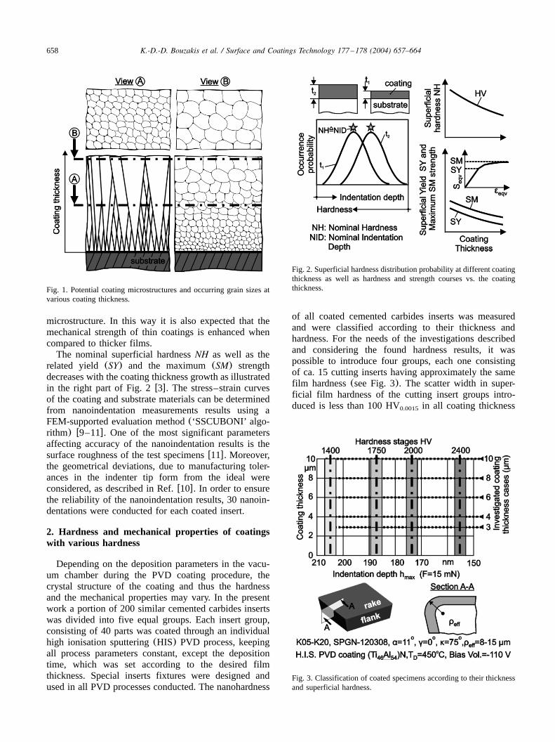
Fig. 3. Classification of coated specimens according to their thicknessand superficial hardness.
microstructure. In this way it is also expected that themechanical strength of thin coatings is enhanced whencompared to thicker films.The nominal superficial hardnessNH as well as the
related yield (SY) and the maximum(SM) strengthdecreases with the coating thickness growth as illustratedin the right part of Fig. 2w3x. The stress–strain curvesof the coating and substrate materials can be determinedfrom nanoindentation measurements results using aFEM-supported evaluation method(‘SSCUBONI’ algo-rithm) w9–11x. One of the most significant parametersaffecting accuracy of the nanoindentation results is thesurface roughness of the test specimensw11x. Moreover,the geometrical deviations, due to manufacturing toler-ances in the indenter tip form from the ideal wereconsidered, as described in Ref.w10x. In order to ensurethe reliability of the nanoindentation results, 30 nanoin-dentations were conducted for each coated insert.
2. Hardness and mechanical properties of coatingswith various hardness
Depending on the deposition parameters in the vacu-um chamber during the PVD coating procedure, thecrystal structure of the coating and thus the hardnessand the mechanical properties may vary. In the presentwork a portion of 200 similar cemented carbides insertswas divided into five equal groups. Each insert group,consisting of 40 parts was coated through an individualhigh ionisation sputtering(HIS) PVD process, keepingall process parameters constant, except the depositiontime, which was set according to the desired filmthickness. Special inserts fixtures were designed andused in all PVD processes conducted. The nanohardness
of all coated cemented carbides inserts was measuredand were classified according to their thickness andhardness. For the needs of the investigations describedand considering the found hardness results, it waspossible to introduce four groups, each one consistingof ca. 15 cutting inserts having approximately the samefilm hardness(see Fig. 3). The scatter width in super-ficial film hardness of the cutting insert groups intro-duced is less than 100 HV in all coating thickness0.0015

659K.-D.-D. Bouzakis et al. / Surface and Coatings Technology 177 –178 (2004) 657–664
Fig. 4. The von Mises equivalent yield and maximum stress as wellas the equivalent yield strain vs. the coating hardness of the investi-gated coatings.
Fig. 5. Coating hardness and stress–strain curves determination at adepthd by means of the superficial hardness, its occurrence proba-i
bility p and its dependence on mechanical properties.
cases. In this way three cutting inserts at least perinvestigated hardness and thickness case were available.The equivalent stress–strain relation for the coatings
was determined from the nanoindentation results. Thenanohardness measurement is a precise indentationmethod to register continuously the course of the appliedforce vs. the occurring penetration depth. With the aidof the nanoindentation procedure the elastoplastic filmlaws of the 200 coated cutting inserts were determinedthrough the mentioned FEM supported evaluation meth-od w9–11x and properly recorded. The extracted yieldand maximum strength and yield strain as a function ofthe film hardness and indentation depth for the depositedcoatings having various thickness are shown in Fig.4a,b. The magnitudes of the parameterst and b in theh
figure illustrated, which describe the indenter tip formdeviations from the ideal geometry, are determined usingthe methodology introduced inw10x. According to theseresults the film hardness and the coating strength dependon each other. Therefore, further investigations in millingwere carried out to show how the improved strengthaffects the cutting behaviour.In the FEM simulations of the coated inserts, in next
sections described, the film strength properties vs. thefilm thickness are taken into account. In order todetermine these properties the behaviour of the coatinghardness as a function of the coating thicknesst isconsidered, as illustrated in Fig. 5. The coating hardnessdistribution at a depthd within the surface, is supposedi
to have the same shape and the corresponding distribu-tion in a coating having thicknesst (ftyd ). Thei i
superficial hardness distributions and furthermore thecorresponding film stress–strain laws at various coatingthickness were determined experimentally, using eachtime one of the mentioned cutting insert groups, con-sisting of 40 parts with approximately constant coatingthickness. Moreover, the stress–strain laws of the inves-
660 K.-D.-D. Bouzakis et al. / Surface and Coatings Technology 177 –178 (2004) 657–664
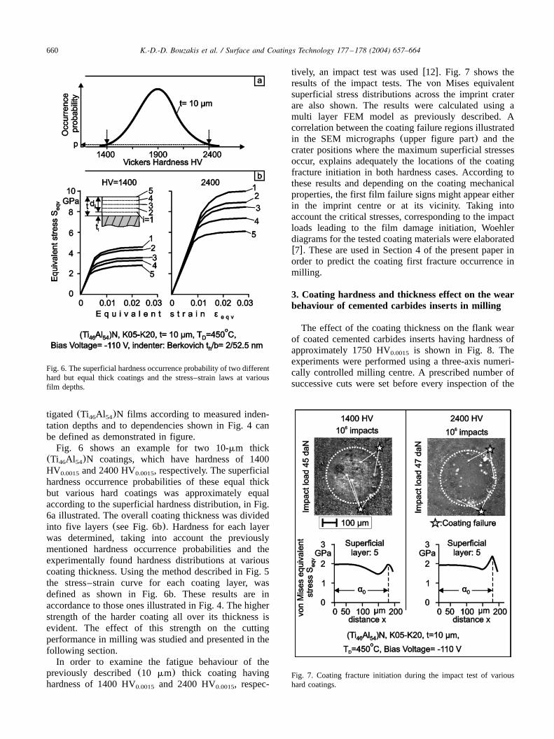
Fig. 6. The superficial hardness occurrence probability of two differenthard but equal thick coatings and the stress–strain laws at variousfilm depths.
Fig. 7. Coating fracture initiation during the impact test of varioushard coatings.
tigated(Ti Al )N films according to measured inden-46 54
tation depths and to dependencies shown in Fig. 4 canbe defined as demonstrated in figure.Fig. 6 shows an example for two 10-mm thick
(Ti Al )N coatings, which have hardness of 140046 54
HV and 2400 HV , respectively. The superficial0.0015 0.0015
hardness occurrence probabilities of these equal thickbut various hard coatings was approximately equalaccording to the superficial hardness distribution, in Fig.6a illustrated. The overall coating thickness was dividedinto five layers(see Fig. 6b). Hardness for each layerwas determined, taking into account the previouslymentioned hardness occurrence probabilities and theexperimentally found hardness distributions at variouscoating thickness. Using the method described in Fig. 5the stress–strain curve for each coating layer, wasdefined as shown in Fig. 6b. These results are inaccordance to those ones illustrated in Fig. 4. The higherstrength of the harder coating all over its thickness isevident. The effect of this strength on the cuttingperformance in milling was studied and presented in thefollowing section.In order to examine the fatigue behaviour of the
previously described(10 mm) thick coating havinghardness of 1400 HV and 2400 HV , respec-0.0015 0.0015
tively, an impact test was usedw12x. Fig. 7 shows theresults of the impact tests. The von Mises equivalentsuperficial stress distributions across the imprint craterare also shown. The results were calculated using amulti layer FEM model as previously described. Acorrelation between the coating failure regions illustratedin the SEM micrographs(upper figure part) and thecrater positions where the maximum superficial stressesoccur, explains adequately the locations of the coatingfracture initiation in both hardness cases. According tothese results and depending on the coating mechanicalproperties, the first film failure signs might appear eitherin the imprint centre or at its vicinity. Taking intoaccount the critical stresses, corresponding to the impactloads leading to the film damage initiation, Woehlerdiagrams for the tested coating materials were elaboratedw7x. These are used in Section 4 of the present paper inorder to predict the coating first fracture occurrence inmilling.
3. Coating hardness and thickness effect on the wearbehaviour of cemented carbides inserts in milling
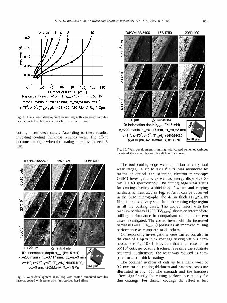
The effect of the coating thickness on the flank wearof coated cemented carbides inserts having hardness ofapproximately 1750 HV is shown in Fig. 8. The0.0015
experiments were performed using a three-axis numeri-cally controlled milling centre. A prescribed number ofsuccessive cuts were set before every inspection of the
661K.-D.-D. Bouzakis et al. / Surface and Coatings Technology 177 –178 (2004) 657–664
Fig. 8. Flank wear development in milling with cemented carbidesinserts, coated with various thick but equal hard films.
Fig. 10. Wear development in milling with coated cemented carbidesinserts of the same thickness but different hardness.
Fig. 9. Wear development in milling with coated cemented carbidesinserts, coated with same thick but various hard films.
cutting insert wear status. According to these results,investing coating thickness reduces wear. The effectbecomes stronger when the coating thickness exceeds 8mm.
The tool cutting edge wear condition at early toolwear stages, i.e. up to 4=10 cuts, was monitored by4
means of optical and scanning electron microscopy(SEM) investigations, as well as energy dispersive X-ray (EDX) spectroscopy. The cutting edge wear statusfor coatings having a thickness of 4mm and varyinghardness is illustrated in Fig. 9. As it can be observedin the SEM micrographs, the 4-mm thick (Ti Al )N46 54
film, is removed very soon from the cutting edge regionin all the coating cases. The coated insert with themedium hardness(1750 HV ) shows an intermediate0.0015
milling performance in comparison to the other twocases investigated. The coated insert with the increasedhardness(2400 HV ) possesses an improved milling0.0015
performance as compared to all others.Corresponding investigations were carried out also in
the case of 10-mm thick coatings having various hard-nesses(see Fig. 10). It is evident that in all cases up to5=10 cuts, no coating fracture, revealing the substrate3
occurred. Furthermore, the wear was reduced as com-pared to 4-mm thick coatings.The obtained number of cuts up to a flank wear of
0.2 mm for all coating thickness and hardness cases areillustrated in Fig. 11. The strength and the hardnessaffect significantly the cutting performance mainly forthin coatings. For thicker coatings the effect is less

662 K.-D.-D. Bouzakis et al. / Surface and Coatings Technology 177 –178 (2004) 657–664
Fig. 11. Cutting performance in milling of inserts coated with differentthick and hard films.
Fig. 12. Stress distributions in the cutting edge region and related filmWoehler diagram.
significant. Their cutting performance is almost inde-pendent of the coating hardness.
4. FEM simulation of the milling process, in order toexplain the obtained tool wear results
In order to explain wear behaviour of the coatedinserts a FEM modelw3,13,14x of the milling processwas used. Taking into account how the coating materialstrength depends on thickness, the stress distribution inthe coating during the material removal can be studied.The following investigations deal with the thick PVDfilms (f10 mm). Corresponding results for thinner 4-mm thick coatings have been performed previouslyw3x.The stress distribution in the thick 10mm coating havinga hardness of 2400 HV is shown in Fig. 12a. The0.0015
maximum stress on the coating surface is 3.4 GPa andit is lower than the yield strength of the coating surfacezone (5.4 GPa). The coating fracture initiation isinduced by fatigue as explained in Fig. 12b. Insertingthe maximum stress value in the Woehler diagram, thecoating fatigue damage initiation during milling can bepredicted. The first coating fracture is expected to takeplace after approximately 1.8=10 successive cuts,4
which is in good agreement with the results shownearlier in Fig. 10.The stress distribution in the 10-mm thick coating
having hardness of 1400 HV is shown in Fig. 13a.0.0015
In this case, the maximum stress(2.5 GPa, see Fig.13a) is above the coating superficial yield strength,which is 1.9 GPa. An overstressed area near the edgerounding occurs. It leads to coating fracture in thatregion only after a small number of cuts. The corre-sponding Woehler diagram for this coating material isshown in Fig. 13c. It indicates clearly that after ca. 200cuts the coating fracture due to fatigue might start. Thus,
the less hard coating is slightly and locally damagedand the substrate is not revealed. Therefore, the substratecould no longer be scanned after 5=10 number of cuts,3
as already shown in the upper right SEM micrograph inFig. 10. The progressive coating damage modifies theeffective cutting edge geometry, as demonstrated in Fig.13b. The load in critical areas then becomes lower(2.2GPa) due to the increased cutting edge radius as alsofound in w13x. This progressive damage of the cuttingedge reveals inner coating layers, which have higherstrength. Thus, the coating fatigue failure risk is decreas-ing, the abrasion resistance is improved and the wear isreduced. Due to this fact and in spite of the low hardness

663K.-D.-D. Bouzakis et al. / Surface and Coatings Technology 177 –178 (2004) 657–664
Fig. 13. Stress distributions in the cutting edge region at various toolwear stages and the related Woehler diagram.
of 1400 HV the coating stands without fracture0.0015
approximately 1.5=10 cuts, according to the Woehler4
diagram, illustrated in Fig. 13c. These results are alsoin accordance to the SEM observations of the cuttingedge as shown earlier in Fig. 10, whereas after 2=104
cuts a substrate reveal was monitored.
5. Conclusions
PVD (Ti Al )N coated cemented carbides inserts46 54
with coating thickness from 3 to 10mm and hardnessfrom 1400 to 2400 HV were investigated with0.0015
regard to their strength properties and milling perform-ance. The coating strength was determined using a FEM-supported procedure to evaluate nanoindentationmeasurement results. The extracted results indicated thatthe mechanical properties and the hardness significantlyaffect the cutting performance, especially in the case ofthe thinner coatings. However, in the case of thickcoatings (8–10 mm) the effect of the strength andhardness becomes less significant and wear dependsmainly on the thickness of the coating itself. The resultsof the FEM calculations are in good agreement with theexperimental observations.
6. Nomenclature
b: Width of the tip roundness(nm)EDX: Energy dispersive X-ray spectroscopyF: Nanoindentation force(mN)FEM: Finite elements methodh :cu Undeformed chip thickness(mm)
:Hdi Hardness at depthdi
HM: Cemented carbidesHIS: High ionisation sputteringh :max Maximum indentation depth(nm)H :s Superficial hardnessHV: Vickers hardnessHV : Vickers hardness at 15 mN indentation load0.0015
ID: Indentation depth(nm)NC: Number of successive cutsNH: Nominal hardnessNID: Nominal indentation depth(nm)p: ProbabilityPVD: Physical vapour depositionR :m Ultimate tensile strength(GPa)SEM: Scanning electron microscopyS :EQV von Mises equivalent stress(GPa)SM: Maximum strength(GPa)SY: Yield strength(GPa)t: Coating thickness(mm)T :D Deposition temperature(8C)t :h Height of the tip roundness(nm)VB: Flank wear(mm)v :c Axial cutting speed(mymin)a: Clearance angle(8)
664 K.-D.-D. Bouzakis et al. / Surface and Coatings Technology 177 –178 (2004) 657–664
a :xy Radial cutting depth(mm)a :z Axial cutting depth(mm)a :0 Radius of the impact imprint(mm)g: Rake angle(8)´ :EQV von Mises equivalent strain´M: Maximum strain´Y: Yield straink: Cutting edge angle(8)r :eff Effective cutting edge radius
References
w1x R.F. Bunshah, Handbook of Hard Coatings, NoyesPublicationsyWilliam Andrew Publishing, LLC, Norwich, NewYork, USA, 2001.
w2x F. Klocke, T. Krieg, Coated tools for metal cutting—featuresand applications, Ann. CIRP 48(2) (1999) 515–525.
w3x K.-D. Bouzakis, S. Hadjiyiannis, G. Skordaris, J. Anastopoulos,I. Mirisidis, N. Michailidis, K. Efstathiou, O. Knotek, G.Erkens, R. Cremer, S. Rambadt, I. Wirth, Surf. Coat. Technol.174–175(2003) 393–401.
w4x R. Messier, A.P. Giri, R.A. Roy, J. Vac. Sci. Technol. A 2(1984) 500.
w5x R. Messier, J. Vac. Sci. Technol. A 4(1986) 490.w6x R. Messier, J.E. Yehoda, J. Appl. Phys. 58(1985) 3739.w7x J. Musil, S. Kadlec, V. Valvoda, R. Kuzel, R. Cerny, Surf.
Coat. Technol. 43–44(1990) 259.w8x E. Kay, F. Parmigiani, W. Parrish, J. Vac. Sci. Technol. A 6
(1988) 3074.w9x K.-D. Bouzakis, N. Michailidis, G. Erkens, Surf. Coat. Technol.
142–144(2001) 102–109.w10x K.-D. Bouzakis, N. Michailidis, S. Hadjiyiannis, G. Skordaris,
G. Erkens, Zeitschrift fur Metallkunde 93(2002) 862–869.¨w11x K.-D. Bouzakis, N. Michailidis, S. Hadjiyiannis, G. Skordaris,
G. Erkens, Mater. Characterization 49(2) (2003) 149–156.w12x K.-D. Bouzakis, N. Michailidis, A. Lontos, A. Siganos, S.
Hadjiyiannis, G. Giannopoulos, et al., Zeitschrift fur Metallk-¨unde 92(2001) 1180–1185.
w13x K.-D. Bouzakis, N. Michailidis, S. Hadjiyiannis, K. Efstathiou,E. Pavlidou, G. Erkens, et al., Surf. Coat. Technol. 146–147(2001) 443–450.
w14x SWANSON Analysis System, INC., ANSYS user manuals,vol. 1 Theory, vol. 2 Procedures, vol. 3 Elements, vol. 4Commands,(1995).