Effect of Coating Thickness on the Properties of TiN Coatings Deposited on Tool Steels Using...
10
Surface Review and Letters, Vol. 15, No. 4 (2008) 401–410 c World Scientific Publishing Company EFFECT OF COATING THICKNESS ON THE PROPERTIES OF TiN COATINGS DEPOSITED ON TOOL STEELS USING CATHODIC ARC PVD TECHNIQUE A. MUBARAK ∗ and PARVEZ AKHTER † Pakistan Council of Renewable Energy Technologies (PCRET), Plot No. 25, Sector H-9, Islamabad, Pakistan ∗ [email protected] † akhterp [email protected] ESAH HAMZAH Department of Materials Engineering, Faculty of Mechanical Engineering, Universiti Teknologi Malaysia, 81310, Skudai, Johor, Malaysia [email protected] MOHD RADZI HJ. MOHD TOFF Advanced Materials Research Center (AMREC), SIRIM Berhad, Lot 34, Jalan Hi-Tech 2/3, Kulim Hi-Tech Park, 09000 Kulim, Kedah, Malaysia [email protected] ISHTIAQ A. QAZI National University of Sciences and Technology, Tamiz-ud-din Road, Rawalpindi, Pakistan ishtiaq [email protected] Received 12 November 2007 Titanium nitride (TiN) widely used as hard coating material, was coated on tool steels, namely on high-speed steel (HSS) and D2 tool steel by physical vapor deposition method. The study concentrated on cathodic arc physical vapor deposition (CAPVD), a technique used for the deposition of hard coatings for tooling applications, and which has many advantages. The main drawback of this technique, however, is the formation of macrodroplets (MDs) during deposi- tion, resulting in films with rougher morphology. Various standard characterization techniques and equipment, such as electron microscopy, atomic force microscopy, hardness testing machine, scratch tester, and pin-on-disc machine, were used to analyze and quantify the following prop- erties and parameters: surface morphology, thickness, hardness, adhesion, and coefficient of friction (COF) of the deposited coatings. Surface morphology revealed that the MDs produced during the etching stage, protruded through the TiN film, resulting in film with deteriorated surface features. Both coating thickness and indentation loads influenced the hardness of the deposited coatings. The coatings deposited on HSS exhibit better adhesion compared to those on D2 tool steel. Standard deviation indicates that the coating deposited with thickness around 6.7 µm showed the most stable trend of COF versus sliding distance. Keywords : Morphology; surface roughness; coefficient of friction; hardness; adhesion. 401
Transcript of Effect of Coating Thickness on the Properties of TiN Coatings Deposited on Tool Steels Using...

July 17, 2008 9:24 01152
Surface Review and Letters, Vol. 15, No. 4 (2008) 401–410c© World Scientific Publishing Company
EFFECT OF COATING THICKNESS ON THE PROPERTIESOF TiN COATINGS DEPOSITED ON TOOL STEELS USING
CATHODIC ARC PVD TECHNIQUE
A. MUBARAK∗ and PARVEZ AKHTER†
Pakistan Council of Renewable Energy Technologies (PCRET),Plot No. 25, Sector H-9, Islamabad, Pakistan
∗[email protected]†akhterp [email protected]
ESAH HAMZAHDepartment of Materials Engineering,Faculty of Mechanical Engineering,
Universiti Teknologi Malaysia, 81310,Skudai, Johor, Malaysia
MOHD RADZI HJ. MOHD TOFFAdvanced Materials Research Center (AMREC),
SIRIM Berhad, Lot 34, Jalan Hi-Tech 2/3,Kulim Hi-Tech Park, 09000 Kulim,
Kedah, [email protected]
ISHTIAQ A. QAZINational University of Sciences and Technology,
Tamiz-ud-din Road, Rawalpindi, Pakistanishtiaq [email protected]
Received 12 November 2007
Titanium nitride (TiN) widely used as hard coating material, was coated on tool steels, namelyon high-speed steel (HSS) and D2 tool steel by physical vapor deposition method. The studyconcentrated on cathodic arc physical vapor deposition (CAPVD), a technique used for thedeposition of hard coatings for tooling applications, and which has many advantages. The maindrawback of this technique, however, is the formation of macrodroplets (MDs) during deposi-tion, resulting in films with rougher morphology. Various standard characterization techniquesand equipment, such as electron microscopy, atomic force microscopy, hardness testing machine,scratch tester, and pin-on-disc machine, were used to analyze and quantify the following prop-erties and parameters: surface morphology, thickness, hardness, adhesion, and coefficient offriction (COF) of the deposited coatings. Surface morphology revealed that the MDs producedduring the etching stage, protruded through the TiN film, resulting in film with deterioratedsurface features. Both coating thickness and indentation loads influenced the hardness of thedeposited coatings. The coatings deposited on HSS exhibit better adhesion compared to thoseon D2 tool steel. Standard deviation indicates that the coating deposited with thickness around6.7 µm showed the most stable trend of COF versus sliding distance.
Keywords: Morphology; surface roughness; coefficient of friction; hardness; adhesion.
401

July 17, 2008 9:24 01152
402 A. Mubarak et al.
1. Introduction
The emission of macroparticles and the formationof pitting defects have been considered for cutting-tool and corrosion-protection, applications in theearly 1980s,1,2 as negative features ever since thecommercialization of cathodic arc evaporated (CAE)coatings.
Over the years, various chamber configurationsand deposition techniques, have been developedto reduce the amount of such coating defects.3–5
Of these, cathodic arc physical vapor deposition(CAPVD) technique is widely used as a hard coatingdeposition technique because of its many advantagessuch as high deposition rate and strong adhesion ofthe resulting film to the substrate. The main draw-back of this technique, however, is the formation ofmacrodroplets (MDs) during deposition, resulting infilms with rougher morphology. Emission of MDs,from the plasma stream, arising from the cathodictarget during coating process is, however, a seriousproblem making it difficult to apply the techniquefor fine coatings. Coating with rougher morphol-ogy increases the coefficient of friction (COF), whichaffects the performance of the coated tool; partic-ularly during dry and high-speed machining,6 it isimportant, therefore, to study the origin of the MDswith the aim of finding ways of their avoidance.
This paper describes our attempts to study thesurface morphology, surface roughness, COF, micro-hardness, adhesion strength, and MDs contamina-tion by varying the film deposition rate.
2. Experimental Details
Titanium nitride (TiN) films were deposited onhigh-speed steel (HSS) (diameter: 10mm; thickness:6 mm) and D2 tool steels discs (diameter: 32mm;thickness: 6mm) under similar physical conditions
Table 1. Deposition parameters.
Rotation Deposition Ar gas flow Bias N2 gas flow Etching) Pre-bias Substratespeed (%) time (h) rate (sccm) voltage (−V) rate (sccm) (min) (V) temperature (◦C)
60 2.0 50 50 250 5 1000 300
60 1.30 50 50 250 5 1000 300
60 1.0 50 50 250 5 1000 300
60 0.45 50 50 250 5 1000 300
60 0.30 50 50 250 5 1000 300
using the Hauzer Techno Coating (HTC) 625/2 ARCcoating system. The substrates were cleaned in anultrasonic bath using a mild, solvent-free, detergentfor 30min. This was followed by rinsing with run-ning water and air-drying. Just before loading thesubstrates into the coating chamber, these were blow-dried with high-pressure nitrogen gas to remove anydust or contamination on the surface.
The film deposition was done with the substratebiased with a DC power source in order to induceproper ion bombardment on the growing surface toassist in getting the desirable structure, grain size,and film density. The chamber was evacuated to apressure of approximately 4 × 10⁻⁶ mbar and thenback filled with nitrogen gas in the range of around10−3 mbar. The complete deposition procedure hasbeen described earlier.7 A summary of the depositionparameters can be seen in Table 1.
Surface morphology and roughness of thedeposited coatings were analyzed and measuredusing an atomic force microscope (model SPM-9500J2, Shimadzu Corporation). The surface rough-ness of uncoated and TiN-coated samples was alsomeasured using surface roughness tester (Model-Surftest SJ-301, Mitutoyo). COF was studied usingPin-on-Disc Machine (CSEM Tribometer). Thehardness of uncoated and coated samples wasmeasured using a micro-Vickers hardness testingmachine (Model-H31, Mitutoyo). Adhesion strengthof deposited coating was determined by opticalobservation of the scratch track (CSM-Instruments,REVETEST). Thickness of the deposited coatingswas analyzed using field emission scanning electronmicroscopy (FE-SEM, Leo 1525).
The film-to-substrate adhesion strength wasmeasured quantitatively using a scratch tester.A diamond indenter (Rockwell type) of 200µmradius applied an initial load 0.9N onto a sample.

July 17, 2008 9:24 01152
Effect of Coating Thickness on the Properties of TiN Coatings Deposited on Tool Steels 403
The sliding velocity was 0.35mm/min. The loadwas increased gradually by 7.27mN per minute withscratch length of 5mm. In the scratch test, criti-cal load (LC) could be used to calculate the adhe-sion strength. In order to obtain the magnitude ofthe critical load, acoustic signal, friction curve, andmicroscope observation were utilized. Acoustic signalproduced by the delamination of the film could beused to characterize the LC . Analysis of the changesof the acoustic signal (AE) together with the fric-tion force FT and microscopic observations of thetopography of the scratch-test tracks were used todetermine the normal forces leading to cohesive andadhesive destruction of the coatings.
The friction coefficient FC , and the acoustic emis-sion signals AE were recorded. AE is constituted byelastic waves generated by the sudden crack in mate-rials when external load is applied. Penetration depth(PD) of the indenter versus critical load was also ana-lyzed. The following test parameters were deducedfrom the scratch test:
(a) critical load deduced from microscopic evalua-tion of the crack pattern around the scratchchannel;
(b) critical load deduced from friction coefficientalong the scratch;
(c) critical load deduced from the acoustic emissionsignals along the scratch.
(d) critical load deduced from the penetration depthalong the scratch.
3. Results and Discussion
Prior to the investigations of TiN coatings, the per-formance of the AFM was confirmed by imaginga standard sample for calibration provided by themanufacturer. We only selected typical AFM imagesconsisting of well-defined scan area (10µm× 10µm)morphology. Two- and three-dimensional topogra-phy images were obtained using a commercial Si3N4
cantilever operating in contact mode and are shownin Figs. 1(a) and 1(b). In Fig. 1(b), the grains wereformed in peaks and valleys-island shaped particleswere clearly identified. To study the origin of MDs,we deliberately created some minor scratches on pol-ished D2 tool steel surface just after standard metal-lography, and studies have been carried out via AFM.From Fig. 1(b), it seems that the MDs produced
(a)
(b)
Fig. 1. (a) Two-dimensional AFM image at coatingthickness of approximately 3.2 µm and (b) three-dimensional AFM image at coating thickness of approx-imately 4.3 µm.
during etching stage and the resulting spikes pro-truded through the TiN film during coating process.As it stands that, the electrons are repelled by thenegative substrate bias and ions are accelerated. Dueto the high ion bombardment energy, the defectswere sputtered and acquired a ‘hone/nail head’ likeshapes in the plasma stream (Fig. 1(b)). Figure 1(b)revealed that the MDs produced during the etchingstage have there stems in the base material and laythrough the TiN film.
The amount of MDs should be same, as the etch-ing time in all deposition rates were constant. Dur-ing SEM observation, it was noted that the most

July 17, 2008 9:24 01152
404 A. Mubarak et al.
Table 2. Surface parameter values of TiN-coated D2tool steel at various coating thickness calculated viaAFM.
Coating thickness (µm)
Parameters ≈ 8.7 ≈ 6.7 ≈ 4.3 ≈ 3.2 ≈ 2.3
Ra (nm) 147.5 99.7 64.7 47.3 48.3Ry (nm) 1090 876.3 572.6 671.8 781.2Rz (nm) 527.1 512.0 377.8 268.0 460.2Rms (nm) 190.9 137.5 89.4 69.1 76.6Rp (nm) 704.1 519.8 345.0 399.5 594.5Rv (nm) 387.7 356.4 227.5 272.3 186.7
of the MDs size were in the range of 2–3µm, andtherefore pronounced in the case of 30min deposi-tion rate (thickness =2.3µm). The thickness of thedeposited coatings at various deposition rates isshown in Table 2, calculated during interface studyof deposited coatings using FE-SEM.
The values of various surface roughness parame-ters measured by AFM are shown in Table 2 fromwhich, the minimum value of Rms was about 69 nm;for the coating having thickness 3.2µm (slightlyhigher than the coating having thickness of 2.3µm)whereas, the maximum value of Rms was noted190.9 nm for the coating having a thickness of 8.7µm.A similar trend in Ra was observed and is shownin Table 2. All coatings were deposited at constantetching rate and process parameters except deposi-tion rate. The MDs produced during etching stagewere more dominant at lower coating thickness com-pare with the coatings deposited at higher thickness.An explanation of the parameters shown in Table 2can be found in our earlier work.7
The results of quantitative surface roughnessmeasured via surface roughness tester of TiN-coatedD2 tool steel at various deposition rates are givenin Table 3. The roughness of the CAE TiN-coatedD2 tool steel coupons defined by the Ra parameteris within the 0.21–0.62µm range and is significantlyhigher than in the case of the uncoated polished sam-ple, i.e., 0.02µm. A line bar graph between averageroughness (Ra) and coating thickness can be seen inFig. 2. Surface profile for coating deposited at coat-ing thickness of ≈ 6.7µm can be seen in Fig. 3. Themaximum Ra value was noted for coating depositedwith maximum thickness, (≈ 8.7µm). In Fig. 3, thepeaks above average center line (Ra) are because ofMDs, whereas the peaks below average center line are
Table 3. Surface roughness measured via surfaceroughness tester of uncoated and TiN-coated D2 toolsteel at various coating thickness.
Ra (ISO 97, Rz (ISO 97, Rq (ISO 97, CoatingGauss) Gauss) Gauss) thickness(µm) (µm) (µm) (µm)
0.03 0.26 0.04 00.62 7.31 0.94 ≈ 8.70.40 4.59 0.63 ≈ 6.70.28 3.50 0.45 ≈ 4.30.28 3.43 0.44 ≈ 3.20.21 3.18 0.38 ≈ 2.3
0
2
4
6
8
10
0.02 0.21 0.28 0.28 0.4 0.62
Surface Roughness, Ra
Co
atin
g T
hic
knes
s
Surface Roughness, Ra Coating Thickness
Fig. 2. Graph between average roughness and coatingthickness of TiN-coated D2 tool steel coupons.
because of hollow spot/pitting defects, from wherethe MD’s re-sputtered during coating stage.
The increased surface roughness resulting fromdeposition of the TiN coatings should be attributedto the PVD process character-CAE and occurrenceof the characteristic MDs, due to deposition of thepure titanium droplets, coming from the cathodeparticularly during etching stage, and pits developingdue to the titanium MDs dropping out, immediatelyafter the coating deposition process is completed.Again, the coated surface exhibits inhomogeneitiesconnected and depend on the shape and size of theMDs. Additionally, it is also correct that the coatingsdeposited with higher thickness occupied higher com-pressive stresses, and hence contribute to enhancethe surface roughness of coated tool. Similar mecha-nism was observed in case of TiN coatings on HSS.In Table 3, Rz values are more pronounced and thiswas mainly because of the generation of MDs andgrowth defects at their respective deposition rates.

July 17, 2008 9:24 01152
Effect of Coating Thickness on the Properties of TiN Coatings Deposited on Tool Steels 405
Fig. 3. Surface profile of the coating deposited on D2 tool steel with coating thickness of ≈ 6.7 µm measured using asurface roughness tester (EVA-L = 4.0 mm, λc = 0.8 mm× 5).
Table 4. List of tribological parametersduring Pin-on-Disc test.
Humidity 60± 10 RH (%)
Temperature 23±4◦CAtmosphere Air/ambientStatic partner AluminaGeometry BallDiameter of ball 6.0 mmRadius of wear track 3.0 mmLubricant NoneNormal load 5.0NSliding speed 8.0 cm/sAcquisition rate 0.2 Hz
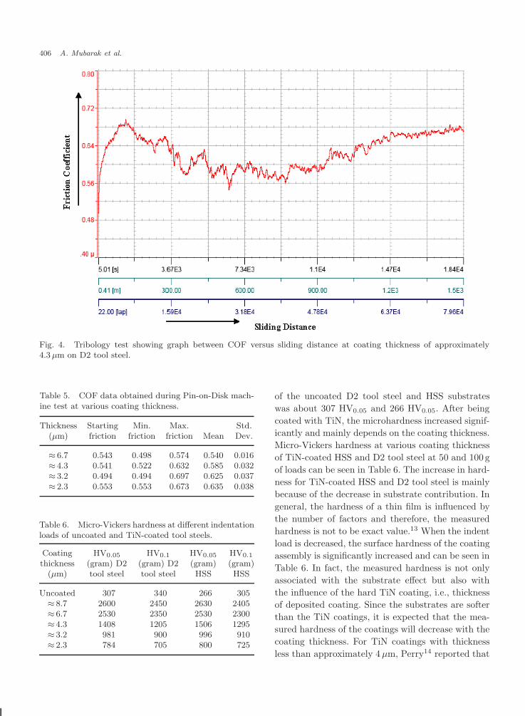
COF was performed using Pin-on-Disc Machine.A more detailed list of parameters used during tri-bological test can be seen in Table 4. All sampleswere coated under same deposition conditions withvarying coating thickness. Therefore, for explanationpurposes, we only selected the sample having coat-ing thickness ≈ 3.2µm. During the initial periods,COF rapidly increases to a peak value and then grad-ually to a stable value with increasing sliding dis-tance. This is due to adhesive wear, which is takingplace between the counter-body and coated surface.In addition, the rough surface experiences greaterasperity contact, increases tendency to plastic defor-mation and mechanical interlocking during sliding,resulting in the formation of wear debris, which accu-mulate in the wear-track, behave as a third-bodysliding leading to higher COF, and hence more timeto deteriorate the coating. The variation in COFagainst the alumina ball versus sliding distance atvarious coating thicknesses can be seen in Fig. 4. Ini-tially, a static ball was sliding on the TiN films withreduced COF. As the sliding progressed, the coatings
were deteriorated and damaged, exposing the sub-strate material, resulting in a sudden increase infriction coefficients. Subsequently, the friction coeffi-cients reduced gradually and thereafter, reached tosteady state. As shown in Fig. 4, typical dry frictionbehavior; a sudden transition and a high friction wereobserved as the contact number of cycle increased.However, all friction signals showed about constantvalues after certain sliding distance. As discussed ear-lier, the starting values of friction coefficients arecomparatively less than that of the end of test val-ues, which is result of an increased wear volume, weardebris, surface roughness chemistry, etc. The reasonfor low values is the formation of an oxide layer andhence penetration of counter-body into the coatingwith an increased hinder. However, after certain dis-tance the oxide film was torn off and the adhesiveforces and oxides formation on the contact surfacesupport to play role in decreasing the friction coeffi-cient and hence to make it stabilize. A small varia-tion in COF was recorded and is shown in Table 5.Cho and Lee8 found that in nitrogen environment,the average value of the steady-state friction coeffi-cient improve about three times as compared in airatmosphere. The coating deposited with thickness ofaround 6.7µm is the most stable coating comparedto others, due to standard deviation value i.e., 0.016for coating thickness of around 6.7µm.
Wear because of oxidation usually occurs in thecase of dry sliding, i.e., in the presence of air or oxy-gen; it causes changes in the friction and wear charac-teristics between materials in sliding contact9,10 andis varied by many factors, such as contact load andsliding speed.11,12
Substrate hardness and coating hardness weremeasured using a micro-Vickers hardness testingmachine and is shown in Table 6. Microhardness
July 17, 2008 9:24 01152
406 A. Mubarak et al.
Fig. 4. Tribology test showing graph between COF versus sliding distance at coating thickness of approximately4.3 µm on D2 tool steel.
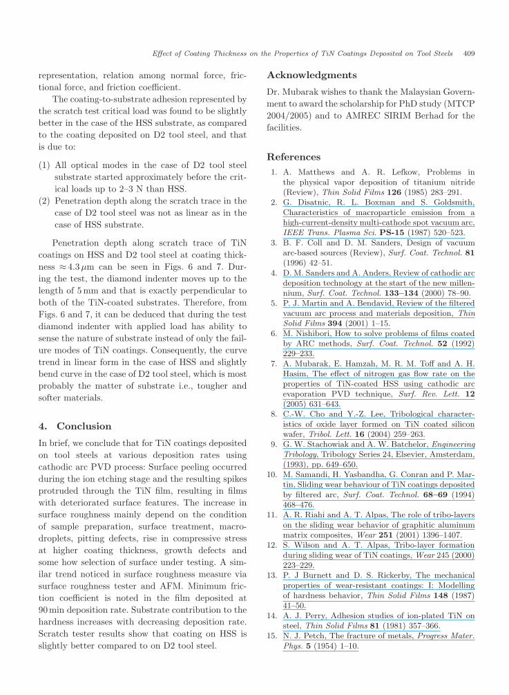
Table 5. COF data obtained during Pin-on-Disk mach-ine test at various coating thickness.
Thickness Starting Min. Max. Std.(µm) friction friction friction Mean Dev.
≈ 6.7 0.543 0.498 0.574 0.540 0.016≈ 4.3 0.541 0.522 0.632 0.585 0.032≈ 3.2 0.494 0.494 0.697 0.625 0.037≈ 2.3 0.553 0.553 0.673 0.635 0.038
Table 6. Micro-Vickers hardness at different indentationloads of uncoated and TiN-coated tool steels.
Coating HV0.05 HV0.1 HV0.05 HV0.1
thickness (gram) D2 (gram) D2 (gram) (gram)(µm) tool steel tool steel HSS HSS
Uncoated 307 340 266 305≈ 8.7 2600 2450 2630 2405≈ 6.7 2530 2350 2530 2300≈ 4.3 1408 1205 1506 1295≈ 3.2 981 900 996 910≈ 2.3 784 705 800 725
of the uncoated D2 tool steel and HSS substrateswas about 307 HV0.05 and 266 HV0.05. After beingcoated with TiN, the microhardness increased signif-icantly and mainly depends on the coating thickness.Micro-Vickers hardness at various coating thicknessof TiN-coated HSS and D2 tool steel at 50 and 100gof loads can be seen in Table 6. The increase in hard-ness for TiN-coated HSS and D2 tool steel is mainlybecause of the decrease in substrate contribution. Ingeneral, the hardness of a thin film is influenced bythe number of factors and therefore, the measuredhardness is not to be exact value.13 When the indentload is decreased, the surface hardness of the coatingassembly is significantly increased and can be seen inTable 6. In fact, the measured hardness is not onlyassociated with the substrate effect but also withthe influence of the hard TiN coating, i.e., thicknessof deposited coating. Since the substrates are softerthan the TiN coatings, it is expected that the mea-sured hardness of the coatings will decrease with thecoating thickness. For TiN coatings with thicknessless than approximately 4 µm, Perry14 reported that

July 17, 2008 9:24 01152
Effect of Coating Thickness on the Properties of TiN Coatings Deposited on Tool Steels 407
the substrate effect, i.e., the thickness of the coating,would dominate.
According to the Hall–Petch relationship15 themicrohardness varies linearly with the inverse squareroot of the grain diameter. The enlargement in thecrystallite size may be interpreted as a result ofincreasing adatom mobility induced by increasing ionenergy.16
To study the adhesion strength of deposited coat-ings on tool steels, only the coating deposited with1 h deposition rate was selected and this is becausethat Tuffy et al.17 determined the optimum resultsof TiN coating thickness on WC inserts for machin-ing carbon steels and found that coating thicknessaround 4 µm is the best one.
Initially, FC is low since the indenter moves ontop of the coating and only plastic deformationoccurs with no or minor cracks. The surface andasperities are deformed into a smooth, polished inter-mediate film, and AE is either very low or doesnot exit. As the load increases, the indenter pene-trates deeper and deeper into the coating and reg-ular cracks hinder the movement of the indenter.As the indenter load increased to 35N, the inter-face cohesive stress is exceeded, but the internal
Fig. 5. Normal load and friction behavior along scratch trace at coating thickness of approximately 4.3 µm on HSSsubstrate.
energy is sufficient only to propagate circular cracksahead of the indenter, and the transverse crack devel-ops into a regular crack pattern just before coat-ing failure and chip elongation at the critical load.FC continues to increase due to the fracture energyabsorbed in the substrate as the indenter ploughs.At the end the indenter penetration into TiN coat-ings at higher load, which lead to complete failureof coating. The ascending tendency of horizontalforce moving the sample under indenter decreasesand AE suddenly increases due to the crackingand fracture in coating. With increasing loading,the indenter penetrates more deeply into the sub-strate. Adhesion is good as the applied mechanicalenergy is absorbed by extensive transverse crack-ing. At the very end of scratch trace, the AE isreduced abruptly and is mainly associated with sub-strate properties. However, the scratch test is influ-enced by a number of intrinsic and extrinsic factors,which are not adhesion-related, and the results ofthe scratch test are regarded as semi-quantitative.18
The stress state around a moving indenter scratch-ing a coating/substrate system is very complexand it is difficult to determine the stresses, whichleads to detachment.18 Figure 5 shows the overall

July 17, 2008 9:24 01152
408 A. Mubarak et al.
Fig. 6. Penetration depth along the scratch trace at coating thickness of approximately 4.3 µm on HSS substrate.
Fig. 7. Penetration depth along the scratch trace at coating thickness of approximately 4.3 µm on D2 tool steel.
July 17, 2008 9:24 01152
Effect of Coating Thickness on the Properties of TiN Coatings Deposited on Tool Steels 409
representation, relation among normal force, fric-tional force, and friction coefficient.
The coating-to-substrate adhesion represented bythe scratch test critical load was found to be slightlybetter in the case of the HSS substrate, as comparedto the coating deposited on D2 tool steel, and thatis due to:
(1) All optical modes in the case of D2 tool steelsubstrate started approximately before the crit-ical loads up to 2–3 N than HSS.
(2) Penetration depth along the scratch trace in thecase of D2 tool steel was not as linear as in thecase of HSS substrate.
Penetration depth along scratch trace of TiNcoatings on HSS and D2 tool steel at coating thick-ness ≈ 4.3µm can be seen in Figs. 6 and 7. Dur-ing the test, the diamond indenter moves up to thelength of 5 mm and that is exactly perpendicular toboth of the TiN-coated substrates. Therefore, fromFigs. 6 and 7, it can be deduced that during the testdiamond indenter with applied load has ability tosense the nature of substrate instead of only the fail-ure modes of TiN coatings. Consequently, the curvetrend in linear form in the case of HSS and slightlybend curve in the case of D2 tool steel, which is mostprobably the matter of substrate i.e., tougher andsofter materials.
4. Conclusion
In brief, we conclude that for TiN coatings depositedon tool steels at various deposition rates usingcathodic arc PVD process: Surface peeling occurredduring the ion etching stage and the resulting spikesprotruded through the TiN film, resulting in filmswith deteriorated surface features. The increase insurface roughness mainly depend on the conditionof sample preparation, surface treatment, macro-droplets, pitting defects, rise in compressive stressat higher coating thickness, growth defects andsome how selection of surface under testing. A sim-ilar trend noticed in surface roughness measure viasurface roughness tester and AFM. Minimum fric-tion coefficient is noted in the film deposited at90min deposition rate. Substrate contribution to thehardness increases with decreasing deposition rate.Scratch tester results show that coating on HSS isslightly better compared to on D2 tool steel.
Acknowledgments
Dr. Mubarak wishes to thank the Malaysian Govern-ment to award the scholarship for PhD study (MTCP2004/2005) and to AMREC SIRIM Berhad for thefacilities.
References1. A. Matthews and A. R. Lefkow, Problems in
the physical vapor deposition of titanium nitride(Review), Thin Solid Films 126 (1985) 283–291.
2. G. Disatnic, R. L. Boxman and S. Goldsmith,Characteristics of macroparticle emission from ahigh-current-density multi-cathode spot vacuum arc,IEEE Trans. Plasma Sci. PS-15 (1987) 520–523.
3. B. F. Coll and D. M. Sanders, Design of vacuumarc-based sources (Review), Surf. Coat. Technol. 81(1996) 42–51.
4. D. M. Sanders and A. Anders, Review of cathodic arcdeposition technology at the start of the new millen-nium, Surf. Coat. Technol. 133–134 (2000) 78–90.
5. P. J. Martin and A. Bendavid, Review of the filteredvacuum arc process and materials deposition, ThinSolid Films 394 (2001) 1–15.
6. M. Nishibori, How to solve problems of films coatedby ARC methods, Surf. Coat. Technol. 52 (1992)229–233.
7. A. Mubarak, E. Hamzah, M. R. M. Toff and A. H.Hasim, The effect of nitrogen gas flow rate on theproperties of TiN-coated HSS using cathodic arcevaporation PVD technique, Surf. Rev. Lett. 12(2005) 631–643.
8. C.-W. Cho and Y.-Z. Lee, Tribological character-istics of oxide layer formed on TiN coated siliconwafer, Tribol. Lett. 16 (2004) 259–263.
9. G. W. Stachowiak and A. W. Batchelor, EngineeringTribology, Tribology Series 24, Elsevier, Amsterdam,(1993), pp. 649–650.
10. M. Samandi, H. Yasbandha, G. Conran and P. Mar-tin, Sliding wear behaviour of TiN coatings depositedby filtered arc, Surf. Coat. Technol. 68–69 (1994)468–476.
11. A. R. Riahi and A. T. Alpas, The role of tribo-layerson the sliding wear behavior of graphitic aluminummatrix composites, Wear 251 (2001) 1396–1407.
12. S. Wilson and A. T. Alpas, Tribo-layer formationduring sliding wear of TiN coatings, Wear 245 (2000)223–229.
13. P. J Burnett and D. S. Rickerby, The mechanicalproperties of wear-resistant coatings: I: Modellingof hardness behavior, Thin Solid Films 148 (1987)41–50.
14. A. J. Perry, Adhesion studies of ion-plated TiN onsteel, Thin Solid Films 81 (1981) 357–366.
15. N. J. Petch, The fracture of metals, Progress Mater.Phys. 5 (1954) 1–10.

July 17, 2008 9:24 01152
410 A. Mubarak et al.
16. G. Hakansson, L. Hultman, J.-E. Sundgren, J. E.Greene and W.-D. Munz, Microstructures of TiNfilms grown by various physical vapor depositiontechniques, Surf. Coat. Technol. 48 (1991) 51–67.
17. K. Tuffy, G. Byrne and D. Dowling, Determinationof the optimum TiN coating thickness on WC inserts
for machining carbon steels, J. Mater. Process. Tech-nol. 155–156 (2004) 1861–1866.
18. S. J. Bull and E. G. Berasetegui, An overview ofthe potential of quantitative coating adhesion mea-surement by scratch testing, Tribol. Int. 39 (2006)99–114.