Investigation on the two-stage active magnetic regenerative ...
9
Investigation on the two-stage active magnetic regenerative refrigerator for liquefaction of hydrogen Inmyong Park, Youngkwon Kim, Jiho Park, and Sangkwon Jeong Citation: AIP Conference Proceedings 1573, 74 (2014); doi: 10.1063/1.4860685 View online: http://dx.doi.org/10.1063/1.4860685 View Table of Contents: http://scitation.aip.org/content/aip/proceeding/aipcp/1573?ver=pdfcov Published by the AIP Publishing Articles you may be interested in INVESTIGATION ON THE ROOM TEMPERATURE ACTIVE MAGNETIC REGENERATIVE REFRIGERATOR WITH PERMANENT MAGNET ARRAY AIP Conf. Proc. 1218, 87 (2010); 10.1063/1.3422444 CRYOGENIC TESTING OF AN ACTIVE MAGNETIC REGENERATIVE REFRIGERATOR AIP Conf. Proc. 985, 1292 (2008); 10.1063/1.2908486 Development of a Magnetic Refrigerator for Hydrogen Liquefaction AIP Conf. Proc. 850, 1583 (2006); 10.1063/1.2355311 Design and Build of Magnetic Refrigerator for Hydrogen Liquefaction AIP Conf. Proc. 823, 591 (2006); 10.1063/1.2202464 On cryosorption pumping of hydrogen with the ZDB–150 type cryopump cooled by a twostage closedcycle refrigerator J. Vac. Sci. Technol. 20, 1000 (1982); 10.1116/1.571527 This article is copyrighted as indicated in the article. Reuse of AIP content is subject to the terms at: http://scitation.aip.org/termsconditions. Downloaded to IP: 143.248.91.113 On: Tue, 19 Aug 2014 11:54:48
-
Upload
khangminh22 -
Category
Documents
-
view
2 -
download
0
Transcript of Investigation on the two-stage active magnetic regenerative ...
Investigation on the two-stage active magnetic regenerative refrigerator for liquefactionof hydrogenInmyong Park, Youngkwon Kim, Jiho Park, and Sangkwon Jeong
Citation: AIP Conference Proceedings 1573, 74 (2014); doi: 10.1063/1.4860685 View online: http://dx.doi.org/10.1063/1.4860685 View Table of Contents: http://scitation.aip.org/content/aip/proceeding/aipcp/1573?ver=pdfcov Published by the AIP Publishing Articles you may be interested in INVESTIGATION ON THE ROOM TEMPERATURE ACTIVE MAGNETIC REGENERATIVE REFRIGERATORWITH PERMANENT MAGNET ARRAY AIP Conf. Proc. 1218, 87 (2010); 10.1063/1.3422444 CRYOGENIC TESTING OF AN ACTIVE MAGNETIC REGENERATIVE REFRIGERATOR AIP Conf. Proc. 985, 1292 (2008); 10.1063/1.2908486 Development of a Magnetic Refrigerator for Hydrogen Liquefaction AIP Conf. Proc. 850, 1583 (2006); 10.1063/1.2355311 Design and Build of Magnetic Refrigerator for Hydrogen Liquefaction AIP Conf. Proc. 823, 591 (2006); 10.1063/1.2202464 On cryosorption pumping of hydrogen with the ZDB–150 type cryopump cooled by a twostage closedcyclerefrigerator J. Vac. Sci. Technol. 20, 1000 (1982); 10.1116/1.571527
This article is copyrighted as indicated in the article. Reuse of AIP content is subject to the terms at: http://scitation.aip.org/termsconditions. Downloaded to IP:
143.248.91.113 On: Tue, 19 Aug 2014 11:54:48

Investigation on the Two-stage Active Magnetic Regenerative Refrigerator for Liquefaction of Hydrogen
Inmyong Park*, Youngkwon Kim†, Jiho Park*, Sangkwon Jeong*
*Korea Advanced Institute of Science and Technology, Daejeon 305-701, Korea †Institute for Basic Science, Daejeon 305-811, Korea
Abstract. An active magnetic regenerative refrigerator (AMRR) is expected to be useful for hydrogen liquefaction due to its inherent high thermodynamic efficiency. Because the temperature of the cold end of the refrigerator has to be approximately liquid temperature, a large temperature span of the active magnetic regenerator (AMR) is indispensable when the heat sink temperature is liquid nitrogen temperature or higher. Since magnetic refrigerants are only effective in the vicinity of their own transition temperatures, which limit the temperature span of the AMR, an innovative structure is needed to increase the temperature span. The AMR must be a layered structure and the thermophysical matching of magnetic field and flow convection effects is very important. In order to design an AMR for liquefaction of hydrogen, the implementation of multi-layered AMR with different magnetic refrigerants is explored with multi-staging. In this paper, the performance of the multi-layered AMR using four rare-earth compounds (GdNi2, Gd0.1Dy0.9Ni2, Dy0.85Er0.15Al2, Dy0.5Er0.5Al2) is investigated. The experimental apparatus includes two-stage active magnetic regenerator containing two different magnetic refrigerants each. A liquid nitrogen reservoir connected to the warm end of the AMR maintains the temperature of the warm end around 77 K. High-pressure helium gas is employed as a heat transfer fluid in the AMR and the maximum magnetic field of 4 T is supplied by the low temperature superconducting (LTS) magnet. The temperature span with the variation of parameters such as phase difference between magnetic field and mass flow rate of magnetic refrigerants in AMR is investigated. The maximum temperature span in the experiment is recorded as 50 K and several performance issues have been discussed in this paper.
INTRODUCTION
Hydrogen energy is drawing attention as the upcoming alternative energy source. Especially hydrogen would have a substantial role to play in the fields of transportation and electricity due to its large heat of combustion and non-production of CO2 emissions . In order to utilize hydrogen economically, however, transport and storage problems of hydrogen have to be resolved. Hydrogen liquefaction would be the best solution because the ratio of liquid to gas density is 800, which is larger than that of natural gas (600) [1]. Hydrogen liquefaction process requires a refrigeration system to achieve 20 K at atmospheric pressure. Since the efficiency of the liquefaction cycle exponentially degrades as the cold end temperature decreases, it has generated considerable recent research interest. Magnetic refrigeration is an effective cooling technique to achieve a cryogenic temperature. It utilizes magnetocaloric effect (MCE) which is a reversible change in entropy of magnetic refrigerants according to the variation of external magnetic field [2]. Because of the reversible characteristics, magnetic refrigerator has an intrinsic potential for high efficiency and can be a good candidate to replace or compensate conventional hydrogen liquefier [3]. AMRR which utilizes MCE of material as a regenerator has been focused on hydrogen liquefaction. The temperature gradient along the AMR facilitates a large temperature span and this characteristic enables AMR to operate between liquid nitrogen and liquid hydrogen temperatures, i.e. 77 K and 20 K. This paper describes the experimental results of two-stage AMRR presumably for hydrogen liquefaction. The experiments are carried out to show the performance of AMRR using low temperature superconducting (LTS) magnet with the variation of experimental conditions such as composition of the AMR and phase difference between magnetic field and the mass flow rate.
Advances in Cryogenic EngineeringAIP Conf. Proc. 1573, 74-81 (2014); doi: 10.1063/1.4860685
© 2014 AIP Publishing LLC 978-0-7354-1201-9/$30.00
74 This article is copyrighted as indicated in the article. Reuse of AIP content is subject to the terms at: http://scitation.aip.org/termsconditions. Downloaded to IP:
143.248.91.113 On: Tue, 19 Aug 2014 11:54:48
(a)
(b)
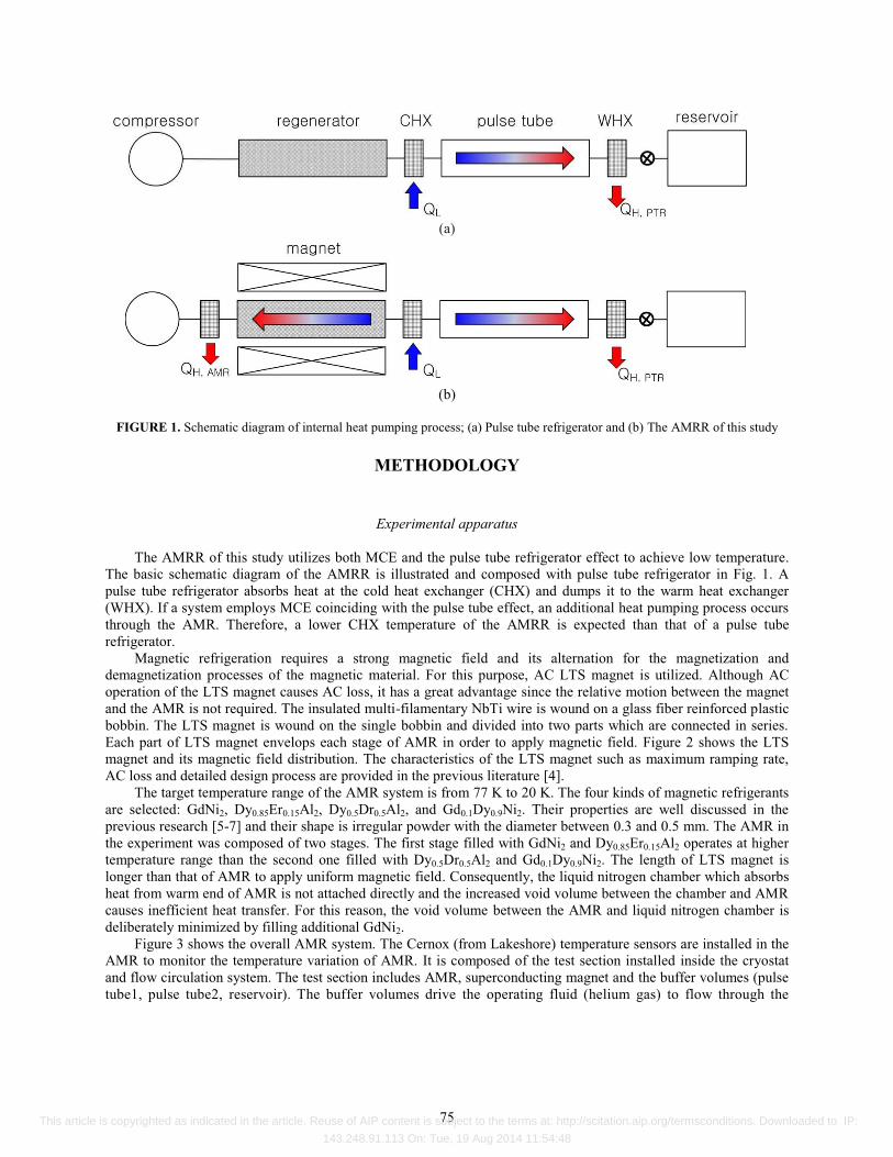
FIGURE 1. Schematic diagram of internal heat pumping process; (a) Pulse tube refrigerator and (b) The AMRR of this study
METHODOLOGY
Experimental apparatus
The AMRR of this study utilizes both MCE and the pulse tube refrigerator effect to achieve low temperature. The basic schematic diagram of the AMRR is illustrated and composed with pulse tube refrigerator in Fig. 1. A pulse tube refrigerator absorbs heat at the cold heat exchanger (CHX) and dumps it to the warm heat exchanger (WHX). If a system employs MCE coinciding with the pulse tube effect, an additional heat pumping process occurs through the AMR. Therefore, a lower CHX temperature of the AMRR is expected than that of a pulse tube refrigerator.
Magnetic refrigeration requires a strong magnetic field and its alternation for the magnetization and demagnetization processes of the magnetic material. For this purpose, AC LTS magnet is utilized. Although AC operation of the LTS magnet causes AC loss, it has a great advantage since the relative motion between the magnet and the AMR is not required. The insulated multi-filamentary NbTi wire is wound on a glass fiber reinforced plastic bobbin. The LTS magnet is wound on the single bobbin and divided into two parts which are connected in series. Each part of LTS magnet envelops each stage of AMR in order to apply magnetic field. Figure 2 shows the LTS magnet and its magnetic field distribution. The characteristics of the LTS magnet such as maximum ramping rate, AC loss and detailed design process are provided in the previous literature [4].
The target temperature range of the AMR system is from 77 K to 20 K. The four kinds of magnetic refrigerants are selected: GdNi2, Dy0.85Er0.15Al2, Dy0.5Dr0.5Al2, and Gd0.1Dy0.9Ni2. Their properties are well discussed in the previous research [5-7] and their shape is irregular powder with the diameter between 0.3 and 0.5 mm. The AMR in the experiment was composed of two stages. The first stage filled with GdNi2 and Dy0.85Er0.15Al2 operates at higher temperature range than the second one filled with Dy0.5Dr0.5Al2 and Gd0.1Dy0.9Ni2. The length of LTS magnet is longer than that of AMR to apply uniform magnetic field. Consequently, the liquid nitrogen chamber which absorbs heat from warm end of AMR is not attached directly and the increased void volume between the chamber and AMR causes inefficient heat transfer. For this reason, the void volume between the AMR and liquid nitrogen chamber is deliberately minimized by filling additional GdNi2.
Figure 3 shows the overall AMR system. The Cernox (from Lakeshore) temperature sensors are installed in the AMR to monitor the temperature variation of AMR. It is composed of the test section installed inside the cryostat and flow circulation system. The test section includes AMR, superconducting magnet and the buffer volumes (pulse tube1, pulse tube2, reservoir). The buffer volumes drive the operating fluid (helium gas) to flow through the
75 This article is copyrighted as indicated in the article. Reuse of AIP content is subject to the terms at: http://scitation.aip.org/termsconditions. Downloaded to IP:
143.248.91.113 On: Tue, 19 Aug 2014 11:54:48

(a) (b)
FIGURE 2. (a) The LTS magnet (unit: mm) and (b) Magnetic field distribution of the LTS magnet
Rotary valve
Heliumcompressor
Valve #1
MFM
Check valve
P
Heat exchanger #2(Water)
1
2
3
Valve #2 Valve #3
Valve #4
Valve #5
Heat exchanger #1(LN2)
Oscillating flowOne-way flow
Check valve Pinlet
(b)
(a) (c)
FIGURE 3. Schematic diagram of (a) the test section installed in the cryostat, (b) the flow circulation system, and (c) the composition of the AMR and the location of the temperature sensors
P
AMR1
LN2 chamber
GHe Feedline
Vacuum chamber
Magnet1
Pulse tube1
AMR2
Heat exchanger
Thermal anchoring
Reservoir
P
P
Orifice valve2
Pulse tube2
Orifice valve1
132
Magnet2
Pres
PPT
Cryostat
76 This article is copyrighted as indicated in the article. Reuse of AIP content is subject to the terms at: http://scitation.aip.org/termsconditions. Downloaded to IP:
143.248.91.113 On: Tue, 19 Aug 2014 11:54:48
each stage of AMR. The pressure oscillation of the system and the corresponding mass flow rate of the working fluid are controlled by the valve #1. Additionally, the orifice valves can control the oscillating mass flow rate of each AMR stage. The operating fluid, helium gas, is cooled by liquid nitrogen before entering the pulse tubes and heated by water before returning to the compressor. The flow circulation system can control helium gas flow in two ways: the oscillating flow or the one-way circulating flow. The one-way circulating flow is used to pre-cool the AMR to 77 K. When the temperature sensors in the AMR system show steady 77 K value, the flow is changed to the oscillating mode by the rotary valve. The mass flow rate is measured by the mass flow meter. In order to measure the oscillating mass flow rate, two check valves have to allow the helium flow only one direction as shown in Fig. 3(b).
Experimental procedure The experimental procedure is as follows: 1) Pre-cool the LTS magnet with liquid nitrogen 2) Cool down the LTS magnet with liquid helium 3) Fill liquid nitrogen in the LN2 chamber 4) Pre-cool the AMR by one-way circulating flow 5) Supply the oscillating flow of helium gas with magnetic field variation 6) Measure the steady-state temperature distribution of the AMR.
Various experimental parameters are measured during the experiment: inlet pressure, pulse tube pressure,
reservoir pressure, alternating current, temperature distribution of AMR (T1 ~ T5 in the second stage AMR and T6~T10 in the first stage AMR), and mass flow rate of the working fluid. The AMR system operates with the frequency of 0.1 Hz. The magnetic field changes for 3 seconds and maintains a constant value for 2 seconds. The mass flow rate usually occurs during the magnetization and the demagnetization processes. The maximum magnetic field and the mass flow rate are 4 T and 1.5 g/s respectively. The vacuum chamber surrounding the AMR thermally isolates the system from liquid helium reservoir which cools down LTS magnet. Since the saturation temperature of liquid helium is 4.2 K at atmospheric pressure, it is very important to estimate the amount of heat leak to precisely characterize the performance of the AMR. The pressure of the vacuum chamber is lower than 10-3 torr and the heat leak can be calculated by measuring the temperature variation of the AMR without operating fluid flow. The total heat leak of the AMR is estimated as 21 mW. More precise description of the experimental procedure is explained in the previous research [8].
EXPERIMENTAL RESULTS AND DISSCUSSION
Effect of the second stage composition of the AMR
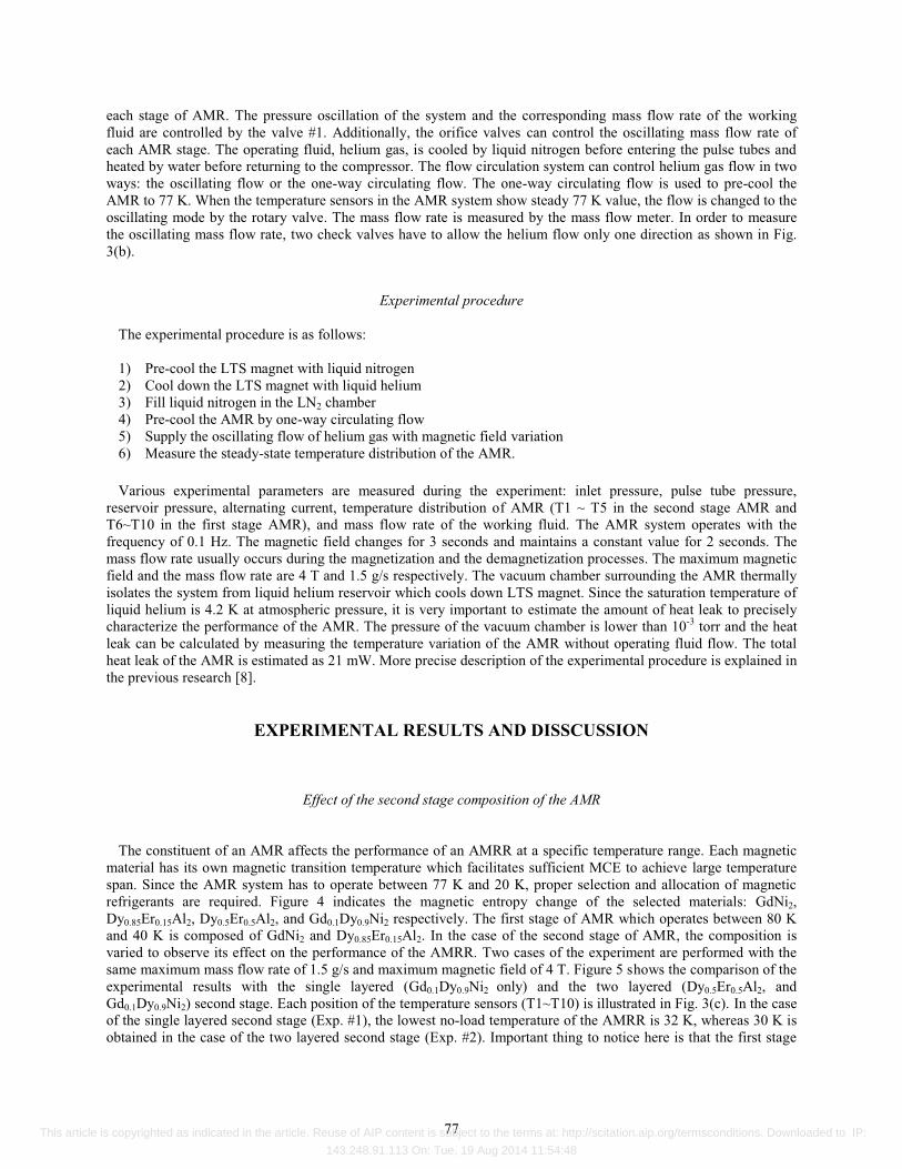
The constituent of an AMR affects the performance of an AMRR at a specific temperature range. Each magnetic material has its own magnetic transition temperature which facilitates sufficient MCE to achieve large temperature span. Since the AMR system has to operate between 77 K and 20 K, proper selection and allocation of magnetic refrigerants are required. Figure 4 indicates the magnetic entropy change of the selected materials: GdNi2, Dy0.85Er0.15Al2, Dy0.5Er0.5Al2, and Gd0.1Dy0.9Ni2 respectively. The first stage of AMR which operates between 80 K and 40 K is composed of GdNi2 and Dy0.85Er0.15Al2. In the case of the second stage of AMR, the composition is varied to observe its effect on the performance of the AMRR. Two cases of the experiment are performed with the same maximum mass flow rate of 1.5 g/s and maximum magnetic field of 4 T. Figure 5 shows the comparison of the experimental results with the single layered (Gd0.1Dy0.9Ni2 only) and the two layered (Dy0.5Er0.5Al2, and Gd0.1Dy0.9Ni2) second stage. Each position of the temperature sensors (T1~T10) is illustrated in Fig. 3(c). In the case of the single layered second stage (Exp. #1), the lowest no-load temperature of the AMRR is 32 K, whereas 30 K is obtained in the case of the two layered second stage (Exp. #2). Important thing to notice here is that the first stage
77 This article is copyrighted as indicated in the article. Reuse of AIP content is subject to the terms at: http://scitation.aip.org/termsconditions. Downloaded to IP:
143.248.91.113 On: Tue, 19 Aug 2014 11:54:48
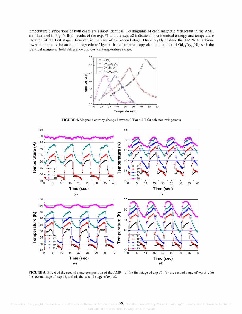
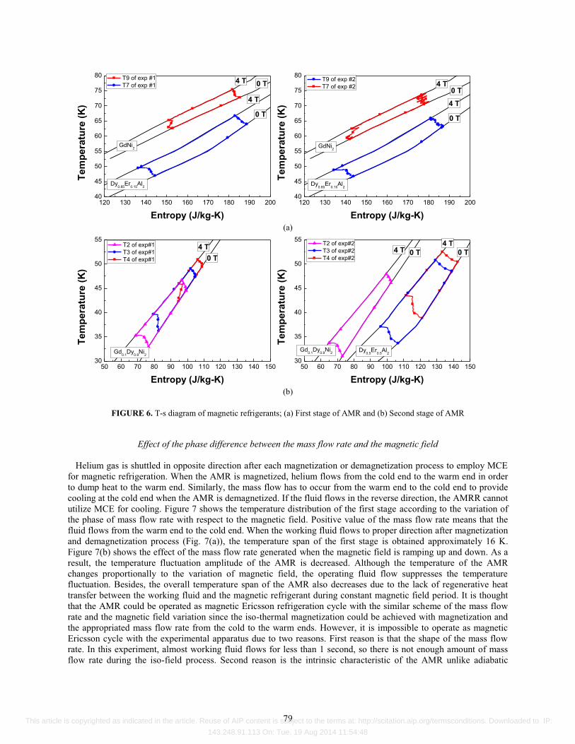
temperature distributions of both cases are almost identical. T-s diagrams of each magnetic refrigerant in the AMR are illustrated in Fig. 6. Both results of the exp. #1 and the exp. #2 indicate almost identical entropy and temperature variation of the first stage. However, in the case of the second stage, Dy0.5Er0.5Al2 enables the AMRR to achieve lower temperature because this magnetic refrigerant has a larger entropy change than that of Gd0.1Dy0.9Ni2 with the identical magnetic field difference and certain temperature range.
FIGURE 4. Magnetic entropy change between 0 T and 2 T for selected refrigerants
0 5 10 15 20 25 30 35 4045
50
55
60
65
70
75
80
85
Tem
pera
ture
(K)
Time (sec)
T6 T7 T9 T10
0 5 10 15 20 25 30 35 4030
35
40
45
50
55
Tem
pera
ture
(K)
Time (sec)
T1 T2 T3 T4 T5
(a) (b)
0 5 10 15 20 25 30 35 4045
50
55
60
65
70
75
80
85
Tem
pera
ture
(K)
Time (sec)
T6 T7 T8 T9 T10
0 5 10 15 20 25 30 35 4030
35
40
45
50
55
Tem
pera
ture
(K)
Time (sec)
T1 T2 T3 T4 T5
(c) (d)
FIGURE 5. Effect of the second stage composition of the AMR; (a) the first stage of exp #1, (b) the second stage of exp #1, (c) the second stage of exp #2, and (d) the second stage of exp #2
78 This article is copyrighted as indicated in the article. Reuse of AIP content is subject to the terms at: http://scitation.aip.org/termsconditions. Downloaded to IP:
143.248.91.113 On: Tue, 19 Aug 2014 11:54:48
120 130 140 150 160 170 180 190 20040
45
50
55
60
65
70
75
80 T9 of exp #1 T7 of exp #1
Tem
pera
ture
(K)
Entropy (J/kg-K)
Dy0.85
Er0.15
Al2
GdNi2
4 T
0 T
0 T4 T
120 130 140 150 160 170 180 190 20040
45
50
55
60
65
70
75
80 T9 of exp #2 T7 of exp #2
Tem
pera
ture
(K)
Entropy (J/kg-K)
Dy0.85
Er0.15
Al2
GdNi2
4 T
0 T
0 T4 T
(a)
50 60 70 80 90 100 110 120 130 140 15030
35
40
45
50
55 T2 of exp#1 T3 of exp#1 T4 of exp#1
4 T0 T
Tem
pera
ture
(K)
Entropy (J/kg-K)
Gd0.1
Dy0.9
Ni2
50 60 70 80 90 100 110 120 130 140 15030
35
40
45
50
55
Dy0.5
Er0.5
Al2
T2 of exp#2 T3 of exp#2 T4 of exp#2
4 T 0 T
Tem
pera
ture
(K)
Entropy (J/kg-K)
4 T0 T
Gd0.1
Dy0.9
Ni2
(b)
FIGURE 6. T-s diagram of magnetic refrigerants; (a) First stage of AMR and (b) Second stage of AMR
Effect of the phase difference between the mass flow rate and the magnetic field
Helium gas is shuttled in opposite direction after each magnetization or demagnetization process to employ MCE for magnetic refrigeration. When the AMR is magnetized, helium flows from the cold end to the warm end in order to dump heat to the warm end. Similarly, the mass flow has to occur from the warm end to the cold end to provide cooling at the cold end when the AMR is demagnetized. If the fluid flows in the reverse direction, the AMRR cannot utilize MCE for cooling. Figure 7 shows the temperature distribution of the first stage according to the variation of the phase of mass flow rate with respect to the magnetic field. Positive value of the mass flow rate means that the fluid flows from the warm end to the cold end. When the working fluid flows to proper direction after magnetization and demagnetization process (Fig. 7(a)), the temperature span of the first stage is obtained approximately 16 K. Figure 7(b) shows the effect of the mass flow rate generated when the magnetic field is ramping up and down. As a result, the temperature fluctuation amplitude of the AMR is decreased. Although the temperature of the AMR changes proportionally to the variation of magnetic field, the operating fluid flow suppresses the temperature fluctuation. Besides, the overall temperature span of the AMR also decreases due to the lack of regenerative heat transfer between the working fluid and the magnetic refrigerant during constant magnetic field period. It is thought that the AMR could be operated as magnetic Ericsson refrigeration cycle with the similar scheme of the mass flow rate and the magnetic field variation since the iso-thermal magnetization could be achieved with magnetization and the appropriated mass flow rate from the cold to the warm ends. However, it is impossible to operate as magnetic Ericsson cycle with the experimental apparatus due to two reasons. First reason is that the shape of the mass flow rate. In this experiment, almost working fluid flows for less than 1 second, so there is not enough amount of mass flow rate during the iso-field process. Second reason is the intrinsic characteristic of the AMR unlike adiabatic
79 This article is copyrighted as indicated in the article. Reuse of AIP content is subject to the terms at: http://scitation.aip.org/termsconditions. Downloaded to IP:
143.248.91.113 On: Tue, 19 Aug 2014 11:54:48
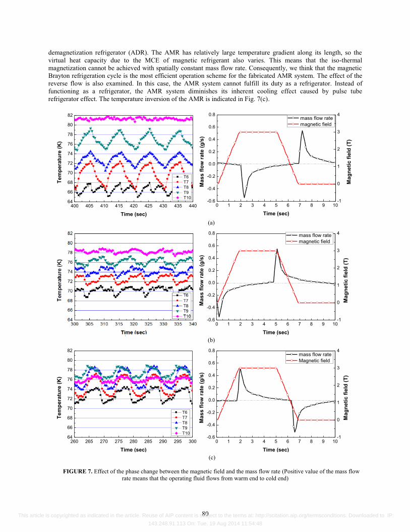
demagnetization refrigerator (ADR). The AMR has relatively large temperature gradient along its length, so the virtual heat capacity due to the MCE of magnetic refrigerant also varies. This means that the iso-thermal magnetization cannot be achieved with spatially constant mass flow rate. Consequently, we think that the magnetic Brayton refrigeration cycle is the most efficient operation scheme for the fabricated AMR system. The effect of the reverse flow is also examined. In this case, the AMR system cannot fulfill its duty as a refrigerator. Instead of functioning as a refrigerator, the AMR system diminishes its inherent cooling effect caused by pulse tube refrigerator effect. The temperature inversion of the AMR is indicated in Fig. 7(c).
400 405 410 415 420 425 430 435 44064
66
68
70
72
74
76
78
80
82
Tem
pera
ture
(K)
Time (sec)
T6 T7 T8 T9 T10
0 1 2 3 4 5 6 7 8 9 10-0.6
-0.4
-0.2
0.0
0.2
0.4
0.6
0.8
Mag
netic
fiel
d (T
)
Mas
s flo
w ra
te (g
/s)
Time (sec)
mass flow rate magnetic field
-1
0
1
2
3
4
(a)
0 1 2 3 4 5 6 7 8 9 10-0.6
-0.4
-0.2
0.0
0.2
0.4
0.6
0.8
Mas
s flo
w ra
te (g
/s)
Time (sec)
mass flow rate magnetic field
-1
0
1
2
3
4
Mag
netic
fiel
d (T
)
(b)
260 265 270 275 280 285 290 295 30064
66
68
70
72
74
76
78
80
82
Tem
pera
ture
(K)
Time (sec)
T6 T7 T8 T9 T10
0 1 2 3 4 5 6 7 8 9 10-0.6
-0.4
-0.2
0.0
0.2
0.4
0.6
0.8
Mas
s flo
w ra
te (g
/s)
Time (sec)
mass flow rate Magnetic field
-1
0
1
2
3
4M
agne
tic fi
eld
(T)
(c)
FIGURE 7. Effect of the phase change between the magnetic field and the mass flow rate (Positive value of the mass flow
rate means that the operating fluid flows from warm end to cold end)
80 This article is copyrighted as indicated in the article. Reuse of AIP content is subject to the terms at: http://scitation.aip.org/termsconditions. Downloaded to IP:
143.248.91.113 On: Tue, 19 Aug 2014 11:54:48
CONCLUSION
The AMRR for potential liquefaction of hydrogen is fabricated and tested. The AMR system utilizes not only MCE but also pulse tube refrigerator effect. The two-stage AMR composed of four magnetic refrigerants is compared with those consisting of three magnetic refrigerants. The experimental results show that the two layered second stage of AMR with Dy0.5Er0.5Al2 and Gd0.1Dy0.9Ni2 achieves lower cold end temperature more than 2 K in comparison with the single component AMR of Gd0.1Dy0.9Ni2 only. This is because Dy0.5Er0.5Al2 has more entropy change below 40 K than that of Gd0.1Dy0.9Ni2. Furthermore, the effect of phase difference between the magnetic field and the mass flow rate is analyzed. In order to maximize MCE for refrigeration, the working fluid has to flow with proper phase during magnetization or demagnetization process. The experimental result shows that the precise manipulation of mass flow rate in terms of magnitude and timing is of utmost importance to facilitate the best performance of the AMRR.
ACKNOWLEDGEMENT This research was supported by the Converging Research Center Program funded by the Ministry of Education,
Science and Technology (2012K001433)
REFERENCES
1. Andrews, J., Shabani B., Int. J. of Hyd. E. 37, 1184-1203 (2012). 2. Iwasaki, W., Int. J. of Hyd. E. 28, 559-567 (2003). 3. Yu, B. F., Gao Q., Zhang B., Meng X. Z., Chen Z., Int. J. of Ref. 26, 622-636 (2003). 4. Zhang, L., Sherif S. A., Degregoria A. J., Zimm C. B., Veziroglu T. N., Cryogenics. 40, 269-278 (2000). 5. Kim, Y., Jeong, S. "Ac Operation of the Low Temperature Superconducting Magnet for the Magnetic Refrigeration", in
ACASC. (2011). 6. Gschneidner Ka , P. V., S. K. Malik Sk. "The (Dy1-Xerx)Al2 Alloys as Active Magnetic Regenerators for Magnetic
Refrigeration", in Adv in Cryo. Eng. 42 475-483 (1996). 7. Pj, V. R., "Influence of the Crystalline Electrical Field on the Magnetocaloric Effect of DyAl2, ErAl2, and DyNi2", in
Physical review B. 58 110-116 (1998). 8. Ranke Pj, N. E., "Influence of the Crystalline Field on the Magnetocaloric Effect in the Series RNi2 (R=Pr, Nd, Gd, Tb, Ho,
Er)", in Physical review B. 63 (2001). 9. Kim, Y., Jeong, S. "Experimental Investigation Of Two-stage Active Magnetic Regenerative Refrigerator Operating
Between 77 K and 20 K", Cryogenics (accepted).
81 This article is copyrighted as indicated in the article. Reuse of AIP content is subject to the terms at: http://scitation.aip.org/termsconditions. Downloaded to IP:
143.248.91.113 On: Tue, 19 Aug 2014 11:54:48