
Distributed space-time coding for regenerative relay networks
13
IEEE TRANSACTIONS ON WIRELESS COMMUNICATIONS, VOL. 4, NO. 5, SEPTEMBER 2005 2387 Distributed Space–Time Coding for Regenerative Relay Networks Gesualdo Scutari, Student Member, IEEE, and Sergio Barbarossa, Member, IEEE Abstract—Cooperation among mobile users (MUs) in a wireless network can be very useful to reduce the total radiated power necessary to insure the delivery of the information with the desired quality of service. A systematic framework for achieving such a gain consists in making the cooperating nodes act as the antennas of a virtual transmit array, operating according to a distrib- uted space–time coding (DSTC) strategy. However, cooperation implies the allocation of dedicated resources, typically power and time slots, for the exchange of data between source and inter- mediate nodes (relays). It is then necessary to design the system properly to make possible a final net gain, taking into account all resources involved in the communication. In this paper, we consider regenerative relays and we analyze the effect of inter- mediate decision errors at the relay nodes. We derive the optimal maximum-likelihood (ML) detector, at the final destination, in case of binary phase-shift keying (BPSK) transmission, and a subop- timal scalar detector, whose bit-error rate (BER) is expressed in (approximate) closed form. Since with DSTC the transmit anten- nas are not colocated, we show how to allocate the power among source and relay terminals in order to minimize the average BER at the final destination. Finally, we compare alternative coopera- tion and decoding strategies. Index Terms—Cooperative communications, distributed space– time coding (DSTC), relay networks. I. I NTRODUCTION C OOPERATION among radio nodes in a wireless network can improve performance considerably with respect to the noncooperative case. Multihop packet radio networks based on relaying have been in fact proposed and analyzed for a long time (see, e.g., [27]). Fundamental theorems on the capacity of relay networks were established in [8] and [13]. Relaying can be very useful to combat shadowing effects, as shown by Emamian and Kaveh in [12]. Quite recently, Sendonaris et al. showed that cooperation among users can enlarge the capacity region of an uplink multiuser channel [22]–[24]. Laneman and Wornell showed, in a series of papers proposing alternative strategies, that cooperation can induce a spatial diversity gain, which can drastically reduce the power necessary to guarantee a desired bit-error rate (BER) at the final destination [17]–[19]. One of the ideas that proved to be more fruitful to design novel coop- eration strategies is the idea of a virtual array (see, e.g., [2], [4], Manuscript received August 9, 2003; revised May 15, 2004 and September 27, 2004; accepted September 27, 2004. The editor coordinating the review of this paper and approving it for publication is A. Molisch. This work was supported by the ROMANTIK project funded by the European Community under Contract IST-2001-32549. The authors are with the INFOCOM Department, University of Rome “La Sapienza,” Rome 00184, Italy (e-mail: [email protected]; sergio@ infocom.uniroma1.it). Digital Object Identifier 10.1109/TWC.2005.853883 [9], [10], and [18]), where the antennas of cooperating nodes are seen as elements of a virtual array. This conceptual link is par- ticularly important as it allows us to design cooperation proto- cols exploiting the powerful tools of space–time coding (STC). This strategy is known as distributed STC (DSTC), as the encoding operation is distributed among the cooperating nodes. The idea of cooperation through DSTC has been analyzed in several recent works, e.g., [2], [14], [18], [21], and [23]–[26]. Most of these works assumed that the relays had none of their own information to transmit. Hunter and Nosratinia considered a slightly different scenario, where two users cooperate with each other to transmit towards a common destination, and they both have data to transmit [14]–[16]. Within the DSTC perspective, conventional relaying can be seen as a kind of space–time repetition coding, where packets are transmitted from different points in space, at different times. But since rep- etition coding is known for being suboptimal, it is reasonable to expect an appreciable gain from the use of more appropriate DSTC strategies. However, cooperation among radio nodes requires dedicated resources, typically power and time slots. The most critical aspect of DSTC is then the balance between the waste of resources necessary to establish a cooperative communication link and the advantages coming from cooperation. In the most typical implementation of a cooperative communication sys- tem, based on a time-division duplexing (TDD) strategy, there are three kinds of time slots dedicated to the following links: 1) from mobile users (MUs) to the access point (AP); 2) from the AP to the MUs; and 3) from MUs to other MUs. The first two slots are the conventional multiple access (uplink) and broadcast (downlink) channels, respectively, whereas the last one is the slot used for the exchange of data between sources and relays directly. To give a general formulation, valid for both uplink and downlink channels, we will denote by S the source of information, whether user or AP, whereas R is a relay, and D is the final destination. Clearly, the insertion of the S/R slot for the link between S and R (or vice versa) induces a rate loss with respect to conventional (nonrelay) networks. To reduce this loss, the S/R slot must be necessarily shared among several pairs of sources and relays. In other words, the system must allow for spatial reuse of the S/R slot. However, this implies that the S/R link is subject to interference. The situation is pictorially sketched in Fig. 1, where there is an AP at the center of the cell and several sources and relays scattered around randomly. The sources transmitting to their relays at the same time interfere with each other. To limit the interference, the most crucial step is the rule that associates a relay to a source. A radio node should be selected from a given source as a relay 1536-1276/$20.00 © 2005 IEEE Authorized licensed use limited to: Universita degli Studi di Roma La Sapienza. Downloaded on November 29, 2008 at 06:50 from IEEE Xplore. Restrictions apply.
-
Upload
independent -
Category
Documents
-
view
0 -
download
0
Transcript of Distributed space-time coding for regenerative relay networks

IEEE TRANSACTIONS ON WIRELESS COMMUNICATIONS, VOL. 4, NO. 5, SEPTEMBER 2005 2387
Distributed Space–Time Coding forRegenerative Relay Networks
Gesualdo Scutari, Student Member, IEEE, and Sergio Barbarossa, Member, IEEE
Abstract—Cooperation among mobile users (MUs) in a wirelessnetwork can be very useful to reduce the total radiated powernecessary to insure the delivery of the information with the desiredquality of service. A systematic framework for achieving such again consists in making the cooperating nodes act as the antennasof a virtual transmit array, operating according to a distrib-uted space–time coding (DSTC) strategy. However, cooperationimplies the allocation of dedicated resources, typically power andtime slots, for the exchange of data between source and inter-mediate nodes (relays). It is then necessary to design the systemproperly to make possible a final net gain, taking into accountall resources involved in the communication. In this paper, weconsider regenerative relays and we analyze the effect of inter-mediate decision errors at the relay nodes. We derive the optimalmaximum-likelihood (ML) detector, at the final destination, in caseof binary phase-shift keying (BPSK) transmission, and a subop-timal scalar detector, whose bit-error rate (BER) is expressed in(approximate) closed form. Since with DSTC the transmit anten-nas are not colocated, we show how to allocate the power amongsource and relay terminals in order to minimize the average BERat the final destination. Finally, we compare alternative coopera-tion and decoding strategies.
Index Terms—Cooperative communications, distributed space–time coding (DSTC), relay networks.
I. INTRODUCTION
COOPERATION among radio nodes in a wireless networkcan improve performance considerably with respect to the
noncooperative case. Multihop packet radio networks based onrelaying have been in fact proposed and analyzed for a longtime (see, e.g., [27]). Fundamental theorems on the capacity ofrelay networks were established in [8] and [13]. Relaying can bevery useful to combat shadowing effects, as shown by Emamianand Kaveh in [12]. Quite recently, Sendonaris et al. showedthat cooperation among users can enlarge the capacity region ofan uplink multiuser channel [22]–[24]. Laneman and Wornellshowed, in a series of papers proposing alternative strategies,that cooperation can induce a spatial diversity gain, which candrastically reduce the power necessary to guarantee a desiredbit-error rate (BER) at the final destination [17]–[19]. One ofthe ideas that proved to be more fruitful to design novel coop-eration strategies is the idea of a virtual array (see, e.g., [2], [4],
Manuscript received August 9, 2003; revised May 15, 2004 and September27, 2004; accepted September 27, 2004. The editor coordinating the reviewof this paper and approving it for publication is A. Molisch. This work wassupported by the ROMANTIK project funded by the European Communityunder Contract IST-2001-32549.
The authors are with the INFOCOM Department, University of Rome “LaSapienza,” Rome 00184, Italy (e-mail: [email protected]; [email protected]).
Digital Object Identifier 10.1109/TWC.2005.853883
[9], [10], and [18]), where the antennas of cooperating nodes areseen as elements of a virtual array. This conceptual link is par-ticularly important as it allows us to design cooperation proto-cols exploiting the powerful tools of space–time coding (STC).This strategy is known as distributed STC (DSTC), as theencoding operation is distributed among the cooperating nodes.The idea of cooperation through DSTC has been analyzed inseveral recent works, e.g., [2], [14], [18], [21], and [23]–[26].Most of these works assumed that the relays had none of theirown information to transmit. Hunter and Nosratinia considereda slightly different scenario, where two users cooperate witheach other to transmit towards a common destination, andthey both have data to transmit [14]–[16]. Within the DSTCperspective, conventional relaying can be seen as a kind ofspace–time repetition coding, where packets are transmittedfrom different points in space, at different times. But since rep-etition coding is known for being suboptimal, it is reasonableto expect an appreciable gain from the use of more appropriateDSTC strategies.
However, cooperation among radio nodes requires dedicatedresources, typically power and time slots. The most criticalaspect of DSTC is then the balance between the waste ofresources necessary to establish a cooperative communicationlink and the advantages coming from cooperation. In the mosttypical implementation of a cooperative communication sys-tem, based on a time-division duplexing (TDD) strategy, thereare three kinds of time slots dedicated to the following links:1) from mobile users (MUs) to the access point (AP); 2) fromthe AP to the MUs; and 3) from MUs to other MUs. Thefirst two slots are the conventional multiple access (uplink) andbroadcast (downlink) channels, respectively, whereas the lastone is the slot used for the exchange of data between sourcesand relays directly. To give a general formulation, valid for bothuplink and downlink channels, we will denote by S the sourceof information, whether user or AP, whereas R is a relay, and Dis the final destination. Clearly, the insertion of the S/R slot forthe link between S and R (or vice versa) induces a rate losswith respect to conventional (nonrelay) networks. To reducethis loss, the S/R slot must be necessarily shared among severalpairs of sources and relays. In other words, the system mustallow for spatial reuse of the S/R slot. However, this impliesthat the S/R link is subject to interference. The situation ispictorially sketched in Fig. 1, where there is an AP at the centerof the cell and several sources and relays scattered aroundrandomly. The sources transmitting to their relays at the sametime interfere with each other. To limit the interference, themost crucial step is the rule that associates a relay to a source.A radio node should be selected from a given source as a relay
1536-1276/$20.00 © 2005 IEEE
Authorized licensed use limited to: Universita degli Studi di Roma La Sapienza. Downloaded on November 29, 2008 at 06:50 from IEEE Xplore. Restrictions apply.
gesualdoscutari
Text Box

2388 IEEE TRANSACTIONS ON WIRELESS COMMUNICATIONS, VOL. 4, NO. 5, SEPTEMBER 2005
Fig. 1. Sketch of a cell with AP, sources S and relays R.
only if the signal-to-noise-plus-interference ratio (SNIR) at therelay, relative to that given source, exceeds a given threshold.For example, without interference, the source S2 in Fig. 1would probably choose as relay R3 as it is its nearest relay.However, because of interference, S2 would more likely chooserelay R2 instead. Most available works on DSTC assume that aradio node acts as a relay only if it is error free. This simplifiesthe analysis, but it is clearly a too-strong assumption. Thisrequirement would in fact prevent the use of a relay also incases where relaying could still be beneficial, even though notnecessarily error free. One important exception to the error-free assumption is [17], where the relay was allowed to makedecision errors and the statistics of the relay decision errorswere explicitly incorporated in the final detector. An elegantclosed-form expression was derived in [17] for the maximumlikelihood (ML) at the final destination. However, the codingstrategy of [17] was essentially time repetition coding, as theinformation was sent over nonoverlapping time slots,1 andthen suboptimal.
In this paper, we remove the assumption that the relay beerror free and we determine the minimum SNIR that canbe tolerated at the relay, while still guaranteeing a sufficientcooperation gain. Different from [17], we assume a DSTCscheme where the available power is optimally distributedamong source and relay while they transmit to the destina-tion. We compare the cooperative and noncooperative schemes,assuming the same overall radiated power (incorporating alltime slots and links). We propose an optimal ML decoder,which exploits the knowledge of the error statistics at therelay, and a suboptimal decoder. The decoding errors at therelay induce an interfering term at the final destination, whose
1Instead of time, one could use the frequency domain to separate the datacoming from R and S, but in any case, the strategy of [17] was based on theorthogonality between the source–relay and the relay–destination channels.
structure depends on the adopted space–time coding technique.We exploit such a structure to derive a closed-form expres-sion for the final BER of the suboptimal decoder. Then, weshow how to distribute the power between S and R in orderto minimize the final average BER. Finally, we show thebalance between the improvement due to the diversity gainoffered by DSTC and the rate loss due to the insertion of theS/R slot.
II. DISTRIBUTED SPACE–TIME BLOCK CODING
We illustrate the proposed transmission protocol by referringto a TDD scheme, but the same considerations could apply to anfrequency-division duplexing (FDD) mode. In a TDD system,each frame is subdivided in consecutive time slots: In the firstslot, S transmits and R receives; in the second slot, S and Rtransmit simultaneously; D can be in a listening mode in bothtime slots or only in the second slot. What we propose in thiswork is that in the second time slot, similar to [3] and [19],S and R transmit using a block Alamouti scheme (see, e.g.,[1] and [5]), as if they were the two antennas of a single node.The extension to other space–time coding techniques is almoststraightforward (see, e.g., [6]). What is important to emphasizehere are the differences between DSTC and conventional STC.Different from common STC, with DSTC: 1) regenerative re-lays might make decision errors, so that the symbols transmittedfrom R could be affected by errors; 2) the links between Sand D and between R and D do not have the same statisticalproperties, in general; 3) even if S and R are synchronous,their packets might arrive at D at different times, as S andR are not colocated. In this paper, we will address all theseproblems specifically.
We describe our proposed solution within the followingsetup.
a1) All channels are finite-impulse response (FIR) of (maxi-mum) order Lh and time invariant over at least a pair ofconsecutive blocks.
a2) The channel coefficients are independent identically dis-tributed (i.i.d.) complex Gaussian random variables withzero mean and variance 1/d2, where d is the link length.
a3) The information symbols are i.i.d. binary phase-shiftkeying (BPSK) symbols that may assume the values Aor −A with equal probability.2
a4) The received data are degraded by additive whiteGaussian noise (AWGN).
a5) The channels are perfectly known at the receive sidesand are unknown at the transmit side.
a6) The transmission scheme for all terminals is a blockstrategy, where each block is composed of M symbols,incorporating a cyclic prefix (CP) of length L equal tothe sum of the relative delay with which packets from Sand R arrive at D plus the maximum channel order Lh.
We describe our distributed space–time protocol assumingthat each terminal is equipped with one antenna, but theextension to multiple receive antennas at the destination is
2Assumption a3) is made only for simplifying our derivations, but there is norestriction to use higher order constellations.
Authorized licensed use limited to: Universita degli Studi di Roma La Sapienza. Downloaded on November 29, 2008 at 06:50 from IEEE Xplore. Restrictions apply.
gesualdoscutari
Text Box

SCUTARI AND BARBAROSSA: DISTRIBUTED SPACE–TIME CODING FOR REGENERATIVE RELAY NETWORKS 2389
Fig. 2. Structure of transmit slots: (a) time slots and block indices;(b) information blocks sent by S; and (c) information blocks sent by R.
straightforward. Throughout the paper, we will use the fol-lowing notation. We denote with hκn
sd (i), hκnsr (i), and hκn
rd (i),the impulse responses between S and D, S and R, and Rand D, respectively, during the time slot indexed with κn; iis the block index. Each block of symbols s(i) has size Mand it is linearly encoded, so as to generate the N -size vectorxs(n) := Fs(n), where F is the N × M precoding matrix.A CP of length L ≥ Lh is inserted at the beginning of eachblock, to facilitate elimination of interblock interference (IBI),synchronization, and channel equalization at the receiver. A†
denotes the pseudoinverse of A; �{x} indicates the real part ofx; when applied to a vector, �{x} is the vector whose entriesare the real part of the entries of x.
With reference to Fig. 2, during the first time slot, S sends,consecutively, the two N -size information symbol blocks s(i)and s(i + 1). The blocks are linearly encoded using the precod-ing matrix F , so that the corresponding transmitted blocks arexs(n) := F ss(n), with n = i, i + 1. Within this time slot, thedestination may be in a listening mode or not. Under a6), afterremoving the guard interval at the receiver, the N -size vectorsyd(n) and yr(n) received from D and R are, respectively
yd(n) =Hκn
sd F ns s(n) + wd(n), n = i, i + 1 (1)
yr(n) =Hκnsr F n
s s(n) + wr(n), n = i, i + 1 (2)
where wr(n) and wd(n) are the additive-noise vectorsin R and D, respectively. The channel matrices Hκn
sd andHκn
sr , thanks to the insertion of the CP, are N × N circu-lant Toeplitz matrices, with entries Hκn
sd (i, j) = hκn
sd ((i − j)mod N) and Hκn
sr (i, j) = hκnsr ((i − j) mod N), respec-
tively.3 Because of their circulant and Toeplitz struc-ture, Hκn
sd and Hκnsr are diagonalized as follows: Hκn
sd =WΛκn
sd W H and Hκnsr = WΛκn
sr W H, where W is the N × N
IFFT matrix with {W}kl = ej2πkl/N/√
N , whereas Λκnsr
and Λκn
sd are the N × N diagonal matrices, whose entriesare Λκn
sr (k, k)=∑Lh−1
l=0 hκnsr (l)e−j2πlk/N and Λκn
sd (k, k)=∑Lh−1l=0 hκn
sd (l)e−j2πlk/N , respectively.The relay node decodes the received vectors and provides
the estimated vectors s(i) and s(i + 1).During the successive time slot, S and R transmit simulta-
neously, using a block Alamouti strategy [5]. More specifi-
3The law of variation of κn versus n depends on the channel stationarityproprieties.
cally, with reference to Fig. 2, in the first half of the secondtime slot, S transmits xs(i + 2) = α1Fs(i) and R transmitsxr(i + 2) = α2F s(i + 1). In the second half, S transmitsxs(i + 3) = α1Gs∗(i + 1) while R transmits xr(i + 3) =−α2Gs∗(i). To guarantee maximum spatial diversity, the twomatrices G and F are related to each other by G = JF ∗, as in[5], where J is a time-reversal (plus a one-chip cyclic shift)matrix. If N is even, J has all null entries except the ele-ments of position (1,1) and (k,N − k + 2), with k = 2, . . . , N ,which are equal to 1. If N is odd, J is the antidiagonal matrix.The two real coefficients α1 and α2 are related to each otherby α2
1 + α22 = 1. They are introduced in order to have a degree
of freedom in the power distribution between S and R, under agiven total transmit power. In Section III, we will show howto choose α1 (and then α2) in order to minimize the finalaverage BER.
After discarding the CP, the blocks received by D in thetwo consecutive time slots i + 2 and i + 3 are
yd(i + 2) =α1Hκi+2sd Fs(i)
+ α2Hκi+2rd F s(i + 1) + wd(i + 2)
yd(i + 3) =α1Hκi+2sd Gs∗(i + 1)
− α2Hκi+2rd Gs∗(i) + wd(i + 3) (3)
where Hκn
sd and Hκn
rd refer to the channels between S and D,and between R and D, respectively. Exploiting again the di-agonalizations Hκn
sd = WΛκn
sd W H and Hκn
rd = WΛκn
rd W H,if we premultiply in (3) yd(i + 2) by W H and y∗
d(i + 3) byW T, we get
W Hyd(i + 2) =α1Λκi+2sd F s(i)
+ α2Λκi+2rd F s(i + 1) + W Hwd(i + 2)
W Ty∗d(i + 3) =α1Λ
κi+2∗sd G
∗s(i + 1)
− α2Λκi+2∗rd G
∗s(i) + W Tw∗
d(i + 3)
where F := W HF and G := W HG. For the sake of sim-plicity, we assume that orthogonal frequency-division multi-plexing (OFDM) is performed at both S and R nodes, so thatN = M , F = W , and thus, F = IN and G = W . We alsointroduce the orthogonal matrix
Λκn:=(
α1Λκn
sd α2Λκn
rd
−α2Λκn∗rd α1Λ
κn∗sd
)(4)
such that ΛHκn
Λκn:= I2 ⊗ Λ2
κn, where Λ2
κn:= α2
1|Λκn
sd |2 +α2
2|Λκn
rd |2, whereas ⊗ denotes the Kronecker product. We in-
troduce also the unitary matrix4 Qκn := Λκn(I2 ⊗ Λ−1
κn), sat-
isfying the relationships QκnHQκn = I2N and QκnHΛκn =
4We suppose that the channels do not share common zeros on the grid zq =
ej2πq/N with q integer, so that Λκn is invertible.
Authorized licensed use limited to: Universita degli Studi di Roma La Sapienza. Downloaded on November 29, 2008 at 06:50 from IEEE Xplore. Restrictions apply.
gesualdoscutari
Text Box

2390 IEEE TRANSACTIONS ON WIRELESS COMMUNICATIONS, VOL. 4, NO. 5, SEPTEMBER 2005
I2 ⊗ Λκn. Exploiting the above equalities and multiplying
the vector u := [(W Hyd(i + 2))T, (W Ty∗d(i + 3))T]T by the
matrix Qκi+2H,5 we get[r(i)
r(i + 1)
]:= Qκi+2Hu
=
∣∣∣Λκi+2
sd
∣∣∣2 −Λκ∗
i+2sd Λ
κi+2
rd
Λκi+2
sd Λκ∗
i+2rd
∣∣∣Λκi+2
sd
∣∣∣2 s
+
∣∣∣Λκi+2
rd
∣∣∣2 Λκ∗
i+2sd Λ
κi+2
rd
−Λκi+2
sd Λκ∗
i+2rd
∣∣∣Λκi+2
rd
∣∣∣2 s + w
(5)
where s := [s(i)T, s(i + 1)T]T, s := [s(i)T, s(i + 1)T]T,
Λκi+2
sd := α1Λκi+2sd Λ−1/2
κn, Λ
κi+2
rd := α2Λκi+2rd Λ−1/2
κn, w :=
[wT(i), wT(i + 1)]T = Qκi+2H[wT(i + 2),wH(i + 3)]T. Asexpected, the previous equations reduce to the classical blockAlamouti equations (see, e.g., [1] and [5]), if the two transmitantennas use the same power, i.e., α1 = α2, and there are no de-cision errors at the relay node, i.e., s(n) ≡ s(n), n = i, i + 1.
Since Qκi+2H is unitary, if w is white, w is also white,with covariance matrix Cw = σ2
nI2N . Furthermore, since allmatrices Λ appearing in (5) are diagonal, the system (5)of 2N equations can be decoupled into N independent sys-tems of two equations in two unknowns, each equation refer-ring to a single subcarrier. More specifically, introducing thevectors rk := [rk(i), rk(i + 1)]T, sk := [sk(i), sk(i + 1)]T,sk := [sk(i), sk(i + 1)]T, and wk := [wk(i), wk(i + 1)]T, re-ferring to the kth subcarrier, with k = 0, . . . , N − 1 [for sim-plicity of notation, we drop the block index and we set Λsd =Λκi+2
sd (k, k) and Λrd = Λκi+2rd (k, k)], (5) is equivalent to the
following systems of equations:
rk =( |Λsd|2 −Λ∗
sdΛrd
ΛsdΛ∗rd |Λsd|2
)sk
+( |Λrd|2 Λ∗
sdΛrd
−ΛsdΛ∗rd |Λrd|2
)sk + wk. (6)
Since the noise vector wk is also white, with covariancematrix Cw = σ2
nI2N , and there is no intersymbol interference(ISI) between vectors sk and rk corresponding to differentsubcarriers, rk represents a sufficient statistic for the decisionon the transmitted symbol vector sk.
Since S and R are not colocated, in general, the blockstransmitted from S and R arrive at D at different times. Thisis a specific difference of distributed space–time block codingwith respect to the classical DSTC. However, if the differencein arrival times τd is incorporated in the CP used from both Sand R, D is still able to get N samples from each receivedblock, without IBI. In such a case, the different arrival time
5This operation does not affect the optimality of the decision since Qκi+2
is unitary.
does not cause any trouble to the final receiver. In fact, let ustake as a reference time the instant when the ith block comingfrom R arrives at D. If the block coming from S arrives with adelay of Ld samples, the only difference, with respect to thecase of perfect synchronization, is that the transfer functionΛsd(k) in (6) will be substituted by Λsd(k)e−j2πLdk/N . From(6), it is clear that such a substitution does not affect theuseful term, as it only affects the interfering term. However,in the hypothesis of Rayleigh fading channel, Λsd(k) is statis-tically indistinguishable from Λsd(k)e−j2πLdk/N . Hence, thecombination of Alamouti (more generally, orthogonal STC)and OFDM is robust with respect to lack of synchronizationbetween the time of arrivals of packets from S and from R [aslong as a6) holds true]. The price paid for this robustness isthe increase of the CP length L, which, in its turn, reflects intoa rate loss. However, this loss can be made small by choosing ablock length N much greater than L or by selecting only relaysthat are relatively close to the source, so as to make the rel-ative delay small.
A. ML Detector
We derive now the structure of the ML detector at the finaldestination. Besides the previous assumptions, we assume alsothat D has perfect knowledge of the vector of error probabilitiespe1(k) and pe2(k), k = 0, . . . , N − 1, occurring at the relay.This requires an exchange of information between R and D.This information has to be updated with a rate depending onthe channel coherence time. Later on, we will show an alterna-tive (suboptimum) detection scheme that does not require suchknowledge.
We denote with S the set of all possible transmitted vectorssk and with pe1(k) and pe2(k) the conditional (to a givenchannel realization) error probabilities, at the relay node, onsk(1) and sk(2), respectively. After detection, at the nodeR, we have sk(l) = sk(l), with probability (1 − pel(k)), orsk(l) = −sk(l), with probability pel(k), l = 1, 2. Since thesymbols are independent, the probability density function ofthe received vector z, conditioned to having transmitted sk,is (see Appendix A)
fz|sk(z|sk)
=1
π2σ2n
×[(1 − pe1(k)) (1 − pe2(k)) exp
{−|z − Ak(1, 1)sk|2
σ2n
}
+ pe1(k)pe2(k) exp
{−|z − Ak(−1,−1)sk|2
σ2n
}
+ (1 − pe1(k)) pe2(k) exp
{−|z − Ak(1,−1)sk|2
σ2n
}
+ pe1(k) (1 − pe2(k)) exp
{−|z − Ak(−1, 1)sk|2
σ2n
}]
(7)
Authorized licensed use limited to: Universita degli Studi di Roma La Sapienza. Downloaded on November 29, 2008 at 06:50 from IEEE Xplore. Restrictions apply.
gesualdoscutari
Text Box

SCUTARI AND BARBAROSSA: DISTRIBUTED SPACE–TIME CODING FOR REGENERATIVE RELAY NETWORKS 2391
where Ak(θ1, θ2) is defined as follows:
Ak(θ1, θ2) =[ |Λsd|2 + |Λrd|2θ1 Λ∗
sdΛrdθ2 − Λ∗sdΛrd
ΛsdΛ∗rd − ΛsdΛ∗
rdθ1 |Λsd|2 + |Λrd|2θ2
].
Based on (7), the ML detector is
sk = arg maxsk∈S
{frk|sk
(rk|sk)}
. (8)
In deriving the optimal receiver (8), we assumed thatD processes only the vectors received in the (i + 2)th and(i + 3)th time slots, ignoring the vectors (1) received in theslots i and (i + 1). If D is in a listening mode also duringthe first time slot, since the vectors yd(i) and yd(i + 1) in(1) contain information about the transmitted symbols s(i) ands(i + 1), an appropriate combination of (1) and (3) improvesthe performance of the system, at the price of a slight increaseof complexity. To this end, we introduce first the paraunitarymatrix Q := Λ(I2 ⊗ Λ−1), where
Λ :=
Λκi
sd 00 Λκi
sd
α1Λκi+2sd α2Λ
κi+2rd
−α2Λκi+2∗rd α1Λ
κi+2∗sd
Λ2 := |Λκi
sd|2 + α2
1
∣∣Λκi+2sd
∣∣2 + α22
∣∣Λκi+2rd
∣∣2ΛHΛ = I2 ⊗ Λ2
.
Then, proceeding as before, the optimal receiver, based on(1) and (3), is given by (8), where rk := [rk(i), rk(i + 1)]T,with [rT(i), rT(i + 1)]T := QH[(W Hyd(i))T, (W Hyd(i +1))T,(W Hyd(i + 2))T, (W Ty∗
d(n + 3))T]T given by
[r(i)
r(i + 1)
]=
∣∣∣Λκi+2
sd
∣∣∣2 +∣∣∣Λκi
sd
∣∣∣2 −Λκ∗
i+2sd Λ
κi+2
rd
Λκi+2
sd Λκ∗
i+2rd
∣∣∣Λκi+2
sd
∣∣∣2 +∣∣∣Λκi
sd
∣∣∣2 s
+
∣∣∣Λκi+2
rd
∣∣∣2 Λκ∗
i+2sd Λ
κi+2
rd
−Λκi+2
sd Λκ∗
i+2rd
∣∣∣Λκi+2
rd
∣∣∣2 s + w (9)
where s := [s(i)T, s(i + 1)T]T, s := [s(i)T, s(i + 1)T]T and(dropping the dependence on k) Ak(θ1, θ2) is given bythe equation at the bottom of the page where Λκi
sd :=Λκi
sd(k, k)Λ−1/2(k, k), Λκ1+2sd := α1Λ
κi+2sd (k, k)Λ−1/2(k, k),
and Λκi+2rd := α2Λ
κi+2rd (k, k) × Λ−1/2(k, k). Note that, thanks
to the orthogonal space–time block coding strategy, the optimaldetector preserves the receiver’s simplicity, because, undera1)–a6), the ML solution performs an exhaustive search onlyamong four possible transmitted vectors sk’s.
B. Suboptimum Detector
The ML detector described above assume the knowledge, atthe destination node, of the set of error probabilities pe1(k)and pe2(k), with k = 0, . . . , N − 1. If this knowledge is notavailable, a suboptimum scalar detector can be implemented,instead of the ML detector. More specifically, the decision onthe transmitted symbol sk(n) can be simply obtained as
s(n) = sign {� [r(n)]} , n = i, i + 1 (10)
where r(n) is given by (5) or (9). Note that, for high signal-to-noise ratio (SNR) at the relay (i.e., when R makes nodecision errors), the symbol-by-symbol decision in D becomesoptimal and, thus, the decoding rule (10) provides the sameperformance as the optimal receiver (8). When the decisionerrors at the relay side cannot be neglected, the suboptimal re-ceiver introduces a floor in the BER curve, because the symbol-by-symbol decision (10) treats the wrong received symbols asinterference. The choice between the decoding rules (8) and(10) should then result as a tradeoff between performance andcomputational complexity, taking into account the need for theML detector to make available, at the destination node, the errorprobabilities of the relay node. We will show a comparisonbetween ML and suboptimum strategies in Section IV.
III. POWER ALLOCATION BETWEEN SOURCE AND RELAYS
Whereas in conventional STC, the transmit antennas typi-cally use the same power over all the transmit antennas, withDSTC, it is useful to distribute the available power betweensource and relay as a function of their relative position withrespect to the final destination, since they are not colocated.In this section, we show how to distribute a given total poweroptimally between source and relay. We provide first a closed-form analysis in the ideal case where there are no decisionerrors at the relay, and then we will show some performanceresults concerning the real case where the errors are taken intoaccount. We carry out our derivations considering the generalcase where the receiver combines all four vectors yd(i) ÷yd(i + 3), as in (9).
A. Error-Free S/R Link
Under the assumption that there are no errors at the re-lay side, using the same derivations introduced in Section II,
Ak(θ1, θ2) =
∣∣∣Λκi
sd
∣∣∣2 +∣∣∣Λκi+2
sd
∣∣∣2 +∣∣∣Λκi+2
rd
∣∣∣2 θ1 Λκ∗
i+2sd Λκi+2
rd θ2 − Λκ∗
i+2sd Λκi+2
rd
Λκi+2sd Λ
κ∗i+2
rd − Λκi+2sd Λ
κ∗i+2
rd θ1
∣∣∣Λκi
sd
∣∣∣2 +∣∣∣Λκi+2
sd
∣∣∣2 +∣∣∣Λκi+2
rd
∣∣∣2 θ2
Authorized licensed use limited to: Universita degli Studi di Roma La Sapienza. Downloaded on November 29, 2008 at 06:50 from IEEE Xplore. Restrictions apply.
gesualdoscutari
Text Box

2392 IEEE TRANSACTIONS ON WIRELESS COMMUNICATIONS, VOL. 4, NO. 5, SEPTEMBER 2005
the optimal detector is a symbol-by-symbol detector and thesignal-to-noise ratio on the kth symbol in the nth block is
SNRk(n) =A2
σ2n
(|Λκi
sd(k, k)|2 + α∣∣Λκi+2
sd (k, k)∣∣2
+ (1 − α)∣∣Λκi+2
rd (k, k)∣∣2) (11)
with k = 0, 1, . . . , N − 1; n = i, i + 1, and α = α21. The sys-
tem performance depends on the channel stationarity proper-ties. We distinguish between two cases: 1) fast-fading channels,where the channels are constant within each pair of blocksbut they vary from any pair of blocks to the next one (thisproperty could be implemented using a block interleaver withsufficient memory) and 2) slow-fading channels, where thechannels are constant (at least within two consecutive timeslots). In all cases, we assume that the variance of the channel-impulse-response coefficients is proportional to 1/d2r, withr ≥ 1, where d is the distance of the link.
1) Fast-Fading Channels: In such a case, the random vari-ables Λκi
sd(k, k), Λκi+2sd (k, k), and Λκi+2
rd (k, k) are independent.The error probability for binary antipodal constellation, condi-tioned to a given channel realization, is given by
Pe|h(k) =12
erfc(√
0.5 SNRk) (12)
where SNRk is given by (11). For each subcarrier k, SNRk
is given by the sum of three statistically independent randomvariables, each one distributed according to a χ2 pdf with twodegrees of freedom. Thus, using (11) and (12), the BER Pb
averaged over the channel realizations is [20]
Pb =12
Q∑k=1
πk
[1 −
√γk
1 + γk
](13)
where Q = 3, and
πk :=Q∏
i�=k=1
γi
γi − γk
γ1 :=A2
σ2n
σ2h
drsd
γ2 :=A2
σ2n
ασ2h
drsd
γ3 :=A2
σ2n
(1 − α)σ2h
drrd
σ2h =σ2
h(Lh + 1).
From (13), we infer that, if the errors at the relay are negligi-ble, our scheme achieves the maximum available diversity gain,equal to 3. The optimal value of α can be found by minimizing(13). In Appendix B, we prove that the average BER (13) is aconvex function with respect to α, so that the problem admits aunique solution.2) Slow-Fading Channels: In case of slow fading [i.e.,
Λκi
sd(k, k) = Λκi+2sd (k, k) and Λκi
rd(k, k) = Λκi+2rd (k, k)], the
SNRk on the kth bit of the received block is [see (11)]
SNRk =A2
σ2n
((1 + α) |Λκi
sd(k, k)|2 + (1 − α) |Λκi
rd(k, k)|2)
(14)
and the BER averaged over the channel realizations is givenby (13), with Q = 2 and
γ1 :=A2
σ2n
(1 + α)σ2h
drsd
, γ2 :=A2
σ2n
(1 − α)σ2h
drrd
.
Hence, in this case, the maximum available diversity gainis 2. It is straightforward to show that, if D is equipped withR antennas, the achieved diversity gain is 3R for fast-fadingchannels, and 2R for slow-fading channels.
B. S/R Link With Errors
We derived a closed-form expression for the BER of thesuboptimum scheme, in the presence of relay decision errors,conditioned to the channel (the details are in Appendix C).In such a case, the errors act as a bias on the final decision.The BER on the ith received bit sk(i) over the kth subcarrier,conditioned to the channel realizations, is (see Appendix C)
Pe|h(k) =
[12
erfc
(Aβk√
σ2n
)](1 − pe1(k)) (1 − pe2(k))
+
[12
erfc
(Aδk√
σ2n
)]pe1(k) (1 − pe2(k))
+
[14
erfc
(A(βk + γk)√
σ2n
)
+14
erfc
(A(βk − γk)√
σ2n
)]pe2(k) (1 − pe1(k))
+
[14
erfc
(A(δk + γk)√
σ2n
)
+14
erfc
(A(δk − γk)√
σ2n
)]pe1(k)pe2(k) (15)
where [because of a4)], for n = i + 2, i + 3
pe1(k) = pe2(k) =12
erfc
(A√
σ2w(k)
)
and
βk =√
α21 |Λκn
sd (k, k)|2 + α22 |Λκn
rd (k, k)|2
γk =2α1α2Re
{Λκ∗
n
sd (k, k)Λκn
rd (k, k)}
√α2
1 |Λκn
sd (k, k)|2 + α22 |Λκn
rd (k, k)|2
δk =α2
1 |Λκn
sd (k, k)|2 − α22 |Λκn
rd (k, k)|2√α2
1 |Λκn
sd (k, k)|2 + α22 |Λκn
rd (k, k)|2(16)
with σ2w(k) := σ2
n/|Λκisr(k, k)|2, κi+2 = κi+3.
Authorized licensed use limited to: Universita degli Studi di Roma La Sapienza. Downloaded on November 29, 2008 at 06:50 from IEEE Xplore. Restrictions apply.
gesualdoscutari
Text Box
SCUTARI AND BARBAROSSA: DISTRIBUTED SPACE–TIME CODING FOR REGENERATIVE RELAY NETWORKS 2393
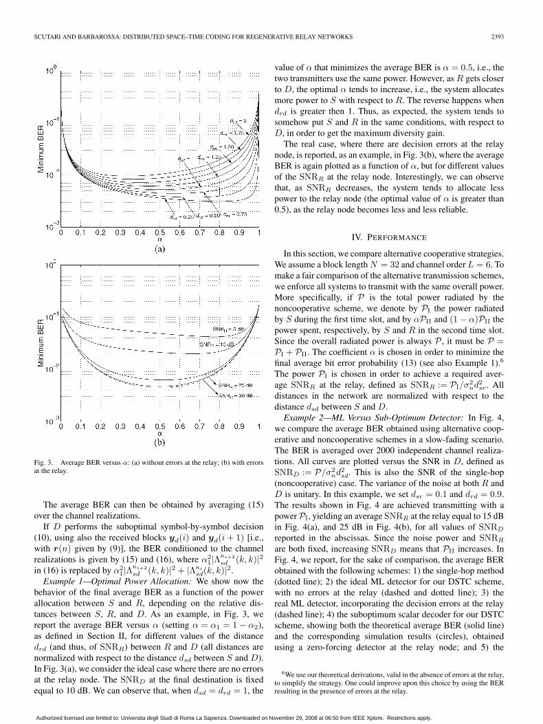
Fig. 3. Average BER versus α: (a) without errors at the relay; (b) with errorsat the relay.
The average BER can then be obtained by averaging (15)over the channel realizations.
If D performs the suboptimal symbol-by-symbol decision(10), using also the received blocks yd(i) and yd(i + 1) [i.e.,with r(n) given by (9)], the BER conditioned to the channelrealizations is given by (15) and (16), where α2
1|Λκi+2sd (k, k)|2
in (16) is replaced by α21|Λ
κi+2sd (k, k)|2 + |Λκi
sd(k, k)|2.Example 1—Optimal Power Allocation: We show now the
behavior of the final average BER as a function of the powerallocation between S and R, depending on the relative dis-tances between S, R, and D. As an example, in Fig. 3, wereport the average BER versus α (setting α = α1 = 1 − α2),as defined in Section II, for different values of the distancedrd (and thus, of SNRR) between R and D (all distances arenormalized with respect to the distance dsd between S and D).In Fig. 3(a), we consider the ideal case where there are no errorsat the relay node. The SNRD at the final destination is fixedequal to 10 dB. We can observe that, when dsd = drd = 1, the
value of α that minimizes the average BER is α = 0.5, i.e., thetwo transmitters use the same power. However, as R gets closerto D, the optimal α tends to increase, i.e., the system allocatesmore power to S with respect to R. The reverse happens whendrd is greater then 1. Thus, as expected, the system tends tosomehow put S and R in the same conditions, with respect toD, in order to get the maximum diversity gain.
The real case, where there are decision errors at the relaynode, is reported, as an example, in Fig. 3(b), where the averageBER is again plotted as a function of α, but for different valuesof the SNRR at the relay node. Interestingly, we can observethat, as SNRR decreases, the system tends to allocate lesspower to the relay node (the optimal value of α is greater than0.5), as the relay node becomes less and less reliable.
IV. PERFORMANCE
In this section, we compare alternative cooperative strategies.We assume a block length N = 32 and channel order L = 6. Tomake a fair comparison of the alternative transmission schemes,we enforce all systems to transmit with the same overall power.More specifically, if P is the total power radiated by thenoncooperative scheme, we denote by PI the power radiatedby S during the first time slot, and by αPII and (1 − α)PII thepower spent, respectively, by S and R in the second time slot.Since the overall radiated power is always P , it must be P =PI + PII. The coefficient α is chosen in order to minimize thefinal average bit error probability (13) (see also Example 1).6
The power PI is chosen in order to achieve a required aver-age SNRR at the relay, defined as SNRR := PI/σ2
nd2sr. All
distances in the network are normalized with respect to thedistance dsd between S and D.Example 2—ML Versus Sub-Optimum Detector: In Fig. 4,
we compare the average BER obtained using alternative coop-erative and noncooperative schemes in a slow-fading scenario.The BER is averaged over 2000 independent channel realiza-tions. All curves are plotted versus the SNR in D, defined asSNRD := P/σ2
nd2sd. This is also the SNR of the single-hop
(noncooperative) case. The variance of the noise at both R andD is unitary. In this example, we set dsr = 0.1 and drd = 0.9.The results shown in Fig. 4 are achieved transmitting with apower PI, yielding an average SNRR at the relay equal to 15 dBin Fig. 4(a), and 25 dB in Fig. 4(b), for all values of SNRD
reported in the abscissas. Since the noise power and SNRR
are both fixed, increasing SNRD means that PII increases. InFig. 4, we report, for the sake of comparison, the average BERobtained with the following schemes: 1) the single-hop method(dotted line); 2) the ideal ML detector for our DSTC scheme,with no errors at the relay (dashed and dotted line); 3) thereal ML detector, incorporating the decision errors at the relay(dashed line); 4) the suboptimum scalar decoder for our DSTCscheme, showing both the theoretical average BER (solid line)and the corresponding simulation results (circles), obtainedusing a zero-forcing detector at the relay node; and 5) the
6We use our theoretical derivations, valid in the absence of errors at the relay,to simplify the strategy. One could improve upon this choice by using the BERresulting in the presence of errors at the relay.
Authorized licensed use limited to: Universita degli Studi di Roma La Sapienza. Downloaded on November 29, 2008 at 06:50 from IEEE Xplore. Restrictions apply.
gesualdoscutari
Text Box

2394 IEEE TRANSACTIONS ON WIRELESS COMMUNICATIONS, VOL. 4, NO. 5, SEPTEMBER 2005
Fig. 4. Comparison between average BER versus SNR (dB) achieved withdifferent decision schemes: 1) single S/D link (dotted line); 2) idealML detector (dashed and dotted line); 3) real ML detector (dashed line);4) suboptimum receiver—theoretical results (solid line) and simulation(circles); 5) Laneman and Wornell’s scheme (solid line with squares) [thesame scalar decoder as in item 4), except that the relay uses an MMSE scalardecoder (solid line with stars)]; (a) SNRR = 15 dB, (b) SNRR = 25 dB;dsr = 0.1, drd = 0.9.
scheme proposed by Laneman and Wornell in [17, Sec. C.1],where R works as in 4) and D implements the ML detectorthat combines the signals coming from S in the first slot andfrom R in the second slot (solid line with squares).
We can observe a very good agreement between our theo-retical derivations for the suboptimum detector and the cor-responding simulation results. The floor on the BER of thesuboptimum receiver is due to the decision errors at the relaynode. Also, the scheme of [17] exhibits a floor because SNRR
is fixed. In fact, as SNRD increases, only PII increases, whilePI is constant. As a consequence, the average number of errorsat the relay does not decrease by increasing SNRD. Thus, fora given BER at the relay, increasing PII does not yield a realbenefit above a certain SNRD. The BER floor can only decrease
if the SNRR at the relay increases, as is evident by comparingFig. 4(a) and (b). Conversely, in our DSTC scheme, even thoughthe SNRR at the relay is fixed, the system has one more degreeof freedom to be used against the effect of the relay decoding er-rors: the optimal power distribution between S and R. It is thisextra degree of freedom that avoids the final BER floor in theDSTC scheme. As an example, in the extreme case where therelay has a very low SNR, and thus a high error probability,the system would set α = 1, i.e., it would shut off the relay byallocating all power to S in the second slot. In such a case, thefinal destination would not be affected by the relay errors at all.The price paid for this advantage, with respect to [17], is that theoptimal power distribution between S and R requires someextra signaling between S and R. Comparing our suboptimumDSTC detector with the ML (repetition coding) detector of[17], we note that [17] outperforms the suboptimal detectorwhen both SNRR and SNRD are sufficiently high, whereasthe situation is reversed at low/intermediate values of SNRR.The comparison between our schemes and [17] is also stronglydependent on the relative distances between S, R, and D. Asan example, in Fig. 5, we report the average BER obtainedin the same scenario as Fig. 4, except that the distances aredsr = 0.3 and drd = 0.7 in Fig. 5(a), and dsr = 0.7 and drd =0.3 in Fig. 5(b).7 We see that as R moves away from S,our suboptimum detector loses with respect to [17], whereasour ML approach is always better than [17]. As before, theadvantage, with respect to [17], is paid in terms of complex-ity, as it requires that S and R cooperate to select the mostappropriate transmit power. Nevertheless, this is a low-ratesignaling exchange that is not expected to affect the overall rateconsiderably.
It is also interesting to notice, from Figs. 4 and 5, that thesuboptimum DSTC scheme exhibits performance very close tothe optimal DSTC ML detector at low SNRD, i.e., before theBER floor, when the relay is relatively close to the source. Thisindicates that the suboptimum detector is indeed a very goodchoice, under such a scenario, because it is certainly less com-plicated to implement than the ML detector. Most importantly,different from our ML and [17], the suboptimum scheme doesnot require any exchange of information between R and Dabout the BER in R. The price paid for this simplicity is thatthe R node must have a sufficiently high SNR to guarantee thatthe BER of interest be above the floor. In Fig. 4, we have alsoreported the average BER (solid line with stars) obtained usinga transmission strategy for our DSTC scheme, where insteadof OFDM, in the S/R slot, we used a linear precoding methodthat insures minimum BER at the relay, under the assumption ofadopting a (suboptimal) minimum mean square error (MMSE)linear decoder (solid line with stars). In such a case, we observethat, with minimum additional complexity at the relay, theperformance of the suboptimal DSTC scheme becomes closerto the ML decoder because of the lower BER at the relay.
7At low SNRD values, there are no corresponding BER because, for thosevalues, the transmitted power is insufficient to guarantee the required SNRR atthe relay and thus, no cooperative communication can take place with the givenSNR at the relay.
Authorized licensed use limited to: Universita degli Studi di Roma La Sapienza. Downloaded on November 29, 2008 at 06:50 from IEEE Xplore. Restrictions apply.
gesualdoscutari
Text Box

SCUTARI AND BARBAROSSA: DISTRIBUTED SPACE–TIME CODING FOR REGENERATIVE RELAY NETWORKS 2395
Fig. 5. Comparison between average BER versus SNR (dB) achieved withdifferent decision schemes: single S/D link (dotted line); ideal ML detec-tor (dashed and dotted line); real ML detector (dashed line); suboptimumreceiver—theoretical results (solid line) and simulation (circles); Lanemanand Wornell’s scheme (squares); (a) dsr = 0.3, drd = 0.7, (b) dsr = 0.7,drd = 0.3; SNRR = 15 dB.
Finally, looking at the slopes of the average BER curvesof the ML DSTC detector shown in Fig. 4(a) and (b), it isworth noticing that, in the absence of errors at the relay, thecooperative scheme achieves full spatial diversity gain. How-ever, in the presence of decoding errors, the cooperativeschemes do not achieve the full diversity gain. Indeed, in thepresence of decoding errors at the relay, all cooperative schemesexhibit an asymptotic average BER behavior proportional to1/SNRD. Nevertheless, there is a considerable coding gain,which justifies the use of cooperation. Indeed, a more attentivelook at the results shows that the average BER starts approach-ing the slope with maximum diversity, as far as the errors at therelay are negligible with respect to the errors at the destination.Then, when the errors at the relay become dominant, thefinal BER curve follows the 1/SNR behavior. The absence offull diversity gain (but high coding gain) was also observed
Fig. 6. Average BER versus SNR (dB) with: 1) no cooperation (circlemarkers); 2) ML detector with slow-fading channel (square markers); and3) ML detector with fast-fading channel (stars); SNRR = 15 dB.
in [6], where (reliable) relays were assumed available only witha certain probability, depending on the random distribution ofthe relays.Example 3—Fast Versus Slowly Varying Channels: If the
S/D channel varies fast enough to assume independent valuesover the two time slots where S transmits alone or when Sand R transmit together, we can achieve a diversity gain of3, if the relay errors are negligible. An example is shown inFig. 6, where we compare the following three cases: 1) nocooperation (circles); 2) ML DSTC detector with slow-fadingchannel; and 3) ML DSTC detector with fast-fading channel.The SNRR at the relay is high enough to make the relay errorsnegligible. In fact, we observe that the average BER, in thefast-fading case, exhibits a behavior proportional to 1/SNR3.Decreasing SNRR, all the curves would smoothly change theirslope until they follow the asymptotic behavior 1/SNR.
V. CHOICE OF THE CONSTELLATION ORDER
IN THE SOURCE–RELAY SLOT
The other major critical aspect of cooperative schemes istheir rate loss due to the insertion of the S/R time slot. As anexample, if all the links would use a BPSK constellation, therate loss factor would be 1/2. To reduce this loss factor, we canuse higher order constellations in the S/R link, with respect tothe constellations used in the other links, so that the durationof the S/R slot can be made smaller than the duration of theother slots. In this section, we assume BPSK transmissions overall links, except the S/R link, where the constellation order isallowed to increase. More specifically, using a constellation Aof cardinality M = 2nb in the S/R link, the rate loss factor isnb/(nb + 1). On the other hand, cooperation reduces the finalBER and then it induces a capacity increase. To quantify theoverall balance in terms of rate, we compared the maximum rateachievable by our DSTC system with the maximum rate achiev-able with a noncooperative scheme. We define as achievable
Authorized licensed use limited to: Universita degli Studi di Roma La Sapienza. Downloaded on November 29, 2008 at 06:50 from IEEE Xplore. Restrictions apply.
gesualdoscutari
Text Box

2396 IEEE TRANSACTIONS ON WIRELESS COMMUNICATIONS, VOL. 4, NO. 5, SEPTEMBER 2005
rate the maximum number of bits per symbol (bps) that canbe decoded with an arbitrarily low error probability, providedthat sufficient error-correction coding is incorporated in thesystem, conditioned to the assumptions a1)–a6).8 We haveshown in Section II that the combination of orthogonal DSTCand OFDM makes the overall time-dispersive channel equiv-alent to a set of parallel nondispersive subchannels. The finalS/D link over each subchannel, in the presence as well as inthe absence of the relay link, can always be made equivalentto a binary symmetric channel (BSC) with crossover probabil-ity depending on the specific cooperative (or noncooperative)scheme adopted. Let us indicate with pe|h(k) such a binary errorprobability, conditioned to the channel realization. The capacityof such an equivalent channel is [20] (dropping the dependencefrom k)
CBSC(pe|h) := 1 + pe|h log2(pe|h) + (1 − pe|h) log2(1−pe|h).
Thus, the maximum rate R(k|h) that can be reliably trans-mitted, over the kth subcarrier, for a given channel realizationh, incorporating the rate loss due to the insertion of the S/Rslot, is
R(k|h) =1
1 + 1nb
CBSC
(Pe|h(k)
)bps. (17)
If the suboptimal symbol-by-symbol detector (10) is per-formed at the receiver, the error probability Pe|h(k) is givenby (15), with pe1(k) = pe2(k) well approximated by [11]
pe1(k) 1N
N∑k=1
{ √M − 1√
M log2
√M
erfc
(√β
σ2w(k)
)
+√
M − 2√M log2
√M
erfc
(3
√β
σ2w(k)
)}(18)
where β = 3σ2s/2(M − 1), σ2
w(k) = σ2n/|Λκi
sr(k, k)|2, and σ2s
is the variance of the transmitted symbols. From (17), we inferthat, because of the S/R link, the cooperative transmissioninduces a systematic rate loss of 1/(1 + 1/nb) with respectto the noncooperative case. But, at the same time, cooperationyields a smaller error probability Pe|h(k) and thus, a higherCBSC(Pe|h(k)). Then, we may expect a tradeoff in the choiceof nb. This tradeoff can be better understood through thefollowing example.Example 4—Rate and Diversity Gain: We report in Fig. 7(a)
and (b) the achievable rate versus SNRD, for an SNRR
in R equal to 10 and 3 dB, respectively, for different choices ofthe constellation used in the S/R link, achieved with or without
8It is important to remark that the rate defined above is smaller than thecapacity of the system, because the proposed scheme is designed to maximizethe spatial diversity gain and not to maximize information rate.
Fig. 7. Achievable rate (bps) versus SNR (dB). Noncooperative case (solidline), cooperative case using: BPSK (circle marker), QPSK (star marker),16-QAM (square marker), 64-QAM (“+”), in the S/R link. (a) SNRR =10 dB; (b) SNRR = 3 dB.
cooperation. In both cases, we assume that the S/D and R/Dlinks assume the same (BPSK) constellation, in both cases ofcooperation or no cooperation.9 We can see that, at high SNRD,the noncooperative case approaches the maximum value,equal to 1 bps, whereas the cooperative cases tend to an as-ymptote less than 1, depending on the constellation used in theS/R slot. We observe from Fig. 7(a) that, for SNRR = 10 dB,increasing the constellation order in the S/R slot from BPSKto 16-QAM (quadrature-amplitude modulation) improves theachievable rate; however, passing from 16-QAM to 64-QAMdoes not induce any further gain because of the higher BER atthe relay. For lower values of SNRR, i.e., SNRR = 3 dB, thereis no appreciable rate gain in increasing the constellation order
9We could indeed use higher order constellations in the cooperative case,with respect to the noncooperative case. But this aspect is beyond the subject ofthis paper.
Authorized licensed use limited to: Universita degli Studi di Roma La Sapienza. Downloaded on November 29, 2008 at 06:50 from IEEE Xplore. Restrictions apply.
gesualdoscutari
Text Box

SCUTARI AND BARBAROSSA: DISTRIBUTED SPACE–TIME CODING FOR REGENERATIVE RELAY NETWORKS 2397
because of the excessive BER at the relay. Nevertheless, eventhough the cooperative scheme proposed in this paper was notaimed at improving the rate, it is interesting to notice that, atlow/medium SNRD (within a range depending on SNRR), thecooperative case can outperform the noncooperative case alsoin terms of achievable rate, because the BER decrease can morethan compensate the rate insertion loss due to the S/R slot.
VI. CONCLUDING REMARKS
In this work, we have shown that a DSTC scheme usingdifferent nodes to build a virtual transmit array can be veryeffective to reduce the overall power radiated in a network,which is necessary to guarantee a desired final BER. However,the gain is achievable if the relays are chosen appropriately.In particular, source and relay should be close to each otherfor a series of convergent reasons: 1) less power is wasted tosend data from the source to the relays; 2) less interferenceis generated towards other source/relay links sharing the sameslot—this allows for the spatial reuse of the S/R slot, whichis particularly important to limit the rate insertion losses; and3) synchronization problem is reduced. We have shown, bytheory and simulation, that a suboptimum DSTC receiver, atthe final destination, has a close behavior to the optimal MLdetector at low SNR, but it exhibits a BER floor, whose valuedepends on the SNR at the relay. The floor can be eliminatedusing an ML decoder, but this comes at the price of increasedcomplexity and the need of sending the estimated relay errorprobabilities at the destination. Overall, we may say that, if theSNR at the relay is sufficiently high, the suboptimum scheme isa good choice. We have then shown how to distribute the trans-mit power between source and relay in order to minimize thefinal average BER. In particular, we have shown that the over-all system is relatively robust with respect to the choice ofthe power balance as the average BER curve is relatively flatfor a large interval of α. Finally, we have shown how to finda good balance, in terms of rate, between the loss due tothe insertion of cooperation time slots and the performanceimprovement resulting from cooperation. Some preliminaryresults on alternative space–time coding strategies have beenreported in [6].
APPENDIX A
We derive the optimal minimum BER detector in thecase where D takes the decision on the transmitted symbolsby collecting all the received blocks. The optimal detector basedonly on the received blocks in the time slots (i + 2)th and(i + 3)th can be derived as a particular case. Given [rT(i), rT
(i+1)]T := QH[(W Hy(i))T, (W Hy(i+1))T,(W Hy(i+2))T,(W Ty∗(i + 3))T]T, since the additive noise in (5) is Gaussianand white and no ISI occurs in the received blocks r(i) andr(i + 1), rk constitutes a sufficient statistic for deciding uponthe transmitted symbols sk(i) and sk(i + 1). The vector rk
assumes, in general, the form shown at the bottom of the page(with Ak(θ1, θ2) defined right below), sk := [sk(i), sk(i +1)]T, Λκi
sd := Λκi
sd(k, k)/Λ−1(k, k), Λκi+2sd := α1Λ
κi+2sd (k, k)/
Λ−1(k, k), and Λκi+2rd := α2Λ
κi+2rd (k, k)/Λ−1(k, k); wk :=
[wk(i), wk(i + 1)]T, and θ1 and θ2 are two independent ran-dom variables, with pdf given by fΘ1(θ1) = pe1(k)δ(θ1 + 1) +(1 − pe1(k))δ(θ1 − 1) and fΘ2(θ2) = pe2(k)δ(θ2 + 1) + (1 −pe2(k))δ(θ2 − 1), respectively; pe1(k) and pe2(k) are, for agiven channel realization, the average error probability at therelay terminal on the kth bit in the blocks s(i) and s(i + 1),respectively. The optimal decision rule minimizing the averageBER Pb|h, conditioned to a given channel realization, is givenby the ML decision on the block rk = [rT
k (i), rTk (i + 1)]T.
Denoting by S the set of all possible vectors sk, and by sik the
ith vector in the set S, the vector rk, given sik, Θ1 = θ1, and
Θ2 = θ2, is a Gaussian random vector with mean Ak(θ1, θ2)sik
and covariance matrix Cw = σ2nI2. Thus, the probability den-
sity function frk|sik(z|si) of receiving the vector z, conditioned
to having transmitted sik, is (we drop the dependence from k)
fr|si(z|si) =1
|πCw|[(1 − pe1)(1 − pe2) g(1, 1,z, si)
+ pe1pe2 g(−1,−1,z, si)
+ (1 − pe1)pe2 g(1,−1,z, si)
+ (1 − pe2)pe1 g(−1, 1,z, si)]
where g (p, q, z, si) = exp {− [z − A (p, q) si]H C−1w [z −
A(p, q)si]} = exp{−|z − A(p, q)si|2/σ2n]}.
rk =
(∣∣∣Λκi
sd
∣∣∣2 +∣∣∣Λκi+2
sd
∣∣∣2) s(i) +∣∣∣Λκi+2
rd
∣∣∣2 s(i) + Λκ∗
i+2sd Λκi+2
rd s(i + 1) − Λκ∗
i+2sd Λκi+2
rd s(i + 1)(∣∣∣Λκi
sd
∣∣∣2 +∣∣∣Λκi+2
sd
∣∣∣2) s(i + 1) +∣∣∣Λκi+2
rd
∣∣∣2 s(i + 1) + Λκi+2sd Λ
κ∗i+2
rd s(i) − Λκi+2sd Λ
κ∗i+2
rd s(i)
+ wk
= Ak(θ1, θ2) sk + wk
Ak(θ1, θ2) =:
∣∣∣Λκi
sd
∣∣∣2 +∣∣∣Λκi+2
sd
∣∣∣2 +∣∣∣Λκi+2
rd
∣∣∣2 θ1 Λκ∗
i+2sd Λκi+2
rd θ2 − Λκ∗
i+2sd Λκi+2
rd
Λκi+2sd Λ
κ∗i+2
rd − Λκi+2sd Λ
κ∗i+2
rd θ1
∣∣∣Λκi
sd
∣∣∣2 +∣∣∣Λκi+2
sd
∣∣∣2 +∣∣∣Λκi+2
rd
∣∣∣2 θ2
Authorized licensed use limited to: Universita degli Studi di Roma La Sapienza. Downloaded on November 29, 2008 at 06:50 from IEEE Xplore. Restrictions apply.
gesualdoscutari
Text Box

2398 IEEE TRANSACTIONS ON WIRELESS COMMUNICATIONS, VOL. 4, NO. 5, SEPTEMBER 2005
APPENDIX B
We prove that the average BER (13) is a convex functionin α. In fact, the function g(x) defined as
g(x) =∫A
w(y)f(x, y)dy (19)
is convex in x if, ∀y, f(x, y) is convex in x and w(y) ≥ 0 [7].From (19) and
Pb = Eh{Pb|h} =∫H
Pb|hfh(h)dh (20)
it follows that Pb is convex in α, if Pb|h =0.5 erfc (
√0.5 SNRk(α)) is convex in α, where SNRk(α)
is given by (11) or (14). Introducing the functionf = h ◦ g : R �→ R defined as f(x) = h(g(x)), withdomf = {x ∈ domg|g(x) ∈ domh}, where domf denotesthe domain of the function f , the second derivative f ′′(x) ofthe composition function f is given by
f′′(x) = h
′′(g(x))
(g
′(x))2
+ h′(g(x)) g
′′(x). (21)
From (21), we infer that f(x) is convex if h(x) is a convex(h′′(x) ≥ 0) nonincreasing (h′(x) ≤ 0) function and g(x) isconcave (g′′(x) ≤ 0). Defining h(x) := erfc(
√a1x), we have
h′(x) = − 1
2
√a1
8π xe−a1
x2 < 0 ∀x > 0
h′′(x) =
12
√a1
32π xe−a1
x2
(a1 +
1x
)> 0 ∀x > 0.
Thus, h(x) is a convex nondecreasing function in x. AsSNRk(α), given by (11) or (14), is concave in α (because itis linear in α) for any given channel realization, from (19) and(21), it follows that f(α) := Pb(α) is convex in α.
APPENDIX C
We derive the closed-form expression for the BER in thecase of suboptimal symbol-by-symbol detection (10), with r(n)given by (5). The decision on the transmitted symbol sk(i) isperformed by taking a hard decision on
rk(i) =∣∣∣Λκi+2
sd
∣∣∣2 sk(i) +∣∣∣Λκi+2
rd
∣∣∣2 sk(i)
+ Λκ∗
i+2sd Λκi+2
rd sk(i + 1) − Λκ∗
i+2sd Λκi+2
rd sk(i + 1) + wk(i)
where Λκi+2sd := Λκi+2
sd (k, k), Λκi+2rd := Λκi+2
rd (k, k). For theensuing derivations, it is useful to introduce the followingevents: H1 ≡ {sk(i) = sk(i), sk(i + 1) = sk(i + 1)}, H2 ≡{sk(i) = −sk(i), sk(i + 1) = sk(i + 1)}, H3 ≡ {sk(i) =sk(i), sk(i + 1) = −sk(i + 1)}, H4≡{sk(i)=−sk(i), sk(i+1)=−sk(i + 1)}, and E1,1 ≡ {sk(i) = A, sk(i + 1) = A},E1,−1 ≡ {sk(i) = A, sk(i + 1) = −A}, E−1,1 ≡ {sk(i)=−A,sk(i + 1) = A}, E−1,−1 ≡ {sk(i) = −A, sk(i + 1) = −A}.
Given the error probabilities pe1(k) and pe2(k), introducedin Section II-A, we have P(H1) = (1 − pe1(k))(1 − pe2(k)),P(H2) = pe1(k)(1 − pe2(k)), P(H3) = (1 − pe1(k))pe2(k),and P(H2) = pe1(k)pe2(k). Denoting, for simplicity, ui =�{rk(i)}, and using a3), the error probability Pe|h(k) on sk(i),conditioned to a given channel realizations, is then
Pe|h(k) :=14
4∑j=1
P(Hj)
×[P{ui >0/E−1,1,Hj} + P{ui >0/E−1,−1,Hj}+P{ui <0/E1,1,Hj} + P{ui <0/E1,−1,Hj}].
(22)
We derive now, in detail, all the terms in the sum of (22).Setting wr := �{wk(i)}, we have
P{ui > 0/E−1,1,H1}
= P{−(∣∣∣Λκi+2
sd
∣∣∣2 − ∣∣∣Λκi+2rd
∣∣∣2)A + wr > 0}
:=12
erfc(
Aβk
σn
)
where βk is given by (16). Using this approach, we find
P{ui > 0/E−1,1,H1} =12
erfc(
Aβk
σn
)
P{ui > 0/E−1,−1,H1} =12
erfc(
Aβk
σn
)
P{ui > 0/E−1,1,H2} =12
erfc(
Aδk
σn
)
P{ui > 0/E−1,−1,H2} =12
erfc(
Aδk
σn
)
P{ui > 0/E−1,1,H3} =12
erfc(
A(βk + γk)σn
)
P{ui > 0/E−1,−1,H3} =12
erfc(
A(βk − γk)σn
)
P{ui > 0/E−1,1,H4} =12
erfc(
A(δk + γk)σn
)
P{ui > 0/E−1,−1,H4} =12
erfc(
A(δk − γk)σn
)
where δk and γk are defined as in (16). Repeating this sameapproach, we are able to find all the terms in (22), which thengive rise to (15).
Authorized licensed use limited to: Universita degli Studi di Roma La Sapienza. Downloaded on November 29, 2008 at 06:50 from IEEE Xplore. Restrictions apply.
gesualdoscutari
Text Box

SCUTARI AND BARBAROSSA: DISTRIBUTED SPACE–TIME CODING FOR REGENERATIVE RELAY NETWORKS 2399
REFERENCES
[1] S. M. Alamouti, “A simple transmit diversity technique for wirelesscommunications,” IEEE J. Sel. Areas Commun., vol. 16, no. 8, pp. 1451–1458, Oct. 1998.
[2] P. A. Anghel, G. Leus, and M. Kaveh, “Multi-user space–time codingin cooperative networks,” in Proc. Int. Conf. Acoustics, Speechand Signal Processing (ICASSP), Hong Kong, Apr. 6–10, 2003, vol. 4,pp. IV-73–IV-76.
[3] ——, “Relay assisted uplink communication over frequency-selectivechannels,” in Proc. IEEE Workshop Signal Processing Advances WirelessCommunications (SPAWC), Rome, Italy, Jun. 15–18, 2003, pp. 125–129.
[4] S. Barbarossa and G. Scutari, “Cooperative diversity through virtualarrays in multihop networks,” in Proc. IEEE Int. Conf. Acoustics, Speechand Signal Processing (ICASSP), Hong Kong, Apr. 6–10, 2003, vol. IV,pp. 209–212.
[5] S. Barbarossa and F. Cerquetti, “Simple space–time coded SS-CDMAsystems capable of perfect MUI/ISI elimination,” IEEE Commun. Lett.,vol. 5, no. 12, pp. 471–473, Dec. 2001.
[6] S. Barbarossa, L. Pescosolido, D. Ludovici, L. Barbetta, and G.Scutari, “Cooperative networks based on distributed space–time cod-ing,” in Proc. Int. Workshop Wireless Ad-Hoc Networks (IWWAN), Oulu,Finland, Jun. 2004.
[7] S. Boyd and L. Vandenberghe, Convex Optimization. Cambridge, U.K.:Cambridge Univ. Press, 2003.
[8] T. M. Cover and A. A. El Gamal, “Capacity theorems for the relaychannel,” IEEE Trans. Inf. Theory, vol. IT-25, no. 5, pp. 572–584,Sep. 1979.
[9] M. Dohler, J. Dominguez, and H. Aghvami, “Link capacity analysis forvirtual antenna arrays,” in Proc. Vehicular Technology Conf. (VTC)—Fall,Vancouver, BC, Canada, Sep. 24–28, 2002, vol. 1, pp. 440–443.
[10] M. Dohler, A. Gkelias, and H. Aghvami, “A resource allocation strat-egy for distributed MIMO multi-hop communication systems,” IEEECommun. Lett., vol. 8, no. 2, pp. 99–101, Feb. 2004.
[11] K. Cho and D. Yoon, “On the general BER expression of one- andtwo-dimensional amplitude modulations,” IEEE Trans. Commun., vol. 50,no. 7, pp. 1074–1080, Jul. 2002.
[12] V. Emamian and M. Kaveh, “Combating shadowing effects for systemswith transmitter diversity by using collaboration among mobile users,”in Proc. Int. Symp. Communications, Taipei, Taiwan, R.O.C., Nov. 2001,vol. 9.4, pp. 105.1–105.4.
[13] A. Host-Madsen, “On the capacity of wireless relaying,” in Proc. Vehicu-lar Technology Conf. (VTC)—Fall, Vancouver, BC, Canada, Sep. 24–28,2002, vol. 3, pp. 1333–1337.
[14] T. E. Hunter and A. Nosratinia, “Cooperation diversity through coding,”in Proc. Int. Symp. Information Theory (ISIT), Lausanne, Switzerland,2002, p. 220.
[15] ——, “Performance analysis of coded cooperation diversity,” in Proc.Int. Conf. Communications (ICC), Anchorage, AK, 2003, vol. 4,pp. 2688–2692.
[16] M. Janani, A. Hedayat, T. E. Hunter, and A. Nosratinia, “Coded coopera-tion in wireless communications: Space–time transmission and iterativedecoding,” IEEE Trans. Signal Process., vol. 52, no. 2, pp. 362–371,Feb. 2004.
[17] J. N. Laneman and G. W. Wornell, “Energy-efficient antenna sharingand relaying for wireless networks,” in Proc. Wireless Communicationsand Networking Conf. (WCNC), Chicago, IL, Sep. 23–28, 2000, vol. 1,pp. 7–12.
[18] ——, “Distributed space–time coded protocols for exploiting coopera-tive diversity in wireless networks,” in Proc. Global Telecommunications(GLOBECOM), Taipei, Taiwan, R.O.C., Nov. 17–21, 2002, pp. 77–81.
[19] ——, “Distributed space–time coded protocols for exploiting cooperativediversity in wireless networks,” IEEE Trans. Inf. Theory, vol. 49, no. 10,pp. 2415–2525, Oct. 2003.
[20] J. Proakis, Digital Communications, 3rd ed. New York: McGraw-Hill,1989, p. 783.
[21] G. Scutari, S. Barbarossa, and D. Ludovici, “Cooperation diversity inmultihop wireless networks using opportunistic driven multiple access,”
in Proc. IEEE Signal Processing Advances Wireless Communications(SPAWC), Rome, Italy, Jun. 2003, pp. 170–174.
[22] A. Sendonaris, E. Erkip, and B. Aazhang, “Increasing uplink capacityvia user cooperation diversity,” in Proc. Int. Symp. Information Theory(ISIT), Cambridge, MA, Aug. 16–21, 1998, p. 156.
[23] ——, “User cooperation diversity. Part I. System description,” IEEETrans. Commun., vol. 51, no. 11, pp. 1927–1938, Nov. 2003.
[24] ——, “User cooperation diversity. Part II. Implementation aspects andperformance analysis,” IEEE Trans. Commun., vol. 51, no. 11, pp. 1939–1948, Nov. 2003.
[25] A. Stefanov and E. Erkip, “Cooperative coding for wireless networks,”in Proc. 4th Int. Workshop Mobile and Wireless CommunicationsNetwork, Stockholm, Sweden, Sep. 9–11, 2002, pp. 273–277.
[26] ——, “On the performance analysis of cooperative space–time codedsystems,” in Proc. Wireless Communications and Networking Conf.(WCNC), New Orleans, LA, Mar. 16–20, 2003, vol. 2, pp. 729–734.
[27] F. Tobagi, “Modeling and performance analysis of multihop packetradio networks,” Proc. IEEE, vol. 75, no. 1, pp. 135–155, Jan. 1987.
Gesualdo Scutari (S’01) received the electricalengineering and Ph.D. degrees from University ofRome “La Sapienza,” Rome, Italy, in 2001 and 2004,respectively.
During 2003, he held a visiting research appoint-ment at the Department of Electrical Engineeringand Computer Sciences, University of California atBerkeley. He is currently a member of the Coop-erative Communications Laboratory at INFOCOMDepartment, University of Rome “La Sapienza.” Hehas participated in two European projects on multi-
antenna systems and multihop systems (IST SATURN and IST-ROMANTIK).His primary research interests include communication aspects of wirelessmultiple-input multiple-output (MIMO) channels, with special emphasis onconvex optimization theory and game theory applied to communications sys-tems, cooperative communications, distributed space–time coding (DSTC), andsensor networks.
Sergio Barbarossa (S’82–M’88) received the elec-trical engineering degree in 1984 and the Ph.D.degree in electrical engineering in 1988, both fromthe University of Rome “La Sapienza,” Rome, Italy.
He joined the Radar System Division of Selenia in1985, as a Radar System Designer. In 1987, he wasa Research Engineer at the Environmental ResearchInstitute of Michigan (ERIM), Ann Arbor, MI. From1988 until 1991, he was an Assistant Professor atthe University of Perugia. He has held positionsas Visiting Scientist and Visiting Professor at the
University of Virginia (1995, 1997), the University of Minnesota (1999), andthe Polytechnic University of Catalonia (2001). In November 1991, he joinedthe University of Rome “La Sapienza,” where he is currently a Full Professorand Director of graduate studies. He has been involved in two European projectson multiantenna systems and multihop systems. His current research interestslie in the areas of cooperative communications, distributed space–time coding,and sensor networks.
From 1998 to 2004, he has been a member of the IEEE Signal Processingfor Communications Technical Committee. He served as an Associate Editorof the IEEE TRANSACTIONS ON SIGNAL PROCESSING from 1998 to 2001. Hereceived the 2000 IEEE Best Paper Award from the IEEE Signal ProcessingSociety, for a coauthored paper in the area of signal processing for communi-cations. He is the author of a research monograph on Multiantenna WirelessCommunication Systems. Since 2004, he has been serving as an AssociateEditor of the IEEE TRANSACTIONS ON SIGNAL PROCESSING, focusing onsensor networks.
Authorized licensed use limited to: Universita degli Studi di Roma La Sapienza. Downloaded on November 29, 2008 at 06:50 from IEEE Xplore. Restrictions apply.
gesualdoscutari
Text Box