Inverse gold photonic crystals and conjugated polymer coated opals for functional materials
6
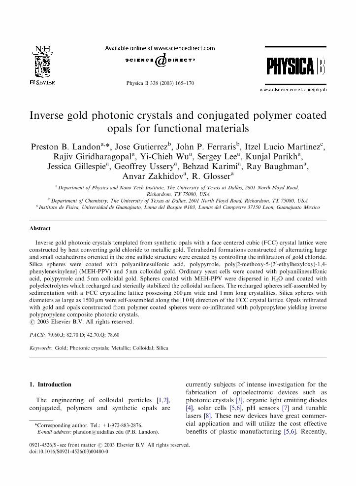
Physica B 338 (2003) 165–170 Inverse gold photonic crystals and conjugated polymer coated opals for functional materials Preston B. Landon a, *, Jose Gutierrez b , John P. Ferraris b , Itzel Lucio Martinez c , Rajiv Giridharagopal a , Yi-Chieh Wu a , Sergey Lee a , Kunjal Parikh a , Jessica Gillespie a , Geoffrey Ussery a , Behzad Karimi a , Ray Baughman a , Anvar Zakhidov a , R. Glosser a a Department of Physics and Nano Tech Institute, The University of Texas at Dallas, 2601 North Floyd Road, Richardson, TX 75080, USA b Department of Chemistry, The University of Texas at Dallas, 2601 North Floyd Road, Richardson, TX 75080, USA c Instituto de Fisica, Universidad de Guanajuato, Loma del Bosque #103, Lomas del Campestre 37150 Leon, Guanajuato Mexico Abstract Inverse gold photonic crystals templated from synthetic opals with a face centered cubic (FCC) crystal lattice were constructed by heat converting gold chloride to metallic gold. Tetrahedral formations constructed of alternating large and small octahedrons oriented in the zinc sulfide structure were created by controlling the infiltration of gold chloride. Silica spheres were coated with polyanilinesulfonic acid, polypyrrole, poly[2-methoxy-5-(2 0 -ethylhexyloxy)-1,4- phenylenevinylene] (MEH-PPV) and 5 nm colloidal gold. Ordinary yeast cells were coated with polyanilinesulfonic acid, polypyrrole and 5 nm colloidal gold. Spheres coated with MEH-PPV were dispersed in H 2 O and coated with polyelectrolytes which recharged and sterically stabilized the colloidal surfaces. The recharged spheres self-assembled by sedimentation with a FCC crystalline lattice possessing 500 mm wide and 1 mm long crystallites. Silica spheres with diameters as large as 1500 mm were self-assembled along the [1 0 0] direction of the FCC crystal lattice. Opals infiltrated with gold and opals constructed from polymer coated spheres were co-infiltrated with polypropylene yielding inverse polypropylene composite photonic crystals. r 2003 Elsevier B.V. All rights reserved. PACS: 79.60.J; 82.70.D; 42.70.Q; 78.60 Keywords: Gold; Photonic crystals; Metallic; Colloidal; Silica 1. Introduction The engineering of colloidal particles [1,2], conjugated, polymers and synthetic opals are currently subjects of intense investigation for the fabrication of optoelectronic devices such as photonic crystals [3], organic light emitting diodes [4], solar cells [5,6], pH sensors [7] and tunable lasers [8]. These new devices have great commer- cial application and will utilize the cost effective benefits of plastic manufacturing [5,6]. Recently, ARTICLE IN PRESS *Corresponding author. Tel.: +1-972-883-2876. E-mail address: [email protected] (P.B. Landon). 0921-4526/$ - see front matter r 2003 Elsevier B.V. All rights reserved. doi:10.1016/S0921-4526(03)00480-0
-
Upload
independent -
Category
Documents
-
view
2 -
download
0
Transcript of Inverse gold photonic crystals and conjugated polymer coated opals for functional materials
ARTICLE IN PRESS
Physica B 338 (2003) 165–170
*Corresp
E-mail a
0921-4526/$
doi:10.1016
Inverse gold photonic crystals and conjugated polymer coatedopals for functional materials
Preston B. Landona,*, Jose Gutierrezb, John P. Ferrarisb, Itzel Lucio Martinezc,Rajiv Giridharagopala, Yi-Chieh Wua, Sergey Leea, Kunjal Parikha,
Jessica Gillespiea, Geoffrey Usserya, Behzad Karimia, Ray Baughmana,Anvar Zakhidova, R. Glossera
aDepartment of Physics and Nano Tech Institute, The University of Texas at Dallas, 2601 North Floyd Road,
Richardson, TX 75080, USAbDepartment of Chemistry, The University of Texas at Dallas, 2601 North Floyd Road, Richardson, TX 75080, USA
c Instituto de Fisica, Universidad de Guanajuato, Loma del Bosque #103, Lomas del Campestre 37150 Leon, Guanajuato Mexico
Abstract
Inverse gold photonic crystals templated from synthetic opals with a face centered cubic (FCC) crystal lattice were
constructed by heat converting gold chloride to metallic gold. Tetrahedral formations constructed of alternating large
and small octahedrons oriented in the zinc sulfide structure were created by controlling the infiltration of gold chloride.
Silica spheres were coated with polyanilinesulfonic acid, polypyrrole, poly[2-methoxy-5-(20-ethylhexyloxy)-1,4-
phenylenevinylene] (MEH-PPV) and 5 nm colloidal gold. Ordinary yeast cells were coated with polyanilinesulfonic
acid, polypyrrole and 5 nm colloidal gold. Spheres coated with MEH-PPV were dispersed in H2O and coated with
polyelectrolytes which recharged and sterically stabilized the colloidal surfaces. The recharged spheres self-assembled by
sedimentation with a FCC crystalline lattice possessing 500mm wide and 1mm long crystallites. Silica spheres with
diameters as large as 1500mm were self-assembled along the [1 0 0] direction of the FCC crystal lattice. Opals infiltrated
with gold and opals constructed from polymer coated spheres were co-infiltrated with polypropylene yielding inverse
polypropylene composite photonic crystals.
r 2003 Elsevier B.V. All rights reserved.
PACS: 79.60.J; 82.70.D; 42.70.Q; 78.60
Keywords: Gold; Photonic crystals; Metallic; Colloidal; Silica
1. Introduction
The engineering of colloidal particles [1,2],conjugated, polymers and synthetic opals are
onding author. Tel.: +1-972-883-2876.
ddress: [email protected] (P.B. Landon).
- see front matter r 2003 Elsevier B.V. All rights reserve
/S0921-4526(03)00480-0
currently subjects of intense investigation for thefabrication of optoelectronic devices such asphotonic crystals [3], organic light emitting diodes[4], solar cells [5,6], pH sensors [7] and tunablelasers [8]. These new devices have great commer-cial application and will utilize the cost effectivebenefits of plastic manufacturing [5,6]. Recently,
d.

ARTICLE IN PRESS
P.B. Landon et al. / Physica B 338 (2003) 165–170166
photonic crystals have been constructed fromconjugated polymers by infiltrating synthetic opalswith a monomer and initiating the polymerizationprocess [9].Colloidal surfaces can easily be modified with
polymers [10] or polyelectrolytes [1,2]. Polyelec-trolytes have been used to create hollow core-shell particles by electrostatistically adsorbingsuccessive layers of small nanoparticles onto muchlarger polystyrene spheres serving as removabletemplates [1]. This layer-by-layer technique hasbeen used to create hollow spherical colloidscomposed of inorganic and organic constituentsincluding luminescent materials [8]. Hollow colloi-dal particles are being used in a number ofapplications including photonic crystals and drugcarriers.
Fig. 2. A zinc blende structure formed from large and small
gold octahedrons held together by thin gold wires.
2. Inverse gold photonic crystals
Synthetic opals were fabricated from 290 nmcolloidal silica spheres, obtained from NissanChemical Company (MP-3040) Lot #100116. Wedo not know the coefficient of variation for thediameter of the spheres; however, to increase theirsize uniformity the spheres were repeatedly sedi-mented and the upper portion of spheres wasdiscarded. The final opals were sedimented forseveral months as 3–6% v/v dispersions in aqueoussolutions with a pH of 8.6 and a conductivity of0.6–2mS. After the colloidal silica spheres sedi-mented they were slowly dried and sintered.The synthetic opals created from 290 nm silica
spheres were infiltrated with metallic gold and the
Fig. 1. Inverse gold photonic crystal fabricated from a
synthetic opal template composed of 290 nm silica spheres.
silica spheres were removed with hydrofluoric acid(Fig. 1). The gold was infiltrated as gold chlorideand converted to metallic gold by a three stepheating process. Aqueous gold chloride was slowlysimmered at 90�C when the gold chloride solutionbecame dark red the temperature was increased to180�C until it turned to a golden solid. The goldfilled opals were then annealed at 350�C forseveral hours. The gold chloride was producedby dissolving 99.9% pure gold in a 41:9 mixture ofconcentrated hydrochloric acid (HCl) and nitricacid (HNO3).Due to the density difference of gold and gold
chloride, the maximum possible filling factor witha single infiltration and heat conversion of goldchloride is 39%. The packing of the gold in thevoids between the spheres of the opal wascontrolled by removing the opal from the solutionduring the simmering process.
Fig. 3. Close up of the gold octahedrons with a tetrahedral
orientation held together by thin gold wires.
ARTICLE IN PRESS
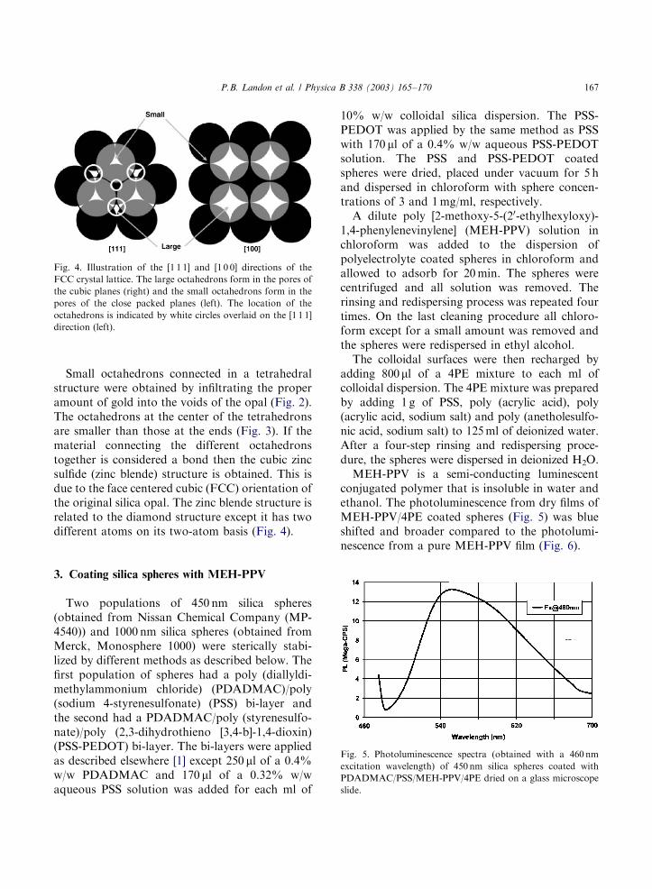
Fig. 4. Illustration of the [1 1 1] and [1 0 0] directions of the
FCC crystal lattice. The large octahedrons form in the pores of
the cubic planes (right) and the small octahedrons form in the
pores of the close packed planes (left). The location of the
octahedrons is indicated by white circles overlaid on the [1 1 1]
direction (left).
P.B. Landon et al. / Physica B 338 (2003) 165–170 167
Small octahedrons connected in a tetrahedralstructure were obtained by infiltrating the properamount of gold into the voids of the opal (Fig. 2).The octahedrons at the center of the tetrahedronsare smaller than those at the ends (Fig. 3). If thematerial connecting the different octahedronstogether is considered a bond then the cubic zincsulfide (zinc blende) structure is obtained. This isdue to the face centered cubic (FCC) orientation ofthe original silica opal. The zinc blende structure isrelated to the diamond structure except it has twodifferent atoms on its two-atom basis (Fig. 4).
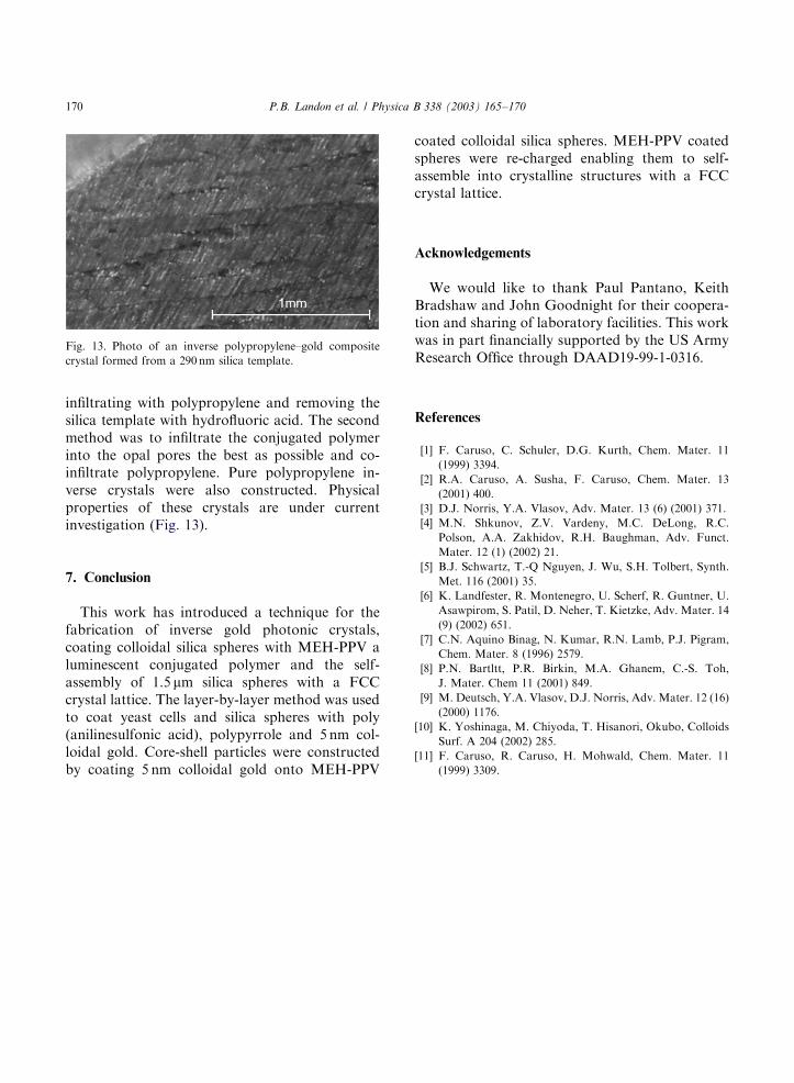
Fig. 5. Photoluminescence spectra (obtained with a 460nm
excitation wavelength) of 450 nm silica spheres coated with
PDADMAC/PSS/MEH-PPV/4PE dried on a glass microscope
slide.
3. Coating silica spheres with MEH-PPV
Two populations of 450 nm silica spheres(obtained from Nissan Chemical Company (MP-4540)) and 1000 nm silica spheres (obtained fromMerck, Monosphere 1000) were sterically stabi-lized by different methods as described below. Thefirst population of spheres had a poly (diallyldi-methylammonium chloride) (PDADMAC)/poly(sodium 4-styrenesulfonate) (PSS) bi-layer andthe second had a PDADMAC/poly (styrenesulfo-nate)/poly (2,3-dihydrothieno [3,4-b]-1,4-dioxin)(PSS-PEDOT) bi-layer. The bi-layers were appliedas described elsewhere [1] except 250 ml of a 0.4%w/w PDADMAC and 170 ml of a 0.32% w/waqueous PSS solution was added for each ml of
10% w/w colloidal silica dispersion. The PSS-PEDOT was applied by the same method as PSSwith 170 ml of a 0.4% w/w aqueous PSS-PEDOTsolution. The PSS and PSS-PEDOT coatedspheres were dried, placed under vacuum for 5 hand dispersed in chloroform with sphere concen-trations of 3 and 1mg/ml, respectively.A dilute poly [2-methoxy-5-(20-ethylhexyloxy)-
1,4-phenylenevinylene] (MEH-PPV) solution inchloroform was added to the dispersion ofpolyelectrolyte coated spheres in chloroform andallowed to adsorb for 20min. The spheres werecentrifuged and all solution was removed. Therinsing and redispersing process was repeated fourtimes. On the last cleaning procedure all chloro-form except for a small amount was removed andthe spheres were redispersed in ethyl alcohol.The colloidal surfaces were then recharged by
adding 800ml of a 4PE mixture to each ml ofcolloidal dispersion. The 4PE mixture was preparedby adding 1 g of PSS, poly (acrylic acid), poly(acrylic acid, sodium salt) and poly (anetholesulfo-nic acid, sodium salt) to 125ml of deionized water.After a four-step rinsing and redispersing proce-dure, the spheres were dispersed in deionized H2O.MEH-PPV is a semi-conducting luminescent
conjugated polymer that is insoluble in water andethanol. The photoluminescence from dry films ofMEH-PPV/4PE coated spheres (Fig. 5) was blueshifted and broader compared to the photolumi-nescence from a pure MEH-PPV film (Fig. 6).

ARTICLE IN PRESS
Fig. 6. Photoluminescence spectra obtained with a 460 nm
excitation wavelength from a dry film of pure MEH-PPV.
Fig. 7. SEM image of 450 nm spheres coated with MEH-PPV
and three layers of 5 nm colloidal gold.
Fig. 8. An SEM image of a film of 450 nm silica spheres coated
with PDADMAC/PSS/MEHPPV. The 2.5mm wide W-shaped
burned into the film with the SEM.
P.B. Landon et al. / Physica B 338 (2003) 165–170168
Silica spheres with an outer MEH-PPV coatingin H2O were coated with four layers of polyelec-trolytes consisting of PSS/PDADMAC/PSS/PDADMAC with the four-step cleaning procedurein between the application of each polyelectrolytelayer. The PSS and PDADMAC were applied byadding 100 ml of the previously prepared solutionsfor each ml of MEH-PPV coated spheres in H2Owith a sphere concentration of 3mg/ml. Singlelayers of 5 nm colloidal gold were electrostaticallyadsorbed to the outer PDADMAC layer on thesurface of the spheres by adding 100 ml of colloidalgold as supplied by Aldrichs for each ml ofdispersion [11]. Unadsorbed colloidal gold wasremoved by repeating the usual cleaning procedurefour times. A total of three layers of colloidal goldwere deposited by coating a layer consisting ofPDADMAC/PSS/PDADMAC on the spheresprior to the adsorption of each layer of goldparticles (Fig. 7).SEM images of PDADMAC/PSS/MEH-PPV
coated spheres taken without a conductive layershowed bright regions from electron charging inareas that had previously been observed with highmagnification. The bombardment from the elec-trons in the SEM permanently scarred the surfacesof the MEH-PPV coated spheres. Electrostaticcharge builds on the surfaces of the non-conduc-tive silica spheres and is visible as bright regions inthe SEM images. An SEM image of a region wherecharging occurred as a result of burning the MEH-PPV off the coated spheres in a zigzag shape
demonstrates the controllability of the MEH-PPVburning (Fig. 8). The scarring of the spheresurfaces was not observed with the MEH-PPVcoated spheres which were also coated with threelayers of colloidal gold.
4. Coating conjugated polymers in H2O
Colloidal silica spheres and ordinary bakingyeast cells were coated with poly (anilinesulfonicacid) (PASA) and polypyrrole (PPY) by firstapplying PDADMAC as described in the previoussection. Once coated with PDADMAC, dilutesolutions of aqueous PPY and PASA were added,allowed to adsorb for 20min and followed by thefour-step cleaning procedure. The process wasrepeated three times yielding colloidal silicaspheres and yeast cells coated with three layers

ARTICLE IN PRESS
Fig. 10. Opalescent crystallites formed by self-assembly of
450 nm silica spheres coated with MEH-PPV and polyelec-
trolytes.
Fig. 11. Photo of crystallites in a synthetic opal composed of
1.5 mm silica spheres.
Fig. 12. SEM image of ordered 1.5 mm silica spheres coated
with polyelectrolytes and self-assembled by sedimentation.
Fig. 9. SEM image of a Yeast cell coated with three layers of
PDADMAC/PPY/PDADMAC and 5 nm colloidal cold.
P.B. Landon et al. / Physica B 338 (2003) 165–170 169
of PDADMAC/PPY and PDADMAC/PASA(Fig. 9).
5. Self-assembly of polymer coated spheres
Colloidal silica spheres coated with PASA, PPYand MEH-PPV were coated with polyelectrolytesand assembled with crystalline order (Fig. 10). Itshould be noted that the MEH-PPV coatedspheres oxidize and lose most of their lumines-cence after several months. We have not studiedthe oxidation rate in detail.Crystallites were formed with 450 and 1000 nm
silica spheres that had PDADMAC, PSS or 4PE asthe outer coating. The crystalline order arises bycontrolling the polyelectrolyte coating, pH, elec-trolyte concentration and sphere v/v concentra-
tions. We used polyelectrolytes to assist in the self-assembly of 1.5 mm silica spheres with a FCCcrystal lattice possessing 1mm wide and 3mm longcrystallites (Figs. 11 and 12). The crystallites grewvertically along the [1 0 0] direction of the FCClattice.
6. Inverse polymer composite photonic crystals
Inverse composite polypropylene photonic crys-tals of MEH-PPV, PASA, PPY and gold wereconstructed by two different methods. The firstmethod was by self-assembling colloidal silicaspheres pre-coated with a conjugated polymer,
ARTICLE IN PRESS
Fig. 13. Photo of an inverse polypropylene–gold composite
crystal formed from a 290 nm silica template.
P.B. Landon et al. / Physica B 338 (2003) 165–170170
infiltrating with polypropylene and removing thesilica template with hydrofluoric acid. The secondmethod was to infiltrate the conjugated polymerinto the opal pores the best as possible and co-infiltrate polypropylene. Pure polypropylene in-verse crystals were also constructed. Physicalproperties of these crystals are under currentinvestigation (Fig. 13).
7. Conclusion
This work has introduced a technique for thefabrication of inverse gold photonic crystals,coating colloidal silica spheres with MEH-PPV aluminescent conjugated polymer and the self-assembly of 1.5 mm silica spheres with a FCCcrystal lattice. The layer-by-layer method was usedto coat yeast cells and silica spheres with poly(anilinesulfonic acid), polypyrrole and 5 nm col-loidal gold. Core-shell particles were constructedby coating 5 nm colloidal gold onto MEH-PPV
coated colloidal silica spheres. MEH-PPV coatedspheres were re-charged enabling them to self-assemble into crystalline structures with a FCCcrystal lattice.
Acknowledgements
We would like to thank Paul Pantano, KeithBradshaw and John Goodnight for their coopera-tion and sharing of laboratory facilities. This workwas in part financially supported by the US ArmyResearch Office through DAAD19-99-1-0316.
References
[1] F. Caruso, C. Schuler, D.G. Kurth, Chem. Mater. 11
(1999) 3394.
[2] R.A. Caruso, A. Susha, F. Caruso, Chem. Mater. 13
(2001) 400.
[3] D.J. Norris, Y.A. Vlasov, Adv. Mater. 13 (6) (2001) 371.
[4] M.N. Shkunov, Z.V. Vardeny, M.C. DeLong, R.C.
Polson, A.A. Zakhidov, R.H. Baughman, Adv. Funct.
Mater. 12 (1) (2002) 21.
[5] B.J. Schwartz, T.-Q Nguyen, J. Wu, S.H. Tolbert, Synth.
Met. 116 (2001) 35.
[6] K. Landfester, R. Montenegro, U. Scherf, R. Guntner, U.
Asawpirom, S. Patil, D. Neher, T. Kietzke, Adv. Mater. 14
(9) (2002) 651.
[7] C.N. Aquino Binag, N. Kumar, R.N. Lamb, P.J. Pigram,
Chem. Mater. 8 (1996) 2579.
[8] P.N. Bartltt, P.R. Birkin, M.A. Ghanem, C.-S. Toh,
J. Mater. Chem 11 (2001) 849.
[9] M. Deutsch, Y.A. Vlasov, D.J. Norris, Adv. Mater. 12 (16)
(2000) 1176.
[10] K. Yoshinaga, M. Chiyoda, T. Hisanori, Okubo, Colloids
Surf. A 204 (2002) 285.
[11] F. Caruso, R. Caruso, H. Mohwald, Chem. Mater. 11
(1999) 3309.