
Reproducibility of magnetic resonance fingerprinting-based ...
Upload
independentCategory
view
4download
0
P1: FPX/fty/ftt P2: FhN
June 17, 2000 9:45 Annual Reviews AR106-24
?Annu. Rev. Biomed. Eng. 2000. 02:661–90
INTERVENTIONAL AND INTRAOPERATIVE
MAGNETIC RESONANCE IMAGING1
J. Kettenbach2,8, D. F. Kacher2,3, S. K. Koskinen4,Stuart G. Silverman3, A. Nabavi2,6,7, Dave Gering5,Clare M. C. Tempany3, R. B. Schwartz3, R. Kikinis2,3,P. M. Black7, and F. A. Jolesz2,32Surgical Planning Laboratory, Department of Radiology, and3Department of Radiology,Brigham and Women’s Hospital, Harvard Medical School, Boston, Massachusetts 02115;4Department of Radiology, Helsinki University Central Hospital, Helsinki, Finland;5Artificial Intelligence-Laboratory, Massachusetts Institute of Technology, Cambridge,Massachusetts 02159;6Division of Neurosurgery, Brigham and Women’s Hospital,Harvard Medical School, Boston, Massachusetts 02115;7Department of Neurosurgery,University of Kiel, Kiel, Germany;8Division of Interventional Radiology andAngiography, Department of Radiology, University Hospital of Vienna, Vienna, Austria;e-mail: [email protected]; [email protected]
Key Words MRI, interventional MRI, minimally invasive therapy, image-guidedtherapy
■ Abstract The goal of the Image Guided Therapy Program, as the name implies,is to develop the use of imaging to guide minimally invasive therapy. The programcombines interventional and intraoperative magnetic resonance imaging (MRI) withhigh-performance computing and novel therapeutic devices. In clinical practice themultidisciplinary program provides for the investigation of a wide range of interven-tional and surgical procedures. The Signa SP 0.5 T superconducting MRI system (GEMedical Systems, Milwaukee, WI) has a 56-cm-wide vertical gap, allowing access tothe patient and permitting the execution of interactive MRI-guided procedures. Thissystem is integrated with an optical tracking system and utilizes flexible surface coilsand MRI-compatible displays to facilitate procedures. Images are obtained with routinepulse sequences. Nearly real-time imaging, with fast gradient-recalled echo sequences,may be acquired at a rate of one image every 1.5 s with interactive image plane selection.Since 1994, more than 800 of these procedures, including various percutaneous proce-dures and open surgeries, have been successfully performed at Brigham and Women’sHospital (Boston, MA).
1The US Government has the right to retain a nonexclusive, royalty-free license in and toany copyright covering this paper.
661

P1: FPX/fty/ftt P2: FhN
June 17, 2000 9:45 Annual Reviews AR106-24
?662 KETTENBACH ET AL
CONTENTS
INTRODUCTION . . . . . . . . . . . . . . . . . . . . . . . . . . . . . . . . . . . . . . . . . . . . . . . . 662INTERVENTIONAL MRI DESIGN FEATURES. . . . . . . . . . . . . . . . . . . . . . . . . . 662
Anesthesia Considerations. . . . . . . . . . . . . . . . . . . . . . . . . . . . . . . . . . . . . . . . 666Pulse Sequences. . . . . . . . . . . . . . . . . . . . . . . . . . . . . . . . . . . . . . . . . . . . . . . . 666Interventional and Surgical Devices. . . . . . . . . . . . . . . . . . . . . . . . . . . . . . . . . . 666
INTERACTIVE IMAGING AND REAL-TIME GUIDANCE . . . . . . . . . . . . . . . . . 667CLINICAL EXPERIENCE. . . . . . . . . . . . . . . . . . . . . . . . . . . . . . . . . . . . . . . . . . 668
MRI-Guided Biopsy and Drainage Procedures. . . . . . . . . . . . . . . . . . . . . . . . . . 669Functional Imaging . . . . . . . . . . . . . . . . . . . . . . . . . . . . . . . . . . . . . . . . . . . . . 673Monitoring and Control of Magnetic Resonance Imaging-Guided
Thermal Ablation. . . . . . . . . . . . . . . . . . . . . . . . . . . . . . . . . . . . . . . . . . . . . . 675Magnetic Resonance-Assisted Surgical Procedures. . . . . . . . . . . . . . . . . . . . . . . 678Studying Brain Shift. . . . . . . . . . . . . . . . . . . . . . . . . . . . . . . . . . . . . . . . . . . . . 683Augmenting Interventional Magnetic Resonance Imaging with the 3D-Slicer. . . . 683
DISCUSSION. . . . . . . . . . . . . . . . . . . . . . . . . . . . . . . . . . . . . . . . . . . . . . . . . . . 685CONCLUSION. . . . . . . . . . . . . . . . . . . . . . . . . . . . . . . . . . . . . . . . . . . . . . . . . . 685
INTRODUCTION
With the increasing use of minimally invasive procedures, there is a strong demandfor imaging techniques that can be used to visualize anatomy, interventional orsurgical devices, and therapeutic effects. To date, ultrasound, fluoroscopy, andcomputed tomography have been the preferred modalities for image guidance ofpercutaneous interventional procedures and for some surgeries. Although each ofthese imaging techniques offers some specific advantages and drawbacks, theirutility is limited (Table 1).
Magnetic resonance (MR) imaging (MRI) offers excellent soft-tissue discrimi-nation, which can be enhanced with specific contrast agents, multiplanar imaging,and a high spatial and temporal resolution. Blood vessels can be reliably visual-ized either with contrast agents or by using the inherent sensitivity of MRI to flow.MRI parameters are also sensitive to temperature, and thermally induced phasetransitions can be relatively easily recognized with MRI. Today, MRI has thegreatest potential for monitoring interventional and surgical procedures, provid-ing the impetus for the development of dedicated systems for MRI-guided therapy(1). These systems include percutaneous, endoscopic, open-surgical interventions,and various thermal ablations.
INTERVENTIONAL MRI DESIGN FEATURES
The ideal interventional MRI unit allows almost unlimited direct access to thepatient from all the sides, while enabling the operators to obtain high-resolutionimages in any desired plane nearly in real time. The system should emulate theadvantages of other competing image guidance systems by providing multiplanar,

P1: FPX/fty/ftt P2: FhN
June 17, 2000 9:45 Annual Reviews AR106-24
?INTERVENTIONAL & INTEROPERATIVE MRI 663
TABLE 1 Advantages and disadvantages of imaging methods
Imaging method Advantages Disadvantages
Ultrasound Commonly available Lower spatial and contrast resolutionNo radiation Cannot be used in imaging of boneLow cost and air-filled spacesReal-time imaging Limited use for thermal monitoringEasy access to the patient
Fluoroscopy Real-time imaging RadiationBone imaging No multiplanar imaging (projection)
Insufficient contrast resolution forsoft tissues
Computed tomography Excellent for bony Radiationstructures Limited multiplanar visualization
Reliable geometrical Limited soft-tissue contrastvisualization Not sensitive to temperature
Stereotactic procedures Limited access to patient duringfeasible imaging
Magnetic resonance Excellent soft-tissue Costimaging (closed system) contrast No access to patient during imaging
Multiplanar imagingVery sensitive to flow,diffusion and temperature
Magnetic resonance Access to patient during Availabilityimaging (open system) imaging Cost
Nearly real-time imaging Limited field strengthMultiplanar imagingAdequate soft-tissuecontrast
Sensitive to temperatureNo ionizing radiation
interactively generated, high-spatial- and temporal-resolution images. In addition,the same standards of sterility and patient monitoring must be met as those inconventional operating rooms. Full access to anesthesia, monitoring, and life-support equipment must be available (1, 2). Several scanner configurations arecurrently used for MRI-guided procedures. These include (a) modification of theconventional high-field (1.5-T), long-bore configuration; (b) high-field (1.5-T),short-bore design; (c) low-field (0.1- to 0.3-T) and midfield (0.5- to 1.0-T) hori-zontal-gap open configuration; and (d) vertical-gap, mid-field (0.5-T) open con-figuration. These scanners are summarized in Table 2.
Although the conventional closed, long-bore configuration systems provide thehighest image quality, there is no direct intraprocedural patient access. However,this design is compatible with certain minimally invasive procedures, such as ther-mal ablations. Interstitial radio frequency (RF), laser, microwave, or cryoprobes
P1: FPX/fty/ftt P2: FhN
June 17, 2000 9:45 Annual Reviews AR106-24
?664 KETTENBACH ET AL
TABLE 2 Possible MRI configurations for interventional imaging
Configuration Field Access Advantages
Long bore (closed) 1–3 T No Highest image quality
Short bore (closed) 1.0–1.5 T Poor Fast gradients/cardiac/vascularapplications
Horizontal open gap 0.02–0.6 T Limited Safety and instrument compatibility
Vertical open gap 0.5 T Full Intraoperative imaging; flexiblepositioning
can be positioned before sliding the patient into the bore of the scanner. Thesubsequent high-field MRI can be used to monitor the thermal-ablation therapy.Alternatively, thermal ablation can be performed without a probe by using a fo-cused ultrasound system, which can be incorporated into the MRI scanner (3–5).The MRI-guided, focused ultrasound technique may be the ultimate minimallyinvasive therapy, as energy is delivered through the body surface and focuseddeeply, eliminating the need for insertion of any probe. The major disadvantageis the inability of ultrasound to penetrate gas-containing structures such as lungor bowel and the relative difficulty in transmitting acoustic energy through thebone.
The closed short-bore configuration with flanged bore openings permits slightlyimproved patient access and may be most useful for cardiac and vascular ap-plications and for some percutaneous approaches. Miniature endovascular coilsmounted on catheters permit tracking of the catheters as they are positioned withinthe vessels (6). Their position can be superimposed on flow-sensitive MR images,creating a “roadmap” type of catheter localization. In addition, endovascular coilsenable imaging of the vessel walls for evaluation of plaque and of patient responseto interventions such as angioplasty (7–11).
The horizontal open gap MRI design provides horizontal access to the patient,allowing most radiologic percutaneous procedures to be performed. The low fieldminimizes the need for shielding of equipment, but also potentially limits imagingcapability. The overlying magnet structure precludes open surgical procedureswhile the patient is within the imaging field, but intraoperative imaging is possibleby physically moving or swinging the table into and out of the MRI scanner toobtain images.
The Signa SP vertical-gap mid-field-strength MRI system was developed byGeneral Electric Medical Systems (Milwaukee, WI) in collaboration with Brighamand Women’s Hospital (Boston, MA) in 1993. This design is the only one thatpermits true intraoperative MRI without moving the patient (Figure 1), with theexception of extremely low-field, permanent-magnet, open-configuration scan-ners. The Signa SP has been described in detail elsewhere (2, 12) and consists oftwo vertically oriented superconducting coils separated by a 56-cm gap, withinwhich a 30-cm sphere of uniform static magnetic field is maintained for imaging.Because the superconducting material composing the magnet can be operated at a
P1: FPX/fty/ftt P2: FhN
June 17, 2000 9:45 Annual Reviews AR106-24
?INTERVENTIONAL & INTEROPERATIVE MRI 665
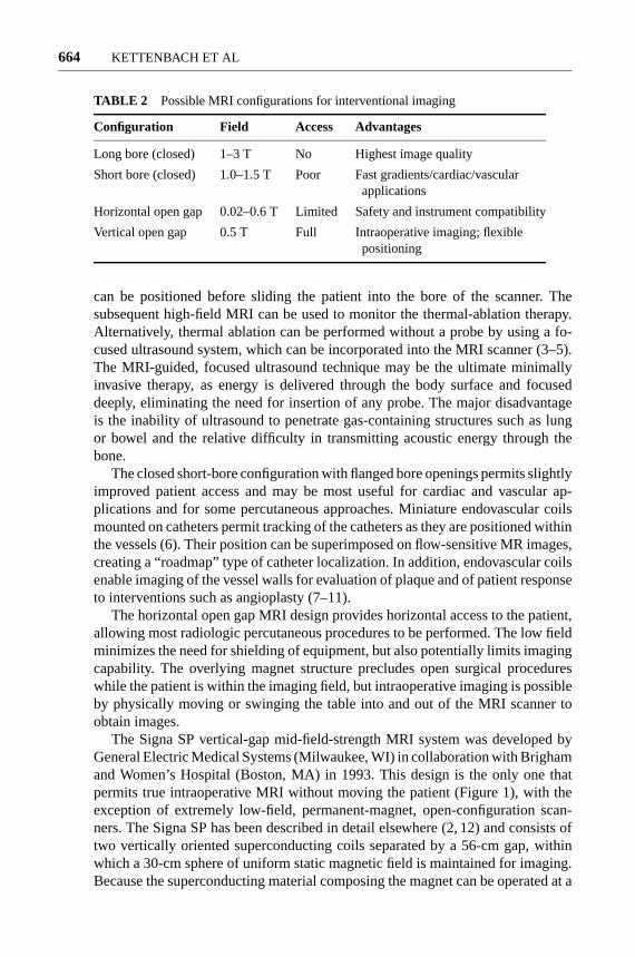
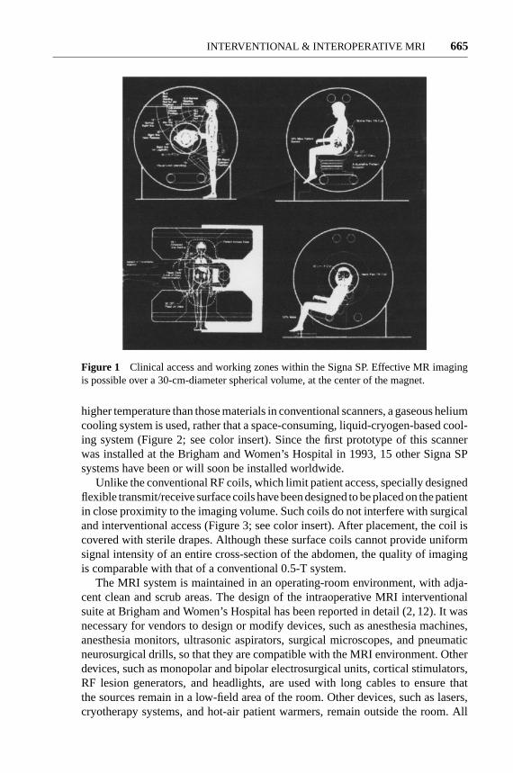
Figure 1 Clinical access and working zones within the Signa SP. Effective MR imagingis possible over a 30-cm-diameter spherical volume, at the center of the magnet.
higher temperature than those materials in conventional scanners, a gaseous heliumcooling system is used, rather that a space-consuming, liquid-cryogen-based cool-ing system (Figure 2; see color insert). Since the first prototype of this scannerwas installed at the Brigham and Women’s Hospital in 1993, 15 other Signa SPsystems have been or will soon be installed worldwide.
Unlike the conventional RF coils, which limit patient access, specially designedflexible transmit/receive surface coils have been designed to be placed on the patientin close proximity to the imaging volume. Such coils do not interfere with surgicaland interventional access (Figure 3; see color insert). After placement, the coil iscovered with sterile drapes. Although these surface coils cannot provide uniformsignal intensity of an entire cross-section of the abdomen, the quality of imagingis comparable with that of a conventional 0.5-T system.
The MRI system is maintained in an operating-room environment, with adja-cent clean and scrub areas. The design of the intraoperative MRI interventionalsuite at Brigham and Women’s Hospital has been reported in detail (2, 12). It wasnecessary for vendors to design or modify devices, such as anesthesia machines,anesthesia monitors, ultrasonic aspirators, surgical microscopes, and pneumaticneurosurgical drills, so that they are compatible with the MRI environment. Otherdevices, such as monopolar and bipolar electrosurgical units, cortical stimulators,RF lesion generators, and headlights, are used with long cables to ensure thatthe sources remain in a low-field area of the room. Other devices, such as lasers,cryotherapy systems, and hot-air patient warmers, remain outside the room. All

P1: FhN/FGI P2: FPX/FOK QC: FHN/fgm T1: FhN
July 31, 2000 13:35 Annual Reviews AR106-01
?Figure 2 The GE Signa SP 0.5 T MRI is designed for both interventional and intraoperativeprocedures. Constructed by two interconnected cryostats separated by a 56-cm gap, theSigma SP permits access to the patient during imaging. Depending on the procedure, thepatient table may be positioned coaxially or perpendicularly to the axis of the scanner. MR-compatible anesthesia equipment and MR-compatible instruments can be placed nearby.LCD screens to monitor imaging data during a procedure are mounted on both sides ofthe work area at eye level. (Courtesy of Gary Zientara, Ph.D., Department of Radiology,Brigham and Woman’s Hospital, Boston MA.)
P1: FhN/FGI P2: FPX/FOK QC: FHN/fgm T1: FhN
July 31, 2000 13:35 Annual Reviews AR106-01
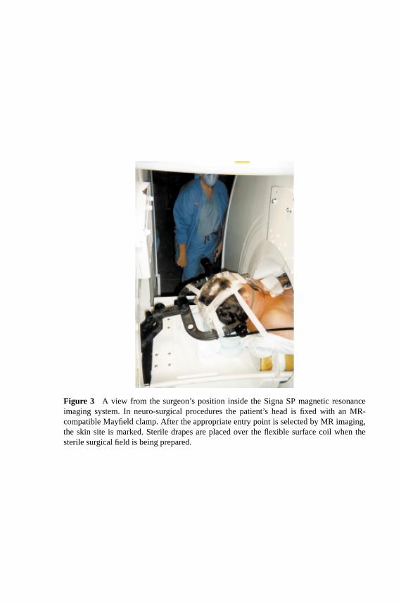
?Figure 3 A view from the surgeon’s position inside the Signa SP magnetic resonanceimaging system. In neuro-surgical procedures the patient’s head is fixed with an MR-compatible Mayfield clamp. After the appropriate entry point is selected by MR imaging,the skin site is marked. Sterile drapes are placed over the flexible surface coil when thesterile surgical field is being prepared.
P1: FPX/fty/ftt P2: FhN
June 17, 2000 9:45 Annual Reviews AR106-24
?666 KETTENBACH ET AL
hand-held instruments must be nonparamagnetic. Those instruments that remainin situ during imaging must be constructed from materials that do not cause sus-ceptibility artifacts in the images.
The environment of the MRI system permits it to be used for both interventionaland intraoperative applications. Although open surgery is, by definition, not aminimally invasive procedure, intraoperative image guidance can, in combinationwith accurate targeting and surgical planning, minimize the damage to healthytissue and maximize removal of the abnormality. In the remainder of this paper,we summarize our experience with MRI-guided interventional and intraoperativeprocedures, using the Signa SP.
Anesthesia Considerations
MRI-compatible anesthesia equipment is now commercially available from severalmanufacturers (13), and general anesthesia services have been established in manyMRI centers worldwide (14). Risk of burns from interactions of the scanner withelectrocardiograph (ECG) leads is significantly lower than with conventional high-field scanners, as reported by Keens & Laurence (15). Limitations in monitoringECG, however, remain a problem; it is difficult to achieve true lead I, II, and IIIwaveforms owing to the close placement of the electrodes that is necessitated bytheir use in the magnetic field (16). Furthermore, the magnetohydrodynamic effectof blood flowing through the heart creates an ECG artifact, masking indicationsof ischemia (17).
Pulse Sequences
Pulse sequences for guidance of interventional procedures have to be tailored to theinterventional or surgical procedures. Procedures that require relatively high tissuecontrast (T2 weighting) but only limited temporal resolution can be monitored withFast Spin Echo (FSE) techniques, which allow image acquisition in∼10 s.
Sequences that provide higher temporal resolution do so at the cost of spatial andcontrast resolution. These sequences include multiple gradient echo techniques.The acquisition time for these sequences is typically in the range of few seconds.In the future there will be a substantial role for limited k-space sampling methodsand for dynamic, adaptive-imaging sequences (18–20).
Interventional and Surgical Devices
Owing to the relatively high magnetic fields applied in magnetic resonance scan-ners, standard medical-grade stainless steel surgical instruments cannot be usedin these systems. Such instruments, with paramagnetic or ferromagnetic content,cause disturbing image artifacts owing to magnetic field inhomogeneities that arecreated by the susceptibility mismatch between tissue and the instrument. In addi-tion, these materials are subject to torque and displacement in the magnetic field.Some standard instruments are potential projectiles, possibly endangering both

P1: FPX/fty/ftt P2: FhN
June 17, 2000 9:45 Annual Reviews AR106-24
?INTERVENTIONAL & INTEROPERATIVE MRI 667
the patient and the operators. Therefore, several alloys and ceramic materials havebeen identified that may be safely used in an MRI environment. Certain alloyshave been developed to minimize image artifacts (21–25).
Passive visualization techniques take advantage of some residual device-inducedsusceptibility artifacts. The visualization is generally sufficient for biopsy anddrainage procedures. Passive visibility of these devices has been investigated atdifferent field strengths. For intravascular interventional procedures, active track-ing techniques are under development. Miniature RF coils can be integrated intodevices such as catheters and endoscopes. The position of these minicoils can thenbe localized with MRI in all three dimensions and nearly in real time (26).
INTERACTIVE IMAGING AND REAL-TIME GUIDANCE
Interactive imaging requires navigational tools. The principles of interactive-imageguidance, frameless stereotaxy, and navigation were established in neurosurgery,in which preoperative images were utilized. The Signa SP combines surgical nav-igation with nearly real-time imaging. Unlike procedures in the conventional op-erating room, a registration process between the patient and the images is notnecessary, because images are acquired in the surgical position of the patient.
An optical tracking device (Flashpoint 5000, Image Guided Technologies, Inc,Boulder, CO) is integrated into the Signa SP. Three high-resolution charge-coupleddevice video cameras located above the magnet’s isocenter detect the emissions oflight-emitting diodes (LEDs) on a hand-held interactive probe. A dedicated com-puter digitizes the position of each LED. Specialized image guidance softwareimplemented on an interactive workstation (Sun Microsystems, Mountain View,CA) uses these coordinates to control the scan plane of the nearly real-time imaging(Figure 4; see color insert). The workstation is capable of displaying a virtual instru-ment (e.g. biopsy needle or therapy probe) and its trajectory, overlaid on the image.
The accuracy of the navigation system has been strictly calibrated and main-tained within the working space, with a resolution of 1 mm. Interactive, nearlyreal-time imaging is accomplished by positioning an optically tracked hand pieceto determine an appropriate trajectory in three planes. Once a trajectory is chosen,a burr hole or craniotomy is drilled in the skull overlying the entry site.
The ideal approach to a lesion is determined by using a combination of thenearly real-time imaging and conventional serial-volume imaging. During brainsurgery, the operator can thereby successfully avoid vital vascular structures andcritical brain regions.
Depending on the MRI sequence selected, continuous scanning provides up-dated MR images every 2–20 s. Graphic annotation allows visualization of the“virtual needle” for trajectory planning. The “fast needle graphics” feature al-lows the user to make fine adjustments to the virtual needle trajectory, which isdisplayed in real time, between image acquisitions. These features facilitate thefeedback loop between the interventionalist or surgeon and the MRI system.

P1: FhN/FGI P2: FPX/FOK QC: FHN/fgm T1: FhN
July 31, 2000 6:45 Annual Reviews AR106-01
?Figure 4 (a) The infrared light-emitting diodes (LEDs) on the handheld tracking deviceare registered by charge-coupled device (CCD) cameras mounted above the image volume.The position of the probe is calculated, and images can be acquired in a so-called “in-plane0”, “in-plane 90” (the image plane is rotated along the probe’s axis), and in “perpendicular”to the probe. (b) The handheld tracking probe has LEDs located at the ends of the armsof the device. The probe is used to establish both the plane of imaging and the proposedtrajectory of a needle placed through the center (arrow) of the device.
P1: FPX/fty/ftt P2: FhN
June 17, 2000 9:45 Annual Reviews AR106-24
?668 KETTENBACH ET AL
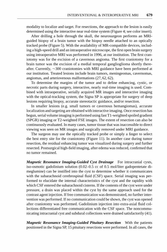
Interactive MRI can be used in several ways for planning and performing inter-ventional and surgical procedures. For interactive imaging, the physician uses theinteractive probes to navigate through the region of interest, in a manner similarto ultrasonography. Imaging planes can be obtained along the plane of the biopsyneedle (or interventional probe) or perpendicular to the needle axis (27, 28). Thistechnique is particularly useful for establishing the relationship between surfacelandmarks and underlying structures and planning the interventional or surgicalapproach. For targeting, the interactive probe is held stationary. Specific annotationis added to the acquired images. The trajectory and target can then be verified byimaging in three orthogonal planes. When the desired trajectory and target pointhave been established, the interventional probe can be advanced, and its progresscan be observed on the MR images as they are acquired in nearly real time andthat confirm satisfactory positioning of the biopsy needle or therapeutic probe(Figure 5).
To provide interactive information to the interventional radiologist or surgeon,a color liquid crystal display (LCD) screen is mounted on each side of the SignaSP at eye level. These screens can be used to display images directly from the MRIscanner, or they can display the nearly real-time images to the physician as theyare acquired (Figure 2; see color insert).
CLINICAL EXPERIENCE
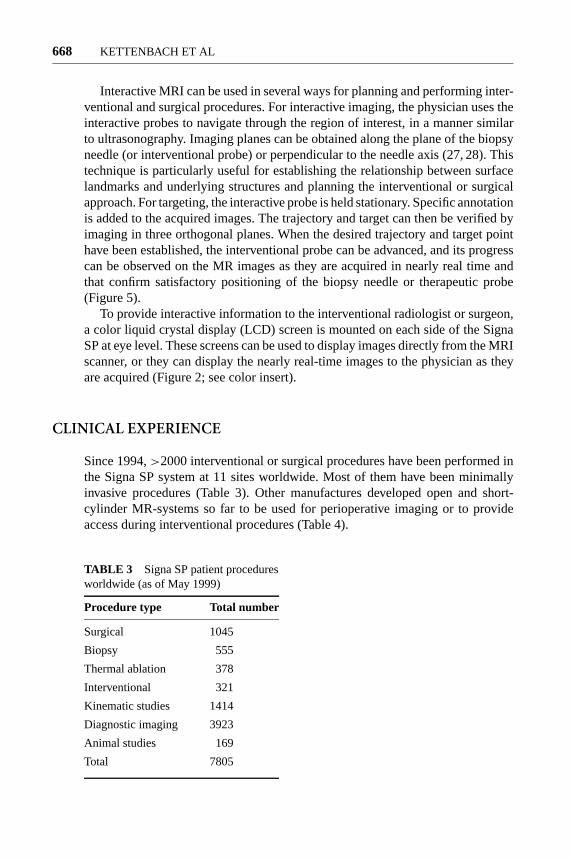
Since 1994,>2000 interventional or surgical procedures have been performed inthe Signa SP system at 11 sites worldwide. Most of them have been minimallyinvasive procedures (Table 3). Other manufactures developed open and short-cylinder MR-systems so far to be used for perioperative imaging or to provideaccess during interventional procedures (Table 4).
TABLE 3 Signa SP patient proceduresworldwide (as of May 1999)
Procedure type Total number
Surgical 1045
Biopsy 555
Thermal ablation 378
Interventional 321
Kinematic studies 1414
Diagnostic imaging 3923
Animal studies 169
Total 7805

P1: FPX/fty/ftt P2: FhN
June 17, 2000 9:45 Annual Reviews AR106-24
?INTERVENTIONAL & INTEROPERATIVE MRI 669
TABLE 4
System PatientVendor Field-strength Type of magnet Access aperture
Magnetom Open 0,2 T Resistive Horizontal 44 cmViva
Siemens AG
Outlook 0,23 T Resistive Horizontal 46 cmPicker-Nordstar
SIGNA Profile 0,2 T Resistive Horizontal 44 cmGeneral Electric
Airis 0,3 T Permanent Horizontal 50 cmHitachi
Quad 7000 0,35 T Resistive Horizontal 48 cmFonar
OPART 0,35 T Superconductive Horizontal 55 cmToshiba (cryogenless)
SIGNA SP 0,5 T Superconductive Vertical and axial 56 cmGeneral Electric (cryogenless) (limited)
Gyroscan ACS NT 1,5 T Superconductive Axial (limited) 60 cmPhilips magnet
Symphony 1.5 T Superconductive Axial (limited) 60 cmSiemens magnet
Signa MR/i 1.0–1.5 T Superconductive Axial (limited) 70 cmGeneral Electric magnet
MRI-Guided Biopsy and Drainage Procedures
When compared with ultrasound, computed tomography, and fluoroscopy, MRIguidance, at present, probably compares unfavorably in terms of procedure cost.This results primarily from the high initial capital investment for the installationof such a system. Nevertheless, some lesions are visualized only with MRI; MRIguidance is obviously the method of choice to biopsy those lesions that are difficultto access by standard imaging-guidance techniques.
Brain Biopsies For biopsies, the MR-compatible biopsy needle and trackingdevice are fixed to the flexible arm of an MR-compatible Bookwalter metallicarm (Codman, Boston, MA), which allows precise control of the needle as it ismanipulated using nearly real-time imaging. Alternatively, an adjustable targetingdevice that fixes to the skull may be used (Navigus, Image-Guided Neurologics,Inc., Melbourne, FL; Neurogate, Daum BmbH, Schwerin, Germany; Snapper,Magnetic Visions GmbH, Ruti, Switzerland).

P1: FPX/fty/ftt P2: FhN
June 17, 2000 9:45 Annual Reviews AR106-24
?670 KETTENBACH ET AL
(a) (b)
(c)
Figure 5 T1-weighted magnetic resonance images obtained during biopsy of an intracranial mass(glioblastoma), localized by using the interactive handheld tracking system with the integratedneedle holder. (a,b) Parasagittal and axial images show the planned trajectory (dashed line) of theneedle. (c) The biopsy needle itself as it is advanced into the lesion.
Contrast enhancing lesions, as revealed by high-field preprocedural imaging,may be biopsied under T1-weighted image guidance (7–10-s updates). Thoselesions that are nonenhancing, after the injection of gadolinium-DTPA (dimeg-lumingado penetrant), are biopsied by using T2-weighted FSE image guidance(14-s updates). Continuous imaging during biopsy procedures allows clinicians

P1: FPX/fty/ftt P2: FhN
June 17, 2000 9:45 Annual Reviews AR106-24
?INTERVENTIONAL & INTEROPERATIVE MRI 671
to be certain of the location of the biopsy needle when specimens are taken, thusobviating the need for multiple needle passes and frozen-tissue sectioning.
The first MRI-guided brain biopsy was performed in January 1996, at our insti-tution. In almost all patients undergoing brain biopsies that include interactive-MRIguidance, the procedure times are comparable to standard frame-based biopsies(27). In the mean time,>200 procedures have been successfully performed, in-cluding biopsy of lesions of the cortex, cerebellum, deep white matter, thalamus,basal ganglia, and brain stem. Currently, brain biopsies are performed by usingthe 3D Slicer, a software package that provides interactive navigation (discussedbelow). This system allows the easy definition of target and entry points and theselection of optimal needle trajectories. The 3D Slicer, used in conjunction withnearly real-time imaging and targeting devices, allows safe and effective biopsiesto be performed.
To date, there have been no long-term complications noted in our patient pop-ulation. In one patient undergoing biopsy, hemorrhage was noted in the operativesite, which necessitated conversion to a craniotomy and removal of the clot; thiscase demonstrated the importance of immediate feedback on post-procedure com-plications, which would have been unavailable without the use of interactive MRI.
Biopsies in the Head and Neck One area where MRI-guided biopsies have beenshown to be advantageous over computed tomography and ultrasound guidance isskull base lesions, in which beam hardening artifacts can make detection of lesionsdifficult and in which visualization by ultrasound is limited. MRI has been foundto be an ideal imaging method because it provides the ability to freely choose animaging plane and visualize blood vessels. Figure 5 illustrates an example of anintracranial biopsy performed with interactive MRI guidance. In this case, a tumorwas localized in the pineal region, using FSE T2-weighted imaging. Initially, atrajectory was selected before the insertion of the biopsy needle, by positioning thebiopsy guide equipped with optical tracking. A virtual needle with user-selectablelengths can then be displayed on the image to target the lesion. Once the trajectoryis established, the needle can be advanced to the target and observed in nearly realtime. Advancement is done in a stepwise manner as the needle approaches thetarget, an essential feature of frameless stereotaxy.
Abdominal/Pelvic Biopsies Abdominal/pelvic biopsies are performed in theMRI system in a manner similar to that using computed tomography or ultra-sound guidance. The multiplanar imaging capability of MRI is particularly usefulif a lesion is in the hepatic dome just below the diaphragm, which can be difficultto access with computed tomography or with ultrasound guidance (Figure 6).
Some lesions are visible only on MRI, making it the guidance modality ofchoice. Real-time, interactive scan plane selection and trajectory planning in anSigna SP provided obvious progress from previous cross-sectional biopsy methods(28). Our experience with MRI-guided interventions involving the genitourinarysystem is described elsewhere (29).

P1: FPX/fty/ftt P2: FhN
June 17, 2000 9:45 Annual Reviews AR106-24
?672 KETTENBACH ET AL
Figure 6 Trajectory planing for MRI-guided needle biopsy of the liver, on the Signa SP magneticresonance imaging system. The trajectory of the needle is predicted by thedotted white linesuperimposed on the image. The needle icon (solid white line) superimposed on the image duringthe intervention indicates the current location of the biopsy needle, determined by the optical-tracking system with LEDs (light-emitting-diodes) affixed to the biopsy needle holder. (Courtesyof Stuart G. Silverman, M.D., Department of Radiology, Brigham and Women’s Hospital, Boston,MA.)
Breast Biopsies MRI of the breast is evolving as a useful modality in certainclinical situations. Occasionally lesions may be seen only on MRI but not with anyother imaging method. Several guiding devices and breast immobilization tech-niques have been described to optimize MRI-guided breast interventions (30, 31).MRI can be used to place localization wires into tumors that are not visible withother modalities, before resection in the standard operating room (Figure 7). Re-cently, the Signa SP has been used to perform MRI-guided and excisional biopsyof breast lesions (32–34).
(a) (b)
Figure 7 (a) Breast image acquired in the Signa SP magnetic resonance imaging system withan open-access breast coil. MRI was necessary because the tumor could not be seen on any othermodality of imaging. (b) A localization wire placed under MRI guidance before lumpectomy wasperformed in the standard operating room.

P1: FPX/fty/ftt P2: FhN
June 17, 2000 9:45 Annual Reviews AR106-24
?INTERVENTIONAL & INTEROPERATIVE MRI 673
Musculoskeletal Biopsies The initial experience with MRI-guided musculoske-letal biopsies at the Brigham and Women’s Hospital has been published (28) andhas been shown to be of benefit in the guidance of biopsies in patients with my-opathies (35).
Drainage Procedures As early as biopsies in MRI guidance were investigated(36), interest in drainage procedures was aroused. Early reports described clinicalexperiences with a wire-sheath system for biopsies and drainages (37, 38). Ex-perience with MRI-guided catheter-based luminal interventions is experimentalto date. However, the first case of a successful percutaneous nephrostomy tubeplacement in a patient in an interventional MRI system was reported by our group(39). Further experiences in performing an MRI-guided cholecystostomy (40),MRI-guided drainage, and shunting of brain cysts (41) were recently reported.
Functional Imaging
The unique design of the vertical gap allows patients to be imaged in sittingpositions and allows joint movement without substantial limitations. MRI in asitting position was also useful for functional imaging of the female pelvis floor,including those of patients with urinary stress incontinence and prolapse.
Functional Imaging of Spine For dynamic and functional imaging of the spine,the patient’s upright sitting position is provided by an MR-compatible chair(Figure 1). In this study, the feasibility of obtaining functional MRI of the lumbarspine in an erect position and with flexion and extension was determined. Thirtysubjects (including five normal volunteers) were imaged in a sitting position whileperforming flexion and extension. The alterations in posterior disc margin, size ofneural foramina, and central canal were evaluated (42).
Although the foraminal size and posterior disc margins did not change apprecia-bly from supine to upright positions, with extension, there was an increased bulgein 27% of discs (40% of those with desiccation). The central canal size (50%) andforaminal size (27%) decreased with extension, especially at levels with disc desic-cation. Images obtained with the Signa SP were diagnostically adequate, althoughof inferior quality compared with those obtained with a conventional unit. Ourpreliminary results show the feasibility of obtaining diagnostic images of the erectlumbar spine with flexion and extension. The results are in agreement with thoseobtained from cadaveric studies. However, the utility of this method in diagnosticimaging of patients with low back pain remains to be determined.
Functional Imaging of Pelvis To determine the anatomic differences in pelvicfloor anatomy between continent women and women with stress incontinence,MRI in the supine and sitting positions in the Signa SP was used to assesswhether these anatomic differences depend on the position of the subject duringimaging.

P1: FPX/fty/ftt P2: FhN
June 17, 2000 9:45 Annual Reviews AR106-24
?674 KETTENBACH ET AL
T2-weighted images were obtained in the midline sagittal plane with subjectsat rest and at maximal pelvic floor strain (5-s updates), by using a modified FSEsequence. In the axial plane, thin-section T2-weighted images were obtained withsubjects at rest by using a standard FSE technique. Images were evaluated formobility of the urethra and bladder neck and for integrity of the vagina, levatorani, and supporting fascia.
Pelvic floor laxity and abnormalities of the supporting fascia were more com-mon in incontinent women than in continent women. Both descent of the bladderneck when subjects strained and the posterior urethrovesical angle were not sig-nificantly greater when subjects were measured in the sitting position(P< 0.1).Therefore, changes of pelvic floor laxity related to incontinence can be seen withsubjects in both the supine and the sitting positions, but are increased in the sittingposition (43, 44).
Functional Imaging of Pediatric Hips To evaluate the use of the Signa SP duringmanual positioning of the hip in Legg-Calve-Perthes disease, Jaramillo et al havestudied Legg-Calve-Perthes disease during manual positioning of the hip (45).Multipositional MRI and conventional arthrography were compared in the assess-ment of containment, femoroacetabular congruency, and femoral head deformity.While images of the hips in several positions were compared subjectively and ob-jectively, MRI correlated well with arthrography for overall subjective assessmentof severity of disease (r = 0.71; P= 0.01), with good interobserver agreement(κ = 0.65; P< 0.001). MRI images demonstrated all cases of hinge abductionshown arthrographically. However, MRI failed to depict one case of femoral headflattening, but correlated well with arthrography in the objective evaluation of jointfluid and lateral subluxation (r = 0.80; P< 0.01). In the evaluation of femoral headdeformity, functional imaging did not perform as well.
Functional Imaging of Patellofemoral Joints Imaging of patellofemoral jointswith quadriceps loading is recommended because associated contracting musclesand related soft-tissue structures can be evaluated (2, 46–49). Therefore, the im-proved sensitivity obtained with the dynamic technique can eventually lead tobetter therapeutic and surgical outcomes in patients with patellofemoral pain. Inthe current study, we describe a new method for kinematic MRI of patellofemoraljoints during active flexion and extension.
The subjects sit between two coils in the imaging chair with the knee supportedat isocenter by a crossbar. The optical-tracking system (described above) wasused to select the image slice plane and location interactively. This selection is ofimportance when imaging the patellofemoral joint, because a nonideal imagingplane may lead to misinterpretation of patellofemoral alignment (50).
Using a continuous fast-gradient-echo (FGR) sequence, kinematic studies maybe performed by having the subject hold the joint in position for the duration of asingle image, moving the joint during the subsequent image, and holding the newposition for the next image. Because images are rapid (<1 s) and the image slice is

P1: FPX/fty/ftt P2: FhN
June 17, 2000 9:45 Annual Reviews AR106-24
?INTERVENTIONAL & INTEROPERATIVE MRI 675
selected relative to the joint by the optical-tracking system, joint positioning can becontrolled by muscular action rather than external devices. Resistance or weightsmay be applied to the limb being imaged. To assess the accuracy of the optical-tracking system in keeping the selected axial-imaging plane in the patellofemoraljoints, we imaged the knee in three different flexion angles (45◦, 25◦, and 10◦). Ateach knee position, an additional crossbar was placed under to the lower leg, justsuperior to the ankle. The flexion angle was confirmed with a goniometer. Eithera circular coil with the extremity passing the coil or a flexible double loop coil,which was wrapped around the knee, was used.
The subject population comprised five asymptomatic volunteers (four malesand one female). Nine knees (five right and four left knees) were imaged. At 45◦
extension, a coronal image was used to localize the sagittal plane, followed bya midpatellar sagittal image. With the optical-tracking probe affixed to the leg,an axial gradient echo (GE) image (1-s updates) was then acquired with nearlyreal-time imaging, through the middle of the patellar articular cartilage. The kneewas passively moved to the next flexion angles, and axial imaging was repeated,maintaining the interactively chosen imaging plane.
These experiments demonstrate the potential of kinematic real-time imaging.We have shown still frames of a symptomatic subject with a provisional diagnosisof patellar malalignment (patellar lateralization). Furthermore, this new imagingmethod is an important step forward to more physiological imaging of joints.It will most likely improve the diagnostic accuracy in certain joint and spinaldisorders. Although the imaging plane was not kept at exactly the same position,the 3-mm difference may be considered acceptable for qualitative evaluation ofthe patellofemoral motion. Improved diagnostic accuracy has a direct impact onpatient care and surgical planning, eventually leading to improved quality of lifeand decreased health care costs.
Monitoring and Control of Magnetic ResonanceImaging-Guided Thermal Ablation
One of the greatest potentials of MRI is in monitoring the delivery of variousdestructive energies. Thermal monitoring is a particularly important application ofinterventional MRI. Thermal ablation techniques require not only good localizationand targeting but also quantitative spatiotemporal control of energy deposition,which in turn requires monitoring of the thermal changes and the resulting tissuealterations (51–53).
Hyperthermia is based on slight temperature elevation (∼41◦C), which requiresrelatively long homogenous thermal treatment of solid tumors. The main assump-tion of hyperthermia is that malignant cells have a higher sensitivity to thermaldamage than normal ones. The temperature sensitivity of various MRI parameters(T1, diffusion, and chemical shift) can be exploited for detecting temperaturechanges within the critical temperature range. Compared with hyperthermia, ther-mal surgery uses temperatures that are>56–60◦C, but for a short period only.

P1: FPX/fty/ftt P2: FhN
June 17, 2000 9:45 Annual Reviews AR106-24
?676 KETTENBACH ET AL
Above that temperature, proteins are denatured, and the resulting thermal coagu-lation causes irreversible tissue damage. Appropriate MRI sequences can demon-strate the normal margins surrounding thermal lesions, where the temperatureelevation is still too low to cause cell necrosis, and, most importantly, can differ-entiate tissue phase transitions (54, 55).
Laser Therapy A typical high-temperature ablative procedure is interstitial lasertherapy (ILT). This method can be direct continuation of a biopsy, because opticalfibers can be introduced via a biopsy needle. Other alternative thermal treatmentscan be achieved with RF or microwave heating, which also require the insertionof a probe(s). The delivery of the laser energy to the target volume results ina coagulative necrosis. Based on our experience, we have developed computer-assisted, temperature-sensitive MRI for interstitial laser therapy (54–56).
Clinical applications involving tumor ablation in the brain and liver have alreadybeen initiated. The Signa SP imaging system was used to guide and monitor theaccurate placement of the laser source (needle with optical fiber) at the targetedlesion. T1-weighted FSE and spoiled gradient-recalled echo sequence (SPGR)images, transferred to a research workstation from the MRI scanner, were used toreconstruct temperature mapping to monitor the effect of the laser ablation. Newlydeveloped software in the imaging system and the research workstation enabledrapid (27–221-ms) and on-line temperature image reconstruction.
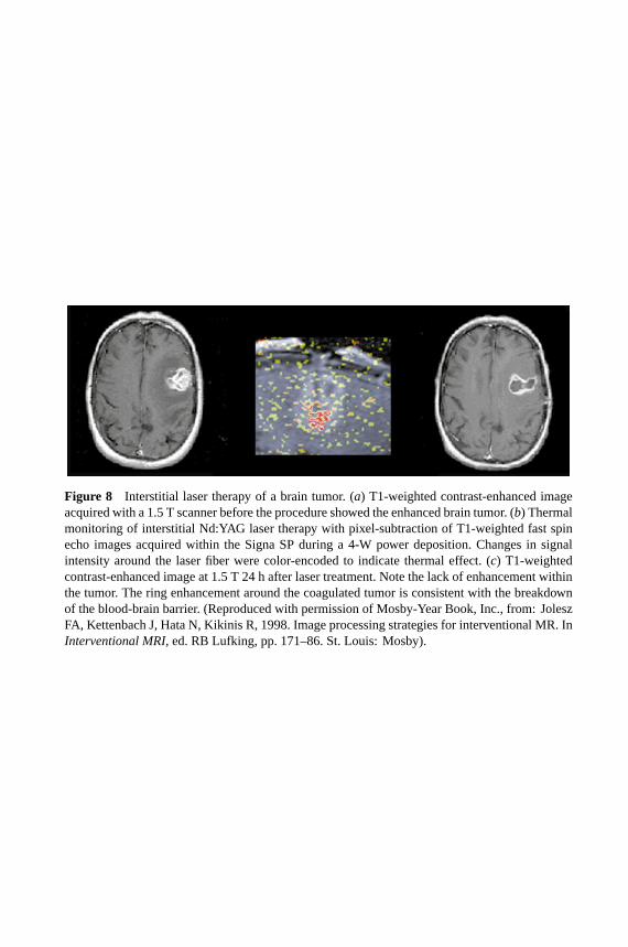
Because the T1 parameter is temperature dependent, simple subtraction of abaseline T1-weighted image from an image acquired during treatment can becalibrated to show the temperature of the treated tissue (Figure 8; see color insert).The temperature-dependent proton resonance frequency (PRF) shift is elucidatedby a complex phase subtraction of SPGR images. Given that the temperaturecoefficient of tumor tissue in vivo is∼−0.01 ppm/◦C, the relative temperatureelevation during laser therapy can be measured. The results of temperature mappingwere color coded and correlated to temperature in real time.
After the feasibility had been proven with animal experiments (51), several clin-ical applications of ILT in liver, brain, etc, have been published recently (52, 53).The preliminary study indicated that the presented system design is feasible forreal-time and on-line monitoring of interstitial laser therapy (55, 56).
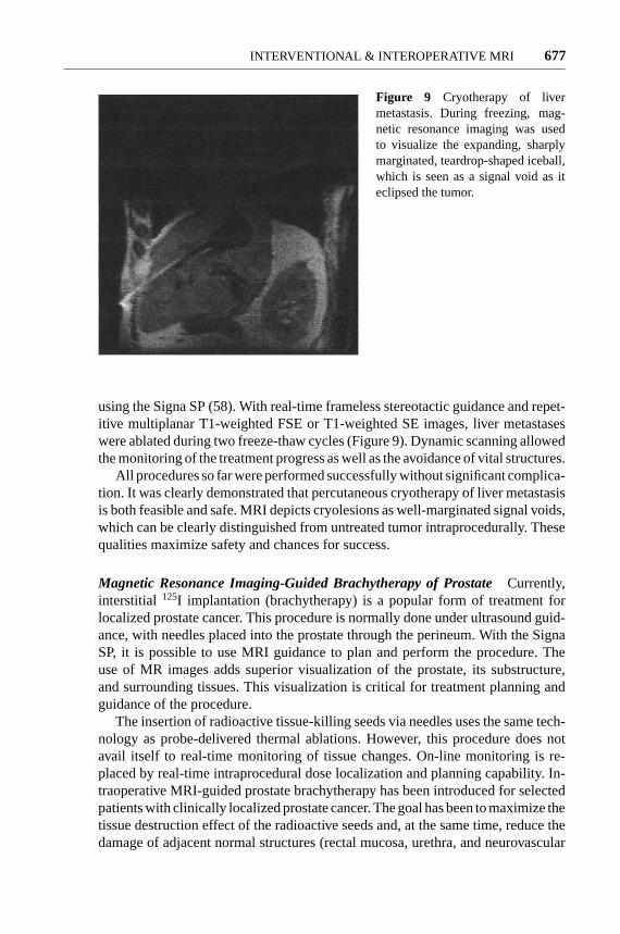
Magnetic Resonance Imaging-Guided CryotherapyCryotherapy is a freezing-based thermal method of ablation, which uses biopsy-like targeting as a first stepbefore a cryoprobe is introduced into the tumor. The frozen tissue is clearly visibleon MR images because the tissue water changes to solid ice crystals during theprocess. The solid ice crystals have an extremely short T2/T2
∗and give no mea-
surable MRI signal with typical imaging techniques. The expanding freezing zoneis therefore represented in MRI images by an increasing area of signal void.
Preliminary experiments done at Brigham and Women’s Hospital showed thefeasibility to monitor cryotherapy in liver in real time with MRI (57). Recently,Silverman et al described a new method for cryoablating tumors percutaneously,
P1: FhN/FGI P2: FPX/FOK QC: FHN/fgm T1: FhN
July 31, 2000 13:35 Annual Reviews AR106-01
?Figure 8 Interstitial laser therapy of a brain tumor. (a) T1-weighted contrast-enhanced imageacquired with a 1.5 T scanner before the procedure showed the enhanced brain tumor. (b) Thermalmonitoring of interstitial Nd:YAG laser therapy with pixel-subtraction of T1-weighted fast spinecho images acquired within the Signa SP during a 4-W power deposition. Changes in signalintensity around the laser fiber were color-encoded to indicate thermal effect. (c) T1-weightedcontrast-enhanced image at 1.5 T 24 h after laser treatment. Note the lack of enhancement withinthe tumor. The ring enhancement around the coagulated tumor is consistent with the breakdownof the blood-brain barrier. (Reproduced with permission of Mosby-Year Book, Inc., from: JoleszFA, Kettenbach J, Hata N, Kikinis R, 1998. Image processing strategies for interventional MR. InInterventional MRI, ed. RB Lufking, pp. 171–86. St. Louis: Mosby).
P1: FPX/fty/ftt P2: FhN
June 17, 2000 9:45 Annual Reviews AR106-24
?INTERVENTIONAL & INTEROPERATIVE MRI 677
Figure 9 Cryotherapy of livermetastasis. During freezing, mag-netic resonance imaging was usedto visualize the expanding, sharplymarginated, teardrop-shaped iceball,which is seen as a signal void as iteclipsed the tumor.
using the Signa SP (58). With real-time frameless stereotactic guidance and repet-itive multiplanar T1-weighted FSE or T1-weighted SE images, liver metastaseswere ablated during two freeze-thaw cycles (Figure 9). Dynamic scanning allowedthe monitoring of the treatment progress as well as the avoidance of vital structures.
All procedures so far were performed successfully without significant complica-tion. It was clearly demonstrated that percutaneous cryotherapy of liver metastasisis both feasible and safe. MRI depicts cryolesions as well-marginated signal voids,which can be clearly distinguished from untreated tumor intraprocedurally. Thesequalities maximize safety and chances for success.
Magnetic Resonance Imaging-Guided Brachytherapy of ProstateCurrently,interstitial 125I implantation (brachytherapy) is a popular form of treatment forlocalized prostate cancer. This procedure is normally done under ultrasound guid-ance, with needles placed into the prostate through the perineum. With the SignaSP, it is possible to use MRI guidance to plan and perform the procedure. Theuse of MR images adds superior visualization of the prostate, its substructure,and surrounding tissues. This visualization is critical for treatment planning andguidance of the procedure.
The insertion of radioactive tissue-killing seeds via needles uses the same tech-nology as probe-delivered thermal ablations. However, this procedure does notavail itself to real-time monitoring of tissue changes. On-line monitoring is re-placed by real-time intraprocedural dose localization and planning capability. In-traoperative MRI-guided prostate brachytherapy has been introduced for selectedpatients with clinically localized prostate cancer. The goal has been to maximize thetissue destruction effect of the radioactive seeds and, at the same time, reduce thedamage of adjacent normal structures (rectal mucosa, urethra, and neurovascular

P1: FPX/fty/ftt P2: FhN
June 17, 2000 9:45 Annual Reviews AR106-24
?678 KETTENBACH ET AL
bundle). By our hypothesis, this controlled-dose delivery will reduce the num-ber of complications usually associated with this procedure under ultrasoundguidance.
The prescribed minimum peripheral dose was 160 Gy to the clinical target vol-ume, which was the MR-defined peripheral zone (PZ) of the prostate gland. Byusing the Signa SP, 5-mm image planes that were obtained throughout the prostategland and the PZ of the prostate gland, anterior rectal wall, and prostatic urethrawere identified on the T2-weighted axial images. After imaging, an optimizedtreatment plan for catheter insertion was generated intraoperatively. Each cathetercontaining the125I sources was placed under real-time MRI guidance to ensurethat its position in the coronal, sagittal, and axial planes was in agreement with theplanned trajectory (Figure 10; see color insert). Real-time dose-volume histogramanalyses were used intraoperatively to optimize the dosimetry. All patients toler-ated the procedure well, and a sufficiently high dose was applied to the clinicaltarget volume within the prostate gland, whereas the anterior rectal wall receiveddoses that were below the reported tolerance.
Real-time MRI-guided interstitial-radiation therapy provided the ability toachieve the planned optimized dose-volume histogram profiles of the clinical tar-get volume and healthy juxtaposed structures intraoperatively, with minimal acutemorbidity (59).
Magnetic Resonance-Assisted Surgical Procedures
One of the greatest promises of intraoperative MRI is for guidance during surgeries.The goal is to complement the surgeons’ visualization with volumetric imaging.Both open surgeries and minimally invasive endoscopic procedures provide viewsof the anatomy, which are limited to the surfaces beyond which only invasivecutting can penetrate. Interactive navigational guidance based on volumetric MRIcan significantly complement this type of visualization. In addition, MRI can de-pict tumors better than direct visual inspection. Malignant brain tumors (gliomas)sometimes visually appear like normal brain tissue. Such lesions become visibleonly by MRI. This advantage can also be exploited by intraoperative MRI to detectmargins and search for residual tumors.
Magnetic Resonance-Assisted Endoscopic ProceduresUsing a nonmagneticendoscope, our group reported initial results of sinus surgery, which was the firstsurgical application of interventional MRI in eat, nose, and throat surgery (60). Al-though sinus surgery is a common procedure, severe complications can be causedby the proximity of important anatomical structures to the paranasal sinuses. Im-age guidance was found to be helpful because MRI provided important adjuvantviewing beyond the limited perspective of the endoscope.
Magnetic Resonance-Guided CraniotomyIn neurosurgery the surgeon usuallycannot see the tumor beyond the surface, so it is very helpful to have an imaging

P1: FhN/FGI P2: FPX/FOK QC: FHN/fgm T1: FhN
July 31, 2000 6:45 Annual Reviews AR106-01
?Figure 10 Needle placement for MRI-guided prostate brachytherapy. (a) The patient isin the lithotomy position with a perineal template in place. There are two needles placedthrough the template, into the prostate gland. (b) Coronal fast-gradient-echo image showsthe two needles in place. The left needle is slightly off target, as shown by thepurple line.The purple line is based on the preplanned trajectory and position as prescribed by medicalphysicists. The needle may be repositioned, or the subsequent placements may be adapted,as mandated by the updated dosimetry planning.
P1: FPX/fty/ftt P2: FhN
June 17, 2000 9:45 Annual Reviews AR106-24
?INTERVENTIONAL & INTEROPERATIVE MRI 679
modality to localize and target. For resections, the approach to the lesion is easilydetermined using the interactive near real-time system (Figure 4; see color insert).
After drilling a hole through the skull, the neurosurgeon performs an MRI-guided biopsy of a brain tumor with the biopsy needle attached to an opticallytracked probe (Figure 5). With the availability of MR-compatible devices, includ-ing a high-speed drill and an intraoperative microscope, the first open brain surgeryusing intraoperative MRI was performed in 1996, at our institution. The first cran-iotomy was for the excision of a cavernous angioma. The first craniotomy for abrain tumor was the excision of a medial temporal ganglioglioma shortly there-after. Currently,∼300 craniotomies with MRI guidance have been performed atour institution. Treated lesions include brain tumors, meningeomas, cavernomas,angiomas, and arteriovenous malformations (27, 62, 62).
To determine the margins of the tumor and to define enhancing, cystic, ornecrotic parts during surgery, interactive, nearly real-time imaging is used. Com-bined with intraoperative, serially acquired MR images and interactive imagingwith the optical-tracking system, the Signa SP is appropriate for surgery of deeplesions requiring biopsy, accurate stereotactic guidance, and/or resection.
In smaller lesions (e.g. small tumors or cavernous hemangiomas), accuratelocalization and targeting are obtained with interactive imaging. Once resection hasbegun, serial volume imaging is performed using fast T1-weighted spoiled gradient(SPGR) imaging or T2-weighted FSE images. The extent of resection can also becontinuously evaluated. In many cases, tumor tissue that was inaccessible to directviewing was seen on MR images and surgically removed under MRI guidance.
The surgeon may use the optically tracked probe or simply a finger to selectthe best entry site for the craniotomy (Figure 11). In another case during tumorresection, the residual enhancing tumor was visualized during surgery and furtherresected. Postsurgical high-field imaging, after edema was reduced, confirmed thatno tumor remained.
Magnetic Resonance Imaging-Guided Cyst DrainageFor intracranial cysts,iso-osmotic gadolinium solution (0.02–0.5 cc of 0.5 mol/liter gadopentetate di-meglumine) can be instilled into the cyst to determine whether it communicateswith the subarachnoid cerebrospinal fluid (CSF) space. Serial imaging was per-formed to elucidate the internal characteristics of the cyst and the rapidity withwhich CSF entered the subarachnoid cisterns. If the contents of the cyst were underpressure, a drain was placed within the cyst by the same approach used for thecontrast agent injection. If free communication was demonstrated, no further inter-vention was performed. If no communication could be shown, the cyst was openedafter craniotomy was performed. Gadolinium injection into extra-axial fluid col-lections differentiated free communication with the CSF space. The noncommu-nicating intracranial cyst and subdural collections were drained satisfactorily (41).
Magnetic Resonance Imaging-Guided Pituitary ResectionWith the patientspositioned in the Signa SP, 15 pituitary resections were performed. In all cases, the

P1: FPX/fty/ftt P2: FhN
June 17, 2000 9:45 Annual Reviews AR106-24
?680 KETTENBACH ET AL
(a) (b)
(c)
Figure 11 Intraoperative image-guidance during craniotomy of a brain tumor (malignantglioma). (a) T2-weighted magnetic resonance (MR) images were acquired within the Signa SP,preoperatively. Localization for the best entry site for craniotomy was accomplished by visual-ization of the surgeon’s finger in the MR images. (b) This T1-weighted image was taken after thecraniotomy. Localization was accomplished by the surgeon’s fingertip on the brain surface beforetumor resection. T1-weighted MR images. (c) T1-weighted intraoperative MR image shows theresection cavity.
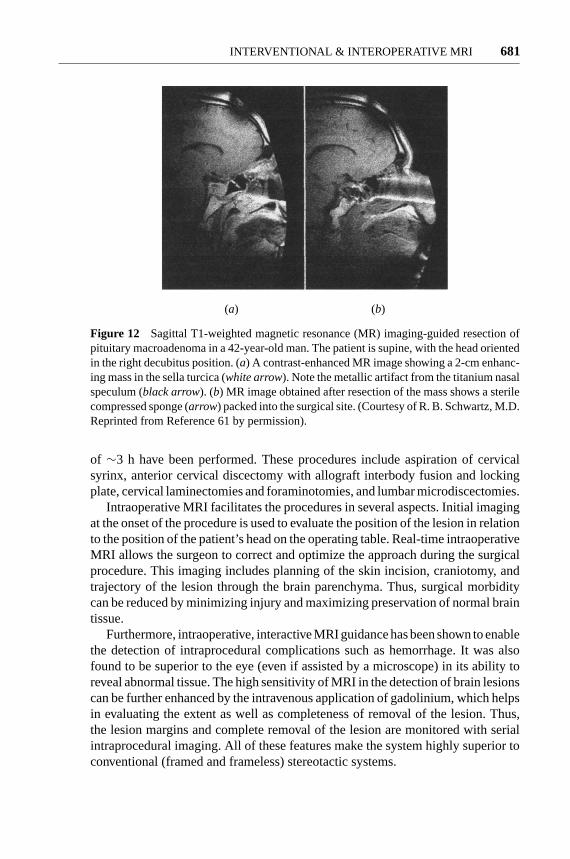
tumor was satisfactorily removed. Serial sagittal, coronal, and axial T1-weightedimages allowed the radiologist to direct the surgeon to the adenoma and avoid thecavernous sinuses and other parasellar regions [optical nerve (61; Figure 12)]. Inseveral cases, residual suprasellar mass was detected by MRI, which was beyondthe surgeon’s view through the exposed surgical site.
Magnetic Resonance Imaging-Guided Spine SurgeryIntraoperative MRI guid-ance has also been applied for spinal surgery at Brigham and Women’s Hospital,since October 1996 (27). Since then, 14 procedures with a mean surgical time
P1: FPX/fty/ftt P2: FhN
June 17, 2000 9:45 Annual Reviews AR106-24
?INTERVENTIONAL & INTEROPERATIVE MRI 681
(a) (b)
Figure 12 Sagittal T1-weighted magnetic resonance (MR) imaging-guided resection ofpituitary macroadenoma in a 42-year-old man. The patient is supine, with the head orientedin the right decubitus position. (a) A contrast-enhanced MR image showing a 2-cm enhanc-ing mass in the sella turcica (white arrow). Note the metallic artifact from the titanium nasalspeculum (black arrow). (b) MR image obtained after resection of the mass shows a sterilecompressed sponge (arrow) packed into the surgical site. (Courtesy of R. B. Schwartz, M.D.Reprinted from Reference 61 by permission).
of ∼3 h have been performed. These procedures include aspiration of cervicalsyrinx, anterior cervical discectomy with allograft interbody fusion and lockingplate, cervical laminectomies and foraminotomies, and lumbar microdiscectomies.
Intraoperative MRI facilitates the procedures in several aspects. Initial imagingat the onset of the procedure is used to evaluate the position of the lesion in relationto the position of the patient’s head on the operating table. Real-time intraoperativeMRI allows the surgeon to correct and optimize the approach during the surgicalprocedure. This imaging includes planning of the skin incision, craniotomy, andtrajectory of the lesion through the brain parenchyma. Thus, surgical morbiditycan be reduced by minimizing injury and maximizing preservation of normal braintissue.
Furthermore, intraoperative, interactive MRI guidance has been shown to enablethe detection of intraprocedural complications such as hemorrhage. It was alsofound to be superior to the eye (even if assisted by a microscope) in its ability toreveal abnormal tissue. The high sensitivity of MRI in the detection of brain lesionscan be further enhanced by the intravenous application of gadolinium, which helpsin evaluating the extent as well as completeness of removal of the lesion. Thus,the lesion margins and complete removal of the lesion are monitored with serialintraprocedural imaging. All of these features make the system highly superior toconventional (framed and frameless) stereotactic systems.

P1: FPX/fty/ftt P2: FhN
June 17, 2000 9:45 Annual Reviews AR106-24
?682 KETTENBACH ET AL
Magnetic Resonance Imaging-Guided Breast LumpectomyBreast lumpec-tomy is often accompanied by local recurrence. A negative surgical margin ofthe resected specimen is an important predictor of local control after breast con-servation surgery (63). About 40%–70% of lumpectomy surgery results in inad-equate surgical margins that require re-excision for adequate surgical treatment(64). Breast MRI with contrast agent has extremely high sensitivity in the detec-tion of breast cancer; sensitivity of>90% has been reported (65). In recent reports,breast MRI shows the size of lesion and the extent of disease more accurately thanmammography or ultrasonography (66). Lobular carcinoma and ductal carcinomain situ (DCIS) are difficult to diagnose by conventional breast imaging. However,MRI accurately predicts the extent of these diseases (67).
MRI-guided lumpectomy allows delineation of the extent of disease in the pa-tient’s position of operation. This procedure may reduce the frequent occurrenceof positive surgical margin. Because permanent pathological results are not re-turned during surgery, MRI gives immediate feedback on residual tumor, beforethe surgical wound is closed. MRI-guided lumpectomy in the Signa SP may reduceor eliminate re-excision, owing to improvement in the ability to obtain negativesurgical margins.
In an initial study, 11 patients (mean age, 54.9 years) underwent MRI-guidedlumpectomy in the Signa SP for early breast cancer. We evaluated the feasibilityof MRI-guided lumpectomy for breast cancer in the Signa SP. In all patients,indication of breast conservation therapy was confirmed. Days before MRI-guidedlumpectomy, a core biopsy proved the presence of carcinoma. Diagnostic breastMRI was performed with a 1.5-T close-bore scanner (Signa Horizon, GeneralElectric Medical Systems, Milwaukee, WI) on a separate day.
Axillary node dissection was performed outside the bore of the Signa SP, neces-sitated by the abduction of the arm for the surgical approach. The patient was thenplaced supine in the isocenter of the imaging volume of the scanner. The locationand the extent of the breast lesion from preoperative images were confirmed byacquiring axial-gradient-echo three-point Dixon images. Because the three-pointDixon method is based on the relative phase difference between fat and water,it is thus not affected by absolute chemical-shift differences. The technique istherefore useful to achieve good fat-suppressed images even at 0.5 T (34, 69). Inaddition, axial three-dimensional fast-spoiled, gradient-recalled acquisition of thesteady-state (3D FSPGR) images with the bolus injection of 20 ml of Gd-DTPAintravenously was obtained in all patients. After resection, this imaging was re-peated with a second bolus of Gd-DTPA. When the contrast-enhanced area wasseen in the lumpectomy site on postlumpectomy images, additional resection ofthe enhanced area was performed before the wound was closed.
All patients tolerated the procedure well, and there were no complications. Twofalse-positive cases from postresection images were noted. The resected cavityincluded air, which is known to yield a high-intensity susceptibility artifact at theinterface of air and tissue. In one of these two cases, extensive atypical hyperplasiawas pathologically present in additional resected specimens. Either of these causes

P1: FPX/fty/ftt P2: FhN
June 17, 2000 9:45 Annual Reviews AR106-24
?INTERVENTIONAL & INTEROPERATIVE MRI 683
may account for the apparent enhancement. In the other case, the high intensity offat was misdiagnosed as an enhanced area, because of lack of fat suppression inthe 3D FSPGR images.
Studying Brain Shift
We have studied the behavior of the brain during surgery to develop models thatsimulate the brain’s biomechanical properties that are determined by the brain’stissue properties, the internal chamber system, the external supporting structures,the arterial and venous mesh, and the pathology (70, 71).
Because both surgery and imaging take place within the Signa SP, the patientand the images are inherently registered. We performed repeated scanning to pro-vide enough temporal resolution to uncover all phases of deformation. Scanningtime and therefore image quality are limited by surgical demands. We found a suf-ficient compromise in routinely acquiring a volume scan of the brain, composed of60 slices with 2.5-mm thickness (4-mm updates). The images were subsequentlyused for targeting the tumor and later post-processed for measuring brain shift.
Serial intraoperative imaging clearly demonstrates that there are substantialshifts and deformations during surgery, caused by CSF drainage, tissue removal,and tissue reaction (swelling) to the manipulations. At least two intracerebralcompartments can be distinguished (brain surface and subsurface region) withdistinct deformation patterns.
Intraoperative MRI surprisingly reveals that the midline cannot be relied on asa rigid landmark. After resection, the cortical displacement is 1.5 cm, but thereis also a significant midline shift of∼1 cm. The left ventricle is compressed, andeven the brain stem itself has shifted. The conclusions we can draw from thesemeasurements are that the intraoperative distortions are not linear or homogenous,can affect the midline considerably, and will be difficult to predict.
Augmenting Interventional Magnetic Resonance Imagingwith the 3D-Slicer
To amplify the benefits of interventional MRI, we have developed a method to fusethe multimodality preoperative images with intraoperative MRI and present thesecombined data during the MRI-guided surgery. This fusion augments the scanningcomponent with computer software that maximizes the information available forthe surgeons and increases the interactivity of an image-guided therapy system byfocusing on the following five areas.
Image Resolution Some anatomical structures are difficult to distinguish oninterventional MR images, but are clearer on conventional, diagnostic MRI thatbenefits from a higher magnetic field and longer applicable imaging times.
Imaging Time For surgical guidance to be interactive, images must be ac-quired quickly enough to be used without disrupting or slowing the procedure.

P1: FPX/fty/ftt P2: FhN
June 17, 2000 9:45 Annual Reviews AR106-24
?684 KETTENBACH ET AL
Fast imaging techniques are being developed, but, in general, faster imagingbrings lower image quality. If images are displayed from a three-dimensionaldatabase, they can be presented much faster as real-time–acquired images. There-fore, neurosurgical guidance in our program primarily uses volumetric images (i.e.3D FSPGR) and displays them with the 3D-Slicer intraoperatively. This databaseis updated with new images as frequently as is necessitated by brain shifts anddeformations.
Multimodal Fusion Functional [e.g. function MRI (fMRI), magnetic resonanceangiography (MRA), transcranial magnetic stimulation (TMS)] and metabolic data(e.g. magnetic resonance spectroscopy (MRS), SPECT, and PET) that are acquiredpreoperatively could deliver increased benefit if integrated with intraoperativeanatomical information.
Integration of cortical mapping, fMRI, and SPECT and PET images will im-prove their effectiveness for intractable epilepsy cases or for tumor removal closeto the primary motor or language cortex.
Faster Localization Interventional MRI provides the capability of planning ap-proach trajectories by maneuvering a tracked wand and collecting images at therate of 6–20 s per image. Although this is a significant accomplishment, an ideallyinteractive system needs an update rate of 10 frames/s.
Three-Dimensional Visualization Interventional images are presently two-dimensional, which requires the surgeon to mentally map the two-dimensionalimages seen on a computer screen to the three-dimensional operating field. The3D-Slicer provides multiplanar and three-dimensional display options.
The 3D-Slicer is a software package that addresses the aforementioned areas(72). Therefore image resolution, imaging time, and localization are improved byperforming real-time reslicing of both preoperative and intraoperative data setsand displaying them for simultaneous review. Multimodal information is incor-porated through automatic registration, integrating imaging data from previouscomputed tomography or MRI along with functional physiologic data (e.g. TMS,MRA, and fMRI) and metabolic information (SPECT). These combined data canthen be coregistered with intraoperative real-time MRI data. The resulting com-posite provides the surgeon with the most comprehensive view of the operativefield and helps not only to plan, but also to execute the procedure. Coregistra-tion of computed tomography, MRA, and MRI is especially helpful in skull basesurgery. The combination of fMRI with cortical physiology is invaluable for exe-cuting surgical resection without sacrificing critical brain functions. SPECT regis-tration to intraoperative MRI distinguishes metabolically active tumor parts fromnecrotic areas. Therefore, the 3D-Slicer features a computer graphics display thatoffers the flexibility to see the situation from viewpoints that are not physicallypossible.

P1: FPX/fty/ftt P2: FhN
June 17, 2000 9:45 Annual Reviews AR106-24
?INTERVENTIONAL & INTEROPERATIVE MRI 685
DISCUSSION
Since its initial introduction, interventional and intraoperative MRI has evolvedfrom a pure research tool into a technique that offers significant promise both inprocedural ease and in added safety.
The addition of MRI guidance can greatly enhance the scope of current mini-mally invasive procedures by providing information about the relationship of theinterventional device to the target lesion and the surrounding anatomic structures.The major advantages of MRI over other cross-sectional imaging modalities are thehigh tissue contrast, multiplanar imaging capability, and sensitivity to parameterssuch as temperature, which allows monitoring of therapeutic interventions duringthe treatment. The major disadvantages of MRI-guided interventions include thehigh cost of the imaging system and the high-magnetic-field environment, whichcomplicate design of interventional devices and associated electronic equipment.Access to the patient for interventional procedures is a problem that has beensolved to a large extent, but at this time no MRI system exists that combines theadvantages of high field strength and open patient access. Interactive MRI is madeavailable by navigational devices that control the plane of image acquisition andpermit direct visual feedback to the interventionist or surgeon. This control allowsnearly real-time control during the interventional procedure.
To meet the goals of cost-effectiveness, the system could be used for several pro-cedures a day. The appropriate patient preparation areas, supplies, records staffing,and staff needs must be anticipated. In our program, the interventional MRI pro-gram is profitable and cost-effective. The numbers of cases and applications areconstantly growing, and therefore a second system will be installed in the nearfuture.
Despite its relatively high cost, MRI is unique in its capacity to enable the detec-tion of subtle abnormalities and to actively monitor minimally invasive and thermaltherapies (73). Apart from cost and practicality, the most important question is howto improve the patient’s outcome. There are a few measures to evaluate the useful-ness of image-guided surgery, such as length of hospital stay, hospitalization cost,extent of tumor resection, postoperative functional status, symptom-free period,and survival period (74–77). Although a preliminary review of image-guided sur-gical cases is encouraging in this regard, a formal study that compares success ratesof conventional neurosurgery and image-guided neurosurgery is still pending (78).
CONCLUSION
Intraoperative and interventional MRI was successfully implemented for a varietyof surgical and minimally invasive percutaneous procedures. Interventional andintraoperative MRI provided continuous visual feedback, which can be helpful inall stages of surgical or other types of interventions, without affecting the durationof the procedure or the incidence of complications. This system has potential

P1: FPX/fty/ftt P2: FhN
June 17, 2000 9:45 Annual Reviews AR106-24
?686 KETTENBACH ET AL
advantages over conventional frame-based and frameless stereotactic proceduresfor the safety and effectiveness of surgical interventions. Its full clinical potentialis not yet realized, and its overall effect on outcomes is not known. Nevertheless,this initial phase has already provided enough encouraging findings and promisingresults to justify our further engagement.
ACKNOWLEDGMENTS
Neurosurgeons involved with the intraoperative MRI project include Peter Black,M.D., Ph.D., Eben Alexander III, M.D., Philip Stieg, M.D., Tom Moriarty, M.D.,and Claudia Martin, M.D. The authors thank MRI technologists Holly Isbister,Jim Rosato, Sharon Spaulding, Cheryl Cahill, and Chris Cusack, and MRI nursesAngela Roddy Kanan and Dennis Sullivan. We are grateful for the technical con-tributions of W. M. Wells III, Ph.D., Kagayaki Kuroda, Ph.D., Noby Hata, Ph.D.,Terence Wong, M. D., Kemal Tuncali, M.D., Amir A. Zamani, M.D., Carl S.Winalski, M.D., Julia R. Fielding, M.D., R. S. Pergolizzi, M.D., and Paul R.Morrison, M.S. This work was supported in part by grants from the National In-stitutes of Health, National Science Foundation (#POT CA67165-03), and GEMedical Systems. J. K. was supported by the Austrian Science Foundation and aResearch and Education Fund of the European Congress of Radiology.
Visit the Annual Reviews home page at www.AnnualReviews.org
LITERATURE CITED
1. Jolesz FA, Shtern F. 1992. The operatingroom of the future: report of the NationalCancer Institute Workshop, imaging-guidedstereotaxic tumor-diagnosis and treatment.Invest. Radiol.27:326–28
2. Schenck JF, Jolesz FA, Roemer PB, ClineHE, Lorensen WE, et al. 1995. Super-conducting open-configuration MR imagingsystem for image-guided therapy.Radiology195:805–14
3. Cline HE, Hynynen K, Watkins RD, AdamsWJ, Schenck JF, et al. 1995. Focused US sys-tem for MR imaging-guided tumor ablation.Radiology194(3):731–37
4. Cline HE, Schenck JF, Watkins RD, Hy-nynen K, Jolesz FA. 1993. Magnetic reso-nance-guided thermal surgery.Magn. Re-son. Med.30(1):98–106
5. Hutchinson EB, Buchanan MT, Hynynen K.1996. Design and optimization of an aperi-odic ultrasound phased array for intracavi-
tary prostate thermal therapies.Med. Phys.23(5):767–76
6. Kandarpa K, Jakab P, Patz S, Schoen FJ,Jolesz FA. 1993. Prototype miniature endo-luminal MR imaging catheter.J. Vasc. In-terv. Radiol.4(3):419–27
7. Atalar E, Bottomley PA, Ocali O, CorreiaLC, Kelemen MD, et al. 1996. High resolu-tion intravascular MRI and MRS by usinga catheter receiver coil.Magn. Reson. Med.36(4):596–605
8. Martin AJ, Plewes DB, Henkelman RM.1992. MR imaging of blood vessels with anintravascular coil.J. Magn. Reson. Imaging2(4):421–29
9. Ocali O, Atalar E. 1997. Intravascular mag-netic resonance imaging using a looplesscatheter antenna.Magn. Reson. Med.37(1):112–18
10. Quick HH, Ladd ME, Zimmermann-PaulGG, Erhart P, Hofmann E, et al. 1999.

P1: FPX/fty/ftt P2: FhN
June 17, 2000 9:45 Annual Reviews AR106-24
?INTERVENTIONAL & INTEROPERATIVE MRI 687
Single-loop coil concepts for intravascularmagnetic resonance imaging.Magn. Re-son. Med.41(4):751–58
11. Quick HH, Ladd ME, Hilfiker PR, PaulGG, Ha SW, Debatin JF. 1999. Autoper-fused balloon catheter for intravascular MRimaging. J. Magn. Reson. Imaging9(3):428–34
12. Silverman SG, Jolesz FA, Newman RW,Morrison PR, Kanan AR, et al. 1997.Design and implementation of an inter-ventional MR imaging suite.Am. J. Roent-genol.168:1465–71
13. Corn SB. 1998. Anesthesia care of patientsin MRI units with special considerations ofthe anesthestic care of patients in the in-terventional MRI. InInterventional MR:Techniques and Clinical Experience,ed.FA Jolesz, IR Young, p. 63. London: Mar-tin Dunitz
14. Rao CC, Krishna G. 1994. Anaestheticconsiderations for magnetic resonanceimaging.Ann. Acad. Med.23:531–35
15. Keens SJ, Laurence AS. 1996. Burnscaused by ECG monitoring during MRIimaging.Anaesthesia51(12):1188–89
16. Kanal E, Shellock FG. 1992. Patient mon-itoring during clinical MR imaging.Radi-ology185(3):623–29
17. Keltner J, Roos M, Brakeman P, BudingerT. 1990. Magnetohydrodynamics of bloodflow. Magn. Reson. Med.16:139–49
18. Panych LP, Zientara GP, Saiviroonporn P,Yoo SS, Jolesz FA. 1998. Digital wavelet-encoded MRI: a new wavelet-encodingmethodology.J. Magn. Reson. Imaging8(5):1135–44
19. Panych LP, Jolesz FA. 1994. A dynamicallyadaptive imaging algorithm for wavelet-encoded MRI.Magn. Reson. Med.32(6):738–48
20. Zientara GP, Panych LP, Jolesz FA. 1994.Dynamically adaptive MRI with encodingby singular value decomposition.Magn.Reson. Med.32(2):268–74
21. Farahani K, Sinha U, Sinha S, Chiu LC,Lufkin RB. 1990. Effect of field strength
on susceptibility artifacts in magnetic res-onance imaging.Comput. Med. ImagingGraph.14(6):409–13
22. Rudisch A, Kremser C, Peer S, KathreinA, Judmaier W, Daniaux H. 1998. Metal-lic artifacts in magnetic resonance imagingof patients with spinal fusion. A compar-ison of implant materials and imaging se-quences.Spine23(6):692–99
23. Wang JC, Sandhu HS, Yu WD, MinchewJT, Delamarter RB. 1997. MR parametersfor imaging titanium spinal instrumenta-tion. J. Spinal Disord.10(1):27–32
24. Ladd ME, Erhart P, Debatin JF, Ro-manowski BJ, Boesiger P, McKinnon GC.1996. Biopsy needle susceptibility arti-facts.Magn. Reson. Med.36(4):646–51
25. Moscatel MA, Shellock FG, Morisoli SM.1995. Biopsy needles and devices: assess-ment of ferromagnetism and artifacts dur-ing exposure to a 1.5-T MR system.J.Magn. Reson. Imaging5(3):369–72
26. Leung DA, Debatin JF, Wildermuth S,Heske N, Dumoulin CL. 1995. Real timebiplanar needle tracking for interven-tional MR imaging procedures.Radiology197(2):485–88
27. Moriarty TM, Kikinis R, Jolesz FA, BlackPM, Alexander E 3rd. 1996. Magneticresonance imaging therapy: intraoperativeMR imaging.Neurosurg. Clin. N. Am.7(2):323–31
28. Silverman SG, Collick BD, Figueira MR,Khorasani R, Adams DF, et al. 1995. In-teractive MRI-guided biopsy in an open-configuration MR imaging system.Radi-ology197:175–81
29. Wong TZ, Silverman SG, Fielding JR,Tempany CMS, Hynynen K, et al. 1998.Open-configuration MR imaging, inter-vention, and surgery of the urinary tract.Urol. Clin. N. Am.25(1):113–22
30. Heywang-Koebrunner SH, Huynh AT,Vieweg P, Hanke W, Requardt H, PaproschiI. 1994. Protoype breast coil for MRI-guided needle localization.J. Comput. As-sist. Tomogr.18:876–81
P1: FPX/fty/ftt P2: FhN
June 17, 2000 9:45 Annual Reviews AR106-24
?688 KETTENBACH ET AL
31. Fischer U, Vosshenrich R, Doeler W,Hamadeh A, Oestmann JW, Grabbe E.1995. MR imaging-guided breast interven-tion: experience with two systems.Radi-ology195:533–38
32. Gould SW, Lamb G, Lomax D, GedroycW, Darzi A. 1998. Interventional MR-guided excisional biopsy of breast lesions.J. Magn. Reson. Imaging8:26–30
33. Daniel BL, Birdwell RL, Ikeda DM, Jef-frey SS, Black JW, et al. 1998. Breast le-sion localization: a freehand interactiveMR imaging-guided technique.Radiology207:455–63
34. Daniel BL, Butts K, Glover GH, CooperC, Herfkens RJ. 1998. Breast cancer:gadolinium-enhanced MR imaging with a0.5-T open imager and three-point Dixontechnique.Radiology207:183–90
35. Pitt AM, Fleckenstein JL, Greenlee RG Jr,Burns DK, Bryan WW, Haller R. 1993.MRI-guided biopsy in inflammatory my-opathy: initial results.Magn. Reson. Imag-ing 11:1093–99
36. Mueller PR, Stark DD, Simeone JF, SainiS, Butch RJ, et al. 1986. MRI-guided as-piration biopsy: needle design and clinicaltrials.Radiology161:605–9
37. vanSonnenberg E, Hajek P, Gylys-MorinV, Varney RA, Baker L, et al. 1988. Awire-sheath system for MRI-guided biopsyand drainage: laboratory studies and expe-rience in 10 patients.Am. J. Roentgenol.151:815–17
38. Gehl HB, Frahm C, SchimmelpenningH, Weiss HD. 1996. Technik der MRT-gesteuerten abdominellen drainage aneinem offenen niederfeldmagneten.Fort-schr. Rontgenstr.165(1):70–73
39. Hagspiel KD, Kandarpa K, SilvermanSG. 1998. Interactive MRI-guided percuta-neous nephrostomy.J. Magn. Reson. Imag-ing 8(6):1319–22
40. Gohde SC, Pfammatter T, Steiner P, ErhartP, Romanowski BJ, Debatin JF. 1997. MRI-guided cholecystostomy: assessment of bi-planar, real time needle tracking in three
pigs. Cardiovasc. Interv. Radiol.20(4):295–99
41. Schwartz RB, Hsu L, Black PM, AlexanderE 3rd, Wong TZ, et al. 1998. Evaluation ofintracranial cysts by intraoperative MR.J.Magn. Reson. Imaging8(4):807–13
42. Zamani AA, Moriarty T, Hsu L, WinalskiCS, Schaffer JL, et al. 1998. FunctionalMRI of the lumbar spine in erect position ina superconducting open-configuration MRsystem: preliminary results.J. Magn. Re-son. Imaging.8(6):1329–33
43. Fielding JR, Versi E, Mulkern RV, LernerMH, Griffiths DJ, Jolesz FA. 1996. MR-imaging of the female pelvic floor in thesupine and upright positions.J. Magn. Re-son. Imaging6:961–63
44. Fielding JR, Griffiths DJ, Versi E, MulkernRV, Lee ML, Jolesz FA. 1998. MR imag-ing of pelvic floor continence mechanismsin the supine and sitting positions.Am. J.Roentgenol.171(6):1607–10
45. Jaramillo D, Galen TA, Winalski CS, Di-Canzio J, Zurakowski D, et al. 1999. Legg-Calve-Perthes disease: MR imaging eval-uation during manual positioning of thehip–comparison with conventional arthro-graphy.Radiology212(2):519–25
46. Brossmann J, Muhle C, Schroder C,Melchert UH, Bull CC, et al. 1993. Patellartracking patterns during active and passiveknee extension: evaluation with motion-triggered cine MR imaging.Radiology187:205–12
47. Powers CM, Shellock FG, Pfaff M. 1998.Quantification of patellar tracking usingkinematic MRI.J. Magn. Reson. Imaging8:724–32
48. Shellock FG, Mink JH, Deutsch AL, FooTKF. 1992. Kinematic MR imaging of thepatellofemoral joint: comparison of pas-sive positioning and active movement tech-niques.Radiology184:574–77
49. Shellock FG, Mink JH, Deutsch AL, FooTK, Sullenberger P. 1993. Patellofemoraljoint: identification of abnormalitieswith active-movement, “unloaded” versus

P1: FPX/fty/ftt P2: FhN
June 17, 2000 9:45 Annual Reviews AR106-24
?INTERVENTIONAL & INTEROPERATIVE MRI 689
“loaded” kinematic MR imaging tech-niques.Radiology188:575–78
50. Koskinen SK, Taimela S, Nelimarkka O,Komu M, Kujala UM. 1993. Magnetic res-onance imaging of patellofemoral relation-ships.Skelet. Radiol.22:403–10
51. Bleier AR, Higuchi N, Panych LP, JakabPD, Hrovat M, Jolesz FA. 1990. Magneticresonance imaging of interstitial laser pho-tocoagulation.Proc. SPIE1202:188–95
52. Kahn T, Bettag M, Ulrich F, SchwarzmaierHJ, Schober R, et al. 1994. MRI-guidedlaser-induced interstitial thermotherapy ofcerebral neoplasms.J. Comput. Assist. To-mogr.18(4):519–32
53. Vogl TJ, Muller PK, Hammerstingl R,Weinhold N, Mack MG, et al. 1995. Malig-nant liver tumors treated with imaging-guided laser induced thermotherapy; tech-nique and prospective results.Radiology196:257–65
54. Kettenbach J, Silverman SG, Hata N,Kuroda K, Saiviroonporn P, et al. 1998.Monitoring and visualization techniquesfor MRI-guided laser ablations in an openMR-system.J. Magn. Reson. Imaging8:933–43
55. Kettenbach J, Kuroda K, Hata N, Morri-son P, McDannold NJ, et al. 1998. Laser-induced thermotherapy of cerebral neo-plasia under MR tomographic control.Min. Invas. Ther. Allied Technol.7/6:589–98
56. Steiner P, Botnar R, Dubno B, Zimmer-mann GG, Gazelle GS, Debatin JF. 1998.Radio-frequency-induced thermoablation:monitoring with T1-weighted and proton-frequency-shift MR imaging in an inter-ventional 0.5-T environment.Radiology206(3):803–10
57. Matsumoto R, Selig AM, Colucci VM,Jolesz FA. 1993. MR monitoring dur-ing cryotherapy of the liver: predictabilityof histological outcome.J. Magn. Reson.Imaging3:770–76
58. Silverman SG, Tuncali K, Adams DF,Kacher DF, Morrison PR, et al. 1999.
Percutaneous MR imaging-guided cryo-therapy of liver metastases.Radiology213(Suppl.):122
59. D’Amico AV, Cormack R, Tempany CM,Kumar S, Topulos G, et al. 1998. Real timemagnetic resonance image-guided intersti-tial brachytherapy in the treatment of selectpatients with clinically localized prostatecancer.Int. J. Radiat. Oncol. Biol. Phys.42(3):507–15
60. Hsu L, Jolesz FA, Fried MP. 1995. MR-guided endoscopic sinus surgery.AJNR9(7):1235–40
61. Schwartz RB, Hsu L, Wong TZ, KacherDF, Zamani AA, et al. 1999. Intraopera-tive MR imaging guidance for intracranialneurosurgery: experience with the first 200cases.Radiology211(2):477–88
62. Black PM, Alexander E 3rd, Martin C,Moriarty T, Nabavi A, et al. 1999. Cran-iotomy for tumor treatment in an intraop-erative magnetic resonance imaging unit.Neurosurgery45(3):423–33
63. Smitt MC, Nowels KW, Zdeblick MJ, Jef-frey S, Carlson RW, et al. 1995. The impor-tance of the lumpectomy surgical marginstatus in long term results of breast conser-vation.Cancer76:259–67
64. Recht A, Come SE, Henderson IC, GelmanRS, Silver B, et al. 1996. The sequencing ofchemotherapy and radiation therapy afterconservative surgery for early-stage breastcancer.N. Engl. J. Med.334:1356–61
65. Gilles R, Guinebretiere JM, Lucidarme O,Cluzel P, Janaud G, et al. 1994. Nonpalpa-ble breast tumors: diagnosis with contrast-enhanced subtraction dynamic MR imag-ing. Radiology191:625–31
66. Boetes C, Mus RDM, Holland R, BarentszJO, Strijk SP, et al. 1995. Breast tumors:comparative accuracy of MR imaging rel-ative to mammograpy and US for demon-strating extent.Radiology197:743–47
67. Rodenko GN, Harms SE, Pruneda JM, Far-rell RS, Evans WP, et al. 1996. MR imagingin the management before surgery of lob-ular carcinoma of the breast: correlation
P1: FPX/fty/ftt P2: FhN
June 17, 2000 9:45 Annual Reviews AR106-24
?690 KETTENBACH ET AL
with pathology.Am. J. Roentgenol.167:1415–19
68. Orel SG, Schnall MD, Powell CM,Hochman MG, Solin LJ, et al. 1995. Stag-ing of suspected breast cancer: effect ofMR imaging and MRI-guided biopsy.Ra-diology196:115–22
69. Dixon WT. 1984. Simple proton spectro-scopic imaging.Radiology153:189–94
70. Haton N, Geting D, Chatzidakis EM,Leveuton M, et al. 1999. Image guidedneurosurgery visualization of brain shift.In Navigated Brain Surgery, ed. U Spetz-ger, HS Stiehl, JM Gilsbach, pp. 17–26.Aachen: Springer-Verlag
71. Hata N, Nabavi A, Warfield S, William W,Kikinis R, et al. 1999. A volumetric opti-cal flow method for measurement of braindeformation from intraoperative magneticresonance images. InProc. 2nd Int. Conf.Med. Image Comput. Comput. Assist. In-terv., Cambridge, UK, pp. 928–35
72. Gering D. 1999.A system for surgical plan-ning and guidance using image fusion andinterventional MR.MS thesis. MIT, Cam-bridge, MA
73. Jolesz FA, Kettenbach J, Grundfest WS.1998. Cost-effectiveness of image-guidedsurgery.Acad. Radiol.5:428–31
74. Nazzaro JM, Neuwelt EA. 1990. The roleof surgery in the management of supraten-torial intermediate and high-grade astro-cytomas in adults.J. Neurosurg.73:331–44
75. Curran WJ Jr, Scott CB, Horton J,Nelson JS, Weinstein AS, et al. 1992. Doesextent of surgery influence outcome for as-trocytoma with atypical or anaplastic foci(AAF)? A report from three RadiationTherapy Oncology Group (RTOG) trials.J. Neuro-Oncol.12:219–27
76. Albert FK, Forsting M, Sartor K, AdamsHP, Wilson CB, et al. 1994. Early postop-erative magnetic resonance imaging afterresection of malignant glioma: objectiveevaluation of residual tumor and its influ-ence on regrowth and prognosis.Neuro-surgery34:45–61
77. Kowalczuk A, Macdonald RL, Amidei C,Dohtmann G 3rd, Erickson RK, et al. 1997.Quantitative imaging study of the extentof surgical resection and prognosis of ma-lignant astrocytomas.Neurosurgery41(5):1028–36
78. Silverman SG, Duerk JL, Lu DS, Jolesz FA.1999. Research in interventional MR imag-ing: Where do we go from here?Acad.Radiol.6(6):368–69
Copyright © 2022 FDOKUMEN