Spinal anesthesia for lengthy lower limb orthopedic surgeries

Prepolarized Magnetic Resonance Imaging around MetalOrthopedic Implants
Ross D. Venook,1* Nathaniel I. Matter,1 Meena Ramachandran,1 Sharon E. Ungersma,1
Garry E. Gold,2 Nicholas J. Giori,3,4 Albert Macovski,1 Greig C. Scott,1 andSteven M. Conolly1,5
A prepolarized MRI (PMRI) scanner was used to image nearmetal implants in agar gel phantoms and in in vivo humanwrists. Comparison images were made on 1.5- and 0.5-T con-ventional whole-body systems. The PMRI experiments wereperformed in a smaller bore system tailored to extremity imag-ing with a prepolarization magnetic field of 0.4 T and a readoutmagnetic field of 27–54 mT (1.1–2.2 MHz). Scan parameterswere chosen with equal readout gradient strength over a givenfield of view and matrix size to allow unbiased evaluation of thebenefits of lower readout frequency. Results exhibit substantialreduction in metal susceptibility artifacts under PMRI versusconventional scanners. A new artifact quantification techniqueis also presented, and phantom results confirm that suscepti-bility artifacts improve as expected with decreasing readoutmagnetic field using PMRI. This proof-of-concept study dem-onstrates that prepolarized techniques have the potential toprovide diagnostic cross-sectional images for postoperativeevaluation of patients with metal implants. Magn Reson Med56:177–186, 2006. © 2006 Wiley-Liss, Inc.
Key words: metal artifact; susceptibility artifact; prepolarizedMRI; low-field MRI; low-cost MRI
Metal hardware is commonly implanted in orthopedic sur-gery to reduce and fixate fractures, to replace arthriticjoints, and to align and stabilize the spine. In the UnitedStates alone, nearly 450000 primary or revision total kneearthroplasties were performed in 2002, representing nearlya threefold increase from 1990 (1). These numbers aregrowing rapidly with improvements in surgical technol-ogy and with the aging population. Because of its uniqueability to visualize both osseous structures and adjacentsoft tissue, orthopedists frequently rely on MRI for diag-nosis and preoperative planning (2). Unfortunately, thephysical characteristics of metal implants often make themdifficult to image with cross-sectional techniques. Metal
artifacts can severely degrade CT images throughout thefield of view, while susceptibility artifacts impair tissuevisualization near metal implants under MRI (3,4). Be-cause of these challenges, postoperative progress is diffi-cult to monitor, and complications including looseningcan go undiagnosed until another surgery becomes neces-sary (5). Without proper preoperative images, these revi-sion surgeries are also more difficult to plan and execute.
The basic obstacles to imaging near metal with MR aresusceptibility-related static field distortions (6,7), gradi-ent-induced eddy currents on metal surfaces (8), and RFshielding effects (9). Among these, susceptibility is by farthe dominant problem in MRI systems. Gradient-echo im-aging is almost impossible near metal because local fieldinhomogeneity causes rapid dephasing and results in sig-nal voids. Spin-echo techniques are more successful be-cause of their rephasing effects, but they still suffer spa-tially dependent artifacts. For 2D Fourier transform (2DFT)acquisitions, these include correctable shifts/distortions,uncorrectable voids and pile-ups, and T*2-related blurringand signal loss.
Specialized pulse sequences have had some successwith addressing these artifacts. View angle tilting (VAT)provides an elegant way to correct for general inhomoge-neity errors (10). It is particularly effective for correctingchemical shift artifacts and is the basis for most sequencesthat endeavor to image near metal (4,11). Recent work alsoprovides a method to correct for VAT-associated blurring(12). Unfortunately, VAT is incompatible with 3D imagingand otherwise requires excellent slice selection—which isimpossible to ensure in the presence of strong inhomoge-neities near metal. Another technique to avoid inhomoge-neity artifacts involves encoding and acquiring MR signalfrom one k-space location at a time. Such “single point”methods can produce almost perfect images near metal,but even the most time-efficient of these sequences are tooslow for clinical applications (13).
Correction of susceptibility artifacts through postpro-cessing is another area of active research. Well-knownmethods can correct mild inhomogeneities (14,15,16),such as those caused by air–tissue interfaces. Most post-processing algorithms use some a priori knowledge aboutthe object and/or perform field mapping to “unwrap” theimages that result from naive reconstruction. Recent workcontinues to improve both the outcome and the computa-tional load of these methods (17,18), but none is yet work-able in in vivo applications involving metal implants.Moreover, if the field errors are strong enough, as they arenear most metals, the encoding becomes ambiguous andsimply uncorrectable.
1Magnetic Resonance Systems Research Laboratory, Department of Electri-cal Engineering, Stanford University, Stanford, California, USA.2Department of Radiology, Stanford University, Stanford, California, USA.3VA Palo Alto Healthcare System, Palo Alto, California, USA.4Department of Orthopedic Surgery, Stanford University, Stanford, California,USA.5Department of Bioengineering, University of California at Berkeley, Berkeley,California, USA.Grant sponsor: NIH; Grant numbers: NIH R33 EB00777, NIH 1R01EB0002524, NIH R01 EB00346, NIH 5R24CA092862–03; Grant sponsor: TheWhitaker Foundation; Grant sponsor: GE Global Healthcare.*Correspondence to: Ross D. Venook, 350 Serra Mall, Packard ElectricalEngineering Building, Room 063, Stanford University, Stanford, CA 94305-9510, USA. E-mail: [email protected] 7 November 2005; revised 14 March 2006; accepted 20 March 2006DOI 10.1002/mrm.20927Published online 24 May 2006 in Wiley InterScience (www.interscience.wiley.com).
Magnetic Resonance in Medicine 56:177–186 (2006)
© 2006 Wiley-Liss, Inc. 177
Finally, many studies attempt to minimize distortions,or at least their effect on the diagnostic quality of theimages, by manipulating patient (and implant) orientationwith respect to the main field (2,19,20). While these allprovide relevant data that are clinically applicable, thereare significant limitations to the generality and effective-ness of such methods.
All existing methods attempt to avoid or correct forartifacts associated with the necessarily large field distur-bances near metal in conventional clinical scanners. Be-cause of the limited success and limited clinical accep-tance of these methods, we suggest a different approach.Magnetic field distortion around an object scales with theinstantaneous applied field, so imaging at lower fieldsreduces susceptibility artifacts (21,22). The obvious trade-off with lowering B0 on a conventional system is loss ofsignal-to-noise ratio (SNR). We propose to image aroundmetal implants with a prepolarized MRI (PMRI) systemthat allows for low-field signal acquisition with mid-fieldSNR.
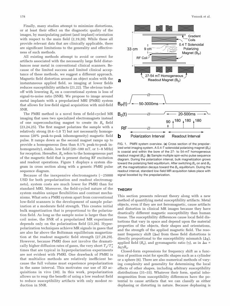
The PMRI method is a novel form of field-cycled MRimaging that uses two specialized electromagnets insteadof one superconducting magnet to create its B0 field(23,24,25). The first magnet polarizes the sample with arelatively strong (0.4–1.0 T) but not necessarily homoge-neous (20% peak-to-peak inhomogeneity) magnetic fieldpulse. It ramps down as the second magnet ramps up toprovide a homogeneous (less than 0.1% peak-to-peak in-homogeneity), stable, low field (20–180 mT, or 1–8 MHz)for reception. Hereafter, B0 refers to the homogeneous partof the magnetic field that is present during RF excitationand readout operations. Figure 1 displays a system dia-gram in cross section along with a generic PMRI pulsesequence diagram.
Because of the inexpensive electromagnets (�25000USD for both prepolarization and readout electromag-nets), system costs are much lower for PMRI than forstandard MRI. Moreover, the field-cycled nature of thesystem enables unique flexibilities and contrast mecha-nisms. What sets a PMRI system apart from conventionallow-field scanners is the development of sample polar-ization at a moderate field strength. This creates initialbulk magnetization that is proportional to the polariza-tion field. As long as the sample noise is larger than thecoil noise, the SNR of a prepolarized MR experimentdepends only on the polarization field (23,26). Hyper-polarization techniques achieve MR signals in gases thatare also far above the Boltzman equilibrium magnetiza-tion at the readout magnetic field strength (27,28,29).However, because PMRI does not involve the dramati-cally higher diffusion rates of gases, the very short T2/T*2times that are typical in hyperpolarization experimentsare not evident with PMRI. One drawback of PMRI isthat multislice methods are relatively inefficient be-cause the full volume must experience prepolarizationin the same interval. This motivates our use of 3D ac-quisitions in vivo (30). In this work, prepolarizationallows us to reap the benefit of using a low readout fieldto reduce susceptibility artifacts with only modest re-duction in SNR.
THEORY
This section presents relevant theory along with a newmethod of quantifying metal susceptibility artifacts. Metalobjects, even if they are not ferromagnetic, cause artifactsand distortion in clinical MR images because they havedrastically different magnetic susceptibility than humantissue. The susceptibility differences cause local field dis-tortions that vary in space and depend upon the materialproperties of the objects, their shapes and orientations,and the strength of the applied magnetic field. The reso-nant frequency shift (��) from these field distortions isdirectly proportional to the susceptibility mismatch (��),applied field (B0), and gyromagnetic ratio (�), as in �� ����B0.
Closed-form expressions for frequency shift as a func-tion of position exist for specific shapes such as a cylinderor a sphere (6). There are also numerical methods of vary-ing complexity and generality for determining the localeffects of other shapes, including arbitrary susceptibilitydistributions (31–33). Whatever their form, spatial inho-mogeneities from susceptibility differences have the po-tential to cause artifacts that we can classify as eitherdephasing or distorting in nature. Because dephasing is
FIG. 1. PMRI system overview. (a) Cross section of the prepolar-ized wrist imaging system. A 0.4-T solenoidal polarizing magnet (BP)is coaxial and within the bore of the 27- to 54-mT homogeneousreadout magnet (B0). (b) Sample multiple spin-echo pulse sequencediagram. During the polarization interval, bulk magnetization growstoward the polarizing field equilibrium. After switching B0 on and BP
off, the magnetization decays toward the B0 equilibrium. During thereadout interval, standard low-field MR acquisition takes place withsignal boosted by the prepolarization.
178 Venook et al.

prohibitive when imaging near metal with gradient-echotechniques at standard field strengths (22), we refer theinterested reader to a full discussion elsewhere (34). In thistreatment, we will focus on distortion artifacts.
Distortion Artifacts
For standard 2DFT data acquisition methods, off-reso-nance conditions manifest singularly as a readout-direc-tion displacement of
�x � ��/�Gr���B0/Gr, [1]
where Gr is the strength of the readout gradient.Equation [1] explains why susceptibility-induced distor-tion artifacts generally become worse with higher mag-netic field strengths during the readout period (21), whileincreasing readout gradient strength improves these arti-facts (4). Because the PMRI scanner in this study acquiresdata at a low static field (27–54 mT, or 1.1–2.2 MHz)without necessarily losing gradient strength, we expectimprovements in the readout-direction shifts due to metalimplants by a factor between 1.5 T/27 mT � 57 and 1.5T/54 mT � 28 versus a 1.5-T system. Table 1 containscalculated maximum shifts for cylinders of different com-mon implant materials at different readout magnetic fieldstrengths. A 7-mm displacement due to titanium at 1.5 Tmay obscure important anatomy, while the artifact wouldbe a benign 0.12-mm shift at 27 mT.
Uncorrectable Distortion
Although Table 1 presents the expected worst-case shiftsfor tissue directly adjacent to metal, there is no indicationof the object size: the maximum shift is only dependent onthe materials involved and is always highest at their inter-face. The shift falls off with distance from the interface, sosignal from voxels near the metal will get displaced furtheralong the readout direction than signal from more distantvoxels. In certain cases, this spatial distribution leavesvoids near the susceptibility/material boundary and pilessignal at the edges of the void. This creates unrecoverableerrors in the reconstruction because signal from manydifferent voxels becomes encoded into the same pixel.Physically, such pile-up occurs whenever the local inho-mogeneity gradient is equal and opposite the readout gra-dient. Ludeke et al. (6) have derived a simple criterion forthis condition. Relating B0, ��, Gr, R (object radius), and �
(a geometrical constant between 0 and 1), the condition forcreating uncorrectable distortion is
��c� � ���B0/RGr � ��x/R � 1/2, [2]
which corresponds to a field error that exceeds the gradi-ent field range over the width of the object. This meansthat smaller objects will more readily experience pile-upartifacts, since the susceptibility-induced gradient issteeper near a smaller object. Given a B0, ��, and maxi-mum Gr, Eq. [2] allows us to calculate the minimum objectradius for avoiding uncorrectable distortion. Figure 2 dis-plays a plot of �c versus object diameter for a titaniumcylinder using 3 mT/m (0.3 G/cm) gradients at 1.5 T and 27mT, corresponding to the conditions of the screw phantomexperiments in this work. We needed to use low gradientstrengths to generate uncorrectable artifacts in the PMRIimages, but even with 40 mT/m (4 G/cm) gradients (Fig. 3)we calculate that a titanium cylinder must be greater than1.2 cm wide to allow proper reconstruction of nearbytissue at 1.5 T. This minimum feature size is about 0.5 mmwide under PMRI at either 27 or 54 mT with the highergradient strength. Hence, one would hypothesize the ab-sence of pile-up artifacts in a prepolarized MRI scan of allbut the smallest (or most magnetic) metal objects.
Measuring Susceptibility Artifacts in Images
To demonstrate the artifact improvement in our PMRIscanner, compared to a conventional 1.5-T scanner, wehave developed a technique for measuring pile-up artifactsin images and comparing the measurements with theory.Quantification studies exist for metal artifacts (11,22,35),but to our knowledge, none have yet linked their measure-ments with theory.
Quantifying susceptibility artifacts in uncorrectably dis-torted images can be difficult because of the ambiguity in
FIG. 2. Graph of condition for uncorrectable image distortion ( �c
1/2) versus diameter for a cylinder of titanium alloy at 1.5 T and 27mT main field strengths with 3 mT/m gradient (�� � 182 ppm). Thissmall gradient was the strongest we could use and still produceuncorrectable distortion around the 4-mm titanium screws in thephantom experiment in Fig. 5 (as indicated by the vertical dottedline).
TABLE 1.Expected Maximum Magnitude of Shift Artifact of Pixels DirectlyAdjacent to Cylinders of Common Metal Implant Materialsa
Material ��b (ppm) �x (at 1.5 T) �x (at 27 mT)
Air 10 0.38 mm 6.8 mTitanium 191 7 mm 0.12 mmChromium 329 12 mm 0.22 mm
aAssumes 2DFT experiment with 40 mT/m readout gradient andcylinder axis perpendicular to both main magnetic field and readoutdirection.bSusceptibility differences tabulated by Schenck (7).
Prepolarized MRI around Metal Orthopedic Implants 179

the location of the signal sources that reconstruct to certainimage pixels. One unambiguous feature, however, is theborder between the signal void and signal pile-up at the tipof the arrowhead artifact that is typically adjacent to themetal object and pointing in the readout direction (seefigures herein). With a known object position, displace-ment between the object and artifact boundaries is mea-surable in an image. Because there is also an analyticalrelationship governing this displacement, we can quantifyartifact improvement in a rigorous way. For a cylinderwith axis perpendicular to both the main magnetic fieldand the readout direction, we quantify the artifact as thedistance z� from the cylinder center to the pile-up edge inthe readout direction, which has the theoretical form
z� �32�3 ��B0R2/Gr. [3]
Details of this analysis are in the Appendix.
METHODS
We compared the ability of our PMRI scanner to imagenear metal orthopedic implants with that of a conventional1.5-T GE Signa scanner and an interventional GE Signa SP0.5-T scanner (General Electric, Milwaukee, WI, USA).The PMRI system in these experiments is a small-borescanner for extremity imaging with a clear bore diameter of9 cm. All PMRI experiments used a 0.4-T prepolarizationfield with either a 27 or a 54 mT readout static magneticfield. We first performed imaging experiments with metalimplants and a plastic grid within agarose gel phantoms.We then imaged metallic hardware within in vivo humanwrists.
Orthopedic Screw and Tibial Implant Phantoms
To analyze metallic implant effects in phantoms with ho-mogeneous background signal, we constructed and imagedan orthopedic screw phantom and a tibial implant phan-tom. Figure 4 displays the experimental setup for the tita-nium alloy tibial implant (Howmedica, Rutherford, NJ,USA). The setup for the screw phantom is somewhatsmaller and contains two 34-mm-long, 4-mm-diametercoated titanium screws (Alphatec, Carlsbad, CA, USA). Inboth cases, we mounted the metal onto a plastic grid (15 �15 � 9 mm units) and suspended this in a cylindricalplastic container filled with agarose gel. We doped the gelwith copper sulfate at 2.3 g/liter (14.7 mM, T1 � T2 �100 ms at 1.5 T). For imaging, we oriented the phantomcoaxially with the bore at isocenter in all scanners.
Imaging parameters for the phantom experiments aregiven in Table 2. We chose to use equal readout gradientsfor all three systems to allow comparisons based uponmain field strength. We did this by holding the bandwidth/field of view ratio constant across the systems. To ensurecomparison of appropriate slices we used the aspect ratio
FIG. 4. Phantom diagram of titanium alloy tibial base plate andplastic grid in a plastic cylinder of agarose gel. (a) Perspective viewof tibial implant (shown inferior-side up, for clarity). (b) Coronalprojection of implant in grid phantom. (c) Isometric view of phantom.Note that posts partially fill two grid squares. Grid squares measure15 � 15 � 9 mm.
FIG. 3. Graph of condition for uncorrectable image distortion ( �c
1/2) versus diameter for a cylinder of titanium alloy at various fieldstrengths with 40 mT/m gradient (�� � 182 ppm). Using Eq. [2], weexpect pile-up artifacts for tissue near cylinders with diameter 1.2 cm at 1.5 T. PMRI images should be correctable for pins assmall 0.5 mm in diameter at either 27 or 54 mT with 40 mT/mgradient strength.
180 Venook et al.

of the agar gel along with the plastic grid as fiducials. Weempirically adjusted the slice position in the PMRI exper-iments to match the 1.5-T slices. We increased the echoand repetition times with increasing readout field to ac-count for differences in relaxation times, matching con-trast while sacrificing some SNR for longer echo times. Asspin echo techniques are refocused, distortion artifacts areunaffected by changes in echo time.
Artifact Quantification
We used the screw phantom images to quantify artifactscaling with readout field strength, comparing the resultswith analytical solutions for long cylinders perpendicularto both the readout direction and the main magnetic field.We used reduced gradients and a small-diameter screw inorder to create pile-up artifacts for measurement at lowfield. To process the images, we used the regular plasticgrid shape as a reference to determine the actual locationof each screw. We then counted the pixels along the read-out direction from the screw center to the first bright pixelon the void/pile-up boundary using custom software writ-ten in MATLAB (The Mathworks, Natick, MA, USA). Per-forming this procedure for both screws, across multipleimage planes from each scanner, we found measurementvariation of �1 pixel. A figure depicting this procedure isin the Appendix.
Human Wrist Imaging
We used our PMRI scanner and a conventional 1.5-T scan-ner to image both wrists of a 20-year-old female volunteer.One wrist had a scaphoid fracture fixated with a titaniumscrew. The other wrist had a steel plate along the distalradius, with four screws in the radial epiphysis and threescrews in the radial metaphysis. Both procedures occurred20 weeks prior to imaging.
In order to image the subjects at isocenter at 1.5 T, weused a transmit/receive quadrature extremity coil witheach wrist above the volunteer’s head. With the PMRIsystem, each volunteer sat next to the scanner, restinghis/her arm within the bore.
We imaged each wrist with RARE sequences using highsystem bandwidth (�25 kHz) over a 10-cm FOV on bothsystems (36,37). We used a 3D RARE sequence becauseslice selection is unreliable near metal and because PMRI’sSNR efficiency with 3D methods approaches that of con-ventional MRI (30), reducing volunteer imaging time. Weperformed all imaging under IRB approval. In vivo imag-ing parameters are given in Table 2. We chose comparableslices based on anatomy, and we increased the readoutmagnetic field to 54 mT because of increases in SNR asso-ciated with improvements in RF coil performance (26). Weused longer echo and repetition times at 1.5 T rather thanat 54 mT to achieve similar contrast.
RESULTS
Here we present results of artifact quantification in anorthopedic screw phantom, proceeding to images of a tib-ial plate phantom, and finally to images of orthopedichardware in two in vivo volunteer wrists.
The images in Fig. 5 demonstrate the drastic differencebetween susceptibility artifacts at 1.5 T and those at lowerreadout frequency with PMRI (27 mT). The distance fromthe center of each screw to the boundary between the voidand the pile-up in the readout direction measured 21 pix-els (�1) in the 1.5-T images and 6 pixels (�1) in the PMRIimages. Theory predicts this measure to scale with thecube-root of readout magnetic field strength (see Appen-dix), or �31.5T/27mT � 3.8. We measured 21 pixels/6pixels � 3.5, which is within the uncertainty of the mea-surement. Changing echo and repetition times (TE and TR)while maintaining gradient strength (BW/FOV) did notmeasurably affect image artifacts.
Figure 6 displays equal gradient strength images of anagarose gel grid phantom on the three systems, with andwithout a titanium tibial base plate. The images withoutthe implant provide a basis for evaluating intrinsic distor-tion in each scanner system; although noticeable at theends of the bottle, the regular grid demonstrates that sucheffects are negligible near the isocenter. The PMRI imagehas almost no susceptibility-induced distortion or drop-
TABLE 2.Sequence Parameters for Conventional MRI (1.5 T) and PMRI (27 or 54 mT) Experimentsa,b
ObjectImageplane
Seq.c,d B0
fieldImagematrix
Slice(mm)
FOV(cm2)
�BW(kHz)
Gr
(mT/m)TE/TR
(ms/ms)Scantimee
ScrewPhantom
COR SE 1.5 T 128 � 128 5 12 8 3 15/300 2:01COR SE 27 mT 128 � 128 5 12 8 3 8/150 1:20
TibialPhantom
COR SE 1.5 T 128 � 128 5 12 15.6 6 17/1000 2:20COR SE 0.5 T 128 � 128 5 12 15.6 6 16/1000 2:20COR SE 27 mT 128 � 128 5 12 15.6 6 9/500 1:20
In vivoWrists
COR RARE 1.5 T 192 � 192 3 10 25 9 17/1000 6:26COR RARE 54 mT 192 � 192 3 10 24 9 9/500 4:35AX RARE 1.5 T 192 � 192 5 10 25 9 17/1000 6:12AX RARE 54 mT 192 � 192 5 10 24 9 9/500 4:35
aReadout direction S/I-parallel to the main field direction for all coronal images and R/L for all axial images.bPrepolarization of 0.4 T for the PMRI scans.cMultislice spin echo (SE) sequences with conventional systems; single-slice spin echo sequences with PMRI.dIn vivo images acquired with 3D RARE acquisitions using 16 phase encodes in the slice direction.eScan times included for completeness, but do not represent scanner limitations.
Prepolarized MRI around Metal Orthopedic Implants 181

out, with the holes on the grid corresponding to the metalposts in the object. The 1.5- and 0.5-T images, in contrast,have severe pile-up artifacts, large voids, and substantialdistortion. The dependence of susceptibility artifacts onfield strength is evident.
Comparison images of an in vivo human wrist with ascaphoid screw are shown in Fig. 7. The 1.5-T imagedisplays the characteristic “arrowhead” artifact, while thePMRI image has no evidence of distortion or artifact. Fig-ure 8 displays radiographs and coronal and axial compar-
FIG. 5. Coronal images of agarose grid phantomwith titanium alloy screws at 1.5 T and 27 mT(PMRI) with 0.4-T prepolarization. (a) Characteristic“arrowhead” artifacts and distortion are substantialat 1.5 T. The pile-up artifact is displaced 21 pixelsfrom the nominal center of the screw. (b) The PMRIimage has no visible distortion, with only minorarrowhead artifacts at 6 pixels from the screw cen-ter. The main field and readout directions are bothtoward the top of the page. Table 2 gives imagingparameters for each system.
FIG. 6. Coronal images of an agarose grid phan-tom, without (a,b,c) and with (d,e,f) titanium alloytibial implant, imaged at 1.5 T, 0.5 T, and 27 mT(PMRI, with 0.4-T prepolarization). Susceptibility-induced distortion from the implant is substantialat 1.5 T (d), but is less so at 0.5 T (e). PMRI image(f) accurately depicts holes in the agar gel from theimplant posts with significantly reduced artifacts.The main field and readout direction both pointtoward the top of the page, and Table 2 givesimaging parameters for each system.
182 Venook et al.

ison images of an in vivo human wrist with metal fixationof a fracture in the volunteer’s distal radius. Because of theseverity of the artifact from the steel plate, the 1.5-T images(left) are essentially nondiagnostic. The PMRI imagesclearly show relevant anatomy throughout the forearm andwrist. Due to their sharp feature size, the screw threads
may be causing local signal pile-up artifacts about thescrews in both the PMRI and 1.5-T images.
DISCUSSIONThis work demonstrates the reduction of susceptibilityartifacts that accompanies an MRI experiment with lower
FIG. 7. In vivo comparison images. (a) In a coronal3D RARE wrist image of a volunteer with a titaniumalloy scaphoid screw (arrows), the screw causes asevere artifact at 1.5 T, obscuring much of thescaphoid. (b) With PMRI (54 mT with 0.4-T prepo-larization), the bone around the screw is clearlydepicted, along with the proximal pole of thescaphoid and the site of the former fracture. Mainfield and readout direction are toward the top ofthe page. Image parameters are given in Table 2.
FIG. 8. Lateral and AP radiographs (a,b) withcoronal (c,d) and axial (e,f) 3D RARE MR images ofan in vivo human wrist with a metal plate andscrews. (c,e) Pile-up, signal loss, and distortionartifacts render useless the 1.5-T images. (d,f) Theplate and screws in the PMRI images (54 mT, with0.4-T prepolarization) have only minor artifacts,however, making it possible to visualize the align-ment of the radiocarpal joint, the distal radioulnarjoint, and the flexor and extensor tendons near theplate. Table 2 gives imaging parameters for theMRI experiments.
Prepolarized MRI around Metal Orthopedic Implants 183

readout magnetic field. As expected, PMRI images contain-ing metal orthopedic hardware have significantly smallersusceptibility artifacts compared with either conventional1.5- or 0.5-T images. The presented method for quantifyingthese artifacts, relating void extent to the cube-root ofimaging field, is in agreement with experimental results inphantoms. Finally, in vivo images qualitatively confirmthat combining low-field reception with prepolarizationallows imaging near metal objects with adequate SNR inreasonable scan times.
There are many well-developed techniques for reduc-ing metal susceptibility artifacts in MRI (4,38). Our ex-periments did not employ any special methods for arti-fact reduction. Instead, we chose to compare simplespin-echo and 3D RARE sequences, with equal readoutgradient strengths on each of three systems, to providedirect comparisons with respect to readout field. Addi-tionally, to assess realistic clinical postoperative imag-ing, we compared 3D RARE sequences using differentTE and TR on the different systems to yield similar softtissue contrast in the nonartifactual regions in vivo. Wecould adapt artifact reduction techniques (such as VATand MARS) to PMRI and expect to achieve similar gainsas with conventional scanners. However, the multislicenature of these methods make them less SNR-efficientunder PMRI because magnetization only polarizes to the0.4-T equilibrium during the polarization interval (seeFig. 1), which is foreshortened in the case of multisliceimaging in which each slice excitation must follow itsown polarization interval. This makes multislice meth-ods no more SNR-efficient than multiple single-sliceexperiments with PMRI and, together with the robust-ness of 3D sequences with respect to slice selectionartifacts near metal, motivated our use of 3D RARE for invivo imaging (30).
As mentioned under Methods, this work does notpresent any gradient-echo images because they exhibitsubstantial dephasing voids in the presence of metal atnearly any readout frequency. However, even with spin-echo techniques, static inhomogeneities can causedephasing artifacts because the signal is completelyrephased only at the exact center of the echo. If theinhomogeneity gradient is strong with respect to thereadout gradient, the beginning and end of the acquisi-tion interval will lose signal. This manifests as spatiallydependent blurring artifacts and signal loss. To avoidsignificant signal loss, T*2 should be at least as long asthe data acquisition interval— ensuring less than 2� ofdephasing across a voxel at any time during acquisition.Since frequency-encoding relies on creating exactly 2�radians across each voxel during the same interval, thiscondition exists when the susceptiblity-induced inho-mogeneity in a voxel equals the readout gradient “inho-mogeneity.” This rough requirement does not take intoaccount the fact that most sequences acquire nonisotro-pic voxels, however, so dephasing artifacts will varysubstantially with readout direction and object shape. Inthese experiments, using longer TE and TR for the con-ventional scanner images could have lead to greaterdephasing artifacts, but separate preliminary experi-ments verified the dominance of susceptibility artifactsin our experimental protocol.
Although this work presents certain benefits of low-field reception, one cannot efficiently receive the SNRboost from prepolarization at arbitrarily low readoutfields using simple receiver coils. The reception fre-quency should be high enough that the dominant noisepower in the receive chain comes from the sample.According to Chronik et al., this “body noise domi-nance” occurs above 5 MHz (125 mT) for a human head,with smaller samples requiring higher frequencies (26).This sets up a direct compromise between SNR andartifact reduction in PMRI, especially for imagingsmaller extremities, and we plan to exploit the flexibil-ity of our system to empirically determine optimumoperating parameters in future studies.
This work addresses only the susceptibility artifacts inimaging metal under MR. Metal objects can also disturbMR experiments through the local eddy currents of RFexcitation or gradient switching, and these effects may notscale down with lower readout frequency (depending onobject size). The gradient-switching artifacts are of lessconcern at present because they vanish near the isocenter.In contrast, RF eddy currents in the metal implants coulddominate susceptibility artifacts below some readout fre-quency because the skin depth remains small in mostconductors until well below 1 MHz. However, the RFheating that limits pulse design on conventional scannersscales with the square of Larmor frequency. As such, PMRIcan safely employ adiabatic pulses to ensure true RF tipangles—even in the vicinity of metal.
The proof-of-concept nature of the current studyopens several new avenues for investigation. Futurework should systematically evaluate which combinationof imaging techniques and field strengths will producethe best images near metal in a PMRI scanner. Onceoptimized, PMRI must be rigorously compared to con-ventional scanners in a best-versus-best study with im-ages graded by radiologists for level of artifact and clin-ical quality. Because of the limitations of conventionalMR scanners and other techniques for imaging nearmetal, findings during revision surgery will be the gold
FIG. 9. Artifact measurement example, coronal image of an aga-rose gel phantom with grid and titanium alloy screws at 1.5 T (fromFig. 5). Although distorted in areas, the grid enables repeatable andaccurate location of the center of each screw.
184 Venook et al.

standard for validating the sensitivity and specificity ofPMRI near metal. The substantial reduction of metalsusceptibility artifacts has the potential to make PMRIimages much more sensitive and specific than the bestconventional MRI images in such a study.
CONCLUSIONS
We have presented comparison images between our PMRIscanner and clinical 1.5- and 0.5-T scanners that highlightthe advantage of low-field signal reception for reducingsusceptibility artifacts from metal orthopedic hardware.The quality of the PMRI images demonstrates the uniquecapability of this system to image near metal implantsusing MRI. The development of a prepolarized MRI systemcould present an important step forward in the postoper-ative monitoring and management of patients with ortho-pedic implants.
APPENDIX
Quantifying Susceptibility Artifacts
This section derives an equation for relating a measurablesusceptibility artifact feature to relevant imaging parame-ters in an uncorrectably distorted imaging experiment. Inthis study, we use an object with known susceptibility anda closed-form field distortion function: a tall metal cylin-der with axis perpendicular to the applied magnetic field.However, the method we describe is general and applies toboth analytical and numerical field distortion expressions.Figure 9 displays an example that demonstrates quantifi-cation of image artifacts.
Given a gradient, or encoding field, and a susceptibility-induced main field distortion, we can choose a convenienttrajectory along the image for analysis. For this experi-ment—coronal 2DFT imaging of a phantom with a verti-cally oriented cylinder and readout along the main fielddirection—we chose the in-plane line through the centerof the cylinder that is in the readout/main field direction.
The field offset from B0 at each location in space is thesum of the susceptibility-induced distortion (�BSUSC) andthe field offset due to the readout gradient (�BG). Thesusceptibility-induced distortion about a cylinder is (6)
�BSUSC�x,z� ���B0R2
2z2 � z2 � x2
�z2 � x2�2�. [4]
�BSUSC�0,z� ���B0R2
2z2 . [5]
The field from the readout gradient (with possible offset �)is simply
�BG�x,z)�Gz��. [6]
The sum of Eq. [5] and Eq. [6] is the field offset at a givenvoxel along x � 0:
�BT�x,z� � �BSUSC�x,z� � �BG�x,z� [7]
�BT�0,z� ���B0R2
2z2 � Gz � �. [8]
Referring to Fig. 10, we can see graphically that any min-imum in the field offset (�BT) will create ambiguity duringreconstruction. To find this minimum, and its position inthe readout direction, we set the derivative equal to zeroand solve for �zmin:
d�BT
dz� �
��B0R2
z3 � G � 0. [9]
Solving this equation for z, we find the position (�zmin) atwhich the local field gradient is zero:
�zmin � �3 ��B0R2
G. [10]
Assuming naive reconstruction, the signal in the few vox-els about �zmin will all be encoded to the same pixel of theimage along the readout direction. Also, all of the signalbetween the object and �zmin will be encoded at pointsfurther along the readout direction, ensuring that the sig-nal from �zmin in object space is piled up at the edge of animage void.
To solve for the location of this edge (z�), we plug �zmin
into the encoding function (which is just �BG(z) becausewe assume simple reconstruction in this case):
z� ��BT��zmin� � �
G[11]
FIG. 10. Graph of magnetic field offsets due to susceptibility dis-tortion (�BSUSC), readout gradient (�BG), and their sum (from Eq.[7]). The edge between void and pileup is the z� pixel. The signalfrom all voxels within a distance ��zmin from the cylinder center aremisregistered to a position that is a distance z� or greater away fromthe cylinder center.
Prepolarized MRI around Metal Orthopedic Implants 185

���B0R2
2G�zmin2 ��zmin [12]
�32�3 ��B0R2
2G. [13]
REFERENCES
1. Kurtz S, Mowat F, Ong K, Chan N, Lau E, Halpern M. Prevalence ofprimary and revision total hip and knee arthroplasty in the UnitedStates from 1990 through 2002. J Bone Joint Surg Am 2005;87:1487–1497.
2. Eustace S, Goldberg R, Williamson D, Melhem ER, Oladipo O, YucelEK, Jara H. MR imaging of soft tissues adjacent to orthopaedichardware: techniques to minimize susceptibility artefact. Clin Radiol1997;52:589–594.
3. Augustiny N, von Schulthess GK, Meier D, Bosiger P. MR imaging oflarge nonferromagnetic metallic implants at 1.5 T. J Comput AssistTomogr 1987;11:678–683.
4. Olsen RV, Munk PL, Lee MJ, Janzen DL, MacKay AL, Xiang QS, MasriB. Metal artifact reduction sequence: early clinical applications. Radio-graphics 2000;20:699–712.
5. White LM, Kim JK, Mehta M, Merchant N, Schweitzer ME, MorrisonWB, Hutchison CR, Gross AE. Complications of total hip arthroplasty:MR imaging-initial experience. Radiology 2000;215:254–262.
6. Ludeke KM, Roschmann P, Tischler R. Susceptibility artefacts in NMRimaging. Magn Reson Imaging 1985;3:329–343.
7. Schenck JF. The role of magnetic susceptibility in magnetic resonanceimaging: MRI magnetic compatibility of the first and second kinds. MedPhys 1996;23:815–850.
8. Graf H, Steidle G, Martirosian P, Lauer UA, Schick F. Metal artifactscaused by gradient switching. Magn Reson Med 2005;54:231–234.
9. Camacho CR, Plewes DB, Henkelman RM. Nonsusceptibility artifactsdue to metallic objects in MR imaging. J Magn Reson Imaging 1995;5:75–88.
10. Cho ZH, Kim DJ, Kim YK. Total inhomogeneity correction includingchemical shifts and susceptibility by view angle tilting. Med Phys1988;15:7–11.
11. Kolind SH, MacKay AL, Munk PL, Xiang QS. Quantitative evaluationof metal artifact reduction techniques. J Magn Reson Imaging 2004;20:487–495.
12. Butts K, Pauly JM, Gold GE. Reduction of blurring in view angle tiltingMRI. Magn Reson Med 2005;53:418–424.
13. Ramos-Cabrer P, van Duynhoven JPM, Van der Toorn A, Nicolay K.MRI of hip prostheses using single-point methods: in vitro studiestowards the artifact-free imaging of individuals with metal implants.Magn Reson Imaging 2004;22:1097–1103.
14. Sekihara K, Kuroda M, Kohno H. Image restoration from non-uniformmagnetic field influence for direct Fourier NMR imaging. Phys MedBiol 1984;29:15–24.
15. O’Donnell M, Edelstein WA. NMR imaging in the presence of magneticfield inhomogeneities and gradient field nonlinearities. Med Phys1985;12:20–26.
16. Jezzard P, Balaban RS. Correction for geometric distortion in echo planarimages from B0 field variations. Magn Reson Med 1995;34:65–73.
17. Skare S, Andersson JLR. Correction of MR image distortions inducedby metallic objects using a 3D cubic B-spline basis set: applicationto stereotactic surgical planning. Magn Reson Med 2005;54:169 –181.
18. Pauchard Y, Smith MR, Mintchev MP. Improving geometric accuracyin the presence of susceptibility difference artifacts produced by me-tallic implants in magnetic resonance imaging. IEEE Trans Med Imag-ing 2005;24:1387–1399.
19. Viano AM, Gronemeyer SA, Haliloglu M, Hoffer FA. Improved MRimaging for patients with metallic implants. Magn Reson Imaging 2000;18:287–295.
20. Guermazi A, Miaux Y, Zaim S, Peterfy CG, White D, Genant HK.Metallic artefacts in MR imaging: effects of main field orientation andstrength. Clin Radiol 2003;58:322–328.
21. Farahani K, Sinha U, Sinha S, Chiu LC, Lufkin RB. Effect of fieldstrength on susceptibility artifacts in magnetic resonance imaging.Comput Med Imaging Graph 1990;14:409–413.
22. Olsrud J, Latt J, Brockstedt S, Romner B, Bjorkman-Burtscher IM. Mag-netic resonance imaging artifacts caused by aneurysm clips and shuntvalves: dependence on field strength (1.5 and 3 T) and imaging param-eters. J Magn Reson Imaging 2005;22:433–437.
23. Macovski A, Conolly S. Novel approaches to low-cost MRI. MagnReson Med 1993;30:221–230.
24. Morgan P, Conolly S, Scott G, Macovski A. A readout magnet forprepolarized MRI. Magn Reson Med 1996;36:527–536.
25. Matter NI, Scott GC, Grafendorfer T, Macovski A, Conolly SM. Rapidpolarizing field cycling in magnetic resonance imaging. IEEE TransMed Imaging 2006;25:84–93.
26. Chronik BA, Venook RV, Conolly SM, Scott GC. Readout frequencyrequirements for dedicated prepolarized and hyperpolarized-gas MRIsystems. In: Proceedings of the 10th Annual Meeting of ISMRM, Ho-nolulu, HI, USA, 2002. p. 58.
27. Albert MS, Cates GD, Driehuys B, Happer W, Saam B, Springer CSJ,Wishnia A. Biological magnetic resonance imaging using laser-polar-ized 129Xe. Nature 1994;370:199–201.
28. Middleton H, Black RD, Saam B, Cates GD, Cofer GP, Guenther R,Happer W, Hedlund LW, Johnson GA, Juvan K. MR imaging withhyperpolarized 3He gas. Magn Reson Med 1995;33:271–275.
29. Johnson GA, Cates G, Chen XJ, Cofer GP, Driehuys B, Happer W,Hedlund LW, Saam B, Shattuck MD, Swartz J. Dynamics of magneti-zation in hyperpolarized gas MRI of the lung. Magn Reson Med 1997;38:66–71.
30. Matter NI, Scott GC, Venook RD, Ungersma SE, Grafendorfer T, Macov-ski A, Conolly SM. 3D Prepolarized MRI with RARE. In: Proceedings ofthe 14th Annual Meeting of ISMRM, Seattle, WA, USA, 2006.
31. Bhagwandien R, Moerland MA, Bakker CJ, Beersma R, Lagendijk JJ.Numerical analysis of the magnetic field for arbitrary magnetic suscep-tibility distributions in 3D. Magn Reson Imaging 1994;12:101–107.
32. Li S, Williams GD, Frisk TA, Arnold BW, Smith MB. A computersimulation of the static magnetic field distribution in the human head.Magn Reson Med 1995;34:268–275.
33. Li L, Leigh JS. Quantifying arbitrary magnetic susceptibility distribu-tions with MR. Magn Reson Med 2004;51:1077–1082.
34. Haacke EM, Brown RW, Thompson MR, Venkatesan R, Magnetic reso-nance imaging: physical principles and sequence design, 1st ed. NewYork: Wiley–Liss; 1999.
35. Matsuura H, Inoue T, Konno H, Sasaki M, Ogasawara K, Ogawa A.Quantification of susceptibility artifacts produced on high-field mag-netic resonance images by various biomaterials used for neurosurgicalimplants. J Neurosurg 2002;97:1472–1475.
36. Sofka CM, Potter HG, Figgie M, Laskin R. Magnetic resonance imagingof total knee arthroplasty. Clin Orthop Relat Res 2003;129–135.
37. Hennig J, Nauerth A, Friedburg H. RARE imaging: a fast imagingmethod for clinical MR. Magn Reson Med 1986;3:823–833.
38. Potter HG, Nestor BJ, Sofka CM, Ho ST, Peters LE, Salvati EA. Magneticresonance imaging after total hip arthroplasty: evaluation of peripros-thetic soft tissue. J Bone Joint Surg 2004;86:1947–1954.
186 Venook et al.
Copyright © 2022 FDOKUMEN