Biodegradable implants in sports medicine: The biological base
Upload
khangminh22Category
view
1download
0
ZYGOMATIC IMPLANTS
FOR THE EXTRA
MAXILLARY APPROACH
Table of Contents
Indications for Use 3
The Extramaxillary Approach 4
Zygomatic Implant 5
Drill Sequence 6-7
Zygomatic Implant Protocol 8-9
Multi-Unit System 10-11
Multi-Unit Components 12-13
Multi-Unit Protocol 14-15
Clinical Case 16-23

Zygomatic Implant - Indications for Use
The Zygomatic implant placement is a highly predictable procedure with a high success rate in restoration of atrophic jaws, without the need for complex bone augmentation procedures.

/ 4 / Cortical Implants/ 4 / Zygomatic Implants
• Noris Medical Zygomatic implant is placed following the extramaxillary protocol; this is a modification of the traditional Branemark technique.
• In the Extramaxillary approach a bypass of the maxillary sinus is being made in a manner that prevents damage to the sinus membrane.
• The Zygomatic implant is anchored in the zygomatic bone; the resulting torque is very high.
• The implant prosthetic platform is being shifted buccally to a more appropriate position of the restoration.
• The design of Noris Medical Zygomatic implant is an unthreaded body ending with an aggressive thread at the apical part of the implant.
• A special drill design allows the clinician to create a clean tunnel preparation with minimal risk of membrane damage.
• A 45° angle Multi-Unit abutment will provide the angle correction needed.
Zygomatic Implant - Extramaxillary Approach

• Especially designed for the extramaxillary approach
• Available in lengths from 30mm to 60mm with 2.5mm increments
• 2.42mm internal hex. connection
• Smooth body to reduce periopathogens adherence
• Deep threads for excellent stability in the zygomatic bone
• RBM treated surface at the threaded part, increases the BIC
0 D (mm) 0 D1 (mm) L (mm) Item
4.2 3.5
30 NM-F4430
32.5 NM-F4432
35 NM-F4435
37.5 NM-F4437
40 NM-F4440
42.5 NM-F4442
45 NM-F4445
47.5 NM-F4447
50 NM-F4450
52.5 NM-F4452
55 NM-F4455
57.5 NM-F4457
60 NM-F4460
Cover Screw Included with all implants NM-S5023
Zygomatic Implant 2.42

/ 6 / Zygomatic Implants
Tools
Zygomatic Surgical Kit NM-X2118
0 D (mm) L (mm) Item
4.2 30
Fine Grit NM-D7201
Medium Grit NM-D7202
Coarse Grit NM-D7203
Zygomatic Burs for Groove Preparation
Zygomatic Step Drills
0 D (mm) L (mm) Drill No. Item
2.0
40
1
NM-D7520
60 NM-D7020
80 NM-D7120
2.8
40
2
NM-D7528
60 NM-D7028
80 NM-D7128
3.2
40
3
NM-D7532
60 NM-D7032
80 NM-D7132
L

Drill Sequence
60
55
50
45
40
35
30
60
55
50
45
40
35
1
60
55
50
45
40
35
2
60
55
50
45
40
35
3
16
ø2.8ø2.8ø2.8ø2
ø3.2ø3.2ø3ø3
ø2.5
ø4.2ø4.2ø4.2ø4.2
D4 D3 D2 D1Bone Type
8
4
0
60
55
50
45
40
35
3

/ 8 / Zygomatic Implants
Pre-Operative Assessment and Planning:Contraindications:
• Acute infection of the Maxillary Sinus.• Pathology of the Maxilla or the
Zygomatic bone.• Conditions which are contraindication
for dental implantation.
Relative Contraindications: • Chronic infection of the Sinus.• Bisphosphonate treatment.• Smoking.
Many factors have to be taken into consideration when a treatment planning is made. The factors and consideration should be based on a thorough examination of the clinical and radiological findings of the patient.
In the clinical examination the following issues should be taken into consideration:
• Missing teeth, bone and gingiva.• Type of bone defects. • Smile line and its impact on the
restoration.• Interdental relations.• Para-functional habits.
In order for the clinician to rule-out any pathology and to plan the number and locations of the implants the radiological examination should be performed on Panoramic image and computed tomography that include all the relevant information of the Maxilla and the Zygomatic bone.
Surgical Protocol:1. The incision should be made at the rim
of the crest with palatine deviation of 5-7mm. Vertical releasing incision should be cut at the posterior vestibulum. Additional vertical releasing incision can be added at midline.
2. Mucoperiosteal flap elevation will be performed to expose the alveolar ridge, the infraorbital nerve and the lateral wall of the Maxilla up to the superior rim of the zygomatic arch. It is important to make sure that adequate visibility of the Zygomatic bone and its borders are achieved.
Determining the direction and position of the Zygomatic implant:
Two points should be planned in order to determine the right angulation of the zygoma implant:
• The prosthetic connection level of the Zygomatic implant is planned to emerge at the position of the second premolar in proximity to the rim of the ridge.
• The extraoral penetration point of the Zygomatic implant into the base of the Zygomatic bone should be located as posterior as possible.
Drilling Protocol3. Using a marking drill, a shallow hole
should be made at the future osteotomy into the Zygomatic bone.
4. In order to prepare the direction of drilling the Zygomatic bone, an orientation groove should be made in the maxilla. There are three Burs having different grits - coarse, medium and fine - for this operation. The outer diameters of the burs are identical to the diameter of the Zygomatic implant i.e. 4.2 mm. At the tip of each bur there is a taper shaped ending that fits into the marking that was previously made in the zygomatic bone. This tapered ending, when positioned in the marking hole, serves as a fulcrum for positioning the bur in the correct direction. For a start, the coarse grit bur is used for making the groove. If necessary the
Zygomatic Implant Protocol

medium and fine grit burs will be used for smoothing any sharp bone edges. With its tip in the marking hole the bur can be easily manipulated to a direction that will coincide with second premolar. At this position, the bur is lowered towards the maxilla and the groove is shaped by the outer diameter of the bur.
• It should be noted that even though penetration into the Maxillary Sinus and tearing of the membrane can happen during the preparation of the groove, the implantation process can be continued.
Osteotomy Preparation:5. Once the groove is ready, a 2.2 mm drill
passing from the alveolar ridge to the Zygomatic bone, guided by the groove, will be used to drill the Zygomatic bone. The drilling will go all the way through the Zygomatic bone
• Note: For better orientation during the osteotomy, it is recommended to place one finger on the cheek at the base of the orbit and another finger at the distal part of the Zygomatic bone. The drilling operation should stop when the finger at the distal part of the Zygomatic bone feels the 2.2 mm drill breaking through.
6. A measurement of the osteotomy has to be taken with the use of the depth probe. For prosthetic purposes 2.5 mm has to be deducted from the depth reading if necessary. Further expansion of the osteotomy will be performed by using a 2.8 mm drill going to the entire depth and a 3.2 mm drill going half way. • Note: If the bone is a D1 type, the 3.2
mm expansion should also be cut to the entire depth.
7. The length of the implant to be chosen will be determined by the depth measurements that were taken.
8. The tube holding the chosen implant has to be taken out of the blister packing. The
implant should be pulled out of the tube and the titanium sleeve.
9. The installation of the implant is done using the surgical Hand Wrench.• The minimal torque for loading is 30
Ncm. If the minimal torque cannot be achieved the loading should be postponed.
• The neck of the implant should coincide with the ridge line or slightly protruding from it.
10. For the rehabilitation, a 45° Multi-Unit should be used, or 45° Vari Connect according to the chosen restoration.
11. In order to avoid adhesions between the gingival tissue and the sinus membrane, it is suggested to use a bone substitute buccal fat pad or a membrane.
12. While closing the flap it is important to ensure that on the buccal part of the implant will be entirely covered by a keratinized tissue.
Prosthetic phase:The available prosthetic components are: Healing Caps, Open and Closed Transfers, Titanium Abutments, Castable Abutments and Analogs. For further information please refer the prosthetic protocol.
Post-operative instruction should be:
• Soft Diet and Medical Supportive therapy. The post-operative instruction are similar to the instructions of sinus lift operation.
• Dental hygiene and follow ups should be periodically maintained.
• After half a year it is possible to do the final restoration.
Possible complications:• Sinusitis• Oral antral fistula• Loss of implant's osseointegration.

/ 10 / Zygomatic Implants
60°45°
30°0°52°
17°
Multi-Unit System
Multi Unit Abutment
A710X
3.75
4.8 L
1
2.0
3.75
a
Multi Unit BaseA711X
L1
2.42
Multi-Unit System
Entire Product Line for Immediate Loading
The Multi-Unit system provides a solution for screw-retained prostheses even on complicated-to-restore implants (for example, multiple tilted implants). The Multi-Unit system comprises a full range of sizes for both the upper and lower jaws. Straight, 17°, 30°, 45°, 52° and 60° adaptors, in a variety of heights, connects to a wide range of complementary products.
Material: Titanium (Ti6Al4V ELI)

Straight L (mm)
1NM-A7101
2NM-A7102
3NM-A7103
4NM-A7104
5NM-A7105
NM-X7100
Included with all multi-unit bases
Angulated 17 °
Angulated 30°
Angulated 45°
Angulated 52°
Angulated 60° L (mm)
2NM-A7112
3NM-A7113 NM-A7133
4NM-A7134 NM-A7144
5NM-A7152 NM-A7160
Included with all multi-unit bases
NM-S7101 NM-X7101
Recommendation: Tighten the screw at a torque of 20 Ncm.Recommendation: Tighten the base at a torque of 25 Ncm.
/ 12 / Cortical Implants
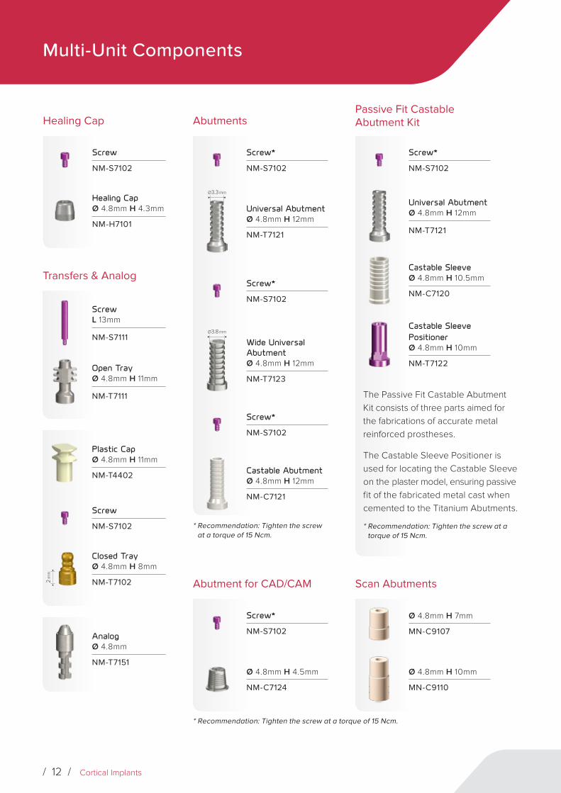
Multi-Unit Components
Passive Fit Castable Abutment Kit
Screw*
NM-S7102
Universal AbutmentØ 4.8mm H 12mm
NM-T7121
Castable SleeveØ 4.8mm H 10.5mm
NM-C7120
Castable Sleeve PositionerØ 4.8mm H 10mm
NM-T7122
The Passive Fit Castable Abutment Kit consists of three parts aimed for the fabrications of accurate metal reinforced prostheses.
The Castable Sleeve Positioner is used for locating the Castable Sleeve on the plaster model, ensuring passive fit of the fabricated metal cast when cemented to the Titanium Abutments.
* Recommendation: Tighten the screw at a torque of 15 Ncm.
Healing Cap
Screw
NM-S7102
Healing CapØ 4.8mm H 4.3mm
NM-H7101
Transfers & Analog
ScrewL 13mm
NM-S7111
Open TrayØ 4.8mm H 11mm
NM-T7111
Plastic CapØ 4.8mm H 11mm
NM-T4402
Screw
NM-S7102
2 m
m
Closed TrayØ 4.8mm H 8mm
NM-T7102
AnalogØ 4.8mm
NM-T7151
Abutments
Screw*
NM-S7102
Ø 3.3 mm
Universal AbutmentØ 4.8mm H 12mm
NM-T7121
Screw*
NM-S7102
Ø 3.8 mm
Wide Universal AbutmentØ 4.8mm H 12mm
NM-T7123
Screw*
NM-S7102
Castable AbutmentØ 4.8mm H 12mm
NM-C7121
Abutment for CAD/CAM
Screw*
NM-S7102
Ø 4.8mm H 4.5mm
NM-C7124
Scan Abutments
Ø 4.8mm H 7mm
MN-C9107
Ø 4.8mm H 10mm
MN-C9110
* Recommendation: Tighten the screw at a torque of 15 Ncm.
* Recommendation: Tighten the screw at a torque of 15 Ncm.

Straight Multi-Unit Drivers
Short Driver 2.0mm L 6mm
NM-X1016
Long Driver 2.0mm L 10mm
NM-X1017
Straight Multi-Unit Motor Mounts
Short Motor Mount 2.0mm L 20mm
NM-X1120
Long Motor Mount 2.0mm L 25mm
NM-X1125
Star Hex. Drivers
Short Driver 1.25mm L 7mm
NM-X7006
Long Driver 1.25mm L 14mm
NM-X7007
Long Driver 1.25mm L 20mm
NM-X7011
Star Hex. Motor Mounts
Motor Mount 1.25mm L 20mm
NM-X7008
Motor Mount 1.25mm L 25mm
NM-X7009
Motor Mount 1.25mm L 35mm
NM-X7010
Multi-Unit Drivers

/ 14 / Cortical Implants
Assembly of a Straight Multi-Unit Base
Assembly of Angled Multi-Unit Base
Impression
Choose the desired impression technique:
Healing Cap Assembly
1
2
1
2
33
4
Adjust the straight Multi-Unit Base to the implant by using the plastic handle.
Adjust the Multi-Unit base to the appropriate angle.
Use the handle as an indicator for the final screw emergence.
For closed tray choose Snap-On-Transfer.
For open tray technique choose conventional Transfer.
Remove the handle.
Tighten the base at 25 Ncm, with a 2.0mm Straight Multi-Unit Driver.
Remove the handle by unscrewing it out.
use the Angulated Guide Pin to choose the right correction angle.
orTighten the base at 20 Ncm, with a 1.25mm Hex Driver or a Star Driver.
Multi-Unit Protocol

Immediate Loading(Fabrication of the temporary bridge)
Laboratory Phase Passive Fit Castable Abutment Kit
1 1
2
Assemble the Titanium Sleeve on the Multi-Unit base and tighten the screw at 15 Ncm.
Mount the Plastic Sleeve on the Multi-Unit analog and tighten with the screw.
3
Carve the Sleeves to the desired shape.
2
Splint the sleeves.
4
Invest and cast the metal frame of the prosthesis.
Attach the pre-prepared provisional acrylic prosthesis
The Passive Fit Castable Abutment Kit consists of three parts aimed for the fabrication of accurate metal reinforced prostheses. The uniquely designed Castable Sleeve Positioner is used for locating the Castable Sleeve on the plaster model, ensuring passive fit of the fabricated metal cast when cemented to the Titanium Abutments.

/ 16 / Zygomatic Implants
Clinical Case
Prosthetic Rehabilitation of Atropic Maxilla Using 4 Zygomatic Implants
Prosthetic rehabilitation of the upper jaw, after major bone resorption, is very challenging from both surgical and prosthetic points of view. The absence of teeth leads to cessation of the stimulation of the alveolar bone. The stimulation is caused by the physiological load which is transferred to the alveolar bone and prevents resorption.
Shortly after the teeth extraction the process of alveolar bone resorption starts. The ongoing resorption is progressively continuing over the years until reaching atrophy. Installation of dental implants at this stage, using conventional techniques, is very difficult due to extensive bone resorption and the accompanied pneumatization of the maxillary sinuses.
The conventional treatment options for these patients are mostly augmentation procedures, which are meant to increase the volume of the load bearing bone.
The bone for the augmentation is taken from different sources, such as: the iliac crest, or intraoral origin, like the mandibular ramus, the intermental region etc. Augmentation procedures are very complicated and require a long recovery period.
An additional treatment option for atrophic maxilla is the placement of Zygomatic implants.
The Zygomatic bone was found to be suitable for installation of dental implants. In 1998 Branemark presented the Zygomatic implant as an optional solution for the treatment of oncologic patients. This solution was expanded later on to Atrophic Maxilla. Long implants were found to be a good alternative for complicated augmentations procedures. Even though they are not easy to install, they present promising outcomes (1, 2, 3).
Noris Medical Zygomatic Implant was especially designed for implantation in the Extramaxillary approach. The Extramaxillary approach enables the positioning of the prosthetic connection on the Alveolar Ridge, unlike the other methods in which the prosthetic unit is more palatinially positioned (4). This location is more correct and easier for the rehabilitation process.
In the Extramaxillary approach, the implant’s stability is being achieved only by the Zygomatic bone. For this reason the implant is designed with a spiral and deep retentive thread shape at its apex, while the rest of the implant is smooth. The diameter of all the Zygomatic Implants is 4.2mm and their lengths vary between 35mm and 57.5mm.

Case DescriptionWith the courtesy of Dr. Balan Igal D.M.D.
68 years old female patient
Medical history:
• Controlled high blood pressure;
• Balanced Type II diabetes;
• Bilateral mastectomy in 2008;
Clinical and radiological findings: Combination Syndrome; Pneumatization of the Maxillary Sinuses; Severe resorption of the upper alveolar ridge; Perimplantitis and mucositis around implant in position of tooth 31.
Treatment Plan
After radiological and CT assessments it was decided to install two Tubero Pterygoid Palatine Implants, 4 Zygomatic implants at the Extramaxillary approach and one implant in the incisive canal.
The surgical procedure was done in the Split Mouth technique, in order to reduce the exposure time of the bone.
After the installation of the implants, augmentation was done, using Calcium Sulfate + HA.
Correction of angulation was achieved by using Multi-Units in angulation of 17°, 30°, 45° as found necessary.
In the lower jaw, the removable prosthesis was changed to fixed prosthesis, on Multi-Unit bases, as well. Rehabilitation was performed on the day of the surgical procedure.
A few hours after the operation, the patient received two provisional acrylic bridges reinforced by induction welded Titanium (grade 5) bar.

/ 18 / Zygomatic Implants
2
1
Panoramic and CT illustrate the Pneumatization of the Maxillary Sinuses and the Severe resorption of the upper Alveolar Ridge (Figs 1, 2).
3
Combination Syndrome.

Groove preparation for leading the Zygomatic Implant drill.
The integrity of the Schneiderian Membrane can be observed (Figs 5, 6).
4
6
5
Zygomatic Implant in situ.
7
Upper Jaw

/ 20 / Zygomatic Implants
Correcting the Angulation using a 45° Multi-Unit Abutment.
8
10
The surgical procedure was done by Split Mouth technique in order to reduce the exposure time of the bone during the installation of the Zygomatic Implants. Two Implants were placed on each side (Figs 9. 10).
9
After the installation of the implants, augmentation was done using Calcium Sulfate + HA.
11

Transfers were mounted and fixed on the Multi-Units in order to take an impression using the Open Tray technique but the impression was taken without using a tray (Figs 12, 13, 14).
12 13
Upper jaw provisional Acrylic Bridge reinforced by induction welded Titanium (grade 5) bar.
14 15
16 17
Impressions of the lower jaw, using Snap-On Transfers

/ 22 / Zygomatic Implants
18 19
20 21
Lower jaw provisional acrylic bridge reinforced by induction welded Titanium (grade 5) bar.
In the upper jaw Two Tubero Pterygoid Palatine Implants, four Zygomatic implants at the Extramaxillary approach and one implant in the incisive canal were installed.
10 months post op. with the final restoration.
22 23

References:
1. Boyes-Varley JG, Howes DG, Davidge-Pitts KD, Brånemark I, McAlpine JA. A protocol for maxillary reconstruction following oncology resection using zygomatic implants. Int J Prosthodont. 2007 Sep-Oct;20:521-31.
2. D'Agostino A, Procacci P, Ferrari F, Trevisiol L, Nocini PF. Zygoma implant-supported prosthetic rehabilitation of a patient after subtotal bilateral maxillectomy. J Craniofac Surg. 2013 Mar;24(2):e159-62.
3. Maló P, Nobre Mde A, Lopes I. A new approach to rehabilitate the severely atrophic maxilla using extramaxillary anchored implants in immediate function: a pilot study. J Prosthet Dent. 2008 Nov;100(5):354-66.
4. Aparicio C, Ouazzani W, Hatano N. The use of zygomatic implants for prosthetic rehabilitation of the severely resorbed maxilla. Periodontol 2000. 2008;47:162-71.

www.norismedical.com
LBL0
12 R
ev. 2
017
-1 EN
Copyright © 2022 FDOKUMEN