Diffusion stabilizes cavity solitons in bidirectional lasers
EUROGRAPHICS 2003 / P. Brunet and D. Fellner(Guest Editors)
Volume 22(2003), Number 3
Interactive Rendering with Bidirectional Texture Functions
Frank Suykens, Karl vom Berge, Ares Lagae and Philip Dutré†
Department of Computer Science, K.U.Leuven, Belgium
AbstractWe propose a new technique for efficiently rendering bidirectional texturefunctions (BTFs). A 6D BTF describesthe appearance of a material as a texture that depends on the lighting and viewing directions. As such, a BTFaccommodates self-shadowing, interreflection, and masking effects of acomplex material without needing anexplicit representation of the small scale geometry. Our method represents the BTF as a set of spatially varyingapparent BRDFs, that each encode the reflectance field of a single pixel in the BTF. Each apparent BRDF isdecomposed into a product of three or more two-dimensional positive factors using a novel factorization technique,which we call chained matrix factorization (CMF). The proposed factorization technique is fully automatic andsuitable for both BRDFs and apparent BRDFs (which typically exhibit off-specular peaks and non-reciprocity).The main benefit of CMF is that it delivers factors well suited for the limited dynamic range of conventionaltexture maps. After factorization, an efficient representation of the BTF is obtained by clustering the factors intoa compact set of 2D textures. With this compact representation, BTFs can be rendered on recent consumer levelhardware with arbitrary viewing and lighting directions at interactive rates.
Categories and Subject Descriptors(according to ACM CCS): I.3.7 [Computer Graphics]: Three-DimensionalGraphics and Realism
1. Introduction
Complex material models are essential for the realistic ap-pearance of rendered objects. Material models are closelyrelated to geometry and can be described at three levelsof increasing scale. The macrostructure relates to the largescale geometry of objects. At the microstructure level, light-surface interaction can be represented by a bidirectional re-flection distribution function (BRDF). The mesostructure issituated in between and exhibits a rich variety of subtlelighting effects, such as self-shadowing, interreflection, andmasking. It can be described by abidirectional texture func-tion (BTF), which makes abstraction of the detailed geome-try of the mesostructure.
A BTF is a 6D function which depends on position, butalso on the lighting and viewing direction. As such, the BTFcan be seen as a set ofapparent BRDFs(ABRDFs)21, one foreach position in the BTF. An ABRDF encodes the reflectionin a single point given a lighting and viewing direction; it
† e-mail: {Frank.Suykens, Karl.vomBerge, Ares.Lagae,Philip.Dutre}@cs.kuleuven.ac.be
is calledapparentbecause the underlying geometry is of amuch larger scale compared to normal BRDFs. Therefore,ABRDFs are usually not symmetric.
As opposed to a regular 2D texture, a BTF is high-dimensional and involves large amounts of data. To renderBTFs on graphics hardware, a compact representation ofthe BTF is needed. To that end, we have developed a new(A)BRDF factorization method, which we callchained ma-trix factorization (CMF). CMF scales well, requires littlemanual tuning, and produces factors well suited for the lim-ited dynamic range of regular texture maps.
Our technique consists out of four steps: BTF acquisi-tion, factorization, clustering, and hardware rendering. Firstwe construct a synthetic BTF by modeling the mesostruc-ture, from which a global illumination renderer computesa set of ABRDFs (§3). This results in a discretized BTF.Next, we factor this set of ABRDFs using CMF (§4). EachABRDF is approximated by a three factor decomposition.Many ABRDFs have similar factors, allowing us to clusterthem into a more compact representation (§5). Finally, thisrepresentation is rendered at interactive frame rates using
c© The Eurographics Association and Blackwell Publishers 2003. Published by BlackwellPublishers, 108 Cowley Road, Oxford OX4 1JF, UK and 350 Main Street, Malden, MA02148, USA.
Suykens, vom Berge, Lagae, Dutré / Interactive BTF rendering
graphics hardware (§6). Results are presented in section7,conclusions in section8.
2. Related work
BTFs have been investigated in both computer vision andcomputer graphics. Seminal work by Dana et al.1 on BTFsaims to capture appearance data for natural materials. Byacquiring images of material samples using a gantry anda video-camera, a (very sparse) sampling of the BTF isobtained. In computer vision, several models exist forBTF analysis and efficient material recognition. Recently, amodel based on 3D textons was presented by Leung et al.14
Inspired by this idea, Tong et al.19 combine 3D textons withan efficient search strategy to synthesize continuous BTFson arbitrary surfaces from a discrete set of samples.
The technique presented in this paper relates to workdone on finding efficient representations for rendering com-plex materials. Early work by Westin et al.20 explicitly mod-els surface microgeometry to synthesize BRDFs. Our tech-nique of generating synthetic BTFs closely resembles themesostructure sampling techniques used by Dischler3 toefficiently raytrace BTFs. A similar technique is used byDaubert et al.2, where a hybrid hardware-software methodfor efficient cloth modeling and rendering is presented. Bothmethods also use mip-mapping to obtain smooth transitionsduring rendering. Heidrich et al.5 present an efficient sam-pling technique and illuminates microgeometry using pre-computed visibility. A variation on the idea of mesostruc-ture sampling is a method for rendering trees by Meyer etal.18 Tree geometry is sampled and represented by a sparse,hierarchical BTF representation which can be rendered at in-teractive speeds.
With the recent advent of sophisticated commodity graph-ics hardware, a lot of research focuses on interactive render-ing methods for complex materials. Finding space-efficientrepresentations for these materials, suitable for hardwarerendering, is an essential part in many papers. Kautz et. al.7
and McCool et al.17 propose techniques based on factoriza-tion to render arbitrary BRDFs at interactive rates. Thesemethods will be discussed in detail in section4. Lensch etal.13 developed an image-based technique to automaticallymeasure objects with spatially varying BRDFs. MeasuredBRDFs are fitted with generalized cosine lobes10, which arethen clustered. McAllister et al.16 store Lafortune BRDFparameters in textures to allow efficient hardware render-ing of spatially varying materials. Because the Lafortunemodel enforces reciprocity, their technique is not directlyapplicable to ABRDFs. A similar technique, also based onBRDF parameter variation was introduced earlier by Kautzet al.8 Polynomial texture maps15 use biquadratic polynomi-als to represent the appearance of surfaces, including self-shadowing and interreflections, under varying illumination.It is important to note that many representations for complexsurfaces only support illumination by point lights. Recently,
extentions have been presented that support illumination byenvironment maps. A good overview can be found in Kautzet al.9 and Latta et al.11.
3. BTF acquisition
The first step towards hardware rendering of BTFs is ac-quiring the BTF data. In this work we synthesize our ownBTFs by passing a modeled mesostructure through Render-Park, our global illumination renderer.
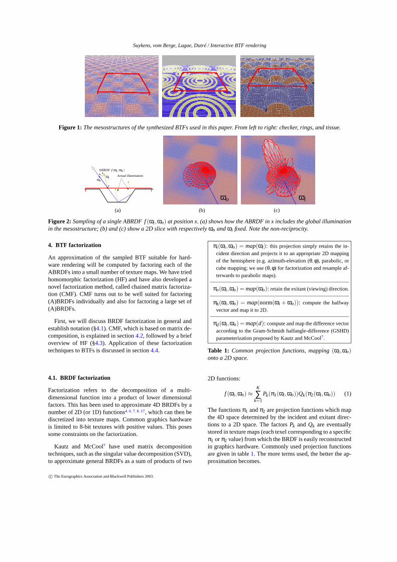
The mesostructures used in this paper are shown in fig-ure1. The first BTF (checker) is a height field created froma smoothed checker pattern. The pink, raised areas have amore specular BRDF than the blue, lower parts. The secondBTF (rings) consists of concentric gold-like rings laid out ona blue, glossy base plane. The third BTF (tissue) is a clothlike structure created by intertwining fibers.
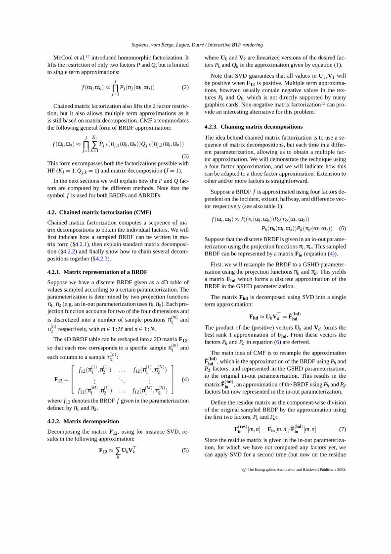
Each red box in figure1 defines a BTF tile that is dis-cretized into a 2D array of ABRDFs. The BTF is denoted byfbt f (x,ωi ,ωo) whereωi is the incident or lighting directionandωo the exitant or viewing direction. An ABRDF forms a4D subset of the BTF by fixing the positionx; it is denotedby f (ωi ,ωo). The BTF sampling process discretizes the BTFtile in a number of pixels. For each pixel an ABRDF is sam-pled, as shown schematically in figure2 (a). For a certainpointx on the BTF tile (red), a viewing directionωo is gener-ated. By tracing a ray towards the mesostructure model, thelocation visible from the viewing direction is found. By com-puting the (global) illumination in this intersection point, dueto a directional light source with directionωi , a single sam-ple in the ABRDF is obtained. Repeating this for a largenumber of lighting and viewing directions results in a sam-pled representation of the ABRDF.
Figures2 (b) and (c) show a 2D slice of a single ABRDFf (ωi ,ωo) on top of the checker BTF. In (b) the viewingdirection ωo is fixed (blue line), and the ABRDF value isshown for all possible lighting directionsωi (red mesh). In(c) the viewing and lighting directions are exchanged. Notethat the resulting 2D slices differ greatly, which indicates thenon-reciprocity of the ABRDFs. For a symmetric BRDF thetwo slices would be the same.
The result of BTF sampling is a set of ABRDFs, regularlysampled over the BTF tile. We commonly use a 64 by 64sampling, resulting in 4096 ABRDFs.
In the following sections these ABRDFs will be factoredand clustered into a suitable representation for hardware ren-dering. It is important to note that, although we use syn-thetic BTFs, none of the subsequent steps rely in any wayon the geometry of the mesostructure. Therefore our tech-niques should be equally applicable to measured BTFs1.
c© The Eurographics Association and Blackwell Publishers 2003.
Suykens, vom Berge, Lagae, Dutré / Interactive BTF rendering
Figure 1: The mesostructures of the synthesized BTFs used in this paper. From leftto right: checker, rings, and tissue.
ABRDF f (ωi , ωo)
ωoωi
Actual illumination
x
(a) (b) (c)
ωiωo
Figure 2: Sampling of a single ABRDF f(ωi ,ωo) at position x. (a) shows how the ABRDF in x includes the global illuminationin the mesostructure; (b) and (c) show a 2D slice with respectivelyωo andωi fixed. Note the non-reciprocity.
4. BTF factorization
An approximation of the sampled BTF suitable for hard-ware rendering will be computed by factoring each of theABRDFs into a small number of texture maps. We have triedhomomorphic factorization (HF) and have also developed anovel factorization method, called chained matrix factoriza-tion (CMF). CMF turns out to be well suited for factoring(A)BRDFs individually and also for factoring a large set of(A)BRDFs.
First, we will discuss BRDF factorization in general andestablish notation (§4.1). CMF, which is based on matrix de-composition, is explained in section4.2, followed by a briefoverview of HF (§4.3). Application of these factorizationtechniques to BTFs is discussed in section4.4.
4.1. BRDF factorization
Factorization refers to the decomposition of a multi-dimensional function into a product of lower dimensionalfactors. This has been used to approximate 4D BRDFs by anumber of 2D (or 1D) functions4, 6, 7, 8, 17, which can then bediscretized into texture maps. Common graphics hardwareis limited to 8-bit textures with positive values. This posessome constraints on the factorization.
Kautz and McCool7 have used matrix decompositiontechniques, such as the singular value decomposition (SVD),to approximate general BRDFs as a sum of products of two
πi(ωi ,ωo) = map(ωi): this projection simply retains the in-cident direction and projects it to an appropriate 2D mappingof the hemisphere (e.g. azimuth-elevation (θ,φ), parabolic, orcube mapping; we use (θ,φ) for factorization and resample af-terwards to parabolic maps).
πo(ωi ,ωo) = map(ωo): retain the exitant (viewing) direction.
πh(ωi ,ωo) = map(norm(ωi + ωo)): compute the halfwayvector and map it to 2D.
πd(ωi ,ωo) = map(d): compute and map the difference vectoraccording to the Gram-Schmidt halfangle-difference (GSHD)parameterization proposed by Kautz and McCool7.
Table 1: Common projection functions, mapping(ωi ,ωo)onto a 2D space.
2D functions:
f (ωi ,ωo) ≈K
∑k=1
Pk(π1(ωi ,ωo))Qk(π2(ωi ,ωo)) (1)
The functionsπ1 andπ2 are projection functions which mapthe 4D space determined by the incident and exitant direc-tions to a 2D space. The factorsPk and Qk are eventuallystored in texture maps (each texel corresponding to a specificπ1 or π2 value) from which the BRDF is easily reconstructedin graphics hardware. Commonly used projection functionsare given in table1. The more terms used, the better the ap-proximation becomes.
c© The Eurographics Association and Blackwell Publishers 2003.
Suykens, vom Berge, Lagae, Dutré / Interactive BTF rendering
McCool et al.17 introduced homomorphic factorization. Itlifts the restriction of only two factorsP andQ, but is limitedto single term approximations:
f (ωi ,ωo) ≈J
∏j=1
Pj (π j (ωi ,ωo)) (2)
Chained matrix factorization also lifts the 2 factor restric-tion, but it also allows multiple term approximations as itis still based on matrix decomposition. CMF accommodatesthe following general form of BRDF approximation:
f (ωi ,ωo) ≈J
∏j=1
K j
∑k=1
Pj,k(π j,1(ωi ,ωo))Q j,k(π j,2(ωi ,ωo))
(3)This form encompasses both the factorizations possible withHF (K j = 1,Q j,k = 1) and matrix decomposition (J = 1).
In the next sections we will explain how theP andQ fac-tors are computed by the different methods. Note that thesymbol f is used for both BRDFs and ABRDFs.
4.2. Chained matrix factorization (CMF)
Chained matrix factorization computes a sequence of ma-trix decompositions to obtain the individual factors. We willfirst indicate how a sampled BRDF can be written in ma-trix form (§4.2.1), then explain standard matrix decomposi-tion (§4.2.2) and finally show how to chain several decom-positions together (§4.2.3).
4.2.1. Matrix representation of a BRDF
Suppose we have a discrete BRDF given as a 4D table ofvalues sampled according to a certain parameterization. Theparameterization is determined by two projection functionsπ1,π2 (e.g. an in-out parameterization usesπi ,πo). Each pro-jection function accounts for two of the four dimensions and
is discretized into a number of sample positionsπ(m)1 and
π(n)2 respectively, withm∈ 1:M andn∈ 1:N.
The 4D BRDF table can be reshaped into a 2D matrixF12,
so that each row corresponds to a specific sampleπ(m)1 and
each column to a sampleπ(n)2 :
F12 =
f12(π(1)1 ,π(1)
2 ) . . . f12(π(1)1 ,π(N)
2 )...
. . ....
f12(π(M)1 ,π(1)
2 ) . . . f12(π(M)1 ,π(N)
2 )
(4)
wheref12 denotes the BRDFf given in the parameterizationdefined byπ1 andπ2.
4.2.2. Matrix decomposition
Decomposing the matrixF12, using for instance SVD, re-sults in the following approximation:
F12 ≈ ∑k
UkV>k (5)
whereUk andVk are linearized versions of the desired fac-torsPk andQk in the approximation given by equation (1).
Note that SVD guarantees that all values inU1,V1 willbe positive whenF12 is positive. Multiple term approxima-tions, however, usually contain negative values in the tex-turesPk and Qk, which is not directly supported by manygraphics cards. Non-negative matrix factorization12 can pro-vide an interesting alternative for this problem.
4.2.3. Chaining matrix decompositions
The idea behind chained matrix factorization is to use a se-quence of matrix decompositions, but each time in a differ-ent parameterization, allowing us to obtain a multiple fac-tor approximation. We will demonstrate the technique usinga four factor approximation, and we will indicate how thiscan be adapted to a three factor approximation. Extension toother and/or more factors is straightforward.
Suppose a BRDFf is approximated using four factors de-pendent on the incident, exitant, halfway, and difference vec-tor respectively (see also table1):
f (ωi ,ωo) ≈ Pi(πi(ωi ,ωo))Po(πo(ωi ,ωo))
Ph(πh(ωi ,ωo))Pd(πd(ωi ,ωo)) (6)
Suppose that the discrete BRDF is given in an in-out parame-terization using the projection functionsπi ,πo. This sampledBRDF can be represented by a matrixFio (equation (4)).
First, we will resample the BRDF to a GSHD parameter-ization using the projection functionsπh andπd. This yieldsa matrixFhd which forms a discrete approximation of theBRDF in the GSHD parameterization.
The matrixFhd is decomposed using SVD into a singleterm approximation:
Fhd ≈ UhV>d = F(hd)
hd
The product of the (positive) vectorsUh andVd forms thebest rank 1 approximation ofFhd. From these vectors thefactorsPh andPd in equation (6) are derived.
The main idea of CMF is to resample the approximation
F(hd)hd , which is the approximation of the BRDF usingPh and
Pd factors, and represented in the GSHD parameterization,to the original in-out parameterization. This results in the
matrixF(hd)io , an approximation of the BRDF usingPh andPd
factors but now represented in the in-out parameterization.
Define the residue matrix as the component-wise divisionof the original sampled BRDF by the approximation usingthe first two factors,Ph andPd:
F(res)io [m,n] = Fio[m,n]/F(hd)
io [m,n] (7)
Since the residue matrix is given in the in-out parameteriza-tion, for which we have not computed any factors yet, wecan apply SVD for a second time (but now on the residue
c© The Eurographics Association and Blackwell Publishers 2003.
Suykens, vom Berge, Lagae, Dutré / Interactive BTF rendering
matrix). This gives aUi andVo vector and the correspond-ing Pi andPo factors:
F(res)io ≈ UiV
>o = F(res,io)
io
The 4 factorsPi , Po, Ph, andPd, computed by a chained sin-gular value decomposition, approximate the BRDF as givenin equation (6). This can be seen by looking at a single ele-ment inFio (from equation7):
Fio[m,n] ≈ F(res,io)io [m,n]×F(hd)
io [m,n]
≈ Pi(πi(ω(m)i ,ω(n)
o ))Po(πo(ω(m)i ,ω(n)
o ))×
Ph(πh(ω(m)i ,ω(n)
o ))Pd(πd(ω(m)i ,ω(n)
o ))
This example shows that by a chain of matrix decomposi-tions, each one in a different parameterization, four, six, ormore factors can be computed in the BRDF approximation.In each matrix decomposition step, a multiple term approxi-mation can be used to obtain a higher accuracy.
The method above is also easily adapted to a 3 factor ap-proximation. For example, a common 3 factor approxima-tion, used by McCool et al.17, uses factors dependent on in-cident, halfway, and exitant directions:Pi(πi)Ph(πh)Po(πo).This can be interpreted as a 4 factor approximation wherePd = 1 for all combinations of incident and exitant di-rections. Given the BRDF in the GSHD parameterization(Fhd), Ph is obtained by averaging all the columns ofFhdcomponent-wise. This corresponds to a projection of thesampled BRDF byπh onto the 2D functionPh. In this casethe factorPd will be 1, and can be left out of the approxima-tion. As such, any approximation in a form corresponding toequation (3) can be computed using CMF.
Note that resampling a discrete BRDF into another pa-rameterization may introduce some error. Also, the approx-imation depends on the order in which the different matrixdecompositions are applied (and hence the order of resam-pling operations). We apply the final matrix decompositionin the original parameterization of the discrete BRDF, be-cause then the final residue is computed with respect to theoriginal data without resampling errors. The resampling er-ror can also be reduced by using a higher sampling resolu-tion for intermediate parameterizations.
4.3. Homomorphic factorization (HF)
McCool et al.17 presented homomorphic factorization whichis able to approximate a BRDF using more than 2 factors, ina form given by equation (2),
f (ωi ,ωo) ≈J
∏j=1
Pj (π j (ωi ,ωo)) (8)
Homomorphic factorization does not try to find the factorsPj directly, but takes the logarithm on both sides of (8) to
convert the product to a sum:
f (ωi ,ωo) ≈J
∑j=1
Pj (π j (ωi ,ωo)) (9)
wherex denotes the logarithm ofx.
Each factorPj is represented by a 2D texture map. Thegoal of the factorization is to find a suitable value for eachtexel. Given a set ofN BRDF samples, a linear equation con-straining the texel values is obtained for each samplen:
f (ω(n)i ,ω(n)
o ) =J
∑j=1
Pj
(
π j (ω(n)i ,ω(n)
o ))
(10)
This system can be written compactly as:
f = Mx
where the target textures are linearized into the solution vec-tor x. Each row in the matrixM contains bilinear interpola-tion coefficients into each of the textures for a single BRDFsamplen. For more information we refer to McCool et al.17
The matrixM is usually rank deficient, meaning that thesystem is under-constrained: some texels may not map tovalid directions, for example the unused texels in a parabolicmap, while other texels might not be constrained due to thesparse sampling of the BRDF. One solution is to perform aregularization on the system: new equations are introducedso that each texel is constrained by at least one equation. InHF each texel is constrained by an additional equation thatsets the (discrete) second derivative (the Laplacian) to zero.This will smooth the resulting textures. A regularization pa-rameterλ is used to control the smoothness of the solution(choosing a good value forλ is, however, not straightfor-ward). This leads to the following set of equations:
[
f0
]
=
[
MλL
]
x
whereL is a block diagonal matrix, with one block for eachtexturePj .
This linear system can be solved using a least squaressolver. The solutionx contains the target textures in loga-rithmic form. The texturePj is obtained by simply exponen-tiating Pj .
A practical comparison between HF and CMF is made inthe next section, when they are applied to a set of ABRDFs.
4.4. BTF factorization
This section gives details on how all the ABRDFs in a fullBTF can be factored, which parameterizations are used, andhow HF and CMF compare.
We have used the following factorization form:
f (ωi ,ωo) ≈ P(πi(ωi ,ωo))Q(πh(ωi ,ωo))R(πo(ωi ,ωo))
Note that we usedP,Q,R instead ofPi ,Ph,Po to simplify
c© The Eurographics Association and Blackwell Publishers 2003.
Suykens, vom Berge, Lagae, Dutré / Interactive BTF rendering
SampledABRDF
HF (FP) CMF (FP) HF (quant) CMF (quant)
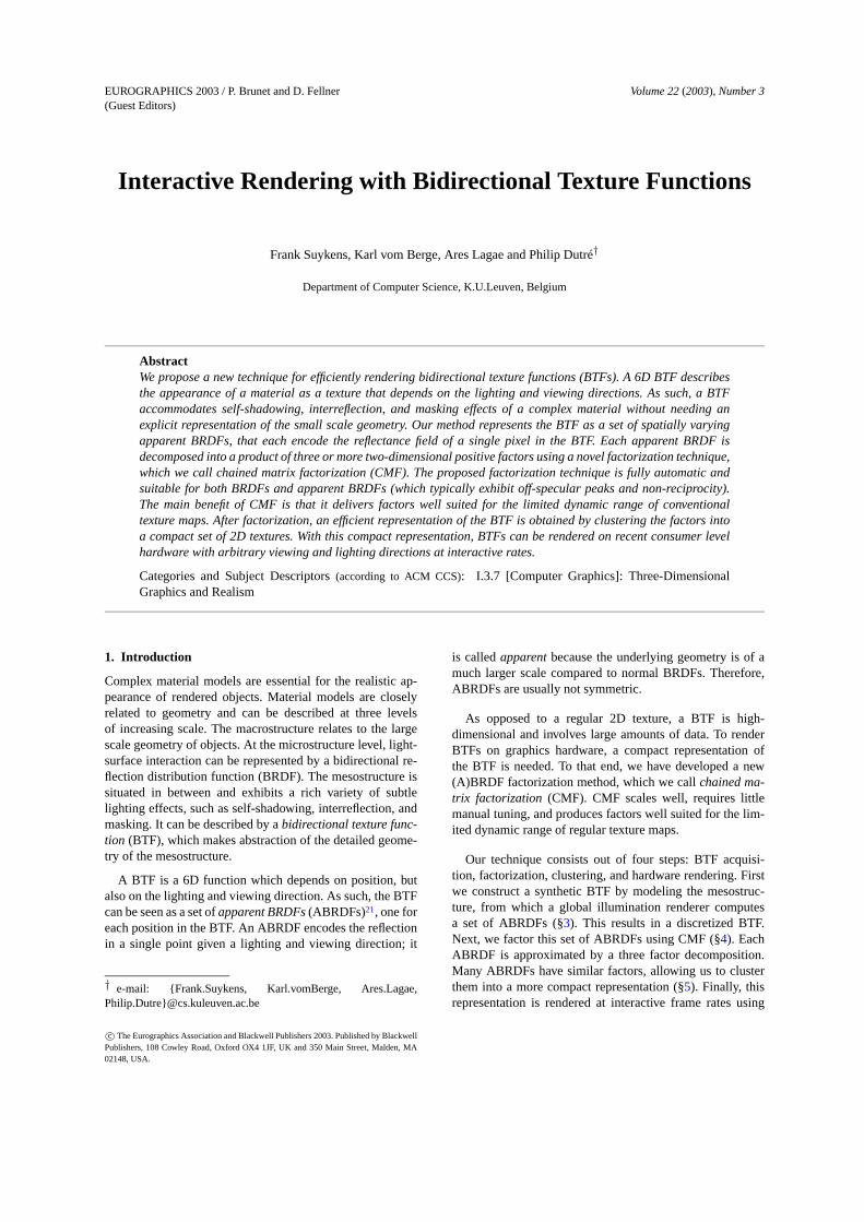
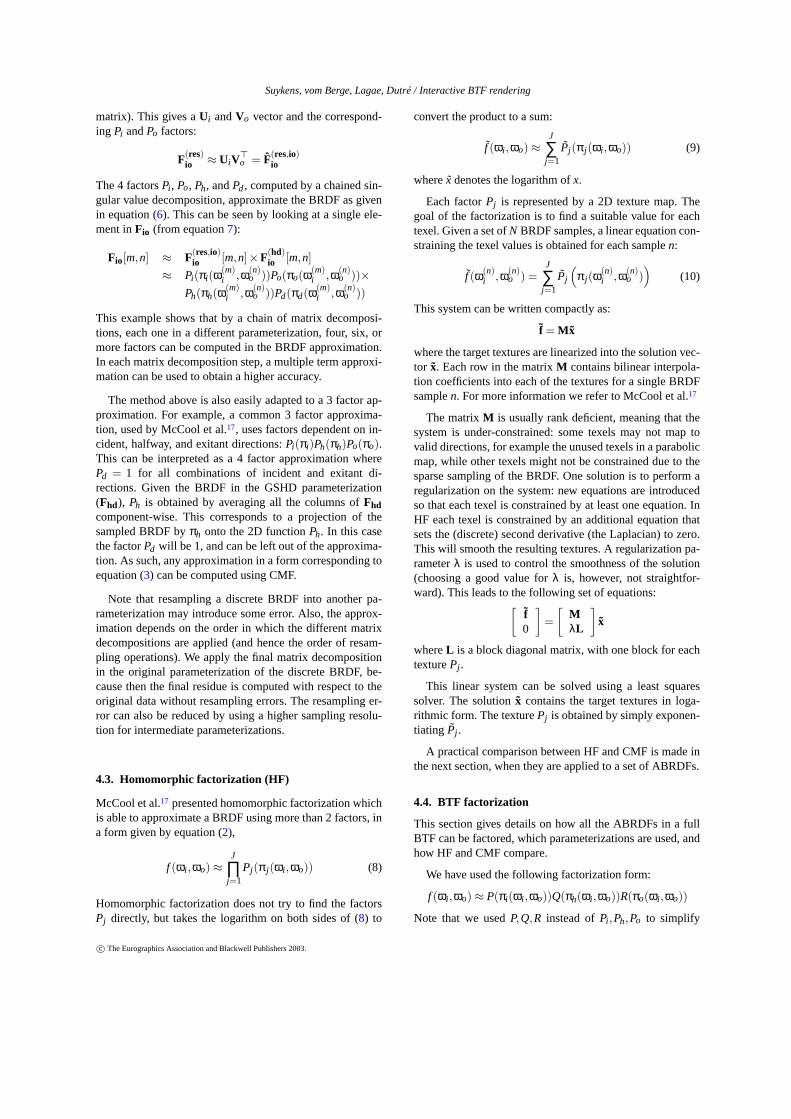
Figure 3: Software rendering of the checker BTF using a top view with a different lightdirection in each row. From left to right:schematic lighting configuration, rendering using the sampled BTF data, homomorphic factorization (HF) in full floating point(FP), chained matrix factorization (CMF) in FP, HF quantized to 8-bit, and CMF quantized to 8-bit. Note that HF looses muchprecision by quantization, while CMF does not.
notation. This form is similar to the BRDF approximationsused by McCool et al.17, except that they use the same factorfor the incident and exitant direction, to ensure a symmetricBRDF approximation. ABRDFs are usually not symmetric,which is why we use separateP andR factors. This factor-ization form works quite well on our ABRDFs and allows acomparison with homomorphic factorization.
To evaluate the results, we wrote a small software rendererthat renders a single BTF tile with a user-defined viewingand lighting direction. Images of the checker BTF are com-puted using the full, unfactored ABRDF data, using HF andCMF approximations with full floating point textures andwith textures quantized to 256 values (since we want to storethem in 8-bit textures). The results of the software rendererare shown in figure3. Each row corresponds to a differentlighting direction.
In full floating point, both HF and CMF give a good ap-proximation of the full BTF on the left. The quantized re-sults, however, show a much bigger difference. Homomor-phic factorization of the ABRDFs results in factors with avery high dynamic range. The large maximum value of afactor causes a significant loss of detail in the smaller valueswhen quantizing, even to the extent that much of the data islost†. The quantized HF results are only usable on the topregions of the checker BTF, where the BTF sampling planecoincides with the actual geometry and the ABRDF corre-sponds to a regular BRDF. When using our new factoriza-tion method, CMF, the factors obtained make much better
† Note that we have tried to use floating point textures on the ATIRadeon 9700, in order to render the BTF using homomorphic factor-ization. Bilinear interpolation of floating point textures, however, isnot supported on current graphics hardware, which results in severebanding effects due to the large difference in values of neighboringtexels.
use of the available dynamic range in the textures, and quan-tisation does not lead to a significant loss of precision. Thisis the largest benefit of CMF with respect to the hardwarerendering of BTFs.
Additional benefits of CMF compared to HF are that it issomewhat easier to implement, allows multiple term approx-imations, and that it does not need a (difficult to choose)smoothing parameterλ. For factoring the ABRDFs usingHF, we have tested severalλ values on a few ABRDFs andused a good value for all (one could optimizeλ for eachABRDF, but this would take a lot of time).
Timings: For a factorization of an ABRDF with 4096 sam-ples, the homomorphic factorization intoP, Q, andR factorstook about 33 seconds per color channel (using a direct leastsquares solver), while CMF required 8 seconds. Of course,when all ABRDFs use the same sampling pattern, the co-efficient matrixM does not change and the pseudo-inversecould be used to efficiently solve the least squares system forall the ABRDFs. We did not do that in our implementation.
Error analysis: We computed the average absolute and rel-ative error of both the (floating point) HF and CMF approx-imations for the checker BTF. Both the absolute and relativeerror of the HF and CMF approximations were similar. Theaverage relative error was large (up to 100%), due to somevery small values in the sampled ABRDF which blew upthe relative errors. Overall, the approximations have aboutthe same accuracy, but CMF has the advantage that it makesbetter use of the dynamic range available in 8-bit textures.
5. BTF clustering
Using normalization and clustering, the factored BTF iscompressed into a more compact representation which canbe used for efficient hardware rendering.
c© The Eurographics Association and Blackwell Publishers 2003.
Suykens, vom Berge, Lagae, Dutré / Interactive BTF rendering
Normalization: BTF factorization produces three factorsP, Q, andR for each ABRDF. Each of these factors is scaledto the 0. . .1 range. This produces three scale factors, whichcan be combined into one scale factor for each ABRDF. Assuch a single scale mapS for the BTF is obtained.
Clustering: For many BTFs, both synthetic and measured,the underlying mesostructure is repetitive in nature. ManyABRDFs at different locations on the mesostructure are sim-ilar, and so are their factors. We exploit this fact by com-pressing the factored ABRDFs into a more compact repre-sentation. The BTF is compressed by performing a separatecluster analysis on each of the normalized factor sets. Thecluster analysis generates a codebook of a given size for eachfactor set. This codebook contains a prototype for each clus-ter. For each factor set an index map is generated, relatingeach location on the BTF with the corresponding prototype.This prototype will later be used to reconstruct the ABRDFat that location.
We tested both k-means clustering and several tree clus-tering schemes with different distance metrics. K-meansclustering produces better error statistics than tree clustering,but seems to introduce slightly more visible artifacts. Also,different tree clustering schemes tend to produce a simi-lar result. We believe that a more intelligent normalizationmust be performed before clustering to further enhance thevisual quality of the results. We noticed, for example, thatmany factors are very similar apart from a rotation. Giventhis observation, one could improve the clustering results byrotating all ABRDFs (e.g. into their direction of maximalanisotropy).
6. Hardware rendering of BTFs
Using the proposed data representation, surfaces with BTFscan be rendered at interactive rates on current hardwaresupporting dependent texture access, such as the NVIDIAGeforce FX and the ATI Radeon 9700. This section providesthe details of our hardware implementation.
The index maps are stored in a single texture with threechannels. The R, G, and B components of a pixel in this tex-ture store the indices of the clusteredP, Q, andR factor ofthe ABRDF for the corresponding position on the BTF. The2D parabolic maps representing theP factors are stackedtogether in a single 3D texture. Two more 3D textures areneeded to store theQ andR factors. The scale mapS is nor-malized by dividing the R, G, and B channel by the maxi-mum value in that channel. The scale map can now be storedinto a regular texture. The maxima are stored in a globalRGB scale factor. The five textures all use the traditional8-bit format.
Rendering: Next to regular vertex attributes (position andnormal), 2D texture coordinates, a tangent, and a binormalare specified for each vertex. Similar to traditional texture
mapping, the texture coordinates determine how the BTF ismapped onto the geometry. The tangent (T), binormal (B),and normal (N) form an orthonormal local frame(T,B,N).This local frame is aligned with the texture coordinates(u,v): the tangent is the derivative of the surface positionwith respect tou. The binormal is given byB = T ×N.
Vertex program: A vertex program calculates the normal-ized light, halfway, and view vector in model space. Usingthe local frame these vectors are transformed to local space.Next, the parabolic mapping is applied, yielding three sets of2D texture coordinates, one for each factorP, Q, andR. Theoriginal set of texture coordinates mapping the BTF onto thesurface is not altered. Finally, the vertex program calculatesthe cosine falloff factor, which is simply thez component ofthe light vector in local space. Negative values of this factor,representing a light behind a primitive, are clamped to zero.
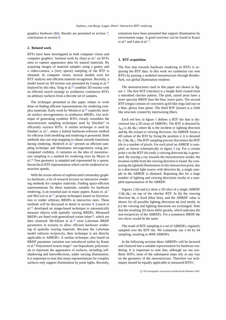
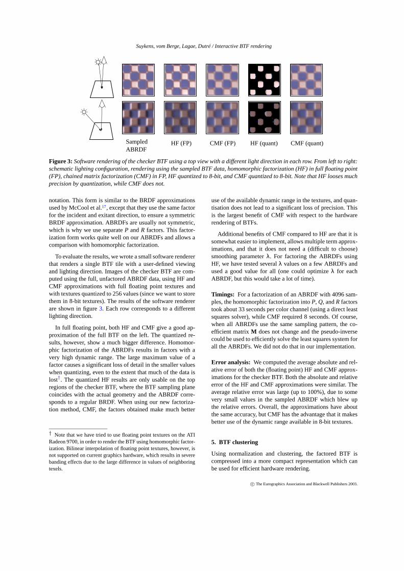
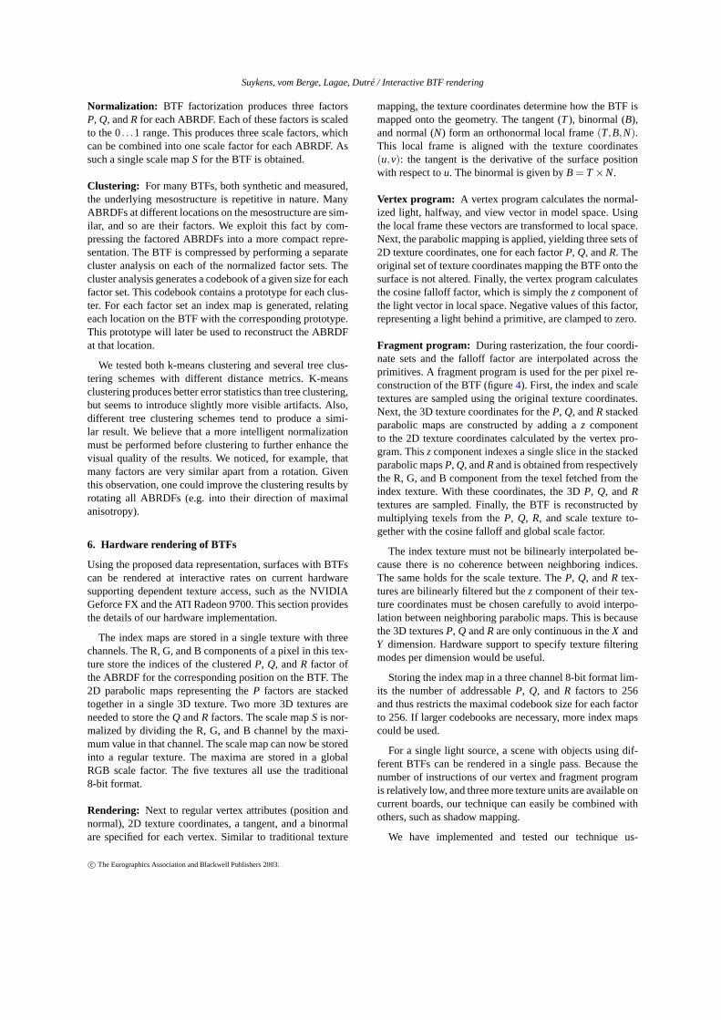
Fragment program: During rasterization, the four coordi-nate sets and the falloff factor are interpolated across theprimitives. A fragment program is used for the per pixel re-construction of the BTF (figure4). First, the index and scaletextures are sampled using the original texture coordinates.Next, the 3D texture coordinates for theP, Q, andRstackedparabolic maps are constructed by adding az componentto the 2D texture coordinates calculated by the vertex pro-gram. Thiszcomponent indexes a single slice in the stackedparabolic mapsP, Q, andRand is obtained from respectivelythe R, G, and B component from the texel fetched from theindex texture. With these coordinates, the 3DP, Q, andRtextures are sampled. Finally, the BTF is reconstructed bymultiplying texels from theP, Q, R, and scale texture to-gether with the cosine falloff and global scale factor.
The index texture must not be bilinearly interpolated be-cause there is no coherence between neighboring indices.The same holds for the scale texture. TheP, Q, andR tex-tures are bilinearly filtered but thez component of their tex-ture coordinates must be chosen carefully to avoid interpo-lation between neighboring parabolic maps. This is becausethe 3D texturesP, Q andRare only continuous in theX andY dimension. Hardware support to specify texture filteringmodes per dimension would be useful.
Storing the index map in a three channel 8-bit format lim-its the number of addressableP, Q, and R factors to 256and thus restricts the maximal codebook size for each factorto 256. If larger codebooks are necessary, more index mapscould be used.
For a single light source, a scene with objects using dif-ferent BTFs can be rendered in a single pass. Because thenumber of instructions of our vertex and fragment programis relatively low, and three more texture units are available oncurrent boards, our technique can easily be combined withothers, such as shadow mapping.
We have implemented and tested our technique us-
c© The Eurographics Association and Blackwell Publishers 2003.
Suykens, vom Berge, Lagae, Dutré / Interactive BTF rendering
iω
h
oω
×
I=
×
×
×
ni•ω
S
R
G
B
Texture
Mapping
P
Q
R
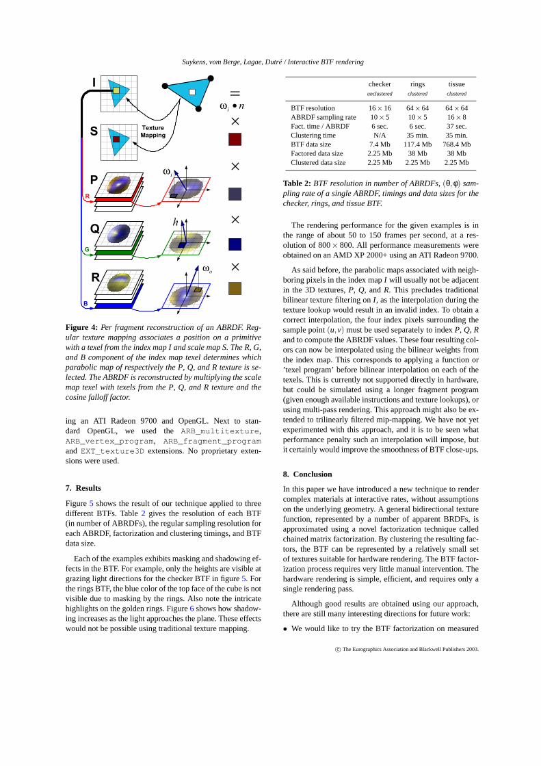
Figure 4: Per fragment reconstruction of an ABRDF. Reg-ular texture mapping associates a position on a primitivewith a texel from the index map I and scale map S. The R, G,and B component of the index map texel determines whichparabolic map of respectively the P, Q, and R texture is se-lected. The ABRDF is reconstructed by multiplying the scalemap texel with texels from the P, Q, and R texture and thecosine falloff factor.
ing an ATI Radeon 9700 and OpenGL. Next to stan-dard OpenGL, we used theARB_multitexture,ARB_vertex_program, ARB_fragment_programand EXT_texture3D extensions. No proprietary exten-sions were used.
7. Results
Figure5 shows the result of our technique applied to threedifferent BTFs. Table2 gives the resolution of each BTF(in number of ABRDFs), the regular sampling resolution foreach ABRDF, factorization and clustering timings, and BTFdata size.
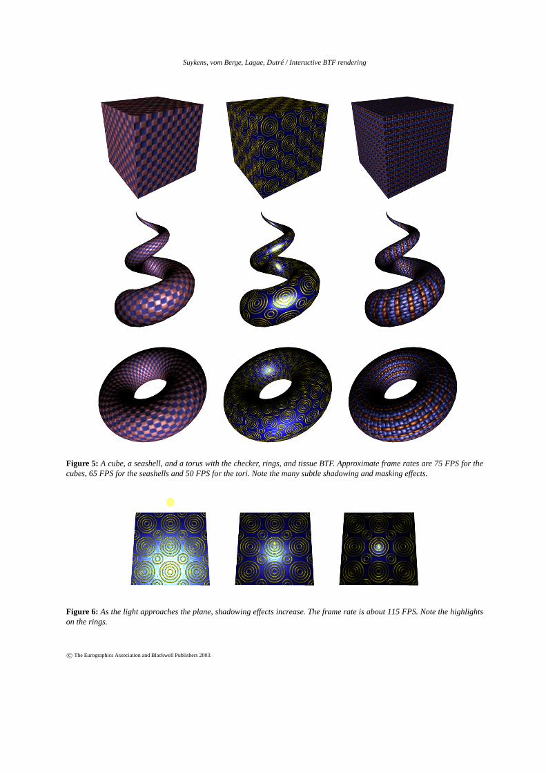
Each of the examples exhibits masking and shadowing ef-fects in the BTF. For example, only the heights are visible atgrazing light directions for the checker BTF in figure5. Forthe rings BTF, the blue color of the top face of the cube is notvisible due to masking by the rings. Also note the intricatehighlights on the golden rings. Figure6 shows how shadow-ing increases as the light approaches the plane. These effectswould not be possible using traditional texture mapping.
checker rings tissueunclustered clustered clustered
BTF resolution 16×16 64×64 64×64ABRDF sampling rate 10×5 10×5 16×8Fact. time / ABRDF 6 sec. 6 sec. 37 sec.Clustering time N/A 35 min. 35 min.BTF data size 7.4 Mb 117.4 Mb 768.4 MbFactored data size 2.25 Mb 38 Mb 38 MbClustered data size 2.25 Mb 2.25 Mb 2.25 Mb
Table 2: BTF resolution in number of ABRDFs,(θ,φ) sam-pling rate of a single ABRDF, timings and data sizes for thechecker, rings, and tissue BTF.
The rendering performance for the given examples is inthe range of about 50 to 150 frames per second, at a res-olution of 800× 800. All performance measurements wereobtained on an AMD XP 2000+ using an ATI Radeon 9700.
As said before, the parabolic maps associated with neigh-boring pixels in the index mapI will usually not be adjacentin the 3D textures,P, Q, andR. This precludes traditionalbilinear texture filtering onI , as the interpolation during thetexture lookup would result in an invalid index. To obtain acorrect interpolation, the four index pixels surrounding thesample point(u,v) must be used separately to indexP, Q, Rand to compute the ABRDF values. These four resulting col-ors can now be interpolated using the bilinear weights fromthe index map. This corresponds to applying a function or’texel program’ before bilinear interpolation on each of thetexels. This is currently not supported directly in hardware,but could be simulated using a longer fragment program(given enough available instructions and texture lookups), orusing multi-pass rendering. This approach might also be ex-tended to trilinearly filtered mip-mapping. We have not yetexperimented with this approach, and it is to be seen whatperformance penalty such an interpolation will impose, butit certainly would improve the smoothness of BTF close-ups.
8. Conclusion
In this paper we have introduced a new technique to rendercomplex materials at interactive rates, without assumptionson the underlying geometry. A general bidirectional texturefunction, represented by a number of apparent BRDFs, isapproximated using a novel factorization technique calledchained matrix factorization. By clustering the resulting fac-tors, the BTF can be represented by a relatively small setof textures suitable for hardware rendering. The BTF factor-ization process requires very little manual intervention. Thehardware rendering is simple, efficient, and requires only asingle rendering pass.
Although good results are obtained using our approach,there are still many interesting directions for future work:
• We would like to try the BTF factorization on measured
c© The Eurographics Association and Blackwell Publishers 2003.
Suykens, vom Berge, Lagae, Dutré / Interactive BTF rendering
Figure 5: A cube, a seashell, and a torus with the checker, rings, and tissue BTF. Approximate frame rates are 75 FPS for thecubes, 65 FPS for the seashells and 50 FPS for the tori. Note the many subtle shadowing and masking effects.
Figure 6: As the light approaches the plane, shadowing effects increase. The frame rate is about 115 FPS. Note the highlightson the rings.
c© The Eurographics Association and Blackwell Publishers 2003.
Suykens, vom Berge, Lagae, Dutré / Interactive BTF rendering
BTFs, for example from the Curet database, to see if wecan handle the very sparse sampling.
• Fairly standard texture synthesis techniques could be usedon the clustered representation of the BTF (i.e., using theindex map and scale map instead of a simple texture map).This could lead to an interesting method for BTF synthe-sis on arbitrary surfaces.
• It would be interesting to also record and approximatetransparency at grazing viewing directions, in order to bet-ter approximate contours of objects.
• We are investigating possible interpolation and mip-mapping solutions.
• The technique might be extended to support illuminationby environment maps.
Due to the ease of use of the chained matrix factorization,we believe BTF factorization will become a valuable toolfor complex material rendering.
Acknowledgements
We would like to thank Marc Van Barel for help on some linear al-gebra issues, and the reviewers and members of our research groupfor helpful suggestions on the text. This research was partially sup-ported by IWT scholarship SB/21538.
References
1. K. Dana, B. van Ginneken, S.K. Nayar, and J.J. Koen-derink. Reflectance and texture of real-world sur-faces. In ACM Transactions on Graphics, volume18(1), pages 1–34, 1997.2
2. K. Daubert, H.P.A. Lensch, W. Heidrich, and H.-P. Sei-del. Efficient cloth modeling and rendering. InEuro-graphics Workshop on Rendering, pages 63–70, 2001.2
3. J.-M. Dischler. Efficiently rendering macrogeomet-ric surface structures using bi-directional texture func-tions. In Rendering Techniques 98, pages 169–180.Springer Computer Science, 1998.2
4. A. Fournier. Separating Reflection Functions for LinearRadiosity. InEurographics Workshop on Rendering,pages 296–305, 1995.3
5. W. Heidrich, K. Daubert, J. Kautz, and H.-P. Seidel. Il-luminating micro geometry based on precomputed visi-bility. In Proceedings of SIGGRAPH 2000, pages 455–464, 2000. 2
6. W. Heidrich and H.-P. Seidel. Realistic, hardware-accelerated shading and lighting. InProceedings ofSIGGRAPH 99, pages 171–178, 1999.3
7. J. Kautz and M.D. McCool. Interactive rendering witharbitrary BRDFs using separable approximations. InEurographics Workshop on Rendering, pages 247–260,1999. 2, 3
8. J. Kautz and H.-P. Seidel. Towards interactive bumpmapping with anisotropic shift-variant BRDFs. InGraphics Hardware 2000, pages 51–58, 2000.2, 3
9. J. Kautz, P.-P. Sloan, and J. Snyder. Fast, arbitraryBRDF shading for low-frequency lighting using spher-ical harmonics. InEurographics Workshop on Render-ing, pages 291–296, 2002.2
10. E.P.F. Lafortune, S.-C. Foo, K.E. Torrance, and D.P.Greenberg. Non-linear approximation of reflectancefunctions. Proceedings of SIGGRAPH 1997, pages117–126, 1997.2
11. L. Latta and A. Kolb. Homomorphic factorizationof BRDF-based lighting computation. InSIGGRAPH2002 Conference Proceedings, pages 509–516, 2002.2
12. D.D. Lee and H.S. Seung. Learning the parts of objectsby non-negative matrix factorization.Nature, 401:788–791, 1999. 4
13. H.P.A. Lensch, J. Kautz, M. Goesele, W. Heidrich, andH.-P. Seidel. Image-based reconstruction of spatiallyvarying materials. InEurographics Workshop on Ren-dering, pages 104–115, 2001.2
14. T. Leung and J. Malik. Representing and recognizingthe visual appearance of materials using 3D textons.In International Journal of Computer Vision, volume43(1), pages 29–44, 2001.2
15. T. Malzbender, D. Gelb, and H. Wolters. Polynomialtexture maps. InProceedings of SIGGRAPH 2001,pages 519–528, 2001.2
16. D.K. McAllister, A. Lastra, and W. Heidrich. Efficientrendering of spatial bi-directional reflectance distribu-tion functions. InGraphics Hardware 2002, pages 79–88, 2002. 2
17. M.D. McCool, J. Ang, and A. Ahmad. Homomorphicfactorization of BRDFs for high-performance render-ing. In Proceedings of SIGGRAPH 2001, pages 171–178, 2001. 2, 3, 4, 5, 6
18. A. Meyer, F. Neyret, and P. Poulin. Interactive render-ing of trees with shading and shadows. InEurographicsWorkshop on Rendering, pages 183–196, 2001.2
19. X. Tong, J. Zhang, L. Liu, X. Wang, B. Guo, and H.-Y.Shum. Synthesis of bidirectional texture functions onarbitrary surfaces. InProceedings of SIGGRAPH 2002,pages 665–672, 2002.2
20. S.H. Westin, J.R. Arvo, and K.E. Torrance. Predictingreflectance functions from complex surfaces.Proceed-ings of SIGGRAPH 1992, pages 255–264, 1992.2
21. T.-T. Wong, P.-A. Heng, S.-H. Or, and W.-Y. Ng.Image-based rendering with controllable illumination.In Rendering Techniques 97, pages 13–22, 1997.1
c© The Eurographics Association and Blackwell Publishers 2003.
Copyright © 2022 FDOKUMEN