
Improved techniques for rearing mud crab Scylla paramamosain (Estampador 1949) larvae
Upload
khangminh22Category
view
0download
0
Improved Simulation Techniques for Modelling Impactand Crash Behaviour of Composite Structures
Von der Fakultat fur Luft- und Raumfahrttechnik und Geodasie
der Universitat Stuttgart zur Erlangung der Wurde
eines Doktor-Ingenieurs (Dr.-Ing.)
genehmigte Abhandlung
vorgelegt von
Levent Aktay
aus Ankara (Turkei)
Hauptberichter : Prof. Dr.-Ing.habil. B. KroplinMitberichter : Prof. Dr.-Ing. H. VoggenreiterTag der mundlichen Prufung : 13. Juli 2009
Institut fur Statik und Dynamik der Luft- und Raumfahrtkonstruktionen
der Universitat Stuttgart
2010

i

Dedicated to my wife Katia and my son Kaan Leonardo
ii

iii

Acknowledgements
First of all, I would like to express my profound gratitude to the German Aerospace
Center (DLR), specifically to the Institute of Structures and Design, where I conducted
this research, for making this work possible and for supporting me financially through-
out the time of the doctorate.
I offer my sincerest thanks to my committee members: to the chair, Prof. Dr.-Ing.
habil. Bernd Kroplin, Director of the Institute for Statics and Dynamics of Aerospace
Structures at the University of Stuttgart, and to the co-chair, Prof. Dr.-Ing. Heinz
Voggenreiter, Director of the Institute of Structures and Design at DLR, for supporting
this work.
I am indebted to the head of the Department of Structural Integrity, Christof Kinder-
vater, for giving me the opportunity to work in his department.
I am deeply grateful to my supervisor, Dr. phil. Alastair Johnson, whose idea was
the starting point of my long journey in the world of particles and composite materials.
His neverending support, detailed and constructive comments, guidance, understanding
and encouragement provided the basis for the present dissertation. His intellectuality
and personality extended our discussions beyond the research topics onto several others
which made valuable contribution to my personal and professional development.
During this work I had the opportunity to collaborate with Prof. Dr. Mustafa Guden
and his research assistant Ahmet Kaan Toksoy from the Department of Mechanical
Engineering at the Izmir Institute of Technology (IYTE) in Turkey. I express my sin-
cere thanks to them for enabling a perfect collaboration and for their valuable support,
which I heartly appreciated.
Over the years I have been helped and encouraged by my colleagues and by the admin-
istrative staff of the DLR Department of Structural Integrity. However, there are some
people whom I would like to single out for special thanks: Nicole Lutzenburger, Dieter
Kohlgruber and Parya Naghipour. Thanks are also due to Rodolfo Aoki, Harald Kraft,
Albert Reiter for conducting the experiments reported in Chapter 5.
iv

This dissertation would not have been possible without the confidence, endurance and
support of my family, who has always been a source of inspiration and encouragement.
I thank my parents, whose love, teachings and believe in me have brought me this far.
Finally, I give my special thanks to my wife, Katia, whose patience and understanding
enabled me to complete this work. Her neverending support let me concentrate just on
my PhD Thesis for many weekends. Obrigado mil vezes!!
This dissertation is dedicated to her for her unconditional support and love and to
my son ”tatlı” Kaan Leonardo who brought so much happiness to our life. Sorry for
the days that ”Baba” was whole day at home to study for his PhD exam and could’nt
play with you!!
Stuttgart, Januar 2010 Levent Aktay
v

Contents
Acknowledgements iv
Contents vii
List of Figures xiii
Abbreviations xiv
Abstract xvi
Kurzfassung xviii
1 Introduction 1
1.1 Crashworthiness and Impact in Aerospace Structures . . . . . . . . . . . 1
1.2 Industry Requirement . . . . . . . . . . . . . . . . . . . . . . . . . . . . 6
1.3 Plan of the Thesis . . . . . . . . . . . . . . . . . . . . . . . . . . . . . . 7
2 Literature Review 9
2.1 Energy Absorption and Energy Absorbing Structures . . . . . . . . . . . 9
2.2 Crashworthiness and Impact in Aerospace Structures . . . . . . . . . . . 18
3 Numerical Modelling of Crush and Impact Mechanisms 21
3.1 Finite Element Method . . . . . . . . . . . . . . . . . . . . . . . . . . . 22
3.2 Other Alternative Methods . . . . . . . . . . . . . . . . . . . . . . . . . 28
3.3 Review of Particle-based Meshless Methods . . . . . . . . . . . . . . . . 28
3.4 Conservation Laws in SPH Method . . . . . . . . . . . . . . . . . . . . . 35
4 Coupling between Finite Element Method and Meshless Methods 39
4.1 Need for Coupling . . . . . . . . . . . . . . . . . . . . . . . . . . . . . . 39
4.2 Principles of Direct Coupling . . . . . . . . . . . . . . . . . . . . . . . . 40
4.3 Principles of Adaptive Coupling . . . . . . . . . . . . . . . . . . . . . . . 40
4.4 Principles of Semi-Adaptive Coupling . . . . . . . . . . . . . . . . . . . 41
4.5 Benchmark Simulations . . . . . . . . . . . . . . . . . . . . . . . . . . . 42
vi

5 Application of Meshless Methods in Impact Simulations 53
5.1 Experimental HVI Investigations . . . . . . . . . . . . . . . . . . . . . . 53
5.2 Numerical Modelling of HVI Simulations - FEM . . . . . . . . . . . . . 59
5.3 Discussion - FEM . . . . . . . . . . . . . . . . . . . . . . . . . . . . . . . 62
5.4 Numerical Modelling of HVI Simulations - SPH and Direct-Coupled
FEM/SPH Method . . . . . . . . . . . . . . . . . . . . . . . . . . . . . . 62
5.5 Discussion - SPH and Direct-Coupled FEM/SPH Method . . . . . . . . 70
5.6 Numerical Modelling of HVI Simulations - Semi-Adaptive Coupling . . . 70
5.7 Discussion - Semi-Adaptive-Coupled FEM/SPH Method . . . . . . . . . 73
5.8 Final Discussion . . . . . . . . . . . . . . . . . . . . . . . . . . . . . . . 77
6 Application of Meshless Methods in Crash and Energy Absorbing
Structures 79
6.1 Experimental Investigations on Empty and Foam-filled Aluminum Crash
Absorbers . . . . . . . . . . . . . . . . . . . . . . . . . . . . . . . . . . . 79
6.2 Numerical Modelling of Foam-filled Aluminum Crash Absorbers - FEM 82
6.3 Discussion - FEM . . . . . . . . . . . . . . . . . . . . . . . . . . . . . . . 93
6.4 Numerical Modelling of Foam-filled Aluminum Crash Absorbers - SPH
and Direct-Coupled FEM/SPH Method . . . . . . . . . . . . . . . . . . 93
6.5 Discussion - SPH and Direct-Coupled FEM/SPH Method . . . . . . . . 104
6.6 Numerical Modelling of Bitubular Foam-filled Aluminum Crash Absorbers
- SPH and Direct-Coupled FEM/SPH Method . . . . . . . . . . . . . . 104
6.7 Discussion - SPH and Direct-Coupled FEM/SPH Method . . . . . . . . 112
6.8 Discussion - Numerical Modelling of Aluminum Crash Absorbers . . . . 112
6.9 Composite Crush Absorbers . . . . . . . . . . . . . . . . . . . . . . . . . 112
6.10 Experimental Investigations on Carbon-Fibre-Reinforced Composite Tube
Segments . . . . . . . . . . . . . . . . . . . . . . . . . . . . . . . . . . . 113
6.11 Numerical Modelling of the Carbon-Fibre-Reinforced Segments . . . . . 120
6.12 Discussion - Numerical Modelling of the Carbon-Fibre-Reinforced Seg-
ments . . . . . . . . . . . . . . . . . . . . . . . . . . . . . . . . . . . . . 125
Conclusions 127
Schlussfolgerungen 129
Bibliography 131
vii

List of Figures
1.1 Composite parts used in Airbus 380 [1] . . . . . . . . . . . . . . . . . . 2
1.2 Composite parts used in Boeing 787 Dreamliner [2] . . . . . . . . . . . 2
1.3 Possible impact loading cases on aircraft [3] . . . . . . . . . . . . . . . . 3
1.4 Energy absorption sequence during vertical crash of a crash-resistant
aircraft system [4] . . . . . . . . . . . . . . . . . . . . . . . . . . . . . . 5
2.1 Classification chart for collapse modes and aluminum (Al) alloy tubes
under axial compression [8] . . . . . . . . . . . . . . . . . . . . . . . . . 11
2.2 Schematic representation of the formation of the splaying/lamina bend-
ing mode crush zone based on macroscopic examination [33] . . . . . . . 15
2.3 Schematic representation of the formation of the fragmentation/transverse
shearing mode crush zone based on macroscopic examination [33] . . . . 16
3.1 Homogenised core modelling . . . . . . . . . . . . . . . . . . . . . . . . . 25
3.2 Unit cell core modelling . . . . . . . . . . . . . . . . . . . . . . . . . . . 25
3.3 Layered shell model for facings . . . . . . . . . . . . . . . . . . . . . . . 25
3.4 Stacked shell model for facings . . . . . . . . . . . . . . . . . . . . . . . 25
4.1 a) Selection of the FEs for the conversion into SPH particles, b) con-
version of the FEs into SPH particles and c) final discretisation of the
FEM/SPH coupling . . . . . . . . . . . . . . . . . . . . . . . . . . . . . 43
4.2 Compression of foam block modelled with discrete particles . . . . . . . 44
4.3 Tension test of the flat specimen modelled with FEM/SPH coupling . . 45
4.4 Impact of a rigid impactor on a composite sandwich plate using EET-
based damage model . . . . . . . . . . . . . . . . . . . . . . . . . . . . . 47
4.5 Enrichment of composite sandwich core with a) global enrichment with
1 particle , b) local enrichment with 4 particles and c) detailed view of
impact damage zone . . . . . . . . . . . . . . . . . . . . . . . . . . . . . 48
4.6 Impact of a rigid impactor on a composite sandwich plate using SAC-
based damage model (1 discrete particle for 1 FE) . . . . . . . . . . . . 49
4.7 Impact of a rigid impactor on a composite sandwich plate using SAC-
based damage model (4 discrete particles for 1 FE) . . . . . . . . . . . . 50
viii

4.8 Tension test of the flat specimen modelled with FEM/SPH coupling
(Discrete particles are embedded in FEs) . . . . . . . . . . . . . . . . . . 51
5.1 Concrete projectiles (26φmm x 37mm and 30φmm x 50mm) . . . . . . . 54
5.2 Damage to sandwich plate after impact . . . . . . . . . . . . . . . . . . 54
5.3 Stress-strain diagram . . . . . . . . . . . . . . . . . . . . . . . . . . . . . 57
5.4 Corresponding fracturing damage function . . . . . . . . . . . . . . . . . 57
5.5 Stress-strain plot of PEI foam core . . . . . . . . . . . . . . . . . . . . . 58
5.6 Stress-strain plot of Nomex core . . . . . . . . . . . . . . . . . . . . . . 60
5.7 a) Final state of PEI core sandwich plate, b) comparison of the contact
force history plots . . . . . . . . . . . . . . . . . . . . . . . . . . . . . . 61
5.8 a) Final state of Nomex core sandwich plate, b) comparison of the contact
force history plots . . . . . . . . . . . . . . . . . . . . . . . . . . . . . . 61
5.9 Kinetic and internal energy history plot for a) PEI core sandwich plate,
b) Nomex core sandwich plate . . . . . . . . . . . . . . . . . . . . . . . . 61
5.10 Numerical HVI model: a) FEM, b) SPH and c) direct-coupled FEM/SPH
model . . . . . . . . . . . . . . . . . . . . . . . . . . . . . . . . . . . . . 64
5.11 Maximum core penetration for a) FEM, b) SPH and c) direct-coupled
FEM/SPH model . . . . . . . . . . . . . . . . . . . . . . . . . . . . . . . 64
5.12 Contact force history of a) FEM vs. Experiment, b) SPH vs. Experiment
and c) FEM/SPH vs. Experiment . . . . . . . . . . . . . . . . . . . . . 65
5.13 Glass impactors . . . . . . . . . . . . . . . . . . . . . . . . . . . . . . . . 66
5.14 a) Impact damage on upper skin, b) damage on upper skin and core, c)
damage on upper skin and core and d) backside damage . . . . . . . . . 67
5.15 Impact states Vo = 65.8m/s: a) t=0.16ms, b) t=0.36ms, c) t=0.72ms
and d) t=1.20ms . . . . . . . . . . . . . . . . . . . . . . . . . . . . . . . 68
5.16 Impact states Vo = 108m/s: a) t=0.16ms, b) t=0.20ms, c) t=0.36ms and
d) t=0.80ms . . . . . . . . . . . . . . . . . . . . . . . . . . . . . . . . . . 68
5.17 Impact states Vo = 95.1m/s: a) t=0.16ms, b) t=0.28ms, c) t=0.52ms,
d) t=0.88ms, e) t=1.00ms and f) backside damage, side view . . . . . . 69
5.18 Stages of quasi-static compression test of Nomex honeycomb: a) buckling
initiation, b) progressive folding and c) densification . . . . . . . . . . . 71
5.19 Stages of quasi-static compression of Nomex honeycomb at 30% and 60%
compressive strain a) experiment (initial and 60% deformation), b) FE
analysis with 1mm and c) 0.5mm element size . . . . . . . . . . . . . . . 72
5.20 Comparison between the load-displacement curves obtained by experi-
ment and the numerical model using micromechanical model of Nomex
honeycomb in compression . . . . . . . . . . . . . . . . . . . . . . . . . . 73
5.21 Comparison between the experimental and numerical stress-strain his-
tory of Nomex honeycomb under compression . . . . . . . . . . . . . . . 74
ix

5.22 Application of SAC technique for modelling of Nomex honeycomb crush
behaviour: a) homogenised FE model, b) 30% and c) 50% compression
of core showing eliminated solids replaced by SPH particles . . . . . . . 75
5.23 Numerical views of impact simulation using homogenised models: a)
initial state, b) t=0.4ms and c) t=0.6ms . . . . . . . . . . . . . . . . . . 76
5.24 Numerical views of impact simulation using SAC technique: a) initial
state, b) t=0.4ms and c) t=0.6ms . . . . . . . . . . . . . . . . . . . . . . 76
5.25 Comparison of experimental and SAC-based numerical contact force his-
tories . . . . . . . . . . . . . . . . . . . . . . . . . . . . . . . . . . . . . . 77
6.1 Bitubular configurations a) BPH, b) BPP and c) BPA . . . . . . . . . . 80
6.2 a) Tensional engineering stress-strain curve of Al tube material, b) quasi-
static compression stress-strain curve of PS foam fillers . . . . . . . . . . 80
6.3 Compression stress-strain curves of Al foam fillers . . . . . . . . . . . . . 82
6.4 FE discretisation of a) empty tube (full model), b) foam-filled tube (half
model), 1 and 2: compression test plates, 3: empty and foam-filled tube
meshing and 4: foam-filler meshing . . . . . . . . . . . . . . . . . . . . . 83
6.5 Quasi-static compression stress-strain curve of PS foam fillers . . . . . . 84
6.6 Penetration of the tube wall into foam filler . . . . . . . . . . . . . . . . 85
6.7 a) Kinetic and internal energy histories of 25mm empty tubes at various
density scaling and deformation rates, b) corresponding load-displacement
curves . . . . . . . . . . . . . . . . . . . . . . . . . . . . . . . . . . . . . 86
6.8 Numerical and experimental load-displacement curves of 25mm empty
tube for different meshes along the height: a) 40x20, b) 40x40, c) 40x80
and d) 40x160 . . . . . . . . . . . . . . . . . . . . . . . . . . . . . . . . . 87
6.9 a) Comparison of experimental and numerical load-displacement curves
of 25mm empty tube, b) comparison of experimental and numerical av-
erage load-displacement curves of 25mm empty tube . . . . . . . . . . . 88
6.10 Deformation histories of 25mm empty tube at various percentage defor-
mation ratios: a-c) experimental, d-f) numerical . . . . . . . . . . . . . . 89
6.11 Deformation histories of 25mm 27.8kg/m3 PS foam-filled tube at various
percentage deformation ratios: a) experimental, b) numerical . . . . . . 89
6.12 Numerical and experimental load-displacement curves of 25mm 27.8kg/m3
PS foam-filled tube . . . . . . . . . . . . . . . . . . . . . . . . . . . . . . 90
6.13 Images of side views of partially deformed 25mm 27.8kg/m3 PS foam-
filled tubes at 30% deformation; filler and tube surfaces . . . . . . . . . 90
6.14 Numerical and experimental fold lengths vs. foam density . . . . . . . . 91
6.15 Numerical and experimental SAEs (at 50% deformation) in tubes as
function of foam density . . . . . . . . . . . . . . . . . . . . . . . . . . . 92
6.16 Discrete particle modelling of foam filler: a) general, b) detailed view . . 94
x

6.17 Coupled solid element/discrete particle modelling of foam filler: a) gen-
eral, b) detailed view . . . . . . . . . . . . . . . . . . . . . . . . . . . . . 94
6.18 a) The initial FEM model for the SPH and direct-coupled FEM/SPH
modelling: a) 1: Central deformation zone, 2: Tube interaction defor-
mation zone, b) conversion of solid elements into discrete particles and
c) discrete modelling of foam-filler . . . . . . . . . . . . . . . . . . . . . 95
6.19 Comparison of compression responses of PS foam with the density of a)
21.7kg/m3, b) 27.8kg/m3 using FEM and SPH . . . . . . . . . . . . . . 96
6.20 Initial states (a and c) and 30% compression strain (b and d) of FEs and
discrete particles under numerical constrained compression setup . . . . 97
6.21 a) Initial distribution of the particles, b) equidistant distribution of the
particles . . . . . . . . . . . . . . . . . . . . . . . . . . . . . . . . . . . . 97
6.22 The comparison of load-displacement response of particle distribution
(Original: initial particle distribution, equal distance: equidistant parti-
cle distribution) . . . . . . . . . . . . . . . . . . . . . . . . . . . . . . . . 98
6.23 The comparison of load-displacement response of number of particles
(Original: 1296 particles, half: 648 particles and double: 2592 particles) 98
6.24 The numerical deformation modes at 50% compression: a) Initial model,
b) model with half number of particles and c) model with double number
of particles . . . . . . . . . . . . . . . . . . . . . . . . . . . . . . . . . . 99
6.25 The comparison of load-displacement response of maximum smoothing
length . . . . . . . . . . . . . . . . . . . . . . . . . . . . . . . . . . . . . 99
6.26 The comparison of load-displacement response of number of particles and
solid elements: Original: 576 particles/600 FEs, half: 288 particles/300
FEs, double: 1152 particles/1200 FEs . . . . . . . . . . . . . . . . . . . 100
6.27 The numerical deformation modes at 50% compression: a) Initial model,
b) model with half number of particles and solid elements and c) model
with double number of particles and solid elements . . . . . . . . . . . . 101
6.28 SPH model progressive folding of foam-filled tube at a) 30%, b) 50% and
c) 80% deformation . . . . . . . . . . . . . . . . . . . . . . . . . . . . . . 101
6.29 Coupled FEM/SPH model progressive folding of foam-filled tube at a)
30%, b) 50% and c) 80% deformation . . . . . . . . . . . . . . . . . . . . 101
6.30 Comparison of experimental and numerical load-displacement curves of
foam-filled tube: a) SPH, b) direct-coupled FEM/SPH . . . . . . . . . . 102
6.31 Deformed shapes of foam-filled tubes at 50% deformation: a) FEM, b)
SPH and c) direct-coupled FEM/SPH . . . . . . . . . . . . . . . . . . . 102
6.32 a) Numerical and experimental fold lengths at 50% deformation, b) com-
parison of experimental and numerical SAE vs. displacement curves of
foam-filled tube . . . . . . . . . . . . . . . . . . . . . . . . . . . . . . . . 103
6.33 Material model for Al foam [161] . . . . . . . . . . . . . . . . . . . . . . 105
xi

6.34 Images of crushed 25mm-diameter Al tube at a) 0%, b) 40% and c) 80%
strains . . . . . . . . . . . . . . . . . . . . . . . . . . . . . . . . . . . . . 106
6.35 a) Numerical and experimental load-displacement curve of a) 25mm- and
b) 35mm-diameter empty tubes . . . . . . . . . . . . . . . . . . . . . . . 106
6.36 Images of crushed 25mm-diameter Al foam-filled (270kg/m3) tube at a)
0%, b) 40% and c) 70% strains . . . . . . . . . . . . . . . . . . . . . . . 107
6.37 Numerical images of crushed 25mm-diameter Al foam-filled (270kg/m3)
tube at a) 0%, b) 40% and c) 70% deformation . . . . . . . . . . . . . . 107
6.38 Numerical and experimental load-displacement curves of a) 270kg/m3,
b) 350kg/m3 and c) 430kg/m3 Al foam-filled 25mm tubes . . . . . . . . 108
6.39 Top view of deformed: a) BPH, b) BPP and c) BPA bitubular config-
urations. In a) both tubes deformed on diamond mode, while interior
tube deformed in concertina mode in b) and c) . . . . . . . . . . . . . . 108
6.40 Side view of crushed BPA specimen . . . . . . . . . . . . . . . . . . . . 109
6.41 Numerical images of crushed BPH design at a) 0%, b) 40% and c) 65%
deformation . . . . . . . . . . . . . . . . . . . . . . . . . . . . . . . . . . 109
6.42 Numerical images of crushed BPP design at a) 0%, b) 40% and c) 65%
deformation . . . . . . . . . . . . . . . . . . . . . . . . . . . . . . . . . . 110
6.43 Numerical images of crushed BPA design at a) 0%, b) 40% and c) 65%
deformation . . . . . . . . . . . . . . . . . . . . . . . . . . . . . . . . . . 110
6.44 Numerical and experimental load-displacement curves of a) BPH, b)
BPP and c) BPA designs . . . . . . . . . . . . . . . . . . . . . . . . . . 111
6.45 Crushing behaviour of different tube segment specimens [176] . . . . . . 113
6.46 Sketch of the DLR-tube segment specimen [176] . . . . . . . . . . . . . . 115
6.47 Carbon-fibre-reinforced segment 0o/90o specimen after dynamic crushing
test with v0=5m/s [176] . . . . . . . . . . . . . . . . . . . . . . . . . . . 116
6.48 Results of dynamic crushing tests - 0o/90o (v0=5m/s) . . . . . . . . . . 116
6.49 Carbon-fibre-reinforced 0o/90o specimens after dynamic crushing test
with v0=10m/s [176] . . . . . . . . . . . . . . . . . . . . . . . . . . . . . 117
6.50 Results of dynamic crushing tests - 0o/90o (v0=10m/s) . . . . . . . . . . 118
6.51 Carbon-fibre-reinforced ±45o specimen after dynamic crushing test with
v0=5m/s [176] . . . . . . . . . . . . . . . . . . . . . . . . . . . . . . . . 118
6.52 Results of dynamic crushing tests - ±45o (v0=5m/s) . . . . . . . . . . . 119
6.53 Carbon-fibre-reinforced ±45o specimen after dynamic crushing test with
v0=10m/s [176] . . . . . . . . . . . . . . . . . . . . . . . . . . . . . . . . 119
6.54 Results of dynamic crushing tests - ±45o (v0=10m/s) . . . . . . . . . . 120
6.55 a) Modelling of segment walls, b) modelling of resin . . . . . . . . . . . 121
6.56 a) Representation of the delamination interface, b) representation of the
debonding interface . . . . . . . . . . . . . . . . . . . . . . . . . . . . . . 122
xii

6.57 Numerical images of crushed carbon-fibre-reinforced composite segment
(v0=5m/s) at a) 0%, b) 20%, c) 40%, d) 60% and e) 80% deformation . 123
6.58 Numerical images of crushed carbon-fibre-reinforced composite segment
(v0=10m/s) at a) 0%, b) 20%, c) 40%, d) 60% and e) 80% deformation 124
6.59 Results of dynamic crushing tests - 0o/90o (v0=5m/s) . . . . . . . . . . 125
6.60 Results of dynamic crushing tests - 0o/90o (v0=10m/s) . . . . . . . . . . 126
xiii

Abbreviations
Al AluminumALE Arbitrary Lagrangian EulerianBEM Boundary Element MethodCFD Computational Fluid DynamicsCFRP Carbon-Fibre-Reinforced PlasticsCPU Central Processing UnitDE Discrete ElementDEM Discrete Element MethodDLR Deutsches Zentrum fur Luft- und Raumfahrt e.V.EA Energy AbsorptionEET Element Elimination TechniqueEFG Element Free GalerkinEOS Equation of StateFDM Finite Difference MethodFE Finite ElementFEM Finite Element MethodFVM Finite Volume MethodGFRP Glass Fibre-Reinforced Plastics (GFRP)HV High VelocityHVI High Velocity ImpactMDO Multidesign OptimizationMLPG Meshless Local Petrov-GalerkinPDE Partial Differential EquationPEI PolyetherimidePS PolysytrenePU PolyurethanePVC PolyvinylchlorideSAE Specific Absorbed EnergySA Semi-AdaptiveSAC Semi-Adaptive CouplingSAN StyreneacrylanitrileSMC Sheet Moulding CompoundSPH Smooth Particle HydrodynamicsUD Unidirectional
xiv

xv

Abstract
Composite elements such as glass- and carbon-fibre-reinforced tubes in axial crush ex-
hibit high specific energy absorption (SEA) and a challenge for the engineer is to utilise
these properties in structural applications. Numerical tools based on the Finite Ele-
ment Method (FEM) are unable to simulate accurately the observed crush fronts in
brittle composite composed of delaminations with fibre and matrix debris, which have
a strong influence on energy absorption (EA). As alternative Meshless Methods replace
finite element (FE)s by a set of nodes or particles and have the potential to simulate the
fragmentation behaviour. However, they are computationally less efficient and costly
and appropriate material models and failure criteria are not yet established. Therefore
there is an increasing interest in combining the two different numerical methods. Such
coupling could exploit the potential of each method while avoiding their deficiencies.
In this work the meshless Smooth Particle Hydrodynamics (SPH) Method was used
for modelling of composite damage phenomena under crash and impact loads. The
computational studies were conducted in the explicit numerical tool PAM-CRASH.
Because SPH Method is computationally expensive depending on the dynamic neigh-
bouring search algorithm, new numerical techniques were suggested to reduce the com-
putational time. In these techniques the failure region was modelled using a discrete
particle formulation (direct coupling) or the FE mesh was converted into discrete par-
ticles (semi-adaptive coupling) to model the debris in the propagating crush front. The
coupling was applied through a sliding interface condition.
The applicability of SPH Method was firstly tested via benchmark simulation exam-
ples, which helped understanding the numerical response of discrete modelling under
different loading conditions. The results of the benchmark study were extended to high
velocity impact (HVI) simulations of sandwich composite panels. These numerical sim-
ulations were conducted for different sandwich panel configurations, impactor shapes
and impact velocities. The sandwich panels consisted of carbon fibre/epoxy facings and
a core of polyetherimide (PEI) or aramid paper honeycomb (Nomex). The facings were
modelled with standard layered shell elements whilst for the PEI core discrete parti-
cles were used. In the case of the Nomex core, the core material was modelled with
standard solid elements in which the discrete particles were embedded. The numerical
xvi

results, such as contact force, core deformation and maximum penetration, obtained by
using FEM, SPH Method, direct- and semi-adaptive coupled FEM/SPH Method were
compared with the experimental results of gas gun impact tests and good agreement
was observed. The coupled techniques showed that they can describe more accurately
the physical phenomena involved in the EA in the core, where element distortion oc-
curs. Due to the increase of computational time with increasing number of particles,
the coupled techniques showed to be adequate since SPH Method was only employed
in the impact damage zone.
The crashworthy response of aluminum (Al) and composite energy absorbers made
of carbon fibre composites were also studied. For both crash absorbers, the tube walls
were modelled with shell elements. In the case of metallic tubes, the discrete and the
coupled FE/discrete element (DE)s were used to model the polystyrene (PS) foam-
filler. For the composite energy absorbers, the crushing response of tube segments
specially developed for crushing studies was investigated. These segments could be
easily built in thermoset and thermoplastic composite materials with the advantage of
giving an indication on the crushing behaviour of bigger structural component made
of the same material. For their modelling, the layered shell model was used. The resin
material, which showed elastic-plastic material response during crushing, was modelled
with discrete particles while bonding and delamination with tied-contact algorithm.
Numerical results were also compared with experimental data obtained by crush tests.
They showed good agreement for the Al absorbers. Since these tubes are, from the
point of view of particles, a closed domain, the experimentally observed deformation
modes could be successfully numerically reproduced. This mainly relied on the repro-
ducibility of the crushing behaviour of the metallic structures and their well-known
standard material parameters. Composite specimens on the other hand presented dif-
ferent deformation patterns.
xvii

Kurzfassung
Verbundstrukturen wie glasfaser- und kohlefaserverstarkte Rohre weisen unter axialer
Crushing-Belastung ein hohes spezifisches Energieabsorptionsvermogen auf. Dem Inge-
nieur wird die Herausforderung gestellt, diese Materialeigenschaften fur die Anwendung
in Strukturen einzusetzen. Numerische Verfahren, die auf der Finite-Elemente-Methode
(FEM) basieren, sind meistens nicht dazu geeignet, die Crushing-Front, die in sproden
Verbundwerkstoffen beobachtet wird, genau zu simulieren. Diese Front spielt dennoch
eine bedeutende Rolle bei dem Energieabsorptionsvermogen der Verbundstrukturen.
Netzfreie Methoden hingegen stellen eine Alternative dar, in der die finiten Elemente
durch Knoten oder Partikel ersetzt werden. Diese Methoden haben somit das Potenzial,
das Fragmentationsverhalten von Verbundstrukturen zu simulieren. Sie sind jedoch nu-
merisch weniger effizient und kostenspielig. Außerdem sind geeignete Materialmodelle
und Versagenskriterien noch nicht etabliert. Daher besteht ein zunehmendes Inter-
esse an der Kopplung dieser zwei unterschiedlichen numerischen Verfahren, welche die
Vorteile jedes Verfahrens ausnutzen, ohne deren Nachteile mit einzubeziehen.
In der vorliegenden Arbeit wurde das netzfreie Smooth-Particle-Hydrodynamics (SPH)
Verfahren fur die Modellierung des Nachbruchverhaltens von Verbundstrukturen unter
Crash- und Impaktbelastungen eingesetzt. Die numerischen Untersuchungen wurden
mit Hilfe des expliziten Berechnungsprogramms PAM-CRASH durchgefuhrt. Da das
SPH-Verfahren je nach ausgewahltem Algorithmus zur dynamischen Suche der um-
liegenden Partikel numerisch betrachtet kostenintensiver wird, wurden hierfur neue
numerische Verfahren zur Minimierung der Rechenzeit vorgeschlagen. Diese verwende-
ten eine diskrete Partikel-Formulierung fur die Modellierung der Versagenszone (direkte
Kopplung) oder ersetzten die finiten Elemente durch diskrete Partikel fur die Model-
lierung von Debris in der sich ausbreitenden Crushing-Front (semi-adaptive Kopplung).
In beiden Fallen wurde die Kopplung durch die sliding interface condition realisiert.
Die Einsetzbarkeit des SPH-Verfahrens wurde zunachst an Hand von Benchmark Simula-
tions-Beispielen getestet. Diese Beispiele trugen dazu bei, die numerische Antwort der
diskreten Modellierung unter bestimmten Lastbedingungen zu verstehen. Die daraus
resultierenden Ergebnisse wurden anschließend fur die Simulation von Hochgeschwindig-
keitsimpakt (HVI) an Sandwich-Verbundplatten herangezogen. Bei der Berechnung
xviii

wurden verschiedene Sandwich-Platten-Konfigurationen, Impaktorgeometrien und Im-
paktgeschwindigkeiten verwendet. Die Sandwich-Verbundplatten bestanden aus Kohle-
faser/ Epoxy-Außenschalen und einem Kern aus Polyetherimide (PEI) oder aus einer
Aramid Papierwabenstruktur (Nomex). Die Außenschalen wurden mit konventionellen
mehrschichtigen Schalenelementen modelliert, der PEI-Kern mit diskreten Partikeln.
Der Nomex-Kern wurde mit herkommlichen Solid-Elementen mit eingebetteten diskreten
Partikeln modelliert. Die numerischen Ergebnisse, die mittels FEM, SPH, direktem und
semi-adaptiv gekoppeltem FEM/SPH-Verfahren gewonnen wurden, wurden mit exper-
imentellen Ergebnissen aus Impakt-Tests verglichen und zeigten eine gute Ubereinstim-
mung. Die vorgeschlagenen gekoppelten numerischen Verfahren ermoglichten eine bessere
Beschreibung der Energieabsorption im Kern, wo Elementdistortion stattfindet. Auf-
grund der erhohten Rechenzeit und mit zunehmender Anzahl von angewandten Par-
tikeln erwies sich der Einsatz des SPH-Verfahrens, wie in der Arbeit vorgeschlagen,
beschrankt auf die Impakt-Versagenszone, als adaquat.
Zusatzlich wurde das Nachbruchverhalten von Aluminium- und Verbund-Crashrohren
bestehend aus Kohlefasergewebe untersucht. Fur die beiden Crashrohrtypen wur-
den die Rohrwande mit Schalenelementen modelliert. Diskrete und gekoppelte fi-
nite/diskrete Elemente wurden fur die Beschreibung der Polystyrene-Schaumfullung
des metallischen Crashrohrs eingesetzt. Rohrsegmente wurden als Verbund-Crashrohre
verwendet und ihr Crushing-Verhalten untersucht. Diese Segmente, bestehend aus
Thermoset- und thermoplastischen Verbundwerkstoffen, wurden besonders fur Crushing-
Untersuchungen entwickelt und haben den Vorteil, dass sie einen guten Hinweis auf
das Crushing-Verhalten großerer Strukturen gleicher Materialien geben. Zur Berech-
nung der Rohrsegmente wurden gestapelte Schalenelemente fur mehrschichtige Ver-
bundwerkstoffe verwendet. Das Harzmaterial, welches ein elastisch-plastisches Ma-
terialverhalten wahrend Crushing aufwies, wurde mit diskreten Partikeln modelliert,
Klebung und Delamination mit einem Tied-Contact Algorithmus. Auch hier wurden
numerische und experimentelle Ergebnisse aus Stauchversuchen verglichen. Der Ver-
gleich erbrachte eine sehr gute Ubereinstimmung der Resultate fur die Aluminium-
Crashrohre. Da die untersuchten Crashrohre aus dem Blickwinkel der Partikel eine
geschlossene Domane darstellen, waren die experimentell beobachteten Deformation-
smoden mit Erfolg numerisch reproduzierbar. Dies wurde im Wesentlichen durch
die Reproduzierbarkeit des Crushing-Verhaltens der metallischen Strukturen und ihre
bekannten Standard-Materialeigenschaften herbeigefuhrt. Im Gegensatz dazu wiesen
die Verbund-Rohrsegmente probenabhangige unterschiedliche Verformungen auf.
xix

Chapter 1
Introduction
1.1 Crashworthiness and Impact in Aerospace Structures
The use of composite materials and their structural components in commercial trans-
port aircraft is attractive since reduced airframe weight enables better fuel economy and
therefore lowers the operating costs. Especially the application of polymeric compos-
ite sandwich structures in aerospace industry has been continuously increasing as new
fibre types, resin systems, adhesives, new lightweight core materials and advanced man-
ufacturing techniques are being developed and introduced into the market. Composite
sandwich construction consists of a lightweight core material sandwiched between two
stiff facings. In terms of structural efficiency, with a small additional weight in the
core it is possible to produce an enhanced shell structure compared with a monolithic
composite laminate, particularly under transverse and bending loads.
In aircraft structures, sandwich materials may be used in ailerons, spoilers, passenger
floors and numerous nacelles and fairings. The latest commercial aeroplane projects of
Airbus and Boeing, the A380 (Fig. 1.1) and the 787 Dreamliner (Fig. 1.2), respectively,
show the evolutionary growth in the use of composites materials. The main structure of
Airbus A380 includes 25% of carbon-fibre-reinforced plastic (CFRP) structures, com-
pared to 15% in the Airbus A340 launched in 2002.
A critical loading case in aircraft structures is impact from birds, hailstones and for-
eign objects such as tyre burst, runway debris and tool or component drops. Aircraft
designers need therefore reliable methods for predicting the impact damage in air-
craft components. Crashworthiness and impact resistance are challenging problems
directly related to structural integrity and passenger safety. The vital importance of
these themes motivated researchers to concentrate on efficiently designed structures or
structural components to serve the optimal performance during an operation. Since
composite structures are relatively more brittle than the metallic structures their im-
pact resistance is low due to the thin outer composite skins.
1

Figure 1.1: Composite parts used in Airbus 380 [1]
Figure 1.2: Composite parts used in Boeing 787 Dreamliner [2]
2

Figure 1.3: Possible impact loading cases on aircraft [3]
Laminated composite materials and sandwich structures, due to the stacking sequence
of lamina, have very low stiffness and strength through the thickness direction, when
compared with the in-plane properties, since no fibres may be present through the
thickness. The sensitivity of laminated materials to out-of-plane loading is of prime
importance and is being studied with different theoretical and experimental approaches.
High velocity impact (HVI) causes surface damage that is relatively easily detected and
therefore repairs may be undertaken. Low velocity impact can produce damage that
is difficult to observe visually. Fig. 1.3 shows an overview of the most common impact
scenarios.
When composite skin laminates are subjected to impact by a projectile, many frac-
ture processes, with their associated energy absorbing capacities, can occur such as
matrix cracking, fibre matrix debonding, delamination and fibre failure. Delamination
is caused by the debonding of two adjacent plies of the laminate. In aeronautical appli-
cations, composite plates are sensitive to impact, a delamination occurs readily in com-
posite laminates in impact. Delamination can cause significant reduction of structural
integrity, especially in terms of strength and stiffness which often leads to catastrophic
failure without advance warning. If the composite structure is subsequently loaded in
compression, delaminations are likely to grow in various propagation modes and even-
tually cause structural failure by buckling.
Many composite components have curved shapes, tapered thickness and plies with
3

different layups, which will also make the delamination grow in a mixed-mode that
depends on the extent of the initial crack. Therefore, delaminations in composite lam-
inates generally grow under mixed-mode conditions. Interaction of failure modes and
the effects of fibre type and layup, the matrix fibre resin bond and environmental effects
result in complex failure modes. After fracture of the skin in sandwich structures an
impacting projectile may damage and penetrate into the core. Low velocity impacts
such as tool drop in which a large object falls onto the structure with low velocity
during maintenance is an important concern, since these impacts can cause delamina-
tion damage which may be barely visible. The detection of such damages is difficult
during routine inspections. The resultant damage may reduce the residual strength
of the structure drastically. Low velocity impacts may induce localised deformations
in sandwich structures. Most common damage mechanisms are fibre breaking, resin
cracking, face sheet-core delamination, core crush, puncture etc.
For relatively low velocity projectiles, a sandwich panel may respond by bending and
no damage occurs if the energy of the projectile can be accommodated by the elastic
strain energy in the panel. HVIs are defined when the ratio between impact veloc-
ity and the velocity of compressive waves propagating through the thickness is larger
than the maximum strain to failure in that direction. This implies that damage is
introduced during the first few travels of the compressive wave through thickness when
overall structural motion is not yet established. At higher impact velocities a critical
condition is reached when a local contact stress exceeds a local material strength, which
may be a laminate bending strength, core compression strength or interface delamina-
tion strength. Thus in order to improve durability and damage tolerance of sandwich
structures, a structural analysis of skin, core and interface damage should be addressed
within the design process.
Another important concern for the aircraft designer is the absorbed crash energy asso-
ciated with the vertical component of the crash velocity, since significant energy from
the horizontal component may be absorbed by friction during aircraft sliding on soil
or water surfaces. Emphasis therefore is given on energy absorbing structures which
absorb the vertical component of the impact energy. In the area of crashworthiness,
an energy absorbing component is design to absorb the crash energy occuring in a con-
trolled progressive manner. The loads on occupants should be minimised during a crash
event (Fig. 1.4). However the type of aircraft affects the crashworthy design approach
which is an optimisation process for a certain aircraft category. Small passenger air-
planes and helicopters have very limited crushable airframes (ca. 200mm). Therefore
the design of sub-floor elements such as bulkheads and beams is a key issue for the
crash safety of these structures. Beside new designs, combinations of new materials are
extensively used in aerospace structures.
4
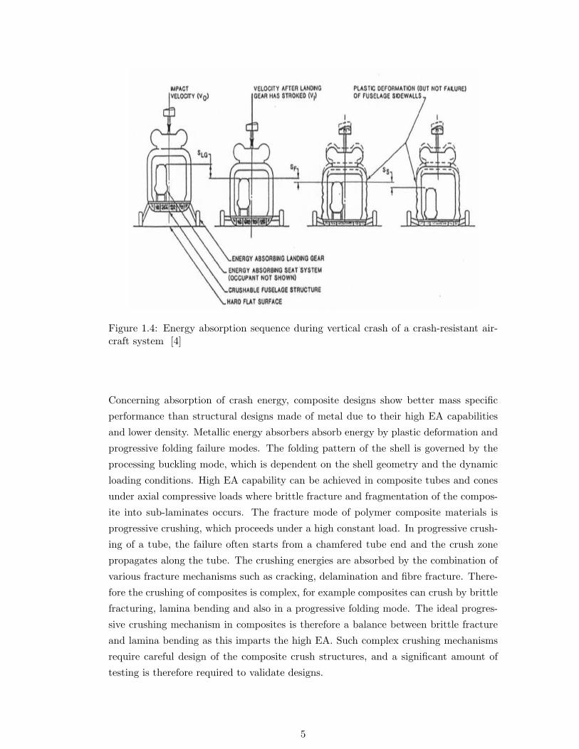
Figure 1.4: Energy absorption sequence during vertical crash of a crash-resistant air-craft system [4]
Concerning absorption of crash energy, composite designs show better mass specific
performance than structural designs made of metal due to their high EA capabilities
and lower density. Metallic energy absorbers absorb energy by plastic deformation and
progressive folding failure modes. The folding pattern of the shell is governed by the
processing buckling mode, which is dependent on the shell geometry and the dynamic
loading conditions. High EA capability can be achieved in composite tubes and cones
under axial compressive loads where brittle fracture and fragmentation of the compos-
ite into sub-laminates occurs. The fracture mode of polymer composite materials is
progressive crushing, which proceeds under a high constant load. In progressive crush-
ing of a tube, the failure often starts from a chamfered tube end and the crush zone
propagates along the tube. The crushing energies are absorbed by the combination of
various fracture mechanisms such as cracking, delamination and fibre fracture. There-
fore the crushing of composites is complex, for example composites can crush by brittle
fracturing, lamina bending and also in a progressive folding mode. The ideal progres-
sive crushing mechanism in composites is therefore a balance between brittle fracture
and lamina bending as this imparts the high EA. Such complex crushing mechanisms
require careful design of the composite crush structures, and a significant amount of
testing is therefore required to validate designs.
5

1.2 Industry Requirement
The understanding of composite structural components under static and dynamic load-
ing conditions is extremely important for the further development of these structures.
In order to reduce the development and certification costs, computational methods can
be used to predict structural integrity under crash and impact loads. The develop-
ment of software tools that can be used to predict the resulting damage from impact
and crash which are directly related to the structural integrity and safety requirements
of engineering structures is of interest to aircraft manufacturers. Despite extensive
research and development of composite structures, their responses under static and
dynamic loadings are still not fully understood. Although experimental tests under im-
pact conditions provide considerable information about the tested specimen and their
characteristic parameters, the deep understanding of the dynamic properties and failure
behaviour of composite structures require test programs which are complex, destruc-
tive, time consuming and consequently expensive for industry.
Since aerospace industry demands reduced development and operating costs, there
is strong interest in ”Virtual Testing” to introduce simulation technology into test-
ing technology aiming at ”Less Structural Test” (complex, expensive and not very
reproducible), ”More Material Test” (relatively easy, cheap and generally repro-
ducible). Impact of high velocity objects on aircraft structures is a damage scenario
that must be evaluated during the development and certification of an aircraft. In
every development phase of a new aircraft, an extensive and costly campaign of impact
tests must be performed, in order to comply with certification requirements and ensure
high standards of safety. The so-called discrete damage is part of the damage tolerance
of the aircraft structure, together with the fatigue and corrosion, as required by reg-
ulations. That means that for all regions where foreign impact objects may represent
a threat to the aircraft airworthiness, a substantiation procedure to show compliance
with certification requirements becomes necessary. For example structural integrity
after bird strike, which is one of the possible sources of impact, should be verified innu-
merous specific primary structure locations on wing leading edges and the front cockpit.
Beside the continuous development of new materials used in aerospace industry, new
concepts and designs, the development of the existing computational methods and the
establishment of new ones are important current themes. Validated finite element (FE)
simulation tools are essential for the industry to reduce the development cycle in order
to keep up with international competitors, since crash and impact tests on large aircraft
structures are becoming too expensive to carry out at the development stage. If the
behaviour of structures or components can be represented in a more realistic way, it
can lead in the near future to a significant reduction in the number of tests that are
6

presently performed. Parallel to the increasing application of composite materials and
composite structural components, the complexity of the new designs, demand for faster
validation and certification processes requires continuous enhancement of these design
analysis methods.
Therefore the main objective of the thesis is to develop improved failure models and
associated numerical modelling techniques for simulating the failure of fibre-reinforced
composite materials under dynamic crash and impact loads.
1.3 Plan of the Thesis
This thesis is divided into 6 chapters:
Chapter 1 has given an introduction into the importance of crashworthiness and impact
in the aerospace industry, energy absorption (EA) phenomena and energy absorbing
structures. Additionally it sets out the demand of industry concerning reduced devel-
opment and operating costs and faster certification procedures.
Chapter 2 gives a more detailed literature review of crashworthiness and impact on
aerospace structures and EA phenomena and energy absorbing structures.
Chapter 3 reports on the state-of-the-art of numerical modelling of crash and impact
mechanisms and discusses the limitations of current Finite Element Method (FEM)
based numerical tools such as time consuming mesh discretisation, element distortions
which occur during large deformation, difficulties to simulate the damage and fracture
of brittle materials with fragmentation failure modes. This is followed by an intro-
duction to the alternative numerical ”Meshless Methods”. It also describes the theory
of particle-based meshless methods such as Smooth Particle Hydrodynamics (SPH)
Method and Discrete Element Method (DEM).
Chapter 4 points out the need concerning ”coupling” in numerical models and focuses
on the theory of several coupling methods, between classical FEM and meshless meth-
ods, proposed in the literature to maintain consistency and stability and to improve
the efficiency of the meshless methods. Chapter 4 following the idea of ”coupling” also
focuses on ”Direct Coupling” and ”Semi-Adaptive Coupling (SAC) Technique”. This
chapter sets out the principles of abovementioned coupling techniques and illustrates
the applicability of the proposed methods by means of benchmark simulations.
Since the main objective of the thesis is to develop improved failure models and as-
sociated numerical modelling techniques for simulating the failure of fibre-reinforced
7

composite materials under dynamic crash and impact loads, Chapter 5 shows the
application of coupling techniques in material characterisation, such as compression
behaviour of aramid paper honeycomb (Nomex) and polyetherimide (PEI) and high
velocity impact (HVI) simulations on sandwich panels.
Chapter 6 shows how the techniques may be applied to model the crush behaviour
of metal and composite energy absorbers, respectively. Although Chapter 5 and 6
focus on the numerical simulation, the results are also compared with the conducted
experimental investigations.
Finallly the conclusions which arise from the presented study were drawn.
8

Chapter 2
Literature Review
This chapter gives a literature review on crashworthiness and impact in aerospace
structures with discussion of EA phenomena and energy absorbing structures. Some
of the reviewed works here also consist of numerical investigations. Since the chapter
aims at giving a brief overview about the conducted investigations, the details of the
numerical works are not discussed here but referred to Chapter 3.
2.1 Energy Absorption and Energy Absorbing Structures
Crashworthiness and impact resistance are challenging engineering problems directly
related to structural integrity and passenger safety. European Community Road Ac-
cident Database [5] has shown that the number of accidents in Europe has the same
trend between 1991 and 2003 with the number of injuries remaining almost the same.
However, the number of casualties decreased approximately 30%, showing an effective
and increased use of passive protection safety systems (seat belts, airbags and etc.)
and the active protection safety systems (sensors, anti-lock brakes and etc.). The vital
importance of the crashworthiness in vehicles has motivated researchers to concentrate
on the designing of novel structural components made of metallic and composite ma-
terials that are capable of absorbing the crash energy in a controlled manner.
Metal Crush Absorbers
Columnar structures including square and circular metal tubes are the examples of
such components progressively absorb the large amount of crash energy through plas-
tic structural collapse. It was first shown by Alexander [6] in 1960 that tubular struc-
tures under axial loads absorb the deformation energy almost at a constant load. He
modelled analytically the concertina mode of deformation based on the plastic work
required for bending and stretching of extensible thin cylinders. The fairly constant
load is the result of the progressive folding which is a desired deformation mechanism
from an efficient energy absorbing component. Since Alexander, many experimental
and numerical investigations have been conducted aiming at determining and under-
9

standing the crushing behaviour of tubular structures and some of these have been
recently reviewed by Alghamdi [7]. Among them, Andrews et al. [8] focused on the
classification of the deformation modes as a function of the material properties, geom-
etry and geometrical parameters such as diameter, wall thickness and length, of the
crash tube absorber. They investigated the relation between the deformation mode
and wall thickness/diameter and length/diameter ratios, see Fig. 2.1. They conducted
crush tests on several tube samples with changing diameter, wall thickness and length
and classified the crushing mode of the cylindrical tubes in seven groups:
1. Concertina: Axisymmetric and sequential or progressive folding starting at the
end of the tube.
2. Diamond: Axisymmetric but sequential or progressive folding starting at the
end of the tube.
3. Euler: Bending of tube as a strut.
4. Concertina and 2-lobe and/or 3-lobe diamond (Mixed): Folding first in
the concertina mode changing to diamond configuration.
5. Axisymmetric/concertina: Simultaneous collapse along the length of the tube,
axisymmetric single or multiple barreling of the tube.
6. 2-lobe diamond: Simultaneous collapse along the tube in the form of the 2-lobe
diamond configuration.
7. Tilting of tube axis: Shearing of tube on the platen surface in the form of the
2-lobe diamond configuration.
Abramowicz and Jones [9]- [11] and Wierzbicki et al. [12] modified the Alexander’s
model and proposed the average crushing load equations for the concertina mode of de-
formation. Pugsley and Macaulay [13] investigated the diamond mode of deformation of
thin cylindrical columns having large diameter/wall thickness ratios. The deformation
energy was assumed to be absorbed by plastic bending and shear of the diamond pat-
tern and they proposed an equation for the average crashing load for diamond mode
of deformation. Abramowicz and Wierzbicki [14] also addressed the same problem
and gave an approximate expression for diamond mode deformation. Abramowicz and
Jones [15] developed an expression for the mean crush force for the same deformation
mode.
The filling of tubular structures with lightweight foams for a goal of increasing spe-
cific energy absorption (SEA) has also taken considerable interest. One of the earliest
investigations on the crushing behaviour of thin-walled sections filled with lightweight
10

Figure 2.1: Classification chart for collapse modes and aluminum (Al) alloy tubes underaxial compression [8]
polyurethane (PU) foam was conducted by Thornton [16], who pointed out that al-
though noticeable increase in SEA was possible with foam filling, it was not weight
effective when compared with the thickening of an unfilled tube wall. Lampinen and
Jeryan [17] investigated the crushing of sheet metal tubes filled with low density PU
foams and concluded that foam filling stabilizes the deformation of thin-walled tubes.
The crushing behaviour of PU foam-filled thin-walled metal tubes was also investigated
by Reid et al. [18], at quasi-static and dynamic deformation rates. It was concluded
that tube wall interacts with the foam filler resulting in a greater tendency for the ax-
isymmetric mode of deformation. They also concluded that the simple addition of the
uniaxial foam contribution to the tube wall folding contribution gave the total average
crushing load of a foam-filled tube. Guillow et al. [19] have recently pointed out that
the average crushing loads of PU foam-filled Al thin-walled tubes were greater than
the sum of the average crushing loads of empty tube (alone) and foam (alone), a result
which contrasted with those of Reid et al. [18] and Reddy and Wall [20]. Seitzberger et
al. [21] investigated the crushing behaviour of Al closed-cell foam-filled monotubal and
bitubal arrangements of square, hexagonal and orthogonal cross-sections and concluded
that mass related average load level can be improved by filling tubular members with
Al foam. It was also pointed out in the same study that suitable foam vs. tube selection
was important for the designing of efficient crush elements. Santosa and Wierzbicki [22]
11

investigated the crushing behaviour of Al honeycomb- and foam-filled box columns both
numerically and experimentally and showed that the effect of filler on the tube crush-
ing load was similar with the strong axis of the honeycomb along and normal to the
compression axis, proving that both axial and lateral strength of the filler were effective
in increasing the crushing load of the tube. Further, Santosa et al. [23] noted that the
bonding between filler and tube wall increased the average crushing load of filled tubes
over the unbounded filled tube when appropriate tube geometry and foam density were
chosen. They also showed, both experimentally and numerically, that the strengthening
of foam-filled tube average crushing load was 1.8 and 2.8 times of Al foam filler plateau
load for the unbounded and bounded cases, respectively. Børvik et al. [24] noticed that
during a crash event the crushing load was neither pure axial nor pure bending but
rather a combination of two and conducted a series of axial and oblique quasi-static
loading tests on the empty and Al foam-filled tubular columns. It was shown by the
same authors that the peak load and EA decreased strongly with increasing loading
angle.
Novel geometrical designs including the filling of tubular structures with lightweight
metal and polymer foams have recently been taken considerable interest. Santosa
et al. [23] investigated the axial crushing behaviour of lightweight Al foam- and Al
honeycomb-filled square box columns at quasi-static rates. It was found that although
honeycomb filling of box columns was more weight efficient in compression, it was less
efficient than Al foam filling in compression-bending loading. A study on the bend-
ing collapse of thin-walled prismatic columns filled with Al foam and Al honeycomb
further showed that columns filled with honeycomb and foam were more efficient in
terms of SAE than the thickening of the column wall [25]. Kim and Wierzbicki [26]
investigated the large planar and biaxial bending rotation response of square cross-
section thin-walled beams partially and fully filled with Al foam. The characteristics
of moment-rotation responses of the beams were investigated under cantilever bending
and found to vary with the length of foam fillers. Kim [27] conducted crushing tests
on an Al foam-filled front side rail and a sub-frame structure of a passenger car and
showed that foam filling increased the EA efficiency. Chen and Nardini [28] investigated
crushing behaviour of closed-top-hat foam-filled Al sections, including single-top-hat,
double-top-hat and double-top-hat with a center plate. It was concluded in the same
study that the thin-walled foam-filled members could be used as efficient crash energy
absorbers. Seitzberger et al. [21], [29] investigated the axial crushing of foam-filled
square, hexagonal, octagonal and bitubular steel tubes. It was reported that consider-
able improvements with respect to EA were obtained with foam filling particularly in
bitubular configurations. Chen and Wierzbicki [30] studied the axial crushing of hollow
multi-cell columns. The enhancement in the total crushing resistance of the columns
increased, depending on the interaction between the foam filler and the column wall,
12
by the amounts of 140% and 180% of the foam filler strength for double- and triple-cell
columns, respectively.
Although the effects of several fillers on SAE have been studied, the honeycomb filling
has not been as extensively studied as other filler types. Santosa and Wierzbicki [22]
investigated the axial crushing behaviour of Al honeycomb- and Al foam-filled box
columns. They showed that the filling of box columns with Al honeycomb can be
preferable to thickening of the column wall. They developed simple formulae for the
relationship between mean crushing force and the strength of the filler. Additionally
they found out that the presence of adhesive increases the EA compared to unbounded
filling of the columns. In case of unidirectional loading Al honeycomb filling showed
better crashworthy performance that the Al foam filling. In their extended study [25]
they investigated the bending collapse of the filled columns. They concluded that the
filling of columns with low density materials such as Al foam or Al honeycomb en-
hances the bending strength. Additionally the presence of adhesive results in higher
bending response. In terms of SAE both filled designs showed better performance than
the thickening of the column wall. Santosa and Wierzbicki [31] also investigated a
novel double-wall sandwich column concept for axial crushing. The column consisted
of lightweight Al foam and inner and outer shells made of Al in a sandwich design.
They concluded that the double-wall sandwich column showed better crash perfor-
mance than the single wall columns for the same weight. Later they focussed on the
Al honeycomb- and Al foam-filled double-wall columnar structures and obtained 40-
60% and 35-40% weight saving, respectively. Al honeycomb-filled double-wall designs
show better performance depending on their relatively lower densities. Finally it was
proven that the double-wall columns were an effective structural element for the axial
crushing. A recent study on the honeycomb filling has been published by Zarei and
Kroger [32]. They investigated the axial and oblique impact crash response of empty
and Al honeycomb-filled square tubes. In the first part of their study they investigated
the EA capability of several empty tube geometries including square, rectangular and
circular tubes. Using Multidesign Optimization (MDO) they aimed at maximizing the
EA and the SAE. They concluded that the empty circular tubes have the best crashwor-
thy response. In the second part of their study they concentrated on the crash response
of honeycomb-filled circular tubes. Optimisation process has also been repeated for the
second part of the study. They concluded that the honeycomb filling of tubes is an
alternative way of increasing the EA capacity of the empty tubes instead of thickening
the tube wall. The same results have been reported in the case of foam filling of Al
tubes by Wierzbicki and Santosa [25].
13

Composite Energy Absorbers
Composite energy absorbers absorb crash energy by multiple fracture and fragmen-
tation of the fibres. Due to the brittle nature of the fibres and thermoset resins, the
composite crush behaviour tends to brittle fracture. Hull [33] defined the crushing
deformation mode of the composite tubes under axial compression as:
1. Euler Buckling: Failing by buckling before the onset of any other failure mech-
anism. Euler buckling gives very low EA capacity.
2. Shell Wall Buckling: Progressive folding involves the formation of successive
local buckles such that the tube folds axially in a manner similar to concertina.
3. Brittle Fracture: The overall failure mode will be one of the stable crushing
with high levels of energy.
The brittle fracture mode is also called as high-energy-mode. Hull [33] and Farley and
Jones [34] extended the brittle fracture into two sub-deformation mechanisms. Splay-
ing (Hull) or lamina bending (Farley and Jones) mode is characterised by very long
interlaminar, intralaminar and parallel-to-fibre cracks with little or no fracture of the
axial laminar bundles, as shown schematically in Fig. 2.2. Beside crack growth which
is the principal EA mechanism, the energy is also absorbed by bending response and
frictional effects. The fragmentation (Hull) or transverse shearing (Farley and Jones)
mode is characterised by a wedge-shaped laminate cross-section, with one or more short
interlaminar and longitudinal cracks forming partial lamina bundles. The primary EA
mechanism is fracture of the lamina bundles, with interlaminar and longitudinal crack
growth as secondary contributiors. Farley [35] and Hamada et al. [36] concluded that
the fragmentation generally absorbs more energy than the splaying mode. Although
most of the investigated structures were tubular conical shells were also investigated
intensively [37]- [40]. Thornton and Edwards [41] report that square and rectangular
tubes are generally less effective at absorbing energy than circular ones. These findings
are supported by Mamalis et al. [38]. Similarly, Kindervater [42] reports that square
and rectangular tubes have respectively 0.8 and 0.5 times the SAE of comparable circu-
lar specimens. This is generally attributed to the fact that corners tend to act as stress
concentrators, leading to the formation of splitting cracks there. These splits tend
to dominate the failure mechanism resulting in poor utilisation of the material as a
whole. There are many research studies in fibre-reinforced plastic tubes made of unidi-
rectional composites, knitted composites, sheet moulding compound (SMC) and other
material systems and their effects on general behaviour, on environmental temperature,
testing speed, geometries as a function of SAE have been discussed in detailed [43]- [49].
Thornton investigated the axial collapse of circular tubes made of carbon-, Kevlar-
14

Figure 2.2: Schematic representation of the formation of the splaying/lamina bendingmode crush zone based on macroscopic examination [33]
and glass-fibre-reinforced composite materials [50]. He also proposed a trigger mecha-
nism to prevent catastrophic failure of brittle composite structures and to induce stable
and progressive crush. The end modification or trigger of the composite tube creates
a region of high stress from which stable crushing is then propagated. Triggers which
have been shown to work well include chamfers (as in Figs. 2.2 and 2.3 ), slots, and
especially tulip geometries. Czaplicki and Robertson [51] investigated the crushing be-
haviour of E-glass/polyester and E-glass/vinyl ester pultruded tubes. They used two
different kinds of trigger, namely bevel and tulip. With the tulip trigger almost a dou-
ble SAE value has been reached. Additionally they concluded that the crushing was
more controlled and predictable. Crushing over metal dies or cones is another way of
triggering stable collapse [43].
The failure of a composite profile under axial compressive loading occurs usually in
catastrophic brittle failure unless triggered to initiate progressive triggering. The trig-
gering mechanism consists mainly of machining a special geometry on one of the ends
of the profile. If the required failure mode of the structure is not triggered the peak
load occurs before the crushing is established. A high peak load results in high ac-
celerations under dynamic loads which are undesirable. Therefore the triggering is a
very important issue for the EA of the composite materials. Thuis and Metz [52] in-
vestigated two different laminates and triggers for the crashworthy composite cylinders
made of hybrid carbon/aramid fabric. They concluded that the cylinders which failed
in splaying mode can absorb more energy than the cylinders which failed in fragmen-
tation. They also pointed out that the trigger configuration affects the failure mode
of the composite energy absorbers. They obtained the highest EA capability with the
chamfer type trigger. Later Jimenez et al. [53] also investigated the effect of trigger
15

Figure 2.3: Schematic representation of the formation of the fragmentation/transverseshearing mode crush zone based on macroscopic examination [33]
on unidirectional box sections made of E-glass/polyester pultrusion. They concluded
that the trigger geometry has a very big influence on the results. When the bevel type
trigger used different bevel angles the SAE may vary ca. 25%. As mentioned above the
friction mechanism can contribute to the EA capability of the composite energy ab-
sorber. Fairfull and Hull [54] investigated the energy absorbed by the frictional process
associated with the axial compression. Both the frictional effects within the crash zone
of the material and those caused by the crushed composite sliding across the test plates
were considered. They concluded that the frictional process can account for more than
50% of the total energy absorbed by the progressive crushing.
Later Mamalis et al. [55] reviewed the investigations on the crashworthiness of compos-
ite structures. In order to enhance the crashworthy capability of composite structures
Harte et al. [56] suggested the foam filling of the braided tubes made of glass fibre/epoxy
with polymer foam cores. The optimised the SAE with respect to relative density and
geometry. They concluded that the foam-filled braided tubes exhibit higher SAE ca-
pability than the combination of the composite tube and the polymeric foam core.
Metallic-Composite Energy Absorbers
In order to enhance the EA of the composite crash absorbers hybrid designs were also
investigated intensively. Some of these hybrid designs consisted of metal and composite
tubes or hybrids of different types of composite materials. Farley [57] studied the EA
capability of carbon fibre/epoxy composite material and glass fibre/epoxy composite
16

material and carbon fibre/epoxy composite material and Kevlar/epoxy composite ma-
terial.
Shin et al. [58] investigated the EA capability of axial crush and bending collapse of
Al/glass-fibre-reinforced plastic (GFRP) hybrid tubes with different ply orientations.
They found out that in axial crushing the hybrid tube with 90o fibre orientation to the
tube axis showed the best EA capability among all designs studied. During crushing
composite plies prevented the Al tubes from folding. The failure of the hybrid tube
was stable and progressive without any trigger. In case of bending collapse, the hybrid
tube which consists of an Al tube with 0o/90o ply orientation composite tube showed
the best performance. The hybrid tube showed the effect of interaction between the Al
and composite tube since the EA capability was higher than the sum of each individual.
El-Hage et al. [59] produced hybrid tubes containing Al tubes and a filament-wound
E-glass-fibre-reinforced/epoxy overwrap and observed that the hybrid tubes have sig-
nificantly higher EA than either the composite tubes or the Al tubes. Song et al. [60]
performed quasi-static and impact tests on E-glass/epoxy wrapped circular Al, steel and
copper tubes. Babbage and Mallick [61] investigated the static axial crushing behaviour
of empty and epoxy foam-filled Al/filament-wound E-glass-fibre-reinforced/epoxy com-
posite tubes. The composite overwrap increased the peak-load, average crushing load
and SAE values of Al square and circular tubes. Epoxy foam filling of round Al/composite
hybrid tubes further improved the axial crush performance of the empty circular hybrid
tubes, while foam filling of square hybrid tubes resulted in the failure of Al tube either
via buckling or tearing at the corners due to the prevention of tube inward folding
by the foam filler. Guden et al. [62] studied the effect of Al closed-cell foam filling
on the quasi-static crushing behaviour of an E-glass woven fabric polyester compos-
ite tube and thin-walled Al/polyester composite hybrid tube. For comparison, empty
Al, empty composite and empty hybrid tubes were also tested. Empty composite and
empty hybrid tubes crushed predominantly in progressive crushing mode, without ap-
plying any triggering mechanism. Foam filling was found to be ineffective in increasing
the crushing loads of the composite tubes over the sum of the crushing loads of empty
composite tube and foam. However, foam filling stabilised the composite progressive
crushing mode. In empty hybrid tubes, the deformation mode of the inner Al tube was
found to be a more complex form of the diamond mode of deformation of empty Al
tubes, leading to higher crushing load values than the sum of the crushing load values of
empty composite tube and empty metal tube. The foam filling of hybrid tubes however
resulted in axial splitting of the outer composite tube due to the resistance imposed
by the foam filler to Al tube inward folding and hence it was ineffective in increasing
crushing load and SAE values over those of empty hybrid tubes.
17

2.2 Crashworthiness and Impact in Aerospace Structures
As stated in Chapter 1 composite sandwich structures are attractive for large integral
low weight shell structures under transverse and bending loads. An important draw-
back of aerospace structural sandwich components is their relatively low resistance to
impact damage due to the thin outer composite skins. Most common damage mecha-
nisms in composites, such as matrix cracking, debonding and fibre failure, may appear
individually or interact, resulting in complex skin failure modes under impact. After
fracture of the skin, the impacting object may damage and penetrate into the core. If
impact speed is low, sandwich panels may respond by bending and little damage oc-
curs if the kinetic energy of the impacting object is accommodated by the elastic strain
energy level of the panel. At higher impact velocities a critical condition is reached
when local contact stress exceeds local strength, leading to laminate bending failure,
core/skin interface delamination and core compression strength failure. Core deforma-
tion and failure are therefore decisive factors for the EA capability of sandwich panels.
Although the major damage mechanisms such as matrix cracking, debonding and fibre
failure may appear individually, their interaction and the effects of fibre type and lay-
up, distribution and geometrical nature, additionally the type and state of the matrix
fibre resin bond and environmental effects result in complex failure modes. Despite
extensive research and development of sandwich structures, their impact response is
still not fully understood.
A review by Abrate [63] demonstrated the recent research efforts aimed to understand
the impact response of the sandwich structures. Rhodes [64] conducted impact tests on
a range of systems and showed that the enhancement in the strength of the core mate-
rial can serve to increase the impact resistance of the sandwich panel. Mines et al. [65]
investigated the impact response of the polymer composite sandwich structures with
Al honeycomb core. They showed that the impact energy of the projectile is mostly
absorbed by the localised impact damage zone around the point of the impact. They
also concluded that the perforation resistance of these structures increases with the
strain rate. Charles and Guedra-Degeorges [66] showed that the dent depth around the
impact point increases with impact energy until a maximum value is reached. Cantwell
et al. [67] pointed out that during a low velocity impact event the skin shearing was
the primary EA mechanism under localised impact conditions. Abrate [68] defined an
energy-balance model in which the impact energy of the projectile is defined as the
summation of the energy stored in bending and shear deformations and the energy
used to create the local deformations (skin and core) in the impact zone. Hazizan and
Cantwell [69] developed and applied an energy-balance model similar to Abrate to pre-
dict the impact reponse of a foam-based sandwich structure. They varied the impact
energy of the projectile and the mechanical properties of the foam core to investigate
18

the accuracy of their model. They concluded that the dynamic response of the sand-
wich structure depends on the elastic properties of the foam core material. They also
showed that the energy-balance model based on the dissipation of the impact energy
during impact is effective to predict the low velocity impact response of sandwich struc-
tures in the elastic regime. Raju et al. [70] pointed out that the small coupons used
in the material characterisation test for composite materials do not behave the same
way as the large structures made of these materials. They focussed on the in-plane
dimensional effect and thickness effect of the composite plates. They found out that
the thickness effect is much more significant than the in-plane dimensional effect.
Beside the efforts to have a better understanding of the deformation mechanisms
mentioned above several researchers studied the effect of impactor on impact dam-
age. Among them, Horrigan et al. [71] investigated the impact response of sandwich
structures with glass-fibre-reinforced/epoxy skins. They showed that the hard projec-
tile results in deeper and more severe damage than the soft projectile. Cantwell and
Morton [72] studied the effect of impactor mass on the impact force and the resulting
damage area for low velocity impacts. They showed that the damage initiation energy
increases with an increase in the impactor mass. Ambur and Kemmerly [73] investi-
gated the effect of impactor mass on the low velocity impact response of the laminated
composite plates. They pointed out that the damage area is a nonlinear function of
the impactor mass. Beside impactor mass the shape of impactor is also an important
factor on the impact response. Mitrevski et al. [74] investigated the effect of impactor
shape on low velocity impact of composite thin plates. The observations show that
the specimen impacted by the conical impactor absorbed most energy as a result of
the depth of local penetration. The hemispherical impactor produced the highest peak
force and the shortest impact duration.
Laminated composite materials and sandwich structures, due to the stacking sequence
of lamina, have very low stiffness and strength through the thickness direction, when
compared with the in-plane properties, since no reinforcing are usually present through
the thickness. One strategy of achieving this is to add reinforcement pins to the foam
core, with the ends of the pins embedded in woven carbon fibre face sheets. This con-
struction technique gives excellent bonding of the pins to the face sheets, and thereby
increases the delamination strength and toughness between face sheets and core. The
improved through-thickness properties have been demonstrated in a number of prelim-
inary experimental investigations. For example, low velocity impact experiments on
composite skin sandwich panels with foam cores reinforced by metallic pins indicate
that these sandwich structures over improved impact and delamination resistance [75]-
[79]. Cartie and Fleck [80] studied the titanium and carbon fibre pins inserted into
the polymer foam core of a sandwich panel in order to increase the through-thickness
19

strength. They showed that the foam core stabilizes the pins against elastic buckling
and the pin-reinforced core has a strength and EA capacity in excess of the individual
contributions from the foam and unsupported pins. The pin reinforcement increased
the stiffness, strength and EA of the conventional foam material.
20

Chapter 3
Numerical Modelling of Crushand Impact Mechanisms
Currently there are several numerical methods used to analyse the response of engi-
neering structures to applied loads. The most common numerical methods are:
• Finite Difference Method (FDM) is where the derivatives of the local oper-
ator in the field equations are replaced by finite differences using so-called finite
difference ”stars” over neighbouring grid points.
• Finite Volume Method (FVM) starts from the weak form (energy, functional)
of the field equations; the weight functions are selected in such a way that only
a boundary integral over a cell or patch has to be evaluated. Most often used in
Computational Fluid Dynamics (CFD).
• Finite Element Method (FEM) is based on the weak form, mostly as Galerkin
Method where the trial and test functions are taken from the same function space
and restricted to a local area, named finite element (FE).
• Boundary Element Method (BEM) uses fundamental solutions satisfying
the domain equations and restricts the approximation to the boundary terms
thus reducing the discretisation order by one.
• Meshless Methods are usually based on the weak form where the field is ap-
proximated over a certain meshless area using random controlling points.
Among these methods the classical numerical methods such as FEM, FDM or BEM
solve partial differential equation (PDE)s of continuum mechanics; hence, they can con-
sider only a small number of discontinuities and cannot encompass the processes which
involve discontinuous states such as fracture and fragmentation of materials. FEM is
a well-suited numerical tool to take into account the complexity of the geometries, the
nonlinear behaviour laws and the contact modelling in the study of such problems.
The Lagrangian algorithm is in its essence relatively simple and well-suited for impact
21

problems between solids. But it has drawbacks when the mesh is subjected to large
deformations and distortions. Remeshing is thus required during the computation. The
Eulerian or Eulerian-Lagrangian formulation helps avoid these large distortions but is
more difficult to set up and presents difficulties when the boundary conditions are of
Lagrangian kind. As an alternative to FEM, Meshless Methods have been developed
and applied to numerical simulations involving extensive material flow and fracture.
Meshless Methods replace FEs by a set of nodes or particles within the problem do-
main as well as sets of nodes scattered on the boundaries of the domain to represent
the problem domain and its boundaries.
This chapter reports on the state-of-the-art of numerical modelling of crash and impact
mechanisms and discusses the limitations of current FEM-based numerical tools such
as time consuming mesh discretisation, element distortions which occur during large
deformation, difficulties to simulate the damage and fracture of material into a large
number of fragments and gives an introduction about the alternative numerical class
”Meshless Methods”. It also contains theory of particle-based, meshless methods such
as SPH Method and DEM.
3.1 Finite Element Method
State-of-the Art
The most popular numerical method FEM is well-established numerical technique,
which has been used to obtain numerical solution of various problems in the area of
engineering and science. Currently several well-developed FEM software packages are
commercially available. For crash and impact simulations FEM dominates. The cur-
rent modelling approaches using FEM for the structural crash and impact problems
being considered in this thesis are listed below:
Modelling Metallic Crash Absorbers
• For the modelling of the thin-walled tubes shell elements which represents the
middle surface are used.
• The compression plates for loading tube structures are modelled using solid ele-
ments and are assumed to be rigid.
• For the material modelling elastic-plastic material models for Al and steel are
selected.
22

• In case of filling such as Al foam filling the filler material is modelled with solid
elements.
• Since fillers such as Al foam and honeycombs are discontinuous materials the
homogenisation technique is applied. The material response of this inhomoge-
neous material is replaced with a homogenised material with the same effective
properties for the element volume.
• In case of non-adhesion a sliding contact with friction is assumed between the
column wall and the filler, in presence of adhesive bonds a tied-contact between
the column wall and the filler is used.
• The folding process is supported by a user-defined self-contact definition to pre-
vent interpenetration of shell elements.
• For thin-walled metal sections, in order to model the experimentally observed
deformation modes a mesh coupling technique is chosen (coarse mesh for unde-
formed zone/fine mesh for deformed zone).
• An adaptive mesh refinement option is chosen for the regions with severe defor-
mation.
• The fracture behaviour (for filler) is modelled by removing the elements on reach-
ing a failure strain threshold.
• In order to speed up a quasi-static process using an explicit numerical code the
mass densities are scaled up.
Modelling the Crashworthy of Composite Crash Absorbers
• For the modelling of the thin-walled tubes shell elements which represent the
middle surface are used. Some detailed models in which the resin is modelled
using solid elements are also presented.
• For the composite laminates multi-layered shell models are used.
• The compression plates for loading tube structures are modelled using solid ele-
ments and are assumed to be rigid.
• Since the material responses of the composite materials are anisotropic it is dif-
ficult to find a symmetry plane for discretisation.
• In case of foam filling the foam material is modelled with solid elements. For
the crushing of the foam core an element removal technique is applied at final
fracture.
23

• A self contact algorithm is defined on the mesh interfaces to prevent interpenetra-
tion of the elements and to provide the friction between the parts of the specimen
during deformation.
• For composite tubes different failure models used are:
Chang-Chang Failure Criterion, which is a modified version of the Hashin
failure criteria in which the tensile fibre failure, compressive fibre failure, tensile
matrix failure and compressive matrix failure are separately considered.
Tsai-Wu Criterion, in which element is eliminated if the maximum effective
strain is equal to the predefined threshold.
Smooth Failure Surface which is based on an anisotropic continuum damage
formulation, which describes a gradual degradation of the elastic material prop-
erties.
Composite Bi-phase Model which defines the degradation functions according
to strain criteria treating fibre and resin phase separately. An elastic damaging
material law allows the modelling of material damage separately in each phase
via reduced material stiffness.
• In order to obtain a progressive crushing which is obtained in experiments by
triggering, the failure strength of the elements in the crush front is reduced.
• The discretisation of the composite section is changed at the crush front to model
the trigger geometry (bevel, tulip and chamfer) for progressive numerical crushing.
• For the modelling of the hybrid tubes, consisting of Al and composite tubes, in
case of non-adhesion sliding contact with friction is assumed between the columns
walls, in presence of adhesion a tied-contact between the columns walls are used.
• In order to speed up a quasi-static process using an explicit numerical tool the
mass densities are scaled up.
Modelling the Impact Mechanism of Sandwich Panels
• Two different approaches are used for the modelling of the honeycomb core sand-
wich structures. One approach utilises standard solid elements (homogenised
model) for the core and shell elements for the facings (Fig. 3.1). The sec-
ond approach models the honeycomb core using shell elements (unit cell model)
(Fig. 3.2).
• Two different approaches are used for the modelling of the interface (bonding)
between the facings and the core material. Both approaches use tied-contact.
One allows the breakage of the contact depending on the transverse and shear
component of the interface stresses. For the case when skin debonding is not
significant a tied-contact without failure is used.
24

Figure 3.1: Homogenised core modelling Figure 3.2: Unit cell core modelling
Figure 3.3: Layered shell model for facings Figure 3.4: Stacked shell model for facings
25

• For the delamination modelling of the skin laminate there are two approaches.
One approach uses a layered shell model without delamination (Fig. 3.3), the
second one considers the interaction between adjacent stacked shells and the
delamination failure between these layers is included in the model (Fig. 3.4).
• For metallic facings an elastic-plastic material law is assumed.
• For composite facings different failure models are used as discussed above.
• For the impact damage and penetration zone finer discretisation is used.
• The impactor modelling is also an important issue. For hailstone impactor solid
elements with rigid material properties are used.
• For tyre burst a detailed fibre-reinforced rubber model with bar (reinforcement)
and solid (rubber matrix) are used.
• For bird impact case solid elements were initially used. The most common pure
FE-based modelling technique for the bird model is ALE (Arbitrary Lagrangian
Eulerian) in which the bird and the surrounding air modelled as fluid using an
Eulerian mesh and the bird applies load to the Lagrangian discretised target
structure. The coupling realises via an ALE algorithm. The latest trend is the
meshless modelling (SPH Method discussed later) of the bird impactor.
• For validation studies the sandwich panels were mounted on a ring force trans-
ducer and the interaction force between the load cell and the sandwich panel was
measured during impact. For the determination of the resultant force numerically
the sandwich panel models are located on a rigid ring, which represents this load
cell.
The above listed points are the currently used modelling approaches used in the the-
sis for the crush and impact simulation using FEM. Another important issue is the
correct choice of the numerical time integration algorithm. Implicit algorithms require
iterative solutions for each time increment unlike explicit schemes. Using an implicit
time scheme to find the displacements at each time step is generally more accurate as
compared to the explicit integration method, although it requires more computational
time. For the explicit time scheme, the displacements are solved by direct numerical
integration of the equations, meaning that prior to numerical integration no transfor-
mation of the equations is required. Furthermore, both linear and nonlinear material
behaviour can be considered in dynamic analysis. Implicit integration is generally used
for the simulations of static responses and moderately nonlinear behaviour whilst the
explicit integration is used for the dynamic response, fast dynamic loading, such as
crash and impact and highly nonlinear behaviour. Most of the commercial codes avail-
able in the market, such as PAM-CRASH, LS-DYNA, ABAQUS, NASTRAN, have
26

explicit solvers for such problems. Recent work of Noels et al. [81], [82] propose a com-
bined implicit/explicit integration for the dynamic loading cases. The proposed scheme
integrates some time intervals with an implicit integration and others with an explicit
one. Since it is the out of scope of this thesis the combined implicit/explicit integration
approach will not be further discussed here.
Modelling of HVI and crash scenarios involving material failure and large deformation
using classical FEM is complex. Although the FEM is established as an effective tool
for predicting structural behaviour in different loading conditions, FEM is less reliable
for large deformations and structural failure modelling under dynamic loads. Addition-
ally it is difficult to simulate structural failure containing the fracture of material into
fragments since FEM is based on a continuum mechanics formulation requiring element
connectivity. The elements can either be totally eroded or remain in one piece. This
may misrepresent the fracture path, especially for brittle materials. FEM uses Element
Elimination Technique (EET) [83] which is based on the quasi-removal of damaged
elements which satisfy some imposed failure condition. The FE solver computes local
values in the structure in the following succession: first, nodal displacements are cal-
culated, then, element strains, thereafter, element stresses, and finally, nodal forces.
As a result of this chain, the reaction forces are calculated for each node of the FE
mesh. After applying the external displacements, nonequilibrium state of the structure
is established. Since the stiffness matrix depends on the displacements in the nodes,
the displacements are corrected in several iterative steps until force equilibrium is es-
tablished. When the structure is in equilibrium, the code decides for each FE whether
it has to be eliminated or not, based on the elimination criteria being applied. To elim-
inate an element, all components of the stress tensors in this element are set to zero.
As a result, all forces in this element become zero as well, and therefore, this element
stops to transmit load to neighbouring non-eliminated elements. So, the element elim-
ination does not mean that an eliminated element is really removed from the FE mesh,
but stops to interact with neighbouring elements. In solving the problem the tangen-
tial stiffness matrix should be corrected after the element elimination. This is done
by setting Young’s modulus of eliminated elements to be equal to zero [83]. Another
drawback of the EET is adjustment of the elimination threshold. Since element elimi-
nation limit may be a non-physical parameter it is very difficult to predict and measure.
The enhancement of existing numerical methods based on FEM is a current research
theme. Remesh or adaptive remeshing approaches have been proposed for handling
these types of problems in FEM. Adaptive remeshing procedures can be summarised
in the following four steps: determination of the error estimator or error threshold to
define remeshing criteria, remeshing of the deformed body, mapping the state variables
and history dependent variables from the deformed state into new one and restart of
27

the simulation. Although it looks very promising method, it is computationally very
expensive since the procedure for determining the error estimation takes time. For this
purpose several complex, robust and adaptive mesh generation processors have to be
developed. However, these processors are only workable for 2D problems. There are
no reliable processors available for creating hexahedral meshes for 3D problems due to
the technical difficulty. Adaptive processors require mappings of field variables between
meshes in successive stages in solving the problem. This mapping process often leads to
additional computation as well as a degradation of accuracy. In addition, for large 3D
problems, the computational cost of remeshing at each step becomes very high, even if
an adaptive scheme is available.
3.2 Other Alternative Methods
As an alternative to FEM, meshless methods have been developed and applied to nu-
merical simulations involving material failure and damage. Meshless methods replace
FEs by a set of nodes or particles within the problem domain and its boundaries. This
feature makes meshless methods very effective since mesh connectivity is not as crit-
ical as in FEM. There are several meshless methods and new meshless methods are
being developed in current research. A class of meshless methods is the particle-based
computational methods which are a very general class of Lagrangian computational
techniques for simulating the motion of fluids, solids and granular materials. These can
be subdivided into meshless continuum methods for solving systems of PDEs (includ-
ing SPH Method, Particle in Cell, Partition-of-Unity Methods, etc.) and methods for
simulating discrete-particle systems (such as DEM and its many variants).
Particle-based methods require a predefinition of particles for material volumes and
masses. The algorithm will then carry out the analyses even if the problem domain
undergoes extremely large deformation and separation such as fragmentation. SPH
Method and DEM belong to this category. Particle-based methods suffer from prob-
lems in the imposition of boundary conditions. In addition, predefining the particles
still technically requires some kind of initial mesh. Since the thesis focus is particle-
based meshless methods, only SPH Method and DEM are discussed in detail here.
3.3 Review of Particle-based Meshless Methods
Discrete Element Method (DEM)
The DEM is an explicit numerical model which approximates the mechanical behaviour
of an assembly of arbitrary shaped particles. Having its roots in molecular dynamics,
Cundall and Strack [84] used this method to describe the behaviour of particles in
granular materials for the first time. These particles displace independently from each
28

other and interact only at contact points. They are assumed to be rigid bodies therefore
their deformation during contact is neglected. Particles are allowed to overlap during
contact. This is referred to as soft-contact approach.
The force between particles during contact is calculated with mechanical elements like
springs and dashpots. For an oblique contact the contact force is decomposed in normal
and tangential direction. For each direction a linear spring and a dashpot are used.
Interface friction is realised with a frictional slider. The frictional slider represents a
Coulomb-type of friction. The properties of the mechanical elements are referred to as
micro parameters. When a virtual material is calibrated the spring stiffness damping
and friction coefficient as well as the particle size have to be adjusted. The spring con-
stant is proportional to the Young’s modulus and inversely proportional to the particle
diameter.
The method is based upon the principles of mechanics for multibody dynamics where
each of the bodies under consideration as well as the interbody medium can be modelled
using the DE discretisation techniques. The distinct element solution scheme assumes
each of its constituents as the separate entity and applies the Newton’s second law of
motion for translation motion, and force-displacement law at contacts. Newton’s law
is used to determine the motion of each particle arising from the contact and body
forces acting upon it and the force displacement law is used to update the contact
forces arising from the relative motion at each contact. For rotational motion it is
used to compute the moment effects. These calculations are adopted at each time step,
for each particle. This individual particle method allows deletion of the contact with
adjacent particles when it experiences the strength equivalent to the bonding strength.
This process shows the fragmentation behaviour of the crushing system, as in reality.
The DEM works in the principle similar to the time marching scheme of an explicit FE
solution. The way of assigning different properties to individual particles (elements) in
DEM is much simpler than that of the FEM. Hence, simple laws of contact and laws
of motion in the DEM can be considered as an effective method to understand the
cracking and fragmentation mechanism of the complex material, such as concrete.
It is particularly suited for studying granular flows, but a couple of drawbacks still
exist. At first, the high computational cost has to be mentioned, especially if a realistic
number of grains and realistic shapes are used. The force between two particles can
be calculated from the strength of the contact between them. The resultant force on
a particle is the vector sum of the forces exerted by each of its neighbours. Once the
resultant force on each particle has been computed, it is a simple procedure to compute
a velocity and position increment for each particle. Finally, the list of which particles
are in contact must be re-computed. Every particle’s force interaction, acceleration
29

and movement are calculated individually at each time step. The assumptions under-
lying the method are only correct and the numerical scheme stable if no disturbance
can travel beyond the immediate neighbours of a particle within one time step. This
generally means that the time step must be limited to a very small value, thus making
the DEM extremely computationally expensive.
DEM has been used in several applications mostly in civil and process engineering
and environmental sciences. Among them Kun and Hermann studied the shock frag-
mentation behaviour of solids [85]- [87]. The concrete cracking was also an interesting
application area of DEM. Masuya et al. [88] investigated the structural behaviour of
concrete members under impact. The model that they proposed was two dimensional.
D’Addetta et al. and Hentz et al. used DEM for the micromechanical modelling of
concrete cracking [89]- [90]. Both works aimed at the structural response of the con-
crete using three dimensional models. Later D’Addetta et al. extended their numerical
model for the modelling of the granular assemblies [91]- [92]. Since the nature of DEM is
very suitable for the crack problems, Wittel et al. studied the transverse cracking of the
cross-ply laminates [93]- [94] and a natural fibre composite soft-wood using DEM [95].
The modelling of bird flow and deformation for a bird strike impact simulation is one of
the drawbacks of the FEM. Petrinic and Duffin [96] introduced a DE-based numerical
algorithm for the predictive modelling of the bird strike on aircraft structure. For the
experimental part of the study gelatine impactors were impacted against a rigid plate.
Comparing the gelatine spread over the flat surface of the target and the length of
continuously eroding projectile, they obtained satisfactory results with their numerical
discrete particle-based tool.
Smooth Particle Hydrodynamics (SPH) Method
SPH Method, also called Free Lagrange Method, is one of the earliest particle methods
in computational mechanics. SPH Method was developed and advanced by Lucy [97]
and Gingold and Monaghan [98] to solve astrophysical problems in 3D open space.
Since its invention, SPH Method has been heavily studied and extended to dynamic
response with material strength [99], [100], [101], fracture simulation [102], impact sim-
ulation [103], [104], brittle solids [105], and metal forming simulation [106]. Parallel
to the introduction of the SPH Method solver in commercial codes and their contin-
uous improvement, SPH Method found several application areas in industry. In the
automobile industry the SPH Method is used for the tank sloshing simulations [107].
Anghileri et al. also visited the topic and they simulated the water sloshing in a tank
(helicopter) during the impact with ground. Currently SPH Method is becoming a
standard simulation tool for bird strike phenomena in aircraft structures [108]- [111].
30

SPH Method has also been explored for simulating dynamic fluid flows by several
researchers. An important application area of SPH Method in aerospace engineering
is the ditching simulation and impact on soil ground. SPH Method has been used
as an alternative to FEM for soil ground modelling in [112] and for water modelling
in [113]- [114]. Pentecote and Kohlgruber described in [115] a modelling procedure
for simulating the aircraft impact on water. They have also used SPH Method and
coupled FEM/SPH Method for the water modelling. Differing from the other studies,
they pointed out that the presence of an air layer between the structure and the water
surface strongly cushions the forces acting on the structure. Using SPH Method and
coupled FEM/SPH Method they obtained promising results and suggested some im-
provements for better correlations. Naghipour et al. [116] studied the impact response
of an energy absorber on coarse soil and rigid ground using both FEM and SPH Method.
They pointed out the difficulties of soil ground modelling with FEM and proposed an
alternative SPH Method-based model. Comparing the experimental crash response of
a metal energy absorber with that of SPH Method-based model satisfactory agreement
was obtained.
As a meshless, particle method of pure Lagrangian nature, SPH Method uses smoothed
particles as interpolation points to represent materials at discrete locations, so it can
easily trace material interfaces, free surfaces, and moving boundaries. The meshless
nature of SPH Method overcomes difficulties due to large deformations because SPH
Method uses particles or points rather than mesh as a computational frame to interpo-
late. These features of SPH Method make it attractive, as can be seen from the large
literature that has emerged during the last decade.
SPH Method is a Lagrangian technique which allows the numerical grid to be em-
bedded in the material as it deforms which reduces some of the material interface
problems associated with Eulerian codes. Furthermore, the ability to handle severe
distortions allows the SPH Method to be applied to problems with large deformations
or severe element distortions. The SPH Method is generally not as efficient as FEM
for structural response applications due to the high computational costs for particle
methods. On the other hand the advantage of SPH Method is that it is possible for
both severe distortions and normal structural responses to be performed with a single
Lagrangian code.
As aforementioned SPH Method is a meshless method which uses a Lagrangian frame.
Smooth hydrodynamics variables are computed using a pseudo-particle interpolation
method. Although SPH Method uses particle-based representation differing from DEM,
each smooth particle has a mass, density, velocity and internal energy which are derived
by interpolation or from constitutive relations. It can be used with great advantage to
31

model bulk materials with no cohesion, such as sand, liquid, gases, or in situations with
perforation, as in HVI, or mixing, as in ditching. However it can be computationally
much more expensive than classical solid elements in a FE mesh. A smooth particle,
similarly to a FE, has its own shape functions, re-constructed at each cycle from its dy-
namic connectivities. Localisation and information transformation from one particle to
another are achieved through the notion of an interpolation distance called the smooth-
ing length. A particle is said to have a contributing neighbour, when another particle
lies with in the sphere of influence of it. In such case, the particle which lies with in
the sphere of influence is said to be connected to the central particle. The sphere of
influence of a particle is a multiple of its smoothing length. The multiplication factor
depends on the type of kernel used to construct the smooth particle shape functions.
PAM-CRASH SPH option contains four most frequently used interpolation kernels.
These are: W4-Bspline, Q-Gaussian, Quadratic, Quatic. An excellent comparison of
these kernel interpolation functions can be found in [117].
First point to be considered is that the foundation of SPH Method is interpolation
theory. Second point is that the conservation laws of continuum dynamics, in the form
of PDEs, are transformed into integral equations in a weak formulation of the field
equations. Computational information is known only at discrete points, so that the
integrals are evaluated as sums over neighbouring particles. SPH Method is based on
two interpolation approximations: Kernel approximation and particle approximation.
Considering the function f(x) in Eq 3.1, value at a point of f(x) over a domain could
be extracted from its integral using the delta function (δ) as a filter,
f(x) =∫
f(x′)δ(x− x′)dx′. (3.1)
One can define delta function as follows:∫δ(x− x′)dx′ = 1. (3.2)
As h → 0, δ(x− x′) can be replaced by with a kernel function W (x− x′, h) which has
a support domain determined by the parameter h,
limh→0
W (x− x′, h) = δ(x− x′). (3.3)
Therefore Eq 3.3 yields to following:
f(x) =∫
f(x′)W (x− x′, h)dx′. (3.4)
Since domain is represented by discrete particles, the summation of the contributions
of each discrete particle within the kernel approximation range results the smoothed
value of f(x) at a point (particle approximation), as
f(x) =N∑
j=1
(mj
ρj
)fjW (x− x′, h) (3.5)
32

in which N represents the number of discrete particles, mj and ρj stand for mass and
the density of the particle j, respectively.
Approximation of Smoothing Function
Any numerical approximation should represent the physical equations such as differ-
ential conservation equations, as the number of particles tends to infinity and as the
smoothing length tends to zero. By using Taylor series expansion it can be understood
that how accurate is an SPH function and how well it represents the real behaviour of
the material.
Suppose that f is a smooth function then applying the Taylor series expansion:
f(x′) = f(x) + f ′(x)(x′ − x) +12f ′′(x)(x′ − x)2 + ... (3.6)
f(x′) =n∑
k=0
(−1)khkf (k)(x)k!
(x− x′
h
)k
+ rn
(x− x′
h
), (3.7)
where (rn(x′ − x)/h) is the remainder after approximating the derivative to order k .
Substituting Eqn 3.7 into Eqn 3.4 leads to;
f(x) =n∑
k=0
Akf(k)(x) + rn
(x− x′
h
)(3.8)
where ;
Ak =(−1)khk
k!
∫ (x− x′
h
)k
W (x− x′, h)dx′. (3.9)
At last comparing the left and right hand sides of Eqn 3.8, one can obtain the coefficients
A as;A0 =
∫W (x− x′, h)dx′ = 1
A1 = h∫
(x−x′
h )W (x− x′, h)dx′ = 0...
An = (−1)nhn
n!
∫ (x−x′
h
)nW (x− x′, h)dx′ = 0
(3.10)
or alternatively the expressions above can be simplified as, in terms of moments, ;
M0 =∫
W (x− x′, h)dx′ = 1M1 =
∫(x− x′)W (x− x′, h)dx′ = 0
.
.
.Mn =
∫(x− x′)nW (x− x′, h)dx′ = 0.
(3.11)
33

Approximation of Derivatives
The approximation of the first derivative can be obtained by replacing the function
f with its derivative;
f ′(x) =∫
f ′(x′)W (x− x′, h)dx′. (3.12)
Reformulating Eqn 3.12 using integration by parts one obtains;
f ′(x) =∫S
f(x′)W (x− x′, h) ·→n ds−∫
f(x′)W ′(x− x′, h)dx′, (3.13)
→n is the unit vector of the surface and the first integral is carried on the surface S of
the computational domain. Using again the Taylor series expansion yields ;
f ′(x) =∫S
f(x′)W (x− x′, h) ·→n ds +n∑
k=0
A′kf
(k)(x) + rn
(x− x′
h
), (3.14)
A′k =
(−1)k+1hk
k!
∫ (x− x′
h
)k
W ′(x− x′, h)dx′. (3.15)
And finally the simplified coefficients can be calculated as ;
M ′0 =
∫W ′(x− x′, h)dx′ = 0
M ′1 =
∫(x− x′)W ′(x− x′, h)dx′ = 1
.
.
.M ′
n =∫
(x− x′)nW ′(x− x′, h)dx′ = 0
(3.16)
WS(x− x′, h) = 0. (3.17)
Eqn 3.17 defines the smoothing function value on the surface to be zero, which deter-
mines the surface integration∫S
f(x′)W (x− x′, h) ·→n ds vanish for arbitrarily selected
function f(x). The first expression in Eqn 3.16 is actually another representation of
Eqn 3.17 as can be observed from the following expression:∫W ′(x− x′, h)dx′ =
∫1.W (x− x′, h) ·→n ds−∫
(1)′W (x− x′, h)dx′ =S∫S
W (x− x′, h) ·→n ds = 0.(3.18)
The approximation of the second derivative can be obtained similarly to the first deriva-
tive and the simplified coefficients can be derived as ;
M ′′0 =
∫W ′′(x− x′, h)dx′ = 0
M ′′1 =
∫(x− x′)W ′′(x− x′, h)dx′ = 0
M ′′2 =
∫(x− x′)2W ′′(x− x′, h)dx′ = 2
.
.
.M ′′
n =∫
(x− x′)nW ′′(x− x′, h)dx′ = 0
(3.19)
34

WS(x− x′, h) = 0 (3.20)
W ′S(x− x′, h) = 0 (3.21)
The last two equations determine the surface term to vanish for an arbitrary selected
function f and its first derivative. In other words;∫W ′′(x− x′, h)dx′ =
∫S
1.W ′(x− x′, h) ·→n ds−
∫(1)′W ′(x− x′, h)dx′ =
S∫S
W ′(x− x′, h) ·→n ds = 0(3.22)
So it can be seen the derivatives in SPH Method are computed via analytic differen-
tiation of smoothing function and there is no need for grid generation. It is also clear
that the previously discussed requirements on the smoothing function are the represen-
tations of SPH approximations for a function and its derivatives. As an illustration the
compact supportness property of the smoothing function is also a constituent of the
surface Eqns. 3.20- 3.21. Consequently approximating the smoothing function and its
derivatives allows estimations of accelerations, strain rates, etc. in continuum equations
and plays a very important role in forming the basis of SPH Method.
3.4 Conservation Laws in SPH Method
The second point of consideration is the form of conservation laws in SPH Method.
General laws of conservation in continuum mechanics are:
∂ρ
∂t= ρ∇ · u (3.23)
∂u
∂t=
1ρ∇ · σ (3.24)
∂E
∂t=
1ρσ : ∇⊗ u (3.25)
In the above equations variables are the scalar density ρ and specific internal energy
E, the velocity field u, and the stress tensor, σ. Independent variables are the spatial
position x, the time t and the total time derivative ∂∂t is taken in the moving Lagrangian
frame. Taking into consideration the smoothing function and its derivative, the conser-
vation equations of continuum mechanics after transformation of Equations 3.23- 3.25
into particle formulations yield the following set of SPH equations [118].
The Continuity Equation:
∂ρi
∂t= ρi
∑j=1
mj
ρj(ui − uj) · ∇Wij (3.26)
35

The Momentum Equation:
∂ui
∂t= −
∑j
mj
(σi
ρi2
+σj
ρj2
+ Qij
)· ∇Wij(3.27)
The Energy Equation:
∂Ei
∂t= −
∑j
mj(uj − ui)(
σi
ρi2
+12Qij
)· ∇Wij(3.28)
All the summations above are over neighbouring j particles. A given particle i has a
density change determined by Eqn 3.26, an acceleration obtained from Eqn 3.27, and an
internal energy change given by Eqn 3.28. The Q term represents the artificial viscous
pressure.
SPH Method can be used as an efficient solution technique to overcome the deficiencies
of classical FEM. However SPH Method suffers from the following problems:
• Tensile Instability: Tensile instability is the situation where particles are under
a certain tensile stress state, and the motion of the particles becomes unstable.
Since the topological connectivity in SPH Method is not as critical as in FEM, in
tensile loading the discrete particles can lose the smoothing interaction and artifi-
cial or numerical cracks can be obtained. This issue will be discussed in Chapter 4.
• Zero Energy Mode: The zero energy mode has been discovered in both FDM
and FEM computations. A comprehensive discussion of the subject can be found
in the book by Belytschko et al. [119]. The reason that SPH Method suffers simi-
lar zero energy mode deficiency is due to the fact that the derivatives of kinematic
variables are evaluated at particle points by analytical differentiation rather than
by differentiation of interpolants. In many cases, the kernel function reaches a
maximum at its nodal position, and its spatial derivatives become zero.
• Corrective SPH Method: As an interpolation among moving particles, SPH
Method is not a partition of unity, which means that SPH interpolants cannot
represent rigid body motion correctly. This problem was first noticed by Liu et
al. [120]- [122].
36

• Boundary Conditions: SPH Method, and in fact particle methods in general,
has difficulties in enforcing essential boundary conditions. For SPH Method, some
effort has been devoted to address the issue. Takeda’s image particle method [123]
is designed to satisfy a no-slip boundary condition; it is further generalised by
Morris et al. [124] to satisfy boundary conditions along a curved boundary. Based
on the same philosophy, Randles and Libersky [118] proposed a so-called ghost
particle method in which the problem domain is bounded by artificially generated
neighbour boundary particles.
Li and Liu [125] discused in detail the abovementioned problems and reported on
the efforts to overcome these problems.
37

38

Chapter 4
Coupling between Finite ElementMethod and Meshless Methods
4.1 Need for Coupling
The particle-based meshless methods have great potential for the engineering problems
involving large deformation and fragmentation; however they use a computationally
expensive dynamic neighbouring search algorithm. Consequently coupling methods
have been proposed to improve the efficiency of meshless methods. There is a great
interest in combining two different numerical methods, because such coupling could ex-
ploit the potential of each method while avoiding their deficiencies. Several techniques
have been proposed in the literature [126]- [138] to couple different numerical methods,
such as combining the FEM with the BEM [126]- [127], the FEM with the Element
Free Galerkin (EFG) Method [128]- [131], the EFG with the BEM [132], the FEM
with the Meshless Local Petrov-Galerkin (MLPG) Method [133] and the FEM with the
DEM [134]- [137]. As Chen and Raju state [138], in coupling methods the analysis
domain is divided into two regions and each method is used in a region where it is
more efficient. At the interface between the regions, the continuity of the primary vari-
able and the balance of the secondary variables need to be maintained. One technique
which is commonly used in the coupling methods [139]- [143] is defining a transition
region between the two regions. In the transition region, a ramp transition function is
chosen to combine the trial functions (shape functions) of the two numerical methods.
This technique is straightforward and widely used in coupling different numerical meth-
ods. Using this technique, the continuity condition of the primary variable is satisfied.
However, the reciprocity condition of the secondary variables is not guaranteed. Other
techniques, such as Lagrange Multipliers Method [144], a Hierarchical Mixed Approxi-
mation Method [145], and a method that comprises both FE and EFG Method shape
functions in the interface region [146] have also been presented recently.
In this chapter coupling phenomena divided into two groups: Direct coupling (cou-
pling of discrete particles with other elements through force and displacement function)
39

and adaptive coupling (the progressive replacement of elements with discrete particles
during simulation).
4.2 Principles of Direct Coupling
Direct coupling methodology in which FEs and discrete particles are coupled via dis-
placement or force compatibility is used very commonly. In these coupling method,
the condition of displacement compatibility must be satisfied. In a coupled method
it is ideal to satisfy both the displacement and force equilibrium conditions. The dis-
placement compatibility is the most important in these two requirements and must
be satisfied in a coupled method although the force equilibrium condition can not be
exactly satisfied in some coupled methods [147].
One of the first coupling procedures for meshless particle methods and FEs was pro-
posed by Attaway et al. [148]. They developed a master-slave coupling for fluid-
structure interactions; the fluid was discretised with particles, the structure was mod-
elled with FEs. Their algorithm is based on a common master-slave coupling with
penalty forces; in every time step they checked whether particles penetrate element
faces. The calculated forces that prevent the interpenetration are always normal to the
corresponding element surface. Sliding between particles and elements in tangential
direction is allowed. A similar approach was proposed by Johnson [149] and Johnson
et al. [150]. In addition, they developed transition elements where particles are fixed
to FE nodes. This allows for a rigid coupling in the sense that tensile and shear forces
are transferred through the interface. Sauer et al. [151] noted the numerical instabil-
ities in the central processing unit (CPU) intensive SPH Method and applied moving
least squares correction methodology to improve the consistency of the meshless SPH
approximation. De Vuyst et al. [152] have recently presented a contact based algo-
rithm allowing a frictionless sliding contact between FEs and particles and simulated
a projectile impact to an Al target and a ditching problem between a cylinder and wa-
ter surface. Such coupling methods would exploit the potential of each method while
avoiding their deficiencies.
4.3 Principles of Adaptive Coupling
Johnson et al. in [153] established the idea of adaptive coupling with the following
sentences: ”A long term objective is to allow the user to define almost any impact
problem with a standard FE grid, and then to allow the standard elements to be
converted to SPH nodes as the standard elements become distorted. Although this
approach has been demonstrated, more work is required to increase the accuracy and
robustness for a wider range of problems”. Later Johnson and Stryk [154] introduced a
conversion algorithm which automatically converts the distorted elements into meshless
40

particles during dynamic deformation. Their method is based on the replacement of
distorted FEs which reached the user-defined plastic strain value. After the element
was removed from the solution cycle all the element variables such as velocity, stress,
strain, internal energy, damage etc. are attached to the replacing particle. They applied
the methodology into 3D hypervelocity impact simulations and obtained promising
results. Cottrell et al. [155] also studied the same conversion technique. However their
conversion technique differs from that of Johnson et al. Additional to the conversion
threshold such as plastic strain a critical time step criterion has been chosen as a
supplementary control for element conversion. Also the proposed method contains an
adaptive remeshing approach. If the deformed element has a critical time step then
element conversion can be delayed until an adaptive remeshing takes place and a more
geometrically conditioned element can then be put forward as candidate for conversion.
Another different point between the works of Cottrell et al. and Johnson et al. is the
material parameters of the created meshless particles. In Cottrell et al.’s model the
material state variables are not transferred from the removed elements to the created
meshless particles. Johnson et al.’s method considers just the particles at the surface;
however Cottrell et al.’s model considers the whole model. They concluded that the
addition of adaptive remeshing approach provides superior mass conservation than
using a purely erosive methodology. Beissel et al. [156] used the methodology that
Johnson and Stryk [154] introduced and simulated the characteristics of debris-cloud
formation due to hypervelocity impact and obtained satisfactorily results.
4.4 Principles of Semi-Adaptive Coupling
As mentioned in Chapter 3 EET is very common approach to model the material
fracture in numerical simulations. The EET is based on the removal of the elements
reaching a critical strain threshold. If they are not removed at failure (in case of com-
pression), the element compression strain distorts the element geometry severe that
the element length in the load direction becomes very small, which in explicit code
simulations significantly reduces the time step and eventually causes error termination.
Further, small changes in the strain elimination threshold can change the crushing
mechanism drastically and introduce mesh dependency. Therefore it is numerically
not effective. In the case of impact the failed material is contained mostly in the im-
pact damage zone and contributed to the damage resistance (friction) after the initial
failure. Since FEM is not a suitable tool because of its topological connectivity to
model fragmentation behaviour, meshless methods are proposed as an alternative. Es-
pecially particle-based meshless methods are very efficient tools since the fragments
of the materials can be modelled using discrete particles. The adaptive coupling is a
powerful numerical technique however it is not yet possible to use this method with the
commercial explicit tools available in the market. Therefore an alternative approach
41

called Semi-Adaptive Coupling Technique (SAC) is proposed in this thesis to model
the fragmentation behaviour more realistically. This technique consists in embedding
the discrete smoothed particles based on SPH Method inside the conventional solid
elements. On eliminating the solid element at a suitable damage state, the SPH par-
ticles remain, thus replacing the FE mesh by a discrete particle formulation in the
failure region or damage zone. Here element equivalent shear strain is the elimination
crierion used as adaptivity threshold. The FEs are enriched with additonal particles.
For one-to-one enrichment the DE is situated at the center of each element. However it
is also possible to enrich a conventional element with a number n of discrete particles.
The discrete particles are connected to FE with tied-contact to ensure the displace-
ment compatibility. One important point is the mass conservation. Since the particle
enrichment brings extra mass to the original component modelled with FEs the mass
must be re-distributed between the conventional FEs and discrete particles to fulfill the
mass conservation issue.
4.5 Benchmark Simulations
This section aims at showing the possible applications of SPH and its coupling with
the conventional FEM for the simulation of structural response with some benchmark
problems. SPH particles are generated with a simple transformation of FE mesh into
mass points. Fig. 4.1 illustrates aforementioned transformation sequentially. Firstly,
classical FE mesh is generated. Later the elements which will be transformed into
SPH particles are selected and with a SOLID TO SNODE option previously selected
elements are transformed into particles (Fig. 4.1). Finally the SPH properties, such as
particle smoothing length to radius ratio, minimum and maximum smoothing length,
anti-crossing force parameter, of the transformed particles are introduced and through
a sliding interface condition, combination or so to say coupling applied. As it is men-
tioned above, sliding interface achieves combination of different mesh discretisations
with a tied kinematic constraint type contact.
Since from-mesh-transformed particles reside in the center of the previously existing
mesh, the different mesh pattern case is fulfilled automatically. Smooth particles can
be subjected to constraints or loads as if they were nodes. In particular, FEM/SPH
coupling is achieved by the use of penalty contacts, where the particles are slave nodes.
In particle meshless methods, construction of a neighbouring search algorithm or gen-
erally speaking search algorithm is a difficult issue. PAM-CRASH SPH option uses the
sorting method to sort the nodes in one direction and to investigate all pairs within
a certain distance from this axis. The search distance is automatically determined by
the program.
42

a) b)
c)Figure 4.1: a) Selection of the FEs for the conversion into SPH particles, b) conversionof the FEs into SPH particles and c) final discretisation of the FEM/SPH coupling
Since here a commercial code, PAM-CRASH whose source code is not available, was
used, coupling was applied through a sliding interface condition. The mesh patterns or
both discretisations are combined with a tied kinematic constraint type contact, which
connects two contact interfaces defined on two meshed parts of a structure that are
close to each other, but whose respective FE grids are not necessarily matching.
Fig. 4.2 shows the compression of an elastic-plastic foam block modelled with dis-
crete SPH particles. In this example discrete particles are compressed between two
rigid plates with a constant velocity. Discrete particles enable a stable computation
under compression loads up to very high compression strains. Since the compressed
specimen undergoes large deformations FEM-based models can suffer from element
distortion and/or hourglassing. Therefore the discrete modelling can overcome such
problems since the particles are semi-independent the topological connectivity is not
as critical as in FEM. The previous example contains only discrete SPH particles and
under compression loads give stable computation. The aim of the thesis is the effective
application of discrete particles with classical FEs. In Fig. 4.3 a tension specimen mod-
elled using both discrete particles and FEs via coupling. The specimen kept constraint
from its lower edge (FE edge) and pulled with a constant velocity from its upper bound
(SPH edge). Here the purpose is to see the effectivity of the interaction between the
DEs, coupling interface and FEs. Fig. 4.3 shows that the applied tension load creates
43

Figure 4.2: Compression of foam block modelled with discrete particles
44

Figure 4.3: Tension test of the flat specimen modelled with FEM/SPH coupling
45

numerical cracks on the upper bound of the specimen. Although the material model
chosen for both discretisations (FEM and SPH) is elastic-plastic without damage, when
the distance between two adjacent particles or particle layers exceeds the smoothing
length the interaction is lost and particles inside the same domain move independently
in contrast to FEM which is based on topological connectivity. As mentioned be-
fore the tensile instability results in the depicted numerical cracks. Therefore one can
see that DE modelling, pure or its direct coupling with FEM, for tension load case is
a problematic issue and it requires specific treatment to overcome the tensile instability.
Fig. 4.4 shows the impact of a rigid impactor onto a composite sandwich plate in
which facings are modelled with shell elements whilst the solid elements used for the
core. Here the damage for the solid and shell elements of the composite plate are
realised by EET. The elements which reach predefined element elimination threshold
(here the shear strain) are eliminated from the solution cycle in order to obtain sta-
ble computation. However this methodology is not a realistic solution approach as
discussed in Chapter 3. Fig. 4.5 shows the discrete-particle-enriched sandwich core.
Here solid elements of the composite plate is enriched (entirely) with 1 (Fig. 4.5a) and
4 (locally) (Fig. 4.5b) discrete particles which represent the fragments of its mother
element. The coupling between the FE and discrete particle is realied via tied-contact
which satisfies the displacement compatibility. Figs. 4.5b-c show the local enriched ver-
sion of the same impact problem. Here since the damage zone is the region in which the
complex damage modes occur just the solid elements in the damage zone are enriched
with 4 particles. Again a tied interface between the particles and the FEs has been used.
For the last two examples the switch from FEs to discrete particles is achieved via
SAC. One can see the contribution of the discrete particles in the damage zone after
EET eliminates the damaged elements from the solution cycle. The elements in the
damage zone are eliminated and the DEs replace them therefore they can still carry
the impact load (Figs. 4.6 and 4.7).
Although the coupling between SPH and FEM is not preferred for the problems
which involve tension Fig. 4.8 shows the robustness of the tied coupling interface be-
tween the elements and the discrete particles. As mentioned before particles can be
embedded into the classical FEs. In the case of tension as in Fig. 4.8, the particles
can carry the tension load, move with the element nodes (displacement compatibility)
in the same displacement field. In this example for both particles and FEs elastic-
plastic material model without damage has been used. In case of tension this coupling
methodology based on SAC can be combined with an EET-based damage. Therefore
discrete particles can continue to carry the tension load for some certain additional time.
46

Figure 4.4: Impact of a rigid impactor on a composite sandwich plate using EET-baseddamage model
47

a) b) c)
Figure 4.5: Enrichment of composite sandwich core with a) global enrichment with 1particle , b) local enrichment with 4 particles and c) detailed view of impact damagezone
These benchmark simulations with the SAC of SPH particles and FE meshes have
demonstrated the feasibility of this numerical technique. This will now be applied in
Chapters 5 and 6 to model failure of metal, hybrid and composite structural elements
under crash and impact loads, where conventional FEM techniques alone are unsuitable
due to the extensive material fragmentation and failure.
48

Figure 4.6: Impact of a rigid impactor on a composite sandwich plate using SAC-baseddamage model (1 discrete particle for 1 FE)
49
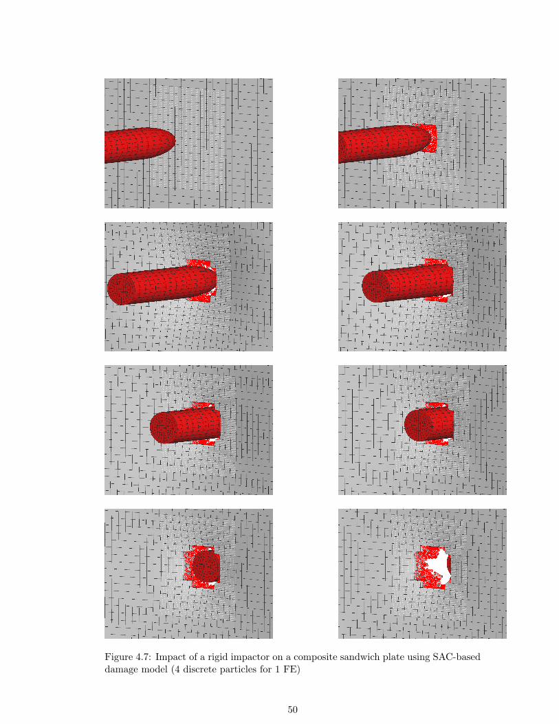
Figure 4.7: Impact of a rigid impactor on a composite sandwich plate using SAC-baseddamage model (4 discrete particles for 1 FE)
50

Figure 4.8: Tension test of the flat specimen modelled with FEM/SPH coupling (Dis-crete particles are embedded in FEs)
51

52

Chapter 5
Application of Meshless Methodsin Impact Simulations
Chapter 5 aims at showing the efficiency and advantages of meshless SPH Method,
direct-coupled FEM/SPH Method and semi-adaptive-coupled FEM/SPH Method for
HVI simulations on composite sandwich panels.
First the chapter gives a short overview about the reference model in which FEs were
used alone. Later numerical results, such as core deformation mode, penetration depth
and impact force pulses of the reference model and those from the proposed alternative
methods were compared with experimental investigations.
5.1 Experimental HVI Investigations
Deutsches Zentrum fur Luft- und Raumfahrt e.V. (DLR) carries out High Velocity
(HV) gas gun impact tests, aiming to determine failure modes, impact resistance, con-
tact force-time curves and total energy dissipation of impact events. In these tests
different projectiles, namely hard and soft, are fired against a test structure or against
a plate specimen mounted on a load cell. Hard projectiles, representative of runway
and engine debris impactors and soft projectiles, representative of bird strike or burst
tyre rubber fragments, are possible impact scenarios for an aircraft structure [157]. The
test results and observations may be used as experimental outputs for the validation
of impact simulations done by FE codes on a range of composite structures. A series
of test cases has been developed to investigate the critical parameters associated with
the effective modelling of composite and sandwich panels used in aircraft components.
Since the impact velocity can be varied, it is possible to simulate in the laboratory
actual impacts at high velocities and observe structural failure modes. Impact velocity
is varied in gas gun tests by changing the pressure in the pressure vessel and calibration
curves for vessel pressure and projectile velocity are used to achieve the required impact
velocity. Test data is used to specify appropriate materials for applications involving
impact and to design impact resistant structures. An important result of a HVI test is
53

Figure 5.1: Concrete projectiles(26φmm x 37mm and 30φmm x50mm)
Figure 5.2: Damage to sandwichplate after impact
to define modes of failure and failure thresholds, such as kinetic energy to cause dam-
age to skin and core. Impact loads as functions of time may be recorded in an impact
test, if the impacted structure is mounted on a load cell. A HV impact test program
was carried out at the DLR in which several sandwich plates were tested with different
projectiles, representative of stones and runway debris.
Two typical concrete projectiles manufactured as cylinders with a spherical end from
B25 concrete are shown in Fig. 5.1. In this chapter the impact test results are based
on a projectile with 26mm in diameter, 37mm in length and mass of 36.4g. Sandwich
plates were manufactured with PEI foam or Nomex honeycomb core, 33mm thick, with
[0/45/0/45]2 carbon fibre fabric/epoxy facings with a nominal thickness of 1.6mm. The
projectiles are placed in 50mm diameter PU sabots which are the exact diameter of the
gas gun barrel and fired at the panels so that the rounded end impacts the panel surface.
A nominal impact velocity of 60m/s was chosen, which corresponds to the maximum
expected impact velocity of runway debris on an aircraft structure during start and
landing. The actual impact velocity is measured optically using two light beams set
100mm apart, which are broken by the passage of the projectile. The first light beam
triggers the transient recorder to start and the time taken for the projectile to reach
the second light beam is measured.
Under these impact conditions the concrete projectiles will usually damage the skin
laminate and penetrate into the PEI or Nomex core before being stopped by the sand-
wich panel as is seen in Fig. 5.2. Quantitative test data are difficult to obtain in HV
gas gun tests, since it is not possible to instrument the projectile which is the procedure
adopted in low velocity drop tower tests. The DLR has developed a procedure which
54

measures the resultant force pulse on the panel specimen by mounting it on a ring load
cell, with the impact position on the panel aligned with the centre point of the load
cell ring.
Modelling Composites Properties
For metals there is extensive information in the literature on dynamic materials prop-
erties at large strains and high strain rates, and appropriate constitutive equations
have been implemented into FE codes for structural impact simulations. For compos-
ite materials dynamic failure behaviour is very complex due to the different fibres and
matrices available, the different fibre reinforcement types such as unidirectional (UD)
fibres and fabrics, the possibility of both fibre- or matrix-dominated failure modes, and
the rate dependence of the polymer resin properties. Thus at present there are no
universally accepted materials laws modelling damage arising in crash and impact of
composites. It was considered that a homogeneous orthotropic elastic damaging ma-
terial was an appropriate model for UD and fabric laminates, as this is applicable to
brittle materials whose properties are degraded by micro cracking. Constitutive laws
for orthotropic elastic materials with internal damage parameters are described here,
and take the general form
ε = Sσ (5.1)
where σ and ε are vectors of stress and strain and S is the elastic compliance matrix.
In the plane stress case required here to characterise the properties of composite plies or
shell elements with orthotropic symmetry axes (x1, x2), the in-plane stress and strain
components are
σ =
σ11
σ22
σ12
ε =
ε11ε222ε12
(5.2)
Using a strain equivalent damage mechanics formulation, the elastic compliance matrix
S may then be written :
S =
1
E1(1−d1)−ν12E1
0−ν12E1
1E2(1−d2)
0
0 0 1G12(1−d12)
(5.3)
where ν12 is the principal Poisson’s ratio, which for simplicity is assumed not to be de-
graded. This general plane stress form for an orthotropic elastic material with damage
has 3 scalar damage parameters d1, d2, d12 and 4 ”undamaged” elastic constants: the
Young’s moduli in the principal orthotropy directions E1, E2, the in-plane shear mod-
ulus G12, and the principal Poisson’s ratio ν12. The damage parameters have values
0 ≤ di ≤ 1 and represent modulus reductions under different loading conditions due to
progressive damage in the material. Thus for UD plies with fibres in the x1 direction,
d1 is associated with damage or failure in the fibres, d2 transverse to the fibres, and
55

d12 with in-plane shear failure. For fabric reinforcements then d2 is associated with
the second fibre direction. In order to proceed further evolution equations are required
which relate the damage parameters to other state variables. Several different models
have been proposed in the literature. In [158] and [159] it is postulated that the damage
parameters are functions of strain energy release rates in the material, and this method
has been developed further in the [160], to include plasticity and rate effects in damage
evolution.
This chapter is concerned with the application of PAM-CRASH, a commercial ex-
plicit FE crash code [161] , to analyse the crash response of composite structures. The
code contains several materials models and special elements for laminated composite
materials. The damage mechanics formulation outlined above is currently being imple-
mented and tested in the code along with a new approach to delamination modelling in
stacked shell elements described in [159] . The crash simulations of composite aircraft
components reported in [158] and [162] are based on alternative models in which it is
supposed that damage evolution is dependent on the strain invariants, which can be
determined from measured stress-strain curves. The elastic damaging materials law
for fabric reinforcements may be modelled in PAM-CRASH as a ”degenerate bi-phase”
model in which the UD fibre phase is omitted, and the matrix phase is assumed to be
orthotropic. If the simplifying assumption is made that d1 = d2 = d12 = d, the com-
posite fabric ply has orthotropic stiffness properties, but a single ”isotropic” damage
function d which degrades all the stiffness constants equally. The code does however al-
low different damage functions in tension and compression. This model has been found
to be easy to apply and appropriate for quasi-isotropic laminates, which are commonly
used in aircraft structures. An improved bi-phase model in [162] has been developed
and implemented, which allows two independent fibre directions in plies and may be
used when orthotropic damage effects are more significant.
It is necessary to determine parameters for the chosen composites model from mea-
sured stress-strain curves. Uniaxial stress-strain curves are assumed to have a damage
evolution equation which is a bilinear function of strain, in which there are two dam-
age constants d1 and du to be determined, (note d1 here should not be confused with
the damage parameter d1). Typical uniaxial stress-strain curves have the general form
shown Fig. 5.3, where εi is strain at the onset of initial damage, ε1 is the strain at the
peak failure stress, and εu is a limiting strain above which the stress is assumed to take
a constant value σu.
Measured test data for fabric composites are used to calibrate the materials model
and to determine the damage parameters d1 and du for the analysis. The parameter d1
is related to the departure from linearity at the first ”knee” in the stress-strain curves,
56

Figure 5.3: Stress-strain diagram Figure 5.4: Corresponding frac-turing damage function
and is thus small in tension, whilst the parameter du determines the residual stress
value σu shown in Fig. 5.4. For the FE analysis it is not good practice to reduce the
material stresses directly to zero at material fracture, as this may lead to numerical in-
stabilities. Thus under tensile stresses typically du ≈ 0.95, indicating that the element
is nearly fully damaged, whilst in compression du ≈ 0.5 to model the residual compres-
sion crushing stresses. In this way it is possible to attribute measured crush stresses
to shell elements under axial compression load so that EA in composite structures may
be simulated with shells. Materials rate dependence is not included in the modelling
presented here.
Modelling of Sandwich Core Materials
Modelling of PEI Foam Core
Foams are one of the most common forms of core materials in composite sandwich
structures. They can be manufactured from a variety of synthetic polymers including
polyvinyl chloride (PVC), polystyrene (PS), polyurethane (PU), polymethyl methacry-
lamide (acrylic), polyetherimide (PEI) and stryeneacrylonitrile (SAN). Foam core ma-
terials are widely used in automotive and aerospace applications for energy absorbers,
sound dampers and for cushioning. Because of their high energy absorbing capability
structural foams are very important in vehicle crashworthiness. However foam-cored
sandwich structures are susceptible to in-plane shear and core compression failure,
buckling instability and face sheet-to-core debonding. The core must be capable of
taking a compressive loading without premature failure. This helps to prevent the thin
skins from wrinkling and failing in a buckling mode.
FE modelling of foam materials becomes important in the prediction of sandwich be-
haviour. Although foams are promising materials, their mechanical properties have
not been studied as extensively as other commonly used engineering materials. Thus
different approaches are available to define the behaviour of foam materials [163]- [164].
The DLR carried out compression tests on PEI foam core and a typical stress-strain
57

Figure 5.5: Stress-strain plot of PEI foam core
curve is shown in Fig. 5.5. To model this behaviour in PAM-CRASH a crushable foam
solid, namely PAM-CRASH Material Model 2 [161], was used. The elastic behaviour of
this material is described by the shear modulus and the initial tangent modulus. The
inelastic behaviour exhibits both, volumetric (bulk) plasticity and deviatoric (shear)
plasticity. The coupling between both parts of the material response is established via
a pressure (p) dependent von Mises (J2 plasticity) yield surface.
φs = J2 − (a0 + a1p + a2p2) = 0 (5.4)
where
J2 =12SijSij =
13σY
2 (5.5)
is the second invariant of the deviatoric stress tensor on the yield surface. a0, a1 and a2
are user-specified material parameters, which are linked to the user-specified pressure
cutoff for tensile fracture.
Volumetric Plasticity
The volumetric plasticity is computed first. It is governed by the volumetric yield
function
φv(p) = p− fp(εv) (5.6)
58
where the fp(εv) is a user-specified volumetric strain-stress curve. The curve must be
specified such that its slope is nowhere greater than the unloading bulk modulus, Ko.
Deviatoric Plasticity
The deviatoric plasticity part of the response is calculated next, using a conventional
plasticity theory with radial return. The program evaluates trial deviatoric stresses as
Strial = Sn + 2G∆en. (5.7)
where ∆[eij ]n = [ ˙eij ]n∆tn is the increment of the deviatoric strain tensor. Using the
trial stress, the program calculates J2,trial and compares it with the present yield level
of J2 = a0 + a1p + a2p2. If the trial value exceeds the yield value of J2, a simple radial
return is performed to obtain the stresses
Sn+1 = (J2/J2,trial)12 Strial (5.8)
at the end of this time step. The total stress is calculated from
σn+1 = Sn+1 − pn+1δ. (5.9)
Modelling of Aramid Paper Honeycomb (Nomex) Core
Nomex honeycomb is made from Nomex paper, a form of paper-based on aramid fibres
rather than cellulose fibres. The initial paper honeycomb is usually dipped in a phe-
nolic resin to produce a honeycomb core with high compression strength and good fire
resistance.
The honeycomb core properties depend on the size of the cells and the thickness and
strength of the web material. They can give stiff and very light sandwich laminates
with composite skins and high-performance resin systems such as epoxy provided that
the necessary adhesion to the laminate skins can be achieved.
For the material modelling of Nomex a homogenised model for solid elements has
been adopted. Fig. 5.6 shows the compression behaviour of the Nomex honeycomb
as measured in tests at the DLR. In PAM-CRASH a nonlinear fibre bi-phase solid,
namely PAM-CRASH Material Model 31 [161], was chosen to simulate the material re-
sponse. PAM-CRASH Material Model 31 corresponds to highly anisotropic and nonlin-
ear honeycomb cores which the through thickness compression properties are modelled
as elastic-plastic.
5.2 Numerical Modelling of HVI Simulations - FEM
The FE simulations were carried out for two kinds of sandwich plate mounted on a ring
load cell and impacted at the centre by a cylinder projectile. Fig. 5.7a illustrates the
59

Figure 5.6: Stress-strain plot of Nomex core
final state of the impact simulation in which the projectile is modelled as rigid. One can
see the large deformation on the PEI core. The core material under impact load shows
a classical elastic-plastic response. Contact force history in Fig. 5.7b shows that the
impact model proposed in this work provides reasonable accurate contact force history
of HVI on sandwich structures.
As one can observe, the first peak load is about 7kN and the second peak load is about
4kN. When the projectile impacts the upper skin of sandwich plate the first peak load
is obtained. Depending the EA mechanism of the sandwich plate and the system dy-
namics, the projectile loses some kinetic energy and this results in a lower second peak.
The same procedure was followed for the simulation of impact on Nomex core sand-
wich plate as shown in Fig. 5.8a. Fig. 5.8b shows the same double peak characteristic
however with different peak values which are a little lower than those from the impact
on PEI core sandwich plate.
The contact force history plot can give us information about the EA capability of
sandwich plates. However kinetic and internal energy history plots illustrate this phe-
nomena more clearly. Figs. 5.9a-b show the kinetic/internal energy history of the PEI
and Nomex core sandwich plates, respectively. For both cases, which have the same
inital velocity, projectile kinetic energy after impact is absorbed as internal energy in
the skins and core. In the two plots, the internal energy levels that the upper and lower
skins absorb after impact are almost the same. However, the level of internal energy
60

a) b)
Figure 5.7: a) Final state of PEI core sandwich plate, b) comparison of the contactforce history plots
a) b)
Figure 5.8: a) Final state of Nomex core sandwich plate, b) comparison of the contactforce history plots
a) b)
Figure 5.9: Kinetic and internal energy history plot for a) PEI core sandwich plate, b)Nomex core sandwich plate
61

that PEI core dissipates is higher than that of Nomex core.
5.3 Discussion - FEM
The numerical impact models based on FEs provide reasonable accurate details of
HVI on sandwich structures including impact force, displacement, velocity and energy
response and damage development during impact. Good agreement was obtained with
impact loads for PEI and Nomex core sandwich panels. Although the existing numerical
model is generally good at predicting failure modes in composite structures, further
refinement is needed for better quantitative correlations.
5.4 Numerical Modelling of HVI Simulations - SPH andDirect-Coupled FEM/SPH Method
The proposed FE mesh-based model can be used for accurate prediction of failure
modes in sandwich panels. However topological element connectivity in FEM can lead
to numerical instabilities (for higher velocities) and further enhancement is needed for
better quantitative correlations. Following this idea, carbon fibre/epoxy facings were
modelled with standard layered shell elements, whilst SPH particles are used for the
PEI core where extensive crushing and fracture by the rigid impactor occur. Use of
solid elements here leads to aforementioned difficulties with excessive distortion. Be-
side the advantages of its meshless nature, as a result of the dynamic neighbouring
search algorithm, the SPH Method is computationally expensive. One alternative nu-
merical solution technique that is commonly used is coupling. Since SPH Method
uses Lagrangian framework, a possible coupling between SPH Method and standard
Lagrangian FEM is straightforward. This means (for impact problems) a coupling be-
tween discrete smoothed particles for the parts where large deformation occurs and
FEs for the parts where small deformation takes place is possible. Such coupling would
exploit the potential of each method while avoiding their deficiencies. In this approach,
coupling was applied through a sliding interface condition. The mesh patterns or both
discretisations can be combined with a tied kinematic constraint contact that connects
two contact interfaces defined on two meshed parts of a structure that are close to each
other but whose respective discretisation grids are not necessarily matching. Discrete
SPH particles are generated with a simple transformation of FE mesh into mass points.
Meshless Modelling of PEI Foam Core
In order to overcome the high mesh distortion which causes numerical problems with
the time step assignment in explicit codes, the elements are replaced by interacting
particles. In the pure SPH approach all FE meshes of the PEI core are replaced by
SPH particles, and the in direct-coupled FEM/SPH approach the highly distorted local
62

damage zone is replaced by particles. The material response assigned for discrete SPH
particles is an isotropic elastic-plastic-hydrodynamics solid material model in which
the pressure-volume relation is modelled by an equation of state (EOS). This material
model was originally developed for ballistic impact in metals and describes an isotropic
elastic-plastic material at low pressure, whose properties are defined by the shear mod-
ulus and tangent modulus or effective plastic stresses and effective plastic strains. Ad-
ditionally with EOS describes the “hydrodynamic” pressure-volume behaviour at high
pressures. In this case it is given as following:
p = C0 + C1ν + C2ν2 + C3ν
3 ν =ρ
ρ0− 1 (5.10)
C0, C1, C2, C3 are material constants, ν is a dimensionless compressibility parameter
defined in terms of the ratio current density, ρ, to initial density, ρ0. The polynomial
form is an established approximation of the observed EOS for many materials, see for
examples [165], with the feature that it reduces to a dilatational elastic materials law
with bulk modulus C1 when C0=C2=C3=0.
To make a qualitative comparison between FEM, SPH Method and direct-coupled
FEM/SPH Method, impact simulations were carried out for a sandwich composite
panel mounted on a ring load cell and impact at the centre. Normal impact from a
rigid impactor was considered at nominal impact velocity of 60m/s, which corresponds
to the typical impact speed of runway debris on an aircraft structure during start and
landing.
Here three different approaches have been used to model the impact damage on PEI
core sandwich panels, as analysed previously by the FEM. In all three cases impactors
first damage the upper skin and penetrate into the sandwich core. Figs. 5.10a and 5.11a
show the maximum penetration and post-impact core deformation with pure FEM. One
can observe the large deformation on the PEI core. The core material under impact
load shows classical elastic-plastic response. FEM approximations are continuum-based
approximations and the topological connectivity in FEM is very critical. The modelling
of core deformation with higher impact velocities can cause element distortion prob-
lems resulting in error termination. Therefore the core has been modelled using discrete
SPH particles. Figs. 5.10b and 5.11b show the maximum penetration and core defor-
mation for the numerical impact simulation with SPH Method. In SPH Method the
topological connectivity is not as critical as in FEM and the core deformation can be
modelled without having element distortion problem. Since in SPH Method the num-
ber of discrete particles and the domain of influence of each particle are decisive for
the CPU times, direct-coupled FEM/SPH Method, which combines the faster compu-
tation nature of FEM and accuracy of SPH Method, is proposed. Figs. 5.10c and
5.11c show the maximum penetration and post-impact core deformation with proposed
63

a) b) c)
Figure 5.10: Numerical HVI model: a) FEM, b) SPH and c) direct-coupled FEM/SPHmodel
a) b) c)
Figure 5.11: Maximum core penetration for a) FEM, b) SPH and c) direct-coupledFEM/SPH model
direct-coupled approach. Here one can observe the interaction between the FEM-based
and SPH Method-based modelled impact damage zone. After damaging the upper
skin the impactor penetrates into the sandwich core. In both SPH Method and direct-
coupled FEM/SPH Method the impactor compresses the particles in the damage zone
and its kinetic energy is absorbed by the particles in the damage zone. However one can
observe that the penetration of the impactor in the pure SPH Method is larger that the
pure FEM and direct-coupled FEM/SPH Method. In experimental investigation the
maximum penetration value has been measured as 25mm. The maximum penetration
values are 20, 32 and 19.5mm, respectively, in the example computed here.
Contact force history comparison between experimental analysis and FEM simula-
tion in Fig. 5.12a shows that the proposed FEM model provides reasonable accurate
contact force history of HVI on sandwich panel. As one can observe from the exper-
imental curve, the first peak load is about 7kN and the second peak is about 4kN.
Depending on the EA mechanism of the sandwich plate, the projectile loses its kinetic
energy and resulting in a lower second peak. Proposed FEM model estimates especially
the first peak value accurately, which is very critical value for impact scenarios. How-
ever as Figs. 5.10a and 5.11a show, FEM model produces very severe deformation on
core which can lead to numerical errors, inaccurate results and numerical instabilities
for higher velocities. In the SPH Method depending on the deformation mechanism
neighbouring particles can separate and as Fig. 5.11b illustrates core deformation is
more realistic than that of FEM.
64

a) b)
c)
Figure 5.12: Contact force history of a) FEM vs. Experiment, b) SPH vs. Experimentand c) FEM/SPH vs. Experiment
Fig. 5.12b shows that the proposed SPH model for the sandwich core approximates
the experimental impact force pulse quite accurately. However the initiation of the
peak force is later than the experimental one and the pulse is more oscillatory than the
FEM results and the experimental pulse. Fig. 5.12c shows the comparison of the con-
tact force histories between experimental and numerical simulation with direct-coupled
FEM/SPH Method. Here one can observe that the numerical pulse is not as oscillatory
as in the SPH case since the topological connectivity is still in use outside the dam-
age zone. The direct-coupled FEM/SPH Method approximates the impact pulse more
accurately. The pulse duration which is important as well as the peak force value is
very similar to the experimental one and better than the approximations produced by
the pure SPH Method. Additional to the PEI core sandwich panels the accuracy of
direct-coupled FEM/SPH Method has been tested in three different impact cases using
65

Figure 5.13: Glass impactors
a demonstrator sandwich panel with a hybrid PEI/Nomex core. The sandwich panel
had thickness of 33mm, composed of 1.6mm carbon fibre/epoxy skins, with 10mm PEI
foam next to the upper skin and 20mm Nomex core next to the lower skin. In this con-
cept the PEI foam acts as a loadspreader in impact to generate more uniform impact
loads into the honeycomb core. Three different impact scenarios have been chosen in
which glass impactors (Fig. 5.13) with 21 and 29mm diameter were fired with the im-
pact velocities of 65.8 , 95.1 and 108m/s. Therefore the efficiency of the direct-coupled
FEM/SPH Method can be tested in a range of impact velocities showing different dam-
age modes.
For the first comparison an impact case with a glass ball impactor 29mm in diame-
ter and impact velocity of 65.8m/s has been chosen. The impactor damages the upper
skin introduces an impact load on the core and bounces back, (Fig. 5.14a). In the
second scenario an impactor 21mm in diameter has been impacted on the plate with an
impact velocity of 108m/s. The impactor damages the upper skin, penetrates into the
core and since its remaining kinetic energy is absorbed by the core it resides inside the
sandwich plate. The damage zone is smaller that the previous case since the diameter
of the impactor is smaller (Fig. 5.14b). In the last case a glass ball impactor 29mm
in diameter and with an impact velocity of 95.1 m/s has been tested. The impactor
damages the upper skin, penetrates into the core and since its kinetic energy was not
absorbed completely by the core it continues its movement and damages the lower skin
(Figs. 5.14c, 5.14d).
Since the hybrid core consists of both Nomex and PEI foam, the Nomex core has been
modelled using classical FEs with discrete particles used for the PEI layer. For the
Nomex layer a nonlinear fibre bi-phase material model with element elimination tech-
nique has been used, as discussed above. This technique eliminates the elements which
reach a prescribed element strain threshold value. Note that Nomex is orthotropic in its
66
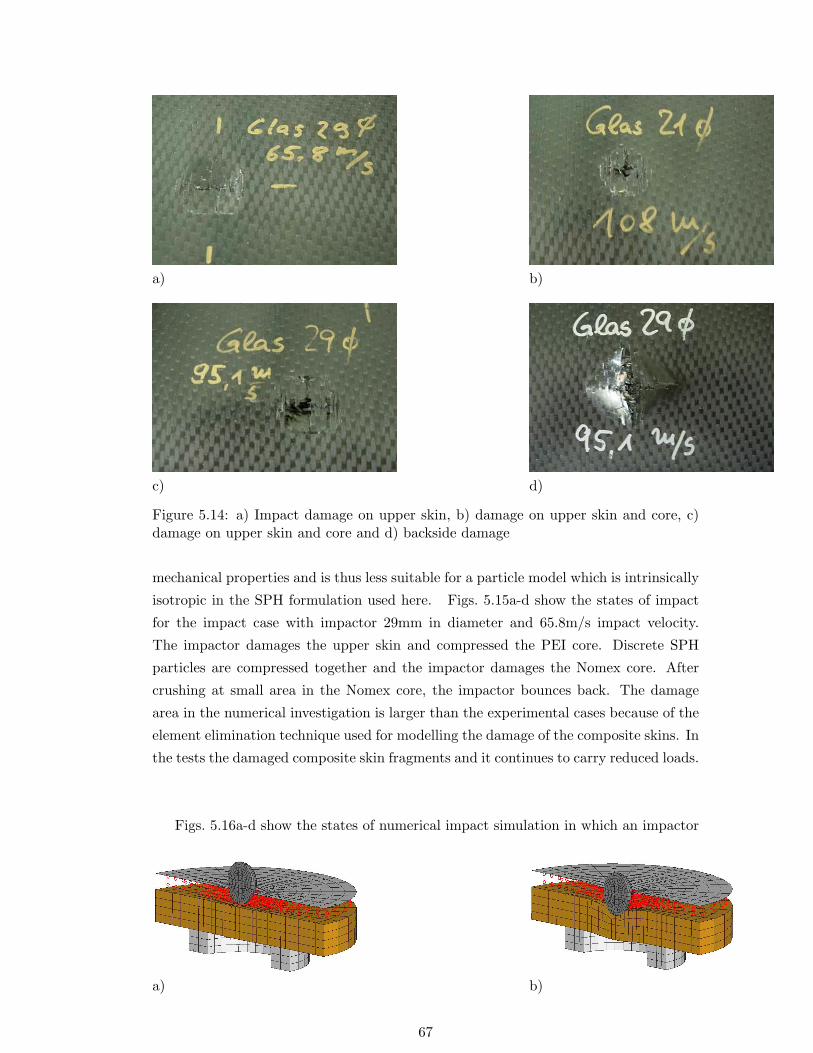
a) b)
c) d)
Figure 5.14: a) Impact damage on upper skin, b) damage on upper skin and core, c)damage on upper skin and core and d) backside damage
mechanical properties and is thus less suitable for a particle model which is intrinsically
isotropic in the SPH formulation used here. Figs. 5.15a-d show the states of impact
for the impact case with impactor 29mm in diameter and 65.8m/s impact velocity.
The impactor damages the upper skin and compressed the PEI core. Discrete SPH
particles are compressed together and the impactor damages the Nomex core. After
crushing at small area in the Nomex core, the impactor bounces back. The damage
area in the numerical investigation is larger than the experimental cases because of the
element elimination technique used for modelling the damage of the composite skins. In
the tests the damaged composite skin fragments and it continues to carry reduced loads.
Figs. 5.16a-d show the states of numerical impact simulation in which an impactor
a) b)
67

c) d)
Figure 5.15: Impact states Vo = 65.8m/s: a) t=0.16ms, b) t=0.36ms, c) t=0.72ms andd) t=1.20ms
a) b)
c) d)
Figure 5.16: Impact states Vo = 108m/s: a) t=0.16ms, b) t=0.20ms, c) t=0.36ms andd) t=0.80ms
68

a) b)
c) d)
21mm in diameter and with an impact velocity of 108m/s. The impactor damages the
skin and firstly penetrates into the PEI core. The discrete particles are compressed
together and since the kinetic energy of the impactor is not yet zero, it continues it
movement. It penetrates into the Nomex core and causes a large deformation. During
this deformation process the residual kinetic energy of the impactor absorbed by the
Nomex core and impactor resides inside the sandwich plate. The same impact failure
was observed in the experimental impact test. Figs. 5.17a-e show the last impact case
in which an impactor 29mm in diameter with 95.1m/s impact velocity impact onto a
hybrid core sandwich plate. The same impact stages can be also observed in this case.
However the residual kinetic energy of the impactor is not absorbed by the Nomex core
and the impactor continues its movement. The impactor damages the lower skin and
rear face damage occurs. Fig. 5.17f shows the side view of the damage zone. Here one
can also observe the deformation in the damage zone modelled with discrete particles.
Again in this impact case the proposed direct-coupled FEM/SPH approximates the
impact scenario very accurate and realistically.
e) f)
Figure 5.17: Impact states Vo = 95.1m/s: a) t=0.16ms, b) t=0.28ms, c) t=0.52ms, d)t=0.88ms, e) t=1.00ms and f) backside damage, side view
69

5.5 Discussion - SPH and Direct-Coupled FEM/SPH Method
In this work the results of impact simulations carried out for a sandwich composite plate
with carbon fibre fabric/epoxy face skins and PEI foam core using SPH and FEM/SPH
Method have been presented. The deformation pattern and the contact force histories
obtained with pure SPH and direct-coupled FEM/SPH Method have been compared
with that of experimental and pure FEM-based numerical results. The two approaches
give quite accurate results. However since the computational time depends on the
domain modelled by discrete particles, a direct-coupled FEM/SPH Method has been
shown to be a good alternative for the numerical simulations where large deformation
and element distortion are critical. Later to show the efficiency of the direct-coupled
FEM/SPH Method in different velocity ranges three impact scenarios in which a hybrid
core consisting of PEI and Nomex sandwich plate impacted by spherical glass impactors
have been modelled. The direct-coupled FEM/SPH Method reproduces the impact
failure modes and observed damage on the sandwich plates to a good approximation.
The results demonstrated the capability of meshless SPH Method and its combination
with FEM to be an effective candidate to overcome the drawbacks of FEM for modelling
fragmentation failures in impact. The following work studies extensions of the method
using a SAC of SPH and FEM and applying this to study crush response in composite
energy absorbing structural elements.
5.6 Numerical Modelling of HVI Simulations - Semi-AdaptiveCoupling
In this section for the prediction of impact damage of Nomex core sandwich panels
under HVIs have been investigated using the proposed SAC technique. In the crush
failure zone the FEs are replaced by the discrete particles during the impact. Here the
transverse shear strain is used as adaptivity threshold. The numerical impact force and
maximum penetration values are compared with those from experimental tests.
As mentioned in Chapter 3 for the modelling of cellular materials several modelling tech-
niques are available, among them unit cell models and homogenised models. However
computational expenses for unit cell finite honeycomb models increase rapidly as the
number of cells increase. Additionally the unit cell models are highly mesh-dependent.
In order to show mesh dependency of the crush behaviour two unit cell models with
mm and 0.5mm mesh sizes have been used. Fig. 5.18 shows the deformation stages of
the quasi-static compression test.
At low strains Nomex honeycomb deforms elastically then cell walls buckle. Com-
pared to Al honeycomb Nomex honeycomb is relatively brittle. Therefore cell walls
start to fracture after reaching a critical load value. As in the crushing of Al honey-
70

a) b) c)
Figure 5.18: Stages of quasi-static compression test of Nomex honeycomb: a) bucklinginitiation, b) progressive folding and c) densification
comb, cell walls collapse until densification. Fig. 5.19 shows the comparison between
the experimental and numerical deformation patterns of the Nomex honeycomb using
the micromechanical model. As one can see the deformation mode is global collapse
which can be observed from the simulation results with 1mm elements. The numeri-
cal model with 0.5mm elements produces progressive collapse which was not observed
in the experimental analysis. It should be remembered that the element thickness is
0.13mm, so that the use of thin shell elements of length 0.5mm here is questionable,
and could cause different failure behaviour. The failure behaviour obtained by the mi-
cromechanical model with 1mm elements is comparable to experimental observations
and this mesh size was used in the subsequent analysis.
As mentioned above in reality after reaching a critical load value, cell walls fracture un-
der compression. In the micromechanical model since an elastic-plastic material model
was used, the cell wall fracture was not highlighted by the numerical model. Fig. 5.20
shows the comparison between the load-displacement curves obtained by experiment
and the numerical micromechanical model with 1mm mesh size. The micromechanical
model gives reasonable agreement with the experimental crushing response. However
since fracture is not included in the numerical model, the first peak load value pre-
dicted is due to local plastic folding which is lower and wider than the experimental
one caused by brittle fracture of the aramid paper. However if unit cell modelling tech-
nique is applied on real aircraft structures such as composite fuselage core or leading
edge the computational expense is the biggest drawback of this modelling technique.
For the reasons given above the micromechanical model is computationally very expen-
sive and is not suitable for structural analysis. Therefore the homogenised core model
has been considered based on solid elements. However the material model proposed
for the homogenised model uses EET for modelling of the cell wall fracture. The EET
is based on the removal of the solid core elements reaching a critical strain threshold.
If they are not removed at failure, the element compression strain distorts the element
71

a)
b)
c)
Figure 5.19: Stages of quasi-static compression of Nomex honeycomb at 30% and 60%compressive strain a) experiment (initial and 60% deformation), b) FE analysis with1mm and c) 0.5mm element size
72

Figure 5.20: Comparison between the load-displacement curves obtained by experi-ment and the numerical model using micromechanical model of Nomex honeycomb incompression
geometry so much that the element length in the load direction becomes very small,
which in explicit code simulations significantly reduces the time step and eventually
causes run termination. Further, small changes in the strain elimination threshold can
change the crushing mechanism drastically and introduce mesh dependency. Therefore
it is numerically not effective. Hence the SAC technique described in Chapter 4 is
applied to model the crushing behaviour of Nomex honeycomb more efficiently [166].
In this method when a critical element compression strain is reached the solid element
is eliminated and replaced by discrete particles in an SPH formulation with an asso-
ciated plastic compression crush materials law. The SAC technique is appropriate for
modelling the Nomex core, which is orhotropic and hence not reallly suited to the SPH
formulation used above for PEI foam cores. With the SAC technique it is possible
to have orthotropic solid elements with correct mechanical properties, which are elim-
inated on reaching their failure strain and become replaced by SPH particles, which
then have an isotropic elastic-plastic crush behaviour.
5.7 Discussion - Semi-Adaptive-Coupled FEM/SPH Method
Fig. 5.21 shows the comparison between the experimental and numerical stress-strain
history of Nomex honeycomb core under through-thickness compression loads. The ho-
mogenised model can model the initial peak and plateau load value correctly. However
73

Figure 5.21: Comparison between the experimental and numerical stress-strain historyof Nomex honeycomb under compression
after the elimination of the FEs at compression failure strains of about 10% the mea-
sured contact force drops down drastically and this causes lost contact information. In
the SAC technique discrete particles replace the fragmented FEs after elimination and
can model the crushing behaviour of Nomex honeycomb very accurately (Fig. 5.22),
which shows the predicted crush deformation with the SAC model. The solid elements
are eliminated at a predefined shear strain threshold. Then the damaged solid elements
are replaced by discrete particles which are crushed further. The solid elements not
converted into discrete particles have not yet reached the element elimination strain
threshold. This hybrid modelling technique has few solid elements compared with the
microscale models above and is thus suitable for efficient numerical analysis of honey-
comb barriers and larger sandwich structures in crash or impact where the honeycomb
core is severely crushed and has an EA function.
After having a stable crush model the technique has been applied to impact problem
in which a projectile impacts on a composite sandwich panel. Here carbon fibre/epoxy
facings were modelled with standard layered shell elements, whilst a homogenised model
was used for the initial state of the Nomex honeycomb and SPH particles for the frag-
ment representation. In this method when a critical element compression strain is
reached the solid element is eliminated and replaced by discrete particles in an SPH
formulation with an associated plastic compression crush materials law.
74

a) b)
c)
Figure 5.22: Application of SAC technique for modelling of Nomex honeycomb crushbehaviour: a) homogenised FE model, b) 30% and c) 50% compression of core showingeliminated solids replaced by SPH particles
75

a) b) c)
Figure 5.23: Numerical views of impact simulation using homogenised models: a) initialstate, b) t=0.4ms and c) t=0.6ms
a) b) c)
Figure 5.24: Numerical views of impact simulation using SAC technique: a) initialstate, b) t=0.4ms and c) t=0.6ms
Fig. 5.23 shows the numerical simulations of the impact test using homogenised FEM
model with low strain threshold. After damaging the upper skin, the impactor pene-
trates into the Nomex honeycomb. Since the strain threshold is low, the homogenised
core can not carry the impactor compression load and eliminates solid elements at fur-
ther stages of the simulation. Hence the impactor reaches the lower skin and damages
it. However in experimental investigations the lower skin damage was not observed.
Just upper facing damage and core crushing were obtained.
Fig. 5.24 shows the stages of HVI simulation using SAC. Here homogenised Nomex
honeycomb core has the same elimination threshold as in previous simulation. After
the elimination of the FEs discrete particles represent the fragmented core debris and
continue carrying compressive impact load.
The impactor now damages the upper skin, penetrates into the core and since its
kinetic energy is absorbed by the upper skin and the core it does not reach the lower
skin, agreeing with the test (Fig. 5.24). Fig. 5.25 shows the comparison of experimental
and SAC-based numerical contact force histories. The proposed model estimates the
first impact force peak as 5.4kN and the second one as 3kN. The experimental values
are for these two peaks are 5.3kN and 3kN, respectively. Additionally the maximum
penetration of the impact were also compared. The maximum penetration values for
experimental and numerical investigations was also compared. The maximum pen-
etration values for experimental and numerical investigations are 25mm and 27mm,
76

Figure 5.25: Comparison of experimental and SAC-based numerical contact force his-tories
respectively, which are in close aggreement.
5.8 Final Discussion
In this section a new approach called SAC Technique has been proposed to model
the impact damage response of the sandwich core previously modelled using EET.
SAC Technique replaces the eliminated core elements which reaches the elimination
threshold by discrete particles and allow stable computation. The efficiency of the
approach was tested under both quasi-static compression and HVI loading and showed
good correlations with the experimentally conducted investigations.
77

78

Chapter 6
Application of Meshless Methodsin Crash and Energy AbsorbingStructures
This chapter reports experimental and numerical analysis of quasi-static crushing of
foam-filled Al thin-walled tubes and composite energy absorbers made of carbon-fibre-
reinforced composites. It aims at showing the efficiency of alternative modelling ap-
proaches such as SPH Method, direct-coupled FEM/SPH and semi-adaptive-coupled
FEM/SPH Method.
For both crashworthy analyses first the FE-based models are presented. Then to study
the effectiveness of meshless methods for the foam-filled Al thin-walled tubes the SPH
Method and direct-coupled FEM/SPH Method are used. Finally the composite energy
absorbers are modelled with the SPH Method.
6.1 Experimental Investigations on Empty and Foam-filledAluminum Crash Absorbers
In this section firstly the crashworthy analysis of empty and PS foam-filled single tube
absorbers (height: 40mm and diameter: 25mm) is presented. In the first part of the
study the foam filler is discretised using solid FEs. Later the above mentioned alter-
native SPH modelling approaches are used for the problem and the results compared
with that of FEM.
Secondly, after obtaining a stable numerical model the crashworthy analysis of foam-
filled (PS and Al foam) bitubular configurations (height: 27mm) are investigated.
Bitubular arrangements have been chosen since they are the good representations of
double-walled energy absorbing structures. Three different bitubular configurations
were tested. These are shown in Fig. 6.1 and coded as BPH (interior: 25mm-diameter
empty tube and exterior: 35mm-diameter PS foam-filled tube), BPP (interior: 25mm-
79

a) b) c)
Figure 6.1: Bitubular configurations a) BPH, b) BPP and c) BPA
a) b)
Figure 6.2: a) Tensional engineering stress-strain curve of Al tube material, b) quasi-static compression stress-strain curve of PS foam fillers
diameter PS foam-filled tube and exterior: 35mm-diameter PS foam-filled tube) and
BPA (interior: 25mm-diameter Al foam-filled tube and exterior: 35mm-diameter PS
foam-filled tube)
For the first part of the study the selected Al thin-walled tubes (99.7% Al), produced
by Metalum Company of Turkey using a cold deep drawing process, were 25mm in
outer diameter with a wall thickness of 0.29mm.
A typical quasi-static (10−3s−1) engineering tensile stress-strain curve of the tube
wall material tested in accordance with ASTM B557M standard is shown in Fig. 6.2a.
The relatively high strain hardening, seen in the inelastic deformation region of the
curve, is most likely due to the cold forming process applied. Tubes were filled and
tested without any heat treatment applied.
Thin-walled Al tubes were filled with a commercially available extruded PS foam
80

sheets manufactured by Izocam Company in two different average densities: 21.7 and
27.8kg/m3. PS foams are currently used as the filler in the inner layer of motorcyclist’s
helmets for impact-protection function, but their capabilities in thin-walled tubes as
lightweight filler materials have not yet been investigated and modelled. As compared
with expanded counterparts, extruded PS foams have more homogenous cell size and
contain no weak boundaries of beads; hence are potentially more suitable materials
for the filling of thin tubular sections. Uniaxial compression stress-strain curves of
foams determined in accordance with ASTM 1621-91 on 40mm long cubic samples are
shown in Fig. 6.2b. The curves show typical elastoplastic foam compression behaviour,
composing of three distinct deformation regions: elastic, collapse (plateau) and densi-
fication.
Cylindrical foam fillers with an outer diameter that was slightly larger than the in-
ner diameter of empty tube (∼ 0.5mm) were core drilled from the as-received PS foam
sheets through the thickness direction. The foam filler samples were inserted into empty
tubes tightly without imposing any damage to the cells. Compression tests were con-
ducted on a fully computer controlled Schmadzu AGI universal testing machine. Test
samples were compressed between two flat plates without any constraint applied to the
ends of tubes. Compression tests on empty and foam-filled tubes, all 40mm in length,
were performed at a deformation rate of 100mm/min, the same as that of compression
tested foam samples.
For the bitubular arrangements the deep-drawn Al tubes received in 25mm (0.29mm in
wall thickness and 27mm in height) and 35mm (0.35mm in wall-thickness and 0.27mm in
height) in outer diameter were produced by Metalum Company of Turkey. As-received
extruded PS foam sheets with dimensions of 50x600x1200mm were manufactured by
Izocam Company of Turkey. The density of the PS foam was determined by divid-
ing the mass of the cubic foam sample (50x50x50mm) by its volume and found to be
32.1kg/m3. The circular PS foam fillers were core-drilled through the thickness of the
as-received foam sheet. Al closed-cell foams were prepared using the foaming from
powder compacts (precursors) process at Izmir Institute of Technology. The detailed
information on the foaming process and foam sample preparation is given in [167]. By
simply changing the furnace holding time, foam plates having three different densi-
ties: 270, 350 and 430kg/m3 were obtained and used in filling of thin-walled Al tubes.
The density of Al foam filler was determined by simply dividing its weight to its volume.
The crushing behaviour of foams samples and foam-filled tubes were determined
using a computer controlled Schimadzu AG-I testing machine at a crosshead speed of
2.5mm/min. Fig. 6.3 shows the compression stress-strain responses of the Al foam
fillers. The stress-strain curves of the foams show typical elastoplastic compression
81

Figure 6.3: Compression stress-strain curves of Al foam fillers
behaviour, composing of three distinct deformation regions: elastic, collapse (plateau)
and densification. As is seen in Fig. 6.3 the plateau stresses of Al foams are not con-
stant in the collapse region and increase with increasing strain and foam density. The
differences in cell size and cell size distribution cause the collapse of weak cells before
the collapse of strong cells, leading to increase in the stress values in collapse region.
6.2 Numerical Modelling of Foam-filled Aluminum CrashAbsorbers - FEM
The geometrical models were created in the commercial FE package ANSYS. Later
the meshed geometrical models were exported to PAM-GENERIS in order to set the
boundary conditions. The numerical solutions were carried out using the explicit FE
code PAM-CRASH. PAM-VIEW was used as the visualisation tool post-processor.
The Al tubes were modelled using Belytschko-Tsay-4 node-thin shell elements. In
foam-filled tube modelling (to save computational time) only one half of the tube was
modelled due to symmetry. The foam filler and the compression test plates were mod-
elled with 8-node solid elements. FE meshes of the quasi-static axial compression
testing of empty and foam-filled tubes are shown in Fig. 6.4, respectively.
The compression test base and upper plates were modelled as rigid bodies. The dis-
82

Figure 6.4: FE discretisation of a) empty tube (full model), b) foam-filled tube (halfmodel), 1 and 2: compression test plates, 3: empty and foam-filled tube meshing and4: foam-filler meshing
placements and rotations of the compression test plates were constrained except the
displacement of the upper plate along the vertical axis. The movement of the upper
load plate was fully determined by the movement of an artificial ”node” located at the
rigid body center of gravity. Boundary conditions for the rigid body were applied to
the center of gravity node only.
PAM-CRASH Material type 103 corresponding to the elastic-plastic isotropic thin shell
material was used for the tube material. Material type 103 uses an enhanced plasticity
algorithm that includes transverse shear effects. It exactly satisfies Hill’s criterion and
precisely updates the element thickness during the plastic deformation.
The material behaviour of PS foam was modelled using the crushable foam (elastic-
plastic) solid mode, namely PAM-CRASH Material type 2, which corresponds to solid
materials exhibiting coupled volumetric bulk and deviatoric shear plasticity, as dis-
cussed before. Prior to the numerical investigation of foam-filled tubes, PS foam com-
pression behaviour was simulated to validate the foam material model. The numerical
simulations and experimental results were compared for each density of PS foam and
the comparison is shown in Fig. 6.5. Agreement between numerical and experimental
stress-strain curves shown in this figure is satisfactory for the modelling purpose.
Three contact models were used in the modelling: i) a tied contact between the base
plate and the empty tube, ii) a node-to-segment contact between the upper plate and
the tube ends and iii) a self-contact (self impacting contact with edge treatment) in
order to prevent interpenetration between folds in the tube wall during plastic defor-
mation. The self-contact impact algorithm of PAM-CRASH type 36 allows all slave
segments to be defined in a given sliding interface. No segment orientation is speci-
fied, since the algorithm automatically detects penetrations and keeps in memory the
83

Figure 6.5: Quasi-static compression stress-strain curve of PS foam fillers
segment side from which a slave node comes into contact. The self-contact impact
algorithm also uses a search algorithm, the so-called 3D Bucket sort algorithm in which
the 3D slave surface is subdivided into a number of buckets and the slave nodes are
recalculated in terms of bucket coordinates. Depending on the slave node bucket co-
ordinates, its proximity to the slave segments is quickly determined. After the global
search phase, an accurate local search algorithm is started.
The folding of the tube wall results in local deformation of and penetration into
the foam filler surface. It was experimentally observed that the penetration depth
through the foam filler surface was relatively small as compared with the radius of the
filler (Fig. 6.6).
Based on this observation, a fine discretisation was applied to the foam filler near
the tube wall surface, in order to reduce the computational time, as shown in Fig. 6.4.
The mesh patterns are combined with a tied kinematic constraint type contact that
connects two contact interfaces defined on two meshed parts of a structure that are close
to each other but whose respective FE grids are not necessarily matching. Internal solid
anti-collapse contact, namely PAM-CRASH contact type 10, was used additionally in
order to prevent numerical problems that could arise when the solid elements of foam
were heavily compressed and distorted. The option helps to reduce excessive compres-
sion; therefore, avoids too large drops in the stable solution time steps. This option
also helps to avoid too large element distortions that may lead to ill-defined elements.
84

Figure 6.6: Penetration of the tube wall into foam filler
The interaction between the tube wall and the foam filler was defined via multiple
segment-to-segment contact, PAM-CRASH contact type 23.
Multiple segment-to-segment contact uses an enhanced searching algorithm for detect-
ing penetrations. Based on each master segment domain box, candidate slave nodes
are searched by an efficient sorting method. For a given master segment at every time
step, only its candidate nodes are checked for penetrations. Penalty forces are applied
to those nodes which are judged to be penetrating the master segment.
Mesh optimisation
In FE analysis the number of FEs for a fixed geometry depend on element size and
may significantly influence numerical results. The optimal FE mesh number has been
established by refining the mesh until convergence is reached. The 25mm tube circum-
ference was meshed with 40 elements and in order to determine the optimal size of
mesh, the geometry was meshed with 20, 40, 80 and 160 elements along the height.
The nomenclature used to describe the models is that 40x80 is to be interpreted as 40
elements along the circumference and 80 elements along the height.
Quasi-Static Simulation
The compression of empty and foam-filled tubes was performed at a cross-head speed
of 100mm/min, corresponding to a deformation rate of (4.16x10⁻²s−1) (the cross-head
speed divided by the initial length of the tube) which is relatively slow for the dynamic
numerical simulations since the explicit time integration method is conditionally stable
when the time step is sufficiently small. Therefore in general very small time increments
85

a) b)
Figure 6.7: a) Kinetic and internal energy histories of 25mm empty tubes at variousdensity scaling and deformation rates, b) corresponding load-displacement curves
have to be used. Contrary to implicit methods which are more efficient for relatively
slow phenomena such as static strength and buckling problems, the explicit method is
more efficient for very fast phenomena such as impact and explosion. Santosa et al. [23]
however presented a procedure to achieve a quasi-static process using the explicit dy-
namics scheme by suggesting two alternatives; scaling down the material mass density
and scaling the test speed up and scaling up the mass density and scaling the test speed
down. The first one results in large number of time increments. The second alternative
results in larger time step and therefore reduces the number of time step increment for
such a low loading rate. In this present work, the loading velocity was scaled up to
2mm/ms and the material density was scaled down by a factor of 1000. The loading
velocity was ramped up from zero and reached the required value after 0.01ms of the
simulation and then was held constant.
As stated in the work Santosa et al. [23], the procedure above requires the control of
two simulation parameters in order to verify the quasi-static process is being correctly
modelled. First, the total kinetic energy should be very small as compared with the
total internal energy over the period of crushing response. Second, the crushing load-
displacement response of the system must be an independent function of the applied
velocity. Therefore, as test example kinetic and internal energy histories of 25mm-
diameter empty tube were carefully investigated using different mass density scaling
and deformation velocities. Fig. 6.7a shows that kinetic energy is relatively smaller than
the internal energy for the investigated three different mass density scaling-deformation
rates combinations. It is also shown in Fig. 6.7b that the load-displacement responses
of density-rate combinations are very similar. Based on efficiency and solution time
considerations, numerical implementations were decided to be performed by scaling
down the mass density with a factor of 1000 and with a loading velocity of 2mm/ms.
86

a) b)
c) d)
Figure 6.8: Numerical and experimental load-displacement curves of 25mm empty tubefor different meshes along the height: a) 40x20, b) 40x40, c) 40x80 and d) 40x160
Empty Aluminum Tubes
The load-displacement curves of empty tube models constructed with four different
numbers of elements; 40x20, 40x40, 40x80 and 40x160, are shown sequentially in
Figs. 6.8a-d for 25mm tube, respectively. In these figures for the purpose of com-
parison experimental load-displacement curve of 25mm empty tube is also shown. As
seen in Figs. 6.8c-d, the load-displacement curves of models with 40x80 and 40x160
elements give reasonably good agreements with the experimental load-displacement
curve while the load-displacement curves of models constructed with 40x20 and 40x40
elements show substantial disagreements. The similar effects of number of elements on
the load-displacement curves of 25mm empty tube were also found. FE models were
however continued with 40x80 elements for both tube geometries for the computational
efficiency.
87

a) b)
Figure 6.9: a) Comparison of experimental and numerical load-displacement curvesof 25mm empty tube, b) comparison of experimental and numerical average load-displacement curves of 25mm empty tube
It was experimentally and numerically found that 25mm empty tubes deformed in
diamond mode and corresponding experimental and numerical load-displacement and
average load-displacement curve shown in Fig. 6.9, respectively. The agreement be-
tween experimental and numerical average load values is quite satisfactory except in
the initial and densification regions of the load-displacement curves, corresponding to
the points of the first and the last fold formation. Totally 7-8 folds formed in 25mm
empty tubes.
The experimental and model deformed shapes of empty 25mm tubes corresponding
to the deformation ratios of 15%, 30% and 50% are sequentially shown in Fig. 6.10.
The model deformed shapes exactly matched to the experimental deformed shapes,
which again confirmed the agreement between model and experiments. It is also noted
in model and experimental deformed shapes of Fig. 6.10 that folding started in ax-
isymmetric mode before reverting into diamond mode in both tubes, a phenomenon
observed in multi-mode collapse mode [168].
Filled Al tubes
The foam filling in 25mm tube switched the collapse mode from diamond to concertina
mode and again model and experiment show very similar deformed shapes (Fig. 6.11)
and load-displacement curves (Fig. 6.12). The effect of foam filling is to reduce the fold
length and hence to increase the number of folds formed (9-10), a result which was also
previously found in foam-filled Al and steel tubes [21]- [23], [29].
The restraining effect of foam filler on the fold formation was considered to be the
88

a) b) c)
d) e) f)
Figure 6.10: Deformation histories of 25mm empty tube at various percentage defor-mation ratios: a-c) experimental, d-f) numerical
a) b) c)
d) e) f)
Figure 6.11: Deformation histories of 25mm 27.8kg/m3 PS foam-filled tube at variouspercentage deformation ratios: a) experimental, b) numerical
89

Figure 6.12: Numerical and experimental load-displacement curves of 25mm 27.8kg/m3
PS foam-filled tube
Figure 6.13: Images of side views of partially deformed 25mm 27.8kg/m3 PS foam-filledtubes at 30% deformation; filler and tube surfaces
90

Figure 6.14: Numerical and experimental fold lengths vs. foam density
major cause of the reduced fold length in filled tubes. The entrance of the column
wall into foam filler results in shorter fold lengths and increases the number of folds
formed [22]. Santosa et al. [23] stated that the encroachment of the column wall into
the Al foam filler allows an additional compression in the foam and retards the sec-
tional collapse of the column. A similar filler-tube encroachment effect is also seen on
the surface images of partially crushed foam-filled tube’s fillers and tubes in Fig. 6.13.
For comparison the experimental and numerical fold lengths of tubes as function of
foam density are shown in Fig. 6.14. The numerically measured fold lengths are slightly
higher than the experimentally measured fold lengths and the effect of increasing foam
density is to reduce the fold length as seen in Fig. 6.14, confirming the restraining effect
of foam filler to tube wall folding; the higher the density of foam filler the higher the
resistance to tube wall folding.
The change of collapse mode from diamond into concertina with foam filling was
also observed previously in Al foam-filled Al and steel tubes, polyurethane foam-filled
Al tubes and wood sawdust-filled plastic tubes [19], [23], [169]- [171] and it was pro-
posed to be due to the thickening effect of foam filling, which drives the deformation
shift from diamond to concertina. It was also shown by Hanssen et al. [169] that at a
critical Al foam density the deformation mode in filled Al tubes shifted from diamond
to concertina mode. A similar mode-shift was also found in polyurethane foam-filled
thin-walled Al tubes with the increasing of foam density [19]. For the present work, it
91

Figure 6.15: Numerical and experimental SAEs (at 50% deformation) in tubes as func-tion of foam density
is quite possible that the foam densities used are higher than the critical foam density
for the mode-shift in 25mm tube. The experimental and numerical SEAs corresponding
to the 50% deformation of empty and foam-filled tubes are shown for 25mm tube in
Fig. 6.15.
Again, experimental and numerical SEAs agree well with each other; the maximum
difference between them is 2%. It is also noted in Fig. 6.15 that lower density foam
filling (21.7kg/m3) is almost ineffective in increasing the SEAs of the filled tubes over
those of empty ones. The percentage increase in SEA in higher density foam filling
(27.8kg/m3) is found numerically 1.5% and experimentally 5% for 25mm tubes. These
results also show agreement with the study of Guillow et al. [19] in that the average
crushing load of foam-filled tube is higher than that of simply addition of crushing
loads of empty tube (alone) and foam filler (alone). It should however be stated here
that the comparison of the EAs between empty and filled tubes should be made on the
equal mass basis by taking into consideration the thickening of the empty tube wall.
Previous studies on Al foam-filled tubes and boxes have shown that there existed a
critical total filled tube mass and the corresponding critical foam density above which
the use of foam filling became more efficient than the empty tube [22], [29], [172]- [174].
The effect of PS foam filler density and the critical total mass of filled tubes should be
further investigated numerically and experimentally for efficient crash element designs.
92

6.3 Discussion - FEM
In general, satisfactory agreements were found between the results of FE modelling
and experimental quasi-static crushing tests of empty and PS foam-filled thin-walled
Al tubes. The model and experiments have also highlighted several effects of foam
filling in thin walled Al tubes. The number of folds formed in foam-filled tubes, both
in diamond and concertina mode of deformation, increased with foam filling and also
with increasing foam filler density. It was further found that the restraining effect of
filler shifted the deformation mode from diamond to concertina in the larger diameter
tube investigated. The EAs in foam-filled tubes were shown to increase with increasing
filler density and higher than the sum of the EAs of empty tube (alone) and filler (alone).
6.4 Numerical Modelling of Foam-filled Aluminum CrashAbsorbers - SPH and Direct-Coupled FEM/SPH Method
Although the above proposed FE mesh-based model can be used for the crashworthy
analysis of foam-filled Al crash absorbers, in general the modelling of crash and impact
scenarios based on FEs are complex. It is difficult to simulate large deformation and
structural failure in FEM since FEM is based on a continuum mechanics formulation
requiring element connectivity. Additionally in explicit analysis the time step depends
on the size of the elements in the simulation. Large deformations may cause small time
steps, element distortion, hourglassing resulting in error termination. Additionally time
consuming discretisation and requirement of special treatments (in above mentioned
example mesh coupling between fine and coarse discretisation) are the drawbacks of
FEM based analysis. Therefore in the second part of this section, a meshless SPH
Method and an FEM/SPH coupling technique were used to model PS foam filler de-
formation. Beside the advantages of its meshless nature, as a result of the dynamic
neighbouring search algorithm, the SPH Method is computationally expensive. One al-
ternative numerical solution technique that is commonly used is coupling, as explained
in Chapter 4. Since SPH uses a Lagrangian formulation, a possible coupling between
SPH and standard Lagrangian FEM is straightforward using contact interfaces. This
means a coupling between discrete smoothed particles for the parts where large defor-
mation occurs and FEs for the parts where small deformation takes place is possible.
Coupled FEM/SPH technique has been chosen here to investigate the efficiency of
coupling for large deformation analysis. In the coupled FEM/SPH technique, discrete
particles were used to model only the deformation zones of severe element distortion
which cause hourglassing and tube wall penetration, while the major part of the PS
foam filler was modelled with FEs. The numerical results including deformation modes,
load-deformation histories, fold length and SAE values were compared with the results
of experimental and FEM numerical analysis.
93

a) b)
Figure 6.16: Discrete particle modelling of foam filler: a) general, b) detailed view
a) b)
Figure 6.17: Coupled solid element/discrete particle modelling of foam filler: a) general,b) detailed view
Meshless Modelling of PS Foam Filler
The fully discrete particle and direct-coupled solid element/DE model of the filler in
the foam-filled tube are shown sequentially in Figs. 6.16- 6.17. Discrete particles and
solid elements are coupled with kinematical type tied contact algorithm that allows
the stable computations without distortion. The material model used for discrete SPH
particles was an isotropic elastic-plastic-hydrodynamics solid material model, of which
an EOS was used to model the pressure-volume relation, as explained in Chapter 4.
Discrete particles were generated with a simple transformation of FE mesh into mass
points.
Since the computational time is related with the number of particles and their con-
tact search duration the optimum number of particles in SPH model and the number
of solid elements and particles for coupled FEM/SPH approach have been investigated.
First of all the initial solid discretisation of the foam filler was considered. The fine
94

a) b) c)
Figure 6.18: a) The initial FEM model for the SPH and direct-coupled FEM/SPHmodelling: a) 1: Central deformation zone, 2: Tube interaction deformation zone, b)conversion of solid elements into discrete particles and c) discrete modelling of foam-filler
discretisation near the tube wall (Tube interaction deformation zone) was removed and
this area meshed with the same mesh size as the central deformation zone of foam filler.
For the characterisation of the foam material same interaction parameters are used in
SPH and direct-coupled FEM/SPH modelling.
As mentioned in Chapter 4 in discrete particles can be compressed under compres-
sion load as FEs. Therefore for the modelling of foam filled, using a compression
test simulation the material parameters can be obtained for further numerical simu-
lations. Fig. 6.19 shows the comparison of the compression responses of discrete- and
FE-modelled foam specimen with the experimental results. SPH Method may suf-
fer from the boundary problems the numerical compression test setup extended to a
constrained compression setup and the response of FEs and discrete particles is also
compared under constrained conditions. Since for the crushing behaviour of foam-filled
tubes both FEs and discrete particles are constrained by the tube wall the constrained
compression test (Fig. 6.20) helps obtaining proper material response of the foam filler
using DEs.
Fig. 6.21a shows the upper view of the discrete particle distribution of the initial model.
Since the discrete particle distribution is based on the previously used FE discretisa-
tion, the particles are distributed equidistant. In order to show the effect of particle
distribution on the crash response a model in which equidistant distribution (in crush
direction too) of the particles used proposed. The distance between the SPH particles
kept constant to obtain a homogeneous distribution of interaction. Since the change in
the number of particles resulting from the change of smoothing length affects the model
results, the model was constructed in a way that the results were stable concerning the
interaction between the particles.
95

a) b)
Figure 6.19: Comparison of compression responses of PS foam with the density of a)21.7kg/m3, b) 27.8kg/m3 using FEM and SPH
Fig. 6.22 shows the comparison of load-displacement curves of abovementioned mod-
els. The crush responses of the three models have the same characteristics and as ex-
pected the model with fewer particles gives the lower load level. The initial model and
model with double number of particles give almost the load levels however the in terms
of computational time the former model is cheaper.
Another interesting aspect is the comparison of the deformation modes. Fig. 6.24
shows the numerical deformation modes of the foam-filled tubes at 50% deformation.
As mentioned in the previous section the PS foam-filled tubes deforms in concertina
mode which was obtained with the initial model.
The model with half number of particles, depending on the lack of interaction between
the particles and the tube wall, gives larger fold lengths and diamond deformation
mode. The model with double number of particles results in mixed-mode in which
contains some concertina deformed folds. Therefore the initial model gives satisfactory
agreements with the experimental investigations in terms of deformation mode. In the
simulations with SPH Method the interaction between the particles is one of the key
issues in modelling. The smoothing length is the driving parameter for the interac-
tion zone for a particle. Fig. 6.25 shows the effect of maximum smoothing length on
the crush force. For this investigations the initial numerical model was used for the
further simulations. The higher the maximum smoothing length the higher the final
crush load. This is the result of the increased number of neighbouring particles which a
reference particle has contact. It can be concluded that the numerical model developed
can highlight the different aspects of the discrete modelling of a solid domain.
96

a) b)
c) d)
Figure 6.20: Initial states (a and c) and 30% compression strain (b and d) of FEs anddiscrete particles under numerical constrained compression setup
a) b)
Figure 6.21: a) Initial distribution of the particles, b) equidistant distribution of theparticles
97

Figure 6.22: The comparison of load-displacement response of particle distribution(Original: initial particle distribution, equal distance: equidistant particle distribution)
Figure 6.23: The comparison of load-displacement response of number of particles(Original: 1296 particles, half: 648 particles and double: 2592 particles)
98

a) b) c)
Figure 6.24: The numerical deformation modes at 50% compression: a) Initial model,b) model with half number of particles and c) model with double number of particles
Figure 6.25: The comparison of load-displacement response of maximum smoothinglength
99

Figure 6.26: The comparison of load-displacement response of number of particles andsolid elements: Original: 576 particles/600 FEs, half: 288 particles/300 FEs, double:1152 particles/1200 FEs
For the direct-coupled FEM/SPH model also a mesh optimisation analysis was con-
ducted. The direct-coupled model consists of 720 particles (12x48) and 600 (12x50)
solid elements. Two models which contain half and double of the number of particles
and solid elements, 288 particles (6x48) and 300 (6x50) solid elements, 1152 (24x48)
particles and 1200 (24x50) solid elements, respectively. Fig. 6.26 shows the comparison
between the load-displacement curves of the models with different number of particles
and solid elements. The three proposed discretisation give similar results however the
model with half number of particles and solid elements give relatively lower crush force
value. Fig. 6.27 shows the deformation mode of PS foam-filled tubes at 50% compres-
sion. The experimentally observed concertina deformation mode was also numerically
observed with the initial model. The model with half of the number of particles and
solid elements deforms in diamond mode with larger fold length depending on the
reduced contact between the particles, solid elements and tube wall. A mixed-mode
deformation was obtained with the model using double the number of particles and
solid elements.
It is noted that the deformed shapes and load-displacement curves of FEM show good
agreement with the experimental results. As the foam filler experiences relatively large
deformations, the sizes of solid elements become smaller, particularly in the region
where the tube wall interacts with the filler. Since an explicit numerical scheme is used
100

a) b) c)
Figure 6.27: The numerical deformation modes at 50% compression: a) Initial model,b) model with half number of particles and solid elements and c) model with doublenumber of particles and solid elements
a) b) c)
Figure 6.28: SPH model progressive folding of foam-filled tube at a) 30%, b) 50% andc) 80% deformation
a) b) c)
Figure 6.29: Coupled FEM/SPH model progressive folding of foam-filled tube at a)30%, b) 50% and c) 80% deformation
101

a) b)
Figure 6.30: Comparison of experimental and numerical load-displacement curves offoam-filled tube: a) SPH, b) direct-coupled FEM/SPH
a)b) c)
Figure 6.31: Deformed shapes of foam-filled tubes at 50% deformation: a) FEM, b)SPH and c) direct-coupled FEM/SPH
in the analysis, the small element size may cause expensive computational time and
error termination.
Figs. 6.28 and 6.29 show SPH and coupled FEM/SPH simulated progressive foam-
filled tube deformations at 30%, 50% and 80% deformations, respectively. The models
used show a deformation mode change from diamond in the empty tube into concertina
in the filled tubes, similar to FEM. The change of deformation mode in SPH Method
and coupled FEM/SPH simulations further proved the successful employment of the
interactions between shell elements and discrete particles and discrete particles and
solid elements.
The resultant load-displacements curves of SPH and coupled FEM/SPH simulations
are shown in Figs. 6.30a-b, respectively. In the same figures, the experimental load-
displacements curves are also shown for comparison. Both approaches, as also seen
in these figures, are found to give satisfactory agreements with the experimental load-
displacement curves. It is also noted in Figs. 6.30a-b that the proposed approaches
102

a) b)
Figure 6.32: a) Numerical and experimental fold lengths at 50% deformation, b) com-parison of experimental and numerical SAE vs. displacement curves of foam-filled tube
result in relatively higher load values than those of FEM around the densification re-
gion of the tube deformation. The higher load values are however more pronounced
in SPH Method (Fig. 6.30a). Under extensive crushing, since the particles have in-
teractions with the surrounding particles in addition to their initial neighbours, the
densification of SPH-modelled foam is steeper than that of FE-modelled foam.
It was previously shown that the restraining effect of foam filling to the tube wall de-
creased the fold lengths hence increased the number of folds formed in the foam-filled
tubes [175]. The FEM, SPH and coupled FEM/SPH deformed shapes of the foam-filled
tubes are sequentially shown in Figs. 6.31a-c at 50% deformation. The total number
of folds formed, 5, in the models used, as seen in this figure, is the same as that in the
experiment. The numerically measured fold lengths are however found slightly higher
than the experimentally measured fold lengths (Fig. 6.32). The foam filling causes
experimentally 75% reduction in the fold length as compared with empty tube, while
the reduction in the fold length increases to 77%, 78% and 84% in FEM, SPH and
coupled FEM/SPH simulations, respectively. The experimental and numerical SAE
values corresponding to 50% deformation of foam-filled tubes are shown in Fig. 6.32b
for comparison.
Numerical simulations based on SPH and coupled FEM/SPH show comparable SAE
values with those obtained by FEM and experiments. In filled tubes, the differences in
SAE values at 50% deformation between experiment and FEM and SPH and coupled
FEM/SPH are 2%, 3.9% and 1.1%, respectively.
In FE modelling of foam filler using explicit numerical solution technique and clas-
sical solid elements, the time step depends on the size of the element in the simulation
103

and the FE model has the longest simulation time primarily due to the severe solid
elements deformation. The coupled model reduces the computational time by a factor
of 0.75 compared to SPH model and by a factor of 0.30 compared to FE model. The
internal force calculation consumes 78% of the total computational time in SPH model
while it is reduced to 65% in coupled FEM/SPH technique.
6.5 Discussion - SPH and Direct-Coupled FEM/SPH Method
The quasi-static axial crushing of PS foam-filled Al tubes was simulated using SPH
and coupled FEM/SPH and the numerical results were compared with those obtained
using FEM and experiments. Both numerical methods were found to give satisfactory
agreements with FEM and experiments. The used models successfully simulated the
switch in the deformation mode of filled tubes. The comparable load-deformation his-
tories, fold lengths and SAE values between the experiments and numerical analysis,
further confirmed that both SPH and coupled FEM/SPH could be applied to model
foam-filled tube deformation in cases where classical FEM suffers from severe element
distortion and expensive computations.
6.6 Numerical Modelling of Bitubular Foam-filled Alu-minum Crash Absorbers - SPH and Direct-CoupledFEM/SPH Method
After obtaining a stable and accurate numerical model based on SPH Method and
direct-coupled FEM/SPH Method, the crushing behaviour of several different crash
elements composing of empty and foam-filled bitubular tubes were investigated numer-
ically and the results were compared with that of experimental investigations.
Modelling of Al Foam Filler
PAM-CRASH provides material model for the metallic cellular solids capable of under-
going large deformation strain including Al foam and Al honeycomb. In this investiga-
tion, the material model of Al foam was simplified by replacing the actual behaviour
with an appropriate equivalent honeycomb having the same properties in three di-
rections (thickness, width and length). The mechanical behaviour of metal foams in
varying densities was simulated using the following relations [161]:
E∗ = Es
(ρ∗
ρs
)2
(6.1)
G∗ = 0.375Es
(ρ∗
ρs
)2
(6.2)
104

Figure 6.33: Material model for Al foam [161]
σ∗PL = σY S
(ρ∗
ρs
) 32
(6.3)
τ∗PL = 0.5σY S
(ρ∗
ρs
) 32
(6.4)
εD = 1− 1.4ρ∗
ρs(6.5)
where, E, G,σY , τ and ρ are the Young’s and shear modulus, yield and shear stress and
density, respectively. The subscript PL, s and * refer to plateau, foam material and
foam, respectively and stands for densification strain at which the metal foam begins to
densification. Fig. 6.33 shows the material parameters listed above with corresponding
stress-strain curves under compression, tension and shear for the simplified model.
Simulation Results
Empty tubes both 25 and 35mm in diameter deformed in progressive diamond mode
forming eight-corner folding geometry. Fig. 6.34 shows the numerically obtained de-
formation patterns of 25mm-diameter tube at 0%, 40% and 80% strains. It has been
experimentally found and numerically confirmed that 4-5 folds formed in both empty
tubes. Typical numerical and experimental load-displacement curves of the tubes are
105

a) b) c)
Figure 6.34: Images of crushed 25mm-diameter Al tube at a) 0%, b) 40% and c) 80%strains
a) b)
Figure 6.35: a) Numerical and experimental load-displacement curve of a) 25mm- andb) 35mm-diameter empty tubes
shown in Figs. 6.35a-b for 25 and 35mm-diameter tubes, respectively. Despite to the
differences between the displacements corresponding the to the peak loads, numerical
and experimental load values are relatively comparable and show well agreements with
each other. It is also noted in Figs. 6.35a-b that numerical and experimental initial
peak load values are greater than those of following peak loads. This is a phenomenon
commonly observed in thin-wall tube crushing, which simply arises from the constrain-
ing effect imposed by the compression test platens.
Foam-filled single tubes
The effect of Al foam filling of 25mm-diameter empty Al tube is to shift the deformation
mode from diamond to progressive axisymmetric (concertina) mode of deformation, re-
gardless the Al-foam density (270, 350 and 430kg/m3) used for filling. The number
of folds formed also increased with Al foam filling from 4 in empty tube to 6 in filled
tube and hence the fold length decreased accordingly. Figs. 6.36- 6.37 show experi-
106

a) b) c)
Figure 6.36: Images of crushed 25mm-diameter Al foam-filled (270kg/m3) tube at a)0%, b) 40% and c) 70% strains
a) b) c)
Figure 6.37: Numerical images of crushed 25mm-diameter Al foam-filled (270kg/m3)tube at a) 0%, b) 40% and c) 70% deformation
mental and numerical concertina mode of deformation of 25mm-diameter tube filled
with 270kg/m3 Al foam at 0%, 40% and 70% strains, respectively. The numerical and
experimental load-displacement curves for Al foam-filled tubes at three different foam
densities are shown in Figs. 6.38a-c. Numerical deformation patterns and load values
of filled tubes show relatively well agreements with those of experiments as shown in
Figs. 6.36- 6.38.
Foam-filled bitubular tubes
In investigated bitubular configurations, BPH, BPP and BPA, the outer 35mm-diameter
tube deformed in diamond mode (Figs. 6.39a-c) similar to empty tubes. The inner
25mm-diameter tube deformed in diamond mode in BPH and concertina mode in BPP
and BPA configurations, showing again the thickening effect of the foam filling. It is
also noted that the PS foam filler experiences low values of compression stresses than
Al foam at the same strain level. For this reason the PS foam filler shows comparably
larger deformations particularly near to the folded tube wall (A in Fig. 6.40) than Al
foam filler (B in Fig. 6.40). Therefore the discrete particles were used to model the
107

a) b)
c)
Figure 6.38: Numerical and experimental load-displacement curves of a) 270kg/m3, b)350kg/m3 and c) 430kg/m3 Al foam-filled 25mm tubes
a) b) c)
Figure 6.39: Top view of deformed: a) BPH, b) BPP and c) BPA bitubular configura-tions. In a) both tubes deformed on diamond mode, while interior tube deformed inconcertina mode in b) and c)
108

Figure 6.40: Side view of crushed BPA specimen
a) b) c)
Figure 6.41: Numerical images of crushed BPH design at a) 0%, b) 40% and c) 65%deformation
extensive deformation zones of PS foam filler in bitubular configurations.
Figs. 6.41- 6.43 show the numerical deformation patterns of the BPH, BPP and
BPA configurations, respectively. The experimental deformation patterns are seen in
these figures reproducible with the proposed numerical coupled model. The experi-
mental and numerical number of folds also shows well coincidence. The experimental
number of folds is the same for the three configurations, 4, while the numerical fold
numbers are 5, 4 and 4 for BPH, BPP and BPA, respectively. The comparison between
numerical and experimental load-displacement curves of BPH, BPP and BPA configu-
rations are shown sequentially in Figs. 6.44a-c. Although the first load-peak values of
the numerical load-displacement curves are higher than those of experimental values,
the following load values are very similar. It is assumed that the foam fillers have the
same strength values in three orthogonal directions in the modelling, but the anisotropy
in strength values of the filler exists due to the variations in the cell size and cell wall
thicknesses. This inevitably results in discrepancies between the numerical model and
experimental results.
109

a) b) c)
Figure 6.42: Numerical images of crushed BPP design at a) 0%, b) 40% and c) 65%deformation
a) b) c)
Figure 6.43: Numerical images of crushed BPA design at a) 0%, b) 40% and c) 65%deformation
Comparison of SAE values
The experimental and numerical SAE values of the investigated empty and foam-
filled single and bitubular tubes corresponding to 50% deformation are tabulated in
Table 6.1. The maximum difference between the experimental and numerical SAE val-
ues in Table 6.1 is about 10%. The experimental SAE values listed in this table show
that single empty tube absorb more energy than foam-filled single and bitubular tubes.
Design Experimental SAE Numerical SAEkJ/kg kJ/kg
Empty 8.21 7.83Filled single tube (270kg/m3) 5.57 5.11Filled single tube (350kg/m3) 6.69 6.14Filled single tube (430kg/m3) 6.16 6.24
BPH 7.38 7.09BPP 7.35 6.95BPA 5.82 5.12
Table 6.1: Experimental and numerical SAE values of empty and foam-filled tubes at50% strain
110

a) b)
c)
Figure 6.44: Numerical and experimental load-displacement curves of a) BPH, b) BPPand c) BPA designs
Design Experimental SAE Numerical SAEkJ/kg kJ/kg
Empty 12.7 12.39Filled single tube (270kg/cm3) 13.17 13.31Filled single tube (350kg/cm3) 16.78 14.89Filled single tube (430kg/cm3) 18.86 19.16
BPH 11.36 11.97BPP 12.28 12.75BPA 13.43 12.93
Table 6.2: Experimental and numerical SAE values of empty and foam-filled tubes at80% strain
111

The SAE values of Al foam-filled single and bitubular tubes are found to be lower
than that of empty tube until large strains are reached. As the crash absorbers un-
dergo large deformations, the foam filling of single, bitubular and multi-tubes designs
become energetically more efficient compared with single empty tube. As is tabulated
in Table 6.2 the experimental and numerical SAE values of Al foam-filled single tubes
and BPA bitubular designs exceed the single empty tube SAE value at 80% strain. The
increase of SAE values of filled tubes over that of empty tube is mainly to the increase of
the foam density with increasing deformation strain. It was previously shown that there
is a critical foam density above which the foam filling became more efficient [22]. The
critical foam filler density therefore reached during the deformation of the foam-filled
tubes.
6.7 Discussion - SPH and Direct-Coupled FEM/SPH Method
In this section the quasi-static crushing behaviour of Al foam-filled single, bitubu-
lar configurations were compared through compression testing and numerical analysis.
Tubes and foam fillers were modelled using FEM and direct-coupled FEM/SPH. In
all tested and modelled configurations Al foam filling changed the deformation mode
from diamond into concertina. Single empty Al tube showed higher SAE values than
Al foam-filled single tubes, Al and PS foam-filled bitubular configurations.
In terms of numerical simulation, the results of proposed numerical models for BPH,
BPP and BPA configurations have shown well accordance with the experimental results.
6.8 Discussion - Numerical Modelling of Aluminum CrashAbsorbers
The quasi-static axial crushing of PS foam-filled single and bitubular Al configurations
were simulated using SPH and coupled FEM/SPH and the numerical results were com-
pared with those obtained using FEM and experiments. Both numerical methods were
found to give satisfactory agreements with FEM and experiments. The used models
successfully simulated the switch in the deformation mode of filled tubes. The compa-
rable load-deformation histories, fold lengths and SAE values between the experiments
and numerical analysis, further confirmed that both SPH and coupled FEM/SPH could
be applied to model foam-filled tube deformation in cases where classical FEM suffers
from severe element distortion and expensive computations.
6.9 Composite Crush Absorbers
Composite crush absorbing elements made of glass- or carbon-fibre-reinforced tubes ex-
hibit high SAE in axial crush. A challenge for the engineer is to utilise these properties
112

Figure 6.45: Crushing behaviour of different tube segment specimens [176]
in structural applications. Therefore it is very important to understand the EA and
failure mechanisms, to have tools for assessing the crashworthiness of such structures
and to consider the design of specific energy absorbing substructures.
After having a fundamental understanding of the modelling of crash behaviour us-
ing particle-based modelling techniques, the previously conducted work extended to
model the crushing behaviour of CFRP energy absorber components.
6.10 Experimental Investigations on Carbon-Fibre-ReinforcedComposite Tube Segments
The European Union funded project CRASURV (Design for Crash Survivability) aimed
at increasing the knowledge of the crash behaviour of lightweight composite structures
and their application in aircraft fuselage structures. DLR was responsible for manu-
facturing and test of different components and sub-components made of carbon fabric,
aramid fabric and a hybrid laminate made of carbon and aramid fabrics (Fig. 6.45).
The experimental results which presented here are from the tests conducted in the
frame of CRASURV Project. Within this test programme the behaviour of two basic
materials, a carbon and an aramid fabric with the epoxy resin system M10 (Ciba-
Geigy) have been selected. In addition to the tests on carbon and aramid materials, a
series of test on a hybrid layup of the two basic materials were conducted. The selected
layup is the same as that in the energy absorbing webs of the generic box structures
which are build and tested by DLR in other tasks of the project. The materials used in
these investigations are: The flat specimens for the tension, coupon compression and
113

Material Industrial Name ThicknessCarbon Fabric VICOTEX G803/M10 tnom=0.3mmAramid Fabric STRAFIL AT2856/M10 tnom=0.22mm
Hybrid Laminate VICOTEX G803/M10 tnom=2.10mmSTRAFIL AT2856/M10
Table 6.3: Materials used for the segment specimens
bending tests have been cut from laminated plates, which have been fabricated in the
autoclave between two polished steel plates. In case of the carbon materials 7 layers
of the VICOTEX G803/M10 material have been used, the aramid plates consists of 9
layers of STRAFIL AT285/M10. A total three plates with the dimensions 300x300mm
have been fabricated with the basic materials, two of them in 0o/90o direction and one
plate in the ±45o direction. One plate of the same dimensions has been produced with
the hybrid layup, Table 6.3.
The tube segment specimens (0o/90o and ±45o) have been manufactured in closed
steel moulds using the same number of layers and layup as described above for the
plates. In one shot a segment of about 200mm length could be fabricated, which was
cut into three individual specimens of about 67mm length, Fig. 6.46. In a following
mechanical process a bevel trigger of 45o has been machined to the top edge of the
specimen. The specimens for the upcoming dynamic crushing tests have been manu-
factured together with those tested quasi-statically. From each 200mm large performs
one specimen has been selected for the quasi-static tests, a second one will be tested
dynamically with v0=5m/s and the last one with v0=10m/s.
During the dynamic tests in DLR’s drop tower the displacement of the drop mass
which corresponds directly to the stroke of the specimen and the load close to the im-
pacting flat plate have been recorded with a sampling frequency of 200 kHz. To get the
load information close to the crush front a piezoelectric load cell has been fixed between
the impacting flat steel plate and the additional masses in the drop mass assembly. In
addition, the exact velocity of the drop mass was measured just before the impact us-
ing a light barrier. The tube segment specimen is embedded in an Al base plate and
fixed on the load platform of the drop tower with adhesive. This prevents tilting and
global movements and buckling caused by the axial loading. Since triggering able a
progressive crushing a bevel trigger of 45o at the outside of the tube segment has been
used for a progressive crushing behaviour.
In the frame of the project several tests such as tensile, shear, coupon compression,
segment compression (dynamic-crushing), short beam and flexural test have been con-
ducted. Since this thesis aims at improving the existing simulation techniques for the
114

Figure 6.46: Sketch of the DLR-tube segment specimen [176]
modelling of impact and dynamic crush behaviour of the composite structures in this
chapter the experimental procedure for obtaining the material parameters of the com-
posite material models is not reported. The experimental dynamic crush of composite
tube segments was discussed in detail. The numerically obtained results were com-
pared with dynamic crush tests. Further information concerning the identification of
the material parameters can be found in [176].
Dynamic Crush Tests of Composite Tube Segments
A Carbon-Fibre-Reinforced Segment 0o/90o (v0=5m/s)
Fig. 6.47 shows the specimen after the dynamic crushing test. The carbon-fibre-
reinforced segment fragmented into small carbon debris and these debris are contin-
uously compressed during the tests or fell apart from the specimen. Fig. 6.48 shows
the crushing force-deformation history of the carbon-fibre-reinforced composite tube
segments. Three tested specimens show the same crushing characteristics: After a first
peak (between 20-25kN), the crushing force oscillates in between 12 and 17kN and ex-
hibit a constant crushing load until the bottoming out. The nearly constant crushing
load shows that the carbon-fibre-reinforced segments can be used as effective crash ab-
sorbers since they absorb crash energy in a progressive manner.
B Carbon-Fibre-Reinforced Segment 0o/90o (v0=10m/s)
The previously highlighted crushing behaviour was also obtained by the dynamic crush
test with v0=5m/s. The deformation patterns depicted in Fig. 6.49. Fig. 6.50 shows
the crushing load-deformation history of the composite segments. The crushing load-
115

Figure 6.47: Carbon-fibre-reinforced segment 0o/90o specimen after dynamic crushingtest with v0=5m/s [176]
Figure 6.48: Results of dynamic crushing tests - 0o/90o (v0=5m/s)
116

Figure 6.49: Carbon-fibre-reinforced 0o/90o specimens after dynamic crushing test withv0=10m/s [176]
deformation history is comparable with the dynamic crush test with v0=10m/s. How-
ever the peak force and the plateau load levels are lower.
C Carbon-Fibre-Reinforced Segment ±45o (v0 =5m/s)
In Fig. 6.51 the tested specimen is shown after the test. The deformation is com-
parable with the tests conducted with the specimens with 0o/90o orientation. The
specimen fragmented into small debris and structural integrity has been lost. Fig. 6.52
shows the crushing force-deformation history during the crushing process. Here one can
observe that the crushing load, after the first peak, slightly increases. Although the
orientation changed, the carbon-fibre-reinforced composite segments exhibits optimal
EA behaviour.
D Carbon-Fibre-Reinforced Segment ±45o (v0 =10m/s)
Finally the carbon-fibre-reinforced specimens with ±45o orientation were tested un-
der a loading speed of v0=10m/s. Fig. 6.53 show the similarity of the deformation
patterns between the specimens with an orientation of 0o/90o and ±45o. However the
crushing load-deformation history differs from the previously conducted tests. Fig. 6.54
shows that the differences between the first peak loads and the progressive crushing
load levels differ measurably.
Experimental investigations showed that the carbon-fibre-reinforced segments can
be used as effective crash energy absorber. The crushing force-deformation histories
during the crush process exhibit similiar characteristics with different load levels. In all
the tests after a high peak level a constant crushing load level was obtained. This indi-
cation also shows the importance of the introduction of the bevel trigger. The crushing
117

Figure 6.50: Results of dynamic crushing tests - 0o/90o (v0=10m/s)
Figure 6.51: Carbon-fibre-reinforced ±45o specimen after dynamic crushing test withv0=5m/s [176]
118

Figure 6.52: Results of dynamic crushing tests - ±45o (v0=5m/s)
Figure 6.53: Carbon-fibre-reinforced ±45o specimen after dynamic crushing test withv0=10m/s [176]
119

Figure 6.54: Results of dynamic crushing tests - ±45o (v0=10m/s)
load level is highly dependent on the crushing speed. Here the contribution, mainly
duration, of the friction mechanics between the specimen and the loader plays a key role.
6.11 Numerical Modelling of the Carbon-Fibre-ReinforcedSegments
In this section a numerical model for the segment compression (dynamic-crushing) was
generated and the crushing behaviour of the segment specimens made of carbon-fibre-
reinforced composite was investigated. Although in the experimental part of the project
three different kinds segments made of carbon fabric, aramid fabric and hybrid fabric
were investigated, here just the results, as in the experimental part, of the segments
made of carbon fabric segment with an orientation of 0o/90o were reported. The mate-
rial parameters used in the numerical simulations are obtained from the experimentally
conducted tests.
The carbon-fibre-reinforced segment specimen consists of 7 layers. As mentioned before
for the modelling of the shell layers there are two different common methods used for
crash and impact simulations: Layered shell model in which the delamination interface
is ignored and stacked shell model in which the interaction between the adjacent layers
and the delamination interface between these layers are calculated. For the modelling
of the crush behaviour of segment specimens a combination of these approaches has
120

a) b)
Figure 6.55: a) Modelling of segment walls, b) modelling of resin
been used. The above mentioned 7 layers divided into two groups: Group1: 3 layers
and Group2: 4 layers. Group 1 and 2 represented with one layer using layered shell
model, Fig. 6.55. Experimental crushing analysis showed that after the initiation of
delamination, the tube walls split and progressive fragmentation takes place. The resin
crushed under compression loads. After the split of the tube walls which initiates a
high peak load, the resin fragments into small debris. This response can be defined as
elastic-plastic material behaviour with an initial peak crush load. Therefore the inter-
face resin is modelled with particles using elastic-plastic material model, (Fig. 6.55).
The particles are compacted under compression stresses, allowing stable computations,
avoiding further element elimination and lost of contact force information dependent
on the EET. Since the study presented here aims to highlight the capability of par-
ticle modelling a simplified model was considered. For each single tube wall element
a corresponding discrete particle for resin was discretised. Between these layers a de-
lamination interface and a tied contact (with represents the debonding at the resin
interface) defined, Fig. 6.56. The delamination parameters used here were obtained by
previously conducted tests at DLR.
In the experimental investigations a bevel type trigger has been used for the pro-
gressive crushing. Therefore a trigger has been also introduced to the numerical model.
During the crush event inner and outer walls of the triggered components bend and
this create a larger crush front for further progressive crushing. However in numerical
models the realistic modelling of the shell bending behaviour made of composites are
hard, since most of the failure mechanisms are based on the EET. Element elimination
shear strain value of 10% was used for the damage initation of the segment walls. Here,
in the numerical model the crushing front and the delamination path were introduced
by offsetting the elements at the upper end of the shell layers.
121

a) b)
Figure 6.56: a) Representation of the delamination interface, b) representation of thedebonding interface
The dynamic test on segment specimens were performed using a drop mass. In nu-
merical investigations the kinetic energy of the drop mass converted into a constant
crushing velocity (v0=5m/s and v0=10m/s). Figs. 6.57 and 6.58 show the deformation
stages of crushing segment at 0%, 20%, 40%, 60% and 80% for v0=5m/s and v0=10m/s,
respectively.
As one can see, the introduced crash front works well and a global progressive crushing
behaviour was obtained. For the numerical simulations with v0=5m/s, tube walls were
eliminated earlier than the simulaton with v0=10m/s. This causes loss of strength in
the direction of crush propagation. However in both cases, the fragmentation behaviour
of the resin was modelled successfully. The fragments are mainly placed in the center
of the specimen and some fell apart. The contact surface between the loaders and the
specimen was kept throught the simulation. However, the damage of the tube walls
is still dependent on the size of the mesh. This phenomena was studied by Holzapfel
et al. [177] and similar findings were obtained. In the numerical simulations presented
here a mesh size of 2mm was used. Although promising results were obtained further
investigations concerning the effect of element size and also the number of particles on
crushing response must be studied.
Figs. 6.59 and 6.60 show the corresponding crush force-displacement history of the
abovementioned numerical simulations. Both simulations reproduce the progressive
crushing characteristics observed in the experimental investigations. The results of the
proposed numerical model are promising. However a stable load path was not obtained.
This can rely on the lack of contact between the loaders and the segment specimen.
Since the contact information, result of lack of contact, between two timesteps can not
122

Figure 6.57: Numerical images of crushed carbon-fibre-reinforced composite segment(v0=5m/s) at a) 0%, b) 20%, c) 40%, d) 60% and e) 80% deformation
123

Figure 6.58: Numerical images of crushed carbon-fibre-reinforced composite segment(v0=10m/s) at a) 0%, b) 20%, c) 40%, d) 60% and e) 80% deformation
124

Figure 6.59: Results of dynamic crushing tests - 0o/90o (v0=5m/s)
be obtained, such severe crush force drops are possible.
As one can observe in Fig. 6.59 such crush force drops, between 30-50mm deforma-
tion, are more critical than the one observed in Fig. 6.60. This is the result of the early
elimination of the segment tube wall observed in the deformation plots (Fig. 6.57).
The level of crush force-displacement histories for both velocities differ slightly which
was not oberved in the experiments and was not expected. Therefore the strain-rate
dependency of the material models must be further studies and validated.
6.12 Discussion - Numerical Modelling of the Carbon-Fibre-Reinforced Segments
The dynamic crushing reponse of carbon-fibre-reinforced composite segments are stud-
ied under two different loading speeds (v0=5m/s and v0=10m/s). The segment tube
walls were modelled with conventional shell elements whilst the discrete particles were
used for the resin. The delamination interface and bonding between the segment walls
and the resin were realised with tied contact. The numerical simulations show satisfac-
tory agreement with the experimentally obtained results. However the model requires
some improvements concerning the material models. Further studies must be also
conducted to understand the effect of element size, number of particles and element
elimination strain on crushing response.
125

Figure 6.60: Results of dynamic crushing tests - 0o/90o (v0=10m/s)
126

Conclusions
Numerical techniques based on the coupling of the Finite Element Method (FEM)
with the meshless Smooth Particle Hydrodynamics (SPH) Method were proposed for
the modelling of composite damage phenomena under crash and impact loads.
The results of the presented study permits the following conclusions to be drawn:
• Although FEM is a well-established numerical tool, it cannot model impact and
crush involving large deformation and brittle fragmentation in their complexity.
• SPH Method can be effectively used for the prediction of large deformations and
thereby represents an important technique for the high velocity impact (HVI)
simulation. It can substitute the FEM-based core models in sandwich structures,
which mostly give error termination.
• Because SPH Method is a particle-based meshless method using Lagrangian
frame, the coupling of SPH Method and FEM can be established via contact
interfaces. In order to optimize the computational time, the discrete particles
can be used for the parts where large deformation and damage occurs, whilst FEs
for the parts where small deformation take place.
• For the modelling of the fragmentation behaviour the particle nature of the SPH
Method offers better possibilities than the FEM.
• The particle discretisation is relatively easy since the discrete particles are gen-
erated with a simple transformation of FE mesh into mass points.
• The discrete particles can be embedded into FEs enabling the implementation of
a semi-adaptive coupling technique.
• Metallic tube crash absorbers can be correctly modelled with the suggested tech-
niques. The numerical simulations highlighted the experimentally observed de-
formation modes in detail. The reproducibility of the experimental results and
the well-known standard material parameters of metals also contributed to the
analysis of results.
• Simulation of the behaviour of composite segments cannot be validated with
experimental results due to their specimen-dependent character. The proposed
127

techniques indicate an important step towards modelling the fragmentation of
thin-walled composite structures.
Some limitations of this study must be considered:
• Additionally to the numerical material parameters used to characterise the particle-
based material, the SPH Method contact parameters such as smoothing length
and radius of the influence, the choice of smoothing function among others are
required. Material characterisation of SPH Method-based material models are
highly contact parameter-dependent.
• The number of particles and the extent of each particle’s domain of influence
employed in the simulations with SPH Method and coupled FEM/SPH Method
were limited due to the influence on computational time.
• The boundary problem limits the application of the SPH Method, which is un-
stable under tension load.
• The explicit tool PAM-CRASH has limited material models for SPH option, there-
fore only an elastic-plastic material model was used throughout the work. This
material model, however, itself is also limited and requires further development
(e.g.: the friction between the particles and damping are not included in the
model).
The presented results indicated the potential of SPH Method and its direct- and semi-
adaptive coupling with FEM. Continuous development of the improved simulation tools
are needed by designers of energy absorbing composite structures such as helicopter
subfloors and landing gear absorbers under crash loads.
128

Schlussfolgerungen
Numerische Verfahren basierend auf der Kopplung von finiten Elementen (FEM) mit
dem netzfreien Smooth Particle Hydrodynamics Verfahren (SPH) wurden fur die Mod-
ellierung des Nachbruchverhaltens von Verbundstrukturen unter Crash- und Impakt-
belastungen vorgeschlagen.
Die in der Arbeit vorgelegten Ergebnisse lassen folgende Schlussfolgerungen zu:
• Obwohl FEM ein etabliertes numerisches Verfahren ist, lassen sich Impakt- und
Crushing-Vorgange mit großen Verformungen und sproder Fragmentierung in
deren Komplexitat nicht modellieren.
• Das SPH-Verfahren ermoglicht eine genaue Beschreibung von großen Verformungen
und stellt somit ein wichtiges numerisches Werkzeug fur die Hochgeschwindigkeits-
Simulation dar. Dieses Verfahren kann die FEM-basierten Modelle ersetzen, die
meistens einen fehlerhaften Abbruch der Simulation verursachen.
• Weil das SPH ein partikelbasiertes netzfreies numerisches Verfahren ist, welches
die Lagrangesche (materielle) Beschreibung nutzt, lasst sich dessen Kopplung
mit FEM durch Kontaktzonen realisieren. Um die Rechenzeit zu optimieren,
empfehlen sich der Einsatz von diskreten Partikeln fur die Zonen, in denen große
Verformungen auftreten, und von finiten Elementen fur die Bereiche, die sich
wenig verformen.
• Das SPH-Verfahren bietet mit seinem partikelbasierten Ansatz eine bessere Moglich-
keit zur Berechnung des Fragmentationsverhaltens als die FEM-Methode.
• Die Partikeldiskretisierung ist weniger aufwendig, da die diskreten Partikel durch
eine einfache Umwandlung von FEM-Netz in mass points generiert werden.
• Die diskreten Partikel werden in finite Elemente eingebettet und erlauben dadurch
die Implementierung eines semi-adaptiv gekoppelten Verfahrens.
• Die vorgeschlagenen Verfahren ermoglicht eine korrekte Aussage uber das Verhal-
ten von metallischen Crash-Rohren. Die numerischen Ergebnisse bestatigen die
experimentell beobachteten Deformationsmoden. Die Reproduzierbarkeit und die
weitestgehend bekannten Materialparamenter der Metalle trugen dazu bei.
129

• Aufgrund des probenabhangigen Verhaltens der Verbund-Rohrsegmente lassen
sich die Simulationsergebnisse nicht mit den experimentellen Daten validieren.
Die hier empfohlenen numerischen Verfahren stellen aber einen wichtigen Schritt
in Richtung der Modellierung der Fragmentierung an dunnwandigen Verbundtruk-
turen dar.
Einige Einschrankugen in dieser Arbeit sind zu beachten:
• Zusaztlich zu den benotigten numerischen Materialparametern fur die Charak-
terisierung des partikelbasierten Materials, mussen die SPH-Kontaktparameter,
wie Smoothing-Lange und der Radius des Einflussbereiches und die Smoothing-
Funktion ermittelt werden. Die Materialcharakterisierung von SPH-basierten Ma-
terialmodellen ist stark von Kontaktparametern abhangig.
• Die Anzahl der eingesetzten Partikel und die Große des Einflussbereiches der
Partikel, die fur die Simulation mit SPH und gekoppelten FEM/SPH-Verfahren
angesetzt wurden, waren wegen ihres Einlusses auf die Rechenzeit limitiert.
• Die Anwendung des SPH-Verfahrens ist durch das jeweilige Randwertproblem
ggf- limitiert; unter Zugbelastung wird das Verfahren instabil.
• Das explizite Berechnungsprogramm PAM-CRASH verfugt uber eine begrenzte
Anzahl von Materialmodellen fur die SPH-Simulation. Deshalb wurde in dieser
Arbeit ausschließlich das elastisch-plastische Materialmodell angewandt. Dieses
Modell ist allerdings beschrankt und verbesserungsfahig, z.B. werden Reibung
und Dampfung zwischen Partikeln im Modell nicht berucksichtigt.
Die Ergebnisse der beschriebenen Untersuchungen bestatigen das Potenzial des SPH-
Verfahrens, der direkten und der semi-adaptiven Kopplung mit der FEM-Methode. Die
Weiterentwicklung dieser numerischen Werkzeuge wird weiterhin fur die Auslegung von
energieabsorbierenden Verbundstrukturen benotigt, z.B. Anwendungsmoglichkeiten sind
die Auslegung von Hubschrauberboden oder Pralldampfer in Fahrwerksanlagen.
130

Bibliography
[1] http://www.carbonfiber.gr.jp/english/tanso/images/plane01b.jpeg.
[2] http://www.carbonfiber.gr.jp/english/tanso/images/plane02b.jpeg.
[3] http://www.embraer.com.br.
[4] Aircraft Survival Design Guide, USARTL-TR-79-22 A-E, Vol. 1-V, 1979.
[5] Annual Statistical Report 2005, CARE, European Commission Community Road
Accident Database 2005.
[6] Alexander J.M., An approximate analysis of collapse of thin-walled cylindrical shells
under axial loading, Quarterly of Applied Mathematics, Vol. 13, pp. 1-9, 1960.
[7] Alghamdi A.A.A., Collapsible impact energy absorbers: an overview, Thin-Walled
Structures, Vol. 39, pp. 189-213, 2001.
[8] Andrews K. R. F., England G. L., Ghani E., Classification of the axial collapse
of cylindrical tubes under quasi-static loading, International Journal of Mechanical
Science, Vol. 25, No. 9-10, pp. 687-696, 1983.
[9] Abramowicz W., Jones N., Dynamic axial crushing of circular tubes, International
Journal of Impact Engineering, Vol. 2, pp. 263-281, 1984.
[10] Abramowicz W., Jones N., Dynamic progressive buckling of circular and square
tubes, International Journal of Impact Engineering, Vol. 4, pp. 243-269, 1986.
[11] Jones N., Abramowicz W., Static and dynamic axial crushing of circular and square
tubes, In: Reid S.R., editor, Metal Forming and Impact Mechanics, New York:
Pergamon Press, pp. 225-247, 1985.
[12] Wierzbicki T., Bhat S.U., Abramowicz W., Brodkin D., A two folding elements
model of progressive crushing of tubes, International Journal of Solids and Struc-
tures, Vol. 29, pp. 3269-3288, 1992.
[13] Pugsley A.G., Macaulay M., The large scale crumpling of thin cylindrical columns,
Quarterly Journal of Mechanics and Applied Mathematics, Vol. 13, Issue 1, pp. 1-9,
1960.
131

[14] Abramowicz W., Wierzbicki T., Axial crushing of foam-filled columns, Journal of
Mechanical Science, Vol. 30, Issues 3-4, pp. 263-271, 1988.
[15] Abramowicz W., Jones N., Dynamic axial crushing of circular tubes, International
Journal of Impact Engineering, Vol. 2, pp. 263-281, 1984.
[16] Thornton P.H., Energy absorptions by foam filled structures, SAE paper 800372,
1980.
[17] Lampinen B.H., Jeryan R.A., Effectiveness of polyurethane foam in energy ab-
sorbing structures, SAE paper 820494, 1982.
[18] Reid S.R., Reddy T.Y., Gray M.D., Static and dynamic axial crushing of foam
filled sheet metal tubes, International Journal of Mechanical Sciences, Vol. 23, pp.
295-322, 1986
[19] Guillow S.R., Lu G., Grezbieta R.H., Quasi-static compression of thin-walled cir-
cular aluminum tubes, International Journal of Mechanical Sciences, Vol. 43, pp.
2103-2123, 2001
[20] Reddy T.Y., Wall R.J., Axial compression of foam filled thin-walled circular tubes,
International Journal of Impact Engineering, Vol. 7, pp. 151-166, 1988.
[21] Seitzberger M., Rammerstorfer F.G., Gradinger R., Degischer H.P., Blaimschein
M., Walch C., Experimental studies on the quasi-static axial crushing of steel
columns filled with aluminum foam, International Journal of Solids and Structures,
Vol. 37, pp. 4125-4147, 2000.
[22] Santosa S., Wierzbicki T., Crash behavior of box columns filled with aluminum
honeycomb or foam, Computers and Structures, Vol. 68, pp. 343-367, 1998.
[23] Santosa S., Wierzbicki T., Hanssen A.G., Langseth M., Experimental and numeri-
cal studies of foam-filled sections, International Journal of Impact Engineering, Vol.
24, pp. 509-534, 2000.
[24] Børvik T., Hopperstad O. S., Reyes A., Langseth M., Solomos G., Dyngeland,
T., Empty and foam-filled circular aluminium tubes subjected to axial and oblique
quasi-static loading, International Journal of Crashworthiness, Vol. 8, pp. 481-494,
2003.
[25] Santosa S., Wierzbicki T., Effect of an ultralight metal filler on the bending collapse
behavior of thin-walled prismatic columns, International Journal of Mechanical Sci-
ences, Vol. 41, pp. 995-1019, 1999.
[26] Kim H.-S., Wierzbicki T., Biaxial bending collapse of thin-walled beams filled
partially or fully with aluminum foam, International Journal of Crashworthiness,
Vol. 5, pp. 363-380, 2000.
132

[27] Kim H-S., Analysis of crash response of aluminum foam-filled front side rail of a
passenger car, International Journal of Crashworthiness, Vol. 2, pp. 189-207, 2001.
[28] Chen W., Nardini D., Experimental study of crush behavior of sheet aluminium
foam-filled sections, International Journal of Crashworthiness, Vol. 5, pp. 447-468,
2000.
[29] Seitzberger M., Rammerstorfer F.G., Degischer H.P., Gradinger R., Crushing of
axially compressed steel tubes filled with aluminum foam, Acta Mechanica, Vol.
125, pp. 93-105, 1997.
[30] Chen W., Wierzbicki T., Relative merits of single-cell, multi-cell and foam-filled
thin-walled structures in energy absorption, Thin-Walled Structures, Vol. 39, pp.
287-306, 2001.
[31] Santosa S., Wierzbicki T., The concept of double-walled sandwich columns for
energy absorption, International Journal of Crashworthiness, Vol. 4, Issue 2, pp.
175-197, 1999.
[32] Zarei H., Kroger M., Optimum honeycomb filled crash absorber design, Materials
and Design, Vol. 29, pp. 193-204, 2008.
[33] Hull D., A unified approach to progressive crushing of fibre-reinforced composite
tubes, Composites Science Technology, Vol. 40, pp. 377-421, 1991.
[34] Farley G.L., Jones R.M., Crushing characteristics of continuous fiber-reinforced
composite tubes, Journal of Composite Materials, Vol. 26, pp. 37-50, 1992.
[35] Farley G.L., The effect of fiber and matrix maximum strain on the energy absorp-
tion capability of composite caterials, Journal of Composite Materials, Vol. 20, pp.
322-334, 1986.
[36] Hamada H., Coppola J.C., Hull D., Effect of surface treatment on crushing be-
haviour of glass cloth / epoxy composite tubes, Composites, Vol. 23, Issue 2, pp.
93-99, 1992.
[37] Price J.N., Hull D., Axial crushing of glass fibre-polyester composite cones, Com-
posites Science and Technology, Vol. 28, pp. 211-230, 1987.
[38] Mamalis A.G., Yuan Y.B., Viegelahn G.L., Collapse of thin-wall composite sections
subject to high speed axial loading, International Journal of Vehicle Design, Vol.
13, Issues 5-6, pp. 564-579, 1992.
[39] Mamalis A.G., Manolakos D.E., Viegelahn G.L., Yap S.M., Demosthenous G.A.,
On the axial crumpling of fibre-reinforced composite thin-walled conical shells, In-
ternational Journal of Vehicle Design, Vol. 12, Issue 4, pp. 450-467, 1991.
133

[40] Mamalis A.G., Manolakos D.E., Viegelahn G.L., Crashworthy characteristics of
thin fibre reinforced composite frusta under axial collapse, International Journal of
Vehicle Design, Vol. 10, Issue 2, pp. 165-174, 1989.
[41] Thornton P.H., Edwards P.J., Energy absorption in composite tubes, Journal of
Composite Materials, Vol. 16, pp. 521-545, 1982.
[42] Kindervater C.M., Energy absorption of composites as an aspect of aircraft struc-
tural crash-resistance, Developments in the Science and Technology of Composite
Materials, Eds. Fuller J. et al., pp. 643-651, Elsevier Applied Science Publishers,
London, 1990.
[43] Farley G.L., Energy absorption of composite materials, Journal of Composite Ma-
terials, Vol. 17, pp. 267-279, 1983.
[44] Thornton P.H., Energy absorption in composite structures, Journal of Composite
Materials, Vol. 13, pp. 247-262, 1979.
[45] Schmueser D., Wickliffe L.E., Impact energy absorption of continuous fibre com-
posite tubes, Journal of Engineering Materials and Technology, Vol. 109, pp. 72-77,
1987.
[46] Dorey G., Impact and crashworthiness of composite structures, Structural Impact
and Crashworthiness, Ed. Davies, G.A.O., Vol. 1, pp. 155-192, Elsevier Applied
Science Publishers, London, 1984.
[47] Tao W.H., Robertson R.E., Thornton P.H., Effects of material properties and
crush conditions on the crush energy absorption of fiber composite rods, Composites
Science and Technology, Vol. 47, pp. 405-418, 1993.
[48] Thornton P.H., Jeryan R.A., Crash energy management in composite automotive
structures, International Journal of Impact Engineering, Vol. 7, Issue 2, pp. 167-180,
1988.
[49] Hamada H., Ramakrishna S., Sato H., Effect of fiber orientation on the energy ab-
sorption capability of carbon fiber / PEEK composite tubes, Journal of Composite
Materials, Vol. 30, Issue 8, pp. 947-963, 1996.
[50] Thornton P.H., Energy absorption in composite structures, Journal of Composite
Materials, Vol. 13, pp. 247-262, 1979.
[51] Czaplicki M. J., Robertson R. E., Thornton P., Comparison of bevel and tulip
pultruded tubes for energy absorption, Composites Science and Technology, Vol.
40, pp. 31-46, 1991.
134

[52] Thuis H. G. S. J., Metz V. H., The influence of trigger configurations and laminate
lay-up on the failure mode of composite crush cylinders, Composite Structures, Vol.
28, Issue 2, pp. 131-137,1994.
[53] Jimenez M. A., Miravete A., Larrod E., Revuelta D., Effect of trigger geometry
on energy absorption in composite profiles, Composite Structures, Vol. 48, Issues
1-3, pp. 107-111, 2000.
[54] Fairfull A.H., Hull D., Energy absorption of polymer matrix composite structures:
Frictional Effects, Structural Failure, Eds. Wierzbicki T. and Jones N., pp. 255-279,
John Wiley Sons, New York, 1988.
[55] Mamalis A.G., Manolakos D.E., Demo G. A., Crashworthiness of composite thin-
walled structural components, Technomic Publishing Co., 1998
[56] Harte A.-M., Fleck N. A.; Ashby M. F., Energy absorption of foam-filled circular
tubes with braided composite walls, European Journal of Mechanics. A. Solids, Vol.
19, Issue 1, pp. 31-50, 2000.
[57] Farley G.L., Energy absorption of composite materials, Journal of Composite Ma-
terials, Vol. 17, pp. 267-279, 1983.
[58] Shin K.C., Lee J.J., Kim K.H., Song M.C., Huh J.S., Axial crush and bending
collapse of an aluminum/GFRP hybrid square tube and its energy absorption ca-
pability, Composite Structures, Vol. 57, Issue 1, pp. 279-287, 2002.
[59] El-Hage H., Mallick P.K., Zamani N., Numerical modelling of quasi-static axial
crush of square aluminium-composite hybrid tubes, International Journal of Crash-
worthiness, Vol. 9, Issue 6, pp. 653-664, 2004.
[60] Song H.W., Wan Z.M., Xie Z.M., Du X.W., Axial impact behaviour and energy
absorption efficiency of composite wrapped metal tubes, International Journal of
Impact Engineering, Vol. 24, pp. 385-401, 2000.
[61] Babbage J.M., Mallick P. K., Static axial crush performance of unfilled and foam-
filled aluminum-composite hybrid tubes, Composite Structures, Vol. 70, Issue 2, pp.
177-184, 2005.
[62] Guden M, Yuksel S., Tasdemirci A., Tanoglu M., Effect of aluminum closed-cell
foam filling on the quasi-static axial crush performance of glass fiber reinforced
polyester composite and aluminum/composite hybrid tubes, Composite Structures,
Vol. 81, Issue 4, pp. 480-490, 2007.
[63] Abrate S. Impact on composite structures. Cambridge University. Press; 1998
135

[64] Rhodes M.D., Impact fracture of composite sandwich structures, pp. 311-316, Pro-
ceedings of 16th ASME/AIAA/SAE Structures, Structural Dynamics and Material
Conference, 1975.
[65] Mines R.A.W., Worrall C.M., Gibson A.G., Low velocity perforation behaviour of
polymer composite sandwich panels, International Journal of Impact Engineering,
Vol. 21, pp. 855-879, 1998.
[66] Charles J.P., Guedra-Degeorges D., Impact damage tolerance of helicopter sand-
wich structures, Proceedings of 23rd International SAMPE Conference pp. 51-61,
1991.
[67] Cantwell W.J., Dirat C., Kausch H.H., Comparative study of the mechanical prop-
erties of sandwich materials for nautical constructions, SAMPE Journal, Vol. 30,
pp. 45-51. 1994.
[68] Abrate S., Localized impact on sandwich structures with laminated facings, Ap-
plied Mechanics Reviews, Vol. 50, pp. 70-82, 1997.
[69] Hazizan Md. A., Cantwell W.J., The low velocity impact response of foam-based
sandwich structures, Composites Part B: Engineering, Vol. 33, Issue 3, pp. 193-204,
2002.
[70] Raju B.B., Liu D., Dang X., Thickness effects on impact response of composite
laminates, Proceedings of the 13th Annual Technical Conference on Composite
Materials, Baltimore, Maryland, 21-23 September, 1998.
[71] Horrigan D.P.W., Aithen R.R., Moltschaniwskyj G., Modelling of crushing due to
impact in honeycomb sandwiches, Journal of Sandwich Structures and Materials,
Vol. 2, Issue 2, pp. 131-151, 2000.
[72] Cantwell W.J., Morton J., The influence of varying projectile mass on the impact
response of CFRP, Composite Structures, Vol. 13, pp. 101-114, 1989.
[73] Ambur D.R., Kemmerly H.L., Influence of impactor mass on the dam-
age characteristics and failure strength of laminated composite plates, 39th
AIAA/ASME/ASCE/AHS/ASC Structures, Structural Dynamics and Material
Conference, Long Beach, California, 20-23 April, 1998.
[74] Mitrevski T., Marshall I.H., Thomson R., Jones R., Whittingham B., The effect of
impactor shape on the impact response of composite laminates, Composite Struc-
tures, Vol. 67, Issue 2, pp. 139-148, 2005.
[75] Partridge I.K., Carti D.D.R, Bonnington T, Manufacture and performance of z-
pinned composites. In: Advani S., Shonaike G. editors. Advanced polymeric mate-
rials: structure-property relationships, Chapter 3, CRC Press, 2003.
136

[76] Carstensen T., Cournoyer D., Kunkel E., Magee C., X-Cor advanced sandwich
core material. Published by Society for the Advancement of Material and Process
Engineering with Permission. Copyright 2001 by Sikorsky Aircraft Corporation.
[77] O’Brien K.T., Paris I.L., Exploratory investigation of failure mechanisms in tran-
sition regions between solid laminates and X-Cor truss sandwich. NASA/TM-2001-
211413 2001 November 19-21.
[78] Vaidya U.K., Palazotto A.N., Gummadi L.N.B, Low velocity impact and
compression-after-impact response of z-pin reinforced core sandwich composites,
Journal of Engineering Materials and Technology, Vol. 122, pp. 434-442, 2000.
[79] Palazotto A.N., Gummad L.N.B., Vaidya U.K., Herup E.J., Low velocity im-
pact damage characteristics of Z-fiber reinforced sandwich panels - an experimental
study, Composite Structures, Vol. 43, Issue 4, December 1998, pp. 275-288, 1998.
[80] Cartie D.D., Fleck N., The effect of pin reinforcement upon the through-thickness
compressive strength of foam-cores sandwich panels, Composite Science and Tech-
nology, Vol. 63, Issue 16, pp. 2401-2409, 2003.
[81] Noels L., Stainier L. , Ponthot J. -P., Combined implicit/explicit algorithms for
crashworthiness analysis International Journal of Impact Engineering, Vol. 30, Is-
sues 8-9, pp. 1161-117, 2004.
[82] Noels L., Stainier L. , Ponthot J. -P., Energy conserving balance of explicit time
steps to combine implicit and explicit algorithms in structural dynamics, Computer
Methods in Applied Mechanics and Engineering, Vol. 195, Issues 19-22, pp. 2169-
2192, 2006.
[83] Mishnaevsky L., Dong M., Honle S., Schmauder S., Computational mesomechanics
of particle-reinforced composites, Computational Materials Science, Vol. 16, Issues
1-4, pp. 133-14, 1999.
[84] Cundall P.A., Strack O.D.L., A discrete numerical model for granular assemblies,
Gotechnique, Vol. 29, Issue 1, pp. 47-65, 1979.
[85] Kun F., Hermann H.J., A study of fragmentation processes using a discrete element
method, Computer Methods in Applied Mechanics and Engineering, Vol. 138, pp.
3-18, 1996.
[86] Kun F., Herrmann H.J., Transition from damage to fragmentation in collision of
solids, Physical Review E, Vol. 59, pp. 2623-2632, 1999.
[87] Kun F., Herrmann H.J., Fragmentation of colliding discs, International Journal of
Modern Physics C, Vol. 7, pp. 837-855, 1996.
137

[88] Masuya H., Kajikawa Y., Nakata Y., Application of the distinct element method
to the analysis of the concrete members under impact, Nuclear Engineering and
Design, Vol. 150, pp. 367-377, 1994.
[89] D’Addetta G.A., Kuhl E., Ramm E., Kun F., Micromechanical modelling of con-
crete cracking, Proceedings of the European Conference on Computational Mechan-
ics (ECCM99), Munich, Germany, 31 September - 3 October, 1999.
[90] Hentz S., Donze F.V., Daudeville L., Discrete element modelling of concrete sub-
mitted to dynamic loading at high strain rates, Computers and Structures, Vol. 82,
Issues 29-30, pp. 2509-2524, 2004.
[91] D’Addetta G.A., Kun F., Ramm E., Herrmann H.J., From solids to granulates -
Discrete element simulations of fracture and fragmentation processes in geomateri-
als, Lecture Notes in Physics, Springer Verlag, Berlin, 2001.
[92] D’Addetta G.A, Kun F., Ramm E., On the application of a discrete model to the
fracture process of cohesive granular materials, Granular Matter, Vol. 44, pp. 77-90.
2002.
[93] Wittel F.K., Schulte-Fischedick J., Kun F., Kroplin B.-H., FrießM. , Discrete
element simulation of transverse cracking during the pyrolysis of carbon fibre re-
inforced plastics to carbon/carbon composites, Computational Materials Science,
Vol. 28, Issue 1, pp. 1-15, 2003.
[94] Wittel F.K., Kun F., Kroplin B.-H., Herrmann H.J., A study of transverse ply
cracking using a discrete element method, Computational Materials Science, Vol.
28, Issues 3-4, pp. 608-619, 2003.
[95] Wittel F.K., Dill-Langer G., Kroplin B.-H, Modeling of damage evolution in soft-
wood perpendicular to grain by means of a discrete element approach, Computa-
tional Materials Science, Vol. 32, Issues 3-4, pp. 594-603, 2005.
[96] Petrinic N., Duffin R., Discrete element modelling of soft body impact against rigid
targets, B2000 Users Workshop, University of Twente, The Netherlands, 2000.
[97] Lucy L.B., A numerical approach to the testing of the fission hypothesis, The
Astronomical Journal, Vol. 82, pp. 1013-1024, 1997.
[98] Gingold R.A., Monaghan J.J., Smoothed particle hydrodynamics: Theory and
applications to non-spherical stars, Monthly Notices of the Royal Astronomical
Society, Vol. 181, pp. 375-389, 1977.
[99] Libersky L.D., Petscheck A.G., Smoothed particle hydrodynamics with strength
of materials, in Next Free Lagrange Conference, Vol. 395, pp. 248-257, Springer
Verlag, New York, 1991.
138

[100] Libersky L.D., Petscheck A.G., High strain lagrangian hydrodynamics - a three
dimensional SPH code for dynamic material response, Journal of Computational
Physics, Vol. 109, pp. 67-75, 1993.
[101] Johnson G.R., Stryk R.A., Beissel S.R. SPH for high velocity impact compu-
tations, Computer Methods in Applied Mechanics and Engineering, Vol. 139, pp.
347-373,1996.
[102] Benz W., Asphaug E., Explicit 3d continuum fracture modeling with smoothed
particle hydrodynamics, in 24th Lunar and Planetary Science Conference, pp. 99-
100, Lunar and Planetary Institute, 1993.
[103] Benz W., Asphaug E., Impact simulations with fracture, I.Methods and tests,
Icarus, Vol. 107, pp: 98-116, 1994.
[104] Randles P.W., Carney T.C., Libersky L.D., Renick J.D., Petscheck A.G., Calcula-
tion of oblique impact and fracture of tungsten cubes using smoothed particle hydro-
dynamics, International Journal of Impact Engineering, Vol. 17, pp. 661-672,1995.
[105] Benz W., Asphaug E., Simulations of brittle solids using smoothed particle hy-
drodynamics, Computer Physics Communications, Vol. 87, pp. 253-265, 1995.
[106] Bonet J., Kulasegaram S., Correction and stabilization of smoothed particle hy-
drodynamics methods with applications in metal forming simulations., International
Journal for Numerical Methods in Engineering, Vol. 47, pp. 1189-1214, 2000.
[107] Meywerk M., Simulation der Fluid-Struktur-Interaktion beim Fahrzeugcrash mit
einer netzfreien Methode, VDI Bericht,Tagung Wurzburg, 14-15 September, Nr.
1559, pp. 351-266, 2000.
[108] Anghileri M., Castelletti Luigi-M. L., Tirelli M.,Fluid-structure interaction of wa-
ter filled tanks during the impact with the ground, International Journal of Impact
Engineering, Vol. 31, Issue 3, pp. 235-254, 2005.
[109] McCarthy M.A., Xiao J.R., McCarthy C.T., Kamoulakos A., Ramos J., Gallard
J.P., Melito V., Modelling bird impacts on an aircraft wing - Part 2: Modelling the
impact with an SPH bird model, International Journal of Crashworthiness, Vol. 10,
No. 1, pp. 51-59, 2005.
[110] Johnson A.F., Holzapfel M., Petrinic N., Modelling of soft body impact on com-
posite structures, Proceedings of European Conference on Computational Mechan-
ics, Cracow, Poland, 26-29 June, 2001.
[111] Starke P., Lemmen G., Drechsler K., Validierung von Verfahren fur die numerische
Simulation von Vogelschlag, 4th LS-DYNA Anwenderforum, Bamberg, 2005.
139
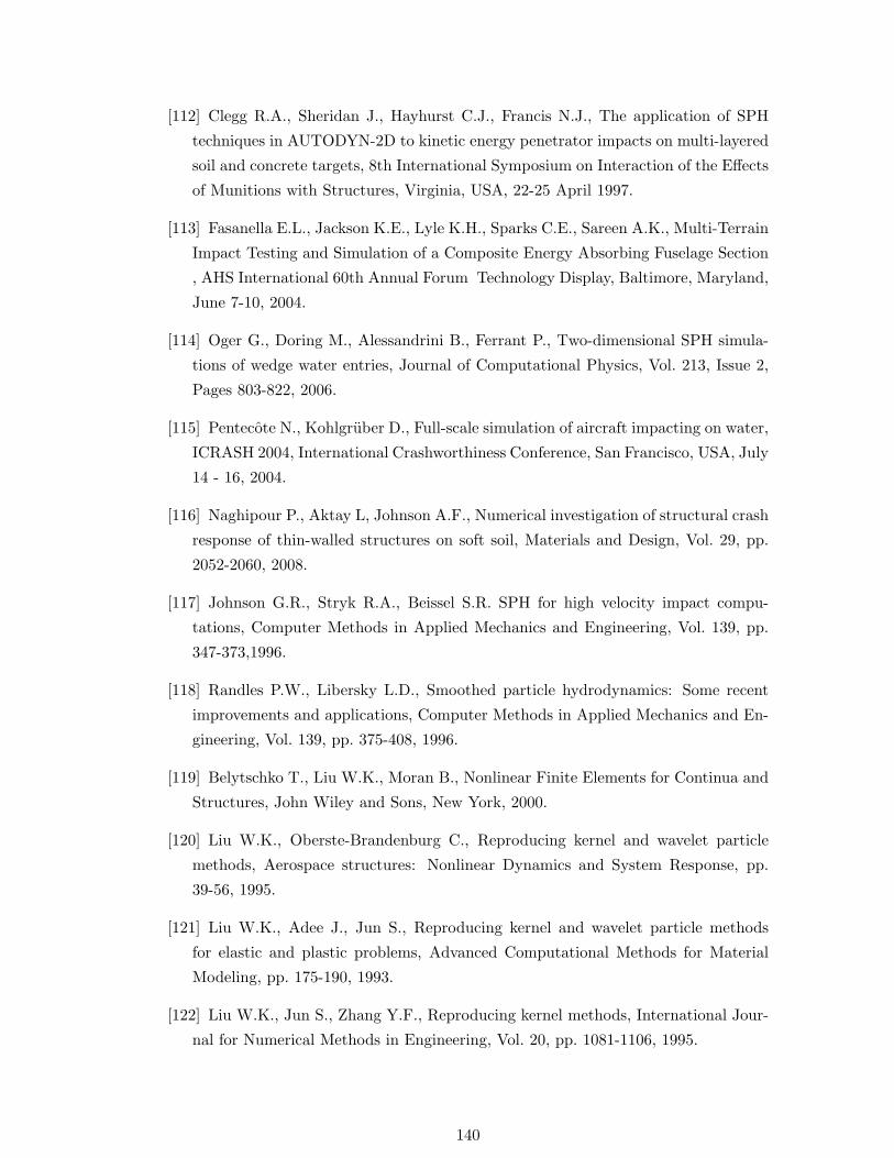
[112] Clegg R.A., Sheridan J., Hayhurst C.J., Francis N.J., The application of SPH
techniques in AUTODYN-2D to kinetic energy penetrator impacts on multi-layered
soil and concrete targets, 8th International Symposium on Interaction of the Effects
of Munitions with Structures, Virginia, USA, 22-25 April 1997.
[113] Fasanella E.L., Jackson K.E., Lyle K.H., Sparks C.E., Sareen A.K., Multi-Terrain
Impact Testing and Simulation of a Composite Energy Absorbing Fuselage Section
, AHS International 60th Annual Forum Technology Display, Baltimore, Maryland,
June 7-10, 2004.
[114] Oger G., Doring M., Alessandrini B., Ferrant P., Two-dimensional SPH simula-
tions of wedge water entries, Journal of Computational Physics, Vol. 213, Issue 2,
Pages 803-822, 2006.
[115] Pentecote N., Kohlgruber D., Full-scale simulation of aircraft impacting on water,
ICRASH 2004, International Crashworthiness Conference, San Francisco, USA, July
14 - 16, 2004.
[116] Naghipour P., Aktay L, Johnson A.F., Numerical investigation of structural crash
response of thin-walled structures on soft soil, Materials and Design, Vol. 29, pp.
2052-2060, 2008.
[117] Johnson G.R., Stryk R.A., Beissel S.R. SPH for high velocity impact compu-
tations, Computer Methods in Applied Mechanics and Engineering, Vol. 139, pp.
347-373,1996.
[118] Randles P.W., Libersky L.D., Smoothed particle hydrodynamics: Some recent
improvements and applications, Computer Methods in Applied Mechanics and En-
gineering, Vol. 139, pp. 375-408, 1996.
[119] Belytschko T., Liu W.K., Moran B., Nonlinear Finite Elements for Continua and
Structures, John Wiley and Sons, New York, 2000.
[120] Liu W.K., Oberste-Brandenburg C., Reproducing kernel and wavelet particle
methods, Aerospace structures: Nonlinear Dynamics and System Response, pp.
39-56, 1995.
[121] Liu W.K., Adee J., Jun S., Reproducing kernel and wavelet particle methods
for elastic and plastic problems, Advanced Computational Methods for Material
Modeling, pp. 175-190, 1993.
[122] Liu W.K., Jun S., Zhang Y.F., Reproducing kernel methods, International Jour-
nal for Numerical Methods in Engineering, Vol. 20, pp. 1081-1106, 1995.
140

[123] Takeda H., Miyama S.M., Sekiya M., Numerical simulation of viscous flow by
smoothed particle hydrodynamics, Progress of Theoretical Physics, Vol. 116, pp.
123-134, 1994.
[124] Morris J.P., Fox P.J., Zhu Y., Modeling low Reynolds number incompressible flow
using SPH, Journal of Computational Physics, Vol. 136, pp. 214-226, 1997.
[125] Li S., Liu W.K., Meshfree and particle methods and their applications, ASME
Applied Mechanics Review, Vol. 54, pp. 1-34, 2002.
[126] Zienkiewicz O.C., Kelly D.W., Bettress F., The coupling of the finite element
method and boundary solution procedures, International Journal for Numerical
Methods in Engineering, Vol. 11, pp. 355-375, 1977.
[127] Krishnamurthy T., Raju I.S., Coupling of finite and boundary element meth-
ods for two-dimensional potential problems, International Journal for Numerical
Methods in Engineering, Vol. 36, pp. 3593-3616, 1993.
[128] Belytschko T., Organ D., Krongauz Y., Coupled finite element-elementfree
galerkin method, Computational Mechanics, Vol. 17, Issue 3, pp. 186-195, 1995.
[129] Hegen D., Element-free galerkin methods in combination with finite element ap-
proaches, Computer Methods in Applied Mechanics and Engineering, Vol. 135,
Issues 1-2, pp. 143-166, 1996.
[130] Huerta A., Fernandez-Mendez S., Enrichment and coupling of the finite element
and meshless methods, International Journal for Numerical Methods in Engineering,
Vol. 48, Issue 11, pp. 1615-1636, 2000.
[131] Rao B.N., Rahman S., A coupled meshless-finite element method for fracture
analysis of cracks, International Journal of Pressure Vessels and Piping, Vol. 78,
Issue 9, pp. 647-657, 2000.
[132] Liu G.R, Gu Y.T., Coupling of element free galerkin and hybrid boundary element
methods using modified variational formulation, Computational Mechanics, Vol. 26,
Issue 2, pp. 166-173, 2000.
[133] Liu G.R., Gu Y.T., Meshless local Petrov-Galerkin(MLPG) method in combi-
nation with finite element and boundary element approaches, Computational Me-
chanics, Vol. 26, Issue 6, pp. 536-546, 2000.
[134] Munjiza A., Bangash T., John N. W. M., The combined finite-discrete element
method for structural failure and collapse, Engineering Fracture Mechanics, Vol.
71, Issues 4-6, pp. 469-483, 2004
141

[135] Han K., Peric D., Crook A.J.L., Owen D.R.J., A combined finite/discrete ele-
ment simulation of shot peening processes - Part I: studies on 2D interaction laws,
Engineering Computations, Vol. 17, Issue 5, pp. 593 - 620, 2000.
[136] Han K., Peric D., Owen D.R.J, Yu J., A combined finite/discrete element simu-
lation of shot peening processes - Part II: 3D interaction laws, Engineering Com-
putations, Vol. 17, Issue 6, pp. 680 702, 2000.
[137] Owen D.R.J., Peric D., Mohammadi S., Discrete Element Modelling of Multi-
Fracturing Solids and Structures, Foreign Object Impact and Energy Absorbing
Structure (Seminar Papers), IMECHE, London, 4 March, 1998.
[138] Chen T., Raju S.I, Coupling finite element and meshless local petrov-galerkin
methods for two-dimensional potential problems. Tech Report AIAA-2002-1659,
American Institute of Aeronautics and Astronautics, American Institute of Aero-
nautics and Astronautics, 2002.
[139] Zienkiewicz O.C., Kelly D.W., Bettress F., The coupling of the finite element
method and boundary solution procedures, International Journal for Numerical
Methods in Engineering, Vol. 11, pp. 355-375, 1977.
[140] Krishnamurthy T., Raju I.S., Coupling of finite and boundary element meth-
ods for two-dimensional potential problems, International Journal for Numerical
Methods in Engineering, Vol. 36, pp. 3593-3616, 1993.
[141] Belytschko T., Organ D., Krongauz Y., Coupled finite element-elementfree
galerkin method, Computational Mechanics, Vol. 17, Issue 3, pp. 186-195, 1995.
[142] Liu G.R, Gu Y.T., Coupling of element free galerkin and hybrid boundary element
methods using modified variational formulation, Computational Mechanics, Vol. 26,
Issue 2, pp. 166-173, 2000.
[143] Liu G.R., Gu Y.T., Meshless local Petrov-Galerkin(MLPG) method in combi-
nation with finite element and boundary element approaches, Computational Me-
chanics, Vol. 26, Issue 6, pp. 536-546, 2000.
[144] Hegen D., Element-free galerkin methods in combination with finite element ap-
proaches, Computer Methods in Applied Mechanics and Engineering, Vol. 135,
Issues 1-2, pp. 143-166, 1996.
[145] Huerta A., Fernandez-Mendez S., Enrichment and coupling of the finite element
and meshless methods, International Journal for Numerical Methods in Engineering,
Vol. 48, Issue 11, pp. 1615-1636, 2000.
142

[146] Rao B.N., Rahman S., A coupled meshless-finite element method for fracture
analysis of cracks, International Journal of Pressure Vessels and Piping, Vol. 78,
Issue 9, pp. 647-657, 2000.
[147] Gu Y.T., Liu G.R., Meshless Methods Coupled with Other Numerical Methods,
Tsinghua Science Technology, Vol. 10, Issue 1, pp. 8-15, 2005.
[148] Attaway S. W., Heinstein M. W., Swegle J. W., Coupling of smooth particle
hydrodynamics with the finite element method, Nuclear Engineering and Design,
Vol. 150, Issues 2-3, pp. 199-205, 1994.
[149] Johnson G. R., Linking of Lagrangian particle methods to standard finite element
methods for high velocity impact computations, Nuclear Engineering and Design,
Vol. 150, Issues 2-3, pp. 265-274, 1994.
[150] Johnson G.R., Petersen E.H., Stryk R.A., Incorporation of an SPH option into
epic code for a wide range of high velocity impact computations, International
Journal of Impact Engineering, Vol. 14, pp. 385-394, 1993.
[151] Sauer M., Hiermeier S., Scheffer U., Modelling penetration events using
FE/MLSPH adaptive coupling. 10th International Symposium on Interaction of
the Effect of Munitions with Structures, San Diego, California, 7-11 May, 2001
[152] De Vuyst, T., Vignjevic R., Campbell J.C., Coupling between meshless and finite
elements methods, International Journal of Impact Engineering, Vol. 31, pp. 1054-
1064, 2005.
[153] Johnson G.R., Stryk R.A., Beissel S.R. SPH for high velocity impact compu-
tations, Computer Methods in Applied Mechanics and Engineering, Vol. 139, pp.
347-373,1996.
[154] Johnson G. R., Stryk R.A., Conversion of 3D distorted elements into meshless
particles during dynamic deformation, International Journal of Impact Engineering,
Vol. 28, Issue 9, pp. 947-966, 2003.
[155] Cottrell M.G., Yu J., Owen D.R.J., The adaptive and erosive numerical modelling
of confined boron carbide subjected to large-scale dynamic loadings with element
conversion to undeformable meshless particles, International Journal of Impact En-
gineering, Vol. 28, Issue 9, pp. 1017-1035, 2003.
[156] Beissel S.R., Gerlach C.A., Johnson G.R., Hypervelocity impact computations
with finite elements and meshfree particles, International Journal of Impact Engi-
neering, Vol. 33, Issues 1-12, pp. 80-90, 2006.
[157] Johnson A.F., Holzapfel M., Modelling soft body impact on composite structures,
Composite Structures, Vol. 61, Issues 1-2, pp. 103-113, 2003.
143

[158] Ladeveze P., Le Dantec E., Damage modelling of the elementary ply for laminated
composites, Composites Science and Technology, Vol. 43, pp. 257-267, 1992.
[159] Johnson A.F., Pickett A.K., Impact and crash modelling of composite struc-
tures: a challenge for damage mechanics, European Conf. Computational Mechan-
ics, ECMM 99, Munich, 1999.
[160] High Velocity Impact of Composite Aircraft Structures (HICAS), EU RTD
Project BE 96-4238, 1998-2000.
[161] PAM-CRASH FE Code, Engineering Systems International, 20 Rue Saarinen,
Silic 270, 94578 Rungis-Cedex, France.
[162] Johnson A.F., Kohlgruber D., Design and performance of energy absorbing sub-
floor structures in aerospace applications, IMechE Seminar S672, London, 9 May,
2000.
[163] Serifi E., Hirth A., Matthei S., Mullerschon H., Modelling of foams using MAT83
- Preparation and evaluation of experimental data, 4th European LS-DYNA Users
Conference, Ulm, Germany, 22-23 May, 2003.
[164] Gibson L.J., Ashby M.F., Cellular Solids: Structure and Properties, Pergamon
Press, Oxford, 1988.
[165] Hiermaier S., Thoma K. Computational simulation of high velocity impact simu-
lations using smoothed particle hydrodynamics, 9th DYMAT Technical Conference
on Materials and Structural Modelling in Collosion Research, TU Munich Germany
1995.
[166] Aktay L., Johnson A.F., Kroplin B.-H., Semi-adaptive coupling technique for
the prediction of impact damage, Complas 2005, Proceedings of the VIII Inter-
national Conference on Computational Plasticity Fundamentals and Applications,
Barcelona, Spain, 5-8 September, 2005.
[167] Guden M., Yuksel S., Compression behavior of SiC-particulate foams produced
by foaming from powder compacts, Journal of Materials Science, Vol. 41, pp. 4075-
4084, 2006.
[168] Singace A.A., El-Sobky H., Interplay of factors influencing collapse modes in
axially crushed tubes, International Journal of Crashworthiness, Vol. 5, pp. 279-
297, 2000.
[169] Hanssen A.G., Langseth M., Hopperstad O.P., Static and dynamic crushing of
square aluminium extrusions with aluminum foam filler, International Journal of
Impact Engineering, Vol. 24, pp. 347-383, 2000.
144

[170] Hanssen A.G., Hopperstad O.S., Langseth M., Design of aluminium foam-filled
crash boxes square and circular cross-sections. International Journal of Crashwor-
thiness, Vol. 6, pp. 177-188, 2001.
[171] Singace A.A., Collapse behaviour of plastic tubes filled with wood sawdust, Thin-
Walled Structures, Vol. 37, pp. 163-187, 2000.
[172] Toksoy A.K., Guden M., Tanoglu M., Hall I.W., Effect of adhesive on the
strengthening of foam-filled circular tubes, Journal of Material Sciences, Vol. 39,
pp. 1503-1506, 2004.
[173] Hanssen A.G., Langseth M., Hopperstad O.P., Optimum design for energy ab-
sorption of square aluminium columns with aluminium foam filler, International
Journal of Mechanical Sciences, Vol. 43, pp. 153-176, 2001.
[174] Seitzberger M, Willminger S. Application of plastic collapse mechanisms for the
axial crushing analysis of tubular steel structures filled with aluminum foam, Inter-
national Journal of Crashworthiness, Vol. 6, pp. 165-176, 2001.
[175] Aktay L., Toksoy A.K., Guden M., Quasi-static axial crushing of extruded
polystyrene foam-filled thin-walled aluminum tubes: experimental and numerical
analysis. Materials and Design, Vol. 27, pp. 556-565, 2007.
[176] ”Commercial Aircraft - Design for Crash Survavibility”: CRASURV, D.1.1.1 Ini-
tial Materials Data of Carbon and Aramid Fabric Materials, 1997.
[177] Holzapfel M., Kopp G., Adamski P., Elsenhans H., Christlein J., Hambrecht T.,
Numerische Nachbildung der Crashfront von faserverstarkten Strukturen mit Hilfe
von Mehrschalenmodellen, 6.LS-DYNA Anwenderforum, Frankenthal, 2007.
145

146

Curriculum Vitae
Personal Data
Name Levent AktayDate of Birth June 02, 1977Place of Birth Ankara, TurkeyMarital Status Married, 1 childNationality Turkish
School Education
1983-1984 Kozyatagı Primary School, Istanbul1984-1987 Hilal Primary School, Izmir1987-1988 Sehit Rahmi Primary School, Balıkesir1988-1991 Suphi Koyuncuoglu Secondary School, Izmir
1991-1994 Uskudar Science High School, Istanbul
University Education
1994-1999 Undergraduate Studies of Mechanical Engineering,Yıldız Technical University, Istanbul
1999-2000 Graduate Studies of Chemical Engineering,Friedrich Alexander University of Erlangen-Nurnberg, Nurnberg
2000-2002 M.Sc. in Computational Mechanics of Materials andStructures (COMMAS), University of Stuttgart
2002-2006 Doctoral Candidate, Institute of Structures and DesignGerman Aerospace Center (DLR), Stuttgart
Professional Carrier
04/2006-10/2007 CAE Engineer, TECOSIM GmbH, Stuttgart10/2007-05/2008 CAE Engineer, MBtech GmbH, Sindelfingensince 05/2008 CAE Engineer, Daimler AG, Sindelfingen
Copyright © 2022 FDOKUMEN