
HULL STRUCTURAL CONCEPTS FOR IMPROVED ...
238
SSC-377 HULL STRUCTURAL CONCEPTS FOR IMPROVED PRODUCIBILITY NTIS # PB95-1 44366 This &cument has been approved for public release and sale; its distribution is unlimited SHIP STRUCTURE COMMITTEE 1994
-
Upload
khangminh22 -
Category
Documents
-
view
4 -
download
0
Transcript of HULL STRUCTURAL CONCEPTS FOR IMPROVED ...

SSC-377
HULL STRUCTURAL CONCEPTSFOR IMPROVED PRODUCIBILITY
NTIS # PB95-1 44366
This &cument has been approvedfor public release and sale; its
distribution is unlimited
SHIP STRUCTURE COMMITTEE
1994

SHIP STRUCTURE COMMI1TEE
The SHIP STRUCTURE COMMI1TEE is constituted to prosecute a research program to improve the hull structures of ships and othermarine structures by an extension of knowledge pertaining to design, materials, and methods of construction.
RADM J. C. Card, USCG (Chairman)Chief, Office of Marine Safety, Security
and Environmental ProtectionU. S. Coast Guard
Mr. Thomas H. Peirce Mr. H. T. HallerMarine Research and Development Associate Administrator for Ship-
Coordinator building and Ship OperationsTransportation Development Center Maritime AdministrationTransport Canada
MILITARY SEALIFT COMMAND
Mr. Robert E. Van Jones (Chairman)Mr. Rickard A AndersonMr. Michael W. ToumaMr. Jeffrey E Beach
AMERICAN BUREAU OF SHIPPING
Mr. Stephen G. ArntsonMr. John F. ConlonMr. Phillip G. RynnMr. William Hanzelek
EXECUTIVE DIRECTOR
CDR Stephen E. Sharpe, USCGU.S. Coast Guard
U. S. MERCHANT MARINE ACADEMY
Dr, C. B. Kim
U. S NAVAL ACADEMY
Dr. Ramswar Bhattacharyya
CANADA CENTRE FOR MINERALS ANDENERGY TECHNOLOGIES
Dr. William R. Tyson
SOClET'OF NAVAL ARCHITECTS ANDMARINE ENGINEERS
Dr. William Sandberg
U. S. TECHNICAL ADIVSORY GROUP TO ThEINTERNATIONAL STANDARDS ORGANIZATION
CAPT Charles Piersall
The SHIP STRUCTURE SUBCOMMITTEE acts for the Ship Structure Committee on technical mailers by providing technicalcoordination for determinating the goals and objectives of the program and by evaluating and interpreting the results in terms ofstructural design, construction, and operation.
MARITIME ADMINISTRATION
Mr. Frederick SeiboldMr. Norman O. HammerMr. Chao H. LinDr. Walter M. Maclean
NAVAL SEA SYSTEMS COMMAND
Mr. W. Thomas PackardMr. Charles L NullMr. Edward KadalaMr. AlIen H. Engle
Dr. Donald UuSenior Vice PresidentAmerican Bureau of Shipping
CONTRACTiNG OFFICER TECHNICAL REPRESENTATIVE
Mr. William J. SiekierkaNaval Sea Systems Command
U. S. COAST GUARD
DEFENCE RESEARCH ESTABLISHMENT ATLANTIC
Dr. Neil Pe9gLCDR D. O ReillyDr. Roger HollingsheadMr. John Porter
SHIP STRUCTURE SUBCOMMITTEE LLISON MEMBERS
U. S. COAST GUARD ACADEMY NATIONAL ACADEMY OF SCIENCES -MARINE BOARD
LCDR Bruce R. Mustain Dr. Robert Sielski
CAPT G. D. MarshCAPT W. E. Colburn, Jr.Mr. Rubin ScheinbergMr. H. Paul Cojeen
TRANSPORT CANADA
Mr. John GrinsteadMr. Ian BaylyMr. David L StocksMr. Peter Timonin
NATIONAL ACADEMY OF SCIENCES -COMMITTEE ON MARINE STRUCTURES
Mr. Peter M. Palermo
WELDING RESEARCH COUNCIL
Dr. Martin Prager
AMERICAN IRON AND STEEL INSTITUTE
Mr. Alexander D. Wilson
OFFICE OF NAVAL RESEARCH
Dr. Yapa D. S. Rapaske
SIUENT MEMBER
Mr. Trevor ButlerMemorial University of Newfoundland
Mr. Edward Comstock Mr. Thomas W. Allen Mr. Warren NethercoteDirector, Naval Architecture Engineering Officer (N7) Head, Hydronautics SectionGroup (SEA 03H) Military Sealift Command Defence Research Establishment-Atlantic
Naval Sea Systems Command

Member Agencies:
American Bureau of ShippingDefence Research Establishment At/antic
Maritime AdministrationMilitary Sea/rn Command
Naval Sea Systems CommandTransport Canada
United States Coast Guard
ShipStructure
Corn mitteeAn Interagency Advisory Committee
December 19, 1994
HULL STRUCTURAL CONCEPTS FOR IMPROVED PRODUCIBILITY
This report represents a landmark work for the SSC as it is thefirst report to focus solely on our third goal, to "Support theUnited States and Canadian maritime industry in shipbuilding,maintenance and repair," by specifically exploring innovativehull structural concepts from a producibility standpoint. As afirst step, the report establishes foreign baselines that areused to measure alternative concepts from a construction time andlabor-hour viewpoint. While there may be controversy over thelabor-hour estimates, and uncertainties over the technicalapproach and computational judgements used, there can be no doubtof a need for substantial United States and Canadian productivityimprovement relative to foreign shipbuilding.
As we look forward it is evident that our maritime industry is ina period of change and there is a need to reexamine the entiredesign, material handling, and production process. We need torecognize the importance of time and competitive ship deliveryschedules along with increased usage of international standards,the metric system and foreign vessel designs as cooperativeworking arrangements are reached between our shipyards and thoseoverseas. Our thought process must also change and reflect anemphasis on an international competition basis and the criticalimportance of the production time line.
I hope this report stimulates the readers to ask probingquestions about the substantial differences between NorthAmerican and foreign construction and impact of structural designon the overall ship producibility.
Address Correspondence to:
Executive DirectorShip Structure CommitteeU.S. Coast Guard (G-MI/SSC)2100 Second Street, S.W.Washinqton, D.C. 20593-0001Ph:(2O2 267-0003Fax: (202) 267-4677
SSC-377SR-1351
C. CARDRear Admiral, U.S. Coast Guard
Chairman, Ship Structure Committee

This Page Intentionally Left Blank

iii
T.chnicsl R.p.rt OocImInstj. P11I. R...,sSC-377
2. C.ee5 A e Na.PB95-144366
3. Rupee, s C...g Ne.
4 SñI SS','iiHULL STRUCTURAL CONCEPTS FOR IMPROVED PRODUCIBILITY
- TANKERS
3. R,p.0 O.,.
December 15, 19946. P.rI.,,, Og..'. s.'..e C.di
i. P.,f.,.i,e, Org....a.'..e R.0.,, N..
SR-1351
7. A..ø., s
John C. Daidola, John Parente, William H. RobinsonC.p. tutee M*,,i I A44',.e
M. ROSENBLATT & SON, Inc.350 BroadwayNew York, NY 10013
10. Wut Ue.t N.. (TRM$)
II. C.e,,.,i.rG'se'N.DTCG2392CE01029
R.,.» ee P.'.. c.....FINAL REPORT
12. N.... .4 Addr.siSHIP STRUCTURE COM'{ITTEEU.S. COAST GUARD (G-MI/SSC)2100 Second Street, S.W.Washington, DC 20593
14. 5.e..,.e,A,.eqpC.d.G-M
15. MeteS
Sponsored by the Ship Structure Coittee. Jointly funded by its member agencies.
16 £S",.C'
Alternative structural system concepts have been developed for 40K and 95KDWTdouble hull tankers, with the object of studying their producibility inexisting U.S. shipyards, including labor hours and construction schedules.Structural components and elements considered included alternative material,shell plating, bulkheads, stiffeners and other structural elements for bothconventional and unidirectional double hull tankers, together with shipbuildingprocesses such as automation and accuracy control, ánd standardization includingdesign. It is concluded that increased automation, accuracy control andstandardization are the areas where the greatest gains may be possible tomake U.S. shipyards more productive and more competitive on a world scale.
17. yCONSTRUCTION COSTS, DESIGN FEASIBILITYSTUDIES, ECONOMIC ANALYSIS, HULL CONSTRUCT-ION, HULL DESIGN, SHIP DESIGN, SHIPBIJILD-ING COSTS, TANKER SHIPS.
1$. '' DistributionAvailable from:
National Technical InformationU.S. Department of CommerceSpringfield, VA 22151
unlimited.
Service
16. 1c,.nty C(.asf. (. Øiis s"
Unclassified
X. S..wvi'y ciÌ. (.1 es p.)
Unclassified
21. NS. I PS5i
240
22. PI.,36. 50-paper
$17.50-microf.
Fu. DOT F 1700.7 (i-72) w.c1ss .1 caalss,d p. a,$aels.d

n2sq
uat.
ncta
.6.
55a
1S C
Sah
ImS
IScm
2
h2.q
.a.a
Iet
0.09
squa
ts51
tun2
quat
. nst
d.0.
0la
tS ..
etn
,n2
squa
t. m
i las
2.1
sql..
.. k.
lq.,e
t..s
km2
acta
I0.
4ta
ct...
.Ic
i
MA
SS
(w
.iib,
I
ME
TR
IC C
ON
VE
RS
ION
FA
CT
OR
S
App
isst
inht
s C
oriv
eisi
sni
o N
itric
Nia
s.,..
App
c.si
m.ts
Cs.
wi,.
i.is
It..
Nitr
icM
usst
..
Q9t
W11
0.03
5al
Can
04
_.bq
k,)o
t..ns
2.2
poel
dslb
-.t
tonn
a, 1
000
b9)
(.1
5unl
'ten
u
VO
LUM
E
uni
,n,ll
,l,l..
.0.
03(lu
id 0
00C
liII
Os
lite,
,2.
1pi
nI.
PI
luI..
,(.
06qo
atts
qllit
.,.O
74
galle
n,,
guaI
nucu
b,c
natte
,,36
cubi
c (e
elC
obic
lIat
lets
(3cu
bIc
y..d
.5d
3
TE
MP
ER
AT
UR
E (
.z.c
t)
-'
Inu;
Cel
sIuS
9,5
then
F.h
,nIe
nit
-
Imtig
iela
tote
atbi
32)
ln.n
pnln
lcln
3299
621
2
-40
014
090
I70
iSO
200
4 (
Oí.O
ì4j
tv
r'''o
it
tIl
-40
'70
020
)40
6090
hOD
37O
C
59m
b.)
WI..
Y..
K...
.M
ehty
by
T. F
ê.d
Sy.
bsI
Sym
b.l
WI..
Y..
Ka.
mM
ultip
ly b
y
LEN
GT
H
T. F
iad
LEN
GT
Hfla
n,n
ullu
iflnl
.,.0
04no
tes,
inch
.sle
st?,
b30
cm
tin h
caah
.,.I.s
c.nh
,nl..
n
cm In Ill
cnol
ffnte
hsm
.I.t.
nata
li
0.4
3.3
(.1
inch
.,I..
,ya
.ds
in lt ydcm
0.9
m.I.
t.n
ken
kulio
nale
..0.
6In
I IS
S
In,
anl.
1.6
AR
EA
k,la
a.l..
ilu
ni-
AR
E A
t.
nq.i«
a ca
tit e
le s
0 19
,qon
ach
..=
a,sq
uat.
n.I.h
(.2
.q..a
ea y
..de
qI2
h.2
sq.ö
.5 Il
latn
atat
.0.
4sq
.....
eol.s
mt2
hahs
ct.n
10.
000
en2)
2.6
act..
NA
SS
t*si
ihtJ
04O
unC
es29
q.an
.g
lbpo
undS
0.45
k.Io
q.w
nsb9
shal
Ions
0.9
lImas
.20
00 lb
)
VO
LUM
E
lipl.a
.00.
m.
S,n
,ll,l,
I.t.
(heg
tlb
l.spo
ons
IS.n
,ll,l,
l5,S
Illlu
.d e
mm
o..
30n,
,)l,l
,t.n
cl
cops
0.24
Itt..,
plpi
nts
0.41
lite,
,ql
qn..l
s0.
95lil
ets
w.'
1411
005
3,9
hInt
seu
bto
(eel
003
Cub
ic ,n
elo.
s0d
3cu
bic
ya,d
s0,
16cu
bic
mel
els
TE
MP
ER
AT
UR
E .a
sct)
I ul,.
nnhe
il5.
9 lu
lIn,
Cel
siuS
lem
peta
Iut*
Slib
ItSC
ling
lOin
peIC
tillO
32)

TABLE OF CONTENTSPAGE
1.0 Introduction
2.0 TASK I - Concurrent Engineering Requirements
2. 1 Objective 3
2.2 Philosophy of Construction 3
2.3 Design Stage 42.4 Approach 72.5 Results of Survey
2.5.1 General 82.5.2 Design/Production Input 8
2.5.3 Shipyard Facility Considerations 102.5.4 Institutional Constraints 10
3.0 TASK II - Structural Elements3.1 Objective 143.2 Tanker Structure - Overall Considerations 15
3.3 Results 18
4.0 TASK III - Alternative Structural System Concepts4. 1 Objective 254.2 Approach 254.3 Results 36
5.0 TASK IV - Application to Specific Double Hull Tankers5.1 Objective 385.2 Selection of Baseline Vessels 385.3 Baseline Construction Schedules and Labor Hours
5.3.1 General 435.3.2 Construction Schedules 435.3.3 Labor Hours 43
5.4 Application of Alternative Structural Systems 555.5 Structural Blocks 58
6.0 TASK V - Estimates of Physical Production Characteristics for AlternativeStructural System Concepts
6.1 Objective 616.2 Approach 616.3 Results 65
7.0 TASK VI - Labor Hours and Schedules7.1 Objective 667.2 Approach 667.3 Labor Hours for Steeiwork 697.4 Labor Hours for Construction of Complete Vessels 797.5 Construction Schedules 80
V

TABLE OF CONTENTS continued
8.0 CONCLUSIONS 89
9.0 ACKNOWLEDGEMENTS 91
10.0 REFERENCES 92
11.0 BIBLIOGRAPHY OF ADDITIONAL REFERENCES 95
APPENDIX
The following summaries in the form of tables and graphs are presented in the Appendix. PagesA30-72 require enlargement if detailed study is required.
vi
4OKDWT Alternative Vessels - Estimation of Labor HoursCalculations for One Tank . A87 - 105
95KDWT Alternative Vessels - Estimation of Labor HoursCalculations for One Tank . A106 - 116
PAGELongitudinal Scantlings with
ABS OMSEC Program . Al - 13
Longitudinal Scantlings withABS OMSEC Program . A14 - 28
Break Down of Blocks andPiece Parts A29 - 44
Break Down of Blocks andPiece Parts A45 - 60
All Block Properties A61 - 67
All Block Properties A68 - 72N2 of Pieces, Area, Weight A73 - 74N2 of Pieces, Area, Weight A75 - 76Weld Volume, Auto, Manual,
Fillet, Butt A77 - 78
Weld Volume, Auto, Manual,Fillet, Butt A79 - 80
Weld Lengths A81 - 82
Weld Lengths A83 - 84A85 - 86
4OKDWT Base Alternative Vessel 4010 -
95KDWT Base Alternative Vessel 9510 -
4OKDWT Base Alternative Vessel 4010 -
95KDWT Base Alternative Vessel 9510 -
Summary - 4OKDWT Alternative Vessels -Summary - 95KDWT Alternative Vessels -Summary - 4OKDWT Alternative Vessels -Summary - 95KDWT Alternative Vessels -Summary - 4OKDWT Alternative Vessels -
Summary - 95KDWT Alternative Vessels -
Summary - 4OKDWT Alternative Vessels -Summary - 95KDWT Alternative Vessels -Not Used

TABLE OF CONTENTS continued
Plots for 4OKDWT and 95 KDWT Alternatives - Al 17 - 122Comparison of Tank Steel Area
(One Side of Plate, One Tank)Comparison of Tank Steel WeightComparison of Tank Weld LengthsComparison of Weld Volumes - Includes
Factors for Weld Position and TechniqueAverage Steel Plate Thickness for
One Tank Length.Plots for 4OKDWT and 95KDWT Alternatives - Al23 - 127
Comparison of Estimated Labor Hours -
Steel for One Tank LengthEstimated Ship Labor Hours - U.S. 1994
Design and ConstructionBreak Down of Cutting, Preparation and Weld
Lengths - 4OKDWT Alternatives U.S. -One Tank
Break Down of Cutting, Preparation and WeldLengths - 95KDWT Alternatives U.S. -
One Tank.
vii

(THIS PAGE INTENTIONALLY LEFT BLANK)
1.0 INTRODUCTION
It is generally acknowledged that the labor hours of constructing commercial ships in U.S.shipyards is higher than foreign shipyards, particularly those in the Far East, Southern Europeand Brazil. There are significant differences of a technical nature which will have a substantialimpact, including labor hour requirements for design and construction, materials, equipment andmachinery lead time, shipbuilding practices and facilities, use of standards, contractualprocesses, and institutional constraints.
During the past twenty years, U.S. shipyards, various agencies of the government and theSociety of Naval Architects and Marine Engineers (SNAME) have tried to address the matterand improve producibility. U.S. shipyards have acknowledged the advancement of Japaneseshipbuilding techniques and, together with the U.S. Maritime Administration (MARAD), haveimported technology from innovators like IHI Marine Technology, Inc. (IHI), who hastransferred information to Bath Iron Works Corporation, Newport News Shipbuilding, IngallsShipbuilding, Avondale Shipyards, National Steel and Shipbuilding Company (NASSCO) andothers. MARAD and later SNAME have sponsored the National Shipbuilding Research Program(NSRP) (now under SNAME sponsorship with U.S. Navy funding), which supports extensiveand varied research in shipbuilding technology from design through delivery. However, asignificant gap still appears to be present between the U.S. and the major world shipbuilders.
The time required for the construction of a vessel has been identified as having a majorimpact on vessel labor hours. Reported delivery times in foreign shipyards are considerably lessthan U.S. shipyards. The reasons for this must be largely tied to the nature of the structurebeing manufactured and to the degree it facilitates installation of outfit and much of the paintingprior to erection on the building berths. The design phase and its integration with constructionhas a significant influence on achieving this goal. These matters, which are in the shipbuilder'scontrol, are addressed herein.
It is acknowledged that the world's aging tanker fleet must be replaced in the years tocome. This will provide a significant opportunity to revitalize shipbuilding in the U.S.Furthermore, the passage of OPA '90 has resulted in new requirements for tankers, specificallydouble hulls, and this allows significant latitude for the development of designs with innovativeenhancements for prod ucibility. These could give the developer a significant advantage over thecompetition.
The objective of this project was to "develop alternative structural system concepts" for40,000 (i.e. 40K) and 100K deadweight tons (KDWT) (reduced to 95KDWT later) Jones Actdouble hull tankers for construction in existing U.S. shipyard facilities. These should result indecreased labor requirements in the design, construction, and outfitting phases of theshipbuilding program as well as providing for low cost maintenance during the life of thevessels. It is hoped that addressing this type and these sizes of vessels will provide informationto shipbuilders which will be useful in identifying improvements necessary for competing in theupcoming boom for rebuilding the world tanker fleet.
i

The objective of the project was approached by a series of six "tasks":
Task I - Concurrent Engineering Requirements
Task II - Structural Elements
Task III - Alternative Structural System Concepts
Task IV - Application to Specific Double Hull Tankers
Task V - Estimates of Physical Production Characteristics for Alternative StructuralSystem Concepts
Task VI - Labor Hours and Schedules
Summaries of the results obtained for each task now follow.

2.0 TASK I - CONCURRENT ENGINEERING REQUIREMENTS
2.1 OBJECTIVE
Concurrent engineering is an approach to the development of a product or system whichseeks to integrate design, production and user requirements from the outset, to arrive at theoptimum solution in the most direct manner. The objective of this task is to define thecharacteristics of concurrent engineering which when applied to tanker structural design willfacilitate identifying the optimum characteristics of a vessel which also result in the leastconstruction labor hours and schedule.
Recent discussions have proposed introducing the ship construction method and sequenceearlier into the design process (i.e. at the conceptual/preliminary design level), with emphasison preliminary build strategy, subdivision of the hull into erection blocks and outfit modules,and advance planning for the development of work instruction packages during the detail design,References [1][2][3]*. The interests of the shipowner have been incorporated as well, [2]. Byexpanding on this approach a concurrent engineering philosophy and its characteristics for thisproject can be readily established.
2.2 PHILOSOPHY OF CONSTRUCTION
The objective of both the shipyard and owner should be identical in the delivery of a ship.An enlightened shipowner and shipyard manager will negotiate a contract design whichsimultaneously incorporates the owners' performance requirements and the yards' build strategy.However, their individual concerns along the way will be different.
Shipowners may tend to be unconcerned with the distinction between the design phases,but will seek to understand the nature of not only the principal design characteristics, but theintended detail of the construction and character of the equipment provided, in particular as tohow it impacts reliability and maintainability. As an additional concern, OPA '90 has placeda significant amount of liability for spills on the shipowners, and it can be expected that theirconcern for risk, reliability and safety will be especially acute.
Shipyards are concerned with the design and construction details of the vessel once acontract has been signed. Theoretically, a shipyard is free to incorporate the productionattributes of the organization into the design process at any stage. As personnel mostexperienced in production may not always be associated with the design departments, successfulintegration of production into design must involve a coordination of disciplines, which does notalways occur.
Design, construction and shipowner requirements should be properly integrated to achievethe most desirable structural alternatives at lowest cost.
* Numbers in brackets indicate reference numbers in Section 10.0.
3

2.3 DESIGN STAGE
It has been noted that about 30% of the difference in productivity between the typical U.S.shipyard and good foreign shipyards can be accounted for by superior design for production inthe foreign yards, [1]. Accordingly, any improvement in producibility at the preliminary designstage can have a major impact on the labor hours of ships.
The design stage in shipbuilding consists of a sequential series of design phases, i.e.Conceptual, Preliminary, Contract, Functional, Transition and Detail Phases. Transition designis the phase in which there is usually a translation of the design from a systems orientationnecessary to establish functional performance, to a planning unit orientation necessary toestablish production requirements.
The Conceptual/Preliminary design represents the design phase at which rough order ofmagnitude (ROM) price quotations may be required for a timely response to a potential buyer.Competitive shipyards simultaneously produce a material budget, which they employ with theirhistory of man-hours required to process materials, for predicting cost. Productionimprovements should be fully considered at this stage in determining price. This will result inthe opportunity to make a meaningful improvement in producibility before the ship constructionprocess begins, when significant changes are still possible without disrupting the entire process.IHI advised nine-years ago "...that initial or basic designers have most affect on a ship's cost,about 60%, while at the same time the cost of their efforts accounts for no more than 3% onincurred direct costs. .. . all design phases combined with material procurement activity affects85% of a ship's cost while such efforts account for approximately 10% of incurred direct costs.Obviously, the efforts of design engineers are the most significant and decisive,' [4].
The conceptual design phase establishes an overall outline design to meet an owner'soutline specification. It can also define a marketable design as part of a shipyard's productdevelopment. Essentially, it embodies technical feasibility studies to determine such fundamentalcharacteristics of the proposed ship as length, beam, depth, draft, hull form coefficients, poweror alternative sets of characteristics, all of which meet the required speed, range, cargo cubic,payload or deadweight. Although the main outcome is a design to meet specified ship missionrequirements, an account can and should be taken of production requirements. At this stage,the designer has considerable flexibility in his choice of dimensions and other parameters whichdefine the vessel, and those selected can be for enhanced production. For example, the tanklength versus a shipyard's maximum plate panel line length may be considered in determiningthe length of cargo tanks for oil tankers.
The preliminary design builds on the concept design with the intent of solidifying certainvessel principal characteristics. These usually include the vessel's length, beam, depth, draft,displacement and propulsion power. Its completion provides a precise definition of a vessel thatwill meet service requirements. Concurrent with the fixing of certain vessel principalcharacteristics, it is possible to further elaborate on the production scenario.
The contents of any design phase can be defined as a series of inputs and outputs. Theconcept/preliminary design inputs may be presented in the form of an outline specification orservice requirements. A more complete list of inputs and outputs is given in Table 2.1. During
4

each of the design phases, from conceptual design through detail design, the entire ship is alwaysaddressed. The design process is really continuous definitization. At first, information isgrouped in a large-frame sense with few such groups. Thereafter the design process is one ofgrouping information into smaller frames while increasing the number of frames. The processends when the final grouping, detail design, exactly matches how work is to be performed.
Table 2.1:CONCEPT/PRELIMINARY DESIGN CHARACTERISTICS
INPUT/OUTPUT
Design InputService requirements, such as cargo capacity and speed.Routes.Critical components and equipment.
Design OutputsPreliminary specification.Preliminary general arrangement and midship section.Preliminary calculations (dimensions, capacities, weight etc.).Preliminary hull form body sections and lines.
Simultaneously at this stage, the shipbuilder or production discipline should identify theessential production inputs and outputs given in Table 2.2.
Table 2.2:CONCEPT/PRELIMINARY DESIGN PRODUCTION CHARACTERISTICS
INPUT/OUTPUT
Production InputsShipbuilding policy.Facility dimension and capacities.Interim product types, including blocks and outfit modules.Material choices.Fabrication choices.
Production OutputsOutline build strategy.Preliminary block breakdown.Zone identification.Material preferences.Fabrication preferences.
5

Preliminary Arrangements. The general arrangement is among the most important aspectsof preliminary ship design, as it largely defines the functional effectiveness of a vessel. Thearrangement drawings must consider the functional spaces, cargo spaces, superstructure,machinery spaces and their relationships. No less important is the provision for access betweenall spaces, meeting operational and regulatory requirements.
During this phase, the machinery systems arrangement may be incorporated in the generalarrangement. The principal components are the main propulsion and auxiliary machinery,including the main engine and large auxiliaries, electrical generators, switchboards and controlareas, shafting, propellers, and the steering gear. The main engine and shafting may be the onlymachinery items actually shown, with space allocations provided for the remaining items.
The general and machinery systems arrangements of the nature described provide ablueprint of space allocations which can be utilized for determination of preliminary structuralblock breakdown, block definition and outfit module considerations. It is at this point that majorchanges to the design to best accommodate these production considerations can be introducedand the arrangements of the vessel altered to suit.
Preliminary Calculations. Preliminary design calculations include powering, tankcapacities, weight, trim, stability and structural strength requirements. Estimates of vesselweight must be maintained during all phases in the development of the design. The designershould be aware of the placement of major machinery components and their effect on the balanceof the vessel. Weight estimates are needed to establish stability, trim and list of the vessel, inaddition to verifying the design deadweight. The basic weight calculations can form the basisfor estimating the construction labor hours.
Although weight is an appropriate parameter for an initial labor hour estimate, it must betreated with caution. A reduction in weight will reduce the relevant material cost, but will notnecessarily reduce the induced labor hours. In some circumstances, it may result in a labor hourincrease as more time intensive fabrication or equipment may be involved. With the potentialimprovement in production resulting from a comprehensive build strategy introduced at an earlystage, weight can only give a partial indication of labor hours. Labor hours as affected byproducibility should impact the production more significantly than relative changes in weight.
If weight is a serious consideration, then an innovative approach based on more detailedstructural analysis may provide a more optimum solution. Alternatively, a review of the maindesign parameters can be undertaken with an eye toward relaxation of those having the greatestnegative impact. Both of these alternatives should be investigated rather than rigid applicationsof rules and guidelines to a weight-sensitive design, which may result in a design incorporatingcomplex fabrication and a wide variety of material sizes. On the other hand, as it is to beexpected that material costs will be less than labor costs, where weight is not a serious problem,a reduction in stiffening elements with increased plate element scantlings should seriously beconsidered as a means of reducing the number of welded elements and thereby reducing laborhours.
6

Structural Considerations. Upon completion of the preliminary general arrangement, amidship section is developed. This design development will have a profound effect onproduction. Basic decisions pertaining to the location of framing elements must be made alongwith the establishment of the material to be used in certain areas of the vessel. Considerationshould be given at this time to the standardization of the elements of frame spacing, types ofstructural elements to be utilized and the use of minimum number of different shaped elements,all in order to simplify fabrication. Methods of structural element fabrication should beconsidered as well, including stiffeners and supports (rolled vs. built-up vs. flanged plate),bulkheads (plate-stiffeners vs. corrugated), etc.
In the conceptual/preliminary design phase, the designer has considerable freedom toattempt innovative structural element arrangements. As a minimum, he should avoid the use offabricated sections which inherently have greater work content than standard rolled sections.If it is shipyard practice to utilize fabricated sections. then this option should be re-analyzed.
This task considers the alternative structural system concepts for tankers in the context ofconceptual/preliminary design. Accordingly the aspects of these phases as just discussed willbe considered and some of the design/production input/output characteristics presented in Tables2. 1 and 2.2 applied to the structural alternative system will be identified.
2.4 APPROACH
In order to obtain concurrent engineering input from knowledgeable parties, contacts withshipbuilders, shipowners, designers and classification society representatives were made asfollows:
O American Bureau of Shipping Tanker Seminar with shipowners, shipbuilders,designers and Classification Society personnel.
O NSRP Panel SP-4 Design/Production Integration.O Conducted 3 shipowner interviews.O Conducted i shipbuilder interview.O Received information from 2 shipbuilders.O Received information from ship surveyor.O Received comments from Government Agencies.
The inquiries addressed those requirements related to the design/production outputs givenin Table 2.1 and 2.2 and the desired characteristics of the components of double hull tankers of40K and approximately 100KDWT. Simultaneously, a literature search was conducted toidentify information pertinent to the project and to identify gaps in the literature which mightbe filled by input from the marine community. In order to address gaps in background dataobtained as a result of the above, two questionnaires were also developed, one aimed at ownersand the other at builders. The information requested therein was relevant to Tasks I & II, andalso addressed Alternative Structural System Concepts for construction of tankers.
7

2.5 RESULTS OF SURVEY
2.5.1 General
The features of the concept/preliminary design and production input/output characteristicsidentified in Tables 2. 1 and 2.2 were considered in grouping the information collected from thesurvey described in Section 2.4. This information has been highlighted herein and utilized laterin the appropriate remaining tasks. A summary of shipyard facility considerations is alsoprovided, followed by a discussion of institutional restraints. Construction schedule and laborhour data obtained are discussed in Section 5.3.
2.5.2 Design/Production Input
2.5.2.1 Design Input
With regard to design, the following input was established from the survey:
o Service requirements -The vessels studied were to be 40K and 100KDWT Jones Act double hull tankers.However, it was established that tankers in the 100KDWT size range are beingconstructed internationally in Aframax sizes of 95KDWT. For consistency,comparison purposes and application to the international market, this capacity hastherefore been adopted herein in lieu of 100KDWT.
o Routes -The routes include those for the U.S. Panamax and Aframax type Jones Act tradevessels.
o Critical components and equipment -Risk in design is a significant potentially overriding concern for a shipownerconsidering the scope of liability in the event of an oil spill. Components,equipment or structural alternatives which are not based on previous full scaleexperience inherently introduce risk through possible failure.
The availability of machinery and equipment relies on many foreign vendors.Owners may have typical lists of acceptable vendors, many of which are foreignand with which U.S. shipyards have had limited interchanges.
The 40K and 95KDWT vessels should be single screw with medium speed twindiesels or slow speed diesel, dependent on owners preference.Maintenance and repair requirements should be given a high profile.
8

2.5.2.2 Production Input
With regard to production, the following input was established from the survey:
o Shipbuilding policy -
To suit structural alternatives within constraints of U.S. shipyards without facilitiesenhancements.
Environmental restrictions may impact on construction practices, coatings, etc..
Incentives for workers may be considered as a means to increase productivity;what are trade/union restrictions?
Fitting accuracy is very important in block production. The less rework due topoor marrying of blocks, the faster the hull will be erected.
Side blocks should be landed on the bottom blocks. Production capabilities willbe different between 40K and 95KDWT vessels; what may be possible with one,may not be possible with the other.
Landing inner bottom plating above bilge turn is good practice for producibility,although generally not applicable to double hull tankers.
With regard to machinery/outfitting, owners should provide any specific materialcoating and equipment preferences and reasons for preferences; i.e. types ofpumps, pump locations, equipment makers, coatings, materials, cable types, cabletrays, piping arrangements, valve types, valve locations, windlass arrangements,hose arrangements, etc.
° Material and fabrication choices -
It is considered that the more conventional large double hull tankers will beconstructed of high strength steel (HSS) at the deck and bottom, with mild steel(MS) in the mid height section. This is to take advantage of the higher bendingstress and reduced thickness afforded by the HSS (typically AH32). One wouldexpect the more unusually configured vessel such as the unidirectional hull, withits complete double envelope and unusual number of girders, to be constructed ofmild steel throughout, since its longitudinal strength is very high and high strengthsteel is generally not required. Of course, it may be made lighter with the use ofHSS, but the cost factor would have to be considered and evaluated.
Compound curvature in plates should be severely limited, including the bulbousbow shape which can be simplified.
High strength steel is considered less the ideal material than previous, due tofatigue problems experienced in ships with less than optimum attention to detail.Corrugated versus stiffened plate bulkheads is mostly an owners choice.

There are welding problems in U.S. yards with joining bulb flats, resulting in poorquality weld splices.
There is a question as to where on a vessel to introduce transverse framing, whichis less production friendly than longitudinal framing. Transverse framing maysometimes be installed at the ends of otherwise longitudinally framed vessels, dueto the amount of twist required in end longitudinals.
Bilge plates without longitudinals and possibly also without brackets, are goodfrom a production viewpoint.
Lapped joints in plating may be acceptable in non-critical areas, but may be moreexpensive than butt joints.
Tapered plating is not liked, possibly due to cost.
2.5.3 Shipyard Facility Considerations
Table 2.3 depicts what is considered to be an existing U.S. shipyard, that is, one thatwould be capable and interested in competing in the world commercial ship market (adopted andmodified from [5]). Table 2.4 depicts a notional shipyard, which may be considered typical ofa modern foreign shipyard.
The study herein is concerned with existing U.S. shipyards without significantfacilities enhancements. Consequently, the data contained in Table 2.4 is presented forinformational and comparison purposes only.
2.5.4 Institutional Constraints
The burden of institutional constraints, in the form of the added cost of compliance withU.S. regulations in the marine industry, has often been cited as a significant contributor :0 thehigh cost of building commercial ships in the U.s. This subject was discussed in Reference [6],specifically with regard to the impact of U.S. Coast Guard (USCG) regulations. Some importantpoints extracted from this paper are as follows:
o U.S. shipbuilders have little choice, in many cases, but to purchase marine machineryand equipment from foreign vendors. According to a recent statement by theShipbuilders Council of America (SCA), foreign manufacturers of marine machinerycharge premium prices, adding an average of 15% to the material costs of a U.S.-flagship built in a U.S. shipyard, to cover the costs - real or perceived - of compliance withUSCG design and inspection requirements for U.S. flag ships. The cause of this is theerosion of the U.S. supply base for marine equipment and material.
o The American Commission on Shipbuilding, created by Congress through the MerchantMarine Act of 1970 in its "Report of the Commission on American Shipbuilding" citesan addition of 3-5% of the cost of a U.S.-flag vessel for compliance with the technical
lo

requirements of the Coast Guard, American Bureau of Shipping (ABS), and U.S. PublicHealth Service. Other added costs are cited which range from a low of 1 % to a highof 9% of total vessel cost. These differences in cost were largely attributed toimplementation of the International Convention for the Safety of Life at Sea, 1974(SOLAS 74) and its Amendments. The impact of this was particularly severe on theconversion of older ships built before SOLAS 74. However, it should be noted thatSOLAS 74, as amended, and other 1MO requirements, have minimized the differencebetween design requirements in force worldwide and those in USCG regulations.
O The cost of ABS classification has been cited as an "add on" cost; however, allcommercial ships in foreign trade must be classed by a reputable classification societyin order to obtain insurance, and the technical standards and service charges of theleading Classification Societies are not all that different.
O It is not clear whether all percentages quoted are based on total ship cost or the price thepurchaser pays the shipyard for the ship, which may exclude sizeable foreigngovernment subsidies.
O While the percentage figures quoted vary widely, it appears that some small incrementalcost of compliance with USCG regulations exists. USCG is sensitive to this incrementalcost and continues to make efforts to reduce the regulatory burden. In any case, a U.S.flag vessel built in a foreign shipyard or within the U.S. is required to comply with thesame regulations. Therefore, the differences in cost and added time for approval maythen be in favor of the vessel building in a U.S. yard.
O USCG regulations are not applicable to foreign flag ships even if built in U.S. yards.The absence of foreign flag shipbuilding in the U.S. must be attributed to factors suchas long delivery schedules and corresponding high costs at U.S. yards, not any "added"cost of compliance with USCG regulations.
11

Table 2.3: EXISTING U.S. SHIPYARD
C Mid 1980 technology steel processingand fabrication shops, material handlingand:çranage. $5 - IO mil annual improv.Facilities
- Plate stockyard- Shane stockyard- Plate treatment- Shape treatment
Plate processing shop- Shape processing shop- Panel line- Subassembly shop- Assembly shop- Shaped assembly shop- Block platens- Treatment and coating- Shop/platens to berth handling- Berths- Pipe shop- Equipment module shop- Outfitting quay
C Equipment- Includes plate and shape pre-processingtreatment.- N/C burning machines, plate rollsand presses.
Line heating frame bending byhydraulic machine. Panel linelfor flatstiffened panels. Welding. Subassembliesare processed in designated area and fedto both panel line and shaped structureshop. Pinjigs are used for shape structure. Somemulti-wheeled transporters used.- Equipuient and piping produced in outfitpackage shop.- Conveyors, overhead cranes in shops,panel and block transporters, outfit pallettrucks, platen cranes and berth cranes areall material handling.
O Designated 'On Block' outfitting before orafter block coating treatment.
- Deckhouse panels assembled inspecialshop for 'On Block outfitting.- Joiner work done after completion ofstructure and outfitting.
12

Table 2.4: NOTIONAL SHIPYARD
O EquipmentIncludes plate and shape pre- processing
treatment wf conveyor handling.* Line heating, frame bending byhydraulic machine w! computer templatesor inverse lines. Panel line for flatstiffened panels w! one side welding andautomatic stiffener welding. Panels andshaped structure are joined to form 3dimensional blocks at outside platens.- Equipment and piping produced in outfitpackage shop.- Submerged Plasmacontrolled.- Mechañized steel storage handling withremote identification and sensing.- Cranes with magnetic or pneumatic lift.- Automatic beam forming.- Computer fairing, straking, nesting andLayo Lit.
- Modular scaffolding.- Self-traveling staging- Block or module turning gimbals.- Hydraulic block alignment systems.
Complete design, engineering and CAD.Design for production emphasized. Suitabledocumentation to suit structural block andzone outfitting.
O WeldingWith Fluxcore Wires (FCW welding).
- Welding robóüôs for the more difficultareas.- Laser Welding.
C Process lanes.Statistical accuracy control.
13
cutting/computer

3.0 TASK II- STRUCTURAL ELEMENTS
3.1 OBJECTIVE
The objective of this task is to identify structural elements which can be utilized inassembling alternative structural system concepts having the potential of improving theprod ucibility of double hull tankers. The characteristics of the structural elements which can beutilized in assembling structural systems for double hull tankers will be identified first. Theseinclude tanker structural arrangements, individual structural components, structural standards,arid processes. This was achieved by the identification of structural elements utilized in the past,proposed concepts, variations suggested by new and relatively modest fabrication equipment, andcharacteristics suggested for possible reduction of potential oil pollution.
At this stage, it is useful to define soilie structral terminology as used herein - see Table
3.1
Table 3.1: STRUCTURAL TERMINOLOGY
Structural Elements.Fundamental features of a structure, such as individual components, type offraming (longitudinal or transverse), flat versus curved plating, incorporation ofstructural standards etc., or a production process such as plate forming, flameburning or welding.
Structural Standards.Standard designs of such items as webs, brackets, collars, outfit modules, etc.
Blocks.Pre-assembled portions of ship's structure. Blocks may be 2-dimensional, suchas a stiffened panel of plating, or 3-dimensional, such as a portion of a doublebottom or wing tank. Blocks may be pre-outfitted, i.e. portions of outfit suchas piping, access hatches, ladders, etc. may be installed prior to erection of theblock on the building berth.
Modules.Outfit assemblies consisting of functionally related components and fittings (such
as a pump unit with associated piping, valves, etc.) mounted on a steel frameready for installation in the ship. Applies particularly to machinery spaces.
Process Lane (or Street).A group of work stations designed to produce a family or families of productswhich require similar processes.
14

3.2 TANKER STRUCTURE - OVERALL CONSIDERATIONS
Tank vessels have been traditionally designed as single skinned hulls with transverse andlongitudinal bulkheads. The overwhelming majority of such vessels are longitudinally framed,(Figure 3. 1). Because of major oil spills and the resulting damage to the environment, the U.S.Congress mandated in OPA '90 the use of double skinned tanker designs, (Figure 3.2) as aneffective means to protect the ocean environment from potentially devastating oil pollution.Since then, a number of alternative generic configurations have emerged as well, mostprominently the mid-deck design, (Figure 3.3), and are being considered by the internationalcommunity, although not permitted by OPA '90. Such designs are not therefore consideredherein. All of the new designs are aimed at achieving the same objective, i.e., reduction of theamount of outflow in the event of hull puncture.
The function of a tank vessel's structural system may be viewed from the standpoints ofnormal operation and casualty operation. In providing adequate resistance for normaloperations, the objective in structural design is to maintain structural integrity of the hull girder,of bulkheads, decks, plating, stiffeners and details. Other design considerations relate to vesselsize, complexity and weight of the structure, producibility, and maintainability. In terms ofcasualty operations, the objective is to maintain vessel integrity and to protect cargo, or,conversely, to protect the environment from oil pollution in case of a casualty. In this case, theprimary structural design considerations should encompass:
O Resistance to fire and explosion damage and its containment.O Resistance to collision and grounding damage.O Containment of petroleum outflow if damage does occur.O Maintenance of sufficient residual strength after damage to permit salvage and rescue
operation.
Tanker structure is characterized by structural arrangements consisting of a number ofelements oriented in repetitive patterns. Examples are the traditional transverse systemconsisting of transverse frames supported by girders and bulkheads, and the longitudinal systemconsisting of longitudinal girders and frames supported by transverse web frames and bulkheads.These have been incorporated in most tanker construction to date. However, the transversesystem has largely been discontinued for tankers (except in the bow and stern) in considerationof the minimization of steel weight.
In recent times, unidirectional double hull structural systems have received attention fromthe commercial community, [7] [8] [9]. Specifically, this hull structural system uses a doublehull structure supported between transverse bulkheads by a series of longitudinal girders betweenthe inner and outer hulls (Figure 3.4). Structural simplification is significant, with intersectionsbetween the longitudinal and transverse members reduced to a minimum. Longitudinal stiffenershave been eliminated except for the girders, which are spaced wider apart than conventionallongitudinals. As a result, the thickness of shell and other plating increases, resulting in heavierhull structure than that of the more conventional double hull tankers. However, the number ofpieces and unique pieces required for construction decreases considerably. Other new unidirec-tional concepts have been developed as well, such as the dished shell plate system, [10] - seeFigure 3.5.
'5

Figure 3.1 Single Skinned Tanker
16

FIGURE 3.4
UNIDIRECTIONAL DOUBLE HULL
STRUCTURAL SYSTEM.
Lonaitudinal- Inner BottomGirder ,/Plating
17
FIGURE 3.5
DISHED PLATE UNIDIRECTIONAL
DOUBLE HULL STRUCTURAL SYSTEM
Bottom ShellPlatins

3.3 RESULTS
Table 3.2 provides concepts for improved producibility which can be utilized inidentifying structural elements for double hull tankers which exhibit the desiredimprovement.
Table 3.2: CONCEPTS FOR IMPROVED PRODUCIBILITY
Maximize areas of flat plateContinue parallel midbody as far forward and aft as possible, replacingcurved plate with flat as far as practicable.
Maximize areas of single curvature and developable surfaces for remaining shellplating, including bow and stern.Compound curvature of plating to be avoided wherever possible.
Maximize frame or longitudinal spacingIncrease frame or longitudinal spacing as far as practicable to obtain an efficientstructure with fewer piece parts. A balance between heavier structure and benefitsfrom this concept will have to be reached. Maximize web frame and longitudinalspacing without the plate thickness requiring additional weld passes.
Maximize ease of fit-up and accuracy of construction configurationEndeavor to provide block breakdown that provides ease of fit up and associatedincreased accuracy of construction. Employ statistical accuracy control for producingparts subassemblies, blocks and for all hull erection work.
Maximize stiffener cross-section efficiencyMaximized stiffener cross-section efficiency will provide the least weight. In additionif a structural piece is made up of a number of sections, care in their arrangement willnot only give the most efficient structure but will facilitate fit up. Maximize use of flatbar stiffeners; use angle bars, tee bars or bulb fiats elsewhere. Where angle bars areused, endeavor to vary only the web depth and use the same flange width with thevarying web depths. Use smallest variations in bar stock size practicable.
Maximize producibility friendly structureThis is structure that when properly arranged will facilitate the erection process due toself-supporting and self-aligning characteristics. This also means that hull blocks will
be defined that are stable when they are upside down and when they are right-side up
in order to facilitate preoutfitting and painting.
Maximize applicability to automatic devices and robotics.The structure should be arranged as much as possible to take advantage of automaticdevices and robots for welding, painting, and inspection, although this will require the
structure to be built to finer tolerances.
Maximize plate forming compatibilityArrangement of seams can facilitate the efficient forming of plate in areas of compound
curvature, e.g. arrange seams so that both ends of plate have approximately the same
curvature.
Is

I. Maximize use of standardization of parts and proceduresStandardize brackets, stiffeners etc.Standardize construction blocks as far as possible.Use of process lanes.
J. Optimize the weights and sizes of blocks to be transported for the purpose offacilitating work flow.Maximize weights and sizes of blocks commensurate with lifting capacity at thebuilding berth.
K. Minimize the total number of piece parts required.
L. Minimize weight without sacrificing producibilityDo not increase the number of piece parts while minimizing weight.
M. Minimize fatigue effect of structural detailing while improving producibility.Try to minimize fatigue without sacrificing producibility.
N. Minimize weldingOne sided welding, use of robotics, prefabricated pieces. Minimize fitting and weldinglengths for subassembly, block assembly and erection work.
O. Support pre-outfittingProvide as much pre-outfitting as possible in blocks and outfit modules, includingpainting on block. Devise block shapes that provide good access for pre-outfitting,(including electric-cable pulling), and painting and that facilitate handling by cranesand/or transporters.
P. Support machinery packaged outfit module developmentFor machinery space, pump rooms, etc.
Q. Minimize stagingPossibly through use of structure that is self supporting and by performing work whenblocks are upside down.
R. Maximize maintainability without compromising producibility.Plan for flat surfaces which will shed cargo, i.e. easy or self-draining surfaces.
S. Maximize automatic weldingSome foreign shipyards may incorporate 60% of semi-automatic or automatic welding.Endeavor to plan blocks for its maximum use. Participate in the development oflightweight automatic welding devices for preferred structural configurations vice beingjust depended upon what welding machine manufacturers have available.
T. Maximize the dual use of structural componentse.g. Bulkheads below deck supporting above-deck foundations, and substituting squaresteel tubing that can serve as vent ducts for H-beams that support engine room flats.
The list of concepts for improved producibility provided in Table 3.2 have been utilizedto identify candidate structural elements including components, material, processes,shipyard facilities or design features, as shown in Table 3.3 below.
19

Table 3.3: STRUCTURAL ELEMENTS
ElementExtra wide plating to reduce the number of welded seams.Tapered plating.High percentage of single curvature plate at forward and aft ends.Reduced numbers of piece parts in structural assemblies.Built up plate piece vs. single plate with cut-outs (e.g. lower wing tank web)Corrugated or swedged plating - see Figure 3.6.Rolled vs. built up sections.Fabricated stiffeners and girders (possibly of two strength materials) vs. rolled section
Stringers - to facilitate construction and aid inspection.Use of bilge brackets in lieu of longitudinals in the bilge turn area.No longitudinals in bilge turn area and bilge brackets negated due to thicker shell
plating.Longitudinal girders without transverses.Standardized plate thicknesses in inventory. Establish limiting plate thickness to avoidweight gain from transition thickness plate.Standardized stiffener sizes in inventory.Standardized structural details (good producibility and weldability together with low
failure rate).Standardized equipment and foundations.Coiled plate - Presumably in rolls and would be available in longer lengths.Stiffened elements fashioned from one frame space width of plate with stiffener formedon one side - see Figure 3.7.Double bottom floors and girders lugged and slotted into bottom shell and inner bottomfor easier alignment. Similar technique could be used in wing tanks and on double pLate
bulkheads etc. - see Figure 3.8.
Material sLimit steel grades used to those which do not present problems with welding, fatigue due
to less than optimum datailing, etc.
ProcessesUse of a product work breakdown structure which identified interim, i.e. in-house
products.Statistical analysis of in-process structural accuracy variations.Employment of statistically obtained data to anticipate shrinkage caused by flame-cutting
and welding operations.Automatic and robotic welding.Automatic and Robotic painting.Automatic and robotic inspection.Numerically-controlled flame cutting.Line heating both for creating required curvature and for removing distortions in
process.Standardize welding details.One-sided welding.
20

Use of Shipyard FacilitiesOptimize block size to suit shipyard transporter and crane capacities.Optimize structure to suit shipyard panel line and other facilities.
Design FeaturesNo dead rise, camber or sheer.Standardized stiffener spacing.Standardized double skin separation (keep saine in all size vessels if feasible).Standardized aft end design - engine room, mooring etc.Standardized forward end design - mooring, anchoring etc.Standardized transition of double skin to single skin.Formed hopper corner knuckle - see Figure 4. 1.Flat deckhouse sides and ends.Standardize deck heights to minimize number of different heights.Standardize size and type of closures, scuttles, and accesses to the smallest variationpracticable.Align and locate all sanitary spaces to simplify piping.Collocate spaces of similar temperature characteristics to minimize insulationrequirements.Locate access openings clear of erection joints to allow pre-installation of closures.Provide specific material coating and equipment preferences and reasons for preferencesi.e. types of pumps, pump locations, equipment makers, coatings, materials,cable types, cable trays, piping arrangements, valve types, valve locations, windlassarrangements, hose arrangements, etc..Structural trunks for cables and pipes (lower tween deck height is then possible).Design risk and possible failure should be considered when proposing new structural oroutfit concepts.
Structural Arrangements
Longitudinal framing with formed hopper side corner and corrugated bulkheads.Unidirectional stiffening supporting inner and outer shells.Dished plate unidirectional hull, wherein the added strength due to the curvature in theshell and other plating increases the resistance to deformation and buckling and thereforepermits decreased thickness of plating for a given spacing of girders.
Table 3. indicates those structural elements applicable to existing shipyards as set forth inTable 2.3. Table 3.5 indicates those alternative elements applicable to a notional shipyard asset forth in Table 2.4.
21

F
b
,Spacing of corrugations similor
( to spacing of conventional stiffeners.
/Flat
bars, angleor bulb flots.
or
(c) Corrugated Plating
bars, teebars
Swedge (triangular shaperecess pressed into platesto form stiffener)
Figure 3.6ALTERNATIVE METHODS FOR STIFFENER PLATING
22
Plating pressed intocorrugated shape toform stiffeners.
Conventional Stiffeninq
,Spacing of swedges similar to
/ spacing of conventional stiffeners.
Swedged Plating

Inner Bottom
Full penetration weld
Figure 3.7STIFFENED ELEMENTS FORMED FROM ONE FRAME (OR STIFFENER)SPACE WIDTH OF PLATE WITH STIFFENER FORMED ON ONE SIDE.
Transverse FloorBottom Shell(or Longitudinal Girder) Figure 3.8
LUGGED AND SLOTTED STRUCTURE
NOTE: With the structure depicted in Figure 3.7, there may beproblems with small bending radii in thick plates, full penetrationwelds in every frame or stiffener space, locked in stresses,and maintenance problems due to the large number of shellpenetrations.With the structure depicted in Figure 3.8, there may beproblems with cutting away longitudinal material, stress risers,fatigue and cracks.
23
i
Floor plate lugged and slottedthrough inner bottom andbottom shell for easy alignment.After welding (full penetration)lugs burnt off flush and groundsmooth.

Table 3.4: STRUCTURAL ELEMENTSAPPLICABLE TO EXISTThG U.S.
SHIPYARIS
- Rolled s,. ailt up- N/Cbull penetratioi-.- Linhea.- Mauntm block size o i t c .pa t
Ifacilits.
axmumlengthotbo tsoLtsavailability.Reduced numbers of l)iee parie I
stru&ural siseinblies.Rounded gunwale.
- Internal webs of upper wings ind hopperfrom traditional web frames to plate webs.Ends .S*iffeners for floors simplified forproduction.
- Cargo area reised to yield identical tankand therefore identical blocks.
- Caitious approach to use of high strengthsteels.
- Coatng applied environmentally in sheds60%4one in sheds, 25% on out(ittin pier,rest4ock. Blasting wT steel and 80%re-iIecopper gnt.
- Pre-installon of access closu:es.
24
Table 3.5: STRUCTURAL ELEMENTSAPPLICABLE TO A NOTIONAL
SHIPYARD
- Standaidized accuracy.Standardized modular/zone construction(Interim products).
- One sided weldsStructure optimized for use with builder sprocess lanes and other facilities
- Standardized size and type of closures tosmallest variation practicable.
- Standardized design details.- Single curvature longitudinals.- Developable surfaces.- Cheaper to change structure to make it
more friendly to automation at a fractionof cost of robotics.
- Unidirectional vessel blocks are as long aspractical considering crane capacity.
- Engine room block size to SOOt.
- Deckhouse 60% outfitting done befotUftingon board.
- Deck piping 80% done before lifted onboard.
- Standard statistical analysis of structuralcra 'y variations.
- Rohoic welding. (Note - see "cheaper" above)- Robotic inspection.- Ròboticpainting and touch up.

4.0 TASK III - ALTERNATIVE STRUCTURAL SYSTEM CONCEPTS
4.1 OBJECTIVE
The objective of this task is to synthesize the structural elements discussed in Section 3.0into alternative structural system concepts based on their apparent potential for improvedproducibility. These then become the candidate alternative system concepts to be utilized in theremaining tasks.
The nature of the alternative structural concepts selected is to be such that their principalcharacteristics are sufficient to establish the entire structural concept for a tanker. That is, theyare to include shell, inner hull, shell stiffening, inner bottom, deck, subdivision bulkheads andother primary hull structure. Sorne aspects of the alternative concepts may be similar to thosealready utilized in tanker construction, as these have proven effective. On the other hand, evenpreviously adopted concepts may offer opportunity for optimization as, for example, in thenumber of structural pieces or processes employed in their fabrication.
4.2 APPROACH
In order to assemble the structural elements identified in Task II into alternative structuralsystem concepts for a double skin tanker, they were first grouped into categories associated withthe components of the structural, machinery and outfitting systems, as shown in Table 4.1.
Table 4.1:COMPONENTS AND ELEMENTS OF
STRUCTURAL SYSTEMS
Hull Form Tank Arrangementjjn addition to double skin)Flat surfaces No CL or wing bulkheadsDevelopable surfaces CL bulkhead (oil tight or non-tight)Compound curvature Wing bulkhead PISNo bulbous bowCylindrical bulbous bow MachineryBulbous bow with compound curvature Single screw slow speed dieselCylindrical bow Single or twin screw medium speed dieselsSingle screw sternSingle screw stern with bulb Pumping SystemTwin screw stern Variable
Deckhouse RudderBlock configuration Horn typeStraight sides and ends Spade typeFlat decks
S heil
Smooth plateDished plate
25

Table 4.1 continued
Shell and Deck Longitudinals Blocks Cont'd.None Structural complexityFlat bars Number of piecesAngles Shoring, pins or jigsTees Number of turnsBulb flatsRolled vs fabricated sections MaterialUnidirectional system Mild Steel (MS)
High Strength Steel (HSS)Deck Combination (HSS/MS)
No sheerNo camber WeldingParabolic camber ManualStraight line camber with C.L. knuckle AutomaticStraight line camber with knuckle P/S RoboticSingle vs double skin
Plate FormingMain Bulkheads Rolling
Stiffened Plate Pressing
Corrugated Line Heating
Double PlateAccuracy
Girders Normal standardStiffened plate High standardS wedged plate
Shipyard FacilitiesPlate Cranes
Flat Transportation
Swedged Automation
Corrugated Material throughputDished Process lanes
Inner Hull Connection to Inner Bottom Structural DetailsBracketed Standard
Sloped hopper Specialized/FittedSloped hopper with formed cornersRadiused corner (unidirectional designs) Coatings
Pre-construction pri mer
Main Deck/Sheer Strake Connection Standard quality
Square (sheer strake extends above deck) High quality
Radiused DesignStandardization
BlocksNumber of blocks Maintainability, Strength and Fatigue
Size and weight AccessibilitySmooth surfacesStructural intersections.
26

In order to maintain a manageable number of alternatives and facilitate an objectiveproducibility comparison, some elements and components had to be selectively considered ona subjective basis. This was accomplished as follows:
Hull Form - Hull form should be based on the principles of developable surfaces, withcompound surfaces avoided except for minor areas such as those at the forward and after endsof the bilge turn. This provides for simpler and more accurate production of curved plates byrolling in one direction, [1 1]. The bow portion of the 4OKDWT alternatives has been assumedto have a cylindrical bulbous bow. The 95KDWT alternatives have been assumed to have acylindrical bow (no bulb), since such a bow at block coefficients above 0.825 has been shownto reduce power requirements at 15 knots for the size of vessels considered herein, [12], versusthe typically shaped bow and bulb with compound curvature. The stern is configured as aconventional single screw vessel without bulb. There has been some consideration of a twinscrew conliguration for a "get us home' redundance, but this would be an owner's option.
As the alternative structural concepts are basically of the same configuration, the effectof the ship's end structure on labor hours will be similar with the exception of the dished plateunidirectional alternatives. The transition from dished to flat and curved plate at ends is aunique feature of these vessels, but tile effect on labor hours was considered to be small.
Deckhouse - The deckhouse is located aft and should be of block configuration withstraight sides and ends. To support producibility, the decks should have no camber and be ofuniform height between decks. Decks should be continuous with the structural bulkheads(including outboard bulkheads) intercostal. This requires a small piece of each deck to projectoutside the peripheries of the house to provide space for fillet welds. This will improveproducibility, since pre-outfitting and painting can be accomplished on upside-down blocks priorto erection of the complete deckhouse. Structural bulkheads may have swedged plate stiffeners.
The machinery casings on tile weather deck and tile stack should form a structure separatefrom the main deckhouse, so that the latter can be completed without interference frommachinery space related work.
Tank Arrangement - Owner preference and the results of stability studies have favoreda centerline bulkhead for the sizes of vessels considered herein. Two longitudinal bulkheadswith no centerline bulkhead llave been utilized for the larger VLCC's, but are not consideredhere. The centerline bulkhead may be omitted or be tight or non-tight, leading to two or onecargo tanks across, depending upon stability requirements. One of the 4OKDWT alternativestructural concepts has no centerline bulkhead, for comparison purposes. The wing tanks anddouble bottom tanks are port and starboard ballast tanks.
Machinery - A single screw s'ow speed diesel has been used for the baseline ships as arepresentative option. As the sterns of the alternative structurai concepts are of basically similarconfiguration, the effect of differences in machinery pre-outfitting and machinery/piping packageunits on producibility can therefore be assumed small and neglected.
Pumping System - This is a variable that will depend on owners preference, productscarried or production considerations. There may be a pump room or deep well pumps. Pumpsmay be electric or hydraulic. For study purposes, all alternatives were assumed to have a pumproom with similar pumping and piping arrangements, cargo piping on deck and ballast pipingrun through a tunnel in the double bottom.
27
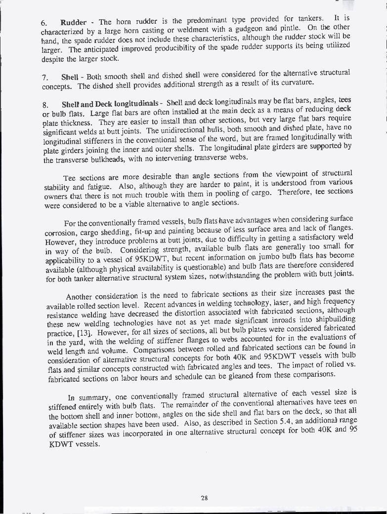
Rudder - The horn rudder is the predominant type provided for tankers. It is
characterized by a large horn casting or weldment with a gudgeon and pintle. On the other
hand, the spade rudder does not include these characteristics, although the rudder stock will be
larger. The anticipated improved producibility of the spade rudder supports its being utilized
despite the larger stock.
Shell - Both smooth shell and dished shell were considered for the alternative structural
concepts. The dished shell provides additional strength as a result of its curvature.
Shell and Deck longitudinals - Shell and deck longitudinals may be flat bars, angles, tees
or bulb fiats. Large flat bars are often installed at the main deck as a means of reducing deck
plate thickness. They are easier to install than other sections, but very large flat bars require
significant welds at butt joints. The unidirectional hulls, both smooth and dished plate, have no
longitudinal stiffeners in the conventional sense of the word, but are framed longitudinally with
plate girders joining the inner and outer shells. The longitudinal plate girders are supported by
the transverse bulkheads, with no intervening transverse webs.
Tee sections are more desirable than angle sections from the viewpoint of structural
stability and fatigue. Also, although they are harder to paint, it is understood from various
owners that there is not much trouble with them in pooling of cargo. Therefore, tee sections
were considered to be a viable alternative to angle sections.
For the conventionally framed vessels, bulb flats have advantages when considering surface
corrosion, cargo shedding, fit-up and painting because of less surface area and lack of flanges.
However, they introduce problems at butt joints, due to difficulty in getting a satisfactory weld
in way of the bulb. Considering strength, available bulb flats are generally too small for
applicability to a vessel of 95KDWT, but recent information on jumbo bulb flats has become
available (although physical availability is questionable) and bulb flats are therefore considered
for both tanker alternative structural system sizes, notwithstanding the problem with butt joints.
Another consideration is the need to fabricate sections as their size increases past the
available rolled section level. Recent advances in welding technology, laser, and high frequency
resistance welding have decreased the distortion associated with fabricated sections, although
these new welding technologies have not as yet made significant inroads into shipbuilding
practice, [l3. However, for all sizes of sections, all but bulb plates were considered fabricated
in the yard, with the welding of stiffener flanges to webs accounted for in the evaluations of
weld length and volume. Comparisons between rolled and fabricated sections can be found in
consideration of alternative structural concepts for both 40K and 95KDWT vessels with bulb
flats and similar concepts constructed with fabricated angles and tees. The impact of rolled vs.
fabricated sections on labor hours and schedule can he gleaned from these comparisons.
In summary, one conventionally framed structural alternative of each vessel size is
stiffened entirely with bulb flats. The remainder of the conventional alternatives have tees on
the bottom shell and inner bottom, angles on the side shell and flat bars on the deck, so that all
available section shapes have been used. Also, as described in Section 5.4, an additional range
of stiffener sizes was incorporated in one alternative structural concept for both 40K and 95
KDWT vessels.
28

Deck - Sheer or camber of weather decks is undesirable from a producibility point ofvìew, and sheer has been generally eliminated from large cargo vessels. It has therefore beeneliminated from the vessels under consideration. Camber has been retained since its lack wouldallow pooling of water on deck. However, parabolic camber has been replaced by the moreproducible straight line camber having a central flat l)ortiOfl with port and starboard knuckles.
With regard to a single vs. double skin main deck, it appears that the double deck has beengenerally avoided in the design of double hull tankers, due to its impact on vessel dimensionsand cost. However, it was noted that sorne of the proposed unidirectional designs, [7] [8] [9][10], have opted for a double skin at the deck, so as to continue the double envelope with itslongitudinal girder system across the deck. Therefore, the alternatives considered are a singleskin deck for conventional double skin tankers and a double skin deck (tight or non-tight innerdeck) for the unidirectional designs. It may be noted that a double deck provides a convenientlocation for a pipe tunnel for cargo piping, should this be considered desirable.
Main Bulkheads - Main transverse bulkheads have been constructed from plate andvertical stiffeners in the conventional double hull alternatives, with the exception of verticallycorrugated bulkheads with top and bottom stools ori one 40K and one 95KDWT alternative, forproducibility comparisons. Centerline bulkheads have also been constructed from plate andlongitudinal stiffeners. With regard to the corrugated bulkhead option, such bulkheads are notnecessarily the bulkheads of choice due to reported problems with cracking in service, althoughthey are preferred by sorne owners for their cargo shedding property as compared withconventional bulkheads. Corrugated bulkheads may also provide some producibility advantages.The unidirectional and dished unidirectional plate alternatives have been constructed withvertically corrugated bulkheads, conventionally stiffened bulkheads with horizontal stiffeners anddouble plate bulkheads.
il. Girders - A swedged girder may be described as one in which the web plate stiffeners areformed by pressing swedges (see Figure 3.6) into the web plate in lieu of fitting flat bar or anglebar stiffeners. However, swedged girder webs are not used (particularly for primary structure),since it is believed that the accordion like swedging will not allow the web to develop the fullshear transfer capabilities that a flat plate would develop.
Plate - The option between stiffened and swedged plating is not viable for the primarystructure of a vessel. However, swedged plating can be used for miscellaneous bulkheads anddeckhouse bulkheads. Corrugated plating is applicable to main or miscellaneous bulkheads.Dished plating is a feature of the dished plate unidirectional concept.
Inner Hull Connection to Inner Bottom - This alternative is concerned with the form ofthe outboard lower corners of the cargo tanks. "Bracketed corner", "sloped hopper", "slopedhopper with formed corners", as shown in Figure 4.1, have all been considered from thestandpoint of producibility. This alternative component is largely in the hands of the designerand owner, and there may be a noticeable but perhaps small difference in producibility. Theunidirectional alternatives have rounded corner connections in these areas.
29

±I I
II ±
T'IT
T'
flcuR
41 -
TY
D
FO
RM
ED
HO
PP
ER
CO
RN
ER
IS O
P L
OW
IP H
OP
PIP
CO
PN
7 'PS
BR
AC
KE
TE
DS
LOP
ED
HO
PP
ER
SID
ES
LOP
ED
HO
PP
ER
SID
EW
/ FO
RM
ED
CO
RN
ER
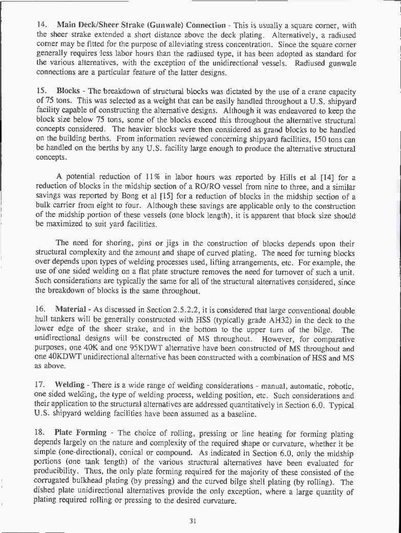
S
Main Deck/Sheer Strake (Gunwale) Connection - This is usually a square corner, withthe sheer strake extended a short distance above the deck plating. Alternatively, a radiusedcorner may be fitted for the purpose of alleviating stress concentration. Since the square cornergenerally requires less labor hours than the radiused type, it has been adopted as standard forthe various alternatives, with the exception of the unidirectional vessels. Radiused gunwaleconnections are a particular feature of the latter designs.
Blocks - The breakdown of structural blocks was dictated by the use of a crane capacityof 75 tons. This was selected as a weight that can be easily handled throughout a U.S. shipyardfacility capable of constructing the alternative designs. Although it was endeavored to keep theblock size below 75 tons, some of the blocks exceed this throughout the alternative structuralconcepts considered. The heavier blocks were then considered as grand blocks to be handledon the building berths. From information reviewed concerning shipyard facilities, 150 tons canbe handled on the berths by any U.S. facility large enough to produce the alternative structuralconcepts.
A potential reduction of li % in labor hours was reported by Hills et al [14] for areduction of blocks in the midship section of a RO/RO vessel from nine to three, and a similarsavings was reported by Bong et al [15] for a reduction of blocks in the midship section of abulk carrier from eight to four. Although these savings are applicable only to the constructionof the midship portion of these vessels (one block length), it is apparent that block size shouldbe maximized to suit yard facilities.
The need for shoring, pins or jigs in the construction of blocks depends upon theirstructural complexity and the amount and shape of curved plating. The need for turning blocksover depends upon types of welding processes used, lifting arrangements, etc. For example, theuse of one sided welding on a flat plate structure removes the need for turnover of such a unit.Such considerations are typically the same for all of the structural alternatives considered, sincethe breakdown of blocks is the saine throughout.
Material - As discussed in Section 2.5.2.2, it is considered that large conventional doublehull tankers will be generally constructed with HSS (typically grade AH32) in the deck to thelower edge of the sheer strake, and in the bottom to the upper turn of the bilge. Theunidirectional designs will be constructed of MS throughout. However, for comparativepurposes, one 40K and one 95KDWT alternative have been constructed of MS throughout andone 4OKDWT unidirectional alternative has been constructed with a combination of HSS and MSas above.
Welding - There is a wide range of welding considerations - manual, automatic, robotic,one sided welding, the type of welding process, welding position, etc. Such considerations andtheir application to the structural alternatives are addressed quantitatively in Section 6.0. TypicalU.S. shipyard welding facilities have been assumed as a baseline.
Plate Forming - The choice of rolling, pressing or line heating for forming platingdepends largely on the nature and complexity of the required shape or curvature, whether it besimple (one-directional), conical or compound. As indicated in Section 6.0, only the midshipportions (one tank length) of the various structural alternatives have been evaluated forproducibility. Thus, the only plate forming required for the majority of these consisted of thecorrugated bulkhead plating (by pressing) and the curved bilge shell plating (by rolling). Thedished plate unidirectional alternatives provide the only exception, where a large quantity ofplating required rolling or pressing to the desired curvature.
31

19. Accuracy - In the process of building ships, it has long been known that in manufacturingcomponents in accordance with design drawings, the dimensions of these components may varyto an extent that adjustments have to be made during the construction process to arrive at thevessel depicted in the design. These adjustments can include a significant amount of re-work,including trimming of excess material, inserting additional material, pulling, straightening andbending structure to suit alignment, and in some cases discarding components which are toodistorted to be reasonably utilized. The setting of accuracy goals and the understanding of theactual accuracy attainable in various manufacturing processes in the shipyard has been identified
as a means of pre-determining sorne of the aforementioned problems and to avoid them byadjustments during the manufacturing process.
Although this matter has always been of importance in shipbuilding, it is probably morecritical in modern shipbuilding techniques utilizing Product Work Breakdown Structure (PWBS)as units, blocks and complex modules are erected and a multitude of systems need to fittogether. This is opposed to the older systems approach to ship construction where simultaneousinterconnection at one time of many systems or components of the same system did not occur.
In order to address accuracy control, the NSRP has compared accuracy levelsmeasurement such as those contained in NSRP 0371, [l6. This reference provides data on thecutting of individual pieces for fabrication and on the fabricated components themselves. It isinteresting to note from this data that the U.S. shows some superiority over Japan in the cuttingof components, whereas the reverse is true for fabricated components. This may be due to thefact that most shipyard cutting is accomplished by numerically controlled equipment which isavailable world wide, whereas fabrication requires control of many other processes. This
suggests that the Japanese have a better control of accuracy on fabricated components.
This also suggests that the Japanese followed the Pareto principle for prioritizing theirmethods development. They recognized that for hull construction typically about 5 % of work-
hours are required for parts cutting, 50% for sub-assembly and block-assembly, and 45% for
hull erection. Thus, they first focused on statistical accuracy control and line heating as means
to reduce the work hours associated with the large percentages. This ultimately led to the needto provide shrinkage compensation both for flame cutting and for subsequent welding operations.In contrast, shipyard managers elsewhere focused on the least amount of work hours with N/Ccutting and ultimately direct computer control of cutting machines. They continued to look fordevices to force fits without significant drop in sub-assembly, block assembly, and hull-erectionwork-hours, without improvement in safety, and with the continuance of locked-in stresses.
The most modern approach which has been taken to achieve accuracy control inshipbuilding is termed "Statistical Accuracy Control." In this procedure, the manufacturingprocesses throughout the shipyard are closely monitored, dimensional data of components iscollected and a data base established. This data is then statistically analyzed and based on the
mean dimensions and standard deviations exhibited by any repetitive production process,adjustments are made to the "designed" dimensions of components so that "adjusted" dimensions
can be used in the production process to enable components to be produced having dimensionalcharacteristics that are within anticipated mean values and variance. The process, when applied
to all the various components throughout the vessel, can result in a pre-determined knowledgeof the ultimate dimensions of the entire vessel within the combined mean dimensions andstandard deviation of its parts. Further adjustments can then be made such that the dimensionalcharacteristics of each of the components can be deli ned for the construction process andfabrication can proceed to these specific dimensions with the confidence that the results will be
32

within an acceptable tolerance level. This will result in all components fitting together to formthe complete vessel without the need for expensive and time-consuming rework. The practiceof incorporating additional material into components, to be trimmed later as necessary, can bevirtually abolished, since all material can be cut to a predetermined tolerance.
Accuracy control is not considered as a separate structural alternative herein, but theamount of rework assumed for alternatives is identified in Section 7.0. Reduction of this reworkby greater accuracy control will be self evident in the results presented in that Section.
Shipyard Facilities - The production inputs including shipbuilding policy, facilitydimensions and capacities and interim product types (blocks) were selected in a manner that canbe accommodated by existing U.S. shipyards. As an example, crane lifting capacity was limitedto 75 tons for individual blocks and 150 tons for grand blocks.
The importance of identifying the entire production strategy cannot be over emphasized.When utilizing advanced shipbuilding systems, a general yard practice is to carry out extensivestudy and evaluation prior to finalization of the basic hull block breakdown to assure that thebest compromise of fabrication cost, block erection and outfitting cost is achieved. Also, theuse of large multi-system machinery/piping package units is one of the most significantimprovements in ship construction methods and these units have to be defined as well. Thesedecisions should be made very early in design for production.
Structural Details - Specialized/fitted structural details are considered time consuming indesign and fabrication. On the other hand, the use of standardized structural details eliminatesdesign and can save time in fabrication and are therefore more producible. In order to obtaina comparison, two alternative choices were selected. Specialized/fitted structural details havebeen taken as indicating the norm and standardized structural details have been taken asindicating the option supporting higher producibility, although details have not been specificallyidentified.
Coatings - Coating choice can be complicated by many factors, including ownerspreference, yard capability, quality, etc.. The selection of coatings is usually more closely tiedto the level of maintenance acceptable to the owner. Although this will not be explicitlyconsidered herein, the type of coating system used will also depend upon whether the alternativesystem concept is constructed of mild steel or high strength steel. The latter will be thinner thanthe equivalent mild steel and may therefore require superior coatings to provide adequatecorrosion resistance.
Coatings are also complicated by the need to have a weld-through pre-construction primerthat will be satisfactory as a base for the next paint coat together with a fast enough work flowso that the primer is sufficiently intact when the next coat is applied. Otherwise there must becomplete blasting and painting rework. It can be seen therefore that the primers are animportant consideration in producibility.
Design (Standardization) - An important aspect of Japanese shipyard productivity is thattanker design has been totally standardized. Unfortunately, it takes a great amount of effort andexperience to obtain the standard design, and it is highly unlikely that the first go around on theship design would be suitable for use as a standard without exceptional effort.
For example, Ishikawajima-Harima Heavy Industries Col, Ltd. (IHI) exploits a veryflexible approach to standardization. For a so called standard ship, even hull blocks can vary
33

significantly while achieveing the benefit normally associated only with a standard design thatmust be rigidly followed. They employ group technology, wherein manufacturing characteristicsare emphasized. As long as the distribution of work does not change significantly, insofar as theshipbuilding system is concerned, a standard ship is being produced regardless of the designdifferences. Regarding engine-room outfitting, IHI employs four basic machinery arrangements.Two are for different low speed and two are for different medium speed main diesel engines.For each auxiiliary machine position in an arrangement, two or three different vendor catalogitems are certified as shipyard standards. The items are functionally equivalent but physicallydifferent. For the purpose of declaring vendors' equipments as shipyard standards, preferenceis given to those vendors who each produce machines of the same basic design for a range ofcapacities. Thus, each standard machinery arrangement can expand or contract with enginehorsepower. Therefore, IHI's standards system offers options that can be negotiated duringcontract design and provides for more than one vendor's equipment for each application in orderto insure competitive pricing. IHI has been able to incorporate the standards in its Future-Oriented Refined Engineering System for Shipbuilding Aided by Computer (FRESCO).FRESCO also features separation of engine room fittings into module assemblies with companiondiagrammatics modularized the same way [17].
Due to standardization, there is no need for preliminary design, design studies orcomponent selection. Everything has already been determined from midship section to mainengine selection. The makes and models of equipment to be used are known, and there appearsto be a loyalty to suppliers. The most extreme case of the latter occurs when a shipyard has aproduct license. For example, if a shipyard is licensed to build a particular engine, all shipsfrom that shipyard will be powered by those engines.
Even drawing numbers are standardized. If the Inert Gas System diagram on one ship isnumbered PAZ0031, then it is numbered PAZ003I on every ship they build, no matter how ifdiffers. The name of the appropriate ship is all that appears on the drawing to distinguish itfrom other drawings. This procedure saves significant time in obtaining drawing numbers,references and correct schedules. In Japan, they never change and it is obviously very timesaving when preparing control documents such as drawing schedules. One drawing schedule canbe used for any ship with minor modifications.
A minimal number of final drawings is provided to the owner. For example, HVAC,piping and electrical diagrams are provided, but detail routing/arrangements are not. In theaccommodation spaces, even the diagrams do not indicate the quantity and location of fixtures.Deck, machinery space and pump room piping arrangements are prepared, but are not providedto the owners as final drawings. However the diagrammatics are quasi arranged andsupplemented with whatever information is needed for regulatory approvals and for use byoperating engineers.
The ship drawings are the same on each vessel. Basically they are a standard drawingwith minor modifications. For example, all diagrams are basically the same. As a comparison,consider the labor hours and time required to design and prepare the diagram for a cargo oilsystem, and then estimate the labor hours and time required to change an existing diagram tosuit say an increase in the number of tanks. If the discharge rate was also to be increased, thenext standard pump size could be selected and the pipe sizes (also standard) changed to suit.
Similarly, the main engine cooling water system on different ships would not change ifthey all had the same engines and auxiliary equipment. For the next engine size, it would onlybe necessary to increase pipe sizes and some quantities.
34

Once tile drawings are completed there are few revisions, compared to the large numberencountered in the U.S.
Even the vendor drawings are standardized. An engine control console remains essentiallythe same for each of the main-engine types maintained in the shipyard's file of flexiblestandards. For each particular console there is apt to be at least two vendors, not more thanthree, for competitive pricing. Only vendors who adopt the same flexible approach are so listed.
Thus their vendors' operations are regarded as extensions of the yard's shipbuilding system.
When Japanese managers participate with an owner in negotiating a contract design theytypically offer a design that they believe will fulfill the owner's requirements. At the same time,they may have available options for altering their initial offer all of which, because of their useof group technology, are consistent with their shipbuilding system. Furthermore, it appears they
prefer to keep contract changes to a minimum to avoid any impact on production.
However, they do accept changes provided work classifications per group technology logicand work amounts do not substantially change so that the scheduled launch date remainsunchanged. Otherwise there would be deleterious impact on other construction projects. Afterlaunch, they would entertain any change the owner is willing to pay for and would, if necessary,employ subcontractors and/or rent a pier, so that there is no adverse impact on the cadence oftheir shipyards work flows.
As a result, Japanese shipyards have files of flexible standards which detail everything in
work instructions. It is therefore plausible that the level of design labor hours can be as low as
50,000, as indicated in Section 5.3.3
As discussed in Section 7.0, 200,000 and 225,000 design labor hours have been assumedfor 40K and 95KDWT tankers building in the U.S., starting from a preliminary design andending with working drawings. In the absence of a standard design, this scenario will alsoimpact the phased material procurement and places some risk on the construction schedule, in
that as the design progresses and equipment and material are identified, there is no guaranteethat issuing purchase orders at that time will result in delivery to the shipyard to supportconstruction in a timely manner.
As a means of comparison for identifying schedule impact, a structural alternative has beenassumed where some design standards exist and less design material is required by the shipyard
workers. In this case, 100,000 labor hours have been assumed for design.
24. Maintainability, Strength and Fatigue - The proper application of effective coatings isan important aspect of maintainability. Double hull tankers have an advantage regarding thecoating of cargo oil tanks in that the internal structure of the tanks is free of longitudinals andtransverse stiffening except for under deck and bulkhead stiffeners. Even greater advantage ispossessed by unidirectional vessels with a double skin deck and in some cases, double platebulkheads. Cargo tank cleaning is also simplified on double hull tankers.
With regard to the coating of water ballast tanks contained within tile double hull, theunidirectional alternatives have a further advantage of smoother surfaces and greateraccessibility, due to the longitudinal girder system. It should be noted, however, that effectiveaccessibility is dependent upon suitable spacing of the girders. In the conventional double hulltankers, the water ballast tanks are framed with longitudinal stiffeners which are difficult to coat,and are therefore more subject to corrosion, particularly in the bottom of the tanks.
35

Steel renewals due to corrosion, on a long term basis, would therefore appear to be morelikely in the conventional alternatives than in the unidirectional vessels.
In addition, the nature of the unidirectional hulls, where relatively thick plating is requiredfor the hull and tank envelopes, dictates that the available hull girder strength is well abovetypical classification society requirements. This results in the longitudinal hull envelope steeloperating at lower induced stresses than the more conventionally framed alternatives, withconsequent longer fatigue life for structural components.
With regard to structural connections, the simple intersections of bulkheads and girderson the unidirectional alternatives provide a detail more preferable from a fatigue viewpoint thanthe typical intersections of longitudinals, webs, floors and bulkheads on the conventionallyframed alternatives. A significantly greater number of possible fatigue areas, operating at higherlongitudinal operating stresses, render the conventionally framed alternatives less desirable thanthe unidirectional vessels from a fatigue viewpoint.
4.3 RESULTS
A series of alternative structural system concepts has been synthesized from thecomponents and elements shown in Table 4. 1. Each alternative consists of 24 components orelements generically depicted in Table 4.2. As can be seen, of the 24 components or elements,eleven are directly varied, while the remainder are in accordance with the baselines describedin Section 4.2. The complete set of structural alternatives is described in Section 5.0.
36

COMPONENT OR ELEMENT
Hull FormDeckhouseTank ArrangementMachineryPumping SystemRudderShellShell and Deck LongitudinalsDeckMain BulkheadsGirdersPlateInner Hull Connection to
Inner BottomMain DecklSheer Strake(Gunwale) ConnectionBlocksMaterialWeldingPlate FormingAccuracyShipyard FacilitiesStructural DetailsCoatingsDesign (Standardization)Maintainability, Strength and
Fatigue
3'
CHARACTERISTICS
Baseline Sect. 4.2 - item iBaseline " - item 2Per AlternativeBaseline Sect. 4.2 - item 4Baseline - item 5Baseline - item 6Per AlternativePer AlternativeBaseline Sect. 4.2 - item 9Per AlternativeBaseline Sect. 4.2 - item 11Per AlternativePer Alternative
Baseline Sect. 4.2 - item 14
Baseline Sect. 4.2 - item 15Per AlternativePer AlternativePer AlternativeBaseline Sect. 4.2 - item 19Baseline T - item 20Per AlternativeBaseline Sect. 4.2 - item 22Per AlternativeBaseline Sect. 4.2 - item 24
Table 4.2: GENERIC ALTERNATIVE STRUCTURAL SYSTEM CONCEPTS

5.0 TASK IV - APPLICATION TO SPECIFIC DOUBLE HULL TANKERS
5.1 OBJECTIVE
The objective of this task is the application of the alternative structural system conceptsidentified in Section 4.0 to 40K and 100KDWT Jones Act double hull tankers to investigate thepotential for improved producibility in the U.S. A further objective is the estimation of baselineconstruction schedules and labor hours for these vessels.
5.2 SELECTION OF BASELINE VESSELS
The statement of work for this project required the application of the alternative structuralsystems to tankers of 40K and 100KDWT for the U.S. Jones Act trade. The 4OKDWT vesselwould likely be a product carrier or a shuttle crude carrier. The 100KDWT vessel would likelybe a crude carrier only. Furthermore, it is desirous that a baseline vessel be identified whichhas been built in a foreign shipyard under a recent building schedule.
The Jones Act trade has made use of tankers of approximately 4OKDWT over the years,although they have been rarer in the international market with vessels in the 30K+ and54KDWT sizes being more prevalent. The 100KDWT size range tanker has also been used inthe Jones Act Trade. Foreign vessels in this size range are generally just under 100KDWT andof the "Aframax" type.
As a result, the following procedure was adopted:
o A vessel resembling a 95KDWT 1993-95 vintage Far Eastern built crude carrier wasadopted as the baseline vessel. The general arrangement and midship section are shownin Figures 5.1 and 5.2 respectively. The principal characteristics are given in Table 5.1.
o A foreign design example for the 4OKDWT vessel was not available. Accordingly, ahybrid was prepared utilizing the generic features of the 9SKDWT Far Eastern vessel andprincipal characteristics indicated by previously built 4OKDWT tankers for the U.S. JonesAct trade. The general arrangement and midship section are shown in Figures 5.1 arid 5.3respectively. The principal characteristics for the vessel are given in Table 5.1.

Table 5.1: BASELINE DOUBLE HULL TANKER PRINCIPAL CHARACTERISTICS
The unidirectional hulls have slightly different dimensions to suit assumed proportions of thestructural cells in the double skin, as shown in Table 5.2, but cargo capacity is essentially thesame as that of the baseline vessels.
Table 5.2: UNIDIRECTIONAL DOUBLE HULL ALTERNATIVES
*open to cargo space
39
95 KDWT Ui U2 U3(Dished Plate)
Breadth B 40.75M 41.8 M 40.4MDepth D 21.0 M 22.4 M 21.2MWing Tank Width 2.0 M 2.2 M 2.2MDouble Bottom Depth 2.6 M 2.2 M 2.2MBottom Girder Spacing l.75M 1.15M 2.4MSide Girder Spacing 1.45M 1.15M 2.4MDeck Void Depth 1.OM 2.2M 2.2M
40 KDWT U4 US U6(Dished Plate)
Breadth B 30.5 M 30.85M 30.8MDepth D 17.57M l9.35M 18.8MWing Tank Width 2.0 M 2.2 M 2.2MDouble Bottom Depth 2.6 M 2.2 M 2.2MBottom Girder Spacing 1.75M 1.l5M 2.4MSide Girder Spacing 1.45M 1.15M 2.4MDeck Void Depth 1.00M 2.2 M* 2.2M
4OKDWT 95KDWT
Length B.P. (LBP) 18100M 234.00MBreadth B 31.00M 41.50MDepth D 17.70M 19.75MDesign draft 11.28M 13.75MBlock Coefficient Cb 0.80 0.83SI-lP 8,500 13,000Displacement 52,790MT 1 14,280MTLightship 12,790MT 19,280MTWing Tank Width 2.20M 2.70MDouble Bottom Depth 2.20M 2.20MCargo Tanks 7 17.90M 7@ 25.06M
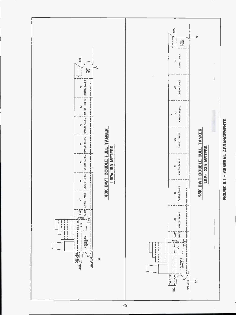
FIG
UR
E 5
.1 -
GE
NE
RA
L A
RR
AN
GE
ME
NT
S
OW
L
ST
G G
EA
RL
AF
T P
EA
K I I-
SP
AC
E
I'FU
EL
L
-IP
/S
[LP
RIS
LOP
TA
NK
S
I
#7
CA
RG
O T
AN
KS
J
#6
CA
RG
O T
AN
KS
j#5
CA
RG
O T
AN
KS
#4
CA
RG
O T
AN
KS
#3
CA
RG
O T
AN
KS
J
#2#1
CA
RG
O T
AN
KS
CA
RG
O T
AN
KS
j IICL-
--
FO
RE
PE
AK
40k
DW
T D
OU
BLE
HU
LL T
AI(
ER
FP
LBP
183
ME
TE
RS
¡\ll'
BA
SE
LIN
E
SIG
GE
AR
L
AF
T P
EA
K1
'FU
EL
OIL
MA
CH
INE
RY
Lc
LS
PA
CE
-L.
I J I
SLO
P#7
CA
RG
O T
AN
KS
#6
CA
RG
O T
AN
KS
L
#5
CA
RG
O T
AN
KS
L
#4
CA
RG
O T
AN
KS
LJ-
I
#3
CA
RG
O T
AN
KS
-t
#2
CA
RG
O T
AN
KS
J
Al
CA
RG
O T
AN
KS
CL r
I iF
OR
EP
EA
K
J I
I/OW
L
FP
AP
95k
DW
T D
OU
BLE
HU
LL T
AN
KE
RLB
P 2
34 M
ET
ER
S
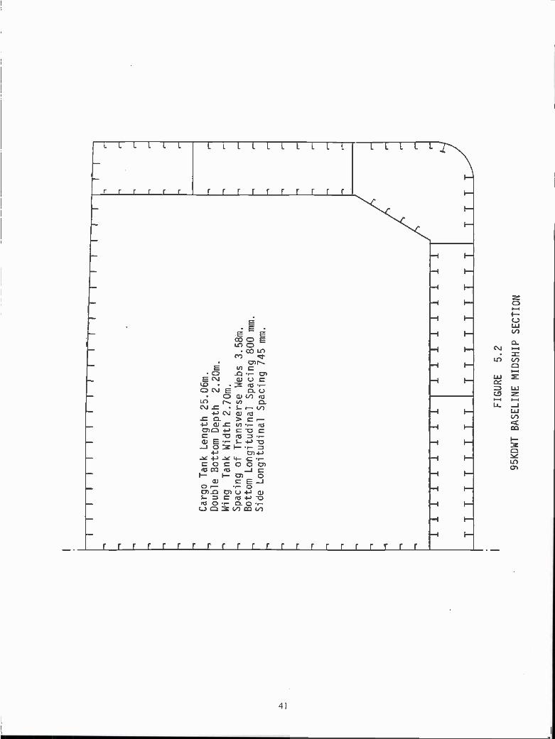
II
II
II
II
Cargo Tank Length 25.06m.
Double Bottom Depth
2.20m.
Wing
Tank Width 2.70m.
Spacing of Transverse Webs 3.58m.
Bottom Longitudinal Spacing 800
mm.
Side Longitudinal Spacing 745
mm.
111111111
I1
1t
II
II
II
F
1!1!
1I11
1TTTTTT
r r r- r f- r r r r
FIGURE
5.2
95KDWT BASELINE MIDSHIP SECTION

iI
II
Ii
IIII
II
1.TF 1
Ii
1
Cargo Tank Length
17.90m.
Double Bottom Depth
2.20m.
Wing Tank Width
2.20m.
Spacing of Transverse Webs 3.58m.
Bottom Longitudinal Spacing 800mm.
Side Longitudinal Spacing 745mm.
TT
TT T
T
FIGURE 5.3
4OKDWT
BASELINE
MIDSHIP SECTION
Bracket
ii
i f-I
1--
LL
-,r r
-,r r
Th-

5.3 BASELINE CONSTRUCTION SCHEDULES AND LABOR HOURS
5.3.1 General
This Section provides highlights of schedule and labor hour data obtained from thesurvey described in Section 2.5, and projections made therefrom.
5.3.2 Construction Schedules
The importance of time in terms of schedule on ship cost has been addressed inSection 1.0. Typical schedules of construction, distribution of labor hours as well as actuallabor hours, were sought in the literature, from shipowner experiences and through foreignshipyard contacts. Pertinent information was received from all sources on shipbuilding schedulesand distribution of labor hours. However, virtually no current information on actual labor hourswas obtained, presumably due to its proprietary nature.
Construction schedules have been identified from the sources noted above. Figure5.4 shows examples for several types of vessels constructed in the U.S. and abroad, indicatingmonths from start of fabrication to launch. Fabrication is defined as commencement of steelcutting.
Figure 5.5 indicates two schedules from contract to delivery for constructingdouble hull tankers. These schedules are for a Danish yard (84KDWT) [18] and a Japaneseyard, [18]. Note that the total schedules from contract signing to delivery are 22 and 20½months respectively.
5.3.3 Labor Hours
Figures 5.6 and 5.7 are U.S. versus Japanese comparisons of hull and machinery!outfitting work for the PD 214 general mobilization vessels, [20], which have the characteristicsof containerships and roll-on/roll-off carriers, both of which are more complex than tankers.They provide estimated labor hours between the U.S. and the Japanese. Note that these vesselswere not built. The total labor hours for design and construction of the vessels was estimatedto be 710,000 hours in Japan and 1,834,000 in the U.S. for the first ship. One would expectthat the design engineering would be greater than indicated (about 50,000 hours) for the Japaneseyard. All that can be said is that for design engineering, production engineering and mold loft,the projected Japanese effort is 20% of the labor hours of the U.S. yard. This low figure isundoubtedly due to the extensive collection of standards and modules in computerized designsystems that are integrated for design, material, and production functions. These are employedlike building blocks and many automatically adjust in size during detail design commensuratewith different capacities, [21].
Table 5.3 shows a 1992 comparison [22] of labor hours and period required fordelivery of the first 8OKDWT tanker after contract for an average U.S. shipyard and a typicalJapanese shipyard. It indicates that the U.S. is superior in outfit and piping construction, butinferior in design techniques, casting techniques and production control. Although the datacompares an average U.S. shipyard and a typical Japanese shipyard, no justification is offeredfor the large differences in the numbers, nor is it clear if the values are applicable to 1992. Asshown, the labor hours are 594,000 for the Japanese and 1,374,000 for the U.S. yard. (Note:the reference indicated the U.S. labor hours as 2,374,000, which is believed to be atypographical error.)
43

Table 5.4 assesses the impact of technologically advanced shipbuilding techniqueson labor hour requirements and shipbuilding cycle time, [23]. It is a comparison between anautomated and a conventional yard in 1985, and indicates a 32% reduction in labor hours forthe automated yard. In addition to labor hour savings, this effects a higher facility utilization(more throughput), resulting in higher return on investment capital. For this comparison, anautomated yard is one in which investments have been made into increasing automation, i.e.automatic beam forming, cranes with pneumatic or magnetic lift, self traveling staging, welding,robots, etc.
It has been stated that: "Strict dimensional control of interim products through thedifferent assembly stages is vitally important for profitable ship production, [24]. Studies inFinland show that a 30% reduction in labor costs is possible in hull construction, [25]. Thisreduction can be gained by eliminating unnecessary fitting and rework using tight accuracycontrol methods, [11]. Reference [26] indicates that large savings in labor hours and costs inJapan, as compared with U.S. shipyards, are due to scientific management methods, whichinclude statistical control of manufacturing. The percentage of erection joints requiring norework at a Japanese shipyard for a vessel in 1977 was 67.4%; in 1982, it was 75% for all typesof ships, [27]. "Through organizational input... minimization of unnecessary rework througha proper accuracy control program can yield a typical potential increase in output of 15%,"[28].
44

FIG
UR
E5.
4
FA
BR
ICA
TIO
N T
O L
AU
NC
HIN
G T
IME
LIN
ES
10 II
285.
000
DW
T T
anke
r. J
apan
. 199
3.
40.0
00 D
WT
Tan
ker.
US
. 198
1.
40,0
00 D
WT
Tan
ker.
US
. 198
3.
18,0
00 D
WT
Oile
r, N
avy.
196
0.
25.0
00 D
WT
Oile
r, N
avy.
198
6.
225m
LB
P P
rodu
ct T
anke
r, D
enm
ark.
And
erso
n. 1
992.
290,
000
DW
T T
anke
r, J
apan
. 199
3.
New
fore
body
125
,000
DW
T T
anke
r 19
93
Mat
son
Con
tain
ersh
i
* V
esse
ls n
oi b
uilt
MO
NT
HS
FR
OM
ST
AR
T O
F F
AB
RIC
AT
ION
TO
VE
SS
EL
LAU
NC
HIN
G11
21 3
f 415
1 6f
78
nlom
l2 1
3 l4
18 l!
J2O
fiiJ2
21 2
3124
125!
2612
7128
1291
301
3113
233
34
35 3
6 37
38
39 4
0 41
42
43 4
4 45
46
Mob
iliza
tion
Shi
p. J
apan
. 198
0, B
unch
198
7.*
Mob
iliza
tion
Shi
p. U
S. 1
983,
Bun
ch 1
987.
*

FIG
UR
E 5
.5
CO
NS
TR
UC
TIO
N S
CH
ED
ULE
D A
N S
H
(B&
w)
84K
DW
T SIG
NIN
G
JAP
AN
ES
E(1
H I)
40K
& 9
4KD
WT
ST
AR
T D
ES
IGN
ST
AR
T S
TE
EL
CU
TT
ING
KE
EL
LAID
SE
AT
RA
I LS
LAU
NC
HD
E L
IVE
R Y
CO
NT
RA
CT
11.6
MO
NT
HS
ST
AR
T O
F F
AB
RIC
AT
ION
ST
AR
T D
ES
IGN
\
5.1
KE
EL
LAID
LAU
NC
H
2.8 SE
A T
RIA
LS
1.8
10.7
DE
LIV
ER
Y
22 M
ON
TH
S
8 M
ON
TH
S2.
03.
83.
22
TO
3.5
20.5
MO
NT
HS

Cut and FabricationSub assy and Assy
ErectionProduction Engineering
Mold Loftn r
CranesMisceIIaneous
Design Engineering
FIGURE 5.6
HULL WORK LABOR HOURS, [20]
MARAD - U.S. vs JapanPD-214 Estimate (early 1980's)
MARAD - U.S. vs Japan *PD 214 Estimate (early 1 980's)
Thousands of Laborhours
0 50 100 150 200 250
U.S liJapan* Ships not built
47

MACHINERY/OUTFITTING LABOR HOURS, 1120]
MARAD - U.S. vs JapanPD-214 Estimate (early 1980's)
MARAD - U.S. vs JapanPD-214 Estimate (early 1980's)
Thousands of Laborhours
Piping. Fabric, and Assem rMachin erv Fab and Assy r
Electrical Fab and Assy rSheet Metal Fab and Assy
InsulationPainting r
Fitting and OutfittingTesting
Cranes for OutfittingServices and Unallocated,
Outfitting Production Engrg -n
Design Engineering
U.S. LJJapan
48
*
FIGURE 5.7
o 50 100 150 200 250 300
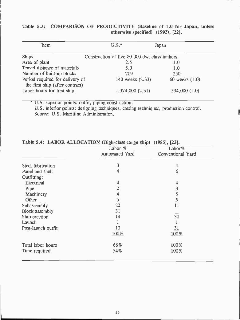
Table 5.3: COMPARISON OF PRODUCTIVITY (Baseline of 1.0 for Japan, unlessotherwise specified) (1992), [22].
Ships Construction of five 80 000 dwt class tankers.Area of plant 2.5 1.0Travel distance of materials 5.0 1.0Number of built-up blocks 209 250Period required for delivery of 140 weeks (2.33) 60 weeks (1.0)
the first ship (after contract)Labor hours for first ship 1,374,000 (2.31) 594,000 (1.0)
a u.s. superior points: outfit, piping construction.U.S. inferior points: designing techniques, casting techniques, production control.Source: U.S. Maritime Administration.
Table 5.4: LABOR ALLOCATION (High-class cargo ship) (1985), [23].
49
Labor %Automated Yard
Labor%Conventional Yard
Steel fabrication 3 4Panel and shell 4 6
Outfitting:ElectricalPipe 2 3
Machinery 4Other 5 5
Subassembly 22 11
Block assembly 31
Ship erection 14 30Launch 1 1
Post-launch outfit IQ II100% 100%
Total labor hours 68% 100%Time required 54% 100%
Item u.s.a Japan

Table 5.5 provides data for five single hull vessels built and delivered at 1H! Yokohama
Shipyard in the year 1972, [18]:
Table 5.5: DATA ON SINGLE HULL SHIPS BUILT AT 1H! in 1972, [191
Type $je
OBO 224,070 dwtTanker 230,906 dwtTanker 227,778 dwtTanker 219,803 dwtTanker 232,315 dwt
The new construction of Table 5.5 was achieved with one building dock, supported bytwo 120-ton cranes and one 30-toit crane, [29]. The area of the yard used for such constructionwas just over 50 acres. According to Reference [19], the above vessels were constructed with
a labor force of 1900, with 1150 employed on steeiwork and 750 employed on machinery/outfitinstallation. A further 800 workers were employed on ship repair contracts. The work weekconsisted of 44 hours, with one shift per day and about 8 hours of overtime per worker perweek. Since the five vessels were built in one year (say 50 weeks), then an average of 988,000manhours per vessel was required for construction, excluding design hours.
Recent labor hour distribution data for construction of 40 and 95 KDWT double hulltankers in Japan was obtained from [19] and data for construction of an 84KDWT double hulltanker in Denmark was obtained from [18]. This data is summarized in Table 5.6 below.Tables 5.7 and 5.8 give the steel and outfitting breakdowns of Table 5.6.
Table 5.6: STEEL AND OUTFITTING RELATIVE LABOR HOURSFOR DOUBLE HULL TANKERS
Japanese* Danish**
Steel 55-63% 70%
Outfitting 45-37% 30%
*IHI **B&W
50

Table 5.7: STEEL LABOR BREAKDOWN FOR DOUBLE HULL TANKERS
Japanese Japanese Danish4OKDWT 95KDWT 84KDWT
Parts Cutting & Bending 15% 14% 13.75%Sub-assembly 13% 13% 12.75%Assembly 45% 48% 45.25%Erection 27% 25% 28.25%
Steel Total 100% 100% 100%
Table 5.8: MACHINERY/OUTFITT1G LABOR BREAKDOWNFOR DOUBLE HULL TANKERS
Japanese Japanese Danish4OKDWT 95KDWT 84KDWT
Machine Shop 2%Pipe fab. and machinery pkgs. 11 %* l0%* 10%Pipe installation 21 %Misc. steel outfitting 17%Hull & Accommodations 25%* 23%*Mechanical Installation 8% *Joiners & carpenters 8%*Machinery Outfitting 18% 16%Electrical Outfitting 9% 9% 16%Tests & trials md. Dry Dockg. 6% 8%Painting 31% 34% 18% Danish coating of cargo
& WB tanks subcontractedOutfitting totals 100% 100% 100%
*Affected by hull structural concept
To produce the Table 5.7 breakdown of steel labor hours, the original categories receivedfrom the Danish shipyard (steel processing, sub-assembly, flat and curved panels, blocks, erection,transport and riggers) were re-combined to better compare with those of the Japanese shipyard sothat a meaningful comparison of labor hours could be made. Note that the Danish coating of cargoand water ballast tanks were subcontracted. It can be seen that if this item is added into the Danishtotal, then their outfitting percentage would increase and their steel percentage would decrease,possibly coming into closer agreement with the Japanese values.
If it is assumed from Table 5.6 that an average of 59% steel and 41 % outfit breakdownin labor hours was consistent with Japanese production in 1972, then the 988,000 labor hoursderived from Table 5.5 for single hull tanker construction in Japan would divide into 582,920labor hours for steel and 405,080 labor hours for machinery/outfitting. Some support for
51

52
assuming identical distribution of labor hours in 1972 and 1994 can be gleaned from aconsideration of the advances made in shipyard steel fabrication through automation, and at thesame time the modular nature of some of the outfit delivered to a shipyard together with pre-outfitting. The above data can then be used to estimate the labor hours required in Japan in1972 to construct 40K, 93K and 84K double hull tankers, and then to project the estimates to1994.
For this purpose, it has been assumed that the total steel labor hours vary in somemanner with the total weld length required for construction. To determine the relationshipbetween weld length and vessel dimensions, a flat plate structural unit with longitudinals andtransverse webs was first considered. The number of welds (butts and fillets) in the width w ofthe unit varies with plate width and the spacing of longitudinals, which both vary with w. Thenthe total length of welds varies with wi, where / is the length of the unit. Similarly, the totallength of welds required for the transverse plate butts and webs (including face plates, etc.)varies with 1w. Then the total length of welds for the complete unit varies with w!, i.e. the areaof the unit.
To extend this reasoning to a ship, it may therefore be assumed that the total length ofwelds (and therefore the steel labor hours) in similar ships, with similar construction and blockcoefficients, varies approximately with an area numeral such as L (B+D). For a better accountof welding on main transverse bulkheads, a factor xBD may be added, where x is the numberof bulkheads. For comparing ships with different internal arrangements however, such as singlehull and double hull tankers, the numeral must be modified to take account of the inner bottom,the side tanks and any additional longitudinal bulkheads. Thus, for a single hull tanker with twolongitudinal bulkheads and say ten transverse bulkheads, the numeral becomes N= (2LB +4LD + 1OBD). For a double hull tanker with a center-line longitudinal bulkhead and tentransverse bulkheads, the numeral becomes ND = (3LB + 5LD + 1OBD).
The average Japanese tanker deadweight in Table 5.5 was taken to be 228,000 tons(single hull) and estimated dimensions of the vessel were derived. The dimensions of the84KDWT Danish double hull tanker were obtained from [18], while the dimensions of the 40Kand 95KDWT double hull tankers are those given in this Section for the baseline vessels.
Table 5.9 was then prepared, providing a comparison of labor hours for theconstruction of tankers in Japan in 1972. The labor hours for construction of the 228 KDWT
single hull tanker were derived previously by assuming steel labor hours andmachinery/outfitting labor hours to be 59% and 41% of the total hours respectively. The steellabor hours for the 40K, 95K and 84KDWT double hull tankers were then obtained from thoseof the 228KDWT tankers by application of the factors ND/Ns. The resulting hours were then
taken to be 59% of the total, with the remaining 41 % applying to machinery/outfitting. Totallabor hours were increased by 50,000 for design, as surmised from Figures 5.6 and 5.7,although this figure appears to be quite optimistic.
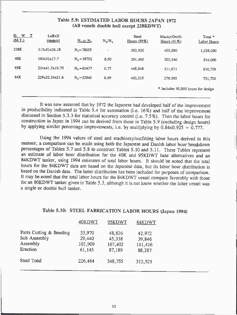
Table 5.9: ESTIMATED LABOR HOURS JAPAN 1972(All vessels double hull except 228KDWT)
* Includes 50,000 hours for design
It was now assumed that by 1972 the Japanese had developed half of the improvementin producibility indicated in Table 5.4 for automation (i.e. 16%) and half of the improvementdiscussed in Section 5.3.3 for statistical accuracy control (i.e. 7.5%). Then the labor hours forconstruction in Japan in 1994 can be derived from those in Table 5.9 (excluding design hours)by applying similar percentage improvements, i.e. by multiplying by 0.84x0.925 = 0.777.
Using the 1994 values of steel and machinery/outfitting labor hours derived in thismanner, a comparison can be made using both the Japanese and Danish labor hour breakdownpercentages of Tables 5.7 and 5.8 to construct Tables 5. 10 and 5. 11. These Tables representan estimate of labor hour distribution for the 40K and 95KDWT base alternatives and an84KDWT tanker, using 1994 estimates of total labor hours. It should be noted that the totalhours for the 84KDWT data are based on the Japanese data, but its labor hour distribution isbased on the Danish data. The latter distribution has been included for purposes of comparison.It may be noted that the total labor hours for the 84KDWT vessel compare favorably with thosefor an 8OKDWT tanker given in Table 5.3, although it is not know whether the latter vessel wasa single or double hull tanker.
Table 5.10: STEEL FABRICATION LABOR HOURS (Japan 1994)
53
D W T LxBxD
N/NSteel
Hours (59%)Machy/OutfitHours (41%)
Total *Labor Hours(M.T.) (meters)
228K 313x51x26.18 N5=78055 582,920 405,080 1,038,000
40K 183x31x17.7 ND=38702 0.50 291,460 202,540 544,000
95K 234x41.5x19.75 N0=60437 0.77 448,848 311,911 810,759
84K 229x32.24x21.6 ND=53845 0.69 402,215 279,505 731,720
4OKDWT 95KDWT 84KDWT
Parts Cutting & Bending 33,970 48,826 42,972Sub Assembly 29,440 45,338 39,846Assembly 101,909 167,402 141,416Erection 61,145 87,189 88,287
Steel Total 226,464 348,755 312,521

Table 5.11: MACHINERY/OUTFITTING LABOR HOURS (Japan 1994)
Table 5.12: TOTAL STEEL & MACHINERY OUTFITTING
4OKDWT 95KDWT 84KDWT
Total Steel and Machinery Outfitting 383,838 591,110 529,696
*Affected by uniqueness of hull structural conceptand difference from base vessel
Danish coatingof cargo and
WB tankssubcontracted
According to information recently received, {29], the following labor hours forconstruction were achieved by Japanese and Korean shipyards in 1992:
This information indicates that the projected Far East labor hours for 40K and95KDWT double hull tankers given in Table 5. 11 are supported by the Korean data.
Reference [3fl states that sorne medium and smaller Japanese shipyards are buildingdouble hull Aframax tankers (approx. 95KDWT) for 200,000 hours. These hours and theJapanese labor hours above are so low compared with historical and other data bases that for thepurpose of this study, the Korean hours have been taken to be typical of Far East construction.
Japan Korea28OKDWT single hull tanker 380-450,000 700-800,00028OKDWT double hull tanker 550-650,000 850-950,00015OKDWT single hull tanker About 300,000 About 640,000
4OKDWT 95KDWT 84KDWT
Machine Shop 4,343Pipe fab. and mach. packages 17,311* 24,235* 21,717*
Pipe installation 45,607*
Misc. steel outfitting 36,920 *
Hull & Accommodations 39,344* 55,742*
Mech. installation 17,374*
Joiners & carpenters 17, 374*
Machinery Outfitting 28,327 38,777Electrical Outfitting 14, 164 21,812 34,748Tests & Trials mcl. Dry Docking 9,442 19,388Painting 48,786 82,401 39,092
Machinery & Outfitting Total 157,374 242,355 217,175

Figure 5.8 provides the Danish B&W yard's "Learning Curve" for series productionof 17 double hull tankers of 84KDWT, [18]. The production index of that figure shows thatafter production of the 17 vessels, the index dropped from loo down to nearly 50. Statedanother way, a shipyard building such a series design can construct the last vessel in one halfthe labor hours of a shipyard with a one-off design. This displays a clear case for seriesproduction and its effect on producibility which, on face value, is likely to overshadow any otherimprovements on producibility.
However, the advantage of series production is available to all shipyards. A learningcurve is not a fixed line and can be improved (i.e. displaced downwards) by superior workmethods or design changes. A shipyard that can improve a learning curve by constant smalldownward displacements will be more competitive.
NDXL
loo
50
I
PRODUCTiON
iDES}GN ANO PRODUCTION
uU \J\20 NO. IN 5ERIES
Figure 5.8Learning Curve for Series Production, [B&W]
5.4 APPLICATION OF ALTERNATIVE STRUCTURAL SYSTEMS
From the list of generic alternative structural system concepts given in Table 4.2, aseries of alternative concepts was identified for study and evaluation for both the 40K and95KDWT vessels.
For the identification of the various structural alternatives, a key code was establishedas follows. The key number for each 4OKDWT alternative starts with 40 and ends in a numbersuch as 10, assigned to identify the structural configuration of the alternative. For example, the4OKDWT base alternative has the number 4010 assigned to it. The other 40K alternatives havenumbers 4020, 4030 etc. assigned to them. Similar key numbers, such as 9510, 9520 etc. havebeen assigned to the 95KDWT alternatives. A full list of the alternatives investigated, togetherwith their key numbers, is provided in Table 5. 13. These numbers appear on all calculationsheets. Alternatives 9590 thru 95112, 95130 , 95140 and 95150 were not evaluated sinceexperience with other alternatives indicated that the relationship of their producibility to theremainder of the 95KDWT series would not differ greatly from the relationship exhibited by the4OKDWT series.
55

Table 5.13: ALTERNATIVE STRUCTURAL SYSTEM CONCEPTS
NOTE: All vessels 4010 thru 4090 and 9510 thru 9580 have high strength steel (grade
AH32) in the deck and bottom except 4020 and 9520. All unidirectional vessels
are mild steel except 40112, which has high strength steel in the deck and bottom.
All vessels have conventionally stiffened transverse bulkheads (vertical stiffeners)
and center line bulkheads (longitudinal stiffeners), except where noted otherwise.
Key N24010 - 4OKDWT base vessel with square (bracketed) lower outboard corner of cargo tank.
9510 - 95KDWT base vessel with sloped tank side (hopper) at lower outboard corner.
4020 - Same as 10, except all mild steel.
9520 - Same as 10, except all mild steel.
4030 - Same as 10, three times the stiffener sizes in order to minimize weight.
9530 - Same as 10, with additional stiffener sizes, as in 4030.
4040 - Same as 10, with vertically corrugated transverse bulkhead.
9540 - Same as 10, with vertically corrugated transverse bulkhead.
4050 - Same as 60, but sloped hopper fitted with formed corners.
9550 - Same as 10, but sloped hopper fitted with formed corners.
4060 - Same as 10, but with sloped hopper at lower outboard corner.
9560 - Same as 10, but with square (bracketed) lower outboard corner of tank.
4070 - Same as 10, but with bulb plates in lieu of other stiffeners.
9570 - Same as 10, but with bulb plates in lieu of other stiffeners.
4080 - Same as 10, but with stiffened elements fashioned from one frame space width of
plate with stiffener formed on one side. This in lieu of plate stiffener combinations.
9580 - Same as 10, but with stiffened elements fashioned from one frame space width of
plate with stiffener formed on one side. This in lieu of plate stiffener combinations.
4090 - Same as 10, but with all floor, girder and web stiffeners assumed automatically
welded.
56

40100- U4 - Unidirectional alternative with vertically corrugated transverse and center linebulkheads.
40110- U5 - Unidirectional alternative with vertically corrugated transverse and center linebulkheads.
40111- U5 - Unidirectional alternative with double plate transverse bulkhead and verticallycorrugated center line bulkhead.
40112- U5 - Unidirectional alternative with high strength steel deck and bottom, verticallycorrugated transverse bulkhead and no center line bulkhead.
40120- U6 - Dished plate unidirectional alternative, with vertically corrugated transverse and
center line bulkheads. Dished plating formed by rolling.
95120- U3 - Dished plate unidirectional alternative, with vertically corrugated transverse andcenter line bulkheads. Dished plating formed by rolling.
40121- U6 - Dished plate unidirectional alternative - same as 120, but dished plating formedby pressing and credit given for unique welding. Also, floor, girder and webstiffeners assumed automatically welded.
95121- U3 - Dished plate unidirectional alternative - same as 120, but dished plating formedby pressing and credit given for unique welding. Also, floor, girder and webstiffeners assumed automatically welded.
40130- Same as 10, but double bottom floors and girders lugged and slotted into bottom shelland inner bottom for easier alignment.
40140- Same as 10, but 50% labor hour reduction for series production of standard vessels.
40150- Same as 10, with use of design standards for contract/detail designs. Design laborhours reduced from 200,000 to 100,000 and schedule reduced to suit.
A midship section was synthesized for each structural system concept considered. Themidship scantlings for all longitudinal items were obtained from the American Bureau ofShipping (ABS) program OMSEC, which incorporates all pertinent sections of ABS Rules. Theinput consisted of the basic geometry of the midship section, spacing of longitudinals andgirders, position of stringers, deck camber and other information pertinent to geometry. Withthis information, a bending moment estimation provided by the older ABS Rules within theprogram and an internal table of stiffeners and plating (which can be modified), the programcalculates the midship section longitudinal scantlings with required hull girder section modulusand minimum weight as the design parameters. Sample OMSEC outputs for the base alternativesare given in the Appendix.
57

It should be noted that stiffener sizes were selected from a limited range of flat bars andbuilt-up shapes included in the program, which can result in some stiffeners being oversized.This procedure was followed since it is the practice in some shipyards to restrict stiffener sizesto a limited range to simplify storage, handling and design details. However, intermediate sizesof stiffeners were also added to the program and alternatives 4030 and 9530 included in the listof structural alternatives studied, so that any oversized stiffeners could be replaced by smallersizes. Alternatives 4030 and 9530 are otherwise similar to the base alternatives 4010 and 9510respectively.
Since they are not included in the OMSEC program, the scantlings of transverse structureand bulkheads were determined from ABS Rules for the 4OKDWT and were adapted fromsimilar ship's drawings for the 95KDWT alternatives.
For the unidirectional alternatives, an assumed spacing of longitudinal girders was usedto enable the OMSEC program to calculate the required minimum ABS Rule shell platingthickness. In addition, some approximate calculations were performed to obtain representativescantlings for the longitudinal girders.
For the dished plate unidirectional alternatives, plating thickness was estimated byconsidering the additional strength due to curvature over an equivalent flat plate structure. Itshould be noted that the spacing of longitudinal girders for the dished plate vessels is greaterthan that of the other unidirectional alternatives, as approximately identical shell thickness wasmaintained and the additional strength due to curvature allowed greater girder spacing. Also,the scantlings of the dished plate double hull were maintained constant around the entireperiphery of the midship section. This feature, which can be applied to any of the unidirectionalalternatives, enables the number of unique structural blocks to be considerably reduced, butincurs some weight penalty.
5.5 STRUCTURAL BLOCKS
To simplify the producibility investigation, yet keep it meaningful, only one midshipcargo tank length of each structural alternative concept, including one transverse bulkhead, wasselected for initial compari son and evaluation.
Since the producibility study required seams and butts of plating to be located, it was thennecessary to break down the midship tank structure into suitable blocks for erection. Somediscussion of block breakdown is provided in Section 4.2, item 15, and the actual breakdownselected is shown in Figures 5.9 and 5.10. It may be noted that the breakdown is similar forboth the 40K and 95KDWT alternatives, although the numbering systems are different, asindicated in Section 6.3.
The lengths of the blocks were based on the length of cargo tanks (17.9m. for 40K and25.06m. for 95KDWT alternatives) and the 3.58m. spacing of transverse floors and webs.Thus, the block lengths are 7. 16m. forward and 10.74m. aft for 40K and 10.74m. forward and
14.32m. aft for 95KDWT alternatives. These arrangements provide some repetitive blockswithin the parallel mid-body of the vessels. The transverse bulkheads inside the double hullformed separate blocks.
58
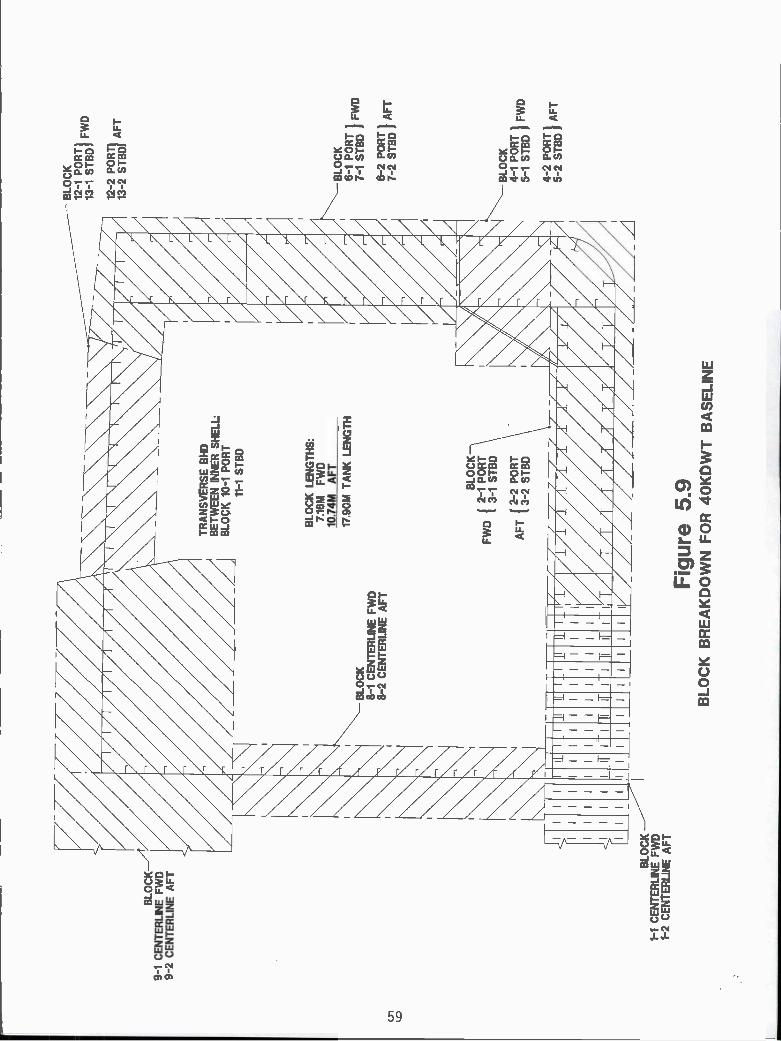
BLO
CK
_A9-
1 C
EN
TE
RLI
4E F
WD
9-2
CE
NT
ER
LIN
E A
FT
BLO
CK
1-1
CE
NT
ER
LIN
E F
WD
1-2
CE
NT
ER
LIA
FT
tA4
____
____
A
NW
i7A
ii
Fig
ure
5.9
BLO
CK
BR
EA
KD
OW
N F
OR
4O
KD
WT
BA
SE
LIN
E
BLO
CK
12-1
PO
RT
13-1
ST
BD
12-2
PO
RT
I13
-2 S
TB
DJ
AF
T
BLO
CK
6-1
PO
RT
7-1
ST
BD
6-2
PO
RT
7-2
ST
BD
AF
T
BLO
CK
4-1
PO
RT
5-1
ST
BD
WD
4-2
PO
RT
5-2
ST
BD
AF
T

BIO
CK
-10
-1 C
EN
TE
RL1
'EFWD
10-2
CE
NT
ER
LIN
EAFT
BLO
CK
8-1
PO
RT
9-1
ST
BD
8-2
PO
RT
9-2
ST
BD
AFT
BLO
CK
6-1
PO
RT
7-1 STBD
8-2
PO
RT
7-2 STBD
AFT
BLO
CK
4-1
PO
RT
5-1
ST
BD
4-2
PO
RT
5-2STUD
AFT
BLOCK
3-1
CE
NT
ER
LIN
E F
WD
3-2
CE
NT
ER
LIP
EAFT
Fig
ure
5.10
BLO
CK
BR
EA
KD
OW
N F
OR
95K
DW
T B
AS
ELI
NE

6.0 TASK V - ESTIMATES OF PHYSICAL PRODUCTION CHARACTERISTICSFOR ALTERNATIVE STRUCTURAL SYSTEM CONCEPTS
6.1 OBJECTIVE
The objective of this task is the development of production characteristics such as weight,number of pieces and other quantifying estimates for each of the alternative structural systemconcepts. They are utilized in the next Section to study the concepts in ternis of producibility.
6.2 APPROACH
In considering the producibility of the various alternative structural system concepts, itis necessary to consider many characteristics aspects of the structure, including the following,[31]:
amount of weldingtype and number of frames, and stiffenersnumber of unique piecestotal number of piecesweightsurface area for coatingsnumber, type and position of welded jointsself-alignment and supportneed for jigs and fixtureswork positionnumber of physical turns/moves before completionaids in dimensional controlspace access and stagingstandardizationnumber of compartments to be entered to complete work
The quantification of these characteristics for producibility considerations shouldgenerally be in terms of physical quantities, i.e. weight, number of pieces, number and lengthof welded joints, etc., or the labor hours and schedule time required for their construction orapplication. The remainder of this sub-section describes how the physical quantifications weremade. The labor hour and schedule quantifications are described in Section 7.0.
As indicated in Section 5.5, the structure of one complete midship tank section for eachalternative, port to starboard, including one transverse bulkhead, was studied for the purposesof considering producibility. Following the breakdown into structural blocks described inSection 5.5, the quantification of the characteristics noted above then required each one tanklength alternative to be broken down into all its component plates, longitudinals, stiffeners,brackets and chocks. A spreadsheet computer program was utilized for this purpose to form thebasis for quantifying the various physical steel construction properties of the alternatives. Thespreadsheet format is shown in Figure 6.1. An entire sample data set is presented in theAppendix, on pages A29 through A60, for both the 40 and 95KDWT baseline alternatives.These data include the number of unique pieces, total number of pieces, dimensions and
61

Alternative
Inst
ruct
ions
: Fill
in s
hade
d ar
eas
by s
imila
r in
put t
oth
at s
how
n on
sam
ples
of c
ompl
eted
Alte
rnat
ives
Leng
th o
r w
idth
of p
late
und
er c
onsi
dera
tion
(usu
ally
4 s
ides
usi
ng4
lines
)
; =--
==
Tot
als
Wel
d le
ngth
s fr
om th
is s
prea
dshe
et -
Met
ers
Mon
ud W
eld
But
t Wel
dF
illet
wel
dF
ll po
sito
nH
oriz
onta
l pos
iton
Ver
scal
pos
iton
Ove
rhea
d po
sito
nI
One
sid
edI
IT
wo
side
dj
II
Tiic
knes
s , r
Oro
roI
II
Tic
lrnas
s u
tOrn
io
II
II
I
II
IIII
II
I
Aut
omal
Man
ual
But
tF
illet
Fla
tH
oriz
Ver
t Ove
rhea
d
Aut
o W
eld
Met
ers
Fill
etB
uff
Man
ual W
eld
Fill
et
Wel
d le
ngth
s us
ed fo
r La
bor
Hou
rD
ownh
and
Cal
cula
tkn,
whi
ch a
re r
atio
s of
thos
e ab
ove
Ver
tical
conv
erte
d to
the
labo
r ho
ur fo
rmat
Ove
rhea
d
auto
mat
ical
ly c
alcu
late
d by
spr
eads
heet
But
tD
ownh
and
Ver
tical
Ove
rhea
dT
otal
Cor
ned
Pla
taF
lat P
inte
Aut
omnt
c w
eld
tota
ls
FIGURE
6.1
SPREADSHEET FOR QUANTIFYING THE
PHYSICAL PRODUCTION CHARACTERISTICS
OF THE ALTERNATIVE STRUCTURAL
SYSTEM CONCEPTS.
Wek
ling
Par
amet
ers
for
leng
th(A
utom
atic
ally
cor
r-çl
eted
by
spre
ad s
heet
whe
n pl
ata
and
stiff
ener
par
amet
ers
are
ente
red
abov
e)
Aut
omat
icM
anua
lB
utt
Fill
etF
lat
Hor
Ver
tO
verh
ead
Tot
als
tiler sria
Arit
omat
oP
l let
to =
10m
mIc
m2-
Ml
to 1
9mw
lcrn
2-M
oir.
sid
edtn
= 1
9mm
lcm
2-M
)
two
side
dt>
10m
wlc
m2-
M)
= 1
915m
(cm
2- M
)t,
lOin
lcm
2-rd
two
side
d19
mw
(crn
2- M
)t>
19m
(cn,
2-M
Non
Sha
ded
area
s ar
e au
tom
atic
ally
com
pute
dT
hic+
rnes
s of
pla
te o
r cr
oss-
sect
iona
l are
a of
stif
fene
r
Alte
rnat
ive
WE
IGH
TS
AN
D W
ELD
LE
NG
TH
FO
R O
NE
TA
NK
II
One
sid
ed a
rea
of p
late
or
stiff
ener
(ca
lcul
ated
by
spre
adsh
)
Ave
rage
t =
ELE
ME
NT
S O
F B
LOC
KS
II
I
Wei
ght
jj
I
of it
em (
calc
ulat
ed b
y sp
read
she
et)
4OK
DW
T B
ase
w/B
kt'd
low
er s
ide
Uni
que
Tot
al #
# E
a.L
LL
LLe
ngth
tAre
aA
rea
ofW
eigh
t
Ele
men
ts o
fB
LKC
omm
ents
Item
of U
ms
LF
.BA
ngle
Tee
Bul
b/W
idth
(m
m)
Pla
teIte
m
(m)
(m)
(m)
(m)
(m)
(mm
"2)
(M"2
)(M
T)
one
side
dtw
o si
ded
two
side
d
lvrt
mm
t> tp
o,m
to =
19m
w t>
tOm
o 1<
10m
m t>
lOm
o, t<
- 1
9mm
t> r
gmm
lcm
2- M
) le
m2-
M lc
m2_
M)
(cm
2-f
d (c
rrr2
- M
l1c
m 2
-M lc
r,r2
- M
) (c
m2-
rd
Wal
d ng
Cur
ved
Pla
te
Aut
omet
cM
anue
lB
utt
fille
tB
olt
Bur
tP
Ilar
Wal
cOng
Fia
r P
late
But
t
I> tO
rnio
to =
19m
mt>
lOm
o, lv
t9rn
rn(C
m2-
M (
cm2-
M)
(cr0
2 M
(cr
n2-
Ml
Item
s of
BLK
r.fi
.rbl
rlfl.
Man
uel
Pl l
et

thickness of plates, type, length, thickness and cross section area of longitudinals and stiffeners,surface areas of plates, longitudinals and stiffeners, weights, weld type (automatic, manual,fillet, butt), weld position, weld length and weld volume. These properties of the variousalternatives were derived for each structural block and then totalled for all blocks. Metric unitswere used throughout. Certain characteristics were defined and handled as follows:
o Number of Unique Pieces - Any structural member such as a plate or longitudinal withunique dimensions, including thickness, was counted as a unique element within each one tanklength alternative.
O Total Number of Pieces - The number of separate structural pieces such as plates orlongitudinals in each alternative.
O Number and Dimensions of Plates and Longitudinals etc. - The number,dimensions and thickness of plates were listed, together with the length,thickness and cross section area of all sectional material such as flat bars,angles, tees and bulb flats.
O Surface Area of Plates and Sections - The surface area (one side only) of allplates and sections in each alternative. No account was taken of lighteningholes or other cutouts in plating. This data was used in Section 7.0 toestimate the labor hours required for coatings.
O Steel Weight - The total weight of all structural members in each alternative.No account was taken of lightening holes or other cutouts in plating.
O Welded Joints and Weld Volume As previously indicated, weld volume wasadopted as a measure of steel labor hours, although it was later replaced byweld length and steel thickness.
Manual and automatic welding processes were considered for both fillet and butt welds.Longitudinal erection seams were assumed to be automatically welded, while transverse erectionbutts were assumed to be manually welded. Elsewhere, manual or automatic welding wasassigned in accordance with current shipbuilding practice. Plate thicknesses were subdivided forwelding purposes according to whether they were less than/equal to 19 mm or greater than19mm, since the latter require significantly more edge preparation than lesser thicknesses, suchas 10 to 16 mm., [7]. Weld length for plates was split up into flat and curved plate categories.Weld volume was estimated as a function of steel thickness for butt welds and leg length forfillet welds. Leg length was selected according to steel thickness.
Weld positions considered were flat (i.e. downhand), horizontal (on sloping or verticalstructure), vertical and overhead. Since welding speeds vary with weld position, the calculatedvolumes were increased by suitable factors to account for the relative speeds in estimates oflabor hours. Factors of 1 for flat, 2 for horizontal, and 3 for vertical were applied, [33], whilean estimated factor of 4 was applied to overhead. For a downhand/overhead weld, an estimatedfactor of 2 was applied. A further factor of 2 was applied to manual welds to take some accountof the difference in labor hours for manual versus automatic welding, [34]. The weldingpositions for each alternative was derived from a construction scenario for each unit based onlaying plate, attaching stiffeners, placing cross structure, including floors, and turning tomaximize downhand welding.
63
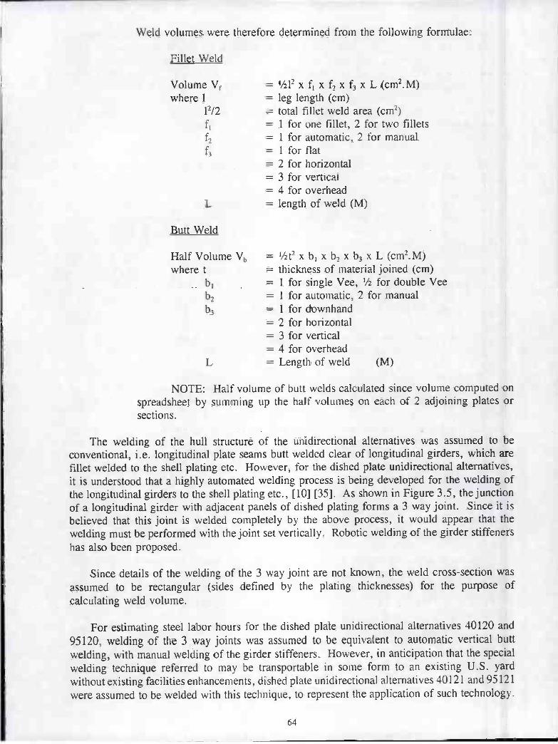
Weld volumes were therefore determined from the following formulae:
Fillet Weld
Volume Vf = ½12 x f1 x f2 x f3 x L (cm2.M)where 1 = leg length (cm)
12/2 = total fillet weld area (cm2)f1 = 1 for one fillet, 2 for two filletsf2 = i for automatic, 2 for manualf3 = i for flat
= 2 for horizontal= 3 for vertical= 4 for overhead
L length of weld (M)
Butt Weld
Half Volume Vb = '/2t2 x b1 x b, x b3 x L (cm2.M)where t = thickness of material joined (cm)
b1 = 1 for single Vee, ½ for double Veeb, = i for automatic, 2 for manualb3 = 1 for downhand
= 2 for horizontal= 3 for vertical= 4 for overhead
L = Length of weld (M)
NOTE: Half volume of butt welds calculated since volume computed onspreadsheet by summing up the half volumes on each of 2 adjoining plates orsections.
The welding of the hull structure of the unidirectional alternatives was assumed to beconventional, i.e. longitudinal plate seams butt welded clear of longitudinal girders, which arefillet welded to the shell plating etc. However, for the dished plate unidirectional alternatives,it is understood that a highly automated welding process is being developed for the welding ofthe longitudinal girders to the shell plating etc., [10] [35]. As shown in Figure 3.5, the junctionof a longitudinal girder with adjacent panels of dished plating forms a 3 way joint. Since it isbelieved that this joint is welded completely by the above process, it would appear that thewelding must be performed with the joint set vertically. Robotic welding of the girder stiffenershas also been proposed.
Since details of the welding of the 3 way joint are not known, the weld cross-section wasassumed to be rectangular (sides defined by the plating thicknesses) for the purpose ofcalculating weld volume.
For estimating steel labor hours for the dished plate unidirectional alternatives 40120 and95120, welding of the 3 way joints was assumed to be equivalent to automatic vertical buttwelding, with manual welding of the girder stiffeners. However, in anticipation that the specialwelding technique referred to may be transportable in sorne form to an existing U.S. yardwithout existing facilities enhancements, dished plate unidirectional alternatives 40121 and 95121were assumed to be welded with this technique, to represent the application of such technology.
64

r
The labor hours for the vertical 3 way joints were then assumed identical to those for the fastestconventional welding, i.e. automatic downhand welding. Automatic welding of the girderstiffeners was also assumed, so as to mimic the proposed robotic welding. It should be notedthat the 3-way joints could also appear in the smooth plate unidirectional alternatives, and theirapplication in 40121 and 95121 should be indicative of the benefit in both types of alternatives.
6.3 RESULTS
Although the data listed was calculated for each alternative, only summaries by block forthe remainder of the alternatives of each ship size are presented in the Appendix on pages A61through A72, since full data sets for each alternative would require too voluminous a document.Summaries of the number of pieces, areas, weights, weld lengths and weld volumes for the 40Kand 95K alternatives are also presented in the Appendix on pages A73 through A84. Graphs ofareas, weights, weld lengths and weld volumes are presented in the Appendix on page Al 17through Al22. Graphs of lengths for flame cutting, edge preparation and different types ofwelds are presented on pages Al26 and Al27.
The original numbering system adopted for the structural blocks is utilized for the 95KDWTalternatives, but the block numbers were later changed to reflect numerically the erectionsequence anticipated for both sizes of vessel. The revised numbers were then utilized for the4OKDWT alternatives. It may be noted that the block breakdown is the same for both sizes ofvessels. A discussion of block breakdown is provided in Section 4.2, item 15 and Figures 5.9and 5.10 show the block breakdown and block numbers for the 40K and 95KDWT alternativesrespectively.
Although it was originally intended to use the length of welded joints as a measure of steellabor hours, weld volume was later considered to be a more realistic measure. However, itwas later decided to use References [36] and [37] for the estimation of steel labor hours, whichrequire weld length and steel thickness in lieu of weld volume.
65

7.0 TASK VI- LABOR HOURS AND SCHEDULES
7.1 OBJECTIVE
The objective of this task is to estimate the labor hours and schedules required to producethe alternative structural system concepts for each of the 40K and 95KDWT double hull tankerdesigns. The principal characteristics of interest are the labor hours and schedules to producethe vessels.
7.2 APPROACH
As indicated in Section 6.3, it was decided to estimate steel labor hours by adopting andmodifying a method proposed in References [36] and [37]. Initially, the intent was to utilize therelative producibility procedure of Reference [36], based on the Analytic Hierarchy Process(AHP). However, further study indicated that with some modifications, the labor hour approachof this reference would be more suitable for the study of the alternatives. Full details of themethod to determine labor hours and schedules are given in Sections 7.3 thru 7.5.
In order to establish a baseline for studying of the alternatives, it was first necessary toestablish more accurate estimates of the labor hours and schedules for the construction of thebaseline vessels in a typical U.S. shipyard.
U.S. shipbuilding's introduction of automation and accuracy control has been advancingbut is acknowledged as being behind that abroad. As a result, both were taken as one-half ofthe 32% presented in Table 54 for a Far Eastern automated yard's advantage over a traditionalyard in 1985. One half of the 15% improvement in overall production by implementation ofstrict dimensional controls and statistical accuracy, as discussed in Section 5.3.3 for Far Easternyards. Then the U.S. yards can be expected to achieve the labor hours and schedules ofconstruction for the base alternative vessels shown in Table 7. 1 and 7.2 respectively.
The schedules in Table 7.2, also shown in Figure 7.1, are from contract signing todelivery, and have been developed to incorporate about 12 months from the start of fabricationto launch, since this was required in 1983 for the last series of tankers to be constructed in theU.S. - see Figure 5.4. These schedules have some potential slack at the beginning and end(particularly from trials to delivery), allowing for meeting contractual dates. It may be notedthat the design labor hours were based on the anticipated performance of U.S. shipyards. lt maybe further noted that according to the data provided by Reference [19], there is almost nodifference between the 40K and 95KDWT Far East baseline building schedules. Therefore nodifference is shown in Table 7.2.
66
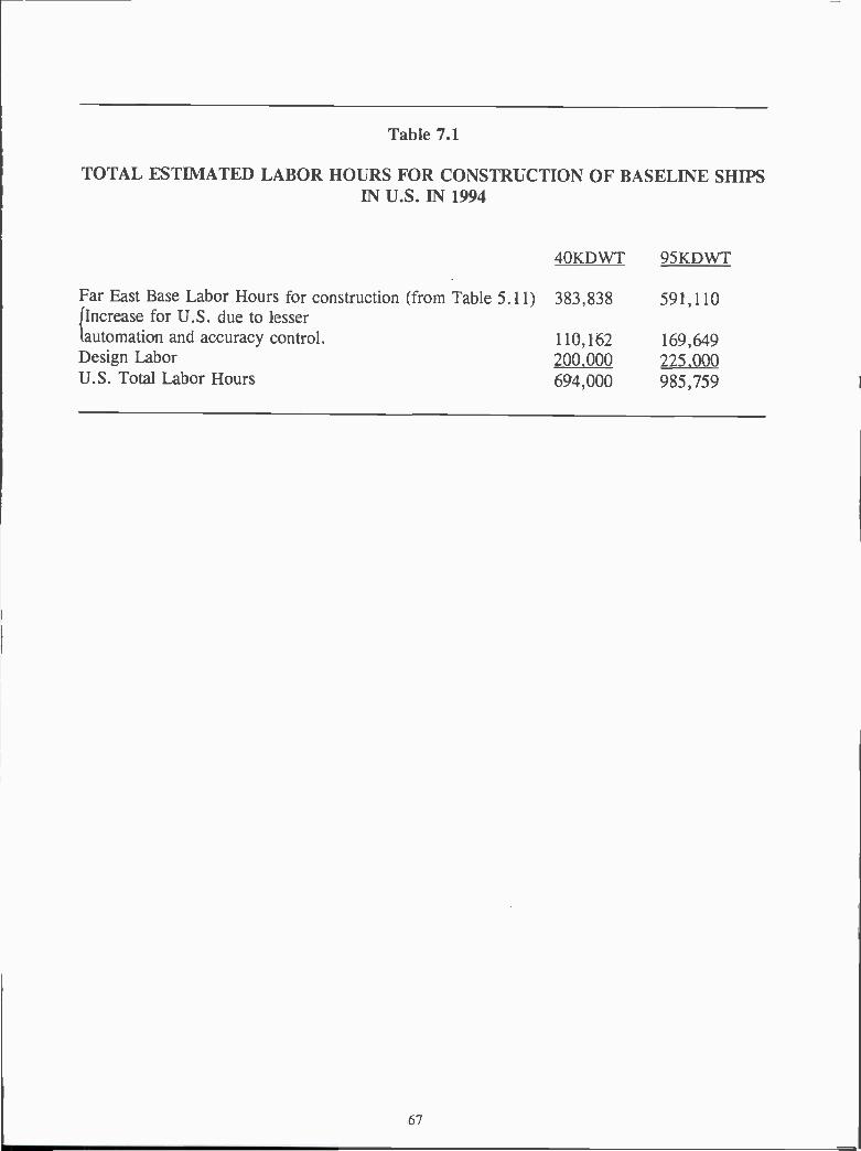
Table 7.1
TOTAL ESTIMATED LABOR HOURS FOR CONSTRUCTION OF BASELINE SHIPSIN U.S. IN 1994
Far East Base Labor Hours for construction (from Table 5.¡Increase for U.S. due to lesserautomation and accuracy control.Design LaborU.S. Total Labor Hours
11)
4OKDWT 95KDWT
383,838
110,162200,000
591,110
169,649225,000
694,000 985,759

U.S
BA
SE
LIN
EA
LTE
RN
AT
IVE
CO
NT
RA
CT
AW
AR
D
9 M
ON
TH
S
14 M
ON
TH
SD
ES
IGN
k38
M3.
2 M
A S
SE
M B
LY 4.3M
ER
EC
TIO
N 2.6
M2.
24 M
PA
INT
ING
29.1
MO
NT
HS
TO
TA
L
ST
AR
T O
F F
AB
RIC
AT
ION
7.6
M
KE
EL
LAID
48 M
LAU
NC
HIN
G
SE
A T
RIA
LS
4.2
M
FIG
. 7.1
- 1
994
U.S
. BA
SE
TIM
E L
INE
SC
HE
DU
LE
3.5
MD
ELI
VE
RY

Table 7.2
ESTIMATED SCHEDULE FOR CONSTRUCTION OFBASELINE SHIPS IN U.S. IN 1994.
4OKDWT 95KDWT
Far East Baseline Schedule, including design (from Figure 5.5) 20.5 months 20.5 monthsIncrease for U.S. due to lesser automationand accuracy control, applied from 2.6 2.6fabrication to sea trials.
Additional Design Period 6.0 6.0
U.S. Schedule for Construction 29.1 months 29.1 months
7.3 LABOR HOURS FOR STEELWORK
The following notes provide the assumptions, approaches and details of the method used toestimate tlìe steel labor hours required for the construction of the various one tank lengthalternatives.
a) In order to estimate the steel labor hours required to construct one midship cargo tanksection for the various structural alternatives, the steel labor hours required to construct thecomplete 40K and 95KDWT base vessels were first obtained from the total labor hours(excluding design labor) given in Table 7.1. For this purpose, the average percentagebreakdown of steel versus outfitting hours given in Table 5.6 for the construction of vessels inJapan was used, i.e. 59% for steel construction and 41% for outfitting.
Then total steel labor hours to construct 40K and 95KDWT base vessels are 291,460 and448,848 respectively.
An estimate of the steel labor hours to construct one cargo tank section for the basevessels was then obtained from a consideration of the relative lengths of the separate parts of thevessels (i.e. 7 cargo tanks + bow + stern + superstructure), the structural contents of each partand the relative complexity (e.g. curved shell plating) of the structure. Approximately 10% ofthe total steel hours was required, but this was later refined to 9.53% and 10.42% for the 40Kand 95KDWT vessels respectively in the following manner:
The 40K and 95KDWT vessels each have 7 cargo tank sections, with constant lengthsof 17.9m and 25.06m respectively. Steel labor hours for Nl & 2 cargo tank sections wereestimated to be 85% and 95% respectively of those for the midship cargo tank section. Steellabor hours for the remaining five tank sections were all assumed to be the same as for themidship tank section. Steel labor hours for the remaining bow and stern portions of the vesselswere assumed initially to vary with those for the midship tank in proportion to length, and werethen corrected for volume and structural contents by applying an estimated correction factor of0.7. Estimated structural complexity factors of 1.5 and 1.3 for bow and stern respectively werethen applied to allow for more difficult construction. Steel labor hours for the deckhouse andstack were similarly assumed to vary with length, followed by the application of an estimated
69

single correction factor of 0.5. Lengths of the bow, stern and deckhouse for the 40K and95KDWT vessels were taken to be l0.5m/10.66m for the bow, 47.2m/47.92m for the stern and24/30.7m for the deckhouse.
Based on these assumptions, it can be shown that the total steel labor hours to constructthe 40K and 95KDWT base vessels are equivalent to the hours required to construct 10.49 or9.60 midship tanks respectively. Then the steel labor hours to construct one midship tanksection for the 40K and 95K base vessels can be obtained by multiplying the total steel hoursby 1/10.49 (i.e. 9.53%) or 1/9.60 (i.e. 10.42%) respectively. Thus the required labor hoursare 27,785 or 46,755.
b) In order to study the various structural one tank length alternatives, a method ofestimating the steel labor hours for each, as compared with the two base designs, was nowrequired. As indicated in Section 7.2, it was therefore decided to utilize the method providedin References [36] and [37] to obtain the man hours to construct the various one tank lengthalternatives.
This method identifies all of the work processes used to manufacture a steel product (e.g.flame cutting, welding, etc.) and assigns appropriate work units such as linear feet or square feetto each. The individual work units are then multiplied by an appropriate process factor (laborhours/work unit) to obtain the labor hours for each process.
Each work process is performed in or at a particular work site or construction stage (e.g.fabrication shop or erection site) and for each of these, difficulty factors have been assigned toaccount for the progressive increase in the difficulty of manufacturing a product under varyingconditions. The stages utilized and their associated difficulty factors are shown in Table 7.3.
Table 7.3: Construction Stages and Difficulty Factors, [36]
To account for the impact of construction stages on steel labor hours, the typical stagefor each process is identified as standard. If a process is performed in a later stage, the laborhours obtained as above are increased in the ratio of actual to standard difficulty factor. Valuesof this ratio less than 1.0 are not permitted by the program.
When the labor hours for each work process have been obtained, they are summed toprovide the total steel trade labor hours. This total is then increased by an appropriatepercentage to account for steel trade support labor hours.
70
DifficultyStage Location Factor
1. Fabrication In Shop 1.02. Pre-Paint Outfitting On Platten - Hot work 1.53. Painting Paint Ship/Stage 2.04. Post-Paint Outfitting On Platten - Cold Work 3.05. Erection Erection Site 4.56. Outfitting Erection Site 7.07. Waterborne Pierside after Launch 10.08. Tests arid Trials Pierside & Underway 15.0

The calculations are performed on spreadsheets, and a typical example from Reference[36] is shown in Table 7.4. The spreadsheet input files provided with the above references arecontained on computer disks for Lotus.
Further to the process factors, many of these vary with material thickness and appropriatefactors are automatically selected from 'look-up' tables within the program spreadsheet whenthe thickness is inputted. The steel thickness used for each alternative in this evaluationprocedure was the average thickness, derived from the weight of the tank section and the surfacearea of the steel components. The programmed process factors are given in Table 7.5 for arange of thickness from 0.25 inch to 2.00 inches. The factors for shaping steel are standardexcept for bending, rolling and pressing. These have basic values of 0.40, 1.00 and 0.02respectively, which are multiplied by appropriate thickness factors to obtain the required processfactors. Other factors not listed in Table 7.5 have the standard values shown in Table 7.4.
c) For the application of this procedure to the structural alternatives, surface preparation,coating and testing were removed from the list of work processes, since they were consideredto be part of machinery/outfitting for the purposes of this report.
However, "rework" was included as an additional factor. Furthermore, the processfactors needed adjustment to correlate with commercial construction, since the factors inReference [35] were based ori Philadelphia Naval Shipyard repair information. This may beillustrated by the application of the described procedure to the 40K and 95KDWT baselinevessels, using the programmed process factors with no modification and with no reworkincluded. This resulted in steel labor hours exceeding those estimated in paragraph (a) by62.70% and 47.28% for the 40K and 95KDWT vessels respectively. As indicated in Table 7.1,
the estimates of labor hours required to construct the 40K and 95KDWT base vessels assumethat U.S. yards have instituted one half of the effort expended by the Japanese on accuracycontrol. However, some rework will still be required. as it is in Japan, and for the purposesof evaluation of the structural alternatives, this has been assumed to require 10% of the laborhours expended on flame cutting, edge preparation, fit up/assembly and welding. Finally, theprocess factor of 0. 10 hours/sq. ft. for obtaining material/receipt etc. was considered to be toohigh and was reduced to 0.01 hours/sq.ft.
71

Table 7.4NSRP PANEL SP-4
72
FILE: STRCTMS COST ESTIMATING FORM FOR STRUCTURAL WORK
PROJECT: 'TITLE MATERIAL: MS-STSFILE. XYZ123.WK1 THICKNESS 0.57 INCHES
WORK PROCESS WORK PROCESS UNIT ACTUAL STANDARD ACTUAL STANDARDUNITS FACTOR AMOUNT STAGE STAGE FACTOR FACTOR
(M NH RS!WORK UNIT)
MNHRSREDO
i OBTAIN MATERIAL SOFT 0.100 0 1 1 10 1.0 0RECEIPT & PREP
2 FLAME CUTTINGAUTOMATIC LN FT 0.050 0 1 1 1 0 1.0 0MANUAL LNFT 0.090 0 2 2 1.5 1.5 0
3 EDGE PREP-GRINDINGFLAT LN FT 0.040 0 1 2 1.0 1.5 0VERTICAL LN FT 0.060 0 2 2 1.5 1.5 0
OVERHEAD LN FT 0.080 0 2 2 1.5 1.5 0
4 SHAPINGBREAK BEND 0.480 0 1 1 1.0 1.0 0ROLLING PIECE 1.200 0 1 1 1.0 1.0 0LINEHEATING PIECE 10.000 0 1 1 1.0 1.0 0FURNACE PIECE 15.000 0 1 1 1.0 1.0 0PRESS PIECE 0.024 0 1 1 1 0 1.0 0MACHINING CU IN 0.020 0 1 1 1.0 1.0 0
5 FIT UP & ASSEMBLY JOINT 0.560 0 2 2 1.5 1.5 0
6 WELDING, AUTO/MACHINEFILLET LNFT 0.065 0 2 2 1.5 1.5 0BUTT LN FT 0.48 0 2 2 1.5 1.5 0
7 WELDING, MANUALFILLETDOWNHAND LN FT 0.340 0 2 2 1.5 1.5 0VERT1CAL LN FT 0.510 0 2 2 1.5 1.5 0OVERHEAD LNFT 0.680 0 2 2 1.5 1.5 0
BUTTDOWNHAND LNFT 1.300 0 2 2 1.5 1.5 0VERTICAL LN FT 1.950 0 2 2 1.5 1.5 0OVERHEAD LNFT 2.600 0 2 2 1.5 1.5 0
8 MARKING PIECE 0.100 0 1 1 l.0 1.0 0
9 HANDLINGSTORAGE PIECE 0,100 0 2 2 1.5 1.5 0
TRANSPORTING ASSY 5.000 0 3 3 2.0 2.0 0
LiFTING ASSY 5.000 0 4 4 3.0 3.0 0
10 SURFACE PREPBLASTING SQ FT 0.100 0 3 3 2.0 2.0 0
GRINDING FOOT 0.200 0 3 3 2.0 2.0 0
11 COATING SOFT 0.100 0 3 3 2.0 2.0 0
12 TESTINGDYE PENETRANT FOOT 0.250 0 2 2 1.5 1.5 0AUDIOGAGE FOOT 0.500 0 2 2 1.5 1.5 0
XRAY FOOT 0.500 0 2 2 1.5 1.5 0
TOTAL TRADE MANHOURS 0
TRADE SUPPORT MANHOURS (35% OF TRADE MANHOURS) 0
TOTAL PRODUCTION MANHOURS o
LABOR COST (MANHOURS X MNHR COST) $20.00 $0
MATERIAL COST (FROM MATERIAL SCHEDULE) $0
TOTAL COST

NS
RP
PA
NE
L S
P-4
FIL
E:
ST
RC
TM
S
TH
ICK
NE
SS
(IN
CH
ES
)
0.25
00.
375
0.50
00.
750
1.00
01
.250
1.50
02.
000
FLA
M E
CU
T11
NG
AU
TO
0.05
0.05
0.05
0.07
0.07
0.08 0.1
0.12
2F
LAM
EC
UT
TIN
GM
AN
UA
L0.
090.
090.
090,
120.
160.
170.
180.
23
12
TH
ICK
NE
SS
(IN
CH
ES
)F
ILLE
TD
OW
NV
ER
T
0.25
00.
120.
240.
375
0.23
0.38
0.50
00.
340.
51
0.75
00.
61.
21.
000
12.
131.
250
1.2
2.1
1 .5
001
.44
2.2
2.00
01.
732.
64
3
ED
GE
PR
EP
GR
IND
IN G
FLA
T0.
020.
030.
040.
060.
080.
120.
170.
17
4E
DG
E P
RE
PG
RIN
DIN
GV
ER
TIC
AL
0.04
0.05
0.06
0.12
0.17
0.21
0.26
0.26
34
WE
LDIN
G -
MA
NU
AL
OV
HD
0.36
0.54
0.68 1 .7
3.25
3.00
2.88
3.46
Tab
le 7
.5
PR
OC
ES
S F
AC
TO
RS
DO
WN
0.62
1.00
1 .3
01
.80
2.40
3.20
3.80
5.10
5E
DG
E P
RE
PG
RIN
DIN
GO
VE
RH
EA
D0.
060.
070.
080.
170.
260.
300.
340.
34
5
BU
TT
VE
RT
1 .2
41.
671
.95
3.6
5.1
5.6
5.81 7.
8
6A
SS
EM
BLY
0.56
0.04
0.56
0.05
0.56
0.07
0.56
0.08
0.56
0.09
0.56
0.11
0.56
0.13
0.56
0.167
MA
CH
IN E
FIL
LET
67
TH
ICK
NE
SS
OV
HD
FA
CT
OR
1.86
1.00
2.33
1.20
2.6
1.20
5.1
1.20
7.8
1.20
81
.20
7.6
1.20
10.2
1.20

When the remaining programmed process factors were applied to the 40K and 95KDWTbase designs for one tank length, the resultant steel labor hours were found to be higher than theestimates given in paragraph (g). The excess amounted to 40.23% for 40K and 23.58% for95KDWT designs, with an average of 3 1.90%.
It would appear justifiable therefore, to reduce some of the process factors to enable thelabor hour estimates of paragraph (a) for the two base designs to be correlated. It would appear,in particular, that process factors for work processes 2,3,5,6 and 7 in Table 7.4 should bereduced. Since it was desirable to use identical process factors for both ship sizes, varying onlywith material thickness, it was decided to reduce programmed factors by 20.75%. The standard35% used on the spreadsheet (Table 7.4) for trade support hours was also reduced by the samepercentage, i.e. to 28%. This procedure provided steel labor hours for the midship cargo tanksof the 40K and 95KDWT base designs that differed from those given in paragraph (a) of thisSection by about ±6%, which was considered satisfactory. The amended labor hours for themidship tanks then became 29,578 and 43,872 respectively. The steel labor hours for allalternatives were therefore computed on this basis. The corresponding modified spreadsheetsare shown in Tables 7.6 and 7.7.
Further to the application of the estimating procedure of References [36] and [37], thefollowing assumptions were made to suit the format of the procedure shown in Tables 7.6 and7.7:
O Manual flame cutting assumed employed on 5% of total plate edge length.O Edge preparation and grinding employed only in way of manual flame cutting.O On data sets and block summaries in the Appendix, welding has been delineated as
automatic or manual, welded joints as butts or fillets and welding positions as flat (i.e.downhand), horizontal, vertical or overhead. To suit the estimating spreadsheet, weldinglengths were then regrouped into automatic butt or fillet welds - or manual butt or filletwelds in downhand, vertical or overhead positions.
O Although metric units have been used throughout this report, British units were used inthe estimating procedure since these units were used in References [36] and [37].
The completed spreadsheets for the estimation of the steel labor hours for the one tanklength structural alternatives are given in the Appendix on pages A87 through A1l5 for both the40 and 95KDWT designs. The results are also shown graphically in Figures 7.2 and 7.3 for the40K and 95KDWT designs respectively, and in the Appendix on page Al24. Figures 7.2 and7.3 include a breakdown of the labor hours required separately for obtaining material/flamecutting etc. (work processes N2 i thru 4), fit up and assembly (work process N9 5), automaticwelding (work process N2 6), manual welding (work process N2 7), marking and handling etc.(work processes N28 and 9) and rework (work process N2 10).
Further to the calibration of the steel labor hours to suit the estimating proceduredescribed in paragraph (d), it was considered desirable to validate this further by applying thesame procedure to the estimated steel labor hours for the construction of the 40K and 95KDWTvessels in the Far East in 1994.

Table 7.6NSRP PANEL SP-4
75
FILE; STRCThIS Revised LABOR HOUR ESTiMATING FORM FOR STRUCTURAL WORK4OKDWT BASE ALTERNATiVE
PROJECT: Entire Tank Section MATERIAL: MS-STSFILE: 4010 THICKNESS 0.57 INCHES
WORK PROCESS WORK PROCESS UNIT ACTUAL STANDARD ACTUAL STANDARDUNITS FACTOR AMOUNT STAGE STAGE FACTOR FACTOR
(MNHRS/WORK UNIT)
MNHRSREQD
I OBTAIN MATERIAL SOFT 0,010 79149 1 1 1.0 1.0 791RECEIPT& PREP
2 FLAME CUTtINGAUTOMATIC LN FT 0,040 47582 1 1 1.0 1.0 1885MANUAL LN FT 0.071 2504 2 2 1.5 1.5 179
3 EDGE PREP-GRINDINGFLAT LN FT 0.032 1990 1 2 1.0 1.5 63VERTICAL LN FT 0.048 407 2 2 1.5 1.5 19OVERHEAD LN FT 0.063 108 2 2 1.5 1.5 7
4 SHAPINGBREAK BEND 0.380 0 1 1 1.0 1.0 0ROLLING PIECE 0.951 4 1 1 1.0 1.0 4UNEHEATING PIECE 10.000 0 1 1 1.0 1.0 0FURNACE PIECE 15.000 0 1 1 1.0 1.0 0PRESS PIECE 0.019 0 1 1 1.0 1.0 0MACHINING CUIN 0.020 0 1 1 1.0 1.0 0
5 FITUP&ASSEMBLY JOINT 0.444 6568 2 2 1.5 1.5 2915
6 WELDING, AUTO/MACHINEFILLET LN FT 0.052 49968 2 2 1 .5 1 .5 2574BUTT LN FT 0.3804 3530 2 2 1.5 1.5 1343
7 WELDING,MANUALFI LLETDOWNHAND W FT 0.269 22352 2 2 1.5 1.5 6023VERTICAL L.N FT 0.404 4571 2 2 1.5 1.5 1847OVERHEAD LNFT 0.539 1213 2 2 1.5 1.5 653
BUTTDOWNHAND LNFT 1.030 1579 2 2 1.5 1.5 1627VERTICAL LN FT 1.545 323 2 2 1 .5 1 .5 499OVERHEAD LNFT 2.061 66 2 2 1.5 1.5 177
8 MARKING PIECE 0.100 1642 1 1 1.0 1.0 164
9 HANDUNGSTORAGE PIECE 0.100 1642 2 2 1.5 1.5 164TRANSPORTING ASSY 5.000 24 3 3 2.0 2.0 120UFT1NG ASSY 5.000 24 4 4 3.0 3.0 120
10 REWORK JOINT 1.000 660 5 2 4.5 1.5 1981
TOTAL TRADE LABORHOURS 23156TRADE SUPPORT LABORHOURS (28% OF TRADE LABORHOURS) 6423
TOTAL PRODUCTION LABORHOURS 29578

NSRP PANEL SP -4
76
FILE: STRCTMS Revised LABOR HOUR ESTiMATING FORM FOR STRUCTURAL WORK95KDWT BASE ALTERNATiVE
PROJECT: Entire Tank Section MATERIAL: MS-STSFILE 9510 THICKNESS 0.6 INCHES
WORK PROCESS PROCESS UNIT ACTUAL STANDARD ACTUAL STANDARDUNITS FACTOR AMOUNT STAGE STAGE FACTOR FACTCR
(MN H RS!WORK UNIT)
MNHRSREQD
OBTAIN MATERIAL SQ FT 0010 132358 1 1 1.0 1 0 1324RECEIPT& PREP
2 FLAME CUflNGAUTOMAflC LN FT 0.040 75044 1 1 1.0 1 0 2974MANUAL LN FT 0.071 3950 2 2 1.5 1 5 282
3 EDGE PREP-GRINDINGFLAT LN FT 0.032 3157 1 2 1.0 1 s' looVERfl CAL LN FT 0.048 674 2 2 1.5 1 5 32OVERHEAD LN FT 0.063 119 2 2 1.5 1.5 8
4 SHAPINGBREAK BEND 0.380 0 1 1 1.0 10 0
ROLLI NG PIECE 0.951 4 1 1 1.0 10 4
LINE HEATiNG PIECE 10.000 0 1 1 1.0 10 0
FURNACE PIECE 15.000 0 1 1 1.0 10 0
PRESS PIECE 0.019 0 1 1 1.0 10 0
MACHINING CU IN 0.020 0 1 1 10 10 0
5 FIT UP & ASSEMBLY JOINT 0.444 9828 2 2 1.5 1 5 4362
6 WELDING, AUTO/MACHINEFILLET LN FT 0.052 82561 2 2 1.5 1.5 4253
BUTT LN FT 0.3804 6294 2 2 1.5 1.5 2394
7 WELDING, MANUALFILLETDOWNHAND LN FT 0.269 30775 2 2 1.5 1.5 8292
VERTiCAL LN FT 0.404 6568 2 2 1.5 1.5 2664
OVERHEAD LN FT 0.539 1164 2 2 1.5 1.5 627
BUTTDOWNHAND LN FT 1.030 2346 2 2 1.5 1.3 2417
VERTiCAL LN FT 1.545 501 2 2 1.5 1.5 774
OVERHEAD LN FT 2.061 89 2 2 1.5 1.5 183
8 MARKING PIECE 0.100 2457 1 1 1.0 1,0 246
9 HANDLINGSTORAGE PIECE 0.100 2457 2 2 1.5 1.5 246
TRANSPORTiNG ASSY 5.000 24 3 3 2.0 2.0 120
LI Fn NG ASSY 5.000 24 4 4 3.0 3.0 120
10 REWORK JOINT 1.000 978 5 2 4.5 1.5 2935
TOTAL TRADE LABORHÖURS 34346346
TRADE SUPPORT LABORHOURS (28% OF TRADE LABORHOURS) 95279527
TOTAL PROD UC11ON LABORHOURS 4387243872

FIG
UR
E 7
.2
BR
EA
K D
OW
N O
F S
TE
EL
LAB
OR
HR
. ES
TIM
AT
ES
4OK
DW
T A
LTE
RN
AT
IVE
S U
.S. 1
994
ON
E T
AN
K
4010
4030
4050
4070
4090
401
10 4
0111
401
21 4
0140
4020
4040
4060
4060
401
00 4
0111
401
20 4
0130
401
50
Alte
rnat
ive
Key
Num
ber
Wor
k P
roce
sses
1 4
Wor
k pr
oces
s 5
Wor
k pr
oces
s 6
Wor
k pr
oces
s 7
i 8&
9 an
d tr
ade
L H
Wor
k pr
oces
s 10
60 50 40
U)
30oc
U)
O20
-Jlo o

o
Wor
k pr
oces
ses
1 4
FIG
UR
E 7
.3
BR
EA
K D
OW
N O
F S
TE
EL
LAB
OR
HR
. ES
TIM
AT
ES
95K
DW
T A
LTE
RN
AT
IVE
S U
.S. 1
994
ON
E T
AN
K
- -
- 'LlI
LI
i uI
II
i
9510
9530
9550
9570
9510
095
111
I 951
2095
2095
4095
6095
8095
110
9511
195
121
Alte
rnat
ive
Key
Num
ber
Wor
k pr
oces
s 5
8,9
& T
rade
L.H
.
Wor
k pr
oces
s 6
Wor
k pr
oces
s 10
Wor
k pr
oces
s 7
70 60 50 40U
)U
)-o
o I U)
30
oo
-o-c
20-J
F-
10

As shown in Table 5. 10, the estimated steel labor hours for these vessels were 226,464and 348,755 respectively, based on increased use of automation and accuracy control. Theabove procedure was therefore applied to the estimated steel labor hours for the midship cargotanks, obtained as described in paragraph (a), assuming transverse erection butts to be weldedautomatically instead of manually (in order to give some credit for the increased automation),and using 2'/2% rework instead of the previously assumed 10%. This resulted in an averageexcess of labor hours of 43.59%. The reduction of the same process factors as before by26.50% then gave steel labor hours for the midship tanks which again differed by about ±6%from the initial estimates, which was again considered satisfactory. This result provided furthervalidation of the calibration procedure and also gave some credence to the estimated labor hoursfor construction in the Far East in 1994. The latter estimates, of course, provided the basis forthe later estimates for construction in the U.S.
These steel labor hours were then extended to the complete ships, using the proceduregiven in paragraph (a). The corresponding total labor hours for the vessels were then obtainedby adding in the machinery/outfit labor hours from Table 5.11 and the 50,000 hours for designfrom Table 5.9. The resulting labor hours for the construction of the 40K and 95KDWT vesselsin the Far East in 1994 were 447,480 and 622,057 respectively. For comparison, these resultsare included in Figures 7.4 and 7.5, and also in the plot of total labor hours given in theAppendix on page Al25.
An important result of this analysis is that it highlights the main causes of reduced laborhours in the Far East as being the greater use of automation and accuracy control, together withreduced hours for design.
7.4 LABOR HOURS FOR CONSTRUCTION OF COMPLETE VESSELS
As indicated in Section 7.3, paragraph (a), the steel labor hours for the construction of themidships one tank length alternatives were estimated to be 1/10.49 and 1/9.60 of the total steellabor hours for the 40K and 95Kdwt designs respectively. Therefore, the total steel labor hoursfor the construction of a complete vessel could be obtained by multiplying the labor hours forone midships tank length by the appropriate factor 10.49 or 9.60.
However, to allow for the transition of cargo tank structure into the bow and stern portionsof the vessels, it was decided to maintain the steel labor hours for the construction of N21 cargotank section, the bow and the stern constant for the two sets of vessel sizes and equal to thehours determined for the 40K and 95KDWT base alternatives in these areas. The steel laborhours for the deckhouses were similarly held constant. Thus, from the information derived inSection 7.3, paragraph (a), the constant portion of the steel labor hours for the 4OKDWTalternatives was obtained from
(10.49 - 5.95) 29,578 = 134,284 hours.where 10.49 expresses the ratio of the total steel labor hours for the vessel to those required forthe midship cargo tank section and 5.95 expresses a similar ratio for the steel labor hours forN22 thru N7 cargo tank sections. The corresponding figure for the 95KDWT alternative wasobtained from
(9.60- 5.95) 43,872 = 160,133 hours.
Thus, only the steel labor hours for the construction of N22 thru N7 cargo tank sectionswere varied to suit the structural alternatives. These hours were obtained by multiplying thederived labor hours for the construction of the midship tank section for the various alternatives
79

by 5.95. The total steel labor hours were then obtained by adding the appropriate constant laborhours given above.
As further indicated in Section 7.3, paragraph (a), the machinery/outfitting labor hoursrequired to construct the complete 40K and 95KDWT base vessels were taken to be 41% of thetotal labor hours (excluding design labor) given in Table 7.1.
Then machinery/outfitting labor hours for the complete 40K and 95KDWT base vesselsare 202,540 and 311,911 respectively. All such labor hours were assumed constant for allalternatives with the exception of the labor hours required for painting.
Table 5.8 gives a percentage breakdown of the labor hours required for machinery!outfitting, and indicates that the labor hours required by the Japanese for painting were 31% ofthe total machinery/outfitting hours for 4OKDWT vessels and 34% for 95 KDWT vessels. Thesepercentages were applied to the two base vessels, and for the remaining alternatives, the laborhours for painting were varied in proportion to the surface area of the steel components.
Thus, the constant portions of the machinery/outfitting labor hours for all alternatives are139,753 for the 40KDWT vessels and 205,861 for the 95KDWT vessels. The totalmachinery/outfitting labor hours were obtained by adding the appropriate painting hours for thevarious alternatives to these figures.
Design labor hours for the 40K and 95KDWT alternatives were estimated at 200,000 and225,000 hours respectively, as indicated in Section 7.2, except for alternative 40150 providingfor enhanced standardization where significant detail design data or working drawings are onfile, for which they were reduced to 100,000.
The total labor hours for the various alternatives were then obtained by summing up thehours for steel construction, the constant hours for machinery/outfitting, the hours for paintingand the hours for design. For the baseline vessels, the resulting total labor hours for theconstruction of the 40K and 95KDWT alternatives in the U.S. in 1994 were 712,813 and958,082 respectively. The results of all calculations are shown graphically in Figures 7.4 and7.5 respectively, and also in the Appendix on page Al24.
7.5 CONSTRUCTION SCHEDULES
As indicated in Section 7.2, Figure 7. 1 and Table 7.2 provide the estimated constructionschedules in a U.S. shipyard for the 40K and 95KDWT baseline vessels. These schedules area modified version of those provided by Reference [19J for similar vessels building in the FarEast As indicated in Section 7.2, this reference shows almost no difference in schedules forthe 40K or 95KDWT vessels, and this is reflected in Table 7.2. The Far East schedule wasmodified to reflect predicted U.S. attainment in 1994 as follows:
80
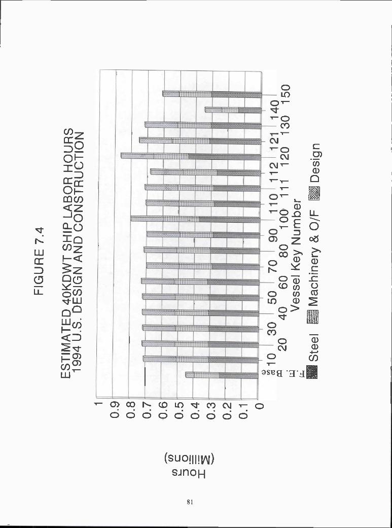
i0.
90.
80.
70.
60.
50.
40.
30.
20.
1 O
FIG
UR
E 7
.4
ES
TIM
AT
ED
4O
KD
WT
SH
IP L
AB
OR
HO
UR
S19
94 U
.S. D
ES
IGN
AN
DC
ON
ST
RU
CT
ION
i
r-
ri
jJ
1030
5070
9011
0 11
212
114
020
4060
8010
0 11
112
0 13
0 15
0V
esse
l Key
Num
ber
i Ste
elM
achi
nery
& 0
/FD
esig
n

FIG
UR
E 7
.5
1.2
1 .1 i
0.9
0.8
0.7
0.6
0.5
0.4
0.3
0.2
0.1 O
ES
TIM
AT
ED
95K
DW
T S
HIP
LA
BO
RH
OU
RS
1994
U.S
. DE
SIG
N A
ND
CO
NS
TR
UC
TIO
N
1030
5070
9011
011
212
120
4060
8010
011
112
0V
esse
l Key
Num
ber
Ste
elO
utfit
ting
r-D
esig
n
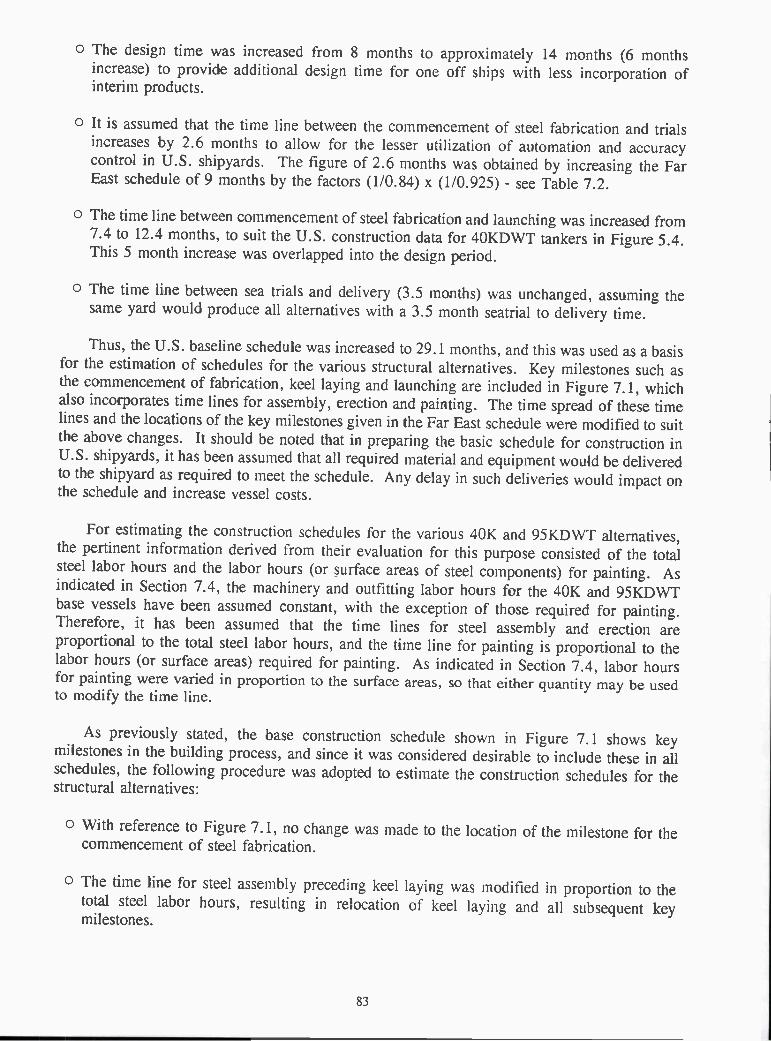
o The design time was increased from 8 months to approximately 14 months (6 monthsincrease) to provide additional design time for one off ships with less incorporation ofinterim products.
O It is assumed that the time line between the commencement of steel fabrication and trialsincreases by 2.6 months to allow for the lesser utilization of automation and accuracycontrol in U.S. shipyards. The figure of 2.6 months was obtained by increasing the FarEast schedule of 9 months by the factors (1/0.84) x (1/0.925) - see Table 7.2.
O The time line between commencement of steel fabrication and launching was increased from7.4 to 12.4 months, to suit the U.S. construction data for 4OKDWT tankers in Figure 5.4.This 5 month increase was overlapped into the design period.
O The time line between sea trials and delivery (3.5 months) was unchanged, assuming thesame yard would produce all alternatives with a 3.5 month seatrial to delivery time.
Thus, the U.S. baseline schedule was increased to 29.1 months, and this was used as a basisfor the estimation of schedules for the various structural alternatives. Key milestones such asthe commencement of fabrication, keel laying and launching are included in Figure 7. 1, whichalso incorporates time lines for assembly, erection and painting. The time spread of these timelines and the locations of the key milestones given in the Far East schedule were iìodified to suitthe above changes. It should be noted that in preparing the basic schedule for construction inU.S. shipyards, it has been assumed that all required iìiaterial and equipment would be deliveredto the shipyard as required to meet the schedule. Any delay in such deliveries would impact onthe schedule and increase vessel costs.
For estimating the construction schedules for the various 40K and 95KDWT alternatives,the pertinent information derived from their evaluation for this purpose consisted of the totalsteel labor hours and the labor hours (or surface areas of steel components) for painting. Asindicated in Section 7.4, the machinery and outfitting labor hours for the 40K and 95KDWTbase vessels have been assumed constant, with the exception of those required for painting.Therefore, it has been assumed that the time lines for steel assembly and erection areproportional to the total steel labor hours, and the time line for painting is proportional to thelabor hours (or surface areas) required for painting. As indicated in Section 7.4, labor hoursfor painting were varied in proportion to the surface areas, so that either quantity may be usedto modify the time line.
As previously stated, the base construction schedule shown in Figure 7. 1 shows keymilestones in the building process, and since it was considered desirable to include these in allschedules, the following procedure was adopted to estimate the construction schedules for thestructural alternatives:
O With reference to Figure 7. 1, no change was made to the location of the milestone for thecommencement of steel fabrication.
O The time line for steel assembly preceding keel laying was modified in proportion to thetotal steel labor hours, resulting in relocation of keel laying and all subsequent keymilestones.
83

O The time lines for steel assembly and erection located between keel laying and launchingwere modified in proportion to the total steel labor hours. The time line for paintingpreceding launching was modified in proportion to the total painting labor hours. Sincethese three construction processes overlap in this portion of the schedule, the changes intheir corresponding time lines were then averaged to provide the accumulative effect uponthe time required between keel laying and launching. Keel laying and all subsequent keymilestones were then again relocated to suit.
o The time line for painting following launching was modified in proportion to the totalpainting labor hours, resulting in further relocation of the milestones for sea trials and shipdelivery.
The resulting construction schedules for all of the 40K and 95KDWT structural alternativesare shown in Figures 7.6 and 7.7 respectively. For comparison purposes, the Far East scheduleof 20.5 months has also been incorporated in these figures.
7.6 IMPROVEMENTS TO DESIGN AND CONSTRUCTION
The labor hours and construction schedules shown in Figures 7.4, 7.5, 7.6 and 7.7 forbaseline vessels constructed in the Far East are considerably smaller than those for the variousalternatives constructed in the U.S. and show the effect of increased automation, increasedaccuracy control and reduced design labor hours, as these were the only variables consideredsignificant in differentiating the U.S. and Far East labor hours and schedules, as discussed inSection 7.2.
In the interest of testing this hypothesis, the automation, accuracy control and design timewere improved for alternatives 4010, 4090 and 40110 yielding alternatives 4010N, 4090N and401 iON. The improvements reflect the following:
O Floor and girder stiffeners are assumed automatically welded. Field welds of side shelldecks and longitudinal bulkhead are assumed automatically welded.
o Accuracy control improved by careful edge preparation and increased statisticalmeasurements and rework was reduced from 10% to 2%.
O Design labor hours, due to standardization was reduced to 100,000 hours.
A comparison of the alternatives before and after these assumptions are shown in figures7.8 and 7.9, using the method of evaluations contained herein. They demonstrate that theimprovements noted reduce the difference in labor hours between the Far Eastern Baseline andthe U.S. constructed vessel is in the order of 12%.
84

Far East Base10203040-so
60- 70
Z 90100
120121130140150
i Contrct. to Fabric.
FIGURE 7.6
CONSTRUCTION SCHEDULE4OKDWT ALTERNATIVES
Months
0 5 10 15 20 25 30 35
-T
----t
To Keel Laying To LaunchingTo Delivery
85
To Sea Trials

Far East Base10
20
3040
50
70
z90
100110
111
112
120
121
I
FIGURE 7.7
CONSTRUCTION SCHEDULE95KDWT ALTERNATIVES
Months
o 10 15 20 25 30 35
86
rContrct to Fabric. To Keel Laying LiTo Launching To Sea Trials
LiTo Delivery

800
700
600
500
DC
I)C
400
300
b-20
0 o(d
2
FIG
UR
E 7
.8
ES
TIM
AT
ED
4O
KD
WT
SH
IP L
AB
OR
HO
UR
S19
94 U
.S. D
ES
IGN
AN
D C
ON
ST
RU
CT
ION
liON
10iO
N90
90N
110
Ves
sel K
ey N
umbe
rS
teel
Lii]
Mac
hine
ry &
0/F
Des
ign

160
140
120
loo
(o IE
BR
EA
K D
OW
N O
F C
UT
TIN
G, P
RE
P. A
ND
WE
LDS
4OK
DW
T A
LTE
RN
AT
IVE
S U
.S. -
ON
ET
AN
K
4010
40 iO
N40
9040
90N
4011
040
110N
Alte
rnat
ive
Key
Num
ber
Aut
o F
illet
I Man
ual F
illet
Aut
o B
utt
Man
ual B
utt
1 F
lam
e C
uttin
g Li
Edg
e P
repa
ratio
n
FIG
UR
E 7
.9

8.0 CONCLUSIONS
The physical characteristics, estimated in Section 6.0 and the labor hour and constructionschedules estimated in Section 7.0, provide a measure of producibility of the alternativestructural concepts. The estimated labor hours for construction of the 4OKDWT alternatives,shown in Figure 7.4, indicate that the labor hours for most of the alternatives are within 20,000(about 3%) of the 712,813 hours estimated for the baseline alternative 4010. As an example,alternative 4070 shows the benefit (about 10,000 hours reduction) of using rolled sections (bulbplates) in lieu of built-up sections. The results show that the effect of the different structuralelements used in the various alternatives is generally small. Exceptions to this trend includeunidirectional alternative 40100 (+80,000 hours) and dished plate unidirectional alternatives40120 (+150,000 hours) and 40121 (+40,000 hours). These results are perhaps surprising,since unidirectional designs incorporate significantly less structural pieces, but the increasedlabor hours for these vessels appears to be largely due to increased flame cutting/welding hoursetc. necessitated by increased plating thickness. Also, as indicated in Section 5.4, the scantlingsof dished plate unidirectional alternatives were maintained constant around the entire peripheryof the midship section, which again incurs additional labor hours due to oversized scantlings insome areas. More notable exceptions are alternative 40140, which shows the advantage of seriesproduction of the baseline vessel, assuming labor hours are halved, and alternative 40150, whichshows the advantage of using standard designs for structural details, assuming the design laborhours are halved. Finally, the comparisons in Figures 7.8 and 7.9 represent alternatives wherethe design hours have been halved, welding automation increased and accuracy control increasedto reduce rework to 2%.
The estimated labor hours for construction of the 95KDWT alternatives, shown in Figure7.5, indicate similar trends relative to the 958,082 hours estimated for the baseline alternative9510 as exhibited by the 4OKDWT alternatives. Labor hours for unidirectional alternative 95100were not estimated (see Section 5.4), but dished plate alternatives 95120 and 95121 show about+ 100,000 hours and -10,000 hours relative to the baseline vessel 9510. This shows a somewhatimproved level of producibility than that shown by the corresponding 4OKDWT vessels.
Further to the increased plating thickness for unidirectional alternatives referred to above,this increase is due to the wider spacing of the longitudinal girders as compared withconventional longitudinal stiffeners. Sorne reduction in plating thickness is achieved in dishedplate unidirectional designs by the adoption of dished plating, but the hull steel weight of bothversions of the dished plate hull exceed those of a corresponding conventional double hulldesign. The advantage of dished plating compared with flat plating may be illustrated bycomparing the shell plating thickness for each case, utilizing dished plate alternative 40120 with2.4M. girder spacing. A thickness of 25.4mm. was estimated for dished plating, but thisincreased to 45mm. for flat plating. The steel weight of one midship cargo tank length wouldthen increase by 37.6%, and the estimated steel labor hours would increase by 45%.
The construction schedules for the 4OKDWT alternatives, shown in Figure 7.6, indicatethat the schedules for most of the alternatives are equal to or slightly lower than that of the 29. 1months required for the baseline alternative 4010. Exceptions include 40100, 40120, 40140 and40150, referred to in the preceding discussion of labor hours. It may be noted that the schedulefor 40140 is only slightly greater than the 20.5 months required for construction in the Far East,but of course a similar advantage for series production should be expected to apply there as well.The schedule for 40150 shows a reduction of about 3 months from the schedule for 4010.
89

Similar trends are exhibited by the construction schedules for the 95KDWT alternatives,shown in Figure 7.7. The schedule for the baseline alternative 9510 is 29. 1 months, as for the4OKDWT baseline 4010.
The labor hours and construction schedule shown in Figures 7.4, 7.5, 7.6 and 7.7 forbaseline vessels constructed in the Far East are considerably smaller than those for the variousalternatives constructed in the U.S. Figures 7.8 and 7.9 demonstrate how improved automationaccuracy control and reduced design labor hours can reduce the labor hours significantly. Thissuggests that these areas are where the greatest gains may be possible to make U.S. shipyardsmore productive and more competitive on a world scale. It is likely that to maximize suchimprovements will require facilities enhancements to mimic Table 2.4, which is beyond thescope of this study.
The differences between the design labor hours in Japan and the U.S. can only beexplained by the existence of standard ship designs and design standards in Japan, as discussedin Section 4.2, paragraph 23. It should also be noted that the absence of such standards incursincreased risk in time phased material procurement. These differences can also suggest aproduction labor force which requires fewer drawings for construction, which also suggestsstandardization.
90

9.0 ACKNOWLEDGEMENTS
This project is being conducted by M. Rosenblatt & Son, Inc. for the Ship StructureCommittee under contract to the U.S. Coast Guard, supported by two consultants, and under thereview of the Ship Structure Committee.
The M. Rosenblatt & Son, Inc. (MR&S) team contributing to this project consisted of theauthors and Messrs. Hans A. Hofmann, and Ta-Jen (Willie) Wu, along with its consultantsMessrs. Louis Chirillo and Roger Kline. Thanks are extended to Ms. Lynn Sloane forpreparation of the text.
The authors are grateful for the constructive comments and guidance received from theShip Structure Committee Project Technical Committee under the chair of Mr. Norman Hammerof MARAD.
A number of individuals from the industry provided valuable discussion and commentduring the project. In particular we acknowledge: Dr. James Wilkins, Wilkins Enterprises,Inc.; Mr. Thomas Lamb, Textron Marine Systems, a division of Textron, Inc.; Mr. RoyJohnson, Mobil Oil Corporation; Messrs. John S. Tucker and Thomas Perrine, National Steeland Shipbuilding Company; Mr. Donald Liu, American Bureau of Shipping; Mr. Rik F. vanHemmen, Martin, Ottoway and van Hemmen, Inc.; and Mr. Jeffrey Beach, Carderock Divisionof the Naval Surface Warfare Center.
91

10.0 REFERENCES
"Design for Production Manual" (Vol's I-III); National Shipbuilding Research Program,December 1985.
Daidola, J. C.; "Considerations for Earlier Design for Production"; S NAME/NSRPSymposium, September 1993.
Lamb, T.; "Design for Production in Basic Design"; SNAME Spring Meeting/STARSymposium, 1986.
Ichinose, Y. et al; "Product Oriented Material Management"; The National ShipbuildingResearch Program, June 1985.
NSRP SP-4; "Build Strategy Development Project"; January 1994.
Henn, A.L. and Marhoffer, W.R.; "Cost of U.S. Coast Guard Regulations to the U.S.Maritime Industry and Coast Guard Initiatives to Reduce These Costs"; SNAME Journalof Ship Production, November 1993.
Kline, R.G.; "Evaluation of Double Skin Hull Structure for a Major Surface Combatant";SNAME Transactions, 1990.
Okamoto, T., et. al.; "Strength Evaluation of Novel Unidirectional-Girder-System ProductOil Carrier by Reliability Analysis"; SNAME, Transactions, 1985.
Skaarup, O.; "The Revival of Commercial Shipbuilding in the U.S.A."; SNAMECentennial Meeting, September 1993.
"Marc Guardian - A New Generation U.S. Supertanker Proposal"; Royal Institution ofNaval Architects, The Naval Architect, May 1993.
Nielsen, K.K.; "Modern Ship Design and Production"; Paper 2, ICMES 93, MarineSystem Design and Operation.
Muntjewerf, Ir.J.J.; "Methodical Series Experiments on Cylindrical Bows"; RoyalInstitution of Naval Architects, Transactions, 1970.
NSRP Project N7-91-4; "Tee-Beam Manufacturing Analysis Milestone Report: Design
Review Phase".
Hills, W.; Buxton, I. L.; Maddison, R.G; "Design for Steeiwork Production During theConcept Design Phase", SNAME Journal of Ship Production, August 1990.
Bong, H.S.; Hills, W.; CaIdwell, J.B.; "Methods of Incorporating Design-for-ProductionConsiderations into Concept Design Investigations'; SNAME Journal of Ship Production,June 1988.
NSRP Publication 0371 "North American Shipbuilding Accuracy - Phase II", July 1993.
92

17. Chirillo, L.D.; "Flexible Standards: An Essential Innovation in Shipyards; SNAMEJournal of Ship Production, February 1991.
18 Burmeister & Wain (B&W - N.H. Brix), telefax to MR&S 11/15/93.
Maritech Engineering Japan Co. Ltd., Tokyo (H. Kurose) via L. Chirillo to MR&S10/26/93.
Bunch, H.M.; "Comparison of the Construction Planning and Manpower Schedules forBuilding the PD-214 General Mobilization Ship in a U.S. Shipyard and in a JapaneseShipyard"; SNAME Journal of Ship Production, February 1987.
Chirillo, L.D.; "Flexible Standards: An Essential Innovation in Shipyards"; SNAMEJournal of Ship Production, February 1991.
Frankel, E.G.; "The Path to U.S. Shipbuilding Excellence - Remaking the U.S. into aWorld Class Competitive Shipbuilding Nation': SNAME Journal of Ship Production,February 1992.
Frankel, E.G.; "Impact of Technological Change on Shipbuilding Productivity"; SNAMEJournal of Ship Production, August 1985.
Storch, R.L; Gribskov, J.R.; "Accuracy Control for U.S. Shipyards"; SNAME Journalof Ship Production, February 1985.
Sormunen J.; "Accuracy Control at Hull Construction"; Diploma Thesis, LappeenrantaUniversity of Technology, Helsinki, Finland, 1986 (in Finnish).
Chirillo, L.D.; "Interim Products - An Essential Innovation in Shipyards": SNAMEJournal of Ship Production, August 1985.
Chirillo L.D. and Chirillo R.D.; "Shipbuilding is a Science"; Pacific Northwest, SNAMEFebruary, 1982.
Vaughan R.; "Productivity in Shipbuilding"; North-East Coast Institution of Engineers andShipbuilders, Transactions, December 1983.
"Zosen Year Book 1973-1974"; Tokyo News Service Ltd., p.103.
Fax from ABS (Donald Liu) dated May 13, 1994, referencing a paper by Mr. S.Nagatsuka entitled "Expansion of Construction Facilities of Korean Yards and Its Effect".(Published in the Japan Maritime Research Report dated April 1994).
Kaiji Press dated 23 March, 1994.
Storch, R.L.; Hammer, C.P. and Bunch, H.M.; Ship Production; Cornell Maritime ress,1988.
Welding Handbook; 3rd Edition, American Welding Society.
American Bureau of Shipping, MR&S Fonecon, 12/8/93.
93

Communication with Carderock Division of Naval Surface Warfare Center, June 1993.
Wilkins, J.R.; Krame, G.L. and Thompson D.H.; "Evaluating the Producibility of ShipDesign Alternatives"; SNAME Journal of Ship Production, September 1992.
NSRP Report N 0352; "Development of Producibility Evaluation Criteria"; 1993.
94

11.0 BIBLIOGRAPHY OF ADDITIONAL REFERENCES
Honda, K.; Tabushi, N.; "The Design of Longitudinal Beam Layout on a Curved ShellBased on the Production-Oriented Design Concept"; 1993 Ship Production Symposiumpaper.
Chaffaut, A., et. al.; "The Rolling of Longitudinally Profiled Plates by GTS Industries(France) and Dillinger Steel Works (Germany)"; 3rd P.L.A.T.E. Seminar U.S.A., May1993.
"Identification of Producibility Inhibitors in Standard NAVSEA Ship Design Practices";The National Shipbuilding Research Program, NSRP 0388, August, 1993.
Sarabia, A.; Gutierrez, R.; "A Return to Merchant Ship Construction: The InternationalImpact of the NSRP and American Technology"; SNAME Journal of Ship Production,February 1992.
"Line Heating Operating Manual'; NSRP 0395, April, 1992.
Frisch, F.A.P.; "Design/Production Integration and the Industrial Structure"; SNAMEShip Production Symposium, September, 1992.
Manninen, M.; Jaatinen, J.; "Productive Method and System to Control DimensionalUncertainties at Final Assembly Stages in Ship Production"; SNAME Journal of ShipProduction, November, 1992.
"Integration and implementation of an Advanced Measurement System into the AssemblyProcess in Support of 'NEAT' Hull Block Construction and Erection"; 0385 NSRP,August 1993.
Japanese Shipbuilding Quality Standard (Hull Part) 1991.
"ABS Double Hull Tank Vessels"; American Bureau of Shipping, March 1991.
"Proceedings of the 1990 Forum on Alternative Tank Vessel Design"; AmericanPetroleum Institute.
"Fabrication Accuracy Through Distortion Control in Shipbuilding"; The NationalShipbuilding Research Program, September 1990.
Krame, G.L.; Ingvason, S.; "Producibility in Ship Design"; SNAME Journal of ShipProduction, November 1990.
Kelly, D.S.; "Improvements in Productivity Through Staff Integration"; SNAME Journalof Ship Production, August 1989.
Brown, D.; "An Aid to Steel Cost Estimating and Structural Design Optimization"; NorthEast Coast Institution of Engineers and Shipbuilders, Transactions Vol. 104, 1987-1988.
95

Bunch, H.M.; "Comparison of the Construction Planning and Manpower Schedules forBuilding the PD214 General Mobilization Ship in a Shipyard of the People's Republic ofChina"; SNAME Journal of Ship Production, February 1988.
Bruce, G.J.; "Ship Design for Production - Some U.K. Experience"; SNAME Journal ofShip Production, February 1988.
Niernenberg, A.B.; Caronna, S.G.; "Proven Benefits of Advanced ShipbuildingTechnology: Actual Case Studies of Recent Comparative Construction Programs";SNAME Journal of Ship Production, August 1988.
Winkle, I. E.; Baird, D.; "Towards More Effective Structural Design through Synthesisand Optimization of Relative Fabrication Costs"; Royal Institution of Naval Architects,Transactions Vol. 128, 1986.
"U.S. Shipbuilding Accuracy Phase I"; NSRP 0239, May 1986.
Hunt, E. C.; "A Monte Carlo Approach to One-Dimensional Variation Merging forShipbuilding Accuracy Control"; SNAME Journal of Ship Production, February, 1987
Sasaki, H.; "IHI's Experience of Technical Transfer and Some Considerations on FurtherProductivity Improvement in U.S. Shipyards"; National Shipbuilding Research Program1987 Ship Symposium, August 1987.
Butler, J. D.; Warren, T. R.; "The Establishment of Shipbuilding ConstructionTolerances"; SNAME Journal of Ship Production, August, 1987.
Di Luca, R.; "An Integrated Procedure for Hull Design and Production"; SNAME Journalof Ship Production, August 1987.
Lamb, T.; "Engineering for Ship Production"; SNAME Journal of Ship Production,November 1987.
Weirs, B. J.; "The Productivity Problem in U.S. Shipbuilding"; SNAME Journal of ShipProduction, February, 1985.
Chirillo, L.D.; Chirillo, R.D.; "The History of Modern Shipbuilding Methods: The U.S.- Japan Interchange"; SNAME Journal of Ship Production, February 1985.
Storch, R. L.; "Accuracy Control Variation-Merging Equations: A Case Study of TheirApplication in U.S. Shipyards"; SNAME Journal of Ship Production, May 1985.
Steiler, M.E.; Dibner, B.; "Rationalization of Shipyard Information Flows for ImprovedShipbuilding Productivity"; SNAME Journal of Ship Production, May 1985.
"Process Analysis Via Accuracy Control"; National Shipbuilding Research Program,Revised August 1985.
Lamb, T.; "Engineering Management for Zone Construction of Ships"; SNAME Journalof Ship Production, November 1985.
96

Vaughan, R.; "Productivity in Shipbuilding"; North East Coast Institution of Engineersand Shipbuilders, Transactions Vol 100, 1983-1984.
Baumler, R.J.; Watanabe, T.; Huzimura, H.; "Sea-Land's D9 Containerships: Design,Construction, and Performance"; SNAME Transactions, 1983.
"Integrated Hull Construction Outfitting and Painting (IHOP)"; the National ShipbuildingResearch Program, 1983.
"Product Work Breakdown Structure"; The National Shipbuilding Research Program,1982.
Lowry, R.; Stevens, W.L.; Craggs, J.D.F; "Technology Survey of Major U.S.Shipyards"; SNAME Transactions 1980.
Gupta, S.K.; "Comparison of U.S. and Foreign Shipbuilding Practices"; 1980
Colton, T.; Mikami, Y.; Bringing Japanese Shipbuilding Ideas to U.S. Shipyards;SNAME, May 1980.
"Survey of Structural Tolerances in the United States Commercial Shipbuilding Industry";Ship Structure Committee, SSC-273, 1978.
Masubuchi, K.; Terai, K.; "Assessment of the Japanese Shipbuilding Industry"; SNAMEMarine Technology , July 1974.
97

(THIS PAGE INTENTIONALLY LEFT BLANK)

Appendix

(THIS PAGE INTENTIONALLY LEFT BLANK)
4OKDWT Base Alternative Vessel 4010 LongitudinalScantlings with
ABS OMSEC Program
- Al -

AEs/OMsEC PROGRAM VERSION 3.02 PAGE - 1
(BASED ON PROPOSED ABS RULE CHANGES FOR 1991)INP FILE: 4BASE.INP TLB FILE: TABLE2.TLB OUTPUT FILE: 4BASE.OUTTITLE : 4OKDWT BASE W/BKT W/OMSEC SCANTL. 4010
ASSIGNED
MATERIALNUMBER DESC
2 AH32i MILD2 AH32
EXTENT OF MATERIAL
BOTTOM TOP(METER) (METER)
.00 1.901.90 16.00
16.00 18.50
YIELDSTRESSKG / MM2
32.24.32.
ULTIMATESTRESSKG / MM2
48.41.48.
Q- FACTOR(6.13.3)
.7801.000.780
- A2 -
TYPE OF VESSEL: OIL CARRIERIBCODE : i ISCODE : i
LEP 183.00 (METER)
ISTRUT : O
L(SCANT.) 181.00 (METER) BILGE RADIUS 1.90 (METER)BREADTH 31.00 (METER) D. B. HEIGHT 2.20 (METER)DEPTH 17.70 (METER) DEADRISE .00 (METER)
DRAFT 11.58 (METER) CAMBER .70 (METER)WIDTH SHEER: 1.71 (METER) GUNWALE RADIUS: .00 (METER)
WIDTHKEEL 1.80 (METER) WIDTH FLATDECK: 4.00 (METER)
ZD IS T .00 (METER) WIDTHFLATBOT.: .00 (METER)WIDTH STRNG: 1.85 (METER) -
DISPLACEMENT : 53280. (METRIC TONS)BLOCK COEFFICIENT : .800
NOMINAL WEB SPACING = 3.58 (METER)FLOOR OR SUPPORTING SPACING = 3.58 (METER)

BENDING MOMENT (FOR THE DESIGN) = 247437.50
(6.3.4 A SECTION MODULUS)
FP = 1.784 (MT/CM**2)SM = 138698.20 (CM**2_M)
(6.3.4 2. MINIMUN SECTION MODULUS)
Cl = 94519E+01SM= 143988.40 (CM**2_M)
(BENDING STRESS AND REQUIRED SECTION MODULUS)
SIGMA B = 1.718 (MT/CM**2)SM = 143988.40 (CM**2_M)
(6.3.4 B REQUIRED HULL-GIRDER MOMENT OF INERTIA)
HGMI = 782639.70 (CM**2_M**2)
(VALUES MODIFIED BY Q FACTOR)
REQ. SECTION MODULUS Q-FACTOR LIMIT STRESS(CM * * 2 - M) (MT/CM**2)
TOP 112311.00 .780 2.203
BOTTOM 112311.00 .780 2.203
SECTION MODULUS(BASED ON PROPOSED ABS RULE CHANGES FOR 1991)
LENGTH OF VESSEL : 181.00 (METER)BREADTH OF VESSEL : 31.00 (METER)BLOCK COEFFICIENT : .800
ClC2
STILL WATER BM (Msw)ABS Wave Sagging BM (Mws)ADS Wave Hogging BM (Mwh)
945E+01.100E-01
= 98687.90= -161555.00= 148749.60
(TONS -METERS)(TONS -METERS)(TONS -METERS)
(TONS-METERS)
- A3 -
ABS/OMSEC PROGRAM VERSION 3.02 PAGE- 2(BASED ON PROPOSED ABS RULE CHANGES FOR 1991)INP FILE: 4BASE.INP TLB FILE: TABLE2.TLB OUTPUT FILE: 4EASE.OUTTITLE : 40KDWT EASE W/BKT W/OMSEC SCANTL.

PLATE SEAN COORDINATES
SHELLSECTION DESCRIPTION NODE GIRTHS Y-COORD Z-COORD
(METER) (METER) (METER)
1 BOTTOM 1 .00 .00 .001 BOTTOM 2 1.80 1.80 .001 BOTTOM 3 4.57 4.57 .001 BOTTOM 4 9.14 9.14 .001 BOTTOM 5 13.30 13.30 .001 BOTTOM 6 13.60 13.60 .001 BOTTOM 7 16.58 15.50 1.902 SIDE 1 .00 15.50 1.902 SIDE 2 .30 15.50 2.202 SIDE 3 4.20 15.50 6.102 SIDE 4 11.42 15.50 13.322 SIDE 5 14.10 15.50 16.002 SIDE 6 15.80 15.50 17.703 MAIN DECK 1 .00 15.50 17.703 MAIN DECK 2 1.85 13.65 17.813 MAIN DECK 3 2.20 13.30 17.833 MAIN DECK 4 11.52 4.00 18.403 MAIN DECK 5 15.52 .00 18.404 INNER BOTTOM 1 .00 .00 2.204 INNER BOTTOM 2 4.57 4.57 2.204 INNER BOTTOM 3 9.14 9.14 2.204 INNER BOTTOM 4 13.30 13.30 2.204 INNER BOTTOM 5 15.50 15.50 2.205 BULKHEAD 1 .00 .00 2.205 BULKHEAD 2 3.00 .00 5.205 BULKHEAD 3 6.00 .00 8.205 BULKHEAD 4 9.00 .00 11.205 BULKHEAD 5 12.00 .00 14.205 BULKHEAD 6 16.20 .00 18.406 BULKHEAD 1 .00 13.30 2.206 BULKHEAD 2 3.00 13.30 5.206 BULKHEAD 3 6.00 13.30 8.206 BULKHEAD 4 9.00 13.30 11.206 BULKHEAD 5 12.00 13.30 14.206 BULKHEAD 6 15.63 13.30 17.83
- A4 -
ABS/OMSEC PROGRAM VERSION 3.02 ?AGE- 3(BASED ON PROPOSED ABS RULE CHANGES FOR 1991)INP FILE: 4BASE.INP TLB FILE: TABLE2.TLB OUTPUT FILE: 4BASE.OUTTITLE : 4OKDWT BASE W/BKT W/OMSEC SCANTL.
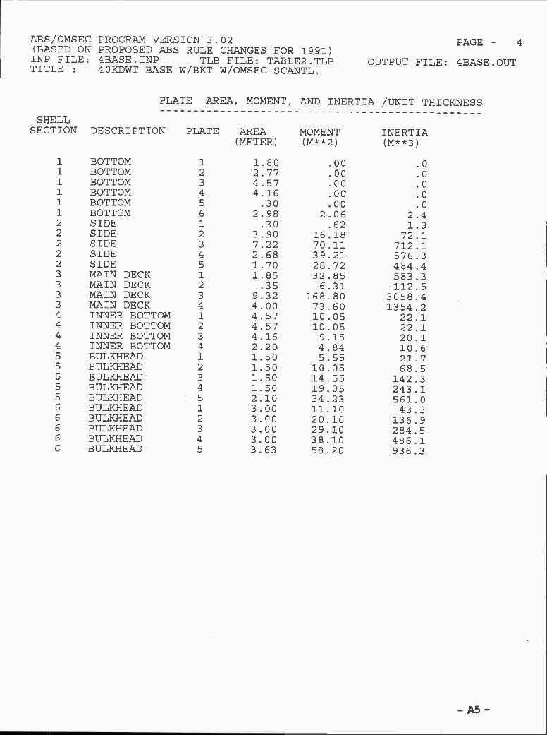
SHELLSECTION DESCRIPTION PLATE AREA MOMENT INERTIA
(METER) (M**2) (M**3)
1 BOTTOM 1 1.80 .00 .0i BOTTOM 2 2.77 .00 .01 BOTTOM 3 4.57 .00 .01 BOTTOM 4 4.16 .00 .01 BOTTOM 5 .30 .00 .01 BOTTOM 6 2.98 2.06 2.42 SIDE 1 .30 .62 1.32 SIDE 2 3.90 16.18 72.12 SIDE 3 7.22 70.11 712.12 SIDE 4 2.68 39.21 576.32 SIDE 5 1.70 28.72 484.43 MAIN DECK 1 1.85 32.85 583.33 MAIN DECK 2 .35 6.31 112.53 MAIN DECK 3 9.32 168.80 3058.43 MAIN DECK 4 4.00 73.60 1354.24 INNER BOTTOM 1 4.57 10.05 22.14 INNER BOTTOM 2 4.57 10.05 22.14 INNER BOTTOM 3 4.16 9.15 20.14 INNER BOTTOM 4 2.20 4.84 10.65 BULKHEAD 1 1.50 5.55 21.75 BULKHEAD 2 1.50 10.05 68.55 BULKHEAD 3 1.50 14.55 142.35 BULKHEAD 4 1.50 19.05 243.15 BULKHEAD 5 2.10 34.23 561.06 BULKHEAD 1 3.00 11.10 43.36 BULKHEAD 2 3.00 20.10 136.96 BULKHEAD 3 3.00 29.10 284.56 BULKHEAD 4 3.00 38.10 486.16 BULKHEAD 5 3.63 58.20 936.3
PLATE AREA, MOMENT, AND INERTIA ¡UNIT THICKNESS
AS
ABS/OMSEC PROGRAM VERSION 3.02 PAGE- 4(BASED ON PROPOSED ABS RULE CHANGES FOR 1991)INP FILE: 4BASE.INP TLB FILE: TABLE2.TLB OUTPUT FILE: 4BASE.OUTTITLE : 4OKDWT BASE W/BKT W/OMSEC SCANTL.

SIDE STRINGERS -
ITEM X-ORD. Y-ORD. PLT L PLT T AREA ARM XIO
- A6 -
ITEM X-ORD. Y-ORD. WEB H WEB T FACE W FACE T AREA ARM XI0
1 .00 .00 2200. 13. 0. 0. 28600. 1.10 11535.2 4.57 .00 2200. 13. 0. 0. 57200. 1.10 23071.3 9.14 .00 2200. 13. 0. 0. 57200. 1.10 23071.4 13.30 .00 2200. 13. 0. 0. 57200. 1.10 23071.
1 15.50 6.10 2200. 13. 57200. 6.10 0.
2 15.50 13.32 2200. 13. 57200. 13.32 0.
ABS /OMSEC PROGRAM VERSION 3.02 PAGE- 5
(BASED ON PROPOSED ABS RULE CHANGES FOR 1991)INP FILE: 4BASE.INP TLB FILE: TABLE2.TLB OUTPUT FILE: 4BASE.OUTTITLE 4OKDWT BASE W/BKT W/OMSEC SCANTL.
BOTTOM GIRDERS -

ABS/OMSEC(BASED ONINP FILE:TITLE
KEEL PLATEBOTTOMBOTTOMBOTTOMBOTTOMBOTTOMSIDESIDESIDESIDESHEERSTRAKESTRINGERMAIN DECKMAIN DECKMAIN DECKINNER BOTTOMINNER BOTTOMINNER BOTTOMINNER BOTTOMBULKHEADBULKHEADBULKHEADBULKHEADBULKHEADBULKHEADBULKHEADBULKHEADBULKHEADBULKHEAD
PROGRAM VERSION 3.02PROPOSED ABS RULE CHANGES4BASE.INP TLB FILE: T4OKDWT BASE W/BKT W/OMSEC
LONGITUDIAL PLATE - 0.4L AMIDSHIPS
SHELL PLATE
SECTION ELE. MAT'L KG/M2
1 AH32 125.60 16.000 (16.000) 1.802 AH32 113.82 14.500 (14.500) 2.773 AH32 113.82 14.500 (14.500) 4.574 AH32 113.82 14.500 (14.500) 4.165 AH32 113.82 14.500 (14.500) .306 AH32 113.82 14.500 (14.500) 2.981 MILD 117.75 15.000 (15.000) .302 MILD 117.75 15.000 (15.000) 3.903 MILD 117.75 15.000 (15.000) 7.224 MILD 117.75 15.000 (15.000) 2.685 AH32 113.82 14.500 (14.500) 1.701 AH32 113.82 14.500 (14.500) 1.852 AH32 113.82 14.500 (14.500) .353 AH32 113.82 14.500 (14.500) 9.324 AH32 113.82 14.500 (14.500) 4.001 MILD 121.67 15.500 (15.500) 4.572 MILD 121.67 15.500 (15.500) 4.573 MILD 121.67 15.500 (15.500) 4.164 MILD 121.67 15.500 (15.500) 2.201 MILD 117.75 15.000 (15.000) 3.002 MILD 109.90 14.000 (14.000) 3.003 MILD 98.13 12.500 (12.500) 3.004 MILD 78.50 10.000 ( 2.500) 3.005 AH32 113.82 14.500 (14.500) 4.201 MILD 117.75 15.000 (15.000) 3.002 MILD 109.90 14.000 (14.000) 3.003 MILD 98.13 12.500 (12.500) 3.004 MILD 78.50 10.000 ( 2.500) 3.005 AH32 113.82 14.500 (14.500) 3.63
THICKNESS (MM) LENGTHLOCAL RULE
DESIGN ( REQ'D ) (METER) FRAMED
LONGITUDINALLONGITUDINALLONGITUDINALLONGITUDINALLONGITUDINALLONGITUDINALLONGITUDINALLONGITUDINALLONGITUDINALLONGITUDINALLONG I TUD INALLONGITUDINALLONGITUDINALLONGITUDINALLONGITUD INALLONGITUDINALLONG I TUD INALLONG I TUD INALLONGITUDINALLONGITUDINALLONG I TUD INALLONG I TUD INALLONGITUDINALLONGITUDINALLONGITUDINALLONGITUDINALLONGITUDINALLONGITUDINALLONGITUDINAL
- A7 -
PAGE- 6FOR 1991)ABLE2 . TLB OUTPUT FILE: 4BASE.OUTSCANTL.

SECTION NO. = 1(BOTTOM ) NOMINAL SPACING = .800
NO MAT'L SCANTLINGS AREA PLATE PLATE Y-ORD. Z-ORD. RULE CALC.THK EFW SM (ABS) SM
1 AH32 400X100X13X182 AH32 400X100X13X183 AH32 400X100X13X184 AH32 400X100X13X185 AH32 400X100X13X186 AH32 400X100X13X187 AH32 400X100X13X188 AH32 400X100X13X189 AH32 400X100X13X18
10 AH32 400X100X13X1811 AH32 400X100X13X1812 AH32 400X100X13X1813 AH32 400X100X13X1814 AH32 400X100X13X1815 AH32 400X100X13X18
\
7000.7000.7000.7000.7000.7000.7000.7000.7000.7000.7000.7000.7000.7000.7000.
16.016 . O
14 . 5
14 . 5
14 . 5
14 . 5
14 . 5
14 . 5
14 . 5
14 . 5
14 . 5
14 . 5
14 . 5
14 . 5
14 . 5
800.800.800.800.800.800.800.800.800.800.800.800.800.800.800.
.801.602.403.204.005.376 . 17
6.977.778.579.94
10.7411.5412 .3413.60
.00
.00
.00
.00
.00
.00
.00
.00
.00
.00
.00
.00
.00
.00
.00
SECTION NO. = 2(SIDE ) NOMINAL SPACING = .780
NO MAT'L SCANTLINGS AREA PLATE PLATE Y-ORD. Z-ORD. RULE CALC.THK EFW SM (ABS) SM
1067.1067.1067.1067.1067.1067.1067.1067.1067.1067.1067.1067.1067.1067.1067.
1314.1314.1301.1301.1301.1301.1301.1301.1301.1301.1301.1301.1301.1301.1301.
1 AH32 350X100X12X17 5900. 15.0 780 15.50 1.90 936. 1019.2 MILD 400X100X13X18 7000. 15.0 780 15.50 2.98 1124. 1303.3 MILD 400X100X13X18 7000. 15.0 780 15.50 3.76 1070. 1303.4 MILD 350X100X12X17 5900. 15.0 780 15.50 4.54 1015. 1019.5 MILD 350X100X12X17 5900. 15.0 780 15.50 5.32 960. 1019.6 MILD 350X100X12X17 5900. 15.0 780 15.50 6.88 851. 1019.7 MILD 350X100X12X17 5900. 15.0 780 15_50 7.66 796. 1019.8 MILD 350X100X12X17 5900. 15.0 780 15.50 8.44 741. 1019.9 MILD 300X90X11X16 4740. 15.0 780 15.50 9.22 686. 728.10 MILD 300X90X11X16 4740. 15.0 780 15.50 10.00 632. 728.11 MILD 300X90X11X16 4740. 15.0 780 15.50 10.78 577. 728.12 MILD 250X90X10X15 3850. 15.0 780 15.50 11.56 522. 532.13 MILD 250X90X10X15 3850. 15.0 780 15.50 12.34 467. 532.14 MILD 250X90X10X15 3850. 15.0 780 15.50 14.10 344. 532.15 MILD 250X90X10X15 3850. 15.0 780 15.50 14.88 289. 532.16 MILD 250X90X10X15 3850. 15.0 780 15.50 15.66 234. 532.17 A.H32 250X90X10X15 3850. 14.5 780 15.50 16.44 140. 531.
18 AH32 250X90X10X15 3850. 14.5 780 15.50 17.22 97. 531.
- A8 -
ABS/OMSEC PROGRAM VERSION 3.02 PAGE- 7(BASED ON PROPOSED ABS RULE CHANGES FOR 1991)INP FILE: 4BASE.INP TLB FILE: TABLE2.TLB OUTPUT FILE: 4BASE.OUTTITLE : 40KDWT BASE W/BKT W/OMSEC SCANTL.
LONGITUDINAL STIFFENER SCANTLINGS - 0.4L AMIDSHIPS

- A9 -
SECTION NO. =
NO MAT'L SCANTLINGS
3(MAIN DECK )
AREA PLATETHK
NOMINAL SPACING =
PLATE Y-ORD. Z-ORD.EFW
.800
RULESM (ABS)
CALC.SM
i AR32 200X15 3000. 14.5 800. 14.70 17.75 190. 203.2 AH32 200X15 3000. 14.5 800. 13.90 17.80 190. 203.3 AH32 200X15 3000. 14.5 800. 12.50 17.88 190. 203.4 AH32 200X15 3000. 14.5 800. 11.70 17.93 190. 203.5 AH32 200X15 3000. 14.5 800. 10.90 17.98 190. 203.6 AH32 200X15 3000. 14.5 800. 10.11 18.03 190. 203.7 AH32 200X15 3000. 14.5 800. 9.31 18.08 190. 203.8 AH32 200X15 3000. 14.5 800. 8.51 18.13 190. 203.9 AH32 200X15 3000. 14.5 800. 7.71 18.17 190. 203.
10 AB32 200X15 3000. 14.5 800. 6.91 18.22 190. 203.11 AH32 200X15 3000. 14.5 800. 6.11 18.27 190. 203.12 AH32 200X15 3000. 14.5 800. 5.31 18.32 190. 203.13 AN32 200X15 3000. 14.5 800. 4.52 18.37 190. 203.14 AR32 200X15 3000. 14.5 800. 3.72 18.40 190. 203.15 AH32 200X15 3000. 14.5 800. 2.92 18.40 190. 203.16 A1132 200X15 3000. 14.5 800. 2.12 18.40 190. 203.17 AH32 200X15 3000. 14.5 800. 1.32 18.40 190. 203.18 AH32 200X15 3000. 14.5 800. .52 18.40 190. 203.
SECTION NO. = 4(INNER BOTTOM)
NO MAT'L SCANTLINGS AREA PLATETHK
NOMINAL SPACING =
PLATE Y-ORD. Z-ORD.EFW
.800
RULESM (ABS)
CALC.SM
i MILD 450X150X11.5X15 7425. 15 . 5 800. .80 2.20 1435. 1669.2 MILD 4SOX1SOX11.5X15 7425. 15 . 5 800. 1.60 2.20 1435. 1669.3 MILD 450X150X11.5X15 7425. 15.5 800. 2.40 2.20 1435. 1669.4 MILD 450X150X11.5X15 7425. 15.5 800. 3.20 2.20 1435. 1669.5 MILD 450X150X11.5X15 7425. 15.5 800. 4.00 2.20 1435. 1669.6 MILD 450X150X11.5X15 7425. 15 . S 800. 5.37 2.20 1435. 1669.7 MILD 450X150X11.5X15 7425. 15.5 800. 6.17 2.20 1435. 1669.8 MILD 450X150X11.5X15 7425. 15.5 800. 6 . 97 2.20 1435. 1669.9 MILD 450X150X11.5X15 7425. 15.5 800. 7.77 2.20 1435. 1669.
10 MILD 450X150X11.5X15 7425. 15.5 800. 8.57 2.20 1435. 1669.11 MILD 450X150X11.5X15 7425. 15.5 800. 9 . 94 2.20 1435. 1669.12 MILD 450X150X11.5X15 7425. 15.5 800. 10.74 2.20 1435. 1669.13 MILD 450X150X11.5X15 7425. 15.5 800. 11.54 2.20 1435. 1669.14 MILD 450X150X11.5X15 7425. 15.5 800. 12 .34 2.20 1435. 1669.15 MILD 450X150X11.5X15 7425. 15 . 5 800. 14.10 2.20 1435. 1669.16 MILD 450X150X11.5X15 7425. 15.5 800. 14.90 2.20 1435. 1669.
ABS/OMSEC PROGRAIVI VERSION 3.02 PAGE- 8(BASED ON PROPOSED ABS RULE CHANGES FOR 1991)INP FILE: 4BASE.INP TLB FILE: TABLE2.TLB OUTPUT FILE: 4BASE.OUTTITLE : 40KDWT EASE W/BKT W/OMSEC SCANTL.
LONGITUDINAL STIFFENER SCANTLINGS - 0.4L AMIDSHIPS

SECTION NO. = 5(BULKHEAD ) NOMINAL SPACING = .780
NO MAT'L SCANTLINGS AREA PLATE PLATE Y-ORD. Z-ORD. RULE CALO.THK EFW SM (ABS) SM
- AlO -
i MILD 400X100X13X18 7000. 15.0 780. .00 2.98 1204. 1303.2 MILD 400X100X13X18 7000. 15.0 780. .00 3.76 1150. 1303.3 MILD 400X100X13X18 7000. 15.0 780. .00 4.54 1095. 1303.4 MILD 400X100X13X18 7000. 14.0 780. .00 5.32 1040. 1293.5 MILD 350X100X12X17 5900. 14.0 780. .00 6.10 985. 1012.6 MILD 350X100X12X17 5900. 14.0 780. .00 6.88 931. 1012.7 MILD 350X100X12X17 5900. 14.0 780. .00 7.66 876. 1012.8 MILD 350X100X12X17 5900. 12.5 780. .00 8.44 821. 1001.9 MILD 350X100X12X17 5900. 12.5 780. .00 9.22 766. 1001.
10 MILD 300X90X11X16 4740. 12.5 780. .00 10.00 712. 716.li MILD 300X90X11X16 4740. 12.5 780. .00 10.78 657. 716.12 MILD 300X90X11X16 4740. 10.0 780. .00 11.56 602. 702.13 MILD 300X90X11X16 4740. 10.0 780. .00 12.34 547. 702.14 MILD 250X90X10X15 3850. 10.0 780. .00 13.12 493. 514.15 MILD 250X90X10X15 3850. 10.0 780. .00 13.90 438. 514.16 MILD 250X90X10X15 3850. 14.5 780. .00 14.68 383. 531.17 MILD 250X90X10X15 3850. 14.5 780. .00 15.46 328. 531.18 AH32 250X90X10X15 3850. 14.5 780. .00 16.24 213. 531.19 AH32 250X90X10X15 3850. 14.5 780. .00 17.02 171. 531.20 AH32 250X90X10X15 3850. 14.5 780. .00 17.80 128. 531.
ABS/OMSEC PROGRAN VERSION 3.02 PAGE- 9
(BASED ON PROPOSED ABS RULE CHANGES FOR 1991)INP FILE: 4BASE.INP TLB FILE: TABLE2.TLB OUTPUT FILE: 4BASE.OUTTITLE : 40KDWT BASE W/EKT W/OMSEC SCANTL.
LONGITUDINAL STIFFENER SCANTLINGS - 0.4L ANIDSHIPS

- All -
SECTION NO. =
NO MAT'L SCANTLINGS
6 (BULKHEAD
AREA
)
PLATETHK
NOMINAL SPACING =
PLATE Y-ORD. Z-ORD.EFW
. 780
RULESM (ABS)
CALC.SM
1 MILD 400X100X13X18 7000. 15.0 780. 13.30 2.98 1204. 1303.2 MILD 400X100X13X18 7000. 15.0 780. 13.30 3.76 1150. 1303.3 MILD 400X100X13X18 7000. 15.0 780. 13.30 4.54 1095. 1303.4 MILD 400X100X13X18 7000. 14.0 780. 13.30 5.32 1040. 1293.S MILD 350X100X12X17 5900. 14.0 780. 13.30 6.10 985. 1012.6 MILD 350X100X12X17 5900. 14.0 780. 13.30 6.88 931. 1012.7 MILD 350X100X12X17 5900. 14.0 780. 13.30 7.66 876. 1012.8 MILD 350X100X12X17 5900. 12.5 780. 13.30 8.44 821. 1001.9 MILD 350X100X12X17 5900. 12.5 780. 13.30 9.22 766. 1001.10 MILD 300X90X11X16 4740. 12.5 780. 13.30 10.00 712. 716.11 MILD 300X90X11X16 4740. 12.5 780. 13.30 10.78 657. 716.12 MILD 300X90X11X16 4740. 10.0 780. 13.30 11.56 602. 702.13 MILD 300X90X11X16 4740. 10.0 780. 13.30 12.34 547. 702.14 MILD 250X90X10X15 3850. 10.0 780. 13.30 13.12 493. 514.15 MILD 250X90X10X15 3850. 10.0 780. 13.30 13.90 438. 514.16 MILD 250X90X10X15 3850. 14.5 780. 13.30 14.68 383. 531.17 MILD 250X90X10X15 3850. 14.S 780. 13.30 15.46 328. S31.18 AH32 250X90X10X15 3850. 14.5 780. 13.30 16.24 213. S31.19 AH32 250X90X10X15 3850. 14.5 780. 13.30 17.02 171. 531.
ABS/OMsEC PROGRAM VERSION 3.02 PAGE - lo(BASED ON PROPOSED ABS RULE CHANGES FOR 1991)INP FILE: 4EASE.INP TLB FILE: TABLE2.TLB OUTPUT FILE: 4BASE.OUTTITLE : 4ÛKDWT BASE W/BKT W/OMSEC SCANTL.
LONGITUDINAL STIFFENER SCANTLINGS 0.4L AMIDSHIPS

SUMMARY OF LONGITUDINAL MATERIAL - 0.4L AMIDSHIPS
PLATE LONGITUDINAL SECTION
SECTION DESCRIPTION AREA (MM-M) (MT/M) AREA (MM-M) (MT/M) (MT/M)
i BOTTOM 243.18 1.91 105.002 SIDE 236.15 1.85 90.573 MAIN DECK 225.06 1.77 54.004 INNER BOTTOM 240.25 1.89 118.805 BULKHEAD 107.70 .85 51.716 BULKHEAD 207.19 1.63 99.56
0.4L AMIDSHIPS = 72.40 (M)
STEEL WEIGHT = 2201.13 (MT)
.82 2.73
.71 256
.42 2.19
.93 2.82
.41 1.25
.78 2.41
- Al2 -
ABS/OMSEC PROGRAM VERSION 3.02 PAGE - 11(BASED ON PROPOSED ABS RULE CHANGES FOR 1991)INP FILE: 4BASE.INP TLB FILE: TABLE2.TLB OUTPUT FILE: 4BASE.OUTTITLE : 4OKDWT BASE W/BKT W/OMSEC SCANTL.
SUB-TOTAL--- 1259.52 9.89 519.64 4.08 13.97
DECK GIRDERS .00
BOTTOM GIRDERS .79
SIDE STRINGERS .45
MISC. VERT. PLTS .00
(ONE SIDE) TOTAL 15.20
TOTAL 30.40
TOTAL WEIGHT OF LONG'L MATERIAL - 0.4L AMIDSHIPS

NEUTRAL AXIS HEIGHT = 7.36 (M) ABV. KEEL
PROPOSEDABS 1990 RULE CHANGES
CALC SECTION MODULUS REQ. SECTION MODULUS SM RATIO(CM**2M) (CM**2M) SMR/SMA
TOP 166568.10 112311.00 .674
BOTTOM 234093.30 112311.00 .480
CALC HULL-GIRDERMOMENT OF INERTIA
(CM**2_M**2)
1722569.00
REQ. HULL-GIRDERMOMENT OF INERTIA
(CM**2 _M**2)
782639.70
-A13-
ABS/OMSEC PROGRAM VERSION 3.02 PAGE - 12(BASED ON PROPOSED ABS RULE CHANGES FOR 1991)INP FILE: 4BASE.INP TLB FILE: TABLE2.TLB OUTPUT FILE: 4BASE.OUTTITLE 4OKDWT BASE W/BKT W/OMSEC SCANTL.
SUMMARY

95KDWT Base Alternative Vessel 9510 LongitudinalScantlings with
ABS OMSEC Program
- A14 -

ABS/OMSEC PROGRAM VERSION 3.02(BASED ON PROPOSED ABS RULE CHANGES FOR 1991)INP FILE: 1BASE.INP TLB FILE: TABLE2.TLBTITLE 95KDWT BASE HULL W/OMSEC 9510: SCANTL.
ASSIGNED EXTENT OF MATERIAL
PAGE- 1
OUTPUT FILE: 1BASE.OUT
ULTIMATESTRESSKG/MM2
Q- FACTOR(6 . 13 . 3)
- A15 -
TYPE OF VESSEL: OIL CARRIERIBCODE : 1 ISCODE : 1 ISTRUT : O
LBP 234.00 (METER)L(SCANT.) 231.54 (METER) BILGE RADIUS 1.90 (METER)BREADTH 42.00 (METER) D. B. HEIGHT 2.20 (METER)DEPTH 19.50 (METER) DEADRISE .00 (METER)DRAFT 13.60 (METER) CAMBER .80 (METER)WIDTH SHEER: 2.90 (METER) GUNWALE RADIUS: .00 (METER)WIDTHKEEL : 2.43 (METER) WIDTH FLATDECK: 6.60 (METER)ZDIST 5.00 (METER) WIDTHFLATBOT.: .00 (METER)WIDTH STRNG: 2.50 (METER)
DISPLACEMENT : 108450. (METRIC TONS)BLOCK COEFFICIENT : .800
2 AR32 .00 1.90 32. 48. .7801 MILD 1.90 16.60 24. 41. 1.0002 AM32 16.60 20.40 32. 48. .780
NOMINAL WEB SPACING = 3 .58 (METER)FLOOR OR SUPPORTING SPACING = 3.58 (METER)
YIELDMATERIAL BOTTOM TOP STRESSNUMBER DESC (METER) (METER) KG/MM2
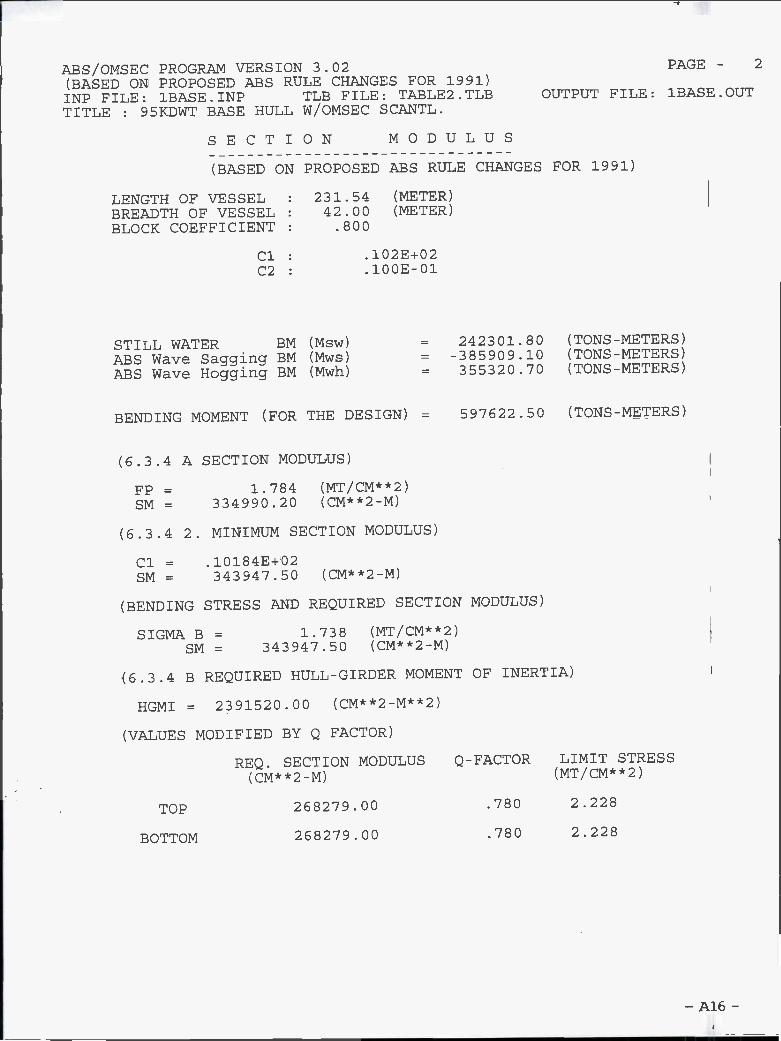
(BASED ON PROPOSED ABS RULE CHANGES FOR 1991)
LENGTH OF VESSEL : 231.54 (METER)BREADTH OF VESSEL : 42.00 (METER)BLOCK COEFFICIENT : .800
Cl 102E+02C2 .100E-01
STILL WATER BM (Msw) = 242301.80 (TONS-METERS)ABS Wave Sagging BM (Mws) = -385909.10 (TONS-METERS)ABS Wave Hogging BM (Mwh) = 355320.70 (TONS-METERS)
BENDING MOMENT (FOR THE DESIGN) = 597622.50 (TONS - METERS)
(6.3.4 A SECTION MODULUS)
FP = 1.784 (MT/CM**2)SM = 334990.20 (CM**2_M)
(6.3.4 2. MINIMUM SECTION MODULUS)
Cl = 10184E+02SM= 343947.50 (CM**2_M)
(BENDING STRESS AND REQUIRED SECTION MODULUS)
SIGMA B = 1.738 (MT/CM**2)SM = 343947.50 (CM**2_M)
(6.3.4 B REQUIRED HULL-GIRDER MOMENT OF INERTIA)
HGMI = 2391520.00 (CM**2_M**2)
(VALUES MODIFIED BY Q FACTOR)
REQ. SECTION MODULUS Q-FACTOR LIMIT STRESS(CM**2_M) (MT/CM**2)
TOP 268279.00 .780 2.228
BOTTOM 268279.00 .780 2.228
- A16 -
ABS/OMSEC PROGRAM VERSION 3.02 PAGE - 2
(EASED ON PROPOSED ABS RULE CHANGES FOR 1991)INP FILE: 1BASE.INP TLB FILE: TABLE2.TLB OUTPUT FILE: 1BASE.OUTTITLE : 95KDWT EASE HULL W/OMSEC SCANTL.
SECTION MODULUS

PLATE SEAM COORDINATES
SHELLSECTION DESCRIPTION NODE GIRTHS Y-COORD Z-COORD
(METER) (METER) (METER)
1 BOTTOM 1 .00 .00 .00i BOTTOM 2 2.43 2.43 .001 BOTTOM 3 8.00 8.00 .00i BOTTOM 4 16.00 16.00 .001 BOTTOM 5 19.10 19.10 .001 BOTTOM 6 22.08 21.00 1.902 SIDE 1 .00 21.00 1.902 SIDE 2 4.20 21.00 6.102 SIDE 3 12.78 21.00 14.682 SIDE 4 14.70 21.00 16.602 SIDE 5 17.60 21.00 19.503 MAIN DECK 1 .00 21.00 19.503 MAIN DECK 2 2.50 18.50 19.643 MAIN DECK 3 2.70 18.30 19.653 MAIN DECK 4 14.42 6.60 20.303 MAIN DECK 5 21.02 .00 20.304 INNER BOTTOM 1 .00 .00 2.204 INNER BOTTOM 2 8.00 8.00 2.204 INNER BOTTOM 3 16.00 16.00 2.205 BULKHEAD 1 .00 16.00 2.205 BULKHEAD 2 2.44 17.25 4.30S BULKHEAD 3 4.53 18.30 6.105 BULKHEAD 4 7.88 18.30 9.455 BULKHEAD 5 10.38 18.30 11.955 BULKHEAD 6 12.94 18.30 14.515 BULKHEAD 7 15.63 18.30 17.205 BULKHEAD 8 18.08 18.30 19.656 BULKHEAD 1 .00 .00 2.206 BULKHEAD 2 3.00 .00 5.206 BULKHEAD 3 6.00 .00 8.206 BULKHEAD 4 9.00 .00 11.20G BULKHEAD 5 12.00 .00 14.206 BULKHEAD 6 15.00 .00 17.206 BULKHEAD 7 18.10 .00 20.30
-A17-
s/OMsEC PROGRAM VERSION 3.02 PAGE- 3(BASED ON PROPOSED ABS RULE CHANGES FOR 1991)INP FILE: 1BASE.INP TLB FILE: TABLE2.TLB OUTPUT FILE: 1BASE.OUTTITLE : 95KDWT BASE HULL W/OMSEC SCANTL.

PLATE AREA, MOMENT, AND INERTIA /UNIT THICKNESS
SHELLSECTION DESCRIPTION PLATE AREA MOMENT INERTIA
(METER) (M**2) (M**3)
1 BOTTOM 1 2.43 .00 .0
1 BOTTOM 2 5.57 .00 .0
i BOTTOM 3 8.00 .00 .0
i BOTTOM 4 3.10 .00 .0
1 BOTTOM 5 2.98 2.06 2.42 SIDE 1 4.20 16.80 73.42 SIDE 2 8.58 89.15 978.92 SIDE 3 1.92 30.03 470.22 SIDE 4 2.90 52.34 946.93 MAIN DECK 1 2.50 48.92 957.43 MAIN DECK 2 .20 4.01 78.83 MAIN DECK 3 11.72 234.07 4675.93 MAIN DECK 4 6.60 133.98 2719.84 INNER BOTTOM 1 8.00 17.60 38.74 INNER BOTTOM 2 8.00 17.60 38.75 BULKHEAD 1 2.44 7.94 26.75 BULKHEAD 2 2.08 10.84 56.95 BULKHEAD 3 3.35 26.05 205.65 BULKHEAD 4 2.50 26.75 287.55 BULKHEAD 5 2.56 33.87 449.55 BULKHEAD 6 2.69 42.65 677.85 BULKHEAD 7 2.45 45.14 833.06 BULKHEAD 1 1.50 5.55 21.76 BULKHEAD 2 1.50 10.05 68.56 BULKHEAD 3 1.50 14.55 142.36 BULKHEAD 4 1.50 19.05 243.16 BULKHEAD 5 1.50 23.55 370.96 BULKHEAD 6 1.55 29.06 5462
- A18 -
ABS/OMSEC PROGRAM VERSION 3.02 PAGE- 4
(EASED ON PROPOSED ABS RULE CHANGES FOR 1991)INP FILE: 1BASE.INP TLB FILE: TABLE2.TLB OUTPUT FILE: 1BASE.OUTTITLE : 95KDWT EASE HULL W/OMSEC SCANTL.

SIDE STRINGERS -
ITEM X-ORD. Y-ORD. PLT L PLT T AREA ARM XI0
-A19-
1 .00 .00 2200. 14. 0. 0. 30800. 1.10 12423.2 8.00 .00 2200. 14. 0. 0. 61600. 1.10 24845.3 16.00 .00 2200. 13. 0. 0. 55000. 1.10 22183.
1 21.00 6.10 2700. 14. 72900. 6.10 0.2 21.00 14.68 2700. 14. 72900. 14.68 0.
ABS/OMSEC PROGRAM VERSION 3.02 PAGE- 5(BASED ON PROPOSED ABS RULE CHANGES FOR 1991)INP FILE: 1BASE.INP TLB FILE: TABLE2.TLB OUTPUT FILE: 1BASE.OUTTITLE : 95KDWT BASE HULL W/OMSEC SCANTL.
BOTTOM GIRDERS -
ITEM X-ORD. Y-ORD. WEB H WEB T FACE W FACE T AREA ARM XI0

ABS/OMSEC PROGRAM VERS(EASED ON PROPOSED ABSINP FILE: 1BASE.INPTITLE : 95KDWT BASE HU
KEEL PLATEBOTTOMBOTTOMBOTTOMBOTTOMSIDESIDESIDESHEERSTRAKESTRINGERMAIN DECKMAIN DECKMAIN DECKINNER BOTTOMINNER BOTTOMBULKHEADBULKHEADBULKHEADBULKHEADBULKHEADBULKHEADBULKHEADBULKHEADBULKHEADBULKHEADBULKHEADBULKHEADBULKHEAD
LONGITUDIAL PLATE - 0.4L AMIDSHIPS
ION 3.02RULE CHANGES FOR 1991)TLE FILE: TABLE2.TLB
LL W/OMSEC SCANTL.
THICKNESS (MM) LENGTHLOCAL RULE
DESIGN ( REQ'D ) (METER) FRAMED
i AH32 129.52 16.500 (16.500) 2.432 AH32 117.75 15.000 (15.000) 5.57
3 AH32 117.75 15.000 (15.000) 8.004 AH32 117.75 15.000 (15.000) 3.105 AH32 117.75 15.000 (15.000) 2.981 MILD 137.38 17.500 (17.500) 4.202 MILD 137.38 17.500 (17.500) 8.583 MILD 137.38 17.500 (17.500) 1.924 AH32 122.36 15.587 (15.500) 2.90i AH32 122.36 15.587 (15.500) 2.50
2 AH32 122.36 15.587 (15.500) .20
3 AH32 122.36 15.587 (15.500) 11.724 AH32 122.36 15.587 (15.500) 6.60
1 MILD 125.60 16.000 (16.000) 8.00
2 MILD 125.60 16.000 (16.000) 8.00i MILD 121.67 15.500 (15.500) 2.442 MILD 117.75 15.000 (15.000) 2.08
3 MILD 109.90 14.000 (14.000) 3.35
4 MILD 102.05 13.000 (13.000) 2.505 MILD 90.28 11.500 (11.500) 2.566 AH32 98.13 12.500 (12.500) 2.69
7 AH32 125.60 16.000 (16.000) 2.451 MILD 121.67 15.500 (15.500) 3.00
2 MILD 113.82 14.500 (14.500) 3.00
3 MILD 105.97 13.500 (13.500) 3.00
4 MILD 94.20 12.000 (12.000) 3.00S AH32 98.13 12.500 (12.500) 3.00
6 AH32 125.60 16.000 (16.000) 3.10
PAGE- 6
OUTPUT FILE: 1EASE.OUT
LONG I TUD INALLONGITUDINALLONG ITUDINALLONGITUDINALLONGITUDINALLONGITUDINALLONGITUDINALLONG I TUD INALLONG I TUD INALLONG ITUD INALLONGITUDINALLONGITUDINALLONGITUDINALLONG I TUD INALLONGITUDINALLONGITUDINALLONGITUDINALLONG I TUD INALLONGITUDINALLONG I TUD INALLONGITUDINALLONGITUDINALLONGITUDINALLONGITUDINALLONGITUDINALLONGITUDINALLONGITUDINALLONGITUDINAL
- A20 -
SHELL PLATE
SECTION ELE. MAT'L KG/M2

ABS/OMSEC PROGRAM VERSION 3.02(BASED ON PROPOSED ABS RULE CHANGES FOR 1991)INP FILE: 1BASE.INP TLE FILE: TABLE2.TLBTITLE : 95KDWT BASE HULL W/OMSEC SCANTL.
LONGITUDINAL STIFFENER SCANTLINGS - 0.4L AMIDSHIPS
PAGE- 7
OUTPUT FILE: 1BASE.OUT
- A21 -
SECTION NO. =
NO MAT'L SCANTLINGS
1(BOTTOM
AREA
)
PLATETHK
NOMINAL SPACING =
PLATE Y-ORD. Z-ORD.EFW
.800
RULESM (ABS)
CALC.SM
1 AH32 400X100X13X18 7000. 16.5 800. .80 .00 1168. 1318.2 AH32 400X100X13X18 7000. 16.5 800. 1.60 .00 1168. 1318.3 AH32 400X100X13X18 7000. 16.5 800. 2.40 .00 1168. 1318.4 AH32 400X100X13X18 7000. 15.0 800. 3.20 .00 1168. 1305.5 AH32 400X100X13X18 7000. 15.0 800. 4.00 .00 1168. 1305.6 AH32 400X100X13X18 7000. 15.0 800. 4.80 .00 1168. 1305.7 AH32 400X100X13X18 7000. 15.0 800. 5.60 .00 1168. 1305.8 AH32 400X100X13X18 7000. 15.0 800. 6.40 .00 1168. 1305.9 AH32 400X100X13X18 7000. 15.0 800. 7.20 .00 1168. 1305.
10 AH32 400X100X13X18 7000. 15.0 800. 8.80 .00 1168. 1305.11 AH32 400X100X13X18 7000. 15.0 800. 9.60 .00 1168. 1305.12 AH32 400X100X13X18 7000. 15.0 800. 10.40 .00 1168. 1305.13 AH32 400X100X13X18 7000. 15.0 800. 11.20 .00 1168. 1305.14 AH32 400X100X13X18 7000. 15.0 800. 12.00 .00 1168. 1305.15 AH32 400X100X13X18 7000. 15.0 800. 12.80 .00 1168. 1305.16 AH32 400X100X13X18 7000. 15.0 800. 13.60 .00 1168. 1305.17 AH32 400X100X13X18 7000. 15.0 800. 14.40 .00 1168. 1305.18 AH32 400X100X13X18 7000. 15.0 800. 15.20 .00 1168. 1305.19 AH32 400X100X13X18 7000. 15.0 800. 16.80 .00 1168. 1305.20 AH32 400X100X13X18 7000. 15.0 800. 17.60 .00 1168. 1305.21 AH32 400X100X13X18 7000. 15.0 800. 18.40 .00 1168. 1305.22 AH32 400X100X13X18 7000. 15.0 800. 19.10 .00 1168. 1305.
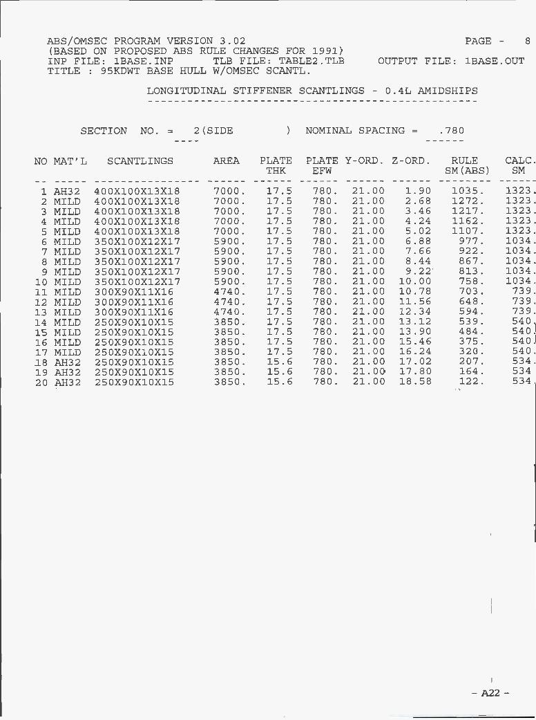
SECTION NO. = 2(SIDE ) NOMINAL SPACING = .780
- A22 -
NO MAT'L SCANTLINGS AREA PLATETHK
PLATE Y-ORD.EFW
Z-ORD. RULESM (ABS)
CALC.SM
1 AH32 400X100X13X18 7000. 17.5 780. 21.00 1.90 1035. 1323.2 MILD 400X100X13X18 7000. 17.5 780. 21.00 2.68 1272. 1323.3 MILD 400X100X13X18 7000. 17.5 780. 21.00 3.46 1217. 1323.4 MILD 400X100X13X18 7000. 17.5 780. 21.00 4.24 1162. 1323.5 MILD 400X100X13X18 7000. 17.5 780. 21.00 5.02 1107. 1323.6 MILD 350X100X12X17 5900. 17.5 780. 21.00 6.88 977. 1034.7 MILD 350X100X12X17 5900. 17.5 780. 21.00 7.66 922. 1034.8 MILD 350X100X12X17 5900. 17.5 780. 21.00 8.44 867. 1034.9 MILD 350X100X12X17 5900. 17.5 780. 21.00 9.22 813. 1034.10 MILD 350X100X12X17 5900. 17.5 780. 21.00 10.00 758. 1034.11 MILD 300X90X11X16 4740. 17.5 780. 21.00 10.78 703. 739.
12 MILD 300X90X11X16 4740. 17.5 780. 21.00 11.56 648. 739.
13 MILD 300X90X11X16 4740. 17.5 780. 21.00 12.34 594. 739.
14 MILD 250X90X10X15 3850. 17.5 780. 21.00 13.12 539. 540.
15 MILD 250X90X10X15 3850. 17.5 780. 21.00 13.90 484. 540.
16 MILD 250X90X10X15 3850. 17.5 780. 21.00 15.46 375. 540.
17 MILD 250X90X10X15 3850. 17.5 780. 21.00 16.24 320. 540.
18 AH32 250X90X10X15 3850. 15.6 780. 21.00 17.02 207. 534.
19 AH32 250X90X10X15 3850. 15.6 780. 21.00 17.80 164. 534.
20 AH32 250X90X10X15 3850. 15.6 780. 21.00 18.58 122. 534.
ABS/OMSEC PROGRAM VERSION 3.02 ?AGE- 8
(BASED ON PROPOSED ABS RULE CHANGES FOR 1991)INP FILE: 1BASE.INP TLE FILE: TABLE2.TLB OUTPUT FILE: :LBASE.OUTTITLE : 95KDWT BASE HULL W/OMSEC SCANTL.
LONGITUDINAL STIFFENER SCANTLINGS - 0.4L AMIDSHIPS

-A23-
SECTION NO. =
NO MAT'L SCANTLINGS
3(MAIN DECK )
AREA PLATETHK
NOMINAL SPACING =
PLATE Y-ORD. Z-ORD.EFW
.800
RULESM (ABS)
CALC.SM
1 AH32 300X18 5400. 15.6 800. 20.20 19.54 190. 517.2 AH32 300X18 5400. 15.6 800. 19.40 19.59 190. 517.3 AH32 300X18 5400. 15.6 800. 18.60 19.63 190. 517.4 AH32 300X18 5400. 15.6 800. 17.50 19.69 190. 517.5 AH32 300X18 5400. 15.6 800. 16.70 19.74 190. 517.6 AH32 300X18 5400. 15.6 800. 15.90 19.78 190. 517.7 A1132 300X18 5400. 15.6 800. 15.10 19.83 190. 517.8 AH32 300X18 5400. 15.6 800. 14.31 19.87 190. 517.9 AH32 300X18 5400. 15.6 800. 13.51 19.92 190. 517.
10 Ai-132 300X18 5400. 15.6 800. 12.71 19.96 190. 517.11 AH32 300X18 5400. 15.6 800. 11.91 20.01 190. 517.12 AH32 300X18 5400. 15.6 800. 11.11 20.05 190. 517.13 AH32 300X18 5400. 15.6 800. 10.31 20.09 190. 517.14 AH32 300X18 5400. 15.6 800. 9.51 20.14 190. 517.15 AH32 300X18 5400. 15.6 800. 8.71 20.18 190. 517.16 AH32 300X18 5400. 15.6 800. 7.92 20.23 190. 517.17 AH32 300X18 5400. 15.6 800. 7.12 20.27 190. 517.18 Ai-132 300X18 5400. 15.6 800. 6.32 20.30 190. 517.19 AH32 300X18 5400. 15.6 800. 5.52 20.30 190. 517.20 AH32 300X18 5400. 15.6 800. 4.72 20.30 190. 517.21 AH32 300X18 5400. 15.6 800. 3.92 20.30 190. 517.22 AH32 300X18 5400. 15.6 800. 3.12 20.30 190. 517.23 AH32 300X18 5400. 15.6 800. 2.32 20.30 190. 517.24 AH32 300X18 5400. 15.6 800. 1.52 20.30 190. 517.25 AH32 300X18 5400. 15.6 800. .72 20.30 190. 517.
ABS/OMSEC PROGRAM VERSION 3.02 PAGE- 9(BASED ON PROPOSED ABS RULE CHANGES FOR 1991)INP FILE: 1BASE.INP TLB FILE: TABLE2.TLB OUTPUT FILE: 1BASE.OUTTITLE : 95KDWT BASE HULL W/OMSEC SCANTL.
LONGITUDINAL STIFFENER SCANTLINGS - 0.4L AMIDSHIPS

A24 -
SECTION NO. = 4(INNER BOTTOM)
NO MAT'L SCANTLINGS AREA PLATETHK
NOMINAL SPACING =
PLATE Y-ORD. Z-ORD.EFW
.800
RULESM (ABS)
CALO.SM
i MILD 450X150X11.5X15 7425. 16.0 800. .80 2.20 1579. 1673.2 MILD 450X150X11.5X15 7425. 16.0 800. 1.60 2.20 1579. 1673.3 MILD 450X150X11.5X15 7425. 16.0 800. 2.40 2.20 1579. 1673.4 MILD 450X150X11.5X15 7425. 16.0 800. 3.20 2.20 1579. 1673.5 MILD 450X150X11.5X15 7425. 16.0 800. 4.00 2.20 1579. 1673.6 MILD 450X150X11.5X15 7425. 16.0 800. 4.80 2.20 1579. 1673.7 MILD 450X150X11.5X15 7425. 16.0 800. 5.60 2.20 1579. 1673.8 MILD 450X150X11.5X15 7425. 16.0 800. 6.40 2.20 1579. 1673.9 MILD 450X150X11.5X15 7425. 16.0 800. 7.20 2.20 1579. 1673.10 MILD 450X150X11.5X15 7425. 16.0 800. 8.80 2.20 1579. 1673.11 MILD 450X150X11.5X15 7425. 16.0 800. 9.60 2.20 1579. 1673.12 MILD 450X150X11.5X15 7425. 16.0 800. 10.40 2.20 1579. 1673.13 MILD 450X150X11.5X15 7425. 16.0 800. 11.20 2.20 1579. 1673.14 MILD 450X150X11.5X15 7425. 16.0 800. 12.00 2.20 1579. 1673.15 MILD 450X150X11.5X15 7425. 16.0 800. 12.80 2.20 1579. 1673.
16 MILD 450X150X11.5X15 7425. 16.0 800. 13.60 2.20 1579. 1673.17 MILD 450X150X11.5X15 7425. 16.0 800. 14.40 2.20 1579. 1673.
18 MILD 450X150X11.5X15 7425. 16.0 800. 15.20 2.20 1579. 1673.
ABS/OMSEC PROGRAM VERSION 3.02 PAGE - 10(BASED ON PROPOSED ABS RULE CHANGES FOR 1991)INP FILE: 1BASE.INP TLB FILE: TABLE2.TLB OUTPUT FILE: 1BASE.OUTTITLE : 95KDWT BASE HULL W/OMSEC SCANTL.
LONGITUDINAL STIFFENER SCANTLINGS - O.4L AMIDSHIPS

- A25 -
SECTION NO. = 5(BULKHEAD
NO MAT'L SCANTLINGS AREA
)
PLATETHK
NOMINAL SPACING =
PLATE Y-ORD. Z-ORD.EFW
.780
RULESM (ABS)
CALC.SM
i MILD 450X150X11.5X15 7425. 15.5 780. 16.38 2.84 1340. 1666.2 MILD 400X100X13X18 7000. 15.5 780. 16.77 3.49 1295. 1307.3 MILD 400X100X13X18 7000. 15.5 780. 17.15 4.13 1250. 1307.4 MILD 400X100X13X18 7000. 15.0 780. 17.55 4.82 1202. 1303.5 MILD 400X100X13X18 7000. 15.0 780. 17.93 5.47 1156. 1303.6 MILD 400X100X13X18 7000. 14.0 780. 18.30 6.85 1059. 1293.7 MILD 350X100X12X17 5900. 14.0 780. 18.30 7.63 1004. 1012.8 MILD 350X100X12X17 5900. 14.0 780. 18.30 8.41 950. 1012.9 MILD 350X100X12X17 5900. 14.0 780. 18.30 9.19 895. 1012.
10 MILD 350X100X12X17 5900. 13.0 780. 18.30 10.05 834. 1005.11 MILD 350X100X12X17 5900. 13.0 780. 18.30 10.83 780. 1005.12 MILD 350X100X12X17 5900. 13.0 780. 18.30 11.61 725. 1005.13 MILD 300X90X11X16 4740. 13.0 780. 18.30 12.39 670. 719.14 MILD 300X90X11X16 4740. 11.5 780. 18.30 12.35 673. 711.15 MILD 300X90X11X16 4740. 11.5 780. 18.30 13.13 618. 711.16 MILD 300X90X11X16 4740. 11.5 780. 18.30 13.91 564. 711.17 MILD 250X90X10X15 3850. 12.5 780. 18.30 15.50 452. 524.18 MILD 250X90X10X15 3850. 12.5 780. 18.30 16.28 397. 524.19 AH32 250X90X10X15 3850. 12.5 780. 18.30 17.06 267. 524.20 AH32 250X90X10X15 3850. 16.0 780. 18.30 17.85 224. 535.21 AH32 250X90X10X15 3850. 16.0 780. 18.30 18.63 181. 535.22 AH32 250X90X10X15 3850. 16.0 780. 18.30 19.41 138. 535.
ABS/OMSEC PROGRAÎ4 VERSION 3.02 PAGE - 11(EASED ON PROPOSED ABS RULE CHANGES FOR 1991)INP FILE: 1BASE.INP TLB FILE: TABLE2.TLB OUTPUT FILE: 1EASE.OUTTITLE : 95KDWT EASE HULL W/OMSEC SCANTL.
LONGITUDINAL STIFFENER SCANTLINGS - 0.4L AMIDSHIPS
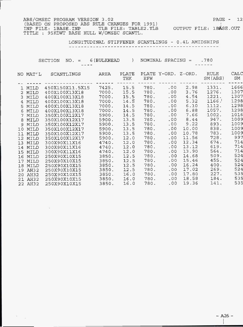
- A26 -
SECTION NO. = 6(BULKHEAD
NO MAT'L SCANTLINGS AREA
)
PLATETHK
NOMINAL SPACING =
PLATE Y-ORD. Z-ORD.EFW
.780
RULESM (ABS)
CALCSM
1 MILD 450X150X11.5X15 7425. 15.5 780. .00 2.98 1331. 16662 MILD 400X100X13X18 7000. 15.5 780. .00 3.76 1276. 13073 MILD 400X100X13X18 7000. 15.5 780. .00 4.54 1221. 13074 MILD 400X100X13X18 7000. 14.5 780. .00 5.32 1166. 12985 MILD 400X100X13X18 7000. 14.5 780. .00 6.10 1112. 12986 MILD 400X100X13X18 7000. 14.5 780. .00 6.88 1057. 12987 MILD 350X100X12X17 5900. 14.5 780. .00 7.66 1002. 10168 MILD 350X100X12X17 5900. 13.5 780. .00 8.44 947. 10099 MILD 350X100X12X17 5900. 13.5 780. .00 9.22 893. 100910 MILD 350X100X12X17 5900. 13.5 780. .00 10.00 838. 100911 MILD 350X100X12X17 5900. 13.5 780. .00 10.78 783. 100912 MILD 350X100X12X17 5900. 12.0 780. .00 11.56 728. 99713 MILD 300X90X11X16 4740. 12.0 780. .00 12.34 674. 71414 MILD 300X90X11X16 4740. 12.0 780. .00 13.12 619. 71415 MILD 300X90X11X16 4740. 12.0 780. .00 13.90 564. 71416 MILD 250X90X10X15 3850. 12.5 780. .00 14.68 509. 52417 MILD 250X90X10X15 3850. 12.5 780. .00 15.46 455. 52418 MILD 250X90X10X15 3850. 12.5 780. .00 16.24 400. 52419 AH32 250X90X10X15 3850. 12.5 780. .00 17.02 269. 52420 AH32 250X90X10X15 3850. 16.0 780. .00 17.80 227. 53521 AH32 250X90X10X15 3850. 16.0 780. .00 18.58 184. 53522 AH32 250X90X10X15 3850. 16.0 780. .00 19.36 141. 535
ABS/OMSEC PROGRAM VERSION 3.02 PAGE - 12(EASED ON PROPOSED ABS RULE CHANGES FOR 1991)INP FILE: 1BASE.INP TLB FILE: TABLE2.TLB OUTPUT FILE: 1BASE.OTJTTITLE : 95KDWT EASE HULL W/OMSEC SCANTL.
LONGITUDINAL STIFFENER SCANTLINGS - 0.4L AMIDSHIPS
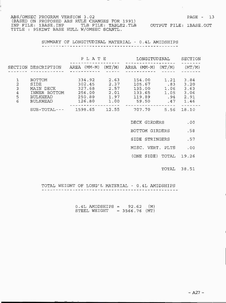
SECTION DESCRIPTION
SUMMARY OF LONGITUDINAL MATERIAL - 0.4L AMIDSHIPS
PLATE
i BOTTOM 334.92 2.63 154.002 SIDE 302.45 2.37 105.673 MAIN DECK 327.68 2.57 135.004 INNER BOTTOM 256.00 2.01 133.655 BULKHEAD 250.80 1.97 119.896 BULKHEAD 126.80 1.00 59.50
0.4L AMIDSHIPS = 92.62 (M)STEEL WEIGHT = 3566.76 (MT)
LONGITUDINAL SECTION
AREA (MM-M) (MT/M) AREA (MM-M) (MT/M) (MT/M)
1.21 3.84.83 3.20
1.06 3.631.05 3.06.94 2.91.47 1.46
- A27 -
AES/OMSEC PROGRAM VERSION 3.02 PAGE - 13(EASED ON PROPOSED ABS RULE CHANGES FOR 1991)INP FILE: 1BASE.INP TLB FILE: TABLE2.TLB OUTPUT FILE: 1BASE.OUTTITLE : 95KDWT BASE HULL W/OMSEC SCANTL.
SUB-TOTAL--- 1598.65 12.55 707.70 5.56 18.10
DECK GIRDERS .00
BOTTOM GIRDERS .58
SIDE STRINGERS .57
MISC. VERT. PLTS .00
(ONE SIDE) TOTAL 19.26
TOTAL 38.51
TOTAL WEIGHT OF LONG'L MATERIAL - 0.4L AMIDSHIPS

SUMMARY
CALC HULL-GIRDERMOMENT OF INERTIA
(CM**2 _M**2)
2918411.00
REQ. HULL-GIRDERMOMENT OF INERTIA
(CM**2_M**2)
2391520.00
- A28 -
ABS/OMSEC PROGRAM VERSION 3.02 PAGE - 14(BASED ON PROPOSED ABS RULE CHANGES FOR 1991)INP FILE: 1BASE.INP TLB FILE: TABLE2.TLB OUTPUT FILE: 1BASE.OUTTITLE : 95KDWT BASE HULL W/OMSEC SCANTL.
NEUTRAL AXIS HEIGHT = 8.59 (M) ABV. KEEL
PROPOSEDABS 1990 RULE CHANGES
CALC SECTION MODULUS REQ. SECTION MODULUS SM RATI((CM**2M) (CM**2M) SMR/SMA
TOP 267620.80 268279.00 1.002
BOTTOM 339548.60 268279.00 .790

4OKDWT Base Alternative Vessel 4010Break Down of Blocks and Piece Parts
- A29 -

h 8cl
88
il fi cl8cl
d
z
8
li
H
clo
gcl cl
cl 88
o 88S88cl888888888g88888 8888888888
n
H
co :8000000 gg
- - o
o o
b
.0
cl 8 o oo o H o
- o O o
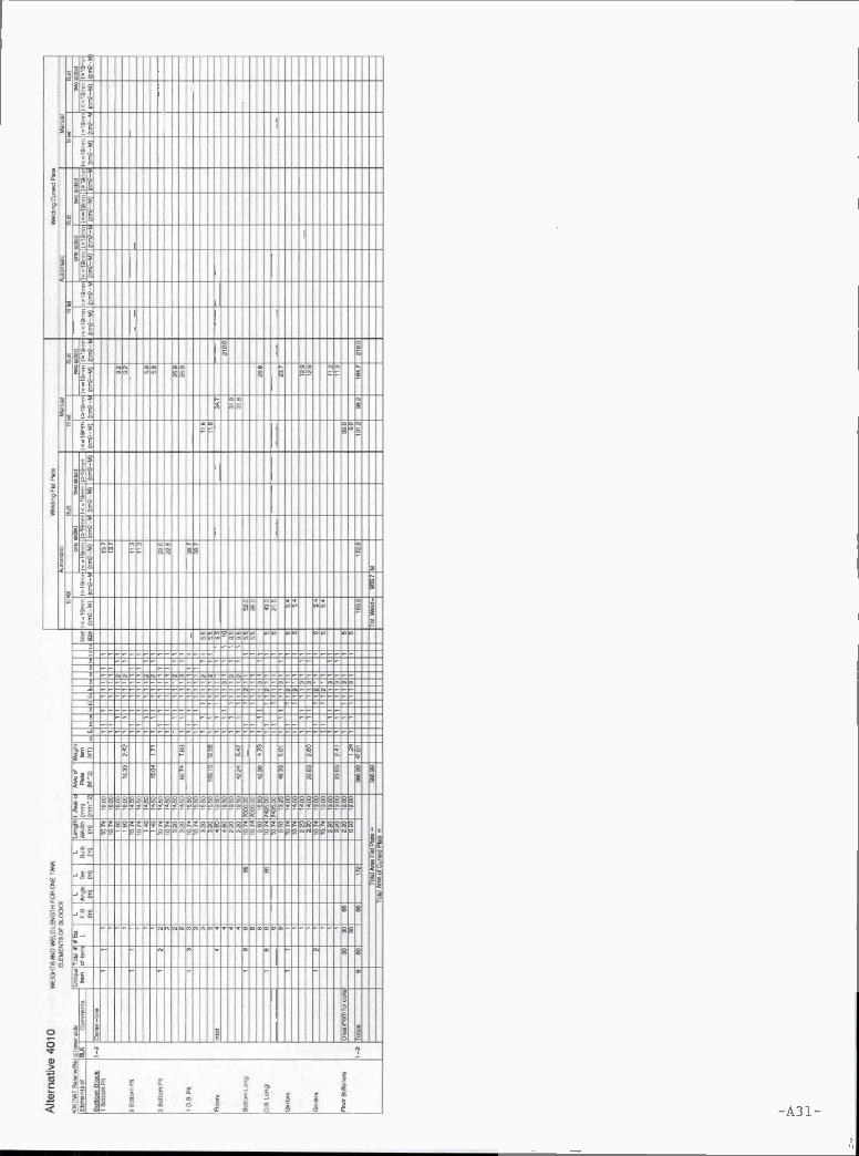
-A31-
1818 81
n
2oG)
18
81
81 12
18
12
18
81
18 ÔÒodÔÓOOddÔ U
81 81
-E81 81
- - -
h
18j
j 18 -¿I 18

-p32-
h
h
.
r
o
2
a)>
=......:......................u...............................u.
HE
o
-h
E
E

-A33-
-
k
5
di
9
li
v
99 99 9 8
9
9
::::::::::::::::::::::::::::::::::::::::::::
2 9w
8o
9O,
2O, (
9gi
9O
99O O, S9
99
99
9 99
92 9
99
28289888882 8888888888888888888888888
flu
HL oot 000000 88800 00 88 00 00888888&8888888888N0000OÖOb000ÔSSÒ88888Ñ8
8
::9
9-
9
g

A34-
II
v
-Í
a).2I8C
8 8 8o o
8 88 8 8
- 8 8 88 8
88
° 88 88888888888888888888888888888888888888888
? 22889882988888 88888888888829899Q99888888289
8
8 8
h58
8-. -2 8 5
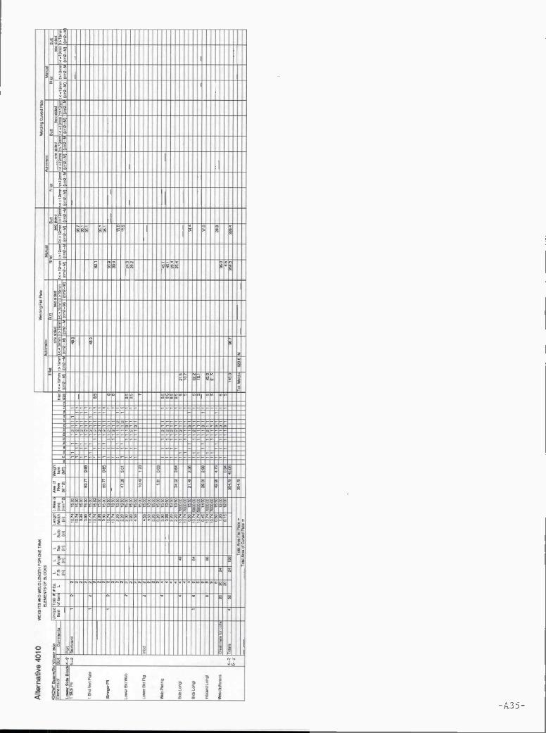
flff-
s
sE o
.2
00 0
8 8o
8O
8 8O
8 8 8
8 88
-9 8
88 8 8
O 888288888888888828288288888888
q9290082 °', 99°29°99°°
8 8
8
00000088
8
-
55O
U
5
i

t
t
g
8
j
8
gv
g
g
g
o
-t
tg
o
8 8 8 8t t t OS
8 85 8b b
8 8 - - 99$-A36-
88 S S
z S S
98 S S S
5 S S S 88
888 8
8S
8 8 89
S S S S8
SS
8S S
2 S S S
8 88 88 9 8 8 8 888 88 8 8 8 8 88 88 8 8 S g S 88 8 S 88 888$
8S
8S
S 888 g S g S 8 8
S 8 88 8$ S S S 98 ej.- S S Sej
8 89 855 S S S Sto
S S 9 S S
S S
S S
S S
-A37-
j9
H
I
'
t
r
1IINOIIIIIIHi!Il..u........ uuluuu.
IIOIIIIIIIIIIIIIIIIII
kiÏÏÏÏÍffiuiffiuiiiiiii O
f d;a)
i i


-A39-
i
9
111
9
8 8
8
E9
=
2
:: i i;
o ô o - - - o
9 9 9 99
88
9 88
9 9 8 9 9 8 0
88889899888888888988898888888288889988889898888988988888998888
H
ji: !!!!!9
8 9
8 8
9
8 8 8 8 8
o

- A4
fi
q
O
fl
L''
- o O O O
- O
O B88 SSB888888: 8888 : 888888 8gg8888 88 88 882OOO Oo o-0000 o 990000_o
n
O-
iiI__I 0:00 :8:
I I 8
1 1 1

-A41-
L p
j
o
i:
-
i i1
js
z
o o
o
- A4 2-
L ih
Il 'd' i k Ldill
G)
Q)
o o o o - -
- -
° 88888888
O 0000 00000000000 O
:
- 000000
o
n.
- G)

IOOIOII1IllhIIIIIIIIIIIllhIIIIIII1IOIIIIIIIIIHhIIIIIIIIIIIIIIIIUIIIIIIIIIIIIIIIlIIIIIIIIII
!IIIIIIIIIIIIHuIIIHIIHIIIIIIIIIIIIIIIIIIIIIflhIIIIHIIIIIIIHhIIIIIIHhIIIHIHHIH
'riiiiiuiuiiuiuiiiiiuiuuuuiiiiiiiiuiiiiiiiuuiiiiuuuuiiiiiiiiiuuiiuiiuiiiiiiiiiuuuuuuiiiiIiuhIIIIIIIIllhIIIIIIIIIIIIIIIIIIIIHhIIIIIIIIIIIIIIIHHIOOIIIIIIIIIIJkIIaIJIJII
uIIII!IIIIIIIIIIIIIIIIIIIIIIIIIIILIII
I!IIllhIIIIIIIIIIIIIIIIIIIIIIIHOIIIIIIIIHHhIflIHIIIIIflhIIIIIIIIIIIIIIIIIIIIIIIHhIIIIIIIIIIIHIHIflhIIHIIHIIIIIIIIIIIIIIIHIIIIIHIIIIIIIIIHIIIIIIIIIIIIIIIIIIIIIIIIII
rIIIIIuIuuIIIIIIIuuIHHIIIIIIIIIuhIuIIuuuIIIIIIuuIuIIIIIIIuuuIIuIuIIIIIIIIIIIIIIIuIIIIIikll IIQhIDhIdIIIIIIIIIIIIlhIIIIIIIflhIIIIIIHhIIIIIIHhIIIIIIIIIIIIIIIIIIIIkIIIiHIIIIIIIHIIIIIIIIIIlIIIHIIIIIHOhIIIIIOhIIIIIHUflHhIIIIIIIIIIHHIIHIIIIIHIU
iIliIIIIHIIIHHhIIkIIIIIIIIIIIIIIIIHIIIIIIIIIUhIIIHIIIIIIIIIllhIIIflIflIftIflhIUII
a..
IIILIILIILIILIILIILIILIIIJIUIHHLIIIJILHLIILIII1IIJLILIIJLIIOIIIIJIIJIIIMIkIIIIIIJIhIIkIIIJIkOkIIkIHJIkIIkIIIJLIIIkIIJLL
1U
iiiíiiiioiíiiiiiíiiìiiimiiiiiimiiiíiiiiiiiiiiîiiiiiooiiiiiiio
P
o5w
h9
o
d
A43-

- A44 -
2
g
li
li
'
g2
di
-
-
G)
a)
gG
g g ggg
gg
g
3
o H
-Lg_
;
g
'- g
g g - g
g
g
o
5
°
k
2
g
g!,
Ig
!E
agg- -8S:::::888
uI
g
g
i!0'
g g G
95KDWT Base Alternative Vessel 9510Break Down of Blocks and Piece Parts
- A45 -

IL8
i hhh
8 8
8
II
- A46-8 88t

00011111 III1OIIIHIIIOOUIIIIINO O 1111111010110
iiiiiiiiiiiooiiii000iiiiiiiiiiiiiiiiiiiiiiiiiiiirnoiiiiiiiiummoiiiii
riiiiiiiiiiiiiiiiiiiiiiiiiiiiiiiiiiiiiiiiiiiiiiiiiiiniiiiiiiiiiiiiiiiiiiiiiiiiiii I!O1
¡lOI011OOO11hlllllllllllIl1IhI1Ilh11IHl1lIHO1lll1lllOhlh11hl111011lOh11 0111
:
-
.4.
i iLl Ii: F JIHIkI0IIHhIIIIIHIIHhIHIIHIIhIhIIIIIhIIIIIhfflhIIIdhIllhIIIIIIIHIIIkM
IHHIHIIIIIHIIHIIHIIHIHHHIIIIIIIIUIIIHHIIIIIHHOIIOIIIIIIOIIIIIHHHIIIIUIIOHhIflhIIflOflhIIIIIIIIIIIIIIIflhIIHHflflhIHflIHHflNOOOOkJflIHIhHIIJI
IIIkIIIJIkHkIIkIIkIIIIIIIJIIIIIIIllkIIkIIkIO1IIJIkOJLiIkIIIJIILi.....11111 Hmli11111
1uhr -i II-A47-

IIIIIIIIIIIIIIIIIIIIIIIIIHIIIIIIIIIIIIIIIIHhIIIIIIIIIIIIIIIIIIIIIIIIIIIIIIIIIIII
¡iiiiiioiiiioioiiiioiiiiiiiiiiooiiiiiiiioiiiiiiiiiiiioioiiiiiiiiiiiioiii: flIHIIIIIIIIIIHIIIIHIIIIIIIIIIIIIIIIflIIIHIIIIIUIIIIIIIIIIHIIIIIIIIIIIIIIHI
.
iIIflhIVhIIIflhIOhIIIIIHIhIIHIIñIIIIIIIIhII1IIkIhIIJIOhIIkIII
iIfflHIllH OOI Et ll] JfflI
L OLi
F ;
fi
H
i
d
K K K K
- g g g g g -A48-z

"i 2
1
:uoIonoIoImoIooIIIHII III i IO
IIIiiIIÏÍIIiiIIÏÍIIIIII1lIIlÍIIÍ III I III
IIIIIIIIIIIIIIUIIIIIIUIIIIIIIIIIIHIIIHIIIIHIIIIIHIIUIIIIIHIIHIHHIIUIHIIHIIHHIHHIHHIHdIIIHHHIHkJ
JIIIIIIIIIIIHIIIIIIIIIIIIIIIIIIIIIIIIIIIIIIIIIIIIIlIIIIIIIIIIIIIIlIIIII1IIIIIOhIIIIIIIIIIIIIIIHHhIIIIIHIIIIIIIIIIIIIIIIIIIU
j:IIIIIIIIIIIlIIHhIIIIIIIIIIIIIIIIIIIIIIIIlIIÍÏIIIIIIiÍIIIIIIIIIIIIIIIIjÏÏIII
kilIflllflhIHhIHhIHIhdhdhiUliIhIIINhIIIUhIIHhIIIIIHhIIIkIII
IIIIIIUIIUIIIIIUIilhIIIIIIIIIIUhIIIIIIPIiIIlIIILllIUùIIlIIIIIIùIIII
IliluHilli
IIlIllIllIllIlli
1111111 JIl
IUhIflhIIIJI
1
EllIkIIJILIIIJILIIIJIIJIkHkIIkIlkIIkIIkIIIIIJIIJIIJILIIIIIIJILIIIJILIIIJHJILIHJILLff
JIJIUIJIIHhIJIIIIJILLIII
j1
Ç
22Oo o o
o
ll

o
E& & o
uu

-A51--
!
L
iiiuiiiiiii o i
iINIIImIIIIDhIIIIINNNIIINhIIIIOIIIIfflINIIIIIIIII IIIIIIIIIIIIIIDNIII
iIIHHIIHIIIIHIIIlHOIIIIIIIIHIIIWIllIIIIllOIIIIIIOhIIIIllhIIIIIIhlll
iI!Ii!II!IIINI!iIII!IIIIIII!IHIIIIIIIIIIIIIllhIIIIIIIiIIIIIiIIIIillSI!III
.
:
i .
IÌIIIÌIIIÍIIIIÍIIIIIIIIIIII1IIIIIIIIIIIIIIIIIIIIIIIIIIIHIIIIIIIIIIIIII000ÏI!If IIOIIIIIIIIIIIIffIHIdIIIIIIdIIHIIIIIIIIIIIIHIIIIIHHIñIHhiIihIFI
lU
o
j
00 00 00000 000 000' 0-1
O
CO000O000C0000WOOIØ0OO 000 000
o 000000
=
fl

-AS
I
iiIllIHIIIIHHIIIIUhIIIIIIIHIflhIUHhIIHIIIIIHINhIIflhIIIIIIIIIIIllhIHIIIllhIIHHhIOIIIIIIIHIHIIIIIIHHIIIIIlIIIHHIIIIIIOIIHII
!IIIIIIIIIIIUhIIIIIIIIlIIIIIIIIIIIIIIIIIIHHIUIIIIIIIIIIIIIIIIIIIIIIIIIIfflkllHII1OflhIkIllhIIkIIIIOhIOIIIIIIOIOIilIdIHIOIiIIIIHIIIIIIIIIUIIHHHIIIIIIIIIIIIIIIIIHINIIIIIflhIIIIflUIIIIIIU
1lIllhhIIIiIIlHkÍIlÍlIIIIiIiNHIÍiIiIImiIIHOIllhIHIIIiÏllhI
lIIIIIIIIIIIIIIIIIIIIIIlHhIIIIIIIIIIIIUIIIUIIIIIII1IllllIlllllIlllllIIIIIIIIIIIIIIHhIflIHIHIHIIIIHHhIIIIIIIIIIIIIIIIIIIIIIIIOhIIIlII
IJIIJlItIhIIIIIIIIIIIIIIIIIIllhIIIlIIIIIIIIIHhIlIIIHhIIIIIIkPI
!
i
:
iIIHhIllllhIIIINIIIIIIIIIHflflhIIIHIIIIflhIIIIIIIIIINIIIIIIIIIIIILI
o
uhu III I
=
o o
o o-

e
t
e a
a
aa
e a
.-iuiïIHIIIIII
e
o,
a
o,
e
A53-
-A5L
9
1:fflhIhIhIIIIIIIiIIIIOUhIj
1IIIIIIIIIIIIIIIIIIIIOIIIIII011IIlI
IIIH11IIIIIIIIIIIIIIIIIIHIOIIIIIII
IIIHIIIIUIIIIKIIIIIIUIIIIIOOI!
'III IiiIIIOiiIIIIIlIIIIIIliIIiiIiI
r
fIIIIIIIkIIIIIIiIIIIIiIIIl!!.
- OÑcuoCCO
ilk
hi
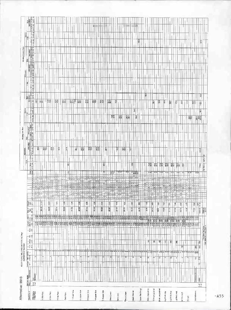
- !
ììIIIIHINIIIIHhIIIIOIOIIIIIIIIIIHIIIHIIOIIIIIIHHIIIOIIOIIIIUI1llh1IIHOWOO
¡IllhIOIOHOOhIOOhIIOhIIIIIIIHhIIIIfflhIIIllhIIIOOOOIOhIIIIOOOONOIIOIIIIIIIIIIIIIIIIIIIIIIIUIIIIUIOIIIIIIIIUIIHIIIIIIONUIU1IIIIUIIIIOIIIIIIIIIIIIIIIIINI
L .
:I4! ; -
I -
_\ . -
.
i ' I i t i I i I
IIIIIIiIIÍÌIIIIIIÍIIIIIIIIIIIIIIIÍÍIIIilIIIIIIIÏÍIIÏIIIIIIIIIIIIIIIIOIIIIllhIIIIIIIIIIkI!I
...su.......u....u.............u.u..... .uu.........uu....uu.......
o
o
i
888S8:: -888888:: 8888 88888:88B$8888:8:8888888 888888:8
h
5
th th
o
-A5 5
9 8899889988Sn on,

6
r
w
U!
8
O 8000000 80 0 0 0 0 8 0 08 80000
O O 88
999 1 080
-5 g
- n ;88:aa:
fig
g
g
888888
088888E OO88 98889988998
O
E
u
O
9!.
wo U.
u
g
O
g
g
8
g 2
p
h
82 8
8 O O 8 O O 8 E 8 E O E O O O O 8 O
888888 8 8 O
8 8 O O O O 8 O O O O O O O O O O O O O O O O
g E
9 E 8
O
O 8 O
E 8 O
O E
89 9 8 9
8 O 8 8 O 9
I-.
E 2 E E E E
E
8
O 8 888 8 8 8
O O O O
-9 ÇV- 9 O
a a
a
a
(D
93
O O E
a
(D
93
g (J1
o o -0 8 E o a
E
8
2 a
8 88 B 8 88 O
g 9 8 8 8 8 9 8 E E
E 8 O
----I EE:

>(8
a)
H
a Ha
oj! h
d
a8
8
8 8
8
8
89cúÑ
88
8
t
a
8 Ba 66
9
a
8
8
8cg
E
8
00
E
a
a
d
898
m
8
8
8E
h t
8
A57
8
9 8
E
8 8 8 8 8 8
88
E 8 8
8 8 8 8 88 8 E 8 E 8cg cg
88 8
88 9
8 88 8
8 88 9
88
a 8 88 8 8 9
8
8 88 8
a a E E8 a 9 8
8
8 E8
a86 88
86
8cg
8 8 6E
9
8
c-cg8888888 89 9 99 889 999 89988 8888
88 8888898E
6
8
aa 96
a
aO
2
d
t
8
8
a
8
8 a
8a -a
9 Jpa
v
H8 cg 8 8 E
E8
88
8
a
o
t
2
a
a
9a
aE E
a8
8 E
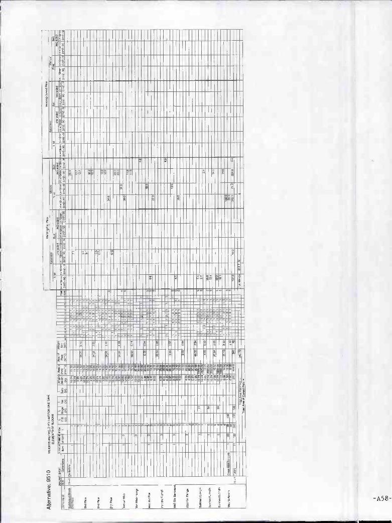
br
3
o
-A58-
:5
S
S
li
y---
diy-66
z;;q
8 8 9 8 8 8 8 9 S9 9 9 8 8 9 8
8 8 8 8 8 8 8 8 8 8 8 8 888 8 8 8 8 8 88 8 8 8 S 8 8 S 8
8 8 8 8 8 8 8 88 8 8
8 8 8 8 8 8 8 8 8 8 8 8 8 8 998 8 8 8 8 8 8 88 8 8 8 S S S
S S
8 8
8 S
9 9 S

A59
Lil
8
8
:
V.-
: :o
3 --.------.---.-.-.- -
8 8 8 8 8 8 8
C8
C8
IC
8C8
88
8 88
8 8 88
8 88
V
9999 Z Z8288888888888888888888888882888888
88822888888C88S88888
"" li
Z9 8
28
s?hg-
hV
8 8V
V

IIHIOHHHIIIIHIIIIIIIIIHHIIIHHIOIIIIIHHHOOIIIIIIIIIIHIOIIHIHOIIIOIIIIOIN
L
ï I
d
h
IIHIIO
L h h
g
- A6 O -

Summary - 4OKDWT Alternative VesselsAll Block Properties
- A61 -

Alte
rnat
ives
Sum
mar
yW
EIG
,SM
OW
E00
0UJC
EF
OR
2000
UO
CLT
EnI
OT
TV
ES
ag5.
r a
aiaL
(ai
a_to
(A
lla-
232-
11U
11Ia
l 224
1 lt
=19
22 1
4124
4113
2 21
4251
2194
22C
LII
IflI (
aia-
l(ai
2-I (
alla
-to
(422
-b 1
,32-
IC (
aal-
Alte
rnat
ive
40t0
W1
044.
2,54
2492
.....4
0aL
A4010 C
,a,e
l.$l.
Issa
taeo
toom
oss
2204
1410
0aa
nlge
o
iOlq
i04
141(
9041
0410
001
04LOLL
*540
= 1
*492
.120
122
CO
lifl
24.2
21pO
I.lIt
io10
.140
141
(a00
....
12.1
4415
(2l
2,l-l
O.I0
1114
154
0.1
0144 I. 11
11.4
I44i
eIla
O14
241
2440
1012
412
lO =
10,1
141
leI
03.
10-_
1041
2.1
4.4 il
1.0
lei 1
0414
1gI
fla$4
1410
0110
=12
0241
lO g
ea 1
4012
4141
$4.4
1012
=91
0_l
t-2
a-a
0_I
t_2
4-a
4_l
o-a
lt_I
Ia_I
P4,
14_I
54=
1024
19P
210-
0091
0.41
2
P4a
4_tie
=lb
a.,0
PO
Ol l
-1 0
4102
=12
Pal
0_a
Sltl
iO2l
a0.
110.
6.0.
11.9
4.05
1,4t
o.C
alat
o.P
al II
_i 4
144
Pt0
14_I
tl.I0
O.2
h In 021
42lIs
a140
104
sa $02
102
40
asa 02
1401
4104
Ial 14
444 02 IS
?tO 00
loO
244
000¿al
go
(0) tO
IgA
IIS
AItO 40
554
(aI) 20
2tU
O
(eI)
(W2 12
441
0442
9440
2041
21*4
,010
IMZ 45
20
9045
4414
2500
0200
4440
,0(4
1042
540
.204
440
2452
224
(atr
I
401
404
500
001
oat
(aia
- t
22 O
nag
050
4491
51?
tlO
tI15
05C
ot(0
46sa
aa 20?
(aia
- i (
aia-
5
2212
saio
gal
2240
122? 04
055
414
14C
OO
(aiC
_ i (
aia-
CS
(aia
-tO
aia-
to 4906
asta
aSgo
4005
2200
202t
1241
2an
a
4454
11?
(aia
- b
aloi
200 O
ass.
2002 .72
0102
2100
4021
22
(aia
_ t
4049
agil
241
3422
2420
420
220
925
atO
?to
o
4141
ItO (24
I, t
(aia
- td
aia-
a( (
ait-
b (a
ia-
h?(a
ia-
.(a
ia-O
(ai
e-t
440
(alla
- î
ail
(aia
-to
41 0
(aia
- b
S02
10m
fflaf
laa
(aaa
)ta
ftiat
,,404
oi
5_I
a.4t
0loo
i00
0.24
200
t000
..aal
eot
24.0
_ale
nflu
oa0.
M1
001.
_aI.o
fl
Alte
rnat
ive:
0050
0.?
0504
250
01
4020
ae(o
ol00
50af
lOoi
NoW
laS
050
1055
w&
4aar
o2.
4.40
1
204
2.0
412
2.2
1=4
.20*
2.2.
2(1
4e20
144e
2.4.
2U
sia.
.0.
51to
It(S
Ill..,
L Ft
L 004(
4(4
11
L 70=
(el)
L SaO
(OlI
AlIt
Col
li?lU
S51
2gO
,P
214
11Z
52.5
1Ig
il(0
010
Io =
104,
2(2
112_
tO(4
=19
1441
(aia
-to
1214
11e
(0,Ia
-5(a
i2_t
I10
1441
0elil
a-O
le_
1451
1(a
iaO
O12
(212
0_S
Col
lais
..lO
I 542
1100
10eS
(aia
_lila
ia-t
o(0
14 (all-
1*01
4210
laie
_t10
1414
5(*
112_
94(a
ia-g
I(ea
a-os
10=
1214
4112
1411
4111
00,4
5512
1141
(ait-
0010
1211
g?Ia
ia-L
lo,lO
-hl
leel
tIlel
laltI
e(a
iO-
l00,
2î(a
ia-I
O1*
0101
,41
1214
141
(aia
-O5o
IIsaa
I4e
I_l
1-a
2_9
0_I
4_l
0-a
2_17
2,14
_I
4-o1
0110
-aS
lalo
a.,a
4_(P
*,ll_
ISI.1
0041
29_
4021
11
4- 2
P0,
lIO_2
0.10
451t
0.eI
.(-0
1g01
1101
-10g 41
.100
.0ae
Oe.
251.
l020
,*C
ils_l
011
0091
0100
-2S
ItIS
O.,a
094(
400.
0.45
to.
1 l_2102
1442
2102O
t40 ItO IS
!
52 lOa
IO?
at 44 54IS
O 22 50 tO
51424
194
14(3
0114
1021I t
e
lOO
002
IlS 112
204
191
010
1050
0241
004
4011
214e
ais
0
0124
OS
lO
0094
405
4400
000
0414
904
9240
042
3401
016
202
101
010
102
050
1221
1010
2220
0024
1040
1440
0941
5115
lOtI
1042
loll
1244
1024
011
041
01 901
2021
3102
laS
t
1402
OS
ta41
0023
4541
0120
5001
5001
02
aLB
O
1540
9941
044
1040
0921
0411
1lIl
It4
1
II? 440
212
t
2400
2120
1410
na,
4542
0540
500
201004
412020
04?
041
Otn
oisa
len
atus
o 04
0io
2.1(
25 2
(410
vSaO
OLO
Itn05
90.1
516
m04
4.0(
04.
012.
0103
22t
a0S
a00_
a400
5*4
105.
949(
400
9534
5(0
15

Alte
rnat
ive:
6000
*1 8
.8.5
51,.
4030
0005
1.U
,lq.
lOI
000.
1090
7030
(110LL
LCF
0009
).?.
.(8
1)00
91
(0)
01.8
(8X
0.11
1180
.558
4)2
(89
5109
7
(91)
1812
40
(*52
69I.
18,1
11(1
2_07
002_
0$
209
9)4.
2
(012
_
7918
83.,
1622
09
4)46
204
0011
67
(*32
6910
4100
,0(1
1,2-
6916
22-I
140
9124
4
los,
(002
6(52
9( (
002_
9
048
14.2
160
0454
1106
.,((
2,2-
69
8)49
461
5.1,
607
aX 0
61*5
1804
030
614)
272.
166,
4,(0
02-6
9I.
16,1
,1,4
.07
950.
19.1
1.(0
32-I
S0(
6.4,
(002
-110
112_
0$ss
rt.,,
016
..,(U
I_I
1018
)411
0870
*5)0
112-
U(0
112-
l97.
1911
.1(0
42-9
0509
83 8
164
3_l
0491
.1-I
ll.02
89lIS
2699
(30
027
1101
090
5489
0)98
11.0
11(9
4902
1104
1ß14
45l-2 2-
i0.
0191
-6..
P,o
,0_I
sl.,b
..,4
6019
489 49
(32
258
000W
029
1895
03?
9(0
000
2220
726
2914
39091050
6099
8571
144
(701
002
4071
0)24
2-2
4_I
Fo,
12_2
111,
lIo.,4
Foo
l 0-1
Sl,0
15,,d
(6210
854 20
142
38?
1010
4816
601
9 I
660
IO S
0720
1080
7895
322
2522
2184
8902
826
lOO
i01
5O
42&
6101
30$
2620
.10(
644-
2
b-2
?TO
lS_2
1101
50,,4
F,0
07_2
S19
l10,
l42
02
102
4310
0
1(06
01
0275
6900
090
623
960
6110
871
982?
3080
9850
1172
001
7626
1112
.510
04O
IÌIO
044O
I,fl 6
-10.
0044
5.I
(02
20lO
O01
2000
110
6009
36lO
SO
5220
2002
1019
.241
.lI 9
_20.
5141
5.I
002
0015
999
9105
910
8201
7221
0097
2720
(081
1891
60$
2_l P
o012
_lS
1soo
.0(0
220
028
6212
209
755
911
6215
0409
0191
0100
4-2,
5601
4-20
1.lO
s.11
(02
311
93)5
222
1217
(040
0150
IllS
Alte
rnat
ive:
3000
6206
6.6)
2 11
00640
40
60 0
1102
684
w6.
6210
0200
5444
4149
5001
625
1625
*9)2
0911
26.
4221
10,
079
9)49
434
49)
284
160
0482
059
4,46
414
4081
002
(29,
484
11.0
,(2
,1.5
1U
1170
2101
.IOLL
LLF
908
9).
466
9146
,00
1,85
0169
4198
2641
9)Il
1119
1811
441
54)9
,,.,
03.1
4111
11 1
0101
111
1047
0117
0 l0
1834
3\II
1341
0110
lOI
1019
4.1
6.64
,631
641
202
O00
4093
l930
1043
1l10
11l2
,118
1 12
0211
8010
.101
181
0219
070
1001
0001
722
8*5
.101
10 1
316.
7114
216
110
1312
111-
1041
64,.,
0201
,080
0112
8031
209(
0112
l_I
l_2
2-2
0_l
0-2
5_I
9_I
2-2
2_l
0-2
lO_I
IO-
(P01
119_
I
0011
.1-4
00,
07.,-
(0.
Po,
12_2
Sl.,
509,
a50
65_1
0 61
0061
2P
.115
_201
,100
,,2P
0111
_IS
I,,00
,102
102
PIII
3_20
1,,b
o,,4
040(
4(04
11.7
)890
,C
9315
908
0837
0)0.
1100
?3_
1S10
201
2700
011
0 0 1 I I I162
lISO62 90
102 82 40 (02 05 05
ITO
(02
(Il)
66 66 (02 24 20 93 90
lOO
280
1034
9)10
0601
1011
129
5270
(81)
149
196
(00
lOO 7
(11) lIS 17
2
04?
(11)
iU'Z 70
5819
2
iU0 09
10
0140
9160
0106
0008
9051
3492
2932
??)
9009
080
0200
960
9100
002
0140
070
III) 61
0
002
100
130
302
235
1490
048
(703
2-09 10
93(0
39
4922
(029
(080
0701
III 5
(OS
I10
4142
202
226
6288
?
(52-
1(03
2-S
S
(15)
(120
9955
342
922
0003
342?
300
505
970
159
1110
2-40
032-
00(0
112-
10(0
1.2-
07 080
2062
0144
0146
0763
2900
0500
9190
120
421596
5969
24
1000
)770
-20
0510
00289
667
0004
3129
(311
2-l)(
01l2
_00
9050
)587
100
029
220) 90
298
235
02
520
020
0263
1)20 56
0
12$
(20
lOO
(011
2_01
1111
2_0(
(62
2-1(
5102
-00
(032
-400
112-
00 (
*521
(010
00 (
0lI2
-I(0
112-
00 0(5
(0.2
_0
0911
,078
(012
1100
8.18
1,24
250,
6,90
,00
0149
00)4
49$1
42 5
(061
517-
20)
2404
040(
5051
0111
4fl0
048i
6091
02)2
_01X
49Q
_2I2
fl00
404_
02_9
1000
1209
1407
290
Alte
rnat
ive:
405
0
9050
M 0
,895
7100
9400
709)
0011
.1
wllo
olso
l004
101O
L059
T01
0000
0ToS
00.
9159
11)0
II.)
.85
0490
07.2
11)4
7.
009
664
160
8104
300
4041
044
0,98
494
1144
.000
1180
4148
2(8
7)(0
1706
10.1
20l
1l,0
IF
0054
1.LI
II 1.9
0091
01..
00,2
.?01
.84
0)8,
.0.
901,
1901
10=
1811
1111
1070
1131
618)
(0,7
8*9,
101
6rn
(041
2810
113
10l,0
-104
l411
011
1811
8014
9041
000
1111
8116
1110
171
14,1
4011
079
1.11
14,1
2110
1 10
1815
lOI 9
1111
(0..l
SlIl
l 101
412,
10.
1811
111
lOIO
IIlllI
OO
I011
lIl 0
7000
1
2-2
4-i
l_2
5_0
6-2
6_I
8-2
2_11
0,1_
I 6.9
104.
1420
ll7_2
0191
0021
2P
0l(5
_101
9100
8)4
P0I
(S_2
S,6
1049
14F
0,l?
_l01
.,004
13lO
I?_2
S02
1048
!0
0921
009
0.41
.170
I I050
2152
10014
411
0 05 00 00
(0) lO
O (9 00 040421
616
0401
1418
01
1919
0
(II) 14
9 00
(11) 27
200
0
(111
(03 70
542
9006
9194
(93 10
6?20
51
4000
0115
0001
913
0020
040
0006
090
3720
080
(OlI 9S
?09
0
20?
002
(002
-03
2322
0290
1209
1511
1071
4)18 69
810
28
lolO
lOI1
2-k(
0002
-I0
2198
2810
(285
2302
2054
392?
350
560
lOO
1011
2_I(
O,I2
_00
(50_
05 (
52-0
0
3010
2022
0000
2026
2026
230400
0001
1191
0020
0206
1267
2
8006
)123
021
2002
2004
(042
-O(1
1112
-4l(
0000
1104
0002
1040
(625 ill
180
182
(0ll0
-k(0
02-9
((*
54-9
0111
2-09
100
2-0(
622-
0$ 1
5201
03,0
10 1
013-
3(00
2_05 II
S20
S
(242
-
0411
4*ß
J294
2,00
24 0
105$
0930
41_2
0449
1100
2610
0811
201
42_0
1041
0142
0100
0
020$
_662
X0
0630
009
10

Alte
rnat
ive:
406
0 w
B1s
o«o,
.o00
,«4o
SB
oS4s
42
6064
7(6
4243
1660
9
07.6
063
SO
S
*264
«S
64
4.4
U6I
0. 67
006*
2 (1
11.5
1
40
ISO
ISO
(02
(SIS
O
5205
4754
1520
5,52
2504
OB
*5
1)
64
45
500
altI
5015
4(42
,00*
2407
LOLL
4414
44
5000
AS
(4
7) 45
5
5510
6447
(S)
171
6
5206
SI
41.6
41*6
4 01
410*
7
(20
5054
2 7(
20'
4550
.
pI.,.
(U
2 260
5404
*76
7546
266
41S
6S66
05
049S
4 45
20.4
6
2523
5*
045
2*6
lO
0514
(424
«644
0 06
171
(MT
)
S*0
l 72
20
5444
7 S
S 74
40
07
5004
705
OS
O
S
IS.0
6004
1 (4
,2-4
7
1600
.2*
241%
44
2*4
04
1S44
2 0*
4754
5045
42
2757
66
02
Sl
IS14
1S41
(0
05-4
5 42
5*00
. 25
44
*56
2564
41
644S
2 55
4 40
24
201*
44
IlS'
20*5
(002
-4
*2(2
4
1671
4
*6,0
0.
M)
¡SI
046
1.61
4007
1(4,
50,0
4.76
005
43*4
00
6,
462
BlO
SS
S*2
42
(002
-4(4
02-0
2 I4
.145
1514
45d1
4.16
414,
2410
400(
0006
6471
0044
06'
SI
&0
0442
0.51
, 11
404
l4I4
SS
II4S
l*llS
l 902
fl.=
(6.1
04
0414
4.0
l4l4
l4.lS
SlS
l
lIOS
OS
44
(227
4 002-
C
7*61
544
0(05
22
45
SIB
BO
SS
4540
.46
4421
(52
(OS
aB
S
5505
* 17
10.2
1
(41*
7!,
(002
-0(7
0?-
(002
-4(0
00-I
F
2750
.4
4750
.6 (0
02-I
l-2
2_I
S_l
5-
2 4_
l
2- ...
(4
...
. 12
-
-
- . -. .
..
4
. II
. 2*
2
(052
-0(0
04-4
7
6540
.55
2S56
772
S14
1(54
54
6«
5140
. A
St
MS
S
6(0.
47
7524
25
1120
.42
(412
-6,0
02-4
7 (7
02-4
7 (0
02-4
4(00
2-4)
(1
712-
44(0
02-4
5
544(
0039
(401
40
(427
09(0
43
2411
0000
6043
(.
5224
4.0(
401
(422
46,4
1,01
01
4.4(
501
4.20
0e
4224
2.04
4J(2
9 96
004(
004
025*
11(0
06
Alte
rnat
ive:
407
0 50
0145
2406
4164
5004
5050
0900
1140
89
2447
42
45.4
0408
0551
21
(644
04
44
.....
430
0046
5 2)
6,.
4640
1.
610.
1067
6.
7036
141
*26
4606
4*5
1*15
5070
.147
1141
IS
IS;,!
? IS
l8S
75I
475S
,611
0.IS
lSS
l 22
02.4
,40
4149
04
005.
50(6
(4
lS5f
l1)4
3lg
1414
1,5,
74
.103
« 4
BO
SO
14
.107
051
1516
7S0
141.
1*61
47,5
141
440
4504
485)
649
1_l
2-4
4_1
I(
I_20
6416
1-
4-21
1.4(
64*4
0.4
SS
OS
_IB
O4l
06*1
2 5s
01-2
51.1
0041
2 4*
4*04
6141
*4
7(7
lI_10
.04
7030
_l 5
7.10
8,41
2110
1
90
lOS
44
2512
422
4.10
8*
(257
16
(SI)
66
7465
28
1614
(SI(
(0
1 (O
( 1710
. 20
70
5566
S
558
5008
4805
45
47
(4
2
*6*0
. 70
455
645%
(
0*61
0864
7*4
54*4
241
4(70
.42
2511
4744
401
4441
1586
721
(247
142
1437
62*
2745
4847
*7
ISO
)
6440
10
00
607S
75
05
(002
-671
1140
.14
4006
10
00.
5252
24*4
084
84S
144
SS
TM
6
04(4
2
(002
-I(2
7S-
47
7444
55
0040
.52
SO
SO
7SO
SS
20
2080
.52
46*4
412
0615
447
(728
54 (0
02
M(o
02
40
(002
-46
(4*4
2_47
1 704
1(21
24
41
SIS
«1
2
5544
920
2624
*2
27*6
4
2065
24*2
* 14
20.
SO
SO
S
2254
2 (6
716
1004
00
(055
-45
60*0
.6
OS
*714
( 44
742(
2445
0.
(724
0(4
0204
252
(570
.45
(502
575
(551
450
(042
- ((
0S52
-
1544
0 10
4)
(20(
.74(
052-
I5
(002
-1(0
02-0
. (4
02.1
,437
*2-4
5
0020
4
1471
2-1(
00I1
-(S
2442
45
4675
(004
-k
4404
47.4
(443
0,
4(20
0_0.
243
4949
26, 5(
4140
_175
05-1
(124
_M14
(64
0.46
0514
40
1020
8_01
1401
443
Alte
rnat
ive:
408
0 w
I,200
4000
51.4
1110
1107
0201
1074
40
0M25
506
0.16
40*2
8
0000
0 40
*654
0 1(
40.0
1.7
51.5
00
0416
01.
1470
1570
4300
41e
00.7
1 78
LOLL
05
0(5
08.
*464
SIS
. 04
0062
0184
55
7(4(
6
5644
70
1100
(4
5703
5 IS
197I
SI\1
5678
500
056
6242
05
7 l0
I6?7
I4 .1
5051
6460
75
1 67
*0
(S.IS
ISS
1 ÌS
(557
0156
0.S
I57
1*0
6064
76
27?
(S*1
6515
1 47
55
208
46(4
00 64
64
(>IS
T.,
1*2
(AS
105
171
8*48
2 )5
O
IS
(41.
74(6
, (5
1445
11(5
56
72 61
0015
461
7074
450
(511
(I
II (5
) (5
1 (4
2 (4
5 (M
OI
(002
70
(002
-1)0
02-4
7 (2
02-4
4(00
2-45
10
02-I
F
(002
_45
(202
1(00
26«
(002
-0.1
002-
01
1702
-1(0
02-C
(0
02-0
)431
2_40
(0
02-4
4(20
2_IF
)0
021(
0024
5 00
2_0
822(
4(0&
2606
I
064)
27_8
56
SS
05
4 77
00
2952
571
i*5
05 4
04
5 02
*
0611
505
800k
64
11,4
(1(2
40
(.2
2_I
065)
41_4
44
PS
l(7_1
06l0
S64
S
S 02(4
25
00
1218
2S
77
470
OS
lO
6S2*
40
4 62
5 2
5 2S
4 54
6 05
4 S
OO
S
556
1011
02
5 11
57
2611
7(
5 0*
5 44
4114
24.4
(443
2-
2 P
502_
2506
105.
12
25
464
5*56
74
5600
11 1
005
502
25*2
64
1
(144
9815
1546
(148
_910
43
5_5 4l P
S4S
_24(
5llO
.l2
PS
OT
_IS
I6IIS
.l4
(155
*5
O
S
((5*
2228
14
44
4045
87
2966
4(
7 A
60
240
5625
40
46
(161
26
1 4
((9*
_014
44
0-5
SO
IIS.2
5091
0081
2 lO
S
475*
S
SO
. 52
06
940
60
250
00(1
fl 5_
I 04
7,4,
46
7*
III
7500
25
45
000
55
2525
20
S6
450
104
(610
0124
4 6-
2060
16(5
6 02
11
0756
1 54
00
054
SS
28
2*
2(44
7*0(
80
(6:6
,F44
Il4:2
116(
b0*0
'(1
11
52
2070
IS
iS
SO
I lO
IS
1129
23
*4
lOIS

Alte
rnat
ive:
409
0w
000r
0000
loom
414
970
::60
,44
SlO
t(.
22_
1
6-0
6_I
lo-I
8-20
.0.6
7..
9-20
66(4
1144
I0_0
P41
116_
24(.
,4O
.4
5.0w
_6..
#641
8_l5
1615
4412
P00
16_2
9«4b
>61
>
C44
1216
4
p04(
4_I 6
1611
4.00
6 2 4 II II 4 2(00
40 52 lOa 20 60 22
4144
1524
0004
2414
14
2874
472964
1718
2414
05 544
4244
4226
2574
4264
146
6*4
5424
6585
22?
45>
10>
4470
4845
4626
5042
402%
64
248(
604
45
4740
4400
4066
4444
2276
2227
2(14
624
7421
5
160%
222*
77(5
0146
2(9
(974
8
1454
200
5%
(724
475
2470
424
4445
4524
064
S54
40,2
7529
7441
2974
2
142%
4225
355
79 I? 07
110
51
656
456
204m
005%
4450
t 7(0
5064
744
2845
54
40 5
*56
27*2
516
2021
(540
028
(711
527
I! le
0149
7844
4251
697
7024
41.4
4672
8214
46.2
414
1%2#
h4fl
4_fl_
2142
2
2_%
u04
2.1*
6)20
5
Alte
rnat
ive:
401
00
4454
W?1
1411
4446
0046
4142
4144
6162
ws,
000s
owoo
sot0
000>
oto,
4241
4441
1(6
8.14
040%
4605
1519
7027
4441
6140
4641
L 02L 24
(2(2
L 74=
L 8640
>1,
.04
14.!
0166
644)
6(4
#644
4(0
46,4
I> =
1441
0 16
1 64
41440>
464
6240
6.0
260
(014
1441
(0?
1412
6144
2.1
9040
141
61,4
044
0464
262
l7'4
6062
(014
410(
0=16
140
1>01
6976
4164
141
054
006.
4.=
1997
0 10
1611
.,404
=16
740
1416
497
1421
6604
1 (0
4664
1,4
(>>
(603
41 (
4l4I
*l4>
I444
0(4
,54.
1*0.
1054
1 10
1140
4
264
4154
1*
2-I
2-2
2-2
4_I
9-1
9-4
(-20
,0.0
40.
II- 8
P#7
l5-2
0915
5610
4474
-(41
4(44
.I240
14_2
0614
0642
p001
4_20
.Ib4,
12
0451
564$
0851
004$
0*97
66.
0
44 44 64 44
204 24 24 52
644
(444
1444 24 41 00 70 42
lOi
(6
2048
(>1)
(0)
1140
444W
7040
12 O 76
0042
5460
6041
442
5574
452
1421
4440
6?
1420
4221
444
740
2527
7
65?
942
(66?
)
8774
1425
2004
4222
7540
1042
-04 (2
4444
1427
64%
2849
7544
100
442
6444
5725
5724
(011
2-40
0042
_45
144*
2520
44(4
4
270*
22
4209
782
1 42
(2(1
6
(12*
1002
-4(0
42-4
5 (4
02-4
0(0
112-
00 5? 2
2046
2444
74(1
472
565*
0412
122
64?
267
552
7402
3
i011
2_b(
002_
4t
4154
4484
244
684
1075
6420
67
(420
14
452%
(441
611
651
7001
1
(001
2-6(
042-
20 (
042-
2474
2-45
(04
2-44
(041
- S
t(0
42-0
0012
-45
(042
-b(0
02-4
4514
1421
6490
6840
42%
25_2
1040
4244
2a21
4*
1)42
2208
1405
2,14
4.42
Blo
sS
4_01
2fl
1796
2212
40
Alte
rnat
ive:
401
10
4441
0*?
U50
6211
400$
21,l0
0019
9402
d
w41
04?5
4040
0Lol
0527
4 00
2440
4725
50.
1004
74.
*446
402
4414
100
6044
2445
818
041d
106'
eLLL
L76
6«0
440
.614
1467
4,66
004(
444
8.44
2154
114
6105
« 14
1811
6(14#4
443
4200
6(2.
24=
1050
104
6(48
217
12>
4?l4
>14
7,41
4 14
44,',
>442
4)44
470
6*0 1>
16(1
40(4
=49
9745
IO 1
944(
11500
4444
8251
4111
25(4
0021
154
140.
746
>14
041
1416
1454
4=14
414,
1016
110?
1416
42W
10>
167,
.,.1
400
4144
51 7
4.10
4041
9140
444
05
o_2
5-2
8_l
12_l
4-05
64(4
44.
7404
2041
4441
2
p4ll7
_221
4?54
612
064(
2146
0401
8_10
6140
464
I 4
44 42 64 44 48
0,41
24 42 24 85 58
(4(4
6
44
(SIl
(04
2244
5
(%2
128 (1
5>4
4744
2432
224
5102
727
2404
424
(401 (500 2(6
(042
-44 14
2
040
647454
025
1011
2-2/
l0I,2
_25
124
I0I7
2258
558446
4
(0I,2
_L(0
144-
4544
2-45
104
2-25 20
>?
4842 70
5
455
976
6120
(502
-010
42-4
5
964
2629
7(22
4259
4500
4044
4041
101,
2-#1
4112
-Sl
(004
.6(0
42.5
8 (0
42-2
(442
-25
(442
.010
42-4
4 (4
42-6
(000
-45
(043
-6
1132
04L4
62S
4
>12
8_01
004
8441
424_
44_0
1000
4.04
4(4
72
0.62
6640
5

r-2
Alte
rnat
ve: 4
0111
7070
01*
WI.
6)80
0400
77.
6*2
*93(
5091
0124
0507
7610
60 0
5910
6611
.607
31).
*073
00
120
6)08
0*4
07!
6520
jo..
6594
740
4062
04 3
4!0.
1117
6011
1
S 1
1.0
F2LL
_0o
04. 7
..(4
)7
C *660
(4.1
0?.6
1.7
716
04
0.69
47P
l.,.
(S2
904(
001
974
(tE
ll10
7197
>41
(072
-25
oIt
7)(1
210
(102
- S
(002
-.89
90.7
)87!
..I0.
008
7775
7).
(002
-072
-2587
007
8780
1(0
72 9
(002
-01
0712
7171
0760
,8,1
(072
-49
06)8
*9o'
1-17
072-
9(o
',2-
0817
6(45
10 49
1007
4?(0
72-4
(002
-01
1218
*7 II
)(0
72-1
(002
-44
1710
7190
,110
=2,
70(0
0.2.
4l(0
72 8
971
1607
273,
)10)
6,37
(07.
28(0
02-1
414
1877
1(1
112-
1
0 48
48 6
1*1*
I - 7-1
6-1
4:2
2-I
4- 10_1- 20
6716
,_11
6
2- 1
7001
6_IO
78Ib
l.74
14-z
Po,
I10-
as,.m
s.2
7015
_101
.,b#.
12
P41
,7-I
606
,608
0207
07:2
0161
6*9,
0
6.9,
9».
727
II-74
162
2
88 29 20 03 44 232
48 581101
27240 60 74 38 54 6826
786
(470
60
2448
212)
0012
42
5 (030 4(46 III.
2792
486
(40)
7(94
1154
3100
0
880
20)4
414
980
72 444
447
7451 44 64
266
930
2179
020
228
7615 2)?
425
7(50
760
2252
5769
2360
22(0
4606
0
172
874
648
2(47
608
0447
6422 04
40(
8(0
64 30*
678
5001
1055
1
9420
9258
*357
(090
1771
3
2427
70(8
2846
6(47
47,4
1720
270?
202?
4146
0
9606
608(
87(1
0066
3191
444
05.4
100_
ksl
a.7,
oO
0a(1
.19
778.
....*
1040
(180
0 71
6cl
LMnÌ
_41o
46
Alte
rna
twe:
401
12
9000
*705
U0I
3480
011S
60.4
2004
8010
(140
(0 0
0101
0447
0 F
07 O
SE
rON
t*6
0229
6112
*644
312
7429
244
894
9480
(11*
462.
206
804
9460
0.0.
260
780
4276
47U
*Iq*
.l4,.l
W04
11.1
3L 98 (4
)
I 04...
..(I
S)
C (01)
L 489
(01
0?66
0674
6770
?.(3
_9*7
8804
(83
8.13
4?11
.7,
(21)
06)4
1767
4*2-
2517
1840
7d4
14.6
,47
(01,
2-C
13=
1901
4110
72-8
(002
-M(
0710
8167
,0(0
72-8
(071
-09
1019
407
(406
0,94
*11
1003
161)
.(0
72-0
(072
-25
4406
(47
6491
1708
*511
4097
90(0
72-8
(072
C (
072-
C(7
1870
111.
1007
(072
-1(1
02_1
507
60.0
(011
2-1(
772-
C40
94,1
7 (0
7698
010
78-9
(002
CIO
066
081
0780
07(0
731(
001C
06,9
47 1
0193
00(0
02-8
6242
._16
.43
8.7,
116(
443
I -,
0-7
4_2
6_7
12_I
l_20
.4)6
7_80
.2-
7811
.4:1
6961
42.1
3
8_21
6016
676
4-44
97?1
4-29
41#4
93
067)
61-6
06
7201
S_l
*?9)
0461
276
75.2
9616
49'd
140,
647.
P87
(2-1
4.6,
64.,
5 5 2
46 28 68 44 48 25 25 45
4494
76886
468
794 407
42
57488
779
1477
6
2877
4486
0
2331
127
201
4731
116
232
186
2421
8661
12
0477
7275
6606
2842
*7*1
145
11)
6812
4699
4410
6907
8' 6
2
26*!
90*8
7446
182
732
2)96
4222
242
842
2864
4296
6728
9766
030
9*22
(211
*768
-117
0
2582
973
7*4)
313
544E
54*8
4
64!
94!
11(8
2040
184
2141
9(8
578
676
986
887
4(06
1
178*
8347
001(
674)
5945
1728
86*
1326
498
9484
7856
0
2588
721
860
546W
4958
7
55l0
4400
60_0
1028
4(0,
86,9
7800
9,28
6,4(
6*1
66(9
(6.2
8(9
288-
20.7
,627
62,
4k_8
702.
tE1s
6081
428
0.43
_912
4328
0042
800
Ajte
rr,a
tive:
4400
01 0
49)9
)90
4012
0
190_
4
,l91I
6oso
,GL0
00IW
,69o
s072
7086
11*0
11.
*491
000
1181
4
U,1
008?
4161
221
169,
F8
(7,0CLI
C04
.....
l#(
(070
60E
(701
O...
....
CO
I48P
190
01
PI.,
.19
006
)47)
1167
)
(21)
441*
0)01
14?
(042
-C47
.,47
66)
0.0
60*
63.2
74.1
*617
(072
-49
026)
2.0
4.1*
7717
072-
007)
2-8)
1418
114?
404
6)2.
440
4=
090
1814
0711
4848
17)
(072
0(07
2-C
4189
4711
4780
4)08
2
0160
691*
06(
04(0
777.
5(6
l2,,2
-t/(
0112
000.
1441
5, 7
)454
1(0
72-6
0(00
2-49
06(0
09,
8(45
80(7
1,2-
JI7-
17.)
*,77
l10
00-1
(110
2-C
1014
7.1
(072
-411
02-0
014
8147
0 4(
4741
>0)
4074
1072
-0(1
12-C
(072
-8(0
78-C
=70
7,4,
016
7870
0(0
72_1
0.00
2-I
22 6_2
14-I
12-1
8_21
8414
1146
P71
8_I0
*I(0
6'2
7741
4_10
7918
1610
C24
1897
6
1401
1-18
0418
*94
l#-2
7011
1044
I 3 4 2 2(
744
240
lOO 94 28
284
400
*74 95
220 67 2(4
72* 16
676
1116
*
2511
527
(0
287)
2572
1182
61*0
103
0027
2487
678
5422
95(6
685
4(0%
1807
8174
164
6057
1440
7*97
0715
707*
4
4567
1685
2259
12)9
8220
187
(*84
5466
002
4186
002
2084
230
007
0404
7
1446
0
2788
702(
28
4443
0720
011
448
7716
6414
8
2512
1)00
37227
4004
4
8280
46
260*
277* 44
260%
52 0
*5
71(0
022W
522W
7436
7o4
5
7042
4526
5)73
7254
4624
3161
440(
4819
14*
0400
3091
049
0M10
0325
_0(4
21
07.2
8_01
404k
Q4_
410f
l
0442
.904
.410
91

AIte
rnat
ive
4014
0
414(
4 (5
4410
000A
01D
015A
O.0
207I
)
Woo
Od
Alte
rnat
ve: 4
0121
saoo
*000
no,
020.
542
AbO
YO
? 04
0442
2454
2040
0050
uo(q
o.ya
.(e
LOLL
0)50
4,5.
2O
0#.
AIS
ALO
SA
TO
O5(
0*2
.00
5424
00(
024
0270
004
204
OIS
AIb
AIT
ELK
0001
4(00
)5T
OS
I00
554)
)58
0A9
7050
0K0
0.0
7(5)
.70
4,)
0 A
(0.,0
(01
570\
T0.
1704
070(
074?
< *
(0)
701
0704
.0T
) 0)
0005
lA 0
0SÙ
0045
A(5
OIg
A.
A14
401
0.49
5K T
OIS
AS
? lo
s (A
AlS
(4)
044)
(0
AllA
,
ft250
2120
9fl
0.01
0010
)00*
T_I
140(
51_2
527
(4))
04(0
1)(A
l)(A
l)(0
4250
(O -
O AS
SO
(57) 54
4(A
.110
00)
(04)
2-k
0057
(040
2-lW 00
(00?
bA
Al-
OS
AI
05(0
75-5
9(0
472-
IO(0
4,2-
b (0
400-
25 (50(
052
272-
IJ04
IO-O
((0
470-
W (
0112
-Al (
0402
I)A
,044
(04
1121
4.2-
25 AIS
(0.2
-1(0
,2-0
9(0
,12-
b
I_2
2_o
000(
51)5
5p0
74_I
S00
2:2
I 5(2
0(0
402
)70
000
7020
0A
SIT
AT
OE
OS
A52
5lO
A20
(04E
TO
SO
SA
lA20
0(S
OS
OS
I)50
4,,
o50
0500
010M
AIA
0*02
20._
0000
)A
_A P
OIT
S_A
0701
0021
24
400
ITA
7410
402)
44)
OS
SA
(02(
020
4700
20
'IOA
SIA
OW
5_l
4007
7_(O
ISIO
OA
IO5
247
SA
l04
0020
7)00
(000
705
(00)
(AS
((50
002
02(
7152
!72
02)
1MtW
)224
0_2
0_l
0404
7_2O
,A10
0014
1.7,
0(0.
I 11(2
272
004
0(A
A50
6029
7)70
2220
070
425)
170
20(A
ISlO
)75
304
047
DA
I00
0(07
945
(005
7005
0S
225S
02 0
)052
02)7
0524
_200
0kA
_l0-20
.715
07.
CA
7I00
05A *
(00 70
AO
(0)
25 55Ill
S4)
01 0042
*70
703
(575
lOT
)(A
)(S
AS
A)
ISO
7000
770
AlO
422
AT
T(lO
S70
)A
S57
0O
SA
5007
Rfl_
2)0n
25(4
fl10
(A
-22.
7102
A00
07Il_
T 0
70(0
0.2
(20
2070
204)
510
(572
2401
520
ES
,70
0540
0200
4A
))K
TA
IT(5
1 50
)5S
AS
2200
022
100S
0S
AO
04
SO
lS00
00 S
AS
SO
(020
040
0000
7000
7050
005
550
220_
0400
0P
5009
(,15
15_2
00.)
((2-
1(2-
2701
100)
04-2
0701
0450
20
25 000
2(0
0«50
0 S
AO
IAIIS
S00
)02)
0705
200
074(
0054
070)
0000
2202
0000
0705
557)
0140
020(
0)7
Alte
rnat
ive:
401
30
0000
5040
5555
Ol)7
00 4
010)
5000
A)0
O0l
70A
0005
0420
000s
o072
702.
005
(429
042
0020
0)0
555
5505
* L
1500
40U
*440
J044
0(f,0
.L11
1100
427)
SS
70.
OA
K70
,00
00)7
5724
.02
7055
<0(
5.14
75,7
02 1
0.10
4(5
0(17
5450
700
5050
(0.0
505
(AA
SO
SO
(40(
0.04
OS
A5(
400
4000
(050 (0
)00,
0074
,0T
OO
254
0141
)041
427
04K
004)
5.40
.IA
IO,0
7!54
(O5l
0( lO
)ST
(501
0010
4)T
lT 4
(050
0T
OT
005W
I0O
Ib77
, (A
I000
,(A
l0(T
O7I
OA
T50
A (
005*
flAS
Tb7
lOl0
(SA
.4T
00lS
A01
l (0(
00,
0041
000)
00*
l_T
2-I
0-(
TO
- T
72-T
4-17
0(13
O_2
0.01
.00S
0.5,
04-0
70
P*T
T4_
I015
(025
l5
_lS
lS(O
AO
IO
PO
T, 7
_T 0
70,0
00(4
0
400*
1_10
414
Psf
llO_l
0l0)
0450
I I(4000
ISA 02 (52
052 (2
(All (A
S
TO
O
079
20705
4(05
20)4
0
15(0
0
(IT
)) 001
057
(54 20
0
(A)
(A)
)09
AS
ST
0452
(22 20
40
0000
0
075W
5000
)
0022
)10
1050
1070
2)0(
0
(2T
(&flo
.54
)9
*227
4400
0004
0007
05 (
0
2&70
1520
50.0
014A
250
0)04
(5_0
5
004
0000
(000
4500 040
5000
501
(000
-004
72-O
S (AT
OA
TS
722
2700
005
(OIS
754
(4.2
0(0,
0-70
(0.2
-59
(042
-04
40(2
4(40
0440
0025
0044
0(00
5204
0,
(217
2(07
227)
)
OA
S
2090
(0,1
2-0(
042-
AO 02
5
5)2
002)
1025
(750
1(04
001
(00
(044
2_21
042_
0)(0
470-
5)04
52-0
0 (0
05-0
00,2
-1W
(00
2-1(
0410
-29 50
0254
(002
_h(0
412-
00 ALS
(070
-1
0204
0n04
000
0022
.0_2
0024
0)40
_540
10
200*
_moo
tp0
7550
20(0
)0t0
1L0)
224

Summary - 95KDWT Alternative VesselsAll Block Properties
- A68 -
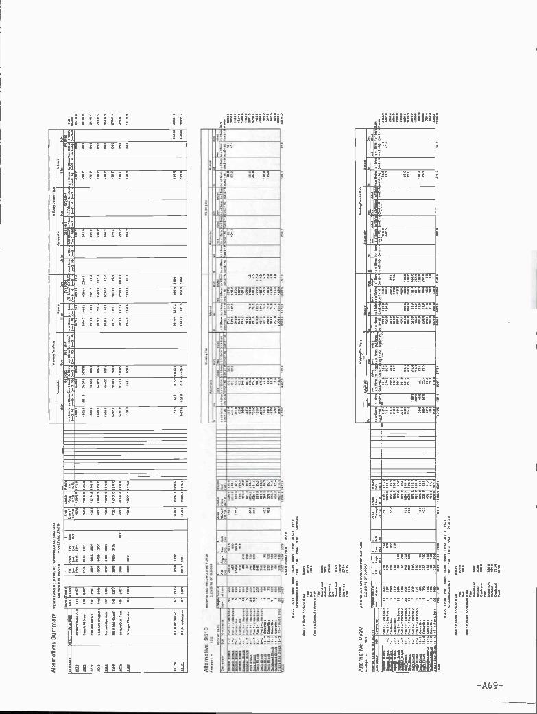
Alte
rnab
ves
Sum
mar
y«o
lou2
o;04
Wo4
1*?W
00l7
ls71
4W
0>23
94P
l18
0599
441
7>5
9140
7.0.
19.2
459
4240
?O9l
344
584)
533«
.111
.IV
1211
8404L
LIL
553(
9(S
Il7.
.(4
11
044
(OIl
AI.
>C
971
Ill
II.,
IIPI
.).
(22
*919
?)>
931
(47)
11.1
131,
3(1
232-
4341
1472
174>
1*12
-h14
>10
31,3
(41)
2-13
=1
2>,d
l>(0
>2-
h10
.121
331
(511
2-27
(31
12-
1>13
2-55
1>11
1131
14>
1931
31 I
I 45
40'?
>(0
52-h
21.1
1125
8O
LI
0884
1ç*7
1744
10(3
)120
5 (0
32.2
114
1931
2111
=11
710
(13>
2-45
1112
3131
(*12
25.1
0041
(052
-55
lOtI
S>(3
)12_
5(4
111.
1129
,314
(002
-20
(>72
-514
1474
1(01
7444
(011
1_45
(17
12-A
5193
3111
(411
2-23
(3,
12-
2510
4540
41 «
10.V
.13
(55
2457
0584
5070
2040
4522
3220
5914
729
5155
144
449(
049
2570
4lI
lie44
223
579
2>42
4727
439
1224
249.
4244
1921
143
1(57
0741
404
02>
0480
2212
4054
154
5000
4244
410
3025
420
714
4543
748
4390
444
224)
525
7347
9540
?
9024
443
4124
(244
,2II
I14
4723
4779
2224
0581
2212
1412
4245
4934
434
112
059
7810
041
400
2701
757
420
4257
4595
9
1112
4940
*1C
4114
4.i.l
142
1040
1740
740
2200
444
2112
5477
4910
5440
754
1511
444
9329
274
1440
493
4342
2342
4745
942
0009
14l4
l940
)041
044?
2044
4747
0474
2005
0522
1221
3914
719
5150
044
140
054
4324
?11
40$
4035
951
52(
0247
9294
9
1040
591o
148>
0>p4
9?(4
121
1440
4333
)041
3315
22(2
5249
4530
4257
545
1041
049
94)4
11*
1799
149
475
2102
4787
449
1511
0329
31o1
1719
1018
12=
5724
41=
430
9422
1153
14 1
3445
170)
377
4491
5094
4314
4141
4445
9397
4144
1142
5741
454
4202
0145
914P
4044
48?
2)71
2744
444?
4022
1124
1914
944
3157
4001
1474
7744
9104
84>
7044
5)0
2002
2444
948
0010
0U
SL(4
1240
97.d
6324
3433
1519
9255
14?
II 0
0414
450
1145
952
791
44=
3)27
)33
)492
2432
4427
2040
?22
3847
443
191.
4.U
4USI
9IS8
LI9
O60
2473
3314
1441
4574
711
1415
1944
024
058
4254
4414
15>
058
8148
04>
000
40 2
504!
0244
4345
2
Alte
rnat
ive:
111.
31.1
1=4?
9510
9560
3114
344
1341
8050
0503
14(0
00L
llhO
9,*1
4349
)127
5211
579
8)29
2lO
O90
9034
1491
2.0
>20
=1>
92
1183
II I
I 85
1!U
4l40
.T4>
9LIL
LL
L04
343)
979.
04)4
(SI)
(3))
(oIl
4)98
C=
11. P
l(2
041
9601
F121
4
(212
5491
3(4
11.4
1(0
14(4
=10
5141
(372
-45
1414
3.14
=14
414
(411
2-45
1414
541
8)14
1114
1144
3114
112-
¼(3
112-
43)
II 1
1701
(145
1017
0(4
3l2_
h(01
2_43
479
91>
4,4
((18
0410
.144
71(4
32-4
)432
-45
SIlO
9442
(019
771
(571
2.-h
(4(I
2_04
1441
4451
(37
004
014
0445
1871
8(4
112-
L(4
112-
I4(4
3144
3114
1172
1140
1444
(072
-517
342-
41(0
3904
0(0
52-4
3(4
112_
h(41
12_4
714
1754
01(4
1(0
52.2
)272
.15
34.1
9173
1 14
1535
3(4
111-
5
I_2
1_4
1_2
6-1
9_2
IO_I
Il_l
11-2
>2>
1.14
*
P402
_23)
8144
610
0.4(
87-9
3.
P404
_03)
.144
.IP4
75_l
4101
h781
5470
.151
8)44
910.
51.1
48
04.I
.14.
2 I
?44
IlS
lOS
072
140 00 122
100
95 III
110
240
845025
953
2742
1021
2474
172
870
410
048
4421
=70
1518
.
20*8
0407
1407
103E
4110
899
4025
1045
5045
400
180?
1444 28
5
404
0714
4154
2235
0658
24>
83>
95
05*
>00
0
4485
4244
461*
4080
0742
818
482
734
529
5)42
444)
4424
0019
08215208
1494
0577
5)4
4054
1215
4043
120
24)5
514)
3344
9
7905
5044
0
5440
>14
80
2450
4542
1(24
09
lOIS
471
845
1552
92=
0401
1040
(944
9004
0(12
(444
0144
29)1
1424
2)49
9)42
4
Q_0
4444
P934
3(20
k
7701
5?91
4.O
i421
482
i101
14..3
I041
Alte
rnat
ive;
952
0
8540
31 4
44E
25)
201
05 E
EL
«DIl
ls 0
4050
4104
091(
090
F034
0404
54«9
1350
3100
41.1
.W
9I13
4900
I54d
P9(
479
*10.
050
58,2
.0(3
19)
290
43*
9122
051
291
240
1>4
8(9.
243
1134
911
9.1
7081
W0>
0.11
1L F2
0034
(Sl)
L (811
L 599
(II
L 8>8
(811
0196
4413
.0>
121
2192
3F1
04 (29
0814
511
3)94
1
(MI)
>44
1002
1(1
432-
5714
0124
1410
52_5
7(4
.184
(91
(372
-4(4
00-0
514
5144
4141
12_5
714
1973
141
8>23
1201
lOL
O04
4(41
.51*
1>18
4451
3174
*14
1002
.14)
3112
_14
(410
0410
52_2
4052
_43
4176
4781
101
4131
1(0
52-0
514
1574
101>
4I4l
,1ll
(121
0-11
312-
0551
454
l01*
4017
14.I
EII
OI
(052
-0(5
702-
4554
(814
1(0
52-4
)011
2-57
41>
448!
10)
9041
1(3
112_
hI0
1l2-
L(V
l12_
5034
1794
0)15
1473
1I4
1122
1
3000
4(1(
924
0001
00.f
fl9f
lI-
O4.
1
0_I
4-2
0-2
8_I
0-0
IO_I
II_I
10-2
>1.
0141
48
11-2
>94
1=19
72
p011
2_I
21.1
00.1
1200
P071
-29,
8)44
.100
41.4
_872
PO41
5_10
101O
O.1
1l64
P405
-201
6140
61
F405
_101
8l44
8)F4
104_
101.
1442
!F0
0*_2
41.1
44.1
04,1
2452
0.31
8902
I1218IS
O 77 III
2(2
186 95 >0 22
lOO
202 04 46 *4 72 242
848
50E
242
232 491421
20210
244
878 14 100
172
370
*10
427
109? 074
402
4408
5289
50
4422
7494
58
1145
7
0048
1>04
4
822*
4040
1458
4140
0
4582
420
2559
1102
8541
454
2198
478
ISIS 80
*
1420
1740
4918
7454
4014
0115
1*49
2257
7718
00=
0=0
1011
1400
155>
0575
54 0
573
7434
2054
0119
221
204
542
358
4015
724
5725
558
4712
248503
*
4070
7140 III
044
0092
=20
457
90
5407
4141
5100
4444
5419
20*4
5521
2,108514
2484
5102
1240
1244 448
438
544
510
514
7459
7322
48
519*
0820
2905
7143
0440 210
1415
1144
1194*5
207545
1
1040
0404
5540 44 42
1105
(>10
790
452
650
048
400
455
430
3331
4,91
31*
0040
840(
402
0>0>
4913
(002
5(94
.0)3
955,
01_4
7000
5&(0
0500
45.4
(4>
905
>4
0141
%«4
(046
.0.4
(0>
922
(94.
42 0
(4>
4

or-
---
6910,001,1101109061991
19510019101
--
-I
-I
I
ge0191009092001
iii-
910¿1,60995
Ill¿ti
100III¿Ii
01I
90412024-Iii-li901559090000959
9_liI_ii
00900900699511,9l809l0IIl00501V
9901(99510)4(900
990%09o ¿I
9191
1000
602
200
0610
95(0
999
9019
1011
¿on
1052900¿L
OI 5110
1000)5909O
Il
00Ill
9099140
100919100-6l154
9_51
900501FflU
0011915.1069200
09091620
0009020909
909159041910i-SiI=
4I-9
(941Wfl4
001091
96099991090
06191510619109
00110990
00016299
lili002190911
00061900990
510160¿52(00
900¿
;51119141180-1i111100911-1 094
9_6i-S
050)95915055400)0
0)0)4)09994
999925
liii
0000
019009115001
0620
006
0091
0955
1099
5519
1000)99
109101101000
65002002
002
OlI
159001901-SIll
119011011V01101
969-100000100000
090091
¿90011O
00010951
19691109090
100100001
1011510
009009
I019091041-1204 9_l
JV1091flJ
0-011o)¿15020
M-92019-901)
11=1.V
92V50i
99-001)0-9201llll55i 911950101
69-0II5l-101I2154)9 0l)I9Il9l0l
M-00°10-9l1
01541=51
15h01Il_02O
1-001119141501 04(0
99-0011,-0201064L
=011191410191i19(90I
99-101199-lIso)
1195010199-920
191952=5;
-01111)lO
i¿I-1.15)
15011=01
-9(152lO
i10-952)1
010202=01
291l0*0.16101911193
0_9I 9_l)(III
(500001 11512151
llI0(III95
0.11102195
91511111590090
05015910020
96005092
0602O
Il]900(9
919960(9
202990(9
09200059
99555519(5
*99(09910
11119 9501 l0b!ilfl6000 16-
09.1110......050950
009(9916I5.1100101900
59)0550001 oorrl000)0)0050 9110(000O
6 :OA
!](9wa]IV
9_001) 1,-0011,-120)
610%6102
00991999-91i011-911à1 09-001)1-120) 99-1201$-9011 99-120)0-1201
0099III901
0990910119950
00129009900609
00220911O
SSItIll09000196
12090019
99-9201,-920)
IIIIIIIII901
9090600909099
lobi0561
90969090(05
00569119
ISISIllS99-920) 99-1201 M
-1Ili_ooOrw
obIa)p
siso6550950090290520990169205996
50065110
-Olió)
10505000105115162¿III916100010005lISO
tOil
6110
10-020)
,ji00066009161000
001150169911199010lILI
06011111IIIIII)
¿000900000
009109991100
¿Sitj
0000900
00001
90000011
oo)
9000_I)lisO
9(6290Ill)
o.,¿II021001III61001
956199¿55900
11111
00II100
909
IIi552lillo
090106% 090O
SI19%02II000
Sil00;
I
91111,b05I900Vl15d
0020h1b90198il09dl9
90590O9lii
94190094510
19h11501b1001140_01149-91I100l9I9IV
9b15d
9(5-b9l0905_11I590
0910911911-01I010091090090111
i-lb9_01i0)l-S0_0
9051
950905019111000040101111
VO
lWflU
01410flV0101W
flV00010flU09019990V07)99010
0017000000191990005
010101 SS0I=01IIO
SIUI0000IU
I005IUSIL
IIIUIO
) lSIs10ilOb 520550 1O
S9l=U
)19159)0I 501210)0Sl1i0I504l0Il0hlU
b10519b051O09i4l 21(151101
590lilS5110iO
O59
III 0020
0099)
91099
IIII
110095
000(5
lOII
I
00005202010Ifl100015005091001I00)
11110110901fl00100150 00l090)10001195001 150009
OS
6 I000!]VU
Ja)IV114001959000.9
5i9h0100011090
00009995
000616600
¿955901090001
010000
05000
00001194 i-01 lOI 0910 070 1011!
9011110519190100096
SOil
Slit000000101;
bOb
OlIO
S001001
CO
IIII
i009109064950900-II
¿-II 015100991090555)70001005
9900tISi
09066(010011
951101
9019SIlO
¿II900
19510001
00002909000010109909
9009995
1610105
6495000911191210
001i-01
110)5945010101)490010(9O
5
090
095
0905000009
III091
9010
001
0090
1195
9900
lISO
1001
0000051019006900
9061
0)0
950
995
9110(I600II(00-115141109_01012
[iO:
0-0
15100015191f500000010
065091205
0000
5909)09
0910
7010
9900
5009
(biO
1201
5002
90191
¿001
900
III
055000Sii
¿00
Oil
0(1600198 l_110115
9(5V415010
1,9)099009007)001000
909090
005091
010190006100O
lIó090109920101
00559011
095916
001109590000
511001909290
00591010091
0010005110h010050)
(992
1005051510
561101991
IIIO
SI000
1119011=bSl-1104
6)0-192555119011980.1lI0d
151¿i9-I
(901910095(99)019019w
99-0I1ó)00-9110106999-01.1)0-020)
19-32011-120)1501=
109119
M-011510-1201
1510911010200102000
60-02010-0201111111-01
1011100110199-001)0-120)
0116111950(9
99-91)010IIIS9IIO
I20ISIU0=
1
-01151 ¿S-02015051=
0149 -1IiO
1-l01)151151004b550111
09!]99015
M-9201$-0201
011010 li960
01111054iM
-0012Iiill)01511
01,99
0_0)091i0
119:1010009_Il
011o
15)07
lollIlL
(SI9)000
1111909,01Is)55
109111012.11
902120510021010
5101001051105
5051010900.0 501i.5l
0511010101
0000(11591=
01lO
S11914101
95)0955592000119501030001920)1150100
OS
6 :aAqB
U]a])y
5101100000000-10100l000560010010511149.0I0,550090
9(9111115 Si000lol

00m
000
t OS
000000
6606101
0006
106
0180015692800161too00800512
660
06061060600660
06606001
6101
6668¿ gotoso,8005
600056 5000660
toolO
t
II
660600lO
I000660600660615800
1666806006
066¿0010506016
0001
6000605oto io,to0666066006160161
061166001800
001108
1060
¿0000086
66601
000
900
LO
tI
¿0106601
16160165(0
66161:116660¿100006600680016
006
fr06110006000
6611
061006068511006
00081066II00101600010611860066005 8tII61
60l81160016160tI100
011871860 I-011-018001061801860686(060
0l0(030-0060*0.10-6000
168616101
1606I-0(l001-6116001610061100116001616 l6
60l6l060606_161860
1160016100-01004
011-0-8l_80_6
00161SI-C0-1
00061:61180000 866000100fl0160700400
no00-0I50)W
09550lW
601880616)6800
800)619660))800)016060))5116(9616U
,l1011010816U
000)6660109
-ollo)100101
06-011o0016100l10100100
001
7-01(0)II. -0010)7-0(00)
(11(861=6) 0600101
01-0200,-6110)(0(061=
01 =0606l101161601106101
56-011o) 6-ollo)0.-6o101-000)
10091.0) 1680(000603
06-too)1611161=
011006101060
0-600) 56-600)(00861=
6156-0088111601101
56-toOts-toot
l010l0I6611160606156-011o)
100061= 61)05110101
I -011o)06-011o)
860$0l16)
00511
006000
0_l)06600....... 6)_9)011
6600
Ill.)860
10)
61III)
606801111416001
Ill)60
110611081600
60508fl6106(110000
.0610*01610
0606600
66006606
09049000
0609600
O6 B
M4ew
e(v
600006
6601
0)6000
06-010)7-610)
5161¿6656-010)0-010)
86¿III00600160
06600000010010000toll
061150¿60
6)10
19(00601
0500006
060160¿06
00610661
890610000
610166100106
0606
00080011
56-010)56-000) 600000
06160060
66606860060001
-00-0) 60(0660066
0910
06-010)
61056600066
61610600600
0901
00616046
6110060606066166016
0000611
0061606
61010600)6111
0)00
01116005
0580)
000
1161
6050516C
l
III6(6560
001
0090100
60066001
III001600
66651000
66000000
18094006
6605
III000
00I10160016161-Ol100
6060106060901060
6160)0601160018(00 60611160016861_9104
oI600lOO
l-91164
01600161180-6ll04
001SI11011l-111-0r70616606606110)l111
£101110I-6
I_6
O_l
7I0)086503)0%716)0 06906)09
6160Wfl9
65616flUfl010fl0
90013)11600610
90013)100000905l90000060
I-010)10110
56-0(017_000)00
06-0(0011-010)06-0000.-010)606
(6106
56-0110)1-000)010
0656-000)(I'S
610)56-004)
loI)
-
00_n) t_o)118)
00((U
f001)
6(0III)
(III89 000010
0086
160001
6050
(0011000
f006((06
110
0L96 OA
(BU
JO(W
000 600010Ml.100981606000605
61001691000)006
20020602
11061¿007
¿65000106)061
616000080
000010111101-01 11016001601169661(
610)00660960
0601
80060061
06110,0060661
0606
600
819
6001
8601
6066000
0010900
606
61160000
010
001
0)
5060:650
6092060
011
001000m
60606001
00001L
II)10)0
600¿66
6(0060(0
0160006
10116080
06000010009
006000610060O
Il510
09166)6:060
1190010066-60041010-9
0O016)9
00(00001650006
66)015(0
0000100906
0071160016061-6004 10
600)Wfl06
066000600
66000000066
61000001
6660160001
061005000
611b0016161-1000 10800)650(9
00010)66660
606115
6111
6008
01006616006
0108
8600660
8(081010
6015
6900805
¿01)0060:
066
006
061
00
011
1160016196-SII086-0
1160916180-0ll=d 001
600001006006)
-61.000656-01,0)1-6111)
16056_000) 7-610)06-011o)
0110)¿0756-0010)49-010) 56-110)0-000)
600010-01,00-000)
0601060056-000) 56-0.0) 56-0041$-0001
000650606-0)0-6lo0I660001-0200
1061III)
006110_6)0601
00_01lo)
6(0loo)(104
606lo)
600I
)06001.I7I-6)0d 11*0010666000
09019005
00000021
660160665009
02000015
0=1
06016650
00660006.006.010 111
$19016600111500000200 P0&
8669 1000660
616,486466706)11001000104010010101301050111101061
09S6 9A
)(56UJO
HV

r-4
9512
1
Alte
rnat
ive:
951
20*4
.99.
7»21
.9
wE
,4rs
n2o9
o(40
0ule
;o8
*547
057
(104
9470
47 4
1000
S
9.44
4790
0270
74.1
*40
8441
4470
7480
0
E9,
*,91
*27
4_50
4474
7474
9*6
4779
020
4444
.76
800
7<09
7094
! 7,2
,.06
(47
70*6
,77
(479
47<
74.
790
14*
(072
.79,
4979
*74*
447
,779
2lO
9*9
7441
4790
4414
107,
44*4
1979
, 744
*97*
47 (
4744
4-49
,944
0141
4704
1051
9741
7707
9731
(15(
9,77
1ol
6*3
17»
»147
9,19
1.,
4.44
8.97
.41
17'7
(9<
40<
2(M
tl70
715
7002
1(4*
205
(97,
2_01
72_0
5 2*
02<
3* (
0721
5 (*
*241
*4-4
5 (4
,12-
I (0*
2-44
(<
9721
(0*2
-3*
(4*2
-1(4
*3-0
) (4
42-k
1*16
45(4
1112
_140
472-
05(4
742-
0
l_l
9_l
P4,
72_I
510
08,6
2*0
0.7*
.,- 9
7.96
403
724
5499
7095
0412
996
6219
7361
447404
0442
2024
4
0816
0074
9,0
749,
89,4
5057
9
419
4707
4*07
59fl9
7407
.'400
100m
_911
4122
2.44
,7_1
9.29
023
9*24
64(9
722*
3*00
729
4474
5477
* 0
6111
.114
1019
44.4
7f0(
6_27
,777
-251
4,04
8,,,
4_ 1
P44
10_1
5141
0491
726
*42
505
240
04*9
0154
78*4
1775
7770
727
73*4
709
0749
24*
29O
S,,
499
7250
I 074
80*
89
2.44
.112
416-
2 P
979-
251,
747.
,21
047
954
0014
4241
944
360*
59*
0092
9444
09
1_91
404
0.2
069,
643.
240
292
lOt
0447
7,48
899
944
995
265
0774
824
4 05
9.91
027
974
570
47
5l(0
04M
4_91
221
7767
9 00
20(4
91»2
-7'l-
20.4
1.43
.lI_
I 797
6097
*09 2*
0026
799
*72
3394
7894
7640
7547
42(
02,
000
0507
(67
2494
4*04
052
5599
480(
9054
82*
9297
62
N2O
720.
'
8540
47 tI
247
895
£491
8019
0
1*9
476
01*
42*0
96.9
1209
0*24
(6
0.46
4947
9021
.0,7
24
L0(
6.49
6400
0477
L
0976
94.0
0*9
,02
2,47
97.4
969
.92.
449
6(21
478
46)
202
744
6426
2.4
.#4
274
0442
s,04
92L1
74&
I47
919
411.
7460
L 6406
L 766
874k
04,4
.7! 7
19,
7807
14.4
64,1
74 1
9191
417*
4.19
1777
741
6010
7-4.
4497
4 04
67.
(4.7
49, (
4794
7.77
(,.7
957#
7 74
7171
4*14
974
(449
544(
4 18
7777
7 (0
7901
0114
.194
141
1974
797-
4444
5176
7 74
7943
1*44
1174
9, 0
7909
,7
7-2
2-I
I_7
6-7
6_2
14_7
107
12_I
l_00
4440
97.
7272
-664
.l4..,
0.01
,7-4
36
P49
7_75
1514
451
6979
_787
6149
014
4047
9-26
4114
4911
0444
.67.
0.4)
247.
19_7
__71
6059
4 4 6 2 9 24
850
66
204
700
2*4 7* 92 (00
210
7811
035
(99
927
049
979
242
9910
26770
(SIl
80
lOO
*72
676
2410
(741
0<0
7605
5*56
01,
04
2478
1104
9207
0
7944
1260
0204
9
8*36
5010
676
.544
77(0
4
(S -
Z 49*2
7978
(907
.
7952
9740
4
0449
974
646
7074 96
*
2704
70*3
-007 *770
890
744
6597
1684
1027
49
14*0
-O
2079
7082
784(
9279
574
44*9
1669
2109
7!
8168
9874
8
2452
9542
06
(nO
-43
9,09
7924
6
181*
109
,6
70*2
-070
7494
5 (9
52-9
(49
2-95 22
9
422
6,!
640
7559
0
(471
2-4
6*4
546 41
4119
44.
9*09
0029
0
1- 4
5 764
249
696
474
9940
(059
(709
4050
9259
676
976
7442
-419
72-4
9 (0
*2-6
7492
-3*
7194
2-17
499-
49 (
0012
. 1,7
p<2_
45
4* 8
469
210
70*0
-1(0
*0-lS
(47
2-I
7489
7497
7495
9
6(94
6114
9497
6097
6444
9a69
7041
5440
4a69
16
010.
_970
41
0_9L
841
2104
1.11
841
9191
*9*2
412.
41.1
1641
0420
0t29
00(L
O71
40.2
54.0
(241

Summary - 4OKDWT Alternative VesselsNo. Pieces, Area, Weight
-A73-

Uni
que
Item
Tot
alof
ltem
LF
.B(m
)
L
Ang
le(m
)
L
Tee (m
)
L
Bul
b(m
)
Are
aC
urve
Pl
(M"2
)
Are
a of
Pla
te(M
'2)
Wei
ght
Item
(MT
)A
ltern
ativ
eB
LKD
escr
iptio
n
4010
4OK
DW
TB
ase
Ves
sel
157
1642
2215
235
793
118
2.0
7353
.484
6.7
4020
Bas
e M
ild S
teel
157
1642
2215
235
793
118
2.0
7467
.987
0.7
4030
Bw
/add
ition
al c
hoic
e st
iffs
195
1646
2258
235
793
118
2.0
7257
.084
0.3
4040
Bw
/Cor
ruga
ted
bhd
155
1566
2215
178
993
111
7.4
7309
.984
1.0
4050
Bw
I for
med
Hop
159
1650
2215
241
496
716
2.0
7287
.983
9.7
4060
B w
! hop
per
side
170
1810
2359
230
793
118
2.0
7185
.582
9.6
4070
Bw
/Bul
bs22
316
4222
1532
3818
2.0
6803
.684
1.3
4060
B w
/PIt
Ang
com
bina
tion
9615
3016
06 3
828
182.
072
88.0
840.
5
4090
B w
/Flr,
etc
Stif
f Aut
o W
eld
157
1642
2214
235
693
0.18
2.0
7353
.484
6.7
4010
0U
4 U
nidi
rect
w/C
orru
gate
133
1360
1295
653
117.
489
71.7
145
5.5
4011
0U
5w!c
orru
gate
d bh
d10
599
282
946
651
211
7.4
8291
.3 1
178.
2
4011
1U
5w!d
oubl
epla
tebh
d10
799
882
946
651
211
7.4
8597
.7 1
213.
3
4011
2U
5w/c
orru
g &
HT
S D
&B
no C
L bh
d86
854
781
328
512
117.
470
87.1
979.
1
4012
0U
6Dis
hed
plat
e67
2116
3448
130
629
31,6
8155
.3 1
369.
5
4012
1U
6Dis
hed
Pla
te/r
ev67
2116
3448
130
629
31.6
8155
.3 1
369.
5
4013
0B
w/S
lotte
d l.B
.15
716
4222
14 2
356
930.
182.
073
53.4
846.
7
4014
0B
w/S
tand
&S
erie
s15
723
5673
53.4
1642
2214
930.
182.
084
6.7
1642
2214
235
693
0.18
2.0
846.
740
150
B w
!Std
Des
ign
157
7353
.4
Alte
rnat
ives
Sum
mar
yW
EIG
HT
S A
ND
WE
LD V
OLU
ME
FO
R V
AR
IOU
S A
LTE
RN
AT
IVE
S
ELE
ME
NT
S O
F B
LOC
KS
- O
NE
TA
NK
LE
NG
TH

Sununary - 95KDWT Alternative VesselsNo. Pieces, Area, Weight
- A75 -

Alte
rn a
tiv e
s S
u m
mar
y W
EIG
HT
S A
ND
WE
LD V
OLU
ME
FO
R V
AR
IOU
S A
LTE
RN
AT
IVE
SE
LEM
EN
TS
OF
BLO
CK
S
Uni
que
Item
Tot
al #
of lt
em#
Ea. L
L F.B
(m)
LA
n g
le
(m)
LB
ulb
(m)
Leng
th/W
idth
(m)
Are
aC
urve
Pl
(M2)
Are
a of
Pla
te(M
'2)
Wei
ght
Item
(MT
)A
ltern
ativ
eD
escr
iptio
n
95K
DW
T B
ase
Ves
sel
153
2457
3796
343
3 20
0445
2.2
1229
6.8
1472
.995
10
9520
Bas
e M
ild S
teel
153
2457
3796
343
3 20
0445
2.2
1249
8.0
1587
.0
9530
Non
Std
Stif
fnrs
191
2457
3897
392
2 20
0545
2.2
1219
4.2
1580
.5
9540
Bas
e w
/Cor
ruga
ted
142
2440
3603
340
2 20
0545
2,2
1236
4.7
1486
.0
9550
For
med
Hpr
Sid
e15
724
6537
97 3
434
2005
452.
212
296.
8 14
72.8
9560
Bkt
in li
eu H
oppe
r14
922
7936
43 3
405
2105
452.
212
424.
6 14
90.0
9570
Bas
e w
/Bul
b F
lats
181
2457
2581
6533
452.
211
544.
6 14
96.5
9580
W/a
ngle
PIt
units
8321
3325
94 6
641
452.
212
264.
4 14
90.9
U3
Uni
dir
dish
ed67
2375
5579
.611
263.
5295
120
3813
144
119
44.
9512
123
7538
13 1
441
U3
Uni
dis
hed/
rev
6755
79.6
1126
3.52
1944
.

Summary - 4OKDWT Alternative VesselsWeld Volume, Auto, Manual, Fillet, Butt
- A77 -

Alte
rnat
ives
Sum
mar
yW
ELD
ING
VO
LUM
ON
ET
AN
KIE
NO
TH
Wel
diug
Fta
tPta
teW
eldi
ng C
wv
Pla
te
Aut
omat
icM
anua
lA
utot
na4c
Men
ual
fille
tB
utt
611.
1B
utt
fIlet
But
tB
IlaI
But
t
t,l9m
m(c
m2-
M)
1>1g
m(c
n,2-
W
on.u
tded
twos
ided
t<l8
mm
(cm
2-M
)t>
lgm
m(c
m2-
M)
twoe
lded
10=
59m
m(c
m2-
M)
1>19
mm
(cm
2-M
)
onas
ided
twos
ided
10=
19m
m(c
m2-
M)
(cm
2-W
twos
ided
Atle
rna9
veD
escr
iptio
nl<
l9m
m t>
lgm
ry 1
0=19
mm
1,1
9mm
10=
19m
m¡1
'mm
(cm
2-M
)I
(cm
2-M
)50
=19
mm
t,lg
mrr
t<=
lgm
m t>
lgrn
lrt,i
gmni
tc=
tgm
m(c
m2-
M)
1>l9
mrr
(cm
2-W
(cm
2-M
) (c
m2-
W (
cm2-
M)
(cm
2-M
)(c
m2-
M)
(cm
2-W
(cn
,2-M
)(c
m2-
I.
4050
4OK
DW
T B
asa
Ves
sel
3138
021
40.2
5502
.214
50.9
2842
.360
.058
.324
.163
.0
4020
Bas
e M
ild S
teel
3135
.722
012
5419
.514
50.9
3094
.360
.058
.329
.171
4
4050
8w/a
dditi
onal
cho
icos
tifti
3157
221
40.2
5502
.214
50.9
2853
,380
.058
.329
.163
.0
4940
Bw
/Cer
rugu
ladb
hd26
67.5
1941
.574
54,4
546.
227
166
60.0
63.0
4050
B w
(for
rrre
d H
op31
389
2197
.853
995
1434
031
44.2
600
58.3
241
61,0
4060
Bw
/ hop
per
sIda
3085
218
97.9
6453
.543
4.0
3094
.080
058
.329
.143
0
4070
B w
/But
bs21
106
2218
.754
17.3
1354
.725
24.8
277.
556
329
.184
5
41)6
0B
w/P
IIAn9
con
Irin
alio
n41
2.6
422.
949
427
143u
023
80.9
60.0
58.3
29,1
63,0
4090
B w
/FIr
.etc
Stil
t Aut
o W
eld
4342
721
40.2
3092
814
50,9
2642
380
.058
.329
.163
.0
4050
0lJ
4 U
lndI
rect
w! C
orru
gata
869
t25
15.4
1433
851
53.9
4733
.449
16.0
5773
,271
05.2
388
4055
0U
5w/c
orru
gale
d bh
d80
2218
31.5
875.
329
52.9
3325
.834
195
4669
242
82.3
1388
4055
1U
S w
/dou
blo
piul
e bh
d10
15.1
1311
.112
86.8
3124
.937
20.4
3978
.349
806
4434
.213
8.8
4055
2U
S w
lcor
rog
6 H
i'S 0
66no
CLb
trd
428.
198
4584
1 5
2533
730
789
2570
.741
39,8
3757
.811
0.3
4012
0U
6üie
hed
plat
a10
33,8
727
5880
273
63,6
3480
927
33,0
9769
1862
222
0,3
5835
.1
4!iZ
iU
SC
/sho
d P
lato
/rev
t791
0r1
505
5880
9121
,218
23,5
375.
397
6.9
1862
222
0.3
5835
,1
4054
0B
w/S
loO
wt l
B31
380
2140
,255
02.2
1450
,928
423
60,0
583
29.1
63,0
4015
0B
w/S
tand
&S
erie
s31
38.0
2140
,255
02,2
1450
.928
42,3
80,0
58.3
29.1
63.0
Bw
/Std
Des
rgn
3138
021
402
5502
245
0.9
2842
360
.058
.329
163
.0
Sum
Wel
ds15
2640
1552
03
1531
4.2
1652
4.3
1552
78
1638
0
1406
57
9848
5
1407
93
3263
6,6
2277
7 3
2394
8 2
1844
5.1
4416
6.S
2374
4 0
1528
40
1528
40
1528
40

Summary - 95KDWT Alternative VesselsWeld Volume, Auto, Manual, Fillet, Butt
-A79-
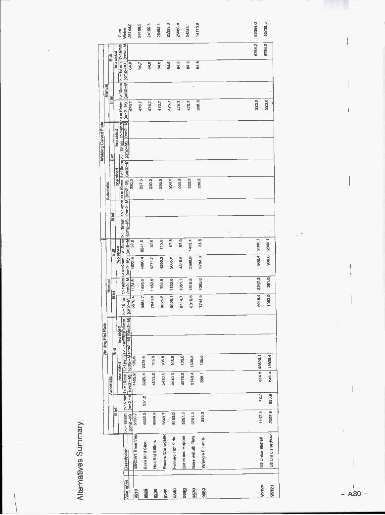
Alte
rnat
ives
Sum
mar
y
o
Wel
ding
Fla
t Pla
taW
eldi
ng C
urve
d P
late
Aut
omat
icM
anua
lA
utom
atic
Man
ual
fil le
tB
utt
fil le
tB
utt
fit le
tB
utt
fil le
tB
utt
one
sIde
dtw
o si
ded
two
sIde
don
e si
ded'
two
side
dtw
o si
ded
Alte
rnat
ive
Des
crip
tion
t<=
l9rn
m t>
19m
nt<
=I9
mm
f>19
mm
t<l9
mrr
t>1Q
mm
t<19
mm
t>19
mt<
=lg
mm
t>lg
mrr
t<=
lQm
m t>
lgm
m'f<
=lQ
mm
t>l9
mm
t<=
l9m
mt>
l9m
rrt<
=lg
mm
t>19
mnt
<19
mm
t>lg
rnrr
(cm
2-M
) (c
m2-
W (
cm2-
M)
(crn
2-W
(cm
2-M
) (c
m2-
M)
(cm
2-M
) (c
m2-
.' (c
m2-
M)
(cm
2-M
(cm
2-M
) (c
m2-
M (
cm2-
M)
(cm
2-M
(cm
2-M
) (c
m2-
F(c
rn2-
M)
(cm
2-f (
cm2-
M)
(cn,
2-M
9510
95K
DW
TB
aseV
es51
55.7
4465
.910
5.6
8570
.411
74.8
4822
.367
.623
0.2
476.
784
.8
9520
Bas
e M
ild S
teel
4532
.056
1.3
3925
.420
75.6
8484
.714
56.3
4090
.422
41.5
257.
347
6,7
94.7
9530
Non
Std
5tif
lnr
4899
.045
132
105.
678
40.0
1180
.647
71.7
57.6
230.
247
5784
.8
9540
Bas
e w
/Cor
ruga
led
5643
.754
10.1
105.
683
26.2
791.
543
99.3
115.
223
0.2
476.
784
,8
9550
For
med
Hpr
Sid
e51
63.9
4949
.010
5.6
8026
.111
93.8
5035
.657
.623
0.2
4757
84.8
9560
Bkt
in li
eu H
oppe
r52
57.5
4575
.910
5.6
8414
,710
61.7
4818
.857
.623
0.2
476.
784
.8
9570
Bas
e w
1Bul
b F
lats
3761
.337
43.4
1308
.583
10,6
1315
.335
96.9
1413
.423
0.2
475.
784
.8
9580
W/a
ngle
Pit
units
325.
356
6.1
105.
677
44.8
1095
.037
34.3
51.6
230.
223
8.3
84.8
9512
0U
3 U
nidi
r di
shed
1147
.472
.787
4.6
4382
5.1
3916
,422
47.2
982.
423
00.1
223,
867
54.2
9512
1U
3 U
ni d
ishe
crev
2007
.892
5.6
641.
4 14
608.
419
63.9
381.
090
9.3
2300
.122
3.8
6764
.2
Sum
Wel
ds25
144.
0
2818
5.9
2415
9.5
2548
3.4
2532
3.3
2508
3.4
2424
3 1
1417
6.0
6236
4.0
3072
6.6

Summary - 4ODWT Alternative VesselsWeld Lengths
-A81-

Alte
rnat
ives
Sum
mar
yW
ELD
ING
LE
NG
TH
SO
NE
TA
NK
LE
NG
TH
Man
ual
Alte
rnat
ive
Des
crip
tion
Ave
rage
tF
i'let
But
tD
ownh
and
Ver
tical
Ove
rhea
dD
ownh
and
Ver
tical
Ove
rhea
dT
otal
leng
t
mm
MM
MM
MM
MM
M
4010
4OK
DW
TB
aseV
esse
l14
.65
1519
6.0
1084
.567
97.5
1390
.036
8.7
485.
199
.226
.325
447.
5
4020
Bas
e M
ild S
teel
14.8
315
118.
510
86.0
6848
.014
01.3
370.
349
1,9
100.
726
.625
443.
2
4030
Bw
/add
ition
alch
oice
stiff
14.7
315
286.
010
83.5
6871
.613
75.3
305.
348
7.1
97.5
21.6
2552
8.0
4040
Bw
/Cor
ruga
ted
bhd
14.6
413
497.
296
2.2
6821
.019
03.5
413,
448
6.2
135.
729
.524
248,
5
4050
Bw
/form
ed H
op14
.66
1527
9.3
1124
.469
01.9
1389
.037
8.2
507.
910
2,2
27.8
2571
0.9
4060
Bw
/ hop
per
side
14.6
915
089.
710
16.5
7625
.215
91.8
339.
151
3.7
107.
222
.826
306.
0
4070
Bw
/Bul
bs15
.73
9247
.492
8.3
5738
.115
29.6
369.
357
6.0
153.
637
.118
579,
4
4080
Bw
/FIt
Ang
com
bina
tion
14.6
744
86.7
1280
.032
97.6
1177
.927
9.9
940.
833
6.1
79.9
1187
9.0
4090
Bw
/Flr,
etc.
Stit
f Aut
o W
eld
14.6
517
695.
112
62.9
4812
.198
4.0
261.
034
3.4
70.2
18.6
2544
7.5
4010
0U
4 U
nidi
rect
iona
l w/c
orr
20.6
449
32.8
856.
541
31.9
1514
.259
3.9
717.
426
2,9
103.
113
112.
7
4011
0U
5w/c
orru
gate
d bh
d18
,08
5180
.196
4.8
4096
.613
92.0
597.
576
3.0
259,
311
1.3
1336
4.4
4011
1U
Sw
/dou
ble
plat
e bh
d17
.96
3928
.490
5.5
3302
.411
23.4
561.
776
1.2
259,
012
9.5
1097
1,1
4011
2U
5 w
/cor
rug
& H
TS
D &
Bno
CL
bhd
17.5
854
36.6
1036
.242
27.4
1404
.658
4.2
805.
826
7.7
111.
313
873.
8
4012
0U
6 D
ishe
d pl
ate
21.3
784
33.1
1107
.037
10.7
3039
.326
2.8
487.
139
9.0
34,5
1747
3.3
4012
1U
6 D
ishe
d P
late
/rev
21.3
711
703.
815
96.7
2666
.037
0.4
120.
936
3.7
50.5
16.5
1688
8.5
4013
0B
w/S
lotte
d lB
.14
.65
1519
6,0
1084
.567
97.5
1390
.036
8.7
485.
199
.226
.325
447.
5
4014
0B
w/S
tand
& S
erie
s14
.65
1519
6.0
1084
.567
97.5
1390
.036
8.7
485.
199
,226
.325
447.
5
4015
0B
w/S
td D
esig
n14
.65
1519
6.0
1084
.567
97.5
1390
.036
8.7
485.
199
.226
.325
447.
5
Aut
o m
atic
Fill
etB
utt
Summary - 9SDWT Alternative VesselsWeld Lengths
-A83-

Alte
rnat
ives
Sum
mar
yW
ELD
ING
LE
NG
TH
S IN
ME
TE
RS
ON
E T
AN
K L
EN
GT
HM
anua
l
Alte
rnat
ive
Des
crip
tion
Ave
rg th
km
mF
illet
M
But
tM
Dow
nhan
dM
Ver
tical
MO
verh
ead
MD
ownh
and
M
Ver
tical
MO
verh
ead
MT
otal
lngt
hM
9510
95K
DW
T B
ase
Ves
sel
15.2
425
165
1919
9380
2002
355
715
153
2739
715
9520
Bas
e M
ild S
teel
16.1
625
074
1916
9448
2024
357
722
155
2739
722
9530
Non
Std
Stif
fnrs
16.4
925
591
1936
9247
1982
328
700
150
2539
957
9540
Bas
e w
/Cor
ruga
ted
15.2
925
763
2146
8951
1692
326
746
141
2739
793
9550
For
med
Hpr
Sid
e15
.24
2531
520
6490
0319
0634
873
415
528
3955
4
9560
Bkt
in li
eu H
oppe
r15
.26
2553
019
5989
4217
6634
369
713
827
3943
1
9570
Bas
ew/B
ulb
Fla
ts16
.49
1521
016
5675
2820
1435
183
422
339
2788
6
9580
W/a
ngle
PIt
units
15.4
764
0422
8638
3015
7736
513
6756
313
016
522
9512
0U
3 U
nidi
r di
shed
21.9
710
278
3301
241
562
4117
3333
3455
620
045
9512
1U
3 U
ni d
ishe
d/re
v13
422
2351
2743
234
480
1919
400
21.9
711
041
Aut
o m
atic
Fill
etB
utt

PAGE NOT USED
-A85-

PAGE NOT USED
-A86

4OKDWT Alternative VesselsEstimation of Labor Hours Calculations for One Tank
-A87-

NSRP PANEL SP-4
- A88 -
FILE: STRCTMS Revised LABOR HOUR ESTIMATING FORM FOR STRUCTURAL WORK4OKDWT BASE ALTERNATIVE
PROJECT: Entire Tank Section MATERIAL: MS-STSFILE: 4010 THICKNESS 0.57 INCHES
WORK PROCESS WORK PROCESS UNIT ACTUAL STANDARD ACTUAL STANDARDUNITS FACTOR AMOUNT STAGE STAGE FACTOR FACTOR
(MNHRS/WORK UNIT)
MNHRSREaD
i OBTAIN MATERIAL SOFT 0.010 79149 1 1 1.0 1.0 791
RECEIPT & PREP
2 FLAME CU1TINGAUTOMATIC LNFT 0.040 47582 1 1 1.0 1.0 1885
MANUAL LNFT 0.071 2504 2 2 1.5 1.5 179
3 EDGE PREP-GRINDINGFLAT LNFT 0.032 1990 1 2 1.0 1.5 63
VERTICAL LNFT 0.048 407 2 2 1.5 1.5 19
OVER H EAD LNFT 0.063 108 2 2 1.5 1.5 7
4 SHAPINGBREAK BEND 0.380 0 1 1 1.0 1.0 0
ROLLING PIECE 0.951 4 1 1 1.0 1.0 4
LINE HEATING PIECE 10.000 0 1 1 1.0 1.0 0
FURNACE PIECE 15.000 0 1 1 1.0 1.0 0
PRESS PIECE 0.019 0 1 1 1.0 1.0 0
MACHINING CU IN 0.020 0 1 1 1.0 1.0 0
5 FIT UP & ASSEMBLY JOINT 0.444 6568 2 2 1.5 1.5 2915
6 WELDING, AUTO/MACHINEFILLET LN FT 0.052 49968 2 2 1 .5 1 .5 2574
BUTT LN FT 0.3804 3530 2 2 1.5 1.5 1343
7 WELDING, MANUALFILLET
DOWN HAND LN FT 0.269 22352 2 2 1.5 1 .5 6023
VERTICAL LNFT 0.404 4571 2 2 1.5 1.5 1547
OVERHEAD LNFT 0.539 1213 2 2 1.5 1.5 653
BUTTDOWN HAND LN FT 1 .030 1579 2 2 1 .5 1 .5 1627
VERTICAL LN FT 1 .545 323 2 2 1 .5 1 .5 499
OVERHEAD LNFT 2.061 86 2 2 1.5 1.5 177
8 MARKING PIECE 0.100 1642 1 1 1.0 1.0 164
9 HANDLINGSTORAGE PIECE 0.100 1642 2 2 1.5 1.5 164
TRANSPORTING ASSY 5.000 24 3 3 2.0 2.0 120
LIFTING ASSY 5.000 24 4 4 3.0 3.0 120
10 REWORK JOINT 1.000 660 5 2 4.5 1.5 1981
TOTAL TRADE LABORHOURS 23156
TRADE SUPPORT LABORHOURS (28% OF TRADE LABORHOURS) 6423
TOTAL PRODUCTION LABORHOURS 29578

NSRP PANEL SP-4
-A89 -
FILE: STRCTMS Revised LABOR HOURS ESTIMATING FORM FOR STRUCTURAL WORK4OKDWT BASE ALTERNATIVE
PROJECT: Entire Tank Section MATERIAL: MS-STSFILE: 4020 THICKNESS 0.58 INCHES
WORK PROCESS WORK PROCESS UNIT ACTUAL STANDARD ACTUAL STANDARDUNITS FACTOR AMOUNT STAGE STAGE FACTOR FACTOR
(MNHRS/WORK UNIT)
MNHRSREaD
1 OBTAIN MATERIAL SQ FT 0.010 80382 1 1 1.0 1.0 804RECEIPT & PREP
2 FLAME CUTTINGAUTOMATIC LNFT 0.040 47622 1 1 1.0 1.0 1887MANUAL LNFT 0.071 2506 2 2 1.5 1.5 179
3 EDGE PREP-GRINDINGFLAT LNFT 0.032 1991 1 2 1.0 1.5 63VERTICAL LNFT 0.048 407 2 2 1.5 1.5 19OVERHEAD LNFT 0.063 108 2 2 1.5 1.5 7
4 SHAPINGBREAK BEND 0.380 0 1 1 1.0 1.0 0ROLLI NG PIECE 0.951 4 1 1 1.0 1.0 4LINE HEATING PIECE 10.000 0 1 1 1.0 1.0 0FURNACE PIECE 15.000 0 1 1 1.0 1.0 0PRESS PIECE 0.019 0 1 1 1.0 1.0 0MACHINING CUIN 0.020 0 1 1 1.0 1.0 0
5 FIT UP & ASSEMBLY JOINT 0.444 6568 2 2 1.5 1.5 2915
6 WELDING, AUTO/MACHINEFILLET LN FT 0.052 49601 2 2 1.5 1.5 2555BUTT LN FT 0.3804 3563 2 2 1.5 1.5 1355
7 WELDING, MANUALFILLET
DOWN HAND LNFT 0.269 22467 2 2 1.5 1.5 6054VERTICAL LNFT 0.404 4597 2 2 1.5 1.5 1858OVERHEAD LNFT 0.539 1215 2 2 1.5 1.5 655
BUTTDOWN HAND LNFT 1.030 1614 2 2 1.5 1.5 1663VERTICAL LNFT 1.545 330 2 2 1.5 1.5 510OVERHEAD LNFT 2.061 87 2 2 1.5 1.5 180
8 MARKING PIECE 0.100 1642 1 1 1.0 1.0 164
9 HANDLINGSTORAGE PIECE 0.100 1642 2 2 1.5 1,5 164TRANSPORTI NG ASSY 5.000 24 3 3 2.0 2.0 120LIFTING ASSY 5.000 24 4 4 3.0 3.0 120
10 REWORK JOINT 1.000 663 5 2 4.5 1.5 1990
TOTAL TRADE LABORHOURS 23266TRADE SUPPORT LABORHOURS (28% OF TRADE LABORHOURS) 6453
TOTAL PRODUCTION LABORHOURS 29719
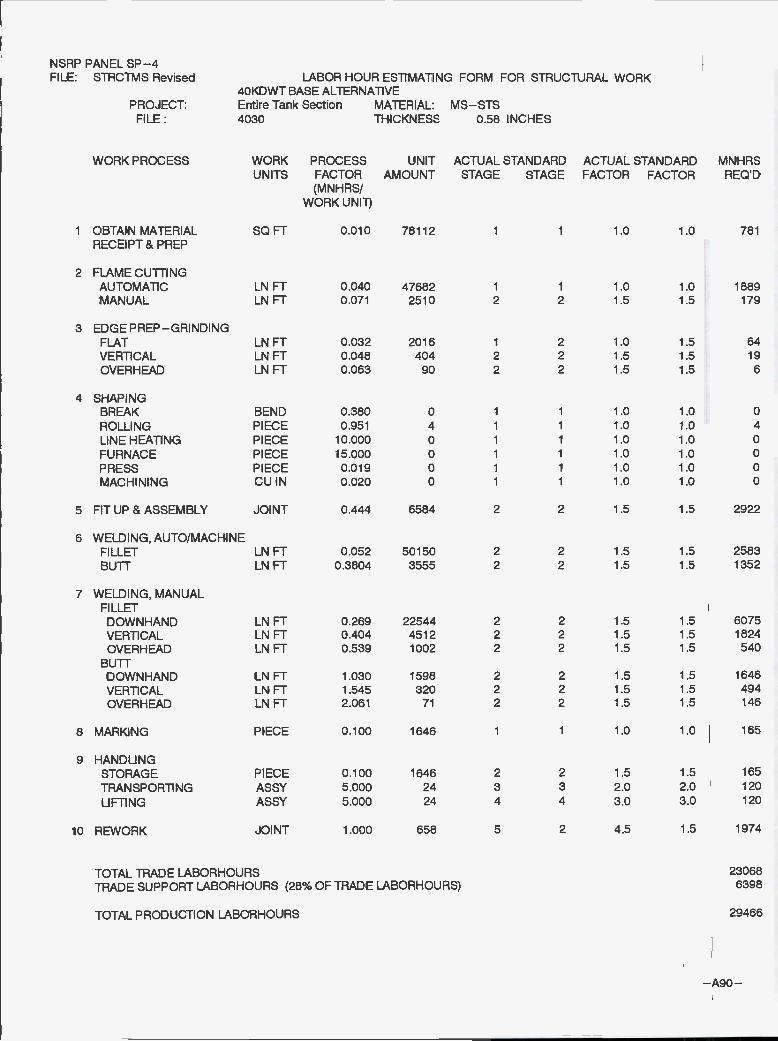
NSRP PANEL SP-4
-A90-
FILE: STRCTMS Revised LABOR HOUR ESTIMATING FORM FOR STRUCTURAL WORK4OKDWT BASE ALTERNATIVE
PROJECT: Entire Tank Section MATERIAL: MS-STSFILE: 4030 THICKNESS 0.58 INCHES
WORK PROCESS WORK PROCESS UNIT ACTUAL STANDARD ACTUAL STANDARDUNITS FACTOR AMOUNT STAGE STAGE FACTOR FACTOR
(M NHRS/WORK UNIT)
MNHRSREaD
i OBTAIN MATERIAL SOFT 0.010 78112 1 1 1.0 1.0 781RECEIPT & PREP
2 FLAME CUTTINGAUTOMATIC LN FT 0.040 47682 1 1 1.0 1 0 1889MANUAL LNFT 0.071 2510 2 2 1.5 15 179
3 EDGE PREP-GRINDINGFLAT LNFT 0.032 2016 1 2 1.0 1.5 64VERTICAL LNFT 0.048 404 2 2 1.5 1,5 19
OVER H EAD LNFT 0.063 90 2 2 1.5 1.5 6
4 SHAPINGBREAK BEND 0.380 0 1 1 1 .0 1 .0 0
ROLLI NG PIECE 0.951 4 1 1 1.0 1.0 4
LINE HEATING PIECE 10.000 0 1 1 1.0 1.0 0FURNACE PIECE 15.000 0 1 1 1.0 1.0 0
PRESS PIECE 0.019 0 1 1 1.0 1.0 0MACHINING CU IN 0.020 0 1 1 1.0 1.0 0
5 FIT UP & ASSEMBLY JOINT 0.444 6584 2 2 1.5 1.5 2922
6 WELDING, AUTO/MACHINEFILLET LNFT 0.052 50150 2 2 1.5 1.5 2583
BUTT LNFT 0.3804 3555 2 2 1.5 1.5 1352
7 WELDING,MANUALFILLET
DOWN HAND LN FT 0.269 22544 2 2 1 .5 1 .5 6075VERTICAL LNFT 0.404 4512 2 2 1.5 1.5 1824OVERHEAD LNFT 0.539 1002 2 2 1.5 1.5 540
BUTTDOWNHAND LNFT 1.030 1596 2 2 1.5 1.5 1646
VERTICAL LNFT 1.545 320 2 2 1.5 1.5 494OVERHEAD LNFT 2.061 71 2 2 1.5 1.5 146
8 MARKING PIECE 0.100 1646 1 1 1.0 1.0 165
9 HANDLINGSTORAGE PIECE 0.100 1646 2 2 1.5 1.5 165
TRANSPORTI NG ASSY 5.000 24 3 3 2.0 2.0 120
LIFTING ASSY 5.000 24 4 4 3.0 3.0 120
10 REWORK JOINT 1.000 658 5 2 4.5 1.5 1974
TOTAL TRADE LABORHOURS 23068TRADE SUPPORT LABORHOURS (28% OF TRADE LABORHOURS) 6398
TOTAL PRODUCTION LABORHOURS 29466

NSRP PANEL SP-4
-Agi -
FILE: STRCTMS Revised COST ESTIMATING FORM FOR STRUCTURAL WORK4OKDWT BASE ALTERNATIVE
PROJECT: Entire Tank Section MATERIAL: MS-STSFILE: 4040 THICKNESS 0.57 INCHES
WORK PROCESS WORK PROCESS UNIT ACTUAL STANDARD ACTUAL STANDARDUNITS FACTOR AMOUNT STAGE STAGE FACTOR FACTOR
(MNHRS/WORK UNIT)
MNHRSREQ'D
i OBTAIN MATERIAL SOFT 0.010 78681 1 1 1.0 1.0 787RECEIPT & PREP
2 FLAME CUTTINGAUTOMATIC LNFT 0.040 45332 1 1 1.0 1.0 1796MANUAL LNFT 0.071 2386 2 2 1.5 1.5 170
3 EDGE PREP-GRINDINGFLAT LNFT 0.032 1781 1 2 1.0 1.5 56VERTICAL LN FT 0.048 497 2 2 i .5 1.5 24OVER H EAD LNFT 0.063 108 2 2 1.5 1.5 7
4 SHAPINGBREAK BEND 0.380 0 1 1 1.0 1 .0 0ROLLING PIECE 0.951 4 1 1 1.0 1.0 4LINE HEATING PIECE 10.000 0 1 1 1.0 1.0 0FURNACE PIECE 15.000 0 1 i 1.0 1.0 0PRESS PIECE 0.019 0 i 1 1.0 1.0 0MACHINING CUIN 0.020 0 1 1 1.0 1.0 0
5 FIT UP & ASSEMBLY JOINT 0.444 6264 2 2 1.5 1.5 2780
6 WELDING, AUTO/MACHINEFILLET LN FT 0.052 44281 2 2 1.5 1.5 2281BUTT LN FT 0.3804 3157 2 2 1.5 1.5 1201
7 WELDING, MANUALFILLET
DOWNHAND LN FT 0.269 22378 2 2 1 .5 1 .5 6030VERTICAL LNFT 0.404 6245 2 2 1.5 1.5 2524OVERHEAD LNFT 0539 1356 2 2 1.5 1.5 731
BUTTD O WN HAND LNFT 1.030 1595 2 2 1.5 1.5 1643VERTICAL LN FT 1 .545 445 2 2 1 .5 1 .5 688OVER H EAD LNFT 2.061 97 2 2 1.5 1.5 199
8 MARKING PIECE 0.100 1566 1 1 1.0 1.0 157
9 HANDLINGSTORAGE PIECE 0.100 1566 2 2 1.5 1.5 157TRANSPORTING ASSY 5.000 24 3 3 2.0 2.0 120LIFTING ASSY 5.000 24 4 4 3,0 3.0 120
lo REWORK JOINT 1.000 671 5 2 4.5 1.5 2013
TOTAL TRADE MANHOURS 23487TRADE SUPPORT MANHOURS (28% OF TRADE MANHOURS) 6515
TOTAL PRODUCTION MANHOURS 30002

NSRP PANEL SP-4
- A92-
FILE: STRCTMS Revised LABOR HOUR ESTIMATING FORM FOR STRUCTURAL WORK4OKDWT BASE ALTERNATIVE
PROJECT: Entire Tank Section MATERIAL: MS-STSFILE: 4050 ThICKNESS 0.57 INCHES
WORK PROCESS WORK PROCESS UNIT ACTUAL STANDARD ACTUAL STANDARD
UNITS FACTOR AMOUNT STAGE STAGE FACTOR FACTOR(MNHRS/
WORK UNIT)
MNHRSREQ'D
i OBTAIN MATERIAL SQ FT 0.010 78445 1 1 1.0 1.0 784
RECEIPT & PREP
2 FLAME CUTTINGAUTOMATIC LNFT 0.040 48307 1 1 1,0 1.0 1914
MANUAL LNFT 0.071 2542 2 2 1.5 1.5 181
3 EDGEPREP-GRINDINGFLAT LNFT 0.032 2024 1 2 1.0 1.5 64
VERTICAL LN FT 0.048 407 2 2 1.5 1,5 19
OVERHEAD LNFT 0.063 111 2 2 1.5 1.5 7
4 SHAPINGBREAK BEND 0.380 0 1 1 1 .0 1.0 0
ROLLING PIECE 0.951 4 1 1 1.0 1.0 4
LINE HEATING PIECE 10.000 0 1 1 1.0 1.0 0
FURNACE PIECE 15.000 0 1 1 1.0 1.0 0
PRESS PIECE 0.019 0 1 1 1.0 1.0 0
MACHINING CUIN 0.020 0 1 1 1.0 1.0 0
5 FIT UP & ASSEMBLY JOINT 0.444 6600 2 2 1 .5 1 .5 2929
6 WELDING, AUTO/MACHINEFILLET LN FT 0.052 50128 2 2 1.5 1.5 2582
BUTT LNFT 0.3804 3689 2 2 1.5 1.5 1403
7 WELDING, MANUALFILLET
DOWN HAND LNFT 0.269 22644 2 2 1.5 1.5 6101
VERTICAL LNFT 0.404 4557 2 2 1.5 1.5 1842
OVERHEAD LNFT 0.539 1241 2 2 1.5 1.5 669
BUTTDOWNHAND LNFT 1.030 1666 2 2 1.5 1.5 1717
VERTICAL LNFT 1.545 335 2 2 1.5 1.5 518
OVERHEAD LNFT 2.061 91 2 2 1.5 1.5 188
8 MARKING PIECE 0.100 1650 1 1 1.0 1.0 165
9 HANDLINGSTORAGE PIECE 0.100 1650 2 2 1.5 1.5 165
TRANSPORTING ASSY 5.000 24 3 3 2.0 2.0 120
LI Fil NG ASSY 5.000 24 4 4 3.0 3.0 120
lo REWORK JOINT 1.000 671 5 2 4.5 1.5 2014
TOTAL TRADE LABORHOURS23508
TRADE SUPPORT LABORHOURS (28% OF TRADE LABORHOURS) 6520
TOTAL PRODUCTION LABORHOURS30026

NSRP PANEL SP-4
-A93-
FILE: STRCTMS Revised LABOR HOUR ESTIMATING FORM FOR STRUCTURAL WORK4OKDWT BASE ALTERNATIVE
PROJECT: Entire Tank Section MATERIAL: MS-STSFILE 4060 THICKNESS 0.58 INCHES
WORK PROCESS WORK PROCESS UNIT ACTUAL STANDARD ACTUAL STANDARDUNITS FACTOR AMOUNT STAGE STAGE FACTOR FACTOR
(M N HRS/WORK UNIi)
MNHRSREQ'D
i OBTAIN MATERIAL SQ FT 0.010 77342 1 1 1.0 1.0 773RECEIPT & PREP
2 FLAME CU1TINGAUTOMATIC LNFT 0.040 48757 1 1 1.0 1.0 1932MANUAL LNFT 0.071 2566 2 2 1.5 1.5 183
3 EDGE PREP-GRINDINGFLAT LNFT 0.032 2048 1 2 1.0 1.5 65VERTICAL LN FT 0.048 427 2 2 1 .5 1 .5 20
4 OVERHEAD LNFT 0.063 91 2 2 1.5 1.5 6
4 SHAPINGBREAK BEND 0.380 0 1 1 1.0 1.0 0ROLLING PIECE 0.951 4 1 1 1.0 1.0 4LINE HEATING PIECE 10.000 0 1 1 1,0 1.0 0FURNACE PIECE 15.000 0 1 1 1.0 1.0 0PRESS PIECE 0.019 0 1 1 1.0 1.0 0MACHINING CUIN 0.020 0 1 1 1.0 1.0 0
5 FITUP&ASSEMBLY JOINT 0.444 7240 2 2 1.5 1.5 3213
6 WELDING, AUTO/MACHINEFILLET LNFT 0.052 49506 2 2 1.5 1.5 2550BUTT LNFT 0.3804 3335 2 2 1.5 1.5 1269
7 WELDING, MANUALFILLETDOWN HAND LNFT 0.269 25017 2 2 1.5 1.5 6741VERTICAL LNFT 0.404 5222 2 2 1.5 1.5 2111OVERHEAD LNFT 0.539 1112 2 2 1.5 1.5 599
BUTTDOWN HAND LNFT 1.030 1685 2 2 1.5 1.5 1736VERTICAL LNFT 1.545 352 2 2 1.5 1.5 544OVERHEAD LNFT 2.061 75 2 2 1.5 1.5 154
8 MARKING PIECE 0.100 1810 1 1 1.0 1.0 181
9 HANDLINGSTORAGE PIECE 0.100 1810 2 2 1.5 1.5 181TRANSPORTING ASSY 5.000 24 3 3 2.0 2.0 120LIFTING ASSY 5.000 24 4 4 3.0 3.0 120
10 REWORK JOINT 1.000 704 5 2 4.5 1.5 2112
TOTAL TRADE LABORHOURS 24615TRADE SUPPORT LABORHOURS (28% OF TRADE LABORHOURS) 6828
TOTAL PRODUCTION LABORHOURS 31442
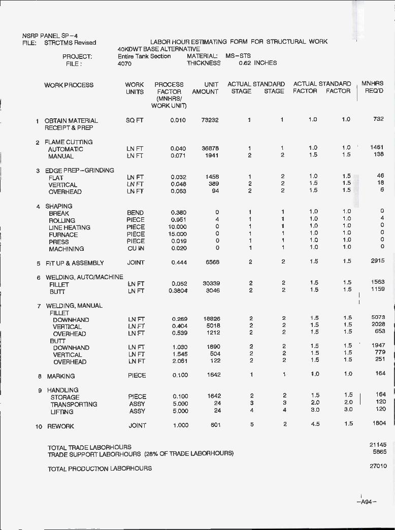
NSRP PANEL SP-4
-A94-
FILE: STRCTMS Revised LABOR HOUR ESTIMATING FORM FOR STRUCTURAL WORK4OKDWT BASE ALTERNATIVE
PROJECT: Entire Tank Section MATERIAL: MS-STSFILE: 4070 THICKNESS 0.62 INCHES
WORK PROCESS WORK PROCESS UNIT ACTUAL STANDARD ACTUAL STANDARDUNITS FACTOR AMOUNT STAGE STAGE FACTOR FACTOR
(MNH R SiWORK UNIT)
MNHRSREaD
i OBTAIN MATERIAL SQFT 0.010 73232 i 1 1.0 1.0 732
RECEIPT& PREP
2 FLAME CUTTINGAUTOMATIC LNFT 0.040 36878 1 1 1.0 1.0 1461
MANUAL LNFT 0.071 1941 2 2 1.5 1.5 138
3 EDGEPREP-GRINDINGFLAT LNFT 0.032 1458 1 2 1.0 1.5 46
VERTiCAL LNFT 0.045 389 2 2 1.5 1.5 18
OVERHEAD LNFT 0.063 94 2 2 1.5 1.5 6
4 SHAPINGBREAK BEND 0.380 0 1 1 1.0 1.0 0
ROLLING PIECE 0.951 4 1 1 1.0 1.0 4
LINE HEATING PIECE 10.000 0 1 1 1.0 1.0 0
FURNACE PIECE 15.000 0 1 1 1.0 1.0 0
PRESS PIECE 0.019 0 1 1 1.0 1.0 0
MACHINING CUIN 0.020 0 1 1 1.0 1.0 0
5 FITUP&ASSEMBLY JOINT 0.444 6568 2 2 1.5 1.5 2915
6 WELDING, AUTO/MACHINEFILLET LN FT 0.052 30339 2 2 1.5 1.5 1563
BUTT LN FT 0.3804 3046 2 2 1.5 1.5 1159
7 WELDING, MANUALFILLET
DOWN HAND LNFT 0.269 18826 2 2 1.5 1.5 5073
VERTiCAL LNFT 0.404 5018 2 2 1.5 1.5 2028
OVERHEAD LNFT 0.539 1212 2 2 1.5 1.5 653
BUTTD OWN HAND LNFT 1.030 1890 2 2 1.5 1.5 1947
VERTICAL LN FT 1 .545 504 2 2 1 .5 1 .5 779
OVERHEAD LNFT 2.061 122 2 2 1.5 1.5 251
6 MARKING PIECE 0.100 1642 1 1 1.0 1.0 164
9 HANDLINGSTORAGE PIECE 0.100 1642 2 2 1.5 1.5 164
TRANSPORTI NG ASSY 5.000 24 3 3 2.0 2.0 120
LIFTING ASSY 5.000 24 4 4 3.0 3.0 120
lo REWORK JOINT 1.000 601 5 2 4.5 1.5 1804
TOTAL TRADE LABORHOURS 21145
TRADE SUPPORT LABORHOURS (28% OF TRADE LABORHOURS) 5865
TOTAL PRODUCTION LABORHOURS 27010

NSRP PANEL SP-4
-A95-
FILE: STRCTMS Revised LABOR HOUR ESTIMATING FORM FOR STRUCTURAL WORK4OKDWT BASE ALTERNATIVE
PROJECT: Entire Tank Section MATERIAL: MS-STSFILE: 4080 THICKNESS 0.58 INCHES
WORK PROCESS WORK PROCESS UNIT ACTUAL STANDARD ACTUAL STANDARDUNITS FACTOR AMOUNT STAGE STAGE FACTOR FACTOR
(MN H RS/
WORK UNID
MNHRSREQ'D
i OBTAIN MATERIAL SQ FT 0.010 78445 1 1 1.0 1.0 784RECEIPT & PREP
2 FLAME CUTTINGAUTOMATIC LNFT 0.040 30774 1 1 1.0 1.0 1219MANUAL LNFT 0.071 1620 2 2 1.5 1.5 116
3 EDGE PREP-GRINDINGFLAT LNFT 0.032 1123 1 2 1.0 1.5 36VERTICAL LNFT 0.048 401 2 2 1.5 1.5 19OVERHEAD LN FT 0.063 95 2 2 1.5 1.5 6
4 SHAPINGBREAK BEND 0.380 7657 1 1 1.0 1.0 2913ROLLI NG PIECE 0.951 4 1 1 1.0 1.0 4LINE HEATING PIECE 10.000 0 1 1 1.0 1.0 0FURNACE PIECE 15.000 0 1 1 1.0 1.0 0PRESS PIECE 0.019 0 1 1 1.0 1.0 0MACHINING CU IN 0.020 0 1 1 1.0 1.0 0
5 FIT UP & ASSEMBLY JOINT 0.444 6120 2 2 1.5 1.5 2716
6 WELDING, AUTO/MACHINEFILLET LN FT 0.052 14720 2 2 1.5 1.5 758BUTT LN FT 0.3804 4200 2 2 1.5 1.5 1598
7 WELDING, MANUALFILLETDOWN HAN D LNFT 0.269 10819 2 2 1.5 1.5 2915VERTICAL LNFT 0.404 3865 2 2 1.5 1.5 1562OVERHEAD LNFT 0.539 918 2 2 1.5 1,5 495
BUTTDOWNHAND LNFT 1.030 3087 2 2 1.5 1.5 3180VERTICAL LNFT 1.545 1103 2 2 1.5 1.5 1704OVERHEAD LN FT 2.061 262 2 2 1 .5 1 .5 540
8 MARKING PIECE 0.100 1530 1 1 1.0 1.0 153
9 HANDLINGSTORAGE PIECE 0.100 1530 2 2 1.5 1.5 153TRANSPORTING ASSY 5.000 24 3 3 2.0 2.0 120LIFTING ASSY 5.000 24 4 4 3.0 3.0 120
10 REWORK JOINT 1.000 562 5 2 4.5 1.5 1686
TOTAL TRADE LABORHOURS 22796TRADE SUPPORT LABORHOURS (28% OF TRADE LABORHOURS) 6323
TOTAL PRODUCTION LABORHOURS 29120

NSRP PANEL SP-4
-A96 -
FILE: STRCTMS Revised LABOR HOUR ESTIMATING FORM FOR STRUCTURAL WORK4OKDWT BASE ALTERNATIVE
PROJECT: Entire Tank Section MATERIAL: MS-STSFILE: 4090 THICKNESS 0.57 INCHES
WORK PROCESS WORK PROCESS UNIT ACTUAL STANDARD ACTUAL STANDARDUNITS FACTOR AMOUNT STAGE STAGE FACTOR FACTOR
(MNH RS/WORK UNIT)
MNHRSREOD
i OBTAIN MATERIAL SOFT 0.010 79149 1 1 1.0 1.0 791
RECEIPT & PREP
2 FLAME CUTTINGAUTOMATIC LNFT 0.040 47582 1 1 1.0 1.0 1885
MANUAL LNFT 0.071 2504 2 2 1.5 1.5 179
3 EDGE PREP-GRINDINGFLAT LNFT 0.032 1990 1 2 1.0 1.5 63
VERTICAL LNFT 0.048 407 2 2 1.5 1.5 19
OVERHEAD LNFT 0.063 108 2 2 1.5 1.5 7
4 SHAPINGBREAK BEND 0.380 0 1 1 1.0 1.0 0
ROLLING PIECE 0.951 4 1 1 1.0 1.0 4
LINE HEATING PIECE 10.000 0 1 1 1.0 1.0 0
FURNACE PIECE 15.000 0 1 1 1.0 1.0 0
PRESS PIECE 0.019 0 1 1 1.0 1.0 0
MACHINING CU IN 0.020 0 1 1 1.0 1.0 0
5 FITUP&ASSEMBLY JOINT 0.444 6568 2 2 1.5 1.5 2915
6 WELDING, AUTO/MACHINEFILLET LN FT 0.052 56054 2 2 1.5 1.5 2991
BUTT LN FT 0.3804 4143 2 2 1.5 1,5 1576
7 WELDING, MANUALFILLETDOWN HAND LNFT 0.269 15788 2 2 1.5 1.5 4254
VERTICAL LNFT 0.404 3228 2 2 1.5 1.5 1305
OVERHEAD LN FT 0.539 856 2 2 1.5 1.5 462
BUTTD OWN HAN D LNFT 1.030 1127 2 2 1.5 1.5 1161
VERTICAL LN FT 1 .545 230 2 2 1 .5 i .5 356
OVERHEAD LNFT 2.061 61 2 2 1.5 1.5 126
8 MARKING PIECE 0.100 1642 1 1 1.0 1.0 164
9 HANDLINGSTORAGE PIECE 0.100 1642 2 2 1.5 1.5 164
TRANSPORTI NG ASSY 5.000 24 3 3 2.0 2.0 120
LIFTING ASSY 5.000 24 4 4 3.0 3.0 120
lo REWORK JOINT 1.000 577 5 2 4.5 1.5 1730
TOTAL TRADE LABORHOURS 20392
TRADE SUPPORT LABORHOURS (28% OF TRADE LABORHOURS) 5656
TOTAL PRODUCTION LABORHOURS 26048

NSRP PANEL SP-4
-A97-
FILE: STRCTMS Revised LABOR HOUR ESTIMATING FORM FOR STRUCTURAL WORK4OKDWT BASE ALTERNATIVE
PROJECT: Entire Tank Section MATERIAL: MS-STSFILE: 40100 THICKNESS 0.51 INCHES
WORK PROCESS WORK PROCESS UNIT ACTUAL STANDARD ACTUAL STANDARDUNITS FACTOR AMOUNT STAGE STAGE FACTOR FACTOR
(M N H RS!
WORK UNIT)
MNHRSREaD
i OBTAIN MATERIAL SOFT 0.010 96568 1 1 1.0 1.0 966RECEIPT& PREP
2 FLAME CUTTINGAUTOMATIC LNFT 0.055 29504 1 1 1.0 1.0 1637MANUAL LNFT 0.095 1553 2 2 1.5 1.5 148
3 EDGE PREP-GRINDINGFLAT LNFT 0048 1028 1 2 1.0 1,5 49VERTICAL LN FT 0.095 377 2 2 1 .5 1 .5 36OVER H EAD LNFT 0.135 148 2 2 1.5 1.5 20
4 SHAPINGBREAK BEND 0.380 0 1 1 1.0 1.0 0ROLLING PIECE 0.951 4 1 1 1.0 1.0 4LINE HEATING PIECE 10.000 0 1 1 1.0 1.0 0FURNACE PIECE 15.000 0 1 1 1.0 1.0 0PRESS PIECE 0.019 0 1 1 1.0 1.0 0MACHINING CU IN 0.020 0 1 1 1.0 1.0 0
5 FIT UP & ASSEMBLY JOINT 0.444 5440 2 2 1.5 1.5 2414
6 WELDING, AUTO/MACHINEFILLET LN FT 0.062 16183 2 2 1.5 1.5 1000BUTT LNFT 0.45965 2810 2 2 1.5 1.5 1292
WELDING, MANUALFILLETDOWN HAN D LNFT 0.476 13556 2 2 1.5 1.5 6446VERTICAL LN FT 0.951 4968 2 2 1 .5 1 .5 4724OVERHEAD LNFT 1.347 1949 2 2 1.5 1.5 2625
BUTTDOWN HAND LN FT 1 .427 2354 2 2 1 .5 1 .5 3358VERTICAL LNFT 2.853 863 2 2 1.5 1.5 2461OVERHEAD LNFT 4.042 338 2 2 1.5 1.5 1367
8 MARKING PIECE 0.100 1360 1 1 1.0 1.0 136
9 HANDLINGSTORAGE PIECE 0.100 1360 2 2 1.5 1.5 136TRANSPORTI NG ASSY 5.000 24 3 3 2.0 2.0 120LIFTING ASSY 5.000 24 4 4 3.0 3.0 120
10 REWORK JOINT 1.000 919 5 2 4.5 1.5 2758
TOTAL TRADE LABORHOURS 31816TRADE SUPPORT LABORHOURS (28% OF TRADE LABORHOURS) 8825
TOTAL PRODUCTION LABORHOURS 40641

NSRP PANEL SP-4
-A98 -
FILE: STRCTMS Revised LABOR HOUR ESTIMATING FORM FOR STRUCTURAL WORK4OKDWT BASE ALTERNATIVE
PROJECT: Entire Tank Section MATERIAL: MS-STSFILE: 40110 THICKNESS 0.7 INCHES
WORK PROCESS WORK PROCESS UNIT ACTUAL STANDARD ACTUAL STANDARDUNITS FACTOR AMOUNT STAGE STAGE FACTOR FACTOR
(M NH RS!WORK UNIT)
MNHRSREaD
i OBTAIN MATERIAL SQFT 0.010 89244 1 1 1.0 10 892
RECEIPT & PREP
2 FLAME CUTTINGAUTOMATIC LN FT 0.040 30637 1 1 1.0 1 0 1214
MANUAL LNFT 0.071 1612 2 2 1.5 1.5 115
3 EDGE PREP-GRINDINGFLAT LNFT 0.032 1085 1 2 1.0 1.5 34
VERTICAL LNFT 0.048 369 2 2 1.5 1.5 18
OVERHEAD LNFT 0.063 158 2 2 1.5 1.5 10
4 SHAPINGBREAK BEND 0.380 0 1 1 1 .0 1.0 0
ROLLI NG PIECE 0.951 4 1 1 1.0 1.0 4
LINE HEATING PIECE 10.000 0 1 1 1.0 1.0 0
FURNACE PIECE 15.000 0 1 1 1.0 1.0 0
PRESS PIECE 0.019 0 1 1 1.0 1.0 0
MACHINING CU IN 0.020 0 1 1 1.0 1 .0 0
5 FIT UP & ASSEMBLY JOINT 0,444 3968 2 2 1.5 1.5 1761
6 WELDING, AUTO/MACHINEFILLET LN FT 0.052 16995 2 2 1.5 1.5 875
BUTT LNFT 0.3804 3165 2 2 1.5 1.5 1204
7 WELDING, MANUALFILLET
DOWN HAND LNFT 0.269 13440 2 2 1.5 1.5 3621
VERTICAL LNFT 0.404 4567 2 2 1.5 1.5 1846
OVERHEAD LNFT 0.539 1960 2 2 1.5 1.5 1056
BUTTDOWN HAND LNFT 1.030 2503 2 2 1.5 1.5 2579
VERTICAL LNFT 1.545 851 2 2 1.5 1.5 1314
OVERHEAD LNFT 2.061 365 2 2 1.5 1.5 752
B MARKING PIECE 0.100 992 1 1 1.0 1.0 99
9 HANDLINGSTORAGE PIECE 0.100 992 2 2 1.5 1.5 99
TRANSPORTING ASSY 5.000 24 3 3 2.0 2.0 120
LIFTING ASSY 5,000 24 4 4 3.0 3.0 120
10 REWORK JOINT 1.000 547 5 2 4.5 1.5 1640
TOTAL TRADE LABORHOURS 19375
TRADE SUPPORT LABORHOURS (28% OF TRADE LABORHOURS) 5374
TOTAL PRODUCTION LABORHOURS 24750

-A99-
PROJECT: Entire Tank SectionFILE: 40111 THICKNESS
WORK PROCESS WORK PROCESSUNITS FACTOR
(MNH R SI
WORK UNID
MATERIAL:
UNITAMOUNT
MS-STS0.7 INCHES
ACTUAL STANDARDSTAGE STAGE
ACTUAL STANDARDFACTOR FACTOR
MNHRSREQD
I OBTAIN MATERIAL SQFT 0.010 92543 1 1 1.0 1.0 925RECEIPT& PREP
2 FLAME CUTflNGAUTOMATIC LN FT 0.040 32005 1 1 1 .0 1 .0 1268MANUAL LNFT 0.071 1684 2 2 1.5 1.5 120
3 EDGE PREP-GRINDINGFLAT LNFT 0.032 1146 1 2 1.0 1.5 36VERTICAL LNFT 0.048 381 2 2 1.5 1.5 18OVERHEAD LNFT 0.063 158 2 2 1.5 1.5 10
4 SHAPINGBREAK BEND 0.380 0 1 1 1.0 1.0 0ROLLI NG PIECE 0.951 4 1 1 1.0 1.0 4LINE HEATING PIECE 10.000 0 1 1 1.0 1.0 0FURNACE PIECE 15.000 0 1 1 1.0 1.0 0PRESS PIECE 0.019 0 1 1 1.0 1.0 0MACHINING CUIN 0.020 0 1 1 1.0 1.0 0
5 FIT UP & ASSEMBLY JOINT 0.444 3992 2 2 1.5 1.5 1772
6 WELDING, AUTO/MACHINEFILLET LN FT 0.052 17837 2 2 1.5 1.5 919BUTT LNFT 0.3804 3400 2 2 1.5 1.5 1293
7 WELDING, MANUALFILLET
DOWN HAND LNFT 0.269 13869 2 2 1.5 1.5 3737VERTICAL LNFT 0.404 4608 2 2 1.5 1.5 1863OVERHEAD LNFT 0.539 1917 2 2 1.5 1.5 1033
BUTTDOWN HAND LN FT 1 .030 2644 2 2 1 .5 1.5 2723VERTICAL LNFT 1.545 878 2 2 1.5 1.5 1357OVERHEAD LNFT 2.061 365 2 2 1.5 1.5 753
8 MARKING PIECE 0.100 996 1 1 1.0 1.0 100
9 HANDLINGSTORAGE PIECE 0.100 998 2 2 1.5 1.5 100TRANSPORTING ASSY 5.000 24 3 3 2.0 2.0 120LIFTING ASSY 5.000 24 4 4 3.0 3.0 120
10 REWORK JOINT 1.000 563 5 2 4.5 1.5 1690
NSRP PANEL SP-4FILE: STRCTMS Revised LABOR HOUR ES11MATÌNG FORM FOR STRUCTURAL WORK
4OKDWT BASE ALTERNATIVE
TOTAL TRADE LABORHOURS 19961TRADE SUPPORT LABORHOURS (28% OF TRADE LABORHOURS) 5537
TOTAL PRODUCTION LABORHOURS 25498

NSRP PANEL SP-4
-Abo-
FILE: STRCTMS Revised LABOR HOUR ESTIMATING FORM FOR STRUCTURAL WORK4OKDWT BASE ALTERNATIVE
PROJECT: Entire Tank Section MATERIAL: MS-STSFILE: 40112 THICKNESS 0.69 INCHES
WORK PROCESS WORK PROCESS UNIT ACTUAL STANDARD ACTUAL STANDARDUNITS FACTOR AMOUNT STAGE STAGE FACTOR FACTOR
(M NHRS/WORK UNIT)
MNHRSREaD
i OBTAIN MATERIAL SQFT 0.010 76283 1 1 1.0 1.0 763RECEIPT & PREP
2 FLAME CUTTINGAUTOMATIC LNFT 0.040 26705 1 1 1.0 1.0 1058MANUAL LNFT 0.071 1406 2 2 1.5 1.5 loo
3 EDGE PREP-GRINDINGFLAT LNFT 0.032 931 1 2 1.0 1.5 30
VERTICAL LNFT 0.048 317 2 2 1.5 1.5 15
OVERHEAD LNFT 0.063 158 2 2 1.5 1.5 10
4 SHAPINGBREAK BEND 0.380 0 1 1 1.0 1.0 0
ROLLING PIECE 0.951 4 1 1 1.0 1.0 4
LINE HEATING PIECE 10.000 0 1 1 1.0 1.0 0
FURNACE PIECE 15.000 0 1 1 1.0 1.0 0
PRESS PIECE 0.019 0 1 1 1.0 1.0 0
MACHINING CUIN 0.020 0 1 1 1.0 1.0 0
5 FIT UP & ASSEMBLY JOINT 0.444 3416 2 2 1,5 1.5 1516
6 WELDING, AUTO/MACHINEFILLET LN FT 0.052 12888 2 2 1.5 1.5 664
BUTT LN FT 0.3804 2971 2 2 1.5 1.5 1130
7 WELDING, MANUALFILLETDOWN HAND LNFT 0.269 10635 2 2 1,5 1.5 2919
VERTICAL LNFT 0.404 3686 2 2 1.5 1.5 1490
OVERHEAD LNFT 0.539 1843 2 2 1.5 1.5 993
BUTTDOWN HAND LNFT 1.030 2497 2 2 1.5 1.5 2573
VERTICAL LNFT 1.545 850 2 2 1.5 1.5 1313
OVERHEAD LNFT 2.061 425 2 2 1.5 1.5 875
8 MARKING PIECE 0.100 854 1 1 1.0 1.0 85
9 HANDLINGSTORAGE PIECE 0.100 854 2 2 1.5 1.5 65
TRANSPORTING ASSY 5.000 24 3 3 2.0 2.0 120
LIFTING ASSY 5.000 24 4 4 3.0 3.0 120
lo REWORK JOINT 1.000 490 5 2 4.5 1.5 1469
TOTAL TRADE LABORHOURS 17332
TRADE SUPPORT LABORHOURS (28% OF TRADE LABORHOURS) 4808
TOTAL PRODUCTION LABORHOURS 22140
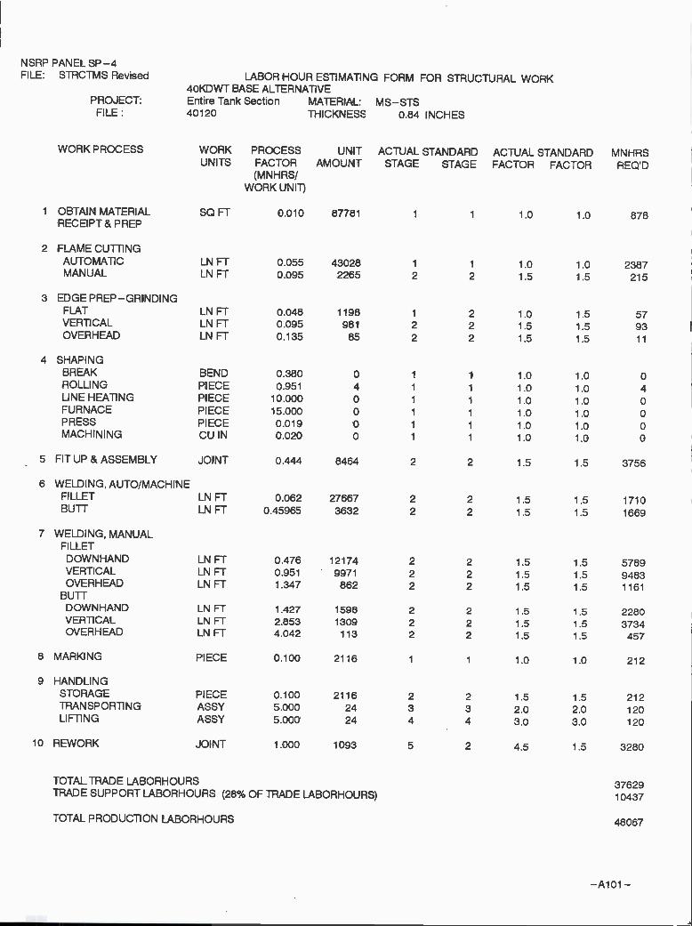
NSRP PANEL SP-4
-Aloi -
FILE: STRCTMS Revised LABOR HOUR ESTIMATING FORM FOR STRUCTURAL WORK4OKDWT BASE ALTERNA11VE
PROJECT: Entire Tank Section MATERIAL: MS-STSFILE: 40120 ThICKNESS 0.84 INCHES
WORK PROCESS WORK PROCESS UNIT ACTUAL STANDARD ACTUAL STANDARDU N ITS FACTOR AMOUNT STAGE STAGE FACTOR FACTOR
(MNH R SIWORK UNIT)
MNHRSREQ'D
i OBTAIN MATERIAL SOFT 0.010 87781 1 1 1.0 1.0 878AECEIPT& PREP
2 FLAME CUTTINGAUTOMATIC LN FT 0.055 43028 1 i 1.0 1.0 2387MANUAL LN FT 0.095 2265 2 2 1.5 1.5 215
3 EDGEPREP-GRINDINGFLAT LN FT 0.048 1198 1 2 1.0 1.5 57VERTICAL LN FT 0.095 981 2 2 1.5 1.5 93OVERHEAD LN FT 0.135 85 2 2 1.5 1.5 11
4 SHAPINGBREAK BEND 0.380 0 1 1 1.0 1.0 0ROLLI NG PIECE 0.951 4 1 1 1.0 1.0 4LINE HEATING PIECE 10.000 0 1 i 1.0 1.0 0FURNACE PIECE 15.000 0 1 1 1.0 1.0 0PRESS PIECE 0.019 0 1 1 1.0 1.0 0MACHINING CU IN 0.020 0 1 1 1.0 1.0 0
5 FIT UP & ASSEMBLY JOINT 0.444 6464 2 2 1.5 i .5 3756
6 WELDING, AUTO/MACHINEFILLET LN FT 0,062 27667 2 2 1.5 1.5 1710BUTT LN FT 0.45965 3632 2 2 1.5 1.5 1669
7 WELDING,MANUALFILLET
DOWN HAND LN FT 0.476 12174 2 2 1.5 1.5 5789VERTICAL LN FT 0.951 9971 2 2 1.5 1.5 9483OVERHEAD LN FT 1.347 862 2 2 1.5 1.5 1161
BUTTD OWN HAND LN FT 1.427 1598 2 2 1.5 1.5 2280VERTICAL LN FT 2.853 1309 2 2 1.5 1.5 3734OVERHEAD LN FT 4.042 113 2 2 1.5 1.5 457
8 MARKING PIECE 0.100 2116 1 1 1.0 1.0 212
9 HANDLINGSTORAGE PIECE 0.100 2116 2 2 1.5 1.5 212TRANSPORTING ASSY 5.000 24 3 3 2.0 2.0 120LIFTING ASSY 5.000 24 4 4 3.0 3.0 120
10 REWORK JOINT 1.000 1093 5 2 4.5 1,5 3280
TOTAL TRADE LABORHOURS 37629TRADE SUPPORT LABORHOURS (28% OF TRADE LABORHOURS) 10437
TOTAL PRODUCTION LABORHOURS 48067

NSRP PANEL SP-4
-A102-
FILE: STRCTMS Revised LABOR HOUR ESTIMATING FORM FOR STRUCTURAL WORK4OKDWT BASE ALTERNATIVE
PROJECT: Entire Tank Section MATERIAL: MS-STSFILE: 40121 THICKNESS 0.84 INCHES
WORK PROCESS WORK PROCESS UNIT ACTUAL STANDARD ACTUAL STANDARDUNITS FACTOR AMOUNT STAGE STAGE FACTOR FACTOR
(MNHRS/WORK UNIT)
MNHRSREOD
1 OBTAIN MATERIAL SOFT 0.010 87781 1 1 1.0 1.0 878RECEIPT& PREP
2 FLAME CUTTINGAUTOMATIC LN FT 0.055 42117 1 1 1.0 1.0 2336MANUAL LN FT 0.095 2217 2 2 1.5 1,5 211
3 EDGE PREP-GRINDINGFLAT LNFT 0.048 1572 1 2 1.0 1.5 89
VERTICAL LN FT 0.095 260 2 2 1 .5 1 .5 25
OVERHEAD LNFT 0.135 85 2 2 1.5 1.5 11
4 SHAPINGBREAK BEND 0.380 0 1 1 1.0 1.0 0
ROLLING PIECE 0.951 4 1 1 1 .0 1 .0 4
LINEHEATING PIECE 10.000 0 1 1 1.0 1.0 0
FURNACE PIECE 15.000 0 1 1 1.0 1.0 0
PRESS PIECE 0.019 0 1 1 1.0 1.0 0
MACHINING CU IN 0.020 0 1 1 1.0 1.0 0
5 FIT UP & ASSEMBLY JOINT 0.444 8464 2 2 1.5 1.5 3756
6 WELDING, AUTO/MACHINEFILLET LN FT 0.062 38398 2 2 1 .5 1.5 2374
BUTT LN FT 0,45965 5239 2 2 1 .5 1 .5 2408
7 WELDING, MANUALFILLET
DOWN HAND LNFT 0.476 6747 2 2 1.5 1.5 4159VERTICAL LNFT 0.951 1215 2 2 1.5 1.5 1156OVERHEAD LNFT 1.347 397 2 2 1.5 1.5 534
BUTTDOWNHAND LNFT 1.427 1193 2 2 1.5 1.5 1702
VERTICAL LNFT 2.853 166 2 2 1.5 1.5 473OVERHEAD LN FT 4.042 54 2 2 1.5 1.5 219
8 MARKING PIECE 0.100 2116 1 1 1.0 1.0 212
9 HANDLINGSTORAGE PIECE 0.100 2116 2 2 1.5 1.5 212
TRANSPORTING ASSY 5.000 24 3 3 2.0 2,0 120
LIFTING ASSY 5.000 24 4 4 3.0 3.0 120
10 REWORK JOINT 1.000 648 5 2 4.5 1.5 1945
TOTAL TRADE LABORHOURS 22943
TRADE SUPPORT LABORHOURS (28% OF TRADE LABORHOURS) 6364
TOTAL PRODUCTION LABORHOURS 29307

NSRP PANEL SP-4
-A103--
FILE: STRCTMS Revised LABOR HOUR ESTIMATING FORM FOR STRUCTURAL WORK4OKDWT BASE ALTERNATIVE
PROJECT: Entire Tank Section MATERIAL: MS-STSFILE: 40130 THICKNESS 0.57 INCHES
WORK PROCESS WORK PROCESS UNIT ACTUAL STANDARD ACTUAL STANDARDU N ITS FACTOR AMOUNT STAGE STAGE FACTOR FACTOR
(MNHRS/WORK UNIT)
MNHRSREOD
1 OBTAIN MATERIAL SOFT 0.010 79149 i 1.0 1 .0 791RECEIPT& PREP
2 FLAME CUTTINGAUTOMATIC LN FT 0.040 47582 1 1 1.0 1.0 1885MANUAL LN FT 0.071 2504 2 2 1.5 1.5 179
3 EDGE PREP-GRINDINGFLAT LN FT 0.032 1990 1 2 1.0 1.5 63VERTICAL LN FT 0.048 407 2 2 1.5 1.5 19OVERHEAD LN FT 0.063 108 2 2 1.5 1.5 7
4 SHAPINGBREAK BEND 0.380 0 1 1 1.0 1.0 0ROLLING PIECE 0.951 4 1 1 1.0 1.0 4LINE HEATING PIECE 10.000 0 1 1 1.0 1.0 0FURNACE PIECE 15.000 0 1 1 1.0 1.0 0PRESS PIECE 0.019 0 1 1 1.0 1.0 0MACHINING CU IN 0.020 0 1 1 1.0 1.0 0
5 FITUP&ASSEMBLY JOINT 0.444 6568 2 2 1.5 1.5 2915
6 WELDING, AUTO/MACHINEFILLET LN FT 0.052 49968 2 2 1 .5 1 .5 2574BUTT LN FT 0.3504 3530 2 2 1.5 1.5 1343
7 WELDING, MANUALFILLETDOWNHAND LN FT 0.269 22352 2 2 1 .5 1 .5 6023VERTICAL LN FT 0.404 4571 2 2 1.5 1.5 1847OVERHEAD LN FT 0.539 1213 2 2 1.5 1.5 653
BUTTDOWN HAND LNFT 1.030 1579 2 2 1.5 1.5 1627VERTICAL LN FT 1 .545 323 2 2 1 .5 1 .5 499OVERHEAD LNFT 2.061 86 2 2 1.5 1.5 177
8 MARKING PIECE 0.100 1642 1 1 1.0 1.0 164
9 HANDLINGSTORAGE PIECE 0.100 1642 2 2 1.5 1.5 164TRANSPORTING ASSY 5.000 24 3 3 2.0 2.0 120LIFTING ASSY 5.000 24 4 4 3.0 3.0 120
10 REWORK JOINT 1.000 660 5 2 4.5 1.5 1981
TOTAL TRADE LABORHOURS 23156TRADE SUPPORT LABORHOURS (28% OF TRADE LABORHOURS) 6423
TOTAL PRODUCTION LABORHOURS 29578

NSRP PANEL SP-4
-A104-
FILE: STRCTMS Revised LABOR HOUR ESTIMA11NG FORM FOR STRUCTURAL WORK4OKDWT BASE ALTERNA11VE
PROJECT: Entire Tank Section MATERIAL: MS-STSFILE: 40140 THICKNESS 0.57 INCHES
WORK PROCESS WORK PROCESS UNIT ACTUAL STANDARD ACTUAL STANDARDUNITS FACTOR AMOUNT STAGE STAGE FACTOR FACTOR
(MNHRS/WORK UNIT)
MNHRSREQD
XO.5
i OBTAIN MATERIAL SQFT 0.010 79149 1 1 1.0 1.0 396RECEIPT & PREP
2 FLAME CUTTINGAUTOMATIC LNFT 0.040 47582 1 1 1.0 1.0 943
MANUAL LNFT 0.071 2504 2 2 1.5 1.5 89
3 EDGE PREP-GRINDINGFLAT LNFT 0.032 1990 1 2 1.0 1.5 32
VERTICAL LNFT 0.048 407 2 2 1.5 1.5 10
OVERHEAD LNFT 0.063 108 2 2 1.5 1.5 3
4 SHAPINGBREAK BEND 0.380 0 1 1 1.0 1.0 0
ROLLI NG PIECE 0.951 4 1 1 1.0 1.0 2
LINE HEATING PIECE 10.000 0 1 1 1.0 1.0 0
FURNACE PIECE 15.000 0 1 1 1.0 1.0 0
PRESS PIECE 0.019 0 1 1 1.0 1.0 0
MACHINING CU IN 0.020 0 1 1 1.0 1.0 0
5 FITUP&ASSEMBLY JOINT 0.444 6568 2 2 1.5 1.5 1457
6 WELDING, AUTO/MACHINEFILLET LN FT 0.052 49968 2 2 1.5 1.5 1287
BUTT LN FT 0.3804 3530 2 2 1.5 1.5 671
7 WELDING, MANUALFILLET
D OWN HAND LNFT 0.269 22352 2 2 1.5 1.5 3011
VERTICAL LNFT 0.404 4571 2 2 1.5 1.5 924
OVERHEAD LNFT 0.539 1213 2 2 1.5 1.5 327
BUTTDOWN HAND LNFT 1.030 1579 2 2 1.5 1.5 813
VERTICAL LN FT 1 .545 323 2 2 1 .5 1 .5 250
OVERHEAD LN FT 2.061 86 2 2 1 .5 1 .5 88
8 MARKING PIECE 0.100 1642 1 1 1.0 1.0 82
9 HANDLINGSTORAGE PIECE 0.100 1642 2 2 1.5 1.5 82
TRAN SPORTI NG ASSY 5.000 24 3 3 2.0 2.0 60
LIFTING ASSY 5.000 24 4 4 3.0 3.0 60
10 REWORK JOINT 1.000 165 5 2 4.5 1.5 495
TOTAL TRADE LABORHOURS 11083
TRADE SUPPORT LABORHOURS (28% OF TRADE LABORHOURS) 1537
TOTAL PRODUCTiON LABORHOURS 12620

NSRPFILE: STRCTMS Revised LABOR HOUR ESTIMA11NG FORM FOR STRUCTURAL WORK
4OKDWT BASE ALTERNATIVE
-A105-
PROJECT: Entire Tank MATERIAL: MS-STSFILE: 40150 THICKNESS 057 INCHES
WORKPROCESS WORK PROCESS UNIT ACTUAL STANDARDACTUALUNITS FACTOR AMOUNT STAGE STAGE FACTOR
(MNHRS/WORK UNIi)
STANDARDMNHRSFACTOR REaD
1 OBTAIN MATERIAL SQ FT 0.010 79149 1 1 1.0 1.0 791
RECEIPT & PREP
2 FLAME CUTTINGAUTOMATIC LN FT 0.040 47582 1 1 1.0 1 .0 1 885
MANUAL LN FT 0.071 2504 2 2 1.5 1.5 179
3 EDGE PREP-GRINDINGFLAT LNFT 0.032 1990 1 2 1.0 1.5 63
VERTICAL LN FT 0.048 407 2 2 1 .5 1 .5 19
OVERHEAD LN FT 0.063 108 2 2 1.5 1.5 7
4 SHAPINGBREAK BEND 0.380 1 1 1.0 1.0
ROLLING PIECE 0.951 4 1 1 1.0 1.0 4
LINEHEATING PIECE 10.000 1 1 1.0 1.0
FURNACE PIECE 15.000 1 1 1.0 1.0
PRESS PIECE 0.019 1 1 1.0 1.0
MACHINING CU IN 0.020 1 1 1.0 1.0
5 FITUP&ASSEMBLY JOINT 0,444 6568 2 2 1.5 1.5 2915
6 WELDING, AUTO/MACHINFILLET LN FT 0.052 49968 2 2 1 .5 1 .5 2574
BUTT LN FT 0.3804 3530 2 2 1.5 1.5 1343
7 WELDING, MANUALFILLETDOWNHAND LN FT 0.269 22352 2 2 1 .5 1.5 6023
VERTICAL LN FT 0.404 4571 2 2 1.5 1.5 1847
OVERHEAD LN FT 0.539 1213 2 2 1.5 1.5 653
BUTTDOWNHAND LN FT 1.030 1579 2 2 1.5 1.5 1627VERTICAL LN FT 1 .545 323 2 2 1 .5 1.5 499OVERHEAD LN FT 2.061 86 2 2 1.5 1 .5 177
8 MARKING PIECE 0.100 1642 1 1 1.0 1.0 164
9 HANDLINGSTORAGE PIECE 0.100 1642 2 2 1.5 1.5 164
TRANSPORTING ASSY 5.000 24 3 3 2.0 2.0 120
LIFTING ASSY 5.000 24 4 4 3.0 3.0 120
10 REWORK JOINT 1.000 660 5 2 4.5 1.5 1981
TOTAL TRADE LABORHOURS 23156TRADE SUPPORT LABORHOURS (28% OF TRADE LABORHOURS) 6423
TOTAL PRODUCTION LAB 29578

95KDWT Alternative VesselsEstimation of Labor Hours Calculations for One Tank
- A106 -

NSRP PANEL SP-4
- A107 -
FILE: STRCTMS Revised LABOR HOUR ESTIMATING FORM FOR STRUCTURAL WORK95KDWT BASE ALTERNATIVE
PROJECT: Entire Tank Section MATERIAL: MS-STSFILE: 9510 THICKNESS 0.6 INCHES
WORK PROCESS WORK PROCESS UNIT ACTUAL STANDARD ACTUAL STANDARDUNITS FACTOR AMOUNT STAGE STAGE FACTOR FACTOR
(MNHRS/WORK UNIT)
MNHRSREQD
i OBTAIN MATERIAL SOFT 0.010 132358 1 1 1.0 1.0 1324RECEIPT& PREP
2 FLAME CUTTINGAUTOMATIC LN FT 0.040 75044 1 1 1 .0 1 .0 2974MANUAL LN FT 0.071 3950 2 2 1.5 1.5 282
3 EDGE PREP-GRINDINGFLAT LNFT 0.032 3157 1 2 1.0 1.5 100
VERTICAL LN FT 0.048 674 2 2 1.5 1.5 32
OVERHEAD LNFT 0.063 119 2 2 1.5 1.5 8
4 SHAPINGBREAK BEND 0.380 0 1 1 1.0 1.0 0
ROLLI NG PIECE 0.951 4 1 1 1.0 1.0 4
LINE HEATING PIECE 10.000 0 1 1 1.0 1.0 0
FURNACE PIECE 15.000 0 1 1 1.0 1.0 0
PRESS PIECE 0.019 0 1 1 1.0 1.0 0
MACHINING CU IN 0.020 0 1 1 1 .0 1 .0 0
5 FIT UP & ASSEMBLY JOINT 0.444 9828 2 2 1.5 1.5 4362
6 WELDING, AUTO/MACHINEFILLET LN FT 0.052 82561 2 2 1 .5 1 .5 4253
BUTT LN FT 0.3804 6294 2 2 1 .5 1 .5 2394
7 WELDING, MANUALFILLETD OWN HAND LNFT 0.269 30775 2 2 1.5 1.5 8292VERTICAL LNFT 0.404 6568 2 2 1.5 1.5 2654OVER H EAD LNFT 0.539 1164 2 2 1.5 1.5 627
BUTTDOWN HAND LNFT 1.030 2346 2 2 1.5 1.5 2417
VERTICAL LNFT 1.545 501 2 2 1.5 1.5 774OVERHEAD LNFT 2.061 89 2 2 1.5 1.5 183
8 MARKING PIECE 0.100 2457 1 1 1.0 1.0 246
9 HANDLINGSTORAGE PIECE 0.100 2457 2 2 1.5 1.5 246
TRANSPORTING ASSY 5.000 24 3 3 2.0 2.0 120LIFTING ASSY 5.000 24 4 4 3.0 3.0 120
10 REWORK JOINT 1.000 978 5 2 4.5 1.5 2935
TOTAL TRADE LABORHOURS 34346TRADE SUPPORT LABORHOURS (28% OF TRADE LABORHOURS) 9527
TOTAL PRODUCTION LABORHOURS 43872

NSRP PANEL SP-4
- A108 -
FILE: STRCTMS Revised LABOR HOUR ESTIMATING FORM FOR STRUCTURAL WORK95KDWT BASE ALTER NAil VE
PROJECT: Entire Tank Section MATERIAL: MS-STSFILE: 9520 THICKNESS 0.63 INCHES
WORK PROCESS WORK PROCESS UNIT ACTUAL STANDARD ACTUAL STANDARDUNITS FACTOR AMOUNT STAGE STAGE FACTOR FACTCR
(MNH RS!WORK UNIT)
MNHRSREaD
i OBTAIN MATERIAL SQFT 0.010 134524 1 1 1.0 10 1345RECEIPT& PREP
2 FLAME CUTTINGAUTOMATIC LN FT 0.040 75087 1 1 1 .0 1 0 2975MANUAL LNFT 0.071 3952 2 2 1.5 1.5 282
3 EDGE PREP-GRINDINGFLAT LNFT 0.032 3157 1 2 1.0 1.5 100
VERTICAL LNFT 0.048 676 2 2 1.5 1.5 32OVERHEAD LNFT 0.063 119 2 2 1.5 1.5 8
4 SHAPINGBREAK BEND 0.380 0 1 1 1.0 1 .0 0
ROLLING PIECE 0.951 4 1 1 1.0 1.0 4
LINE HEATING PIECE 10.000 0 1 1 1.0 1.0 0
FURNACE PIECE 15.000 0 1 1 1.0 1.0 0
PRESS PIECE 0.019 0 1 1 1.0 1.0 0
MACHINING CUIN 0.020 0 1 1 1.0 1.0 0
5 FIT UP & ASSEMBLY JOINT 0.444 9828 2 2 1.5 1.5 4362
6 WELDING, AUTO/MACHINEFILLET LN FT 0.052 82262 2 2 1.5 1.5 4238
BUTT LN FT 0.3804 6287 2 2 1.5 1.5 2392
7 WELDING, MANUALFILLETD OWN HAN D LN FT 0.269 30996 2 2 1 .5 1.5 8352VERTICAL LN FT 0.404 6639 2 2 1 .5 1 .5 2683OVERHEAD LNFT 0.539 1170 2 2 1.5 1.5 630
BUTTDOWN HAND LN FT 1.030 2369 2 2 1 .5 1 .5 2441
VERTICAL LN FT 1 .545 507 2 2 1 .5 1 .5 784
OVERHEAD LNFT 2.061 89 2 2 1.5 1.5 184
8 MARKING PIECE 0.100 2457 1 1 1.0 1.0 246
9 HANDLINGSTORAGE PIECE 0.100 2457 2 2 1.5 1.5 246
TRANSPORTI NG ASSY 5.000 24 3 3 2.0 2.0 120
LIFTING ASSY 5.000 24 4 4 3.0 3.0 120
lo REWORK JOINT 1.000 982 5 2 4.5 1.5 2946
TOTAL TRADE LABORHOURS 34489TRADE SUPPORT LABORHOURS (28% OF TRADE LABORHOURS) 9566
TOTAL PRODUCTION LABORHOURS 44055
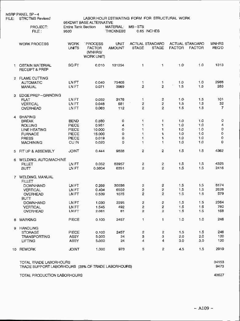
NSRP PANEL SP-4
- A109 -
FILE: STRCTMS Revised LABOR HOUR ESTIMATING FORM FOR STRUCTURAL WORK95KDWT BASE ALTERNATIVE
PROJECT: Entire Tank Section MATERIAL: MS-STSFILE: 9530 THICKNESS 0.65 INCHES
WORK PROCESS WORK PROCESS UNIT ACTUAL STANDARD ACTUAL STANDARDUNITS FACTOR AMOUNT STAGE STAGE FACTOR FACTOR
(MNHRS/WORK UNIT)
MNHRSREQD
i OBTAIN MATERIAL SOFT 0.010 131254 1 1 1.0 1.0 1313RECEIPT& PREP
2 FLAME CUTTINGAUTOMATIC LN FT 0.040 75405 1 1 1 .0 1 .0 2988MANUAL LN FT 0.071 3969 2 2 1.5 1.5 283
3 EDGE PREP-GRINDINGFLAT LN FT 0.032 3176 1 2 1.0 1.5 101
VERTICAL LN FT 0.048 681 2 2 1,5 1.5 32OVERHEAD LN FT 0.063 112 2 2 1.5 1.5 7
4 SHAPINGBREAK BEND 0.380 0 1 i 1.0 1.0 0
ROLLI NG PIECE 0.951 4 1 1 1.0 1.0 4
LINE HEATING PIECE 10.000 0 1 1 1.0 1.0 0
FURNACE PIECE 15.000 0 1 1 1.0 1.0 0
PRESS PIECE 0.019 0 1 1 1.0 1.0 0MACHINING CU IN 0.020 0 1 1 1.0 1.0 0
5 FIT UP & ASSEMBLY JOINT 0.444 9828 2 2 1 .5 1 .5 4362
6 WELDING, AUTO/MACHINEFILLET LN FT 0.052 83957 2 2 1 .5 1.5 4325BUTT LN FT 0.3804 6351 2 2 1.5 1.5 2416
7 WELDING, MANUALFILLET
DOWN HAND LN FT 0.269 30336 2 2 1.5 1.5 8174VERTICAL LN FT 0.404 6502 2 2 1 .5 1 .5 2628OVERHEAD LN FT 0.539 1075 2 2 1.5 1.5 579
BUTTDOWNHAND LN FT 1 .030 2295 2 2 1 .5 1 .5 2364
VERTICAL LN FT 1 .545 492 2 2 1 .5 1 .5 760OVERHEAD LNFT 2.061 81 2 2 1.5 1.5 168
8 MARKING PIECE 0.100 2457 1 1 1.0 1.0 246
9 HANDLINGSTORAGE PIECE 0.100 2457 2 2 1.5 1.5 246TRANSPORTING ASSY 5.000 24 3 3 2.0 2.0 120
LIFTING ASSY 5.000 24 4 4 3.0 3.0 120
10 REWORK JOINT 1.000 973 5 2 4.5 1.5 2919
TOTAL TRADE LABORHOURS 34153TRADE SUPPORT LABORHOURS (28% OF TRADE LABOAHOURS) 9473
TOTAL PRODUCTION LABORHOURS 43627

NSRP PANEL SP-4FILE: STRCTMS Revised LABOR HOUR ESTIMATING FORM FOR STRUCTURAL WORK
95KDWT BASE ALTERNATIVEPROJECT: Entire Tank Section MATERIAL: MS-STSFILE: 9540 THICKNESS 0.6 INCHES
WORK PROCESS WORK PROCESS UNIT ACTUAL STANDARD ACTUAL STANDARDUNITS FACTOR AMOUNT STAGE STAGE FACTOR FACTOR
(MNHRS/WORK UNIT)
MNHRSREaD
1 OBTAIN MATERIAL SOFT 0.010 133089 1 1 1.0 10 1331
RECEIPT & PREP
2 FLAME CUTTINGAUTOMATIC LNFT 0.040 76319 1 1 1.0 1.0 3024
MANUAL LNFT 0.071 4017 2 2 1.5 1.5 286
3 EDGE PREP-GRINDINGFLAT LNFT 0.032 3278 1 2 1.0 1.5 104
VERTICAL LNFT 0.048 620 2 2 1.5 1.5 29
OVER H EAD LNFT 0.063 119 2 2 1.5 1.5 8
4 SHAPINGBREAK BEND 0.380 0 1 1 1 .0 1 .0 0
ROLLING PIECE 0.951 4 1 1 1.0 1.0 4
LINE HEATING PIECE 10.000 0 1 1 1,0 1.0 0
FU RNACE PIECE 15.000 0 1 1 1.0 1.0 0
PRESS PIECE 0.019 0 1 1 1.0 1.0 0
MACHINING CUIN 0.020 0 1 1 1.0 1.0 0
5 FIT UP & ASSEMBLY JOINT 0.444 9760 2 2 1 .5 1.5 4331
6 WELDING, AUTO/MACHINEFILLET LNFT 0.052 84524 2 2 1.5 1.5 4354
BUTT LN FT 0.3804 7042 2 2 1.5 1.5 2679
7 WELDING, MANUALFILLETDOWN HAND LNFT 0.269 29367 2 2 1.5 1.5 7913
VERTICAL LNFT 0.404 5551 2 2 1.5 1.5 2244
OVERHEAD LNFT 0.539 1069 2 2 1.5 1.5 576
BUTTDOWN HAND LNFT 1.030 2447 2 2 1.5 1.5 2521
VERTICAL LNFT 1.545 462 2 2 1.5 1.5 715
OVERHEAD LNFT 2.061 89 2 2 1.5 1.5 184
8 MARKING PIECE 0.100 2440 1 1 1.0 1.0 244
9 HANDLINGSTORAGE PIECE 0.100 2440 2 2 1.5 1.5 244
TRANSPORTING ASSY 5.000 24 3 3 2.0 2.0 120
LIFTING ASSY 5.000 24 4 4 3,0 3.0 120
10 REWORK JOINT 1 .000 966 5 2 4.5 1 .5 2897
TOTAL TRADE LABORHOURS 33927
TRADE SUPPORT LABORHOURS (28% OF TRADE LABORHOURS) 9411
TOTAL PRODUCTION LABORHOURS 43338
- AllO -

NSRP PANEL SP-4
- Alu -
I FILE: STRCTMS Revised LABOR HOUR ESTIMATING FORM FOR STRUCTURAL WORKI 95KDWT BASE ALTERNATIVE
PROJECT: Entire Tank Section MATERIAL: MS-STSFILE: 9550 THICKNESS 0.6 INCHES
WORK PROCESS WORK PROCESS UNIT ACTUAL STANDARD ACTUAL STANDARDUNITS FACTOR AMOUNT STAGE STAGE FACTOR FACTOR
(M NH RS!WORK UNIT)
MNHRSREQ'D
1 OBTAIN MATERIAL SOFT 0.010 132358 1 1 1.0 1.0 1324
RECEIPT & PREP
2 FLAME CU1TNGAUTOMATIC LN FT 0.040 75580 1 1 1.0 1 .0 2995
MANUAL LN FT 0.071 3978 2 2 1.5 1.5 284
3 EDGE PREP-GRINDINGFLAT LNFT 0.032 3181 1 2 1.0 1.5 101
VERTICAL LN FT 0.048 674 2 2 1.5 1.5 32
OVERHEAD LN FT 0.063 123 2 2 1 .5 1 .5 8
4 SHAPINGBREAK BEND 0.380 0 1 1 1.0 1.0 0
ROLLING PIECE 0.951 4 1 1 1.0 1.0 4
LINEHEATING PIECE 10.000 0 1 1 1.0 1.0 0
FURNACE PIECE 15.000 0 1 1 1.0 1.0 0
PRESS PIECE 0.019 0 1 1 1.0 1.0 0
MACHINING CUIN 0.020 0 1 1 1.0 1.0 0
5 FIT UP & ASSEMBLY JOINT 0.444 9860 2 2 1.5 1.5 4376
6 WELDING, AUTO/MACHINEFILLET LNFT 0.052 83053 2 2 1.5 1.5 4278
BUTT LN FT 0.3804 6771 2 2 1.5 1.5 2576
7 WELDING, MANUALFILLET
DOWN HAND LN FT 0.269 29538 2 2 1 .5 1.5 7959VERTICAL LN FT 0.404 6255 2 2 1 .5 1.5 2528
OVERHEAD LN FT 0.539 1141 2 2 1.5 1.5 615
BUTTDOWNHAND LN FT 1.030 2408 2 2 1.5 1.5 2481
VERTICAL LN FT 1.545 510 2 2 1.5 1.5 788
OVERHEAD LN FT 2.061 93 2 2 1.5 1.5 192
8 MARKING PIECE 0.100 2465 1 1 1.0 1.0 247
9 HANDLINGSTORAGE PIECE 0.100 2465 2 2 1.5 1.5 247
TRANSPORTING ASSY 5.000 24 3 3 2.0 2.0 120
LIFTING ASSY 5.000 24 4 4 3.0 3.0 120
10 REWORK JOINT 1.000 974 5 2 4.5 1.5 2921
TOTAL TRADE LABORHOURS 34193TRADE SUPPORT LABORHOURS (28% OF TRADE LABORHOURS) 9484
TOTAL PRODUC11ON LABORHOURS 43677
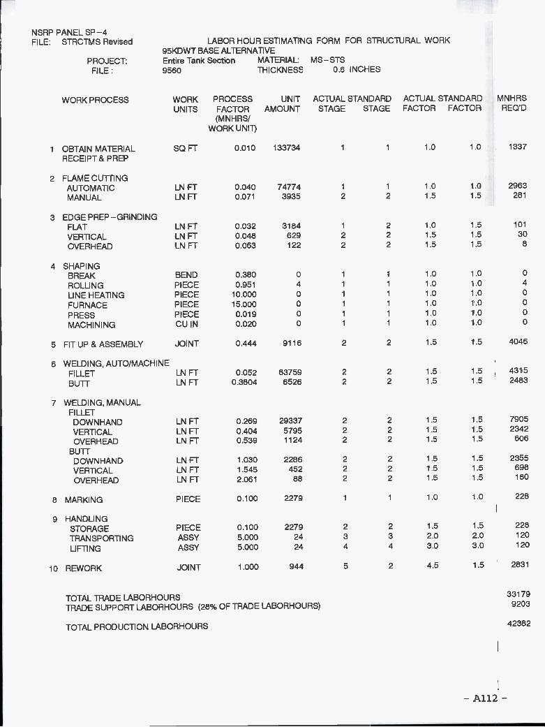
NSRP PANEL SP-4
- A112 -
FILE: STRCTMS Revised LABOR HOUR ESTIMATING FORM FOR STRUCTURAL WORK95KDWT BASE ALTERNATIVE
PROJECT: Entire Tank Section MATERIAL: MS-STSFILE: 9560 THICKNES$ 0.6 INCHES
WORK PROCESS WORK PROCESS UNIT ACTUAL STANDARD ACTUAL STANDARDUNITS FACTOR AMOUNT STAGE STAGE FACTOR FACTOR
(MNH RS!WORK UNIT)
MNHRSREOD
i OBTAIN MATERIAL SOFT 0.010 133734 1 1 1.0 1.0 1337
RECEIPT & PREP
2 FLAME CUTTINGAUTOMATIC LN FT 0.040 74774 1 1 1 .0 1 .0 2963
MANUAL LNFT 0.071 3935 2 2 1.5 1.5 281
3 EDGE PREP-GRINDINGFLAT LNFT 0.032 3184 1 2 1.0 1.5 101
VERTICAL LNFT 0.048 629 2 2 1.5 1,5 30
OVERHEAD LNFT 0.063 122 2 2 1.5 1.5 8
4 SHAPINGBREAK BEND 0.380 0 1 1 1.0 1.0 0
ROLLI NG PIECE 0,951 4 1 1 1.0 1.0 4
LINE HEATING PIECE 10.000 0 1 1 1.0 1.0 0
FU RNACE PIECE 15.000 0 1 1 1.0 1.0 0
PRESS PIECE 0.019 0 1 1 1.0 1.0 0
MACHINING CUIN 0.020 0 1 1 1.0 1.0 0
5 FIT UP & ASSEMBLY JOINT 0.444 9116 2 2 1.5 1.5 4046
6 WELDING, AUTO/MACHINEFILLET LN FT 0.052 83759 2 2 1.5 1.5 4315
BUTT LN FT 0.3804 6526 2 2 1.5 1.5 2483
7 WELDING, MANUALFILLETDOWN HAND LNFT 0,269 29337 2 2 1.5 1.5 7905
VERTICAL LN FT 0.404 5795 2 2 1 .5 1 .5 2342
OVERHEAD LNFT 0.539 1124 2 2 1.5 1.5 606
BUTTD OWN HAN D LN FT 1 .030 2286 2 2 1 .5 1 .5 2355
VERTICAL LNFT 1.545 452 2 2 1.5 1.5 698
OVERHEAD LNFT 2.061 88 2 2 1.5 1.5 180
8 MARKING PIECE 0.100 2279 1 1 1.0 1.0 228
9 HANDLINGSTORAGE PIECE 0.100 2279 2 2 1.5 1.5 228
TRANSPORTING ASSY 5.000 24 3 3 2.0 2.0 120
LIFTING ASSY 5.000 24 4 4 3.0 3.0 120
lo REWORK JOINT 1.000 944 5 2 4.5 1.5 2831
TOTAL TRADE LABORHOURS 33179
TRADE SUPPORT LABORHOURS (28% OF TRADE LABORHOURS) 9203
TOTAL PRODUCTION LABORHOURS 42382

NSRP PANEL SP-4
- A113 -
FILE: STRCTMS Revised LABOR HOUR ESTIMATING FORM FOR STRUCTURAL WORK95KDWT BASE ALTERNATIVE
PROJECT: Entire Tank Section MATERIAL: MS-STSFILE: 9570 THICKNESS 0.6 INCHES
WORK PROCESS WORK PROCESS UNIT ACTUAL STANDARD ACTUAL STANDARDUNITS FACTOR AMOUNT STAGE STAGE FACTOR FACTOR
(M N H RS!
WORK UNIT)
MNHRSREOD
i OBTAIN MATERIAL SOFT 0.010 124262 1 1 1.0 1.0 1243RECEIPT& PREP
2 FLAME CUTTINGAUTOMATIC LNFT 0.040 56902 1 1 1.0 1.0 2255MANUAL LNFT 0.071 2995 2 2 1.5 1.5 214
3 EDGE PREP-GRINDINGFLAT LN FT 0,032 2279 1 2 1.0 1.5 72
VERTICAL LNFT 0.048 610 2 2 1.5 1.5 29OVERHEAD LN FT 0.063 106 2 2 1 .5 1 .5 7
4 SHAPINGBREAK BEND 0.380 0 1 1 1.0 1.0 0
ROLLING PIECE 0.951 4 1 1 1.0 1.0 4
LINE HEATING PIECE 10.000 0 1 1 1.0 1.0 0
FURNACE PIECE 15.000 0 1 1 1.0 1.0 0
PRESS PIECE 0.019 0 1 1 1.0 1.0 0
MACHINING CU IN 0.020 0 1 1 1.0 1.0 0
5 FIT UP & ASSEMBLY JOINT 0.444 9828 2 2 1.5 1.5 4362
6 WELDING, AUTO/MACHINEFILLET LN FT 0.052 49901 2 2 1.5 1.5 2571
BUTT LN FT 0,3804 5531 2 2 1.5 1.5 2104
7 WELDING, MANUALFILLET
DOWNHAND LNFT 0.269 24699 2 2 1.5 1.5 6655VERTICAL LNFT 0.404 6607 2 2 1.5 1.5 2670OVERHEAD LNFT 0.539 1152 2 2 1.5 1.5 621
BUTTDOWN HAND LN FT 1 .030 2738 2 2 1 .5 1 .5 2821
VERTICAL LNFT 1.545 732 2 2 1.5 1.5 1132OVERHEAD LN FT 2.061 128 2 2 1.5 1.5 263
8 MARKING PIECE 0.100 2457 1 1 1.0 1.0 246
9 HANDLINGSTORAGE PIECE 0100 2457 2 2 1.5 1.5 246TRANSPORTING ASSY 5.000 24 3 3 2.0 2.0 120LIFTING ASSY 5.000 24 4 4 3.0 3.0 120
10 REWORK JOINT 1.000 859 5 2 4.5 1.5 2577
TOTAL TRADE LABORHOURS 30330TRADE SUPPORT LABORHOURS (28% OF TRADE LABORHOURS) 8413
TOTAL PRODUCTION LABORHOURS 38742

NSRP PANEL SP-4
- A114 -
FILE: STRCTMS Revised LABOR HOUR ESTIMATING FORM FOR STRUCTURAL WORK95KDWT BASE ALTERNATIVE
PROJECT: Entire Tank Section MATERIAL: MS-STSFILE: 9580 THICKNESS 0.61 INCHES
WORK PROCESS WORK PROCESS UNIT ACTUAL STANDARD ACTUAL STANDARDUNITS FACTOR AMOUNT STAGE STAGE FACTOR FACTOR
(M N H RS/
WORK UNIT)
MNHRSREQ'D
1 OBTAIN MATERIAL SOFT 0.010 132009 1 .0 1 .0 1320
RECEIPT & PREP
2 FLAME CUTTINGAUTOMATIC LN FT 0,040 45338 1 1 1.0 1.0 1797
MANUAL LN FT 0,071 2386 2 2 1.5 1.5 170
3 EDGEPREP-GRINDINGFLAT LN FT 0.032 1583 1 2 1.0 1,5 50
VERTICAL LN FT 0.048 652 2 2 1.5 1.5 31
OVERHEAD LN FT 0.063 151 2 2 1.5 1.5 10
4 SHAPINGBR EA K BEND 0.380 13283 1 1 1.0 1.0 5053
ROLLI NG PIECE 0.951 4 1 1 1.0 1.0 4
LINE HEATING PIECE 10.000 0 1 1 1.0 1.0 0
FURNACE PIECE 15.000 0 1 1 1.0 1.0 0
PRESS PIECE 0.019 0 1 1 1.0 1.0 0
MAC H INI NG CU IN 0.020 0 1 1 1.0 10 0
5 FIT UP & ASSEMBLY JOINT 0.444 8532 2 2 1.5 1 5 3787
6 WELDING AUTO/MACHINEFILLET LN FT 0.052 21011 2 2 1.5 1 5 1082
BUTT LN FT 0.3804 7499 2 2 1,5 1 5 2853
7 WELDING, MANUALFILLET
DOWNHAND LN FT 0.269 12566 2 2 1,5 1 5 3386
VERTICAL LN FT 0,404 5173 2 2 1.5 1 5 2091
OVERHEAD LN FT 0.539 1199 2 2 1.5 1 5 646
BUTTDOWN HAND LN FT 1 .030 4485 2 2 1 .5 1 5 4620
VERTICAL LN FT 1.545 1846 2 2 1.5 1 5 2853
OVER H EAD LN FT 2.061 428 2 2 1.5 1 5 882
8 MARKING PIECE 0.100 2133 1 1 1.0 10 213
9 HANDLINGSTORAGE PIECE 0.100 2133 2 2 1.5 1.5 213
TRANSPORTI NG ASSY 5.000 24 3 3 2.0 2.0 120
LIFTING ASSY 5.000 24 4 4 3.0 3,0 120
lo REWORK JOINT 1,000 809 5 2 4.5 1,5 2426
TOTAL TRADE LABORHOURS 33726
TRADE SUPPORT LABORHOURS (28% OF TRADE LABORHOURS) 9355
TOTAL PRODUCTION LABORHOURS 43080

i NSRP PANEL SP-4
- A115 -
FILE: STRCTMS Revised LABOR HOUR ESTIMATING FORM FOR STRUCTURAL WORK95KDWT BASE ALTERNATIVE
PROJECT: Entire Tank Section MATERIAL: MS-STSFILE: 95120 THICKNESS 0.86 INCHES
WORK PROCESS WORK PROCESS UNIT ACTUAL STANDARD ACTUAL STANDARDUNITS FACTOR AMOUNT STAGE STAGE FACTOR FACTOR
(MNH RS!WORK UNIT)
MNHRSREQ'D
i OBTAIN MATERIAL SOFT 0.010 121237 1 1 1.0 1.0 1212
RECEIPT & PREP
2 FLAME CUTTINGAUTOMATIC LN FT 0055 53768 1 1 1.0 1.0 2983
MANUAL LN FT 0.095 2830 2 2 1.5 1.5 269
3 EDGE PREP-GRINDINGFLAT LN FT 0.048 1359 1 2 1.0 1.5 65
VERTICAL LN FT 0.095 1372 2 2 1.5 1.5 131
OVER H EAD LN FT 0.135 99 2 2 1,5 1.5 13
4 SHAPINGBREAK BEND 0.380 0 1 1 1.0 1.0 0
ROLLI NG PIECE 0.951 4 1 1 1.0 1.0 4
LINE HEATING PIECE 10.000 0 1 1 1.0 1.0 0
FU RNACE PIECE 15.000 0 1 1 1.0 1.0 0
PRESS PIECE 0.019 0 1 1 1.0 1.0 0
MACHINING CU IN 0.020 0 1 1 1.0 1.0 0
5 FIT UP & ASSEMBLY JOINT 0.444 9500 2 2 1.5 1.5 4216
6 WELDING, AUTO/MACHINEFILLET LN FT 0.062 33721 2 2 1.5 1.5 2084
BUTT LN FT 0.45965 5684 2 2 1.5 1.5 2613
WELDING, MANUAL7 FILLET
DOWN HAND LN FT 0.476 10829 2 2 1.5 1.5 5149VERTICAL LN FT 0.951 10938 2 2 1.5 1.5 10402
OVERHEAD LN FT 1.347 789 2 2 1.5 1.5 1063
BUTTD O WN HAN D LN FT 1 .427 1825 2 2 1 .5 1.5 2604
VERTICAL LN FT 2.853 1844 2 2 1.5 1.5 5260OVERHEAD LN FT 4.042 133 2 2 1.5 1.5 538
8 MARKING PIECE 0.100 2375 1 1 1.0 1.0 238
9 HANDLINGSTORAGE PIECE 0.100 2375 2 2 1.5 1.5 238
TRANSPORTI NG ASSY 5.000 24 3 3 2.0 2.0 120
LIFTING ASSY 5.000 24 4 4 3.0 3.0 120
10 REWORK JOINT 1.000 1246 5 2 4.5 1.5 3739
TOTAL TRADE LABORHOURS 43061TRADE SUPPORT LABORHOURS (28% OF TRADE LABORHOURS) 11944
TOTAL PRODUCTION LABORHOURS 55005
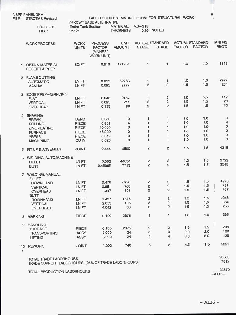
NSRP PANEL SP-4
- A116 -
-A115-
FILE: STRCTMS Revised LABOR HOUR ESTIMATING FORM FOR STRUCTURAL WORK95KDWT BASE ALTERNATIVE
PROJECT: Entire Tank Section MATERIAL: MS-STSFILE: 95121 THICKNESS 086 INCHES
WORK PROCESS WORK PROCESS UNIT ACTUAL STANDARD ACTUAL STANDARDUNITS FACTOR AMOUNT STAGE STAGE FACTOR FACTOR
(MNHRS/WORK UNIT)
MNHRSREaD
i OBTAIN MATERIAL SOFT 0.010 121237 1 1 1.0 1.0 1212
RECEIPT & PREP
2 FLAME CUTTINGAUTOMATIC LN FT 0.055 52763 1 1 1.0 1.0 2927
MANUAL LNFT 0.095 2777 2 2 1.5 1.5 264
3 EDGE PREP-GRINDINGFLAT LNFT 0.048 2467 1 2 1.0 1,5 117
VERTICAL LNFT 0.095 211 2 2 1.5 1.5 20
OVER H EAD LNFT 0.135 99 2 2 1.5 1.5 13
4 SHAPINGBREAK BEND 0.380 0 1 1 1 .0 1 .0 0
ROLLING PIECE 0.951 4 1 1 1.0 1.0 4
LINE HEATING PIECE 10.000 0 1 1 1.0 1,0 0
FURNACE PIECE 15.000 0 1 1 1.0 1.0 0
PRESS PIECE 0.019 0 1 1 1.0 1.0 0
MACHINING CU IN 0.020 0 1 1 1.0 1.0 0
5 FIT UP & ASSEMBLY JOINT 0.444 9500 2 2 1.5 1.5 4216
6 WELDING, AUTO/MACHINEFILLET LN FT 0.062 44034 2 2 1.5 1.5 2722
BUTT LN FT 0.45965 7713 2 2 1.5 1.5 3545
7 WELDING, MANUALFILLET
DOWN HAND LN FT 0.476 8998 2 2 1 .5 1.5 4278
VERTICAL LNFT 0.951 768 2 2 1.5 1.5 731
OVERHEAD LNFT 1.347 361 2 2 1.5 1.5 487
BUTTDOWN HAND LNFT 1.427 1576 2 2 1.5 1.5 2248
VERTICAL LNFT 2.853 135 2 2 1.5 1.5 384
OVERHEAD LNFT 4.042 63 2 2 1.5 1.5 256
8 MARKING PIECE 0.100 2375 1 1 1.0 1.0 238
9 HANDLINGSTORAGE PIECE 0.100 2375 2 2 1.5 1.5 238
TRANSPORTI NG ASSY 5.000 24 3 3 2.0 2.0 120
LIFTING ASSY 5.000 24 4 4 3.0 3.0 120
10 REWORK JOINT 1.000 740 5 2 4.5 1.5 2221
TOTAL TRADE LABORHOURS26360
TRADE SUPPORT LABORHOURS (28% OF TRADE LABORHOURS) 7312
TOTAL PRODUCTION LABORHOURS 33672
Plots for 4OKDWT and 95KDWT Alternatives
Comparison of Tank Steel Area(One Side of Plate, One Tank)
Comparison of Tank Steel Weight
Comparison of Tank Weld Lengths
Comparison of Weld VolumesIncludes Factors for Weld Position and Technique
Average Steel Plate Thicknessfor One Tank Length
- A117 -

13 12 11 10
WC
6(I
)
5 4 3(I
)2 1 o
Com
paris
on o
f Tan
k S
teel
Are
as(O
ne S
ide
of P
late
, One
Tan
k) I
1030
5070
9011
O 1
12 1
2114
020
4060
8010
0 11
112
0 13
0 15
0V
esse
l Key
Num
bers
I 4O
KD
WT
Tan
kers
j 95K
DW
T T
anke
rs

Com
paris
on o
f Tan
k S
teel
Wei
ght
1030
5070
9011
011
212
114
020
4060
8010
011
112
013
015
0V
esse
l Key
Num
ber
I 4O
KD
WT
Tan
kers
j 95K
DW
T T
anke
rs

50 40 30 20 lo o
Com
paris
on o
f Tan
k W
eld
Leng
ths
1030
5070
9011
011
212
114
020
4060
8010
011
112
013
015
0V
esse
l Key
Num
ber
4OK
DW
T T
anke
rsfl
95K
DW
T T
anke
rs

Com
paris
on o
f Wel
d V
olum
es-
Incl
udes
Fac
tors
for
Wel
d P
ositi
on &
Tec
hniq
ue
i10
3050
7090
110
112
121
140
2040
6080
100
111
120
130
150
Ves
sel K
ey N
umbe
r-
One
Tan
k4O
KD
WT
Tan
kers
L 9
5KD
WT
Tan
kers

24 22 20 18 16 12C
I) cl) 0
6r E
-4 2 O
Ave
rage
Ste
el P
late
Thi
ckne
ssF
or O
ne T
ank
Leng
th
10 3
0 50
70
90 1
10 1
1212
1 14
020
40
60 8
0 10
0 11
1 12
0 13
015
0V
esse
l Key
Num
ber
4OK
DW
T T
anke
rsi 9
5KD
WT
Tan
kers

Plots for 4OKDWT and 95KDWT Alternatives
Comparison of Estimated Labor Hours - Steelfor One Tank Length
Estimated Ship Labor HoursU.S. 1994 Design and Construction
Break Down of Cutting, Preparation and Weld Lengths4OKDWT Alternatives U.S. - One Tank
Break Down of Cutting, Preparation and Weld Lengths95KDWT Alternatives U.S. - One Tank
- Al23 -

60 50 40 30 20 10
Com
paris
on o
f Lab
or H
ours
- S
teel
-fo
r O
ne T
ank
Leng
th
1030
5070
9011
011
212
114
020
4060
80lO
O11
112
013
015
0V
esse
l Key
Num
ber
.i 4O
KD
WT
Tan
kers
95K
DW
T T
anke
rs

1.1 i
0.9
0.8
0.7
06 0.5
0= I-0.
4
0.3
0.2
0.1 o
Est
imat
ed S
hip
Labo
r H
ours
-U
.S. 1
994
Des
ign
and
Con
stru
ctio
n
1030
5070
9011
011
212
114
020
4060
8010
011
112
013
015
0V
esse
l Key
Num
ber
I4O
KD
WT
Tan
kers
95K
DW
T T
anke
rs

160
140
120
100 80 60 40 20
o
--,
,_-.
4010
4030
4050
4070
4090
401
10 4
0111
401
21 4
0140
4020
4040
4060
4080
401
00 4
0111
401
20 4
0130
401
50
Alte
rnat
ive
Key
Num
ber
..J A
uto
Fill
et L
i Man
ual F
illet
Aut
o B
uff
Man
ual B
uff
Fla
me
Cut
ting
j Edg
e P
repa
ratio
n
Bre
ak D
own
of C
uffin
g, P
rep.
and
Wel
ds4O
KD
WT
Alte
rnat
ives
U.S
. One
Tan
k

240
220
200
180
160
140
120
loo 80 60 40 20 o
Bre
ak D
own
of C
uttin
g,P
rep.
and
Wel
ds95
KD
WT
Alte
rnat
ives
U.S
. - O
ne T
ank
9510
9530
9550
9570
9510
095
111
9512
095
2095
4095
6095
8095
110
9511
195
121
Alte
rnat
ive
Key
Num
ber
Aut
o F
lUet
Man
ual F
illet
Aut
o B
utt
Man
ual B
utt
j Fla
me
Cut
ting
Edg
e P
repa
ratio
n

Mr. Norman Hammer
Mr. Fred Siebold
Mr. Paul Gilmour
Mr. Marty Hecker
Mr. Jack Waidman
Mr. James Wilkins
Mr. William Siekierka
Dr. Robert SielskiMr. Alex Stavovy
CDR Steve Sharpe
Maritime Administration
Maritime Administration
Maritime Administration
U.S. Coast Guard
Naval Sea Systems Command
Wilkins Enterprise, Inc.
Naval Sea Systems Command,Contracting Officer'sTechnical Representative
National Academy of Science,Marine Board Liaison
U.S. Coast Guard, Executive DirectorShip Structure Committee
Project Technical Committee Members
The following persons were members of the committee that represented the Ship Structure
Committee to the Contractor as resident subject matter experts. As such they performed
technical review of the initial proposals to select the contractor, advised the contractor in
cognizant matters pertaining to the contract of which the agencies were aware, and performed
technical review of the work in progress and edited the final report.