
Part 3 Hull Structures - Korean Register
432
2022 Rules for the Classification of Steel Ships Part 3 Hull Structures RA-03-E KR
-
Upload
khangminh22 -
Category
Documents
-
view
0 -
download
0
Transcript of Part 3 Hull Structures - Korean Register

2022
Rules for the Classification of Steel Ships
Part 3 Hull Structures
RA-03-E KR

RulesGuidance
2022Rules for the Classification of Steel Ships
Part 3 Hull Structures
2022Guidance Relating to the Rules for the Classification of Steel ships
Part 3 Hull Structures

- i -
APPLICATION OF PART 3 "HULL STRUCTURES"
1. Unless expressly specified otherwise, the requirements in the Rules apply to ships for which contracts for construction are signed on or after 1 July 2022.
2. The amendments to the Rules for 2021 edition and their effective date are as follows;
Effective Date : 1 July 2021
CHAPTER 14 WATERTIGHT BULKHEADS
Section 4 Watertight Doors- 404. 1 has been amended.- 407. 1 has been amended.- 408. 2 has been amended.- Table 3.14.5. has been amended.
Effective Date : 1 July 2022
CHAPTER 1 GENERAL
Section 2 General - 201. 4 has been newly added.- 201. 5 has been newly added.- 201. 6 has been newly added.
Section 4 Materials- Table 3.1.8 has been amended.
CHAPTER 16 SUPERSTRUCTURES
Section 1 General- 101. 3 has been amended.

- iii -
CONTENTS
CHAPTER 1 GENERAL ··········································································································· 1Section 1 Definitions ······································································································· 1Section 2 General ············································································································ 4Section 3 Approval of Plans and Documents ··························································· 5Section 4 Materials ·········································································································· 6Section 5 Weldings ······································································································· 11Section 6 Scantlings ······································································································ 17Section 7 Workmanship ······························································································· 19Section 8 Corrosion Protection Coating ···································································· 20
CHAPTER 2 STEMS AND STERN FRAMES ···································································· 21Section 1 Stems ············································································································ 21Section 2 Stern Frames ······························································································· 21
CHAPTER 3 LONGITUDINAL STRENGTH ········································································ 27Section 1 General ·········································································································· 27Section 2 Bending Strength ························································································ 28Section 3 Shear Strength ····························································································· 31Section 4 Buckling Strength ························································································ 35
CHAPTER 4 PLATE KEELS AND SHELL PLATINGS ····················································· 39Section 1 General ·········································································································· 39Section 2 Plate Keels ··································································································· 39Section 3 Shell Plating below Strength Deck ························································· 39Section 4 Special Requirements for Shell Plating ·················································· 42Section 5 Side Plating in way of Superstructure ··················································· 43Section 6 Compensation at ends of Superstructure ············································· 44Section 7 Local Compensation of Shell Plating ······················································ 44
CHAPTER 5 DECKS ·············································································································· 45Section 1 General ·········································································································· 45Section 2 Effective Sectional Area of Strength Deck ··········································· 45Section 3 Deck Plating ································································································· 46Section 4 Wood Decks and Deck Compositions ···················································· 47
CHAPTER 6 SINGLE BOTTOMS ························································································ 49Section 1 General ·········································································································· 49Section 2 Centre Keelsons ·························································································· 49Section 3 Side Keelsons ······························································································ 49Section 4 Floor Plates ·································································································· 50

- iv -
CHAPTER 7 DOUBLE BOTTOMS ······················································································ 53Section 1 General ·········································································································· 53Section 2 Centre Girders and Side Girders ····························································· 55Section 3 Solid Floors ··································································································· 58Section 4 Bottom Longitudinals ·················································································· 60Section 5 Inner Bottom Plating, Margin Plates and Bottom Shell Plating ······· 62Section 6 Hold Frame Brackets ················································································· 65Section 7 Open Floors ·································································································· 65Section 8 Construction of Strengthened Bottom Forward ··································· 66
CHAPTER 8 FRAMES ··········································································································· 71Section 1 General ·········································································································· 71Section 2 Frame Spacing ····························································································· 72Section 3 Hold Frames ································································································· 72Section 4 Side Longitudinals ······················································································· 76Section 5 Tween Deck Frames ·················································································· 77
CHAPTER 9 WEB FRAMES AND SIDE STRINGERS ···················································· 79Section 1 General ·········································································································· 79Section 2 Web Frames ································································································ 79Section 3 Side Stringers ······························································································ 81Section 4 Side Transverse ··························································································· 82Section 5 Cantilever Beams ························································································ 83
CHAPTER 10 BEAMS ··········································································································· 89Section 1 General ·········································································································· 89Section 2 Deck Load ···································································································· 90Section 3 Longitudinal Beams ···················································································· 92Section 4 Transverse Beams ······················································································ 93
CHAPTER 11 DECK GIRDERS ··························································································· 95Section 1 General ·········································································································· 95Section 2 Longitudinal Deck Girders ········································································· 95Section 3 Transverse Deck Girders ··········································································· 98Section 4 Deck Girders in Tanks ··············································································· 99Section 5 Hatch Side Girders ····················································································· 99Section 6 Hatch End Girders ······················································································ 99
CHAPTER 12 PILLARS ······································································································ 101Section 1 General ········································································································ 101Section 2 Scantling of Pillars ···················································································· 101

- v -
CHAPTER 13 ARRANGEMENTS TO RESIST PANTING ·············································· 105Section 1 General ········································································································ 105Section 2 Arrangements to Resist Panting forward the Collision Bulkhead ·· 105Section 3 Arrangements to Resist Panting abaft Aft-peak Bulkhead ············· 111Section 4 Arrangements to Resist Panting between Both Peaks ··················· 112
CHAPTER 14 WATERTIGHT BULKHEADS ···································································· 113Section 1 General ········································································································ 113Section 2 Arrangement of Watertight Bulkheads ················································· 113Section 3 Construction of Watertight Bulkheads ················································· 115Section 4 Watertight Doors ······················································································· 121
CHAPTER 15 DEEP TANKS ······························································································ 127Section 1 General ········································································································ 127Section 2 Bulkheads of Deep Tanks ······································································ 128Section 3 Fittings of Deep Tanks ············································································ 135Section 4 Welding of Corrugated Bulkheads ························································ 135
CHAPTER 16 SUPERSTRUCTURES ················································································· 137Section 1 General ········································································································ 137Section 2 Superstructure End Bulkheads ······························································· 137Section 3 Access Openings in Superstructure End Bulkheads ························ 140
CHAPTER 17 DECKHOUSES ···························································································· 141Section 1 General ········································································································ 141Section 2 Construction ······························································································· 141
CHAPTER 18 MACHINERY SPACES AND ENGINE CASINGS ·································· 145Section 1 General ········································································································ 145Section 2 Main Engine Foundation ·········································································· 145Section 3 Construction of Boiler Rooms ································································ 146Section 4 Thrust Blocks and Foundations ····························································· 146Section 5 Engine Casings ·························································································· 146
CHAPTER 19 TUNNELS AND TUNNEL RECESSES ···················································· 149Section 1 General ········································································································ 149

Pt 3 Hull StructuresCh 1 General Pt 3, Ch 1
Rules for the Classification of Steel Ships 2022 1
CHAPTER 1 GENERAL
Section 1 Definitions
101. Application 【See Guidance】The definitions of symbols and terms used in the Rules, except otherwise specified, are to be in accordance with this Section.
102. Rule Length (2020) 【See Guidance】 The rule length ( ) is the distance in metres measured on the waterline at the scantling draught from the fore side of stem to the after side of rudder post in case of a ship with rudder post, or to the axis of rudder stock in case of a ship without rudder post or stern post. is not to be less than 96 % and need not be greater than 97 % of the extreme length on the waterline at the scan-tling draught. In ships without rudder stock (e.g. ships fitted with azimuth thrusters), is to be taken equal to 97% of the extreme length on the waterline at the scantling draught. In ships with unusual stern and bow arrangement the rule length, will be specially considered.
103. Length for freeboard 【See Guidance】 The length of ship for freeboard () is 96 % of the length in metres measured from the fore side of stem to the aft side of aft end shell plate on the waterline at 85 % of the least moulded depth measured from the top of keel, or the length in metres measured from the fore side of stem to the axis of rudder stock on that waterlines, whichever is the greater. However, where the stem contour is concave above the waterline at 85 % of the least moulded depth, the forward terminal of this length is to be taken at the vertical projection to this waterline of the aftermost point of the stem contour. For ships without a rudder stock, the length of ship for freeboard is 96 % of the length measured from the fore side of stem to the aft side of aft end shell plate on the waterline at 85 % of the least moulded depth measured from the top of keel. The waterline on which this length is measured is taken to be parallel to the load line defined in 110.
104. Breadth (2020) 【See Guidance】 The breadth of ship ( ) is the horizontal distance in metres from the outside of frame to the out-side of frame measured amidships at the scantling draught, .
105. Breadth for freeboardThe breadth of ship for freeboard () is the maximum horizontal distance in metres from the out-side of frame to the outside of frame measured at the middle of .
106. Depth(the least moulded depth) 【See Guidance】The depth of ship () is the vertical distance in metres at the middle of measured from the top of keel to the top of the freeboard deck beam at side. Where watertight bulkheads extend to a deck above the freeboard deck and are to be registered as effective to that deck, D is the vertical distance to that bulkhead deck.
107. Depth for strength computation 【See Guidance】The depth of ship for strength computation () is the vertical distance in metres from the top of keel to the top of beam at side of the superstructure deck at the middle of , for the part where the superstructure deck is strength deck, or the freeboard deck for other parts. Where the deck does not cover midship, the depth is to be measured at the imaginary deck line which is extended to the middle of along the strength deck line.
108. MidshipThe midship means the part covering 0.4 amidships.

Pt 3 Hull StructuresCh 1 General Pt 3, Ch 1
2 Rules for the Classification of Steel Ships 2022
109. Fore and aft end partThe fore and aft end part means the part covering 0.1 from the fore and aft end of the ship.
110. Load lineThe load line is the waterline corresponding to the designed summer load draught in case of a ship which is required to be marked with load lines and the waterline corresponding to the designed maximum draught in case of a ship which is not required to be marked with load lines.
111. Load draughtThe load draught () is the vertical distance in metres from the top of keel to the load line meas-ured at the middle of in case of a ship which is required to be marked with load lines and at the middle of in case of a ship which is not required to be marked with load lines.
112. Full load displacementThe full load displacement (∆) is the displacement (including shell plating and appendages, etc.) in tons at the summer load line.
113. Block coefficient (2020)The block coefficient () is the moulded coefficient corresponding to waterline at the scantling draught, , based on rule length, and moulded breadth, .
××
.
114. Freeboard deck1. The freeboard deck is normally the uppermost continuous deck. However, in cases where openings
without permanent closing means exist on the exposed part of the uppermost continuous deck or where openings without permanent watertight closing means exist on the side of the ship below that deck, the freeboard deck is the continuous deck below that deck.
2. For ships having a discontinuous freeboard deck (e.g. a stepped freeboard deck), the freeboard deck is to be determined as follows.(1) Where a recess in the freeboard deck extends to both sides of the ship and is in excess of 1
m in length, the lowest line of the exposed deck and the continuation of that line parallel to the upper part of the deck is taken as the freeboard deck.
(2) Where a recess in the freeboard deck does not extend to the sides of the ship or is not in ex-cess of 1 m in length, the upper part of the deck is taken as the freeboard deck.
(3) Recesses not extending from side to side in a deck below the exposed deck, designated as the freeboard deck, may be disregarded, provided all openings in the weather deck are fitted with weathertight closing appliances.
3. Where a ship has multiple decks, an actual deck lower than one that complies with the freeboard deck defined above in 1 or 2 can be deemed the freeboard deck. However, this lower deck is to be continuous in a fore and aft direction at least between the machinery space and peak bulkheads and continuous athwartships.(1) When this lower deck is stepped, the lowest line of the deck and the continuation of that line
parallel to the upper part of the deck is taken as the freeboard deck.(2) When a lower deck is designated as the freeboard deck, such deck as a minimum shall consist
of suitably framed stringers at the ship sides and transversely at each watertight bulkhead which extends to the upper deck, within cargo spaces.
115. Bulkhead deckThe bulkhead deck is the highest deck to which the watertight transverse bulkheads except both peak bulkheads extend and are made effective.

Pt 3 Hull StructuresCh 1 General Pt 3, Ch 1
Rules for the Classification of Steel Ships 2022 3
116. Strength deckThe strength deck at a part of ship's length is the uppermost deck at that part to which the shell plates extend. However, in way of superstructures, except sunken superstructures, not exceeding0.15 in length, the strength deck is the deck just below the superstructure deck. The deck just below the superstructure deck may be taken as the strength deck even in way of the super-structure exceeding 0.15 in length at the option of the designer.
117. Raised deckThe raised deck is the sunken superstructure deck below which no deck, is provided.
118. SuperstructureThe superstructure is a decked structure on the freeboard deck, extending from side to side of the ship or having its side walls at the position not farther than 0.04 from the side of ship. Raised quarter deck is to be considered as a superstructure.
119. Enclosed superstructureAn enclosed superstructure is a superstructure complying with the following conditions:(1) Enclosed by bulkheads of efficient construction.(2) Access openings in these bulkheads are fitted with doors complying with the requirements of Ch
16, 301. or equivalent.(3) All other openings in sides or ends of the superstructure are fitted with efficient weathertight
means of closing.(4) Access means, which are available at all times when bulkhead openings are closed, are provided
for the crew to reach machinery and other working spaces within a bridge or poop.
120. Speed of shipThe speed of ship () is the designed speed in knots obtainable with clean bottom at calm sea and at the designed summer load line with the engine running at maximum continuous rating.
121. Light weight 【See Guidance】The Light Weight () is the displacement in tons excluding cargoes, fuel oil, lubricating oil, ballast and fresh water in tanks, stored goods, crew and their properties.
122. Deadweight tonnageThe deadweight () is the difference in tons between full load displacement and light weight.
123. Fore end and Aft endThe fore end is the start point of forward side, where measuring the length of ship in 102., and after end is the end point of afterward side of .
124. Section modulus ratioThe section modulus ratios ( and ) are as following formulae. However, is not to be less than 0.85 or , whichever is the lesser.
where:
and = required section moduli at the deck and bottom of transverse sections of the hull determined according to the requirements in Ch 3, 201. respectively when mild steel material symbol A, B, D and E specified in Pt 2, Ch 1, 301. Par 2 is used (cm3).

Pt 3 Hull StructuresCh 1 General Pt 3, Ch 1
4 Rules for the Classification of Steel Ships 2022
and = actual section moduli at the deck and bottom of transverse sections of the hull respectively (cm3).
125. Net thicknessNet thickness is the thickness that does not include corrosion addition and voluntary addition.
126. Scantlig draught (2020)Scantling draught, at which the strength requirements for the scantlings of the ship are met and represents the full load condition. The scantling draught is to be not less than that corresponding to the assigned freeboard.
Section 2 General
201. Application 【See Guidance】
1. The requirements in this Part unless otherwise specified elsewhere, are framed for hull structural arrangement and scantlings of ships not less than 90 m in length, of normal form and proportion, and intended for unrestricted service.
2. Hull construction, equipment and scantlings of ships to be classed for restricted service may be ap-propriately modified according to the condition of service.
3. In the application of relevant provisions in the Rules to ships which are not required to be marked with load lines, is to be read as and as .
4. For bulk carriers ( ≥ m) and double hull oil tankers ( ≥ m), the requirements in Pt 13 Common Structural Rules for Bulk Carriers and Oil Tankers are applied. (2022)
5. For container ships ( ≥ m), the requirements in Pt 14 Structural Rules for Container Ships are applied. (2022)
6. For membrane type liquefied natural gas carriers ( ≥ m) for construction on or after January 1, 2021, the requirements in Pt 15 Structural Rules for Membrane Type Liquefied Natural Gas Carriers are applied. (2022)
202. Exception in application 【See Guidance】In ships of which length is specially long or in ships to which requirements in the Rules for some special reasons, are not directly applicable, hull construction, equipment, arrangement and scantlings are to be in accordance with the discretion of the Society, notwithstanding the provisions in 201.
203. Ships of unusual form or proportion, or intended for carriage of special cargoes 【See Guidance】
In ships of unusual form or proportion, or intended for carriage of special cargoes, the requirements concerning hull construction, equipment, arrangement and scantlings will be decided individually bas-ing upon the general principle of the Rules instead of the requirements in the Rules.
204. Passenger shipsHull construction, equipment, arrangement and scantlings of passenger ships are to be specially considered with respect to the design features in addition to the requirements in 201. to 203.
205. EquivalencyThe equivalence of alternative and novel features which deviate from or are not directly applicable to the Rules is to be in accordance with Pt 1, Ch 1 105. of Rules for the Classification of Steel Ships. (2021)

Pt 3 Hull StructuresCh 1 General Pt 3, Ch 1
Rules for the Classification of Steel Ships 2022 5
206. Direct strength calculation 【See Guidance】
1. Where approved by the Society, scantlings of structural members may be determined basing upon direct strength calculation. Where the calculated scantlings based on direct strength calculation ex-ceed the scantlings required in this Part, the former is to be adopted.
2. Where the direct strength calculation specified in the preceding Par 1 is carried out, the data nec-essary for the calculation are to be submitted to the Society.
3. The evaluations of direct strength and fatigue strength for hull structures are in accordance with Appendix 3-2 「Guidelines for Direct Strength Assessment」 and Appendix 3-3 「Guidelines for Fatigue Strength Assessment of Hull Structures」 respectively. (2021)
207. Stability of shipThe requirements in the Rules are framed for ships having appropriate stability in all conceivable conditions. The Society emphasizes that the special attention be paid to the stability by the builders in design and construction stage and by the masters while in service.
208. Carriage of oil1. The requirements for construction and arrangement for carriage of fuel oils specified in Pts 3, 4 and
7 are to be applied to the case intended to carry fuel oils having a flash point 60°C or above at a closed cup test.
2. The construction and arrangement for carriage of fuel oils having a flash point below 60°C at a closed cup test, are to be in accordance with the requirements provided in Pts 3, 4 and 7 or the special requirements are to be applied.
3. The construction and arrangement of deep oil tanks intended to carry cargo oils are to be corre-spondingly in accordance with the requirements in Pt 7, Ch 1 or Pt 7, Ch 10.
Section 3 Approval of Plans and Documents
301. Plans and documents for approvalWhen it is intended to build a ship for Classification, the following plans and documents are to be submitted for the approval of the Society before the work is commenced.(1) Midship section(2) Construction profile(3) Shell expansion(4) Watertight and oiltight bulkheads(5) Deck plans(6) Stem, sternframe and rudder(7) Single bottoms and double bottoms(8) Superstructure end bulkheads(9) Fore and aft bodies(10) Pillars and deck girders(11) Shaft tunnels(12) Foundations and the relevant structure plan of boilers, main engines, thrust and plummer
blocks, generators, and other heavy weight auxilary machinery.(13) Machinery casings(14) Deckhouses(15) Masts, derrick posts and derrick booms and the relevant structure plans(16) Final stability data(17) Loading manual(18) Other plans and documents deemed necessary by the Society
302. Plans and documents for reference1. When it is intended to build a ship for Classification, the following plans and documents for refer-

Pt 3 Hull StructuresCh 1 General Pt 3, Ch 1
6 Rules for the Classification of Steel Ships 2022
ence are to be submitted in addition to the plans and documents for approval in 301.(1) General arrangement(2) Specification(3) Calculation sheets for midship section modulus(4) Where special cargoes are to be loaded, the plans showing their distribution and loading
arrangements.(5) Calculation sheets for masts, derrick booms, boat davits, and similar structures requiring strength.(6) Preliminary stability data.(7) Other plans and documents deemed necessary by the Society.
2. Hydrostatic curves, capacity plans, records of sea trials and various tests are to be submitted before the delivery of the ship.
303. Plans and documents for assignment of load linesWhere load lines are to be assigned the following plans and documents are to be submitted. But submission of plans and documents already submitted for the Classification Survey during con-struction may be dispensed with.(1) General arrangement(2) Midship section(3) Construction profile(4) Superstructures and superstructure end bulkheads(5) Hydrostatic curves(6) If the timber load lines are to be assigned, the plans showing the height of timber deck cargo
and the arrangements of lashing and fixing(7) Other plans and documents deemed necessary by the Society.
Section 4 Materials
401. Standard of materials 【See Guidance】The materials used for hull construction and equipment are to be those complying with the require-ments in Pt 2, Ch 1, unless otherwise specified.
402. Materials outside the RulesWhere materials other than those specified in the Rules are used, the use of such materials and corresponding, scantlings are to be specially approved by the Society.
403. High tensile steels 【See Guidance】
1. Where high tensile steels are to be used for hull construction, the drawings showing the scope and locations of the used place together with the type and scantlings are to be submitted for the ap-proval of the Society.
2. Where high tensile steels are used for hull construction, material factor (hereinafter refer to as in this Part and Pt 7) according to steels being used is as specified in Table 3.1.3.

Pt 3 Hull StructuresCh 1 General Pt 3, Ch 1
Rules for the Classification of Steel Ships 2022 7
Table 3.1.3 Material factor
Steel grades
A, B, D and E 1.0
AH 32, DH 32 and EH 32 0.78
AH 36, DH 36 and EH 36 0.72
AH 40, DH 40 and EH 40 0.68(1)
Note :(1) 0.66 for material factor provided that a fatigue assessment of the struc-
ture is performed to verify compliance with the requirements of Annex 3-3 "Guidance for the Fatigue Strength Assessment of Ship Structures" (2018)
404. Ships of restricted service area 【See Guidance】Materials for hull construction and equipment for ships intended for Classification with the condition of restricted service areas are to be in accordance with the discretion of the Society.
405. Application of steels 【See Guidance】
1. The steels used for hull structures are to be of the grades provided in Pt 2, Ch 1 in accordance with the requirements given in Tables 3.1.4 to 3.1.10. In applying these requirements, B, D or E may be substituted for A; D or E for B; E for D; DH 32 or EH 32 for AH 32; EH 32 for DH 32; DH36 or EH 36 for AH 36; and EH 36 for DH 36, DH 40 or EH 40 for AH 40; and EH 40 for DH 40, respectively.
2. For strength members not mentioned in Table 3.1.4, grade A, AH 32, AH 36 and AH 40 may gen-erally be used. As for rounded gunwale, the single strake is to have breadth to the satisfaction of the Society.
The steel grade is to correspond to the as-built plate thickness and material class.
3. Plating materials for sternframes supporting the rudder and propeller boss, rudder horns, rudders and shaft brackets are not to be of lower grades than corresponding to class II. However, for rudder and rudder body plates subjected to stress concentrations (e.g. in way of lower support of semi-spade rudder (D and E in Fig 4.1.1 of Pt 4, Ch 1) or at upper part of space rudder (C in Fig 4.1.1 of Pt 4, Ch 1)) class III is to be applied.
4. The steels with the thickness above 50 mm up to 100 mm used for stern frame may be of the grades E, EH32, EH36 or EH40.
5. The grades of steel to be used in the hull construction are to be clearly indicated on the hull struc-tural plans.

Pt 3 Hull StructuresCh 1 General Pt 3, Ch 1
8 Rules for the Classification of Steel Ships 2022
Structural member category Material class/grade
○ Secondary:A1. Longitudinal bulkhead strakes, other than that belong-
ing to the Primary category A2. Deck plating exposed to weather, other than that be-
longing to the Primary or Special category A3. Side plating
- Class I within 0.4L amidships- Grade A/AH outside 0.4L amidships
○ Primary:B1. Bottom plating, including keel plateB2. Strength deck plating, excluding that belonging to the
Special category B3. Continuous longitudinal plating of strength members
above strength deck, excluding hatch coamingsB4. Uppermost strake in longitudinal bulkheadB5. Vertical strake (hatch side girder) and uppermost slop-
ed strake in top wing tank
- Class II within 0.4L amidships- Grade A/AH outside 0.4L amidships
○ Special:C1. Sheer strake at strength deck (1) C2. Stringer plate in strength deck (1)C3. Deck strake at longitudinal bulkhead, excluding deck
plating in way of inner-skin bulkhead of double-hull ships (1)
- Class III within 0.4L amidships- Class II outside 0.4L amidships- Class I outside 0.6L amidships
C4. Strength deck plating at outboard corners of cargo hatch openings in container carriers and other ships with similar hatch opening configurations
- Class III within 0.4L amidships- Class II outside 0.4L amidships- Class I outside 0.6L amidships- Min. Class III within cargo region
C5. Strength deck plating at corners of cargo hatch open-ings in bulk carriers, ore carriers combination carriers and other ships with similar hatch opening config-urations
C5-1. Trunk deck and inner deck plating at corners of openings for liquid and gas domes in membrane type liquefied gas carriers
- Class III within 0.6L amidships- Class II within rest of cargo region
C6. Bilge strake in ships with double bottom over the full breadth and length less than 150 m (1)
- Class II within 0.6L amidships- Class I outside 0.6L amidships
C7. Bilge strake in other ships (1) - Class III within 0.4L amidships- Class II outside 0.4L amidships- Class I outside 0.6L amidships
C8. Longitudinal hatch coamings of length greater than 0.15L including coaming top plate and flange
C9. End brackets and deck house transition of longitudinal cargo hatch coamings
- Class III within 0.4L amidships- Class II outside 0.4L amidships- Class I outside 0.6L amidships- Not to be less than Grade D/DH
(Note)(1) Single strakes required to be of class Ⅲ within 0.4 amidships are to have breadths not less
than (mm), need not be greater than 1800 mm, unless limited by the geometry of the ship's design.
(2) The symbols in the table mean the grades of steel as follows :AH : AH 32, AH 36 and AH 40DH : DH 32, DH 36 and DH 40EH : EH 32, EH 36 and EH 40
Table 3.1.4 Material Classes

Pt 3 Hull StructuresCh 1 General Pt 3, Ch 1
Rules for the Classification of Steel Ships 2022 9
Structural member category Material grade
Longitudinal plating of strength deck where contributing to the longitudinal strengthLongitudinal strength members of strength deck plating
Grade B/AH within 0.4 amidships
Continuous longitudinal strength members above strength deck Grade B/AH within 0.4 amidships
Single side strakes for ships without inner continuous longi-tudinal bulkheads between bottom and the strength deck Grade B/AH within cargo region
Table 3.1.5 Minimum material grades for ships, excluding liquefied gas carriers covered in Table 3.1.6, with length exceeding 150m and single strength deck
Structural member category Material grade
Longitudinal plating of strength deck where contributing to the longitudinal strength
Grade B/AH within 0.4 amid-ships
Continuous longitudinal plating of strength members above the strength deck
Trunk deck plating Class II within 0.4 amidships
Inner deck plating Longitudinal strength member plating between the trunk deck and inner deck
Grade B/AH within 0.4 amid-ships
(*) Table 3.1.6 is applicable to membrane type liquefied gas carriers with deck arrangements as shown in Fig 1. Table 3.1.6 may apply to similar ship types with a “double deck” arrangement above the strength deck.
Table 3.1.6 Minimum material grades for membrane type liquified gas carriers with length exceeding 150m(*)
Fig 3.1.1 Typical deck arrangement for membrane type Liquefied Natural Gas Carriers

Pt 3 Hull StructuresCh 1 General Pt 3, Ch 1
10 Rules for the Classification of Steel Ships 2022
Structural member category Material grade
Sheer strake at strength deck (1) Grade E/EH within 0.4 amidships
Stringer plate in strength deck (1) Grade E/EH within 0.4 amidships
Bilge strake (1) Grade D/DH within 0.4 amidships
(Note)(1) Single strakes required to be of Grade E/EH and within 0.4 amidships are to have breadths not
less than 800+5 (mm), need not be greater than 1800 (mm), unless limited by the geometry of the ship’s design.
Table 3.1.7 Minimum Material Grades for ships with length exceeding 250 m
Structural member category Material grade
Lower bracket of ordinary side frame (1), (2) Grade D/DH
Side shell strakes included totally or partially between the two points located to 0.125 above and below the inter-section of side shell and bilge hopper sloping plate or inner bottom plate (1)
Grade D/DH
(Note)(1) The term "lower bracket" means webs of lower brackets and webs of the lower part of side
frames up to the point of 0.125 above the intersection of side shell and bilge hopper sloping plate or inner bottom plate.
(2) The span of the side frame, , is defined as the distance between the supporting structures.
Table 3.1.8 Minimum Material Grades for single-side skin bulk carriers subjected to SOLAS regulation XII/6.4 (2022)
Structural member category Material grade
Shell strakes in way of ice strengthening area for plates Grade B/AH
Table 3.1.9 Minimum material grades for ships with ice strengthening
Class
Thickness(mm)
I II III
MS HT MS HT MS HT
≤ ≤
AA
AHAH
AA
AHAH
AB
AHAH
≤
≤
AA
AHAH
BD
AHDH
DD
DHDH
≤
≤
BB
AHAH
DD
DHDH
EE
EHEH
≤ D DH E EH E EH
Note: The symbols in the table mean the grades of steel as follows:
AH : AH 32, AH 36 and AH 40 MS : Mild steelsDH : DH 32, DH 36 and DH 40 HT : High tensile steelsEH : EH 32, EH 36 and EH 40
Table 3.1.10 Steel grades

Pt 3 Hull StructuresCh 1 General Pt 3, Ch 1
Rules for the Classification of Steel Ships 2022 11
406. Special requirements for application of steels 【See Guidance】For vessels intended to operate for longer period in areas with low temperatures or to carry re-frigerated cargoes, and for the cases where deemed necessary, the Society may require the grade of higher toughness, regardless of the requirements in 405.
Section 5 Weldings
501. General (2021)1. Arrangements
Special attention is to be paid to the arrangements of hull structural members so that welding may be carried out without much difficulty.
2. Structural details 【See Guidance】(1) Structural discontinuities and the abrupt changes of cross sections are to be avoided as far as
practicable, and welded joints are to be properly shifted from places where the stresses are highly concentrated.
(2) Corners of all openings are to be well rounded.(3) Where rigid structural members with small sectional area, such as brackets, are welded on rela-
tively thin plate, at least the toes of members are to be welded just on other rigid members.(4) Upper ends of sheer strakes for midship part are to be finished smoothly, and bulwark or equip-
ment is not to be directly welded to the sheer strakes.3. Tee joints
The kinds and sizes of fillet welds are to be in accordance with Table 3.1.11 and their application to the hull construction parts is to be as required by Table 3.1.12.
4. Slot weld 【See Guidance】(1) The slot weld is to have adequate shape to permit a thoroughly fused bead to be applied all
around the bottom edge of the opening.(2) The fillet sizes of slot welds are to be F1 and the spacing of slots is to be as determined by
the Society.5.
(1) In areas with high tensile stresses or areas considered critical, full or partial penetration welds are to be used. In case of full penetration welding, the root face is to be removed, e.g. by gouging before welding of the back side. For partial penetration welds the root face, f, is to be taken between 3 mm and . The groove angle made to ensure welding bead pene-trating up to the root of the groove is usually from 40° to 60°. The welding bead of the full/partial penetration welds is to cover root of the groove. Example of partial penetration welds are given as follows.
Fig 3.1.2 Partial penetration welds
(2) For partial penetration welds, the leg length of fillet weld at the opposite side of the bevel is to satisfy F2.

Pt 3 Hull StructuresCh 1 General Pt 3, Ch 1
12 Rules for the Classification of Steel Ships 2022
(3) The minimum extent of full/partial penetration welding from the reference point(i.e. intersection point of structural members, end of bracket toe, etc.) is not to be taken less than 300 mm, un-less otherwise specifically stated.
(4) Locations required for full penetration welding(a) Floors to hopper/inner bottom plating in way of radiused hopper knuckle.(b) Radiused hatch coaming plate at corners to deck.(c) Crane pedestals and associated bracketing and support structure.(d) Rudder horns and shaft brackets to shell structure.(e) Connection of vertical corrugated bulkhead to the lower hopper plate and to the inner bottom
plate within the cargo hold region, when the vertical corrugated bulkhead is arranged without a lower stool.
(f) Connection of vertical corrugated bulkhead to top plating of lower stool(g) Abutting plate panels with as-built thickness less than or equal to 12 mm, forming outer
shell boundaries below the scantling draught, including but not limited to: sea chests, rudder trunks, and portions of transom.
(5) Locations required for partial penetration welding(a) Connection of hopper sloping plate to longitudinal bulkhead(inner hull).(b) Abutting plate panels with as-built thickness greater than 12 mm, forming outer shell boun-
daries below the scantling draught, including but not limited to: sea chests, rudder trunks, and portions of transom
(c) Corrugated bulkhead lower stool side plates to lower stool top plates(d) Corrugated bulkhead lower stool side plates to inner bottom.(e) Corrugated bulkhead lower stool supporting floors to inner bottom.(f) Corrugated bulkhead gusset and shedder plates.(g) Lower 15 % of the length of built-up corrugation of vertical corrugated bulkhead(h) Lower hopper plate to inner bottom

Pt 3 Hull StructuresCh 1 General Pt 3, Ch 1
Rules for the Classification of Steel Ships 2022 13
Kind of fillet weld
Thicknessof members
continuous fillet weld Intermittent fillet weld
size of fillet Size of fillet
Length of fillet
Pitch
F1 F2 F3 F4
Up to 5 3 3 3 60 150 250
6 4 3 4
75 200 350
75
4
58
9
6 610
11
12
7 5 713
14
15
8 6 816
17
18
9 7 919
20
21
22
10 7 1023
24
25
from 26 to 40 11 8 11
NOTE:1. The size of fillet "" for tee joints is in general to be determined according to the thickness of webs
in case of connections of beams, frames, stiffeners and girders to deck plating, inner bottom plates, bulkhead plates, shell plating or face plates, and the thickness of the thinner plate in case of con-nections of other members.
2. Lap joints are to have the fillet size of F1 determined according to the thickness of thinner plate3. The throat thickness of fillet is to be 0.74. In general F2 is to be minimum fillet size.5. Intermittent fillet welds are to be staggered and at the ends is to be welded on both sides.6. The minus tolerance of fillet size is to be 10 % of the nominal size.
Table 3.1.11 Kinds and sizes of fillet weld (Unit : mm)

Pt 3 Hull StructuresCh 1 General Pt 3, Ch 1
14 Rules for the Classification of Steel Ships 2022
Table 3.1.12 Application of fillet weld
LineNo. Item Application Kind of
weld
1Rudders Rudder frames
Rudder plates F32 Vertical frames forming main pieces F13 Rudder frames (except above) F2
4
Single bottoms
Floors plates
Shell platesIn strengthened bottom forward, aft peaks and deep tanks F2
5 Elsewhere F4
6 Face plates of floor plates
In strengthened bottom forward and main engine rooms F2
7 Elsewhere F48 Through plates and rider plates of centre keelsons F19
Centre keelson Girders
Flat plate keels
In strengthened bottom forward F210 Elsewhere F311 Rider plates F312 Floor plates F213
Side keelson Girders
Shell plates In strengthened bottom forward F214 Elsewhere F415 Rider plates In main engine rooms F216 Elsewhere F417 Floor plates F318
Double bottoms
with transver
se framing
Solid floors
Shell plates In strengthened bottom forward F219 Elsewhere F420
Inner bottom plates
Bed plates of main engine and thrust bearings F2
21 In strengthened bottom forward and engine rooms (except above) F2
22 Elsewhere F423 Girders under inner bottom below main engine seatings F1
24 Centre girdersIn strengthened bottom forward and main engine rooms (except above) F2
25 Elsewhere F326 Margin plates F2
27 Oiltight and watertight floors Boundaries F1
28 Stiffeners on floor plates
Oiltight and watertight floors F329 Elsewhere F430
Open floors
Frames Shell plates F4
31 Reverse frames Inner bottom plates F4
32 Brackets Centre girders F333 Margin plates F2
34 Vertical struts Side girders F4
35
Centre girders
Flat plate keels
Where oiltight or watertight F136 Elsewhere F337
Inner bottom plates
Where oiltight or watertight F1
38 Lower portion of girders for main engine seatings or thrust bearings F2
39 Elsewhere F340
Side girders(intercostal
plates)
Shell plates In strengthened bottom forward F241 Elsewhere F442 Inner bottom
platesIn engine rooms F2
43 Elsewhere F4
44 Solid floorsIn strengthened bottom forward and main engine rooms F2
45 Elsewhere F446 Main engine
girdersInner bottom plates F2
47 Shell plates F248 Margin plates Shell or gusset plates F1

Pt 3 Hull StructuresCh 1 General Pt 3, Ch 1
Rules for the Classification of Steel Ships 2022 15
Table 3.1.12 Application of fillet weld (continued)
LineNo. Item Application Kind of
weld
49 Hold frame brackets
Margin plates F1
50 Gusset plates F2
51 Shell stiffeners Connections to shell plates are as required for longitudinal frames
52 Half height girders Connections to shell plates and solid floors are as required for side girders
53
Double bottoms withlongitudinal framing
Longitudinal framesShell plates in strengthened bottom forward F2
54 Shell plates(except above) or inner bottom plates F4
55
Solid floors
Shell plates and inner bottom plates
For two frame spaces at the end of floors F2
56 Elsewhere F3
57 Centre girders F2
58 Brackets on centre girders Centre girders, shell plates and inner bottom plates F3
59 Brackets on margin plates in double bottoms
Margin plates F2
60 Shell plates and inner bottom plates F3
61 Stiffeners on side girders Side girders F4
62Frames Shell plates
In aft peak tanks, for 0.125 from fore end, and in deep tanks F3
63 Elsewhere F4
64 Built-up frames Webs Shell plates or
face plates0.125 from fore end, and in deep tanks F2
65 Elsewhere F3
66
Decks
Stringer plates Shell platesIn strength decks F1
67 Elsewhere F2
68Beams Decks
In tanks F3
69 Elsewhere F4
70 Built-up beams Webs Decks or face
platesIn tanks F2
71 Elsewhere F3
72Pillars Pillars
Heels and heads F1
73 Connections of built-up pillar members F3
74
HatchwaysCoamings
Decks(except below) F2
75 Hatchway corners on strength decks F1
76 Portable beams Connections of members F3
77
Bulkheads
Stiffeners Bulkhead plates
Above the lower ends of brackets connecting stiffeners to deck girders F1
78 In deep tank bulkheads F3
79 Elsewhere F4
80Bulkhead plates Boundaries
In oiltight and watertight bulkheads F1
81 Elsewhere F3
82
Seatings Girders or brackets
Bed plates In seatings for main engines, thrust bearings, boiler bearers and main dynamo engines F1
83 Inner bottom plates or shell In seatings for main engine or thrust bearings F2
84 Girder plates In seatings for main engine or thrust bearings F1

Pt 3 Hull StructuresCh 1 General Pt 3, Ch 1
16 Rules for the Classification of Steel Ships 2022
Table 3.1.12 Application of fillet weld (continued)
85
Web beams, web frames,
side stringers, deck girders and girders
on bulkheads
Web plates or girder plates
Shell, decks or bulkhead
In tanks, web frames for 0.125 from fore end and side stringers F2
86 Elsewhere F3
87 End connections of web or girder plates to shell, decks, inner bottom plates or bulkheads F1
88
Webs or face plates of webs
In tanks, web frames for 0.125 from fore end and side stringers F2
89Elsewhere
Where face area exceeds 65 cm2 F2
90 Where face area does not exceed 65 cm2 F3
91
Tripping brackets on webs or girder plates
Boundaries F2
92Serrations of webs or girder plates
Webs of frames, beams or stiffeners F2
93 Brackets at ends of members Connections of members to brackets(except otherwise specified) F1
NOTES:1. Where longitudinal strength members are mutually, connected by fillet weld, the fillet sizes are to be
in accordance with Table 3.1.11 and this Table, except that the total throat areas of fillet joints are not to be less than the minimum sectional area of the members.
2. Where the ends of frames, beams and stiffeners are directly fillet welded to decks, shell, inner bot-tom plates or bulkhead plates, the fillet sizes are not to be less than 0.7 times the web thickness of members.
3. Where beams, frames, stiffeners and girders are intermittently welded to decks, shell, inner bottom plates and bulkhead plates, the fillet welds are to be partly continuous as shown in Fig (a). Where members are fitted at the opposite side of brackets as shown in Fig (b) or (c), the fillet welds are to be continuous for proper length at the ends of members or at the toe of brackets of members. The fillet weld may be as shown in Fig (d), where the whole lengths of the joints are light continuously welded with the fillet size not less effective than F2
4. Where the rider plates or inner bottom plates consist of bed plates of main engine seating or im-portant seatings, the kind of fillet is to in accordance with the requirements for the seatings.
5. As to the connections not specified in double bottoms with longitudinal framing, the requirements for transverse framing are to be applied.

Pt 3 Hull StructuresCh 1 General Pt 3, Ch 1
Rules for the Classification of Steel Ships 2022 17
Section 6 Scantlings
601. General1. The midship scantlings and scantlings specified in the Rules are to be applied for the parts which
specified in 108. and 109.2. The reduction from the midship scantlings to the end scantlings is to be applied for the parts within
0.1 from the fore and aft ends.
602. Section modulus 【See Guidance】Unless otherwise specially specified, the section moduli of members required by the Rules are those including the steel plates with the effective breadth of 0.1 on either plate side of the members. However, the breadth of 0.1 is not to exceed one-half of the spacing of member, is the length specified in the relevant Chapter.
603. Built-up sectionsWhere flat bars, bulb plates, inverted angles or flanged plates are welded to form beams, frames or stiffeners for which section moduli are specified, they are to be of suitable depth and thickness in proportion to the section modulus.
604. Scantlings of end brackets1. Secondary members, such as longitudinals, beams, frames and stiffeners forming part of the hull
structure, are generally to be connected at their ends by the brackets of thickness not to be less than that obtained from the following formula, Where it is desired to adopt bracketless connections, the proposed arrangements will be individually considered.
(mm)
where: = section modulus in cm3 specified in the following (a) to (c):
(a) Bracket connecting stiffener to primary member, section modulus of the stiffener.(b) Bracket at the head of main transverse frame where frame terminated, section modulus
of frame(c) Elsewhere the lesser section modulus of the members being connected by the bracket.
= factor depending on the flange of bracket is as following: = 0.27 : without flange = 0.23 : with flange
2. Where a flange is fitted, its breadth is not to be less than that obtained from following formula. Where the length of longer arm exceeds 800 mm, the free edge of brackets are to be stiffened by flanges or other means, except where tripping brackets or the like are provided.
(mm)
where: = as specified in Par 1.
3. The length of bracket arm measured from shown in Fig 3.1.3 is not to be less than that obtained from the following formula. The lengths of bracket arms of tank side and hopper side are to be 20 percent greater than that required above.

Pt 3 Hull StructuresCh 1 General Pt 3, Ch 1
18 Rules for the Classification of Steel Ships 2022
Fig 3.1.3 Measurement of and for arms
≥
and
where: = as given by the following formula, but in no case is to be taken as less than twice the
web depth of the stiffener on which the bracket scantlings are to be based.
Z = as specified in Par 1.
605. Modification of Where brackets of not less thickness than that of the girder plates were provided, the value of specified in Chs 9, 11, 12, 14 and 15 may be modified in accordance with the following:(1) Where the face area of the bracket is not less than one-half that of the girder and the face
plates or flange on the girder is carried to the bulkhead, deck, tank top, etc., the length may be measured to a point 0.15 m inside the toe of bracket.(See Fig 3.1.4(a))
(2) Where the face sectional area of the bracket is less than one-half that of the girder and the face plate or flange on the girder is carried to the bulkhead, deck, tank top, etc., may be measured to a point where the sum of sectional area of the bracket outside the line of girder and its free flanges equal to the sectional area of free flanges of girder, or to a point 0.15 m inside the toe of bracket, whichever is the greater.(See Fig 3.1.4(b))
(3) Where brackets are provided and the face plate or flange on the girder are extended along the brackets to the bulkhead, deck, tank top, etc., the face plate or flange of bracket may be curved, but is to be measured to the toe of bracket.
(4) Brackets are not to be considered effective beyond the point where the arm on the girder is 1.5 times the length of arm on the bulkhead, deck, tank top, etc.
(5) In no case is the allowance in at either end to exceed one-quarter of the overall length of the girder.

Pt 3 Hull StructuresCh 1 General Pt 3, Ch 1
Rules for the Classification of Steel Ships 2022 19
Fig 3.1.4 Modification of
Section 7 Workmanship
701. General1. The workmanship is to be of the best quality.
2. During the construction, the builder is to supervise and inspect in detail every job performed in shed or yard and prepare the necessary records.
3. Any defect is to be rectified to the satisfaction of the surveyor before the material is covered with paint, cement or any other composition.
4. Structural fabrication is to be carried out in accordance with IACS Recommendation No. 47 or with a recognised fabrication standard which has been accepted by the Society prior to the commencement of fabrication/construction.
5. In order to be assigned the hull construction monitoring notation "SeaTrust (HCM)", the provisions in Appendix 3-4 「Hull Drying Monitoring Procedures」 should be followed. (2021)
702. Cut-outs, plate edges1. The free edges (cut surfaces) of cut-outs, hatch corners, etc are to be properly prepared and are to
be free from notches. As a general rule, cutting draglines, etc are to be smoothly ground.
2. Corners in hatch opening are to be machine cut.
3. Where frames or beams pass through watertight deck or bulkhead, the deck or bulkhead is to be constructed watertight.
703. WeldingAll welding is to be carried out by approved welders, in accordance with approved welding procedures, using approved welding consumables, in compliance with Pt 2, Ch 2.. Personnel manning automatic welding machines and equipment are to be competent, sufficiently trained and certified by the Society as specified in Society Rules or Guidelines for welding.
Pt 3 Hull StructuresCh 1 General Pt 3, Ch 1
20 Rules for the Classification of Steel Ships 2022
704. Heating1. Curve forming or fairing, by linear or spot heating, is to be carried out using accepted procedures in
order to ensure that the properties of the material are not adversely affected. Heating temperature on the surface is to be controlled so as not to exceed the maximum allowable limit applicable to the plate grade.
2. Steel which is burnt is not to be used.
705. Assembly and alignment1. The use of excessive force is to be avoided during the assembly of individual structural components
or during the erection of sections. Major distortions of individual structural components are to be corrected before further assembly. After completion of welding, straightening and aligning are to be carried out in such a manner that the material properties are not influenced significantly. In case of doubt, the Society may require a procedure test or a working test to be carried out.
2. Structural members are to be aligned following the provisions of IACS Recommendation No. 47, Tables 7 or according to the requirements of a recognised fabrication standard that has been ac-cepted by the Society.
706. JigsJigs used for welding and construction work are to be appropriately treated (i.e., removed, smooth-ened out, etc.) upon completion of concerned work in order to avoid any adverse effects on strength.
Section 8 Corrosion Protection Coating (2018)
801. Corrosion protection coating
1. All sea water ballast spaces having boundaries formed by the hull envelope are to have an effective corrosion protection coating in accordance with the manufacturer's requirements.
2. Corrosion protection coating for dedicated sea water ballast tanks in all types of Ships and dou-ble-side skin space of bulk carriers and cargo oil tanks of crude oil tankers are to be in accordance with the requirements as specially prepared by the Society. 【See Guidance】
3. The bottom in ships with single bottoms, the bilges in all ships and the double bottoms in the boil-er spaces of all ships are to be efficiently protected by Portland cement or other equivalent materi-als which cover the plates and frames as far as the upper turn of bilge. However, cement pro-tection may be dispensed with in the bottom of the space solely used for carriage of oil.

Pt 3 Hull StructuresCh 2 Stems and Stern Frames Pt 3, Ch 2
Rules for the Classification of Steel Ships 2022 21
CHAPTER 2 STEMS AND STERN FRAMES
Section 1 Stems
101. Plate stems 【See Guidance】
1. The thickness of steel plate stems at the load waterline is not to be less than that obtained from the following formula. Above and below the load waterline, the thickness may be gradually tapered toward the stem head and the keel. And at the upper end of stem it may be equal to the thick-ness of the side shell plating (at the fore end part) of the ship, and at the lower end of stem, it is to be equal to the thickness of plate keel.
′ (mm)
where:
′ = length of ship (m), where, however, exceeds 230 m, ′ is to be taken as 230 m
2. Horizontal ribs are to be provided on the stem plates at an interval preferably not exceeding 1 m and where the radius of curvature at the fore end of stem is large, proper reinforcement is to be made by providing with a centre line stiffener or by other means.
Section 2 Stern Frames
201. ApplicationThe requirements in this Section apply only to stern frames without rudder post.
202. General 【See Guidance】
1. Stern frames may be cast, forged, or fabricated of plates and are to be of the shape suitable for the stream line of the stern part of the hull.
2. Cast or plate stern frames are to be fitted with transverse ribs of suitable spacing and where the curvature is large a centre line stiffener is to be fitted.
3. Care is to be taken to avoid any sudden change in thickness or sectional area along the frame.
203. Propeller post 【See Guidance】
1. The scantlings of propeller post are not to be less than those obtained from the formulae given in Table 3.2.1.
2. The propeller post may be built up of plates welded to a suitable bar steel of circular or rectangular cross section at the after end.
3. The scantlings of propeller post below the propeller boss are to be gradually increased to suit the strength of the shoe piece.
4. In ships with relatively high speed for their length, and in ships exclusively engaged in towing pur-poses, the scantlings of various parts of propeller posts are to be suitably increased.

Pt 3 Hull StructuresCh 2 Stems and Stern Frames Pt 3, Ch 2
22 Rules for the Classification of Steel Ships 2022
Cast steel Steel plate
(mm) (mm)
(mm)
(mm)
(mm)min (mm)
(mm) (mm)
(mm)
(mm)min (mm)
Note :(1) Material factor for the Propeller post of cast steel is to be as Pt 4, Ch 1, Table 4.1.1.(2) Material factor for the Propeller post of steel plate is to be as Pt 4, Ch 1, Table 4.1.2.
Table 3.2.1 Standards of propeller posts
204. Propeller bossThe thickness of propeller boss is not to be less than that obtained from the following formula:
(mm).where:
: diameter (mm) of propeller shaft specified in Pt 5, Ch 3, 204.
205. Shoe piece 【See Guidance】
1. The scantlings of each cross section of the shoe piece are to be determined by the following for-mula (1) to (4) considering the bending moment and shear force acting on shoe piece when the rudder force specified in Pt 4, Ch 1, 201. is applied to the rudder.(1) The section modulus around Z-axis(axis of depthwise) is not to be less than that obtained
from the following formula:
(cm3)
where:M = bending moment at the section considered, which is obtained from the following
formula.(N-m):
(N-m)max (N-m)

Pt 3 Hull StructuresCh 2 Stems and Stern Frames Pt 3, Ch 2
Rules for the Classification of Steel Ships 2022 23
= supporting force in the pintle bearing as given in Pt 4, Ch 1, 401.(N). = distance from mid-point of the length of pintle bearing to section considered (m).(See
Fig 3.2.1). = distance from mid-point of the length of pintle bearing to fixed point of the shoe
piece (m).(See Fig 3.2.1). = material factor for the shoe piece as given in Pt 4, Ch 1, 103.
Fig 3.2.1 Shoe piece
(2) The section modulus around Y-axis(axis of breadthwise) is not to be less than that obtained from the following formula:
(cm3)
where: = as specified in (1)
(3) The total section area in Y-axis is not to be less than that obtained from the following for-mula:
(mm2)
where: and = as specified in (1).
(4) At no section within the length of shoe piece, the equivalent stress is to be exceed 115/Ksp(N/mm2). The equivalent stress is to be determined by the following formula:
(N/mm2)
where: = bending stress acting on shoe piece is to be determined by the following formula
(N/mm2):
(N/mm2)
= shear stress acting on shoe piece is to be determined by the following formula (N/mm2):

Pt 3 Hull StructuresCh 2 Stems and Stern Frames Pt 3, Ch 2
24 Rules for the Classification of Steel Ships 2022
(N/mm2)
= actual section modulus of shoe piece around Z-axis at the section considered.(cm3) = actual section area of shoe piece in Y-axis at the section considered.(mm2) and = as specified in (1).
2. The thickness of steel plates forming the main part of shoe piece of steel plate stern frame is not to be less than that of steel plates forming the main part of propeller post. Ribs are to be arranged in the shoe piece below the propeller post, under brackets and at other suitable positions.
206. Heel piece 【See Guidance】Heel piece of stern frame is to be of length at least 3 times the frame space at that part and is to be strongly connected to the keel.
207. Rudder horn 【See Guidance】
1. The scantlings of each cross section of the rudder horn are to be determined by the formulae in (1) to (3) considering the bending moment, shear force and torsional moment acting on rudder horn when the rudder force as given in Pt 4, Ch 1, 201. is applied to the rudder.(1) Section modulus around X-axis(axis of lengthwise) is not to be less than that obtained from
the following formula:
(cm3)
where: = bending moment at the section considered, which is obtained from the following for-
mula (N-m) (See Fig 3.2.2):
(N-m)max (N-m)
= supporting force in the pintle bearing (N) as given in Pt 4, Ch 1, 401. = distance (m) from mid-point of length of the pintle bearing to the section considered
(see Fig 3.2.2). = distance (m) from mid-point of length of pintle bearing to the supporting point of rud-
der horn (See Fig 3.2.2). = material factor for rudder horn as given in Pt 4, Ch 1, 103.
(2) The total section area in Y-axis is not to be less than that obtained from following formula:
(mm2)
where:
and = as specified in (1).
Pt 3 Hull StructuresCh 2 Stems and Stern Frames Pt 3, Ch 2
Rules for the Classification of Steel Ships 2022 25
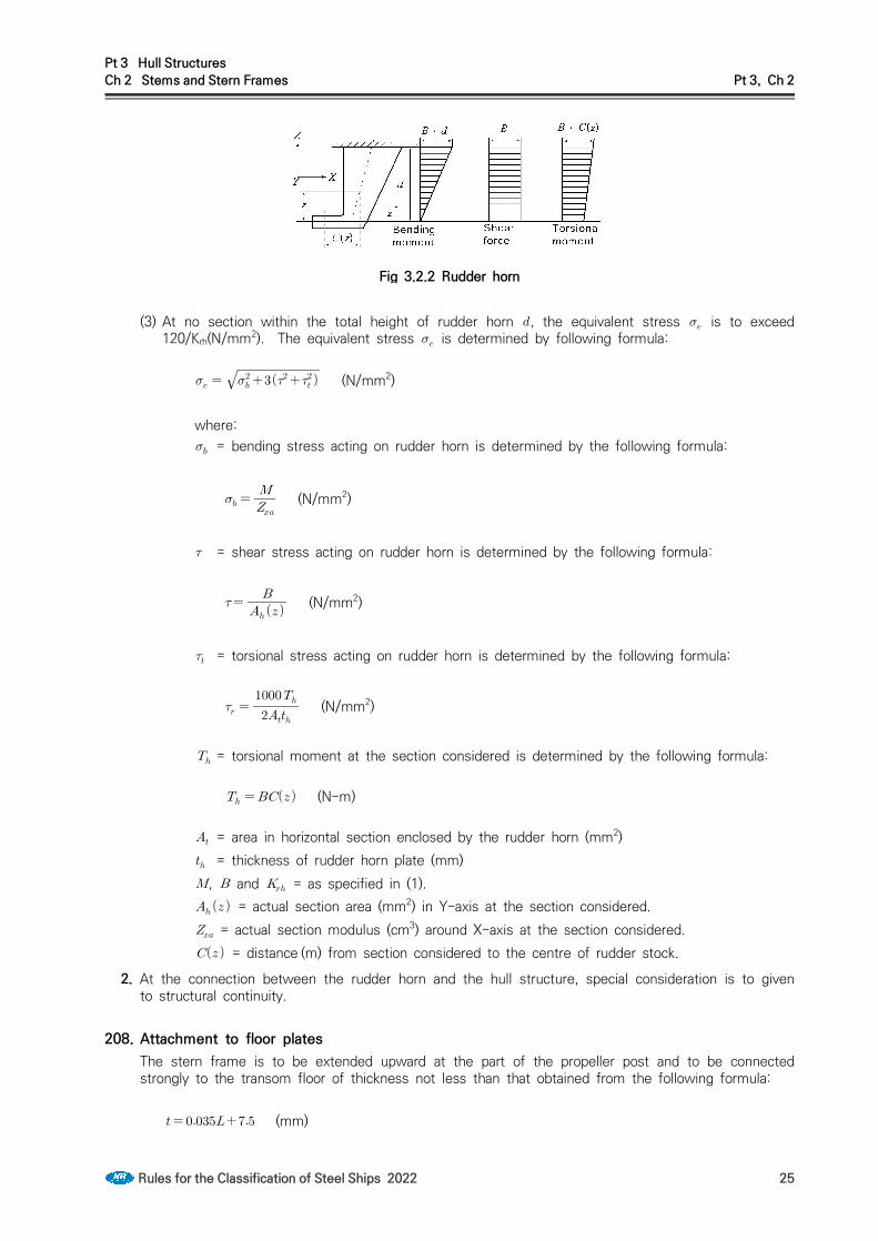
Fig 3.2.2 Rudder horn
(3) At no section within the total height of rudder horn , the equivalent stress is to exceed 120/Krh(N/mm2). The equivalent stress is determined by following formula:
(N/mm2)
where: = bending stress acting on rudder horn is determined by the following formula:
(N/mm2)
= shear stress acting on rudder horn is determined by the following formula:
(N/mm2)
= torsional stress acting on rudder horn is determined by the following formula:
(N/mm2)
= torsional moment at the section considered is determined by the following formula:
(N-m)
= area in horizontal section enclosed by the rudder horn (mm2) = thickness of rudder horn plate (mm), and = as specified in (1). = actual section area (mm2) in Y-axis at the section considered. = actual section modulus (cm3) around X-axis at the section considered. = distance (m) from section considered to the centre of rudder stock.
2. At the connection between the rudder horn and the hull structure, special consideration is to given to structural continuity.
208. Attachment to floor platesThe stern frame is to be extended upward at the part of the propeller post and to be connected strongly to the transom floor of thickness not less than that obtained from the following formula:
(mm)

Pt 3 Hull StructuresCh 2 Stems and Stern Frames Pt 3, Ch 2
26 Rules for the Classification of Steel Ships 2022
209. Gudgeon (2019)1. The depth of gudgeon is not to be less than the length of pintle bearing
2. The thickness of the gudgeon is not to be less than 0.25 . For ships specified in Pt 4, Ch 1, 104., the thickness of the gudgeon is to be appropriately increased.
where:
= Actual diameter of the pintle measured at the outer surface of the sleeve(mm).

Pt 3 Hull StructuresCh 3 Longitudinal Strength Pt 3, Ch 3
Rules for the Classification of Steel Ships 2022 27
CHAPTER 3 LONGITUDINAL STRENGTH
Section 1 General
101. Application 【See Guidance】
1. The requirements in this Chapter apply to ships of 90 m in length and above in unrestricted service. For ships having one or more of the following characteristics, special additional considerations will be given by the Society.(1) Proportion ≤ , ≥
(2) Length ≥ m(3) Block coefficient (4) Large deck opening(5) Ships with large flare or high speed ships(6) Carriage of heated cargoes(7) Unusual type or design
2. Notwithstanding the requirements in Par 1, the requirements specified in 103. and 104. are applied to the ships of 65 m and above in .
3. Longitudinal strength of container ships is to be in accordance with the requirements in Pt 7, Ch 4, Sec 2.
102. Continuity of strengthLongitudinal members are to be so arranged as to maintain as good continuity of strength as practicable.
103. Loading manual 【See Guidance】
1. For ships of 65 m in length and above in , in order to enable the ship master to adjust the load-ing of cargo and ballast to avoid the occurrence of unacceptable stress in the ship's structure, the ship is to be provided with a loading manual approved by the Society. However, a ship may not be provided with a loading manual where deemed unnecessary by the Society.
2. In the loading manual, as required in the preceding paragraph, at least the following items are to be included.(1) Loading conditions on the basis of which the ship is designed, and the allowable limits of longi-
tudinal still water bending moment and still water shear force.(2) Results of calculation longitudinal still water bending moment and still water shear force corre-
sponding to the standard loading conditions.(3) Data and calculation examples to calculate the still water bending moment and the still water
shear force for the loading conditions other than standard loading conditions. This requirement, however, may be dispense with to the ships with which the loading instruments specified in 104. is provided.
(4) Allowable limits of local loads applied to hatch covers, deck, double bottom construction, etc., where deemed necessary by the Society.
104. Longitudinal strength loading instrument 【See Guidance】
1. In addition to loading manual as specified in 103. the following ships of 100 m in length and above in are to be provided with loading instrument(Longitudinal strength loading instrument), together with its operating manual, by means of which the still water bending moments, still water shear forces and still water torsional moments, etc. where applicable, in any loading or ballast condition can be easily and quickly ascertained. However, a ship may not be provided with a loading instru-ment where deemed unnecessary by the Society.(1) Ships with large deck openings where combined stresses due to vertical and horizontal hull gird-
er bending and torsional and lateral loads have to be considered.(2) Ships liable to carry non-homogeneous loadings, where the cargo and/or ballast may be unevenly

Pt 3 Hull StructuresCh 3 Longitudinal Strength Pt 3, Ch 3
28 Rules for the Classification of Steel Ships 2022
distributed. Ships less than 120 m in length, when their design takes into account uneven dis-tribution of cargo or ballast, are deemed unnecessary.
(3) Chemical tankers and gas carriers.2. The loading instrument specified in Par 1 is to be approved by the Society and tested at the pres-
ence of the surveyor in accordance with the approved test reports after installation on board.
Section 2 Bending Strength
201. Bending strength at amidships 【See Guidance】
1. The section moduli of the transverse sections of the hull calculated in accordance with the require-ments in 203, at the midship part are not to be less than the values of obtained from the for-mulae given in Table 3.3.1 at the transverse sections under consideration along the length of hull for all design cargo and ballast loading condition.
2. Notwithstanding the requirements of Par 1, the section modulus of the transverse section of hull at 0.4 part is not to be less than the value of min obtained from formula given in Table 3.3.1.
3. Moment of inertia of the transverse section of hull at the middle point of is not to be less than the value of min obtained from the formula given in Table 3.3.1. and the calculation method for moment of inertia of the actual transverse section is to be correspondingly in accordance with the requirements in 203.
4. Scantlings of all continuous longitudinal members of hull girder based on the section modulus re-quirement in Par 2 and 3 are to be maintained within 0.4 amidships. However, in special cases, based on consideration of type of ship, hull form and loading conditions, the scantlings may be gradually reduced towards the end of the 0.4 part, where deemed necessary by the Society.
202. Bending strength at sections other than amidships 【See Guidance】
1. The bending strength of hull at sections other than 0.4 amidships is to be determined according to the requirements of Ch 5, Sec 2.
2. As a minimum, hull girder bending strength checks are to be carried out at the following locations: - In way of the forward end of the engine room.- In way of the forward end of the foremost cargo hold.- At any locations where there are significant changes in hull cross-section.- At any locations where there are changes in the framing system.Buckling strength of members contributing to the longitudinal strength and subjected to compressive and shear stresses is to be checked, in particular in regions where changes in the framing system or significant changes in the hull cross-section occur. The buckling evaluation criteria used for this check is determined by Sec 4.
3. Continuity of structure is to be maintained throughout the length of the ship. Where significant changes in structural arrangement occur adequate transitional structure is to be provided.
4. For ships with large deck openings, the bending strength of sections at or near to 0.25 L and 0.75 L are to be checked. For such ships with cargo holds aft of the superstructure, deckhouse or engine room, strength checks of sections in way of aft end of the aft-most holds, and aft end of the deckhouse or engine room are to be performed. (2020)
203. Calculation of hull section modulus 【See Guidance】As for calculation of the hull section modulus, the following (1) through (6) are to be applied:(1) All longitudinal members which are considered effective to the longitudinal strength of the ship
may be included in the calculation.

Pt 3 Hull StructuresCh 3 Longitudinal Strength Pt 3, Ch 3
Rules for the Classification of Steel Ships 2022 29
Table 3.3.1 Section modulus of transverse section of hull, etc.Item Requirement
Section modulus
× (cm3),
× (cm3)
Minimum section modulus min (cm3)
Minimum moment of inertia min (cm4)
= longitudinal bending moment in still water (kN-m) at the transverse section under consid-eration along the length of hull, which is calculated by the method deemed appropriate by the Society. The value of is defined as positive which is obtained assuming that down-ward loads are taken as positive and are integrated in the forward direction from the aft end of the ship. Sign of positive is shown in Fig 3.3.1.
and = wave induced longitudinal bending moments (kN-m) at the transverse section under consideration along the length of hull, which are obtained from the following formulae,
(kN-m)
(kN-m)
= allowable bending stress obtained from the following formula.
= coefficient given by the following table. (m)
≤ ≤
≺ ≤ 10.75
≺ ≤
= distribution factor specified along the length of at positions where the transverse section of the hull is under consideration, as given in Fig 3.3.2.
= block coefficient, however, to be taken as 0.6, where it is less than 0.6.

Pt 3 Hull StructuresCh 3 Longitudinal Strength Pt 3, Ch 3
30 Rules for the Classification of Steel Ships 2022
(2) Deck openings on the strength deck are to be deducted from the sectional area used in the section modulus calculation. However, small openings not exceeding 2.5 m in length or 1.2 m in breadth need not be deducted, provided that the sum of their breadths in one transverse section is not more than . Where, is the sum of breadths of large openings (m). (See Fig 3.3.3)
(3) Notwithstanding the requirement in (2), deck openings on the strength deck need not be de-ducted, provided that the sum of their breadths in one transverse section is not reducing the section modulus at deck or bottom by more than 3 %.
(4) Deck openings prescribed in (2) and (3) include shadow area which is obtained by drawing two tangential lines with an opening angle of 30 degrees having the focus on the longitudinal line of the ship. (See Fig 3.3.3)
Fig 3.3.3 Deck openings on the strength deck
(5) Continuous trunks and longitudinal hatch coamings are to be included in the longitudinal sectional area provided they are effectively supported by longitudinal bulkheads or deep girders. And the section modulus at the strength deck is to be calculated by dividing the moment of inertia of the athwartship section about its horizontal neutral axis by the following distance (a) or (b), whichever is the greater.
(a) Vertical distance from the neutral axis to the top of the strength deck beam at side.(b) Distance obtained from the following formula:
where: = horizontal distance from the top of continuous strength member to the centre line
of the ship (m). = vertical distance from the neutral axis to the top of continuous strength member
(m).
and are to be measured to the point giving the largest value of the above formula.

Pt 3 Hull StructuresCh 3 Longitudinal Strength Pt 3, Ch 3
Rules for the Classification of Steel Ships 2022 31
(6) The section modulus at the bottom is to be calculated by dividing the moment of inertia of the athwartship section about its horizontal neutral axis by the vertical distance from the neutral axis to the top of keel.
Section 3 Shear Strength
301. Thickness of side shell of ships without the effective longitudinal bulkhead 【See Guidance】
1. Thickness of side shell plating of ships without the effective longitudinal bulkhead is not to be less than the values obtained from the following formulae the transverse section under consideration along the length of hull for all conceivable loading and ballasting conditions.
× × (mm),
× × (mm)
= moment of inertia (cm4) of the transverse section under consideration about its horizontal neutral axis, where the requirements in 203. are to be applied to the calculation method.
= at the transverse section under consideration, moment of area about the horizontal neutral axis (cm3) for the longitudinal members above the horizontal line passing through the con-sidered position of side shell plating in case the considered position is above the horizontal axis, or for the longitudinal members under the horizontal line in case the considered posi-tion is under the horizontal neutral axis, where the requirements in 203. are to be applied to the calculation method.
= allowable shear stress obtained from the following formula.
(N/mm2)
= shear force in still water (kN) at the transverse section under consideration which is calcu-lated by the method deemed appropriate by the Society. The value of , is defined as positive which is obtained assuming that downward loads are taken as positive and are in-tegrated in the forward direction from the aft end of the ship. Sign of shown in Fig 3.3.4 is taken as positive.
Fig 3.3.4 Sign covention of shear force
and = wave induced shear forces (kN) at the transverse section under consid-eration along the length of hull, which are obtained from the following formulae.
(kN), (kN)
, = as specified in Table 3.3.1. and = distribution factor to be determined at the position of the transverse section under

Pt 3 Hull StructuresCh 3 Longitudinal Strength Pt 3, Ch 3
32 Rules for the Classification of Steel Ships 2022
consideration along the length of the ship, where the value is to be as specified in Fig 3.3.5 and 3.3.6.
2. In case of ships which have bilge hopper tanks or top side tanks, or ships of which other longi-tudinal members below the strength deck are considered to share a part of the shear force effec-tively, the thickness of side shell plate required by Par 1 may be reduced at the discretion of the Society.
Fig 3.3.5 Value of distribution factor Fig 3.3.5 Value of distribution factor
302. Thickness of side shell and longitudinal bulkhead plating of ships having one to four rows of longitudinal bulkheads 【See Guidance】Thickness of side shell and longitudinal bulkhead plating of ships specified Fig 3.3.7 is not to be less than the value obtained from the following formula at the transverse section under consid-eration along the length of hull for all conceivable loading and ballasting conditions. Where, however, ships with double side hull construction provided with bilge hoppers in double side hull structure are to be as deemed appropriate by the Society.
× (mm)
where:, and = as specified in 301. = shear force acting on the side shell plating or longitudinal bulkhead plating, the value of
which is to be the following or , whichever is the greater (kN):
∆ , ∆
, and = as specified in 301. = sharing factor of shear force shared by the side shell and longitudinal bulkhead, the value
of which is to be deemed appropriate by the Society. However, unless otherwise specially specified, may be obtained from the formulae in Table 3.3.2.
= shear force acting on side shell and longitudinal bulkhead due to local load (kN) the value of which is to be as deemed appropriate by the Society. However, unless otherwise spe-cially specified, may be obtained from the formulae in Table 3.3.2.

Pt 3 Hull StructuresCh 3 Longitudinal Strength Pt 3, Ch 3
Rules for the Classification of Steel Ships 2022 33
Table 3.3.2 Values of and
ShipType Application
×
ASide shell
1
Longitudinal bulkhead
2
BSide shell
1
Longitudinal bulkhead
CSide shell
0.5
Longitudinal bulkhead
D
Side shell
Outer longitudinal bulkhead
Centre longitudinal bulkhead
2
E
Side shell
Outer longitudinal bulkhead
Inner longitudinal bulkhead
1
NOTE: = value is to be as specified in (a) to (c) below
for longitudinal bulkheads other than those provided in double side hull.
= value is to be as specified in (a) to (c) below for longitudinal bulkheads provided in double side hull.Where, however, values of , and may be suitably modified for cases where mem-bers considered to share part of shear force are provided:(a) 0, for the part not provided with longi-
tudinal bulkhead(b) 1.0, for the part provided with longitudinal
bulkhead excluding the length of 0.5 respectively from both ends.
(c) Value obtained by linear interpolation for the intermediate parts between those specified in (a) and (b).
, , and = sectional area of side shell plat-ing amidships, longitudinal bulkhead plating provided other than in double side hull, and longitudinal bulkhead plating in double side hull, respectively at midship part(mm2).
, , and = value obtained from the fol-lowing formula, respectively:
′ ′ ′
′ = draught at the part concerned in the load-ing condition under consideration(m).
, , , and = water head converted from the pressure of cargo or ballast in the centre tanks, wing tanks, double side hull tanks(excluding double bottom parts) and double bottom tank in the loading con-ditions under consideration, respectively(m). In this connection, even in case where the double hull forms one single tank, the requirements apply separately to a portion of the double side hull tank and portion of double bottom tank. In case where the double bottom tank is divided within ei-ther , or , is to be determined for respective ranges of the tank divided.

Pt 3 Hull StructuresCh 3 Longitudinal Strength Pt 3, Ch 3
34 Rules for the Classification of Steel Ships 2022
Table 3.3.2 Values of and (continued)
NOTE:
, and c = half breadth of the centre tank, breadth of wing tanks, and breadth of double side hull tanks (m).
= spacing of floors in double bottom(m). = number of floors in double bottom from the mid-point of transverse bulkheads to the section
under consideration in double bottom. The sign of is negative when counted afterward and positive when counted forward. Where, however, a swash bulkhead with an opening ratio of not less than 20 % is not to be considered as a transverse bulkhead. When a floor is provided at mid-point between transverse bulkheads, in this case, is to be obtained counting the floor as 0.5.When a partial bulkhead(dividing wing tank or double side hull tank) is provided between trans-verse bulkheads, the number of under consideration may consider individually.
Example: a partial bulkhead is provided in wing tank of type B ship1) Side shell:
2) Longitudinal bulkhead:
: number of floors in double bottom from the mid-point of transverse bulkheads of wing tank to the section under consideration in double bottom.
: number of floors in double bottom from the mid-point of transverse bulkheads of cen-ter tank to the section under consideration in double bottom.
= as specified by the following table.
Description
where effective centre girder is provided 0.7
where no effective centre girder is provided 1.0
Fig 3.3.7 Types of a ship with longitudinal bulkheads
303. Compensation for openingWhere openings are provided in the shell plating, sufficient consideration is to be paid to the shear strength and suitable compensation is to be made as necessary.

Pt 3 Hull StructuresCh 3 Longitudinal Strength Pt 3, Ch 3
Rules for the Classification of Steel Ships 2022 35
Section 4 Buckling Strength
401. Apllication 【See Guidance】The requirements in this section apply to the buckling strength of panels and longitudinal frames subject to hull girder bending stress and shear stress.
402. Working stress1. Compression stresses
The compression stress (N/mm2) acting on the members under consideration are given in the following formula, however, minimum value is not to be less than :
× (N/mm2)
where: = as specified in Table 3.3.1. For strength deck, value of is taken 0 in case that is
always positive. = wave bending moment as given in Table 3.3.1. For the members above the neutral axis of
transverse section of hull, value of is taken and for the members under, value of is taken .
= distance(m) from the neutral axis of transverse section of hull to the considered point. = as specified in 301. 1.
2. Shear stresses
The shear stress (N/mm2) acting on the members under consideration are given in the following formula:(1) For ships not provided the effective longitudinal bulkheads
× × (N/mm2)
where:, and = as specified in 301. 1. = absolute value of or as given in 301. 1., whichever is the greater. = actual thickness of the considered plate (mm).
(2) For ships having one to four row longitudinal bulkheads.
× (N/mm2)
where: = as specified in 301. 1. = as specified in 302. and = as specified in (1).
403. Elastic buckling stresses 【See Guidance】
1. Elastic buckling of plates(1) Compression
The ideal elastic buckling stress (N/mm2) is determined by the following formula:

Pt 3 Hull StructuresCh 3 Longitudinal Strength Pt 3, Ch 3
36 Rules for the Classification of Steel Ships 2022
(N/mm2)
where: = value is determined by the following formulae depending on direction of working
stress:(a) longitudinal framing panel:
(b) transverse framing panel:
= modulus of elasticity of material. For steels, × (N/mm2) = net thickness of plate (mm), considering standard deductions equal to the values
given in Table 3.3.3. = length of shorter side of panel (m) = length of longer side of panel (m) = factor depending on kind of stiffeners on longer side of panel is as following:
When plating stiffened by floors or deep girders : = 1.3When stiffeners are angles or T-section : = 1.21 When stiffeners are bulb plates : = 1.10When stiffeners are flat bar : = 1.05
= ratio between smallest and largest compression stress when linear variation across panel. ≤ ≤
(2) ShearThe ideal elastic buckling stress (N/mm2) is determined by the following formula:
(N/mm2)
where: = factor depending on aspect ratio of panel is determined by the following formula:
, , and = as specified in (1)
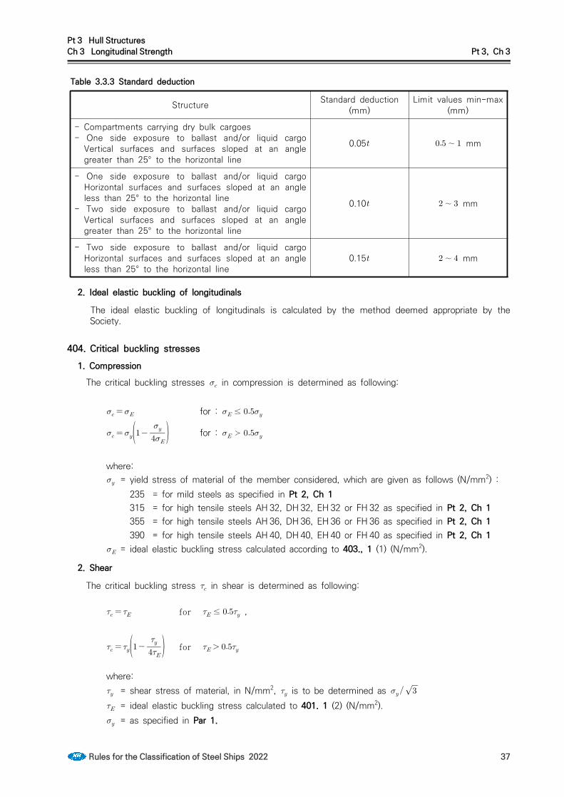
Pt 3 Hull StructuresCh 3 Longitudinal Strength Pt 3, Ch 3
Rules for the Classification of Steel Ships 2022 37
Table 3.3.3 Standard deduction
Structure Standard deduction (mm)
Limit values min-max (mm)
- Compartments carrying dry bulk cargoes- One side exposure to ballast and/or liquid cargo
Vertical surfaces and surfaces sloped at an angle greater than 25° to the horizontal line
0.05 ∼ mm
- One side exposure to ballast and/or liquid cargo Horizontal surfaces and surfaces sloped at an angle less than 25° to the horizontal line
- Two side exposure to ballast and/or liquid cargo Vertical surfaces and surfaces sloped at an angle greater than 25° to the horizontal line
0.10 ∼ mm
- Two side exposure to ballast and/or liquid cargo Horizontal surfaces and surfaces sloped at an angle less than 25° to the horizontal line
0.15 ∼ mm
2. Ideal elastic buckling of longitudinals
The ideal elastic buckling of longitudinals is calculated by the method deemed appropriate by the Society.
404. Critical buckling stresses1. Compression
The critical buckling stresses in compression is determined as following:
for : ≤
for : ≻
where: = yield stress of material of the member considered, which are given as follows (N/mm2) :
235 = for mild steels as specified in Pt 2, Ch 1315 = for high tensile steels AH 32, DH 32, EH 32 or FH 32 as specified in Pt 2, Ch 1355 = for high tensile steels AH 36, DH 36, EH 36 or FH 36 as specified in Pt 2, Ch 1390 = for high tensile steels AH 40, DH 40, EH 40 or FH 40 as specified in Pt 2, Ch 1
= ideal elastic buckling stress calculated according to 403., 1 (1) (N/mm2).
2. Shear
The critical buckling stress in shear is determined as following:
for ≤ ,
for
where: = shear stress of material, in N/mm2, is to be determined as = ideal elastic buckling stress calculated to 401. 1 (2) (N/mm2). = as specified in Par 1.

Pt 3 Hull StructuresCh 3 Longitudinal Strength Pt 3, Ch 3
38 Rules for the Classification of Steel Ships 2022
405. Scantling criteria1. The critical buckling stress of panel and longitudinal frames in compression calculated according
to 404. 1 is to comply with the following formula:
≥
where: = safety factor is as following:
For plate panel and web plating of stiffeners: For stiffeners:
= working stress as given in 402.
2. The critical buckling stress of panel and longitudinal frames in shear calculated according to 404. 2 is to comply with the following formula:
≥
where: = working stress as given in 402.

Pt 3 Hull StructuresCh 4 Plate Keels and Shell Platings Pt 3, Ch 4
Rules for the Classification of Steel Ships 2022 39
CHAPTER 4 PLATE KEELS AND SHELL PLATINGS
Section 1 General
101. Consideration for corrosionThe thickness of shell plating at such parts that the corrosion considered excessive due to the loca-tion and/or special service condition of the ship is to be properly increased over that required in this Chapter.
102. Special consideration for contact with the quay, etc. 【See Guidance】In cases where the service condition of the ship is considered to be such that there is possibility of indent of shell plating due to contact with the quay, etc., special consideration is to be given to the thickness of shell plating.
103. Consideration for ship with unusually large freeboard 【See Guidance】Correction from the requirements in this Chapter will be specially considered where the ship has an unusually large freeboard.
104. Consideration for bucklingWith regard to the prevention of buckling of the shell, in addition to complying with the require-ments in Ch 3, Sec 4. sufficient consideration is to be paid to the prevention of buckling due to compression.
105. Continuity in thickness of the shell platingSufficient consideration is to be paid to the continuity in the thickness of shell plating and to the avoidance of remarkable difference between the thickness of the shell plating under consideration and that of the adjacent shell plating.
Section 2 Plate Keels
201. BreadthThe breadth of plate keel over whole length of the ship is not to be less than that obtained from the following formula:
(mm)
202. ThicknessThe thickness of plate keel over whole length of the ship is not to be less than the thickness of the bottom shell for the midship part obtained from the requirements in 304. increased by 2.0 mm. This thickness, however, is not to be less than that of the adjacent bottom shell plating.
Section 3 Shell Plating below Strength Deck
301. Minimum thickness 【See Guidance】The thickness of shell plating below the strength deck is not to be less than that obtained from the following formula:
(mm)

Pt 3 Hull StructuresCh 4 Plate Keels and Shell Platings Pt 3, Ch 4
40 Rules for the Classification of Steel Ships 2022
302. Thickness of side shell platingThe thickness of side shell plating other than the sheer strake of the strength deck of the midship part is to be as required in the following formula, in addition to the requirement specified in 301.
′ (mm)
where: = spacing of frames (m).′ = length of ship (m). Where, however, exceeds 230 m, is to be taken as 230 m. = vertical distance (m) from the top of keel to the lower edge of plating. Where, however,
is more than , is to be taken as . = as given in (a) or (b).
(a) For 0.3 from the fore end : ′ (b) For elsewhere except (a) : 0
′ = block coefficient. Where, however, exceeds 0.85, ′ is to be taken as 0.85., and = coefficient given in Table 3.4.1.
303. Sheer strakes for midship part 【See Guidance】The thickness of sheer strakes at the strength deck for midship part is not to be less than 0.75 times that of the stringer plate of the strength deck. In no case, however, is the thickness to be less than that of the adjacent side shell plating.
304. Thickness of bottom shell platingThe thickness of bottom shell plating for the midship part is not to be less than that obtained from the following formula.
′ (mm)
where: = spacing of transverse frames or longitudinals (m).′ , , = as specified in 302. = coefficient given in Table 3.4.2.

Pt 3 Hull StructuresCh 4 Plate Keels and Shell Platings Pt 3, Ch 4
Rules for the Classification of Steel Ships 2022 41
Table 3.4.1 Coefficients and Framing
Transverse
≤ m : 1.0
≥ m : 1.07For intermediate values of , is to be obtained by linear interpolation
Longitudinal
But, in no case is it to be less than 3.78
= either or according to value of . However, value of is not to be less than .
′ ≤
≻
= vertical distance from the top of keel at midship to the horizontal neutral axis of the ath-wartship section of hull (m).
= distance(m) from the top of keel to the lower edge of plating when the platings under con-sideration are under and to the upper edge of plating when the platings under consid-eration are above , respectively.
′ = the greater of the value specified in Pt 3, Ch 3, 203., (5) (a) or (b) = coefficient determined according to values of as specified below:
when is 230 m and under when is 400 m and above
For intermediate values of , is to be obtained by liner interpolation. = when high tensile steels are used for not less than 80 % of side shell plating at the
transverse section amidship and 1.0 for other parts. = as given by the following formula.
= distance from the fore end to the part under consideration for the side shell plating afore the midship, or from the after end to the part under consideration for the side shell plating after the midship (m). Where, however, is less than 0.1 , is to be taken as 0.1 and where exceeds 0.3 , is to be taken as 0.3 .
Table 3.4.2 Coefficient
Framing
Transverse
Longitudinal
But, in no case is it to be less than 3.78 .
= as specified in Table 3.4.1

Pt 3 Hull StructuresCh 4 Plate Keels and Shell Platings Pt 3, Ch 4
42 Rules for the Classification of Steel Ships 2022
305. Bilge plates 【See Guidance】
1. The thickness of bilge plates is not to be less than that obtained from the following formula. However, it is not to be less than the thickness of the adjacent bottom plating.
′
(mm)
where: = bilge radius (m). (see Fig 3.4.1), = distance from the lower and upper turns of bilge to the longitudinal frames nearest to
the turns respectively, taking the distance outward from the bilge part as positive (m). Where, however, () is negative, () is to be taken as zero. (see Fig 3.4.1)
′ = as specified in 302. = spacing of solid floors, bottom transverses or bilge brackets (m).
2. Where some of longitudinal frames at bilge part in longitudinal framing system is omitted, longi-tudinal frames are to be provided as near to the turns of bilge as practicable and suitably con-structed to maintain the continuity of strength.
3. Where longitudinal frames are provided at bilge part at nearly the same spacing as that of bottom longitudinals, the bilge plates may be in accordance with the requirements in 304. irrespective of the requirements in Par 1.
4. Where bilge keels are fitted, special consideration is to be given to bort the material and the arrangement. (2019)
Fig 3.4.1 Measurement of and
Section 4 Special Requirements for Shell Plating
401. Large flared ship 【See Guidance】With regard to the shell plating at a location where flare is specially large, sufficient consideration is to be paid to the reinforcement against panting impact, etc. at bow.
402. Shell plating stiffened in a spacing remarkably different from the frame spacing 【See Guidance】
Where the stiffener spacing measured along the shell plating supported by frames is remarkably dif-ferent from the frame spacing, the shell plating is to be reinforced in consideration of the stiffener spacing, for example, by suitably increasing in thickness.
403. Aft part of ships with specially high power enginesWith regard to the shell plating at the aft part of ships with specially high power engines compared with the ship length, sufficient consideration is to be paid to the reinforcement against vibration.

Pt 3 Hull StructuresCh 4 Plate Keels and Shell Platings Pt 3, Ch 4
Rules for the Classification of Steel Ships 2022 43
404. Strengthened bottom forward1. The thickness of shell plating at the strengthened bottom forward in ships having the bow draught
at the ballast condition is not to be less than that obtained from the formula given in Table 3.4.3.
Table 3.4.3 Thickness of shell plating at the strengthened bottom forward
Bow draft Thickness (mm)
≤′
≥′ ′′ = as defined in 302. = spacing of frames, girders or longitudinal shell stiffeners, whichever is the smallest
(m). = slamming impact pressure specified in Ch 7, 804. = coefficient given in following formula.
Where, however, is less than 0.4, is to be taken as 1.0 and where
is 1.0,
C is to be taken as 0.72. = spacing of frames, girders or longitudinal shell stiffeners, whichever is greater (m).
NOTES: In ships having intermediate value of the bow draught at the ballast condition speci-
fied in the above Table, the thickness is to be obtained by linear interpolation.
2. Notwithstanding the requirements in Par 1, in ships of which and are not more than 150 m and 0.7 respectively and (kt/m) is 1.4 and over, the thickness of shell plating at the strengthened bottom forward is to be increased to a value deemed appropriate by the Society. 【See Guidance】
405. Spectacle bossings and stern frames 【See Guidance】The thickness of shell plating fitted up on spectacle bossings and sternframes is not to be less than that obtained from the following formula. Where, however, the spacing of transverse frames in afterpeak exceeds 610 mm or the length of ship exceeds 200 m, the thickness of shell plating con-cerned is to be in accordance with the satisfaction of the Society.
(mm)
Section 5 Side Plating in way of Superstructure
501. Superstructure deck not designed as strength deckWhere the superstructure deck is not designed a strength deck, the thickness of superstructure side plating is not to be less than that obtained from the formula given in Table 3.4.4, but not less than 5.5 mm. Side plating of superstructures exceeding 0.15 in length, except at the end parts, is to be suitably increased in thickness.

Pt 3 Hull StructuresCh 4 Plate Keels and Shell Platings Pt 3, Ch 4
44 Rules for the Classification of Steel Ships 2022
Table 3.4.4 Thickness of superstructure side plating
Location Thickness (mm)
For 0.25 from the fore end
Elsewhere
= spacing of longitudinals or transverse frames (m).
Section 6 Compensation at ends of Superstructure
601. Strengthening method 【See Guidance】Breaks of superstructures are to be strengthened according to the following requirements:(1) The sheer strakes of the strength deck, clear of the superstructure, are to be extended well into
the superstructure and to be increased in thickness by not less than 20 % above the normal thickness of sheer strakes, for a distance well inside and outside the superstructure end.
(2) The side plating of the superstructure is to be tapered into upper deck sheer strakes to avoid abrupt change of the form at the breaks. The thickness of side plating at the superstructure end is to be increased approximately by 20 % above the normal thickness of superstructure side plating.
(3) For the breaks of superstructures located at fore and after end parts, the requirements in (1) and (2) may be suitably modified.
602. Openings in shellGangway ports, large freeing ports and other openings in the shell or bulwarks are to be kept well clear of the break. Where holes are necessarily provided in the plating near breaks, they are to be kept as small as possible and to be circular or oval in form.
Section 7 Local Compensation of Shell Plating
701. Openings in shell 【See Guidance】All openings in the shell plating are to have well rounded corners and to be compensated as necessary.
702. Thickness of sea chest 【See Guidance】In case where a sea chest is provided in the shell plating for sea suction or discharge the thickness of sea chest is not to be less than that obtained from the following formula and to be suitably stiffened so as to provide sufficient rigidity as necessary. The thickness, however, is not to be less than the required thickness of shell plating where the sea chest is installed.
(mm)
703. Location of openings 【See Guidance】Openings for cargo ports, coaling ports, etc. are to be kept well clear of discontinuous parts in the hull construction, and they are to be locally compensated so as to maintain the longitudinal and transverse strengths of the hull.
704. Hawse pipes and the plating belowThe shell plating fitted with hawse pipes and the plating below is to be increased in thickness or to be doubled, and their longitudinal seams are to be protected against damages by anchors or cables.
Pt 3 Hull StructuresCh 5 Decks Pt 3, Ch 5
Rules for the Classification of Steel Ships 2022 45
CHAPTER 5 DECKS
Section 1 General
101. Steel deck plating 【See Guidance】Decks are to be plated from side to side of the ship except deck openings, etc. Decks, however, may be provided with only stringer plates and tie plates, subject to the approval by the Society.
102. Watertightness of decks 【See Guidance】Weather decks are to be made watertight.
103. Continuity of steps of decksWhere strength deck or effective decks (the decks below the strength deck which are considered as strength members in the longitudinal strength of hull) change in level, the change is to be ac-complished by gradually sloping, or each of structural members which form deck is to be extended, and is to be effectively tied together by diaphragms, girders, brackets, etc. and special care is to be taken for the continuity of strength.
104. Compensation for openings 【See Guidance】Hatchways or other openings on strength or effective decks are to have well rounded corners, and compensation is to be suitably provided as necessary.
105. Rounded gunwales 【See Guidance】Rounded gunwales, where adopted, are to have a sufficient radius for the thickness of plates.
Section 2 Effective Sectional Area of Strength Deck
201. DefinitionThe effective sectional area of strength deck is the sectional area, on each side of the ship's centre line, of steel plating, longitudinal beams, longitudinal girders, etc. extending for 0.5 amidships.
202. Effective sectional area of strength deck 【See Guidance】
1. The effective sectional area for the midship part is to be so determined as not to give less modulus of athwartship section of the hull specified in Ch 3.
2. Beyond the midship part, the effective sectional area may be gradually reduced, however, at 0.15 from each end it is not to be less than 40 % for ships with machinery amidship and 50 % for ships with machinery aft, of the area required for the midship part.
3. Where the section modulus of the hull at 0.15 from each end is calculated and approved by the Society, the requirements specified in Par 2 may not be applied.
203. Strength deck beyond 0.15 from each endBeyond 0.15 from each end, the effective sectional area and the thickness of strength deck may be gradually reduced avoiding abrupt change.
204. Long poop 【See Guidance】Notwithstanding the requirements of 202., the effective sectional area of strength deck within long poop may be properly modified.

Pt 3 Hull StructuresCh 5 Decks Pt 3, Ch 5
46 Rules for the Classification of Steel Ships 2022
205. Superstructure deck designed as strength deck 【See Guidance】Where the superstructure deck is designed as strength deck, the strength deck plating clear of the superstructure is to extend into the superstructure for about 0.05 without reducing the effective sectional area, and may be gradually reduced within.
Section 3 Deck Plating
301. Thickness 【See Guidance】
1. The thickness of deck plating is to be as specified in Table 3.5.1, however, within such enclosed spaces as superstructures, deckhouses, etc., the thickness may be reduced by 1 mm.
Table 3.5.1 Thickness of deck plating
Kind of deck Location Framing Thickness (mm)
Strength deck
Outside the line of openings for the midship part
Longitudinal Systems
Transverse Systems
Elsewhere
Other deck
= spacing of longitudinal or transverse beams. = coefficient obtained from the following formula:
′
′ = length of ship (m). Where, however, is 230 m and under, ′ is to be taken as 230 m, and where is 400 m and above, ′ is to be taken as 400 m.
= deck load as specified in Ch 10, 201. (kN/m2)
2. Where strength deck is transversely framed, or decks inside the line of openings are longitudinally framed, sufficient care is to be taken to prevent buckling of the deck plating.
302. Thickness of the top of tanksThe thickness of deck plating forming the top of tanks is not to be less than that required in Ch 15, 208. for deep tank bulkhead plating, taking the beam spacing as the stiffener spacing.
303. Thickness of the bulkhead recessesThe thickness of deck plating forming the top of shaft tunnels, thrust recesses or bulkhead re-cesses is not to be less than that required in Ch 14, 309. for watertight bulkhead plating, taking the beam spacing as the stiffener spacing.
304. Under boilers or refrigerated cargoes1. The thickness of effective deck plating under boilers is to be increased by 3 mm above the normal
thickness.
2. The thickness of deck plating under refrigerated cargoes is to be increased by 1 mm above the nor-mal thickness. Where special means for the protection against the corrosion of the deck is provided, the thickness need not be increased.

Pt 3 Hull StructuresCh 5 Decks Pt 3, Ch 5
Rules for the Classification of Steel Ships 2022 47
305. Loaded by wheeled vehiclesThe thickness of deck plating loaded by wheeled vehicles is to be determined by considering the concentrated loads from the wheeled vehicles.
306. Deck plating carrying unusual cargoesThe thickness of deck plating subjected to cargo loads which can not be treated as even distributed loads is to be determined taking account of load distribution for particular cargoes.
307. Deck plating for helicopter landing 【See Guidance】Where decks for Helicopter taking off and landing are provided, the requirements are to be in ac-cordance with the Guidance relating to the Rules.
Section 4 Wood Decks and Deck Compositions
401. Quality of wood planks1. Planks of wooden decks are to be of good quality, thoroughly seasoned, free from rot, sap and
shakes and reasonably free from bad knots.
2. Teaks and similar woods are treated as hard wood, and cedars and similar woods as soft wood.
402. Scantlings of wood planksHard wood planks are not to be less than 50 mm in thickness and soft wood planks not less than 63 mm. They are to be effectively arranged and fastened. For decks used for accommodation or navigation spaces, the thickness may be properly reduced.
403. Deck compositionThe deck composition is to be non-destructive to steel, or to be effectively insulated from the steel by a suitable protecting covering. The composition is to be effectively laid on the deck so that the composition may not cause cracks, exfoliation, etc.

Pt 3 Hull StructuresCh 6 Single Bottoms Pt 3, Ch 6
Rules for the Classification of Steel Ships 2022 49
CHAPTER 6 SINGLE BOTTOMS
Section 1 General
101. Application1. The requirements in this Chapter apply to the single bottoms of ships whose double bottom is
omitted partially or wholly in accordance with the requirements in Ch 7, 101. 3 or 4.2. The bottom constructions in way of fore and after peaks are to be in accordance with the require-
ments in Ch 13, 201. and 301.
Section 2 Centre Keelsons
201. Arrangement and constructionAll single bottom ships are to have centre keelsons composed of girder plates and rider plates, and the centre keelsons are to extend as far forward and afterward as practicable.
202. Centre girder plates1. The thickness of continuous plates or intercostal plates of centre keelsons is not to be less than
that obtained from the following formula. Beyond the midship part, the thickness may be gradually reduced and it may be 85 % of the midship value at the ends of the ship.
(mm)
2. The girder plates are to extend to the top of floors.
203. Rider platesThe rider plates are to extend from the collision bulkhead to the aft peak bulkhead and the thick-ness is not to be less than that required for the continuous centreline plates amidships. The breadth of rider plates is not to be less than that obtained from the following formula or 400 mm whichever is the greater, and where it is more than 400 mm the breadth may be gradually reduced beyond the midship part to the ends where it may be 80 % of the required breadth or 400 mm, whichever is the greater.
(mm)
204. Centre keelsons in boiler roomsThe thickness of the members forming the centre keelson is to be increased by 1.5 mm in boiler rooms.
Section 3 Side Keelsons
301. Arrangements1. Side keelsons are to be so arranged that their spacing is not more than 2.15 m between the centre
keelson and the lower turn of bilge.2. At least one row of shell stiffener of proper size is to be provided within 0.4 amidships between
the centre keelson and the side keelson, between the side keelsons, and between the side keelson and the lower turn of bilge.
3. In the space between the collision bulkhead and the position 0.05 after the strengthened bottom forward, the spacing of side keelsons is not to exceed 0.9 m.

Pt 3 Hull StructuresCh 6 Single Bottoms Pt 3, Ch 6
50 Rules for the Classification of Steel Ships 2022
302. ConstructionSide keelsons are to be composed of intercostal plates and rider plates and are to be extended as far forward and aftward as practicable.
303 Intercostal plates1. The thickness of intercostal plates of side keelson is not to be less than that given by the following
formula for the midship part. Beyond the midship part, the thickness may be gradually reduced to 85 % at the ends of the ship.
(mm)
2. In the machinery room the thickness of intercostal plates is not to be less than that required for the continuous centreline plates in 202.
304. Rider platesThe thickness of rider plates for side keelson is not to be less than that of the midship intercostal plates and the sectional area of rider plates in the midship part is not to be less than that obtained from the following formula. The sectional area may be gradually reduced to 90 % of the midship value at the ends of the ship.
(cm2)
305. Side keelsons in boiler roomsIn the boiler rooms, the thickness of intercostal and rider plates is to be 1.5 mm greater than those required in 303. and 304. respectively.
Section 4 Floor Plates
401. Arrangements and scantlings1. Floor plates are to be provided on every frame and the scantlings are not to be less than that ob-
tained from the following formulae, but the thickness needs not exceed 12 mm.
Depth at the centre line: (mm)Thickness: (mm)
where: = span between the toes of frame brackets measured amidships plus 0.3 m. Where curved
floors are provided, the length may be suitably modified. (See Fig 3.6.1)
Fig 3.6.1 Shape of floors

Pt 3 Hull StructuresCh 6 Single Bottoms Pt 3, Ch 6
Rules for the Classification of Steel Ships 2022 51
2. Beyond 0.5 amidships, the thickness of floor plates may be gradually reduced and at the end parts of the ship it may be 0.90 times the value specified in Par 1. In the flat part of bottom forward, this reduction is not to be made.
3. Floors under engines and thrust seats are to be of ample depth and to be specially strengthened. Their thickness is not to be less than that of the continuous centre girder plates.
4. The thickness of floors under boilers is to be increased by at least 2 mm above the thickness of midship floors. Where boilers are less than 457 mm clear of the floors, the thickness is to be fur-ther increased. This requirement may, however, be modified if the boiler is remote from floor plates or if the boiler is of such a type as well prevent excessive heat to the structures in the vicinity.
402. Depth of floors1. Upper edges of floor plates at any part are not to be below the level of upper edge at the centre
line.
2. In the midship part, the depth of floors measured at a distance specified in 401. 1 from the in-ner edge of frames along the upper edge of floors, is not to be less than 0.5. Where frame brackets are provided, the depth of floors at the inner edge of brackets may be 0.5. (See Fig 3.6.1)
3. In ships having unusually large rise of floor, the depth of floor plates at the centre line is to be suitably increased.
403. Scantlings1. Where face plates are fitted, the thickness of the face plate is not to be less than that required for
the floor plate of that place. The sectional area of the face plates is not to be less than that given by the following formula:
(cm2)
where: = as defined in 401.1. = frame spacing (m). = or 0.66, whichever is the greater (m). = depth of floor plates at centre line (mm). = thickness of floor plates (mm).
2. Where the upper edge of floor plates is flanged, the breadth of flange is not to be less than that obtained from the following formula:
(mm)
where: = sectional area of face plates defined in Par 1. (cm2). = thickness of floor plates (mm).
3. The sectional areas of face plates are to be doubled for engine and boiler bearer floors. Flanging of floors at these parts is to be avoided.
404. Strengthened bottom forwardIn the strengthening of bottom forward the floors are to be increased in their depth or the sectional areas of the face plates are to be doubled.

Pt 3 Hull StructuresCh 6 Single Bottoms Pt 3, Ch 6
52 Rules for the Classification of Steel Ships 2022
405. Frame bracketsThe scantlings of frame brackets are to be determined in accordance with the requirements of the following. The free edge of the bracket is to be flanged.(1) The height of the bracket measured from the top of keel is not to be less than twice the re-
quired depth of the floor plate at the centreline of the ship. (See Fig 3.6.1)(2) The arm of the bracket measured along the upper edge of the floor plate from the inner edge
of frame is not to be less than the depth of the floor plate required at the centreline of the ship. (See Fig 3.6.1)
(3) The thickness of frame brackets is not to be less than that of floor plates.
406. Drainage holesDrainage holes are to be provided on the floor plates on both sides of the centreline and for ships with flat bottom also at the low parts of the turn of bilge.
407. Lightening holesLightening holes may be provided in floor plate. Where the holes are provided, appropriate strength compensation is to be made by increasing the floor depth or by some other suitable means.
408. Floor plates forming part of bulkheadsFloor plates forming part of bulkheads are to be in accordance with the requirements in Chs 14 and 15.

Pt 3 Hull StructuresCh 7 Double Bottoms Pt 3, Ch 7
Rules for the Classification of Steel Ships 2022 53
CHAPTER 7 DOUBLE BOTTOMS
Section 1 General
101. Application 【See Guidance】
1. Passenger ships engaged on international voyages and cargo ships(except tankers) of not less than 500 tons gross tonnage engaged on international voyages, in principle, are to be provided with wa-tertight double bottoms extending from the collision bulkhead to the after peak bulkhead. The longi-tudinal system of framing is, in general, to be adopted. (2018)
2. Where a double bottom is required to be fitted, the inner bottom is to be continued out to the ship's sides in such a manner as to protect the bottom to the turn of the bilge. And the inner bot-tom is not to be lower at any part than a plan parallel with the keel line and which is located not less than a vertical distance measured from the keel line, as calculated by the formula: (2018)
′′ : the greatest moulded breadth in meters of the ship at or below the deepest subdivision
draught.
However, in no case is the value of to be less than 760 mm , and need not be taken as more than 2,000 mm .
3. Where, for the structural configuration, hull form, purpose etc., it is desired to omit double bottom partially or wholly subject to the approval by the Society. (2018)
4. A double bottom may be omitted in way of watertight tanks, including dry tanks of moderate size subject to the approval by the Society. (2018)
5. The scantlings of double bottom may be determined with the method as appropriate by the Society, in case of special construction such as having inclined side shell or double side shell, where longi-tudinal bulkheads are provided, or for the parts beyond the midship part.
6. The scantlings of members in double bottom tanks intended to be deep tanks are to be corre-spondingly in accordance with the requirements in Ch 15. However, the thickness of inner bottom plating needs not be increased by 1 mm as given Ch 15, 208. for the top plating of deep tanks.
7. The requirements in this Chapter are to be applied, where the apparent specific gravity of cargoes in the loaded hold, is 0.9 and under. The requirements in Pt 7, Ch 3 are to be correspondingly applied, where is more than 0.9, or to the holds which are empty in fully loaded condition, or to the ships which are provided with bilge hoppers. However, the specific gravity of cargoes, , is to be as obtained from the following formula:
(t/m3)
where: = mass of cargoes for the hold (t) = volume of the hold excluding its hatchway (m3)
8. Double bottom structure of holds is to be subjected to special consideration, where intended to car-ry heavy cargoes or where the ratio of cargo weight per unit area (kN/m2) of the inner bottom plat-ing to is less than 5.40 or where cargo loads can not be treated as even distributed loads. Where the value of cargo weight per unit area as given in t/m2, the value in kN/m2 should be ob-tained from the product of the value in t/m2 and 9.81.
9. Scantlings of structural members for ships intended to carry out the steel coils are to be in accord-ance with Annex 3-5 「Guidance for structural members for ships intended to carry out the steel coils」. (2021)

Pt 3 Hull StructuresCh 7 Double Bottoms Pt 3, Ch 7
54 Rules for the Classification of Steel Ships 2022
102. Manholes and lightening holes1. Manholes and lightening holes are to be provided in all non-watertight members to ensure access
and ventilation except in way of pillars and where such openings are not permitted by the Rules. The size of holes should not in general exceed 50 % of the double bottom height, unless edge re-inforcement is provided, and are to be shown in the plans submitted for approval. The edges of openings are to be made smooth.
2. Care is to be taken for locating the manholes in tank tops to avoid possibility of interconnection of main subdivision compartments through the double bottom so far as practicable.
3. Manhole covers in tank tops are to be of steel, and where no ceiling is provided in the cargo holds, the covers and their fittings are to be effectively protected against damages by cargoes.
103. Drainage
1. The bilge well in suitable size are to be provided for draining water which may gather on the double bottom.
2. Small wells constructed in the double bottom in connection with drainage arrangements of holds, etc., shall not extend downward more than necessary. A well extending to the outer bottom is, however, permitted at the after end of the shaft tunnel.
3. Other wells (e.g., for lubricating oil under main engines) may be permitted by the Society if satisfied that the arrangements give protection equivalent to that afforded by a double bottom complying with this Chapter. (2018)
4. For wells specified in 2. and 3. above, except those at the ends of shaft tunnels, the vertical dis-tance from the bottom of such a well to a plane coinciding with the keel line be less than 500 mm. Where, however, the vertical distance do not meet the requirement, the concerned parts are to be in accordance with the requirements in 101. 3. above. (2018)
104. Drain and air holesDrain and air holes sufficient for the pumping rates are to be provided in all non-watertight mem-bers of the double bottom structure to give efficient passage of drain and air from all parts of the tank to the suction heads and air pipes.
105. Cofferdams1. The following dedicated tanks are to be separated from adjacent tanks by cofferdams. However,
these cofferdams may be omitted provided that the common boundaries of lubricating oil and fuel oil tank have full penetration welds.(1) Fuel oil(2) Lubricating oil(3) Vegetable oil(4) Fresh water
2. The cofferdams in Par 1 are to be provided with the air pipes to comply with the requirements in Pt 5, Ch 6, 201. and with the manholes of adequate size which are well accessible.
106. Striking platesStriking plates of adequate thickness or other approved arrangements are to be provided under sounding pipes to prevent from injuring the ship's bottom plating by striking of the sounding rod.
107. Strengthening under boilers 【See Guidance】In the boiler room the thickness of structures in the tank under boilers are to be suitably increased. This requirement may, however, be modified if the boiler is remote from the tank top or if the boil-er is of such a type as will prevent excessive heat to the structures in the vicinity.

Pt 3 Hull StructuresCh 7 Double Bottoms Pt 3, Ch 7
Rules for the Classification of Steel Ships 2022 55
108. Continuity of strength1. Where the longitudinal system of framing is transformed into the transverse system, or the depth of
double bottom changes suddenly, special care is to be taken for the continuity of strength by means of additional intercostal girders or floors.
2. In double bottoms under pillars or the toes of end brackets for bulkhead stiffeners, suitable re-inforcement is to be provided by means of additional local side girders or floors.
109. Minimum thicknessNo member of the double bottom structure is to be less than 6 mm in thickness.
110. Ceilings1. In ships with double bottoms, close ceilings are to be laid from the margin plate to the upper turn
of bilge so arranged as to be readily removable for inspection of the limbers.
2. Ceilings are to be laid on the inner bottoms under hatchways, unless the requirements in 501. 3 or Pt 7, Ch 3, 204. 2 of the Rules are applied.
3. Ceilings on the top of double bottom are to be laid on battens not less than 13 mm in thickness. The top plating of tanks, where ceiled directly, is to be covered with good tar put on hot and well sprinkled with cement powder, or with other equally effective coatings.
4. The thickness of ceilings is not to be less than 63 mm.
Section 2 Centre Girders and Side Girders
201. Arrangement and construction 【See Guidance】
1. Centre girders are to be extended as far forward and afterward as practicable and centre girder plates are to be continuous for 0.5 amidships.
2. Where double bottoms are used for carriage of fuel oil or fresh water, the centre girders are to be watertight and may be suitably modified in narrow tanks at the end parts of the ship or where oth-er watertight longitudinal girders are provided at about from the centre line or where deemed appropriate by the Society. (2020)
3. Side girders in amidships and aft are to be so arranged that the distance from the centre gird-er to the first side girder, between girders, or from the outermost girder to the margin plate does not exceed approximately 4.6 m and to extend as far afterwards as practicable.
4. In the strengthened bottom forward of ships, side girders and half-height girders are to be provided as required by 802.
5. Adequate strengthening is to be made under main engines and thrust seatings by means of addi-tional full or half-height girders.
202. Depth of centre girdersThe depth of centre girders is not to be less than that obtained from the following formula unless specially approved by the Society.
(mm)
203. Thickness 【See Guidance】The thickness of centre girder plates and side girder plates is not to be less than that obtained from the following requirements (1) and (2), whichever is the greater:(1) The thickness is to be obtained from the following formula depending on the location in the
hold:

Pt 3 Hull StructuresCh 7 Double Bottoms Pt 3, Ch 7
56 Rules for the Classification of Steel Ships 2022
×
(mm)
where: = distance between the centres of two adjacent spaces from the centre or side girder
under consideration to the adjacent longitudinal girders or the line of toes of tank side brackets (m).
= depth of the centre or side girder under consideration (mm). = depth of the opening at the point under consideration (mm). = length of the hold (m). = longitudinal distance between the centre of of each hold and the point under con-
sideration (m). Where, however, is under 0.2 , is to be taken as 0.2 , and where is 0.45 and over, may be taken as 0.45 .
= transverse distance from the centre line of ship to the longitudinal girder (m). = coefficient given by the following formulae Where, however is 1.4 and over,
is to be taken as 1.4, and where is under 0.4, is to be taken as 0.4.
Longitudinal framing :
Transverse framing :
(2) The thickness is to be obtained from the following formula:
′ (mm)
where: = depth of the girder at the point under con sideration (mm). Where, however, horizon-
tal stiffeners are provided at the half way of the depth of girder, is the distance from the horizontal stiffener to the bottom shell plating or inner bottom plating or the distance between the horizontal stiffeners (mm).
′ = coefficient obtained from Table 3.7.1 depending on . For intermediate values of , ′ is to be obtained by linear interpolation.
= spacing of the brackets or stiffeners provided on the centre girders or the side girders (mm).
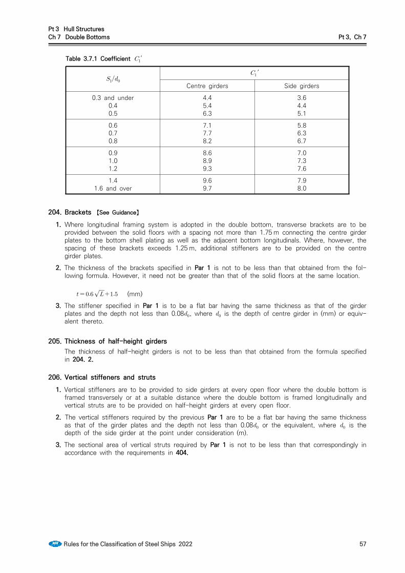
Pt 3 Hull StructuresCh 7 Double Bottoms Pt 3, Ch 7
Rules for the Classification of Steel Ships 2022 57
Table 3.7.1 Coefficient ′
′
Centre girders Side girders
0.3 and under0.40.5
4.45.46.3
3.64.45.1
0.60.70.8
7.17.78.2
5.86.36.7
0.91.01.2
8.68.99.3
7.07.37.6
1.41.6 and over
9.69.7
7.98.0
204. Brackets 【See Guidance】
1. Where longitudinal framing system is adopted in the double bottom, transverse brackets are to be provided between the solid floors with a spacing not more than 1.75 m connecting the centre girder plates to the bottom shell plating as well as the adjacent bottom longitudinals. Where, however, the spacing of these brackets exceeds 1.25 m, additional stiffeners are to be provided on the centre girder plates.
2. The thickness of the brackets specified in Par 1 is not to be less than that obtained from the fol-lowing formula. However, it need not be greater than that of the solid floors at the same location.
(mm)3. The stiffener specified in Par 1 is to be a flat bar having the same thickness as that of the girder
plates and the depth not less than 0.08, where is the depth of centre girder in (mm) or equiv-alent thereto.
205. Thickness of half-height girdersThe thickness of half-height girders is not to be less than that obtained from the formula specified in 204. 2.
206. Vertical stiffeners and struts1. Vertical stiffeners are to be provided to side girders at every open floor where the double bottom is
framed transversely or at a suitable distance where the double bottom is framed longitudinally and vertical struts are to be provided on half-height girders at every open floor.
2. The vertical stiffeners required by the previous Par 1 are to be a flat bar having the same thickness as that of the girder plates and the depth not less than 0.08 or the equivalent, where is the depth of the side girder at the point under consideration (m).
3. The sectional area of vertical struts required by Par 1 is not to be less than that correspondingly in accordance with the requirements in 404.

Pt 3 Hull StructuresCh 7 Double Bottoms Pt 3, Ch 7
58 Rules for the Classification of Steel Ships 2022
Section 3 Solid Floors
301. Arrangements1. Solid floors are to be provided at a spacing not exceeding 3.5 m.2. In addition to complying with the requirements in Par 1, solid floors are to be provided at the fol-
lowing locations:(1) At every frame in the main engine room. Solid floors may, however, be provided at alternate
frames outside the engine seatings, if the double bottom is framed longitudinally.(2) Under thrust seatings and boiler bearers.(3) Under transverse bulkheads.(4) At the location specified in 803. between the collision bulkhead and the after end of the
strengthened bottom forward.(5) Every frame where the height of double bottom changes.
3. Watertight floors are to be so arranged that the subdivision of the double bottom generally corre-sponds to that of the ship.
302. Thickness 【See Guidance】The thickness of solid floors is not to be less than that obtained from the following requirements (1) and (2), whichever is the greater:(1) The thickness is to be obtained from the following formula depending on the location in the
hold:
′ ″ (mm)
where: = spacing of solid floors (m). ′ = distance between the lines of toes of tank side brackets at the top of inner bottom
plating at the midship part (m). ″ = distance between the lines of toes of tank side brackets at the top of inner bottom
plating at the position of the solid floor (m). = transverse distance from the centre line to the point under consideration (m). Where,
however, is under ″ , is to be taken as ″, and where is ″ and over, may be taken as ″ .
= depth of the solid floor at the point under consideration (mm). = depth of the opening at the point under consideration (mm). = coefficient obtained from Table 3.7.2 depending on . = length defined in 203.
Table 3.7.2 Coefficient
and above 0.4 0.6 0.8 1.0 1.2
below 0.4 0.6 0.8 1.0 1.2
Longitudinal framing29 27 24 22 19 17
Transverse framing
Where solid floors are provided at every frame
Elsewhere 20 19 17 15 13 12
(2) The thickness is to be obtained from the following formula depending on the location in the hold:

Pt 3 Hull StructuresCh 7 Double Bottoms Pt 3, Ch 7
Rules for the Classification of Steel Ships 2022 59
′
(mm)
where: = thickness obtained from the requirement in Sub-paragraph (1). = depth defined in Sub-paragraph (1).′ = coefficient given in Table 3.7.3 depending on the ratio of the spacing of stiffeners
(mm) to . = value obtained from Table 3.7.4.
Table 3.7.3 Coefficient ′
0.3 and under 0.4 0.5 0.6 0.7 0.8 0.9 1.0 1.2 1.4 and over
′ 64 38 25 19 15 12 10 9 8 7
For intermediate values of , the value of ′ is to be determined by linear interpolation
Table 3.7.4 Value of
Case
(a) Where slots are provided on solid floors without reinforcement
but, where is 0.5 and under, is to be 1.0.
(b) Where openings are provided on solid floors without reinforcement
(c) Where slots and openings are provided on solid floors without reinforcement Product of the values given by (a) and (b)
(d) Except where (a), (b) and (c) are applied 1.0
= depth of slot without reinforcement provided at the upper and lower parts of solid floors, whichever is the greater (mm).
= major diameter of the openings (mm).
303. Vertical stiffenersVertical stiffeners are to be provided on the solid floors at a suitable spacing in case of the double bottom framed transversely, and at every longitudinal in case of the double bottom framed longitudinally. The vertical stiffener is to be a flat bar having the same thickness as that of the floor plate and the depth not less than 0.08 or the equivalent, where is the depth of the floor at the point under consideration (mm).

Pt 3 Hull StructuresCh 7 Double Bottoms Pt 3, Ch 7
60 Rules for the Classification of Steel Ships 2022
Section 4 Bottom Longitudinals
401. ConstructionLongitudinals are to be continuous through floors or to be attached to floors by brackets so as to effectively develop the resistance to tension and bending.
402. SpacingThe standard spacing of longitudinals is obtained from the following formula, but it is recommended not to exceed 1 m.
(mm)
403. Section modulus 【See Guidance】
1. The section modulus of bottom longitudinals is not to be less than that obtained from the following formula:
′ (cm3)
where: = coefficient given in Table 3.7.5.′ = length of ship (m). Where, however, exceeds 230 m, ′ is to be taken as 230 m. = spacing of solid floors (m). = spacing of longitudinals (m).
Table 3.7.5 Coefficient
Case
In case where no strut specified in 404. is provided midway between floors 100
In case where a strut specified in 404, is provided midway between floors
Where holds are deep tanks 62.5
Elsewhere 50
NOTE:Where, however, the width of vertical stiffeners provided on floors and that of struts are spe-cially large, the coefficient may be properly reduced.
2. The section modulus of inner bottom longitudinals is not to be less than that obtained from the fol-lowing formula. However, the section modulus of inner bottom longitudinals is not to be less than 0.75 times that of the bottom longitudinals as specified in Par 1 at the same location.
(cm3)
where: = coefficient obtained from Table 3.7.6.

Pt 3 Hull StructuresCh 7 Double Bottoms Pt 3, Ch 7
Rules for the Classification of Steel Ships 2022 61
, = as specified in Par 1. = vertical distance from the top of inner bottom plating to the lowest deck at centre line (m).
Where, however, the cargo is carried exceeding the lowest deck, is to be taken from the top of inner bottom plating to the deck just above the top of cargo at centre line.
Table 3.7.6 Coefficient
Case
In case where no strut specified in 404. is provided midway between floors 90
In case where a strut specified in 404, is provided midway between floors 54
NOTE:Where, however, the width of vertical stiffeners provided on floors and that of struts are specially large, the coefficient may be properly reduced.
404. Vertical struts1. Vertical struts are to be rolled sections other than flat bars or bulb plates and to be well overlapped
with the webs of bottom and inner bottom longitudinals. 【See Guidance】
2. The sectional area of the above-mentioned vertical struts is not to be less than that obtained from the following formula:
(cm2)
where: = spacing of longitudinals (m). = breadth of the area supported by the strut (m). = as obtained from the following formula (m). In no case is to be less than d.
′
′ = as specified in 403.1. = 0.9 times the value of specified in 403. 2. (m). However, under deep tanks, is
not to be less than the vertical distance from the upper surface of inner bottom to the midpoint between the top of overflow pipe and the top of inner bottom or 0.7 times the vertical distance from the upper surface of inner bottom to the point of 2.0m above the top of overflow pipe, whichever is the greater (m).
= coefficient obtained from the following formula. In no case is the value of coefficient to be less than 1.43.
= length of struts (m). = minimum radius of gyration of struts obtained from the following formula (cm).

Pt 3 Hull StructuresCh 7 Double Bottoms Pt 3, Ch 7
62 Rules for the Classification of Steel Ships 2022
= the least moment of inertia of the struts (cm4). = sectional area of the struts (cm2).
Section 5 Inner Bottom Plating, Margin Plates and Bottom Shell Plating
501. Thickness of inner bottom plating 【See Guidance】
1. The thickness of inner bottom plating is not to be less than that obtained from the following for-mula, whichever is the greater:
(mm)
′ (mm)
where: = height of centre girders (mm). = spacing of inner bottom longitudinals for longitudinal framing or frame spacing for trans-
verse framing (m). = as specified in 403. 2. = coefficient obtained from Table 3.7.7. ′ = coefficient obtained from Table 3.7.8.
2. Where cargoes whose specific gravity is especially low are carried, the thickness of inner bottom plating may be suitably modified.
3. The thickness of inner bottom plating under hatchway, where no ceiling is provided, is to be in-creased by 2 mm above that obtained from the second formula in Par 1 or that specified in 101. 5, whichever is the greater, except where the provision in Par 4 is applied.
4. In ships in which cargoes are handled by grabs or similar mechanical appliances, the thickness of inner bottom plating is to be increased by 2.5 mm above that specified in Par 1 or in 101. 6, whichever is the greater, except where ceiling is provided.
5. The thickness of inner bottom plating in main engine room is to be increased by 2 mm above that specified in Par 1 or in 101. 5, whichever is the greater.
502. Thickness of margin platesThe thickness of margin plates is to be increased by 1.5 mm above that obtained from the second formula in 501. However, the thickness of margin plates is not to be less than that of the inner bottom plating at the location.
503. Arrangements of margin plates1. It is recommended that the margin plates are to be of sufficient height to protect the bottom up to
the turn of bilge and for forward from the stem the margin plates are to extend to the ship' s sides horizontally as far as practicable.
2. Margin plates are to be of adequate breadth and to extend well inside from the line of toes of tank side brackets.

Pt 3 Hull StructuresCh 7 Double Bottoms Pt 3, Ch 7
Rules for the Classification of Steel Ships 2022 63
504. Margin brackets1. Where the double bottom is framed longitudinally, transverse brackets are to be provided at every
hold frame extending from the margin plate to the adjacent bottom and inner bottom longitudinals.
2. The thickness of brackets specified in Par 1 is not to be less than that obtained from the formula in 204. 2 and free edges are to be strengthened by flanging or other suitable method.
505. Bottom shell plating 【See Guidance】The thickness of bottom shell plating of cargo holds in way of double bottom is not to be less than that obtained from the formula in Ch 4, 304. or from the first formula in 501. 1, whichever is the greater. However, in application of the latter formula, is to be as given by the following formula:

Pt 3 Hull StructuresCh 7 Double Bottoms Pt 3, Ch 7
64 Rules for the Classification of Steel Ships 2022
Table 3.7.7 Coefficient
≺
≤
≺ or , whichever is the greater
≤
= as specified in 203. = as given by the following formula.
, = as given by the following table according to the value of . However, for trans-verse framing, is to be 1.1 times the value given in this Table.
≺
≤
≺
4.4
3.9
─
─
≤
≺
≤
≺
3.3
2.2
─
2.2
≤
≺
≤
≺
1.6
─
2.1
1.9
≤
≺
≤
─
─
1.7
1.4
Tabie 3.7.8 Coefficient ′
′
≤ ≺
≤ 4.0
= distance between floors for longitudinal framing or distance between girders for trans-verse framing (m).

Pt 3 Hull StructuresCh 7 Double Bottoms Pt 3, Ch 7
Rules for the Classification of Steel Ships 2022 65
Section 6 Hold Frame Brackets
601. Thickness and scantlings1. The thickness of brackets connecting hold frames to margin plates is to be increased by 1.5 mm
above that obtained from the formula in 204. 2. The free edges of brackets are to be flanged.
2. Where the shape of ship requires exceptionally long brackets, the thickness of brackets is to be in-creased or additional stiffness is to be provided by fitting angles longitudinally across the top of flanges, or by other suitable means.
602. Gusset platesHold frame brackets and margin plates are to be connected by gusset plates of the same thickness as the margin plates. The gusset plates may be omitted where deemed dispensable in relation to structural arrangements.
Section 7 Open Floors
701. ArrangementWhere the double bottom is framed transversely, open floors composed of brackets fitted at centre girder and margin plate, and main frames and reverse frames are to be provided at every hold frame between solid floors.
702. Main framesThe section modulus of main frames is not to be less than that obtained from the following for-mula:
(cm3)
where: = distance between the brackets attached to the centre girder and the margin plate (m).
Where side girders are provided, is the greatest distance among the distances between the vertical stiffeners on side girders and brackets. (See Fig 3.7.1).
S = spacing of frames (m). = ′ (m)′ = as specified in 403. 1. = coefficient given in Table 3.7.9.
703. Reversed framesThe section modulus of reverse frames is not to be less than that obtained from the following for-mula:
′ (cm3)
where:, = as specified in 702. = as specified in 403. 2. ′ = coefficient given in Table 3.7.10.

Pt 3 Hull StructuresCh 7 Double Bottoms Pt 3, Ch 7
66 Rules for the Classification of Steel Ships 2022
Table 3.7.9 Coefficient
Case
In case where no vertical strut specified in 705. is provided 6.67
In case where vertical struts specified in 705. are provided
For holds which are used as deep tanks
4.17For holds which become empty in the full load condition
Elsewhere 3.33
Table 3.7.10 Coefficient ′Case ′
In case where no vertical strut specified in
705. is provided6.0
In case where vertical struts specified in 705.
are provided3.6
704. Brackets1. Frames and reverse frames are to be connected to the centre girder and margin plates by brackets
of not less than thickness obtained from the formula in 204. 2.2. The breadth of brackets specified in Par 1 is not to be less than 0.05 and the brackets are to be
well overlapped with frames and reverse frames. The free edges of brackets are to be flanged.
705. StrutsVertical struts are to be rolled sections other than flat bars or bulb plates and to be well overlapped with the frames and reverse frames. The sectional area of the struts is to be in accordance with the requirements of 404.
Section 8 Construction of Strengthened Bottom Forward
801. Application 【See Guidance】
1. In ships having bow draught under 0.037′ at the ballast condition, the construction of strengthened bottom forward is to be in accordance with the requirements of this Section, where ′ is as defined in 403. 1.
2. In ships having unusually small draught in the ballast condition and having specially high speed length ratio, special consideration is to be paid to the construction of strengthened bottom forward.
3. In ships having bow draught not less than 0.037′ at the ballast condition, the construction of strengthened bottom forward may be as specified in Sec. 2 to 4.
802. Definition 【See Guidance】
1. The strengthened bottom forward is the part of the ship's bottom up to a height of 0.05 ( : Bow draught at the ballast condition) from the top of keel at forward from the position specified in Table 3.7.11.
Table 3.7.11 Range of strengthened bottom forward
Position(from Fore Perpendicular)
≤
≤
≤
≤
≤
≤

Pt 3 Hull StructuresCh 7 Double Bottoms Pt 3, Ch 7
Rules for the Classification of Steel Ships 2022 67
Fig 3.7.1 Open floors
2. Notwithstanding the requirement in Par 1, in case of ships of which and especially small, the ships of which the draft in the ballast condition are especially small, and so on, the extent of the strengthened bottom forward is to be extended up to the satisfaction of the Society.
803. Construction1. Between the collision bulkhead and 0.05 abaft the aft end of strengthened bottom forward, side
girders are to be provided with a spacing not more than 2.3 m. Where transverse framing system is adopted between the collision bulkhead and 0.025 abaft the aft end of strengthened bottom for-ward, half height girders or longitudinal shell stiffeners are to be provided between the side girders.
2. Between the collision bulkhead and the aft end of strengthened bottom forward, solid floors are to be provided at every frame in transverse framing system, and at alternate frames in longitudinal framing system.
3. The solid floors are to be strengthened by fitting vertical stiffeners in way of half-height girders or longitudinal shell stiffeners except where the shell stiffeners are spaced considerably close and the solid floors are adequately strengthened, the vertical stiffeners may be provided on alternate shell stiffeners.
4. In ships having bow draught more than 0.025′ but less than 0.037′ at the ballast condition, where the construction and arrangement of strengthened bottom forward are impracticable to com-ply with each above mentioned requirement, suitable compensation is to be provided for floors and side girders.
804. Scantlings1. In ships having bow draught not more than 0.025′ at the ballast condition, the section modulus of
longitudinal shell stiffeners or bottom longitudinals in way of the strengthened bottom forward is not to be less than that obtained from the following formula:
(cm3)
where: = spacing of solid floors (m). = . Where, however, the spacing of longitudinal shell stiffeners or bottom longitudinals
is not more than 0.774 , is to be taken as the spacing. = coefficient obtained from the following formula:
=
Where, however, is 1.0 or over, is to be taken as 1.0.

Pt 3 Hull StructuresCh 7 Double Bottoms Pt 3, Ch 7
68 Rules for the Classification of Steel Ships 2022
= slamming impact pressure obtained from the following formula. In Ships of which and are 150 m or more and 0.7 or more respectively, other requirements by the Society will be applied.
×
(kPa)
= coefficient given in Table 3.7.12. For intermediate values of , is to be ob-tained by linear interpolation.
= coefficient given in Table 3.7.13. = coefficient given in the following value.
, when is and above.
, when is less than .
= longitudinal distance from F.P. to cross section considered (m) = as given in the following value. = (m), when is less than 0.7. = (m), where is greater than 0.7 and less than 0.8. = (m), when is 0.8 and above.
= coefficient obtained from the following formula:
Where, however, is less than 1.0, is to be taken as 1.0. = bow draught at the ballast condition.
= slope of the ship's bottom obtained from the following formula, but need not be tak-en as greater than 11.43.
= horizontal distance measured at the station 0.2 from the stem, from the center line of ship to the intersection of the horizontal line 0.0025 above the top of keel with the shell plating(m). (See Fig 3.7.2)
Fig 3.7.2 Measurement of

Pt 3 Hull StructuresCh 7 Double Bottoms Pt 3, Ch 7
Rules for the Classification of Steel Ships 2022 69
Table 3.7.12 Value of
1.0 and
under1.1 1.2 1.3 1.4
1.5 and
above
0.12 0.18 0.23 0.26 0.28 0.29
Table 3.7.13 Value of
less than 0.9
greater than 0.9 and less than 1.3
1.3 and above
0.333
2. In ships having bow draught more than 0.0025 but less than 0.037 ′ at the ballast condition, the section modulus of longitudinal shell stiffeners or bottom longitudinals in way of the strengthened bottom forward is to be obtained by linear interpolation from the values given by the requirements in Par 1 and Sec 4.
Pt 3 Hull StructuresCh 8 Frames Pt 3, Ch 8
Rules for the Classification of Steel Ships 2022 71
CHAPTER 8 FRAMES
Section 1 General
101. ApplicationThe requirements in this Chapter apply to ships having transverse strength due to bulkheads not less effective than that specified in Ch 14. Where the transverse strength due to bulkheads is less effective, additional stiffening is to be made by means of increasing the scantlings of frames, the number of web frames, etc.
102. Frames in way of deep tanksThe strength of frames in way of deep tanks are not to be less than those required for stiffeners on deep tank bulkheads.
103. Frames in way of tank topsFrames are not to extend through tops of tanks, unless the effective watertight or oiltight arrange-ments are specially submitted and approved.
104. Increase of scantlings due to holesWhere large holes are cut in the webs of frames or holes are cut in the flanges of frames, the scantlings of the frames are to be appropriately increased.
105. Frames in boiler spaces and in way of bossing 【See Guidance】
1. In boiler spaces, the scantlings of frames and side stringers are to be appropriately increased.
2. The construction and scantlings of frames in way of bossing are to be to the satisfaction of the Society.
106. Frames and stringers fitted up at extremely small angles 【See Guidance】Where the angle between the web of frames and shell plating is extremely small, the scantlings of frames are to be suitably increased above the normal requirements and where necessary, appro-priate supports are to be provided to prevent tripping.
107. Lower end construction of framesThorough considerations are to be given to stress concentration, etc. at lower end construction of frames.
108. Frames at a location where flare is specially large 【See Guidance】The transverse frames, side longitudinals and web frames supporting side longitudinals, which are fitted in the bow flare position considered to endure large wave impact pressure, are to be properly strengthened taking care of the effectiveness of their end connections.
109. Direct strength calculationWhere approved by the Society, the scantlings of frames may be determined basing upon direct strength calculation as specified in Ch 1, 206.

Pt 3 Hull StructuresCh 8 Frames Pt 3, Ch 8
72 Rules for the Classification of Steel Ships 2022
Section 2 Frame Spacing
201. Transverse frame spacing1. The standard spacing of transverse frames is obtained from the following formula:
(mm)
2. Transverse frame spacing in peaks or cruiser sterns is not to exceed 610 mm.3. Transverse frame spacing between 0.2 from the fore end and the collision bulkhead is not to ex-
ceed 700 mm or the standard spacing specified in Par 1, whichever is the smaller.
4. The requirements in Par 2 and 3 may be modified, where structural arrangement or scantlings are suitably considered.
202. Longitudinal frame spacingThe standard spacing of longitudinal frames is obtained from the following formula:
(mm)
203. Maximum frame spacingFrame spacing is recommended not to exceed 1 m.
204. Consideration for frame spacing exceeding the standardWhere the spacing of frames is equal to or above the spacing of 250 mm greater than the standard spacing in 201. and 202., the scantlings and structural arrangement of single and double bottoms and of other relevant structures are to be specially considered.
Section 3 Hold Frames
301. Application1. The transverse hold frame is the frame provided below the lowest deck from the collision bulkhead
to the aft peak bulkhead, including the machinery space.
2. The provisions in 302. to 304. are applicable to the transverse hold frames of ordinary construction.
3. The transverse hold frames of ships which have hopper side tanks, top side tanks, or which have a special construction such as inner hulls, will be specially considered.
4. Special considerations are to be given to the scantlings of transverse hold frames, where the spe-cific gravity of cargoes defined in Ch 7, 101. 7 in the loaded hold exceeds 0.9.
302. Scantlings of transverse hold frames 【See Guidance】
1. The section modulus of transverse hold frames is not to be than that obtained from Table 3.8.1.2. Where the depth of double bottom centre girder is less than , the scantlings of frames are to
be suitably increased.
3. Where long hatchways or multi-row hatchways are provided on the deck at the top of frames, spe-cial considerations are to be given to the scantlings of transverse hold frames and their upper end construction of frames.
303. Hold frames supported by web frames and side stringers1. Where transverse hold frames are supported by web frames and side stringers specified in Ch 9,

Pt 3 Hull StructuresCh 8 Frames Pt 3, Ch 8
Rules for the Classification of Steel Ships 2022 73
the section modulus of frames is not to be less than that obtained from the following formula:
(cm3)
where: = spacing of frames (m). = as specified in 302. 1. = vertical distance from the top of inner bottom plate at side to the line of the lowest side
stringers (m) and it is to be measured at the measuring point for stipulated in 301. 1. Where this distance is less than 2 m, is to be 1 m greater than one half of the distance. (See Fig 3.8.1 and 3.8.2 (c))
= coefficient given in Table 3.8.2. = as obtained from the following formula, but to be taken as 1.0, where is less than 1.0.
= vertical distance at side from the lowest side stringer to the one immediately above or to the deck (m). (See Fig 3.8.2. (c)).
= height of the lower bracket measured from the lower end of , where, however, this height exceeds 0.25 , is to be taken as (m). (See Fig 3.8.2 (c))
, = as given in Table 3.8.3. = as obtained from the following formula, but to be taken as 1.0, where is less than
1.0, and as 2.2 where exceeds 2.2.
= vertical distance from the top of inner bottom plate at side to the lowest deck (m). (See Fig 3.8.2 (c))
= vertical distance from the lower end of to the freeboard deck at side (m). (See Fig 3.8.2 (c))
2. The difference between any two adjacent unsupported spans of the frames in the preceding para-graph is not to be more than 25 % nor is it to be more than 50 % between the largest and small-est spans in case of more than two stringers. 【See Guidance】
3. Where the height of lower brackets of frames is less than 0.05 times specified in Par 1, special considerations are to be given to the scantlings of transverse hold frames and their lower end con-struction of frames.

Pt 3 Hull StructuresCh 8 Frames Pt 3, Ch 8
74 Rules for the Classification of Steel Ships 2022
Table 3.8.1 Section modulus
Location Section modulus (cm3)(1) Between from the fore end and the after peak
bulkhead
(2) Between from the fore end and the collision bulk-head
(3) For the frames under deck transverse supporting deck longitudinals
= frame spacing (m). = vertical distance from the top of inner bottom plating at side to the top of deck beams above the
frames (m). For frames abaft 0.25 from the fore end, is to be measured at midship. For frames between 0.25 and 0.15 from the fore end, is to be measured at 0.25 from the fore end. For frames provided to the shell with a remarkable flare, is to be the unsupported length of frames. Where the length of frames is markedly different from that measured at the aforementioned place on account of discontinuity in the lowest deck or change in the height of double bottom, lines ex-tended from the lowest deck or the top of double bottom in parallel with the upper deck or keel re-spectively are to be taken as the lowest deck or double bottom top and is to be measured at the corresponding place of measurement. (see Fig 3.8.1 and 3.8.2).
= vertical distance from the lower end of at the place of measurement to a point of ′ above the top of keel (m). (see Fig 3.8.2).
′ = length of ship (m). Where, however, exceeds 230 m, ′ is to be taken as 230 m. = coefficient obtained from the following formula, but not to be less than 0.85.
= height of the tank side bracket measured from the lower end of (m). = ratio of the deck transverse spacing to the frame spacing. = deck load stipulated in Ch 10, Sec 2 for the deck transverse at the top of frame (kN/m2). = total length of the transverse web beam (m). (see Fig 3.8.2 (a)). = coefficient obtained from the following formula:
Framing systems
For ordinary framing systems without top side tanks
For framing systems with top side tanks
(*1) Where exceeds 4.0, the value of is to be suitably increased.
= coefficient given in the following table. For intermediate values of , is to be obtained by lin-ear interpolation.
= length of hold (m)
0.5 and under 0.6 0.8 1.0 1.2 1.4 and over 2.3 1.8 1.0 0.6 0.34 0.2
= coefficient given in the following table according to the number of layers of deck:
No. of layers of deck Value of (*2)For single deck systemsFor double deck systemsFor triple deck systems
132150
2.84.25.0
(*2) Where exceeds the value given in the above table according to the deck systems, the value of is to be suitably increased:
NOTE: Where the ratio of the depth of frame to the length measured from the deck at the top of frame to the toe of lower bracket is less than 1/24 and 1/22 in case of the frame prescribed in line (1) and of that in line (2) respectively, the scantlings of such frames are to be suitably increased.

Pt 3 Hull StructuresCh 8 Frames Pt 3, Ch 8
Rules for the Classification of Steel Ships 2022 75
Fig 3.8.1 Measuring point of for hold frames
Fig 3.8.2 Measurement of etc.
Table 3.8.2 Coefficient
Location of frames
Between 0.15 from the fore end and the after peak bulkhead 2.1
Between 0.15 from the fore end and the collision bulkhead 3.2
Table 3.8.3 Values of and
Nos. of side stringers provided below the lowest deck
1 0.75 2.0
2 0.90 1.8
3 and more 1.25 1.3
304. Connection1. Transverse hold frames are to be overlapped with tank side brackets by at least 1.5 times the
depth of frame sections and are to be effectively connected thereto.
2. The upper ends of transverse hold frames are to be effectively connected by brackets with the deck and deck beams, and where the deck at the top of frames is longitudinally framed, the upper end brackets are to be extended and connected to the deck longitudinals adjacent to the frames.

Pt 3 Hull StructuresCh 8 Frames Pt 3, Ch 8
76 Rules for the Classification of Steel Ships 2022
Section 4 Side Longitudinals
401. Section modulusThe section modulus of side longitudinals in the midship part below the freeboard deck is not to be less than that obtained from the following formula, whichever is the greater:
(cm3), (cm3)
where: = spacing of longitudinals (m). = distance between the web frames or between the transverse bulkhead and the web frame
including the length of connection (m). = vertical distance from the side longitudinal concerned to a point ′ above the top
of keel (m).′ = length of ship (m). Where, however, exceeds 230 m, ′ is to be taken as 230 m. = coefficient given by the following formula:
= either or according to value of . However, value of is not to be less than .
′ for ≥ ,
for
= coefficient determined according to value of as specified below:
when is 230 m and under when is 400 m and above
For intermediate values of , is to be obtained by linear interpolation. ′ = the greater of the value specified in Pt 3, Ch 3, 203., (5) (a) or (b) = , when high tensile steels are used for not less than 80 % of side shell platings at
the transverse section amidship and 1.0 for other parts.
2. Beyond the midship part, the section modulus of side longitudinals may be gradually reduced to-wards the ends of ships, and may be 0.85 times that obtained from the formula in Par 1 at the ends. However, the section modulus of side longitudinals between 0.15 from the fore end and the collision bulkhead is not to be less than that obtained from the formula in Par 1.
3. The depth of flat bars used for longitudinals is not to exceed 15 times the thickness of flat bars.
4. Side longitudinals on sheer strakes in the midship part are to be, as far as possible, of slenderness ratio not greater than 60.
5. The section modulus of bilge longitudinals need not exceed that of bottom longitudinals.
402. Attachment1. Side longitudinals are to be continuous at transverse bulkheads or to be attached thereto by brack-
ets so as to provide adequate fixity and continuity of longitudinal strength.
2. Webs of longitudinals and web frames are to be attached to each other.

Pt 3 Hull StructuresCh 8 Frames Pt 3, Ch 8
Rules for the Classification of Steel Ships 2022 77
Section 5 Tween Deck Frames
501. GeneralThe scantlings of tween deck frames are based on the standard structural arrangement which the maintenance of general transverse stiffness is kept by means of efficient tween deck bulkheads provided above the hold bulkheads or by web frames extended to the tops of superstructures at proper intervals. Tween deck frames are to be considered in relation to hold frames and care is to be given to the maintenance of continuity of strength in the framing from the bottom to the top of hull.
502. Scantlings of tween deck frames 【See Guidance】The section modulus of tween deck frames is not to be less than that obtained from Table 3.8.4.
503. Special care to tween deck frames 【See Guidance】
1. Care is to be taken so that the strength and stiffness of framing at the ends of ship may be in-creased in proportion to the actual unsupported length of frame as well as the vertical height of tween decks.
2. In ships having specially large freeboard, the scantlings of tween deck frames may be properly reduced.
504. Superstructure frames1. Superstructure frames are to be provided at every frame located below.
2. Superstructure frames for four frame spaces at the ends of bridges and of detached superstructures within amidships are to be of the section modulus obtained from the formula in Table 3.8.4 (2) using 0.74 as the coefficient .
3. Web frames or partial bulkheads are to be provided above the bulkheads or at other positions such as may be considered necessary to give effective transverse rigidity to the superstructures.

Pt 3 Hull StructuresCh 8 Frames Pt 3, Ch 8
78 Rules for the Classification of Steel Ships 2022
Table 3.8.4 Section modulus
Locations Section modulus (cm3)
(1) Tween deck frames below the freeboard deck
(2) Tween deck frames except those specified in (1)
(3) Tween deck frames supporting deck transverse
= frame spacing (m). = tween deck height (m). = vertical distance from the middle of to the point ′ above top of keel (m). Where,
however, is less than 0.03(m), is to be taken as 0.03(m).′ = length of ship (m). Where, however, exceeds 230 m , ′ is to be taken as 230 m .′, = as specified in Table 3.8.1. = coefficient given in the following table.
Description of tween deck frames
Superstructure frames (excluding the (following two lines) 0.44
Superstructure frames for 0.125 from aft end 0.57
Superstructure frames for 0.125 from fore end and cant frames at stem 0.74
NOTES:1. The scantlings of tween deck frames below the freeboard deck within 0.15 from the fore end
and within 0.125 from the after end are to be appropriately increased above those given by line (1).
2. The section modulus of tween deck frames supporting web beams is not to be less than that obtained from the above line (1).
505. Frames of cruiser sternsCruiser sterns are to have frames of section modulus not less than 86 % of that required for frames under freeboard deck in aft peak in Ch 13, 302.

Pt 3 Hull StructuresCh 9 Web Frames and Side Stringers Pt 3, Ch 9
Rules for the Classification of Steel Ships 2022 79
CHAPTER 9 WEB FRAMES AND SIDE STRINGERS
Section 1 General
101. Application1. The requirements in Sec 2 and 3 apply to the structures stiffened by side stringers supporting the
transverse ordinary frames specified in Ch 8, 303. and web frames supporting side stringers.
2. The requirements in Sec 4 apply to the structures stiffened by side transverse supporting the longi-tudinal frames specified in Ch 8, 401.
102. Arrangement1. Web frames and side stringers are to be arranged to provide effective stiffness to the ship side
structures.
2. Side stringers are to be in line with bulkhead stringers, if fitted, as far as possible.
103. Minimum strengthThe strength of web frames and side stringers in way of deep tanks is not to be less than that re-quired for vertical or horizontal girders on deep tank bulkheads.
104. Web frames and side stringers at a location where flare is specially large 【See Guidance】The side stringers supporting transverse frames and web frames supporting these side stringers, which are fitted in the bow flare position considered to endure large wave impact pressure, are to be properly strengthened taking care of the effectiveness of their end connections.
105. Direct strength calculationWhere approved by the Society, the scantlings of structural members may be determined basing upon direct strength calculation as specified in Ch 1, 206.
Section 2 Web Frames
201. Scantlings1. The scantlings of web frames supporting side stringers are not to be less than those obtained from
the following formulae:
Depth : (mm)
Section modulus : (cm3)Thickness of web : or , whichever is the greater.
(mm),
(mm)
where: = web frame spacing(m). = unsupported length of web frame (m) = vertical distance from the lower end of to a point ′ above the top of keel (m).′ = length of ship (m). Where, however, exceeds 230 m, is to be taken as 230 m. = depth of web frame (mm). Where the webs are provided with vertical stiffeners, the div-

Pt 3 Hull StructuresCh 9 Web Frames and Side Stringers Pt 3, Ch 9
80 Rules for the Classification of Steel Ships 2022
ided web depth may be used for in the formula for ., = coefficients given in Table 3.9.1.k = coefficient given in Table 3.9.2 according to the ratio of (mm) to , where is the
spacing of stiffeners or tripping brackets provided on web plates of web frames. For the intermediate values of , is to be obtained by linear interpolation.
Table 3.9.1 Coefficients and
Location
For web frames abaft from the fore end 3.0 23
For web frames between from the fore end and the
collision bulkhead3.8 28
Table 3.9.2 Coefficient
0.3 and under0.4
60.040.0
0.50.6
26.820.0
0.70.8
16.414.4
0.91.0
13.012.3
1.52.0 and over
11.110.2
2. Where the web frames are in the close proximity to boilers, the thickness of webs and face bars is to be suitably increased.
202. Stiffeners of webs1. Stiffeners or tripping brackets are to be provided on deep webs as may be required.
2. Tripping brackets are to be arranged at an interval of about 3 m. Where the breadth of face plates on either side of the web exceeds 180 mm, the tripping brackets are to be arranged to support the face bars.
203. Continuity of transverse strengthTween deck web frames are to be provided below the bulkhead deck over the hold web frames as may be required, to provide continuity of transverse strength above the main web frames in holds and machinery space.
204. Beams at the top of web framesBeams at the top of web frames are to be suitably increased in both strength and stiffness.

Pt 3 Hull StructuresCh 9 Web Frames and Side Stringers Pt 3, Ch 9
Rules for the Classification of Steel Ships 2022 81
Section 3 Side Stringers
301. Scantlings1. The scantlings of side stringers are not to be less than those obtained from the following formulae:
Depth : (mm) added by one quarter of the depth (mm) of slot for ordinary frames.
Section modulus : (cm3)Thickness of web : or , whichever is the greater
(mm) ,
(mm)
where: = distance between the mid-points of the spaces from the side stringer concerned to the
adjacent side stringers or to the top of inner bottom plating at side or to the top of deck beams at side (m).
= web frame spacing (m). Where, however, effective brackets are provided, the span may be modified as specified in Ch 1, 605.
= vertical distance from the middle of S to a point ′ above the top of keel (m). Where, however, is less than 0.05(m), is to be taken as 0.05 (m).
′ = as specified in 201. 1. = depth of side stringer (mm). Where, however, the depth of the web is divided by provid-
ing a stiffener in parallel to the face bar, the divided depth may be taken as in the cal-culation of .
, = coefficients given in Table 3.9.3. = coefficient given in Table 3.9.2 according to the ratio of (mm) to , where is the
spacing of stiffeners or tripping brackets provided on web plates of side stringers. For the intermediate values of , is to be obtained by linear interpolation.
Table 3.9.3 Coefficients and
Location
For web frames abaft 0.15 from the fore end 5.1 42
For web frames between 0.15 from the fore end and the collision bulkhead 6.4 52
2. In boiler spaces, the thickness of web plates, face bars, etc. of stringer plates is to be suitably increased.
302. Stiffeners on websStiffeners, the length of which is equal to the web depth, are to be provided on the webs of side stringers at alternate frames.
303. Tripping brackets1. Tripping brackets are to be provided on side stringers at an interval of about 3 m.2. Where the breadth of face bar on either side of the side stringer exceeds 180 mm, tripping brackets
are to be arranged to support the face bars.

Pt 3 Hull StructuresCh 9 Web Frames and Side Stringers Pt 3, Ch 9
82 Rules for the Classification of Steel Ships 2022
304. Connections1. Connection of side stringers to web frames is to extend for the full depth of web frame.
2. Where stringers are of the same depth as web frames, the face bars of side stringers are to be connected with the face bars of web frames by efficient gussets.
3. Side stringers are to be effectively connected to the transverse bulkheads by brackets of proper size.
Section 4 Side Transverse
401. ArrangementsSide transverses supporting the side longitudinal frames are to be provided at places where solid floors are located.
402. ScantlingsThe scantlings of side transverses are not to be less than that obtained from the following for-mulae:
Depth : (mm)or 2.5 times the depth of slot for the longitudinals, whichever is the greater.
Section modulus : (cm3)Thickness of web : or , whichever is the greater.
(mm) ,
(mm)
where: = side transverses spacing (m). = unsupported length of side transverse (m). = depth of side transverses (mm). In the calculation of , however, the depth of slots
for side longitudinals, if any, is to be deducted from the web depth. Where the depth of webs is divided by vertical stiffeners, the divided depth may be taken as in the calculation of .
= vertical distance from the lower end of to a point ′ above the top of keel (m), where, however, the distance is less than 1.43 (m), h is to be taken a 1.43 (m).
′ = as specified in 201. 1., = coefficients given in Table 3.9.4. = coefficient given in Table 3.9.2 according to the ratio of (mm) to , where is the
spacing of stiffeners or tripping brackets provided on web plates (mm). For the inter-mediate values of , is to be obtained by linear interpolation.
Table 3.9.4 Coefficients and
Location For side transverses abaft 0.15 from the fore end
For side transverses between 0.15 from the fore end and the collision bulkhead

Pt 3 Hull StructuresCh 9 Web Frames and Side Stringers Pt 3, Ch 9
Rules for the Classification of Steel Ships 2022 83
403. Tripping brackets1. Side transverses are to be provided with tripping brackets at an interval of above 3 m.2. Where the breadth of face plates of side transverses exceeds 180 mm on either side of the web,
the tripping brackets are to support the face plates as well.
404. Attachments 【See Guidance】
1. A stiffener is to be provided on the web at every longitudinal except for the middle part of the span of where stiffeners may be provided at alternate longitudinals.
2. Webs of longitudinals and side transverses are to be connected each other.
Section 5 Cantilever Beams
501. ScantlingsCantilever beams are to comply with the following requirements:(1) The root depth of cantilever beams measured at the toes of end brackets at side is not to be
less than one fifth of the horizontal distance from the inboard end of cantilever beam to the toe of end bracket at side.
(2) The depth of cantilever beams may be gradually tapered from the root towards the inboard end where it may be reduced to about a half of the root depth.
(3) The section modulus of cantilever beams at the toe of end brackets is not to be less than that obtained from the following formula: (see Fig 3.9.1)
(cm3)
where: = cantilever beam spacing (m). = horizontal distance from the inboard end of cantilever beams to the toe of end brack-
ets (m). = horizontal distance from the inboard end of cantilever beams to the inner edge of
beam knees or end brackets of transverse beams at side (m). Where, however, the deck is framed longitudinally and no deck transverse is provided between the canti-lever beams, is to be taken as .
= one-half of the breadth of hatch opening in the deck supported by the cantilever beams (m).
= deck load stipulated in Ch 10, Sec 2 for the deck transverses of the deck supported by the cantilever beams (kN/m2).
= load on hatch covers of the deck supported by the cantilever beams which is not to be less than that obtained from the following (a) to (c), depending on the type of the deck (kN/m2):

Pt 3 Hull StructuresCh 9 Web Frames and Side Stringers Pt 3, Ch 9
84 Rules for the Classification of Steel Ships 2022
Fig 3.9.1 Measurement of etc(a) For the weather deck, is the deck load stipulated in Ch 10, 201. 2 for the deck trans-
verses or the maximum design cargo weight on hatches per unit area (kN/m2), whichever is the greater. In Ch 10, 201. 2 (1), the value of may be taken as the vertical distance from the load line to the upper edge of hatch coaming. In either case, is not to be less than 17.5 (kN/m2) for hatches at Position I and 12.8 (kN/m2) for those at Position II, specified in Pt 4, Ch 2, respectively.
(b) For decks other than the weather deck where ordinary cargoes or stores are intended to be carried, is the deck load stipulated in Ch 10, 201.1.
(c) For decks other than those specified in (a) or (b) above, is the value equal to .(4) The sectional area of face bars of cantilever beams may be gradually tapered from the inner
edge of end brackets towards the inboard end of cantilever beams, where it may be reduced to 0.60 times that at the inner edge of end brackets.
(5) The web thickness of cantilever beams at any place of it is not to be less than that obtained from the following formula, whichever is the greater:
(mm) ,
)
(mm)
where:, , , , = as stipulated in (3). Where, however, the deck is framed longitudinally and
no deck transverse is provided between the cantilever beams, is to be substituted by the horizontal distance in metres from the inboard end of cantilever beams to the section under consideration in the formula for .
= depth of the cantilever beam at the section under consideration (mm). In the calcu-lation of , however, the depth of slots for deck longitudinals, if any, is to be de-ducted from the depth of cantilever beams. Where the webs are provided with hori-zontal stiffeners, the divided web depth may be used for in the formula for .
(6) Cantilever beams are to be provided with tripping brackets at an interval of about 3 m. Where the breadth of face bars of cantilever beams exceeds 180 mm on either side of the web, the

Pt 3 Hull StructuresCh 9 Web Frames and Side Stringers Pt 3, Ch 9
Rules for the Classification of Steel Ships 2022 85
tripping brackets are to support the face bars as well. And a stiffener is to be provided on the web at every deck longitudinal adjacent to the root of cantilever beams and at alternate longi-tudinals elsewhere.
(7) Web plates adjacent to the inner edge of end brackets are to be specially reinforced.
502. Web framesWeb frames supporting cantilever beams are to comply with the following requirements:(1) The depth of web frames is not to be less than one eighth the length including the length of
connection at both ends.(2) The section modulus of web frames is not to be less than that obtained from the following
formula. Where, however, a tween deck web frame in association with cantilever beam support-ing the deck above is provided at the top of web frame, the value of the formula may be re-duced to 60 %.
(cm3)
where: = web frames spacing (m). = horizontal distance from the end of supported cantilever beams to the inside of web
frames (m)., , , = as stipulated in 501. (3) for the supported cantilever beams, where, however,
the deck is framed longitudinally and no deck transverse is provided between the cantilever beams, is to be substituted for .
(3) The section modulus of tween deck web frames is to be in accordance with the requirements in (2), and additionally, it is not to be less than that obtained from the following formula:
(cm3)
where:, , , , , = as stipulated in (2). = coefficient obtained from the following formula:
′′′′
′, ′, ′, ′ = , , , and respectively stipulated in (2) in respect of cantilever beams to be provided below the web frames concerned.
(4) The web thickness is not to be less than that obtained from the following formula, whichever is the greater:
×
(mm) ,
(mm)
where:, , , , = as stipulated in (2). = the smallest depth of web frame (mm). In the calculation of , however, the depth
of slots for side longitudinals, if any, is to be deducted from the web depth. Where

Pt 3 Hull StructuresCh 9 Web Frames and Side Stringers Pt 3, Ch 9
86 Rules for the Classification of Steel Ships 2022
the depth of webs is divided by vertical stiffeners, in the calculation of , the divided depth may be used for .
= length of web frame including the length of connections at both ends (m). = coefficient given in Table 3.9.5, where, however, , as specified in (3).
Table 3.9.5 Coefficient
Location
For hold web frames
Where web frame in association with cantilever beam supporting the deck above is provided at the top of them
0.9
Elsewhere 1.5
For tween deck web frames
(5) Where web frames supporting cantilever beams also support side longitudinals or side stringers, the scantlings are to comply with the following requirements in addition to those in Ch 2, Ch 3 and Ch 4.(a) The section modulus is not to be less than that obtained from the formula in (2), multiplied
by the following coefficient:Where tween deck web frame together with cantilever beam is provided above:
Elsewhere: where: = length of hold web frame including the length of connections at both ends (m). = length of tween deck web frame provided directly above, including the length of
connections at both ends (m). = vertical distance from the middle of to a point ′ above the top of keel
(m). = vertical distance from the middle of to a point to which is to be measured
(m). Where, however, the point is below the middle of , is to be taken as zero.
′ = as specified in 201. 1., , , = as given by (2).
(b) The web thickness is not to be less than that given by (4), in which the value of is to be increased by the amount obtained from the following formula:
(mm)
where: = web frame spacing (m). , = as stipulated in (a) above. = as stipulated in (4).

Pt 3 Hull StructuresCh 9 Web Frames and Side Stringers Pt 3, Ch 9
Rules for the Classification of Steel Ships 2022 87
(6) Web frames are to be provided with tripping brackets at an interval of about 3 m. Where the breadth of face bars of web frames exceeds 180 mm on either side of the web, the tripping brackets are to support the face bars as well. And a stiffener is to be provided on the webs at every side longitudinal except for the middle part of the span of web frames where stiffeners may be provided at alternate longitudinals. Webs of longitudinals and web frames are to be con-nected each other.
(7) Web frames are to be effectively connected with those located beneath or solid floors so as to maintain strength continuity.
503. Connections 【See Guidance】Cantilever beams and their supporting web frames are to be effectively connected by brackets to meet the following requirements:(1) The radius of curvature of the free edges of brackets is not to be less than the depth of canti-
lever beams at the toe of brackets.(2) The thickness of brackets is not to be less than that of webs of cantilever beams or web
frames, whichever is the greater.(3) The brackets are to be sufficiently strengthened by stiffeners.(4) The free edges of brackets are to have face bars of sectional area not less than that of canti-
lever beams or web frames, whichever is the greater, and the face bars are to be connected with those of cantilever beams and web frames.

Pt 3 Hull StructuresCh 10 Beams Pt 3, Ch 10
Rules for the Classification of Steel Ships 2022 89
CHAPTER 10 BEAMS
Section 1 General
101. Standard camberThe standard camber of weather decks is 0.02 at midship.
102. Connections of ends of beams 【See Guidance】
1. Longitudinal beams are to be continuous or to be connected with brackets at their ends in such a manner as to effectively develop the sectional area and to have sufficient strength to bending and tension.
2. Transverse beams are to be connected to frames by brackets.
3. Transverse beams provided at positions where frames are omitted in tween decks or super-structures, are to be connected to the side plating by brackets.
4. Transverse beams on boat decks, promenade decks, etc. may be connected by clips at their ends.
103. Beams on bulkhead recesses and othersThe section modulus of beams at deck forming the top of bulkhead recesses, tunnels and tunnel recesses is not to be less than that obtained from the formula in Ch 14, 309., using measured from the top of beams to the top of bulkhead deck at the centre line of ship. Where, however, is less than 6.0 m, is to be taken as 0.8 times the actual height plus 1.2 m.
104. Beams on the top of deep tanksThe section modulus of beams at deck forming the top of deep tanks is to be in accordance with this Chapter, and not to be less than that obtained from the formula in Ch 15, 203., taking the top of deck beams as the lower end of and beams as stiffeners.
105. Special heavy loadsThe deck beams supporting special heavy loads or arranged at the ends of superstructures or deck-houses, in way of masts, winches, windlasses and auxiliary machineries, etc. are to be properly re-inforced by increasing the scantlings of beams, or by the additional deck girders or pillars.
106. Long machinery opening 【See Guidance】For unusually long machinery opening, suitable strengthening is to be made by means of adequate cross ties provided at each level of deck or equivalent arrangement.
107. Loaded by wheeled vehiclesThe section modulus of beams on deck loaded by wheeled vehicles is to be determined by consid-ering the concentrated loads from the wheeled vehicles.
108. Continuity of strengthIn parts where longitudinal systems are transformed to transverse systems, special care is to be taken to keep the continuity of strength.
109. Beams on deck carrying unusual cargoesThe section modulus of beams on deck subjected to cargo loads which can not be treated as evenly distributed loads is to be determined taking account of load distribution for particular cargoes.

Pt 3 Hull StructuresCh 10 Beams Pt 3, Ch 10
90 Rules for the Classification of Steel Ships 2022
Section 2 Deck Load
201. Value of 【See Guidance】
1. Deck load (kN/m2) for decks intended to carry cargoes or stores, etc. on them is to be as speci-fied in the following (1) to (3):(1) is to be equivalent to the standards given by 7 times the tween deck height at side of the
space (m), or 7 times the height from the deck concerned to the upper edge of hatch coaming of the above deck (m). However, may be specified as the maximum design cargo weight per unit area of deck (kN/m2). In this case, the value of is to be determined by considering the loading height of cargo.
(2) Where timber and other cargoes are intended to be carried on the weather deck, is cargo weight per unit area of the deck (kN/m2) or the value stipulated in Par 2, whichever is the greater.
(3) Where cargoes are suspended from the deck beams, or deck machinery is installed, is to be suitably increased.
2. Deck load (kN/m2) for the weather deck is to be as specified in the following (1) to (4):(1) h for the freeboard deck and the superstructure deck and the top of deckhouses on the free-
board deck is not to be less than that obtained from the following formula:
(kN/m2)
where:, = as given by Table 3.10.1 according to the position of decks.= block coefficient, however, where is less than 0.6, is to be taken as 0.6, and
where is 0.8 and over, is to be taken as 0.8. = as given in Table 3.10.2. (see Fig 3.16. 1): = vertical distance from the load line to weather deck at side (m), and is to be meas-
ured at fore end for deck forward of 0.15 abaft the fore end; at 0.15 abaft the fore end for deck between 0.3 and 0.15 abaft the fore end; at midship for deck be-tween 0.3 abaft the fore end and 0.2 afore the aft end; and at aft end for deck aftward of 0.2 afore the aft end (see Fig 3.10.1):
Fig 3.10.1 Position of measuring

Pt 3 Hull StructuresCh 10 Beams Pt 3, Ch 10
Rules for the Classification of Steel Ships 2022 91
Table 3.10.1 Values of and
Line Position of deck
Beams(1), Deck plating Pillars Deck
girders
I Forward of 0.15 abaft the fore end 14.7 4.90 7.35
II Forward of 0.15 and 0.3 abaft the fore end 11.8 3.90 5.90
III Between 0.3 abaft the fore end and 0.2 afore the aft end 6.90 2.25 2.25(2)
3.45(3) 1.0
IV Afterward of 0.2 afore the aft end 9.80 3.25 4.90
NOTE:(1) Where is 150 m or less, value may be multiplied by the value of following formula:
(2) In case of longitudinal deck girders outside the line of hatchway opening of the strength deck
for midship part.(3) In case of deck girders other than (2).
Table 3.10.2 Coefficient
Length of ship
150 m
150 m≤ 300 m
300 m≤ 11.03
Table 3.10.3 Minimum Values of
Line Position of deck C
Beams(2), Deck plating Pillars, Deck girders
I and II Forward of 0.3 abaft the fore end
′4.20 1.37
III Between 0.3 abaft the fore end and 0.2 afore the aft end 2.05 1.18
IV Afterward of 0.2 afore the aft end′
2.95 1.47
Second tier superstructure deck above the free-board deck 1.95 0.69
NOTES:(1) ′ = length of ship (m). Where, however, exceeds 230 m, ′ is to be taken as 230 m.(2) Where is 150 m or less, value may be multiplied by the value of following formula:.

Pt 3 Hull StructuresCh 10 Beams Pt 3, Ch 10
92 Rules for the Classification of Steel Ships 2022
(2) for deck in Line II in Table 3.10.1, need not exceed that in Line I.(3) is not to be less than that obtained from the formulae in Table 3.10.3, irrespective of the
provisions in (1) and (2).(4) Value of is to be in accordance with the discretion of the Society, where the ship has an un-
usual large freeboard.3. Deck loads (kN/m2) on non-exposed decks and platforms are to be defined by the designer with-
out being less than 3.0 (kN/m2) for accommodation decks and 10.0 (kN/m2) for other decks and platforms.
Section 3 Longitudinal Beams
301. Spacing1. The standard spacing of the longitudinal beams is obtained from the following formula:
(mm)
2. It is recommended that the spacing of the longitudinal beams should not exceed 1 m.
302. Proportion1. Longitudinal beams are to be supported by deck transverses of appropriate spacing. In midship part
of the strength deck, the slenderness ratio of deck longitudinals is not to exceed 60. This require-ment may, however, be suitably modified where longitudinal beams are given a sufficient strength to prevent buckling.
2. Flat bars used for longitudinals are not to be of depth-thickness ratio exceeding 15.
303. Section modulus 【See Guidance】
1. The section modulus of longitudinal beams outside the line of openings of the strength deck for the midship part is not to be less than that obtained from the following formula:
(cm3)
where: = spacing of longitudinal beams (m). = deck load specified in Sec 2 (kN/m2). = horizontal distance between bulkhead and deck transverse or between deck transverses
(m).
2. The section modulus of longitudinal beams outside the line of openings of strength deck at 0.1 from fore end and aft end is not to be less than that obtained from the following formula:
(cm3)
where:, , and = as specified in Par 1.
3. The section modulus of longitudinal beams outside the line of openings of strength deck for the parts forward and aftward the midship part may be gradually reduced from the value given in Par 1, and may be taken as Par 2 at 0.1 from fore end and aft end.
304. Deck transversesIn single deck ships, the deck transverses are to be provided in line with the solid floors in double

Pt 3 Hull StructuresCh 10 Beams Pt 3, Ch 10
Rules for the Classification of Steel Ships 2022 93
bottom, and in two deck ships, the transverses are also to be provided in line with the solid floors in double bottoms as far as practicable.
Section 4 Transverse Beams
401. ArrangementsTransverse beams are to be provided on every frame.
402. Proportion 【See Guidance】It is preferable that the length-depth ratio of transverse beams be 30 or less at the strength deck, and 40 or less at effective decks (the decks below the strength deck which are considered as strength members in the longitudinal strength of hull) and superstructure decks as far as practicable.
403. Section modulusThe section modulus of transverse beams is not to be less than that obtained from the following formula:
(cm3)
where: = spacing of transverse beams (m). = deck load specified in Sec 2 (kN/m2). = horizontal distance from the inner edge of beam brackets to the longitudinal deck girder, or
between the longitudinal deck girders (m).

Pt 3 Hull StructuresCh 11 Deck Girders Pt 3, Ch 11
Rules for the Classification of Steel Ships 2022 95
CHAPTER 11 DECK GIRDERS
Section 1 General
101. ApplicationTransverse deck girders supporting longitudinal deck beams and longitudinal deck girders supporting transverse deck beams are to be in accordance with the requirements in this Chapter.
102. ArrangementIn way of the bulkhead recesses and the top of tanks, deck girders are to be arranged at an inter-val not exceeding 4.6 m as far as practicable.
103. Construction 【See Guidance】
1. Deck girders are to be composed of face plates provided along the lower edge.
2. Tripping brackets are to be provided at an interval of about 3 m and where the breadth of face plates exceeds 180 mm on either side of the girder, these brackets are to be so arranged as to support the face plates as well.
3. The thickness of face plates forming girders is not to be less than that of web plates and the width of the face plates is not to be less than that obtained from the following formula:
(mm)
where: = depth of webs (mm). = span of girders specified in 201. (m).
4. The depth of girders is more than 2.5 times that of slots for beams, and is to be kept constant between two adjacent bulkheads for the longitudinal girders.
5. The girders are to have a sufficient rigidity to prevent excessive deflection of decks and excessive additional stresses in deck beams.
104. End connection 【See Guidance】
1. End connections of deck girders are to be in accordance with the requirements in Ch 1, 604.2. Bulkhead stiffeners or girders at the ends of deck girders are to be suitably strengthened to support
deck girders.
3. Longitudinal deck girders are to be continuous or to be effectively connected so as to maintain the continuity at ends.
Section 2 Longitudinal Deck Girders
201. Section modulus1. The section modulus of longitudinal deck girders outside the lines of hatchway opening of the
strength deck for midship part is not to be less than that obtained from the following formula:
(cm3)
where:

Pt 3 Hull StructuresCh 11 Deck Girders Pt 3, Ch 11
96 Rules for the Classification of Steel Ships 2022
= distance between supporting points (m). Where the deck girder is effectively bracketed to bulkhead, may be modified as specified in Ch 1, 605. (See Fig 3.11.1)
= distance between the centres of two adjacent spans of beams supported by the girders or the frames (m). (See Fig 3.11.1)
= deck load specified in Ch 10, Sec 2 for the deck supported (kN/m2). = deck load supported by the tween deck pillar as specified in Ch 12, 201. (kN). = as specified in the following (a) and (b):
(a) Coefficient obtained from the following formula according to the ratio of the horizontal distance from the pillar or bulkhead supporting the deck girder to the tween deck pillar (m) and . (See Fig 3.11.1)
(b) Where there is only one tween deck pillar, is to be obtained basing upon the smaller value of . Where there are two or more tween deck pillars, is to be measured from the same end of for each tween deck pillar, and the sum of is to be used for the computation of the formula. In this case, the greater value between the sums of obtained basing upon measured from each end of is to be used.
2. The section modulus of longitudinal deck girders outside the lines of hatchway opening of the strength deck for the parts forward and afterward the midship part may be gradually reduced. In no case, however, is the section modulus to be less than that obtained from the following formula:
(cm3)
where:, , , , = as specified in Par 1.
Fig 3.11.1 Measurement of and

Pt 3 Hull StructuresCh 11 Deck Girders Pt 3, Ch 11
Rules for the Classification of Steel Ships 2022 97
3. The section modulus of longitudinal deck girders for the parts other than that stipulated in Par 1 and 2 is not to be less than obtained from the formula in Par 2.
4. Where a deck carrying cargoes which loads can not be treated as evenly distributed loads, deck load supported by a pillar is to be determined taking account of load distribution for particular cargoes. Where cargo loads can be treated as concentrated loads acting on specific points, the pro-visions of 1. to 3. above may be applied so that such concentrated loads are treated as deck loads supported by the upper tween deck pillar(W).
202. Moment of inertiaIt is advised that the moment of inertia of girders is not to be less than that obtained from the following formula:
(cm4)
where: = coefficient obtained from the following formulae:
For deck girders arranged outside the line of deck openings of strength deck of midship part of ship ----------------------------------------- 1.6For other deck girders --------------------------- 4.2
= required section modulus of girders specified in 201. (cm3). = as specified in 201. 1.
203. Thickness of web plates1. The thickness of web plates of longitudinal deck girders outside the line of openings of strength
deck amidship is not to be less than that obtained from the following formula. This thickness, how-ever, is not to be less than that obtained from the formula in Par 2.:
(mm)
where: = spacing of web stiffeners or depth of girders, whichever is the smaller (m).
2. The thickness of web plates of longitudinal deck girders other than those in parts specified in Par 1 is not to be less than that obtained from the following formula:
(mm)
where: = as specified in Par 1.
3. The thickness of web plates at both end parts of 0.2 is not to be less than that specified in Par 1, 2 or that obtained from the following formula in (1) and (2) according to kinds of steel, which-ever is the greatest:(1) For mild steel
(mm)
where: = depth of webs (mm)., and = as specified in 201. 1.

Pt 3 Hull StructuresCh 11 Deck Girders Pt 3, Ch 11
98 Rules for the Classification of Steel Ships 2022
(2) For high tensile strength steel, this thickness, however, is not to be less than that obtained from (1).
(mm)
where: = as specified in Par 1., , and = as specified in (1).
Section 3 Transverse Deck Girders
301. Section modulus1. The section modulus of transverse deck girders is not to be less than that obtained from the fol-
lowing formula:
(cm3)
where: = distance between the centres of pillars or from the centre of pillar to the inner edge of
beam bracket (m). = distance between the centres of two adjacent girders or bulkhead (m)., , = in accordance with 201.
2. Where a deck carrying cargoes which loads can not be treated as evenly distributed loads, deck load supported by a pillar is to be determined taking account of load distribution for particular cargoes. Where cargo loads can be treated as concentrated loads acting on specific points, the pro-visions of 1. above may be applied so that such concentrated loads are treated as deck loads sup-ported by the upper tween deck pillar(W).
302. Moment of inertiaIt is advised that the moment of inertia of girders is not to be less than that obtained from the following formula:
(cm4)
where: = required section modulus of girders specified in 301. (cm3). = as specified in 301.
303. Thickness of web platesThe thickness of web plates is to be in accordance with the requirements in 203.

Pt 3 Hull StructuresCh 11 Deck Girders Pt 3, Ch 11
Rules for the Classification of Steel Ships 2022 99
Section 4 Deck Girders in Tanks
401. Section modulusThe section modulus of deck girders in tanks is to be in accordance with the requirements in 201. or 301., and is to be in compliance with the requirements in Ch 15, 204. 1 as well.
402. Moment of inertiaThe moment of inertia of girders is to be in accordance with the requirement in Ch 15, 204. 2.
403. Thickness of web platesThe thickness of web plates is to be in accordance with the requirements in 203. or 303. and is to be in compliance with the requirements in Ch 15, 204. 3 as well.
Section 5 Hatch Side Girders
501. Deep coamings on decksWhere deep coamings are provided on decks as in the case of hatchway on weather deck, the hor-izontal coaming stiffener and the coaming up to its stiffener may be included in the calculation of the section modulus, subject to the approval by the Society.
502. Strength continuityAt hatchway corners, the face plates of hatch coamings and longitudinal deck girders or their ex-tension parts and the face plates on both sides of hatch end girders are to be effectively connected so as to maintain the strength continuity.
Section 6 Hatch End Girders
601. ScantlingThe scantlings of hatch end girders are to be in accordance with the requirements in Sec 2 to 5.

Pt 3 Hull StructuresCh 12 Pillars Pt 3, Ch 12
Rules for the Classification of Steel Ships 2022 101
CHAPTER 12 PILLARS
Section 1 General
101. Pillars in tween decksPillars in tween decks are to be arranged directly above those under the deck, or effective means are to be provided for transmitting their loads to the supports below.
102. Pillars in holds 【See Guidance】Pillars in holds are to be provided in line with the keelsons or double bottom girders or as close thereto as practicable, and the structure under pillars is to be of ample strength to provide effective distribution of the load.
103. End connection of pillarsThe head and heel of pillars are to be secured by thick doubling plates and brackets as necessary. Where the pillars which may be subjected to tensile loads such as under bulkhead recesses, tunnel tops or deep tank tops, the head and heel of pillars are to be efficiently secured to withstand the tensile loads.
104. ReinforcementsWhere the pillars are connected to the deck plating, the top of shaft tunnels, or the frames, these structures are to be efficiently strengthened.
Section 2 Scantling of Pillars
201. Sectional area 【See Guidance】
1. The sectional area of pillars is not to be less than that obtained from the following formula:
(cm)
where: = distance from the top of inner bottom, deck or other structures on which the pillars are
based to the underside of beam or girder supported by the pillars (m). (See Fig 3.12.1) = minimum radius of gyration of the section of pillars (cm). = deck load (kN) supported by the pillar obtained from the following formula:
(kN)
= distance between the mid-points of two adjacent spans of girders supported by the pillars or the bulkhead stiffeners or bulkhead girders (m). (See Fig 3.12.1)
= mean distance between the mid-points of two adjacent spans of beams supported by the pillars or the frames (m). (See Fig 3.12.1)
= deck load specified in Ch 10, Sec 2 for the deck supported (kNm). = deck load supported by the upper tween deck pillar (t). = as obtained from the following formula according to the ratio of the horizontal distance
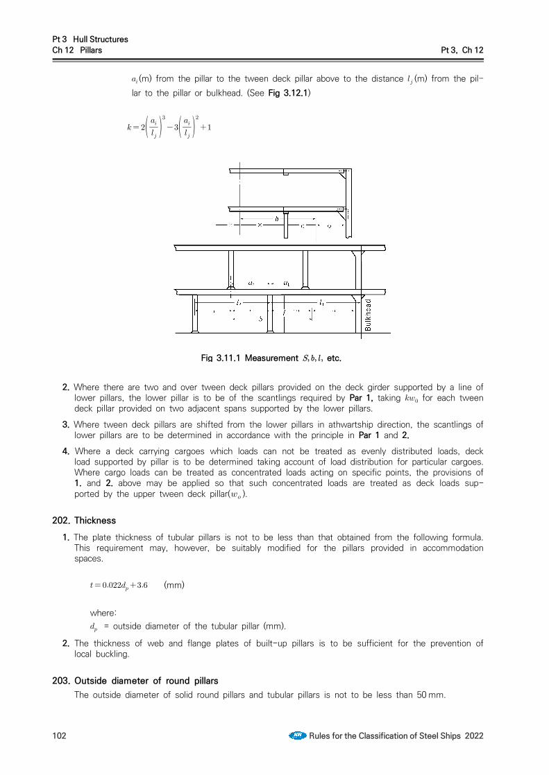
Pt 3 Hull StructuresCh 12 Pillars Pt 3, Ch 12
102 Rules for the Classification of Steel Ships 2022
(m) from the pillar to the tween deck pillar above to the distance (m) from the pil-lar to the pillar or bulkhead. (See Fig 3.12.1)
Fig 3.11.1 Measurement etc.
2. Where there are two and over tween deck pillars provided on the deck girder supported by a line of lower pillars, the lower pillar is to be of the scantlings required by Par 1, taking for each tween deck pillar provided on two adjacent spans supported by the lower pillars.
3. Where tween deck pillars are shifted from the lower pillars in athwartship direction, the scantlings of lower pillars are to be determined in accordance with the principle in Par 1 and 2.
4. Where a deck carrying cargoes which loads can not be treated as evenly distributed loads, deck load supported by pillar is to be determined taking account of load distribution for particular cargoes. Where cargo loads can be treated as concentrated loads acting on specific points, the provisions of 1. and 2. above may be applied so that such concentrated loads are treated as deck loads sup-ported by the upper tween deck pillar( ).
202. Thickness1. The plate thickness of tubular pillars is not to be less than that obtained from the following formula.
This requirement may, however, be suitably modified for the pillars provided in accommodation spaces.
(mm)
where: = outside diameter of the tubular pillar (mm).
2. The thickness of web and flange plates of built-up pillars is to be sufficient for the prevention of local buckling.
203. Outside diameter of round pillarsThe outside diameter of solid round pillars and tubular pillars is not to be less than 50 mm.

Pt 3 Hull StructuresCh 12 Pillars Pt 3, Ch 12
Rules for the Classification of Steel Ships 2022 103
204. Pillars provided in deep tank1. Pillars provided in deep tank are not to be tubular pillars.
2. The sectional area of pillars is not to be less than that specified in 201. or that obtained from the following formula, whichever is the greater.
(cm2)
where: and = as specified in 201. = 0.7 times the vertical distance from the top of deep tank to the point of 2 m above the
top of overflow pipe (m).
205. Longitudinal bulkheads and others provided in lieu of pillarsThe transverse bulkheads supporting longitudinal deck girders and the longitudinal bulkheads provided in lieu of pillars are to be stiffened in such a manner as to provide supports not less effective than required for pillars.
206. Casings provided in lieu of pillarsThe casings provided in lieu of pillars are to be of sufficient scantlings to withstand the deck load and side pressure.
Pt 3 Hull StructuresCh 13 Arrangements to Resist Panting Pt 3, Ch 13
Rules for the Classification of Steel Ships 2022 105
CHAPTER 13 ARRANGEMENTS TO RESIST PANTING
Section 1 General
101. ApplicationIn way of the spaces from the fore end of ship to a proper place beyond the collision bulkhead and from the aft end of ship to a proper place beyond the aft peak bulkhead, suitable arrangements to resist panting are to be provided according to the ship form at the place.
102. Swash plate 【See Guidance】In fore and aft peak tanks to be used as deep tanks, effective swash plates are to be provided at the centre line of ship or the scantlings of structural members are to be suitably increased.
103. Stringers fitted up with extremely small angle 【See Guidance】Where the angle between the web of stringers and the shell plating is extremely small, the scan-tlings of stringers are to be suitably increased above the normal requirements and, where necessary, appropriate supports are to be provided to prevent tripping.
Section 2 Arrangements to Resist Panting forward the Collision Bulkhead
201. Arrangement and construction1. Deep centre girders, etc. are to be provided forward the collision bulkhead.
2. In fore peaks of transverse framing, floors of sufficient height are to be arranged at the frame spacing stipulated in Ch 8, 201. 2 and side girders are to be arranged at an interval not exceeding about 2.5 m. Transverse frames are to be supported by the structures specified in 203. 2 at an in-terval not exceeding 2.5 m.
3. In fore peaks of longitudinal framing, bottom transverses supporting bottom longitudinals and side transverses supporting side longitudinals are to be arranged at an interval not exceeding about 2.5m. Bottom transverses and side transverses are to be effectively connected each other and deck transverses are to be arranged on the deck in the same section to providing structures.
202. Floors and centre girders1. The thicknesses of floors and centre girders in fore peaks are not to be less than those obtained
from the following formula:
(mm)
2. Floors are to extend to such a height as being necessary to give adequate stiffness to the structure and are to be properly stiffened with stiffeners as may be required.
3. The upper edges of the floors and centre girders are to be properly stiffened.
4. The thickness of side girders is to be approximately equal to that of centre girders and side girders are to extend to such a proper height as may be required according to the height of floors.
203. Transverse framing1. Transverse frames below the freeboard deck.
The section modulus of transverse frames below the freeboard deck is not to be less than that ob-tained from the following formula.

Pt 3 Hull StructuresCh 13 Arrangements to Resist Panting Pt 3, Ch 13
106 Rules for the Classification of Steel Ships 2022
(cm2)
where: = frame spacing (m). = distance between the supports of transverses (m), but to be taken as 2.15 m where the
height is less than 2.15 m. = vertical distance from the midpoint of to a point of 0.12 above the top of keel (m), but
to be taken as 0.06 where the height is less than 0.06.
2. Side construction to resist panting(1) Where panting beams are provided at alternate frames together with stringer plates connected to
the shell plating:(a) Panting beams are to be angles or channel sections of sectional area not less than that ob-
tained from the following formula, being connected effectively with frames by means of brackets having the thickness not less than that of the frames. And further, the panting beams are to be sufficiently connected vertically and longitudinally at the centre line of ship by means of angles as may be required in consideration of the span.
(cm2)
(b) The scantlings of stringer plates are not to be less than those obtained from the following formula, and their inner edges are to be suitably stiffened by flanging or by angle sections.
Breadth: (mm)Thickness: (mm)
(c) The frames to which no panting beam is provided are to be connected to the stringer plates by brackets. The length of each arm of brackets is to be at least equal to one half of the breadth of stringer plates required in (b) and the thickness of brackets at least equal to that of the stringer plates. In this case, the stringer plates are to be stiffened by providing flat bars extending from the toe of brackets to the inner edge of stringer plates.
(d) Stringer plates are to be connected by effective brackets to the breast hooks and the hori-zontal girders of transverse bulkhead.
(2) Where panting beams are provided at every frame together with perforated steel plates com-pletely fitted up thereon from side to side:(a) The sectional area of panting beams is not to be less than that obtained from the following
formula:
(cm2)
(b) The thickness of perforated steel plates completely plated on the panting beams is not to be less than that obtained from the following formula:
(mm)
(3) Where transverse frames are supported by side stringers:(a) The scantlings of side stringers are not to be less than those obtained from the following
formula:
Web depth: (mm), (mm) or 2.5 times the depth of slot for the transverse frames, whichever is the greatest.
Section modulus : (cm3)Web thickness : or , whichever is the greater.

Pt 3 Hull StructuresCh 13 Arrangements to Resist Panting Pt 3, Ch 13
Rules for the Classification of Steel Ships 2022 107
(mm),
(mm)
where: = spacing of side stringers (m). = horizontal distance between the supporting points of side stringers (m). = vertical distance from the middle of S to a point 0.12 above the top of keel
(m). Where, however, is less than 0.06(m), h is to be taken as 0.06(m). = depth of side stringers (mm). ln the calculation of , however, the depth of
slot for transverse frames, if any, is to be deducted from the depth of side stringers. Where the depth of side stringers is divided by horizontal stiffeners, the divided depth may be taken as in the calculation of .
= coefficient given in Table 3.13.1 according to the ratio of to , where (mm) is the spacing of stiffeners or tripping brackets provided on web plates of side stringers. For the intermediate values of , is to be obtained by linear interpolation.
Table 3.13.1 Coefficient
0.3 and under0.4
60.040.0
0.50.6
26.820.0
0.70.8
16.414.4
0.91.0
13.012.3
1.5 2.0 and over
11.110.2
(b) Side stringers are to be provided with tripping brackets at an interval of about 3 m. Where the breadth of face bars of side stringers exceeds 180 mm on either side of the web the tripping brackets are to support the face bars as well. And stiffeners are to be provided on the webs at every longitudinal except for the middle part of the span of side stringers where they may be provided at alternate transverse frames.
(c) Where the side stringers are supported by cross ties, the scantlings of cross ties are not to be less than those obtained from the formula given in Table 3.13.2.

Pt 3 Hull StructuresCh 13 Arrangements to Resist Panting Pt 3, Ch 13
108 Rules for the Classification of Steel Ships 2022
Table 3.13.2 Scantlings of cross ties
Sectional area (cm2) Web thickness (mm)
≥
= spacing of side stringers (m). = breadth of area supported by the cross tie (m) = vertical distance from the middle of to a point 0.12 above the top of keel (m).
Where, however, is less than 0.06(m), h is to be taken as 0.06(m). = length of cross tie (m). = minimum radius of gyration of cross tie, obtained from the following formula (cm).
= the least moment of inertia of cross tie (cm4) = sectional area of cross tie (cm2). = web depth of cross tie (mm). Where, however, stiffeners are fitted up horizontally,
the largest divided web depth may be taken as .
(d) Cross ties are to be effectively connected with the side stringers by brackets or by other suitable arrangements and the side stringers are to be provided with tripping brackets in way of the cross ties.
(e) Where the breadth of face bars of cross ties on either side of the web exceeds 150 mm, stiffeners are to be provided on the webs at a suitable interval, to be connected with the face bars and to support the face bars.
204. Longitudinal framing1. Longitudinal frames below the freeboard deck are to comply with the following requirements:
(1) The section modulus is not to be less than that obtained from the following formula. However, the section modulus obtained from the formula is to be increased by 25 % between 0.15 and 0.15 from the top of keel and 50 % below 0.05 from the top of keel.
(cm3)where: = longitudinal frame spacing (m). = distance between side transverse or between side transverse and transverse bulkhead
(m), but where it is less than 2.15 m, is to be taken as 2.15 m. = vertical distance from longitudinal frames to a point 0.1 above the top of keel (m),
but where it is less than 0.06(m), is to be taken as 0.06(m).(2) Longitudinal frames are to be connected at each end to breast hooks or transverse bulkheads by
efficient brackets.2. The side transverses supporting longitudinal frames are to comply with the following requirements.
However, where these are found impractical to apply these requirement are to be to the satisfaction of the Society.(1) Side transverses on both sides are to be connected providing cross ties at a vertical interval not
greater than that obtained from the following formula:
(m)

Pt 3 Hull StructuresCh 13 Arrangements to Resist Panting Pt 3, Ch 13
Rules for the Classification of Steel Ships 2022 109
(2) The scantlings of transverses are not to be less than those obtained from the following formula: 【See Guidance】
Web depth : (mm), (mm) or 2.5 times the depth of slots for longi-tudinals, whichever is the greatest.
Section modulus : (cm3)Web thickness : or , whichever is the greater.
(mm) ,
(mm)
where = vertical distance between supporting points of side transverses (m). = spacing of side transverses (m). = vertical distance from the middle of to a point 0.12 above the top of keel (m).
Where, however, is less than 0.06(m), h is to be taken as 0.06(m). = depth of side transverse (m). In the calculation of , however, the depth of slot
for longitudinals, if any, is to be deducted from the depth of transverses. Where the depth of side transverses is divided by vertical stiffeners, the divided depth may be taken as in the calculation of .
= coefficient given in Table 3.13.1 according to the ratio of to , where (mm)is the spacing of tripping brackets or stiffeners provided on web plates of side transverses. For the intermediate values of , is to be obtained by linear interpolation.
(3) Side transverses are to be connected effectively with the bottom transverses. Where side trans-verses are connected with bottom transverses, the scantlings of webs and face bars in the low-est span are to be so decided as to provide strength continuity in the transient from side to bottom transverse; the sum of effective sectional area of web and area of face bar in the lower half of the lowest span is not to be less than the required sectional area of web of the bottom transverse.
(4) Side transverses are to be provided with tripping brackets at an interval of about 3 m. Where the breadth of face bars of side transverses exceeds 180 mm on either side of the web, the tripping brackets are to support the face bars as well. And stiffeners are to be provided on the webs at every longitudinal, except that these stiffeners may be provided at alternate longitudinals in the middle part of spans other than the lowest span.
3. Cross ties specified in Par 2 (1) are to comply with the requirements in items 203. 2 (3) (c), (d) and (e). In this case, side stringers of quotable paragraph are to be replaced with side transverse. Where, however, it is found impracticable to apply these requirements, the constructions are to be at the discretion of the Society.
4. Bottom transverses supporting bottom longitudinals are to be of the construction specified in (1) to (6) or to be of that deemed equivalent thereto by the Society. In case of ships capable of maintain-ing adequate fore draught in rough seas, however, the section modulus of transverses and the sec-tional area of webs specified in (1) to (3) may be reduced by 10 % respectively.(1) The scantlings of bottom transverses are not to be less than that obtained from the following
formula, and the bottom transverses are to be supported by struts at the centre line, and further the adjacent bottom transverses are to be connected each other by a centre girder of about the same scantlings as those of the bottom transverses or to be supported by a specially deep cen-tre girder or a longitudinal bulkhead.
Web depth : Section modulus : (cm3)Web thickness : (mm)

Pt 3 Hull StructuresCh 13 Arrangements to Resist Panting Pt 3, Ch 13
110 Rules for the Classification of Steel Ships 2022
where:
= spacing of bottom transverses (m). = distance between the supporting points of bottom transverses (m).
(2) Where bottom transverses and centre girders are of scantlings exceeding those obtained from the following formula, notwithstanding the requirements in (1), the centre line struts may be ar-ranged at alternate bottom transverses.(a) Centre girders:
Web depth : (mm)Web thickness : (mm)Section modulus : Value obtained from the formula in (1). In the formula, however,
the average load bearing width (m) of the centre girder is to be taken as and the distance between the supporting points of the centre girder (m) as .
(b) Bottom transverses :
Web depth : (mm)Web thickness : (mm)Section modulus : Value obtained from the formula in (1).
(3) Where the scantlings of bottom transverses are greater than those obtained from the following formula, notwithstanding the requirements in (1) the centre line struts or longitudinal bulkheads may be dispensed with. In this case, the scantlings of web plates of centre girders are not to be less than those required in (1) for bottom transverses and free edges of web plates are to be suitably stiffened.
Web depth : (mm)Web thickness : (mm)Section modulus : Value obtained from the formula in (1).
(4) Where the web depths of bottom transverses and centre girders are greater than those obtained from (3) their thicknesses may be reduced from the thicknesses prescribed in (3) notwithstand-ing the requirements in (3). However, in no case is the thickness to be less than that obtained from the following formula:
(mm)
(5) Where the length of bottom transverses measured between their supporting points at each side exceeds 0.045(m) or the spacing of bottom transverses exceeds 2.5 m, the scantlings of bot-tom transverses and centre girders prescribed in (1) to (4) are to be suitably increased.
(6) Bottom transverses are to be provided with tripping brackets at an interval of about 3 m. Where the breadth of face bars of bottom transverses exceeds 180 mm on either side of the web, the tripping brackets are to support the face bars as well. And stiffeners are to be pro-vided on the webs at every longitudinal.
5. The struts stipulated in 4 (1) and (2) are not to be less effective than those required by the follow-ing (1) to (3) or equivalent thereto.(1) The scantlings of struts are not to be less than that obtained from the formula given in Table
3.13.3.
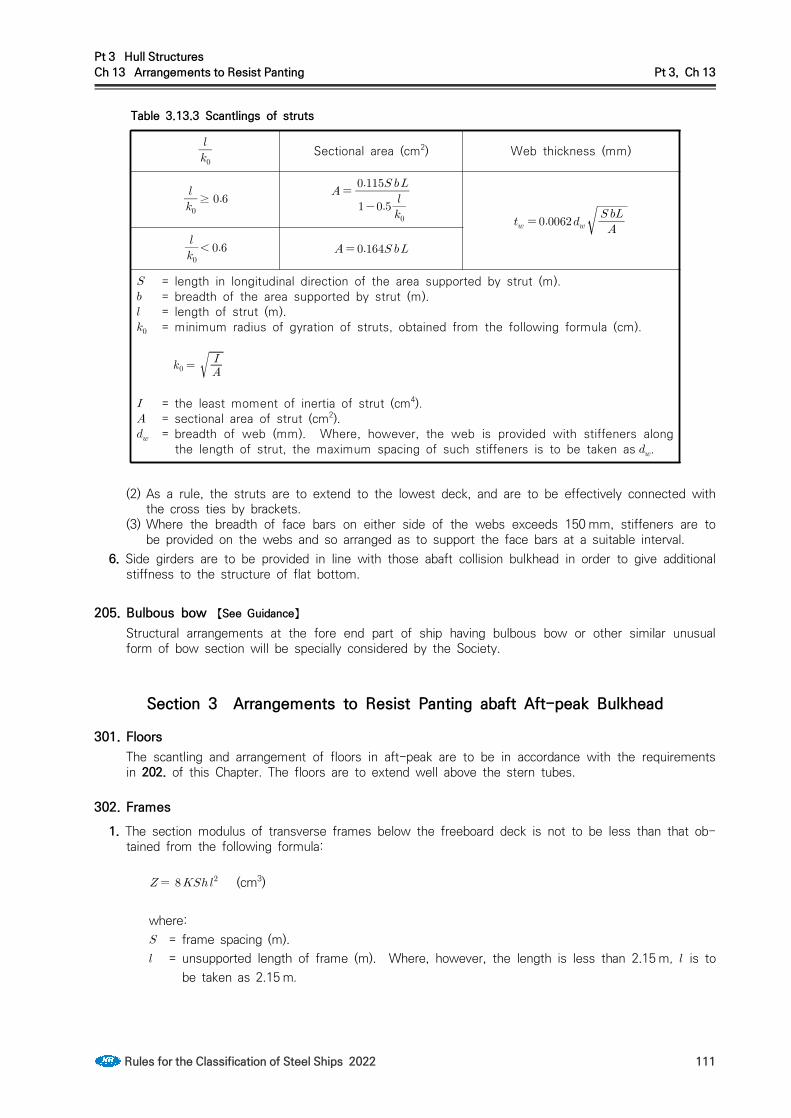
Pt 3 Hull StructuresCh 13 Arrangements to Resist Panting Pt 3, Ch 13
Rules for the Classification of Steel Ships 2022 111
Table 3.13.3 Scantlings of struts
Sectional area (cm2) Web thickness (mm)
≥
= length in longitudinal direction of the area supported by strut (m). = breadth of the area supported by strut (m). = length of strut (m). = minimum radius of gyration of struts, obtained from the following formula (cm).
= the least moment of inertia of strut (cm4). = sectional area of strut (cm2). = breadth of web (mm). Where, however, the web is provided with stiffeners along
the length of strut, the maximum spacing of such stiffeners is to be taken as .
(2) As a rule, the struts are to extend to the lowest deck, and are to be effectively connected with the cross ties by brackets.
(3) Where the breadth of face bars on either side of the webs exceeds 150 mm, stiffeners are to be provided on the webs and so arranged as to support the face bars at a suitable interval.
6. Side girders are to be provided in line with those abaft collision bulkhead in order to give additional stiffness to the structure of flat bottom.
205. Bulbous bow 【See Guidance】Structural arrangements at the fore end part of ship having bulbous bow or other similar unusual form of bow section will be specially considered by the Society.
Section 3 Arrangements to Resist Panting abaft Aft-peak Bulkhead
301. FloorsThe scantling and arrangement of floors in aft-peak are to be in accordance with the requirements in 202. of this Chapter. The floors are to extend well above the stern tubes.
302. Frames1. The section modulus of transverse frames below the freeboard deck is not to be less than that ob-
tained from the following formula:
(cm3)
where: = frame spacing (m). = unsupported length of frame (m). Where, however, the length is less than 2.15 m, is to
be taken as 2.15 m.

Pt 3 Hull StructuresCh 13 Arrangements to Resist Panting Pt 3, Ch 13
112 Rules for the Classification of Steel Ships 2022
= vertical distance from the middle of to a point ′ above the top of keel (m). Where, however, the distance is less than 0.04 (m), is to be taken as 0.04 (m).
′ = length of ship (m). Where, however, exceeds 230 m, ′ is to be taken as 230 m.
2. Where the speed of ship exceeds 14 kts, the section modulus of side frames is to be increased over the value required by Par 1 at the rate of 2 % per knot excess, but the increase need not ex-ceed 12 %.
303. Panting beams and stringers1. The structure below the lowest deck is to be effectively stiffened by means of panting beams and
stringers as required for the fore peak in 203. 2.2. Where the distance between supports at any part of the girth of the frame exceeds 2.5 m, the
scantlings of frames are to be increased, or side stringers or struts are to be additionally provided to give adequate stiffness to the structure.
304. Cruiser sternsCruiser sterns are to be strengthened by means of web frames, side stringers, etc. as may be required.
Section 4 Arrangements to Resist Panting between Both Peaks
401. Abaft collision bulkhead 【See Guidance】Between the collision bulkhead and 0.15 from the fore end, side stringers are recommended to be provided in line with stringer plates or side stringers in way of the fore peak tanks, in association with web frames provided at a suitable interval. Even in case where no web frame and side string-er are provided, brackets, etc. are to be provided to provide continuity at sections where side stringers or perforated steel plates in the fore peak tanks are located.
402. Forward after peak bulkheadAs for forward of the aft peak bulkhead, side stringers are to be provided or the frames are to be increased in size in a similar manner as prescribed in the preceding Article, where the frames have specially long unsupported spans as compared with the span amidships.

Pt 3 Hull StructuresCh 14 Watertight Bulkheads Pt 3, Ch 14
Rules for the Classification of Steel Ships 2022 113
CHAPTER 14 WATERTIGHT BULKHEADS
Section 1 General
101. ApplicationIn general all ships are to be provided with strength and watertight bulkheads in accordance with the requirements in this Chapter. In ships of special types, arrangements where it is impracticable to be in accordance with the requirements of this Chapter, are to be specially approved by this Society.
102. SymbolsWatertight bulkheads constructed in accordance with the requirements in this Chapter will be re-corded in the Register Book as the symbols being prefixed in each case by the number of such bulkheads.
Section 2 Arrangement of Watertight Bulkheads
201. Collision bulkheads 【See Guidance】
1. All ships except where the larger distance is accepted by the Society due to special structural rea-sons, are to have a collision bulkhead, at position not less than 0.05 or 10m, whichever is the lesser, but not more than 0.08 or 0.05 + 3 m, whichever is the greater, but at position between 0.05 and 0.13 for the ships are engaged in great coastal services and whose tonnages are less than 500 ton, the ships are engaged in under coastal services and fishing vessels, measured from the forward end of the length for freeboard.
However, where any part of the ship below the waterline at 85 % of the least moulded depth ex-tends forward beyond the forward end of the length for freeboard, the above-mentioned distance is to be measured from following points whichever gives the smallest measurement. (See Fig 3.14.1)(1) at the mid-length of such extension; or(2) at a distance(a) of 0.015 for ships whose length is less than 200 m, 3 m for ships whose
length is 200 m or greater, measured from the forward end of the length for freeboard 2. For ships having a collision bulkhead with steps or recesses, the measurement of the distance may
be observed in accordance with Fig 3.14.1 (B).
Fig 3.14.1 Measuring positions of collision bulkhead location
3. Arrangement of collision bulkhead in a ship provided with bow door is to be at the discretion of the Society. However, where a sloping ramp forms a part of the collision bulkhead above the freeboard

Pt 3 Hull StructuresCh 14 Watertight Bulkheads Pt 3, Ch 14
114 Rules for the Classification of Steel Ships 2022
deck, the part of the ramp which is more than 2.3 m above the freeboard deck may extend forward of the limit specified in the above Par 1. In this case, the ramp is to be weathertight over its com-plete length.
202. Aft peak bulkheads1. All ships are to have an after peak bulkhead situated at a suitable positions.
2. The stern tube is to be enclosed in a watertight compartment by the after peak bulkhead or other suitable arrangements.
203. Machinery bulkheads1. Watertight bulkhead is to be provided at each end of the machinery space.
2. In ships having the machinery room at aft body, aft end bulkhead of machinery room specified in Par 1 may be regarded as aft peak bulkhead specified in 202.
204. Hold bulkheads 【See Guidance】
1. Cargo ships of ordinary type, are to have hold bulkheads in addition to the bulkheads specified in 201. to 203. at a reasonable interval so that the total number of the watertight bulkheads including the bulkheads specified in 201. to 203. may not be less than that given by Table 3.14.1.
Table 3.14.1 Number of watertight bulkheads
Length of ship (m)Total number of bulkhead
Ships with machinery room at aft body Elsewhere
≤ 4 5
≤ 5 6
≤ 6 7
≤ 7 8
≤ 8 9
≤ to be considered individually
2. The requirements in Par 1 may be not applied to the arrangements of bulkhead subject to the ap-proval of the Society.
205. Height of watertight bulkheadsThe watertight bulkheads required in 201. to 204. are the extend to the freeboard deck with the following exceptions:(1) A watertight bulkhead in way of raised quarter or sunken forecastle deck is to extend up to the
said deck.(2) Where a forecastle having openings without closing appliances led to a space below the free-
board deck is provided, or where a forecastle of 0.25 or above in length is provided, the colli-sion bulkhead is to extend up to the forecastle deck. However, the extended part above free-board deck may have steps within the limit of bulkhead position specified in 201. and may be weathertight.
(3) Aft peak bulkhead may terminate at a deck above the load line, provided that this deck is made watertight to stern or to watertight stern floor of the ship.

Pt 3 Hull StructuresCh 14 Watertight Bulkheads Pt 3, Ch 14
Rules for the Classification of Steel Ships 2022 115
206. Construction1. Where the watertight bulkheads required in 201. to 204. are not extended up to the strength deck,
deep webs or partial bulkheads situated immediately or nearly above the main watertight bulkheads are to be provided so as to maintain the transverse strength and stiffness of the hull.
2. Where the length of a hold exceeds 30 m, suitable means are to be provided so as to maintain the transverse strength and stiffness of the hull.
207. Chain lockers 【See Guidance】
1. Spurling pipes and cable lockers are to be watertight up to the weather deck. Bulkheads between separate cable lockers, or which form a common boundary of cable lockers need not however be watertight.
2. Where means of access is provided, it is to be closed by a substantial cover and secured by closely spaced bolts.
3. Where a means of access to spurling pipes or cable lockers is located below the weather deck, the access cover and its securing arrangements are to be in accordance with recognized standards(e.g. ISO 5894 etc.) or equivalent for watertight manhole covers. Butterfly nuts and/or hinged bolts are prohibited as the securing mechanism for the access cover.
4. Spurling pipes through which anchor cables are led are to be provided with permanently attached closing appliances to minimize water ingress.
Section 3 Construction of Watertight Bulkheads
301. Thickness1. The thickness of bulkhead plating is not to be less than that obtained from the following formula:
(mm)
where: = spacing of stiffeners (m). = vertical distance (m) from the lower edge of plate to the freeboard deck or to the deepest
equilibrium water line at centre in damage stability calculation, whichever is the greater. But in no case is it to be less than 3.4 m.
2. Notwithstanding the requirements in Par 1. In no case is the thickness of watertight bulkhead plat-ings to be less than that obtained from following formula:
min (mm)
where: = as specified in Par 1.
302. Increase of thickness1. The thickness of lowest strake of plating is not to be less than that obtained from the above for-
mula given in 301. plus 1 mm.
2. The lowest strake of bulkhead plating is to extend at least 610 mm above the top of inner bottom plating in way of double bottom or 915 mm above the top of keel in way of single bottom. Where the double bottom is provided only on one side of the bulkhead, the extension of the lowest strake is to be of the greater value among the two cases above.

Pt 3 Hull StructuresCh 14 Watertight Bulkheads Pt 3, Ch 14
116 Rules for the Classification of Steel Ships 2022
3. The bulkhead platings in way of bilge wells are to be at least 2.5 mm thicker than given by 301.4. The bulkhead plating is to be doubled or increased in thickness in way of stern tube opening, not-
withstanding the requirements in the preceding Article.
303. Stiffeners 【See Guidance】The section modulus of bulkhead stiffeners is not to be less than that obtained from the following formula:
(cm3)where: = span measured between the adjacent supports of stiffeners including the length of con-
nection (m). Where girders are provided, it is the distance from the heel of end connection to the first girder or the distance between the girders.
= spacing of stiffeners (m). = vertical distance (m) measured from the midpoint of for vertical stiffeners, and from the
midpoint of distance between the adjacent stiffeners for horizontal stiffeners, to the top of freeboard deck or to the deepest equilibrium water line at centre in damage stability calcu-lation, whichever is the greater. Where the vertical distance is less than 6.0 m, is to be taken as 0.8 times the vertical distance plus 1.2 m.
= coefficient given in Table 3.14.2 according to the type of end connection.
Table 3.14.2 Valua of
Vertical Stiffener
Upper end
Lower end
Lug-connection or supported by
horizontal girders
Connection End of stiffener
unattachedType A Type B
Lug-connection or supported by horizontal girders 2.80 2.80 3.22 3.78
Bracketed 2.24 2.24 2.52 2.80
Only the web of stiffener attached at end 3.22 3.22 3.78 4.48
End of stiffener unattached 3.78 3.78 4.48 5.60
Horizontal Stiffener
One end
The other end
Lug-connection, brack-eted or supported by vertical girders
End of stiffener unattached
Lug-connection, bracketed or sup-ported by vertical girders 2.80 3.78
End of stiffener unattached 3.78 5.60
NOTES:1. "Lug-connection" is such a connection as both web and face bar of stiffener are effectively at-
tached to the bulkhead plating, decks or inner bottoms which are strengthened by effective supporting members on the opposite side of plating.
2. "Connection-Type A" of vertical stiffeners is a connection by bracket to the longitudinal members or to the adjacent members, in line with the stiffeners, of the same or larger sections, (See Fig 3.14.2 (a))
3. "Connection-Type B" of vertical stiffeners is a connection by bracket to the transverse members such as beams, or other connections equivalent to the connections mentioned above. (See Fig, 3.14.2 (b))

Pt 3 Hull StructuresCh 14 Watertight Bulkheads Pt 3, Ch 14
Rules for the Classification of Steel Ships 2022 117
Fig 3.14.2 Types of end connection Fig 3.14.3 Measurement of
304. Corrugated bulkheads 【See Guidance】
1. The plate thickness of corrugated bulkheads is not to be less than that obtained from the following formula, whichever is the greater:
(mm)
(mm)
where: = as specified in 301. = breadth of face part and web part, respectively (mm), indicated as and in Fig 3.14.3. = coefficient given below:
Face part:
Web part: , = thickness of plates of face part and web part, respectively (mm).
2. The section modulus per half pitch of corrugated bulkheads is not to be less than that obtained from the following formula:
(cm3)
where: = half pitch length of the corrugation (m). (See Fig 3.14.3) = as specified in 303. = length between the supports (m), as indicated in Fig 3.14.4. = coefficient given in Table 3.14.3, according to the type of end connection.
3. Where the end connection of corrugated bulkheads is remarkably effective, the value of specified in Par 2 may be adequately reduced.
4. The thickness of plates at end parts for 0.2 in line with is not to be less than that obtained from the following formulae respectively:
Web part :
(mm)

Pt 3 Hull StructuresCh 14 Watertight Bulkheads Pt 3, Ch 14
118 Rules for the Classification of Steel Ships 2022
In no case is the web thickness to be less than that obtained from the following formula:
(mm)
Face part, except the upper end part of vertically corrugated bulkheads:
(mm)
where:, , , = as specified in Par 2., = breadth of face part and web part, respectively (mm). = coefficient given in Table 3.14.4. Where the vertically corrugated bulkheads are constructed
with single span, the value of may be taken as the value for the uppermost span in the Table.
Tale 3.14.3 Values of
Line
One end of bulkhead The other end of bulkhead
Supported by rule horizontal or vertical
girders
Upper end welded directly to deck
Upper end welded to stool efficiently
supported by ship structure
(1)
Supported by rule horizontal or vertical
girders or lower end of bulkhead welded directly
to decks or inner bottoms
(2)
Lower end of bulkhead welded to stool
efficiently supported by ship structure
In no case is the value of less than that obtained from (1).
= minimum section modulus per half pitch of mid part for of the corrugated bulkhead (cm3)., = section modulus per half pitch of end part (cm3). In case of vertical corrugation, is the section
modulus of the upper end part and is that of lower end part. Where the plate thickness is in-creased in accordance with Par 5 the section modulus is to be that for the plate thickness reduced by the increment.
= height of stool measured from the inner bottom (m).= breadth of stool measured on the inner bottom plating (mm). = depth of corrugation (mm).

Pt 3 Hull StructuresCh 14 Watertight Bulkheads Pt 3, Ch 14
Rules for the Classification of Steel Ships 2022 119
Tale 3.14.4 Values of
Position Upper end
Lower end
Vertically corrugated bulkhead
Uppermost span 0.4 1.6
Other spans 0.9 1.1
Both ends of horizontally corrugated bulkhead 1.0
Fig 3.14.4 Measurement of
5. The thickness of the plates specified in the preceding Paragraphs are to be in accordance with 302.6. The actual section modulus per half pitch of corrugated bulkheads is to be calculated by the follow-
ing formula:
(cm3)
where:, = breadth of face part and web part respectively (m)., = thickness of plates of face part and web part respectively (mm). = depth of corrugation (mm).
305. Collision bulkheadsFor collision bulkheads, the plate thickness and section modulus of stiffeners are not to be less than those specified in 301., 303. and 304. taking as 1.25 times the specified height.
306. Girders1. The section modulus of girders supporting bulkhead stiffeners (hereinafter referred to as girder) is
not to be less than that obtained from the following formula:
(cm3)
where = breadth of the area supported by the girder (mm). = vertical distance (m) measured from the midpoint of for vertical girders, and from the
mid-point of for horizontal girders, to the top of freeboard deck or to the deepest equili-brium water line at centre in damage stability calculation, whichever is the greater. Where the vertical distance is less than 6.0 m, is to be taken as 0.8 times the vertical distance plus 1.2 m.
= span measured between the adjacent supports of girders (m). may be modified in ac-cordance with Ch 1, 605. Where brackets with curved free edge are attached the effec-tive arm length of the brackets is to be taken as indicated in Fig 3.14.5.

Pt 3 Hull StructuresCh 14 Watertight Bulkheads Pt 3, Ch 14
120 Rules for the Classification of Steel Ships 2022
Fig 3.14.4 Measurement of
2. The moment of inertia of girders is not to be less than that obtained from the following formula. In no case is the depth of girders to be less than 2.5 times the depth of slots for stiffeners.
(cm)
where:, = as specified in Par 1.
3. The thickness of web plates is not to be less than that obtained from the following formula:
(mm)
where: = spacing of web stiffeners or depth of girders, whichever is the smaller (mm).
4. The thickness of web plates at both end parts for 0.2 is not to be less than that obtained from the following formulae, whichever is the greater:
(mm) ,
(mm)
where:, , = as specified in Par 1. = depth of girders (mm). = as specified in Par 3. = as specified in 304. 4.
5. Tripping brackets are to be provided at an interval of about 3 m and where the breadth of face plates exceeds 180 mm on either side of the girder, these brackets are to be so arranged as to support the face plates.
6. The actual section modulus and moment of inertia of girders are to be calculated in association with the steel plates specified in Ch 1, 602. Where stiffeners are provided within the effective breadth, they may be included in the calculation.
307. BracketsThe scantlings of the effective brackets at the ends of bulkhead stiffener are to be in accordance with the requirement in Ch 1, 604. 2.

Pt 3 Hull StructuresCh 14 Watertight Bulkheads Pt 3, Ch 14
Rules for the Classification of Steel Ships 2022 121
308. Strengthening of bulkhead plating, deck plating, etc.Platings of bulkheads, decks, inner bottoms, etc. are to be, if necessary, strengthened at the loca-tion of the end brackets of stiffeners and the end of girders.
309. Bulkhead recesses1. In way of bulkhead recesses, beams are to be provided at every frame and under the upper bulk-
head in accordance with the requirements in Ch 10, 403. and Ch 14, 303. taking the beam spacing as the stiffener spacing. Where the lower end of upper bulkhead is specially strengthened, the beam under the upper bulkhead may be dispensed with.
2. The thickness of deck plating in way of bulkhead recesses is to be at least 1 mm greater than that given by 301., regarding the deck plating as bulkhead plating and the beams as stiffeners respectively. In no case is the thickness to be less than that required for deck plating in that location.
3. The thickness of pillars supporting bulkhead recesses are to be determined taking account of the water pressure which might be applied on the upper surface of recesses, and their end connections are to be sufficient to withstand the water pressure which might be applied on the under surface.
310. Construction of bulkheads in way of watertight doorsWhere stiffeners are cut or the spacing of stiffeners is increased in order to provide the watertight door in the bulkhead, the opening is to be suitably framed and strengthened as to maintain the full strength of the bulkhead. In this case the door frames are not to be considered as stiffeners.
Section 4 Watertight Doors
401. General (2020)
1. Any access openings, doors, manholes or ducts for ventilation, etc. are not to be cut in the collision bulkhead below freeboard deck. The number of openings in collision bulkheads above the freeboard deck is to be kept to a minimum as possible and all such openings are to be provided with weath-ertight means of closing.
2. The design and testing requirements for watertight doors vary according to their location relative to the 1) equilibrium waterplane or intermediate waterplane at any stage of assumed flooding and or 2) bulkhead deck or freeboard deck.
3. Definitions(1) Watertight: Capable of preventing the passage of water in any direction under a design head.
The design head for any part of a structure shall be determined by reference to its location rel-ative to the bulkhead deck or freeboard deck, as applicable, or to the most unfavourable equili-brium/intermediate waterplane, in accordance with the applicable subdivision and damage stability regulations, whichever is the greater. A watertight door is thus one that will maintain the water-tight integrity of the subdivision bulkhead in which it is located.
(2) Equilibrium Waterplane: The waterplane in still water when, taking account of flooding due to an assumed damage, the weight and buoyancy forces acting on a vessel are in balance. This relates to the final condition when no further flooding takes place or after cross flooding is completed.
(3) Intermediate Waterplane: The waterplane in still water, which represents the instantaneous float-ing position of a vessel at some intermediate stage between commencement and completion of flooding when, taking account of the assumed instantaneous state of flooding, the weight and buoyancy forces acting on a vessel are in balance.
(4) Sliding Door or Rolling Door: A door having a horizontal or vertical motion generally parallel to the plane of the door.
(5) Hinged Door: A door having a pivoting motion about one vertical or horizontal edge.
402. Type of watertight doors 【See Guidance】
1. Watertight doors are to be of sliding type. (2019)

Pt 3 Hull StructuresCh 14 Watertight Bulkheads Pt 3, Ch 14
122 Rules for the Classification of Steel Ships 2022
2. Notwithstanding the provisions in 1 above, where watertight door is as small as crew can pass, the watertight door may be of hinged type or rolling type, except where the doors are required to be capable of being closed remotely in accordance with 404. 3.
3. Notwithstanding the provisions in 1 above, watertight doors in large cargo hold division may be of a type other than sliding type provided that such doors are permanently closed at sea.
4. Doors which are closed by dropping or by the action of a dropping weight are not permitted.
5. Doors should be fitted in accordance with all requirements regarding their operation mode, location and outfitting, i.e. provision of controls, means of indication, etc., as shown in Table 3.14.5 below. (2020)
403. Strength and watertightness1. Watertight doors are to be of ample strength and watertightness for water pressure to a head up to
the bulkhead deck, and door frames are to be effectively secured to the bulkheads. Where deemed necessary by the Society, watertight doors are to be tested by water pressure before they are fitted. 【See Guidance】
2. Where watertight doors are provided in cargo spaces, such doors are to be protected against dam-ages due to cargoes, etc. by suitable means.
404. Control (2021) 【See Guidance】
1. Watertight doors are categorized as the following (1) to (3) corresponding to its purpose and fre-quency of use.(1) Normally Closed at sea : Kept closed at sea but may be used if authorised. To be closed again
after use.(2) Permanently Closed at sea : The time of opening such doors in port and of closing them before
the ship leaves port shall be entered in the log-book. Should such doors be accessible during the voyage, they shall be fitted with a device to prevent unauthorised opening.
(3) Used at sea : Kept closed. but may be opened during navigation when authorized by the Society to permit the passage of passengers or crew, or when work in the immediate vicinity of the door necessitates it being opened. The door shall be immediately closed after use.
2. All watertight doors, except those which are to be permanently closed at sea, are to be capable of being opened and closed by hand (and by power, where applicable) locally, from both sides of the doors, with the ship listed of 30 degrees to either side.
3. Where indicated in Table 3.14.5, the doors are to be capable of being remotely closed by power from the bridge for all ships.
4. It is not to be possible to remotely open any watertight door. In addition, watertight doors which are applying to the provisions of 402. 3 are not to be remotely controlled.
405. Indication (2020) 【See Guidance】
1. Where shown in Table 3.14.5, position indicators are to be provided at all remote operating positions (5), for all ships and provided locally on both sides of the internal doors (6) for cargo ships, to show whether the doors are open or closed and, if applicable, with all dogs/cleats fully and properly engaged.
2. In addition to the requirements of 1 above for watertight doors which are to be capable of being remotely closed, an indication is to be placed locally showing that the door is in remote control mode.
3. The door position indicating system is to be of self-monitoring type and the means for testing of the indicating system are to be provided at the position where the indicators are fitted.
4. Signboard/instructions should be placed in way of the door advising how to act when the door is in "doors closed" mode.

Pt 3 Hull StructuresCh 14 Watertight Bulkheads Pt 3, Ch 14
Rules for the Classification of Steel Ships 2022 123
406. Alarms 【See Guidance】Watertight doors which are capable of being remotely closed are to be provided with an audible alarm which will sound at the door position whenever such a door is remotely closed.
407. Source of power1. The remote controls, indications and alarms required in 404. to 406. are to be operable in the event
of main power failure. For passenger ships, failure of the normal power supply of the required alarms shall be indicated by an audible and visual alarm at the central operating console at the nav-igation bridge. For cargo ships, failure of the normal power supply of the required alarms shall be indicated by an audible and visual alarm at the navigation bridge. (2021)
2. Where Electrical installations specified in 1 are situated below the freeboard deck, they are to be provided with a degree of protection appropriate for flooding. 【See Guidance】
3. Cables for devices specified in 1. are to comply with the requirements of Pt 6, Ch 1, Sec 5 of the Rules.
408. Notices (2020) 1. Watertight doors which are to be normally closed at sea but not provided with means of remote
closure, are to have notices fixed to both sides of the doors stating "To be kept closed at sea".2. Watertight doors which are to be permanently closed at sea are to have notices fixed to both sides
stating "Not to be opened at sea". Such doors which are accessible during the voyage are to be fit-ted with a device which prevents opening. (2021) 【See Guidance】
409. Sliding doors 【See Guidance】 (2019)1. Where a sliding watertight door is operated by rods, the lead of operating rods is to be as direct as
possible and the screw is to work in a nut of gun-metal or other approved material.
2. The frames of vertically sliding watertight doors are to have no groove at the bottom in which dirt might lodge and prevent the door from closing.
410. Hinged and rolling doors1. For hinged and rolling watertight doors, the hinge pins and the wheel axle of these doors are to be
of gun-metal or other approved materials.
2. Hinged and rolling watertight doors except those are to be permanently closed at sea, are to be of quick acting or single acting type which is capable of being closed and secured from both sides of the doors.
411. OthersFor fitting of valves or cocks to a watertight bulkhead, see Pt 5, Ch 6, 107. 8. For pipes passing through bulkheads, see Pt 5, Ch 6, 107. 7. For electric cables passing through bulkhead, see Pt 6, Ch 1, 508. 1 to 3.
412. Test 【See Guidance】 (2020) 1. Doors which become immersed by an equilibrium or intermediate waterplane, are to be subjected to
a hydrostatic pressure test.
2. For large doors intended for use in the watertight subdivision boundaries of cargo spaces, structural analysis may be accepted in lieu of pressure testing. Where such doors utilise gasket seals, a pro-totype pressure test to confirm that the compression of the gasket material is capable of accom-modating any deflection, revealed by the structural analysis, is to be carried out.

Pt 3 Hull StructuresCh 14 Watertight Bulkheads Pt 3, Ch 14
124 Rules for the Classification of Steel Ships 2022
Table 3.14.5 Doors in Internal Watertight Bulkheads and External Watertight Boundaries in Cargo Ships (2021)
Position relative to bulkhead or freeboard deck
1. Frequency of Use while
at sea 2. Type 3. Remote
Closure4. Remote Indication
5. Audible or Visual
Alarm6. Notice 7. Regulation 8. Comments
(1) Below
Used POS Yes Yes Yes(local) No
SOLAS II-1/10, 13-1.2, 16.2 and 22.3MARPOL I/28.3 ICLL66+A.320 1988 Protocol to
ICLL66 IBC, and IGCNorm.Closed S, H No Yes No Yes SOLAS II-1/10, 13-1.3, 16.2, 22.3 and 24.4 See Note 1
Perm.Closed S, H No No No Yes
SOLAS II-1/10, 13-1.4, 16.2, 24.3 and 24.4SOLAS II-1/10, 13-1.4, 13-1.5, 16.2, 22.2,
24.3 and 24.4See Notes 3 + 4
(2) At or above
Used POS Yes Yes Yes(local) No
SOLAS II-1/10, 13-1.2, 16.2 and 22.3MARPOL I/28.3 ICLL66+A.320 1988 Protocol to
ICLL66 IBC, and IGCSee Notes 2 + 5
Norm.Closed S, H No Yes No Yes SOLAS II-1/10, 13-1.3, 16.2, 22.3 and 24.4 See Note 1
Perm.Closed S, H No No No Yes SOLAS II-1/10, 13-1.4, 13-1.5, 16.2, 24.3
and 24.4 See Notes 3 + 4
Notes:Type
- Power operated, sliding or rolling POS- Power operated, hinged POH- Sliding or Rolling S- Hinged H
1. If hinged, this door shall be of single action type. 2. Under ICLL66, doors separating a main machinery space from a steering gear compartment may be hinged single action type provided the lower sill of such doors is
above the Summer Load Line and the doors remain closed at sea whilst not in use. 3. The time of opening such doors in port and closing them before the ship leaves port shall be entered in the logbook, in case of doors in watertight bulkheads sub-
dividing cargo spaces. 4. Doors shall be fitted with a device which prevents unauthorized opening. 5. Under MARPOL, hinged watertight doors may be acceptable in watertight bulkhead in the superstructure. 6. Passenger ships which have to comply with SOLAS II-1/14.2 require an indicator on the navigation bridge to show automatically when each door is closed and all
door fastenings are secured. 7. Refer to the Explanatory Note to Regulation 17.1 of Res.MSC.429(98) regarding sliding watertight doors with a reduced pressure head and sliding semi-watertight
doors.
A. Door in Internal Watertight Bulkheads

Pt 3 Hull StructuresCh 14 Watertight Bulkheads Pt 3, Ch 14
Rules for the Classification of Steel Ships 2022 125
Position relative to bulkhead or freeboard deck
1. Frequency of Use while
at sea 2. Type 3. Remote
Closure4. Remote Indication
5. Audible or Visual
Alarm6. Notice 7. Regulation 8. Comments
(1) Below Perm.Closed S, H No Yes No Yes SOLAS II-1/15.9, 15-1.2, 15-1.3, 15- 1.4,
22.6, 22.12 and 24.1 See Notes 2 + 3
(2) At or above
Norm.Closed S, H No Yes No Yes SOLAS II-1/15-1.2 See Note 1
Perm.Closed S, H No Yes No Yes SOLAS II-1/15-1.2 and 15-1.4 See Notes 2 +3
Notes:Type
- Power operated, sliding or rolling POS- Power operated, hinged POH- Sliding or Rolling S- Hinged H
1. If hinged, this door shall be of single action type.2. The time of opening such doors in port and closing them before the ship leaves port shall be entered in the logbook.3. Doors shall be fitted with a device which prevents unauthorized opening.
B. Door in External Watertight Boundaries below equilibrium or intermediate waterplane

Pt 3 Hull StructuresCh 15 Deep Tanks Pt 3, Ch 15
Rules for the Classification of Steel Ships 2022 127
CHAPTER 15 DEEP TANKS
Section 1 General
101. DefinitionA deep tank is a tank used for carriage of water, fuel oil and other liquids, forming a part of the hull in holds. The deep tanks used for carriage of oil are designated as "deep oil tanks", if necessary.
102. Application1. The constructions of all deep tanks are to be in accordance with the requirements in this Chapter.
Where the bulkhead of deep tank partly serves as a watertight bulkhead, the part of the bulkhead is to be in accordance with the requirement in Ch 14.
2. The requirements in Pt 7, Ch 1 are to be applied to the bulkheads of the deep tanks for carriage of oils having flash a point below 60°C, in addition to those in this Chapter.
103. Divisions in tanks 【See Guidance】
1. Deep tanks are to be of proper size and to be provided with such longitudinal watertight divisions as necessary to meet the requirements for stability in service conditions as well as while the tanks are being filled or discharged.
2. Where the width of the deep tank extends to the ship sides of the ship, watertight bulkheads, swash bulkheads or deep swash plates are to be arranged as necessary for the ship safety.
3. Tanks for fresh water or fuel oil or those which are not intended to be kept entirely filled in service conditions are to have additional divisions or deep wash plates as necessary to minimize the dy-namic forces acting on the structure.
4. Where it is impracticable to comply with the requirements in Par 3, the scantlings required in this Chapter are to be properly increased.
5. Longitudinal watertight divisions which will be subjected to pressure from both sides, in tanks which are to be entirely filled or emptied in service conditions, may be of the scantlings required for ordi-nary watertight bulkheads by Ch 14. In such cases, the tanks are to be provided with deep hatches, etc., fitted with inspection plugs in order to ensure that the tanks are kept full in service conditions.
104. Minimum thickness 【See Guidance】In wing tanks and hold tanks with the length or breadth which exceeds (m) and in top-side tanks and hopper tanks, the thickness of girders, struts and the brackets and bulkhead plates is not to be less than that given by Table 3.15.1 in accordance with the length of ship.
105. Additional strengthening of bulkheads in large tanksAs for large tank boundaries, the scantlings of bulkhead plates, stiffeners, girders and cross ties are not to be less than that obtained from the relevant formulae in 202. to 205. and 207., where the value of is the one specified in each requirement or that given by the following formula, which-ever is the greater.
(m)
where:h = water head, as specified in each requirement of 202. or 203. = additional water head given by the following formula:

Pt 3 Hull StructuresCh 15 Deep Tanks Pt 3, Ch 15
128 Rules for the Classification of Steel Ships 2022
(m)
= tank length (m). It is not to be less than 10 m.
= tank breadth (m). It is not to be less than 10 m. but may be in case of ballast
hold of bulk carrier with top side tanks.
Table 3.15.1 Minimum thickness
Length of ship (m) Thickness (mm)
≤ 8.0
≤ 8.5
≤ 9.0
≤ 9.5
≤ 10.0
≤ 10.5
≤ 11.0
≤ 11.5
≤ 12.0
≤ 12.5
≤ 13.0
≤ 13.5
Section 2 Bulkheads of Deep Tanks
201. Application The construction of bulkheads and decks forming boundaries of deep tanks is to be in accordance with the requirements in Ch 14, unless otherwise specified in this Chapter.
202. Bulkhead plates (2020) 【See Guidance】 The thickness of deep tank bulkhead plating is not to be less than that obtained from the following formula:
mm
where: = spacing of stiffeners. (m). = distance given below, whichever is the greater:
: Vertical distance from the lower edge of the bulkhead plating under consideration to the mid-point between the point on tank top and the upper end of the overflow pipe. For side shell plating, a water head corresponding to the minimum draught amidship min (m) under all operating conditions of the ship may be deducted therefrom. The deductible water head at the top of keel is to be min, value at point min above the top of keel, 0, and value at an intermediate point is to be obtained by linear interpolation
: in 105.

Pt 3 Hull StructuresCh 15 Deep Tanks Pt 3, Ch 15
Rules for the Classification of Steel Ships 2022 129
: Value (m) obtained by multiplying 0.7 by vertical distance from the lower edge of the bulkhead plating under consideration to the point 2.0 m above the top of overflow pipe.
When the ship use the flow-through ballast water exchange operations method, the follow-ing water heads, and are to be additionally considered.: Vertical distance from the lower edge of the bulkhead plating under consideration to the
top of the overflow pipe (or air pipe) to the point where the overpressure is added (m). (Overpressure : due to sustained liquid flow through overflow pipe in case of overfilling or filling during flow through ballast water exchange. It is to be defined by the designer, but not to be less than 2.5.)
: : as specified in 105.
= coefficients determined according to values of as specified below : = 1.0 where is 230 m and under,
1.07 where is 400 m and above.For intermediate values of , are to be obtained by linear interpolation.
= coefficients is obtained from Table 3.15.2.In determining the thickness of longitudinal bulkhead plating, coefficient for may be gradually reduced for the parts forward and aftward the midship part, and it may be taken as 3.6 in calculations at 0.1 from fore end and aft end.

Pt 3 Hull StructuresCh 15 Deep Tanks Pt 3, Ch 15
130 Rules for the Classification of Steel Ships 2022
Table 3.15.2 Coefficient
For
longitudinal bulkhead of longitudinal framing
longitudinal bulkhead of transverse framing
minimum : 3.6
For or and for transverse bulkhead
= either or according to value of . However, value of is not to be less than .
′ for
for ≤
= distance from the top of keel to the lower edge of plating when the platings under con-sideration are under , to the upper edge of plating when the platings under consid-eration are above and to the longitudinals stiffener under consideration for longitudinal stiffener, respectively (m).
= distance from the top of keel to the horizontal neutral axis of transverse section amidship (m).
′ = the greater of the value specified in Ch 3, 203., (5), (a) or (b). = coefficient determined according to the values of as specified below: For intermediate
values of , the value of b is to be determined by linear interpolation: = 6/ when is 230 m and under,
10.5/ when is 400 m and above. = when high tensile steels are used for not less than 80 of side shell platings
at the transverse section amidship and 1.0 for other parts. = horizontal distance from the side shell plating to the longitudinal bulkhead plating
under consideration (m).
203. Bulkhead stiffeners (2020) 【See Guidance】
1. Section modulus of stiffeners is not to be less than that obtained from the following formula :
cm
Where: = water head , or as specified in 202., whichever is the greater. Where, however,
"the lower edge of the bulkhead plating under consideration" is to be construed as "the mid-point of the stiffener under consideration" for vertical stiffeners and as "the stiffener under consideration" for horizontal stiffeners. And "side shell plating" is to be construed as "stiffener attached to side shell plating". When the ship use the flow-through ballast water exchange operations method, and as specified in 202. are to be additionally considered.

Pt 3 Hull StructuresCh 15 Deep Tanks Pt 3, Ch 15
Rules for the Classification of Steel Ships 2022 131
= value obtained from following formula. The value for , however, is to be as obtained from the formula in Table 3.15.3
= as determined from Table 3.15.4 according to the fixity condition of stiffener ends; = as specified in 202. and = as specified in Ch 14, 303.
2. For the parts forward and aftward of midship part in determining the section modulus of stiffeners attached to longitudinal bulkhead of longitudinal framing systems, coefficient for may be grad-ually reduced, and at the end parts may be as /18.
Table 3.15.3 Coefficient
Bulkhead and framing systems
Longitudinal bulkhead of longitudinal framing system
, minimum
Longitudinal bulkhead of transverse framing system, transverse bulkhead
= as specified in 202.
Table 3.15.4 Coefficient
One end of stiffener
The other end of stiffener
Connection be hard bracket
Connection be soft bracket
Supported by rule girder or lug connection
Snip
Connection be hard bracket 0.70 1.15 0.85 1.30
Connection be soft bracket 1.15 0.85 1.30 1.15
Supported by rule girder or lug connection 0.85 1.30 1.00 1.50
Snip 1.30 1.15 1.50 1.50
1. Connection by hard bracket is a connection by bracket to the double bottoms or to the ad-jacent members, such as longitudinals or stiffeners in line, of the same or larger sections, or a connection by bracket to the equivalent members mentioned above. (See Fig 3.14.2 (a))
2. Connection by soft brackets is a connection by bracket to the transverse members such as beams or equivalent thereto. (See Fig 3.14.2 (b))
204. Girders supporting bulkhead stiffeners 【See Guidance】
1. The section modulus of girders supporting bulkhead stiffeners (hereinafter referred to as "girder") is not to be less than that obtained from the following formula:
(cm3)
where: = breadth of the area supported by the girders (m). = vertical distance measured from the midpoint of for horizontal girders, and from the
mid-point of for vertical girders, to the top specified in 203. (m).

Pt 3 Hull StructuresCh 15 Deep Tanks Pt 3, Ch 15
132 Rules for the Classification of Steel Ships 2022
= span specified in Ch 14, 306 (m).
2. The moment of inertia of girders is not to be less than that obtained from the following formula. The depth of girders is not to be less than 2.5 times the depth of slots for stiffeners.
(cm4)
where:, = as specified in preceding Paragraph.
3. The thickness of plates of web part is not to be less than that obtained from the following for-mulae, whichever is the greater:
(mm),
(mm), (mm)
where:, and = as specified in Par 1. = spacing of web stiffeners or the depth of girders, whichever is the smaller (mm). = depth of the girder at the location considered, reduced by the depth of slots for stiffeners
(mm) = coefficient obtained from the following formulae. It is not to be less than 0.5.
For horizontal girders :
For vertical girders : ×
= distance measured from the end of for horizontal girders, and from the lower end for vertical girders, to the location considered (m)
4. The actual section modulus and moment of inertia of girders are to be calculated in accordance with the provisions in Ch 14, 306. 6.
205. Cross ties1. Where efficient cross ties are provided across deep tanks connecting girders on each side of the
tanks, the span of girders specified in 204. may be measured between the end of girder and the centre line of cross tie or between the centre lines of adjacent cross ties.
2. The sectional area of cross ties is not to be less than that obtained from the following formula:
(cm2)
where :, = as specified in 204.bs = breadth of the area supported by the cross ties (m).
3. The end of cross ties are to be bracketed to girders.
206. BracketsThe scantlings of effective brackets on both end of stiffeners are to be in accordance with the re-quirements in Ch 14, 307.

Pt 3 Hull StructuresCh 15 Deep Tanks Pt 3, Ch 15
Rules for the Classification of Steel Ships 2022 133
207. Corrugated bulkheads 【See Guidance】
1. The thickness of plates of corrugated bulkheads is not to be less than that obtained from the fol-lowing formula:
(mm)
where:, and = as specified in Ch 14, 304. 1. = as specified in 202. = coefficient given below:
For face part :
For web par t:
2. The section modulus per half pitch of corrugated bulkheads is not to be less than that obtained from the following formula:
(cm3)
where: = as specified in Ch 14, 304. 2. = length between the supports (m), as indicated in Fig 3.15.1. = as specified in 203. = coefficient given in Table 3.15.5, according to the type of end connection.
As for bulkheads with lower stools of which the width in longitudinal direction at the lower end, is less than 2.5 times of web depth of the bulkhead, (See Fig 3.15.1), the measurement of and the values of are to be at the discretion of the Society.
Fig 3.15.1 Measurement of

Pt 3 Hull StructuresCh 15 Deep Tanks Pt 3, Ch 15
134 Rules for the Classification of Steel Ships 2022
Table 3.15.5 Values of
Column
Upper endLower end
Supported by Girders
Welded directly to deck
Welded to stool efficiently
supported by ship structure
(1)Supported by girders or welded directly to deck or inner bottoms
1.00 1.50 1.35
(2) Welded to stool efficiently supported by ship structure 1.50 1.20 1.00
3. The thickness of plates at end parts for 0.2 in line with is not to be less than that obtained from the following formulae :
Thickness of web part :
(mm)
It is not to be less than that obtained from the following formula :
min
(mm)
Thickness of the face part except the upper end part of vertically corrugated bulkheads:
(mm)
where: = as specified in 203., = as specified in Par 2., , and = as specified in Ch 14, 304. 4.
208. Top and bottom constructionThe scantlings of the members forming the top or the bottom of deep tanks are to be in accord-ance with the requirements in this Chapter, regarding the members as the members forming the deep tank bulkheads at the location. They are not to be less than that required for the deck plating or the bottom plating at the location. For top plating of deep tanks the thickness of plates is to be at least 1 mm greater than the thickness specified in 202. However, the thickness of top plating of deep tanks which is not weather deck like as inner bottom plating needs not be increased by 1mm.
209. Scantling of members not in contact with sea water 【See Guidance】The thickness of plates of bulkheads and girders which are not in contact with sea water in service conditions may be reduced from the requirements in 202., 204. and 207. by the values given be-low:For the plates of which only side is in contact with sea water ........................................ 0.5 mmFor the plates of which neither side is in contact with sea water .................................... 1.0 mmHowever, bulkhead plate in way of the location such as bilge wells are to be regarded as the plates in contact with sea water.

Pt 3 Hull StructuresCh 15 Deep Tanks Pt 3, Ch 15
Rules for the Classification of Steel Ships 2022 135
Section 3 Fittings of Deep Tanks
301. Limbers and air holesLimbers and air holes are to be cut suitably in the structural members to ensure that air or water does not remain stagnated in any part of the tank.
302. DrainageEfficient arrangement is to be made for draining bilge water on the top of deep tanks.
303. Inspection plugThe inspection plugs provided on deep tank tops as required in 103. 5 are to be located in readily accessible positions.
304. Cofferdam1. The following dedicated tanks are to be separated from adjacent tanks by cofferdams. However,
these cofferdams may be omitted provided that the common boundaries of lubricating oil and fuel oil tank have full penetration welds.(1) Fuel oil(2) Lubricating oil(3) Vegetable oil(4) Fresh water
2. The cofferdams in Par. 1 are to be provided with the air pipes to comply with the requirements in Pt 5, Ch 6, 201 and with the manholes of adequate size which are well accessible.
3. Crew spaces and passenger spaces are not to be directly adjacent to the tanks for carriage of fuel oil. Such compartments are to be separated from the fuel oil tanks by cofferdams which are well ventilated and is not less than 600 mm in width for easy access. Where the top of fuel oil tanks has no opening and is coated with incombustible coverings of 38 mm and over in thickness, the cofferdam between such compartments and the top of fuel oil tanks may be omitted.
Section 4 Welding of Corrugated Bulkheads (2016)
401. General1. The welding of corrugated bulkheads is to be in accordance with Table 3.15.6.2. For the supporting members of corrugated bulkheads or stools, such as floors, girders or other pri-
mary supporting members and stiffeners, fillet weld leg length is to be suitably increased or to be bevelled and welded. In cases where the angle between the side plating of a lower stool and inner bottom plating is relative small, the fillet weld leg lengths for supporting members to inner bottom plating are to be suitably increased taking into account such an angle.
3. In cases where stools are fitted, the fillet weld leg length for the top or bottom plating of stools to the side plating of stools as well as the side plating of stools to inner bottom plating is to be suit-ably increased or to be bevelled and welded.
4. In cases where gusset plates and shedder plates are fitted at the lower parts of corrugated bulk-heads, the welding is to be in accordance with the requirements given in Pt 7, Ch 3, 1204. 2. (1) (A) (a) (ii) and (b) (iv).

Pt 3 Hull StructuresCh 15 Deep Tanks Pt 3, Ch 15
136 Rules for the Classification of Steel Ships 2022
Type of Corrugated bulkhead Application Welding
Vertically Corrugated bulkhead
Without stool
Upper deckDouble continuous fillet welding with a fillet weld leg length that is not less than 0.7 times the thickness of the corru-gated bulkhead.
Inner bottom, lower hopper
plate
(1) For ships having a length, L of 150m and above • Full Penetration welds
(2) For ships having a length, L, that is less than 150m• Full penetration welds for webs and flanges of the cor-
rugated bulkhead that are within about 200mm from R ends of the corner of the corrugation (see Fig 3.15.2)
• For other parts, double continuous fillet welding with a fillet weld leg length that is not less than 0.7 times the thickness of the corrugated bulkhead.
Corrugated bulkhead Full penetration welds
Lower stool Top plate
(1) For ships having a length, L of 150m and above • Full Penetration welds
(2) For ships having a length, L, that is less than 150m• Full penetration welds for webs and flanges of the cor-
rugated bulkhead that are within about 200mm from R ends of the corner of the corrugation (see Fig 3.15.2)
• For other parts, double continuous fillet welding with a fillet weld leg length that is not less than 0.7 times the thickness of the corrugated bulkhead.
Upper stool Bottom plate
Double continuous fillet welding with a fillet weld leg length that is not less than 0.7 times the thickness of the corru-gated bulkhead.
Horizontally Corrugated bulkhead
Upper deck, Inner bottom,
Corrugated bulkhead
Double continuous fillet welding with a fillet weld leg length that is not less than 0.7 times the thickness of the corru-gated bulkhead.
Table 3.15.6 Welding of Corrugated Bulkheads (2021)
Corner part of corrugation is included the extent of application for full penetration welding
R
(a) Wlded type (b) Bent type
Fig 3.15.2 Extent of about 200mm from the Corner of the Corrugation

Pt 3 Hull StructuresCh 16 Superstructures Pt 3, Ch 16
Rules for the Classification of Steel Ships 2022 137
CHAPTER 16 SUPERSTRUCTURES
Section 1 General
101. General1. All ships are to have forecastles, or increased sheer so that the vertical distance at measured
from the summer load water line to the top of exposed deck at side is not to be less than that obtained from the following formula. However, for ships to which timber freeboard are assigned, the summer freeboard(and not the timber summer freeboard) is to be assumed when applying this requirement.
×
: Draft at 85 % of the least moulded depth : Waterplane area coefficient forward of , × : Waterplane area forward of at draft (m)
2. The length of forecastles is to be extended to a point not less than 0.07 abaft the forward perpendicular. Where an increase of sheer is adopted in lieu of forecastle, the sheer is to continue to a point not less than 0.15 abaft the forward perpendicular.
3. Par 1 and/or 2 may be exempt, subject to the special approval by the Administration. (2022)
102. Application 【See Guidance】
1. The construction and scantlings of superstructures are to be in accordance with the relevant Chapters in addition to this Chapter.
2. The requirements in this Chapter are prescribed for the superstructures up to the third tier above the freeboard deck. As for the superstructures above the third tier, the construction and scantlings thereof are to be as deemed appropriate by the Society.
3. As for the superstructures in ships with specially large freeboard, the construction of end bulkheads may be suitably modified subject to the approval by the Society.
Section 2 Superstructure End Bulkheads
201. Head of water1. The head of water for the calculation of the scantlings of superstructure end bulkheads is not to be
less than that obtained from the following formula:
(m)
where: = as given in Table 3.16.1. = as given in Table 3.16.2. = as given by Fig 3.16.1. = vertical distance from the summer waterline to the mid-point of span of stiffener in case
where the scantlings of stiffeners are determined, and to the mid-point of plate in case where the thickness of bulkhead plating is determined (m).

Pt 3 Hull StructuresCh 16 Superstructures Pt 3, Ch 16
138 Rules for the Classification of Steel Ships 2022
Table 3.16.1 Values of
Bulkhead Superstructure
Exposed front bulkhead
First tier
′
Second tier
′
Third tier
′
Protected end bulkheads of the all tiers
Aft bulkheadAfterward of the midship
′
Forward of the midship
′
′ = length of ship (m). Where, however, exceeds 300 m, ′ is to be taken as 300 m. = distance from the bulkhead to the after perpendicular (m).
Table 3.16.2 Values of
≥
= distance from the bulkhead to the after perpendicular (m). = block coefficient. Where, however, is less than 0.6, is to be taken as 0.6, and
where is 0.8 or over, is to be taken as 0.8. And in calculating for aft bulk-head located forward of the midship, , is to be taken as 0.8.
2. The head of water is not to be less than that obtained from the formulae in Table 3.16.3, irre-spective of the provisions in Par 1.
Table 3.16.3 Head of water, (m)
Length of ship Exposed front bulkhead of the first tier superstructure Others
≤ m
m 5.0 2.5

Pt 3 Hull StructuresCh 16 Superstructures Pt 3, Ch 16
Rules for the Classification of Steel Ships 2022 139
Fig 3.16.1 Value of
202. Thickness1. The thickness of superstructure end bulkhead plating is not to be less than that obtained from the
following formula:
(mm)
where: = head of water specified in 201. (m). = spacing of stiffeners. (m)
2. The thickness of bulkhead plating is not to be less than that obtained from the following formula, irrespective of the provisions in Par 1.
Bulkhead plating of the first tier superstructure : ′
(mm)
Plating of other bulkheads : ′ (mm)
where:′ = as specified in Table 3.16.1.
203. Stiffeners1. The section modulus of stiffeners on superstructure end bulkheads is not to be less than that ob-
tained from the following formula:
(cm3)
where:, = as specified in 202. = tween deck height (m). Where, however, is less than 2 m, is to be taken as 2 m.
2. Both ends of stiffeners on the exposed bulkheads of superstructures are to be connected to the deck by welding except where otherwise approved by the Society.

Pt 3 Hull StructuresCh 16 Superstructures Pt 3, Ch 16
140 Rules for the Classification of Steel Ships 2022
204. End bulkheads of raised decks1. The fore ends of the raised decks are to be provided with intact bulkheads.
2. The thickness of plating and the scantlings of stiffeners of the bulkhead specified in Par 1 are not to be less than those required in 202. and 203. taking this bulkhead as that of the first-tier superstructure.
Section 3 Access Openings in Superstructure End Bulkheads
301. Closures for access openings 【See Guidance】
1. The doors to be provided on the access openings in the end bulkheads of enclosed superstructures are to be in accordance with the requirements in (1) through (5).(1) The doors are to be made of steel or other equivalent materials and to be permanently and rig-
idly fitted up to the bulkheads;(2) The doors are to be rigidly constructed, to be of equivalent strength to that of intact bulkhead
and to be weathertight when closed;(3) The means for securing weathertightness are to consist of gaskets and clamping devices or oth-
er equivalent devices and to be permanently fitted up to the bulkhead or the door itself;(4) The doors are to be operated from the both sides of the bulkheads;(5) Hinged doors are, as a rule, to open outward.
2. The height of sills of access openings specified in Par 1 is not to be less than 380 mm above the upper surface of the deck. For sills protecting access openings, the height is to comply with the provisions of Pt 4, Ch 2, 702. However, higher sills may be required when deemed necessary by the Society.
3. In principal, portable sills are not permitted unless specially approved by the Society.

Pt 3 Hull StructuresCh 17 Deckhouses Pt 3, Ch 17
Rules for the Classification of Steel Ships 2022 141
CHAPTER 17 DECKHOUSES
Section 1 General
101. Application 【See Guidance】
1. The construction and scantlings of deckhouses are to be in accordance with the relevant Chapters in addition to this Chapter.
2. The requirements in this Chapter are prescribed for the deckhouses up to the third tier above the freeboard deck. As for the deckhouses above the third tier, the construction and scantlings thereof are to be as deemed appropriate by the Society.
3. As for the deckhouses in ships with specially large freeboard the construction of bulkhead may be suitably modified subject to the approval by the Society.
Section 2 Construction
201. Head of water1. The head of water for the calculation of the scantlings of boundary walls of deckhouses is not to be
less than that obtained from the following formula:
(m)
where: = as given by Table 3.17.1. = as given by Table 3.17.2.

Pt 3 Hull StructuresCh 17 Deckhouses Pt 3, Ch 17
142 Rules for the Classification of Steel Ships 2022
Table 3.17.1 Values of
Walls Location
Exposed front wall
First tier
′
Second tier
′
Third tier
′Side walls and
protected front walls of the all tiers
Aft walls
Afterward of the midship
′
Forward of the midship
′
′ and = as specified in Table 3.16.1
Table 3.17.2 Values of
1
≥
1 = distance from the end wall to the after
perpendicular, however, in case of side wall, distance from the mid-point of side wall to the after perpendicular (m). Where, however, the length of side wall exceeds 0.15, the side wall is to be nearly equally subdivided as not to exceed 0.15 and the distance from the mid-point of the sub-division to the after perpendicular to be taken.
= block coefficient. Where, however, is 0.6 and under, is to be taken as 0.6 and where is 0.8 and over, is to be taken as 0.8. And, in calculating b for the aft wall located forward of the midship, is to be taken as 0.8.
= as given in Fig 3.16.1. = as given by the following formula, where, however, ′ ′ is less than 0.25, ′ ′ is to be
taken as 0.25.
′ ′
′ = breadth of deckhouse at the position under consideration (m). ′ = breadth of ship on the exposed deck at the position under consideration (m).
= vertical distance from the summer waterline to the mid-point of span of stiffener in case where the scantlings of stiffeners are determined, and to the mid-point of plate in case where the thickness of boundary wall plating is determined (m).
2. The head of water is not to be less than that obtained from the requirements in Ch 16, Table 3.16.3, irrespective of the provisions in Par 1.
202. Scantlings1. The thickness of boundary wall plating and the scantlings of stiffeners are not to be less than those
required in Ch 16, 202. and 203. taking the head of water specified in 201. as .
2. Both ends of stiffeners on exposed boundary walls of deckhouses are to be connected to the deck by welding except where otherwise approved by the Society.
203. Closing meansAccess openings of deckhouses protecting companionways giving access to the spaces under the freeboard deck or the spaces in the enclosed superstructures are to be provided with the closing means at least complying with the requirements in Ch 16, 301. Where, however, stairways are en-

Pt 3 Hull StructuresCh 17 Deckhouses Pt 3, Ch 17
Rules for the Classification of Steel Ships 2022 143
closed with boundary walls fitted with closing means complying with the requirements in Ch 16, 301. the external doors need not be weathertight.
204. Reinforcement of construction under deckhouses1. Where transverse bulkheads are provided under deckhouses, special consideration is to be paid not
to have discontinuity in the construction of deckhouses just above the transverse bulkheads as far as practicable.
2. On the side walls and end walls of large deckhouses, partial bulkheads or special stiffeners are to be arranged at intervals not exceeding about 9 m just above the bulkheads, web frames or under deck girders underneath.
3. In the vicinity of both ends of long deckhouses, special consideration is to be paid to the con-struction connecting boundary walls of deckhouses to the decks. The side walls are to be suitably constructed so as to maintain strength continuity and to avoid stress concentration.
4. The connections between deckhouses supporting crane post and deck structure are to be of appro-priate construction such that beams or longitudinal members are arranged beneath surrounding wall of deckhouses, etc. to avoid stress concentration.
205. Loaded with heavy equipment articlesDeckhouses under the spaces loaded with specially heavy equipment articles such as lifeboats, deck machineries and so on are to be suitably strengthened.
206. Deckhouses on the upper tiers of deckAs for deckhouses on the upper tiers of deck, suitable measures are to be taken to prevent vi-bration in such a manner as to arrange the side walls and pillars of respective tiers of deckhouses in a same plane as far as practicable.

Pt 3 Hull StructuresCh 18 Machinery Spaces and Engine Casings Pt 3, Ch 18
Rules for the Classification of Steel Ships 2022 145
CHAPTER 18 MACHINERY SPACES AND ENGINE CASINGS
Section 1 General
101. ApplicationThe construction of machinery space in addition to this Chapter is to be in accordance with the re-quirements in relevant Chapters.
102. CompensationMachinery space is to be sufficiently strengthened by means of web frames, strong beams and pil-lars or other suitable arrangements.
103. ConstructionMachineries, shafting, etc. are to be efficiently supported and the adjacent structures are to be ad-equately stiffened.
104. Twin screw ships and others of high powerIn twin screw ships and others of high power, the structure and attachments of the seatings are to be specially strengthened in relation to the proportion of the height of engines to their length or width, weight, power, type, etc.
105. Means of escape1. In each engine room and boiler room, at least two means of escape are to be provided. These
means are to be formed by steel ladders as widely separated as possible leading to doors in the casing similarly separated and from which an access is provided to the lifeboat embarkation deck.
2. Where a watertight door is available as a means of escape from each engine room or boiler room to other spaces from which an access is provided to the embarkation deck, one of the means specified in the preceding Paragraph may be dispensed with.
3. In case of ships of less than 2000 tons gross, where it is difficult to separate ladders or doors from each other, the requirement in Par 1 may be suitably modified.
Section 2 Main Engine Foundation
201. Single bottomsIn ships with single bottoms, the main engine are to be seated upon thick seat plates laid on heavy foundation girders efficiently bracketed and stiffened and having sufficient strength in proportion to the power and size of engines. Transverse rigidity of the seat plates is to be provided by means of tripping brackets fitted at the position of each floor.
202. Double bottoms 【See Guidance】In ships with double bottoms, the main engines are to be seated directly upon thick inner bottom plating or thick seat plates on top of heavy foundation girders so arranged as to effectively distrib-ute the weight. Transverse rigidity of the seat plates is to be provided by means of tripping brack-ets fitted at the position of each floor.

Pt 3 Hull StructuresCh 18 Machinery Spaces and Engine Casings Pt 3, Ch 18
146 Rules for the Classification of Steel Ships 2022
Section 3 Construction of Boiler Rooms
301. Boiler foundations 【See Guidance】
1. Boilers are to be supported by deep saddle type floors or by transverse or longitudinal girders so arranged as to effectively distribute the weight.
2. Where boilers are supported by transverse saddles or girders, the floors in way of same are to be specially stiffened.
302. Boiler location1. Boilers are to be so placed as to ensure accessibility and proper ventilation.
2. Boilers are to be at least 457 mm clear of tank tops, etc. The thickness of adjacent members is to be increased as may be required where the clear space is unavoidable less. The available clearance is to be indicated on the plans submitted for approval.
3. Hold bulkheads and decks are to be kept well clear of the boilers and uptakes, or provided with suitable insulating arrangements.
4. Side sparrings are to be provided on the bulkheads adjacent to the boilers, keeping suitable clear-ance on 502. their hold sides.
Section 4 Thrust Blocks and Foundations
401. Thrust blocks and foundations1. Thrust blocks are to be bolted to efficient foundations extending well beyond the thrust blocks and
so arranged as to effectively distribute the loads into the adjacent structures.
2. Additional intercostal girders are to be provided in way of the foundations as necessary.
402. Plummer blocks and auxiliary machinery seatsPlummer blocks and auxiliary machinery seats are to be of ample strength and stiffness in pro-portion to the weight supported and to the height of foundations.
Section 5 Engine Casings
501. Plates1. The thickness of casing plates on exposed decks or within not enclosed superstructures is not to be
less than that obtained from the requirements in Ch 17, 201. and 202. with such modifications that 1.0 is substituted for .
2. The thickness of casing plates below the freeboard deck or within enclosed superstructures is not to be less than 6.5 mm in cargo spaces and not to be less than 4.5 mm in accommodation spaces. Where the spacing of stiffeners exceeds 760 mm, the thickness is to be increased at the rate of 0.5 mm per 100 mm excess in spacing.
502. Stiffeners1. The section modulus of stiffeners of the casings on exposed decks or within not enclosed super-
structures is not to be less than that obtained from the requirements in Ch 17, 201. and 202. with such modifications that 1.0 is substituted for . The ends of stiffeners are to be attached to decks.
2. The stiffeners of casings below the freeboard deck or within enclosed superstructures are to be provided at the position of every deck beam in cargo spaces and their section modulus is not to be less than that obtained from the following formula:

Pt 3 Hull StructuresCh 18 Machinery Spaces and Engine Casings Pt 3, Ch 18
Rules for the Classification of Steel Ships 2022 147
(cm3)
where: = tween deck height (m). = spacing of stiffeners (m).
503. Casing topThe thickness of top plating of exposed casings is not less than that obtained from the following formulae:
Position I (mm)Position II (mm)
where: = spacing of stiffeners (m).

Pt 3 Hull StructuresCh 19 Tunnels and Tunnel Recesses Pt 3, Ch 19
Rules for the Classification of Steel Ships 2022 149
CHAPTER 19 TUNNELS AND TUNNEL RECESSES
Section 1 General
101. Arrangement 【See Guidance】
1. In ships with machinery amidships, the shafting is to be enclosed by watertight tunnels of sufficient dimensions.
2. Watertight doors are to be provided at the fore end of the tunnel. The closing and construction of the watertight doors are to be as required in Ch 14.
3. In tunnels which are provided with watertight doors in accordance with the requirement in the pre-ceding paragraph, escape trunks are to be provided at a suitable location and they are to be led to the bulkhead deck or above.
102. Flat side platingThe thickness of plating on flat sides of tunnel is not to be less than that obtained from the fol-lowing formula:
(mm)
where: = spacing of stiffener (m). = vertical distance at the mid-length of each hold from the lower edge of the side wall plat-
ing to the bulkhead deck at the centre line of ship (m).
103. Flat top plating1. The thickness of flat plating on the top of tunnels or tunnel recesses is not to be less than that
obtained from the formula given in 102. being taken as the height from the top plates to the bulkhead deck at the centre line of ship.
2. Where the top of the tunnel or tunnel recess forms part of deck, the thickness is to be increased by at least one mm above that obtained from the requirements in Par 1, but in no case is it to be less than that required for the deck plating at the same position.
104. Curved top or side platingThe thickness of curved top or side plating is to be determined by the requirements in 102. in as-sociation with stiffener spacing reduced by 150 mm from the actual spacing.
105. Top plating under hatchwaysTop plating of tunnel under hatchways is to be increased by at least 2 mm or to be protected by wood sheathing not less than 50 mm in thickness.
106. Wood sheathingsThe wood sheathing prescribed in 105. is to be so secured as to keep watertightness of tunnel where it might be damaged by cargo.
107. Stiffeners1. Stiffeners are to be provided not more than 915 mm apart on the top and side plating of tunnels.
2. The section modulus of stiffeners is not to be less than that obtained from the following formula.

Pt 3 Hull StructuresCh 19 Tunnels and Tunnel Recesses Pt 3, Ch 19
150 Rules for the Classification of Steel Ships 2022
(cm3)
where: = distance from the heel of the lower edge of side wall to the top of flat side (m). = spacing of stiffeners (m). = vertical distance at mid-length of each hold from the mid-point of to the bulkhead deck (m).
3. Where the ratio of the radius of the rounded tunnel top to the distance between the bottom and top of the tunnel is comparatively large, the section modulus of the stiffeners is to be adequately increased over that specified in the preceding Paragraph.
4. The lower ends of stiffeners over 150 mm in depth are to be connected to the inner bottom plating, etc. by lug connection.
108. Construction under masts, stanchions, etc.Where masts, stanchions, etc. are based upon tunnels or tunnel recesses, local strengthening is to be provided in proportion to the weight carried.
109. Construction under top of tunnels or tunnel recessesBeams, pillars and girders under the top of tunnels or tunnel recesses are to be of the scantlings as required for similar members of bulkhead recesses.
110. Ventilators and escape trunks 【See Guidance】Escape trunks and ventilators provided on tunnels or tunnel recesses are to be made watertight up to the bulkhead deck and are to be strong enough to withstand the pressure to which they may be subjected.
111. Tunnels in water or oil tanksTunnels in water or oil tanks are to be of equivalent construction and strength to those required for deep tank bulkheads.
112. Watertight tunnelsWhere watertight tunnels similar to the shaft tunnels are provided, they are to be of similar con-struction to the shaft tunnels.
113. Tunnels of curved formWhere the tunnels of curved form pass through deep tanks, the thickness of the plating in way of the tanks is not to be less than that obtained from the following formula.
(mm)
where: = diameter of tunnel (m). = vertical distance measured from the bottom of tunnel to the mid-point between the top of
tanks and the top of overflow pipes, or 0.7 times the vertical distance measured from the bottom of tunnel to the point of 2.0 m above the top of overflow pipes, whichever is the greater (m)

2022
Guidance Relating to the Rules for the Classification of Steel Ships
Part 3 Hull Structures
GA-03-E KR

APPLICATION OF THE GUIDANCE RELATING TO THE RULES
This "Guidance Relating to the Rules for the Classification of Steel Ships" (hereafter called as the Guidance Relating to the Rules) is prepared with the intent of giving details as to the treatment of the various provisions for items required the unified interpretations and items not specified in the Rules, and the requirements specified in the Guidance Relating to the Rules are to be applied, in principle, in addition to the various provisions in the Rules.As to any technical modifications which can be regarded as equivalent to any requirements in the Guidance Relating to the Rules, their flexible ap-plication will be properly considered.

- i -
APPLICATION OF PART 3 "HULL STRUCTURES"
1. Unless expressly specified otherwise, the requirements in the Guidance apply to ships for which contracts for construction are signed on or after 1 July 2022.
2. The amendments to the Guidance for 2021 edition and their effective date are as fol-lows;
Effective Date : 1 July 2021
CHAPTER 14 WATERTIGHT BULKHEADS
Section 4 Watertight Doors- 404. 10 has been newly added.- 406. 3 has been amended.- 408 has been deleted.- 412 has been amended.- Table 3.14.3. has been amended.
Effective Date : 1 January 2022
Annex 3-1 Guidance for Survey and Composition of Loading Manuals
3. Standard loading condition- 3. (1) (G) has been amended.
6. Guidelines for ballast loading conditions of cargo vessels involving partially filled ballast tanks
- 6. has been newly added.
Effective Date : 1 July 2022
CHAPTER 1 GENERAL
Section 1 Definitions- 102. 2 has been amended.- 102. 3 has been amended.- 103. 1 has been newly added.- 106. 3 has been newly added.
CHAPTER 14 WATERTIGHT BULKHEADS
Section 4 Watertight Doors- 404. 8 has been amended.- 404. 9 has been amended.

- iii -
CONTENTS
CHAPTER 1 GENERAL ··········································································································· 1Section 1 Definitions ······································································································· 1Section 2 General ············································································································ 2Section 4 Materials ·········································································································· 6Section 5 Welding ········································································································· 13Section 6 Scantlings ···································································································· 13Section 8 Corrosion Protection Coating ···································································· 13
CHAPTER 2 STEMS AND STERN FRAMES ···································································· 15Section 1 Stems ·········································································································· 15Section 2 Stern Frames ······························································································· 15
CHAPTER 3 LONGITUDINAL STRENGTH ········································································ 21Section 1 General ·········································································································· 21Section 2 Bending Strength ························································································ 24Section 3 Shear Strength ····························································································· 27Section 4 Buckling Strength ························································································ 29
CHAPTER 4 PLATE KEELS AND SHELL PLATINGS ····················································· 35Section 1 General ·········································································································· 35Section 3 Shell Plating below Strength Deck ························································· 35Section 4 Special Requirements for Shell Plating ·················································· 40Section 6 Compensation at end of Superstructure ··············································· 41Section 7 Local Compensation of Shell Plating ······················································ 42
CHAPTER 5 DECKS ·············································································································· 43Section 1 General ·········································································································· 43Section 2 Effective Sectional Area of Strength Deck ··········································· 44Section 3 Deck Plating ································································································· 44
CHAPTER 7 DOUBLE BOTTOMS ······················································································ 47Section 1 General ·········································································································· 47Section 2 Centre Girders and Side Girders ····························································· 49Section 3 Solid Floors ··································································································· 50Section 4 Bottom Longitudinals ·················································································· 52Section 5 Inner Bottom Plating, Margin Plates and Bottom Shell Plating ······· 53Section 8 Construction of Strengthened Bottom Forward ································· 55
CHAPTER 8 FRAMES ··········································································································· 61Section 1 General ·········································································································· 61

- iv -
Section 3 Hold Frames ································································································· 66Section 5 Tween Deck Frames ·················································································· 67
CHAPTER 9 WEB FRAMES AND SIDE STRINGERS ···················································· 69Section 1 General ·········································································································· 69Section 4 Side Transverse ··························································································· 72Section 5 Cantilever Beams ························································································ 73
CHAPTER 10 BEAMS ··········································································································· 75Section 1 General ·········································································································· 75Section 2 Deck Load ···································································································· 75Section 3 Longitudinal Beams ···················································································· 75Section 4 Transverse Beams ······················································································ 76
CHAPTER 11 DECK GIRDERS ··························································································· 77Section 1 General ·········································································································· 77
CHAPTER 12 PILLARS ········································································································· 79Section 1 General ·········································································································· 79Section 2 Scantling of Pillars ······················································································ 79
CHAPTER 13 ARRANGEMENTS TO RESIST PANTING ················································ 81Section 1 General ·········································································································· 81Section 2 Arrangements to Resist Panting forward the Collision Bulkhead ···· 81Section 4 Arrangements to Resist Panting between Both Peaks ······················ 81
CHAPTER 14 WATERTIGHT BULKHEAD ········································································· 83Section 2 Arrangements of Watertight Bulkheads ················································· 83Section 3 Construction of Watertight Bulkhead ····················································· 84Section 4 Watertight Door ··························································································· 87
CHAPTER 15 DEEP TANKS ································································································ 93Section 1 General ·········································································································· 93Section 2 Bulkheads of Deep Tank ········································································· 93
CHAPTER 16 SUPERSTRUCTURES ················································································· 101Section 1 General ········································································································ 101Section 3 Access Opening in Superstructure End Bulkheads ·························· 101
CHAPTER 17 DECKHOUSES ···························································································· 103Section 1 General ········································································································ 103
CHAPTER 18 MACHINERY SPACES AND ENGINE CASING ···································· 105Section 2 Main Engine Foundation ·········································································· 105

- v -
Section 3 Construction of Boiler Rooms ································································ 105
CHAPTER 19 TUNNELS AND TUNNEL RECESSES ···················································· 107Section 1 General ········································································································ 107
<Annex>Annex 3-1 Guidance for Survey and Composition of Loading Manuals ········ 109Annex 3-2 Guidance for the Direct Strength Assessment ······························· 139Annex 3-3 Guidance for the Fatigue Strength Assessment of
Ship Structures ····················································································· 233Annex 3-4 Guidance for the Hull Construction Monitoring Procedure ··········· 271Annex 3-5 Guidance for structural members for ships intended to carry
out the steel coils ················································································· 285

Pt 3 Hull StructuresCh 1 General Pt 3, Ch 1
Guidance Relating to the Rules for the Classification of Steel Ships 2022 1
CHAPTER 1 GENERAL
Section 1 Definitions
101. Application 【See Rule】 , , , , and other significant scantlings have two significant figures and third figure is raised to a unit. However, scantling depth and scantling draft for freeboard have three significant fig-ures and fourth figure is raised to a unit.
102. Length 【See Rule】
1. When the length of ship is measured, the end of stern is from the midpart of the rudder stock re-garded as which has not a rudder post when it is not elongated from the upper part of stern post to heel part. In case of simplex rudder, end of stern is from the midpart of rudder stock.
2. In cases where is determined by 96% of the extreme length on waterline at scantling draught, the aft end of is to be the point situated at a distance from the fore side of the stem parallel to the base line. (2022)
3. For ships having neither rudder post nor rudder stock (for example, a ship equipped with a Voith-Schneider Propeller), is to be 96% of the extreme length on waterline at scantling draught. End of stern is as follows above mentioned Par 2. (2022)
4. When the difference is not much than 300 mm between designed load line and draft of assigned freeboard, the length of ship and overall length of load line are regarded as a designed load line. And when the difference is not less than 300 mm, those are regarded as assigned draft.
5. When the difference is not much than 300 mm between the scantling draft () and designed load line, the length of ship and overall length of load line are regarded as a designed load line. And when the difference is not less than 300 mm, those are regarded as .
103. Length for freeboard 【See Rule】
1. In ships designed with a rake of keel the waterline on which this length is measured shall be paral-lel to the designed waterline. .(See Fig 3.1.2-1) (2022)
104. Breadth 【See Rule】For ships having inclined shipline, breadth( ) used of the Rules is as following;
1. Double bottom in Fig 3.1.1 is to be used instead of breadth
2. Longitudinal strength on the same line to load line is to be used instead of breadth
3. Equipment numberThe breadth of ship is to be used.
106. Depth(the least moulded depth) 【See Rule】1. For the depth of ships having a rounded gunwale, depth is the distance to the conjunction point of
the elongated line to end point of and elongated line to inside face of side plate.(See Fig 3.1.2)
2. For the ships having multiple deck, "freeboard deck", specified in 114. 3 of the Rules, only used for calculating depth in accordance with the Rules. Freeboard deck used for assigning load line may use the upper deck than the above mentioned deck.
3. For a ship with a rake of keel, least moulded depth (min), is found by drawing a line parallel to the keel line of the vessel (including skeg) tangent to the moulded sheer line of the freeboard deck, as illustrated in the above sketch. The least moulded depth is the vertical distance measured from the top of the keel to the top of the freeboard deck beam at side at the point of tangency. (2022)

Pt 3 Hull StructuresCh 1 General Pt 3, Ch 1
2 Guidance Relating to the Rules for the Classification of Steel Ships 2022
Fig 3.1.2-1
107. Depth for strength computation 【See Rule】If the lowest point of sheer is not located in the center of , depth for strength calculation () is the minimum depth to strength deck between 0.4 of the midship.
121. Light weight (2017) 【See Rule】The weight of mediums on board for the fixed firefighting systems (e.g. freshwater, CO2, dry chemical powder, foam concentrate, etc.) should be included in the lightweight and lightship condition.
Section 2 General
201. Application 【See Rule】For the ships classed for restricted service area, special consideration for hull construction and equipment of the ship is to be as followings.
1. Decreasing for scantlings of structural members is in accordance with Table 3.1.1 in this Guidance and for the other members may be properly decreased in accordance with Table 3.1.1. However, for scantlings of the beams be loaded the cargo on, the weather deck beams be loaded timber cargoes on, the inner bottom and longitudinals attached to inner bottom and deep tanks, is not to be decreased.
2. The height of sills of access opening is to be in accordance with the following Table 3.1.2. However, ships engaged in international voyage are not applied to.
Fig 3.1.1 Fig 3.1.2

Pt 3 Hull StructuresCh 1 General Pt 3, Ch 1
Guidance Relating to the Rules for the Classification of Steel Ships 2022 3
Table 3.1.1 Minimum dimension and lightening of the members
Items Coastal services Smooth water services Minimum
dimension
Longitudinal strength
Wave load( & ) 20 % 30 % ─
min 10 % 15 % ─
Shell plating (including plate keels) 5 % 10 % 6 mm (excluding superstructure)
Min. thickness of deck 1 mm 1 mm 5 mm
Section modulus of frame(including bottom longitudinal) 10 % 20 % 30 cm3
Section modulus of deck beam 15 % 15 % ─
Section modulus of girder under deck 15 % 15 % ─
Plate thickness of double bottom 1 mm 1 mm 5.5 mm
Plate thickness. of single bottom 0.5 mm 10% or 1 mm whichever is smaller ─
Plate thickness of B.H.D of superstructure end and section modulus
of B.H.D stiffeners10 % 1 0 % ─
Note:1. For the ships engaging in international services may not be lightened the thickness of B.H.D
of superstructure end and section modulus of B.H.D stiffeners.2. min & : refer to Table 3.3.1 of the Rules
: refer to Ch 3, 301 of the Rules.
Table 3.1.2 Height of door sills of hatch coaming and access doors.
TypeServicearea Position
General hatch
opening
Small hatch opening(area) Elevator doorE/R
entrance
Access door of
superstructure end
Ventilation
tunnel0.45~1.5
m2Not exceeding
0.45 m2
Smooth sea water area
I 600 450 380 450 380 900
II 450 380 230 300 300 760
Fresh water area
I 450 380 230 300 300 760
II 300 230 180 100 100 450
3. Equipment and equipment number is to be in accordance with Pt 4, Ch 8 of the Rules.
202. Exception in application 【See Rule】In application to 202. of the Rules, the term "the discretion of the Society" means to comply with the direct strength calculation specified in 206. of the Rules, or to accept in accordance with Pt 1, Ch 1, 105. of the Rules.
203. Ships of unusual form or proportion, or intended for carriage of special cargoes 【See Rule】
1. Timber carrier(1) Ships marked timber load line, when the difference between timber load line and in 110. of
the Rules is not much than 300 mm, may be use , and corresponding to the value of . However, if the difference is not less than 300 mm, ships is to be used , and corre-sponding to the timber load line.
(2) Ships intended for carrying timber cargoes without timber load line mark, is to be complied with
Pt 3 Hull StructuresCh 1 General Pt 3, Ch 1
4 Guidance Relating to the Rules for the Classification of Steel Ships 2022
the following (3). (3) For the hull structure of timber carrier is to be protected with complying to the followings.
However, for timber carrier only carrying the packaged timber, the followings may be properly considered excepting (H).(A) Welding structure (Ch 1, Sec 5 of the Rules)
For the welding of the member impacted by the cargoes, it is to be double continuous welding(at least F2). However, when the bottom ceilings are provided, welding for structural member of double bottom tank top is not to be continuous welding.
(B) Deck girders and hatch end girders (Ch 11 of the Rules)For deck girders and hatch end girders of side hatch, tripping bracket having 1.5 m spacing is to be provided and free edges are to be flanged.
(C) Protection of watertight bulkhead (Ch 14 of the Rules)Hold bulkhead of ships of 130 m or less in length is preferably not to be of corrugated type but of plane type. One side of plane type bulkhead not fitted with stiffeners and on both sides of corrugated type bulkhead, special protection is to be made by providing square sec-tion wooden bars(250 mm × 250 mm) or steel angle bars, etc. at proper intervals. Protection of bulkhead stiffeners is to be in accordance with the following (F).
(D) The structure of hatch opening, machinery opening(Pt 4, Ch 2 of the Rules) and hatch coamings of other deck opening is to be strongly constructed.
(E) Bulwarks (Pt 4, Ch 4 of the Rules) It is recommended that area of freeing ports provided on bulwarks is to be as small as pos-sible in way of hatchway and the area is to be increased in other parts so as to maintain the total required freeing port area.
(F) Protection of hold framesProtection method of hold frames is to be in accordance with the following. However, this protection may be dispensed with for ships exceeding 130 m in length.(a) Hold frames are to be stiffened by one of the followings.
(i) Longitudinal stiffeners or tripping brackets are to be fitted at intervals of about 2 m.(ii) Angle bars are to be fitted longitudinally at intervals of about 1.5 m on flange surface
of hold frames.(iii) Flat bars of about 150 mm wide × 10 mm thick are to be fitted longitudinally at in-
tervals of about 0.5 m on flange surface of hold frames.(b) Angle bars or flat bars (in case of flat bars, at least 2 tiers) are to be fitted longitudi-
nally on flange surface of tank side brackets or of the lower bracket of hold frames of bulk carrier type ships. However, the above requirements may be dispensed with where thickness and breadth of flange of hold frames of bulk carrier type ships are not less than that determined by the followings.(i) Thickness of bracket is in accordance with 604. of the Rules. However, the length
of bracket arms is to be in accordance with Fig 3.1.3.(ii) Breadth of free edges of bracket is to be obtained from the following formula.
(mm)
= depth of throat of bracket as specified in Fig 3.1.3. (m) = length of flange of bracket as specified in Fig 3.1.3. (m)
(iii) For abaft and aft peaks and other parts, where the frames is provided beneath of hatch, it is to be properly compensated.
(iv) Where the projected part is large as like as deep frames in the hold, special con-sideration is to be given for the dimension and provision of tripping bracket.
(G) PaintingFor the inside of hold, all hull structural members below the point of 150 mm above the top of tank side brackets (including shell plate and piping) are to be coated with tarepoxy paint or other similar paint of good quality not easily peeling off.
(H) Air pipes, ladders, weathertight doors and equipment fitted on hull structural members which are liable to cause damage due to impact of cargoes are to be properly protected.
(I) Protection of hatch coversHatch covers are to be protected from timber by dunnage, etc. and to be fitted with the devices to prevent from moving due to the ship's motion such as rolling, pitching, etc. In

Pt 3 Hull StructuresCh 1 General Pt 3, Ch 1
Guidance Relating to the Rules for the Classification of Steel Ships 2022 5
case of hatch covers with gasket, the devices for preventing gasket from excessive com-pression by timber loads are to be provided.
2. Ships having an unusual large freeboard and an unusual large height from the load line to strength deck.(1) "Ships having an unusual large freeboard" is the ships having a actual summer freeboard
(corresponding to the assigned load line) which is not less than the sum of minimum summer freeboard (See Fig 3.1.4) and standard height of superstructure (See Reg 33. of "1966 International Convention on Load Line").
Fig 3.1.3 Measurements of bracket arm Fig 3.1.4 Ships having specially large freeboard
(2) The dimension of member is to be comply with the followings in addition to the Rules. However, for the Type B ship in the 1966 International Convention on Load Line, under men-tioned treatments are not apply to ships whose assigned freeboards are B-60 or B-100 type.(A) Single bottom
For the sectional area of floor, the value of may be replaced instead of ′ for the for-mula specified in Ch 6, 403 of the Rules.
(B) Frames (Ch 8 of the Rules)Where the deck supporting frames above an imaginary freeboard deck, those frames may be regarded as superstructure frames
(C) Deck Load (Ch 10 of the Rules)In the provision of "" specified in Ch 10, Table 3.10.3 in the Rules, a weather deck may be regarded as follows in accordance with the vertical distance, from an imaginary freeboard deck to the weatherdeck at side. In other Chapters of the Rules, this deck load "" may be treated in the same manner. ≤ < = Superstructure deck of first tier above an imaginary freeboard deck ≤ < = Superstructure deck of second tier above an imaginary freeboard deck ≤ = Superstructure deck of third tier above an imaginary freeboard deck
(D) Plate keels and shell platings (Ch 4 of the Rules)The thickness of side shell platings above than freeboard deck (imaginary freeboard deck for which is regarded as a freeboard deck) is in accordance with Ch 4, 103 of the Guidance.
(E) Hatch openings and bulwarks (Pt 4, Ch 2 and Ch 4 of the Rules)For the following items, provision to providing on freeboard deck may be released to provi-sion to providing on superstructure deck and provision to providing on superstructure deck may be released to upper deck.(a) Height of hatch coamings, scantlings and height of hatch covers(b) Sill height of openings in the exposed machinery space casings(c) Sill height of openings in deckhouses enclosing deck openings or sills of companionways.(d) Height of ventilation duct coamings(e) Height of air pipe(f) Type of side scuttles

Pt 3 Hull StructuresCh 1 General Pt 3, Ch 1
6 Guidance Relating to the Rules for the Classification of Steel Ships 2022
206. Direct strength calculation 【See Rule】
1. When the scantlings of hull structural members is decided by the direct strength calculation speci-fied in 206. of the Rules, it is to be in accordance with Annex 3-2 "Guidance for the Direct Strength Assessment". However, if it is not applicable to comply with this Guidance, the analysis method, loading and allowable stress are to be in accordance with the discretion of the Society.
2. Buckling stress of each structural member is to be reviewed based on the results of direct strength calculation. Analysis method and allowable stress are to be in accordance with Annex 3-2 "Guidance for the Direct Strength Assessment".
3. If it is deemed to be necessary by the Society that fatigue analysis of the connection parts of ship structure, discontinuous parts of the structure and stress concentrated parts are to be reviewed, da-ta for the analysis method and loading is to be submitted.
Section 4 Materials
401. Standards of material 【See Rule】
1. When the stainless steels are used for plate, use of the materials and their scantling are to be subject to the followings. (1) Stainless steel being used in the structural members is to be complied with Pt 2, Ch 1, 305.
and 309. of the Rules.(2) This section is to be applied to structural members using stainless steels irrelevant to corrosion
prevention is provided or not.(3) When the stainless steel are used in the structural members, it is to be complied with buckling
strength criteria in Ch 3, Sec 4 in the Guidance and Rules.(4) Material factor() are obtained from the following formula. However, is to be rounded to
three decimal places and not less than 0.63. (2018)
- for ≤ (N/mm2)
- for (N/mm2)
where : The minimum value of yield strength or proof stress of stainless steel or stainless clad
steel specified in Pt 2, Ch 1, 305. and 309. of the Rules. (N/mm2) : To be given by the following formula.
: To be given by the following formula. Where T is more than 100°C, the value is at the discretion of the Society.
: The maximum cargo temperature in (°C) to be contacted by the materials. Where the temperature is less than 60°C, is to be taken as 60°C.
(5) Notwithstanding the requirements in (4) above, 0.78 is to be used as the lower limit of the co-efficient (K) when determining the construction and scantlings for areas of anticipated stress concentration excepted that fatigue strength assessments based upon hot spot stresses obtained using finite element method specified in Annex 3-3, 5. of Guidance are carried out. (2018)
(6) Areas of anticipated stress concentration in (5) above, for example, is as following (2018)- the connections of the lower corner parts of corrugated bulkheads and inner bottom plates- the connections of the lower corner parts of corrugated bulkheads and the top plate of the
lower stools- the connections of inner bottom plates and bilge hopper plates- the connections of inner bottom plates and lower stools, etc.

Pt 3 Hull StructuresCh 1 General Pt 3, Ch 1
Guidance Relating to the Rules for the Classification of Steel Ships 2022 7
(7) Members which do not come in contact with sea water may be reduced from the scantlings re-quired by the relevant requirements as following (2018)(a) For stainless steel
- Where the scantling is determined by the thickness of the plate : 1.0 mm- Where the scantling is determined by the section modulus : 5%
(b) For stainless clad steel- Where the scantling is determined by the thickness of plate : 0.5mm
2. Where no other information is available, the minimum specified yield stress ′ and the material factor of steels used at design temperatures between 90 °C and 300 °C may be taken equal to:(1) yield stress at higher temperatures
′
: the minimum specified yield stress at ambient temperature specified in Pt 2, Ch 1, Sec 3. Table 2.1.7
: design temperature(°C) (2) material factor
403. High tensile steels 【See Rule】
1. Where high tensile steels are used for the longitudinal strength members, it is to be in accordance with the followings.(1) Application
For the mid part of ships having strength deck and bottom with longitudinal structure, where the section modulus of vertical section is reduced by the using high tensile steels in accordance with 403. of the Rules, longitudinal strength members are to in accordance with the followings
(2) Extents of use of high tensile steelsHigh tensile steels are to be used in the following parts. (A) Longitudinal strength members within the ranges from the strength deck or the bottom
down or up to the points specified below respectively. (See Fig 3.1.5 and 3.1.6)(a) Strength deck
(m)
= distance from the neutral axis of the cross section of hull to the strength deck (m)
(b) Bottom
(m)
= distance from the neutral axis of the cross-section of hull to the top of keel (m)

Pt 3 Hull StructuresCh 1 General Pt 3, Ch 1
8 Guidance Relating to the Rules for the Classification of Steel Ships 2022
Fig 3.1.5 For the case that high tensile steels are used for deck and bottom
Fig 3.1.6 For the case that high tensile steels are used for deck
(B) Longitudinal strength members on strength deck(C) Portions as shown in Fig 3.1.7 of deck inside the line of openings(D) Hatch coamings and their horizontal stiffeners within the extents shown in Fig 3.1.8.
Fig 3.1.7 Deck Fig 3.1.8 Hatch coaming
(E) Gutter bars and bilge keels welded to high tensile steel materials. Where bilge keels are welded to shell plating need not be of high tensile steel.
(F) Doubling plates fitted to the longitudinal strength members of high tensile steel for reinforc-ing openings, etc.
(G) It is recommended that the range of 0.5 amidship be constructed of high tensile steel. If the range of 0.5 amidship is not covered by high tensile steel, special consideration should be given to the continuity of section modulus of hull girder between the range of 0.4 and 0.5 amidship.
(3) Tapering of longitudinal strength members(A) The manner of tapering of longitudinal strength members of high tensile steel is to comply
with the provisions of the Rules, assuming that the entire hull be constructed of high tensile steel.
(B) Where the midship part is constructed of high tensile steel, the scantlings of mild steel members forward of and abaft the midship part are to be in accordance with Fig 3.1.9.
(C) At the connection of high tensile and mild steel materials, due consideration should be so given to the continuity of strength that appreciable difference of plate thickness may be avoided.
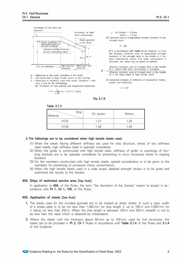
Pt 3 Hull StructuresCh 1 General Pt 3, Ch 1
Guidance Relating to the Rules for the Classification of Steel Ships 2022 9
Fig 3.1.9
Table 3.1.3
ShipMaterial Oil tanker Others
HT32 1.27 1.34
HT36 1.38 1.45
2.The followings are to be considered when high tensile steels used.(1) When the steels having different stiffness are used for ship structure, stress of low stiffness
steel nearby high stiffness steel is specially considered.(2) When the girder is constructed with high tensile steel, stiffness of girder or scantlings of trip-
ping brackets are to be specially considered for preventing to occur excessive stress to tripping brackets.
(3) For the members constructed with high tensile steels, special consideration is to be given to the members for preventing of excessive stress concentration.
(4) When the high tensile steels used in a wide scope, detailed strength review is to be given and submitted the results to the Society.
404. Ships of restricted service area 【See Rule】In application to 404. of the Rules, the term "the discretion of the Society" means to accept in ac-cordance with Pt 1, Ch 1, 105. of the Rules.
405. Application of steels 【See Rule】
1. The steels used for the rounded gunwale are to be treated as sheer strake. In such a case, width of a strake plate is to be not less than 1,300 mm for ship length up to 100 m and 2,600 mm for being not less than 250 m. When the ship length is between 100 m and 250 m, breadth is not to be less than the value which is obtained by interpolation.
2. Where the steels with the thickness above 50 mm up to 100 mm used for hull structures, the steels are to be provided in Pt 2, Ch 1 Rules in accordance with Table 3.1.4 of the Rules and 3.1.4 of the Guidance.

Pt 3 Hull StructuresCh 1 General Pt 3, Ch 1
10 Guidance Relating to the Rules for the Classification of Steel Ships 2022
Class
Thickness(mm)
I II III
MS HT MS HT MS HT
≤ D DH E EH E EH
≤ E EH E EH E EH
Note:The symbols in the table mean the grades of steel as follows:DH : DH 32, DH 36 and DH 40, MS : Mild steelsEH : EH 32, EH 36 and EH 40, HT : High tensile steels
Table 3.1.4 Steel grades (50 mm < t ≤ 100 mm)
406. Special requirements for application of steels (2019) 【See Rule】
1. The application of steels for ships designed to operate in area with low air temperatures is to com-ply with the following requirements: (2017)(1) For ships intended to operate in areas with low air temperatures (below -10°C), e.g. regular
service during winter seasons to Arctic or Antarctic waters, the materials in exposed structures are to be selected based on the design temperature , to be taken as defined in 2. Materials in the various strength members above the lowest ballast water line (BWL) exposed to air(in-cluding the structural members covered by the Note [5] of Table 3.1.6) and materials of cargo tank boundary plating for which 3. is applicable are not to be of lower grades than those corre-sponding to classes Ⅰ, Ⅱ and Ⅲ, as given in Table 3.1.6, depending on the categories of structural members(SECONDARY, PRIMARY and SPECIAL). For non-exposed structures(except as indicated in Note [5] of Table 3.1.6) and structures below the lowest ballast water line, see 405. of the Rules.

Pt 3 Hull StructuresCh 1 General Pt 3, Ch 1
Guidance Relating to the Rules for the Classification of Steel Ships 2022 11
Table 3.1.6 Application of material classes and grades - Structures exposed at low temperatures
Structural member categoryMaterial class
Within 0.4 amidships
Outside 0.4 amidships
○ SECONDARY:- Deck plating exposed to weather, in general- Side plating above BWL- Transverse bulkheads above BWL [5]- Cargo tank boundary plating exposed to cold cargo [6]
I I
○ PRIMARY:- Strength deck plating [1]- Continuous longitudinal members above strength deck,
excluding longitudinal hatch coamings- Longitudinal bulkhead above BWL [5]- Top wing tank bulkhead above BWL [5]
II I
○ SPECIAL:- Sheer strake at strength deck [2]- Stringer plate in strength deck [2]- Deck strake at longitudinal bulkhead [3]- Continuous longitudinal hatch coamings [4]
III II
Notes :[1] Plating at corners of large hatch openings to be specially considered. Class Ⅲ or
grade E, EH 32, EH 36 and EH 40 to be applied in positions where high local stresses may occur.
[2] Not to be less than grade E, EH 32, EH 36 and EH 40 within 0.4 amidships in ships with length exceeding 250 m
[3] In ships with a breadth exceeding 70 m at least three deck strakes to be class Ⅲ.[4] Not to be less than grade D, DH 32, DH 36 and DH 40.[5] Applicable to plating attached to hull envelope plating exposed to low air temperature.
At least one strake is to be considered in the same way as exposed plating and the strake width is to be at least 600mm.
[5] For cargo tank boundary plating exposed to cold cargo for ships other than liquefied as carriers, see 3.
(2) The material grade requirements for hull members of each class depending on thickness and design temperature are defined in Table 3.1.7. For design temperatures -55°C, materials are to be in accordance with the discretion of the Society.
(3) Single strakes required to be of class Ⅲ or of grade E, EH 32/EH 36/EH 40 and FH 32/FH36/FH 40 are to have breadths not less than the values given by the following formula, max-imum 1800 mm.
(mm)
(4) Plating materials for stern frames, rudder horns, rudders and shaft brackets are not to be of lower grades than those corresponding to the material classes given in 405. 3 of the Rules.
2. The design temperature is to be taken as the lowest mean daily average air temperature i the area of operation. For seasonally restricted service the lowest value within the period of operation applies.(see Fig 3.1.10)
∙ Mean: Statistical mean over observation period (at least 20 years) ∙ Average: Average during one day and night ∙ Lowest: Lowest during year ∙ MDHT = Mean Daily High (or maximum) Temperature ∙ MDAT = Mean Daily Average Temperature ∙ MDLT = Mean Daily Low (or minimum) Temperature

Pt 3 Hull StructuresCh 1 General Pt 3, Ch 1
12 Guidance Relating to the Rules for the Classification of Steel Ships 2022
For the purpose of issuing a Polar Ship Certificate in accordance with the Polar Code, the design temperature shall be no more than 13oC higher than the Polar Service Temperature (PST) of the ship. In the Polar Regions, the statistical mean over observation period is to be determined for a period of at least 10 years.
Table 3.1.7 Material grade requirements for classes I, II and III at low temperatures
classⅠ
Platethickness in
(mm)
-11/-15°C
-16/-25°C
-26/-35°C
-36/-45°C
-46/-55°C
MS HT MS HT MS HT MS HT MS HT
≤ A AH A AH B AH D DH D DH
≤ A AH B AH D DH D DH D DH
≤ A AH B AH D DH D DH E EH
≤ B AH D DH D DH D DH E EH
≤ B AH D DH D DH E EH E EH
≤ D DH D DH D DH E EH E EH
≤ D DH D DH E EH E EH - FH
≤ D DH E EH E EH - FH - FH
class Ⅱ
Platethickness in
(mm)
-11/-15°C
-16/-25°C
-26/-35°C
-36/-45°C
-46/-55°C
MS HT MS HT MS HT MS HT MS HT
≤ A AH B AH D DH D DH E EH
≤ B AH D DH D DH E EH E EH
≤ D DH D DH E EH E EH - FH
≤ D DH E EH E EH - FH - FH
≤ E EH E EH - FH - FH - -
≤ E EH E FH - FH - FH - -
class Ⅲ
Platethickness in
(mm)
-11/-15°C
-16/-25°C
-26/-35°C
-36/-45°C
-46/-55°C
MS HT MS HT MS HT MS HT MS HT
≤ B AH D DH D DH E EH E EH
≤ D DH D DH E EH E EH - FH
≤ D DH E EH E EH E FH - FH
≤ D DH E EH E EH - FH - FH
≤ E EH E EH - FH - FH - -
≤ E EH E FH - FH - FH - -
≤ E EH - FH - FH - - - -
Notes :The symbols in the table mean the grades of steel as follows :
AH : AH 32, AH 36 and AH 40 DH : DH 32, DH 36 and DH 40EH : EH 32, EH 36 and EH 40FH : FH 32, FH 36 and FH 40MS : Mild steelsHT : High tensile steels
Fig 3.1.10 Commonly used definitions of temperatures

Pt 3 Hull StructuresCh 1 General Pt 3, Ch 1
Guidance Relating to the Rules for the Classification of Steel Ships 2022 13
3. Cold cargo for ships other than liquefied gas carriersFor ships other than liquefied gas carriers, intended to be loaded with liquid cargo having a temper-ature below -10°C, e.g. loading from cold onshore storage tanks during winter conditions, the mate-rial grade of cargo tank boundary plating is defined in Table 3.1.7 base on the following:
- design minimum cargo temperature in °C
- steel grade corresponding to Class I as given in Table 3.1.6The design minimum cargo temperature, is to be specified in the loading manual.
Section 5 Welding
501. General1. Structural details 【See Rule】
When the ship having hatchs are fall under the following (1) to (4), detailed review of the fatigue strength for strength deck at hatch corner and end parts of hatch is to be completed and the cross section is not to be changed radically or scantlings of hatch side coaming are to be increased.(1) Ships with hatch in the mid part, where the breadth of the hatch exceeds 0.7 .(2) Ships having strength deck which is constructed with high tensile steels in accordance with 403.
of the Rules. (3) Ships with unusual high hatch coamings (4) Ships with strength deck constructed with special shape or hatch opening constructed with spe-
cial structure.2. Slot weld 【See Rule】
For the applying 501. 4 (2) of the Rules, the spacing of slots is to be in accordance with Pt 13, Sub Pt 1, Ch 12, Sec 3, 4.2.2 of the Rules.
Section 6 Scantlings
602. Section Modulus 【See Rule】 1. Scantlings of stiffeners based on requirements in this part may be decided based on the concept of
grouping designated sequentially placed stiffeners of equal scantlings. The scantling of the group is to be taken as the greater of the following (1) and (2). However, this concept of grouping is not applicable to fatigue requirements as given in 206.3.(a) the average of the required scantling of all stiffeners within a group(b) 90 % of the maximum scantling required for any one stiffener within the group.
Section 8 Corrosion Protection Coating (2018)801. Corrosion protection coating 【See Rule】
1. Corrosion protection coating for sea water ballast tanks and double-side skin spaces arranged in bulk carriers (2017)(1) Where ships engaging in international voyage and not less than 500 gross tonnage are relevant
to (A) or (B), all dedicated seawater ballast tanks and double-side skin spaces arranged in bulk carriers of 150 m in length and upward are to be in accordance with IMO Res. MSC. 215(82) PSPC(Performance Standard for Protective Coatings). However, tankers or bulk carrier whose keels are laid after 1 July 2008 and before the date specified in (A) are to be in accordance with IMO Res. 798(19).(A) for which the building contract is placed on or after 1 July 2008 (in the absence of a build-

Pt 3 Hull StructuresCh 1 General Pt 3, Ch 1
14 Guidance Relating to the Rules for the Classification of Steel Ships 2022
ing contract, the keels of which are laid or which are at a similar stage of construction on or after 1 January 2009); or
(B) the delivery of which is on or after 1 July 2012.(2) Maintenance of the protective coating system shall be included in the overall ship’s maintenance
scheme. The effectiveness of the protective coating system shall be verified during the life of a ship by the Administration or an organization recognized by the Administration, based on the guidelines developed by the IMO.(refer to MSC.1/Circ.1330)
2. Corrosion protection coating for COT of Crude Oil Tankers(1) Application target : Where Crude Oil Tanker not less than 5000 gross tonnage are relevant to (A)
or (B), all COTs are to be in accordance with IMO Res. MSC. 288(87) PSPC(Performance Standard for Protective Coatings). (A) for which the building contract is placed on or after 1 January 2013 (in the absence of a
building contract, the keels of which are laid or which are at a similar stage of construction on or after 1 July 2013); or
(B) the delivery of which is on or after 1 January 2016.(2) This requirement is not applied to following (A) and (B).
(A) Combination carriers specified in MARPOL Res. 73/78 Annex I, Reg.1. (excluding the combi-nation carriers cerified to carry crude oil only in cargo tanks)
(B) Chemical tankers specified in MARPOL Res. 73/78 Annex II, Reg.1. (including the tankers certified to carry cargo oil)
(C) Product carrier not carried crude oil.3. Nomal and higher strength corrosion resistant steel may be used as the alternative means of corro-
sion protection for cargo oil tanks as specified in 2. The performance standards are to be in accord-ance with IMO Res. MSC. 289(87) (Performance standards for alternative means of corrosion pro-tection for cargo oil tanks of crude oil tankers).
4. The Administration may exempt a crude oil tanker from the requirements of paragraph 2 if the ship is built to be engaged solely in the carriage of cargoes and cargo handling operations not causing corrosion.(Refer to MSC.1/Circ.1421 "Guidelines on exemptions for crude oil tanker solely engaged in the carriage of cargoes and cargo handling operations not causing corrosion")

Pt 3 Hull StructuresCh 2 Stems and Stern Frames Pt 3, Ch 2
Guidance Relating to the Rules for the Classification of Steel Ships 2022 15
CHAPTER 2 STEMS AND STERN FRAMES
Section 1 Stems
101. Plate stems 【See Rule】
1. The thickness of plate stems may be same as that of side shell plating at the level of freeboard deck and same as that of forecastle-side shell in the range of forecastle.
2. Where the plate stem with a large radius of curvature at its fore end is not fitted with a centreline stiffener or is not reinforced by using thicker plate than that in accordance with 101. 1 of the Rules, horizontal breast-hooks are to be provided at a space not exceeding 600 mm apart for reinforcement.
Section 2 Stern Frames
202. General 【See Rule】
1. Welding of cast steel stern frames(1) When cast steel stern frames is constructed with dividing 2 or 3 pieces, shape of weld is based
on Fig 3.2.1.(2) Connection of cast steel stern frame and shell plating is in accordance with Fig 3.2.2. However,
if the welding procedure is approved, it may be in accordance with that procedure.
Fig 3.2.1 Welding of cast steel stern frames Fig 3.2.2 Connection with shell plating and cast steel stern frames
203. Propeller post 【See Rule】
1. Connection of cast steel boss and plate parts of built up stern frame
The connection of cast steel boss and built-up stern frame is to be well grooved and welded with full penetrations at the root as shown in Fig 3.2.3.
2. Length of shaft hole of propeller boss
The length of shaft hole of the propeller boss is to be greater than 1.25 times the inside diameter of the boss hole.

Pt 3 Hull StructuresCh 2 Stems and Stern Frames Pt 3, Ch 2
16 Guidance Relating to the Rules for the Classification of Steel Ships 2022
3. Round bars used for built-up stern frame
In case that a round bar is used as the aft edge of a built-up stern frame, its radius is, as a standard, to be more than 70 % of prescribed in Table 3.2.1 of the Rules. At the connection of round bar to cast steel part or at the connection of round bars, the depth of bevel for welding is to be at least 1/3 of the diameter of round bar. The thickness of ribs fitted to the stern frame is, as a standard, to be 75 % of the stern frame plate. (See Fig 3.2.4)
Fig 3.2.3 Connection with steel and propeller boss Fig 3.2.4
205. Shoe Piece 【See Rule】
1. Connection of shoe pieces and propeller postsThe top plate of shoe piece is to be extended forward beyond the aft end of propeller post. A bracket of the same thickness as the stem frame is to be fitted at the connection of the shoe piece and the aft end of propeller post to keep a sufficient continuity of strength. (See Fig 3.2.4)
2. Steel bolts for fixing zinc slabs to the shoe piece must not be directly screwed into the shoe piece but they are to be directly welded to the shoe piece or screwed into steel plates welded to the shoe piece.
3. Shoe pieces of built-up construction are to be made watertight and the inside coated with effective coating material. Where no coating is applied to the inside of built-up shoe piece, the thickness of the shoe piece is to be increased by 1.5 mm.
206. Heel Piece 【See Rule】
1. Determination of length of heel pieces(1) In built-up stern frames, the length of heel pieces may be equal to twice the frame spacing at
the position of heel pieces providing that the thickness of flat keels connected to the heel pieces is increased by about 5 mm.
(2) The length of heel piece is to be measured as shown in Fig 3.2.5.
Fig 3.2.5 Measurements of
(3) The thickness of ribs fitted to the heel piece is, as a standard, to be 75% of the ribs.

Pt 3 Hull StructuresCh 2 Stems and Stern Frames Pt 3, Ch 2
Guidance Relating to the Rules for the Classification of Steel Ships 2022 17
207. Rudder horn 【See Rule】
1. When the connection between the rudder horn and the hull structure is designed as a curved tran-sition into the hull plating, special consideration should be given to the effectiveness of the rudder horn plate in bending and to the stresses in the transverse web plates.
2. The bending moments and shear forces are to be determined by a direct calculation or in line with the guidelines given in Pt 4, Ch 1, 401. 6 and 7 of the Guidance.
3. The thickness of the rudder horn side plating is not to be less than:
(mm)
where : = Rule length as defined in Pt 3, Ch 1, 102. of the Rules.(m) = material factor as given in Pt 3, Ch 1, 403. 2 or Pt 4, Ch 1, 103. of the Rules
respectively.
4. Welding and connection to hull structure (1) The rudder horn plating is to be effectively connected to the aft ship structure, e.g. by connect-
ing the plating to side shell and transverse/ longitudinal girders, in order to achieve a proper transmission of forces.Brackets or stringer are to be fitted internally in horn, in line with outside shell plate. (See Fig 3.2.6)
Fig 3.2.6 Connection of rudder horn to aft ship structure
(2) Transverse webs of the rudder horn are to be led into the hull up to the next deck in a suffi-cient number.
(3) Strengthened plate floors are to be fitted in line with the transverse webs in order to achieve a sufficient connection with the hull.
(4) The centre line bulkhead (wash-bulkhead) in the after peak is to be connected to the rudder horn.
(5) Scallops are to be avoided in way of the connection between transverse webs and shell plating.(6) The weld at the connection between the rudder horn plating and the side shell is to be full
penetration. The welding radius is to be as large as practicable and may be obtained by grinding.
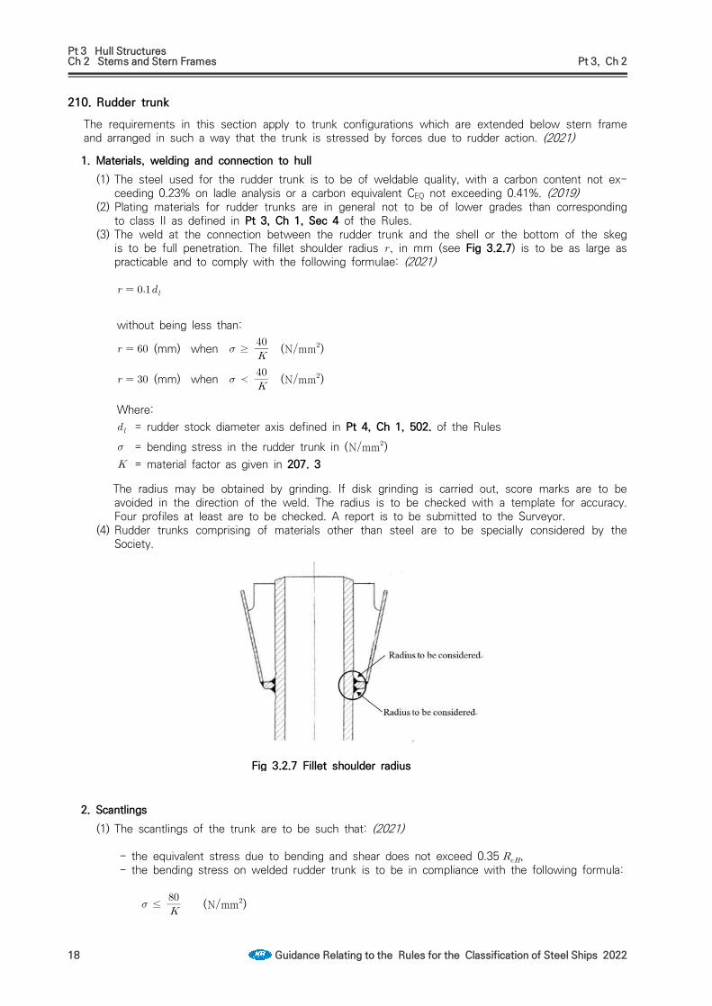
Pt 3 Hull StructuresCh 2 Stems and Stern Frames Pt 3, Ch 2
18 Guidance Relating to the Rules for the Classification of Steel Ships 2022
210. Rudder trunk The requirements in this section apply to trunk configurations which are extended below stern frame and arranged in such a way that the trunk is stressed by forces due to rudder action. (2021)
1. Materials, welding and connection to hull(1) The steel used for the rudder trunk is to be of weldable quality, with a carbon content not ex-
ceeding 0.23% on ladle analysis or a carbon equivalent CEQ not exceeding 0.41%. (2019)(2) Plating materials for rudder trunks are in general not to be of lower grades than corresponding
to class II as defined in Pt 3, Ch 1, Sec 4 of the Rules.(3) The weld at the connection between the rudder trunk and the shell or the bottom of the skeg
is to be full penetration. The fillet shoulder radius , in mm (see Fig 3.2.7) is to be as large as practicable and to comply with the following formulae: (2021)
without being less than:
(mm) when ≥ (Nmm)
(mm) when ≺ (Nmm)
Where: = rudder stock diameter axis defined in Pt 4, Ch 1, 502. of the Rules = bending stress in the rudder trunk in (Nmm) = material factor as given in 207. 3
The radius may be obtained by grinding. If disk grinding is carried out, score marks are to be avoided in the direction of the weld. The radius is to be checked with a template for accuracy. Four profiles at least are to be checked. A report is to be submitted to the Surveyor.
(4) Rudder trunks comprising of materials other than steel are to be specially considered by the Society.
Fig 3.2.7 Fillet shoulder radius
2. Scantlings (1) The scantlings of the trunk are to be such that: (2021)
- the equivalent stress due to bending and shear does not exceed 0.35 , - the bending stress on welded rudder trunk is to be in compliance with the following formula:
≤ (Nmm)

Pt 3 Hull StructuresCh 2 Stems and Stern Frames Pt 3, Ch 2
Guidance Relating to the Rules for the Classification of Steel Ships 2022 19
With: = bending stress in the rudder trunk, as defined in 1 (4) = material factor for the rudder trunk as given in 207. 3, not to be taken less than 0.7 = specified minimum yield stress of the material used (Nmm)
(2) For calculation of bending stress, the span to be considered is the distance between the mid-height of the lower rudder stock bearing and the point where the trunk is clamped into the shell or the bottom of the skeg.
211. Propeller shaft brackets (2011)1. General
(1) The following requirements are applicable to propeller shaft brackets having two struts to support the propeller tail shaft boss. The struts may be of solid or welded type.
(2) The angle between the struts shall not be less than 50 degrees.2. Arrangement
(1) Solid struts shall be carried continuously through the shell plating and shall be given satisfactory support by the internal ship structure.
(2) Welded struts may be welded to the shell plating. The shell plating shall be reinforced, and in-ternal brackets in line with strut plating shall be fitted. If the struts are built with a longitudinal centre plate, this plate shall be carried continuously through the shell plating. The struts shall be well rounded at fore and aft end at the transition to the hull.
(3) The propeller shaft boss shall have well rounded fore and aft brackets at the connection to the struts.
3. Struts(1) Solid or welded struts of propeller shaft brackets shall comply with the following requirements:
≥
≥
≥
where: = gross area of strut section in mm2
= gross section modulus of section in mm3. shall be calculated with reference to the neutral axis as indicated on Fig 3.2.8
= the greatest thickness of the section in mm = propeller shaft diameter in mm.
max
= actual propeller shaft diameter in mm= diameter (mm) of propeller shaft specified in Pt 5, Ch 3, 204. = Specified minimum tensile strength (N/mm2). For the tensile strength exceeding
600N/mm2, is to be taken as 600 N/mm2.
Fig. 3.2.8 Detail of Propeller shaft brackets

Pt 3 Hull StructuresCh 3 Longitudinal Strength Pt 3, Ch 3
Guidance Relating to the Rules for the Classification of Steel Ships 2022 21
CHAPTER 3 LONGITUDINAL STRENGTH
Section 1 General
101. Application 【See Rule】
1. Transverse section modulus of ships with unusual proportion
For the ships with ≤5 or ≥2.5, all strength excepting longitudinal strength is to be ad-equately considered.
2. Ships with especially large hatchesFor ships breadth of whose hatches exceeds 0.7 in midship part, according to the requirements in Pt 7, Ch 4, Sec 2, bending and torsional strength is to be specially considered.
3. Ships with large flare and high speed shipsAccording to the value of and obtained from the following (1) and (2), wave induced longi-tudinal bending moment is to be increased.
,
where = projected area onto a horizontal plane of exposed deck from the fore end extending to 0.2L
aft of fore end including the part forward of fore end (m2), Where a forecastle is provided, the horizontal project area of the forecastle is overlapped to the fore mentioned area.
= water plane area corresponding to designed maximum load line within the forward 0.2 (m2) = vertical distance from designed maximum load line to exposed deck at the side of fore end (m)
(1) In case that exceeds 0.28 specified in Fig 3.3.2 of the Rules is to be replace with the value given in Table 3.3.1 in ac-cordance with and (m) which is the distance from aft end of to the position of consid-ered hull transverse section. Where the and/or become intermediate, the value is to be determined by interpolation.
(2) In case that () exceeds 0.4 specified in Fig 3.3.2 of the Rules is to be replaced with the value given in Table 3.3.2. for the under (-) condition. However, where the () and/or become intermediate, the value is to be determined by interpolation.
Table 3.3.1 Coefficient of
0.65 0.75 1.0
0.28 1.0 5/7 0.0
0.32 over 1.0 0.80 0.0
Table 3.3.2 Coefficient of
0.65 0.75 1.0
0.4 1.0 5/7 0.0
0.5 over 1.0 0.80 0.0
103. Loading manual 【See Rule】
1. "a ships may not be provided with a loading manual where deemed unnecessary by the Society" in 103. 1 of the Rules means fishing vessels or the ships with length less than 90 m () in which the deadweight does not exceed 30 % of the displacement at the summer loadline draft and with arrangement giving small possibilities for variation in the distribution of cargo and ballast, and ships on regular and fixed trading pattern. However, ships such as fishery training, fishery patrol, fishery research and so on are to comply with the requirements of flag state. (2017)

Pt 3 Hull StructuresCh 3 Longitudinal Strength Pt 3, Ch 3
22 Guidance Relating to the Rules for the Classification of Steel Ships 2022
2. The loading manual to be approved by the Society according to 103. of the Rules, are to be pre-pared in accordance with Annex 3-1 "Guidance for Preparation and Survey of Loading Manual". They are to be written with a language easily understood by the shipmaster and if it is not English, English version is to be attached.
3. In addition, Bulk carriers of 150 m in length and above in , where one or more cargo holds are bounded by the side shell only, which were contracted for construction before 1st July 1998 are to be provided with an approved loading manual with Guidance for typical loading/unloading sequences where the vessel is loaded from commencement of cargo loading to reaching full deadweight capacity, for homogeneous conditions, alternate conditions and relevant part load conditions where applicable. (see Table 4 of Annex 3-1) The followings are to be included in the guidance.(1) The minimum acceptable number of typical sequences is ;
(A) one homogeneous full load condition(B) one full load alternate hold condition, if the ship is approved for alternate hold loading.(C) one part load condition where relevant, such as block loading or two port unloading.
(2) The shipowner/operator should select actual loading/unloading sequences, where possible, which may be port specific or typical.
(3) The results of the calculations of bending moments, shear force for each step from initial loading to full loading
(4) For each load condition in above mentioned in (1), the summary for all steps is to include the followings.(A) How much cargo is filled in each hold during the different steps.(B) How much ballast is discharged from each ballast tank during the different steps.(C) The maximum still water bending moment and shear at the end of each step(D) The ship's trim and draught at the end of each step
(5) Approved guidance for loading /unloading is to be attached to loading manual or to be placed on board ship in annex of the manual.
(6) The form of guidance for loading/unloading is referred to Table 4 in Annex 3-1.4. Application for providing of loading manual is to be in accordance with Table 3.3.3.
104. Longitudinal strength loading instruments 【See Rule】
1. "a ships may not be provided with a loading manual where deemed unnecessary by the Society" in 104. 1 of the Rules means fishing vessels or the ships with arrangement giving small possibilities for variation in the distribution of cargo and ballast, and ships on regular and fixed trading pattern and with suitable Guidance are included in loading manual However, ships such as fishery training, fishery patrol, fishery research and so on are to comply with the requirements of flag state. (2017)
2. Bulk carriers, ore carriers and combination carriers of 150 m in length and above, which are con-tracted for construction before 1st July 1998 are to be provided with an approved loading instru-ments for longitudinal strength with satisfaction of the requirements of this Society.
3. Application for providing of loading instruments for longitudinal strength is to be in accordance with Table 3.3.3.
4. The followings are to be included in loading instruments for longitudinal strength for bulk carriers, ore carriers and combination carriers of 150 m in length and above, which are contracted for con-struction on or after 1st July 1998.(1) the mass of cargo and double bottom contents in way of each hold as a function of the draught
at mid-hold position.(2) the mass of cargo and double bottom contents of any two adjacent holds as a function of the
draught at mid-part of these holds.(3) the still water bending moment and shear forces in the hold flooded conditions in accordance
with Pt 7, Ch 3, Sec 10 of the Rules.5. “Approval by the Society" in 104. 2 of the Rules means each of the followings.
(1) It is recommended that software for longitudinal strength loading instrument is taken design approval. Regardless of the design approval to be of the software for longitudinal strength load-ing instrument, test result of typical service condition is to be submitted to the Society for ap-proval and the software installed on board ship is to be approved by Society in accordance with

Pt 3 Hull StructuresCh 3 Longitudinal Strength Pt 3, Ch 3
Guidance Relating to the Rules for the Classification of Steel Ships 2022 23
test result.(2) Where type approved hardware is installed, one instrument may install, and otherwise two in-
struments are to be installed.
Table 3.3.3 For the case of ships, loading manual and longitudinal loading instruments are to be installed (2018)
Kind of ship
Application
Category 1-1 Category 1-2 Category 1-3 Category 2
Loading Manual
Longitudinal loading
instruments
Loading Manual
Longitudinal loading
instruments
Loading Manual
Longitudinal loading
instruments
Loading Manual
Longitudinal loading
instruments
①
Ships under survey during
(after) construction
before 1992/11/1
≥100 m NA ≥100 m NA(C) Lf≥100 m NA NA NA
②
Ships under survey during
(after) construction
after 1992/11/1
≥100 m NA ≥100 m NA(C) ≥65 m (D) NA NA NA
③
Ships under survey during
(after) construction
after 1993/5/1
≥100 m ≥100 m ≥100 m Lf≥120 m ≥65 m (D) ≥65 m (D) NA NA
④
Ships contracted for construction
after 1998/7/1
≥65 m ≥100 m ≥65 m ≥100 m (A) ≥65 m ≥100 m ≥65 m
(B) NA
1. All ships engaged in under the coastal services may not be installed the loading manual and longitudinal loading instruments.
2. Kind of ships(1) Category 1-1 = For ships having large opening on the deck and are to be considered for combined
stress of bending moment and torsional moment(2) Category 1-2 = For ships having non-homogeneous cargo and ballast loading(3) Category 1-3 = Chemical tankers and Ships carrying liquified gases in bulk.(4) Category 2 = For ships having homogeneous cargo and ballast loading in usual as followings
(A) ships having no loadline mark(B) ships not carrying out cargoes(C) cargo vehicle carrier(D) ships having homogeneous cargo loading
3. For the application ① to ⑤, they means application date for the ships under the survey of during con-struction and construction date for the ships under the survey after construction.
4. (A) : For the ships having not exceeding 120 m in length and reflected in design for non-homogeneous cargo loading, it is specified in category 2 and longitudinal loading instrument may be not installed.
5. (B) : For the ships in category 2 with not exceeding 90 m in length and dead weight is not exceed 30 % of fully loaded displacement, longitudinal loading instrument may be not installed.
6. (C) : For all bulk carriers, ore carriers and combination carriers, longitudinal loading instrument is to be in-stalled until 1 Jan 1999.
7. (D) : The ships less than 100 m in length may not be provided with a loading manual where deemed un-necessary by the Society.
8. For the ships exempted the installation of longitudinal loading instrument may be not installed, when the instruments is installed, they are to be complied with related regulations.

Pt 3 Hull StructuresCh 3 Longitudinal Strength Pt 3, Ch 3
24 Guidance Relating to the Rules for the Classification of Steel Ships 2022
Section 2 Bending Strength
201. Bending strength at amidships 【See Rule】
1. The calculation of Longitudinal bending moment in still water is to be as follows.(1) When performing the calculation of longitudinal bending moment in still water () specified in
Table 3.3.1 of the Rules, the method of calculation used is, upon submission of necessary docu-ments, to be approved before hand by the Society.
(2) For ships desired to be built under the survey of the Society's Surveyors, calculation sheets for longitudinal strength in still water corresponding to the actual loading plans and the set of data necessary for the calculation are to be submitted to the Society.
(3) In the Classification Survey longitudinal strength calculations in still water are to be performed at the time of completion of the ship on each type of operating condition, and the necessary sets of data and the results of these calculations are to be included in the loading manual specified in 301. of the Rules.
202. Bending strength at sections other than amidship 【See Rule】For those ships categorized in the following (1) or (2), the coefficient in the formula for , specified in Table 3.3.1 of the Rules is obtained from the value in accordance with the dotted line in Fig 3.3.2 of the Rules and the same provision is to be applied.(1) Ships with of less than 0.7(2) Ships whose longitudinal bending moments in still water at the parts other than the midship part
are equal to or greater than the value at the midship part
203. Calculation of hull section modulus 【See Rule】
1. Unit of hull section modulusThe section modulus (cm3)is to have five significant figures.
2. Members included in longitudinal strengthThe ratio of inclusion of members effective for longitudinal strength is to be as follows.(1) Intercostal plates may be included in 100% if the fillet welding complies with Ch 1, Notes 1 in
Table 3.1.7 of the Rules.(2) For new building ship, the Area of doubling plate may be included 1007. in the rate of inclusion
of member and for the ship fitted during conversion or addition, it may be included 90 %.(3) For side stringers, slots for frames are to be deducted.(4) Scallops complying with the following conditions need not be deducted from the sectional area.
(See Fig 3.3.1)(A) not exceeding 4 nor exceeding 7, but maximum 75 mm(B) more than 5 and more than 10
Fig 3.3.1 and of scallops
(5) Lightening holes and draining holes in longitudinals or longitudinal girders need not be deducted from the sectional area provided that the height of the holes does not exceed 25 % of the web depth.
(6) As for the longitudinal continuous decks between hatch ways of ships having 2 or 3 rows of cargo hatches, the ratio of sectional area to be included in the calculation of section modulus of hull girder is to be obtained from Table 3.3.4.

Pt 3 Hull StructuresCh 3 Longitudinal Strength Pt 3, Ch 3
Guidance Relating to the Rules for the Classification of Steel Ships 2022 25
(7) Where sectional area of longitudinals, which are unable to be continued due to the arrangement of small hatch openings, etc., are compensated by adjacent ones, they may be included in the calculation of section modulus of hull girders.
Table 3.3.4 Ratio of inclusion of sectional area
No of holds
2 3 and over
0.10 0.20 0.30 0.10 0.15 0.20
0.0 0.96 0.85 0.70 0.96 0.91 0.85
0.5 0.65 0.57 0.48 0.89 0.80 0.69
1.0 0.48 0.43 0.36 0.83 0.73 0.62
2.0 0.32 0.29 0.25 0.73 0.63 0.53
3.0 0.24 0.22 0.18 0.65 0.57 0.47
4.0 0.19 0.17 0.14 0.59 0.51 0.43
5.0 0.16 0.14 0.12 0.53 0.47 0.39
NOTE:1. is to be in accordance with followings
×
= moment of inertia of deck between hatches, including hatch coaming(cm4) = effective shear area of deck between hatches (cm2) = sectional area of continuous deck between hatches(one side) (cm2) = length of hatch (m) and = as specified in Fig 3.3.2 (m)2. or may obtained from the interpolation.3. When the value of is over 5.0, it may be obtained extrapolation.
(8) The car deck platings of Pure Car Carriers, in case they are intermittently welded in lap joint, are not to be included in the calculation.
3. Openings in strength deck
Openings in strength decks outside the line of hatch openings are to be treated as mentioned below.(1) Where the shape and dimensions do not meet the conditions in Table 3.3.5 reinforcement by
menas of rings, thicker plates, etc. is required (See Fig 3.3.3 and 3.3.4)(2) Where the intervals between centres of holes do not meet the conditions in Fig 3.3.5 reinforce-
ment as per (1) above is needed.
Table 3.3.5 Opening
Elliptic hole Circular hole
Oil tanker
≤
≤ (max. 900 mm) ≤ (max. 450 mm)
Cargo ships
≤
≤ (max. 450 mm) ≤ (max. 200 mm)

Pt 3 Hull StructuresCh 3 Longitudinal Strength Pt 3, Ch 3
26 Guidance Relating to the Rules for the Classification of Steel Ships 2022
Fig 3.3.2 and
Fig 3.3.3 Where elliptical hole and circular hole are in same cross-section Fig 3.3.4 Reinforcements by ring
Fig 3.3.5 Spacing of opening

Pt 3 Hull StructuresCh 3 Longitudinal Strength Pt 3, Ch 3
Guidance Relating to the Rules for the Classification of Steel Ships 2022 27
Section 3 Shear Strength
301. Thickness of side shell of ships without the effective longitudinal bulkhead 【See Rule】
1. Ships with bilge hopper tanks or top side tanks
Where the sloping plates of the bilge hopper tank and topside tank are joined to the side shell plating and are considered to be effective to carry a part of the shearing force, the shear current at the transverse section of the hull under consideration may be calculated directly and the thickness of the side shell plating forming a part of the bilge hopper tank and topside tank may be determined. However, when performing this direct strength calculation and determining the thickness of plating, shearing force given in (1) is made to act on the transverse section of the hull, and shearing stresses which develop in the side shell plating forming a part of the bilge hopper tank and topside tank and in the sloping plates are obtained, and these values are to be less than the allowable stress given in (2).(1) The value of shearing force acting on the transverse section of hull is obtained from the follow-
ing formula, whichever is greater.
(kN), (kN)
where, and = still water shear force and wave induced shear force specified in 301.1 = as specified in the following 2.
(2) Allowable stress of sloping plate and side shell plate inside of bilge hopper tanks or topside tanks
90 (N/mm2)
2. Modification of shearing force in still water in case where cargo is loaded in every other hold
Where a loaded hold (or a ballast hold) adjoins an empty hold by a transverse bulkhead, the shear-ing force in still water at the transverse section of hull under consideration may be determined as following .
(kN)
= still water shear force specified in Table 3.3.2 (kN) = the value obtained from the following formula by the distance form the transverse sec-
tion and fore/aft end of hold(1) At the bulkhead aft of hold
(2) At the bulkhead fore of hold
(3) At a section in the holdThe value obtained by applying the linear interpolation of the values of (1) and (2) depending on the distance between the transverse section under consideration and the bulkhead aft or fore of the hold which contains the transverse section.
, = shearing force in still water() at the bulkhead aft and fore of the hold, re-spectively, in the loading condition concerned, applying the calculation method as specified in 301. of the Rules(kN).

Pt 3 Hull StructuresCh 3 Longitudinal Strength Pt 3, Ch 3
28 Guidance Relating to the Rules for the Classification of Steel Ships 2022
= mass of ballast in the topside tank which is contained in the hold concerned (kN) = Coefficient which depends on the values of as specified in Pt 7, Ch 3, Sec 201, 4
of the Rules and as given in the Table 3.3.6. For intermediate value of linear interpolation is to be applied.
Table 3.3.6 Coefficient
0.4 0.6 0.8 1.0 1.2 1.4 1.6 1.8 2.0 2.2 2.4 over
0.4 under 0.6 0.8 1.0 1.2 1.4 1.6 1.8 2.0 2.2 2.4
10.0 0.092 0.115 0.159 0.197 0.230 0.255 0.275 0.289 0.300 0.308 0.314 0.317
5.0 0.088 0.110 0.152 0.190 0.223 0.250 0.270 0.286 0.298 0.307 0.313 0.315
2.0 0.081 0.101 0.140 0.177 0.210 0.238 0.261 0.279 0.293 0.302 0.310 0.312
1.0 0.075 0.094 0.131 0.166 0.200 0.230 0.254 0.273 0.288 0.300 0.307 0.310
0.0 0.063 0.079 0.112 0.145 0.179 0.211 0.238 0.261 0.279 0.291 0.302 0.306
3. Simplified formula for
The ratio of and specified in 301. of the Rules may be simplified to .
302. Thickness of side shell and longitudinal bulkhead plating of ships having one to four rows of longitudinal bulkheads 【See Rule】For double hull ships with bilge hopper tanks, and specified in Table 3.3.2 of the Rules is in accordance with Table 3.3.7 of the Guidance. However, the thickness of the side shell plating and slant plates forming bilge hoppers is not to be less than 1.2 times the values determined by the requirements of the Rules.
Table 3.3.6 Measurements of and

Pt 3 Hull StructuresCh 3 Longitudinal Strength Pt 3, Ch 3
Guidance Relating to the Rules for the Classification of Steel Ships 2022 29
Table 3.3.7 and of the ships having bilge hopper tanks
Type Application
C
Side shell
Longitudinal bulkhead
Bilge hopper slant plate
Others
D
Side Shell
Outer longitudinal bulkhead
Bilge hopper slant plate
Others
Centre longitudinal bulk 2
E
Side Shell
Outer longitudinal bulkhead
Bilge hopper slant plate
Others
Inner longitudinal bulkhead 1
, , and : as specified in Fig 3.3.6, , , , , , , , and : as specified in Table 3.3.2 of the Rules
Section 4 Buckling Strength
401. Apllication 【See Rule】Carlings (100×10 FB as standard type) are to be fitted in the longitudinal direction at the carling spaces which satisfy the following formula, on the part of midships, of strength deck plating of transverse framing system, and/or of side shell plating of transverse framing system connecting with strength deck and bottom both having same system as side shell plating. Where, however, an ap-proval by the Society is obtained, the following requirements may not be applied.
≧
= thickness of deck or shell plating (mm) = spacing of carling (m) = spacing of transverse beams (m) = as given by the followings:

Pt 3 Hull StructuresCh 3 Longitudinal Strength Pt 3, Ch 3
30 Guidance Relating to the Rules for the Classification of Steel Ships 2022
ZD
MSminMW× (N/mm2) for strength deck
max× (N/mm2) for bottom shell
min and max = min. and max. values respectively, of longitudinal bending moment in still water as required in 201. of the Rules
and = as specified in 201. of the Rules and = actual section moduli of transverse section of hull whose values are
determined against the strength deck and ship bottom according to the requirements in 203. of the Rules
: 1.0 for strength deck plating and bottom shell plating, and the value given by the following for side shell plating:
= for members located above the neutral axis of athwartship considered
= for members located below the neutral axis of athwartship considered
= vertical distance from neutral axis to deck (m) = vertical distance from base line to neutral axis (m) = vertical distance from neutral axis to upper edge of each strake (m), but need not be
greater than = vertical distance from neutral axis to lower edge of each strake (m), but need not be
greater than
Fig 3.3.7
403. Elastic buckling stress 【See Rule】
1. When examining the buckling strength of plate with an opening, the elastic buckling stress ′ or ′ obtained from following formulae is to be used in place of or for determination of critical buckling stress in 404. of the Rules:
′ (N/mm2)′ (N/mm2)

Pt 3 Hull StructuresCh 3 Longitudinal Strength Pt 3, Ch 3
Guidance Relating to the Rules for the Classification of Steel Ships 2022 31
= reduction factor due to the opening, given by the following. When the opening is reinforced properly, it may be taken as 1.0:
= span of the major axis of the opening = span of the side of the panel along the major axis of the opening
S
2. Elastic buckling stress for longitudinal frames is to be obtained from the following formulae(1) Buckling of pillars without torsion
Elastic buckling stress of pillar (N/mm2) for pillar buckling mode is to be obtained from the following formula.
(N/mm2)
and = second moment of inertia (cm4) and sectional area (cm2) of longitudinal frame including plate flange. The breadth of flange is in accordance with Ch 1, Sec 602 of the Rules.
= length of longitudinal frame (m)(2) Buckling of pillars with torsion
Elastic buckling stress of pillar (N/mm2) for torsional buckling mode is to be obtained from the following formula.
(N/mm2)
= coefficient, it is to be obtained from the following formula.
×
= the number of half-waves of buckling mode is to be in accordance with the value of in Table 3.3.8.
= St. Venant moment of inertia for the section (cm4), as specified in Table 3.3.9. However, flange of plate is not considered.
= polar moment of inertia of connection point with plate, as specified in Table 3.3.9. However, flange of plate is not considered.
= sectorial moment of inertia for the section of connection point with plate (cm6), as specified in Table 3.3.9.
= the length of tripping brackets (m)
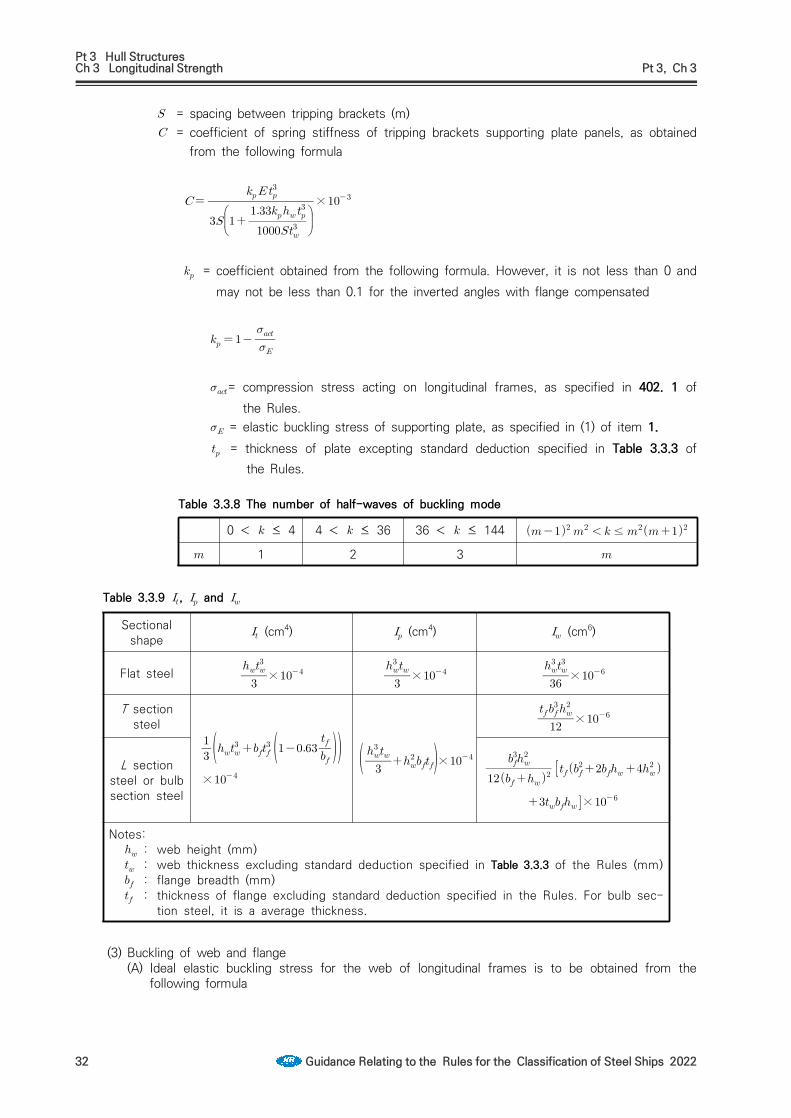
Pt 3 Hull StructuresCh 3 Longitudinal Strength Pt 3, Ch 3
32 Guidance Relating to the Rules for the Classification of Steel Ships 2022
= spacing between tripping brackets (m) = coefficient of spring stiffness of tripping brackets supporting plate panels, as obtained
from the following formula
×
= coefficient obtained from the following formula. However, it is not less than 0 and may not be less than 0.1 for the inverted angles with flange compensated
= compression stress acting on longitudinal frames, as specified in 402. 1 of the Rules.
= elastic buckling stress of supporting plate, as specified in (1) of item 1. = thickness of plate excepting standard deduction specified in Table 3.3.3 of
the Rules.
Table 3.3.8 The number of half-waves of buckling mode
0 < ≤ 4 4 < ≤ 36 36 < ≤ 144 ≤
1 2 3
Table 3.3.9 , and
Sectional shape
(cm4) (cm4) (cm6)
Flat steel
×
×
×
T section steel
×
×
×
L section steel or bulb section steel
×
Notes: : web height (mm) : web thickness excluding standard deduction specified in Table 3.3.3 of the Rules (mm) : flange breadth (mm) : thickness of flange excluding standard deduction specified in the Rules. For bulb sec-
tion steel, it is a average thickness.
(3) Buckling of web and flange(A) Ideal elastic buckling stress for the web of longitudinal frames is to be obtained from the
following formula

Pt 3 Hull StructuresCh 3 Longitudinal Strength Pt 3, Ch 3
Guidance Relating to the Rules for the Classification of Steel Ships 2022 33
(N/mm2)
(B) The ratio of breadth of flange to longitudinal frames and as built thickness of flange is not more than 15. However, is the half-breadth for T type section and breadth of L type section flange. (2018)

Pt 3 Hull StructuresCh 4 Plate Keels and Shell Platings Pt 3, Ch 4
Guidance Relating to the Rules for the Classification of Steel Ships 2022 35
CHAPTER 4 PLATE KEELS AND SHELL PLATINGS
Section 1 General
102. Special consideration for contact with the fishing gear, etc. 【See Rule】In cases where the service condition of the ship is considered to be such that there is possibility of indent of shell plating due to contact with the fishing gear etc., special consideration is to be given to the thickness of shell plating. However, the Rules and Guidance 102. may not apply where the shell is protected by suitable accessories such as fenders.
103. Consideration for ship with unusually large freeboard 【See Rule】 Where the distance from the designed maximum load line to strength deck is usually large, the thickness of side shell plating of superstructures and in the range between the imaginary freeboard deck specified in Ch 1, Sec 203, 2 (1) of the Guidance and the strength deck (hereinafter referred to as "super structure side plating") is obtained from the followings. However, where this require-ment is applied, the requirements in Sec 301. of the Rules do not need to be applied to shell plate above the freeboard deck.(1) The thickness of superstructure side shell plating from the freeboard deck (or imaginary free-
board deck in ships where the imaginary deck is regarded as the freeboard deck) to the level at a height of 2hs above the freeboard deck is to be obtained from the formulas in 302. of the Rules, where ′ may be replaced by ′ . In this formula, hs is decided by the L and is to be obtained from the followings,
= 90 m ----------- 1.95≥125 m ----------- 2.30
(2) The thickness of superstructure side plating from the level at a height equal to twice as per (1) above the freeboard deck to the strength deck is not to be less than that obtained from the following formula, but need not be greater than that obtained from (1).
(mm)
(3) The thickness of superstructure side plating from the freeboard deck to the level at a height as per (1) above the freeboard deck forward from 0.25 aft from the F.P. is not to be less than obtained from (1) above or 501. of the Rules. whichever is greater.
Section 3 Shell Plating below Strength Deck
301. Minimum thickness 【See Rule】The thickness of shell plating of membrane tank LNG ships is not to be less than that obtained from the following formula:
(mm)
303. Sheer strakes for midship part 【See Rule】Attentions to be paid as to sheer strakes(1) The upper edges of sheer strakes are to be properly smoothed.(2) Bulwarks are not to be directly welded to sheer strakes in the range of 0.6 amidships. Further,
fixtures, such as eye plates, are not to be directly welded on the upper edge of sheer strake, except in the fore and aft end parts.
(3) Special care should be taken where fixtures, gutter bar ends, etc. are directly welded to the curved parts of round gunwales.

Pt 3 Hull StructuresCh 4 Plate Keels and Shell Platings Pt 3, Ch 4
36 Guidance Relating to the Rules for the Classification of Steel Ships 2022
(4) At least for 0.6 amidship the manner of the welding construction of T type joints between sheer strakes and stringer plates of strength deck is, in general, to be as shown in Fig 3.4.1 as a standard. However, where the thickness of stringer plates is less than 13 mm, fillet weld of F1 grade may be acceptable without edge preparation.
Fig 3.4.1 Welding construction of joints between sheer strakes and stringer plates of strenth deck
305. Bilge plate 【See Rule】
1. Where, in the midship part, longitudinal frames are omitted in the bilge part, the distance from the end of bilge curvature to the nearest longitudinal frame outside the curved part is not to exceed 1/2 of the spacing of longitudinal frames.
2. In determining the thickness of bilge strake in the midship part according to the formula in 305. 1 of the Rules, the following condition is to be met.
≥
where = radius of bilge circle (m) = spacing of solid floor, bottom transverse or bilge brackets (m) = thickness of bilge strake (mm)
3. The bilge strake in the midship part are to be carefully worked so that deformations of the bilge circle may not exceed 1/3 of thickness of bilge strake amidships.
4. Where bilge keel plates are fitted in the midship part, special consideration is to be given to both the material and the arrangement. (2019)(1) Material
The material of the bilge keel and ground bar is to be of the same yield stress as the material to which they are attached. In addition, when the bilge keel extends over a length more than 0.15L, the material of the bilge keel and ground bar is to be of the same grade as the material to which they are attached.
(2) DesignThe design of single web bilge keels is to be such that failure to the web occurs before failure of the ground bar. This may be achieved by ensuring the web thickness of the bilge keel does not exceed that of the ground bar. Bilge keels of a different design, from that shown in Fig 3.4.2, are to be specially considered by the Society.
(3) Ground barsBilge keels are not to be welded directly to the shell plating. A ground bar, or doubler, is to be fitted on the shell plating as shown in Fig 3.4.2 and Fig 3.4.3. In general, the ground bar is to be continuous.The gross thickness of the ground bar is not to be less than the gross thickness of the bilge strake or 14mm, whichever is the lesser.

Pt 3 Hull StructuresCh 4 Plate Keels and Shell Platings Pt 3, Ch 4
Guidance Relating to the Rules for the Classification of Steel Ships 2022 37
Fig 3.4.2 Bilge keel construction
(4) End detailsThe ground bar and bilge keel ends are to be tapered or rounded. Tapering is to be gradual with a minimum ratio of 3:1, see items (a), (b), (d) and (e) in Fig 3.4.3. Rounded ends are to be as shown in item (c) of Fig 3.4.3. Cut-outs on the bilge keel web, within zone 'A' (see items (b) and (e) of Fig 3.4.3) are not permitted.The end of the bilge keel web is to be not less than 50 mm and not greater than 100 mm from the end of the ground bar, see items (a) and (d) of Fig 3.4.3.Ends of the bilge keel and ground bar are to be supported by either transverse or longitudinal members inside the hull, as indicated as follows:• Transverse support member is to be fitted at mid length between the end of the bilge keel
web and the end of the ground bar, see items (a), (b) and (c) of Fig 3.4.3.• Longitudinal stiffener is to be fitted in line with the bilge keel web, it is to extend to at least
the nearest transverse member forward and aft of zone 'A' (see items (b) and (e) of Fig 3.4.3)Alternative end arrangements may be accepted, provided that they are considered equivalent.

Pt 3 Hull StructuresCh 4 Plate Keels and Shell Platings Pt 3, Ch 4
38 Guidance Relating to the Rules for the Classification of Steel Ships 2022
Fig 3.4.3 Bilge keel end design

Pt 3 Hull StructuresCh 4 Plate Keels and Shell Platings Pt 3, Ch 4
Guidance Relating to the Rules for the Classification of Steel Ships 2022 39
Fig 3.4.3 Bilge keel end design (continued)

Pt 3 Hull StructuresCh 4 Plate Keels and Shell Platings Pt 3, Ch 4
40 Guidance Relating to the Rules for the Classification of Steel Ships 2022
Section 4 Special Requirements for Shell Plating
401. Shell plating at a location where flare is specially large (2019) 【See Rule】 1. For ships with large flare, the thickness of shell plate above the load line for 0.2L forward is not to
be less than that obtained from the following formula: (2020)
× (mm)
= spacing of frames, or spacing of girders or longitudinal shell stiffeners measured along the shell plating, whichever is the smaller. (m)
= specified yield stress of materials (N/mm2) = as obtained from following formula
= spacing of frames, or spacing of girders or longitudinal shell stiffeners measured along the shell plating, whichever is the greater(m), divided by .
= slamming impact pressure as specified in Ch 8, 108.(kPa)
2. For ships whose and are not less than 250 m and 0.8 respectively, the provisions of Sub-part 1 Ch 10, Sec 1, 3.3 of Rule Pt 13 are to be applied.
402. Shell plating stiffened in a spacing remarkably different from the frame spacing 【See Rule】 Where the spacing of stiffening members on shell plating is remarkably different from the spacing, actual spaces is to be used in calculating the thickness of shell plating.(See Fig 3.4.4) (2019)
Fig 3.4.4 Measurements and shell plating stiffened in a spacing S
404. Strengthened bottom forward 【See Rule】In ships of which and are not more than 150 m and 0.7 respectively and is 1.4 and over, the thickness of shell plating at the strengthened bottom forward is not to be less than the value determined in accordance with 404. of the Rules using slamming pressure in Ch 7, Sec 801, 2 (2) (A).

Pt 3 Hull StructuresCh 4 Plate Keels and Shell Platings Pt 3, Ch 4
Guidance Relating to the Rules for the Classification of Steel Ships 2022 41
405. Spectacle bossings and stern frame 【See Rule】 In case where the spacing of transverse frames in the aft-peak exceeds 610 mm or the length of ship exceeds 200 mm, the thickness of shell plating adjacent to stem frame or in way of spectacle bossing is to be equivalent to the standards given by Table 3.4.1.
Table 3.4.1 Standard thickness of shell plating adjacent to stern frame or in way of spectacle bossing
Spacing of trans frame (mm)
Length of Ship (m)90 150 200 250 300
610 12.5 18.0 22.5 26.0 29.0700 14.5 20.0 24.5 27.0 30.0800 17.0 22.5 27.0 29.5 32.0900 20.0 25.0 30.0 32.5 35.0
Notes : When the value is between the above values, it may be obtained by the interpolation.
Section 6 Compensation at end of Superstructure
601. Strengthening method 【See Rule】(1) The side shell plating of superstructure is to be well extended beyond the end of superstructure
to terminate with an ample radius≥ mm).(2) Butt welding joint of sheer strake at the strength deck is to be off at least 150 mm from the
R-end.(3) The rate of thickening of shell plating in the region of 0.4 amidships is to be as shown in Fig
3.4.5 and 3.4.6 The rate of thickening is to be zero in the region of 0.2 from the fore and aft ends of the ship, and at the intermediate points, the ratio is to be determined by linear interpolation.
(4) Where the superstructure is set in, increasing of thickness of shell plating is not needed.
Fig 3.4.5 Construction of end part of super-structure(without expansion joints)
Fig 3.4.6 Construction of end part of super-structure(with expansion joints)

Pt 3 Hull StructuresCh 4 Plate Keels and Shell Platings Pt 3, Ch 4
42 Guidance Relating to the Rules for the Classification of Steel Ships 2022
Section 7 Local Compensation of Shell Plating
701. Opening in shell 【See Rule】 1. Opening of shell plate of 300 mm or more in size are to be compensated by doubling plate or in-
creasing thickness.
2. In the end parts of hull, proper modification may be accepted for the manners of compensation for opening.
3. The radius at the corners of openings is to be at least 100 mm.
702. Thickness of sea chest 【See Rule】As for compensation for openings which is acting for sea water suction, 701. of the Guidance is to be referred to.
703. Locations of openings 【See Rule】As for compensation for openings, 701 of the Guidance is to be referred to.
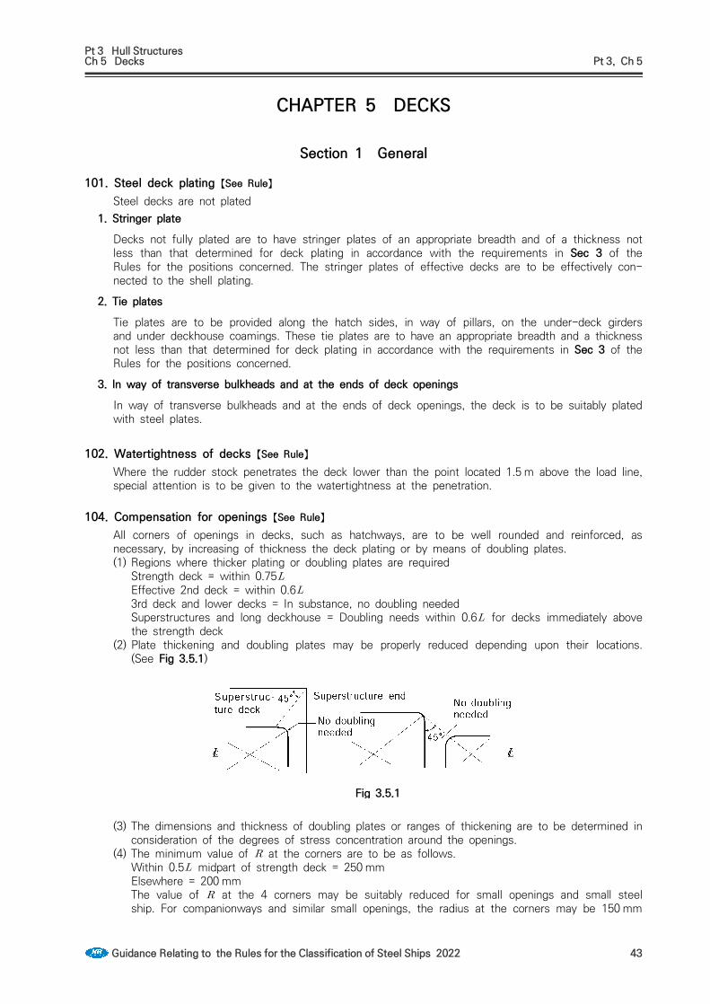
Pt 3 Hull StructuresCh 5 Decks Pt 3, Ch 5
Guidance Relating to the Rules for the Classification of Steel Ships 2022 43
CHAPTER 5 DECKS
Section 1 General
101. Steel deck plating 【See Rule】Steel decks are not plated
1. Stringer plateDecks not fully plated are to have stringer plates of an appropriate breadth and of a thickness not less than that determined for deck plating in accordance with the requirements in Sec 3 of the Rules for the positions concerned. The stringer plates of effective decks are to be effectively con-nected to the shell plating.
2. Tie platesTie plates are to be provided along the hatch sides, in way of pillars, on the under-deck girders and under deckhouse coamings. These tie plates are to have an appropriate breadth and a thickness not less than that determined for deck plating in accordance with the requirements in Sec 3 of the Rules for the positions concerned.
3. ln way of transverse bulkheads and at the ends of deck openingsIn way of transverse bulkheads and at the ends of deck openings, the deck is to be suitably plated with steel plates.
102. Watertightness of decks 【See Rule】Where the rudder stock penetrates the deck lower than the point located 1.5 m above the load line, special attention is to be given to the watertightness at the penetration.
104. Compensation for openings 【See Rule】All corners of openings in decks, such as hatchways, are to be well rounded and reinforced, as necessary, by increasing of thickness the deck plating or by means of doubling plates.(1) Regions where thicker plating or doubling plates are required
Strength deck = within 0.75Effective 2nd deck = within 0.63rd deck and lower decks = In substance, no doubling neededSuperstructures and long deckhouse = Doubling needs within 0.6 for decks immediately above the strength deck
(2) Plate thickening and doubling plates may be properly reduced depending upon their locations. (See Fig 3.5.1)
Fig 3.5.1
(3) The dimensions and thickness of doubling plates or ranges of thickening are to be determined in consideration of the degrees of stress concentration around the openings.
(4) The minimum value of at the corners are to be as follows.Within 0.5 midpart of strength deck = 250 mmElsewhere = 200 mmThe value of at the 4 corners may be suitably reduced for small openings and small steel ship. For companionways and similar small openings, the radius at the corners may be 150 mm

Pt 3 Hull StructuresCh 5 Decks Pt 3, Ch 5
44 Guidance Relating to the Rules for the Classification of Steel Ships 2022
in the strength deck outside the line of openings and 75 mm or so elsewhere.(5) For corners of openings having radius not less than 600 mm or having elliptical or similar shape,
neither doubling plates nor thickening of plating is required. The recommended corner shape is as shown in Fig 3.5.2.
(6) No welded joints are permitted at the corners of openings in the strength deck and the welded joints are to be off properly form the end of curvature. (See Fig 3.5.3)
Fig 3.5.2 Fig 3.5.3
105. Rounded gunwales 【See Rule】Where round gunwales are made of steel plate of Grade D or Grade E, the inner radius of curva-ture is not to be less than 20 times the thickness of gunwale plate, except that the radius may be reduced down to 15 times the plate thickness where the width of sheer strake to be bent to form round gunwale is not less than the plate width of a strake prescribed in Ch.1, Sec 405 of the Guidance plus 500 mm, or the method of bending work is specially approved by the Society.
Section 2 Effective Sectional Area of Strength Deck
202. Effective sectional area of strength deck 【See Rule】
1. Tapers of stem/stern part to strength deck may tapered with average value of sectional area as Fig 3.5.4. However, thickness of plate is not be reduced rapidly.
2. Where rounded gunwales are provided, the sectional area is to be calculated assuming that the plate of round gunwale be horizontally extended to the ship's side.
204. Long poop 【See Rule】The effective sectional area of strength deck within long poop which is not deal with strength deck is to be in accordance with Fig 3.5.5.
205. Superstructure deck designed as strength deck 【See Rule】When the poop deck is deal with strength deck, the sectional area of deck within poop is to be in accordance with Fig 3.5.6.
Section 3 Deck Plating
301. Thickness 【See Rule】 When strength deck is framed longitudinally, deck inside the line of openings are desirable to be transversely framed as Fig 3.5.7.

Pt 3 Hull StructuresCh 5 Decks Pt 3, Ch 5
Guidance Relating to the Rules for the Classification of Steel Ships 2022 45
Fig 3.5.4 Fig 3.5.5
Fig 3.5.6 Fig 3.5.7
307. Deck plating for helicopter landing 【See Rule】
1. For
t K
S a
S b×
P (mm)
where,S : spacing between deck beam (m)a, b : length of wheel print measured in parallel and perpendicular to beam (m)(See the Fig
7.7.2 of Guidance Pt 7, Ch 7) Unless otherwise specified elsewhere, a × b is to be 0.3 m× 0.3 m.
P : As for the deck loads in the range where a helicopter takes off or lands, a load of 75 % of the helicopter maximum take-off weight(MTOW) is to be taken on each of two square areas. But where the emergency condition is considered, a load of 100 % of the MTOW is to be used. (kN)
K : material factor
2. When the scantling of stiffeners are calculated, simple support beam is to be assumed and allow-able stress, 235/K (Nmm) and P obtained fram 1. are to be used. But where the arrangement of stiffeners or etc. are considered, continuous beam may be assumed.

Pt 3 Hull StructuresCh 7 Double Bottoms Pt 3, Ch 7
Guidance Relating to the Rules for the Classification of Steel Ships 2022 47
CHAPTER 7 DOUBLE BOTTOMS
Section 1 General
101. Application (2018) 【See Rule】
1. Where it is desired to omit double bottom partially or wholly in accordance with the requirements in 101. 3. or 4. of the Rules, the concerned parts are to be in accordance with following requirements. (1) calculated in accordance with requirements of SOLAS II-1/7.2 is not less than 1 when subject
to a bottom damage assumed at any position along the ship's bottom and with an extend speci-fied in (3) below for the affected part of the ship.
(2) Flooding of such spaces is not to render emergency power and lighting, internal communication, signals or other emergency devices inoperable in other parts of the ship.
(3) Assumed extent of damage is as followings
For 0.3 L from the forwardperpendicular of the ship Any other part of the ship
Longitudinal extent
1/3 or 14.5m , whichever is less
1/3 or 14.5m , whichever is less
Transverse extent or 10m , whichever is less
or 5m , whichever is less
Vertical extent, measured from
the keel line
or 2m , whichever is less
or 2m , whichever is less
(4) If any damage of a lesser extent than the maximum damage specified in (3) above would result in a more severe condition, such damage is to be considered.
2. For the ships subject to Korean Ship Safety Act., relevant requirements of Standard for Steel Ship's Hull Structure is to be applied.
3. For ships with special structure, the scantlings of structural members are to be in accordance with the followings.(1) Double hull ship (See Fig 3.7.1)
may replaced with the 0.5 .(2) For ships with inclined sides
may replaced with the length between intersection of extension of inner bottom plate and conjunction point with side shell plate (See Fig 3.1.1)
(3) For ships, the breadth of which becomes particularly narrow in fore and/or aft part in comparison with the breadth in midship part.The distance between the intersection of inner bottom and shell plating at centre of hold length may be used in place of (See Fig 3.7.2)
(4) In spite of the (1) through (3), the scantlings may be determined by direct calculation method.

Pt 3 Hull StructuresCh 7 Double Bottoms Pt 3, Ch 7
48 Guidance Relating to the Rules for the Classification of Steel Ships 2022
Fig 3.7.1 Fig 3.7.2 For ships, the breadth of which becomes particularly narrow in fore and/or aft part
4. In holds with pillars, the thickness of centre girder, side girders, solid floor, inner bottom plating and bottom shell plating may be reduced in accordance with the results of direct strength calculation.
5. With respect to the provisions of 101. 7 of the Rules, where the ratio of cargo weight per unit area (kNm ) of the inner bottom plating to d is less than 5.40, double bottom structures are to be in accordance with 203. 1, 302. 1, 501. 2 and 505. 1. Where cargo loads can not be treated as evenly distributed loads, scantlings of double bottom structures are to be determined by taking account of load distribution for particular cargoes. Where concentrated loads act on specific points of double bottoms, scantlings of center girders, side girders, floors, inner bottom plates and bottom plates and their stiffeners are to be determined by an appropriate strength assessment such as direct calculations.
107. Strengthening under boilers 【See Rule】Considering the corrosive environment due to high temperature, thickness of all members under boiler is to be increased according to the following standards. However, where the effective means for preventing corrosion or overheating are provided, increasing of thickness is not be needed. Above mentioned effective preventing for overheating means the case which temperature of the up-per surface of inner bottom plate is 40°C or less in usual condition.
Structural member Increasement
Centre girder3.0 mmSide girder
Solid floorsInner bottoms 3.5 mmVertical stiffener 1.5 mm
Section modulus of reverse frames of open floors and inner bottom longitudinals 15 %
Section modulus of frames of open floors and bottom longitudinal 7 %
Sectional area of vertical strut 10 %

Pt 3 Hull StructuresCh 7 Double Bottoms Pt 3, Ch 7
Guidance Relating to the Rules for the Classification of Steel Ships 2022 49
Section 2 Centre Girders and Side Girders
201. Arrangement and construction 【See Rule】
1. Where side girders are unable to extend forward and/or aftward because of the breadth of double bottom becoming narrow in fore and/or aft part, the side girders are to be sufficiently lapped over the adjacent girders in order to keep continuity of strength.
2. Girders or half height girders are to be provided under longitudinal bulkheads for proper strengthen-ing of double bottom.
203. Thickness 【See Rule】 1. Where the ratio of load per square meter of double bottom (kN/m2) to is less than 5.40, in
the formula in 203. (1) of the Rules is to be obtained from the following formula.
′
= coefficient, as obtained from the following(1) For holds adjacent to each other and being loaded or empty simultaneously; Where is 1.4
and over, it is to be taken as 1.4, and where is less than 0.4, it is to be taken as 0.4
(2) Other cargo holds : = 1.0
= as specified in 203. of the Rules = as obtained from the following formula
= as specified in 403. 2 of the Rules = as specified in 101. 6 of the Rules = coefficient,
for the longitudinal framed construction = 17for the transversely framed construction = 20
2. For the double hull construction, specified in 203. (1) is to be obtained from the following formulae.
″ ′
= coefficient, As specified in Table 7.3.2 of the Rules = as specified in 1. above. But not to be less than 0.8 = as specified in 1. above.′ = for the longitudinal framed construction = 4
for the transversely framed construction = 5 = coefficient to be obtained from the following formula. However, where the hold is unusually
long or where the sides are constructed on the transverse framing system and the spacing of side transverses is unusually large, special consideration is to be given.

Pt 3 Hull StructuresCh 7 Double Bottoms Pt 3, Ch 7
50 Guidance Relating to the Rules for the Classification of Steel Ships 2022
= mean thickness of inner bottom plating and bottom shell plating (mm) = mean thickness of longitudinal bulkhead and side shell plating, , and = distance (m), shown in Fig 3.7.5
Fig 3.7.5 Double side structure
204. Brackets 【See Rule】The thickness, size, form, etc. of brackets specified in 204. of the Rules are to be determined by taking into consideration of the height of centre girders and their buckling strength. As the exam-ples, Fig 3.7.6 is shown.
Fig 3.7.6 Forms of docking brackets
Section 3 Solid Floors
302. Thickness 【See Rule】
1. Where the ratio of load per square metre of double bottom to is less than 5.40, the coefficient in the formula in 302. (1) of the Rules is to be obtained from the following formula.
′
= as specified in 203. 1 of the Rules = value is specified in Table 3.7.3 of the Guidance according to the value of = as specified in 203. of the Rules

Pt 3 Hull StructuresCh 7 Double Bottoms Pt 3, Ch 7
Guidance Relating to the Rules for the Classification of Steel Ships 2022 51
Table 3.7.3 Coefficient
Not less thanNot more than
0.4
0.40.6
0.60.8
0.81.0
1.01.2 1.2
Longitudinal structure36 34 31 28 23 21
Trans. Structure
When solid floors are provided in each frame
When solid floors are provided between 2 frames or over 25 24 21 20 16 15
2. The thickness of solid floors of ships of double hull construction is to be obtained according to the following prescriptions.(1) ′ and ″ in the formula in 302. (1) of the Rules are to be as follows.
′ = distance between longitudinal bulkheads at the top of inner bottom plating at amidship (m) (See Fig 3.7.5)
″ = distance between longitudinal bulkheads at the top of inner bottom plating at the position of solid floor (m)
(2) The coefficient in the formula in 302. (1) of the Rules is to be obtained from the following formula.
′
= as specified in 203. 1 of the Guidance. However, it is not to be less than 0.8 = value is specified in Table 3.7.3 of the Guidance according to the value of ′ = value is specified in Table 3.7.4 of the Guidance according to the value of = as specified in 203. 2 of the Guidance = as specified in 203. of the Rules
Table 3.7.4 Coefficient ′
Not less thanNot more than 0.4
0.40.6
0.60.8
0.81.0
1.01.2 1.2
Longitudinal structure1 3 6 9 14 15
T r a n s . Structure
When solid floors are provided in each frame
When solid floors are provided between 2 frames or over 1 2 4 6 9 11

Pt 3 Hull StructuresCh 7 Double Bottoms Pt 3, Ch 7
52 Guidance Relating to the Rules for the Classification of Steel Ships 2022
Section 4 Bottom Longitudinals
403. Section modulus 【See Rule】
1. Where the apparent specific gravity of cargoes in loaded holds exceeds 0.9, the coefficient in the formula in 403. 1. of the Rules is to be as follows(1) where no strut as per 404. of the Rules is provided midway between the floors-------100(2) where a strut as per 404. of the Rules is provided midway between the floors
Under deep tanks-------------- 62.5Elsewhere------------------------ 30 + 20In no case is to be less than 50.
= As specified in 101. 7. of the Rules.
2. In case where the width of vertical stiffeners fitted on solid floors and vertical struts is unusually large, the coefficient in 403. 1. and 2. of the Rules may be multiplied by the value obtained from the following formula.
= distance between floors (m) = width of vertical stiffeners on floors (m). is to be zero, if the vertical stiffeners are not
well fixed to longitudinals by means of lug connection. = width of vertical strut (m) (See Fig 3.7.7)
Fig 3.7.7 Fig 3.7.8 Details of lap of strut and longitudinal frame
404. Struts 【See Rule】Depth of lapped parts of vertical struts over web of longitudinals is to be of 1.5 times as large as the breadth of face plates of struts as a standard. Where the sufficient depth of lapped parts is unable to be taken due to weld ability, throat of fillet weld is to be properly increased. (See Fig 3.7.8)

Pt 3 Hull StructuresCh 7 Double Bottoms Pt 3, Ch 7
Guidance Relating to the Rules for the Classification of Steel Ships 2022 53
Section 5 Inner Bottom Plating, Margin Plates and Bottom Shell Plating
501. Thickness of inner bottom plating 【See Rule】
1. Where the height of centre girder is less than , the thickness of inner bottom plating and bot-tom shell plating are to be increased so that the moment of inertia of the double bottom obtained from the following formula may be equivalent to that corresponding to the case where the centre girder has the required height.
= height of centre girder (m) = thickness of bottom shell plating (mm) = thickness of inner bottom plating (mm)
2. Where the ratio of load per square metre of double bottom to is less than 5.40, the coefficient in the formula of 501. 1. of the Rule is to be obtained from the following formula.
′
= as specified in 203. 1. of the Guidance = coefficient or as specified in the followings according to the value of
< 0.8 ; 0.8≤ < 1.2 ; or , whichever is greater.1.2≤ ;
= as specified in 203. of the Rules. and = as specified in Table 3.7.5 according to the value of . However, for the
transversely framed construction, the value specified in the Table, is to be multi-plied by 1.1.
= as obtained from the following formula
Table 3.7.5 Coefficient and
Not less than 0.4 0.6 0.8 1.0 1.2 1.4 1.6
Not much than 0.4 0.6 0.8 1.0 1.2 1.4 1.6
5.5 4.9 4.1 2.8 2.0 ─ ─ ─
─ ─ ─ 2.8 2.6 2.4 2.2 1.8
3. For the ships with double hull construction, in the formula in 501. 1. of the Rules, is to be obtained from the following formula, whichever is greater.
′

Pt 3 Hull StructuresCh 7 Double Bottoms Pt 3, Ch 7
54 Guidance Relating to the Rules for the Classification of Steel Ships 2022
′
= coefficient, is to be in accordance with 203. 1. of the Guidance. However, it is not to be less than 0.8
, and = as obtained from the above mentioned 2.′ and ′ = as specified in Table 3.7.6 according to the value of . However, for the trans-
versely framed construction, the value ′ specified in the Table, is to be multi-plied by 1.1.
= as specified in 203. of the Rules = It is to be in accordance with 203. 2 of the Guidance.
Table 3.7.6 Coefficient ′ and ′
Not less than 0.4 0.6 0.8 1.0 1.2 1.4 1.6
Not much than 0.4 0.6 0.8 1.0 1.2 1.4 1.6
′ 3.1 2.5 1.8 1.0 0.5 ─ ─ ─
′ ─ ─ ─ 1.1 1.1 0.8 0.7 0.4
4. In case forklift is used for unloading operation, thickness of inner bottom plate is to be also in ac-cordance with Ch 5, 305. of the Rules.
5. Butt joints of inner bottom plating in the midship part are generally not to be arranged at the knuckle line of the inner bottom.
505. Bottom shell plating 【See Rule】
1. Where the ratio of load per square metre of double bottom to is less than 5.40, the thickness of bottom shell plating is to be determined as follows.
In the region of double bottoms under cargo holds, the thickness of bottom shell plating is not to be less than obtained from the formula in Ch 4, 304. of the Rules or from the first formula in Ch 7, 501. 3 of the Rules whichever is greater. In applying the latter formula, coefficient ′ is de-scribed in 501. 3 of the Guidance. However, In applying the first formula in 501. 1 of the Rules, is to be obtained from the following formula.
2. In the region of double hull construction, the thickness of bottom shell plating is not to be less than obtained from the formula in Ch 4, 304. of the Rules or from the first formula in 501, 3. of the Rules whichever is greater. In applying the latter formula, coefficient described in 501. 2 of the Guidance. However, In applying the first formula in 501. 1 of the Rules, is to be obtained from the following formula.

Pt 3 Hull StructuresCh 7 Double Bottoms Pt 3, Ch 7
Guidance Relating to the Rules for the Classification of Steel Ships 2022 55
Section 8 Construction of Strengthened Bottom Forward
801. Application 【See Rule】
1. Here, the ballast condition means the ordinary ballast condition where only the ballast tanks such as clean ballast tanks, segregated ballast tanks and ballast holds are ballasted. This ballast condition excludes an exceptional case where cargo tanks are ballasted only in the heavy weather condition to assure the safety of the ship.
2. In ships of which and are not more than 150 m and 0.7 respectively and is 1.4 and over, the construction of bottom forward is to be as required in the followings. However, ships that carry a certain amount of cargo regularly such as Container Ships may comply with the require-ments in 802. to 804. of the Rules instead.(1) Construction
Construction of strengthened bottom forward is to be in accordance with 803. of the Rules. However, the vertical stiffeners for the solid floors specified in 803. 3 of the Rules are to be provided on all shell stiffeners. Where the bottom longitudinals or longitudinal shell stiffeners are extended through the solid floors, slots are to be reinforced with collar plates.
(2) Scantlings of longitudinal shell stiffeners or bottom longitudinals(A) In ships having bow draught not more than 0.025 at the ballast condition, the section
modulus () of longitudinal shell stiffeners or bottom longitudinals in way of the strengthened bottom forward is not to be less than that obtained from the following formula
(cm3)
= spacing of solid floor (m) = 0.774 l (m) However, where the spacing of longitudinal shell stiffeners or bottom
longitudinals is not more than 0.774 , is to be taken as the spacing (m). = slamming pressure obtained from the following formula
(kPa)
= as specified in Table 3.3.7 of the Guidance. For the intermediate value is to be obtained by linear interpolation.
Table 3.7.7 Coefficient
1.4 1.5 1.6 1.7 1.8
0.31 0.33 0.36 0.38 0.40
= coefficient obtained from the following formula
≤
≤
≤
= slope of ship's bottom obtained from the following formula, but is greater than 11.43, it is to be taken as 11.43.

Pt 3 Hull StructuresCh 7 Double Bottoms Pt 3, Ch 7
56 Guidance Relating to the Rules for the Classification of Steel Ships 2022
= horizontal distance measured at the station 0.2 from the stem, from the centre line of ship to the intersection of the horizontal line 0.0025 above the top of keel with the shell plating (m) (See Fig 3.7.2)
= as obtained from the following formula
= minimum bow draught at the ballast conditions. = coefficient obtained from the followings.
≤
= length to longitudinal direction from end of stem to transverse section (m) = as obtained from the followings
≤ (m)≤
(B) In ships having bow draught more than 0.025 but less than 0.037 at the ballast condition, the section modulus of longitudinal shell stiffeners or bottom longitudinals in way of the strengthened bottom forward is to be obtained by the linear interpolation from the values given by the requirements in (A) and the values in 403. 1 of the Rules.
(3) Thickness of solid floorsThickness of solid floors is obtained from the following (A) and (B), whichever is greater.(A) The thickness of solid floors in 1/2 spacing of both sides of bottom longitudinals is to be
obtained from the following formula. (See Fig 3.7.9)
(mm)
= slamming pressure given by (2)(A). In ships having bow draught more than 0.025 but less than 0.037 at the ballast condition, this requirement is to be applied using actual bow draught at the ballast condition.
= spacing of solid floors (m) = breadth of panel (m) = sum of breadth of panel opening (m), where the opening compensated with dou-
ble plates, sectional area may be properly considered.(B) Thickness of solid floors is to be obtained from the following formula.
(mm)
and = as specified in (A) = spacing of bottom longitudinal (m)

Pt 3 Hull StructuresCh 7 Double Bottoms Pt 3, Ch 7
Guidance Relating to the Rules for the Classification of Steel Ships 2022 57
Fig 3.7.9 Solid floor of strengthened bottom forward
3. With respect to the requirements of 801. of the Rules, ships of which and are 150 m or more and 0.7 or more respectively may apply to the followings.(1) Slamming impact pressure specified in 804. 1 of the Rules, may be given by the following
formula. In this case, the slamming impact pressure is to be calculated at the mid-span point for each longitudinal shell stiffeners or bottom longitudinals.
(kPa)
= as given by the following formula. In no case, the value of is greater than 11.43.
= in considering transverse section, horizontal distance (m) from the ship’s center line to the intersection of the horizontal line of 0.025L above the ship’s base line and the ship’s moulded line of shell.
= relative speed (m/s)between the ship’s bottom of considered position and sea surface as given by the following formula.
cos sin sin
= as given by the following formula.
= as given by the following formula. In no case, the value is less than zero.
′
= longitudinal distance (m) from the midship to the considered position.′ = length of ship (m). Where, however, exceeds 230 m, ′ is to be taken as
230 m.

Pt 3 Hull StructuresCh 7 Double Bottoms Pt 3, Ch 7
58 Guidance Relating to the Rules for the Classification of Steel Ships 2022
= pitch angle (rad) as given by the following formula.
= significant wave height (m) as given by the following formula. However, this value may not be greater than the maximum value of 0.055L and 11.5.
= as given by the following formula.
≤ :
≤ : = 10.75
:
= As given by the following formula.
= as given by the following formula. In any case, this value is not to be less than 0 and not to be greater than 1.
= wave length as given by the following formula.
′ (m)
= natural period of pitch motion as given by the following formula.
(sec)
= as given by the following formula. However, this value may not be greater than
tan ′
(rad)
(2) For the examination of the position within ballast tanks which are to be filled up by sea water in the ballast conditions, the slamming impact pressure P specified in (1) above may be reduced by as given by the following formula. In this case, it is to be stated in the ship’s loading manual that such ballast tanks are to be filled up in the heavy weather condition.

Pt 3 Hull StructuresCh 7 Double Bottoms Pt 3, Ch 7
Guidance Relating to the Rules for the Classification of Steel Ships 2022 59
(kPa)
= depth of the ballast tank (m)
4. In way of strengthened bottom forward, structural arrangements other than those specified in 803. of the Rules may be adapted subject to the following (1) to (3).(1) The thickness of solid floors in the longitudinal stiffened system and girders in the transverse
stiffened system is to apply to the provisions of 801. 2 (3). For the thickness of solid floors in the longitudinal stiffened system, the slamming impact pressure may be corrected by multi-plying the coefficient specified in (3) the below.
(2) The thickness of solid floors and girders is not to be less than the value obtained by the follow-ing (A) and (B), whichever is the greater.
(A)
(mm)
= the considered slamming impact pressure as specified in 804. 1 of the Rules, 801. 2. or 801. 3. In ships having bow draught more than 0.025 ′ but less than 0.037 ′ at the ballast condition, the slamming impact pressure is to be obtained by linear inter-polation from the above value and the value obtained by the following formula as the pressure when the bow draught is 0.037 ′ . The slamming impact pressure is not to be less than the value obtained by the following formula.
(kPa)
= as given by the following formula. In any case, this value is not to be less than 0.1 and not to be greater than 1.
= area (m2) considered in the strength examination, in this case, as given by the following formula
×
= spacing (m) at solid floors or girders for themselves under the consideration = spacing (m) at solid floors or girders for members crossing those under the consid-
eration = depth (m) of the floors or the girders at the considered position = depth (m) of the opening in the floors or the girders at the considered position.
(B) The value given by the requirements of 302. (2) of the Rules, using the value of as given by the above (a), in the mentioned requirements. For the application to girders, the wording 'solid floors' specified in 302. (2) of the Rules is to be read as 'girders'.
(3) For scantlings of longitudinal shell stiffeners and bottom longitudinals, the slamming impact pres-sure may be corrected by multiplying the coefficient as given by the following formula. In any case, the coefficient is not to be less than 0.1 and not to be greater than 1.
= as given in 804. 1 of the Rules

Pt 3 Hull StructuresCh 7 Double Bottoms Pt 3, Ch 7
60 Guidance Relating to the Rules for the Classification of Steel Ships 2022
802. Definition 【See Rule】In ships of which and are less than 150 m and 0.7 respectively and bow draught is less than 0.025 at the ballast condition, the area of strengthened bottom forward of the ship is to be ex-pended as follows.(1) The after end of strengthened area is to be extended the following distance afterwards from
the position required in Table 3.7.11 of the Rules.
, where , where
For intermediate values of , is to be obtained by linear interpolation.(2) In addition to (1) above, bottom areas of which tangential slope to the base line is less than 25°
are required to be strengthened. (See Fig 3.7.10).
Fig 3.7.10 Range of transverse direction of strengthened bottom forward

Pt 3 Hull StructuresCh 8 Frames Pt 3, Ch 8
Guidance Relating to the Rules for the Classification of Steel Ships 2022 61
CHAPTER 8 FRAMES
Section 1 General
105. Frames in boiler spaces and in way of bossing 【See Rule】
In application to 105. 2 of the Rules, the term "the satisfaction of the Society" means to accept in accordance with Pt 1, Ch 1, 105. of the Rules.
106. Frames and stringers fitted up at extremely small angles 【See Rule】
For the applying 106. of the Rules, Where the angle between the web of frames and shell plating is extremely small, the requirements of Pt 13, Sub Pt 1, Ch 3, Sec 6, 3.1.2 and Sec 7, 1.4.4 of the Rules may be applied.
108. Frames at a location where flare is specially large (2019) 【See Rule】
1. For ships with large flare, the thickness of web plates and the plastic section modulus of transverse frames and side longitudinals, which are fitted where the bow flare located above the load line and forward of 0.2 is considered to endure large wave impact pressure, are not to be less than that obtained from the following formula. (2020)
Required thickness of web plate : cos (mm)
Required plastic section modulus : cos
× (cm3)
Where, = frame spacing measured along the shell plating (m) = unsupported length of frame as obtained from the following formula (m)
= refer to Fig 3.8.1 and = bracket length for span correction as obtained from the following formulae
×
×
, , , and = refer to Fig 3.8.1 = specified yield stress of the material (N/mm2) = frame list angle to side shell (deg), refer to Fig 3.8.2 = slamming impact pressure as obtained from the following formula (kPa)
cos
= sea water density, 1.025 (t/m3) = relative impact angle between wave surface and a point under consideration on ship’s
surface as obtained from the following formula (deg)

Pt 3 Hull StructuresCh 8 Frames Pt 3, Ch 8
62 Guidance Relating to the Rules for the Classification of Steel Ships 2022
= as obtained from the following formula (deg)
tantancos
= as obtained from the following formula (deg)
(≤ )
( )
= shell angle at the section under consideration (deg) (see Fig 3.8.3) = as obtained from the following formula (deg)
= longitudinal distance from the aft end of to the section under consid-eration (m)
= vertical distance from base line at the middle of to the section under consideration (m)
= shell angle at the section under consideration (deg) (see Fig 3.8.3) = as obtained from the following formula
(where, ≤ )
(where, ≤) (where, ) (where, ≤ ) (where, ≤ )
= coefficient obtained from the formula in Table 3.8.1 = coefficient obtained from the following formula
(where, ≤)
(where, )
= maximum relative velocity between wave surface and a point under consideration on ship’s surface as obtained from the following formula (m/s)
tantantan tan
tan tan tan
= longitudinal relative velocity at a point under consideration on ship’s surface as obtained from the following formula (m/s). However, is to be greater than 0.

Pt 3 Hull StructuresCh 8 Frames Pt 3, Ch 8
Guidance Relating to the Rules for the Classification of Steel Ships 2022 63
= coefficient obtained from the formula in Table 3.8.2 = longitudinal relative velocity at the waterline as obtained from following for-
mula (m/s)
= 0.36 (m/s) = speed of ship (kt) = gravity acceleration, 9.81 (m/s2) = coefficient obtained from the formula in Table 3.8.2
= relative velocity at a point under consideration on ship’s surface in the direction of ship’s depth as obtained from the following formula (m/s). However, is to be greater than 0.
= coefficient obtained from the formula in Table 3.8.2 = relative velocity at the waterline in the direction of ship's depth as obtained
from the following formula (m/s)
= coefficient obtained from the formula in Table 3.8.2
= as obtained from the following formula
tantan
tan
= plastic section modulus of frame, where the frame is joined to shell plate with a right an-gle, as obtained from the following formula. (cm3)
= sectional area of flange (cm2) = depth of web plate (mm) = thickness of web plate (mm)

Pt 3 Hull StructuresCh 8 Frames Pt 3, Ch 8
64 Guidance Relating to the Rules for the Classification of Steel Ships 2022
255.85
≤ 758.60
≤ 453.91
≤ 335.41
≤ 173.61
≤ 80.523
≤
Table 3.8.1 Coefficient
Table 3.8.2 Coefficient , , and
Note : = , however, is to be greater than 0.6 = longitudinal distance to the section under consideration from the midship (m) = , however, is to be greater than 0 = height from the load line to the section under consideration (m) =
2. For ships with large flare, the scantling of web frames supporting side longitudinals, which are fitted in the bow flare located above the load line and forward of 0.2 is considered to endure large wave impact pressure, is to be in accordance with requirements of side stringers supporting trans-verse frames in Ch 9, 104. (2020)

Pt 3 Hull StructuresCh 8 Frames Pt 3, Ch 8
Guidance Relating to the Rules for the Classification of Steel Ships 2022 65
Fig 3.8.1 Modified Span Length of Frames
Fig 3.8.2
Fig 3.8.3 Shell Angle

Pt 3 Hull StructuresCh 8 Frames Pt 3, Ch 8
66 Guidance Relating to the Rules for the Classification of Steel Ships 2022
Section 3 Hold Frames
302. Scantlings of transverse hold frames 【See Rule】The scantlings of hold frames which are considered to support the loads from steel coils at ship's rolling are recommended to be determined in accordance with not only 302. of the Rules but also mentioned below based on calculation in elastic range.
(1) Boundary condition ; Simply supported at deck and fixed at inner bottom(2) Allowable stress ; 196 (N/mm2)(3) Loading condition ; Hydraulic pressure of ship's side by specified in Table 3.8.1 of the Rules
and mass of steel coils() calculated by the following formula(A) In case of loading steel coils lined up in one tier.
sin (ton)
= mass of one steel coil (ton) = maximum heeling angle (deg) = number of frame supporting one steel coil = coefficient according to acceleration direction due to ship's rolling, to be normally
taken 1.0 = coefficient according to the arrangements of key coil as obtained from the
followings.Where the key coils are arranged at second from ship side -- 4.0Where the key coils are arranged towards center line than second steel coil form ship side -- 2.5
(B) In case of loading steel soils lined up in two tiers
sin(ton)
, , = as specified in (A) = total number of steel coils loaded in the relevant transverse frame section = coefficient defined according to arrangement of steel coil, in general, to be taken
0.7. However, where steel coils in lower tier are arranged so closely that the contact pressure of each other is considered large enough to be reduced, the val-ue may be reduced.
303. Transverse hold frames supported by web frames and side stringers 【See Rule】Where the arrangement of side stringers are not complies with 303. 2 of the Rules, the scantlings of frames are to be applied in 303. 1. of the Rules. However, if it is reviewed and decided the scantlings with proper manner, the scantlings of frames may not be applied in 303. 1 of the Rules. (see Fig 3.8.4)(1) Where the difference between unsupported spans of any adjacent frames is more than 25 %
(A) In case that the value of ≥ , is to be used instead of .(B) In case that the value of ≥ and , modification is not required.
(2) Where the difference between the largest and smallest span is more than 50 %.(A) In case the lowest span is smallest, (maximum span)/1.5 to be used instead of . (B) In other cases than above, no modification required.

Pt 3 Hull StructuresCh 8 Frames Pt 3, Ch 8
Guidance Relating to the Rules for the Classification of Steel Ships 2022 67
Fig 3.8.4 Transverse hold frames supported by side stringers specially arranged
Section 5 Tween Deck Frames
502. Scantlings of tween deck frames 【See Rule】Where ends of tween deck frames are connected with brackets, the size of which is bigger than 8, the requirements of 502. of the Rules may be applied as the manner shown in Fig 3.8.5.
Fig 3.8.5 Frames between decks fixed by the bracket
503. Special consideration to tween deck frames 【See Rule】
1. In ships having multi-decks like as Pure Car Carriers, where freeboard is less than the value given in Table 3.8.1, the tween deck frames above freeboard deck are to be generally reinforced accord-ing to the ship's length as follows.
Table 3.8.1 Standard freeboard
Length of ship (m) <75 75≤<125 125≤
Standard freeboard (m) 0.36 0.40 0.46
(1) Range of reinforcement is at least up to the between deck frames of the first tier counted from freeboard deck.
(2) The section modulus of tween deck frames is applied to the following requirements. (A) Tween deck frame is arranged toward of forward the collision bulkhead : It is to be applied
to Ch 13, 204 .1 of the Rules.(B) Tween deck frame is arranged afterward of abaft aft peak bulkhead : It is to be applied to
Ch 13, 302. of the Rules.(C) Others : It is to be applied (2) in Table 3.8.4 in 502. of the Rules. However for coefficient C
of Table 3.8.4 in 502. of the Rules, 0.57, 0.74 and 0.89 should be substituted for 0.44, 0.57 and 0.74 respectively.
2. Tween deck frames, which are fitted in the bow flare position considered to endure large wave im-pact pressure, are to be properly strengthened taking care of the effectiveness of their end connections.

Pt 3 Hull StructuresCh 9 Web Frames and Side Stringers Pt 3, Ch 9
Guidance Relating to the Rules for the Classification of Steel Ships 2022 69
CHAPTER 9 WEB FRAMES AND SIDE STRINGERS
Section 1 General
104. Web frames and side stringers at a location where flare is specially large (2019) 【See Rule】 1. For ships with large flare, the thickness of web plate and section modulus , of side stringers
supporting transverse frames and web frames supporting these side stringers, which are fitted in the bow flare located above the load line and forward of 0.2 is considered to endure large wave impact pressure, are not to be less than those obtained from the following formulae. (2020)
Required thickness of web plate : cos (mm)
Required section modulus : cos
× (cm3)
where, = slamming impact pressure as specified in Ch 7, 108. (kPa) = spacing of girder (m) = unsupported length of girder taking into account geometry of girder at end parts (m).
Where form of girder at end parts is arc form such as Fig 3.8.1 this length is to be modi-fied considering it triangle, as follows.(1) To join R-ENDs together. ( )(2) To draw tangent line ′′ with arc, parallel to .(3) To put point ″ so that ″ ′ and to put ″ so that ″ ′ , and
triangle ″″ is considered as bracket of triangle.
: length of girder measured along the shell plating, refer to Fig 3.8.1 and = bracket length for span correction as obtained from the following formulae (m)
×
×
, , and : refer to Fig 3.9.1 = depth of web plate (mm) = specified yield stress of the material (N/mm2) = angle between girder and vertical axis of shell plate (deg). Refer to Fig 3.9.2 = section modulus of girder as obtained from the following formula. (cm3)
= sectional area of flange (cm2) = thickness of web plate of girder (mm)

Pt 3 Hull StructuresCh 9 Web Frames and Side Stringers Pt 3, Ch 9
70 Guidance Relating to the Rules for the Classification of Steel Ships 2022
Fig 3.9.1 Fig 3.9.2
2. Buckling strength of the web plates of girders supporting frames in above 1. is to be in accordance with followings. compressive stress for the web plates is not to exceed the critical value obtained from the following.
(N/mm2), where ≤
(N/mm2), where
= as specified in 1. = reference buckling stress of the web plates as obtained from the following for-
mula
(N/mm2)
×, Modulus of elasticity (N/mm2) = as specified in 1.
= compressive stress working on web plates as obtained from the following formula
cos
(N/mm2)
, and = as specified in 1.

Pt 3 Hull StructuresCh 9 Web Frames and Side Stringers Pt 3, Ch 9
Guidance Relating to the Rules for the Classification of Steel Ships 2022 71
3. Buckling strength of girder webs at end parts in above 1. is to be in accordance with followings (1) and (2).(1) Shearing stress for the web plates of girders at end parts is not to exceed the critical value
obtained from the following.
(N/mm2), where ≤
(N/mm2), where
= specified yield stress of the material (N/mm2) = shear buckling stress for web plates of girders at end parts as obtained from the fol-
lowing formula
(N/mm2)
= coefficient as obtained from Table 3.9.1 depending on . For intermediate values of , is to be obtained by linear interpolation.
= length of web plate at end parts (mm) See Fig 3.9.3 = modulus of elasticity, × (N/mm2) = thickness of web plate of girder at end parts (mm) = mean depth of web plate of girder at end parts (mm)
= shear stress for web plate at end parts as obtained from the following formula
cos
Fig 3.9.3
0.3 and
under0.4 0.5 0.6 0.7 0.8 0.9 1.0 1.2
1.4 and over
64 38 25 19 15 12 10 9 8 7
Table 3.9.1 Coefficient
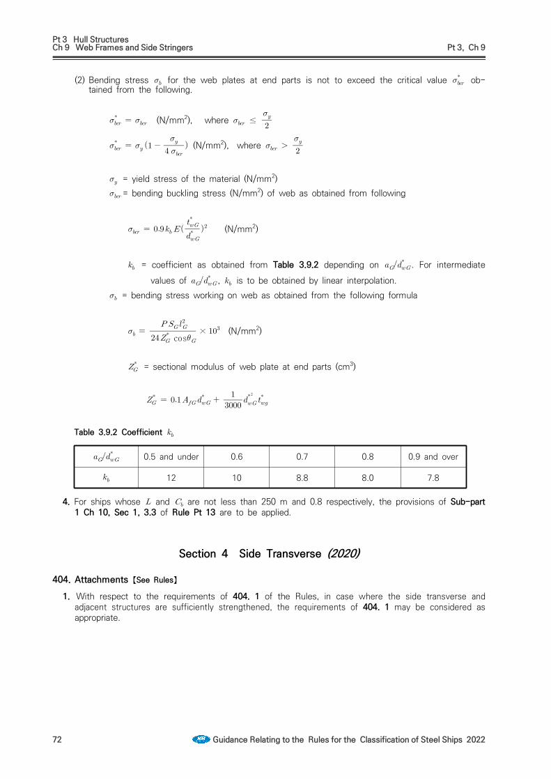
Pt 3 Hull StructuresCh 9 Web Frames and Side Stringers Pt 3, Ch 9
72 Guidance Relating to the Rules for the Classification of Steel Ships 2022
(2) Bending stress for the web plates at end parts is not to exceed the critical value ob-tained from the following.
(N/mm2), where ≤
(N/mm2), where
= yield stress of the material (N/mm2) = bending buckling stress (N/mm2) of web as obtained from following
(N/mm2)
= coefficient as obtained from Table 3.9.2 depending on . For intermediate values of , is to be obtained by linear interpolation.
= bending stress working on web as obtained from the following formula
cos
× (N/mm2)
= sectional modulus of web plate at end parts (cm3)
0.5 and under 0.6 0.7 0.8 0.9 and over
12 10 8.8 8.0 7.8
Table 3.9.2 Coefficient
4. For ships whose and are not less than 250 m and 0.8 respectively, the provisions of Sub-part 1 Ch 10, Sec 1, 3.3 of Rule Pt 13 are to be applied.
Section 4 Side Transverse (2020)
404. Attachments 【See Rules】
1. With respect to the requirements of 404. 1 of the Rules, in case where the side transverse and adjacent structures are sufficiently strengthened, the requirements of 404. 1 may be considered as appropriate.

Pt 3 Hull StructuresCh 9 Web Frames and Side Stringers Pt 3, Ch 9
Guidance Relating to the Rules for the Classification of Steel Ships 2022 73
Section 5 Cantilever Beams
503. Connections 【See Rule】
1. To prevent the buckling of end brackets of cantilever beams connected with web frames, stiffeners are to be fitted to the brackets with at suitable spacing in order to make their panels smaller as shown in Fig 3.9.4.
Fig 3.9.4 Compensation of bracket
2. Within the range of 1/2 of the throat depth of the end bracket from the side of face plate, stiff-eners such as inverted angle are to be arranged in the direction of compression at the spacing() obtained from the following formula as the standard.
(mm)
= thickness of bracket (mm)

Pt 3 Hull StructuresCh 10 Beams Pt 3, Ch 10
Guidance Relating to the Rules for the Classification of Steel Ships 2022 75
CHAPTER 10 BEAMS
Section 1 General
102. Connections of ends of beams 【See Rule】
1. The standards of end connection of longitudinal beams are as shown below.
2. The standards of end connection of transverse beams by means of brackets are as shown below.
Fig 3.10.1 Fig 3.10.2
106. Long machinery opening 【See Rule】 Where the length of machinery opening is not less than 20 m, a cross tie is to be provided at mid-dle of opening.
Section 2 Deck Load
201. Value of 【See Rule】
1. The value of is to be prescribed in suitable documents like as loading manual specified in Ch 3, 103. of the Rules to aid the ship's master.
2. In application to 201. 2 (4) of the Rules, the term "the discretion of the Society" means Ch 1, 203. 2 (2) (C) of the Guidance.
Section 3 Longitudinal Beams
303. Section modulus 【See Rule】The section modulus of longitudinal beams outside the line of hatchway openings of the strength deck for the parts forward and afterward the midship part of ship may be determined by the inter-polation between the requirements of 303. 1 and 2 of the Rules. In general the interpolation may be made at the mid position of each building block in ship lengthwise. However, where the length of block is over 15 m, it may be properly divided.

Pt 3 Hull StructuresCh 10 Beams Pt 3, Ch 10
76 Guidance Relating to the Rules for the Classification of Steel Ships 2022
Section 4 Transverse Beams
402. Proportion 【See Rule】
1. In case where the span/depth ratio of transverse beams exceeds 30 in strength decks or 40 in ef-fective decks and superstructure decks, the second moduli of beams are to be increased in the corresponding ratios.
2. In bulk carrier, ore carrier, etc. over 200 m in their length, the slenderness ratio of transverse beams inside the line of hatchway openings of the strength deck is recommended that is to be below 60.

Pt 3 Hull StructuresCh 11 Deck Girders Pt 3, Ch 11
Guidance Relating to the Rules for the Classification of Steel Ships 2022 77
CHAPTER 11 DECK GIRDERS
Section 1 General
103. Construction 【See Rule】
1. At the upper and lower ends of pillars and other places where concentrated loads are expected, girders are to be fitted with tripping brackets and slots in girders are to be fitted with collars. Under the end bulkheads of superstructures, only collars are required. Collars are also to be fitted at the slots near the toe of end bracket.
2. Butt joints of girder webs are to be avoided at corners of slots. Butt joints of face plates are to be likewise avoided at knuckled parts. If butt joints of face plates are inevitably placed at knuckled parts, butt straps are to be provided as shown in Fig 3.11.1. The depth of slots is not to exceed 0.4. If this limit is exceeded, collars are to be fitted with the depth not exceeding 0.5. These requirements may be suitably modified for superstructures.
Fig 3.11.1
3. Sizes of lightening holes are to be as follows.
Where slots are provided , ≤
Where slots are not provided , ≤
= depth of girder = diameter of lightening holes
4. In RO-RO ships, etc., the scantlings of girders may be determined by the direct strength calculation.
5. Where the value obtained from the following formulas equal to or greater than 1.6, special consid-eration is to be given to the beams on the shell side or bulkhead side in the region of mid-span of girders because of added stress due to forced deflection.
and = actual moment of inertia of beams and girders (cm4) and = span of beams and girders (m) = spacing of beams (m)

Pt 3 Hull StructuresCh 11 Deck Girders Pt 3, Ch 11
78 Guidance Relating to the Rules for the Classification of Steel Ships 2022
104. End connection 【See Rule】
1. Where a girder stops at a bulkhead, a bracket is to be fitted on the reverse side. (See Fig 3.11.2)
2. Continuity of deck girders(1) The depth of bracket is, as a standard, to be equal to twice the depth of web. If the depth of
bracket is smaller than this standard, suitable equivalent means, such as gusset plate, is to be provided.(See Fig 3.11.3)
Fig 3.11.2 Fig 3.11.3
(2) Girders to be considered for the section modulus calculation of hull girder are to penetrate bulk-heads as a whole including the web and face plate, or to be so connected at the ends as to give an equivalent effectiveness. (See Fig 3.11.4)
(3) Where deck girders are discontinuous, they are be sufficiently overlapped. (See Fig 3.11.5)
Fig 3.11.4 Fig 3.11.5

Pt 3 Hull StructuresCh 12 Pillars Pt 3, Ch 12
Guidance Relating to the Rules for the Classification of Steel Ships 2022 79
CHAPTER 12 PILLARS
Section 1 General
102. Pillars in holds 【See Rule】Compensation of under pillars is to be as shown in Fig 3.12.1.
Fig 3.12.1 Compensation of under pillars
Section 2 Scantling of Pillars
201. Sectional area 【See Rule】Sectional area of pillars which is regarded as fixed ends may be obtained from the following formula.
(cm2)

Pt 3 Hull StructuresCh 13 Arrangements to Resist Panting Pt 3, Ch 13
Guidance Relating to the Rules for the Classification of Steel Ships 2022 81
CHAPTER 13 ARRANGEMENTS TO RESIST PANTING
Section 1 General
102. Swash plate 【See Rule】Scantlings of swash plates which are used for deep tanks at fore and aft peak tanks are to be complied with 203. 2 (2) of the Rules.
103. Stringers fitted up with extremely small angle 【See Rule】In case the angle between webs of girders and shell plating is not more than 75°, substantially the following treatment (1) and (2) are to be required (See Fig 3.13.1). And where the webs of girder is inclined provided to shell plating, actual section modulus of girder is to be calculated against neutral axis parallel to shell plating.(1) Face plate is to be fitted on the side of open bevel (2) Tripping brackets are to be fitted in suitable spacing
Section 2 Arrangements to Resist Panting forward the Collision Bulkhead
204. Longitudinal framing 【See Rule】For the applying 204. 2 (2) of the Rules, where the side transverses are supported by side stringers or panting stringers, in the formula for the depth of side stringers is not applied.
205. Bulbous bow 【See Rule】
In application to 205. of the Rules, the term "specially considered by the Society" means to apply Pt 13, Sub Pt 1, Ch 10, Sec 1, 2.5 of the Rules and to accept in accordance with Pt 1, Ch 1, 105. of the Rules.
Section 4 Arrangements to Resist Panting between Both Peaks
401. Abaft collision bulkhead 【See Rule】The reinforcement is recommended such that, between the 0.15 from the fore end, side stringers are provided in line with stringer plates or side stringers in way of the fore peak tank in association with web frames provided at a suitable interval. Even in case where it is impracticable to provide with frame and side stringer, at least the reinforcement as the followings is to be provided.
1. Appropriate range of scantlings of hold frames abaft the collision bulkhead are to be reinforced to not less than the value in 302. of the Rules by gradually increasing scantlings of hold frames from the prescribed Table 3.8.1 of the Rules.
2. Solid brackets are to be provided and firmly connected with collision bulkhead and hold frame abaft the collision bulkhead at appropriate positions in way of depth of ship.

Pt 3 Hull StructuresCh 13 Arrangements to Resist Panting Pt 3, Ch 13
82 Guidance Relating to the Rules for the Classification of Steel Ships 2022
Fig 3.13.1 In case the angle between webs of girders and shell plating is small Fig 3.13.2

Pt 3 Hull StructuresCh 14 Watertight Bulkheads Pt 3, Ch 14
Guidance Relating to the Rules for the Classification of Steel Ships 2022 83
CHAPTER 14 WATERTIGHT BULKHEAD
Section 2 Arrangements of Watertight Bulkheads
201. Collision bulkheads 【See Rule】
1. In ships with bow doors, the collision bulkhead under the deck just above the freeboard deck is to comply with the 201., 202. and 205. of the Rules.
2. The expression "accepted by the Society" means that an application submitted together with calcu-lations verifying that no part of the bulkhead deck will be immersed even when the compartment forward of collision bulkhead is flooded under the loading condition (without trim) corresponding to the load line.
204. Hold bulkheads 【See Rule】
1. In case the spacing between bulkheads is not more than (m), these bulkheads are regarded as one bulkhead.
2. The expression "to the approval of the Society" in 204. 2 of the Rules means that the ships are complied with the International convention or relative Laws of flag state for damage stability and subdivision regulation, for other ships are to be complied with the following 3.
3. Omission standard(1) The arrangement of watertight bulkheads may be different from that specified of the Rules, pro-
vided that, under the loading condition corresponding to the load line, the final waterline will not exceed the upper surface of bulkhead deck at side even after any one compartment, except the machinery space, has been flooded. In this case, the ratio of flooding used in the flooding cal-culations are to be as follows.Cargo Space
empty hold ……………………………………………
loaded with general cargoes ……………………… loaded with timber……………………………………
loaded with ore………………………………………
loaded with car or containers…………………………………×
Where, is the volume occupied by cars and/or containers, and the moulded volume of the compartment.
Deep tanks filled out with liquid ………………………………… empty tanks ……………………………………………
(2) In case the spacing between bulkheads is not more than (m), these bulkheads are re-garded as one bulkhead
4. For the ships which is not less than 186 m in length, the number of hold bulkheads is not to be less than that determined by the above mentioned 3.
207. Chain lockers 【See Rule】
1. In application to 207. 1 of the Rules, the term "Bulkheads between separate cable lockers, or which form a common boundary of cable lockers" is referred to Fig 3.14.1.
2. In application to 207. 4 of the Rules, examples of acceptable arrangements of the term "permanently attached closing appliances to minimize water ingress" are as follows.(1) Steel plates with cutouts to accomodate chain links(2) Canvas hoods with a lashing arrangement that maintains the cover in the secured position

Pt 3 Hull StructuresCh 14 Watertight Bulkheads Pt 3, Ch 14
84 Guidance Relating to the Rules for the Classification of Steel Ships 2022
Fig 3.14.1 Arrangements of chain Locker
Section 3 Construction of Watertight Bulkhead
303. Stiffeners 【See Rule】
1. Scantlings of bulkheads stiffeners just under deck girdersThe scantlings of bulkhead stiffeners supporting under deck girders are to comply with the following formula.
≤
= required section modulus of stiffener (cm2) = actual section modulus (cm3) = sectional area of stiffener (cm2)
(including effective breadth) = axial load of stiffener obtained from the following formula.
(kN)
= distance between mid-spaces of adjacent girders supported by stiffeners (See Fig 3.14.2)
and = as specified in Ch 11, 201. of the Rules. However, in ships having two or more decks, may not be considered.
= 17.7
Fig 3.14.2 Measurements of
2. Scantlings of bulkheads stiffeners just under cargo gears and deck girders.The scantlings of bulkhead stiffeners just under cargo gears and deck girders are to comply with the above 1. using the value obtained from following formula as axial load to stiffener. Where the stiffeners support only tare weight of cargo gears, the first term in the formula may be of zero.

Pt 3 Hull StructuresCh 14 Watertight Bulkheads Pt 3, Ch 14
Guidance Relating to the Rules for the Classification of Steel Ships 2022 85
(kN)
, , = as specified in above 1. = tare weight of cargo gears (kN)
In case of derrick systems, it may be acceptable to use the value shown in Table 3.14.1 of the Guidance.
Table 3.14.1 Tare weight of derrick system
Type of derrick postArrangement of derrick booms Independent Type Gate Type
Booms arranged only on fore or aft side 2.0 2.3
Booms arranged on both sides 2.7 3.0
Note; is a safe working load (kN) of each boom. However, in case of booms are arranged in both sides, average value is to be taken
3. Scantlings of brackets of stiffeners is to be in accordance with Fig 3.14.3.4. Where a deck terminates at the bulkhead, the stiffeners are to have ribs at the level of the deck.
(See Fig 3.14.4)
Fig 3.14.3 Fig 3.14.4 Rib
304. Corrugated bulkheads 【See Rule】
1. Section modulus of corrugated bulkheads(1) Where the end connection of corrugated bulkhead is specially strong, the coefficient in 304.
of the Rules may be the value taken from Table 3.14.2 in calculating the section modulus per half pitch. The term "specially strong end connection" means one of the followings.(A) connection of upper end of corrugated bulkhead to deck, where the specified below is
greater than 0.2(B) connection of upper end of corrugated bulkhead to stool, where the specified below is
greater than 0.6(C) connection of lower end of corrugated bulkhead to stool, where the plate thickness of stool
is not less than 1/2 of the thickness of face plate of corrugated bulkhead.

Pt 3 Hull StructuresCh 14 Watertight Bulkheads Pt 3, Ch 14
86 Guidance Relating to the Rules for the Classification of Steel Ships 2022
Table 3.14.2 Value of
Col One endAnother end Supported by girder Upper end connected
to deck
Upper end connected to
stool
1Supported by girder, or lower end connected to
deck or to double bottomAs per Rules
2 Lower end connected to stool
However, it is not to be less than the value of column 1.
NOTE:, , , and are to be in accordance with the Rules = It is to be obtained from the following formula for the upper.
= the section modulus of the continuous stiffener at the upper end (cm3), = span and section modulus of the longitudinal member connected to the upper end (See
Fig 3.14.5) = as specified of the Rules = as obtained from the following formula, whichever is smaller.
×
,
= area enclosed into upper stool (See Fig 3.14.6) = average plate thickness of upper stool (mm) (See Fig 3.14.6) = number of pitches of corrugation supported by upper stool (m) (See Fig 3.14.6) = distance between insides of upper and lower stool (m) (See Fig 3.14.6)= section modulus per half pitch of lower end of lower stool (See Fig 3.14.6)
2.Construction of corrugated bulkheads(1) Stiffeners are to be provided at the ends of under deck girders.(2) Where the brackets are fixed to the bulkhead plate, pads or headers are to be fitted at the
bracket toe.(3) The angle of corrugation is to be not less than 45 (4) Girders fitted to corrugated bulkheads are to be balanced girders, except where the strength of
such girders is at least equivalent to that of girders fitted to flat bulkheads. In calculating the actual section modulus of girder, the depth of girder is taken as shown in Fig 3.14.7. The bulk-head plate of corrugated bulkhead is not to be included into the section modulus of the girder as effective attached plate.
(5) The lower end of corrugated bulkhead is to be constructed as shown Fig 3.14.8 (A) or (B). The construction of the upper end is recommended to follow the construction of the lower end.

Pt 3 Hull StructuresCh 14 Watertight Bulkheads Pt 3, Ch 14
Guidance Relating to the Rules for the Classification of Steel Ships 2022 87
Fig 3.14.5
Fig 3.14.6
Fig 3.14.7 Measurements of depth of girder
Fig 3.14.8
Section 4 Watertight Door
402. Type of watertight doors 【See Rule】
1. Watertight doors provided in watertight bulkheads are to be sliding type as far as practicable. If hinged doors are used, they are to be accessible at any time and, further, to be protected against damages due to cargoes, etc. by suitable means.
2. For passenger ships the watertight doors and their controls are to be located in compliance with SOLAS II-1/13.5.3 and II-1/13.7.1.2.2. (2020)
403. Strength and watertightness 【See Rule】The term of “where deemed necessary by the Society” in 403. 1 of the Rules means cases other than those specified in the following (1) to (3):(1) Prototype of such doors which have been tested by design water pressure.(2) Design of such doors has been verified to have enough strength and watertightness by direct
structural analysis: Where those watertight doors utilize gasket seals, a prototype pressure test to confirm that the compression of the gasket material is capable of accommodating any de-flection, revealed by the structural analysis, is to be carried out.
(3) Doors complying with a standard deemed appropriate by the Society.
404. Control (2020) 【See Rule】
1. Where it is necessary to operate the power unit for remote operation of the watertight door re-quired by 404. of the Rules, means to operate the power unit are also to be provided at remote control stations. The operation of such remote control is to be in accordance with SOLAS II-1/13.8.1 to 13.8.3. For tankers, where there is a permanent access from a pipe tunnel to the main pump room, in accordance with SOLAS II-2/4.5.2.4 the watertight door shall be capable of being manually closed from outside the main pump room entrance in addition to the requirements

Pt 3 Hull StructuresCh 14 Watertight Bulkheads Pt 3, Ch 14
88 Guidance Relating to the Rules for the Classification of Steel Ships 2022
above.
2. With respect to the provisions of 404. 2 of the Rules, for passenger ships, the angle of list at which operation by hand is to be possible is 15 degrees.
3. Where indicated in Table 3.14.3, the doors are to be capable of being remotely closed by power from the bridge and by hand also from a position above the bulkhead deck for passenger ships as required by SOLAS II-1/13 7.1.4.
4. Remote controls required by 404. of the Rules, are to be in accordance with the followings.(1) The operating console at the navigation bridge is to have a “master switch” with following two
modes of control. This switch is normally to be in the “local control” mode. The “remote control” mode is only used in an emergency or for testing purposes. Special consideration is to be given to the reliability of the “master switch”.(a) A “local control” mode: This mode is to allow any door to be locally opened and locally
closed after use without automatic closure.(b) A “remote control” mode: This mode is to permit doors to be able to opened locally but is
to be automatically reclose the doors upon release of the local control mechanism.(2) The operating console at the navigation bridge is to be provided with a diagram showing the lo-
cation of each door, with visual indicators to show whether each door is opened or closed. A red light is to indicate a door is fully opened and a green light is to indicate a door is fully closed. When the door is being closed remotely, the red light is to indicate the intermediate po-sition by flashing. The indicating circuit is to be independent of the control circuit for each door. This applies to cargo ships and passenger ships.
5. Where remote control is required by 404. of the Rules, signboard/instructions are to be placed in way of the door advising how to act when the door is in “remote control” mode.
6. With respect to the provisions of 404. of the Rules, where a watertight door is located adjacent to a fire door, both doors are to be capable of independent operation, remotely if required and from both sides of the each door. Watertight doors may also serve as fire doors but need not be fire-tested if fitted on cargo ships or if fitted below the bulkhead deck on passenger ships. However, such doors fitted above the bulkhead deck on passenger ships shall be tested to the FTP Code in accordance with the fire rating of the division they are fitted in. If it is not practicable to ensure self-closing, means of indication on the bridge showing whether these doors are open or closed and a notice stating ‘To be kept closed at sea’ can be alternative of the self-closing.
7. The wording “navigation bridge” stated in 404. of the Rules means the place always served by a watch officer and it normally represents the navigation bridge deckhouse.
8. With respect to the provisions of 404. 2 of the Rules, an operation capability of the listed ship is to be verified by prototype tests, etc. (2022)
9. With respect to the provisions of 404. 2 of the Rules, power operated doors are also to be capable of being opened and closed by power, as well as to by manual. (2022)
10. Locking device for closing apparatus itself or a box of operation device by the key is acceptable as "a device which prevents unauthorized opening" required in 408. 2 of the Rules. (2021)
405. Indication 【See Rule】 1. For watertight doors with dogs/cleat for securing watertightness, position indicators required by 405.
1 of the Rules are to be provided to show whether all dogs/cleats fully and properly engage or not.
2. With respect to the provisions of 405. 1 of the Rules, a position indicator may not be required for doors which are designed to confirm easily whether the doors are open or closed and, if applicable, all dogs/cleats fully and properly engage or not.
3. The door position indicating system required by 405. of the Rules is to be of self-monitoring type and the means for testing of the indicating system are to be provided at the position where the in-dicators are fitted.
4. An indication required by 405. 2 of the Rules is to be placed locally showing that the door is in the “remote control” mode specified in 404. 2 (i.e. red light).

Pt 3 Hull StructuresCh 14 Watertight Bulkheads Pt 3, Ch 14
Guidance Relating to the Rules for the Classification of Steel Ships 2022 89
406. Alarm (2020) 【See Rule】 1. An audible alarm required by 406. of the Rules is to sound from the door begins to move and con-
tinue to sound until the door is completely closed. Other audible alarms shall be provided that are distinct from those in the area. For passenger ships the alarm shall sound for at least 5 s but not more than 10 s before the door begins to move and shall continue sounding until the door is com-pletely closed.
2. In the case of remote closure by hand operation, an alarm is required to sound only while the door is actually moving. In passenger areas and areas of high ambient noise, the audible alarms are to be supplemented by visual signals at both sides of the doors.
3. All watertight doors, including sliding doors, operated by hydraulic door actuators, either a central hydraulic unit or an independent hydraulic unit for each door is to be provided with a low fluid level alarm or low gas pressure alarm, as applicable or some other means of monitoring loss of stored energy in the hydraulic accumulators. This alarm is to be both audible and visible and shall be lo-cated on the central operating console at the navigation bridge. For passenger ships this alarm is to be both audible and visible and shall be located on the central operating console at the navigation bridge. For cargo ships, this alarm shall be both audible and visible and should be located at the navigation bridge. (2021)
407. Source of power 【See Rule】The term of “electrical installations” stated in 407. 2 of the Rules means electrical motors for open-ing and closing the doors and their control components, indicators whether the doors are opened or closed, audible alarms, limit switches to confirm the door position and their associated cables. The degree of protection for these electrical installations is to be at least IPX6 in accordance with the (KS C ) IEC 60529. However, passenger ship is to comply with the following :(1) electrical motors, associated circuits and control components : IPX7(2) door position indicators and associated circuit components : IPX8 (The water pressure IPX8 is to
be based on the pressure that may occur at the location of the component during flooding for a period specified from the relevant national or international standards to ship types.)
(3) door movement warning device : IPX6
409. Sliding doors 【See Rule】
1. The section modulus of stiffeners adjacent to both sides of sliding doors (the one asterisked in Fig 3.14.9) are to be determined by the formula for stiffeners of deep tank bulkheads. the upper end of in the formula is to be the bulkhead deck at the centreline of hull.
Fig 3.14.9
412. Test (2021) 【See Rule】
1. Doors above freeboard or bulkhead deck, which are not immersed by an equilibrium or intermediate waterplane but become intermittently immersed at angles of heel in the required range of positive stability beyond the equilibrium position are to be hose tested.
2. Pressure Testing(1) The head of water used for the pressure test shall correspond at least to the head measured
from the lower edge of the door opening, at the location in which the door is to be fitted in the vessel, to the bulkhead deck or freeboard deck, as applicable, or to the most unfavourable dam-age waterplane, if that be greater. Testing may be carried out at the factory or other shore

Pt 3 Hull StructuresCh 14 Watertight Bulkheads Pt 3, Ch 14
90 Guidance Relating to the Rules for the Classification of Steel Ships 2022
based testing facility prior to installation in the ship.(2) The following acceptable leakage criteria should apply
- Doors with gaskets No leakage - Doors with metallic sealing Max leakage 1 liter/min.
(3) Limited leakage may be accepted for pressure tests on large doors located in cargo spaces em-ploying gasket seals or guillotine doors located in conveyor tunnels, in accordance with the fol-lowing
Leakage rate(liter/min.) = ×
where
= perimeter of door opening (m) = test head of water (m)
(4) However, in the case of doors where the water head taken for the determination of the scan-tling does not exceed 6.10 m, the leakage rate may be taken equal to 0.375 liter/min if this val-ue is greater than that calculated by the above-mentioned formula.
(5) For doors on passenger ships which are normally open and used at sea or which become sub-merged by the equilibrium or intermediate waterplane, a prototype test shall be conducted, on each side of the door, to check the satisfactory closing of the door against a force equivalent to a water height of at least 1 m above the sill on the centre line of the door.
3. All watertight doors shall be subject to a hose test in accordance with Annex 1-16 of Guidance Pt 1. after installation in a ship. Hose testing is to be carried out from each side of a door unless, for a specific application, exposure to floodwater is anticipated only from one side. Where a hose test is not practicable because of possible damage to machinery, electrical equipment insulation or out-fitting items, it may be replaced by means such as an ultrasonic leak test or an equivalent test.

Pt 3 Hull StructuresCh 14 Watertight Bulkheads Pt 3, Ch 14
Guidance Relating to the Rules for the Classification of Steel Ships 2022 91
Table 3.14.3 Doors in Internal Watertight Bulkheads and External Watertight Boundaries in Passenger Ships (2021)
Position relative to bulkhead or freeboard deck
1. Frequency of Use
while at sea2. Type 3. Remote
Closure4. Remote Indication
5. Audible or Visual
Alarm6. Notice 7. Regulation 8. Comments
(1) BelowUsed POS Yes Yes Yes
(local) NoSOLAS II-1/10, 13.4, 13.5.1,
13.5.2,13.6, 13.7.1,13.8.1, 13.8.2, 16.2, 22.1, 22.3 and 22.4
For doors that are used, see SOLAS II-1/22.3 and
IMO MSC. 1/Circ.1564Perm.Closed S, H No No No Yes SOLAS II-1/10, 13.9.1, 13.9.2, 14.2,
16.2, 22.2 and 22.5 See Notes 3 + 4 + 6
(2) At or aboveUsed
POS,POH Yes Yes Yes
(local) No SOLAS II-1/10, 16.2, 17.1 and 22.3 See Note 7
S, H No Yes No Yes See Note 1
S, H No Yes Yes(remote) Yes SOLAS II-1/17-1.1.1, 17-1.1.2,
17-1.1.3, 23.6 and 23.8Doors giving access to
below Ro-Ro DeckPerm.Closed S, H No Yes Yes
(remote) Yes SOLAS II-1/17-1.1.1, 17-1.1.2, 17-1.1.3, 22.7 and 23.3 to 23.5 See Notes 1 + 3 + 4
Notes:Type
- Power operated, sliding or rolling POS- Power operated, hinged POH- Sliding or Rolling S- Hinged H
1. If hinged, this door shall be of single action type.2. Under ICLL66, doors separating a main machinery space from a steering gear compartment may be hinged single action type provided the lower sill of such doors
is above the Summer Load Line and the doors remain closed at sea whilst not in use.3. The time of opening such doors in port and closing them before the ship leaves port shall be entered in the logbook, in case of doors in watertight bulkheads
subdividing cargo spaces.4. Doors shall be fitted with a device which prevents unauthorized opening.5. Under MARPOL, hinged watertight doors may be acceptable in watertight bulkhead in the superstructure.6. Passenger ships which have to comply with SOLAS II-1/14.2 require an indicator on the navigation bridge to show automatically when each door is closed and all
door fastenings are secured.7. Refer to the Explanatory Note to Regulation 17.1 of Res.MSC.429(98) regarding sliding watertight doors with a reduced pressure head and sliding semi-watertight
doors.
A. Door in Internal Watertight Bulkheads

Pt 3 Hull StructuresCh 14 Watertight Bulkheads Pt 3, Ch 14
92 Guidance Relating to the Rules for the Classification of Steel Ships 2022
Position relative to bulkhead or freeboard deck
1. Frequency of Use while
at sea 2. Type 3. Remote
Closure4. Remote Indication
5. Audible or Visual
Alarm6. Notice 7. Regulation 8. Comments
(1) Below Perm.Closed S, H No No No Yes SOLAS II-1/15.9, 22.6 and 22.12 See Notes 2 + 3
(2) At or above
Norm.Closed
S, H No Yes No Yes SOLAS II-1/17.1 and 22.3MSC.Circ.541 See Note 1
S, H No Yes Yes(Remote) Yes SOLAS II-1/17-1.1.1, 17-1.1.2,
17-1.3, 23.6 and 23.8Doors giving access
to below Ro-Ro DeckPerm.Closed S, H No Yes Yes
(Remote) Yes SOLAS II-1/17-1.1.1, 17-1.2, 17-1.3, 23.3 and 23.5 See Notes 2 + 3
Notes:Type
- Power operated, sliding or rolling POS- Power operated, hinged POH- Sliding or Rolling S- Hinged H
1. If hinged, this door shall be of single action type.2. The time of opening such doors in port and closing them before the ship leaves port shall be entered in the logbook.3. Doors shall be fitted with a device which prevents unauthorized opening.
B. Door in External Watertight Boundaries below equilibrium or intermediate wate6rplane

Pt 3 Hull StructuresCh 15 Deep Tanks Pt 3, Ch 15
Guidance Relating to the Rules for the Classification of Steel Ships 2022 93
CHAPTER 15 DEEP TANKS
Section 1 General
103. Swash bulkhead 【See Rule】
1. The length of deep tanks is not to exceed the following limits. (2020)(1) Where longitudinal bulkhead is not provided or longitudinal bulkhead is provided in the centreline
only; 0.15 (m) or 10 m, whichever is greater. (2) Where two or more bulkheads are provided
0.2 (m). However, 0.15 (m) in the bow and stern parts of bulk carriers. Further, where the breadth of wing tank is less than (mm), the inner wall is not be regarded as a longi-tudinal bulkhead.
2. Swash bulkhead(1) Except in the bow and stern parts, longitudinal bulkheads are to be provided through the whole
breadth from side to side in deep tanks of the ship. However, when it can be confirmed by the safety data of ship that such bulkheads will be unnecessary.
(2) In fresh water tanks, fuel oil tanks or other tanks which may not be kept completely full during navigations, swash bulkheads or deep girders are to be provided in the centreline as well as in positions approximately distant from the ship's sides, except when it can be confirmed by the data on the rolling period of the ship and the inherent period of oscillation of water or oil in the tanks, that they will be unnecessary.
104. Minimum thickness 【See Rule】The thickness of floors, girders, transverses, stringers and end brackets in membrane tank LNG ship's deep tank are not to be less than that obtained from the following formula:
(mm) : length of ship (m). Where, however, exceeds 300 m, is to be taken as 300 m.
Section 2 Bulkheads of Deep Tank
202. Bulkhead plates 【See Rule】
1. In the provision of specified in 202. in the Rules, for bottom and side shell plating, a water head corresponding to the minimum draught amidship min (m) under all operating conditions of the ship may be deducted therefrom. The deductible water head at the top of keel is to be min, value at point min above the top of keel, 0, and value at an intermediate point is to be obtained by linear interpolation.
2. For the thickness of deep tank bulkhead plating in membrane tank LNG ship's holds, the following value of and is to be used for the formula specified in 202. in the Rules.
= either or according to value of . However, value of is not to be less than .
′ for ≥
for

Pt 3 Hull StructuresCh 15 Deep Tanks Pt 3, Ch 15
94 Guidance Relating to the Rules for the Classification of Steel Ships 2022
= water head(m), equal to the greater of the value obtained from internal pressure in Pt 7, Ch 5, 413. 2. and the value of the following formula (2018) : sloshing pressure is to be calculated by dividing 10.
: static pressure when the height of the liquid cargo is the max-
imum tank height
: or : Sloshing pressure due to longitudinal liquid motion is to be de-
termined by the following formula and applied to the trans-verse bulkhead
: Sloshing pressure due to transverse liquid motion is to be de-termined by the following formula and applied to the longi-tudinal bulkhead
: Design density of LNG (ton/m3). : Metacentric height (m) in the considered loading con-
dition in the loading manual. : length of tank (m). : breadth of tank (m). : height of tank (m). : Filling height measured from tank bottom (m). : Design vapour pressure, in kN/m2, but not less than 25
kN/m2. : Coefficient to be taken as ;
0.0 0.0
0.1
0.3
1.0
For intermediate values of , are to be obtained by lin-ear interpolation.
3. For the thickness of deep tank bulkhead plating in Type A independent tanks, the following value of and is to be used for the formula specified in 202. in the Rules
= 3.6 = water head (m), equal to internal pressure in Pt 7, Ch 5, 413. 2. is to be calculated by
multiplying 100.

Pt 3 Hull StructuresCh 15 Deep Tanks Pt 3, Ch 15
Guidance Relating to the Rules for the Classification of Steel Ships 2022 95
203. Bulkhead stiffeners 【See Rule】 1. For stiffeners having "strongly connected bracket" the span may be taken as ′ for calculating, if
the arm length of brackets exceed . (See Fig 3.15.1).
2. End connection of stiffeners at the top of deep tanks stiffeners of deep tank bulkheads, which are not in line with stiffeners of tween deck bulkheads at the top of the tank, are to have bracket ends.
3. Scantlings of bulkheads stiffeners supporting under deck girders are to be calculated according to Ch 14, 303. 1 of the Guidance, taking as 9.81
4. In the provision of specified in 203. in the Rules, for side shell plating, a water head correspond-ing to the minimum draught amidship min (m) under all operating conditions of the ship may be deducted therefrom. The deductible water head at the top of keel is to be min, value at point min above the top of keel, 0, and value at an intermediate point is to be obtained by linear interpolation.
5. The section modulus of deep tank bulkhead stiffeners in membrane tank LNG ship's holds is not to be less than that obtained from the following formula:
cm
Where: = as specified in 202. 3., , and = as specified in Pt 7, Ch 10, 105. = value obtained from the following formula.
The value for is to be obtained from the following formula.
, minimum
for Longitudinal bulkhead of longitudinal framing system
for Longitudinal bulkhead of transverse framing system, transverse bulkhead
= either or according to value of . However, value of is not to be less than .
′ for ≥
for
= as determined from Pt 7, Ch 10, Table 7.10.6 according to the fixity condition of stiffener ends;
6. The section modulus of deep tank bulkhead stiffeners in Type A independent tanks is not to be less than that obtained from the following formula. Where the corrosion of bulkhead plating of Type A independent tanks does not occur, the following formula may be multiplied by 0.85
cm
= water head, equal to internal pressure in Pt 7, Ch 5, 413. 2. is to be calculated by dividing 10.
= coefficient given in the following value:

Pt 3 Hull StructuresCh 15 Deep Tanks Pt 3, Ch 15
96 Guidance Relating to the Rules for the Classification of Steel Ships 2022
0.065 = for mild steels as specified in Pt 2, Ch 10.059 = for high tensile steels AH 32, DH 32, EH 32 or FH 32 as specified in Pt 2, Ch 10.053 = for high tensile steels AH 36, DH 36, EH 36 or FH 36 as specified in Pt 2, Ch 1
and = as specified in Pt 7, Ch 10, 105. = as specified in Pt 7, Ch 10, Table 7.10.6.
Fig 3.15.1
204. Girders supporting bulkhead stiffeners 【See Rule】
1. Girders fitted to corrugated bulkheads are to be balanced girders. In case it is difficult to form a balanced girder, the neutral axis of the girder is to be brought as close as possible to the bulkhead plate.
2. In the provision of specified in 204. in the Rules, for side shell plating, a water head correspond-ing to the minimum draught amidship min(m) under all operating conditions of the ship may be de-ducted therefrom. The deductible water head is to be of min at the top of keel, 0(zero) at the po-sition of minimum draft and the values at an intermediate point is to be obtained by linear interpolation.
207. Corrugated bulkheads 【See Rule】
1. Upper and lower structures supporting corrugated bulkheads (2016)(1) In cases where stools are not fitted with corrugated bulkhead, the standard upper and lower
structures supporting the corrugated bulkheads are to be in accordance with Table 3.15.1.
Type of corrugated bulkhead
Location Supporting structure
Vertically corrugated bulkhead
Transverse
Lower
Floors with a thickness that is the same as that of the lower part of a corrugated bulkhead are to be arranged beneath both flanges of the corrugated bulkhead or a floor and bracket with a thickness that is the same as that of the lowe part of a corrugated bulkhead is to be arranged beneath one flange of the corrugated bulkhead and a bracket with a web depth that is not less than 0.5 times the depth of the corrugation is to be arranged beneath the other side flange of the corrugated bulkhead.(See Fig 3.15.2)Brackets are to be arranged below inner bottom and hopper tank plating in line with corrugation webs as far as practicable.
Longitudinal
Upper
An on-deck longitudinal girder or an on-deck longitudinal with a web thickness of not less than 80% of the thickness of the upper part of a corrugated bulkhead is to be arranged above both flanges of the corrugated bulkhead.
Lower
Girders(center girders or side girders) with a thickness that is the same as that of the lower part of a corrugated bulkhead are to be arranged beneath both flanges of the corrugated bulkhead or a girder with a thickness that is the same as that of the lower part of a corrugated bulkhead is to be arranged beneath one flange of the
Table 3.15.1 Upper and lower structures supporting corrugated bulkheads

Pt 3 Hull StructuresCh 15 Deep Tanks Pt 3, Ch 15
Guidance Relating to the Rules for the Classification of Steel Ships 2022 97
(2) In cases where a stool is fitted with a corrugated bulkhead, the standard lower stool and struc-tures supporting such a lower stool are to be in accordance with the following (a) and (b);
(a) The thickness of the top plate and the uppermost part of the side plating of the lower stool is to be the same as that of the lower part of the corrugated bulkhead.
(b) At the bottom of a lower stool, floors in a double bottom are to be arranged beneath the side plating of the lower stools for transverse corrugated bulkheads and girders(center girders or side girders) are to be arranged beneath the side plating of the lower stools for longi-tudinal corrugated bulkhead. In addition, the thickness of the upper part of floors and girders are to be the same as that of the side plating of the lower stool.
(3) In cases (1) and (2) above, any openings such as slots or scallops providing penetration for stiff-eners to a floor, web of transverses or girders are to be eliminated or covered by collar plates.
2. Section modulus of corrugated bulkheads (2016)Where the width in the direction of ship's length of stool of a corrugated bulkhead at the inner bottom is less than 2.5 times the web depth of corrugated bulkhead, the span between sup-ports is to be measured as shown in Fig 3.15.3. Further, the section modulus per half pitch of cor-rugated bulkhead and the section modulus of lower stool at the inner bottom are to be obtained from the formula in 207. 2 of the Rules, using the value of specified in Table 3.15.2.
3. Construction of corrugated bulkheads (2016)
The corrugation angle, , of a corrugated bulkhead is not to be less than 55 degrees. (See Fig 3.15.4)
4. In evaluating the corrugated bulkheads of compartments intended to carry liquid cargoes with specific gravity, , more than 1.0, the scantlings of the corrugated bulkheads are to be calculated by multiplying h by before using the formulae specified in 207. 1 to 3 of the Rules. (2016)
corrugated bulkhead and an inner bottom longitudinal with a web depth that is not less than 0.5 times the depth of the corrugation or an equivalent stiffener is to be arranged beneath the other side flange of the corrugated bulkhead.Brackets are to be arranged below inner bottom in line with corrugation webs as far as practicable.
Horizontally corrugated bulkhead
Transverse
Lower
A floor with a thickness that is the same as that of the lower part of a corrugated bulkhead is to be arranged beneath the web of the corrugated bulkhead.
Longitudinal
Upper
An on-deck longitudinal girder with a web thickness that is not less than 80% of the thickness of the upper part of a corrugated bulkhead is to be arranged above the web of the corrugated bulkhead.
Lower
A girder(center girder or side girder) with a thickness that is the same as that of the lower part of a corrugated bulkhead is to be arranged beneath the web of the corrugated bulkhead

Pt 3 Hull StructuresCh 15 Deep Tanks Pt 3, Ch 15
98 Guidance Relating to the Rules for the Classification of Steel Ships 2022
Fig 3.15.3 When , Measurements of
(a) In case of floors arranged beneath both flanges
(b) In case of a floor arranged beneath one flange and a bracket arranged beneath the other side flange
Fig 3.15.2 Example of structures supporting vertically corrugated bulkheads(Transverse bulkheads)
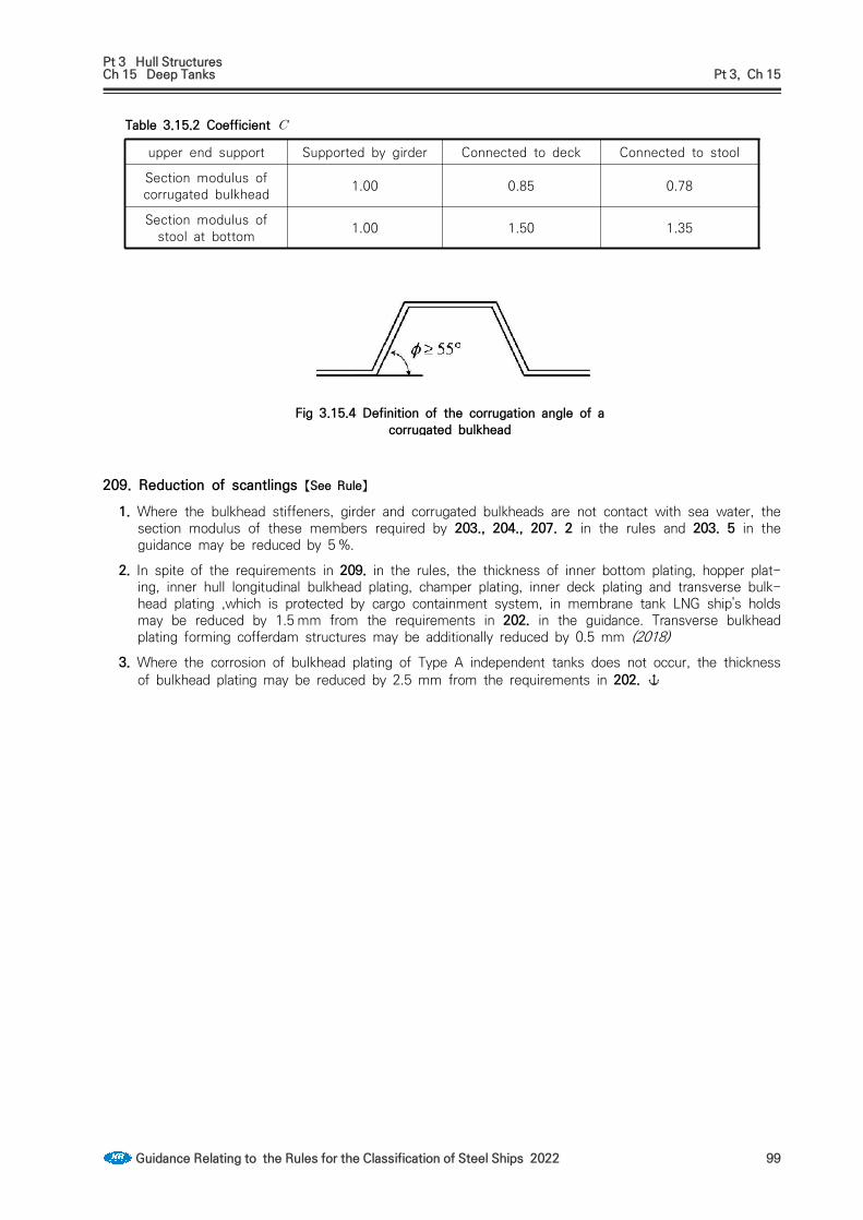
Pt 3 Hull StructuresCh 15 Deep Tanks Pt 3, Ch 15
Guidance Relating to the Rules for the Classification of Steel Ships 2022 99
Table 3.15.2 Coefficient
upper end support Supported by girder Connected to deck Connected to stool
Section modulus of corrugated bulkhead 1.00 0.85 0.78
Section modulus of stool at bottom 1.00 1.50 1.35
Fig 3.15.4 Definition of the corrugation angle of a corrugated bulkhead
209. Reduction of scantlings 【See Rule】
1. Where the bulkhead stiffeners, girder and corrugated bulkheads are not contact with sea water, the section modulus of these members required by 203., 204., 207. 2 in the rules and 203. 5 in the guidance may be reduced by 5 %.
2. In spite of the requirements in 209. in the rules, the thickness of inner bottom plating, hopper plat-ing, inner hull longitudinal bulkhead plating, champer plating, inner deck plating and transverse bulk-head plating ,which is protected by cargo containment system, in membrane tank LNG ship's holds may be reduced by 1.5 mm from the requirements in 202. in the guidance. Transverse bulkhead plating forming cofferdam structures may be additionally reduced by 0.5 mm (2018)
3. Where the corrosion of bulkhead plating of Type A independent tanks does not occur, the thickness of bulkhead plating may be reduced by 2.5 mm from the requirements in 202.

Pt 3 Hull StructuresCh 16 Superstructures Pt 3, Ch 16
Guidance Relating to the Rules for the Classification of Steel Ships 2022 101
CHAPTER 16 SUPERSTRUCTURES
Section 1 General
101. General (2019)The forecastle for fishing vessels, may be omitted provided that they are satisfied with the relevant requirements of Standard for Fishing Vessel's Structure of Fishing Vessel Act.
102. Application 【See Rule】
In application to 102. 2 of the Rules, the construction and scantlings of the superstructures above the third tier are to be applied as if they are in third tier.
Section 3 Access Opening in Superstructure End Bulkheads
301. Closure for access opening 【See Rule】Where the sill of access opening is to make hindrance to the passage of heavy spare parts, etc., removable sill may be provided subject to approval by the Society.

Pt 3 Hull StructuresCh 17 Deckhouses Pt 3, Ch 17
Guidance Relating to the Rules for the Classification of Steel Ships 2022 103
CHAPTER 17 DECKHOUSES
Section 1 General
101. Application 【See Rule】
In application to 101. 2 of the Rules, the construction and scantlings of the superstructures and deckhouses above the third tier are to be applied as if they are in third tier.

Pt 3 Hull StructuresCh 18 Machinery Spaces and Engine Casings Pt 3, Ch 18
Guidance Relating to the Rules for the Classification of Steel Ships 2022 105
CHAPTER 18 MACHINERY SPACES AND ENGINE CASING
Section 2 Main Engine Foundation
202. Double bottom 【See Rule】
1. Scantlings of members of double bottom structure in machinery space are based on the following standards.(1) The thickness of centreline girder is not less than the value obtained from the following formula
(mm)
(2) The thickness of side girders and solid floors is not less than the value obtained from the fol-lowing formula. If man holes are provided in girder plates, its number is to be minimized as far as possible.
: (mm) ≥ : (mm)
2. Girder plates beneath seat plates of main engine are in general to be penetrated through inner bot-tom plates. Where they are unable to be penetrated, inner bottom plates are to be suitably thicker than required and girder plates are to be welded with edge preparation.
3. Where main engines are directly installed on inner bottom plates, the compartments beneath main engine are recommended to be cofferdams. In case they are used as deep tanks, cap nuts, pack-ing, etc. are to be fitted with in order to keep water/oil tightness at foundation bolts.
Section 3 Construction of Boiler Rooms
301. Boiler foundations 【See Rule】
For the applying 301. 2 of the Rules, the strengthening under boiler is to be in accordance with Ch 7, 107 of the Guidance.

Pt 3 Hull StructuresCh 19 Tunnels and Tunnel Recesses Pt 3, Ch 19
Guidance Relating to the Rules for the Classification of Steel Ships 2022 107
CHAPTER 19 TUNNELS AND TUNNEL RECESSES
Section 1 General (2019)
101. Arrangement 【See Rule】
In application to 101. 3 of the Rules, escape trunks of passenger ships are to be in accordance with SOLAS II-1/13.11.1.
110. Ventilators and escape trunks 【See Rule】
Escape trunks of passenger ships are to be in accordance with SOLAS II-1/13.11.1.

Pt 3 Hull StructuresAnnex 3-1 Guidance for Survey and Composition of Loading Manuals Pt 3, Annex 3-1
Guidance Relating to the Rules for the Classification of Steel Ships 2022 109
Annex 3-1 Guidance for Survey and Composition of Loading Manuals
1. Composition of loading manualThe loading manual is to be composed to the followings;(1) General
Explanation of guidance for loading which is related to the ship's strength and in aiding of ship's master for its performance and condition.
(2) Standard loading conditionExplanation for the ship's standard loading condition
(3) Strength calculation for other conditions than standard loading condition. (See 5)However, the ships relating category 2 of Ch 3, Table 3.3.3 are not necessary.
2. Contents is to be included in 'General'(1) General explanatory notes for the arrangements, scantlings, structure and characteristics(2) Precaution for loading
For the standard loading conditions the results of analysis of structural strength including trans-verse strength and local strength and operational precautions based on the results of analysis of the strength are to be specified. For loading different from the standard loading conditions, such items of precautions that no excessive stress as viewed from hull strength might be caused are to be specified. And further, precautions relative to weight shifting involving the transfer of bal-last water and cargo for making the standard loading conditions or any other arbitrary loading conditions are to be specified. Although specific contents may differ on each ship, precautions must be generally taken on the following points in preparing the Loading Manual;(A) The minimum bow draught required for the structural strength of the strengthened bottom
forward(B) Limitation to loading height of cargo holds (C) Acceptability of alternate loading, two-port loading, etc.(D) Limitation to liquid levels in tanks(E) Limitation to loading with respect to local strength and transverse strength (e.g. limitations to
the maximum design cargo weight on deck or hatch cover)(F) Limitation to loading with respect to longitudinal hull strength(G) Precautions for ballasting / deballasting and drydocking
(3) Allowable values for longitudinal still water bending moment and still water shearing force, and allowable stressesAllowable values of longitudinal still water bending moment and still water shearing force calcu-lated in accordance with the requirements of 4. are to be prescribed. And, definition of positive (+) and negative (-) symbols of shearing force and longitudinal bending moment are to be pre-scribed in 5.2.
(4) For bulk carriers, ore carriers and combination carriers of 150 m in length and above in , the followings are included in addition to the above (1) to (3);(A) For bulk carriers, envelop results or envelop data and allowable values to shearing force and
still water bending moment under the cargo hold flooding.(B) Where the cargos are fully loaded, empty cargo holds. if the ship is not permitted to re-
maining empty hold, this is to be noted in loading manual.(C) Maximum allowable and minimum required mass of cargo and double bottom contents of
each hold as a function of draught at mid-hold position.(D) Maximum allowable and minimum required mass of cargo and double bottom contents of any
two adjacent holds as a function of the mean draught in way of these holds. This mean draught may be calculated by averaging the draught of the two mid-hold positions. The cal-culating methods for allowable mass including the mass in (C) above are to be in accordance with Annex 7-4 "Guidance for calculating the maximum allowable and minimum required mass of cargo and double bottom contents for bulk carriers"
(E) Allowable loading weight of tank top and characteristic for the cargoes other than bulk car-goes
(F) Allowable loading weight of cargo hatch covers and deck. If cargo is not approved to load on the cargo hatch covers and deck, this is to be noted in loading manual.
(G) Ratio of maximum ballast exchanging and loading plans of ballast. And it is also to be pre-scribed that these are to be agreed with terminal including the ratio of ballasting exchange.

Pt 3 Hull StructuresAnnex 3-1 Guidance for Survey and Composition of Loading Manuals Pt 3, Annex 3-1
110 Guidance Relating to the Rules for the Classification of Steel Ships 2022
3. Standard loading condition(1) In general, the following design cargo and ballast loading conditions, based on amount of bunker,
fresh water and stores at departure and arrival, are to be considered for the calculations of still water bending moment and shear force.Where the amount and disposition of consumables at any intermediate stage of the voyage are considered more severe, calculations for such intermediate conditions are to be submitted in ad-dition to those for departure and arrival conditions.Also, where any ballasting and/or deballasting is intended during voyage, calculations of the in-termediate condition just before and just after ballasting and/or deballasting any ballast tank are to be submitted and where approved included in the loading manual for guidance.(A) Cargo ships, roll on roll off ships, refrigerated cargo ships, bulk carriers, ore carriers, etc. (2020)
(a) Light load condition(b) Ballast conditions (at arrival and departure)(c) Homogeneous loading conditions of cargo (at arrival and departure)(d) All non-homogeneous loading conditions as given in the specifications (at arrival and de-
parture)(e) Specially approved loading conditions for short voyage or in smooth water, where neces-
sary (f) Temporary severe loading conditions during cargo loading or unloading, where necessary (g) Conditions for entering dry dock while afloat(h) If applicable, Guidance for the ballasting exchange while the ship is at sea.(i) All loading conditions specified Rule Pt 7, Ch 3, Sec 2 for bulk carriers with notation
BC-A, BC-B or BC-C, as applicable.(B) Oil tankers
(a) Light load condition(b) Ballast conditions (at arrival and departure)(c) Homogeneous loading conditions (at arrival and departure)(d) All non-homogeneous loading conditions as given in the specifications (at arrival and de-
parture)(e) Conditions which largely differ from the standard ballast condition due to tank cleaning or
other work while the ship is at sea(f) Temporary severe loading conditions during cargo loading or where necessary, unloading(g) Conditions for entering dry dock while afloat (h) If applicable, Guidance for the ballast exchanging while the ship is at sea.
(C) Chemical tankers(a) The same conditions as specified in (B) for oil tankers(b) The loading conditions specified in the Operation Manual(c) Loading conditions for cargo items included in the approved list of cargoes, which are
with high density, or require heating or isolated stowage.(d) If applicable, Guidance for the ballast exchanging while the ship is at sea.
(D) Ships carrying liquefied gas as in bulk(a) Light load condition(b) Ballast conditions (at arrival and departure)(c) Homogeneous loading conditions (at arrival and departure)(d) Loading conditions involving empty or partially loaded tanks(e) Loading conditions where two or more kinds of cargoes with largely different specific
gravity are loaded in different tanks(f) Loading in smooth water where an increased vapour pressure is approved(g) Temporary severe loading conditions during cargo loading or unloading, where necessary.(h) Conditions for entering dry dock while afloat (i) If applicable, Guidance for the ballast exchanging while the ship is at sea.
(E) Combination carriers(a) The same conditions as specified respectively in (A) and (B) above for cargo ships and
oil tankers(b) If applicable, Guidance for the ballast exchanging while the ship is at sea.
(F) For bulk carriers, ore carriers and combination carriers of 150 m length and above in , the following loading conditions are to be included in addition to the above (A) and (E) loading conditions. However, the following (d) and (e) loading conditions may be followed by the specification agreed between owner and builder, and also if some of the following loading

Pt 3 Hull StructuresAnnex 3-1 Guidance for Survey and Composition of Loading Manuals Pt 3, Annex 3-1
Guidance Relating to the Rules for the Classification of Steel Ships 2022 111
conditions are not included in the Loading Manual a note to this effect is to be given in the Loading Manual.(a) Alternate light and heavy cargo loading conditions at maximum draught, where applicable.(b) Homogeneous light and heavy cargo loading conditions at maximum draught.(c) Ballast conditions, For vessels having ballast holds adjacent to topside wing, hopper and
double bottom tanks, it shall be strengthwise acceptable that the ballast holds are filled when the topside wing, hopper and double bottom tanks are empty. Partial filling of fore peak tank is not acceptable in design ballast conditions, unless effective means are pro-vided to prevent accidental overfilling.
(d) Short voyage conditions where the vessel is to be loaded to maximum draught but with limited amount of bunkers.
(e) Multiple port loading/unloading conditions.(f) Deck cargo condition, where applicable.(g) Guidance for typical loading/unloading sequences where the vessel is loaded from com-
mencement of cargo loading to reaching full deadweight capacity, for homogeneous con-ditions, alternate conditions where applicable and relevant part loaded conditions is to be included. When this guidance is composed, precaution must be taken on loading rate, ballast and deballasting rates and applicable strength limitations, and the followings in this guidance are to be included.(i) The typical loading sequences as relevant should include the following loading con-
ditions① Loading conditions in above (a), (b), (d), (e) and (f)② Block loading
(ii) The loading/unloading sequences may be port specific or typical.(iii)The sequence is to be built up step by step from commencement of cargo loading to
reaching full deadweight capacity. Each time the loading equipment changes position to a new hold defines a step. In addition to longitudinal strength, the local strength of each hold is to be considered.
(iv)For each load condition above mentioned in (i), the summary for all steps is to in-clude the followings,
① How much cargo is filled in each hold during the different steps.② How much ballast is discharged from each ballast tank during the different steps.③ The maximum still water bending moment and shear at the end of each step.④ The ship's trim and bow, stern and mean draught at the end of each step.⑤ The ship's air-draught when necessary.
(v) The form of guidance for loading/unloading sequences is referred to Table 4.(G) Partially filled ballast tanks in ballast loading conditions
(a) Ballast loading conditions involving partially filled peak and/or other ballast tank at de-parture, arrival or during intermediate conditions are not permitted to be used as design conditions unless:(i) design stress limits are satisfied for all filling levels between empty and full, and(ii) for bulk carriers, Rule Pt 7, Ch 3, Sec 10, as applicable, is complied with for all fill-
ing levels between empty and full.(b) To demonstrate compliance with all filling levels between empty and full, it will be ac-
ceptable if, in each condition at departure, arrival and any intermediate condition, the tanks intended to be partially filled are assumed to be:(i) empty(ii) full(iii) partially filled at intended level
(c) Where multiple tanks are intended to be partially filled, all combinations of empty, full or partially filled at intended level for those tanks are to be investigated.
(d) However, for conventional ore carriers with large wing water ballast tanks in cargo area, where empty or full ballast water filling levels of one or maximum two pairs of those tanks lead to the ship's trim exceeding one of the following conditions, it is sufficient to demonstrate compliance with maximum, minimum and intended partial filling levels of those one or maximum two pairs of ballast tanks such that the ship's condition does not exceed any of these trim limits. Filling levels of all other wing ballast tanks are to be considered between empty and full.

Pt 3 Hull StructuresAnnex 3-1 Guidance for Survey and Composition of Loading Manuals Pt 3, Annex 3-1
112 Guidance Relating to the Rules for the Classification of Steel Ships 2022
The trim conditions mentioned above are:(i) trim by stern of 3% of the ship's length, or(ii) trim by bow of 1.5% of the ship's length, or(iii) any trim that cannot maintain propeller immersion(I/D) not less than 25 %,
where; I : the distance from propeller centerline to the waterline D : propeller diameter (see Fig 1)
Fig 1 Immersion of propeller
The maximum and minimum filling levels of the above mentioned pairs of side bal-last tanks are to be indicated in the loading manual.Par 6 contains the guidance for partially filled ballast tanks in ballast loading conditions. (2022)
(H) Partially filled ballast tanks in cargo loading conditionsIn cargo loading conditions, the requirements of (G), applies to the peak tanks only.
(I) Sequential ballast water exchangeRequirements of (G) and (H) are not applicable to ballast water exchange using the sequen-tial method. However, bending moment and shear force calculations for each deballasting or ballasting stage in the ballast water exchange sequence are to be included in the loading manual or ballast water management plan of any vessel that intends to employ the sequen-tial ballast water exchange method.
(2) Graphical illustration of standard loading conditions(A) To enable the ship master to readily grasp the relationships between loading conditions and
hull strength under the standard loading conditions and to utilize them as guidance for plan-ning the loading, the results of calculation of longitudinal still water bending moment () and still water shearing force () at each condition are to be subjected to graphical illus-tration together with the respective allowable values. In this case, the directions of positive and negative are also to be specified for and .
(B) The above mentioned results of calculation are to be shown on a single page or on two spread pages as far as possible on each condition, together with arrangement plan of com-partments (tanks and cargo holds), cargo stowage table and the results of trim and stability calculations. Descriptive examples of these are shown 5.3. Restrictions imposed for operation of the ship in the standard loading conditions if any, are to be specified.
(3) Additional notation, BLU(A) In addition to the requirements in 3 (1) (F) (g), the additional special feature notation BLU
shall be assigned to ships which for bulk carriers with notation BC-A or BC-B and Ore car-riers satisfied with the The average loading rate is 16,000 ton/h and if the average loading rate is not this value, loading rates are specified in the loading manual and submitted for the approval of the Society. The average loading rate is defined as rate achieved from start to completion of total cargo loading divided by time elapsed. Special consideration shall be giv-en if loading with two or more loaders simultaneous is specified and provided as part of the documentation for approval.
Relevant loading sequences for the following conditions shall be defined:— homogeneous condition— part loading conditions (if applicable)— alternate conditions (if applicable)
Each step in the loading sequences from commencement of cargo loading to full deadweight is reached, stepwise and time-wise synchronized with the de-ballasting operation, shall be

Pt 3 Hull StructuresAnnex 3-1 Guidance for Survey and Composition of Loading Manuals Pt 3, Annex 3-1
Guidance Relating to the Rules for the Classification of Steel Ships 2022 113
documented. Each time the loading equipment changes position to a new cargo hold is de-fined as a step.
Time-wise synchronized in this context means that the de-ballasting is completed within the same time as the loading step.The typical loading sequences shall also be developed to not exceed applicable strength limitations.For all relevant loading sequences, considering one, two or more loaders acting simulta-neously as applicable, a summary of all steps shall be included with at least the following information included:
- how much cargo is filled in each cargo hold during the different steps- how much ballast is discharged from each ballast tank during the different steps- the maximum still water bending moment and shear force at the end of each step- the ship's trim and draught at the end of each step- the ship's draught aft and forward, trim and air-draught, if restrictions are applicable- the ship's local strength criteria for single and adjacent hold loading
If the Master deems necessary due to operational reasons to deviate from the approved loading sequence calculations with loading ratings, he may do so provided he is in com-pliance with SOLAS Ch.VI Pt. B, Reg.7.3 and on this condition agree with the terminal on a new loading plan.
(B) The de-ballast capacity of the vessel at loading berth prior to commencement of loading, in-cluding arrangement of ballast tanks and relevant piping system, shall meet the requirements for the average loading rates. If average loading rate is higher than 16,000 ton/h as specified in (A), the loading operation is not be interrupted due to de-ballast operations.
(C) The vessel shall be fitted with a separate stripping system. To enhance de-ballasting and stripping, the trim is to be by stern during the whole operation as far as practicable.
(D) The vessel shall be designed such that minimum 100% of maximum permissible cargo intake per cargo hold can be loaded in one pour.
(E) Inner bottom strength shall be according to the requirements as given in Rule Pt.11 Ch. 12, Sec.1 for CSR Bulk carriers or Rule Pt.7 Ch.2, 202. for Ore carriers or Rule Pt.7 Ch.3, 304. 3 for Bulk carriers.
(F) The vessel shall be fitted with a remote sounding for water ballast and fuel oil storage tanks and draught reading system with an on-line interface into the software of the onboard load-ing computer.
(G) Check of local strength for single and adjacent hold loading pattern shall be integrated into the software of the onboard loading computer.
4. Allowable values for longitudinal strength
The allowable values for longitudinal still water bending moment and still water shearing force which are specified in the Loading Manual are to be determined with the consideration given to the design condition of the ship. Those values, however, are not to exceed the values specified in the follow-ing, at positions of transverse section of the hull where deemed necessary by the Surveyor.(1) Allowable still water longitudinal bending moment ()
For the ships specified in Ch 3, 104. 1 (1) of the Rules, the values obtained from the following (A) or (B), whichever is smaller, is to be taken as the allowable value for each positive and neg-ative moment at a transverse section of the ship under consideration. However, these values are to be also complied with Ch 3, Sec 4. (A) Value determined by longitudinal bending moment
× (kN-m)
× (kN-m)
= for the ships using the value or specified in Ch 3, 124. of the Rules, those val-ues is to be used. For the ships not using those values, the value is to be used.
= section modulus of transverse section of the ship with respect to the ship's bottom or

Pt 3 Hull StructuresAnnex 3-1 Guidance for Survey and Composition of Loading Manuals Pt 3, Annex 3-1
114 Guidance Relating to the Rules for the Classification of Steel Ships 2022
strength deck at the position under consideration (cm3) , is to be in accordance with Ch 3, Table 3.3.1 of the Rules.
(B) Value determined by torsional bending momentIn case where torsional moment is generated in the hull due to uneven cargo stowage, the warping stress value used in applying Pt 7, Ch 4, 202. of the Guidance is to be deducted from the value in [ ] in the following formula.
(kN-m)
(kN-m)
, is to be obtained from the following formula.
×
×
, = as specified in Ch 3, Table 3.3.1 of the Rules., , = as specified in Pt 7, Ch 4, Sec 2 of the Guidance.
(2) For the ships under Ch 3, 104. 1 (2) and (3) of the Rules and for the ships which are not under (1) and (3), longitudinal still water bending moment at the positions of transverse section of the ship under consideration for each positive and negative moment is to be determined from the preceeding (1) (A) and to satisfy the requirements Ch 3, Sec 4 of the Rules.
(3) The allowable value for shearing force ()(A) The allowable value for shearing force is to be obtained from the following formula.
×
× (kN)
×
× (kN)
= thickness of side shell plating at positions under consideration. However, for the ships having longitudinal bulkheads, thickness of the part of longitudinal bulkheads are to be included (mm)
, , and = as specified in Ch 3, 301. of the Rules.(B) When the shearing force of the thickness of side shell plating is directly calculated, the val-
ue of preceeding (A) or the value to be obtained from following formula is to be taken, whichever is smaller.
(kN)
(kN)
= the shearing force acting on transverse section of the ship used in the direct strength calculation which is in accordance with Ch 3, 301. of the Guidance.
, = As specified in Ch 3, 301. of the Rules

Pt 3 Hull StructuresAnnex 3-1 Guidance for Survey and Composition of Loading Manuals Pt 3, Annex 3-1
Guidance Relating to the Rules for the Classification of Steel Ships 2022 115
= allowable shearing force as specified in Ch 3, 301. of the Guidance. (N/mm2) = shearing force acting on transverse section of the ship determined by the direct
strength calculation, where the greatest value among those which occur in side shell plating, bilge hopper tanks and top side tanks is to be taken (N/mm2).
(C) The allowable value for shearing force in still water bending moment determined by the pre-ceeding (A) and (B) is to be also complied with Ch 3, Sec 4 of the Rules.
(4) Allowable values for still water bending moment and shearing force in harbour water free from the effects of waves may be obtained by taking half the values of the wave induced longitudinal bending moment and shearing force as specified in (1) and (2) respectively.
5. Composition of loading manual
5.1 Method of longitudinal strength for loading conditions different from the standard loading condition(1) Confirmation items for longitudinal strength
Calculating and checking method of longitudinal strength for loading conditions different from the standard loading condition is to be in accordance with Fig 2 and the following items are to be included for each point of output.(A) Still water bending moment () (B) Still water shearing force ()(C) Still water shearing force for alternate loading condition () (shearing force modified by al-
ternate loading to ). However, for the ships designed without consideration of load dis-tribution by double bottom structure, confirmation of still water shearing force for alternate loading condition may be dispensed
(2) Point of output for checking longitudinal strength (A) At least six points of output of longitudinal still water bending moment are to be properly
arranged in the range (including the midship 0.5 ).(B) The points of output of still water shearing force are to be arranged at a position of fore
and aft bulkheads of cargo loaded compartments and/or similar spaces. However, where the distance between transverse bulkheads is small such as cofferdam, checking of strength at either one of the bulkheads may be omitted. Also, where the shearing force is considered to be apparently small, checking of strength may be omitted.
(3) Grouping of loads in calculation(A) Loads in those tanks symmetrically arranged on both sides of the ship may be summarized
in same group in calculation.(B) In case where two or more hatch openings are provided for one cargo hold, calculations to
be made for each such hatch opening. However, where separation according to type of car-go is unnecessary, calculation may be made by hold.
(4) Procedure for checking longitudinal strength(A) In order to facilitate checking of allowable cargo loading, the relation between loading and
longitudinal strength, and the procedure of checking longitudinal strength are to be explained by using flow chart or any other proper means. Descriptive examples are shown in 5.4.
(B) The following allowable values corresponding to values calculated in (1) above are to be clearly specified so that the shipmaster can judge the adequacy of cargo loading without making mistakes.(a) Allowable value for longitudinal still water bending moment (allowable value of )(b) Allowable value for still water shearing force (allowable value of )
(C) Terms and symbols used for describing the calculated values and allowable values are to be same as used in (1) and (4) (B).
(5) Method of Calculation(A) Calculations of longitudinal still water bending moment () and still water shearing force
()Longitudinal still water bending moment and still water shearing force are to be determined basing upon direct strength calculation.
(B) Calculation of still water shearing force in alternate loading ()Corrective calculations in case where the adjoining holds are alternately loaded are to be made according to the method as given in 5.6.
(C) Calculation of these are to be attached to Loading Manual.

Pt 3 Hull StructuresAnnex 3-1 Guidance for Survey and Composition of Loading Manuals Pt 3, Annex 3-1
116 Guidance Relating to the Rules for the Classification of Steel Ships 2022
Fig 2 Flow chart of confirmation of longitudinal strength
5.2 Descriptive example for the allowable value for longitudinal bending moment and still water shear-ing force.
For the permissible value of still water bending moments and shearing forces are to be as follows at sea and in harbor.

Pt 3 Hull StructuresAnnex 3-1 Guidance for Survey and Composition of Loading Manuals Pt 3, Annex 3-1
Guidance Relating to the Rules for the Classification of Steel Ships 2022 117

Pt 3 Hull StructuresAnnex 3-1 Guidance for Survey and Composition of Loading Manuals Pt 3, Annex 3-1
118 Guidance Relating to the Rules for the Classification of Steel Ships 2022
5.3 Descriptive example for standard loading conditions
CONDITION NO.Ⅱ NORMAL BALLAST CONDITION DEPARTURE

Pt 3 Hull StructuresAnnex 3-1 Guidance for Survey and Composition of Loading Manuals Pt 3, Annex 3-1
Guidance Relating to the Rules for the Classification of Steel Ships 2022 119
CARGO OIL (BALLAST WATER)
TANK NO1CT
NO2CT
NO3CT
NO4CT
NO5CT
NO1WT
NO2WT
NO3WT
NO5WT
NO6WT
NO7WT
NO8WT SLOPT
WEIGHT (t) 0 0 0 0 0 0 0 20000 0 27284 14000 0 0
VOL/CAP (%) 0 0 0 0 0 0 0 74 0 98 53 0 0
WEIGHT CONDITIONS
BALLAST WATER FRESH WATER FUEL OIL
TANK FPTNO4WT
APT FWT DRWTTSWT
(F)TSWT
(A)FOT(P)
FOT(S)
FOST(P)
FOST(S)
WEIGHT (t) 9919 27288 954 200 170 60 70 995 994 1091 680VOL/CAP (%) 98 98 98 50 54 53 50 33 33 98 98

Pt 3 Hull StructuresAnnex 3-1 Guidance for Survey and Composition of Loading Manuals Pt 3, Annex 3-1
120 Guidance Relating to the Rules for the Classification of Steel Ships 2022
Fig 3
5.4 Descriptive example on the procedure of calculation of longitudinal still water bending moment and still water shearing force
Adjustments in loading and judging procedure
In case where loading different from the standard loading conditions is made, the longitudinal still water bending moment () and still water shearing force(, ) are to be obtained by the proce-dures stated below and the loading is to be adjusted in such a manner that the values as obtained above do not exceed the respective allowable values. Since the allowable value are set in such a manner that the stresses acting on the hull due to longitudinal bending moment and shearing force predictable while the ship is sailing in the ocean do not exceed the allowable limits to the structural strength of the specific part of the hull under consideration, the strength of the ship during at sea can be ensured so far as the values of , and at each point of output do not exceed the corresponding allowable values.
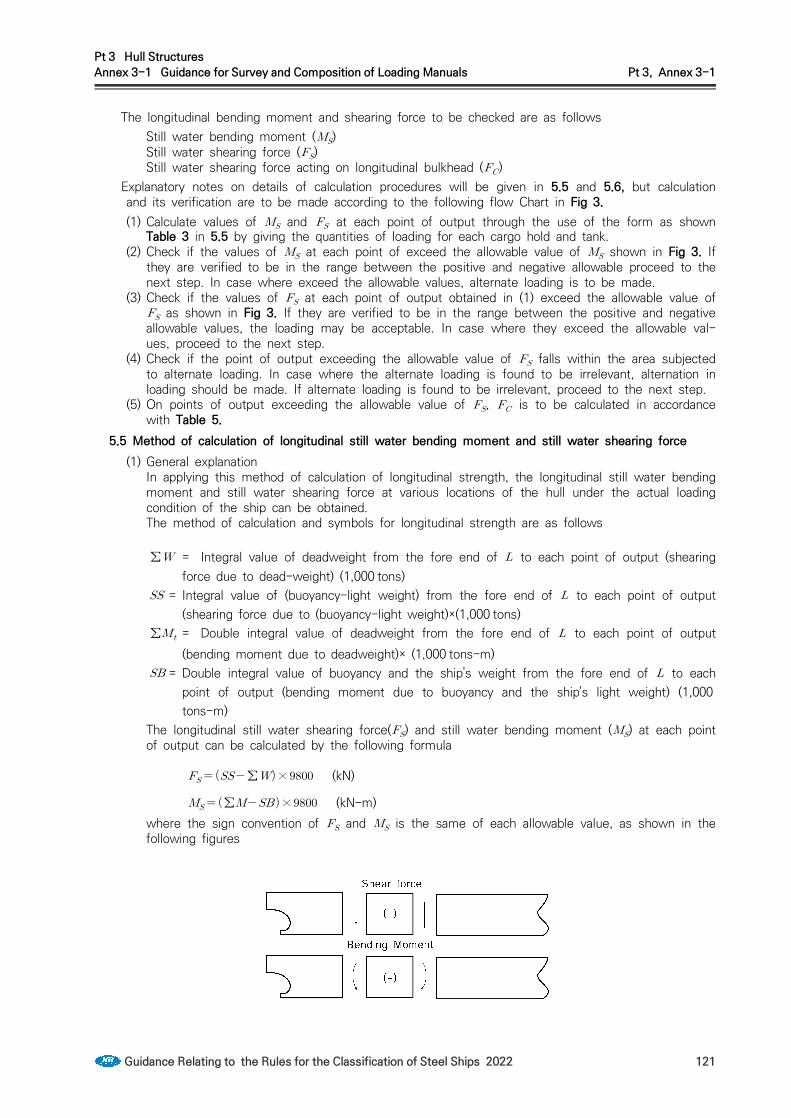
Pt 3 Hull StructuresAnnex 3-1 Guidance for Survey and Composition of Loading Manuals Pt 3, Annex 3-1
Guidance Relating to the Rules for the Classification of Steel Ships 2022 121
The longitudinal bending moment and shearing force to be checked are as followsStill water bending moment ()Still water shearing force ()Still water shearing force acting on longitudinal bulkhead ()
Explanatory notes on details of calculation procedures will be given in 5.5 and 5.6, but calculation and its verification are to be made according to the following flow Chart in Fig 3.(1) Calculate values of and at each point of output through the use of the form as shown
Table 3 in 5.5 by giving the quantities of loading for each cargo hold and tank.(2) Check if the values of at each point of exceed the allowable value of shown in Fig 3. If
they are verified to be in the range between the positive and negative allowable proceed to the next step. In case where exceed the allowable values, alternate loading is to be made.
(3) Check if the values of at each point of output obtained in (1) exceed the allowable value of as shown in Fig 3. If they are verified to be in the range between the positive and negative allowable values, the loading may be acceptable. In case where they exceed the allowable val-ues, proceed to the next step.
(4) Check if the point of output exceeding the allowable value of falls within the area subjected to alternate loading. In case where the alternate loading is found to be irrelevant, alternation in loading should be made. If alternate loading is found to be irrelevant, proceed to the next step.
(5) On points of output exceeding the allowable value of , is to be calculated in accordance with Table 5.
5.5 Method of calculation of longitudinal still water bending moment and still water shearing force(1) General explanation
In applying this method of calculation of longitudinal strength, the longitudinal still water bending moment and still water shearing force at various locations of the hull under the actual loading condition of the ship can be obtained.The method of calculation and symbols for longitudinal strength are as follows
∑ = Integral value of deadweight from the fore end of to each point of output (shearing force due to dead-weight) (1,000 tons)
= Integral value of (buoyancy-light weight) from the fore end of to each point of output (shearing force due to (buoyancy-light weight)×(1,000 tons)
∑ = Double integral value of deadweight from the fore end of to each point of output (bending moment due to deadweight)× (1,000 tons-m)
= Double integral value of buoyancy and the ship's weight from the fore end of to each point of output (bending moment due to buoyancy and the ship's light weight) (1,000tons-m)
The longitudinal still water shearing force() and still water bending moment () at each point of output can be calculated by the following formula
∑× (kN)
∑× (kN-m)where the sign convention of and is the same of each allowable value, as shown in the following figures

Pt 3 Hull StructuresAnnex 3-1 Guidance for Survey and Composition of Loading Manuals Pt 3, Annex 3-1
122 Guidance Relating to the Rules for the Classification of Steel Ships 2022
In this method of calculation of longitudinal strength, the shearing forces () and the bending moments ( ) due to buoyancy and the ship's light weight are calculated for every metre of draught and the longitudinal strength data, a list of shearing forces and bending moments for respective set-up draughts are prepared. In Table 4, an example of numerical table for one set for the specific draught is given for an example.Accordingly, by calculating only the shearing force and bending moment due to dead weight, the longitudinal still water shearing force () and still water bending moment () for each point of output can easily be obtained on board the ship.
(2) Procedure for calculation of Longitudinal strengthThe calculation of longitudinal strength may be proceeded by filling up the spaces given in Table 3. The procedure is given as follows(A) After draught () and trim
The after draught and trim, in the conditions for which the calculation of longitudinal strength is to be made, are to be filled up in the blank spaces. In this case, the trim by the bow is to be noted with negative sign (-).
(B) Base draught () and difference of draught ()A draught, closes to but is less than the after draught is to be selected from among the base draughts given in the longitudinal strength data and is to be filled up in the space for the base draught, and the difference between the after draught and the selected base draught is to be entered in the space for the difference ().
(C) Column for WeightOne-thousandth of the deadweight (ton) in the respective compartments is to be entered in this column.
(D) Column for This column is for indicating the dead-weight in the respective compartments exerted on points of longitudinal strength output, which is obtained by multiplying the deadweight by the ratio (ratio of compartment to be included in each point of output).
(E) Column for This column is for indicating the moment around the midship which is created by the dead-weight in the respective compartments, and here the value of × is to be entered.
(F) ∑, ∑The accumulations of and . included between the fore end and each point of output are to be filled up here.
(G) and and indicate the shearing force and the bending moment due to buoyancy and the ship's light weight respectively and they are to be calculated according to the following pro-cedures(a) Correction factors ( and ) in accordance with base value, difference of draught and
trimThe base value (column ①) and the respective correction factors ( and ) at each point of output is to be transferred from the longitudinal strength data for the draught adopted as the base draught to the corresponding space.
(b) Correction for difference of draught () (column ②)This is to correct the difference between the base draught and the actual draught. The correction is to be made by multiplying the correction factor () by the difference of draught ().

Pt 3 Hull StructuresAnnex 3-1 Guidance for Survey and Composition of Loading Manuals Pt 3, Annex 3-1
Guidance Relating to the Rules for the Classification of Steel Ships 2022 123
○ CONDITIONAFT DRAFT (DA) : (m)BASE DRAFT (DB) : (m)DIFFERENCE(△D)=DA-DB : (m)TRIM : (m)
D.W.ITEMWEIGHT1/1,000
RATIOLOAD( )
G MOMENT
1 FORE PEAK TANK 1.000 140.08
FR. 99∑ = ( )
1∑ = ( )
12 No. 1C.O.T. (C) 1.000 121.303 No. 1C.O.T. (P/S) 1.000 120.20
FR. 94∑ = ( )
1~3∑ = ( )
1~34 No. 2C.O.T. (C) 0.500 94.805 No. 2C.O.T. (P/S) 1.000 94.63
FR. 88∑ = ( )
1~5∑ = ( )
1~56 No. 2C.O.T. (C) 0.500 64.807 No. 3C.O.T. (P/S) 1.000 64.80
FR. 82∑ = ( )
1~7∑ = ( )
1~78 No. 3W.B.T. (C) 0.500 34.809 No. 4C.O.T. (P/S) 1.000 34.80
FR. 76∑ = ( )
1~7∑ = ( )
1~910 No. 3W.B.T. (C) 0.500 4.8011 No. 5C.O.T. (P/S) 1.000 4.80
FR. 70∑ = ( )
1~7∑ = ( )
1~1112 No. 4C.O.T. (C) 0.500 -25.2013 No. 6C.O.T. (P/S) 1.000 -25.19
FR. 64∑ = ( )
1~7∑ = ( )
1~1314 No. 4C.O.T. (C) 0.500 -55.2015 No. 7C.O.T. (P/S) 1.000 -55.07
FR. 58∑ = ( )
1~7∑ = ( )
1~1516 No. 5C.O.T. (C) 0.674 -80.1717 No. 8C.O.T. (P/S) 1.000 -79.93
FR. 54∑ = ( )
1~7∑ = ( )
1~1718 No. 5C.O.T. (C) 0.326 -95.0819 SLOP TANK (P/S) 1.000 -94.74
FR. 52∑ = ( )
1~7∑ = ( )
1~19
FR.99
FR.94
FR.88
FR.82
FR.76
FR.70
FR.64
FR.58
FR.54
FR.52
ITEM SHEARING FORCE ( ) BENDING MOMENT ( )BASE VALUE ① ①
DRAFT CORRECTION CD ( ) × △ D ② CD ( ) × △ D ②TRIM CORRECTION CT ( ) × TRIM ③ CT ( ) × TRIM ③
BUOYANCY & L.W. ①+②+③ SS ①+②+③ SBDEADWEIGHT ∑ ∑W ∑W × (-132.8) + ∑ ( ) ∑WCALCULATED VALUE (SS-∑W) × 9,800 (∑M - SB) × 9,800ALLOWABLE VALUE ALLOWABLE SHEARING FORCE 110,000~-99,080 ALLOWABLE BENDING MOMENT 2,790,000~-2,183,600BASE VALUE ① ①
DRAFT CORRECTION CD ( ) × △ D ② CD ( ) × △ D ②TRIM CORRECTION CT ( ) × TRIM ③ CT ( ) × TRIM ③
BUOYANCY & L.W. ①+②+③ SS ①+②+③ SBDEADWEIGHT ∑ ∑W ∑W × (-109.8) + ∑ ( ) ∑WCALCULATED VALUE (SS-∑W) × 9,800 (∑M - SB) × 9,800ALLOWABLE VALUE ALLOWABLE SHEARING FORCE 129,000~-113,370 ALLOWABLE BENDING MOMENT 4,340,000~-3,321,300BASE VALUE ① ①
DRAFT CORRECTION CD ( ) × △ D ② CD ( ) × △ D ②TRIM CORRECTION CT ( ) × TRIM ③ CT ( ) × TRIM ③
BUOYANCY & L.W. ①+②+③ SS ①+②+③ SBDEADWEIGHT ∑ ∑W ∑W × (-79.8) + ∑ ( ) ∑WCALCULATED VALUE (SS-∑W) × 9,800 (∑M - SB) × 9,800ALLOWABLE VALUE ALLOWABLE SHEARING FORCE 128,000~-112,030 ALLOWABLE BENDING MOMENT 6,040,000~-4,449,800BASE VALUE ① ①
DRAFT CORRECTION CD ( ) × △ D ② CD ( ) × △ D ②TRIM CORRECTION CT ( ) × TRIM ③ CT ( ) × TRIM ③
BUOYANCY & L.W. ①+②+③ SS ①+②+③ SBDEADWEIGHT ∑ ∑W ∑W × (-49.8) + ∑ ( ) ∑WCALCULATED VALUE (SS-∑W) × 9,800 (∑M - SB) × 9,800ALLOWABLE VALUE ALLOWABLE SHEARING FORCE 122,000~-112,720 ALLOWABLE BENDING MOMENT 6,590,000~-4,459,000BASE VALUE ① ①
DRAFT CORRECTION CD ( ) × △ D ② CD ( ) × △ D ②TRIM CORRECTION CT ( ) × TRIM ③ CT ( ) × TRIM ③
BUOYANCY & L.W. ①+②+③ SS ①+②+③ SBDEADWEIGHT ∑ ∑W ∑W × (-19.8) + ∑ ( ) ∑WCALCULATED VALUE (SS-∑W) × 9,800 (∑M - SB) × 9,800ALLOWABLE VALUE ALLOWABLE SHEARING FORCE 113,000~-112,900 ALLOWABLE BENDING MOMENT 6,520,000~-4,159,000BASE VALUE ① ①
DRAFT CORRECTION CD ( ) × △ D ② CD ( ) × △ D ②TRIM CORRECTION CT ( ) × TRIM ③ CT ( ) × TRIM ③
BUOYANCY & L.W. ①+②+③ SS ①+②+③ SBDEADWEIGHT ∑ ∑W ∑W × (-10.2) + ∑ ( ) ∑WCALCULATED VALUE (SS-∑W) × 9,800 (∑M - SB) × 9,800ALLOWABLE VALUE ALLOWABLE SHEARING FORCE 113,500~-113,690 ALLOWABLE BENDING MOMENT 6,520,000~-4,459,000BASE VALUE ① ①
DRAFT CORRECTION CD ( ) × △ D ② CD ( ) × △ D ②TRIM CORRECTION CT ( ) × TRIM ③ CT ( ) × TRIM ③
BUOYANCY & L.W. ①+②+③ SS ①+②+③ SBDEADWEIGHT ∑ ∑W ∑W × (-40.2) + ∑ ( ) ∑WCALCULATED VALUE (SS-∑W) × 9,800 (∑M - SB) × 9,800ALLOWABLE VALUE ALLOWABLE SHEARING FORCE 102,000~-113,180 ALLOWABLE BENDING MOMENT 6,520,000~-4,159,000BASE VALUE ① ①
DRAFT CORRECTION CD ( ) × △ D ② CD ( ) × △ D ②TRIM CORRECTION CT ( ) × TRIM ③ CT ( ) × TRIM ③
BUOYANCY & L.W. ①+②+③ SS ①+②+③ SBDEADWEIGHT ∑ ∑W ∑W × (-70.2) + ∑ ( ) ∑WCALCULATED VALUE (SS-∑W) × 9,800 (∑M - SB) × 9,800ALLOWABLE VALUE ALLOWABLE SHEARING FORCE 93,000~-112,030 ALLOWABLE BENDING MOMENT 6,030,000~-4,422,200BASE VALUE ① ①
DRAFT CORRECTION CD ( ) × △ D ② CD ( ) × △ D ②TRIM CORRECTION CT ( ) × TRIM ③ CT ( ) × TRIM ③
BUOYANCY & L.W. ①+②+③ SS ①+②+③ SBDEADWEIGHT ∑ ∑W ∑W × (-90.2) + ∑ ( ) ∑WCALCULATED VALUE (SS-∑W) × 9,800 (∑M - SB) × 9,800ALLOWABLE VALUE ALLOWABLE SHEARING FORCE 100,400~-111,370 ALLOWABLE BENDING MOMENT 1,100,000~-3,358,000BASE VALUE ① ①
DRAFT CORRECTION CD ( ) × △ D ② CD ( ) × △ D ②TRIM CORRECTION CT ( ) × TRIM ③ CT ( ) × TRIM ③
BUOYANCY & L.W. ①+②+③ SS ①+②+③ SBDEADWEIGHT ∑ ∑W ∑W × (-100.0) + ∑ ( ) ∑WCALCULATED VALUE (SS-∑W) × 9,800 (∑M - SB) × 9,800ALLOWABLE VALUE ALLOWABLE SHEARING FORCE 102,000~-112,370 ALLOWABLE BENDING MOMENT 3,830,000~-3,321,300
Table 3 Calculation sheet for still water bending moments( ) shearing force ( )

Pt 3 Hull StructuresAnnex 3-1 Guidance for Survey and Composition of Loading Manuals Pt 3, Annex 3-1
124 Guidance Relating to the Rules for the Classification of Steel Ships 2022
(c) Correction for trim (column ③)In case where the ship has any trim, the correction for trim is to be made by multi-plying the correction factor () by the value of trim (m).
(d) SummationThe base value 0, corrected value for the difference of draught ② and the corrected value for trim ③ are to be summed up and the sums are to be filled up in the spaces for and .
Table 4 Longitudinal strength data (for buoyancy & light ship weight)*** Each value shows(actual value/1,000) ***Base draft 12.000 meter
SHEAR FORCE (UNIT MT) BENDING MOMENT (UNIT MT-M)
CALCULATION POSITION
BASE VALUE (S.F.)
DRAFT CORRECTION
(CD)
TRIM CORRECTION
(CT)
BASE VALUE (B.M.)
DRAFT CORRECTION
(CD)
TRIM CORRECTION
(CT)
FRAME (99)FRAME (94)FRAME (88)FRAME (82)FRAME (76)FRAME (70)FRAME (64)FRAME (58)FRAME (54)FRAME (52)
2.87611.90226.93342.27257.51072.78088.048102.735110.924114.087
0.4011.40312.9324.4716.0097.5489.087
10.63811.59912.026
-0.398-1.298-2.545-3.647-4.594-5.389-6.029-6.515-6.740-6.818
18.730181.011760.620
1798.7193295.5045249.9107662.468
10528.06012667.05013770.015
2.90323.03987.944198.979356.179559.546809.082
1104.8441327.2221443.008
-3.078-22.151-80.102
-173.183-297.098-447.489-619.135-807.690-940.344
-1006.792
(H) ∑ and ∑∑ and ∑ indicate the shearing force and bending moment due to deadweight re-spectively which are obtained by the following procedure (a) Column for ∑
∑ is the accumulation(∑) of dead-weight at each point of output which is to be transferred in this column.
(b) Column for ∑∑ is the bending moment at each point of output converted from the bending mo-ment (∑) around the midship due to deadweight at each point of output, and the values obtained from the following formula is to be entered.
∑ × ≤ ∑
(I) Still water shearing force Still water shearing force() indicated the actual still water shearing force under loading condition at each point of output and is obtained from by the following formula.
․ ∑× (kN)
(J) Longitudinal still water bending moment ()Longitudinal still water bending moment indicates the actual longitudinal still water bending moment under loading condition at each point of output, and is obtained from the following formula
∑× (kN-m)

Pt 3 Hull StructuresAnnex 3-1 Guidance for Survey and Composition of Loading Manuals Pt 3, Annex 3-1
Guidance Relating to the Rules for the Classification of Steel Ships 2022 125
5.6 Method of calculation of shearing force in alternate loading
In case where the adjoining holds are loaded alternately, the shearing force is to be corrected in ac-cordance with the calculation form shown in Table 5.(1) Method of calculation (See Fig 4)
Fig 4 Correction of still water shearing force in alternate loading condition
Table 5 Example of calculation sheets for shearing force () when alternately loaded.
FR. 37 FR. 70 FR. 102 FR. 125 FR. 158 FR. 181 FR. 205
① (kN)
Holds No. 6Cargo Hold
No. 5Cargo Hold
No. 4Cargo Hold
No. 3Cargo Hold
No. 2Cargo Hold
No. 1Cargo Hold
② (kN)
Top Side Tank No. 4 Top Side Tank No. 3 Top Side Tank No. 2 Top Side Tank
No. 1 Top Side Tank
③ Weight of TST (kN)
④ (Load ratio) 0.5 0.5 0.5 0.5 1.0 1.0
⑤ (③×④)
⑥ (②-⑤)
⑦ (coefficient) 0.305 0.264 0.264 0.250 0.264 0.302
⑧ (⑥×⑦)
⑨ and
①+⑧
①-⑧
①+⑧
①-⑧
①+⑧
①-⑧
①+⑧
①-⑧
①+⑧
①-⑧
①+⑧
①-⑧
⑩Permissible
shearing forces (kN)
+ 30,200 25,500 26,300 27,600 27,600 25,200 29,300
- -28,100 -25,200 -25,200 -27,600 -28,700 -28,500 -30,400

Pt 3 Hull StructuresAnnex 3-1 Guidance for Survey and Composition of Loading Manuals Pt 3, Annex 3-1
126 Guidance Relating to the Rules for the Classification of Steel Ships 2022
(A) Still water shearing force () (column ①) (kN)Still water shearing force obtained in 5.5 is to be transferred to column ①.
(B) Load between transverse bulkheads () (column ②) (kN)For each hold, still water shearing force () at aft end bulkhead of hold is given as , and shearing force () at fore end bulkhead of hold is given as , and the difference, is entered in column ②.
(C) Ballast weight of topside tank (column ③) (kN)Where topside tank is loaded with ballast etc., the weight of the load (tons) is multiplied by 9.8 and the corresponding value (kN) is entered in column ③.
(D) Ballast weight of topside tank between bulkheads () (column ⑤) (kN)This column represents, for each hold, ballast () of topside tank supported by transverse bulkheads at fore and aft ends of the holds, and a value derived by multiplying the ballast weight of top side tank by the load ratio C in column ④ is recorded.
(E) Load acting on double bottoms() (column ⑥) (kN)This column represents, for each hold, the load which acts on the double bottoms of the holds, and (value of column ② ― value of column ⑤) is recorded.
(F) Shearing force modifier () (column ⑧) (kN)This column represents, for each hold, the shearing force modifier which modifies the shear-ing force at fore and aft ends bulkhead of the hold, and the value obtained by multiplying the load in column ⑥ by a coefficient (column ⑦) in accordance with Ch 3, Table 3.3.6 of the Guidance is recorded.
(G) Shearing force at fore and aft of transverse bulkhead ( and ) (column ⑨) (kN)This column represents shearing force at fore side of aft end bulkhead of hold () or shearing force at aft side of fore end bulkhead of hold () is given in the following (a) and (b).(a) The shearing force at the fore side of aft end bulkhead of hold is to be givens as
follows.
where = shearing force at aft end bulkhead of hold under consideration, whose value
is recorded in column ①.= shearing force modifier at the hold under consideration whose value is re-
corded in column ⑧.(b) the shearing force at the aft side of fore end bulkhead of hold is to be given as FCF as
follows.
where = shearing force at fore end bulkhead of hold under consideration, whose
value is recorded in column ①. = as given in the preceding (a).
(H) Allowable value of shearing force (kN)The allowable values of shearing force are indicated in the column ⑩, and thus the value of shearing force in alternate loading condition (value of column ⑨) is to be in the range be-tween these two allowable values.

Pt 3 Hull StructuresAnnex 3-1 Guidance for Survey and Composition of Loading Manuals Pt 3, Annex 3-1
Guidance Relating to the Rules for the Classification of Steel Ships 2022 127
Table 6 Form of the guidance for cargo loading/unloading

Pt 3 Hull StructuresAnnex 3-1 Guidance for Survey and Composition of Loading Manuals Pt 3, Annex 3-1
128 Guidance Relating to the Rules for the Classification of Steel Ships 2022
6. Guidelines for ballast loading conditions of cargo vessels involving partially filled ballast tanks (2022)
6.1 General(1) Par 6 is the recommendation of partially filled ballast tanks in ballast loading conditions.(2) Case A and B are generally applicable for ballast loading conditions for any cargo vessel which
might have one Ballast Water (BW) Tank (or one pair of BW Tanks) partially filled.(3) Case C is showing the conditions necessary for checking longitudinal strength for a conventional
ore carrier with two pairs of large wing water ballast tanks partly filled during the ballast voyage.(4) Where applicable, similar considerations are to be given to other cargo vessels covered by Ch 3,
Sec 1 where ballast loading conditions involving partially filled ballast tanks may cause concerns for the longitudinal strength of the vessels.
(5) In the Figures, the conditions only intended for strength verification (not operational) are marked with a star (*).
6.2 Case A and B(1) Case A
Fig 5 shows Case A, with a cargo vessel where partial filling of BW Tank no. 6 (P/S) is permit-ted and may take place at any time during the ballast voyage. Intermediate condition(s) should be specified as shown in the Figure, however filling/partial filling of BW Tank no. 6 (P/S) may be done at any step to keep acceptable trim and propeller immersion during the ballast voyage. To obtain full operational flexibility regarding the filling level of BW Tank no. 6 (P/S), loading con-ditions A2 (full at departure)* and A8 (empty at arrival)* shall be added for strength verification. Additional conditions (full and empty BW Tank no. 6 (P/S)) related to the intermediate conditions A3-A6 are not necessary as A2* and A8* will be the most critical one.
(2) Case BFig 6 shows Case B, with a cargo vessel where partial filling of BW Tank no. 6 (P/S) to a given level (f6-int%) will be done after a specified % consumables is reached, see conditions B2 and B3. Before this % consumables (shown as 50% in this Figure) is reached, BW Tank no. 6 (P/S) shall be kept empty. When reaching a given level of consumables (shown as 20% in Figure 2), BW Tank no. 6 (P/S) shall be kept full, see conditions B5 and B6. Two additional intermediate conditions (B4* and B7*) shall be added for longitudinal strength verificationIn order to categorize a vessel according to Case B, clear operational guidance for partial filling of ballast tanks, in association with the consumption level as shown in Figure 2, is to be given in the loading manual. If such operational guidance is not given, Case A is to be applied. Case A has no limitation of consumables, whereas Case B has limitation of consumables.

Pt 3 Hull StructuresAnnex 3-1 Guidance for Survey and Composition of Loading Manuals Pt 3, Annex 3-1
Guidance Relating to the Rules for the Classification of Steel Ships 2022 129
Notes(1) For peak tanks intended to be partially filled, all combinations of full or parti-
ally filled at intended level for those tanks are to be investigated.(2) The intermediate condition(s) to be specified incl. % consumables.(3) For bulk carriers carrying ore and with large wing water ballast tanks
full/empty may be replaced with maximum/minimum filling levels according to trim limitations given in 3. (1) (G).
Case A, Partial filling of ballast tank No. 6 (P/S) is permitted at any stage dur-ing voyage. The intermediate conditions are specified, however other partial fill-ing of BW Tank No. 6 (P/S) may be applied to keep acceptable trim and pro-peller immersion during the ballast voyage. Conditions only intended for strength verification (not operational) are marked: *
Fig 5 Ballast loading conditions of cargo vessels involving partially filled ballast tanks - Case A

Pt 3 Hull StructuresAnnex 3-1 Guidance for Survey and Composition of Loading Manuals Pt 3, Annex 3-1
130 Guidance Relating to the Rules for the Classification of Steel Ships 2022
Notes(1) For peak tanks intended to be partially filled, all combinations of full or parti-
ally filled at intended level for those tanks are to be investigated.(2) The intermediate condition(s) to be specified incl. % consumables.(3) For bulk carriers carrying ore and with large wing water ballast tanks
full/empty may be replaced with maximum/minimum filling levels according to trim limitations given in 3 (1) (G).
Case B, Partial filling of BW Tank No. 6 (P/S) only allowed during intermediate conditions, in this example between 50 - 20 % consumables. Conditions only in-tended for strength verification (not operational) are marked: *
Fig 6 ballast loading conditions of cargo vessels involving partially filled ballast tanks - Case B

Pt 3 Hull StructuresAnnex 3-1 Guidance for Survey and Composition of Loading Manuals Pt 3, Annex 3-1
Guidance Relating to the Rules for the Classification of Steel Ships 2022 131
6.3 Case C – Conventional (with usual arrangement of WBT) ore carrier with two pairs of partially fil-led ballast water tanks(1) Fig 7(a) show the operational loading conditions, departure condition (C1), four intermediate con-
ditions (C2-C5) and arrival condition (C6), for a conventional (with usual arrangement of WBT) ore carrier with partial filling of both BW tank no.1 (P/S) and 7 (P/S) during voyage.
Loading cond. Consumables Filling level, WBT 1
(P/S) Filling level, WBT 7
(P/S) C1 - Departure 100 % f1dep% f7dep%
C2 – Intermediate 1 50 % (i) f1dep% f7dep%C3 – Intermediate 2 50 % (i) f1int% f7int%C4 – Intermediate 3 20 % (i) f1int% f7int%C5 – Intermediate 4 20 % (i) f1arr% f7arr%
C6 - Arrival 10 % f1arr% f7arr%Note: (i) % consumables to be specified, indicated to 50% and 20 %
Table 4 Filling level in partially filled BW tanks No.1 (P/S) and 7 (P/S) for the operational conditions during ballast voyage.
(2) Fig 7(b) shows the additional twelve loading conditions (C1-1 ~ C1-12) which shall be added for longitudinal strength verification of the departure condition (C1).
(3) Fig 7(c), (d), (e) and (f) show the additional 32 loading conditions (C2-1 ~ C2-12, C3-1 ~ C3-4, C4-1 ~ C4-12 and C5-1 ~ C5-4) which shall be added for longitudinal strength verification of the intermediate conditions (C2 ~ C5).
(4) Fig 7(g) shows the additional twelve loading conditions (C6-1 ~ C6-12) which shall be added for longitudinal strength verification of the arrival condition (C6).
(5) For the additional loading conditions, the maximum and the minimum filling level of BW tank are according to trim and propeller immersion limitations given in 3 (1) (G):
(6) However, for conventional ore carriers with large wing water ballast tanks in cargo area, where empty or full ballast water filling levels of one or maximum two pairs of these tanks lead to the ship’s trim exceeding one of the following conditions, it is sufficient to demonstrate compliance with maximum, minimum and intended partial filling levels of these one or maximum two pairs of ballast tanks such that the ship’s condition does not exceed any of these trim limits. Filling levels of all other wing ballast tanks are to be considered between empty and full. The trim conditions mentioned above are: (i) trim by stern of 3% of the ship’s length, or(ii) trim by bow of 1.5% of ship’s length, or(iii) any trim that cannot maintain propeller immersion (I/D) not less than 25%, where;
I = the distance from propeller centerline to the waterlineD = propeller diameter (see Fig 1)

Pt 3 Hull StructuresAnnex 3-1 Guidance for Survey and Composition of Loading Manuals Pt 3, Annex 3-1
132 Guidance Relating to the Rules for the Classification of Steel Ships 2022
Note: (1) The intermediate condition(s) to be specified incl. % consumables.
Fig 7(a) Ore Carrier. Partial filling of BW Tank no.1 (P/S) and 7 (P/S) during ballast voyage, operational conditions C1-C6. - Case C

Pt 3 Hull StructuresAnnex 3-1 Guidance for Survey and Composition of Loading Manuals Pt 3, Annex 3-1
Guidance Relating to the Rules for the Classification of Steel Ships 2022 133
Note: (1) The intermediate condition(s) to be specified incl. % consumables. (2) Maximum and minimum filling level of BW tank according to trim and propeller immersion limitations given in 3. (1) (G). Departure conditions C1-1 ~ C1-12, only intended for strength verification (not operational) are marked: *
Fig 7(b) Ore Carrier. Partial filling of BW Tank no.1 (P/S) and 7 (P/S) during voyage. - Case C1

Pt 3 Hull StructuresAnnex 3-1 Guidance for Survey and Composition of Loading Manuals Pt 3, Annex 3-1
134 Guidance Relating to the Rules for the Classification of Steel Ships 2022
Note: (1) The intermediate condition(s) to be specified incl. % consumables. (2) Maximum and minimum filling level of BW tank according to trim and propeller immersion limitations given in 3. (1) (G). Departure conditions C2-1 ~ C2-12, only intended for strength verification (not operational) are marked: *
Fig 7(c) Ore Carrier. Partial filling of BW Tank no.1 (P/S) and 7 (P/S) during voyage. - Case C2

Pt 3 Hull StructuresAnnex 3-1 Guidance for Survey and Composition of Loading Manuals Pt 3, Annex 3-1
Guidance Relating to the Rules for the Classification of Steel Ships 2022 135
Note: (1) The intermediate condition(s) to be specified incl. % consumables. (2) Maximum and minimum filling level of BW tank according to trim and
propeller immersion limitations given in 3. (1) (G).
Departure conditions C3-1 ~ C3-4, only intended for strength verification (not operational) are marked: *
Fig 7(d) Ore Carrier. Partial filling of BW Tank no.1 (P/S) and 7 (P/S) during voyage. - Case C3

Pt 3 Hull StructuresAnnex 3-1 Guidance for Survey and Composition of Loading Manuals Pt 3, Annex 3-1
136 Guidance Relating to the Rules for the Classification of Steel Ships 2022
Note: (1) The intermediate condition(s) to be specified incl. % consumables. (2) Maximum and minimum filling level of BW tank according to trim and propeller immersion limitations given in 3. (1) (G). Departure conditions C4-1 ~ C4-12, only intended for strength verification (not operational) are marked: *
Fig 7(e) Ore Carrier. Partial filling of BW Tank no.1 (P/S) and 7 (P/S) during voyage. - Case C4

Pt 3 Hull StructuresAnnex 3-1 Guidance for Survey and Composition of Loading Manuals Pt 3, Annex 3-1
Guidance Relating to the Rules for the Classification of Steel Ships 2022 137
Note: (1) The intermediate condition(s) to be specified incl. % consumables. (2) Maximum and minimum filling level of BW tank according to trim and
propeller immersion limitations given in 3 (1) (G).
Departure conditions C5-1 ~ C5-4, only intended for strength verification (not operational) are marked: *
Fig 7(f) Ore Carrier. Partial filling of BW Tank no.1 (P/S) and 7 (P/S) during voyage. - Case C5

Pt 3 Hull StructuresAnnex 3-1 Guidance for Survey and Composition of Loading Manuals Pt 3, Annex 3-1
138 Guidance Relating to the Rules for the Classification of Steel Ships 2022
Note: (1) The intermediate condition(s) to be specified incl. % consumables. (2) Maximum and minimum filling level of BW tank according to trim and propeller immersion limitations given in 3 (1) (G). Departure conditions C6-1 ~ C6-12, only intended for strength verification (not operational) are marked: *
Fig 7(g) Ore Carrier. Partial filling of BW Tank no.1 (P/S) and 7 (P/S) during voyage. - Case C6

Pt 3 Hull StructuresAnnex 3-2 Guidance for the Direct Strength Assessment Pt 3, Annex 3-2
Guidance Relating to the Rules for the Classification of Steel Ships 2022 139
Annex 3-2 Guidance for the Direct Strength Assessment
I. General
1. Application(1) This Guidance deals with procedure of direct structural analysis that is composed of structural
modeling, stress calculating, yielding check and buckling check for the primary supporting mem-bers of hull.
(2) This Guidance consists of global structural analysis and hold structural analysis according to size of structural model.
2. Classification note
Upon the request of the applicant (i.e., the Owner or the Builder), the class notation SeaTrust(DSA1) or SeaTrust(DSA2) shall be assigned to ships which have been built to comply with the following requirements.(1) The ships, which are contracted for construction on or after 1 April 2006 and are to be complied
with Rule Pt 11 or Pt 12, are to meet all the requirements of the corresponding parts.(2) The container ships, bulk carriers, double hull tankers, Ro-Ro and car carrier, membrane tank
LNG carriers and LPG carriers with independent tank type A should meet all requirements in Ⅲ. Hold Analysis and SeaTrust(DSA1) is assigned to those ships. Where, however, it is deemed to be necessary by the Society, the requirements in Ⅱ. Direct Global Structural Analysis should be applied additionally, and SeaTrust(DSA2) is assigned in this case. However, in case that SeaTrust(DSA2) is assigned to ships , SeaTrust(DSA1) is to be performed. (2017)
(3) When allowing the classification notation SeaTrust(DSA1) or SeaTrust(DSA2) for other types of ships not specified in (1) or (2) above, the relevant requirements of this Guidance may be ap-plied as appropriate.
II. Direct Global Structural Analysis
1.General(1) Application
(A) This Guidance provides overall procedures to be used in the global structural analysis with direct transfer of loads from hydrodynamic and stochastic analysis for the purpose of struc-tural safety assurance. This guidance is only applicable to ships intended for unrestricted service and specified in Ch 3 of the Rules.
(B) The design of the structure is to be in accordance with Ch 3 of the Rules regardless of the structural analysis according to this guidance, and the results of the direct global structural analyses cannot be used to reduce the basic scantlings based on the Rules.
(C) The seakeeping and hydrodynamic load analysis is to be carried out using computer program recognized by the Society based on linear 2D Strip method or linear 3D panel method. The non-linear effects should be considered if these effects are regarded to be important after initial evaluation of the hull shape.
(D) The structural analysis is to be carried out using computer program which can consider the effects of bending deformation, shear deformation, axial deformation and torsional deformation.
(2) Documentation (2020)The followings should be presented to the Society for approval of the direct global structural analysis in accordance with this Guidance.(A) List of drawings used for the direct global structural analysis(including date and revision
number).(B) Information about the software used in the hydrodynamics and structural analysis (name, ver-
sion and reference of the software).(C) Description of the idealized part of the structural modeling compared to the drawings.(D) Structural modeling information, including steel grades, plate thicknesses, and stiffener di-
mensions (figure and table).(E) Details of boundary conditions applied to structural analysis (figure and table).

Pt 3 Hull StructuresAnnex 3-2 Guidance for the Direct Strength Assessment Pt 3, Annex 3-2
140 Guidance Relating to the Rules for the Classification of Steel Ships 2022
(F) Result of motion analysis and load analysis (transfer function, design wave calculation result, etc.).
(G) Structural analysis results at design wave condition (figure and table).(a) Deformation shape and magnitude of structural analysis model.(b) Stress contour and allowable stress ratio of all members.(c) Buckling strength of plate member.
(H) The design amendment and evaluation result when the allowable stress and buckling strength evaluation is not satisfied.
(3) The flow chart of the direct global structural analysis is shown in Fig 1
Fig 1 Flow chart of the direct global structural analysis
2. Hydrodynamic model(1) The hydrodynamic model applied in seakeeping and hydrodynamic load analysis is to represent
the geometry and hydrodynamic characteristics of wetted surface exactly as far as possible. (2) 2D strip model
At least 25 ~ 30 strips should be applied, including at least 10 ~ 14 offsets points on half side. A good representation in areas with large transitions in shape(fore and aft part, bilge) should be ensured using higher density of strips and offsets points. Even areas with constant shape should be divided into several segments to consider the gradient of the hydrodynamic pressure distribution.
(3) 3D Panel modelThe element size should be sufficiently small to avoid numerical errors. At least 30 ~ 40 sta-tions, including 15 ~ 20 panels at each station should be applied. This means 500 ~ 800 ele-ments on half side. A good representation in areas with large transitions in shape(bow and fore part, bilge) should be ensured using higher density of panels. Areas with constant shape should be divided into several panels to consider of hydrodynamic pressure distribution.
(4) Hydrodynamic model should be made to coincide with structural model in geometry, displace-ment and center of buoyancy.

Pt 3 Hull StructuresAnnex 3-2 Guidance for the Direct Strength Assessment Pt 3, Annex 3-2
Guidance Relating to the Rules for the Classification of Steel Ships 2022 141
3.Structural model(1) Modeling of structure (2020)
(A) The extent of the finite element model is all hull structures, including superstructures, for the full breadth and length of the ship. All main longitudinal and transverse structural ele-ments are to be modelled. These include:(a) Inner and outer shell,(b) Deck,(c) Double bottom floors and girders,(d) Transverse and vertical web frames,(e) Hatch coamings,(f) Stringers,(g) Transverse and longitudinal bulkhead structures,(h) Other primary supporting members,(i) Other structural members which contribute to hull girder strength.
(B) Four or three node shell elements and two node beam element are to be used for the finite element model.
(C) All stiffeners are to be modelled with beam elements having axial, torsional, bi-directional shear and bending stiffness. Face plates of primary supporting members and brackets are to be modelled using rod or beam elements.
(D) The aspect ratio of the shell elements is in general not to exceed 3. The use of triangular shell elements is to be kept to a minimum. Where possible, the aspect ratio of shell ele-ments in areas where there are likely to behigh stresses or a high stress gradient is to be kept close to 1 and the use of triangular elements is to be avoided.
(E) The scantlings is to be modelled with corrosion addition.(F) In general, the shell element mesh is to follow the stiffening system as far as practicable,
hence representing the actual plate panels between stiffeners. (G) At least 3 elements over the depth of double bottom girders, floors, transverse web frames,
vertical web frames and horizontal stringers on transverse bulkheads.(H) Model check
In order to confirm the proper modelling of the hull structure, the model is to be checked according to the following methods, or equivalent ones recognized by the Society.(a) The tolerance between the section modulus obtained from F.E model and that of the
midship drawings, is to be less than ±1 %.(b) The axial bending stresses should be the same value as those obtained from the beam
theory as far as possible. The axial bending stresses are in the beam theory, where is the sum of the still water bending moment and the wave bending moment and is the section modulus of the section of interest.
(2) Boundary conditions (2021)The boundary conditions for the global structure model should reflect simple supporting. This is obtained through the example shown Table 2 and Fig 2. The fixation points should be located far away from the areas of interest. However, when it is necessary to evaluate the area near the boundary condition, or in the case of wave load conditions in which reaction force occurs largely in the boundary condition, the boundary condition can be replaced by using the inertia relief method. In this case, data on the unbalanced force are to be submitted to the Society and dis-cussed in order to confirm the accuracy of the load transfer.
LocationDisplacement
Point A 1 1 1Point B 0 1 1Point C 0 1 0
(Notes) 1 : constrained 0 : Free
Table 2 Boundary condition

Pt 3 Hull StructuresAnnex 3-2 Guidance for the Direct Strength Assessment Pt 3, Annex 3-2
142 Guidance Relating to the Rules for the Classification of Steel Ships 2022
Fig 2 Boundary condition
4. Mass model(1) The total weight of the ship structures is the sum of all the individual members. The weight of
each member is the product of structure volume by structure density, and the structure density may be increased properly to consider omitted minor structures. The additional weight should be distributed properly over ship length because the weight differences occur all over the ship.
(2) The cargo weight model should have the same longitudinal, vertical and transverse mass dis-tribution in accordance with the loading manual. However, the total weight can be modelled as a point mass at the gravity center of weight.
(3) If there is a slight differences between the mass model used in hydrodynamic analysis and that used in structural analysis, severe unbalance forces may be resulted in. Therefore the amount, the gravity center and the distribution of the total weight used in both of the analysis are to be identical, as far as possible.
(4) The hydrodynamic model and the structure model should be in proper balance and give a good representation of the still water vertical bending moment distribution in the ship loading manual. The displacement, longitudinal gravity center (LCG) and the still water vertical bending moment(SWBM) should be checked to meet following tolerances compared with those from loading manual.
- Displacement : 1 %- LCG : 0.1 % of length- SWBM : 3 %
5. Load analysis(1) Loading condition
The loading conditions are to include both of the ballast condition and the full load condition which are most demanded and also include both of the maximum still water sagging and the hogging condition. In addition, when the Society considers that the distribution of cargo loads may affect the overall behavior of the ship, additional loading conditions are to be considered. (2020)
(2) Hydrostatic loadsHydrostatic loads may be calculated based on hydrodynamic model and weight or structural model and weight. The buoyancy and the weight should be in proper balance. Especially for the ship with significant trim, the unbalance forces should be minimized as far as possible.
(3) Hydrodynamic loads (2020)(A) It is recommended to use 5 knots for strength analysis and 2/3 of design speed for fatigue
analysis.(B) Wave heading angles
In the strength analysis, the wave heading angle should be considered in all directions from 0° to 360° and applied at intervals of up to 30°. If the structure and loading conditions of the hull are left and right symmetrical and approved by the Society, it may be considered from 0° to 180°. In the fatigue analysis, the wave heading angle should be considered for all directions from 0° to 360°.
(C) Wave lengthThe hydrodynamic load analysis should consider a sufficient number of wave lengths more than 20 including the longest length about 4times of the ship length and the shortest length about 5times of the smallest panels. The range and density of wave lengths should be se-lected to ensure a good representation of all relevant response transfer functions, including peak values.

Pt 3 Hull StructuresAnnex 3-2 Guidance for the Direct Strength Assessment Pt 3, Annex 3-2
Guidance Relating to the Rules for the Classification of Steel Ships 2022 143
(D) Seakeeping and hydrodynamic load analysisThe seakeeping and hydrodynamic load analysis is to be carried out using the program rec-ognized by the Society based on the calculation conditions described in (A), (B) and (C) above. The results of the analysis should include the transfer functions of motions in 6 de-grees of freedom (for 2D strip, surge motion omitted), sectional forces and moments, accel-eration and pressure at the places of interest(for 2D strip, the axial forces due to pressures omitted).
(E) Short-term analysisThe short-term analysis is to be carried out based on the transfer functions obtained from the analysis described in (D) above and the wave spectrum which represents the total en-ergy of irregular seaway. The Bretschneider or two parameter Pierson-Moskowitz spectrum is recommended for the North Atlantic, described by the following expression :
exp
where,
: Significant wave height (m) : Angular wave frequency (rad/s) : Average Zero up-crossing wave period (s)
The short-term response spectrum of a ship is calculated using the load transfer function as follows.
The spectral moments of order of the response process for a given heading may be de-scribed as
using a spreading function usually defined as cos
where is selected such that :
where, : Main wave heading : Relative spreading around the main wave heading
(F) Long-term analysis (2020)(a) The long-term analysis can be performed using wave data and short-term analysis re-
sults obtained in above (E). The wave data used in the strength analysis are for the North Atlantic region corresponding to 8, 9, 15, and 16 in Fig. 3, and are shown in the Table 3 (IACS Rec. No. 34). The wave data used for fatigue analysis is to be taken as the wave data considering the route of the ship or as recognized by the Society.
(b) The wave load for the global structural analysis can be used by multiplying the value of 10-8 probability level calculated by the North Atlantic wave data condition with the co-efficient ( ) related to the ship operation.

Pt 3 Hull StructuresAnnex 3-2 Guidance for the Direct Strength Assessment Pt 3, Annex 3-2
144 Guidance Relating to the Rules for the Classification of Steel Ships 2022
Fig 3 Definition of the extent of the North Atlantic
Table 3 Probability of sea-states in the North Atlantic described as occurrence per 100000 observations. Derived from BMT's Global Wave Statistics
1.5 2.5 3.5 4.5 5.5 6.5 7.5 8.5 9.5 10.5 11.5 12.5 13.5 14.5 15.5 16.5 17.5 18.5 SUM
0.5 0.0 0.0 1.3 133.7 865.6 1186.0 634.2 186.3 36.9 5.6 0.7 0.1 0.0 0.0 0.0 0.0 0.0 0.0 3050
1.5 0.0 0.0 0.0 29.3 986.0 4976.0 7738.0 5569.7 2375.7 703.5 160.7 30.5 5.1 0.8 0.1 0.0 0.0 0.0 22575
2.5 0.0 0.0 0.0 2.2 197.5 2158.8 6230.0 7449.5 4860.4 2066.0 644.5 160.2 33.7 6.3 1.1 0.2 0.0 0.0 23810
3.5 0.0 0.0 0.0 0.2 34.9 695.5 3226.5 5675.0 5099.1 2838.0 1114.1 337.7 84.3 18.2 3.5 0.6 0.1 0.0 19128
4.5 0.0 0.0 0.0 0.0 6.0 196.1 1354.3 3288.5 3857.5 2685.5 1275.2 455.1 130.9 31.9 6.9 1.3 0.2 0.0 13289
5.5 0.0 0.0 0.0 0.0 1.0 51.0 498.4 1602.9 2372.7 2008.3 1126.0 463.6 150.9 41.0 9.7 2.1 0.4 0.1 8328
6.5 0.0 0.0 0.0 0.0 0.2 12.6 167.0 690.3 1257.9 1268.6 825.9 386.8 140.8 42.2 10.9 2.5 0.5 0.1 4806
7.5 0.0 0.0 0.0 0.0 0.0 3.0 52.1 270.1 594.4 703.2 524.9 276.7 111.7 36.7 10.2 2.5 0.6 0.1 2586
8.5 0.0 0.0 0.0 0.0 0.0 0.7 15.4 97.9 255.9 350.6 296.9 174.6 77.6 27.7 8.4 2.2 0.5 0.1 1309
9.5 0.0 0.0 0.0 0.0 0.0 0.2 4.3 33.2 101.9 159.9 152.2 99.2 48.3 18.7 6.1 1.7 0.4 0.1 626
10.5 0.0 0.0 0.0 0.0 0.0 0.0 1.2 10.7 37.9 67.5 71.7 51.5 27.3 11.4 4.0 1.2 0.3 0.1 285
11.5 0.0 0.0 0.0 0.0 0.0 0.0 0.3 3.3 13.3 26.6 31.4 24.7 14.2 6.4 2.4 0.7 0.2 0.1 124
12.5 0.0 0.0 0.0 0.0 0.0 0.0 0.1 1.0 4.4 9.9 12.8 11.0 6.8 3.3 1.3 0.4 0.1 0.0 51
13.5 0.0 0.0 0.0 0.0 0.0 0.0 0.0 0.3 1.4 3.5 5.0 4.6 3.1 1.6 0.7 0.2 0.1 0.0 21
14.5 0.0 0.0 0.0 0.0 0.0 0.0 0.0 0.1 0.4 1.2 1.8 1.8 1.3 0.7 0.3 0.1 0.0 0.0 8
15.5 0.0 0.0 0.0 0.0 0.0 0.0 0.0 0.0 0.1 0.4 0.6 0.7 0.5 0.3 0.1 0.1 0.0 0.0 3
16.5 0.0 0.0 0.0 0.0 0.0 0.0 0.0 0.0 0.0 0.1 0.2 0.2 0.2 0.1 0.1 0.0 0.0 0.0 1
SUM 0 0 1 165 2091 9280 19922 24879 20870 12898 6245 2479 837 247 66 16 3 1 100000
* The and are class midpoints.

Pt 3 Hull StructuresAnnex 3-2 Guidance for the Direct Strength Assessment Pt 3, Annex 3-2
Guidance Relating to the Rules for the Classification of Steel Ships 2022 145
6. Design waves (2020)(1) The target load is calculated according to (F) of 5. (3) and can be replaced by the load specified
in the Rules. For the beam sea condition (90° or 270°), the heading correction factor( ) can be additionally applied.
(2) The design wave is defined as the regular wave that gives the same response level as the tar-get load. The heading angle and the wave length of the design wave are chosen as the values where the relevant transfer function has its maximum and the design wave amplitude is chosen as the target load divided by the maximum value of the transfer function. If the wave steepness is too high (wave height/wave length>1/7) it is necessary to choose a slightly longer wave length and to apply corresponding wave amplitude.
(3) Dominant Load Parameter (DLP), the basis of design wave determination, should be chosen to assure that structural members, where extreme wave loads may act on or severe stresses may occur, are safe. Following DLPs should be considered necessarily. In case where deemed neces-sary by the Society, additional dominant load parameters are to be considered.
- Vertical bending moment at midship (including head sea and following sea conditions)- Horizontal bending moment at midship- Torsional moment at , and - Vertical acceleration at FP- Roll- Dynamic pressure acting on ship draught at midship.
It is necessary to chose other DLPs where the structural safety should be assured due to its weak structure like a large opening.
7. Loads transfer(1) The design waves are to be determined according to each DLP, and the dynamic loads including
inertia forces and the hydrodynamic pressures should be transfer to the structural model properly. It should be confirmed that the sectional loads acting on the structural model are the same values as the loads calculated in the hydrodynamic load analysis.
(2) Hydrodynamic pressure transferThe hydrodynamic pressure calculated in the hydrodynamic load analysis may be transferred in type of force or pressure. The unbalance forces resulted from the difference between hydro-dynamic model and the structural model should be minimized as far as possible.
(3) Inertia force transfer(A) Weight of structure itself
The acceleration at the center of a element is calculated by the combination of motions in 6 degree-of-freedom. The inertia forces are obtained from the product of the acceleration by the mass of the element and are to be distributed on the relevant nodes properly.
(B) Solid cargoThe acceleration of a solid cargo like a container should be calculated at the center of its real position and the inertia forces induced by the cargo should be distributed on the actual supporting nodes, which depend on the direction of the acceleration.
(C) Liquid cargoThe acceleration of a liquid cargo may be calculated at its center of gravity and the internal pressures induced by the acceleration should be distributed on the boundary of the tank in the type of pressure. The reference location of pressure head is top of the tank boundary for the vertical acceleration and mid of the free surface for the axial and the lateral acceleration.
(4) Unbalance forceThe unbalance forces may be resulted from a variety of sources such as the differences be-tween the structural model and the hydrodynamic model, the non-consistent mass model, vis-cous damping forces due to roll motion and etc. These forces, which act on the fixation points of structural model should be documented and presented including the total amount, the sources and the procedures used to resolve.
8. Structural analysis and acceptance criteria(1) Structural analysis
(A) The structural analysis is to be carried out with the Finite Element Method.

Pt 3 Hull StructuresAnnex 3-2 Guidance for the Direct Strength Assessment Pt 3, Annex 3-2
146 Guidance Relating to the Rules for the Classification of Steel Ships 2022
(B) An approved analysis program having adequate accuracy should be used. If deemed neces-sary, documents related to systems used in the analysis and documents for confirming the accuracy may be required to be submitted to the Society.
(2) Structural members to be assessed (2020)(A) Structural safety assurance targets hull structural members affected by global behavior due to
wave loads. Superstructures and deckhouses which are not continuously arranged in the lon-gitudinal direction of the ship shall not be considered. However, the parts connected with the hull and affected by global behavior are included in the evaluation.
(B) Areas of boundary condition in the fore and aft structure where local stress concentration is caused by unbalanced force are excluded from evaluation.
(3) Acceptance criteriaThe results of global structural analysis is to be assessed for the failure mode of yielding ac-cording to the allowable stress shown in Table 4.
Element type Allowable stress
Shell element Nmm
3.
(Notes) 1. : 235 Nmm
2. The equivalent stress is to be as follows.
: Normal stress in -direction of element coordinate system : Normal stress in -direction of element coordinate system : Shear stress in plane of element coordinate system 3. : Mesh density factor taken as;
1.0 for longitudinal spacing mesh size,1.15 for less than or equal to 200 x 200 mm mesh size,1.25 for less than or equal to 100 x 100 mm mesh size,1.5 for less than or equal to 50 x 50 mm mesh size,1.7 for less than or equal to 2t x 2t mesh size,where t is thickness of element, in mm.
Table 4 Allowable stress (2020)
Steel grades
A, B, D and E 1.0 AH32, DH32 and EH32 0.78 AH36, DH36 and EH36 0.72 AH40, DH40 and EH40 0.68(1)
AH47, DH47 and EH47 0.62(2)
Note:(1) 0.66 for material factor provided that a fatigue assessment of the
structure is performed to verify compliance with the requirements of Annex 3-3 "Guidance for the Fatigue Strength Assessment of Ship Structures"
(2) For the application of extremely thick steel for container ships in accordance with Guidance Pt 7, Annex 7-8.
Table 5 Material factor (2020)

Pt 3 Hull StructuresAnnex 3-2 Guidance for the Direct Strength Assessment Pt 3, Annex 3-2
Guidance Relating to the Rules for the Classification of Steel Ships 2022 147
9. Local structural strength analysis (2020)(1) Application
In case of (A) to (C) below, local structural strength analysis may be required at the discretion of the Society.(A) When the stress calculated by the structural analysis exceeds 95% of the allowable stress
(when the element size exceeds × mm).(B) Areas where stress concentration is expected but cannot be assessed through III. Guidance
for the Hold Analysis due to difficulties in applying loads and boundary conditions.(C) When the mesh density is large and it is difficult to reflect the structure in the drawing.
(2) Modelling(A) The extent of the fine mesh zone is not to be less than 10 elements in all directions from
the area under investigation.(B) All plating within the fine mesh zone is to be represented by shell elements.(C) The aspect ratio of elements within the fine mesh zone is to be kept as close to 1 as
possible. In all cases, the elements within the fine mesh model are to have an aspect ratio not exceeding 3.
(D) Distorted elements, with element corner angles of less than 45° or greater than 135°, are to be avoided.
(3) Stress assessmentThe results of local structural strength analysis should satisfy the allowable stress criteria in Table 4.
10. Buckling strength (2020)The buckling strength calculation for the structural analysis results is based on Ⅳ. Buckling strength calculation.

Pt 3 Hull StructuresAnnex 3-2 Guidance for the Direct Strength Assessment Pt 3, Annex 3-2
148 Guidance Relating to the Rules for the Classification of Steel Ships 2022
III. Guidance for the Hold Analysis
1. General(1) Application
(A) When determining the scantlings of each structural member by using a direct strength cal-culation, the scope and the procedure of the direct strength calculation may be defined in consultation with the Society.
(B) Even when the scantlings of each structural members are decided by the hold analysis, the requirements in Ch 3 of the Rules are to be complied with.
(C) When the thickness of steel plate is decided by the direct strength calculations, the thick-ness is not to be less than minimum thickness specified in the Rules
(D) Analysis method and analysis program is able to consider the effect of bending deformation, shear deformation, axial deformation and torsional deformation.
(E) Analysis method and analysis program is able to express the movements of 2-D or 3-D structural models under the reasonable boundary conditions.
(F) Where hold analysis is executed, data specifying the conditions of calculations and data summarizing their results are to be submitted to the Society.
(G) When carrying out the hold analysis for other types of ships not specified in this guidance, the relevant requirements of this guidance may be applied as appropriate.
(2) Procedure of hold analysisA general flow chart of the hold analysis is show in Fig 4
Fig 4 Procedure for hold analysis
(3) Modeling of structure(A) The model of structure to be analysed is to include its surrounding members considered to
have material influences on the behaviors of the members of which the scantlings are to be determined by direct strength calculations.

Pt 3 Hull StructuresAnnex 3-2 Guidance for the Direct Strength Assessment Pt 3, Annex 3-2
Guidance Relating to the Rules for the Classification of Steel Ships 2022 149
(B) The modeling is to be such that any proper elements chosen from among plate bending ele-ments, beam elements, bar elements, etc. can reproduce the behaviors of the structure with the highest possible fidelity.
(C) The scantlings including corrosion allowances which are shown on the plans may be used for modelling.
(D) When the degree of division of a member into model elements is insufficient for the deter-mination of scantlings by direct strength calculation, the member concerned is to be subject to the calculation by remeshing with fine meshes to enable further study on the basis of the results of the analysis.
(E) The structural models of bulk carriers, double hull tankers, container ships, Ro-Ro and car carrier, membrane tank LNG ships and LPG Carriers with Independent Tank Type A are to comply with the requirements in 3, 4, 5, 6, 7 and 8 respectively. (2020)
(F) The F.E model should be represented using a right handed cartesian co-ordinate system as shown in Table 6.
Direction Remark
Longitudinal Positive forward
Transverse Positive to port
Vertical Positive upwards from the baseline
Table 6 Co-ordinate system
(G) Side shell, longitudinal bulkheads and other similar members subjected to large shearing force are preferably to be modelled into two or three dimensional structure by using shell elements.
(H) In meshing, proper sizes of meshes are to be selected in accordance with the stress dis-tribution in the model which can be predicted and abnormally large aspect ratios of meshes are to be avoided.
(I) Girders and similar members having stress gradients along their depth are to be so meshed as to enable their discrimination.
(J) In principle, access openings and lightening holes, etc., are to be represented. Where open-ings are not represented in the structural model, both the mean shear stress and the ele-ment shear stress are to be increased in direct proportion to the modelled web shear area divided by the actual web area. But in areas of interest of shear stress, especially in double bottom girders and in floor plates adjacent to the hopper knuckle, etc., representing the opening using a fine mesh is to be required.
(K) When modelling into beam element, the plate of a width equal to 0.1 of span of the mem-ber on its each side may, as a rule, be included, provided that the plate to be included is effectively reinforced by other members or is recognized by the Society to have a sufficient thickness, and, in addition, this width equal to 0.1 of the span does not exceed half of the distance to the neighbouring member.
(L) Non-continuous stiffeners are to be represented by line elements with the cross sectional area according to the end connection as shown in Table 1.
(4) Model check(A) In order to confirm the proper modelling of the hull structure, the model is to be verified
according to the following methods, or to be in accordance with the discretion of the Society.
(B) The difference between the section modulus calculated from F.E model and the midship drawing, is to be in ±1 % allowance.
(C) The hull girder bending stresses resulting from the finite element analysis are to be in good agreement with those calculated according to the beam theory. The hull girder bending stresses by the beam theory are calculated as , where is the sum of still water bending moment and wave bending moment and is the section modulus at the considered position.
(5) Boundary conditionsReasonable boundary conditions are to be applied to describe the behaviour of actual structure. The boundary conditions of bulk carriers, double hull tankers, container ships, Ro-Ro and car

Pt 3 Hull StructuresAnnex 3-2 Guidance for the Direct Strength Assessment Pt 3, Annex 3-2
150 Guidance Relating to the Rules for the Classification of Steel Ships 2022
carrier, membrane tank LNG ships and LPG Carriers with Independent Tank Type A are to com-ply with the requirements in 3, 4, 5, 6, 7 and 8 respectively. (2020)
(6) Design loads(A) The loads due to longitudinal bending moment of hull girder at the forward and aft end
boundaries of the structure model may, as a rule, not be taken into consideration. When these loads are taken into consideration, however, the allowable stress to be applied to the results of calculations is to be determined at the directions of the Society.
(B) The design loads to be taken into consideration are, as a rule, to be the loads due to cargo and water ballast loaded on board, hydrostatic pressure and wave loads.
(C) The load due to the inertia force of cargo is to be considered in addition to those specified in (B) above, when the Society considers it is necessary.
(D) The cargo holds, where dynamic impact loads such as sloshing loads are predicted, are to be specially considered and proper data in this connection are to be submitted.
(E) The design loads of bulk carriers, double hull tankers, container ships, Ro-Ro and car carrier and membrane tank LNG ships are to comply with the requirements in 3, 4, 5, 6 and 7 respectively.
(7) Loads due to cargo and water ballast(A) Loads due to liquid cargo, water ballast, etc.
(a) The upper end of water head for a tank is to be the mid-point of the distance between the top of tank and the top of overflow pipe.
(b) For the water head of large deep tanks, proper additional water head corresponding to the dynamical influence is to be considered in addition to the water head specified in (a) above.
(c) For the liquid cargo and water ballast to be loaded in harbours or similar quiet waters, the water head corresponding to the actual loading height may be used as the water head.
(d) Except where considered necessary, the loads due to fuel oil, fresh water and similar consumables may not be taken into consideration.
(e) The densities and water heads of cargoes are to be specified.(B) Loads due to Ore Cargo, Grain Cargo, etc.
Loads of bulk carriers are to comply with the requirements in 3.(8) Hydrostatic pressure
(A) The water head at the scantling draught(m), corresponding to respective loading conditions is to be considered as hydrostatic pressure at the ships bottom and sides.
(B) Load for hydraulic pressure test(a) The upper end of water head of a tank being subjected to hydraulic pressure test is to
be a point at a height of 2.4 m above the top of tank.(b) The water pressure at the bottom and sides under the condition of hydraulic pressure
test is to be the hydrostatic pressure corresponding to a draught equal to 1/3 of the scantling draught.
(9) Wave loads(A) Wave induced loads
(a) As the wave induced loads corresponding to the wave crest and trough, the water heads(m) corresponding to the variations , and from the hydrostatic pressure at the still water draught, according to the following formulae are to be taken into consideration. (See Fig 5)
× (m), × (m), × (m)
where, -------------------- ≤ 150 m --------------------- 150 m ≤ 250 m --------------------- 250 m ≤ 300 m --------------------- 300 m

Pt 3 Hull StructuresAnnex 3-2 Guidance for the Direct Strength Assessment Pt 3, Annex 3-2
Guidance Relating to the Rules for the Classification of Steel Ships 2022 151
Fig 5 Wave induced load
(b) The wave induced loads in harbours and similar quiet waters may be taken as equal to 1/2 of the values of , and specified in (a) above.
(c) The wave induced loads may be assumed to be equally distributed throughout the ship's length.
(10) Allowable stress When the loads and boundary conditions specified in from (5) to (9), preceding are to be applied
to the structural model according to the (3) above, the scantlings of members are to be de-termined so that the values of stress in each of them may not exceed the values given below.
(A) Allowable stress for mild steel members For bulk carriers, double hull tankers, container ships, Ro-Ro and car carrier and membrane
tank LNG ships are to comply with the requirements in 3, 4, 5, 6 and 7 respectively, are to be applied. Where nothing particular is provided for, the values are to be left to the Society's directions.
(B) Allowable stress for high tensile steel members Values according to (1) above divided by the coefficient in Table 7 are to be used.
Table 7 Material factor
Steel grades
A, B, D and E 1.0
AH 32, DH 32 and EH 32 0.78
AH 36, DH 36 and EH 36 0.72
AH 40, DH 40 and EH 40 0.68

Pt 3 Hull StructuresAnnex 3-2 Guidance for the Direct Strength Assessment Pt 3, Annex 3-2
152 Guidance Relating to the Rules for the Classification of Steel Ships 2022
3. Bulk Carrier(1) General
(A) When determining the scantlings of structural members of cargo hold of a bulk carrier by di-rect strength calculations, necessary materials and date on the calculation procedure are previously to be submitted to the Society for approval. The procedure is to comply with the following (2) to (5).
(B) Except for those specifically provided for in this part, Par 1. is to be applied.(2) Structural models
(A) Model extentThe range of structure to be analyzed is, one side of the three(1/2+1+1/2) adjacent cargo tanks in the parallel body part, including whole length or half length of each cargo oil tank and transverse bulkhead between these two tanks. However, If there is asymmetry of the ship structure or cargo or ballast loading condition about the ship's centerline. Cargo hold length() is described in Pt 7, Ch 3, 301.2 of the Guidance.(See Fig 8)
(B) Structural modeling(a) The structural modeling with shell elements mesh is : longitudinally, one element be-
tween every frame, transversely one element between longitudinal spacing and vertically three or more elements over the depth of double bottom girders and floors. Typical ar-rangements representing bulk carrier are shown in Fig 9 to 11
(b) For the calculation by remeshing with fine meshes, an example of meshing, as a stand-ard, is shown in Fig 12. The depth of transverse web is to be meshed into 3 sub depths.
(c) The primary members including side shell, inner bottom, upper deck and corrugated bulkheads, etc. subjected to large shearing shell elements. Shedder plates in corrugated bulkhead are also to be modelled by using shell elements.
(d) Girders and similar members having stress gradients along their depth are to be so meshed as to enable their discrimination.
Fig 8 Hold model extent

Pt 3 Hull StructuresAnnex 3-2 Guidance for the Direct Strength Assessment Pt 3, Annex 3-2
Guidance Relating to the Rules for the Classification of Steel Ships 2022 153
Fig 9 Example of hold model
Fig 11 Example of typical web frame
Fig 12 Example of fine-mesh
Fig 10 Example of corrugated bulkhead

Pt 3 Hull StructuresAnnex 3-2 Guidance for the Direct Strength Assessment Pt 3, Annex 3-2
154 Guidance Relating to the Rules for the Classification of Steel Ships 2022
(3) boundary condition The following descriptions of boundary conditions are to be applied for half breadth model. For a
full breadth model, no constraints are required for the centerline plane. However, a node on the centerline at the keel at the both ends of the model are to be constrained in the transverse direction. The example of boundary conditions are shown in Table 14 and Fig 13.
(A) End planes (①) : Symmetric condition(B) Centerline plane (②) : Symmetric condition(C) Vertical counter forces distributed to the side shell nodes at the oil tight BHDs to eliminate
reaction at the vertical constraints.(③)
Fig 13 Boundary condition
Coord.Position
Displacement Rotation
① Both end of model 1 0 0 0 1 1
② Centerline 0 1 0 1 0 1
③ Top of Transverse BHD
0 0 1 0 0 0
Remarks 1 : Restrainted 0 : Free
Table 14 Restraint on degrees of freedom
Fig 14 Assumed cargo surface
(4) Load(A) General
In principle, the cargo and ballast loads, still water loads and wave loads etc. are applied to the F.E model.
(B) Loading conditionsThe loading conditions to be taken into consideration are, as a rule, to be the full load con-dition and the ballast condition. When special loading conditions, such as alternate loading, multi-port loading or loading of cargo of specially high density are predicted, such conditions are to be contained in the calculations. Table 16 gives an example.
(C) Internal loads(a) Loads due to ore cargo grain cargo, etc.
(i) The height and surface of the cargo are to be determined in accordance with below as a standard.(See Fig 14)

Pt 3 Hull StructuresAnnex 3-2 Guidance for the Direct Strength Assessment Pt 3, Annex 3-2
Guidance Relating to the Rules for the Classification of Steel Ships 2022 155
- The shape of cargo surface is assumed to be horizontal longitudinally and trans-versely in the part near the ship's centreline and sloped down straight to the ship's sides with the angle of repose .
- The width of the horizontal part is assumed to be equal to 1/4 of the breadth of the hold.
- The loading height is determined in accordance with the mass, angle of re-pose and density of the cargo to be loaded. The shape of cargo surface may be assumed to be unchanged for the whole breadth above.
- When the density and angle of repose of the cargo are not specified, they are to be taken as 3.0 (t/m3) and 35° respectively.
(ii) The loads on the vertical walls of the hold are, in principle, to be determined by the following formula. The cargo load is not to be applied to the side platings.
(N/m2)
where: = density of cargo (kg/m3) = vertical height from the panel in question to the surface of cargo right above
the panel (m) = values given in Table 15. = angle between slant plating of bilge hopper and inner bottom plating.(see Fig
15)
Table 15 Coefficient
angle (degree)
≤40° 1.0
40° < < 80° 1.4 - 0.01
≥ 80° 0.6
Fig 15 Angle

Pt 3 Hull StructuresAnnex 3-2 Guidance for the Direct Strength Assessment Pt 3, Annex 3-2
156 Guidance Relating to the Rules for the Classification of Steel Ships 2022
No Description Draft Load pattern Masses
1 Full loaded
Cargo Mass
DB Mass empty
empty
2 Slack load 1
Cargo Mass
DB Mass empty empty
empty
3 Slack load 2
Cargo Mass
DB Mass empty empty
empty
4 Normal ballast
Cargo Mass empty empty
empty
DB Mass
empty
5 Multi port 1
Cargo Mass empty
empty
DB Mass empty
empty
6 Multi port 2
Cargo Mass
empty
DB Mass empty empty
empty
7 Multi port 3aBlock loading
Cargo Mass empty
DB Mass empty
8 Multi port 3bBlock loading
Cargo Mass
empty
DB Mass
empty
Table 16 Load case

Pt 3 Hull StructuresAnnex 3-2 Guidance for the Direct Strength Assessment Pt 3, Annex 3-2
Guidance Relating to the Rules for the Classification of Steel Ships 2022 157
No Description Draft Load pattern Masses
9 Multi port 3cBlock loading
Cargo Mass empty
DB Mass empty
10 Multi port 3dBlock loading
Cargo Mass
empty
DB Mass
empty
11 Multi port 4aBlock loading
Cargo Mass empty empty
DB Mass empty empty
empty
12 Multi port 4bBlock loading
Cargo Mass
empty empty
DB Mass empty empty
empty
13 Alter. 1
Cargo Mass
empty
DB Mass empty empty
empty
14 Alter. 2
Cargo Mass empty
empty
DB Mass empty empty
empty
15
Alter. 3a Block loading
(according to a design loading
condition)
Cargo Mass empty
DB Mass empty empty
empty
16
Alter. 3b Block loading
(according to a design loading
condition)
Cargo Mass
empty
DB Mass empty empty
empty
Table 16 Load case (continued)

Pt 3 Hull StructuresAnnex 3-2 Guidance for the Direct Strength Assessment Pt 3, Annex 3-2
158 Guidance Relating to the Rules for the Classification of Steel Ships 2022
No Description Draft Load pattern Masses
17 Heavy ballast
Cargo Mass empty
empty
DB Mass
18 Harbour 1a
Cargo Mass empty
empty
DB Mass empty empty
empty
19 Harbour 1b
Cargo Mass empty
empty
DB Mass empty empty
empty
20Harbour 2a
Block loading
Cargo Mass empty
DB Mass empty
21Harbour 2b
Block loading
Cargo Mass
empty
DB Mass
empty : scantling draught, : heavy ballast draught, : deepest ballast draught : the cargo mass in the cargo hold corresponding to cargo with virtual density(homoge-
neous mass/volume of the hold including its hatchway, minimum 1.0 ton/m3) filled to the top of the hatch coaming (ton). is in no case to be less than .
: the cargo mass in the cargo hold corresponding to a homogeneously loaded condition at designed maximum load draught (ton)
: the maximum cargo mass allowed to be carried in a cargo hold according to design al-ternately cargo loaded condition (ton)
: the cargo mass in the cargo hold corresponding to a condition with high density cargo in two adjacent holds, if applicable (ton)
: the water mass in ballast hold (ton) : the fuel mass in double bottom fuel oil tank (ton) : the water mass in double bottom ballast tank (ton) : number of the cargo hold to be investigated : number of the cargo hold aft of the cargo hold to be investigated and forward of the
cargo hold to be investigated
Table 16 Load case (continued)
(b) Loads due to liquid cargo, water ballast, etc.In a cargo hold commonly used as a water ballast tank, the water head at a certain po-sition is to be taken equal to the greater of the value obtained from the following for-mula and the value of in the same formula.
(m)

Pt 3 Hull StructuresAnnex 3-2 Guidance for the Direct Strength Assessment Pt 3, Annex 3-2
Guidance Relating to the Rules for the Classification of Steel Ships 2022 159
where: = height from the position in question to the top of hatch coaming (m) = a value obtained from the following formula
= length of tank (m), it is to be taken as 10 m, where it is less than 10 (m). = breadth of ship (m), it is to be taken as 15 m, where is less than 15 (m).
(D) External load(a) Still water load
Still water load is to apply as specified in 1 (8).(b) Wave induced load
Wave induced load is to apply as specified in 1 (9).(5) Allowable stress for element types
(A) Allowable stress for element types The permissible values of normal stress and equivalent stress of each member are to be
as given in Table 17. The allowable stresses in the fine meshes according to the Table 18.
Table 17 Allowable stress (N/mm2)
Structural members considered ,
Longitudinal strength members
Bottom shell plating; inner bottom plating; sloping plate of bilge hopper
tanks or topside tanks
Girder ─
Transverse strength members
Sloping plate of stools, transverse bulkhead plating
Floor ─
Notes:1. The equivalent stress is to be as follows.
: (for longitudinal strength members)
: (for transverse strength members)
= normal stress in lengthwise direction = normal stress in breadthwise direction = normal stress in depthwise direction = shearing stress
2. Openings in floors and girders, if any, are to be taken into consideration in evaluating the stresses.
3. The point of detecting stress is to the centre of the element.4. : material factor given in Table 7.
(B) Allowable Stress in the case where hull girder section modulus has a fair allowances. The allowable values of normal stress (N/mm2) in lengthwise direction in the bottom shell and inner bottom plating may be as determined from the following formula.
- For structural model by using shell elements :
(C) Allowable stress for loading / unloading conditions in the harbourThe allowable stress for loading / unloading conditions in the harbour may be 110 % of the

Pt 3 Hull StructuresAnnex 3-2 Guidance for the Direct Strength Assessment Pt 3, Annex 3-2
160 Guidance Relating to the Rules for the Classification of Steel Ships 2022
values given in Table 17 and Table 18.(6) Buckling strength
Buckling strength is to be calculated according to Ⅳ. Buckling strength calculation. Buckling strength is to satisfy the criteria defined in 1 (5) of Ⅳ. Buckling strength calculation based on static load combination. (2020)
(7) Fatigue strengthFatigue strength assessment may be carried out in accordance with Annex 3-3 "Guidance for the Fatigue Strength Assessment of Ship Structures".
Table 18 Allowable stress (N/mm2) (For results of the calculations by remeshing with fine meshes)
Structural members considered
Transverse rings
Parallel part ─ ─
Corners ─
Side framesMiddle of parallel part ─
Upper and lower ends of parallel part
Note:1. = normal stress of face plate2. The equivalent stress is to be as follows.
(The element coordinate system is to be rectangular coordinate system) = normal stress in direction of element coordinate system = normal stress in direction of element coordinate system = shearing stress on the face in the direction of element coordinate system
3. The point of detecting stress is to be the centre of the element.4. : material factor given in Table 7.
4. Double Hull Oil Tanker(1) General
(A) In case where scantlings of structural members of cargo oil tank in double hull tanker are determined by the hold analysis, necessary documents and data on the calculation method are to be submitted to the Society for obtaining approval beforehand.
(B) Except for those specifically provided for in this part, Par 1 is to be applied.(2) Structural modeling
(A) The range of analysisThe range of structure to be analyzed is, one side of the three adjacent cargo oil tanks in the parallel body part, including whole length or half length of each cargo oil tank and trans-verse bulkhead between these two tanks. However, this range is to be extended if neces-sary so that every condition can be reproduced considering the arrangement of ballast tanks in double hull structures, loading patterns of cargo oil and ballast, and longitudinal and trans-verse symmetries of the bulkheads and girders attached thereto.
(B) Structural modellingThe structural modelling with shell element mesh is : longitudinally two or more elements between every web frame, transversely one element between longitudinal spacing and verti-cally three or more elements over the depth of double bottom girders an floors. Typical ar-rangements representing double hull tanker are shown in Fig 16 to Fig 17.

Pt 3 Hull StructuresAnnex 3-2 Guidance for the Direct Strength Assessment Pt 3, Annex 3-2
Guidance Relating to the Rules for the Classification of Steel Ships 2022 161
Fig 16 Example model for cargo oil tank structures
Fig 17 Example of model for side transverse structure
(3) Boundary conditionsThe boundary conditions described in this section are to be applied to the F.E model for sym-metric load case, as shown in Fig 18 and Table 19.
- End planes (①) : Symmetric condition
- Centerline plane (②) : Symmetric condition - Vertical counter forces distributed to the side shell nodes at the oil tight BHDs to eliminate
reactions at the vertical constraints.(③)

Pt 3 Hull StructuresAnnex 3-2 Guidance for the Direct Strength Assessment Pt 3, Annex 3-2
162 Guidance Relating to the Rules for the Classification of Steel Ships 2022
Fig 18 Boundary condition
Coord.Position
Displacement Rotation
① Both ends of model 1 0 0 0 1 1
② Centerline 0 1 0 1 0 1
③ Top of side shell at the oil tight bulkheads
0 0 1 0 0 0
Remark ; 1 : Fixed 0 : Free
Table 19 Boundary conditions
(4) Applied load Load to be applied to structural models are to be a combination of internal loads and external
loads specified below. In case where, however, another combination of loads is clearly severer than that specified, the latter may be omitted.(A) Internal loads
(a) Hydrostatic test conditionThe water head is to be the vertical distance (m) from each point to a point 2.4 m above the deck at side (m). Examples relating to ship types are shown in Table 20 to 24.
(b) Navigating conditionThe loading conditions for consideration are, in principle, to be the full load condition and ballast condition. In case where special loading condition such as two-ports loading is predicted, such a special case is to be included. Examples relating to ship's types are shown in Table 20 to 24.(i) Water head ′ at each position in cargo oil tanks is to be obtained from the follow-
ing formula:
′ (m)
where : = maximum designed specific gravity of cargo as given in the loading manual. = vertical distance measured from the position under consideration to the top of

Pt 3 Hull StructuresAnnex 3-2 Guidance for the Direct Strength Assessment Pt 3, Annex 3-2
Guidance Relating to the Rules for the Classification of Steel Ships 2022 163
hatch (m). But, for lower cargo oil tanks in tankers having mid-decks, vertical distance measured from the position under consideration on the level of mid-deck (m).
= Additional water head given by the following formula; For L-type, U-type of tanks, is to be determined as deemed appropriate by the Society (m)
= tank length (m). however, where it is less than 10 (m), it is to be taken as 10.
b t = tank breadth (m). however, where it is less than 10 (m), it is to be tak-en as 10.
(ii) Water head ′ at each position in ballast tanks is to be obtained from the following formula:
′ (m)
where : = sea water gravity (=1.025) = vertical distance measured from the position under consideration to the
mid-point of distance between the top of tanks and the top of overflow pipes (m).
(iii) Requirements prescribed in (b) also apply to cargo oil tanks which possibly utilized as ballast tanks at sea.
(iv) For water head ′ in ships in harbour or similar quiet waters, may not be considered.
(B) External loads(a) Hydrostatic test condition
The water pressure at the bottom and sides under the condition of hydraulic pressure test is to be the hydrostatic pressure corresponding to a draught equal to 1/3 of the designed maximum load draught. (9)
(b) Navigating condition(i) The water heads (m) of outer bottom and side shell are to apply as specified in 1
(9).(ii) In case where cargo oil tanks are empty under the navigation condition and the wave
induced load assumes wave crests, deck loads are to be taken into account. Deck loads in this case are to be of values given by the following formula referred to as deck girders(see Ch 10, Table 3.10.1 of the Rules).
(kN/m2)
where : = 2.25 (In case of longitudinal deck girders outside the line of hatchway open-
ing of the strength deck for midship part) or 3.45 (In case of the other deck girders)
= 1.0 = as given in the following table

Pt 3 Hull StructuresAnnex 3-2 Guidance for the Direct Strength Assessment Pt 3, Annex 3-2
164 Guidance Relating to the Rules for the Classification of Steel Ships 2022
Ship Length
150 m
150 m ≤ 300 m
300 m ≤ 11.03
= vertical distance from the load line to weather deck at side (m).(C) Loading condition
Table 20 to 24 gives the standard load cases which are to be considered in the assessment.(5) Allowable stress Allowable stress for the modelling by using shell elements are shown in Table 25.(6) Deflection of transverses In case where the results of the hold analysis show that relative deformations on transverses
and vertical web supporting longitudinals, longitudinal beams or bulkhead stiffeners or between bulkheads are large, the added stress due to their effects is to be considered by detail analysis.
(7) Buckling StrengthBuckling strength is to be calculated according to Ⅳ. Buckling strength calculation. Buckling strength is to satisfy the criteria defined in 1 (5) of Ⅳ. Buckling strength calculation based on static load combination. (2020)
(8) Fatigue strengthFatigue strength assessment may be carried out in accordance with Annex 3-3 "Guidance for the Fatigue Strength Assessment of Ship Structures".
Load Case CaseExternal load Internal load
Static Wave induced load
Caro oil tank Ballast tank
Hydrostatic test condition T-1
1) - m -
Full loading conditions
F-1 1)
2) 4) -
F-2 1)
3) 4) -
F-3 1)
2) 4) -
F-4 0.4 - 4) -
Ballast condition
B-1 Ballast draft6) - - 5)
B-2 Ballast draft6) - 4) 5)
Remark 1) : scantling draught 2) : wave induced load for wave crest 3) : wave induced load for wave trough 4) Water head of cargo oil tank is described in (4) (A) (b) (i) 5) Water head of cargo oil tank is described in (4) (A) (b) (ii) 6) Ballast draft in loading manual is to be applied
Table 20 Load case of two or three rows of longitudinal bulkhead

Pt 3 Hull StructuresAnnex 3-2 Guidance for the Direct Strength Assessment Pt 3, Annex 3-2
Guidance Relating to the Rules for the Classification of Steel Ships 2022 165
Load case CaseExternal load Internal load
Static Wave induced load
Cargo oil tank Ballast tank
Hydrostatic test condition
T-1 1) - m -
T-2 1) - m -
Full load and special loading
condition
F-1 1)
2) 4) -
F-2 1)
3) 4) -
F-3 1)
2) 4) -
F-4 1)
3) 4) -
F-5 1)
2) 4) -
F-6 1)
3)3)3) 4) -
F-7 - 4) -
F-8 - 4) -
F-9 1)
2) 4) -
F-10 1)
2) 4) -
F-11 1)
2) 4) -
Ballast condition
B-1 Ballast draft6) - - 5)
B-2 Ballast draft6) - 5) 5)
B-3 Ballast draft6) - 5) 5)
Remark 1) : scantling Draught 2) : wave induced load for wave crest 3) : wave induced load for wave trough 4) Water head of cargo oil tank is described in (4) (A) (b) (i) 5) Water head of cargo oil tank is described in (4) (A) (b) (ii) 6) Ballast draft in loading manual is to be applied
Table 21 Load case of four rows of longitudinal bulkhead

Pt 3 Hull StructuresAnnex 3-2 Guidance for the Direct Strength Assessment Pt 3, Annex 3-2
166 Guidance Relating to the Rules for the Classification of Steel Ships 2022
Load case Loading pattern Center tank
Hydrostatic test
conditionT-1
Full load and special
loading condition
F-1
F-2
F-3
F-4
Table 22 Case of two rows of longitudinal bulkhead

Pt 3 Hull StructuresAnnex 3-2 Guidance for the Direct Strength Assessment Pt 3, Annex 3-2
Guidance Relating to the Rules for the Classification of Steel Ships 2022 167
Load case Loading patter Center tank
Ballast condition
B-1
B-2
Table 22 Case of two rows of longitudinal bulkhead (continued)

Pt 3 Hull StructuresAnnex 3-2 Guidance for the Direct Strength Assessment Pt 3, Annex 3-2
168 Guidance Relating to the Rules for the Classification of Steel Ships 2022
Load case Loading pattern Center tank
Hydrostatic test condition
Cargo Density:
1.025
T-1
Full load and special loading
conditions
F-1
F-2
F-3
F-4
Table 23 Case of three rows of longitudinal bulkhead

Pt 3 Hull StructuresAnnex 3-2 Guidance for the Direct Strength Assessment Pt 3, Annex 3-2
Guidance Relating to the Rules for the Classification of Steel Ships 2022 169
Load case Loading pattern Center tank
Full load and special
loading conditions
F-5
F-6
Ballast conditions
B-1
B-2
Table 23 Case of three rows of longitudinal bulkhead (continued)

Pt 3 Hull StructuresAnnex 3-2 Guidance for the Direct Strength Assessment Pt 3, Annex 3-2
170 Guidance Relating to the Rules for the Classification of Steel Ships 2022
Load case Loading pattern Center tank
Hydrostatic test
condition
T-1
T-2
Full load and special loading
conditions
F-1
F-2
F-3
F-4
Table 24 Case of four rows of longitudinal bulkhead

Pt 3 Hull StructuresAnnex 3-2 Guidance for the Direct Strength Assessment Pt 3, Annex 3-2
Guidance Relating to the Rules for the Classification of Steel Ships 2022 171
Load case Loading pattern Center tank
Full load and special loading
conditions
F-5
F-6
F-7
F-8
F-9
F-10
Table 24 Case of four rows of longitudinal bulkhead (continued)

Pt 3 Hull StructuresAnnex 3-2 Guidance for the Direct Strength Assessment Pt 3, Annex 3-2
172 Guidance Relating to the Rules for the Classification of Steel Ships 2022
Load case Loading pattern Center tank
Full load and special loading
conditions
F-22
Ballast conditions
B-1
B-2
B-3
Table 24 Case of four rows of longitudinal bulkhead (continued)

Pt 3 Hull StructuresAnnex 3-2 Guidance for the Direct Strength Assessment Pt 3, Annex 3-2
Guidance Relating to the Rules for the Classification of Steel Ships 2022 173
Structural members considered
,
primary members in double hull structure
Longitudinal strength members
Shell plating,
Longitudinal bulkhead
max.
Girder, stringers ―
Floor, transverse ―
1. is as followshorizontal longitudinal strength member :
vertical longitudinal strength member :
transverse strength member :
: normal stress in lengthwise direction : normal stress in breadthwise direction : normal stress in depthwise direction : shearing stress
2. Openings in floors and girders, if any, are to be taken into consideration in evaluating the stresses.
3. The point of detecting stress is to be the center of the element.
4. is to be 0 at the position of the horizontal neutral axis of the cross sectional area of hull, on upper deck, and on bottom shell plating, and to be determined by linear interpolation according to height from the neutral axis.
Structural members considered
Primary members outside
double hull structure
Face plateParallel part ―
Corners ―
Web plate
Parallel part ―
Corners ―
1. : normal stress of face plate
2. is as follows
: normal stress in -direction of element coordinate system
: normal stress in -direction of element coordinate system
: shearing stress on the face in direc-tion of element coordinate system
3. The point of detecting stress is to be the cen-ter of the element.
Table 25 Allowable stress for plate structure

Pt 3 Hull StructuresAnnex 3-2 Guidance for the Direct Strength Assessment Pt 3, Annex 3-2
174 Guidance Relating to the Rules for the Classification of Steel Ships 2022
5.Container ship(1) General
(A) In case where scantlings of structural members of cargo hold in container ship are de-termined by the hold analysis, necessary documents and data on the calculation method are to be submitted to the Society for obtaining approval beforehand.
(B) Except for those specifically provided for in this part, Par 1 is to be applied.(2) Structural modeling
(A) Model extentThe extent of finite element model is to include four 40 ft container bays (2-holds length) located at amidship. The model is to represent the full depth of the ship and the half breadth. However if there is asymmetry about the ship's centerline for the primary structure and cargo loading, then full breadth model need to be represented. (see Fig 19)
Fig 19 Model extent
(B) Structural modellingThe structural modelling with shell element mesh is : longitudinally two or more elements between every web frame, transversely one element between longitudinal spacing and verti-cally three or more elements over the depth of double bottom girders and floors. Typical ar-rangements representing container ship are shown in Fig 20 to 23.
Fig 20 Hold model Fig 21 Web frame model

Pt 3 Hull StructuresAnnex 3-2 Guidance for the Direct Strength Assessment Pt 3, Annex 3-2
Guidance Relating to the Rules for the Classification of Steel Ships 2022 175
Fig 22 Support BHD model Fig 23 W.T.BHD. model
(3) Boundary conditionThe boundary conditions described in this section are to be applied to the analysis model for symmetric load case, as shown in Fig 24 and Table 26.
- End planes (①) : symmetric condition- Centerline plane (②) : symmetric condition- Vertical counter forces distributed to the side shell nodes at the oil tight BHDs to eliminate
reactions at the vertical constraints.(③)
Coord.Position
Displacement Rotation
① Both ends of the model 1 0 0 0 1 1
② Centerline plane 0 1 0 1 0 1
③ Top of side shell at the oil tight bulkheads
0 0 1 0 0 0
(Notes) 1 : Fixed 0 : Free
Table 26 Boundary conditions (Symmetric)

Pt 3 Hull StructuresAnnex 3-2 Guidance for the Direct Strength Assessment Pt 3, Annex 3-2
176 Guidance Relating to the Rules for the Classification of Steel Ships 2022
Fig 24 Boundary conditions (Symmetric)
The boundary conditions described in this section are to be applied to the analysis model for asymmetric load case, as shown in Fig 25 and Table 27.
- Both ends of the model (①) : symmetric condition- Connection line of bottom shell and watertight bulkhead to be restrained in horizontal dis-
placement (②)- Connection line of side shell and watertight bulkhead to be restrained in vertical displace-
ment(③)
Coord.Position
Displacement Rotation
① Both ends of the model 1 0 0 0 1 1
② Line 0 1 0 0 0 0
③ Line 0 0 1 0 0 0
(Notes) 1 : Fixed 0 : Free
Table 27 Boundary conditions (Asymmetric)

Pt 3 Hull StructuresAnnex 3-2 Guidance for the Direct Strength Assessment Pt 3, Annex 3-2
Guidance Relating to the Rules for the Classification of Steel Ships 2022 177
Fig 25 Boundary conditions (Asymmetric)
(4) Load(A) Applied load
The following load components are be considered : container load, hydrostatic pressure, wave loads and ballast loads etc..(a) Container load (i)Container loads according to design load are to be applied as point loads to the hull
structure grid points nearest to the base of the container stacks. On hatch cover con-tainer stack load should be considered properly in account for actual force transfer to hull structure through girder system of hatch cover and support arrangement on hatch coaming.
(ii) According to the load case, acceleration components due to ship motion are to be considered. The formulas of acceleration factors are to be applied in accordance with the method deemed appropriate by the Society.
(b) Still water loadStill water load is to apply as specified in 1 (8)
(c) Wave induced loadWave induced load is to apply s specified in 1 (9)
(d) Ballast loadBallast load is to apply as specified in 1 (7)
(B) Loading conditionsTable 28 and Table 29 gives the standard load cases which are to be considered in the assessment.(a) One bay empty condition (F-1)
(i) One 40 ft bay to be empty of containers. The remaining bays and hatch covers over to be filled with 20 ft containers.
(ii) The external pressure is to be taken scantling draft and wave induced loads corre-sponding to the wave crest.
(b) One bay empty condition (F-2)(i) One 40 ft bay to be empty of containers. The remaining bays to be filled with 40 ft
containers and hatch covers over to be filled with 20 ft containers.(ii) The external pressure is to be taken scantling draft and wave induced loads corre-
sponding to the wave crest.(c) One bay empty condition (F-3)
(i) One 40 ft bay and hatch covers over to be empty of containers. The remaining bays to be filled with 40 ft containers and hatch covers over to be filled with 20 ft containers.
(ii) The external pressure is to be taken scantling draft and wave induced loads corre-sponding to the wave crest.

Pt 3 Hull StructuresAnnex 3-2 Guidance for the Direct Strength Assessment Pt 3, Annex 3-2
178 Guidance Relating to the Rules for the Classification of Steel Ships 2022
(d) One bay empty condition (F-4)(i) One 40 ft bay and hatch covers over to be empty of containers. The remaining bays
and hatch covers over to be filled with 40 ft containers.(ii) The external pressure is to be taken scantling draft and wave induced loads corre-
sponding to the wave crest.(e) Homogeneous loading condition (F-5)
(i) All container bays in hold and hatch covers over to be filled with 20 ft containers.(ii) The external pressure is to be taken scantling draft and wave induced loads corre-
sponding to the wave crest.(f) Homogeneous loading condition (F-6)
(i) All container bays in hold and hatch covers over to be filled with 40 ft containers.(ii) The external pressure is to be taken scantling draft and wave induced loads corre-
sponding to the wave crest.(g) Homogeneous loading condition (F-7)
(i) All container bays in hold and hatch covers over to be filled with 40 ft contain-ers(Light cargo weight, Refer to Table 28).
(ii) The external pressure is to be taken scantling draft and wave induced loads corre-sponding to the wave crest.
(h) Homogeneous loading condition (F-8)(i) All container bays in hold and hatch covers over to be filled with 20 ft containers.(ii) The external pressure is to be taken reduced draft(, Refer to Table 28) and wave
induced loads corresponding to the wave trough.(i) Heeled condition (H-1)
(i) All container bays in hold and hatch covers over to be filled with 20 ft containers. External sea pressure in the heeling condition are to be taken at the moment of freeboard deck immersion and no wave induced load to be applied.
(ii) Transverse loads caused by ship acceleration are to be calculated by the method deemed appropriate by the Society.
(j) Heeled condition (H-2)(i) All container bays in hold to be filled with 40 ft containers and hatch covers over to
be filled with 20 ft containers. External sea pressure in the heeling condition are to be taken at the moment of freeboard deck immersion and no wave induced load to be applied.
(ii) Transverse loads caused by ship acceleration are to be calculated by the method deemed appropriate by the Society.
(k) Surge loading condition (S-1)(i) All container bays in hold to be filled with 40 ft containers and hatch covers over to
be filled with 20 ft containers. The external pressure is to be taken scantling draft and wave induced loads corresponding to the wave crest.
(ii) The container loads to be considered longitudinal acceleration factor due to ship motion. The longitudinal force acting on containers within hold is to be calculated at the center of each container and is to be suitably distributed to the bulkhead primary members in way of the cell guides. The longitudinal force action on containers on hatch covers is to be calculated at the midheight of the stack. The following as-sumptions are to be made:
․ Wind load may be neglected․ The moment about the stack base caused by the longitudinal force may be ig-
nored ․ Container load of hatch cover over to be applied properly on the hatch coming.
(l) Flooded condition (A-1)(i) Two 40 ft bays over to be empty of containers. The remaining bays to be filled with
40 ft containers and hatch covers over to be filled with 20 ft containers.(ii) This loading case is to ensure that the structural integrity of the transverse water-
tight bulkhead and stringers when the container hold is flooded as a result of colli-sion or other accidental occurrence.
(iii) The external pressure may be taken at a draught equal to the scantling draught and internal pressure in damaged hold may be taken at a draught equal to 90 % of free-board deck level.

Pt 3 Hull StructuresAnnex 3-2 Guidance for the Direct Strength Assessment Pt 3, Annex 3-2
Guidance Relating to the Rules for the Classification of Steel Ships 2022 179
Load case description
Case
External load Container load
Still water load
Wave induced
loadCargo hold Hatch cover over
One bay empty
condition
F-11)
2)empty bay -
empty bay above
20 ft
other bays 20 ftother
covers20 ft
F-2
1) 2) empty bay -
empty bay above
20 ft
other bays 40 ft other bays 20 ft
F-3 1)
2) empty bay -empty bay
above-
other bays 40 ft other bays 20 ft
F-4 1)
2) all bays -empty bay
above-
other bays 40 ft other bays 40 ft
Homogeneous loading condition
F-5 1)
2) all bays 20 ft all covers 20 ft
F-6 1)
2) all bays 40 ft all covers 40 ft
F-7 1)
2) all bays 40 ft6) all covers 40 ft6)
F-8 5)
3) all bays 20 ft all covers 20 ft
Heeled condition
H-1 4) - all bays 20 ft all covers 20 ftH-2 4) - all bays 40 ft all covers 20 ft
Surge loading
conditionS-1
1) 2) all bays 40 ft all covers 20 ft
Flooded condition
A-1 1) -
flooded hold
-all covers 20 ft
non-flooded hold
20 ft
Notes :1) : scantling draught2) : wave induced load for wave crest3) : wave induced load for wave trough4) Draft at the moment of freeboard deck immersion5) Reduced draft () is to be 2/3 of the scantling draft.6) Light cargo weight corresponds to the expected cargo weight when light cargo is loaded in
the considered holds.- Light cargo weight in hold is not to be taken more than 55% of design container weight.- Light cargo weight on deck is not to be taken more than 90% of design container weight
or 17 metric tons, whichever is the lesser.
Table 28 Load cases

Pt 3 Hull StructuresAnnex 3-2 Guidance for the Direct Strength Assessment Pt 3, Annex 3-2
180 Guidance Relating to the Rules for the Classification of Steel Ships 2022
Load case Loading pattern Center tank
One bay empty
condition
F-1
F-2
F-3
F-4
Homogeneous loading
condition
F-5
F-6
F-7
Table 29 Load case

Pt 3 Hull StructuresAnnex 3-2 Guidance for the Direct Strength Assessment Pt 3, Annex 3-2
Guidance Relating to the Rules for the Classification of Steel Ships 2022 181
Load case Loading pattern Center tank
Homogeneous loading condition
F-8
Heeld condition
H-1
H-2
Surge loading condition
S-1
Flooded condition
A-1
Table 29 Load case (continued)

Pt 3 Hull StructuresAnnex 3-2 Guidance for the Direct Strength Assessment Pt 3, Annex 3-2
182 Guidance Relating to the Rules for the Classification of Steel Ships 2022
(5) Allowable stressAllowable stress for the modelling by using shell elements are shown in Table 30. But, The stresses resulting from Load case A-1 are given in Table 31.
(6) Buckling strength calculationBuckling strength is to be calculated according to Ⅳ. Buckling strength calculation. Buckling strength is to satisfy the criteria defined in 1 (5) of Ⅳ. Buckling strength calculation based on static load combination. However, For LCA-1, allowable buckling utilization factor is to be applied 1.0. (2020)
StressStructural member considered
,
Bottom shell, Inner bottom -
Longitudinal bulkhead, Side shell - -
Girder - -
Stringer -
Water tight bulkhead - -
Transverse web frame, floor - - -
(Notes) 1. The equivalent stress is to be as follows.
⋅ (for longitudinal strength members)
⋅ (for transverse strength members)
: normal stress in lengthwise direction : normal stress in breadthwise direction : normal stress in depthwise direction : shear stress
2. Opening in floors and girders, if any, are to be taken into consideration in evaluating the stresses.
3. The point detection stress is to the center of the element.
Table 30 Allowable stress
Structural members considered
Steel grades
Trans. water tight bulkhead, side transverse web frame, stringer and
girder
A, B, D and E 235 136
AH 32, DH 32 and EH 32 315 182
AH 36, DH 36 and EH 36 355 205
Table 31 Allowable stress (A-1)

Pt 3 Hull StructuresAnnex 3-2 Guidance for the Direct Strength Assessment Pt 3, Annex 3-2
Guidance Relating to the Rules for the Classification of Steel Ships 2022 183
6. Ro-Ro ship (2021)(1) General
(A) In case where scantlings of structural members of cargo hold in Ro-Ro ship are determined by direct strength calculation, necessary documents and data for its calculation are to be submitted to the Society for approval beforehand.
(B) Except for those specifically provided for in this part, Par 1 is to be applied.(2) Structural modeling
(A) Model extentThe extent of finite element model is to include two piller spaces(1/2+1+1/2) located amidship. The model is to represent the full breadth of the ship. (see Fig 26.)
Fig 26 Analysis extent
(B) Structural modelling for finite elementsMeshes for the structural modelling with shell elements is longitudinally two or more ele-ments between every web frame, transversely one element between longitudinal spacings and vertically three or more elements over the depth of double bottom girders and floors. Typical arrangements representing pure car and truck carrier are shown in Fig 27 to 29.
Fig 27 Hold model

Pt 3 Hull StructuresAnnex 3-2 Guidance for the Direct Strength Assessment Pt 3, Annex 3-2
184 Guidance Relating to the Rules for the Classification of Steel Ships 2022
Fig 28 Web frame model Fig 29 Pillar model
(3) Boundary condition Reasonable boundary conditions for the analysis model are to be applied to describe the same
behaviour of actual structure. The boundary conditions described in this section are to be applied as shown in Table 32 and Fig 30.
- Both ends of the model (①) : symmetric condition- All nodes on line (②) are to be restrained in horizontal displacement - All nodes on line (③) are to be restrained in vertical displacement
Coord.Position
Displacement Rotation
① Both ends of the model 1 0 0 0 1 1
② Line 0 1 0 0 0 0
③ Line 0 0 1 0 0 0
(Note) 1 : Fixed 0 : Free
Table 32 Boundary conditions (Asymmetric)
Fig 30 Boundary condition

Pt 3 Hull StructuresAnnex 3-2 Guidance for the Direct Strength Assessment Pt 3, Annex 3-2
Guidance Relating to the Rules for the Classification of Steel Ships 2022 185
(4) Load(A) Applied load
The following load components are to be considered : cargo load, hydrostatic pressure, wave loads and ballast loads etc. as shown in Table 33 and 34.(a) Cargo load
(i) Cargo loads are to be applied as the design uniform loads according to the vehicle, passenger, etc expected to be loaded on each deck.
(ii) According to the load case, acceleration components due to ship motion are to be considered. The formulas of acceleration factors are to be applied in accordance with the method deemed appropriate by the Society.
(b) Still water loadStill water load is to be applied as specified in 1 (8).
(c) Wave induced loadWave induced load is to be applied as specified in 1 (9).
(d) Ballast loadBallast load is to be applied as specified in 1 (7).
(B) Loading conditions (2021)6 types of loading cases are to be considered and corresponding members are to be as-sessed according to each loading condition.(a) Maximum cargo on lower part of section in upright condition
(i) The load case may be decisive for the lower decks and pillars(where relevant) sub-ject to design uniform load of vehicle, passenger, etc on lower deck.
(ii) The external pressure is to be taken by scantling draft and wave induced loads cor-responding to the wave crest.
(b) Maximum cargo on upper part of section in upright condition(i) The load case may be decisive for the upper decks, double bottom and pillars(where
relevant) subject to design uniform load of vehicle, passenger, etc on upper deck.(ii) The external pressure is to be taken by scantling draft and wave induced loads cor-
responding to the wave crest.(c) Ballast condition
(i) Design uniform load of vehicle, passenger, etc is not to be considered. However, the ballast water weight in the ballast tank is to be considered.
(ii) The external pressure is to be taken by actual draft according to the loading manual and wave induced loads corresponding to the wave crest.
(d) Transversely unsymmetrical deck load(i) The load case may be decisive for the transverse deck girders subject to design uni-
form load of vehicle, passenger, etc on one side deck only (port or starboard).(ii) The external pressure is to be taken by scantling draft and wave induced loads cor-
responding to the wave crest.(e) Longitudinally unsymmetrical deck load
(i) The load case may be decisive for the longitudinal deck girders subject to design uniform load of vehicle, passenger, etc on deck between each piller only.
(ii) The external pressure is to be taken by scantling draft and wave induced loads cor-responding to the wave crest.
(f) Flooding condition(i) The damage flooding condition where the ship is floating on watertight decks is in
general subject to special assessment with respect to the strength of the watertight deck in the final damage condition.
(ii) The external pressure is to be taken by actual draft according to the damage stability data.

Pt 3 Hull StructuresAnnex 3-2 Guidance for the Direct Strength Assessment Pt 3, Annex 3-2
186 Guidance Relating to the Rules for the Classification of Steel Ships 2022
Load case CaseExternal load Cargo load
Still water load Wave induced load Cargo hold
Maximum cargo on lower part of section in upright condition F-1
1) 2) Design uniform
load
Maximum cargo on upper part of section in upright
conditionF-2
1) 2) Design uniform
load
Ballast condition B-1 Ballast draft3) 2) -
Transversely unsymmetrical deck load H-1
1) 2) Design uniform
load
Longitudinally unsymmetrical deck load H-2
1) 2) Design uniform
load
Flooding condition A-1 4) - -
(Note) 1) : scantling draught 2) : wave induced load for wave crest 3) Ballast draft in loading manual is to be applied. 4) Flooding condition draft in damage stability data is to be applied.
Table 33 Load cases

Pt 3 Hull StructuresAnnex 3-2 Guidance for the Direct Strength Assessment Pt 3, Annex 3-2
Guidance Relating to the Rules for the Classification of Steel Ships 2022 187
Load case Case Center cargo hold
Maximum cargo on lower part of section in upright condition
F-1
Maximum cargo on upper part of section in upright condition
F-2
Ballast condition B-1ballast draft
Table 34 Load case

Pt 3 Hull StructuresAnnex 3-2 Guidance for the Direct Strength Assessment Pt 3, Annex 3-2
188 Guidance Relating to the Rules for the Classification of Steel Ships 2022
Load case Case Center cargo hold
Transversely un-symmetrical deck
loadH-1
<A-A VIEW>
Longitudinally un-symmetrical deck
loadH-2
<A-A VIEW>
Flooding condition A-1
Table 34 Load case (continued)

Pt 3 Hull StructuresAnnex 3-2 Guidance for the Direct Strength Assessment Pt 3, Annex 3-2
Guidance Relating to the Rules for the Classification of Steel Ships 2022 189
(5) Allowable stressAllowable stresses for the modelling using shell elements are shown in Table 35. However, The stresses resulting from load case A-1 are given in Table 36.
(6) Buckling strength calculationBuckling strength is to be calculated according to Ⅳ. Buckling strength calculation. Buckling
strength is to satisfy the criteria defined in 1 (5) of Ⅳ. Buckling strength calculation based on static load combination. (2020)
StressStructural member considered
,
Bottom shell, Inner bottom -
Longitudinal bulkhead, Side shell - -
Girder - -
Stringer -
Watertight bulkhead - -
Transverse web frame, floor - - -
(Note)1. The equivalent stress is to be as follows.
⋅ (for longitudinal strength members)
⋅ (for transverse strength members)
: normal stress in lengthwise direction : normal stress in breadthwise direction : normal stress in depthwise direction : shear stress
2. Openings in floors and girders, if any, are to be taken into consideration in evaluating the stresses.
3. The point of stress evaluation is to be the center of the element.
Table 35 Allowable stress
Structural members considered Steel grades
Trans. watertight bulkhead, side transverse web frame, stringer and
girder
A, B, D and E 235 136
AH 32, DH 32 and EH 32 315 182
AH 36, DH 36 and EH 36 355 205
Table 36 Allowable stress (A-1)

Pt 3 Hull StructuresAnnex 3-2 Guidance for the Direct Strength Assessment Pt 3, Annex 3-2
190 Guidance Relating to the Rules for the Classification of Steel Ships 2022
(7) Racking Assessment (2021)(A) Racking assessment in this Guidance is to be applied to vehicle carriers carrying over 6000
Car units, based on small car, and car ferries (RoPax) with Rule length over 130 m. (B) Racking assessment should be performed for full ship model in accordance with II.3 (refer to
Fig 30-1). In case that hull section is asymmetry, racking assessment shall perform for each side of starboard and port side.
Fig. 30-1 Full ship model and boundary condition of Ro-Ro ship
(C) Racking load is to be assessed for full loading condition defined in Trim and Stability Booklet. Loads for racking assessment are followed as below;(a) Vertical loads such as self-weight, liquid in tanks and cargo weight.(b) Unsymmetrical external pressure based on center line considering heeling angle ( ), see
Fig. 30-2. (c) Horizontal load induced from deck self weight and cargo weight (vehicle, passenger, etc)
considering horizontal acceleration ( ) as below;
sin sec
′
,
horizontal acceleration at -th deck
where,
, sway acceleration
sec
, basic acceleration,

Pt 3 Hull StructuresAnnex 3-2 Guidance for the Direct Strength Assessment Pt 3, Annex 3-2
Guidance Relating to the Rules for the Classification of Steel Ships 2022 191
sec
, roll acceleration
: height of j-th deck from base line
sec min ′ max ′
′ : height (m) between upper plane of cargo compartment and base line, see Fig.
30-2.
sec
deg
sec , roll period
, inertia radius
sec , transverse metacentric height
Fig. 30-2 Racking loads in heeling

Pt 3 Hull StructuresAnnex 3-2 Guidance for the Direct Strength Assessment Pt 3, Annex 3-2
192 Guidance Relating to the Rules for the Classification of Steel Ships 2022
(D) For racking assessment, the harbour condition is to be applied without hull girder force balancing. However, the unbalance forces due to racking moment should be removed by us-ing pair forces ( ), see Fig. 30-3, on intersected location between side shell and upper deck. Racking moment can be calculated as below;
∙
where,
: self weight of j-th deck
: cargo weight of j-th deck : horizontal acceleration of j-th deck : heights of j-th deck and bulkhead deck from base line : pair forces at i-th frame : half breadth of upper deck at i-th frame
(E) Target structural members for racking assessment are as below; - connection of racking constraining structure such as vertical web frames to bulkhead
deck and deck transverse- connection of transverse member, deck or inner bottom between pillar support- connection of staircase or ventilation ducts between primary support members- other high stress zones such as deep racking frames, partial bulkheads, engine room
casing and stairway/lift casings(F) For racking assessment, the allowable stress of target structural members is to be 0.94⦁
(235/K) of equivalent stress defined in (5). (G) Fine-mesh analysis
a) High stress concentrated areas where the stress concentration is more than 95% of the evaluation criteria defined in (F) need to be verified by fine mesh analysis with the cri-teria, 0.94⦁β⦁(235/K).
Fig. 30-3 Force balancing for racking moment

Pt 3 Hull StructuresAnnex 3-2 Guidance for the Direct Strength Assessment Pt 3, Annex 3-2
Guidance Relating to the Rules for the Classification of Steel Ships 2022 193
β : mesh density factor- 1.15 for less than or equal to 200 x 200 mm mesh size- 1.25 for less than or equal to 100 x 100 mm mesh size- 1.5 for less than or equal to 50 x 50 mm mesh size- 1.7 for less than or equal to 2t x 2t mesh size
(b) In the case of pure vehicle carrier, the following areas, regardless with (a), are to be modeled with 2t x 2t mesh size in order to check local stress concentration reflecting the shape of cruciform joints, back side supporting members in large structures, etc. The mesh density factor, β, is to be applied 1.35 for the element adjacent to weld and 1.53 for the element not adjacent to weld.
- the below areas where the maximum stress from racking assessment in (F) is oc-curred at each deck;. ⦁the area where the face plate of support members of pillar meets deck. ⦁the area where the face plate of deck transverse (or floor) meets side transverse
web frame,- the area where the fixed lamp meets forward wall of engine room.
7. Structural Analysis Procedure for Membrane Tank LNG Carriers(1) General
(A) This guidance apply to the Membrane Tank LNG Ships.(B) In case where scantlings of structural members of cargo hold in Membrane Tank LNG Ships
are determined by direct strength calculation, necessary documents and data for its calcu-lation are to be submitted to the Society for approval beforehand.
(C) Except for those specifically provided for in this part, Par 1 is to be applied.(2) Structural modelling
(A) Model extent (a) The 3D finite element model is to cover midship and forward cargo tank regions. It is in
order to verify the effect due to the change of hull structural arrangements and the change of the cargo tank structure according to the ship shape. Also it is in order to verify the effect of acceleration in the foremost cargo tank(hereinafter No. 1 cargo tank).
(b) The minimum longitudinal extent of the finite element model is to represent from the bow to the aft bulkhead of tank located in midship. If aft cargo tank of midship cargo tank and midship cargo tank have significantly different structural arrangement and scan-tling, the aft cargo tank of midship cargo tank is to be included in the modeling.
(c) The full depth of the ship is to be modeled.(d) When the structure of cargo tank is symmetric with respect to the center line, only one
side of the cargo tank may be modeled by imposing appropriate boundary conditions at the centerline. However, it is recommended that both sides of the ship to be modeled, as this will simplify the loading and analysis of the asymmetric heeled loading conditions.
(e) First, analysis with the model in accordance with (B) is to be carried out and detail anal-ysis with fine mesh model in accordance with (C) is to be carried out, if necessary.
(B) Structural modeling(a) Mesh size of cargo hold model is to follow as below(Refer to Fig 31 to 38).
(i) Longitudinally, two or more elements between every web frame(ii) Transversely, one element between longitudinal spacing(iii) Vertically, three or more element over the depth of double bottom girders and floors
(b) In principle, access opening is to be modeled by deleting the appropriate elements.(c) After choosing the appropriate element for structural member, structure is to be modeled
in order to simulate the performance properly.(i) shell element : side shell, bottom shell, floors, transverse bulkhead, longitudinal bulk-
head, deck, web plates of primary support members, etc.(ii) beam element : longitudinal/transverse stiffeners, water tight bulkhead stiffeners, etc.
(iii) truss element : face plate of primary support members, etc.(C) Fine mesh
(a) In case where the mesh size of cargo hold model is not enough to simulate the high stress area, independent local model with fine mesh imposed by the boundary conditions from main model is to be assessed. Alternatively, the high stress area can be assessed by modeling through fine mesh directly in the cargo hold model.

Pt 3 Hull StructuresAnnex 3-2 Guidance for the Direct Strength Assessment Pt 3, Annex 3-2
194 Guidance Relating to the Rules for the Classification of Steel Ships 2022
(b) Notwithstanding (a), areas where a fine mesh is needed are as follows(Refer to Fig 39 to 41).(i) The inner bottom to hopper side connections at mid-hold, including local floor and
hopper web plating(ii) The hopper side to inner side connection at mid-hold, including local hopper web
and side transverse plating(iii) Transverse bulkhead to inner bottom connection, including local vertical webs and
girders(iv) Transverse bulkhead to inner trunk deck connection, including local vertical webs and
girders(v) Transverse bulkhead to inner side structure connection, including horizontal girders(vi) Connection to the Liquid dome
(c) In general, the minimum required mesh size in fine mesh areas is not to be greater than 200 x 200 mm. (2018)
Fig 31 Example of Cargo Hold model(Mark III Type)

Pt 3 Hull StructuresAnnex 3-2 Guidance for the Direct Strength Assessment Pt 3, Annex 3-2
Guidance Relating to the Rules for the Classification of Steel Ships 2022 195
Fig 32 Example of Cargo Hold model(Mark III Type)
Fig 33 Example of Cargo Hold model(Mark III Type, Except outer hull)

Pt 3 Hull StructuresAnnex 3-2 Guidance for the Direct Strength Assessment Pt 3, Annex 3-2
196 Guidance Relating to the Rules for the Classification of Steel Ships 2022
Fig 34 Example of Cargo Hold model(NO 96 Type)
Fig 35 Example of Cargo Hold model(NO 96 Type)

Pt 3 Hull StructuresAnnex 3-2 Guidance for the Direct Strength Assessment Pt 3, Annex 3-2
Guidance Relating to the Rules for the Classification of Steel Ships 2022 197
Fig 36 Example of Cargo Hold model(NO 96 Type, Except outer hull)
Fig 38 Typical F.E. Model of a transverse watertight bulkhead

Pt 3 Hull StructuresAnnex 3-2 Guidance for the Direct Strength Assessment Pt 3, Annex 3-2
198 Guidance Relating to the Rules for the Classification of Steel Ships 2022
Fig 39 Sample 1 of fine mesh
Fig 40 Sample 2 of fine mesh
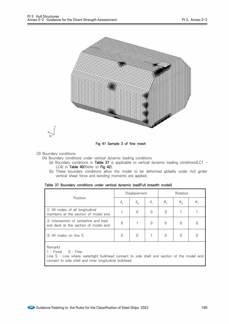
Pt 3 Hull StructuresAnnex 3-2 Guidance for the Direct Strength Assessment Pt 3, Annex 3-2
Guidance Relating to the Rules for the Classification of Steel Ships 2022 199
Fig 41 Sample 3 of fine mesh
(3) Boundary conditions(A) Boundary conditions under vertical dynamic loading conditions
(a) Boundary conditions in Table 37 is applicable to vertical dynamic loading conditions(LC1 ~ LC4) in Table 40(Refer to Fig 42).
(b) These boundary conditions allow the model to be deformed globally under hull girder vertical shear force and bending moments are applied.
PositionDisplacement Rotation
① All nodes of all longitudinal members at the section of model end 1 0 0 0 1 1
② Intersection of centerline and keel and deck at the section of model end 0 1 0 0 0 0
③ All nodes on line S 0 0 1 0 0 0
Remark)1 : Fixed 0 : FreeLine S : Line where watertight bulkhead connect to side shell and section of the model end connect to side shell and inner longitudinal bulkhead
Table 37 Boundary conditions under vertical dynamic load(Full breadth model)

Pt 3 Hull StructuresAnnex 3-2 Guidance for the Direct Strength Assessment Pt 3, Annex 3-2
200 Guidance Relating to the Rules for the Classification of Steel Ships 2022
Fig 42 Boundary conditions for vertical dynamic loading condition
(B) Boundary conditions under impact loading conditions(a) Boundary conditions in Table 38 is applicable to impact loading conditions(LC9 and LC10)
in Table 40(Refer to Fig 43).(b) Distributed vertical forces are applied to the intersection of watertight bulkhead and side
shell to eliminate reaction forces due to the vertical constraints. These forces equal to the vertical imbalance of the model caused by the difference between the internal loads and the applied buoyancy. Alternatively, vertical direction spring elements may be applied to these intersection.
PositionDisplacement Rotation
① All nodes of all longitudinal members at the section of model end
1 0 0 0 1 1
② Intersection of centerline and keel and deck at the section of model end
0 1 0 0 0 0
③ Top intersection of side shell and watertight bulkhead 0 0 1 0 0 0
Remark)1 : Fixed 0 : Free
Table 38 Boundary conditions under impact loading condition

Pt 3 Hull StructuresAnnex 3-2 Guidance for the Direct Strength Assessment Pt 3, Annex 3-2
Guidance Relating to the Rules for the Classification of Steel Ships 2022 201
Fig 43 Boundary conditions for impact loading condition
(C) Asymmetric boundary conditions(Transverse dynamic loading condition, static transverse heel-ed conditions)Boundary conditions in Table 39 is applicable to transverse dynamic loading con-ditions and static transverse heeled conditions(LC5 ~ LC8) in Table 40(Refer to Fig 44).
(4) Applied load(A) Loading conditions considered in direct strength analysis are to be applied by combining the
loading components from (B) to (D) in accordance with Table 40.(B) Internal loads
PositionDisplacement Rotation
① All nodes of alllongitudinal members at thesection of model end
1 0 0 0 1 1
② All nodes on line L 0 1 0 0 0 0
③ All nodes on line S 0 0 1 0 0 0
Remark)Line L : Line where watertight bulkhead connect to inner bottom and trunk deckLine S : Line where watertight bulkhead connect to side shell and section of the model end connect to side shell and inner longitudinal bulkhead1 : Fixed, 0 : Free
Table 39 Boundary condition at transverse dynamic loading condition and static transverse heeled condition

Pt 3 Hull StructuresAnnex 3-2 Guidance for the Direct Strength Assessment Pt 3, Annex 3-2
202 Guidance Relating to the Rules for the Classification of Steel Ships 2022
Fig 44 Boundary condition for transverse dynamic loading condition and transverse heeled condition
(a) The internal loads are to be considered the following load components. (i) Cargo load(ii) Ballast load(iii) Self-weight of structural model
(b) Acceleration application(i) Acceleration by hull motion is to be calculated by following Pt 7, Ch 5, 428.
of the rules. Maximum acceleration among all loading conditions is to be applied as cargo load. Also, other equivalent methods of calcu-lation(acceleration by ship motion) will be acceptable and methods to predict accelerations are to be submitted to the Society for approval. (2018)
(ii) For transverse dynamic load cases, transverse acceleration is to be cal-culated based on (i). However transverse acceleration is to be more than 0.5.
(iii) For impact load cases, 0.5 in forward direction is to be applied.(c) Cargo load
(i) When cargo load is applied, the design vapor pressure of cargo tank is to be considered.
(ii) Cargo load, for load combination for design vapor pressure, static and dynamic load due to acceleration, is to be accordance with the following equation.① Cargo load on still water
: Design density of LNG(ton/m3) : Design vapor pressure of Cargo tank(MPa) : gravity acceleration, 9.81 (m/s2) : Vertical distance from the highest point of Cargo Hold to a point under
consideration(m)② Cargo load under vertical dynamic loading conditions
: calculated acceleration in x-direction in accordance with (b)

Pt 3 Hull StructuresAnnex 3-2 Guidance for the Direct Strength Assessment Pt 3, Annex 3-2
Guidance Relating to the Rules for the Classification of Steel Ships 2022 203
: calculated acceleration in z-direction in accordance with (b) : Distance in forward direction from after end of cargo hold under consid-
eration to a point under consideration(m)③ Cargo load under transverse dynamic loading conditions
: Inertia load of cargo induced by transverse acceleration is to be determined as follows.
: calculated acceleration in y-direction in accordance with (b) : Transverse distance from inner bulkhead of starboard to a point under con-
sideration (m)④ Impact load (2018)
forward direction :
aftward direction :
(C) External loads(a) The external loads are to be considered the following load components.
(i) Hydrostatic pressure (ii) Hydrostatic pressure under transverse heeled condition(iii) Wave induced load(iv) Hull girder bending moment
(b) Hydrostatic pressure distribution for transverse heeled condition(i) Transverse 30° heel at port is applied and the sign of loading is assumed to be pos-
itive for port heel. (ii) Hydrostatic pressure under transverse heel condition at a point of shell plating under
consideration is to be accordance with following equation(Refer to Fig 45). cos sin
: Draft under non heeled conditions : Transverse distance from centerline to a point under consideration, positive to
port : Heel angle is applied as 30°.
Fig 45 Hydrostatic pressure distribution for transverse heeled
(c) Wave induced load is to determined in accordance with Par 1 (9).(d) Hull girder bending moment
(i) Wave bending moment, and Still water bending moment, is to be applied in accordance with Table 40.
(ii) Hull girder bending moment induced in the model area by local load is to be ad-

Pt 3 Hull StructuresAnnex 3-2 Guidance for the Direct Strength Assessment Pt 3, Annex 3-2
204 Guidance Relating to the Rules for the Classification of Steel Ships 2022
justed in order to reach target value of design bending moment.(iii) In order to induce the required vertical bending moment in the point considered
along tank length, distributed load in length direction is to be applied to each frame position. Precaution must be taken on the sign of hogging and sagging.
(iv) This loading is to be applicable in order to get the required vertical bending moment stress. Afterward, this loading is to be applied as dynamic loading in Table 40 for the analysis of stress and buckling.

Pt 3 Hull StructuresAnnex 3-2 Guidance for the Direct Strength Assessment Pt 3, Annex 3-2
Guidance Relating to the Rules for the Classification of Steel Ships 2022 205
Load CaseLoad Description Bending
Moments1)Wave load Draft Cargo
Load
Boundary Condition
sLoading condition Acceleration
Still water Wave
1
Vertical dynamic
load case
Full Loaded Vertical Download Msw Mvw
Wave crest Tsc
2) ①+② refer toFig 42
2 Full Loaded Vertical Download Msw Mvw
Wave troug
hTsc
2) ①+② refer toFig 42
3Alternate hold
(odd number tanks full)
Vertical Download Msw Mvw
Wave crest Tact
3) ①+② refer toFig 42
4Alternate hold
(even number tanks full)
Vertical Download Msw Mvw
Wave crest Tact
3) ①+② refer toFig 42
5 Transverse
dynamic load
cases
Single No. 1 cargo tank loaded
(Transverse dynamic maximum acceleration)
TransversePort - -
Wave troug
hTact
3) ①+③ refer toFig 44
6
Single No. 2 cargo tank loaded
(Transverse dynamic maximum acceleration)
TransversePort - -
Wave troug
hTact
3) ①+③ refer toFig 44
7 Static heel load
cases(30° heel)
Only No. 1 cargo tank full - - - - Tact
3) ① refer toFig 44
8 Only No. 2 cargo tank full - - - - Tact
3) ① refer toFig 44
9 Impact load
cases(Forward/aftward collision)
Full Loaded Forward0.5g - - - Tsc
2) ①+④ refer toFig 43
10 Full Loaded Aftward 0.25g - - - Tsc
2) ①+④ refer toFig 43
Remark)1) Bending moment in the same direction is to be applied dependent on hull girder performance
(hogging/sagging) when applying the local load.2) Tsc : Scantling draught(m)3) Tact : The deepest draft in midship for alternate hold under consideration(m)
Table 40 Load combination(Refer to Fig 46) (2018)

Pt 3 Hull StructuresAnnex 3-2 Guidance for the Direct Strength Assessment Pt 3, Annex 3-2
206 Guidance Relating to the Rules for the Classification of Steel Ships 2022
Fig 46 Loading condition(refer to Table 40) (2018)

Pt 3 Hull StructuresAnnex 3-2 Guidance for the Direct Strength Assessment Pt 3, Annex 3-2
Guidance Relating to the Rules for the Classification of Steel Ships 2022 207
Fig 46 Loading condition(refer to Table 40) (Continued)

Pt 3 Hull StructuresAnnex 3-2 Guidance for the Direct Strength Assessment Pt 3, Annex 3-2
208 Guidance Relating to the Rules for the Classification of Steel Ships 2022
Fig 46 Loading condition(refer to Table 40) (Continued)
※ For loading or unloading in the ballast tank for alternate cases, it is to be applied according to the T&S Booklets.

Pt 3 Hull StructuresAnnex 3-2 Guidance for the Direct Strength Assessment Pt 3, Annex 3-2
Guidance Relating to the Rules for the Classification of Steel Ships 2022 209
(5) Allowable stress(A) The allowable stress of Load cases from LC1 to LC8 in Table 40 is to be as given in
Table 41.(B) The allowable stress of Load cases from LC9 to LC10 in Table 40 is to be in accordance
with the discretion of the Society.(C) Notwithstanding (A) and (B), the allowable stress for inner side plates(inner bottom, hop-
per tank and top side tank, slope plate, inner longitudinal bulkhead, inner deck) depend-ing on the type of cargo tank is to be in compliance with the criteria presented by tank developer for each tank type.
(D) Members which have particularly large shear stress are to be specially considered in ad-dition to (A) and (B).
Structural members Load caseAllowable stress
The equivalent stress, All structural members
considered LC 1 ~ LC 8
(Remark)1. The equivalent stress is to be as follows.
: Normal stress in x-direction of element coordinate system : Normal stress in y-direction of element coordinate system : Sheer stress on the face in x-y plane of element coordinate system2. : Yield stress of material(Nmm)3. Position for stress reading is to be the center of element.4. : mesh density factor taken as;
1.0 for longitudinal spacing mesh size1.15 for less than or equal to 200 x 200 mm mesh size1.25 for less than or equal to 100 x 100 mm mesh size1.5 for less than or equal to 50 x 50 mm mesh size1.7 for less than or equal to 2t x 2t mesh size
Table 41 Allowable stress(LC1 ~ LC8) (2018)
(6) Buckling strength calculation(A) Buckling strength is to be calculated according to Ⅳ. Buckling strength calculation. Buckling
criteria for all load cases in Table 40 is to be in accordance with Table 42. (2020)(B) Combining effect of biaxial compressive stress, shear stress and in-plane bending stress is
to be considered in calculation of buckling strength.(C) In general, mean stress in panel is to be used in calculation of buckling strength.
Structural members Buckling factor,
All structural members considered 1.0
Table 42 Buckling factor

Pt 3 Hull StructuresAnnex 3-2 Guidance for the Direct Strength Assessment Pt 3, Annex 3-2
210 Guidance Relating to the Rules for the Classification of Steel Ships 2022
8. LPG Carriers with Independent Tank Type A(1) General
(A) This guidance apply to the LPG carriers with independent tank type A.(B) In case where scantlings of structural members of cargo hold in LPG carriers are verified by
direct strength calculation, necessary documents and data for its calculation are to be sub-mitted to the Society for approval beforehand.
(C) Except for those specifically provided for in this part, 1. is to be applied.(2) Structural modelling
(A) Model extent (a) The model extent varies depending on the cargo hold numbers and arrangement. Main
focus is on midship cargo area. The longitudinal model extent is to cover the 3 hold cargo length of midship area and 2 hold cargo length with E/R or Fore structure. The full breadth of the ship shall be used transversely. And, the full depth of the ship is to be modelled including primary supporting members above the upper deck, trunk and/or hatch coaming, if any.
(b) Basically, one cargo hold amidship and foremost hold shall be structurally assessed. The midship cargo hold model shall be such that the cargo hold amidship is located at the middle of the FE model. The Foremost or aftmost cargo hold shall be located at the middle of the corresponding FE model.
Fig 47 Model extent of cargo hold region for strength assessment
(c) If the finite element model of aftward of engine room bulkhead and forward of fore peak bulkhead is available and if ship has 3 cargo hold, the full cargo hold model can be used instead of using midship cargo hold and foremost cargo hold model. In that case, the all cargo hold region is to be evaluated.
(d) Aftmost cargo hold model shall be established to check the strength if the hull girder loads exceed the midship values or structural arrangement is significantly different from the midship area or the scantlings of aftmost cargo hold are not gradually tapered.
(e) In the foremost cargo hold model and the aftmost cargo hold model, the hull form aft of the middle of the machinery space or forward of the transverse section at the middle of the fore part may be modelled with a simplified geometry, which means that hull form can be extruded out to its aft bulkhead and FP.
(B) Structural modeling(a) The used linear FE element is 4 node or 3 node shell elements and 2 node beam
elements. 2D shell elements are used to represent the plate of the hull structure, and

Pt 3 Hull StructuresAnnex 3-2 Guidance for the Direct Strength Assessment Pt 3, Annex 3-2
Guidance Relating to the Rules for the Classification of Steel Ships 2022 211
all stiffeners are modeled with beam elements having axial, torsional and bending stiffness.
(b) Face plate of primary supporting members are modeled using rod elements.(c) The use of 3 node shell element is limited only for the mesh transition area as far as
practicable. The aspect ratio of the shell elements is in general not to exceed 3 and the aspect ratio in areas where high stresses are expected is to be kept to 1 where possible.
(C) Properties and Corrosion Allowance(a) The properties of FE models for cargo hold region including local structural strength are
to be based on the gross scantling approach for yielding and net thickness approach for buckling, applying a thickness deduction as defined in Ch 3, Sec 4 Table 3.3.3 of the Rule if not defined specifically. In net thickness application, only plate members are considered.
(b) For the independent tank structure made of stainless steel, there is no need to apply the thickness deduction in general.
(D) Supporting Structure Idealization(a) To minimized the movement of the independent tank in cargo hold of hull, 4 types of
supports are installed generally; - Vertical support for Z downward direction, - Anti-rolling supports for Y direction, - Anti-pitching and/or anti-collision support for X direction and - Antiflotation chocks for Z upward direction.
Fig 49 shows the typical support arrangement of web section.(b) It is very important to get the force distribution on each support by independent tank.
Therefore, all tank supports are to be idealized by shell elements according to the ar-rangement of tank supports. The spacer between upper and lower seat of the hull and tank supports should be considered using solid elements, gap elements or 1D element such as spring or rod element.
(c) If solid elements are used, contact elements should be defined for interface surface. In case of gap elements implementation, the upper and lower surface of tank support seat is to be rigidly linked respectively with 6 DOF constraints. If the gap elements or contact elements are used, analysis results should be obtained using a nonlinear analysis. Fig 50 shows the typical implementation of gap elements with 6 DOF constraints.
(d) For the usage of linear 1D element, the spring or axial stiffness is to be calculated based on the actual elastic modulus of the spacer materials. And, an iterative procedure is required to eliminate any spring or rod element sustaining a tensile stress. Spring or rod element may require two or three elements to correctly represent the behaviour of the support.
Fig 48 Transverse section

Pt 3 Hull StructuresAnnex 3-2 Guidance for the Direct Strength Assessment Pt 3, Annex 3-2
212 Guidance Relating to the Rules for the Classification of Steel Ships 2022
inner hull side
tank side
gap element
Fig 50 Tank support (Implementation of 1D Gap element with 6 DOF constraints)
(e) The coefficient of friction between the spacer between upper and lower seat of the tank supports is used according to Table 43 unless specifically defined in design stage by designer. In case of accidental loading condition i.e. collision and flooded, friction is not considered with a conservative viewpoint.
Type Intact condition Accidental condition
Vertical support 0.5 N.A
Other supports 0.2 N.A
Table 43 Friction coefficient of support idealization
Fig 49 Typical web section of FE model using spring elements

Pt 3 Hull StructuresAnnex 3-2 Guidance for the Direct Strength Assessment Pt 3, Annex 3-2
Guidance Relating to the Rules for the Classification of Steel Ships 2022 213
Fig 51 Example of Cargo Hold Model (Midship)
Fig 52 Example of All Cargo Hold Model
Fig 53 Example of Independent Tank Model(Midship)
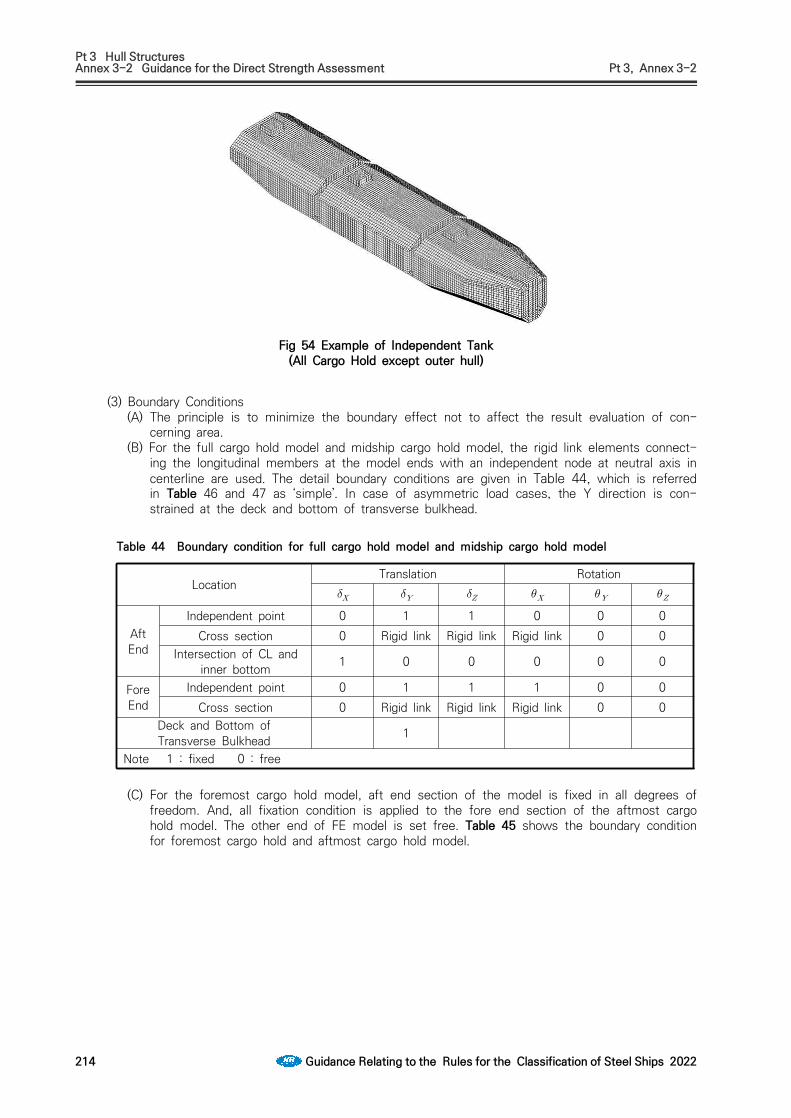
Pt 3 Hull StructuresAnnex 3-2 Guidance for the Direct Strength Assessment Pt 3, Annex 3-2
214 Guidance Relating to the Rules for the Classification of Steel Ships 2022
Fig 54 Example of Independent Tank (All Cargo Hold except outer hull)
(3) Boundary Conditions(A) The principle is to minimize the boundary effect not to affect the result evaluation of con-
cerning area.(B) For the full cargo hold model and midship cargo hold model, the rigid link elements connect-
ing the longitudinal members at the model ends with an independent node at neutral axis in centerline are used. The detail boundary conditions are given in Table 44, which is referred in Table 46 and 47 as ‘simple’. In case of asymmetric load cases, the Y direction is con-strained at the deck and bottom of transverse bulkhead.
LocationTranslation Rotation
Aft End
Independent point 0 1 1 0 0 0Cross section 0 Rigid link Rigid link Rigid link 0 0
Intersection of CL and inner bottom 1 0 0 0 0 0
Fore End
Independent point 0 1 1 1 0 0Cross section 0 Rigid link Rigid link Rigid link 0 0
Deck and Bottom of Transverse Bulkhead 1
Note 1 : fixed 0 : free
Table 44 Boundary condition for full cargo hold model and midship cargo hold model
(C) For the foremost cargo hold model, aft end section of the model is fixed in all degrees of freedom. And, all fixation condition is applied to the fore end section of the aftmost cargo hold model. The other end of FE model is set free. Table 45 shows the boundary condition for foremost cargo hold and aftmost cargo hold model.
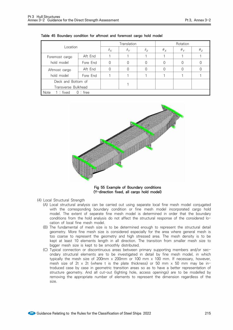
Pt 3 Hull StructuresAnnex 3-2 Guidance for the Direct Strength Assessment Pt 3, Annex 3-2
Guidance Relating to the Rules for the Classification of Steel Ships 2022 215
LocationTranslation Rotation
Foremost cargo hold model
Aft End 1 1 1 1 1 1
Fore End 0 0 0 0 0 0
Aftmost cargo hold model
Aft End 0 0 0 0 0 0
Fore End 1 1 1 1 1 1Deck and Bottom of Transverse Bulkhead
1
Note 1 : fixed 0 : free
Table 45 Boundary condition for aftmost and foremost cargo hold model
(4) Local Structural Strength (A) Local structural analysis can be carried out using separate local fine mesh model conjugated
with the corresponding boundary condition or fine mesh model incorporated cargo hold model. The extent of separate fine mesh model is determined in order that the boundary conditions from the hold analysis do not affect the structural response of the considered lo-cation of local fine mesh model.
(B) The fundamental of mesh size is to be determined enough to represent the structural detail geometry. More fine mesh size is considered especially for the area where general mesh is too coarse to represent the geometry and high stressed area. The mesh density is to be kept at least 10 elements length in all direction. The transition from smaller mesh size to bigger mesh size is kept to be smoothly distributed.
(C) Typical connection or discontinuous areas between primary supporting members and/or sec-ondary structural elements are to be investigated in detail by fine mesh model, in which typically the mesh size of 200mm x 200mm or 100 mm x 100 mm. If necessary, however, mesh size of 2t x 2t (where t is the plate thickness) or 50 mm x 50 mm may be in-troduced case by case in geometric transition areas so as to have a better representation of structure geometry. And all cut-out (lighting hole, access openings) are to be modelled by removing the appropriate number of elements to represent the dimension regardless of the size.
Fig 55 Example of Boundary conditions (Y-direction fixed, all cargo hold model)

Pt 3 Hull StructuresAnnex 3-2 Guidance for the Direct Strength Assessment Pt 3, Annex 3-2
216 Guidance Relating to the Rules for the Classification of Steel Ships 2022
(5) Fine Mesh Area(A) The required areas for fine mesh analysis are as follows;
- Large openings (tank dome, duct keel, etc.)- Typical connections of double bottom longitudinal stiffeners to transverse bulkheads- Typical vertical support at maximum reaction introduced- Typical Anti-rolling support at maximum reaction introduced- Typical Anti-pitching support at maximum reaction introduced- Typical Anti-flotation support at maximum reaction introduced- Other support not having typical support configuration
(B) High stress concentrated areas where the stress concentration is more than 95% of the evaluation criteria need to be verified by fine mesh analysis.
Fig 56 Example of Fine Mesh (Hatch Corner)
Fig 57 Example of Fine Mesh (Supporting member)
(6) Loads (A) Local loads required in IGC Code are to be fully compliant with applicable IGC Code.(B) The design load cases are selected to give the maximum support reaction of each support
type and configuration among defined in (E). The reaction forces are derived from cargo hold analysis and applied to the corresponding surface of fine mesh model using multi-point constraints. And, the relevant local loads should be applied simultaneously.
(C) The obtained reaction forces shall be used for the strength check for the wood spacer and the dam plate. The stress of wood spacer, vertical reaction force divided by wood spacer sectional area perpendicular to the force direction, should not exceed the 1/3 allowable wood compressive stress. And, the dam plate shear area shall be satisfied with the required shear area given by friction force with 10% margin divided by dam plate allowable shear stress.

Pt 3 Hull StructuresAnnex 3-2 Guidance for the Direct Strength Assessment Pt 3, Annex 3-2
Guidance Relating to the Rules for the Classification of Steel Ships 2022 217
(D) Internal pressure is to be calculated for each load cases in accordance with Pt 7, Ch 5, 403.2 of the Rule for internal independent tank pressure, with 1(7) for ballast tank pressure. External pressure is to be calculated for each load cases in accordance with 1(9).
(E) Hull Girder Loads (a) The local hull girder distribution by applied local loads including structural steel weight
is to be obtained according to the Pt 13, Ch 7, Sec 2 4.4.2 of the Rules. The final adjusted hull girder shear force and hull girder bending moment should not exceed the hull girder target values.
(b) Target Hull Girder Vertical Bending Moment The target vertical bending is the combined envelope of and or itself de-
pending on the load cases. Design and wave induced are should be com-pliant with Pt 3, Ch 3, Table 3.3.1 of the Rules.
(c) Target Hull Girder Vertical Shear Force The target vertical shear force is the or envelope of and depending on the
combined loads. Design and wave induced are should be compliant with the requirements described in Pt 3, Ch 3, 301 of the Rules.
(d) Hull Girder Shear Force Adjusting The vertical forces at the transverse web frame position to generate vertical shear
forces , at the transverse target positions are to be applied. The adjusted forces are distributed vertically to the nodes of the corresponding cross section ac-cording to the direct shear flow calculation method in Pt13, Ch5, App 1 of the Rules.
(i) Midship Cargo Hold ModelThe required adjustments in hull girder shear force for midship cargo hold model should be made in accordance with relevant method described in Pt13, Ch 7, Sec 2 of the Rules.
(ii) Full Cargo Hold ModelIn case of full cargo hold length model, the hull girder shear force adjustments should be done according to following equations as shown in Fig 58.
: Resultant force by local loads at FP : Adjustment shear force at foward target bulkhead : Adjustment shear force at aft target bulkhead
, ,
(iii) Foremost or Aftmost Cargo Hold Model In case of foremost or aftmost cargo hold model, the hull girder shear force adjust-
ments should be done according to following equations as shown in Fig 59 and Fig 60.
: Resultant force by local loads and adjusting forces ( & ) at fixed boundary position
: Design shear force at fixed boundary position : Adjustment shear force at foward target bulkhead : Adjustment shear force at aft target bulkhead
, ,
for foremost cargo hold model, for aftmost cargo hold model
for foremost cargo hold model,
for aftmost cargo hold model
Only when exceeds ,

Pt 3 Hull StructuresAnnex 3-2 Guidance for the Direct Strength Assessment Pt 3, Annex 3-2
218 Guidance Relating to the Rules for the Classification of Steel Ships 2022
Fig 58 Target shear force adjustment by applying vertical forces for full cargo hold
Fig 59 Target shear force adjustment by applying vertical forces for foremost cargo hold model

Pt 3 Hull StructuresAnnex 3-2 Guidance for the Direct Strength Assessment Pt 3, Annex 3-2
Guidance Relating to the Rules for the Classification of Steel Ships 2022 219
Fig 60 Target shear force adjustment by applying vertical forcesfor aftmost cargo hold model
(e) Hull Girder Bending Moment Adjusting The vertical hull girder bending moment adjustments are to be applied to the considered
cross section of the cargo hold FE model by distributing the longitudinal axial nodal forces to all hull girder bending effective members according to Pt 13, Ch 7, Sec2 4.4.10 of the Rules.(i) Midship Cargo Hold Model
The required adjustments in hull girder bending moment shear force for midship car-go hold model should be made in accordance with relevant method described in Pt 13, Ch 7, Sec 2 4.4.8 of the Rules.
(ii) Full Cargo Hold Model, Foremost and Aftmost Cargo Hold ModelTo obtain the vertical hull girder target values at each web frame and transverse bulkhead position, the vertical bending moment adjustments () are to be cal-culated and applied at web frames and transverse bulkhead position as described in Pt 13, Ch 7, Sec 2 4.4.9 of the Rules.
(F) Design Load Case (a) In seagoing phase, full load condition with scantling draft, alternate load condition and
ballast condition with minimum draft are to be check for structural strength.(b) For the harbour phase, any alternate loading condition is to be assessed. In that case,
the static sea pressure and internal pressure are used considering overflow height. If the harbour phase is not specified in Loading Manual, the assessment for habour condition may be omitted.

Pt 3 Hull StructuresAnnex 3-2 Guidance for the Direct Strength Assessment Pt 3, Annex 3-2
220 Guidance Relating to the Rules for the Classification of Steel Ships 2022
LC No
Loading condition
External pressure
Independent Tank Load
Ballast Tank
Hull Girder
Loading Patterns
SF Adjusting BC
LC1 Full Load Homo
- Trough Static -
+
simple
LC2 Full Load Homo
- Crest Static -
+
simple
LC3 Alt Load - Crest Static
Rule Load in Annex III-2
+
Applied simple
LC4 Alt Load - Trough Static
Rule Load in Annex III-2
+
Applied simple
LC5 Ballast - Static -
Rule Load in Annex III-2
+
simple
LC6 Full Load Homo
- Static
Static+ Dynamic with
- +
simple
LC7 Full Load Homo
- Static
Static+ Dynamic with
-
simple+y constraint at
deck & bottom of TBHD
LC8 Alt Load - Static
Static+ Dynamic with
Rule Load in Annex III-2
Applied
simple+y constraint at
deck & bottom of TBHD
LC9 Harbour min- Static Static
Rule Load in Annex III-2
simple
LC10 Harbour min-
Static Static
Rule Load in Annex III-2
simple
LC11
Full Load with
Heeled(30°)
- Static Static -
simple+y constraint at
deck & bottom of TBHD
LC12
Full Load with
Collision forward
BHD(0.5g)
- Static
Static+ Dynamic
with (0.5g)
- simple
LC13
Full Load with
Collision aftward
BHD(0.25g)
- Static
Static+ Dynamic
with (0.25g)
- simple
LC14 Flooded -
Static
Static loads opn 2nd barriers
below
Applied simple
Table 46 Design load cases for midship cargo hold model

Pt 3 Hull StructuresAnnex 3-2 Guidance for the Direct Strength Assessment Pt 3, Annex 3-2
Guidance Relating to the Rules for the Classification of Steel Ships 2022 221
LC No
Loading condition
External pressure
Independent Tank Load
Ballast Tank
Hull Girder
Loading Patterns
SF Adjusting BC
LC1 Full Load Homo
- Trough Static -
+
Applied simple
LC2 Full Load Homo
- Crest Static -
+ Applied simple
LC3 Alt Load - Crest Static
Rule Load in Annex
III-2
+ Applied simple
LC4 Alt Load - Trough Static
Rule Load in Annex
III-2
+
Applied simple
LC5 Ballast - Static -
Rule Load in Annex
III-2
+
Applied simple
LC6 Full Load Homo
- Static
Static+ Dynamic with
- Applied simple
LC7 Full Load Homo
- Static
Static+ Dynamic with
- Applied
simple+y constraint at
deck & bottom of TBHD
LC8 Alt Load - Static
Static+ Dynamic with
Rule Load in Annex
III-2 Applied
simple+y constraint at
deck & bottom of TBHD
LC9 Harbour min- Static Static
Rule Load in Annex
III-2 simple
LC10 Harbour min- Static Static
Rule Load in Annex
III-2 simple
LC11Full Load
with Heeled(30°)
min- Static Static - Applied
simple+y constraint at
deck & bottom of TBHD
LC12
Full Load with
Collision forward
BHD(0.5g)
- Static
Static+ Dynamic with (0.5g)
- Applied simple
LC13
Full Load with
Collision aftward
BHD(0.25g)
- Static
Static+ Dynamic with (0.25g)
- Applied simple
LC14 Flooded - Static
Static loads on
2nd barrier below
Applied simple
Table 47 Design load cases for full cargo hold model

Pt 3 Hull StructuresAnnex 3-2 Guidance for the Direct Strength Assessment Pt 3, Annex 3-2
222 Guidance Relating to the Rules for the Classification of Steel Ships 2022
LC No
Loading condition
External pressur
e
Independent Tank Load
Ballast Tank Hull Girder Loading
PatternsSF
Adjusting BC
LC1 Full Load Homo
- Trough Static -
+ Applied Aft fixed
LC2 Full Load Homo
- Crest Static -
+
Applied Aft fixed
LC3 Alt Load - Crest Static
Rule Load in Annex
III-2
+
Applied Aft fixed
LC4 Alt Load - Trough Static
Rule Load in Annex
III-2
+ Applied Aft fixed
LC5 Ballast - Static -
Rule Load in Annex
III-2
+ Applied Aft fixed
LC6 Full Load Homo
- Static
Static+ Dynamic with
- Applied Aft fixed
LC7 Full Load Homo
- Static
Static+ Dynamic with
- Applied
Aft fixed+y constraint at
deck & bottom of
BHD
LC8 Harbour min- Static
Static+ Dynamic with
Rule Load in Annex
III-2 Aft fixed
LC9 Harbour min- Static Static
Rule Load in Annex
III-2 Aft fixed
LC10Full Load
with Heeled(30°)
- Static Static - Applied
LC11
Full Load with
Collision forward
BHD(0.5g)
- Static
Static+ Dynamic with (0.5g)
- Applied Aft fixed
LC12
Full Load with
Collision aftward
BHD(0.25g)
- Static
Static+ Dynamic with (0.25g)
- Applied Aft fixed
LC13 flooded - Static
Static loads on 2nd barrier
below
- Applied Aft fixed
Table 48 Design load cases for foremost cargo hold model

Pt 3 Hull StructuresAnnex 3-2 Guidance for the Direct Strength Assessment Pt 3, Annex 3-2
Guidance Relating to the Rules for the Classification of Steel Ships 2022 223
LC No
Loading condition
External pressure
Independent Tank Load
Ballast Tank Hull Girder Loading
PatternsSF
Adjusting BC
LC1 Full Load Homo
- Trough Static -
+ Applied Fwd fixed
LC2 Full Load Homo
- Crest Static -
+
Applied Fwd fixed
LC3 Alt Load - Crest Static
Rule Load in Annex
III-2
+
Applied Fwd fixed
LC4 Alt Load - Trough Static
Rule Load in Annex
III-2
+ Applied Fwd fixed
LC5 Ballast - Static -
Rule Load in Annex
III-2
+ Applied Fwd fixed
LC6 Full Load Homo
- Static
Static+ Dynamic with
- Applied Fwd fixed
LC7 Full Load Homo
- Static
Static+ Dynamic with
- Applied
Aft fixed+y constraint at
deck & bottom of
BHD
LC8 Harbour min- Static Static
Rule Load in Annex
III-2 Fwd fixed
LC9 Harbour min- Static Static
Rule Load in Annex
III-2 Fwd fixed
LC10
Full Load with
Heeled(30°)Static Applied
Aft fixed+y constraint at
deck & bottom of
BHD
LC11
Full Load with
Collision forward
BHD(0.5g)
- Static
Static+ Dynamic with (0.5g)
- Applied Fwd fixed
LC12
Full Load with
Collision aftward
BHD(0.25g)
- Static
Static+ Dynamic with (0.25g)
- Applied Fwd fixed
LC13 Flooded -
Static
Static loads on
2nd barrier below
- Applied Fwd fixed
Table 49 Design load cases for aftmost cargo hold model

Pt 3 Hull StructuresAnnex 3-2 Guidance for the Direct Strength Assessment Pt 3, Annex 3-2
224 Guidance Relating to the Rules for the Classification of Steel Ships 2022
(7) Allowable Stress(A) The stresses resulting from the application of the specified load cases are not to exceed the
allowable stress obtained from following formula.
: general yield utilization factor taken as;0.9 for intact load cases1.0 for accidental load cases (collision, flooded, damaged)0.8 for habour load case (Table 46∼49)
: mesh density factor taken as;1.0 for longitudinal spacing mesh size1.15 for less than or equal to 200 x 200 mm mesh size1.25 for less than or equal to 100 x 100 mm mesh size1.5 for less than or equal to 50 x 50 mm mesh size1.7 for less than or equal to 2t x 2t mesh size
: material factor , : Normal stress at element centroid (Nmm) : Shear stress at element centroid (Nmm)
(8) Buckling Strength (2020)Buckling strength is to be calculated according to Ⅳ. Buckling strength calculation. Buckling strength is to satisfy the criteria defined in 1 (5) of Ⅳ. Buckling strength calculation based on static+dynamic load combination except below load cases.
Load cases based on static load combination in 1 (5) of Ⅳ. Buckling strength calculation:- Table 46 and 47: LC9, LC10 and LC11,- Table 48: LC9 and LC10,- Table 49: LC8, LC9 and LC10.
However, for the cargo hold structural members under intact load cases, following enforced buckling criterion is to be applied.
≤
where: , : refer to 1 (5) of Ⅳ. Buckling strength calculation.

Pt 3 Hull StructuresAnnex 3-2 Guidance for the Direct Strength Assessment Pt 3, Annex 3-2
Guidance Relating to the Rules for the Classification of Steel Ships 2022 225
IV. Buckling strength calculation (2020)
1. General(1) Assumption
This Guidance includes buckling strength calculation and criteria for direct strength analysis re-sults of all structural members. Unless otherwise specified, the scantling requirements of struc-tural members are based on net scantling obtained by removing from the gross offered thick-ness, where is defined in 3 (2), compressive and shear stresses are to be taken as positive, tension stresses are to be taken as negative.
(2) ApplicationThe buckling checks are to be performed according to:
• 2. for the buckling requirements of the FE analysis for the plates, stiffened panels and other structures.
• 3. for the buckling capacity of prescriptive and FE buckling requirements.(3) Definitions
‘Buckling’ is used as a generic term to describe the strength of structures, generally under in-plane compressions and/or shear and lateral load. The buckling strength or capacity can take into account the internal redistribution of loads depending on the load situation, slenderness and type of structure. Buckling capacity based on this principle gives a lower bound estimate of ulti-mate capacity, or the maximum load the panel can carry without suffering major permanent set. Buckling capacity assessment utilises the positive elastic post-buckling effect for plates and ac-counts for load redistribution between the structural components, such as between plating and stiffeners. For slender structures, the capacity calculated using this method is typically higher than the ideal elastic buckling stress (minimum Eigen value). Accepting elastic buckling of struc-tural components in slender stiffened panels implies that large elastic deflections and reduced in-plane stiffness will occur at higher buckling utilisation levels.
(4) Assessment methodsThe buckling assessment is carried out according to one of the two methods taking into account different boundary condition types:• Method A: All the edges of the elementary plate panel are forced to remain straight (but free
to move in the in-plane directions) due to the surrounding structure/neighbouring plates.• Method B: The edges of the elementary plate panel are not forced to remain straight due to low in-plane stiffness at the edges and/or no surrounding structure/neighbouring plates.
(5) Allowable buckling utilization factorA structural member is considered to have an acceptable buckling strength if it satisfies the fol-lowing criterion:
≤
: Buckling utilisation factor based on the applied stress, defined in 3. : Allowable buckling utilisation factor as defined in Table 50.

Pt 3 Hull StructuresAnnex 3-2 Guidance for the Direct Strength Assessment Pt 3, Annex 3-2
226 Guidance Relating to the Rules for the Classification of Steel Ships 2022
2. Buckling requirements for direct strength analysis(1) General
The requirements of this Section apply for the buckling assessment of direct strength analysis subjected to compressive stress, shear stress and lateral pressure. All structural elements in the FE analysis are to be assessed individually. The buckling checks have to be performed for the following structural elements: • Stiffened and unstiffened panels, inclusive curved panels.• Web plate in way of openings.• Corrugated bulkhead.• Vertically stiffened side shell of single side skin bulk carrier.• Struts, pillars and cross ties.
(2) Panel modeling and assessmentThe plate panel of hull structure is to be modelled as stiffened panel, SP or unstiffened panel, UP. Method A and Method B as defined in 1 (4) are to be used according to Table 51 to 54 and Fig 61 to 65. Where the plate thickness along a plate panel is not constant, the panel used for the buckling assessment is to be modelled according to III. Guidance for the Hold Analysis with a weighted average thickness taken as:
: Area of the i-th plate element : Net thickness of the i-th plate element. : Number of finite elements defining the buckling plate panel.
The panel yield stress ReH_P is taken as the minimum value of the specified yield stresses of the elements within the plate panel.
Structural component Allowable buckling utilisation factor Plates and stiffenersStiffened and unstiffened panelsVertically stiffened side shell plating of single side skin bulk carrierWeb plate in ways of openings
1.00 for load combination: S+D0.80 for load combination: S
Struts, pillars and cross ties 0.75 for load combination: S+D0.65 for load combination: S
Corrugation of vertically corrugated bulkheads with lower stool and horizontally corrugated bulkhead, under lateral pressure from liquid loads, for shell elements only.Supporting structure in way of lower end of corrugated bulk-heads without lower stool.
0.90 for load combination: S+D0.72 for load combination: S
Corrugation of vertically corrugated bulkheads without lower stool under lateral pressure from liquid loads, for shell elements only.
0.81 for load combination: S+D0.65 for load combination: S
Note 1: Supporting structure for a transverse corrugated bulkhead refers to the structure in longitudinal direction within half a web frame space forward and aft of the bulkhead, and within a vertical extent equal to the corrugation depth.
Note 2: Supporting structure for a longitudinal corrugated bulkhead refers to the structure in transverse direction within three longitudinal stiffener spacings from each side of the bulkhead, and within a vertical extent equal to the corrugation depth.
Table 50 Allowable buckling utilization factor

Pt 3 Hull StructuresAnnex 3-2 Guidance for the Direct Strength Assessment Pt 3, Annex 3-2
Guidance Relating to the Rules for the Classification of Steel Ships 2022 227
Structural elements Assessment method Normal panel definition
Longitudinally stiffened panels, shell envelope, deck, in-ner hull, hopper tank side and longitudinal bulkheads SP-A
Length : between web framesWidth : between primary sup-porting members
Double bottom longitudinal girders in line with longi-tudinal bulkhead or connected to hopper tank side SP-A
Length : between web framesWidth : full web depth
Web of double bottom longitudinal girders not in line with longitudinal bulkhead or not connected to hopper tank side
SP-B
Web of horizontal girders in double side space con-nected to hopper tank side SP-A
Web of horizontal girders in double side space not con-nected to hopper tank side SP-B
Web of single skin longitudinal girders or stringers (regular meshed area) SP-B
Plate between local stiff-eners/face plate/PSMWeb of single skin longitudinal girders or stringers
(irregular meshed area) UP-B
Table 51 Assessment method for longitudinal structural elements
Structural elements Assessment method Normal panel definition
Web of transverse deck frames including brackets (regular meshed area) SP-B Plate between local
stiffeners/face plate/PSMWeb of transverse deck frames including brackets (irregular meshed area) UP-B
Vertical web in double side space SP-BLength: full web depthWidth: between primary
supporting members
Irregularly stiffened panels, e.g. web panels in way of hopper tank and bilge UP-B Plate between local
stiffeners/face plate/PSM
Double bottom floors SP-ALength: full web depthWidth: between primary
supporting membersVertical web frame including brackets (regular meshed area) SP-B
Plate between vertical web stiffeners/face plate/PSM
Vertical web frame including brackets (irregular meshed area) UP-B
Cross tie web plate (regular meshed area) SP-B
Cross tie web plate (irregular meshed area) UP-B
Table 52 Assessment method for transverse structural elements

Pt 3 Hull StructuresAnnex 3-2 Guidance for the Direct Strength Assessment Pt 3, Annex 3-2
228 Guidance Relating to the Rules for the Classification of Steel Ships 2022
Structural elements Assessment method Normal panel definition
Regularly stiffened bulkhead panels inclusive the secondary buckling stiffeners perpendicular to the regular stiffener (such as carlings)
SP-A
Length : between primary supporting membersWidth : between primary supporting members
Irregularly stiffened bulkhead panels, e.g. web panels in way of hopper tank and bilge UP-A Plate between local
stiffeners/face plateWeb plate of bulkhead stringers including brackets (regular meshed area) SP-B
Plate between web stiffeners /face plateWeb plate of bulkhead stringers including brackets
(irregular meshed area) UP-B
Table 53 Assessment method for transverse oil-tight and watertight bulkheads
Structural elements Assessment method Normal panel definition
Upper/lower stool including stiffeners SP-ALength: between internal web diaphragmsWidth: length of stool side
Stool internal web diaphragm (regular meshed area) SP-B Plate between local stiffeners /face plate /PSMStool internal web diaphragm (irregular meshed area) UP-B
Cross deck SP-A Plate between local stiffeners/ PSM
Table 54 Assessment method for Transverse corrugated bulkheads and cross deck
Fig 61 Longitudinal plates in LPG carrier (Type A)

Pt 3 Hull StructuresAnnex 3-2 Guidance for the Direct Strength Assessment Pt 3, Annex 3-2
Guidance Relating to the Rules for the Classification of Steel Ships 2022 229
Fig 62 Transverse web frame in LPG carrier (Type A)
Fig 63 Transverse bulkhead in LPG carrier (Type A)

Pt 3 Hull StructuresAnnex 3-2 Guidance for the Direct Strength Assessment Pt 3, Annex 3-2
230 Guidance Relating to the Rules for the Classification of Steel Ships 2022
Fig 64 Longitudinal plate in car ferry Fig 65 Transverse web frame in car ferry
(3) Stiffened panelsTo represent the overall buckling behaviour, each stiffener with attached plate is to be modelled as a stiffened panel. If the stiffener properties or stiffener spacing varies within the stiffened panel, the calculations are to be performed separately for all configurations of the panels, i.e. for each stiffener and plate between the stiffeners. Plate thickness, stiffener properties and stiffener spacing at the considered location are to be assumed for the whole panel.
(4) Unstiffened panels(A) Irregular plate panel In way of web frames, stringers and brackets, the geometry of the panel (i.e. plate bounded
by web stiffeners/face plate) may not have a rectangular shape. In this case, an equivalent rectangular panel is to be defined according to (B) for irregular geometry and (C) for triangu-lar geometry and to comply with buckling assessment.
(B) Modelling of an unstiffened panel with irregular geometry is to be based on Pt 13, Sub-pt 1, Ch 8, Sec 4, 2.3.2.
(C) Modelling of an unstiffened plate panel with triangular geometryis to be based on Pt 13, Sub-pt 1, Ch 8, Sec 4, 2.3.3.
(5) Reference stressThe stress distribution is to be taken from the direct strength analysis and applied to the buck-ling panel model. The reference stresses of buckling panel as shown in Fig 12 are to be calcu-lated using the Stress based reference stresses as defined in Pt 13, Sub-pt 1, Ch 8, App 1.

Pt 3 Hull StructuresAnnex 3-2 Guidance for the Direct Strength Assessment Pt 3, Annex 3-2
Guidance Relating to the Rules for the Classification of Steel Ships 2022 231
Fig 66 Example of buckling panel
(6) Lateral pressureThe lateral pressure applied to the direct strength analysis is also to be applied to the buckling assessment. Where the lateral pressure is not constant over a buckling panel defined by a num-ber of finite plate elements, an average lateral pressure, Nmm, is calculated using the following formula:
where : : Area of the i-th plate element, in mm. : Lateral pressure of the i-th plate element, in Nmm
: Number of finite elements in the buckling panel. (7) Buckling criteria of panel
Buckling strength of panel is satisfy the criterion defined in Pt 13, Sub-pt 1, Ch 8, Sec 4, 2. (8) Buckling criteria of corrugated bulkhead
Buckling strength of corrugated bulkhead is satisfy the criterion defined in Pt 13, Sub-pt 1, Ch 8, Sec 4, 3.
(9) Buckling criteria of vertically stiffened side shell Buckling strength of vertically stiffened side shell is satisfy the criterion defined in Pt 13, Sub-pt 1, Ch 8, Sec 4, 4. (refer to Fig 67).
(10) Buckling criteria of strut, pillar and cross tiesBuckling strength of strut, pillar and cross ties is satisfy the criterion defined in Pt 13, Sub-pt 1, Ch 8, Sec 4, 5.
Fig 67 Vertically stiffened side shell

Pt 3 Hull StructuresAnnex 3-2 Guidance for the Direct Strength Assessment Pt 3, Annex 3-2
232 Guidance Relating to the Rules for the Classification of Steel Ships 2022
3. Buckling capacity (1) Assessment
Assessment of bucking capacity for panel, stiffener, primary support members, strut, pillar, cross ties anf corrugated bulkhead is to perform according to Pt 13, Sub-pt 1, Ch 9, Sec 5. As de-termined by the Society. assessment of local plate panel can only be performed according to Pt 11, Ch 6, Sec 3 or Pt 13, Sub-pt 1, Ch 9, Sec 5.
(2) Application of net thickness Assessment of buckling capacity is to be based on net thickness extracted by corrosion addition, as shown in Table 55, from gross thickness. If the specific corrosion addition depending on a ship type based on measurement data is provided, this corrosion addition can be applied.
Compartment type Corrosion addition
Ballast water tank, bilge tank, drain storage tank, chain locker(1) 1.0
Exposed to atmosphere 1.0
Exposed to sea water 1.0
Fuel oil and lube oil tank 0.5
Fresh water tank 0.5
Void spaces and dry spaces(2)(3) 0.0
Accommodation spaces 0.0
Compartments other than those mentioned above 0.5
Note: (1) 1.0 mm is to be added to the plate surface within 3 m above the upper surface of
the chain locker bottom. (2) For the determination of the corrosion addition of the outer shell plating, the pipe
tunnel is considered as for a ballast water tank. (3) For bottom plate of compartment, corrosion addition is to be taken equal to 0.5mm.
Table 55 Corrosion addition for each compartment

Pt 3 Hull StructuresAnnex 3-3 Guidance for the Fatigue Strength Assessment of Ship Structures Pt 3, Annex 3-3
Guidance Relating to the Rules for the Classification of Steel Ships 2022 233
Annex 3-3 Guidance for the Fatigue Strength Assessment of Ship Structures
1. General (2020)(1) This Annex is the Guidance which assesses the fatigue strength of a ship structure. This guid-
ance provides a guideline for a simplified fatigue analysis method, fatigue analysis method by hold analysis and fatigue analysis method by global analysis (See Fig 1)
(2) The ships, which are to be complied with Rule Pt 13 and Pt 14, are to meet all the require-ments of the corresponding parts. For other ships deemed necessary by the Society in consid-eration of the ship's kind, size and configuration, the requirements in this Annex are to be applied.
(3) For ships which were checked based on the above fatigue analysis method, following class no-tation is assigned from (A) to (C), including information about evaluated sea area.
NA - North AtlanticWW - Worldwide
(A) The method of simplified fatigue analysis : SeaTrust(FSA1[NA(or WW)])(B) The method of fatigue analysis by hold analysis : SeaTrust(FSA2[NA(or WW)])(C) The method of fatigue analysis by global analysis : SeaTrust(FSA3[NA(or WW)])However, in case that SeaTrust(FSA2) or SeaTrust(FSA3) is assigned to ships , SeaTrust(DSA1) is to be performed.
(4) Upon the request of the applicant, the design fatigue life which is exceeding 25 years for ships complied with to Pt 13 and Pt 14 or exceeding 20 years for other ships can be reviewed additionally. In this case, [XX years] is added to the class notation in (3) above (e.g. SeaTrust(FSA1[WW, 30 years])).
(5) In case of special purpose ships, new type of ships or ships requiring more precise fatigue strength assessment, fatigue analysis method by global analysis is to be applied to assess the fatigue strength. A spectral fatigue analysis method or a transfer function method may apply to fatigue analysis by global analysis.
(6) Other equivalent methods may be applied to assess the fatigue strength when deemed appro-priate by the Society.
Fig 1 Fatigue analysis method

Pt 3 Hull StructuresAnnex 3-3 Guidance for the Fatigue Strength Assessment of Ship Structures Pt 3, Annex 3-3
234 Guidance Relating to the Rules for the Classification of Steel Ships 2022
2. Definition of stressIn the fatigue analysis, three kinds of stresses; i. e. the nominal stress, the hot spot stress and notch stress can be used. The hot spot stress approach and edge stress approach are to be em-ployed in this Guidance.
(1) Nominal stressThe Nominal stress is global stress calculated in a sectional area, disregarding the local stress-raising effects of the structural discontinuities, weld bead shape, etc.
(2) Hot spot stress (A) The hot spot stress includes all stress-raising effects by a structural discontinuity. It
does not include the stress peak effect caused by the local notch and the weld bead shape. The hot spot stress in plate structure is divided into the membrane stress and the bending stress. It is linearly distributed in thicknesswise. In general, hot spot stress is greater than the nominal stress, but hot spot stress is equal to nominal stress at the position far enough from the discontinuity of structures.
(B) For the calculation of the hot spot stress, multiplying notch stress by stress concen-tration factor or the three dimensional finite element analysis is to be performed. Then, it can be determined by extrapolating maximum principal stresses outside the region af-fected by the weld geometry. The stress range near welding toe is to be used con-sistently depending on the effect by type and size of the finite element.
(3) Notch stressHot spot region is the location where occurs a fatigue crack as the welding toe. The total stress at the location is defined as the notch stress.
(4) Edge stressEdge stress on plate members includes the nominal stress of the plates and stress-raising effects on the edge of plates. It is calculated by using the finite element method.
3. Fatigue life assessment(1) Hot spot stress approach
It is not easy to calculate the nominal stresses nor to select the corresponding S-N curves for complex ship structure. Therefore, for the fatigue strength assessment of a ship structure, the hot spot stress by geometrical discontinuity of the structure is to be calculated using the finite element method or the stress concentration factors. The S-N curve which is not including the stress concentration effect is to be applied the hot spot stress approach. In this case, only the structural geometry effects are accounted for, while local notch effects like the weld geometry are considered to be implicitly included in the S-N curve.
(2) Design S-N curve(A) In order to assess the fatigue strength of ship structure, S-N curves as shown in Fig 2 are
to be used where D curve is to be used for welded structures, C curve for the edge of plate and B curve for the grounded edge of plate.
(B) In case of welded area, if the calculated fatigue life is not to be less than L/1.47(L:Design Life) excluding the grinding effects, whichever is greater, an improvement in fatigue life up to the design fatigue life will be granted considering the grinding effect for weld toe. (Welded area is the area of transverse butt weld, T and cruciform weld, and longitudinal at-tachment weld excluding longitudinal end connections). This benefit can only be achieved in a corrosion free condition and may only be considered provided that a suitable protective coating is applied after the post-weld treatment and maintained during the design lifetime.Where grinding is applied, full details of the grinding standard including the extent, smooth-ness particulars, final weld profile, and grinding workmanship and quality acceptance criteria are to be clearly shown on the applicable drawings. Grinding is preferably to be carried out by rotary burr and to extend below the plate surface in order to remove toe defects and the ground area is to have effective corrosion protection.
The treatment is to produce a smooth concave profile at the weld toe with the depth of the depression penetrating into the plate surface to at least 0.5 mm below the bottom of any visible undercut. The depth of groove produced is to be kept to a minimum, and, in general, kept to a maximum of 1 mm. In no circumstances is the grinding depth to exceed 2 mm or 7 % of the plate gross thickness, whichever is smaller. Grinding has to extend to areas well outside the highest stress region.

Pt 3 Hull StructuresAnnex 3-3 Guidance for the Fatigue Strength Assessment of Ship Structures Pt 3, Annex 3-3
Guidance Relating to the Rules for the Classification of Steel Ships 2022 235
(C) The design S-N curves are defined as the mean(the curves of (A) above) minus two stand-ard deviations and thus correspond to survival probability of 97.6 %. The slopes of these curves are changed beyond cycles considering Haibach effect. (see Fig 2) (2020)
log loglog∆
log loglog
where, : Constant related to mean S-N curve, as given in Table 1. : Constant related to design S-N curve, as given in Table 1. : Standard deviation of log (N), as given in Table 1.∆ : Stress range at cycles related to design S-N curve, in N/mm2, as given
in Table 1.
Class
Standard deviaton,
Design stress range(N/mm2)
log log∆,
107 cycles2×106
cycles
B 2.343E15 15.3697 4.0 0.1821 1.013E15 100.2 149.9
C 1.082E14 14.0342 3.5 0.2041 4.227E13 78.2 123.9
D 3.988E12 12.6007 3.0 0.2095 1.519E12 53.4 91.3
Table 1 Basic S-N curve data (2020)(a) In-air environment
Curve Design stress range at 2×10⁶ cycles, N/mm2
B 5.05E14 4.0 126.1
C 2.12E13 3.5 101.6
D 7.60E11 3.0 72.4
(b) Corrosive environment

Pt 3 Hull StructuresAnnex 3-3 Guidance for the Fatigue Strength Assessment of Ship Structures Pt 3, Annex 3-3
236 Guidance Relating to the Rules for the Classification of Steel Ships 2022
(a) In-air environment
(b) Corrosive environmentFig 2 Design S-N curve (2020)
(3) Corrosion effect (2020)For unprotected joints exposed to sea water, the design S-N curve is to be modified with half life time of S-N curve in air. However, no slope change is incorporated in the S-N curve at cycles:
log loglog∆
where, : Predicted number of cycles to failure under stress range ∆. : Constant related to design S-N curve as given in Table 1 (b).
However, in case that the hull structure members in ballast tanks are protected against the cor-rosion by effective means, the design S-N curve in air is to be applied for the first half of the design life and the free-corrosion S-N curve for the remainder of the design life. In calculation, the stresses are determined with as-built scantlings.
(4) Mean stress effect(A) Since most fatigue tests are conducted under pulsating tension loading, the effect of mean
tensile stresses, which tend to reduce the fatigue life, is accounted for in the S-N curves. The beneficial effect of compressive stresses may be considered when these S-N curves are used for the fatigue strength assessment.

Pt 3 Hull StructuresAnnex 3-3 Guidance for the Fatigue Strength Assessment of Ship Structures Pt 3, Annex 3-3
Guidance Relating to the Rules for the Classification of Steel Ships 2022 237
(B) The correction of stress range with the consideration of mean stress effect is to follow Annex C 1.4.5.11. of Rule Pt 12.
(5) Thickness effect(A) The fatigue performance of a structural detail depends on member thickness. For the same
stress range the joint's fatigue resistance may decrease as the member thickness increases. This effect (also called the ‘scale effect’) is caused by the local geometry of the weld toe in relation to the thickness of the adjoining plates and the stress gradient over the thickness. The basic design S-N curves are applicable to thicknesses that do not exceed the reference thickness of 22 mm.
(B) The correction of stress range with the consideration of thickness effect is to follow Annex C 1.4.5.11. of Rule Pt 12.
(6) Material effect (2020)For base material free edge, the fatigue stress range can be corrected to consider base material strength in accordance with Pt 13, Ch 9, Sec 3, 3.1.3.
(7) Calculation of fatigue lifeAccording to the Miner-Palmgren linear cumulative damage rule, the fatigue damage ratio is calculated. The fatigue life is given by (years) where is design life (years).
4. Simplified fatigue analysisThe simplified fatigue analysis based on stress concentration factor is to be used to evaluate the fatigue strength of the longitudinal stiffener end connection. The hull girder bending load and the lo-cal load are taken into account in this analysis. The former accounts for the vertical wave bending moment and the horizontal wave bending moment, and the latter for the wave load. In this guid-ance, the loads are determined at the probability level of exceedance .(1) Fatigue design load
(A) Hull girder bending load(a) Vertical wave induced bending moment
The vertical wave induced bending moments are obtained from the following formulae.
(kN-m)
(kN-m)
where, = factor to transform the load from to probability level, and to be calcu-
lated as follows.
= Weibull shape parameter as specified in (4) (B).
= the block coefficient. However, it is to be taken as 0.6, where it is less than 0.6. = wave coefficient as specified in Ch 3, 201. Table 3.3.1 of the Rules = distribution factor as presented respectively in Ch 3, 201. Tables 3.3.1 of the
Rules.(b) Horizontal wave induced bending moment
The horizontal wave bending moment is obtained from the following formula:
(kN-m)
where, = factor as specified in (a) and = as specified in (a) = as specified in Pt 7, Ch 4, 205. of the Guidance

Pt 3 Hull StructuresAnnex 3-3 Guidance for the Fatigue Strength Assessment of Ship Structures Pt 3, Annex 3-3
238 Guidance Relating to the Rules for the Classification of Steel Ships 2022
(B) Local wave load(a) Local wave pressure
The wave pressure on the ship's side is to be taken as follows:(i) For the load point on and above the waterline:
(kN/m2)
(ii) For the load point below the waterline:
(kN/m2)
where, (kN/m2) = Coefficient as specified in the following formulae
for 0.4 amidships = 1.0afterward of AP = 1.5
forward of FP =
For intermediate longitudinal positions, is to be obtained by interpolation.
= Coefficient as specified in the following formulaefor 0.4 amidships = 0.5at the ends of ship = 1.0For intermediate longitudinal positions, is to be obtained by interpolation.
= as specified in (b) = vertical distance from the waterline to the load point = block coefficient. Where, however, when exceeds 0.85, is to be taken
as 0.85. (b) Local wave pressure range
The local wave pressure range is to be calculated as follows. (See Fig 3)
Fig 3 Local wave pressure range

Pt 3 Hull StructuresAnnex 3-3 Guidance for the Fatigue Strength Assessment of Ship Structures Pt 3, Annex 3-3
Guidance Relating to the Rules for the Classification of Steel Ships 2022 239
(i) For the load point on and above the waterline:
(kN/m2)
(ii) For the load point between the waterline and max :
(kN/m2)
(iii) For the load point on and below max :
(kN/m2)
: the vertical distance from the waterline to the point of the maximum pressure range, max, given as:
(C) Internal pressure loads due to ship motion(a) Dynamic internal pressure loads
The dynamic internal pressure, in kN/m2, from liquid cargo or ballast water is not to be less than that obtained from the following formulas, which is the greater:
(kN/m2) (kN/m2)
= as specified in (A) (a) above = density of liquid cargo and density of sea water, 1.025 = vertical distance from point considered to surface inside tank (m) = horizontal distance from center of free surface of liquid in tank to point considered
(m) or = accelerations in vertical or horizontal direction as specified in (b) (ⅵ)
(b) Accelerations due to ship motion(i) Acceleration due to heave motion
The acceleration due to heave motion of a ship is given by the following formula.
(m/sec2)
: ship design speed (knots)(ii) Accelerations due to sway motion
The acceleration due to sway motion of a ship is given by the following formula.
(m/sec2)

Pt 3 Hull StructuresAnnex 3-3 Guidance for the Fatigue Strength Assessment of Ship Structures Pt 3, Annex 3-3
240 Guidance Relating to the Rules for the Classification of Steel Ships 2022
(iii) Accelerations due to pitch motionThe acceleration due to pitch motion is given by the following formula.
×
× (m/sec2)
= maximum pitch angle (single amplitude) given by the following formula
(rad)
= period of pitch given by the following formula
(sec)
= distance from axis of rotation for pitching to center of tank/mass (m), and the axis of rotation may be taken as the smaller of and above the base line at 0.45 from A.P.
(iv) Accelerations due to roll motionThe acceleration due to roll motion is given by the following formula.
×
× (m/sec2)
= maximum roll angle (single amplitude) given by the following formula
(rad)
= 1.0 for ships without bilge keel = 0.8 for ships with bilge keel (including ships with anti-rolling tank) = 0.82 for bulk carriers and tankers = 0.96 in generals = values obtained from the following formula.
×
Where is under 0.45, is to be taken as 0.45, and where is 0.7 and over, is to be taken as 0.7. And where is under 2.4, is to be taken as 2.4, and where is 3.5 and over, is to be taken as 3.5.
= period of roll given by the following formula.
(sec)
Where is under 6.0, is to be taken as 6.0, and where is 20.0 and over, is to be taken as 20.0.

Pt 3 Hull StructuresAnnex 3-3 Guidance for the Fatigue Strength Assessment of Ship Structures Pt 3, Annex 3-3
Guidance Relating to the Rules for the Classification of Steel Ships 2022 241
= values obtained from the following formula.
Where is under 2.4, is to be taken as 2.4, and where is 3.5 and over, is to be taken as 3.5.
= metacentric height (m). Where, however, the values of the have not been calculated for relevant loading condition, the following approx-imate values may be used:
in general for single skin tankers, bulk carriers and fully loaded double hull tankers for bulk carriers in the ballast condition for double hull tankers in the ballast condition
= distance from axis of rotation for rolling to center of tank/mass (m), and the axis of rotation may be taken as the smaller of and above the base line at 0.45 from A.P.
(v) Accelerations due to yawingThe acceleration due to yawing is given by the following formula.
(m/sec2)
= distance from axis of rotation for yawing to center of tank/mass (m), and the axis of rotation may be taken as stipulated in (ⅲ).
(vi) Combined accelerations① Combined vertical acceleration
(m/sec2)
= as specified in (ⅰ) = vertical component of roll acceleration given by the following formula
(m/sec2)
and = as specified in (ⅳ) = transverse distance from axis of rotation for rolling to center of tank/mass
(m), and the axis of rotation may be taken as stipulated in (ⅲ). = vertical component of pitch acceleration given by the following formula
(m/sec2)
and = as specified in (ⅲ)

Pt 3 Hull StructuresAnnex 3-3 Guidance for the Fatigue Strength Assessment of Ship Structures Pt 3, Annex 3-3
242 Guidance Relating to the Rules for the Classification of Steel Ships 2022
= longitudinal distance from axis of rotation for pitching to center of tank/mass (m), and the axis of rotation may be taken as stipulated in (ⅲ).
② Combined horizontal acceleration
(m/sec2)
= as specified in (ⅱ) = horizontal component of roll acceleration given by the following formula
(m/sec2)
and = as specified in (ⅳ) = vertical distance from axis of rotation for rolling to center of tank/mass
(m), and the axis of rotation may be taken as stipulated in (ⅲ). = horizontal component of yaw acceleration given by the following formula
(m/sec2)
= longitudinal distance from axis of rotation for yawing to center of tank/mass (m), and the axis of rotation may be taken as stipulated in (iii).
(2) Nominal stress calculation(A) Nominal stress due to axial load
(a) The wave induced vertical hull girder bending stress range for the structural member is to be calculated as follows:
(i) For the structural member above the neutral axis:
× (N/mm2)
(ii) For the structural member below the neutral axis:
× (N/mm2)
where, = the section moduli at the strength deck about the horizontal neutral axis
(cm3) = the section moduli at the bottom about the horizontal neutral axis (cm3) = the vertical distances from the bottom to the structural member under con-
sideration (m) = the vertical distances from the bottom to the horizontal neutral axis (m)

Pt 3 Hull StructuresAnnex 3-3 Guidance for the Fatigue Strength Assessment of Ship Structures Pt 3, Annex 3-3
Guidance Relating to the Rules for the Classification of Steel Ships 2022 243
(b) The wave induced horizontal hull girder bending stress range for the structural member is calculated as follows:
× (N/mm2)
where, = the section modulus at the ship's side about the ship's centerline (cm3) = the horizontal distance from the ship's centerline to the structural member under
consideration (m)(c) Hull girder wave bending stress range
The hull girder wave bending stress range is not to be less than that obtained from the following formula, whichever is the greater:
(N/mm2)
(N/mm2)(B) Nominal stress due to lateral load
Nominal stress on the flange of a longitudinal, at the connection with a transverse web, can be analyzed by using a uniformly loaded beam with both ends fixed in consideration of the effective breadth of the shell plating. In addition, nominal stress is to account for the in-creased stress due to the asymmetrical section of the longitudinal. Then, the nominal stress on the flange of the longitudinal is defined as
= the correlation factor between the wave load and internal load, being taken as
= nominal stress due to external sea pressure load is determined according to the following formula.
× (N/mm2)
= nominal stress due to liquid cargo or ballast water is determined according to the following formula.
× (N/mm2)
= wave pressure (N/mm2) as specified in (1) (B) (b). = internal pressure load (kN/m2) due to liquid cargo or ballast water as specified in
(1) (C) (a). = spacing of longitudinal (m) = spacing of transverse web (m) = section modulus of longitudinal (cm3) = the stress increasing factor due to the asymmetrical section of a longitudinal
is to be calculated as follows:

Pt 3 Hull StructuresAnnex 3-3 Guidance for the Fatigue Strength Assessment of Ship Structures Pt 3, Annex 3-3
244 Guidance Relating to the Rules for the Classification of Steel Ships 2022
= flange area (cm2) = web area (cm2) = distance from the flange center to the web center (cm) (See Fig 4) = breadth of the flange (cm) (See Fig 4)
Fig 4 and
(C) Nominal stress due to relative deflection(a) At the connection of a longitudinal to a transverse bulkhead, the additional bending
stress, due to the relative deflection between the transverse bulkhead and the adjacent transverse web, is to be considered and defined as
× (N/mm2)
where, = relative deflection between transverse bulkhead and transverse web (m) = moment of inertia of longitudinal (cm4) = elastic modulus, × (N/mm2) for steel. = section modulus of longitudinal (cm3) = spacing of transverse web (m)
The relative deflection between the transverse bulkhead and the transverse web can be determined by the three dimensional hold analysis. However, when the relative deflection is not known, the nominal stress due to the relative deflection is assumed to be 50% of the nominal stress due to the lateral load as follows:
Where the longitudinal is fitted with soft toe brackets on both sides of the transverse bulkhead, the additional bending stress due to the relative deflection may not be consid-ered in the fatigue analysis.
(b) In case of double side skin construction, nominal stress due to relative deflection may be calculated according to the Rule Pt 12, Annex C, 1.4.4.11.
(3) Stress concentration factor(A) The stress concentration factor is defined as the ratio of the hot spot stress to the
nominal stress . In the weld connection of the longitudinal and transverse (or trans. BHD) stiffeners, the hot spot stress may be calculated using the stress concentration fac-tors , in Table 2 as follow:
Pt 3 Hull StructuresAnnex 3-3 Guidance for the Fatigue Strength Assessment of Ship Structures Pt 3, Annex 3-3
Guidance Relating to the Rules for the Classification of Steel Ships 2022 245
where, = the stress concentration factor by axial load = the stress concentration factor by lateral load = nominal stress as specified in (2) (A) (c) = nominal stress as specified in (2) (B)
(B) For end structures of longitudinals, the stress concentration factor due to relative deflection is considered to be the same value as the stress concentration factor due to lateral load.

Pt 3 Hull StructuresAnnex 3-3 Guidance for the Fatigue Strength Assessment of Ship Structures Pt 3, Annex 3-3
246 Guidance Relating to the Rules for the Classification of Steel Ships 2022
IDConnection type(2)
(3)Point 'A' Point 'B'
1(1)
1.28 for ≤
1.36 for ≤
1.45 for
1.40 for ≤
1.50 for ≤
1.60 for
1.28 for ≤
1.36 for ≤
1.45 for
1.60
2(1)
1.28 for ≤
1.36 for ≤
1.45 for
1.40 for ≤
1.50 for ≤
1.60 for
1.14 for ≤
1.24 for ≤
1.34for
1.27
3 1.28 1.34 1.52 1.67
4 1.28 1.34 1.34 1.34
5 1.28 1.34 1.28 1.34
6 1.52 1.67 1.34 1.34
7 1.52 1.67 1.52 1.67
Table 2 Stress concentration factors

Pt 3 Hull StructuresAnnex 3-3 Guidance for the Fatigue Strength Assessment of Ship Structures Pt 3, Annex 3-3
Guidance Relating to the Rules for the Classification of Steel Ships 2022 247
IDConnection type(2)
(3)Point 'A' Point 'B'
8 1.52 1.67 1.52 1.67
9 1.52 1.67 1.28 1.34
10 1.52 1.67 1.52 1.67
11 1.28 1.34 1.52 1.67
12 1.52 1.67 1.28 1.34
13 1.52 1.67 1.52 1.67
14 1.52 1.67 1.34 1.34
Table 2 Stress concentration factors (continued)

Pt 3 Hull StructuresAnnex 3-3 Guidance for the Fatigue Strength Assessment of Ship Structures Pt 3, Annex 3-3
248 Guidance Relating to the Rules for the Classification of Steel Ships 2022
IDConnection type(2)
(3)Point 'A' Point 'B'
15 1.52 1.67 1.52 1.67
16 1.52 1.67 1.28 1.34
17 1.28 1.34 1.52 1.67
18 1.28 1.34 1.34 1.34
19 1.28 1.34 1.28 1.34
20 1.28 1.34 1.52 1.67
21 1.28 1.34 1.52 1.67
Table 2 Stress concentration factors (continued) (2018)

Pt 3 Hull StructuresAnnex 3-3 Guidance for the Fatigue Strength Assessment of Ship Structures Pt 3, Annex 3-3
Guidance Relating to the Rules for the Classification of Steel Ships 2022 249
IDConnection type(2)
(3)Point 'A' Point 'B'
22 1.28 1.34 1.34 1.34
23 1.28 1.34 1.28 1.34
24 1.28 1.34 1.52 1.67
25(1)
1.28 for ≤
1.36 for ≤
1.45 for
1.40 for ≤
1.50 for ≤
1.60 for
1.14 for ≤
1.24 for ≤
1.34for
1.25 for ≤
1.36 for ≤
1.47for
26 1.28 1.34 1.34 1.47
27 1.52 1.67 1.34 1.47
28 1.52 1.67 1.34 1.47
Table 2 Stress concentration factors (continued) (2018)
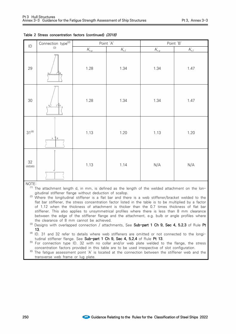
Pt 3 Hull StructuresAnnex 3-3 Guidance for the Fatigue Strength Assessment of Ship Structures Pt 3, Annex 3-3
250 Guidance Relating to the Rules for the Classification of Steel Ships 2022
IDConnection type(2)
(3)Point 'A' Point 'B'
29 1.28 1.34 1.34 1.47
30 1.28 1.34 1.34 1.47
31(4) 1.13 1.20 1.13 1.20
32(4)(5)(6) 1.13 1.14 N/A N/A
NOTE:(1) The attachment length d, in mm, is defined as the length of the welded attachment on the lon-
gitudinal stiffener flange without deduction of scallop.(2) Where the longitudinal stiffener is a flat bar and there is a web stiffener/bracket welded to the
flat bar stiffener, the stress concentration factor listed in the table is to be multiplied by a factor of 1.12 when the thickness of attachment is thicker than the 0.7 times thickness of flat bar stiffener. This also applies to unsymmetrical profiles where there is less than 8 mm clearance between the edge of the stiffener flange and the attachment, e.g. bulb or angle profiles where the clearance of 8 mm cannot be achieved.
(3) Designs with overlapped connection / attachments, See Sub-part 1 Ch 9, Sec 4, 5.2.3 of Rule Pt 13.
(4) ID. 31 and 32 refer to details where web stiffeners are omitted or not connected to the longi-tudinal stiffener flange. See Sub-part 1 Ch 9, Sec 4, 5.2.4 of Rule Pt 13.
(5) For connection type ID. 32 with no collar and/or web plate welded to the flange, the stress concentration factors provided in this table are to be used irrespective of slot configuration.
(6) The fatigue assessment point ‘A’ is located at the connection between the stiffener web and the transverse web frame or lug plate.
Table 2 Stress concentration factors (continued) (2018)

Pt 3 Hull StructuresAnnex 3-3 Guidance for the Fatigue Strength Assessment of Ship Structures Pt 3, Annex 3-3
Guidance Relating to the Rules for the Classification of Steel Ships 2022 251
(4) Combined stress range(A) The combined stress used to calculate the fatigue life of a ship structure is the hot spot
stress, which is to be determined from multiplying the nominal stress in (2) by stress con-centration factor in (3). The combined stress determined at the probability level of is to be complied with the following formulae as the combination of the stress component due to the local load, the hull girder bending load and the relative deflection.
×max
where, : Reduction factor on derived combined stress range accounting for the long-term sailing
routes of a ship, the following values may be used:
= 1.0 for shuttle tankers and vessels that frequently operate in the North Atlantic or in other harsh environments
Elsewhere : = 0.8
(B) The long-term distribution of the stress range may be represented by the two parameter Weibull distribution. The Weibull shape parameter depends on ship type, location of struc-tural member, sea environment, etc. In this guidance, however, the Weibull shape parameter for a longitudinal may be taken as
(C) The Weibull shape parameter of the combined stress range is assumed to be the same val-ue as the local stress range.
(5) Calculation of fatigue damage ratio (2020)(A) According to the Miner-Palmgren linear cumulative damage rule, the fatigue damage ratio
is calculated using numerical integration as follows:
where, = number of stress cycles in stress block for long-term distribution of the combined
stress range = number of cycles to failure at the -th constant stress range.
If the long-term distribution of the stress range follows a Weibull one, the damage ratio is given by the following formula:
ln
∙∙
where, = Constant of the design S-N curve, as given in Table 1 (a) for in-air environment = Weibull shape parameter = complete Gamma function given by the following formula

Pt 3 Hull StructuresAnnex 3-3 Guidance for the Fatigue Strength Assessment of Ship Structures Pt 3, Annex 3-3
252 Guidance Relating to the Rules for the Classification of Steel Ships 2022
∞
= incomplete Gamma function given by the following formula.
= Coefficient taking into account the change of inverse slope of the S-N curve, .
∙
= as specified in the following formula
ln
= stress range of the design S-N curve at cycles
= the total number of stress cycles for a design life of ships and considering voyage days of 85% for the design life of (years), the total number of stress cycles is giv-en by the following formula.
log ×
×
(B) For unprotected joints exposed to sea water, the damage ratio D cor is given by
ln
= Constant of the design S-N curve, as given in Table 1 (b) for corrosive environment.
However, for the structural members protected by effective means in ballast tanks, the damage ratio D is to be calculated as follows:
(C) In case of considering the full loaded condition and the ballast condition as the load con-dition, the relevant draft is to be applied in the calculation of the local wave pressure range and the fatigue damage ratio at each condition ( and ) is to be calculated. Therefore, the formula for calculating the total fatigue damage can be expressed as follow:
and = probability at the full loaded condition and the ballast condition, where, how-ever, the values are not given, 0.5 may be used respectively. However, if deemed necessary by the Society, fatigue strength assessment may be car-

Pt 3 Hull StructuresAnnex 3-3 Guidance for the Fatigue Strength Assessment of Ship Structures Pt 3, Annex 3-3
Guidance Relating to the Rules for the Classification of Steel Ships 2022 253
ried out by adjusting the operating ratio in accordance with the loading manual. The following shows the general operating rates for representative ship types.- LNG carrier(Membrane type): Full load condition - 0.5 / Ballast condition – 0.5- RO-RO ship: Full load condition - 0.7 / Ballast condition – 0.3.In case of ore carriers, unless otherwise provided, loading condition with high and low density cargo also has a same probability level. Probability level at heavy ballast condition and normal ballast condition, 0.3 and 0.2 may be used respectively. If no heavy ballast condition, only normal ballast condition is to be considered in fatigue strength assessment.
(6) Locations of member subjected to fatigue strength assessmentStructural members for which the fatigue strength assessment is to be required in accordance with the simplified fatigue analysis are longitudinals and locations of the members are given in Table 3.Fatigue assessment is performed for midship transverse section, fore and after transverse sec-tion of watertight bulkheads located in the ship’s midship hold. For the cases where deemed necessary, the Society may require the fatigue assessment for other transverse sections
Locations
1 Intersection of bottom or inner bottom longitudinals and floor or transverse bulkhead
2 Intersection of side shell or inner skin bulkhead longitudinals and transverse or transverse bulkhead
3 Intersection of deck longitudinals and transverse or transverse bulkhead
Table 3 Locations to be assessed for fatigue analysis
5. Fatigue analysis by hold analysisProcedure based on finite element stress analysis is used to determine hot spot stress at weld toe of specified structural details, from very fine mesh models. The hot spot stress is generally highly dependent on the finite element model used for representing the structure.(1) Fatigue design load
(A) Hull girder bending load(a) Vertical still water bending moment
Vertical still water bending moments are obtained from values corresponding to the ac-tual loading condition.
(b) Vertical wave induced bending momentVertical wave induced bending moments are to be in accordance with Par 4 (1) (A) (a).
(B) Local wave loadThe wave pressure on the ship's side is to be taken as follows, but not to be taken less than 0.
- Wave induced load for wave crest : kNm
- Wave induced load for wave trough : kNm
where,
: sea water density, 1.025tm
: as specified in Par 4 (1) (B).

Pt 3 Hull StructuresAnnex 3-3 Guidance for the Fatigue Strength Assessment of Ship Structures Pt 3, Annex 3-3
254 Guidance Relating to the Rules for the Classification of Steel Ships 2022
(C) Internal loadsInternal loads applied to structural model are loads due to liquid( ballast water, etc) and ore cargo grain cargo, etc. Internal loads are to be taken as follows, but not to be taken less than 0.
Accelerations due to ship motion are to be in accordance with Par 4 (1) (C) (b).(a) Loads due to liquid cargo and ballast water
(i) Loads due to liquid cargo and ballast water are to be taken as follows.
kNm
: density of liquid cargo and density of sea water, 1.025tm
: height of considered position from tank topm(ii) The dynamic internal pressure, , from liquid cargo or ballast water is not to be
less than that obtained from the following formulas, which is the greater:
kNm
kNm
, , , , : as specified in Par 4 (1) (C) (a)., : as specified in Table 5 and Table 6.
(b) Loads due to ore cargo grain cargo, etc. (i) The height and surface of the cargo are to be determined in accordance with Par 4
(1) (C) (a) (ii) of the Guidance.(ii) The loads , , on the vertical walls of the hold are to be determined by the fol-
lowing formula.
: density of cargo tm
: vertical distance from the panel in consideration to the surface of the cargo right above the panel (m)
: cos sinsin : Angle, in deg, between panel considered and the horizontal plane. : Assumed angle of repose, in deg, of bulk cargo(considered drained and
removed) to be taken as follows. = 30° in general = 35° for iron ore = 25° for cement
(iii) The dynamic internal pressure, , from cargo is to be taken as follows.
: as specified in (a) (ii) : as specified in (ii)
(2) Calculation of hot spot stress(A) Structural model
The modelling is to be done in accordance with III. Hold Analysis and the portion to be evaluated is to be within the cargo hold evaluation range.

Pt 3 Hull StructuresAnnex 3-3 Guidance for the Fatigue Strength Assessment of Ship Structures Pt 3, Annex 3-3
Guidance Relating to the Rules for the Classification of Steel Ships 2022 255
(B) Boundary conditionsThe boundary conditions is to be accordance with Table 4.
LocationTranslation Rotation
Aft End
Independent point 0 1 1 0 0 0Cross section 0 Rigid link Rigid link Rigid link 0 0
Intersection of CL and inner bottom 1 0 0 0 0 0
Fore End
Independent point 0 1 1 1 0 0Cross section 0 Rigid link Rigid link Rigid link 0 0
Note 1 : fixed 0 : free
Table 4 Boundary condition for midship cargo hold model
(C) Load(a) Applied load
The following load components are be considered : hull girder bending load, local wave load and internal load as specified in (1).
(b) Loading conditionsTable 5 and Table 6 gives the standard load cases which are to be considered in the assessment.
No. Load case Loading pattern
External load Hull girder load
C t or CvStill water load
Wave induced loa
d
Still water bending
moments2)
Wave bending
moments3)
F-1 Full load condition
1)
Trough
Ms
Mw 1
F-2 Crest Mw -1
B-1 Normal ballast
condition
Ballast draft4) Trough Mw 1
B-2 Ballast draft4) Crest Mw -1
Remark)1) : scantling draught2) Ms : Still water bending moment in loading manual is to be applied.3) Mw : as specified in Par 4 (1) (A) (a).4) Ballast draft in loading manual is to be applied.
Table 5 Loading conditions for fatigue assessment of Oil Tanker and LNG (Membrane Type)

Pt 3 Hull StructuresAnnex 3-3 Guidance for the Fatigue Strength Assessment of Ship Structures Pt 3, Annex 3-3
256 Guidance Relating to the Rules for the Classification of Steel Ships 2022
No Load case
Internal load
Loading pattern
External load Hull girder load
C t or CvStill water load
Wave induced
load
Still water bending
moments2)
Wave bending
moments3)
F1-1
Full load condition
High density
1)
Trough
Ms
Mw 1
F1-2 Crest Mw -1
F2-1 Low density
Trough Mw 1
F2-2 Crest Mw -1
B1-1 Normal ballast
condition
- Ballast draft4) Trough Mw 1
B1-2 - Ballast draft4) Crest Mw -1
B2-1 Heavy ballast
condition
- Ballast draft4) Trough Mw 1
B2-2 - Ballast draft4) Crest Mw -1
Remark)1) : scantling draught2) Ms : Still water bending moment in loading manual is to be applied.3) Mw : as specified in Par 4 (1) (A) (a).4) Ballast draft in loading manual is to be applied.
Table 6 Loading conditions for fatigue assessment of Ore Carrier
(D) Finite element analysisThe finite element model of the structure is to consist of shell elements. At the hot spot region, the 4-noded quadrilateral shell elements of the size × are used, where is the plate thickness. The weld bead is not included in the finite element model. In order to de-termine the surface stress distribution of the shell element, fictitious beams without stiff-ness are put on the connection line of shell element and stress evaluation is to be per-formed by the structural analysis. Also, stress evaluation is to be obtained from the shell el-ement by the structural analysis. In case, FE models are to be based on as built scantlings and the beam element stresses are calculated taking account of shear flexibility. Hot spot stress is to follow (a) or Sub-part 1 Ch 9, Sec 5, [3] and [4] of Rule Pt 13.(a) Calculation of hot spot stress
The hot spot stress is to be calculated by means of the surface stress distribution from the FE analysis. The hot spot stress approach at weld toe in accordance with the con-nection types is shown in Fig 5. In order to eliminate the notch effect and to consider the weld leg length, the hot spot stress at the weld toe is obtained by a linear ex-trapolation of the stresses determined at the locations and from the weld toe.
: Using the Lagrange interpolation method, the stress at a location from the weld toe is to be generally calculated as follows

Pt 3 Hull StructuresAnnex 3-3 Guidance for the Fatigue Strength Assessment of Ship Structures Pt 3, Annex 3-3
Guidance Relating to the Rules for the Classification of Steel Ships 2022 257
Fig 5 Determination of hot spot stress
(b) Calculation of edge stressThe FE model of the plate structure is to consist of 4-noded quadrilateral shell elements of size × in the vicinity of the edge, where is the plate thickness. In order to cal-culate the edge stress, fictitious beams without stiffness are put on the edge of the plate. In the structural analysis, the edge stresses are obtained from these beam ele-ment stresses.

Pt 3 Hull StructuresAnnex 3-3 Guidance for the Fatigue Strength Assessment of Ship Structures Pt 3, Annex 3-3
258 Guidance Relating to the Rules for the Classification of Steel Ships 2022
(3) Calculation of fatigue damage ratioCalculation of fatigue damage ratio for fatigue analysis by hold analysis is to be in accordance with the requirements in Par 4 (5).
(4) Locations of member subjected to fatigue strength assessmentStructural members for the fatigue strength assessment by hold analysis are to be in accordance with the requirements in Par 6 (6).
6. Spectral fatigue analysis(1) General
For assessment of the spectral fatigue analysis, the Short-term closed-form method is to be applied in this Guidance. The part fatigue damage from each cell in the wave scatter diagram can be calculated using the closed-form expressions by incorporating a S-N curve and the Miner-Palmgren rule. The fatigue damage for a life time of a ship is a sum of all the part fa-tigue damage considering.
(2) Wave load analysis is to comply with Annex 3-2, II. Direct Global Structural Analysis, 5 of the Guidance. (2020)
(3) Calculation of hot spot stress is to be in accordance with the requirements in Par 5 (2) (D).(4) Short-term response
(A) Since the wave is assumed to be stationary in a short-term sea state, its statistical proper-ties are specified by the wave spectrum. The wave spectrum for the different sea states can be given by the following Bretschneider or two parameter Pierson-Moskowitz spectrum.
exp
where, = wave frequency (rad/sec) = significant wave height = wave period
(B) Using the stress transfer function , the response spectrum of the ship can be calcu-lated as follows.
where = wave heading angle = stress response to a regular wave with unit amplitude for different frequencies
and wave heading angles
(C) The area under the response spectrum and the second moment of the response spectrum can be calculated as follows.
using a spreading function usually defined as cos
where is selected such that :

Pt 3 Hull StructuresAnnex 3-3 Guidance for the Fatigue Strength Assessment of Ship Structures Pt 3, Annex 3-3
Guidance Relating to the Rules for the Classification of Steel Ships 2022 259
where, : Main wave heading : Relative spreading around the main wave heading
(5) Short-term fatigue damage (2020)(A) Referring to the cell in the wave scatter diagram associated with a significant wave
height and a zero up-crossing wave period , if the stress range distribution is repre-sented by a probability density function , the number of stress cycles within and is obtained from the following formulae.
= design life of a ship = probability of occurrence of and = Zero up-crossing frequency of stress response in the sea state.
, = area under the response spectrum and the second moment of the re-sponse spectrum as specified in (2) (C) above
= probability density function as specified in (B)(B) The part fatigue damage for a sea state can be calculated from,
∞
= total stress cycles for a life time of a ship given by the following formula
n T = f T
, = life intercepts and negative inverse slopes of the design S-N curve, as given in Table 1 (a) for in-air environment and in Table 1 (b) for corrosive environment
= as specified in (A) above = ratio of the response zero up-crossing frequency in a given sea state to the average
crossing frequency given by the following formula
f = average frequency given by the following formula
= probability density function of the stress range for a sea state expressed as fol-lows

Pt 3 Hull StructuresAnnex 3-3 Guidance for the Fatigue Strength Assessment of Ship Structures Pt 3, Annex 3-3
260 Guidance Relating to the Rules for the Classification of Steel Ships 2022
exp
, = as specified in (A) abovewhere a bi-linear S-N curve is used to consider Haibach effect, the short-term fatigue dam-age ratio may be calculated from,
where, = as specified in the following formula
= as specified in (B)
= the stress range of the design S-N curve at cycles
and = complete Gamma function and incomplete Gamma function, respectively
= Rain flow correction factor in a given sea state
(6) Long-term cumulative fatigue damage (2020)(A) Taking account of all heading directions and loading conditions, the long-term cumulative fa-
tigue damage ratio in air is calculated as follows.
, : life intercepts and negative inverse slopes of the design S-N curve, as given in Table 1 (a)
= combined probability given by the following formula

Pt 3 Hull StructuresAnnex 3-3 Guidance for the Fatigue Strength Assessment of Ship Structures Pt 3, Annex 3-3
Guidance Relating to the Rules for the Classification of Steel Ships 2022 261
, = probability for the heading angle and the loading condition, respectively
(B) For unprotected joints exposed to sea water, the damage ratio D cor is given by
, : life intercepts and negative inverse slopes of the design S-N curve, as given in Table 1 (b)
However, for the structural members protected by effective means in ballast tanks, the dam-age ratio is to be calculated as follows:
(7) Structural members to be assessed for fatigue strength(A) General
(a) Structural members subject to fatigue strength assessments are selected considering the structural system of the ship, and the importance, functions, etc of the members.
(b) Structural members in which fatigue cracks are likely to initiate because of stress con-centration due to structural discontinuities, and structural members at locations where watertightness problems are likely to occur due to cracks in the compartments, are se-lected for the fatigue assessment on priority.
(B) Structural members subject to the fatigue strength assessment according to ship type(a) Structural members being of possible assessment for the fatigue strength according to
ship type(i) Tankers : as specified in Table 7(ii) Bulk carriers : as specified in Table 8 (iii) Container carriers : as specified in Table 9(iv) Ore carriers : as specified in Table 10(v) LNG ships(Membrane Tank) : as specified in Table 11(vi) RO-RO ships : Table 12 (2020)
(b) Locations with high stresses are selected from the locations mentioned in (a) above and the fatigue strength is assessed.
(c) Notwithstanding the requirements in (a) and (b), additional fatigue assessment may be required for other locations where deemed necessary by the Society.

Pt 3 Hull StructuresAnnex 3-3 Guidance for the Fatigue Strength Assessment of Ship Structures Pt 3, Annex 3-3
262 Guidance Relating to the Rules for the Classification of Steel Ships 2022
Symbol
Members Locations
a
Inner bottom plating, slant plating
Intersection of double bottom floor and bilge hopper slant plating
dd
b
ac
c
c
b
Side longitudinal bulkhead plating,slant plating
Intersection of side longitudinal bulkhead and bilge hopper slant plating
c
Inner bottom plating,longitudinal bulkhead
Intersection of double bottom floor and transverse on longitudinal bulkhead
d
Side longitudinal bulkhead plating,Longitudinal bulkhead plating
Intersection of deck transverse and side longitudinal bulkhead
Intersection of deck transverse and longitudinal bulkhead
Table 7 Structural members of tankers for fatigue strength assessment

Pt 3 Hull StructuresAnnex 3-3 Guidance for the Fatigue Strength Assessment of Ship Structures Pt 3, Annex 3-3
Guidance Relating to the Rules for the Classification of Steel Ships 2022 263
Symbol
Members Locations
e
Side longitudinal bulkhead plating,Longitudinal bulkhead plating
Intersection of horizontal girder and side longitudinal bulkhead
e
e
e
e
Intersection of horizontal girder and longitudinal bulkhead
f
Side longitudinal bulkhead plating,Longitudinal bulkhead plating
Intersection of swash bulk-head and side l o n g i t u d i n a l bulkhead
f fIntersection of swash bulkhead and longitudinal bulkhead
g
Side longitudinal bulkhead plating
Intersection of cross tie and side longitudinal bulkhead
g
g
Table 7 Structural members of tankers for fatigue strength assessment (continued)

Pt 3 Hull StructuresAnnex 3-3 Guidance for the Fatigue Strength Assessment of Ship Structures Pt 3, Annex 3-3
264 Guidance Relating to the Rules for the Classification of Steel Ships 2022
Symbol Members Locations
a
Inner bottom plating,Sloping plate of bilge hopper tanks
Intersection of sloping plate of lower stool, girder, floor plate and inner bottom plating
a
b
c
d
b
Sloping plate of bilge hopper tanks
Intersection of lower end of hold frame and sloping plate of bilge hopper tank
c
Sloping plate of topside tanks
Intersection of upper end of hold frame and sloping plate of topside tanks
d
Intersection of end of hatch coaming and sloping plate of topside tanks
e
Transverse bulkhead
Intersection of sloping plate of lower stool and transverse bulkhead
h
e
f
g
f
Intersection of sloping plate of upper stool and upper part of transverse bulkhead
g
Intersection of slant plating of topside tanks and upper part of transverse bulkhead
h
Sloping plate of lower stool,Inner bottom plating
Intersection of inner bottom plate and sloping plate of lower stool
Table 8 Structural members of bulk carriers for the fatigue strength assessment

Pt 3 Hull StructuresAnnex 3-3 Guidance for the Fatigue Strength Assessment of Ship Structures Pt 3, Annex 3-3
Guidance Relating to the Rules for the Classification of Steel Ships 2022 265
Symbol Members Locations
a
Hatch
Typical hatch coaming and corner in the
midship
d
After hatch coaming and corner in the
after cargo hold (in front of
engine room forward
bulkhead)
c
Hatch coaming and corner within the
forward part of the cargo area
d
Hatch
Typical hatch coaming and corner in the
midship
e
Hatch coaming and corner
located behind engine room
forward bulkhead
f
Hatch coaming and corner in
first bulkhead in front of engine room forward
bulkhead
g
Hatch coaming and corner
adjacent to the collision bulkhead
hHatch coaming
and corner adjacent to the
deckhouse.
Table 9 Structural members of container carriers for the fatigue strength assessment (2020)

Pt 3 Hull StructuresAnnex 3-3 Guidance for the Fatigue Strength Assessment of Ship Structures Pt 3, Annex 3-3
266 Guidance Relating to the Rules for the Classification of Steel Ships 2022
Symbol Members Locations
a
Inner bottom plating,Sloping plate of
bilge hopper tanks
Intersection of sloping plate of
lower stool, girder, floor
plate and inner bottom plating
b
ab Hatch
End bracket of longitudinal hatch
coaming
Hatch corner of cargo hold
c
Sloping plate of
lower stool,Inner
bottom plating
Intersection of inner bottom
plate and sloping plate of lower
stool
d
cd Transverse bulkhead
Intersection of sloping plate of lower stool and
transverse bulkhead
Table 10 Structural members of ore carriers for the fatigue strength assessment

Pt 3 Hull StructuresAnnex 3-3 Guidance for the Fatigue Strength Assessment of Ship Structures Pt 3, Annex 3-3
Guidance Relating to the Rules for the Classification of Steel Ships 2022 267
Symbol
Members Locations
a
Inner bottom plating,Sloping plate of
bilge hopper
tank
Intersection of sloping plate
of lower stool, girder, floor plate and inner
bottom plating
d
a
b
c
b
Side longitudinal bulkhead plating,slant
plating
Intersection of side
longitudinal bulkhead and bilge hopper slant plating
c
Side longitudinal bulkhead,
Inner trunk slant
plating
Intersection of side
longitudinal bulkhead and inner trunk slant plating
d
Inner trunk slant
plating,Inner trunk
deck plating
Intersection of inner trunk slant plating
and inner trunk deck
plating
e
Transverse bulkhead,
Inner bottom plating
Intersection of inner bottom
plate and transverse
bulkhead plate
e
f
f Stringer plating
Intersection of side stringer
plate and stringer plate of transverse
bulkhead
Table 11 Structural members of LNG(Membrane Type) for the fatigue strength assessment

Pt 3 Hull StructuresAnnex 3-3 Guidance for the Fatigue Strength Assessment of Ship Structures Pt 3, Annex 3-3
268 Guidance Relating to the Rules for the Classification of Steel Ships 2022
Symbol Members Locations
a Pillar and deck
Connections between deck
and pillar(top)
Connections between deck
and pillar(bottom)
bSide
transverse,deck
Connections between side transverse and
deck(top)
Connections between side transverse and
deck(bottom)
c Bracket, deck
Connections between
superstructure and deck
d Opening Openings in engine room
d
Table 12 Structural members of RO-RO ships for the fatigue strength assessment (2020)

Pt 3 Hull StructuresAnnex 3-3 Guidance for the Fatigue Strength Assessment of Ship Structures Pt 3, Annex 3-3
Guidance Relating to the Rules for the Classification of Steel Ships 2022 269
7. Transfer function method(1) General
In order to perform the spectral fatigue assessment, structural analyses for all wave loads calcu-lated for all heading directions and frequencies have to be carried out to obtain stress transfer functions. However, in the transfer function method, a discrete unit load approach is used. The loads acting on the hull are divided into several load components. The transfer functions for the each load component are determined using a seakeeping software for each wave condition and the influence coefficients for structure are computed by finite element analysis for each unit load. The non-linear effect of the wave induced load at the waterline region can also be consid-ered in the transfer function method.
(2) Stress transfer functionThe stress transfer function may be obtained by multiplying the load transfer function by the stress influence coefficient which means the stress value due to the unit load. The combined stress transfer function is to be obtained by a linear summation of each stress transfer function as follows:
(A) Hull girder load = stress influence coefficient due to unit hull girder load = stress influence coefficient due to unit vertical bending moment = stress influence coefficient due to unit horizontal bending moment = stress influence coefficient due to unit torsional moment = transfer function of hull girder load = transfer function of vertical bending moment = transfer function of horizontal bending moment = transfer function of torsional moment
(B) Wave pressure : transfer function for pressure coefficient of 5th order power function, , at the -th station of a ship is given by the following formula.
≅
= external pressure distribution with the girth-wise coordinate = girth-wise coordinate, at keel = coefficient of the power function is to be determined by the regression analysis for the
calculated hydrodynamic pressures at the -th station of a ship = stress influence coefficient due to the -th unit pressure distribution at the -th sta-
tion of a ship and the -th unit pressure distribution is as follows:
for uniform pressure (1) for linear distributed pressure for quadratic distributed pressure for cubic distributed pressure for forth order distributed pressure for fifth order distributed pressure

Pt 3 Hull StructuresAnnex 3-3 Guidance for the Fatigue Strength Assessment of Ship Structures Pt 3, Annex 3-3
270 Guidance Relating to the Rules for the Classification of Steel Ships 2022
(C) Cargo load = stress influence coefficient due to unit inertia force at the -th station of a ship = stress influence coefficient due to unit vertical inertia force at the -th station of a ship = stress influence coefficient due to unit horizontal inertia force at the -th station of a ship = transfer function due to the inertia force of cargo weight at the -th station of a ship = transfer function due to vertical inertia force at the -th station of a ship = transfer function due to horizontal inertia force at the -th station of a ship
(D) In order to consider the non-linear effect of the stress range in the waterline region, the re-duction factor,, is to be used as follows:
: above the waterline
: at the waterline : below a w
and = as specified in Par 4 (1) (B) (a)For intermediate location between the waterline and , is to be obtained by interpolation
(3) Using stress transfer function obtained from (2) above, the short-term response spectrum is to be calculated according to Par 6 (3). The short-term fatigue damage ratio and the long-term cumulative fatigue damage ratio are to be obtained according to Par 6 (4) and (5), respectively. The requirements not listed in this paragraph are to be in accordance with Par 6.

Pt 3 Hull StructuresAnnex 3-4 Guidance for the Hull Construction Monitoring Procedure Pt 3, Annex 3-4
Guidance Relating to the Rules for the Classification of Steel Ships 2022 271
Annex 3-4 Guidance for the Hull Construction Monitoring Procedure
1. General(1) Introduction
(A) The general quality of a vessel is enhanced by superior structural design, improved con-struction procedures and effective through life monitoring. In structural terms, the perform-ance of structural elements or connections between members is dependent on the adoption of adequate quality control measures relating to both the quality of detail design and the construction. The detail design, the methods of manufacture and the degree of quality con-trol significantly affect the fatigue performance of a structure. This is particularly evident at locations within the structure identified as 'critical'.
(B) Misalignment, inappropriate edge preparation, excessive gap, weld sequence and weld quality alters the fatigue properties of these joints. Setting appropriate controls on the key factors affecting fatigue performance at the design stage and utilising enhanced monitoring proce-dures at critical locations ensures that a high degree of workmanship is achieved and avoids unnecessary remedial action in the later stages of the build process.
(C) The links to Direct Strength Assessment (DSA) and Direct Fatigue Assessment (DFA) within the Hull Construction Monitoring (HCM) procedure ensure that a seamless transition of qual-ity monitoring is achieved throughout the life of the vessel.
(D) The SeaTrust HCM procedure forms an element of an integrated approach to the design, construction and monitoring of the critical areas of ship structures. The application of the HCM procedure enhances not only the confidence of the Owner and this Society in the hul1 construction but also quality control procedures employed by the Shipyard at the structurally critical locations.
(2) Objective(A) The main objective of the SeaTrust HCM procedure is to ensure that the locations within the
ship structure, that have been identified as critical, are built to both an acceptable quality standard and approved construction procedures.
(B) The HCM procedure is applied in addition to the requirements for vessels built under special survey, and is based on the application of enhanced controls on alignment, fit-up, edge preparation and workmanship to the critical areas of the relevant hul1 structures to attain the required structural performance.
(C) A secondary objective is that during the service life of the vessel, the Hull Construction Monitoring Plan(HCMP) is used to focus the attention of any future classification survey to the critical locations.
(3) Outline of the procedure(A) The pre-construction meeting includes advice to the Builder's representatives and owners site
manager on the specific application of the Hull Construction Monitoring procedure.(B) At the plan development and approval stage, the application of the HCM procedure identifies
the areas and locations within the ship structure that may experience high levels of stress or fatigue damage assessed on the basis of DSA and DFA results and procedures. The crit-ical areas are those areas of the ship structure that have been shown by structural analysis and service experience to have a higher probability of failure than the surrounding ship structure. The critical locations are specific points identified within the critical areas that are prone to fatigue, and where detail design improvement may have to be undertaken. Particular emphasis is placed on those primary structural locations specified as having en-hanced fatigue life specifications within the DFA procedures.
(C) In order to promote a satisfactory level of strength and fatigue performance, detailed con-struction tolerances are agreed between this Society and the Shipbuilder for each ship con-sidered for the HCM notation in accordance with the Hull Construction Monitoring Standards. The HCMP is prepared by the builder as a catalogue of the critical locations together with the required construction tolerances and an outline of the quality control and quality assur-ance procedures to be applied. The completed HCMP is sent to this Society for review and subsequent approval.
(D) The Shipyard quality personnel are responsible for the inspection and recording of results during the construction of the ship in accordance with approved yard procedures and the requirements of this society. This site Surveyor provide third party inspection to confirm that the alignment, fit-up, workmanship and construction tolerances conform to the agreed

Pt 3 Hull StructuresAnnex 3-4 Guidance for the Hull Construction Monitoring Procedure Pt 3, Annex 3-4
272 Guidance Relating to the Rules for the Classification of Steel Ships 2022
standard specified in the HCMP. Where the approved construction tolerances are exceeded, the Shipbuilder undertakes corrective action to the satisfaction of the requirements of the HCMP.
(E) On satisfactory completion of the HCM requirements, this Society assigns the "SeaTrust (HCM)" notation. Upon completion of the ship, the site Surveyor sends a copy of the ap-proved HCMP to head office.
(F) During the lifetime of the vessel, the HCMP is maintained on board and is used to focus periodical surveys on the critical locations in order to monitor the structural integrity and performance.
(G) The Construction Monitoring Procedure has been subdivided into three phases to be applied sequentially as shown in Table 1 and Fig 1.
Phase I Plan approval Analysis to determine the critical locations
Phase II Survey during Construction Survey to ensure satisfactory construction stand-ards
Phase III Lifetime application of HCMP Monitor the structural integrity using the HCMP
Table 1 Hull construction monitoring phases
(4) Scope of application(A) The requirements in this Annex apply at the request of the applicant.(B) Notwithstanding the requirements in (A), the ship built in accordance with Common Structural
Rules for Bulk Carriers and Oil Tankers(Pt. 13) shall be applied.(C) This procedure is applied to areas of the structure that have been identified as being critical
locations through the application of the SeaTrust procedures for Direct Structural Assessment (DSA) and Direct Fatigue Assessment (DFA).
(D) The procedure is adopted in association with requirements of this Society for vessels con-structed under Special Survey.
(E) Any subsequent modifications or repairs to the ship's structure are, where applicable, to be in accordance with this procedure.
(5) Classification notation(A) Upon satisfactory application of this procedure, the vessels may be eligible to be assigned
the Hull Construction Monitoring notation "SeaTrust (HCM)".2. Hull Construction Monitoring Standard
(1) Hull Construction Monitoring Standard(A) The Hull Construction Monitoring Standard (HCMS) sets down the Construction Monitoring
tolerances to be achieved at the critical locations in order that the requirements for the HCM notation are met. The HCMS covers such aspects of construction such as:. Alignment. Fit-up. Remedial Measures
(B) When identifying the critical locations, particular consideration should be given to critical loca-tions identified by DSA or DFA that constitute a unit joint and critical joints assembled in areas where environmental controls are difficult to apply such as in the erection area or building dock.
(C) In all cases, the construction standards and tolerances not indicated in this standard are to be at least equivalent to the approved yard, national or international ship construction stand-ards in use.
(D) The quality standards for the alignment, fit-up and repair of critical structural components during new construction are shown in Table 2 to Table 5.
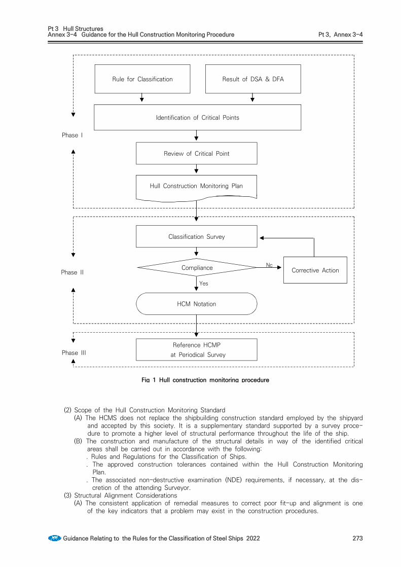
Pt 3 Hull StructuresAnnex 3-4 Guidance for the Hull Construction Monitoring Procedure Pt 3, Annex 3-4
Guidance Relating to the Rules for the Classification of Steel Ships 2022 273
Rule for Classification Result of DSA & DFA
Identification of Critical Points
Review of Critical Point
Hull Construction Monitoring Plan
Classification Survey
HCM Notation
Reference HCMP at Periodical Survey
Compliance Corrective Action
Phase I
Phase II
Phase III
No
Yes
Fig 1 Hull construction monitoring procedure
(2) Scope of the Hull Construction Monitoring Standard(A) The HCMS does not replace the shipbuilding construction standard employed by the shipyard
and accepted by this society. It is a supplementary standard supported by a survey proce-dure to promote a higher level of structural performance throughout the life of the ship.
(B) The construction and manufacture of the structural details in way of the identified critical areas shall be carried out in accordance with the following:. Rules and Regulations for the Classification of Ships.. The approved construction tolerances contained within the Hull Construction Monitoring
Plan.. The associated non-destructive examination (NDE) requirements, if necessary, at the dis-
cretion of the attending Surveyor.(3) Structural Alignment Considerations
(A) The consistent application of remedial measures to correct poor fit-up and alignment is one of the key indicators that a problem may exist in the construction procedures.

Pt 3 Hull StructuresAnnex 3-4 Guidance for the Hull Construction Monitoring Procedure Pt 3, Annex 3-4
274 Guidance Relating to the Rules for the Classification of Steel Ships 2022
(B) Any inaccuracy in the welding of blocks into erection units will have an amplified effect at the erection stage. If adequate dimensional control has not been exercised it will be neces-sary to cut away edges to align the units being erected. This has the effect of causing fur-ther misalignments in adjacent units that will also require modification.
(C) The most critical types of welded structural connection are angled cruciform joints such as the sloping hopper plate connection with the inner bottom plating and the outer longitudinal girder of double hull tankers. At these locations, adequate dimensional control is a pre-requisite to ensure good alignment.
(D) The application and maintenance of a suitable alignment method such as 100 mm offset lines is recommended to aid accurate fit up and alignment. For critical structural members it is recommended that any reference marks are indicated in a permanent manner, on both sides of the plate and the actual misalignment checked using jigs/templates, if necessary.
Fig 2 Recommended alignment of primary members
(E) In general, there are two types of alignment method in use ; the median line principle and the heel or moulded principle. These principles are outlined in Fig 2. While both alignment methods are generally acceptable, in cases where a more onerous trading pattern is speci-fied or enhanced service life expectations are required, consideration should be given to the application of a suitable alignment method appropriate to the design criteria in order to ach-ieve a preferable level of alignment. In addition to alignment considerations it may also be preferable to apply a more stringent tolerance beyond those detailed in this procedure. In order to eliminate difficulties associated with alignment, a prudent consideration by the ship-yard would be to ensure, where practicable, that the thickness of all structural members is reasonably compatible within regions where critical locations are likely to be identified.
(F) In addition to the basic design criteria, certain joints may be identified as requiring an en-hanced level of alignment through the application of service experience. The joints identified may depend upon the ship type and the structural configuration but in general the following joints may require additional consideration: . Lower hopper knuckle on bulk carriers and oil tankers.. Lower stool connection to floors in way of longitudinal girders in bulk carriers.. Lower cofferdam bulkhead cruciform joint on membrane type gas carriers.. Upper hopper knuckle on membrane type gas carriers.

Pt 3 Hull StructuresAnnex 3-4 Guidance for the Hull Construction Monitoring Procedure Pt 3, Annex 3-4
Guidance Relating to the Rules for the Classification of Steel Ships 2022 275
. Aft end cargo area transition zone on membrane type gas carriers.
. Fore end cargo area transition zone on membrane type gas carriers.(G) When verifying the alignment of structural members, it should be noted that it is often im-
practical to directly measure the median line alignment and a heel line approach is used in lieu of direct measurement of alignment at median lines. Where the heel line approach is used, the maximum median line tolerances maybe converted into heel line values using the equations given in Fig 3.
(H) In cases where two or more critical locations are connected by a secondary stiffening ar-rangement i.e. double bottom/inner bottom longitudinals, it may be considered prudent to ensure that the alignment is maintained.
(4) Construction considerations(A) At the sub-assembly stage, a high degree of accuracy may be obtained using methods such
as 'backmarking' prior to fit-up.(B) It is generally found that a consistently higher degree of accuracy is achieved within the as-
sembly shop where the conditions are controlled since blocks and pre-erection units are generally of a smaller size. This makes it easier to meet the specified construction toler-ances during fit-up and alignment.
(C) If the critical connections are part of much larger erection joints in the building dock or berth it is much harder to control the alignment and fit-up of the interface and weld quality due to the size of the units and other external factors.During all stages of construction, but particularly when fabrication and erection takes place external to the construction hall, measures are to be taken to screen and pre-warm, as nec-essary, the general and local weld areas. Surfaces are to be dry and rapid cooling of welded joints is to be prevented.
(5) Quality control and quality assurance(A) The construction standards are to be received general approval as part of the certification
procedures and their application is included with the quality plan submitted to this Society for approval.
(B) The construction standards and tolerances to be applied to the critical areas are to be agreed between this Society and the shipbuilder.
(C) In all cases the applied tolerances and standards are not to be less than those specified in the IACS "Shipbuilding and Repair Quality Standard".
(D) Any deviation from the approved structural configuration and/or approved procedures is to be submitted to this Society for consideration.

Pt 3 Hull StructuresAnnex 3-4 Guidance for the Hull Construction Monitoring Procedure Pt 3, Annex 3-4
276 Guidance Relating to the Rules for the Classification of Steel Ships 2022
max
sin
tan
minmax
min
sin
tan
min min
max = max heel line tolerance measured in the direction of the acute anglemin = max heel line tolerance measured in the direction of the abuse angle = angle of sloping plate to the horizontal = thickness of girder or transverse member = thickness of sloping plate = thickness of table member
Comparison of equivalent tolerances
max min Med. Line
12121414
22262226
20202020
60604545
16.518.823.226.0
8.510.813.916.7
44
4.74.7
Fig 3 Equivalent heel line tolerances
3. Phase 1 - Plan Development and Approval (1) Objectives
(A) The first objective of this stage is to identify the critical locations as defined in l.2.3 of this document.
(B) The second objective is to compile the HCMP prior to submission to this Society for approval.
(2) Identification of the critical locations(A) Experience with ships in service has enabled this Society to provide information to assist the
Shipbuilder in determining the critical locations that may be vulnerable to fatigue. Particular emphasis is placed on are as where high stress magnitudes may be anticipated and for which correct alignment is important.

Pt 3 Hull StructuresAnnex 3-4 Guidance for the Hull Construction Monitoring Procedure Pt 3, Annex 3-4
Guidance Relating to the Rules for the Classification of Steel Ships 2022 277
(B) The critical locations are to be clearly identified and labelled on the appropriate structural drawings contained within the HCMP and submitted to this Society for approval.
(3) Hull construction monitoring plan(A) The hull construction monitoring plan (HCMP) is a document compiled by the shipyard to
provide a record of the enhanced quality standards and procedures employed by the Shipbuilder to ensure that an increased level of construction quality control is employed at those areas of the structure that have been identified as critical to the vessel.
(B) The HCMP is submitted to Head Office of this Society for formal approval as soon as possi-ble prior to steel cutting. The HCMP is reviewed by both this society's site Surveyor and Plan Approval Surveyor in order that the findings of practical construction, structural analysis and fatigue analysis are uniquely reflected in the plan. Once approval is given, this society's site Surveyors maintain efficient contact between all interested parties to ensure that the requirements of the HCMP are fully understood and are complied with.
(C) The HCMP is supplemental to and does not replace the Quality Plan provided by the Shipbuilder.
(D) On receipt of the approved HCMP, the Shipbuilder, in association with this Society's Surveyor, ensures that all of the requirements contained within the HCMP are met in addi-tion to any shipbuilding standards used.
(E) A typical HCMP is to contain the following information:. Appropriate structural plans with the critical locations clearly marked.. Details of appropriate construction tolerances including any 'design offset' at the critical lo-
cations are to be included on the appropriate structural plans for approval.. Summary table of all critical locations indicating tolerances applied.. Alignment verification methods used, i.e. Offset marking.. Outline of quality controls in place during block construction, pre-erection and erection. . Outline of Q.A procedures used.. Methods for recording and reporting of inspection results.. Details of standard remedial measures to be employed where required.. Non destructive testing plan(where non destructive testing plan is submitted separately, it
may not be included in HCMP.)(F) A copy of the approved HCMP is maintained on board either in electronic or hard copy for-
mat through-out the life of the vessel. The HCMP is to be used to focus survey on those areas of the structure identified during the design process as being critical to the operational effectiveness of the vessel.
4. Phase 2 - Construction Monitoring(1) Fabrication and pre-erection
(A) The attending Surveyor and the Shipbuilder's quality control personnel agree a satisfactory in-spection routine that embodies both the Shipbuilders Quality Control and the Construction Monitoring requirements. The Owner's Representatives shall be notified of the agreed in-spection routine.
(B) Measures are, in general, to be taken to screen and pre-warm, as necessary, the general and local weld areas. Surfaces are to be dry and rapid cooling of welded joints is to be prevented. For any given welding method, the welding procedures are to be approved by this society. In addition, the Shipbuilder ensures that all welding operators employed on that process are qualified as approved by this society.
(C) The fabrication plans and other appropriate specifications, procedures and work instructions necessary for each phase of the fabrication process are to be made available at the appro-priate inspection locations. The Shipbuilder maintains the inspection status of the critical structural components at appropriate stages in the fabrication process. This may include the direct marking of individual components. The marking method used is to be discussed and agreed with the attending Surveyor.
(D) Prior to the welding of critical joints, the Shipbuilder liaises with the attending Surveyor with respect to arranging appropriate 'fit-up' inspection, if necessary. Records of inspection and measurements are to be easily referenced against the relevant structural components and be accessible to this society.
(E) The workmanship employed throughout the stages of material preparation and assembly of pre-fabricated units is to conform to the relevant standards defined in the HCMP. Faulty workmanship or non-compliance with the specified tolerances noted by the Surveyor is to be rectified to the Surveyors satisfaction before progressing to the next stage of production.

Pt 3 Hull StructuresAnnex 3-4 Guidance for the Hull Construction Monitoring Procedure Pt 3, Annex 3-4
278 Guidance Relating to the Rules for the Classification of Steel Ships 2022
(2) Assembly of units(A) The assembly welding sequences, in general, are to be agreed prior to construction and to
the satisfaction of the attending Surveyor. At each stage of assembly, particular attention is to be paid to ensure that the fit-up, alignment and welding of units is in accordance with the approved plans and to the approved HCM tolerances.
(B) Where a critical connection is also an erection joint, the attending Surveyor is to liaise with the Shipyard to provide adequate inspection to ensure that the required construction toler-ances are achieved. During unit erection it is common for plates to be released and material cropped to allow acceptable fit-up and alignment. This process often results in damage to the surrounding plating detrimental to the strength of the structure. It is recommended that where such practices have been employed, full penetration welding is specified for the re-welding of the structure. Where insert plates have been used, it is recommended that these plates are left loose until such time that acceptable fit-up and alignment has been achieved.
(3) Inspection of welds(A) Regular examination of the NDE records, in conjunction with the Shipbuilder, verifies that the
quality of welding operations is satisfactory. Any departure from acceptable standards is to be investigated, including additional tests as considered desirable.
(B) Finished welds are to undergo a visual inspection by the attending Surveyor. The Shipbuilder shall ensure that all welds presented for visual inspection are clean, having all rust and weld slag removed and be free of coatings that may impair the inspection. The inspection is to verify that all welds are sound, free from cracks, undercut, notches, substantially free from lack of fusion, incomplete penetration, slag inclusion and porosity. The surface of all finished welds shall be inspected to ensure that they are reasonably smooth, substantially free of overlap and undercut. Fillet welds are to be inspected to ensure that they are continuous around scallops, brackets, stiffeners, etc. thus avoiding craters and incipient cracks at points of stress concentration.
(C) Weld sizes shall be inspected to ensure they are consistent over their entire length and are of the correct dimensions. Finished weld profile characteristics can have a marked effect upon joint fatigue. The approved dimensional requirements are to be verified using a suitable gauge and shall meet the criteria specified in the HCM Standard.
(D) In addition to visual inspection, non-destructive testing for at least 10 % of the critical loca-tions are to be carried out. The Surveyor may request the additional non-destructive testing according to the quality of workmanship of the shipyard. Welds may be examined using ap-proved methods such as Ultrasonic, Magnetic Particle, Radiographic, Eddy Current, Dye Penetrant or other acceptable methods appropriate to the configuration of the weld.
(E) The Shipyard production personnel involved in the fabrication joints to undergo NDE are not to be informed of the exact locations of the NDE prior to welding. Similarly, the proposed location of NDE is not to be marked or indicated on the plates prior to welding.
(F) The quality of a finished weld often varies with the method used due to factors such as heat input and the process itself. When specifying an NDE procedure, full consideration is to be given to the weld process employed to ensure that the method of NDE is suitable for the type of weld under consideration.
(G) Where defects are observed, additional NDE is to be carried out to determine the full extent. Unacceptable weld defects detected by NDE inspection are to be repaired or completely re-moved and re-welded as appropriate using approved procedures and consumables.
(H) Prior to any repair or re-welding at critical locations, the joint is to be inspected by the at-tending Surveyor to ensure that the alignment and gap comply with the specified tolerances.
(I) In critical areas where repairs and rewelds have been undertaken, the Surveyor is to ensure that excessive welding leading to distortion, stress concentration has not taken place. Re-in-spection using the appropriate method of NDE shall be carried out until no further defects are discovered.
(J) Only where absolutely necessary should methods for fatigue strength improvement be con-sidered at the fabrication stage and then only as remedial measures. In these cases, strict quality control procedures are to be applied.
(4) Departure from the approved arrangements(A) Modifications or alterations to the design or construction of a particular structural arrangement
or detail in way of an identified critical area are to be approved by this society.(B) In this case, the Shipbuilder is to re-submit to this society, the appropriate plans indicating
Pt 3 Hull StructuresAnnex 3-4 Guidance for the Hull Construction Monitoring Procedure Pt 3, Annex 3-4
Guidance Relating to the Rules for the Classification of Steel Ships 2022 279
all of the required changes. Reassessment of the structure may be a requirement along with the submission of a revised HCMP. Any reassessment carried out by this Society with regard to post-approval modifications or alterations may be chargeable to the Shipbuilder.
5. Construction Monitoring Compliance(1) Compliance
(A) The attending Surveyor shall ensure that during the various stages of the construction proc-ess, all structure in way of fatigue critical locations has been examined in accordance with the inspection plan.
(B) The attending Surveyor is to ensure that, where applicable, all of the requirements of the HCMP have been met in addition to any rules and standards applied.
(C) On satisfactory completion of all inspections, the Surveyor shall confirm that the structure complies with the approved HCM tolerances and assign the appropriate notation "SeaTrust(HCM)".
(2) Non-Compliance(A) Throughout the various stages of construction, the attending Surveyor shall inform the
Shipbuilder immediately, upon completion of an inspection, of any defined critical joint or lo-cation that does not comply with the approved HCMP.
(B) Where the Shipbuilder is to utilize remedial measures or corrective action not stated in the HCMP, an agreement should be reached on an approved remedial plan to ensure that com-pliance is reached through discussions between this Society and the Shipbuilder. The pro-posal shall contain details of any modifications to the structural arrangement, scantlings, welding processes to be employed and NDE to be performed.
(C) Through discussions between this Society and the Shipbuilder an agreement shall be reached on an approved remedial plan. Repairs, re-work and inspection shall be carried out in ac-cordance with the approved remedial plan until compliance is granted.
6. Phase 3 - Lifetime Application(1) Through life monitoring
(A) The Surveyor attending future classification surveys shall identify, from the HCMP, those structural locations that will require special consideration and extended examination during survey.
(B) The nature of the critical locations requires that the Surveyor pay particular attention to de-fects such as corrosion, local damage, evidence of cracking, and local coating breakdown.
(C) All repairs undertaken at the critical locations identified in the HCMP are to be undertaken in accordance with these procedures.
(2) Structural alterations(A) In cases where a vessel has undergone significant structural alteration, any locations sub-
sequently identified as being critical to the structural integrity are to be constructed to the tolerances specified in the original HCMP. A revised HCMP is to be produced as early as practicable in the design process in accordance with these procedures and submitted for approval.
(B) Joints not previously identified but subsequently found to be critical are to be examined in detail to ensure that no construction irregularities such as severe misalignment and weld imperfections exist.

Pt 3 Hull StructuresAnnex 3-4 Guidance for the Hull Construction Monitoring Procedure Pt 3, Annex 3-4
280 Guidance Relating to the Rules for the Classification of Steel Ships 2022
Detail Heel Median
max ≥≥min
where,
max
min
≤
Median line tolerances may be con-verted to an equivalent heel line tolerance using the equations given below.
max ≥≥min
where,
max
sin
tan
min
sin
tan
min (max 5 mm)where, min = min (, , )
Table 2 Median line principle alignment

Pt 3 Hull StructuresAnnex 3-4 Guidance for the Hull Construction Monitoring Procedure Pt 3, Annex 3-4
Guidance Relating to the Rules for the Classification of Steel Ships 2022 281
Detail HCM Standard Remark
≤
min
Where a is the ‘overhang’ of the thinner
plate.
min = min(, , )
- Where deemed necessary by the Society(thick insert plate etc), heel line principle alignment may be applied
Table 2-1 Heel line principle alignment

Pt 3 Hull StructuresAnnex 3-4 Guidance for the Hull Construction Monitoring Procedure Pt 3, Annex 3-4
282 Guidance Relating to the Rules for the Classification of Steel Ships 2022
Detail HCM Standard Remark
≤ mm
= 45°- 60° = 70°- 90° ≤ mm
≤ mm ≤ mm = 50°
mm ≤ mm ≤ mm = 50°
Table 3 Fit-up of tee fillet welds
Detail Heel Median
max ≥ ≥ maxormin ≥ min
Increase weld leg by 15 %
≥ max or ≥ min
Release and refit over a minimum 50
where
min (max 5 mm)min = min(, , )
min ≤ min
Increase weld leg by 15 %
min
Release and refit over a minimum 50
Table 4 Misalignment repair

Pt 3 Hull StructuresAnnex 3-4 Guidance for the Hull Construction Monitoring Procedure Pt 3, Annex 3-4
Guidance Relating to the Rules for the Classification of Steel Ships 2022 283
Detail HCM Standard Remark
min ≤ min
Increase weld leg by 15 %
min
Release and refit over a minimum 50
min = min(, )
Table 4-1 Heel line misalignment repair

Pt 3 Hull StructuresAnnex 3-4 Guidance for the Hull Construction Monitoring Procedure Pt 3, Annex 3-4
284 Guidance Relating to the Rules for the Classification of Steel Ships 2022
Detail Repair Standard Note
2 mm ≤ 5 mm :length of weld to Rule leg by
+()
5 mm ≤ 16 mm :champer to 30°- 45°, build up
with welding on one side, with or without backing bar, remove
backing strip if used, back gouge and seal with weld.
≤ 16 mm or
Insert plate of min width 300 mm to be used
Table 5 Fillet weld fit-up repair (2019)

Pt 3 Hull StructuresAnnex 3-5 Guidance for Structural Members for Ships Intended to Carry out the Steel Coils Pt 3,Annex 3-5
Guidance Relating to the Rules for the Classification of Steel Ships 2022 285
Annex 3-5 Guidance for structural members for ships intended to carry out the steel coils
1.Application(1) The requirements in this Annex apply to structural members of inner bottom plating and hopper
slopping tanks for ships intended to carry out the steel coils. (2) In addition to the requirements in this Annex, the scantlings for structural members are to be
complied with related regulations.(3) This calculation method is a standard means of securing steel coils as like to Fig 1.(4) When steel coils are lined up two or more tiers, the lowest tier of steel coils is assumed to be
in contact with inner bottom plating and hopper slopping tanks. In other cases, these require-ment are to be to the satisfaction of the Society.
(5) For hopper tank, the requirements in this Annex apply to the structural members in contact with steel coils from inner bottom plating.
Fig 1 Standard means of securing steel coils
2.Arrangement of steel coils on inner bottom
The two following arrangements of steel coils on the inner bottom are considered:• The steel coils are positioned without respect to the location of the inner bottom floors,
as shown in Fig 2.• The steel coils are positioned with respect to the location of the inner bottom floors, as
shown in Fig 3.
and are given by Tables 1 and 2
Fig 2 Steel coils loaded independently of inner bottom floors locations

Pt 3 Hull StructuresAnnex 3-5 Guidance for Structural Members for Ships Intended to Carry out the Steel Coils Pt 3,Annex 3-5
286 Guidance Relating to the Rules for the Classification of Steel Ships 2022
Fig 3 Steel coils loaded between inner bottom floors
3. Inner bottom
For the steel coils are positioned without respect to the location of the inner bottom floors, the thickness of plating of longitudinally framed inner bottom is not to be taken less than that obtained from following formula.
(mm)
: coefficient taken as:
: coefficient taken as:
= spacing of floors (m) = spacing of longitudinals (m) = the distance between outermost load point dunnages per elementary plate panel
(m). (See Fig 2 and Fig 3)when ≤ and ≤ , can be obtained from Table 2 according to the values of
and . when or , is to be taken equal to .
= weight of steel coils which is supported by the one inner bottom panel. It is to be ob-tained from the following formulae:
(ton) for ≤ and ≤
(ton) for or
= coefficient obtained from the following formula: = 1.4, in case where steel coils are lined up in one tier with a key coil = 1.0, for other cases = mass of a steel coil (ton) : number of tiers of steel coils : number of load points per panel of inner bottom plates (See Fig 2 and Fig 3), as given

Pt 3 Hull StructuresAnnex 3-5 Guidance for Structural Members for Ships Intended to Carry out the Steel Coils Pt 3,Annex 3-5
Guidance Relating to the Rules for the Classification of Steel Ships 2022 287
in Table 1 according to the value of and : number of dunnages supporting one steel coil : length of a steel coil (m)
, : as specified in Pt 3, Ch 1, 124. and 403.
2 3 4 5
1 ≤
≤
≤
≤
2
≤
≤
≤
≤
3
≤
≤
≤
≤
4
≤
≤
≤
≤
5
≤
≤
≤
≤
6
≤
≤
≤
≤
7
≤
≤
≤
≤
8
≤
≤
≤
≤
9
≤
≤
≤
≤
10
≤
≤
≤
≤
Table 1 Number of load point dunnages per elementary plate panel
2 3 4 5
1 actual breadth of dunnages
2 0.5 0.33 0.25 0.2
3 1.2 0.67 0.5 0.4
4 1.7 1.2 0.75 0.6
5 2.4 1.53 1.2 0.8
6 2.9 1.87 1.45 1.2
7 3.6 2.4 1.7 1.4
8 4.1 2.73 1.95 1.6
9 4.8 3.07 2.4 1.8
10 5.3 3.6 2.65 2.0
Table 2 Distance between outermost load point dunnages per elementary plate panel, (m)

Pt 3 Hull StructuresAnnex 3-5 Guidance for Structural Members for Ships Intended to Carry out the Steel Coils Pt 3,Annex 3-5
288 Guidance Relating to the Rules for the Classification of Steel Ships 2022
4. Inner bottom longitudinals
For the steel coils are positioned without respect to the location of the inner bottom floors, the section modulus of inner bottom longitudinals is not to be less than that obtained from the following formula. In case where a strut specified in Pt 3, Ch 7, 404. is provided midway between floors, the section modulus of inner bottom longitudinals is not to be less than 0.6 times that of the following formula.
(cm3)
: Coefficient defined in Table 3. When , is taken equal to
: as specified in Par 3.
1 2 3 4 5
6 7 8 9 10
Table 3 Coefficient
5. Hopper sloping plating
For the steel coils are positioned without respect to the location of the inner bottom floors, the thickness of plating of longitudinally framed bilge hopper sloping plate is not to be taken less than that obtained from following formula.
(mm)
: weight of steel coils which is supported by the one hopper sloping panel. It is to be ob-tained from the following formulae:
(ton) for ≤ and ≤
(ton) for or
: Coefficient taken equal to:
Stowage method of steel coils
when steel coils are lined up two or more tiers
1.4when steel coils are lined up one tier and key coil is located second from hopper sloping plate or inner hull plate
for other cases 1.0
: angle between inner bottom plate and hopper sloping plate (deg). : as specified in Par 3.

Pt 3 Hull StructuresAnnex 3-5 Guidance for Structural Members for Ships Intended to Carry out the Steel Coils Pt 3,Annex 3-5
Guidance Relating to the Rules for the Classification of Steel Ships 2022 289
6. Longitudinals of hopper sloping plating
For the steel coils are positioned without respect to the location of the inner bottom floors, the section modulus of longitudinals of hopper sloping plating is not to be less than that obtained from the following formula.
= coefficient obtained from the following formula:
= coefficient obtained from the following formula:
: vertical distance from the top of keel at midship to the horizontal neutral axis of the athwartship section of hull (m)
: vertical distance from base line to longitudinal considered (m) : as specified in Par 3.
: as specified in Par 4. : as specified in Par 5.
7. Arrangement of steel coils between floorsFor steel coils loaded with respect to the locations of floors in the inner bottom, the scantlings of structural members for inner bottom plating and hopper slopping tanks are to be in accordance with the following and to be complied with related regulations. (See Fig 3)(1) The number of load point dunnages per elementary plate panels is to be taken as : (2) The distance between outermost load point dunnages per elementary plate panel is to be
taken as the distance between the outermost dunnage supporting one row of steel coils

Rules for the Classification of Steel ShipsGuidance Relating to the Rules for theClassification of Steel Ships
PART 3 HULL STRUCTURES
Published byKR
36, Myeongji ocean city 9-ro, Gangseo-gu,BUSAN, KOREA
TEL : +82 70 8799 7114FAX : +82 70 8799 8999
Website : http://www.krs.co.kr
CopyrightⒸ 2022, KRReproduction of this Rules and Guidance in whole or in parts is prohibited without permission of the publisher.