Utran Concepts
34
RNC - AN INTRODUCTION
-
Upload
independent -
Category
Documents
-
view
0 -
download
0
Transcript of Utran Concepts

Slide titleIn CAPITALS
50 pt
Slide subtitle 32 pt
RNC - AN INTRODUCTION

Slide titleIn CAPITALS
50 pt
Slide subtitle 32 pt
UTRAN TOPOLOGY

Top right corner for field-mark, customer or partner logotypes. See Best practice for example.
Slide title 40 pt
Slide subtitle 24 pt
Text 24 pt
Bullets level 2-520 pt
2008-03-113
Radio Access Network
Radio NetworkController
Core Network
NODE B
Mobile terminals
Radio Access NetworkRadio Access Network
Network Management Network Management systemsystem
OSS
Operation Support System
CN/other management appl.
Iu
Iur
Iub
RAN Customer Services
ServiceServicess

Top right corner for field-mark, customer or partner logotypes. See Best practice for example.
Slide title 40 pt
Slide subtitle 24 pt
Text 24 pt
Bullets level 2-520 pt
2008-03-114
NODE B
RNC Interfaces
CN
D-RNCS-RNC
UE
NAS
Iu(RANAP)
Iub
Uu
Iur
(NBAP)
(RNSAP)
(RRC)NODE B
Iub(NBAP)

Top right corner for field-mark, customer or partner logotypes. See Best practice for example.
Slide title 40 pt
Slide subtitle 24 pt
Text 24 pt
Bullets level 2-520 pt
2008-03-115
RNC Concepts - Serving and Drift RNS
Core Network
SRNSDRNS
UE
IurIu-cs Iu-ps

Slide titleIn CAPITALS
50 pt
Slide subtitle 32 pt
RADIO ACCESS BEARERS
Slide titleIn CAPITALS
50 pt
Slide subtitle 32 pt
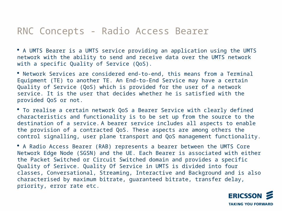
A UMTS Bearer is a UMTS service providing an application using the UMTS network with the ability to send and receive data over the UMTS network with a specific Quality of Service (QoS). Network Services are considered end-to-end, this means from a Terminal Equipment (TE) to another TE. An End-to-End Service may have a certain Quality of Service (QoS) which is provided for the user of a network service. It is the user that decides whether he is satisfied with the provided QoS or not. To realise a certain network QoS a Bearer Service with clearly defined characteristics and functionality is to be set up from the source to the destination of a service. A bearer service includes all aspects to enable the provision of a contracted QoS. These aspects are among others the control signalling, user plane transport and QoS management functionality. A Radio Access Bearer (RAB) represents a bearer between the UMTS Core Network Edge Node (SGSN) and the UE. Each Bearer is associated with either the Packet Switched or Circuit Switched domain and provides a specific Quality of Serivce. Quality Of Service in UMTS is divided into four classes, Conversational, Streaming, Interactive and Background and is also characterised by maximum bitrate, guaranteed bitrate, transfer delay, priority, error rate etc.
RNC Concepts - Radio Access Bearer

Slide titleIn CAPITALS
50 pt
Slide subtitle 32 pt
TE MT RAN CN EDGE NODE
CN Gateway
TE
UMTS
End-to-End Service
TE/MT Local Bearer Service
UMTS Bearer Service External Bearer Service
UMTS Bearer Service
Radio Access Bearer Service CN Bearer Service
Backbone Bearer Service
RAN Access Bearer Service
Radio Bearer Service
Physical Radio Bearer Service
Physical Bearer Service
RNC Concepts - Radio Access Bearer

Top right corner for field-mark, customer or partner logotypes. See Best practice for example.
Slide title 40 pt
Slide subtitle 24 pt
Text 24 pt
Bullets level 2-520 pt
2008-03-119
Conversational RAB for AMR speech (Voice RAB - CS) Interactive RAB (Internet access - PS) Conversational RAB for UDI of 64 kbps (H.324M multimedia - CS) Streaming RAB (CS) offers support for variable rate circuit switched data up to 57.6 kbps Streaming RAB (PS) offers support for guaranteed rate packet switched data Multiple RABs offers support for multiple RABs configured simultaneously to the same UE
one or more PS RABs together with maximum one CS RAB Multiple PS RABs
RNC Concepts - Radio Access Bearer

Top right corner for field-mark, customer or partner logotypes. See Best practice for example.
Slide title 40 pt
Slide subtitle 24 pt
Text 24 pt
Bullets level 2-520 pt
2008-03-1110
RAB Id Included in the RANAP RAB Assignment Request to identify a specific RAB instance for a specific UE connection. Unique to the CN and UE connection
Internal RAB Id RNC internal identifier representing the RAB type. Where multiple instances of a RAB type are supported, multiple Internal RAB Ids are defined
RNC Concepts - Radio Access Bearer Identities
SRB Only: 0
Conversational CS Speech: 1Conv CS Unknown First:
2Conv CS Unknown Second (reserved):
3Conv PS Speech: 4Conv PS Unknown First:
5Conv PS Unknown Second (reserved):
6
Streaming CS Unknown: 7
Streaming PS Unknown First: 8Streaming PS Unknown Second (reserved):
9Interactive PS First:
10interactive PS Second:
11Conversational CS Speech (AMR-WB):
12Interactive PS Third:
13
Internal RAB Id Mapping

Slide titleIn CAPITALS
50 pt
Slide subtitle 32 pt
RADIO BEARERS

Top right corner for field-mark, customer or partner logotypes. See Best practice for example.
Slide title 40 pt
Slide subtitle 24 pt
Text 24 pt
Bullets level 2-520 pt
2008-03-1112
Control PlaneThe Control Plane implements the control of the Radio Access Bearers and the connection between the UE and the Network from different aspects (Requesting the service, controlling different transmission resources, handover etc). Also a mechanism for the transparent transfer of NAS messages is included.The Control Plane Includes the Application Protocol, i.e. RANAP, RNSAP or NBAP, and the Signalling Bearer for transporting the Application Protocol messages.
User PlaneThe User Plane implements the actual radio access bearer service, i.e. carrying user Data/Data Stream(s) through the access stratum The Data Stream(s) is/are characterised by one or more frame protocols specified for that interface.
RNC Concepts - Control and User Planes

Top right corner for field-mark, customer or partner logotypes. See Best practice for example.
Slide title 40 pt
Slide subtitle 24 pt
Text 24 pt
Bullets level 2-520 pt
2008-03-1113
RRC
RLC
MAC
PHY
PDCPBMC
L3
L2
USER PLANE RADIO BEARERSSIGNALLING RADIO BEARERS
L1
Control Plane User Plane
LOGICAL CHANNELS
TRANSPORT CHANNELS
Control
RNC Concepts - Radio Interface Protocol Architecture

Slide titleIn CAPITALS
50 pt
Slide subtitle 32 pt
• A Radio Bearer (RB) represents a bearer between the UTRAN and the UE. Therefore RABs are realised via bearers between the Core Network and UTRAN and Radio Bearers between UTRAN and UE. In general there is a one to one mapping between RABs and RBs. Speech RAB is an exception where each 20ms sample of speech is coded into three classes, A, B and C with different requirements on channel coding due to different sensitivity to errors. Each class is transferred via a separate radio bearer.
• Signalling Radio Bearers (SRB) are defined to allow control plane signalling between UTRAN and the UE and between the UMTS Core Network (Non Access Stratum) and the UE. They represent the bearer between the UTRAN and the UE over which such signalling is transferred. There are four SRBs, SRB 1, 2, 3 and 4 for dedicated control channel (DCCH) signalling with:
• SRB 1 used for RRC unacknowledged mode• SRB 2 for RRC acknowledged mode• SRB 3 for Non Access Stratum high priority Signalling• SRB 4 for Non Access Stratum low priority Signalling• SRB 0 is used for common control channel (CCCH) signalling
• Signalling between the UTRAN and the Core Network is via Signalling Connection Control Part (SCCP) connections, with a SCCP connection (a logical connection over a physical link) established for each UE to each Core Network (PS and CS) as needed.
RNC Concepts - Radio Bearers

Top right corner for field-mark, customer or partner logotypes. See Best practice for example.
Slide title 40 pt
Slide subtitle 24 pt
Text 24 pt
Bullets level 2-520 pt
2008-03-1115
RB Identity UTRAN identifier configured in UE to represent a specific Radio Bearer RNC is responsible for allocation of RB Identity, based on hardcoded table Incoming CN Relocation can trigger flexible allocation of RB Identity
RNC Concepts - Radio Bearer Identities
SRB1: 1SRB2: 2SRB3: 3SRB4: 4Conversational CS Speech Subflow 1:
5Conversational CS Speech Subflow 2:
6Conversational CS Speech Subflow 3:
7Conv CS Unknown: 12
Streaming CS: 22Streaming PS: 23Interactive PS First:
16Interactive PS Second:
17Interactive PS Third:
18AMR-WB Conversational CS Speech Subflow 1:
5AMR-WB Conversational CS Speech Subflow 2:
6AMR-WB Conversational CS Speech Subflow 3:
7
RB Id Mapping

Top right corner for field-mark, customer or partner logotypes. See Best practice for example.
Slide title 40 pt
Slide subtitle 24 pt
Text 24 pt
Bullets level 2-520 pt
2008-03-1116
RB Type RNC MOM enum used to distinguish Radio Bearer specific MO instances (UeRcRb, UeRcTrCh etc) Used internally in UEH to distinguish different services (speech, packet, etc) Used in UEH for transport bearer handling (determination of transport bearers to add/remove, identifying specific transport bearer instances etc.)
RNC Concepts - Radio Bearer Types
uehRbRrc: 0
uehRbSpeech: 1uehRbPacket: 2uehRbCsFix:
3uehRbCsVar:
4uehRbPsStreaming 5uehRbPacketAdch 6uehRbPacketHs 7
uehRbPacket2: 8uehRbPacket3: 9uehRbPacketHs2: 10uehRbPacketHs3: 11uehRbpacketAdch2: 12uehRbPacketAdch3: 13uehRbPsStreamingHs: 14uehRbPsStreamingAdch
15
RB Type Mapping

Top right corner for field-mark, customer or partner logotypes. See Best practice for example.
Slide title 40 pt
Slide subtitle 24 pt
Text 24 pt
Bullets level 2-520 pt
2008-03-1117
CommonLogicalChannel
Uu Interface
CommonTransportChannel
CommonPhysicalChannel
DedicatedLogicalChannel
DedicatedTransportChannel
DedicatedPhysicalChannel
RNC
RBS
Logical Channel: A Logical Channel is an information stream
dedicated to the transfer of a specific type ofinformation over the radio interface.
Transport Channel:The channels offered by the physical lay-er to Layer 2 for data transport betweenpeer L1 entities are denoted as TransportChannels. Different types of TransportChannels are defined by how and with
which characteristics data is transferredon the physical layer, e.g. whether using
dedicated or common Physical Channelare employed.
Physical Channel:
RNC Concepts - Channel Concepts
In FDD mode, a Physical Channel is definedby code, frequency and, in the Uplink, relative phase (I/Q). In TDD mode, a physical Channel is defined by code, frequency, and time slot.

Top right corner for field-mark, customer or partner logotypes. See Best practice for example.
Slide title 40 pt
Slide subtitle 24 pt
Text 24 pt
Bullets level 2-520 pt
2008-03-1118
Physical Channels Transport Channels Logical Channels
DCH (DL/UL)Dedicated Channel
CCCHCommon Control Channel
DCCHDedicated Control Channel
PCCHPaging Control Channel
BCCHBroadcast Control Channel
DTCHDedicated Traffic Channel
PCH (DL)Paging Channel
FACH (DL)Forward Access Channel
BCH (DL)Broadcast Channel
RACH (UL)Random Access
Channel
Common Transport Channels
PRACH (UL)Physical Random Access
ChannelAICH
Acquisition Indication Channel
P-CCPCH (DL)Primary Common Control Physical
ChannelS-CCPCH (DL)
Secondary Common Control Physical Channel
PICH (DL)Paging Indication Channel
DPDCH (UL/DL)Dedicated Physical Data
ChannelDPCCH (UL/DL)
Dedicated Physical Control Channel
DPCH - Dedicated Physical Channel
*simplified
RNC Concepts - Channels

Slide titleIn CAPITALS
50 pt
Slide subtitle 32 pt
RRC STATES AND CHANNEL SWITCHING

Top right corner for field-mark, customer or partner logotypes. See Best practice for example.
Slide title 40 pt
Slide subtitle 24 pt
Text 24 pt
Bullets level 2-520 pt
2008-03-1121
Cell DCH
RNC Concepts - RRC UE State Model
Idle mode
UTRAN Connected mode
ReleaseRRC
Connection
URA_PCH
CELL_FACH
CELL_PCH
Establish/
Cell FACH
Cell PCH URA PCH

Slide titleIn CAPITALS
50 pt
Slide subtitle 32 pt
RNC Concepts – Transport Channel Types
CELL_FACH RRC State (Only valid for single PS Interactive RAB)RACH – Random Access Channel (uplink only)FACH – Forward Access Channel (downlink only)Signalling Radio Bearers and PS RAB use cell common channels (RACH/FACH)
CELL_DCH RRC State (Valid for all RAB configurations)
DCH – Dedicated Channel (uplink or downlink)HS-DSCH – High Speed Downlink Shared Channel (downlink only)E-DCH – Enhanced Dedicated Channel (uplink only)Signalling Radio Bearers and configured RABs use dedicated channels via radio links configured in each cell
Combinations include RACH/FACH, DCH/DCH, DCH/HS-DSCH and E-DCH/HS-DSCH

Slide titleIn CAPITALS
50 pt
Slide subtitle 32 pt
RNC Concepts – Channel Switching
Channel Switching: Reconfigure Transport Channel Type or change DCH. Applies to PS Interactive RABs (QoS class Interactive or Background).
The transport channel type can be reconfigured between using the RACH/FACH in CELL_FACH and using DCH, E-DCH or HS-DSCH in CELL_DCH. The combinations supported for uplink/downlink are: RACH/FACH DCH/DCH DCH/HS-DSCH E-DCH/HS-DSCH.
For connections using DCH, the rate can be reconfigured and this is also channel switch, e.g. 64kbps/64kbps to 64kbps/128kbps or 64kbps/HS-DSCH to 384kbps/HS-DSCH.
Note that an existing PS Streaming RAB may be reconfigured when establishing or releasing another RAB, although this is not considered ‘channel switching’.

Slide titleIn CAPITALS
50 pt
Slide subtitle 32 pt
TRANSITIONS FROM COM TO DED, DED TO COM ETC.

Top right corner for field-mark, customer or partner logotypes. See Best practice for example.
Slide title 40 pt
Slide subtitle 24 pt
Text 24 pt
Bullets level 2-520 pt
2008-03-1125
COM to DED is a reconfiguration from CELL_FACH to CELL_DCH– Triggered by RAB Establishment, Release or Channel Switch
DED to COM is a reconfiguration from CELL_DCH to CELL_FACH– Triggered by a RAB Establishment, Release or Channel Switch
DED to DED is a reconfiguration in CELL_DCH– Triggered by a RAB Establishment, Release or Channel Switch
Note that CELL_FACH is only valid for a single PS Interactive RAB
RNC Concepts – Transition from COM to DED, DED to COM etc.

Slide titleIn CAPITALS
50 pt
Slide subtitle 32 pt
UeRc, Connection Properties and Connection Capabilities

Top right corner for field-mark, customer or partner logotypes. See Best practice for example.
Slide title 40 pt
Slide subtitle 24 pt
Text 24 pt
Bullets level 2-520 pt
2008-03-1127
RNC concepts - UeRc
UeRc is a Managed Object class
Each UeRc instance models a specific Radio Connection Configuration
A Radio Connection Configuration is a UE configuration including UTRAN-UE signalling connection and optionally one or more Radio Access Bearers (RAB)
Each RAB combination is supported via a specific UeRc instance:
– UeRc 1: SRB only– UeRc 2: Speech– UeRc 3: CS Conversational Data– UeRc 4: PS Interactive on RACH/FACH– UeRc 5: PS Interactive on DCH 64/64– UeRc 6: PS Interactive on DCH 64/128– UeRc 7: PS Interactive on DCH 64/384– …– UeRc 10: Speech + PS Interactive on DCH 64/64– …– UeRc 15: PS Interactive on DCH 64/HS-DSCH– …– UeRc 62: 2 x PS Interactive on EUL/HS– ...

Top right corner for field-mark, customer or partner logotypes. See Best practice for example.
Slide title 40 pt
Slide subtitle 24 pt
Text 24 pt
Bullets level 2-520 pt
2008-03-1128
RNC concepts - UeRc
UeRc Managed Object class contains the following subclasses:
– UeRcRb (models Radio Bearer parameters including RLC)– UeRcRbRlc (models alternative RLC parameters for EL2, EUL 2ms TTI)– UeRcTrCh (models Dedicated Transport Channel parameters, e.g. TFS, TTI)– UeRcPhyChUl (models uplink Physical Channel Parameters, e.g. SF, Slot Format)– UeRcPhyChDl (models downlink Physical Channel Parameters, e.g. SF, Slot Format)– UeRcRab (models RAB parameters)– UeRcHsdsch (models HS-DSCH priority queue parameters)– UeRcEdchFlow (models E-DCH Mac-d flow parameters)– UeRcPhyChEdch (models E-DPDCH and E-DPCCH parameters)– UeRcEdchGainFactors (models E-DPDCH gain factors parameters)

Top right corner for field-mark, customer or partner logotypes. See Best practice for example.
Slide title 40 pt
Slide subtitle 24 pt
Text 24 pt
Bullets level 2-520 pt
2008-03-1129
RNC concepts – UeRc transition
A UeRc transition describes a UE reconfiguration from one UE combination to another, e.g.
– UeRc 1 -> UeRc 5 (SRB to PS Interactive 64/64)– UeRc 5 -> UeRc 10 (PS Int 64/64 to Speech + PS Int 64/64)
A UeRc transition involves a reconfiguration of RBS/DRNC (NBAP, RNSAP), DcSP (SP Bag) and UE (RRC) via a UEH procedure capsule

Top right corner for field-mark, customer or partner logotypes. See Best practice for example.
Slide title 40 pt
Slide subtitle 24 pt
Text 24 pt
Bullets level 2-520 pt
2008-03-1130
RNC concepts – Connection Properties
Connection property is a concept introduced in addition to UeRc to describe a UE Radio Connection Configuration
– UE configuration is function of UeRc instance + Connection Properties
Allows multiple configurations (alternative L1 and L2 parameter settings) to be supported with a single UeRc and therefore minimise the number of supported UeRc instances and UeRc transitions
Applies where the RAB combination is described by one UeRc but specific sub-characteristics are described by connection properties, e.g. EUL/HS evolved HS concepts providing higher bitrates
Connection properties include:– Eul 2ms TTI (active set property)– Enhanced Layer 2 (serving cell set property)– 64QAM (serving cell set property)– MIMO (serving cell set property)– SRB on EUL (active set property)– SRB on HS (serving cell set property)– MultiCarrier (serving cell set property)– AMR Multimode (cell independent property)

Top right corner for field-mark, customer or partner logotypes. See Best practice for example.
Slide title 40 pt
Slide subtitle 24 pt
Text 24 pt
Bullets level 2-520 pt
2008-03-1131
RNC concepts – Connection Capabilities Connection capabilities allow support of specific
UE Connection Configurations within a UeRc instance to be enabled/disabled
Connection capabilities map to connection properties as follows:
– Connection capabilities describe the alternative configurations potentially supported by a specific UeRc instance
– Connection properties describe the actual connection capabilities which are currently active for the currently configured UeRc instance for a specific UE connection
Connection capabilities can be enabled/disabled per UeRc via attribute UeRc.connectionCapability. Currently only the following are configurable
– Fractional DPCH (required for SRB on HS)– MultiCarrier

Slide titleIn CAPITALS
50 pt
Slide subtitle 32 pt
TRANSPORT BEARERS

Slide titleIn CAPITALS
50 pt
Slide subtitle 32 pt
• Transport Bearers are bearers in the Transport Network used to transfer control plane and user plane data between RNC and the RBS, between the UMTS Core Network (Non Access Stratum) and the RNC and between Serving RNC and Drift RNC.
• A UTRAN may consist of multiple RNC and RBS (also called Node B). Transport Bearers support IP or ATM transport.
• Transport bearer establishment, release and fault handling is provided by the DRH subsystem in RNC, but only for dedicated transport bearers for UEs. UEH uses this DRH service via the signal interface DrhIfTrBrP. DRH uses the Cello Packet Platform (CPP) to execute the requests from UEH to establish or release transport bearers and to inform UEH of faults reported from CPP.
• Transport bearers are established by UEH on Iu interface for CS RABs and on Iub/Iur interface when not in CELL_FACH
RNC Concepts - Transport Bearers

Slide titleIn CAPITALS
50 pt
Slide subtitle 32 pt
• Each interface (Iu to CN, Iur to DRNC and Iub to RBS) can support the following transport layer technologies:
• Iu and Iur interface: ATM or IP• Iub interface – user plane: ATM, IP or both (dual stack)• Iub interface – control plane: ATM or IP
• ATM transport connections are established directly from the SRNC to the RBS
• DRNC is not involved in transport bearer configuration where
both Iur (SRNC-DRNC link) and Iub (DRNC-RBS link) are configured for ATM
• DRNC is involved in transport bearer configuration where either Iur (SRNC-DRNC link) or Iub (DRNC-RBS link) are configured for IP
RNC Concepts – IP and ATM Transport Bearers

Slide titleIn CAPITALS
50 pt
Slide subtitle 32 pt
• The principles and rules for configuring transport bearers for different services on the Iu, Iur and Iub interface are documented in the attached document:
RNC Concepts – IP and ATM Transport Bearers
Microsoft Word Document
• The relationship between transport bearers and RB Type is described at: http://wiki.eei.ericsson.se:8080/index.php/UEH:UehBehaviourBaseSsL_Information