Modelling, Simulation and Analysis Techniques in the Prediction of Non-Stationary Vibration Response...
8
Modelling, Simulation and Analysis Techniques in the Prediction of Non-stationary Vibration Response of Hoist Ropes in Lift Systems Y. Terumichi 1 , S. Kaczmarczyk 2 , S. Turner 2 M. Yoshizawa 3 and W. Ostachowicz 4 1 Faculty of Science and Technology, Sophia University, Tokyo, Japan, e-mail: [email protected] 2 School of Technology and Design, University College Northampton, UK, e-mail: [email protected] 3 Faculty of Science and Technology, Keio University, Kanagawa, Japan, e-mail: [email protected] 4 Institute of Fluid-Flow Machinery, Polish Academy of Sciences, Gdansk, Poland, e-mail: [email protected] Keywords : Non-stationary System, Non-linear Coupling, Perturbation Methods, Numerical Integration Abstract. The paper presents the results of a study in which the non-stationary dynamic response of typical lift installations is investigated. A general approach to describe the dynamic behaviour of a vertical transport installation is presented. Subsequently, vibration models of a building elevator and a mine hoist installation are discussed. Perturbation and numerical techniques are discussed and applied to predict the non-stationary response of hoist ropes. It is shown that the method of multiple scales with non-linear scale as well as the method of characteristics can be employed to analyse a passage through resonance in a simple lift installation. Furthermore, the effectiveness of direct numerical integration of equations of motion is demonstrated in the case of a mine hoist installation. Introduction Cables and ropes are commonly used as structural members in engineering arrangements. They are classified in the category of one-dimensional continuous systems and consequently the displacement field depends on time and on a single spatial co-ordinate. Often lengths of these members vary with time due to an axial transport motion. In these cases the rate of change of the length may often be considered as small over a time period corresponding to the fundamental natural frequency, and the respective system can be treated as a slowly varying (non-stationary) system. Rope and cable systems used to carry payloads in lift installations, including building elevators and mine hoists, represent typical non-stationary systems. A number of studies into the dynamic behaviour of systems with load-carrying members of time-varying length were conducted. These include investigations into lateral and longitudinal oscillations of mine hoist ropes [1,2,3], vibrations of strings with time-varying length [4,5], and the dynamics of translating beams and strings of varying length [6,7]. Governing Equations. A vertical transport installation may be considered as an assemblage of one-dimensional distributed subsystems (referred to as components) and acting together as a single system due to constraints imposed between adjacent subsystems. Assuming that the components have time dependent lengths, the entire system is then non-stationary and its response can be described by a system of partial differential equations of the form ( ) ( ) , 0 , , , , ] [ ] [ ] [ ) ( , , ¥ < £ ˛ + = + + t t D x t x x s s s s t s tt s q r s s s s s F U N U L U C U (1) Materials Science Forum Vols. 440-441 (2003) pp. 497-504 online at http://www.scientific.net © 2003 Trans Tech Publications, Switzerland Licensed to Kaczmarczyk ([email protected]) - University College Northampton - UK All rights reserved. No part of the contents of this paper may be reproduced or transmitted in any form or by any means without the written permission of the publisher: Trans Tech Publications Ltd, Switzerland, www.ttp.net . (ID: 194.81.104.235-04/03/05,10:44:23)
-
Upload
northampton -
Category
Documents
-
view
0 -
download
0
Transcript of Modelling, Simulation and Analysis Techniques in the Prediction of Non-Stationary Vibration Response...
Modelling, Simulation and Analysis Techniques in the Prediction of Non-stationary Vibration Response of Hoist Ropes in Lift Systems
Y. Terumichi1, S. Kaczmarczyk2, S. Turner2 M. Yoshizawa3 and W. Ostachowicz4
1Faculty of Science and Technology, Sophia University, Tokyo, Japan, e-mail: [email protected]
2School of Technology and Design, University College Northampton, UK, e-mail: [email protected]
3Faculty of Science and Technology, Keio University, Kanagawa, Japan, e-mail: [email protected]
4Institute of Fluid-Flow Machinery, Polish Academy of Sciences, Gdansk, Poland, e-mail: [email protected]
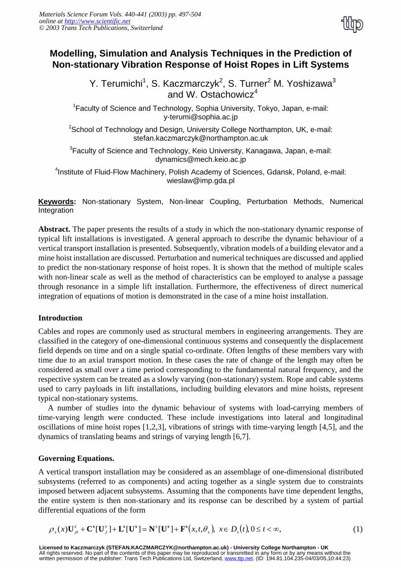
Keywords: Non-stationary System, Non-linear Coupling, Perturbation Methods, Numerical Integration Abstract. The paper presents the results of a study in which the non-stationary dynamic response of typical lift installations is investigated. A general approach to describe the dynamic behaviour of a vertical transport installation is presented. Subsequently, vibration models of a building elevator and a mine hoist installation are discussed. Perturbation and numerical techniques are discussed and applied to predict the non-stationary response of hoist ropes. It is shown that the method of multiple scales with non-linear scale as well as the method of characteristics can be employed to analyse a passage through resonance in a simple lift installation. Furthermore, the effectiveness of direct numerical integration of equations of motion is demonstrated in the case of a mine hoist installation.
Introduction
Cables and ropes are commonly used as structural members in engineering arrangements. They are classified in the category of one-dimensional continuous systems and consequently the displacement field depends on time and on a single spatial co-ordinate. Often lengths of these members vary with time due to an axial transport motion. In these cases the rate of change of the length may often be considered as small over a time period corresponding to the fundamental natural frequency, and the respective system can be treated as a slowly varying (non-stationary) system. Rope and cable systems used to carry payloads in lift installations, including building elevators and mine hoists, represent typical non-stationary systems.
A number of studies into the dynamic behaviour of systems with load-carrying members of time-varying length were conducted. These include investigations into lateral and longitudinal oscillations of mine hoist ropes [1,2,3], vibrations of strings with time-varying length [4,5], and the dynamics of translating beams and strings of varying length [6,7].
Governing Equations.
A vertical transport installation may be considered as an assemblage of one-dimensional distributed subsystems (referred to as components) and acting together as a single system due to constraints imposed between adjacent subsystems. Assuming that the components have time dependent lengths, the entire system is then non-stationary and its response can be described by a system of partial differential equations of the form
( ) ( ) ,0 , ,,,][][][)( ,, ∞<≤∈+=++ ttDxtxx ssss
tstts θρ sssss FUNULUCU (1)
Materials Science Forum Vols. 440-441 (2003) pp. 497-504online at http://www.scientific.net© 2003 Trans Tech Publications, Switzerland
Licensed to Kaczmarczyk ([email protected]) - University College Northampton - UKAll rights reserved. No part of the contents of this paper may be reproduced or transmitted in any form or by any means without thewritten permission of the publisher: Trans Tech Publications Ltd, Switzerland, www.ttp.net. (ID: 194.81.104.235-04/03/05,10:44:23)
where s = 1,2,…indicates the component number, x denotes the spatial co-ordinate, ),( txSU is a local (component) dynamic displacement vector representing motion of the component s, ( ),t designates partial derivatives with respect to time, and sC and sL are local linear operators. Furthermore, sN is an operator acting upon the global displacement vector, and representing non-linear couplings and inter-component constraints in the system. sF is a forcing function with harmonic terms of frequency
ss Ω=θ& , where the overdot indicates total differentiation with respect to time, and )(xsρ is a local
mass distribution function. Ds represents a local time-variant spatial domain defined as )(0:)( tLxxtD ss <<= , where Ls(t)
represents the time-varying length of the component s. When the variation of Ls is small over a time period corresponding to its lowest fundamental frequency, the length is said to vary slowly with time. This prompts the introduction of a slow time scale
s to observe the variation of the length parameters. One can introduce the non-dimensional fast time scale as tT ss 0ω= , where 0sω is the lowest value of
the fundamental frequency (referred to as a characteristic frequency). Noting that this value
corresponds to length Ls0 the non-dimensional length is introduced as 0
*
s
ss L
LL = . The time rate of
variation of *sL with respect to the fast time scale Ts is given then as
000
*
ss
s
ss
s
s
s
L
V
dT
dt
L
L
dt
d
dT
dL
ω=
= ,
where ss LV &= . Subsequently, this non-dimensional rate of variation defined as the quantity
00 ss
ss L
V
ωε = (2)
can be used as a small parameter to assess the slow variability of the component length. Then, the slow time scale can be defined as sss Tετ = . For typical one-dimensional members used in vertical
transport systems, namely ropes and cables, this parameter is directly related to the ratio of the rate of variation of the length of the member and the respective wave velocity [1]. For example, treating a rope as a uniform string of tension Ti, of mass per unit length ρ and of time-varying length L(t), its
lowest fundamental frequency corresponding to the maximum length L0 is cL0
0
πω = . Thus, the small
parameter in this case is given as c
V
πε = , where LV &= and
ρ
iTc = .
It is convenient to establish a global slow time scale for the entire system as Tετ = , where ε is the smallest element within the local value range ],,,,[ 21 KK sεεε , and tT 0ω= , with 0ω
representing the lowest fundamental frequency of the entire system. Accordingly, the spatial domain in Eq. 1 becomes )(τss DD = and represents a slowly varying spatial domain.
In the model given by Eq. 1 the Lagrangian or Eulerian coordinate may be applied as the spatial coordinate. If the Lagrangian formulation is applied then it is convenient to refer the dynamic elastic deformations to a moving frame associated with the overall axial transport motion of the system. Otherwise, a fixed (inertial) frame is used to describe the deformations.
Subsequently, Eq. 1 can be discretised by expansion in terms of eigenfunctions of the corresponding linear stationary system. This modal expansion leads to the standard first-order ordinary differential equation (ODE) system given as
),(~
),(~
)();,()( ττεετ TTTT FyNyAy ++=& (3)
Modern Practice in Stress and Vibration Analysis498

in which y is the system state vector, A represents a slowly varying linear coefficient matrix, N~
denotes non-linear coupling terms, and F~
is the external excitation vector. This system cannot be solved exactly. An approximate solution can be sought using asymptotic (perturbation) methods or direct numerical integration techniques.
Alternatively, in some cases, the system of partial differential equations Eq. 1 can be treated directly without discretization and the method of multiple scales can be applied to investigate the non-stationary behaviour of the system.
For example, lateral oscillations U a vertical string with time-varying length given as VtLL ±= )0( can be analysed using the method of multiple scales [8]. Introducing tT 0ω= , and
0L
Ll = , where L0 corresponds to 0ω , using this method the length of the string can be treated as
constant. Consequently, TlTl ε+= )0()( and new time scales, namely the fast time +t and the slow time τ , are defined as follows
=+
T
TdTl
t0 )(
1 , Tετ = (4)
Subsequently, the lateral non-dimensional displacement a
Uw = , where a is a characteristic length, is
represented by an expansion having the form
⋅⋅⋅++= +++ ),,(),,();,,( 10 τξετξετξ twtwtw (5)
where ξ is a non-dimensional spatial coordinate. After this expansion is substituted into the equation of motion and coefficients of like powers of ε are equated an approximation to w is obtained.
Modelling of Vertical Transport Installations
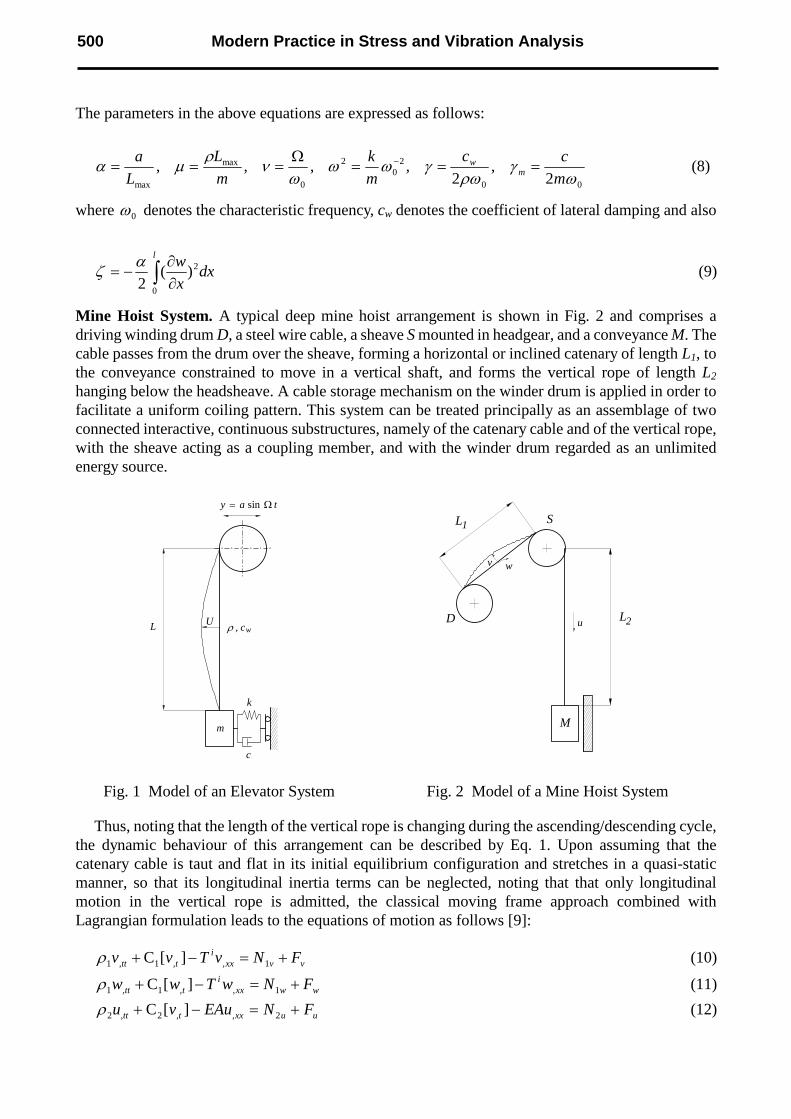
Elevator System. In an elevator system vibration interactions between the car, guide system and hoist ropes take place. Ride quality is particularly affected by lateral vibrations in the system. A simple model of an elevator that can be used to investigate the lateral response of the system is shown in Fig. 1. The model consists of a vertical string of time-varying length with a mass m attached at its end. The mass is is constrained by a spring-damper element in a vertical direction. It is assumed that only lateral motions are allowed and that the lateral deflections of the string are small. The upper end of the string is excited horizontally and moves by tay Ω= sin .
This model can be used to investigate the effect of the axial transport speed of the string and the passage through resonance. The dimensionless equation governing the lateral response of the string is as follows
0)1
1(])[(2),(22
2
2
2 2
=∂
∂−−
∂
∂−
∂
∂−+
x
w
dT
d
x
wxl
xDT
Dwtx
DT
wD ζ
µµγ (6)
where xTDT
D
∂
∂+
∂
∂= ε . The dimensionless boundary conditions are as follows
),(),(),(2),(
,sin),0(
22
2
Tlx
wTlwTl
DT
DwTl
DT
wD
TTw
m∂
∂−=++
=
µωγ
ν
(7)
Materials Science Forum Vols. 440-441 499
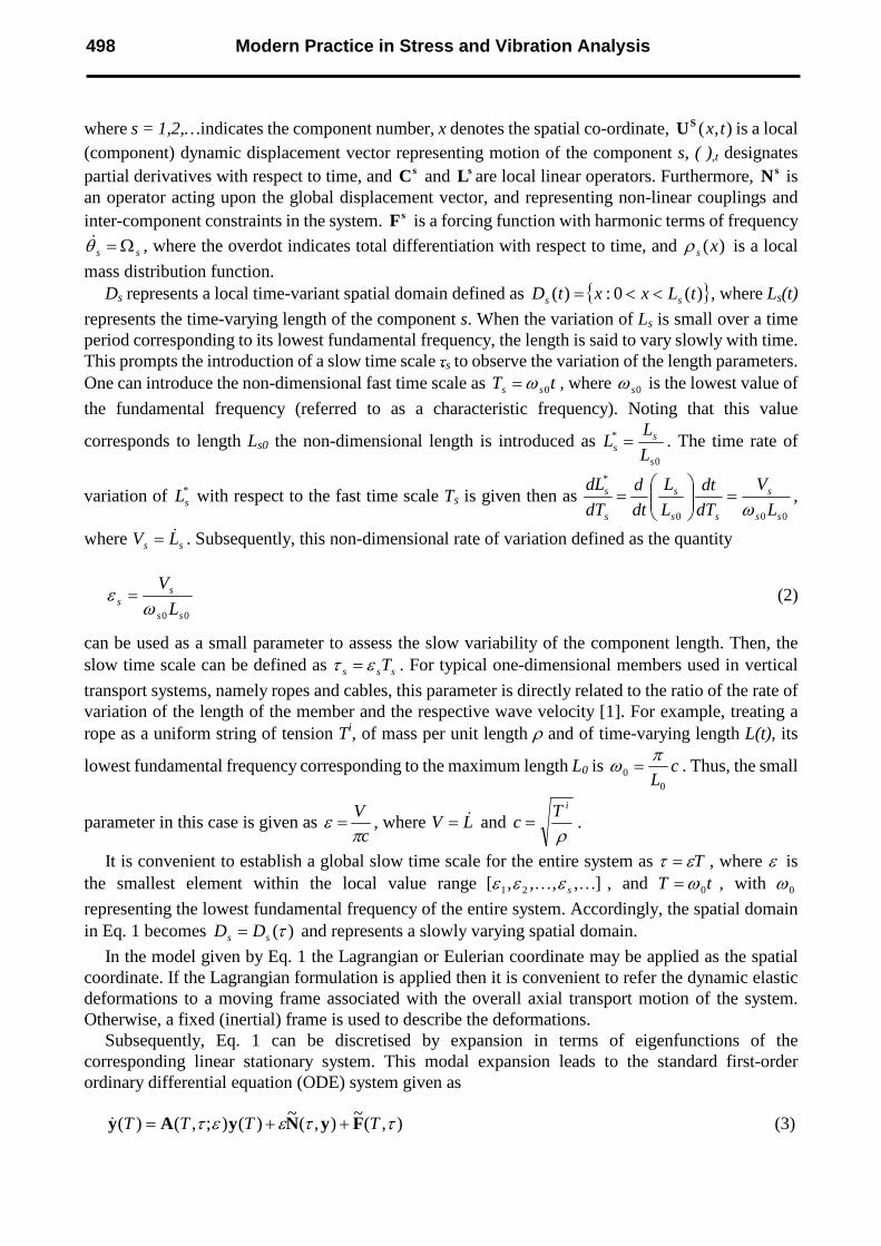
The parameters in the above equations are expressed as follows:
00
20
2
0
max
max 2,
2,,,,
ωγ
ρωγωω
ων
ρµα
m
cc
m
k
m
L
L
am
w ===Ω
=== − (8)
where 0ω denotes the characteristic frequency, cw denotes the coefficient of lateral damping and also
dxx
wl
∂
∂−=
0
2)(2
αζ (9)
Mine Hoist System. A typical deep mine hoist arrangement is shown in Fig. 2 and comprises a driving winding drum D, a steel wire cable, a sheave S mounted in headgear, and a conveyance M. The cable passes from the drum over the sheave, forming a horizontal or inclined catenary of length L1, to the conveyance constrained to move in a vertical shaft, and forms the vertical rope of length L2 hanging below the headsheave. A cable storage mechanism on the winder drum is applied in order to facilitate a uniform coiling pattern. This system can be treated principally as an assemblage of two connected interactive, continuous substructures, namely of the catenary cable and of the vertical rope, with the sheave acting as a coupling member, and with the winder drum regarded as an unlimited energy source.
D
S
M
L
L
v w
u
1
2
Fig. 1 Model of an Elevator System Fig. 2 Model of a Mine Hoist System
Thus, noting that the length of the vertical rope is changing during the ascending/descending cycle, the dynamic behaviour of this arrangement can be described by Eq. 1. Upon assuming that the catenary cable is taut and flat in its initial equilibrium configuration and stretches in a quasi-static manner, so that its longitudinal inertia terms can be neglected, noting that that only longitudinal motion in the vertical rope is admitted, the classical moving frame approach combined with Lagrangian formulation leads to the equations of motion as follows [9]:
vvxxi
ttt FNvTvv +=−+ 1,,1,1 ][Cρ (10)
wwxxi
ttt FNwTww +=−+ 1,,1,1 ][Cρ (11)
uuxxttt FNEAuvu +=−+ 2,,2,2 ][Cρ (12)
m
k
c
U, cwL
tay Ω= sin
ρ
Modern Practice in Stress and Vibration Analysis500
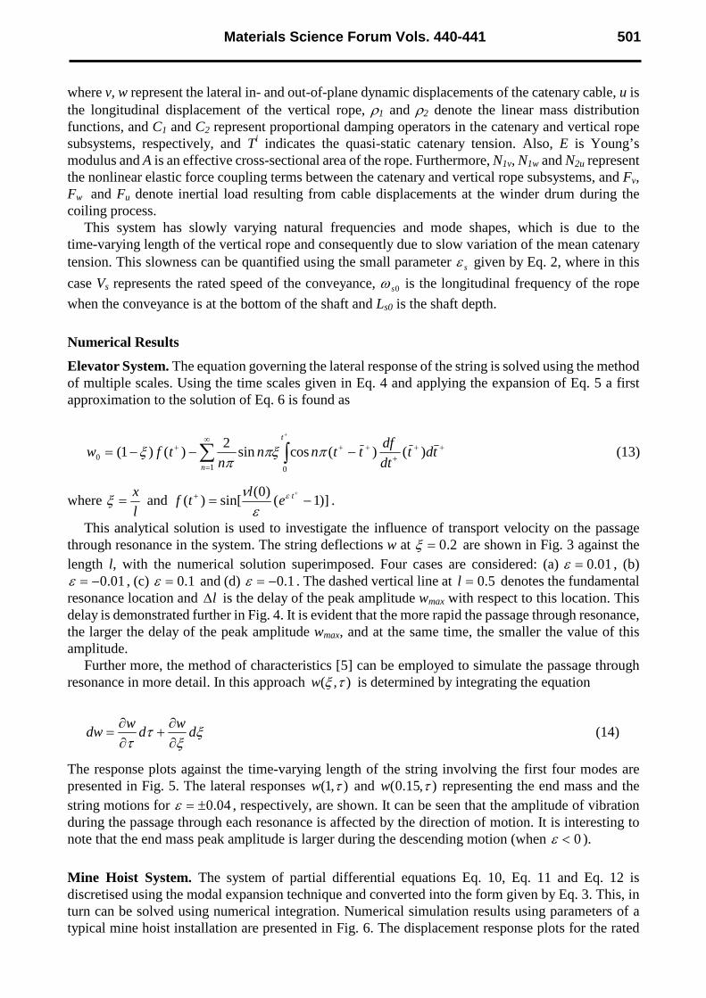
where v, w represent the lateral in- and out-of-plane dynamic displacements of the catenary cable, u is the longitudinal displacement of the vertical rope, ρ1 and ρ2 denote the linear mass distribution functions, and C1 and C2 represent proportional damping operators in the catenary and vertical rope subsystems, respectively, and Ti indicates the quasi-static catenary tension. Also, E is Young’s modulus and A is an effective cross-sectional area of the rope. Furthermore, N1v, N1w and N2u represent the nonlinear elastic force coupling terms between the catenary and vertical rope subsystems, and Fv, Fw and Fu denote inertial load resulting from cable displacements at the winder drum during the coiling process.
This system has slowly varying natural frequencies and mode shapes, which is due to the time-varying length of the vertical rope and consequently due to slow variation of the mean catenary tension. This slowness can be quantified using the small parameter sε given by Eq. 2, where in this
case Vs represents the rated speed of the conveyance, 0sω is the longitudinal frequency of the rope
when the conveyance is at the bottom of the shaft and Ls0 is the shaft depth.
Numerical Results
Elevator System. The equation governing the lateral response of the string is solved using the method of multiple scales. Using the time scales given in Eq. 4 and applying the expansion of Eq. 5 a first approximation to the solution of Eq. 6 is found as
++
+
+∞
=
++ −−−= +
tdtdt
dfttnn
ntfw
n
t
)()(cossin2
)()1(1 0
0 ππξπ
ξ (13)
where l
x=ξ and )]1(
)0(sin[)( −=
++ tel
tf ε
ε
ν.
This analytical solution is used to investigate the influence of transport velocity on the passage through resonance in the system. The string deflections w at 2.0=ξ are shown in Fig. 3 against the length l, with the numerical solution superimposed. Four cases are considered: (a) 01.0=ε , (b)
01.0−=ε , (c) 1.0=ε and (d) 1.0−=ε . The dashed vertical line at 5.0=l denotes the fundamental resonance location and l∆ is the delay of the peak amplitude wmax with respect to this location. This delay is demonstrated further in Fig. 4. It is evident that the more rapid the passage through resonance, the larger the delay of the peak amplitude wmax, and at the same time, the smaller the value of this amplitude.
Further more, the method of characteristics [5] can be employed to simulate the passage through resonance in more detail. In this approach ),( τξw is determined by integrating the equation
ξξ
ττ
dw
dw
dw∂
∂+
∂
∂= (14)
The response plots against the time-varying length of the string involving the first four modes are presented in Fig. 5. The lateral responses ),1( τw and ),15.0( τw representing the end mass and the string motions for 04.0±=ε , respectively, are shown. It can be seen that the amplitude of vibration during the passage through each resonance is affected by the direction of motion. It is interesting to note that the end mass peak amplitude is larger during the descending motion (when 0<ε ).
Mine Hoist System. The system of partial differential equations Eq. 10, Eq. 11 and Eq. 12 is discretised using the modal expansion technique and converted into the form given by Eq. 3. This, in turn can be solved using numerical integration. Numerical simulation results using parameters of a typical mine hoist installation are presented in Fig. 6. The displacement response plots for the rated
Materials Science Forum Vols. 440-441 501

speed of V = 15 m/s are given, where the lateral motion w at the first quarter point of the catenary cable, and the longitudinal motions at the sheave uS vs. the length of vertical rope L2 are presented in this figure together with their spectral components.
Fig. 3 Passage through fundamental resonance Fig. 4 Peak amplitude delay
Fig. 5 Mass and string response during passage through the resonance conditions
Modern Practice in Stress and Vibration Analysis502
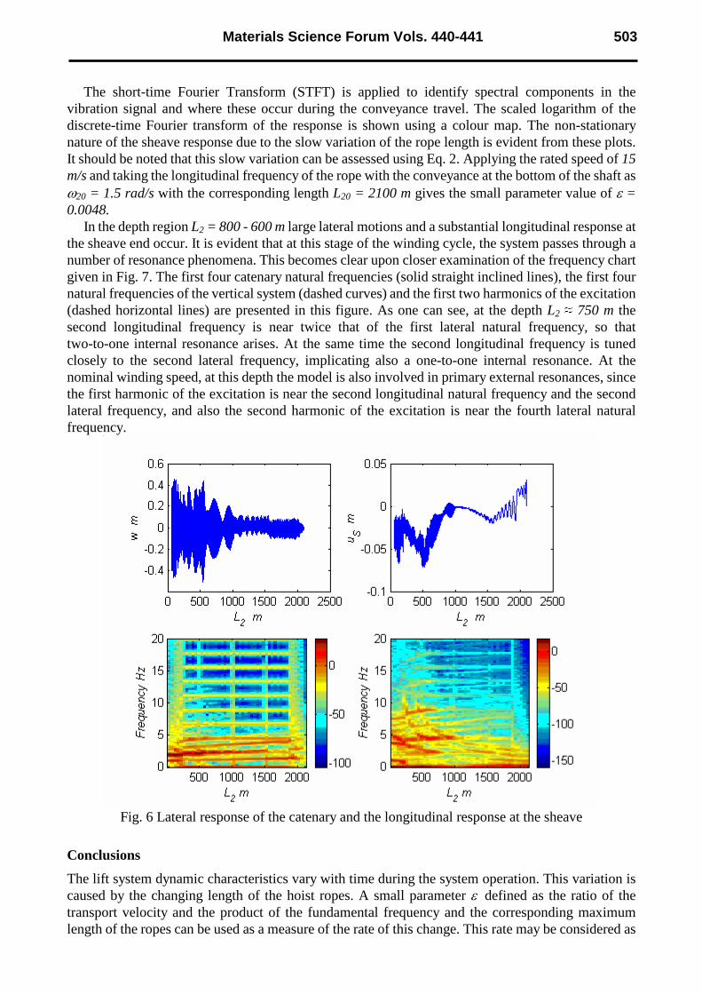
The short-time Fourier Transform (STFT) is applied to identify spectral components in the vibration signal and where these occur during the conveyance travel. The scaled logarithm of the discrete-time Fourier transform of the response is shown using a colour map. The non-stationary nature of the sheave response due to the slow variation of the rope length is evident from these plots. It should be noted that this slow variation can be assessed using Eq. 2. Applying the rated speed of 15 m/s and taking the longitudinal frequency of the rope with the conveyance at the bottom of the shaft as ω20 = 1.5 rad/s with the corresponding length L20 = 2100 m gives the small parameter value of ε = 0.0048.
In the depth region L2 = 800 - 600 m large lateral motions and a substantial longitudinal response at the sheave end occur. It is evident that at this stage of the winding cycle, the system passes through a number of resonance phenomena. This becomes clear upon closer examination of the frequency chart given in Fig. 7. The first four catenary natural frequencies (solid straight inclined lines), the first four natural frequencies of the vertical system (dashed curves) and the first two harmonics of the excitation (dashed horizontal lines) are presented in this figure. As one can see, at the depth L2 750 m the second longitudinal frequency is near twice that of the first lateral natural frequency, so that two-to-one internal resonance arises. At the same time the second longitudinal frequency is tuned closely to the second lateral frequency, implicating also a one-to-one internal resonance. At the nominal winding speed, at this depth the model is also involved in primary external resonances, since the first harmonic of the excitation is near the second longitudinal natural frequency and the second lateral frequency, and also the second harmonic of the excitation is near the fourth lateral natural frequency.
Fig. 6 Lateral response of the catenary and the longitudinal response at the sheave
Conclusions
The lift system dynamic characteristics vary with time during the system operation. This variation is caused by the changing length of the hoist ropes. A small parameter ε defined as the ratio of the transport velocity and the product of the fundamental frequency and the corresponding maximum length of the ropes can be used as a measure of the rate of this change. This rate may be considered as
Materials Science Forum Vols. 440-441 503

slow for typical lift installations that include building elevators and mine hoists. Consequently, these systems are considered as non-stationary with slowly varying natural frequencies.
Fig. 7 Frequency chart
In such systems transient resonance phenomena take place during the conveyance motion. The
mathematical models describing these phenomena are of non-stationary and non-linear nature and they cannot be solved exactly. An approximate solution can be sought using perturbation techniques. More specifically, the method of multiple scales with non-linear time scale can be employed to treat simplified models, as demonstrated for the case of the elevator model. The method of characteristics also presents itself as a useful tool to predict the response during the passage through multiple resonance conditions. However, direct numerical simulation of discrete equations of motion proves to be more effective when more adverse dynamic phenomena are to be accounted for. The STFT technique is well suited to study these transient phenomena further and to identify the response spectral components and to localize them in time.
References
[1] O.A. Goroshko and G.N. Savin: Introduction to Mechanics of One-Dimensional Bodies with Variable Length (Naukova Dumka, Kiev 1971).
[2] A. Kumaniecka and J. Niziol: Journal of Sound and Vibration Vol. 178 (1994) p. 211-226.
[3] S. Kaczmarczyk and W. Ostachowicz: International Journal of Acoustics and Vibration Vol. 5 (2000) p. 117-126.
[4] T. Kotera: Bulletin of the JSME Vol. 21 (1978) p. 1469-1474.
[5] Y. Terumichi, M. Ohtsuka, M. Yoshizawa, Y. Fukawa and Y Tsujioka: Nonlinear Dynamics Vol. 12 (1997) p. 39-55.
[6] W.D. Zhu and J. Ni: Journal of Vibration and Acoustics Vol. 122 (2000) p. 295-304.
[7] W.D. Zhu, J. Ni and J. Huang: Journal of Vibration and Acoustics Vol. 123 (2001) p. 347-35
[8] A.H. Nayfeh and D.T. Mook: Nonlinear Oscillations (John Wiley, New York 1979)
[9] S. Kaczmarczyk and W. Ostachowicz: Journal of Sound and Vibration Vol. 262 (2003) p. 219-244.
Modern Practice in Stress and Vibration Analysis504