document.pdf - International Lift Equipment
92
-
Upload
khangminh22 -
Category
Documents
-
view
0 -
download
0
Transcript of document.pdf - International Lift Equipment


GU
IDES &
ACCESSORIES
Page 2
INTERN
ATION
AL LIFT EQ
UIPM
ENT
TERMS & CONDITIONSPRICING
Standard list prices. Customers discount is not shown.
DELIVERY CHARGE
Goods delivered by our transport is 2.5% of the value of the goods with a minimum of £70.00 for goods up to the value of £5000 in the London area. For deliveries outside the M25 a minimum delivery charge of £35.00 will be applied. Goods delivered by other methods are at cost.
PACKING CHARGE
Goods delivered or collected by an outside carrier are subject to a packing charge at cost.
PRICE INCREASES
All prices are subject to increase without notifi cation.
ORDER CANCELLATIONS
Acceptance of cancellation of an order will be at the discretion of the supplier and the right is reserved to make a reasonable charge for accepted cancellations when costs have been incurred by the supplier.
CHANGING OF MATERIAL
Changing of material (other than that incorrectly supplied) will be subject to a handling charge.
PAYMENT
Non-account clients: 7 working days clearance required from receipt of cheque. Account clients: 30 days unless agreed.
GUARANTEE
12 months from date of delivery unless otherwise stated
INVOICING
Goods not collected or requested to be delivered within the month stated on the order will be automatically invoiced at the requested month for the full amount.
FAULTY MATERIAL
International Lift Equipment liability will not be extended beyond the replacement of the faultycomponent. Damaged goods must be reported within 3 days from receipt of goods.
BACK CHARGES
International Lift Equipment do not except back charges or damages.
MATERIAL SHORTAGES
Material shortages must be reported within 10 days from receipt of goods.
RETURNS
Non-stock lines and equipment not acceptable for re-sale due to condition cannot be accepted back for credit.
STORAGE
Equipment not being accepted for delivery within 4 weeks of agreed delivery date will incur costs for storage outside of our premises.
ENGINEER’S CALLOUT
Attendance of an electrical or mechanical engineer.
CHARGES
To site: for other than warranty or quality work, will be charged against a required order.
TEST WEIGHT HIRE
Test weight hire per ton, per week or £53.00 part of a ton or week delivery and collection (inside M25) £80.00.
ILLUSTRATIONS
The photographs and illustrations in this catalogue fairly represents the products listed. However, due to a policy of continuous improvement, we reserve the right to alter or amend the product specifi cation and as such it does not form part of any contract.

GU
IDES &
ACCESSORIES
Page 3
INTERN
ATION
AL LIFT EQ
UIPM
ENT

GU
IDES &
ACCESSORIES
Page 4
INTERN
ATION
AL LIFT EQ
UIPM
ENT
ABOUT ILE
DEPARTMENTS AND CONTACTS
International Lift Equipment was established in 1976 and has expanded its business annually with quality and state of the art equipment. Today the company boasts a 22,000sq ft offi ce and warehouse in Chingford and a 65,000sq ft manufacturing outlet and offi ce facility in Leicester. Together, they employ over 140 people.
Quality is a key issue for ILE. They were successfully assessed and registered as meeting the requirements of ISO 9001 in 1991. Certifi cation is via BSI, who are a notifi ed body, meeting the requirements of the European Lift Directive. This gives ILE the legal entitlement to design, manufacture, supply, install and test lift equipment.
The company has outlets in Europe, America, Africaand Australia. It also enjoys an association with major sales and manufacturing companies in the majority of European countries, together with GAL and Hollister Whitney in the United States
The head offi ce in London is home to a team of sales staff who are available to answer both technical and commercial enquiries. Technical representatives operate nation-wide and are available to visit customers and resolve any problems they may be experiencing. In addition to their extensive pre-sales service, they also off er a full after-sales service including on-site technical back up and group product training. The London warehouse houses in excess of £1 million worth of stock and is therefore able to provide a fast, effi cient service to customers.
The manufacturing facility based in Leicester is generally split into three sections, these being mechanical, electrical and electronic departments.
The mechanical section produces a full range of lift equipment via a drawing offi ce that off ers a variety of services ranging from the design of complete bespoke lift packages to a single design item such as door packages, counter weights, lift cars, gear rafts etc. The manufacturing section utilises the latest machine technology, including a laser linked to CAD/CAM to produce high quality sheet metal parts.
The electrical section produces a full range of lift control systems to suit all requirements, from simple goods-only controls to more complex multi car group systems utilising the latest drive technology. The heart of the control system is the microprocessor that is designed by ILE’s team of R & D engineers.
The electronics section has benefi tted from heavy investment in the latest surface mount technology and produces products such as: Serial comms, digital indicators, speech synthesisers, tapehead detectors and their own microprocessors. All hardware and software is produced in house, giving ILE total control over quality and specifi cation.
The group’s policy of constant re-investment and re-appraisal in every aspect of the business, via a team of dedicated staff helps provide the service customers quite rightly demand.
Should you have a query or problem, please ensure you contact the correct department.
ILE LONDON: HEAD OFFICE
Sales, accounts, purchasing, warehousing, trade counter and technical supportSALES: The sales department in London deals with all issues relating to stock equipment (i.e. PL items) motors, gears, doorgears.ACCOUNTS: The accounts department deals with all issues regarding the payment of invoices for the ILE group.PURCHASING: The purchase offi ce deals with orders placed and delivery enquiries.WAREHOUSE: Contact the warehouse for information regarding transport, despatch and GAL.
TRADE COUNTER: Our trade counter allows for the collection of stock items and also carries a range of equipment for the lift fi tter.TECHNICAL SUPPORT: For support or advice on both mechanical and electrical equipment including on site support, contact our technical support team.
ILE LEICESTER: MANUFACTURING
Sales of controllers and complete lift packages. Electrical, electronic and mechanical production and technical supportSALES: For controller quotations and associated parts or complete lift packages, contact our sales team in LeicesterMANUFACTURING: Should you require any information about ILE’s in-house manufactured equipment, contact our Leicester offi ce.

Page 5
GU
IDES &
ACCESSORIES
GUIDE LUBRICATORS
GUIDE RAILS
LUBRICATORS ILE PART No.
Lubricator type 3016 PL0760
Bracket (For 3016 lubricator only) PL0773
“F” Type lubricator (16 mm guide rail) PL0747
“F” Type lubricator (5 to 9 mm guide rail) PL0747A
Oil drip tray (Fits 5 to 16 mm guide blade width) PL0200
GUIDE RAILS & ACCESSORIES ILE PART No.
COLD DRAWN GUIDE RAIL (INCLUDING FISHPLATES AND BOLTS)
T45/A 45X45X5X5 mtr long B101
T45/A 45x45x5x2.5 mtr long B102
T70-1/A 70x65x9x5 mtr long B103
T70-1/A 70x65x9x2.5 mtr long B104
PLANED GUIDE RAIL (INCLUDING FISHPLATES AND BOLTS)
T89/B 89x62x16x5 mtr long B107
T89/B 89x62x16x2.5 mtr long B139
T127-/B 127x89x16x5 mtr long B108
T127-/B 127x89x16x2.5 mtr long B140
GUIDE RAIL FIXINGS
T127-2/B Fishplate only PL0216
T45/A Fixings only (set of 8) PL0204
T70-1/A Fixings only (set of 8) PL0208
T89/B Fixings only (set of 8) PL0214
T127-2B Fixings only (set of 8) PL0217
• Sliding type, both fi xed and self aligning available from stock with a range of liners e.g. Tufnol and Polyeuthane• Roller guide shoes for speeds up to 5mps with or without lubricators for top shoes
PL0760 PL0747 PL0747A PL0200
Note: T701/A BGR Type T170 T89/B BGR Type T161 T127-2/B BGR Type T160
ILE also off ers a full range of guide rails and fi xings to suit.

GU
IDES &
ACCESSORIES
Page 6
SHOES & LINERS• Set of 4 shoes suitable for 1200Kg max contract load at 1.6m/s max lift speed
• Set of 4 shoes suitable for 1500Kg max contract load at 1.6m/s max lift speed
GUIDE SHOES ILE PART No.
“F” Type Ali shoe PL0743
“F” Type liner 5/9/10/16 mm PL0744/745/745A/746/746N
HSML guide shoe PL07461
HSML liner 16 mm PL07462
PL0746
PL0743
PL07462
PL07461

Page 7
GU
IDES &
ACCESSORIES
T TYPE SHOES
PL0752
• T305 Guide Shoe• Max contract load: 4000Kg• Available in Bronze
• T306 Guide Shoe• Max contract load: 7000Kg• Available in Bronze
PL0753
GUIDE SHOES ILE PART No.
T305 Guide shoe PL0752
T306 Guide shoe PL0753
T409 Guide shoe PL0754
T410 Guide shoe PL0755

GU
IDES &
ACCESSORIES
Page 8
T TYPE SHOES• T409 Guide Shoe• Max contract load: 1500Kg• Available in Bronze
• T410 Guide Shoe• Max contract load: 2500Kg• Available in Bronze
PL0754
PL0755PLPL07075555

Page 9
GU
IDES &
ACCESSORIES
ROLLER GUIDES
PL0762
PL0763
GUIDE SHOES ILE PART No.
HW roller guide shoe 377 PL0762
HW roller guide shoe 378 PL0763
HW roller guide shoe 379 PL0763B
HW roller guide shoe 380 PL0718x
HW377 Roller GuideWhen used on car• Max car capacity: 900Kg• Max car speed: 1.5m/sWhen used on counter - weight• Max car capacity: 1800Kg• Max car speed: 3.0m/s
HW378 Roller GuideWhen used on car• Max car capacity: 1800Kg• Max car speed: 3.0m/s
GU
IDES &
ACCESSORIES
Page 10
ROLLER GUIDES
PL0763B
PL0718xPL0718x
HW379 Roller GuideWhen used on car• Max car capacity: 1590Kg• Max car speed: 1.5m/sWhen used on counter - weight• Max car capacity: 3600Kg• Max car speed: 5.0m/s
HW380 Roller GuideWhen used on car• Max car capacity: 3600Kg• Max car speed: 5.0m/s

Page 11
GU
IDES &
ACCESSORIES
BUFFERS
PART No.PL0245
PART No.PL0245
PART No.PL0245A PART No.PL0245B PART No.PL0245C
PART No.PL0245D PART No.PL0245E PART No.PL0245F
PART No.PL0245B PART No.PL0245D
•To suit rated speeds up to 2.5mps with range of car + load up to 3000kg•Supplied in full compliance with EN81•Certifi cates available
BUFFERS ILE PART No.
ACLA Buff er (300116) PL0245
ACLA Buff er (300183) PL245A
ACLA Buff er (300117) PL0245B
ACLA Buff er (300148) PL0245C
ACLA Buff er (300143) PL0245D
ACLA Buff er (300144) PL0245E
ACLA Buff er (300147) PL0245F

GU
IDES &
ACCESSORIES
Page 12
OIL BUFFERS
TYPEA
CODE TOTAL MASS LIFT SPEED STROKE A B 0 D OIL CAPACITY WEIGHT ILE PART No.
MAX Kg
MIN Kg
MAX m/s
MIN m/s
C - mm mm mm mm LITRES Kg
A 101 G 430010 1000 250 0.85 0.63 105 303 431 90 0.6 16 *
A 102 G 430020 1000 250 1.5 0.9 175 383 581 90 0.9 17 *
A 103 G 430030 1000 250 2 1.5 295 528 846 100 2 23 *
A 201 G 430040 2000 1000 0.85 0.63 105 303 431 100 0.8 18 PL0257
A 202 G 430050 2000 1000 1.5 0.9 175 383 581 100 1.1 20 PL0263
A 203 G 430060 2000 1000 2 1.5 295 528 846 110 2.1 26 PL0261
A 301 G 430070 3000 2000 0.85 0.63 105 303 431 110 1 20 PL0265
A 302 G 430080 3000 2000 1.5 0.9 175 383 581 110 1.3 22 PL0258
A 303 G 430090 3000 2000 2 1.5 295 528 846 120 2.8 30 PL0260
TYPES01,02,03
DESIGNATION No.
SPEED STROKE H OIL MASS CAR + LOADKg
ILE PART No.
MAX IMPACT
m/s
MIN RATED
m/s
mm mm ltrs Kg MIN MAX
01 A 001 1.84 1.6 175 540 0.4 14.3 430 1370 *
B 002 620 2000 PL0268
C 003 970 3020 PL0270
02 A 004 2.30 2.0 275 790 0.61 18.2 430 1370 PL0267
B 005 620 2000 PL0269
C 006 970 3020 PL0271
03 A 007 2.88 2.5 430 1180 0.94 23.5 430 1370 *
B 008 620 2000 *
C 009 970 3020 PL0272
*Non stock items
*Non stock items
TYPE “A” OIL BUFFER
TYPE “01,02,03” OIL BUFFER
PL0265
PL0268

Page 13
GU
IDES &
ACCESSORIES
SHIMS & PACKERS• Various guide packers in stock to suit common standard guides• Packers available for GAL equipment e.g. clutch, hanger, track etc
SHIMS ILE PART No.
Trouser shim 2.5sq 20SWG PL0231
Trouser shim 2.5sq 16SWG PL0232
Trouser shim 2.5sq 10SWG PL0233
Trouser shim 2.5sq ¼ inchSWG PL0234
Shim U.K door shoe 1.2 mm (ST/ST) PL0234A
Keeper plate T89 1.0 mm PL0237
Keeper plate T70 1.0 mm PL0238
Keeper plate T127 1.0 mm PL0238A
Shim T89 1.0 mm PL0240
Shim T89 1.5 mm PL0243
Shim T70 1.5 mm PL0244
Shim T70 1.0 mm PL0247
Shim T127 1.5 mm PL0248
Shim T127 1.0 mm PL0249
Sheave shim 20SWG 1.0 mm PL0381
Sheave shim 10SWG 3.0 mm PL0381A
“A” sheave horse shoe shim 0.75 mm PL0382E
“A” sheave horse shoe shim 3.0 mm PL0382F
PACKERS ILE PART No.
Landing hanger packer 6 mm PL0382
Landing hanger packer 3 mm PL0382A
Landing hanger packer 1.5 mm PL0382B
Clutch packer 16 SWG PL382C
Clutch packer 10 SWG PL0382D
CONTROL SWITCHES ILE PART No.
Pit stop switch MEM PL1104
Isolation switch PL1104A
Fireman’s switch PL1111
Evacuation switch PL1111A
Firefi ghter switch PL1114
PL0381/A
PL0382A/B
PL0237/8/8A
PL1111 PL1104A
PL0231/2/3
PL0240/3/4/7/8/9
PL0382C/D
PLPL1111 PLPL1104AA
• Pit switches and fi remans switches available from stock• Special designs available to order
Firemans Switch
PL1111

Page 14
DO
ORS, D
OO
R GEA
RS & ACCESSO
RIES
DOOR OPERATORS-GAL
Features
• Parameter unit • Capable of holding 5 complete sets of parameters• Contractors can store one working set and all 4 GAL defaults.• Optional heavy door input • You can now comply with the kinetic energy requirements found in the ASME A17.1-2000+ codes and still maximise door performance
• Plug and play door protection • Choose your product from Adams, Formula Systems, Janus , TL Jones, Tri-tronics• No need to locate, mount or wire a power supply• Edges bought from GAL plug directly into the MOVFR operator saving hours on installation• Closed loop regulated speed via motor performance feedback. Perfect consistency from fl oor to fl oor
• Automatic adjustment for wind and door conditions• Keypad programming for all speeds, torques, acceleration and deceleration allowing for complete controllability• Download all operating parameters from one operator - upload them to another• Incredibly fast and easy fi ne tuning especially on multi-car banks• LED indication of all inputs and outputs
• Mechanic friendly• Eliminates time spent trouble shooting• LED indication of every speed zone during open and close cycles• Test switches for open, close and nudging allows testing of mechanical set-up before running on automatic
GAL produces an extensive line of vandal resistant door equipment that has been designed and manufactured to ensure safe and reliable use for years to come. Whether you are installing the equipment on a new system, or completing a modernisation program, GAL has a door system to suit your needs.
Schematic of main GAL door gear components

DO
ORS, D
OO
R GEA
RS & ACCESSO
RIES
Page 15
DOOR OPERATORS-GAL
Gal MOVFR Door Gear
• Only 3 inputs required - door open, door close and nudging (optional input for “heavy door”)• Minimise wiring time• Universal voltage inputs will accept from 24-300V AC or DC or a dry set of contacts• Can adapt to the output of virtually any elevator control• Perfect for modernisation
• Water-resistant models available• Control encased in gasket housing• Motor rated for “wash down” duty• Water-resistant grommets for all wiring• Heavy duty 1/2HP motor, 230V AC single phase motor speed able to handle any application
• Non-contact optical couplers (available with a spare for extra functions) • Eliminates mechanical cams and electrical contacts • Substantially lowers routine maintenance• This is the fastest, easiest, quietest and most dependable door operator ever available from GAL, now more than ever
If you are not installing MOVFR, you won’t know how good a door operator can be
Doors and conversion packages are available. Please contact our sales offi ce for further information. We also off er HA, Zone Locking and Spring Unlocking options.
Schematic showing available door handsCENTRE OPENING

Page 16
DO
ORS, D
OO
R GEA
RS & ACCESSO
RIES
DOOR OPERATORS-PRISMA
Micro
Sinus D.O.S And Linear D.O.SSinus /Linear D.O.S off er three levels of robustness depending on the lift traffi c and on the weight of the door panels:
•Slim: Suitable for standard traffi c and light duty lifts. The sliding rollers have a standard diameter. The maximum weight for each panel is 30Kg•Medium: Sliding rollers have a bigger diameter (67 mm). The maximum weight for each panel is 38Kg•Large: Suitable for large, clear openings and heavy door panels. Besides the large sliding rollers, it is provided with reinforced top tracks. In the standard version the maximum weight for each panel is 60Kg. On request, a special version is available suitable for 90Kg panels
Prisma are a renowned high quality manufacturer of lift components and accessories. Their car and landing doors and mechanisms are the ideal solution for lift modernisation across a large range of varying applications.
• The MICRO car operator is the most recent result of the research and development activities carried out by PRISMA and it has been designed to comply with the new standards regulating machineroomless elevators.• Thanks to its reduced overall dimensions (the space occupied corresponds to the sill thickness), the operator is fi tted to the car front wall and therefore it doesn’t project onto the car roof.• The DC motor equipping the MICRO is controlled by the “FOX” electronic regulator. The system is powered with single phase current 230 V.• The specifi c characteristics and the versatility of the MICRO, the possibility of using the Mini Sill system (sill with reduced overall dimensions, 25 mm for each sliding groove), the complete opening range for 2, 3, 4 and 6 panels, the absence of limit switches, its light weight and a prearrangement for opening in case of a power outage; all these features make the MICRO the ideal operator for modernising existing lifts.
Micro car door operator

DO
ORS, D
OO
R GEA
RS & ACCESSO
RIES
Page 17
DOOR OPERATORS-PRISMASinus D.O.S
Linear D.O.S
Sinus D.O.S is an arm - driven operator with a 3-phase 415VAC motor. Speed control is harmonically mechanical via the door arms. To prevent problems associated with arm drive units such as rebound, Prisma resolved the problem by using a chain traction system which enables the driving roller, assembled on the arm, to operate tangentially on the chain, thus improving the system silence.
Features• New coupling cam to remove eff ects of rebounding.• New innovative trucks: they are not manufactured with simple fl at plate, but they have a bottom double bend. Such a structure enables an adequate anchorage of the panel fi xing bolts and gives more stiff ness to the truck/ panel system.• New panel fi xing bolts: it is very easy to fi t them in and their adjustment is wide in any direction.• “Free” fi xing on the top of the cabin: the two rear grooves of the operator support allow the horizontal “sliding” of the fi xing brackets and off er an high fl exibility for the position.
Linear D.O.S is a belt-driven operator with a brushless motor and electronic control.
Features• Brushless motor (no maintenance required) is particularly suitable to obtain great torques for a few seconds and for automatic doors• An encoder• Jaguar drive -17 adjustables to allow setting for optimum performance. It is possible to adjust separately all speeds during opening and closing phases; acceleration and braking ramps during closing and opening phases; torque and safety device values for closed and opened door• The system is supplied with preset standard parameters established by Prisma. The set-up parameters can be changed with a programming pad supplied on request. Limit switches are not required since the open and close positions of the doors are automatically learnt.
The chain, in its turn, develops a diagonal reaction force (not vertical), therefore, with no eff ect on the roller, avoiding rebounding.

Page 18
DO
ORS, D
OO
R GEA
RS & ACCESSO
RIES
Micro MS40 car door operator Serie Q50 landing door hanger
DOOR OPERATORS - PRISMASYSTEM 115
QKS8 and QKS9 SERIES
The system (car door with MICRO MS40 operator and Serie Q50 landing hanger) is called 115 System and is a new PATENTED space-saving concept: it is the ideal solution for modernisation, because it can even be used for old installations with manual doors and limited shaft depth and width.
• The characteristic quality of the MICRO MS40 car door operator is the stiff ness of the trucks combined with the overall place requirement of the sill reduced to 40 mm.• The overall dimension for the “landing hanger + car door” sill set of a 4-panels centre parting door is 115 mm.• The specially designed coupling system of the panels makes for an easy adjustment while still retaining stiff ness of the structure.• Both the car door and the landing door can be supplied in SYMMETRIC or ASYMMETRIC execution• Very convenient for old installations with manual doors and limited shaft depth. • High toughness and strength despite panels reduced thickness. • Landing mechanism Serie Q and car operator Micro MS40 share the same components of the standard Serie Q and Micro range (no new items to be added to the spare parts stock). • Micro operator with toothed belt transmission, DC motor and Fox electronic regulator
(single-phase 230 V operated).
Landing and car doors mechanisms for the modernisation of existing QKS8 and QKS9 Hangers and car door operators.
PRISMA company has recently introduced into its product catalogue the mechanisms for the refurbishment of Schindler doors to meet customers’ demand for the modernisation of elevators provided with such a kind of door.
In particular, with reference to the car door operator, at least two solutions are available:
QKS Serie
QKS9The fi rst one concerns the application of the coupling cam on car door panel. The coupling cam here represented has an asymmetrical movement enabling the coupling with rollers that do not have an equidistant centre of symmetry from coupling rollers, but one roller being more distant than the other one.
The second solution concerns an operator where the coupling cam has standard dimensions in length and is assembled on the car operator, but having a specifi c shape in order to enable the coupling with asymmetrical landing door rollers. In this case the replacement of the car door operator is very easy.
DO
ORS, D
OO
R GEA
RS & ACCESSO
RIES
Page 19
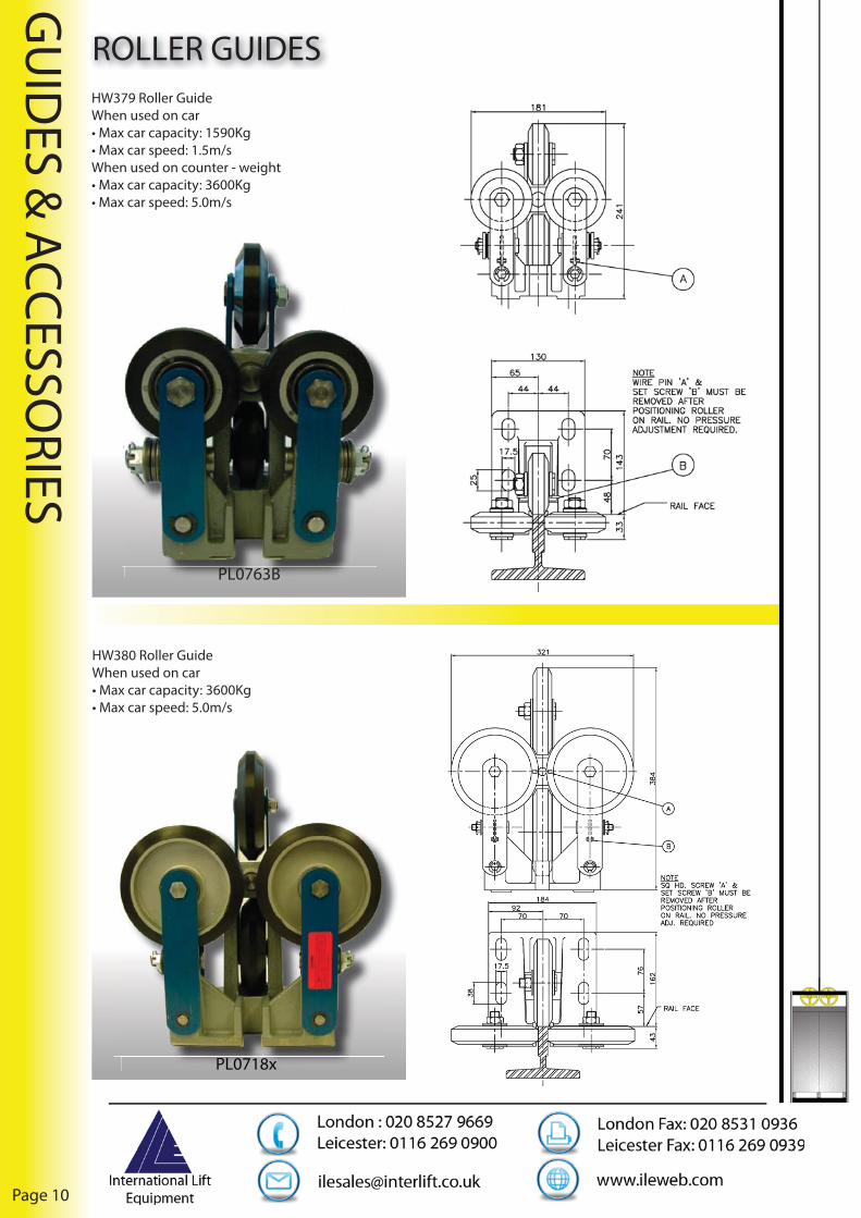
DOOR MODERNISATION - PRISMAKIT M1 -M2 - M3 comes from many lift installers requirements having the necessity of refurbishing old lifts with the replacement of existing swing doors with fully automatic ones.
Usually during the refurbishment operation, a third company (building contractors) is charged with masonry (disassembly of the existing doors and wall restoration once the new automatic doors have been assembled). This represents an important cost which could also be increased due to further structural work being required.
KIT M1 is the result of the experience of engineers that have been studying automatic doors for lifts for 25 years, combined with the experience of their customers giving important suggestions and judgments.
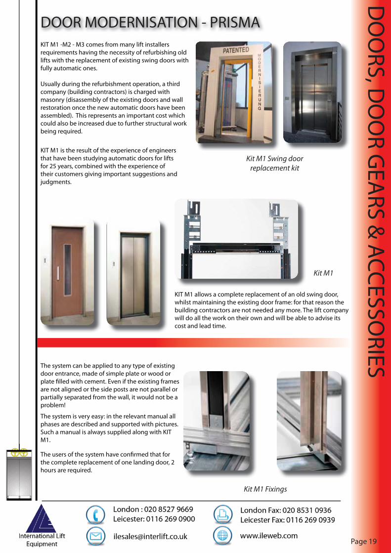
KIT M1 allows a complete replacement of an old swing door, whilst maintaining the existing door frame: for that reason the building contractors are not needed any more. The lift company will do all the work on their own and will be able to advise its cost and lead time.
The system can be applied to any type of existing door entrance, made of simple plate or wood or plate fi lled with cement. Even if the existing frames are not aligned or the side posts are not parallel or partially separated from the wall, it would not be a problem!
The system is very easy: in the relevant manual all phases are described and supported with pictures. Such a manual is always supplied along with KIT M1.
The users of the system have confi rmed that for the complete replacement of one landing door, 2 hours are required.
Kit M1
Kit M1 Fixings
Kit M1 Swing door replacement kit

Page 20
DO
ORS, D
OO
R GEA
RS & ACCESSO
RIES
LANDING DOORS - PRISMAPanels can be manufactured in many diff erent executions: from the full glass version up to stainless steel coated and coloured.
The car door operator is the most sturdy and technological component of such a door.
Panels are designed upon specifi c requirements of the customer since they depend on cabin and shaft radius.
Every detail has been studied and carefully analysed in order to obtain the best performance.
Panel movement is controlled by an electronic device (DRIVE) with variable parameters.
The DRIVE device can also carefully control acceleration and deceleration curves of the door according to customer and installation needs.
All parameters are pre-adjusted at Prisma, nevertheless, once the installation is completed, the customer can take advantage of maximum fl exibility in adjustment.
In case panels are very heavy, e.g. full glass panels, it is possible to control the torque and deceleration curve so that a smooth movement during closing and opening phases is always assured.
The control is made with a programming pad for drive software.
With such a remote key it is possible to select a parameter and change its value, after that new data can be memorised in control system.
Round doors
Drive unit
R d d

DO
ORS, D
OO
R GEA
RS & ACCESSO
RIES
Page 21
LANDING DOORS - PRISMA
FEATURES• Fire resistance certifi ed to EN81/58 (E120)• TÜV certifi ed• Available in galvanised, fi re painted stainless steel (coated with transparent P.V.C protective fi lm) and stainless 304 grade• Noiseless due to high performance sliding door shoes• Easy-assemble system
The Carina landing door is a highly standardised product, introducing new concepts of construction and assembly on site.
The Carina door is designed and constructed to a high technological standard but off ers a “low cost” solution.
Components are partially pre-assembled in the packaging, and arranged in sequence, in order to facilitate mounting on site. This task is simplifi ed further by a book graphically illustrated with all the various stages of assembly.
Each phase is numerically associated with a bag containing screws and components for the assembly of the phase in question.
The installer can perform the assembly:
1. In the lift shaft. An engineer should be able to install and adjust 5/6 doors per day.
2. On the landings prior to mounting within the entrance.
Frame Sizes
Free passage PL 700 to 750 - 800 - 850 to 900 mm Headroom LH 2000 - 2100 mm
Upright width 120 mm Height upper crosshead 235 mm
Type L2C - Centre opening
Dimension of frame + threshold
frame 80mm + threshold 37.5mm = Total 117.5mm
Type L2S/RL Telescopic door
Dimensions of frame + thresholdframe 60mm + threshold 75mm (90-15)=Total 135mm

Page 22
DO
ORS, D
OO
R GEA
RS & ACCESSO
RIES
GALAXY CAR & LANDING DOOR PACKAGES• Designed around the well proven GAL doorgear, the modular design provides a compact unit with classic lines
• Manufactured from high quality primed Zintec steel sheet suitably ribbed, then skinned in stainless steel to customers requirements, the packages present a robust unit.
• Available with standard aluminium sill or phosphor bronze
• Doors are normally prepared for GAL drop fl ag lock release. However, preparation can be extended to triangular euro lock or clients’ bespoke arrangement
• A choice of fi nishes are available upon request ranging from plain/patterned and coloured stainless steel
• The folded box section frames carry all fi xings for top tracks and locks with doors arranged for nylon door slippers, pick-up rollers and closers
• Both fi re certifi ed and standard non fi re rated entrances are fully adjustable for door to post clearances and are set up to give 3mm clear on fi re certifi ed and 6mm clear on non certifi ed doors
• For ease of transportation/site access, frames are supplied disassembled for assembly on site with 8 set screws.
• Compatible car door packages are available complete with sill nosing, support angle and apron
• Doors can be prepared to receive any requested safety edge either mechanical, proximity or infra-red
• A full range of car and landing door panels can be manufactured to suit most replacement requirements including heavy construction, vandal resistant designs
• Full depth 1.5mm stainless steel architraves, wrap around design on front wall with all necessary fi xing brackets
• Finally both technical and site back up are provided upon request
Single panel doors and frames available in full compliance with EN81-71 (Cat 2) vandal resistant lifts
Euro release lock

DO
ORS, D
OO
R GEA
RS & ACCESSO
RIES
Page 23
GALAXY CAR & LANDING DOOR PACKAGESFEATURES
•Competitively priced•Modular construction for ease of assembly on site•GAL equipment compatible•2 hour fi re certifi cate to BS476 up to 1300 mm x 2200 mm clear opening for centre parting and 2 panel side opening •2 hour fi re assessment for centre parting 1400 mm clear opening 2 panel side opening 1400 mm 2 speed centre parting (4 panel) up to 1650 mm x 2100 mm•1.5 hour fi re assessment for single panel side opening
A typical hospital landing layout including landing doors, frames architraves, push buttons and LED indicators.
ILE can off er bespoke solutions to suit specifi c customer requirements. Whether this includes a full door package including doors, frames and architraves or individual installation components to allow the retaining of existing doors.

Page 24
DO
ORS, D
OO
R GEA
RS & ACCESSO
RIES
ELEVATOR DOOR BARRIER
The elevator door barrier creates a Protection Zone in front of the elevator doors protecting them from damage caused by trolleys and other wheeled devices.
International Lift Equipment are now pleased to be able to off er an electric powered elevator door barrier.....
Potential damage to the elevator doors, could eventually lead the elevator malfunctioning and being taken out of service.
The Protection Zone created by the fl oor mounted barrier when in the raised position will not allow trolleys or any other wheeled device to get too close and therefore collide with the elevator door or surrounding area.
When raised the barrier presents an impassable obstacle to all oncoming trolleys etc. As a safety measure, the barrier remains low enough for foot traffi c to pass over.
Barrier in raised position
The product comes with an IP55 rating and is registered under design number 4009918, within international design classifi cation LOC (07)CL 25-02.
When in the lowered position, the barrier lays fl at against the fl oor / base plate, presenting only a slight hump which trolleys can be pushed over and foot traffi c can safely pass over.
DO
ORS, D
OO
R GEA
RS & ACCESSO
RIES
Page 25
ELEVATOR DOOR BARRIER
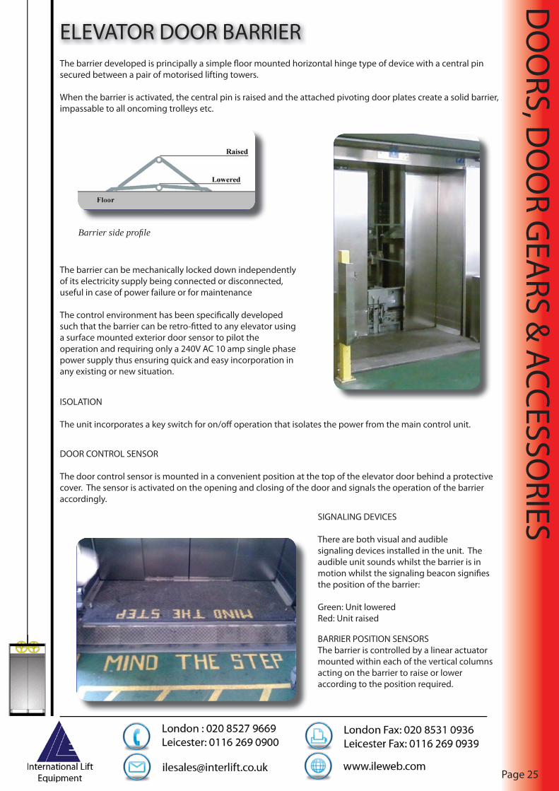
Barrier side profi le
The barrier can be mechanically locked down independently of its electricity supply being connected or disconnected, useful in case of power failure or for maintenance
The control environment has been specifi cally developed such that the barrier can be retro-fi tted to any elevator using a surface mounted exterior door sensor to pilot the operation and requiring only a 240V AC 10 amp single phase power supply thus ensuring quick and easy incorporation in any existing or new situation.
The barrier developed is principally a simple fl oor mounted horizontal hinge type of device with a central pin secured between a pair of motorised lifting towers.
When the barrier is activated, the central pin is raised and the attached pivoting door plates create a solid barrier, impassable to all oncoming trolleys etc.
ISOLATION
The unit incorporates a key switch for on/off operation that isolates the power from the main control unit.
DOOR CONTROL SENSOR
The door control sensor is mounted in a convenient position at the top of the elevator door behind a protective cover. The sensor is activated on the opening and closing of the door and signals the operation of the barrier accordingly.
SIGNALING DEVICES
There are both visual and audible signaling devices installed in the unit. The audible unit sounds whilst the barrier is in motion whilst the signaling beacon signifi es the position of the barrier:
Green: Unit loweredRed: Unit raised
BARRIER POSITION SENSORSThe barrier is controlled by a linear actuator mounted within each of the vertical columns acting on the barrier to raise or lower according to the position required.

Page 26
DO
ORS, D
OO
R GEA
RS & ACCESSO
RIES
DOOR SHOESDOOR SHOES ILE PART No.
U.K door shoes 76 mm centres PL0373
Door shoes DW2 PL0374
Door shoes DW3 PL0375
Door shoes DW4 PL0376
Door shoes DWR2H-2 PL0377
Door shoes DL2 PL0378
Door shoes DL3 PL0379
Door shoes DL4 PL0380
Selcom butterfl y shoe SL-305 SHOE SL-305-SHOE
PL0373
PL0374
PL0377

DO
ORS, D
OO
R GEA
RS & ACCESSO
RIES
Page 27
BOTTOM TRACKS
PL037S2
• Single and double groove extrusions available up to 3 metres in length from stock• Available in aluminium or phosphur bronze
PL0371
PL037S1
PL0372B
PL0372
PL0371B
PL039A1
PL039A2
BOTTOM TRACKS ILE PART No.
Aluminium single groove track PL0371
Aluminium double groove track PL0372
Bronze track single speed 1900 mm PL0371B
Bronze track single speed 3000 mm PL0371B3
Bronze track two speed 1900 mm PL0372B
Bronze track two speed 3000 mm PL0372B3
Bronze single groove Selcom 3000 mm PL037S13m
Bronze track single speed 1900 mm A1 PL039A1
Bronze track two speed 1900 mm A2 PL039A2
Bronze track two speed 4m A1 PL039A1-4

Page 28
DO
ORS, D
OO
R GEA
RS & ACCESSO
RIES
DOOR LOCKS & SPARES• GAL, Prisma, Liftstore and Kronenberg locks, spares and release keys available from stock
DOOR LOCKS & SPARES ILE PART No.
MOH left hand release SG0173L
MOH right hand release SG0173R
Small spoon lock release key PL0385
Selcom lock release key PL0389
Kronenberg lock release key PL0390
“V” release key PL0398A
GAL HA lock release key EINTHAMC
GAL KMO lock release key EINTKMO
GAL fob EINTKMOFOB
V/R express drop release key SPTV-VR KEY
VL10 beak and carrier DPVL10B
VL11 beak and carrier DPVL11B
VL10 roller and arm DPVL10A
VL11 roller and arm DPVL11A
SG0173L/R SPTV-VR KEY
PL0385 PL0389
DPVL10B DPVL10A DPVL11A PL0390DPDPDPDPVLVLVLVL11111111AAAA PLPLPLPL0303030390909090
PL0398A EINTKMO EINTKMOFOB EINTHAMCPLPLPLPL0303030398989898AAAA EIEIEIEINTNTNTNTKMKMKMKMOOOO EIEIEIEINTNTNTNTKMKMKMKMOFOFOFOFOBOBOBOB EIEINTNTHAHAMCMC

DO
ORS, D
OO
R GEA
RS & ACCESSO
RIES
Page 29
MICROSCAN DETECTOR EDGE
DETECTOR EDGES ILE PART No.
Microscan D101 40mm deep x 2000mm high x 36mm wide PL03012
Microscan D101SL 9mm deep x 2000mm high x 38mm wide PL03011
Microscan GAL VF 40mm deep x 2000mm high x 36mm wide PL03005
Microscan GAL VF Slimline 9mm deep x 2000mm high x 38mm wide PL03006
SPECIFICATION
Vertical/horizontal/angular displacement at 0mm
± 20mm / ± 10mm
Angular displacement at 0mm ± 15o 1 (Microscan 101); ± 5o 1 (Microscan 101SL
Number of diodes/beams 16/100
Highest/lowest beam 1823mm/25mm (complies with EN81-70:5.2.4)
Redundancy/blanking Single element, factory set on request
Maximum/minimum recommended opening 3000mm/0mm
Maximum response time 35mS (transistor output); 40ms (relay output)
Light immunity at 2000mm - Sunlight 100,000 LUX
IP rating - RX & TX unit IP65 (AS1939:1990)
Electromagnetic compatibility - Emission BS EN 12015:2004 - lifts, escalators & passenger conveyors
Electromagnetic compatibility - Immunity BS EN 12016:2004 - lifts, escalators & passenger conveyors
Cable reliability IEC 60227-2:2003
Vibration/free fall IEC 60068-2-64:1993/IEC 60068-2-32:1975
Composite temperature/humidity cyclic test -10oC to 65±C, 95% RH, IEC60068-2-38:1974
Supply voltages 110 or 220V AC: 50/60 Hz (Switch in AC PSU housing)
• Standard and slimline profi le• Fully sealed unit is water and dust proof to IP65• One unit suitable for both side-opening or centre opening doors• No on-site adjustment required• No special cables required• Immune to interference from refl ection or sunlight• SMT electronics with proven technology and reliability• Easy installation without need to expose componentry• High impact vandal resistant materials• Fully tested in compliance with international standards• Tested to CE requirements• Tested to exceed requirements of EN81-70 and GB7588-2003

Page 30
DO
ORS, D
OO
R GEA
RS & ACCESSO
RIES
GATELOCKSILE off ers a full range of gatelocks
DPVL10
DPVL11
DPVL20

DO
ORS, D
OO
R GEA
RS & ACCESSO
RIES
Page 31
GATELOCKS
DPVL30
GATELOCKS ILE PART No.
VL10 Gatelock DPVL10
VL11 Gatelock DPVL11
VL20 Gatelock DPVL20
VL30 Left Hand Gatelock DPVL30L
VL30 Right Hand Gatelock DPVL30R
VL31B Left Hand Gatelock DPVL31L
VL31A Right Hand Gatelock DPVL31R
DPVL31

Page 32
DO
ORS, D
OO
R GEA
RS & ACCESSO
RIES
SWITCHES
SWITCHES ILE PART No.
Coffi n switch PL0739
VC50 limit switch DPVC50
Car gate switch with striker DPCGS
DPVC50
DPCGS
PL0739

MO
TORS &
DIVERTO
RS
Page 33
GEARED MOTORS - SASSIIn the ruined Italy of post war years, reconstruction was a national priority. One of the leading protagonists of this eff ort was the Alberto Sassi company. Managed by its founder, Mr Alberto Sassi, it started manufacturing essential building construction equipment, specialising in the production of gearboxes for lifts.
Their long experience in the lift industry has led them to adopt state-of-the-art manufacturing solutions, customised for their particular requirements. Their system monitors every aspect of production and is controlled by skilled personnel with extensive experience utilising the most advanced machine tools available. The components used in assembling gears and motors are designed, manufactured and inspected to achieve the highest possible precision of the machined surfaces.
MF94 TORO
ILE’s experienced engineers will size the unit to suit the installation via Sassi’s “Algani” calculation program. Motor gear units can be supplied complete with bespoke bedplates to suit specifi c installation characteristics.
Page 34
MO
TORS &
DIVERTO
RS
GEARLESS MOTORS - LOHER
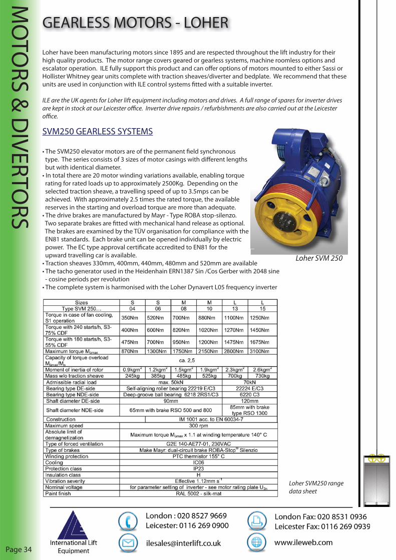
Loher have been manufacturing motors since 1895 and are respected throughout the lift industry for their high quality products. The motor range covers geared or gearless systems, machine roomless options and escalator operation. ILE fully support this product and can off er options of motors mounted to either Sassi or Hollister Whitney gear units complete with traction sheaves/diverter and bedplate. We recommend that these units are used in conjunction with ILE control systems fi tted with a suitable inverter.
ILE are the UK agents for Loher lift equipment including motors and drives. A full range of spares for inverter drives are kept in stock at our Leicester offi ce. Inverter drive repairs / refurbishments are also carried out at the Leicester offi ce.
SVM250 GEARLESS SYSTEMS
• The SVM250 elevator motors are of the permanent fi eld synchronous type. The series consists of 3 sizes of motor casings with diff erent lengths but with identical diameter.• In total there are 20 motor winding variations available, enabling torque rating for rated loads up to approximately 2500Kg. Depending on the selected traction sheave, a travelling speed of up to 3.5mps can be achieved. With approximately 2.5 times the rated torque, the available reserves in the starting and overload torque are more than adequate.• The drive brakes are manufactured by Mayr - Type ROBA stop-silenzo. Two separate brakes are fi tted with mechanical hand release as optional. The brakes are examined by the TÜV organisation for compliance with the EN81 standards. Each brake unit can be opened individually by electric power. The EC type approval certifi cate accredited to EN81 for the upward travelling car is available.• Traction sheaves 330mm, 400mm, 440mm, 480mm and 520mm are available• The tacho generator used in the Heidenhain ERN1387 Sin /Cos Gerber with 2048 sine - cosine periods per revolution• The complete system is harmonised with the Loher Dynavert L05 frequency inverter
Loher SVM250 range data sheet
Loher SVM 250

MO
TORS &
DIVERTO
RS
Page 35
GEARLESS MOTORS - LOHER
SVM 250-04 and 06, brake with manual release
SVM 250-08 and 10, brake with manual release
SVM 250-13 and 15, brake with manual release

Page 36
MO
TORS &
DIVERTO
RS
PERMANENT MAGNET MOTORS
‘Q’ RANGE
Two types are available, suitable for machine or machine roomless applications, Q185M and QE225L.
GEARLESS MOTORS - SICMEMOTORI
NOTE: The brake is approved as a protective device against uncontrolled upward movement in accordance with EN81
Q185M
QE225L
Please see opposing page for Q range motor data sheets.Pl i f Q

MO
TORS &
DIVERTO
RS
Page 37
GEARLESS MOTORS - SICMEMOTORI
Q185M MAIN FEATURESMotor Type Q185M Q185M Q185M Q185M
Roping 1:1 1:1 2:1 2:1Payload Kg 350/400 450/550 680/775 880/1060
Traction Sheave Dia mm 320 240 320 240MOTOR FEATURES
Motor Speed RPM 60 80 113 170Power Kw 2,3 / 2,7 2,9 / 3,4 4,1 / 4,9 6,2 / 7,4Supply INVERTERCurrent A 7,0 / 8,3 7,9 / 9,4 9,9 / 11,8 14,1 / 16,7
Max. Current A 14 15,8 19,8 28,2Frequency Hz 12 16 22,6 34
Torque Nm 350/420 350/420 350/420 350/420Max Torque Nm 700 700 700 700
GENERAL TECHNICAL FEATURESMax Load On Axle Kg 2500 2500 2500 2500
Weight Kg 280 280 280 280Noise Level dBA ≤ 50 ≤ 50 ≤ 50 ≤ 50
BRAKE FEATURESBrake Type Electrically Released Disk Brake
Brake Supply dc V 104/207 104/207 104/207 104/207Brake Torque (each) Nm 440 440 440 440
ENCODER FEATURESPulse Generator Type Sincos/Endat/
HiperfaceSincos/Endat/
HiperfaceSincos/Endat/
HiperfaceSincos/Endat/
HiperfacePulse Per Revolution 2.048/1.024 2.048/1.024 2.048/1.024 2.048/1.024
QE225L MAIN FEATURESMotor Type QE225L QE225L QE225L QE225L
Roping 1:1 1:1 2:1 2:1Payload Kg 625/775 780/960 1200/1450 1500/1850
Traction Sheave Dia mm 400 320 400 320MOTOR FEATURES
Motor Speed RPM 50 80 139 168Power Kw 4,2 / 5,0 6,8 / 7,1 11,8 / 14,0 14,2 / 16,9Supply INVERTERCurrent A 10 / 11,9 14,8 / 17,6 24,7 / 29,3 29 / 34.4
Max. Current A 20 29,6 49,4 58Frequency Hz 10 16 27,8 33,6
Torque Nm 810/960 810/960 810/960 810/960Max Torque Nm 1600 1600 1600 1600
GENERAL TECHNICAL FEATURESMax Load On Axle Kg 3500 3500 3500 3500
Weight Kg 420 420 420 420Noise Level dBA ≤ 50 ≤ 50 ≤ 50 ≤ 50
BRAKE FEATURESBrake Type Electrically Released Disk Brake
Brake Supply dc V 104/207 104/207 104/207 104/207Brake Torque (each) Nm 440 440 440 440
ENCODER FEATURESPulse Generator Type Sincos/Endat Sincos/Endat Sincos/Endat Sincos/EndatPulse Per Revolution 2.048/1.024 2.048/1.024 2.048/1.024 2.048/1.024
*Max load dependant on car weight and usage

Page 38
MO
TORS &
DIVERTO
RS
MH375M
GEARLESS MOTORS - SICMEMOTORIWith current trends it seems the future for the lift drives market will be permanent magnet, three-phase, synchronous gearless motors. Calls for effi ciency and a “greener” environment will raise expectations of lift technology. A gearless motor has many advantages over its geared counterpart, namely:
• Gearless, therefore, no gear maintenance and no periodical lubrication oil replacement• Vibration - free giving better ride quality• Low noise levels• Greater effi ciency, thus less power consumption; a “green” product that will meet future standards with regards to energy consumption• Better intrinsic reliability due to less mechanical components• Compact construction• Added benefi t of brakes being certifi ed in accordance with EN81-1 as a safety device for uncontrolled upward car movement, therefore, negating the need for bi-directional safety gear ILE, in conjunction with Sicmemotori, can off er a cost-eff ective solution when compared to geared operation for a gearless motor. We recommend these units are used in conjunction with ILE control systems fi tted with a suitable inverter.
M355M
PERMANENT MAGNET MOTORS
‘M’ RANGE
Two types are available, suitable for machine or machine roomless applications, M355M and MH375M.
NOTE: The brake is approved as a protective device against uncontrolled upward movement in accordance with EN81
Please see opposing page for M range motor data sheets.

MO
TORS &
DIVERTO
RS
Page 39
M355M MAIN FEATURESMotor Type M355M M355M M355M M355M
Roping 1:1 1:1 2:1 2:1Payload Kg 675/800 675/800 1260/1500 1260/1500
Traction Sheave Dia mm 400 400 400 400MOTOR FEATURES
Motor Speed RPM 50 96 139 168Power Kw 4,2 / 5 8,0 / 9,5 11,6 / 13,8 14,1 / 16,75Supply INVERTERCurrent A 7,0 / 8,3 7,9 / 9,4 9,9 / 11,8 14,1 / 16,7
Max. Current A 21 33,4 46,4 59Frequency Hz 13,33 25,60 37,07 44,80
Torque Nm 800/950 800/950 800/950 800/950Max Torque Nm 1500 1500 1500 1500
GENERAL TECHNICAL FEATURESMax Load On Axle Kg 3600 3600 3600 3600
Weight Kg 485 485 485 485Noise Level dBA ≤ 50 ≤ 50 ≤ 50 ≤ 50
BRAKE FEATURESBrake Type Electrically Released Disc Brake
Brake Supply V 104/207 104/207 104/207 104/207Brake Torque (each) Nm 2 x 1000 2 x 1000 2 x 1000 2 x 1000
ENCODER FEATURESPulse Generator Type Sincos/Endat/
HiperfaceSincos/Endat/
HiperfaceSincos/Endat/
HiperfaceSincos/Endat/
Hiperface
Pulse Per Revolution 2.048/1.024 2.048/1.024 2.048/1.024 2.048/1.024
GEARLESS MOTORS - SICMEMOTORI
MH375M MAIN FEATURESMotor Type MH375M MH375M MH375M MH375M
Roping 1:1 1:1 2:1 2:1Payload Kg 900/1125 900/1125 1740/2120 1740/2120
Traction Sheave Dia mm 480 480 480 480MOTOR FEATURES
Motor Speed RPM 40 80 139 168Power Kw 4,8 / 5,7 9,6 / 11,4 16,7 / 19,8 20,2 / 24,0Supply INVERTERCurrent A Nov-13 20,8/24,7 32,4/38,5 39/46,3
Max. Current A 22 41,6 64,8 78Frequency Hz 10,7 20,8 37,1 44,8
Torque Nm 1150/1400 1150/1400 1150/1400 1150/1400Max Torque Nm 2300 2300 2300 2300
GENERAL TECHNICAL FEATURESMax Load On Axle Kg 4500 4500 4500 4500
Weight Kg 600 600 600 600Noise Level dBA ≤ 50 ≤ 50 ≤ 50 ≤ 50
BRAKE FEATURESBrake Type Electrically Released Disk Brake
Brake Supply V 100/200 100/200 100/200 100/200Brake Torque (each) Nm 3 x 1200 3 x 1200 3 x 1200 3 x 1200
ENCODER FEATURESPulse Generator Type Sincos/Endat/
HiperfaceSincos/Endat/
HiperfaceSincos/Endat/
HiperfaceSincos/Endat/
HiperfacePulse Per Revolution 2.048/1.024 2.048/1.024 2.048/1.024 2.048/1.024
*Max load dependant on car weight an usage

Page 40
MO
TORS &
DIVERTO
RS
GEARLESS MOTORS - PRISMA
ADVANTAGES OF GEARLESS TECHNOLOGY:
· Compact footprint that allows mounting within the lift shaft
· Elimination of the traditional gearbox thereby reducing maintenance and off ering far higher effi ciencies therefore, reducing running costs
· Fewer mechanical components with consequent advantages during assembly and alignment of the machine.
· Maintenance-free
· No lubricating oil required
· Gearless machines with 160, 210, and 450 mm diameter pulleys, ideal for replacing old geared machines with cables up to 11 mm in diameter
• Ideal for the replacement of existing gearless MRL systems, thanks to the reduced overall dimensions
Gearless series
· High effi ciency, more than 90%, a guaranteed energy saving of 30%, with 50% reduction in power draw.
· Smooth operation in acceleration and deceleration due to the elimination of the gearbox and mechanical linkages.
The Prisma gearless motors are off ered in two ranges. The “F” (fl at) range and the “C” (compact) range which are based on the overall dimensions of the motor.

MO
TORS &
DIVERTO
RS
Page 41
GEARLESS MOTORS - PRISMA
C450/630 Series machine
F03/04 Series machine
F03 F04
C630C450

Page 42
MO
TORS &
DIVERTO
RS
STANDARD LIFT MOTORS - ZIEHL - ABEGG
GEARLESS LIFT MOTORS - ZIEHL - ABEGG
ILE are pleased to be able to off er the Ziehl - Abegg VFD range of elevator motors for frequency operation. • Frame sizes from 132 up to 280 • From 4 up to 120Kw at 38/50/66 Hz.• Foot mounting (IMB3)
Please contact us for more details and prices
• System Voltage: 400 V• Rated Voltage: 360 V• Poles: 4• Noiseless running ball bearings• Construction: IMB3• Protection: IP54• Insulation: Class F• 3 PTC thermistors• Without fan blower• 240 starts per hour
Attributes and special features:
Due in particular to the fl at and narrow design, the ZETASYN is ideally suitable for individual elevators with or without machine rooms.The certifi ed brake can be used in addition as a safety device against uncontrolled car movement upwards.
Full range of Zetatop and Zetasyn available from ILE.
ZETASYN GEARLESS MOTOR
ZETATOP GEARLESS MOTOR
Attributes and special features:
The ZETATOP off ers all of the advantages of a modern permanent magnet excited synchronous motor. It is compact and can be mounted in many ways, even in the smallest elevator shaft. The ride quality and the smoothness of these kinds of drives is unsurpassed. The certifi ed brake can be used in addition as a safety device againstuncontrolled car movement upwards.

MO
TORS &
DIVERTO
RS
Page 43
DIVERTORS
T234 DIVERTOR PULLEY ON BALL BEARINGS COMPLETE WITH FIXED AXLES AND SUPPORTS
P Grooves Nr Rope ø mm
A C V Z D Static Load Kgs
ILE PART No.
400 4 9.5 77 17 82 215 155 2500 PL0501
4 10 77 17 82 215 155 2500 PL0531
450 4 11 77 17 82 215 155 3100 PL0502
5 11 94 17 102 240 180 3900 PL0525
6 11 111 17 102 240 180 4700 PL0517
550 4 11 77 17 82 215 155 3100 PL0503B
4 13 94 20 102 240 180 4200 PL0503
5 11 94 17 102 240 180 3900 PL0521
5 13 111 20 102 240 180 5200 PL0519
6 11 111 17 102 240 180 4700 PL0526
6 13 130 20 122 260 200 6300 PL0518
PFB Deadeyes 45mm per pair PL0505
T234 DIVERTOR TYPE
Others available on request

Page 44
MO
TORS &
DIVERTO
RS
DIVERTORS
T235 DIVERTOR TYPE
T235 DIVERTOR PULLEY ON BALL BEARINGS COMPLETE WITH FIXED AXLES FOR KEEPER PLATES
P Grooves Nr Rope ø mm
A C V Z O Static Load Kgs
ILE PART No.
400 4 10 77 17 82 140 120 2500 PL0532
450 4 11 77 17 82 140 120 3100 PL0511
550 4 11 77 17 82 140 120 3100 PL0533
4 13 94 20 102 164 144 4200 PL0512
5 13 111 20 102 164 144 5200 PL0523
6 11 111 17 102 164 144 4700 PL0527
PFB Deadeyes 45mm per pair PL0505
PL0505PL0505
• 4,5 and 6 rope divertors to suit 9.5, 11 and 13mm diameter ropes available from stock
• Other confi gurations available including heavy duty divertors with bronze bearings and Stauff er grease feeds
Others available on request

SAFETY G
EARS &
OVERSPEED
GO
VERNO
RS
Page 45
SAFETY GEARS
PL07VG5
• Variable geometry (VG) progressive safety gear available from stock for speeds up to 3 mps and loads up to 6000kg
• Higher loads available via special design
SAFETY GEARS ILE PART No.
VG2A Safety Gear PL07VG2A
VG4 Safety Gear PL07VG4
VG5 Safety Gear PL07VG5
VG6 Safety Gear PL07VG6
SAFETY GEAR FIXING ACCESSORIES ILE PART No.
Standard operating kit PL07VGSK1
Inertia bracket PL07VGSK2
Inertia spring PL07VGSK3
Pivot bracket assembly PL07VGSK4
Duplexing kit PL07VGSK5
Up-down connection kit PL07VGSK6
Switch kit PL07VGSK7
Lockdown kit PL07VGSK8
Pair of wedge sockets PL07VGSK9
Bi-directional kit for VG-5 and combined safety gear
PL07VGSK10
Link plate combining 2 safety gears PL07VGSK10 A-B-C-D
VG4 to VG2A pivot bar PL07VGSK11
SAFETY GEARS VG-2A VG-4 VG-5 VG-6
Minimum Mass 900Kg 700Kg 850Kg 2000Kg
Maximum Mass 3200Kg 1600Kg 2250Kg 4500Kg
Max Gov’r Speed (m/s) 2.33 2.33 2.63 3.23
Max Lift Speed (m/s) 1.75 1.75 2.00 2.5
Width 370 270 370 370
Fixing Centres 134/238 112/168 134/238 134/238
Height 175 143 224 175
ACCESSORY KIT SK1 SK2 SK3 SK4 SK5 SK7 SK8 SK9 SK10 SK10A SK10B SK10C SK10DDownward acting safety gear
1 1 1 1
VG 5 Bi-directional safety gear
2 2 1 1 1 1
Combined bi-directional safety gear - direct connection
2 1 2 1 1 1 * *
Combined bi-directional safety gear - indirect connection
2 2 1 1 1 1
Duplexed safety gears - single direction
2 1 1 2 1
Special 4 Guide System 4 1 2 2 1 1 1Kit SK10 for Combined and Dual Acting Safety Gears
2 2 1 1
When ordering safety gears please state the car weight, contract load, lift speed, governor rope position and guide type
The above loads can be increased by “duplexing” the above units. Please contact the sales offi ce for further information.
Note: Internal torsion inertia springs are now fi tted as standard to all end assemblies. These are suitable for lift travels up to 40 metres. Additional torsion springs can be fi tted for travel over 40 metres to increase inertia force.
* Indicates options

SAFETY G
EARS &
OVERSPEED
GO
VERNO
RS
Page 46
PFB OVERSPEED GOVERNORS
PART No. PL070R5
PART No. PL070R6
PART No. PL070R10
• Rope gripping• Down direction only• Safety switch• Test groove• Rope Size: 8 to 10mm• Min tripping speed 0.63m/s• Max tripping speed 2.50m/s• 495mm high• 460mm wide• 196mm depth• Weight 33Kg
• ILE off ers a full range of Overspeed Governors and tension weights• Overspeed governors can be fitted with digital pulse encoder for use with control system shaft encoder.
OVERSPEED GOVERNORS ILE PART No.
PFB R5 governor 0.5-1.68 PL070R5 L/R
PFB R6 governor 0.5-2.1 PL070R6 L/R
PFB R10 rope gripping governor 0.9-2.5 PL070R10
PFB LK200 Bi-directional 0.32-1.7 PL07LK200
PFB LK300 Bi-directional 0.4-2.73 PL07LK300
• Down direction only• Safety switch• Test groove• Rope Size: 6 to 8mm• Min tripping speed 0.50m/s• Max tripping speed 2.10m/s• 335mm high• 300mm wide• 238mm depth• Weight 16Kg
• Down direction only• Safety switch• Test groove• Rope Size: 6 to 6.5mm• Min tripping speed 0.35m/s• Max tripping speed 1.68m/s• 261mm high• 200mm wide• 204mm depth• Weight 10Kg

SAFETY G
EARS &
OVERSPEED
GO
VERNO
RS
Page 47
PFB OVERSPEED GOVERNORS
TENSION WEIGHTS
PART No. PL07LK300
• Bi-directional• 300 mm pulley• Safety switch• Test groove• Rope Size: 6 to 8mm• Min tripping speed 0.40m/s• Max tripping speed 2.73m/s• 370mm high• 300mm wide• 220mm depth• Weight 14Kg Optional:• Remote reset• Encoder
PFB TENSION WEIGHTS ILE PART No.
PFB D1 200 Tension Weight PL0719
PFB R4 300 Tension Weight PL0720
ILE TENSION WEIGHTS PULLEY DIA (mm) ILE PART No.
450N Load 200 B138
450N Load 300 B132
550N Load 300 B136
800N Load 300 B137
Pit mounted 200 B114A
Pit mounted 300 B114
• Bi-directional• 200 mm pulley• Test groove• Rope size: 6 to 6.5mm• Min tripping speed 0.32 m/s• Max tripping speed 1.7m/s• 170mm high• 200mm wide• 220mm depth• Weight 12Kg Optional:• Remote reset• Encoder
PART No. PL07LK200
B132

SAFETY G
EARS &
OVERSPEED
GO
VERNO
RS
Page 48
BODE OVERSPEED GOVERNORS
OVERSPEED GOVERNORS ILE PART No.
BODE overspeed governor type 7: 0.7-1.3 PL07BD07
BODE H.S overspeed governor type 7: 1.4-3.43 PL07BD07H
BODE overspeed governor type 8: 0.8-0.46 PL07BD08
BODE H.S overspeed governor type 8: 0.5-1.33 PL07BD08H
BODE overspeed governor type 9: 0.5-0.7 PL07BD09 PART No. PL07BD07PART N PL0 BD0
•Bode type 7 can be fi tted with a digital pulse encoder for use with control systems shaft encoder•Bode overspeed governors can be fi tted with an anti slip device to allow compliance with EN81 A3 ammendment.
PL07BD07• Tripping speed 0.70 to 1.3m/s• Rope size: 6 to 8 mm• 360mm high• 304 wide• 208 deep (with encoder)Optional extras:• Remote release device• Anti slip protection
PL07BD07H• Tripping speed 1.4 to 3.43m/s• Rope size: 6 to 8 mm• 360mm high• 304 wide• 150 deepOptional extras:• Remote release device• Anti slip protection
PL07BD08/8H• Tripping speed (08) 0.18 to 0.46m/s• Tripping speed (8H) 0.5 to 1.33 m/s• Rope size: 6 to 6.5 mm• 310mm high• 362 wide• 150 deepOptional extras:• Remote release device• Anti slip protection
PL07BD09• Tripping speed 0.5 to 0.7m/s• Rope size: 6 to 8 mm• 360mm high• 291 wide• 157 deep (with encoder)

CAR ACCESSO
RIES & SW
ITCHIN
G
Page 49
FURINI & KRONENBERG RETIRING RAMPS
LOAD WEIGHING UNITS
RETIRING RAMPS ILE PART No.
Furini retiring ramp 100v B135
Furini retiring ramp 185v B134
Furini cam PL0399
Kronenberg retiring ramp 48V DC PL0360
Kronenberg retiring ramp 48v DC Heavy Duty PL0361
LOAD WEIGHING UNITS ILE PART No.
DMG LEC5F self contained load weighing system with cross head mounted sensor PL07LEC5F
DMG LEC5F self contained load weighing system with rope mounted sensor PL07LEC5R
Load weighing device 800-1300Kg PL0768
Load weighing device 1300-2200Kg PL0768A
Load weighing device 2200-2800Kg PL0769
Load weighing device 2800-4000Kg PL0769A
• Suitable for the operation of Kronenberg manual swing door locks and Dupar (Liftstore) gatelocks (VL10, VL11, VL21 and VL31).
• Very simple installation to car crosshead via 2 M8 bolts • Digital weight display in Kg• Compact unit 200 mm x 56 mm x 42 mm • Suitable for car loads of 300 to 5000Kg• Push buttons set tripping levels, scale and zero-setting • Stable measurements over long periods and in • Circuit blocking to eliminate tripping during travel variable conditions (automatic calibration)• Two independently settable load measurements • Supplied complete with mounting template (i.e. 90 & 110% load) with volt free contact outputs • Full LED status indication
DMG LEC5F Load Weighing Unit
NG UNITS
f contain
PL07LEC5F PL0768
PL0360 B135
Note: Special version available if rope compensation is fi tted to the lift. Please specify if required

CAR ACCESSO
RIES & SW
ITCHIN
G
Page 50
ROPE GRIPPER
Rope Gripper 620G
Protects against ascending car overspeed and unintended car movement, as required by EN81-1 + A3:2009
• Car can’t fall up or down• Car can’t leave fl oor with the doors open• Protects against slipping traction
Powerful, steady pressure on ropes
• Won’t damage ropes• Won’t put excessive stress on machine or sheave• Easily replaceable, non asbestos, non metallic linings• Brake engages rope gently, but provides a quick, powerful grip
Compact - one piece design
• No separate hydraulic unit• Adjusts for almost every application• Easy installation• Triggers instantly on removal of power• Designed to protect gears from potential damage• Quiet, dependable operation
Electrically reset
• Automatic reset when power restores• Manual reset required if fault is detected
230 VAC - 50/60 Cycle - 3 Amp
FEATURES
In recent years, there has been a great deal of discussion about the need for protection against injuries caused by elevator cars leaving the fl oor with the doors open and overspeeding in the up direction. That’s why Hollister and Whitney introduced the rope gripper, a remarkable device used to grab elevator suspension ropes to stop the elevator in the event of mechanical or electrical failure. It is imperative if an elevator overspeeds in the up direction and if the elevator leaves the fl oor with the doors open.
US Patent 5,228,540Chinese Patent 93109093.8Worldwide Patents apply -Others pending
The Rope Gripper has many unique features such as a gently applied but powerful “grip” which doesn’t damage the rope or cause any undue stress to the machine or traction sheave. Protection is assured even when slipping traction occurs.
The Rope Gripper provides easy alignment with adequate clearances between the rope and self grooving “grip” linings and provides power compensation with a constant but powerful force to the rope even as linings wear.
Only four wires are required to the elevator controls and installation is simple. The Rope Gripper is mechanically activated and hydraulically reset.

CAR ACCESSO
RIES & SW
ITCHIN
G
Page 51
ROPE GRIPPER
1:1 ROPING (MAXIMUM RATINGS)
1:1 ROPING (MINIMUM RATINGS)
2:1 ROPING (MINIMUM RATINGS)
2:1 ROPING (MAXIMUM RATINGS)
Max out to out of cables: 124mm
Rated speed: 1.78 m/s
Tripping speed: 2.04 m/s
Car rated load (with 40 to 50% counterweights): 1134 Kg
Car, car load, counterweight, hoist and compensation rope mass: 5216 Kg
Door zone: 254 mm
Car rated load: 272 Kg
Car and counterweight mass: 1034 Kg
Car rated load: 680 Kg
Car and counterweight mass: 2722 Kg
Max out to out of cables: 124mm
Rated speed: 1.27 m/s
Tripping speed: 1.54 m/s
Car rated load (with 40 to 50% counterweights): 2268 Kg
Car, car load, counterweight, hoist and compensation rope mass: 8437 Kg
Door zone: 254 mm

CAR ACCESSO
RIES & SW
ITCHIN
G
Page 52
HANDWIND UNIT
PAWL DEVICE
PL04HW2008
FEATURES• Clear backlit LCD display• The ILE hand operation unit displays the position of the lift regardless of the mains power being on or off .• The unit displays the exact location of the lift i.e. “lift at fl oor level”, “lift just above”, “lift between”, or “lift just below fl oor level”.• The exact fl oor designations can be programmed into the unit, i.e. “basement”, “ground”, “1st”, “mezz” etc up to 7 characters. • Unlimited number of fl oors.
• Large standard library of designations stored in non-volitile memory.• 2.8 Ah battery allows usage up to 6 hours on mains failure.• Alarm and tungsten emergency light supply• Normal/hand switch with additional contact to connect into main lift control safety circuit for isolation.• Buzzer and indicator for fl oor level annunciation.• Self contained unit housed in plastic box for mounting adjacent to the gear (alternatively the faceplate can be mounted in the door of an ILE controller).
The ILE PAWL device system has been designed for use on either traction or hydraulic lift/platform systems to prevent uncontrolled descent of the carriage at rest.
When the lift has stopped at fl oor level the solenoid is de-energised, the actuator will be released via spring pressure. Uncontrolled descent will be prevented by keeper plates in the shaft.
The actuator solenoid must be engaged and the proving contact made before travel of the lift is permitted. It is not possible and should not be attempted to energise the solenoid whilst the actuator piston is under pressure.
Max load: 5000KgSupply voltage: 48V DCDuty rating: 25%Power consumption: 128WCurrent draw: 2.7 Amp
Note: Solenoid can remain energised for a maximum of 70 seconds. An adaptor is available if additional time is required.

CAR ACCESSO
RIES & SW
ITCHIN
G
Page 53
SIGNS•Range of signs available from stock to suit EN81 requirements
SIGNS ILE PART No.
Entrance barrier PL0102
Danger (Motor Room) sign PL0413
Emergency winding sign PL0414
Emergency lowering sign PL0414H
Shock sign PL0415
Lift beam not tested sign PL0416
Reduced headroom sign PL0417
Lift out of service sign PL0419
Pit prop sign PL0420
Lift out of service tape (33m long) PL0421
Caution in the event of a fi re do not use lift sign PL0423
Do not forget to close and lock sign PL0422
Machine room door sign PL0435
Lift well safety sign PL0436
Unsafe car roof sign PL0437
No car safety gear sign PL0438
Falling hazard sign (large) PL0439
Falling hazard sign (small) PL0440
Reduced pit sign PL0496
Danger 415 volts sign PL0497
Counterweight descending sign PL0498
PL0102
PL0416
PL0496 PL0497
PL0413
PL0422 PL0419 PL0438 PL0436 PL0421
PL0440 PL0439 PL0435 PL0417
PL0414 PL0498 PL0423

CAR ACCESSO
RIES & SW
ITCHIN
G
Page 54
ROPE ANCHORAGES
Stock No.
Type 0 Rope mm
A mm MIN
B mm
C mm
D mm
E F mm
G mm
H mm
J mm
Mass Kg
PL0905 1021 6-8 60 320 130 46 M12 50 22 44 22 1.5
PL0906 1022 9-11 65 320 165 65 M16 50 22 50 30 2
PL0907 1025 12-14 75 400 200 80 M20 67 28 60 40 3.5
PL0908* 1027 15-17 83 450 225 95 M24 85 28 72 45 6
Stock No.
Type 0 Rope mm
A mm MIN
B mm
C mm
D mm
E F mm
G mm
H mm
J mm
Mass Kg
PL0927 1031 6-8 90 320 130 46 M12 50 22 44 22 1.5
PL0909 1032 9-11 95 320 165 65 M16 50 22 50 30 2
PL0910 1035 12-14 105 400 200 80 M20 67 28 60 40 3.5
PL0911* 1037 15-17 115 450 225 95 M24 85 28 72 45 6
Stock No.
Type 0 Rope mm
A mm MIN
B mm
C mm
D mm
E F mm
H mm
J mm
Mass Kg
PL0901 1011 6-8 170 320 130 46 M12 44 44 22 1.5
PL0902 1012 9-11 165 320 165 65 M16 44 50 30 2.5
PL09028 1012 9-11 165 500 165 65 M16 44 50 30 2.5
PL0903 1015 12-14 180 400 200 80 M20 52 60 40 5
PL0904* 1017 15-17 260 445 225 95 M24 64 72 45 8.5
* No test certifi cate
* No test certifi cate
* No test certifi cate

CAR ACCESSO
RIES & SW
ITCHIN
G
Page 55
TRAILING CABLE
SHAFT ENCODERS
Cables ILE PART No.
12 way trailing cable x 1 mm PL1202
24 way trailing cable x 1 mm PL1203
Wedge clamp to suit trailing cable PL1210
Cable hanger fl at PL1214
100 way terminal box PL1223
• Stock trailing cables as shown• Also available with LSF and video cable options
PL1202 PL1203
ILE SHAFT ENCODER SYSTEM
STANDALONE PULSE ENCODER SYSTEM
The ILE digital shaft encoder has been developed for use on higher speed lifts or where the use of a tapehead or proximity switching device is not suitable, due to aesthetics or environment. The system is a dedicated position sensing device, capable of providing no compromise control over the lifts slowing and stopping functions.
The positioning and speed information is achieved via a 1024 pulse per rev encoder preferably mounted on the overspeed governor. A correction proximity (with button magnets at each fl oor level) is mounted on the lift car for automatic fl oor learning and subsequent position checking. Levelling accuracy of +/- 1mm is easily achievable.
Note 1: The overspeed governor is either the Bode or PFB type, fi tted with encoder and available via ILENote 2: The option of using the pulses from a standard motor mounted 1024 ppr encoder is now available. Floor levelling accuracy of +/- 5mm is achievable. A programming unit is supplied and fi tted with each Skycom control panel and the system may also be programmed via a laptop P.C. The simple setting up procedure considerably reduces installation time. With a compatible drive, accurate direct to fl oor operation is possible, thus reducing passenger waiting times and overall system effi ciency.
For lifts requiring shaft encoder operation where the overspeed governor is not being fi tted and no encoder is or can be fi tted to the motor we can off er a stand alone system where the encoder is fi tted on the lift car and a toothed-belt is run over pulleys attached to the car. All pulleys and mounting brackets are included in the package.
Encoder must be wired in screened cable with trailing fl ex’s.Max lift speed: 4mpsMax travel: 180m1024ppr encoder HTL

CAR ACCESSO
RIES & SW
ITCHIN
G
Page 56
TAPEHEADILE Low Profi le Floating Tapehead Detector
• This tapehead detector unit is available in 4 or 8 way operation, both using 80 mm wide steel tape• The 4 way unit utilises 4 south-pole magnet sensors horizontally displaced in line• The 8 way unit uses an extra 4 north-pole magnets• Sensor heads are mounted on a “fl oating” self-lubricating nylon guide system in order to minimise guide wear associated with misalignment of the tape down the lift shaft• Relay contacts are 250v, 5amp rated and on site confi gurable as “normally open” or “normally closed”• Magnets, tape and fi xing brackets all available separately if required
TAPEHEAD & COMPONENTS ILE PART No.
4-way 240v PL1070
4-way 12v PL1070A
4-way 110v PL1070B
8-way 240v PL1071
8-way 12v PL1071A
8-way 110v PL1071B
80 mm wide stainless steel tape PL1072A
Car top fi xing bracket PL1074
Tape-to-guides fi xing kit B146/7
500 mm long south pole magnets PL1027S
500 mm long north pole magnets PL1027N
PL1070

CAR ACCESSO
RIES & SW
ITCHIN
G
Page 57
TAPEHEAD FIXING KIT
PL1072A
PL1074
B146/7
ILE also off ers a full fi xing solution for the steel guide tape as well as the tapehead itself. The tape head fi xing kit consists of an anchor bracket, tapehead mounting bracket, bolt kit, guide clips, magnets and steel tape. This allows the tapehead to be securely fastened and the steel tape tensioned and fi xed in position.
Tapehead tensioning device
Tapehead fi xing bracket
Tape head fi xing bracket consits of:1. 1 x Twin unistrut mounting bracket2. 2 x Unistrut mounting bracket3. 1 x Mounting plate4. 12 x M10 x 25 hex set screw5. 12 x M10 unistrut nut6. 12 x10mm Spring washer7. 6 x M6 x 15 hex set screw8. 6 x M6 plain washer9. 6 x M6 spring washer10. 4 x Unistrut clip
PL107
PL1072A
B146/7

CAR ACCESSO
RIES & SW
ITCHIN
G
Page 58
LIMIT SWITCHES & PRE-WIRED ARRANGEMENTS
LIMIT SWITCHES AND KITS ILE PART No.
FES Kronenberg 1320 double pole spring return PL1028
FES Limit switch fi xing kit B128
Ersce limit switch PL1039A
Ersce limit switch fi xing kit B112
Ersce Limit Switch
FES Limit Switch
PL1039A
PL1028PLPL10102828

CAR ACCESSO
RIES & SW
ITCHIN
G
Page 59
LIMIT SWITCHES & PRE-WIRED ARRANGEMENTS
PRE-WIRED LIMIT SWITCH KITS ILE PART No.
Pre-wired FES 3-way PL1001
Pre-wired FES 4-way PL1002
Pre-wired Ersce 3-way PL1003
Pre-wired Ersce 4-way PL1004
• 3 or 4 limit switches pre-wired to terminal box• Option of either FES or Ersce limits• Fully adjustable over 3 metres• Attaches to guides with fi xings provided• Ideal for reducing expensive site installation time
Pre-wired Limit Switch
Pre-wired and assembled 3 and 4-way FES limit switch assembly
Ersce Limit Assembly
FES Limit Assembly
Ersce fi xing kit comprises of:
1. Mounting plate 7. 8 mm spring washer2. Unistrut 600 long 8. M10 x 30 hex screw3. M8 Uninut 9. 10 mm spring washer4. M10 Uninut 10. 5 mm spring washer 5. Uniclip 11. M5 x 45 cheese head6. M8 x 20 hex screw 12. M5 nut
FES fi xing kit comprises of:
1. Mounting plate 7. M8 x 25 hex screw2. Unistrut 600 long 8. 8 mm plain washer3. M8 Uninut 9. 8 mm spring washer4. M10 Uninut 10. 8 mm nut 5. Uniclip 11. M10 x 30 hex screw6. M8 x 20 hex screw 12. 10 mm spring washer
Ersce style limits also available pre-wired

CAR ACCESSO
RIES & SW
ITCHIN
G
Page 60
CAR TOP CONTROL
CAR TOP CONTROL ILE PART No.
BS7255 Car top control PL117255S
CTCU + Emergency light and charger PL117255EL*
Energy saving lamp PL117255LP*
Additional emergency stop PL117255ES*
• Switched RCCD socket outlet • 50 mm emergency stop with fl ag indication • Geometrically shrouded test/normal switch • Geometrically shrouded door open/close switch• Colour coded buttons and background. Illuminated (12V) engineers alarm button fi tted as standard• Bulkhead light and switch fi tted as standard, capable of accepting energy saving light• Facility for additional emergency stop button in rear• All notices as stated in BS7255 fi tted as standard• Compact steel construction• Multi conduit knockouts• Captive fi xings
PL117255S
* Options
Car top technical details

CAR ACCESSO
RIES & SW
ITCHIN
G
Page 61
ALARMS
EMERGENCY LIGHT
ALARMS ILE PART No.
Gate open warning buzzer PL1107A
ELB alarm bell 6inch 12V PL1108
ELB alarm bell 6inch 6V PL1109
PL1108 PL1107A
• On/off switch for tube• Supply “On” Indicator• Charger “On” Indicator• Battery charger with stabilised output voltage of 13.5v• Operating time 3 hours from fully charged• Battery protection circuit stopping battery voltage from dropping below 8v• Full recharge time from 8v to max in 24hrs• Inverter protection fuse 2A rated• Mains protection fuse 1A rated• Alarm protection fuse 1A rated• Tungsten protection fuse 1.6A rated
PL0603

CAR ACCESSO
RIES & SW
ITCHIN
G
Page 62
AUTODIALLERS
LIFT COMMUNICATIONS
ETL LCO2 V2 AUTODIALLER SYSTEM
The LCO2 V2 range has become the industry benchmark for providing autodialling facilities for the trapped passenger, this unit can be used on any lift and is particularly good as a retro-fi t unit for all of the multinational lift companies.
LCO2 V2 STANDALONE: Retro-fi t Otis, Kone, Schindler, and Thyssen range
This autodialler range was developed for the multinational lift companies and will fi t over existing fi xings and face plates and utilises existing wiring to provide an easy to fi t alternative to REM, KONEXION and Schindler TAM.
It provides all the requirements for a trapped passenger to communicate with an emergency helpline. Four numbers can be programmed into the unit locally or remotely and the lift can be called back to inform the passenger of the pending rescue.
LCO2 V2 KIT5
The basic LCO2 V2 model can be upgraded to an LCO2 KIT5, by the addition of three separate assemblies, one of which is situated in the pit or under the car, one in the machine room and the other on top of the lift car. These units expand the autodial facility to the engineer, who is able to communicate with the emergency helpline if they become trapped in the pit or on top of the car. (see below for kit layout)
AUTODIALLER PTU80-28 SYSTEM OVERVIEW
LCO2 V2

CAR ACCESSO
RIES & SW
ITCHIN
G
Page 63
AUTODIALLERSPTU 80V2 28 V2 KIT5 FULLY COMPLIANT SYSTEM
BS EN81-28 and BS81-70 each require diff erent equipment and facilities in addition to the standard autodialler kit. Examples of such items are pictograms and inductive loops, which are integrated into the car unit.
For this reason, there are many variations and bespoke systemsfrom which to select, the standard unit, stand alone with pictogram and also the unit with pictograms and inductive loop.
PLIANT SYSTEM
ff odan
nsst
LIANT SYSTEM
fferent equipment and dialler kit. nd inductive loops,
s and bespoke systemstand alone with
PICTOGRAM PTU 80-28 V2 AD28 FIL
ETL GSM TECHNOLOGY RANGE
This communication technology utilises the mobile phone networks and will replace a landline. We supply both complete GSM autodialler and a GSM interface unit that can be connected to an ordinary existing autodialler.
ETL GSM 3000 AUTODIALLER SYSTEM
This system has been developed to incorporate all the facilities of an analogue land line based autodialler, the only diff erence is that it uses the mobile phone network instead of land lines. This system has a central unit that can be fi tted in the machine room. Once the central unit has been situated the outstations can be installed anywhere on the installation, lift car (fl ush, surface, behind the COP), car top and under the car/lift pit (as all of these units are identical). It is possible to establish inter-communication both from the handset in the machine room to the lift car, car top and under the car/ lift pit and visa versa calling the handset in the machine room from the car top and under the car / lift pit.
ETL GSM 3000 can be programmed on-site, remotely using a telephone or by software. It can be programmed on site with spoken messages (local comfort message in the lift car and site information to the recipient) to allow the customer to customise the messages that they require. This system can be connected to a BT phone line or can utilise the ETL GSM line interface.
ETL GSM LINE INTERFACE
This interface unit GSM line is easily connected to an installed autodialler in the same manner as if the autodialler was going to be connected to a land line. GSM line interface must have a SIM card similar to one used for mobile phones. When the alarm push is activated, the autodialler behaves in the exact manner as if it was connected to a normal telephone network. Running costs are minimal compared to a BT subscription.

CAR ACCESSO
RIES & SW
ITCHIN
G
Page 64
INDICATORSDot Matrix Digital Indicators
• Reduced wiring via CAN serial comms technology• 60 pre-defi ned fl oors and 7 messages as standard• Discrete and Binary switchable inputs• Site re-programmable via laptop or Skycom control system if required• Scrolling position, direction and message indication• Relay output for hall lantern and arrival gong• User defi ned characters (make your own)• Red, green or blue display 40 or 60mm• Available as vandal resistant pre-mounted in box• Compatible with ILE speech synthesiser• EMC compliant• EN81-70 DDA compliant
PL1189G
PL1191R
PL1189 PL1191 PL1189LP
DOT MATRIX DIGITAL INDICATORS ILE PART No.40mm Serial comms dot matrix digital indicator 10-30 VAC/DC PL1189G/R/B*
60mm Serial comms dot matrix digital indicator 10-30 VAC/DC PL1191G/R/B*
Serial comms control unit PL1192
Available in Red/Green/BlueAvailable separately or pre-mounted in standard or bespoke housings*Low profi le option 25mm deep suffi x : LP
PLPL11118989 PLPL11119191 PL1189LP
PL1189G
40mm Lens 60mm LensIndicator lens dimensions

CAR ACCESSO
RIES & SW
ITCHIN
G
Page 65
LCD INDICATORS
LCD Indicator
LCD Digital Indicators
• High defi nition LCD indicator: 40mm fl oor designations• Colour options of black on white /white on black/blue on white/white on blue• Reduced wiring via serial control (CAN)• Fully site programmable• Displays positions, scrolling direction arrows’ static hall lanterns• Up to 7 messages• 2 character fl oor designations• Static messages up to 60 characters long• Arrival gong option• Available separately or in stainless steel angled box for surface mounting• Horizontal mounting
LCD INDICATORS ILE PART No.
BLUE / WHITE OR WHITE / BLUE LCD INDICATOR PL1188BLU
BLACK/WHITE OR WHITE/BLACK LCD INDICATOR PL1188BW
Part No. PL1188BLU
LCD Indicator technical detailing

Page 66
CAR ACCESSO
RIES & SW
ITCHIN
G
SURFACE -MOUNTED INDICATORS
SURFACE MOUNTED LCD INDICATORS ILE PART No.
Blue/White or White/Blue LCD Indica-tor
PL1188BLUBOX
Black/White or White/Black LCD Indicator
PL1188BWBOX
SURFACE MOUNTED 3D ANGLED INDICATOR
ILE PART No.
3D Angled Indicator station 40 mm
Indicator (Vandal Resistant)
PL1186 VR G/R
PL1188BLUBOX
PL1191STAG PL1191VRG PL1191STARPL1191STAG
PL1186 VR R
DOT MATRIX PRE-MOUNTED INDICATORS ILE PART No.
Angled Indicator Station 40 mm Indicator (cutout) PL1189 STA G/R/B
Indicator (Vandal Resistant) PL1189 VRA G/R/B
Flush Mount Indicator Station + Box 40 mm Indicator (cutout) PL1189 ST G/R/B
Indicator (Vandal Resistant) PL1189 VR G/R/B
Angled Indicator Station 60 mm Indicator (cutout) PL1191 STA G/R/B
Indicator (Vandal Resistant) PL1191 VRA G/R/B
Flush Mount Indicator Station + Box 60 mm Indicator (cutout) PL1191 ST G/R/B
Indicator (Vandal Resistant) PL1191 VR G/R/B
When ordering add: G = Green, R = Red, B = Blue
Special indicator displays of varying lengths i.e. 720 mm, 960 mm, 1440 mm with 60 mm characters available on request.
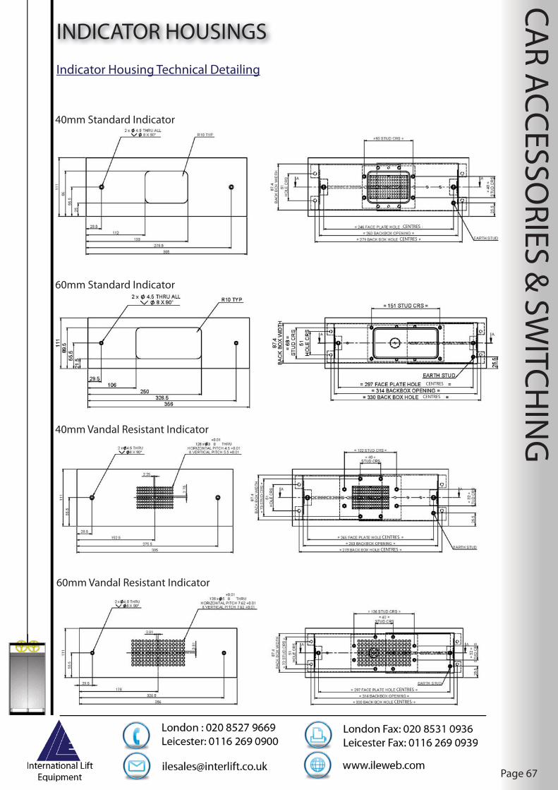
CAR ACCESSO
RIES & SW
ITCHIN
G
Page 67
INDICATOR HOUSINGS
40mm Standard Indicator
60mm Standard Indicator
40mm Vandal Resistant Indicator
60mm Vandal Resistant Indicator
Indicator Housing Technical Detailing
CENTRES
CENTRES
CENTRES
CENTRES
CENTRES
CENTRES
CENTRES
CENTRES

CAR ACCESSO
RIES & SW
ITCHIN
G
Page 68
SERIAL SPEECH UNITS
PINHOLE CAMERA
• ILE serial comms speech synthesisor 12-24VAC/AC complete with 5V 8 ohm speaker
• Standard phrases: Sub basement fl oor Lower basement fl oor Basement fl oor Lower ground fl oor Ground fl oor Levels 1-20 and -2, -1,0 etc Going up Going down Please mind the doors Lift overloaded This lift is under fi re control operation This lift is under evacuation control operation This lift is under priority service Lift out of service The alarm has been activated
• Large vocabulary library available, please contact ILE for special versions
• Site re-programmable via laptop or Skycom control system if required
SERIAL SPEECH UNITS & SPEAKER ILE PART No.
Serial speech / indicator control unit PL1192
Serial speech unit & speaker PL1193
Pinhole camera and supply PL1187
Pinhole camera mounted in angled station box
PL1187STAT
PL1192
PL1193
PL1187
Speaker Dimensions
Pinhole
Pinholeangled
Serial speech unit
Serial comms control unit

CAR ACCESSO
RIES & SW
ITCHIN
G
Page 69
ARRIVAL GONG
CALL RECOGNITION SOUNDER
PART No. PL1110
Power supply and input voltage range: 9-30v AC/DCPower supply peak current: 500mAPower supply standby current: 5mAInput circuit peak current: 50mA @ 30v
Positive Negative Switching (LK1)Link (LK1) can be in two positions to give a positive
or negative input common to the input circuitry.
External SpeakerAn external speaker may be connected in place of the speaker supplied, this must be 8OHM, 0.5W
WiringThe ILE arrival gong can be wired to give the following outputs:
1. Single / Pulsed GongThe single gong is activated via terminal 1 on the PC board. The term pulsed means that the input is interruptible and the tone can be re-started when the input is pulsed again. This is used when the direction of the lift is announced as a number of pulses i.e. one “Bing” for up direction and two “Bings “ for down direction.
2. The two tone sound is activated via an input to terminal2 on the PCB.
3. The three tone sound is activated via an input to bothterminal 1 & 2 on the PCB board, therefore these terminals must be linked together.
Power Supply: 9-30VDCConsumption: 12VDC = 9mA 24VDC = 12mA
Negative / Positive Switching (LK1)Link LK1 can be set to suit either positive or negative input.
PART No. PL1140
MountingThe unit is designed to mount inside the push box. The rear of the P.C board is affi xed with a self adhesive backing.WiringThe ILE Call Recognition Sounder can be wired to suit either Positive or Negative Call Switching systems dependant on what control system it is being used with. The unit can also be used without interfacing to the existing call circuit by using back contacts on call buttons (ideal solution for Car Call Recognition).

CAR ACCESSO
RIES & SW
ITCHIN
G
Page 70
DDA INDICATOR / SPEECH INTERFACE SYSTEM
DDA SYSTEM ILE PART No.
3 Floor system DDA MR3
6 Floor system DDA MR6
10 Floor system DDA MR10
This system is designed to interface with ILE indicators and speech units, (required under the DDA legislation) which can be installed to an existing lift installation without necessity to modify the existing control panel.
As part of the lift compliance (EN81-70) to the DDA Act, a lift should have position indication both visual and audible fi tted. We recognise that to retro-fi t indicators and voice synthesiser to an existing lift installation would normally require modifi cations to the existing control system. These modifi cations require a high degree of technical knowledge to complete, and in some cases would not actually be possible. For example, a lot of modern lift package equipment utilises serial communication (2/4 wire) for wiring into the pushes and indicators and it is therefore not possible to pick up supplies for new equipment.
Our solution has been to develop a package that allows for the introduction of ILE indicators and ILE speech synthesiser to give fl oor indication, without the need of modifying the control circuits. This is achieved primarily by the installation of a tapehead detector and connected in conjunction with a relay interface system to give the appropriate signals. The only connections required from the existing controller is a 240v AC supply.
System Features
Serial comms control unit PSU an signal interface PCB in GRP enclosure
• 240V 8 way tapehead
• 80 mm wide S/ST tape
• Magnets
• Tapehead mounting kit
• Tape tensioning kit
• Trailing cable x 1@ 20 way
TO BE ORDERED SEPARATELY
• Position / direction indicator
• Speech synthesiser
This system does not operate car or landing arrows, for the next direction of travel or a two tone arrival electric gong. For these facilities interfacing with the existing control panel will be necessary. Full message facility is available via the serial comms power unit, however interfacing to the existing control panel is necessary.

CAR ACCESSO
RIES & SW
ITCHIN
G
Page 71
DMG PRODUCTSInternational Lift Equipment off ers a wide range of DMG products including car operating stations, landing stations , push buttons and indicators.
The car and landing stations are available in a variety of shapes, sizes and fi nishes including brass, stainless steel, and anodised aluminium. A choice of fl ush or surface mounted is also available. This means that the DMG range can be used in a variety of applications:
• Modernisation• Residential• Heavy duty• Vandal resistant
A range of indicators are available too: dot matrix, LCD/TFT and multi-purpose indicators in diff erent sizes, shapes and colours which can be purchased individually, within a box or as apackage i.e. COP
DMG off er a wide range of push buttons which are very versatile and cost eff ective. There are a number of types of buttons which can include: braille, dual illumination and vandal resistant
The DMG range is stylish, hard-wearing and versatile as well as very competitively priced. These can also be installed to bring existing equipment up to date as they are fully compliant with EN81-70
Please ask for details of additional DMG products which are also available direct from ILE

PUSH
STATION
S & LIFT CA
RS
Page 72
CAR OPERATING STATIONSILE design and manufacture their own Car Operating Panels, which are ideal for modernisation or new lift installations. Their COP’s are made from 2mm 304 grade stainless steel. Though there is also an option for 316 grade.
ILE off er their COP’s with the option of being full height and vandal resistant. These have a hinged door which opens only from the car top and a chain which prevents the door being opened past a set distance. All COP’s are off ered as populated or un-populated.
ILE indicators are available in 40 or 60 mm in Green, Red or Blue. Alternatively, the ILE LCD indicator can be used displaying white text with a blue background or visa versa. The COP is engraved to suit customer requirements and can include a mixture of colours, text and images including company logo’s.
With respect to the fi xtures, ILE off er a range of buttons, auto-diallers, induction loops, key switches etc so that compliance with any specifi cation can be achieved relatively easily.
As a further benefi t of purchasing a COP from ILE, landing stations and angled indicators can be purchased at the same time allowing the customer to create the perfect bespoke package for the required installation. This package would be fully compliant with EN81-70.
At ILE we understand that not all installations are the same and that your criteria may diff er, so we also off er bespoke solutions where we will design and manufacture to satisfy your requirements.
set distance All COP’s
all installations are the same nd that your

PUSH
STATION
S & LIFT CA
RS
Page 73
LANDING OPERATING STATIONS
Landing push plate
Full range of landing operating stations are available for either surface or fl ush mounting. We off er both standard sizes or bespoke design to suit the installation requirements. Options to suit diff erent fi nishes e.g. s/st, brass etc and various push buttons available.

PUSH
STATION
S & LIFT CA
RS
Page 74
VANDAL RESISTANT - ATLAS CARILE have specifi cally developed this lift car in conjunction with a major London Borough to off er the highest possible level of protection against vandalism and misuse. The car panels are constructed of timber and sandwiched between stainless steel panels. Panel width is kept to a minimum to reduce fl exing and drumming. The steel panels are separated by a “plastic” strip (Darvic™ equivalent).
CAR FEATURES
• Full range of stainless steel fi nishes available (304 or 316 grade)• Heavy duty epoxy resin fl oor (Storvite™ or equivalent)• Standard lighting would be fl ush mounted fl uorescent tubes behind Georgian wired glass (Access via car roof )• High and low level car ventilation• Design to incorporate GAL MOVFR doorgear with HA facility complete with electronic door edge protection• The car operating panel incorporates Liftstore US91EN pushbuttons, ILE 40 mm dot matrix position indicator, autodialler and speech synthesiser facilities• Engraving to suit the installation company and client• Access to rear of car operating panel is via a release mechanism positioned on top of lift car• Handrail to rear of car
CAR OPTIONS
• Vision panel• Laminated mirror (stainless steel mirror off ered as standard)• Galvanised sling/platform• LED lighting• Tilt up seat• Side handrails• Rubber bump strips• Alternative pushbuttons, indicators, electronic door edge protection all available• Options for 4-10 persons to suit existing shaft dimensions
LED lighting panel
Our LED lighting option can be fi tted to the sides and if necessary the back of the lift car. The panels contain white LED’S and are produced to suit the full depth of the car with an overall height of 160 mm. The LED panel is enclosed within a stainless steel frame 16 mm deep and protected by a Polycarbonate diff user. A battery backed power supply enables one of the fi ttings to be used for emergency lighting and will give out full brightness for a period of 3 hours. As an option the lights can be dimmed to save energy whilst the lift is not in use.

PUSH
STATION
S & LIFT CA
RS
Page 75
STANDARD LIFT CAR
Typical hospital bed / passenger lift car with a combination of laminate and stainless steel
fi nishes to the car walls.
ILE can supply a full range of lift cars, e.g. passenger/bed passenger/goods. These are all of a bespoke design to exactly match customer requirements. All types of stainless steel and laminate fi nishes available.
All cars are manufactured to DDA requirements and fully assembled within our works before being despatched to site. Slings and car top handrails available, designed to suit new or existing installations. Galvanising also available.

CON
TROL SYSTEM
S & M
RL LIFTS
Page 76
LIFT CONTROLLERSILE manufacture a full range of lift control systems to suit most requirements from a simple two fl oor goods hoist to a multi-car group system, or a single speed machine, to a high speed gearless drive. ILE can produce the control system to meet your needs.
ILE has been assessed under the European Lift Directive 95/16/EC and have been awarded the Quality Assurance Module Certifi cate of Conformity to Annex X111 of the Lift Directive. This directive is strictly adhered to via EN81. Signifi cant steps have been taken to ensure compliance to the European Directive 2004/108/EC with regards to Electromagnetic Compatibility (EMC). All electrical and electronic apparatus have undergone both in house testing and in certain cases testing via a Namas accredited test facility, resulting in documentation allowing us to issue self certifi cation of compliance with this directive. The fi tting of fi lters, ferrites and cable segregation ensures compliance.
All of our systems, whether it is a simple relay system or a complex microprocessor design, are designed and built using the highest quality materials and there is never a compromise in safety.
GENERAL SPECIFICATION FOR ALL ILE CONTROL SYSTEMS
• All control equipment is mounted within a sheet steel enclosure, with a minimum protection rating of IP54, suitable for wall/ fl oor mounting, with front access only required• All control panels are supplied fi tted with lifting eyes to ease transportation to the machine room• Encapsulated diagrams and manuals are supplied with each control panel via an internally mounted document pocket• The control system operates on a voltage of 110VAC (option for 240VAC) with the main control gear being selected from the Telemechanique “Tesys” range of equipment with silver to silver contacts. Main contractors are rated to AC3 duty plus a minimum of 10% for inching duty• Internal panel wiring is via tri-rated cable to BS6231 or optionally using LSZH cable• All electrical equipment is protected from direct fi nger contact with terminals being selected of a shrouded pattern• Resistors, when fi tted, are mounted externally in IP20 enclosures to give optimum heat dissipation• All electronics, hardware and software, utilised within our control systems are produced in-house, designed by our own R & D team of engineers with manufacturing via our own P.C.B department

CON
TROL SYSTEM
S & M
RL LIFTS
Page 77
SKYCOM CONTROL SYSTEMSKYCOM MICROPROCESSOR CONTROL SYSTEM
SKYCOM CONTROL SYSTEM SPECIFICATION
For the more complex, to the most sophisticated installations we off er our SKYCOM microprocessor control system. This is a modular system of rack mounted boards and off ers the ultimate fl exibility on site.
• The system benefi ts from being site programmable via a keypad (password protected) or via a PC or laptop.• A prominent feature of the SKYCOM system is its large graphical and pictoral 128 x 64 pixel LCD display
This control system is designed to suit the following typical specifi cation:
DRIVES• Single/two speed traction/DCVV/VVVF/SCR/MRL• Hydraulic
CONTROL SYSTEM• APB/Down collective/ full collective/non-selective collective• Rack system will control up to 40 fl oors full collective or 48 fl oors down collective/ non-selective collective or APB• System fl exibility allows boards to be added for the required number of fl oors• Group operation available without the use of a despatcher• Inter-panel communication is via Can (Controller Area Network) serial communication
DOOR OPERATORS• Suitable for all types of door operator both AC and DC, with the option of selective door operation• Also suitable for manual or swing type door operation
ENCLOSURE• IP54 (min) wall/fl oor mounting

CON
TROL SYSTEM
S & M
RL LIFTS
Page 78
SKYCOM CONTROL SYSTEM BENEFITS FROM THE FOLLOWING ADVANCED FEATURES
• Fully programmable and parameterised processor system via P.C/laptop or using the keypad interface as supplied• Design based upon a rack system using surface mount component technology to be small and compact so that a standard size box fi ts comfortably inside a control panel cabinet up to a maximum of 48 fl oors• Powerful 16bit processor, allowing the implementation and addition of complex software routines to enhance the system performance• Comprehensive fault logging including trace recording with real time/date stamp and an extra 63 characters of event description
• IO rack system allows variable lift confi gurations to be implemented, which can be tailor made to suit the application and be cost eff ective according to the number of fl oors. Also, each rack plug in board has on board identifi cation (plug and play) which is used to provide information and help setup the board. All boards are protected against mains and overvoltage• Graphical and pictoral high resolution display allowing the implementation of the “lift viewer” showing graphical information such as lift position, door status, speed, direction, primary and safety circuits, all call information, fl oor vane status and power supply status. Also the “Input Output Viewer” showing confi guration and status of all the inputs as well as showing the identifi cation of the circuit boards fi tted• Parameter system allows users to confi gure and re-confi gure the system as required. Modifi ed parameter indication shows all parameters that have changed. ILE serial indicators and speech unit are fully programmable from SKYCOM.
OPERATING VOLTAGEControl circuit 240 or 110VACPush buttons, indicators etc 24VDCSuitable for various brake, ramp and valve voltagesAll inputs and outputs are fully opto-isolated
FLOOR SELECTIONIn microprocessor, via ILE shaft encoder, tapehead or proximity switches with terminal limits as backup
INDICATORSOutputs for 24VDC lift coming or call accepted indicatorsPosition indicators and direction arrows Hall lanterns and arrival gongsLift here and out of service indication is optionalGate open warning system for manual gate installations with 24VDC buzzer supply
SYSTEM FEATURES110% overload with 24VDC output for indicator, 90% bypass, homing fi re control and fi refi ghting control, service control, emergency recall, standby generator operation
SKYCOM CONTROL SYSTEM
Skycom group viewer

CON
TROL SYSTEM
S & M
RL LIFTS
Page 79
SKYCOM CONTROL SYSTEM
• Password protection system incorporating diff erent password levels for security of parameters• Facility to enter individual, all and patterns of calls from SKYCOM• Real-time clock enhances event storage and allows time based features such as call reallocation (call barring) at diff erent times during the day• Local remote monitoring system (up to 500m) can provide selected programmability and graphical representation of the lift(s) i.e. “lift viewer”, via stand alone P.C. or laptop.• Despatcherless Group systems, achieved via the use of a master/slave system• Direct serial communication to drives, also direct to fl oor control• Adjustment of slowing distance / fl oor levels via software• Integral shaft encoder plug in board for high rise / high speed applications with its own programming tool
SKYCOM CONTROL SYSTEM OPTIONS
• Fault logger download/print out facility via a standard P.C• Full remote monitoring system• On group systems we would supply a PC for system monitoring / programming• Full volt-free outputs for BMS monitoring• Facility is generally provided to suit customer requirements
Lift control panel
Skycom statistics viewer

CON
TROL SYSTEM
S & M
RL LIFTS
Page 80
SKYCOM SOLO CONTROL SYSTEMSkycom Solo is the latest ILE control system. Solo is the next generation of Skycom processor utilising the latest surface mounted technology to improve an established and market proven ILE product. ILE has been producing control systems for the U.K market for 20 years. We have utilised our knowledge and expertise to create a modern product for today’s market place. Solo represents aff ordable, modern technology developed to be both fl exible and reliable.
The controller consists of a main processor board, and expandable I/O via the addition of either I/O, relay, or mains cards. The controller is fully confi gurable and all peripherals connected to the processor via the CAN network are also confi gurable.
Parameterisation is achieved either via a USB connection to a P.C or via a serial link to an on-site hand-held interface, supplied with each controller.
The processor is backward compatible with all existing ILE peripheral products.
FEATURES SKYCOM SOLO PROCESSOR• Simplex control • USB serial connection to P.C• Up to 8 fl oors • CAN connection to peripherals• Up to 1.6m/s • Web server, email facility• Hydraulic/traction • RTC with external battery backup• Collective types (Full, Down, Non-selective, APB) • Automatic discovery of I/O boards• Allocation settings • LED indication (loop, comms, faults)• Tapehead positioning
• Confi gurable I/O (with inversion and timers) HANDHELD CONTROLLER• Fully confi gurable speech and indicators • LCD display 128 x 64 pixel resolution• Fully confi gurable service routines: • 6 button keypad to enable confi guration Doors • Memory for storage of parameter profi les Travel
Anti-nuisance ADDITIONAL ENERGY SAVING Energy saving (EcoMode) • The LCD has a backlight timeout and on both the Solo Homing and handheld unit: Out of service indication • Energy effi cient switch mode power supply Emergency return profi les • Non-active processor hardware components are• Time stamped event logging powered down• BMS monitoring• LED indication
Skycom Solo
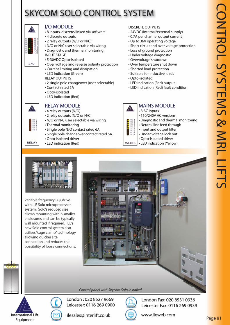
CON
TROL SYSTEM
S & M
RL LIFTS
Page 81
SKYCOM SOLO CONTROL SYSTEMI/O MODULE DISCRETE OUTPUTS• 8 inputs, discrete/linked via software • 24VDC (internal/external supply)• 4 discrete outputs • 0.7A per channel output current• 2 relay outputs (N/O or N/C) • Up to 36V operating voltage• N/O or N/C user selectable via wiring • Short circuit and over voltage protection• Diagnostic and thermal monitoring • Loss of ground protectionINPUT STAGE • Under voltage diagnostic• 5-30VDC Opto-isolated • Overvoltage shutdown• Over voltage and reverse polarity protection • Over temperature shut down• Current limiting and dissipation • Shorted load protection• LED indication (Green) • Suitable for inductive loadsRELAY OUTPUTS • Opto-isolated• 2 single pole changeover (user selectable) • LED indication (Red) output• Contact rated 5A • LED indication (Red) fault condition• Opto-isolated• LED indication (Red)
RELAY MODULE• 4 relay outputs (N/O)• 2 relay outputs (N/O or N/C)• N/O or N/C user selectable via wiring• Thermal monitoring• Single pole N/O contact rated 6A• Single pole changeover contact rated 5A• Opto-isolated driver• LED indication (Red)
MAINS MODULE• 8 AC inputs• 110/240V AC versions• Diagnostic and thermal monitoring• Neutral line feed through• Input and output fi lter• Under voltage lock out• Opto-isolated driver• LED indication (Yellow)
Control panel with Skycom Solo installed
Variable frequency Fuji drive with ILE Solo microprocessor system. Solo’s reduced size allows mounting within smaller enclosures and can be typically wall mounted if required. ILE’s new Solo control system also utilises “cage clamp” technology allowing quicker site connection and reduces the possibility of loose connections.

Page 82
CON
TROL SYSTEM
S & M
RL LIFTS
SKYCOM + CONTROL SYSTEM
Skycom+ represents aff ordable, modern technology developed to be both fl exible and reliable.The controller consists of a processor board, with distributed expandable islands of I/O. The controller and all peripherals connected to the processor via the CAN network are fully confi gurable. Parameterisation is achieved either via a USB connection to a PC or via the processor keypad interface. A handheld programmer can be plugged into any distributed Network Interface Module (NIM) to allow parameterisation of the shaft encoder e.g. from within the car. Skycom+ is backward compatible with all existing ILE peripheral products.
Skycom+ is the next generation of Skycom processor from ILE. Utilising the latest surface mounted technology to improve an established and market proven ILE product. ILE has been producing control systems for the UK market for 20 years, and with Skycom+ we have utilised our knowledge and expertise to create a modern product for today’s market place.
Features:
• Up to 8 car group control• Up to 64 fl oors• Up to 5.0 m/s• Hydraulic/traction• Collective types (Full, Down, Non-Selective, APB)• Allocation settings (LUP/LDN/CAR/PRI/LUX/LDX)• Absolute Shaft encoder position• Serial drive communication• Confi gurable I/O (with inversion and timers)• Fully confi gurable speech and indicators• Fully confi gurable service routines: Doors Travel Anti-Nuisance Energy saving (EcoMode) Homing Out of service indication Emergency return profi les Swipe card Emergency Supply• Time stamped event logging• Destination Call control• ETA algorithm• Remote monitoring• LED indication
Skycom+ Processor
• USB serial connection to PC• CAN connection to peripherals• Integrated shaft encoder control• Web server, email facility• RTC with external battery backup• Automatic discovery of I/O islands• LED indication (loop, comms, faults)
Additional Energy Saving:
• All LCDs have a backlight timeout and on both the Skycom+ and the handheld processor• Energy effi cient switch mode power supply• Non-active processor hardware components are powered down

CON
TROL SYSTEM
S & M
RL LIFTS
Page 83
SKYCOM + CONTROL SYSTEM
Skycom +

CON
TROL SYSTEM
S & M
RL LIFTS
Page 84
MRL CONTROL PANELSILE can also off er replacements to various other companies MRL control systems.
Our MRL controller produced to suit our own range of Motor Room Less lifts conforms to the following specifi cation. This can be adapted suit other companies systems.
CONTROLLER FEATURES
• ILE Skycom microprocessor system suitable for operation up to 8 car group• On site programmability via built in keypad or via a PC • Facility to program via Serial communication Digital Indicators, Speech synthesiser, shaft encoder and the shaft mounted inverter drive system• Large graphical and pictorial LCD display 128 x 64 pixel in clear text• Fault and occurrence logging in real time and date with 10 year battery back up
• Facility to enter all car and landing calls with auto run feature.• Control panel suitable for mounting up to 15 metres from the lift motor and housed within a sheet steel enclosure, 2000mm x 400mm x 300mm with protection rating of IP54.• Controller cabinet contains its own switchable internal light giving a minimum of 200 lux at the control terminal connections• Fitted with its own lockable 3 phase isolator• Supplies via suitably rated circuit breakers provided for external devices
• Options for remote monitoring and advanced door opening• ECO Mode facilities available• BMS monitoring• Password protected• Full benefi ts of our Skycom control panel• Supplies via suitably rated circuit breakers provided for external devices• Emergency release of trapped passengers via the control panel with speed and position indication• Designed fully in compliance with EN81-1: 1998-A2
The lift inverter is designed to be mounted within the lift shaft adjacent to the motor. The option is available to mount the inverter within the control panel, however on Gearless systems the cable between the inverter and the motor encoder must not exceed 10 metres in length.
Eco modes available on all MRL panels to reduce power usage
MRL controllerMRL controller

CON
TROL SYSTEM
S & M
RL LIFTS
Page 85
MRL CONTROL PANELSThe range of MRL packages and gearless machines which have been modernised with ILE Skycom control panels:
Kone Monospace – (encoder unit replaced).Zielh-Abegg – ZytaTop & ZetaSynLoher – SVM gearelsss rangeNimbo Xinda – various models including ‘Diana’Imperial Electric/AvantiSicmemotoriSchindlerThyssenKruppOronaOTIS Gen 2
Geared motors generally do not present a problem as the compatibility of the motor encoder can be resolved.
There are however limitations to what can be off ered.
Many of the foreign packages bought into and installed in the UK use ‘bus’ type communication systems for the operation of equipment such as indicators and speech, door operators and switching system. It may not always be possible to remove the original control panel and keep the periphery equipment. If the item of equipment has discrete inputs i.e. open/close door operation signals or PI1,2,3,4,5 etc. direct inputs for an indicator there should not be a problem controlling this device. However, if the item of equipment only has 2-4 inputs this is likely to be serially controlled with the information coming directly from the control panels’ microprocessor. It would be very diffi cult for any company to tie up to someone else’s software protocol.
Normally it would simply be a matter of replacing the indicators with either an ILE type or if the specifi cation dictates any other familiar indicator. It is generally more cost eff ective to use the ILE indicators as the encoder control unit is in-built into the Skycom microprocessor. The ILE speech synthesiser is included as standard.
Kone Monospace motor“Diana” motor

CON
TROL SYSTEM
S & M
RL LIFTS
Page 86
VF ADD-ON SYSTEMWith litigation following accidents becoming more and more of an issue, it is important that lift installations should give good fl oor leveling accuracy to negate the chance of tripping and subsequent legal action being taken. Furthermore, with the advent of the Disability Discrimination Act and the introduction of EN81-70 there is a requirement to maintain a stopping accuracy of +/- 10mm.
On both two speed and single speed (additional engineering required) lift systems, this level of accuracy can be very diffi cult to achieve and maintain. The options are to either replace the existing motor and control panel or interface an inverter to run in conjunction with the existing motor and controller. The option of replacing the motor, control panel or both can be expensive and require long delivery and installation periods.
ILE have produced a solution requiring minimal interfacing with the existing controller. Installation time varies depending on site location but normally only requires 8 hours site work using competent engineers. Copies of the existing wiring diagrams must be made available to ILE before commencement of the work.
VF ADD-ON FEATURES
• The inverters are suitable for open loop operation up to 1mps with a fl oor level accuracy +/- 5mm and closed loop operation up to 2.5mps with a fl oor level accuracy +/- 3mm• ILE can produce systems to suit most motor ratings but this particular arrangement is suitable for use with motors rated between 4 and 25Kw up to approximately 50A full load current (dependant on starting torque required)• For closed loop operation a 1024 pulse HTL 10-30v encoder is required. ILE off er a conversion service to replace any existing analogue unit with a suitable digital encoder picking up the existing fi xings/couplings.• This system is also suitable as a replacement for existing obsolete or faulty inverters• Using this system the lift can be refurbished in two stages i.e. fi rstly replacing the inverter and then at a later date the main controller can be replaced with a new ILE system. The inverter will simply plug into the new controller
VF Add-on systemwith Fuji drive unit

CON
TROL SYSTEM
S & M
RL LIFTS
Page 87
MACHINE ROOMLESS LIFTS (MRL)
We off er a full consulting and technical service when planning your lift installation. Firefi ghting and Evacuation lifts available. MRL lift installed at the Leicester factory available for viewing.
The Emerald 100 and 300 MRL’s brings together German Engineering and British Control Panel Technology to form a versatile MRL Package which can be designed to suit Special Dimensions and Special Arrangements on customers requests.
Emerald 100
Duty Loads: from 450Kg to 1600Kg on 2;1 Underslung Roped layouts and 2000Kg to 3200Kg on 4:1 Underslung Roped Layout with Special Arrangements on 4:1 Underslung Roped layouts carrying on up to 4000Kg and 5000Kg Duty Loads Maximum.Speed: 450Kg – 1600Kg 1.0, 1.6, 2.0M/Sec 2000Kg – 5000Kg 1.0 M/Sec OnlyDrive Units:Geared Drive Sassi pit depth Min 1300mmGearless Drive Ziehl Abegg Pit depth Min 1400mm (450Kg – 1600Kg )Gearless Drive Ziehl Abegg Pit Depth Min 1600mm (2000Kg – 5000Kg )Travel Height up to 45M @ 1.0M/Sec and up to 75M/Sec @ 1.6 and 2.0M/Sec for duty loads from 450Kg to 1600Kg, Duty loads above 1600Kg are restricted to 1.0 M/Sec.Geared ( Sassi ) and Gearless ( Ziehl Abegg ) options are available up to a duty load of 1600Kg above this Gearless Drive is only available @ 1.0M/SecCabin Arrangements
• Wide Body Options for 800Kg, 900Kg and 1000Kg.
• Doors Centre or Side Opening Sematic 2000 Series or ILE - GAL
• Open Through Car available for 630Kg,1000Kg (Stretcher version ) 1275Kg and 1600Kg as well as 2000Kg and 3200Kg.
• Shutter Gates available on 2000Kg and above.• Non Standard Cabin Dimensions Available.
** Special Arrangements **
• Upgrade in Speed to 1.6 M/Sec on 2000Kg – 3200Kg On Request.
• Safety Gear on Balance Weight available.• Special dimensions and Arrangements ( Individual Check
required )• Higher Travel Height
on Request (Individual Check required).

CON
TROL SYSTEM
S & M
RL LIFTS
Page 88
MACHINE ROOMLESS LIFTS (MRL)
Emerald 300
Duty Loads: from 450Kg to 1600Kg on 2:1 Top slung roped layout.( 1050mm pit depth minimum)Speed: 1.0 M/Sec OnlyDrive Units : Gearless Sassi G 300 @ 1.0 M/Sec Max Travel Height: Up to 45M MaxCabin Arrangements
• Open through car available for 630Kg,1000Kg,1275Kg and 1600Kg• Doors centre or side opening sematic 2000 only.
** Special Arrangements **• With special dispensation and notifi ed body approval the Emerald
300 lift can be incorporated in to a lift pit depth of 250mm with a
folding apron arrangement.
• Non standard cabin dimension available.
Jade 100 MRL
The Jade MRL lift is a German engineered product based on a rucksack designed layout principle therefore giving you the opportunity for open through and / or open adjacent layouts.The system is fully pre-wired using the latest modern can bus technology with the control panel outside the lift shaft on the uppermost landing.
Duty Loads: from 250Kg to 1600KgSpeed: 1.0M/Sec and 1.6M/SecTravel Height: Up to 45MDrive Units: Ziehl Abegg Gearless Only.Cabin Arrangements
• Open Front Only.• Open Through.( 500Kg,630Kg,1050Kg,1275Kg and 1600Kg )• Open Adjacent.• Doors Centre or Side Opening Sematic 2000 Only.
** Special Arrangements **• Firefi ghting Lift Compliant to EN81-72:12.2003• Reduced Headroom ( 320Kg – 1050Kg ) Jade 400 ( Individual Check
required )• Uprate in speed to 1.75M/Sec ( Individual Check Required )• Non Standard Cabin Dimension.• Evacuation Control Available.• Balance Weight Safety Gear only for Speed 1.0 M/Sec for duty load
450Kg or higher.• Travel in Excess of 45M ( Individual Check required )
MRL FEATURES• No infringements of existing patents• Duty load 450-5000Kg• Travel up to 75m• Basic worm geared unit at 1mps (Gearless option)• Gearless motor for 1.0-2.5mps• Bespoke car designs• Remote controller positioning• Standard equipment supplied includes trailing fl exes, pre-wired shaft limit switches, shaft lighting, pit ladder, battery back-up for emergency passenger release, safety notices, rubber mat and safety barrier• Flexibility throughout the range to accommodate existing lift shaft restrictions

GU
IDES &
ACCESSORIES
Page 89
INTERN
ATION
AL LIFT EQ
UIPM
ENT
SERVICE REPAIR & REPLACEMENT
International Lift Equipment have been producing control systems since 1987. All of the microprocessors used during this period are still available as replacements or can be repaired in-house. Upgrading to Skycom is also feasible.
WITRONIC MPSA MPSA-L MPSLC MIDIFLITE INTERFLITE
ILE off er a repair or replacement service for motor drives / inverters. Repairs of the following drives are available:
• Micotrol• ACVV regulators• ABB inverters• Autinor inverters• All Loher equipment• Omron FV inverters
In some cases cost eff ective repair may not be possible or the drives may be obsolete. In these instances ILE can off er upgrade of equipment using Loher or Fuji inverters. Spare parts are in stock for Loher, Omron and Fuji inverters.
• A range of control gear is always in stock including Telemechanique relay, timers and contactors, Omron relay, timers, transformers, fuses, resistors and control cabinets
• ILE off er telephone and on-site support as well as a commissioning and trouble shooting assistance service on all control equipment supplied right back to 1987 systems
ALL NEW CONTROL PANELS CARRY A 2 YEAR WARRANTY.

GU
IDES &
ACCESSORIES
Page 90
INTERN
ATION
AL LIFT EQ
UIPM
ENT
Page 90
ENERGY EFFICIENCYILE – helping the environment
Energy effi ciency and savings when using ILE Skycom control systems
Up to 15% of a building’s energyrequirement is used by its lift system,which means there’s plenty of scope forenergy savings to be made.International Lift Equipment believethat energy effi ciency is paramount andhave therefore fully embraced the newtechnology available to achievesignifi cant energy savings, and by sodoing help in:
• reducing the use of natural resources;• lowering carbon dioxide emissions;• combating climate change• reducing costs
The Skycom control system along withpowerful VVVF inverter technologyoff ers an impressive energy effi cientsolution to lift systems.The VVVF system off ers improvedenergy effi ciency over existing AC orDC motor control. The geared VVVFsystem can also off er improved energysavings and a gearless VVVF systemcan give a further increase to thissaving. ILE can also off er a fullyregenerative solution where unwantedenergy from the system can be putback into the mains, using invertertechnology instead of a dynamicbraking resistor network.The Skycom processor has numerous‘ECO’ options which have beenincorporated to improve energyeffi ciency as follows:• Automatically turning off car lightsand fans when there is no demand forthe lift as the system is deemed to bein an idle state. A confi gurable outputis provided that can be adjusted viaparameters within the Skycomprocessor to suit site conditions.
• Automatically turning off allindicators when the lift is deemed tobe idle.• Automatically turn off all nonessentialpower supplies within thecontrol panel.• Automatically select a reducedpower saving mode by selecting amore economic ride profi le. Thiseconomy feature is provided for noncritical runs such as homing to specifi cfl oors following power failure or anon- essential journey.• Manipulate lift zoning and homingcontrol to reduce the number ofjourneys a group system makes duringoff -peak periods. These features areconfi gurable via parameters within theprocessor to suit site conditions usingtimers or digital inputs.TYPICAL POWER SAVING OF
UP TO 30% OF PER DAY
Calculations are based on 240 starts per hour between the hours of 5.30 am to 7.30 pm on a 12 fl oor lift with Position Indicators at all landings and 60 watts of car lighting with dual illuminated landing and car pushes.
The savings using just reduced Power Mode One are 1035.3 kW/h per annum which equates to a saving indicative of £120 per annum.
The savings using both Reduced Power Mode One & Two are 4554.893 kW/h which equates to a saving indicative of £525 per annum.

GU
IDES &
ACCESSORIES
Page 91
INTERN
ATION
AL LIFT EQ
UIPM
ENT
ENERGY EFFICIENCYEnergy effi ciency and savings off ered by gearless systemsFurther effi ciency and energy savings are achieved by introducing our Gearless technology. The benefi ts of Gearless applications are as follows:
• Ease of installation• Reduced lift ‘out of service’ time.• No gear maintenance or periodic lubrication oil replacement.• Vibration free operation refl ected in the ride quality within the lift car.• Low operating noise level.• More effi cient therefore requiring less power in accordance with Eco policies and standards.
• Increased reliability due to there being far less mechanical components.• Dual brakes fi tted which ensure full compliance with EN81 with regards to the upward falling of a lift.• Due to the effi ciency of the gearless system, the lift motor is reduced in kilowatt rating by up to 50% thereby not only substantially reducing the kw rating of the motor but also the cable requirements. This enables the VVVF drive rating to be proportionally smaller resulting in a reduction in the price of the control panel.