Construction of Grade A VTS Tender Document.pdf - Lepelle ...
200
Contractor Witness 1 Witness 2 Employer Witness 1 Witness 2 T1-1 LEPELLE-NKUMPI LOCAL MUNICIPALITY BID DOCUMENT BID NO: LNM019/2020/21 CONSTRUCTION OF GRADE A VTS (LEBOWAKGOMO) (WARD 18) LEPELLE NKUMPI LOCAL MUNICIPALITY CLOSING DATE: 12 NOVEMBER 2021 at 11H00 TECHNICAL ENQUIERIES BIDDING RELATED ENQUERIES TECHNICAL SERVICES (PMU): Mr Phasha Tebogo LEPELLE-NKUMPI LOCAL MUNICIPALITY P/BAG X 07 CHUENESPOORT 0745 Tel: (015) 633 4556/7 Fax: (015) 632 4594 MANAGER: SUPPLY CHAIN MANAGEMENT Mr. Jeffrey Pitseng LEPELLE-NKUMPI LOCAL MUNICIPALITY P/BAG X 07 CHUENESPOORT 0745 Tel: (015) 633 4519 Fax: (015) 633 6896 NAME OF BIDDER (BIDDING ENTITY) : TEL NUMBER : FAX NUMBER : CENTRAL SUPPLIER DATABASE NO : BBBEE STATUS : THE OFFERED TOTAL OF THE PRICES INCLUDING VALUE ADDED TAX IS: R………………..……….........................................................………….. (In figures)
-
Upload
khangminh22 -
Category
Documents
-
view
1 -
download
0
Transcript of Construction of Grade A VTS Tender Document.pdf - Lepelle ...

Contractor Witness 1 Witness 2 Employer Witness 1 Witness 2
T1-1
LEPELLE-NKUMPI LOCAL MUNICIPALITY
BID DOCUMENT
BID NO: LNM019/2020/21
CONSTRUCTION OF GRADE A VTS (LEBOWAKGOMO) (WARD 18)
LEPELLE NKUMPI LOCAL MUNICIPALITY
CLOSING DATE: 12 NOVEMBER 2021 at 11H00
TECHNICAL ENQUIERIES BIDDING RELATED ENQUERIES
TECHNICAL SERVICES (PMU): Mr Phasha Tebogo LEPELLE-NKUMPI LOCAL MUNICIPALITY P/BAG X 07 CHUENESPOORT 0745 Tel: (015) 633 4556/7 Fax: (015) 632 4594
MANAGER: SUPPLY CHAIN MANAGEMENT Mr. Jeffrey Pitseng LEPELLE-NKUMPI LOCAL MUNICIPALITY P/BAG X 07 CHUENESPOORT 0745 Tel: (015) 633 4519 Fax: (015) 633 6896
NAME OF BIDDER (BIDDING ENTITY) :
TEL NUMBER :
FAX NUMBER :
CENTRAL SUPPLIER DATABASE NO :
BBBEE STATUS :
THE OFFERED TOTAL OF THE PRICES INCLUDING VALUE ADDED TAX IS:
R………………..……….........................................................………….. (In figures)

Contractor Witness 1 Witness 2 Employer Witness 1 Witness 2
T1-2
LEPELLE-NKUMPI LOCAL MUNICIPALITY
CONTRACT NO. LNM019/2020/21
CONTENTS
THE TENDER Part T1: Tendering Procedures T1.1 Tender notice and invitation to tender T1.2 Tender Data Part T2: Returnable Documents T2.1 List of Returnable Documents and Returnable Schedules
THE CONTRACT Part C1: Agreements and Contract Data C1.1 Form of Offer and Acceptance C1.2 Contract Data C1.3 Form of Guarantee C1.4 Agreement in Terms of Occupational Health and Safety Act, 1993 (Act No. 85 of 1993) Part C2: Pricing Data C2.1 Pricing Instructions C2.2 Bills of quantities Part C3: Scope of Work C3 Scope of Work Part C4: Drawings C4 Site Information

Contractor Witness 1 Witness 2 Employer Witness 1 Witness 2
T1-3
LEPELLE-NKUMPI LOCAL MUNICIPALITY
CONTRACT NO. LNM019/2020/21
PART T1
TENDERING PROCEDURES
Objections and complaints
Persons aggrieved by decisions or actions taken in the appointment of this tender or affected
by the entire process of supply chain management system, may lodge within 14 days of the
decision or action, a written objection or complaint against the decision or action to: The
Municipal Manager, Private Bag X 07, Chuenespoort, 0745.To report any fraud; irregularities
or corruption related incidents you may call our Anti Fraud Hotline number: 0800 20 50 53

Contractor Witness 1 Witness 2 Employer Witness 1 Witness 2
T1-4
TENDERING PROCEDURES
INDEX
Section Description Page No
PART T1.1 TENDER NOTICE AND INVITATION TO TENDER………………………………….T1.1-3 PART T1.2 TENDER DATA...................................................................................................... T1.2-1 PART T1.3 STANDARD CONDITIONS OF TENDER ............................................................. T1.3-1

Contractor Witness 1 Witness 2 Employer Witness 1 Witness 2
T1.1-5
PART T1.1
Tender Notice and Invitation to Tender

1
LEPELLE-NKUMPI LOCAL MUNICIPALITY
CONTRACT NO. LNM019/2020/21
CONSTRUCTION OF GRADE A VTS(LEBOWAKGOMO) (WARD 18)
T1.1 TENDER NOTICE AND INVITATION TO TENDER
VERY IMPORTANT NOTICE ON DISQUALIFICATIONS:
The Lepelle-Nkumpi Municipality will consider no Bid unless it meets the following responsiveness criteria:
Pre-qualification criteria for preferential procurement
1) That only one or more of the following tenders may respond
An EME or QSE
A tenderer who fails to meet any pre-qualifying criteria stipulated in the tender documents is an
unacceptable tender.
Administrative compliance The bid must be properly received in a sealed envelope clearly indicating the description of the service and
the bid number for which the bid is submitted.
The bid must be deposited in the relevant bid box as indicated on the notice of the bid on or before the closing date and time of the bid.
Tax Compliance Pin/ CSD number must be completed in MBD form 1
Bid forms must be completed in full and each page of the bid initialized or signed
Alterations must be signed/initialized
Copy of the company registration certificate must be submitted with the bid.
Copy of BBBEE Certificate or original sworn affidavit must also be attached
Certified copy of Identity document (ID) of all director (s)must be attached
CIDB Grading 6GB OR Higher.
Submission of a Joint Venture Agreement, where applicable, which has been properly signed by all parties.
Complies with the requirements of the bid and technical specifications.
Bidders to attach Authority for signatory in company letterhead -attach resolution
Adheres to Pricing Instructions( e.g. Providing lump sums on quantified items in the BOQ)
Attached valid certified copy of NHBRC certificate
Letter of good standing from Department of Labour
THE USE OF CORRECTION FLUID (TIPPEX) WILL AUTOMATICALLY INVALIDATE YOUR BID
Bidders must attach the Statement of Municipal Rates on the municipality letterhead not older than 3 months for the company and all directors (if the Statement of Municipal Rates is not in the name of bidder and all directors affidavit from SAPS must be attached) or letter from Traditional Authority not older than 3 months for the company and all directors or a lease agreement for the company and all directors.
The bid will be rejected if any municipal rates and taxes or municipal service charges owed by that
bidder or any of its directors to the Municipality or Municipal entity, or to any other Municipality or
Municipal entity are in arrears for more than three months (90 days)

2
Recovery of rates in arrears from tenants and occupiers
(1) If an amount due for rates levied in respect of a property is unpaid by the owner of the property after the date determined in terms of section 26(2), the municipality may recover the amount in whole or in part from a tenant or occupier of the property, despite any contractual obligation to the contrary on the tenant or occupier. The municipality, may recover an amount only after the municipality has served a written notice on the tenant or occupier.
(2) The amount a municipality may recover from the tenant or occupier of a property in terms of subsection (1) is limited to the amount of the rent or other money due and payable, but not yet paid, by the tenant or occupier to the owner of the property.
(3) Any amount a municipality recovers from the tenant or occupier of the property must be set off by the tenant or occupier against any money owed by the tenant or occupier to the owner. The tenant or occupier of a property must, on request by a municipality, furnish the municipality with a written statement specifying all payments to be made by the tenant or occupier to the owner of the property for rent or other money payable on the property during a period determined by the municipality Proof of Municipal Rates and Taxes or letter for Tribal Authority or lease agreement must be attached (Not older than 3 months).
Late bids shall not be admitted for consideration.

3
MBD1
PART A INVITATION TO BID
YOU ARE HEREBY INVITED TO BID FOR REQUIREMENTS OF THE LEPELLE NKUMPI MUNICIPALITY
BID NUMBER: LNM019/2020/21 CLOSING DATE: 12 NOVEMBER 2021
CLOSING TIME:
11H00
DESCRIPTION CONSTRUCTION OF GRADE A VTS(LEBOWAKGOMO) (WARD 18)
THE SUCCESSFUL BIDDER WILL BE REQUIRED TO FILL IN AND SIGN A WRITTEN CONTRACT FORM (MBD7). BID RESPONSE DOCUMENTS MAY BE DEPOSITED IN THE BID BOX
SITUATED AT (STREET ADDRESS
LEPELLE-NKUMPI MUNICIPALITY
UNIT 170 BA, CIVIC CENTRE
LEBOWAKGOMO
0737 SUPPLIER INFORMATION
NAME OF BIDDER
POSTAL ADDRESS
STREET ADDRESS
TELEPHONE NUMBER CODE NUMBER
CELLPHONE NUMBER
FACSIMILE NUMBER CODE NUMBER
E-MAIL ADDRESS
VAT REGISTRATION NUMBER
TAX COMPLIANCE STATUS TCS PIN: OR CSD No:
B-BBEE STATUS LEVEL VERIFICATION CERTIFICATE [TICK APPLICABLE BOX]
Yes
B-BBEE STATUS LEVEL SWORN AFFIDAVIT
Yes
No No
[A B-BBEE STATUS LEVEL VERIFICATION CERTIFICATE/ SWORN AFFIDAVIT (FOR EMES & QSEs) MUST BE SUBMITTED IN ORDER TO QUALIFY FOR PREFERENCE POINTS FOR B-BBEE]
ARE YOU THE ACCREDITED REPRESENTATIVE IN SOUTH AFRICA FOR THE GOODS /SERVICES /WORKS OFFERED?
Yes No [IF YES ENCLOSE PROOF]
ARE YOU A FOREIGN BASED SUPPLIER
FOR THE GOODS /SERVICES /WORKS
OFFERED?
Yes No [IF YES, ANSWER PART B:3 ]
TOTAL NUMBER OF ITEMS OFFERED ……………………………… TOTAL BID PRICE R………………………………
SIGNATURE OF BIDDER ……………………………… DATE ………………………………
CAPACITY UNDER WHICH THIS BID IS SIGNED

4
BIDDING PROCEDURE ENQUIRIES MAY BE DIRECTED TO:
TECHNICAL INFORMATION MAY BE DIRECTED TO:
DEPARTMENT Lepelle Nkumpi Municipality CONTACT PERSON Mr Mxolisi Bembe
CONTACT PERSON Jeffrey Pitseng TELEPHONE NUMBER 015 633 4560
TELEPHONE NUMBER 015 633 4531 FACSIMILE NUMBER (015) 633 6896
FACSIMILE NUMBER (015) 633 6896 E-MAIL ADDRESS [email protected]
E-MAIL ADDRESS [email protected]
MBD1
PART B TERMS AND CONDITIONS FOR BIDDING
1. BID SUBMISSION: 1.1. BIDS MUST BE DELIVERED BY THE STIPULATED TIME TO THE CORRECT ADDRESS. LATE BIDS WILL
NOT BE ACCEPTED FOR CONSIDERATION.
1.2. ALL BIDS MUST BE SUBMITTED ON THE OFFICIAL FORMS PROVIDED–(NOT TO BE RE-TYPED) OR ONLINE
1.3. THIS BID IS SUBJECT TO THE PREFERENTIAL PROCUREMENT POLICY FRAMEWORK ACT AND THE
PREFERENTIAL PROCUREMENT REGULATIONS, 2017, THE GENERAL CONDITIONS OF CONTRACT
(GCC) AND, IF APPLICABLE, ANY OTHER SPECIAL CONDITIONS OF CONTRACT.
2. TAX COMPLIANCE REQUIREMENTS 2.1 BIDDERS MUST ENSURE COMPLIANCE WITH THEIR TAX OBLIGATIONS.
2.2 BIDDERS ARE REQUIRED TO SUBMIT THEIR UNIQUE PERSONAL IDENTIFICATION NUMBER (PIN) ISSUED
BY SARS TO ENABLE THE ORGAN OF STATE TO VIEW THE TAXPAYER’S PROFILE AND TAX STATUS.
2.3 APPLICATION FOR THE TAX COMPLIANCE STATUS (TCS) CERTIFICATE OR PIN MAY ALSO BE MADE VIA
E-FILING. IN ORDER TO USE THIS PROVISION, TAXPAYERS WILL NEED TO REGISTER WITH SARS AS E-FILERS THROUGH THE WEBSITE WWW.SARS.GOV.ZA.
2.4 FOREIGN SUPPLIERS MUST COMPLETE THE PRE-AWARD QUESTIONNAIRE IN PART B:3.
2.5 BIDDERS MAY ALSO SUBMIT A PRINTED TCS CERTIFICATE TOGETHER WITH THE BID.
2.6 IN BIDS WHERE CONSORTIA / JOINT VENTURES / SUB-CONTRACTORS ARE INVOLVED, EACH PARTY MUST SUBMIT A SEPARATE TCS CERTIFICATE / PIN / CSD NUMBER.
2.7 WHERE NO TCS IS AVAILABLE BUT THE BIDDER IS REGISTERED ON THE CENTRAL SUPPLIER DATABASE (CSD), A CSD NUMBER MUST BE PROVIDED.
3. QUESTIONNAIRE TO BIDDING FOREIGN SUPPLIERS
3.1. IS THE ENTITY A RESIDENT OF THE REPUBLIC OF SOUTH AFRICA (RSA)? YES NO
3.2. DOES THE ENTITY HAVE A BRANCH IN THE RSA? YES NO
3.3. DOES THE ENTITY HAVE A PERMANENT ESTABLISHMENT IN THE RSA? YES NO
3.4. DOES THE ENTITY HAVE ANY SOURCE OF INCOME IN THE RSA? YES NO
3.5. IS THE ENTITY LIABLE IN THE RSA FOR ANY FORM OF TAXATION? YES NO
IF THE ANSWER IS “NO” TO ALL OF THE ABOVE, THEN IT IS NOT A REQUIREMENT TO REGISTER FOR A TAX COMPLIANCE STATUS SYSTEM PIN CODE FROM THE SOUTH AFRICAN REVENUE SERVICE (SARS) AND IF NOT REGISTER AS PER 2.3 ABOVE.

5
NB: FAILURE TO PROVIDE ANY OF THE ABOVE PARTICULARS MAY RENDER THE BID INVALID. NO BIDS WILL BE CONSIDERED FROM PERSONS IN THE SERVICE OF THE STATE.
SIGNATURE OF BIDDER: ……………………………………………
CAPACITY UNDER WHICH THIS BID IS SIGNED: ……………………………………………
DATE: …………………………………………...

6
LEPELLE-NKUMPI LOCAL MUNICIPALITY
CONSTRUCTION OF GRADE A VTS(LEBOWAKGOMO) (WARD 18)
SUMMARY FOR BID OPENING PURPOSES NAME OF BIDDING ENTITY: ...................………………………………………………………. ........................................................................................................
PHYSICAL STREET ADDRESS: POSTAL ADDRESS:
TELEPHONE NUMBER ......................................................................................................: FAX NUMBER : ...................................................................................................... E-mail ADDRESS .......................................................................................................: CONTRACT PRICE : R.................................................................................................... (Amount brought forward from the Form of Offer and Acceptance)* Signed by authorised representative of the Bidding Entity: .................................................. DATE: …………………………………………………
Should any discrepancy occur between this figure and that stated in the Form of Offer and Acceptance, the latter shall take precedence and apply.

7
LEPELLE-NKUMPI LOCAL MUNICIPALITY
CONTRACT NO. LNM019/2020/21
CONSTRUCTION OF GRADE A VTS(LEBOWAKGOMO) (WARD 18)
INVITATION TO TENDER
Tenders are hereby invited from Contractors with necessary experience and compliance documents, have an active CIDB grading of a minimum 6GB and are in good standing with the South African Revenue Services. Tender documents will be available and downloadable for free from the municipal website at www.lepelle-nkumpi.gov.za. A Compulsory Site meeting and Inspection will NOT be necessary for this tender request, any bidder interested in visiting the site can make appointments to be taken to site where project’s construction will be taking place.
All tenders and supporting documents shall be sealed in an envelope or package clearly marked “Contract
Number: LNM019/2020/21? – CONSTRUCTION OF GRADE A VTS(LEBOWAKGOMO) (WARD 18). Duly completed tenders shall be placed in the tender box situated at the main entrance of Lepelle-Nkumpi Municipality situated Civil Centre, Lebowakgomo Unit F, not later than 11h00 on TBA. No Fax or Late tenders will be accepted. The municipality shall adjudicate and award tenders in accordance with the Preferential Procurement Policy Framework Act 5/2000 and revised Preferential Procurement Regulation 2017 on Pre –qualification criteria for preferential procurement, 80/20 points system, where 80 points are for the price and 20 points for B-BBEE according to the said legislation and 100 points on Functionality.
The Tenderer must have a staff member who has completed, or, is registered for training towards, the NQF level 5 unit standard "Develop and Promote Labour Intensive Construction Strategies". All Technical enquiries are to be directed to Mr.Mxolisi Bembe on 015 633 4560. KG MANKGA MUNICIPAL MANAGER

8
LEPELLE-NKUMPI LOCAL MUNICIPALITY
CONTRACT NO. LNM019/2020/21
CONSTRUCTION OF GRADE A VTS(LEBOWAKGOMO) (WARD 18)
PART T1.2
TENDER DATA

Contractor Witness 1 Witness 2 Employer Witness 1 Witness 2
T1.3-9
LEPELLE-NKUMPI LOCAL MUNICIPALITY
CONTRACT NO. LNM019/2020/21
CONSTRUCTION OF GRADE A VTS(LEBOWAKGOMO) (WARD 18)
T1.2 TENDER DATA
The conditions of tender are the Standard Conditions of Tender as contained in Annexure F of the CIDB
Standard for Uniformity in Construction Procurement (Jan 2009) as published in Government Gazette
No: 31823, Board Notice 11 of 2008 of 30 February 2009. (See www.cidb.org.za).
The Standard Conditions of Tender make several references to the Tender Data for details that apply
specifically to this tender. The Tender Data shall have precedence in the interpretation of any ambiguity
or inconsistency between it and the Standard Conditions of Tender.
Each item of data given below is cross-referenced to the clause in the Standard Conditions of Tender
to which it mainly applies.
Clause
Number
F.1.1 The Employer is:
Lepelle-Nkumpi Local Municipality
P/BAG X07
CHUENESPOORT
0745
F.1.2 The Tender documents issued by the Employer comprise the following documents:
THE TENDER
Part T1 : Tendering Procedures
T1.1 Tender Notice and invitation to tender
T1.2 Tender Data
Part T2: Returnable Documents
T2.1 List of Returnable documents
T2.2 Returnable schedules

Contractor Witness 1 Witness 2 Employer Witness 1 Witness 2
T1.3-10
THE CONTRACT
Part C1: Agreements and Contract Data
C1.1 Form of offer and acceptance
C1.2 Contract Data
C1.3 Performance guarantee
C1.4 OHS
Part C2: Pricing Data
C2.1 Pricing Instructions
C2.2 Bill of Quantities
Part C3: Scope of Work
C3 Scope of Work
Part C4: Site Information
C4 Site Information
F1.3 Interpretation
The tender data and additional requirements contained in the tender schedules that
are included in the returnable documents are deemed to be part of these tender
conditions.
F.1.4 The Employer is:
Lepelle-Nkumpi Local Municipality
P/BAG X07
CHUENESPOORT
0745
F.1.5.1 Reject or accept
The Employer may accept or reject any variation, deviation, tender offer, or
alternative tender offer, and may cancel the tender process and reject all tender
offers at any time before the formation of a contract. The employer shall not accept
or incur any liability to a tenderer for such a cancellation and rejection, but will give
written reasons for such action upon written request to do so.
F.2.1 Eligibility
Only those tenderers who satisfy the following criteria are eligible to submit tenders:
F.2.1 Only those Tenderers who are registered with the CIDB, or are capable of being so
prior to the evaluation of submissions, in a Contractor grading designation equal to
or higher than a Contractor grading designation determined in accordance with the
sum tendered, or a value determined in accordance with Regulation 25 (1B) or 25
(7A) of the Construction Industry Development Regulations, for a 6GB or higher
class construction work, are eligible to have their tenders evaluated.
Joint Ventures are eligible to submit tenders provided that:

Contractor Witness 1 Witness 2 Employer Witness 1 Witness 2
T1.3-11
1. every member of the joint venture is registered with the CIDB;
2. the e lead partner has a Contractor grading designation in the 6GB OR
higher class of construction work; and
3. the combined Contractor grading designation calculated in accordance
with the Construction Industry Development Regulations is equal to or
higher than a contractor grading designation determined in accordance
with the sum tendered for a 6GB or higher class of construction work
or a value determined in accordance with Regulation 25 (1B) of 25 (7A)
of the Construction Industry Development Regulations.
Only tenderers who employ staff which satisfy EPWP requirements are eligible to submit tenders. The Tenderer must have a staff member who has completed, or, is registered for training towards, the NQF level 5 unit standard "Develop and Promote Labour Intensive Construction Strategies".
F.2.2 Compensation of tendering
Accept that the Employer will not compensate the tenderer for any costs incurred in
the preparation and submission of a tender offer, including the costs of any testing
necessary to demonstrate that aspects of the offer satisfy requirements.
F.2.3 Check documents
Check the tender documents on receipt for completeness and notify the employer
of any discrepancy or omission.
F.2.4 Confidentiality and copyright
Treat as confidential all matters arising in connection with the tender. Use and copy
the documents issued by the employer only for the purpose of preparing and
submitting a tender offer in response to the invitation.
F.2.5 Reference documents
Obtain, as necessary for submitting a tender offer, copies of the latest versions of
standards, specifications, conditions of contract and other publications, which are
not attached but which are incorporated into the tender documents by reference.
F2.6 Acknowledge Addenda
Acknowledge receipt of addenda to the tender documents, which the employer may
issue, and if necessary apply for an extension of the closing time stated in the tender
data, in order to take the addenda into account.
F.2.7 The arrangements for a compulsory site meeting are:
Date: N/A
Starting time: N/A
Location: N/A
F.2.10 Pricing the tender
State the rates and prices in Rand.

Contractor Witness 1 Witness 2 Employer Witness 1 Witness 2
T1.3-12
F.2.11 Alterations to documents
Do Not make any alterations or additions to the tender documents, except to comply
with instructions issued by the employer, or necessary to correct errors made by the
tenderer. All signatories to the tender offer shall initial all such alterations. Erasures
and the use of masking fluid are prohibited.
F.2.12 Alternative tender offers
Alternative offers may be submitted only if a main tender offer, strictly in accordance
with all the requirements of the tender documents, is also submitted. The alternative
tender offer is to be submitted with the main tender offer together with a schedule
that compares the requirements of the tender documents with the alternative
requirements the tenderer proposes.
Acceptance of an alternative tender offer will mean acceptance in principle of the
offer. It will be an obligation of the contract for the tenderer, in the event that the
alternative is accepted, to accept full responsibility and liability that the alternative
offer complies in all respects with the Employer’s standards and requirements.
F2.13.3 Tender offer communicated on paper shall be submitted as an original.
F.2.13.5
The Employer’s address for delivery of Tender offers and identification details to be
shown on each Tender offer package are:
CONSTRUCTION OF GRADE A VTS(LEBOWAKGOMO) (WARD 18)
(LEPELLE NKUMPI MUNICIPALITY)
Closing date and time: Closing date:12 NOVEMBER 2021 Closing Time: 11H00
Location of Tender box: Lepelle-Nkumpi Local Municipality, Civic Centre,
Lebowakgomo Unit F.
Physical address: Lepelle-Nkumpi Local Municipality, Civic Centre, Lebowakgomo
Unit F.
F.2.13.9 Telephonic, telegraphic, telex, facsimile or e-mailed tender offers will not be
accepted.
F.2.14 Accept that tender offers, which do not provide all the data or information requested
completely and in the form required, may be regarded by the employer as non-
responsive.
F2.15 The closing time for submission of tender offers is as mentioned in F.2.13.5 above
and as stated in the Tender Notice and Invitation to Tender.
F.2.16 The Tender offer validity period is 90 Days.
F.2.18 The tenderer shall, when requested by the Employer to do so, submit the names of
all management and supervisory staff that will be employed to supervise the Labour
Intensive portion of the works together with satisfactory evidence that such staff
members satisfy the eligibility requirements.
F2.20 The tenderer is required to submit a Performance Guarantee from an approved
insurer within 14 days from appointment. A format is included in Part C1.3 of this

Contractor Witness 1 Witness 2 Employer Witness 1 Witness 2
T1.3-13
document.
The tenderer is to submit to the employer before formation of the contract, all
securities, bonds, guarantees, policies and certificates of insurance required in
terms of the conditions of contract identified in the contract data.
F.2.23 The tenderer is required to submit with his tender:
(1) an original valid Tax Clearance Certificate issued by the South African
Revenue Services; and
(2) An original or certified copy of the Company / CC Registration. In case of Joint
Venture – both companies / cc to submit registration documentation.
(3) In case of Joint Venture – the Joint Venture Agreement.
F.3.4
The time and location for opening of the Tender offers are:
Closing date: 12 NOVEMBER 2021 Closing Time: 11H00
Location: Lepelle-Nkumpi Local Municipality, Civic Centre, Lebowakgomo Unit F.
F3.9.1 Replace the contents of the clause with the following: Check responsive tender offers for arithmetical errors, correcting them in the following manner:
Where there is a discrepancy between the amounts in figures and in words, the amount in words shall govern.
If a bill of quantities (or schedule of rates) apply and there is an error in the line item total
resulting from the product of the unit rate and the quantity, the line item total shall govern and the rate shall be corrected. Where there is an obviously gross misplacement of the decimal point in the unit rate, the line item total as quoted shall govern, and the unit rate will be corrected.
Where there is an error in the total of the prices either as a result of other corrections
required by this checking process or in the tenderer's addition of prices, the total of the prices shall govern and the tenderer will be asked to revise selected item prices (and their rates if a bills of quantities applies) to achieve the tendered total of the prices.
Consider the rejection of a tender offer if the tenderer does not correct or accept the correction of his arithmetical errors in the manner described above.
F3.11

Contractor Witness 1 Witness 2 Employer Witness 1 Witness 2
T1.3-14
LEPELLE-NKUMPI LOCAL MUNICIPALITY
CONTRACT NO. LNM019/2020/21
CONSTRUCTION OF GRADE A VTS(LEBOWAKGOMO) (WARD 18)
PART T1.3
Standard Conditions of Tender

Contractor Witness 1 Witness 2 Employer Witness 1 Witness 2
T2-1
Annex F (Normative)
Standard Conditions of Tender
Note: 1 These Standard Conditions of Tender are identical to that contained In Annex F of SANS 294: 2004, Construction Procurement Processes, Procedures and Methods.
2 Annex E of SANS 294, Construction Procurement Processes, Procedures and Methods, and SAICE‘s Practice Manual #1, The use of South African National Standards in Construction Procurement , provide guidance on referencing these Standard Conditions of Tender in procurement documents.
F.1 General F.1.1 Actions The employer and each tenderer submitting a tender offer shall comply with these conditions of tender. In their dealings with each other, they shall discharge their duties and obligations as set out in F.2 and F.3, timeously and with integrity, and behave equitably, honestly and transparently.
F.1.2 Tender Documents The documents issued by the employer for the purpose of a tender offer are listed in the tender data.
F.1.3 Interpretation F.1.3.1 The tender data and additional requirements contained in the tender schedules that are included in the returnable documents are deemed to be part of these conditions of tender.
F.1.3.2 These conditions of tender, the tender data and tender schedules which are only required for tender evaluation purposes, shall not form part of any contract arising from the invitation to tender.
F.1.3.3 For the purposes of these conditions for the calling for expressions of interest, the following definitions apply:
a) Comparative offer means the tenderer’s financial offer after the factors of non-firm prices, all unconditional discounts and any other tendered parameters that will affect the value of the financial offer have been taken into consideration
b) corrupt practice means the offering, giving, receiving or soliciting of anything of value to influence the action of the employer or his staff or agents in the tender process; and
c) fraudulent practice means the misrepresentation of the facts in order to influence the tender process or the award of a contract arising from a tender offer to the detriment of the employer, including collusive practices intended to establish prices at artificial levels quality (functionality) means the totality of features and characteristics of a product or service that bear on its ability to satisfy stated or implied needs
F.1.4 Communication and employer’s agent Each communication between the employer and a tenderer shall be to or from the employer’s agent only, and in a form that can be read, copied and recorded. Writing shall be in the English language.
The employer shall not take any responsibility for non-receipt of communications from or by a tenderer. The name and contact details of the employer’s agent are stated in the tender data.

Contractor Witness 1 Witness 2 Employer Witness 1 Witness 2
T2-2
F.1.5 The employer’s right to accept or reject any tender offer F.1.5.1 The employer may accept or reject any variation, deviation, tender offer, or alternative tender offer, and may cancel the tender process and reject all tender offers at any time before the formation of a contract. The employer shall not accept or incur any liability to a tenderer for such cancellation and rejection, but will give written reasons for such action upon written request to do so.
F.1.5.2 The employer may not subsequent to the cancellation or abandonment of a tender process or the rejection of all responsive tender offers re-issue a tender covering substantially the same scope of work within a period of six months unless only one tender was received and such tender was returned unopened to the tenderer.
F.2 Tenderer’s obligations
F.2.1 Eligibility Submit a tender offer only if the tenderer satisfies the criteria stated in the tender data and the tenderer, or any of his principals, is not under any restriction to do business with employer.
F.2.2 Cost of tendering Accept that the employer will not compensate the tenderer for any costs incurred in the preparation and submission of a tender offer, including the costs of any testing necessary to demonstrate that aspects of the offer satisfy requirements.
F.2.3 Check documents Check the tender documents on receipt for completeness and notify the employer of any discrepancy or omission.
F.2.4 Confidentiality and copyright of documents Treat as confidential all matters arising in connection with the tender. Use and copy the documents issued by the employer only for the purpose of preparing and submitting a tender offer in response to the invitation.
F.2.5 Reference documents Obtain, as necessary for submitting a tender offer, copies of the latest versions of standards, specifications, conditions of contract and other publications, which are not attached but which are incorporated into the tender documents by reference.
F.2.6 Acknowledge addenda Acknowledge receipt of addenda to the tender documents, which the employer may issue, and if necessary apply for an extension to the closing time stated in the tender data, in order to take the addenda into account.
F.2.7 Clarification meeting Attend, where required, a clarification meeting at which tenderers may familiarize themselves with aspects of the proposed work, services or supply and raise questions. Details of the meeting@) are stated in the tender data.
F.2.8 Seek clarification Request clarification of the tender documents, if necessary, by notifying the employer at least five working days before the closing time stated in the tender data.

Contractor Witness 1 Witness 2 Employer Witness 1 Witness 2
T2-3
F.2.9 Insurance Be aware that the extent of insurance to be provided by the employer (if any) might not be for the full cover required in terms of the conditions of contract identified in the contract data. The tenderer is advised to seek qualified advice regarding insurance.
F.2.10 Pricing the tender offer F.2.10.1 Include in the rates, prices, and the tendered total of the prices (if any) all duties, taxes (except Value Added Tax (VAT), and other levies payable by the successful tenderer, such duties, taxes and levies being those applicable 14 days before the closing time stated in the tender data.
F2.10.2Show VAT payable by the employer separately as an addition to the tendered total of the prices.
F.2.10.3 Provide rates and prices that are fixed for the duration of the contract and not subject to adjustment except as provided for in the conditions of contract identified in the contract data
F.2.10.4 State the rates and prices in Rand unless instructed otherwise in the tender data. The conditions of contract identified in the contract data may provide for part payment in other currencies.
F.2.11 Alterations to documents Not make any alterations or additions to the tender documents, except to comply with instructions issued by the employer, or necessary to correct errors made by the tenderer. All signatories to the tender offer shall initial all such alterations. Erasures and the use of masking fluid are prohibited.
F.2.12 Alternative tender offers F.2.12.1 Submit alternative tender offers only if a main tender offer, strictly in accordance with all the requirements of the tender documents, is also submitted. The alternative tender offer is to be submitted with the main tender offer together with a schedule that compares the requirements of the tender documents with the alternative requirements the tenderer proposes.
F.2.12.2 Accept that an alternative tender offer may be based only on the criteria stated in the tender data or criteria otherwise acceptable to the employer.
F.2.13 Submitting a tender offer F.2.13.1 Submit a tender offer to provide the whole of the works, services or supply identified in the contract data and described in the scope of works, unless stated otherwise in the tender data.
F.2.13.2 Return all returnable documents to the employer after completing them in their entirety, either electronically (if they were issued in electronic format) or by writing in Mack ink.
F.2.13.3 Submit the parts of the tender offer communicated on paper as an original plus the number of copies stated in the tender data, with an English translation of any documentation in a language other than English, and the parts communicated electronically in the same format as they were issued by the employer.
F.2.13.4 Sign the original and all copies of the tender offer where required in terms of the tender data.
The employer will hold all authorized signatories liable on behalf of the tenderer. Signatories for tenderers proposing to contract as joint ventures shall state which of the signatories is the lead partner whom the employer shall hold liable for the purpose of the tender offer.
Contractor Witness 1 Witness 2 Employer Witness 1 Witness 2
T2-4
F.2.13.5 Seal the original and each copy of the tender offer as separate packages marking the packages as “ORIGINAL” and ”COPY”. Each package shall state on the outside the employer’s address and identification details stated in the tender data, as well as the tenderer’s name and contact address.
F.2.13.6 Where a two-envelope system is required in terms of the tender data, place and seal the returnable documents listed in the tender data in an envelope marked “financial proposal” and place the remaining returnable documents in an envelope marked “technical proposal”. Each envelope shall state on the outside the employer’s address and identification details stated in the tender data, as well as the tenderer‘s name and contact address.
F.2.13.7 Seal the original tender offer and copy packages together in an outer package that states on the outside only the employer‘s address and identification details as stated in the tender data.
F.2.13.8 Accept that the employer will not assume any responsibility for the misplacement or premature opening of the tender offer if the outer package is not sealed and marked as stated.
F.2.14 Information and data to be completed in all respects Accept that tender offers, which do not provide all the data or information requested completely and in the form required, may be regarded by the employer as non-responsive.
F.2.15 Closing time F.2.15.1 Ensure that the employer receives the tender offer at the address specified in the tender data not later than the closing time stated in the tender data. Proof of posting shall not be accepted as proof of delivery. The employer shall not accept tender offers submitted by telegraph, telex, facsimile or e-mail, unless stated otherwise in the tender data.
F.2.15.2 Accept that, if the employer extends the closing time stated in the tender data for any reason, the requirements of these conditions of tender apply equally to the extended deadline.
F.2.16 Tender offer validity F.2.16.1 Hold the tender offer(s) valid for acceptance by the employer at any time during the validity period stated in the tender data after the closing time stated in the tender data.
F.2.16.2 If requested by the employer, consider extending the validity period stated in the tender data for an agreed additional period.
F.2.17 Clarification of tender offer after submission Provide clarification of a tender offer in response to a request to do so from the employer during the evaluation of tender offers. This may include providing a breakdown of rates or prices and correction of arithmetical errors by the adjustment of certain rates or item prices (Or both). No change in the competitive position of tenderers or substance of the tender offer is sought, offered, or permitted.
Note: Sub-clause F.2.17 does not preclude the negotiation of the final terms of the contract with a preferred tenderer following a competitive selection process, should the Employer elect to do so.
F.2.18 Provide other material F.2.18.1 Provide, on request by the employer, any other material that has a bearing on the tender offer, the tenderer’s commercial position (including notarized joint venture agreements), preferencing arrangements, or samples of materials, considered necessary by the employer for the purpose of a full and fair risk assessment. Should the tenderer not provide the material, or a satisfactory reason as to why it cannot be provided, by the time for submission stated in the employer’s request, the employer

Contractor Witness 1 Witness 2 Employer Witness 1 Witness 2
T2-5
may regard the tender offer as non-responsive.
F.2.18.2 Dispose of samples of materials provided for evaluation by the employer, where required.
F.2.19 Inspections, tests and analysis Provide access during working hours to premises for inspections, tests and analysis as provided for in the tender data.
F.2.20 Submit securities, bonds, policies, etc. If requested, submit for the employer’s acceptance before formation of the contract, all securities, bonds, guarantees, policies and certificates of insurance required in terms of the conditions of contract identified in the contract data.
F.2.21 Check final draft Check the final draft of the contract provided by the employer within the time available for the employer to issue the contract.
F.2.22 Return of other tender documents If so instructed by the employer, return all retained tender documents within 28 days after the expiry of the validity period stated in the tender data
F.2.23 Certificates Include in the tender submission or provide the employer with any certificates as stated in the tender data.
F.3 The employer’s undertakings
F.3.1 Respond to clarification Respond to a request for clarification received up to five working days before the tender closing time stated in the Tender Data and notify all tenderers who drew procurement documents.
F.3.2 Issue Addenda If necessary, issue addenda that may amend or amplify the tender documents to each tenderer during the period from the date that tender documents are available until seven days before the tender closing time stated in the Tender Data. If, as a result a tenderer applies for an extension to the closing time stated in the Tender Data, the Employer may grant such extension and, shall then notify all tenderers who drew documents.
F.3.3 Return late tender offers Return tender offers received after the closing time stated in the Tender Data, unopened, (unless it is necessary to open a tender submission to obtain a forwarding address), to the tenderer concerned.
F.3.4 Opening of tender submissions F.3.4.1 Unless the two-envelope system is to be followed, open valid tender submissions in the presence of tenderers’ agents who choose to attend at the time and place stated in the tender data. Tender submissions for which acceptable reasons for withdrawal have been submitted will not be opened.
F.3.4.2 Announce at the meeting held immediately after the opening of tender submissions, at a venue indicated in the tender data, the name of each tenderer whose tender offer is opened, the total of his prices, preferences claimed and time for completion, if any, for the main tender offer only.

Contractor Witness 1 Witness 2 Employer Witness 1 Witness 2
T2-6
F.3.4.3 Make available the record outlined in F.3.4.2 to all interested persons upon request.
F.3.5 Two-envelope system F.3.5.1 Where stated in the tender data that a two-envelope system is to be followed, open Only the technical proposal of valid tenders in the presence of tenderers’ agents who choose to attend at the time and place stated in the tender data and announce the name of each tenderer whose technical proposal is opened.
F.3.5.2 Evaluate the quality of the technical proposals offered by tenderers, then advice tenderers who remain in contention for the award of the contract of the time and place when the financial proposals will be opened. Open only the financial proposals of tenderers, who score in the quality evaluation more than the minimum number of points for quality stated in the tender
data, and announce the score obtained for the technical proposals and the total price and any preferences claimed. Return unopened financial proposals to tenderers whose technical proposals failed to achieve the minimum number of points for quality.
F.3.6 Nondisclosure Not disclose to tenderers, or to any other person not officially concerned with such processes, information relating to the evaluation and comparison of tender offers, the final evaluation price and recommendations for the award of a contract, until after the award of the contract to the successful tenderer.
F.3.7 Grounds for rejection and disqualification Determine whether there has been any effort by a tenderer to influence the processing of tender offers and instantly disqualify a tenderer (and his tender offer) if it is established that he engaged in corrupt or fraudulent practices.
F.3.8 Test for responsiveness F.3.8.1 Determine, after opening and before detailed evaluation, whether each tender offer properly received:
a) complies with the requirements of these Conditions of Tender,
b) Has been properly and fully completed and signed, and
c) is responsive to the other requirements of the tender documents.
F.3.8.2 A responsive tender is one that conforms to all the terms, conditions, and specifications of the tender documents without material deviation or qualification. A material deviation or qualification is one which, in the Employer's opinion, would:
a) Detrimentally affect the scope, quality, or performance of the works, services or supply identified in the Scope of Work,
b) Change the Employer's or the tenderer's risks and responsibilities under the contract, or
c) Affect the competitive position of other tenderers presenting responsive tenders, if it were to be rectified. Reject a non-responsive tender offer, and not allow it to be subsequently made responsive by correction or withdrawal of the non-conforming deviation or reservation.

Contractor Witness 1 Witness 2 Employer Witness 1 Witness 2
T2-7
F.3.9 Arithmetical errors F.3.9.1 Check responsive tender offers for arithmetical errors, correcting them in the following manner:
a) Where there is a discrepancy between the amounts in figures and in words, the amount in figures shall govern.
b) If bills of quantities (or schedule of quantities or schedule of rates) apply and there is an error in the line item total resulting from the product of the unit rate and the quantity, the line item total shall govern and the rate shall be corrected. Where there is an obviously gross misplacement of the decimal point in the unit rate, the line item total as quoted shall govern, and the unit rate shall be corrected.
c) Where there is an error in the total of the prices either as a result of other corrections required by this checking process or in the tenderer's addition of prices, the total of the prices shall govern and the tenderer will be asked to revise selected item prices (and their rates if bills of quantities apply) to achieve the tendered total of the prices.
F.3.9.2 Consider the rejection of a tender offer if the tenderer does not correct or accept the correction of his arithmetical errors in the manner described in F.3.9.1.
F.3.10 Clarification of a tender offer Obtain clarification from a tenderer on any matter that could give rise to ambiguity in a contract arising from the tender offer.
F.3.11 Evaluation of tender offers F.3.11.1 General Appoint an evaluation panel of not less than three persons. Reduce each responsive tender offer to a comparative offer and evaluate it using the tender evaluation method that is indicated in the Tender Data and described below:
Method 1 : Financial offer
1) Rank tender offers from the most favourable to the least favourable comparative offer. 2) Recommend highest ranked tenderer for the award of the contract, unless there are compelling and justifiable reasons not to do so.
Method 2 : Financial offer and preferences
1) Score tender evaluation points for financial offer. 2) Confirm that tenderers are eligible for the preferences claimed and if so, score tender evaluation points for preferencing. 3) Calculate total tender evaluation points. 4) Rank tender offers from the highest number of tender evaluation points to the lowest. [ 5) Recommend tenderer with the highest number of tender evaluation points for the award of the contract, unless there are compelling and justifiable reasons not to do so.
Method 3 : Financial offer and quality
1) Score quality, rejecting all tender offers that fail to score the minimum number of points for quality stated in the Tender data. 2) Score tender evaluation points for financial offer. 3) Calculate total tender evaluation points. 4) Rank tender offers from the highest number of tender evaluation points to the lowest. 5) Recommend tenderer with the highest number of tender evaluation points for the award of the contract, unless there are compelling and justifiable reasons not to do so.
Method 4 : Financial offer, quality and preferences
1) Score quality, rejecting all tender offers that fail to score the minimum number of points for quality stated in the Tender data. 2) Score tender evaluation points for financial offer. 3) Confirm that tenderers are eligible for the preferences claimed, and if so, score tender evaluation points for preferencing. 4) Calculate total tender evaluation points. 5) Rank tender offers from the highest number of tender evaluation points to the lowest. 6) Recommend tenderer with the highest number of tender evaluation points for the award of the contract, unless there are compelling and justifiable reasons not to do so.
Score financial offers, preferences and quality, as relevant, to two decimal places.

Contractor Witness 1 Witness 2 Employer Witness 1 Witness 2
T2-8
F.3.11.2 Scoring Financial Offers
Score the financial offers of remaining responsive tender offers using the following formula:
NFO = W, x A where:
NFO = the number of tender evaluation points awarded for the financial offer.
W1 = the maximum possible number of tender evaluation points awarded for the financial offer as stated in the Tender Data.
A = a number calculated using either formulas 1 or 2 below as stated in the Tender Data.
Formula Comparison aimed at achieving Option 1 Option 2
1 Highest price or discount A = (1 + (P – Pm)) Pm
A = P / Pm
2 Lowest price or percentage commission/fee
A = (1 - (P – Pm)) Pm
A = Pm / P
Where:
Pm = the comparative offer of the most favourable tender offer. P = the comparative offer of tender offer under consideration.
F.3.11.3 Scoring for B-BBEE
B-BBEE Status Level of Contributor
Number of points
(90/10 system)
Number of points
(80/20 system)
1 10 20
2 9 18
3 8 16
4 5 12
5 4 8
6 3 6
7 2 4
8 1 2
Non-compliant contributor 0 0

Contractor Witness 1 Witness 2 Employer Witness 1 Witness 2
T2-9
2. Functionality – Phase Two (100 points allocation)
The bidders who complied administratively are considered for further evaluation on ability to execute the project.
The assessment of functionality will be done in terms of the evaluation criteria and minimum threshold as specified.
A bid will be disqualified if it fails to meet the minimum threshold for functionality as per the bid invitation.
Functionality Points Allocation
Company Experience (Certified copy of appointment letters & Completion certificates for Building project qualifies points)
Each appointment letter accompanied by its completion certificate will carry 10 Point
Total
Max 40
Management and key Staff (Site Agent) Certified copy of Qualifications to be attached
Technical Certificate (N6 Civil Engineering) FET College
Technical Diploma (N dip) University of Technology
Degree ( B-Tech, B Eng ,B sc Civil) University or University of Technology
Professional registration ECSA/SACPMP (Pr. Techni, Pr CPM. Pr CM. Pr. Tech ,Pr. Eng
Total
10 15 20 25
Max 20
Safety Officer: Certified copy of Qualifications to be attached
National Diploma In OHS
Max 10
Attached letter of intent from Registered financial institution with full details as guarantor in
the amount of 10% as specified for surety purposes
Total
10
Max 10
Plant (attach certified copies of registration documents of plants or letter of intent to rent) NB. In terms of hiring of Plant, letter of intent to rent must be accompanied by certified copies of registration documents from the plant company.
Required Plant: TLB Water Tanker Roller Tipper Truck x2 (2 points each) Grader Excavator Flat Bed Truck (Minimum 4 Ton)=5 points Total
2 2 2 4 5 5
Max 20
Total Points Achievable 100
Minimum Score required 60

Contractor Witness 1 Witness 2 Employer Witness 1 Witness 2
T2-10
F.3.12 Insurance provided by the employer If requested by the proposed successful tenderer, submit for the tenderer's information the policies and/or certificates of insurance which the conditions of contract identified in the contract data, require the employer to provide.
F.3.13 Acceptance of tender offer F.3.13.1 Accept tender offer only if the tenderer complies with the legal requirements stated in the Tender Data.
F.3.13.2 Notify the successful tenderer of the employer's acceptance of his tender offer by completing and returning one copy of the form of offer and acceptance before the expiry of the validity period stated in the tender data, or agreed additional period. Providing the form of offer and acceptance does not contain any qualifying statements, it will constitute the formation of a contract between the employer and the successful tenderer as described in the form of offer and acceptance.
F.3.14 Notice to unsuccessful tenderers After the successful tenderer has acknowledged the employer's notice Of acceptance, notify other tenderers that their tender offers have not been accepted.
F.3.15. Prepare contract documents If necessary, revise documents that shall form part of the contract and that were issued by the employer as part of the tender documents to take account of:
a) Addenda issued during the tender period,
b) Inclusion of some of the returnable documents,
c) Other revisions agreed between the employer and the successful tenderer, and
d) The schedule of deviations attached to the form of offer and acceptance, if any.
F.3.16 Issue final contract Prepare and issue the final draft of contract documents to the successful tenderer for acceptance as soon as possible after the date of the employer's signing of the form of Offer and acceptance (including the schedule of deviations, if any). Only those documents that the conditions of tender require the tenderer to submit, after acceptance by the employer, shall be included.
F.3.17 Complete adjudicator's contract Unless alternative arrangements have been agreed or otherwise provided for in the contract, arrange for both patties to complete formalities for appointing the selected adjudicator at the same time as the main contract is signed.
F.3.18 Provide copies of the contracts Provide to the successful tenderer the number of copies stated in the Tender Data of the signed copy of the contract as soon as possible after completion and signing of the form of offer and acceptance.

Contractor Witness 1 Witness 2 Employer Witness 1 Witness 2
T2-11
LEPELLE-NKUMPI LOCAL MUNICIPALITY
CONTRACT NO. LNM019/2020/21
CONSTRUCTION OF GRADE A VTS(LEBOWAKGOMO) (WARD 18)
PART T2
LIST OF RETURNABLE DOCUMENTS

Contractor Witness 1 Witness 2 Employer Witness 1 Witness 2
T2-12
RETURNABLE DOCUMENTS
INDEX
Section Description Page No
PART T2.1 LIST OF RETURNABLE DOCUMENTS AND RETURNABLE SCHEDULES ..... T2.1-1
END OF SECTION

Contractor Witness 1 Witness 2 Employer Witness 1 Witness 2
T2.1-1
PART T2.1
LIST OF RETURNABLE DOCUMENTS AND RETURNABLE SCHEDULES

Contractor Witness 1 Witness 2 Employer Witness 1 Witness 2
T2.1-2
LEPELLE-NKUMPI LOCAL MUNICIPALITY
CONTRACT NO. LNM019/2020/21
CONSTRUCTION OF GRADE A VTS(LEBOWAKGOMO) (WARD 18)
T2.2 RETURNABLE DOCUMENTS
RETURNABLE DOCUMENTS REQUIRED FOR TENDER EVALUATION PURPOSES

Contractor Witness 1 Witness 2 Employer Witness 1 Witness 2
T2.1-3
FORM A COMPULSORY ENTERPRISE QUESTIONNAIRE
In the case of a Joint Venture – This questionnaire is to be completed and submitted in respect of each partner.
1. Name of Enterprise: ………………………………………………………………………………………..
2. VAT Registration number, if any:………………………………………………………………. 3. CIDB Registration number: .……………………………………………………………………. 4. Particulars of sole proprietors and partners in partnership:
Name Identity Number Personal Income Tax Number
* Complete only if sole proprietor or partnership and attach separate page if more than 4 partners. 5. Particulars of companies and close corporations: Company Registration Number: ..……………………………………………………………….….. Close Corporation Number : …………………………………………………………………….. Tax reference Number : ……………………………………………………………………..

Contractor Witness 1 Witness 2 Employer Witness 1 Witness 2
T2.1-4
6. Record in the service of the state:
Indicate by marking the relevant boxes with a cross, if any sole proprietor, partner in a
partnership of director, manager, principal stakeholder or stakeholder in a company or close
corporation is currently of has been within the last 12 months in the service of any of the
following:
a member of any municipal council
a member of any provincial legislature
a member of the National Assembly or the National Council of Province
a member of the board of Directors of any Municipal entity
an official of any municipality or municipal entity
an employee of any provincial department, national or provincial public entity or constitutional institution within the meaning of the Public Finance Management Act, 1999 (Act 1 of 1999)
a member of an accounting authority of any national or provincial public entity
an employee of Parliament or a provincial legislature
If any of the above boxes are marked, disclose the following information:
Name of sole proprietor,
partner, director, manager
or principal stakeholder or
stakeholder
Name of Institution, public office,
board or organ of state and position
held
Status of service (tick appropriate column)
Current Within the last 12
months
Name of Tenderer : …………………………………………............................................... Date : …………………………………............... Signature :…………………………………………... Position : ……………………………......................

Contractor Witness 1 Witness 2 Employer Witness 1 Witness 2
T2.1-5
Full name of signatory : ……………………………………………
ATTACH THE FOLLOWING DOCUMENTS HERETO
1. For Closed Corporations
CK1 or CK2 as applicable (Founding Statement)
2. For Companies
Shareholders register
3. For Joint Venture Agreements
Copy of the Joint Venture Agreement between all the parties, as well as the documents in (1) or (2) of each Joint Venture member.

Contractor Witness 1 Witness 2 Employer Witness 1 Witness 2
T2.1-6
We confirm that the following communication received from the Employer before the submission
of this tender offer, amending the tender documents, have been taken into account in this tender
offer:
Date Title of Details
Name of Tenderer : …………………………………………...............................................
Date : …………………………………...............
Signature : …………………………………………...
Position : ……………………………......................
Full name of signatory : ……………………………………………
FORM B RECORD OF ADDENDA TO TENDER DOCUMENTS

Contractor Witness 1 Witness 2 Employer Witness 1 Witness 2
T2.1-7
PRO-FORMA FOR JOINT VENTURES:
Certificate of Authority for Joint Ventures
We, the undersigned, are submitting this tender offer in Joint Venture and hereby authorise
Mr/Ms ................………………………………….., authorised signatory of the company
……..........................................................................……………………, acting in the capacity of lead
partner, to sign all documents in connection with the tender offer an any contract resulting from it on
our behalf.
NAME OF FIRM ADDRESS DULY AUTHORISED
SIGNATORY
Lead Partner:
CIDB Reg No: …………………
Signature: ……………………..
Name: ………………………….
Designation: …………………..
CIDB Reg No: …………………
Signature: ……………………..
Name: ………………………….
Designation: …………………..
CIDB Reg No: …………………
Signature: ……………………..
Name: ………………………….
Designation: …………………..
CIDB Reg No: …………………
Signature: ……………………..
Name: ………………………….
Designation: …………………..
CIDB Reg No: …………………
Signature: ……………………..
Name: ………………………….
Designation: …………………..

Contractor Witness 1 Witness 2 Employer Witness 1 Witness 2
T2.1-8
ATTACH HERETO THE DULY SIGNED AND DATED
ORIGINAL OR CERTIFIED COPY OF AUTHORITY OF
SIGNATORY ON COMPANY LETTERHEAD

Contractor Witness 1 Witness 2 Employer Witness 1 Witness 2
T2.1-9
FORM E SCHEDULE OF PREVIOUS EXPERIENCE
Provide the following information on relevant previous experience (indicate specifically projects of
similar or larger size and/or which is similar with regard to type of work. This information is material
to the award of the Contract.
Description Value (R)
VAT excluded
Year(s) work
executed
Reference
Name Organisation Tel no
Name of Tenderer : …………………………………………...............................................
Date : …………………………………...............
Signature : …………………………………………...
Position : ……………………………......................
Full name of signatory : ……………………………………………
FORM F SCHEDULE OF CURRENT PROJECTS

Contractor Witness 1 Witness 2 Employer Witness 1 Witness 2
T2.1-10
Provide the following information on current projects. This information is material to the award of the Contract.
Description Value (R)
VAT excluded
Date Appointed
Reference
Name Organisation Tel no
Name of Tenderer : …………………………………………...............................................
Date : …………………………………...............
Signature : …………………………………………...
Position : ……………………………......................
Full name of signatory : ……………………………......................

Contractor Witness 1 Witness 2 Employer Witness 1 Witness 2
T2.1-11
FORM I PROPOSED KEY PERSONNEL
Please list the personnel that you intend to appoint on this contract.
DESCRIPTION
Name of Full time
member
Staff to be appointed on this contract
No of Full Time
employment
No of Part Time
employment
Contract Manager
Site Agent
Clerk
Foreman
Material
Technician
Surveyor
Operators
Supervisor
Labourers
Other 1.
1.
2.
Name of Tenderer : …………………………………………...............................................
Date : …………………………………...............
Signature : …………………………………………...
Position : ……………………………......................
Full name of signatory : ……………………………………………

Contractor Witness 1 Witness 2 Employer Witness 1 Witness 2
T2.1-12
FORM J SCHEDULE OF PLANT AND EQUIPMENT
1. TRENCH EXCAVATION
NUMBER OF
UNITS OWNED BY
CONTRACTOR
NUMBER OF UNITS ALLOCATED
TO THIS CONTRACT
OWNED HIRED
2. EARTH MOVING EQUIPMENT
3. CONSTRUCTION EQUIPMENT
4. TRANSPORT
Name of Tenderer : …………………………………………...............................................
Date : …………………………………...............
Signature : …………………………………………...
Position : ……………………………......................
Full name of signatory : ……………………………………………

Contractor Witness 1 Witness 2 Employer Witness 1 Witness 2
T2.1-13
FORM K SCHEDULE OF PROPOSED SUB-CONTRACTORS
NAME OF SUB-CONTRACTOR
FULL DESCRIPTION OF WORK TO BE
PERFORMED BY SUB-CONTRACTOR
Name of Tenderer : …………………………………………...............................................
Date : …………………………………...............
Signature : …………………………………………...
Position : ……………………………......................
Full name of signatory : ……………………………………………

Contractor Witness 1 Witness 2 Employer Witness 1 Witness 2
T2.1-14
FORM L FINANCIAL REFERENCES
FINANCIAL STATEMENTS
I/We agree, if required, to furnish an audited copy of the latest set of financial statements together with my/our Directors' and Auditors' report for consideration by the Client.
DETAILS OF TENDERERS BANKING INFORMATION
I/We hereby authorise the Client/Engineer to approach all or any of the following banks for the purposes of obtaining a financial reference: you are also required to attach a financial reference letter stating bank rating from your financial institution,
BANK NAME
ACCOUNT NAME :(e.g. ABC Civil Construction cc)
ACCOUNT TYPE :( e.g. Savings, Cheque etc)
ACCOUNT NO
ADDRESS OF BANK
CONTACT PERSON
TEL. NO. OF BANK / CONTACT
How long has this account been in existence: (Tick which is appropriate)
0-6 months
7-12 months
13-24 months
More than 24 months
Name of Tenderer : ………………………………………….....
Date : …………………………………...............
Signature : …………………………………………... Position : ……………………………......................
Full name of signatory : ………………………………………….

Contractor Witness 1 Witness 2 Employer Witness 1 Witness 2
T2.1-15
FORM N MBD 4
MBD 4
DECLARATION OF INTEREST
1. Any legal person, including persons employed by the state¹, or persons having a kinship with persons employed by the
state, including a blood relationship, may make an offer or offers in terms of this invitation to bid (includes an advertised competitive bid, a limited bid, a proposal or written price quotation). In view of possible allegations of favouritism, should the resulting bid, or part thereof, be awarded to persons employed by the state, or to persons connected with or related to them, it is required that the bidder or his/her authorised representative declare his/her position in relation to the evaluating/adjudicating authority where-
- the bidder is employed by the state; and/or - the legal person on whose behalf the bidding document is signed, has a relationship with persons/a person who
are/is involved in the evaluation and or adjudication of the bid(s), or where it is known that such a relationship exists between the person or persons for or on whose behalf the declarant acts and persons who are involved with the evaluation and or adjudication of the bid.
2. In order to give effect to the above, the following questionnaire must be completed and submitted with the bid. 2.1 Full Name of bidder or his or her representative: …………………………………………………………. 2.2 Identity Number:………………………………………………………………………………………………... 2.3 Position occupied in the Company (director, trustee, shareholder², member):
……………………………………………………………………………………………………………………. 2.4 Registration number of company, enterprise, close corporation, partnership agreement or trust:
………………………………………………………………………..………….………………………………. 2.5 Tax Reference Number: ……………………………………………………………………………………… 2.6 VAT Registration Number: ……………………………………………………………………………….... 2.6.1 The names of all directors / trustees / shareholders / members, their individual identity numbers, tax reference numbers
and, if applicable, employee / PERSAL numbers must be indicated in paragraph 3 below. ¹“State” means – (a) any national or provincial department, national or provincial public entity or constitutional institution within the meaning of the Public Finance
Management Act, 1999 (Act No. 1 of 1999); (b) any municipality or municipal entity; (c) provincial legislature; (d) national Assembly or the national Council of provinces; or (e) Parliament.

Contractor Witness 1 Witness 2 Employer Witness 1 Witness 2
T2.1-16
²”Shareholder” means a person who owns shares in the company and is actively involved in the management of the enterprise or business and exercises control over the enterprise.
2.7 Are you or any person connected with the bidder YES / NO presently employed by the state? 2.7.1 If so, furnish the following particulars:
Name of person / director / trustee / shareholder/ member: Name of state institution at which you or the person connected to the bidder is employed : Position occupied in the state institution: Any other particulars: ………………………………………………………………
……………………………………………………………… ………………………………………………………………
2.7.2 If you are presently employed by the state, did you obtain YES / NO
the appropriate authority to undertake remunerative work outside employment in the public sector?
2.7.2.1 If yes, did you attach proof of such authority to the bid YES / NO
document? (Note: Failure to submit proof of such authority, where applicable, may result in the disqualification of the bid.
2.7.2.2 If no, furnish reasons for non-submission of such proof:
……………………………………………………………………. ……………………………………………………………………. …………………………………………………………………….
2.8 Did you or your spouse, or any of the company’s directors / YES / NO trustees / shareholders / members or their spouses conduct business with the state in the previous twelve months?
2.8.1 If so, furnish particulars:
………………………………………………………………….. ………………………………………………………………….. …………………………………………………………………...
2.9 Do you, or any person connected with the bidder, have YES / NO any relationship (family, friend, other) with a person employed by the state and who may be involved with the evaluation and or adjudication of this bid?
2.9.1 If so, furnish particulars. ……………………………………………………………...

Contractor Witness 1 Witness 2 Employer Witness 1 Witness 2
T2.1-17
…………………………………………………………..…. ………………………………………………………………
2.10 Are you, or any person connected with the bidder, YES/NO aware of any relationship (family, friend, other) between
any other bidder and any person employed by the state who may be involved with the evaluation and or adjudication of this bid?
2.10.1 If so, furnish particulars.
……………………………………………………………… ……………………………………………………………… ………………………………………………………………
2.11 Do you or any of the directors / trustees / shareholders / members YES/NO
of the company have any interest in any other related companies whether or not they are bidding for this contract?
2.11.1 If so, furnish particulars: ……………………………………………………………………………. ……………………………………………………………………………. …………………………………………………………………………….
3 Full details of directors / trustees / members / shareholders.
Full Name Identity Number Personal Income Tax Reference Number
State Employee Number / Persal Number
4 DECLARATION
I, THE UNDERSIGNED (NAME)……………………………………………………………………… CERTIFY THAT THE INFORMATION FURNISHED IN PARAGRAPHS 2 and 3 ABOVE IS CORRECT. I ACCEPT THAT THE STATE MAY REJECT THE BID OR ACT AGAINST ME SHOULD THIS
DECLARATION PROVE TO BE FALSE. ………………………………….. ..…………………………………………… Signature Date

Contractor Witness 1 Witness 2 Employer Witness 1 Witness 2
T2.1-18
…………………………………. ……………………………………………… Position Name of bidder
MBD 5
DECLARATION FOR PROCUREMENT ABOVE R10 MILLION (ALL APPLICABLE TAXES INCLUDED)
For all procurement expected to exceed R10 million (all applicable taxes included), bidders must complete the following questionnaire: 1 Are you by law required to prepare annual financial statements for auditing? *YES/NO 1.1 If yes, submit audited annual financial statements for the past three years or since the date of establishment if
established during the past three years. ……………………………………………………………… …………………………………………………………… 2 Do you have any outstanding undisputed commitments for municipal services towards any municipality for more
than three months or any other service provider in respect of which payment is overdue for more than 30 days? *YES/NO
2.1 If no, this serves to certify that the bidder has no undisputed commitments for municipal services towards any
municipality for more than three months or other service provider in respect of which payment is overdue for more than 30 days.
2.2 If yes, provide particulars.
……………………………………………………………… ………………………………………………………………. * Delete if not applicable 3.Has any contract been awarded to you by an organ of state during the past five years, including particulars of any material non-compliance or dispute concerning the execution of such contract?
*YES/NO 3.1 If yes, furnish particulars
………………………………………………………………. ………………………………………………………………. ………………………………………………………………. 4. Will any portion of goods or services be sourced from outside the Republic, and, if so, what portion and whether any
portion of payment from the municipality / municipal entity is expected to be transferred out of the Republic?

Contractor Witness 1 Witness 2 Employer Witness 1 Witness 2
T2.1-19
*YES/NO
4.1 If yes, furnish particulars
…………………………………………………….. ……………………………………………………..
CERTIFICATION I, THE UNDERSIGNED (NAME)………………………………………………………………………CERTIFY THAT THE INFORMATION FURNISHED ON THIS DECLARATION FORM IS CORRECT.
I ACCEPT THAT THE STATE MAY ACT AGAINST ME SHOULD THIS DECLARATION PROVE TO BE
FALSE.
………………………………….. ……………………………………..
Signature Date ………………………................. ……………………………………. Position Name of Bidder

Contractor Witness 1 Witness 2 Employer Witness 1 Witness 2
C1-20
MBD 6.1 PREFERENCE POINTS CLAIM FORM IN TERMS OF THE PREFERENTIAL PROCUREMENT REGULATIONS 2017
This preference form must form part of all bids invited. It contains general information and serves as a claim form for preference points for Broad-Based Black Economic Empowerment (B-BBEE) Status Level of Contribution NB: BEFORE COMPLETING THIS FORM, BIDDERS MUST STUDY THE GENERAL
CONDITIONS, DEFINITIONS AND DIRECTIVES APPLICABLE IN RESPECT OF B-BBEE, AS PRESCRIBED IN THE PREFERENTIAL PROCUREMENT REGULATIONS, 2017.
1. GENERAL CONDITIONS
1.1 The following preference point systems are applicable to all bids:
- the 80/20 system for requirements with a Rand value of up to R50 000 000 (all applicable taxes included); and
- the 90/10 system for requirements with a Rand value above R50 000 000 (all applicable taxes included).
1.2
a) The value of this bid is estimated to exceed/ not exceed R50 000 000 (all applicable taxes included) and therefore the 80/20 preference point system shall be applicable; or
b) Either the 80/20 or 90/10 preference point system will be applicable to this tender (delete whichever is not applicable for this tender).
1.3 Points for this bid shall be awarded for:
(a) Price; and
(b) B-BBEE Status Level of Contributor.
1.4 The maximum points for this bid are allocated as follows:
POINTS
PRICE 80
B-BBEE STATUS LEVEL OF CONTRIBUTOR 20
Total points for Price and B-BBEE must not exceed
100
1.5 Failure on the part of a bidder to submit proof of B-BBEE Status level of contributor together with the bid, will be interpreted to mean that preference points for B-BBEE status level of contribution are not claimed.
1.6 The purchaser reserves the right to require of a bidder, either before a bid is adjudicated or at any time subsequently, to substantiate any claim in regard to preferences, in any manner required by the purchaser.

Contractor Witness 1 Witness 2 Employer Witness 1 Witness 2
C1-21
2. DEFINITIONS
(a) “B-BBEE” means broad-based black economic empowerment as defined in section 1 of the Broad-Based Black Economic Empowerment Act;
(b) “B-BBEE status level of contributor” means the B-BBEE status of an entity in terms of a code of good practice on black economic empowerment, issued in terms of section 9(1) of the Broad-Based Black Economic Empowerment Act;
(c) “bid” means a written offer in a prescribed or stipulated form in response to an invitation by an organ of state for the provision of goods or services, through price quotations, advertised competitive bidding processes or proposals;
(d) “Broad-Based Black Economic Empowerment Act” means the Broad-Based Black Economic Empowerment Act, 2003 (Act No. 53 of 2003);
(e) “EME” means an Exempted Micro Enterprise in terms of a code of good practice on black economic empowerment issued in terms of section 9 (1) of the Broad-Based Black Economic Empowerment Act;
(f) “functionality” means the ability of a tenderer to provide goods or services in accordance with specifications as set out in the tender documents.
(g) “prices” includes all applicable taxes less all unconditional discounts;
(h) “proof of B-BBEE status level of contributor” means:
1) B-BBEE Status level certificate issued by an authorized body or person;
2) A sworn affidavit as prescribed by the B-BBEE Codes of Good Practice;
3) Any other requirement prescribed in terms of the B-BBEE Act;
(i) “QSE” means a qualifying small business enterprise in terms of a code of good practice on black economic empowerment issued in terms of section 9 (1) of the Broad-Based Black Economic Empowerment Act;
(j) “rand value” means the total estimated value of a contract in Rand, calculated at the time of bid invitation, and includes all applicable taxes;
3. POINTS AWARDED FOR PRICE
3.1 THE 80/20 OR 90/10 PREFERENCE POINT SYSTEMS
A maximum of 80 or 90 points is allocated for price on the following basis: 80/20 or 90/10
min
min180
P
PPtPs or
min
min190
P
PPtPs
Where
Ps = Points scored for price of bid under consideration
Pt = Price of bid under consideration
Pmin = Price of lowest acceptable bid

Contractor Witness 1 Witness 2 Employer Witness 1 Witness 2
C1-22
4. POINTS AWARDED FOR B-BBEE STATUS LEVEL OF CONTRIBUTOR
4.1 In terms of Regulation 6 (2) and 7 (2) of the Preferential Procurement Regulations, preference points must be awarded to a bidder for attaining the B-BBEE status level of contribution in accordance with the table below:
B-BBEE Status Level of Contributor
Number of points
(90/10 system)
Number of points
(80/20 system)
1 10 20
2 9 18
3 6 14
4 5 12
5 4 8
6 3 6
7 2 4
8 1 2
Non-compliant contributor
0 0
5. BID DECLARATION
5.1 Bidders who claim points in respect of B-BBEE Status Level of Contribution must complete the following:
6. B-BBEE STATUS LEVEL OF CONTRIBUTOR CLAIMED IN TERMS OF PARAGRAPHS 1.4 AND 4.1
6.1 B-BBEE Status Level of Contributor: . = ………(maximum of 10 or 20 points)
(Points claimed in respect of paragraph 7.1 must be in accordance with the table reflected in paragraph 4.1 and must be substantiated by relevant proof of B-BBEE status level of contributor.
7. SUB-CONTRACTING
7.1 Will any portion of the contract be sub-contracted?
(Tick applicable box)
YES NO
7.1.1 If yes, indicate:
i) What percentage of the contract will be subcontracted............…………….…………% ii) The name of the sub-contractor………………………………………………………….. iii) The B-BBEE status level of the sub-contractor......................................…………….. iv) Whether the sub-contractor is an EME or QSE
(Tick applicable box)
YES NO
v) Specify, by ticking the appropriate box, if subcontracting with an enterprise in terms of Preferential Procurement Regulations,2017:

Contractor Witness 1 Witness 2 Employer Witness 1 Witness 2
C1-23
Designated Group: An EME or QSE which is at last 51% owned by:
EME √
QSE √
Black people
Black people who are youth
Black people who are women
Black people with disabilities
Black people living in rural or underdeveloped areas or townships
Cooperative owned by black people
Black people who are military veterans
OR
Any EME
Any QSE
8. DECLARATION WITH REGARD TO COMPANY/FIRM
8.1 Name of company/firm:…………………………………………………………………………….
8.2 VAT registration number:……………………………………….…………………………………
8.3 Company registration number:…………….……………………….…………………………….
8.4 TYPE OF COMPANY/ FIRM
Partnership/Joint Venture / Consortium
One person business/sole propriety
Close corporation
Company
(Pty) Limited [TICK APPLICABLE BOX]
8.5 DESCRIBE PRINCIPAL BUSINESS ACTIVITIES
…………………………………………………………………………………………………………
…………………………………………………………………………………………………………
…………………………………………………………………………………………………………
…………………………………………………………………………………………..
8.6 COMPANY CLASSIFICATION
Manufacturer
Supplier
Professional service provider
Other service providers, e.g. transporter, etc. [TICK APPLICABLE BOX]
8.7 MUNICIPAL INFORMATION
Municipality where business is situated: ….……………………………………………….
Registered Account Number: ………………………….
Stand Number:……………………………………………….
8.8 Total number of years the company/firm has been in business:……………………………

Contractor Witness 1 Witness 2 Employer Witness 1 Witness 2
C1-24
8.9 I/we, the undersigned, who is / are duly authorised to do so on behalf of the
company/firm, certify that the points claimed, based on the B-BBE status level of contributor
indicated in paragraphs 1.4 and 6.1 of the foregoing certificate, qualifies the company/ firm for
the preference(s) shown and I / we acknowledge that:
i) The information furnished is true and correct;
ii) The preference points claimed are in accordance with the General Conditions as indicated in paragraph 1 of this form;
iii) In the event of a contract being awarded as a result of points claimed as shown in paragraphs 1.4 and 6.1, the contractor may be required to furnish documentary proof to the satisfaction of the purchaser that the claims are correct;
iv) If the B-BBEE status level of contributor has been claimed or obtained on a fraudulent basis or any of the conditions of contract have not been fulfilled, the purchaser may, in addition to any other remedy it may have –
(a) disqualify the person from the bidding process;
(b) recover costs, losses or damages it has incurred or suffered as a result of that person’s conduct;
(c) cancel the contract and claim any damages which it has suffered as a result of having to make less favourable arrangements due to such cancellation;
(d) recommend that the bidder or contractor, its shareholders and directors, or only the shareholders and directors who acted on a fraudulent basis, be restricted by the National Treasury from obtaining business from any organ of state for a period not exceeding 10 years, after the audi alteram partem (hear the other side) rule has been applied; and
(e) forward the matter for criminal prosecution.
………………………………………. SIGNATURE(S) OF BIDDERS(S)
DATE: …………………………………..
ADDRESS …………………………………..
…………………………………..
…………………………………..
WITNESSES 1. ……………………………………..
2. …………………………………….

Contractor Witness 1 Witness 2 Employer Witness 1 Witness 2
C1-25
MBD 6.2
DECLARATION CERTIFICATE FOR LOCAL PRODUCTION AND CONTENT
This Municipal Bidding Document (MBD) must form part of all bids invited. It contains general information and serves as a declaration form for local content (local production and local content are used interchangeably). Before completing this declaration, bidders must study the General Conditions, Definitions, Directives applicable in respect of Local Content as prescribed in the Preferential Procurement Regulations, 2011 and the South African Bureau of Standards (SABS) approved technical specification number SATS 1286:201x. 1. General Conditions 1.1. Preferential Procurement Regulations, 2011 (Regulation 9.(1) and 9.(3) make provision for the
promotion of local production and content. 1.2. Regulation 9.(1) prescribes that in the case of designated sectors, where in the award of bids
local production and content is of critical importance, such bids must be advertised with the specific bidding condition that only locally produced goods, services or works or locally manufactured goods, with a stipulated minimum threshold for local production and content will be considered.
1.3. Regulation 9.(3) prescribes that where there is no designated sector, a specific bidding
condition may be included, that only locally produced services, works or goods or locally manufactured goods with a stipulated minimum threshold for local production and content, will be considered.
1.4. Where necessary, for bids referred to in paragraphs 1.2 and 1.3 above, a two stage bidding
process may be followed, where the first stage involves a minimum threshold for local production and content and the second stage price and B-BBEE.
1.5. A person awarded a contract in relation to a designated sector, may not sub-contract in such a
manner that the local production and content of the overall value of the contract is reduced to below the stipulated minimum threshold.
1.6. The local content (LC) as a percentage of the bid price must be calculated in accordance with
the SABS approved technical specification number SATS 1286: 201x as follows:
LC = 1 x 100 Where
x imported content y bid price excluding value added tax (VAT)
Prices referred to in the determination of x must be converted to Rand (ZAR) by using the exchange rate published by the South African Reserve Bank (SARB) at 12:00 on the date, one week (7 calendar days) prior to the closing date of the bid as required in paragraph 4.1 below.
1.7. A bid will be disqualified if:
the bidder fails to achieve the stipulated minimum threshold for local production and content indicated in paragraph 3 below; and.

Contractor Witness 1 Witness 2 Employer Witness 1 Witness 2
C1-26
this declaration certificate is not submitted as part of the bid documentation.
2. Definitions 2.1. “bid” includes advertised competitive bids, written price quotations or proposals; 2.2. “bid price” price offered by the bidder, excluding value added tax (VAT); 2.3. “contract” means the agreement that results from the acceptance of a bid by an organ of state; 2.4. “designated sector” means a sector, sub-sector or industry that has been designated by the
Department of Trade and Industry in line with national development and industrial policies for local production, where only locally produced services, works or goods or locally manufactured goods meet the stipulated minimum threshold for local production and content;
2.5. “duly sign”means a Declaration Certificate for Local Content that has been signed by the Chief
Financial Officer or other legally responsible person nominated in writing by the Chief Executive, or senior member / person with management responsibility(close corporation, partnership or individual).
2.6. “imported content” means that portion of the bid price represented by the cost of components,
parts or materials which have been or are still to be imported (whether by the supplier or its subcontractors) and which costs are inclusive of the costs abroad, plus freight and other direct importation costs, such as landing costs, dock duties, import duty, sales duty or other similar tax or duty at the South African port of entry;
2.7. “local content” means that portion of the bid price which is not included in the imported
content, provided that local manufacture does take place;
2.8. “stipulated minimum threshold” means that portion of local production and content as determined by the Department of Trade and Industry; and
2.9. “Sub-contract” means the primary contractor’s assigning, leasing, making out work to, or
employing another person to support such primary contractor in the execution of part of a project in terms of the contract.
3. The stipulated minimum threshold(s) for local production and content for this bid is/are
as follows:
Description of services, works or goods Stipulated minimum threshold __Electrical cables_________________ 90% __Valves Products and Actuators____ 90% __Steel Products and components of Construction___ 100% ____Plastic Pipes and fittings____________ 100%
4. Does any portion of the services, works or goods offered have any imported content? YES / NO
4.1 If yes, the rate(s) of exchange to be used in this bid to calculate the local content as
prescribed in paragraph 1.6 of the general conditions must be the rate(s) published by the

Contractor Witness 1 Witness 2 Employer Witness 1 Witness 2
C1-27
SARB for the specific currency at 12:00 on the date, one week (7 calendar days) prior to the closing date of the bid.
The relevant rates of exchange information is accessible on www.reservebank.co.za.
Indicate the rate(s)of exchange against the appropriate currency in the table below:
Currency Rates of exchange
US Dollar
Pound Sterling
Euro
Yen
Other
NB: Bidders must submit proof of the SARB rate (s) of exchange used.
LOCAL CONTENT DECLARATION BY CHIEF FINANCIAL OFFICER OR OTHER LEGALLY RESPONSIBLE PERSON NOMINATED IN WRITING BY THE CHIEF
EXECUTIVE OR SENIOR MEMBER/PERSON WITH MANAGEMENT RESPONSIBILITY (CLOSE CORPORATION, PARTNERSHIP OR INDIVIDUAL)
IN RESPECT OF BID No. ................................................................................. ISSUED BY: (Procurement Authority / Name of Municipality / Municipal Entity): .........................................................................................................................
NB The obligation to complete, duly sign and submit this declaration cannot be transferred to an external authorized representative, auditor or any other third party acting on behalf of the bidder. I, the undersigned, …………………………….................................................. (full names), do hereby declare, in my capacity as ……………………………………… ……….. of ...............................................................................................................(name of bidder entity), the following:
(a) The facts contained herein are within my own personal knowledge. (b) I have satisfied myself that the goods/services/works to be delivered in terms of the above-specified bid comply with the minimum local content requirements as specified in the bid, and as measured in terms of SATS 1286. (c) The local content has been calculated using the formula given in clause 3 of SATS 1286, the rates of exchange indicated in paragraph 4.1 above and the following figures:
Bid price, excluding VAT (y) R
Imported content (x) R
Stipulated minimum threshold for Local content (paragraph 3 above)
Local content % as calculated in terms of SATS 1286
If the bid is for more than one product, a schedule of the local content by product shall be attached.

Contractor Witness 1 Witness 2 Employer Witness 1 Witness 2
C1-28
(d) I accept that the Procurement Authority / Municipality /Municipal Entity has the right to request that the local content be verified in terms of the requirements of SATS 1286. (e) I understand that the awarding of the bid is dependent on the accuracy of the information furnished in this application. I also understand that the submission of incorrect data, or data that are not verifiable as described in SATS 1286, may result in the Procurement Authority / Municipal / Municipal Entity imposing any or all of the remedies as provided for in Regulation 13 of the Preferential Procurement Regulations, 2011 promulgated under the Policy Framework Act (PPPFA), 2000 (Act No. 5 of 2000). SIGNATURE: DATE: ___________ WITNESS No. 1 DATE: ___________ WITNESS No. 2 DATE: ___________

Contractor Witness 1 Witness 2 Employer Witness 1 Witness 2
C1-29
MBD 7.2
CONTRACT FORM - RENDERING OF SERVICES
THIS FORM MUST BE FILLED IN DUPLICATE BY BOTH THE SERVICE PROVIDER (PART 1) AND THE PURCHASER (PART 2). BOTH FORMS MUST BE SIGNED IN THE ORIGINAL SO THAT THE SERVICE PROVIDER AND THE PURCHASER WOULD BE IN POSSESSION OF ORIGINALLY SIGNED CONTRACTS FOR THEIR RESPECTIVE RECORDS.
PART 1 (TO BE FILLED IN BY THE SERVICE PROVIDER)
1. I hereby undertake to render services described in the attached bidding documents to (name of the institution)……………………………………. in accordance with the requirements and task directives / proposals specifications stipulated in Bid Number………….……….. at the price/s quoted. My offer/s remain binding upon me and open for acceptance by the Purchaser during the validity period indicated and calculated from the closing date of the bid.
2. The following documents shall be deemed to form and be read and construed as part of this
agreement: (i) Bidding documents, viz
- Invitation to bid; - Tax clearance certificate; - Pricing schedule(s); - Filled in task directive/proposal; - Preference claims for Broad Based Black Economic Empowerment Status Level
of Contribution in terms of the Preferential Procurement Regulations 2011; - Declaration of interest; - Declaration of Bidder’s past SCM practices; - Certificate of Independent Bid Determination; - Special Conditions of Contract;
(ii) General Conditions of Contract; and (iii) Other (specify)
3. I confirm that I have satisfied myself as to the correctness and validity of my bid; that the price(s) and rate(s) quoted cover all the services specified in the bidding documents; that the price(s) and rate(s) cover all my obligations and I accept that any mistakes regarding price(s) and rate(s) and calculations will be at my own risk.
4. I accept full responsibility for the proper execution and fulfilment of all obligations and conditions devolving on me under this agreement as the principal liable for the due fulfillment of this contract.
5. I declare that I have no participation in any collusive practices with any bidder or any other person regarding this or any other bid.
6. I confirm that I am duly authorised to sign this contract.
NAME (PRINT) ……..…………………………….
CAPACITY ……………..…………………….
SIGNATURE ……………………..…………….
NAME OF FIRM …..……………………………….
WITNESSES 1 …….……………………………. 2 ……….…………………………. DATE: ……………………………..

Contractor Witness 1 Witness 2 Employer Witness 1 Witness 2
C1-30
DATE …………..……………………….
MBD 7.2
CONTRACT FORM - RENDERING OF SERVICES
PART 2 (TO BE FILLED IN BY THE PURCHASER)
1. I…………………………………………….in my capacity as ……………………...…………accept
your bid under reference number ………………dated………………………for the rendering of
services indicated hereunder and/or further specified in the annexure(s).
2. An official order indicating service delivery instructions is forthcoming.
3. I undertake to make payment for the services rendered in accordance with the terms and
conditions of the contract, within 30 (thirty) days after receipt of an invoice.
DESCRIPTION OF
SERVICE
PRICE (ALL APPLICABLE
TAXES INCLUDED)
COMPLETION DATE
B-BBEE STATUS LEVEL
OF CONTRIBUTION
MINIMUM THRESHOLD FOR LOCAL
PRODUCTION AND CONTENT (if applicable)
4. I confirm that I am duly authorised to sign this contract. SIGNED AT ……………………………………… ON ……………………………….. NAME (PRINT) …………………………………………. SIGNATURE …………………………………………
OFFICIAL STAMP
WITNESSES 1 ….……………………………. 2 …..……………………………. DATE: ……………………………..

Contractor Witness 1 Witness 2 Employer Witness 1 Witness 2
C1-31
FORM P MBD 8
DECLARATION OF BIDDER’S PAST SUPPLY CHAIN MANAGEMENT PRACTICES
1 This Municipal Bidding Document must form part of all bids invited. 2 It serves as a declaration to be used by municipalities and municipal entities in ensuring that
when goods and services are being procured, all reasonable steps are taken to combat the abuse of the supply chain management system.
3 The bid of any bidder may be rejected if that bidder, or any of its directors have:
a. abused the municipality’s / municipal entity’s supply chain management system or
committed any improper conduct in relation to such system; b. been convicted for fraud or corruption during the past five years; c. willfully neglected, reneged on or failed to comply with any government, municipal or
other public sector contract during the past five years; or d. been listed in the Register for Tender Defaulters in terms of section 29 of the Prevention
and Combating of Corrupt Activities Act (No 12 of 2004).
4 In order to give effect to the above, the following questionnaire must be completed and submitted with the bid.
Item Question Yes No
Is the bidder or any of its directors listed on the National Treasury’s Database of Restricted
Suppliers as companies or persons prohibited from doing business with the public sector?
(Companies or persons who are listed on this Database were informed in writing of this restriction by the Accounting Officer/Authority of the institution that imposed the restriction after the audi alteram partem rule was applied).
The Database of Restricted Suppliers now resides on the National Treasury’s website(www.treasury.gov.za) and can be accessed by clicking on its link at the bottom of the home page.
Yes
No
4.1.1 If so, furnish particulars:
Contractor Witness 1 Witness 2 Employer Witness 1 Witness 2
C1-32
4.2 Is the bidder or any of its directors listed on the Register for Tender Defaulters in terms of section 29 of the Prevention and Combating of Corrupt Activities Act (No 12 of 2004)? The Register for Tender Defaulters can be accessed on the National Treasury’s website (www.treasury.gov.za) by clicking on its link at the bottom of the home page.
Yes
No
4.2.1 If so, furnish particulars:
4.3 Was the bidder or any of its directors convicted by a court of law (including a court of law outside the Republic of South Africa) for fraud or corruption during the past five years?
Yes
No
4.3.1 If so, furnish particulars:
Item Question Yes No
4.4 Does the bidder or any of its directors owe any municipal rates and taxes or municipal charges to the municipality / municipal entity, or to any other municipality / municipal entity, that is in arrears for more than three months?
Yes
No
4.4.1 If so, furnish particulars:
4.5 Was any contract between the bidder and the municipality / municipal entity or any other organ of state terminated during the past five years on account of failure to perform on or comply with the contract?
Yes
No
4.7.1 If so, furnish particulars:
CERTIFICATION
I, THE UNDERSIGNED (FULL NAME) …………..……………………………..……CERTIFY THAT THE INFORMATION FURNISHED ON THIS
DECLARATION FORM TRUE AND CORRECT.
I ACCEPT THAT, IN ADDITION TO CANCELLATION OF A CONTRACT, ACTION MAY BE TAKEN AGAINST ME SHOULD THIS DECLARATION PROVE TO BE FALSE.
………………………………………... …………………………..
Signature Date
………………………………………. …………………………..
Position Name of Bidder

Contractor Witness 1 Witness 2 Employer Witness 1 Witness 2
C1-33
MBD 9
CERTIFICATE OF INDEPENDENT BID DETERMINATION
1 This Municipal Bidding Document (MBD) must form part of all bids¹ invited.
2 Section 4 (1) (b) (iii) of the Competition Act No. 89 of 1998, as amended, prohibits an
agreement between, or concerted practice by, firms, or a decision by an association of firms,
if it is between parties in a horizontal relationship and if it involves collusive bidding (or bid
rigging).² Collusive bidding is a pe se prohibition meaning that it cannot be justified under any
grounds.
3 Municipal Supply Regulation 38 (1) prescribes that a supply chain management policy must provide measures for the combating of abuse of the supply chain management system, and must enable the accounting officer, among others, to:
a. take all reasonable steps to prevent such abuse;
b. reject the bid of any bidder if that bidder or any of its directors has abused the supply
chain management system of the municipality or municipal entity or has committed any improper conduct in relation to such system; and
c. cancel a contract awarded to a person if the person committed any corrupt or fraudulent
act during the bidding process or the execution of the contract.
4 This MBD serves as a certificate of declaration that would be used by institutions to ensure that,
when bids are considered, reasonable steps are taken to prevent any form of bid-rigging.
5 In order to give effect to the above, the attached Certificate of Bid Determination (MBD 9) must
be completed and submitted with the bid:
¹ Includes price quotations, advertised competitive bids, limited bids and proposals.
² Bid rigging (or collusive bidding) occurs when businesses, that would otherwise be expected to compete, secretly conspire to
raise prices or lower the quality of goods and / or services for purchasers who wish to acquire goods and / or services through a
bidding process. Bid rigging is, therefore, an agreement between competitors not to compete.

Contractor Witness 1 Witness 2 Employer Witness 1 Witness 2
C1-34
MBD 9
CERTIFICATE OF INDEPENDENT BID DETERMINATION I, the undersigned, in submitting the accompanying bid:
________________________________________________________________________
(Bid Number and Description)
in response to the invitation for the bid made by:
__________________________________________________________________________
(Name of Municipality / Municipal Entity)
do hereby make the following statements that I certify to be true and complete in every respect:
I certify, on behalf of:_______________________________________________________that:
(Name of Bidder)
1. I have read and I understand the contents of this Certificate;
2. I understand that the accompanying bid will be disqualified if this Certificate is found not to be
true and complete in every respect;
3. I am authorized by the bidder to sign this Certificate, and to submit the accompanying bid, on
behalf of the bidder;
4. Each person whose signature appears on the accompanying bid has been authorized by the
bidder to determine the terms of, and to sign, the bid, on behalf of the bidder;
5. For the purposes of this Certificate and the accompanying bid, I understand that the word
“competitor” shall include any individual or organization, other than the bidder, whether or not
affiliated with the bidder, who:
(a) has been requested to submit a bid in response to this bid invitation;
(b) could potentially submit a bid in response to this bid invitation, based on their
qualifications, abilities or experience; and
(c) provides the same goods and services as the bidder and/or is in the same line of
business as the bidder

Contractor Witness 1 Witness 2 Employer Witness 1 Witness 2
C1-35
6. The bidder has arrived at the accompanying bid independently from, and without consultation, communication, agreement or arrangement with any competitor. However communication
between partners in a joint venture or consortium³ will not be construed as collusive bidding.
7. In particular, without limiting the generality of paragraphs 6 above, there has been no consultation, communication, agreement or arrangement with any competitor regarding:
(a) prices; (b) geographical area where product or service will be rendered (market allocation) (c) methods, factors or formulas used to calculate prices; (d) the intention or decision to submit or not to submit, a bid; (e) the submission of a bid which does not meet the specifications and conditions
of the bid; or (f) bidding with the intention not to win the bid.
8. In addition, there have been no consultations, communications, agreements or arrangements with any competitor regarding the quality, quantity, specifications and conditions or delivery particulars of the products or services to which this bid invitation relates.
9. The terms of the accompanying bid have not been, and will not be, disclosed by the bidder, directly or indirectly, to any competitor, prior to the date and time of the official bid opening or of the awarding of the contract.
³ Joint venture or Consortium means an association of persons for the purpose of combining their expertise, property, capital, efforts, skill and knowledge in an activity for the execution of a contract.
10. I am aware that, in addition and without prejudice to any other remedy provided to combat any restrictive practices related to bids and contracts, bids that are suspicious will be reported to the Competition Commission for investigation and possible imposition of administrative penalties in terms of section 59 of the Competition Act No 89 of 1998 and or may be reported to the National Prosecuting Authority (NPA) for criminal investigation and or may be restricted from conducting business with the public sector for a period not exceeding ten (10) years in terms of the Prevention and Combating of Corrupt Activities Act No 12 of 2004 or any other applicable legislation.
………………………………………………… …………………………………
Signature Date
…………………………………………………. …………………………………
Position Name of Bidder

Contractor Witness 1 Witness 2 Employer Witness 1 Witness 2
C1-36
LEPELLE-NKUMPI LOCAL MUNICIPALITY
CONTRACT NO. LNM019/2020/21
C. THE CONTRACT
Part C1: Agreements and Contract Data
C1.1 Form of Offer and Acceptance
C1.2 Contract Data
END OF SECTION

Contractor Witness 1 Witness 2 Employer Witness 1 Witness 2
C1.1-1
PART C1.1
Form of Offer and Acceptance

Contractor Witness 1 Witness 2 Employer Witness 1 Witness 2
C1.2-1
C1.1 FORM OF OFFER AND ACCEPTANCE
OFFER
The Employer, identified in the Acceptance signature block, has solicited offers to enter into a contract
in respect of the following works:
…………………………………………………………………………………………………
The Tenderer, identified in the Offer signature block below, has examined the documents listed in the
Tender Data and addenda thereto as listed in the Tender Schedules, and by submitting this Offer has
accepted the Conditions of Tender.
By the representative of the Tenderer, deemed to be duly authorised, signing this part of this Form of
Offer and Acceptance, the Tenderer offers to perform all of the obligations and liabilities of the
Contractor under the Contract including compliance with all its terms and conditions according to their
true intent and meaning for an amount to be determined in accordance with the Conditions of Contract
identified in the Contract Data.
THE OFFERED TOTAL OF THE PRICES INCLUSIVE OF VALUE ADDED TAX IS
……………………………………………………………………………………………………………
……………………………………………. Rand (in words); R ………………………………… (in figures).
This Offer may be accepted by the Employer by signing the Acceptance part of this Form of Offer and
Acceptance and returning one copy of this document to the Tenderer before the end of the period of
validity stated in the Tender Data, whereupon the Tenderer becomes the party named as the Contractor
in the Conditions of Contract identified in the Contract Data.
Signature(s) __________________________ ___________________________
Name(s) __________________________ __________________________
Capacity __________________________ __________________________
For the tenderer___________________________________________________________
(Name and address of organisation)
Name & Signature of Witness
____________________________ ___________________________
Name Date

Contractor Witness 1 Witness 2 Employer Witness 1 Witness 2
C1.2-2
ACCEPTANCE
By signing this part of this Form of Offer and Acceptance, the Employer identified below accepts the Tenderer’s Offer. In consideration thereof, the Employer shall pay the Contractor the amount due in accordance with the Conditions of Contract identified in the Contract Data. Acceptance of the Tenderer’s Offer shall form an agreement between the Employer and the Tenderer upon the terms and conditions contained in this Agreement and in the Contract that is the subject of this Agreement.
The terms of the contract are contained in: Part 1 Agreements and Contract Data (which includes this Agreement) Part 2 Pricing Data Part 3 Scope of Work Part 4 Site information and drawings and documents or parts thereof, which may be incorporated by reference into Parts 1 to 4 above. Deviations from and amendments to the documents listed in the Tender Data and any addenda thereto listed in the Tender Schedules as well as any changes to the terms of the Offer agreed by the Tenderer and the Employer during this process of offer and acceptance, are contained in the Schedule of Deviations attached to and forming part of this Agreement. No amendments to or deviations from said documents are valid unless contained in this Schedule, which must be duly signed by the authorised representative(s) of both parties.
The Tenderer shall within two weeks after receiving a completed copy of this Agreement, including the Schedule of Deviations (if any), contact the Employer’s agent (whose details are given in the Contract Data) to arrange the delivery of any bonds, guarantees, proof of insurance and any other documentation to be provided in terms of the Conditions of Contract identified in the Contract Data at or just after the date this Agreement comes into effect. Failure to fulfil any of these obligations in accordance with those terms shall constitute a repudiation of this Agreement.
Notwithstanding anything contained herein, this Agreement comes into effect on the date when the Tenderer receives one fully completed original copy of this document, including the Schedule of Deviations (if any). Unless the Tenderer (now Contractor) within five days of the date of such receipt notifies the Employer in writing of any reason why he cannot accept the contents of this Agreement, this Agreement shall constitute a binding contract between the parties. Signature(s) __________________________ ___________________________
Name(s) __________________________ __________________________
Capacity __________________________ __________________________
For the tenderer ___________________________________________________________
(Name and address of organisation)
Name & Signature of Witness
____________________________ ___________________________

Contractor Witness 1 Witness 2 Employer Witness 1 Witness 2
C1.2-3
LEPELLE-NKUMPI LOCAL MUNICIPALITY
CONTRACT NO. LNM019/2020/21
CONSTRUCTION OF GRADE A VTS(LEBOWAKGOMO) (WARD 18)
PART C1.2
Contract Data

Contractor Witness 1 Witness 2 Employer Witness 1 Witness 2
C2-1
C1.2 CONTRACT DATA
PART 1: DATA PROVIDED BY THE EMPLOYER
CONDITIONS OF CONTRACT
The Conditions of Contract are the General Conditions of Contract for Construction Works (2010) 2ND
Edition, published by the South African Institution of Civil Engineering. Private Bag x200, Halfway
House, 1685. Is applicable to this contract and is obtainable from www.saice.org.za.
The following contract specific data, referring to the General Condition of Contract for Construction
Works, Second Edition, 2010, are applicable to this contract:.
PART 1: Data provided by the Employer
Clause Data
1.1.1.1.13 The Defects Liability Period is 12 months.
1.1.1.1.15 The Name of the Employer is Lepelle-Nkumpi Local Municipality
1.1.1.1.26 Pricing Strategy is fixed Contract.
1.2.1.2 The address of the Employer is:
Private Bag x07
CHUENESPOORT,
0745
Telephone: 015 633 4500
Facsimile: 015 633 6896
1.1.1.16
1.2.1.2
The address of the Employer is:
Private Bag x07
CHUENESPOORT,
0745
Telephone: 015 633 4500
Facsimile: 015 633 6896
5.3.1 The documentations required before commencement with works execution are:
Healthy and Safety Plan (Ref to Clause 4.3)
Initial Programme (Ref to Clause 5.6)
Security/Gurantee (Ref to Clause 6.2)
Insurance (Ref to Clause 8.6)
25% local SMMES breakdown plan
And other requirements
5.3.2 The time to submit documentation required before commencement with works
execution is 14 days.
5.8.1 The non-working days are Sundays and the special non-working days are official

Contractor Witness 1 Witness 2 Employer Witness 1 Witness 2
C2-2
builder’s holiday plus all statutory public holidays.
The year-end break commences on 15th December and the first Monday of the
subsequent year.
5.13.1 The penalty for failing to complete the works is 0.05% of the total contract value per
calendar day.
6.2 The Form of Guarantee is to contain the wording of the proforma document included in
the General Conditions of Contract (Pro-forma included in section C1.3 to this
document).
6.2 The liability of the guarantee shall be 10 %.
6.5.1.2.3 The percentage allowance to cover overhead charges is 14%
6.10.1.5 The percentage advance on materials not yet built into the Permanent Works is 80 %.
6.10.3 The limit of retention money is 10 % of the contract value.`
8.6.1.1.2 The value of the materials supplied by the Employer to be included in the insurance
sum is nil.
8.6.1.1.3 The amount to cover professional fees for repairing damage and loss to be included in
the insurance sum is nil.
8.6.1.3 The indemnity for liability insurance shall be applicable.
The Works shall be completed within Six (06) Months.
5.12.2.2 The additional clauses to the General Conditions of Contract are:
Extensions of time in respect of clause 42 in respect of abnormal rainfall shall be
calculated using the following formula for each calendar month or part thereof:
V = (Nw – Nn) + (Rw – Rn)
X
Where:
V = Extension of time in calendar days in respect of the calendar month under
consideration.
Nw = Actual number of days during the calendar month on which a rainfall of 10 mm
or more has been recorded.
Nn = Average number of days in the relevant calendar month , as derived from
existing rainfall records, on which a rainfall of 20mm or more has been recorded
for the calendar month.
Rw = Actual average rainfall in mm recorded for the calendar month under
consideration.
Rn = Average rainfall in mm for the calendar month as derived from existing rainfall
records as stated in the Site Information.
For purposes of the Contract Nn, Rn, X and Y shall have those values assigned to
them in the South African Weather Service’s rainfall records of the nearest station to
the site.

Contractor Witness 1 Witness 2 Employer Witness 1 Witness 2
C2-3
If V is negative and its absolute value exceeds Nn, then V shall be taken as equal to
minus Nn.
The total extension of time shall be the algebraic sum of all monthly totals for the period
under consideration, but if the total is negative the time for completion shall not be
reduced due to subnormal rainfall. Extensions of time for part of a month shall be
calculated using pro rata values of Nn and Rn.
This formula does not take account flood damage which could cause further or
concurrent delays and will be treated separately as far as extension of time is
concerned.
The factor (Nw – Nn) shall be considered to represent a fair allowance for variations
from the average in the number of days during which rainfall exceeds 10 mm. The
factor (Rw-Rn) shall be considered to represent a fair allowance for variations from the
average in the number of days during which the rainfall did not exceed 10 mm but wet
conditions prevented or disrupted work.
For the purpose of applying the formula, accurate rain gauging shall be taken at a
suitable point on the Site and the Contractor shall at his own expense, take all
necessary precautions to ensure that rain gauges cannot be interfered with by
unauthorized persons.
5.12.2.2 A delay caused by inclement weather conditions will be regarded as a delay only if, in the
opinion of the Engineer, all progress on an item or items of work on the critical path of the
working programme of the contractor has been brought to a halt. Delays on working days
only (based on a five-day working week) will be taken into account for the extension of
time, but the Contractor shall make provision in his programme of work for an expected
delay of "n”” working days caused by normal rainy weather, for which he will not receive
any extension of time, where “n” equals …… days. Extension of time during working
days will be granted to the degree to which actual delays, as defined above, exceed the
number of "n" workings days.

Contractor Witness 1 Witness 2 Employer Witness 1 Witness 2
C2-4
PART 1: DATA PROVIDED BY THE CONTRACTOR
The Contractor is advised to read the General Conditions of Contract for Construction Works (2010)2nd
Edition, published by the South African Institution of Civil Engineering, in order to understand the
implications of this Data which is required to be completed.
Each item of data given below is cross-referenced to the clause of Conditions of Contract to which it
mainly applies.
Clause Data
1.1.1.9
1.2.1.2
The Contractor is:
Name: …………………………………………………………………………………………
The Address of the Contractor is:
Address (physical): …………………………………………………………………………….
……………………………………………………………………………..
Address (postal): ……………………………………………………………………………..
Telephone: ……………………………. Facsimile: …………………………………
E-mail: …………………………………..
6.5.1.2.3
The percentage allowance to cover overhead charges is 14%.
The Works are to be completed within ,,,,,,,,,,,,,,,,,,,,,weeks.

Contractor Witness 1 Witness 2 Employer Witness 1 Witness 2
C2-5
LEPELLE-NKUMPI LOCAL MUNICIPALITY
CONTRACT NO. LNM019/2020/21
CONSTRUCTION OF GRADE A VTS(LEBOWAKGOMO) (WARD 18)
PART C2
Pricing Data

Contractor Witness 1 Witness 2 Employer Witness 1 Witness 2
C2-6
PART C2: PRICING DATA
CONTENTS
PAGE C2.1 Pricing Instructions ............................................................................................................... C2.1-1
C2.2 Bill of Quantities .................................................................................................................... C2.2-1 C2.3 Banking Details .................................................................................................................... C2.4-1

Contractor Witness 1 Witness 2 Employer Witness 1 Witness 2
C3.2-1
PART C2.1
Pricing Instruction

Contractor Witness 1 Witness 2 Employer Witness 1 Witness 2
C3.2-2
PRICING INSTRUCTIONS
1. The General Conditions of Contract, the Contract Data, Standard Specifications For Roads and Bridge Works for State Road Authorities (including the Project Specifications) and the Drawings shall be read in conjunction with the Bill of Quantities.
2. a. The Schedule comprises items covering the Contractor's profit and costs of general
liabilities and of the construction of temporary and permanent Works.
b. Although the Tenderer is at liberty to insert a rate of his own choosing for each item
in the Schedule, his attention is drawn to the fact that the Contractor has the right,
under various circumstances, to payment for additional works carried out and that the
Engineer is obliged to base his assessment of the payment to be paid for such
additional work on the rates inserted in the Schedule by the Contractor.
c. Clause 8 of each Standardized Specification and the measurement and payment
clause of each Particular Specification, read together with the relevant clause of the
Project Specification, set out what ancillary or associated activities are included in the
rate for the operations specified.
3. Descriptions in the Schedule of Quantities are abbreviated. The schedule has been drawn
up generally in accordance with the ‘’Standard Specifications for Roads and Bridge Works
for State Road Authorities, 1998 Edition". Should any requirement of the measurement and
payment clause of the applicable Standardized Specification, or the Project Specification, or
the Particular Specification(s) conflict with the terms of the Schedule or, when relevant
‘’Standard Specifications for Roads and Bridge Works for State Road Authorities, 1998
Edition", the requirement of the Standardized, Project or Particular Specification, as
applicable, shall prevail.
4. Unless otherwise stated, items are measured net in accordance with the Drawings, and no
allowance has been made for waste.
5. The prices and rates to be inserted in the Schedule of Quantities are to be the full inclusive
prices to the Employer for the work described under the several items. The prices and rates
shall be exclusive of Value Added Tax. Such prices shall cover all costs and expenses that
may be required in and for the construction of the work described, and shall cover the cost
of all general risks, liabilities, and obligations set forth or implied in the documents on which
the tender is based.
6. A price or rate is to be entered, in BLACK INK, against each item in the Schedule of
Quantities.
7. In the event of the Tenderer failing to price any item it will be held that the Tenderer has made
adequate allowance under other items for all labour, material and costs required for the
execution, not only of the quantum of work covered by the unpriced item but also for any
increase in the said quantum which may have to be undertaken during the course of the
Contract.

Contractor Witness 1 Witness 2 Employer Witness 1 Witness 2
C3.2-3
8. The quantities set out in the schedule of quantities are only approximate quantities. The
quantities of work finally accepted and certified for payment, and not the quantities given in the schedule of quantities, will be used to determine payments to the contractor.
9. An amount or rate shall be entered against each item in the Bill of Quantities, whether or not
quantities are stated. An item against which no amount or rate is entered will be considered to be covered by the other amounts or rates in the Bill.
10. The Bidder shall also fill in a rate against the items where the words "rate only" appear in the
amount column. Although no work is foreseen under these items and no quantities are consequently given in the quantity column, the bidded rates shall apply should work under these items actually be required.
11. Should the Bidder group a number of items together and bid one sum for such group of items,
the single bidded sum shall apply to that group of items and not to each individual item, or
should he indicate against any item that full compensation for such item has been included in
another item, the rate for the item included in another item shall be deemed to be nil.
12. The bidded rates, prices and sums shall, subject only to the provisions of the
Conditions of Contract, remain valid irrespective of any change in the quantities during the execution of the Contract.
13. The quantities of work as measured and accepted and certified for payment in accordance with the Conditions of Contract, and not the quantities stated in the Bill of Quantities, will be used to determine payments to the Contractor. The validity of the Contract shall in no way be affected by differences between the quantities in the Bill of Quantities and the quantities certified for payment.
Ordering of materials are not to be based on the Bill of Quantities, but only on information issued for construction purposes.
14. For the purposes of this Bill of Quantities, the following words shall have the meanings hereby
assigned to them: Unit : The unit of measurement for each item of work as defined in the
Standardized, Project or Particular Specifications Quantity : The number of units of work for each item Rate : The payment per unit of work at which the Bidder bids to do the work Amount : The quantity of an item multiplied by the bidded rate of the (same) item Sum : An amount bidded for an item, the extent of which is described in the Bill of
Quantities, the Specifications or elsewhere, but of which the quantity of work is not measured in units

Contractor Witness 1 Witness 2 Employer Witness 1 Witness 2
C3.2-4
15 The units of measurement indicated in the Bill of Quantities are metric units. The following
abbreviations may appear in the Bill of Quantities:
mm = millimetre m = metre km = kilometre km-pass = kilometre-pass m² = square metre m²-pass = square metre-pass ha = hectare m³ = cubic metre m³-km = cubic metre-kilometre kW = kilowatt kN = kilonewton kg = kilogram t = ton (1 000 kg) % = per cent MN = meganewton MN-m = meganewton-metre PC Sum = Prime Cost Sum Prov Sum = Provisional Sum

Contractor Witness 1 Witness 2 Employer Witness 1 Witness 2
C3.2-5
PART C2.2
BILL OF QUANTITIES
TENDER NO: LNM019/2020/21

Contractor Witness 1 Witness 2 Employer Witness 1 Witness 2
C3.2-6
LEPELLE-NKUMPI LOCAL MUNICIPALITY
CONTRACT NO. LNM019/2020/21
THE CONSTRUCTION OF GRADE A VTS(LEBOWAKGOMO) (WARD 18)
PART C3.1 Description of Works

Contractor Witness 1 Witness 2 Employer Witness 1 Witness 2
C3.2-7
C3.1 DESCRIPTION OF THE WORKS
C3.1.1 MISCELLANEOUS
The Project Specifications form an integral part of the Contract Documents and supplement the Standard Specifications. In the event of any discrepancy with a part or parts of the Standard Specifications, the Schedule of Quantities or the drawings, the Particular or Project Specifications shall take precedence. The Standard Specifications, which form part of this contract, have been written to cover all phases of work normally required for building contracts, and they may therefore cover items not applicable to this particular contract.
C3.1.2 THE SITE
The project comprises the Construction of grade A VTS(Lebowakgomo) (Ward 18) The description of the project as described in this section is merely an outline of the contract works and shall not be regarded as limiting to the amount of work to be done by the Contractor under this contract. The brief scope of work is as follows:
Site clearance
780m2 wall plate (Brick wall), plastering, painting and floor tiling, IBR Roofing
Supply and installation of uPVC pipes complete with fittings and valve for water
connection to the building
Supply and installation electricity supply to the entire building
Reinforced concrete spread footing foundation, reinforced concrete columns and
fabrication of roof steel trusses
The project shall include Electrical Work (Cabling and tubing)
Mechanical for vehicle servicing
Installation and connection of water sewerage system
Paving using 80mm grey interlocking paving bricks
Dealing with existing services including water pipes, electrical and Telkom cables and existing sewer lines form part of the works.
Contractor Witness 1 Witness 2 Employer Witness 1 Witness 2
C3.2-8
No housing is available for the Contractor's employees and the Contractor shall make his own arrangements for housing his employees or transporting them to and from the site. The Contractor is in all respects responsible for the housing and transporting of his employees and for the arrangement thereof, and no extension of time due to any delays resulting from this will be granted.
No housing is required for the Engineer. Other facilities such as an office, telephone, name board, survey equipment, and any relevant services required for the Engineer are described under the relevant sections. The tenderers are to tender for the road by completing all the bills of quantities. A valid bid shall be a completed bill of quantities with a total after VAT, corresponding with the amount recorded in the offer of acceptance.
C3.1.2.5 CIDB Rating The tender notice calls for a minimum CIDB grading of 6GB or Higher. A bid with a CIDB rating not complying with what is specified shall be regarded as non-responsive.

Contractor Witness 1 Witness 2 Employer Witness 1 Witness 2
C3.2-9
CONTRACT NO. LNM019/2020/21
Construction of grade A VTS(Lebowakgomo) (Ward 18)
PART C3.2
Particular Specifications

PART C3.2.1
Particular Specification (read with PW371-A)
This specification falls under the Scope of Work as defined in Standard for Uniformity in Construction Procurement, published by the Construction Industry Development Board (CIDB), and is based on national or international standards, where such exist.
Works: THE CONSTRUCTION OF GRADE A VTS(LEBOWAKGOMO) (WARD 18) Ref no: LNM057/2016/17
NOTE TO THE COMPILER
NOTE TO THE TYPIST
> Make an office print-out of this part of PW371 for marking up during documentation.
> Delete irrelevant clauses and add variations or additional requirements where necessary. Do not change heading numbers – they should correllate with PW371-A.
> Choose the desired attribute or value where choices are separated with a double space-slash-double space. Delete unwanted attribute(s) or value(s). Asterisk (*) denotes the preferred attribute or value.
> The specification data for SANS 2001 standards as listed in this publication is for guidance only. See Annex A of the relevant standard for the full list of specification data, and follow instructions when required.
> Where the reader is directed to <see drawings>, ensure the relevant item is shown in the drawings.
> Dimensions presented are preferred dimensions according to the relevant SANS standard. Check availability or other dimensions with manufacturers/suppliers.
> Delete all guidance notes (framed text) on completion (click just outside frame on text box and press <delete>).
> Print out and hand in with drawings.
> Text in this document is “styled”. All styles are listed in the Quickstyle box at the top of your screen under the HOME tab. Use the same styles throughout, and do not create new styles.
> Heading 1 has autonumbering on (to keep footer text intact).
> Heading 2 and 3 styles have autonumbering “off” in order to be consistent with Part A. You have to number these headings manually.
> To update the Table of Contents, click anywhere on the table to highlight and press F9.

TABLE OF CONTENTS
1 Earthworks ............................................................................................................................................................... 1
1.1 Site clearance ..................................................................................................................... 1
1.2 Earthworks (general) ........................................................................................................... 1
2 Concrete works ......................................................................................................................................................... 1
2.1 Structural works (SANS 2001-CC1) ..................................................................................... 1
2.2 Minor works (SANS 2001-CC2) ........................................................................................... 2
2.3 Foundations (SANS 2001-CM2) .......................................................................................... 2
2.4 Concrete floors and paving on the ground ........................................................................... 3
2.5 Strongrooms ........................................................................................................................ 3
3 Masonry .................................................................................................................................................................... 1
3.1 Masonry Walling (SANS 2001-CM1) ................................................................................... 1
3.2 Glass blockwork .................................................................................................................. 2
3.3 Stone masonry .................................................................................................................... 3
3.4 Masonry-type facings .......................................................................................................... 3
4 Structural timberwork ............................................................................................................................................ 1
4.1 Structural timberwork (flooring) (SANS 2001-CT1) .............................................................. 1
4.2 Structural timberwork (roofing) (SANS 2001-CT2) ............................................................... 2
4.3 Structural laminated timber (SANS 1460) ............................................................................ 2
5 Structural steelwork ................................................................................................................................................ 1
5.1 Structural steelwork (SANS 2001-CS1) ............................................................................... 1
5.2 Sundry steelwork ................................................................................................................. 1
5.3 Coating ................................................................................................................................ 1
5.4 Fire protection ..................................................................................................................... 2
6 Insulation, sealants, seals ......................................................................................................................................... 1
6.1 Thermal insulation ............................................................................................................... 1
6.2 Vapour barriers.................................................................................................................... 2
6.3 Sound absorption ................................................................................................................ 3
6.4 Joint fillers/sealants ............................................................................................................. 3
6.5 Architectural seals ............................................................................................................... 3
7 Roof coverings, cladding .......................................................................................................................................... 1
7.1 General ............................................................................................................................... 1
7.2 Tile roofing/cladding ............................................................................................................ 1
7.3 Profiled sheet roofing/cladding ............................................................................................ 2
7.4 Fully-supported metal sheet roofing and cladding ................................................................ 4
7.5 Thatch roofing ..................................................................................................................... 4
7.6 Flashings, trim ..................................................................................................................... 4
7.7 Fascias and barge boards ................................................................................................... 4

8 Waterproofing .......................................................................................................................................................... 1
8.1 Materials.............................................................................................................................. 1
8.2 Preparation .......................................................................................................................... 1
8.3 Application ........................................................................................................................... 2
1.5 Waterproofing surface finishes/protection ............................................................................ 2
9 Ceilings, linings, partitions, access flooring ........................................................................................................... 1
9.1 Brandered ceilings ............................................................................................................... 1
9.2 Suspended ceilings ............................................................................................................. 2
9.3 Partitions, linings ................................................................................................................. 3
9.4 Raised access flooring ........................................................................................................ 5
10 Windows, doors, curtain walls, skylights, solar control ........................................................................................ 1
10.1 Performance ........................................................................................................................ 1
General requirements ..................................................................................................................... 1
10.3 Steel frame units ................................................................................................................. 2
10.4 Cold-rolled steel frame units ................................................................................................ 2
10.5 Aluminium frame units ......................................................................................................... 2
10.6 Adjustable glass louvre windows ......................................................................................... 3
10.7 Wood frame units ................................................................................................................ 3
10.8 PVC-U frame units (SANS 1553) ......................................................................................... 3
10.9 Polymer concrete frame units .............................................................................................. 4
10.10 Wood doors (SANS 545) ..................................................................................................... 4
10.11 Fire doors and fire shutters (SANS 1253) ............................................................................ 4
10.12 Garage doors ...................................................................................................................... 5
10.13 Roller shutter doors ............................................................................................................. 5
10.14 Strongroom/record room doors, ventilators .......................................................................... 5
10.15 Solar control ........................................................................................................................ 6
11 Plaster, screeds, toppings, terrazzo ........................................................................................................................ 1
11.1 Plaster ................................................................................................................................. 1
11.2 Screeds, toppings, terrazzo ................................................................................................. 1
12 Tiling ......................................................................................................................................................................... 1
12.1 Materials.............................................................................................................................. 1
12.2 Tiling ................................................................................................................................... 2
12.3 Jointing ................................................................................................................................ 2
12.4 Movement joints .................................................................................................................. 2
13 Floor coverings, wall linings .................................................................................................................................... 1
13.3 Thermoplastic and similar flexible floor covering .................................................................. 1
13.4 Wood flooring, solid and laminate, on solid substrates ........................................................ 2
13.5 Textile flooring ..................................................................................................................... 3
13.6 Epoxy flooring ..................................................................................................................... 3

14 Painting, paperhanging ........................................................................................................................................... 1
14.1 Materials.............................................................................................................................. 1
14.2 Preparation of surfaces ....................................................................................................... 1
14.3 Colours ................................................................................................................................ 2
14.8 Paint systems for on-site application ................................................................................... 2
14.9 Paperhanging ...................................................................................................................... 2
15 Furniture, equipment, stairs, architectural metalwork ........................................................................................ 1
15.1 Joinery ................................................................................................................................ 1
15.2 Commercial kitchen cupboards (SANS 1385) ...................................................................... 4
15.3 Commercial steel furniture (SANS 757) ............................................................................... 4
15.4 Metal counters, balustrades, cladding, signs, street furniture ............................................... 5
15.5 Stairs and ramps ................................................................................................................. 5
16 Hardware .................................................................................................................................................................. 1
16.1 General ............................................................................................................................... 1
16.2 Fasteners ............................................................................................................................ 1
16.3 Locks, latches, catches, bolts .............................................................................................. 1
16.4 Hinges ................................................................................................................................. 2
16.5 Door closers ........................................................................................................................ 2
16.6 Pelmets, curtain rails, rods, blinds ....................................................................................... 2
16.7 Edge, feature, dividing strips ............................................................................................... 3
16.8 Sunken door matting ........................................................................................................... 3
16.9 Number/name plates, safety signs....................................................................................... 3
16.10 Drawer runners/slides.......................................................................................................... 3
17 Glazing ...................................................................................................................................................................... 1
17.1 Materials.............................................................................................................................. 1
17.2 Glazing ................................................................................................................................ 1
17.3 Mirrors ................................................................................................................................. 2
18 Drainage, sewerage, water and gas supply, fire equipment, sanitary plumbing ................................................ 1
18.1 Roof eaves drainage ........................................................................................................... 1
18.2 Flat concrete roof, balcony and floor drainage ..................................................................... 1
18.3 Stormwater drainage ........................................................................................................... 2
18.4 Sewerage ............................................................................................................................ 2
18.5 Water supply ....................................................................................................................... 4
18.6 Electric geysers and solar water heaters ............................................................................. 5
18.8 Fire equipment .................................................................................................................... 5
18.9 Sanitary plumbing ................................................................................................................ 6
19 Electrical works ........................................................................................................................................................ 1
19.1 Earthworks (SANS 2001-DP1) ............................................................................................ 1
19.2 Cable ducts (underground) (SANS 2001-DP3) .................................................................... 1
19.3 Materials and installation ..................................................................................................... 1

20 Mechanical works .................................................................................................................................................... 1
20.1 Installation ........................................................................................................................... 1
20.3 Location and access ............................................................................................................ 1
21 External works ......................................................................................................................................................... 1
21.1 Paving ................................................................................................................................. 1
21.2 Concrete culverts, kerbs, channels ...................................................................................... 2
21.3 Concrete retaining blocks .................................................................................................... 2
21.4 Gabions ............................................................................................................................... 2
21.5 Fencing ............................................................................................................................... 3
21.6 Precast concrete plank walling ............................................................................................ 4
21.7 Swimming pools .................................................................................................................. 4
21.8 Timber decking .................................................................................................................... 4
21.9 Landscaping ........................................................................................................................ 5

PW371-B edition 2.1
EARTHWORKS 1
1 Earthworks
1.1 Site clearance Applicable standard: SANS 2001 – Construction Works Part BS1: Site clearance
Specification data1:
designated area/site in which work is to be carried out: see drawings
level of finished earthworks: see drawings
site clearing activity numbers: …
description of materials to be reused: …
depth of underground structures to be demolished: see drawings
depth for ripping or excavation: see drawings
designated sites for disposal of materials: see drawings
designated sites for disposal of reusable materials: see drawings
trees, turf, plants, bushes, shrubs and flora to be preserved and/or replanted: see drawings
topsoil: select and stockpile
1.2 Earthworks (general) Applicable standard: SANS 2001-Construction works Part BE1: Earthworks (general).
Specification data:
topsoil: select and stockpile
areas where surplus and unsuitable materials shall be disposed of: see drawings
areas to be topsoiled: see drawings
areas to be grassed or vegetated: see drawings
degree of accuracy required : II
1 The specification data for SANS 2001 standards as listed in this publication is a selection of importance mainly for buildings. See
Annex A of the relevant standard for the full list of specification data, and follow instructions when required for civil works.
SANS 2001 standard specifications are deemed to satisfy the provisions of SANS 10400.
SANS 2001-BS1 covers removal of vegetation, fences, guard rails and posts, litter and building rubble, boulders of size up to 0,15 m3, and surface and subsurface obstructions, and demolition and removal of structures (including their basements, if any), not directly associated with or incidental to any excavation.
1 / 2 / 3 / 4 / 5 / 6 / 7 / 8 / 9 / 10 / 11 / 12
1 removal and disposal of vegetation; 2 removal and disposal of structures by means of bulldozing; 3 demolition, breaking up and removal of buildings to ground level; 4 demolition, breaking up and removal of underground structures; 5 ditto septic tanks, soak pits; 6 ditto litter, rubble, rocks on surface; 7 removal and stacking of re-useable materials; 8 removal of asphalt layers; 9 removal of paving; 10 removal of kerbs, channels, hunching; 11 scarifying, ripping to blocks <200 mm; 12 removal of disused foul water and storm water drains and water mains
Activity 7 requires description of re use able materials
Activity 4 requires depth of demolition of underground structures to be specified.
Activity 11 requires depth for ripping or excavation to be specified
Look up tree distance guidelines in SANS 10400-H Annex E.
Topsoil is mostly a precious commodity.
SANS 2001-BE1 covers: excavation, filling, compaction and finishing of general excavations for buildings, bridges and structures, terracing, landscaping and private railway sidings, carried out with heavy construction equipment or light construction equipment, or by hand.
Relevant standards:
SANS 10400-F Site Operations.
SANS 10400-G Excavations.
To be published: SANS 2001- Construction works Part BE2: Earthworks (small works).

PW371-B edition 2.1
CONCRETE WORKS 1
2 Concrete works
2.1 Structural works (SANS 2001-CC1)
Specification data: materials
strength concrete grade: see drawings
prescribed mix concrete: SANS 2001-CC2 table 5 / …
characteristic strength of tendon steel for prestressing: …
joint fillers, sealants, waterstops, bearings and accessories: … / see Section 6
steel joint cover plate finish: not galvanized / galvanized
off-form surfaces concrete off-form surface finish (smooth-special): steel forms, uniform texture, appearance and colour
construction joints type: see drawings
joint sealing requirements: see Section 6
parts of the structure which need to be watertight: see drawings
degree of accuracy required: II
Omit this part if not relevant, or SANS 2001-CC2 Concrete Works (Minor Works) is specified.
SANS 2001-CC1 covers: structural concrete in buildings and structures where the design and supervision of reinforced, prestressed and precast concrete are under the direct control of appropriately qualified engineers and technologists. Does not cover piles, harbour and marine works, and underground works in mines.
10 / 15 / 20 / 25 / 30 / 40
Omit if prescribed mix concrete is specified.
Contractor is responsible for design of strength concrete.
Strength concrete is designated by its characteristic strength followed by the size of stone used in its manufacture, for example, grade 30/19 refers to a 30 MPa mix made with 19 mm stone. Stone size has little influence on strength but does affect workability and water demand.
Grades for typical applications are
10 (plain [unreinforced] concrete strip foundations, or surface beds where the slab does not serve as the final wearing surface);
15 (plain concrete strip foundations, floors on the ground that will serve as the final wearing surface);
20 (reinforced concrete subject to non-aggressive (dry) conditions; base courses of lightly loaded floors (no trucking) and one-course domestic and office floors on the ground that will serve as the final wearing surface; landscape footpaths);
25 (general reinforced concrete construction in buildings, bridges, culverts, silos, machine foundations, slab-on-the-ground foundations, unplastered walls above ground);
30 (machine foundations subject to vibration and shock; concrete roads; paving and floors on the ground to carry fork-lift trucks), precast concrete;
40 (specially watertight walls and tanks; highly stressed rc members; precast structural units; concrete subject to severe vibration and shock, abrasion and wear).
Omit if strength concrete is specified. SANS 2001-CC2 table 5 (19 mm aggregate) and table 6 (13 mm aggregate) contains generic prescribed concrete mixes for strength grade 10, 15, 20, 25, 30, or specify bespoke requirements.
Specify special off-form and exposed aggregate surfaces only with permission: timber boards, special patterned finish (hardboard, rubber, plastic), brushed, tooled, sand-blasted or aggregate transfer. See SANS 2001-CC1 table 1.
construction joint / movement joint / contraction joint / expansion joint
In general, in off-form surfaces, construction joints should be shown where a day’s casting starts and ends, e.g. bottom and top of slab/column.
SANS 2001-CC1 specifies the finishing of exposed horizontal cast in situ concrete surfaces excluding industrial floors. Public ramps must have a safe gradient and frequent landings for disabled persons. Check with SANS 10400-S. See note on stairways at end of section.

PW371-B edition 2.1
CONCRETE WORKS 2
precast/prestressed concrete surface finish required to precast units: special off-form / exposed aggregate / mosaic / …
prestressing particulars: …
order of loading and magnitude of load for each component of prestressing tendon: …
prestressing test requirements: …
position of lifting and supporting points, method of lifting, type of equipment and transport used in handling and erection of precastunits: …
method of assembly and erection of precast units: …
design requirements for structural connections of precast units: …
degree of accuracy required: II
additional requirements low-density concrete if not breeze (clinker) concrete at 800-960 kg/m3
form drip joint or downstand under all exposed off-form slab edges; chamfer exposed edges of off-form columns, slabs, joints etc.; use standard plastic joint formers
2.2 Minor works (SANS 2001-CC2)
Specification data:
horizontal surfaces that need to be non-skid: see drawings
2.3 Foundations (SANS 2001-CM2)
Specification data:
site class designation: see drawings
foundations: in accordance with the requirements of SANS 10400-H for strip footings, slab-on-the-ground foundations or modified normal construction for category of expected damage 1 or 2 / rational design by competent person
construction of steps in foundations in excess of 400 mm: see drawings
minimum founding depth: see drawings
additional requirements protection against termites: SANS 10124.
60-160 (vermiculite) / 120-240 (perlite) / 450-720 (foamed slag) kg/m3
Omit this part if SANS 2001-CC1 is specified.
SANS 2001-CC2 covers concrete works in foundations, slabs, stairways, masonry walls, pipelines, manholes, latrines, conservancy tanks, septic tanks and the like where the design and supervision of plain, reinforced and precast concrete are not necessarily under the direct supervision of approved, qualified engineers and technologists and no special finishes to the concrete are required. Use SANS 2001-CC1 when special finishes are required.
SANS 2001-CM2 covers construction requirements for strip footings, pad footings and slab-on-the-ground foundations to receive masonry walling, and the construction of lightly loaded concrete surface beds.
R / H / C / S / P / H1 / C1 / S1 / H2 / C2 / S2 / H3
R rock; H heaving (expansive) soils; C collapsible soils; S compressible sand; P fill, dolomite, marshy areas, mine waste, very soft clays. Site class designations R, H, C,S indicate that the expected range of total soil movements arising from ground movements is such that no special precautionary measures are required to minimize the effects of differential ground movements on buildings. Number denotes higher range of movement. Behaviour of P is variable and the reason for such classification should be given in brackets, e.g. P (fill).
See SANS 10400-H for geotechnical and/or structural solutions for foundations on problem soils.
Required where the geotechnical report indicates a deeper requirement than that provided for in SANS 10400-H.

PW371-B edition 2.1
CONCRETE WORKS 3
2.4 Concrete floors and paving on the ground industrial floors: direct-finished one course slab as designed and constructed to SANS 10109 under
direction of a competent person
concrete concrete grade: see drawings
damp-proof under-surface membrane DPM under floor area: required / not required
fabric reinforcement fabric reinforcement ref. no. 100 / … / not required
floor/paving thickness: see drawings
placing levels and gradients: see drawings
joints joint sealing: left open / sealed
2.5 Strongrooms fire rating, burglar resistance and wall thickness class: see drawings
Direct-finished one-course concrete floors on the ground are superior to concrete bases with screed or topping, and should be used if floor is to be left as is, or if to be covered with resilient floor finishes like thermoplastic tiles or carpet.
20 / 30
Show grades on drawings.
Default: (grade 20 for base courses of lightly loaded floors [no trucking] and one-course domestic and office floors on the ground that will serve as the final wearing surface, or grade 30 for paving and floors on the ground to carry fork-lift trucks) is acceptable.
Dpm normally not required under external floors.
Floor thickness ranges between 120 and 360 mm, depending on loading, use
Joints should be sealed when the floor is used under wet conditions, or where hygiene or dust has to be controlled.
1 / 2 / 3 / 4
Class: 1 (4h, no burglar resistance, 200 mm wall, 125 mm floor/ceiling); 2 (4h, limited burglar resistance, 300 mm); 3 (4h, medium burglar resistance, 450 mm); 4 (4h, high burglar resistance, 525 mm)
NOTE ON STAIRWAYS
The rule in SANS 10400 – M of a minimum going of 250 mm and a maximum rise of 200 mm often leads to a disregard for two other rules, i.e, “the dimension of each step of the stairway shall be such that the sum of the going and twice the riser is not less than 570 mm and not more than 650 mm”, and “any stairway … shall have dimensions appropriate to its use” (NBR part M Stairways). A maximum rise of 180 and a minimum going of 280 is a more comfortable and safer proportion, and should be used in most public buildings.
The full range of a more comfortable and safer proportion would be (rise/going):
180/280 mm; 170/280 – 320 mm; 150/280 – 350 mm; 120/280

PW371-B edition 2.1
MASONRY 1
3 Masonry
3.1 Masonry Walling (SANS 2001-CM1)
Specification data:
masonry units
type: burnt clay / concrete
masonry units: SANS 2001-CM1 clause 4.1.1.3
burnt clay masonry units (SANS 257*2)
nature of face unit: hollow / solid / contractor’s choice
class of face units: FBS / FBX / FBA
nominal dimensions: 222 x 103 x 76 mm
colour of face units: …
concrete masonry units (SANS 1215*)
nature of unit: hollow / solid
colour of face units: …
nominal dimensions: 190 x 90 x 90 / 290 x 90 x 90 / 390 x 90 x 190 / 390 x 190 x 190 mm
mortar sand: SANS 1090*
mortar class: II
pigments for mortar: … ; colour: ... ; other requirement(s) : …
reinforcement prestressing steel (hot-rolled bars or high tensile steel wire and strand) : …
2 Asterisk (*) denotes the preferred attribute or value.
SANS 2001-CM1 Masonry Walling covers requirements for masonry walls, materials, the laying of masonry units in unreinforced and reinforced applications, the building in of door and window frames, holes and chases, the securing of timber roof structures and the fixing of slips.
Bricks and blocks are collectively termed masonry units, whether solid or hollow. A block has dimensions which satisfy any one of the following conditions: a length of 300–650 mm, width of 130–300 mm, or height of 120–300 mm.
Omit if masonry units to SANS 257 and SANS 1215 are specified.
SANS 2001 CM1 clause 4.1.1.1 states “Masonry units shall comply with the requirements of either 4.1.1.2 (SANS 257 and SANS 1215) or 4.1.1.3”. Clause 4.1.1.3 is a generic description, which may be more practical in areas where bricks to SANS 257 are unobtainable. Specify to clause 4.1.1.3 only with permission.
Omit if requirements of SANS 2001-CM1 clause 4.1.1.3 are acceptable.
Class E bricks are any class of masonry unit produced for structural or load-bearing purposes in face or non-face work, and is supplied to an agreed compressive strength e.g. FBSE2, where the number equals the nominal compressive strength in megapascals.
See SANS 257 for modular sizes, e.g. 190 x 90 x 90 mm.
Omit if requirements of SANS 2001-CM1 clause 4.1.1.3 are acceptable.
Omit if default (clause 4.1.4.1) is acceptable.
Clause 4.1.4.1 states that “Sand shall either comply with all of the following requirements or, if required in terms of the specification data, the requirements of SANS 1090 for mortar sand (natural or manufactured)”
Class I mortar is suitable for highly stressed masonry, e.g. multi-storey loadbearing buildings; class II is suitable for normal loadbearing applications, including parapets, balustrades, retaining structures, freestanding and garden walls, and walls exposed to severe dampness; class III mortar (not mentioned in SANS 2001-CM1) is suitable for lightly stressed bearing walls where exposure to dampness is not severe, or for renovation to unburnt clay masonry walling.

PW371-B edition 2.1
MASONRY 2
work face work jointing: struck* / flush / recessed / drip
face work pointing shape, colour: …
multi-leaf wall bond: stretcher and brickforce / English bond (header course every second course) / collar-jointed bond
position of control and articulation joints: see drawings
additional requirements wall type: see drawings
special shape face bricks: see drawings
lintels in face work: see drawings
cavity reveals around windows/doors: open / closed / see drawings
3.2 Glass blockwork
glass blocks nominal dimensions: …
surface pattern: …
opacity: …
colour: …
Provide particulars or omit if not required.
NOTE on metal wall ties: SANS 204 requires masonry walls enveloping habitable portions of the building fabric in all climatic zones to be cavity or insulated cavity walls. Note that existing wire tie types may not be able to be centred centrally and conform to the minimum embedment rule of 50 mm. Note that crimp wire ties are not for use on cavity walls.
Struck (half-round) joints are denser with better resistance to water penetration. Flush joints require careful cleaning of face work. Face work includes fair face work.
Pointing is the raking out of brickwork joints 20 mm deep, then filling with mortar, usually coloured. Joint faces can be left flush, projecting, or shaped in the same way as jointing.
SANS 2001-CM1 specifies collar-jointed walls as default. Collar-jointed walls have a narrow cavity (<25 mm) between the leaves (the collar joint) which is filled solid with mortar or grout as the work progresses (not to be confused with grouted cavity construction where the cavity is wider and filled with concrete). Collar-jointing is intended for walls that require an effective thickness equal to the actual overall thickness of the wall. The success of this construction depends heavily on proper supervision. Collar-jointing is not mentioned in SANS 10249 Masonry Walling.
single leaf / multileaf / cavity / insulated cavity / grouted cavity / sealed multileaf
Sealed multileaf walls (outside face of inner leaf treated with a bitumen sealer) may be used in place of cavity walls in areas of prolonged, heavy, wind-driven rains, or where wall is faced with masonry-type facings (see Masonry-type facings)
single bullnose / double bullnose / single cant / double cant
bed joint reinforced masonry / prestressed concrete lintels / galvanized steel / wood
For timber lintels see Section 4.
In energy rated buildings, at cavity reveals around openings, cavity insulation should continue up to window or door frames to prevent thermal bridging, therefore “open”.
A bituminous damp-proofing type may be required where bituminous waterproofing is to be bonded to damp-proofing – see Section 8.

PW371-B edition 2.1
MASONRY 3
3.3 Stone masonry
type: rubble / dimension stone
3.3.1 Rubble
bedding of stones: set in mortar / dry set, with smaller stones to achieve stability.
3.3.2 Dimension stone stone type: freestone / granite / marble / slate / cast stone
face dressing: plain / polished / rusticated / vermiculated / boasted / drafted margin
shape and size: square sawn in modular rectangular sizes / …
bond to homogenuous pattern: random coursed / regular coursed
jointing: flush / keyed
pointing colour: …
3.4 Masonry-type facings
facing type: precast concrete / natural stone / burnt clay units / concrete units of design, size, colour and finish: …
Loadbearing stone masonry. For stone cladding see Masonry-type facings.
Rubble (koppieklip) is stone with irregular faces as found in nature on or near surface.
Freestone (makklip) is building stone soft enough to be cut with tools and uniform enough to be carved in any direction, typically sandstone.
SANS 10073 The Safe Application of Masonry-type Facings to Buildings was withdrawn in May 2011 and “replaced” by SANS 10400-K Walls which does not yet touch on this important subject.
Thin panel cladding, e.g. marble, should be rail-fixed, leaving a cavity between facing and backing. The advantages of this system are avoidance of staining of the stone face, more reliable support, faster erection, smaller joints and less dependency on skilled labour. Consult specialist stonework contractors.
Facings wholly dependent on fixing to the backing with proprietary adhesive only may lead to failure.
Joints should be sealed to prevent ingress of water and to provide for thermal and structural movement.
Relevant standards
SANS 993Modular co-ordination
SANS 10021 The waterproofing of buildings (in the case of facings this depends on climatic region, facing material and backing).
SANS 10073 The safe application of masonry-type facings to buildings (withdrawn).
SANS 10145 Concrete masonry construction.
SANS 10164 The structural use of masonry.
SANS 10249 Masonry walling.
SANS 10400-H Foundations.
SANS 10400-K Walls.
SANS 10400-M Stairways.
SANS 10400-P Drainage.

PW371-B edition 2.1
STRUCTURAL TIMBERWORK 1
4 Structural timberwork
4.1 Structural timberwork (flooring) (SANS 2001-CT1)
Specification data:
softwood timber joists type: solid / laminated
cross section: see drawings
hangers, masonry anchors size/strength: …
softwood flooring boards
softwood flooring boards:
hardwood strip flooring
species: …
dimensions: ≥460 x 57 – 90 x ≥20 mm
additional requirements hardwood species: …
hardwood prefinish: required / not required
exposed faces of sawn structural timber: planed, sandpapered, and arris rounded to 3 mm radius.
SANS 2001-CT1 covers the installation of suspended timber floors in buildings to be constructed for occupancy class H3 (domestic residence) and H4 (dwelling house) buildings, as described in SANS 10400-J Floors, and that have a distance that does not exceed 7 m between supports, and a beam/joist spacing that does not exceed 600 mm. Modify to make this part of SANS 2001 applicable for the installation of suspended timber floors designed for other occupancies or for greater dimensions between beams or supports.
For wood floors on solid substrates see Section 13.
Omit if default description (to SANS 10400-J) is acceptable.
Omit if default description in SANS 2001-CT1 (hangers: 4,0 kN; masonry anchors: 10 dia x 45 mm length, 2,5 kN) is acceptable.
Omit this part if default description in SANS 2001-CT1 is acceptable. NOTE SANS 629 withdrawn 2012 without replacement. Most req’d data kept except marking.
genus: Pinus / Cedrus / Podocarpus / Cupressus
nature: solid / laminated
grade: clear flooring / select flooring / flooring
density group: light / heavy
Density group: light (400-550 kg/m3); heavy (550 kg/m3, for example squash court floor boards)
cross section: see drawings
Omit if default (50 – 140 x ≥22 mm) is acceptable. Also 33 mm thickness.
length: >1 800 mm when square sawn at ends, >600 mm when matched
finger joints: not prominent
Omit if default (prominent) is acceptable.
NOTE SANS 281 Hardwood block and strip flooring withdrawn 2009 without replacement.

PW371-B edition 2.1
STRUCTURAL TIMBERWORK 2
4.2 Structural timberwork (roofing) (SANS 2001-CT2)
Specification data:
softwood roofing timber type: solid / laminated
cross section, grade: see drawings / to SANS 10400-L Roofs / to standard …
roofing poles (“fence poles” SANS 457)
roofing pole type: softwood SANS 457-2 / hardwood SANS 457-3 / to standard …
top diameter (thin end, colour-coded) : see drawings
hangers, clips, masonry anchors size/strength: …
additional clauses truss type: monoplanar prefabricated rational design to SANS 10243 or SANS 1900 / lapped and bolted
within scope of SANS 10400-L/10243
“transmission” poles, diameter: softwood poles SANS 753 / hardwood poles SANS 754
gang planks: two 150 x 38 mm softwood grade S5, nailed onto tie beams where shown on drawings / nailed onto tie beams of two adjoining trusses on both sides of geysers
timber lintels type and size: see drawings
4.3 Structural laminated timber (SANS 1460) material: see drawings
exposure class: 1 (exterior), 2 (semi-exterior), 3 (humid interior), 4 (dry interior)
type: G (stocklam) / C (customlam)
appearance and finish: rough-sawn (R), fine-sawn (F), planed (P), sanded (S), smoothed (G), coated (C), special (X)
stress grade: 5 / 7 / 10 / 14
fire retardant treatment: required / not required
cross section: see drawings.
SANS 2001-CT2 covers the construction of timber roof assemblies in buildings. It includes the manufacture of bolted trusses that are designed in accordance with the requirements of SANS 10400, the erection of prefabricated timber trusses, the erection of rafters and purlin rafters, the fixing of purlins and battens, and the fixing of brandering to roofing members to support ceilings that comprise gypsum plasterboard, fibre-cement board or similar boards
“fence” poles are normally used for roofs. See also “transmission” poles below
50-79 (red), 80-99 (yellow), 100-119 (blue), 120-139 (white), 140-159 (orange), 160-179 (green), 180-199 (black) mm; ditto posts: 145-174, 175-199, 200-230 mm.
Omit if default requirements (hangers: 4,0 kN; hurricane clips: 1,2 kN; masonry anchors: 10 dia x 45 mm length, 2,5 kN) are suitable.
In case of lapped and bolted trusses, show all member sizes and connection details on drawings. SANS 10243 provides guidance on the manufacture, erection and bracing of timber roof trusses. SANS 1900 covers a rational design prepared by a Competent Person and inspected by such a person during installation.
Omit if “fence” poles to SANS 457 as required by SANS 2001-CT2 are acceptable. “Transmission” poles to SANS 753/754 should only be used when high strength is specifically required. See SANS 753 for lengths, minimum top diameter of poles.
Gang planks for walking/crawling in roof space, when required.
softwood / hardwood / structural laminated timber / composite structural plywood web and solid timber flanges; grade: 5 / 7 / 10
softwood (Pinus) / hardwood (Eucalyptus) / board (fibreboard, plywood, composite board)

PW371-B edition 2.1
STRUCTURAL TIMBERWORK 3
Relevant standards:
SANS 1288 Preservative treated timber.
SANS 1900: Monoplanar prefabricated timber roof trusses (nail-plated).
SANS 10005: Preservative treatment of timber.
SANS 10043:The laying of wood floors.
SANS 10082: Timber buildings.
SANS 10096: Manufacturing of finger-jointed structural timber.
SANS 10163 The structural use of timber.
SANS 10243 The design, manufacture and erection of timber trusses.
SANS 10400-J Floors.
SANS 10400-L Roofs.
SANS 10400-M Stairways.
SANS 10400-T Fire Protection.

PW371-B edition 2.1
STRUCTURAL STEELWORK 1
5 Structural steelwork
5.1 Structural steelwork (SANS 2001-CS1)
Specification data:
class and grade of fasteners: …
format of drawings: …
hole sizes for holding-down bolts in excess of 36 mm diameter: …
connections to allow movement: …
requirements for machining: …
requirements for non-destructive tests on welds: …
5.2 Sundry steelwork 5.2.1 Material
cold-formed structural steel (SANS 10162) commercial quality steel: permitted if yield stress equals 200 MPa, tensile strength 365MPa; obtain
proof.
structural steel tubes SANS 657-1 coating: uncoated / hot dip galvanized coating SANS 32 quality B
size/profile: see drawings
corrosion resistant (weathering) steel
grade: 1 / A
steel wire rope (cables) class: 6 x 7 / 6 x 24 / 6 x 37 / 8 x 19 mm
diameter: 6 / 7 / 8 / 9 / 10 mm.
5.3 Coating type: hot dip galvanising / prepainting / hot dip galvanising and prepainting (duplex system)
hot dip galvanising
significant (architectural) surfaces: see drawings
SANS 2001-CS1 covers structural steelwork for buildings and other structures, excluding bridges, offshore structures, mobile equipment (stackers, reclaimers, draglines, cranes, etc.), mine shaft steelwork (buntons and guides) and mining conveyances, but does not cover roof and side cladding, or the detailed aspects of sundry items such as handrails, ladders, steel flooring and the like, neither does it cover protection of steelwork against corrosion or fire.
State in which format and to which standards each category of drawings shall be prepared.
Cold-formed profiles are often made from commercial quality steel of which the yield stress is seldom less than 210 MPa.
Size/profile: 21, 57, 32, 34, 38, 42, 48, 51, 60, 76, 89, 102, 114, 157, 140, 152, 165, 178, 219 mm ø (general purpose); 20 x 20, 25 x 25, 30 x 30, 40 x 40, 50 x 50, 60 x 60, 70 x 70, 80 x 80, 90 x 90, 100 x 100, 115 x 115, 120 x 120, 135 x 135, 140 x 140, 150 x 150, 160 x 160, 175 x 175, 180 x 180 mm (square); 40 x 20, 50 x 30, 60 x 40, 80 x 40, 90 x 50, 100 x 50, 100 x 60, 120 x 60, 120 x 80, 140 x 90, 150 x 100, 160 x 80, 180 x 100, 200 x 100, 200 x 120, 220 x 140, 250 x 150 mm (rectangular)
Corrosion resistant steel also known as COR-TEN, a registered trademark of USX Corporation. Corrosion resistant steel is weldable. Available in sheet (<2,0 mm) and strip (2,5 – 6,0 mm). Consult Mittal Steel.
Other coating types on steel are vitreous enamel, plastic or protective tape.
SANS 121 provides for one set of coating thickness only – see NOTES at end of Section. Thicker (25%) coatings may be requested without affecting specification conformity. The primary influencer on hot dip galvanized coating is the steel composition. See SANS 14713 for design guidelines.
The Hot Dip Galvanizers Association South Africa (HDGASA) is the industry representative body.
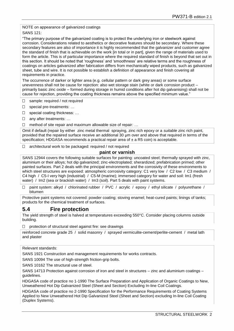
PW371-B edition 2.1
STRUCTURAL STEELWORK 2
sample: required / not required
special pre-treatments: …
special coating thickness: …
any after treatments: …
method of site repair and maximum allowable size of repair: …
architectural work to be packaged: required / not required
paint or varnish
paint system: alkyd / chlorinated rubber / PVC / acrylic / epoxy / ethyl silicate / polyurethane / bitumen
5.4 Fire protection
protection of structural steel against fire: see drawings
NOTE on appearance of galvanized coatings
SANS 121:
“The primary purpose of the galvanized coating is to protect the underlying iron or steelwork against corrosion. Considerations related to aesthetics or decorative features should be secondary. Where these secondary features are also of importance it is highly recommended that the galvanizer and customer agree the standard of finish that is achievable on the work [in total or in part], given the range of materials used to form the article. This is of particular importance where the required standard of finish is beyond that set out in this section. It should be noted that ‘roughness’ and ‘smoothness’ are relative terms and the roughness of coatings on articles galvanized after fabrication differs from mechanically wiped products, such as galvanized sheet, tube and wire. It is not possible to establish a definition of appearance and finish covering all requirements in practice.
The occurrence of darker or lighter area (e.g. cellular pattern or dark grey areas) or some surface unevenness shall not be cause for rejection: also wet storage stain (white or dark corrosion product – primarily basic zinc oxide – formed during storage in humid conditions after hot dip galvanising) shall not be cause for rejection, providing the coating thickness remains above the specified minimum value.”
Omit if default (repair by either zinc metal thermal spraying, zinc rich epoxy or a suitable zinc rich paint, provided that the repaired surface receive an additional 30 μm over and above that required in terms of the specification; HDGASA recommends a practical repair area of ± a R5 coin) is acceptable.
SANS 12944 covers the following suitable surfaces for painting: uncoated steel; thermally sprayed with zinc, aluminium or their alloys; hot dip galvanized; zinc-electroplated; sherardized; prefabrication primed; other painted surfaces. Part 2 deals with the principal environments and the corrosivity of these environments to which steel structures are exposed: atmospheric corrosivity category: C1 very low / C2 low / C3 medium / C4 high / C5-I very high (industrial) / C5-M (marine); immersed category for water and soil: Im1 (fresh water) / Im2 (sea or brackish water) / Im3 (soil). Part 5 deals with paint systems.
Protective paint systems not covered: powder coating; stoving enamel; heat-cured paints; linings of tanks; products for the chemical treatment of surfaces.
The yield strength of steel is halved at temperatures exceeding 550°C. Consider placing columns outside building.
reinforced concrete grade 25 / solid masonry / sprayed vermiculite-cement/perlite-cement / metal lath and plaster
Relevant standards:
SANS 1921 Construction and management requirements for works contracts.
SANS 10094 The use of high-strength friction-grip bolts.
SANS 10162 The structural use of steel.
SANS 14713 Protection against corrosion of iron and steel in structures – zinc and aluminium coatings – guidelines.
HDGASA code of practice no 1-1990 The Surface Preparation and Application of Organic Coatings to New, Unweathered Hot Dip Galvanized Steel (Sheet and Section) Excluding In-line Coil Coatings.
HDGASA code of practice no 2-1990 Specification for the Performance Requirements of Coating Systems Applied to New Unweathered Hot Dip Galvanized Steel (Sheet and Section) excluding In-line Coil Coating (Duplex Systems).

PW371-B edition 2.1
STRUCTURAL STEELWORK 3
Estimated service life of hot dip galvanized steel complying with SANS 121
Corrosivity Cate-gory ISO 9223
Zinc corrosion rate / yr
55 μm for steel 1.5 – 3mm thick
70 μm for steel 3 – 6 m m thick
85 μm for steel >6 mm thick
C 1 very low <0.1 μm >100 yrs >100 yrs >100 yrs
C 2 low 0.1 – 0.7 <78.5 yrs >100 yrs >100 yrs
C 3 medium 0.7 – 2.1 26 – 78.5 yrs 33 – 100 yrs 40 – >100 yrs
C 4 high 2.1 – 4.2 13 – 26 yrs 16 – 33 yrs 20 – 40 yrs
C 5 very high 4.2 – 8.4 6.5 – 13 yrs 8.3 – 16 yrs 10 – 20 yrs
NOTES on hot dip zinc coating thickness and service life:
Consult the Hot Dip Galvanizer’s Association of South Africa (HDGASA) for determination of high corrosivity areas.
All hot dip galvanising specifications state the minimum suitable coating thickness and not average coating thickness. The thickness actually achieved varies with steel composition and thickness of steel, and can range from the minimum up to >50% greater. As life expectancy predictions are normally based on the minimum coating thickness, they are usually conservative.
Hot dip galvanized coating on structural steel should in most cases provide a service-free life of 40 – 50 years. This is determined by dividing the minimum achieved coating thickness taken on the thinnest steel component by the corrosion rate per year for the location in question (see table).
HDGASA uses SANS ISO 9223 to determine corrosivity categories, based on three factors: 1) Time of wetness, being the period that the zinc surface is covered by liquid containing the corrosive elements (electrolyte); 2) Airborne pollution containing sulphur dioxide (SO2); 3) Airborne pollution containing salinity, usually in the form of chlorides carried on prevailing sea winds.
Source: HDGASA Information sheet No 8.
Coating thickness in μm can be converted to approximate coating mass per unit area in g/m² by multiplying by the nominal density of the coating (7,2 g/cm³): thus 55 μm = 395 g/m²; 70 μm = 505 g/m²; 85 μm = 610 g/m²
Source: SANS 121 / SANS 14713.
Z575 is the designation for 575 g/m² zinc/surface area on both sides of steel sheet (for sheet that would mean 137.5 g/side) which equals a mean coating thickness of 19 μm. Similarly, Z450 equals 22 μm, and Z600 equals 43 μm).
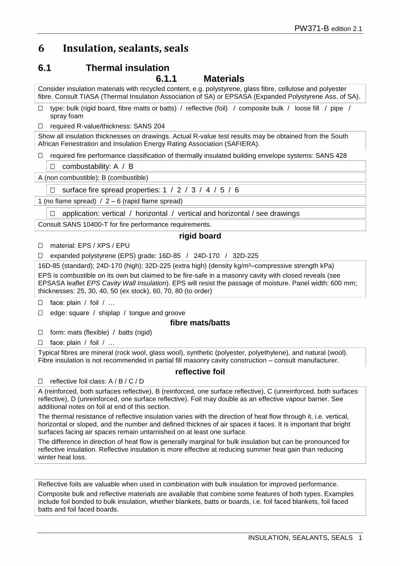
PW371-B edition 2.1
INSULATION, SEALANTS, SEALS 1
6 Insulation, sealants, seals
6.1 Thermal insulation 6.1.1 Materials
type: bulk (rigid board, fibre matts or batts) / reflective (foil) / composite bulk / loose fill / pipe / spray foam
required R-value/thickness: SANS 204
required fire performance classification of thermally insulated building envelope systems: SANS 428
rigid board material: EPS / XPS / EPU
expanded polystyrene (EPS) grade: 16D-85 / 24D-170 / 32D-225
face: plain / foil / …
edge: square / shiplap / tongue and groove
fibre mats/batts form: mats (flexible) / batts (rigid)
face: plain / foil / …
reflective foil reflective foil class: A / B / C / D
Consider insulation materials with recycled content, e.g. polystyrene, glass fibre, cellulose and polyester fibre. Consult TIASA (Thermal Insulation Association of SA) or EPSASA (Expanded Polystyrene Ass. of SA).
Show all insulation thicknesses on drawings. Actual R-value test results may be obtained from the South African Fenestration and Insulation Energy Rating Association (SAFIERA).
combustability: A / B
A (non combustible); B (combustible)
surface fire spread properties: 1 / 2 / 3 / 4 / 5 / 6
1 (no flame spread) / 2 – 6 (rapid flame spread)
application: vertical / horizontal / vertical and horizontal / see drawings
Consult SANS 10400-T for fire performance requirements.
16D-85 (standard); 24D-170 (high); 32D-225 (extra high) (density kg/m³–compressive strength kPa)
EPS is combustible on its own but claimed to be fire-safe in a masonry cavity with closed reveals (see EPSASA leaflet EPS Cavity Wall Insulation). EPS will resist the passage of moisture. Panel width: 600 mm; thicknesses: 25, 30, 40, 50 (ex stock), 60, 70, 80 (to order)
Typical fibres are mineral (rock wool, glass wool), synthetic (polyester, polyethylene), and natural (wool). Fibre insulation is not recommended in partial fill masonry cavity construction – consult manufacturer.
A (reinforced, both surfaces reflective), B (reinforced, one surface reflective), C (unreinforced, both surfaces reflective), D (unreinforced, one surface reflective). Foil may double as an effective vapour barrier. See additional notes on foil at end of this section.
The thermal resistance of reflective insulation varies with the direction of heat flow through it, i.e. vertical, horizontal or sloped, and the number and defined thicknes of air spaces it faces. It is important that bright surfaces facing air spaces remain untarnished on at least one surface.
The difference in direction of heat flow is generally marginal for bulk insulation but can be pronounced for reflective insulation. Reflective insulation is more effective at reducing summer heat gain than reducing winter heat loss.
Reflective foils are valuable when used in combination with bulk insulation for improved performance.
Composite bulk and reflective materials are available that combine some features of both types. Examples include foil bonded to bulk insulation, whether blankets, batts or boards, i.e. foil faced blankets, foil faced batts and foil faced boards.

PW371-B edition 2.1
INSULATION, SEALANTS, SEALS 2
metal faced insulation panels
corrosion comparison index of panel-facing coating: 1 / 2 / 3 / 4
core insulation: calcium silicate / mineral fibre / polyisocyanurate / polyphen / polystyrene / polyurethane / rockwool
facing: chromadek / galvanized steel / PVC laminated galvanized steel / stainless steel / zincalume
loose fill loose fill: pellets or granules / cellulose.
6.1.2 Installation system: SANS 204 / rational design
masonry cavity wall insulation type: full fill cavity / partial fill cavity / loose fill / see drawings
masonry wall external face insulation masonry wall external face insulation: …
pitched roof/ceiling insulation system: reflective foil under roof covering / bulk insulation on ceiling / foil + bulk / see drawings
flat roof insulation material: rigid EPS insulation density 32D
flat roof insulation position: over waterproofing / under screed
floor insulation under floor slab insulation: required / not required
6.2 Vapour barriers type: …
position: see drawings
For use in buildings, cold rooms and hot rooms, interior and exterior.
Metal faced insulation panels are typically used in cold storage systems. Consult TPMA (Thermal Panel Manufacturer’s Association).
Insulation can be installed full fill in cavities in most areas where cavity walls are not required to prevent moisture migration, or where walls are plastered and painted or protected by roof overhangs of >750 mm.
Insulation should be installed partial fill in cavities where the cavity also serves as a moisture barrier against wind-driven rain, mostly in winter rainfall areas, but also in cases of exposed face brick walls in general (e.g. gable walls, walls without roof overhangs, high buildings).
In exposed walls, filling cavities with loose fill insulation may result in insulation becoming wet, losing its insulation value and causing dampness on the inner leaf.
Filling of concrete block cores with any type of insulation offers little energy savings since the majority of heat is conducted through the webs and mortar joints.
Omit if default (patent system of EPS external insulation bonded and mechanically fixed to dry, sound and flat surface, finished with reinforced polymeric plaster) is acceptable, or specify alternative.
Installing insulation against internal face of envelope wall would result in losing capacitive insulation of internal leaf (thermal mass).
Insulation on flat trafficable concrete roofs should be firm enough to support the waterproofing system and foreseeable loadings, i.e.under screed. See Section 8 for further particulars.
In case of in-slab heating as required by SANS 204.
Clay brick and concrete block masonry is able to accommodate moisture migration (damp open), normally rendering a vapour barrier unnecessary. SANS 204 advises that designers should consider that interstitial condensation occurs in walling systems which are not able to prevent or accommodate moisture migration. Also, that artificial cooling of buildings in some climates can cause condensation to form inside the layers of the building envelope. Such condensation can cause significant structural or cosmetic damage to the envelope before it is detected. Associated mould growth may also create health risks to the occupants. Effective control of condensation is a complex issue. In some locations a fully sealed vapour barrier may need to be installed on the more humid, or generally warmer, side of the insulation.

PW371-B edition 2.1
INSULATION, SEALANTS, SEALS 3
6.3 Sound absorption materials
structure-borne sound insulation: mineral fibre mats SANS 1381 / cork
airborne sound absorption: mineral fibre mats SANS 1381 + perforated 10 mm plywood / plasterboard / hardboard / metal / see drawings.
6.4 Joint fillers/sealants joint filler/sealant colour: …
6.5 Architectural seals type: patent extruded aluminium carriers with flexible seal inserts of synthetic rubber, rigid PVC, nylon
brush filaments, polypropylene pile, or silicone rubber / patent PVC, pile or neoprene door and window frame seals / patent silicone intumescent seals (fire and smoke) / patent external extruded aluminium threshold plate seals
aluminium extrusion finish: mill / anodised / painted
intended use of seal: energy (draughts, dust, insects) / intumescent (fire and smoke) / acoustic (noise) / finger-pinch protection (schools, day-care centres) / threshold plate / access (mobility, disabled persons)
duty level: light / medium / heavy
mounting: fully morticed / semi morticed / surface mounted / grooved.
Industrial sealants compatible with bitumen may not be available in SA.
Two-part sealants are generally more effective and costly than one-part sealants.
See also SANS 2001-CC1 for specification of waterstops.
Architectural seals need careful study by the designer – consult supplier.
Intumescent seals are designed to expand when subjected to heat.
Duty level: light (domestic); medium (commercial); heavy (hospitals, airports, shopping malls).
NOTE: Additional notes on reflective foil thermal insulation:
The difference in direction of heat flow is generally marginal for bulk insulation but can be pronounced for reflective insulation. Reflective insulation is more effective at reducing summer heat gain than reducing winter heat loss.
The thermal resistance of reflective insulation varies with the direction of heat flow through it, i.e. vertical, horizontal or sloped, the number of air spaces and defined thicknesses of the air spaces. Furthermore, that the bright surfaces facing the air space/spaces remains untarnished on at least one surface.
Reflective foils are valuable when used in combination with bulk insulation for improved performance.
Composite bulk and reflective materials are available that combine some features of both types. Examples include foil bonded to bulk insulation, whether blankets, batts or boards, i.e. foil faced blankets, foil faced batts and foil faced boards.

PW371-B edition 2.1
ROOF COVERINGS, CLADDING 1
7 Roof coverings, cladding
7.1 General type of cover, cladding: see drawings
roof pitch: see drawings
underlay underlay type: reflective foil / polymer / the subject of an active Agrément Certificate
7.2 Tile roofing/cladding 7.2.1 Materials type of tile: concrete / clay / slate / fibre-cement / metal
concrete roof tiles
pattern and colour: …
type: plain / interlocking
body colour or surface coating category: 1 / 2 / 3 / 4
finish: throughcolour / granular / sanded
clay roof tiles type: Broseley (plain) / Marseilles (interlocking) / …
colour: …
natural slate tiles size, colour: …
fibre-cement slates texture, colour: plain / textured / natural / …
metal roofing tiles material, finish: hot dip galvanized steel / aluminium alloy / stainless steel / coated / uncoated
fixing materials fixing materials: galvanized steel / stainless steel or aluminium
7.2.2 Roof tiling preparation
terrain category: 1 / 2 / 3 / 4
design wind speed: 40 / 45 / 50 / 55 m/s
height above ground / number of storeys: …
eaves: open / boarded
To be published: SANS 2001-CR2 Tiled and sheeted roofs.
tile / profiled sheet / fully-supported sheet / thatch
Check minimum roof pitches with SANS 10400-L. Roof pitches below that recommended by the manufacturer can be achieved by laying plywood boarding over the rafters and covering with waterproofing before tiling. Check with manufacturer.
See Section 6 for reflective foil. Reflective foil doubles as thermal insulation and should be first choice in hot climates.
Concrete roof tiles have a mass of ±55 kg/m² laid.
1 (none); 2 (surface coating only); 3 (body colour only); 4 (both).
Mass of fibre-cement tiles is 25 kg/m2 laid.
Galvanized steel in inland regions. Stainless steel or aluminium in coastal regions or corrosive atmospheres, except for clay tiles where all fixings shall be stainless steel.
Terrain category 1: exposed open/ coastal areas (generally the area within 5km from the coast-line unless otherwise defined locally); 2: exposed with scattered obstructions; 3 : well-wooded areas and suburbs, town and industrial areas; 4: large city centres.
Eaves should be boarded in exposed terrains.

PW371-B edition 2.1
ROOF COVERINGS, CLADDING 2
laying tile: concrete / clay / slate / fibre-cement / metal
valley gutter: open / concealed
verge tiles: required / not required
roof underlay roof underlay: required / not required
7.3 Profiled sheet roofing/cladding 7.3.1 Metal sheet
metal metal and coating: zinc-coated (galvanized) steel / AZ-coated steel / prepainted zinc coated steel /
weathering steel / natural aluminium alloy / prepainted aluminium alloy / stainless steel / copper
profile profile: corrugated / box rib (IBR) / interlocking box rib / rib-trough/standing seam
sheet length: single lengths per roof slope / standard lengths with overlap / single length standing seam over-ridge (see ridging)
steel nominal sheet thickness: 0,5 / 0,6 mm
coating grade: Z575 / Z600 / AZ150 / AZ200
aluminium alloy aluminium roofing sheet thickness: 0,6 (cladding only) / 0,7 / 0,8 / 0,9 mm
stainless steel stainless steel thickness: 0,5 / 0,6 mm
copper copper: 0,6 mm thick
prepainted metal prepainted metal sheet type: 3 / 4 / 5a / 5b / 6a / 6b
Underlays are strongly recommended in any area, and are mandatory in exposed and coastal terrains, depending on pitch. Not required for metal roof tiles.
SANS 204 states ”all tile roofs in climatic zones 1, 2, 4 and 6 shall have a tile underlay or radiant barrier and the joints shall be sealed to prevent air infiltration and leakage”.
Mass of metal sheet roofing is ±11 kg/m2.
Copper, aluminium, stainless steel or weathering steel should be used in environments where atmospheric corrosion is aggressive. Check availability, thickness and finish of these metals with manufacturer/ supplier.
Standard lengths (1,8 – 14 m) – check with manufacturer/ supplier.
Corrugated and IBR sheets in standard lengths with overlap causes less thermal movement stress on exposed fixings than long lengths.
Check availability of 0,8 mm sheets. 0,6 mm thick sheet costs ±16% more than 0,5 mm.
Z575 and AZ150 for inland regions, Z600 and AZ200 for coastal regions and aggressive atmospheres.
Coiled sheeting with hot dip zinc coating (galvanising) class Z575 has an average zinc coating thickness of about 19μm; Z600 - 42μm. AZ coatings have increased corrosion resistance over zinc coating by 3 or 4. See notes on hot dip galvanising under Section 5 Structural Steel. Get expert advice from HDGASA or ARTF - SCRACE.
Type 3 (mild to moderate rural, urban, tropical and industrial environments) / 4 (marine and industrial) / 5a (severe marine) / 5b (heavy industrial and industrial marine) / 6a very severe marine) / 6b (very severe industrial).
Coil coated and prepainted products are e.g. Chromadek or Chromadek Plus (Mittal Steel) for marine and industrial environments; there are several others. Paint coating more than doubles the life of sheets with metal coating only.

PW371-B edition 2.1
ROOF COVERINGS, CLADDING 3
weathering steel (Cor-ten) weathering steel: 0,8 mm
bullnosing bullnosing radius: …
roof ventilators roof ventilator type, material, dimensions: …
7.3.2 Fibre-cement sheet
bullnosing radius: …
7.3.3 Glass-reinforced polyester sheet
type: 1 / 2
class: W / WF
mass: 1,0 – 1,4 kg/m2 (domestic) / 1,4 / 1,8 / 2,4 kg/m2 (industrial)
opacity: clear / opaque
colour: …
profile: see drawings / to match roofing/cladding sheet / corrugated / IBR / …
7.3.4 Polycarbonate sheet colour: …
thickness: 1,0 mm / 1,2 mm
profile: see drawings / to match roofing/cladding sheet / corrugated / IBR / …
7.3.5 Fasteners and washers corrosion resistance class: 1 / 2 / 3 / 4
type and size: hook-bolt / U-bolt / J-bolt / drive screw / self-tapping screw / according to roofing material manufacturer’s instruction
material: zinc-coated carbon steel / stainless steel.
Minimum radius about 500 mm (inside radius), depending on material, profile and sheet thickness.
Mass of 5 mm thick fibre-cement sheets is 15 kg/m2. Purlins must be 50 x 76 mm at 1 200 max spacing on trusses/beams at 1 200 max spacing (SANS 10243). Finish fibre-cement sheets in coastal areas with an anti-fungicidal paint – see section 14 Painting.
See also SANS 141 GRP laminates.
1 (with weathering protection both sides) / 2 (ditto one side)
W (without fire-retardant properties) / WF (with fire-retardant properties)
SANS 10400-L: “skylights shall have a maximum opening area of 0,6 m² or, if in the form of a translucent roof sheet, an installed width of 700 mm”.
1,0 mm (domestic) / 1,2 mm (industrial)
1 (general internal / 2 (general internal with significant condensation) / 3 external, mild to moderate industrial or marine) / 4 (external severe marine)
Identification of corrosive characteristics of the environment is essential.
Corrosion resistance class 2, 3 and 4 correspond with class C2, C3 and C4 of ISO 9223.
Some coating information for zinc and tin-zinc coated fasteners (corrosion resistance class, coating type, coating thickness in µm):
1, electroplated zinc (EZ), 4
2, EZ, 12
2, mech. plated zinc (MPZ), 17
3, EZ, 30
3, hot dip galv (HDG), 30
3, MPZ, 40
4, HDG, 50
4, MPZ, 45. For full list see SANS 1573.

PW371-B edition 2.1
ROOF COVERINGS, CLADDING 4
7.3.6 Installation exposed fixing
box rib cladding: with rib against girt / with rib away from girt
lapping
7.4 Fully-supported metal sheet roofing and cladding
7.5 Thatch roofing
thatch type: grass / Cape reed (dekriet) / water reed
wire sways: prohibited / allowed
ridging: thatch / sand-cement / fibreglass
fire retardant treatment: none / pre-treatment / during construction / after installation
7.6 Flashings, trim
7.7 Fascias and barge boards size: see drawings.
Sealing of laps in sheeted roofs in climate zone 1, 2, 4 and 6 is mandatory (SANS 204)
Flat metal sheet with standing seams on continuous solid boarding can follow any shape within limits of the boarding. The specification presented in PW371-A is for copper. Other materials are zinc, lead, aluminium or hot dip galvanized steel. Check material and fixing with specialists.
Boarding must be able to absorb condensation under roof sheet - use of chipboard or other dense boarding material will cause corrosion. Board thickness depends on span.
To be published: SANS 2001- Construction Works Part CR3: Thatch Roofing.
Cost of a thatch roof is 15 – 20 % higher than a conventional roof. Check insurance requirements.
Consider requesting that the work be done by a member of the South African Thatcher’s Association.
Avoid penetrations of the roof area – place chimneys preferably at the ridge, ventilation pipes outside the exterior wall faces.
Thatch can be shaped and moulded.
Local grass will weather better in the same climate from which it originates. Hyparrhenia and Hyparphilia species should last for 35 years. Thamnochortis species (Cape reed/dekriet) could last for 75 years. Also Phragmites Communis reed. 175 mm thick thatch weighs 35 kg/m2, about 40 bundles of grass per m2.
Roof pitch in general should not be less than 45 degrees, 40 degrees at dormers (SANS 10400-L).
After the maintenance period the roof should be serviced every 10 – 12 years, and a new layer of 70 – 100 mm thatch added after 35 years. The life of thatch will be prolonged by brushing with a thatch spade at 4 – 5 year intervals.
Wire sways should not be used in roof construction in areas where lightning is a problem unless provided with a lightning protection system (See SANS 10400-T).
Flashings to metal roofs should be similar to roof material to ensure same life to first maintenance and avoid electrolytic corrosion.
Counter flashings with an anti-capillary fold avoid electrolytic corrosion.
Relevant standards:
SANS 10062: The fixing of concrete roof tiles.
SANS 10237: Roof and side cladding.
SANS 1200 HB-Cladding and sheeting.
SANS10400-L Roofs.
SANS 10400-T Fire protection.
Concrete Roof Tiles – Technical Manual. Concrete Manufacturer’s Association.
Guide to good thatching practice. Thatcher’s Ass of SA.

PW371-B edition 2.1
WATERPROOFING 1
8 Waterproofing
8.1 Materials
reinforced bitumen membrane (RBM) finish: plain / slate granular / metal foil: aluminium or copper
self-adhesive plastic membrane (APM) finish: plain / foil / granular / polyester fabric
reinforced liquid membrane (RLM) in situ reinforced liquid system: acrylic emulsion / bitumen emulsion / cementitious
cavity drainage membrane
slip/protection layers, geomembranes
outlets outlet type: roof / small balcony / shower
size: >75 mm.
8.2 Preparation falls
To be publshed: SANS 2001-EW Waterproofing.
This section covers the conventional system of waterproofing with membranes only. Damp proofing in masonry is covered in SANS 2001-CM1. Consult The Concrete Institute for the waterproofing of concrete with additives.
The Waterproofing Federation of South Africa is the industry representative body.
SANS 10021 is outdated but useful and hopefully to be revised.
Bituminous felt (SANS 92), mastic asphalt (SANS 297/298) and elastomeric membranes like butyl rubber (polyisobuty-lene, SANS 187), chloroprene rubber (SANS 580) and EPDM (Ethylene Propylene Diene Monomer) have been used in the past but have largely been replaced by polymer modified bitumen membranes. No national standard exists for polymer-modified bitumen membranes, but most systems are Agrément certified.
Self-adhesive membranes are thin (1,5 mm), normally laid as single layer systems to be covered (not UV resistant, except with foil, granular or fabric finishes).
Acrylic or bitumen emulsion is suitable only for exposed roofs and parapet walls. Cementitious systems can only be applied to cementitious backgrounds and can be tiled directly.
Studded polypropylene or HDPE cavity drainage membranes allow damp or running water to travel behind the membrane to a controlled drainage system. They are lighter than conventional stone and geotextile, provide continuous drainage and act as slip/separation layer.
Check requirements for bituminous felt or HDPE slip/protection layers and thermplastics geomembranes.
SANS 10400-L: Slope of a (cast in situ) concrete roof should be achieved by casting the concrete to the required fall, eliminating the need for a screed which may be susceptible to cracking and and resultant spreading of leaks.
Falls in flat timber roofs should be created in the rafter/beam design and not by raising purlins.
Show ridges, valleys and falls clearly in drawings.
SANS 10400-L Roofs stipulates a design fall of 1:50, allowing for construction inaccuracies and deflection under dead or imposed loads.

PW371-B edition 2.1
WATERPROOFING 2
balconies
outlets
8.3 Application
8.3.2 Termination
1.5 Waterproofing surface finishes/protection
8.5.1 Exposed non-trafficable areas type finish/protection: see drawings
paint
crushed stone
Ensure balconies are at a sufficiently lower level than door thresholds to allow for the screed or topping to be minimum 50 mm thick, and have sufficient fall to outlet(s).
Balustrades are best fixed to front of upstands.
Balcony door thresholds exposed to rain: waterproofing should be continued up against threshold and finished under door frame
Diagram: Section through a balcony
1 concrete slab; 2 screed (optional); 3 tiles in adhesive on screed or bonded to waterproofing; 4 soft joint/sealant; 5 sliding door frame; 6 tiles bonded to waterproofing; 7 balustrade; 8 outlet.
Outlets set lower than their surroundings to prevent ponding: SANS 10400-L 4.3.2.4
SANS 10400-L: “attention should be given to the provision of ventilation to allow moist air, which might accumulate below the waterproofing layer, to be vented to the outside air”. Check with manufacturer/ supplier.
For basement construction see SANS 10021. Basement floors and walls may be tanked, or formed with a cavity construction combined with drainage or pumping, or both, or may be constructed with cavity drainage membranes.
Bonding waterproofing with DPC’s should be considered in winter rainfall areas. DPC’s should be the same material as the waterproofing and have sufficient overhang to facilitate overlapping and bonding.
Balcony door thresholds exposed to rain are a common cause of leakage. Waterproofing should be taken up against thresholds and finished under the door frame and sealed.
Protection against UV degradation, traffic and hail prolongs life expectancy of membranes. No protection required to exposed bitumen membranes with slate granular or metal foil finishes.
Paint / crushed stone / crushed stone on insulation panels / tiled insulation panels
Acrylic does not adhere well to new bituminous-based systems.
A layer of gravel protects waterproofing and acts as anchor, but makes leaks difficult to trace. Thermal insulation value of gravel layer on its own is slight.

PW371-B edition 2.1
WATERPROOFING 3
tiled insulation panels
8.5.2 Pedestrian traffic areas type finish/protection: see drawings
thermal insulation panels lay finish on thermal insulation panels: required / not required
tiles on waterproofing tile type, size: …
paving slabs on adjustable pads paving surface levels: see drawings
8.5.3 Vehicular traffic areas type finish/protection: see drawings
8.5.4 Basement, retaining walls before backfilling, protect waterproofing with: softboard / hardboard / cavity drainage membrane /
masonry leaf
drainage system behind wall: …
8.5.5 Planters, roof gardens type finish/protection: 100–150 mm layer stone with geocomposite drainage layer with minimum mass of
210 g/m2 laid on top / cavity drainage membrane laid directly on waterproofing.
Thermal insulation should be placed over the waterproofing (“inverted roof”), protecting it from high temperature fluctuation, ultraviolet degradation and mechanical damage,while allowing easy visual inspection of the waterproofing when laid loose.
Depending on tile mass, loose-laid tiled insulation panels should be installed only on flat roofs protected against wind by perimeter upstands. Tiles should be fully vitrified to withstand freeze-thaw cycles and should be sturdy enough to withstand handling and maintenance foot traffic. Panel size depends on multiples of tile size. Panels could float during heavy downfalls. Panels are easily removed for inspection and maintenance.
topping / topping on insulation panels / tiles on screed / tiles on waterproofing / paving slabs on insulation panels / paving slabs on adjustable pads
Paving units are suitable for trafficable roofs, and for roof gardens and planters where waterproofing may be damaged by garden tools.
Paving on adjustable pads can be easily removed for inspection/repair, and the air space provides considerable thermal downward insulation. Paving slabs need to be sturdy, depending on traffic.
See Section 12 Tiling.
50 mm premix laid directly onto waterproofing / brick or concrete pavers laid on 25 – 30 mm sand bed (see Section 21 External works) / 75 mm concrete paving on protection/slip layer (see Section 2 Concrete works)
Omit if not agricultural drain encased in stone as specified.
Relevant standards:
SANS 10021 Waterproofing of buildings (including damp-proofing and vapour barrier installation).
SANS 10400-L Roofs.
BS.8102:2009 - Protection of Below Ground Structures against Water from the Ground.
GP Koning. The Waterproofing of Buildings. PO Box 26153 Hout Bay 76872.

PW371-B edition 2.1
CEILINGS, LININGS, PARTITIONS, ACCESS FLOORING 1
9 Ceilings, linings, partitions, access flooring
9.1 Brandered ceilings 9.1.1 Branders, grounds type: timber / steel
timber branders/grounds
steel branders
perimeter trim: standard / shadowline.
9.1.2 Fibre cement and gypsum board brandered ceilings type: fibre-cement / gypsum
fibre-cement board
gypsum board
type: standard / moisture resistant / fire rated
edge: square / tapered
cornices material, size: coved gypsum 75 mm wide / ditto 125 mm wide / coved polystyrene cornice / foam
moulded / hardwood / softwood, profile …
cover strips joint cover strips: H-profile: prepainted galvanized steel, aluzinc or plastic / gypsum board / hardwood:
specie …; profile, size: see drawings
fixing board pattern: see drawings
position of movement/control joints: see drawings
finish finish to plaster board ceiling: plain with cover strips / plain with plastered joints / entire ceiling
plastered
9.1.3 Wood board brandered ceilings, linings type of board: tongue and groove / strip / plywood / perforated plywood
tongue and groove board (SANS 1039) species: softwood / hardwood / species …
To be published: SANS 2001- Construction Works Part EC1: Ceilings, partitions, access flooring.
SANS 2001-CT2 (and SANS 10400-L) covers the fixing of timber brandering to roofing members to support ceilings that comprise gypsum plasterboard, fibre-cement board or similar boards only: “Brandering of size 38 mm × 38 mm required to support gypsum plasterboard, fibre-cement board or similar board shall be securely spiked to the supporting timbers with 75 mm wire nails. Cross brandering shall be cut in between the longitudinal brandering and skew nailed to the same, using 75 mm wire nails at centres that do not exceed 900 mm”.
Grounds for wall linings: depth of 25 mm may be influenced by thickness of required insulation, services.
Steel brandering is ideal for bulkhead construction.
Flat fibre-cement boards are made with organic fibres, plain or textured, and are water and fire resistant.
Gypsum board is non-comustible. Standard board should not be exposed to contact with water – do not use in industrial bathrooms or kitchens, or in exterior applications. For high moisture conditions use moisture resistant board. For fire resistance use X-rated board. Use double layers where acoustic insulation is required.
Use tapered edge board for scrim and plaster joints when full ceiling surface is not to be plastered.
Omit if ceiling is plastered.
Omit if not visible or default (symmetrical about room) is acceptable.
movement/control joints should be a clean break of 15 mm through the complete ceiling structure and finish.

PW371-B edition 2.1
CEILINGS, LININGS, PARTITIONS, ACCESS FLOORING 2
grade: clear / select / knotty
profile: see drawings
face width: 50 / 65 / 75 / 102 / 140 mm
thickness: ceiling board: 12 / 16; panelling 12 / 16 / 22 mm
wood strip, trim strip spacing: see drawings
plywood exposure class: 1 / 2 / 3 / 4
veneer species: …
cut: rotary / sliced
grade: S / A / B
perforations: size, spacing: …
fixing position of ceiling: see drawings
strip spacing: …
cornice, trim size and profile: …
9.1.4 Hatches position of ceiling hatches: see drawings
trap door: hinged / laid loose
9.2 Suspended ceilings
type: board / fabric / louvre / grid / bulkhead
material: mineral fibre / metal / …
performance required fire resistance in minutes: see drawings
required airborne sound insulation grading dB: see drawings
board type: plain / perforated / smoke-tight / impact-proof (e.g. ball) / removable / fold-down / drop-and-
slide
material: mineral fibre / gypsum / fibre cement / metal / vinyl clad / grid / flush plaster
mineral fibre edge: square / revealed square / bevelled concealed / concealed
size: see drawings
colour: …
See SANS 1039 for various profiles.
1 (exterior); 2 (semi-exterior); 3 (humid interior); 4 (dry interior).
S (select, for decorative applications), A (furniture, for joinery where it may be reworked), B (standard, to be covered, coated or painted).
For effect and/or acoustic control.
above / in beteen / below roof beams
See note on geyser position under Section 18.
Consult SABISA (South African Building Interior Systems Association, part of the AAAMSA group).
20 / 30 / 60 / 90 / 120 / 180 / 240
See also note under 9.3.
30 / 35 / 40 / 45 / 50
For noise measurement and rating consult SANS 10103.
See also note under 9.3.

PW371-B edition 2.1
CEILINGS, LININGS, PARTITIONS, ACCESS FLOORING 3
texture: plain / fissured / perforated
finish: …
ceiling panels: removable and replaceable from below / fixed / as required for maintenance
suspension fittings suspension system: patent / rational design
installation grid pattern: see drawings
access access: see drawings
9.3 Partitions, linings type: see drawings
performance required fire resistance in minutes: see drawings
required sound insulation grading dB: see drawings
9.3.1 Materials
gypsum plasterboard type: wallboard / moisture resistant wallboard / high-temperature wallboard
thickness: 12 / 15 mm
type of edge: square / tapered / bevelled / rounded
covering: paper backed vinyl of weight in g/m2 : …
type: MD / HD
thickness: 9 mm
studs and tracks material: metal / wood
aluminium extrusions abrasion resistance: required / not required
colour: natural / anodized
Access depends on hold-down system, panel removability, access requirements to above-ceiling services, weight of ceiling panels. Discuss with manufacturer/supplier.
drywall / light weight internal wall / demountable / cubicle / operable
20 / 30 / 60 / 90 / 120 / 180 / 240
Fire resistance: SANS 10400 Part T classifies the performance of materials in respect of fire resistance in categories of 20, 30, 60, 90, 120, 180 and 240 minutes. Architect/Competent Person to specify. Fire resistance is achieved by increasing layers of board. Deflection requirements are achieved by multiple studs reinforced with layers of board. Check with SABISA.
30 / 35 / 40 / 45 / 50
30 (normal speech audible, but unintelligible), 35 ( loud speech understood), 40 (loud speech audible, but unintelligible), 45 (loud speech barely audible), 50 (shouting barely audible)
Comparable constructions: 26 (solid wood door without seals), 32 (6 mm laminated glass), 42 (100 mm brick wall), 48 (230 mm hollow concrete wall).
For noise measurement consult SANS 10103.
Moisture resistant board for use in all wet areas such as bathroom showers as well as locations with high humidity levels.
fibre cement board
flat unpressed (MD), flat pressed (HD).

PW371-B edition 2.1
CEILINGS, LININGS, PARTITIONS, ACCESS FLOORING 4
anodising anodising grade SANS 1407: AG10 / AG15 / AG20 / AG25
abrasion resistance when relevant: required / not required
colour: …
powder coating SANS 1574 type: 1 / 2
colour: …
finish: matt / satin / high gloss / hammertone / textured
glass type: see drawings
thickness: see drawings
9.3.2 Drywall partitions, light weight internal walls framing: timber / steel
cladding: gypsum board / fibre cement board
gypsum board cladding finish: vinyl / paint / tile
door/window frame finish: anodising / powder coating
glazing: clear / opaque / patterned / safety
9.3.3 Demountable partitions framing: steel / aluminium
exposed frame finish: anodized aluminium / powder coating
cladding: gypsum plasterboard / melamine-faced board / …
cladding finish: vinyl / paint
glazing: clear / opaque / patterned / safety
9.3.4 Cubicle partitions mounting: flush floor / raised on stainless steel stiles
panels: vitreous enamel / melamine faced
hinge type: normal butt / rising butt
accessories: indicator bolt / coat hook / …
9.3.5 Operable partitions operation: individual panels / hinged paired panels
accessories: pass doors / work surfaces (chalkboard, dry marker board, tackboard) / pocket doors (to hide stacked panels).
grade AG10 (0,1 mm thick), for interior use only; AG15 and 20 for mild atmospheric conditions; AG25 where little or no deterioration is permitted. According to ASFA (Aluminium Surface Finishers Association), SANS 1407 is suitable for internal use only.
1 (heavy duty interior), 2 (interior and non-corrosive conditions).
float glass / wired / patterned / safety
See GLAZING
For cladding finish of appropriate type to suit expected traffic in designated areas, refer to manufacturer for recommendations.

PW371-B edition 2.1
CEILINGS, LININGS, PARTITIONS, ACCESS FLOORING 5
9.4 Raised access flooring
required fire resistance in minutes: see drawings
required sound insulation grading in dB: see drawings
class: A / B / C
floor panel covering: heavy duty high pressure laminate on particle board P6 / textile / …
degree of corrosion resistance if other than default : …
clear height to underside of floor: see drawings
required life of covering: …
details of special floor panels: see drawings
whether floor assembly forms part of a plenum system: …
lifting devices: required / not required.
Annex B and C of SANS 1549 gives information on quality verification of components; electrical properties; fire protection and safety; special panels; surface of completed installation; moving and placing of safes and other heavy equipment.
NOTE: this standard has been withdrawn but is regarded by industry as superior to the new (European) standard (SANS 52825). Check with supplier.
20 / 30 / 60 / 90 / 120 / 180 / 240
See note under Section 9.3.
30 / 35 / 40 / 45 / 50
See note under Section 9.3.
Class: A, B or C depending on static or dynamic loads. Check with manufacturer.
Relevant standards: SANS 10400-L Roofs.
SANS 10218 Acoustical properties of buildings.
SANS 10103 The measurement and rating of environmental noise with respect to annoyance and to speech communication.
SANS 52825 / EN 12825 Raised access floors.

PW371-B edition 2.1
WINDOWS, DOORS CURTAIN WALLS, SKYLIGHTS, SOLAR CONTROL 1
10 Windows, doors, curtain walls, skylights, solar control
10.1 Performance mechanical performance
site category: 1 / 2 / 3 / 4
height above ground: …
plastic, shrinkage and creep deflection of floor slabs: …
thermal performance fenestration unit conductance: see drawings
fenestration unit SHGC: see drawings
fire resistance fire resistance: …
sound insulation sound insulation: … .
General requirements type: see drawings
type opening section: see drawings
handing, whether viewed from inside or outside, including proportion of vertically pivoted casements that opens outwards: see drawings
frame material: see drawings
glazing from inside: see drawings
shape and size: see drawings
glazing bars: see drawings
burglar bars: …
insect screens: see drawings
glazing: see drawings
sealants and seals: …
Design wind pressure must be specified in terms of SANS 10160. It is derived from the site category and height above ground. Site categories are: 1: open sea, lake shores, flat treeless plains; 2: airfields, parklands, farmlands, outskirts of towns and suburbs; 3 and 4: built-up areas or city centres.
Omit if not relevant. If relevant (curtain walling/ window walling), deflection of floor slabs MUST be specified by a structural engineer.
Actual Conductance and SHGF-value test results for fenestration units may be obtained from the South African Fenestration and Insulation Energy Rating Association (SAFIERA), representative of the National Fenestration Rating Council (NFRC) in the USA.
residential / industrial / stock / purpose made
casement / sliding / sash / tilt-and-turn / pivot
hot-rolled steel / cold-rolled steel / pressed steel / aluminium / wood / polymer / polymer concrete / composite
Aluminium is durable with low maintenance but highly heat conductive – frames with thermal breaks are acceptable. Wood has good insulating values and strength, but needs regular maintenance. Polymer frames are maintenance free with good insulation value.
For windows not accessible from outside.
to all opening sections / to complete window
Ensure extent to which openable sections can open is acceptable.
pattern: see drawings
See Section 17.
see Section 6.

PW371-B edition 2.1
WINDOWS, DOORS CURTAIN WALLS, SKYLIGHTS, SOLAR CONTROL 2
hardware and fixings: see drawings
additional security devices: …
building in
10.3 Steel frame units factory finish: primed / hot dip galvanized
10.3.1 Hot-rolled steel framed units (SANS 757)
10.3.2 Cell windows
10.3.3 Pressed steel clisco type window frames (SANS 1311) type: A / B
10.3.4 Pressed steel door frames (SANS 1129) type: see drawings
material of lock strike plate: chromium/cadmium plated steel / brass
hinges: steel / brass
handing: see drawings
size: see drawings
type of profile: see drawings
fanlight: see drawings
type of lock/latch: see drawings
additional clauses
10.4 Cold-rolled steel frame units
10.5 Aluminium frame units performance class: A1 / A2 / A3
frame surface finish: anodised / powder coated / liquid organic coated
Hinges (ordinary or projecting), handles, stays, catches, bolts etc.: see also Section 16.
Best way to fit single aluminium frame units is to build in steel or timber subframes, finish all wet trades, and fit window or door at last possible stage. If built in early, protection of frames against damage is required. Another good method is to build and finish openings and make and fit frames to measure – thus also making it possible to fit at last possible moment. Screw fitting of frames can only be done before glazing. Discuss with supplier/installer.
See notes on zinc coating under Structural Steelwork.
Hot-rolled steel frames are not thermal performance rated and will not meet air leakage requirements as specified in SANS 10400 XA or SANS 613 without weather seals. See also cold-rolled steel framed units.
All manganese bars shall display the trade mark TISAT3030tm visible for identification on site.
A (single rebate surround) / B (double rebate surround)
single leaf door without fanlight / ditto with fanlight / double door without fanlight / ditto with fanlight / door and frame combination
single rebate / double rebate / half wall width / full wall width
fixed, with glazing beads / opening hinged bottom / opening hinged top
Frames for power floated floors need to be shorter, and temporary bracing has to be removed after fixing.
Cold rolled steel frames may meet air leakage requirements as specified in SANS 10400 XA or SANS 613. Check with manufacturer/supplier.
A1 (residential and light commercial); A2 (commercial); A3 (monumental).
Aluminium framed windows, doors and shopfronts manufactured according to the minimum requirements of the Association of Architectural Aluminium Manufacturers of South Africa (AAAMSA) are mark-bearing with the mark and number of the test certificate issued by AAAMSA. Consult AAAMSA General Specification for Glazed Architectural Products (Including Energy Efficiency Design for Fenestration).

PW371-B edition 2.1
WINDOWS, DOORS CURTAIN WALLS, SKYLIGHTS, SOLAR CONTROL 3
anodising grade: AA15 / AA25
powder coating colour: … ; gloss category/finish: mat / satin / high gloss / hammertone / textured.
10.5.1 Windows and glazed doors colour of gaskets and weatherstrips: black
weatherstrips: renewable.
10.5.2 Skylights
type, shape: see drawings
size: see drawings
slope: see drawings
frame: powder-coated steel / natural aluminium / anodized aluminium / powder-coated aluminium / painted wood / varnished wood
glazing: glass / polycarbonate / acrylic
mounting: flush / curb / integral
fixed or operable: …
10.5.3 Curtain walling curtain walling type: …
curtain walling panel construction: …
10.6 Adjustable glass louvre windows operation: manual / remote control.
10.7 Wood frame units
wood species: …
profile and dimensions: see drawings
10.8 PVC-U frame units (SANS 1553) profile and dimensions: see drawings
surface finish: matt / glossy.
Anodising is a harder and more abrasion-resistant finish than powder coating, but has a limited choice of six colours (natural through four shades of metallic bronze to black). Colours are light fast but never identical and virtually impossible to match with older or other finishes. Anodising is susceptible to mortar and lime attack during construction. Consult AAAMSA or the Aluminium Surface Finishers Association (ASFA) for the selection of anodized and powder coating thicknesses.
Grade: AA15 (0,015 mm thick, for mild atmospheric conditions in rural environments), AA25 (0,025 mm thick, for polluted atmosphere, sites within 5 km from chemical plants, coastal regions within 25 km from the sea, marine conditions, windy areas where sand causes abrasion). See AAAMSA Surface Finishes.
No national standard on skylights exists. The Skylight Association of Southern Africa (SASA, part of the AAAMSA group) is the industry representative body. Consider heat transmission, glare, UV radiation and ventilation carefully. Provide drawings at time of tender, if available.
sloped / pitched / arched / domed / single / composite / openable
SANS 10400-L: “skylights shall have a maximum opening area of 0,6 m² or, if in the form of a translucent roof sheet, an installed width of 700 mm”.
To ensure proper condensation and water infiltration control, and to minimize the accumulation of dirt, inclination of glazing materials should be 15° minimum. Sloping glazing to have sufficient overhang to shed rainwater from significant vertical surfaces.
site assembled continuous mullions with discontinuous transoms with infill glazing and panels / prefabricated units of framework, glazing and panels / rational design / submit proposals
external finish / internal finish / core insulation / combustability / surface fire spread.
No national standard exists on wood frame doors and windows, but check compliance with SANS 613.
Wood frames should be protected from rain by adequate roof overhangs or extended lintels with drips.

PW371-B edition 2.1
WINDOWS, DOORS CURTAIN WALLS, SKYLIGHTS, SOLAR CONTROL 4
10.9 Polymer concrete frame units profile and dimensions: see drawings
surface finish: …
sub- and opening frame material: aluminium / cold rolled steel.
10.10 Wood doors (SANS 545) type of door: see drawings
dimensions: see drawings
handing: see drawings
exposure class: see drawings
flush panel doors performance class: see drawings
any special properties: …
finish, and wood species when relevant: see drawings
10.11 Fire doors and fire shutters (SANS 1253) class (fire resistance in minutes) : see drawings
type door: see drawings
type of closing device: see drawings
handing: see drawings
size: see drawings
balanced / batten / flush / casement / prehung / security-view / louvre / patterned / screen / sliding / special / stable / cupboard / X-ray / single / paired single swing / paired double swing
610 / 762 / 813 / 864 mm x 457 / 2032 x 40/44 mm
457 mm high doors for cupboards. Entry doors for disabled persons in wheelchairs must be at least 813 mm wide.
Hand refers to position of hinge when door opens towards viewer. Show first opening leaf of paired doors when important.
2 / 3 / 4
2 (semi-exterior, partly or wholly exposed at infrequent intervals to unprotected open air conditions); 3 (humid interior); 4 (dry interior). Note there is no exposure class 1. Hardwood framed and braced batten doors are heavy duty doors, suitable for exposure class 2.
LD / MD / HD
LD (light duty, hollow core) / MD (medium duty, semi-solid core / HD (heavy duty, solid core)
Solid core flush panel doors are heavy duty doors suitable for dry interior use only – specify for frequent use and abuse, e.g. schools, public places, hospitals.
Semi-solid flush panel doors are medium duty doors suitable for dry interior use only - specify for general use in office blocks, dwellings, barracks and single quarters, including cupboard doors.
Hollow core flush panel doors are light duty doors suitable for dry interior use only – specify for dwellings or cupboard doors in dwellings only.
fibre board / sapele mahogany veneer / plywood / coating
Do not specify veneer when door is to be painted. Other commercial veneer species: maple, cherrywood, beech – check with suppliers.
A / B / C / D / E / F
A (60 min) / B or C or D (120 min) / E or F (30 min)
single / double / swing / sliding
Manually operated sliding fire doors are normally parked in open position, closing only in event of a fire by means of a fusible link or electric magnet.
fusible link / electric magnet
Electrical operation is recommended for larger doors that are frequently used.
Doors forming part of fire escape routes must open in direction of route.

PW371-B edition 2.1
WINDOWS, DOORS CURTAIN WALLS, SKYLIGHTS, SOLAR CONTROL 5
finish: see drawings
10.12 Garage doors type: up-and-over / sectional overhead / sliding / swing
size: single / double
framework material: steel / wood
cladding/boarding material: hardwood / aluminium / prepainted galvanised steel / primed steel
operation: manual / electric / chain drive / hand crank
finish: varnish/sealer / paint / powder coated / anodised / epoxy coated
locking devices: chrome plated centre lock with spring loaded side catches, interior/exterior padlock bolt and keep / automated (no locking device required)
sectional overhead doors panels: aluminium / aluminium/zinc / galvanised mild steel / prepainted galvanised mild steel /
hardwood / glass
specialised applications for solid doors: fire-doors SANS 1253 class … / with fusible link, permanently open / gas leak proof / tornado wind resistant / high-frequency / petrol bomb resistant / acoustic control.
10.13 Roller shutter doors
size: see drawings
operation: push-up / chain / crank / electric
slats: steel / aluminium / solid / see-through/ventilated / double wall / grille / with end-locks
grill pattern: …
finish: mill / hot dip galvanised / wet spray / anodised / powder coated
canopy enclosing rolling mechanism: required / not required
bottom bar in case of sloping floor: sloping / with flexible weatherstrip
locking devices: side bolt at waste height / external pad bolt / centre lift lock with external key and internal knob operation / floor level four point slide bolts
wicket door 685 x 1830 mm: opening in / opening out
additional features required: card readers / inductive loop circuits / automation
specialised applications for solid doors: not required / fire-door SANS 1253 class … / with fusible link, permanently open / gas leak proof / tornado wind resistant / high-frequency / petrol bomb resistant / floor shutter / acoustic control .
10.14 Strongroom/record room doors, ventilators type: see drawings
strongroom and vault doors (SANS 949) category strongroom doors: 1 / 2 / 2 ADM
category vault doors: 1 / 2 / 2 ADM / 3 / 4 / 5
dimensions: see drawings
fittings: see drawings
handing: see drawings
Maximum 4 x 4 m.
hardboard / galvanized steel cladding
Galvanized steel for heavy duty and external doors or corrosive conditions.
Roller shutter doors are suitable for from counter closures to aircraft hangars, and may be used for security, fire, smoke, gas, wind and bomb control.
Push-up operation is limited to 7,5 m²; chain 8 – 30 m²; crank to 25 m²; electrical to any size.
strongroom / vault / record room
Category: 1 (fire resistance 30 minutes, entry resistance 15 minutes), 2 (30 minutes, 1 h), 2 ADM (anti-disc cutter material)
Category 3, 4 and 5 resist increasing levels of attack.

PW371-B edition 2.1
WINDOWS, DOORS CURTAIN WALLS, SKYLIGHTS, SOLAR CONTROL 6
type and number of locks if other than specified: …
factory finish: primer only / baked enamel / hammertone
fire-resisting record room doors (SANS 1015) type of lock if other than specified: …
finish: baked enamel / hammertone.
10.15 Solar control type: internal / external / fixed / retractable / awning / canopy / blind / louvre
material: fabric / metal / concrete / glass
fabric: UV-resistant, washable, rot-proof
metal: aluminium / prepainted hot dip galvanized steel
louvre: fixed / adjustable
operation when relevant: manual / automated / from inside.
visible transmission: …
solar transmission: …
Relevant standards:
SANS 10400-O Lighting and Ventilation.
SANS 204 Energy efficiency in buildings

PW371-B edition 2.1
PLASTER, SCREEDS, TOPPINGS, TERRAZZO 1
11 Plaster, screeds, toppings, terrazzo
11.1 Plaster type: see drawings
11.1.1 Cement plaster (SANS 2001 EM1)
Specification data:
application: single coat / multicoat
finish to cement plaster: smooth / textured / roughcast / bagged / skimmed
11.1.2 Gypsum plaster
11.1.4 Insulating plaster low density aggregate density range: 60 – 160 / 120 – 240 / 450 – 720 kg/m³
11.1.6 Accessories expanded metal, type: sheet/plate / angle bead / base bead / corner mesh / plaster lath / plaster
stop / rib lath / strip mesh
angle rounded corner protection: 1 500 x 1,0 x 35 mm girth strip, position: see drawings.
11.2 Screeds, toppings, terrazzo
11.2.1 Materials
proprietary surface treatments
form: dry shake / coating / screed
to improve: abrasion resistance / chemical impact resistance / slip resistance / density / UV resistance
colour/finish: …
cement plaster / gypsum plaster / lime plaster / insulating plaster / barite plaster / waterproof plaster.
SANS 2001- Construction Works Part EM1: Cement Plaster Admixtures are not permitted in cement plasters to improve workability or improve the properties of the finished plaster.
Show in drawings: V-joints through full plaster thickness at dpc level and where different materials meet; metal lath strips over roof anchors on single leaf masonry walls, or across joints between different materials – see SANS 2001-EM1.
Do not mix gypsum-based plaster with plaster made with common cement – the sulphate compound in gypsum attacks common cement paste.
60 – 160 (exfoliated vermiculite); 120 – 240 (perlite); 450 – 720 (foamed slag).
Omit if default (800 – 960 kg/m³ (clinker) covered in SANS 2001-EM1) is acceptable.
Barite plaster for use in X-ray rooms. Thickness for general diagnostic X-ray work normally between 15 and 30 mm. Check mix and thickness with requirements.
To be published: SANS 2001-EM2 Screeds and toppings.
Screed is a layer of a well-compacted mixture of cement and fine aggregate applied to a concrete base, suitable for receiving a floor finish.
Topping is a layer of high-strength concrete designed to provide a dense, abrasion-resistant surface on a concrete base.
Terrazzo is a hard-wearing decorative concrete finish in which crushed or uncrushed aggregate like marble and pigments is used, and of which the surface is generally ground and polished.
Specify screed or topping only where a direct-finished one-course concrete floor is impracticable.
Treatments to harden or seal the surface of toppings are not normally required, provided a sufficiently high grade of properly finished concrete is used. They may however be useful in dust sensitive areas or where oil spills or mildly acidic solutions may occur. Expert advice should be sought from the manufacturer/supplier.

PW371-B edition 2.1
PLASTER, SCREEDS, TOPPINGS, TERRAZZO 2
mesh reinforcement mesh reinforcement: …
water water: SANS 51008
11.2.2 Mix topping
concrete grade: see drawings
11.2.4 Laying
screed thickness: see drawings
topping thickness: see drawings
edge/feature/dividing strips: see drawings.
11.2.5 Finishing type of finish: ordinary / hard / colour pigmented / dry shake / surface ground and polished
surface smoothness: smooth / non-slip
pigmentation type: integral (mix with dry cement ) / add to freshly laid surface as a dry shake / not required.
11.2.6 Joints type: isolation joint / intermediate sawn contraction joint / patent movement joint
pattern: see drawings
seal joints: required / not required
patent movement joint system with flexible inserts: aluminium / stainless steel / PVC
Mesh reinforcement may be required to restrain differential shrinkage stresses and control cracking on precast concrete elements – not normally required.
Omit if default (drinking water) is acceptable.
20 / 30 / 40 / 50
Topping: 1 part cement to 1½ parts sand to 1½ parts stone would produce a concrete strength of 25 – 30 MPa. Use concrete of at least grade 20 where abrasion resistance is not a consideration; grade 30 for floors for light duty industrial and commercial purposes; 40 for ditto medium duty; 50 for heavy duty industrial, workshops, special commercial; very heavy duty engineering workshops would require a proprietary topping. Consult The Concrete Institute for advice.
Method of laying as described here is known as "separate bonded construction", where the topping or screed is laid on and bonded to a hardened base. For other methods, for example monolithic construction, and separate unbonded construction, consult SANS 10109 part 2.
Compaction of the mix is most important. Stiff semi-dry mixes not well compacted are a common cause of bond failure. Compact stiff mixes with power-operated equipment such as vibrating screed boards.
Joints in screeds should be minimal. Screeds laid in large areas may crack, but this is more acceptable than curling at edges of small panels.
25 – 50 mm
25 – 40 mm
Ordinary finish is suitable for surfaces that are to be covered by flooring. Hard finish is suitable for surfaces that are not to be covered with flooring and for toppings that require high resistance to wear (grade 30 and higher).
Hardwearing surfaces like toppings and terrazzo may be ground and polished – not recommended for sand:cement screeds. Grinding tends to create lower slip resistance. Grinding will affect appearance and will remove surface treatments such as dry shakes.

PW371-B edition 2.1
PLASTER, SCREEDS, TOPPINGS, TERRAZZO 3
11.2.7 Surface regularity degree of surface regularity: I (3 mm) / III (10 mm over 3 m in any direction)
11.2.8 External thresholds
11.2.13 Surface sealing seal floor surface with: one coat non-slip wax polish / epoxy / not required.
Material depends on nature and intensity of traffic. Joints should be sealed when floor is subjected to liquids, hygiene.
Omit if default (II) is acceptable. Check with SANS 10155. In small rooms deviation should be less.
Placing the door in line with the inside wall face allows the joint between surface bed and threshold to be under the door and adds a measure of rain protection to the door.
Relevant standards:
SANS 10109 Part 2 Finishes to Concrete Floors.
Concrete Basics for Building. 2004. Cement and Concrete Institute.
1 break out bricks 2 metal edge strip
3 in situ or precast concrete threshold with slight fall
4 reeding 5 external door 6 weather bar
7 concrete surface bed

PW371-B edition 2.1
TILING 1
12 Tiling
12.1 Materials type of tile: see drawings
ceramic wall and floor tiles (SANS 1449/13006) group: A1 / A2 / A3 / A4 / B1 / B2 / B3 / B4 / C
surface: glazed / unglazed
shape, pattern, colour: …
nominal dimensions: see drawings
grade: first grade / second grade
glazed tile abrasion resistance class: 1 / 2 / 3 / 4 / 5 / not required
slip resistance value (coefficient of friction) : dry …, wet … / on stairs and ramps only
acid and alkali resistance of glazed tiles: type of chemical … / not required
stone tiles
type: natural stone / cast stone
natural stone: slate / quartzite / marble / granite
slip resistance value (coefficient of friction) : dry …, wet … / on stairs and ramps only / not required
nominal dimensions: see drawings
shape: …; colour: …
concrete tiles type: concrete / terrazzo
nominal size: see drawings
mosaic material: ceramic / glass / stone
appearance: glazed / unglazed
colour: …
size of tesserae: …
grout proprietary grout: cement-based / organic-based / reaction resin (epoxy)
ceramic / stone / concrete / terrazzo / mosaic
Group A (extruded split /quarry tiles) and B (dust pressed tiles) are classified according to their water absorption properties. C=other. Group A1 and B1 have the lowest water absorption (≤3%). Fully vitrified porcelain tiles, covered by SANS 13006 only, are frost resistant and suitable for cold rooms etc.. Not all manufacturers produce to SANS 13006.
200 x 200 / 300 x 300 / 400 x 400 / 500 x 500 mm
Second grade tiles have minor blemishes.
Abrasion resistance class to SANS 13006: 1 for interior soft domestic footwear such as bathrooms and bedrooms; 2 for interior light domestic traffic such as living rooms; 3 for interior and exterior areas such as domestic kitchens, halls and terraces, and low-traffic commercial areas; 4 for frequent traffic such as public entrances, shops, hospitals, hotel kitchens and exhibition rooms; 5 for severe pedestrian traffic such as shopping malls, airport concourses, sports stadia and factories.
For slip resistance, contact manufacturer. Slip resistance is important in public places and on ramps and a requirement for disabled people (SANS 10400-S). Several test methods exist. The Pendulum Test Value (PTV) to BS 7932 is acceptable. PTV 0–24 is high, 25–35 moderate, 36+ low slip potential. A calibrated tester is available in SA. Slipperiness is also affected by use, water, spills and floor care.
No local standard exists on natural stone tiles. Consult supplier/installer.
For slip resistance contact manufacturer.
300 x 300 / 450 x 450 / 600 x 600 x 50 / 65 mm
300 / 450 / 600 x 300 / 450/300 / 600/450 x 50 / 65 mm

PW371-B edition 2.1
TILING 2
profiled and decorative tiles profiled and decorative tiles: see drawings
accessories edging, trim, stair nosing and movement joint strip material: PVC / aluminium / brass / stainless steel
profile, size, colour: …
12.2 Tiling
bedding external angles: see drawings
internal sills in bathrooms: see drawings / level / sloping
field, border, pattern: see drawings.
12.3 Jointing
joint width: …
12.4 Movement joints type: formed in situ / preformed strip / isolation joint / intermediate joint / structural joint
preformed compression joint strip material, colour: PVC / aluminium / brass / stainless steel / …
isolation (perimeter) joints
Diagram: Isolation joint where hygiene is important (SANS 10107).
Epoxy grout e.g. in food storage and preparation and processing areas, abattoirs, breweries, dairies, bottling plants, restaurants, industrial kitchens, hospitals and clinics.
skirting / dado / bullnose
see also Section 16.
To be published: SANS 2001-ET Tiling.
mitred / lapped / strip edged / bullnose tile
Sloping sill to prevent internal sills being used as a shelf.
External sills should be tucked in under all window frames - fixed in front of window frame will lead to moisture damage in exposed conditions. See also SANS 2001-CM1.
Floor tiling joint width may be subject to manufacturer’s recommendations, irregularities in the tiles, modular discipline or decorative effect.
Extruded tiles require a wider joint to cater for distortions.
In internal work, laser cut natural or cast stone of precise dimensions may be butt jointed with little or no grout.
Omit if default widths are acceptable.
Preformed joint strip: PVC is suitable for light traffic, stainless steel for heavy traffic. Check whether chemical resistance is required.
Isolation joint design depends on the wall finish, skirting, hygiene requirements and floor cleaning method, e.g. if regularly washed.

PW371-B edition 2.1
TILING 3
structural joints
In practice structural substrate joints are often not true. Ignoring this fact will result in a tiling joint not uniformly coinciding with the base joint, leading to cracks. Possible solutions are:
a) if the joint is out of line but straight, consider continuing the joint through the tiling (the joint will not be aligned to the tile joints, but will at least be straight), or
b) if the joint is irregular within a narrow straight band, consider installing a prefabricated flexible metal joint capable of spanning the irregularity, or
c) if the joint is out of line and irregular, consider leaving out the row(s) of tiles in which the troublesome joint occurs, and lay the row of tiles over an underlay or in a permanently flexible adhesive, or lay a different flooring material over the joint which is able to accommodate the expected movement, e.g. carpet, thermoplastic, wood or laminate. Reinforce the edges or, in the case of rigid materials, seal both sides of the strip covering the structural movement joint.
Relevant standard: SANS 10107 Design and Installation of Ceramic Tiling.
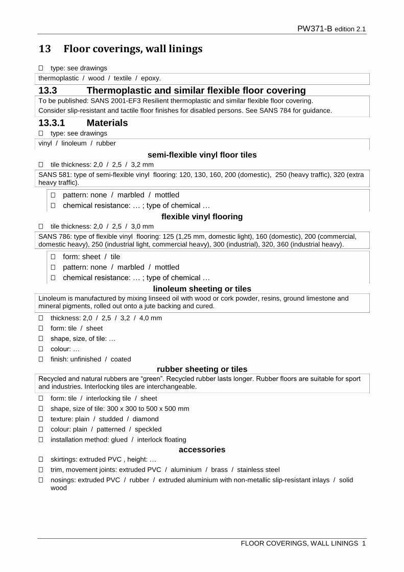
PW371-B edition 2.1
FLOOR COVERINGS, WALL LININGS 1
13 Floor coverings, wall linings
type: see drawings
13.3 Thermoplastic and similar flexible floor covering
13.3.1 Materials type: see drawings
semi-flexible vinyl floor tiles tile thickness: 2,0 / 2,5 / 3,2 mm
flexible vinyl flooring tile thickness: 2,0 / 2,5 / 3,0 mm
linoleum sheeting or tiles
thickness: 2,0 / 2,5 / 3,2 / 4,0 mm
form: tile / sheet
shape, size, of tile: …
colour: …
finish: unfinished / coated
rubber sheeting or tiles
form: tile / interlocking tile / sheet
shape, size of tile: 300 x 300 to 500 x 500 mm
texture: plain / studded / diamond
colour: plain / patterned / speckled
installation method: glued / interlock floating
accessories skirtings: extruded PVC , height: …
trim, movement joints: extruded PVC / aluminium / brass / stainless steel
nosings: extruded PVC / rubber / extruded aluminium with non-metallic slip-resistant inlays / solid wood
thermoplastic / wood / textile / epoxy.
To be published: SANS 2001-EF3 Resilient thermoplastic and similar flexible floor covering.
Consider slip-resistant and tactile floor finishes for disabled persons. See SANS 784 for guidance.
vinyl / linoleum / rubber
SANS 581: type of semi-flexible vinyl flooring: 120, 130, 160, 200 (domestic), 250 (heavy traffic), 320 (extra heavy traffic).
pattern: none / marbled / mottled
chemical resistance: … ; type of chemical …
SANS 786: type of flexible vinyl flooring: 125 (1,25 mm, domestic light), 160 (domestic), 200 (commercial, domestic heavy), 250 (industrial light, commercial heavy), 300 (industrial), 320, 360 (industrial heavy).
form: sheet / tile
pattern: none / marbled / mottled
chemical resistance: … ; type of chemical …
Linoleum is manufactured by mixing linseed oil with wood or cork powder, resins, ground limestone and mineral pigments, rolled out onto a jute backing and cured.
Recycled and natural rubbers are “green”. Recycled rubber lasts longer. Rubber floors are suitable for sport and industries. Interlocking tiles are interchangeable.

PW371-B edition 2.1
FLOOR COVERINGS, WALL LININGS 2
13.3.2 Laying pattern: see drawings / straight joints in both directions
finishing polymer floor dressing type: 1 / 2
13.4 Wood flooring, solid and laminate, on solid substrates
traffic class: 21 / 22 / 23 / 31 / 32 / 33
13.4.1 Materials
flooring type: see drawings
solid wood strip, block, parquet, mosaic
species: …
grade: clear / figured
preservative treatment: …
second-hand blocks: allowed / prohibited
prefinishing: required / not required
faced plywood or fibreboard facing: natural hardwood / cork / bamboo
species: …
prefinishing: required / not required
decorative melamine laminate pattern, colour: …
built-in underlay: required / not required
prefinishing: required / not required
underlays required insulating underlay function: acoustic / thermal / noise control / impact (sports)
polyethylene elastic-adhesive underlay:
Floor dressing type 1 produces hard coating; type 2 produces soft coating.
To be published: SANS 2001- EF1 Wood and Laminate Floor Covering.
For the installation of timber suspended floors see Section 4 Structural timber (flooring).
Solid wood floors may be sanded several times during their life span.
Wood and laminate flooring is laid directly on solid cementitious substrates. Solid wood floors are glued or nailed to battens. Laminate floors are floating floors assembled by using a patent click lock system. Wood and laminate floors expand and contract – do not use in wet areas.
SAWLFA South African Wood and Laminate Flooring Association is the industry representative body.
See SANS 10043 table 1 for a traffic classification according to EN 13329: 21 (domestic moderate, e.g. bedrooms), 22 (domestic general, e.g. living rooms), 23 (domestic heavy); 31 (commercial moderate, e.g. conference rooms, offices), 32 (commercial general, e.g. offices, hotels, classrooms, 33 (commercial heavy, e.g. corridors, stores, schools, halls, open plan offices).
See SANS 10043 table 6 for traffic, hardness, density and shrinkage classification of flooring timbers in common use.
Solid wood floors may be sanded several times during their life span.
solid wood strip/block / solid wood parquet/mosaic / plywood / faced plywood or fibreboard / melamine laminates
SANS 281 Hardwood block and strip flooring and SANS 978 Wood mosaic flooring were withdrawn in May 2009 and not replaced.
Note that some woods are naturally durable.

PW371-B edition 2.1
FLOOR COVERINGS, WALL LININGS 3
13.4.2 Installation installation in general
installation method: nail down / glue down / floating / stick down on elastic-adhesive underlay / sprung / as recommended by manufacturer
pattern: see drawings
nail down
13.5 Textile flooring
13.5.1 Materials textile flooring
type: pile construction / needle punched construction
colour and design: …
fire index class: 1 / 2 / 3 / 4 / 5
location grade: U1 / U2 / U3 / U4 / U5
carpet underlays type: fibrous / foam / contractor’s choice
13.5.2 Installation
13.6 Epoxy flooring
aggregate colour, size: …
application position of edge/dividing/feature strips: see drawings
thickness: 1 – 6 mm
finish: smooth / exposed aggregate finish.
This is an imported underlay with several advantages, not requiring gluing, nailing or clipping of the floor boards. Check with supplier.
density: 30 / 50 kg/m³
thickness: 2 / 3 / 5 / 10 / 15 mm
adhesive type: permanent / re-usable.
Underfloor heating has important repercussions for wood and laminate flooring. Check with supplier, SAWLFA.
Nail down is suitable for solid and engineered wood strip on new concrete floors or stairs, on existing rigid floors that are reasonably level, where a dpm is required, and where the total floor covering thickness of about 40 mm can be accommodated. Not to be installed over underfloor heating unless space between battens is filled with a cement:sand mix. Can be installed on walls as panelling.
Nail down floors can reduce impact noise transmission.
To be published: SANS 2001- EF2 Textile flooring.
Fire index: material to be used for floor covering (including underlays) or wall finish is tested in a standard manner and is classified on a scale of 1 to 5. These classifications are based on a "fire index" which in turn represents the effect of rate of burning and the amount of heat and smoke generated. Most good quality floor coverings have a fire index of 1 or 2. See SANS 10400-T table 9 and 10 for required classes for different occupancies.
Location grade: U1 (light domestic); U2 (medium domestic); U3 (heavy domestic, light commercial); U4 (medium commercial); U5 (heavy commercial).
Underlays: needled fibre, foam rubber, latex bonded fibre or composites. A carpet should be fire tested with its underfelt, since no fire classification for underfelt is currently available. Underfelt makes an important contribution to impact sound insulation, and to airborne sound absorption provided the carpet has a porous backing.
Seams should run parallel to length of area (so that traffic moves along rather than across the seam) and so that light from windows does not strike across the seam. Pile should face away from incident light and downwards on stairs.
Epoxy floors are hard-wearing and have excellent resistance to chemicals, oils etc.

PW371-B edition 2.1
FLOOR COVERINGS, WALL LININGS 4
Relevant standards:
SANS 10043 The installation of wood and laminate flooring
SANS 10070 The laying of thermoplastic and similar types of flooring.
SANS 10170 The cleaning and maintenance of floors.
SANS 10177 Fire testing of materials, components and elements used in buildings.
SANS 10186 The installation of textile floor coverings.
SANS 10245: The maintenance of textile floor coverings.
SANS 2424 Textile floor coverings – vocabulary.
SANS 10400-J Floors.
SANS 13746 Textile floor coverings – guidelines for installation and use on stairs.

PW371-B edition 2.1
PAINTING, PAPERHANGING 1
14 Painting, paperhanging
14.1 Materials primers
undercoats
universal undercoat grade: 1 / 2 / as required
finishing paints alkyd
alkyd high gloss finishing paint (SANS 630) grade: 1 / 2 / as required
decorative paint for interior use (SANS 515) type: semi-gloss / flat
emulsion emulsion paint (SANS 1586)
textured emulsion wall coating (SANS 1257)
fungus resistance: required / not required
varnishes, varnish stains, stains, sealers
varnish or varnish stains for interior use (SANS 887)
bituminous and tar-based coatings
specialized coatings
14.2 Preparation of surfaces hardware etc.: remove, mark, store and refix / mask.
To be published: SANS 2001-EP Painting.
Standards for red lead or red lead/red oxide primers, zinc chromate primers, calcium plumbate primers, metallic lead primers have been withdrawn due to toxic lead content.
Universal undercoats are suitable for interior and exterior use for subsequent application of solvent-borne finishes, especially gloss finishes.
1 (high hiding), 2 (utility grade).
Alkyd paint, also known as enamel paint, is solvent-borne.
1 (high hiding), 2 (regular hiding).
grade: 1 / 2 / 3 / 4
Grade: 1 (high hiding, scrub resistant), 2 (high hiding, washable), 3 (general purpose, washable), 4 (utility, interior only)
Emulsion paint is water-borne and suitable for application over plaster and masonry substrates. Grade 1, 2 and 3 is suitable for interior and exterior use, grade 4 for interior use only.
gloss designation: matt / semi-matt / semi-gloss
type: 1 / 2 / 3 / 4
1 (smooth aggregate-free), 2 (low-relief, sand-textured finish), 3 (high-relief, coarse-textured)
Aluminium paint is typically an alkyd resin binder pigmented with flake aluminium.
Micaceous iron oxide paint is typically solvent-borne. Masonry paint may be solvent-borne or emulsion type.
Varnishes are transparent or semi-transparent.
Stains have no protective or preservative properties and are suitable for interior work only.
type: 1 / 2
1 (general purpose), type 2 (heat and chemical resistant)
gloss designation: glossy / eggshell
Bitumen-based coatings for interior and exterior use on primed metal, masonry, fibre cement, wood, roofing felt, creosoted timber, hard bituminous surfaces.
Epoxy and polyurethane coatings have superior resistance to abrasion and chemicals. One-pack materials usually do not have the same resistance as the two-pack types. They require a high standard of surface preparation.

PW371-B edition 2.1
PAINTING, PAPERHANGING 2
14.3 Colours
identification colour marking (pipes etc.): required / not required.
14.8 Paint systems for on-site application paint system: see drawings
colour: see drawings.
14.8.1 Cement-based surfaces, brick and stone alkyd paint
14.8.3 Wood transparent finish systems for wood (interior)
14.8.5 Plastics paint on unplasticized polyvinyl chloride (PVC-U)
14.8.6 Intumescent paint surfaces requiring intumescent paint: …
14.9 Paperhanging
wallpaper type, pattern, colour: …
Specify colours on schedules. There is a marked difference in price for various colours, especially bright colours.
alkyd / emulsion / textured emulsion / masonry / cement / lime / varnish / aluminium / heat-resistant / sealer / intumescent
Alkyd-based coatings are sensitive to alkali. Alkali-resistant sealers are required on cement plaster and off-shutter concrete.
In transparent finishes the darker colours are more durable because they absorb ultraviolet light more effectively, but increase solar heat gain so that the moisture content of the wood decreases more rapidly.
Varnish is not recommended on exterior wood.
A two-pack wash primer is no guarantee for proper adhesion of conventional paint systems
No general specification can be made with regard to the painting of plastic coatings. Seek expert advice.
Intumescent paint enhances fire resistance by limiting spread of flame. Check compliance with fire regulations.
Relevant standards:
SANS 10064: Preparation of steel surfaces for coating.
SANS 10305: Painting of buildings:
Part 1: Paint and paint selection.
Part 2: Paint application and defects.
Part 3: Paint types.
Part 4: Painting of walls, ceilings and cladding.
Part 5: Painting of roofs and steel structures.
Part 6: Painting of wood.

PW371-B edition 2.1
FURNITURE, EQUIPMENT, STAIRS, ARCHITECTURAL METALWORK 1
15 Furniture, equipment, stairs, architectural metalwork
15.1 Joinery
15.1.1 Solid wood wood
type: hardwood / softwood / laminated wood
hardwood species: …
softwood species: …
laminated timber exposure class: 1 / 2 / 3 / 4
type of wood: hardwood / softwood
species: …
15.1.2 Wood board type: plywood / composite board / decorative melamine-faced boards (MFB) / fibreboard / particle
board / oriented strand board (OSB)
plywood and composite board (SANS 929) exposure class: 1 / 2 / 3 / 4 / as required
type board: ply / composite
type plywood: commercial / marine / structural
type composite board: batten board / blockboard / laminated board / high-pressure decorative board / veneered particle board / veneered fibre board
thickness plywood: 3 / 6 / 9 / 12 / 15 / 18 / 22 mm
number of plies or laminae: 3 / 5 / 7
veneer: species…, rotary cut / sliced
plywood grade: S / A / B
decorative melamine-faced boards (MFB) (SANS 1763)
core: particle board / MDF
thickness: 9 / 12 / 16 / 18 / 22 / 32 mm
shelving edge: sapele-print / melamine
surface finish: smooth matt / textured / embossed wood grain
moisture resistant board: required / not required
fibreboard (SANS 540)
type: insulation board / medium density fibreboard (MDF) / tempered hardboard
For wood doors and windows see Section 10.
SANS 1099 includes requirements for preservative treament. Annex C gives properties of 29 hardwood species, local or exotic.
1 (exterior); 2 (semi-exterior); 3 (humid interior); 4 (dry interior).
1 (exterior); 2 (semi-exterior); 3 (humid interior); 4 (dry interior).
Number of plies are always odd.
S (select, for decorative applications), A (furniture, for joinery where it may be reworked), B (standard, to be covered, coated or painted).
MFB is low pressure melamine on particle board or MDF, suitable for medium duty vertical and light duty horizontal surfaces e.g. shelving – not for kitchen and office desktops.
Board size 3,6 x 1,8 m.
MDF has a fine structure allowing for traditional wood-working techniques like moulding, embossing, routing and edge profiling.

PW371-B edition 2.1
FURNITURE, EQUIPMENT, STAIRS, ARCHITECTURAL METALWORK 2
thickness of tempered hardboard: 3,2 / 4,8 / 6,4 mm / as required
moisture content range: …
particle board (SANS 50312) type: P2 / P3 / P4 / P5 / P6 / P7 / as required
thickness: 12 / 16 / 18 / 22 / 25 / 28 mm / as required
oriented strand board (OSB) (SANS 472) type: OSB/1 / OSB/2 / OSB/3 / OSB/4 / as required
thickness: 6 / 9 / 12 / 15 / 18 mm / as required
15.1.3 Polymer laminate and solid surfaces high pressure decorative laminates (HPL) (SANS 4586)
material type: S / F / P / as required
grade/duty class (wear, impact and scratch resistance) : 1 / 2 / 3 / 4 / / as required
thickness: light duty and post forming: 0,35 / 0,6 / 0,8 / 1,0; general purpose: 1,2 / 1,5 / 2,0 / 2,5 / 3,0 / 3,5 / 4,5 mm; heavy duty: 6,0 / as required
surface finish, colour, texture: smooth matt / textured / embossed wood grain / writing
solid core grade: interior grade / exterior grade
thickness interior grade: 3 / 6 / 8 / 10 / 20 mm
thickness exterior grade: 20 mm
continuous pressed laminates (CPL)
grade/duty class, thickness: HGP / VGP / VLP / as required
colour, pattern: …
Hardboard can be bent by cold-dry, cold-moist and hot-moist bending techniques. Consult manufacturer. For full range of thicknesses see SANS 540.
P2 (general purpose, dry conditions); P3 (interior fitments, dry conditions); P4 (load-bearing, dry conditions); P5 (load-bearing, humid conditions); P6 (heavy-duty, dry conditions); P7 (heavy-duty, humid conditions).
OSB/1 general purpose dry interior; OSB/2 load-bearing dry conditions; OSB/3 load bearing humid conditions; OSB/4 heavy-duty load-bearing humid conditions, e.g. walls, floors, roofing, I-beams.
HPLs consist of layers of phenol formaldehyde impregnated sheets of Kraft paper with melamine formaldehyde (MF) impregnated décor and overlay paper, pressed together. Normally glued to suitable board with a backer laminate for balance, but can be self-supportive (solid core).
S (standard) / F (flame-retardant) / P (postformable).
1 (light duty, post-forming), 2 (vertical surface), 3 (general purpose), 4 (heavy duty)
General Purpose grade, thickness1,2 / 1,5 / 2,0 / 2,5 / 3,0 / 3,5 / 4,5 mm: for work surfaces on counters, vanities, desks and tables, and for vertical surfaces like wall panels and front panels of work stations in hospitals, airports and restaurants.
Vertical Surface grade: for cabinet walls, door and drawer panels, desks, restaurant booths, architectural cladding.
Light duty/post forming grade, thickness 0,35 / 0,6 / 0,8 / 1,0 mm: for rounded edges.
Heavy duty, thickness 6,0 mm
Omit if default (1,2 mm for grade 3 (general purpose) and 1,0 mm for grade 1 and 2 (vertical surfaces and post forming) is acceptable.
Solid core for horizontal and vertical work surfaces; exterior grade for vertical surfaces only, e.g. cladding, balustrading and signage.
Check thickness and usage with manufacturer.
CPLs are supplied in 100 –150m rolls.
HGP (horizontal, general purpose, postformable), thickness 0,6 mm, wear index number 3, impact index number 2, scratch index number 2; VGP (vertical, general purpose, postformable), 0,6 mm, 2, 2, 2; VLP (vertical, light duty, postformable), 0,35/0,5 mm, none, 2, 2.

PW371-B edition 2.1
FURNITURE, EQUIPMENT, STAIRS, ARCHITECTURAL METALWORK 3
polymer solid surfacing material
colour: …
inlays: …
form: …
15.1.4 Stone surfaces stone surfacing material
type: …
thickness: …
edge: …
form: …
15.1.5 Steel tubes for furniture steel tubes for furniture SANS 657-4
material and grade: mild steel 230 / 250 / stainless steel class A type 1 or 2, grade 304
size, profile: see drawings
wall thickness: see drawings
stainless steel finish: mill / matt / polished / mirror.
15.1.6 Joinery general
wood sizes: see drawings
exposed edges of veneered composite board: solid wood edging to match veneer and to full thickness of board
grain, pattern direction of grain or pattern: see drawings
backs backs to fittings: 4,8 mm hardboard / 16 mm ply/composite board / contractor’s choice / not required
drawers drawer construction: see drawings
shop painting delivery of joinery on site: knot and prime / knot and prime hidden faces only / brush apply one coat
clear finish as specified under Section 14 / reaction lacquer spray paint
15.1.7 Fixing
Size, profile: 16, 20, 25, 32, 38, 40, 50, 60, 70 mm ø (round steel); 16, 20, 25, 32, 50 mm (round stainless steel); 30 x 16 mm (oval steel); 20 x 20, 25 x 25, 32 x 32, 40 x 40, 50 x 50, 65 x 65 mm (square steel); 25 x 25, 32 x 32 mm (square stainless steel); 50 x 20, 50 x 25 mm (rectangular steel and stainless steel)
0,9 / 1,2 / 1,6 / 1,8 / 2,0 mm, depending on material.
Climate zones: inland / coastal. Inland zones represent over 90% of South Africa’s climate, made up of an average 8% moisture content, including air-conditioned indoor areas.
Wood sizes: show finished sizes of timber members on drawings to avoid arguments about tolerance: 25 mm nominal size reduces to 22 mm after planing, 38 to 32, 50 to 44, 76 to 68, 114 to 105, 150 to 140, 228 to 118 mm.
Check available board sizes to ensure optimum yield and to avoid unnecessary waste.
Marine ply is a superior choice to moisture resistant particle board in wet areas.
Omit if default (vertical on vertical surfaces, parallel to walls on horizontal surfaces) is acceptable.
Omit if default construction is acceptable.
Omit if fully painted (default) is acceptable.
Consider tables, counters and shelves at a variety of heights to accommodate standing, sitting and a range of different tasks for disabled persons.
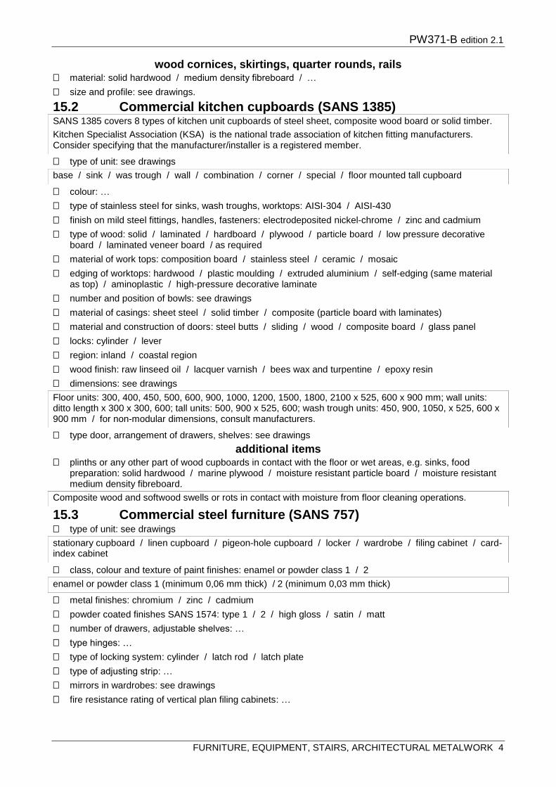
PW371-B edition 2.1
FURNITURE, EQUIPMENT, STAIRS, ARCHITECTURAL METALWORK 4
wood cornices, skirtings, quarter rounds, rails material: solid hardwood / medium density fibreboard / …
size and profile: see drawings.
15.2 Commercial kitchen cupboards (SANS 1385)
type of unit: see drawings
colour: …
type of stainless steel for sinks, wash troughs, worktops: AISI-304 / AISI-430
finish on mild steel fittings, handles, fasteners: electrodeposited nickel-chrome / zinc and cadmium
type of wood: solid / laminated / hardboard / plywood / particle board / low pressure decorative board / laminated veneer board / as required
material of work tops: composition board / stainless steel / ceramic / mosaic
edging of worktops: hardwood / plastic moulding / extruded aluminium / self-edging (same material as top) / aminoplastic / high-pressure decorative laminate
number and position of bowls: see drawings
material of casings: sheet steel / solid timber / composite (particle board with laminates)
material and construction of doors: steel butts / sliding / wood / composite board / glass panel
locks: cylinder / lever
region: inland / coastal region
wood finish: raw linseed oil / lacquer varnish / bees wax and turpentine / epoxy resin
dimensions: see drawings
type door, arrangement of drawers, shelves: see drawings
additional items plinths or any other part of wood cupboards in contact with the floor or wet areas, e.g. sinks, food
preparation: solid hardwood / marine plywood / moisture resistant particle board / moisture resistant medium density fibreboard.
15.3 Commercial steel furniture (SANS 757) type of unit: see drawings
class, colour and texture of paint finishes: enamel or powder class 1 / 2
metal finishes: chromium / zinc / cadmium
powder coated finishes SANS 1574: type 1 / 2 / high gloss / satin / matt
number of drawers, adjustable shelves: …
type hinges: …
type of locking system: cylinder / latch rod / latch plate
type of adjusting strip: …
mirrors in wardrobes: see drawings
fire resistance rating of vertical plan filing cabinets: …
SANS 1385 covers 8 types of kitchen unit cupboards of steel sheet, composite wood board or solid timber.
Kitchen Specialist Association (KSA) is the national trade association of kitchen fitting manufacturers. Consider specifying that the manufacturer/installer is a registered member.
base / sink / was trough / wall / combination / corner / special / floor mounted tall cupboard
Floor units: 300, 400, 450, 500, 600, 900, 1000, 1200, 1500, 1800, 2100 x 525, 600 x 900 mm; wall units: ditto length x 300 x 300, 600; tall units: 500, 900 x 525, 600; wash trough units: 450, 900, 1050, x 525, 600 x 900 mm / for non-modular dimensions, consult manufacturers.
Composite wood and softwood swells or rots in contact with moisture from floor cleaning operations.
stationary cupboard / linen cupboard / pigeon-hole cupboard / locker / wardrobe / filing cabinet / card-index cabinet
enamel or powder class 1 (minimum 0,06 mm thick) / 2 (minimum 0,03 mm thick)

PW371-B edition 2.1
FURNITURE, EQUIPMENT, STAIRS, ARCHITECTURAL METALWORK 5
15.4 Metal counters, balustrades, cladding, signs, street furniture material: see drawings
stainless steel
austenitic stainless steel grade: 304 or 304L / grade 316 in the coastal region 3 – 4km from the coast
finish: annealed and pickled mill finish / polished / coloured / etched / mirrored / electro-polished
form: see drawings
aluminium finish: mill / anodising / liquid organic coating / powder coating
colour: …
finish: matt / satin / high gloss / hammertone / textured
prefinished sheet metal products
type: 1 / 2a / 2b / 3 / 4 / 5a / 5b / 6a / 6b / as required
colour: …
finish: flat / semi-gloss / gloss
dry film thickness: …
type of substrate: hot dip galvanized steel / aluminium / stainless steel
15.5 Stairs and ramps type: see drawings
structure: see drawings
treads: see drawings
stainless steel / aluminium / prefinished metal
Stainless steel is low carbon steel containing >11% chromium (Cr), providing the steel with a corrosion resisting passive film.
Stainless steel classes are austenitic (300 series) and ferritic (400 series). Each class has several grades. Austenitic stainless steel grade 304 (European Norm1.4301) is normally used for street furniture, shop fronts, doorways, counters, balustrades, cladding, signs, roofing and street furniture. Use grade 316 in corrosive regions. Ferritic stainless steel is used only in interior applications of a non-aggressive nature.
Locally produced stainless steel is available in flat products, forgings and castings. Hot-rolled flat sheet is 3 – 50 mm thick, cold-rolled 0,4 – 3 mm thick. Sections like angles, channels, welded pipe and tubes are cold-rolled from flat sheet. Other grades and products are imported.
Stainless steel mill finishes can be annealed, pickled or polished. Processed finishes are achieved by grinding, polishing or buffing. Stainless steel can be coloured, acid-etched, mirrored, electro-polished, perforated, expanded, meshed or screened.
Choose the correct grade with consideration of the building’s location, prevailing environment and climate.
Design stainless steel elements to avoid receiving run-off water from other metals, or concentrated flows of rainwater over parts of the element. Designs must cater for the facilitation of regular cleaning.
Consult the Southern African Stainless Steel Association (SASSDA).
sheet / section / perforated / expanded / meshed / screened
Organic film coating on steel, aluminium, stainless steel for interior and exterior use.
1 (interior, requiring further application after fabrication); 2a (dry areas); 2b (wet corrosive areas); 3 (mild to moderate rural, urban, tropical and industrial environments); 4 (marine and industrial); 5a (severe marine); 5b (heavy industrial and industrial marine); 6a (very severe marine); 6b (very severe industrial)
straight / spiral / dogleg / combination / helical / security/fire / enclosed
The rule in SANS 10400 – M of a minimum going of 250 mm and a maximum rise of 200 mm often leads to a disregard for another rule, i.e, “any stairway … shall have dimensions appropriate to its use” (NBR part M Stairways). The full range of a more comfortable and safer proportion within the rule that “the sum of the going and twice the riser is not less than 570 mm and not more than 650 mm” would be: 180/280 mm; 170/280 – 310 mm; 150/280 – 350 mm and should be used in most public buildings.
Public ramps must have a safe gradient and frequent landings for disabled persons. Check with SANS 10400-S.
painted mild steel / stainless steel / wood, species

PW371-B edition 2.1
FURNITURE, EQUIPMENT, STAIRS, ARCHITECTURAL METALWORK 6
balustrade / handrail: see drawings
wood, species … / stainless steel / steel / glass
stainless steel / wood / glass / polymer concrete.
Relevant standards:
SANS 10400-M Stairways.
SANS 10400-S Facilities for Persons with disabilities.
SANS 10104 Handrailing and balustrading (safety aspects).

PW371-B edition 2.1
HARDWARE 1
16 Hardware
16.1 General type: see drawings
fire door hardware type: see drawings
material: see drawings
finish
finish: see drawings
sherardising coating thickness class: 15 / 30 / 45
electroplating service condtion: 1 / 2 / 3
appearance: bright / dull / satin.
16.2 Fasteners fastener type: bolt / screw / nut / washer / pin / rivet
metal screws for wood, type: countersunk-head / round-head / raised countersunk-head / slotted or cross recess drive / hexagon-head / scant shank
material and size: steel / brass / silicon-bronze / aluminium / stainless steel
mild steel nails: type…; finish…
16.3 Locks, latches, catches, bolts type lock: see drawings
type handle: see drawings
type latch: see drawings
type catch: see drawings
type of bolt, size: see drawings
Hardware information should appear on door, window or finishes schedules.
lock / latch / handle / plate / closer / hook and eye / bracket / hinge / bolt / door stop / door knob / door knocker / sanitary / furniture / curtain rail / edge or feature strip / sunken door mat / signage / drawer runner
escape hardware / panic bars / locksets with thumb turns / fire bolts
steel / stainless steel / aluminium / brass / nylon / ceramics / porcelain / wood
For finishes on metal see SANS 1171 Annex C.
natural / brass plated / copper plated / chrome plated / zinc plated / nickel plated / sherardised / cadmium plated / phosphated / passivated / antiqued / epoxy coated / powder coated / anodised
15 m normal indoor/outdoor / 30 m severe outdoor / 45 m highly severe outdoor/industrial/ marine.
1 (mild), 2 (moderate), 3 (severe)
Commercially plated fasteners are mostly sold with minimum corrosion protection, suitable only for dry interior conditions (corrosion resistance class C1). Thicker plating implies a special order (contact SAMFA – SA Metal Finishers Association – for details).
Rather specify solid brass, stainless steel or sherardized steel (30/45) for exterior or wet interior conditions, or ensure that plated products are protected by an appropriate paint system.
See SANS 1700 for full list of fastener types.
For roof/cladding fasteners see Section 7.
mortise / rim / cylinder / cupboard / drawer
lever / knob
mortise / cupboard / finger
magnetic / ball / roller

PW371-B edition 2.1
HARDWARE 2
hardware on fire doors: see drawings
padlocks type: see drawings
duty: medium / heavy
material: see drawings
size: see drawings
keys master and grand master keys: see drawings.
16.4 Hinges hinges for lightweight doors
type: see drawings
hinges for medium to heavy doors material: see drawings
number of hinges for fire doors: see drawings.
16.5 Door closers type: see drawings
floor springs, consisting of a floor spring unit set into the floor, bottom and top door strap of size and finish: see drawings
16.6 Pelmets, curtain rails, rods, blinds pelmets
type, size and profile: see drawings / wood / metal / fabric
rails with rollers or glides track: single / double
duty class: light / heavy
finish: …
cord: with / without weighted cord pulleys
barrel / flush / tower / stable / extension / size
SANS 10400-S stipulates that door handles should be 450 mm away from any wall.
Consider handles, levers and controls that are easy to operate by disabled persons. SANS 10400-S: The manual operation of handles, taps, levers, switches, locks, control mechanisms and keys is in part affected by their design. The selection of controls requiring a ‘twist-action’ of the wrist and hand, and fine-finger movements should be avoided.
keyed / combination / masterkeyed
brass / iron / chrome plated brass / aluminium / stainless steel
40 / 50 / … mm
piano / pivot / flush / european (adjustable) / strap
steel / stainless steel / brass / bronze
surface-mounted / concealed in frame / concealed in floor / concealed in door / overhead / floor / manual / automatic
Consult AAAMSA Technical Publication: Hardware, Door Controls etc.
Ensure surface mounted overhead closers do not hit the wall when opening.
All fire doors are required to be fitted with closers (NBR), usually overhead. Do not fit a mechanical hold open arm to a fire door. Use concealed mechanisms in hygienic areas.
For concealed floor types, ensure floor spring box depth of up to 75 mm can be accommodated.
Specifiy a higher strength closer for exposed, windy or draughty conditions. Specify a lower strength for narrow doors.
Double doors with rebated meeting stiles must be fitted with a door selector to ensure the inactive leaf closes first.
Size depends on door size and weight – see manufacturer’s literature.

PW371-B edition 2.1
HARDWARE 3
rods with rings rod, rings, end caps: wood / aluminium / steel
tie backs tie backs: …
indoor venetian blinds slat width: 50 / 35 / 25 mm
headbox: steel / aluminium
type of ladder web: reinforced plastic / woven cotton / knitted cords
16.7 Edge, feature, dividing strips strip material: solid brass / aluminium / hot dip galvanized steel / PVC
colour of plastic: …
16.8 Sunken door matting material: natural coconut fibre with PVC backing / rubber / interlocking aluminium channels with plastic
inserts / light or heavy-duty loop matting.
16.9 Number/name plates, safety signs
type: changeable plate system / variable room identification system / changeable letter system / illuminated signs / in-house signage / statutory signage
materials: aluminium / plastic / stainless steel
colour: …
symbolic safety signs type: PV / MV / WW / FB / GA
reflectivity, luminousity: standard (non-reflective) / self-luminous (radio luminescent) / internally illuminated / retro-reflective or photo luminescent / decal / embossed
size: 100 x 100 (WW7 only) / 150 x 150 / 190 x 190 / 290 x 290 / 440 x 440 / 880 x 880 mm)
16.10 Drawer runners/slides type commercial ball-bearing runner: normal / self-closing / soft-closing / push-locking
load capacity: 30 kg static / 45/90 – 160 kg (heavy duty)
extension: full / three-quarter.
Type, letter size, position, message etc. should be given in schedule form.
Signs may be grouped: general information signs; hospital signs; safety signs; signs for disabled persons; statutory signs, e.g. fire safety.
Changeable plate system: fixed plate holders to which may be attached or inserted removable interchangeable sign plates; variable room identification system: fixed room numbers and removable name strips; changeable letter system: holders into which can be inserted removable individual letters, numbers, etc.; illuminated signs: cabinet enclosing a light source illuminating a translucent face panel bearing the specified signage; in-house signage: project specific signs
PV (prohibitory – circular, red), MV (mandatory – circular, blue), WW (warning – triangular, yellow), FB (informative, fire-fighting – square, red), GA (informative, general – square, green)
See SANS 1186 Annex C for positioning, fixing, illumination and maintenance of signs.
Relevant standards:
SANS 10140 Identification colour marking.

PW371-B edition 2.1
GLAZING 1
17 Glazing
17.1 Materials glass
type of glass: see drawings
float glass thickness: see drawings
laminated safety glass interlayer strength class: NS / HPR / HI
bullet-resistant glass: class and level of attack: GA / GC / RA / RB / SB
pattern glass thickness: 4 / 6 mm; colour: clear / amber / bronze; pattern: …
tinted glass: heat-absorbing / heat-reflecting / glare-reducing
insulated glass units (SIGU’s) : 6/12/6, low-e surface #2, dehydrated air filled gap / …
coloured glass: …
work on glass: cutting / obscuring / acid embossing / silvering / gilding / staining or painting / bending
polymer glazing polymer glazing type: PC / PMMA / PVC clear / GRP / PS / PET / single wall / multi-wall
17.2 Glazing 17.2.2 Structural glazing design: by competent person (glazing) / submit proposals
SAGGA – South African Glass and Glazing Association – is the trade association and AAAMSA member.
Clear and tinted float glass is made in South Africa by one manufacturer in Springs.
float / safety / security / pattern / tinted / insulated / polymer
Local float glass thickness: 3, 4, 5, 6 and 10 mm.
NS (normal strength), HPR (high penetration resistance), HI (high impact).
Safety and security glass is made by several local manufacturers. Laminated safety glass is made with a poly-vinyl butyral interlayer (0,38 mm for Normal Strength (NS); 0,76 mm High Penetration Resistant (HPR); 1,14mm High Impact (HI)); or a cast in place polyester resin interlayer, available in one thickness only (0,5 mm Normal Strength). SANS 1263 provides for three applications, i.e. human contact, burglary and firearms. See SANS 1263 for bullet-resistant glass classes and level of attack.
All patterns cost the same.
6/12/6 denotes glass-space-glass. Common insulated glass thickness range (glass-space-glass) in South Africa is 20–28 mm. Life expectancy of double glazing in South Africa has not been recorded. Northern hemisphere experience indicates 7–12 years, 20 years being exceptional.
Available polymer glazing materials are polycarbonate (PC), polymethyl methacrylate (PMMA or ‘acrylic’), polyvinyl chloride (PC), glass-fibre reinforced polyester (GRP), polystyrene (PS), polyethylene teraphthalate (PET). PC and PMMA is available in sheet sizes 1 250, 1 500 or 2 050 wide by up to 6 m long by 1,5 – 6 mm thick. They can be cold bent to minimum radii of 300 x thickness for acrylic, or 100 x thickness for polycarbonate.
Outstanding properties of polymer glazing are impact strength (polycarbonate 250x glass), light transmission, light weight, weather resistance, thermal insulation in multi-wall construction (40% better than glass). Typical applications: rooflights, industrial roofs, commercial greenhouses, shopping centres.Polycarbonate is self-extinguishing, acrylic burns like hardwood. No toxic fumes are claimed. Make generous allowance for thermal movement.
Structural glazing depends on stringent quality tests and checks, for example the pretreatment of aluminium, surface finishing, sealants, and factory and site care. Check with AAAMSA.
A butt joint in structural glazing is assumed to have no structural strength.
Check underwater glazing, glazing for fire protection, for control of reflections in shop windows, for solar control, for one-way vision, unframed glazing, suspended glazing, glass floors, glazing with channel profiles, glazing with plastics and patent glazing, with manufacturers, specialists and SANS 10137.

PW371-B edition 2.1
GLAZING 2
17.2.3 Protection and cleaning
17.3 Mirrors type: silvered clear glass / silvered coloured glass / stainless steel / privacy
size and position: see drawings
coloured glass: pink / gold / bronze / black
Anti-sun glass can be permanently damaged by mortar or plaster splashes. Specify precautions if risk is high.
silvered mirror backs are easily damaged. Silvered obscure glass also available. Stainless steel for vandal proof areas.
Consider full length mirrors in public places for children and disabled persons.
Relevant standards:
SANS 10137 The installation of glazing materials in buildings.
SANS 1263 Safety and security glazing materials for buildings.
SANS 10400-N Glazing.
SANS 2001-CG1 Installation of glazing.
Relevant sources:
Selection Guide for architectural Aluminium Products. AAMSA.
Skylight Association of Southern Africa.

PW371-B edition 2.1
DRAINAGE, SEWERAGE, WATER AND GAS, FIRE EQUIPMENT, SANITARY PLUMBING 1
18 Drainage, sewerage, water and gas supply, fire equipment, sanitary plumbing
18.1 Roof eaves drainage 18.1.2 Gutters and downpipes
gutter type: see drawings
material: Z575 / Z450 / Z600 / AZ150 / AZ200 hot dip galvanised steel sheet / uncoated steel painted on-site / aluminium / copper / U-PVC / fibre cement / prepainted
profile: see drawings
size: see drawings
accessories outlet drop boxes: funnel shaped
overflow weirs in box gutters: required
hail guards: see drawings
launders: see drawings
gutter brackets type: purlin / fascia / purpose-designed for industrial/box gutters / as supplied by gutter manufacturer
downpipes material: galvanised steel sheet / PVC
size: see drawings
sheet metal downpipe bends: crimped / solder mitred / sealed and pop riveted
18.2 Flat concrete roof, balcony and floor drainage 18.2.1 Rainwater outlets
type: see drawings
patent type: see drawings
eaves / valley / box / parapet/chimney
Galvanized sheet: Z575 or AZ150 for inland use; Z450/ Z600 or AZ200 for the coastal region, prepainted for corrosive industrial use. Commercial standard rainwater goods are made of 0,4 or 0,5 mm thick sheet.
half round / square / rectangular
100 x 75 mm, or 100 / 125 / 150 mm half round (domestic); 125 x 100 (institutional); 150 x 100 / 200 x 150 / >225 x 225 (industrial). Sheet metal gutter standard lengths: 1,8; 3,0; 3,6; 4,8; 5,4; 6,0 m.
Gutter and downpipe sizes are determined by roof area and rainfall region in accordance with the requirements of SANS 10400-R: summer rainfall area:140 mm²/m² roof area served; year-round rainfall area:115 mm²; winter rainfall area: 80 mm². Downpipe internal size: 100 mm²/m² roof area served or 4400 mm² (75 mm diameter). For more information on gutter design, e.g. risk, rainfall intensity, hail and outlet protection, launders, drop boxes etc. see The Red Book – Southern African Steel Design Handbook, Section 11.
Drop boxes for box gutter outlets improve flow and reduce stoppage by debris.
removable / pedestrian trafficable
Hail guards over gutters act as protection against hail, as maintenance walkways, as outlet protection and as protection against leaves and wind-blown debris. Trafficable hail guards should be made of suitable gauge expanded mesh – provide clear working drawings. Hail guards should be removable for maintenance.
Launders are horizontal downpipes draining intermediate box gutter outlets to the exterior of large industrial buildings.
Do not use PVC downpipes if offsets are required.
75 / 100 / 120 / 150 mm square / diameter
Best solution for outlet protection is to use oversize downpipes ≥200 mm diameter.
patent with grating / pipe without grating

PW371-B edition 2.1
DRAINAGE, SEWERAGE, WATER AND GAS, FIRE EQUIPMENT, SANITARY PLUMBING 2
outlet size: see drawings
18.2.2 Floor outlets material: ductile iron with baked epoxy coating / stainless steel
18.2.3 Outlet downpipes material: PVC / galvanized steel
size: see drawings
18.3 Stormwater drainage 18.3.1 Earthworks (SANS 2001-DP1)
Specification data:
pipes that are to be encased in concrete: see drawings
18.3.2 Storm water drainage (SANS 2001-DP5)
Specification data:
pipes material of pipe, associated fittings: see drawings
diameter: see drawings
culverts precast concrete culverts
tests tests: required / not required
18.3.3 In situ concrete stormwater channels overall width: see drawings
fall: see drawings
spill basin shape, size and finish: see drawings.
18.4 Sewerage 18.4.1 Earthworks (SANS 2001-DP1) Specification data:
pipes that are to be encased in concrete: see drawings
vertical / 45° / 90° / two-way / car-park / pedestrian
50 / 80 / 100 / 150 mm diameter
Outlets without gratings should be used for small roof areas in accessible position only, e.g. for balconies, and be not less than 75 mm in diameter due to the waterproof dressing restricting the pipe bore, unless pipe can be flanged.
75 / 110 / 160 mm (PVC); 80 / 100 / 125 / 150 mm (steel)
SANS 2001-DP1 covers earthworks for trenches for all types and sizes of buried pipelines, ducts, cables and prefabricated culverts, including excavation, preparation of trench bottoms, bedding, backfilling and reinstatement of surfaces.
SANS 2001-DP5 covers the construction of stormwater drainage systems including pipelines, manholes, culverts, catchpits, inlet and outlet structures.
concrete / fibre cement / PVC-U / GRP / PP / PE
concrete pipes: 100, 150, 225, 300, 375, 450, 525, 600, 675, 750, 825, 900, 1050, 1200, 1350, 1500, 1800 mm. Check diameters of other material pipes.
class: 75S / 100S / 125S / 150S / 175S / 200S
dimensions (internal) : see drawings
span: 450, 600, 750, 900, 1200, 1500, 1800, 2400, 3000 mm
height: 300, 450, 600, 900, 1200, 1500, 1800, 2400, 3000 mm
380 / 450 / … mm
380 mm width: 230 mm x 75 mm deep channel; 450 mm width: 300 mm x 100 mm deep channel.
1:250 min.

PW371-B edition 2.1
DRAINAGE, SEWERAGE, WATER AND GAS, FIRE EQUIPMENT, SANITARY PLUMBING 3
18.4.2 Sewers (>160 mm) (SANS 2001-DP4)
Specification data:
type of pipe, associated fittings: ductile iron / fibre cement / PVC-U / structured wall PVC-U / PP / GRP / pitch impregnated fibre / vitrified clay / reinforced concrete
diameter: see drawings
gradient: see drawings
step irons in manholes: required / not required
masonry manholes: plastered internally / plastered internally and externally to prevent infiltration
tests on completed pipelines: required / not required.
18.4.3 Sewers for buildings (SANS 2001-DP7)
Specification data:
type of pipe, associated fittings: cast iron / ductile iron / fibre cement / PVC-U / structured wall PVC-U / PP / GRP / pitch impregnated fibre / vitrified clay / reinforced concrete
nominal diameter: see drawings
gradient: see drawings
18.4.4 Surface boxes, manhole covers, gulley gratings, frames
type: see drawings
material: polymer concrete / cast iron or steel
polymer concrete polymer concrete covers
cast iron/steel and concrete cast iron, cast steel, rolled steel combined with concrete covers
gulley gratings: laid loose / bedded in bitumen.
SANS 2001-DP4, Sewers, covers the construction of sewer systems within servitudes, road reserves and interconnected complexes and is suitable for the construction of below ground sewers having a diameter greater than 160mm. Excludes sewer rising mains, pump stations, treatment works, and ancillary works.
Unplasticised polyvinyl chloride (PVC-U); polypropylene (PP); glass-reinforced plastics (GRP)
200 / 250 / 315 / 355 / 400 / 450 / 500 / 560 / 630 / 750 / 800 / 900 / 1 000 mm diameter (PVC-U). Check diameters of other material pipes.
SANS 2001-DP7 covers surface mounted sewers having a nominal diameter of 200 mm or less; and below ground sewers having a nominal diameter of 160 mm or less including manholes and the like which discharge into a connecting sewer, conservancy tank, French drain or septic tank. This standard is suitable for constructing sewers designed in accordance with the design rules provided in SANS 10400-P, Drainage. Construction of manholes is referred to SANS 2001-DP4.
40 / 50 / 75 / 110 / 160 mm
SANS 10400-P requires that sewer gradient be not flatter than 1:120 for 100 mm diameter pipes and 1:200 for 150 mm pipes. The hydraulic load determines the minimum grade of the pipe.
For vehicular and pedestrian areas only (does not apply to gullies and manholes in buildings).
surface box / valve chamber / manhole/inspection cover / gulley grating
size: see drawings
duty class: see drawings
heavy (trucks) / medium (domestic vehicles / light (no wheeled vehicles)
size: see drawings
duty class: see drawings
A15 / B125 / C250 / D400 / E600 / F900
Class A15 pedestrian and pedal cyclists; B125 car parks; C250 road kerbside channels; D400 roads, hard shoulders, parking for all types of road vehicles; E600 docks, aircraft pavements; F900 particularly high wheel loads.

PW371-B edition 2.1
DRAINAGE, SEWERAGE, WATER AND GAS, FIRE EQUIPMENT, SANITARY PLUMBING 4
18.4.5 Grease interceptors material: stainless steel / reinforced fibreglass
type, capacity and size: see drawings / to approval of the local authority
18.4.6 Pit latrines type: see drawings
construction: masonry / patent precast concrete / patent polymer
pit size: see drawings
18.4.7 Conservancy tanks, septic tanks and french drains type: see drawings
construction: masonry / patent precast concrete / patent polymer
tank capacity: see drawings / as prescribed by local authority
french drain length: see drawings
18.5 Water supply 18.5.1 Earthworks (SANS 2001-DP1)
Specification data:
pipes that are to be encased in concrete: see drawings.
18.5.2 Below ground medium pressure pipelines (SANS 2001-DP2)
Specification data:
type of pipe: steel / ductile iron / concrete / fibre-cement / GRP / PE / PP / contractor’s choice)
nominal pipe sizes: see drawings.
18.5.3 Below ground water installation for buildings (SANS 2001-DP6)
Specification data:
type of pipe and associated fittings: galvanised mild steel / fibre cement / GRP / PE / PP / PVC / PVC-U / PVC-M / PVC-O / copper / contractor’s choice
Several models are available on the market.
VIP / masonry / patent / to approval of local authority
Pit size depends on capacity/ number of persons using. Omit if default (750 x 1 500 x 2 000 mm minimum deep) is acceptable. Maximum pit size: 1 000 x 2 500 x 2000 mm.
conservancy tank / septic tank / french drain
Conservancy tank capacity is typically 6 000 L. See SANS 10400-P for sizing of septic tank. Patent septic tank capacity 1 250 litres (2-4 persons); 1 500 (2-6); 1 750 (4-6); 2 000 (4-7); 2 500 (4-9). Consult SANS 10252 for design guidelines.
See SANS 10400-P for length formula, positioning, soil type, etc.
SANS 2001-DP1 covers earthworks for trenches for all types and sizes of buried pipelines, ducts, cables and prefabricated culverts, including excavation, preparation of trench bottoms, bedding, backfilling and reinstatement of surfaces.
SANS 2001-DP2 covers the supply and installation of pipelines of diameter greater than 160 mm and up to 1 000 mm, complete with ancillary works (valves, strainers, hydrants, manholes, surface boxes, chambers) for transporting water and sewage under working pressures up to 2,5 MPa.
Erf or connections to buildings from mains are covered in SANS 2001-DP6.
glass-reinforced plastics (GRP); polyethylene (PE); polypropylene (PP)
225 / 300 / 375 / 450 / 525, 600 / 675 / 750 / 825 / 900 mm
SANS 2001-DP6 covers the construction of water pipelines having a nominal diameter of up to 160 mm from a water reticulation main to the boundaries of individual erven or other specified points on erven. It covers the installation of pipework and associated specials which provide water, meters and fire hydrants
SANS 2001-DP6 is suitable for construction of fire installations designed in accordance with the design rules provided in SANS 10400 W, Fire installations.

PW371-B edition 2.1
DRAINAGE, SEWERAGE, WATER AND GAS, FIRE EQUIPMENT, SANITARY PLUMBING 5
nominal pipe size: see drawings
meter type and size: …
18.5.4 Above ground water installation pipe material: galvanised mild steel / PP / copper / contractor’s choice
nominal pipe size: see drawings
fixing of pipes <20 mm: chased / surface fixed
18.5.5 Water storage tanks tank material: tumbled polymer / pressed steel sections bolted and sealed together / corrugated steel
capacity or size: see drawings / …L
stand for external tanks: …
18.6 Electric geysers and solar water heaters 18.6.1 Electric geysers
geyser type: open outlet / cistern type / closed (unvented) / floor or wall mounting / horizontal or vertical
nominal capacity: see drawings
design: standard / solar / dual purpose.
18.6.2 Solar water heaters type: domestic / commercial / industrial
capacity in litres (integral units only): …
collector/storage combination: integral / close-coupled / split
heat transfer method: direct / indirect
circulation method: thermo-siphon / pumped
cover: with cover / without cover
supplementary energy source required: mains electricity / gas / …
working pressure: 0 / 100 / 200 / 300 / 400 kPa
freezing, hail resistance: required / not required.
18.8 Fire equipment fire hose reels
height from floor to spindle if not 2 100 mm: …
enclose reel in security box with clear acrylic cover and suitable closer: required / not required
portable fire extinguishers portable non-refillable general purpose extinguishers (SANS 1322):
Glass-fibre reinforced plastics (GRP) / polyethylene (PE) / polypropylene (PP) / polyvinyl chloride (PVC) / unplasticised polyvinyl chloride (PVC-U) / modified polyvinyl chloride (PVC-M) / oriented polyvinyl chloride (PVC-O).
40 / 50 / 75 / 110 / 160 mm
8 / 10 / 12 / 15 / 18 / 22 / 28 / 35 / 42 / 54 / 67 / 76 / 108 mm (copper, check other pipe types)
Surface mounting may be a requirement from a maintenance point of view.
Chasing is prohibited in wall faces that are to receive roof flashing. Roof flashing is inserted in grooves sawn by a separate trade with disc cutters after pipes are installed, leading to unnecessary and costly pipe repair work when pipes are damaged.
geysers should be placed near kitchen sinks that are regularly used throughout the day. Show geyser positions in drawings.
open outlet and cistern type 15 / 25 / 50 / 75 / 100 / 125 / 150 / 175 / 200 / 250 L; closed type 15 / 25 / 50 / 75 / 100 / 125 / 150 / 175 / 200 / 250 / 300 / 400 / 600 L

PW371-B edition 2.1
DRAINAGE, SEWERAGE, WATER AND GAS, FIRE EQUIPMENT, SANITARY PLUMBING 6
water, foam or dry powder rechargeable extinguishers (SANS 1910):
CO2 type extinguisher (SANS 1567):
BCF type extinguisher (SANS 1151) capacity: 1 – 12 kg
enclose extinguisher in security box with clear acrylic cover and suitable closer: required / not required.
18.9 Sanitary plumbing 18.9.1 Sanitary appliances
appliances appliance type: see drawings
material: see drawings
stainless steel grade: 430 / 304 / 316; finish: satin / bright
anti-theft waste plug: required / not required
flow restrictors: required / not required
baths type, shape: see drawings
handles: required / not required
basins type, shape: see drawings
wash troughs type: see drawings
water closets type: see drawings
flushing cisterns type: see drawings
flush capacity: low-flush (4½ or 6 L) / regular flush (6 or 9 L)
Suitable for all classes of fire other than class D
class: I / II
class I (temp <110°C); II (temp <65°C)
capacity: 1,5 / 2,5 kg
extinguishing medium: lp gas / dry powder
type: water / foam / dry powder
class of fire: A / B / C
A (ordinary combustibles); B (flammible liquids); C (live electric power), or combinations, e.g. ABC
capacity: <9kg
class of fire: A / B / C
Suitable for class of fire AC / BC / ABC
wash-hand basin / bath / water closet / urinal / bidet / sink / flushing cistern
glazed ceramic / stainless steel / plastic / stone / concrete
Omit if default (430) is acceptable. Stainless steel grades are listed by the American Iron and Steel Institute (AISI). Grade 430 is suitable for domestic purposes, kitchen sinks, wash troughs and hand wash basins. Grade 304 is suitable where mild corrosive conditions exist, e.g. in coastal areas. Grade 316 is suitable for laboratories, photographic workrooms and seagoing vessels where corrosive conditions are severe.
built-in / freestanding / spa / rectangular / oval / corner
counter-top / wall hung / drop-in / pedestal / round / oval / corner
single trough / double trough / with drainboard
wall-hung / floor mounted / close-couple / squat
high level / low level / near level / close coupled / wall-hung / concealed

PW371-B edition 2.1
DRAINAGE, SEWERAGE, WATER AND GAS, FIRE EQUIPMENT, SANITARY PLUMBING 7
flush valve flushing operation: single flush / dual flush / interruptible flush
urinals urinal type: see drawings
bidets bidet type: see drawings
sinks sink type: see drawings
bowl position: see drawings
shower enclosures
shower enclosure type: purpose made / prefabricated / domestic to SANS 549 / medical / industrial / cabinet / curtain / roofed (steam shower)
drained floor type: tiled / tray / bath
glazed wall/door/roof construction: framed / frameless
safety glass: toughened safety glass / laminated safety glass / plastic
door type: pivoting / folding- sliding
metal finish: anodising, grade … / powder coating, type 4
18.9.2 Taps, valves, showerheads tap, valve type: see drawings
showerhead type: see drawings
material: chromium plated brass / stainless steel / plastic
flush valve type: WCHP / WCLP / urinal
18.9.3 Traps type: see drawings
material: plastic / rubber / chromium plated brass
depth of seal: 40 / 75 mm.
18.9.4 Miscellaneous holders
holder type: see drawings
material: chromium plated brass / glazed ceramic / aluminium / wood
bowl / trough / stall
wall-hung / floor mounted
domestic / laboratory / scullery / scrub sink / cleaner’s / drop-in / wall-hung / pot / freestanding / with drainboard / with backsplash and tiling key / single, double or triple compartment
left / right / centre
SASEMA (South African Shower Enclosure Manufacturer’s Association). SANS 549 “domestic” includes use in hotels, student accommodation, hospitals.
Frameless construction requires toughened safety glass. Holes for hinges etc. must be prepared before toughening.
Metal coating grade/thickness will depend on location: anodising grade AG15 or AG20 will suffice for mild atmospheric conditions, while grade AG25 will be required for coastal applications. For powder coating, type 4 or 5 should suffice. Check with manufacturer.
bath / basin / shower / sink / garden / bib / pillar / mixer / divert mixer / swivel / stop / flush / gate / hose / washing machine / draincock / float
fixed rose, diameter … / adjustable rose / swivel / rail / vandalproof / handshower and holder
WCHP (Water closet high pressure; WCLP (water closet low pressure).
bottle trap / P-trap / P-trap resealing / pop-up
paper / soap / tumbler / tooth brush / toilet brush / towel rail/ring/hook

PW371-B edition 2.1
DRAINAGE, SEWERAGE, WATER AND GAS, FIRE EQUIPMENT, SANITARY PLUMBING 8
shelves material: safety glass with polished edges on nickel-chromed / wood / metal / plastic brackets
cabinets type: wall / vanity / with mirror
material: wood / plastic / metal.
Relevant standards:
SANS 10105 The classification, use and maintenance of portable fire extinguishers.
SANS 10112 The installation of polyethylene and PVC-U pipes.
SANS 10102 Selection of pipes for buried pipelines.
SANS 10252-1 part 1: Water supply and drainage for buildings; part 2: Drainage installation for buildings.
SANS 10254: The installation of fixed electric storage water heating systems.
SANS 10400-P Drainage.
SANS 10400-Q Non-water-borne means of sanitary disposal.
SANS 10400-R Stormwater disposal.
Relevant sources:
Concrete Pipe Handbook published by the Concrete Society of Southern Africa.

PW371-B edition 2.1
ELECTRICAL WORKS 1
19 Electrical works
19.1 Earthworks (SANS 2001-DP1)
Specification data:
areas where pipes are to be encased in concrete: see drawings
19.2 Cable ducts (underground) (SANS 2001-DP3)
Specification data:
type of pipe, associated fittings: pitch impregnated fibre / PVC-U / fibre cement / vitrified clay
draw pits: see drawings.
19.3 Materials and installation 19.3.1 Wiring
conduits
conductors
distribution board, meter cabinets position of DB’s and meter cabinets: see drawings.
19.3.2 Fittings luminaires
type: see drawings
stove, hob, oven, cooker hood stoves, hobs, ovens, cooker hoods model, type: … / see drawings.
SANS 2001-DP1 covers earthworks for trenches for all types and sizes of buried pipelines, ducts, cables and prefabricated culverts, including excavation, preparation of trench bottoms, bedding, backfilling and reinstatement of surfaces.
SANS 2001-DP3 covers the supply, and the laying and bedding in trenches, of pipes of diameter not exceeding 160 mm as ducts for the protection of telephone and electric power cables.
Unplasticised polyvinyl chloride (PVC-U).
Chasing is prohibited in wall faces that are to receive roof flashing. Roof flashing is inserted in grooves sawn with disc cutters after conduits are installed, leading to unnecessary and costly repair work.
See SANS 10198 The selection, handling and installation of electric power cables of rating not exceeding 33 kV.
surface mount / recessed / accent / downlighter / step / theatre / outdoor (pole, step, bollard)
Relevant standards:
SANS 10114 Interior lighting.
SANS 10389 Exterior lighting.
SANS 10142 The wiring of premises.
SANS 10222 Electrical security installations.
SANS 10313: The protection of structures against lightning.
SANS 61024 Lightning protection of structures.
PW371-B edition 2.1
MECHANICAL WORKS 1
20 Mechanical works
20.1 Installation routing and/or concealment of cables, ducts, trays, pipes etc. : see drawings.
20.3 Location and access catwalks, cat ladders, access panels: see drawings.
Catwalks and cat ladders should be detailed and coordinated with other services in order to keep to a minimum.

PW371-B edition 2.1
EXTERNAL WORKS 1
21 External works
21.1 Paving 21.1.1 Materials
units paving unit type: see drawings
precast concrete segmental paving blocks type: S-A (interlock) / S-B (semi-interlock) / S-C (rectangular)
class: 25 / 35
nominal thickness: 50 / 60 / 80 / 100 / 120 mm
top edges: chamfered / not chamfered
colour: …
burnt clay paving units class: PB / PA
colour and work size: …
precast concrete paving slabs size: 295 / 445 / 595 x 295 / 445/295 / 595/455 x 50/65 mm
sand for bedding and jointing of flexible paving
21.1.2 Preparation subgrade
subgrade levels and falls: see drawings
concrete sub-base for rigid paving thickness, reinforcement: see Section 2
weed killer treat area to be paved with suitable weed killer: required / not required
levels, falls, pattern levels and falls: see drawings
pattern: see drawings / herringbone / basket weave / stretcher / waving
21.1.3 Laying
type of paving: see drawings / flexible block/brick / flexible slab / rigid block/brick / in situ concrete
flexible block/brick paving
concrete anchor beams across road on grades exceeding 8%: …
precast concrete blocks / burnt clay pavers / in-situ concrete / precast concrete slabs
Class 25 (MPa) concrete blocks should be specified for most uses.
Thickness of blocks depends on site conditions, design requirements and cost.
PB (uniform), PA (highly uniform in shape and size).
The use of mine sand for jointing is generally accepted.
Check soil and traffic conditions with a Competent Person. The sub-base thickness is a function of both the type and amount of traffic to be carried and the strength of the subgrade. See also SANS 1200 ME, MF, ML.
A fall of 1:60 is regarded as an optimum fall. Gradients of 1:100 are less forgiving (workmanship, settlement).
Edge restraints along the perimeter of the paving is necessary to prevent lateral spread of the units and to retain the bedding course sand. See concrete culverts, kerbs etc. below.
See SANS 784 for guidance on tactile indicators for access and mobility.
Flexible paving is paving laid on sand, with joints filled with sand. The surfaces of flexible paving usually bed down ±5 mm after trafficking.
Consider mixing filling sand with 10 – 15% cement depending on traffic, type of paver, and control of weed growth. Spray paving thus filled with a fine spray of water immediately after filling to clean off all cement.
PW371-B edition 2.1
EXTERNAL WORKS 2
flexible slab joints: filled with mortar / to be left open
rigid block/brick paving
accuracy
21.2 Concrete culverts, kerbs, channels type: see drawings
21.2.1 Materials precast concrete culvert class: 75S / 100S / 125S / 150S / 175S / 200S
kerb type: see drawings
edging type: see drawings
channel type: see drawings
21.2.2 Laying movement joints: leave open / fill with polysulphide.
21.3 Concrete retaining blocks
blocks shape, size and colour: …
preparation depth, level and type of foundation: see drawings
width of foundation: see drawings
drain pipes, aggregate drain, geofabric drain behind retaining wall: required / not required
placing stacking pattern: see drawings
geofabric reinforcement: required / not required.
21.4 Gabions materials
cage dimension: 4 x 1 x 1 / 6 x 2 x 0,5 m
Horizontal forces of motor traffic increase considerably on grades exceeding 8%, causing creep. This is avoided by casting concrete anchor beams across the road. On steeper grades the paving should preferably be rigid. See CMA technical note 6.2 1994.
Rigid paving is paving units bedded in mortar on a concrete base. External paving is exposed to wide temperature and moisture fluctuation which can only be provided for by movement joints.
Accuracy depends on experience of contractor and/or labourers, and importance of the contract.
culvert / kerb / channel
Class depends on foundation conditions and fill.
dimensions (internal) : see drawings
span: 450 / 600 / 750, 90 / 120 / 150 / 180 / 240 / 3 000 mm; height: 300 / 450 / 600 / 900 / 1 200 / 1 500 / 1 800 / 2 400 / 3 000 mm
rectangular / half-battered / battered / mountable
rectangular / half-round
rectangular / tapered.
Concrete retaining blocks are an economical, versatile and environmentally compatible method of retaining earth and be used for planting, steps, seats, pavilions, and for erosion and scour control.
Foundations: also on sloping or gravel foundation. Drawings should show this. Compacted earth foundation is usually sufficient for structures not higher than 1,2m. Higher walls should be thicker, inclined towards the retained earth, anchored with a geogrid mesh, or by modifying the properties of the backfill. Consult the supplier of the blocks and/or Competent Person. Ensure building regulations are complied with.
Show width of foundation if of concrete.
SANS 207 gives recommendations for the application of reinforcement techniques to soils and other fills.
PW371-B edition 2.1
EXTERNAL WORKS 3
mesh wire to be PVC-coated: required / not required.
21.5 Fencing type: see drawings
21.5.1 Line wire and chain-link mesh fencing type wire: …
type chain link wire: 1 / 2
colour of PVC coating when relevant: dark green / white
nominal size mesh of chain-link wire: 40 / 50 / 60 / 75 / 100 mm
posts, stays, standards, droppers type: steel / concrete / wood
erection fence height: see drawings
fencing gates size, shape: see drawings.
21.5.2 Weld mesh fencing material: mild steel / high tensile steel / very high tensile steel
mesh size: 25 x 25 / 50 x 25 / 50 x 50 / 100 x 50 / 100 x 100 mm
finish: hot dip galvanized / black / hot dip galvanized and powder-coated
fence height: see drawings
21.5.3 Barbed tape fencing type: A (concertina) / B (flatwrap) / C (barbed tape unclipped) / D barbed razor tape
material: zinc-coated steel strip / stainless steel
zinc coating grade: light / medium / heavy
21.5.4 Palisade fencing type: steel / concrete
finish on steel: paint / hot dip galvanized
steel type: security purpose / general purpose
steel fence height: see drawings
concrete fence height: see drawings
21.5.5 Electric fencing type: wall top / from ground up / electrified palisade / freestanding
number of lines for wall-top type: 6 / …
powered by: mains / battery / solar.
21.5.6 Gate automation theft-resistant cages with padlock: required / not required.
line wire on steel posts, stays, droppers and standards / wire chain-link mesh on strain wire on steel posts, stays, droppers and standards / welded mesh / barbed tape / palisade / electric / private swimming pool
line / barbed
1 (zinc coated) / 2 (zinc coated and PVC coated).
900 / 1 200 / 1 800 / 2 000 / 2 400 / 3 000 / 3 600 mm
High tensile steel (>950 MPa); very high tensile steel (>1 250 MPa).
1 200 / 1 800 / 2 400 mm
1 800 / 2 400 / 3 000 / 3 600 mm
1 800 / 2 400 mm.
PW371-B edition 2.1
EXTERNAL WORKS 4
21.5.7 Private swimming pool fencing fence height: see drawings
type of protective wire coating: powder / zinc / paint / dual (paint over zinc).
21.6 Precast concrete plank walling type panel: plain / decorative
colour: natural / …
height of wall: see drawings
width of panel: 300 / 600 mm.
21.7 Swimming pools swimming pool size, shape and finish: see drawings
21.8 Timber decking
21.8.1 Materials poles
wood: softwood / hardwood
top diameter (thin end): see drawings
structural laminated timber wood: softwood / hardwood
appearance and finish: P
fire retardant treatment: required / not required
size: …
deck boarding wood: softwood (Pinus) / hardwood
softwood:
hardwood:
fixings screws: solid brass / silicon bronze / aluminium / stainless steel
balustrades material: wood / metal / glass / …
construction: …
1,6 m* / 1,2 m
900 / 1 200 / 1 500 / 1 800 / 2 200 mm
SANS 10043 covers general principles on the installation of timber decking.
Softwood: Pinus; hardwood: Eucalyptus.
50-79 (red) / 80-99 (yellow) / 100-119 (blue) / 120-139 (white) / 140-159 (orange) / 160-179 (green) / 180-199 (black) mm; ditto posts: 145-174 / 175-199 / 200-230 mm.
Softwood: Pinus; hardwood: Eucalyptus.
Rough-sawn (R), fine-sawn (F), planed (P), sanded (S), smoothed (G), coated (C), special (X).
Preservative treatment: The Forestry Act 1968 (Act 72 of 1968) provides for the legal requirement of pressure treatment of structural softwood timber to combat any fungus or bacterial disease, insects or parasites affecting the timber. The present legislation applies to the so-called the coastal region only.
grade: clear / semi-clear
dimensions: 22 / 33 mm x >50 mm wide
specie: …
grade: clear / figured
dimensions: 20 mm x 35 – 90 mm wide
Balustrades to conform to SANS 10400-M.

PW371-B edition 2.1
EXTERNAL WORKS 5
21.8.2 Installation pole to ground contact: see drawings / planted in concrete / on metal brackets on concrete footings
plug screw holes with matching wood: required / not required
protect end grain with metal caps: required / not required / see drawings.
21.9 Landscaping 21.9.9 Garden furniture garden furniture type: see drawings
material: see drawings
finish: …
21.9.10 River pebbles size, colour, mix: …
table / bench / seat / canopy / litter bin / playground equipment
precast concrete / wood / metal
Relevant standards:
SANS 1200 MJ Segmental paving.
Precast concrete paving blocks – laying manual. The Concrete Masonry Association.
Technical guide: Clay Pavers & Paving – selection and construction guidelines. Corobrik.
SANS 10244 Zinc and zinc-alloy coatings on steel wire.
SANS 10104 Handrailing and balustrading (safety aspects).
SANS 14001 Environmental management systems.


EXTERNAL WORKS 7
PART C3.3.1
Particular Project Specifications
In the event of any discrepancy between the Project Specifications and a part or parts of the COLTO Standardized Specifications, SANS 1200 Standardized Specifications, the Schedule of Quantities or the Drawings, the Project Specifications shall take precedence. Where discrepancies arise with regard to the units of the payment items only, the units stated in the Schedule of Quantities shall prevail.
PS 1 CONSTRUCTION PROGRAMME
PS 2 SITE FACILITIES AVAILABLE
PS 3 SITE FACILITIES REQUIRED
PS 4 FEATURES REQUIRING SPECIAL ATTENTION
PS 5 INFORMATION SUPPLIED BY EMPLOYER
PS 6 EXTENSION OF TIME ARISING FROM ABNORMAL RAINFALL
PS 7 CERTIFICATES OF PAYMENT
PS 8 CONSTRUCTION IN LIMITED AREAS
PS 9 NON-WORKING DAYS
PS 10 SPOIL MATERIAL
PS 11 DRAWINGS
PS 12 LENGTH OF TRENCHES
PS 13 SAMPLES
PS 14 MANUFACTURER'S INSTRUCTIONS
PS 15 MATERIALS AND PLANT
PS 16 NOTICES, SIGNS, BARRICADES AND ADVERTISEMENTS
PS 17 SETTING OUT OF WORK
PS 18 WORKMANSHIP AND QUALITY CONTROL
PS 19 TRANSPORT OF MATERIAL
PS 20 LIAISON WITH LOCAL AUTHORITIES
PS 21 LOCAL LABOUR AND LOCAL SUBCONTRACTORS
PS 22 TRAINING SCHEMES
PS 23 PRESCRIPTIONS IN RESPECT OF EXISTING SERVICES

EXTERNAL WORKS 8
PS 1: CONSTRUCTION PROGRAMME It is a prerequisite of this contract that minimal disruption of the public is ensured during construction. Construction methods must be of such a nature that no property or life is endangered. The Municipality accepts no responsibility for any work done outside the site boundaries without the Engineer's approval. The Contractor himself is responsible for liaison and arrangements with the Engineer in connection with the finalization and approval of the construction programme. The Contractor is responsible for liaison with residents and house owners via the Project Steering Committee in respect of the programming of construction through private erven and the crossing of driveways to erven. No additional payment will be made in this regard and it shall be deemed to be covered by the relevant items. Sufficient digital photographs of all existing structures and obstructions in the pipe line routes must be taken by the Contractor, compiled electronically, indexed and handed over to the Engineer before construction commences. . The Contractor shall submit a programme of work to the Engineer/Municipality not later than 14 (fourteen) days after the Contractor has been notified of the acceptance of his tender. This programme must take into account, and allow for phased completion of the work. The Engineer may instruct the Contractor to stop construction work at any stage and time, as may be dictated by financial constraints highlighted by the Clients Cost Control Programme. If necessary, the Engineer may instruct the Contractor to adjust his programme to suit other activities. The programme shall not be in the form of a bar chart only, but shall clearly show the anticipated quantities, the production rates and value of work to be performed each month. A network-based programme according to the precedence method shall also be provided showing the various activities and critical path in such detail as may be required by the Engineer. The programme shall be updated monthly in accordance with the progress made by the Contractor. Failure to comply with these requirements will entitle the Engineer to use a programme based on his own assumptions for the purpose of evaluating claims for extension of time or additional payments. If the programme submitted by the Contractor in terms of Clause 15 of the General Conditions of Contract, has to be revised because the Contractor is falling behind in his programme, he shall submit a revised programme of how he intends to regain lost time to ensure completion of the Works within the period defined in Clause 45 of the General Conditions of Contract or within a granted extension of time. A proposal to increase the tempo of work must incorporate positive steps to increase production either by more labour and plant on the site, or by using the available labour and plant in a more efficient manner. Failure on the part of the Contractor to submit or to work according to the programme or revised programmes shall be sufficient reason for the Engineer to take steps as set out in Clause 58 of the General Conditions of Contract.
The approval by the Engineer of a programme shall have no contractual significance other than the Engineer will be satisfied if the work is carried out according to the programme. The said approval shall not limit the right of the Engineer to instruct the Contractor to vary the programme if necessary. The Contractor shall allow for the effect of normal rainfall and special non-working days in his programme. (CRITICAL PATH MUST BE INDICATED ON PROGRAMME) PS 2: SITE FACILITIES AVAILABLE

EXTERNAL WORKS 9
PS 2.1: Camp site The Contractor shall negotiate with property owners and make his own arrangements to obtain sites for the erection of offices, laboratories, yards, etc. Written approval must be obtained from the owners on whose property the camp is to be situated. The choice of all sites for the establishment of camps is subject to the approval of the Engineer. Campsites within the road reserve will not be permitted. PS 2.2: Water, electricity and sewage The Contractor shall make his own arrangements concerning the supply of electrical power, water, telephone and all other services, both for use at the site establishment area as well as for the use in the construction of the Works. No direct payment shall be made for the provision of any service and the cost thereof shall be deemed to be included in the rates tendered for the various items of work for which these services are required. PS 2.3: Rain gauge The contractor must set up his own rainfall gauge. This item is included in the Schedule of Quantities under other fixed-charge obligations. PS 3: SITE FACILITIES REQUIRED PS 3.1: Facilities for the Engineer No separate office is required for the Engineer's representative but the Contractor must provide a table, a chair and a plan cupboard in one of his offices for the exclusive use of the Engineer's representative. The Engineer's representative shall be allowed free use of the Contractor's facilities. The Engineer's representative shall be allowed free use of survey equipment and survey assistants to carry out control work as and when required. PS 3.2: Equipment for Engineering staff The Contractor shall allow for providing the following protective clothing for the engineering staff: 2 high visibility vests 2 hard hats (white) 2 Sets of safety boots The contractor shall supply the Engineer with a Business cell phone and be responsible for the monthly running cost, and other cost relating to the use of the cell phone. Office facilities shall be provided by the Contractor as described by Colto Specification. PS 3.3: Water, electricity and sewage The Contractor shall, at his own expense, be responsible for obtaining and distributing the water and electricity required for construction and domestic use. The distribution of water and electricity shall be carried out in accordance with the applicable laws and regulations. No separate payment will be made for obtaining and distributing water and electricity, the cost of which will be deemed to be included in the tendered rates. PS 3.4: Site instruction book A triplicate book shall be provided by the Contractor to be used for site instructions. It shall at all times be kept on the site.
EXTERNAL WORKS 10
PS 4: FEATURES REQUIRING SPECIAL ATTENTION PS 4.1: Access to properties The Contractor shall organize the work in such a manner as to cause the least possible inconvenience to the public and to the property owners adjacent to or affected by the work included in this contract. If, as a result of restricted road reserve widths and the nature of the works, the construction of bypasses is not feasible, construction shall be carried out under traffic conditions in order to provide access to the erven and properties. The Contractor may, with the approval of the Engineer, make arrangements with the occupiers of the affected erven and properties to close off a portion of a street, road, footpath or entrance temporarily, provided the Contractor duly notifies the occupiers of the intended closure and its probable duration and shall, as punctually as possible, re-open the route at the prescribed time. Where possible, the road shall be made safe and re-opened to traffic overnight. Any such closure shall be made by arrangement between the Contractor and the occupiers and shall not absolve the Contractor from his obligations under the contract to provide access at all times. Barricades, traffic signs and drums shall be provided by the Contractor to suit the specific conditions. The Contractor shall also comply with all the requirements of the Local Authority with regard to safety, signage and notices to the public. PS 4.2: Existing residential areas Access to the adjacent residential areas shall be maintained at all times, as shall access to individual houses. Electricity and water supply interruptions to existing residential areas shall be kept to a minimum. Whenever it is necessary to interrupt these supplies, the Engineer's approval shall first be obtained. The affected residents shall then be notified in writing at least 3 days, but not more than 5 days in advance. Supplies shall be normalized by 16:00 on the same day. Cognisance shall be taken by the Contractor of the possibility of residents from the adjacent residential areas having access, whether authorized or not, to the works. It is strongly emphasized that under no circumstances shall any claims be considered for delays or disruptions as a result of the presence of residents from the adjacent occupied areas. PS 4.3: Facilities to other Contractors In addition to the requirements of clause 21 of the general conditions of contract, the Contractor must make allowance for the presence of other Contractors engaged on other contracts on the site, which may involve, inter alia, the adoption of his programme to fit in with work to be done by the other Contractors, as well as assuring other Contractors access to their sites along prescribed routes which may fall within the site of this contract. PS 4.4: Contractor's vehicles All equipment and vehicles used by the Contractor shall be roadworthy at all times and all drivers and operators shall be in possession of valid drivers' licences. PS 4.5: Site maintenance During the progress of the work and upon its completion, the site of the works shall be kept and left in a clean and orderly condition. The Contractor shall at all times store materials and equipment for which he is responsible in an orderly manner, and shall keep the site free from debris and obstruction. Workers shall lunch or have tea breaks only in a designated area with approved refuse and toilet facilities. No open fires shall be permitted on the site.

EXTERNAL WORKS 11
Vehicles and workers must adhere to property demarcated access routes and not take or make short cuts. PS 4.6: Testing and quality control The Contractor shall engage the services of an approved independent testing laboratory for the testing of materials and the quality testing of layer works, to ensure that his work conforms to the specifications. No separate payment will be made for such testing by an approved independent laboratory, the costs of which will be deemed to be included in the Contractor's tenderered rates for the various items of work requiring testing in accordance with the specifications. Certificates shall be submitted to the Engineer for all materials and equipment included in the works, where applicable. PS 4.7: Subcontractors The Contractor is responsible for work carried out on his behalf by subcontractors. The Engineer will not liaise directly with such subcontractors, and all problems relating to payments, programming, workmanship, etc, shall be the concern of the Contractor and the subcontractor, and the Engineer will not be involved. PS 4.8: Existing Services Before the Contractor commences operations, he must discuss with and have the approval of the Employer, authority or owner concerned regarding the method he proposes to use for relocating or safe-guarding any services and existing works he may encounter during construction. The positions of existing services shown on the Drawings are given in good faith and no guarantee can be given that: (a) These services actually are in the approximate positions indicated. (b) That these are the only services in the vicinity, and (c) That the nature and description of these services are correct. The Contractor shall be responsible to locate and safeguard any existing service or works he may encounter during construction and shall obtain clearance from the Employer, authority and the Engineer before commencing work in the proximity of existing services or works. The Contractor shall be responsible for any damage to such existing services and works in the execution of this contract and shall reimburse the Employer, authority or the owner concerned for any repairs required and for damages. The Contractor shall be responsible for immediately notifying the Engineer and the authorities concerned regarding any damage caused to public services and existing works.
Any alteration to public services shall be carried out by the Authority concerned unless the Contractor is instructed otherwise.
The Contractor shall provide the necessary assistance during any operations necessary in connection with the removal, alteration or safe-guarding of any public service.
4. PS 4.9 Safety
The Contractor shall apply suitable proven methods for construction so that his activities will not constitute a hazard to the public or any adjacent property. All excavations shall be suitably safeguarded and barricaded especially during night time, weekends or holidays and any other day of inactivity by the Contractor.

EXTERNAL WORKS 12
PS 5: INFORMATION SUPPLIED BY EMPLOYER Certain information contained in these contract documents, or provided separately, is being offered in good faith. However, in the circumstances pertaining to the type of information supplied, no guarantee can be given that all the information is necessarily correct or representative. More specifically this applies to all material surveys and reports and similar information, the accuracy of which is necessarily subject to the limitation of testing, sampling, the natural variation of material or formations being investigated and the measure of confidence with which conclusions can be drawn from any investigations carried out. It also applies to the positions of existing services as indicated on the drawings. The Employer accepts no liability for the correctness or otherwise of the information supplied or for any resulting damages, whether direct or consequential, should it prove during the course of the contract that the information supplied is either incorrect or not representative. Any reliance placed by the tenderer on this information shall be at his own risk. PS 6: EXTENSION OF TIME ARISING FROM ABNORMAL RAINFALL
If abnormal rainfall or wet conditions occur during the course of the Contract, the Employer may grant an extension of time in accordance with Clause 45 of the General Conditions of Contract, calculated in accordance with the formula given below for each calendar month or part thereof:
V = (Nw - Nn) + (Rw - Rn)/X
If V is negative and its absolute value exceeds Nn, then V shall be taken as equal to minus Nn.
The symbols shall have the following meanings:
V = Extension of time in calendar days for the calendar month under consideration. When the value of V for any month exceeds the number of days in the particular month, V will be the number of days in the month.
Nw = Actual number of days in the calendar month on which a rainfall of Y mm or more were recorded.
Nn = Average number of days, derived from existing rainfall records, on which a rainfall of Y mm or more were recorded for the calendar month.
Rw = Actual rainfall in mm recorded on the Site in an approved rain gauge for the calendar month under consideration.
Rn = Average rainfall in mm for the calendar month, derived from existing rainfall records.
The total extension of time is the algebraic sum of all the monthly totals for the period under consideration, but if the total is negative, the time for completion will not be reduced on account of subnormal rainfall. Extensions of time for part of a month will be calculated by using pro rata values for Nn and Rn. The factor (Nw - Nn) is considered a fair allowance for variations from the average number of days during which the rainfall exceeds Y mm.
The factor (Rw - Rn)/X is considered a fair allowance for variations from the average number of days during which the rainfall did not exceed Y mm but wet conditions prevented or disrupted work. The average rainfall record for the past 10 years at the nearest rainfall station shall be for the purposes of this Contract are taken as normal rainfall. Rn and Nn for this period shall be used and the values of X and Y are 20 and 10 respectively. PS 7: CERTIFICATES OF PAYMENT

EXTERNAL WORKS 13
It was agreed that the master copy of the payment certificates would be drawn up and processed by the Contractor. All costs to this effect, as well as reproduction costs shall be to the account of the Contractor. It was agreed that the first month’s certificate will be evaluated and if in order, the same format will be used throughout the contract. PS 8: CONSTRUCTION IN LIMITED AREAS In certain cases working space may be limited. The method of construction in these restricted areas will depend largely on the Contractor's plant. However, the Contractor must note that measurement and payment will be according to the specified cross-sections and dimensions irrespective of the method used to achieve these cross-sections and dimensions, and that the rates and prices tendered shall be deemed to include full compensation for any difficulty encountered while working in limited areas and narrow widths, and that no extra payment will be made, nor will any claim for payment due to these difficulties be considered. PS 9: NON-WORKING DAYS The Contractor shall not work on Sundays or on the following statutory Public Holidays: New Years Day, Human Rights Day, Good Friday, Family Day, Freedom Day, Workers Day, Youth Day, National Women's Day, Heritage Day, Day of Reconciliation, Christmas Day and Day of Goodwill. Whenever any of the above statutory Public Holidays fall on a Sunday, the following Monday shall be a Public Holiday. PS 10: SPOIL MATERIAL No indiscriminate spoiling of material will be allowed. All surplus or unsuitable material shall be spoiled in designated areas as directed by the Engineer. Spoiling shall comply with the applicable statutory and municipal regulations. PS 11: DRAWINGS All "as built" information, as listed below, must be submitted to the Engineer’s Representative before a certificate of completion will be issued. No separate payment will be made for the"as built" drawings List of "as built" information required (a) Exact coordinates or chainage on the road centre line of each duct road crossing for electrical and
irrigation services. (b) Exact coordinates and invert levels of all stormwater manholes, culverts and kerb inlets. (c) Exact coordinates and invert levels of all construction work A Registered Land Surveyor shall be required to provide the above information. Only figured dimensions shall be used and drawings shall not be scaled unless so instructed by the Engineer. The Engineer will supply any figured dimensions which may have been omitted from the drawings. PS 12: LENGTH OF TRENCHES Where no limitations are imposed by construction stages and unless otherwise permitted in writing by the Engineer, not more than 200 m of trench in any one place shall be opened in advance of pipe laying operations. No trench may be left open over the builders' holidays. PS 13: SAMPLES

EXTERNAL WORKS 14
The Contractor shall at his own cost, supply all samples that may be required. Material or work not conforming to the approved samples shall be rejected. The Engineer reserves to himself the right to submit samples to any tests to ensure that the material represented by the sample conforms to the requirements of the specifications. The cost of all tests failed shall be for the Contractor’s account. PS 14: MANUFACTURER'S INSTRUCTIONS The recommendations of the manufacturers of patented materials must be strictly adhered to regarding the use, mixing, application, fastening, etc. thereof except when otherwise instructed in writing by the Engineer. PS 15: MATERIALS AND PLANT The contractor, when using materials that are required to comply with any standard specification, shall, if so ordered, furnish the engineer with certificates of compliance. Where so specified, materials shall bear the official mark of the appropriate authority. Samples ordered or specified shall be delivered to the engineer's office on the site free of charge. Where proprietary products have been specified, similar products may be used subject to the prior written approval of the engineer. Unless otherwise specified, all proprietary materials shall be used and placed in strict accordance with the relevant manufacturer's current published instructions. Unless anything to the contrary is specified, all manufactured articles or materials supplied by the contractor for the permanent works shall be unused. Existing structures on the site shall remain the property of the employer and except as and to the extent required elsewhere in the contract, shall not be interfered with by the contractor in any way. Materials to be included in the works shall not be damaged in any way and, should they be damaged on delivery or by the contractor during handling, transportation, storage, installation or testing they shall be replaced by the contractor at his own expense. All places where materials are being manufactured or obtained for use in the works, and all the processes in their entirety connected therewith shall be open to inspection by the engineer (or other persons authorised by the engineer) at all reasonable times, and the engineer shall be at liberty to suspend any portion of work which is not being executed in conformity with these specifications. The contractor shall satisfy himself that any quarry selected for use provides the necessary mined material in accordance with the specification. PS 16: NOTICES, SIGNS, BARRICADES AND ADVERTISEMENTS The Contractor shall erect the necessary signs, notices and barricades for the duration of the contract in order to safeguard both the works and the public. Notices, signs and barricades as well as advertisements may be used only upon approval by the Engineer, and the Contractor shall be responsible for their supply, erection, maintenance and ultimate removal and shall make provision for this in his tendered rates. The Engineer shall have the right to have any sign, notice or advertisement moved to another position or to have it removed from the site of the works, should it in any way prove to be unsatisfactory, inconvenient or dangerous to the general public. Such notices, signs and barricades shall be provided and erected at the Contractor's own expense.

EXTERNAL WORKS 15
The standard name board of the South African Association of Consulting Engineers is specified. The cost of which shall be included in the rates tendered for items 1300 (Colto) of the Schedule of Quantities. PS 17: SETTING OUT OF WORK Reference and level beacons will be shown to the Contractor by the Engineer at the commencement of the Contract and the Contractor will be responsible for transferring the data to the Site of Works. The Contractor shall check the condition and accuracy of all reference and level beacons and satisfy himself that they have not been disturbed and are true with regard to position and level. A beacon that has been disturbed shall not be used until its true position and level have been re-established and the new values have been certified by the Engineer. The Contractor shall thereafter be held entirely responsible for the protection of all reference and level beacons. The Contractor shall employ a capable surveyor to set out the Works to the required lines and levels. The Engineer shall be informed immediately should any discrepancy be discovered between the levels or dimensions obtained by the Contractor and those shown on the drawings. Where a beacon is likely to be disturbed during construction operations, the Contractor shall establish suitable reference beacons at locations where they will not be disturbed during construction. No beacons shall be covered over, disturbed or destroyed before accurate reference beacons have been established and details of the positions and levels of such beacons have been submitted to the Engineer. The Contractor's reference beacons shall be of at least the same accuracy and sturdiness of construction as the existing beacons. The Contractor shall submit the method of setting out he proposes to employ to the Engineer. Accurate control of line and level shall be provided by the Contractor at all stages of construction. Work set out by the Contractor may be checked by the Engineer and any errors found shall be rectified by the Contractor at his own expense. The Contractor shall supply any instrument, equipment, material and labour required by the Engineer for this survey work. Any assistance, including checking given to the Contractor by the Engineer or any setting out done by the Engineer for Contractor shall not be held as relieving the Contractor of his responsibility for the accurate construction of the Works. The Contractor's survey instruments and survey equipment shall be suitable for the accurate setting out of the Works and shall be subject to the approval of the Engineer. They shall furthermore be checked and correctly adjusted by the authorized agents before the commencement of the contract and subsequently when required by the Engineer and when otherwise necessary. When required the Contractor shall, at his own expense, provide two labourers to assist the Engineer. The Engineer shall have the sole right of approving of such a labourer. Survey work shall not be measured and paid for directly and compensation for the work involved in setting out shall be deemed to be covered by the rates tendered and paid for the various items of work included under the contract. PS 18: WORKMANSHIP AND QUALITY CONTROL The onus to produce work which conforms in quality and accuracy of detail to the requirements of the Specifications and Drawings rests with the Contractor, and the Contractor shall, at his own expense, institute a quality-control system and provide experienced Engineers, foremen, surveyors, materials technicians, other technicians and technical staff, together with all transport, instruments and equipment, to ensure adequate supervision and positive control of the works at all times. The costs of all supervision and process control, including testing thus carried out by the Contractor shall be deemed to be included in the rates tendered for the related items of work. The Contractor's attention is drawn to the provisions of the various standardized specifications regarding the minimum frequency of testing that will be required for process control. The Contractor shall, at his own

EXTERNAL WORKS 16
discretion, increase this frequency where necessary to ensure adequate control. On completion of every part of the work and submission thereof to the Engineer for examination, the Contractor shall furnish the Engineer with the results of all relevant tests, measurements and levels to indicate compliance with the specifications. PS 19: TRANSPORT OF MATERIAL All costs of transporting material, including overhaul, shall be included in the applicable tendered rates. All references in the specifications to transport, overhaul and haul distances shall be deleted irrespective of whether or not the deletion is included in these project specifications. PS 20: LIAISON WITH LOCAL AUTHORITIES The Contractor will have to liaise with local authorities regarding the following matters: (a) Dealing with traffic. (b) Locating of existing underground services. (c) Protection of existing services during construction. All the relevant authorities were notified of above operations. It is then the Contractor's onus to immediately contact all these authorities and to accommodate their involvement in his programme of work. The Contractor should also warn the authorities at least 48 hours before the actual work commences. Compensation for delays, losses or accidents will not be considered should the Contractor at any time have failed to keep the local authorities informed. The Engineer or Employer must immediately be notified, should the Contractor experience any problem regarding work which involve a local authority. PS 21 LOCAL LABOUR AND LOCAL SUBCONTRACTORS PS 21.1 Introduction It is envisaged that the works will be constructed by one Contractor employing local labour to construct the work applying the principles of the Expanded Public Works Programme (EPWP). PS 21.2 Workload The Contractor is required to execute certain components of this contract with labour-based construction methods as described in relevant sections. PS 21.3 Assisting ABE’s The Contractor is required to assist ABE's in accordance with the Contractors proposal included in his/her tender. PS 21.4 Local Labour It is the intention that this Contract should make maximum use of the local labour force that is presently under-employed. To this end the Contractor is expected to limit non-local employees to key personnel only and to employ and train local labour on this Contract. The Contractor shall complete the form: AnnexureF and state how many non-local key personnel he intends to employ in the various categories. The numbers stated on the above-mentioned form will be strictly controlled during the Contract period and any increase in numbers is subject to the approval of the Employer. A Project Steering Committee (PSC) has been formed and consists of representatives of the affected community, Lepelle Nkumpi Local Municipality and the Engineer. The PSC is up to date with the details

EXTERNAL WORKS 17
of the project and appointment of all local labour must be through the PSC. The Contractor will be required to arrange his own documentation regarding a contract for locally employed labour and must include provisions for the Occupational Health and Safety Act (1993) and the Compensation for Occupational Injuries and Diseases Act. The minimum daily wage to be paid in accordance with the Wage Bill for the geographical area shall be as stated in the Government Gazette in terms of Wage Determination for the Civil Engineering Industry. PS 21.5 Contractors Obligations The Contractor is to supply the Engineer with copies of the agreements between himself/herself and his/her subcontractors within twenty-one (21) days of the contract being awarded. Should the Contractor be unable to or unwilling to: i) Subcontract the required Works as detailed in his/her tender document; ii) Submit the necessary documentation to prove that he/she is subcontracting the work as specified
in paragraph PS 10.6. iii) Implement his/her proposed training scheme or any other scheme agreed to by the relevant parties; The Municipality reserves the right to: a) Nullify the said contract and re-issue it to tender; b) Nominate available local subcontractors for the required Works; c) Deduct payment from the monthly certificates, the value of which will be calculated as follows: X = Y - Z X = Amount of deduction from the monthly certificate Y = Value of the work that should have been undertaken by the subcontractor during the month Z = Value of the work actually undertaken by the Subcontractor during the month; (d) = Nominate agents to undertake the proposed training at the expense of the Contractor. PS 21.6 Work considered to be Labour Based It is a condition of this contract that the following components of work must be executed using labour based construction methods. 1) Excavation of soft/ intermediate / hard material in pipe trenches not deeper than 1,2 m if the uninterrupted
trench length of soft material is greater than 50 m, and the total depth of the trench consists of soft material.
2) Excavation of soft/ intermediate/ hard material in all pipe trenches for erf connections with no limitations. 3) Preparation of pipe bedding. 4) Laying and jointing of all pipes with a nominal diameter smaller than 230mm: 5) Backfilling of all trenches with compaction excluded. 6) Placing of concrete for anchor blocks and toilet foundations. 7) Brickwork in toilet structures. 8) Basic plumbing installation in toilets. 9) All earthworks required for foundations of toilet structures. 10) Precast concrete roof slabs for toilets, excluding erection. 11) Location of existing services. Note: The abovementioned work must either be done by local labourers employed by the Contractor or by local subcontractors. In the Schedule of Quantities, as an alternative to machine excavation, the cost of a compulsory labour based construction activity is covered by using the standard Colto payment item (where applicable). Site conditions and material present will dictate the application of labour-based trench

EXTERNAL WORKS 18
excavation or machine excavation. A prerequisite for payment of these labour-based excavation items is that the Contractor keeps daily written records with names of labourers, tasks completed, man-hours spent and payments made. Items excluded from labour based items: 1) Excavation in Boulders and rock material - Mechanical excavators and blasting allowed.
2) Compaction of bedding and backfilling - Rollers and plate compactors allowed. 3) Transport of materials LDV, dumpers and other transport equipment allowed. 4) Mixing of concrete - Mechanical mixers allowed. 5) Vibration of concrete - Vibrators compulsory. 6) Precast concrete manholes. PS 22 TRAINING SCHEMES Certain members of the Contractors staff will be selected from the locally recruited employees, to be subjected to training in tasks related to the execution of the contract. The PSC will select the trainees and decide upon the specific training for each of them. The Contractor must guide PSC in this regard and make all the necessary arrangements with the training institution and the trainees, to ensure that the process runs smoothly. All other costs, including transport of trainees, will be borne by the Contractor and is deemed to be included in the P &G. PS 23 PRESCRIPTIONS IN RESPECT OF EXISTING SERVICES The scope of works for this contract could be affected by existing services. Where necessary the contractor must familiarize himself with the position and extent of existing services and to carry out the works in such a manner as not to cause damage to existing services. PS 23.1 Water and Storm Water Services All manhole covers in the road must be clearly referenced and absolutely no surfacing shall be allowed on any manhole cover. Any cost of repairs, replacement and/or installation of services and equipment resulting from the contractor’s negligence or unauthorized action shall be to the contractor’s account. PS 23.2 Electrical Services The following procedures will apply: 1. The Contractor will in all instances submit construction drawings to the Electricity Supply
Authority (ESA) for comments and for ESA to indicate known electrical services. These drawings will in all instances be available on site during the construction period or in the possession of the supervisor of the construction workers.
2. The cable’s precise position on the terrain, with reference to the approximate position as
indicated on the drawing, must be confirmed on terrain by means of cable tracing equipment to be supplied or arranged by the Contractor for this purpose. In the case of primary cables (11 kV and 33kV) as indicated on the drawings, it is essential that cable tracing be conducted by ESA. The Contractor will provide sufficient white lime to mark the cable on the ground. The contact persons and telephone numbers for cable tracing personnel shall be obtained from ESA by the Contractor.
3. The Contractor must thereafter, very carefully, open up the cable by hand on at least two places,
of which the in between distances will not exceed 50 meters.

EXTERNAL WORKS 19
4. At any position, between any two points of the exposed cable as described in 1.3 above, that
cable shall be identified as a known service if it lays within 0,5 meters of a straight line drawn between these two points
5. If the cable lays further than 0,5 meters away from a straight line drawn between the two exposed points, it shall be identified as an unknown service.
6. With reference to the approximate position of cables on the drawing, the Contractor will be
responsible for confirming the location of such cables on terrain by means of the equipment referred to in 1.2 above, and by careful digging by hand. If the exact position of the cables cannot be determined without doubt, ESA can be approached for help.
7. When existing electrical cables fall within the excavation area of the new service, the Contractor
will be responsible for protecting and supporting such cable. During backfilling of the trench, the Contractor will ensure that the cable is not damaged and repositioned at the original position and depth with the necessary bedding and marker tape.
8. Before any exposed cables are backfilled, such cables shall be inspected for possible damage by
the terrain agent, in the presence of the Engineer or his/her representative. A complete record of all positions where cables were exposed must be indicated on the drawing.
9. The Contractor is responsible for keeping a complete record of incidents where electrical cables
(known or unknown) were damaged that includes the following:
Date when damaged and the reason
Date when repaired
The extent of repairs, for instance cable size, number of joints necessary, the length of cable replaced etc
The exact cable position and depth indicated on the plan 10. The Engineer’s representative must check these records. The above-mentioned record will be
an annexure to the minutes of the monthly site meetings. All repairs of damaged cables (known or unknown) will be conducted by ESA. The account for repairs done on known services (cables) will be delivered to the Contractor via the Engineer. On the basis of accounts delivered monthly by ESA, the repair cost of a known service (electrical cable) that was damaged, will be recovered from the Contractor’s certificate.
11. 33 kV Cables In no instances will any Contractor be allowed to expose cover 33kV cables or excavate closer to
500mm (by hand) and 2000 mm (mechanical excavation) from the centre of a 33 kV cable. ESA will do the required excavation for the Contractor’s account.
12. Overhead Services Excavation and backfill shall be such that no foundation of overhead structures (power lines,
streetlights, high mast lights, stays etc.,) will be disturbed. If disturbed, the Contractor will inform ESA in writing and will reinstate the foundation to its original state.
13. Maintenance Period
During the maintenance period the Contractor’s responsibility shall include: All electrical cables that were exposed or handled by him Excavations in the vicinity of poles and stays, at the time of the construction activities
This makes provision for instances where damaged cables were covered up without informing ESA that may cause many problems later on. The Contractor is responsible to repair all disturbed pole and stay foundations and to reinstate it to its original condition (electrical and structural), as they are disturbed.

EXTERNAL WORKS 20
LEPELLE-NKUMPI LOCAL MUNICIPALITY
CONTRACT NO. LNM019/2020/21
THE CONSTRUCTION OF GRADE A VTS(LEBOWAKGOMO) (WARD 18)
PART C3.4
Amendments to the Standard and Particular Specifications
EXTERNAL WORKS 21
AMENDMENTS TO THE STANDARD AND PARTICULAR SPECIFICATIONS
INDEX
PSAA: GENERAL (SMALL WORKS)
PSC: SITE CLEARANCE
PSD: EARTHWORKS
PSDB: EARTHWORKS (PIPE TRENCHES)
PSGA: CONCRETE (SMALL WORKS)
PSL: MEDIUM PRESSURE PIPELINES
PSLB: BEDDING (PIPES)
PCL: COMMUNITY LIAISON AND COMMUNITY RELATIONS
PTR: TRAINING

EXTERNAL WORKS 22
INTRODUCTION In certain clauses the Standard, Standardized and Particular Specifications allow a choice to be specified in the Project Specifications between alternative materials or methods of construction and for additional requirements to be specified to suit a particular contract. Details of such alternative or additional requirements applicable to this contract are contained in this part of the Project Specifications. It also contains additional specifications required for this particular contract. The number of each clause and each payment item in this part of the Project Specifications consists of the prefix PS followed by a number corresponding to the number of the relevant clause or payment item in the Standard Specifications. The number of a new clause or payment item, which does not form part of a clause or a payment item in the Standard Specifications and which is included here, is also prefixed by PS, but followed by a new number which follows on the last clause or item number used in the relevant section of the Standard Specifications. PSAA GENERAL (SMALL WORKS) PSAA-3 MATERIALS PSAA-3.1 Quality
Where there is a standardization mark programme for any material, all such material supplied shall bear the official standardization mark.
Alternative materials or equipment proposed by the Contractor shall be tested. The test, as well as the materials or equipment, shall be approved by the Engineer prior to any such materials or equipment being built into the works and all costs involved in testing shall be deemed to be included in the rates tendered.
PSAA-4. PLANT PSAA-4.2 Contractor's Office, Stores and Services
It is not a requirement of this contract for the Contractor to provide an approved field laboratory on site, although he may elect to do so. If no laboratory is provided, the Contractor shall nevertheless arrange to have the required quality control tests (e.g. densities, concrete strengths etc) performed by an approved commercial laboratory, and his tendered rates shall include full compensation for such tests.
The Contractor's camp shall be kept neat and clean at all times and all surplus or rejected material shall be removed from the site.
PSAA-5 CONSTRUCTION PSAA-5.1 Survey PSAA-5.1.1 Setting out of the Works
Reference points are indicated on the drawings or will be made available on the site of the works. Additional lines and levels required for setting-out the works shall be established by the Contractor and must be checked and approved by the Engineer before commencement of construction.
PSAA-5.5 Ground and access to works
Add the following:
”On completion of operations the Contractor shall restore the ground surface, wherever it may have been disturbed, to its original condition by filling in all ruts with material similar to the material within the rut and levelling the ground and, where necessary, planting grass and shrubs as may be required. Any boundary fences which have been removed or damaged by his operations and activities shall be repaired and/or reinstated at the Contractor’s expense”.

EXTERNAL WORKS 23
PSAA-5.6 Accommodation of Traffic (additional sub clause)
Where construction work has to be carried out on or near public roads, the Contractor shall deal with traffic as specified in SANS 1921-2 (2004): Construction and Management Requirements for Works Contracts, Part 2 : Accommodation of Traffic on Public Roads occupied by the Contractor. The Contractor is also referred to Project Specification PS-10.
PSC SITE CLEARANCE PSC-3 MATERIALS PSC-3.1 Disposal of material Overhaul will not be payable on this contract. PSC-5 CONSTRUCTION PSC-5.2 Cutting of Trees PSC-5.2.1 Protection of Persons, Animals and Structures Before commencing work in any particular area the Contractor shall in conjunction with the
Engineer’s Representative compile a report on the state of repair of all adjoining fences and structures that could be affected by the Contractor’s operations.
PSC-5.2.3 Preservation of trees PSC-5.2.3.2 Individual trees The penalty shall be R2 500-00 for every tree that is damaged or removed unnecessarily. PSD EARTHWORKS PSD-3 MATERIALS PSD-3.1 Classification for Excavation purposes PSD-3.1.2 Classes of excavation
For this contract classes of excavation will be subdivided as follows:
(a) Soft excavation, being all excavation other than material classified as hard excavation as defined below.
(b) Hard rock excavation, except that for this contract boulder excavation will normally not be measured as
stated in the payment clause 8.3.2(b). Boulders of such a size that they cannot be removed without drilling, wedging and splitting, or other mechanical means, shall be measured individually and will be regarded as hard rock excavation.
PSD-3.3 Selection PSD-3.3.1 General
Add the following:
Excavated material ordered to be temporarily stockpiled for later re-use, shall be stockpiled selectively in such a way that material suitable for bedding or other special purpose, shall be kept separately from unsuitable material.
PSD-5 CONSTRUCTION

EXTERNAL WORKS 24
PSD-5.1 Precautions PSD-5.1.1 Safety PSD-5.1.1.1. Barricading and Lighting All expenses incurred by the Contractor with regard to the barricading and lighting of the area of works
in order to safeguard the public will be deemed to be covered by the rates for excavation or other scheduled items.
PSD-5.2 Methods and Procedures PSD-5.2.2 Excavation PSD-5.2.2.1 Excavation for general earthworks and for structures
Add the following to sub clause (a):
The general area on which the structures will be founded shall be excavated to the levels indicated on the drawings. Thereafter excavations for pipes, footings etc. shall be made to at least the depths shown on the drawings.
PSD-5.2.2.3 Disposal
All excess excavated material not used for backfilling shall be disposed of at a site to be found by the Contractor and approved by the Engineer. The spoil site shall be finished off at the completion of the works to the satisfaction of the Engineer.
PSD-5.2.5 Transport for Earthworks
PSD-5.2.5.1 Free haul
Add the following:
"For this contract all haul will be regarded as free haul and the cost of transportation of all materials will be deemed to be included in the rates and prices tendered in the Schedule of Quantities."
PSD-5.2.6 Inspection of excavations (Additional clause)
All foundations for structures shall be inspected by the Engineer and/or an Engineering Geologist or Geotechnical Engineer before any backfilling with material or concrete of any kind is commenced. The Engineer shall be given at least two days notice by the Contractor for the necessary arrangements to be made for the inspection.
PSD-6 TOLERANCES
Position, dimensions, levels, etc.
Degree of Accuracy II shall apply. Overbreak where applicable shall be filled in with 15 MPa concrete at the Contractor’s cost.
PSD-7 TESTING
PSD-7.2 Taking and Testing of Samples
The Contractor is responsible for his own quality control and shall therefore take an adequate number of samples and carry out tests to ensure that the material conform to the requirements in respect of quality, density, etc. (quality or process control).
All test results and the positions where samples were taken must be submitted to the Engineer. The number and positions of tests shall be adequate to prove to the Engineer that the works as a whole comply with the requirements.

EXTERNAL WORKS 25
The Engineer will audit the Contractor’s test results and he may, for acceptance control, have additional tests carried out by an independent commercial laboratory at the Employer's cost and he will make the results available to the Contractor (acceptance control). Should these test results show that the work or the material does not comply with the specifications the Contractor will be responsible for the cost of such testing and he shall do the necessary remedial work.
PSDB EARTHWORKS (Pipe trenches)
PSDB-3 MATERIALS
PSDB-3.1 Classes of Excavation
For this contract classes of excavation will be subdivided as follows:
(a) Soft excavation
Soft excavation shall be excavation in material that can be efficiently removed and loaded with picks, shovels and other hand tools. Soft excavation shall include all boulders with a volume of less than 0,125 m3 and a maximum dimension of 500 mm, which can still be removed by hand methods.
(b) Hard excavation
Hard excavation shall be excavation in material, which can only be removed efficiently with mechanical equipment such as jackhammers, drilling and blasting, etc. Hard excavation shall also include boulders with a volume exceeding 0,125 m3 and the maximum dimension exceeding 500 mm, which cannot be broken down and removed by hand methods.
PSDB-5 CONSTRUCTION
PSDB-5.3 Site clearance
Add the following to the clause:
"The Contractor shall dispose of all surplus and unsuitable material on a site to be found by him and approved by the Engineer. All costs related to the disposal of surplus material shall be deemed to be included in the tendered rates.
Where pipes are to be laid the Contractor will be allowed to clear and grub a strip 2,5 m wide along the centre-line of the trench. No vegetation outside this strip may be damaged without the written approval of the Engineer.
All trees with a girth exceeding 250 mm or a height exceeding 2,5 m within this strip, shall be protected and may only be damaged or removed after a written order by the Engineer."
PSDB-5.6 Backfilling PSDB-5.6.1 General
No pipe joint or pipefitting shall be covered by either the blanket fill or main fill prior to the successful completion of the visual inspection and/or the testing of the relevant section of the pipeline.
PSDB-5.6.2 Material for backfilling Hard rock material shall not be used for or incorporated in the backfill of the trench without the Engineer's
approval.
PSDB-5.6.3 Disposal of Soft Material
Surplus and/or unsuitable excavated material must be disposed of at a site found by the Contractor and approved by the Engineer. All costs related to the disposal of surplus material shall be deemed to be included in the tender rates.

EXTERNAL WORKS 26
PSDB-5.6.4 Disposal of Hard Rock Material
Hard Rock Material must be disposed of at a site found by the Contractor and approved by the Engineer. All costs related to the disposal of surplus material shall be deemed to be included in the tender rates.
PSDB-5.6.7 Trenches in road reserves and paved areas Where trenches are to be excavated through existing asphalt surfacing, the asphalt surface material shall be
removed by saw-cutting and removal of the asphalt before commencing with the trench excavation.
PSDB-5.6.8 Transport for Earthworks for Trenches
For this contract all haul will be regarded as free haul and the cost of transportation of all materials will be deemed to be included in the rates and prices tendered in the Schedule of Quantities.
PSDB-7 TESTING
PSDB-7.1 Notwithstanding the contents of Clause 7.1, the Contractor shall bear the cost of all density tests as necessary for his own process or quality control.
The following are the minimum frequencies for the process or quality control tests to be executed by the Contractor.
(a) Pipe bedding: one density test for each section, with a minimum of one test per 50 m of pipe trench or part thereof.
(b) Normal trench backfilling: one density test on every 150 mm layer for each section of trench, with a minimum of one test per 50 m of each layer or part thereof.
(c) Backfilling in areas subject to traffic: one test on each 150 mm layer at each road crossing, with a minimum of one test per 10 m of each layer or part thereof in all other areas subject to road traffic.
The positions of these density tests shall be determined randomly by the Contractor and shall be clearly documented with the results. The results of the tests shall be submitted to the Engineer and shall prove to the Engineer that the work as a whole was done satisfactorily. Additional tests, over and above the minimum tests will be ordered by the Engineer, for acceptance control. Payment for such tests will be made under Item PSA-8.5(c) if the tests indicate that the work complies with the specifications. If any such tests fail, the cost of the tests shall be for the account of the Contractor.
PSDB-8 MEASUREMENT AND PAYMENT PSDB-8.1 Basic Principles
Disposal of surplus and/or unsuitable material will be as specified in PSDB-5.6.3 and PSDB-5.6.4. No additional payment other than the tendered scheduled rates will be made for such disposal of material.
PSDB-8.3 Scheduled Items PSDB-8.3.1 Site clearance
Add the following sub-item:
(d) Saw-cutting of existing asphalt surfacing and removal of asphalt
material at road crossings .............................................................................. Unit : m The unit of measurement shall be the linear metre of saw-cutting necessary for the removal of asphalt surfacing. The tendered rate shall include full compensation for saw-cutting the asphalt surfacing and taking out the asphalt material and disposal thereof at a site found by the Contractor and approved by the Engineer.
PSDB-8.3.2 Excavation

EXTERNAL WORKS 27
(a)(1) Excavate in all materials, for trenches, backfill, compact and dispose of surplus material………………………….........…..Unit : m
Only lengths that have been completed and backfilled will be measured for payment. The rates tendered for excavation shall in addition allow for the use and/or disposal at any point or points within the site boundaries as the Engineer may direct.
Add the following subclause: (d) Excavate unsuitable materials from trench bottom ............................. Unit : m³ The tendered rate shall cover the cost of excavation of unsuitable materials from the trench bottom using tools and equipment, and disposal of the material.
Add the following subclause:
(e) Hardcore filling of 38mm to 75 mm nominal size crushed stone to trench bottom ...................................................................................... Unit : m³ The tendered rate shall cover the cost for the supply, placing and compaction of the hardcore fill in the place of unsuitable material removed.
Add the following subclause:
(f) Excavate by hand in all materials to expose existing services, including
backfilling and/or disposal of surplus material (all depths) ……...............….Unit : m3
The tendered rate shall cover the costs for hand excavation as required, to backfill and compact where necessary and to dispose of surplus and unsuitable material at an approved spoil site found by the Contractor.
PSDB-8.3.3 Excavation Ancillaries PSDB-8.3.3.4 Overhaul
Overhaul will not be measured on this contract and all haul will be regarded as free haul. PSGA CONCRETE (SMALL WORKS) PSGA-3 MATERIAL PSGA-3.2 Cement PSGA-3.2.1 Applicable Specifications
The standard cement specifications SABS 471, SABS 626, SABS 831, SABS 1466 and SABS
1491 have been withdrawn and are replaced by SANS 50197-1: Common cements, and SANS 50413-1: Masonry cement. These specifications will be applicable to this contract, and the descriptions and types of cements specified, will be based on the designations as defined in these specifications.
PSGA-3.2.2 Storage of cement
Add the following after the words “...may promote deterioration.” in the second paragraph:
“It is of prime importance that cements to be used in concrete for water-retaining structures shall always be stored in a cool environment, and it is strongly advised that cement silos be painted white to reduce any temperature rise in the stored cement.”
PSGA-5 CONSTRUCTION

EXTERNAL WORKS 28
PSGA-5.1 Reinforcement PSGA-5.1.3 Cover
• In Sub clause 5.1.3(a) amend the words " ... or stirrup" to read: "bar, secondary reinforcement, tie stirrup,
tying-wire knots or wire ends." • Add to Sub clause 5.1.3 : "Tying wire shall not encroach on the specified minimum cover by more than
a single strand thickness."
The minimum concrete cover to reinforcement shall be 75 mm unless otherwise indicated on the drawings.
Cover blocks shall be manufactured from concrete of grade, durability, density and impermeability at least equal to that specified for the respective elements except that 12 mm stone instead of 19 mm stone shall be used. The size of the cover blocks shall be 60 mm x 60 mm, with a thickness equal to the specified cover. Wires shall be cast into the blocks to enable them to be fixed to the reinforcement. The wires shall be fully galvanised Class A as per SABS 675 - 1993. The wires shall be carefully held in position while the concrete is setting to ensure that all the wires are inserted to a uniform and consistent depth of 50 % of the thickness of the cover block for all the cover blocks. The concrete shall be thoroughly compacted by means of a vibrator or vibratory table and the blocks shall be protected against early drying and shrinkage due to sun and wind, by being kept continually wet while still in the mould. After the blocks have been removed from the mould they shall be kept in water continuously until being used, and this period shall not be less than 14 days.
A proper mix design for concrete in cover blocks shall be submitted to the Engineer for approval.
PSGA-5.1.4 Splicing (additional clause) Splice lengths for reinforcement in the case of water-retaining structures shall not be less than 58 diameters and
in non-water-retaining structures not less that 40 diameters. Where applicable in water-retaining structures, splices shall be staggered so that they are evenly spread throughout the structure.
PSGA-5.4 Concrete PSGA-5.4.1 Quality PSGA-5.4.1.3 Workability The workability range for all PFA concrete (slump) shall be between 50 and 75 mm.
PSGA-5.4.3 Mixing
Add the following additional paragraph to clause 5.4.3.1 after item (f): PSGA-5.4.3.1 Ready-mixed concrete The use of ready-mixed concrete for this contract will be permitted provided that it complies with the requirements
of this specification. Test results obtained by such a production facility shall not be regarded as part of the quality control system, and the Contractor shall take his own samples of concrete on site and have them tested in accordance with clause 7 of SANS 1200 G and Clause PSG-7.1.2.
PSGA-5.4.5 Placing PSGA-5.4.5.1 Add the following to subclause 5.4.5.1: The Contractor shall give the Engineer at least 48 hours notice of his intention to cast concrete.
PSGA-7.2 Testing PSGA-7.2.1 General
Add the following:
The Contractor shall allow in his tendered rates for all the costs for quality or process control testing.
PSGA-7.2.3 Early-strengths Testing

EXTERNAL WORKS 29
Add the following to this clause:
Of each sample of four cubes, one cube shall be tested at 7 days and the remaining three cubes at 28 days.
PSGA-8 MEASUREMENT AND PAYMENT PSGA-8.1 Measurement and rates PSGA-8.1.2 Reinforcement PSGA- 8.1.2.2 Replace subparagraph (a) with the following:
“The mass of steel bars will be measured as the total mass of the steel, irrespective of diameters.”
PSGA-8.1.2.3 (a) Delete the words “nominal size 25 mm” in the first line of this subparagraph
Delete subparagraph (b) PSL MEDIUM-PRESSURE PIPELINES
PSL-3 MATERIALS
PSL-3.1 General
Unless otherwise specified, pipes with a diameter of 50 mm OD or larger shall be uPVC Class 9 with standard push-in type coupling "Lyng" joint or similar approved. Pipes with smaller diameters shall be HDPE PE 80 PN 12.5 with compression fittings. Fittings and specials are normally Class 16. If required because of problems to maintain minimum cover (extensive rock excavation, narrow section, crossing of sewers or other reasons), uPVC and HDPE pipes can be encased in concrete where ordered by the Engineer.
PSL-3.8 Jointing Materials PSL-3.8.3 Flanges and accessories
Each bolt shall be supplied with two washers. Only compressed asbestos fibre flange packing of uniform thickness between 1,5 mm and 3,0 mm shall be used on all sizes of pipe flanges.
Delete BS 4504 references.
All flanges, not jointing to existing flanges, shall be drilled in accordance with SABS 1123 Table 1000/3; 1600/3 or 2500/3. The type, drilling pattern and sizes of flanges jointing to existing flanges shall match those of the existing flanges and shall be determined on site.
PSL-3.8.3(a) Drilling and flanges for all type of valves shall conform to SANS 1123.
PSL-3.8.4 Loose Flanges
All bolts and nuts shall comply with the requirements of SABS 646. Only stainless steel bolts and nuts shall be used with stainless steel pipes, flanges and fittings. All other bolts and nuts shall be cadmium-coated.
PSL-3.9 Corrosion Protection
PSL-3.9.5 Joints, Nuts, Bolts and Washers
Only stainless steel bolts, nuts and washers shall be used for all stainless steel pipes and fittings. All other nuts, bolts and washers shall be hot dipped galvanized GR8.8.

EXTERNAL WORKS 30
PSL-3.9.6 Corrosive soil
For this contract all steel pipes, pipe fittings and steel flanges in contact with soil shall, over and above the protection as described above, be protected as specified in Clause 3.9.6 with "DENSO" tape and/or mastic or approved similar. Application shall be strictly in accordance with the manufacturer's instructions. A polyethylene tape of 300 microns minimum shall be spirally wrapped over the petrolatum tape and fixed to the clean pipe ends with pressure-sensitive tape.
PSL-3.11 Manholes and Surface Boxes PSL-3.11.1 Bricks
Notwithstanding the requirements of Subclause 3.11.1 of SANS 1200L, 230 mm wide hollow concrete blocks with minimum compressive strength 3,5 MPa and filled with Grade 15 MPa mass concrete, will be accepted for valve chamber walls.
PSL-3.11.5 Manhole covers and frames
Types shall be as indicated in the schedule and on the drawings.
PSL-5 CONSTRUCTION PSL-5.1 Laying PSL-5.1.1 General
Where necessary to avoid conflict with sewer manholes, stormwater drains or other obstacles, the pipeline may have to be realigned locally as directed by the Engineer.
PSL-5.1.3 Keeping Pipelines Clean
The interior surfaces of all pipes, specials, valves and fittings shall at all times be kept free from dust, silt and foreign matter. Access by rodents, animals and birds shall be prevented. Pipes and specials shall not be used as shelters by staff or for the storage of garments, tools, materials, food containers or similar goods. Particular care shall be exercised at all times to prevent faecal contamination of pipe interiors by staff, casual visitors or passersby.
Metal night-caps approved by the Engineer shall be used to close off all ends of each laid section of pipeline when work is stopped at the end of the day or for longer periods and shall be left on the ends of sections of completed pipework until such sections are tied-in with the remainder of the completed pipeline.
The Contractor shall construct and maintain the necessary berms and furrows to prevent the ingress of storm water into the trench at all times. Notwithstanding all precautions taken, the Contractor shall at his own expense make good all damage to pipe linings and fittings caused by the ingress of dirty water, silt, sand, debris, vermin, insects and other foreign matter. The Contractor shall at his own expense and to the satisfaction of the Engineer clean the interior of the pipeline of such contaminants, failing which the Engineer may order the Contractor to remove the pipes from the trench and replace them with clean pipes at his own cost.
PSL-5.1.4 Depths and cover
Add the following sub clause:
The minimum cover over pipes shall be 1 000 mm. PSL-5.1.5 Locating of existing pipes (Additional clause)
The Engineer will indicate the approximate positions of existing pipes on site where new pipelines are to be joined with existing pipelines, or when new pipelines may cross existing pipelines or services. At the indicated positions a trench shall be excavated to locate the existing pipe or service. Payment for locating existing pipes and services will be made under Section 1200 D, Clause 8.3.8.

EXTERNAL WORKS 31
PSL-5.1.6 Connection with existing pipelines (Additional clause)
Before any pipe fittings and accessories for connecting with existing pipelines are ordered, the precise dimensions of the existing pipe shall be determined on site. The method of cutting into the existing pipe, the special pipe fittings to be used as well as the dimensions of the pipe fittings shall be determined in consultation with the Engineer
PSL-5.2 Jointing Methods PSL-5.2.2 Flanges (Steel pipelines)
All flanges shall be installed with bolt holes off-centre and symmetrically off-set from the vertical centre-line of the flange. Flanges shall be installed truly square to the axis of the pipe. The Contractor shall ensure that the correct jointing materials, i.e. gaskets, bolts and nuts are available when required. Only correct diameters and lengths of bolts and studs shall be used. Flat washers shall be used under all nuts. The length of bolts and studs shall be such that at least two threads protrude from the nut when fully tightened. The threads of bolts, studs and nuts shall be thoroughly cleaned and then coated with a graphite/grease compound immediately prior to assembly. Flanged fittings shall be so installed that there are no stresses induced into the pipework, specials or fittings by forcing ill-fitting units into position or by bolting up flanges with faces not uniformly in contact with their gaskets over their whole faces.
PSL-5.6 Valve and Hydrant Chambers
All valve and meter chambers required shall be constructed as detailed on the relevant drawings. PSL-5.8 Brickwork in Chambers and Manholes Construction shall be as detailed on the drawings. PSL-5.11 Connection to existing mains (additional clause)
Connections to existing mains shall be made as detailed on the drawings.
PSL-7 TESTING
PSL-7.3 Standard hydraulic pipe test
PSL-7.3.1 Test pressure and time of test
The maximum working pressure shall be 12,5 bar and the test pressure for field testing shall be 1,5 times this value.
PSL-7.3.4 General (Additional sub-clause) All completed pipelines shall be satisfactorily tested hydrostatically and no payment in respect of
pipelaying or the supply of pipes and fittings on any section of pipeline shall be made until such tests have been completed.
Hydrostatic tests shall be carried out on approved suitably sized completed sections of the works as
pipelaying proceeds. The Contractor shall be responsible to arrange all aspects of the hydrostatic testing and for the supply of
all equipment, material, water for testing and labour required. The mains shall be carefully and slowly charged with potable water, so that all air is expelled and shall
then be allowed to stand full for at least 48 hours before pressure testing is commenced.
Joints shall, except where otherwise approved, be exposed during testing. Except where unavoidable,
testing shall preferably not be carried out against closed valves. Care shall be taken to strut and support the mains wherever necessary during testing such as at ends of pipelines, at bends, etc.
The pressure shall be applied by a manually operated force pump or by a power driven pump, which shall not be left unattended during testing. The Contractor shall ensure that pressure gauges are accurately

EXTERNAL WORKS 32
calibrated before testing commences and precautions shall be taken to ensure that the quantity of make-up water pumped into the pipelines during testing is measured.
The test pressure applied to the section of mains being tested shall be such that the pressure in any pipe,
fitting or valve in the section does not exceed its specified pressure rating. The test pressure shall be maintained by the pump for at least one hour and during the period the quantity
of make-up water required to maintain the test pressure in the mains shall be measured and all joints shall be carefully inspected for signs of leakage.
The hydrostatic test shall be regarded as satisfactory if the amount of make-up water required during the
last hour of the testing period does not exceed 0,005 litres per millimetre of diameter per kilometre of length of the pipelines making up the section for every 30 m head of water and if no visible leaks were observed at joints, fittings, valves, etc. If any hydrostatic test result is unsatisfactory in any regard, the Contractor shall carry out all necessary remedial measures to approval and the test shall be repeated, all at his expenses.
Water used for hydrostatic testing shall be disposed of in an approved manner without causing damage,
nuisance or injury. The Contractor shall allow for the cost of all labour, equipment, water for testing and material for
hydrostatic testing in the Scheduled Rates for supply and laying of pipes and supply and laying of fittings and no separate payment will be made in respect of hydrostatic testing.
PSL-8 MEASUREMENT AND PAYMENT PSL-8.2 Scheduled Items PSL-8.2.4 No additional payment will be made for cutting and jointing of any pipes.
PSL-8.2.15 Special wrapping in corrosive soil
Change the unit of measurement "m" to "No".
For this contract special wrapping will be required only for steel flanges, pipe fittings, couplings, etc as described in PSL-3.9.6. The unit of measurement shall therefore be the number of fittings or flanges etc wrapped as described.
PSL-8.2.16 (a)Tie into existing municipal water connection inclusive off all pipes, fittings, necessary to do the connections etc. ................................................................... Unit : No
Connection to the existing water mains shall be as detailed on drawing. The tendered sum for each connection shall include the cost to tie into the existing main including the cost of all additional excavations required to provide working space over and above the necessary trench excavation and excavations previously done for locating existing pipelines, labour, equipment, tools, fittings, pipes, cutting of pipes, specials, removal of end caps/loose flanges, anchor blocks and supervision necessary to complete the connection.
PSL-8.2.17 (b) Municipal water connection by Local Council………………………………….Prov. Sum
The stated provisional sum is provided for the cost of the municipal water connection by the local council. The stated sum, or any part thereof, shall only be expended as ordered by the Engineer.
PSLB BEDDING (PIPES)
PSLB-3 MATERIALS
PSLB-3.3 Bedding
All buried pipes shall be bedded on Class B bedding unless otherwise ordered by the Engineer or specified in the bill of quantities.
PSLB-3.4 Selection
Suitable selected bedding material is expected to be generally available from trench excavations. PSLB-5 CONSTRUCTION

EXTERNAL WORKS 33
PSLB-5.1 General PSLB-5.1.1 Trench PSLB-5.1.1.2 Bottom
Where unsuitable material is encountered in the bottom of a trench, the material shall be excavated an additional 150 mm, or to the depth as directed by the Engineer, and removed as described in clauses 5.5 and 8.3.2(c) of SANS 1200 DB. The excavated material shall then be replaced with suitable selected material excavated elsewhere on the site, and trimmed and compacted to the satisfaction of the Engineer.
PSLB-6 TOLERANCES PSLB-6.1 Moisture content and density
Degree II accuracy shall be applicable. PSLB-8 MEASUREMENT AND PAYMENT PSLB-8.1 Principles PSLB-8.1.3 Volume of Bedding Materials
Add the following:
"The volume of bedding material shall exclude the volume taken up by the pipe." PSLB-8.2 Scheduled Items PSLB-8.2.5 Overhaul of material for bedding cradle and selected fill blanket
For this contract freehaul is not limited and no payment will be made for overhaul. Additions to Scope of Works As much as is economically feasible all work shall be implemented by employing Labour Intensive Construction methods. Over and above the normal Building and Allied works to be implemented by employing skilled and unskilled labour the works specified in the “Guidelines for the Implementation of Labour-Intensive Infrastructure Projects under the Expanded Public Works Programme (EPWP)” shall be undertaken using Labour Intensive Construction methods. Employer’s objectives The employer’s objectives are to deliver public infrastructure using labour intensive methods. Labour-intensive works
Labour-intensive works comprise the activities described in SANS 1921-5, Earthworks activities which are to be performed
by hand, and its associated specification data . Such works shall be constructed using local workers who are temporarily
employed in terms of this Scope of Work.
Labour Intensive Competencies of Supervisory and Management Staff
Contractors having a CIDB contractor grading designation of 4GB/CE and higher shall engage, as far as is feasible,
supervisory and management staff in labour intensive works who have relevant Labour Intensive Construction
Qualifications or have relevant experience in Labour Intensive Construction.
The managing principal of the contractor, namely, a sole proprietor, the senior partner, the managing director or managing
member of a close corporation, as relevant, having a
contractor grading designation of 1GB/CE, 2GB/CE, 3GB/CE and 4GB/CE shall have, as far as is feasible, personally
completed a relevant skills programme in Labour Intensive Construction or have relevant experience in Labour Intensive
Construction. All other site supervisory staff in the employ of such contractors must, as far as is feasible, have completed
a relevant skills programme in Labour Intensive Construction or have relevant experience in Labour Intensive Construction.
The Employer may set other conditions at their discretion which must be complied to when engaging Contractors who do

EXTERNAL WORKS 34
not comply with is provision.
1 Employment of Unskilled and Semi-Skilled Workers in Labour-Intensive Works
1.1 Requirements for the sourcing and engagement of labour.
1.1.1 Unskilled and semi-skilled labour required for the execution of all labour intensive works shall be engaged
strictly in accordance with prevailing legislation and SANS 1914-5, Participation of Targeted Labour.
1.1.2 The rate of pay set for the SPWP is R …….. per task or per day. (Insert value determined by public body in
terms of clause 2.2 of these Guidelines)
1.1.3 Tasks established by the contractor must be such that:
a) the average worker completes 5 tasks per week in 40 hours or less; and
b) the weakest worker completes 5 tasks per week in 55 hours or less.
1.1.4 The contractor must revise the time taken to complete a task whenever it is established that the time taken
to complete a weekly task is not within the requirements of 1.1.3.
1.1.5 The Contractor shall, through all available community structures, inform the local community of the labour
intensive works and the employment opportunities presented thereby. Preference must be given to people with previous
practical experience in construction and / or who come from households:
a) where the head of the household has less than a primary school education;
b) that have less than one full time person earning an income;
c) where subsistence agriculture is the source of income.
d) those who are not in receipt of any social security pension income
1.1.6 The Contractor shall endeavour to ensure that the expenditure on the employment of temporary workers is in
the following proportions:
a) 55% women;
b) 40% youth who are between the ages of 18 and 35; and
c) 2% on persons with disabilities.
1.2 Specific provisions pertaining to SANS 1914-5
1.2.1 Definitions
Targeted labour: Unemployed persons who are employed as local labour on the
project.
1.2.2 Contract participation goals
1.2.2.1 There is no specified contract participation goal for the contract. The contract participation goal shall be
measured in the performance of the contract to enable the employment provided to targeted labour to be quantified.
1.2.2.2 The wages and allowances used to calculate the contract participation goal shall, with respect to both time-
rated and task rated workers, comprise all wages paid and any training allowance paid in respect of agreed training
programmes.
1.2.3 Terms and conditions for the engagement of targeted labour
Further to the provisions of clause 3.3.2 of SANS 1914-5, written contracts shall be
entered into with targeted labour.
1.2.4 Variations to SANS 1914-5
1.2.4.1 The definition for net amount shall be amended as follows: Financial value of the contract upon completion,
exclusive of any value added tax or sales tax which the law requires the employer to pay the contractor.
1.2.4.2 The schedule referred to in 5.2 shall in addition reflect the status of targeted labour as women, youth and
persons with disabilities and the number of days of formal training provided to targeted labour.
1.3 Training of targeted labour
1.3.1 The contractor shall provide all the necessary on-the-job training to targeted labour to enable such labour to
master the basic work techniques required to undertake the work in accordance with the requirements of the contract in a
manner that does not compromise worker health and safety.
1.3.2 The cost of the formal training of targeted labour, will be funded by the provincial office of the Department of
Labour. This training should take place as close to the project site as practically possible. The contractor, must access this
training by informing the relevant provincial office of the Department of Labour in writing, within 14 days of being awarded
the contract, of the likely number of persons that will undergo training and when such training is required. The employer
must be furnished with a copy of this request.
1.3.3 A copy of this training request made by the contractor to the DOL provincial office must also be faxed to the
EPWP Training Director in the Department of Public Works– Cinderella Makunike, Fax Number 012 328 6820 or email
[email protected] Tel: 083 677 4026.
1.3.4 The contractor shall be responsible for scheduling the training of workers and shall take all reasonable steps
to ensure that each beneficiary is provided with a minimum of six (6) days of formal training if he/she is employed for 3
months or less and a minimum of ten (10) days if he she is employed for 4 months or more.
1.3.5 The contractors shall do nothing to dissuade targeted labour from participating in the above mentioned

EXTERNAL WORKS 35
training programmes.
1.3.6 An allowance equal to 100% of the task rate or daily rate shall be paid by the contractor to workers who attend
formal training, in terms of 1.3.4 above.
1.3.7 Proof of compliance with the requirements of 1.3.2 to 1.3.6 must be provided by the Contractor to the
Employer prior to submission of the final payment certificate.
PCL: COMMUNITY LIAISON AND COMMUNITY RELATIONS PCL 1 GENERAL
The construction site is situated in a built-up area and the Contractor shall ensure the least possible disruption of movement of the public during construction. The Contractor shall be responsible for liaison with the Community Liaison Officer (CLO) in respect of construction activities next to private properties and entrances to properties. No separate payment will be made in this regard.
PCL 2 PROJECT STEERING COMMITTEE (PSC)
A Project Steering Committee (PSC) will be established for the project. The functions and powers of the PSC will be as approved by the Lepelle Nkumpi Local municipality. In view of the Contract being executed in various Municipal Wards and to limit representation on the PSC, the PSC will consist of the local Ward Councillors and a total of three community representatives appointed by the Ward Councillors affected by the Works. The Contractor will liaise with the CLO and Ward Councillors for the permanent appointment of local labour workforce for the duration of the Contract, irrelevant of the work being executed in various wards.
PCL 3 PUBLIC LIAISON OFFICER (PLO)
A Community Liaison Officer (CLO) will be appointed by the Contractor only on instruction of the Employer. In the event of an appointment of a CLO, the contractor shall, however, accept the appointment as part of his management personnel.
PCL 3.1 DUTIES OF THE CLO
The CLO's duties will be the following: a. The CLO will liaise with the PSC for the permanent appointment of local labour
workforce for the duration of the Contract, irrelevant of the work being executed in various wards.
b. To be available on site daily between the hours of 07:15 and 10:30 and at other times
as the need arises. His normal work day will extend from 07:15 in the morning until 16:45 in the afternoon inclusive of a thirty minute lunch interval.
c. To determine, in consultation with the Contractor, the needs of the local labour for
relevant technical training. He will be responsible for the identification of suitable trainees and will attend one of each of the training sessions.
d. To communicate with the Contractor and the Engineer to determine the labour
requirements with regard to numbers and skill, to identify possible labour disputes and to assist in their resolution.

EXTERNAL WORKS 36
e. To attend all meetings in which the community and/or labour is present or is required
to be represented. In particular he will attend the first part of the monthly Site Meeting to report on local community labour involvement.
f. To report to and liaise with the Project Steering Committee.
g. To inform local labour of their conditions of employment and to inform local labourers as early as possible when their period of employment will be terminated.
h. To ensure that all labourers who are involved in activities where tasks have been set
are fully informed regarding the principle of task work.
i. To attend disciplinary proceedings to ensure that hearings are fair and reasonable.
j. To receive and attend to any complaints lodge by PSC and members of the community.
k. To keep a daily written record of his interviews and community liaison.
l. All such other duties as agreed upon between all parties concerned.
m. To prevent any interference with any matter that is in conflict with the relevant contract
as approved by the Local Municipality, that could have a direct influence on the technical specification or the conditions of contract as set out in the relevant contract documents.
n. To ensure that no member of the PSC or any member of the community put any
pressure on the consultant and/or the contractor involved to make any financial or other contribution to individuals or the community as a whole without the knowledge of the Lepelle Nkumpi Local municipality.
PCL 3.2 PAYMENT FOR THE CLO
Remuneration of the CLO will be R4 500 per month unless otherwise ordered by the Engineer. A special item is incorporated in the Schedule of Quantities relating to payment of the CLO on a monthly basis. The Contractor shall give to the CLO, at the earliest opportunity, written notice of the termination of the project, provided always that such notice shall not be less than one month.
PTR: TRAINING PTR 1 GENERAL
Training needs will be determined during the construction period. The Community Liaison Officer (CLO) in consultation with the Project Steering Committee (PSC) and the Engineer will identify possible training needs. The training needs will be put before Lepelle Nkumpi Local Municipality and the Engineer for approval.

EXTERNAL WORKS 37
LEPELLE-NKUMPI LOCAL MUNICIPALITY
CONTRACT NO. LNM019/2020/21
THE CONSTRUCTION OF GRADE A VTS(LEBOWAKGOMO) (WARD 18)
PART C4
LOCALITY PLAN
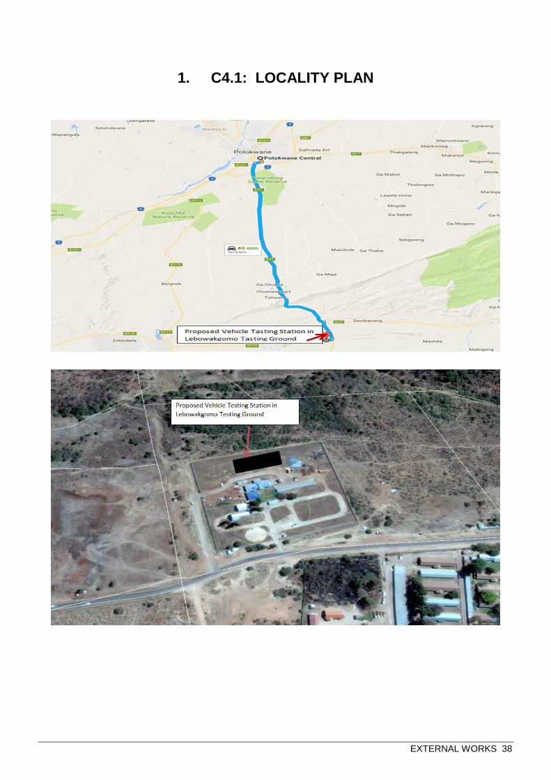
EXTERNAL WORKS 38
1. C4.1: LOCALITY PLAN

EXTERNAL WORKS 39
C4.2: DRAWINGS
All drawings are bound in book 2

EXTERNAL WORKS 40
SATS 1286.2011
Annex C
Local Content Declaration - Summary Schedule
(C1) Tender No.
(C2) Tender description:
(C3) Designated product(s)
(C4) Tender Authority:
(C5) Tendering Entity name:
(C6) Tender Exchange Rate: Pula EU GBP
(C7) Specified local content %
Calculation of local content Tender summary
Tender item
no's
Tender price
- each
(excl VAT)
Exempted
imported
value
Tender value
net of
exempted
imported
content
Imported
valueLocal value
Local
content %
(per item)
Tender
Qty
Total tender
value
Total exempted
imported content
Total Imported
content
(C8) (C10) (C11) (C12) (C13) (C14) (C15) (C16) (C17) (C18) (C19)
(C20) Total tender value R 0
Signature of tenderer from Annex B (C21) Total Exempt imported content R 0
(C22) Total Tender value net of exempt imported content R 0
(C23) Total Imported content R 0
(C24) Total local content R 0
Date: (C25) Average local content % of tender
Note: VAT to be excluded from all
calculations
List of items
(C9)

EXTERNAL WORKS 41
SATS 1286.2011
Annex D
Imported Content Declaration - Supporting Schedule to Annex C
(D1) Tender No.
(D2) Tender description:
(D3) Designated Products:
(D4) Tender Authority:
(D5) Tendering Entity name:
(D6) Tender Exchange Rate: Pula EU R 9.00 GBP R 12.00
Calculation of imported content Summary
Tender item
no'sLocal supplier Overseas Supplier
Forign
currency
value as per
Commercial
Invoice
Tender
Exchange
Rate
Local value of
imports
Freight costs to
port of entry
All locally
incurred
landing costs
& duties
Total landed
cost excl VAT
Tender
Qty
Exempted imported
value
(D7) (D9) (D10) (D11) (D12) (D13) (D14) (D15) (D16) (D17) (D18)
(D19) Total exempt imported value R 0
B. Imported directly by the Tenderer Calculation of imported content Summary
Tender item
no's
Unit of
measureOverseas Supplier
Forign
currency
value as per
Commercial
Invoice
Tender Rate
of Exchange
Local value of
imports
Freight costs to
port of entry
All locally
incurred
landing costs
& duties
Total landed
cost excl VAT
Tender
Qty
Total imported
value
(D20) (D22) (D23) (D24) (D25) (D26) (D27) (D28) (D29) (D30) (D31)
(D32) Total imported value by tenderer R 0
Calculation of imported content Summary
Unit of measure Local supplier Overseas Supplier
Forign
currency
value as per
Commercial
Invoice
Tender Rate
of Exchange
Local value of
imports
Freight costs to
port of entry
All locally
incurred
landing costs
& duties
Total landed
cost excl VAT
Quantity
imported
Total imported
value
(D34) (D35) (D36) (D37) (D38) (D39) (D40) (D41) (D42) (D43) (D44)
(D45) Total imported value by 3rd party R 0
D. Other foreign currency paymentsSummary of
payments
Local supplier
making the
payment
Overseas
beneficiary
Foreign currency
value paid
Tender Rate
of Exchange
Local value of
payments
(D47) (D48) (D49) (D50) (D51)
(D52) Total of foreign currency payments declared by tenderer and/or 3rd party
Signature of tenderer from Annex B
(D53) Total of imported content & foreign currency payments - (D32), (D45) & (D52) above R 0
Date:
`
This total must correspond with
Annex C - C 23
This total must correspond with
Annex C - C 21
Calculation of foreign currency
payments
Type of payment
(D46)
Description of imported content
(D21)
A. Exempted imported content
Note: VAT to be excluded
from all calculations
Description of imported content
(D8)
C. Imported by a 3rd party and supplied to the Tenderer
`
Description of imported content
(D33)

EXTERNAL WORKS 42
SATS 1286.2011
(E1) Tender No.
(E2) Tender description:
(E3) Designated products:
(E4) Tender Authority:
(E5) Tendering Entity name:
Local Products
(Goods, Services
and Works)
Local suppliers Value % of LC
(E7) (E8)
(E9) Total local products (Goods, Services and Works) R 0
(E10) Manpower costs ( Tenderer's manpower cost) R 0
(E11) Factory overheads (Rental, depreciation & amortisation, utility costs, consumables etc.) R 0
(E12) Administration overheads and mark-up (Marketing, insurance, financing, interest etc.) R 0
(E13) Total local content R 0
Signature of tenderer from Annex B
Date:
Annex E
Local Content Declaration - Supporting Schedule to Annex C
(E6)
Note: VAT to be excluded from all
calculations
This total must correspond with Annex C -
C24
Description of items purchased