ET-411en Electric Lift UHe
24
TECHNICAL SPECIFICATIONS ET-411en Vers. 03 16/02/2021 UHe ELECTRIC LIFT
-
Upload
khangminh22 -
Category
Documents
-
view
3 -
download
0
Transcript of ET-411en Electric Lift UHe
TECHNICAL SPECIFICATIONS
ET-411enVers. 0316/02/2021
UHeELECTRIC LIFT

TECHNICAL SPECIFICATIONS
UHe ELECTRIC LIFT
ET-411enVers. 03Page 1
Contents
1. General description................................................................................................................. Page 2
1.1. Application ................................................................................................................. Page 2
1.2. Regulations................................................................................................................ Page 2
1.3. Features .................................................................................................................... Page 2
2. Detailed description ................................................................................................................ Page 4
2.1. Drive and guiding....................................................................................................... Page 4
2.2. Installation ................................................................................................................. Page 4
2.3. Machinery .................................................................................................................. Page 5
2.4. Structure and enclosure ............................................................................................ Page 5
2.5. Electrical installation .................................................................................................. Page 6
2.6. Car ............................................................................................................................. Page 6
2.7. Landing doors ............................................................................................................ Page 8
2.8. Control ....................................................................................................................... Page 8
2.9. Safety features .......................................................................................................... Page 9
3. Installation dimensions ........................................................................................................... Page 11
3.1. Minimum shaft dimensions, front view....................................................................... Page 11
3.2. Minimum shaft dimensions, top view. ........................................................................ Page 12
3.3. Front structure dimensions ........................................................................................ Page 15
3.4. Top structure dimensions ........................................................................................... Page 16
3.5. Machinery location..................................................................................................... Page 19
ET-411enVers. 03Page 2
TECHNICAL SPECIFICATIONS
ELECTRIC LIFT UHe
1. General description
1.1. ApplicationLift for the vertical transportation of passengers between defined landings in houses, commercial premises and public buildings.
The lift has been designed for installation in shafts of reduced size in buildings where a machine room is not available. It is appropriate both for the replacement of outdated lifts and for the installation of new lifts in existing buildings.
1.2. RegulationsThe lift is compliant with the 2014/33/EU Lifts Directive and may, therefore, be marketed in any country of the European Union. Conformity by way of compliance with harmonised Standard EN 81-20, with some exceptions.
Any deviations from the standards of reference are indicated in the corresponding sections of the document. An EU Design Examination certificate issued by AENOR is available for compliance with the Directive.
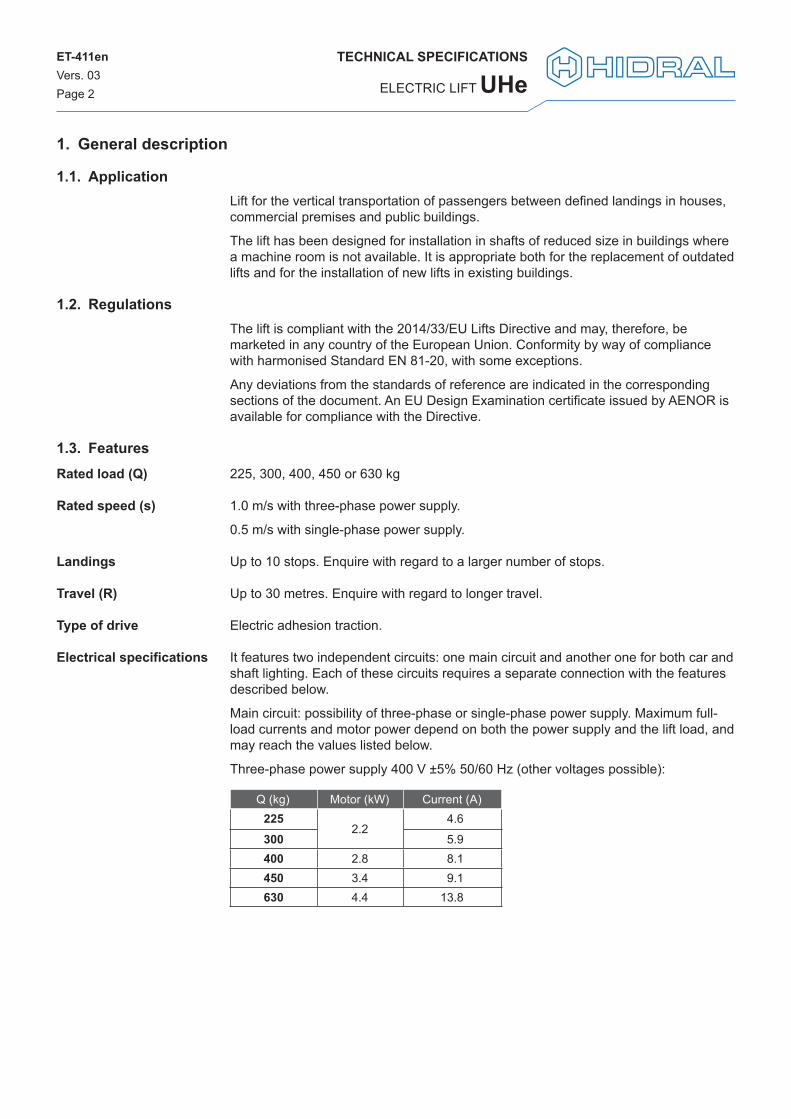
1.3. Features225, 300, 400, 450 or 630 kg
1.0 m/s with three-phase power supply.
0.5 m/s with single-phase power supply.
Up to 10 stops. Enquire with regard to a larger number of stops.
Up to 30 metres. Enquire with regard to longer travel.
Electric adhesion traction.
It features two independent circuits: one main circuit and another one for both car and shaft lighting. Each of these circuits requires a separate connection with the features described below.
Main circuit: possibility of three-phase or single-phase power supply. Maximum full-load currents and motor power depend on both the power supply and the lift load, and may reach the values listed below.
Three-phase power supply 400 V ±5% 50/60 Hz (other voltages possible):
Q (kg) Motor (kW) Current (A)225
2.2 4.6
300 5.9400 2.8 8.1450 3.4 9.1630 4.4 13.8
Rated load (Q)
Rated speed (s)
Landings
Travel (R)
Type of drive
Electrical specifications

TECHNICAL SPECIFICATIONS
UHe ELECTRIC LIFT
ET-411enVers. 03Page 3
Single-phase power supply 230 V ±5% 50 Hz (other voltages possible):Q (kg) Motor (kW) Current (A)
2251.1
5.3300 7.3400 1.4 10.8450 1.7 10.7630 2.2 14.0
Lighting circuit: 230 V ±5% single-phase 50/60 Hz (other voltages possible). Depending on the lift travel, the power consumed may reach 300 W.

ET-411enVers. 03Page 4
TECHNICAL SPECIFICATIONS
ELECTRIC LIFT UHe
2. Detailed description2.1. Drive and guiding
Electric adhesion traction drive with counterweight and suspension with a 2:1 ratio by means of 3, 4, 5 or 6 cables, depending on the load or the car size and options. The cables feature 6.5 mm in diameter, a 8x19W-IWRC composition and 1770 N/mm2 resistance wires. An EU Design Examination certificate issued by AENOR is available for compliance with the 2014/33/EU Lifts Directive.
Rucksack-type sling with guide shoes for a rated load equal to or less than 450 kg or with a roller at the bottom and a guide shoe at the top for a rated load equal to 630 kg.
Guiding by means of calibrated lift guides; two T70 guides are used for guiding the car and two T45 for the counterweight.
2.2. InstallationThe guides are supplied as standard in 5-metre sections and optionally in 2.5-metre sections and are intended to be attached to the shaft using brackets every 1500 mm maximum.
Standard assembly includes attaching of both the car and counterweight guides to one of the walls of the lift shaft. All the material required to attach the guide rails using brackets and mechanical anchors is supplied. The anchors are suitable for both concrete and hollow or solid brick walls. Enquire about the possibility of another type of anchorage or attachment to another type of support.
The shaft shall be used exclusively by the lift and shall meet the following requirements:
- It shall be fully enclosed with imperforate walls, floor and ceiling. The finish shall be smooth, with no protrusions and with vertical alignments of less than 1:1000.
- The walls of the shaft to which the guide rails are attached shall be made of structural concrete (minimum C20/C25) for mechanical anchors to be used.
- It shall be permanently ventilated at the top, with a minimum cross-section area of the shaft of 2.5%.
- The pit shall be impervious to infiltration of water and its bottom shall be levelled and smooth.
A hook or beam shall be provided in the shaft ceiling that withstands at least 1000 kg and placed within the vertical projection of the guide rails to handle the different parts during assembly. This hook shall be marked with its maximum working load.
Solutions are available for lift installation in existing buildings that do not have the permanent upper or lower refuge spaces required by harmonised Standard EN 81-20.
Reduced pit solution with a safety system for detecting shaft access and blocking the car by means of a speed limiter. An EU Design Examination certificate issued by AENOR is available for compliance with the 2014/33/EU Lifts Directive.
Enquire about the possibility of solutions for reduced headroom.
Installation conditions
Small spaces
Bottom of shaft
Top of shaft

TECHNICAL SPECIFICATIONS
UHe ELECTRIC LIFT
ET-411enVers. 03Page 5
2.3. MachineryIt is designed for installation without a machine room, with the installation of the machine and the main parts of the control system foreseen as described below.
Gearless-type machine supported by a bench which is mounted on the guide rails at the top of the shaft. This is a machine with a permanent magnet synchronous motor, a fan, a disc brake and a 240-mm diameter pulley for up to 6 6.5-mm diameter cables. The cable diameter and the ratio between pulley and cable diameter do not comply with the requirements of harmonised Standard EN 81-20. Special, highly flexible cables that have been tested by the manufacturers are used to ensure an equivalent safety level.
The main elements of the lift control system are distributed in two different boards, both located at the top of the assembly.
The electric landing board is located in a metal cabinet measuring 300 x 800 x 120 mm (width x height x depth), next to the door frame of the last landing and outside the shaft, on a 1100-mm high base. This cabinet includes the main switch, the rescue actuator plate, the control and frequency inverter consoles as well as the terminals for the electrical connections.
The electrical power board measuring 520 x 500 x 260 mm (width x height x depth) is installed inside the shaft, above the door of the upper landing level. It includes the frequency inverter, the control boards, the contactors as well as the motor and brake connection terminals. The braking resistor is installed in the upper part of the board. The uninterruptible power supply is installed next to the electrical power board, but also inside the lift shaft.
2.4. Structure and enclosure
Possibility of supplying a steel structure that allows the shaft to be enclosed, which is necessary for the lift operation, without subsequent brickwork. The lift may be installed against a courtyard wall or in a staircase.
The structure is designed to be attached to the pit floor and to the floor slabs of each landing level. The structure is also intended to be attached at the top, either to the ceiling or laterally to a structural element (see "3.3. Front structure dimensions"). All the material necessary for fixing the structure to the building and the guide rails to the structure is supplied. There is no need for intermediate fixings.
Modular structure made up of profiles made of folded sheet metal and with screwed joints without the need for welding.
The structure may be supplied for mounting the main entrance landing doors either on the structure itself or on the building slab.
RAL7035 grey epoxy-polyester paint as standard finish.
Enclosure panels to be placed on the profiles as enclosure, made of folded sheet metal or glazed with clear or tinted glass.
Available in other RAL colours.
Highly corrosion-resistant finish using galvanised sheet metal and polyester paint.
Closure of the upper end of the structure by means of roofing.
Machine
Electric board
Finish
Options
ET-411enVers. 03Page 6
TECHNICAL SPECIFICATIONS
ELECTRIC LIFT UHe
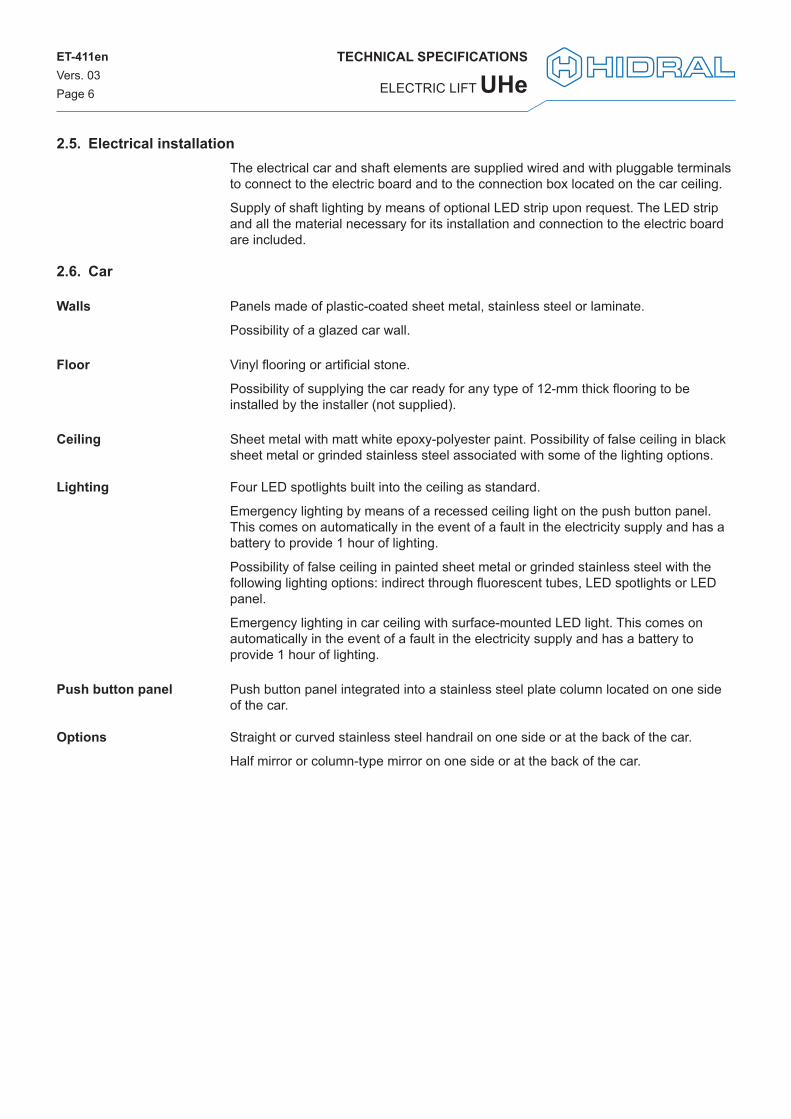
2.5. Electrical installationThe electrical car and shaft elements are supplied wired and with pluggable terminals to connect to the electric board and to the connection box located on the car ceiling.
Supply of shaft lighting by means of optional LED strip upon request. The LED strip and all the material necessary for its installation and connection to the electric board are included.
2.6. Car
Panels made of plastic-coated sheet metal, stainless steel or laminate.
Possibility of a glazed car wall.
Vinyl flooring or artificial stone.
Possibility of supplying the car ready for any type of 12-mm thick flooring to be installed by the installer (not supplied).
Sheet metal with matt white epoxy-polyester paint. Possibility of false ceiling in black sheet metal or grinded stainless steel associated with some of the lighting options.
Four LED spotlights built into the ceiling as standard.
Emergency lighting by means of a recessed ceiling light on the push button panel. This comes on automatically in the event of a fault in the electricity supply and has a battery to provide 1 hour of lighting.
Possibility of false ceiling in painted sheet metal or grinded stainless steel with the following lighting options: indirect through fluorescent tubes, LED spotlights or LED panel.
Emergency lighting in car ceiling with surface-mounted LED light. This comes on automatically in the event of a fault in the electricity supply and has a battery to provide 1 hour of lighting.
Push button panel integrated into a stainless steel plate column located on one side of the car.
Straight or curved stainless steel handrail on one side or at the back of the car.
Half mirror or column-type mirror on one side or at the back of the car.
Walls
Floor
Ceiling
Lighting
Push button panel
Options

TECHNICAL SPECIFICATIONS
UHe ELECTRIC LIFT
ET-411enVers. 03Page 7
Width (A): between 800 and 1100 mm (between 850 and 1250 mm for cars with single entrance and back guide rails)
Depth (B): between 900 and 1400 mm (between 800 and 1000 mm for cars with single entrance and back guide rails)
Height (H): 2100 mm
Maximum surface area depending on the rated load (Q):
Q (kg) A·B (m2)225 0.70300 0.90400 1.17450 1.30630 1.66
Single, double at 180º or double at 90º.
Single entrance with guide rails at the
bottom
Double entrance at 180º
Single entrance with guide rails on the left
Double entrance at 90º with guide rails on the left
Single entrance with guide rails on the right
Double entrance at 90º with guide rails on the
right
Automatic “bus”-type folding doors with vision panel or glazed and stainless steel plate finish.
Automatic two- or three-leaf telescopic doors with side opening and stainless steel plate finish.
Dimensions
Entrances
Car doors

ET-411enVers. 03Page 8
TECHNICAL SPECIFICATIONS
ELECTRIC LIFT UHe
2.7. Landing doors
Semi-automatic swing doors with vision panel or glazed.
Two- or three-leaf telescopic doors with side opening, operating at the same time as car doors.
RAL7032 grey epoxy paint as standard. Possibility of stainless steel plate telescopic doors.
Clear height (HL): 2000 mm.
Clear opening (FP): 700, 800, 900 mm.
Swing doors:
LeftRight
Telescopic doors:
LeftRight
2.8. ControlThe lift has a control push button panel on each landing level and a push button panel inside the car.
Push button panels to be built into the door frame on each landing level. These are flush-mounted push button panels with control elements assembled on a stainless steel plate.
The following elements are included in the push button panels:
- Call push button with call confirmation indicator on outer lit ring.
- Call push button with key as option.
Possibility of supplying landing position indicators for flush mounting in the wall.
Control elements flush mounted at a height suitable for operation by wheelchair users.
The push button panel includes the following elements:
- Push buttons for each stop, with call confirmation indicator on outer lit ring.
- Push buttons with optional key.
- Open doors push button.
- Push button to trigger the alarm and the emergency alarm device at the same time.
- Emergency telephone or intercom (optional).
- Position and overload indicator.
- Backlit nameplate on the top of the column indicating load, use, logo and reference. This nameplate also includes emergency lighting.
Types
Finish
Dimensions
Hand
Landing push button panel
Car push button panel
TECHNICAL SPECIFICATIONS
UHe ELECTRIC LIFT
ET-411enVers. 03Page 9
- Electronic control with microprocessor.
- Configuration console for selecting the type of operation and setting other parameters, such as times and functions. Fault signalling by means of a display on the console and storage of the recent fault history.
- Detection of stops and speed changes by means of magnetic detectors.
- Photoelectric barrier to detect obstacles in the doors. A photocell can be optionally supplied instead of a photoelectric barrier (solution not compliant with 2014/33/EU Lifts Directive).
- Automatic timed switching off of car lighting to save energy.
- Motor control by means of frequency variation.
2.9. Safety featuresAmong all the safety measures included in the lift, the following are listed below:
- Progressive roller safety gear as a safety measure against the car’s free fall due to breakage of the suspension cables and against its overspeed both during ascent and descent. It is operated by means of a speed limiter installed on the car and driven by a toothed belt.
- Doors with electric control of both closure and the lock interlocking.
- Car doors with electric closure control.
- Brake status monitoring system to protect against uncontrolled car movement, when the doors are not closed and locked.
- Upper and lower limit switches.
- Maximum motor operating time control.
- Temperature relay as a safety measure against overheating of control board components.
- Thermistors as a means of protection against motor overheating.
- Phase absence or reversal detection on the power supply.
- Overload control system by means of a compression load cell installed at the point where the cables are fixed to the machine bench.
- Photoelectric barrier to detect obstacles in the event of telescopic doors.
- Restricted door closing strength and door reopening in the event of obstacles.
- Alarm triggered by the alarm push button on the car push button panel to call for external assistance, if trapped in the car due to a fault.
- Remote emergency alarm device, according to Standard EN 81-28, to ensure two-way voice communications in permanent contact with a rescue service via a telephone line or GSM mobile network, triggered using the alarm push button on the car push button panel. As option, an intercom can be supplied instead for own line, so that the car can communicate with a fixed point (solution not compliant with 2014/33/EU Lifts Directive).
- System for communication with the machinery area via a conventional telephone.
Main operating features
General
Use

ET-411enVers. 03Page 10
TECHNICAL SPECIFICATIONS
ELECTRIC LIFT UHe
- Non-linear energy accumulation-type car buffers and counterweight.
- Electrical emergency control system for levelling the car for rescue operations. The control system works by load decompensation and features movement speed control.
- Possibility of automatic car movement system to the nearest landing level, with door opening in case of power failure. Movement by load decompensation and with uninterrupted power supply system.
- Manual door opening using a triangular safety key for rescue in the event of failure.
- Car doors with between-floors mechanical lock mechanism. The car door may only be opened in the unlocking area of each landing level.
- Signalling of the door unlocking area and of the car movement speed and direction for the rescue operation. In cases with limited space at the bottom of the shaft, the lift has low-height skirting so that the door interlocking mechanism prevents rescue, except when the car is located on a landing level.
- Emergency stop push button in pit and on ceiling.
- Pit access detection system for maintenance on installations with limited space at the bottom of the shaft. The system is tripped when opening of the lower landing door using the triangular emergency key is detected and the regular lift movement is prevented. It includes a visual warning. The reset push button located outside the shaft in the control cabinet is used to return to normal operation.
- Pre-actuation stop system by blocking the speed limiter and the safety gear to ensure the necessary safety spaces for maintenance operations in the pit for installations with limited space at the bottom of the shaft.
- Possibility for the supply of a pit access ladder for maintenance work.
- Push buttons under car and on car ceiling to trigger the alarm and the emergency alarm device as a safety measure in the event of being trapped in the pit or on the car ceiling.
- Possibility of supplying car ceiling handrails to carry out maintenance tasks safely from the ceiling with distances to the wall greater than or equal to 300 mm.
Maintenance

TECHNICAL SPECIFICATIONS
UHe ELECTRIC LIFT
ET-411enVers. 03Page 11
3. Installation dimensions3.1. Minimum shaft dimensions, front view
Swing door
2-leaf telescopic door 3-leaf telescopic door
HL+
140
= 21
40
80
50
125
HL
= 20
00
100
20÷75(1)
195
220
HL
= 20
00
HL+
290
= 22
90
H =
2100R1
RF
≥ 10
00(2
)Hu
≥ 3
400(3
)
1
Upperlanding
2
HL =
200
0
R TravelF Pit (maximum 1500 mm)Hu HeadroomH Car clear heightHL Door clear height(1) Distance from the edge of the sill to the shaft wall(2) Possibility of reduced pit between 200 mm and 500 mm for
installation in existing buildings with limited space in the lower part (minimum 220 mm for rated load 630 kg and 250 mm for 3-leaf telescopic door)
(3) Enquire about possibility of reduced headroom
140
70
20÷140(1)
190
HL
= 20
00
HL+
220
= 22
20
ET-411enVers. 03Page 12
TECHNICAL SPECIFICATIONS
ELECTRIC LIFT UHe
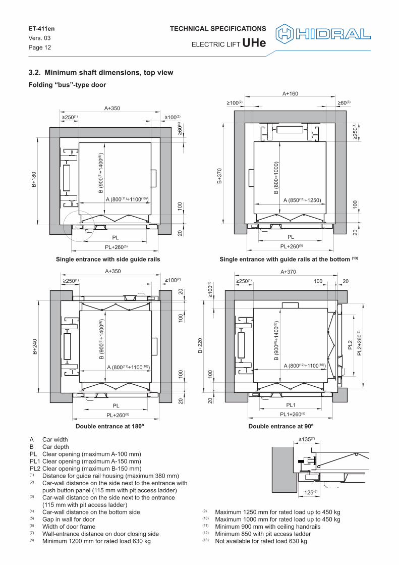
3.2. Minimum shaft dimensions, top viewFolding “bus”-type door
A Car widthB Car depthPL Clear opening (maximum A-100 mm)PL1 Clear opening (maximum A-150 mm)PL2 Clear opening (maximum B-150 mm)(1) Distance for guide rail housing (maximum 380 mm)(2) Car-wall distance on the side next to the entrance with
push button panel (115 mm with pit access ladder)(3) Car-wall distance on the side next to the entrance
(115 mm with pit access ladder)(4) Car-wall distance on the bottom side(5) Gap in wall for door(6) Width of door frame(7) Wall-entrance distance on door closing side(8) Minimum 1200 mm for rated load 630 kg
(9) Maximum 1250 mm for rated load up to 450 kg(10) Maximum 1000 mm for rated load up to 450 kg(11) Minimum 900 mm with ceiling handrails(12) Minimum 850 with pit access ladder(13) Not available for rated load 630 kg
125(6)
≥135(7)
Single entrance with guide rails at the bottom (13)
Double entrance at 180º
Single entrance with side guide rails
Double entrance at 90º
A+160
B+3
70
B (8
00÷1
000)
A (850(11)÷1250)
≥250
(1)
2010
0
PL
PL+260(5)
≥100(2) ≥60(3)
A+350
B+1
80
≥250(1)
B (9
00(8
) ÷14
00(9
) )
A (800(11)÷1100(10))
≥100(2)
≥60(
4)20
100
PL
PL+260(5)
A+350
B+2
40
B (9
00(8
) ÷14
00(9
) )
A (800(11)÷1100(10))
≥100(2)
2010
020
100
PL
PL+260(5)
≥250(1)
A+370
B+2
20
B (9
00(8
) ÷14
00(9
) )
A (800(12)÷1100(10))
≥100
(2)
2010
0
20100
PL1
PL1+260(5)
PL2
PL2
+260
(5)
≥250(1)
TECHNICAL SPECIFICATIONS
UHe ELECTRIC LIFT
ET-411enVers. 03Page 13
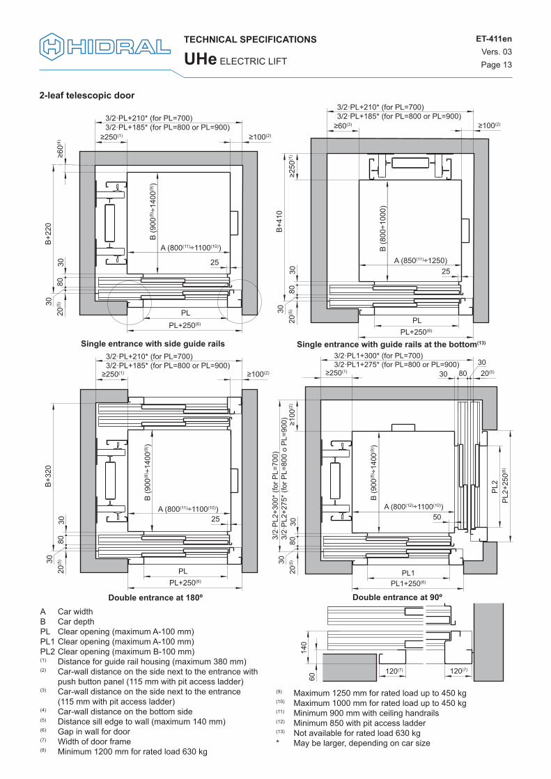
2-leaf telescopic door
60
120(7)120(7)
140
Single entrance with guide rails at the bottom(13)
Double entrance at 180º
Single entrance with side guide rails
Double entrance at 90º
3/2·PL+210* (for PL=700)3/2·PL+185* (for PL=800 or PL=900)
B+22
0
B (9
00(8
) ÷14
00(9
) )
A (800(11)÷1100(10))
≥100(2)
≥60(4
)80
3030
PLPL+250(6)
25
≥250(1)
20(5
)
B (8
00÷1
000)
A (850(11)÷1250)
≥100(2)
PLPL+250(6)
25
≥250
(1)
B+41
0
≥60(3)
3/2·PL+210* (for PL=700)3/2·PL+185* (for PL=800 or PL=900)
8030
3020
(5)
A (800(11)÷1100(10))
≥100(2)
25
≥250(1)
B (9
00(8
) ÷14
00(9
) )
PLPL+250(6)
8030
3020
(5)
B+32
0
3/2·PL+210* (for PL=700)3/2·PL+185* (for PL=800 or PL=900)
3/2·PL1+300* (for PL=700)3/2·PL1+275* (for PL=800 or PL=900)
3/2·
PL2+
300*
(for
PL=
700)
3/
2·PL
2+27
5* (f
or P
L=80
0 o
PL=9
00)
B (9
00(8
) ÷14
00(9
) )
A (800(12)÷1100(10))
PL1PL1+250(6)
PL2
PL2+
250(6
)
50
≥250(1)
≥100
(2)
8030
3020
(5)
80303020(5)
A Car widthB Car depthPL Clear opening (maximum A-100 mm)PL1 Clear opening (maximum A-100 mm)PL2 Clear opening (maximum B-100 mm)(1) Distance for guide rail housing (maximum 380 mm)(2) Car-wall distance on the side next to the entrance with
push button panel (115 mm with pit access ladder)(3) Car-wall distance on the side next to the entrance
(115 mm with pit access ladder)(4) Car-wall distance on the bottom side(5) Distance sill edge to wall (maximum 140 mm)(6) Gap in wall for door(7) Width of door frame(8) Minimum 1200 mm for rated load 630 kg
(9) Maximum 1250 mm for rated load up to 450 kg(10) Maximum 1000 mm for rated load up to 450 kg(11) Minimum 900 mm with ceiling handrails(12) Minimum 850 with pit access ladder(13) Not available for rated load 630 kg* May be larger, depending on car size
ET-411enVers. 03Page 14
TECHNICAL SPECIFICATIONS
ELECTRIC LIFT UHe
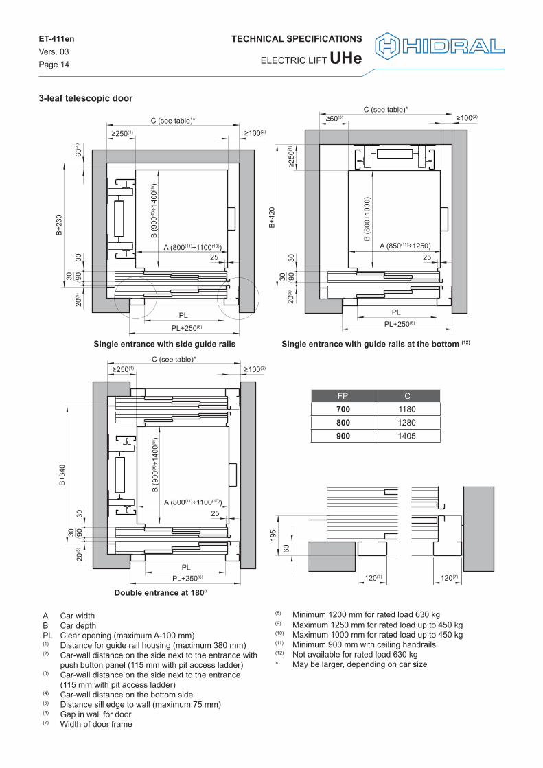
3-leaf telescopic door
Single entrance with guide rails at the bottom (12)
Double entrance at 180º
Single entrance with side guide rails
B+23
0
PL
A (800(11)÷1100(10))
≥100(2)
25
60(4
)
C (see table)*
B (9
00(8
) ÷14
00(9
) )
20(5
)90
3030
PL+250(6)
≥250(1)
B+42
0
PL
A (850(11)÷1250)
≥100(2)C (see table)*
B (8
00÷1
000)
9030
30
PL+250(6)
25
20(5
)≥2
50(1
)
≥60(3)
B+34
0
A (800(11)÷1100(10))
B (9
00(8
) ÷14
00(9
) )
PL+250(6)
≥100(2)≥250(1)
C (see table)*
PL
20(5
)90
3030
25
120(7)120(7)
60
195
A Car widthB Car depthPL Clear opening (maximum A-100 mm)(1) Distance for guide rail housing (maximum 380 mm)(2) Car-wall distance on the side next to the entrance with
push button panel (115 mm with pit access ladder)(3) Car-wall distance on the side next to the entrance
(115 mm with pit access ladder)(4) Car-wall distance on the bottom side(5) Distance sill edge to wall (maximum 75 mm)(6) Gap in wall for door(7) Width of door frame
(8) Minimum 1200 mm for rated load 630 kg(9) Maximum 1250 mm for rated load up to 450 kg(10) Maximum 1000 mm for rated load up to 450 kg(11) Minimum 900 mm with ceiling handrails(12) Not available for rated load 630 kg* May be larger, depending on car size
FP C700 1180800 1280900 1405
TECHNICAL SPECIFICATIONS
UHe ELECTRIC LIFT
ET-411enVers. 03Page 15
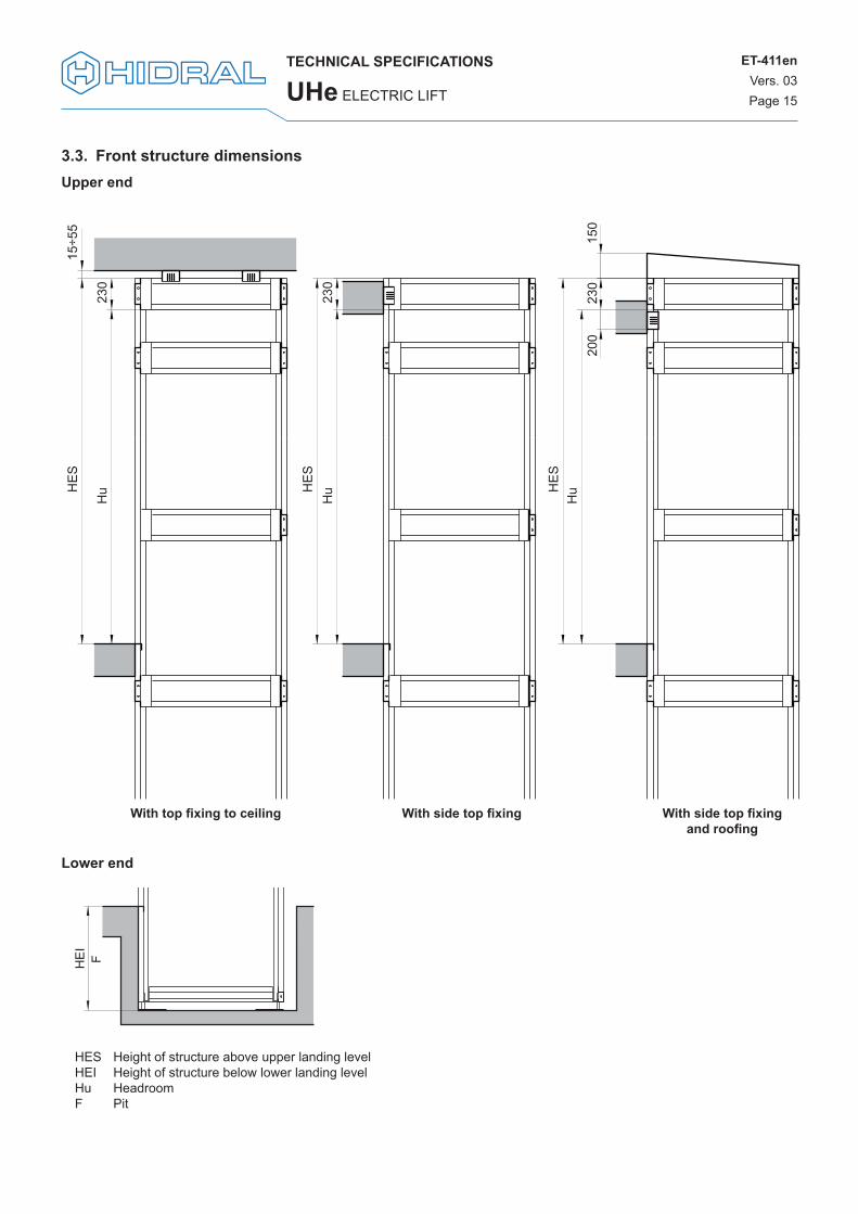
3.3. Front structure dimensionsUpper end
With top fixing to ceiling With side top fixing With side top fixingand roofing
HE
S
HE
S
HE
S
Hu
Hu
Hu
230
230
15÷5
5
200
230
150
Lower end
HE
IF
HES Height of structure above upper landing levelHEI Height of structure below lower landing levelHu HeadroomF Pit

ET-411enVers. 03Page 16
TECHNICAL SPECIFICATIONS
ELECTRIC LIFT UHe
3.4. Top structure dimensionsFolding bus-type car doors
A Car widthB Car depthPL Clear opening (maximum A-100 mm)(1) Distance for guide rail housing(2) Car-crossbeam distance on the side next to the entrance
with push button panel (115 mm with pit access ladder)(3) Structure crossbeam width(4) Car-crossbeam distance on bottom side(5) Door frame width(6) Door frame-structure column clearance with structure-
mounted door(7) Structure column width(8) Door frame-external structure distance on the hinge side(9) Door frame depth
(10) Gap in wall for door(11) Door frame-structure column clearance, closing side with
slab-mounted doors(12) Minimum 1200 mm for rated load 630 kg(13) Maximum 1250 mm for rated load up to 450 kg(14) Maximum 1000 mm for rated load up to 450 kg(15) Minimum 900 mm with ceiling handrails* May be larger, depending on door features
Door on structure
Door on building slab
≥25(11)
125(5) 80(7)
125(5) ≥80(8)
Closing side
Hinge side
A+450*
B+2
80
B (9
00(1
2)÷1
400(1
3))
A (800(15)÷1100(14))
≥100(2)
60(4
)20
100
PL
250(1)50(3) 50(3)
50(3
)
PL+260(10)
B+2
30
B (9
00(1
2)÷1
400(1
3))
A (800(15)÷1100(14))
2010
0
PL
A+450*250(1)50(3) ≥100(2) 50(3)
60(4
)50
(3)
80(7) 125(5)
50(9
)
≥10(6)

TECHNICAL SPECIFICATIONS
UHe ELECTRIC LIFT
ET-411enVers. 03Page 17
2-leaf telescopic doors
A Car widthB Car depthPL Clear opening (maximum A-100 mm)(1) Distance for guide rail housing (maximum 380 mm)(2) Car-external structure distance on door closing side(3) Structure crossbeam width(4) Car-crossbeam distance on bottom side(5) Door frame width(6) Door frame-structure column clearance(7) Structure column width(8) Distance sill edge to wall (maximum 140 mm)(9) Gap in wall for door(10) Minimum 1200 mm for rated load 630 kg(11) Maximum 1250 mm for rated load up to 450 kg
(12) Maximum 1000 mm for rated load up to 450 kg(13) Minimum 900 mm with ceiling handrails* It may be greater, depending on the door features and the
car size.
Door on structure
Door on building slab
10(6) 120(5) 80(7)
3/2·PL+375* (for PL=700)3/2·PL+350* (for PL=800 or PL=900)
B+39
0
B (9
00(1
0)÷1
400(1
1))
A (800(13)÷1100(12))
140
8030
30
PL
25
≥250(1) 185(2)50(3)
60(4
)50
(3)
3/2·PL+375* (for PL=700)3/2·PL+350* (for PL=800 or PL=900)
B+27
0
B (9
00(1
0)÷1
400(1
1))
A (800(13)÷1100(12))
8030
PL
25
PL+250 (9)
≥250(1)50(3)
60(4
)50
(3)
185(2)
3020
(8)
120(5) 80(7) 10(6)

ET-411enVers. 03Page 18
TECHNICAL SPECIFICATIONS
ELECTRIC LIFT UHe
3-leaf telescopic doors
Door on structure
Door on building slab
10(6) 120(5) 80(7)
B+46
0
PL
A (800(13)÷1100(12))
C (see table)*
B (9
00(1
0)÷1
400(1
4))
195
9030
≥250(1)50(3)
60(4
)50
(3)
30 25
≥185(2)
A (800(13)÷1100(12))
9030
PL
C (see table)*
2030
(8)
PL+250(9)
B+28
0
B (9
00(1
0)÷1
400(1
1))
≥250(1)50(3)
25
60(4
)50
(3)
≥185(2)
A Car widthB Car depthPL Clear opening (maximum A-100 mm)(1) Distance for guide rail housing (maximum 380 mm)(2) Car-external structure distance on door closing side(3) Structure crossbeam width(4) Car-crossbeam distance on bottom side(5) Door frame width(6) Door frame-structure column clearance(7) Structure column width(8) Distance sill edge to wall (maximum 75 mm)(9) Gap in wall for door(10) Minimum 1200 mm for rated load 630 kg(11) Maximum 1250 mm for rated load up to 450 kg
(12) Maximum 1000 mm for rated load up to 450 kg(13) Minimum 900 mm with ceiling handrails* It may be greater, depending on the door features and the
car size.
FP C700 1345800 1445900 1570
80(7) 10(6)
120(5)

TECHNICAL SPECIFICATIONS
UHe ELECTRIC LIFT
ET-411enVers. 03Page 19
3.5. Machinery location
260
195
520 280
Electricalpower board
Uninterrumped powersupply system
Motor
300
120
Electricallanding panel
800
1100
≥270
0H
u ≥
3400
120
140
500
Breakingresistor


Polígono Industrial PARSICalle 7, 3 - 41016Sevilla (España)+34 954 514 500www.hidral.com