Vibration Reduction Simulation of Lift-offset Compound ...
13
8 TH EUROPEAN CONFERENCE FOR AERONAUTICS AND SPACE SCIENCES (EUCASS) Copyright 2019 by Y. –L. Lee and J. –S. Park. Published by the EUCASS association with permission. Vibration Reduction Simulation of Lift-offset Compound Helicopters Using Active Vibration Control System Ye-Lin Lee* 1 , Do-Hyung Kim**, Jae-Sang Park* 2 , Sung-Boo Hong* 3 *Dept. of Aerospace Eng., Chungnam National Univ., Republic of Korea 1 [email protected], 2 [email protected], 3 [email protected] **Aircraft System Division, Korea Aerospace Research Institute, Republic of Korea [email protected] Abstract This study attempts to alleviate numerically both the rotor and airframe vibrations of a lift-offset compound helicopter using two different active vibration control techniques. The XH-59A helicopter is considered as the lift-offset compound helicopter, and the IBC (Individual Blade pitch Control) and AVCS (Active Vibration Control System) are applied to the lift-offset rotor and airframe of XH-59A, respectively. The vibration of the XH-59A rotor with or without IBC is predicted using the rotorcraft comprehensive analysis code, CAMRAD II. Various tools such as NDARC, MSC.NASTRAN, and MATLAB Simulink are used for the AVCS simulation. At the flight speed of 200 knots, the 3/rev hub vibration of the XH-59A rotor is reduced by 62% using the IBC, and then the 3/rev vibration response at the pilot seat of the XH-59A airframe in longitudinal or vertical direction is eliminated perfectly vibration reduction by 100% using the AVCS with SISO (single input single output) model. 1. Introduction Although traditional helicopters are capable of hovering and vertical take-off/landing, the maximum speed is very slow (about 150~170 knots), as compared to fixed-wing aircrafts. Thus, compound helicopters using not only rotors but also auxiliary propulsions and wings have been developed to solve this low-speed flight performance problem of traditional helicopters. Among various configurations of compound helicopters, the lift-offset compound helicopter using a rigid coaxial rotor such as XH-59A, X2 technical demonstrator (TD), S-97 Raider, and SB>1 Defiant (Figure 1) has excellent high-speed flight capability. As given in Figure 2, the lift-offset rotor uses a counter-rotating rigid coaxial rotor. Because the advancing blades produce most lift, the lift-offset rotor may not suffer from the dynamic stall on the retreating side of a rotor, and it can produce more lift than the traditional helicopter rotor. Thus, the rotation speed of a lift-offset rotor can be moderately reduced and high-speed forward flight can be achieved using the auxiliary propulsions. (a) XH-59A (b) S-97 Raider (c) X2 TD (d) SB>1 Defiant Figure 1: Lift-offset compound helicopters using ABC TM . DOI: 10.13009/EUCASS2019-422
-
Upload
khangminh22 -
Category
Documents
-
view
0 -
download
0
Transcript of Vibration Reduction Simulation of Lift-offset Compound ...

8TH EUROPEAN CONFERENCE FOR AERONAUTICS AND SPACE SCIENCES (EUCASS)
Copyright 2019 by Y. –L. Lee and J. –S. Park. Published by the EUCASS association with permission.
Vibration Reduction Simulation of Lift-offset Compound Helicopters Using Active Vibration Control System
Ye-Lin Lee*1, Do-Hyung Kim**, Jae-Sang Park*2, Sung-Boo Hong*3
*Dept. of Aerospace Eng., Chungnam National Univ., Republic of Korea [email protected], [email protected], [email protected]
**Aircraft System Division, Korea Aerospace Research Institute, Republic of Korea
Abstract This study attempts to alleviate numerically both the rotor and airframe vibrations of a lift-offset compound helicopter using two different active vibration control techniques. The XH-59A helicopter is considered as the lift-offset compound helicopter, and the IBC (Individual Blade pitch Control) and AVCS (Active Vibration Control System) are applied to the lift-offset rotor and airframe of XH-59A, respectively. The vibration of the XH-59A rotor with or without IBC is predicted using the rotorcraft comprehensive analysis code, CAMRAD II. Various tools such as NDARC, MSC.NASTRAN, and MATLAB Simulink are used for the AVCS simulation. At the flight speed of 200 knots, the 3/rev hub vibration of the XH-59A rotor is reduced by 62% using the IBC, and then the 3/rev vibration response at the pilot seat of the XH-59A airframe in longitudinal or vertical direction is eliminated perfectly vibration reduction by 100% using the AVCS with SISO (single input single output) model.
1. Introduction
Although traditional helicopters are capable of hovering and vertical take-off/landing, the maximum speed is very slow (about 150~170 knots), as compared to fixed-wing aircrafts. Thus, compound helicopters using not only rotors but also auxiliary propulsions and wings have been developed to solve this low-speed flight performance problem of traditional helicopters. Among various configurations of compound helicopters, the lift-offset compound helicopter using a rigid coaxial rotor such as XH-59A, X2 technical demonstrator (TD), S-97 Raider, and SB>1 Defiant (Figure 1) has excellent high-speed flight capability. As given in Figure 2, the lift-offset rotor uses a counter-rotating rigid coaxial rotor. Because the advancing blades produce most lift, the lift-offset rotor may not suffer from the dynamic stall on the retreating side of a rotor, and it can produce more lift than the traditional helicopter rotor. Thus, the rotation speed of a lift-offset rotor can be moderately reduced and high-speed forward flight can be achieved using the auxiliary propulsions.
(a) XH-59A (b) S-97 Raider (c) X2 TD (d) SB>1 Defiant
Figure 1: Lift-offset compound helicopters using ABCTM.
DOI: 10.13009/EUCASS2019-422

Ye-Lin Lee, Do-Hyung Kim, Jae-Sang Park, and Sung-Boo Hong
2
(a) Single main rotor (b) Lift-offset coaxial rotor
Figure 2: Advancing Blade Concept (ABCTM, [1]).
Because of the unique characteristics of helicopter rotor dynamics, the N/rev vibration is the most important for the
helicopter when N is the number of blades for a rotor. The helicopter vibration causes a restricted flight envelop, low fatigue of structural components, passengers’ discomfort, and negative effect to electronic equipment. Particularly, the high level of vibration of a lift-offset compound helicopter may reduce the maximum flight speed [2]. For an example, the first lift-offset compound helicopter, XH-59A helicopter (Figure 1(a)), there were serious 3/rev vibrations and stresses at the cockpit, auxiliary engine mount, and connection of vertical tail with horizontal tail in high-speed flights. For vibration reduction of compound helicopters, typical passive vibration control techniques using rotor head-mounted vibration absorbers, compliant mounts, airframe-mounted vibration absorbers, and so on are not appropriate since the rotor rotational speed of compound helicopters is reduced appropriately for high-speed flights. Therefore, X2 TD used the Active Vibration Control System (AVCS) for reduction of vibration at the airframe [3]. The AVCS consists of accelerometers as the feedback sensors and airframe-mounted force generators (Figure 3) with electric motors and eccentric masses as actuators. The AVCS generates the vibration cancellation signals with the same amplitude but opposite direction to the airframe vibration signals, using a closed-loop feedback control algorithm. The AVCS could reduce significantly the 4/rev airframe vibration of X2 TD without performance degradation [3]. Although the AVCS has shown the excellent vibration reduction capability for lift-offset compound helicopter such as X2 TD and S-97 Raider as well as conventional helicopters such as S-92 [4], UH-60M [5], and Korean Utility Helicopter, Surion [6], this approach cannot reduce the rotor vibration, which is the main source of helicopter vibration. As another technology for active vibration reduction of a lift-offset compound helicopter, the active rotor controls such as HHC (Higher harmonic pitch control, [7]) and IBC (Individual Blade pitch Control, [8]) through numerical studies have been applied to the XH-59A lift-offset rotor to reduce the 3/rev hub vibration in high-speed flights. The IBC could the 3/rev hub vibration of the XH-59A rotor at 200 knots by about 62% [8].
This study using two different active vibration control techniques attempts to reduce the vibrations at both the rigid coaxial rotor and airframe of a lift-offset compound helicopter. First, the IBC is applied to the rigid coaxial rotor system for reduction of rotor vibratory loads, and then, second, the AVCS is used to alleviate the vibration response at the specified locations of the airframe. As the lift-offset compound helicopter, the XH-59A helicopter with auxiliary propulsions is considered in this study. The number of blades is 3 for each rotor and the rotor tip speed is 650 ft/s in helicopter mode. The minimized 3/rev hub vibratory loads of the XH-59A lift-offset rotor with IBC is obtained from the present authors’ previous work [8] using CAMRAD II [9], rotorcraft comprehensive analysis code. For the AVCS simulation, various tools such as NDARC (NASA Design and Analysis of Rotorcraft, [10]), MSC.NASTRAN, and
(a) Counter rotating force generator (Moog Inc.)
(b) Schematic diagram of counter rotating force generator
Figure 3: Counter rotating force generator (CRFG) for AVCS.
DOI: 10.13009/EUCASS2019-422

3
MATLAB Simulink are used. In the AVCS simulation, the XH-59A airframe is modelled as a stick model (elastic line model) using MSC. NASTRAN. The detailed weight data of the XH-59A helicopter is obtained from Reference [11]. The SISO (Single Input Single Output) model is used for the present AVCS simulation, and Filtered-X least mean square (FX-LMS) algorithm is applied as an adaptive algorithm to generate appropriately the vibration cancellation signal. In this study, the active vibration controls for the XH-59A rotor and airframe (at the pilot seats in the longitudinal and vertical directions) are simulated at the flight speed of 200 knots.
2. Analytical methods
2.1 Lift-offset rotor vibration reduction using IBC
The vibration of the XH-59A lift-offset rotor is actively reduced using IBC before the AVCS is applied the XH-59A airframe. The vibration reduction of the XH-59A lift-offset rotor using IBC at the flight speed of 200 knots is simulated by a rotorcraft comprehensive analysis code, CAMRAD II. This result has already been given in the present authors’ previous work [8]; however, the modelling and analysis techniques and important result for the XH-59A rotor with IBC are described briefly in this paper. Figure 4 shows the CAMRAD II model for the XH-59A rotor when the cross-over angle of 0° is considered. Each blade of the XH-59A rotor is modelled using seven nonlinear finite beam elements and complex rotor control system such as the pitch link, swashplates, and pitch horn is also modelled. The pitch motion induced by the IBC inputs applied both the upper and lower rotors is expressed using Equation (1). For multiple harmonic inputs,
IBC N NN=2
θ A cos Nψ (1)
Figure 4: CAMRAD II model for XH-59A rotor.
where θIBC is the IBC equivalent blade pitch, ψ is the blade azimuth angle, and N, AN, and φN are the actuation frequency, amplitude, and control phase angle, respectively, of the IBC input. In this study, the multiple harmonic inputs are used for the IBC. The 2/rev and 3/rev IBC actuations are considered for the present multiple harmonic inputs. The unsteady aerodynamics along with the C81 airfoil table look-up is applied to calculate the aerodynamic loads on
each blade. In this work, 16 aerodynamic panels for a blade are considered and the prescribed wake model is used considering the aerodynamic interference between the upper and lower rotors of a rigid coaxial rotor system. The rotor trim is achieved using the six primary rotor controls of the upper and lower rotors. The rotor thrust, hub rolling moment, and rotor drag force are considered as the trim targets. The hub rolling moment of each rotor can be prescribed using the assumed lift-offset (LOS, Figure 2(b)) value. In the present work, the value of LOS is assumed as 0.25. In addition, the rotor vibration index (VI, [12]) is used to evaluate the vibration level of the XH-59A lift-offset rotor as
DOI: 10.13009/EUCASS2019-422

Ye-Lin Lee, Do-Hyung Kim, Jae-Sang Park, and Sung-Boo Hong
4
3 3 3 3 3
2 2 2 2 2y0.5 0.67
VIP P P P P
x z x yF F F M M
W RW
(2)
where W is the aircraft weight (13,000 lb) and R is the rotor radius (18ft). It is noteworthy that the inter-rotor cancellation of a lift-offset rotor [7] is considered when the vibration index of the XH-59A rotor is calculated. When the IBC in Eq. (1) is applied to the XH-59A at 200 knots, the percent change in vibration index is given Figure
5 [8]. The baseline indicates the result when the IBC is not applied. As shown in the figure, the vibration index of the XH-59A lift-offset rotor increases or decreases significantly when the IBC is applied. Particularly, when the IBC with multiple harmonic inputs, θIBC=2cos(2ψ-270°)+1cos(3ψ-210°), is used, the rotor vibration can be minimized by 62% while the rotor effective lift-to-drag ratio is improved slightly by about 0.37% from the baseline value [8]. The 3/rev hub vibratory loads of the XH-59A lift-offset rotor for the baseline case without IBC and the minimum vibration case with IBC are obtained from this example. These predicted 3/rev hub vibratory loads of the XH-59A lift-offset rotor without or with IBC will excite the XH-59A airframe for the AVCS simulation which will be given in the following sections.
2.2 Lift-offset helicopter airframe vibration reduction using AVCS
2.2.1 Airframe structure vibration response analysis
A finite element analysis program, MSC. NASTRAN, is used. The present finite element model for the XH-59A airframe is constructed using a stick model which has the similar dynamic characteristics of the actual XH-59A helicopter. Two slightly different models are considered for the normal mode and frequency response analyses in Figures 6 and 7, respectively. The geometric properties of the XH-59A helicopter are obtained from 3D drawings in public domain, and the weight data of various airframe components are obtained the previous work [11] using NDARC. After the weight data of the main components of the XH-59A airframe are entered into the MSC.NASTRAN model, and the gross-weight (13,000 lb) and the center of gravity of the aircraft are adjusted. Using the constructed XH-59A stick model, the normal mode analysis is conducted considering the free-free boundary
conditions. The beam cross-sectional area of the present stick model and material properties such as the elastic modulus and Poisson’s ratio are appropriately assumed to match the target natural frequency in the second bending mode of the XH-59A fuselage [11]. Table 1 shows the predicted natural frequencies in the lowest four bending modes of the XH-59A helicopter fuselage. As seen in the table, the second vertical bending mode frequency in this work has an error of 3.07% with respect to the reference value [11]; therefore, it is considered that the present stick model has the dynamic similarity appropriately with the actual XH-59A helicopter. In addition, based on the stick model for the normal mode analysis (Figure 6), the ground vibration test model for the XH-59A helicopter is also constructed for the frequency response analysis using MSC.NASTRAN (Figure 7). Two bungee cables are added newly to the previous XH-59A stick model used for the normal mode analysis. The material properties of bungee cables for the frequency response analysis model are adjusted to match the natural frequencies in the lowest four bending modes from the normal mode
Figure 5: 3P hub loads reduction of the XH-59A rotor using IBC with multiple harmonic inputs.
DOI: 10.13009/EUCASS2019-422
5
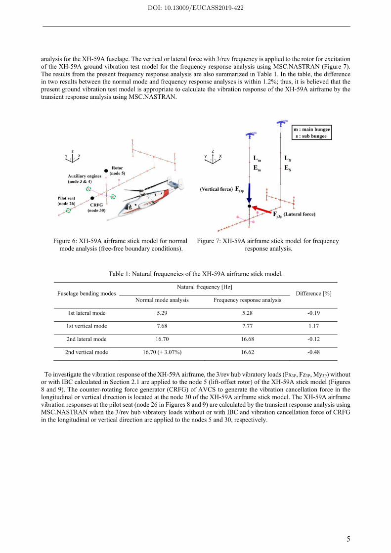
analysis for the XH-59A fuselage. The vertical or lateral force with 3/rev frequency is applied to the rotor for excitation of the XH-59A ground vibration test model for the frequency response analysis using MSC.NASTRAN (Figure 7). The results from the present frequency response analysis are also summarized in Table 1. In the table, the difference in two results between the normal mode and frequency response analyses is within 1.2%; thus, it is believed that the present ground vibration test model is appropriate to calculate the vibration response of the XH-59A airframe by the transient response analysis using MSC.NASTRAN.
Figure 6: XH-59A airframe stick model for normal mode analysis (free-free boundary conditions).
Figure 7: XH-59A airframe stick model for frequency response analysis.
Table 1: Natural frequencies of the XH-59A airframe stick model.
Fuselage bending modesNatural frequency [Hz]
Difference [%] Normal mode analysis Frequency response analysis
1st lateral mode 5.29 5.28 -0.19
1st vertical mode 7.68 7.77 1.17
2nd lateral mode 16.70 16.68 -0.12
2nd vertical mode 16.70 (+ 3.07%) 16.62 -0.48
To investigate the vibration response of the XH-59A airframe, the 3/rev hub vibratory loads (Fx3P, Fz3P, My3P) without or with IBC calculated in Section 2.1 are applied to the node 5 (lift-offset rotor) of the XH-59A stick model (Figures 8 and 9). The counter-rotating force generator (CRFG) of AVCS to generate the vibration cancellation force in the longitudinal or vertical direction is located at the node 30 of the XH-59A airframe stick model. The XH-59A airframe vibration responses at the pilot seat (node 26 in Figures 8 and 9) are calculated by the transient response analysis using MSC.NASTRAN when the 3/rev hub vibratory loads without or with IBC and vibration cancellation force of CRFG in the longitudinal or vertical direction are applied to the nodes 5 and 30, respectively.
DOI: 10.13009/EUCASS2019-422

Ye-Lin Lee, Do-Hyung Kim, Jae-Sang Park, and Sung-Boo Hong
6
Figure 8: XH-59A airframe stick model for transient
response analysis without IBC application. Figure 9: XH-59A airframe stick model for transient
response analysis with IBC application.
2.2.2 Closed-loop feedback algorithm for AVCS (Fx-LMS Algorithm)
Fx-LMS (Filtered-x Least Mean Square) algorithm is used to generate the vibration cancellation signal of AVCS. In this study, one accelerometer (vibration measurement sensor) and one actuator (CRFG) are used for the SISO (Single Input and Single Output) system. The accelerometer is located at the pilot seat (node 26) but the CRFG is attached to the node 30 in Figures 8 and 9. There are three different acceleration signals: the airframe vibration response signal (y(n)) transferred from the lift-offset rotor, the vibration cancellation response signal (ŷ(n)) produced by the CRFG, and the error signal (e(n)) which is the sum of two signals (y(n)) and ŷ(n)). The gradient descent method in the Fx-LMS algorithm is used to minimize the error signal (e(n)). The forward path dynamics, which is the transfer function of the CRFG, should be identified to implement Fx-LMS algorithm. The forward path dynamics are assumed to be linear time invariant. In the present work, the AVCS using Fx-LMS algorithm is modeled using MATLAB Simulink as shown in Figure 10. The reference signal, 3/rev phase angle, is generated (Block ① in Figure 10) and fed into disturbance path model and control algorithm. The disturbance path model (Block ② in Figure 10) represents the dynamics of the airframe vibration. Control algorithm contains the forward path model (Block ③ in Figure 10) representing the numerical transfer function model of the actual CRFG actuator (Block ④ in Figure 10). The output signal of the disturbance path model is represented as the 3/rev vibration response signal extracted from the transient response analysis result for the XH-59A airframe. For the forward path model, the system identification parameters of the actuator are determined by the LMS update equations. Also, a scope (Block ⑤ in Figure 10) is modeled to check the convergence of the system identification parameters. Finally, the required time to achieve the convergence can be controlled by adjusting the time step size (μ).
Figure 10: Block diagram using MATLAB Simulink for AVCS.
DOI: 10.13009/EUCASS2019-422
7
3. Results and Discussions
3.1 Validation of airframe vibration response
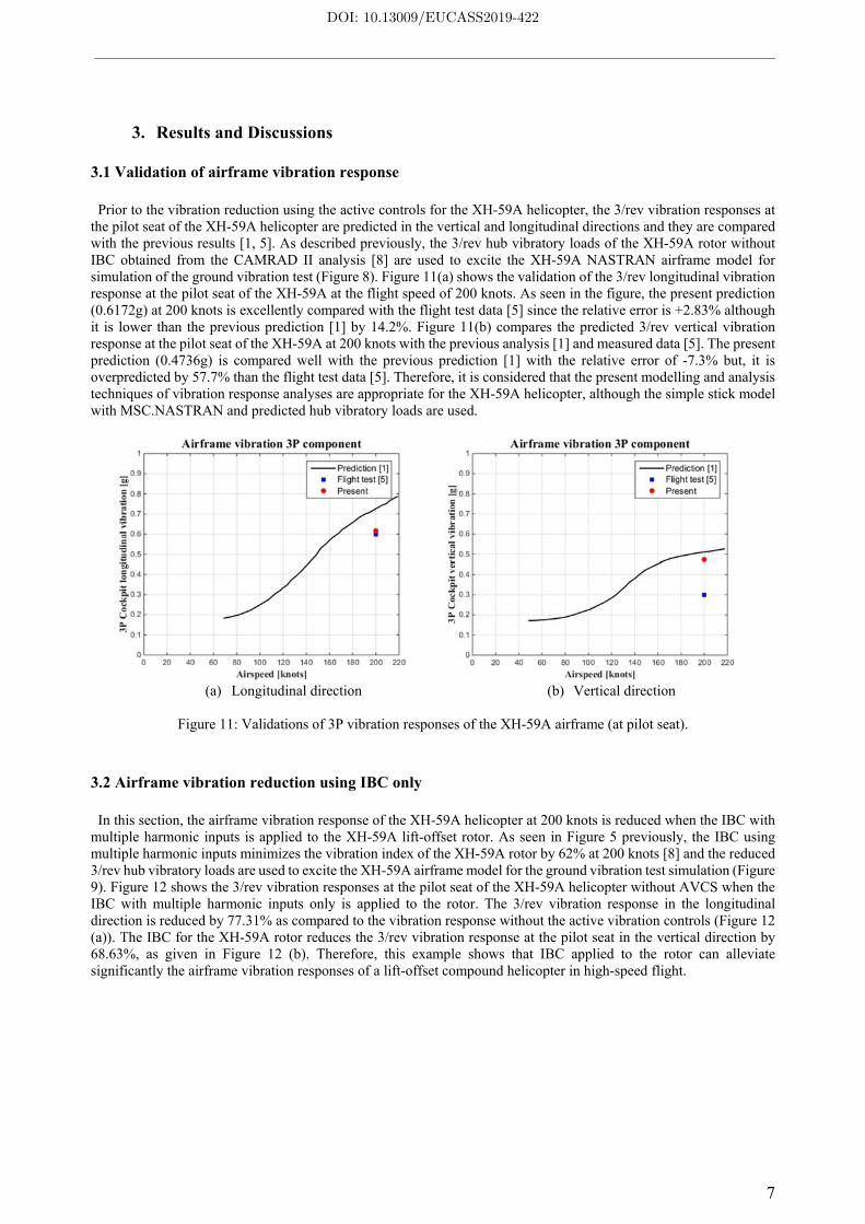
Prior to the vibration reduction using the active controls for the XH-59A helicopter, the 3/rev vibration responses at the pilot seat of the XH-59A helicopter are predicted in the vertical and longitudinal directions and they are compared with the previous results [1, 5]. As described previously, the 3/rev hub vibratory loads of the XH-59A rotor without IBC obtained from the CAMRAD II analysis [8] are used to excite the XH-59A NASTRAN airframe model for simulation of the ground vibration test (Figure 8). Figure 11(a) shows the validation of the 3/rev longitudinal vibration response at the pilot seat of the XH-59A at the flight speed of 200 knots. As seen in the figure, the present prediction (0.6172g) at 200 knots is excellently compared with the flight test data [5] since the relative error is +2.83% although it is lower than the previous prediction [1] by 14.2%. Figure 11(b) compares the predicted 3/rev vertical vibration response at the pilot seat of the XH-59A at 200 knots with the previous analysis [1] and measured data [5]. The present prediction (0.4736g) is compared well with the previous prediction [1] with the relative error of -7.3% but, it is overpredicted by 57.7% than the flight test data [5]. Therefore, it is considered that the present modelling and analysis techniques of vibration response analyses are appropriate for the XH-59A helicopter, although the simple stick model with MSC.NASTRAN and predicted hub vibratory loads are used.
(a) Longitudinal direction (b) Vertical direction
Figure 11: Validations of 3P vibration responses of the XH-59A airframe (at pilot seat).
3.2 Airframe vibration reduction using IBC only
In this section, the airframe vibration response of the XH-59A helicopter at 200 knots is reduced when the IBC with multiple harmonic inputs is applied to the XH-59A lift-offset rotor. As seen in Figure 5 previously, the IBC using multiple harmonic inputs minimizes the vibration index of the XH-59A rotor by 62% at 200 knots [8] and the reduced 3/rev hub vibratory loads are used to excite the XH-59A airframe model for the ground vibration test simulation (Figure 9). Figure 12 shows the 3/rev vibration responses at the pilot seat of the XH-59A helicopter without AVCS when the IBC with multiple harmonic inputs only is applied to the rotor. The 3/rev vibration response in the longitudinal direction is reduced by 77.31% as compared to the vibration response without the active vibration controls (Figure 12 (a)). The IBC for the XH-59A rotor reduces the 3/rev vibration response at the pilot seat in the vertical direction by 68.63%, as given in Figure 12 (b). Therefore, this example shows that IBC applied to the rotor can alleviate significantly the airframe vibration responses of a lift-offset compound helicopter in high-speed flight.
DOI: 10.13009/EUCASS2019-422

Ye-Lin Lee, Do-Hyung Kim, Jae-Sang Park, and Sung-Boo Hong
8
(a) Longitudinal direction (b) Vertical direction
Figure 12: 3P vibration response of the XH-59A helicopter using IBC only (Pilot seat and 200 knots).
3.3 Airframe vibration response control using AVCS only
The AVCS is applied to the XH-59A airframe but IBC is not used for the lift-offset rotor in this section. Therefore, the 3/rev hub vibratory loads of the XH-59A rotor for the baseline case without IBC are considered to excite the XH-59A airframe model at the flight speed of 200 knots (Figure 8). As previously explained, a single CRFG is located at the node 30 of the NASTRAN airframe model and its weight is included for the finite element modelling. Since a CRFG generates the vibration cancellation signal (or force) in the only one direction, two different examples are given in this section. Figure 13 exhibits the reduction of 3/rev longitudinal vibration response at the pilot seat of the XH-59A helicopter when a CRFG for AVCS generates the vibration cancellation signal in the longitudinal direction. In Figure 13 (a), the 3/rev vibration response (y) in the longitudinal direction has the amplitude of 0.6 g when AVCS is not applied to the XH-59A airframe. The vibration cancellation signal (ŷ) generated by Fx-LMS algorithm has the same amplitude but opposite direction to the airframe vibration signal (y) after about 1.5 second as shown in Figure 13 (b). Figure 13 (c) shows the 3/rev longitudinal vibration response reduced by AVCS at the pilot seat. The 3/rev airframe vibration response in the longitudinal direction is alleviated perfectly (by 100%) when the AVCS is applied. Similar to the active vibration reduction of the XH-59A airframe in the longitudinal direction in Figure 13, the 3/rev vibration response control at the pilot seat in the vertical direction is given in Figure 14 when a CRFG (located at the node 30) for AVCS produces a vibration cancellation force in the vertical direction. As one can see, AVCS can alleviate perfectly the 3/rev vertical vibration response at the pilot seat. Although it is possible that the airframe vibration can be reduced by 100% when AVCS is applied; however, the vibration of a lift-offset rotor is not reduced when AVCS only is applied to the airframe. Thus, there is still a high level of rotor vibration.
(a) Helicopter vibration
DOI: 10.13009/EUCASS2019-422

9
(b) Command input
(c) Error signal
Figure 13: Reduced 3/rev longitudinal vibration response of
XH-59A helicopter using AVCS only (pilot seat and 200 knots).
(a) Helicopter vibration
(b) Command input
(c) Error signal
Figure 14: Reduced 3/rev vertical vibration response of
XH-59A helicopter using AVCS only (pilot seat and 200 knots).
DOI: 10.13009/EUCASS2019-422

Ye-Lin Lee, Do-Hyung Kim, Jae-Sang Park, and Sung-Boo Hong
10
3.4 Airframe vibration response control using simultaneous AVCS and IBC applications
In this section, the IBC and AVCS are applied simultaneously to the XH-59A helicopter. Therefore, the 3/rev hub vibratory loads of the XH-59A rotor with IBC are considered to excite the XH-59A airframe model at the flight speed of 200 knots (Figure 9). First, the 3/rev hub vibratory loads reduced by the IBC with multiple harmonic inputs excite the XH-59A airframe (Figure 9). The reduced vibration responses at the pilot seat in the longitudinal and vertical directions are obtained using the transient response analysis by MSC.NASTRAN. Second, the AVCS simulation considering the airframe vibration responses reduced by IBC is conducted using the framework (Figure 10). For AVCS application, as similar to the previous example, a single CRFG is located at the node 30 of the NASTRAN stick model and its weight is also considered for the modelling. Because a CRFG can generate the vibration cancellation signal in the only one axis, two different SISO problems are considered in this section. In Figure 15(a), the 3/rev airframe vibration response (y) in the longitudinal direction has the amplitude of 0.136 g
when IBC is applied to the XH-59A lift-offset rotor. Because of the IBC application to the lift-offset rotor, the airframe vibration response in Figure 15(a) is much smaller by 77.44% than that in Figure 13(a). The vibration cancellation signal (ŷ) generated by Fx-LMS algorithm has the same amplitude but opposite direction to the airframe vibration signal (y) shown in Figure 15(b). In addition, the vibration cancellation signal (ŷ) is also reduced by 77.44% compared to vibration cancellation signal using AVCS only (Figure 13(b)). Thus, it is considered that the power required for AVCS application in this example is much less than that in Figure 13. Figure 15(c) shows the 3/rev longitudinal vibration response at the pilot seat reduced by AVCS which is the second active vibration control technique in this example. As given in the figure, the 3/rev vibration response in the longitudinal direction at the pilot seat is reduced by 100%. Similar to the active vibration reduction of the XH-59A airframe in the longitudinal direction in Figure 15, the 3/rev
vibration response control at the pilot seat in the vertical direction is given in Figure 16 when the IBC and AVCS is used simultaneously. In Figure 16(a), the 3/rev airframe vibration response (y) in the vertical direction has the amplitude of 0.115 g when IBC is applied to the XH-59A lift-offset rotor. Because of the IBC application to the lift-offset rotor, the airframe vibration response in Figure 16(a) is much smaller by 75.23% than that in Figure 14(a). The vibration cancellation signal (ŷ) generated by Fx-LMS algorithm has the same amplitude but opposite direction to the airframe vibration signal (y) as shown in Figure 16(b). In addition, the vibration cancellation signal (ŷ) is reduced by 75.23% compared to vibration cancellation signal using AVCS only (Figure 14(b)). Thus, it is believed that the power required for AVCS application in this example is much less than that in Figure 14. Figure 16(c) shows the 3/rev vertical vibration response at the pilot seat reduced secondly by AVCS. As given in the figure, the 3/rev vibration response in the vertical direction at the pilot seat is reduced by 100%. In this section, it is studied that the vibrations at the rotor and airframe both are alleviated when IBC and AVCS are simultaneously applied to the lift-offset rotor and airframe of the XH-59A helicopter, respectively.
(a) Helicopter vibration
(b) Command input
DOI: 10.13009/EUCASS2019-422

11
(c) Error signal
Figure 15: Reduced 3/rev longitudinal vibration response of
XH-59A helicopter using IBC and AVCS (pilot seat and 200 knots).
(a) Helicopter vibration
(b) Command input
(c) Error signal
Figure 16: Reduced 3/rev vertical vibration response of
XH-59A helicopter using IBC and AVCS (pilot seat and 200 knots).
DOI: 10.13009/EUCASS2019-422

Ye-Lin Lee, Do-Hyung Kim, Jae-Sang Park, and Sung-Boo Hong
12
4. Conclusions
This study using two different active vibration control techniques such as IBC and AVCS investigated the vibration reductions at both the rotor and airframe of the XH-59A lift-offset compound helicopter at 200 knots. The 3/rev hub vibratory loads of the XH-59A without or with IBC were predicted by a rotorcraft comprehensive analysis code, CAMRAD II. First, the IBC with multiple harmonic inputs was applied to the XH-59A lift-offset rotor with the cross-over angle of 0°, as a result, the rotor vibration was reduced by 62% while the rotor performance was slightly improved by 0.37%. Second, when the 3/rev hub vibratory loads reduced by IBC excited the XH-59A airframe, the AVCS was applied to alleviate the 3/rev vibration response at the pilot seat in the longitudinal or vertical direction. The XH-59A airframe structure was modelled as the simple stick model based on the finite element method and the airframe vibration responses were calculated using MSC.NASTRAN. For the present AVCS simulation, the vibration cancellation force in the longitudinal or vertical direction was generated by a closed-loop feedback algorithm, Fx-LMS. The AVCS applied to the XH-59A airframe could alleviate perfectly (airframe vibration reduction by 100%) the airframe vibration responses in the longitudinal or vertical direction. Through the present study, both the lift-offset rotor and airframe vibrations could be reduced successfully by two active vibration control approaches such as IBC and AVCS.
Acknowledgment
This research was supported by Basic Science Research Program through the National Research Foundation of Korea (NRF) funded by the Ministry of Science, ICT and Future Planning (NRF-2016R1C1B007199). This work was supported by the research fund of the Korea Aerospace Research Institute. This work was conducted at the High-Speed Compound Unmanned Rotorcraft (HCUR) research laboratory with the support of the Agency for Defense Development (ADD).
References
[1] Bagai, A. 2008. Aerodynamic design of the X2 technology demonstrator main rotor blade. In: 64th American Helicopter Society Annual Forum.
[2] Ruddell, A. J. 1981. Advancing Blade Concept (ABC) technology demonstrator. USAAVRAD COM-TR-81-D-5.
[3] Blackwell, R., and Millott, T. 2008. Dynamics design characteristics of the Sikorsky X2 technology™ demonstrator aircraft. In: 64 th American Helicopter Society Annual Forum.
[4] Goodman, R. K., and Millott, T. A. 2000. Design, development, and flight testing of the active vibration control system for the Sikorsky S-92. In: 56 th American Helicopter Society Annual Forum.
[5] Millott T. A., Goodman R. K., Wong J. K., Welsh W. A., Correia J. R., and Cassil C. E. 2003. Risk reduction flight test of a pre-production active vibration control system for the UH-60M. In: 59 th American Helicopter Society Annual Forum.
[6] Kim, D. -H., Kwak, D. -I., and Song, Q. 2019. Demonstration of active vibration control system on a Korean utility helicopter. International Journal of Aeronautical and Space Sciences. 20(1): 249-259.
[7] O'Leary, J., and Miao, W. 1982. Design of higher harmonic control for the ABC™. Journal of the American Helicopter Society. 27(1):52-57.
[8] Park, J. -S., Kim, D. -H., Chae, S., Lee, Y. -L., and Go, J. -I. 2019. Vibration and performance analyses using individual blade pitch controls for lift-offset rotors. International Journal of Aerospace Engineering. Volume 2019: Article ID 9589415.
[9] Johnson, W. 2012. CAMRAD II: Comprehensive analytical method of rotorcraft aerodynamics and dynamics.
[10] Johnson, W. 2009. NDARC-NASA Design and analysis of rotorcraft. NASA TP 2009-215402.
[11] Go, J. -I., Park, J. -S., and Choi, J. -S., Validation on conceptual design and performance analyses for compound rotorcrafts considering lift-offset. International Journal of Aeronautical and Space Sciences. 18(1): 154-164.
[12] Lim, J. -W. 2015. Consideration of structural constraints in passive rotor blade design for improved performance.
DOI: 10.13009/EUCASS2019-422

13
In: 71st American Helicopter Society International Annual Forum.
[13] Kim, D. -H., Kim, T. -J., Jung, S. -U., and Kwak, D. -I. 2016. Test and simulation of an active vibration control system for helicopter applications. International Journal of Aeronautical and Space Sciences. 17(3): 442-453.
DOI: 10.13009/EUCASS2019-422