Offset-QAM based coherent WDM for spectral efficiency ...
15
Offset-QAM based coherent WDM for spectral efficiency enhancement J. Zhao* and A. D. Ellis Photonic Systems Group, Tyndall National Institute and Department of Physics, University College Cork, Lee Maltings, Prospect Row, Cork, Ireland *[email protected] Abstract: Optically multiplexed multi-carrier systems with channel spacing reduced to the symbol rate per carrier are highly susceptible to inter-channel crosstalk, which places stringent requirements for the specifications of system components and hinders the use of high-level formats. In this paper, we investigate the performance benefits of using offset 4-, 16-, and 64- quadrature amplitude modulation (QAM) in coherent wavelength division multiplexing (CoWDM). We compare this system with recently reported Nyquist WDM and no-guard-interval optical coherent orthogonal frequency division multiplexing, and show that the presented system greatly relaxes the requirements for device specifications and enhances the spectral efficiency by enabling the use of high-level QAM. The achieved performance can approach the theoretical limits using practical components. ©2011 Optical Society of America OCIS codes: (060.2330) Fiber optics communications; (060.4080) Modulation. References and links 1. X. Zhou, J. Yu, M. F. Huang, Y. Shao, T. Wang, L. Nelson, P. Magill, M. Birk, P. I. Borel, D. W. Peckham, and R. Lingle, “64Tb/s (640×107Gb/s) PDM-36QAM transmission over 320km using both pre- and post- transmission digital equalization,” Optical Fiber Communication Conference (2010), paper PDPB9. 2. A. Sano, E. Yamada, H. Masuda, E. Yamazaki, T. Kobayashi, E. Yoshida, Y. Miyamoto, R. Kudo, K. Ishihara, and Y. Takatori, “No-guard-interval coherent optical OFDM for 100Gb/s long-haul WDM transmission,” J. Lightwave Technol. 27(16), 3705–3713 (2009). 3. S. Chandrasekhar and X. Liu, “Experimental investigation on the performance of closely spaced multi-carrier PDM-QPSK with digital coherent detection,” Opt. Express 17(24), 21350–21361 (2009). 4. J. Yu, Z. Dong, X. Xiao, Y. Xia, S. Shi, C. Ge, W. Zhou, N. Chi, and Y. Shao, “Generation, transmission and coherent detection of 11.2 Tb/s (112×100Gb/s) single source optical OFDM superchannel,” Optical Fiber Communication Conference (2011), paper PDPA6. 5. G. Bosco, A. Carena, V. Curri, P. Poggiolini, and F. Forghieri, “Performance limits of Nyquist-WDM and Co- OFDM in high-speed PM-QPSK systems,” IEEE Photon. Technol. Lett. 22(15), 1129–1131 (2010). 6. A. D. Ellis and F. C. G. Gunning, “Spectral density enhancement using coherent WDM,” IEEE Photon. Technol. Lett. 17(2), 504–506 (2005). 7. J. Zhao and A. D. Ellis, “A novel optical fast OFDM with reduced channel spacing equal to half of the symbol rate per carrier,” Optical Fiber Communication Conference (2010), paper OMR1. 8. S. Yamamoto, K. Yonenaga, A. Sahara, F. Inuzuka, and A. Takada, “Achievement of sub-channel frequency spacing less than symbol rate and improvement of dispersion tolerance in optical OFDM transmission,” J. Lightwave Technol. 28(1), 157–163 (2010). 9. Y. Cai, J. X. Cai, C. R. Davidson, D. Foursa, A. Lucero, O. Sinkin, A. Pilipetskii, G. Mohs, and S. N. Bergono, “High spectral efficiency long-haul transmission with pre-filtering and maximum a posteriori probability detection,” Proc. European Conference on Optical Communication (2010), paper We.7.C.4. 10. R. R. Mosier and R. G. Clabaugh, “Kineplex, a bandwidth-efficient binary transmission system,” AIEE Trans. Commun. 76, 723–728 (1958). 11. R. W. Chang, “Synthesis of band-limited orthogonal signals fro multi-channel data transmission,” Bell Syst. Tech. J. 45, 1775–1796 (1966). 12. S. B. Weinstein and P. M. Ebert, “Data transmission by frequency division multiplexing using the discrete Fourier transform,” IEEE Trans. Commun. Technol. Com. 19(5), 628–634 (1971). 13. J. Zhao and A. D. Ellis, “Electronic impairment mitigation in optically multiplexed multi-carrier systems,” J. Lightwave Technol. 29(3), 278–290 (2011). 14. G. Gavioli, E. Torrengo, G. Bosco, A. Carena, V. Curri, V. Miot, P. Poggiolini, M. Belmonte, F. Forghieri, C. Muzio, S. Piciaccia, A. Brinciotti, A. L. Porta, C. Lezzi, S. Savory, and S. Abrate, “Investigation of the impact of #148015 - $15.00 USD Received 25 May 2011; revised 7 Jul 2011; accepted 8 Jul 2011; published 14 Jul 2011 (C) 2011 OSA 18 July 2011 / Vol. 19, No. 15 / OPTICS EXPRESS 14617
-
Upload
khangminh22 -
Category
Documents
-
view
6 -
download
0
Transcript of Offset-QAM based coherent WDM for spectral efficiency ...
Offset-QAM based coherent WDM for spectral
efficiency enhancement
J. Zhao* and A. D. Ellis
Photonic Systems Group, Tyndall National Institute and Department of Physics, University College Cork, Lee
Maltings, Prospect Row, Cork, Ireland *[email protected]
Abstract: Optically multiplexed multi-carrier systems with channel spacing
reduced to the symbol rate per carrier are highly susceptible to inter-channel
crosstalk, which places stringent requirements for the specifications of
system components and hinders the use of high-level formats. In this paper,
we investigate the performance benefits of using offset 4-, 16-, and 64-
quadrature amplitude modulation (QAM) in coherent wavelength division
multiplexing (CoWDM). We compare this system with recently reported
Nyquist WDM and no-guard-interval optical coherent orthogonal frequency
division multiplexing, and show that the presented system greatly relaxes
the requirements for device specifications and enhances the spectral
efficiency by enabling the use of high-level QAM. The achieved
performance can approach the theoretical limits using practical components.
©2011 Optical Society of America
OCIS codes: (060.2330) Fiber optics communications; (060.4080) Modulation.
References and links
1. X. Zhou, J. Yu, M. F. Huang, Y. Shao, T. Wang, L. Nelson, P. Magill, M. Birk, P. I. Borel, D. W. Peckham, and
R. Lingle, “64Tb/s (640×107Gb/s) PDM-36QAM transmission over 320km using both pre- and post-transmission digital equalization,” Optical Fiber Communication Conference (2010), paper PDPB9.
2. A. Sano, E. Yamada, H. Masuda, E. Yamazaki, T. Kobayashi, E. Yoshida, Y. Miyamoto, R. Kudo, K. Ishihara,
and Y. Takatori, “No-guard-interval coherent optical OFDM for 100Gb/s long-haul WDM transmission,” J.
Lightwave Technol. 27(16), 3705–3713 (2009).
3. S. Chandrasekhar and X. Liu, “Experimental investigation on the performance of closely spaced multi-carrier
PDM-QPSK with digital coherent detection,” Opt. Express 17(24), 21350–21361 (2009). 4. J. Yu, Z. Dong, X. Xiao, Y. Xia, S. Shi, C. Ge, W. Zhou, N. Chi, and Y. Shao, “Generation, transmission and
coherent detection of 11.2 Tb/s (112×100Gb/s) single source optical OFDM superchannel,” Optical Fiber
Communication Conference (2011), paper PDPA6. 5. G. Bosco, A. Carena, V. Curri, P. Poggiolini, and F. Forghieri, “Performance limits of Nyquist-WDM and Co-
OFDM in high-speed PM-QPSK systems,” IEEE Photon. Technol. Lett. 22(15), 1129–1131 (2010). 6. A. D. Ellis and F. C. G. Gunning, “Spectral density enhancement using coherent WDM,” IEEE Photon. Technol.
Lett. 17(2), 504–506 (2005).
7. J. Zhao and A. D. Ellis, “A novel optical fast OFDM with reduced channel spacing equal to half of the symbol rate per carrier,” Optical Fiber Communication Conference (2010), paper OMR1.
8. S. Yamamoto, K. Yonenaga, A. Sahara, F. Inuzuka, and A. Takada, “Achievement of sub-channel frequency
spacing less than symbol rate and improvement of dispersion tolerance in optical OFDM transmission,” J. Lightwave Technol. 28(1), 157–163 (2010).
9. Y. Cai, J. X. Cai, C. R. Davidson, D. Foursa, A. Lucero, O. Sinkin, A. Pilipetskii, G. Mohs, and S. N. Bergono,
“High spectral efficiency long-haul transmission with pre-filtering and maximum a posteriori probability detection,” Proc. European Conference on Optical Communication (2010), paper We.7.C.4.
10. R. R. Mosier and R. G. Clabaugh, “Kineplex, a bandwidth-efficient binary transmission system,” AIEE Trans.
Commun. 76, 723–728 (1958). 11. R. W. Chang, “Synthesis of band-limited orthogonal signals fro multi-channel data transmission,” Bell Syst.
Tech. J. 45, 1775–1796 (1966).
12. S. B. Weinstein and P. M. Ebert, “Data transmission by frequency division multiplexing using the discrete Fourier transform,” IEEE Trans. Commun. Technol. Com. 19(5), 628–634 (1971).
13. J. Zhao and A. D. Ellis, “Electronic impairment mitigation in optically multiplexed multi-carrier systems,” J.
Lightwave Technol. 29(3), 278–290 (2011). 14. G. Gavioli, E. Torrengo, G. Bosco, A. Carena, V. Curri, V. Miot, P. Poggiolini, M. Belmonte, F. Forghieri, C.
Muzio, S. Piciaccia, A. Brinciotti, A. L. Porta, C. Lezzi, S. Savory, and S. Abrate, “Investigation of the impact of
#148015 - $15.00 USD Received 25 May 2011; revised 7 Jul 2011; accepted 8 Jul 2011; published 14 Jul 2011(C) 2011 OSA 18 July 2011 / Vol. 19, No. 15 / OPTICS EXPRESS 14617

ultra-narrow carrier spacing on the transmission of a 10-carrier 1Tb/s superchannel,” Optical Fiber
Communication Conference (2010), paper OThD3. 15. D. Hillerkuss, T. Schellinger, R. Schmogrow, M. Winter, T. Vallaitis, R. Bonk, A. Marculescu, J. Li, M.
Dreschmann, J. Meyer, S. Ben Ezra, N. Narkiss, B. Nebendahl, F. Parmigiani, P. Petropoulos, B. Resan, K.
Weingarten, T. Ellermeyer, J. Lutz, M. Moller, M. Huebner, J. Becher, C. Koos, W. Freude, and J. Leuthold, “Single source optical OFDM transmitter and optical FFT receiver demonstrated at line rates of 5.4 and 10.8
Tbit/s,” Optical Fiber Communication Conference (2010), paper PDPC1.
16. S. K. Ibrahim, J. Zhao, F. C. Garcia Gunning, P. Frascella, F. H. Peters, and A. D. Ellis, “Coherent WDM: analytical, numerical, and experimental studies,” IEEE Photon. J. 2(5), 833–847 (2010).
17. J. G. Proakis, Digital Communications, 4th ed. (McGraw-Hill, 2000).
18. B. Hirosaki, S. Hasegawa, and A. Sabato, “Advanced groupband data modem using orthogonally multiplexed
QAM technique,” IEEE Trans. Commun. 34(6), 587–592 (1986).
1. Introduction
The rapid growth in video based Internet applications is increasing the demand for spectrally-
efficient optical communication systems. Spectral efficiency can be increased by either using
higher-level modulation formats or reducing the channel spacing. In conventional wavelength
division multiplexing (WDM) systems, a channel spacing equal to 1.2 times symbol rate per
carrier using 36-quadrature amplitude modulation (QAM) was reported [1]. According to
communication theory, it is possible to reduce the channel spacing to the symbol rate per
carrier without any penalty from inter-channel crosstalk or intersymbol interference (ISI). For
ultra-high-speed optical communications, this concept has been implemented by using
optically multiplexed multi-carrier systems, including no-guard-interval coherent orthogonal
frequency division multiplexing (OFDM) [2–4], Nyquist wavelength division multiplexing
(N-WDM) [5], and coherent WDM (CoWDM) [6]. When the channel spacing is further
reduced, crosstalk and/or ISI free operation cannot be achieved unless single-quadrature
format is used [7], or the channel number J is small (e.g. J = 2) and the occupied bandwidth is
~(J + 1)/T, where T is the symbol period, resulting in redundancy in the spectral usage [8]. In
[9], a pre-filtered 28Gsym/s 4-QAM system with 25GHz channel spacing was reported, which
employed maximum a posteriori probability detection to mitigate the inevitable ISI.
In optically multiplexed multi-carrier systems with channel spacing equal to the symbol
rate per carrier, it is essential to ensure orthogonality between channels so that they can be
demultiplexed at the receiver without inter-channel crosstalk. Here, orthogonality [10,11] is a
broad term and is not limited to the use of rectangular waveform (or sinc-function based
spectral profile) as in discrete-Fourier-transform (DFT) based OFDM [12]. In fact, due to a
high symbol rate per carrier (~10-40Gsym/s) in optically multiplexed multi-carrier systems,
rectangular pulses with infinite spectral tails cannot be obtained by any practical devices,
which commonly have bandwidths less than 50GHz. Consequently, ideal orthogonality cannot
be achieved. In the no-guard-interval coherent optical OFDM system employing more than
two channels, this residual crosstalk limits the achievable format level to 4-QAM even when a
stringently specified digital signal processing (DSP) based receiver filter is employed [3]. To
improve the receiver sensitivity and relax the requirements of the receiver-side filter, a
bandwidth limited solution, N-WDM, has been proposed, in which an extra optical filter is
used for pre-filtering [5]. However, N-WDM aims for a rectangular spectral profile (or sinc-
function based pulse shape), which is still difficult to achieve. Consequently, residual inter-
channel crosstalk also exists even with careful design of the optical [5] or DSP-based [13] pre-
filter. This residual crosstalk, as will be shown in this paper, not only increases the difficulty
of the filter design at the transmitter and the required memory length of the receiver digital
filter, but also hinders the use of 16- and 64-QAM. Note that an extra guard band (or interval)
can be used to alleviate the impact of the crosstalk in N-WDM (or OFDM) [14,15]. However,
systems with additional guard band only offer the same information spectral density as
conventional dense WDM and will not be considered in this paper.
CoWDM [6] is one class of optically multiplexed multi-carrier systems with channel
spacing equal to the symbol rate per carrier, which is distinguished by the use of extra phase
#148015 - $15.00 USD Received 25 May 2011; revised 7 Jul 2011; accepted 8 Jul 2011; published 14 Jul 2011(C) 2011 OSA 18 July 2011 / Vol. 19, No. 15 / OPTICS EXPRESS 14618
control at the transmitter to mitigate the inter-channel crosstalk. However, conventional
CoWDM only uses single-quadrature formats, e.g. on-off keying [6] or binary phase shifted
keying [16], and it has been shown that the phase control cannot be used to mitigate the
crosstalk with two-quadrature formats [13]. In this paper, we propose a CoWDM system using
offset 4-, 16-, and 64-QAM. Offset QAM is a group of modulation formats in general
communications [17], and has been implemented using the DFT technique for data modems
[18]. We derive the conditions for crosstalk and ISI free operation in offset-QAM CoWDM
and find that the use of this group of formats can significantly relax the requirements for
optimum operation of CoWDM. By offsetting the in-phase and quadrature tributaries by half
symbol period in time, the crosstalk and ISI can be eliminated even using practical signal
spectral profile or pulse shape. We compare this system with N-WDM and no-guard-interval
optical OFDM, and show that the presented system significantly improves the performance
and consequently enhances the spectral efficiency by enabling the use of high-order offset
QAM, with the performance approaching the theoretical limits using practical components.
The paper is organized as follows. In Section 2, we describe the principle of offset-QAM
CoWDM, including the theoretical derivations to obtain the conditions for crosstalk and ISI
free operation and semi-analytical analysis on crosstalk levels to illustrate its performance
benefits. Based on the implications of the analysis, Section 3 gives the simulation setup and
Section 4 shows that the presented system significantly improves the performance and relaxes
the system specifications. Finally, Section 5 summarizes the results.
2. Principle
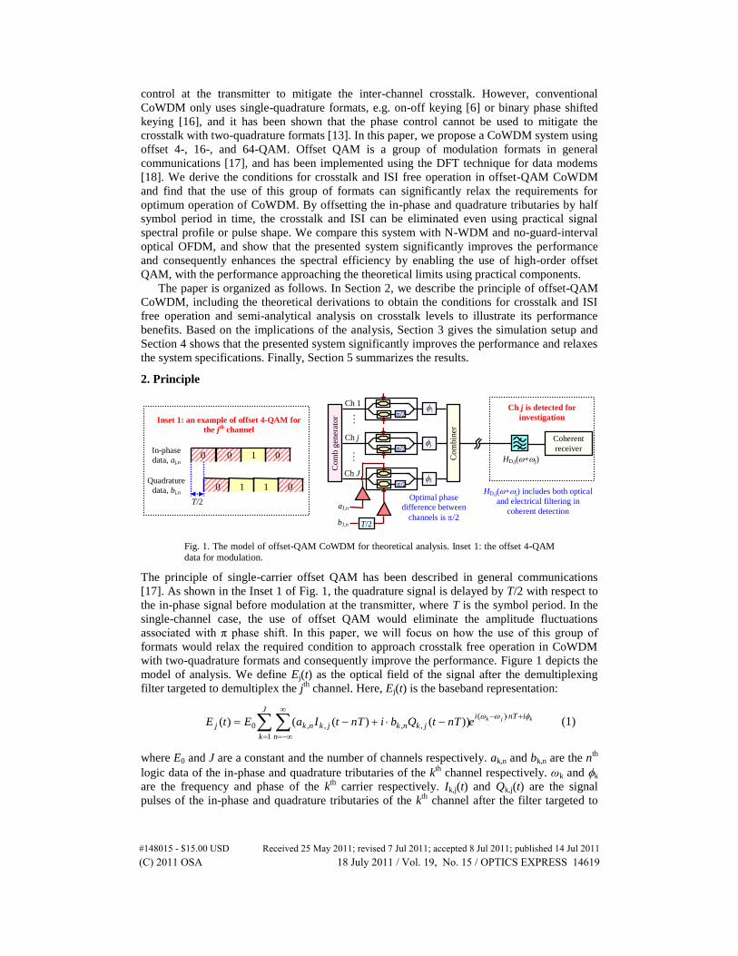
Fig. 1. The model of offset-QAM CoWDM for theoretical analysis. Inset 1: the offset 4-QAM
data for modulation.
The principle of single-carrier offset QAM has been described in general communications
[17]. As shown in the Inset 1 of Fig. 1, the quadrature signal is delayed by T/2 with respect to
the in-phase signal before modulation at the transmitter, where T is the symbol period. In the
single-channel case, the use of offset QAM would eliminate the amplitude fluctuations
associated with π phase shift. In this paper, we will focus on how the use of this group of
formats would relax the required condition to approach crosstalk free operation in CoWDM
with two-quadrature formats and consequently improve the performance. Figure 1 depicts the
model of analysis. We define Ej(t) as the optical field of the signal after the demultiplexing
filter targeted to demultiplex the jth
channel. Here, Ej(t) is the baseband representation:
kjk inTiJ
k n
jknkjknkj enTtQbinTtIaEtE
)(
1
,,,,0 ))()(()( (1)
where E0 and J are a constant and the number of channels respectively. ak,n and bk,n are the nth
logic data of the in-phase and quadrature tributaries of the kth
channel respectively. ωk and k
are the frequency and phase of the kth
carrier respectively. Ik,j(t) and Qk,j(t) are the signal
pulses of the in-phase and quadrature tributaries of the kth
channel after the filter targeted to
0 1 1 0
0 0 1 0
T/2
In-phase
data, aj,n
Quadrature
data, bj,n
Inset 1: an example of offset 4-QAM for
the jth channel
Co
mb
gen
erat
or
…
/2
/2
/2
…
Co
mb
iner
1
j
J
Ch 1
Ch j
Ch J
T/2
aJ,n
bJ,n
Coherent
receiver
Ch j is detected for
investigation
HD,j(+j)
HD,j(+j) includes both optical
and electrical filtering in
coherent detection
Optimal phase
difference between
channels is /2
#148015 - $15.00 USD Received 25 May 2011; revised 7 Jul 2011; accepted 8 Jul 2011; published 14 Jul 2011(C) 2011 OSA 18 July 2011 / Vol. 19, No. 15 / OPTICS EXPRESS 14619

demultiplex the jth
channel, and represent the overall impulse response of the whole system.
Ik,j(t) and Qk,j(t) are related to the baseband pulse shape of the signal before demultiplexing,
hs(t), and the impulse response of the demultiplexing filter for the jth
channel, hD,j(t), by:
( )( )
, ,( ) ( ) ( )k j ji t i
k j s D jI t h t e h e d
(2.1)
( )( )
, ,( ) ( / 2) ( )k j ji t i
k j s D jQ t h t T e h e d
(2.2)
We define Hin-phase,k,j(ω), Hquadrature,k,j(ω), Hs(ω), HD,j(ω) as the Fourier transforms of Ik,j(t),
Qk,j(t), hs(t), hD,j(t) respectively, and have:
)()()( ,,, jjDjksjkphasein HHH (3.1)
)()()( ,
2/)(
,, jjD
Ti
jksjkquadrature HeHH jk
(3.2)
Here Hs(ω) represents the overall baseband system response before demultiplexing, including
the transmitted electrical signal pulse shape, the transfer functions of the driving amplifier and
the modulator, chromatic dispersion in the fiber link etc. HD,j(ω + ωj) here represents the
receiver-side filter for channel demultiplexing, and, in coherent detection, should include both
the optical filtering, Hopt,j(ω + ωj), and the electrical filtering, Hele,j(ω + ωj-ωlo):
)()()( ,,, lojjelejjoptjjD HHH (4)
where ωlo is the frequency of the local oscillator. In practice, HD,j(ω + ωj) is usually matched
to Hs(ω), i.e. HD,j(ω + ωj) = Hs*(ω), to minimize the noise impact, which is achieved by using
digital filters at the receiver. Therefore, the number of free parameters is reduced and the
problem degenerates to the design of only Hs(ω) to achieve crosstalk and ISI free operation.
Due to the close channel spacing, the demultiplexing filter for the channel j, HD,j(ω + ωj),
may allow through parts of the signals from other channels, e.g. channels (j-1) and (j + 1), in
addition to the targeted channel, such that Ik,j(t) and Qk,j(t) (kj) are not zero for all t.
However, the symbol decisions are made based only on the final samples of the signal, where
the final decision samples are those obtained after all over- or non-over-sampling based digital
processing in coherent detection. Consequently, we only require that the crosstalk and ISI
levels at the final sampling points are zero. By setting t = mT and (m + 0.5)T in Eq. (1) for the
in-phase and quadrature tributaries respectively, we have the decoded logical data a’j,m and
b’j,m:
jk
i
n
jknkjknk
mn
jjnjjjnjjjmjjjmjmj
jkeTnmQbiTnmIa
TnmQbiTnmIaQbiIareala
})))(())(((
)))(())((())0()0({('
)(
,,,,
,,,,,,,,,
(5.1)
, , , , , , , , ,
( )
, , , ,
' {( (0.5 ) (0.5 )) ( (( 0.5) ) (( 0.5) ))
( (( 0.5) ) (( 0.5) )) }k j
j m j m j j j m j j j n j j j n j j
n m
i
k n k j k n k j
k j n
b imag a I T i b Q T a I m n T i b Q m n T
a I m n T i b Q m n T e
(5.2)
Here we use the property of (ωk-ωj) = 2π(k-j)/T. The first, second, and third terms on the right-
hand of Eqs. (5.1) and (5.2) represent the signal, ISI, and crosstalk, respectively. Note that in
Eq. (5), the phase of the targeted jth
channel, j, is assumed to be compensated. In practice,
similar to other coherent-detection systems, j varies with time and an adaptive algorithm is
#148015 - $15.00 USD Received 25 May 2011; revised 7 Jul 2011; accepted 8 Jul 2011; published 14 Jul 2011(C) 2011 OSA 18 July 2011 / Vol. 19, No. 15 / OPTICS EXPRESS 14620
required to mitigate the impact of phase noise, unless the laser linewidth is sufficiently narrow
and j is approximately constant for the acquired data window.
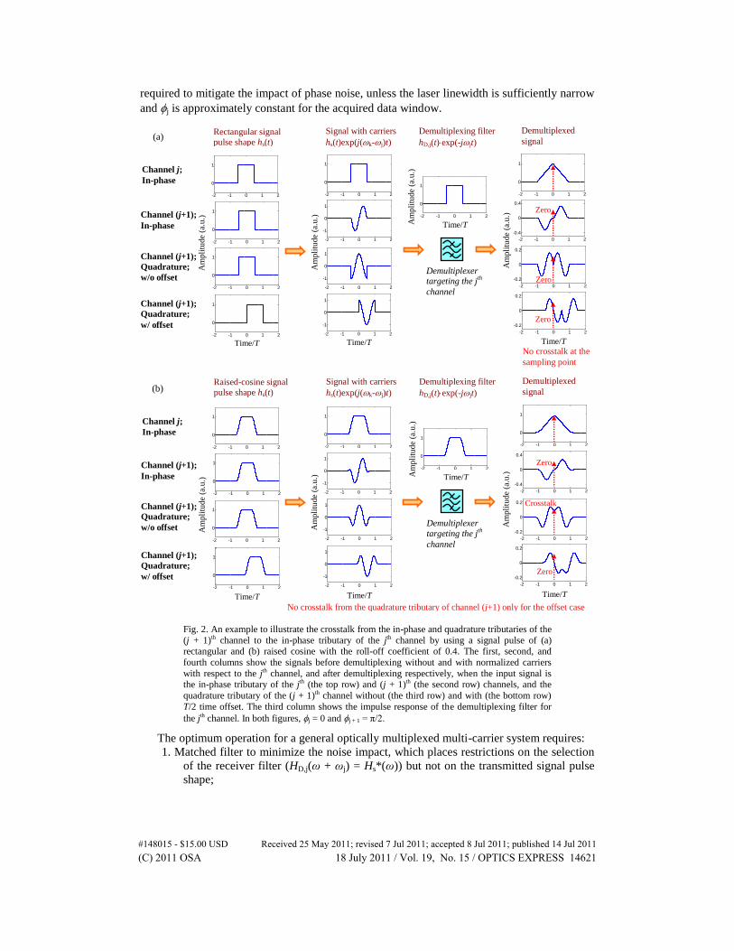
Fig. 2. An example to illustrate the crosstalk from the in-phase and quadrature tributaries of the
(j + 1)th channel to the in-phase tributary of the jth channel by using a signal pulse of (a) rectangular and (b) raised cosine with the roll-off coefficient of 0.4. The first, second, and
fourth columns show the signals before demultiplexing without and with normalized carriers
with respect to the jth channel, and after demultiplexing respectively, when the input signal is the in-phase tributary of the jth (the top row) and (j + 1)th (the second row) channels, and the
quadrature tributary of the (j + 1)th channel without (the third row) and with (the bottom row)
T/2 time offset. The third column shows the impulse response of the demultiplexing filter for
the jth channel. In both figures, j = 0 and j + 1 = π/2.
The optimum operation for a general optically multiplexed multi-carrier system requires:
1. Matched filter to minimize the noise impact, which places restrictions on the selection
of the receiver filter (HD,j(ω + ωj) = Hs*(ω)) but not on the transmitted signal pulse
shape;
-2 -1 0 1 2
0
1
-2 -1 0 1 2
0
1
-2 -1 0 1 2
0
1
-2 -1 0 1 2
0
1
-2 -1 0 1 2
0
1
-2 -1 0 1 2
0
1
-2 -1 0 1 2
0
1
Channel (j+1);
In-phase
Channel (j+1);
Quadrature;
w/o offset
Channel (j+1);
Quadrature;
w/ offset
Rectangular signal
pulse shape hs(t)
Signal with carriers
hs(t)exp(j(k-j)t)
Demultiplexing filter
hD,j(t)exp(-jjt)
Demultiplexed
signal
Channel j;
In-phase
Time/T
Am
pli
tude
(a.u
.)
Time/T Am
pli
tude
(a.u
.)
Demultiplexer targeting the j
th
channel
-2 -1 0 1 2
-1
0
1
-2 -1 0 1 2
-1
0
1
-2 -1 0 1 2
-1
0
1
Am
pli
tude
(a.u
.)
Time/T
-2 -1 0 1 2
-0.4
0
0.4
-2 -1 0 1 2
-0.2
0
0.2
-2 -1 0 1 2
-0.2
0
0.2
Time/T
Am
pli
tude
(a.u
.)
No crosstalk at the
sampling point
Zero
Zero
Zero
(a)
-2 -1 0 1 2
-0.2
0
0.2
-2 -1 0 1 2
-0.2
0
0.2
-2 -1 0 1 2
-0.4
0
0.4
-2 -1 0 1 2
0
1
-2 -1 0 1 2
0
1
Channel (j+1);
In-phase
Channel (j+1);
Quadrature;
w/o offset
Channel (j+1);
Quadrature;
w/ offset
Raised-cosine signal
pulse shape hs(t)
Signal with carriers
hs(t)exp(j(k-j)t)
Demultiplexing filter
hD,j(t)exp(-jjt)
Demultiplexed
signal
Channel j;
In-phase
Time/T
Time/T Am
pli
tud
e (a
.u.)
Demultiplexer
targeting the jth
channel
Time/T Time/T
Am
pli
tud
e (a
.u.)
Zero
Crosstalk
No crosstalk from the quadrature tributary of channel (j+1) only for the offset case
Zero
-2 -1 0 1 2
0
1
-2 -1 0 1 2
0
1
-2 -1 0 1 2
0
1
-2 -1 0 1 2
0
1
-2 -1 0 1 2
-1
0
1
-2 -1 0 1 2
-1
0
1
-2 -1 0 1 2
0
1
-2 -1 0 1 2
-1
0
1
(b)
Am
pli
tud
e (a
.u.)
Am
pli
tud
e (a
.u.)
#148015 - $15.00 USD Received 25 May 2011; revised 7 Jul 2011; accepted 8 Jul 2011; published 14 Jul 2011(C) 2011 OSA 18 July 2011 / Vol. 19, No. 15 / OPTICS EXPRESS 14621

2. Nyquist ISI criterion for ISI free operation in generic communication systems, which is
satisfied by only particular set of signal pulse shapes with associated matched
receiver filters. Fortunately, the selection of signal pulse shape under this restriction
is not stringent and a signal generated by a practical transmitter in the conventional
WDM or single-channel case can achieve ISI free operation, unless the system is
bandwidth-limited [1,9];
3. Channel orthogonality specific to optically multiplexed multi-carrier systems for
crosstalk free operation. This condition strictly limits the freedom of selecting the
spectral profiles of the signal before demultiplexing (Hs(ω)) and the associated
matched filter (HD,j(ω + ωj)).
As the conditions for the matched filter and ISI free operation of a particular channel are
similar to those in the single-channel case, we will assume that these two conditions are
satisfied and focus on the analysis of inter-channel crosstalk, i.e. the third term on the right
hand of Eqs. (5.1) and (5.2). In conventional optically multiplexed multi-carrier systems, the
requirement for channel orthogonality is strict. In recently reported works, rectangular- (no-
guard-interval optical OFDM) and sinc-function (N-WDM) based signal pulse shapes have
been used. Figure 2(a) illustrates the example using a rectangular signal pulse shape. As
depicted in the second and third rows of the figure, the crosstalk from the in-phase and
quadrature tributaries of the (j + 1)th
channel to the targeted jth
channel at the sampling point,
equal to the integration of the sine and cosine wave over the time period of T, is zero.
However, precluded by the limitations of device fabrication, these signal pulses cannot be
practically realized. On the other hand, commonly used practical signal pulses do not satisfy
the condition for crosstalk free operation or channel orthogonality, as depicted by the second
and third rows of Fig. 2(b) where the signal pulse is a raised cosine with roll-off coefficient of
0.4. The figure clearly shows that crosstalk exists. It is also observed that when the carrier
phase difference between channels is π/2, the crosstalk is only from the other quadrature of
the (j + 1)th
channel. This is the principle of conventional CoWDM [13], where with single-
quadrature modulation, crosstalk free operation can be achieved even with practical
components.
2.1 Relaxed Condition for Crosstalk Free Operation
Figure 2(a) and 2(b) also depict the case when the signal of the quadrature tributary of the (j +
1)th
channel is offset by T/2 in time (the bottom row). It can be seen that in this specific
example, the crosstalk from both the in-phase and quadrature tributaries of the (j + 1)th
channel becomes zero even for the practical raised-cosine pulse shape. This implies that
potential performance benefits could be obtained by offset-QAM CoWDM. Note that in Fig.
2(b), as will be shown later, crosstalk and ISI free operation is still not ideally achieved
because the spectrum of a raised-cosine shaped pulse remains infinite such that the crosstalk
from channels (j-2) and (j + 2) are not eliminated. In this subsection, we will firstly identify
the condition to obtain the optimum operation of offset-QAM CoWDM. For a simple
illustration, we firstly study the crosstalk levels to the in-phase tributary of the targeted jth
channel (i.e. (5.1)), with Ik,j((m-n)T) and Qk,j((m-n)T) obtained from Eq. (2):
dheTnmhTnmI sTTnmjki
sjk
)())(())((*/)))(((2
, (6.1)
2 ( )(( ) )/ *
, (( ) ) (( ) / 2) ( )i k j m n T T
k j s sQ m n T h m n T T e h d
(6.2)
Here, we have used (ωk-ωj) = 2π(k-j)/T and the condition of a matched filter with HD,j(ω + ωj)
= Hs*(ω). Without giving detailed mathematical manipulations, we simplify Eq. (6) as:
#148015 - $15.00 USD Received 25 May 2011; revised 7 Jul 2011; accepted 8 Jul 2011; published 14 Jul 2011(C) 2011 OSA 18 July 2011 / Vol. 19, No. 15 / OPTICS EXPRESS 14622

')2/)('()'2/)(()1())((*/')(2))((
, dTnmheTnmhTnmI sTjki
snmjk
jk
(7.1)
( )( 0.5) 2 ( ) '/ *
, (( ) ) ( 1) (( 0.5) / 2 ') ( ' ( 0.5) / 2) 'k j m n i k j T
k j s sQ m n T h m n T e h m n T d
(7.2)
We place the first requirement on the signal pulse to achieve channel orthogonality: hs(t) is a
even function (real and symmetric). This applies to the majority of practically generated
signals. In systems with transmission impairments such as chromatic dispersion,
compensation using optical or digital devices is assumed. By using this kind of signal pulse, it
can be proved that in (7), hs((m-n)T/2 + τ’)hs*(τ’-(m-n)T/2) and hs((m-n-0.5)T/2 + τ’)hs*(τ’-
(m-n-0.5)T/2) are also even functions. Therefore, (7) can be re-written as:
( )( )
, (( ) ) ( 1) (( ) / 2 ') ( ' ( ) / 2)cos(2 ( ) '/ ) 'k j m n
k j s sI m n T h m n T h m n T k j T d
(8.1)
')/')(2cos()2/)5.0('()'2/)5.0(()1())(( )5.0)((
, dTjkTnmhTnmhTnmQ ssnmjk
jk
(8.2)
Physically, Eq. (8) implies that Ik,j((m-n)T) is always real, while Qk,j((m-n)T) is imaginary for
odd (k-j) and real for even (k-j). We then place the second requirement: CoWDM with the
phase difference between channels of π/2. Without loss of generality, we define k = (k-1)π/2,
and can obtain from Eq. (5.1):
...))(())(()0(' ,2,2,2,2,,,
n
jjnj
n
jjnjjjmjmj TnmIaTnmIaIaa (9.1)
With the same mathematical manipulations, we can also obtain that Qk,j((m-n + 0.5)T) is
always real, while Ik,j((m-n + 0.5)T) is imaginary for odd (k-j) and real for even (k-j).
Consequently, the detected logical data for the quadrature tributary of the jth
channel, b’j,m, is:
, , , 2, 2, 2, 2,' (0.5 ) (( 0.5) )) (( 0.5) ))...j m j m j j j n j j j n j j
n n
b b Q T b Q m n T b Q m n T (9.2)
It is clear from Eqs. (9.1) and (9.2) that the crosstalk to a particular quadrature of a particular
channel j has only contributions from the same quadrature of channels more than one channel
distant from the targeted channel (i.e. channels (j-2) and (j + 2) and beyond). Therefore, we
place the third requirement for crosstalk free operation: the spectral profiles of the signal and
its associated matched receiver filter are designed to avoid the spectral overlap between the
targeted channel j and channels (j-2) and (j + 2).
In summary, crosstalk and ISI free operation in offset-QAM CoWDM can be achieved
provided that:
a). The spectral profile of the demultiplexing filter is matched to that of the signal.
b). The design of hs(t) satisfies Nyquist ISI criterion for ISI free operation.
c). hs(t) is a even function.
d). The transmitter is coherent with optimal phase difference between channels of π/2.
e). hs(t) is designed to avoid the spectral overlaps between the targeted channel (e.g. the
jth
channel) and channels more than one channel distant (e.g. the (j-2)th
and (j + 2)th
channels).
Intuitively, as depicted in Fig. 2, the relaxed condition for offset-QAM CoWDM can be
understood that when the carrier phase difference between channels is π/2, the crosstalk to a
particular tributary of the targeted channel from the adjacent channels (j-1) and (j + 1) can
only come from the other tributary, which however experiences a zero crossing at the
#148015 - $15.00 USD Received 25 May 2011; revised 7 Jul 2011; accepted 8 Jul 2011; published 14 Jul 2011(C) 2011 OSA 18 July 2011 / Vol. 19, No. 15 / OPTICS EXPRESS 14623

sampling point provided that the signal pulse of the other tributary of the adjacent channels (j-
1) and (j + 1) is the image of the impulse response of the receiver filter about the time point
T/4.
2.2 Crosstalk Analysis
In the previous subsection, we identified the requirements to enable crosstalk and ISI free
operation in offset-QAM CoWDM, and consequently obtained guidelines for system design.
In this subsection, we theoretically analyze the crosstalk levels for some practical signal pulse
shapes to illustrate the benefits of the presented system. For a simple illustration, we only
focus on the crosstalk to the in-phase tributary of the targeted channel (i.e. Eq. (5.1)). For
comparison, we also analyze the crosstalk levels using conventional systems without the T/2
time offset for the quadrature tributary. From Eq. (5.1), it is clear that the essential step for the
semi-analytical crosstalk analysis is to obtain Ik,j((m-n)T) and Qk,j((m-n)T) given the signal
pulse shape and the associated matched receiver filter. By using similar mathematical
manipulation to [13], we have:
...})2()2()()()0({)( 2,
2,,,,,,
Ti
jkTi
jkTi
jkTi
jkjkjkphasein eTIeTIeTIeTIITFH (10.1)
...})2()2()()()0({)( 2,
2,,,,,, Ti
jkTi
jkTi
jkTi
jkjkjkquadrature eTQeTQeTQeTQQTFH (10.2)
where ω[-π/T π/T] and kj. The folded spectra of Ik,j(t) and Qk,j(t), FHin-phase,k,j(ω) and
FHquadrature, k,j(ω), are defined as:
, , ( ) , ,
2( )in phase k j in phase k j
p
pFH H
T
(11.1)
p
jkquadraturejkquadratureT
pHFH )
2()( ,,,,
(11.2)
Therefore, Ik,j((m-n)T) and Qk,j((m-n)T) are proportional to the Fourier series coefficients of
FHin-phase,k,j(ω) and FHquadrature,k,j(ω) respectively, which can be determined by Hs(ω) and
HD,j(ω + ωj) with Eqs. (3) and (11).
Table 1. The Contributions to the Decoded a’j,m (the mth Sample of the jth Channel) in the
Conventional System without T/2 Time Offset for the Quadrature Tributary*
the contribution of the (m-1)th symbol
the contribution of the mth symbol
the contribution of the (m + 1)th symbol
channel (j-2) 0.036aj-2,m-1 0.072aj-2,m 0.036aj-2,m + 1
channel (j-1) 0.05bj-1,m-1 0.1bj-1,m 0.05bj-1,m + 1
channel j 0.056aj,m-1 aj,m 0.056aj,m + 1
channel (j + 1) 0.05bj + 1,m-1 0.1bj + 1,m 0.05bj + 1,m + 1
channel (j + 2) 0.036aj + 2,m-1 0.072aj + 2,m 0.036aj + 2,m + 1
*All terms are normalized by Ij,j(0). hs(t) and hD,j(t)exp(-iωjt) are both raised-cosine shaped with the roll-off
coefficient of 0.4.
Table 2. The Contributions to the Decoded a’j,m (the mth Sample of the jth Channel) in
Offset-QAM CoWDM*
the contribution of the (m-1)th
symbol
the contribution of the mth
symbol
the contribution of the (m + 1)th
symbol
channel (j-2) 0.036aj-2,m-1 0.072aj-2,m 0.036aj-2,m + 1
channel (j-1) 0 0 0
channel j 0.056aj,m-1 aj,m 0.056aj,m + 1
channel (j + 1) 0 0 0
channel (j + 2) 0.036aj + 2,m-1 0.072aj + 2,m 0.036aj + 2,m + 1
*All terms are normalized by Ij,j(0). hs(t) and hD,j(t)exp(-iωjt) are both raised-cosine shaped with the roll-off coefficient of 0.4.
#148015 - $15.00 USD Received 25 May 2011; revised 7 Jul 2011; accepted 8 Jul 2011; published 14 Jul 2011(C) 2011 OSA 18 July 2011 / Vol. 19, No. 15 / OPTICS EXPRESS 14624

Tables 1 and 2 compare the calculated signal level, ISI and crosstalk on the received mth
sample of the in-phase tributary of the jth
channel (a’j,m in Eq. (5.1)) for the conventional
system and offset-QAM CoWDM respectively. The signal pulse shape before demultiplexing
and the impulse response of the demultiplexing filter in both tables are raised cosine with the
roll-off coefficient of 0.4. The phase difference between channels is π/2. Note that in the
conventional system, the crosstalk level is only weakly dependent on this phase difference
[13]. We can clearly see that offset-QAM CoWDM can eliminate the crosstalk from the
adjacent channels (j-1) and (j + 1), so would improve the performance when compared to the
conventional system. It is also observed that in offset-QAM CoWDM, the crosstalk from
channels (j-2) and (j + 2) is still not fully eliminated due to the infinite spectral tails of raised-
cosine signal pulse.
Tables 3 and 4 illustrate another example with Hs(ω) and HD,j(ω + ωj) both being the
square root of a raised-cosine function with the roll-off coefficient of 0.4. The phase
difference between channels is π/2. In the conventional system (Table 3), the bandwidth-
limited signal spectrum results in the crosstalk only arising from the adjacent channels (j-1)
and (j + 1). However, the crosstalk levels from not only the mth
symbol but also the (m-1)th
and (m + 1)th symbols of channels (j-1) and (j + 1) are increased when compared to Table 1
because of the long pulse tails in the time domain. Therefore, the total crosstalk levels might
not be reduced. In contrast, crosstalk and ISI free operation can be achieved when using
offset-QAM CoWDM. It can be proved that in this case, the requirements (a)–(e) in
subsection 2.1 are satisfied. In practice, this function can be readily achieved by using
commercial components.
Table 3. The Contributions to the Decoded a’j,m (the mth Sample of the jth Channel) in the
Conventional System without T/2 Time Offset for the Quadrature Tributary*
the contribution of the (m-1)th symbol
the contribution of the mth symbol
the contribution of the (m + 1)th symbol
channel (j-2) 0 0 0
channel (j-1) 0.109bj-1,m-1 0.127bj-1,m 0.109bj-1,m + 1
channel j 0 aj,m 0
channel (j + 1) 0.109bj + 1,m-1 0.127bj + 1,m 0.109bj + 1,m + 1
channel (j + 2) 0 0 0
*All terms are normalized by Ij,j(0). Hs(ω) and HD,j(ω + ωj) are both the square root of a raised-cosine function
with the roll-off coefficient of 0.4.
Table 4. The Contributions to the Decoded a’j,m (the mth Sample of the jth Channel) in
Offset-QAM CoWDM*
the contribution of the (m-1)th
symbol
the contribution of the mth
symbol
the contribution of the (m + 1)th
symbol
channel (j-2) 0 0 0
channel (j-1) 0 0 0
channel j 0 aj,m 0
channel (j + 1) 0 0 0
channel (j + 2) 0 0 0
*All terms are normalized by Ij,j(0). Hs(ω) and HD,j(ω + ωj) are both the square root of a raised-cosine function with the roll-off coefficient of 0.4.
3. Simulation Setup
In addition to the theoretical analysis, we numerically investigate the performance
improvement enabled by the proposed system. Figure 3 shows the simulation setup, which
was implemented using Matlab. A continuous wave (CW) light with 6kHz laser linewidth was
fed into an optical comb generator to obtain five carriers with equal intensities and phases.
The channel spacing was 25GHz, equal to the symbol rate per carrier. The signal data trains
consisted of 25Gbit/s 211
-1 pseudo-random binary sequences (PRBS) repeated 5 times (10,235
bits). Different delays were applied to each tributary of the multi-level formats and also to
each channel to ensure that their bit sequences were uncorrelated. These logic data trains were
#148015 - $15.00 USD Received 25 May 2011; revised 7 Jul 2011; accepted 8 Jul 2011; published 14 Jul 2011(C) 2011 OSA 18 July 2011 / Vol. 19, No. 15 / OPTICS EXPRESS 14625

used to generate multi-level electrical signals with 40 samples per symbol and raised-cosine
pulse shape with the roll-off coefficient of 0.4. The quadrature signal was delayed by T/2 with
respect to the in-phase signal (see the Inset of Fig. 1). These analogue electrical signal outputs
were amplified and used for data modulation. The equivalent frequency response of the
driving amplifier and the modulator’s electronic interface was assumed to 3rd-order Gaussian
or 5th-order Bessel shaped. The modulated optical signals were phase controlled by adding an
additional phase k = (k-1), k = 1…5 before they were combined. At the receiver, the noise
of the optical preamplifier was modeled as additive white Gaussian noise. The launch power
into the preamplifier was adjusted to control the optical signal-to-noise ratio (OSNR). An
optical band-pass filter (OBPF) was not used because in a linear coherent receiver, any
functionality of an OBPF could be performed by an electrical filter (EF). The signal and local
oscillator were mixed by a 90° optical hybrid and detected by balanced detectors to extract the
in-phase and quadrature tributaries. The powers of the local oscillator and the received signal
were 10dBm and 3dBm respectively and their polarizations were controlled to be the same.
The equivalent thermal noise spectral power density of the detectors was 18pA/Hz1/2
. After
detection, the signals were electrically amplified and filtered by 3rd-order Gaussian-shaped
EFs. The received analogue signals were sampled by analogue-to-digital converters (ADCs)
with two samples per symbol and 8-bit physical resolution, unless otherwise stated. The
sampled signals were fed into a finite impulse response (FIR) filter, which employed mean-
square error criterion to update the FIR coefficients. Then the equalized signal was decoded to
evaluate the bit error rate (BER) performance.
Fig. 3. Simulation setup for systems of offset-QAM CoWDM, no-guard-interval optical
OFDM, and N-WDM, with 25Gsym/s per channel and 25GHz channel spacing.
For comparison, conventional no-guard-interval optical OFDM and Nyquist WDM were
also simulated. In the former case, the simulation setup was similar to that of the offset-QAM
CoWDM except that there was no T/2 time offset for the quadrature tributary. In the latter
case, pre-filtering was used such that the output of the pre-filter had a raised-cosine shaped
spectrum with the roll-off coefficient of 0.1 [5]. The 6dB bandwidth of the output of the pre-
filter was 12.5GHz, unless otherwise stated. Note that because the performance of these two
systems was only weakly dependent on the phase difference between channels [13], separate
lasers with proper wavelength spacing instead of an optical comb generator could be used. All
CoWDM Nyquist WDM No-guard-interval optical
OFDM
900
optical
hybrid
TX1
Co
mb g
ener
ator
Co
mbin
er
EDFA
TX5
TX3
TX2
TX4
EDFA
Attenuator
ADC
ADC
FIR
2samples/sym
EF LO
Amplifier
Central channel (Ch3) is detected for investigation
k
/2
T/2
In-phase
25Gbaud data
Quadrature
25Gbaud data
k=1…5
Phase
control
/2
/2
Optical
filter
#148015 - $15.00 USD Received 25 May 2011; revised 7 Jul 2011; accepted 8 Jul 2011; published 14 Jul 2011(C) 2011 OSA 18 July 2011 / Vol. 19, No. 15 / OPTICS EXPRESS 14626

simulations were iterated with different random number seeds to give a total of around
200,000 simulated bits. The performance was evaluated in terms of the required normalized
OSNR to achieve a BER of 5 × 10⁴
for the central channel by direct error counting, where
5 0.1
Total Signal PowerNormalized OSNR
Noise Power in nm
(12)
4. Results
4.1 Comparison of Fundamental Performance Limit
Fig. 4. (a). Performance versus the received OSNR for offset-QAM CoWDM (solid circles),
Nyquist WDM (empty circles), and no-guard-interval optical OFDM (cross circles) using 4-QAM format. (b) Performance versus the received OSNR for CoWDM using offset 16- (solid
triangles) and 64-QAM (solid squares), and for 16-QAM N-WDM (empty triangles). Dashed or
dotted lines represent the theoretical limits. The phase difference between channels is π/2.
Fig. 5. Constellation diagrams of (a): 4-QAM no-guard-interval optical OFDM; (b): 4-QAM N-
WDM; (c): 16-QAM N-WDM; (d): offset 4-QAM CoWDM; (e): offset 16-QAM CoWDM; (f):
offset 64-QAM CoWDM. The system parameters are the same as Fig. 4.
Figure 4(a) and (b) show the simulated performance versus the received OSNR for offset-
QAM CoWDM, no-guard-interval optical OFDM, and N-WDM under optimized transmitter
and receiver bandwidths. The corresponding constellation diagrams are depicted in Fig. 5(a)–
5(f). In Fig. 4 and 5, the equivalent response of the driving amplifier and the modulator’s
electronic interface was 3rd-order Gaussian shaped, which was found to result in better
performance than a 5th-order Bessel shaped response. Note that in N-WDM, the signal
Imag
inary
co
mp
on
ent
(a.u
.)
(d): Offset 4-QAM CoWDM (e): Offset 16-QAM CoWDM (f): Offset 64-QAM CoWDM
Real component (a.u.) Real component (a.u.) Real component (a.u.)
(a): 4-QAM OFDM (b): 4-QAM N-WDM (c): 16-QAM N-WDM
6 8 10 12 14 16
-2
-3
-4
-515 20 25
-2
-3
-4
-5
Received OSNR (dB)
Log
10(B
ER
)
Received OSNR (dB) L
og
10(B
ER
)
Offset 4-QAM
4-QAM N-WDM
4-QAM OFDM
Offset 16-QAM
16-QAM N-WDM
Offset 64-QAM
Theory Theory
Theory (a) (b)
#148015 - $15.00 USD Received 25 May 2011; revised 7 Jul 2011; accepted 8 Jul 2011; published 14 Jul 2011(C) 2011 OSA 18 July 2011 / Vol. 19, No. 15 / OPTICS EXPRESS 14627
spectral profile from the output of the pre-filter was fixed regardless of this equivalent
response. The memory length of the receiver FIR filter was 6 for offset-QAM CoWDM and
no-guard-interval optical OFDM, and 12 for Nyquist WDM. The phase difference between
channels was π/2. It can be seen from the figures that no-guard-interval optical OFDM
exhibited the worst performance, and even with optimized transmitter and receiver
bandwidths, this technique had around 3dB penalty at BER of 5 × 10⁴
for the 4-QAM format
and could not support the 16-QAM format. On the other hand, Nyquist WDM used
rectangular spectral profile and improved the performance by using optical pre-filtering.
However, residual crosstalk still existed, which resulted in ~5dB penalty for 16-QAM at BER
of 5 × 10⁴
. In contrast, the presented system showed very clear constellation diagrams even
for offset 64-QAM and the performance could approach the fundamental limits using practical
devices with optimized bandwidths. This clearly illustrates the performance benefits of the
proposed system, with the potential to achieve crosstalk and ISI free operation.
4.2 Relaxed Transmitter Specifications
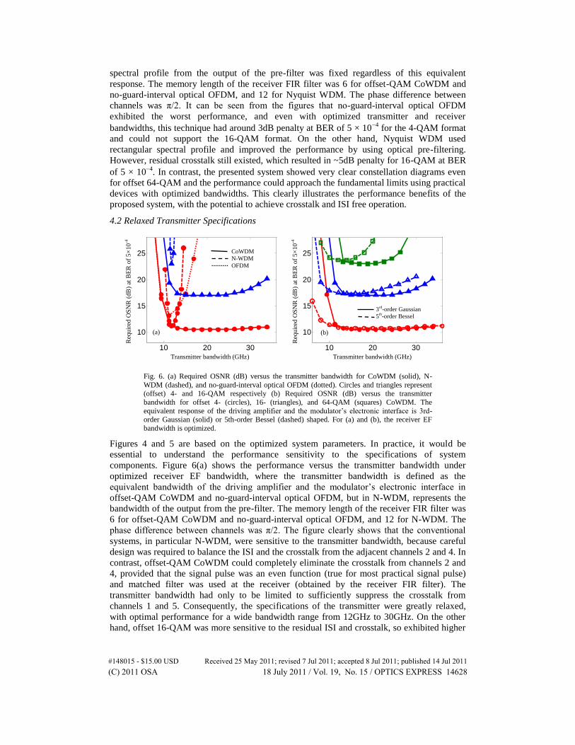
Fig. 6. (a) Required OSNR (dB) versus the transmitter bandwidth for CoWDM (solid), N-
WDM (dashed), and no-guard-interval optical OFDM (dotted). Circles and triangles represent
(offset) 4- and 16-QAM respectively (b) Required OSNR (dB) versus the transmitter
bandwidth for offset 4- (circles), 16- (triangles), and 64-QAM (squares) CoWDM. The
equivalent response of the driving amplifier and the modulator’s electronic interface is 3rd-order Gaussian (solid) or 5th-order Bessel (dashed) shaped. For (a) and (b), the receiver EF
bandwidth is optimized.
Figures 4 and 5 are based on the optimized system parameters. In practice, it would be
essential to understand the performance sensitivity to the specifications of system
components. Figure 6(a) shows the performance versus the transmitter bandwidth under
optimized receiver EF bandwidth, where the transmitter bandwidth is defined as the
equivalent bandwidth of the driving amplifier and the modulator’s electronic interface in
offset-QAM CoWDM and no-guard-interval optical OFDM, but in N-WDM, represents the
bandwidth of the output from the pre-filter. The memory length of the receiver FIR filter was
6 for offset-QAM CoWDM and no-guard-interval optical OFDM, and 12 for N-WDM. The
phase difference between channels was π/2. The figure clearly shows that the conventional
systems, in particular N-WDM, were sensitive to the transmitter bandwidth, because careful
design was required to balance the ISI and the crosstalk from the adjacent channels 2 and 4. In
contrast, offset-QAM CoWDM could completely eliminate the crosstalk from channels 2 and
4, provided that the signal pulse was an even function (true for most practical signal pulse)
and matched filter was used at the receiver (obtained by the receiver FIR filter). The
transmitter bandwidth had only to be limited to sufficiently suppress the crosstalk from
channels 1 and 5. Consequently, the specifications of the transmitter were greatly relaxed,
with optimal performance for a wide bandwidth range from 12GHz to 30GHz. On the other
hand, offset 16-QAM was more sensitive to the residual ISI and crosstalk, so exhibited higher
10 20 30
10
15
20
25
10 20 30
10
15
20
25
Transmitter bandwidth (GHz)
Req
uir
ed O
SN
R (
dB
) at
BE
R o
f 5×
10
-4
Transmitter bandwidth (GHz)
Req
uir
ed O
SN
R (
dB
) at
BE
R o
f 5×
10
-4
(a) (b)
3rd-order Gaussian
5th-order Bessel
CoWDM
N-WDM
OFDM
#148015 - $15.00 USD Received 25 May 2011; revised 7 Jul 2011; accepted 8 Jul 2011; published 14 Jul 2011(C) 2011 OSA 18 July 2011 / Vol. 19, No. 15 / OPTICS EXPRESS 14628

penalty when the transmitter bandwidth was smaller than 12GHz or larger than 30GHz when
compared to offset 4-QAM.
Figure 6(b) shows the performance versus the transmitter bandwidth for two types of
transmitter responses in offset-QAM CoWDM. It is found that 3rd-order Gaussian shaped
response exhibited slightly better optimal performance and could support a larger transmitter
bandwidth when compared to the 5th-order Bessel shaped response. This is because the sharp
roll-off of the 3rd-order Gaussian response would suppress the crosstalk from channels 1 and
5 more effectively for a larger transmitter bandwidth, resulting in better performance
especially for higher-level formats. However, this sharp roll-off also introduced more ISI and
degraded the performance when the transmitter bandwidth was small.
4.3 Relaxed Receiver Specifications
Fig. 7. (a) Required OSNR (dB) versus the receiver EF bandwidth for offset 4-QAM CoWDM (solid lines), 4-QAM N-WDM (dashed lines), and 4-QAM no-guard-interval optical OFDM
(dotted lines). Solid symbols represent a FIR memory length of 6 for CoWDM and OFDM, or
12 for N-WDM. Empty symbols represent a FIR memory length of 2 for CoWDM, OFDM, and N-WDM. (b) Required OSNR (dB) versus the memory length of the receiver FIR filter.
Circles, triangles, and squares represent (offset) 4-, 16-, and 64-QAM respectively. For (a) and
(b), the transmitter bandwidth is optimized and the phase difference between channels is π/2.
Fig. 8. (a) Required OSNR (dB) versus receiver filter bandwidth for offset 4- (circles), 16-
(triangles), and 64-QAM (squares) CoWDM when the equivalent response of the driving
amplifier and the modulator’s electronic interface is 3rd-order Gaussian (solid) and 5th-order Bessel (dashed). The transmitter bandwidth is optimized. (b) Required OSNR (dB) versus the
ADC resolution for offset 4- (circles), 16- (triangles), and 64-QAM (squares) CoWDM under
optimized transmitter and receiver bandwidths. In (a) and (b), the receiver FIR filter memory length is 6 and the phase difference between channels is π/2.
2 4 6 8 10
10
15
20
25
10 20 30
10
15
20
25
Req
uir
ed O
SN
R (
dB
) at
BE
R o
f 5
×1
0-4
Receiver EF bandwidth (GHz)
Req
uir
ed O
SN
R (
dB
) at
BE
R o
f 5
×1
0-4
ADC resolution (bits)
(a) (b)
Offset 4-QAM
Offset 16-QAM
Offset 64-QAM
3rd
-order Gaussian
5th-order Bessel
0 5 10 15 20
10
15
20
25
10 20 30
10
15
20
25
Req
uir
ed O
SN
R (
dB
) at
BE
R o
f 5×
10
-4
Receiver EF bandwidth (GHz)
Req
uir
ed O
SN
R (
dB
) at
BE
R o
f 5×
10
-4
FIR memory length (bits)
(a) (b) CoWDM
N-WDM
OFDM
CoWDM
N-WDM
OFDM
#148015 - $15.00 USD Received 25 May 2011; revised 7 Jul 2011; accepted 8 Jul 2011; published 14 Jul 2011(C) 2011 OSA 18 July 2011 / Vol. 19, No. 15 / OPTICS EXPRESS 14629

In addition to the relaxed transmitter specifications, the presented system also reduces the
requirements for the receiver specifications under optimized transmitter bandwidth. Figure
7(a) illustrates the performance as a function of the receiver EF bandwidth for CoWDM, N-
WDM and no-guard-interval optical OFDM with varied memory length of the receiver FIR
filter when the response of the driving amplifier and the modulator was 3rd-order Gaussian
shaped. Note that the signal spectrum of the output from the pre-filter in N-WDM was fixed
regardless of this response. The phase difference between channels was assumed to be π/2. It
is further confirmed that under optimized transmitter and receiver bandwidths, offset-QAM
CoWDM exhibited better performance than the no-guard-interval optical OFDM and N-
WDM. In addition, the tolerance range of the receiver EF bandwidth was almost unchanged
even when the memory length of the receiver FIR filter was reduced to 2. In contrast, in the
no-guard-interval optical OFDM and N-WDM, when the receiver EF bandwidth was larger
than 12GHz, the balance of ISI and crosstalk could not be well performed by using a memory
length of 2. Consequently, the bandwidth tolerance range was reduced. The conclusion was
further confirmed in Fig. 7(b). It can be clearly seen that CoWDM was insensitive to the
memory length even for offset 64-QAM. On the other hand, the no-guard-interval optical
OFDM and N-WDM required a larger memory length to obtain the optimal performance,
especially for higher-level modulation formats. In the 16-QAM N-WDM, the optimal
performance could not be achieved even for a memory length as large as 20 bits.
More investigations on the required receiver specifications for offset-QAM CoWDM are
shown in Fig. 8(a), where the required OSNR versus the receiver EF bandwidth using varied
modulation formats and transmitter responses are depicted. Similar to Fig. 6(b), 3rd-order
Gaussian shaped response for the driving amplifier and the modulator’s electronic interface
resulted in better performance. The bandwidth tolerance range was reduced when the format
level increased due to the increased sensitivity to residual ISI and crosstalk.
In Fig. 4–8(a), the ADC resolution was assumed to be 8 bits. It would be important in
practice to understand the performance variations associated with the ADC resolutions, as
shown in Fig. 8(b). In the figure, the transmitter and receiver bandwidths were optimized and
the memory length of the FIR filter was 6. It is observed that the required ADC resolution
depended on the format level. However, less than 1dB penalty could be ensured by using 6-bit
resolution even for offset 64-QAM CoWDM. This resolution could be readily achieved by the
state-of-the-art commercial ADC products.
4.4 Performance Sensitivity to Phase Difference between Channels
Fig. 9. Performance as a function of phase difference between channels for 3rd-order Gaussian
shaped transmitter and receiver EF with optimized bandwidths. Circles, triangles, and squares represent offset 4-, 16-, and 64-QAM respectively.
It was theoretically proved in Section 2 that one of necessary conditions to achieve crosstalk
free operation was the control of the phase difference between channels. This conclusion is
0 90 180 270 360
10
15
20
25
Req
uir
ed O
SN
R (
dB
) at
BE
R o
f 5
×1
0-4
Phase difference (degree)
#148015 - $15.00 USD Received 25 May 2011; revised 7 Jul 2011; accepted 8 Jul 2011; published 14 Jul 2011(C) 2011 OSA 18 July 2011 / Vol. 19, No. 15 / OPTICS EXPRESS 14630

numerically confirmed in Fig. 9, which shows the performance versus the phase difference
between channels under optimized transmitter and receiver filter bandwidths. The memory
length of the receiver FIR filter was 6. The figure shows that the performance of the proposed
offset-QAM system depended on the phase difference between channels such that phase
control at the transmitter, i.e. CoWDM, was needed. In this aspect, the implementation
complexity was increased when compared to the no-guard-interval optical OFDM. It is also
shown that the optimal performance was obtained when the phase difference was π/2 or 3π/2.
At 1dB OSNR penalty, the phase tolerance range was around ± 45°, ± 40°, ± 35° for offset 4-,
16-, and 64-QAM, respectively.
5. Conclusions
We have proposed and investigated a CoWDM system using offset 4-, 16-, and 64-QAM to
significantly improve the performance and relax the device specifications. We have
theoretically derived the condition for crosstalk free operation for the presented system and
found that by offsetting the two quadratures by half symbol period in time, the crosstalk and
ISI can be eliminated even using practical signal spectral profiles. Based on the implications
of the analysis, we have numerically compared this system with recently reported no-guard-
interval optical coherent OFDM and Nyquist WDM, and shown that the presented system
significantly relaxes the specifications of the system components and enhances the spectral
efficiency by enabling the use of higher-level modulation formats, with the achieved
performance approaching the theoretical limits using practical devices.
Acknowledgments
This work was supported by Science Foundation Ireland under grant number 06/IN/I969.
#148015 - $15.00 USD Received 25 May 2011; revised 7 Jul 2011; accepted 8 Jul 2011; published 14 Jul 2011(C) 2011 OSA 18 July 2011 / Vol. 19, No. 15 / OPTICS EXPRESS 14631