Implicit Compositional Simulation of Single-Porosity and Dual ...
37
SPE -of l+tmfem~ SPE 18427 Implicit Compositional Simulation of Single-Porosity and Dual-Porosity Reservoirs by K.H. Coats, Scientific Software-lntercomp SPE Member Copyright 1989, %ciely of Petroleum Engineers This paper was prepared for presentation at the SPE Sympoalum on Reservoir Simulstlon in Houston, TX, Fabruary 6-S, 1989. This paper wee selected for presentation by an SPE Program Committee following review of information contained in en abstract submitted by the author(a). Contents of the paper, as presented, have not been raviewed by the Society of Petroleum Englneera and are subject to correction by the author(a), The material, as presented, does not necessarily reflect any position of the Society of Petroleum Engineere, Ite officers, or members. Papera presented at SPE meetings are aubjacf to publiczflon review by Editorial Gmmittees of the Society of Petroleum Engineers. Permission to copy is restricted to an abstract of not more than 306 worda. Illustrations may not be copied. The abstract should contain conspicuous acknowledgment of where and by whom the paper is presanted. Write Publice~ ma Manager, SPE, P.O. Sox 833636, Richardson, TX 75063-3636. Telex, 730969 SPEDAL. Abstract cubic equation-of-state 1 (EOS) forrepresentation of gas-oil phaee equilibriaand deneitiee. The generalizedEOS Thispaper describeean iraplicit numerical model for repreaente the Redlich-Kwong2 Soave-Redlich-Kwong3 compositionalaimulation of single-porosityand dual- .! Zudkevilch-JoffeRedlich-Kwong 95, and Peng-Robinson d poroeityoilor gaa condensatereservoirs.A 3-component EOS. Atabular,pressure-dependentK-valueoptionprovides equation-of-state compositionalapproach ia proposedas a an alternativeto EOS usage. EOS parametesaareobtained desirablealternativeto extended black oil modelling, using a regression-basedpVT program~. Different requiringlittlemore computingtime than theletter.The parametersetsareueedforrese~oirand surfaceseparation approachiaillustrated foran actualneas-critical volatileoil calculations. This eases the burden of determining reservoir. A aimple method for reducing implicit formulation time truncation error is described and parameters and increasesEOS accuracy at reservoirand surface conditions.Viscositiesare calculatedfro m the illustrated. A new bottomhole constraintfunction is Lohrenz et al correlationsand interfacieltension ia describedforbetterpreservationof productionwelltarget obtainedusingthe MacLeod-Sugdenmethodg. ratee in compositionalmodels. A new matrix-fracture transferformulationincludingmatrix-fracturediffusionis The model simulates1-,2- and 3-dimenaiortel flow in preeentedfor the dual-porosity description; itsaccuracy is Cartesianor cylindrical coordinates.Darey’sLaw modified examined in connectionwith severaltestproblema where by relativepermeabilityand capillarypressurerepresenta correct reeulte are available from single-porosity the viacoue.,capillaryand gravityforcee. Effects of simulation. Results are discussedfor a 3D 600-block interracial tensionon capillarypressureareincluded.The aimulationof a highlyfracturednear-critical volatileoil model appliesto depletion,water injection,cycling(gas reeervoir. injection), andenrichedgas/solventinjectionoperationsin reeervoixtypes ranging from black oil to near-critical Introduction volatileoil and condensate to lean gas condensate. Applicationsincludeaimulationoflaboratoryexpenm enta, Thispaperdescribeea fullyimplicitnumericalmodel cylindncel-coordinate single-wel.1etudiasand are~ crose- for compositionalaimulationof multidimenaion~ threa- sectionalor3D field-scale studiee. phaae flow in single-porosityand naturallyfractured reservoirs.A generaldescription of the model is given, Implicit formulafions generally have a tendency followedby a sectiongivingmore detailregardingcertain toward greatacnumericaldispersioneffectsthantheIXPES features. The model equationsare then preeented. The formulation. A dispersion-control feature is described major em phaaiahere relatesto the fracturedreservoir which reduces sensitivityof reaultato time step aiaein application. Therefore, the remainder of the paper some caees. describesa new matrix-fracturefluidtransferformulation and estimatesitsaccuracyin connectionwith a number of Production well rate is allocatedamong Layers by exam plaortestproblems. pressureand mobility,includingan implicitbottomhole constrainttreatmenttopreserveapecifiadtargetrate.The GeneralDescriptionoftheModel well rate terms involved are implicitin all variables: com positions, saturationsandpressure.A new formulation The model iE fullycom poaitimmlwith a generalized for the impw bottomhole target rate constraintgives better preeenrationof specifiedrate for the case of R&erences and illustrations atend~fpaper. compositionalsimulation, --- 239
-
Upload
khangminh22 -
Category
Documents
-
view
0 -
download
0
Transcript of Implicit Compositional Simulation of Single-Porosity and Dual ...

SPE-of l+tmfem~
SPE 18427
Implicit Compositional Simulation of Single-Porosity andDual-Porosity Reservoirsby K.H. Coats, Scientific Software-lntercomp
SPE Member
Copyright 1989, %ciely of Petroleum Engineers
This paper was prepared for presentation at the SPE Sympoalum on Reservoir Simulstlon in Houston, TX, Fabruary 6-S, 1989.
This paper wee selected for presentation by an SPE Program Committee following review of information contained in en abstract submitted by theauthor(a). Contents of the paper, as presented, have not been raviewed by the Society of Petroleum Englneera and are subject to correction by theauthor(a), The material, as presented, does not necessarily reflect any position of the Society of Petroleum Engineere, Ite officers, or members. Paperapresented at SPE meetings are aubjacf to publiczflon review by Editorial Gmmittees of the Society of Petroleum Engineers. Permission to copy isrestricted to an abstract of not more than 306 worda. Illustrations may not be copied. The abstract should contain conspicuous acknowledgment ofwhere and by whom the paper is presanted. Write Publice~ ma Manager, SPE, P.O. Sox 833636, Richardson, TX 75063-3636. Telex, 730969 SPEDAL.
Abstract cubic equation-of-state1 (EOS) forrepresentationof gas-oilphaee equilibriaand deneitiee. The generalized EOS
This paper describeean iraplicitnumerical model for repreaente the Redlich-Kw ong2 Soave-Redlich-Kw ong3com positionalaimulation of single-porosityand dual- .!Zudkevilch-JoffeRedlich-Kwong 95, and Peng-Robinsond
poroeityoilor gaa condensatereservoirs.A 3-component E OS. A tabular,pressure-dependentK-valueoptionprovidesequation-of-statecom positionalapproach ia proposed as a an alternativeto EOS usage. EOS parametesaare obtaineddesirablealternativeto extended black oil modelling, using a regression-basedpVT program~. Differentrequiringlittlemore computing time than the letter. The parameter setsare ueed forrese~oir and surfaceseparationapproachiaillustratedforan actualneas-criticalvolatileoil calculations. This eases the burden of determiningreservoir. A aimple method for reducing implicitformulation time truncation error is described and
parameters and increasesEOS accuracy at reservoirandsurface conditions. Viscositiesare calculatedfrom the
illustrated. A new bottomhole constraintfunction is Lohrenz et al correlationsand interfacieltension iadescribedfor betterpreservationof productionwelltarget obtainedusingthe M acLeod-Sugdenm ethodg.ratee in com positionalmodels. A new matrix-fracturetransferformulationincludingmatrix-fracturediffusionis The model simulates1-,2- and 3-dimenaiortelflow inpreeentedfor the dual-porositydescription;itsaccuracy is Cartesianor cylindricalcoordinates.Darey’sLaw modifiedexamined in connection with severaltest problema where by relativepermeabilityand capillarypressurerepresentacorrect reeulte are available from single-porosity the viacoue.,capillaryand gravity forcee. Effects ofsimulation. Results are discussedfor a 3D 600-block interracialtensionon capillarypressureare included. Theaimulationof a highlyfracturednear-criticalvolatileoil model appliesto depletion,water injection,cycling(gasreeervoir. injection),and enrichedgas/solventinjectionoperationsin
reeervoixtypes ranging from black oil to near-criticalIntroduction volatile oil and condensate to lean gas condensate.
Applicationsincludeaimulationof laboratoryexpenm enta,This paper describeea fullyimplicitnumerical model cylindncel-coordinatesingle-wel.1etudiasand are~ crose-
for compositionalaimulationof m ultidimenaion~ threa- sectionalor 3D field-scalestudiee.phaae flow in single-porosityand naturally fracturedreservoirs.A general descriptionof the model is given, Implicit formulafions generally have a tendencyfollowedby a sectiongivingmore detailregardingcertain toward greatacnumericaldispersioneffectsthan theIX PESfeatures. The model equationsare then preeented. The formulation. A dispersion-controlfeature is describedmajor em phaaia here relates to the fracturedreservoir which reduces sensitivityof reaultato time step aiae inapplication. Therefore, the rem ainder of the paper some caees.describesa new matrix-fracturefluidtransferformulationand estimatesitsaccuracyin connectionwith a number of Production well rate is allocatedamong Layers byexam plaor testproblems. pressure and mobility,includingan implicitbottomhole
constrainttreatmentto preserveapecifiadtargetrate. TheGeneralDescriptionof the Model well rate terms involved are implicitin all variables:
com positions,saturationsand pressure.A new formulationThe model iE fullycom poaitimmlwith a generalized for the impw bottomhole target rate constraintgives
better preeenrationof specifiedrate for the case ofR&erences and illustrationsat end ~f paper. compositionalsimulation,
---239

2 IMPLICIT COMPOSITIONAL SIMULATION OF SINGLE-POROSITY ANO DUAL-POROSITY RESERVOIRS SPE 18427
Pseudo or extended black oil models are frequently computed usinga method developedby da Silvaand Belery.
used to approximate com postinal effectsin volatileoil Their method includesdetailedequationsfor calculating
resewoire undergoingdepletionandlor cycling. There are diffusioncoeftiientsfor each component from the static
advantages in many euch caeee in favor of using a variable group of (resemoir ternperature, component
com positionalmodel with a pseudoized, tuned three- molecularweightsand criticalproperties),and the dynamic
component fluiddescription. These advantages include: group of pressureand com positions,Allth.ssevariablesare
easier preparationof PVT data, increased accuracy in presentin any com positionalmodel or are calculatedin therepresentationof com positionalphenom ens, and only aimulation.
m arginzllygreatercomputing expense.Da Silvaproposedsome time ago thatdiffusioncan be
The code utilizesmapping so that storageisrequired importantin fracturedmatrixreservoirbehavior,especially
onlyforactivegridblocks. For exam plea 49 x 30 x 56000- when injec(iongas com position(e.g.N2) differsgreatlyblock @d having 4200 activebloclw requiresstorage for from native reservoir gas. Computations chow thatonly 4200-block arrays. To our knowledge, this mapping diffusioncan act very rapidlyto nearlyeliminatematrix-logicwas firstdevisedby Dr.A. D. Modine in 1971. fracturecom positiondifferenceboth in the liquidand gas
phaee. The diffusioncoefficientsand rate expressionsandM&id com positionmay vary with depth throughout theirdenvativeeare coded implicitlyinthe m odeL
the hydrocarbon column in the case of initiallyundeysaturatedresenroire.Ttdz depth variationmay crossthe Table 1 shows the expreseioneformatrix-fracturegae-
criticalpoint with near-criticalcondensate in the upper gas and Iiquid-gaediffusionrates. The term Tor isportionsand near-criticalvolatileoilin the 10wer portions tortuoeity,A@/!?isthe diffusion“tranemiscibility”reflectingof theinitialcolumn. m atr& and @d block dimeneione,S g (Sgg)isa saturation-
?%dependent fractionbetween O and , and D g (Dgg) is theThe model offersthe option of internally-generated diffusion coefficient,different for eac component.
vertical-equilibriam (VE)capfiry pressurecurveslO. These Diffusioncoefficientsfor liquid-liquiddiffusioncan becurvesvary in time and from block to block. They reduce about 100 times em allerthan those for gae-gaa diffusion.the erroreand occasionaldisruptive“steel-plate”effects Liquid-gascoefficientsare largerbut stilllessthan gae-gaeassociatedwithuse ofrock capillarypressurecurves. coefficients.
liiatorymatching oftenentailsa largenumber of long The diffusionratesare illustratedin Table I forcellsrune w~h productionwell rates specifiedae STB/d of oil.. 1 (matrix)and 2 (fracture).Tf both cells,remain 2-phaseUntil a good match is approached, rune may encounter gas-oiland equilibratewith both the gas-gasand liquid-gaserroneouslylargecalculatedG O R valueswithresultinghigh diffusionterms shown, then an equilibrium-statedilemmacom puti.ngexpense. A method of avoidingthisisdescribed eriaea. The equilibriumrequirem ent that all matrixbelow.“-1 gatheringcenterlogicl1 which has proven weful component K-values be equal is a contradiction. Theinfieldstudypredictionsisalsodescribed. problem is resolvedmm ply by usinggae-gasdiffusiononly.
For am allmatrixblocks(e.g.1-4 ft. cubes),diffusionissoTh the dual-porositycase,the model nl.lows reseqvoir rapid that gae-gaecliffueionalone reeultein sm allmatrix-
descriptionewhere the matrix block size and shape vary fracturecom positiondifferencesboth in the liquidand gasfrom block to block throughout the grid. Storage and phaaes.computingtime requirem enteare proportionalto the degreeof fracturing. For a 1000 gridblockproblem withallblocks An estimateof the diffusiontransienttime isgivenbydual-porosity,theeerequiremente are proportionalto 2000. solutionof the diffusionequationW, due to regionalfracturing,only 100 blocks were dual-porosity,then these requirem enta would be proportionalto a2c
1100.—.
axiSD
For regionallyfracturedreservoixdescriptions,the for initialconditionC(XD,0)= 1 and boundary condkionemodel treatsthe three clifferent types of interlock 50 w:
C(l,tD)= O and 3C/3xD = O at XD = O,wherematrix-matrixElow between blocksin unfracturedregions,fracture-fractureflow between blocksin fracturedregions,and I.Iatrix-fractureflow between block pairs on the ‘D
= x / (!2/2) ‘D= Dt / ~or(k/2)2
interfaceof such regions,The model can be run in single-porositymode with virtuallyno lossof efficiencycausedby This corresporidsto the case of a linearcore 8 feetlong
thepresenceof dual-porositycode. initiallysaturated with fluidof unit concentrationandexposed to zero-concentrationfluidat x = O and x = E. The
The calculationsinclude matrix-fractureliquid-gae solutionforaverageconcentrationia
and gas-gasdiffusion,usinga method developedby da Silva
~
k -A tand Belery12. $s oCdtiQ=2~ 1 enll
1 ~2
The linear-solvercode includesthe threeoptionsof D4n
(reduce?band-width)directsolution13,iterativeblock SO Rwhere 1 is(2n-1)~/2.* Using first-termapproximation,thetime t*%ecessaryfor C to decay 90% from itsinitialvalue
(successiveoverrelaxation),and the vectorizedconjugate- ~gradientESPID O method developedby Don Thurnau.
t* = .S5Tor(%/2)2/D.Diac&ion of Features
Diffusion “For gas-gas high pressure(e.g. 4500 p&) diffusion,arepresentativeD valueis.001cm 2/see.For a l-ft.core and
Diffusionis calculatedbetween matrix and fractures -a tortuoeityvalue of 3.5,t* = 8 daya. The same analyaia
within a grid block but not between grid blocks. Theperformed in threedimewione givesa lower transienttime.For practicalpurpoaeathisb inatantaneow.
matrix-fracturegas-geeand liquid-gasdiffusionratea are
---i?w

SPE 18427 KEITH H. COATS 3
The Extended Black OilApplication
The extendedblackoilmodel generallyrequires3 andsometimes 4 (non-aqueous)com ponent8.Itscomputing timethen reflectsthe solutionof 4 or 5 equations(per gridblock). ItsPVT treatm ent frequentlyinvotvesmultidimen-eional tables representingcertain rules establishedforpresence/absenceof various components in the variousphases.
Today’s EOS com positionaltechnology allows analternativeapproach. A black- or volatile-oillaboratoryPVT datasetcan be used with EOS regressionto obtainapseudoized 3-component fluid description. This 3-component descriptioncan representthe oilin respecttoreservoirvolumetric(expansion)behavior,multiple-contactrevaporizationunder gas injection,and surfaceseparationbehavior. If C 02 or N2 are to be injected,then thisapproach entails4 com ponents$the same as the extendedblackOiL
The 3-com ponent EOS com positionalapproach offersseveraladvantages. First,the PVT treatm ent isboth easierand more accurate. Frequently,extended blackoilmodelsinvolve significanteffort to devise and code tabularrepresentationsof PVT behaviorwhich become increasinglycomplex. The resultsinsome casesinclude:
a) distortedPVT behavior causing com mutationalrunningproblems,
b) difficultyin understandingand preparingPVTinputdatarequirem ente,
c) difficultyin designing meaningful laboratoryteststo determinePVT parameters,and
d) difficulty in representing multicom ponentsurfaceseparations.
The EOS 3-com ponent approach is easier,involvingrepeated multivariableregressionson a collectionof fluidbehavior data. The EOS approach should also be moreaccurate. Whatever itscomplexity,the extended black oilPVT treatm ent attempts to represent what are aimplycom positionalphenomena generallyhandled wellby today’sk OS compositionaltechnology. The EOS regressionon a 3-component basisallows adjustment of a number cf EOSparam etereand introducesa PVT continuityor consistenceyover allpressureasd com postions. All components arepresentinboth hydrocarbonphasesina manner continuouslydependentupon pressureand com positioq.
This isnot to say that any collectionof oil(blackorvolatile)data representingnumerous and differenttypes oftestswillalwaysbe matched accuratelyby the 3-componentEOS description.How ever,in any case the data shouldbematched as wellorbetterby theletterthanby the extendedblackoilPVT treatm ent.
A common argument in favorof the extendedblackoilmodel b that the few pseudo com ponente give a fasterrunning m odeL Thisisnot necesaacilytrue. For the samenumber of components,the compositionalmodel frequentlywill require littlemore com puling time. An arguableconclusionis that the com positionalmodel should have ablack-oiloptionfor the conventional2-com ponent black oilcase,and any extended black oilPVT behaviorshould beaddreasedby the 3-component com positionalaimulation.
The oil Reservoir A study discussedbelow M anexam ple of 3-component com positionalre&sentation of avolatileoilin a resetwoirsubjectedto depletionand gasinjection.Table 2 givesthe lo-component composition andsome bubble-pointdata for vofi Oil A. Also listedare
the pseudo 3-com ponent descriptionand correspondingEOSregressed match of date at the 266 deg. F. reservoirtemperature. Table 2 includes the 3=tage surfaceseparationconditionsand the regressedmatch of data forthe 10-com ponent and 3-component descriptions.Figs.1and 2 show the differentialexpansiondata and the regressedmatch forthe 10-and3-com ponentdescriptions
Multiple-contactoilvaporizationis a mechanism ofsome importance in ReservoirA due to the 86Z methanecontent of injectedgas. Previousexperiencein composi-tionalsimulationindicatesthat accuracy iu E OS-computedmultiple-contactvaporizationrequiresa splitof the heavyC7+ fractioninto several subfractions.In thiscase nolaboratory vaporization test data were available.Therefore,the PVT program was usedto generatea I&pointvaporization “test” using the tuned (regressed) 10-component description.This descriptionincludesthe C 7+fractionssplitinto 3 subfractions.The computed resultswere treatedas “data”and e~.~eredas part of the dataeetforthe 3-com ponentregression.Fig.3 shows the agreementbetween 3-and lo-cornponent calculationsof multiple-contactvaporization.
Overall,Table 2 and Figs. 1-3 illustratea goodapproximation of Oil A available data using the 3-component description. The tuned EOS param etere areclifferentfortheresemoirand surfacecalculations.
Vertical-EquilibriumCapillaryPressureCurves
The laboratoryor r~ck capillarypressure(Pc) curvereflectsthe relationshipbetween capillarypressureand
‘;::;a?ei ;~~e%~~~% td blOck center). The VE orc at the point to the averagesaturationover the gridblockheightintervalencom passingthe point. The VE curve is obtainedby integratingthelaboratorycurve over a capillmypressureincrement equalto the product of block height and wate~oil or gas-oildensitydifference.Thus each gridblockhas a differentVEPc curve and the curve changes with time reflectingchanges in fluiddensities.The gas-oilVE P= curve alsoreflectschanginginterracialtension.
Used in equilibrationof rese~oirshaving initialgas-oiland/or water-oilcontacts,VE Pc curvesgivethe exactlycorrectinitialfluids-in-place.Rock Pc curvesgiveemore inthese quantitieswhich increase as the ratio of blockthicknessto transitionzone heightincreases.
Uriderdynamic conditions,the VE Pc curves reflectthe underlyingequilibriam state withoutassuming that thedynamic fluiddistributionissegregatedor,in any sense,inequilibriam. If the reservou were shut-inand ellowed toaproach equilibrium,the calculated equilibrium fluiddistributionsare More correctifVE ratherthan rock Pc areused.
Table 3 shows differencesin initialfluid+-placevalues calculatedusing VE and rock capillarypressurecurves for a 400-ft. column with gas-oiland wateroilcontacts. Calculationsare given for the number of layers(Nz) rangingfrom 20 (Az = 20 ft.)to 10,5, 2 and 1 (Az =400 ft.).The VE Pc resultsare correctand identicalforallNz values. The rock Pc resultsare good for Nz = 10 and 20and are only a few per cent in errorfor Nz = 5. The rockcurveresultsexhibitsevereerrorforN z valuesbelow 5.
The VE Pc cumee give better accuracy for a givennumber of layersand in some cases allow fewer layersbypreservingaccuracy in regard to definitionor transitionzone saturation”distributions.They alsopreventthe “steel
241

4 IMPLICIT COMPOSITIONAL SIMULATION OF SINGLE-POROS~Y AND DUAL-POROSITY RESERVOIRS SPE 16427
pLste”conditionwhich occasionallysriaesduringaimulation resultsif onlybottomhole liquidcontributesto surface oiLwithrock tunes. Thisterm refersto the case where a grid But in generalthe bottomhole gas phase contributesalsotoblock pair interfaceis te m poratilysealed to all flow surfaceliquid. Choosing F as the totalbottomhole molar
because (e.g.} a)gas in the upper block dOe8 not want to productionratew orkareasonablywellin many casesbut canflow down and oilin the lower blockdoes not want to flow resultin rate deviationsor in additionalouteriterationsto
UP, and b) oilmobility iszero in the upper and gas mobility reduce them ifcom position{~i}ischangingsignificantly.is zero in the 10wer block. Thisphenomenon is most likelyto occur when permeabilityis high, viscous pressure The m ultietagesurface separationresults exactlygradientsare low and rock Pc iElow. It can act in a very satisfythe equivalentsingle-stagefish equationdestructiveor destabilizingmanner inimplici.tformukiona.
Nc Zi(l- iii) Nc ZiIn the dual-porositycase,capillzrypressureisassumed 02= =,x (4)
zeroin the fractures.The resultingfracturegridblock VE i=l *=1 ~ai
Pe curvesare:L(I - fi~+ ki
~ VEwhere
= (1-2 Sw+ h(Yw -Ye)/2Cwo
(la)Ri > yi$/XiS ai E ili/(l-$) (5)
PVE=(2s ~f- 1)h (Y.- Yg)/2
Cgo(lb) L ismole of etocktankliquidper mol of feed and subscripts
denotes surface com poeitione.Multiplyingnumerator andEquilibrationwith the VE matrix and fracturePc curves denominatorby wellstreammolarrateq givesgives correct fluid distributionsand initialgas-oilandw ate~oil contacts which are horizontalthroughout the
Nc qi
fracturesyatem.(6)
Fracturesaturationsare between O and 1 F=E—=,=1 qL .+~q
o
ingridblocksintemectedby the contacts.Also,withineachgridblockthe matrixand fracturesare in equilibriuminthe and this is chosen es the constraintfunction F. qi issense thata model run with zero we~ rateswillexhibitno wellstream molar rate of component i and q isstocktanksaturationor pressurechanges. The matrixand fractureVE kPc curvesare used forequilibrationand interlock flaw but
rate,mole liquid/d.Assu mptioneare: over t e iterationas
play no role in the matrix-fracturetransfercalculations.q and {Zi}change,(a)the Cii vzluesrem sinunchanged and(b)ifqk rem sineconstantthen the conesponding STB/d oil
They are an optioninthe program and may be deactivatedifrock-curve use is desired.
rate rem sinecmstant. Both aasum ptionshappen to be veryUae of nonzero fracturePc good ones. Thw the constraintequatin is
curves gives erroneouz initialtransitionzones in thefractureaystem. N
c aF (7)WellBottomhole ConstraintEquations 6F=E
j=l ~ ‘qj = 0
In black oil m odela the bottomhole constraint The variablesinF subjectto the differentiationare qiin theequationsensuringpreservationof productionwell target numerator and q = Z qi in the denominator. qL and ~ arerates are easilydetermined. h compositional models, known constants(latest&erate valuea).effectiveor properconstraintequationsare more difficult
Use of Eqn. (7)
to determine, The compositionalmodel equationsexpresstogether with Eqna.(6)and (2)and chain-ruledifferencingleadsto a constraintequationintheform of Eqn.(3).
productionrateas m olsfd
This constraint’equationgivesgood resultseven when
%k = p~QoPo ~x.+ ~gp$yi)k‘~wb)k (2) the bottomhole gas phaseisthe sourceof most or allof the
where i and k denote component and perforatedV; -r,surfaceoiL In the case where specifiedwallrateM M CF/d
respectively.For a given value of pwb, totalw e~treamgas,a eimilarprocedureleadato a constraintfunction
molar rate q and com positionZi are easilyobtainedfrom Nc qithis expression. The multistage surface separation F=T— (8)calculationthen givesthe surface8TB/d oiland M CF/D gas ~=1 qv + ~iq
ratesand com positions.U the welltargetrateiaspecifiedin uNte of STB/d, then an iterativeprocedure determinesPwb so that the surfaceoilrate equalsthe specifiedSTB/d
where 8.i= 1/(1- ?i)and surfacemols/dgasrateqv and 8iareheldconstant.
rate at the beginning of each outer iteration. If nobottomhole constraintis used,the well W.B/d rate at the Tim e TruncationErrorControlend of theiterationwillnot equalthe specifiedvaluedue tochangesinq and Ziover theiteration. Fig. 4 ‘showa a resewoir% total GOR vs. time
The bottomholeconstraintfora wellisan equationofcalculatedfrom the fullyimplicitform@a&n with andwithout the time-truncation error control method.
the formThe
reservoiris a 3D 8 x 13 x 6 single-poro~ grid represen-tationof the fracturedReservoirA describedlater. The
(3)6F = ~(;(a~sp~k) “ O 4380-day emulation run was made using91-day and 45-daytime steps. The figureshows thatwithoutthe errorcontro~
where Pj denotesthe COm positionalm’odelvariableset { .
{YO P, Swv SO, Sg, and 6 Pj ie the new ~erate change, ~f day steps.calculatedG O R issignificantlyhigherusingthe larger91-
4-. 1!The outersum isover allperforatedgridblocks. heobjectiveis choice of an appropriatefunctionF euch that , The open and solidcircularpointsrepresentthe sameinvarianceof F over the iterationensuresinvarianceof the 9l-day and 45-day step rune performed with the errorSTB/d rateover the iteration.ChoosingF es the expression controL The sensitivityof resultsto time step size bfortotalwellbottomholeliquidphase molarrategivesgood reduced ei@ficantly. Another point of compa~om is
242

SPE 18427 KEITH H. COATS 5
average fieldpressure,reflectingdi.fferenceain c&uleted The occurrenceof thisevent is flegsedin the output wellproducedgas,as follows: eum m arias(end of step and end of run) and the overall
impact of the featureisnoted by printingan oil-deficiencyFinal Final variablein each step summary. Oil-deficiencyisthe total
Tim e Outer cumulative shortage of oil produced (STB) due to thisRun s&s Ens. C%~ol SCYS; B % featuredividedby totalspecifiedcumulativeoilproduction.——-i- 48 m No 15600 m2 96 194 No 13000 4357 Untila descriptionis tuned to avoid emoneous high3 4s 104 Yes 11900 4429 G O R valueswe have a choiceof procedure. We can not use4 96 194 Yes 11500 4463 the Q G M A X feature and aimply let the wells blow out,
indicating the mismatch. This type of run can take (say)T&LA fieldpressure was 6943 Paia. The error control hoursof computing time due to very smalltime stepaandlorfeaturereduces the 91 vs.45-day steprun pavg clifferance step cute due to largechanges accompanying blowout. Orfrom 175 paito 34 paL we can run with the Q G MA X featurewith (say)20-minute
runa with high oil-deficiencyvalues. Both rune indicateorThis controlfeaturerelatesonly to im miscibleflow, tellw the earne information- our G O R istoo high- but the
reducing sensitivityof saturationdistributions,W O R and latterruns tellus thatin faster,smoother rune. Aleo,theG O R to time step aiae. It does not controlthe compoai- Q G MA X restraintactsto preventor reducethe phenomenontionalsmearing or numerical dispersioneffectsassociated of one w ell’ablowout destroyingother w ells’smatch orwith m iacibledisplacem ent. behavior. Lf GOR isvery high,the reservoirvoidageeffect
of a wellon Q G MA X isnot much differentthan itapressureA subtle impl.icationappears in the above tabular effectifit were producingspecifiedoilSTB/d withcorrect
results. We prefer implicitover IMPES formulationsin GOR - provided Q G MAX is equal or near the actualgeecases where maximum IMPES time step is small and rate.computing expense consequently high. However, theimplicit formulation generally requires much more In the Resenoir A studydiscussedbelow,the Q G M AXarithmeticper step than IMPES and to come out ahead (of values were obtainedfrom the historyE& for each wallesIMPES) we must use a largetime stepintheimplicitmodeL the maxim um surfacegas ratesproducedover allofhistory.If,however, as shown here,the implicitmodal time step The end-of~tep wellsummary printoutgivesoildeficiencyrequiresconstraintto reduce truncationerror,then we are by well,showing at a glance which wells are the majordefeatingour purpose. The 45-day stepNna requiredtwice culpritsinthe Q G M A X constraint- Le. which wellshave thethe computing expense of the 9l-day step rune. Thus a greateatG O R problems.method of reducingtruncationerrorisimportant in regardto computing expenseinsome cases. GatheringCenters
The error control method requixeslittleadditional The wells are assignedin groups to any number ofstorage and virtuallyno increasedcomputing time. It is gatheringcenters(GC). A given G C generallyincludesavery aimpie, consistingessentiallyof a Crank-Nicholeon number of productionwellsand gas andlor water injectiontreatm ent of relativeperm eabilities.For each phase,the wells.Assignm ent of a G C productiontargetrateresultsinupstream relativeperm eabilityused for the new i+l outer allocationof thatrateamong the G C producerson the basisiterationis of their current open-flow potentialsor deliverabilitiaa.
Alternatively,individualproduction well ratee may be~ f.+1
= .5(krn + kr(Sg+l)) (9) specifiedwithom isaionof a G C productiontargetrate.r
G C injectiontargetrates may be specifiedin threeA violentinstabilitycan resultwhen kr issmall and S forms: a) absoluteunits-MC F/d gas and STB/d water,b)
is decreasing. Methods of protectingagainst this are fractionsof the G C total M CF/d gaa and STB/d waternum eroua and of variouscomplexities.We simply use the productionrates,and c) fractionsof the total reservoir
Afullyimplicitk= = %(s ‘+1) when thatsituationexists.We voidage rate represented by the G C producers. The
findno benefitfrom extandingthisprocedure to capillary resultingtarget injectionrates are allocatedamong the
pressure and do not apply it to ~ in the dual-porosity appropriatetype G C injectorson the basisof theh current
matrix-fracturetransferterms. injectionpotentialor injectivities.In the case (c)above,the RB/d voidage rate is converted to MCFId gas andlor
Maximum Gas Rate ST3/d water injectionrates which at current bottomholepressuregivethe desiredR B/d rate.
Specificationof ST B/d oilin historymatch runs whereG O R isa problem can resultin a semistableprocess. As a Ih the case of gas injection,the model provideafor
well G O R risesabove itsfieldvalues,“blowout”can occur. entry of salesgas, fuel gas, and makeup gaa G C values.
That is,as G O R risesabove observedthe I.erSefreegee rate Entered salesand fuelgas valuesare subtractedfrom the
causes rapidpressuredecline- a pressuresink- which in G C produced gas to determinegas avd.able forreinfection.
turnresultsin even higherG O R and highergas rate-and so If the targetinjectionrate exceeds availablegas, makeup
on. Also, excessivegas rate at one well can affectits gas is added to meet the target. Provisionis made for
neighbors- reducingpressureregionally,resultingin their injectingmakeup gas Erst and meeting any difference
erroneouslygassingout as welL between availablemakeup gas and targetrate withrecycledproduced gas. Injectiongas com positioniscalculatedfrom
The model provides for data entry of a maximum the com positionsand am ounta of produced and makeup gas
surfacegas rate (QG M AX) for each productionweLL The constitutingthereinfectionetream.
model then producesthe specifiedSTB/d oilrate for eachwell unless the associatedgas rate exceeds the w en’s If no G C productionor injectiontargetsare specified,
enteredQ G M AX. In the latterevent,the wallproducesthe then allindividualwell rates must be specifiedand the
Q G M A X gas rateasti targetinplaceof the STB/d oilrate. asaignments of wells to gathering centers becomes anexercisefor cosmetic (printou@purposes. The G C feature
—243

——
6 IMPLICIT COMPOSITIONAL SIMULATION OF SINGLE-POROSITY AND DUAL-POROSITY RESERVOIRS SPE 18427
is option~ that is,the model can be run with no wells = V ~ (@(PoSoXi+,Pg$#)m i= 1,2,.0.Nc (Ma)assignedto any gatheringcenters.
The Model Equations -TAwbw(Ap-~cw~=V8($b S ) (14b)wwm
The conventionalsingleporositymodel equationeare where V here is A XA yA z (l-@f)and T isgivenby Eqn. (23)
firstretiewed. The model consistsof Nc + 1 primazy below. On the leftaides,all mobility,0, x~ yi and bw
equations expressing conservation of mass for Nc values are upstream - matrix or fracture,depending upon
hydrocarbon(IiC) components and water in each gridblock. flow direction.AP iSporn- pof. The diffusionarea S g is
The H C components include N 2, C 02 and H2S and are?B
calculatedas the geometric mgan 2 Sgm Sgf / (S m + gf).
insolublein wate~ water b absentinthe oiland gas phases. The pseudocapillarypressuresPcare chacussedbe OW.
An additionalset of N c + 3 constraintequationsapply ineach gridblock,includingNc equationsexpressingH C phase These Nc+l primary equationsin 2NC+4 unknowns are
eqdibrium (equaloiland gaa phase component fugacities), linearizedand NC+3 unknowna are eliminatedusing the
and three equationsexpressingunitsums of H C phase m 01 constraintequati.ons14. The result is a set of Nc+l
fractionsand phase saturations. The 2NC + 4 unknowna unknowns expressiblein matrixform as:co~espondin to these2NC + 4 equationsare denoted Pj and
fareinorder xi}${yi},p,So,SgsSw. cm Wrn =T(6~-6qJ+g (15)
The time differencenotationhere is,for any quantity where T and C m are (Nc+l)x (N +1) m atnces. As previously1or variableX, describedforthe blackoilcase 7, m u.ltiplyingthisEqn. by
the inversematrixC-k and insertingtheresultingexpression
8X z Xn+l - x“ (lOa) for 6~m into Eqn. (13) gives the finalsingle m ateri.albalanceequationinterms of fracturesystem unknowns.
6X. = x’+’ - X2 a Xn+l -x’ (lOb) 66g = A(TA6~) + & (16)
where superscript1 denotesouteriterationand subscriptn All coefficientmatricesor column vectors(excepting6~)
denotestime stepleveL The new iterateapproximationia containknow n alem entsevaluatedat the lateatiteration.Aobtainedas linearsolvergivesthe solution6~ and a matrixand column
2NC+4 (~ ~, ~pj vector saved from Eqn. (15) manipulation then allowXg+l . ~g +~ apj (11) calculationof the matrix ~~m unknown.
A fulldescriptionof theseequationa,theu linearizationand The Matrix-FractureTransferFormulation
reductionto a setof Nc + 1 equationsin the Nc + 1 primatyunknowna ~ b givenelaewhere14. For each gridblock,the Assureptioneand Definitions
Nc + 3 conatreintequationsare used to eliminateNc + 3unknowns from the Nc + 1 primary equations. The Severalauthorsl5-17 give detaileddiscussionsof the
remaining set of Nc + 1 primary unknowns is denoted $, a dual-porosityfracturedreservoirdescriptionaddreseedincolumn vector of mol fractions,pressureand saturah.nns thiswork. As describedby Warren and Rootl5,the complexdependent upon whether the blockisthree-phase,two-phase fracturesystem is idealizedto a network of intersectingH C-water,or allwater. The resultisan equationforeach horizontal and vertical fractures. The dual-porositygridblockof the form assumption/descriptionpicturesthe matrixrock as an array
of discontinuousisatrixblocksin the continuousfracturec&~ = A(TA6~)+& (12) system. The effectivefractureporosityissm au the matrix
providesnearlyallthe fluidstoragecapacity.where bottomhole pressurevariableterms are omitted forclarity,C and T are (Nc+l)x (Nc+l) matricesand P and R Effectsof viscousgradientsinthe fractureon m atrk
are column vectorsoflengthN c + 1. Allphase m ob~ties ~ fracture transferare neglected. The calculatedmatrix
the transmissibilitymatrix are upstream. The well response to changing fracturesaturationsassumes phaseinjection/productionterms are implicitlyexpressedin C and segregationin the fractures.There isno directflow Erom& For each bottomhole pressurevariable,an imp~cit matrix block to matrix block withina grid bloclqnor isconstraintequationexistsas describedabove. thereany directflow from the matrixblocksin a gridblock
to those in an adjacentgridblock. Most of the published
For the dual-porositycase, the grid block mass dual-porosityformulationsl6-23 assuree that all matrixbalanceEqn.(12)is blocks in the grid block exist at the same maturation.
C13~ + Cm Wm = A(TA6~)+BLitvak22 and Rossen and Shen23 are exceptions. Theformukion here assumes thae matrixblocksaturationsvarywithverticalpositionwithinthe gridblock.
+ cm (~mn - g;) (13)The capillary diecontinuitiesat the horizontal
where the term C ~ representsthe mass storagecapacityof fractureshave an adverse effect on ultimate recoverythe matrix in the grid block. All terms with no m or f com pared to a system having no horizontalfracturee.subscriptare fractureayatem terms; matrix variablesand Horizontalshale streakswould act in the same manner asterms carry thesubscriptm. No matrix-fracturetransfer fracturesinsofaras the capillarydiscontinuityand effectonrates belong or appear in this mass balance. The mass recoveryare concerned.balanceequationsforthe matrixinthe gridblockare:
- ‘D Sgg Dg ((~gy~m - (~g y~~If the fracturespaciugaalong the Cartesianaxes are
Lx, Ey, and J?.z,respectively,then a gridblock of volumeAx AyAz containsAx AyAz (1- @f)/&xAy $2 matrixblocks.
. A gridblock of height Az containsa stack of n = A zlh
- T ‘aopoxi‘p + ‘gp#i (‘p + ‘ego)) matrixblockswhere h is matrixblockheight(Lz),and n is1
-..244

or greater. The complexity of the matrix-fracturetransferformuladon described below reflects en attempt toaccuratelyrepresentthe case where n isconsiderablylargerthan 1. A grid block is referredto as a stack of matrixblockewithoutliteralim plicationthat s gridblockhas onlyone stackof matrixblocks.Obviously,thereareroughlyAxA y / Lx Ly identicalcolumns or etacksin one gridblochThe term aspectratiodenotesthe ratioof blockheighth toits lateraldimensionEx.
H any authorsstateor imply that capillarypressureiszero and relativepermeabilityis linear(kr‘= S for eachphaae)in the fractures.Here,theeeare assumed physicallycorrect fracture properties. Fracture nonzero Pc ornonlinear~ may be introducedfor methodologicalor otherpurposesbut are not attributedas real propertiesto thefracture8.
The VE Pc optionaffectsonlythe interlock fLow audinitialdistributions;the matrix-fracture transfer iEunaffectedby itsuse or nonuse. Nonzero fracturePc maybe enteredas data but it affectsonly the interlock flow.Noul~nearfracturekr willaffectinterlock flow and, aeupstwa m values,the m atrix-fmcturetransfer.
The term immersion denotesthe subjectionof au oil-saturated matrix block or grid block to a fixed fractureenvironm erttof all gas or all water. The term partialimmersion refersto exposure of a grid block to a fixedfracturegas/oilor water/oilcontactlevelbetween the topand bottom of the block. A frequentlyunstated dual-porosityassureption is that the recovery rate from anim m ersedstackof n matrixblocksequalsn times thatof asingleim mersed matrixblock.
There & littleinterestin the im m ereiontransientincaseswhere both the trueand calculatedtransienttimes aresmall - e.g.60 days or less.Inaccuracyof a formulation’stransientcalculationwillhave littleeffect on aimulatedreservoirbehaviorinsuch cases.
Thisand othersimilarpaperspresentexam pleproblemresultsreflectingtheirtranefer formulations.These resultsshed littlelighton the questionof accuracy unlessthey arecom pared to correct results. This is possiblefor eingle-matrix block problems,for some singlegridblock studies,and, rarely,for fullfield-acale problems. These correctresultsare obtainedby single-porositymodeling.usinggridswhich subdividethe matrix and fracturesinto grid blocks.Resultsfrom these single-porosityand dual-porositymodelrunsare designatedSP M and DP M results,respectively.AllSP M calculationsare performed usingrock Pc and kr data.An effortis made to presentexample problems where thecorrectSP M resultscan be obtained.
—
SPE 18427 KEITH H. COATS 7
I
,.
Thomas et all7 describeda dual-porositymodel andpresentedresultsfor severalexam ple problems. In certaincases, our model can duplicate their matrix-fracture~ansfer method. Therefore,forseveralexample problemsour DP M refwitaare com pared to thoseobiainedusingtheirmethod. The term D P M T denotes resultsof theirmethodgeneratedusingour m odeL
Any calculatedeffect of injectionto or productionfrom the matrix in a dual porositygrid block is error.Physically,a 6-inch diemeter wellbore can intersectorpenetrateat most one of the many matrix block stacksinthe gridblock. The only possibleeffectof the matrixisintroductionof a skin factor. This is true even if orespeciallyif horizontal fractures are absent and thew ell/verticelfractureorientationsare viewed such that thewdlbore intersectsno fractures.
Models of the type describedhere representa stackofn matrixblocksby a singlegridor nodal point. There is alimitto the accuracyobtainablewitheuch coarse,one-pointdefinition.Test or example problema need to show theinaccuraciesas well as accuraciesof a proposed transfermethod. Ideally,a m ethod’s areas of accuracy andinaccuracy should relate to dominant and subdominantaspectsof resenfoirbehavior,respectively.Admittedly,itis difficultto generalizein a definitionof what the latterare.
The Shape Factor
Warren and Rootl5 introduceda shape factorU torelatematrix-fracturepressuredifferenceand flowrateae,
q= c“ (Fm-pf) (17)
for the singla-phaeecase, where q is the flow rate in anelement V of bulk reservoirvolume and pm is volumetricaverage matrix pressure. For a cubic matrix block ofdimensionL and quasi-steady-state(QSS)flow,they gave
(18)
where N isthe number of normal eeteof fractures,1,2,or3. Kaze mi et a116proposedforfinitedifferencesimulation,
(19)
or 12/~2 forthe cubicbl~ckcase. The valuerecoinmendedhere is
u= 8(>+ ~)++&2 (20)x Y z
More generally,this work aimply uses an exchangetransmiasibil.itydefinedby
(21)
For a singlematrixblock,
and forthe gridblockof bulkvolume A x A y A z,‘kx k kz
T =8(— +2+
If t; z~ ) Ax AY AZ(l -@f) ’23)
For QSS single-phaseflow,the diffusivityequationcanbe solvedto give exact valuesof u for any anisotropyandany matrixblockshape. Appendix A givesthiscalculation.Rem.Ltafor an isotropic,cubic matrixblockof dineneionEforN= 1,2 and 3 aetaof normal Eractureeare:
d 2Warren Analytical Kazemi This
JJ & Root QSS-~~w et ai Work1 12 4 T2 32 2S.45 8 163 60 49.58 12 24
The ahape factor and lengthy aseocieteddiscussionscontributeconfusionwith littlebenefit. Single-phaseQSSflowisseldom of interestin the resemoir simulationbut ifit were the above recommended and Piazemi’s shape factorsare 2 and 4 times too 10w, respectively.TWO blocks ofdifferentshape can have the aam e shape facto~ but blockshape,especiallyaspectratio,can be a dom &ant parameter
‘- ’245

8 IMPLICIT COMPOSITIONAL SIMULATION OF SINGLE-POROSITY AND DUAL-POROSITY RESERVOIRS SPE 18427
in reservoirbehavoir. The shape factor definitionloses gas flow are three-dimeneionelb the matrixbut the oilflowm caningaltogetherforanizotropicmatrixpermeability. iesubstantiallyverticaldownward.
The shape factorisneitherhelpfulnor relevantin the A key characteristicof this processis the virtualmatrix-fracture transferformulationdescribedhere. The absence of viscouspressuregradientin the gas phase. Thattwo matrix block transmiaeibiWes of imterestare T (Eqn.(22))and
is,gee phase pressureessentiallyobeys 8PI 8z = Yg wheregee exists,and oil mobilitycontrolsthe dtainage rate.
7= = kztx~+tz (24) Capilleryforces act to retain oil in the matrix and atequil.ibrium (largetime), the gee saturationdistribution,
The former givesttearlycorrectresulm for the imbibition curve ABC in Fig. 5 M the sectionABC of the capillaryprocess. Calculationof T from the shape factorand Eqn. pressurecurve, The volumetricor integratedaverage gas
(19)essentiallygivesimbibitionrates correspondingto an saturationat equilibriam isdenotedsge~effectivematrix perm eability1/2 itstrue value. Tz isthe
J
htransmissibilityconnected with the gxavity drainage Sg(z)dz
‘ge=~o (25)procesf5.
At equilibrium,capillarypreeeure is zero at theThe transientdecay time for single-phase,mat+ bottom and h Ay at the top of theblock,varyinglinearlyas
fractureflow ia generallyvery sm elL Aa developed inAppendix A; theratio(~m-pf)/ (pi-p?isabout.03at a time PC=(h-z)AY (26)
t = .1 P ($C k2 / .00633k where Ay iey. - yg~the ga=oildensitydifferenceexpressedin pai/ft.This Eqn.‘givesdz = -dPc/AY at equilibriumand
where matrix initiallyat pressure pi ie subjected to a Eqn.(25)becomes
!
hAYconstantfracturepressurepf on allblock facea and FM is
‘ge.& Sg (Pc)dPe
volumetricaverage matrixpressure.For properties (27)o
I.l=lcp $= .3 L=lofio k=lmd C=10 -5 p~-l which is“the area Aabcd of Fig. 5 dividedby h AY. IfthresholdcapillarypressurePce exceeds h AY, Sge ie zero
Thisgivesa 97Z transientdecay at a time of and no drainageoccun% If capillarypressurevariea withinterfacieltensionthen Eqn.(27)is
t = .1(1)(.3)(10-5)(100)/ .00633(1)= .0047days 1
1
hAY/ur
‘ge = mrSg (Pc)dPc (28)
Equilibnum Saturationswhere Pc in this Eqn.Oia the invariantrock (laboratory)
Any matrix-fracture transfer method has twofundamental properties.
matrix capillarypressurecurve measured at tension@ andThe fket is the grid block q is U@. Sge varies with pressureand com positionin
equilibriumcurve, the relationship- between grid block accordance with theireffectson the value of AY/~ Forfractureand equilibriummatrixsaturations.The second is pressuredepletion,both increaseae pressuredecreases,butthe natureof ths transientby which the equilibriummatrix ~ increasesfasterthan AY. The rasultis that Sge cansaturationia reached under conditionsof partialor full decreaseeigticantlyas pressuredeclines.im m ereion. The gridblockequilibriumcurve depends uponvalues of.the matrix block equilibriam saturationsSge Fig.6 shows drainageand imbibitionmatrht water-oiland Swe. Sge @ we) iZ the matrix block equilibriumgaa capillarypressurecurves. we defer diacueeionof the_case(water) saturationreached by fullim m ereion of an oil- of a matrixblockin the initialtransitionzone and”considersaturated matrix block in gas (water). Matrix block an oil-saturatedmatrix block with Sw = SWC and Sg “ 0.
ultimate oilrecoveryin pore volumes is equal to Sge and
‘we
Im m ereionin water resultsin oilrecoveryby imbibitionand- SWc for the gas and water im m ereion caaes, gravitydrainage. Imbibitiondominatee the earlytransient
respectively.The matrixblock equilibriumsaturationsare with fracturewater flowingintoallsixfaceaof the matrixdefined firstand then used in expressingthe grid block block. This process slows se matrix water saturationequilibriam curve. approaches the value where imbibitioncapillarypressure
equals zero (pointC on Fig. 6). Gravity drainage thenThornas et alproposedthe use of pseudo or VE matrix continueswith water enteringthe matrixat the bottom and
and fracturecapi31arypressurecurvesin the drivingforces laterallyalong the aides in much the-same fashion asfor matrixfractureexchange. That proceduregivescorrect describedfor the gas/oilcaee. During thisI$Jtedrtia.gematrixblock equilibriam gas and water saturation for the process,oilflows out of the block only at the top; noneim m ereioncase. The equilibriummatrix block saturations flows laterallyout the aides. At equilibriam, capillary
Sge and Swe describedhere shouldequaltheirvalues. pressureiazero at the top and - h;: at the bottom Of theblock? where AY ia Yw - Yo, watepoil density
The gasfoil gravity drainage process has been difference,peifft. The average matrix block wateriescribedand studiedby many authors for decades. In saturationat equ.ilibrium iZSwe)particular,van Gol.f-Racht24gives a detailedanalysisfor:hecase of drainageaccompanying the im m eraionof an oil- s
{
Ih Sw(z)dzwe -5ii-
(29)Jaturatedmatrix block in fracturegas. Fig. 5 illustratesthisprocess.Gse flowsintothe matrixblockat the top and Capillary-gravitatio%considerationssimilarto those oflaterallyalong the sides. The lateralgaa entry rate is the gae-oilcase givehighestat the top and decreaeeeto zero at a heightPee/ AY
!
ornbovethe bottom of the block. Lateraloilflow rateiazero
s(30)
we = h .hAysw(Pc)dPe
at the block’sverticalzideaand oilleavesthe blockonlyatthebottom. Due to theviscouspressuregradientinducedbythe downward oilfLow,the point of zero lateralgas flow which ia the area Aabcd of Fig. 6 dividedby hAY. Atintothe blockisabove pointC in Fig.5 in earlystagesand equilibrium,water saturationsat the top and bottom of themoves downward toward C as time increases.Both oiland blockare thosenotedby pointsC and B,respectively.
248

SPE 18427 KEITH H. COATS 9
The grid block equilibriumcurves are now discussed. where T is given by Eqn. (22). The ~c terme are pseudoThe gridblockisa stackof n matrixblockewhere n is 1 or functionsfor approximate representationof 3D unateady-greater. Litvak22pointedout that partia.im m eraionof a state gravity and capillaryforces active in the matrix-grid block resultsin drainage (imbibition)only in those fracturetransfer. Most publisheddual-porositytransfermatrixblocks above (below)the fracturegas (water)leveL formtdations are equivalent to these equations;theirThus for the gas-oilcase, the grid block fracture and exprgasionaof capillarypre~ure and.gravityterme defineequilibriam matrixgassaturationsare rebted by the Pc terms in Eqna.(35).Pcgo and PcW. are functioneof
● (Sgm~ ?gf) and (Sw m ? S Wf)s respectively. The phase
‘ge = ‘gf ‘ge (31) m obilitiesare upatream valuee. The fracturem obilitieearecalculatedfrom linearcurveskr = S foreach phase normally
Thisrekionahip appliesforlarge n and isapproximateto a but nonlinearfracture~ data may be entered.data-dependentdegree for n = I. As an exception,forzerocapillarypressureitiaexact for alln, includingn = 1, and The con~on qw + q. + qg = O wows e~minationof
‘ge = 1 - ‘erg - ‘WC* A p from Eqna.(35)to obtain&the3-phasetransferratesinterms of the pseudofunctionePc
For the w ate~il case, the grid block equilibnumb
curve can be determtied exactlyfor any value of n. We qw=- T@o+x ‘t +~ ;
firstconsiderthe case of n =‘1 or A z = h, the case of ag Cwo g Cgo) (36a)
singlematrixblockand itsadjoiningverticalfractures.TheVE capillarypressurecurves for matrix and fractureare q.= T+ ( aw 6CW0 - Xg ~ ~go)easilydetermined. The fr~ure VE curve isEqn. (la). For
(36b)
each SWf, we calculatePcf from thisEqn. and find the
qg’.~(kwfiewo+(a w+ao)t )equilibriummatrix,blocksaturationfrom the matrix VE Pccurve at thisPc value. The resultisshown by the upper A Cgo (36c)
curve on Fig. 37, for an example problem discussedlater.The data are thoseof Table 4 and matrixblockdimensionasre 10 x 1“0x 30 ft.
where A = Aw + X. + Ag.
For the case of intermediaten, n = 3 forillustrationFor the water-oilcase Sw = Swc, ,lW= O and mass balance
here,the grid block curve can be constructedusing thegives,
upper (n = 1) curve. The resultis the step-functioncurve ‘wf bm ~shown on Fig.37. For largen, the gridblock equilibrium qo’T— Cwo
= v~m(isWm/dt (37)
curveis ‘wf + km
s*we
= SwfSwe + (1-Swf)Swc (32) For the gas-oilcase,Sgm = Xgm = O and mass balancegivee,
Our DPM formulationusesthisEqn. in a form coreplicatedby considerationsof transitionblocks and hysteretic * $ .V$m@gm, d~behavior. M kdleEqn. (32) appliesonly for large n, it is qo=-T (38)
alteredas followsfor improved accuracy at small n. ‘She~f + brn Cgo
Swf valueisreplacedbyIntegration of these equations gives the saturation
;Wf = (Swf + s; f)/(l+ S;f) (33)(recovery)transientin analyticalform for given fracturesaturations.
swhere S~f isa displacementwish a defaultvalueof .1.The
\
wmkWf + ~m ~
resultinggridblockequilibnum curve T=— t (39)
S:e = SWf Swe + (1- iw+ Swc ‘wf %m CCWOwm
o ‘$m(34)
forS~f = .0856isshown on Fig.37 and agrees more closelyI
\
swiththe correctcurveforn = 3. ‘m%f+%m ~ .: ~ (40)
The Tran8fert%quation8 o ~f %m ~cgt ‘m ‘@m
The pseudo capillarypressuresin Eqne. (14) areIfthe forms of the pseudcfunctionsare known then the grid
defied hereinthe contextof coatrixco fracturephase flowblock equilibriumcurve giving m atrik Maturationas a
ratesat constantpressurewith no mass transfer.This&lafunctionof fracturematurationis obtainedby settingthe
clarityand d0e8not affecttheirdefinitions.Thisaimpl.ifiedpseudofunctionsto O.
fiame work is similarto that presented by Rossen andShen23. The phase transferratee expressedin reservoir
For the gas-oilcase,the well-knowngravitydrainage
volume unitsfora singlem atri.xblockare,equation describing the initialofi rate response toimmersion is24
‘g= T kg (Ap + ;Cgo) (35a)
q. = Tz kom (hAy - Pee) (41)
q. ‘TAO AP (35b) where AY b Y. - Yg. The overalltransientreflectsacomplex interactionof matrix Pc, hog And block height
qw = T Xw (Ap - $Cwo) (35C)variable8.The baaiaof the method describedhere is theobservationby van Gelf-Racht24 that many researchersh?~e found experimentally and com mutationallythat the
247

10 IMPLICIT COMPOSITIONAL SIMULATION OF SINGLE-POROSn Y AND DUAL-P OROS~Y RESERVOIRS SPE 18427
transient in m ereion response often approtimates the The sign of the term may be positivewhen oilis
exponentialform actuallycontinuingto drainto the fractures.A gridblock
s = Sge(l-e-x*t, may exist at some time near the equi.libnum condition.
13(42) Then a decrease in Sge and an increaee in S f may
teimultaneoualyoccur in relativedegreessuch thatt e termwhere X* isconstant.Our SP M calculationsagree withthis signis potive. Let Sgfi be the fracturecontactlevelatobservation. We adopt thisform becauee if givesbetter the beginning of this situation. Then above Sg~ no
resultsover a wide range of data.setsthan any other method exchange takes place. Below the contact in the verticalwe have tried. intervalSgf - S fn, matrixblocksare becoming exposed to
“%,.. fracturegas wti drainageresulting(matri.x-to-fractureoil
~ pcgodefin.ifionissoughtwhichexhibitsthefonow~g flow) in that intervalrelated to the new lower Sge.
beha=o~ Additionalcom plexitieacan be descibedat greatlength.
a) The im m ereiontransientobeys the exponential For brevity,the equationsof additionallogicaregivenform Eqn.(42). without lengthy identificationof terme with phenomena.
b) The gridblockequilibriumsaturationsobey Eqn. Two arrayaare carried.The firstisS fmx. Sgfmx isreset
(31). ‘$equalto S f at the end of every step w ere the term signisc) For partialimmersion, the tranaientrem sins ?negative norm al drainage is occurring). The second S*
#fivafint withSg/Sgfva time independentof Sgfi variableisresetas matrix S mn only when (a)the end-od) The initialoilrate responseobeys the form of 5etepterm rngnispotive, an (b)S fn c Sgfmx and thenew
Eqn.(41) sBf > s .fm*. Two .aaeeare co~ered for a positiveterme) Im m ereiontransientaccuracy for a given rock ~. #he firstcase entailaa poei.iiveterm signtogether
type (kro , Pc data)ispresened ae blockheight!
withSgf < Sgfm x. Imbibitionoccurein thiscase. The term
and interacid tensionvary. iD Eqn. (43)u multipliedby (Sgfmx - Sgf)and the fo~w~g
additivecapilhmyterm appears:Skippingderivationaldetails,thereeultis
(s -s s )-Pee)ur (44)(sgfmx-‘gf)‘Pcgo g gf ge
A T
z
hAY-PP b Ce (l+!!W- ) (Sg-SgfSge)
The imbibi.tioncapillarypressureisusedhere.
Cgo=r g sge l“o~gf The second case entailsa positiveterm signwithSgf>
(43) Sgfmxo The terms X and Y are defined
X5 S*-Stogetherwiththe “constant-~”contion thatkrog = 1 iI’Ithe g gfmx ‘ge
calculationof k.m in Eqn.(35b). 6g is a parameter easily S-s s-x (45)determined by comparing SPM and DP M single-block YE
g gf geim m eraiontransients.Itisa singleparameter foreach rocktype,not a differentparameterforeach gridblock. Default The term in Eqn. (43)isreplacedby Y. If Y is negatbe~
valueis 1. .~the constantA optionisdeactivated,the DP M drainage is occurring and no additional terms areim m eraion traneientexhibitatoo much curvature and a introduced.IfY ispositive,imbibitionisoccurringand thelarger ~g value is required. The for-m~43)s~tiefies(a) followingadditiveterm appears:because the left-handaideof Eqn. (3S)~ hear UI s~ The (Pcgo(Y)- p )u ifX~Ocoudition8(b)and (c)are exactlysatisfied.Condition(d)is ce r
satisfiedby inspection. The degree of satisfactionof (46)
condition(e)is generallygood but isonly approximate and (Pcgo ‘Sg - ‘gf ‘ge)- ‘Cc)or if X < 0problem (data)-dependent.The capillarypressuresare drainage or imbibitionvalues
Real fieldproblems exhibita complexity of gas-oil depending upon whether Sg is increa~ng or decrea~g~exchange behavior which seldom appeare in test or respectively.conceptualexam pleproblems. The fo11owing describedlogicrepresents only one of many possibleapproaches for The w ateeoil case is now addressed. For clarity
approximatetreatm ent of thiscomplexity. The signof the subscript m is omitted from all matrix saturalione,term Sg - S f Sge in Eqn.(43)isimportant. A negativeaig:
~rainage proceeding toward equilibrium.m obil.itiesand capillarypressures. Fracture saturations
indicates carry the subscriptf. Subscriptw is omitted since allpositivesign may or may not indicate oil flow from saturationsare water saturations.Fig. 7 illustratesthe
fracturesto matrixin the gridblock. With no additionstoEqn. (43)a poeiIivesign will.resultin such fracture-to-
initialwater saturationdistributionin a grid block lyingwithin the water-oiltransitionzone. The block’eupper
m atrb.oilflow. Whether thieis correctdepends upon the intervalbetween pointsC and E containsmobileoilwith ansourceor cause of the positivesign. A positivevalue can average water saturationSb at Capil.lavpressurePCW Theresult from S increa~g andlor from Sgf andlor Sge
I!?the positivesign only reflectsincreasing10wer intervalbetween pointsE and H containsimmobile oil
decreasing. with an average water saturationSa. The [email protected] 10wer Sge then oilflowto the matrix averagematurationisshouldnot be allowed. The upper block region,above thefracturegas-oilcontacc leve~ containsthe m aerixblocks Si = SFiSa + (l-sF#~ (47)drainedto a Sg valuelargerthan the new (decreasing)Sge.But there is no oilin the fractureaoppositethese blocke where S .isthe fractionaldistanceof the pointE up fromavdable forimLibition.Withoutadditionallogic,Eqn.(43) the bot%m of the block
‘Fiis not fracture water
willreeultin falseimbibi.~onof fractureoilfrom below the saturation.Sfiis zero for the case shown. The pointSb,gas-oilcontact into the matrix blocksabove the contact. Pcb lies on the grid block matrix VE capitky pressureThisinturnresults in model G O R valueserroneouslylarge. curve.Tn terms of areas,the saturationare
24s

SPE 18427 KELTH H. COATS 11
‘i=A ~big/Az AY Sa ‘sFi=O
% = Aabed/(ze - Zc)AY (48)
‘b = Adei~(zh - ze)AY
where Ay isyw - yo.
The maximum gridblock-watersaturationattainablecorrespondsto recovery of the mobile oil in the upperintervaland is
s Wro= sFi Sa + (1-SF)(1- Sorw) (49)
The blockmay have an initialsaturationSinear or above 1-Sorw and yet hava a significantamount of mobile,recoverableoiL The entered kro” curve is stored es afunctionof normalizedwater saturation(S~ - Swc)/(l-Sorw- Swc). For blocks where Swro exceeds 1 - Sorw, bowvaluesare calculatedusing(Sw - Swc)/(Swre- Swc) for thisnorm alizedsaturation.This resultsin oil mobilityat allwater saturationsup to S“ro.
Only the matrix blocks in the upper intervalofaveragesaturationSb wti imbibe water. As fracturewaterentersat the bottom of the gridblock,no responseOCCUrS.‘hisnon-responsecontinuesuntilfracturewater levelrisesto pointE. As the levelrisesabove pointE, imbibitionandgravitydrainageoccur as an increasingnumber of upperintervalx atrixblocksbecome exposed to fracturewater.The imbihkion rates of the upper intervalmatrix bIocksreflectrock imbibitioncapillarypressureforces (not VEcapillarypressure). These rock capillaryforces areassociatedwith the initialcapi&wy pressurePcb of theblocksat saturationSb, not any totalgridblock saturationor Pc value.
For Sf> SF~ the gridblocksaturationat any ti.me is
s= sFi Sa + (Sf -sF/ s+(1 -Sf)Sb (50)
where S k-the averagesaturationinthe verticalintervalSf- SFi and S i = Sb. The imbibitioncapiJLsrypressurecuwe isstoredas a functionof normalizedsaturation
i= (sw - Swe)m - Sorw - Swc) (51)
All scanning qurves are the same functionof norm aliaedsaturationbut S iscalculatedas
I
‘b= Si= S:c = Swc
s = ‘fs+(l-sf)swc
s:=‘Fwe + ‘1- ‘Gswc
s: - s (Swc - Swe)s* =Swe+ —s: - Swc
The matrix-fracturewater-oiltransferEqn.(37)above is
(55)
(56)
A
The capillaryportionof P cW. isA-
‘0+ ‘Wf ‘Wf;Cwo = A. +~wf
~Pe(6) (57)
The term ~ Wf ishow Sf/pw where ~ow is matrix ~w atim bibitioriPc = O. Thisreflectsthe effectivecorrectinflowvalue of Thomas et SL The imbibitioncontinuesuntilPc =O. Thereforeany negativevalueaof the imbibitionPc curveare set to O. Effectsof any positivevalueof imbibitionPcat 1- Sorw are alsoeliminated.
The gravitydrainaseportionof ?CW. istreatedas anadditiveeffectand stems from the bazi.cequation
~. = Tz (3wAoh AY, (58)
analogousto the gas-oildrainageequation(41). The term$W is a parameter of defaultvalue 1. The gravitydrainageportionis
A
P = : ~whAYY(i)cWo
(59)
where Y isa straightlineequalling~lat S* = Sb and O at S*= Swe. The totalwater-oilpseudoPcW. reflectingcaPfirYand gravityforcesisthen
; ❑ (s* - S:c) / (1- Sorw-S;J (52) Ao+Awf if=~ 4PC(3)+7F ‘z f3WhAYy(~) (60)
The value of S~c for each scanningcurve is calculatedso Cwo ~o + bf Awf
the curve passesthroughthe pointSb~pCb as ShOWn on Fig.6. The matrix block equilibriumsaturation Swe is For norm al cases where imbibitiondominates gravity
Adjka/hAy. The corresponding gqoilibrium grid block forces,~w remains 1. For significantgravityeffects,SP M
saturationforany Sf correspondstoS = Swe and is im m eraionresultsare used to determinea @w valuegivingagood DP M match. @w is a singleparameter for each rock
s: = ‘F~sa + (Sf‘sFi)‘we +(l-sf)~ (53) ,type(saturationtable),not a separatevalue for each gridblock.
The term S* is
S:-ss* z Swe +— (Sb - Swe)
S:-si(54)
SettingS to SigivesS* = Sb SO imbibitionPc equalspcb attime O,satisfyingthe equ”librium requirem ent.
The above treatm ent isconsiderablymore complex ifa featureallowingtrapped water ti activated.~ fracturewater advanaes then recedes, the temporarily exposedmatrixmay retainitsimbibed water. Thisdepends upon theslopes of the drainage and drainage scanning capillarypressurecurves. In thiscase the model treatstwo gridblock matrixsaturations,S and S2 (haverun out of symbols)~withEqn.(50)appearing
s= ‘~i ‘a + (Sf - ‘~~ g + (1 - ‘f)‘~For the simpiercase of a gridblock lyingabove the (61)
initial transitionzone
249
,,

12 IMPLICIT COMPOSITIONAL SIMULATION OF SINGLE-POROS~Y AND DUAL-P OROS~Y RESERVOIRS SPE 1S427
[did S2 illSb. S2 is recalculatedby maze balance W e tried m ethoda aimilar to Roazen and Shen,considerationseach time step in a manner dependent upon generatingpeeudo kro andlor Pc curves from SP M results.whether fracturewater saturationincreasedor decreased.
The resultisthatifa gridblock were to stabi.kzeat someDifferent h/~o/Pc com binationzgave differentpseudocurves,requiring~in general differentpseudo cuzvss for
S~ the matrixsaturationabove Sf k not Sb but .some larger each gridblock. Even if only one or a limitednumber ofsaturationS2 reflectingearlier temporary periods of blockhedghtawere allowed,the pseudo curvezchanged withexposureto and imbibikionof water. time due to densityand interracialtensionchanges. In
addition,pseudo curves were different for differentAllcalculationof Sge)Swe, Sa! Sb$etc.in the a~~ve positionsin the i#tieltransitionzone(a).Finally,forsome
equationaare internallyperformed in the m od~ requmng dataseta,pseudo Pcgo curves wkh negativealopeoccurred,no externalaimulationsor calculations. leading to com mutationalinstability.The pseudo curves
Discussionapplyto the drainage(gae-oil)processbut do not representoilimbibition.
Dean and L021 describe sever~ formul.etione, Sonier et el19emphasize the need fordynamti m ode~&Iclud@ duel-porosity.For the ga~il caae they generate ratherthan previouslypubliehedstatk m odelz. Theirterma matrix block pseudo capillarypreseurecurve using full staticbaaicallyreferato the need forexternalgenerationofim m eraionSP M resultsin Eqn. (38). Thisgivesthe co=ect some parameter(s). In particularthey referred to theSge value. They then generatea pseudo fracturecapfiry Thom aa et al model aa static. In fact it is dynamic.pressurecurve which givesconect equilibriummatrixblock Thornas’use of pseudo capillaryprezzurecurves reflectesaturationafor partialim m ereion. They apply the same both capillarypressureand gravityforceswith no externalprocedurein the wateroil case. They statethatThomaa et calibrationsor parameter.al used a matrix pseudo P= whilethey use pseudo Pc curvesfor both fractureand matrix. In fact,Thornse et al used Soaier et al pointed out deficienciesin previousboth fractureand matrixpseudo Pc curves. Thornas’curves formulations’gravityterms and presentedtheirimprovedgive the same correctmatrix block equilibriumsaturations method.for fulland partialim m eraionas obtainedby Dean and Lo.
They illustratedthe accuracy of theirmethod in
m addition, Thomas’connection with the Kazemi et al five spot waterflood
method does thie automaticalLy(internally)for matrix blocksof any sizeor shape and for
problem16. This problem is treatedin detailbelow and isbriefly sum m arizedhere. The verticallyfracturedrezervok
changing Pc o (with tension),requiringuone of the SPMF
is a 600 x 600 x 30 ft.five-spotquadrant with 10 x 10 x 30matchingef ortof Dean and Lo. An advantageof the Dean ft.matrix blocksand an 8 x S x 1 DPM arealgridis used.and Lo procedureliesinitstransientaccuracy which shouldbe exactinthe fullim m eraioncase.
Therefore matrixblockand gridblockheightsare equalandthere are no horizontalfractures.Data provided(Table4)
Both of the above methods representthe gridblockbyincludematrix block perm eability,porosityand ~ and Pcdataand nonzerofracturePc and nonlinearfracturekr data.
a singlerepresentativematrixblock,similarto otherduel-poro~y formulationa16S19.
Here and below we use zero fracturePc and linearfractureThe partial im m eraion
transientsand equilibriam saturationsare thoseof a single~ Thishas no effecton,theobservationsand conclusions.
matrix block ratherthan those of the gridblock (stackof Sonieret al showed that theirnew gravityterms arematrixblocks). so correct that with capillarypreaeureezeroed and only
Rossen and Shen23 specifieda fracturepseudo Pc ofgravityforces active,their model closelyreproducesthe
SgfhAY (essentblly),then generatedthe matrix pseudo PcnonzeroP= Kazemi et alresults.Thisissurp-g becauzethe nonzero Pc Kaze mi problem is imbibitiondominated;
usingfullimmersion SPM resultein Eqn. (38). Throu8h aaimpie, clever transformation they obtain matrix and
gravity forces are insignificantin the m atxix-fracturetranafer.
fracturepseudos which give exactLycorrecttransientsandResultswith capillarypressurezeroed and only
gravityforces active differwidely from those with theequilibriummatrix saturationsfor allSgf on a @ b~ckbasis<e. for a stack of matrixblocks. They appliedthe
givencapillarypressure.
same procedureto the wate~oilcase. Since we may be in errorin understandingthe Sonier
Our difficultiesin use of a method similarto Thornaset al method, theirequationsare reproducedhere se used
et al were as.follows. Reduced gas-oiltransientaccuracyforthe zero Pc water-oiltestproblem describedbelow. Forwate~oilmatrixto fractureflowthey write
was obsened as h,kro,andlorPc data were changed. As aaimple exam pie, coneider the case of negligiblegas-oil % = -Tkc (AP + Yo(zwf - zwm))
(62)capillarypressure.The m alrixVE krog curve ~ a str~htlinein thiscase,independentof the rock curve. The dual-
~wporositytransientisthe same form hog curv:s. Kowever$
= T Aw (AP - Yw(zwf - zwm))
the SP M transientahows wide variationfor ~f erentbog where fora singlematrixblockcurves.7n the wate=iL case,the SPM imbibitiontransientreflectsthe rock capillarypressurecurve regardlessof
T = .001127 LX !tYkz u k (~= .08)(63)
blockheight. However, the vertical’equilibriumpseudo Pc andcutie @e gives a dual-porositytransientrate which z ~f = (Swf - Swf$ t= (64albcreases with height. Loosely speaking,the errorin thedual-porositywater imbibitiontraneientis proportionalto s -s
wmithe differencebetween the pseudo and rock Pc curves. If z
wm = 1 :~orwm -Swmi ~z (64b]theix method b appliedto the water-oilgravitydrainagecase (negligiblerock Pc)sthe transient emor can be ~r8 e In this problem oilflowa from matrixto fractureand watelsimplybecause the fullmatrix blocktranzmiaeibilityisused(when water ispresent)es opppaed to the gravitydrainage
in the oppositedirectionso forclaritywe omit subscriptsmand f on nobilities.EliminatingA p from theirequatimu
z-directiontramsmieaibility.A reasonablepresum pti.oniz usingq. + qw = Ogivesthatthey intendtheirwater-oilformulationfor use in thenormalcase where imbibihn dominatesgravitydrainage.
ml!”Zml

SPE 18427 KEITH H. COATS 13
(65)
20m parieonwith Eqn. (37)shows theirequivalentgravitylrzinagepseudofunctionis
; = (Y. +Yw) 2Z (Swf-SwfiCwos -s .
- Iw-msorwwmm:sWmi)
Forthe im merzioncase, Swmi = Swc, Swfi = On the above equations. The above equations
(66)
and Swf = 1reflectonly
:hei.rgravity ~erms. Capillarypre~ures are zero &~ccordancewiththeixapplicationto Kaze mi’sproblem.
The zero Pc immersion transientequationfor theirmethod iagivenby equatingq. from Eqn.(65)to (V/5.6146)im 8Swm/8t where V is matrixblockvolume ~x~y~z. We;olvedthisequationwith resultsshown in Fig. 8, usingtheiataof Table 4. Zero Pc SPM resultsusinga S x 5 x 10 gridiedcribedbelow areshown forcomparison. The error(h our:esultsusingtheirmethod)iseo largethat we alteredtheirmethod a~ follows.Ina laterpaperSonieret e120statethey?eviaed theix gravity terms by using phaae density
differencesrather than phase densitiesin front of theiriepthterms,as describedby Litvak. They alsostatedthis:hangeresultedininsignificantdifferencesforpracticalandrealisticproblems. We don’tunderstandwhat is m cant butsasume it may somehow resultinYw -Y. appearingin Eqn.:65)in placeof y w + yo. Resultsusingtheirmethod withthey w - Y. substitutionare”shown in Fig.8. Again,theiraew gravity term exhibitslargeerroron the”highside. Fig.B alao shows the zero Pc DP El resultsfor the methodflescribedin this paper. Their (revised)gravity termsignificantlyoverestimatesthe true gravityresponse(Pc =0). One source of errorin theirgravityterm isthe use oftotal-blockT in place ofthe smeller,correctz-direction~zEor gravitydrainage. In additiontheirnew gravitytermresultsin gravitydrainageeven when oiland water densitiesareequal(seeEqn.(65)).
With capillarypressuresincluded in their pseudofunction(6.6),two additionalerrorsappear. First,settingthe pseudo function to zero doea not give correcte@librium matrix block or grid block aaturationa(Swe}Swe). Second,the fracture~wf valueforimbibitionisnotconstrainedto krw m (pcWO”O) assuggestedby Thornes et ZL
A subtleaspectof the above zero Pc gravity drainageSP M calculationsreLetea to the @roper value of theupstream krwf value. By analogy to the Thomas et alrecom m endation for gas-oil gravity drainage, a DP Mtransferformuletionshoulduse the matrix~wro value forupstream ~wfy or (presumably)SWf x kr~ro forthe partialimmersion case. Our gas-oildrainagecalculationsto dateshow the gP M grid resultsare independent of whetherupstream ~gf is&go (theirrecom m endati~ or 1.0. Thereasonfortluaisthatgasentersthe blocklaterallyover theaides as well as from the top and the effectiveentrytransmissibilityis much largerthan a 1D verticalpictureofthe processwould indicate.The aam e situationexistsherein the zero-Pc water-oilgravitydrainagecaee. Followingare SP M w atex=oilgravitydrainageresultsforthe 5 x 5 x 10and 2 x 1 x 10 grids with ~wf = krwro = .2 and for the2 x 1 x 10 grid with ~wf = 1. These resultsare for fullimmersion of the 10 x 10 x 30 ft. block w~h Table 4 dstaexceptthatPc = O.
s
Tim e 5X5X1O 2 x:: 10 2X1XI0Days krw7w32 kw~”z %Wrlm .2750 .27531200 .3003 .2993 .30012000 .3326 .3301 .33193200 .3786 .3726 .3754
The SP M resultsare essentiallyindependentof ~wfvaluesrangingfrom .2 to 1,a factorof 5. For drainage,aDP M formulationshoulduse krwf = Swf and,in the gas-oilcase,~gf = Sgfi
W u and Preuza25 presented a duel-porositymethodallowing matrix block subdivision(MIN C) and com paredresultswith conventionalD P M results.Their MIN C resultacompare very closelywith SPM results. In part, theyconcludedthat for single❑ atrixblock studies,theirMIN Cmethod gives more reliablebehaviorthan the conventionalD P M. They ahowed that MIN C (matrixblocksubdivision)isneceaaary or desirablewhen fracture water saturationchange ia rapid,when block sizeor oilviscosityare large,and when matrixpermeability‘ialow.
We considera case where fracturewater saturatiotichange is rapid.- the im m ersion case of instantaneouschange from O to 1. The data are the Table4 data withthe10 x 10 x 30 ft.1 md UIatrixblock. In the gravitydrainagecase discussed above the saturationgradients in the5 x 5 x 10 SP M gridat 500 days are large. Near the blockbottom, water saturationsrange from facialgrid blockvaluesof .37 to .53 to the W .25 at the interior block.The D P M one-pointrepresentationof such gradientsby am“ngleaverage value might be expected to show errorindicating“aneed for matrixsubdivision.Howevar, Fig.8shows the DP M and SPM resultsagree w elL
For the imbibitioncase (Pc = Table 4 values)Fig.36shows SP M and our DP M resultsagree welL W u and Preusaalao made. thiscalculationand showed moderately poorerSPM - DPt4 agreement. Fig. 9 shows our SPM and DPMresultsfor the case where matrix permeabilityia 10weredtenfoldto .1 m d, The significantlygreater accuracy ofMIN C (SPM here)k.evident.However, a practicalquestionariaearelatingto the shape of the DP M curve. Uncertaintyin actualmatrixpermeabilityand historymatchingresultinadjuatm ents to match reservoirbehavior. The questioniswhether a reasonableD P M permeabilityadjustmentaimplygives a curve crossingthe true curve with no overallimprovement in match or whether the D P M curve shape issuch thatsignificantlygreateroverallagreem entOCCUTX.
The,open circleson Fig.9 chow D P M resulta%r km =.14, a 40% adjustment. The agreem ent is significantlybetter.Large-timeagreement isgoo~
Tim e swmDaye 5X5X1O DPM km = .14md
e .5488 .55935000 .5S12 .5912
10000 .6230 .630620000 .6536 .6608
The questionof need for matrixsubdivisionisone thatcan be argued endlesslywithlittleresolutionor agreement.Meaningfulanswers are problem dependent. Neverthelesswe have seen littleneed for subdivision,especiallyinrespectto othererrorsourcesin dual-porositymodeling. Tnthe case justtreatedoilviscositywee 2 cp, the block was10 x 10 x 30 ft. and permeabfiy was .1 md. The ReservoirA describedlaterhae .23 Cp o% .5 m d permeabilityand
I
I
251
I

14 IMPLICIT COMPOSITIONAL SIMULATION OF 81NGLE-POROSITY AilU DUAL-POROSITY RESI?RVOIRS .QPR liV197-.. —--- . . . . ... ----- .-.1
maxim um blocksizeof 4 ft.cubes. Withoutbelaboringthe o- W-AJt (67)
variousscalingcriteria,there is aimply no need for sub-divisionin thiscase. Since the water level and oil recovery data are nearly
straightlines,the materielbalancecheck may be performed
To some extent, their conclusionsregarding D P M at any one pointpriorto breakthrough. For the 10w-rate
inaccuracymay be affectedby the DP M model they used. testat W = 1400 cc, the data are Z = 99.3cm and O =
For exam pie, they pres.mt D P M imbibitionim m ereion 575 cc. Eqn.(67)gives
resultsfora 10-ft.cubicblockwithdata givenby Thomas et‘sL They show ratherpoor agreement between MIN C (SPM) o . 1400 - 8.2743(99.3)= 578 CC.
and their D PM results. However for the same problemThornas et al showed their DP M matched SP M “results However, forthe high-ratetestat W = 1200 CC,observedL
virtuallyexactly. and O are about 102.5cm and 440 cc,respectively,and Eqn.(67)gives *
CornparisonWith ExperimentalData0= 1200 - 8.2743(102.5)= 352 CC.
Kleppe and M oree26 reportedimbibitionoilrecoverydata for a ed.nglecylindricalmatrix block with an annular The discussionof rate dependency and the manner of
verticalfracture.The matrixblockwas .324ft.in diem eter plottingoil recovery in this experiment are somewhat
and 4 ft.in height. Their data are given in Table 5. misleading. They give the impressionthat there is some
Constantwaterinjectionrateat the bottom of the core was meaningful adverse effect of water injectionrate on
3.3 and 35 cc/min for their low and high-rate tests, recovery. ICIfact,thereisbasically.noeffector,arguably,
respectivdy. These re8ultedin roughlyconstantrates of a favorableeffectof rate on recovery. Ultimaterecovery
fracturewater levelriseof about 11 and 140 ft./dfor the of course is independent of rate. Plottingrecovery vs.
two tests. cum ulativewater injectionshoWS,forany fixedvalueof thelatter,decreasingrecovery with increasingrate. However,
Beckner et a127 eimulated these expenm ents in a plot of the same recovery vs. time would show, at any
single-porosityand dual-porositymodes using a numerical fixedvalue of time, higherrecovery at higherrates. The
aimulator.TheirEine-gridSP M resultsagreed wellwiththe basicrecovery process(imbibition)isindependentof water
low-rate test data but showed almost none of the rate injectionrate;a given portionof the matrix willimbibe
dependency necessaryto match thehigh-ratetest.Our SP M water,once water isavailabletoit,at a rateindependentof
resultsshown in Figs. 10 and 11 exhibitsignificantrate thevelocityof the water flowingthroughthe fracture.
dependence;agreem ent with data is good at low rate andmoderate at high rate. A 5x12 cylindrical-coordinategrid The matrix propertiesof thisexperiment providean
was used and isdescribedinTable 5. exam ple of the type of problem in which the natureof andability to match the transient are of no’ practical
There”is no pointin pursuingthe SP M match of the consequence. The transientimbibitiontime in thiscase isa
high-ratetestdatabecause Figs.10 and 11 indicatethe data sm all fractionof a day, which for practicalpurposesis
are in error. The SP M calculatesrecoveryand water level instantaneous. Any conceivableerror in the calculated
both lower than observed. But this cannot be, since if kaneient would have no effect on aimulated resetvoir
recoveryis10w er than obsezved then water level must be behavior.
greater than observed. Thus a materialbalance errorispresenteitherinthe data or the SP M. The latter%m aterhl The Cascade or ReinfiltrationEffect
balancesare 1.0to fivedecimal places. We returnto thismatterbelow. The publisheddual-porositymatrix/fractureexchange
formuletionereflect an implied assureption that under
Beckner et al performed dual-porositymm ulatormns im m ereiongravitydrainageconditions,recovefjratefrom a
and reported “The inabilityof current double-porosity stack of n matrix blocks equals or approximates the
.simulationto model imbibitionwith an advancing water recoveryrate of n singlematrixblockssubjectedseparately
levd was clearlyshown..2’.Fig.12 compares our DP M and toim m ereion.
SP M resultsfor the 10w- and high-ratetests.Agreement isgood at the 10w rate. The high-ratecase com pariaon Du preY28 and Festoey et S129 present SP M
exhibitsa differencesimilarin type (but much less in calculationsfor a stack of matrixblocksshowing that this
magnitude)to thatwhich theyreported. assureptionis wrong. They show thatoildrainingfrom thebottom of one matrix block imbibes into the top of the
Returningto the questionof high-ratetestdata error, matrix block immediately beneath and does not enter the
we firstqualifyour usage of the term “data”. The data verticalfractures.The resultisthatrecoveryratefrom the
shown here were interpolatedfrom figuresin the Beckneret stack approximatea that of a singlematrix blockinitially,
al paper,obviouslywith some attendanterror. Moat cases and for a long periodthereafterthe totalstack recovery
involving comparisons of theory (calculation) and may rem sin much less than n times the singleblock
experimentel data involve an unresolvablequestion of recovery. Further,for the partialim m eraioncase,no oil
whether the data might be wrong and the calculations flows to the verticalfracturesabove the gas/oilfracture
correct. Fortunatelyin this case, the nature of the contact; oilfbw to the verticalfracturesoccurs at the
expenm ent and reported data allow a materialbalance firstm atrbtblockbelow thecontact.
check. DefiningThese resultshave two damaging consequences for
w= Curnulativewaterinjection,cc m odela incorporatingthe aaaum ption. First,the true
o= Oil recoveryfrom the core(matrix),cc recovery rate of a grid block is much less than that. Annularfracturearea= 8.2743cm 2 calculated.Second,and perhapsmore serious,inthe case of
;= Heightof waterinthe fracture,cm m ultilayergridsthereisno longerany relationshipbetweenavailableoilrecovery in a gridblock (oildeliveredto the
yields a aimple m aterisl balance requirement before verticalfractures)and gridblock fracturesaturation.For
breakthrough, exam pie,considera reservoir150 ft.thick modelled’w~h

SPE 18427 KEITH H. COATS 15
three50-ft.layerswitha matrixblockheightof 10 ft. Let oilis the non-wettingphase case and P=wo actsto preventthe initialfracturegastoilcontact of O be lowered to and reinfiltration.This can be argued againstby consideringheld at 75 ft. The top gridblock willexperienceincreaainE negativevaluea of imbibitionPcW. at each matrix blockmatrix gas saturationbut none of the corresponding bottom,but atthispoimtwe tireof futiherspeculation.displacedoilappearsin thatgridblock. Rather,itflowstothe verticalfractureain the second (middle)grid block. Gas OilExampleaThus one gridblock’sdeliveryof oilto itsverticalfracturesdependaupon othergridblocks’conditions. The firstexam piespresentedhere com pare SP M and
D P M results for constant-pressuregravity drainage.To examine thisreinfiltrationeffect,we performed Calculationsare performed forthe data of Table 6, and for
gravitydrainageSPM calculations for a single10 x 10 x 10 the data of Table 7 which are roughlyrepresentativeof theft.matrix block and for a gridblockcontaininga stackof Resemoir A propefies. The SP M gridis2 x 2 x Nz forthesixof these matrixblocks. Data are givenin Table 6. For symmetrical 1/4 element,actuallyrun es a 2 x 1 x Nz withclarityhere we referto the horizontalfractureaas the xy x-directiontranam iaaibilitiesdoubled.fractures.First,the singlematrixblockwas m odelledusingthe 2 x 1 x 7 gridshown in Fig.13. The calculatedrecovery Figs. 15 and 17 compare SPM and DPM 10- and l-i%.curve is shown by the solidlineon Fig. 14. Second, the block resultsforconstant-pressuredrainageat bubble-pointstackof six matrixblockswas modelledusingthe 2 x 1 x 37 pressureusingthe data given in Table 6. The equilibriumgridof Fig. 13. The recoverycurve isshown by the dashed gas aaturationeSge at bubble-pointpressureare .498 and‘he in Fig.14. The inkialrateisindeedabout sixtimesleas .1258 for the 10 and 1 ft. blocks,respectively. Thesethan the eingIe-blockrecovery rate, as reported by the values reflectthe gas-oildensitydifferenceof .1477 paabove-mentionedauthors, used in Eqn. (28). The calculatedI,arge-time or stabilized
Sgm values are .4998 and .4974 for the SP M and DP MAllauthorsacknowledge thatthe cartesiannetwork of calculations,respectively.The firstvalueisatabilize~,the
verticaland horizontalfracturesisan idealizationof a far latterisstillincreasingveryS1Owly at 10000days.more complex reservoirdescription.The xy fractures,ifthey exist at all,are not preciselyhorizont~ just as Fig.15 shows good agreement between SP M and DP Mvertical fractures are not exactly verticaL A third resultsfor the 10-ft.block using a ~g of 1.14. Thecalculationwas thereforeperformed with a .5 ft.downward agreem ent with SP M resultaahows thatthe recovery curveverticaldisplacem ent of each fractureintersection(sub-) is closelyapproximatedby the exponentialform, Eqn. (42),block inthe2xlx37 grid. This correspondsto xy fortheseparticularkr and Pc data.fracturesslopingat an angleof about 11 degreesfrom thehorizontal The resultingrecovery curve shown by the Thornas et alreportedbetteragreement than we showtriangularpointsin Fig. 14 agrees closelywith the single- fortheirmethod in Fig.15. Thisisbecauaethey performedblockrecoverycurve. theircalculationswith pressuredepletion- about 750 psi
pressuredeclineover 1000 days. This depletionmasks theIn sum m ary, with slopingxy fractures,calculated accuracy or evaluationof the tranefer form ulationsincethe
recoveryfrom a stack of six matrixblocksvirtuallyequals increaseof matrixgassaturationisa combined resultof thesix times the recovery of a single m atdx block. A matrix-fracturetransferand gas evolutionorliberationdueconservativeconclusioniathatSP M resultican be obtdned to pressuredecline.Thisgasevolutionreducesthe tranehitto argue in favor or againstthe asaum ption,indicatinga time and improvea the apparent accuracy of the tra~ferneed for experimentaldata..The experimente of Saidiet formulation.a131indicateour sloped-fractureSP M resultsare erroneous.
As previouslystated,one difficultobjectivein DP MSome sensitivityrune were performed for the sloped development is constructing a transfer or exchange
xy fracturecase. Tbe base case reportedhere used five formulation which at leaat approximately preserves(sub-)gridblocksverticallyforeach matrixblockwith A z = accuracy under time and spatialvariationof reservoix/fluid3, 3, 2, 1, 1 ft. The xy fracturegridblock permeability properties. Fig. 16 indicates the senaithikyof. DP Mcorrespondsto a contributionof about 50 m d to x- or y- accuracytovariationinthe bog curve. The curve of Table
directionefEective fracture system permeability. The 6 was reducedby a factorof 3 exceptforthe entry~og = 1.fractureslopeis 11 degrees. A run was performed usinga 2 The D PM with f3g= .485 only approximatelym atchea thex L x 49 gridwith each matrixblock Az = .5,1, 1.5,3,2,1, SP M resultsfor the 10-ft.block case. The method of1 ft.to obtaina small gridblock at the top of the matrix Thomas et al givesa higherrecoverycurve. The DP M andblock. In addition,a verticaldiaplacement of .2ft.lowered SP M recovery curve shapea show that the SP M recoverythe dipangleto only4.6degrees. Thisrun gave a recovery curve does not obey the exponentialform as well wifhcurve 10wer than but close to the base case curve - a krog/3asitdidforthe originalkzopmaxim um of 2.7 saturationpercentagepointslessover alltime. Another run usedthe 2 x 1 x 37 base casegridand dip Fig.17 shows SP M and D PM resultefor the conatant-anglebut 10w ered the xy fracturepermea~i3ityby a factor pressuredrainagecaae for the 1 ft. matrix block. Theof 10 to a contributionof only 5 m d to fracturesystem calculationsusingTho m as’method agreevery wellwiththeeffectivex- or y-directionpermeability.The resultwas a SP M results;the agreement isessentiallythe aam e aa theylower recovery curve with the m a~mum difference‘~from reported. The reason for similarityof their and ourbaae case)of 4.2saturationpercentagepointsat 600 dayn. com pariaonein thiscase (as opposed to the Fig. 15 lo-ft
case)ia thattheirdepletionwas minimalin the 1 ft.case,In ~ theeesloped-fracturestackrune,the saturation havingleesthan 100 days to act due to the festertransient.
distributionsin the individualmatrixblockswere esaen~y The D P M gives a recovery curve slightlyhigherthan the@dependent of positionin the stack and very similarto the SP M and DP M T results.The Bg valueof 1.14determinedfordistributioncalculatedforthe singlematrixblockcaae. the lo-ft.block waa uae~ the SP M/D P M curve differences
of Figs. 15 and 17 thus indicate the approximateIh these gas/oil.calculations,capillaryforcestend to preservationof accuracy of the DP M formulationfora ten-
promote the imbibition or reinfiltrationof oiL The foldvariationofblockheight.aaeum ptionmight be more validin the water/oilcase since
26s

16 I14PLICITCO MPOST1’IONAL SIMULATION OF SINGLE-POROSITY AND DUAL-POROSITY RESERVOIRS SPE 18427
The resultsjustdiscussedrelateto the caseof a single from 600 to 1200 days. Gas evolutionaccompanyingmatrix block. For the case of a grid block containinga pressure decline tends to increase Sgm w~e caP~stack of many matrix blocks,the drainagerecovery curve forces along with weaker gravityforcentend to decreaseforpartialim m ereion(sridblockSgf c 1)eho~d be identic~ Sgm by forcingflow of matrixgas to the fracturee.Theeeto the single-matrixblockcurveprovidedSg❑ /Sgfisplotted opposingtendenciesbecome equal at about 600 daye within ‘lieuof Sgm. Our DP M givesthisresult.Our run using the capillary-gravityforcesdominatingthereafter. Afterthe Thom ae et al DPM method forSgf = .5 gave a stabilized shut-in at 1200 days, the depletion/evolutioneffect isSgm/Sgf of .446 for the 10-ft.block case and an S m of Oforthe l-ft.case. The .446valuereflectsthe equ!libtim
absentand the capillary-gratiyforcesact alone to reduceSgm. The rateof Sgm declinediminishesas Sgm decreaaeep
Sgm value of .223 for a single10 ft. matrix block as due to decreasing~gm and Pcgom.opposed to the value of .249 for the stack of blocksrepresentedby the gridblock. The O valueof the 1 ft.case The DP M resultsshown by the open circularpointsinreflectsthe influenceof the thresholdcapillarypressureon Fig. 21 match the SPM results welL The growingeqflbrium Sgm of a single1 ft.matrixblockforSgf = .5. discrepancyat largetime reflects the verticaldistribution
or variationof gas saturationin each matrix block in theThe proceduresuggestedby Roeeen et alwas used with SP M calculation.The DPM uses ~gm and Pcgom values
the SP M resultsshown in Fige. 15 and 17 to calculate evaluated at the average eaturati.onvalue of thispeeudo matrixgas/oilcapillarypressurecurves forthe 10 ft. distribution.These valuesare lesethan the SP M effectiveand 1 ft block cases,respectively.Fig. 1S show.sthat the values which reflectvalues integratedover the verticalcurves differgreatlyfor the two differentblock heights. distribution.The implicationof thisis that in caees of variableblockheightover the reservoixgrid,each gridblock would need to For the resultsjustdiscussed,a singlematrixcapillaryhave input and storageof a differentp8eudo curve. The pressurecurve of S; was used. The triangular-pointD P Mslopeof the pseudo curveissatisfactory(positive)forthe 1ft.case but ia negativefor the 10 ft case at saturations
resultsin Fig. 21 nulicatethe effect of use of a .1*S2
below .3. A negative slope can cause stabilityorimbibitioncurve along with the S: drainagecurve. Resultsare identicalto 600 days Ace Sgm is inCreSSkig and o~y
convergenceproblems. the drainage curve is applicable. After 600 days,,Sgmdeclinesand the DPM calculationswtiches to imbibitmn
Tn this and other unreported cases,the unorthodox curve values. The lower imbitdfioncurve resultsin a 10warintegrated curve shapes obtained lead us to question rate of gas expulsionfrom the matrixor @“eatermatrix gaswhether we are in error either in understanding or retention.implementing thisproposedprocedure. For thisreason weincludeTable 6 Vhich givesthe SP M Sgm vs. time curvefor The SP M and DP M calculationsgivethe same matrixthe 10 ft.block. These are the only data missingfor the pressureand interracialtensionvs. time cuwee~ shown inpurposeof performingtheintegration. the lower portionof Fig. 21. The plottedIFT is ratioof
Figs.19 and 20 compare SP M and DPM resultsforthetensionto initialtensionat the initiAI5553.7 peia bubblepointpressure. The value of nearly6 at 1200 days m eana
gas/oildrainageprocessforthe data of Table 7. A 1x1x4 ft. thatgas-oilcapillarypressuresincreasesix-foldfrom bubblematrix block containing saturated oil is im m creed in poihtto 4200 peia.equilibriam fracturegas at constantbubble-pointpressure.Fig. 19 shows that the SP M and D PM resultsagree fairly For the 8econd depletion case, gas entering theW~ with 13g= 1.3. As previouslystated,the DP M should fracturescannot percolate out of the grid block. Oilgivean invariantplotof S&m/Sgf forthe partialimmersioncase. The cixculerpointsm F%. 19 are a plotof Sgm/Sgf
productionrate at the bottom of the blockisconstantfor1500 days and O thereafter.In thiscase gas simultaneously
from the DP M forthe caseof a constantSgf = ,5. flows from fractureto matrixand from mat& to fracture
The approximate preservationof DP M accuracy for aat differentpositionsin the gridblock. In the upper partofthe block,gas flowsfrom fractureto m atti. In the 10wer
fixed~g and differentblockheightsisindicatedin Fig.20.SPM and DPM resultsare shown for Sgf = 1 and ~g = 1.3for
part,fracturesare oil-filledand gas flows from matrix tofracture. Aftershut-inat 1500 days,a circulatorytype of
a matrixblockheightof 1 ft. flow occurs; gas flowsfrom matrixto the fracturesin thelower region,percolatesupward and enters matrix blocks
Simple pressure depletion may be a dominant above the fracturegao-oilcontact.m echaniem during periodsof production with no gas orwater injection.Two casesare consideredfor a singlegrid The D P M cannot representsimultaneousfbw of ablocksubjectedto pressuredepletion.Data in Table 7 are phase in both directions;it can only approximate thatused. The gridblockof.height24 ft.isa stackof six1 x 1 x4 ft.matrix blocks. In the firstcase,gaa evolvedin and
situationby a net flow in one direction.Fig.22 comparesSP M and D PM resultsfor thissecond depletioncase, with
escaping from the matrix percolatesupward through the and without~ T effects.U the latterare ignored,lessgasverticalfracturesleaving the grid block’sfracturesoil-filled.Jn the second case,caprock or gas-filledfracturesin
appeam in the fractureswhich, in terms of reservoir
an overlyingblockpreventsthispercolationand the evolvingperformance, translatesinto 10wer G OR. The reason forthisisthatSge islargerwhen IFT effectsare @nored and
m atb gae enters and accumulates in the fractures, largerSge correspondsto more gasin the m atxixand lessinres~tingin an increaaimgSgf or declininggas-oilfracture the fractures.Fig.22 ahowa only moderate agreement ofcontact, The SPM and DPM gridsare 2 x 1 x 24 and 1 x 1 x SP M and DP M resultsforthisseconddepletioncase.2 respectively.A productionwallproduceea constanttotalRB/day rate from the fracturesfrom O to 1200 days and is Fig.23 shows pressureand matrix gas saturationvs.shutinfrom 1200 to 2500 days. time for the gP M and D P M calculationwith and without
IFT effects. The curves are the same for allfour cases.Fig. 21 shows the SP M matrix gas saturation,Sgm ? The interracialtensionratiorisesfrom an initialvalue of
plottedva. time. Sgm is the volumetric average of gas 1.0to 4.5at 4430 pt& at 1500 days.saturationsin the 24 matrix sub-blocksof the 2 x 1 x 24SP H @l. Sgm increasesfrom O to 600 days and decreases
--.m
?t
.-

Fig.24 comperee SP M and D P M resultsforthe case of existedat earlytime with a downward verticalmovementfractureoilimbibitioninto a gas-filledmatrix block at over time of a nearly piatodike gas-oilinterface. Theconstant,bubble-pointpressure.Thisprocessmay occur in inifialS e value was .5664at theinitialIFT (rat5.oof te.tinthe reservoirif oilin pushed upward into a gas-cap grid t. d te~~ of 1.0. Rough averages of IFT, Sge andblock or a previouslydrainedg-idblock. The 1 x 1 x 4 ft. Sgm valuee over blocks where Sgf = 1.0 at 7 years are esmatrixblockinitialsaturationsare Sgm = .9,Sw m “ Swc “ follous:.1,and the fractureoilsaturationisconstantat 1.0. Table IFT7 g$ee otherdata. An imbibitioncapillarypressurecurve Csee Inj.Gas Diffusion Fracture Matrix Sge ‘gmof Sg was used.
1 Separator No 7 1.4 .53 .542
Fig.24 shows closeagreement between SP M cnd D P M ~Separator Yes 2 2 .50 .53
single-matrix-blockreeultaforthe caseSof = 1.0. However; 4Nitrogen No 60 5 .37 .37
the D P M formulationdoes not exhibitthe properinvarianceNitrogen Yes 40 40 .23 .50
to partialfracturesaturation.The correct(dashedline)andactual(triangtirpoints)D P M resuh forthe case of Sof = The averageSgm of .53for Case 2 includeseeveralblocksat
.5are shown, The correctD P M Sgm valueiS1/2 the sum ofand near the gas injector where Sgm was .9due tO matrixOfi
vaporization With diffusion,●9 and ‘he ‘~M ‘gm value calculatedfor Sof = 1.0. The
matrix/fracture gee
DPM formule~on does givethe correctasymptoticor large- com positionswere nearlyidenticalas were matrix/fracture
time valueof Sgm of .45. oilcom poeMons where fractureoilexisted.In Case 4,thelarge differencebetween Sgm (.5)and Sge (.23)reflectsa
The above discussionand Figs.15-24 examined thecombination of early-tiree drainage of oil when S8e WJM
accuracy of the D PH formulationin connectionwith singlelargerand vaporizationof matrixoilby the high-N2 content
m at~ block or singlegridblockbehavior. The sensitivitymatrixgas. No complete matrix oilvaporizationoccurred
of DP M full-gridaimulationresultsto inaccuraciesin thein Case 4. No grid block matrix oilsaturationat eeven
formul.etionis of equal interest. Fig. 25 shows the D P M yearewas lessthan .3.
single matrix block, constant-pressuredrainage curveWater/OilExa mplee
calculatedwith (a)f3g= 1.3(asin Fig.19),(b)13g= l.% and(c)Bg = 1.0 and the constant-~option deactivated. Thecases(b)and (c)give moderate and largeerrorein the DP M
Single-BlockImbibition
resultsforthe rnngle-m atrix-blockcase.SP M and D P M resultsare compared firstfor water
The DP M parameteraof the three cases(a)-(c)shownimbibitioninto a singlematrixblock. The accuracy of the
fi rig.25 were used in 12x5 x-z cross-aectiona~constant-DP M resultsisexamined forchangesin two variables-block
pressuregas injection,D PM aimulationrum. The crose-heightand the irnbibitioncapill.atypressurecurve. The two
sectiongridand welldata are givenin Table 7. The injectedblocksizesare 10 x 10 x 10 ft.and 10x 10x 30 ft. The fkvt
separator gas com positiongivee a vaporizinggae drive.Pc isthat givenin Table 6. The second,denoted %w PC”,
Average reservoix pressure during the seven yeara ofgiven in Ref. 30, is identicalexcept for the fol.lo wingentries:
simulationis about 5600 psia for allruns diacusaedhere.Gas injectionra!e is constant and the productionwell is Pcwo
placed on deliverabilityat a bottomhole pressure,of 5500 ‘urn Table6 Low Pc
psia. 7 50. r
Fig..25 9. .5
26 shows that the moderate and large .3 2. .3inaccuraciesin the DP M single-blockbehaviortranslateto .35 .5 .15am alland moderate inaccuraciesin the 12x5 cross-sectional .4 o* o.results. ThiE tendency of a change in a given model(reservoiror fluidor M echaniam) parameter to cause a
.45 -.4 -.2
significantlysmallerchange in overallsimulationresultsiEwell known. Nevertheless,(as,indeed,~here perhaps)we
Obtain@g the correctSP M resultsfor these cases isnot entirelystreightforward. A l/4-elementNx x Ny x Nz
frequentlybelaborthe accuracy of a model parameter or SP M gridincludeehorizontalfractureblocksat k = 1 and N zmechanism without examining its impact on the overall and verticalfractureblocks at i = Nx and j = N~ Theaimulationreaulta. choice of krwf value in these wate~filledfractureblocks
For several years, da Silva12 has gathered andfor upstream use in water imbibitioncan affectthe SP Mresultsby a fractionto severalsaturationpercentagepoints.
presented evidence that diffusion may play a very In theory,the facial~wf value is determinablefrom thesignificant role in dual-porosityreeervoir behavior, boundary conditionSWf -=1. Firstthoughtleadsto a valueespeciallywhen injectiongas com poeidon differsgreatlyfrom that of the naturalreservoirgas. Fig.27 ahous the
of krwf = kflwm = the matrix~w at Sum = S$m = watersaturationat imbibitionPcwo = O. Thisvalueis .03 forthe
effectof diffusioninthe D PM cross-sectionalaimuletionfor data here for both Pc curves. However, the blockthe case of separatorgas injection.With diffusionincludedin the calculations,the resultsshow somewhat higher
experiencesgravitydrainagein additionto imbibitionwithfinalequilibriumwater saturationequallingS% m at the top
recovery with significantly10w er G OR. Fig. 28 showa agreatereffectof diffusionwhen nitrogenis injected. Oil
and the Sw of pointB in Fig. 6 at the bottom of the block.The maxim urnpossiblevalueof thelattersaturationforany
recoveryiaroughly60% greaterwith diffusionwhileG O R is block height is I-Sorw and the maxim urn possiblesignificantlylower. A crossplotof GOR ve.recovery wouldillustratethe effectof diffusionmore dramatically;at 16%
corresponding~wf valueiskrwro,which iS.23forthe datahere. These values of .23 and .03 are over seven-fold
recovery,calculatedG O R is 3800 Scf/STB with diffusion differentand at varioustimes and block positions,the trueand 25,500Scf/STB withoutdiffusion. fac~ krwf upstream value for water flow titothe m atdx
These cross-sectionrune with the two differentblock may apan thisrange, SPM resultsobtainedusingfixed
%tif = .23and ●O3 v~uea aresis~an~y differentinjectiongaseaand with and withoutdiffusionexhibitedthefollowinggeneralcharacter.A strongfracturegas override
---I

18 IMPIJCIT COMPOSITIONAL SIMULATION OF SINGLE-POROSITY AND DUAL-P OK OSITY RESERVOIRS SPE 18427
The proble❑ isreso’vedin the followingmanner. Fora givenblockheightand P= curve,the value of Sw at pointB of Fig.6 isdetermined. The valueof ~w ~ at thisSw iscalculated.The proper~wf value cannot exceed this~wand it b used for facial upstream krwf in the SP Mcalculation.The resultingkrwf values for the four casesare:
MatrixBlockSise Pcwo krwf
10 X1OX1O Table 6 .06910 X1OX3O Table 6 .108Lox loxlo Low .06S10 XIOX3O Low .104
The valueof krwf onlyaffectscalculatedflow intothe firstmatrix grid block at the m atrixffracture interface.Thereforeuse of a sufficientlyfinegridwillgivevery smalldimensionsof thisfirstblock and the SP M resultsbecomeinsensitive to the valueof krwf. We used a 5 x 5 x 12 gridfor the l/4-element(x = O to 5 ft.,y = O to 5 ft.)with AX
and Ay matrixspacingsfrom centerto fractureface of 2.5,1.5,.7,.3ft.
Sensitivityruns with other grids and ~wf valuesindicatedthe above proceduregivesaccurateSP M results.The truncationerrorof Nz = 12 vs Nz = 22 issmalleven forthe 30 ft.blockheightand isinthe oppositedirectionof thes m d error of using the maximum possiblekrwfi Theverticalspacingfor Nz = 12 is .001,10 * (h/lO),.001 ft.The SP M calculationisactuallyperformed as a l/8-elementwhich reducescomputing time. The aimpleatgridisa 2 x 2x Nz with the matrix grid pointat x = y = 2.5 ft.and isequivalentareallyto thatusedinthe DPM formulati.on-alsoequivalentto the shapefactorEqn.(20).The 2 x 2 x Nz gridis actuallyrun as a 2 x 1 x N ~ with x-directiontransmis-sibilitydoubled. The resultingSw m vs.time curve rangesfrom a fractionto about 3 saturationpointslower than the 5x5x Nz grid.
Fig. 29 shows SP M and D P M resultsfor the 10 ft.
block and Table 6 pcwo. Thornas et al presentedSP M andDP M resultsforthiscase. Our SP M resultsand resultsusingtheir method show about the same agreement se theyreported. The two D P M methods give virtuallythe sametransientforthiscase.
Fig.30 shows thatforthe 30 ft.blockour DP M resultsare slightlyhigh and our curve using Thom as’ method ishigheryet.
Fig.31 shows forthe 10 ft.blocksnd low Pc case goodSP M agreement usingour DPM and a low transientusingThomas’ method.
For the 30 ft.block and low Pc case,Fig.32 showsgood accuracy of our DP M and a significantlymore rapidtransientusingThom as’method.
For both 10 ft.and 30 ft.block heights,the low Pccase requixeda f3wvalueof 2.7whilethe higherTable 6 Pcase requiredno change from the default1.0 value. Ti-&reflectsour experiencethatimbibition-dominated(highPc)casesgenerallyrequireno adjustmentof f3w.
Figs.31 and 32 show fairpreservationof accuracy ofDP M resultsusing the same 2.7 8 w value with a 3-foldchange inblockheight.
If matrix block heightis significantlylessthan gridblockheight,then a plotof (Swm -Swc)/((Swf* (Swe - Swc))forthe partialim m ereioncalculationshouldgivea transient
curve independent of Swf. Fig. 33 shows SP M and DP MresultsforSwf = .5 and 1.0forthe 10 ft.block and Table 6Pc“ The curvesare nearlyindependentof Swf value.
Three-DimensionalWaterfloodExample
Resultsare com pared to those of Thomas et al fortheirlinedrive water injectionexam pie. Their 10 x 3 x 5griddescribesa 2000 x 2000 x 250 ft.resemoir with waterinjectionand totalliquidproductionratesspecifiedat x = Oand x = 2000 ft.,respectively.Pc and ~ data and fluidpropertiesat 6215 paie formation pressureare given inTable6. Matrixblocksare 10 ft.cubes. The remainingdataarenot reproducedhere.
Each layer of thisgridis 50 ft.thickand containsastack of five matrix blocks. Fig. 29 shows that bothThomast and our D P M methods give good agreement withfullim m ereicn SP M resultsforwaterimbibitionintoa single10 ft.m atr”xblock. However, Fig.34 ahows the differentgridblockequilibriumcurvesforthe two methods. Equatingthe VE (pseudo) matrix and fracture capillarypressurecurves for variousSwf values gives the two solidcurv..shown on Fig.34. The upper curve is obtainedby applyingthis procedure for a single 10 ft. matrix block andrepresentsThomas’method. The step-functioncurveisthecorrectresultobtainedby applyingthe procedure on thebasisof the 50-ft.gridblockheight.The dashedlineistherelationshipusedinour method ifS~f = O.
The expected impact of the differencesin theseequilibriam curves on 3D resultsis difficultto deduce.Confusionarisesintrying‘:0reconcilethe curve differenceswith factorssuch as (a)vhe magnitude of the imbibitiontransienttime (Fig.29, about 1 year)com pared with flooddisplacementtimes,(b)the time a gridblock spends in apartialimmersion etate,com psred withimbibitiontransienttime, and others, If a problem were designed whera adominant aspect of resemoir behavior was a long-term orstabilizedestablishm ent of partialfracturesaturation(say,.5),then reasoningalone might deduce from Fig. 34 thatcalculated recovery would be significantlyhigher forTho m as’method than oura. Tn any event,it seems safe toinferfrom” Fig. 34 thatThom as’resultsmight reflectfasterearlyimbibitionleadingto 10w ar W O R and higherrecovery.However, allblocks eventuallyexperiencepermanent SWfvalues of 1.0 at which recoveriesfor both methods areidenticaL
Fig. 35 com pares the two methods on the basisofwater cut calculatedfrom the 3D simulations.The methodsgivevery similarresults.Our water cut iahigherearlyand10w er atlatetimes. Thomas reportedbreakthroughat about1.5years,and water cut and recoveryvaluesat 10 yearaof92% and 35 % OOIP, respectively.Our breakthroughtime isabout 1 year and ill-yearwater cut and recoveryare 88.4%and 34.6% O 07.P,respectively.
Our run was made using an initial5-day step withautom atic step selectionlimited only by a specifiedmaximum step sise and a maximum increaseof 50% fromstep to step. For a maximum step of .5 years,the runrequired27 steps and 63 iterationsfor the 10 years. Amaximum step of .25 yeara resultedin 45 steps and 91iterations.Time truncationerrorissmall as the fasterrungave lo-year water cut and recovery values of 87.4 Z and34.4 % OOIP. Resultswere insensitiveto whether the VE Pcoptionwas used fortheinterlockfractureflow.
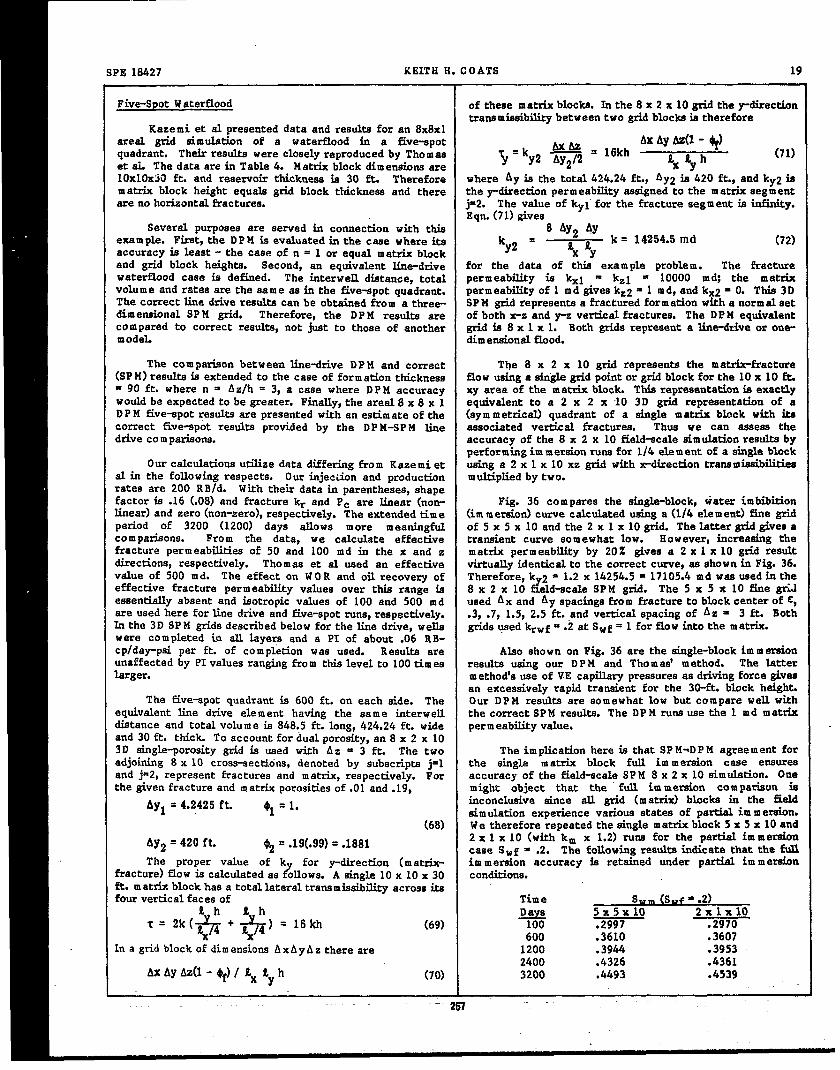
SPE 18427 KEITH H. COATS 19
Five-SpotWaterflood of these matrix blocks. Tnthe 8 x 2 x 10 gridthe@irectiontranemiaeibilitybetween two gridblocksistherefore
Kaze mi et al presenteddata and resultsfor an SX8X1areal grid simul.ationof a waterflood in a five-epot Ax Ay AZ(1- ~)quadrant. Theirresultewere closelyreproducedby Thomas
5 = ‘Y2 W2 = 16kh(71)
et ei. The data arein Table 4. Matrixblockdimensioneare %$yh10x1OX5O ft.and reservoirthicknessis 30 ft. Therefore where Ay isthe total424.24ft.?AYZ ie420 ft.?and kYz iSmatrix block height equalsgridblock thicknessand there the y-directionpermeabilityassignedto the matrixsegmentare no horizontalfractures. j=2. The value of kyl’for the fracturesegment isinfinity.
Eqn.(71)givesSeveral purposes are served in connection with this 8 Ay2 AY
exam pie. First,the DPM isevaluatedin the case where its~y2 = %x .4Y
k = 14254.5md (72)accuracy isleaat- the case of n = 1 or equal matrixblockand grid block heights. Second, an equivalentline-drive for the data of this example problem. The fracturewaterfloodcase is defined. The interwell distance, total permeability is kxl = kzl E 10000 mm the matrixvolume and ratesare the aam e as in the five-spotquadrant. permeabilityof 1 md giveskz2 = 1 md, and kx2 = O. ThiE3DThe correctlinedriveresultscan be obtainedfrom a three- SP M gridrepresentsa fracturedformationwitha normal setdimensionalSP M grid. Therefore,the DP M resultsare of both x-z and p verticalfractures.The DP M equivalentcom pared to correctreaulta,not justto those of another gridis 8 x 1 x 1. Both gridsrepresenta line-driveor one-m odeL dimeneionalflood.
The com pariaonbetween line-driveDP M and correct The 8 x 2 x 10 grid representsthe matrix-fracture(SPM) resultsisextendedto the case of formationthickness flowusinga singlegridpointor gridblockforthe 10x 10 ft.= 90 ft.where n = Az/h = 3, a case where D P M accuracy xy area of the matrixblock. ThizrepresentationisexectLywould be expectedto be greater.Finally,the areal8 x 8 x 1 equivalentto a 2 x 2 x 10 3D grid representationof a
D PM five-spotresultsare presentedwith an estimateof the (symmetrical)quadrant of a singlematrix block with kccorrect five-spotresultsprovidedby the DP M-SP H line associatedverticalfractures. Thus we can aeeees thedrivecom parisone. accuracy of the 8 x 2 x 10 field-scalesimulationresultsby
Our calculationsutilizedata differingfrom Kazemi etperformingim meraionrunefor 1/4 element of a singleblockusinga 2 x 1 x 10 xz gridwith x-dixectionCranemieaibililiee
al in the fcllowingrespects. Our injecdon and production multipliedby two.rates are 200 RB/d. With theirdata in parentheses,shapefactoris .16 (.0S)and fracturekr and Pc are linear(non- Fig. 36 com pares the single-block,water imbibitionlinear)and zero(non-zero),respectively.‘theextendedtime (immersion)curve calculatedusinga (1/4element)finegridperiod of 3200 (1200) days allows more meaningful of 5 x 5 x 10 and the 2 x 1 x 10 grid.The lattergridgivesa
comparisons. Fro m che data, we calculate effective transientcurve somewhat low. However, increasingthefractureperm eabilitieaof 50 and 100 md in the x and zdirections,respectively.
matrix permeabilityby 20% givesa 2 x 1 x 10 @ resultThomas et al used an effective virtuallyidenticalto the correctcurve,as shown in Fig.36.
value of 500 md. The effecton W O R and oilrecovery of Therefore,ky2 = 1.2x 14254.5= 17105.4md was usedintheeffectivefracturepermeabilityvalues over thisrange is 8 x 2 x 10 field-scaleSPM @d. The 5 x 5 x 10 finegaessentiallyabsent and isotropicvalues of 100 and 500 m d used A x and Ay spacingsfrom fractureto blockcenterof C,are used here forlinedriveand five-spotrune,respectively. .3,.7,1.5,2.5ft.and verticalspacingof A z = 3 ft. Bothb the 3D SPM gridsdescribedbelow forthe linedrive,wells gridsusedkrwf = .2at Swf = 1 forflowintothe matrix.were completed in alllayersand a PI of about .06 R B-cplday-paiper ft.of com pl’etionwas used. Resulteare Alao shown on Fig.36 are the single-blockim m eraionunaffectedby PIvaluesrangingfrom thislevelto 100times reeultausing our D PM and Thom as’ method. The latterlarger. m ethod’ause of VE capillarypressureses drivingforcegives
an excessivelyrapid traneientfor the 30-ft.block height.The Ehre-epotquadrant is 600 ft.on each aide. The Our DPM read% are somewhat low but compare wall with
equivalentline drive element having the same interwell the correctSP M results.The DP M runeuse the 1 md matrixdiztanceand totalvolume is848.5ft.long,424.24ft.wide perm eabilityvalue.and 30 ft.thick.To accountfordualporosity,an 8 x 2 x 103D single-porositygridia used with A z = 3 ft. The two The implicationhere is thatSP M-D PM agreement foradjoining8 x 10 cros~ections, denoted by subscriptsj=l the sing%e matrix block full im m eraion case ensureeand j=2,representfracturesand matrix,respectively.For accuracy of the field-scaleSPM 8 x 2 x 10 simulation.Onethe givenfractureand matrixporositiesof .01and .19, might object that the full im mereion com pariwn is
AY1 = 4.2425 ft. @l=1. inconclusivesince all grid (matrix)blocke in the fieldaimulationexperiencevanoua statesof partialim m ereion.
(68) We thereforerepeatedthesinglematrixblock5 x 5 x 10 and
AY2 = 420 ft. ~ = .19(.99)=.18812 x 1 x 10 (withkm x 1.2)rune for the partialimmersioncase SWf = .2. The followingreaulteindicatethatthe full
The proper value of k!?
for y-direction(matrix- im m ereion accuracy is retained under partialim m ereionfracture)flowiscalculatedas ollows.A skgle 10 x 10 x 30 conditione.ft.matrixblockhas a totallateraltram miaaibilityacroesitsfourverticalfacesof Time s“m (swf = .2)
‘h ~=18kh5X5X1O
%% + 5X14)
l?S#— 2X1X1O‘K= (69) .2997 ~
x 600 .3610 .3607Ina gridblockof dimensionsA xA yA z thereare 1200 .3944 .3953
2400 .4326 .4361AX Ay Az(l- of)/ 2X Ey h (70) 3200 .4493 .&539
‘-.257

20 IMPLICIT COMPOSITIONAL SIMULATION OF 81NGLE-POROS~y AND DUAL-P OROS~Y RESERVOIRS SPE 18427
Fig.37 #hows the gridblockequilibriumcurvesforthe volatileoilwith B. of about 2.2 RB/STB and solutiongas ofcaseshere of n = 1 and 3. The uppercurveiscorrectforthe 1966 SCF/STB at the 5553 paia bubble point. originalcaae n = 1 and isobtainedas discussedpreviously.Thom as’ reservoirpressure is about 7000 peia with a water-oilmethod reflectsthis(upper)curve in the matrix-fracture contact about 1200 feet balmw top of structure. The 3-drivingforce expressionfor any value of n. The correct component EOS representationof the oil wae discussedcurve forthe case n = 3 isshown by the etep-functionsolid above in connectionwith Figs. 1-2and Table 2.curve of Fig. 37. The DP M curves(Eqn.(34))are ahown bythe dashedlineeforS~f = O,.0856and .314. W e used S~f = Duringthe lest13 of the 16 years’history,first-stage.314and .0S56forthe casesn = 1 and n = 3, respectively. separator gas (86Z methane) w es injacted. When gasThisreducesthe D P M error forsmalln. The valueof .463 injectionbegan, rese~oir pressure wee 6S00 peie,aboutfor equilibriumgrid block saturationat SWf = O is the 1300 PM above bubble point. Reservoir pressureand oilequilibnum saturationof a 30-ft. matrixblock exposed to recovery at the end of historyare about4000 paieand 12%water atitsbottom face. of OOIP, respectively. GOR hms risen to about 9000
Scf/STB. Queetiona concerning future recovery includeFig.38 com paresSP M end DP M oflrecoveryand water continuedseparatorgas injection,N2 injectinandlorwater
cut resultsfor the field-scaleline-drivewaterflood with injectiowformation thickness= h = 30 ft. The DP M recovery iamoderatelyhighup to 1500 days and toolow atlargertimes. The reservoirstudyhas proceeded far pastthe statusThe SP M and DP H recoveriesare 37.9 and 39.1% OOIP, described here. The originalhistory match dateaet isrespectively,at 1200 days, and are 56.? and 53.2Z O OLP, retained as a fixed reference for the purpose of testingrespectively,at 3200 days. The ultimate recovery for all model changes or enhancem ente. Table 9 gives somethree calculationsis 62.6Z OOIP when the fracturesare res.ervofr descriptiondata. Since the reservoiria highly100Z water-Eilled. heterogeneoua~ only average values are given for
permeability,porosity, etc. The effective fractureThe high DP MT recovery curve aimply reflectsthe permeabilityisthe orderof 100 times matrix permeability
high im m eraion transient of Fig.36. If the matrix, with the latteraveragingabout .5 m d with variationstopermeabilityisreduced 65X inthatrun,agreement withthe much 10w ervalues.SP M resultsismuch better.
Of interestare the sm all mattix block size(prolificFor the case of reservoirthickness= 90 ft.,the well fracturing)on the orderof 1x1x3 ft.?and the 10w fracture
ratez are increasedto 600 RB/d so that rate per ft. of porosityaveraging.0005or lees. A consequenceof the firstthicknessisunchanged. The SP M gridis S x 2 x 30 with 303-ft.layersand zero z-directiontranamissibilit.iesbetween
isa large matrix-fractureexchange coefficientthe orderof107 (RB-cp/da~ei). The 10w fracturepororntygivesam all
layers10 and 11 and between layers20 and 21 inthe matrix fracture-ayetemporevolumes and highthroughputratiosforcross-aectinj = 2. large time steps. Thisrequireeimplicit model aimulation.
The large transfer coefficientsresult in com putatkmelFig. 39 compares SP M and DP M recovery and water difficultysincethe matrix-fracturedarcy flowratesarethe
cut resultsfor the case where resenoir thickness= 90 ft. products of large coefficients and small potentialand n M Az/h = 3 for the 8 x 1 x 1 DPM calculation.The differences(.01to .001 and lower psi). This combinationDP M resultsare more accurate in this case than in the can cause round-off and com putationel convergencepreviouscase of n = 1. The D P M T resultsforthiscase are difficulties,especiallyfor large time eteps and large,the same es the DPMT resultsfor n = 1 ehown on Fig.38. rapidlychangingiajection/producticmrates.The SP M and DP M recoveriesare 36.1 end 36.4Z OOIP,respectively,at 1200 days, and are 53 and 51.4% OOIP} Fige.41 and 42 show totalfieldoilproductionrateandrespectively,at 3200 days. Recovery for this 90 ft. gas injectin rate ve time as 9l-day averages. The ratesthicknesscaee isroughly2 to 3 recoverypercentagepoiutelower than forthe 30 ft.thicknesscaee.
change every 91 days throughout the dataset,giving amaximum 91-day step size. Fig. 42 ahowa the extremevariationsin gas injectionrate from one 91-day periodto
Fig. 40 shows five-spotoilrecovery and water cut the next+ About 6 of the 47 wellsare gee injectionw ewD P H resultscalculatedusingthe 8 x 8 x 1 areelgridand the30-ft.reservoirthickness.We believethe correctfive-spot
only one well injectswater, during the lest 270 days ofhistory.The gas injectionrate changee might be expected
recovery curve would compare to the 3PM curve on Fig.40 to resultin oscillatingfractureoilsaturationsfrom steptoinaboutthesame fashionas exhibitedby the SP M-DP M lime step,especiallyat or near injectionand/orproductionwells.drivecomparisonof Fig.38. Fig.43 ahowa calculatedfractureoilsaturationvs time in a
gridblock adjacentto a high-rateinjector.CalculatedofiThe five-spotD P M mu requixed28 timeatepsand 34 saturationisvirtuallymonotonic withtime inspiteof ‘large
iterationsto 1200 days and 44 eteps and 50 iteratkme to injectionratechanges.3200 daya. Materielbalances were .99998. Tim e stepsranged from the initial2 days to 180 days. Tim e step The S e value is important in this study. Itscontrolswere maximum saturationchange per step of .15 3internally-cculeted value changea wish time and fromand maximum step size of 180 daya but both were rarely block to block. Historyruns were made forthe threecameinvoked. Rather,output times of every 200 daya to 1200 of constantSge (withspatialvarietion)~de~fiependentdays and every 400 daye thereafter together with a S e, and dermt~ and tension-dependentS e. Rune weremaximum increaseof 50% from stepto stepdeterminedthe a%o made with and without diffusion. T%e o~d S etime steps. Rune with varioussmellermaximum step has fvelueaare about .4-.5forblockheightsin the range of 3 0indicate that time truncationerrorisminimeL 4 ft. The model historyrune show calculatedgrid block
matrix saturationsb closeagreement with the Sgf x SgeApplicationto VolatileOilReservoixA product~ reflecting the Lsrge matrix-fracturetram mw
aibilitiee.Two exceptionsoccur. First,forrock type 2,SwcReeemoir A isa fracturedmatrixreeervotiwith about is large, oil saturationis low and oil easily becomes
16 yeare’history. The reeervoiroilie an undereaturated immobile due to trappingby gas and watar in accordancewiththe Stone 2 km method. Thus a number of the type 2
m.-Zou

SPE 18427 KEITH H. COATS 21
blocks show matrix gas saturation< Sgf x S ~ simply8
The 5753-day historyrun required60 time stepsandbecause the matrix oilisimmobile and cannot rain out. 167 total outer iterations,an average of about 3 outerThe second exceptionis that gridblock equilibriumoccurs iterationsper 9l-day tine step. 91-day steps were usedat some pressure,followedby significantpressuredecline. throughoutwithlarger,up “to20*day, stepsused duringtheOildoes not want to (anddoes not in the calculations)drain first1280 days before gas injectionbegan. No time-stepout of the blockto matrixoilsaturationsbelow equilibriam cutsoccurredand totalcomputing time was about 2.5VAXvaluesbut the oilsnrinkein accordance with the constant- 780 CPU hours.volume expansion. Also, depending upon the nature ofinjected gas, oil can vaporize, further reducing its An iterativeY Z planarSO R was used with reeultingsaturationor,equivalently,increasingmatrixgas saturation omega valuesof about 1.4and totalinneriterationsat 5753aboveitsequil.ibnum value. days of about 1700,or an average of 10 SO R iterationsper
outeri.tmation.The linearsolvertakeaabout 20% of totalFig.44 compares fieldtotalobservedand model G O R computing time. Allcomponent materialbalances’were the
vs time. The model resultsreflectdiffusionand density-and order of .999X .to .9999X throughout the runa with thetension-dependentS e.
FCalculated G O R is avout 9400 “sensitive”norm aldenominatorbasisof cum dative injection
Scf/STB atthe end o history.Withoutdiffusion,calculated or production.G O R isabout 14Z higher. For the time-constantSge case,calculatedG O R is7700 Scf/STB at the end of .Gtory. S Computer time with 4 components (3+N2) activeisand diffusionare the controllingparameters in tl% about 60% greaterthan that for 3 components. All runecalculated G O R behavoir. Runs with depth-dependent were made with a 4-component set of PVT data enteredinitialcom position(bubble point decreasing with depth) withN2 thelastcompol.ant.SinceinitialN2 mol fractionisshow significantlylower G OR. O, the model autornatically com putea with only 3
com ponenteuntilthe firsttime step(ifany)of N 2 injection.Fig. 45 indicatesthe strong diffusioneffect when It then automatically expands to the 4-tom ponent
injected and native reservoir gas compositions cliffer calculation.Thiscan save considerablecomputing expensesignificantly.Restart runs were made from the titme- in problems where certaincom ponente(s)are absentinitiallyconstantSge case,injectingN 2 ratherthan separatorgas and throughoutpartor allof historybut become activedueduringthe 3472-5753(end of history)day period,with and tolaterinjection.withoutdiffusion.Fig. 45 shows that calculatedG O R isextremely higherwithoutdiffusionthan with it. Table 10 Sum maryshows the effectof diffusionon matrix-fractureoiland gasphase compositionforthisN2 injectioncase in a gridblock An ,implicitcom positionalmodel has been describedadjacentto a gas injector.Without diffusion,virtuallyno for con positionalemulation of single-or dual-porosityN2 appea~ in the matrix phases and large composition reservoira. The model simdates uneteadptate three-differencesexist between matrix and fracture phase dimenaional,three phase flow in heterogeneousreservoirscom positions. Wifh diffusion(only gas-gas diffusionwas rangingin type from black oilto near-crkicaloilor gas toused),matrixand fracturephase compositionsare identic~ leangas condensate. Applicationsincludedepletionand gasbothinthe gas and oil. andfo~w?.:erinjection.Single-porosityapplicationsincurno
10SS ,.’ ef :iencycaused by the presence of dual-porosityTable 11 shows calculatedmatrix and fracturegas code. . code is mapped so thatstorageisrequiredonly
saturationsat the end of historyfor the constantSge run for active grid blocks. This can ai@ficantly reducewith diffusion. Saturationsare shown for severalcells, machine storagerequirem enta for reaervo~ having highlyincludingactiveand shut-ingas injectionblocks. As stated irregubr geometry. Dual-porosityapplicationsincludeabove,eqwbti m matrix gas satxationieSgf x Sge. Table11 shows that the calculated matrix gas saturationsare
regionallyfracturedreservoirswhere unfracturedaingle-porosityregionsexist.
close to equilibriam, due to the large n atrix-fractureexchange coefficients. Table 11 shows a matrix gee Advantages of 3-tomponent com positionalas opposedsaturationexceedingSge for the activegaa injectionblock to extendedblackoilm odellingare describedand illustrated4-8-1. Thisreflectsthe vaporizingeffectof the separator for an actualnest-criticalvolatileoilreservoir.A aimplegas, reducing matrix oil saturation to lees than its method for reducing time truncation error in implicitequilibriam value. formulationeisdescribedand illustrated.A new bottomhole
constraint function is presented for presezwation ofIn allmodel rune no computed matrix oilsaturations
leasthqn .2 were computed. That is,complete vaporizationproductionwelltargetratesincom positionalm odela.
of oildidnot occurin any case/block.In fact,the minimum A new matrix-fracture tranafer formulation iamatrixoilsaturationsoverthe gridwere closeto .2both for deecxibedfor the dual-porositycase. Matrixblockhe ‘andN 2 and separatorgas injectioncases. These minimums shape may vary fro m block to block over the grid. Theoccured in gas injectioncellsand matrix oileaturatior.a formulation accounts for matrix-fracturediffusionandwere significantlyhigherthroughoutthe non-injectioncells, effects of changing gas-oil density difference andobsyingthe equilibriumraldionship. interfaci.sltension on gravity drainage recovery. The
approximate accuracy of the formulationis shown for aMaxim um gas productionrates(QG M A X) were entered number of testproblems where correctresultsare available
in the data fileforallproducingwells.They were obtained from single-porositysimulation.Resultaare givenfor a 3Dfrom the historyfileas the maximum gas M CF/D rates 600-block simulationof a highly fractured nearmiticalproduced throughout history. The model produces the volatileoitreservoir.specifiedST Bid oilrate for each v allunlessthe associatedgas rate exceeds the w en’sentered Q G M AX. In the latter Nom encletureevent,the wallproducesthe Q G M A X gaa rate, The overall ~impact of thisisnotedby printingtotalcum dative ehortage
Form ationvolume factor,RB/STB
of oilproduced (STB) dividedby totalspecifiedCUm ulative b l/BOn production.Thisfractionis .0145 for the run shown inFig. 44. %j EOS binaryinteractioncoefficients
259
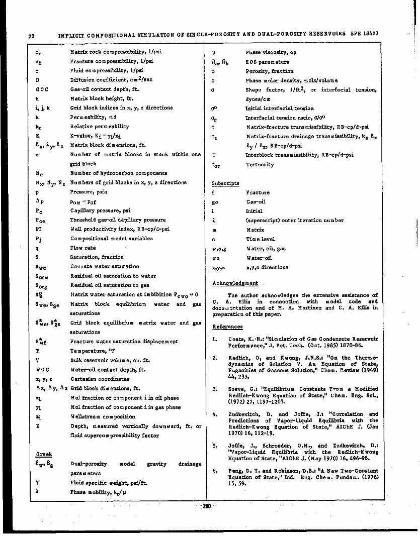
22 IMPLICIT CO MPOS~ONAL SIMULATION OF SINGLE-POROSITY AND DUAL-POROSITY RESERVUIKS SPE 18427
/
c~ Matrix rock com preaeibility,I/psi P Phase viscosity,cp
Cf Fracturecom preseibility,l/p8i ~a, Qb EOS parameters
c Fluidcom presaibility,I/psi 4 Porosity,fraction
D Diffusioncoefficient,cm 2/see P Phase m olerdensity,m olslvolume
GOC Gas-oilcontactdepth,ft. c1 Shape factor, l/ft2, or interfacieltension,
h Matrixblockheight,ft. dynesfcm
~j, k Gridblockindicesin x,y,z directions 00 Initialinterfacieltension
k Permeability,m d % Interracialtensionratio,afOo
kr Relativeperm eabil.ity T Matrix-fracturetransmiezibility,RB-cpfd-psi
K K-value,Ki = yi/xi Tz H atrix-fracturedrainagetranamieeibility,Itzkx
!zX,gy,kz Matrixblockdimensionz,ft. Ey / kz, RB-cp/d-pai
n Number of matrix blocksin stack wixhinone T Interlocktram miscibility,RB-cp/d-prn
gridblock ‘or l!ortuosity
Nc Number ofhydrocarboncomponents
NXS NY* Nz Numbers of gridblocksinx,y,z directions Subscripts
P Pressure,psia f Fracture
Ap Porn- Pof go Gas-oil
Pc Capillarypressure,psi i Initial
pce Thresholdgas-oilcapillarypressure 9. (auperacript)outeriterationnumber
PI Wellproductivityindex,RB-cp/d-psi m Matrix
Pj Co m positionalmodel variables n Tim e level
q Flow rate w ,O,g Water,oil,gas
s Saturation,fraction Wo Water-oil
Swc Connate water saturation XPY9Z x,y,zdirections
‘orw Residualoilsaturationto water
‘erg Reaidueloilsaturationto gaa Acknowledgem ent
S$ Matrixwater saturationatimbibitionPcW. = O The author acknowledges the extensiveassistanceof
Swes Sge Matrix block equilibrium water and gaa c“ A. Ellis in connection with model code anddocuG station and of M. A. Martinez and C. A. Elb in
saturationa preparationof thispaper.
s$fe~S$e Gfi block equilibriummatrix water and gasReferences
aaturationz
S:f Fracturewater saturationdi$plecement 1. Coats,K.‘H.:“Simulationof Gas Condensate ReservoirPerformance:’J.Pet.Tech. (Och 1985)1870-86.
T Temperature,oF
v Bulkreservoirvolume,cu.ft. 2. Redlich, O, and Kwong, J. N.S.Z “OU the Thermo-dynamics of Solution V. An Equation of State,
woc w ate~oflcontactdepth)ft.. Fugacitiesof Gaaeouz Solution;’Chem. Review (1949)
x,y,z Cartesiancoordinate 44,233.
Ax, A y, A z Gridblockdimenaione,ft. 3. Soave, G.: “EquilibriumConetantaP~om a M edified
xi Mol fractionof component iinoilphase Redlich-Kwong Equation of State;’Ghem. Eng. SCL,(1972)27,1197-1203.
Yi M 01fractionof component iingas phase
Zi W ellstreamcomposition 4. Zudkevitch, D. and Joffe, J.: “CorreletionandPrediction of Vapo~Liquid Equilibria with the
z Depth, m eaaured verticallydownward, ft. or , Redlich-Kwong Equation of State,”AIChE J. (Jan
fluidsupercom preasibilityfactor 1970)16,112-19.
“5. Joffe, J., Schroeder, O.M., and Zudkevitch~ D.:llVaPoeLiq~ Eq~rie with the Redlic~K w‘ng
Greek
~gEquationof State,“AIChE J.(May 1970)16,496-98.
Dual-porosity model gravity drainage6. Peng, D. Y. and Robinson,D.B.:“A New Two-Constantparametera
Equation of State;’Ind. Eng. Chem. Fundam. (1976)Y Fluidspecificweight,pzi/fL 15,59.
A Pheae mobility,krivI I

SPE 18427 KEITH H. COATS 23
7. Coats, K.H. and Smart, G.T.: “Applicationof a the 1987 SPE Amual Technical Conference, DallastRegression-BasedEOS PVT Program to Laboratory TX.,Sept.27-30.
Data;’SPE Res.Engr.(May 1986)277-299.24. Golf-Itacht,T.D. van: Fundsm entele of Fractured
8. Lohrenz,J.,Bray,B.G.,and CLsrk,C.R.:“Calmdating ReservoirEngineering& ElsevierScientificPublishingViscosities of Reservoir Fluids From th~k CO~ 1982.Compositions/’J. Pet. Tech. (Oct. 1964) 1171-70;Trans.,AIME, 231. 25. W u, Yu-Shu and Kareten Preuzz,“A Multiple-Porosity
Method for Simuhtion of Naturally Fractured9. Reid, R. C. and Sherwood, T. K.:“i’hePropertiesof Petroleum Reservoirs”,SPE Reservoir Engineering
Gases and Liquids,u t~d edition,M cGraw-Hill Book (Feb.,1988)327-336.Co.Inc.,New York City(1977).
26. Kleppe, J. and Morse, R.A.: “Oii Freductionfrom10. Coats, K.H.,Nielsen,R.L.,Terhune, M.H. and Weber, Fractured Reserb’oirs5y Water Displecemcut:’paper
A.G.: “Sireulationof Three-Dimeneion~ Twe-Phase SPE 5084 presentedat the 1314 SPE Annual T $chnicalF1OW in Oil and Gas Reservoirs/’Sot. Pet. Eng. J. Conference,Houston,TX., Oct.6-9.(Dec. 1967)377-88.
27. Beckner, B.L., Tahimoto, K., Yamaguci@ s.,lL Marathon Oil Cornpany, Littleton,Co1o.,Personal Firoozaba@ A., Aziz, K.: ‘Ymbibidon-Dominated
Communication, 1985 M atrkFracture Fluid Transfer im Dual PorositySimulatoreflpaper SPE 16981 presentedat the 1937
12. da Silva,F. and Belery,P.:PersonalCornmunication, SPE Annual TechnicalConference,Dallas,TX., Sept.Petrofina,Brussels,1987. 27-30.
13. Price, H.S. and K.H. Coats, “Dfiect Methods in 28. Lefevbredu Prey, E.J.,“Caecade drai~ageofblocksinReservoirSimulation”,Sot. Pet. Eng. J. (June,1974) a fissuredrese~oir~ Revue de l’institutFranceiedu295-308. petrole,Janv.-Fev.(1976),p. 173-178.
14. Coats, K.H.: “An Equation of State Com positional 25.. Festoey, S., Van Golf-Racht, T.D.: “Gas GravityModel;’Sot.Pet.Eng. J.(Oct. 1980)363-376. ?)reinagein Fractured ReservoirsThrough New Dual
Continuum Approach”,paper SPE 16980,presentedat15. W erren$ J.E. and Root, P.J.: “The Behavior of the 1987 SPE Annual Technical Conferance,Dall.cw,
NaturallyFractured Resenroire;’Sot.‘Pet. Eng. J. TX., Sept.27-30.(Sept.1963)245-44;Trans.,AIM E, 22S.
30. Thomas, L.K.,Firoozabad&A.:“Tenth SPE Symposium16. Kazem~ H.,Merr& L.,Porterfield,K. and Zeman, P.: on R eaervoirSimulationDual Porosity Comparative
llNumeric~ sim~a~n of Water-OilF1OW iIIN atura~Y SolutionProject,u to be presentedat the 1989 ‘PE
Fractured Resemoire/’Sot. Pet. Eng. J. (Dec. 1976) Symposium on Reservoir Simulation,Houston, TX.,
317-32Q Trans.,AIME, 261. Feb.6-8.
17. Thomas, L.K., Dixon, T.N. and Piereon, R.G.: 31. said& A.M. and Tehra~ D.H.: “Mathematical“Fractured Reae~oir Simulation/lSot. Pet. Eng. J. Simulationof FracturedResezvoirPerformante,Based(Feb.1983)42-54. on PhysicalModel Expenm ents,”Paper PD10(3)on the
Developm ents in ReservoirEngineering,Proceedings18. Gilman, J.R. and Kazem~ H.: ‘Improvements k of the 10th World Petroleum Congresa,Bucharest,
Simulationof NaturallyFractured Reservoir/’ Sot. 1979.Pet.Eng.J.(August1983)695-707.
Appendix A19. Sonier, F., Souillard,P. and B~skovich, F.T.:
“Numerical Simulation of Naturelly Fractured For quasi-steady-state(QSS),single-phase,m at~fractureReservoirs:’paper SPE 15627 presentedat the 1986 flow in a bulkvolume element V of reservoir,the ftow rateSPE Annual TechnicalConference,New Orleans,LA, ~O ct.5-8.
~= -’<*C aft (Al)20. Sonier,F. and Eymard, R.: “A New Simtitor for
NaturallyFractured Reservoirs:’paper SPE 1600S where @c iseffectiveporosity-compressibilityof the m atrixpresentedat the Ninth SPE Symposium on Reservo& inV. In the cliffueivityequationSimulationheldinSan Antonio,TX., Feb. 1-4,1987.
kfi+Kd+kti= l.l~ca~tx~xz
(A2)21. Dean, R.H. and Lo, L.L., YaY2 Zaz2Ilsim&tio~ of N atur.zlly
Fractured Reservoirs”,SPE Reservoir Engineering ap/at isindependentof positionwitti”the matrixfor QSS(May, 1988),638-648. flowso thatsubs~ution from Eq~ (Al)gives
22. Litvak$ B.L.: “Simulation and Characterizationof a2k~+k~+
~~+=
Natwlly Fractured R eservoire;’Proceedingsof the Yay2 Zaz2= o (A3)
‘ax vReservoir CharacterizationTechnical Conferences,Dallas(April29-May 1, 1985). Academic .Presa,New where V isthe m atrk blockvolume. Ifthe matrixblockh-York (1985). dim enaiona a, b, c in the x, y, z directions,respectively,
then Eqn. (A3) can be written23. Rozsen, R.H., Shen, E.L: “Sim~&n of Gas/0~
&+r~+s_?.!$+Q=ODrainage and W aterlOil Imbibition in Naturally (A4)Fractured Reaeiwoi.rs/’paper SPE 16982 presentedat ax; ay~ 3ZD
261
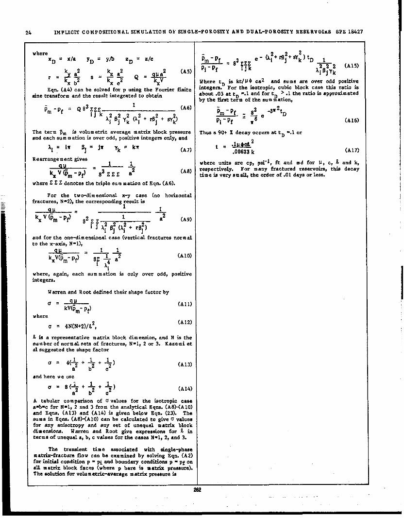
———=-—
24 IMPLICIT CO MPOS~ONAL SIMULATION OF SINGLE-PORO~y AND DUAL-POROSITY RES5RVOIKS SPE 18427
where
‘D= xla yD = y~ ‘D = Zlc
=$~~=>a~Q .&(AS)
rX b2 Xe x
Eqn. (A4) can be solvedforp usingthe Fourierfinitesinetransformand the resultintegratedto obtain
;m = Q 83EZE1
-Pf (A6)ijk 2222
‘i ‘j y~ (Ai j+ rB2 + w:)
The term ~m is volumetricaverage matrixblockpressureand each EWm m ationisover odd,positiveintegersonly,and
= iw‘i $j =jfi yk=kfl
(A7)
where ~ ~ ~ denotesthetriplesummation of Eqn.(A6).
Where tD is ktlIJ~ ca2 and sums are over odd postiveintegera. For the isotropic,cubic block case thisratioisabout .03at tD =.1and fortD >.1 theratioizapproximatedby the firstterm of the summation,
Fm- Pf *3 -31!2tD—~— ePi-Pf - fi6
Thus a 90+ Z decay occursattD ‘.1or
t . “[email protected] k
(A16)
(A17)
For the twe-dimensional x-y case (no horizontalfractures,N*2),the corresponding~esultis
and forthe one-dimensionalcase (verticalfracturesnormalto thex-axis,N=l), I
(A1O)
where, again,each sum m ation is only over odd, positiveintegers.
Warren and Root definedtheirshape factorby I
u= qll
kV(~m- pf)
vhere
(A11)
u= 4N(N+2)/L2,(A12)
k iE a representativematrixblock dimension,and N isthenumber of normal eetsof fractures,N=l, 2 or 3. Kazemi etalsuggestedthe shapefactor
(A13)
and here we use I
(A14)
A tabular com pariaonof U values for the isotropiccasea-b-c for N=l, 2 and 3 from the analyticalEqna.(ASXA1O)and Eqne. (A 13) and (A14)is given below Eqn. (23). Thesum a in Eqne.(A8HA 10)can be calculatedto giveu valuesfor any anisotropyand any set of unequal matrix blockdimenaiona. Warren and Root give expressions for k interms of unequala,b,c valuesforthe caseaN-l, 2,and 3.
The transient time associated wtih single-phasematrix-fractureflow can be examined by solvingEqn. (A2)forirkialconditionp = piand boundary conditionsp = pf onallmatrix block facw (where p here is matrix pressure).The aoludonforvolumetric-averagematrixpressureis
ZU
where uniteare CP, psi-l,ft and md for U, c, g and k,respectively. For many fracturedreservoirs,this decaytime isverys m ~ the orderof .01daysorless.

18427
69
?AILE1mrnms (MAXUX+IACXL7ECI
~.&# ‘CG‘cc(cc,. CC*)’00 Da, ~L .
~-A ‘LC ‘LG
‘LG ~ “L1 - CC2)or
CL . OL. cc - Pcy
TASLE 6
Wauwis pm8mre
Co.preni6&iy ef rock, fiamre, ●nd water
onCo.psudbiuk,At ,anwokr 91WIKU
k!*C,, V2?.odtyon ViU.mlf”
3959.89+
2.0x 10⁻⁶Ilpd
10+ 1/+
.5 Cp2 op.9SS12 BB/ST1n“
a.M.c*r ‘ledfy022detuizy
71it& ~tte,billtyM,U2x g0?&2ySbqle Factor51.tr& bbck &eFraetum pm.e.bi7icyFramdre pamizy
.96o6 EB/STB
- Wm..3611 9d/fL1 *d.19
cc EOUIL2BR1U71 D2LEH)5A,
~-rlccl “ C.32
CL1 - CG21 2
CL1 “ ccl
‘L1 ‘i “ Dc, Yi
yilxi .‘i- ‘L1lPG1l ‘ii
LO
.08iJx10x30f2,100DO -d.01
mid;:. Ay
8X.3X17522.3052.
wU- Lajectiorl rateTota2 Ziquid pmd.c!iori rate
200 Srnld210 SWdEAcn CELL
2-PHASE GAS-02L
5A1LS 2
VOLAY2LS OIL MSBIVO1l A PLOTD COk2?0231201S ASD DAfA
71.2zix k, ,md PC da2a 17
S= krw
75 r.02
:: .055
:: ::45.7 .2
k.
=.705.42.26.11
0
Pc”or2.951.65.85T -266° F.3
0RE8CS.V017(FLUID mxzcnon GAS
M ~.5898 .5898 PC1.0093 .1926 Pc 2.0757 .2176 Pc 3.D409.0300
~ ~.8601 .S601.1243 .0113.00$6 .071s
.0283
.0115
.0039
.0D17
.0053
.0003
ZAILX 5
KL1?P1 AmD k70UlE 51? XL262X8TAL BAZAclC02
::C4C5C6?7F8F9
21@ix Wme.bi!iz, 290 mdM.tl’2Y p+r.adq .225care .Jh..t*, 9.87 enMid. dia.tit. .f tube 10.39 c.Core hei2btW .ter density
122.8c.
0i3d.~,1.02~W.811dc.
.0192
.0175
.07812
.09517
.04431 %7+ “ .8578
wate, V&ity 1 :pOkzticc.dq 2.3 cpPare V.2U. * of core 2114 ccEos
DATA ~ ~BUS8LE PT. Ssm 5333.7 5s53.700 ●t B.P. 36.11 36.11 36. IL Ib,lcu. ft
Vdu.e of beture 1017ccLow 5nJcc2ioarat. 3.3 CC1.ialush&jec&?. “m 33 Cel.iu
a at B.P. .2716dpnwlc~k=●nd P= data 27
3-cPT EOs B.P.RESULTS k-z%
k~
.75
.675
.605
.533
.67
.4
.33
.27
.19
.12
.06
~Pcl .5898
=*
PC2 .1926 .1670PC3 .2176 .0’364
A%. . 11z4pbvR
-L.13507.S67D.1672
.3
.352
.35
.375
.6,423.45.475.5
0.0005.001.00;5.002.003.Owl.D07.01.01s.027
3.12.31.831.521.291.D8.96.823-STAGE SURFACE SZPARAT30N.7.61.52
~ Iis@4 T&1014.7
:150
264.7 803 lk.7 6D
.55
TABLE 6
TEOMA8 H AL s2E@LE-sLOCC DATA
~ ~ ~STAGE 1 OOR1 1057 1057 1057
STAGE lYG .6910 .6819 .6708
STAGE 3YL .8363 .8363 .8324
C07L2 1489 1510 1489
no 1.8530 1.8530 1.8530
Co.preni6iUCy c.f cock ZM.tucg, ●nd “’tu 2.5.104I/&M●Q3x bbck dimwims, Lx, k,y, !X Ift.orloff.Permesb@, k=, ItY, k% 196. *m ..38ubb2e-@at -m 5360 C&C& dam . ---- -!. . . . . –J,-
W.tcr den,0
ZUY2YZU 5560 m X;’#-*mDL3d.wlc, at 6215+.“ .-.. -4-. . . . ..= -d. .2344 @m2.
.2213 es0. .“.-, . ..’., -
W.tervkadsyOiJ d.+ .t$560 @aG“ der,dz, .C 5560 @aCU vL!c.c+ ● 5560+
.,”>”, pm/m.
.0274 CpOil viac~ ●t 5560 w .21 C9
H’frh k ,sd P D.m,
.3s cp -,25075 PcIJ~. . . . . . . . . .
1) SCF S2.U.1 Cu/BSL u.at 1liqti2) T.ttiSC?ISTB
k~1.00
.66
.723
.6
.692
.392
.304
.154
.D42o.0.
kw.
1.0.42.31.19.103.05.015
0.
XY~CC’2 0? ~OCK v&~ IT2CA2AQ023JB82UMcA?2LLA1Y P116sU1S0211VXS09
CALCOLArBD 162V26L ?L727M ~-?LAOE
P~30.09.02.0
0::-c6-1.2
400 FT. VEM2CAL COLLIIIR .3 Xi’
Goc.35
- 835L.02
woc - 285ft. .4 .03
P - 3D(1-C”)3:7”0
= 10s3.45
.“0.045
LjY.5 .C4
“0 - .1662a.
- .11$1 p4i/5L .6 .11.7 .18.75 .23
,.. ,..
-4.0-10.0-40.0-120.0z rR33TAL F2, DID9-IN.PLAcG lDOOVSM
VE P= ROCK Pc
L ~ 07L Y2LF.EGAS 21ATE21 OIL ?RSE GAS
.... ....
‘2.-1-ssh—..2 0.
peso—1.0
.386
.255
.145
.11s
.095
.08s
.075
2747.1 3319 1226.4 1423: 2747.1
59473319 1224.4 3518 3727 :
2747,1 3319 1324.6 2623 34411:
12332?47.1 3319 1224.4 2737 3326
20 2747.91207
3319 1224.3 2771 3323 1196
.45 0.
.3 .0227
.6 .11
.7 .25
.8 .45
.9 .71,0 1.0
-m

?ABL6 7
GAS-232LDATA FO1 1s2s6 ~?. MA?kIf uLOCK
TAIM 10
lwKc? OP B31POU01 01 51A712X-~lACfUll COUP061?20WS
;ock CO. pressibMty 5.5x10+ lIPcI
r“cturecomF.redbiuk. 5.5x1O* 11P16
Tim. -5753 Dtya (Ed Of EhnT)
122Ioj@~d 2472-57$3 DayT
ce2t3 -8-l
NO Dif2ud0. Difl%dm22.t.r c.* reuibCif2YPermsblh?y, k=, Ity, kg
p:; Il,a
M.txix bfmk dirnen.dor.h L=, L ,YE
122.Ilk
Matrix p-mayz .3
Effective 2nctum per. eabiUy 60 md
?r.ez.nn VKic? ,002Iaf2ia2 preuure 5553.7 F&Ini&2 .** ,.tlxaciot?s
022 .9
1.000000.7290.744°4 0.5120.53351 0.3430.&3675 0.2698
0.35137 0.20780.27687 0.15610.212760.11380.15b49 0.07990.11351 0.053550.07721 0.03370.0489k 0.0195
~ ~“ ~ ~ ~
on, =c1 .4424 .0805 .2899 .2897
x 222 .!3032 .2696 .1306 .1307
GAS yc1 .0208 .1769 .s510 .S567
Y U2 .0071 .7846 .3176 .3181
w*tcr .1GM 0
Cd dencizg Aiffer.nce at 5553.7 Pti .1181 pd.%Sze u 5353.7 Pda .5722
Diftin t0r2u0& 3.5
0. 7i462 0.576030.83846 0.674660.89231 0.776350.946150.886061.008Q0 1.04000
0.028020.0100.013650.0042150.004950.0012b90.000880.0041S60.000000.0
TABLZ 11
CM 8ATu RAT20#S b~ 5753 DAISGtidAx
AsAs
12X1X5100 EC.500 ft.50 ft.
1mbi60ion Pcgoi - .1 ● Dmim8e PcgO
CELL
2+-1k k Sfxs~.4998 .2621 .2624
cu bjecdon weU completed in ti 5 fayera ●t 1- LPI Wr fqer 1.23 8B-cp/damcitijecciam race 2500 MSCPld 3-8-1 .8625 .4796 .4131 .4136
4-8-1(1) 1.ODDO .4627 .5369 .4627
2-10-27-’+2(2)
.239 .5044 .1217 .1206
.9796 .4961 .4863 .4860
c1 .8621 0C 2-6 .1305 0P7-9 .0074 0N2 o 1.0
(1) Activ. foje.cor(2) Sh.efn 2ojector
Pmdudm we22comp2eted in 2qers 4 and 5, 1-12.PI per Llyer 1.23 RB-cplda~ PsiP20wLw bottomhole pressure 5500 ph.
EE.uELLTABLE 8
31ATL23 GAs SATURATIOW 1S fIMC 10s T~I S?f2 10 ?I. BLOCK CA22Z
(la p3meAiu7ig. 15)
Time Tim eD‘y,
LDays
. — %-
0 0 300 .31735 .0069 400 .3690
20 .0273 500 .402050 .0670 60D .4263
100 .1300 800 .4531150 .1878 1000 .6704200 .2383 7000 .4998250 .2S17
RESERVOIR FLUID A
DIFFERENTIAL EXPANSION
‘“”~ 2“
‘.5kc’00
I.YSCF
RB/STB~ .9
R~.8
2.0 “-~ )’ 1000 ~-.Q
*. r .7
“%..-.
e.
‘%.. .6Q
B.1.5 500 .5
TA3.LZ9
BE8ERV02E & DsscM?r309
Rock CO.p=ti~y 5.3 x 10+ I/@i
w .t.r co mprenLb53Lcr 3.0 x ID+ llpcl
w,ml Vim@ .22 cpw ok2ticc.ri23. .23 Cp
B“1.06 RB/STB
W●ce. denciw 63.65 lbs/m.5L
AZJ 3691 2461 16h0 2 e 1230 3, 1640 20S1 2&61 2661 f~
~v 4101 14 ● 1640.4 3.2461 4921 Ec.
L,yer thkktieia 200, 100, 150 kSm.mture 9500-11000 t% subsea22.* Pc.c. ●.bilicy .5 ~dM,cdx pmdcy .322●zria b20ck size (., y, s fr.et.t’=p..inm) 1.4z.SX45LEffective Cr.ctut’. per mC&+Licy 50 md?C,cture p+mlicy .0005
k \-l
Ctititud amk-kactuteexchange coef2tc2ent 9 x 10⁷ Ef.%91d.y psi~ Fescure at 105t39 53. 7000 +
1065022. P, 1000’S PSIAD DIP h.3 z 10-p STS
2s4

I
1.
1.05
zGAS1.0
.95
.9
.85
FIGURE 2
RESERVOIR FLUID A
DIFFERENTIAL EXPANSION
S!% 18427
FIGURE 4
TIME TRUNCATION ERRoq
IN 4380-OAY RIJNS
DATA —
1
10-CPT CALC’D ● ● EOS
3-CPT CALC’1) O 0 Eos
, I 1 ,-%,
1 2 3 4 5
P, 1000’S PSIA
FIGURE 3
RESERVOIR FLUID A
MULTIPLE -CONTACT VAPORIZATION
EOS CALCULATED RESULTS
4415 PSIA 266 “F
10-CPT —
3-CPT O 0
1.0
-\
.9 -\
\
.8 - \
sLIO
\.7-
\
.6 -\
\.5 1 * , i
o I 2 3 4 5
PV SEPARATOR GAS INJECTED
.8
.6
PO
CP
4
2
214
1400C
12000
FIELD GOR,
SCF/STB
10000
8000
— 41J STEPS, M TTEC
‘--% STEP& HO TTEC● ● 4S STEPS WITH TTEC
00 9S STEPS WITH T?EC I
hA7
Pcgo
6000
TIME. DAYS
FIGURE 5
GAS-OIL GRAVITY DRAINAGE
%?!o; t
Q Sti Swc+sorg1Lo
GAS FLOW
Z=o a +b
B
~ GAS_ FLOW
S9
r
Z=h IpM\AY
+
5a
5b
I
o

flGURE 6
WATER-OIL CAPILLARY PRESSURE CURVES
U-Jm. o0 0
0
m A
w. o A0 A
A
—SPM 5x5x1O GRIDswm~. A
0 0 SONIER ET AL *9
A SONIER ET AL 190A
(YW-YO REPLACES YO+YW)mm.0 A •l OPM BETAW=1,5
)
E
/lME191TtON
D - -. — --- —c
‘e
A
F
PCwo
o
-hAY
A
u-lw
TIME (OAYS)
I 10 Sw - 1.0
FIGURE 7HATFR MBJRIT’1ON CURVF iOx~x30 FT. BI OCJ(
GRID BLOCK IN INITIAL
WATER-OIL TRANSITION ZONEkm=.l md TABLE 4 DATA
mul
0 — SPM-- OPM
A OPM km=.14 md
\
-DRAINAGE ~
IPCwo I
. I \ I I
surn
GRIDBLOCK
*l!k+2k!Lo I-sorw Lo
Sw 4
U!m0
9/mN
0 1200 400 600 aoo *000 1200
TIME [DAYS)
. . w.-..

COMP~N OF S PM AND EXPERIMENTAL RFSUl TS
0 —KLEPPE ANO MORSEs
1
0 SPM LOW RATEA SPM HIGH RATE
DATA
,4””0
:.
CUM OILPRODUCEO -FROM CORE
(cc)
z.ml
0-0 500 1000 1500 2000
CUMULATIVE WATER INJECTION, CC
FIGURE 11
COM PARISON OF SPM AND EXPFRIMENTAI RFS L!JJs
0m —KLEPPE AND MORSE DATA
1
0 SPM LOW RATEA SPM HIGH RATE , * O
g“
0m-
0ln-
lfATERLEVEL IN-FRACTURE
(cm) c+
%-
0
0 500 10001
1500 2000CUMULATIVE WATER INJECTION, CC
FIGURF 12
~ R“
KLEPPE AND MORSE EXPERIMENT
g
1
— SPMm o DPM LOW RATE
A OPM HIGH RATE
-1
o 500 1000 iioo “ 2000CUMULATIVE WATER INJECTION, CC
FIGURE 13
SINGLE-BLOCK AND STACK-OF-BLOCK
SPM GRIDS FOR GRAVITY DRAINAGE
STACK OF SIX BLOCKS2xIx37GRID.-
rlSINGLE BLOCK
2x1x7 GRID
H-IF- FRACTURES
Az=q~3,2,1,1,e FT
AX*5,EFT@*5F~
~ 3,001667F~
kEXf=1500
‘SLOPED FRACTURE2xIx37GRID
l-B.7 ““
.5 FT
.5 FT
227.. .

In
0
T
0
m
0
‘gm
FIGURE 14
OVER “{ FOR SINGI E-BI OCK ANQ-- INAGE, h=iO FT,
—SINGLE BLOCK- – STACK OF 6 BLOCKS
HORIZONTAL XY FRACTURESA STACK OF 6 BLOCKS
SLOPEO X’f FRACTURES
// /
// ---
/0
//
////
200 400 600 800 1000TIME (OAYS)
FIGURF 15
$AS/OIL OR AINAGE RFCO ‘4FRYOxloxfo FT. MATRIX CK
sgf= 1.0
A
o
— SPMO DPMTA CIPM BETAG=l.14
FIGU FR 16
@sLu+wL~W.LBLQM
%og /3
‘4
o — SPMO DPMT
. A DPM BETAG=.485
0
TIME (DAYS)
u-l
0
w
0
—
m
0
‘gm
wa“
0“
0
00 200 400 600,,.,,00 :L
TIME (DAYS)30 60 90 120 150 180 2i0 240 270 300
TIME (OAYS)
2U
. .
FIGURE 17
-GAS/IJIL ORAINA6F RECOVERY1x1 FT. MAT IX BLOCKR
N A0 A
AOo
0 A.
0 0
A
m o0.
0 A
‘gm~-
:-0 6-1
—SPM0 DPMTA DPM BETAG=l.14
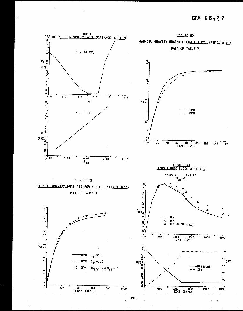
PSFUDO P. FROM SPM GAS/OIL ORAINAGE RESU s
~1 /u
$ i,0.00
,0.04 0.08 0.12 ’716
‘gm
OATA OF TABLE 7
(00
In0
v
0“
‘gm~-
all
e
‘SPM Sgf=l.O
0
I –- DPM Sgf=f,f)
O OPM (SQm/Sgf)Sgf=.5.
+‘o
,200 400
,600 800
(
TIME (OAYS]1000
SPE 1842 ?
U!NJBF?Q
VITY DWAGF FOR A i FT. MATR~
OATA OF TABLE 7
w
0
m
0
%:’
0“
0
‘i
0
10
m00
In00“
— SPM–- DPM
20 40 ‘ do,
100,
t20I
TIME *?OAYS)140 160
QNGIF GRIR_RIQGK Depiction.!2,QJRF 21
AZ=24 FT. h=4 FT.Sgf=o.
r%.
— SPM \
A
A
Ao
0 A
o
i=2000 2500
TIME (OAYS)
zwIi-1.——. ___ ___ -a
0
p 9- -m
PSIA IFT0.0g —PRESSURE -w
/‘- IFT
0 /.m
g
w. /
/- w
00 /g<
o, ,
500 1000 1500r
2000TIME (DAYS)
250;

EwBE22’
In
0
=?0
I-u
0
AZ=24 FT. h=4 FT.
EILJEEm—SPM0 RPM
-- SPM O!!Fo c o
A DPM OFF
o
0
~+-----0
0
A
:~400 aoo 1200 1600 2000
TIME (DAYS)
FIGLIRE 23
I f)CK GAS/Oil OF Pi FTION~Q
p ‘ND‘gm ‘s ‘rhfE
00 m10”m /
——_ 0
/
0 /0. /; /
/
00. m!
z 0
— PRESSURE0
P; ‘gm
PSIA- /“
0/
0m- /w 0
/
/.00~-
/
w0
,‘o
,400 800 1200 1600 2008
TIME (DAYS)
J3AS-FIIJFD MATRIX WQCK
DATA OF TABLE, 7
‘gmi=gla
01’ —5PM So f=l. O
w O OPM So f=l. O
‘gm
N0
n l-)0 0
I A OPM Sof= .5
I-- ‘CORRECT’ OPM Sof=.5
:IA‘gm \ A
\ AAm --~0“ -A-3— - - - - . - .
A A
:~o 200 400 600 000 1000
TIME [OAYS)
FIGURF .%
FFFFCTS OF PARAM.TFRS ON DP~
~
4 FT. MATfiIX !3LOCKDATA OF TABLE 7
—00
A
A
N
01/A —BETAG = 1.30 BETAG = 1.0
b A BETAG = 1.0 LAMBOA=CONSTANT.0
g------130 200 300 400 500 600 700 aoo 900 1000
TIME (DAYS)
270

.
-SENSITIVITY O~
DPM CROS!j SFCTIIJNA1
CONSTANT PFIESSURE SEPAt3AT0R-GAsINJECTION D1FFUS1ON = O.
—BETAG=l.3
‘1
‘ 0 BETAG-l. oA BETAG.l. O LAMBDA+ COt.lSTANT
GORSCF/STB o
2-m
0 A0.
1% A
g0
-0 1 2TIM~ (y E;Rs)
5I
6 7
FIGURF 27
FFFECT OF DIFFuSION IJN DPM
CONSTANT PRESSURE SEPARATOR-GAS INJECTION
—NO OIFFUSION0e-l O OIFFUSION
I o0
0lv- 0
OIL 0
RECOVERY% OOIP %-
0-
0- , , 1
GORSCFA3TB
OILRECOVERY
% OOIP
FFFECT OF OIF USIOtIi oN op~FSULTS
CONSTANT PRESSURE N2 INJECTION
0m
1‘NO OIFFUS1ON
0, OIFFUSION
o 00
0o
c.-
GOR %
SCF/STB
0“-
o~
0 1 2 5TIfE (YEiRS)
16 7
EIGURF .%
Pc OF TABLE 6
s~e=.475
u!
0
n m a
T0
s Wm
m0
h
W7
00 200 400 600I
800 ioooTIME (DAYS)
— SWO dPMTA OPM
27””

ITION CURVF 1=30 FT. Bl OC K
Pc OF TABLE 6
swe=.544
0 0 0A
o A
Ao
A
OA
oA
o
— SPMO OPMTA DPM
I200 400 600 aoo 1000
TIME (DAYS)
FIGURF 31
TION CURVF 10XIOXIO FT. BI OC K
LOW Pcwo CURVE
sHe=.4Ell
a4
A
A
v
0
%m
m0“
N1
00,
200 400 600 600 1000TIME (OAYS)
—SPMO DPMTA DPM BETAW=2.7
I ,. - —.. ?72
~E 18427
UGl!MJQWATFR TION CURVF IOX1OX3O FT. B! 0~
(n0
U-I0
surn:-0
LOW Pcwo CURVE
Swe~.546
o 00
0 Ao
0
0
1/ —SPMOA O OPMT
m A A DPM0
r, , I
00 200 400 600 600 1000TIME (OAYS)
FIGURF 33
INVARIANCE TO FRACTURFWATERSATURU~
PC OF TABLE 6
m0
00
DPM RESULTS
A 4A
A
{“A
A
A
—Swf=l.o
A Swf=.5
#200 400 600 600 1000
TIME (3AYS)

FIW+F 34
RIUM MATRIX WATFR SATUR~li
AZ = 50 FT. h=lOFT
m0 —1 MATRIX BLOCK CALCULATION
•l CORRECT– – DPM
v
s nme -
m0
N/
0.2 0.4I
0.6 0.0 1.0
Swf
FIGURF 35
3D IINF-ORIVE WATFRFIOOO FXAMPI F
OATA OF TABLE 6
00
-1—OPhfT–- DPM (O+OIL RECOVERYI
G-
0(n”
MATERCUT(m% /
/
/
0tll-
0/
o-0 2
I8 10
T;ME (YEA&)
FIGURE X
WATER~BITION CIJ~ 10X1OX3 O FT. BI 0~
OATA OF- KAZEMI ET AL (TABLE 4)
~0
0 0 0mm0 0
g
0
swm 6EI.QMEzHOJl—5X5X1O SPM
m - - 2X1X1Ov SPMo 2X1X10 DPMTA 1x1x1 DPMn 2X1X1O SPM kIfl.2
Inlx
TIME (OAYSI
EL!WIF 3Z
BIOCK FQU~IuM CURVFS . 0 FT.
y.4z.41——..3
-- OPM
Inla.
0
/m /’.u-l- /“ /0 /
,,/’sWm ,...-
U-1 /-.
0-0 //
0Inm. y0
<
/ /u-l(IJ
/
OO.O 0.2 0.4I
0.6 0.6 i.o
Swf
m

Y AND WATEFIQJJ
AZE30 .FT, h=30 FT. q=200 RB/D
aA
l%- A0 Aw“
% OOIP ~-m- —SPM
-- DPM0tu -
0
0-IL,,,,,,,,, ---—
01 1I
‘o 400 800 1200 1600 2000 2400 2800 3200TIME (DAYS)
~uRF 39
I TNF-DRIVF OIL WVFRY AND WATFRC~
AZ=90 FT. h=30 FT. q=600 RB/O
i%-
C+
% OOIPl%- —SPM
0- – OPM
ru-
0.
0
0m-
% WATERCUT ~
ln-
~.
z~1200 1600 2000 2400 2800 3200TIME (DAYSI
%UOIP
Bx8xI GRIDRESERVOIR THICKNESS = 30 FT
0LO-
--”-C& //”
.-0=r-
//
0m- —DPM
–- OPMT0m!-
0*-
0
0m-
% WATERCUT
i%-
0w-
~0
‘o 500 1000I
1500 2000 2500 3000 3500TIME (DAYS)
FIGURE 41
TOTAL FIELDA OIL RATE
(91- DAY AVERAGE)
300
200 -
MMSTBDAY
100 “
L-10
r‘
, t , & t , , , 174 76 76 60 82 84 86 88

SEE 18427
TOTAL FIELD A
GAS INJECTION RATE
f91-DAY AVERAGE]
400 r n 1
3001- lull II.n\HI [1u
MMSCF
DAYn nil
TIME
IIu
I86 68
I.c
.8
.6
sOF
.4
.2
0
FIGURE 43
CALCULATED FRACTURE SO VS. TIME
GAS INJECTION WELL 39, LAYER 2
76 78 80 82 84 86
GOR
SCF/STB
FIGURE 44
RESERVOIR A GoR
— OBSERVED000 DpM
Sge -DEPENOENT UPoNDENSITIES AND TENSION
WITH DIFFuSION
FIGURE 45
N2 INJECTION STARTING 1981
I (1 1
15000
I
NO;:
DIFFUSION+ \1:
I 1000 - . ;!
‘::/ 1, ,4’
%-1:
9000 - I
7000-GOR
SCF/STB
5000 -
3om -
1000* , ,
74 76 78 80 82 84 86 [TIME TIME
m
.