RADIOACTIVE WASTE MANAGEMENT IN HUNGARY: CHANGING APPROACHES AND CONFLICTS
Upload
independentCategory
view
1download
0
(12) United States Patent Lan et al.
US008831885B2
US 8,831,885 B2 Sep. 9, 2014
(10) Patent N0.: (45) Date of Patent:
(54)
(75)
(73)
(21)
(22)
(65)
(60)
(51)
(52)
(58)
INTEGRATED RADIOACTIVE SOURCE-FREE METHOD AND APPARATUS FOR POROSITY DETERMINATION: NMR CALIBRATED ACOUSTIC POROSITY
Inventors: Chun Lan, Spring, TX (US); Songhua Chen, Katy, TX (US); Fabio Brambilla, Milan (IT)
Assignee: Baker Hughes Incorporated, Houston, TX (US)
Notice: Subject to any disclaimer, the term of this patent is extended or adjusted under 35 U.S.C. 154(b) by 331 days.
Appl. No.: 13/267,140
Filed: Oct. 6, 2011
Prior Publication Data
US 2012/0101732 A1 Apr. 26, 2012
Related US. Application Data
Provisional application No. 61/406,300, ?led on Oct. 25, 2010.
Int. Cl. G01 V3/38 (2006.01) G01V 1/40 (2006.01) G01V3/18 (2006.01) G01 V 9/00 (2006.01) G01N 24/08 (2006.01) US. Cl. CPC .................................. .. G01N24/081 (2013.01)
USPC ........................................ .. 702/11; 73/152.06
Field of Classi?cation Search CPC ......... .. G01V 3/32; G01V 11/00; G01V 3/38;
G01V 5/04; G01V 2210/6167; G01N 24/081; G01N 2291/0231; G01N 29/07
USPC ................ .. 702/7, 8, 11, 12, 6; 324/303, 309, 324/323i377, 300; 73/152.01, 152.05,
lea
73/152.14, 152.06; 175/50; 250/253 See application ?le for complete search history.
(56) References Cited
U.S. PATENT DOCUMENTS
5,431,224 A * 7/1995 Laali ........................... .. 166/256
6,470,274 B1* 10/2002 Mollison et a1. ..... .. 702/7 6,646,437 B1 * 11/2003 Chitale et a1. .... .. 324/303
7,617,050 B2 * 11/2009 Allen et al. . . . . . . . . . . . . . .. 702/7
7,710,823 B2 * 5/2010 Tabarovsky et al. 367/35 7,839,144 B2 * 11/2010 Jebutu ......................... .. 324/303
2009/0195246 A1 8/2009 Jebutu 2010/0256915 A1* 10/2010 Frost, Jr. ......................... .. 702/9
OTHER PUBLICATIONS
McKenzie, J.A. Davies, P.J., Palmer-Julson, A. et al 1993 (Resistiv ity/Porosity/Velocity Relationships from Downhole Logs: An Aid for Evaluating Pore Morphology) teaches well-known relationships between formation parameters.* Wyllie, M.R. et al., “Elastic wave velocities in heterogeneous and porous media,” Geophysics, vol. 21, N0. 1, pp. 41-70 (1956). Raymer, L.L., et al., “An improved sonic transit time to porosity transform,” SPWLA 21st Annual Logging Symposium (1980). Minh C.C., et al., “Sonic-magnetic resonance method: A sourceless porosity evaluation in gas-bearing reservoirs,” SPE72180 (2001).
* cited by examiner
Primary Examiner * Sujoy Kundu
Assistant Examiner * Lisa Peters
(74) Attorney, Agent, or Firm * Mossman Kumar & Tyler PC
(57) ABSTRACT
NMR porosity measurements made in a gas free-formation are used to calibrate acoustic measurements. The calibration parameters are then used in conjunction With estimates of shale content to provide improved estimates of formation porosity in shaly intervals Which may include a gas.
18 Claims, 4 Drawing Sheets

US. Patent Sep. 9, 2014 Sheet 1 0f4 US 8,831,885 B2
FIG. 1

US 8,831,885 B2 Sheet 2 0f 4 Sep. 9, 2014 US. Patent
N GI F23 mm 2: 8 8 9“ ON C _ _ _ _
O ......................................................................................... -iE ......................................................................................... -iON ......................................................................................... -iom ow
(ll/S“) WW

US. Patent Sep. 9, 2014 Sheet 3 0f4
301\ Calibrate the constant C and Atpma-dean
in the clean water zone
303\ u
Calculate Atp,ma in shaly water zone
"
Plot the calculated Atp,ma with FSV ‘x’
"
in the gas bearing zone Use the fitting function to calculate Atp,ma
v
Calculate (bacous?c using calibrated Atpma and C
FIG. 3
401 \
Calibrate the constant C and Atpmwean in the clean water zone
v
Calibrate Mum-sham and At? in shale water zone
v
Calculate FSV ‘x’ in the gas bearing zone
"
Calculate Atp,ma in the gas bearing zone by using FSV
"
Calculate <|>acous?C using calibrated Atpma and C
FIG. 4
US 8,831,885 B2

US. Patent Sep. 9, 2014 Sheet 4 of4 US 8,831,885 B2
501\ Calibrate _the constant C and Atpma-Mean
in the clean water zone
v
Calculate <|>acoustic using calibrated Atp,ma.c|ean and C
FIG. 5
601\ Obtain shear velocity log
"
Calculate Ats,ma in the water interval
"
Establish a correlation between the calculated Ats,ma with selected curve “x”
"
Calculate Ats,ma in the gas-bearing interval using the correlation from previous step
"
Calculate <|> using calculated Ats ma in the gas-bearing interval ’
FIG. 6
US 8,831,885 B2 1
INTEGRATED RADIOACTIVE SOURCE-FREE METHOD AND APPARATUS FOR POROSITY DETERMINATION: NMR CALIBRATED ACOUSTIC POROSITY
CROSS-REFERENCES TO RELATED APPLICATIONS
This application claims priority from US. Provisional Patent Application Ser. No. 61/406,300, ?led on Oct. 25, 2010, incorporated herein by reference in its entirety.
FIELD OF THE DISCLOSURE
This disclosure relates to apparatus and techniques for making porosity measurements of an earth formation without using radioactive sources. Speci?cally, the disclosure relates to the design of an accurate acoustic measurement technique which, when calibrated with NMR measurements, gives the porosity of an earth formation over a wide range of lithologies and in the presence of gas in the formation.
BACKGROUND OF THE DISCLOSURE
Oil well logging has been known for many years and pro vides an oil and gas well driller with information about the particular earth formation being drilled. In conventional oil well logging, after a well has been drilled, a probe known as a sonde is lowered into the borehole and used to determine some characteristic of the formations which the well has traversed. The probe is typically a hermetically sealed steel cylinder which hangs at the end of a long cable which gives mechanical support to the sonde and provides power to the instrumentation inside the sonde. The cable also provides communication channels for sending information up to the surface. It thus becomes possible to measure some parameter of the earth’s formations as a function of depth, that is, while the sonde is being pulled uphole. Such “wireline” measure ments are normally done in real time (however, these mea surements are taken long after the actual drilling has taken place).
Porosity measurements are commonly done by using a dual detector neutron logging tool using a source of neutrons irradiating the formation being studied. Density measure ments are commonly done by using a dual detector gamma ray logging tool using a source of gamma rays irradiating the formation being studied. The density measurements, and some of the porosity measurements, may require the use of a radioactive source of neutrons and/or gamma rays. From a safety standpoint, the use of radioactive sources is problem atic, particularly for measurement while drilling (MWD) applications.
Radioactive-source-free tools, such as Nuclear Magnetic Resonance (N MR) and acoustic logging have beenused in the past for porosity determination. NMR logging has the advan tage of directly measuring ?uids in pore space and, thus, does not suffer from the lithology effect onporosity determination. However, the accuracy of NMR total porosity in gas-bearing formations is affected by low hydrogen index (HI) and the ability to separate gas and liquid NMR responses. In the cases of extremely viscous oil-bearing reservoirs, coal-bed meth ane-bearing formation or gas-hydrates, the hydrocarbon sig nals may relax too fast to be observed by the state of art NMR well logging instruments, thereby causing under-estimation of porosity. On the other hand, acoustic measurements respond to lithology and texture in addition to porosity. Con sequently acoustic porosity is an indirect measurement based
20
25
30
35
40
45
50
55
60
65
2 on empirical or semi-empirical models, which often requires calibration of model parameters.
Integrating acoustic and NMR measurements for gas-zone porosity estimation has been reported in relatively clean sand stones. However, the existing methods in literature have not been extended to shaly sandstones. The present disclosure describes a radioactive source-free porosity estimation method using NMR logs to calibrate acoustic porosity mod els. This approach is applicable to clean and shaly sandstones using wireline and logging while drilling (LWD) measure ments.
SUMMARY OF THE DISCLOSURE
In view of the foregoing, the present disclosure is directed to a method and apparatus for making porosity measurements of an earth formation without using a radioactive source. In particular, the present disclosure is directed to acoustic mea surements calibrated with NMR measurements and used to estimate porosity of an earth formation over a range of lithologies and in the presence of gas in the formation. One embodiment of the disclosure includes a method of
estimating a value of a porosity of an earth formation com prising a ?rst solid component, a second solid component, and a gas. The method includes: using an acoustic tool for making a measurement indicative of a porosity of the earth formation in an interval that includes (i) a gas, (ii) the ?rst solid component, and (iii) the second solid component; and using a processor for: estimating the value of the porosity in the interval using the measurement made by the acoustic tool, a fractional value of the second component, and at least one parameter relating an additional measurement made by the acoustic tool to a measurement by a nuclear magnetic reso nance (NMR) tool in another interval that does not include a gas.
Another embodiment of the disclosure includes an appa ratus con?gured to estimate a value of a porosity of an earth formation comprising a ?rst solid component, a second solid component and a gas. The apparatus includes: an acoustic tool con?gured to make a measurement indicative of a poros ity of the earth formation in an interval that includes: (i) a gas, (ii) the ?rst solid component, and (iii) the second solid com ponent; and a processor con?gured to: estimate a value of the porosity in the interval using the measurement made by the acoustic tool, a fractional value of the second component and at least one parameter relating an additional measurement made by the acoustic tool to a measurement by a nuclear magnetic resonance (N MR) tool in another interval that does not include a gas.
Another embodiment of the disclosure is a tangible com puter-readable medium product having stored thereon instructions what when read by a processor cause the proces sor to execute a method. The method includes: estimating a value of a porosity of a formation, using a measurement made by an acoustic tool in a borehole in an interval containing a ?rst solid component, a second solid component, and a gas; a fractional value of the second component; and at least one parameter relating an additional measurement made by the acoustic tool to a measurement by a nuclear magnetic reso nance (NMR) tool in another interval that does not include a gas.
BRIEF DESCRIPTION OF THE DRAWINGS
The present disclosure is best understood with reference to the following ?gures in which like numerals refer to like elements, and in which:

US 8,831,885 B2 3
FIG. 1 depicts diagrammatically an NMR logging tool in a borehole according to one embodiment of the present disclo
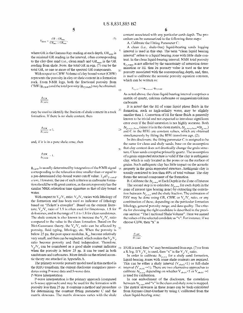
sure; FIG. 2 shows plot of Atma vs. GR in the water bearing
zones; FIG. 3 shows a ?ow chart of one embodiment of a method
according to the present disclosure; FIG. 4 shows a ?ow chart of another embodiment of a
method according to the present disclosure; FIG. 5 shows a simpli?ed ?ow chart of a method for a clean
formation according to one embodiment of the present dis closure; and
FIG. 6 shows a simpli?ed ?ow chart of a method for using shear waves according to one embodiment of the present disclosure.
DETAILED DESCRIPTION OF THE DISCLOSURE
FIG. 1 depicts a borehole 10 drilled in a typical fashion into a subsurface geological formation 12 to be investigated for potential hydrocarbon producing reservoirs. An NMR log ging tool 14 has been lowered into the borehole 10 using a cable 16 and appropriate surface equipment (represented dia grammatically by a reel 18) and is being raised through the formation 12 comprising a plurality of layers 1211 through 12g of differing composition, to log one or more of the forma tion’s characteristics. The NMR logging tool may be pro vided with bowsprings 22 to maintain the tool in an eccentric position within the borehole with one side of the tool in proximity to the borehole wall. The permanent magnets 23 provide the static magnetic ?eld. Signals generated by the tool 14 are passed to the surface through the cable 16 and from the cable 16 through another line 19 to appropriate surface equipment 20 for processing, recording, display and/or for transmission to another site for processing, recording and/or display. Alternatively, the processor may be located at a suit able position (not shown) downhole, e.g., in the logging tool 14. It should be noted that the use of a wireline-conveyed NMR tool is for illustrative purposes only and the method of the present disclosure can be implemented using a logging tool conveyed on a bottomhole assembly by a drilling tubular.
In the method of the present disclosure, two models are used. One is a model relating acoustic measurements to for mation porosity and the other is a model relating NMR mea surements to an estimated formation porosity. The NMR model is discussed ?rst.
The total porosity ¢tJVMR made by an exemplary NMR logging tool is given by the relation:
(1)
where q) is the formation porosity, SW is the water saturation, I HW and I Hg are the hydrogen indices of water and gas respec tively, TZW and T18 are the longitudinal relaxation times of water and gas respectively, and tW is the wait time of the NMR pulsing. In gas-bearing formations logged with insuf?cient wait time, the low HI of the gas cause ¢tJVMR to be less than the true total porosity of the formation. The NMR measurement made in a gas-free formation may be referred to as a “?rst measurement” made in a ?rst interval.
The present disclosure is illustrated using the Raymer Hunt-Gardner (RHG) time transform, which is primarily
20
25
30
35
40
45
50
55
60
65
4 developed for clean formations. The RHG transform for com pressional wave can be written as:
Alp — Arpyma
Alp C, (2)
¢acousti c =
where Atp is the measured compressional wave slowness, Atpma is the compressional wave slowness of the dry matrix, and C is a ?tting parameter. We note that C has low sensitivity to ?uid typing, and is fairly stable and often can be treated as a constant. However, as the porosity increases, eqn. (2) becomes more sensitive to ?uid typing.
The RHG equation for shear waves can be written as:
— a
Alma AIS
where q) is the total porosity of the formation, Ats is the measured S-wave slowness in the formation, and Atsma is the S-wave slowness of the dry matrix. This equation assumes the S-wave modulus does not depend on the pore ?uid.
With respect to the RHG method, if the formation is pure sandstone, limestone, or dolostone, Atma is a constant num ber, which can be found in literature. Thus, the formation includes a ?rst component (the matrix) that may be made of quartz, calcium carbonate or magnesium/calcium carbonate.
If the formation of interest includes shale, Atma can vary with the shale type, distribution, and percentage. This makes Atma highly unpredictable for complex-lithology reservoirs. In the method described in this disclosure, a basic assumption that is made is that within a certain depth interval, there is a good consistency of Atma on the shale type and distribution. Atma then only varies with fractional shale percentage and the ?tting parameter C in the RHG transform is considered to be constant.
Under such assumptions, NMR logs are used for calibra tion in the liquid-bearing zones to serve two main purposes.
1. Calibrate the ?tting parameter in the RHG transform.
2. Extract the correlation between Atma and the fraction of shale content.
The Fractional Shale Volume (FSV) can be estimated by one or more of the downhole measurement techniques, e.g., a Gamma Ray (GR) log, a spectral GR log, a Potassium-Tho rium (KTh) log, a clay bound water (CBW) log, or an acoustic log that measures compressional wave velocity (VP) and shear wave velocity (V S), or a ratio between these velocities (V P/V S). The CBW log is obtained using an NMR tool in the shaly interval. With respect to GR: the Natural GR log, which is mainly
responsive to potassium, uranium, and thorium, has been widely used as shale indicator. The potassium spectrum log of the GR response is indicative of clay minerals. For heavy oil or Kerogen-rich shales, the uranium may exist in the hydro carbon or biomass rather than in shale matrix. Hence spectral GR logs, which separately determine K, Th, and U, may be used as shale indicators and for quantifying shale volume. Although, in general, the correlation between GR response and fractional shale content is complex and can be affected by many factors, a commonly-used simpli?ed linear correlation model is an adequate approximation to interpret fractional shale volume (F SV) for many underground rock formations:
US 8,831,885 B2 5
V _ GR — GM. (7)
Shall? _ m,
where GR is the Gamma Ray reading at each depth, GRmz-n is the minimal GR reading in the interval, often corresponding to the clay-free sand (i.e., clean sand) and GRmax is the GR reading from shale. Note, the total GR in eqn. (7) can be the total GR, or one or more of the spectral GR components.
With respect to CBW: Volume of clay bound water (CBW) represents the porosity in clay or shale content in a formation rock. From NMR logs, both the fractional porosity from CBW (4) CE W) and the total porosity ($UVMR) may be obtained.
may be used to identify the fraction of shale content in a rock formation. If there is no shale content, then
and, if it is in a pure shale zone, then
¢CBWis usually determined by integration of the NMR signal corresponding to the relaxation time smaller than or equal to a pre-determined clay-bound water cutoff value: T25T2 cutof (CBW). However, the use of such criterion in carbonate forma tion shouldbe with great caution, as the microporosity has the similar NMR relaxation time signature as that of clay bound water.
With respect to VP/VS ratio: VP/VS varies with lithology of the formation and has been used as indicator of lithology based on “Pickett’s crossplot”. Based on the current litera
ture, VP/VS ratio of 1.9 is often used for limestones, 1.8 for dolostones, and in the range of 1 .6 to 1.8 for clean sandstones. The shale content is also known to increase the VP/VS ratio compared to the value in the clean formation. Based on the Biot-Gassmann theory, the VP/VS ratio can be affected by porosity, ?uid typing, lithology, etc. When the porosity is below 25 pp, the pore space modulus, KP, become relatively very small, and then can be neglected, which makes the VP/VS ratio become porosity and ?uid independent. Therefore, VP/VS can be considered as a good shale content indicator when the porosity is below 25 pp. It can be used in both sandstones and carbonates. More details on the related acous tic theory are attached in Appendix A.
The primary acoustic porosity model used in this method is the RHG transform; the current disclosure comprises proce dures using P-wave data and S-wave data. P-Wave Interpretation
P-wave interpretation is the primary approach (compared to S-wave approach) and may be used for the formation with porosity less than 25 pp. It contains a method and procedure for determining the constant ?tting parameter C and the matrix slowness. The matrix slowness varies with the shale
20
25
30
35
6 content associated with any particular earth depth. The pro cedure can be summarized in the following three steps:
A. Calibrate the Fitting Parameter C: A clean (i.e., shale-free) liquid-bearing sands logging
interval is used in this step. The term “clean liquid bearing interval” refers to a liquid bearing zone with little shale con tent. In the clean liquid-bearing interval, NMR total porosity ¢UVMR is not affected by the uncertainty of saturation deter mination or HI, thus its porosity value is used as the true porosity associated with the corresponding depth, and, thus, is used to calibrate the acoustic porosity equation constant, which can be written as:
As noted above, the clean liquid bearing interval comprises a matrix of quartz, calcium carbonate or magnesium/calcium carbonate.
It is noted that the HI of some liquid phase ?uids in the formation, such as high-salinity water, may be slightly smaller than 1. Correction of HI for those ?uids is generally known to be trivial and not expected to introduce signi?cant error even if the ?uid saturation is not highly accurate. Both
Atpmaplean (since it is in the clean matrix, Atp,ma,clean:Atp,ma) and C in the RHG are constant values, which are obtained simultaneously by ?tting the RHG transform eqn. (2).
In this disclosure, the ?tting parameter C is assigned to be the same for clean and shaly sands, base on the assumption that clay content does not drastically change the grain struc ture. Clean sands comprise primarily quartz. The assumption of a grain supported structure is valid if the clay is authigenic clay, which is only located in the pores or on the surface of grains. Such authigenic clay has little impact on the acoustic property in the grain supported structure. Authigenic clay is usually restricted to less than 40% of total volume. The clay forms the second component of the formation.
B. Calibrate the Atpma at Each Depth in the Zone of Interest The second step is to calculate Atpma for each depth in the
zone of interest (gas bearing zone) by extracting the correla tion between Atpma and the shale fraction. The estimation of FSV may be done using GR, CBW, or VP/VS ratio, or any combination of these, depending on the particular formation lithology, general porosity range, and data quality. The crite ria for choosing the right candidate is described in the previ ous section: “The Fractional Shale Volume”. Here we named the values of the selected candidate as “x”. For instance, if we choose CBW, then “x” is
If GR is used, then “x” may be estimated from eqn. (7) or from a K log. If VP/VS is used, then “x” is the VP/VS ratio.
In order to calibrate Atpmm for a shaly sand formation, liquid-bearing zones with some shale contents are required. This can be either a shaly interval (Vshale<1) or full-shale interval (V Shale—>1). There are two alternative approaches to calibrate Atpma depending on whether Vshale<1 or Vshale is used for calibration.
In one embodiment of the disclosure, the correlation between Atpma and “x” in the clean and shaly zone is mapped. The matrix slowness in these zones can be back-calculated from Raymer-Hunt-Gardner by using C calibrated from the clean liquid-bearing zone:
US 8,831,885 B2
(3)
Polynomial functions can be used to provide a good ?tting to the data trend, which may sometimes be a simple ?rst order linear function. Finally Atpma in the gas zone can be calcu lated by applying “x” at each depth into the ?tting function. It should be noted that the notation herein makes a distinction between Atp?a?ean for a clean dry matrix and A for a shale formation. An example of using GR as shale indicator can be used to
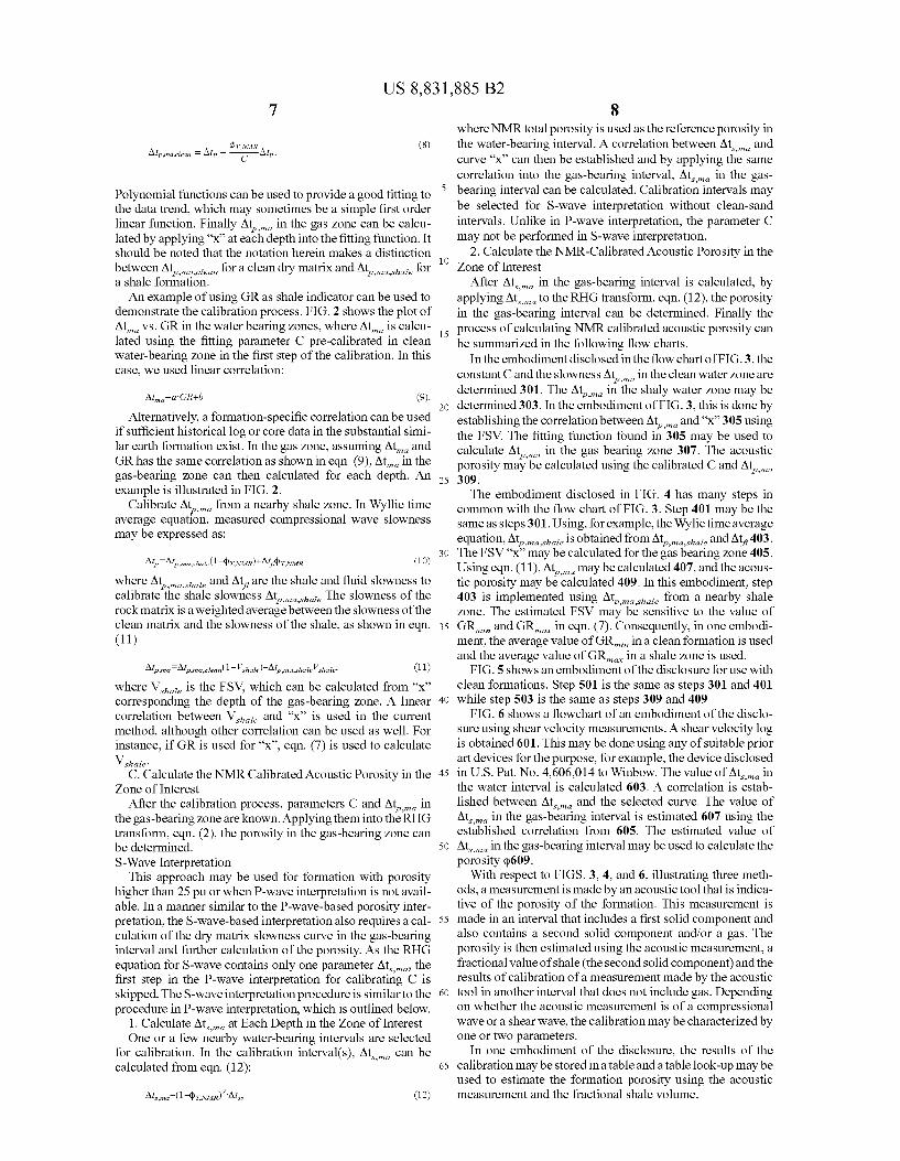
demonstrate the calibration process. FIG. 2 shows the plot of Atma vs. GR in the water bearing zones, where Atma is calcu lated using the ?tting parameter C pre-calibrated in clean water-bearing zone in the ?rst step of the calibration. In this case, we used linear correlation:
tp,ma,shale
AlmQIa-GRw (9).
Alternatively, a formation-speci?c correlation can be used if suf?cient historical log or core data in the substantial simi lar earth formation exist. In the gas zone, assuming Atma and GR has the same correlation as shown in eqn. (9), Atma in the gas-bearing zone can then calculated for each depth. An example is illustrated in FIG. 2.
Calibrate Atpama from a nearby shale zone. In Wyllie time average equation, measured compressional wave slowness may be expressed as:
where Atpamaashale and At? are the shale and ?uid slowness to calibrate the shale slowness Atp,ma,shale The slowness of the rock matrix is a weighted average between the slowness of the clean matrix and the slowness of the shale, as shown in eqn.
(11)
AZPWQIAZPWQCIEMU - Vshale)+Alp,ma,shale Vshale’ (1 1)
where V Shale is the FSV, which can be calculated from “x” corresponding the depth of the gas-bearing zone. A linear correlation between Vshale and “x” is used in the current method, although other correlation can be used as well. For instance, if GR is used for “x”, eqn. (7) is used to calculate Vshale'
C. Calculate the NMR Calibrated Acoustic Porosity in the Zone of Interest
After the calibration process, parameters C and Atpma in the gas-bearing zone are known. Applying them into the RHG transform, eqn. (2), the porosity in the gas-bearing zone can be determined. S-Wave Interpretation
This approach may be used for formation with porosity higher than 25 pu or when P-wave interpretation is not avail able. In a manner similar to the P-wave-based porosity inter pretation, the S-wave-based interpretation also requires a cal culation of the dry matrix slowness curve in the gas-bearing interval and further calculation of the porosity. As the RHG equation for S-wave contains only one parameter Atsma, the ?rst step in the P-wave interpretation for calibrating C is skipped. The S-wave interpretation procedure is similar to the procedure in P-wave interpretation, which is outlined below.
1. Calculate Atsma at Each Depth in the Zone of Interest One or a few nearby water-bearing intervals are selected
for calibration. In the calibration interval(s), Atsama can be calculated from eqn. (12):
20
25
30
35
40
45
50
55
60
65
8 where NMR total porosity is used as the reference porosity in the water-bearing interval. A correlation between Atsama and curve “x” can then be established and by applying the same correlation into the gas-bearing interval, Atsma in the gas bearing interval can be calculated. Calibration intervals may be selected for S-wave interpretation without clean-sand intervals. Unlike in P-wave interpretation, the parameter C may not be performed in S-wave interpretation.
2. Calculate the NMR-Calibrated Acoustic Porosity in the Zone of Interest
After Atsama in the gas-bearing interval is calculated, by applying Atsma to the RHG transform, eqn. (1 2), the porosity in the gas-bearing interval can be determined. Finally the process of calculating NMR calibrated acoustic porosity can be summarized in the following ?ow charts.
In the embodiment disclosed in the ?ow chart of FIG. 3, the constant C and the slowness Atpma in the clean water zone are determined 301. The Atpma in the shaly water zone may be determined 303. In the embodiment of FIG. 3, this is done by establishing the correlation between Atpma and “x” 305 using the FSV. The ?tting function found in 305 may be used to calculate Atpama in the gas bearing zone 307. The acoustic porosity may be calculated using the calibrated C and Atpmm 309. The embodiment disclosed in FIG. 4 has many steps in
common with the ?ow chart of FIG. 3. Step 401 may be the same as steps 301. Using, for example, the Wylie time average equation, Atpmmshale is obtained from Atp,ma,shale and At? 403. The FSV “x” may be calculated for the gas bearing zone 405. Using eqn. (1 l), Atpma may be calculated 407, and the acous tic porosity may be calculated 409. In this embodiment, step 403 is implemented using Atpamaghale from a nearby shale zone. The estimated FSV may be sensitive to the value of GRmz-n and GRmax in eqn. (7). Consequently, in one embodi ment, the average value of GRmz-n in a clean formation is used and the average value of GRmax in a shale zone is used.
FIG. 5 shows an embodiment of the disclosure for use with clean formations. Step 501 is the same as steps 301 and 401 while step 503 is the same as steps 309 and 409
FIG. 6 shows a ?owchart of an embodiment of the disclo sure using shear velocity measurements. A shear velocity log is obtained 601. This may be done using any of suitable prior art devices for the purpose, for example, the device disclosed in US. Pat. No. 4,606,014 to Winbow. The value of Atama in the water interval is calculated 603. A correlation is estab lished between Atsama and the selected curve. The value of Atsma in the gas-bearing interval is estimated 607 using the established correlation from 605. The estimated value of Atsma in the gas-bearing interval may be used to calculate the porosity (1)609.
With respect to FIGS. 3, 4, and 6, illustrating three meth ods, a measurement is made by an acoustic tool that is indica tive of the porosity of the formation. This measurement is made in an interval that includes a ?rst solid component and also contains a second solid component and/or a gas. The porosity is then estimated using the acoustic measurement, a fractional value of shale (the second solid component) and the results of calibration of a measurement made by the acoustic tool in another interval that does not include gas. Depending on whether the acoustic measurement is of a compressional wave or a shear wave, the calibration may be characterized by one or two parameters.
In one embodiment of the disclosure, the results of the calibration may be stored in a table and a table look-up may be used to estimate the formation porosity using the acoustic measurement and the fractional shale volume.

US 8,831,885 B2
The method of the present disclosure is described above with reference to a wireline-conveyed NMR logging tool. The method may also be used on logging tools conveyed on coiled tubing in near horizontal boreholes. The method may also be used on NMR sensors conveyed on a drilling tubular, such as a drillstring or coiled tubing for Measurement-While-Drilling (MWD) applications. As is standard practice in well-logging, the results of the
processing are recorded on a suitable medium. Implicit in the processing of the data is the use of a computer program implemented on a suitable machine-readable medium that enables the processor to perform the control and processing. The machine-readable medium may include ROMs, EPROMs, EAROMs, Flash Memories and Optical disks. These are all examples of non-transitory computer-readable media.
APPENDIX
When acoustic wave propagates through formation rocks, the wave velocity ratio VP/VS varies with lithology of the formation and has been used as indicator of lithology based on “Pickett’s crossplot”. Based on the current literature, VP/VS ratio is 1.9 for carbonate, 1.8 for dolomite, and in the range of 1.6 to 1.8 for clean sandstones. Using the grain contact theory Murphy et al. proposed in 1982, the calculated VP/VS ratio is 1.5 for sandstone, which has also been sup ported by experimental data on sandstones of a wide range of porosities. Castagna et al and Han et al observed that the clay content decreases the velocities of the acoustic wave, and proposed linear empirical correlations between the wave velocity ratio and FSV.
In Biot-Gassmann theory, the acoustic wave velocity for an isotropic, non-porous media is related to the frame moduli for the formation. The velocity of the compressional wave in a porous media can be written as:
and the velocity of the shear wave in a porous media is
where KP is de?ned as pore space modulus, p. is the frame shear modulus, and Kb is the frame bulk modulus. We then have the VP/VS ratio as:
is the pore space modulus, where Km and Kfare bulk moduli for matrix materials and ?uid, respectively, 4) is porosity, and 0t is the Biot coef?cient.
20
25
30
35
40
45
50
55
60
65
10 At low porosities, or in dry sand,
There are many theoretical and empirical models for Kb and N values. Murphy et al proposed the grain contact model,
Kb Skn
where kn, kt are the normal and tangential stiffness of the grain contact. Murphy et al reported laboratory results that the
Kb
ratio for clean sandstone (overgrowth dominated) is a con stant value 0.9 independent from porosity, which form a lower bound for the ratio VP/VS?/O. 9+4/3:1 .5, and stated the frame moduli
increases non-linearly with clay content, and approaching 2.0 in shale. However, there is no literature proposed any corre lation between clay content and frame moduli ratio to further link to velocity ratio. Only empirical models have been reported such as the Castagna and Han’s linear correlations between VP/VS ratio and FSV.
While the foregoing disclosure is directed to the preferred embodiments of the disclosure, various modi?cations will be apparent to those skilled in the art. It is intended that all variations within the scope and spirit of the appended claims be embraced by the foregoing disclosure.
What is claimed is: 1. A method of estimating a value of a porosity of an earth
formation in a gas-bearing interval, the earth formation com prising the gas-bearing interval and a liquid-bearing interval, the method comprising:
using an acoustic tool for making a measurement indicative of a porosity of the earth formation in the gas-bearing interval, the gas-bearing interval comprising:
a ?rst solid component having a ?rst value of an acoustic property affecting the measurement, and
a second solid component having a second value of an acoustic property affecting the measurement, wherein the ?rst value is different than the second value; and
using an at least one processor to estimate the value of the porosity in the gas-bearing interval using: (i) the mea surement made by the acoustic tool, and (ii) an estimated value of the acoustic property for the gas-bearing inter val determined using a fractional volume of the second

US 8,831,885 B2 11
solid component and a correlation between acoustic property values and corresponding fractional volumes of the second solid component in the liquid-bearing interval.
2. The method of claim 1 wherein the correlation between the acoustic property values and the corresponding fractional volumes of the second solid component in the liquid-bearing interval comprises a relationship between the acoustic prop erty values and values of a parameter indicative of fractional volume of the second solid component, the method compris ing using the at least one processor to determine the correla tion by:
estimating a corresponding value of the porosity at a plu rality of depths in the liquid-bearing interval using a corresponding measurement made by a nuclear mag netic resonance (NMR) tool;
estimating a corresponding value of the parameter at the plurality of depths in the liquid-bearing interval; and
determining the relationship between the corresponding values of the porosity and the corresponding values of the parameter.
3. The method of claim 1 wherein the measurement is selected from the group consisting of: (i) a compressional wave slowness and (ii) a shear wave slowness.
4. The method of claim 1 wherein the ?rst solid component further comprises quartz or carbonate and the second solid component further comprises a clay.
5. The method of claim 4 wherein the clay further com prises an authigenic clay.
6. The method of claim 2 wherein the at least one parameter further comprises at least one of: (i) a matrix slowness of a compressional velocity, (ii) a matrix slowness of a shear velocity, and (iii) a calibration factor.
7. The method of claim 2 further comprising obtaining the fractional value of the second component using at least one of: (i) a measurement made by a natural gamma ray tool, (ii) an estimate of clay bound water (CBW) using a measurement made by the NMR tool in the second interval, and (iii) an estimate of a ratio of a compressional velocity in the second interval to a shear velocity in the second interval.
8. An apparatus con?gured to estimate a value of a porosity of an earth formation in a gas-bearing interval, the earth formation comprising the gas-bearing interval and a liquid bearing interval, the apparatus comprising:
an acoustic tool con?gured to make a measurement indica tive of a porosity of the earth formation in the gas bearing interval, the gas-bearing interval comprising:
a ?rst solid component having a ?rst value of an acoustic property affecting the measurement, and
a second solid component having a second value of an acoustic property affecting the measurement, wherein the ?rst value is different than the second value; and
an at least one processor con?gured to: estimate a value of the porosity in the gas-bearing inter
val using the measurement made by the acoustic tool and an estimated value of the acoustic property for the gas-bearing interval determined using a fractional volume of the second solid component and a correla tion between acoustic property values and corre sponding fractional volumes of the second solid com ponent in the liquid-bearing interval.
9. The apparatus of claim 8 wherein the correlation between the acoustic property values and the corresponding fractional volumes of the second solid component in the liquid-bearing interval comprises a relationship between the acoustic property values and values of a parameter indicative
5
20
35
40
55
60
65
12 of fractional volume of the second solid component, and the at least one processor is con?gured to determine the correla tion by:
estimating a corresponding value of the porosity at a plu rality of depths in the liquid-bearing interval using a corresponding measurement made by a nuclear mag netic resonance (NMR) tool;
estimating a corresponding value of the parameter at the plurality of depths in the liquid-bearing interval; and
determining the relationship between the corresponding values of the porosity and the corresponding values of the parameter.
10. The apparatus of claim 8 wherein the measurement is selected from: (i) a compressional wave slowness and (ii) a shear wave slowness.
11. The apparatus of claim 8 wherein the ?rst solid com ponent further comprises one of: (i) quartz and (ii) carbonate, and the second solid component further comprises a clay.
12. The apparatus of claim 11 wherein the clay further comprises an authigenic clay.
13. The apparatus of claim 8 wherein the at least one parameter estimated by the processor further comprises at least one of: (i) a matrix slowness of a compressional velocity, (ii) a matrix slowness of a shear velocity, and (iii) a calibration factor.
14. The apparatus of claim 8 wherein the processor is further con?gured to obtain the fractional value of the second component using at least one of: (i) a measurement made by a natural gamma ray tool, (ii) an estimate of clay bound water (CBW) using a measurement made by the NMR tool in the second interval, and (iii) an estimate of a ratio of a compres sional velocity in the second interval to a shear velocity in the second interval.
15. The apparatus of claim 8 further comprising a convey ance device con?gured to convey the NMR tool into the borehole, the conveyance device selected from: (i) a wireline, and (ii) a bottomhole assembly on a drilling tubular.
16. A non-transitory computer-readable medium product having stored thereon instructions what when read by at least one processor cause the at least one processor to execute a
method, the method comprising: estimating a value of a porosity of an earth formation in a
gas-bearing interval, the earth formation comprising the gas-bearing interval and a liquid-bearing interval, using:
a measurement made by an acoustic tool in a borehole penetrating the earth formation in the gas -bearing inter val, the gas-bearing interval comprising: a ?rst solid component having a ?rst value of an acoustic
property affecting the measurement, and a second solid component having a second value of an
acoustic property affecting the measurement, wherein the ?rst value is different than the second value; and
an estimated value of the acoustic property for the gas bearing interval determined using a fractional volume of the second solid component and a correlation between acoustic property values and corresponding fractional volumes of the second solid component in the liquid bearing interval.
17. The non-transitory computer-readable medium prod uct of claim 16 further comprising at least one of: (i) a ROMs, (ii) an EPROM, (iii) an EAROM, (iv) a ?ash memory, and (v) an optical disk.
18. A method of estimating a value of a porosity of an earth formation in a gas-bearing interval, the earth formation com prising the gas-bearing interval and a liquid-bearing interval, the method comprising:

US 8,831,885 B2 13 14
using an acoustic tool for making a measurement indicative of a porosity of the earth formation in the gas-bearing interval, the gas-bearing interval comprising:
a ?rst solid component having a ?rst value of an acoustic property affecting the measurement, and 5
a second solid component having a second value of an acoustic property affecting the measurement, Wherein the ?rst value is different than the second value; and
using an at least one processor to estimate the value of the porosity in the gas-bearing interval using: (i) the mea- 10 surement made by the acoustic tool, and (ii) an estimated value of a ?tting parameter for an acoustic porosity model relating an additional measurement indicative of porosity made by the acoustic tool in the liquid-bearing interval to a measurement indicative of porosity by a 15 nuclear magnetic resonance (NMR) tool in the liquid bearing interval.
Copyright © 2022 FDOKUMEN