
An Object-Oriented Simulator for 3D Digital Breast Tomosynthesis Imaging System

Tomosynthesis-based localization of radioactive seedsin prostate brachytherapy
Ismail B. Tutar, Ravi Managuli, and Vijay ShamdasaniImage Computing Systems Laboratory, Departments of Electrical Engineering and Bioengineering,University of Washington, Seattle, Washington 98195
Paul S. ChoDepartment of Radiation Oncology, University of Washington, Seattle, Washington 98195
Sayan D. PathakDepartments of Electrical Engineering and Bioengineering, University of Washington, Seattle,Washington 98195 and Insightful Corporation, Seattle, Washington 98109
Yongmin Kima)
Department of Bioengineering, University of Washington, Seattle, Washington 98195-2500
~Received 14 April 2003; revised 25 July 2003; accepted for publication 17 September 2003;published 19 November 2003!
Accurately assessing the quality of prostate brachytherapy intraoperatively would be valuable forimproved clinical outcome by ensuring the delivery of a prescribed tumoricidal radiation dose to theentire prostate gland. One necessary step towards this goal is the robust and rapid localization ofimplanted seeds. Several methods have been developed to locate seeds from x-ray projectionimages, but they fail to detect completely-overlapping seeds, thus necessitating manual interven-tion. To overcome this limitation, we have developed a new method where~1! a three-dimensionalvolume is reconstructed from x-ray projection images using a brachytherapy-specific tomosynthesisreconstruction algorithm with built-in blur compensation and~2! the seeds are located in thisreconstructed volume. In contrast to other projection-based methods, our method can detect com-pletely overlapping seeds. Our simulation results indicate that we can locate all implanted seeds inthe prostate using a tomosynthesis angle of 30° and seven projection images. The mean localizationerror is 1.27 mm for a case with 100 seeds. We have also tested our method using a prostatephantom with 61 implanted seeds and succeeded in locating all seeds automatically. We believe thisnew method can be useful for the intraoperative quality assessment of prostate brachytherapy in thefuture. © 2003 American Association of Physicists in Medicine.@DOI: 10.1118/1.1624755#
Key words: prostate brachytherapy, seed localization, intraoperative dosimetry, tomosynthesis
ate
en
ed
tidu
unntaa
pn
th
hy-
ra-nt
n,y. Ifsid-r a
n behile
ntte.notteyforcon-e-nd
I. INTRODUCTION
Prostate cancer is the second leading cause of cancer demen in the United States, but it can be fully treated if dtected early.1 Prostate brachytherapy is an effective treatmoption for early-stage prostate cancer,2,3 which typically in-volves permanent implantation of 35–140 radioactive se(125I or 103Pd) into the prostate gland.4–6 The goal is to im-plant a sufficient number of seeds to ensure that the england is treated with a prescribed tumoricidal dose. Thelivered dose to the prostate depends on the location and nber of implanted seeds. Typically, a preoperative ultrasovolume study is performed a few weeks prior to the implatation, and a treatment plan is developed. During the prosbrachytherapy procedure, physicians implant the seedscording to this plan under ultrasound and fluoroscoguidance.7 However, an error between the preplanned aactual implant locations can be introduced due tofollowing:8–10
~i! anesthetically induced relaxation of pelvic muscle;~ii ! prostate motion during the procedure;~iii ! deviation of the needle from the planned direction;~iv! seed movement along needle tracks;
3135 Med. Phys. 30 „12…, December 2003 0094-2405 Õ2003Õ3
h in-t
s
ree-m-d-tec-
yde
~v! prostate swelling due to the invasive nature of bractherapy; and
~vi! difference in the patient position during the preopetive study and the implant even after careful patiepositioning.
This error results in deviation from the treatment plawhich needs to be assessed via post-implant dosimetrunderdosed regions are identified, the patient may be conered for supplemental external beam radiation therapy osecond implant.7 However, if the quality of the implant canbe assessed intraoperatively, corrective measures cataken with additional seeds to achieve the target dose wthe patient is still on the operating table.
A major limitation in intraoperative dosimetric assessmeis the inability to locate the seeds in relation to the prosta8
Although CT and MR modalities could be used, they arequite practical for intraoperative use during prostabrachytherapy.8,11 Now that ultrasound and x-ray fluoroscopare both readily available in the operating room and usedguidance in seed implants, the seed positions can be restructed from fluoroscopic images while the thredimensional~3D! prostate shape is derived from ultrasou
31350„12…Õ3135Õ8Õ$20.00 © 2003 Am. Assoc. Phys. Med.

-
t,
u-
3136 Tutar et al. : Tomosynthesis-based localization of radioactive seeds in prostate brachytherapy 3136
z
x
y
S��
S�
S Scan direction
Detector
X-ray
source
(a)
x
z y
(b)
Table
Isocenter
v
u
z
x
y
S��
S�
S Scan direction
Θ
Detector
X-ray
source
(a)
x
z y
(b)
Table
Isocenter
v
u
⊕
⊕
⊕
FIG. 1. Geometry of the x-ray sourcedetector system:~a! cranial-caudal and~b! lateral views.S and S9 show theextreme left anterior oblique and righanterior oblique position, respectivelywhile S8 is the anterior position of thex-ray source.Q is the angle betweenthe extreme gantry positions.x, y, andz denote the global coordinates whileand v are the coordinates within a projection image.
o-thtios
imbe
g.imsmpu
--n
thon
-
bont
thucthjeheumim
ng
al
dted
A.D,
e-
rce-m,r’s
ionten
o3Ded
ser-val-rayon-tom
so-atee is
the-
images.8,11 Therefore, the fusion of these two imaging mdalities can lead to a clinically useful method to realizelocalization of seeds in the prostate, which is an essencondition for intraoperative quality assessment during prtate brachytherapy.8,11
Several methods to locate seeds from x-ray projectionages have been reported. The three-film approach haswell-known and used widely.12–15 This method involvesidentifying each seed in a projection image and matchinwith its corresponding seed in other projection imagesthere are completely overlapping seeds in the projectionages, then some seeds can be missed. These missedneed to be recovered by manual intervention, which is ticonsuming and typically not suitable for use in an intraoerative environment. Furthermore, the associated comptional complexity isO((N!) 2),16 whereN denotes the number of seeds. Narayananet al.16 proposed the fast crossprojection method, which allows for matching of a giveseed within a subset of seeds in other projections. Withmethod, even four views can be used since the computaticomplexity is reduced toO(K3(A!) P21), whereP is thenumber of projection images,K is the number of searchlimiting bands in a projection image,A is the number ofseeds in each band,A!N and K!N. Tubic et al.17 im-proved the localization accuracy of the three-film methodcorrecting the distortions arising from hardware imprecisipatient movements and operator errors. Like all other meods proposed thus far, however, it requires that allN seedsmust be identified on each projection image.
We have developed a new seed localization methodsegments and locates the seeds in a 3D volume reconstrfrom multiple projection images. This method removesrestriction that all seeds must be identified on each protion. Its computational complexity increases linearly with tnumber of projection images and is independent of the nber of seeds. We have tested our method using various slation scenarios and a physical phantom.
II. MATERIALS AND METHODS
Our seed localization method consists of the followithree steps:
Medical Physics, Vol. 30, No. 12, December 2003
eal-
-en
itIf-
eedse-ta-
isal
y,
h-
attedec-
-u-
~1! acquisition of x-ray projection images using rotationscan motions,
~2! 3D reconstruction of a volume from these images, an~3! detection and localization of seeds in the reconstruc
volume.
We describe the image acquisition geometry in Sec. IIThe latter two steps are explained in Secs. II C and IIrespectively.
A. Image acquisition geometry
Figure 1 shows the rotational motion of the x-ray sourcdetector system around a patient lying on the table.x, y, andz denote the global coordinates whileu and v are the localcoordinates within the detector. The isocenter of the soudetector system is the origin of our global coordinate systeand the center of the detector is the origin of the detectolocal coordinate system.
B. Simulator
We developed a simulator to study the image acquisitgeometry described above. This simulator, which is writin C and runs under Linux environment, consists of twparts: a 3D phantom generator and an x-ray module. Thephantom generator is capable of placing cylindrically shapseeds in a simulated volume. Each cylinder has uspecified dimensions, centroid coordinates, and angularues to specify its size, location and orientation. The x-module generates the projection images for the volume ctaining the seeds that have been created by the 3D phangenerator. Its resolution is 0.332 mm/pixel, which is the relution of the 6-inch fluoroscopy system used in our prostclinic. Source-to-detector and source-to-isocenter distanc140 cm and 100 cm, respectively.
C. Volume reconstruction using tomosynthesis
Tomosynthesis is a broadly used term that refers toreconstruction of a 3D volume from multiple projection images acquired within a limited angle.18 The angle betweenthe extreme gantry positions, e.g.,Q in Fig. 1, is known as
ccT
remthdo,
h
,edtio
ug
po
ecd
crw
nw
pe
-
pec-ht
ingd to
l-in
ol-a-
n,eratethodas
luet a
g-con-alue
ar-rt ofval-
edrt ofof
is as-
go-
. 3ial,an
the
. Tn b
are
3137 Tutar et al. : Tomosynthesis-based localization of radioactive seeds in prostate brachytherapy 3137
the tomosynthesis angle. In the most simplified approaeach voxel in a 3D volume is reconstructed by backprojeing pixel values on different projection images, similar to Creconstruction. However, this backprojection leads to blurregions in the reconstructed volume due to the limited nuber of images used. The nature of blurring depends onscan motion. Figure 2 shows the blurred regions arounsingle seed that is imaged by using the tomosynthesis geetry described earlier. VoxelA, which is part of the anatomyis projected onto pixelsP9, P8, andP in the projection im-ages acquired fromS, S8, andS9, respectively. The x raysreachingP andP9 are not attenuated while the x rays reacing P8 are attenuated by the seed. Therefore,P8 has a larger~brighter! value thanP andP9 according to the ‘‘bone-whiteair-black’’ convention. If a 3D volume is to be reconstructfrom these three projection images by the backprojecmethod, then the average ofP, P8, and P9 is assigned tovoxel A, leading to the reconstructed value ofA to be largerthan it should be. In contrast, the x rays passing throvoxels outside the triangular regions, such as voxelB, arenever attenuated by the seed regardless of the sourcetion.
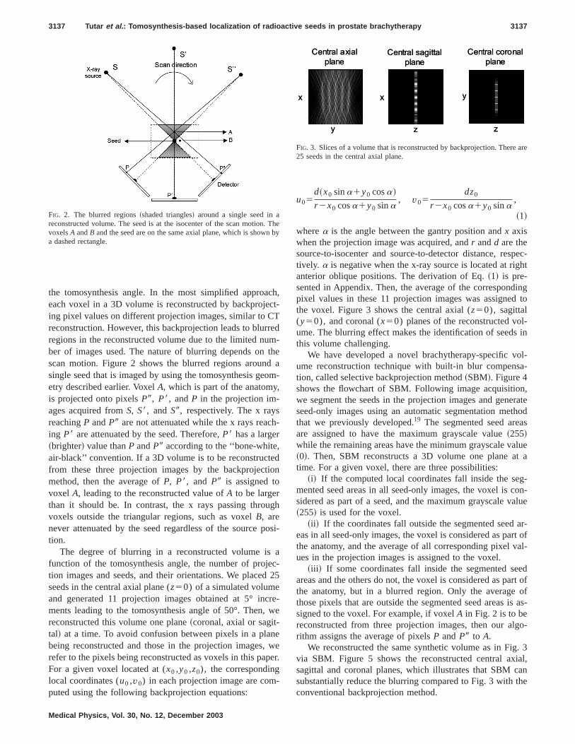
The degree of blurring in a reconstructed volume isfunction of the tomosynthesis angle, the number of projtion images and seeds, and their orientations. We placeseeds in the central axial plane (z50) of a simulated volumeand generated 11 projection images obtained at 5° inments leading to the tomosynthesis angle of 50°. Then,reconstructed this volume one plane~coronal, axial or sagit-tal! at a time. To avoid confusion between pixels in a plabeing reconstructed and those in the projection images,refer to the pixels being reconstructed as voxels in this paFor a given voxel located at (x0 ,y0 ,z0), the correspondinglocal coordinates (u0 ,v0) in each projection image are computed using the following backprojection equations:
FIG. 2. The blurred regions~shaded triangles! around a single seed in areconstructed volume. The seed is at the isocenter of the scan motionvoxelsA andB and the seed are on the same axial plane, which is showa dashed rectangle.
Medical Physics, Vol. 30, No. 12, December 2003
h,t-
d-ea
m-
-
n
h
si-
a-25
e-e
eer.
u05d~x0 sina1y0 cosa!
r 2x0 cosa1y0 sina, v05
dz0
r 2x0 cosa1y0 sina,
~1!
wherea is the angle between the gantry position andx axiswhen the projection image was acquired, andr andd are thesource-to-isocenter and source-to-detector distance, restively. a is negative when the x-ray source is located at riganterior oblique positions. The derivation of Eq.~1! is pre-sented in Appendix. Then, the average of the correspondpixel values in these 11 projection images was assignethe voxel. Figure 3 shows the central axial (z50), sagittal(y50), and coronal (x50) planes of the reconstructed voume. The blurring effect makes the identification of seedsthis volume challenging.
We have developed a novel brachytherapy-specific vume reconstruction technique with built-in blur compenstion, called selective backprojection method~SBM!. Figure 4shows the flowchart of SBM. Following image acquisitiowe segment the seeds in the projection images and genseed-only images using an automatic segmentation methat we previously developed.19 The segmented seed areare assigned to have the maximum grayscale value~255!while the remaining areas have the minimum grayscale va~0!. Then, SBM reconstructs a 3D volume one plane atime. For a given voxel, there are three possibilities:
~i! If the computed local coordinates fall inside the semented seed areas in all seed-only images, the voxel issidered as part of a seed, and the maximum grayscale v~255! is used for the voxel.
~ii ! If the coordinates fall outside the segmented seedeas in all seed-only images, the voxel is considered as pathe anatomy, and the average of all corresponding pixelues in the projection images is assigned to the voxel.
~iii ! If some coordinates fall inside the segmented seareas and the others do not, the voxel is considered as pathe anatomy, but in a blurred region. Only the averagethose pixels that are outside the segmented seed areassigned to the voxel. For example, if voxelA in Fig. 2 is to bereconstructed from three projection images, then our alrithm assigns the average of pixelsP andP9 to A.
We reconstructed the same synthetic volume as in Figvia SBM. Figure 5 shows the reconstructed central axsagittal and coronal planes, which illustrates that SBM csubstantially reduce the blurring compared to Fig. 3 withconventional backprojection method.
hey
x
y z
x
z
y
Central sagittal
plane
Central axial
plane
Central coronal
plane
x
y z
x
z
y
Central sagittal
plane
Central axial
plane
Central coronal
plane
FIG. 3. Slices of a volume that is reconstructed by backprojection. There25 seeds in the central axial plane.

, watt bs
m
e
ng tosizeand
ore,ro-FPde-
andM.
on-6-
tsaleme
e-ionouttial
ds.BM
l
3138 Tutar et al. : Tomosynthesis-based localization of radioactive seeds in prostate brachytherapy 3138
D. Detection and localization of seeds
Since only seed voxels have a grayscale value of 255can detect the seeds automatically in the blur-compensvolume. However, some of the detected regions might noa seed. For example, voxelA in Fig. 6 is mapped onto seedX, Y, andZ in the projection images obtained fromS, S8, andS9, respectively. If these three images are used for volu
Obtain projection
images
Pick a plane to
reconstruct
Pick a voxel in
the selected plane
Computecorresponding
coordinates in
all projections
Generate seed-only
images
Coordinatesinside
segmented
areas in
Some
projections
Voxel belongs
to a blurred area
No
projection
Voxel part of
the anatomy
All
projections
Voxel part
of a seed
Any othervoxel left in
the
reconstructed
plane?
Yes No
Start
Any otherplane left to be
reconstructed?
Yes NoStop
Compute the
voxel value
FIG. 4. Flowchart of our volume reconstruction algorithm.
x
Central sagittal
plane
y z z
x y
Central axial
plane
Central coronal
plane
x
Central sagittal
plane
y z z
x y
Central axial
plane
Central coronal
plane
FIG. 5. Slices of the same volume as in Fig. 3, but reconstructed by S
Medical Physics, Vol. 30, No. 12, December 2003
eede
e
reconstruction, SBM reconstructsA as a seed voxel. Falspositive ~FP! regions, consisting of voxels such asA, mayappear as seeds in the reconstructed volume, thus leadithe detection of more seeds than actually implanted. Theof FP regions depends on the number of implanted seedsprojection images and the tomosynthesis angle. Therefby making the tomosynthesis angle and the number of pjection images sufficiently large, we could ensure that theregions are smaller than a seed to avoid any false seedtection.
We have developed an algorithm to detect the seedsderive their centroids in the volume reconstructed by SBThe steps of this algorithm are as follows:
~1! Potential seed regions are extracted from the recstructed volume by utilizing the grayscale value and 2way connectivity of voxels, i.e., if a voxel and one of i26 neighbors in 3D both have a maximum grayscvalue of 255, they are considered to belong to the saregion.
~2! After all potential seed regions are identified in the rconstructed volume, the number of voxels in each regis counted. A seed region should ideally consist of ab60 voxels based on the seed’s size and voxel’s spa
z
y
z
y
FIG. 7. One coronal plane of the simulated volume containing 100 see.
S"
S'
S Scan direction
Detector
X-ray
source
Y
Z
X
A
S Scan direction
Detector
X-ray
source
Y
Z
X
A
FIG. 6. An incorrectly reconstructed voxel~A! due to incomplete samplingin tomosynthesis. VoxelA and the seedsX, Y, andZ are on the same axiaplane.

ss
eedtr
A
ll
fluthanr,.
oo2
teep
inetdehep
ror.thak
at ame
vox-ed.lleringas-
hegle
rac-hy-six
andber
s aec-ingiza-yn-omofter-
100.dinging
ngleu-
itsore,ec-ratemeatro-
f
no
gleyn-rce
3139 Tutar et al. : Tomosynthesis-based localization of radioactive seeds in prostate brachytherapy 3139
resolution. If the number of voxels in a region is lethan 60, we consider it to be an FP region.
~3! We derive the centroid of each seed by averaging thx,y, andz coordinates of all voxels belonging to the seregion. These centroids can finally be used in dosimecalculations.
E. Phantom
We used a tissue-equivalent ultrasound phantom~Model53, Computerized Imaging Reference Systems, Norfolk, V!placed in an 11.5 cm37.0 cm39.5 cm clear acrylic con-tainer. The phantom was implanted with 61 radiographicavisible dummy 125I seeds~4.5 mm long30.4 mm radius;Standard Imaging, Middleton, WI! using a brachytherapytemplate and applicator needles under ultrasound androscopy guidance. We acquired the projection images ofphantom with the resolution of 0.332 mm/pixel by usingimage intensifier~Elekta SLS-14 radiotherapy simulatoCrawley, UK! and corrected them for geometric distortion
III. RESULTS AND DISCUSSION
A. Simulation studies
We simulated a volume with 100 seeds and testedseed detection and localization method by varying the tomsynthesis angle and the number of projection images.seeds~4.5 mm long30.4 mm radius! per coronal plane wereplaced at 10 mm distances from each other alongy and zdirections with a random orientation angle of less than620°around the z direction as shown in Fig. 7. The simulavolume consisted of four such coronal planes that were srated by 10 mm along thex direction. After obtaining theprojection images and reconstructing a 3D volume usSBM, we attempted to detect the seeds using our seed dtion and localization algorithm. We considered automatictection to be successful if all seeds were detected. Wautomatic detection succeeded, we derived the centroidsition for each seed. The difference between this centposition and the real seed position is the localization erro
The localization error arises because some FP regionsare merged with a seed in the region identification step m
TABLE I. Localization error~mean error followed by the standard deviatio!in mm as a function of the number of projection images with a fixed tomsynthesis angle of 30°. For a given number of projection images~P!, theincremental angle between successive source positions is 30°/~P21!. ~F:failure in automatic detection!
5 6 7 8 9 10
F 1.2760.54 1.2360.51 1.2160.50 1.2060.48 1.1860.46
Medical Physics, Vol. 30, No. 12, December 2003
y
y
o-is
ur-5
da-
gec--no-id
ate
the seed larger than it should be. Another reason is thvoxel in a blurred region could be shadowed by the saseed that caused blurring,20 leading the voxel to fall insidethe segmented seed in all seed-only images. Then, suchels would be incorrectly reconstructed as part of a seHowever, the shadow regions are typically much smathan the blurred regions, and the localization error arisfrom the shadow regions can be further reduced by increing the tomosynthesis angle.
Table I shows the localization error as a function of tnumber of projection images when the tomosynthesis anis fixed at 30°. Larger tomosynthesis angles may not be ptical due to geometric constraints imposed by the bractherapy procedure. With the 100-seed volume, at leastprojection images are required for automatic detection,the localization error does not decrease much as the numof projection images increases. The localization error afunction of tomosynthesis angle when the number of projtion images is fixed at seven is shown in Table II. Increasthe tomosynthesis angle leads to an improvement in localtion accuracy. Table II also shows that a minimum tomosthesis angle of 25° is required for automatic detection. FrTables I and II, our method can automatically detect allthe seeds from seven projection images obtained at 5° invals and locate them with the localization error of 1.2360.51mm. The number of implanted seeds can be larger thanTherefore, we also generated a 125-seed volume by adone more coronal plane to the 100-seed volume. By usseven projection images acquired with a tomosynthesis aof 30°, we were able to detect all the seeds in the new simlated volume with the localization error of 1.4660.54 mm.
Detection of completely overlapping seeds:Our methoddoes not involve identifying and matching a seed withcorresponding seeds in other projection images. Therefeven if there are completely overlapping seeds in all projtion images, we can still detect all the seeds. To demonstthis, we generated a volume with four seeds on the saaxial plane withz50 and obtained three projection images30° intervals. Although only three seeds appear in the pjection images@Figs. 8~a!–8~c!# due to the overlapping oseeds, the 3D volume reconstructed by SBM@Fig. 8~d!#shows that all four seeds have been detected.
-TABLE II. Localization error in mm as a function of the tomosynthesis anwhen the number of projection images is fixed at 7. For a given tomosthesis angle value~Q!, the incremental angle between successive soupositions isQ/6.
20° 25° 30° 40° 50°
F 1.3860.56 1.2360.51 1.1760.46 1.1260.42
cith
FIG. 8. ~a!, ~b!, ~c! The projection images of a synthetivolume with four seeds on the same axial plane wz50 obtained at 30° increments~left anterior oblique@left#, anterior-posterior@middle#, and right anterior ob-lique @right#!, and ~d! the axial plane of the recon-structed volume withz50.

ed30o
ononth
ledF.al
pgddtwct
tic-tte
isa
chnt-
re,
notby
e-theonlyintheultsan-the
thelo-
cen-onors.64ano-
owlm
m.is
jec-er,orehotom
mte-m-
the
3140 Tutar et al. : Tomosynthesis-based localization of radioactive seeds in prostate brachytherapy 3140
B. Phantom studies
With the phantom described in Sec. II E, we acquirseven projection images with a tomosynthesis angle ofand then generated the seed-only images. Figure 9 shthree projection images and their corresponding seed-images. We reconstructed a 3D volume from these seed-images rather than the original projection images to showseeds more clearly in the reconstructed planes. Figureshows some of the coronal planes in this volume.
A seed can move along the needle track as a needwithdrawn,21 leading seeds to touch each other end-to-ensome cases. For example, three seeds that are circled in9~d!–9~f! and Fig. 10~a! touch each other in the phantomThese seeds were merged and identified as one seedvolume reconstruction. Therefore, our seed detection andcalization method detected 59 of 61 seed regions, onewhich is three times as large as a typical seed. We develoa post-processing technique to detect the large seed reand to separate it into three seeds. We located the miseed at the centroid of the large seed region. The otherseeds were found at one seed length from the detemiddle seed along2z and1z directions. Although end-to-end contacts of seeds are more common in clinical practhere may be instances when two seeds are touching sideside or crossing over each other. We can distinguish the lacases by checking if the distance between the two furthmost points along thez direction of a large seed regionapproximately equal to a seed length. If so, both seedslocated at the centroid of this region. The problem of touing seeds can also be eliminated by using suture-mouseeds, e.g., RAPID Strand™~Nycomed-Amersham, Prince
FIG. 9. ~a!, ~b!, ~c! The projection images of the phantom acquired fro215°, 0°, and 15°~left anterior oblique, anterior–posterior, and right anrior oblique!, and ~d!, ~e!, ~f! the corresponding segmented seed-only iages.
Medical Physics, Vol. 30, No. 12, December 2003
°wslylye
10
isinigs.
ftero-ofedionleo
ed
e,by-err-
re-ed
ton, NJ!. These seeds are mounted in #1 Vicryl™ sutuensuring 1 cm separations between seed centroids.
The true seed locations in the prostate phantom areknown. Therefore, we adopted the method proposedTodor et al.5 to evaluate the accuracy of the localization rsults. After the 3D seed centroids were calculated usingproposed method, we projected them back onto the seed-images by using the x-ray simulator module. As shownFig. 11, there is one-to-one correspondence betweenseeds and the projected centroids indicating that the resare in agreement with the real locations of seeds in the phtom. Then, in the seven seed-only images, we derivedcentroid of each of the 61 seeds by averaging thex and ycoordinates of pixels belonging to the seed and computeddistance to the projected centroid of the same seed. Thecalization error is equal to the distance between thesetroids. Figure 12 shows the histogram of 427 localizatierror measurements, indicating that only about 5% of erris larger than 1.5 mm. The mean localization error is 0mm with a standard deviation of 0.48 mm. This includesamplification factor of 1.4, which is the ratio of source-tdetector to source-to-isocenter distances. Tubicet al.17 re-ported that the maximum localization error should be as las 2 mm for clinical applications and that the three-fimethod locates 8% of seeds with an error greater than 5 mWe believe that the error associated with our methodwithin clinically acceptable ranges.
From our simulation and phantom studies, seven protion images would be sufficient for most implants. Howevthe dose given to the patient for image acquisition is mthan that given in other seed localization methods. Cet al.22 reported that the exposure at the surface of a phan
FIG. 11. The seed centroids derived by our method are mapped ontoseed-only image generated from the projection image acquired at210°.
s
(a) (b) (c) (d)
z z z z
y y y y
(a) (b) (c) (d)
z z z z
y y y y
(a) (b) (c) (d)
z z z z
y y y yFIG. 10. Reconstructed coronal planeof the phantom with~a! x51.93 cm~b! x50.73 cm,~c! x520.46 cm, and~d! x520.86 cm.

e
te.
re
erd
Ctioas
stio9gn2.uta
e
ionof
ze
s onand
au--
tives forof a
enp-t-er-be
ac-een
, ouravem-nd61eedatal-
all
po-
s
ge
3141 Tutar et al. : Tomosynthesis-based localization of radioactive seeds in prostate brachytherapy 3141
to acquire one projection image is about 4.431025 Gy byusing a setup similar to ours. Therefore, the total exposuracquire seven projection images is about 3.131024 Gy. Incomparison, the therapeutic dose prescribed to the prosta144 Gy and 115 Gy for125I and 103Pd seeds, respectivelyTherefore, this additional x-ray dose is negligible compato the overall dose delivered to the prostate.
Figure 13 shows the overall computation time for genating seed-only images, reconstructing a 3D volume, andtecting and locating the seeds on a 2.5-GHz Pentium 4 Pa function of the number of images used. The computatime is independent of the number of seeds and increlinearly with the number of views. The computational complexity is significantly less than the three-film and crosprojection methods. Considering that the overall computatime for locating seeds from seven projection images is 4and a skilled technician can acquire seven projection imain less than 1.5 minutes using a radiotherapy simulator uthe complete localization procedure would take aboutminutes. However, both the image acquisition and comption time can be reduced. For example, C-arm units withautomated scan motion, such as Toshiba Ultimax~Tustin,CA!, would enable acquisition of seven projection imag
FIG. 12. The localization error histogram for the phantom with 61 seed
FIG. 13. Computation time as a function of the number of projection imaon a 2.5 GHz Pentium 4 PC.
Medical Physics, Vol. 30, No. 12, December 2003
to
is
d
-e-asnes--ns
esit,5a-n
s
within a tomosynthesis angle of 30° in 2 s. The computattime can be reduced by a factor of typically 8 with the usePentium’s MMX/SSE/SSE2 instruction sets that utiliinstruction-level and data-level parallelism.23 Combinationof automated scan motions and better algorithm mappingthe processor architecture could complete seed detectionlocalization in less than 10 s.
We have developed a method that offers potential fortomatic 3D localization of seeds from x-ray projection images. This study is a key step towards realizing intraoperadosimetry. Several researchers have proposed methodthe other required steps, such as deriving the 3D shapeprostate from ultrasound images24,25 and registering fluoros-copy and ultrasound images.11,26 Once these methods arfully developed, integration of our method with them cahelp the physicians overcome a major limitation in intraoerative dosimetry, i.e., the inability of identifying and locaing seeds in relation to the prostate. By improving the pformance of our method as described above, it couldmade more suitable for intraoperative use.
IV. CONCLUSION
A new tomosynthesis-based method to locate the radiotive seeds implanted during prostate brachytherapy has bpresented. In contrast to other projection-based methodsmethod can detect completely overlapping seeds. We hfound the minimum tomosynthesis angle value and the nuber of projection images required through simulations atested our method on a prostate phantom implanted withseeds. The results show that our method obviates the nfor manual intervention in seed localization. We believe ththis study may be useful for realizing the intraoperative quity assessment of prostate brachytherapy in the future.
APPENDIX: PROJECTION OF A VOXEL ONTO THEDETECTOR PLANE
Let x, y, and z denote the unit vectors along the globcoordinates whileu andv are the unit vectors along the locacoordinates.
Then, according to Figs. 1 and 14,
v5 z and u5 x sina1 y cosa. ~A1!
The source is located at@r cosa,2r sina,0#T.The line l connecting the source and a targeted voxel
sitioned at@x0 ,y0 ,z0#T is given by
x2r cosa
x02r cosa5
y1r sina
y01r sina5
z
z0. ~A2!
The equation of the detector plane is given by
x cosa2y sina1~d2r !50. ~A3!
From Eqs.~A2! and ~A3!, the position of the intersectionpoint (Pi) of the detector plane andl is given by
.
s

as
ma
2,’
ndn i
en
J.
e,iol.
teed.
annent
K.a-apy:l.,
W.os-
he
ak,or
n
d-tion
ch-d.
of
lgo-ys.
edper-
ing
statee
.
. D.
io-
-
mSci.
e-rom
meant
3142 Tutar et al. : Tomosynthesis-based localization of radioactive seeds in prostate brachytherapy 3142
F d~x02r cosa!
r 2x0 cosa1y0 sina1r cosa
d~y01r sina!
r 2x0 cosa1y0 sina2r sina
dz0
r 2x0 cosa1y0 sina
G . ~A4!
The center of the detector (Pc) is located at
@2~d2r !cosa,~d2r !sina,0#T. ~A5!
From Eqs.~A4! and ~A5!, the vector (PW d) from Pc to Pi isgiven by
F xd~x0 sina1y0 cosa!sina
r 2x0 cosa1y0 sina
yd~x0 sina1y0 cosa!cosa
r 2x0 cosa1y0 sina
zdz0
r 2x0 cosa1y0 sina
G . ~A6!
From Eqs.~A1! and ~A6!, PW d can also be represented@ uu0 ,vv0#T, where
u05d~x0 sina1y0 cosa!
r 2x0 cosa1y0 sina, v05
dz0
r 2x0 cosa1y0 sina.
a!Author to whom correspondence should be addressed; [email protected]. Jemal, A. Thomas, T. Murray, and M. Thun, ‘‘Cancer statistics, 200Ca-Cancer J. Clin.52, 23–47~2002!.
2J. C. Blasko, H. Ragde, R. W. Luse, J. E. Sylvester, W. Cavanagh, aD. Grimm, ‘‘Should brachytherapy be considered a therapeutic optiolocalized prostate cancer?’’ Urol. Clin. North Am.23, 633–650~1996!.
3J. B. Priestly and D. C. Beyer, ‘‘Guided brachytherapy for the treatmof confined prostate cancer,’’ Urology40, 27–32~1992!.
y
Isocenter
x
z
Pi
dP
uv
y
xz
A targeted voxel at
α
Pc
r
d-r
Scan direction
y
xz
Detector
X-ray
source
Line l
0
0
0
z
y
x
Isocenter
Pi
dP
A targeted voxel at
Pc
r
d-r
Scan direction
Detector
X-ray
source
Line l
[0
0
0
z
y
x [
>
>
>>>
>
>>
>>
>
FIG. 14. Projection of a voxel onto the detector plane.
Medical Physics, Vol. 30, No. 12, December 2003
il:
’
P.n
t
4P. W. McLaughlin, V. Narayana, M. T. Fields, M. E. Dworzanin, R.Winfield, and P. L. Roberson, ‘‘Permanent implantation of125I sources inthe prostate: radical limits of simplicity,’’ Radiology213, 839–844~1999!.
5D. A. Todor, G. N. Cohen, H. I. Amols, and M. Zaider, ‘‘Operator-frefilm-based 3D seed reconstruction in brachytherapy,’’ Phys. Med. B47, 2031–2048~2002!.
6B. H. Han, K. Wallner, G. Merrick, S. Sutlief, and J. Sylvester, ‘‘Prostabrachytherapy seed identification on post-implant TRUS images,’’ MPhys.30, 898–900~2003!.
7S. Nag, D. Beyer, J. Friedland, P. Grimm, and R. Nath, ‘‘Americbrachytherapy society recommendations for transperineal permabrachytherapy of prostate cancer,’’ Int. J. Radiat. Oncol., Biol., Phys.44,789–799~1999!.
8S. Nag, J. P. Ciezki, R. Cormack, S. Doggett, K. DeWyngaert, G.Edmundson, R. G. Stock, N. N. Stone, Y. Yu, and M. J. Zelefsky, ‘‘Introperative planning and evaluation of permanent prostate brachytherreport of the American Brachytherapy Society,’’ Int. J. Radiat. OncoBiol., Phys.51, 1422–1430~2001!.
9P. L. Roberson, V. Narayana, D. L. McShan, R. J. Winfield, and P.McLaughlin, ‘‘Source placement error for permanent implant of the prtate,’’ Med. Phys.24, 251–257~1997!.
10J. F. Corbett, J. J. Jezioranski, J. Crook, T. Tran, and I. W. T. Yeung, ‘‘Teffect of seed orientation on the quality of125I prostate implants,’’ Phys.Med. Biol. 46, 2785–2800~2001!.
11L. Gong, P. S. Cho, B. H. Han, K. E. Wallner, S. G. Sutlief, S. D. PathD. R. Haynor, and Y. Kim, ‘‘Ultrasonography and fluoroscopic fusion fprostate brachytherapy dosimetry,’’ Int. J. Radiat. Oncol., Biol., Phys.54,1322–1330~2002!.
12R. L. Siddon and L. M. Chin, ‘‘Two-film brachytherapy reconstructioalgorithm,’’ Med. Phys.12, 77–83~1985!.
13M. D. Altschuler and A. Kassaee, ‘‘Automated matching of corresponing seed images of three simulator radiographs to allow 3D triangulaof implanted seeds,’’ Phys. Med. Biol.42, 293–302~1997!.
14M. S. Rosenthal and R. Nath, ‘‘An automatic seed identification tenique for interstitial implants using three isocentric radiographs,’’ MePhys.10, 475–479~1983!.
15H. I. Amlos and I. Rosen, ‘‘A three-film technique for reconstructionradioactive seed implants,’’ Med. Phys.8, 210–214~1981!.
16S. Narayanan, P. S. Cho, and R. J. Marks II, ‘‘Fast cross-projection arithm for reconstruction of seeds in prostate brachytherapy,’’ Med. Ph29, 1572–1579~2002!.
17D. Tubic, A. Zaccarin, L. Beaulieu, and J. Pouliot, ‘‘Automated sedetection and three-dimensional reconstruction. II. Reconstruction ofmanent prostate implants using simulated annealing,’’ Med. Phys.28,2272–2279~2001!.
18D. G. Grant, ‘‘Tomosynthesis: A three-dimensional radiographic imagtechnique,’’ IEEE Trans. Biomed. Eng.19, 20–28~1972!.
19P. S. Cho, ‘‘Computerized segmentation of clustered seeds in probrachytherapy,’’ inProceedings of XIIIth International Conference on thUse of Computers in Radiation Therapy, edited by W. Schlegel and TBortfeld ~Springer-Verlag, Heidelberg, 2000!, pp. 105–107.
20T. M. Persons, R. L. Webber, P. F. Hemler, W. Bettermann, and JBourland, ‘‘Brachytherapy volume visualization,’’ Proc. SPIE3976,45–56~2000!.
21K. Wallner, J. Blasko, and M. J. Dattoli,Prostate Brachytherapy MadeComplicated, 2nd ed.~SmartMedicine, Seattle, WA, 2001!.
22P. S. Cho, R. H. Johnson, and T. W. Griffin, ‘‘Cone-beam CT for radtherapy applications,’’ Phys. Med. Biol.40, 1863–1883~1995!.
23M. S. Grow and Y. Kim, ‘‘Evaluation of Pentium 4 for imaging applications,’’ Proc. SPIE4674, 42–50~2002!.
24S. Fan, L. K. Voon, and W. S. Ng, ‘‘3D prostate surface detection froultrasound images based on level set method,’’ Lect. Notes Comput.2489, 389–396~2002!.
25A. Ghanei, H. Soltanian-Zadeh, A. Ratkewicz, and F. Yin, ‘‘A thredimensional deformable model for segmentation of human prostate fultrasound images,’’ Med. Phys.28, 2147–2153~2001!.
26A. Haworth, M. Ebert, and D. Joseph, ‘‘Registration of prostate voluwith radiographically identified iodine-125 seeds for permanent implevaluation,’’ J. Brachyther. Int.16, 157–167~2000!.
Copyright © 2022 FDOKUMEN


![Breast percent density estimation from 3D reconstructed digital breast tomosynthesis images [6913-43]](https://static.fdokumen.com/doc/165x107/6336264964d291d2a302c4a3/breast-percent-density-estimation-from-3d-reconstructed-digital-breast-tomosynthesis.jpg)