HP IAP 2.1 Administrator Guide - Support
192
HP Integrated Archive Platform nl Version 2.1 Administrator Guide This guide covers administration of IAP version 2.1.2, in both virtual and non-virtual IAP environments. Part Number: PDF Second edition: March 2011
-
Upload
khangminh22 -
Category
Documents
-
view
0 -
download
0
Transcript of HP IAP 2.1 Administrator Guide - Support

HP Integrated Archive Platformnl
Version 2.1
Administrator GuideThis guide covers administration of IAP version 2.1.2, in both virtual and non-virtual IAP environments.
Part Number: PDFSecond edition: March 2011

Legal and notice information
© Copyright 2004-2011 Hewlett-Packard Development Company, L.P.
Hewlett-Packard Company makes no warranty of any kind with regard to this material, including, but not limited to, the impliedwarranties of merchantability and fitness for a particular purpose. Hewlett-Packard shall not be liable for errors containedherein or for incidental or consequential damages in connection with the furnishing, performance, or use of this material.
This document contains proprietary information, which is protected by copyright. No part of this document may be photocopied,reproduced, or translated into another language without the prior written consent of Hewlett-Packard. The information containedin this document is subject to change without notice. The only warranties for HP products and services are set forth in theexpress warranty statements accompanying such products and services. Nothing herein should be construed as constitutingan additional warranty. HP shall not be liable for technical or editorial errors or omissions contained herein.
Microsoft® and Windows® are US registered trademarks of Microsoft Corporation. Outlook™ is a trademark of MicrosoftCorporation.
Hewlett-Packard Company shall not be liable for technical or editorial errors or omissions contained herein. The informationis provided “as is” without warranty of any kind and is subject to change without notice. The warranties for Hewlett-PackardCompany products are set forth in the express limited warranty statements for such products. Nothing herein should be construedas constituting an additional warranty.

Contents
About this guide ................................................................................. 13Intended audience .................................................................................................................... 13Related documentation .............................................................................................................. 13Support ................................................................................................................................... 14Subscription service .................................................................................................................. 14Document conventions and symbols ............................................................................................. 14
1 IAP product overview ........................................................................ 17Introduction to IAP .................................................................................................................... 17
Understanding the components ............................................................................................ 17Conceptual overview ................................................................................................................. 17
Organizational content ....................................................................................................... 17Application archiving software ............................................................................................. 17
HP Email Archiving software (EAs) for Exchange .............................................................. 18HP Email Archiving software (EAs) for Domino ................................................................. 18HP File Archiving software ............................................................................................ 18
Archiving methods .............................................................................................................. 18Working with content on IAP ............................................................................................... 18Key benefits ....................................................................................................................... 19Features ............................................................................................................................ 19
Software components ................................................................................................................ 20Applications for users ......................................................................................................... 20Tools for administrators ....................................................................................................... 21
Hardware components .............................................................................................................. 22IAP base system ................................................................................................................. 22Expansion rack .................................................................................................................. 23Additional options .............................................................................................................. 23
Additional factory-integrated options .............................................................................. 23Network architecture ................................................................................................................. 24
IAP 2.1 Network diagram ................................................................................................... 24Virtual LANS (VLANS) ........................................................................................................ 25Grid architecture ................................................................................................................ 26Management servers .......................................................................................................... 26
Firewall/NAT .............................................................................................................. 26Load balancer ............................................................................................................. 26HTTP portal ................................................................................................................. 26SMTP portal ................................................................................................................ 26Metaserver ................................................................................................................. 27Cloud router ................................................................................................................ 27Database server (DB2) ................................................................................................. 27Kickstart server ............................................................................................................ 27Platform Control Center (PCC) ........................................................................................ 27Archive Gateway (option) ............................................................................................. 28Backup server (option) .................................................................................................. 28Universal Smartcell ...................................................................................................... 28
HP IAP 2.1 Administrator Guide 3
Data flow ................................................................................................................................ 28Store path ......................................................................................................................... 28
Bitfile ......................................................................................................................... 29How the SMTP portal processes data ............................................................................. 29How the Smartcells process data ................................................................................... 30
Query and retrieval path ..................................................................................................... 30Query ........................................................................................................................ 30Retrieval .................................................................................................................... 30
IAP power on/off ...................................................................................................................... 31Power off ........................................................................................................................... 31Power on ........................................................................................................................... 31How to restart IAP after a power failure ................................................................................ 32
Maximum file size ..................................................................................................................... 32VPN access ............................................................................................................................. 32
2 Introduction to Platform Control Center (PCC) ....................................... 33Accessing PCC ......................................................................................................................... 33User interface components ......................................................................................................... 33User interface orientation tips ..................................................................................................... 34Pages for common tasks ............................................................................................................ 34Updating pages before printing .................................................................................................. 35Left menu ................................................................................................................................. 35Monitoring and reporting .......................................................................................................... 37Statuses and states .................................................................................................................... 37
Smartcell life cycle states ..................................................................................................... 38
3 System Status ................................................................................... 41Overview ................................................................................................................................. 41
Current Platform Alerts ........................................................................................................ 41Alert levels .................................................................................................................. 42Application alerts ........................................................................................................ 42Hardware alerts .......................................................................................................... 42Clearing alerts ............................................................................................................ 43
Platform Performance .......................................................................................................... 43Account Manager Service ................................................................................................... 43CatchAll and Partially indexed objects .................................................................................. 44Platform Statistics ................................................................................................................ 44
Platform Statistics features ............................................................................................. 45IAP Version ........................................................................................................................ 46SMTP Flow Control ............................................................................................................. 46
Storage Status .......................................................................................................................... 46Software Management .............................................................................................................. 47
Software Management features ............................................................................................ 47Starting, stopping, and restarting servers on the system ........................................................... 48
Hardware Management ............................................................................................................ 49Hardware Management features .......................................................................................... 49Hardware monitoring .......................................................................................................... 50
Performance Graph ................................................................................................................... 53Example: Platform Store graph ............................................................................................. 53Example: System Monitoring graph ...................................................................................... 54Creating performance graphs .............................................................................................. 54
4 Configuration .................................................................................. 57
4

Platform Settings ....................................................................................................................... 57Domain Configuration ........................................................................................................ 57Platform Settings ................................................................................................................. 58
Firewall Settings ........................................................................................................................ 58SSL Configuration ..................................................................................................................... 58
Available certificate signing requests .................................................................................... 59Creating a certificate signing request .................................................................................... 59Deleting a certificate signing request .................................................................................... 59Installing and generating a certificate on the PCC portal ......................................................... 60Installing and generating a certificate on the HTTP portals ....................................................... 61
Software Version ...................................................................................................................... 62Software Update ...................................................................................................................... 62
5 Account Synchronization ................................................................... 63Account Synchronization overview .............................................................................................. 63Creating and running DAS jobs .................................................................................................. 63
Creating LDAP server connections ........................................................................................ 63Creating jobs ..................................................................................................................... 64Assigning HTTP portals ....................................................................................................... 67
Assigning a portal ....................................................................................................... 67Unassigning and reassigning a portal ............................................................................ 68
Starting, scheduling, and stopping DAS jobs .......................................................................... 68Editing or deleting jobs ............................................................................................................. 69Managing available HTTP portals ............................................................................................... 70Editing or deleting available LDAP connections ............................................................................. 70Viewing DAS history logs ........................................................................................................... 71
6 Account Manager (AM) .................................................................... 73Account Manager overview ....................................................................................................... 73
Account Manager features .................................................................................................. 74Managing user accounts ........................................................................................................... 75
Adding a new user ............................................................................................................. 75Editing user information ...................................................................................................... 76User account information ..................................................................................................... 77
Managing groups ..................................................................................................................... 79Managing repositories .............................................................................................................. 79
Repository overview ............................................................................................................ 79User repository types .................................................................................................... 79Access only (audit) repositories ...................................................................................... 80Quarantine repositories ................................................................................................ 80AuditLog repository ...................................................................................................... 81System repository types ................................................................................................ 81Repository grouping on PCC pages ................................................................................ 81
Adding repositories ............................................................................................................ 82Editing repository information .............................................................................................. 82Repository information ........................................................................................................ 83Setting up an audit repository .............................................................................................. 84Configuring routing rules for an audit repository ..................................................................... 85
7 Account Error Recovery ..................................................................... 87Error Recovery overview ............................................................................................................ 87Error Recovery features .............................................................................................................. 87Repairing synchronization errors ................................................................................................. 88
HP IAP 2.1 Administrator Guide 5

8 Data management ........................................................................... 89Duplicate Manager ................................................................................................................... 89
Duplicate Manager overview ............................................................................................... 89Duplicate Manager job schedules ........................................................................................ 90
Scheduling a job ......................................................................................................... 90Enabling or disabling a job .......................................................................................... 91Starting, pausing, or aborting a job ............................................................................... 91
Duplicate Manager job histories ........................................................................................... 91Replication ............................................................................................................................... 92
Replication overview ........................................................................................................... 92Database Replication .......................................................................................................... 93
Re-initializing DB2 replication ........................................................................................ 93Data Replication Flow and Detail Information ......................................................................... 96Replication Status ............................................................................................................... 96
Reprocessing ............................................................................................................................ 97Rescheduling all reprocessing schedules ................................................................................ 97Editing reprocessing schedules ............................................................................................. 97Changing the reprocessing status ......................................................................................... 98Using the Reprocessing Utility .............................................................................................. 98Viewing reprocessing history logs ......................................................................................... 99
Retention ................................................................................................................................. 99Retention overview .............................................................................................................. 99
Retention basis .......................................................................................................... 100Retention periods ....................................................................................................... 100End User Delete ......................................................................................................... 101When the retention period expires ............................................................................... 103
Editing domain retention periods ........................................................................................ 103Viewing deletion statistics .................................................................................................. 104
Automatic deletion statistics ......................................................................................... 104Manual deletion statistics ............................................................................................ 105
Editing repository retention periods ..................................................................................... 106Backup .................................................................................................................................. 107
Backup Overview ............................................................................................................. 107Overall backup service summary ................................................................................. 108Individual backup service summaries ............................................................................ 108Disable/enable tape backup schedule .......................................................................... 110Configuration Information ........................................................................................... 110
Database backup ............................................................................................................. 110Tape Backup Console ....................................................................................................... 111Local backup file locations ................................................................................................ 111Restoring DB2 local backup files ........................................................................................ 111Restoring the master configuration files ............................................................................... 112
Restoring a Smartcell group ..................................................................................................... 112Smartcell Cloning ................................................................................................................... 115
Cloning overview ............................................................................................................. 115Cloning features ............................................................................................................... 115Cloning Smartcells (copying data) ...................................................................................... 116
Preparing for Smartcell cloning in virtual IAP environments .............................................. 116Copying Smartcell data .............................................................................................. 120
Folder capture support ............................................................................................................ 121Enabling folder capture ..................................................................................................... 121
Administrative Delete ............................................................................................................... 121Enabling Administrative Delete ........................................................................................... 122Granting the Delete Admin privilege ................................................................................... 123Executing Administrative Delete .......................................................................................... 123
6

Logging in AuditLog ......................................................................................................... 124Current limitations ............................................................................................................ 124
9 Reporting ...................................................................................... 125Event Viewer .......................................................................................................................... 125
Event Viewer overview ...................................................................................................... 125Searching the Event Viewer ............................................................................................... 126Deleting events ................................................................................................................ 126
SNMP Management ............................................................................................................... 127Downloading the IAP MIB ................................................................................................. 127Selecting SNMP traps ....................................................................................................... 128Setting the SNMP server ................................................................................................... 128Sending SNMP events by email ......................................................................................... 128Setting SNMP Community ................................................................................................. 129Testing the configuration ................................................................................................... 129
Email Reporter ....................................................................................................................... 129Creating and scheduling email reports ................................................................................ 129
Collect Log Files ...................................................................................................................... 131Collecting the logs ............................................................................................................ 131
User Repository Utilization Report ............................................................................................. 132User Repository Utilization Report data ............................................................................... 133Job summary file .............................................................................................................. 134
Job summary data ..................................................................................................... 134Enabling the report and the job summary mode ............................................................ 135
Using the User Repository Utilization Report ......................................................................... 135Utilization Report Collection page ................................................................................ 135Report Download page .............................................................................................. 138
Limitations ....................................................................................................................... 140
10 External access ............................................................................ 141Archive Gateway Management ................................................................................................ 141
VNC Archive Gateway ..................................................................................................... 141Overview Archive Gateway ............................................................................................... 142
System Services ......................................................................................................... 142Configured Tasks ....................................................................................................... 143Journal Mining .......................................................................................................... 143Selective Archiving ..................................................................................................... 145Synchronize Deleted Items ........................................................................................... 145Tombstone Maintenance ............................................................................................. 145
11 Enabling the AuditLog .................................................................. 147Enabling the AuditLog feature ................................................................................................... 147Granting user access to the AuditLog repository .......................................................................... 148Monitoring status .................................................................................................................... 149AuditLog repository retention period .......................................................................................... 149
12 Optional backup system ................................................................ 151Default configuration ............................................................................................................... 152
Tape library ..................................................................................................................... 152Setting the busy drive handling option ................................................................................ 153Backup specification and scheduling ................................................................................... 154
Changing the configuration ...................................................................................................... 155Operational workflow for vaulting ............................................................................................. 157
HP IAP 2.1 Administrator Guide 7

Estimating needed number of tapes .................................................................................... 157Replacing tapes ............................................................................................................... 158
Restoration of a Smartcell group from a vaulted tape ................................................................... 159Restoration in case of non-Smartcell group data loss .................................................................... 161Restoring IAP configuration information ...................................................................................... 161Configuring multiple backup servers .......................................................................................... 162Troubleshooting ...................................................................................................................... 164
13 Remote management of servers ...................................................... 165Remote management solution overview ...................................................................................... 166
Goals ............................................................................................................................. 166Network topologies .......................................................................................................... 166
Direct mode .............................................................................................................. 166Proxy mode .............................................................................................................. 167
Hardware wiring .............................................................................................................. 168Checking the iLO mode ........................................................................................................... 168Disabling remote management ................................................................................................. 168Using Proxy mode .................................................................................................................. 168
Prerequisites .................................................................................................................... 168Configuring remote management ....................................................................................... 169Accessing the remote management web interface ................................................................. 169Accessing the command line interface ................................................................................ 170Using the command line interface to power cycle a server ..................................................... 170Using the web interface to power cycle a server ................................................................... 171Accessing the KVM console ............................................................................................... 171Monitoring a server reboot ................................................................................................ 171Turning on a server UID light ............................................................................................. 172Power cycling an unresponsive proxy server (PCC) ................................................................ 172Changing the administrative password on all iLOs ................................................................ 172Updating iLO firmware ...................................................................................................... 172Configuring the iLO processor of a new or replacement server ............................................... 173
Using Direct mode .................................................................................................................. 173Prerequisites .................................................................................................................... 173Configuring remote management ....................................................................................... 173Accessing the direct mode remote management web interface ............................................... 174Accessing the command line interface ................................................................................ 174Using the command line interface to power cycle a server ..................................................... 174Using the web interface to power cycle a server ................................................................... 175Accessing the KVM console ............................................................................................... 175Monitoring a server reboot ................................................................................................ 175Turning on a server UID light ............................................................................................. 175Changing the administrative password on all iLOs ................................................................ 176Updating iLO firmware ...................................................................................................... 176Configuring the iLO processor of a new or replacement server ............................................... 176
A IAP application-generated alerts ...................................................... 179
B Indexed document types .................................................................. 187
Index ............................................................................................... 189
8

Figures
Architecture diagram ............................................................................................... 251
PCC user interface .................................................................................................. 342
Sample application alerts ........................................................................................ 423
Sample hardware alerts ........................................................................................... 434
SIM Console .......................................................................................................... 515
System Homepage .................................................................................................. 526
IAP events .............................................................................................................. 527
Performance Graph: Store Rate ................................................................................. 538
Performance Graph: Free Memory ............................................................................ 549
Domain Configuration ............................................................................................. 5710
New LDAP connection ............................................................................................. 6411
Create DAS job ...................................................................................................... 6412
Mapping information .............................................................................................. 6513
Advanced options ................................................................................................... 6614
Assign a job to a portal ........................................................................................... 6715
Job Update page .................................................................................................... 6816
Initializing DAS setup .............................................................................................. 6917
Account Manager page .......................................................................................... 7418
Editing user account information ............................................................................... 7619
Editing repository information ................................................................................... 8320
Repository form for an audit repository ...................................................................... 8521
Duplicate Manager job schedules ............................................................................. 9022
Duplicate Manager job history ................................................................................. 9123
Editing reprocessing schedules ................................................................................. 9824
Change the reprocessing status ................................................................................. 9825
Reprocessing utility ................................................................................................. 9926
End User Delete and retention ................................................................................ 10227
Editing the domain retention period ......................................................................... 10328
Auto Delete Statistics ............................................................................................. 10429
Backup Overview .................................................................................................. 10830
Unregistering a Smartcell ....................................................................................... 11431
Selecting datacenter for new Smartcell VM .............................................................. 11732
HP IAP 2.1 Administrator Guide 9

Completing creation of the newSmartcell VM ........................................................... 11833
Adjust Power-on Boot Delay .................................................................................... 11934
AuditLog enabled ................................................................................................. 14935
Data Protector Devices & Media ............................................................................. 15236
Busy drive handling ............................................................................................... 15337
Backup Specifications and Source ........................................................................... 15438
Backup Schedule .................................................................................................. 15539
Full backup .......................................................................................................... 15640
Incremental backup ............................................................................................... 15641
Backup Object ..................................................................................................... 15842
Entering a tape ..................................................................................................... 15943
Restoring information ............................................................................................. 16244
Configuring devices .............................................................................................. 16345
10

Tables
Document conventions ............................................................................................. 141
IAP application for users .......................................................................................... 202
EAs and FAs applications for users ............................................................................ 213
IAP tools for administrators ....................................................................................... 214
Applications for administrators ................................................................................. 225
Pages for common system administration tasks ............................................................ 346
Pages accessible from left menu ................................................................................ 367
Smartcell life cycle states .......................................................................................... 388
Platform Statistics features ........................................................................................ 459
Storage Status features ............................................................................................ 4610
Software Management features ................................................................................ 4711
Hardware Management features ............................................................................... 4912
Performance Graph features ..................................................................................... 5313
Firewall ports .......................................................................................................... 5814
Available certificate signing requests (CSRs) in the IAP ................................................. 5915
Software Version features ......................................................................................... 6216
Account Manager features ....................................................................................... 7417
User account information ......................................................................................... 7718
Repository information ............................................................................................. 8319
Error Recovery features ............................................................................................ 8720
Database Replication features ................................................................................... 9321
Data Replication Flow .............................................................................................. 9622
Replication Service General Status ............................................................................ 9623
Auto Delete Statistics ............................................................................................. 10524
Current Smartcell Group Restore Jobs information ...................................................... 11325
Cloning features ................................................................................................... 11526
Event Viewer features ............................................................................................ 12527
Fields reported for all repository classes ................................................................... 13328
Fields reported for user and quarantine repositories ................................................... 13329
Fields reported for quarantine and system repositories ............................................... 13430
Fields reported in the job summary file .................................................................... 13431
Overview Archive Gateway features ........................................................................ 14232
HP IAP 2.1 Administrator Guide 11

System Services features ......................................................................................... 14233
Configured Tasks features ...................................................................................... 14334
Journal Mining features ......................................................................................... 14335
IAP application-generated alerts ............................................................................. 17936
IAP indexed document MIME types ......................................................................... 18737
12

About this guide
This guide provides information about administering the HP Integrated Archive Platform (IAP). Forinformation on administering HP Email Archiving Software (EAs) for Exchange or Domino, see therespective administration guide included on the documentation CD in those products.
Intended audienceThis guide is intended for HP Integrated Archive Platform administrators.
Related documentationHP provides the following related documentation.
For administrators and installers:
• HP Integrated Archive Platform Installation Guide (available to HP personnel installing IAP hardwareand software)
• HP Virtual IAP 2.1.2 Installation Guide (available to HP personnel installing virtual IAP software)• HP IAP File Export Installation and Administration Guide (available to HP personnel installing IAP
hardware and software)• Online help for the Platform Control Center (PCC) (the help is a subset of the administrator guide)• HP Email Archiving software for Microsoft Exchange or IBM Lotus Domino administration guide
(located on the documentation CD included in those products)• HP Email Archiving software for Microsoft Exchange or IBM Lotus Domino installation guide
(available to HP personnel installing those products)
For users:
• HP Integrated Archive Platform User Guide (located on the documentation CD)• Online help for the IAP Content Search and Retrieve Web Interface; the help is a subset of the
user guide• HP Email Archiving software for Microsoft Exchange or IBM Lotus Domino user guide (located on
the documentation CD included in the those products)
HP IAP 2.1 Administrator Guide 13

SupportYou can visit the HP Software Support web site at: http://www.hp.com/go/hpsoftwaresupport
HP Software Support Online provides an efficient way to access interactive technical support tools.As a valued support customer, you can benefit by using the support site to:
• Search for knowledge documents of interest• Submit and track support cases and enhancement requests• Download software patches• Manage support contracts• Look up HP support contacts• Review information about available services• Enter into discussions with other software customers• Research and register for software training
Most of the support areas require that you register as an HP Passport user and sign in. Many alsorequire a support contract.
To find more information about access levels, go to: http://support.openview.hp.com/new_access_levels.jsp
For continuous quality improvement, calls may be recorded or monitored.
Subscription serviceHP strongly recommends that customers register online using the Subscriber's choice web site: http://www.hp.com/go/e-updates.
Subscribing to this service provides you with email updates on the latest product enhancements, newestdriver versions, and firmware documentation updates as well as instant access to numerous otherproduct resources.
Document conventions and symbolsTable 1 Document conventions
ElementConvention
Cross-reference links and email addressesMedium blue text: Related docu-mentation
Web site addressesMedium blue, underlined text (ht-tp://www.hp.com)
• Key names• Text typed into a graphical user interface (GUI) element, such as into
a box• GUI elements that are clicked or selected, such as menu and list items,
buttons, and check boxes
Bold font
Text emphasisItalic font
About this guide14

ElementConvention
• File and directory names• System output• Code• Text typed at the command line
Monospace font
• Code variables• Command-line variablesMonospace, italic font
Emphasis of file and directory names, system output, code, and text typedat the command lineMonospace, bold font
WARNING!Indicates that failure to follow directions could result in bodily harm or death.
CAUTION:Indicates that failure to follow directions could result in damage to equipment or data.
IMPORTANT:Provides clarifying information or specific instructions.
NOTE:Provides additional information.
TIP:Provides helpful hints and shortcuts.
HP IAP 2.1 Administrator Guide 15

About this guide16

1 IAP product overview
This chapter describes key concepts involving the HP Integrated Archive Platform.
Introduction to IAPHP’s Integrated Archive Platform (IAP) is a fault-tolerant, secure system of software and services forarchiving and retention management. It provides long-term information retention combined withhigh-speed, interactive search and retrieval capabilities to help organizations meet their regulatoryrequirements.
The IAP software can be deployed on IAP hardware (HP Proliant servers and ProCurve switches ona factory-assembled rack system) or on servers running VMware ESXi Server software.
Understanding the componentsIn order to create a framework for understanding the components of IAP and how they work together,this chapter covers a number of high level themes, such as a conceptual overview, key benefits andfeatures, software components, hardware components, network architecture and data flow. Takinga look at the anatomy or architecture of IAP and its components will support the goal of operating,maintaining, optimizing and troubleshooting the IAP system more effectively.
Conceptual overviewIn broad conceptual terms, the IAP can be thought of as having three aspects:
1. An organization's archived content2. Application archiving software3. Working with archived content effectively through the capabilities of IAP
Organizational contentIAP serves as a platform for archiving many types of content generated by an organization. Itautomatically and actively archives files, email (Exchange, Domino), documents and other types ofdata. See Appendix B on page 187.
Application archiving softwareHP provides a variety of application archiving software that works with IAP to capture and store data.These software components are focused on ingesting data into IAP. The IAP can be precisely customizedand configured to support an organization’s archiving and retention policies.
IAP works with the following application archiving software:
HP IAP 2.1 Administrator Guide 17

HP Email Archiving software (EAs) for ExchangeHP Email Archiving software (EAs) for Exchange is mail administration software that archives messagesand attachments, and stores the messages in IAP. Users can search for and retrieve their archivedmessages directly from Outlook. HP EAs for Exchange fully integrates with Microsoft Exchange andOutlook. Outlook Integrated Archive Search enables search of the IAP repositories directly fromOutlook by key words and date ranges.
HP Email Archiving software (EAs) for DominoHP Email Archiving software (EAs) for Domino is mail administration software that archives messagesand attachments, and stores the messages in IAP. Users can retrieve their archived messages directlyfrom IBM Lotus Notes and iNotes, and EAs for Domino is fully integrated with Lotus Notes and iNotes.
HP File Archiving softwareHP File Archiving software (FAs) is a policy-based file archiving solution that enables you toautomatically archive files, web and application server data from a Windows environment for migrationinto IAP. (FAs was formerly known as FMA.)
Archiving methodsHP EAs for Exchange and HP EAs for Domino support the following archiving methods:
• Compliance Archiving. In EAs for Exchange, compliance archiving captures all inbound and out-bound messages. EAs for Exchange provides two different mechanisms to implement compliancearchiving. One technique copies each inbound and outbound message to a journal mailbox whichthe Archive Gateway scans periodically to archive the contents on the IAP. The other technique,available on Exchange 2007 and later, uses Simple Mail Transport Protocol (SMTP) to relay everymessage directly to an Archive Gateway which then archives them to the IAP.In EAs for Domino, compliance archiving can capture messages at an individual, group, and/ororganization level when the Advanced Filtering feature is used.
• Selective archiving (mail database mining). Selective archiving helps administrators reduce theamount of primary storage used on the mail servers. It provides policies to mine messages fromusers’ mailboxes. Administrators can centrally configure policies, including quota archive thresholds,message age or size, sender/recipient, specific folders, and keywords. Policies can be set at theindividual, group, and/or organization level. Messages are automatically archived when thepolicies are enabled. After archiving, links to the archived messages (called tombstones) can beplaced in mail databases.
• Archiving of inactive or archive mail databases. EAs for Exchange and EAs for Domino alsoprovide optional tombstoning of messages in inactive PST and NSF databases.
Working with content on IAPAn overarching focus of IAP is the ability to work effectively with an organization's stored content.The many abilities and benefits of working with stored content on IAP include:
• Storage• Indexing• Single instancing• Retention policies
IAP product overview18

• Encryption• Authentication• Replication
(This feature is not currently available in virtual IAP environments.)
• Monitoring• Search• Retrieval• Backup/restore
(The optional backup system running HP Data Protector software, and the IAP Smartcell grouprestore feature are not supported in virtual IAP environments.)
Key benefitsUsing IAP helps you:
• Mitigate the costs and business impact of regulatory compliance, e-discovery preparation, andlegal response. When entering litigation, companies need to be able to show that their emailshave not been tampered with and to be able to pull the information that pertains to a particularcase.
• Effectively manage, retain, and retrieve information. IAP turns data into information by providingfast retrieval of archived content. Data retrieval from the archival system is accelerated usingstorage grid architecture that evenly distributes full text indexes and original content across manySmartcells (storage cells). Searches are executed across all Smartcells in parallel.
• Increase email, file, and application server performance by offloading documents from the serverto the IAP. Storing mail and files on IAP provides a faster means for query and retrieval. IAP supportsfree text searching through any Web browser.
• Reduce the cost and complexity of managing email, file system storage, and quotas.• Defer capital expenditures on new primary storage systems.
FeaturesIAP automatically and actively archives email messages and other types of data. It provides interactivedata querying to quickly and easily search for and retrieve archived data according to various criteria.Authorized users are granted access to archived information through IAP’s Web user interface.
The following is a list of high-level features of IAP:
• Grid computing architecture. HP IAP’s grid computing architecture provides scalability in perform-ance and capacity. Searches are executed across all Smartcells in parallel.
• Integrated distributed content indexing and search tools. Comprehensive integrated search cap-abilities that leverage the IAP's distributed indexing and grid architecture technologies ensure fastaccess to consolidated and centralized multi-content information silos, such as email and files, forhundreds of thousands of users across hundreds of terabytes and billions of objects.
• Storage reduction algorithms. IAP uses storage reduction algorithms including data compressionand object level single instancing. This enables IAP to provide an efficient means for identifyingduplicate emails or documents and removing them from the archive.
• Search tool integrated with Exchange Outlook and Lotus Notes. Users can search for their archivedmessages directly from within their email application; they don’t have to learn or bring up a sep-arate utility.
• Business policy-driven automated archiving applications. Selectively archive emails and documentsaccording to flexible policies.
HP IAP 2.1 Administrator Guide 19

• Reduced administration overhead for managed applications such as Microsoft Exchange servers.HP IAP Platform Control Center (PCC) software is included to monitor the status and administrationof the IAP system.
• Tamper-resistant environment. Digital signatures, timestamps, and data retention policies are usedto protect data against erasure and tampering. Data cannot be deleted from the archive until theend of the retention period.
• Data replication and mirroring. Data is mirrored synchronously across a group of Smartcells forincreased data availability.
• Support for unstructured, semi-structured, and structured data such as email and files.• Mitigation of regulatory and legal risks and support of corporate governance initiatives. Data
stored in HP IAP is managed by retention policies and is tamper-resistant in alignment with SECand regulatory rules. Data can be searched with proper credentials. Litigation holds can be appliedwhen required.
• Flexible retention management. Preservation of information through flexible retention policies ensuresproper disposition of data at the end of its retention period whether it is to meet compliance, legalhold, or governance requirements.
Software componentsThere are two main types of software components for working with IAP – user applications andadministrator applications.
Applications for usersThe following application is available for all IAP users.
Table 2 IAP application for users
TasksApplication
Use a web browser to:
• Search for documents archived on the system and save and reusesearch criteria and results.
• Send archived emails to the email client.• Download files to a local computer or network folder.• Export emails and files when the appropriate export tool is installed
on the user's system.• (Compliance/legal officers) Place a legal hold on emails so they are
retained indefinitely.• (Compliance/legal officers) View the AuditLog, the compliance system
log.
IAP Web Interface
To interact with the system, the following optional email archiving and file archiving applications areavailable for users. Outlook Plug-In, Notes Client Plug-In, Local Cache, Export Search, and IAP File
IAP product overview20

Export are installed on users' computers. The Outlook Plug-In can also be installed on a server runningCitrix Presentation Manager.
Table 3 EAs and FAs applications for users
TasksApplication
Search for, view, and work with archived emails using Outlook with aMicrosoft Exchange mail server. Export email from the IAP to a PST file.Outlook Plug-In (customer option)
View and work with archived emails using Outlook Web Access with aMicrosoft Exchange mail server.OWA Extension (customer option)
View and work with archived emails using Lotus Notes with an IBMDomino mail server.Access archived email offline while traveling.Export email from the IAP to a Notes NSF file.
Notes Client Plug-InLocal CacheExport Search(customer options)(Windows users only)
View and work with archived emails using iNotes (Domino Web Access)with an IBM Domino mail server.DWA Extension (customer option)
Export files migrated using HP File Archiving Software or BIBO to a localcomputer or network folder.IAP File Export (customer option)
Tools for administratorsThe IAP provides the following troubleshooting and administrative features.
Table 4 IAP tools for administrators
TasksFeature
Monitor and troubleshoot system status and performance, configure systemoptions, and manage user accounts using the web-based administratorinterface. See “Introduction to Platform Control Center (PCC)” on page 33.
Platform Control Center (PCC)
Configure and enable system options from the command line (in somecases under the guidance of HP authorized support personnel)Command-line interface
Enable the AuditLog for regulatory compliance. See “Enabling theAuditLog” on page 147.AuditLog
View and configure EAs for Exchange options using VNC access to theArchive Gateway. See “External access” on page 141.External access
Administer remote management of IAP servers using HP ProLiant OnboardAdministrator Powered by Lights-Out 100 or Integrated Lights-Out 2. SeeChapter 13 on page 165.This feature is not supported in virtual IAP environments.
Remote server management
HP IAP 2.1 Administrator Guide 21

The following email archiving, file archiving, and backup applications are available for use with theIAP.
Table 5 Applications for administrators
TasksApplication
Archive journaled mail, configure archiving rules, and batch processmultiple Outlook PST files for Microsoft Exchange. See the HP EmailArchiving software for Microsoft Exchange Administrator Guide includedwith the EAs for Exchange product on the documentation CD.
HP Email Archiving software forExchange
Archive journaled mail, configure archiving rules, and batch processmail databases for IBM Lotus Domino. See the HP Email Archivingsoftware for IBM Lotus Domino Administrator Guide included with theEAs for Domino product on the documentation CD.
HP Email Archiving software forDomino
Archive files, web, and application server data from Windows systems.HP File Archiving software
Automates high-performance backup and recovery with scalable dataprotection.This feature is not supported in virtual IAP environments.
HP Data Protector
Hardware componentsThe following components are available in non-virtual IAP environments.
IAP base systemThe IAP base system consists of the following components:
• 42U rack• (9x) management servers• (1x) Universal Smartcell• (1x) KVM/Mon• (1x) 5406 switch• (1x) 2510G-48 switch for iLO• Total U used in base rack: 19U• Available U for upgrade: 23U
The management servers consist of the following:
• Archive Gateway (option)• Firewall• Load Balancer• Query portal (HTTP)• Store portal (SMTP)• Metaserver• Cloud router• Database (DB2)• PCC (Platform Control Center)• Kickstart server
IAP product overview22

The IAP 2.1 base system ships with DL360 G6 or G7 servers for all servers except the UniversalSmartcell, which uses DL180 G6 servers. It includes one pair of Smartcells which provides 5 TB ofstorage. Two additional pairs of Smartcells can be ordered to fully load the base system. This increasesthe storage capacity from 5 TB to 15 TB.
NOTE:When you upgrade to IAP 2.1 software, you may need to upgrade to IAP 2.1 hardware to achieveoptimal performance.
Expansion rack42U rack
(10x) Universal Smartcells
Total: 40U
Total capacity of one expansion rack: 50 TB
Up to 21 expansion racks per HP IAP system
Maximum capacity of an IAP is now 10650 TB (213 groups times 5 TB)
Performance upgrades (for example additional SMTP or HTTP portals) can optionally be housed inexpansion racks
The expansion rack can hold an additional ten pairs of Smartcells providing 50 TB of storage capacity.
Additional optionsThe base system can accommodate up to three Smartcell groups. If you choose to add Smartcells,you must have an expansion rack. An expansion rack can accommodate up to ten pairs of Smartcells.It can also hold performance upgrades, such as an additional query portal or store portal. You canmix and match on the expansion rack.
Additional factory-integrated optionsThe following are available as factory-integrated options:
• 5 TB Smartcell storage capacity upgrade• Query (HTTP) portal performance upgrade• Store (SMTP) portal performance upgrade• Replication performance upgrade• IAP backup option (a dedicated tape backup solution)
HP IAP 2.1 Administrator Guide 23
Expansion Capacity Performance upgrade option
The Expansion Capacity Performance upgrade option allows for improved performance with a larger(expanded capacity) IAP.
Replication option
Another option is an IAP replication option for one system. The replication option is a software licensethat supports the replication of a base system, local or remote. Replication is not currently availablein virtual IAP environments.
Network architectureThe following diagram shows the overall picture of the network architecture. It is a basic networkdiagram of IAP. The VLAN 500 is the backbone of the IAP network. Users connect through thefirewall/NAT. Administrative functions connect through the PCC. With the PCC, you can monitor theIAP and its health, the state of the servers, and whether or not IAP is storing or not storing.
IAP 2.1 Network diagramAll systems are Linux-based, except for the optional HP Gateway server, which runs Windows Serversoftware.
IAP product overview24

Figure 1 Architecture diagram.
Virtual LANS (VLANS)IAP uses Virtual LANS (VLANS), or Virtual Local Area Networks. The VLANS connect the managementservers to one another. The following list indicates how various components are connected throughthe VLANS:
• VLAN 200: Connects the firewall/NAT with the load balancer and Archive Gateway servers• VLAN 300: Connects the load balancer with the HTTP portal and the SMTP portal• VLAN 400: HTTP portal goes to VLAN 400 and can talk through the VLAN 300• VLAN 500: The backbone of the IAP network. Connects with the PCC server, the database server,
kickstart server, cloud router, and metaserver(s).• VLAN 600: Connects to Cloud Router 1 and optional backup servers• VLAN 700: Connects to Cloud Router 2 and optional backup servers
HP IAP 2.1 Administrator Guide 25

Grid architectureIAP’s grid storage implementation using Universal Smartcells is a distributed computer system ofself-contained, all-inclusive data repositories. It enables intelligent distribution of hundreds of terabytesof content and billions of objects across a grid of Smartcells. It allows parallel searches, so that withinthree to five seconds, IAP can perform a quick search across terabytes of referenced information.
IAP’s grid computing architecture helps manage explosive growth in information by consolidatingand centralizing silos of information throughout the enterprise. It ensures the highest levels ofperformance as the number of users or document traffic into HP IAP increases.
Part of the grid architecture implementation involves domains and repositories. Domains are sub-groupsof Smartcells within the larger grid architecture. For example, domain 1 may have four pairs ofSmartcells, while domain 2 may have three pairs of Smartcells (both domains being in the same IAPgrid). Each domain can have distinct policies, representing different divisions of a large organization.Repositories are logical entities spanning one or more Smartcells. Multiple repositories can exist withina single domain. A repository might represent a single user’s mailbox, or it might represent themailboxes of a group of users. Access control determines who has access to a particular domain orrepository.
Management serversThe basic IAP system includes nine management servers. The following section briefly describes eachmanagement server’s primary functions.
Firewall/NATThe firewall/NAT (Network Address Translation) restricts access to IAP. It leads out to users. Datathat is stored goes through the firewall/NAT, which provides network address translation betweeninternal and external networks. The firewall/NAT static IP address is 10.0.101.1. You can have asecond firewall.
Load balancerThe load balancer balances incoming traffic to the SMTP and HTTP portals. Its IP address is 10.0.100.1.You can have a second load balancer.
HTTP portalThe HTTP portal is used for querying and retrieving documents. Queries first pass through the firewall,then to the load balancer. The load balancer selects an available HTTP portal. The HTTP portal queriesthe metaserver to identify which Smartcell groups contain the document.
The HTTP portal’s IP address is 10.0.71.1. Additional HTTP portals use IP addresses that increaseincrementally by the last digit. For example: 10.0.71.2, 10.0.71.3, and so forth.
SMTP portalThe SMTP portal is used for storing messages. It identifies which repositories have access to messages.Its IP address is 10.0.102.1. Additional SMTP portals use IP addresses that increase incrementallyby the last digit. For example: 10.0.102.2, 10.0.102.3, and so forth.
IAP product overview26

MetaserverThe metaserver manages Smartcell allocation, system state, and Bias Dimensional Indexing (BDI)mapping. It determines if additional Smartcells need to be allocated for storage. The metaservercontinuously monitors the Smartcell states; for example, suspended state or stopped state.
The metaserver also tracks which IAP domains correspond to which Smartcells and users. For example,certain Smartcells belong to domain 1. Certain other Smartcells belong to domain 2. The metaservercommunicates with the DB2 server and with the HTTP and SMTP portals to determine which Smartcellis applicable to each store or query request.
The metaserver’s IP address is 10.0.97.1. It is possible to have a second metaserver. In that case,you would have a primary or master metaserver. The additional or secondary metaserver would useIP address 10.0.97.2.
Cloud routerThe cloud router routes internal network traffic to and among Smartcells. In order for data to be storedor retrieved, it goes through the cloud router and then goes to the Smartcells via VLAN 600 or VLAN700. Its static IP address is 10.0.96.3. It is possible to add a second cloud router.
Database server (DB2)The database server stores usernames, passwords, and other access-control information. It storesrouting rules for messages entering the repository, reflecting who will have access to that repositoryand message. The database server also stores query results. Those query results can be pulled out ata later time. In addition, the server stores Smartcell state information. Smartcell state information isalso stored in the Smartcell itself which supersedes the state in the DB2 database.
The database server controls the replication flow between the primary IAP and the replica IAP in caseswhere the replication option is utilized. The DB2 server’s IP address is 10.0.99.1.
Kickstart serverThe kickstart server acts as a hub for all the IAP management servers. It stores the operating systems,software applications and configuration files needed for each of the management servers. Eachmanagement server has its own MAC address. For any given MAC address, the kickstart server knowsthe management server, the operating system (OS) of the server, the applications that the server runs,and the configuration files the server requires. The kickstart server’s IP address is 10.0.107.1.
Platform Control Center (PCC)The PCC provides a web-based interface for administrators to monitor and troubleshoot the IAP andmanage user accounts. It also provides a command-line interface. Common administrator tasks include:
• Checking overall system health and performance• Checking Smartcell health and performance• Monitoring system status and RAID support• Starting, stopping, and restarting system servers• Synchronizing user accounts• Managing user accounts• Monitoring system alerts
The PCC’s IP address is: 10.0.101.2.
HP IAP 2.1 Administrator Guide 27

Archive Gateway (option)The Archive Gateway server is optional, based on customer requirements. It contains the softwarecomponents necessary for archiving email. It is a connector to the IAP and drains email messagesfrom production mail servers. The Archive Gateway also creates message stubs or tombstones in theclient mailboxes if selective archiving is implemented.
There are two types of Archive Gateways, one for Microsoft Exchange and one for Lotus Domino.For Exchange, the Archive Gateway contains HP Email Archiving software for Exchange (HP EAs forExchange). The IP address for the Exchange Archive Gateway is 10.0.14.x.
For Domino, the Archive Gateway contains HP Email Archiving software for Domino (HP EAs forDomino). The IP address for the Domino Exchange Gateway is not fixed as it resides outside of theIAP firewall.
Backup server (option)In non-virtual IAP environments, customers can choose to add the backup option, which is a backupserver with HP Data Protector software. The backup server performs backups of the IAP's Smartcell,DB2 data, and IAP configuration to tape. You can have one or more backup servers.
The backup server’s IP addresses are 10.0.169.x and 10.0.201.x (one interface on each Smartcellnetwork).
Universal SmartcellThe Universal Smartcell is the basic element of storage for IAP. Two Smartcells make one Smartcellgroup; Smartcells are always configured as a pair – a primary and a secondary Smartcell. TheSmartcells are “intelligent storage” servers that handle their own data operations, including capture,indexing, compression, storage, searching and retrieval. A Universal Smartcell group has up to 5 TBof storage capacity and it is in a RAID 6 configuration with ADG protection.
The IP address for the primary Smartcell can be 10.0.172.1 or 10.0.204.1, and it is accessed throughVLAN 600. The IP address for the secondary Smartcell can be 10.0.172.1 or 10.0.204.1 (but itmust not be the same as the primary), and it is accessed through VLAN 700. For situations in whichcustomer needs require additional Smartcells, additional primary Smartcells will use IP addresses of10.0.172.2, 10.0.172.3, and so forth. Additional secondary Smartcells will use IP addresses of10.0.204.2, 10.0.204.3, and so forth.
Data flowThis section describes the general flow of data going into and coming out of IAP.
Store pathThe store path is a part of the data flow in which data goes into IAP. It refers to email and files beingarchived. The actual unit of data that the store path works with is a bitfile. Before describing the dataflow in more detail, we need to understand the bitfile.
IAP product overview28

BitfileA bitfile is a basic document storage unit used by the IAP. It is a four-part ZIP file consisting of theseparts:
• Manifest• Data• Metadata• Sig
Manifest
The manifest is a plain text date. It contains three comma-separated pieces of information. The firstpiece of information is a plain-text date (for example, Tue Jul 10 17:45:18 JST 2007); the secondpiece is a version number (for example, 1); the third is a key type number (for example, 1). An exampleof a manifest looks like this:
(Tue Jul 10 17:45:18 JST 2007,1,1)
Data
This is the original data. For email, messages are archived in the RFC822 format.
Metadata
IAP adds metadata to each bitfile. The metadata describes the bitfile's data; it consists of dates,repositories, an indexable structure of the document, and e-mail envelope information. The metadatais originally added by the SMTP portal, which scans the data being streamed into the bitfile. Metadatais primarily used for indexing and access control.
Sig
The Sig is a digital signature, used to ensure that the digital content has not been tampered with. Theway it is computed ensures that the data content's digital signature is also “time locked.”
How the SMTP portal processes dataIn the store path, an object enters the system through the network. A mail message comes from theExchange or Domino mail server via the Archive Gateway, goes through the front firewall/NAT, andis load balanced. If there are multiple SMTP portals, the system determines which SMTP portal isavailable.
The SMTP portal processes the object by doing the following:
• It creates a digital signature of the object plus the date and time of receipt.• For email, it performs address resolution.• It locates the repository for the data. In a sense, it is asking the question, “Whose document is
this?” It then locates the corresponding repository. If the data is an email message for Jan, forexample, the message will be archived for Jan. The SMTP portal will find a repository to whichJan has access.
• It streams data through the cloud router to the primary and secondary Smartcell.
HP IAP 2.1 Administrator Guide 29

How the Smartcells process dataAt this point in the store path, the Smartcells receive and process the data by doing the following:
• Confirm successful storing of data on both the primary and secondary Smartcells.• Schedule the bitfile for indexing (parsing the data for keywords so that when searches are per-
formed, the relevant data can be found).• Transmit an acknowledgement to the sending application that the data was successfully stored,
and then move on to the next item.
This store path process just described is the same for all types of archiving.
Query and retrieval pathThe query and retrieval path refers to email and files being searched and retrieved, resulting in dataflowing out of IAP to the user.
QueryQueries are performed using the system's HTTP portals, and are performed from the IAP Web Interface(via a web browser) or through the Outlook Integrated Archive Search.
The query is submitted through the front firewall. If there are multiple HTTP portals, the load balancerdetermines which HTTP portal is available.
The HTTP portal formats the query and uses information from the metaserver to determine whichSmartcells will return data.
The Smartcells receive a multicast request in parallel; those with the data perform a local query.
RetrievalAfter the multicast is performed, the Smartcells search for a match to the search criteria. Each Smartcellreturns results from its search, along with results’ digital signature.
The metaserver receives the results, places them in a time-sequential order, and passes them back tothe HTTP portal.
The HTTP portal computes the digital signature and validates it against the stored digital signature.This is to make sure that nothing was tampered with before returning data to the querying application.
At that point, the system sends the data back through the firewall, and to the user’s browser screenor Outlook client to show the results. For example, if a user had performed a search for “technicalinformation” in messages archived during the past three months, the system returns email messagesthat contain the key words from that search query.
IAP product overview30

IAP power on/offBelow are instructions for turning the IAP on and off, and specific instructions to follow in case of apower failure.
Power offTo turn off the IAP:
1. In a virtual IAP environment, follow steps a-e below.
In non-virtual IAP environments, go to step 2.
a. Start vSphere Client by selecting Start > All Programs > VMware > VMware vSphere Client.
b. Log in to the vCenter Server that manages the ESXi host using the IP address, AdministratorID, and password.
c. Select the ESXi host.
d. Click the PCC virtual server.
e. Click the Console tab.
2. On the PCC console, log in as the root user.
3. Enter the following commands:
# /opt/bin/stop
# /opt/bin/shutdown
4. Wait until the shutdown script completes before removing power from server(s) running IAPsoftware.
Power onTo power on the IAP:
1. In non-virtual IAP environments, make sure the ProCurve switch(es) inside the IAP are poweredon. Once power is restored, the ProCurve switch(es) should automatically come up.
2. In a virtual IAP environment, follow steps a-c below.
In non-virtual IAP environments, go to step 3.
a. Start vSphere Client by selecting Start > All Programs > VMware > VMware vSphere Client.
b. Log in to the vCenter Server that manages the ESXi host using the IP address, AdministratorID, and password.
c. Select the ESXi host.
3. Power on the kickstart server/kickstart virtual machine. Wait five minutes.
4. Power on the other servers/virtual machines. Order is not important, unless there has been apower failure (see below).
5. Wait for all machines to start, then log in to the PCC console and issue the command:
# /opt/bin/restart
HP IAP 2.1 Administrator Guide 31

How to restart IAP after a power failureAfter a power failure has occurred, a specific power on sequence is required.
1. In a virtual IAP environment, follow steps a-c below.
In non-virtual IAP environments, go to step 2.
a. Start vSphere Client by selecting Start > All Programs > VMware > VMware vSphere Client.
b. Log in to the vCenter Server that manages the ESXi host using the IP address, AdministratorID, and password.
c. Select the ESXi host.
2. Power off all IAP systems.
3. Power on the kickstart server/virtual machine.
4. When the kickstart server is running, log in to the kickstart console and issue these commands:
# /etc/init.d/postgresql stop
# /etc/init.d/postgresql start
5. Wait for the start to complete successfully.
6. Power on the DB2 server, routers, firewall, and load balancers.
7. Power on the Smartcells.
8. Power on the metaservers.
9. Power on the remaining servers/virtual machines.
10. Wait for all machines to start, then log in to the PCC console and issue the command:
# /opt/bin/restart
11. After the IAP has restarted, log into PCC Web Administration and verify that the IAP is runningand monitoring reporting system availabilities as expected.
NOTE:In the event both routers go down, the system should be restarted with /opt/bin/restart oncethe routers are back up.
Maximum file sizeThe maximum file size that the IAP API allows for all file types is 1.47 GB.
VPN accessYour HP authorized support representative can discuss your VPN access options with you and helpselect and implement the option that will work best for you.
IAP product overview32

2 Introduction to Platform Control Center(PCC)
This chapter introduces the Platform Control Center (PCC) administration tool for monitoring andtroubleshooting the IAP and user accounts.
It includes the following topics:
• Accessing PCC, page 33• User interface components, page 33• User interface orientation tips, page 34• Pages for common tasks, page 34• Updating pages before printing, page 35• Left menu, page 35• Monitoring and reporting, page 37• Statuses and states, page 37
NOTE:PCC pages must be fully loaded (as indicated by the progress bar or icon in the browser) beforeusing the functions on the page.
Accessing PCCTo access the PCC, open a web browser, enter the PCC server's IP address, then log in using theadministrative user name and password.
Administrator privileges are set up in the Account Manager. See “User account information” on page77 for more information.
You can also log in as the super user. The IAP super user login name and password are set up duringsystem installation.
NOTE:When opening PCC using Mozilla Firefox, accept the exception request if one appears.
User interface componentsThe PCC is an HTML-based application containing a menu on the left side of the page (referred to asthe left menu). Use the left menu to access most pages in the PCC.
HP IAP 2.1 Administrator Guide 33

Figure 2 PCC user interface.
User interface orientation tipsTo orient yourself, pay attention to the different ways a PCC page is characterized.
• Link text: A navigation link leading to a page is a general description of the page.Most links to a page are from the left menu.
• HTML name: Each PCC page has a descriptive HTML name, which is displayed in the browser.
NOTE:Be sure to wait until a PCC page is fully loaded before using any of the page functionality.
Pages for common tasksTable 6 Pages for common system administration tasks
PageTask
“Overview” on page 41Check overall system health and performance
“Software Management” on page 47Start, stop, and restart IAP applications on sys-tem servers
“Hardware Management” on page 49Monitor system hardware status or remotelymanage servers (non-virtual IAP environmentsonly)
Introduction to Platform Control Center (PCC)34

PageTask
“Platform Settings” on page 57Check the platform configuration
“Firewall Settings” on page 58Display firewalled ports enabled in the system
“Software Version” on page 62View IAP software version code installed
“Account Synchronization” on page 63Synchronize user accounts
“Account Manager (AM)” on page 73Manage user accounts
“Replication” on page 92Monitor, start, and stop replication for domains(non-virtual IAP environments only)
“Smartcell Cloning” on page 115Clone Smartcells (copy data)
“Backup” on page 107Check database backup history
“Event Viewer” on page 125Monitor system events
“SNMP Management” on page 127Activate SNMP traps and send email notifica-tions
“Email Reporter” on page 129Configure periodic email reports of system statusand performance
“Archive Gateway Management” on page 141Link to Microsoft Exchange Archive Gateway
Updating pages before printingPCC pages displayed in the web interface are not automatically updated. To manually update thepage, click Refresh (or Reload) in your browser.
If the browser caches web pages, the cached page displayed when you click the browser's Backbutton can be out of date. Refresh it manually.
Some browsers print from an updated version of the web page without refreshing the browser display.If the displayed page is out of date, the printout can be different from the displayed page. To ensureyou print what is displayed, refresh the browser manually before printing.
Left menuThe left menu provides quick access to PCC views. The left menu varies depending on the way thesystem is configured. For example, systems not using replication do not have the Replication menuitem available. Also, HP support personnel utilizes a Service Tools menu item which they may makeavailable to you as needed.
HP IAP 2.1 Administrator Guide 35

Table 7 Pages accessible from left menu
DescriptionLeft menu item
View summary of system health, storage status, Smartcell perform-ance by domain, and system alerts.“Overview” on page 41
View summary, by domain, of document storage rates andused/free disk space.“Storage Status” on page 46
View server software status, and start, stop, or restart IAP applic-ations on one or more servers on the system.“Software Management” on page 47
Monitor server hardware status and remotely manage servers.(Not supported in virtual IAP environments).“Hardware Management” on page 49
Graph system storage and indexing rates and system perform-ance.“Performance Graph” on page 53
General Configuration pages
Display configuration information about the IAP.“Platform Settings” on page 57
Display each firewalled port that is enabled in the system.“Firewall Settings” on page 58
Generate third party public certificate requests for the PCC andHTTP portals.“SSL Configuration” on page 58
View the IAP software version code used by the system.“Software Version” on page 62
Install patches to the IAP software.“Software Update” on page 62
User Management pages
Configure dynamic account synchronization (DAS) to automaticallycreate and update IAP users with information obtained from LDAPservers.
“Account Synchronization” on page 63
Provision, update, and manage IAP user accounts.“Account Manager (AM)” on page 73
Repair account synchronization errors.“Account Error Recovery” on page 87
Archive Gateway Management pages
View status information about the Archive Gateway for each do-main.“Overview Archive Gateway” on page 142
Access the Microsoft Exchance Archive Gateway using VNC.“VNC Archive Gateway” on page 141
Data Management pages
View status of duplicate merge jobs and schedule duplicate mergejobs. (For Microsoft Exchange only)“Duplicate Manager” on page 89
Schedule and enable reprocessing based on new routing rules.“Reprocessing” on page 97
Configure retention periods for domains and repositories.“Retention” on page 99
Introduction to Platform Control Center (PCC)36

DescriptionLeft menu item
View status information about database, configuration, andSmartcell backup.Access HP Data Protector user interface for backup system detailedinformation and configuration. (Not supported in virtual IAPenvironments.)
“Backup” on page 107
Monitor and start or stop replication for IAP domains. (Not cur-rently available in virtual IAP environments.)“Replication” on page 92
Restore a Smartcell group from tape. (Not supported in virtualIAP environments.)“Restoring a Smartcell group” on page 112
Clone Smartcells (copy data) to give them a new, viable mirrorcell.“Smartcell Cloning” on page 115
Reporting pages
View events that have occurred in a system service or applicationor system hardware.“Event Viewer” on page 125
Set SNMP traps for system monitoring and send email notifica-tions.“SNMP Management” on page 127
Configure system monitoring reports to be sent to email recipients.“Email Reporter” on page 129
Collect log file reports and email or FTP them to HP technicalsupport or other recipients.“Collect Log Files” on page 131
Create a snapshot of the current utilization of IAP user repositories.“User Repository Utilization Re-port” on page 132
Monitoring and reportingPCC monitors the system and reports on its health and activity. PCC provides reports on:
• System health• System performance• Smartcell states
Servers in the system (and their services) are organized into groups of the same type, called hostgroups.
As long as services appear to be functioning correctly, the server is assumed to be healthy. If monitoringindicates a server is not functioning correctly, none of its services are available. If a service has criticalstatus, but the host is up, the service probably needs to be restarted.
Statuses and statesSeveral PCC pages show current life cycle states of Smartcells or status values of particular hosts orservices. Status values measure relative health, and can be associated with a status condition conveyinga measure of confidence in the reported value.
HP IAP 2.1 Administrator Guide 37

For example, the health of a Smartcell in the SUSPENDED life cycle state can be reported with theHEALTHY host status value, which means the IAP operating system and applications are functioningas they should be.
PCC pages often use status and state loosely and interchangeably when referring to hosts and services.State is always used when referring to Smartcell life cycle states, but status and state are both usedwhen reporting Smartcell health, since Smartcells are regarded as a host like any other. PCC pagesalso refer to status conditions as states or state types.
Smartcell life cycle statesTable 8 Smartcell life cycle states
ImportanceDefinitionLife cycle state
normal
The Smartcell is assigned to a domain.The Smartcell is available for document storage,search, and retrieval. If backup is enabled, Smartcelldata can be backed up.
ASSIGNED
normal
The Smartcell is full.It is available for document search and retrieval, butnot storage. If backup is enabled, all Smartcell datawas backed up before the Smartcell entered this state.
CLOSED
maintenance
Data indexing is being completed.The Smartcell is full. It is available for documentsearch and retrieval, but not storage. If backup isenabled, Smartcell data can be backed up.
COMPLETE_PROCESSING
maintenance
The Smartcell is a target for data restoration fromanother Smartcell.The Smartcell is not available for document storage,search, or retrieval.
RESTORE
maintenance (startuponly)
The metaserver and Smartcell are determining theSmartcell's start state (the state followingDISCOVERY), based on expected states of theSmartcell and its mirror Smartcell.The Smartcell is not available for document storage,search, or retrieval.
DISCOVERY
maintenance
The Smartcell is being recycled. Stored documentsand corresponding management data, such asdocument indexes, are destroyed during recycling.The system administrator has determined that existingSmartcell data is no longer needed. The RESET stateis only set manually.The Smartcell is not affiliated with any domain, so itis not available for document storage, search, orretrieval.
RESET
Introduction to Platform Control Center (PCC)38
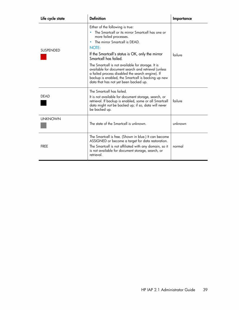
ImportanceDefinitionLife cycle state
failure
Either of the following is true:• The Smartcell or its mirror Smartcell has one or
more failed processes.• The mirror Smartcell is DEAD.NOTE:If the Smartcell's status is OK, only the mirrorSmartcell has failed.The Smartcell is not available for storage. It isavailable for document search and retrieval (unlessa failed process disabled the search engine). Ifbackup is enabled, the Smartcell is backing up newdata that has not yet been backed up.
SUSPENDED
failure
The Smartcell has failed.It is not available for document storage, search, orretrieval. If backup is enabled, some or all Smartcelldata might not be backed up; if so, data will neverbe backed up.
DEAD
unknownThe state of the Smartcell is unknown.UNKNOWN
normal
The Smartcell is free. (Shown in blue.) It can becomeASSIGNED or become a target for data restoration.The Smartcell is not affiliated with any domain, so itis not available for document storage, search, orretrieval.
FREE
HP IAP 2.1 Administrator Guide 39

Introduction to Platform Control Center (PCC)40

3 System Status
This chapter discusses the information that is found in the system status pages.
It includes the following topics:
• Overview, page 41• Storage Status, page 46• Software Management, page 47• Hardware Management, page 49• Performance Graph, page 53
OverviewThe Overview provides a high-level look at system health. It displays the following information:
• Alerts for problems that are currently occurring in the system.• Information about document storage rates and capacity, for the system and for each domain.• Platform information on objects stored or deleted.• Summary of the number of IAP users, groups, and repositories in the system. (Groups are not
currently supported, so the number is always 0.)• Summary of the number of partially indexed objects and CatchAll repository objects.• Information, by domain, about the status, health, and storage rate of each Smartcell.• Information about the IAP software version code installed.• The number of SMTP connections in each domain.
NOTE:Typically, you should monitor the Overview every day.
To open the page, go to Overview in the left menu.
Current Platform AlertsA Current Platform Alerts log at the top of the Overview displays alerts for problems that are currentlyoccurring in system hardware, services, or applications.
NOTE:Current Platform Alerts does not appear in the Overview if problems are not currently occurring inthe system.
HP IAP 2.1 Administrator Guide 41

Alerts are grouped by features. For example, all indexing alerts are grouped under Indexing. Eachalert includes a description of the problem, the context in which the problem is occurring, the serveron which the problem is occurring, and the date and time the problem began. Clicking More, if itappears in the alert context, displays more details about the issue.
Whenever an alert is raised or cleared, a system event is logged. You can view all recent systemevents by clicking Go to Event Viewer or navigating to Reporting > Event Viewer. See “EventViewer” on page 125 for more information.
Alert levelsThere are three levels of alerts:
• Critical: The feature is completely down. It is critical for the entire system and requires immediateaction from the IAP administrator.
• Major: The feature has major issues, but it is not critical for the entire system.• Minor: The feature has some internal problems, but it is not critical for the feature health.
Application alertsApplication alerts are generated by the IAP software. They are cleared from the PCC Overview pageautomatically when the problem is fixed or has disappeared. (See Clearing alerts.) For a descriptionof each application alert, see “IAP application-generated alerts” on page 179.
Figure 3 Sample application alerts.
Application alerts can be forwarded as SNMP traps to external SNMP trap listeners or forwarded inemail to designated recipients. For more information, see “SNMP Management” on page 127.
Hardware alertsHardware alerts are generated by the Proliant Service Packs installed on the machines in the IAPsystem. Generally, hardware alerts require your intervention. They are not cleared automatically,unless the server where the problem occurred is restarted. All hardware alerts have an alert ID ofH001.
Each hardware alert provides a link to the server's HP System Management Homepage, where moreinformation can be found. See “Hardware monitoring” on page 50.
Hardware alerts are not supported and do not appear in virtual IAP environments.
System Status42

Figure 4 Sample hardware alerts.
Clearing alertsAlerts are maintained as runtime information. They are only generated once, when the problem firstoccurs. They can be cleared in one of three ways:
• The problem is resolved; the system observes that the problem is resolved; and the alert is clearedautomatically from the PCC Overview page. (Applies to application alerts only.)
• A server is restarted; it notifies the PCC that it has restarted; and it requests the PCC to removeany alerts previously raised by it.
• The problem is resolved manually. You can resolve the problem and then manually clear the alerton the PCC Overview page by selecting the check box in front of the alert and clicking ClearChecked Alert(s).
IMPORTANT:Use caution when clearing an alert manually, as the system does not perform any verification thatthe problem is actually fixed. The assumption is that you know the problem does not exist anymore.
Platform PerformanceThis area of the overview provides information from the Storage Status page (see “StorageStatus” on page 46). The table on the left displays the number of objects (documents) stored, theamount of used and total disk space, the document storage rate, and the document index rate foreach domain. The bar graph displays the system's storage space ratio. The line graph on the rightshows the messages per second that the system stored and updated in the past day, ending with thecurrent time, as well as the amount of folder updates.
Account Manager ServiceThe Account Manager Service provides a brief summary of information from the PCC Account Manager(see “Account Manager (AM)” on page 73). This area displays the number of individual IAP usersand groups, pending users and groups, and the number of IAP repositories. (Groups are not currentlysupported, so the number is always 0.) This area also displays the number of synchronization errors,if any, pertaining to IAP user accounts. Synchronization errors can be corrected in the Error Recoverypage (see “Account Error Recovery” on page 87).
HP IAP 2.1 Administrator Guide 43

CatchAll and Partially indexed objectsThis area of the Overview displays the following information:
• CatchAll Objects: The number of documents in the CatchAll repository. This repository containsdocuments that fail to route into the correct user repositories because they cannot be associatedwith:• Email addresses of registered IAP users imported by DAS• A domain routing ruleMailing-list messages cannot be routed if the recipient's name is not included in the message asa destination.The CatchAll repository can be viewed in the Account Manager (see “Account Manager(AM)” on page 73 by clicking the Repository radio button in AM, clicking the Other tab, thenopening the CatchAll repository.
• Partially Indexed Objects: The number of documents in the failed indexing repository. This repos-itory contains documents that failed to be indexed or were partially indexed. (For example, thesystem might not have been able to index the particular file type.) The failed indexing repositorycan be viewed in the Account Manager (see “Account Manager (AM)” on page 73. Click theRepository radio button in Account Manager, click the Other tab, then open the failed indexingrepository.
The CatchAll and failed indexing repositories are automatically created when the system is started.
NOTE:If the number of documents shown is –1, the values cannot be read by the system.
Platform StatisticsThe Platform Statistics area provides status, health, and storage information about the IAP Smartcells.You can click a tab to view information about Smartcells in all domains or Smartcells in a particulardomain. The Platform Statistics area also shows the IP addresses of free Smartcells in the system.
Each Smartcell's life cycle state is color-coded.
•A green table row indicates a Smartcell is ASSIGNED.
•A light green table row indicates Smartcell is CLOSED.
•A yellow-orange table row indicates a Smartcell is in the COMPLETE_PROCESSING or RESTORE
state.•
A light yellow table row indicates a Smartcell is in the DISCOVERY or RESET state.•
A red table row indicates a Smartcell is SUSPENDED.•
A black table row indicates a Smartcell is DEAD.•
A gray table row indicates the state of a Smartcell is UNKNOWN.
See “Smartcell life cycle states” on page 38 for more information.
The icon at the beginning of the table row displays the JBoss status of the Smartcell.
System Status44

• A green check icon indicates the Smartcell is healthy, and both machine and JBoss are up.• A yellow icon indicates the Smartcell is unhealthy. The machine and JBoss are up, but there
are some failed and/or unhealthy MBeans.• A red X icon indicates the Smartcell is down. Either the whole machine or JBoss is down.• A gray icon indicates that service monitoring failed. The server status is unknown.
TIP:If you move your mouse over the icon, you will see more information including the host name, activethread count, and the Smartcell's MAC address.
Platform Statistics featuresTable 9 Platform Statistics features
DescriptionFeature
The platform name, IP address, and document storage rate.Platform
The name of the domain.Domain
A Smartcell group identifier generated automatically by IAP. This number is uniqueacross all systems.Group Name
The IP address of the Smartcell.Smartcell IP
A Smartcell can be Primary, Secondary, Replica-1, or Replica-2.Smartcell Role
The current life cycle state of the Smartcell. See “Smartcell life cyclestates” on page 38.State
The number of objects stored since the Smartcell was assigned.NOTE:When the system is actively storing objects, this count might be different thanthe stored object count in “Platform performance” on page 43. This numberis the real-time count on the Smartcell, while the Platform Performance count(taken from the local database) is only updated every minute.
Stored Object(s)
The number of objects indexed since the Smartcell was assigned.Indexed Object(s)
The number of objects being stored per second.Store Rate
The number of documents being indexed per second.Index Rate
The number of documents waiting to be indexed.Index Queue
The number of indexed documents waiting to be deleted.Index Deletion Queue
The number of documents waiting to be updated. (For example, email folder up-dates.)Update Queue
IP addresses of Smartcells in the FREE state.Other Smart Cells
HP IAP 2.1 Administrator Guide 45

IAP VersionNear the bottom of the Overview, you will find information about the IAP software version codeinstalled.
SMTP Flow ControlAt the bottom of the Overview, the SMTP Flow Control area shows the following information, bydomain:
• The maximum number of connections allowed• The current number of connections• The number of archiver connections
Storage StatusThe Storage Status page provides detailed object storage information for each domain.
To open the page, go to Storage Status in the left menu.
Table 10 Storage Status features
DescriptionFeature
The number of objects and store rate per domain, and the allocated space on thesystem for storage and replication.The dark area on the right side of the example storage bar graph below shows thepoint at which storage space is 90 percent full. The dark area typically representsthe amount of disk space reserved for work space for the Smartcell maintenancetasks.
NOTE:The storage bar graph shows only assigned and allocated Smartcells for allactive domains. The IAP might have free, unallocated hardware that is notrepresented in the bar graph.
Platform Store
A line graph showing the number of messages per second that the system stored inthe past day, ending with the current time. It also shows the amount of folder updates.Example:
Store Rate Graph
System Status46

DescriptionFeature
The number of Smartcells in each life cycle state. (See “Smartcell life cyclestates” on page 38 for an explanation of each state.)Example:
Smart Cell Allocation
The domain group ID, the number of objects stored, the amount of used and totalstorage space, and the disk/space ratio, shown in bar graph format.Domain Details
Software ManagementUse the Software Management page to view the status of all IAP servers that are running JBoss, andto start, stop, or restart the applications on one or more of the IAP servers.
This page is useful to show the software status of a server. However, you should use thestart/stop/restart functions only when necessary — for example, when you are upgrading a serveror before a planned power outage.
To open the page, go to Software Management in the left menu.
Software Management featuresThe following information is displayed on the Software Management page.
Table 11 Software Management features
DescriptionFeature
The type of host group, the servers in the group, and the full name of each server.
Host group types include the following:
• BACKUP Servers: Backup servers• CLOUD ROUTER Servers: Cloud router servers• DB Servers: DB2 database server• FIREWALL Servers: Firewall servers• HTTP Servers: HTTP portal servers• KICKSTART Servers: Server for loading and deploying system software/configur-
ation files• LOAD BALANCER Servers: Load Balancer servers• PCC Servers: Platform Control Center server• META Servers: Metaservers• SMARTCELL Servers: Servers to store archived documents• SMTP Servers: SMTP portal serversThe Archive Gateway does not use JBoss in IAP 2.1 and later versions, so is notshown on the Software Management page.
Hostname
HP IAP 2.1 Administrator Guide 47

DescriptionFeature
The status icon in front of the host name displays the JBoss status of the server.• A green check icon indicates the server is healthy, and both machine and
JBoss are up.• A yellow icon indicates the server is unhealthy. The machine and JBoss are
up, but there are some failed and/or unhealthy MBeans.• A red X icon indicates the server is down. Either the whole machine or JBoss
is down.• A gray icon indicates that service monitoring failed. The server status is un-
known.
Status icon
The server's IP address.IP Address
The status of the server. Corresponds to the icon in front of the server in the Hostnamecolumn.Status
Starting, stopping, and restarting servers on the systemTo stop, start, or restart one or more servers, follow these instructions:
1. Select the machine(s) on which the action will be performed:
• To perform an action on all servers or all machines in a server group, click the Machine Typeradio button and select the servers from the drop-down list.
• To perform an action on specified machine(s), click the Selected Machine(s) Below radio button,and then select the check box in front of the machine(s).
NOTE:Because the PCC server hosts the user interface, it is not listed in the Machine Type list andcannot be selected if you specify Selected Machine(s) below.
2. In the Action drop-down list, select the action to perform:
• Start: Start a single machine, start all machines, or start all machines in a selected servergroup.
• Stop: Stop a single machine, stop all machines, or stop all machines in a selected servergroup.
• Restart: Stop and immediately start a single machine, or stop and immediately start all ma-chines or all machines in a selected server group.
• Staggered Restart: Restart all machines in sequence, or all server group machines in sequence,with a minimum of downtime.
3. Click Run Now.
System Status48

Hardware Management
NOTE:In virtual IAP environments, this feature is not supported and the Hardware Management page doesnot appear.
Use the Hardware Management page to view the servers that are part of the IAP infrastructure andlinks to their corresponding HP System Management pages and Remote Management iLO pages (ifenabled). (See the IAP Administration Guide chapter “Remote management of servers” for moreinformation about remote management.)
To open the page, go to Hardware Management in the left menu.
Hardware Management featuresTable 12 Hardware Management features
DescriptionFeature
The type of host group, the servers in the group, and the full name of each server.Move your mouse over the status icon to view a server's IP address.
Host group types include the following:
• ARCHIVEGATEWAY Servers: Archive Gateway (email mining) servers• BACKUP Servers: Backup servers• CLOUD ROUTER Servers: Cloud router servers• DB Servers: DB2 database server• FIREWALL Servers: Firewall servers• HTTP Servers: HTTP portal servers• KICKSTART Servers: Server for loading and deploying system software/configur-
ation files• LOAD BALANCER Servers: Load Balancer servers• PCC Servers: Platform Control Center servers• META Servers: Metaservers• SMARTCELL Servers: Smartcell servers to store archived data• SMTP Servers: SMTP portal servers
Hostname
The icon in front of the host name displays the hardware status of each server.• A green check icon indicates there are no hardware alerts for the server.• A red X icon indicates there is at least one hardware alert for the server.
Move your mouse over the status icon to display the number of alerts. To viewthe alerts, navigate to Current Platform Alerts on the PCC Overview page.
Status icon
The server's MAC address.MAC Address
Click View to link to the HP System Management Homepage on the server, whichdisplays the server hardware status and other data.For more information, see Hardware monitoring below.
System Management
HP IAP 2.1 Administrator Guide 49

DescriptionFeature
Shows whether iLO/Lights-Out 100 is set up on the server and configured in ProxyAccess Mode.If remote management is enabled, a Manage link appears. Clicking the link displaysthe iLO or Lights-Out 100 Web interface and allows you to perform operations suchas power cycling the server.
Remote Management
Hardware monitoringYou can monitor IAP hardware health from either the PCC user interface, the HP System ManagementHomepage on every server, or (if available) an HP System Management console. Hardware monitoringfor IAP servers is provided by Proliant management agents. We include the standard HP Prolianthardware management and system homepage agents as part of the IAP software. The managementagents provide SNMP support for hardware monitoring by way of SNMP traps.
A standalone IAP Proxy Agent running on PCC aggregates SNMP hardware traps from the Proliantagents on the IAP servers. The agent is used for SIM discovery and trap forwarding
SIM discovery: The IAP Proxy agent responds to SNMP get requests from external SIM servers on thePCC external network IP address. An external SIM server needs to be configured to identify IAPappliances. The IAP appliance is displayed in the SIM console with the IP address as the PCC externalnetwork IP address.
Trap forwarding: The proxy agent listens for SNMP traps from the individual IAP servers.
• SIM: Once discovered in SIM, the proxy agent in the PCC server must be configured with the SIMserver's IP address for trap forwarding. Any number of external SIM servers are supported. TheSIM server displays traps received from the IAP Proxy agent as long as the source address is theIAP appliance address: the PCC's external IP address. The proxy agent modifies the traps receivedfrom the IAP servers by setting the source address to the PCC external address before forwardingthe traps to SIM servers.
• PCC: The IAP proxy agent loads known MIB definitions used by the Proliant agents in order toparse the SNMP traps and retrieve source and description information. The IAP Proxy agent for-wards the traps in the form of IAP alerts to the PCC, where they are displayed in the CurrentPlatform Alerts log at the top of the Overview page. A link to the System Management Homepagefor the IAP server is displayed in the alert context.
The Proliant management agents monitor hardware components such as storage (raid controllers anddisks), server (CPU, memory, temperature, and power), and NICS. The full list of hardware traps isshown in the documentation for the Proliant Support Packs: http://bizsupport2.austin.hp.com/bc/docs/support/SupportManual/c00760188/c00760188.pdf.
Other information is included in the Proliant support pack user and installation guide: http://bizsupport2.austin.hp.com/bc/docs/support/SupportManual/c01527454/c01527454.pdf
Since hardware monitoring of IAP servers is dependent on the Proliant management agents, thehardware requirements are tied to the minimum requirements for the Proliant Support Packs. See theIAP Support Matrix for more information.
Log messages from the IAP Proxy agent are stored in the proxyagent.log files in the /opt/tools/snmpProxyAgent/ directory on the PCC server.
System Status50

SIM ConsoleIf you use the HP SIM Central Management Server (CMS), it can recognize the IAP appliance viaSNMP from the SIM console, using the PCC external IP address. Once configured to identify IAPappliances, the SIM console displays the IAP as a single managed system as shown below.
Figure 5 SIM Console.
The ES column indicates the event status of the IAP, which is the most severe event or trap that hasbeen received. The trap detail contains information about the actual IAP server that originated thetrap.
IMPORTANT:The addresses of SIM servers must be manually configured in a text file to enable trap forwardingfrom the proxy agent. For trap forwarding, create or use the file /opt/tools/snmpProxyAgent/conf/ProxyAgent.properties and add the following line: trapsink=<sim_server_ip>(for example 192.168.50.59).
Clicking the IAP System Name brings up the System Homepage as shown below.
HP IAP 2.1 Administrator Guide 51

Figure 6 System Homepage.
The events received from the IAP can be seen by clicking the Events tab. This brings up the eventstable. Trap detail can be obtained by clicking the Event Type. The detail includes the IAP server thatwas the source of the trap.
Figure 7 IAP events.
The SIM documentation describes the use, configuration, and user interface of the HP SIM serverapart from the specific use to monitor the IAP:
• HP SIM installation and configuration guide for Windows installations:http://docs.hp.com/en/418812-005/418812-005.pdf
• HP SIM installation and configuration guide for Linux installations:http://docs.hp.com/en/418811-004/418811-004.pdf
System Status52

Performance GraphUse this page to create graphs showing different types of system events over specified time periods.You can generate two categories of graphs:
• System monitoring graphs that show idle CPU usage, free memory usage, or the number of threadsused.
• Platform store and indexing graphs that show the number of objects stored or indexed on thesystem, and the rate at which objects are stored or indexed per second.
Table 13 Performance Graph features
DescriptionFeature
The type of graph or the server name.Graph Type
The platform, domain, or Smartcell to be graphed.Assigned Smartcell orDomain
The time period being reported.Time Frame
To open the page, go to Performance Graph in the left menu.
Example: Platform Store graphAn example of a platform store or indexing performance graph is shown below. This graph chartsthe Domain1 store rate for today at five minute intervals.
Figure 8 Performance Graph: Store Rate.
HP IAP 2.1 Administrator Guide 53

Example: System Monitoring graphAn example of a system monitoring performance graph is shown below. This graph charts the freememory on the database server at hourly intervals over the past 24 hours.
Figure 9 Performance Graph: Free Memory.
Creating performance graphs1. Click the System Monitoring tab or the Platform Store and Indexing tab for the category of graph
that you want to create.
2. Select a graph type:
• For Platform Store and Indexing, select one of the following:• Store Rate (Objects/Sec)• Store Rate (MB/sec)• Index Rate• Object Count• Index Count• Active Transactions• Update Rate (Objects/Sec)
System Status54

• For System Monitoring, select one of the following:• Idle CPU
Percentage of the CPU that is idle.
• Free MemoryPercentage of the amount of free memory in the Java virtual machine vs. the total amountof memory in the Java virtual machine (same as JVM Heap Free / JVM Heap Total)
• JVM Heap TotalThe total amount of memory in the Java virtual machine.
• JVM Heap UsedThe total amount of memory in the Java virtual machine minus the amount of free memoryin the Java virtual machine (same as JVM Heap Total – JVM Heap Free).
• JVM Virtual Memory UsedThe amount of virtual memory the JVM processes were using, in bytes. (Includes the amountin RAM and in the swap memory.)
• IOThe percentage of disk resource (I/O) utilization for all main disks on the system.
• Active Thread CountNumber of Java threads that JBoss was running at the time.
3. Select one of the following options:
• Machine Type (System Monitoring graphs): Select the type of machine (for example, PCCServers or SMTP).
• Assigned Smartcell/Domain (Platform Store and Indexing graphs): Select Entire Platform, thedomain name, or the Smartcell IP address.
4. Select the time frame and reporting interval:
• Time Frame: For a preselected time period, click Select Time Frame, and select a time framefrom the drop-down list.
• From Date, To Date: For a custom time period, click Custom Time Range, and select the startdate and time and end date and time. The custom time range can be useful for troubleshooting.
• Interval: Select the reporting interval from the drop-down list.5. Click Generate Graph.
HP IAP 2.1 Administrator Guide 55

System Status56

4 Configuration
This chapter contains the following information:
• Platform Settings, page 57• Firewall Settings, page 58• SSL Configuration, page 58• Software Version, page 62• Software Update, page 62
Platform SettingsThe Platform Settings page is an administrative tool that displays configuration information about theIAP.
This page is divided into two parts:
• Information about the services enabled in each domain is in the upper portion of the page.• Information about the IAP configuration is in the lower portion of the page.
To open the page, go to General Configuration > Platform Settings in the left menu.
Domain ConfigurationThe upper portion of the Platform Settings view shows information about each domain. It includes thedomain type (Exchange or Domino), the services that are enabled (for example, indexing, replication,folder support, compliance, and data backup), supported object (document) types, and retentionperiod(s).
The domain configuration information is drawn from the Domain.jcml configuration file.
Figure 10 Domain Configuration.
HP IAP 2.1 Administrator Guide 57

Platform SettingsThe lower portion of the Platform Settings page displays the setup details for the IAP. This informationis taken from the BlackBoxConfig.bct file.
Firewall SettingsThe Firewall Settings page shows the firewall status and settings for the PCC server and the IAP HTTPportals, and their virtual IP (VIP) addresses.
It includes the following information:
Table 14 Firewall ports
DescriptionFeature
The virtual IP address.Virtual IP
The port number.Port
The service running on the port.Service
The transfer protocol used on the port: TCP or UDPType
Shows if the firewall is enabled or disabled on the port's inbound and out-bound traffic. Outbound traffic is not filtered on the PCC server ports.Inbound/Outbound
To open the page, go to General Configuration > Firewall Settings in the left menu.
SSL ConfigurationSSL, or Secure Socket Layer, is a technology that allows web browsers and web servers to communicateover a secured connection. This means that the data being sent is encrypted by one side, transmitted,then decrypted by the other side before processing. It is a two-way process, meaning that both theserver AND the browser encrypt all traffic before sending out data.
The SSL Configuration page lets you generate certificate signing requests (CSRs), and correspondingprivate keys, for secured connections on the IAP. You can create two types of CSRs: one for accessto the PCC portal, and one for access to the HTTP portals.
After generating the CSRs, see “Installing a third party certificate on the PCC portal” on page 60 and“Installing a third party certificate on the HTTP portals” on page 61 for the steps needed to completethe process.
The SSL Configuration page contains two areas. The top area shows any current certificate signingrequests in the system. The bottom area contains a form to complete to generate a certificate signingrequest (CSR) and RSA private key.
To open the page, go to General Configuration > SSL Configuration in the left menu.
Configuration58

Available certificate signing requestsTable 15 Available certificate signing requests (CSRs) in the IAP
DescriptionFeature
The host for which the CSR has been generated. The host is either a PCC or HTTPportal.Machine Type
The virtual IP address of the host.Virtual IP
The date the CSR was created.Creation Date
The path to the CSR. The CSR files are always placed on the PCC host.Path
Creating a certificate signing requestTo create a certificate signing request (CSR):
1. Complete the form at the bottom of the SSL Configuration page.
You can create only two types of CSR files: one for access to the PCC, and one for access to theHTTP portal machines.
2. Click Generate CSR.
To install a certificate on the PCC portal, see “Installing a third party certificate on the PCCportal” on page 60.
To install a certificate on each HTTP portal, see “Installing a third party certificate on the HTTPportals” on page 61.
NOTE:If you enter incorrect information in the form and need to generate a new CSR, see “Deleting acertificate signing request” on page 59 for the procedure to follow.
Deleting a certificate signing requestAfter a certificate signing request (CSR) is generated for the PCC or HTTP portals, it cannot beregenerated. If you have entered incorrect information in the certificate request, the file must bemanually deleted before you can create a new CSR in the SSL Configuration page.
To delete a CSR:
1. Log in to the PCC console.
2. Go to /opt/keys and delete the CSR with one of the following commands:
# rm -f pccCert.pem (to remove the PCC certificate request)
# rm -f httpCert.pem (to remove the HTTP certificate request)
3. Upon deleting pccCert.pem and/or httpCert.pem in directory /opt/keys, log off or closethe PCC UI. If you do not, refreshing the PCC UI will re-create these files, and the <SSLConfiguration> page will not allow new CSRs be created.
HP IAP 2.1 Administrator Guide 59

IMPORTANT:Important! Do not delete the private key files (pcckey.pem or httpkey.pem).
NOTE:After deleting pccCert.pem or httpCert.pem in /opt/keys, be sure to log off or close thePCC UI. If you don't and refresh, the PCC UI will re-create these files. (The SSL Configuration pagewill also not allow new CSRs be created.)
Installing and generating a certificate on the PCC portalFollow these steps to generate and install a certificate for the IAP PCC portal.
1. Create a certificate signing request (CSR) for the PCC:
a. Log in to the PCC Web interface and go General Configuration > SSL Configuration.
b. Complete the CSR generation form.
c. Log out of the PCC Web interface.
This generates two files on the PCC:
• # /opt/keys/pccCert.pem (the certificate request)• # /opt/keys/pcckey.pem (the RSA private key)
2. Manually copy the certificate request file to your local machine:
# scp root@<external ip address of PCC>:/opt/keys/pccCert.pem
3. Send the certificate request to a certificate authority (CA) such as VeriSign for signing.
Follow the instructions provided by your CA.
4. Import the certificate you receive from the CA into the IAP PCC:
a. Store the certificate from the CA on your local machine (for example, aspccCertSigned.pem).
b. Copy the certificate to the PCC:
# scp pccCertSigned.pem root@<external ip address of PCC>:/opt/keys/pccCertSigned.pem
5. Import the certificate into the PCC's Apache server:
# /usr/local/bin/ssl_cert_update.pl --pcc --cert /opt/keys/pccCertSelfSigned.pem --key /opt/keys/pcckey.pem
6. Restart the PCC's Apache server by issuing the following command:
# /etc/init.d/httpd restart
Configuration60

Installing and generating a certificate on the HTTP portalsFollow these steps to install a certificate on the IAP HTTP portals.
1. Create a certificate signing request (CSR) for the HTTP portals:
a. Log in to the PCC Web interface and go General Configuration > SSL Configuration.
b. Complete the CSR generation form.
c. Log out of the PCC Web interface.
This generates two files on the PCC:
• /opt/keys/httpCert.pm (the certificate request)• /opt/keys/httpkey.pem (the RSA private key)
2. Manually copy the certificate request file to your local machine:
# scp root@<external ip address of PCC>:/opt/keys/httpCert.pm
3. Send the certificate request to a certificate authority (CA) such as VeriSign for signing.
Follow the instructions provided by your CA.
4. Import the certificate you receive from the CA into the IAP PCC:
a. Store the certificate from the CA on your local machine (for example, ashttpCertSigned.pem).
b. Copy the certificate to the PCC:
# scp httpCertSigned.pem root@<external ip address of PCC>:/opt/keys/httpCertSigned.pem
5. From the PCC console:
a. Import the certificate into the Apache server on each HTTP portal.
# /usr/local/bin/ssl_cert_update.pl --http --cert /opt/keys/httpCertSelfSigned.pem --key /opt/keys/httpkey.pem
b. Restart all services on the HTTP portal by issuing the following command:
# /opt/bin/restarthttp
(You can also restart the services using Platform Control in the PCC Web interface. See“Software Management” on page 47.)
HP IAP 2.1 Administrator Guide 61

Software VersionThis page shows the software version that is used by hosts in the system, and any software updatesthat have been installed.
Table 16 Software Version features
DescriptionFeature
IAP software version code installed.Software Version
History of IAP software patches (updates) applied to the system.Patches Applied
To open the page, go to General Configuration > Software Version in the left menu.
Software UpdateThe Software Update link will connect you to the IAP tool which allows you to install patches. To openthe page, go to General Configuration > Software Update in the left menu.
Configuration62

5 Account Synchronization
Use this page to configure dynamic account synchronization (DAS), which automatically creates andupdates email user accounts on the IAP. You can define multiple configurations that track sets of usersfrom one or more LDAP servers for specific IAP domains.
NOTE:This chapter contains a DAS example for EAs for Exchange. EAs for Domino administrators will findinformation on DAS in the EAs for Domino Administrator Guide.
• Account Synchronization overview, page 63• Creating and running DAS jobs, page 63• Editing or deleting jobs, page 69• Managing available HTTP portals, page 70• Editing or deleting available LDAP connections, page 70• Viewing DAS history logs, page 71
To open the page, go to User Management > Account Synchronization in the left menu.
Account Synchronization overviewThe Account Synchronization page is divided into three areas.
• The DAS Available Jobs area lists all jobs created and assigned to an HTTP portal.• The LDAP Server Connectors area lists available LDAP connections.• The Jobs History Logs area shows the history of DAS job runs.
Creating and running DAS jobsThe basic steps for creating and running a DAS job are as follows:
1. Create an LDAP connection. See “Creating LDAP server connections” on page 63.
2. Create the job. When you create a new job, you assign the job a name and an LDAP connection,and set up the job query in the LDAP server. See “Creating jobs” on page 64.
3. Assign the job to an HTTP portal. See “Assigning HTTP portals” on page 67.
4. Run the job. See “Starting, scheduling, and stopping DAS jobs” on page 68.
Creating LDAP server connectionsTo create an LDAP connection:
1. In the LDAP Server Connectors area, click New LDAP.
HP IAP 2.1 Administrator Guide 63

2. Complete the form to create an LDAP service connection by entering the following information:
Figure 11 New LDAP connection.
• Connection Name: Name used to identify the LDAP connection.• Hostname: IP address of the LDAP server.• Binder user: User in the LDAP directory tree that you want to bind to. At a minimum, the user
must have read access to all users objects. For example: cn=Administrator,cn=Users,dc=hostname,dc=com.
• Binder pswd: Password of the Binder user.• Directory Server type: Type of LDAP server to which you are connecting: Microsoft Active
Directory• Security Option: Type of LDAP security: simple authentication or SSL.• Port: Open LDAP port of the LDAP server. Use the port 389 for simple authentication. Use
port 636 for SSL support.3. To test the LDAP server connection before creating it, click LDAP test.
A content pane displays the status of the LDAP connection. It tells you whether the connectionand bind are successful and the authentication types that are supported by the LDAP server. Errorsare displayed in red.
4. Click Create.
5. Return to the Account Synchronization page and verify that the new LDAP server connection islisted under LDAP Server Connectors.
Creating jobsTo create a DAS job:
1. In the DAS Available Jobs area, click New JOB.
2. Name the job you are creating by entering it in the Job Name box. (In addition to the charactersnoted below, the name can contain no spaces.) Click Next Step.
Figure 12 Create DAS job.
3. From the drop-down list, select the LDAP connection you want to use with the job.
The LDAP connection must already be created. For more information, see “Creating LDAP serverconnections” on page 63.
Account Synchronization64

4. Click Next Step.
The Mapping Information form appears.
Figure 13 Mapping information.
5. Complete the form by entering the following:
• LDAP Domain name: Domain to which the users belong. For example: itchyexch.com.• LDAP Job Starting Point: Root node where the user accounts are stored. Example:
For Exchange, enter cn=Users,dc=itchyexch,dc=com for node Users in domainitchyexch.com. The value must specify the relative location in the LDAP tree, includingparent nodes and domain name. (Another example is ou=stest,dc=sandbox2k_12,dc=com where ou is the organization name in the exchange.)
• IAP DomainID: The IAP domain ID (not the domain name) where users are synchronized withusers on the LDAP server. This is the same as the domainID set in Domain.jcml.
• Delete Starting Point: The root node where deleted user objects are stored on the LDAP server.Example: For Exchange, enter cn=deletedObjects,dc=itchyexch,dc=com for nodedeletedObjects in domain itchyexch.com. The value must specify the relative locationin the LDAP tree, including parent nodes and domain name.
HP IAP 2.1 Administrator Guide 65

6. Click the Advanced Options icon ( ) and complete the advanced options.
Figure 14 Advanced options.
• USNChanged: Active Directory's unique sequence number (USN). Active Directory incrementsthe USN for each change in any of its user accounts. When DAS finds a larger USN, it extractsnew information. For initial setup, set USNChanged to 1 so DAS extracts all users. Thereafter,do not change this value.
• Delete USNChanged: USN in deleted users directory. This is the same as USNChanged butfor deleted objects. For initial setup, set this value to 0. Thereafter, do not change this value.This value must be set to 0 the first time the mapping is set up.
• NextRepID: IAP repository ID assigned to new users. DAS retrieves this value from the database,but you can use this feature to specify the repository ID for the first user inserted when DASruns. For example, if you enter 67, the repository created and assigned for the first importeduser is R0000067. You can use this feature if users already exist in the system or to reserverepository IDs for any reason. If you specify a value that is lower than an existing repositoryID, DAS automatically changes the value to the next higher number. The default is set to 5.
• Audit Repository: Do not change.• Update LDAP filter: Criteria to include or exclude specific users. For example:
For Exchange, use at least the default, (objectclass=user)(mail=*), which excludesusers who do not have email accounts.
• LDAP Query return attributes: List of return attributes. Example:For Exchange, use the default attributes unless your LDAP schema requires mapping changes.
• Delete LDAP Filter: Criteria to include or exclude specific users in the LDAP deleted users dir-ectory. Add to the default for special cases.
• LDAP Attribute to Map to Username: Active Directory attribute that will be mapped to users’username. The attribute that is selected will be the webui username login name. You may useActive Directory fields sAMAccountName, userPrincipalName or mail as the IAP usernamemapping.
NOTE:It is no longer necessary to modify the LoadChanges.dse file on the HTTP portal to performthe username mapping.
Account Synchronization66

7. Click Next Step.
A status page appears, stating that the mapping has been updated for the new job.
You are asked if you want to attach the job to a HTTP portal.
8. Click Assign Job to continue, then follow the instructions in Assigning HTTP portals below.
If a HTTP portal is not available for the new job because it is being used for another job, clickBack to Main Page, and unassign the HTTP portal. See “Unassigning and reassigning aportal” on page 68 for the steps to take.
Assigning HTTP portalsBefore running a DAS job, assign a HTTP portal on which to run the job. Only one job can be assignedto a HTTP portal. These steps are performed in the DAS Available Jobs area of the Dynamic AccountSynchronization page.
Assigning a portalWhen you click Assign Job after creating a new job, the Assign a Job page appears:
Figure 15 Assign a job to a portal.
Complete the form to assign a HTTP portal to the job.
1. Enter the following information:
• DAS server IP: IP of the DAS HTTP portal where DAS runs the configuration.• Configuration Enabled: Select Yes to enable. If not enabled, the job cannot be scheduled or
started with this console.• Configuration running state: Do not change.• Period: Number of minutes between job runs. Enter 0 to run the job once.• DAS server running state: Do not change.
2. Click Save.
HP IAP 2.1 Administrator Guide 67

Unassigning and reassigning a portalIf all HTTP portals are being used for other jobs and none are available for a new job, reassign aHTTP portal from another job.
To reassign a HTTP portal:
1. Select an existing DAS job in DAS Available Jobs, and then click Unassign HTTP.
2. Select the new job.
The Job Update page appears.
Figure 16 Job Update page.
3. Click Edit in HTTP Server State.
The Assign a Job page appears.
4. Complete the form by following the instructions in Assigning a portal.
5. Start the job by following the instructions in the next section.
The DAS setup must be initialized whenever a new HTTP portal is assigned to a job.
Starting, scheduling, and stopping DAS jobsIf you are running DAS for the first time or have assigned a DAS job to a new HTTP portal, followthese steps:
1. In DAS Available Jobs, select the job and click Stop/Start.
The job control page appears.
2. Schedule the job:
a. Click Schedule.
b. Enter the number of minutes between job runs.
To run a job once, enter 0. To run a job continuously, set the interval so that it is equal toor greater than 60 minutes.
c. Click Confirm Schedule to save your changes.
You are returned to the job control page.
Account Synchronization68

3. Click Yes in Initialize DAS setup.
Figure 17 Initializing DAS setup.
4. Click Start.
A notice appears stating that the job started successfully.
5. Click Back to Main Page.
To start a DAS job when DAS has already been initialized and the HTTP portal has not changed:
1. Select the job in DAS Available Jobs.
2. Schedule the job if you have not already done so:
a. Click Schedule.
b. Enter the number of minutes between job runs.
To run a job once, enter 0. To run a job continuously, set the interval so that it is equal toor greater than 60 minutes.
c. Click Confirm Schedule to save your changes.
3. Click Start.
4. If necessary, click Back to Main Page.
To stop a DAS job from running:
1. In DAS Available Jobs, select the job, and then click Start/Stop.
2. In the job control page, click Stop.
A notice appears stating that the job has stopped. When the DAS job is stopped, DAS willunschedule itself and will not run the DAS job any more. (A currently running DAS job will notstop.)
3. Click Back to Main Page.
Editing or deleting jobsTo edit an active or configured DAS job:
1. In DAS Available Jobs, select the job and click Edit.
2. Make any changes needed for the job mapping.
3. Click the Advanced Options icon ( ) to edit any advanced options.
See “Creating jobs” on page 64 for information about job options.
4. Click Update.
A confirmation page appears.
HP IAP 2.1 Administrator Guide 69

5. Click Assign Job and ensure that a HTTP portal is selected and the configuration is enabled.
If you are changing the HTTP portal on which a job is running, select the new portal from thedrop-down list.
6. Click Save.
7. If you changed the HTTP portal for the job:
a. Click Back to Main Page.
b. Follow the steps in “Starting, scheduling, and stopping DAS jobs” on page 68.
The DAS setup must be reinitialized whenever the HTTP portal is changed.
8. If you did not change the HTTP portal, you can click Back to Main Page or click Run Job to startthe job.
To delete a DAS job:
1. In DAS Available Jobs, select the name of the job to delete.
2. Click Delete.
3. If you are deleting a job without an assigned HTTP portal:
a. In DAS Available Jobs, click the job.
b. On the Job Update page, click Delete, and then click Delete Job.
c. Click Back to Main Page.
Managing available HTTP portalsTo assign or unassign a HTTP portal for a job, see “Unassigning and reassigning a portal” on page 68.
Editing or deleting available LDAP connectionsTo edit or delete an LDAP connection:
1. In the LDAP Server Connectors area of the DAS page, click the name of the connection you wantto edit or delete.
2. To edit the connection, click Edit, complete the form, and click Save.
3. To delete the connection, click Delete.
4. Click Back to Main Page when you are finished.
Account Synchronization70

Viewing DAS history logsThe DAS jobs history log provides a list of job runs for each configured active job. The log includesthe job name; the number of IAP users that were added, deleted, and updated; the time between jobruns; the job status; and the date and time the job was completed.
The history also displays the number of IAP groups that were added, deleted, and updated.
To display the history log, scroll down to the Jobs History Log area at the bottom of the AccountSynchronization page.
To display a history of the previous runs for a specific DAS job, click the job name.
To check the status of a job, view the process icon in the State column. For example, the iconindicates the job is Complete.
You can also point to the process icon to display the status. If a red X icon is displayed, issues werefound during the DAS run, or errors occurred in the job during its previous runs which have not yetbeen repaired using Account Error Recovery. For more information about the issues, check the tooltipon the status icon, Account Error Recovery Tool, and DAS logs on the HTTP portal.
HP IAP 2.1 Administrator Guide 71

Account Synchronization72

6 Account Manager (AM)
Use the Account Manager (AM) page to provision and update user accounts.
This chapter contains the following topics:
• AM overview, page 73• Managing user accounts, page 75• Managing groups, page 79• Managing repositories, page 79
To open the page, go to User Management > Account Manager in the left menu.
Account Manager overviewUse Account Manager (AM) to view and update user accounts and repositories for unusualcircumstances on the IAP. Initial setup, and routine addition and deletion of user accounts, occurautomatically through synchronization with Active Directory or the Domino Directory.
IAP archives emails and other documents in repositories — virtual collections of documents associatedwith a given user by routing rules (storing) and access lists (retrieving).
Use AM to update accounts as follows:
• Add users not imported through dynamic account synchronization (DAS).• Change user permissions.• Give users access to other repositories.• Add special-purpose repositories such as audit repositories.• Add or modify routing rules.• Edit the retention period for some repositories.
NOTE:You can view accounts on replica domains, but you cannot use AM to add or edit them. Fields cannotbe edited and action buttons are unavailable when you select a domain that is a replica of anotherdomain.
HP IAP 2.1 Administrator Guide 73

Figure 18 Account Manager page.
The total number of users and groups for the domain(s) is shown in the upper right corner of the page.
Account Manager featuresTable 17 Account Manager features
DescriptionFeature
Use the search feature to find users, groups, or repositories.The search function uses the “Like” SQL database capability. For example, in theUser panel, you could enter jack to match users jackdoe or jacksmith. Entering %doewould match users jackdoe, janedoe, or maryjanedoe. Entering %ja% would matchusers jadams, jackdoe, janedoe, jacksmith, or maryjanedoe.Searches are not case sensitive.For users and groups, you can search by email account name.
Search button
Account Manager (AM)74

DescriptionFeature
Select this check box to display all objects of the type indicated by filter name (user,group, or repository). For example, select the User filter and All button to show allusers.
All check box
Use to display only names starting with the button letter. Names correspond to theobjects of the current filtered panel.You can use the search function within the filtered panel.
A-to-Z buttons
Select the user, group, or repository radio button to view the corresponding panel.
• Users (see “Managing user accounts” on page 75) - You can add users, viewand edit user information, change user status and privileges, and remove usersfrom the system.
• Groups - Groups are not currently supported in the IAP.• Repositories (see “Managing repositories” on page 79). You cannot delete existing
repositories.
Panels
Click the navigation buttons at the bottom of the page to:
• Add a repository.• Add a user.• Delete a user from the system. Grant or revoke access to a repository
Navigation buttons
Managing user accountsOpen the Users panel to view, add, remove, or change individual user accounts on the IAP.
Adding a user in Account Manager automatically creates a primary repository for the user. It alsoadds routing rules and filters for the user's contact email address, and gives the user access to his orher personal repository.
When the IAP is first installed, a single user (Default) is listed in the Users panel. You can delete thisentry after users are imported into the system using DAS.
Adding a new userUsers can be added directly to the system using the Account Manager. For example, it is likely thatyou will create an IAP administrator directly in the system, rather than granting administrative privilegesto specific users imported by DAS.
Users created in the system and given a local password are known as local users. Users imported byDAS are known as remote users.
To add a new user:
1. Click Add User at the bottom of the Account Manager page.
2. Complete the Integrated Archive Platform Account and LDAP Information form that appears.
See “User account information” on page 77 for details on completing this form.
3. Click Save Now! to save the user information.
HP IAP 2.1 Administrator Guide 75

Editing user informationTo edit user information:
1. Click the User radio button, locate the user account that you want to edit, and then click the username.
See “Account Manager features” on page 74 for information on searching for a user.
2. In the Integrated Archive Platform Account and LDAP Information form that appears, clear thecheck box labeled Deactivate this check box and then edit the user entries.
Figure 19 Editing user account information.
3. Edit the relevant user entries.
4. Click Save Now! when you are finished.
NOTE:To change a user's repository retention period, edit the repository. See “Editing repositoryinformation” on page 82.
Account Manager (AM)76

User account informationTable 18 User account information
DescriptionFeature
Integrated Archive Platform Account Information
(Required.) The system login name for the selected user.Usernames must be unique, but they can be the same except for their domains. Forexample, [email protected] could be an Active Directory user imported intothe system through dynamic synchronization (DAS); at the same time, user johnkdoecould be created as a local user in the IAP.
Username
The password in the IAP for a selected user. Active Directory users who are importedinto the system through DAS are not required to have a local password. However,local users must have one.
Local Password
First name of the selected user.First Name
Last name of the selected user.Last Name
(Required.) Email address for the selected user.Email Contact
(Required.) Email destination when the selected user clicks Send results to send acopy of an archived document from the Web Interface.Mail To Me Address
The system administrators' comments on the selected user account.Comments
(Required.) The IAP domain to which the selected user belongs. Select the domainfrom the drop-down list; the selection limits the scope of the Search and A-to-Z filterbuttons.
Domain
The IP address of the mail server for the selected user. (Optional, unless queryingwithin Microsoft Outlook is required.)Mail Server
In RISS versions prior to 1.5, this number identifies the account to be billed for ser-vices. It is not used in later RISS or IAP versions.Billing Group ID
The ID of the repository created for the selected user.Personal Repository
The IDs of the repositories to which the user has access. The user automatically hasaccess to his or her own repository. If the user is a member of a group, he or shealso has automatic access to the group's primary repository.You can give the user access to another repository by clicking Edit, selecting thecheck box for the repository, clicking Save to List, and then clicking Exit.Repositories (except for the user's personal repository) can be removed from the listby selecting the repository name and clicking Remove From List.
Direct Repositories
LDAP information
Any groups to which a remote user belongs.Membership
The Windows domain to which a remote user belongs.WinDomain
The remote user's object name, relative location in the LDAP tree, and domain. CN(Common Name) is the object name, cn is its branch in the tree, and dc values aredomain names. DAS supplies this value.
LDAP Dn
HP IAP 2.1 Administrator Guide 77

DescriptionFeature
An account synchronization maintained field that indicates which DAS job was usedto create or manage the information.Source
The Global Unique Identifier of the user account on the LDAP server. This is accountsynchronization's key to the correct account on the LDAP server.Object GUID
An identifier for the user, automatically generated and maintained by Active Directory.(Cannot be edited.)Object SID
The USN (Active Directory unique sequence number) imported from the correspondingaccount on the LDAP server the last time account synchronization was run.USNChange
The date the user account was created.Created Date
The date the user account was last modified.Last Modified
All repositories to which a user has access — either through direct access or throughgroup membership.All Repositories
Displays the email addresses that will route to the user's primary repository.Proxies
Check boxes
Select or clear this check box to enable or disable the user account on the IAP.Active/Disabled
Select this check box to grant the user administrative privileges on the PCC.It's best to create a new, local account for the administrator. Be sure to also definea local password.
IAP Admin
Select this check box if the user is authorized to view all recipients (including BCCaddressees) in the repositories to which the user has access. This function is generallylimited to compliance officers. For a compliance officer to see any BCC information,either BCC or envelope journaling must be enabled on the mail server and thecorresponding setting must be enabled on the gateway server. Compliance Archiving(archiving of journal mailboxes) must be enabled, as this feature is not available withSelective Archiving.
Compliance
An IAP remote authorization user must be in the system for replication statistics to bedisplayed properly in the Replication page. A user account is automatically createdfor this purpose, with the username of AuthorizationUser and a randomly-generatedpassword.You can change the password for this account. You can also create a new IAP remoteauthorization user account and password if you want. If you create a new account,be sure to clear this check box in the AuthorizationUser account, or deleteAuthorizationUser from the system.
IAP Remote Authoriza-tion
This user is authorized to delete messages from the IAP before their retention periodhas expired. The check box only appears when the Admin Delete service is enabledin Domain.jcml. See “Administrative Delete” on page 121.
Admin Delete
Account Manager (AM)78

Managing groupsGroups are not currently supported in the IAP.
Managing repositoriesUse the Repositories pane to change the routing rules for a repository, change the retention periodfor some repositories, or add repositories. You could, for example, add a repository to provide acontainer for special routings (email addresses or email domains).
You cannot delete a repository in Account Manager.
Repository overviewThe IAP archives emails and other documents into repositories. A repository is a virtual collection ofdocuments associated with a given user by routing rules (for storing documents) and access controllists (for retrieving documents).
Repositories are used to manage retention and access to documents stored on the IAP. They definethe scope of a query; users can search for documents only in the repositories to which they haveaccess.
Email messages that are stored on the IAP can be associated with several repositories. For example,an email might be sent to several recipients and archived into each recipient's repository. The messageitself is only stored once in the system, but contains references to all the associated repositories. Themessage remains on the IAP until the retention period of all repositories associated with the messagehas been exceeded.
There are several types of repositories that reside on an IAP: user repositories, access only repositories,quarantine repositories, AuditLog repositories, and system repositories. They are described in thefollowing sections.
User repository typesThe IAP supports the following types of user repositories:
• Unregulated repositories• Regulated repositories
Unregulated repositories
Unregulated repositories are automatically created for users that are imported by DAS from ActiveDirectory or the Domino Directory. An unregulated repository can also be created directly in AccountManager, for example to set up a local user account for the IAP administrator. (Users created in thesystem and given a local password are known as local users. Users imported by DAS are known asremote users.)
An email that is sent to a user’s email address and ingested into the IAP is associated with the user’srepository. When the user is deleted from the Active Directory or the Domino Directory and a DASjob is run, the user’s repository is disabled.
The document retention period for an unregulated repository is often the same as the retention periodfor its IAP domain, but it can be greater. This value is set in Domain.jcml. For more information,see “Retention periods” on page 100.
HP IAP 2.1 Administrator Guide 79

Regulated repositories
Regulated repositories can be created for users whose activities require a different retention periodfrom users in unregulated repositories. The retention period is the only difference between regulatedand unregulated repositories. Regulated repositories can be created in Account Manager, or anexisting unregulated repository can be converted to a regulated repository by editing the repositoryinformation in Account Manager. (See “Repository information” on page 83.)
The retention period for regulated repositories must be set in Domain.jcml, even if your organizationdoes not use regulated repositories. For more information, see “Retention periods” on page 100.
Access only (audit) repositoriesDocuments sent to the IAP can be routed to an audit repository in addition to their respective userrepositories, to enable compliance or legal discovery searches.
Audit repositories are special purpose repositories that allow compliance officers to execute searcheswithin the archived documents of more than one user. This can be all employees of an organizationor a subset of employees in a specific email domain.
Before IAP 2.0, audit repositories could be created using either regulated or unregulated repositorytypes. IAP 2.0 introduced a new type of repository, the access only repository, which is specificallyintended for audit purposes. The access only repository was created to avoid two retention issues thatsometimes occurred when regulated or unregulated repositories were used as audit repositories: theretention period for the repository was too long, causing storage capacity problems on the IAP; orthe retention period was too short, leading to email being deleted from the audit repository andimpacting compliance searches.
The access only repository addresses this situation by keeping a document for as long as it is retainedin the corresponding user or quarantine repositories. After the retention period has expired in the lastuser repository that is associated with the document, and any quarantine hold has been removed,the document is removed from the access only repository and deleted. This type of repository doesnot have its own retention period.
If your system has been upgraded from an earlier IAP version and you currently have one or morerepositories used for audit purposes, they can be converted from a regulated or unregulated repositorytype to an access only repository type. This conversion is not required. You should only convert anexisting audit repository into an access only repository if the current arrangement does not allow youto implement useful retention policies. Any conversion must be handled by the HP Professional ServicesOrganization.
For the steps required to set up a new audit repository, see “Setting up an audit repository” on page 84.
Quarantine repositoriesDocuments that are placed in a quarantine repository are not subject to automatic deletion. As longas items are in this repository, they are preserved in a legal hold and cannot be deleted when theirretention period expires.
(The exception to this rule is the deletion of quarantined messages by an Administrative Delete user.See “Administrative Delete” on page 121 for more information.)
When the hold is no longer necessary, the contents of the quarantine repository can be deleted. Thisaction does not delete the items from the IAP. It releases documents from the legal hold and makesthem subject once again to the retention period that was set for them.
Account Manager (AM)80

Compliance officers can create one or more quarantine repositories directly in the Web Interface. Inthe PCC Account Manager, these repositories appear in the user's Account Information form, andare shown under the Quarantine tab in the Repositories panel.
There is no limit to the number of active quarantine repositories that a user can have.
Because documents in a quarantine repository are removed from retention processing, the retentionperiod for this repository type is shown as -1 in the IAP Repository form.
The steps involved in creating and deleting quarantine repositories are described in “Using quarantinerepositories” in the IAP user guide.
AuditLog repositoryThe AuditLog provides a surveillance system log for companies that are required to prove they areadhering to compliance processes. Logs are created for each user session in the Web Interface, eachDuplicate Manager job, and the granting of Administrative Delete authority in the PCC. The logs arestored in the domain's AuditLog repository (<domain>.auditlog). This repository is created automaticallyif the AuditLog feature is enabled in the Domain.jcml file. The default retention period for therepository is seven years.
NOTE:The minimum retention period allowed, as for all repositories, is 30 days.
For information on setting up the AuditLog and granting compliance users access to the AuditLogrepository, see “Enabling the AuditLog” on page 147.
For information on performing AuditLog searches, see “Querying the AuditLog” in the IAP User Guide.
System repository typesEach of the following repositories is automatically created for an IAP domain:
• Recycle Bin repository (<domain>.recyclebin): If the folder capture and/or End User Delete featuresare enabled for a domain, messages that no longer have email folders or user repositories asso-ciated with them are placed in the Recycle Bin repository. When the retention period for the RecycleBin repository expires, the documents are automatically removed from IAP during retention pro-cessing. The default retention period for this repository is 30 days and can be extended.
• CatchAll repository (<domain>.catch all): The CatchAll repository holds documents that fail toroute into any user or audit repositories because they cannot be associated with:• Email addresses of registered IAP users imported by DAS• A domain routing ruleThe default retention period for this repository is 30 days and can be extended.
• Failed indexing repository (<domain>.failed.indexing.repository): This repository holds documentsthat cannot be indexed or are partially indexed. (For example, the system might not be able toindex the particular document type of an email attachment.)
Repository grouping on PCC pagesIn the Account Manager and Retention pages, repositories are listed under the following tabs:
• Unregulated• Regulated
HP IAP 2.1 Administrator Guide 81

• Quarantine• Other or Other Type
Includes the AuditLog, failed indexing, CatchAll, Recycle Bin, and access only repositories for adomain.
Adding repositoriesUser accounts and repositories are created automatically for each user that is imported by the DASprocess. You can also manually create the following types of repositories in Account Manager:
• Unregulated repositories• Regulated repositories• Access only repositories
See “Repository overview” on page 79 for information about these repository types.
To manually add a repository from the Account Manager:
1. Click Add repository on the Account Manager page.
2. In the IAP Repository form that appears:
• Enter a unique name for the repository in the Name box.• In the Domain box, select the IAP domain in which the repository will reside.• In the Retention box, enter the number of days that documents should be retained in the re-
pository. The field will be populated with the default value for the specified repository typeas configured in Domain.jcml. This value can be modified but must be equal to or greaterthan the number of days specified for the domain and the repository type in the Domain.jcmlfile.For an access only (audit) repository, this field cannot be modified.
• In the Type box, select the repository type from the drop-down menu.You can create repositories of the following types: Unregulated, Regulated, or Access Only.If you select Access Only, a dialog box appears stating that this repository type should onlybe used for audit repositories. Click OK to close the dialog box.
• In the Add Email box, specify the user's email address(es). For example, [email protected] not complete this field for an access only (audit) repository.
• In the Add Email Domain box, specify the email routing domain to be associated with therepository. For example, company.com.You do not need to complete this field for a user repository.
3. Click Save Now!
For more information on the fields in the IAP Repository form, see “Repository information” on page 83.
For information on creating access only (audit) repositories, see “Access only (audit)repositories” on page 80.
Editing repository informationTo edit an IAP Repository form:
1. Click the Repository radio button on the Account Manager page.
Account Manager (AM)82

2. Click the tab for the type of repository: Unregulated, Regulated, or Other (for access onlyrepositories).
3. Locate and click the name of the repository you want to edit.
4. In the IAP Repository form, clear the check box labeled Deactivate this check box and then editthe repository entries.
Figure 20 Editing repository information.
5. Edit the relevant entries, using the descriptions in Repository information.
6. Click Save Now! to save the repository information.
Repository informationTable 19 Repository information
DescriptionFeature
(Required.) Enter a name if adding a repository.Name
The IAP domain to which the selected repository belongs. Select the domain fromthe drop-down list; the selection limits the scope of the Search and A-to-Z filter buttons.Domain
HP IAP 2.1 Administrator Guide 83

DescriptionFeature
Enter the number of days that documents are retained in the repository. (For example,30=30 days.)For regulated or unregulated repositories, this value cannot be lower than two valuesset in the Domain.jcml file:• The retention period specified for the domain• The retention period specified for the repository type(See “Retention overview” on page 99 for more information on these values.)Do not complete this field if you are creating an access only repository.
Retention
If adding a repository, you can select one of the following types:• Regulated• Unregulated• Access OnlyIf changing the type of repository, you can:• Change a regulated repository to an unregulated repository.• Change an unregulated repository to a regulated repository.Access only repositories cannot be changed to another repository type.
Type
Mailing address(es) for email routing. To delete one or more addresses, select therelevant address(es) in the list, and then select the check box beneath the field.Email routing
Specify the email addresses associated with this repository (for example,[email protected]). This entry appears in the EMail routing box after the repositoryinformation is saved.
Add Email
The email domain associated with the repository.Email Domain Routing
Specify the email routing domain to be associated with this repository (for example,company.com). This entry appears in the EMail Domain Routing box after the repos-itory information is saved.
Add Email Domain
The date the repository was created. (Cannot be edited.)Created Date
The date the repository was last modified. (Cannot be edited.)Last Modified
Setting up an audit repositoryAudit repositories are special purpose repositories that allow compliance officers to execute searcheswithin the archived documents of more than one user. This can be all employees of an organizationor a subset, such as users with significant legal exposure.
Perform the following steps to set up a repository for audit purposes:
1. Create the repository.
a. Follow the instructions in “Adding repositories” on page 82.
b. Specify the email routing domain to be associated with the repository in the Add EmailDomain box.
See Configuring routing rules for an audit repository for details.
Account Manager (AM)84
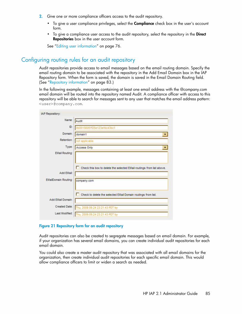
2. Give one or more compliance officers access to the audit repository.
• To give a user compliance privileges, select the Compliance check box in the user's accountform.
• To give a compliance user access to the audit repository, select the repository in the DirectRepositories box in the user account form.
See “Editing user information” on page 76.
Configuring routing rules for an audit repositoryAudit repositories provide access to email messages based on the email routing domain. Specify theemail routing domain to be associated with the repository in the Add Email Domain box in the IAPRepository form. When the form is saved, the domain is saved in the Email Domain Routing field.(See “Repository information” on page 83.)
In the following example, messages containing at least one email address with the @company.comemail domain will be routed into the repository named Audit. A compliance officer with access to thisrepository will be able to search for messages sent to any user that matches the email address pattern:<user>@company.com.
Figure 21 Repository form for an audit repository.
Audit repositories can also be created to segregate messages based on email domain. For example,if your organization has several email domains, you can create individual audit repositories for eachemail domain.
You could also create a master audit repository that was associated with all email domains for theorganization, then create individual audit repositories for each specific email domain. This wouldallow compliance officers to limit or widen a search as needed.
HP IAP 2.1 Administrator Guide 85

Account Manager (AM)86

7 Account Error Recovery
The Account Error Recovery page displays account synchronization activities that have not beenperformed successfully.
To open the page, go to User Management > Account Error Recovery in the left menu.
Error Recovery overviewUnsuccessful account synchronization activities can include:
• Not being able to add a new user because the user name or object GUID (Global Unique Identi-fier) already exists
• Not being able to update a user because the user's entry cannot be found• Not being able to remove a user because the user's entry cannot be found• Not being able to add an alias or email routing rule for a user's repository• Not being able to add a membership to a group
Activity errors are shown grouped by object GUID, with the most recent error at the top of the list.You can select an activity to attempt it again, or you can delete it.
Activities can be filtered by clicking User, Group, or Membership at the top of the page.
Error Recovery featuresTable 20 Error Recovery features
DescriptionFeature
Date the error occurred.Date
Type of activity error. For example, not being able to add an alias or email routingrule for a user's repository.Error
Active Directory unique sequence number. (User or group filters only.)USN
The name of the user account. (User filter only.)UserName
The name of the group account. (Group filter only.)GroupName
Automatically generated identifier for the selected group; unique to the system.(Membership filter only.)Group
The name of the repository. (Membership filter only.)Member
HP IAP 2.1 Administrator Guide 87

DescriptionFeature
The type of repository:• Regulated• Unregulated• Quarantine• Other (includes the AuditLog, failed indexing, CatchAll, Recycle Bin, and access
only repositories for a domain)(Membership filter only.)
MemberType
The Global Unique Identifier of the user account on the LDAP server; its correspondingobject name, relative location in the LDAP tree, and domain. CN (Common Name)is the object name, cn is its branch in the tree, and dc values are domain names.Account synchronization (DAS) supplies these values.(User filter only.)
Object GUIDLDAP DN
Repairing synchronization errorsTo repair synchronization activity errors, identify the activities that you want to reattempt or delete.Click an entry to display more information about an activity, including its Java User ManagementServices (UMS) database entry (only shown if a UMS database entry matches the activity).
You will need to decide the order in which to reattempt or delete the activities.
To repair or delete synchronization errors:
1. Identify the activities that you want to reattempt and select the check box in front of those entries.
You can click the entry in the UserName or GroupName column to find out more about the error.
2. Click Apply Selected.
If the reattempt is successful, the entry is removed from the list.
3. Identify the activities that you want to delete and select the check box in front of those entries.
You can click the entry in the UserName or GroupName column to find out more about the error.
4. Click Delete Selected.
When an activity is deleted, it is immediately removed from the list and cannot be recovered.
Account Error Recovery88

8 Data management
This chapter discusses the following topics:
• Duplicate Manager, page 89• Reprocessing, page 97• Retention, page 99• Backup, page 107• Restoring a Smartcell group, page 112• Smartcell Cloning, page 115• Replication, page 92• Folder support, page 121• Administrative Delete, page 121
Duplicate ManagerThe Duplicate Manager page lets you schedule duplicate merge jobs and view the status of duplicatemerge jobs.
NOTE:Duplicate Manager is only supported for email archived from Microsoft Exchange.
To open the page, go to Data Management > Duplicate Manager in the left menu.
Duplicate Manager overviewDuplicate Manager is intended for organizations that are storing with single instancing enabled.Single instancing is the ability to store a single copy of an email that exists in multiple user repositories.Emails are uniquely identified by a cryptographic checksum called a hash. If an email client attemptsto store the same email twice (as determined by the message hash) only one copy is physically storedand the same reference URI is returned for both store requests.
Storing duplicate emails uses unnecessary space on the Smartcells and clutters search results by listingthe same email multiple times. Once the email file has been stored there is additional data attachedto the file called metadata. Over the lifecycle of the email, the metadata will change as user accesspermissions and folder information change. The purpose of the Duplicate Manager tool is to eliminateduplicate emails while retaining all associated metadata. To that end, the Duplicate Manager willtake the union of all metadata and attach it to a single copy of the email and remove all redundantcopies.
HP IAP 2.1 Administrator Guide 89

If a user previously ran a successful query that returned duplicate emails and saved the query results,after running this tool all but one of the duplicate emails should be accessible. If a user has quarantinedthe files in the saved query result set after running this tool, the single remaining copy of the emailwill remain quarantined.
Smartcells have a storage threshold that is lower than the total capacity of the hard disk. This isbecause the services that run on the Smartcells require a percentage of the disk space in order tooperate. Once the Smartcell reaches this threshold it will transition into a closed state. Becauseduplicate emails can be stored across Smartcell groups, there is a possibility that the merge job willnot be able to work on a set of duplicates because the Smartcells have exceeded the storage thresholdand are no longer able to accept additional metadata. These duplicates cannot be merged untiladditional space has been made available on the closed Smartcell by either migrating some of theemails to a new group or waiting for retention to delete emails and free additional storage space.
The amount of time for a merge job to complete is dependent on the total number of files stored, thepercentage of those files that are duplicates, and the average number of duplicates stored per hash.The first merge job can take many days to complete, while subsequent merge jobs can complete muchfaster.
If no errors occur during the duplicate merge, duplicates are significantly reduced in the system.However, there is no guarantee that all duplicates are removed. Some emails might not have anassociated hash, and cannot be merged into a single copy. The duplicate merge procedure mightalso miss a few duplicate emails on the first pass, since duplicate merge speed was traded for anexhaustive duplicate elimination. Duplicate merge does not attempt to merge all emails in a singlepass. It merges all emails in the system in manageable batches according to default or user configurablebatch size. As a result of this batching, unmerged duplicate emails often occur at the beginning orend of the batches. A subsequent duplicate merge pass will remove the remaining duplicate emails.
Duplicate Manager job schedulesThe Duplicate Manager Schedule shown on the top portion of the Duplicate Manager page showseach domain, domain portal IP address, days of the week that a duplicate merge job is scheduled,time for which it is scheduled, and whether the job status is enabled.
Figure 22 Duplicate Manager job schedules.
Scheduling a jobTo schedule a duplicate merge job:
1. In the Duplicate Manager Schedule by Domain section, click the edit link next to the domain forwhich you want to schedule a job.
2. On the resulting schedule page, use the check box to enable the job, select the HTTP portal wherethe job will run, the days of the week to run the job, the time to run the job, and then click SaveSchedule Now!
Data management90

TIP:For optimal performance this tool should run on a different HTTP portal than DAS and replication.
Enabling or disabling a jobTo enable or disable a duplicate merge job:
1. In the Duplicate Manager Schedule by Domain section, click the edit link next to the domain forwhich you want to enable or disable a job.
2. On the resulting schedule page, select or deselect the Enable check box and then click SaveSchedule Now!.
Starting, pausing, or aborting a jobTo start, pause, or abort a duplicate merge job:
Use the radio button to the left of the desired domain, and click Start, Pause, or Abort as appropriate.Start will start a duplicate merge job on the selected domain immediately. Pause will pause a duplicatemerge job currently running on the selected domain. Abort will abort a currently running or pausedduplicate merge job on the selected domain.
Duplicate Manager job historiesThe Duplicate Manager History Logs displayed on the bottom portion of the Duplicate Manager pageshows information for the five latest duplicate merge job runs. You may also click a domain to seeall (up to 50) duplicate merge job history logs for that domain.
Figure 23 Duplicate Manager job history.
The Duplicate Manager History Log provides the following job history information.
DescriptionFeature
Domain nameDomain
Time stamp of when Duplicate Manager job startedStart Time
Initializing, Started, Not Available, Failed, or FinishedStatus
HP IAP 2.1 Administrator Guide 91

DescriptionFeature
Time since a job was started until finished, aborted, or pausedElapsed Time
Percentage of Duplicate Manager processed sets compared to the totalProgress
Number of duplicates processedDuplicated Processed
Number of duplicates that could not be processed by the DuplicateManager in the job.Duplicates Deferred
Replication
NOTE:This page is available only if a replicated system is configured.Replication is not currently available in virtual IAP environments.
Use the Replication page to monitor and to start or stop replication for a domain on a remote system.
To open the page, go to Data Management > Replication in the left menu.
Replication overviewReplication status is updated after each polling cycle. Therefore, it could be up to five minutes afteryou start replication before you see results on the graph of replication rates. Errors and warnings,however, are displayed as soon as they happen on the system. (The Replication page is unavailableuntil at least one domain on the PCC host system is configured for replication.)
The behavior of the primary Smartcell groups on the replication process is the following: The primarySmartcell of a primary group by default is the one responsible of replicating the email. If this primarySmartcell fails a failover occurs. A failover is the action performed by the secondary Smartcell oftaking over the responsibility to replicate email for its group. When the primary Smartcell is restartedit will regain control of replicating email, this is known as failback. The intention of the failover andfailback mechanisms is to be able to provide fault tolerance by taking advantage of the Smartcellredundancy that IAP provides and continue replicating even if the primary Smartcell is down and toreplicate from the primary Smartcell whenever it is up and healthy.
The behavior of the replica Smartcell groups in an IAP installation is basically to ingest messages fromits primary Smartcell group. In order for the ingestion to happen both replica 1 and replica 2 Smartcellsneed to be available and healthy; or, in the case of a IAP installation configured to only have onereplica Smartcell, only replica 1 needs to be available and healthy. Once a replica group is allocatedno further allocation will occur in the case where the replica Smartcell(s) are unavailable for anyreason. In the case where the replica Smartcell(s) are unavailable for any reason, no allocation forreplica Smartcells will occur, and the replication will fail until the replica Smartcell(s) become availableagain.
If the primary site is not available for queries, users must enter the address of the replica site, insteadof the primary site, in their browsers.
Data management92

NOTE:In order for the Replication page to display statistics from the remote system, an IAP remoteauthorization user must be set up in Account Manager. See IAP Remote Authorization in “User accountinformation” on page 77.
Database ReplicationThe top part of the Replication page describes the database replication.
Table 21 Database Replication features
DescriptionFeature
The replication and primary systems if you are logged into the replicated system.Local Server/nl
Source Server
The primary and replication systems if you are logged into the primary system.Local Server/nl
Target Server
A set is made of one or more DB2 tables that replicated.Replication Set
The time at which the database tables in the replication set got last synchronized.The synchronization time is displayed in two colors: green and red. Green meansthat the database tables on the primary and replica DB2 have been synchronizedsuccessfully within the last 30 minutes. Red means that the synchronization hasnot happened for 30 minutes or more; this could indicate a DB2 replication issueand you should contact HP technical support for advice.
Inbound Sync Time/nl
Outbound Sync Time
The replication status on the replicated and primary systems.Inbound Status/nl
Outbound Status
Re-initializing DB2 replicationFollow these steps to remove and re-initialize DB2 replication on the primary and replica systems. Besure to wait for each step to complete before proceeding to the next step.
1. Stop the IAP applications on the replica system:
PCC server on replica: /opt/bin/stop
2. Restart DB2 on the replica system:
DB2 server on replica: /etc/init.d/db2_app start
3. Stop the IAP applications on the primary system:
PCC server on primary: /opt/bin/stop
4. Restart DB2 on the primary system:
DB2 server on primary: /etc/init.d/db2_app start
5. Unconfigure DB2 replication on the replica system:
DB2 server on replica: /opt/bin/repl/dbRepl rm
HP IAP 2.1 Administrator Guide 93

6. Unconfigure DB2 replication on the primary system:
DB2 server on primary: /opt/bin/repl/dbRepl rm
7. Re-initialize DB2 replication on the primary system:
DB2 server on primary: /opt/bin/repl/dbRepl init
8. Re-initialize DB2 replication on the replica system:
DB2 server on replica: /opt/bin/repl/dbRepl init
9. Wait for the replication process to complete.
On average, it should take less than 30 minutes for the DB2 databases to synchronize.
Use the following steps to monitor DB2 replication and determine when the DB2 databases onthe primary and replica systems are synchronized:
a. Log on to the DB2 server of the replica IAP and enter the following commands:
ssh db2su - db2udbdb2 connect to ark01dbwhile truedo
datedb2 "select set_name,status,synchpoint,synchtime from asn.ibmsnap_subs_set"sleep 10
done
b. Wait until:
• All items listed in STATUS are 0.
NOTE:If one or more items in STATUS is -1, replication is unlikely to succeed. You might wantto start over and repeat steps 1–8.
• All items listed in SYNCHPOINT have values.• All items listed in SYNCHTIME have values and are within a few minutes of the current
time.
Data management94
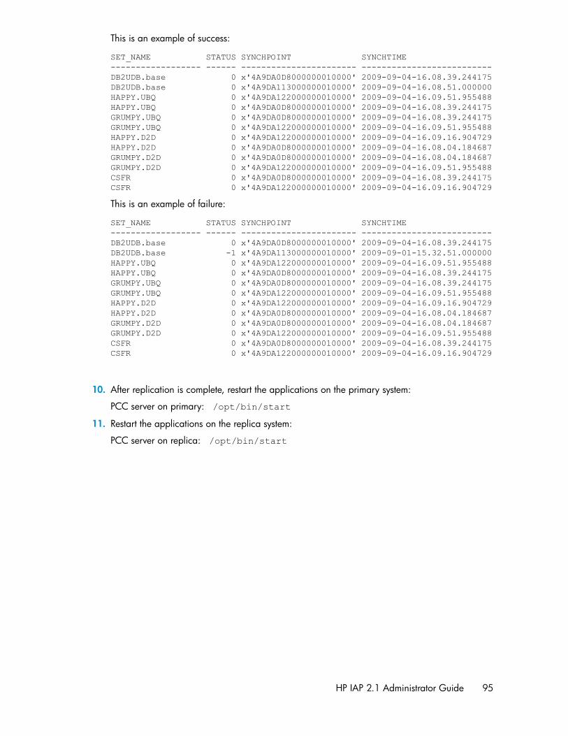
This is an example of success:
SET_NAME STATUS SYNCHPOINT SYNCHTIME------------------ ------ ----------------------- --------------------------DB2UDB.base 0 x'4A9DA0D8000000010000' 2009-09-04-16.08.39.244175DB2UDB.base 0 x'4A9DA113000000010000' 2009-09-04-16.08.51.000000HAPPY.UBQ 0 x'4A9DA122000000010000' 2009-09-04-16.09.51.955488HAPPY.UBQ 0 x'4A9DA0D8000000010000' 2009-09-04-16.08.39.244175GRUMPY.UBQ 0 x'4A9DA0D8000000010000' 2009-09-04-16.08.39.244175GRUMPY.UBQ 0 x'4A9DA122000000010000' 2009-09-04-16.09.51.955488HAPPY.D2D 0 x'4A9DA122000000010000' 2009-09-04-16.09.16.904729HAPPY.D2D 0 x'4A9DA0D8000000010000' 2009-09-04-16.08.04.184687GRUMPY.D2D 0 x'4A9DA0D8000000010000' 2009-09-04-16.08.04.184687GRUMPY.D2D 0 x'4A9DA122000000010000' 2009-09-04-16.09.51.955488CSFR 0 x'4A9DA0D8000000010000' 2009-09-04-16.08.39.244175CSFR 0 x'4A9DA122000000010000' 2009-09-04-16.09.16.904729
This is an example of failure:
SET_NAME STATUS SYNCHPOINT SYNCHTIME------------------ ------ ----------------------- --------------------------DB2UDB.base 0 x'4A9DA0D8000000010000' 2009-09-04-16.08.39.244175DB2UDB.base -1 x'4A9DA113000000010000' 2009-09-01-15.32.51.000000HAPPY.UBQ 0 x'4A9DA122000000010000' 2009-09-04-16.09.51.955488HAPPY.UBQ 0 x'4A9DA0D8000000010000' 2009-09-04-16.08.39.244175GRUMPY.UBQ 0 x'4A9DA0D8000000010000' 2009-09-04-16.08.39.244175GRUMPY.UBQ 0 x'4A9DA122000000010000' 2009-09-04-16.09.51.955488HAPPY.D2D 0 x'4A9DA122000000010000' 2009-09-04-16.09.16.904729HAPPY.D2D 0 x'4A9DA0D8000000010000' 2009-09-04-16.08.04.184687GRUMPY.D2D 0 x'4A9DA0D8000000010000' 2009-09-04-16.08.04.184687GRUMPY.D2D 0 x'4A9DA122000000010000' 2009-09-04-16.09.51.955488CSFR 0 x'4A9DA0D8000000010000' 2009-09-04-16.08.39.244175CSFR 0 x'4A9DA122000000010000' 2009-09-04-16.09.16.904729
10. After replication is complete, restart the applications on the primary system:
PCC server on primary: /opt/bin/start
11. Restart the applications on the replica system:
PCC server on replica: /opt/bin/start
HP IAP 2.1 Administrator Guide 95

Data Replication Flow and Detail InformationThe middle part of the Replication page displays the flow of replicated data. You can also suspendor resume the replication process per domain from this area.
Table 22 Data Replication Flow
DescriptionFeature
The domain name and group ID of the domain being replicated, and the followinginformation:• The IP addresses of the Smartcells being duplicated, the status of the replication,
and the number of stored and indexed documents being copied.
A check icon indicates normal operation.
An X icon indicates that replication failed the last time it was tried.
An ! icon indicates replication is being retried.
• An arrow showing the direction of data. The direction is left to right from theprimary system to the replicated system. The direction is right to left on crossreplica configurations, reflecting that a primary Smartcell group in the remote IAPinstallation is replicating to a replica Smartcell group on this IAP.
• The number of stored and indexed documents that have been copied to the rep-licated domain.
• The percentage of data that has been copied to the replicated domain.
Domain
To stop replication, click Suspend. Replication will stop after the current batch isreplicated.To start replication, click Resume. The batch that would have been replicated nextwhen replication stopped will be replicated.
Suspend/Resume
The Data Replication Flow and Detail Information section also includes a More Details link. Click MoreDetails to open the Data Replication Detail Information page to see additional primary and replicasystem statistics. Statistics are provided by system group name and include Stored Objects, IndexedObjects, Active Transactions, Active Entries, Stored Resources, Stored Chunks, Stored References,and Used Diskspace.
Replication StatusThe bottom part of the Replication page displays the status of the replication.
Table 23 Replication Service General Status
DescriptionFeature
The domain name of the domain being replicated.Domain
Group ID of the domain being replicated.Group ID
Shows whether or not replication is in progress.State
Data management96

DescriptionFeature
The number of file batches that have been iterated to replicate. A batch is composedof 100 messages; therefore, file batch count is the number of replication attemptsfor a batch of 100 messages. (Under certain conditions a batch might get partiallyreplicated, meaning only an x number of files out of the 100 will be successfullyreplicated. In such a case, replication attempts for the batch with the remaining100-x also increases the file batch count.
File Batch Count
The time of the last replication update.Update Time
The date and time of the next replication update.Next Retry Time
Any messages about the last replication update.Message
ReprocessingThe Reprocessing page displays each domain and shows whether reprocessing is enabled, whenreprocessing is scheduled, and a history log report. Reprocessing is an engine service that scansrecently stored data and reallocates messages to the proper repository.
Most reprocessing occurs as an automated and transparent background process that does not requireany operational effort other than passive monitoring.
In most cases, messages are reprocessed to reapply routing rules that have been recently added andare applied to a short time period before the change has occurred. The Reprocessing view allowsyou to schedule and enable reprocessing based on new routing rules.
NOTE:When you make a change using the Reprocessing Utility, the change does not take place immediately.It is put in the job queue, and the reprocessing itself occurs 24 hours later.
To open the page, go to Data Management > Reprocessing in the left menu.
Rescheduling all reprocessing schedulesTo reschedule all the domains to the same reprocessing schedule:
1. In the Reprocessing page, click Reschedule All.
2. Complete the form to set the status and schedule.
3. Click Reschedule All.
4. To ensure that all schedules are enabled, verify that all Reprocessing Status check boxes areselected.
If selected, the text Enabled appears next to the check box.
Editing reprocessing schedulesTo edit a domain's reprocessing schedule:
HP IAP 2.1 Administrator Guide 97

1. In the Reprocessing page, click the edit link next to the domain you want to edit.
Figure 24 Editing reprocessing schedules.
2. Complete the form to set the status and schedule.
3. Click Save Schedule.
4. To ensure the schedule is enabled, verify that the corresponding Reprocessing Status check boxis selected.
If selected, the text Enabled appears next to the check box.
Changing the reprocessing statusYou can enable or disable a reprocessing schedule of a specific domain or all the domains listed.
To change a reprocessing schedule:
1. In the Reprocessing page, locate the domain whose schedule you want to enable or disable.
2. Complete any of the following tasks to change the status:
Figure 25 Change the reprocessing status.
• To enable reprocessing for a specific domain, select the corresponding Reprocessing Statuscheck box.
• To disable reprocessing for a specific domain, clear the corresponding Reprocessing Statuscheck box.
• To enable reprocessing for all domains, click Resume All.• To disable reprocessing for all domains, click Suspend All.
3. Verify the status by noting the text Disabled or Enabled next to the Reprocessing Status checkbox.
Using the Reprocessing UtilityYou can reprocess a user repository if you think a user hasn’t been included in the processing.
In the Reprocessing Utility area of the page:
Data management98

Figure 26 Reprocessing utility.
1. Enter the following information in the text boxes:
• The user email address• The user repository ID
Users can only be reprocessed if their email address and repository are in the IAP. If so, theyare listed in the Account Manager.
2. In the Domain Name drop-down list, select the domain in which the user repository resides.
3. Specify a date range, and click Add in Reprocessing Queue.
The job is sent to the queue, and the reprocessing takes place 24 hours later.
Viewing reprocessing history logsThe reprocessing history log at the bottom of the Reprocessing page shows a list of the last successfulreprocessing runs for each configured domain. The log includes each domain group, when a domainwas reprocessed last, the number of processed files, and the elapsed time of the run. This report isbased on data from Smartcell groups, which is averaged from the individual Smartcells of each group.
RetentionRetention periods are configured for an IAP domain and its repositories when the system is installed.Use the Retention page to change the amount of time that documents are kept before they are deletedfrom the system.
Retention is useful in meeting compliance requirements, when your company must retain emails orfiles for a specified number of years.
To open the page, go to Data Management > Retention in the left menu.
Retention overviewRetention determines how long a document resides on the IAP before it is subject to automatic deletionand permanently deleted from the system. Retention periods can be applied to IAP domains andrepositories. Documents remain physically on the IAP until all retention periods that are associatedwith the item are exceeded.
This section describes how documents are retained in the system and includes the following topics:
• Retention basis• Retention periods• End User Delete• When the retention period expires
HP IAP 2.1 Administrator Guide 99

Retention basisDocuments are retained based on either the send date or the archive date (also known as the ingestdate).
The send date for an email represents the date on the email client when the email was sent or received.The send date for a file, stored via the HP File Archiving software or the Object Storage API interface,represents the “last modified timestamp” of the file.
The ingest date (archive date) of an email or file is the date it was stored in the IAP, using the localtime on the SMTP server.
The retention basis is set in the Domain.jcml file on the kickstart server. One of the following optionsshould be listed in the file:
RetentionBasis=IngestDate
RetentionBasis=SendDate
If neither of the options is specified in the Domain.jcml file, the configuration defaults to the archivedate.
If the retention basis is changed from the archive date to the send date, email with an older send datebut recently archived (for example via the HP EAs Exchange PST Importer) might be deleted the nexttime a retention job runs, if the send date is outside the retention period for the domain and repository.
The PCC Domain Configuration page and the Retention page show the retention basis.
NOTE:Whenever you configure any retention settings in the Domain.jcml file, run the following commands:
regloader.pl —cv —clearallConfirm=<IAP name> on the kickstart server and /opt/bin/restart on the PCC to restart the IAP.
Retention periodsWhen the system is set up, three retention periods are configured in Domain.jcml:
• The retention period for the domain:DomainRetentionPeriodDays=[number of days]
This is the minimum number of days that documents are stored in an IAP domain's repositoriesbefore they are automatically deleted from the system. Values can be -1 (which disables retention)or can range from 30 (days) to 2,147,483,647 (days).After the system is put into production, domain retention can only be altered using the PCC Retentionpage. You can enable or disable retention or increase the domain retention period. The domainretention period cannot be decreased after the IAP starts archiving documents.When retention is enabled on the Retention page, the -1 setting in Domain.jcml has no effect.Configuration changes made via the PCC retention page will override the settings made in theDomain.jcml file.
• The retention period for unregulated repositories:UnregulatedRetentionPeriodDays=[number of days]
Unregulated repositories are created for users imported by DAS from the Active Directory or theDomino Directory. The unregulated retention period is used as the default retention period when
Data management100

the repositories are created. If necessary, individual repository retention periods can later bechanged via the PCC Account Manager page.Setting the value to -1 one does not disable retention.You can change the unregulated retention period by increasing the value in the Domain.jcmlfile.
• The retention period for regulated repositories:RegulatedRetentionPeriodDays=[number of days]
Regulated repositories can be created for users whose activities require a different retention periodthan users in unregulated repositories. These repositories can either be created in Account Manager,or an existing unregulated repository can be converted to a regulated repository by editing therepository information in Account Manager.If your organization uses regulated repositories, the retention period is usually greater than theperiod for domain retention. A value must be configured for this field, even if you do not useregulated repositories. Setting the value to -1 one does not disable retention.You can change the regulated retention period by increasing the value in the Domain.jcml file.
All three retention periods must be set for retention to work. The retention periods are displayed onthe PCC Domain Configuration page and the Retention page.
See “Editing domain retention periods” on page 103 and “Editing repository retentionperiods” on page 106.
Exceptions
The configurable retention periods do not apply in the following cases:
• Quarantine repositories: Documents placed in a quarantine repository are preserved in a legalhold and cannot be deleted when their retention period expires. See “Quarantine repositor-ies” on page 80 for more information on these repositories.
• Admin Delete: A user with administrative delete privileges can manually delete documents froma quarantine repository, or a regulated or unregulated repository before its minimum retentionperiod has expired. See “Administrative Delete” on page 121 for more information.
End User Delete
What is End User Delete?
If users delete an archived email from an Outlook folder, the email is not automatically deleted fromthe IAP. Users are deleting a “tombstone,” a pointer to the actual email that is now stored on the IAP.(When users select the message in their email client, they are viewing a retrieved copy of the message.)
When a tombstone is deleted, and retention and End User Delete are enabled in the Domain.jcmlfile, the reference to the user's repository is removed from the archived message. If folder capture isenabled, references to the Outlook folders where the tombstone was located are also removed fromthe archived item. The message is deleted from the user's repository, and the user can no longeraccess it—either from Outlook, the Web Interface, or Outlook Integrated Archive Search. (This doesnot affect other users who access the message via their own repositories.)
The End User Delete function applies to items in regulated or unregulated repositories, and is used inconjunction with HP EAs Exchange Outlook clients. An archiving event, Synchronize Deleted Items,must be scheduled in EAs Exchange so that removal of a tombstone is synchronized with removal ofthe message in the user repository.
End User Delete removes a message from a user repository. The archived message itself can beremoved from the IAP only when all repository (and folder) references are removed from the message.
HP IAP 2.1 Administrator Guide 101

Messages that no longer have email folders or user repositories associated with them are placed inthe Recycle Bin repository when folder support and/or End User Delete are enabled for a domain.After the retention period for the Recycle Bin repository expires (the default is 30 days), the messagesare automatically removed from the index and the Smartcell during the next retention job.
NOTE:When messages are placed in the Recycle Bin repository, they are re-indexed. The items can besearched for in the Recycle Bin repository but cannot be searched for in the user repository from whichthey were removed.
Configuring End User Delete
Use the following fields in Domain.jcml to configure End User Delete:
• MinUnregulatedRetentionPeriodDays
• MinRegulatedRetentionPeriodDays
The value in each field determines the amount of time an email remains in a user repository after thetombstone is deleted from Outlook. If set to -1, End User Delete is disabled. If set to >=0, End UserDelete is enabled for the repository type (regulated or unregulated).
When the value is set to 0, messages can be deleted from the user's repository immediately. Whenthe value is the same as the retention period for the repository type(RegulatedRetentionPeriodDays or UnregulatedRetentionPeriodDays), messagescannot be deleted via the Outlook client. (This is common in compliance environments.)
Archived messages are removed automatically from the IAP when the retention period has expiredfor each repository in which the message was located.
The following diagram displays how the process works.
Figure 27 End User Delete and retention.
Example
An example of a configuration with End User Delete could be:
DomainRetentionPeriodsDays=30UnregulatedRetentionPeriodsDays=30RegulatedRetentionPeriodDays=365MinUnregulatedRetentionPeriodDays=0MinRegulatedRetentionPeriodDays=365
This configuration means that:
Data management102

• Users can delete messages from their unregulated repository immediately, using their Outlook client.• From the minimum retention period (MinUnregulatedRetentionPeriodDays) to the maximum
retention period (UnregulatedRetentionPeriodsDays), manual deletion is possible in un-regulated repositories.
• Users cannot delete messages from their regulated repository (if one exists) since, for regulatedrepositories, the minimum retention period is the same as the maximum retention period.
• After the retention period has expired for all repositories associated with a message, the messageis available for automatic deletion during the next retention job.
When the retention period expiresWhen the retention feature is enabled, a retention job runs every night at midnight. The Smartcellretention manager first checks the domain retention period for the minimum number of days andverifies that retention processing is enabled. If retention is enabled, it retrieves the information for arepository, including the repository retention period, and locates documents that were ingested orsent before the age limit specified for the repository. The reference to the expired repository, and anycorresponding folder references, are removed from the document. If a document is also located inother repositories and is still within their retention period, it is re-indexed.
Documents that no longer contain repository references are physically deleted from the Smartcell andremoved from the index.
Editing domain retention periodsThe Setting and Configuration area of the Retention page shows the retention basis and retentionperiod for each IAP domain. It also shows whether retention has been enabled for the domain.
You can increase the retention period and/or enable retention processing for a domain by followingthese steps:
1. In the Retention page, click Edit under Set Domain Retention.
2. Set a new retention period by selecting a preset time period from the drop-down list, or by enteringa specific time period in the text box.
The time period must be greater than the Minimum Domain Retention Period.
Figure 28 Editing the domain retention period.
3. If retention processing should be enabled for the domain, select the Retention Status check box.
(Clear the check box to disable retention processing.)
4. Click Save Retention Now to save the revised settings.
You can enable retention processing for all domains by clicking Resume All. Retention processingcan be disabled by clicking Suspend All.
HP IAP 2.1 Administrator Guide 103

NOTE:After the system starts archiving documents, retention processing can only be disabled or enabledusing the PCC Retention page. It cannot be disabled by editing the retention fields in the Domain.jcmlfile.
Viewing deletion statisticsDocuments can be deleted automatically from the IAP when their retention period expires, or theycan be deleted manually. The Retention page displays an Auto Delete Statistics table and a ManualDelete Statistics table with information collected during the most recent retention job run.
These tables, located at the bottom of the Retention page, show aggregate data for domains andSmartcells.
Automatic deletion statisticsThe Auto Delete Statistics table shows information for the current (or last) retention job for eachSmartcell. You can view the history of retention jobs for each Smartcell by clicking the Smartcell link.
Figure 29 Auto Delete Statistics.
Data management104

Click the “+” icon below the domain name to see the detailed activity statistics by Smartcell. Whena job is running, the statistics are updated every five minutes.
Table 24 Auto Delete Statistics
DescriptionField
The IP address of each Smartcell in the domain.Move the cursor (mouse) over the icon in front of the Smartcell IP address to viewthe Smartcell server name, the type of Smartcell (primary or secondary), theSmartcell state and status, active thread number, and Mac address.You can click the Smartcell IP address to see the Platform Auto Delete History table,which displays the retention history for that Smartcell.
Smartcell IP
Always AutoDelete.Job Name
A retention job is either:• Finished• Failed• RunningMove the cursor over the icon in the Job Status column to find the progress(percentage complete) of the job. When a job is running, the status is updatedevery five minutes.
Job Status
The number of documents that were deleted during the run.Deleted Objects
The number of documents for which a repository reference was removed, becausethe repository retention period had expired.Documents with no remaining repository references are marked for deletion.Documents that still contain repository references are re-indexed.
Updated Objects
The number of documents that failed to be deleted plus the number of documentsthat failed to be updated.Failed Objects
Start date and time of the job run.Retention jobs run automatically every night at midnight (12:00 a.m.).
Start Time
The amount of time the job took to complete.Elapsed Time
Manual deletion statisticsThe Manual Delete Statistics table shows domain level statistics for the End User Delete function, ifthis function is enabled in Domain.jcml. (See “End User Delete” on page 101.) End User Deleteoccurs when users manually delete message tombstones (pointers to archived messages) from theirOutlook folders. If the minimum retention period for End User Delete has expired, the reference to theuser's repository is removed from the message. When folder capture is enabled, the reference to theOutlook folder where the tombstone was located is also removed from the message. The number ofremoved repository references are displayed in the Deleted References column.
Messages can be deleted from the IAP only when all references have been removed from the message.
HP IAP 2.1 Administrator Guide 105

Editing repository retention periodsFollow the instructions below to modify the retention period for an unregulated or regulated repository.You can change the retention period as long as it is above the default retention period for the repositorytype.
You can also edit the retention periods for the AuditLog, CatchAll, and Recycle Bin repositories in adomain. Documents in a quarantine repository are removed from retention processing, so there is noretention period for this repository type. (For more information about IAP repositories, see “Repositoryoverview” on page 79.)
1. In the Configuration and Setting area of the Retention page, click the name of the domain.
2. Click the repository tab (Regulated, Unregulated, Other Type) to locate the repository.
The AuditLog, CatchAll, and Recycle Bin repositories are located in Other Type.
You can search for a user repository by entering the user name in the Edit User Repositories boxand clicking Search.
The search function uses the “Like” SQL database capability. For example, you could enter jackto match users jackdoe or jacksmith. Entering %doe would match users jackdoe, janedoe, ormaryjanedoe. Entering %ja% would match users jadams, jackdoe, janedoe, jacksmith, ormaryjanedoe.
Searches are not case sensitive.
3. Click the repository name to edit its retention period.
4. In the form that appears, click the drop-down list in Set New Retention Period or enter the numberof days in the text box.
Retention periods are shown in days. The number of days must be the same or greater than thedomain retention period. The system ignores any value that is less than the domain retentionperiod.
5. Click Save Retention Now.
NOTE:You can view user repositories on replica domains, but you cannot edit them. Retention periods andother fields cannot be edited and action buttons are unavailable when you select a domain that is areplica of another domain.
Data management106

BackupThe PCC Backup pages provide status information about the standard and optional backup servicesrunning on the platform and provide access to HP Data Protector, which runs on optional backupserver(s).
NOTE:If none of the IAP domains is configured with tape backup (DataBackupEnabled=false inDomain.jcml), tape backup is disabled in the IAP. Tape backup is also disabled in virtual IAPenvironments. When tape backup is disabled, tape backup status is not included on the PCC backuppages.
IAP backup data:
• Configuration files such as IAP configuration from the kickstart, SSL certificates, and SSO keys arebacked up locally (the standard backup). IAP configuration files from the kickstart server are backedup locally to the PCC when the converter script is run. Configuration files can also be backed upto tape (the optional backup system) by full and incremental backups.
• Database data is backed up locally. A local backup of the DB2 database is made daily on theplatform's local disk. A copy of that local backup is kept on the database server and the kickstartserver for added security. Database data files can also be backed up to tape (optional backupsystem) by full and incremental backups.
• Smartcell data: This data can be backed up to tape (optional backup system) by full and incre-mental backups. The content indexes are also backed up to tape.
NOTE:In virtual IAP environments, the optional backup system is not supported. You must use anotherenterprise backup solution to back up Smartcell data and the virtual IAP system.
To open the Backup pages, go to Data Management > Backup in the left menu.
For detailed information about the optional backup system which runs Data Protector, see “Optionalbackup system” on page 151.
Backup OverviewThe Backup Overview page provides backup status information for configuration, database, andSmartcell data. From this page you can also disable or enable tape backup to run as scheduled ifyou have the optional backup server. (The backup server is not supported in virtual IAP environments.)
HP IAP 2.1 Administrator Guide 107

Figure 30 Backup Overview.
Overall backup service summaryAn overall backup service summary is at the top of the page.
A check icon indicates backup service completed successfully. This status is displayed if the lastbackup of all three sets of data completed successfully without error.
An ! icon indicates backup service completed with warnings. This status is displayed if the lastbackup of all three sets of data completed but at least one backup completed with warnings.
An X icon indicates backup service failed. This status is displayed if the last backup of any of thethree sets of data failed.
An information icon indicates backup service information is being provided. This status is displayedin non-error conditions. When backup service is initially set up, the information icon signifies that nobackup session has run yet.
Individual backup service summariesThe Backup Overview page also shows the backup status of each set of data: for configuration,database, and Smartcells.
The success check icon is displayed if there is at least one full backup in the last 28 days and oneincremental backup in a 24 hour period. These time intervals are default but they can be customized.Otherwise, the page shows a warning icon or an error icon . Warnings are displayed when thelast full or incremental backup completed with warnings. Errors are shown when the last backup failedor completed with errors, or the last full backup is older than 28 days and the last incremental backupis older than a day.
Data management108

An information icon indicates backup service information is being provided for the backup type.This status is displayed in non-error conditions. (When backup service is initially set up, the informationicon signifies that no backup session has run yet.)
Conditional information will inform you when:
• The given backup type has a backup schedule enabled or disabled.• A current backup session is running and its status (if any).• A full backup is older than a certain threshold (by default 28 days).• An incremental backup is older than a certain threshold (by default one day).
For the configuration and database data types (which have local backups performed on the IAP) youwill see bulleted information regarding the last backup session status.
Configuration data backup statusConfiguration data to be backed up resides on various servers (for example, PCC, HTTP, and kickstartservers). These servers are called the backup clients.
A check icon is displayed if the last backups of the configuration data on all backup clientscompleted successfully without error and are not older than a certain number of days (one day forincremental backup, 28 days for full backup).
An ! icon is displayed if the last backups of the configuration data on all backup clients completed,but incremental backup on some backup clients is older than two days (for example, “Last completedincremental backup on kickstart is older than 1 day”).
An X icon is displayed if the last FULL backup of the configuration data on any client is older than28 days (for example, “Last completed full backup on PCC is older than 28 days”), or if the backupstatus on any backup client cannot be found (for example, “No backup found on backup server”).
Database data backup statusDatabase data is backed up on the IAP local disk (kickstart and database servers) and also backedup to tape if tape backup is enabled. The database data that is backed up to tape resides on thekickstart server.
A check icon is displayed if the last local backup and tape backup of the database data completedsuccessfully without error, and tape backups are not older than a certain number of days (one dayfor incremental backup, 28 days for full backup).
An ! icon is displayed if the last backup of database data completed but the local database backuphas a warning (for example, “Local backup 1 completed with warnings”), or an incremental tapebackup is older than one day (for example, “Last completed incremental backup on kickstart is olderthan 1 day”).
An X icon is displayed if the last full tape backup is older than 28 days (for example, “Last completedfull backup on kickstart is older than 28 days”), if the tape backup status cannot be found (for example,“No backup found on tape”), or if the local backup status cannot be found (for example, “No backupfound on DB2 server”).
If tape backup is disabled, the status of the database backup to tape is not displayed on the dashboard.
Smartcell data backup statusSmartcell data to be backed up resides on assigned Smartcells. These Smartcells are also backupclients. The name of the Smartcell backup client consists of gid and the group ID that the Smartcellbelongs to and the domain name of the IAP.
HP IAP 2.1 Administrator Guide 109

A check icon is displayed if the last backup of the data on all assigned Smartcells completedsuccessfully without error and is not older than a certain number of days (one days for incrementalbackup, 28 days for full backup).
An ! icon is displayed if the last backup of the data on all assigned Smartcells completed butincremental backup on some Smartcells is older than one day (for example, “Last completed incrementalbackup on gidxxx1 is older than 1 day”).
An X icon is displayed if the last full backup of the data on any assigned Smartcell is older than28 days (for example, “Last completed full backup on PCC is older than 28 days”), or if the backupstatus on any assigned Smartcell cannot be found (for example, “No backup found on gidxxx1.”).
If tape backup is disabled, Smartcell data backup is not displayed on the dashboard.
Disable/enable tape backup scheduleIf the tape backup feature is configured on the Backup Overview page, a button to disable/enablescheduled tape backup is displayed. If the tape backup schedule is disabled, tape backup will nolonger occur. The data on the previously backed-up tape will not be erased. When the tape backupschedule is disabled, a bullet under each of the three backup types is displayed stating that the backupis disabled.
Configuration InformationThe lower portion of the Backup Overview page displays configuration information for the local andtape backups.
The Configuration Information area contains the internal IAP IP address of the configuration anddatabase server, the run time schedule for the local backup process, and the location of the localbackup files.
The Configuration Information area also contains the internal IAP IP address of the backup server (ifavailable), the version of the Data Protector backup software being used, and a list of the IAP domainsthat have tape backup enabled.
NOTE:If tape backup is disabled, this section displays “Tape Backup is disabled.” If tape backup is enabledbut the backup server is not available, the Backup Server IP section displays “Backup applicationServer is down, cannot retrieve information.”
Database backupDatabase data is backed up on the IAP local disk (kickstart and database servers) and also backedup to tape if tape backup is enabled. The Database Backup page provides detailed information onthe last two local backups (one on the local database server and the other on the kickstart server).The Database Backup page also provides detailed information on the last tape full and incrementaldatabase backups (for optional backup servers). It includes completion time, size, type (full orincremental) information, and informational messages.
The entry in the Last Database Backup table for the local database backup contains information aboutthe database backup job, which extracts information from the DB2 database and stores it in arecoverable format.
The PCC displays statistics about the database backup process itself. In particular, the CompletionTime column shows the time at which the database extraction process completed. Other job logs
Data management110

might show the local backup job completing at a later time, but those later timestamps include theoverhead tasks that are managing the disk storage space for the database backup archive, and arenot the specific database backup process.
The Local Completion Time is useful for determining the data that was included in the backup, forsituations where recovery of backed-up data is dependent on the time the data was extracted.
Tape Backup ConsoleThe Tape Backup Console page provides VNC access to the HP Data Protector graphical user interface(GUI), which runs on the optional backup server(s). Use HP Data Protector for detailed optional backupserver status information and configuration.
This page does not appear in virtual IAP environments.
Local backup file locationsThe contents of the install/config/primary directory on the kickstart server are backed up.
• Database backup files: The database backup files and DB2 transaction log files are stored on thedatabase server (partition /db2/VolBack). The files are mirrored to a directory on the kickstartmachine (/install/db2backups). The DB2 database is backed up once a day and the lasttwo backup files are kept on disk.
• Master configuration files: There are three master configuration files: BlackBoxConfig.jcml,Domain.jcml, and the UserKeyStore file in the /install/configs/primary directoryon the kickstart server. Whenever one of these files is changed and the converter and RegistryLoader are run, the modified files are copied to the PCC machine, to the directory /usr/local/MasterConfigFiles.(To run the RegistryLoader after changing a configuration file, run the following script on thekickstart server: regloader.pl -cv.)
NOTE:The file BlackBoxConfig.bct is not included in the local backup, because it can be generatedfrom BlackBoxConfig.jcml (/install/tools/converter/dumpBCT). The scriptcreateBBC.zr generates the .jcml version that is backed up.
Restoring DB2 local backup filesThe DB2 database can be restored from the backup files on the /db2/VolBack partition on thedatabase server. If data is lost because the database machine was reinstalled, restore the backupfiles first. Restore the backup files from either the copy on the kickstart server, or tape backups ifapplication backup is enabled.
The functionality to restore the database backup partition and the database itself is implemented inthe /opt/bin/backup/db2BackupUtility script on the database server.
Follow these steps to restore the database:
1. Before restoring the database, stop all IAP applications by issuing /opt/bin/stop on the PCCserver.
2. Log on to the database system.
HP IAP 2.1 Administrator Guide 111

3. If the database server was reinstalled, run the following command to restore the /db2/VolBackpartition from the version stored on the kickstart server:
/opt/bin/backup/db2BackupUtility -restore_from_kickstart
NOTE:This will delete the content of the VolBack directory.
4. To restore the database, make sure the database is up by issuing the command:
su – db2udb –c db2start
5. To restore DB2, run the following command. You will be asked for a timestamp of the backup torestore.
/opt/bin/backup/db2BackupUtility -restore_db2
Normally, the last two backups of the database are kept.
6. After the installation is finished, run /opt/bin/start on the PCC server to start the IAP andvalidate that it operates correctly.
Restoring the master configuration filesCopies of the master configuration files are kept in the /usr/local/MasterConfigFiles directoryon the PCC server. Whenever one of the files is changed on the kickstart server and the converter isrun, the master configuration file is copied to the PCC server, and renamed toYYYY-MM-DD-hh.mm.ss_FileName.
Restoring a Smartcell group
NOTE:In virtual IAP environments, Smartcell restoration is not supported and this page does not appear.You must use another backup/restore solution to back up and restore a Smartcell group.
The Restore Smartcell Group page lists broken groups that can be restored from tape, groups thatare currently being restored (including progress information), as well as past completed or abortedrestore operations.
If you lose one Smartcell of a group, use the Smartcell Cloning page to clone the Smartcell to rebuildthe group. Cloning is much faster than tape restore and the healthy Smartcell may have recent datanot on the tape backup.
If you experience the loss of both Smartcells in a group, use the Restore Smartcell Group page torestore one Smartcell from tape. After one Smartcell is restored from tape, use cloning to get thesecond Smartcell thus rebuilding the group.
Data management112

NOTE:You should only restore from tape when cloning is not possible. Cloning a Smartcell is faster than atape restore and also guarantees that the data is complete (data on tape is only as current as the timethe last backup took place).
To open the Restore Smartcell Group page, go to Data Management > Restore Smartcell Group inthe left menu.
Smartcell Group Restore candidatesThe Smartcell Group Restore candidates section appears on the Restore Smartcell Group page whenthere are one or more broken groups that can be restored from tape. Only groups for which both theprimary and secondary Smartcells are unavailable are listed here. If only one of the Smartcells in agroup has to be restored, cloning is the preferred option to recover the group.
Each entry in the group lists the domain name, the group ID, and (if available) the IP address ofprimary and secondary Smartcell.
The Start Restore button initiates the tape restore for the given group. When you click the button, taperestore for the particular group begins and an entry for the operation appears in the list of currentrestore jobs.
Current Smartcell Group Restore JobsThe Current Smartcell Group Restore Jobs section lists running or failed restore jobs along with theircurrent progress. Each entry provides the following information:
Table 25 Current Smartcell Group Restore Jobs information
DescriptionField
The group ID of the group being restored from tape.Group ID
Either Running or Failed.Status
IP address of the Smartcell to which the data is being restored. This field is populatedas soon as a free Smartcell has been assigned for restore.Smartcell IP
Date and time when this operation began.Started
Information about the restore step currently being executed.Completed Step
One or more possible actions to control the job.Action
You can perform the following actions:
• ResetCan be performed as soon as the Smartcell has been assigned. This action aborts the current joband resets the Smartcell that was assigned as a restore target. All data that was potentially restoredis already removed and the cell is moved back into the pool of free Smartcells.
• RetryOnly available if the current step fails. This action resumes the operation, retrying from the lastfailed step.
HP IAP 2.1 Administrator Guide 113

• CloneOnly available once the Smartcell is restored completely and is ready to be cloned. This actiontakes you to the Cloning PCC page and marks the restore operation for this Smartcell as complete.
Unregistering a configured SmartcellIf a Smartcell that is already configured in an IAP must be “re-kickstarted,” you need to unregister theSmartcell in the Tape Backup Console to be able to use it for the restoration process. (If this is a newSmartcell added to IAP, this step is not necessary.)
To unregister a Smartcell:
1. Go to Data Management > Backup.2. On the Backup page, click the Tape Backup Console tab and log into the Tape Backup Console.3. Connect to the HP Data Protector Cell Manager by selecting File > Connect to Cell Manager, then
select the primary backup server to connect.If you are already connected you can skip this step.
4. Once connected, select the Smartcell hostname from Clients, then right-click and select Delete.In the figure below, the Smartcell being selected for delete is sc-s1-172-1.persistcorp.com.
Figure 31 Unregistering a Smartcell.
5. When asked if you want to remove Data Protector software, click No.Once this step finishes, the Smartcell is ready to be rekicked and available for restore.
Data management114

Smartcell CloningUse the Smartcell Cloning page to show the status of current and past cloning operations, and toclone a Smartcell.
To open the page, go to Data Management > Smartcell Cloning in the left menu.
Cloning overviewYou can clone a Smartcell if its mirror Smartcell is SUSPENDED, DEAD, or FAILED. (See “Smartcelllife cycle states” on page 38.) Cloning a Smartcell copies all its information to another Smartcell thatis in the FREE state to give the Smartcell a new, viable mirror. Cloning operations can take a longtime (as much as a day), depending on the amount of information cloned.
Smartcells are placed in the free pool upon their initial installation. If your system does not contain aSmartcell in the FREE state, do one of the following:
• (Non-virtual IAP systems) Contact your local HP sales representative to order additional Smartcell(s).• (Virtual IAP systems) Follow the steps in “Preparing for Smartcell cloning in virtual IAP environ-
ments” on page 116.
When you access the Cloning page, PCC searches for ongoing cloning operations and loads thecurrent data. Only one Smartcell can be cloned at a time, so you see the progress of any ongoingcloning operation.
NOTE:The type of file system used on the Smartcell has an impact on the cloning operation. A Smartcellrunning the ReiserFS file system will require a clone Smartcell with a same size ReiserFS file system.
Cloning featuresTable 26 Cloning features
DescriptionFeature
The IP address of a Smartcell without a viable mirror. If all Smartcells have viablemirrors, the Source displays No Broken Groups Found. If more than one Smartcellneeds a mirror, a Change Source button appears below the automatically selectedIP address.
Source
The number of Smartcells currently in the FREE state. This number is decreased byone after a cloning operation starts.Free Cells
A graphical representation of the assigned and free Smartcells.Assigned/Free
Starts the cloning operation. See “Cloning Smartcells (copying data)” on page 116.Clone Cell
HP IAP 2.1 Administrator Guide 115

DescriptionFeature
This area provides the following information about an ongoing cloning operation:• Source selected: IP address of the Smartcell being duplicated.• Target selected: IP address of the Smartcell receiving duplicate data.• Current Step Percentage: Dynamic bar showing how much source data has been
duplicated.• Overall Percentage: Current step in the cloning operation.
Cloning operation steps are as follows:• Initializing• Assigning target host• Transferring data• Transferring indexes• Waiting for indexer to complete• Updating history log• Completed or Failed
Some steps happen so quickly you might not see them.Steps such as Transferring data and Transferring indexes can take a long time ifthere is a great deal of data to clone.
Cloning Area
The following information about each cloning operation that has occurred sincestartup:• Source• Target• Time Elapsed• Status• Date
History Logs
Cloning Smartcells (copying data)
Preparing for Smartcell cloning in virtual IAP environmentsBefore copying a Smartcell's data, you need to add a Smartcell virtual machine (VM) to the virtualIAP to act as the free Smartcell. This is done using the clone function provided by VMware's vSphereClient.
In a virtual system, use different datastores for the source and the target (clone) Smartcell virtualmachines. The logical units (LUNs) created for the datastores must be allocated on different physicaldisks for storage redundancy.
1. Start vSphere Client: Start > All Programs > VMware > VMware vSphere Client.
2. Log in to the vCenter Server that manages the ESXi host using the IP address, Administrator ID,and password.
3. Select the ESXi host.
Data management116

4. Clone an existing Smartcell using these steps:
a. Select the Smartcell to be cloned.
b. Right-click the Smartcell, and select Clone.
c. Enter a name for the new Smartcell.
The name should be in the form P_SC-<3rd_octet_of_ip>-<4th_octet_of_ip>.For example, if the IP address chosen is 10.0.204.2, then the VM name must be P_SC-204-2.
The IP address for a Smartcell must be 10.0.172.x or 10.0.204.x, with the fourth octetfollowing on sequentially from the previous IP address. For example, 10.0.204.1,10.0.204.2, 10.0.204.3, and so on. You cannot use an IP address that is already in use.
d. Select the virtual datacenter where you want to create the new Smartcell VM, and click Next.
Figure 32 Selecting datacenter for new Smartcell VM.
e. Select the host on which you want to create the new Smartcell VM, and click Next.
f. Select the Resource Pool in which you want to create the new Smartcell VM, and click Next.
g. Select the datastore for the new Smartcell VM, and then click Next.
This must be a different datastore than the datastore for the source.
h. Select the disk format option Same format as source, and click Next.
i. Click Next. (No Guest OS customization is required.)
j. Verify that all the configuration information is correct, and click Finish.
HP IAP 2.1 Administrator Guide 117

The new Smartcell VM is created in the specified location in the vSphere Client.
Figure 33 Completing creation of the newSmartcell VM.
Data management118

5. Adjust the Power-on Boot Delay:
a. In the vSphere client, select the new Smartcell VM.
b. Click the Summary tab.
c. Click the Edit Settings link.
d. Select the Options tab.
e. In the Advanced options, select Boot Options and enter the value 90,000 (ms) for the Power-onBoot Delay.
f. Click OK.
Figure 34 Adjust Power-on Boot Delay.
6. Get the MAC address of the new Smartcell VM:
a. In the vSphere client, select the new Smartcell VM.
b. Click the Summary tab.
c. Click the Edit Settings link.
d. Click Network Adapter 1 in the Virtual Machine Properties window.
The MAC address of the Smartcell VM is displayed in the window's right panel.
HP IAP 2.1 Administrator Guide 119

7. Add the IP address and the MAC address of the new Smartcell VM to the BlackBoxConfig.bctconfiguration file:
a. Select the kickstart server VM, click the Console tab, and log in to the kickstart VM as theroot user.
b. Navigate to the /install/configs/primary directory.
c. Make a copy of the BlackBoxConfig.bct file as a precaution:
# cp BlackBoxConfig.bct BlackBoxConfig.bct.orig
d. Open BlackBoxConfig.bct using a text editor such as Vim.
e. In the MACHINES section of BlackBoxConfig.bct, add a new entry with the IP addressand MAC address assigned to the new Smartcell VM.
For example:
SC: 10.0.204.2 <MAC Address>
f. Add KS:ks.sc.clearall to the end of the new entry.
Using the example above, the complete entry would be:nl
SC: 10.0.204.2 <MAC Address> KS:ks.sc.clearall
g. Save and close the file.
8. At the kickstart prompt, run the following scripts:
• createBBC.zr
• regloader.pl —cv —c=<IAP Name>IAP Name is the BlackBox value located at the beginning of the BlackBoxConfig.bct file.Enter y at the prompt to confirm.
9. In the vSphere Client, power on the new Smartcell VM.
10. Press F12 to PXE boot the new Smartcell VM.
Monitor the PXE boot until the server is initialized.
11. Perform the steps in the next section, Copying Smartcell data.
Copying Smartcell dataIn both virtual and non-virtual IAP environments, follow these steps to copy data from a source Smartcellto a target Smartcell:
1. Perform one of the following actions:
• Select the source Smartcell from the Source field.• If the option is present, click Change Source to select a different Smartcell for cloning. When
the selection box appears, select the Smartcell you want from the drop-down list, and clickSelect.
2. Click Clone Cell.
This button is unavailable if there are no Smartcells to clone.
When cloning is successful a pop-up panel appears on screen.
Data management120

3. Check the Status Area to see results of the cloning operation.
A check icon indicates the cloning operation is proceeding normally.
An X icon appears if the cloning operation has failed.
Folder capture supportIAP 2.x supports folder capture for Email Archiving software for Exchange (HP EAs Exchange) version2.x.
This feature captures the original Outlook location of archived messages and updates the correspondingdocuments in the IAP. The folder location (for example, /Inbox/project) is stored as metadata inthe archived email.
For folder capture to occur, it must be enabled on both the IAP and HP EAs Exchange. In HP EAsExchange, folder capture is enabled by default. On the IAP, it is disabled by default and must beenabled in Domain.jcml.
When folder information is indexed, the folder name can be used to search for and retrieve messagesstored on the IAP. To limit the number of archived messages that are re-indexed when folder informationis added, a cut off date is specified in Domain.jcml. Messages stored before the cut off date haveonly their metadata updated, while messages stored after the cut off date have both the metadataand indexes updated with folder information.
NOTE:If the IAP contains a number of closed Smartcells, available disk space can be quickly depleted whenindexed folder information is added.To prevent this error, we strongly recommend setting the cut off date to the date the system is upgradedso that only new messages are indexed.
For more detail on folder support, see the “Working with folder capture” chapter in HP Email Archivingfor Exchange Administration Guide version 2.x.
Enabling folder captureThe FolderSupportEnabled option in Domain.jcml indicates whether folder support is enabled inthe IAP for a domain. If enabled, the IAP allows users from this domain to search for email by folderand display the folder in which the email is stored. To enable folder support, this option must be setto true: FolderSupportEnabled=true
After configuring Domain.jcml, run the following commands: regloader.pl –cv–clearallConfirm=<IAP name> on the kickstart server and /opt/bin/restart on PCC torestart the IAP.
The PCC Domain Configuration shows whether folder support is enabled.
Use the date of the IAP 2.x installation or upgrade as the date, for example 07/30/2008.
Administrative DeleteThe Administrative Delete function gives designated users the ability to manually delete an email thathas been stored in the archive. This function is typically used in the Federal area for dealing with
HP IAP 2.1 Administrator Guide 121

classified data; for example, to remove inadvertently distributed messages from the archive. Emailcan be manually deleted from regulated, unregulated, and quarantine repositories.
IMPORTANT:It is the responsibility of customers to verify that using Administrative Delete does not interfere withtheir organization's record retention policies. HP will not be held liable for the irresponsible use ofthis feature. HP has made every effort to put the proper controls and logging in place to preventunintentional removal of data from the system.
Enabling Administrative DeleteAdministrative Delete is enabled or disabled at the domain level. If enabled, the system allows a userwho has the appropriate privilege to delete email.
1. In a virtual IAP environment, follow steps a-e below.
In non-virtual IAP environments, go to step 2.
a. Start vSphere Client by selecting Start > All Programs > VMware > VMware vSphere Client.
b. Log in to the vCenter Server that manages the ESXi host using the IP address, AdministratorID, and password.
c. Select the ESXi host.
d. Click the kickstart virtual server.
e. Click the Console tab.
2. At the kickstart console, log in as the root user.
3. Open the Domain.jcml file:
a. At the prompt enter:
# cd /install/configs/primary
b. Open Domain.jcml in a text editor.
For example:
# vi Domain.jcml
4. Enable Administrative Delete by setting the AdminDeleteEnabled field to true:
AdminDeleteEnabled=true
Add this field if it does not exist in the file.
NOTE:If Administrative Delete is enabled, the AuditLog must also be enabled, as described in“Enabling the AuditLog” on page 147.
(Administrative Delete can be disabled by setting the AdminDeleteEnabled field to false.)
5. Save and close the file.
Data management122

6. Run the RegistryLoader by entering:
# regloader.pl —cv —clearallConfirm=<IAP Name>
Enter y at prompt to confirm.
7. After the RegistryLoader has executed, go to the PCC console and log in as the root user.
8. Restart the IAP from the PCC:
# /opt/bin/restart
9. Log into PCC Web Administration.
The General Configuration Platform Settings page should show the Admin Delete Service asenabled.
Granting the Delete Admin privilegeAll IAP Admin users, with the exception of super users, can grant or revoke the Delete Administrationprivilege. Only a remote user (a user existing in the Active Directory and imported by DAS) can begranted Delete Administration privilege.
To grant this privilege to a user:
1. Log in to PCC Web Administration as the super user.
2. Open the PCC Account Management page and grant the IAP Admin privilege to a user.
3. Log in to PCC Web Administration as the IAP Admin user and open the PCC Account Managementpage.
4. Select the user who needs to execute Administrative Delete and edit this user by selecting theDelete Admin check box.
The domain that this user belongs to should have Administrative Delete enabled; otherwise, theDelete Admin check box will not appear.
5. Save the change.
To revoke the Admin Delete privilege:
1. Log in to PCC as the remote IAP Admin user.
2. Open the PCC Account Management page and select the user who has the Delete Admin privilegeand edit this user by deselecting the Delete Admin check box.
3. Save the change.
Executing Administrative DeleteAfter obtaining the Delete Admin privilege, a user is allowed to delete any messages stored in IAP.To delete messages:
1. Log in to the IAP Web Interface as the user with the Delete Admin privilege.
2. Search for and select the message to be deleted.
3. Click More Options.
4. Select Delete Checked Items.
5. To confirm the deletion, click Confirm Delete.
HP IAP 2.1 Administrator Guide 123

6. After confirming deletion, a status page appears, which contains a report on the success or failureof the deletion submittal.
After the message is submitted to delete, it may take up to two hours for the message to beremoved from the index. During that time, the message contents will be still searchable, but notretrievable.
When a message is deleted by Administrative Delete:
• The deletion physically removes the message and all references of the message from IAP.• The message is deleted if it is quarantined.• A message in Saved Results is deleted from the index and the message body is no longer
searchable. However, the message is still listed in Saved Results.• The deletion is done on both primary and secondary Smartcells. If the IAP is running in a replication
environment, the message is also deleted on the replica Smartcells.• If the IAP is running in a replication environment, Administrative Delete can only be executed to
delete a message that is stored on the primary IAP; the deletion is triggered on the replica IAP bythe replication process. Administrative Delete can not delete any message stored on the replicaIAP directly.
Logging in AuditLogActivities in Administrative Delete are logged in the AuditLog and stored in the AuditLog repository.
• When a user obtains or loses the Delete Admin privilege, the change is logged in the AuditLog.• When a message is deleted by Administrative Delete, the operation is logged in AuditLog.
Current limitationsThe following are current limitations of Administrative Delete:
• In IAP 2.x, Administrative Delete only deletes emails. It does not delete documents that were storedwith the Object Store API (BIBO) or the HP File Archiving software (formerly FMA), and it doesnot delete an audit trail.
• If email has been backed up with the IAP backup feature, the email can be deleted from the IAPusing Administrative Delete. However, the email and any related information on the tape will notbe deleted. Because of this, all administrative delete operations should be re-executed on the IAPwhen any Smartcell recovery has been performed. (This is a low-probability event.) The AuditLogprovides the necessary information to determine which delete operations need to be re-executed.
• At this time, deleted messages in a saved query result appear when reloading the saved result inthe Web Interface. However, if you click the deleted messages, you will see Error displayingmessage. The saved queries keep the reference to the file until the saved query is cleaned up.
• This feature does not currently satisfy DoD or NSA data destruction standards.
Data management124

9 Reporting
This chapter includes information about the following topics:
• Event Viewer, page 125• SNMP Management, page 127• Email Reporter, page 129• Collect Log Files, page 131• “User Repository Utilization Report” on page 132
Event ViewerThe Event Viewer shows the events that are occurring or have occurred on system servers and insystem services and applications.
NOTE:All alerts are logged as events in the PCC, and are displayed among the other events on the EventViewer page. See “Current Platform Alerts” on page 41.
There are two ways to open the Event Viewer:
• Go to Reporting > Event Viewer in the left menu.• Select Overview from the left menu, and then click Go to Event Viewer in Current Platform Alerts.
Event Viewer overviewThe following information is displayed in the Event Viewer.
Table 27 Event Viewer features
DescriptionFeature
A short description of the event.The description is preceded by an icon showing the event level:• Critical: The issue is critical for the entire system.• Major: A server or application feature has a major problem, but the issue
is not critical for the entire system.• Minor: A server or application feature has some internal problems, but they
are not critical for the server or feature health.• Resolved/Manually resolved: The issue has been automatically or manually
resolved.• Unknown: The cause of the issue was unknown.• Information: The event was part of the normal operation of the system.
Description
HP IAP 2.1 Administrator Guide 125

DescriptionFeature
The context in which the event occurred.Context
The type of server on which the event occurred and the IP address of the machine.Machine
The date and time that the event first occurred or was resolved.Date
Searching the Event ViewerYou can choose to display only events that match the search type and criteria specified in the Searcharea of the viewer.
To search the Event Viewer:
1. Select the number of events to be shown on each page.
The default is 20 events per page.
2. Select a Search Type in the drop-down list.
You can choose from the following types of searches:
• Show All Events• Level (of event)• Machine Type (of the machine on which the event occurred)• IP Address (of the machine on which the event occurred)• Host Name (of the machine on which the event occurred)
3. In the Search Criteria text box, enter the criteria for the search.
You must enter criteria for all searches except Show All Events. Searches are not case sensitive.
• For Level, see the legend at the bottom of the Event Viewer.• For Machine Type, see the Machine column in the Event Viewer for examples.• For IP Address, see the Machine column of the Event Viewer or the Software Management
page.• For Host Name, see the Software Management page.
The search function uses the “Like” SQL database capability. For example, you could use SearchType: Host Name and enter sc% in Search Criteria to match host names sc-s1-172-1.company.comor sc-s2-204-1.company.com. Entering %204% would match hosts sc-s2-204-1.company.com,or sc-s2-204-2.company.com.
Or, to search for resolved events, you could select Search Type: Level and enter %resolved inSearch Criteria to view both resolved and manually resolved events.
4. Click Submit.
Deleting eventsDelete events from the Event Viewer in one of the following ways:
Reporting126

1. Choose one of the following:
• Select the check box in front of one or more events.• Select a cutoff time in the drop-down list at the bottom of the page. For example, events older
than two weeks.• Select All Events in the drop-down list at the bottom of the page to remove all events in the
viewer.2. Click Delete after making your selection.
NOTE:The system automatically clears events (oldest first) when the number of records reaches 20,000. Tenpercent (2,000) of the maximum number of entries are removed. Currently, event retention is notconfigurable.
SNMP ManagementApplication-generated alerts that occur in the IAP system are shown in Current Platform Alerts on thePCC Overview page. These alerts can be forwarded as SNMP traps to external monitors in yournetwork and/or to email recipients.
Use the SNMP Management page to perform the following functions:
• Download the IAP MIB file to be imported into your monitoring management server(s).• Select the SNMP traps to be monitored.• Set the monitoring servers and/or email recipients to be notified when an alert is received.• Set SNMP community.• Send a test trap to verify that the configuration has been set up properly.
NOTE:Only application-generated alerts can be selected as SNMP traps on this page. Hardware monitoringfor IAP servers is provided by Proliant management agents. See “Hardware monitoring” on page50 for more information.
To open the page, go to Reporting > SNMP Management in the left menu.
Downloading the IAP MIBThe IAP MIB (management information base) allows monitoring applications such as HP SIM torecognize SNMP events coming from the IAP.
IAP SNMP traps are placed in an SNMP XML file, which is used by the IAP system to generate a MIBfile, iap.mib. The generated iap.mib uses SNMP version 2, which is compliant with the transferprotocol SNMP version 1.
Whenever a new version of the IAP software is installed on your system, download \opt\mibs\iap.mib from the PCC server and import it into your monitoring management software so the monitorcan recognize the IAP SNMP traps. In the MIB Manager Service area, click Download to copy theIAP MIB file to your local machine.
HP IAP 2.1 Administrator Guide 127

To import the MIB to the monitoring servers, refer to the documentation for your monitoring managementsoftware.
Selecting SNMP trapsIn the SNMP Trap Manager Service area, select the SNMP traps to be monitored. When one of thealerts is generated, a corresponding trap is sent to the SNMP monitoring server and/or email recipientthat is entered on the SNMP Management page.
To set the SNMP traps:
1. Select the system for which the traps will be activated.
This is always IAP.
2. Select the traps to be sent:
Traps are grouped by features. You can activate all traps, activate traps by feature, or activatetraps individually.
The trap IDs correspond to the alert IDs that are listed in “IAP application-generatedalerts” on page 179.
3. Click Save when you are finished.
Setting the SNMP serverIn the SNMP Trap Server Monitors area, enter the IP address of the server where you wish to sendSNMP Traps, then click Add.
You can enter more than one IP address, since the SNMP information can be broadcast to multipleservers, or receivers.
NOTE:Always enter the IP address of the server; do not enter the hostname.
HP SIM servers can be used as SNMP receivers. To be compliant with SIM servers, the system usesSNMP protocol version 1. All SNMP receivers should be compatible with this version.
Use of a server can be enabled or disabled by clicking the radio button in front of the server entry,then clicking Toggle Enabled/Disabled.
A server can be deleted from the list by clicking the radio button in front of the server entry, thenclicking Delete.
If you do not have an SNMP trap monitoring server, you can receive SNMP event notifications viaemail. See Sending SNMP events by email.
Sending SNMP events by emailIf you do not have an SNMP trap monitoring server, you can receive SNMP notifications via email.This option is also useful if you are away from the office.
To enable the service, enter your email address or the email address of the person who will receivethe notifications, and click Add.
Repeat this step if you want to add more recipients.
Reporting128

To enable/disable an email recipient, click the radio button in front of the person's name and clickToggle Enabled/Disabled.
To delete an email recipient, click the radio button in front of the person's name, and then click Delete.
IMPORTANT:The mail host's IP address must be entered in the Email Reporter page for SNMP email notificationsto be sent. See “Creating and scheduling email reports” on page 129 for more information.
Setting SNMP CommunityAn SNMP community string is a text string that acts as a password. It is used to authenticate messagesthat are sent between the management station (the SNMP manager) and the device (the SNMP agent).The community string is included in every packet that is transmitted between the SNMP manager andthe SNMP agent.
Public is the default choice for the SNMP Community.
Testing the configurationAfter configuring or updating the settings, you can click Send Test Trap to verify that the configurationhas been set up properly.
Email ReporterUse the Email Reporter to configure summary monitoring reports that are sent periodically to chosenemail recipients.
You can select the information to be sent and the frequency of the reports— from one time only toevery seven days. These reports can include system status, storage rates, node health, and otherinformation from the PCC pages.
To open the page, go to Reporting > Email Reporter in the left menu.
Creating and scheduling email reportsTo generate and schedule email reports:
1. Configure the fields in Mail Configuration if this is the first time you are using email reports:
a. Enter the IP address of the mail host.
b. Enter an email address for the report's sender, for example [email protected],or [email protected]. This does not have to be a real email address.
c. Click Save to save the mail configuration.
HP IAP 2.1 Administrator Guide 129

2. In Generate Report With, select one of the following:
• All Contents to send all the information listed in Custom Contents.
NOTE:Always use All Contents when you are sending email to HP technical support.
• Custom Contents to select specific information to send.
Report taken fromReport on
Overview > Current Platform AlertsAlerts
Archive Gateway Management > Overview Archive GatewayArchive Gateway (EAs Ex-change only)
Data Management > Retention Information > Auto Delete StatisticsAuto Delete Statistics
Data Management > BackupBackup
User Management > Account Synchronization > DAS AvailableJob(s)DAS Statistics
General Configuration > Platform SettingsDomain Settings
Software ManagementNode Health
Overview > Platform PerformancePlatform Performance
Overview > Platform StatisticsSmartcell Metrics
Software VersionVersion
3. Enter one or more email addresses in the Send to Recipient(s) text box.
When entering several email addresses in the box, separate them with a space, comma, orsemicolon. For example: [email protected],[email protected].
4. In the Frequency list, select the frequency that the report should be sent.
The frequency ranges from one time only to every seven days.
5. Click Schedule.
The Email Report information appears in the Current Active Schedules area of the page, unless thefrequency is set to one time only. You can click Send Now anytime to immediately receive a copy ofthe defined report rather than wait for the scheduled time.
To delete a recipient, select the radio button in front of the recipient's email address, then click Delete.
Reporting130

Collect Log FilesThe Collect Log Files page lets you collect logs detailing system runtime events and errors. These logscan be gathered from specific servers or from all servers on the IAP. For example, you can collectlogs from the HTTP servers and email them to HP technical support for help in troubleshooting.
The logging level can be set to INFO, to collect announcements about the normal operation of thesystem, or changed to DEBUG or TRACE to collect more detailed information and to help diagnoseruntime errors. This change is made either on the Archive Gateway (to log errors on the Gatewayserver) or in the PCC Service Tools (to log errors on other system servers), under the guidance of HPtechnical support.
To open the Collect Log Files page, go to Reporting > Collect Log Files in the left menu.
Collecting the logsFollow these instructions to collect a log file:
1. Select the type of server from which logs should be collected.
You can select one of the following:
• SMARTCELL servers• META servers• DB server• SMTP servers• HTTP servers• SMTP and HTTP servers• PCC server• ARCHIVEGATEWAY servers (Exchange only)• BACKUP servers• All Servers (except Exchange ARCHIVEGATEWAY)
HP IAP 2.1 Administrator Guide 131

2. Determine how the log will be collected by selecting one of the following methods:
• Download the log to a .tar file.• Email the log.
Enter the recipient's email address in the Email Logs field. To send to more than one emailaddress, separate the addresses by a space, comma, or semicolon.The nms-mail-relay in BlackBoxConfig.bct on the kickstart server must be configuredproperly for the logs to be sent via email.
NOTE:The size of the logs may be huge. Depending on the email server rules regarding theattachment sizes in the customer environment, the email might not go through. There is nocheck to see whether the email has been correctly sent to the recipient.
• FTP the log.Enter the destination host address and the username, password, and destination directory.(Optional) Enter an encryption password to encrypt the logs. You will need to provide thepassword to HP support engineers so they can open the logs.
NOTE:Log files are compressed into .zip format for logs from the Archive Gateway or .tgz formatfor logs from the other system servers. If the logs are downloaded, the .zip or .tgz files arebundled into a .tar file.
3. Click Run Now.
User Repository Utilization ReportThe User Repository Utilization Report feature provides you with a snapshot of the current utilizationof IAP user repositories. A collection job gathers the utilization data and places it in an internaldatabase. You can then download a ZIP archive that contains CSV-formatted User Repository Utilizationreports and a collection job summary file. You can also configure the feature to send the ZIP archiveinto a valid IAP repository for historical documentation.
NOTE:HP does not recommend enabling this feature at sites with large quantities of previously archiveddata. (All documents in the IAP must be reindexed before the report can be run and the IAP is notfully functional during reindexing, which can take weeks.)
Reporting132

User Repository Utilization Report dataA CSV-formatted User Repository Utilization report contains the following information for each repositorywithin an IAP domain. Some fields are only specific to certain classes of repositories.
Table 28 Fields reported for all repository classes
DescriptionField
There are three classes of repositories: user repositories, quarantinerepositories, and system repositories. Every IAP user has a primaryrepository that belongs to that user. Users can quarantine a query resultset by creating a quarantine repository and routing the query results intoit. Repositories that are not associated with users are referred to as systemrepositories.
REPOSITORY_CLASS
The unique identifier for the repository.REPOSITORY_ID
The total number of documents routed to the repository.NUM_DOCS
The total uncompressed size (in bytes) of all documents routed to therepository. Each document is internally stored in a compressed archive.The information in this field conveys the total inflated size of all documents.The uncompressed size disregards the fact that documents may be routedto multiple repositories (single-instanced).
UNCOMPRESSED_SIZE
The total compressed size (in bytes) of all documents routed to therepository. Each document is internally stored in a compressed archive.This information conveys the total amount of disk space that all of therepository's documents are using. The compressed size disregards thefact that documents may be routed to multiple repositories(single-instanced).
COMPRESSED_SIZE
Table 29 Fields reported for user and quarantine repositories
DescriptionField
For users that are created in the PCC Account Manager (known as localusers), the administrator manually enters the username. For users that areimported into the IAP via Dynamic Account Synchronization (DAS), theusername is populated with a value from the LDAP server (ActiveDirectory/Domino).
USERNAME
The user’s email address as entered into the Email Contact field in theAccount Manager.EMAIL_ADDRESS
The user’s last name as entered into the Last Name field in the AccountManager.LAST_NAME
The user’s first name as entered into the First Name field in the AccountManager.FIRST_NAME
HP IAP 2.1 Administrator Guide 133

DescriptionField
The organizational unit to which the user belongs. This field is retrievedfrom the LDAP distinguished name field. Because LDAP configurationsvary widely across companies, this field may not represent theorganizational hierarchy for all customers.
OU
Table 30 Fields reported for quarantine and system repositories
DescriptionField
Every repository in the IAP has a name.• For quarantine repositories, the name is based on the saved query
results name as given by the IAP user. The naming convention is<saved_query_name>.<repositoryid>.quarantine.repos-itory.
• For system repositories, the name is human readable, such as thedomain Catchall repository; for example, domain1.catch all.
REPOSITORY_NAME
Job summary fileThe User Repository Utilization report also contains a collection job summary file.
This file is the last part of the downloaded ZIP archive. If there is a problem downloading the report,the job summary file is dropped. Therefore, the existence of the job summary file indicates that thereport has been successfully downloaded. (However, you should always examine the report forcorrectness when the download is complete.)
Job summary dataTable 31 Fields reported in the job summary file
DescriptionField
The IAP domain on which the report was generated.Domain
The report excludes documents stored after this date. Generally this fieldshows the time that the utilization collection job was started. However,you can set it to some time in the past to create backdated reports.
Ignore Documents Stored After
The time that the utilization data collection job started.Start
The time that the utilization data collection job ended.End
Either complete or incomplete. The status is complete if the collection jobcompleted without any errors. Otherwise, it is incomplete. If the collectionjob encountered an error, such as a Smartcell (storage node) notresponding, the report can still be downloaded. In that case, thecompleteness of the report is unknown.
Results
The number of Smartcells that were expected to respond to the utilizationquery.SmartCell Groups Expected
Reporting134

DescriptionField
The number of Smartcells that responded to the utilization query. If thisnumber is smaller than the number expected, the report is incomplete.However, if this number is the same as the number expected it does notmean that the results are complete. Other errors might have beenencountered to make the results incomplete.
SmartCell Groups Responded
Enabling the report and the job summary modeThe job summary feature can be run in one of two modes – repository mode or folder mode. Inrepository mode, the report collects utilization summary data for all documents in all repositories inthe domain. In folder mode, the report collects utilization summary data of only those documents inuser repositories that have attached folder information.
The HP representative must enable the User Repository Utilization Report feature and define the typeof job summary. The report only appears in the PCC Web Administration menu if it has specificallybeen enabled.
Using the User Repository Utilization ReportThe User Repository Utilization Report is generated in two steps. The first step is to collect the utilizationdata for all repositories in a domain. The second step is to download the report. There is a Web pagefor each step: the collection page and the download page.
You can access the User Repository Utilization Report from the left menu of PCC Web Administrationby selecting Reporting > Utilization Report.
Utilization Report Collection pageThe first page in the Utilization Report view is the Utilization Report Collection page. This page displaysthe status of the latest collection jobs and contains the mechanisms for triggering new collection jobs.It consists of four areas: tabbed IAP domains, Latest Collection Job Status, Collect Utilization Data,and Recurring Collection Jobs.
Tabbed IAP domains
Select the IAP domain by clicking the associated tab. The selected tag is colored gray.
Latest Collection Job Status
HP IAP 2.1 Administrator Guide 135

The collection job queries all the Smartcells in the specified domain, aggregates the results, and placesthem in a database. In general, this process can take up to six hours to complete. However, alarge-scale volume of users, with a corresponding volume of emails, will lengthen the processing timefor the report.
You can monitor the job status in this area of the page. A job can be in one of the following states:
• Running – The job is currently running.• Completed – The job has completed and the data has been placed in the database.• Completed with errors – The job has completed, but it encountered an error during processing.
This happens when only a subset of the Smartcells responded to the utilization query.• Failed – An unrecoverable error occurred and the job was aborted.
You can perform the following actions:
• Get a report of completed jobs by clicking Download Report. After clicking this button, you aretaken to the Report Download page.
• Archive completed jobs into the IAP by clicking Archive Report. The report will be attached to anemail and sent into an IAP repository. The archive feature allows you to keep an historical recordof the utilization reports, which can be retrieved via a search in the IAP Web Interface. An IAPrepository for the reports must be selected before the report can be archived. (See “ConfigureArchiving Parameters” on page 138).
• Refresh the status of the latest collection job by selecting Reporting > Utilization Report in the PCCleft menu.
NOTE:Be careful not to refresh the page using the Web browser’s refresh option. You might unintentionallyresubmit the last command (collect data/archive report/schedule/delete/configure). If this happens and the browser prompts you to continue resubmitting the form,select Cancel.
If a collection job encounters an error or fails, an SNMP trap is thrown. The traps, which are configuredin the PCC SNMP Management page, can be sent to an external server or to an email address. Thefollowing traps have been added for utilization reports:
• utilization_report_failure – The collection job failed.• utilization_report_error – The collection job completed with errors.• utilization_report_archiving_failure – The utilization report failed to archive.
Collect Utilization Data
Use this area to run a single collection job.
Reporting136

1. Select the domain on which the collection job will be run in the tabbed IAP domains area at thetop of the page.
2. If you want the report to be archived when the collection job is complete, configure the archivingparameters.
3. If necessary, configure the Ignore documents stored after field.
The collection job ignores documents that are archived after the given date. By default, the jobis set to ignore objects stored after midnight (11:59:59 p.m.) on the current day.
You can set this field to an earlier date. This will generate a backdated report for all data currentlystored in the domain that was ingested before the given date. Current document routing is applied.
The backdated report feature should be used judiciously. The data collected in backdated reportscan misrepresent the actual utilization on the selected date if the retention, reprocessing, orquarantine features have modified the document routing information. The retention feature canremove items from a repository, so that lower utilization data could be reported. The reprocessingfeature routes email into a repository, so that higher utilization data could be reported. Thequarantine feature creates and routes the document to an additional repository, which will bedisplayed in the report.
4. Start the collection job by clicking Collect Data.
After the job has started, the Collect Data button becomes disabled.
Only one collection job can run on a selected domain at a time. While the collection job isrunning, the status in the Latest Collection Job Status area of the page displays running.
Recurring Collection Jobs
You can schedule utilization collection jobs to run on a weekly, monthly, or yearly basis by followingthese steps:
1. Select the domain on which the collection job will be run in the tabbed IAP domains area at thetop of the page.
2. If you want the report to be archived when a collection job is complete, configure the archivingparameters. Be sure to select the Enable automatic archiving check box.
3. Configure the recurrence pattern.
HP IAP 2.1 Administrator Guide 137

4. Click Schedule.
The scheduled job will be listed in Active Job Schedules.
(To remove a scheduled collection job, select the job in Active Job Schedules and click Delete.)
Configure Archiving Parameters
You can archive utilization reports for historical reference. The report is attached to an email and sentinto an IAP repository. It can be retrieved through a search in the IAP Web Interface.
To configure the archiving feature:
1. Ensure the relevant domain is selected in the tabbed IAP domains area at the top of the page.
2. In the text box, enter an email address that is associated with a valid IAP repository.
You might want to create a repository in the domain especially for these reports.
3. If you want the utilization report to be archived automatically, select the Enable automatic archivingcheck box.
4. Click Configure.
Report Download pageYou can download the User Repository Utilization Report for a selected collection job. The downloadedreport is a ZIP archive containing CSV files and a report summary page. The data is chunked intoCSV files with 65,000 lines (plus one header line) in order to maximize compatibility with MicrosoftExcel.
Reporting138

To download a User Repository Utilization Report:
1. Click Download Report on the Utilization Report Collection page.
2. To download the report for all user repositories in the IAP domain, click All users.
3. To download the report for a select set of users, click Selected users and complete the UserRepository Selection fields.
• To select a single user, add the user's email address (for example, [email protected])to the Email Address/Domain field and click Add User.
• To select all users in an email domain, add the domain (for example, @domain.com) to theEmail Address/Domain field and click Add User.
NOTE:Downloading the report for all users in a selected email domain (such as @domain.com)requires the system to perform additional work to expand the list of users. Downloading fora large selection of users means that database queries are less efficient. Depending on thenumber of users to which the email domain expands, the download time can be greater thandownloading the report for all users.
• Users can also be added by uploading a newline-separated file. Click Choose file, select thefile, and then click Upload Users.The newline-separated file should be a plain text file (use Notepad or vim) where every linecontains either an email address ([email protected]) or email domain (@domain.com).The newline-separated file can have any extension.
The users are added to the selection box. There is a limit of 500 entries in this box. You canremove a user by selecting the email address and then clicking Remove User(s).
4. Select the check boxes for Quarantine repositories and System repositories if you want to includethem in the report.
Quarantine repositories and system repositories can only be included if reports are in repositorymode. (See Enabling the report and the job summary mode.)
5. Click Download Report.
HP IAP 2.1 Administrator Guide 139

LimitationsThe following limitations apply to User Repository Utilization Reports:
• Only one collection job can run at a time on a given IAP domain.• Only one set of utilization data can be stored in the IAP database at a given time for each IAP
domain.• In general, the process of collecting utilization data can take up to six hours to complete. However,
a very large volume of users, with a corresponding volume of emails, will lengthen the processingtime for the report.During the time it takes to process the data, failures might occur on a subset of the Smartcells inthe IAP domain. The job will continue to process even if some of the Smartcells do not respond,thereby creating a partial report. The report can still be downloaded, but it will not accuratelyreport the utilization data for the domain. No mechanism exists to reissue the collection job onthat subset of Smartcells. Instead, the job must be run again across the entire domain.
• This feature runs on the PCC server. If the PCC server is restarted, any collection jobs that arecurrently running will fail, and you will need to start a new job. The Smartcells, however, willcontinue to process the previous jobs to completion.To prevent the Smartcells from running out of memory, we strongly recommend that you wait aday before starting a new collection job, to allow the previous jobs to finish.
Reporting140

10 External access
The PCC left menu contains an Archive Gateway Management section. The Archive GatewayManagement section has a link to an overview of the Archive Gateway status for each EAs forExchange domain, and a link for VNC access to the Archive Gateway.
Archive Gateway ManagementFor information on the Overview Archive Gateway page, see “Overview ArchiveGateway” on page 142.
To open the page, go to Archive Gateway Management in the left menu.
VNC Archive GatewayTo access an Archive Gateway for an EAs for Exchange domain:
1. In the left menu, go to Archive Gateway Management and select the VNC Archive Gateway link.
The VNC Viewer: Connection Details dialog box appears.
2. Click OK.
The VNC Authentication dialog box appears.
3. Enter the password that was provided by your HP service representative, and press Enter.
The Windows Welcome screen appears.
4. Place your mouse cursor anywhere in the VNC viewer and press F8. In the menu that is displayed,select Send Ctrl-Alt-Del to display the Windows login screen.
You can also call the Windows login screen by pressing Shift+Ctrl+Alt+Delete or AltGr+Delete.
5. Log in to VNC using the password provided by HP.
NOTE:Important! Do not use Ctrl+Alt+Delete. This key sequence does not work when logging into VNC from the PCC.
HP IAP 2.1 Administrator Guide 141

Overview Archive GatewayThis page provides information about the Archive Gateway system for each domain, including servicestatus and health.
Table 32 Overview Archive Gateway features
DescriptionFeature
The header shows the name of the Archive Gateway (for example, EM-S0-110-1),and the version of the Email Archiving software (for example, 1.05.0000).Header
The date and time that the statistics were collected (for example, 5/11/2009 2:10:17PM).Statistics Collected
Each section in the overview describes a major area inside the Archive Gateway,together with an overall health status for that area. The sections include informationon:• System services• Configured tasks• Journal mining• Selective archiving• Synchronized deleted items• Tombstone maintenance
If a disabled icon is displayed, the section is either disabled or data was notavailable at the time statistics were collected.
Sections
System ServicesThe System Services section displays the health of the specific system services running on the ArchiveGateway.
Table 33 System Services features
DescriptionFeature
The name of the service.Name
The following status types can be displayed:• The service is running and the Service Account is not set to LocalSystem. (VNC
Server is expected to have LocalSystem as its Service Account.)• The service is stopped or the Service Account is set to LocalSystem. (VNC
Server is expected to have LocalSystem as its Service Account.)The Service Information summary displays the red icon if any service is stopped orthe Service Account is set to LocalSystem. Otherwise, the summary displays the greenicon.
Status
Possible values for Startup Type are Auto, Manual, or Disabled.Startup Type
The name of the service account.Service Account
External access142

Configured TasksThe Configured Tasks section displays configuration information about tasks that have been createdand modified using the Scheduler program.
Table 34 Configured Tasks features
DescriptionFeature
The name of the task.Task Name
The following status types can be displayed:• The task is enabled.• The task is disabled.The Task Information summary displays the yellow icon if all configured tasks aredisabled. Otherwise, the summary displays the green icon.
Status
The type of task, for example Selective Archiving or Journal Mining.Task Type
Journal Mining only: Displays the number of processes that are configured to runconcurrently.Process Count
Journal Mining only: Displays the frequency of the processes that are configured torun concurrently.Schedule Frequency
Journal MiningThe Journal Mining section contains information on each Microsoft Exchange Journal Mailbox beingmined. It includes three areas: Exchange Statistics, Process Information, and Message Statistics. Ifany of these areas has minor or major error conditions, then a fourth section is displayed. The fourtharea, Processes in Failed or Retry State, contains information about the particular processes that haveerrors.
Table 35 Journal Mining features
DescriptionFeature
• Connection Status:
The Exchange server is available and communicating with the email miner.
A connection to the Exchange server cannot be completed.
• Exchange Server: The Exchange server on which the journal mailbox resides.• Journal Mailbox Name: The name of the journal mailbox being mined.• Journal Message Count: The number of messages in the journal mailbox at the
time statistics were collected.• Journal Folder Size: The size (in KB) of the journal mailbox at the time statistics
were collected.• Failed To Archive Count: The number of messages in the FailedToArchive folder
of the journal mailbox at the time statistics were collected.• Failed To Archive Size: The size (in KB) of the FailedToArchive folder of the
journal mailbox at the time statistics were collected.
Exchange Statistics
HP IAP 2.1 Administrator Guide 143

DescriptionFeature
• Status:
No error conditions for any journal mining process on the journal mailbox.
A journal mining process is in a retry state.
A journal mining process is in a failed state.
• Active: The number of journal mining processes that were executing at the timestatistics were collected.
• Failed: The number of journal mining processes that were in a failed state at thetime statistics were collected.
• Retry: The number of journal mining processes that were in a retry state at thetime statistics were collected.
• Completed: The number of journal mining processes that had completed processingat the time statistics were collected.
• Queued: The number of journal mining processes that were queued for executionat the time statistics were collected.
Process Information
• Processed: The number of messages that have been processed. Note that pro-cessed means different things depending on the context in which it is displayed.
• Submitted: The number of messages that were submitted to the IAP for archiving.• Tombstoned: The number of messages that were replaced with “stubs” on the
Exchange server.• Ignored: The number of messages that were ignored. Note that ignored means
different things depending on the context in which it is displayed.• Rejected: The number of messages that were rejected because there was something
wrong with the original MAPI message, possibly message corruption on the Ex-change server.
• Average Processing Rate (msg/sec): The average processing rate.
Message Statistics
• Entry: This information helps identify the process that has entered a failed or retrystate. An icon identifies the state:
A minor error has occurred. These errors will be retried.
A major error has occurred. These errors will not be retried.
• Status: The problem that caused the process to enter a failed or retry state.• Proc: The number of messages that were processed before the condition occurred.• Tomb: The number of messages that were tombstoned before the condition oc-
curred.• Sub: The number of messages that were submitted to the IAP before the condition
occurred.• Rej: The number of messages that were rejected before the condition occurred.• Ign: The number of messages that were ignored before the condition occurred.• Elapsed: The number of elapsed seconds of processing before the condition oc-
curred.• Last Run: The date and time that the condition occurred.
Processes in Failed orRetry State
External access144

Selective ArchivingThe Selective Archiving section contains the following areas described in Journal Mining:
• Process Information• Message Statistics• Processes in Failed Or Retry State
See “Journal Mining” on page 143 for information on these areas.
Synchronize Deleted ItemsThe Synchronize Deleted Items section contains the following areas described in Journal Mining:
• Process Information• Message Statistics• Processes in Failed Or Retry State
See “Journal Mining” on page 143 for information on these areas.
Tombstone MaintenanceThe Tombstone Maintenance section contains the following areas described in Journal Mining:
• Process Information• Message Statistics• Processes in Failed Or Retry State
See “Journal Mining” on page 143 for information on these areas.
HP IAP 2.1 Administrator Guide 145

External access146

11 Enabling the AuditLog
The AuditLog provides a surveillance system log for companies that are required to prove they areadhering to compliance processes. The AuditLog records details about the following types of actions:
• Actions that users perform from the Web Interface, such as searching for an email, downloadinga file, or viewing a message.
• Actions that are performed to manually delete emails from the IAP. Logged actions include grantingAdministrative Delete privileges to a user from the IAP's Platform Control Center (PCC), and deletingemails from the IAP via the Administrative Delete feature in the Web Interface.
• Actions that are performed to merge duplicate copies of an email in IAP's Duplicate Manager.
For a complete list of the actions that are logged, and for information on performing AuditLog repositoryqueries, see “Querying the AuditLog” in the IAP user guide.
This chapter describes how to enable the AuditLog feature, set the retention period, monitor status,and grant user access to the repository.
• Enabling the AuditLog feature, page 147• Granting user access to AuditLog repository, page 148• Monitoring status, page 149• AuditLog repository retention period, page 149
Enabling the AuditLog featureThe AuditLog feature is enabled per domain. To enable the feature:
1. In a virtual IAP environment, follow steps a-e below.
In non-virtual IAP environments, go to step 2.
a. Start vSphere Client by selecting Start > All Programs > VMware > VMware vSphere Client.
b. Log in to the vCenter Server that manages the ESXi host using the IP address, AdministratorID, and password.
c. Select the ESXi host.
d. Click the kickstart virtual server.
e. Click the Console tab.
2. At the kickstart console, log in as the root user.
3. Open the Domain.jcml file:
a. At the prompt enter:
# cd /install/configs/primary
b. Open Domain.jcml in a text editor.
For example:
# vi Domain.jcml
HP IAP 2.1 Administrator Guide 147

4. Add the following attributes in the /install/configs/primary/Domain.jcml file for eachdomain in which the AuditLog feature needs to be enabled:
• AuditLogEnabled=true
• domainLog_IP=<VIP for this domain>
If the IAP is part of a replicated site, the value of the domainLog_IP attribute needs to be theVIP of the primary site. (Note that replication is not currently available in virtual IAP environ-ments.)
• DocClass=email,windoc
5. Save and close the file.
6. Run the RegistryLoader by entering:
# regloader.pl —cv —clearallConfirm=<IAP Name>
Enter y at prompt to confirm.
7. After the RegistryLoader has completed its run, open the PCC console and log in as the root user.
8. Restart the IAP from the PCC:
# /opt/bin/restart
9. Log into PCC Web Administration.
The General Configuration Platform Settings page should show the AuditLog Service as enabled.See “Monitoring status” on page 149.
Granting user access to the AuditLog repositoryBy default, no user has access to the AuditLog repository. To grant access to a compliance officer orother user:
1. Log in to the Platform Control Center (PCC).
2. Go to the Account Manager page (User Management > Account Manager).
3. Click the User radio button at the top of the page.
4. Find the user's name in the list.
You can search for the user with the letter buttons, or by using the search function.
See “Account Manager features” on page 74 for information about user name searches.
5. In the Integrated Archive Platform Account and LDAP Information form that appears, clear thecheck box labeled Deactivate this check box and then edit the user entries.
6. Click any entry in the Direct Repositories box.
There should be at least one entry in the box, for the user's personal repository.
7. In the Adding Repository Access form that appears, click the Other tab.
8. Select the check box for the AuditLog repository, for example<domainname>.userauditlog.repository.
NOTE:The user's personal repository must be in the same domain as the AuditLog repository.
Enabling the AuditLog148

9. Click Save to List.
10. Click Exit.
The repository is added to the user's direct repositories.
Monitoring statusUse the PCC Platform Settings page (General Configuration > Platform Settings) to check whether theAuditLog feature (AuditLog Service) is enabled for a specific domain.
Figure 35 AuditLog enabled.
AuditLog repository retention periodThe default retention period for the AuditLog repository is seven years, and can be changed. Forinstructions on changing the retention period, go to “Editing repository retention periods” on page 106.
HP IAP 2.1 Administrator Guide 149

Enabling the AuditLog150

12 Optional backup system
NOTE:In virtual IAP environments, the optional backup system is not available. You must use another enterprisebackup solution to back up the virtual IAP system.
For customers who require a tape backup of IAP configuration, DB2 database, and Smartcell data,HP offers an optional backup system which runs HP Data Protector backup service software. An HPauthorized representative can add the optional backup system by adding one or more backup serversto IAP and pre-configuring the backup system. The HP representative enables the hardware andapplication backup (APP) in the BlackBoxConfig.bct file and sets the Domain.jcmlDataBackupEnabled flag to true: DataBackupEnabled=true
Once properly configured, the backup server does not require manual interaction (beyond managingtapes; for example, making sure there are enough free tapes in the library). Administrators need toscan and format the tapes – tapes can only be used for backup after they are formatted. For moreinformation, consult the Data Protector documentation.
Administrators are also expected to connect the media to the backup server and configure the devicefor single or additional backup servers. For more information, consult the Data Protector documentation.
The PCC Backup pages provide general backup status information for database, configuration, andSmartcell data.
Topics in this chapter include:
• Default configuration, page 152• Changing the configuration, page 155• Operational workflow for vaulting, page 157• Restoration of a Smartcell group from a vaulted tape, page 159• Restoration in case of non-Smartcell group data loss, page 161• Restoring IAP configuration information, page 161• Troubleshooting, page 164• Configuring multiple backup servers, page 162
For more information and best practices, see the Data Protector 6.1 Concepts Guide available athttp://www.hp.com/support/manuals and Data Protector online help.
HP IAP 2.1 Administrator Guide 151

Default configurationData Protector (as a backup solution) is automatically installed and pre-configured on IAP. Thisconfiguration includes:
• Auto-configuring of your attached tape library by Data Protector• Adding the IAP Smartcells, DB2 database, and configuration data to the backup specification• Setting up a default backup schedule
After the HP representative has set up backup, backups are done on a regular basis using the attachedtape library. However, you may want to change this configuration to customize the setup to certainneeds or to introduce vaulting capabilities. This chapter includes a sample scenario which explainshow to use Data Protector to make these changes.
Tape libraryData Protector auto-configures the attached tape library when the HP service representative oradministrator uses the Autoconfigure Devices option to auto detect the library. (To use this option, useVNC to open the Data Protector user interface, select the Devices & Media context, right-click Devices,and then select Autoconfigure Devices.)
You can see the configuration by selecting the Devices & Media context from the Data Protector userinterface. To open the Data Protector interface, initiate a VNC connection from the PCC or your localdesktop to the backup server.
After expanding the Devices section, you can see the drives, robotic paths and slots. In this example,the tape library has two tape drives and several slots for tapes partly loaded with tapes. Data Protectoruses its standard algorithm for tape rotation to use the tapes equally available in the tape library.
Figure 36 Data Protector Devices & Media.
Optional backup system152

NOTE:The tape library drive is specified in the backup specification by going to the Data Protector Backupcontext, expanding the tree, and selecting one backup specification, e.g. IAP_DATA, selecting theDestination tab, and selecting the tape library drive, and clicking Apply. After performing the samesteps for the other backup specifications IAP_CONFIG, and IAP_DB2, backup runs on the schedule.
Setting the busy drive handling optionThe busy drive handling option must be set as “Eject Medium” to prevent errors when there are queuedoperations and the backup device drive is busy. To configure this option, perform the following stepsafter auto configuring the backup device:
1. Initiate a VNC connection from the PCC or your local desktop to the backup server, and thenopen the Data Protector user interface.
2. Select the Devices & Media context, right-click Devices, and then select Devices by Host.
3. Expand the backup server item.
4. Right-click HP:MSL G3 Series_bs-s0-169-1, and select Properties.
5. In the settings on the right side of the window, click the Control tab.
6. In the Busy drive handling drop-down menu, change the option to Eject Medium.
7. Click Apply.
Figure 37 Busy drive handling.
HP IAP 2.1 Administrator Guide 153

Backup specification and schedulingThe auto-configuration also sets up the backup specification including the data sources, shown in thefigure below. You can access it by selecting Backup from the context drop down box. The left panelists all backup specifications needed to properly back up your IAP, i.e. IAP_CONFIG, IAP_DATA,and IAP_DB2. The right pane shows the properties for each individual backup specification, in thedata sources. The Smartcells that are included are automatically updated whenever the Smartcellssetup of the IAP changes. You should not make any changes here. If you experience misconfigurationshere, contact HP.
NOTE:If an IAP configuration was changed to remove some existing Smartcell groups and add new groups,the tape backup console will show the old groups that are removed as registered backup clients.Although, these groups are still available in the tape backup console, these groups are not selectedas a source for backup in the specification. Only valid groups are selected for backup.
Figure 38 Backup Specifications and Source.
If you click Schedule, you will see the predefined schedule. As you can see, the schedule is automaticallyset up to do a full backup every four weeks and an incremental backup once a day.
Optional backup system154

Figure 39 Backup Schedule.
Changing the configurationThe section above introduced Data Protector and explained the default backup configuration that IAPuses. Let's look at what you would need to do to deviate from this default configuration and customizeyour backup strategy to a full backup every two weeks and an incremental backup once a day.
NOTE:It is best to have the full backups of IAP_CONFIG, IAP_DATA, and IAP_DB2 at the same point in timein case you would like to use the vaulting strategy (described later in this chapter).
The first step is to change the backup schedule for each backup specification. To do this, select theSchedule tab and click Reset. This will remove all pre-configured schedules. Then click Add and setup the schedule for the full backup as shown below. After you click OK, every other Friday in thecalendar should be marked red.
HP IAP 2.1 Administrator Guide 155

Figure 40 Full backup.
The second step is to do the same to set up the incremental backups. Note that for both schedules itis very important that you specify backup protection to four weeks, so that Data Protector can reusethe tapes after four weeks.
Figure 41 Incremental backup.
Optional backup system156

Having changed the configuration, your backup works already. If you do not need any vaulting youcan stop here; Data Protector will automatically use the available tapes for storage and make surethat your data is protected. However, you may want to introduce some vaulting capability and storesets of tapes offsite. This will be explained in the next section.
Operational workflow for vaultingOne recommended way to perform vaulting is to have three different sets of tapes and cycle throughthem. This means:
• For the first backup cycle have a set of tapes in the tape library storing the data of the first fullbackup followed by the frequently applied incremental backups
• After the first backup cycle, the complete set of tapes used for the backup is replaced by a secondset of tapes. The first set can be brought to an offsite location for vaulting purposes.
• After another backup cycle, the second set of tapes is replaced by a third set of tapes. Now thesecond set of tapes can be brought to the offsite location as well.
• After yet another backup cycle, the third set of tapes is replaced by the first set of tapes, overwritingthe old backup.
For the sample scenario explained in the previous section, the duration of a cycle would be fourweeks. A backup cycle always begins with a full backup followed by a number of (optional) incrementalbackups and ends with the last incremental backup before a new full backup.
To enhance data protection even more, the scenario could be extended by making copies of the setsof tapes before moving them to one offsite location. The copies could then be moved to another offsitelocation.
Estimating needed number of tapesLet's assume that there is only one pair of Smartcells in the IAP, i.e. you have 5 TB of data to backup. Therefore, for the full backup you need roughly a maximum of seven tapes (assuming LTO-4).Depending on how many changes there are during one backup cycle, you need an appropriateadditional amount of tapes for the incremental backups, say one more tape. For three different set oftapes (for vaulting) you need 24 tapes.
In the same scenario for LTO-3 you would need twice as many tapes.
This is a rough estimate and it can deviate depending on your use case. The amount of changes canalso vary over time within one setup, so you should always make sure that there are enough tapes inthe library. For a quick overview, however, the following table shows the numbers of tapes neededfor one backup cycle (note that you will need three times as many tapes for implementing vaulting).
LTO-4 tapesLTO-3 tapesSmartcells
8161 (5 TB)
16322 (10 TB)
24483 (15 TB)
Refer to Data Protector Concepts Guide, Chapter 3 “Media management and devices” for moreinformation.
HP IAP 2.1 Administrator Guide 157

Replacing tapesLet's assume that you have the first set of tapes already in the library and the backup is working. Aftereach backup cycle, operational work is required.
You can determine the end of a complete backup cycle by looking at the backup schedule. A backupcycle ends with the last incremental backup before a new full backup.
If you would like to make sure that your operational work does not conflict with the next full backup,navigate to the PCC Web Interface and disable all backup schedules. Also make sure that no backupis currently running using the Data Protector graphical user interface. Don’t forget to enable the backupschedule once you are done with operational work.
You can label tapes, eject them and replace them with new ones from within the Devices & Mediacontext in Data Protector. Navigate from Devices via your tape library to the Slots node and expandit. You should see all your tapes.
To check which tapes were used for backup and need to be ejected, select each tape and click theObjects tab. This shows you the backup object it contains. It also shows the backup times (StartTime/End Time), which you can use to determine if a tape was used in the current backup cycle ornot.
Figure 42 Backup Object.
NOTE:Data Protector respects retention times set in the backup schedule. This means that no backup objectwill be overwritten on a tape until it expires. It also means that you do not have to delete certainbackup objects, since Data Protector will automatically do that if it needs the space on the tape.
Before ejecting a tape:
1. Go to Data Protector UI Device & Media > Device > Slots, select the tape you want to eject forvaulting, and then right-click and select Recycle.
2. Again select the tape and click Export.3. Select the tape and click Eject.4. The tape will be ejected and can be taken to an offsite location for vaulting.
Every tape you eject should be replaced by a tape from the next set of tapes.
Optional backup system158

TIP:If you have many tapes to eject, select them all while holding down the Ctrl key to select themindividually or while holding down the Shift key to select a complete range. Then open the contextmenu and select Eject.When you hold down the Ctrl+eject keys you see a page that lets you enter a vault location for a tape— for multiple tapes it will ask one by one the location. After you enter the location for all the tapes,they will eject.
IMPORTANT:You should not eject a tape directly from the library panel. If you do, Data Protector cannot keeptrack of the tapes. Always use Data Protector to eject backup tapes. To enter a tape, insert it into thetape library and select Enter on an empty slot from within Data Protector.
Figure 43 Entering a tape.
After replacing all used tapes of the set by a new set, you should move the ejected set of tapes to anoffsite location for vaulting purposes. Do not forget to enable your backup schedule if you disabledit for replacing the tapes. The operational work is done. After the next backup cycle, perform theoperational work again.
Restoration of a Smartcell group from a vaulted tapeIf you experience the loss of both Smartcells in a group, you can use the last backups to restore theSmartcell group. (If you lose only one Smartcell of a group, use the PCC Smartcell Cloning menufunction to recover the lost Smartcell.) To recover both Smartcells from tape, go to the PCC DataManagement Backup page and make sure that backup scheduling is disabled.
With the backup scheduling disabled, verify that there are no backups in progress using the DataProtector console’s Monitor context. For example, the Current Sessions view should display the sentence“No running sessions.”
Once you have verified that no backups are in progress, eject the current set of tapes from the tapelibrary and replace them with the set of tapes from the last full backup of the Smartcell group.
When the tapes are in the tape library, use the Data Protector console’s Devices & Media context toscan the barcodes of the tapes. If the tapes were created on a different backup server, or if the backup
HP IAP 2.1 Administrator Guide 159

server has had its Data Protector’s internal database (IDB) cleared of information about the vaultedtapes, then the tapes will be listed as either “DataProtector Foreign” or “unknown” tape formats. Ifeither of these formats is displayed after the scan barcode function, then highlight the tapes and selectthe Import Catalog function.
Importing a medium writes detailed information about backed up data that is on the medium to theIDB, so that you can later browse it for a restore. Use media import when moving your media betweenData Protector cells. This operation is not available for media in free pools. Refer to the HP OpenViewStorage Data Protector Administrator’s Guide for more information on media management.
After inserting vaulted tapes:
1. Scan the device.2. Right-click the slot/tape and click Import. The sessions will be imported.
NOTE:Attribute information such as object or media size is not reconstructed during import. Thus the sizeof the imported objects will be shown as 0 KB. Importing can take a considerable amount of time,depending on the device and media used.
IMPORTANT:Import all media used in one backup session at once. If you add only some media from the backupsession, you will not be able to restore data spanning to other media.
When finished importing the catalog, verify that the correct tapes have been mounted and catalogedby using the Data Protector console’s Devices & Media context. Also examine each slot of the tapelibrary under the Objects tab to verify that the Smartcell group's data is on tape in one or more of theslots, i.e. under the heading Client you should see the groupid (gid0200...) of the Smartcell groupthat was backed up. Verify that the tapes are loaded by looking at each of the tapes, searching forthe Smartcell group ID.
With the tapes from the last full backup placed in the tape library, use the PCC Restore SmartcellGroup menu function to start the Smartcell group restore. The PCC will allocate a Smartcell to holdthe restored data and Data Protector will begin reading data from the tape restoring it to the newlyallocated Smartcell.
During the restore process, you may find that the restore requires additional tapes from subsequentincremental backups. Use the Data Protector’s Monitor context to keep track of the progress of therestore, and respond to the additional media mount requests as Data Protector issues them. Pay closeattention to the device and slot information that is displayed in the mount message and make sure toplace the correct tape into the requested device and slot. For more information about Data Protectordevices and media management, refer to the Data Protector documentation.
When all the data has been restored, the PCC will manage the post data restore processing. It willrequire user interaction to start cloning to complete the restore process.
Optional backup system160

Restoration in case of non-Smartcell group data lossIf you experience data loss of backed up information other than Smartcell groups, use Data Protectorfor the restoration process. Change to the Restore context and expand the Filesystem node. Selectthe client and backup object you would like to restore and click Restore. Data Protector willautomatically know which tape it needs. If the tape is not in the library Data Protector will tell you.From the location label you will know where the tape is located.
Restoring IAP configuration informationThe tape backup system stores selected IAP configuration information to tape. The Data Protectorbackup specification named IAP_CONFIG defines the specific information that is stored to tape.
The IAP_CONFIG backup specification stores information from the PCC, kickstart, and backup servers:
• The PCC server information includes server certificates and host keys.• The kickstart server information includes IAP configuration and Archive Gateway backup data.• The backup server information includes backup specifications and schedules.
In the event that the configuration information is lost, overwritten or corrupted, it can be recoveredfrom the tape backup. The information should be restored only on an as needed basis as it may notbe as current as information stored on servers themselves. The information stored on the tape backupis intended for disaster recovery and under most operating conditions; it should not need to be restored.
The IAP_CONFIG information is restored using the Tape Backup Console (the Data Protector graphicaluser interface). To bring up the console:
1. Open the tape backup console by clicking the tab on the backup page in the IAP PCC UI.2. In the tape backup console, connect to the HP Data Protector Cell Manager, by selecting File >
Connect to Cell Manager. Select the primary backup server to connect. If you are already connec-ted you can skip the connection step.
3. Once connected, you can use the Data Protector Restore context to select the information to restore.The information is restored by selecting the machine and then selecting the files to restore fromtape using the Source tab. In the example below, the PCC server (tn-s0-101-2.viap11.com) certi-ficate and host key files are being restored.
HP IAP 2.1 Administrator Guide 161

Figure 44 Restoring information.
4. Click the Destination tab and verify that the files are being restored to their original locationsand that the most recent file is being used.
5. Click the button labeled Restore (located at the bottom of the page) when all the options havebeen selected. The Preview button can be used to perform the restore without actually storing thefiles to the destination. After clicking Restore or Preview you may be asked to choose multipleor single objects to restore. If you are not asked this question, then skip to step 7. Otherwise,choose single and click Next.
6. If asked to select host (object), make sure you select the host chosen earlier (step 3) from the drop-down box. In this example, we are restoring the PCC (tn-s0-101.2.viap11.com).
7. A summary of the proposed restore will be displayed. If it is correct, click Finish. Otherwise, usethe Back button to navigate back and make your changes. Once Finish is clicked, the restore isstarted as a Data Protector restore session and progress messages will be displayed. When therestore is finished, a completion message is displayed.
Configuring multiple backup serversIAP 2.1 supports adding multiple backup servers to shorten full backup cycles. We recommend thatyou add one backup server per 50 TB of data. Up to three backup servers are supported. This translatesto 25 groups of 2 TB Smartcells or 10 groups of 5 TB Smartcells per backup server. If more than threebackup servers are required, replication should be used.
The installation of additional backup servers is the same as installing the primary backup server.
The HP Data Protector Cell Manager is installed and configured to work only from the primary backupsever. (This is the first backup server configured in the BlackboxConfig.bct file, typically10.0.169.1). The tape backup console (the Data Protector graphical user interface) runs on theprimary backup server and all the backup specifications and media configurations are configured
Optional backup system162

and controlled from the primary backup server. A default specification is provided and can becustomized based on the customer needs.
The second and third backup servers act as media agents only, providing additional backup devicesto increase the amount of data that can be concurrently backed up. Additional tape devices areconnected to these backup servers. Once the device and media is connected to the additional backupservers, the backup devices can be imported into the primary backup server as devices from theadditional backup servers. The importing of devices is done using the tape backup console runningon the primary backup server.
If the primary backup server is down for any reason, tape backup will not be run. If the primarybackup server cannot be brought back up, the IAP must be reconfigured to use one of the additionalbackup servers as the primary backup server.
Automatic failover of the primary backup server to one of the additional backup servers is not supportedin IAP 2.1. A fresh kick of the backup servers is used to perform the reconfiguration to a differentprimary backup server.
To reconfigure backup server configurations, comment or remove the “down” backup server from theBlackboxConfig.bct file, then kick all the backup servers. Note that the regloader.pl –cvcommand needs to be run after changing the Blackbox.bct file.
To configure devices attached to additional backup servers:
1. Open the tape backup console using the tab on the backup page in the IAP PCC UI.2. In the tape backup console, connect to the HP Data Protector Cell Manager, by selecting File >
Connect to Cell Manager. Select the primary backup server to connect. If you are already connec-ted you can skip the connection step.
3. Once connected, configure the devices connected to the additional backup servers using theDevices & Media drop down menu. In the figure example below, bs-s0-169-2.paris.com is thesecond backup server:
Figure 45 Configuring devices.
HP IAP 2.1 Administrator Guide 163

4. To add an additional backup device, right-click the Devices by host menu item and select AddDevice from the drop down menu. In the Client field, choose the additional backup server. Aswe mentioned, for our example this would be bs-s0-169-2.paris.com.
5. Select the device and finish the configuration of the device.6. Once the backup device on the additional backup server is configured and its media prepared
for backup, change to the Data Protector Backup context and modify the IAP_DATA backupspecification in the Backup drop down menu to add this newly configured device as the destinationfor backup.
7. The backup will run based on the schedule and data is backed up to all the selected media atthe same time. The tapes required for restore are automatically identified by Data Protector andno additional setup is required.
TroubleshootingFor detailed backup server status information, use the Data Protector graphical user interface runningon the backup server (connecting via VNC). The backup service on the Smartcells, the kickstart server,and the DB2 server keeps a log file of recent events.
Data Protector keeps a log file on the backup server. This log file is also be included in the IAP logcollection script.
If a problem with the IAP backup occurs, determine if the root cause is on the IAP or on the DataProtector side. Check the PCC status page and the alerts sent through the alert framework. For example,an alert notifying you that the library is out of free tapes would clearly indicate that this is a DataProtector issue in the error message. In addition, the log files both on the IAP and the Data Protectorside help determine on which side the problem originates.
NOTE:There is currently a Data Protector limitation in which the Data Protector Devices & Media Usage tabinformation for tapes/slots may show zero percent usage even though the Objects tab correctly showsthat data has been imported.
Optional backup system164

13 Remote management of servers
NOTE:Server remote management is not available in virtual IAP environments.
Server remote management capabilities allow you to perform administrative activities on IAP serverswithout having to be physically present at the console. Remote management capabilities allow youto use remote power management, remote console, and other features that iLO and Lights-Out 100support. Every server within IAP can be remotely managed using iLO or LO100.
This chapter describes common tasks for administering remote management for IAP servers using HPProLiant Onboard Administrator Powered by Lights-Out 100 or Integrated Lights-Out 2. Throughoutthis chapter we refer to the HP ProLiant Onboard Administrator Powered by Lights-Out 100 or IntegratedLights-Out 2 as LO100, iLO, or Remote Processor.
Topics in this chapter include:
• Remote management solution overview, page 166• Checking the iLO mode, page 168• Disabling remote management, page 168• Using Proxy mode, page 168• Using Direct mode, page 173
IAP 2.1 hardware (DL180 G6, DL360 G6) and newer will ship with the iLO/LO100 Advanced Packlicense preinstalled on the servers. Customers with previous hardware releases who want the AdvancedPack features will need to obtain and install the licenses through their standard channels. This chapterassumes that the Advanced Pack license has been installed on the server. Licenses can be installedon the servers either through the iLO/LO100 web interface or using the command line tools hponcfgand lo100cfg. Refer to the iLO/LO100 user guides listed below for details.
Refer to the HP ProLiant Onboard Administrator Powered by Lights-Out 100 or Integrated Lights-Out2 product documentation for comprehensive instructions for configuring and using remote management.
• HP ProLiant Lights-Out 100 Remote Management User Guide for HP ProLiant DL140 G2, ML110G3, and ML150 G2 Servers at http://bizsupport1.austin.hp.com/bc/docs/support/SupportManu-al/c00857454/c00857454.pdf
• HP ProLiant Onboard Administrator Powered by Lights-Out 100 User Guide for HP ProLiant ML150G6, DL160 G6, and DL180 G6 Servers at http://bizsupport1.austin.hp.com/bc/docs/support/SupportManual/c01716486/c01716486.pdf
• HP Integrated Lights-Out User Guide for HP Integrated Lights-Out firmware 1.91 at http://bizsup-port1.austin.hp.com/bc/docs/support/SupportManual/c00209014/c00209014.pdf
• HP Integrated Lights-Out 2 User Guide for Firmware 1.75 and 1.77 at http://bizsupport1.aus-tin.hp.com/bc/docs/support/SupportManual/c00553302/c00553302.pdf
HP IAP 2.1 Administrator Guide 165

Remote management solution overviewThe following sections provide an overview of the IAP remote management solution.
GoalsThe primary goals of the IAP remote management solution are to:
• Allow you to choose between:• Direct access to iLO remote management processors via your management network for usability
and higher availability (no single point of failure).• Proxy access to iLO remote management processors for manageability and greater security.
• For any IAP server, allow you to:• Establish a secure connection to the iLO remote management processors.• Power cycle or turn the remote server on or off.• Monitor or interact with the boot sequence of the remote server.• Access local media or ISO images on the server to remotely upgrade firmware.
Network topologiesThe IAP remote management network keeps the iLO remote management processors isolated, bothphysically and logically. The administrator can choose whether the IAP remote management networkis connected to the customer management network directly or by proxy. For both direct and proxyaccess, the PCC remote management processor must always be connected to the customer managementnetwork.
Direct modeIn Direct mode the iLO interfaces of the IAP servers are connected to the customer management networkdirectly. Since the IAP remote management network is self-contained, connecting it directly to thecustomer network does not pose the risk of accidentally exposing internal IAP network. In this networktopology, a port on one of the dedicated remote management network switches is uplinked to a switchin the customer's management network. The administrator is then responsible for configuring andmanaging access to the remote processors in the IAP. For example, the administrator has to allocateIP addresses on his network for each remote management processor in the IAP. This associationbetween a given IAP server and its remote management processor has to be maintained by theadministrator, e.g. using a spreadsheet that needs to be updated each time physical servers areadded or replaced in the IAP. To help with the setup task, HP provides a PCC command to use to setup the network settings and user management of the remote management processors. This script andthe required configurations steps are discussed below.
Advantages:
• Usability• Can access all remote management processors concurrently.• Can be integrated with customer network management solution for access from their manage-
ment console.
• Availability: Direct access to remote management processors means no IAP Single Point of Failure.
Disadvantages or limitations:
Remote management of servers166

• Security: All internal IAP servers can be accessed via their remote management processor, bypassingthe IAP firewalls.• Potential for unauthorized access to IAP servers• The administrator is responsible for restricting access to the IAP remote management processors
only to authorized personnel
• Manageability: No automated mapping of a given IAP server IP address to its remote managementprocessor IP address.• Requires maintaining manually a mapping of IAP server IP to remote management processor
IP• Such a mapping would have to be communicated to HP Support personnel needing access to
the IAP remote management processors
• More IP addresses required on customer network for IAP: Need one IP address for each IAPserver’s remote management processor.
Proxy modeIn Proxy mode all IAP server iLO interfaces are connected through a separate network to the PCC. Adedicated NIC on the PCC acts as the gateway to the IAP remote management network. Access tothe iLO network is through an additional IP address on the PCC that acts as the proxy. IAP assignsinternal IP addresses to all iLOs and the PCC gateway. The PCC iLO is connected to the customermanagement network. Additionally, a Virtual IP (VIP) address on the same network as the PCC IPaddress is used for the proxy access from the UI.
When it is connected by proxy, the network is contained inside the IAP. The remote processors arenot accessible from the outside unless an action is initiated to request access to them. In this networktopology, a user who is successfully authenticated on the PCC or the PCC Web UI has to requestaccess to a remote processor 1) via the PCC command line interface using HP provided commands,or 2) via the PCC Web UI. The IAP firewall dynamically grants access to one remote managementprocessor at a time. All access requests to remote processors are logged in an audit log.
Advantages:
• Security• Direct access to the remote management processors of all IAP servers (except PCC) is not
available.• There is an audit log of requests to enable proxy access to remote management processors
• ManageabilityThe PCC UI displays a list of IAP servers and redirects the user transparently to the remote man-agement processor of the selected server.
• You need fewer IP addresses for IAP on the customer networkYou need one IP address for the PCC remote management processor and one VIP for proxy accessfrom the user interface.
Disadvantages or limitations:
• UsabilityCan only enable proxy access to one remote management processor at a time.
• Availability: PCC is an IAP Single Point of Failure.• Access to internal remote management processors is via proxy on the PCC, which requires at
a minimum that the PCC operating system and networking are working.
HP IAP 2.1 Administrator Guide 167

• Though access to remote management is through the PCC UI, JBoss does not need to be upand running to gain access to the remote management processor. Users can bypass the UIand use a direct SSH from the PCC to the iLO.
• You can enable proxy from the command line by running the “iloproxy” script.
• The PCC must be a ProLiant DL320 G5 or newer server. (The DL360 G4/G4p are lacking aneth2 network interface that is required to connect the Remote Management network to the PCC.)
• The DL140 G2 LO100 web user interface can not be accessed via PCC in Proxy mode. The LO100command line interface can be accessed by logging on to the PCC and telneting to the IP addressof the LO100 remote processor.
Hardware wiringAll LO100s/iLOs for IAPs hardware generation 2.1 or above are pre-wired at the factory in the proxyaccess mode.
At deployment time, the PCC iLO is wired to the customer management network. Should the customerprefer a direct access topology, the wiring can be altered to remove the connection to the PCC eth2interface and uplink the switches to the customer management network.
Checking the iLO modeTo determine the iLO access mode of the IAP, refer to the “REMOTE MANAGEMENT” section of the/install/configs/primary/BlackBoxConfig.bct configuration file on the kickstart machine.There is a field called “iLO Access Mode” with the value of either direct or proxy. When this sectionis missing from the configuration file, remote management is disabled for the IAP.
Disabling remote managementThe IAP is shipped with remote management wired for Proxy mode, but is not enabled by default. Ifremote management has been enabled by an administrator, it can be disabled with the followingsteps:
1. Edit the file /install/configs/primary/BlackBoxConfig.bct on the kickstart machineto remove the section “REMOTE MANAGEMENT” from the file.
2. Run createBBC.zr.3. Run converter.zr
4. Run regloader.pl –cv
Using Proxy mode
PrerequisitesYou must supply the following:
• iLO Subnet – The default subnet that iLO is configured with is 10.1.0.0/16. However, if thisconflicts with your network, the subnet can be updated to X.X.0.0/16 as you desire.The value of 10.1.0.0 for “iLO Subnet” is a default and can be changed to one that is suitablefor your environment. In Proxy mode, the static IP addresses for the iLOs are derived automaticallyfrom the server IP address and assigned on the configured iLO Subnet. For example, when theserver is at IP address 10.0.172.1 and the iLO Subnet is 14.0.0.0/16, then the iLO is assigned
Remote management of servers168

the IP address 14.0.172.1, and the PCC server’s eth2 interface is assigned a static IP address14.0.0.1 on the iLO network. When the default iLO Subnet of 10.1.0.0 is used, then the iLO ofthe server whose IP address is 10.0.172.1 is assigned the IP address 10.1.172.1 and the PCCserver’s eth2 interface is assigned the IP address 10.1.0.1.
• iLO Proxy VIP – The iLO Proxy VIP is an IP on your network to allow access to the iLO proxy. Enterthe IP in the BCT with the mask binary shorthand. This IP must be on the same subnet as the PCCexternal IP.
• IP of PCC iLO – The PCC iLO IP is the IP of the PCC’s remote management processor. This IP doesnot have to be on the same subnet as the PCC external IP. In Proxy mode, the PCC is the onlyserver for which its iLO device sits on your network. The rest of the servers use internal IP’s. Thisis required to be able to access the PCC iLO device when the PCC server is unreachable.
Configuring remote managementTo configure remote management in Proxy mode:
1. Edit the /install/configs/primary/BlackBoxConfig.bct file on the kickstart machineto add the following section:
#########################
### REMOTE MANAGEMENT ###
#########################
iLO Access Mode: proxy
iLO Subnet: 10.1.0.0/16
iLO Proxy VIP: <proxy_VIP>/??
2. Run createBBC.zr.3. Run converter.zr
4. Run regloader.pl –cv
5. When run on the PCC server, the following command configures iLO on all the IAP servers, createsthe Administrator user for iLO, and allows you to set the administrator supplied password for thatuser:nl
# /opt/tools/ilo/configure_ilo –v –set –f /opt/tools/ilo/ilo_ips.csv
The file ilo_ips.csv is a text file that must be in the directory from which the command is run.The file must contain the contents:<Internal IP of PCC>,<IP of PCC iLO>,<iLO netmask>,<Gateway IP for iLOSubnet>
Here is an example of the contents: 10.0.101.2,15.1.2.30,255.255.0.0,15.1.2.1
6. When prompted, enter a password for the Administrator account.
Accessing the remote management web interfaceTo access the remote management web interface of all servers except the PCC:
1. Log in to the PCC using the PCC external VIP address.2. Select Hardware Management from the left menu.3. In the Hardware Management view, click the Manage link for the server for which remote man-
agement is required. For iLO, this opens the Remote Management login page for the login cre-dentials. (For LO100, an intermediate access page will be opened first which provides access
HP IAP 2.1 Administrator Guide 169

links for the LO100 Web UI and the LO100 Virtual KVM/Media applet. Virtual KVM/Mediafeatures are only available if you are licensed for ILO/LO100 Advanced Pack.)
4. Enter the user ID and Password login credentials to gain access to the remote management webinterface.
To access the remote management web interface of the PCC: Connect to the URL https://<PCC iLOIP address> directly.
NOTE:When Proxy mode is configured, access iLO/LO100 remote management only via the links in theHardware Management page of the PCC because each link requests specific iLO/LO100 access forthe server clicked on (since all servers have the same URL for iLO/LO100 in Proxy mode). Also,logging out (or timing out) from the PCC page will cause the iLO/LO100 access to be revoked.Therefore, connecting to the URL https://<PCC iLO IP address> directly will not work unless the remotemanagement web interface has already been accessed at least once via the Hardware Managementpage link, and the PCC webpage stays logged in.
NOTE:When accessing iLO/LO100 using a web browser, the browser may complain that the certificatepresented matches another server. For IE, click Continue to ignore this warning. For Firefox, removethe previously stored certificate to avoid the warning.
Accessing the command line interfaceTo access the remote management command line interface:
1. Using ssh, log in to the PCC server as the root user.2. Enter the command ssh Administrator@<iLO IP Address> for the server to which iLO
access is required.For example, use ssh [email protected] to connect to the iLO IP 10.1.172.1.
3. When prompted, enter the password to gain access to the iLO command line interface of thatserver.
Using the command line interface to power cycle a serverTo use the command line interface to power cycle a server:
1. Using ssh, login to the PCC server as the root user.
NOTE:To access the LO100 of DL140 G2 servers, use telnet not ssh.
2. Enter the command ssh Administrator@<iLO IP Address> for the server to which iLOaccess is required.For example, use ssh [email protected] to connect to the iLO IP 10.1.172.1.
Remote management of servers170

3. When prompted, enter the password to gain access to the iLO command line interface of thatserver.
4. If you have iLO or iLO2, at the hpiLO-> prompt, enter: power reset
5. If you have LO100, press Enter at the EMS-> prompt to get the Lights-Out> prompt and enterthe command: reset [WARM|COLD]
Using the web interface to power cycle a serverTo use the web interface to power cycle a server:
1. Log in to the remote management web interface as described above in Accessing the remotemanagement web interface.
2. If you are using iLO, click the Virtual Devices tab, and then Virtual Power.3. If you are using iLO2, click the Power Management tab at the top.4. If you are using LO100, in the left menu click the Power Control Options link, and then select
one of the “Power Control Options” from the pull-down menu and click Apply.5. For the iLO type, select one of the power cycle options.
Accessing the KVM consoleTo access the KVM console:
1. Log in to the remote management web interface as described above in Accessing the remotemanagement web interface.
2. If you are using LO100, click the KVM link in the “intermediate” page.3. If you are using iLO or iL02, click the Remote Console tab at the top.4. If you are using iLO, click the Remote Console link.5. If you are using iLO2, click the Integrated Remote Console link.
The server console will open in a new window.
NOTE:Virtual KVM features are only available if you are licensed for ILO/LO100 Advanced Pack.
Monitoring a server rebootTo monitor a server reboot:
1. Log in to the remote management web interface as described above in Accessing the remotemanagement web interface.
2. Click the Remote Console tab at the top.3. If you are using iLO, click the Remote Console link.4. If you are using iLO2, click the Integrated Remote Console link.5. When the server console opens in a new window, log in to the IAP server as the root user.6. Enter the command: reboot7. Monitor the boot sequence of the server in the console window.
HP IAP 2.1 Administrator Guide 171

Turning on a server UID lightTo turn on a server UID light:
1. Log in to the remote management web interface as described above in Accessing the remotemanagement web interface
2. If you are using iLO, click the Virtual Devices tab at the top, click the Virtual Indicators link, andclick Turn Unit ID On.
3. If you are using iLO2, click the System Status tab at the top and click Turn UID On.4. If you are using LO100, click the Power Control Options link in the left menu, select one of the
Chassis Locator options from the pull-down menu, and click Identify.
Power cycling an unresponsive proxy server (PCC)To power cycle an unresponsive proxy server (PCC):
1. Connect to the URL https://<iLO IP address> to access proxy server (PCC) iLO.2. Log in to the remote management web interface using the user ID and password.3. If you are using iLO, click the Virtual Devices tab, and then Virtual Power.4. If you are using iLO2, click the Power Management tab at the top.5. If you are using LO100, click the Power Control Options link in the left menu, select one of the
Power Control Options from the pull-down menu, and click Apply.6. To power cycle the proxy server (PCC), select one of the power cycle options available for the
iLO type.
Changing the administrative password on all iLOsTo change the administrative password on all iLOs:
1. Using SSH, log in to the PCC server as the root user.2. Enter the command:
# /opt/tools/ilo/configure_ilo -changepassword all
3. When prompted, enter the new password for the administrator account. The new password willbe applied to all configured iLO Administrator accounts.
Updating iLO firmwareTo update iLO firmware:
1. If you are using iLO and iLO2 devices, the firmware is automatically updated with the latestfirmware shipped with the IAP whenever the iLO devices are configured. To update to a newerfirmware than what the IAP shipped with:a. Extract the iLO bin file and place it under /opt/tools/ilo/firmware/<ilo|ilo2>.b. Enter the command:
# /opt/tools/ilo/configure_ilo –query all
2. If you are using Lights-Out 100 devices, you must manually perform firmware updates:a. Create the bin file using the firmware package.b. Place the bin file on the PCC under /tftpboot/firmware/lo100/<version> omitting
any periods in the version number.
Remote management of servers172

c. From the PCC command line, enter the command:# /opt/tools/ilo/flashLO100 <iLO IP> <admin name> <admin password>
For example, to update LO100 firmware for IP 10.1.172.1, enter the command:# /opt/tools/ilo/flashLO100 10.1.172.1 Administrator <admin pass-word>
The iLO IP is generated by taking the first two octets of the iLO subnet (set in the REMOTEMANAGEMENT section in the BlackBoxConfig.bct file) and the last two octets of thehost IP.
Configuring the iLO processor of a new or replacement serverUse the configure_ilo command from the PCC server to configure iLO on a new or replaced IAPserver, create the Administrator user for iLO, and set the customer supplied password for that user:
1. Run /opt/tools/ilo/configure_ilo –v –set –f ilo_ips.csv <IP Address>
<IP Address> is the new or replaced server’s IAP IP address. For example, use /opt/tools/ilo/configure_ilo –v –set –f ilo_ips.csv 10.0.172.11 to configure the iLO ofthe server whose IP address is 10.0.172.11.
2. Enter a password for the Administrator account when prompted.
The file ilo_ips.csv is a text file that must be current directory with the following contents:
<Internal IP of IAP server>,<IP of PCC iLO>,<iLO netmask>,<Gateway IP for iLO Subnet>
The following line is an example of the contents of the ilo_ips.csv file:
10.0.101.2,15.1.2.30,255.255.0.0,15.1.2.1
Using Direct mode
PrerequisitesYou must supply one IP address for each server to be configured with iLO access.
Configuring remote managementTo configure remote management in Direct mode:
1. Edit the /install/configs/primary/BlackBoxConfig.bct file on the kickstart machineto add the following section:
#########################
### REMOTE MANAGEMENT ###
#########################
iLO Access Mode: direct
2. Run createBBC.zr.3. Run converter.zr
4. Run regloader.pl –cv
HP IAP 2.1 Administrator Guide 173

5. When run on the PCC server, the following command configures iLO on all the IAP servers, createsthe Administrator user for iLO, and allows you to set the administrator supplied password for thatuser:nl
# /opt/tools/ilo/configure_ilo –v –set –f ilo_ips.csv
The file ilo_ips.csv is a text file that must be in the directory from which the command is run.The file must contain the following entry for each server to be configured with iLO access, oneper line:<Internal IP of IAP server>,<IP of iLO>,<iLO netmask>,<Gateway IP foriLO Subnet>
Here is an example of the contents: 10.0.204.2,16.1.2.40,255.255.254.0,16.1.2.1
6. When prompted, enter a password for the Administrator account.
NOTE:The IPs of iLO (16.1.2.40) are addresses on the customer management network. One such IP addressmust be included in the ilo_ips.csv file for each server whose iLO needs to be configured.
Accessing the direct mode remote management web interfaceTo connect to an IAP server for remote management:
1. Connect to the URL https://<Server iLO IP address>
2. This opens the Remote Management login page for the login credentials. To gain access to theremote management web interface, enter the user ID and Password for remote management.
NOTE:On the PCC Hardware Management page, the links in the Remote Management column displayNot Enabled in Direct mode.
Accessing the command line interfaceTo access the remote management command line interface:
1. Enter the command ssh Administrator@<iLO IP Address> for the server to which iLOaccess is required.For example, use ssh [email protected] to connect to the iLO IP 16.1.2.40.
2. When prompted, enter the password to gain access to the iLO command line interface of thatserver.
Using the command line interface to power cycle a serverTo use the command line interface to power cycle a server:
1. Enter the command ssh Administrator@<iLO IP Address> for the server to which iLOaccess is required.
2. When prompted, enter the password to gain access to the iLO command line interface of thatserver.
3. If you have iLO or iLO2, at the hpiLO-> prompt, enter: power reset
Remote management of servers174

4. If you have LO100, press Enter at the EMS-> prompt to get the Lights-Out> prompt and enterthe command: reset [WARM|COLD]
Using the web interface to power cycle a serverTo use the web interface to power cycle a server:
1. Log in to the remote management web interface as described above in Accessing the direct moderemote management web interface
2. If you are using iLO, click the Virtual Devices tab, and then Virtual Power.3. If you are using iLO2, click the Power Management tab at the top.4. If you are using LO100, in the left menu click the Power Control Options link, and then select
one of the “Power Control Options” from the pull-down menu and click Apply.5. For the iLO type, select one of the power cycle options.
Accessing the KVM consoleTo access the KVM console:
1. Log in to the remote management web interface as described above in Accessing the direct moderemote management web interface
2. Click the Remote Console tab at the top.3. If you are using iLO, click the Remote Console link.4. If you are using iLO2, click the Integrated Remote Console link.
The server console will open in a new window.
NOTE:Virtual KVM features are only available if you are licensed for ILO/LO100 Advanced Pack.
Monitoring a server rebootTo monitor a server reboot:
1. Log in to the remote management web interface as described above in Accessing the direct moderemote management web interface
2. Click the Remote Console tab at the top.3. If you are using iLO, click the Remote Console link.4. If you are using iLO2, click the Integrated Remote Console link.5. When the server console opens in a new window, log in to the IAP server as the root user.6. Enter the command: reboot7. Monitor the boot sequence of the server in the console window.
Turning on a server UID lightTo turn on a server UID light:
1. Log in to the remote management web interface as described above in Accessing the direct moderemote management web interface
HP IAP 2.1 Administrator Guide 175

2. If you are using iLO, click the Virtual Devices tab at the top, click the Virtual Indicators link, andclick Turn Unit ID On.
3. If you are using iLO2, click the System Status tab at the top and click Turn UID On.4. If you are using LO100, click the Power Control Options link in the left menu, select one of the
Chassis Locator options from the pull-down menu, and click Identify.
Changing the administrative password on all iLOsTo change the administrative password on all iLOs:
1. Using SSH, log in to the PCC server as the root user.2. Enter the command:
# /opt/tools/ilo/configure_ilo -changepassword all
3. When prompted, enter the new password for the administrator account. The new password willbe applied to all configured iLO Administrator accounts.
Updating iLO firmwareTo update iLO firmware:
1. If you are using iLO and iLO2 devices, the firmware is automatically updated with the latestfirmware shipped with the IAP whenever the iLO devices are configured. To update to a newerfirmware than what the IAP shipped with:a. Extract the iLO bin file and place it under /opt/tools/ilo/firmware/<ilo|ilo2>.b. Enter the command:
# /opt/tools/ilo/configure_ilo –query all
2. If you are using Lights-Out 100 devices, you must manually perform firmware updates:a. Create the bin file using the firmware package.b. Place the bin file on the PCC under /tftpboot/firmware/lo100/<version> omitting
any periods in the version number.c. From the PCC command line, enter the command: /opt/tools/ilo/flashLO100 <iLO
IP> <admin name> <admin password>
For example, to update LO100 firmware for IP 16.1.2.40, enter the command:nl
# /opt/tools/ilo/flashLO100 16.1.2.40 Administrator <administratorpassword>
Configuring the iLO processor of a new or replacement serverUse the configure_ilo command from the PCC server to configure iLO on a new or replaced IAPserver, create the Administrator user for iLO, and set the customer supplied password for that user:
1. Modify the file /opt/tools/ilo/ilo_ips.csv and add or edit the entry for the new server.Replacement servers do not need modification if they are using the same IP address.
2. Run /opt/tools/ilo/configure_ilo –v –set –f ilo_ips.csv
3. Enter a password for the Administrator account when prompted.
Remote management of servers176

The file ilo_ips.csv is a text file that must be current directory with the following contents:
<Internal IP of IAP server>,<IP of iLO>,<iLO netmask>,<Gateway IP for iLO Subnet>
The following line is an example of the contents of the ilo_ips.csv file:
10.0.204.11,16.1.2.50,255.255.254.0,16.1.2.1
NOTE:The IP of iLO (16.1.2.50) is an address on the customer management network.
HP IAP 2.1 Administrator Guide 177

Remote management of servers178

A IAP application-generated alerts
The table below shows the application-generated alerts that appear in the IAP system.
These alerts notify the IAP administrator about significant problems that affect or can affect the functionalbehavior of the IAP.
Alerts appear on the PCC Overview page, in the Current Platform Alerts area at the top of the page.They can also be sent to external monitors or email recipients. (See “SNMP Management” on page 127.)
Alerts are logged as events in the persistent storage (postgres) of the PCC, and displayed among theother events on the Event Viewer page. (See “Event Viewer” on page 125.)
NOTE:Some alerts are generated or cleared with a time delay of up to 30 minutes. (The exact delay dependson the alert specifics.)
Table 36 IAP application-generated alerts
Alertlevel
After manualnl
removal fromnl
PCC Overview
After PCC/nl
servernl
restart
ContextDescriptionID
System Infrastructure
MajorAlert disappearsand is not showneven if theproblem still exists
After PCC restart:Alert is shownAfter serverrestart: Alertusuallydisappears, orappears again ifSmartcell issuspended
The reason isspecified by variousfeatures
The Smartcell issuspended becauseof a service failure
A010-01
CriticalAlert disappearsand is not showneven if theproblem still exists
After PCC restart:PCC cannot startunless DB2 is upand runningAfter serverrestart: After DB2restarts the alertdisappears
Could not createconnection to DB2
The DB2 instance isunavailable
A010-03
HP IAP 2.1 Administrator Guide 179

Alertlevel
After manualnl
removal fromnl
PCC Overview
After PCC/nl
servernl
restart
ContextDescriptionID
CriticalAlert is shownAfter PCC restart:Alert is shownAfter serverrestart: Alert isshown
Found gap in DB2transaction log:Missing log file<missing_tx_log>
A DB2 transactionlog file is missing
A010-06
CriticalAlert disappearsand is not showneven if theproblem still exists
After PCC restart:Alert is shownAfter serverrestart: If theproblem is notfixed, the alertappears again
JBoss failed to loadall the services
The applicationserver did not startsuccessfully
A010-07
CriticalAlert disappearsand is not showneven if theproblem still exists
After PCC restart:Alert is shownAfter serverrestart: AfterMySQL restartsthe alertdisappears
Could not createconnection to MySQL
The MySQL instanceon the Smartcell isunavailable
A010-09
CriticalAlert disappearsAfter PCC restart:Alert is not shownAfter serverrestart: This is therecoverycondition for Outof Memory alert.Alert is clearedwhen machinerestarts.
Out of memory erroron server<ip_address>
The runtimeenvironment detectedan out-of-memoryproblem
A010-11
CriticalAlert disappearsand is not showneven if theproblem still exists
After PCC restart:Alert is shownAfter serverrestart: Alertdisappears
The machine is notresponding to‘<command>’requests, where<command> is ‘ping’or ‘netcat at port 22’
The machine cannotbe reached
A010-12
CriticalAlert disappearsand is not showneven if theproblem still exists
After PCC restart:Alert is shownAfter serverrestart: Alertdisappears
JBoss is downThe applicationserver on thismachine is down
A010-13
CriticalAlert disappearsand is not showneven if theproblem still exists
After PCC restart:Alert is shownAfter serverrestart: Alert isshown
Could not createconnection toPostgres (PCCpersistent storage)
The Postgres instanceon the Kickstart isunavailable
A010-14
IAP application-generated alerts180

Alertlevel
After manualnl
removal fromnl
PCC Overview
After PCC/nl
servernl
restart
ContextDescriptionID
MinorAlert is shownAfter PCC restart:Alert is shownAfter serverrestart: Alert isshown
Free swap space is<free_swap>%nl
(the threshold limit is:nl
<threshold_free_swap>%)
Free swap space isless than thresholdlimit
A010-15
MinorAlert is shownagain when nextcheck for disksize is made andthe disk size is stillabove thethreshold
After PCC restart:Alert is shownAfter serverrestart: Alert isshown againwhen next checkfor disk sizes ismade and thedisk size is stillabove thethreshold
Disk Partition<disk_partition_nl
name> is<used_percentage>full. <used_absolute>is used of<total_size>
Disk partition sizehas reached the lowthreshold limit (95%)
A010-16
MajorAlert is shownagain when nextcheck for disksize is made andthe disk size is stillabove thethreshold
After PCC restart:Alert is shownAfter serverrestart: The alertis shown againwhen next checkfor disk sizes ismade and thedisk size is stillabove thethreshold
Disk Partition<disk_partition_nl
name> is<used_percentage>full. <used_absolute>is used of<total_size>
Disk partition sizehas reached the highthreshold limit (99%)
A010-17
Archiving
CriticalAlert disappearsand is not showneven if theproblem still exists
After PCC restart:Alert is shownAfter serverrestart: The alertdisappears for ashort period oftime, and appearsagain
No archiver servicesare available fordomain <domain>
The archiving processcould not find anyavailable Smartcellgroup
A020-01
Indexing
MajorAlert disappearsand is not showneven if theproblem still exists
After PCC restart:Alert is shownAfter serverrestart: The alertdisappears if theproblem isrecovered duringSmartcell start-up
Index <index> isunavailable andneeds repair. Searchresults might beincomplete.
An index is corruptedA030-01
HP IAP 2.1 Administrator Guide 181

Alertlevel
After manualnl
removal fromnl
PCC Overview
After PCC/nl
servernl
restart
ContextDescriptionID
Query Service
MajorAlert disappearsand is not showneven if theproblem still exists
After PCC restart:Alert is shownAfter serverrestart: Alertdisappears if theproblem isrecovered duringSmartcell restart
Group <group> isunavailable forquery. Search resultsmight be incomplete.
The query servicecannot reach aSmartCell group
A040-01
Replication(In virtual IAP systems, replication is not supported and these alerts do not appear.)
CriticalAlert is shownAfter PCC restart:Alert is shownAfter serverrestart: Alert isshown
Failed to replicatedata because theconnection to<smtp_server> failed
The replica SMTPserver cannot bereached
A050-01
MajorAlert is shownAfter PCC restart:Alert is shownAfter serverrestart: Alert isshown
Failed to replicatedata for group<group> in domain<domain> becausethe connection wasclosed by the replicaSMTP server at<smtp_server>
The replica SMTPserver is busy
A050-02
CriticalAlert is shownAfter PCC restart:Alert is shownAfter serverrestart: Alert isshown
Failed to replicatedata becauseconnection to thereplica SMTP servertimed out at<smtp_server>
A connection to thereplica SMTP servertimed out
A050-03
CriticalAlert is shownAfter PCC restart:Alert is shownAfter serverrestart: Alert isshown
Failed to replicatedata for group<group> in domain<domain>
The replicationprocess failed to senddata
A050-04
CriticalAlert is shownAfter PCC restart:Alert is shownAfter serverrestart: Alert isshown
The replica archivingservice for group<group> in domain<domain> isunavailable
The replica archivingservice for a groupon the replica systemis unavailable
A050-05
IAP application-generated alerts182

Alertlevel
After manualnl
removal fromnl
PCC Overview
After PCC/nl
servernl
restart
ContextDescriptionID
CriticalAlert is shownAfter PCC restart:Alert is shownAfter serverrestart: Alert isshown
Could not get list offiles to replicate forgroup <group> indomain <domain>
The replicationprocess failed to listfiles for a group
A050-06
CriticalAlert is shownAfter PCC restart:Alert is shownAfter serverrestart: Alert isshown
Could not retrievedata to replicate forgroup <group> indomain <domain>
The replicationprocess cannotaccess data from thesource group
A050-07
CriticalAlert is shownAfter PCC restart:Alert is shownAfter serverrestart: Alert isshown
Could not replicatedata for group<group> in domain<domain>
The replicationprocess failed for agroup
A050-08
CriticalAlert is shownAfter PCC restart:Alert is shownAfter serverrestart: Alert isshown
The replica archivingservice for group<group> in domain<domain> isunavailable
The replica archivingservice for a group isunavailable
A050-09
Database Replication(In virtual IAP systems, replication is not supported and these alerts do not appear.)
CriticalAlert is shownAfter PCC restart:Alert is shownAfter serverrestart: Alert isshown
A DB2 transactionlog <missing_tx_log>required by DB2replication could notbe found. DB2replication has beenstopped and willhave to be manuallyre-initialized.
A DB2 transactionlog required bydatabase replicationis missing
A051-01
MinorAlert is shownAfter PCC restart:Alert is shownAfter serverrestart: Alert isshown
An IPC file<missing_ipc_nl
queue_file> requiredby DB2 replication(<program>) couldnot be found. Thismay cause DB2replication to fail tostop when requestedto do so.
An IPC file is missingA051-02
HP IAP 2.1 Administrator Guide 183

Alertlevel
After manualnl
removal fromnl
PCC Overview
After PCC/nl
servernl
restart
ContextDescriptionID
CriticalAlert is shownAfter PCC restart:Alert is shownAfter serverrestart: Alert isshown
DB2 replication is inerror state. Details:<error_msg>
DB2 replication haserrors
A051-03
MajorAlert is shownAfter PCC restart:Alert is shownAfter serverrestart: Alert isshown
The primary andreplica DB2databases are notsynchronized formore than<threshold_nl
latency> secs (ActualLatency:<actual_latency>secs). Details:<error_msg>
The primary andreplica databases arenot synchronized
A051-04
MajorAlert is shownAfter PCC restart:Alert is shownAfter serverrestart: Alert isshown
DB2 replication hasnot captured updatesto the DB2 databasefor more than<threshold_nl
latency> secs (ActualLatency:<actual_latency>secs). Details:<error_msg>
DB2 replication hasnot captured updates
A051-05
User Management and User Synchronization
CriticalAlert is shownwhen the job isrun again
After PCC restart:Alert is shownAfter serverrestart: Alert isshown when thejob is run again
DAS job <das_job>failed to import users
The dynamic accountsynchronization jobfor users failed
A060-01
CriticalAlert is shownwhen the job isrun again
After PCC restart:Alert is shownAfter serverrestart: Alert isshown when thejob is run again
DAS job <das_job>failed to importgroups
The dynamic accountsynchronization jobfor groups failed
A060-02
IAP application-generated alerts184

Alertlevel
After manualnl
removal fromnl
PCC Overview
After PCC/nl
servernl
restart
ContextDescriptionID
CriticalAlert is shownwhen the job isrun again
After PCC restart:Alert is shownAfter serverrestart: Alert isshown when thejob is run again
DAS job <das_job>failed to disable usersand groups
The dynamic accountsynchronization jobfor deleted objectsfailed
A060-03
MajorAlert is shownwhen the job isrun again
After PCC restart:Alert is shownAfter serverrestart: Alert isshown when thejob is run again
Check Account ErrorRecovery for anyimporting issues forstartingpoint=<ldapdn>,Server=<ldap_nl
server>
The dynamic accountsynchronization jobcompleted with errors
A060-04
Database Backup
MajorAlert is shownAfter PCC restart:Alert is shownAfter serverrestart: Alert isshown
DB2 online backupsunder<online_backup_nl
dir> are older than<max_days> days
The DB2 onlinebackups are too old
A070-01
MajorAlert is shownAfter PCC restart:Alert is shownAfter serverrestart: Alert isshown
No DB2 onlinebackups could befound under <online_nl
backup_dir>
The DB2 onlinebackup cannot befound.
A070-02
Tape Backup(In virtual IAP systems, tape backup is not supported and these alerts do not appear.)
CriticalAlert is shown ifthe problempersists when thejob is run again
After PCC restart:Alert is shown ifthe problempersists when thejob is run againAfter serverrestart: Alert isshown if theproblem persistswhen the job isrun again
Error allocating smartcell to restore to.Group ID:<group_id>
Tape restore failed.Manual interventionrequired.
A071-01
CriticalAlert is shown ifthe problempersists when thejob is run again
After PCC restart:Alert is shownAfter serverrestart: Alert isshown if theproblem persistswhen the job isrun again
Tape restoreinterrupted on smartcell.
Tape restore failed.Manual interventionrequired.
A071-02
HP IAP 2.1 Administrator Guide 185

Alertlevel
After manualnl
removal fromnl
PCC Overview
After PCC/nl
servernl
restart
ContextDescriptionID
CriticalAlert is shown ifthe problempersists when thejob is run again
After PCC restart:Alert is shownAfter serverrestart: Alert isshown if theproblem persistswhen the job isrun again
Tape restore stepfailed on smart cell.
Tape restore failed.Manual interventionrequired.
A071-03
Administration
CriticalAlert disappearsand is not showneven if theproblem still exists
After PCC restart:Alert is shownAfter serverrestart: AfterPostgres restartsthe alertdisappears
Could not createconnection toPostgres (PCCpersistent storage).
The Postgres instanceon the PCC isunavailable
A080-01
Retention
CriticalAlert disappearsand is not showneven if theproblem still exists
After PCC restart:Alert is shownAfter serverrestart: Alert isshown if problempersists when themachine isrestarted
The domain retentionperiod of<domain_ret_nl
period> is below theminimum of<min_ret_period> forDomain <domain>
Retention ismisconfigured andwill not run
A090-01
IAP application-generated alerts186
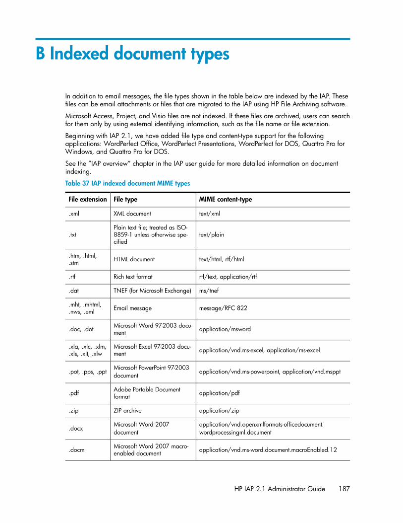
B Indexed document types
In addition to email messages, the file types shown in the table below are indexed by the IAP. Thesefiles can be email attachments or files that are migrated to the IAP using HP File Archiving software.
Microsoft Access, Project, and Visio files are not indexed. If these files are archived, users can searchfor them only by using external identifying information, such as the file name or file extension.
Beginning with IAP 2.1, we have added file type and content-type support for the followingapplications: WordPerfect Office, WordPerfect Presentations, WordPerfect for DOS, Quattro Pro forWindows, and Quattro Pro for DOS.
See the “IAP overview” chapter in the IAP user guide for more detailed information on documentindexing.
Table 37 IAP indexed document MIME types
MIME content-typeFile typeFile extension
text/xmlXML document.xml
text/plainPlain text file; treated as ISO-8859-1 unless otherwise spe-cified
.txt
text/html, rtf/htmlHTML document.htm, .html,.stm
rtf/text, application/rtfRich text format.rtf
ms/tnefTNEF (for Microsoft Exchange).dat
message/RFC 822Email message.mht, .mhtml,.nws, .eml
application/mswordMicrosoft Word 97-2003 docu-ment.doc, .dot
application/vnd.ms-excel, application/ms-excelMicrosoft Excel 97-2003 docu-ment
.xla, .xlc, .xlm,
.xls, .xlt, .xlw
application/vnd.ms-powerpoint, application/vnd.mspptMicrosoft PowerPoint 97-2003nl
document.pot, .pps, .ppt
application/pdfAdobe Portable Documentformat.pdf
application/zipZIP archive.zip
application/vnd.openxmlformats-officedocument.nl
wordprocessingml.documentMicrosoft Word 2007nl
document.docx
application/vnd.ms-word.document.macroEnabled.12Microsoft Word 2007 macro-enabled document.docm
HP IAP 2.1 Administrator Guide 187

MIME content-typeFile typeFile extension
application/vnd.openxmlformats-officedocument.nl
wordprocessingml.templateMicrosoft Word 2007nl
template.dotx
application/vnd.ms-word.template.macroEnabled.12Microsoft Word 2007 macro-enabled document template.dotm
application/vnd.openxmlformats-officedocument.nl
spreadsheetml.sheetMicrosoft Excel 2007nl
workbook.xlsx
application/vnd.ms-excel.sheet.macroEnabled.12Microsoft Excel 2007 macro-enabled workbook.xlsm
application/vnd.openxmlformats-officedocument.nl
spreadsheetml.templateMicrosoft Excel 2007 template.xltx
application/vnd.ms-excel.template.macroEnabled.12Microsoft Excel 2007 macro-enabled workbook template.xltm
application/vnd.ms-excel.addin.macroEnabled.12Microsoft Excel 2007 add-in.xlam
application/vnd.openxmlformats-officedocument.nl
presentationml.presentationMicrosoft PowerPoint 2007presentation.pptx
application/vnd.ms-powerpoint.presentation.nl
macroEnabled.12Microsoft PowerPoint 2007macro-enabled presentation.pptm
application/vnd.openxmlformats-officedocument.nl
presentationml.slideshowMicrosoft PowerPoint 2007slide show.ppsx
application/vnd.ms-powerpoint.slideshow.nl
macroEnabled.12Microsoft PowerPoint 2007macro-enabled slide show.ppsm
application/vnd.openxmlformats-officedocument.nl
presentationml.templateMicrosoft PowerPoint 2007template.potx
application/vnd.ms-powerpoint.template.nl
macroEnabled.12
Microsoft PowerPoint 2007macro-enabled presentationtemplate
.potm
application/wordperfect, application/wpdCorel WordPerfect for Win-dows – versions through Ver-sion 12.0, X3
.wpd
application/qpw, application/wb1, application/wb2,application/wb3
Corel Quattro Pro for Windows– versions through Version12.0, X3
.qpw, .wb1,
.wb2, .wb3
application/presentationsCorel Presentations – versionsthrough Version 12.0, X3.shw
Indexed document types188

Index
AAccount Error Recovery page, 87Account Manager, 73
See also AMAccount Manager Service, 43
account synchronizationSee DAS
Account Synchronization page, 63accounts, user, 75Administrative Delete, 78, 101, 121administrative privileges, IAP, 78alerts
application-generated, 42, 179clearing from PCC Overview, 43current platform, 41hardware-generated, 42levels, 42
AM, 73See also Account Managerabout AM, 73Account Manager window, 73adding repositories, 82adding users, 75definition, 73group panel, 79user accounts, 75
Archive Gateway managementlogging in, 141
ASSIGNED Smartcell state, 38audit log, 147AuditLog, 21
Bbackup files
backup file history, 107backup file locations, 111configuration files, 112database files, 111restoring configuration files, 111restoring DB2 backups, 111
backup system administration, 151
CCatchAll repository, 44, 81certificate signing request (CSR)
deleting, 58generating, 58
certificatesinstalling, 58
cloning Smartcell, 115CLOSED Smartcell state, 38collect log files, 131COMPLETE_PROCESSING Smartcell state, 38compliance, regulatory, 78, 80, 81, 84, 99, 147configuration
domain, 57IAP, 58
configuration file backup, 107conventions
text symbols, 15Corel Presentations, 188CPU use, 45current platform alerts, 41
DDAS
configuring, 63creating jobs, 63editing or deleting jobs, 69history logs, 71repairing synchronization errors, 87scheduling jobs, 68starting jobs, 68stopping jobs, 68
datareprocessing, 97retention, 99
Data Protector, 151Database and data backup page, 107database backup, 107, 151DEAD Smartcell state, 39DISCOVERY Smartcell state, 38document retention, 99Duplicate Manager, 89DWA Extension, 21
HP IAP 2.1 Administrator Guide 189

EEmail Reporter, 129email SNMP notifications, 128End User Delete, 101, 105event log, 125
Ffailed indexing repository, 44File Export, 21file extensions, 187firewall settings, 58folder capture, 121FREE Smartcell state, 39
HHardware Management view, 49health
checking system, 41machine, 49Smartcell, 45
help, obtaining, 14host groups
definition, 37types, 47, 49
host machinesstarting, stopping, or restarting, 47status, 37, 47, 49
HPSubscriber's choice web site, 14technical support, 14
HP OpenView, 128HTTP servers, starting, stopping, or restarting,47
IIAP administrator, 78IAP Authorization User, 78, 93index rate, 43, 46, 53indexed documents
file extensions, 187MIME content types, 187
JJBoss, 45, 49journal mining, 143
LLDAP servers
configuring DAS, 63left menu, PCC, 35
life cycle statesdefinition, 37
life cycle states, types, 38log in
email mining system, 141PCC, 33VNC, 141
Lotus Notes options, 21
MMIB, 127MIME content types, 187Mining
Archve Gateway Management, 141monitoring reports, 128, 129monitoring, PCC, 37
Nnotifications
SNMP events, 128
OOutlook Plug-In
description, 21Overview Archive Gateway, 142Overview, PCC, 41OWA Extension, 21
Ppatch history, 62
190

PCCCloning page, 115about, 33accessing, 33Account Error Recovery page, 87Account Manager page, 73Account Synchronization page, 63Archive Gateway Management view, 141collecting log files, 131common administration tasks, 34Database and data backup page, 107description, 21Email Reporter, 129Event Viewer, 125Hardware Management view, 49health, checking system, 41left menu, 33, 35log in, 33monitoring tools, 37Overview, 41patch history, 62Performance Graph page, 53Platform Settings page, 57printing, 35refreshing pages, 35Replication page, 92Reprocessing, 97Retention page, 99Smartcell life cycle states, 38SNMP Management page, 127Software Management view, 47Software Version view, 62SSL Configuration page, 58states, 37status conditions, 37Storage Status page, 46updating pages, 35user interface, 34views, 33, 34
performance graphsappliance storage and indexing, 53system monitoring, 53
Platform Control CenterSee PCC
platform performance, 43Platform Settings page, 57power on/off, 31printing PCC pages, 35private keys (certificates), 58
QQuattro Pro, 188
Rregulatory compliance, 78, 80, 81, 84, 99, 147related documentation, 13Remote Authorization, IAP, 78replicating Smartcells, 92replication
suspending and resuming, 96Replication page, 92reports
SNMP events, 128repositories
access only, 80, 84, 85adding, 82audit, 84, 85AuditLog, 81CatchAll, 44, 81changing retention period, 106creating, modifying, 79definition, 73description, 79domain retention period, 100, 103editing repository information, 82failed indexing, 44, 81quarantine, 81, 101Recycle Bin, 81regulated, 80regulated retention period, 101repository information form, 83retention period, 84, 99unregulated, 79unregulated retention period, 100
reprocessing data, 97RESET Smartcell state, 38restarting servers, 47RESTORE Smartcell state, 38retention
basis, 100deletion statistics, 104period, 103periods, 100
Retention page, 99retention, document, 99routing
email, 84, 85RSA private key, 58
Ssearch function, 74selective archiving, 141, 142
HP IAP 2.1 Administrator Guide 191

serversDAS, configuring, 63IP address, 47starting, stopping, or restarting, 47status, 47
SIM, 50Smartcells
allocation, 46Hardware Management view, 49MAC address, 45machine health, 44overview information, 44replicating, 92states, life cycle, 38, 44thread count, 45
SMTP Flow Control, 46SMTP Servers, starting, stopping, or restarting,47SNMP Management page, 127SNMP traps, 50
notifications, 128selecting, 128setting SNMP server, 128
Software Management view, 47Software Version view, 62software versions, 46, 62SSL Configuration page, 58states
definition, 37types of, 38
stopping servers, 47storage rate, 43, 46, 53Storage Status page, 46Subscriber's choice, HP, 14SUSPENDED Smartcell state, 39symbols in text, 15synchronization, 63synchronization errors, 43
repairing, 87
Ttechnical support
HP, 14text symbols, 15thread count, 45
UUNKNOWN Smartcell state, 39users
accounts, 75adding new, 75PCC management, 63Users panel, 75
Vversion identifier, viewing, 46, 62
WWeb Interface, 20web sites
HP Subscriber's choice, 14WordPerfect, 188
192