omnicast 4.8 administrator guide
613
OMNICAST 4.8 ADMINISTRATOR GUIDE This document explains how to configure and deploy Omnicast and its administrative concepts
-
Upload
khangminh22 -
Category
Documents
-
view
2 -
download
0
Transcript of omnicast 4.8 administrator guide
OMNICAST 4.8 ADMINISTRATOR
GUIDE
This document explains how to configure and deploy Omnicast and its administrative concepts

GENETECOMNICAST 4.8 ADMINISTRATOR GUIDE
Copyright notice© Genetec Inc., 2015Genetec Inc. distributes this document with software that includes an end-user license agreement and is furnished under license and may be used only in accordance with the terms of the license agreement. The contents of this document are protected under copyright law.The contents of this guide are furnished for informational use only and are subject to change without notice. Genetec Inc. assumes no responsibility or liability for any errors or inaccuracies that may appear in the informational content contained in this guide.This publication may not be copied, modified, or reproduced in any form or for any purpose, nor can any derivative works be created therefrom without Genetec Inc.’s prior written consent. Genetec Inc. reserves the right to revise and improve its products as it sees fit. This document describes the state of a product at the time of document’s last revision, and may not reflect the product at all times in the future.In no event shall Genetec Inc. be liable to any person or entity with respect to any loss or damage that is incidental to or consequential upon the instructions found in this document or the computer software and hardware products described herein. The use of this document is subject to the disclaimer of liability found in the end-user license agreement."GENETEC", "OMNICAST", "SYNERGIS", "AUTOVU", "FEDERATION", "STRATOCAST", "SIPELIA”, “CITYWISE”, and the Omnicast, Synergis, AutoVu, and Stratocast logos are trademarks of Genetec Inc., and may be registered or pending registration in several jurisdictions.Other trademarks used in this document may be trademarks of the manufacturers or vendors of the respective products.All specifications are subject to change without notice.
Document informationDocument title: Omnicast 4.8 Administrator GuideDocument number: EN.100.005-V4.8.C8(1)Document update date: July 20, 2015You can send your comments, corrections, and suggestions about this guide to [email protected].
COPYRIGHT © 2001 - 2015 BY GENETEC INC. REPRODUCTION AND DISCLOSURE PROHIBITED. iiEN.100.005-V4.8.C8(1)

GENETECOMNICAST 4.8 ADMINISTRATOR GUIDE
Product documentationOmnicast includes the following documentation:• Omnicast Release Notes. Describes the Omnicast release in detail, including new features, fixed
issues, and known issues.• Omnicast Installation and Upgrade Guide. Describes the prerequisites for installing Omnicast and
provides instructions for installing and upgrading Omnicast on your system.• Omnicast Administrator Guide. Provides all the instructions and conceptual information you’ll
need to set up, configure, and administer your Omnicast system.• Omnicast Live Viewer User Guide. The Live Viewer is the control and monitoring center of your
entire security system. This manual teaches you how to perform your every day monitoring func-tions.
• Omnicast Archive Player User Guide. The Archive Player is Omnicast’s investigative tool. This man-ual explains how to perform intelligent archive database queries based on date, time, camera, event type, motion, complex metadata tags, bookmarks, and past alarms.
• Omnicast Video Unit Configuration Guide. Provides the pre-configuration instructions for integrat-ing video units into Omnicast, and any configuration steps required for some video unit features to work.
• Omnicast Portable Archive Player User Guide. Explains how to use the Portable Archive Player to view exported video files.
About Omnicast plugin manualsOmnicast plugins distributed individually are described in the following manuals.
• AutoVu LPR Plugin User Guide• iOmniscient Plugin User Guide• ObjectVideo Plugin User Guide• Point of Sale Plugin User Guide• Interlogix Picture Perfect Plugin User Guide• Hirsch Velocity Plugin User Guide• Lenel OnGuard Plugin User Guide• MicroPoint Plugin User Guide• RBH Plugin User Guide• Verex Plugin User Guide• Micros Plugin User Guide• ACS Parking Revenue Control System Plugin User Guide• Generic Point of Sale Plugin User Guide• Software House C•Cure Plugin User Guide• Barco Cottus Viewer Plugin User Guide• Barco Hydra Plugins User Guide• Barco TransForm A Plugins User Guide
Where can I find the product documentation?• Product DVD. The documentation is available on the product DVD in the Documentation folder.
Release notes and installation guides include a direct link to the latest version of the document.• Genetec Technical Assistance Portal (GTAP). The latest version of the documentation is available
from GTAP. Note, you’ll need a username and password to log on to GTAP.• Online help. Omnicast client applications include online help, which explain how the product works
and provide instructions on how to use the product features. To access the online help, click Help or press F1 in the different client applications.
COPYRIGHT © 2001 - 2015 BY GENETEC INC. REPRODUCTION AND DISCLOSURE PROHIBITED. iiiEN.100.005-V4.8.C8(1)
GENETECOMNICAST 4.8 ADMINISTRATOR GUIDE
Technical supportGenetec Technical Assistance Center (GTAC) is committed to providing its worldwide clientele with the best technical support services available. As a Genetec customer, you have access to the Genetec Technical Assistance Portal (GTAP), where you can find information and search for answers to your product questions.• Genetec Technical Assistance Portal (GTAP). GTAP is a support website that provides in-depth sup-
port information, such as FAQs, knowledge base articles, user guides, supported device lists, train-ing videos, product tools, and much more.Prior to contacting GTAC or opening a support case, it is important to look at this website for poten-tial fixes, workarounds, or known issues. You can log in to GTAP or sign up at https://gtap.gene-tec.com.
• Genetec Technical Assistance Center (GTAC). If you cannot find your answers on GTAP, you can open a support case online at https://gtap.genetec.com. For GTAC's contact information in your region see the Contact page at https://gtap.genetec.com.NOTE Before contacting GTAC, please have your System ID (available from the About button in your client application) and your SMA contract number (if applicable) ready.
• Licensing. • For license activations or resets, please contact GTAC at https://gtap.genetec.com.• For issues with license content or part numbers, or concerns about an order, please contact
Genetec Customer Service at [email protected], or call 1-866-684-8006 (option #3).
• If you require a demo license or have questions regarding pricing, please contact Genetec Sales at [email protected], or call 1-866-684-8006 (option #2).
Additional resourcesIf you require additional resources other than the Genetec Technical Assistance Center, the following is available to you:• GTAP Forum. The Forum is an easy to use message board that allows clients and Genetec staff to
communicate with each other and discuss a variety of topics, ranging from technical questions to technology tips. You can log in or sign up at https://gtapforum.genetec.com.
• Technical training. In a professional classroom environment or from the convenience of your own office, our qualified trainers can guide you through system design, installation, operation, and trou-bleshooting. Technical training services are offered for all products and for customers with a varied level of technical experience, and can be customized to meet your specific needs and objectives. For more information, go to http://www.genetec.com/English/Support/Training.
COPYRIGHT © 2001 - 2015 BY GENETEC INC. REPRODUCTION AND DISCLOSURE PROHIBITED. ivEN.100.005-V4.8.C8(1)

GENETEC TABLE OF CONTENTSOMNICAST 4.8 ADMINISTRATOR GUIDE
Table of Contents
This document explains how to configure and deploy Omnicast and its administrative concepts
Section 1 Preface
Information about this document and what’s new
About this Guide . . . . . . . . . . . . . xxxIntended audience . . . . . . . . . . . . . xxxPurpose and scope . . . . . . . . . . . . . xxxDocument overview . . . . . . . . . . . . . xxx
Section 2 Omnicast Overview
An introduction to Omnicast IP video surveillance system
Architecture Overview . . . . . . . . . . . . 2Introduction . . . . . . . . . . . . . . 2Example of a full scale system . . . . . . . . . . . 2Failover mechanism . . . . . . . . . . . . . 2Scalability through Federation . . . . . . . . . . . 2
Client-Server Applications . . . . . . . . . . . 3Omnicast applications . . . . . . . . . . . . . 3
Client Applications . . . . . . . . . . . . . . 3Server Admin . . . . . . . . . . . . . . 3Discovery Tool . . . . . . . . . . . . . . 3Config Tool . . . . . . . . . . . . . . 3Live Viewer . . . . . . . . . . . . . . 3Archive Player . . . . . . . . . . . . . . 3Macro Editor . . . . . . . . . . . . . . 3Report Viewer . . . . . . . . . . . . . . 4Watchdog Tray . . . . . . . . . . . . . . 4
Server Applications . . . . . . . . . . . . . . 4Directory . . . . . . . . . . . . . . . 4Directory Failover Coordinator . . . . . . . . . . . 4Gateway . . . . . . . . . . . . . . . 4Archiver . . . . . . . . . . . . . . . 4Auxiliary Archiver . . . . . . . . . . . . . 4Restore Archiver . . . . . . . . . . . . . 4Virtual Matrix . . . . . . . . . . . . . . 5Metadata Engine . . . . . . . . . . . . . 5Federation Server . . . . . . . . . . . . . 5Watchdog . . . . . . . . . . . . . . 5
COPYRIGHT © 2001 - 2015 BY GENETEC INC. REPRODUCTION AND DISCLOSURE PROHIBITED. vEN.100.005-V4.8.C8(1)

GENETEC TABLE OF CONTENTSOMNICAST 4.8 ADMINISTRATOR GUIDE
Section 3 System Concepts
A collection of articles explaining the important concepts of the system
Alarm Management . . . . . . . . . . . . 7Concepts and Definitions . . . . . . . . . . . . . 7
What is an alarm? . . . . . . . . . . . . . 7Alarm entity . . . . . . . . . . . . . . 7Contextual alarm . . . . . . . . . . . . . 7Triggering alarms . . . . . . . . . . . . . 8Alarm instance . . . . . . . . . . . . . . 8Alarm recipients . . . . . . . . . . . . . 8Alarm display . . . . . . . . . . . . . . 9
Alarm Display Modes 9Simple mode . . . . . . . . . . . . . . 9Salvo mode . . . . . . . . . . . . . . 10Block mode . . . . . . . . . . . . . . 11
Responding to Alarms 11Alarm acknowledgement . . . . . . . . . . . . 11Forward and snooze . . . . . . . . . . . . . 12Alarm history database . . . . . . . . . . . . 12
Archiving Management . . . . . . . . . . . . 13Concepts Overview . . . . . . . . . . . . . . 13
Archiving Services . . . . . . . . . . . . . 13Archiver . . . . . . . . . . . . . . . 13Restore Archiver . . . . . . . . . . . . . 13Auxiliary Archiver . . . . . . . . . . . . . 14Archiving Options . . . . . . . . . . . . . 14Backup . . . . . . . . . . . . . . . 14Encryption . . . . . . . . . . . . . . 14Standby Archiver . . . . . . . . . . . . . 14Redundant archiving . . . . . . . . . . . . . 14
Archive Storage Management 14Storage evaluation . . . . . . . . . . . . . 15Archiving Configuration . . . . . . . . . . . . 16Storage Usage Monitoring . . . . . . . . . . . . 16
Archiver Security 16Access to the system . . . . . . . . . . . . . 16Protection against hacking . . . . . . . . . . . . 17Protection against data tampering . . . . . . . . . . . 17Protection against sabotage and accidents . . . . . . . . . . 17
Archiver Availability 17System availability issues . . . . . . . . . . . . 17Protection against service interruptions . . . . . . . . . . 17Directory Failover Coordinator . . . . . . . . . . . 17Standby Archiver . . . . . . . . . . . . . 18Protection against data loss . . . . . . . . . . . . 19Redundant archiving . . . . . . . . . . . . . 19
COPYRIGHT © 2001 - 2015 BY GENETEC INC. REPRODUCTION AND DISCLOSURE PROHIBITED. viEN.100.005-V4.8.C8(1)

GENETEC TABLE OF CONTENTSOMNICAST 4.8 ADMINISTRATOR GUIDE
Auxiliary Archiver . . . . . . . . . . . . . 20Monitoring Archiver events . . . . . . . . . . . . 20
Backup and Restore 20Backup . . . . . . . . . . . . . . . 20Restore . . . . . . . . . . . . . . . 21
Event Management . . . . . . . . . . . . 22About events . . . . . . . . . . . . . . 22About actions . . . . . . . . . . . . . . 22System vs. custom events . . . . . . . . . . . . 22
Event Handling . . . . . . . . . . . . . . 22Monitoring events . . . . . . . . . . . . . 22Searching for events . . . . . . . . . . . . . 22Event reports . . . . . . . . . . . . . . 22
Coupling Actions to Events 23How to couple an action to an event . . . . . . . . . . 23Generalizing event handling . . . . . . . . . . . . 25Custom actions . . . . . . . . . . . . . . 25
Federation . . . . . . . . . . . . . 26Introduction . . . . . . . . . . . . . . . 26
Definition . . . . . . . . . . . . . . 26How it works . . . . . . . . . . . . . . 26Federated entities . . . . . . . . . . . . . 27
Limitations . . . . . . . . . . . . . . . 27Configuration . . . . . . . . . . . . . . 27Interface with older Omnicast versions . . . . . . . . . . 28Archive playback . . . . . . . . . . . . . 28Audio . . . . . . . . . . . . . . . 28Camera sequence . . . . . . . . . . . . . 28
Network Connections . . . . . . . . . . . . 29Network Connection Types . . . . . . . . . . . . 29
Unicast . . . . . . . . . . . . . . . 29Broadcast . . . . . . . . . . . . . . 29Multicast . . . . . . . . . . . . . . . 29Best available . . . . . . . . . . . . . . 29RTSP stream over HTTP . . . . . . . . . . . . 29RTSP stream over TCP . . . . . . . . . . . . . 29
Video Analytics . . . . . . . . . . . . . 30Video Analytics Types . . . . . . . . . . . . . 30
On-The-Edge Video Analytics . . . . . . . . . . . . 30Third Party Metadata Engine Plugins . . . . . . . . . . 30ObjectVideo with OV Ready . . . . . . . . . . . . . . 31
COPYRIGHT © 2001 - 2015 BY GENETEC INC. REPRODUCTION AND DISCLOSURE PROHIBITED. viiEN.100.005-V4.8.C8(1)

GENETEC TABLE OF CONTENTSOMNICAST 4.8 ADMINISTRATOR GUIDE
Section 4 Deploying Omnicast
Omnicast installation and configuration procedure doubled as a reading plan for this guide
Deployment Procedure . . . . . . . . . . . . 33Prerequisites . . . . . . . . . . . . . . 33
Simple System Configuration . . . . . . . . . . . . 34General setup procedure . . . . . . . . . . . . 34Common server configuration . . . . . . . . . . . 37
Failover Configuration 38Directory failover . . . . . . . . . . . . . 38Archiver failover . . . . . . . . . . . . . 38Virtual Matrix failover . . . . . . . . . . . . . 38
Federation Configuration 38
Section 5 Server Admin
Server Admin reference guide
Server Admin Overview . . . . . . . . . . . . 40Introduction . . . . . . . . . . . . . . 40Server Admin workspace . . . . . . . . . . . . 40Resources covered by Server Admin . . . . . . . . . . . 41
Server Admin Menu 41Introduction . . . . . . . . . . . . . . 41Check Database Status . . . . . . . . . . . . . 42Description . . . . . . . . . . . . . . 42Fixing corrupted databases . . . . . . . . . . . . 43Options . . . . . . . . . . . . . . . 43Date and time options . . . . . . . . . . . . . 43Find Orphan Files . . . . . . . . . . . . . 44Description . . . . . . . . . . . . . . 44Finding orphan files . . . . . . . . . . . . . 44
System . . . . . . . . . . . . . . 46Introduction . . . . . . . . . . . . . . 46
License . . . . . . . . . . . . . . . 46Directory options . . . . . . . . . . . . . 47Archiver options . . . . . . . . . . . . . 50Activating your license . . . . . . . . . . . . . 53
SMTP 53SMTP settings . . . . . . . . . . . . . . 54
Network 54Public address . . . . . . . . . . . . . . 54
Directory . . . . . . . . . . . . . . 55
COPYRIGHT © 2001 - 2015 BY GENETEC INC. REPRODUCTION AND DISCLOSURE PROHIBITED. viiiEN.100.005-V4.8.C8(1)

GENETEC TABLE OF CONTENTSOMNICAST 4.8 ADMINISTRATOR GUIDE
Introduction . . . . . . . . . . . . . . 55General . . . . . . . . . . . . . . . 55
General settings . . . . . . . . . . . . . 56Directory database . . . . . . . . . . . . . 56Alarm database . . . . . . . . . . . . . . 56Database Diagnostics . . . . . . . . . . . . . 57
Email 58Send link to web applications . . . . . . . . . . . . 59
Logging 59File logging . . . . . . . . . . . . . . 60Database logging . . . . . . . . . . . . . 60
Active Directory 62Enabling the Active Directory . . . . . . . . . . . . 63Changing the Directory service logon user . . . . . . . . . . 68Enabling SSL . . . . . . . . . . . . . . 70Disabling the Active Directory . . . . . . . . . . . 71
Password . . . . . . . . . . . . . . . 72Description . . . . . . . . . . . . . . 72
Directory Failover Coordinator . . . . . . . . . . . 73Introduction . . . . . . . . . . . . . . 73
Configuration . . . . . . . . . . . . . . 73General settings . . . . . . . . . . . . . 73
Gateway . . . . . . . . . . . . . . 75Introduction . . . . . . . . . . . . . . 75
General 76General settings . . . . . . . . . . . . . 76Port settings . . . . . . . . . . . . . . 77Multicast connection test settings . . . . . . . . . . . 77
Logging 79File logging . . . . . . . . . . . . . . 79
Advanced 80Detection parameters . . . . . . . . . . . . . 80Video redirection . . . . . . . . . . . . . 81
IP Filtering 81Default parameters . . . . . . . . . . . . . 82IP filtering configuration . . . . . . . . . . . . 83
Federation Server . . . . . . . . . . . . 84Introduction . . . . . . . . . . . . . . 84
Configuration . . . . . . . . . . . . . . 84General settings . . . . . . . . . . . . . 84
Archiver . . . . . . . . . . . . . . 85Introduction . . . . . . . . . . . . . . 85
General 86Archiving 87
Archive option . . . . . . . . . . . . . . 87Archive database . . . . . . . . . . . . . 87
COPYRIGHT © 2001 - 2015 BY GENETEC INC. REPRODUCTION AND DISCLOSURE PROHIBITED. ixEN.100.005-V4.8.C8(1)

GENETEC TABLE OF CONTENTSOMNICAST 4.8 ADMINISTRATOR GUIDE
Archive storage configuration . . . . . . . . . . . 88Minimum free space on disk . . . . . . . . . . . . 89Disk groups . . . . . . . . . . . . . . 89Additional archiving options . . . . . . . . . . . . 90General archiving options . . . . . . . . . . . . 90Default retention settings . . . . . . . . . . . . 91Video file options . . . . . . . . . . . . . 92
Backup 92Description . . . . . . . . . . . . . . 92Backup option . . . . . . . . . . . . . . 92
Security 93Description . . . . . . . . . . . . . . 93Video watermarking . . . . . . . . . . . . . 93
Logging 95Description . . . . . . . . . . . . . . 95
NTP 96Description . . . . . . . . . . . . . . 96
Archiver Extensions . . . . . . . . . . . . 97Definition . . . . . . . . . . . . . . 97Automatic discovery . . . . . . . . . . . . . 97Creating an Archiver extension . . . . . . . . . . . 97Extension types . . . . . . . . . . . . . . 98
ACTi Extension 99Definition . . . . . . . . . . . . . . 99General settings . . . . . . . . . . . . . 99
Arecont Extension 101Definition . . . . . . . . . . . . . . 101General settings . . . . . . . . . . . . . 101
AutoVu Extension 102Definition . . . . . . . . . . . . . . 102
AXIS Extension 103Definition . . . . . . . . . . . . . . 103General settings . . . . . . . . . . . . . 103
Bosch Extension 105Definition . . . . . . . . . . . . . . 105General settings . . . . . . . . . . . . . 105VRM Settings . . . . . . . . . . . . . . 107
Generic Extension 108Definition . . . . . . . . . . . . . . 108General settings . . . . . . . . . . . . . 108
Generic Plus Extension 109Definition . . . . . . . . . . . . . . 109General settings . . . . . . . . . . . . . 109Available drivers . . . . . . . . . . . . . 110
Genetec Extension 110Definition . . . . . . . . . . . . . . 110General settings . . . . . . . . . . . . . 111
Interlogix CamPlus IP Extension 112
COPYRIGHT © 2001 - 2015 BY GENETEC INC. REPRODUCTION AND DISCLOSURE PROHIBITED. xEN.100.005-V4.8.C8(1)
GENETEC TABLE OF CONTENTSOMNICAST 4.8 ADMINISTRATOR GUIDE
Definition . . . . . . . . . . . . . . 112General settings . . . . . . . . . . . . . 112
Interlogix CamPlus 2 IP Extension 114Definition . . . . . . . . . . . . . . 114General settings . . . . . . . . . . . . . 114
Interlogix Megapixel Extension 116Definition . . . . . . . . . . . . . . 116General settings . . . . . . . . . . . . . 116
Interlogix MPEG-4 Extension 117Definition . . . . . . . . . . . . . . 117General settings . . . . . . . . . . . . . 117
Interlogix Wavelet/JPEG 2000 Extension 119Definition . . . . . . . . . . . . . . 119General settings . . . . . . . . . . . . . 119
IQinVision Extension 121Definition . . . . . . . . . . . . . . 121General settings . . . . . . . . . . . . . 121
Panasonic Extension 122Definition . . . . . . . . . . . . . . 122General settings . . . . . . . . . . . . . 122
Pelco Extension 124Definition . . . . . . . . . . . . . . 124General settings . . . . . . . . . . . . . 124
Siqura Extension 125Definition . . . . . . . . . . . . . . 125General settings . . . . . . . . . . . . . 125
Sony Extension 126Definition . . . . . . . . . . . . . . 126General settings . . . . . . . . . . . . . 127
Verint Extension 128Definition . . . . . . . . . . . . . . 128General settings . . . . . . . . . . . . . 128SSL settings . . . . . . . . . . . . . . 129
Vivotek Extension 131Definition . . . . . . . . . . . . . . 131General settings . . . . . . . . . . . . . 131
Auxiliary Archiver . . . . . . . . . . . . 133Introduction . . . . . . . . . . . . . . 133
General 134Archiving 135
Archive database . . . . . . . . . . . . . 135Archive storage configuration . . . . . . . . . . . 136Minimum free space on disk . . . . . . . . . . . . 137Disk groups . . . . . . . . . . . . . . 137Additional archiving options . . . . . . . . . . . . 138General archiving options . . . . . . . . . . . . 138Video file options . . . . . . . . . . . . . 138
Backup 139
COPYRIGHT © 2001 - 2015 BY GENETEC INC. REPRODUCTION AND DISCLOSURE PROHIBITED. xiEN.100.005-V4.8.C8(1)

GENETEC TABLE OF CONTENTSOMNICAST 4.8 ADMINISTRATOR GUIDE
Backup option . . . . . . . . . . . . . . 139Security 140
Video watermarking . . . . . . . . . . . . . 140
Restore Archiver . . . . . . . . . . . . . 142Introduction . . . . . . . . . . . . . . 142
General . . . . . . . . . . . . . . . 142General settings . . . . . . . . . . . . . 143
Restore 144Restoring a backup set . . . . . . . . . . . . . 144
Metadata Engine . . . . . . . . . . . . . 146Introduction . . . . . . . . . . . . . . 146
General . . . . . . . . . . . . . . . 147General settings . . . . . . . . . . . . . 147Database settings . . . . . . . . . . . . . 148Security settings . . . . . . . . . . . . . 148
Plugins 149
Virtual Matrix . . . . . . . . . . . . . 150Introduction . . . . . . . . . . . . . . 150
General . . . . . . . . . . . . . . . 150General settings . . . . . . . . . . . . . 151
Plugins 151
Section 6 Config Tool
Config Tool reference guide
Config Tool Overview . . . . . . . . . . . . 153Introduction . . . . . . . . . . . . . . . 153
Aspects of system configuration . . . . . . . . . . . 153Workspace 154
Main menu . . . . . . . . . . . . . . 154Main toolbar . . . . . . . . . . . . . . 154View selection pane . . . . . . . . . . . . . 155Using the View selection pane . . . . . . . . . . . 155View selection pane contextual menu . . . . . . . . . . 156Configuration pane . . . . . . . . . . . . . 156Customizing your workspace . . . . . . . . . . . . 156
Entity Configuration 157Identity . . . . . . . . . . . . . . . 157Configurable entities . . . . . . . . . . . . . 158
Entity Search Tool 159Local search . . . . . . . . . . . . . . 159Global search . . . . . . . . . . . . . . 159
Logical View 161Purpose . . . . . . . . . . . . . . . 161
COPYRIGHT © 2001 - 2015 BY GENETEC INC. REPRODUCTION AND DISCLOSURE PROHIBITED. xiiEN.100.005-V4.8.C8(1)

GENETEC TABLE OF CONTENTSOMNICAST 4.8 ADMINISTRATOR GUIDE
Hidden site . . . . . . . . . . . . . . 162Show/hide entities . . . . . . . . . . . . . 162Making copies of resources . . . . . . . . . . . . 162
Physical View 163Purpose . . . . . . . . . . . . . . . 163Show/hide entities . . . . . . . . . . . . . 163
Config Tool Menu 164Introduction . . . . . . . . . . . . . . 164System menu . . . . . . . . . . . . . . 164Action menu . . . . . . . . . . . . . . 165View menu . . . . . . . . . . . . . . 166Tools menu . . . . . . . . . . . . . . 167Help menu . . . . . . . . . . . . . . 168
Directory Failover Configuration 170What is failover? . . . . . . . . . . . . . 170Directory failover . . . . . . . . . . . . . 171Default failover configuration . . . . . . . . . . . . 171Directory failover list . . . . . . . . . . . . . 172Directory Failover Coordinator . . . . . . . . . . . 172Directory scope . . . . . . . . . . . . . . 172Local address, public address and port . . . . . . . . . . 173Manual Failover Configuration . . . . . . . . . . . 173Step #1: Directory Failover List . . . . . . . . . . . 175Step #2: Gateway Connections . . . . . . . . . . . 176Step #3: Client Connections . . . . . . . . . . . . 177Limitations . . . . . . . . . . . . . . 179
Copy Configuration Tool 180Source and destination considerations . . . . . . . . . . 180Copy configuration from a source to destination(s) . . . . . . . . 181
Customizing the Tools Menu 181Introduction . . . . . . . . . . . . . . 181The .ini file . . . . . . . . . . . . . . 181An example . . . . . . . . . . . . . . 182
Access Control System . . . . . . . . . . . . 183Definition . . . . . . . . . . . . . . 183Creating an access control system entity . . . . . . . . . . 183
Properties 184Standby Virtual Matrices 185
Alarm . . . . . . . . . . . . . . 186Definition . . . . . . . . . . . . . . 186Creating an alarm entity . . . . . . . . . . . . 186
Properties 187General settings . . . . . . . . . . . . . 187Acknowledgement settings . . . . . . . . . . . . 189
Cameras 190Changing the camera list . . . . . . . . . . . . 190Adding cameras . . . . . . . . . . . . . 190
COPYRIGHT © 2001 - 2015 BY GENETEC INC. REPRODUCTION AND DISCLOSURE PROHIBITED. xiiiEN.100.005-V4.8.C8(1)

GENETEC TABLE OF CONTENTSOMNICAST 4.8 ADMINISTRATOR GUIDE
Warnings . . . . . . . . . . . . . . 193Recipients 194
Changing the recipient list . . . . . . . . . . . . 194Broadcast options . . . . . . . . . . . . . 195Adding recipients . . . . . . . . . . . . . 195
Acknowledgement 196Default acknowledgement . . . . . . . . . . . . 196Alternate acknowledgement . . . . . . . . . . . . 196Custom acknowledgement . . . . . . . . . . . . 196
Actions 197
Analog Monitor (Video Decoder) . . . . . . . . . . 198Definition . . . . . . . . . . . . . . 198Monitor ID . . . . . . . . . . . . . . 198
Attributes 199Info 200
Video image resolution . . . . . . . . . . . . 200Megapixel resolutions . . . . . . . . . . . . . 201
Network . . . . . . . . . . . . . . . 201Network information . . . . . . . . . . . . . 201Connection type between unit and Archiver . . . . . . . . . 202Viewing quality . . . . . . . . . . . . . . 202
Links 202Creating new links . . . . . . . . . . . . . 203Removing existing links . . . . . . . . . . . . 203
Archiver . . . . . . . . . . . . . . 204Definition . . . . . . . . . . . . . . 204
Archiving 205Disk group . . . . . . . . . . . . . . 205Automatic cleanup . . . . . . . . . . . . . 205Retention period . . . . . . . . . . . . . 206
Statistics 206Disk group . . . . . . . . . . . . . . 206Disk usage . . . . . . . . . . . . . . 207Connections . . . . . . . . . . . . . . 208Camera statistics dialog . . . . . . . . . . . . 208General . . . . . . . . . . . . . . . 209
Firmware Upgrade 210Upgrading the firmware of selected units . . . . . . . . . . 210
Actions 212Backup 213
Backup configuration . . . . . . . . . . . . . 213Backup status . . . . . . . . . . . . . . 214
Trickling 215Description . . . . . . . . . . . . . . 215Apply trickling settings to all units . . . . . . . . . . . 216Trickling Properties . . . . . . . . . . . . . 216Camera list . . . . . . . . . . . . . . 218Start and stop trickling manually . . . . . . . . . . . 218
COPYRIGHT © 2001 - 2015 BY GENETEC INC. REPRODUCTION AND DISCLOSURE PROHIBITED. xivEN.100.005-V4.8.C8(1)
GENETEC TABLE OF CONTENTSOMNICAST 4.8 ADMINISTRATOR GUIDE
Limitations . . . . . . . . . . . . . . 219Event Search 219
Searching for Archiver events . . . . . . . . . . . . 219
Archiving Schedule . . . . . . . . . . . . 220Definition . . . . . . . . . . . . . . 220Creating an archiving schedule . . . . . . . . . . . 220
Properties 221Generic schedule . . . . . . . . . . . . . 221Archiving mode . . . . . . . . . . . . . . 221Camera list . . . . . . . . . . . . . . 222
Auxiliary Archiver . . . . . . . . . . . . 223Definition . . . . . . . . . . . . . . 223Differences between Archivers and Auxiliary Archivers . . . . . . . . 223
Cameras 224Camera tree . . . . . . . . . . . . . . 225Selected camera info . . . . . . . . . . . . . 225
Archiving 226Disk group . . . . . . . . . . . . . . 226Automatic cleanup . . . . . . . . . . . . . 227Retention period . . . . . . . . . . . . . 227
Statistics 227Disk group . . . . . . . . . . . . . . 228Disk usage . . . . . . . . . . . . . . 228Connections . . . . . . . . . . . . . . 229Camera statistics dialog . . . . . . . . . . . . 230General . . . . . . . . . . . . . . . 231
Actions 231Backup 232
Backup configuration . . . . . . . . . . . . . 232Backup status . . . . . . . . . . . . . . 233
Event search 234Searching for Auxiliary Archiver events . . . . . . . . . . 234
Backup Set . . . . . . . . . . . . . 235Definition . . . . . . . . . . . . . . 235
Info . . . . . . . . . . . . . . . . 235Backup info . . . . . . . . . . . . . . 236Restore info . . . . . . . . . . . . . . 236
Camera (Video Encoder) . . . . . . . . . . . 237Definition . . . . . . . . . . . . . . 237Camera ID . . . . . . . . . . . . . . 237
Video Quality 238Video stream configuration . . . . . . . . . . . . 238Video stream usage . . . . . . . . . . . . . 242Automatic stream selection . . . . . . . . . . . . 243Schedule for the displayed configuration . . . . . . . . . . 243Schedule overview . . . . . . . . . . . . . 244Boosting recording quality on special events . . . . . . . . . 245
COPYRIGHT © 2001 - 2015 BY GENETEC INC. REPRODUCTION AND DISCLOSURE PROHIBITED. xvEN.100.005-V4.8.C8(1)
GENETEC TABLE OF CONTENTSOMNICAST 4.8 ADMINISTRATOR GUIDE
Video stream preview . . . . . . . . . . . . . 247Recording 248
Recording settings . . . . . . . . . . . . . 248Archiving schedule list . . . . . . . . . . . . . 249Schedule overview . . . . . . . . . . . . . 250Archiving on unit . . . . . . . . . . . . . 250Metadata overlays . . . . . . . . . . . . . 251
Motion Detection 251General concepts . . . . . . . . . . . . . 252Motion detection configuration . . . . . . . . . . . 252Respect archiving schedules . . . . . . . . . . . . 252Motion detection modes . . . . . . . . . . . . 252Motion detection capabilities . . . . . . . . . . . . 253What constitutes a positive motion detection? . . . . . . . . . 254Testing motion detection . . . . . . . . . . . . 255Auto Sensitivity . . . . . . . . . . . . . . 256Testing motion through Web access . . . . . . . . . . . 256Motion related events . . . . . . . . . . . . . 257Automatic recording on motion . . . . . . . . . . . 257Adding new configurations . . . . . . . . . . . . 257Detection Zone . . . . . . . . . . . . . . 258Purpose . . . . . . . . . . . . . . . 258Testing multi-zone motion detection . . . . . . . . . . 259Edit mode . . . . . . . . . . . . . . 260Advanced H.264 Motion Detection . . . . . . . . . . . 261
Attributes 263Analog format . . . . . . . . . . . . . . 263Schedule for the displayed configuration . . . . . . . . . . 263Video attributes configuration . . . . . . . . . . . 264Schedule overview . . . . . . . . . . . . . 265
Actions 266Video Analytics 267
Description . . . . . . . . . . . . . . 267Creating a rule . . . . . . . . . . . . . . 267Creating a tripwire . . . . . . . . . . . . . 270Defining an area of interest . . . . . . . . . . . . 270Associating actions . . . . . . . . . . . . . 271
Info 271Video image resolution . . . . . . . . . . . . 272Megapixel resolutions . . . . . . . . . . . . . 272
Network 273Network information . . . . . . . . . . . . . 273Connection type between unit and Archiver . . . . . . . . . 273Multicast address . . . . . . . . . . . . . 274Multiple streams . . . . . . . . . . . . . 274
Links 275Creating new links . . . . . . . . . . . . . 275Attached metadata . . . . . . . . . . . . . 276
COPYRIGHT © 2001 - 2015 BY GENETEC INC. REPRODUCTION AND DISCLOSURE PROHIBITED. xviEN.100.005-V4.8.C8(1)
GENETEC TABLE OF CONTENTSOMNICAST 4.8 ADMINISTRATOR GUIDE
Removing links . . . . . . . . . . . . . . 276Time Zone 276
Time zone . . . . . . . . . . . . . . 276Geographical location . . . . . . . . . . . . . 277
Specific Settings 277
Camera Group . . . . . . . . . . . . . 280Definition . . . . . . . . . . . . . . 280Creating a camera group . . . . . . . . . . . . 280
Cameras 281Changing the camera list . . . . . . . . . . . . 281
Camera Sequence . . . . . . . . . . . . 282Definition . . . . . . . . . . . . . . 282Creating a camera sequence . . . . . . . . . . . . 282
Cameras 283Step list . . . . . . . . . . . . . . . 283Adding a camera to the sequence . . . . . . . . . . . 283Testing the camera sequence . . . . . . . . . . . . 284
Schedules 285Schedule list . . . . . . . . . . . . . . 285
Network 286Network information . . . . . . . . . . . . . 286Connection types . . . . . . . . . . . . . 286Multicast address . . . . . . . . . . . . . 286
Standby Virtual Matrices 287
CCTV Keyboard . . . . . . . . . . . . . 288Definition . . . . . . . . . . . . . . 288Creating a CCTV keyboard entity . . . . . . . . . . . 288
Properties 289Standby Virtual Matrices 290
Digital Input . . . . . . . . . . . . . 291Definition . . . . . . . . . . . . . . 291
Properties . . . . . . . . . . . . . . . 291Digital input properties . . . . . . . . . . . . 292Linking cameras to the digital input . . . . . . . . . . . 292
Actions 292Network 293
Directory . . . . . . . . . . . . . . 294Definition . . . . . . . . . . . . . . 294
License . . . . . . . . . . . . . . . 295Description . . . . . . . . . . . . . . 295
Online Users 296Connections 297
Types of connections . . . . . . . . . . . . . 297Creating a new connection . . . . . . . . . . . . 298
COPYRIGHT © 2001 - 2015 BY GENETEC INC. REPRODUCTION AND DISCLOSURE PROHIBITED. xviiEN.100.005-V4.8.C8(1)
GENETEC TABLE OF CONTENTSOMNICAST 4.8 ADMINISTRATOR GUIDE
Command buttons . . . . . . . . . . . . . 299Logical IDs 299Custom Events 300
Creating custom events . . . . . . . . . . . . 301Custom Actions 301
Creating custom actions . . . . . . . . . . . . 302Alarms 302
Limiting the number of alarms . . . . . . . . . . . 302Command buttons . . . . . . . . . . . . . 303Alarm history dialog . . . . . . . . . . . . . 303
Discovery 304Actions 305Time Zones 306
Directory Failover Coordinator . . . . . . . . . . . 307Definition . . . . . . . . . . . . . . 307
Statistics . . . . . . . . . . . . . . . 307Directory failover list . . . . . . . . . . . . . 308Status . . . . . . . . . . . . . . . 308Manual synchronization . . . . . . . . . . . . 309
Federated Directory . . . . . . . . . . . . 310Definition . . . . . . . . . . . . . . 310Creating a federated Directory . . . . . . . . . . . 310
Properties 312Federated Directory properties . . . . . . . . . . . 312
Entities 313Remote entities . . . . . . . . . . . . . . 313Command buttons . . . . . . . . . . . . . 314Federated entities . . . . . . . . . . . . . 314Definition . . . . . . . . . . . . . . 314Entity creation . . . . . . . . . . . . . . 314Federated Archivers . . . . . . . . . . . . . 315Federated sites . . . . . . . . . . . . . . 315Entity configuration . . . . . . . . . . . . . 315Remote event handling . . . . . . . . . . . . 315
Federation Server . . . . . . . . . . . . 316Definition . . . . . . . . . . . . . . 316
Actions . . . . . . . . . . . . . . . 316Statistics . . . . . . . . . . . . . . . 317
Description . . . . . . . . . . . . . . 317Statistics . . . . . . . . . . . . . . . 317Network packet capture . . . . . . . . . . . . 317
Gateway . . . . . . . . . . . . . . 319Definition . . . . . . . . . . . . . . 319
Connections 320Statistics 321
Description . . . . . . . . . . . . . . 321
COPYRIGHT © 2001 - 2015 BY GENETEC INC. REPRODUCTION AND DISCLOSURE PROHIBITED. xviiiEN.100.005-V4.8.C8(1)

GENETEC TABLE OF CONTENTSOMNICAST 4.8 ADMINISTRATOR GUIDE
Statistics . . . . . . . . . . . . . . . 321Network packet capture . . . . . . . . . . . . 321
Actions 323
Generic Schedule . . . . . . . . . . . . 324Definition . . . . . . . . . . . . . . 324Creating a generic schedule . . . . . . . . . . . . 324
Properties 325Recurrence pattern . . . . . . . . . . . . . 325Introduction . . . . . . . . . . . . . . 325Daily . . . . . . . . . . . . . . . 326Weekly . . . . . . . . . . . . . . . 326Monthly . . . . . . . . . . . . . . . 326Yearly . . . . . . . . . . . . . . . 327Specific . . . . . . . . . . . . . . . 328Time coverage . . . . . . . . . . . . . . 329Introduction . . . . . . . . . . . . . . 329All day . . . . . . . . . . . . . . . 329Range . . . . . . . . . . . . . . . 329Daytime/Nighttime . . . . . . . . . . . . . 330
Linked Entities 330Usage context . . . . . . . . . . . . . . 330
Schedule Priorities and Conflict Resolution . . . . . . . . . . 331Default schedule . . . . . . . . . . . . . 331Conflict resolution . . . . . . . . . . . . . 331
Ghost Camera . . . . . . . . . . . . . 333Definition . . . . . . . . . . . . . . 333
Hardware Matrix . . . . . . . . . . . . . 334Definition . . . . . . . . . . . . . . 334Creating a hardware matrix . . . . . . . . . . . . 334
Properties 335Hardware matrix status . . . . . . . . . . . . 335Hardware matrix protocol . . . . . . . . . . . . 335Hardware matrix users . . . . . . . . . . . . . 335Definition . . . . . . . . . . . . . . 335Hardware matrix user properties . . . . . . . . . . . 336Modifying the hardware matrix user list . . . . . . . . . . 336
Inputs 337Defining the virtual cameras . . . . . . . . . . . . 337Virtual camera limitations . . . . . . . . . . . . 337
Outputs 338Assigning video encoders to the outputs . . . . . . . . . . 338
Connections 339Command buttons . . . . . . . . . . . . . 339
Standby Virtual Matrices 340
Macro . . . . . . . . . . . . . . 341Definition . . . . . . . . . . . . . . 341
COPYRIGHT © 2001 - 2015 BY GENETEC INC. REPRODUCTION AND DISCLOSURE PROHIBITED. xixEN.100.005-V4.8.C8(1)
GENETEC TABLE OF CONTENTSOMNICAST 4.8 ADMINISTRATOR GUIDE
Creating a macro . . . . . . . . . . . . . 341Properties 342
Adding a macro step . . . . . . . . . . . . . 343Commands and arguments . . . . . . . . . . . . 344
Actions 348Code 349
Working with an external editor . . . . . . . . . . . 349Omnicast Macro Editor . . . . . . . . . . . . 349
Metadata Engine . . . . . . . . . . . . . 350Definition . . . . . . . . . . . . . . 350
Plugins 351Actions 352
Macro Schedule . . . . . . . . . . . . . 353Definition . . . . . . . . . . . . . . 353Creating a macro schedule . . . . . . . . . . . . 353
Properties 354Standby Virtual Matrices 355
Microphone (Audio Encoder) . . . . . . . . . . . 356Definition . . . . . . . . . . . . . . 356
Properties . . . . . . . . . . . . . . . 356Audio encoder properties . . . . . . . . . . . . 357
Specific Settings 358Unit specific audio settings . . . . . . . . . . . . 358
Network 359Network information . . . . . . . . . . . . . 359Connection type between unit and Archiver . . . . . . . . . 360Multicast address . . . . . . . . . . . . . 360
Monitor Group . . . . . . . . . . . . . 361Definition . . . . . . . . . . . . . . 361Creating a monitor group . . . . . . . . . . . . 361
Properties 362Monitor group properties . . . . . . . . . . . . 362
Standby Virtual Matrices 363
Output Relay . . . . . . . . . . . . . 364Definition . . . . . . . . . . . . . . 364
Properties . . . . . . . . . . . . . . . 364Default output mode . . . . . . . . . . . . . 364Custom action list . . . . . . . . . . . . . 365
Network 366
Plugins . . . . . . . . . . . . . . 367Introduction . . . . . . . . . . . . . . 367Plugin-specific documentation . . . . . . . . . . . 367Versioning . . . . . . . . . . . . . . 367Plugin Types . . . . . . . . . . . . . . 367
Virtual Matrix Plugin 368
COPYRIGHT © 2001 - 2015 BY GENETEC INC. REPRODUCTION AND DISCLOSURE PROHIBITED. xxEN.100.005-V4.8.C8(1)

GENETEC TABLE OF CONTENTSOMNICAST 4.8 ADMINISTRATOR GUIDE
Definition . . . . . . . . . . . . . . 368Creating VM plugins . . . . . . . . . . . . . 368Properties . . . . . . . . . . . . . . 368Schedules . . . . . . . . . . . . . . 369Adding a new schedule . . . . . . . . . . . . 369Actions . . . . . . . . . . . . . . . 370
SNMP Traps (VM Plugin) 370Introduction . . . . . . . . . . . . . . 370Description . . . . . . . . . . . . . . 370Configuration . . . . . . . . . . . . . . 371Properties . . . . . . . . . . . . . . 371Schedules . . . . . . . . . . . . . . 371
Metadata Engine Plugin 372Definition . . . . . . . . . . . . . . 372Creating ME plugins . . . . . . . . . . . . . 373Properties . . . . . . . . . . . . . . 373Database . . . . . . . . . . . . . . . 374Links . . . . . . . . . . . . . . . 375Actions . . . . . . . . . . . . . . . 375
Live Viewer Plugin 375Definition . . . . . . . . . . . . . . 375Creating LV plugins . . . . . . . . . . . . . 376Properties . . . . . . . . . . . . . . 376Actions . . . . . . . . . . . . . . . 377
Remote Live Viewer (LV Plugin) 377Introduction . . . . . . . . . . . . . . 377Definition . . . . . . . . . . . . . . 378Configuration – Properties . . . . . . . . . . . . 379Plugin mode . . . . . . . . . . . . . . 379Remote Live Viewer monitor control . . . . . . . . . . . 379 . . . . . . . . . . . . . . . . 380
PTZ Motor . . . . . . . . . . . . . 381Definition . . . . . . . . . . . . . . 381Creating a PTZ motor . . . . . . . . . . . . . 381
Properties 383PTZ motor properties . . . . . . . . . . . . . 383
Test 385Testing the PTZ . . . . . . . . . . . . . . 385Advanced PTZ commands configuration . . . . . . . . . . 386
Actions 386Typical application . . . . . . . . . . . . . 386
Network 387Coordinates 388
Direct XYZ positioning . . . . . . . . . . . . . 388Setting the zero position . . . . . . . . . . . . 388Current position . . . . . . . . . . . . . 388Change position . . . . . . . . . . . . . 389
COPYRIGHT © 2001 - 2015 BY GENETEC INC. REPRODUCTION AND DISCLOSURE PROHIBITED. xxiEN.100.005-V4.8.C8(1)

GENETEC TABLE OF CONTENTSOMNICAST 4.8 ADMINISTRATOR GUIDE
Max zoom factor . . . . . . . . . . . . . 389
Restore Archiver . . . . . . . . . . . . . 390Definition . . . . . . . . . . . . . . 390
Backup Sets . . . . . . . . . . . . . . . 390Viewing the content of a backup set . . . . . . . . . . . 391Deleting a backup set . . . . . . . . . . . . . 391
Actions 391
Serial Port . . . . . . . . . . . . . . 392Definition . . . . . . . . . . . . . . 392
Properties . . . . . . . . . . . . . . . 392Line driver . . . . . . . . . . . . . . 393
Network 394Network information . . . . . . . . . . . . . 394Connection type between unit and Archiver . . . . . . . . . 394
Site . . . . . . . . . . . . . . 395Definition . . . . . . . . . . . . . . 395Creating a new site . . . . . . . . . . . . . 395Deleting a site . . . . . . . . . . . . . . 395
Accepted Users 396Permission list . . . . . . . . . . . . . . 396Permission inheritance . . . . . . . . . . . . . 396Hidden site . . . . . . . . . . . . . . 397Rules governing the hidden sites . . . . . . . . . . . 397Rules governing the hidden entities . . . . . . . . . . . 398Limitations regarding the configuration of hidden entities . . . . . . . 398
Maps 399HTML maps . . . . . . . . . . . . . . 399Testing the HTML map . . . . . . . . . . . . . 399Current map / Set current . . . . . . . . . . . . 399
Speaker (Audio Decoder) . . . . . . . . . . . 401Definition . . . . . . . . . . . . . . 401
Properties . . . . . . . . . . . . . . . 401Audio decoder properties . . . . . . . . . . . . 402
Network 403Network information . . . . . . . . . . . . . 403Connection type between unit and Archiver . . . . . . . . . 403
Unit . . . . . . . . . . . . . . 404Definition . . . . . . . . . . . . . . 404Adding Video Units . . . . . . . . . . . . . 405Introduction . . . . . . . . . . . . . . 405Adding a unit manually . . . . . . . . . . . . 405
Audio 407Firmware Upgrade 409
COPYRIGHT © 2001 - 2015 BY GENETEC INC. REPRODUCTION AND DISCLOSURE PROHIBITED. xxiiEN.100.005-V4.8.C8(1)

GENETEC TABLE OF CONTENTSOMNICAST 4.8 ADMINISTRATOR GUIDE
Upgrading the unit firmware . . . . . . . . . . . . 409Specific Settings 410Actions 411Network 412
Network settings . . . . . . . . . . . . . 412Reboot . . . . . . . . . . . . . . . 413Identify . . . . . . . . . . . . . . . 413Diagnose Network Connectivity . . . . . . . . . . . 413
Security 415Security settings . . . . . . . . . . . . . 415
Standby Archivers 416Archiver failover list . . . . . . . . . . . . . 416Redundant archiving . . . . . . . . . . . . . 416How the failover works . . . . . . . . . . . . 416
User . . . . . . . . . . . . . . 418Definition . . . . . . . . . . . . . . 418The Admin user . . . . . . . . . . . . . . 418Creating a user . . . . . . . . . . . . . . 418
Properties 419User email . . . . . . . . . . . . . . 419User password . . . . . . . . . . . . . . 420User logon . . . . . . . . . . . . . . 420Logon schedules . . . . . . . . . . . . . 420Schedule overview . . . . . . . . . . . . . 421Activating / Deactivating a user . . . . . . . . . . . 421
Permissions 422Access rights . . . . . . . . . . . . . . 423Site permission inheritance . . . . . . . . . . . . 423User group membership . . . . . . . . . . . . 423Supervised logon . . . . . . . . . . . . . 424Description . . . . . . . . . . . . . . 424Who can supervise who . . . . . . . . . . . . 425Assigning Supervisors . . . . . . . . . . . . . 427Identifying who a user or group supervises . . . . . . . . . . 428Identifying who a user or group is supervised by . . . . . . . . . 429Toggling the logon mode . . . . . . . . . . . . 430Supervised logon usage scenarios . . . . . . . . . . . 432
Privileges 434Privilege Governing Rules . . . . . . . . . . . . 434Privilege grants . . . . . . . . . . . . . . 434Privilege inheritance . . . . . . . . . . . . . 434Privilege hierarchy . . . . . . . . . . . . . 435Privilege Description . . . . . . . . . . . . . 435Application privileges . . . . . . . . . . . . . 435Config Tool privileges . . . . . . . . . . . . . 435Live Viewer privileges . . . . . . . . . . . . . 437PTZ controls . . . . . . . . . . . . . . 437
COPYRIGHT © 2001 - 2015 BY GENETEC INC. REPRODUCTION AND DISCLOSURE PROHIBITED. xxiiiEN.100.005-V4.8.C8(1)

GENETEC TABLE OF CONTENTSOMNICAST 4.8 ADMINISTRATOR GUIDE
General privileges . . . . . . . . . . . . . 438Live Viewer 439
Alarm display preferences . . . . . . . . . . . . 439List of viewer layouts . . . . . . . . . . . . . 440List of hot macros . . . . . . . . . . . . . 440
Actions 441Security 442
PTZ priority . . . . . . . . . . . . . . 442PTZ priority overrides . . . . . . . . . . . . . 443PTZ locks . . . . . . . . . . . . . . . 444Viewing priority . . . . . . . . . . . . . . 444Archive viewing limitation . . . . . . . . . . . . 444
User Group . . . . . . . . . . . . . 445Definition . . . . . . . . . . . . . . 445Standard user groups . . . . . . . . . . . . . 445Creating a user group manually . . . . . . . . . . . 446
Members 447Permissions 448Privileges 449Security 450
Viewer Layout . . . . . . . . . . . . . 451Definition . . . . . . . . . . . . . . 451Layout ID . . . . . . . . . . . . . . 451Managing viewer layouts . . . . . . . . . . . . 451
Virtual Camera . . . . . . . . . . . . . 452Definition . . . . . . . . . . . . . . 452Logical ID . . . . . . . . . . . . . . 452
Network 453Network information . . . . . . . . . . . . . 453Connection types . . . . . . . . . . . . . 453Multicast address . . . . . . . . . . . . . 453
Virtual Matrix . . . . . . . . . . . . . 455Definition . . . . . . . . . . . . . . 455
Statistics 456Executing macros and plugins . . . . . . . . . . . 456Keyboard list . . . . . . . . . . . . . . 456Hardware matrix list . . . . . . . . . . . . . 457
Plugins 458Actions 458Standby Virtual Matrices 459
Configuring the current VM as a standby for another VM on the system . . . . . 460
Customizing the Config Tool . . . . . . . . . . . 461Options Dialog . . . . . . . . . . . . . . 461General Options 462
COPYRIGHT © 2001 - 2015 BY GENETEC INC. REPRODUCTION AND DISCLOSURE PROHIBITED. xxivEN.100.005-V4.8.C8(1)

GENETEC TABLE OF CONTENTSOMNICAST 4.8 ADMINISTRATOR GUIDE
User logon dialog . . . . . . . . . . . . . 462Network Options 464
. . . . . . . . . . . . . . . . 464Network card . . . . . . . . . . . . . . 464Connection type . . . . . . . . . . . . . 464Default viewing stream . . . . . . . . . . . . 465
Audio Options 466Sound bites . . . . . . . . . . . . . . 466Audio volume . . . . . . . . . . . . . . 466
User Interaction Options 467System messages . . . . . . . . . . . . . 467When renaming a device . . . . . . . . . . . . 468When moving a device . . . . . . . . . . . . 468
Display Options 469Video options . . . . . . . . . . . . . . 469List of detected display adapters . . . . . . . . . . . 471
Date and Time Options 472Device time zone . . . . . . . . . . . . . 472Time zone abbreviations . . . . . . . . . . . . 472
Section 7 Tools
User guides for various administrative tools
Backup Tool . . . . . . . . . . . . . 474Overview . . . . . . . . . . . . . . . 474
Using the Backup Tool . . . . . . . . . . . . . 475Back up your system . . . . . . . . . . . . . 475Restore your system . . . . . . . . . . . . . 475Automate the Backup Tool . . . . . . . . . . . . 475
Discovery Tool . . . . . . . . . . . . . 476Overview . . . . . . . . . . . . . . . 476
Using the Discovery Tool . . . . . . . . . . . . . 477Performing a search . . . . . . . . . . . . . 477Command menu . . . . . . . . . . . . . 478Options dialog . . . . . . . . . . . . . . 478
Discovery Options . . . . . . . . . . . . . . 479ACTi . . . . . . . . . . . . . . . 479Archiver Extensions . . . . . . . . . . . . . 480Arecont . . . . . . . . . . . . . . . 480AXIS . . . . . . . . . . . . . . . 480Bosch . . . . . . . . . . . . . . . 480Interlogix CamPlus IP . . . . . . . . . . . . . 481Interlogix CamPlus 2 IP . . . . . . . . . . . . 482Interlogix Megapixel . . . . . . . . . . . . . 482Interlogix MPEG-4 . . . . . . . . . . . . . 482Generic Plus . . . . . . . . . . . . . . 483
COPYRIGHT © 2001 - 2015 BY GENETEC INC. REPRODUCTION AND DISCLOSURE PROHIBITED. xxvEN.100.005-V4.8.C8(1)

GENETEC TABLE OF CONTENTSOMNICAST 4.8 ADMINISTRATOR GUIDE
Genetec . . . . . . . . . . . . . . . 483IQinVision . . . . . . . . . . . . . . 483Panasonic . . . . . . . . . . . . . . 483Pelco . . . . . . . . . . . . . . . 484Sony . . . . . . . . . . . . . . . 484UPnP . . . . . . . . . . . . . . . 484Verint . . . . . . . . . . . . . . . 484Vivotek . . . . . . . . . . . . . . . 485Zero Configuration . . . . . . . . . . . . . 485
Discovery Results . . . . . . . . . . . . . . 486Result list . . . . . . . . . . . . . . 486Column selection menu . . . . . . . . . . . . 486
Macro Editor . . . . . . . . . . . . . 488Overview . . . . . . . . . . . . . . . 488Prerequisites . . . . . . . . . . . . . . 488Using the Macro Editor . . . . . . . . . . . . 489
Report Viewer . . . . . . . . . . . . . 490Overview . . . . . . . . . . . . . . . 490
Prerequisites . . . . . . . . . . . . . . 490Windows Authentication . . . . . . . . . . . . 491SQL Authentication . . . . . . . . . . . . . 493
Using the Report Viewer . . . . . . . . . . . . . 494Report Customization . . . . . . . . . . . . . 495
Adding filters . . . . . . . . . . . . . . 495Text search . . . . . . . . . . . . . . 495Changing the report properties . . . . . . . . . . . 495Changing the sort option . . . . . . . . . . . . 496Export, refresh and print . . . . . . . . . . . . 496
Standard Report Models . . . . . . . . . . . . . 497Application Failure Report . . . . . . . . . . . . 497Entity Configuration Report . . . . . . . . . . . . 497Entity Connection (by Entity) Report . . . . . . . . . . . 498Entity Connection (by User) Report . . . . . . . . . . . 498Equipment Failure Report . . . . . . . . . . . . 498System Monitoring Report . . . . . . . . . . . . 498User Configuration Report . . . . . . . . . . . . 499User Logon Report . . . . . . . . . . . . . 499User Tracking Report . . . . . . . . . . . . . 499
Report Tool . . . . . . . . . . . . . 500Overview . . . . . . . . . . . . . . . 500Prerequisites . . . . . . . . . . . . . . 500
Using the Report Tool . . . . . . . . . . . . . 501Configure the Report Tool . . . . . . . . . . . . 502Generate reports . . . . . . . . . . . . . 503Export the report results . . . . . . . . . . . . 503
Watchdog Tray . . . . . . . . . . . . . 504
COPYRIGHT © 2001 - 2015 BY GENETEC INC. REPRODUCTION AND DISCLOSURE PROHIBITED. xxviEN.100.005-V4.8.C8(1)

GENETEC TABLE OF CONTENTSOMNICAST 4.8 ADMINISTRATOR GUIDE
Overview . . . . . . . . . . . . . . . 504Toolbar . . . . . . . . . . . . . . . 504Options Dialog . . . . . . . . . . . . . . 505
General options . . . . . . . . . . . . . . 505Startup options . . . . . . . . . . . . . . 506Console options . . . . . . . . . . . . . 506Event log . . . . . . . . . . . . . . . 507
Section 8 Appendix A: Omnicast Events
Complete description of all Omnicast predefined event types and the additional data they carry
Events in Omnicast . . . . . . . . . . . . 509
Omnicast Event Types (sorted by event name) . . . . . . . . 510
Omnicast Event Types (sorted by source entity) . . . . . . . . 518
Section 9 Appendix B: Actions
Complete description of all Omnicast action types and their required parameters
Actions in Omnicast . . . . . . . . . . . . 527
Omnicast Action Types (sorted by action name) . . . . . . . . 528
Omnicast Action Types (sorted by object entity) . . . . . . . . 533
Section 10 Appendix C: Time Zone Abbreviations
Description of time zone abbreviations
Time Zones in Omnicast . . . . . . . . . . . 539
Time Zone Abbreviations (sorted by time zone) . . . . . . . . 540
Time Zone Abbreviations (sorted by abbreviation) . . . . . . . . 544
COPYRIGHT © 2001 - 2015 BY GENETEC INC. REPRODUCTION AND DISCLOSURE PROHIBITED. xxviiEN.100.005-V4.8.C8(1)

GENETEC TABLE OF CONTENTSOMNICAST 4.8 ADMINISTRATOR GUIDE
Section 11 Appendix D: Default Ports
Information about the default communication settings for services configured in the Server Admin
Default Communication Port Settings . . . . . . . . . 549Summary of ports . . . . . . . . . . . . . 549
Directory . . . . . . . . . . . . . . . 549Gateway . . . . . . . . . . . . . . . 550
Incoming TCP connection settings . . . . . . . . . . . 550Outgoing UDP data settings . . . . . . . . . . . . 550Connection settings . . . . . . . . . . . . . 550
Archiver . . . . . . . . . . . . . . . 551Federation . . . . . . . . . . . . . . . 552Directory Failover Coordinator . . . . . . . . . . . . 552
TCP Port connection settings . . . . . . . . . . . . 552Virtual Matrix . . . . . . . . . . . . . . 552
Glossary
Explains the terminology used in this user guide
Index
COPYRIGHT © 2001 - 2015 BY GENETEC INC. REPRODUCTION AND DISCLOSURE PROHIBITED. xxviiiEN.100.005-V4.8.C8(1)
SECTION 1
PREFACE
Information about this document and what’s new

GENETEC ABOUT THIS GUIDEOMNICAST 4.8 ADMINISTRATOR GUIDE 1 PREFACE
About this Guide
Intended audience This document is written for the Omnicast administrator or anyone sharing the responsibilities of system configuration. The reader must have the following knowledge or experience:• Microsoft Windows operating system and administrative concepts.• Familiarity with basic security and video surveillance system concepts.• Basic knowledge of the Omnicast Live Viewer and Archive Player applications.
Purpose and scope This document is the main reference for the Omnicast administrator. It explains the important system concepts and covers every aspect of the system's configuration. Omnicast supports a wide variety of third party hardware and software products. For the configuration and wiring information of these products, please refer to their respective manufacturer’s documentation.
Because of the sheer amount of information contained in this manual, we recommend that you familiarize yourself with its structure in order to get the most out of it (see Document overview). Experienced users can go straight to their topics of interest by using the index located at the end of the manual.
NOTE Certain features described in this manual may not be available to you because you do not have the proper privileges or because the feature is not supported by your software license.
Document overview This guide is organized into sections, appendices, and back matter.
Sections are organized as follows:
In Section You find
1 Preface Information about this document and what’s new on page xxix.
2 Omnicast Overview An introduction to Omnicast IP video surveillance system on page 1.
3 System Concepts A collection of articles explaining the important concepts of the system on page 6.
4 Deploying Omnicast
Omnicast installation and configuration procedure doubled as a reading plan for this guide on page 32.
5 Server Admin Server Admin reference guide on page 39.
6 Config Tool Config Tool reference guide on page 152.
7 Tools User guides for various administrative tools on page 473.
COPYRIGHT © 2001 - 2015 BY GENETEC INC. REPRODUCTION AND DISCLOSURE PROHIBITED. xxxEN.100.005-V4.8.C8(1)

GENETEC ABOUT THIS GUIDEOMNICAST 4.8 ADMINISTRATOR GUIDE 1 PREFACE
Complete description of all Omnicast predefined event types and the additional data they carry on page 508.
Complete description of all Omnicast action types and their required parameters on page 526.
Description of time zone abbreviations on page 538.
Information about the default communication settings for services configured in the Server Admin on page 548.
Appendices are organized as follows:
Back matter is organized as follows:
Explains the terminology used in this user guide.
In You find
A Appendix A: Omnicast Events
B Appendix B: Actions
C Appendix C: Time Zone Abbreviations
D Appendix D: Default Ports
In Back Matter You find
Glossary
Index
COPYRIGHT © 2001 - 2015 BY GENETEC INC. REPRODUCTION AND DISCLOSURE PROHIBITED. xxxiEN.100.005-V4.8.C8(1)

SECTION 2
OMNICAST OVERVIEW
An introduction to Omnicast IP video surveillance system

GENETEC ARCHITECTURE OVERVIEWOMNICAST 4.8 ADMINISTRATOR GUIDE 2 OMNICAST OVERVIEW
Architecture Overview
Introduction Omnicast™ is an enterprise IP security solution that provides seamless management of digital video, audio and data across any IP network. Its open and distributed architecture offers the freedom to design a system that truly matches your needs.
Omnicast’s design provides the flexibility to grow your system one camera at a time, from one to tens of thousands of cameras. Regardless of your system’s complexity, the intuitive user interface ensures that security personnel can easily assess and respond effectively to events, from anywhere on the network.
Example of a full scale system
Omnicast’s flexible architecture allows it to be installed on a single PC for a very small system to hundreds of PCs distributed over several different LANs. See the Omnicast Installation & Upgrade Guide for the minimum system requirements.
Failover mechanism To ensure maximum system availability, all critical Omnicast server applications can be protected by the failover mechanism. In the above diagram, two Directory servers are illustrated. One acting as the primary Directory server and the other one acting as a backup in case the first one fails. While the primary Directory is running, the secondary Directory is on standby. When the primary Directory becomes offline, the secondary Directory immediately takes over. When the primary Directory is restored to normal service, the secondary Directory will automatically relinquish the control to it.
See Directory Failover Configuration on page 170 and Archiver Availability on page 17.
Scalability through Federation
To extend the scalability of the system beyond a single Directory, multiple Omnicast systems can be joint into a Federation™. See Federation on page 26.
Local IP network
Local IP network
Local IP network
Primary Directory Server Primary Directory*
Directory Failover Coordinator* Gateway*
Config Tool* Live Viewer*
Archive Player*
Backup Directory Server Secondary Directory* (on standby) Directory Failover Coordinator* Gateway*
Archiver* Virtual Matrix*
Auxiliary Archiver* Gateway*
Live Viewer* Archive Player*
Restore Archiver*
Archiver* Metadata Engine*
Gateway*
Encoder unit*
Analog cameras Analog
monitor
IP cameras*
IP connection
Analog connection
Legend
Decoder unit*
COPYRIGHT © 2001 - 2015 BY GENETEC INC. REPRODUCTION AND DISCLOSURE PROHIBITED. 2EN.100.005-V4.8.C8(1)

GENETEC CLIENT-SERVER APPLICATIONSOMNICAST 4.8 ADMINISTRATOR GUIDE 2 OMNICAST OVERVIEW
Client-Server Applications
Omnicast applications Omnicast has the following types of applications:• Client Applications• Server Applications
These are described below.
Client Applications
Server Admin This is the first application you use to configure Omnicast. It must be run locally on each server on which Omnicast server applications have been installed. It is used to:• Install or update the Omnicast license (a separate license is required on every
server running either the Directory or the Archiver service).• Configure the Omnicast server applications installed locally.
See Server Admin Overview on page 40.
Discovery Tool The Discovery Tool is used to help you find the video units and Archivers connected to your LAN. It is an essential tool during initial system configuration.
Config Tool The Config Tool offers the management of all system settings, from the configuration of hardware to user preferences and privileges. It also helps the administrator program highly intelligent system behaviors, such as motion detection, automatic recording on events, dynamic recording quality adjustment, and alarm management.
Live Viewer The Live Viewer serves as the control and monitoring center of your entire security system. Through the Live Viewer, security personnel can view full-motion video, control camera movements, receive on-screen alarm notifications, save and print video snapshots, view instant replay clips, and generate bookmarks among other functions. Both intuitive and powerful, the Live Viewer provides the tools necessary to gain a complete understanding of events taking place within a facility with a user interface streamlined for proper event management.
Please refer to the Omnicast Live Viewer User Guide for more details.
Archive Player The Archive Player retrieves and plays stored video sequences. Using a relational database, the Archive Player allows the user to perform intelligent queries that reduce searching for alarms and events to a matter of seconds. Up to 16 archived sequences can be viewed simultaneously. Please refer to the Omnicast Archive Player User Guide for more details.
Macro Editor The Macro Editor is an integrated development environment for writing macros for Omnicast Virtual Matrix. It allows the user to write and test the macro, all from the same user interface.
COPYRIGHT © 2001 - 2015 BY GENETEC INC. REPRODUCTION AND DISCLOSURE PROHIBITED. 3EN.100.005-V4.8.C8(1)
GENETEC CLIENT-SERVER APPLICATIONSOMNICAST 4.8 ADMINISTRATOR GUIDE 2 OMNICAST OVERVIEW
Report Viewer The Report Viewer is user-friendly reporting tool that offers standard reports for the administrator to monitor various aspects of the system. Each report can be customized by sort and filter options.
Watchdog Tray The Watchdog tray is the user interface for the Omnicast Watchdog service. It allows you to start, stop, restart or open a debug console on any of the Omnicast services installed on your PC.
Server Applications
All Omnicast server applications are installed as Windows services.
Directory The Directory is the main server application whose service is required to provide a centralized catalog for the other Omnicast services and applications on the system. From the Directory, applications can view, establish connections and receive centralized configuration information. Only one Directory service should be running at all times.
Directory Failover Coordinator
The Directory Failover Coordinator (DFC) is the special service installed on every Directory server to guarantee the continuity of the Directory service in the context of a failover configuration. The DFC performs two main functions:1 Keeping the local Directory database up to date while the Directory service is on
standby;2 Start or stop the local Directory service when it is appropriate to do so, based on
a failover list.
Gateway The Gateway is the service that provides seamless connections between all Omnicast applications in a given system, regardless of whether they are located on the same LAN or not. The Gateway acts as a doorway to the Directory for all Omnicast applications. Multiple Gateways can be installed on large Omnicast systems to increase service availability and to provide load balancing.
Archiver The Archiver is the service responsible for dynamic discovery and status polling of video units. All communications with units are established through this service. This is also where all the video and multimedia streams are archived. There can be as many Archivers as needed on the same system to share the archiving load.
Auxiliary Archiver The Auxiliary Archiver is a supplemental archiving service. Unlike the Archiver, the Auxiliary Archiver is not bound to any particular discovery port. Therefore, it is free to archive any video stream from any video encoder in the system, including the federated encoders. Auxiliary Archivers depend on Archivers to communicate with the video units. They cannot operate on their own.
Restore Archiver The Restore Archiver is the Omnicast service used to make restored tape or folder backups available for search and playback in the Archive Player.
COPYRIGHT © 2001 - 2015 BY GENETEC INC. REPRODUCTION AND DISCLOSURE PROHIBITED. 4EN.100.005-V4.8.C8(1)

GENETEC CLIENT-SERVER APPLICATIONSOMNICAST 4.8 ADMINISTRATOR GUIDE 2 OMNICAST OVERVIEW
Virtual Matrix The Virtual Matrix provides all of the functionality that one expects from a traditional analog matrix without the limitations associated with hardware matrices. Since there is no hardware matrix, the Omnicast system offers an infinite number of inputs/outputs. This makes Omnicast a truly scalable system. Furthermore, there are no location limitations to the Virtual Matrix; it can literally manage video feeds from multiple locations from all around the world.
Metadata Engine The Metadata Engine is the link between Omnicast and third party applications such as video analytics software and points of sale applications. Through the use of specific ME plugins, the Metadata Engine performs live conversions of Omnicast information to and from third party applications and enables users to query this information through the Archive Player.
Federation Server The Federation Server is the service that is at the core of the Omnicast Federation™, the virtual system formed by joining multiple independent Omnicast systems together. It allows users on the local system to access entities belonging to other remote Omnicast systems. The remote entities published by the Federation Server are called federated entities.
Watchdog The Watchdog is the application used to provide monitoring functionality to the other Omnicast services. Should Omnicast services fail, the Watchdog is responsible for restarting services as well as notifying the user by e-mail of the reason and time of the crash. The Watchdog is configured through the Watchdog user interface, called the Watchdog Tray.
COPYRIGHT © 2001 - 2015 BY GENETEC INC. REPRODUCTION AND DISCLOSURE PROHIBITED. 5EN.100.005-V4.8.C8(1)

SECTION 3
SYSTEM CONCEPTS
A collection of articles explaining the important concepts of the system

GENETEC ALARM MANAGEMENTOMNICAST 4.8 ADMINISTRATOR GUIDE 3 SYSTEM CONCEPTS
Alarm Management
Concepts and Definitions
What is an alarm? An alarm is the notification procedure used to warn the security guard of a particular situation (intrusion, object stolen, unattended luggage, camera being sabotaged, etc.) that requires his or her immediate attention.
Typically, the security guard is warned by displaying live video or recently recorded video on the Live Viewer. Please read the section on “Alarm Management” in the Omnicast Live Viewer User Guide to have the security operator’s perspective on alarm management.
Alarm entity Each type of alarm situation may require a different response from both the system and the human operators. A given set of handling requirements is encapsulated in an alarm entity in Omnicast. The essential characteristics of an alarm entity are:• Name – Uniquely identifies the alarm entity.• Priority – Used for alarm prioritization. When multiple alarms occur at the same
time, the ones with higher priorities are brought first to the attention of the security operators.
• Camera list – List of cameras that should be displayed to describe the alarm situation. Each camera can be configured to show live video, playback sequences (what happened seconds before the alarm triggering event) or a sequence of still frames. Multiple cameras could be used to provide different viewing angles of the same scene.
• Recipient list – List of users that should receive the alarm. The alarm recipients are the people responsible to respond to the alarm situation. The recipients can be notified all at once or one after another, following a pre-configured sequence.
• Acknowledgement – To respond to an alarm is to acknowledge it. There are many different ways an operator can acknowledge an alarm. For each alarm entity, the administrator can define which are the acceptable responses.
An alarm entity with an empty camera list is called a silent alarm.
More characteristics can be configured for an alarm entity. To learn them all, see Config Tool – Alarm on page 186.
Contextual alarm The Contextual alarm is a special alarm entity defined by the system. It is used to generate context sensitive alarms from the Live Viewer. The purpose of this type of alarm is to report on the spot, ad hoc events observed on specific cameras.
The Contextual alarm entity cannot be deleted nor renamed. You may change its properties in the Config Tool, but not its camera list nor its recipient list. These two attributes are purposely left undefined so they can be adapted to the context from which the alarm is generated.
The contextual alarm instances will follow the properties of the Contextual alarm entity but show only live video from the selected camera. Before sending a contextual alarm, the operator must choose its recipients. See Alarm instance on page 8.
COPYRIGHT © 2001 - 2015 BY GENETEC INC. REPRODUCTION AND DISCLOSURE PROHIBITED. 7EN.100.005-V4.8.C8(1)

GENETEC ALARM MANAGEMENTOMNICAST 4.8 ADMINISTRATOR GUIDE 3 SYSTEM CONCEPTS
Triggering alarms There are three ways to trigger an alarm:1 The most common method is to associate the Trigger alarm action to a particular
event corresponding to an alarm situation. When the specified event occurs, Omnicast will automatically trigger the specified alarm. The same alarm entity can be associated to more than one event in the system. See Coupling Actions to Events on page 23.
2 Alarms can also be triggered manually by the operator from the Live Viewer. This can be done from the Live Viewer's tile contextual menu, triggering contextual alarms, or from the Live Viewer’s main menu, triggering any predefined alarm. See “Triggering New Alarms” in Omnicast Live Viewer User Guide.
3 A third method to trigger alarms is to use the Trigger alarm command from a macro. Please refer to Config Tool – Macro on page 341 for details on using macros.
Alarm instance Every time an alarm is triggered, an alarm instance is created. The alarm instance is what defines a specific occurrence of an alarm situation, represented by an alarm entity, the triggering event (or macro), and the instance creation time. Each alarm instance is identified by a unique instance number for tracking purpose.
An alarm instance that has not yet been acknowledged is called an active alarm.
Alarm recipients The alarm recipients are the people designated to respond to specific types of alarms (represented by the alarm entities). An alarm recipient can be a user, a user group or a monitor group. Each alarm recipient has its own alarm queue, which is a list of active alarms waiting to be processed.
The alarm queues are maintained by the Directory even when the user is not logged on. Alarm instances are ordered in the alarm queues according to their priority and their creation time (oldest first). This order is used to determine which alarm instance should be displayed first to the user.
An alarm instance is removed from the alarm queue when the alarm is acknowledged. See Alarm acknowledgement on page 11.
COPYRIGHT © 2001 - 2015 BY GENETEC INC. REPRODUCTION AND DISCLOSURE PROHIBITED. 8EN.100.005-V4.8.C8(1)

GENETEC ALARM MANAGEMENTOMNICAST 4.8 ADMINISTRATOR GUIDE 3 SYSTEM CONCEPTS
Alarm display Alarms are displayed on Live Viewer applications or on analog monitors. Only active alarms can be displayed. For the Live Viewer to display alarms, one or more viewing tiles must be armed. Similarly, to display alarms on analog monitors, the monitors must be part of a monitor group. See “Viewing Alarms” in Omnicast Live Viewer User Guide.
All cameras assigned to a given alarm are displayed for the same amount of time, called the camera dwell time. The cameras can be displayed all at once or one after another, depending on the alarm display mode.
Alarm Display Modes
Definition When there are many elements to display in an alarm, the display pattern depends on the number of armed tiles (tiles designated for alarm display) in the Live Viewer and the alarm display mode. Omnicast supports three distinct alarm display modes:
– Simple mode– Salvo mode (default)– Block mode
All three display modes share the following rules:– Only active alarms are displayed– Higher priority alarms are always displayed first
The alarm display mode is a characteristic of the user. See Config Tool – User – Live Viewer on page 439.
Simple mode With the Simple mode, the Live Viewer tries to display as many alarm elements as possible, using the available armed tiles, and starting with the alarm with the highest priority.
Each armed tile will only show one alarm element. Therefore, if there are more alarm elements than there are armed tiles available, only the highest priority elements will be shown.
Only after a currently displayed alarm is acknowledged will the remaining alarms be able to take its place in the armed tiles.
Let us look at an example to better describe this mode.
Consider 3 consecutive alarms with 2 display elements each, and 3 armed tiles.• Tile-1 displays Alarm-1 / Element-1• Tile-2 displays Alarm-1 / Element-2• Tile-3 displays Alarm-2 / Element-1• Alarm-2 / Element-2 is not shown• Alarm-3 is not shown
COPYRIGHT © 2001 - 2015 BY GENETEC INC. REPRODUCTION AND DISCLOSURE PROHIBITED. 9EN.100.005-V4.8.C8(1)
GENETEC ALARM MANAGEMENTOMNICAST 4.8 ADMINISTRATOR GUIDE 3 SYSTEM CONCEPTS
When Alarm-1 is acknowledged, everything shifts up by 2 tiles, and we get:• Tile-1 displays Alarm-2 / Element-1• Tile-2 displays Alarm-2 / Element-2• Tile-3 displays Alarm-3 / Element-1• Alarm-3 / Element-2 is not shown
If an alarm has more elements to display than there are armed tiles available, the remaining elements will never be shown.
If a new alarm with a priority higher than all the current ones is triggered, the new alarm elements will be displayed in the first tiles of the list, and the rest will be shifted down.
Salvo mode The Salvo mode is similar to the Simple mode with regard to the use of the armed tiles. Both modes try to display all the elements of a given alarm simultaneously. But this is where the similarity ends.
The Salvo mode differs from the Simple mode in these two aspects:1 Only one alarm is displayed at a time, regardless of how many elements it has.2 All elements of a given alarm will take turn to be displayed.
The following example will illustrate how this mode works.
Consider 2 consecutive alarms with 5 display elements each and a dwell time of 5 seconds, and 3 armed tiles.• Tile-1 displays Alarm-1 / Element-1• Tile-2 displays Alarm-1 / Element-2• Tile-3 displays Alarm-1 / Element-3
After 5 seconds (the dwell time), the remaining 2 elements of Alarm-1 will be displayed.• Tile-1 displays Alarm-1 / Element-4• Tile-2 displays Alarm-1 / Element-5• Tile-3 displays whatever it was showing before the alarm occurred
After another 5 seconds, Alarm-2 will be displayed, following the same display pattern as Alarm-1.
After all Alarm-2 elements have been displayed once (i.e. after 2 x 5 seconds), if the active alarms haven’t changed, Alarm-1 will be displayed again, and the cycle continues.
When there are more alarm elements to display than there are armed tiles available, the display will occur in batches, starting with the elements at the top of the list. Each batch of alarm elements will be displayed for the duration specified by the dwell time until all elements have been displayed once before the cycle repeats.
A 5-element alarm with a dwell time of 5 seconds will take 15 seconds to be displayed completely on two armed tiles, but will take only 5 seconds on five tiles.
If there is more than one alarm in the queue, the display will cycle through all of them, up to the Maximum displayed alarms, which is another user characteristic, following the order of the alarms in the queue.
COPYRIGHT © 2001 - 2015 BY GENETEC INC. REPRODUCTION AND DISCLOSURE PROHIBITED. 10EN.100.005-V4.8.C8(1)

GENETEC ALARM MANAGEMENTOMNICAST 4.8 ADMINISTRATOR GUIDE 3 SYSTEM CONCEPTS
If a higher priority alarm is triggered while a lower priority alarm is being displayed, the display will immediately switch to the higher priority alarm. After all the elements of the new alarm have been displayed once, the display will resume with the next alarm in the queue, following the order of the alarms in the queue.
Block mode With the Block mode, all elements of a same alarm are displayed sequentially on a single armed tile. Each element will be displayed for the amount of time specified by the dwell time. Therefore, a 5-element alarm with a dwell time of 5 seconds will take 25 seconds to display, regardless of the number of armed tiles available.
If there is more than one alarm in the queue, the Live Viewer can display simultaneously as many alarms as there are armed tiles available, up to the Maximum displayed alarms configured for the logged on user.
The higher priority alarms will be shown in the tiles with the lower tile IDs.
If there are more alarms to display simultaneously than there are armed tiles available, then the last armed tile (the one with the highest tile ID) will be used to cycle through the remainder alarms.
Let us consider an example to better describe this mode.
Consider 4 consecutive alarms with 3 display elements each, and 3 armed tiles.• Tile-1 displays Alarm-1, cycling through all its display elements• Tile-2 displays Alarm-2, cycling through all its display elements• Tile-3 displays Alarm-3 and 4, cycling through all their display elements
If a 5th alarm with a priority higher than the rest is triggered:• Tile-1 displays Alarm-5, cycling through all its display elements• Tile-2 displays Alarm-1, cycling through all its display elements• Tile-3 displays Alarm-2, 3 and 4, cycling through all their display elements
If Alarm-1 is acknowledged, Alarm-2 will take its place in Tile-2:• Tile-1 displays Alarm-5, cycling through all its display elements• Tile-2 displays Alarm-2, cycling through all its display elements• Tile-3 displays Alarm-3 and 4, cycling through all their display elements
NOTE When there is only one armed tile available, Salvo and Block modes become identical.
Responding to Alarms
Alarm acknowledgement
The most common response to an alarm is to acknowledge it. It tells the other users on the system that the alarm situation has been taken care of. Therefore, the moment an alarm is acknowledged, it becomes inactive and is removed from all displays, except when it is paused. See “Pausing an alarm” in Omnicast Live Viewer User Guide.
COPYRIGHT © 2001 - 2015 BY GENETEC INC. REPRODUCTION AND DISCLOSURE PROHIBITED. 11EN.100.005-V4.8.C8(1)

GENETEC ALARM MANAGEMENTOMNICAST 4.8 ADMINISTRATOR GUIDE 3 SYSTEM CONCEPTS
Alarms can only be acknowledged from the Live Viewer. Omnicast provides three variants of alarm acknowledgement to cover all types of situations:
Each company can decide on the meaning they want to associate to each type of alarm acknowledgement. See Config Tool – Alarm – Acknowledgement on page 196.
Forward and snooze A user can also forward an alarm to another user or temporarily silence it (snooze) for a preset amount of time. Once forwarded or put to snooze, the alarm is removed from the current user's display, but remains active for the other users.
Alarm history database
All actions performed on the alarm instances (creation, forward, snooze, acknowledge) are logged in an alarm history database which can be consulted for later analysis. All three Omnicast client applications allow the user to view the alarm history database.
To learn more about what you can do in each application concerning the alarm history, please read the following references.• Archive Player – View and perform queries on alarm history database.
See “Alarm Search Workflow” in Omnicast Archive Player User Guide. • Config Tool – View and delete alarm instances in the system.
See Config Tool – Directory – Alarms on page 302.• Live Viewer – View current user's alarm queue and alarm history.
See “Alarm list” and “View alarm history” in Omnicast Live Viewer User Guide.
Acknowledgement Description
Default acknowledgement
This is the most common form of acknowledgement and the only form available in Omnicast version 3.5 and earlier. This action generates two alarm events:• Alarm acknowledged
• Alarm acknowledged (Default).
Alternate acknowledgement
The second form of alarm acknowledgement is very similar to the first. The difference is found in the alarm events it generates:• Alarm acknowledged
• Alarm acknowledged (Alternate)
The alternate form of acknowledgement is often used together with the default form to provide two opposite responses to a same triggering event; for example, to open or not to open a door when someone rings the bell.
Custom acknowledgement
The custom acknowledgement is designed to handle alarms that require multiple choice responses. This action generates the alarm event Alarm acknowledged plus an extra custom event that the user must choose when acknowledging the alarm.
COPYRIGHT © 2001 - 2015 BY GENETEC INC. REPRODUCTION AND DISCLOSURE PROHIBITED. 12EN.100.005-V4.8.C8(1)
GENETEC ARCHIVING MANAGEMENTOMNICAST 4.8 ADMINISTRATOR GUIDE 3 SYSTEM CONCEPTS
Archiving Management
Concepts Overview
This article gives you an overview of the different archiving services and options available in Omnicast. It is an excellent starting point for understanding Archiving Management.
Archiving Services
There are three different types of archiving services (or archivers) in Omnicast. The common characteristics of all archivers is that they are all individually responsible for the video archives they manage. The video archives are digitally recorded according to one of the three video compression standards: MPEG-4, MPEG-2 or MJPEG. Each archiving service maintains its own catalog of video archives which enables it to quickly return the desired video sequences when a user issues a query from the Archive Player.
Archiver The Archiver (with a capital “A”) is the main archiving service in Omnicast. This is the only service capable of communicating with the video units. The Archiver sends command and control messages to the units via specific discovery and command ports. Typical commands sent by the Archiver to the units are:• discovery commands (finding the active units)• start/stop streaming video• video stream redirection commands• video streaming settings (data format, video attributes, etc.)
The Archiver is also responsible to save the live video streams on disks and to create off-line safety copies of the video archive (see Backup). For added security, all commands sent to the units can be encrypted to prevent hacking and the video data can be watermarked to prevent tampering (see Encryption).
There can be as many Archivers as needed on the same system to share the archiving load. The number of encoders that a single Archiver can handle depends on the machine and the desired video quality. The maximum number of Archivers permitted on a system is controlled by the Directory option Number of Archivers of your Omnicast license.
See Config Tool – Archiver on page 204 to learn more.
Restore Archiver The Restore Archiver is a special type of archiving service used only to restore off-line copies of video archives to full search and playback capabilities for the Archive Player. To use this service, the Directory option Number of Restore Archivers must be greater than zero in your Omnicast license.
See Config Tool – Restore Archiver on page 390 to learn more.
COPYRIGHT © 2001 - 2015 BY GENETEC INC. REPRODUCTION AND DISCLOSURE PROHIBITED. 13EN.100.005-V4.8.C8(1)
GENETEC ARCHIVING MANAGEMENTOMNICAST 4.8 ADMINISTRATOR GUIDE 3 SYSTEM CONCEPTS
Auxiliary Archiver The Auxiliary Archiver is a supplemental archiving service. Unlike the Archiver, the Auxiliary Archiver is not bound to any particular discovery port. Therefore, it is free to archive any camera in the system, including the ones that are federated. In addition, the Auxiliary Archiver offers the choice to archive different video streams on different schedules than those followed by the regular Archiver.
The Auxiliary Archiver cannot operate on its own. It relies on the Archiver to communicate with the video units. The Auxiliary Archiver has two distinct purposes:• to create off-site (outside the LAN) copies of the video archive for selected
cameras; • to create a different version (different quality and different time) of the video
archive for specific usage;
To use this service, the Directory option Number of Auxiliary Archivers must be greater than zero in your Omnicast license.
See Config Tool – Auxiliary Archiver on page 223 to learn more.
Archiving Options
Backup Video archives created by both Archivers and Auxiliary Archivers can be protected through backups. No particular license option is necessary to enable this feature. However, you need to enable Restore Archivers in order to make use of the backups. See Backup and Restore on page 20.
Encryption Encryption occurs at two different levels:1 Commands sent by Archivers to units can be encrypted using SSL (Secure Sockets
Layer) protocol to protect against hackers. The SSL on Archiver option needs to be turned on in your Omnicast license in order to use this feature.
2 Archived video data can be watermarked to protect against tampering. This feature is both supported by the Archivers and the Auxiliary Archivers. See Archiver Security on page 16.
Standby Archiver Archivers can be configured to be each other's failover if the Directory option Standby Archivers is enabled in your Omnicast license. See Archiver Availability on page 17.
Redundant archiving To protect against accidental data loss, the standby Archivers can be given an optional role of redundant Archivers when they are not assuming the primary role of command and control. See Archiver Availability on page 17.
Archive Storage Management
Regardless of the types of archiving services you use, they all have the same storage requirements for the same amount of video archives. This article teaches you how to evaluate your archive storage requirements and directs you to the proper section in this user guide for storage configuration and monitoring.
COPYRIGHT © 2001 - 2015 BY GENETEC INC. REPRODUCTION AND DISCLOSURE PROHIBITED. 14EN.100.005-V4.8.C8(1)

GENETEC ARCHIVING MANAGEMENTOMNICAST 4.8 ADMINISTRATOR GUIDE 3 SYSTEM CONCEPTS
Storage evaluation The amount of storage space required for archiving video is influenced by the following factors:1 The number of cameras that need archiving
Archiving is enabled on a camera only if the camera is part of an archiving schedule.To learn how to create an archiving schedule, see Archiving Schedule on page 220.To learn how to enroll a camera on an archiving schedule, see Camera – Recording on page 248.
2 The number of days you need to keep the archive onlineThe Archiver uses two methods to free up storage space for new video archives. The first method is to delete the oldest video files when running out of disk space. This is the simplest method if video archives from all cameras are equally important and if you wish to keep as much video as possible (this method maximizes disk usage).The second method is to specify for each camera the number of days the archives need to be kept online. When the archives become obsolete, they will automatically be deleted, even if the disk space is not running out. This method allows you to keep important video archives longer.To learn how to set the archive retention period on each camera, see Config Tool – Archiver – Archiving on page 205.The Archiver can also be instructed not to delete any video archive before it is due. In this case, if the Archiver ever runs out of disk space, the archiving will stop.To learn how to configure this option, see Server Admin – Archiver – General archiving options on page 90.
3 The percentage of recording timeThe percentage of recording time for a given camera depends on the selected archiving mode. You can configure a camera so archiving is (1) disabled, (2) only performed on user requests, (3) performed automatically whenever the motion level is above a certain threshold, or (4) performed continuously. All these modes could be applied to any period of the day and any day of the week.It is possible to enroll a camera on more than one archiving schedule. To learn how the system sorts out the priorities between conflicting schedules, see Config Tool – Schedule Priorities and Conflict Resolution on page 331.To learn how to configure the motion detection threshold, see Camera – Motion detection configuration on page 252.
4 The selected frame rateThe higher the frame rate, the more storage space the recording will require. To learn how to configure the recording frame rate, see Camera – Video Quality on page 238.
5 The selected image resolutionThe higher the image resolution, the more storage space the recording will require. The image resolution is determined by the video data format in effect. For a description of the available video data format, see Camera – Video image resolution on page 272.
COPYRIGHT © 2001 - 2015 BY GENETEC INC. REPRODUCTION AND DISCLOSURE PROHIBITED. 15EN.100.005-V4.8.C8(1)

GENETEC ARCHIVING MANAGEMENTOMNICAST 4.8 ADMINISTRATOR GUIDE 3 SYSTEM CONCEPTS
6 The expected percentage of movementMPEG-4 encoding scheme compresses data by storing only the changes in the image between consecutive frames instead of the whole image for every single frame. Therefore, a video containing a lot of movement would require a lot more storage than a still image video. To simplify the movement estimation, we have defined two categories of cameras: the fixed cameras (or cameras with less than 30% of movement) and the PTZ cameras (or cameras with more than 30% of movement).
Archiving Configuration
To store video archives, the archiving service needs a database to store the archives catalog and disk space to store the video files. These configurations are done on the local machine where the archiving service is installed. See Server Admin – Archiver – Archiving on page 87.
To learn how to configure the archiving storage space for the Auxiliary Archiver, see Server Admin – Auxiliary Archiver – Archiving on page 135.
Storage Usage Monitoring
An estimate, no matter how good it is, remains an estimate. Once the system is in operation, it is always recommended to verify regularly the actual storage consumption of the system.
The Config Tool provides insightful statistics on the actual disk usage for each of the Archivers. The available statistics are:• The remaining available space on each disk selected for archiving.• The average disk usage per day for all cameras controlled by the Archiver.• The average disk usage per day for one camera.• The estimated remaining recording time left.• The current online archives span.
To view a sample statistics page for the Archiver, please turn to Config Tool – Archiver – Statistics on page 206.
To learn about how much space each restored backup set is using, please turn to Config Tool – Restore Archiver – Backup Sets on page 390.
Archiver Security
This section talks about protecting your video archives against tampering and your system against malicious attacks.
Access to the system The first step to system security is always to prevent illegal access, either physically or through software. Make sure that all privileged accounts are duly protected with passwords and that computer rooms where the Omnicast equipment are installed are not easily accessible to everyone.
Beyond these simple security measures, Omnicast also offer some extra protection against data tampering and hacking.
COPYRIGHT © 2001 - 2015 BY GENETEC INC. REPRODUCTION AND DISCLOSURE PROHIBITED. 16EN.100.005-V4.8.C8(1)

GENETEC ARCHIVING MANAGEMENTOMNICAST 4.8 ADMINISTRATOR GUIDE 3 SYSTEM CONCEPTS
Protection against hacking
Protection against hacking is achieved by using the SSL (Secure Socket Layer) protocol. All commands sent by the Archiver to the units (PTZ controls, redirection of video streams, etc.) can be encrypted to prevent hackers from remotely taking control of a camera. See Server Admin – Verint Extension – SSL settings on page 129.
Each group of units, characterized by one VSIP port, can be protected with a different SSL password.
Protection against data tampering
Protection against tampering is achieved through watermarking. It is the process by which a digital watermark (a digital signature) is added to each recorded video frame to ensure its authenticity. If anyone later tries to make changes to a recorded video sequence by adding, deleting or modifying a video image, the signature will no longer match, thus, showing that the video has been tampered with.
To learn how to setup the Archiver to prevent tampering, see Server Admin – Archiver – Security on page 93.
To learn how to validate the authenticity of video files, see Validate file in Omnicast Archive Player User Guide.
Protection against sabotage and
accidents
Other aspects of security management deal with the destruction of the system hardware and data, either by accident or by acts of terrorism. To learn what Omnicast could offer to reduce the vulnerability of the system against such mishaps, see Archiver Availability on page 17.
Archiver Availability
This section discusses the different options you have to ensure maximum availability of your surveillance video, either live or archived, in the event of a hardware failure or media loss.
System availability issues
When it comes to the availability of the system, there are three aspects to consider:1 Protection against service interruptions2 Protection against data loss3 Monitoring Archiver events
Protection against service interruptions
The archiving services (Archiver, Auxiliary Archiver and Restore Archiver) must all be running if the users are to be able to access the full range of video archives. And most importantly, the Directory service must be running at all times or nothing will work.
Directory Failover Coordinator
The first step in securing the availability of the system is to ensure the availability of the Directory service. Omnicast offers a safety mechanism by which multiple machines located anywhere on the WAN can be setup to take over the responsibility of the Directory service should the main Directory machine fail. When the main Directory machine is restored, the service will automatically switch back without losing any configuration data. See Directory Failover Configuration on page 170.
COPYRIGHT © 2001 - 2015 BY GENETEC INC. REPRODUCTION AND DISCLOSURE PROHIBITED. 17EN.100.005-V4.8.C8(1)

GENETEC ARCHIVING MANAGEMENTOMNICAST 4.8 ADMINISTRATOR GUIDE 3 SYSTEM CONCEPTS
Standby Archiver The Archiver services can also be protected by a failover mechanism. Each Archiver service in the system can be configured to oversee multiple groups of units. Each unit in the system can be configured to have a list of Archivers that it can report to. At any one time, only one Archiver is in charge of any unit. When the primary Archiver fails, the units that are under its care can be automatically handled by the remaining working Archivers, thus ensuring a continuity of service.
Let us consider an example to illustrate how this works. Suppose we have three Archivers and twelve units configured as follow.
When everything is working fine, each Archiver takes care of four units (see Primary Archiver).
If Archiver-A fails, then the four units under the care of Archiver-A will have to fall back on their secondary Archiver. Units A1 and A2 will be taken care by Archiver-B, while units A3 and A4 will be taken care by Archiver-C (see Secondary Archiver).
If Archiver-B also fails, then the entire load will be assumed by Archiver-C. The same thing is true if Archiver-C fails instead of Archiver-B.
When Archiver-A is restored to service, it will automatically pick up its units and free the load from the other two Archivers.
From this simple example, you can see that the more Archivers you have in the system, the more evenly you can distribute the load when one of them fails so the performance impact felt will be minimal.
To learn how to configure Archivers to handle more than one group of units, see Server Admin – Archiver Extensions on page 97.
To learn how to configure a unit so it accepts more than one Archiver, see Config Tool – Unit – Standby Archivers on page 416.
Unit Primary Archiver Secondary Archiver Tertiary Archiver
Unit-A1 Archiver-A Archiver-B Archiver-C
Unit-A2 Archiver-A Archiver-B Archiver-C
Unit-A3 Archiver-A Archiver-C Archiver-B
Unit-A4 Archiver-A Archiver-C Archiver-B
Unit-B1 Archiver-B Archiver-A Archiver-C
Unit-B2 Archiver-B Archiver-A Archiver-C
Unit-B3 Archiver-B Archiver-C Archiver-A
Unit-B4 Archiver-B Archiver-C Archiver-A
Unit-C1 Archiver-C Archiver-A Archiver-B
Unit-C2 Archiver-C Archiver-A Archiver-B
Unit-C3 Archiver-C Archiver-B Archiver-A
Unit-C4 Archiver-C Archiver-B Archiver-A
COPYRIGHT © 2001 - 2015 BY GENETEC INC. REPRODUCTION AND DISCLOSURE PROHIBITED. 18EN.100.005-V4.8.C8(1)
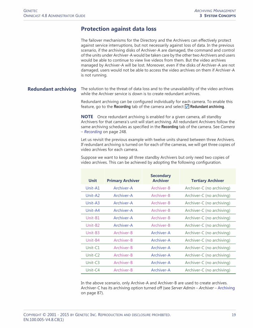
GENETEC ARCHIVING MANAGEMENTOMNICAST 4.8 ADMINISTRATOR GUIDE 3 SYSTEM CONCEPTS
Protection against data loss
The failover mechanisms for the Directory and the Archivers can effectively protect against service interruptions, but not necessarily against loss of data. In the previous scenario, if the archiving disks of Archiver-A are damaged, the command and control of the units under Archiver-A would be taken care by the other two Archivers and users would be able to continue to view live videos from them. But the video archives managed by Archiver-A will be lost. Moreover, even if the disks of Archiver-A are not damaged, users would not be able to access the video archives on them if Archiver-A is not running.
Redundant archiving The solution to the threat of data loss and to the unavailability of the video archives while the Archiver service is down is to create redundant archives.
Redundant archiving can be configured individually for each camera. To enable this feature, go to the Recording tab of the camera and select Redundant archiving.
NOTE Once redundant archiving is enabled for a given camera, all standby Archivers for that camera’s unit will start archiving. All redundant Archivers follow the same archiving schedules as specified in the Recording tab of the camera. See Camera – Recording on page 248.
Let us revisit the previous example with twelve units shared between three Archivers. If redundant archiving is turned on for each of the cameras, we will get three copies of video archives for each camera.
Suppose we want to keep all three standby Archivers but only need two copies of video archives. This can be achieved by adopting the following configuration.
In the above scenario, only Archive-A and Archiver-B are used to create archives. Archiver-C has its archiving option turned off (see Server Admin – Archiver – Archiving on page 87).
Unit Primary ArchiverSecondary Archiver Tertiary Archiver
Unit-A1 Archiver-A Archiver-B Archiver-C (no archiving)
Unit-A2 Archiver-A Archiver-B Archiver-C (no archiving)
Unit-A3 Archiver-A Archiver-B Archiver-C (no archiving)
Unit-A4 Archiver-A Archiver-B Archiver-C (no archiving)
Unit-B1 Archiver-A Archiver-B Archiver-C (no archiving)
Unit-B2 Archiver-A Archiver-B Archiver-C (no archiving)
Unit-B3 Archiver-B Archiver-A Archiver-C (no archiving)
Unit-B4 Archiver-B Archiver-A Archiver-C (no archiving)
Unit-C1 Archiver-B Archiver-A Archiver-C (no archiving)
Unit-C2 Archiver-B Archiver-A Archiver-C (no archiving)
Unit-C3 Archiver-B Archiver-A Archiver-C (no archiving)
Unit-C4 Archiver-B Archiver-A Archiver-C (no archiving)
COPYRIGHT © 2001 - 2015 BY GENETEC INC. REPRODUCTION AND DISCLOSURE PROHIBITED. 19EN.100.005-V4.8.C8(1)

GENETEC ARCHIVING MANAGEMENTOMNICAST 4.8 ADMINISTRATOR GUIDE 3 SYSTEM CONCEPTS
Archiver-C will become active only if both Archiver-A and Archiver-B have failed. In this case, the users can still view live videos but there will be no archiving.
Auxiliary Archiver It is sometimes desirable to have a copy of the video archives kept at a remote location (not connected to the same LAN as the core of the system) for safety reasons. In this case, the Auxiliary Archiver should be considered. The Auxiliary Archiver is a better alternative than creating backups because the redundant archives are readily available without the necessity to restore (see Backup and Restore on page 20), but it offers no protection against service failures, because it cannot assume the command and control functions of the Archiver.
Monitoring Archiver events
There are many ways to monitor the Archiver events in the system.1 By defining user notification actions when important Archiver events arise (disk
load is over 80%, disks full, application lost, etc.). To learn how to set up the Archiver for automatic notification, see Config Tool – Archiver – Actions on page 212.
2 By viewing the User Tracking Reports with the Report Viewer, if Database reporting is supported by your license. See Report Viewer on page 490.
3 By searching the event database for Archiver events with the Config Tool. See Config Tool – Archiver – Event Search on page 219.
4 By examining the log files generated by the Archivers. To learn how to configure the Archiver for event logging, please read Server Admin – Archiver – Logging on page 95. The Archiver logs are not as easy to use as the Archiver’s Event search tab in the Config Tool, but it contains more information. All events pertaining to the cameras managed by the Archiver are logged as well.
Backup and Restore
It is not always possible nor necessary to keep weeks or months worth of video archives online. Part of the archiving management strategy is to keep the older video archives offline to achieve a balance between archive availability and storage cost.
In this section, we are going to look at how you can make backup copies of the online video archive and how to restore these backups to full search and playback capabilities should the need arise.
Backup Backup is the operation that copies a subset of the online video archives, specified by a list of cameras and a date range, to a secondary storage (tape, RW-CD, Zip disk, etc.) for safekeeping.
Backups are handled by Archivers and Auxiliary Archivers in Omnicast. Each archiving service must be configured to backup its own data. Both types of archivers can be configured to perform the backup automatically at regular intervals or on an ad hoc basis.
The data preserved through a single backup operation is called a backup set. Backup sets are allowed to overlap each other, providing extra data protection.
COPYRIGHT © 2001 - 2015 BY GENETEC INC. REPRODUCTION AND DISCLOSURE PROHIBITED. 20EN.100.005-V4.8.C8(1)

GENETEC ARCHIVING MANAGEMENTOMNICAST 4.8 ADMINISTRATOR GUIDE 3 SYSTEM CONCEPTS
Backup not only extends the availability of the video archives beyond the capacity of the online storage, but also protects, to a certain extent, the online data against accidental loss. This is achieved by backing up the data as soon as possible (the earliest is the following day), versus waiting until the last minute. The drawback of such a practice is that any bookmarks generated after a backup will not be included in the backup set.
For the backup operations to take place, the Backup option must be selected on the appropriate archiving service. See Server Admin – Archiver – Backup on page 92.
To learn how to set up the Archiver to perform periodic backups, please read Config Tool – Archiver – Backup on page 213.
To learn how to check the status of the last backup operation and how to perform unscheduled backups, please read Config Tool – Archiver – Backup status on page 214.
The complete backup history of a specific archiver can be viewed by searching the following events with the Config Tool: Backup started, Backup success, Backup failed. For more details about this feature, please read Config Tool – Archiver – Event Search on page 219.
Restore Before the video archive contained in a backup set can be manipulated with the Archive Player, the backup set must first be restored using the Restore Archiver. In order to use this application, the Directory option Number of Restore Archivers must be greater than zero in your Omnicast license.
To learn how to restore a backup set, please read Server Admin – Restore Archiver – Note If you are using a remote database server and there are multiple archivers on the system, please ensure that the database specified is unique on each archiver on page 143.
You can view the characteristics (size, content description, etc.) of a restored backup set with Config Tool. See Config Tool – Backup Set – Info on page 235.
To learn how to delete a restored backup set, please read Config Tool – Restore Archiver – Backup Sets on page 390.
COPYRIGHT © 2001 - 2015 BY GENETEC INC. REPRODUCTION AND DISCLOSURE PROHIBITED. 21EN.100.005-V4.8.C8(1)

GENETEC EVENT MANAGEMENTOMNICAST 4.8 ADMINISTRATOR GUIDE 3 SYSTEM CONCEPTS
Event Management
About events An event is a signal that Omnicast sends when something (an activity or an incident) occurs in the system. All events are attributed to a source entity which is the main focus of the event. See Omnicast Event Types (sorted by source entity) on page 518.
About actions Events can be used to trigger actions such as starting the recording on a camera, triggering an alarm, or sending a message to a user. The ability to associate actions to specific events allows the administrator to program intelligent system behaviors. See Coupling Actions to Events on page 23.
System vs. custom events
Omnicast comes with a long list of predefined event types called system events. These event types cover virtually all aspects of Omnicast’s operation. You may not rename nor delete system events.
Omnicast also allows you to define custom events. Unlike the system events, you may rename and delete custom events. See Config Tool – Directory – Creating custom events on page 301.
New custom events may also be added through the installation of ME plugins. These events typically carry metadata with them and are associated to cameras. Refer to a plugin’s own user guide to find out what events it generates. For a list of currently available plugin documentation, see About Omnicast plugin manuals on page iii.
Event Handling
Monitoring events Events can be monitored in real time with the Live Viewer. Events can be filtered and displayed chronologically in an event list as they occur. See “Event Monitoring” in Omnicast Live Viewer User Guide.
Searching for events Camera related events can be used to search for specific video sequences for playback. See Event Search Workflow and Metadata Search Workflow in Omnicast Archive Player User Guide.
Archiver related events can be viewed with the Config Tool from the Event search tab. See Config Tool – Archiver – Event Search on page 219.
Event reports Omnicast can also be configured to create event logs and event reports for analysis and debugging purposes.
To set up event logs for the Directory and the Archiver, see– Server Admin – Directory – Logging on page 59– Server Admin – Archiver – Logging on page 95
To create database reports and to view them, see– Server Admin – Directory – Database logging on page 60– Tools – Report Viewer on page 490
COPYRIGHT © 2001 - 2015 BY GENETEC INC. REPRODUCTION AND DISCLOSURE PROHIBITED. 22EN.100.005-V4.8.C8(1)
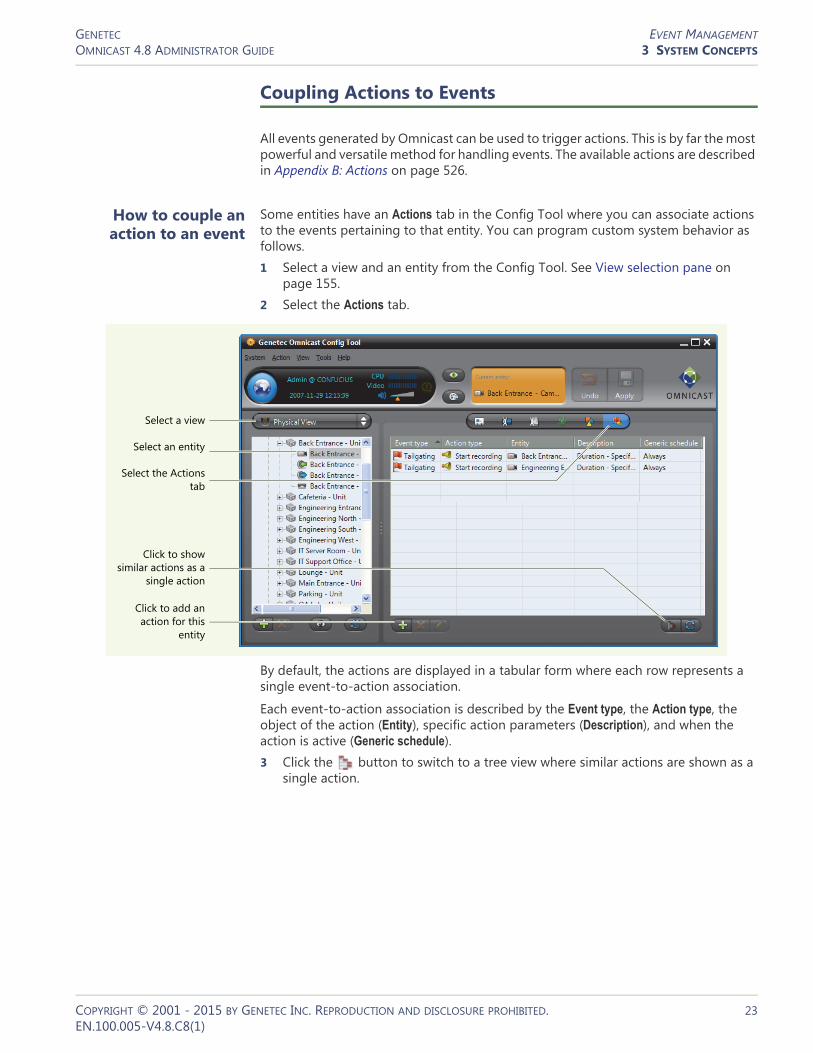
GENETEC EVENT MANAGEMENTOMNICAST 4.8 ADMINISTRATOR GUIDE 3 SYSTEM CONCEPTS
Coupling Actions to Events
All events generated by Omnicast can be used to trigger actions. This is by far the most powerful and versatile method for handling events. The available actions are described in Appendix B: Actions on page 526.
How to couple an action to an event
Some entities have an Actions tab in the Config Tool where you can associate actions to the events pertaining to that entity. You can program custom system behavior as follows.1 Select a view and an entity from the Config Tool. See View selection pane on
page 155.2 Select the Actions tab.
By default, the actions are displayed in a tabular form where each row represents a single event-to-action association.
Each event-to-action association is described by the Event type, the Action type, the object of the action (Entity), specific action parameters (Description), and when the action is active (Generic schedule).3 Click the button to switch to a tree view where similar actions are shown as a
single action.
Select a view
Select an entity
Click to add an action for this
entity
Select the Actions tab
Click to show similar actions as a
single action
COPYRIGHT © 2001 - 2015 BY GENETEC INC. REPRODUCTION AND DISCLOSURE PROHIBITED. 23EN.100.005-V4.8.C8(1)

GENETEC EVENT MANAGEMENTOMNICAST 4.8 ADMINISTRATOR GUIDE 3 SYSTEM CONCEPTS
4 Click the button to switch back to the tabular view.5 Click at the bottom of the Configuration pane. The Create / edit an action dialog
box appears.
6 Select the event that will trigger the action.See Appendix A: Omnicast Events on page 508 for a list of available event types and their description.
Select a view
Select an entity
Click to add an action for this
entity
Select the Actions tab
Click to show each action on a
separate row
COPYRIGHT © 2001 - 2015 BY GENETEC INC. REPRODUCTION AND DISCLOSURE PROHIBITED. 24EN.100.005-V4.8.C8(1)

GENETEC EVENT MANAGEMENTOMNICAST 4.8 ADMINISTRATOR GUIDE 3 SYSTEM CONCEPTS
7 Select the action that should be triggered.The dialog box will dynamically adjust itself to show the required parameters of the selected action type.See Appendix B: Actions on page 526 for a list of available action types and their parameters.
8 Enter all required parameters.9 Select the schedule during which this action will be active. See Generic Schedule on
page 324.10 Click OK to add the action(s). One or more actions may be added depending on
what your entered.11 Click to save the changes.
Generalizing event handling
Certain camera (video encoder) events used for troubleshooting such as Signal lost and Signal recovered can be generalized at the unit level or the Archiver level so you do not need to associate the same action to each individual camera event.
When you associate an action to camera event at the unit level, the action will apply to all cameras attached to that unit.
When you associate an action to camera event at the Archiver level, the action will apply to all cameras attached to all units controlled by this Archiver.
Custom actions Custom actions can be defined in the Config Tool. A custom action is nothing more than a meaningful name that can be assigned to an output relay state to ease programming. See Config Tool – Directory – Custom Actions on page 301.
Once a custom action is defined, it will appear in the Action type drop-down list of the Create / edit an action dialog. See How to couple an action to an event on page 23.
COPYRIGHT © 2001 - 2015 BY GENETEC INC. REPRODUCTION AND DISCLOSURE PROHIBITED. 25EN.100.005-V4.8.C8(1)

GENETEC FEDERATIONOMNICAST 4.8 ADMINISTRATOR GUIDE 3 SYSTEM CONCEPTS
Federation
Introduction
Definition The Federation™ is a virtual system formed by joining multiple independent Omnicast systems together. One of the systems must act as the Federation host. The purpose of forming a federation is to allow Omnicast clients on the host system to view video sources belonging to multiple independent Omnicast installations simultaneously as if they were on the same system.
How it works At the core of the Federation is the Federation Server . This special service must be part of the Omnicast system hosting the Federation. It possesses the ability to connect to the local Directory on the host system as well as to other independent Directories on remote systems.
The Federation Server must connect to each remote Directory using one of its local user accounts. Therefore, the entities that the Federation Server is permitted to access on a remote system are limited to the ones that the logon user is permitted to access.
ArchiverGateway
Directory
Client application
Real cameras
Federated cameras
Federation ServerFederation™
(Host system)
Federated system (Remote system)
Directory
Client application
Gateway Archiver
Real cameras
COPYRIGHT © 2001 - 2015 BY GENETEC INC. REPRODUCTION AND DISCLOSURE PROHIBITED. 26EN.100.005-V4.8.C8(1)

GENETEC FEDERATIONOMNICAST 4.8 ADMINISTRATOR GUIDE 3 SYSTEM CONCEPTS
Once connected to a remote Directory, the Federation Server creates a local representative for each remote entity it can access. These local representatives are called federated entities. From the local user's point of view, federated entities behave exactly like real entities, with only a few limitations. The federated entities are indicated in the entity trees with a yellow arrow superimposed on the entity icon.
In the scenario illustrated above, the Federation Server created two federated cameras for the two real cameras on the remote system. When a client application requests the video feed from a federated camera, the Federation Server will first get the video feed from the remote system, then multicast it on the local system. The client application on the local system can then view the remote video feed as though it comes from the local system.
Federated entities The types of entities that can be federated are:• Cameras • Camera sequences • Virtual cameras • PTZ motors • Microphones • Digital inputs • Output relays • ME plugins
The federated entities can be used anywhere the real entities can. For example, you can define alarms or camera sequences with federated cameras. Events associated to the remote entities can be replicated by the federated entities as an option. Therefore, full event handling capability is also supported for federated entities. The limitations pertaining to federated entities are discussed in the next section.
For information on how to create and configure federated entities, please refer to the section on Federated Directory in the Config Tool reference guide.
Limitations
Configuration The configuration of the real entities cannot be done through the federated entities. What you may change though, are the local attributes of the federated entities:• logical ID • entity name • entity description • actions linked to the entity events (when it applies)
The above attributes belong to the federated entities. Changing them does not affect in any way the remote entities they reference.
There is one exception worth mentioning regarding the entity name and description. These two attributes cannot be changed if entity synchronization is turned on. This feature forces all entities under the federated Directory to follow the same name and hierarchy as they are configured in the remote Directory. Essentially, the Logical view defined in the remote Directory is replicated under the federated Directory.
COPYRIGHT © 2001 - 2015 BY GENETEC INC. REPRODUCTION AND DISCLOSURE PROHIBITED. 27EN.100.005-V4.8.C8(1)

GENETEC FEDERATIONOMNICAST 4.8 ADMINISTRATOR GUIDE 3 SYSTEM CONCEPTS
For more details concerning this feature, please read about the SYNCHRONIZED option in Config Tool – Federated Directory on page 310.
Interface with older Omnicast versions
The Federation Server is able to connect to remote Directories running Omnicast 3.5 or more recent. Omnicast systems older than 3.5 are not supported.
Archive playback The number of playback streams that can be viewed simultaneously from a same Federation Server for a given version of federated Directory is limited to 20.
Audio Speaker entities cannot be federated.
Camera sequence Federated camera sequence cannot be paused.
COPYRIGHT © 2001 - 2015 BY GENETEC INC. REPRODUCTION AND DISCLOSURE PROHIBITED. 28EN.100.005-V4.8.C8(1)

GENETEC NETWORK CONNECTIONSOMNICAST 4.8 ADMINISTRATOR GUIDE 3 SYSTEM CONCEPTS
Network Connections
Omnicast supports many network connection types. This flexibility allows the system administrator to provide the best possible service to the users in virtually every network configuration.
Network Connection Types
Unicast Unicast is communication between a single sender and a single receiver over a network. Omnicast's preferred protocol for unicast is UDP (User Datagram Protocol) for video and audio transmissions because it is more efficient (less overhead), and TCP (Transmission Control Protocol) for serial port connections. When the LAN is protected by a firewall, TCP (Transmission Control Protocol) must be used.
Unicast is recommended when the connection is made over a dialup phone line or a wireless LAN, where the bandwidth is very low or when multicast is not permitted.
If a video encoder (camera) is configured for unicast on the system network, then only one user at a time can receive the transmission. If later a second user connects to the same camera, the first user automatically loses the signal.
Broadcast Broadcast is a receiver unspecific transmission over a network. This type of connection is not used by Omnicast for video transmission because it tends to clog up the network.
Multicast Multicast is communication between a single sender and multiple specific receivers on a network. This is the preferred connection type for Omnicast whenever the network permits. In this mode, multiple users in multiple locations can receive the same video transmission simultaneously from a same source, using the bandwidth only once. Most video units are capable of multicast transmissions.
Best available Best available is selected when the user does not want to be bothered by complicated decisions concerning connection types. This is actually the default setting and is the recommended configuration in the majority of cases.
When best available is selected, the user is letting the Directory make the connection decision. When a connection is requested between two parties, the Directory will always try its preferred mode, which is multicast. If both parties asked for multicast or best available, then multicast will be used. If one of the parties chose unicast and the other party chose best available, then unicast will be used. If one party chose multicast and another chose unicast, then the connection cannot be established.
RTSP stream over HTTP
Use this connection to tunnel RTSP communications over HTTP when single TCP connections are blocked by firewalls. This connection type is only available on certain units.
RTSP stream over TCP Use this connection to tunnel RTSP communications over TCP. This connection type is only available on certain units.
COPYRIGHT © 2001 - 2015 BY GENETEC INC. REPRODUCTION AND DISCLOSURE PROHIBITED. 29EN.100.005-V4.8.C8(1)

GENETEC VIDEO ANALYTICSOMNICAST 4.8 ADMINISTRATOR GUIDE 3 SYSTEM CONCEPTS
Video Analytics
Video analytics is software technology that analyzes video for specific data. The technology can evaluate a video stream to determine specific information about its content. Examples of video analytics include counting the number of people entering a door, license plate recognition, detection of unattended objects, the direction of people walking or running, etc.
Omnicast supports different types of video analytics, such as server-based solutions to add analytics capabilities to existing cameras, or on-the-edge solutions where the analytics are performed directly on a device. This flexibility allows the system administrator to provide the best possible service to the users in virtually every network configuration.
Video Analytics Types
On-The-Edge Video Analytics
Omnicast supports on-the-edge video analytics from manufacturers such as Axis, Bosch, Sony, and Panasonic. Using edge analytics, video analytics behavior is detected on the camera, and received as events in Omnicast. The video analytic event types available depend on the manufacturer and unit type. Some examples are tampering alarms (events triggered if the camera is blocked or moved in any way), audio alarms (events triggered if the sound in the video reaches a set volume), or video content analytics (such as cross-line detection, object detection, moving object detection, and unattended object detection).
The video analytics rules are configured on the unit’s Web page. For more information about which units support edge analytics, see the Omnicast Supported Hardware.pdf, available for download from the GTAP Documents page, at https://gtap.genetec.com.
NOTE You need a username and password to log on to GTAP.
Third Party Metadata Engine Plugins
Omnicast can integrate with third party applications such as video analytics software using ObjectVideo’s server-based solution, OnBoard Complete, through Metadata Engine plugins. ObjectVideo’s server-based solution includes the rule configuration interface and central analytics communication server, and can work with existing deployed IP or analog cameras.
For example, the ObjectVideo plugin interfaces Omnicast with ObjectVideo's VEW® software, and the iOmniscient plugin interfaces Omnicast with iOmniscient's IQ Product Series software. These Metadata Engine plugins receive and store video analytic events from the third party server (for example, intrusion, object entered, object exited, camera view lost, etc.).
Plugins are installed on the Metadata Engine server, and configured in Config Tool. For more information about creating and configuring plugins, see the individual plugin guides (About Omnicast plugin manuals on page iii).
COPYRIGHT © 2001 - 2015 BY GENETEC INC. REPRODUCTION AND DISCLOSURE PROHIBITED. 30EN.100.005-V4.8.C8(1)

GENETEC VIDEO ANALYTICSOMNICAST 4.8 ADMINISTRATOR GUIDE 3 SYSTEM CONCEPTS
ObjectVideo with OV Ready
Omnicast supports ObjectVideo analytic platforms using OV Ready, an open standards based intelligent video protocol. With this on-the-edge solution, the analytic engine from ObjectVideo is completely embedded in an edge device, such as an IP camera or encoder. There is no need to deploy additional servers, because the analytic engine uses the resources available on the device to calculate the analytic rules.
Analytic events generated by the device and sent to Omnicast can make the system react based on the behavior being detected (for example, intrusion, object left or removed, camera tampering, loitering, etc.), based on the video analytics rules you configured in Omnicast. For more information about setting up video analytic rules that will trigger events when using OV Ready compliant units, see Video Analytics on page 267.
NOTE To use this type of video analytics, you need the “Number of OVReady cameras” license option, for the number of cameras you require.
COPYRIGHT © 2001 - 2015 BY GENETEC INC. REPRODUCTION AND DISCLOSURE PROHIBITED. 31EN.100.005-V4.8.C8(1)

SECTION 4
DEPLOYING OMNICAST
Omnicast installation and configuration procedure doubled as a reading plan for this guide
GENETEC DEPLOYMENT PROCEDUREOMNICAST 4.8 ADMINISTRATOR GUIDE 4 DEPLOYING OMNICAST
Deployment Procedure
Introduction Omnicast can be installed on a single PC managing a small number of cameras to a vast network of servers distributed over multiple LANs and managing tens of thousands of cameras. See Architecture Overview on page 2.
Omnicast is designed to grow with your needs. New servers and new units can be added at any time during the life span of your system. There is no single deployment strategy that works best in all situations. However, certain procedures make more sense to follow than others because they take into account the dependencies that exist between the entities. For example, it makes more sense to create the sites before configuring the users, because the sites are used to control the user’s access rights to the system resources.
We have two goals in this chapter:1 Propose a simple procedure that will ease your configuration process.2 Provide a starting point and a logical reading plan for this document.
Prerequisites Before you start the system configuration, it is best to complete the physical setup of all hardware devices on your system (PCs, units, cameras, cables, etc.).
All Omnicast server applications (Windows services) should be installed on their respective servers. On a very small system, they can all be hosted on the same PC. On a large scale system, you should have a plan drawn out by a qualified Omnicast system engineer, detailing where each PC should be on the network and what applications they should be hosting.
We also recommend that you set up at least one PC (it could be the Directory server) with the Config Tool installed on it. You will need this application throughout the configuration procedure to monitor the progress of your configuration.
The installation procedures for Omnicast server and client software are found in the Installation and Upgrade Guide.
It is assumed that you have read the Sections 1 through 3 of this manual. It is highly recommended that you take the Omnicast Technical Certification Training course.
COPYRIGHT © 2001 - 2015 BY GENETEC INC. REPRODUCTION AND DISCLOSURE PROHIBITED. 33EN.100.005-V4.8.C8(1)

GENETEC DEPLOYMENT PROCEDUREOMNICAST 4.8 ADMINISTRATOR GUIDE 4 DEPLOYING OMNICAST
Simple System Configuration
General setup procedure
The following procedure suggests a logical sequence of steps for you to follow. You may skip the steps that do not apply to your situation. The steps are only briefly described in this procedure. The emphasis is on showing the sequence. For detailed instructions on how to configure each piece of the system, please follow the links. This procedure is also intended as a reading guide for this document.
Step Description (1 of 4)
1 Set up the main Directory server
The main Directory, as opposed to the backup Directories, is the Directory that should be running at all times. You need to activate the Omnicast license on the Directory server. See Common server configuration on page 37.
If you are planning to import the users and user groups from your company’s Active Directory, do so now, but leave the configuration of the users until Step 15. See Active Directory on page 62.
2 Configure the Gateway
The Gateway is required to provide connections to the Directory to other Omnicast applications. It is typically installed on the Directory server but it may also be installed on a different server (see Gateway on page 75).
Repeat this step as many times as necessary for all the Gateways on your system.
3 Configure the Archiver (Part 1)
The Archiver may be installed on the Directory server or installed on its own server (see Archiver on page 85). If the Archiver is hosted on a separate PC, you would need to activate the Omnicast license on that PC.
You also need to create an Archiver extension for every type of units controlled by this Archiver (see Archiver Extensions on page 97).
Repeat this step as many times as necessary for all the Archivers on your system.
4 Configure other Omnicast services
If your system requires other Omnicast services, such as Virtual Matrix, Metadata Engine, Auxiliary Archiver, etc., please configure them now. See Common server configuration on page 37.
5 Verify your configuration with the Config Tool
Connect the Config Tool the Directory using the Admin user (the default password is blank) and select Physical View. See Physical View on page 163
All the server applications that you have configured so far should appear under the Gateway .
Now is a good time to change the Admin user‘s password. To do this select System > Change password from the Config Tool menu.
COPYRIGHT © 2001 - 2015 BY GENETEC INC. REPRODUCTION AND DISCLOSURE PROHIBITED. 34EN.100.005-V4.8.C8(1)

GENETEC DEPLOYMENT PROCEDUREOMNICAST 4.8 ADMINISTRATOR GUIDE 4 DEPLOYING OMNICAST
6 Discover/add the units for each Archiver
If the units installed on your system support automatic discovery, they should appear in the Physical view, under the Archiver that is controlling them. The devices discovered on each unit should appear under the unit in the Physical view.
If your units do not support automatic discovery, you must add them manually to your system. See Adding Video Units on page 405.
Use the Discovery Tool to find the units on your system. See Discovery Tool on page 476.
7 Define the Logical View
The Logical view helps you organize your system resources into logical groups called sites. It also helps you control the visibility of your system resources by the users. See Logical View on page 161 and Site on page 395.
When moving or renaming the units in the Logical view, you have the option to move and rename the devices associated to the unit along or separately. See User Interaction Options on page 467.
8 Define the generic schedules
A generic schedule defines a set of time constraints to follow. Schedules are used in a variety of places in Omnicast. See Generic Schedule on page 324.
9 Configure the Archiver (Part 2)
Part 2 of Archiver configuration involves the configuration of the Archiving, the Backup and the Actions for each Archiver from the Config Tool. See Archiver on page 204 and Archiving Schedule on page 220.
For general archiving concepts, please read Archiving Management on page 13.
10 Configure the discovered hardware devices
Configure the various devices discovered or added with the units in Step 6. Follow the links that apply to your installation.• – Unit on page 404• – Camera (Video Encoder) on page 237• – Analog Monitor (Video Decoder) on page 198• – Serial Port on page 392• – PTZ Motor on page 381 (necessary dome cameras )• – Digital Input on page 291• – Output Relay on page 364• – Microphone (Audio Encoder) on page 356• – Speaker (Audio Decoder) on page 401
To avoid repetitive work, use the Copy configuration tool found in the Tools menu. See Copy Configuration Tool on page 167.
11 Configure Auxiliary Archivers
If the use of Auxiliary Archivers is part of your archiving strategy, configure them now. See Auxiliary Archiver on page 223.
Step Description (2 of 4)
COPYRIGHT © 2001 - 2015 BY GENETEC INC. REPRODUCTION AND DISCLOSURE PROHIBITED. 35EN.100.005-V4.8.C8(1)
GENETEC DEPLOYMENT PROCEDUREOMNICAST 4.8 ADMINISTRATOR GUIDE 4 DEPLOYING OMNICAST
12 Configure the Virtual Matrix
The Virtual Matrix controls a host of entities in Omnicast. If your license supports these entities, create them now. See• – Access Control System on page 183• – Camera Sequence on page 282• – CCTV Keyboard on page 288• – Hardware Matrix on page 334
13 Configure macros and VM plugins
If your license supports the use of macros and VM plugins, create them now.• – Macro on page 341 and Macro Editor on page 488• – Macro Schedule on page 353• – Virtual Matrix Plugin on page 368
For specific VM plugin configuration, refer to individual plugin user guides; see About Omnicast plugin manuals on page iii.
14 Configure the Metadata Engine and ME plugins
If your license supports the use of ME plugins, install and create them now. Generic information on ME plugins are found in Metadata Engine Plugin on page 372. Specific instructions on how to configure and use each type of ME plugins are also found in individual plugin user guides; see About Omnicast plugin manuals on page iii.
15 Create/configure users and user groups
If you have not imported the users and user groups from your company’s Active Directory in Step 1, you must create them now.
It is best to configure the user groups first so the users can inherit their properties (Permissions, Privileges and Security) from them.
See User on page 418 and User Group on page 445.
16 Configure Alarm Management
If your license supports Alarm management, now is the time to define all necessary entities. Create the entities in the following order.• – Camera Group on page 280• – Monitor Group on page 361• – Alarm on page 186
You also need to associate the Trigger alarm action to the appropriate events. See Alarm Management on page 7 and Event Management on page 22.
Step Description (3 of 4)
COPYRIGHT © 2001 - 2015 BY GENETEC INC. REPRODUCTION AND DISCLOSURE PROHIBITED. 36EN.100.005-V4.8.C8(1)

GENETEC DEPLOYMENT PROCEDUREOMNICAST 4.8 ADMINISTRATOR GUIDE 4 DEPLOYING OMNICAST
Common server configuration
A server is a PC hosting one or more Omnicast server applications. Please make sure that the minimum requirements for the server PC are met. The minimum requirements are found in the Omnicast Installation and Upgrade Guide.
All server applications require a two-part configuration. The first part is done through the Server Admin and pertains to the parameters that are specific to the local machine. See Server Admin Overview on page 40.
The second part is done through the Config Tool and pertains to the machine independent parameters of the application. See Config Tool Overview on page 153.
On servers hosting the Directory or the Archiver service, you need to activate the Omnicast software license. See Server Admin – System – License on page 46.
Omnicast uses emails to notify the administrators when anything goes wrong in the system. To enable the email notification, the SMTP server must be properly configured. See Server Admin – System – SMTP on page 53.
The Watchdog service is installed on each Omnicast server. Use the Watchdog tray to verify that all your services. See Server Admin – Watchdog Tray on page 504.
For instructions on how to configure each type of server application, follow the links below:• Directory on page 55• Directory Failover Coordinator on page 73• Gateway on page 75• Archiver on page 85• Auxiliary Archiver on page 133• Restore Archiver on page 142• Metadata Engine on page 146• Virtual Matrix on page 150• Federation Server on page 84
17 Set up the client workstations
Install and configure each client workstation according to your system requirements. Please make sure that the minimum requirements for the client PC are met. The minimum requirements are found in the Omnicast Installation and Upgrade Guide.
Now is the time to create the viewer layouts with the Live Viewer and to test the permissions and privileges configured in Step 15.
If users on your system are not supposed to change their client views, you need to configure their workspace for them in advance. Please refer to the Omnicast Live Viewer User Guide and the Omnicast Archive Player User Guide to learn how to customize these two client applications.
18 Associate actions to events
Make one final round through the system entities and add the necessary actions to program the desired behavior to your system. See Event Management on page 22.
Step Description (4 of 4)
COPYRIGHT © 2001 - 2015 BY GENETEC INC. REPRODUCTION AND DISCLOSURE PROHIBITED. 37EN.100.005-V4.8.C8(1)

GENETEC DEPLOYMENT PROCEDUREOMNICAST 4.8 ADMINISTRATOR GUIDE 4 DEPLOYING OMNICAST
Failover Configuration
Omnicast support the failover mechanism on most of its server applications.
Directory failover To configure Directory failover, you need to set up at least two Directory servers and designate one as the primary Directory server. The DFC must be installed on every Directory server you have on your system. See Directory Failover Coordinator on page 73.
For the Directory failover configuration, use the Directory Failover Configuration Wizard found in the Tools menu. See Directory Failover Configuration on page 170.
Archiver failover In Omnicast, every unit must be controlled by one and only one Archiver at all times. Additional Archivers can be configured as substitutes in case the primary Archiver becomes unavailable. See System Concepts – Archiver Availability on page 17.
For one Archiver to act as the standby of another Archiver for a group of units, the two Archivers must have the exact same Archiver extension defined in Server Admin (see Archiver Extensions on page 97).
Units that are covered under multiple Archiver extensions have multiple Archivers showing in their Standby Archivers tab in the Config Tool (press <Shift>+<F10> if you do not see this tab). You must specify for each unit which Archiver is to be its primary Archiver. See Unit – Standby Archivers on page 416.
Virtual Matrix failover Entities controlled by the Virtual Matrix can be protected by additional Virtual Matrices on standby in case the primary Virtual Matrix becomes unavailable. These entities are:• – Access Control System on page 183• – Camera Sequence on page 282• – CCTV Keyboard on page 288• – Hardware Matrix on page 334• – Macro Schedule on page 353• – Monitor Group on page 361
All these entities have a Standby Virtual Matrices tab in the Config Tool that allows you to define standby Virtual Matrices.
Federation Configuration
On very large multi-site installations, each site can be managed by a independent Omnicast system, while the headquarter can monitor the activities at each individual site through the Federation™. See System Concepts – Federation on page 26.
To set up the Federation site, it is best to dedicate a PC to run the Federation Server. See Federation Server on page 84. Once the Federation Server is up and running, you need to create a Federated Directory of each of the independent Directory you wish to monitor. See Federated Directory on page 310.
COPYRIGHT © 2001 - 2015 BY GENETEC INC. REPRODUCTION AND DISCLOSURE PROHIBITED. 38EN.100.005-V4.8.C8(1)

SECTION 5
SERVER ADMIN
Server Admin reference guide

GENETEC SERVER ADMIN OVERVIEWOMNICAST 4.8 ADMINISTRATOR GUIDE 5 SERVER ADMIN
Server Admin Overview
Introduction The Server Admin is the first application you use to configure Omnicast. It must be run locally on each PC where Omnicast server applications have been installed. See Server Applications on page 4. It is used to:• Install or update the Omnicast license (a separate license is required for every
server running either the Directory or the Archiver service).• Configure the Omnicast server applications installed locally.
Only users with access (Microsoft Windows username/password) to the server hosting the Omnicast services can run the Server Admin.
When Omnicast Server is installed for the first time, a wizard appears to help you configure the Server Admin. For more information about the Server Admin Configuration Wizard, see “Configure the Server Admin” in the Omnicast Installation and Upgrade Guide.
Server Admin workspace
The Server Admin workspace is divided into two panes (see illustration below). The left pane displays the resource tree. Only the services installed on the local machine are listed. Selecting any of the elements in the resource tree displays its configuration screen on the right.
COPYRIGHT © 2001 - 2015 BY GENETEC INC. REPRODUCTION AND DISCLOSURE PROHIBITED. 40EN.100.005-V4.8.C8(1)

GENETEC SERVER ADMIN OVERVIEWOMNICAST 4.8 ADMINISTRATOR GUIDE 5 SERVER ADMIN
Resources covered by Server Admin
The system resources that must be configured with Server Admin are:
Server Admin Menu
Introduction The following describes the entire Server Admin menu system.
Icon Click To configure
System The Omnicast license and server wide parameters, such as SMTP server and public network address.
Directory The Directory service on the local machine.
Directory Failover Coordinator
The Directory Failover Coordinator service on the local machine.
Gateway The Gateway service on the local machine.
Federation Server
The Federation Server service on the local machine.
Archiver The Archiver service on the local machine.
Archiver Extensions
Additional Archiver settings for individual unit groups.
Auxiliary Archiver
The Auxiliary Archiver service on the local machine.
Restore Archiver
The Restore Archiver service on the local machine and to restore offline video from backup sets.
Metadata Engine
The Metadata Engine service on the local machine.
Virtual Matrix The Virtual Matrix service on the local machine.
Submenu Description
System You may Exit the application from here.
Action The Action menu is identical to the contextual menu when you right-click in the resource tree. It allows you to Start, Stop or Restart the selected application. These same functions are also available from the Watchdog Tray.
When the selected application is the Archiver, you can also Create the Archiver extensions.
Use Delete to remove applications that are not running or to delete Archiver extensions that are no longer needed.
Use Refresh to refresh the tree structure.
COPYRIGHT © 2001 - 2015 BY GENETEC INC. REPRODUCTION AND DISCLOSURE PROHIBITED. 41EN.100.005-V4.8.C8(1)

GENETEC SERVER ADMIN OVERVIEWOMNICAST 4.8 ADMINISTRATOR GUIDE 5 SERVER ADMIN
Check Database Status
Description The Check database status dialog is a tool that can help you fix yourself minor database corruption problems that may occur in some rare situations.
A database can sometimes become corrupted due to an accident, such as when the machine is not shutdown properly. When this happens, the database is flagged as suspicious and cannot be listed by the regular database search tabs offered by the Server Admin.
Tools This menu gives access to the following commands:• Check Database Status on page 42• Backup Tool on page 474• Server Admin Configuration Wizard. For more information, see
“Configure the Server Admin” in the Omnicast Installation and Upgrade Guide.
• Options on page 43
These commands can only be accessed from this menu.
Help This menu lets the user access various help functions.
Selecting Contents or clicking the <F1> key will open the Omnicast Administrator Guide (this current document).
Selecting Technical Support will list the support information relevant to your license, and selecting About will list license and copyright information. See Help menu on page 168.
Submenu Description
COPYRIGHT © 2001 - 2015 BY GENETEC INC. REPRODUCTION AND DISCLOSURE PROHIBITED. 42EN.100.005-V4.8.C8(1)

GENETEC SERVER ADMIN OVERVIEWOMNICAST 4.8 ADMINISTRATOR GUIDE 5 SERVER ADMIN
The database instances used by Omnicast applications are:• DirectorySQL, see Directory – Directory database on page 56• AlarmSQL, see Directory – Alarm database on page 56• ReportingSQL, see Directory – Database logging on page 60• VideoArchiveSQL, see Archiver – Archive database on page 87• AuxiliaryArchiveSQL, see Auxiliary Archiver – Archive database on page 135• ObjectStore, see Metadata Engine – Database settings on page 148
A sure indication that a corrupted database exists is when the Server Admin tells you that the database name you chose is already being used by another database when you try to create a new database from one of the above listed tabs.
Fixing corrupted databases
To fix a database corruption problem:1 Select Tools > Check Database Status from the main menu. The Check Database Status
dialog appears.2 Select Data server from the drop-down list. All databases known to that server will
be shown in the Database list. The corrupted ones have a Flag different from None.3 Select a suspicious database and click to clear the flags. The flag can be cleared
if it is only a temporary problem.4 If the flag cannot be cleared, click to delete the database.
If you delete a video archive database, the referenced video files (if they exist) will not be deleted. You can use the Find Orphan Files tool to locate the video files on disk. See Find Orphan Files on page 44.
Options
The Server Admin Options dialog allows you to change the time zone display options.
Date and time options The time zone settings apply to all client applications. Changing a setting in one will automatically affect the other applications installed on the same machine. Note that the date and time display format follows the Windows settings.
DISPLAY BASED ON EACH DEVICE'S TIME ZONE – Each device in the system follows a specific time zone. Generally speaking, an application follows the time zone of the PC where it is running and all devices (units) follow the time zone of the application controlling it.
COPYRIGHT © 2001 - 2015 BY GENETEC INC. REPRODUCTION AND DISCLOSURE PROHIBITED. 43EN.100.005-V4.8.C8(1)

GENETEC SERVER ADMIN OVERVIEWOMNICAST 4.8 ADMINISTRATOR GUIDE 5 SERVER ADMIN
DISPLAY BASED ON THE FOLLOWING TIME ZONE – You can choose to display the time according to each entity's time zone or to display everything following a time zone of your choice. This change is effective immediately and affects all client applications.
DISPLAY TIME ZONE ABBREVIATIONS – Select this option to display the time zone abbreviation wherever time is displayed. Please refer to the Appendix for the time zone abbreviations used in Omnicast.
See also Config Tool – Date and Time Options on page 472.
Find Orphan Files
Description The Find Orphan Files dialog is used to help you find orphan files in a particular folder.
An orphan file is a video file that is no longer referenced by a designated archive database. These files, if not deleted manually, will stay on disk forever, since the Archiver can only delete files that are referenced by its database. This is to address a situation that may arise when the user changes the archive database.
Finding orphan files To find the orphan files regarding a specific archive database:1 Select from the resource tree, the archiving service (Archiver or Auxiliary Archiver
) you wish to verify.2 Select the corresponding Archiving tab of the selected service.3 Click the Find orphan files button opposite the Database field.
In the Find orphan files dialog box, the Folder list shows the archiving folders assigned to the selected archiver. You may add or remove folders from that list.
COPYRIGHT © 2001 - 2015 BY GENETEC INC. REPRODUCTION AND DISCLOSURE PROHIBITED. 44EN.100.005-V4.8.C8(1)
GENETEC SERVER ADMIN OVERVIEWOMNICAST 4.8 ADMINISTRATOR GUIDE 5 SERVER ADMIN
4 Select a folder and click Search. A search progress window will be displayed while the tool is searching for orphan files under the selected folder. All G64 files that are not referenced by the archiver database will be listed in the Orphan files list.
5 Choose how you wish to handle the orphan files. You have the choice to delete or to quarantine the selected files. If you choose to quarantine the selected files, you will be prompted to enter a quarantine folder.
6 Click OK when you are finished.
COPYRIGHT © 2001 - 2015 BY GENETEC INC. REPRODUCTION AND DISCLOSURE PROHIBITED. 45EN.100.005-V4.8.C8(1)

GENETEC SYSTEMOMNICAST 4.8 ADMINISTRATOR GUIDE 5 SERVER ADMIN
System
Introduction The System screen shows the general parameters pertaining to the local server machine. It comprises the following configuration tabs.
License
Description The License tab shows the options supported by your software license. Omnicast uses a license key to enable the features that are available to you.
A separate license key is issued for every server machine running either the Directory or the Archiver service. If the license has not yet been activated on your machine, this page would be blank. See Activating your license on page 53.
The license options are divided in two categories. The Directory options apply to the entire system while the Archiver options only apply to the local Archiver.
The options that are not supported by your license are not shown on this page.
Icon Tab Description
License License information and activation.
SMTP Common SMTP server and domain settings.
Network Public address for this machine.
COPYRIGHT © 2001 - 2015 BY GENETEC INC. REPRODUCTION AND DISCLOSURE PROHIBITED. 46EN.100.005-V4.8.C8(1)

GENETEC SYSTEMOMNICAST 4.8 ADMINISTRATOR GUIDE 5 SERVER ADMIN
Directory options Omnicast only counts the active connections. For example, if the license supports a maximum of 1 client, 2 different PCs can connect to the Directory at different moments but not simultaneously. Exceeding connection requests will be rejected and an error message will be displayed.
The following table describes each of the Directory options.
Icon Option Description (1 of 3)
Number of cameras and analog monitors
Maximum number of video encoders and decoders allowed on the system. A unit with n video inputs/outputs will require n connections.
In the License tab of the Directory in Config Tool, this option also specifies how many encoders and decoders are currently being used.
Number of standby Directories
Maximum number of DFCs (Directory Failover Coordinator) allowed on the system.
Active Directory integration
Allows the integration of Windows Active Directory to Omnicast's user management.
Number of Gateways Maximum number of Gateway services allowed on the system.
Number of Media Gateways
Maximum number of video encoders that can be exposed to applications outside Omnicast through the Media Gateway application.
Number of Archivers Maximum number of Archiver services allowed on the system.
Standby Archivers Allows standby Archiver to be defined to support the failover mechanism.
Redundant archiving Enables redundant archiving by Archivers. Requires Standby Archivers option to be supported.
Number of Virtual Matrices
Maximum number of Virtual Matrix services allowed on the system.
Standby Virtual Matrices
Allows Virtual Matrices to support the failover mechanism.
Number of Metadata Engines
Maximum number of Metadata Engine services allowed on the system.
Standby Metadata Engines
Allows Virtual Matrices to support the failover mechanism.
Number of Restore Archivers
Maximum number of Restore Archiver services allowed on the system.
Number of Auxiliary Archivers
Maximum number of Auxiliary Archiver services allowed on the system.
Number of federated Directories
Maximum number of federated Directory allowed on the system.
Number of federated cameras/camera sequences
Maximum number of federated cameras and camera sequences allowed on the system.
COPYRIGHT © 2001 - 2015 BY GENETEC INC. REPRODUCTION AND DISCLOSURE PROHIBITED. 47EN.100.005-V4.8.C8(1)

GENETEC SYSTEMOMNICAST 4.8 ADMINISTRATOR GUIDE 5 SERVER ADMIN
Number of Auxiliary Archiver cameras
Maximum number of video streams that can archived by Auxiliary Archivers.
Number of client workstations
Maximum number of client connections (Live Viewer, Archive Player, Web Live Viewer*, Web Archive Player*) allowed on the system.
(*) Web clients are allowed only if Web clients option is supported.
Number of SDK connections
Maximum number of SDK connections allowed on the system.
Number of Pocket PC clients
Maximum number of Pocket PC (Windows CE) connections allowed on the system.
Web clients Allows Web Live Viewer and Web Archive Player connections. Each connection requires a client license.
Number of uncompressed video filters
Maximum number of uncompressed video filters allowed on the system. This option is necessary for third party application integration such as ObjectVideo's VEW).
Number of DVR inputs Maximum number of Digital Video Recorder inputs allowed on the system.
Number of AutoVu LPR units
Maximum number of AutoVu LPR units allowed on the system.
Number of hardware matrices
Maximum number of hardware matrix entities allowed on the system. A Virtual Matrix is required to use this option.
Number of CCTV keyboards
Maximum number of CCTV keyboard connections allowed. A Virtual Matrix is required to use this option.
Number of access control systems
Maximum number of access control systems allowed on the system.
Number of OVReady cameras
Maximum number of OV Ready compliant units.
HTML maps Allows the use of HTML maps in the Live Viewer.
Trickling Allows you to perform trickling with units that support edge recording.
Audio Allows live audio and audio recording in Omnicast.
Macros Allows creation and execution of macros in the Virtual Matrix. A Virtual Matrix is required to use this option.
Database reporting Allows the logging of system events in a database. This feature allows the user to generate reports.
Icon Option Description (2 of 3)
COPYRIGHT © 2001 - 2015 BY GENETEC INC. REPRODUCTION AND DISCLOSURE PROHIBITED. 48EN.100.005-V4.8.C8(1)
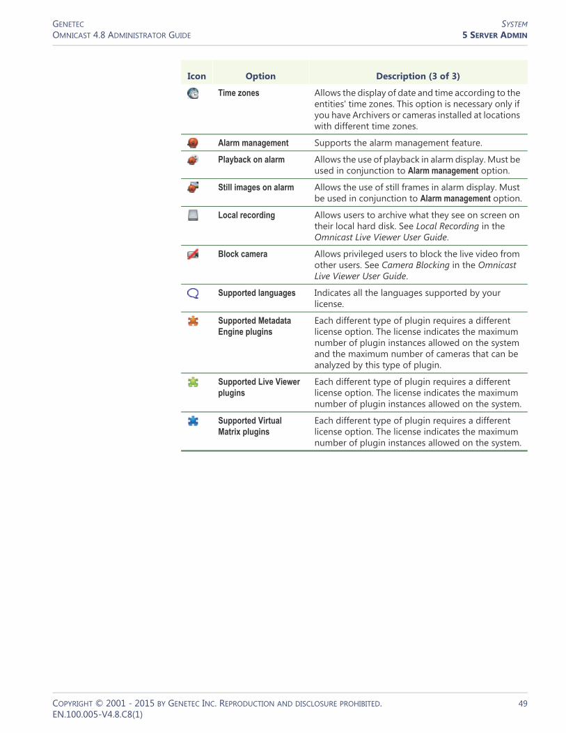
GENETEC SYSTEMOMNICAST 4.8 ADMINISTRATOR GUIDE 5 SERVER ADMIN
Time zones Allows the display of date and time according to the entities' time zones. This option is necessary only if you have Archivers or cameras installed at locations with different time zones.
Alarm management Supports the alarm management feature.
Playback on alarm Allows the use of playback in alarm display. Must be used in conjunction to Alarm management option.
Still images on alarm Allows the use of still frames in alarm display. Must be used in conjunction to Alarm management option.
Local recording Allows users to archive what they see on screen on their local hard disk. See Local Recording in the Omnicast Live Viewer User Guide.
Block camera Allows privileged users to block the live video from other users. See Camera Blocking in the Omnicast Live Viewer User Guide.
Supported languages Indicates all the languages supported by your license.
Supported Metadata Engine plugins
Each different type of plugin requires a different license option. The license indicates the maximum number of plugin instances allowed on the system and the maximum number of cameras that can be analyzed by this type of plugin.
Supported Live Viewer plugins
Each different type of plugin requires a different license option. The license indicates the maximum number of plugin instances allowed on the system.
Supported Virtual Matrix plugins
Each different type of plugin requires a different license option. The license indicates the maximum number of plugin instances allowed on the system.
Icon Option Description (3 of 3)
COPYRIGHT © 2001 - 2015 BY GENETEC INC. REPRODUCTION AND DISCLOSURE PROHIBITED. 49EN.100.005-V4.8.C8(1)

GENETEC SYSTEMOMNICAST 4.8 ADMINISTRATOR GUIDE 5 SERVER ADMIN
Archiver options The Archiver options only apply to the local Archiver. Each Archiver on the system may have different license options.
Icon Option Description (1 of 3)
Archiving There are three possible options:• None – No archiving allowed on the system. The
Archiver is used only for viewing live video.• Locally only – Video archives are stored locally
by the Archiver. Recording performed on units cannot be retrieved by the Archiver.
• On unit only – Video archives are stored directly on the units, not by the Archiver. However, the Archiver maintains a database of associated bookmarks so subsequent archive search can be made.
• Locally and on unit – This is the full archiving option. Video archives can be stored both locally by the Archiver and on the units.
Number of cameras and analog monitors per Archiver
Maximum number of video encoders and decoders allowed on this Archiver. A unit with n video inputs/outputs will require n connections.
Maximum storage capacity
The maximum storage space (in TB) allowed for the local Archiver.
Maximum archive retention period
The maximum number of days the local Archiver is allowed to keep the archives.
SSL on Archiver Allows the Archiver to use SSL encryption for communication with units.
ACTi H.264 cameras Allows the Archiver to control ACTi H.264 cameras.
ACTi MPEG4 cameras Allows the Archiver to control ACTi MPEG4 cameras.
ACTi MJPEG cameras Allows the Archiver to control ACTi MJPEG cameras.
Arecont H.264 cameras Allows the Archiver to control Arecont H.264 cameras.
Arecont MJPEG cameras
Allows the Archiver to control Arecont MJPEG cameras.
Autovu cameras Allows the Archiver to control AutoVu cameras.
AXIS H.264 cameras Allows the Archiver to control Axis H.264 cameras.
AXIS MPEG4 cameras / analog monitors
Allows the Archiver to control Axis MPEG4 video encoders and decoders.
AXIS MJPEG cameras / analog monitors
Allows the Archiver to control Axis MJPEG video encoders and decoders.
Bosch H.264 cameras / analog monitors
Allows the Archiver to control Bosch H.264 video encoders and decoders.
Bosch MPEG4 cameras / analog monitors
Allows the Archiver to control Bosch MPEG4 video encoders and decoders.
COPYRIGHT © 2001 - 2015 BY GENETEC INC. REPRODUCTION AND DISCLOSURE PROHIBITED. 50EN.100.005-V4.8.C8(1)

GENETEC SYSTEMOMNICAST 4.8 ADMINISTRATOR GUIDE 5 SERVER ADMIN
Bosch MPEG2 cameras / analog monitors
Allows the Archiver to control Bosch MPEG2 video encoders and decoders.
Bosch MJPEG cameras / analog monitors
Allows the Archiver to control Bosch MPEG video encoders and decoders.
Generic H.264 cameras Allows the Archiver to control generic H.264 cameras.
Generic MPEG4 cameras
Allows the Archiver to control generic MPEG4 cameras.
Generic MJPEG cameras
Allows the Archiver to control generic JPEG and MJPEG cameras.
Generic Plus H.264 cameras
Allows the Archiver to control generic plus H.264 cameras.
Generic Plus MPEG4 cameras
Allows the Archiver to control generic plus MPEG4 cameras.
Generic Plus MJPEG cameras
Allows the Archiver to control generic plus MJPEG cameras.
Genetec H.264 cameras Allows the Archiver to control H.264 cameras using the Genetec protocol.
Genetec MPEG4 cameras
Allows the Archiver to control MPEG4 cameras using the Genetec protocol.
Genetec MJPEG cameras
Allows the Archiver to control JPEG and MJPEG cameras using the Genetec protocol.
Interlogix CamPlus IP cameras
Allows the Archiver to control Interlogix CamPlus IP cameras.
Interlogix CamPlus 2 IP MPEG4 cameras
Allows the Archiver to control Interlogix CamPlus 2 IP MPEG4 cameras.
Interlogix CamPlus 2 IP MJPEG cameras
Allows the Archiver to control Interlogix CamPlus 2 IP MJPEG cameras.
Interlogix Megapixel H.264 cameras
Allows the Archiver to control Interlogix Megapixel H.264 cameras.
Interlogix Megapixel MJPEG cameras
Allows the Archiver to control Interlogix Megapixel MJPEG cameras.
Interlogix MPEG-4 cameras / analog monitors
Allows the Archiver to control Interlogix MPEG4 video encoders and decoders.
Interlogix Wavelet/JPEG 2000 cameras
Allows the Archiver to control Interlogix Wavelet/JPEG cameras.
IQinVision H.264 cameras
Allows the Archiver to control IQinVision H.264 cameras.
IQinVision MJPEG cameras
Allows the Archiver to control IQinVision MJPEG cameras.
Icon Option Description (2 of 3)
COPYRIGHT © 2001 - 2015 BY GENETEC INC. REPRODUCTION AND DISCLOSURE PROHIBITED. 51EN.100.005-V4.8.C8(1)

GENETEC SYSTEMOMNICAST 4.8 ADMINISTRATOR GUIDE 5 SERVER ADMIN
Mango DSP MPEG4 cameras
Allows the Archiver to control Mango DSP MPEG4 cameras.
Panasonic H.264 cameras
Allows the Archiver to control Panasonic H.264 cameras.
Panasonic MPEG4 cameras
Allows the Archiver to control Panasonic MPEG4 cameras.
Panasonic MJPEG cameras
Allows the Archiver to control Panasonic MJPEG cameras.
Pelco H.264 cameras Allows the Archiver to control Pelco H.264 cameras.
Pelco MPEG4 cameras Allows the Archiver to control Pelco MJPEG cameras.
Sim cameras / analog monitors
Allows the Archiver to control simulated video encoders and decoders.
Siqura H.264 cameras Allows the Archiver to control Siqura H.264 cameras.
Siqura MPEG4 cameras Allows the Archiver to control Siqura MPEG4 cameras.
SIqura MJPEG cameras Allows the Archiver to control Siqura MJPEG cameras.
Sony H.264 cameras Allows the Archiver to control Sony H.264 cameras.
Sony MPEG4 cameras Allows the Archiver to control Sony MPEG4 cameras.
Sony MJPEG cameras Allows the Archiver to control Sony MJPEG cameras.
Verint H.264 cameras / analog monitors
Allows the Archiver to control Verint H.264 video encoders and decoders.
Verint MPEG4 cameras / analog monitors
Allows the Archiver to control Verint MPEG4 video encoders and decoders.
Vivotek H.264 cameras Allows the Archiver to control Vivotek H.264 cameras.
Vivotek MPEG4 cameras
Allows the Archiver to control Vivotek MPEG4 cameras.
Vivotek MJPEG cameras
Allows the Archiver to control Vivotek MJPEG cameras.
Icon Option Description (3 of 3)
COPYRIGHT © 2001 - 2015 BY GENETEC INC. REPRODUCTION AND DISCLOSURE PROHIBITED. 52EN.100.005-V4.8.C8(1)

GENETEC SYSTEMOMNICAST 4.8 ADMINISTRATOR GUIDE 5 SERVER ADMIN
Activating your license When you install Omnicast, you will be asked to provide the Validation key for your machine. The validation key is created by Omnicast Installer and uniquely identifies your computer. Genetec requires the validation key to generate your license key. Each license key can be used on one and only one computer.
You can activate the license for your computer two ways:1 Use the Web activation (if your PC is connected to the Internet)2 Request a license key and apply it
For more information about how to activate your license, see “Activating your Omnicast license” in the Omnicast Installation and Upgrade Guide.
SMTP
Description The SMTP tab is used to configure the mail service available to Omnicast. The mail service is needed by the Directory to execute the Send an email action and by the Watchdog to send error notifications.
Parameter Icon Description
Validation Key Export the validation key to a file.
Copy the validation key to the clipboard.
Generate a new validation key.
Activate License Activate your license through Web activation.
Import the license key from a file.
Paste the license key from the clipboard.
COPYRIGHT © 2001 - 2015 BY GENETEC INC. REPRODUCTION AND DISCLOSURE PROHIBITED. 53EN.100.005-V4.8.C8(1)

GENETEC SYSTEMOMNICAST 4.8 ADMINISTRATOR GUIDE 5 SERVER ADMIN
SMTP settings The following parameters must be specified to configure the SMTP server.
Network
Public address The Network tab allows you to assign a public IP address to the local machine.
The Public address is used to let this machine be accessed from outside its current LAN. This configuration is only necessary on large systems spreading over multiple LANs.
Parameter Description
SMTP server Name of the mail server on your company's LAN.
SMTP port The SMTP mail server port number is normally 25, though your mail server may use another port.
Domain Your company's domain name.
Reply address Email address shown as the sender (in the From field). Use a valid address if you want the email recipients to be able to reply to the emails sent by the Directory.
Minimum time between 2 identical emails
The number of seconds to wait before the Directory sends an identical email to someone. A value of zero cancels this feature.
COPYRIGHT © 2001 - 2015 BY GENETEC INC. REPRODUCTION AND DISCLOSURE PROHIBITED. 54EN.100.005-V4.8.C8(1)

GENETEC DIRECTORYOMNICAST 4.8 ADMINISTRATOR GUIDE 5 SERVER ADMIN
Directory
Introduction
The Directory is the main server application whose service is required to provide a centralized catalog for all other Omnicast services and applications on the system. From the Directory, applications can view, establish connections and receive centralized configuration information.
The following are the Directory configuration tabs.
General
Description The General tab is used to configure the connection and database settings.
Icon Tab Description
General Connection and database settings.
Email Additional email options for the Send an email action.
Logging Logging settings (for both file and database logging).
Active Directory Synchronize the user profiles with Windows Active Directory.
Password Password expiry notification.
COPYRIGHT © 2001 - 2015 BY GENETEC INC. REPRODUCTION AND DISCLOSURE PROHIBITED. 55EN.100.005-V4.8.C8(1)
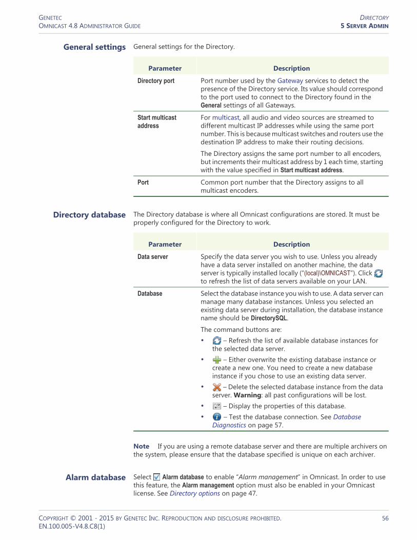
GENETEC DIRECTORYOMNICAST 4.8 ADMINISTRATOR GUIDE 5 SERVER ADMIN
General settings General settings for the Directory.
Directory database The Directory database is where all Omnicast configurations are stored. It must be properly configured for the Directory to work.
Note If you are using a remote database server and there are multiple archivers on the system, please ensure that the database specified is unique on each archiver.
Alarm database Select Alarm database to enable “Alarm management” in Omnicast. In order to use this feature, the Alarm management option must also be enabled in your Omnicast license. See Directory options on page 47.
Parameter Description
Directory port Port number used by the Gateway services to detect the presence of the Directory service. Its value should correspond to the port used to connect to the Directory found in the General settings of all Gateways.
Start multicast address
For multicast, all audio and video sources are streamed to different multicast IP addresses while using the same port number. This is because multicast switches and routers use the destination IP address to make their routing decisions.
The Directory assigns the same port number to all encoders, but increments their multicast address by 1 each time, starting with the value specified in Start multicast address.
Port Common port number that the Directory assigns to all multicast encoders.
Parameter Description
Data server Specify the data server you wish to use. Unless you already have a data server installed on another machine, the data server is typically installed locally (“(local)\OMNICAST”). Click to refresh the list of data servers available on your LAN.
Database Select the database instance you wish to use. A data server can manage many database instances. Unless you selected an existing data server during installation, the database instance name should be DirectorySQL.
The command buttons are:• – Refresh the list of available database instances for
the selected data server.• – Either overwrite the existing database instance or
create a new one. You need to create a new database instance if you chose to use an existing data server.
• – Delete the selected database instance from the data server. Warning: all past configurations will be lost.
• – Display the properties of this database.• – Test the database connection. See Database
Diagnostics on page 57.
COPYRIGHT © 2001 - 2015 BY GENETEC INC. REPRODUCTION AND DISCLOSURE PROHIBITED. 56EN.100.005-V4.8.C8(1)

GENETEC DIRECTORYOMNICAST 4.8 ADMINISTRATOR GUIDE DIAGNOSING DATABASES; DATABASE, DIAGNOSING
Specify the data server you wish to use. Unless you already have a data server installed on another machine, the data server is typically installed locally (“(local)\OMNICAST”). Click to refresh the list of data servers available on your LAN.
Select the database instance you wish to use. A data server can manage many database instances. Unless you selected an existing data server during installation, the database instance name should be AlarmSQL.
The command buttons are the same as for Directory database.
Number of days the alarm history should be kept in the database. This value should be set high. The default value is 90 days.
The administrator can set a different retention period for each individual alarm type. See Config Tool – Alarm – Properties on page 187.
Note If you are using a remote database server and there are multiple archivers on the system, please ensure that the database specified is unique on each archiver.
Database Diagnostics You can test the connection of any one of your databases from the Server Admin, which includes the DirectorySQL, AlarmSQL, VideoArchiveSQL, ReportingSQL AuxiliaryArchiveSQL, and ObjectStore databases.
NOTE To diagnose your database connections, you will be required to provide your Windows credentials.
To test your database connection:1 In the Server Admin, open the Database diagnostics dialog box of database you want
to diagnose:– DirectorySQL/AlarmSQL: In the General tab of the Directory entity, click the
button next to the Database parameter.– ReportingSQL: In the Logging tab of the Directory entity, click the button next
to the Database parameter.– VideoArchiveSQL: In the Archiving tab of the Archiver entity, click the button
next to the Database parameter.– AuxiliaryArchiveSQL: In the Archiving tab of the Auxiliary Archiver entity, click the
button next to the Database parameter.The Omnicast Service Verification dialog box will open.
2 Enter your Windows username and password.If you did not enter the correct username and password, the diagnostic will not run.
3 In the Database diagnostics dialog box, the database will be tested for four things:a If the database existsb If the user has read privileges on the databasec If the user has write privileges on the database
Parameter Description
Data server
Database
Keep history for
COPYRIGHT © 2001 - 2015 BY GENETEC INC. REPRODUCTION AND DISCLOSURE PROHIBITED. 57EN.100.005-V4.8.C8(1)

GENETEC DIRECTORYOMNICAST 4.8 ADMINISTRATOR GUIDE DIAGNOSING DATABASES; DATABASE, DIAGNOSING
d If the user has permission to create a new database on the serverOnce the tests are completed, there are details about why or why not each test was successful.
4 Click OK.
Description The Email tab is used to configure optional behaviors for the Send an email action. See Appendix B – Omnicast Action Types (sorted by action name) on page 528.
COPYRIGHT © 2001 - 2015 BY GENETEC INC. REPRODUCTION AND DISCLOSURE PROHIBITED. 58EN.100.005-V4.8.C8(1)

GENETEC DIRECTORYOMNICAST 4.8 ADMINISTRATOR GUIDE DIAGNOSING DATABASES; DATABASE, DIAGNOSING
Send link to web applications
Select this option to include links to the Web Live Viewer and the Web Archive Player to the message body of emails sent by the Send an email action when the event source is a video encoder.
The purpose of this feature is to allow the email recipients to view the live video or the archived video immediately upon reception of the email, regardless whether the machines they use have Omnicast clients installed or not.
In order to use this feature, the Web clients option must be enabled in your Omnicast license (see Directory options on page 47), the mail server must be configured on the Directory server (see SMTP on page 53), and the following parameters must be set.
Logging
Description The Logging tab is used to configure the logging of all system events. SeeAppendix A: Omnicast Events on page 508.
Parameter Description
Web Live Viewer URL Web address of the Web Live Viewer. It should point to the ASP page "LiveViewer.asp".
Web Archive Player URL Web address of the Web Archive Player. It should point to the ASP page "ArchivePlayer.asp".
External Gateway name Machine name where the Gateway is installed.
COPYRIGHT © 2001 - 2015 BY GENETEC INC. REPRODUCTION AND DISCLOSURE PROHIBITED. 59EN.100.005-V4.8.C8(1)

GENETEC DIRECTORYOMNICAST 4.8 ADMINISTRATOR GUIDE DIAGNOSING DATABASES; DATABASE, DIAGNOSING
Two logging methods are available:• File logging• Database logging
File logging Select Enable file logging to keep a copy of all system events on disk. The log files contain <Tab> separated values so they can be easily viewed with Microsoft Notepad or Excel.
Database logging Select Enable database logging to log selected system events in a relational database. Database logs are viewed with the Report Viewer. Please read Tools – Report Viewer on page 490 to find out what standard reports are available.
Parameter Description
Folder Location of the log files.
Prefix Prefix to be used in the log file names. The file name consists of the prefix, followed by the date (yyyy-mm-dd), followed by a 3-digit sequence number. Example: "_DIR_2007-09-11_000.log".
Keep log for Number of days the log files should be kept on-line.
Maximum size Maximum number of lines each log file may contain. When the specified maximum is reached, the Directory will open a new file.
Parameter Description (1 of 2)
Data server Specify the data server you wish to use. Unless you already have a data server installed on another machine, the data server is typically installed locally (“(local)\SQLExpress”). Click to refresh the list of data servers available on your LAN.
Database Select the database instance you wish to use. A data server can manage many database instances. Unless you selected an existing data server during installation, the database instance name should be ReportingSQL.
The command buttons are:• – Refresh the list of available database instances for
the selected data server.• – Either overwrite the existing database instance or
create a new one. You need to create a new database instance if you chose to use an existing data server.
• – Delete the selected database instance from the data server.
• – Display the properties of this database.• – Test the database connection. See Database
Diagnostics on page 57.
COPYRIGHT © 2001 - 2015 BY GENETEC INC. REPRODUCTION AND DISCLOSURE PROHIBITED. 60EN.100.005-V4.8.C8(1)

GENETEC DIRECTORYOMNICAST 4.8 ADMINISTRATOR GUIDE DIAGNOSING DATABASES; DATABASE, DIAGNOSING
Note If you are using a remote database server and there are multiple archivers on the system, please ensure that the database specified is unique on each archiver
Keep log for Number of days the log entries should be kept in the database.
Filter Click the Filter button to select the categories of events that should be logged in the database. The following dialog appears.
Expand the Entity modification node to select the individual entity types whose change should be logged.
Parameter Description (2 of 2)
COPYRIGHT © 2001 - 2015 BY GENETEC INC. REPRODUCTION AND DISCLOSURE PROHIBITED. 61EN.100.005-V4.8.C8(1)

GENETEC DIRECTORYOMNICAST 4.8 ADMINISTRATOR GUIDE DIAGNOSING DATABASES; DATABASE, DIAGNOSING
Active Directory
Description The Active directory tab allows you to integrate Omnicast's user management with Windows Active Directory.
The purpose of integrating Omnicast to Windows Active Directory is to have a unified user management system within the organization and to simplify the initial Omnicast setup. The system administrator can import any groups of users defined in the Active Directory as Omnicast users and user groups.
Once the Active Directory is enabled, only the imported users will be able to run Omnicast applications.
NOTE Exceptions to this rule are the user Admin and the user group Administrators. These two system entities will remain under the sole control of Omnicast. Always protect the Admin user's password.
As long as Omnicast is integrated to the Active Directory, the creation and deletion of users and user groups must all be handled through Windows Active Directory Users and Computers management tool. Passwords and email addresses will also be managed under the Active Directory. Omnicast will continue to manage the properties that are specific to Omnicast, such as permissions, privileges, etc. (see Config Tool – User on page 418).
Users deleted from the Active Directory are not deleted immediately from Omnicast. However, the denial of connection privilege is effective immediately. The user profile will only be deleted during the next cleanup job. To speed up the cleanup operation,
COPYRIGHT © 2001 - 2015 BY GENETEC INC. REPRODUCTION AND DISCLOSURE PROHIBITED. 62EN.100.005-V4.8.C8(1)

GENETEC DIRECTORYOMNICAST 4.8 ADMINISTRATOR GUIDE DIAGNOSING DATABASES; DATABASE, DIAGNOSING
the Omnicast administrator is allowed to delete user profiles. If the deleted user is still active in the Active Directory, it will be recreated in Omnicast the next time the user logs on.
WARNING All users and user groups that were defined in Omnicast prior to the integration which are not found in the Active Directory will be deleted.
A potential benefit for the end-users is that they no longer need to enter their username and password every time they start an Omnicast application.
Enabling the Active Directory
To enable the Active Directory:1 Assuming that the Active Directory is currently inactive.
2 Stop the Directory service.If the Directory is part of a failover system, you must first stop the Directory Failover Coordinator (DFC) before you can stop the Directory. Otherwise, the DFC will automatically restart the Directory service every time you try to stop it.If you enable the Active Directory integration on one Directory server, you must also enable it on all Directory servers that are part of the same failover configuration.
COPYRIGHT © 2001 - 2015 BY GENETEC INC. REPRODUCTION AND DISCLOSURE PROHIBITED. 63EN.100.005-V4.8.C8(1)

GENETEC DIRECTORYOMNICAST 4.8 ADMINISTRATOR GUIDE DIAGNOSING DATABASES; DATABASE, DIAGNOSING
3 Click the Activate button. You will be prompted to select the Active Directory groups you wish to add to Omnicast.
Only Active Directory security groups may be added to Omnicast.You may add as many groups as needed.
4 If you know the name of the group you wish to add, enter its name and click .If more than one match is found, you will have to select the groups you want.
COPYRIGHT © 2001 - 2015 BY GENETEC INC. REPRODUCTION AND DISCLOSURE PROHIBITED. 64EN.100.005-V4.8.C8(1)

GENETEC DIRECTORYOMNICAST 4.8 ADMINISTRATOR GUIDE DIAGNOSING DATABASES; DATABASE, DIAGNOSING
5 If you do not know the group names by heart, click the button to browse the Active Directory content. Only one group may be selected from this dialog.
6 Click OK to add your selection to the list.Step 4 to Step 5 can be repeated as many times as necessary.
COPYRIGHT © 2001 - 2015 BY GENETEC INC. REPRODUCTION AND DISCLOSURE PROHIBITED. 65EN.100.005-V4.8.C8(1)

GENETEC DIRECTORYOMNICAST 4.8 ADMINISTRATOR GUIDE DIAGNOSING DATABASES; DATABASE, DIAGNOSING
7 Click OK once you have selected all the security groups you want.The application will start comparing what is currently defined in Omnicast with what is in the Active Directory. Once the comparison is finished, the following dialog will appear, showing all the conflicts found.
There are three types of conflicts:• Username match – When this happens, the password and email address will be
replaced by the information found in the Active Directory. All other user properties (such as permissions and privileges) will be preserved.
• Email match – When this happens, the username and email address will be replaced by the information found in the Active Directory. All other user properties (such as permissions and privileges) will be preserved.
• Exist only in Omnicast – This is when the Merge Tool cannot find a match for an Omnicast user or user group in the Active Directory. When this happens, the Omnicast entity will be deleted.
8 Click the button to view the details regarding any selected conflict.
COPYRIGHT © 2001 - 2015 BY GENETEC INC. REPRODUCTION AND DISCLOSURE PROHIBITED. 66EN.100.005-V4.8.C8(1)
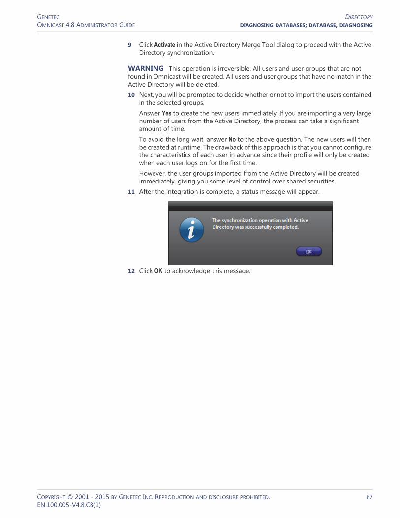
GENETEC DIRECTORYOMNICAST 4.8 ADMINISTRATOR GUIDE DIAGNOSING DATABASES; DATABASE, DIAGNOSING
9 Click Activate in the Active Directory Merge Tool dialog to proceed with the Active Directory synchronization.
WARNING This operation is irreversible. All users and user groups that are not found in Omnicast will be created. All users and user groups that have no match in the Active Directory will be deleted.10 Next, you will be prompted to decide whether or not to import the users contained
in the selected groups.Answer Yes to create the new users immediately. If you are importing a very large number of users from the Active Directory, the process can take a significant amount of time.To avoid the long wait, answer No to the above question. The new users will then be created at runtime. The drawback of this approach is that you cannot configure the characteristics of each user in advance since their profile will only be created when each user logs on for the first time.However, the user groups imported from the Active Directory will be created immediately, giving you some level of control over shared securities.
11 After the integration is complete, a status message will appear.
12 Click OK to acknowledge this message.
COPYRIGHT © 2001 - 2015 BY GENETEC INC. REPRODUCTION AND DISCLOSURE PROHIBITED. 67EN.100.005-V4.8.C8(1)

GENETEC DIRECTORYOMNICAST 4.8 ADMINISTRATOR GUIDE DIAGNOSING DATABASES; DATABASE, DIAGNOSING
13 The name of the selected security group as well as the Domain name will be shown.
You must now configure the Cleanup job. The cleanup job is used to delete obsolete users from Omnicast when they have been deleted from the Active Directory. Note that the start time is disabled and ignored when the job frequency is configured in minutes.
14 Before you restart the Directory, its service logon user must be changed to a domain user.Note that the default user ".\OmnicastSvcUsr"created at Omnicast Server installation is a local user. It will not be able to access the Active Directory. It must be changed to a domain user with the rights to access the Active Directory.If the DFC is being used, its user must be changed to the same domain user as the Directory.See Changing the Directory service logon user on page 68.
15 To complete the user management configuration, open the Config Tool and set up the permissions and privileges of all new entities imported from the Active Directory.The security groups are imported as a flat structure and will not reflect the structure in the Active Directory. You will have to recreate the desired group hierarchy manually using the Config Tool.To learn about the parameters that you can configure, please read User on page 418 and User Group on page 445.
Changing the Directory service
logon user
1 To change the Directory service logon user, do the following.2 Open the Services.msc in Windows.3 In the Services dialog box, find Genetec Omnicast Directory. Note that this service
should be stopped.
COPYRIGHT © 2001 - 2015 BY GENETEC INC. REPRODUCTION AND DISCLOSURE PROHIBITED. 68EN.100.005-V4.8.C8(1)
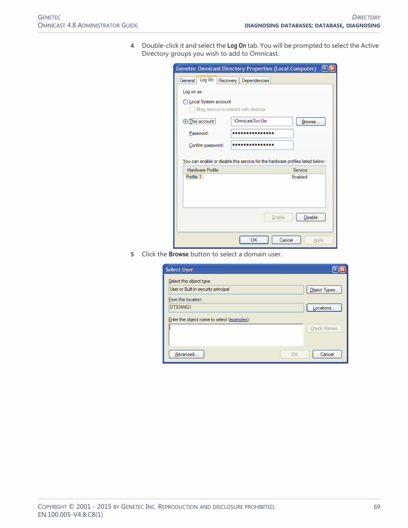
GENETEC DIRECTORYOMNICAST 4.8 ADMINISTRATOR GUIDE DIAGNOSING DATABASES; DATABASE, DIAGNOSING
4 Double-click it and select the Log On tab. You will be prompted to select the Active Directory groups you wish to add to Omnicast.
5 Click the Browse button to select a domain user.
COPYRIGHT © 2001 - 2015 BY GENETEC INC. REPRODUCTION AND DISCLOSURE PROHIBITED. 69EN.100.005-V4.8.C8(1)

GENETEC DIRECTORYOMNICAST 4.8 ADMINISTRATOR GUIDE DIAGNOSING DATABASES; DATABASE, DIAGNOSING
6 Click the Locations button to change the location from your local machine to the Active Directory's domain.
7 Enter the domain user name and click Check Names to validate the name.
We recommend that you create a new domain user as the logon user for Omnicast Directory. This user must have the rights to read the information on the users and user groups which are members of the selected Base group.8 Once the system has found the user you want, click OK.
IMPORTANT The Directory service logon user must have interactive logon privileges.9 Enter the password of the newly selected user, click OK.10 Restart the Genetec Omnicast Directory service.
Enabling SSL Select this option to enable the SSL (Secure Sockets Layer) protocol. When this option is enabled, all communications between Omnicast and the Active Directory domain controller use the SSL protocol. This option is disabled by default, and the Active Directory domain controller must be configured to support SSL.
COPYRIGHT © 2001 - 2015 BY GENETEC INC. REPRODUCTION AND DISCLOSURE PROHIBITED. 70EN.100.005-V4.8.C8(1)
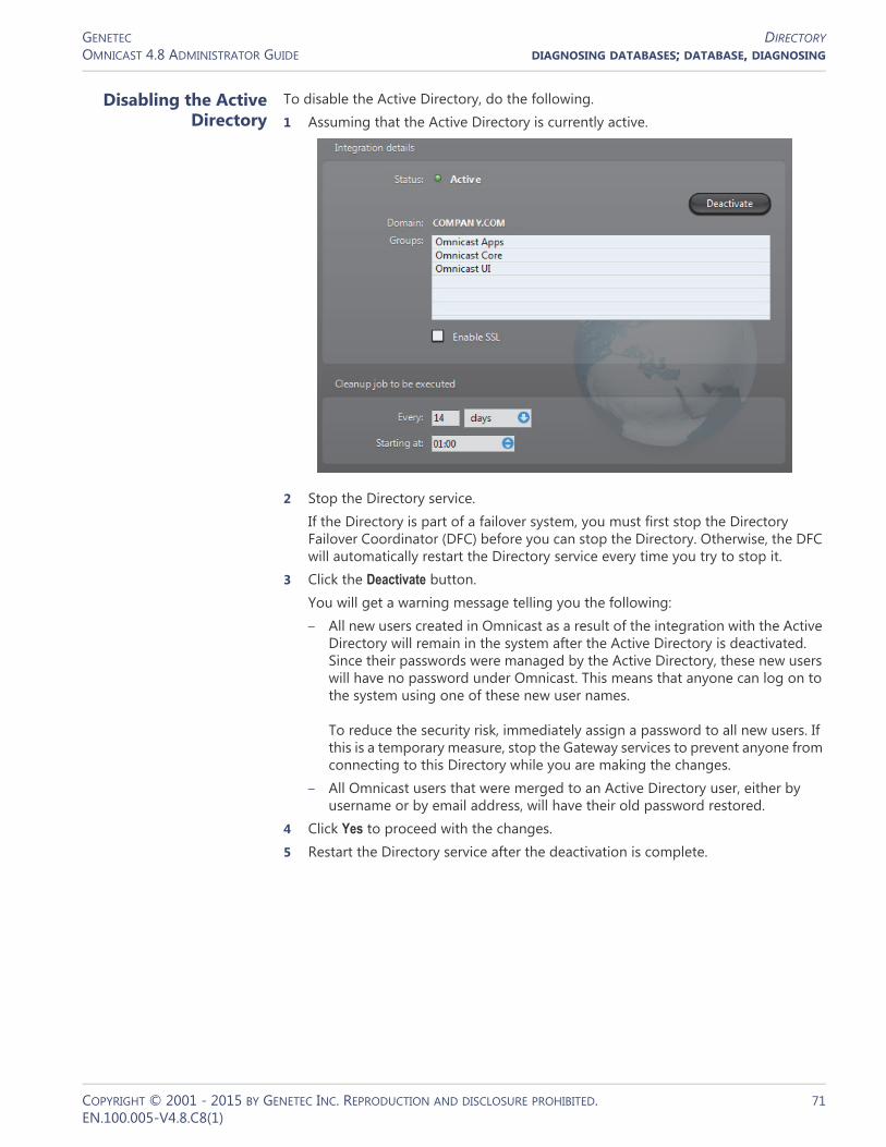
GENETEC DIRECTORYOMNICAST 4.8 ADMINISTRATOR GUIDE DIAGNOSING DATABASES; DATABASE, DIAGNOSING
Disabling the Active Directory
To disable the Active Directory, do the following.1 Assuming that the Active Directory is currently active.
2 Stop the Directory service.If the Directory is part of a failover system, you must first stop the Directory Failover Coordinator (DFC) before you can stop the Directory. Otherwise, the DFC will automatically restart the Directory service every time you try to stop it.
3 Click the Deactivate button.You will get a warning message telling you the following:– All new users created in Omnicast as a result of the integration with the Active
Directory will remain in the system after the Active Directory is deactivated. Since their passwords were managed by the Active Directory, these new users will have no password under Omnicast. This means that anyone can log on to the system using one of these new user names. To reduce the security risk, immediately assign a password to all new users. If this is a temporary measure, stop the Gateway services to prevent anyone from connecting to this Directory while you are making the changes.
– All Omnicast users that were merged to an Active Directory user, either by username or by email address, will have their old password restored.
4 Click Yes to proceed with the changes.5 Restart the Directory service after the deactivation is complete.
COPYRIGHT © 2001 - 2015 BY GENETEC INC. REPRODUCTION AND DISCLOSURE PROHIBITED. 71EN.100.005-V4.8.C8(1)

GENETEC DIRECTORYOMNICAST 4.8 ADMINISTRATOR GUIDE DIAGNOSING DATABASES; DATABASE, DIAGNOSING
Password
Description The Password tab allows you to set the password expiry advance notice.
This setting ensures that you will be notified n days before your Server Admin password expires. The default value is 7 days, and the maximum value is 30.
NOTE You will be required to restart the Directory Service to apply your changes.
COPYRIGHT © 2001 - 2015 BY GENETEC INC. REPRODUCTION AND DISCLOSURE PROHIBITED. 72EN.100.005-V4.8.C8(1)

GENETEC DIRECTORY FAILOVER COORDINATOROMNICAST 4.8 ADMINISTRATOR GUIDE 5 SERVER ADMIN
Directory Failover Coordinator
Introduction
The Directory Failover Coordinator (DFC) is the service installed on every server machine hosting the Directory service to guarantee the continuity of the latter in the context of a fail-proof system.
The DFC performs two main functions: (1) Keeping the local Directory and Alarm databases up to date while the Directory service is on standby; (2) Start or stop the local Directory service when it is
appropriate to do so, based on a failover list.
Configuration
General settings Selecting Directory Failover Coordinator from the resource tree displays its general settings.
The configurable parameters are described below.
Parameter Description (1 of 2)
Gateway Name of the Gateway that the DFC must use to connect to the primary Directory. This information is necessary for the service to report its presence when the Directory failover list is not yet configured.
Network card Select the network card used to communicate with the Directory if your machine is equipped with more than one network card.
Incoming TCP command
TCP port where the DFC service listens for incoming client connections.
COPYRIGHT © 2001 - 2015 BY GENETEC INC. REPRODUCTION AND DISCLOSURE PROHIBITED. 73EN.100.005-V4.8.C8(1)

GENETEC DIRECTORY FAILOVER COORDINATOROMNICAST 4.8 ADMINISTRATOR GUIDE 5 SERVER ADMIN
Ping period Frequency at which the DFC pings for its Directory service.
Password In order to keep the databases synchronized, the DFC services must talk to each other periodically.
In the rare situation where two or more independent Omnicast systems are installed on the same network, you need to identify the DFCs belonging to different failover systems with different passwords so that they will not talk to the wrong peers.
To set a new password or to change the password, click on the button.
You will have to enter the same password twice for confirmation.
Click on to clear the password.
Enable entity replication
Select this option if the DFC must keep the entity configuration tables synchronized. This option should be disabled if the secondary Directory server shares the same database as the primary server. See Directory database on page 56.
Enable alarm replication
Select this option if the DFC must keep the alarm database tables synchronized. This option should be disabled if the secondary Directory server shares the same database as the primary server. See Alarm database on page 56.
In some rare cases where alarms are generated at a very high pace in the system, it may be recommended not to synchronize the AlarmSQL database for performance sake.
If you are in this situation, you can synchronize the databases manually in the Config Tool. See Manual synchronization on page 309.
Parameter Description (2 of 2)
COPYRIGHT © 2001 - 2015 BY GENETEC INC. REPRODUCTION AND DISCLOSURE PROHIBITED. 74EN.100.005-V4.8.C8(1)

GENETEC GATEWAYOMNICAST 4.8 ADMINISTRATOR GUIDE 5 SERVER ADMIN REFERENCE
Gateway
Introduction
The Gateway is the service that provides seamless connections between all applications in a given Omnicast system, regardless of whether they are located on the same LAN or not. The Gateway acts as a doorway to the Directory for all Omnicast applications. Multiple Gateways can be installed on large Omnicast systems to increase service availability and to provide load balancing.
Multiple instances of Gateways may be running on the same system, but their use must be granted by the Number of Gateways of your Omnicast license. See Directory options on page 47.
The local settings of the Gateway are found in the following tabs.
The machine independent parameters of this server application are configured with the Config Tool. See Gateway on page 319.
Icon Tab Description
General Basic Gateway settings.
Logging Logging settings (folder, cleanup, etc.).
Advanced Advanced settings (change only as instructed by qualified Omnicast support engineer).
IP Filtering Restrict client connections to specified IP addresses, ports and types.
COPYRIGHT © 2001 - 2015 BY GENETEC INC. REPRODUCTION AND DISCLOSURE PROHIBITED. 75EN.100.005-V4.8.C8(1)

GENETEC GATEWAYOMNICAST 4.8 ADMINISTRATOR GUIDE 5 SERVER ADMIN REFERENCE
General
Description The General tab is used to configure the basic settings of the Gateway.
General settings General settings for the Gateway.
Parameter Description
Connection type You have the choice to connect the Gateway directly to a Directory (using the LAN) or indirectly via another Gateway (using the Internet).
Directory / Gateway This field name will vary depending on your selection of connection type.
Directory – Leave this field blank if the Directory and the Gateway are installed on the same PC. Indicate the Directory port if it is different from the default value (7998). See General settings on page 56.
Gateway – When connecting via another Gateway, the name of the remote Gateway must be specified. Note that the remote Gateway must be one that connects directly to the primary Directory. Indicate its Incoming TCP command port if it is different from the default value (5001).
Network card Select the network card used for Omnicast if your machine is equipped with more than one network card.
COPYRIGHT © 2001 - 2015 BY GENETEC INC. REPRODUCTION AND DISCLOSURE PROHIBITED. 76EN.100.005-V4.8.C8(1)

GENETEC GATEWAYOMNICAST 4.8 ADMINISTRATOR GUIDE 5 SERVER ADMIN REFERENCE
Port settings Various port settings for the Gateway.
Multicast connection test settings
In order to test the multicast connectivity with a client, the Gateway specifies two IP addresses: one for the client to receive multicast transmissions from the Gateway, another for the Gateway to receive transmissions from the client.
The Gateway uses a pool of addresses for client transmissions, which it assigns in turn to connecting clients. Using multiple client transmission addresses helps avoid network congestions, especially when the Gateway restarts.
While processing a client connection, the Gateway detects all connection types (Multicast, Unicast UDP, Unicast TCP) supported by the client.
Parameter Description
Incoming TCP command
Port used for incoming TCP commands, such as client connection requests.
The default connection port used by Omnicast is 5001. If you choose a different port number, users must explicitly specify it in the Connect dialog. See example below.
A different TCP command port may be used on some specific clients when IP filtering is enabled. See IP Filtering on page 81.
Incoming TCP video Port used to listen for incoming TCP video connections. If the Gateway is running behind a firewall, make sure that this port is unlocked for inbound packets for TCP connections.
Outgoing UPD data Range of ports used by the Gateway to send video using UDP. The first port number is also used as a discovery port, i.e. to determine if unicast connections are supported between the Gateway and the remote client. If the Gateway is running behind a firewall, make sure that these ports are unlocked for inbound packets for UDP connections.
COPYRIGHT © 2001 - 2015 BY GENETEC INC. REPRODUCTION AND DISCLOSURE PROHIBITED. 77EN.100.005-V4.8.C8(1)

GENETEC GATEWAYOMNICAST 4.8 ADMINISTRATOR GUIDE 5 SERVER ADMIN REFERENCE
The connection test parameters are:
If the Gateway is running behind a firewall, be sure to unlock the Gateway ports. The following firewall rules should apply:
Note Gateway multicast test addresses should be unique on a multiple Gateway system when client or service applications are connecting from behind a router that is blocking multicast. If the multicast test addresses are not unique, the Gateway will falsely detect multicast transmissions and will not redirect the video streams requested by client applications behind the router.
Parameter Description
Gateway transmission address
IP address used by the Gateway to transmit multicast packets to client applications during the connection test.
Client transmission addresses
Pool of IP addresses used to receive multicast transmission from clients. You need to specify the starting address and the number of addresses you wish to reserve in the pool. The resulting range of addresses will be indicated as a comment.
Port Protocol Direction
TCP command port TCP Inbound
TCP video port TCP Inbound
UDP video port UDP Inbound/Outbound
COPYRIGHT © 2001 - 2015 BY GENETEC INC. REPRODUCTION AND DISCLOSURE PROHIBITED. 78EN.100.005-V4.8.C8(1)

GENETEC GATEWAYOMNICAST 4.8 ADMINISTRATOR GUIDE 5 SERVER ADMIN REFERENCE
Logging
Description The Logging tab lets you configure the logging for the Gateway.
File logging Select Enable file logging to keep a copy of all Gateway events on disk. The log files contain <Tab> separated values so they can be easily viewed with Microsoft Notepad or Excel.
Parameter Description
Folder Location of the log files.
Prefix Prefix to be used in the log file names. The file name consists of the prefix, followed by the date (yyyy-mm-dd), followed by a 3-digit sequence number. Example: "_GTW_2007-11-14_000.log".
Keep log for Number of days the log files should be kept on-line.
Maximum size Maximum number of lines each log file may contain. When the specified maximum is reached, the Gateway will open a new file.
COPYRIGHT © 2001 - 2015 BY GENETEC INC. REPRODUCTION AND DISCLOSURE PROHIBITED. 79EN.100.005-V4.8.C8(1)

GENETEC GATEWAYOMNICAST 4.8 ADMINISTRATOR GUIDE 5 SERVER ADMIN REFERENCE
Advanced
Description The Advanced tab contains rarely used parameters. The settings in this tab should never be changed by the end user unless specifically instructed by a qualified Omnicast technical support engineer.
Detection parameters Select Enable Gateway detection to allow the local Gateway to test whether other Gateways are running on the same LAN. This option should never be disabled. The following are the configurable timeout values.
Timeout value Description
Directory poll timeout Polling interval used to make sure that the Directory is still online. 10 seconds is the recommended value.
Client application poll timeout
Polling interval used to make sure that the clients are still online. 10 seconds is the recommended value.
Client connection write timeout
Timeout used for commands sent to clients. 5 seconds is the recommended value.
Client connection test timeout
Timeout used to test the connections with the clients. 2 seconds is the recommended value.
COPYRIGHT © 2001 - 2015 BY GENETEC INC. REPRODUCTION AND DISCLOSURE PROHIBITED. 80EN.100.005-V4.8.C8(1)

GENETEC GATEWAYOMNICAST 4.8 ADMINISTRATOR GUIDE 5 SERVER ADMIN REFERENCE
Video redirection Select Enable video redirection to allow the Gateway to redirect video streams. This option should never be disabled.
IP Filtering
Description The IP filtering tab allows you to restrict the client connections to a list of specific IP addresses. You may also impose a different incoming TCP command port than the default one and force a specific connection type.
Parameters Description
Default supported connection
Allows the administrator to force certain types of video redirection under particular situations. For instance, if your network does not support multicast, you should select Unicast UDP. Normally this setting is set to Automatic detection.
Device UDP port Start port number for UDP redirection.
COPYRIGHT © 2001 - 2015 BY GENETEC INC. REPRODUCTION AND DISCLOSURE PROHIBITED. 81EN.100.005-V4.8.C8(1)

GENETEC GATEWAYOMNICAST 4.8 ADMINISTRATOR GUIDE 5 SERVER ADMIN REFERENCE
Default parameters These are parameters set in other configuration tabs.
Parameters Description
Incoming TCP command Default incoming TCP command port set in the General tab. See Port settings on page 77.
Default supported connection
The default supported connection type is set in the Advanced tab. See Video redirection on page 81.
COPYRIGHT © 2001 - 2015 BY GENETEC INC. REPRODUCTION AND DISCLOSURE PROHIBITED. 82EN.100.005-V4.8.C8(1)

GENETEC GATEWAYOMNICAST 4.8 ADMINISTRATOR GUIDE 5 SERVER ADMIN REFERENCE
IP filtering configuration
Select Enable IP filtering to turn IP filtering on. When this feature is enabled, only the clients satisfying one of the IP filtering rules are allowed to connect through this Gateway.
To add a new IP filtering rule, do the following.1 Click on to show the following dialog.
2 Choose either Single IP address or Multiple IP addresses.– When two rules conflict over the IP address range, the system will give
precedence to the most restrictive rule. A single IP address will always have precedence over a range of IP addresses. Use Single IP address to create exceptions.
– Two IP address ranges cannot overlap if they share the same TCP command port.
3 Select the Incoming TCP command port.– You may use the default port or specify a different one.– The system does not limit the number of different TCP command ports you use.
However, it is generally recommended not to use more than 2 or 3 different ports (1 for normal use, 1 for maintenance, and 1 for emergency).
4 Select a Supported connection.– Default supported connection Use the connection specified in the Advanced tab
to send the stream.– Automatic detection The Gateway determines how to stream is sent.– Unicast UDP The stream is sent using Unicast UDP.– Multicast The stream will be sent in Multicast. If the network does not support
Multicast, the stream will not be received.This setting has no effect if the option Enable video redirection is not selected in the Advanced tab. See Video redirection on page 81
5 Click OK to add the new rule.
COPYRIGHT © 2001 - 2015 BY GENETEC INC. REPRODUCTION AND DISCLOSURE PROHIBITED. 83EN.100.005-V4.8.C8(1)

GENETEC FEDERATION SERVEROMNICAST 4.8 ADMINISTRATOR GUIDE 5 SERVER ADMIN
COPYRIGHT © 2001 - 2015 BY GENETEC INC. REPRODUCTION AND DISCLOSURE PROHIBITED. 84EN.100.005-V4.8.C8(1)
Federation Server
Introduction
The Federation Server is the service that resides at the core of the Omnicast Federation™, the virtual system formed by joining multiple independent Omnicast systems together. It allows users on the local system to access entities belonging to other remote Omnicast systems. The remote entities published by the Federation Server are called federated entities.
Configuration
General settings Selecting Federation Server from the resource tree shows the configuration of the Federation Server on the local machine. More important parameters must be configured in the Config Tool. See Federation Server on page 316.
The configurable parameters are:
Parameter Description
Gateway Name of the Gateway that the Federation Server must use to connect to the Directory. If the Gateway and the Federation Server are installed on the same machine, leave this field blank.
Network card Network interface used for the multicast transmission of live video from the federated cameras. You need to specify the network card to use if your PC is equipped with more than one.
Video port Starting port number used by the Federation Server for video connections used for federated cameras.

GENETEC ARCHIVEROMNICAST 4.8 ADMINISTRATOR GUIDE 5 SERVER ADMIN
Archiver
Introduction
The Archiver is the service responsible for automatic discovery and status polling of the video units. All communications with the units are established through this service.
The specific communication parameters with the units are defined as Archiver extensions. Each Archiver extension describes a group of units that the Archiver is intended to control. Therefore, you need to
create the appropriate Archiver extensions based on the type of units you have in order to complete the Archiver configuration. See Archiver Extensions on page 97.
There can be as many Archivers as needed on the same system to share the archiving load. The maximum number of Archivers you may have on your system is determined by the Number of Archivers option of your Omnicast license. See Directory options on page 47.
The local settings of the Archiver are found in the following tabs.
The machine independent parameters of this server application are configured with the Config Tool. See Archiver on page 204.
Icon Tab Description
General General settings (Gateway, network card).
Archiving Archiving settings (database, storage disks, etc.).
Backup Backup settings (backup folder, tape group and size, etc.).
Security Security settings (video watermarking).
Logging Logging settings (folder, cleanup, etc.).
NTP NTP settings (time sync with NTP server).
COPYRIGHT © 2001 - 2015 BY GENETEC INC. REPRODUCTION AND DISCLOSURE PROHIBITED. 85EN.100.005-V4.8.C8(1)

GENETEC ARCHIVEROMNICAST 4.8 ADMINISTRATOR GUIDE 5 SERVER ADMIN
General
Description The General tab is used to configure the Gateway the Archiver must connect to and the Network card to use.
If the Gateway and the Archiver are installed on the same machine, leave the Gateway field blank.
You only need to specify the network card if your PC is equipped with more than one.
COPYRIGHT © 2001 - 2015 BY GENETEC INC. REPRODUCTION AND DISCLOSURE PROHIBITED. 86EN.100.005-V4.8.C8(1)
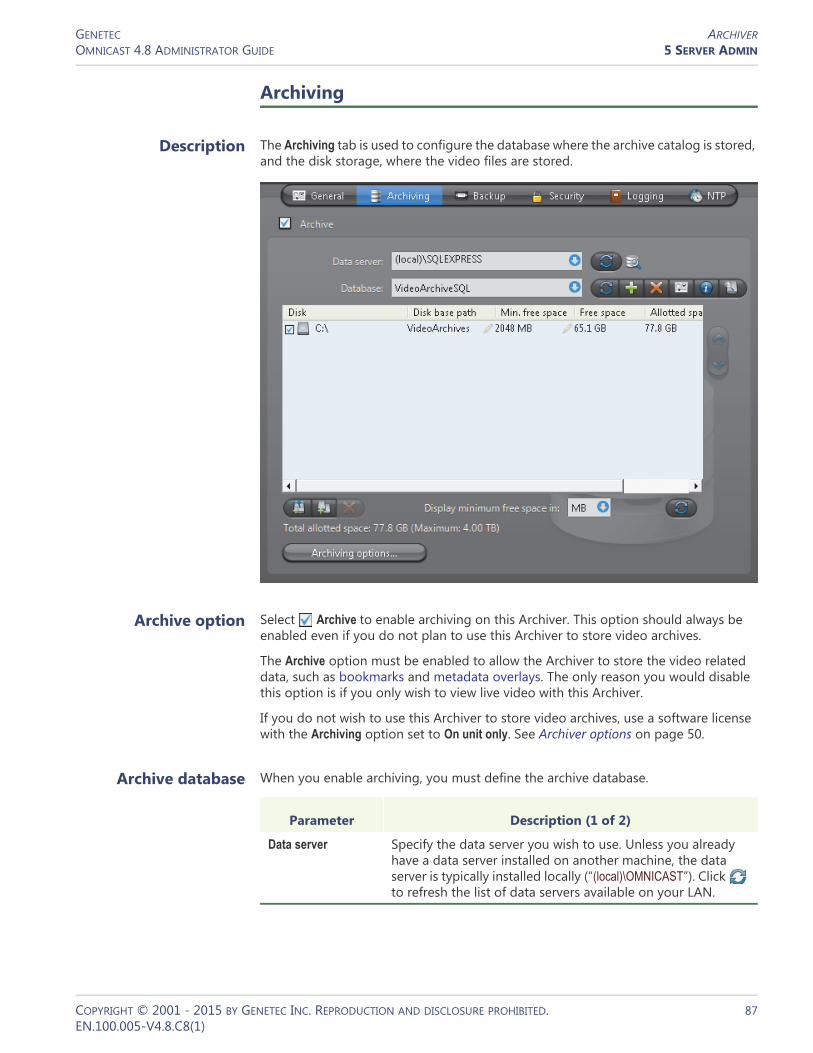
GENETEC ARCHIVEROMNICAST 4.8 ADMINISTRATOR GUIDE 5 SERVER ADMIN
Archiving
Description The Archiving tab is used to configure the database where the archive catalog is stored, and the disk storage, where the video files are stored.
Archive option Select Archive to enable archiving on this Archiver. This option should always be enabled even if you do not plan to use this Archiver to store video archives.
The Archive option must be enabled to allow the Archiver to store the video related data, such as bookmarks and metadata overlays. The only reason you would disable this option is if you only wish to view live video with this Archiver.
If you do not wish to use this Archiver to store video archives, use a software license with the Archiving option set to On unit only. See Archiver options on page 50.
Archive database When you enable archiving, you must define the archive database.
Parameter Description (1 of 2)
Data server Specify the data server you wish to use. Unless you already have a data server installed on another machine, the data server is typically installed locally (“(local)\OMNICAST”). Click to refresh the list of data servers available on your LAN.
COPYRIGHT © 2001 - 2015 BY GENETEC INC. REPRODUCTION AND DISCLOSURE PROHIBITED. 87EN.100.005-V4.8.C8(1)

GENETEC ARCHIVEROMNICAST 4.8 ADMINISTRATOR GUIDE 5 SERVER ADMIN
Note If you are using a remote database server and there are multiple archivers on the system, please ensure that the database specified is unique on each archiver.
Archive storage configuration
While the archive database is used to store the archive catalog, the actual video files are stored directly on disks. You may designate a local drive or a network drive as a location to store your video files.
Multiple disks may be assigned to the same Archiver. See example below.
At installation, the default disk assigned to the archive storage is "C:\VideoArchives". You may add more network locations to the Archiver by clicking the Add network location button. For each disk you designate for archive storage, you must specify its Disk base path and its Min. free space.
Database Select the database instance you wish to use. A data server can manage many database instances. Unless you selected an existing data server during installation, the database instance name should be VideoArchiveSQL.
The command buttons are:• – Refresh the list of available database instances for
the selected data server.• – Either overwrite the existing database instance or
create a new one. You need to create a new database instance if you chose to use an existing data server.
• – Delete the selected database instance from the data server. Warning: all past configurations will be lost.
• – Display the properties of this database.• – Test the database connection. See Database
Diagnostics on page 57.• – Search for orphan files. See Find Orphan Files on
page 44.
Parameter Description (2 of 2)
COPYRIGHT © 2001 - 2015 BY GENETEC INC. REPRODUCTION AND DISCLOSURE PROHIBITED. 88EN.100.005-V4.8.C8(1)

GENETEC ARCHIVEROMNICAST 4.8 ADMINISTRATOR GUIDE 5 SERVER ADMIN
Minimum free space on disk
Disk space is not allocated in advance for the archive storage, but rather, the Archiver is allowed to use the available space on the selected disk up to a given maximum which is limited by the minimum free space that must remain on disk. You may choose to display the Min. free space in MB, GB or TB. Note that only the integer part of the value is displayed. Therefore, 5120 MB will be displayed as 5 GB or 0 TB.
WARNING There is nothing to prevent other applications from using up the disk space set aside for the Archiver. The responsibility to make sure that this does not happen is left to the care of the administrator.
The Free space indicates the actual free space remaining on disk. The Allotted space is the total capacity of the disk minus Min. free space. If the selected disk is not dedicated to Omnicast use, then the actual space available for archiving may be less than the allotted space. The Total size indicates the total capacity of the disk.
The disks are used by the Archiver in the order they appear in the list. Use the and buttons to change the order of the selected disk in the list.
Disk groups The main bottleneck on the Archiver is the disk throughput. Omnicast has a way to alleviate this problem by allowing the Archiver to write simultaneously to multiple disks. This optimization is achieved by defining disk groups .
Each disk group must correspond to a separate disk controller. By judiciously splitting the video archive over several disk groups, the administrator can effectively attain the maximum throughput in terms of disk access. The way the video archive should be distributed among the available disk groups is defined in the Config Tool. See Archiving on page 205.
The following example, two disk groups named Default Disk Group and Alternate Group are being used.
When the Archiver is installed, only the Default Disk Group is defined. The disk groups are shown in the list only if there are more than one group defined. You may add more disk groups by clicking on the Add disk group button. Then use the and buttons to move the selected disk from one group to another.
Click on the button to remove a selected disk or disk group.
Click on the button to refresh the remaining free space on each disk.
COPYRIGHT © 2001 - 2015 BY GENETEC INC. REPRODUCTION AND DISCLOSURE PROHIBITED. 89EN.100.005-V4.8.C8(1)

GENETEC ARCHIVEROMNICAST 4.8 ADMINISTRATOR GUIDE 5 SERVER ADMIN
Additional archiving options
Clicking on the Archiving options button displays the following dialog which lets you configure additional archiving options.
The parameters are separated into three groups:• General archiving options• Default retention settings• Video file options
General archiving options
DELETE OLDEST FILES WHEN DISKS FULL – Select this option if you want to recycle the archive storage (the default mode), i.e. oldest files are deleted to make space for new files when all the disks are full.
NOTE If multiple disk groups are used, each disk group is considered as a single storage unit. The disk group is considered full when all the disks within that group are full.
Another way to manage the archiving space is to set individual archive retention period for each video encoder (see Retention period on page 206). This method allows you to keep the more important data for a longer period of time and to purge the less important video first.
TRIGGER A FAILOVER WHEN A DISK FAILURE OCCURS – Select this option if you want to enable archiving failover when all the disks in a disk group for a given archiver are full, corrupted, or unavailable. For more information about archiving failover, see Archiver Availability on page 17.
TRIGGER A FAILOVER WHEN THE CONNECTION TO THE DATABASE IS LOST– Select this option if you want to enable archiving failover when the connection to the archiver database is lost. For more information about archiving failover, see Archiver Availability on page 17.
COPYRIGHT © 2001 - 2015 BY GENETEC INC. REPRODUCTION AND DISCLOSURE PROHIBITED. 90EN.100.005-V4.8.C8(1)

GENETEC ARCHIVEROMNICAST 4.8 ADMINISTRATOR GUIDE 5 SERVER ADMIN
LIMIT THE NUMBER OF SIMULTANEOUSLY ARCHIVED CAMERAS – This option is only relevant when the Archiver is part of a failover pool. Setting a limit to the number of cameras that the Archiver can simultaneously manage helps to prevent the host server from being crushed by a load heavier than what it can handle during a failover. (Note: A camera is said to be archived when it is currently covered by one or more archiving schedules.)
The way to make this work is to assign an archiving priority to each Archiver extension handled by the Archiver. All encoders covered under the same Archiver extension share the same archiving priority.
When the number of archived encoders reaches the configured limit, the Archiver will refuse all new archiving requests unless the requesting encoder has a higher archiving priority than one that is currently being archived. If it is the case, the encoder with the lowest archiving priority which was the last to be added to the archiving list will be bumped off in favor of the new one.
By setting judiciously the archiving priorities, the administrator can ensure that the archiving of important cameras in the system will not be jeopardized by a failover, regardless which Archiver fails.
To set the archiving priority on Archiver extensions, click on the Priorities button. Then make the changes in the dialog that appears.
This option only affects the archiving and does not affect the viewing of live video nor the command and control of the video units.
PROTECTED VIDEO THRESHOLD – This is a safety threshold that limits the amount of space that protected video files can occupy on disks. The percentage you set is the proportion of protected video you can have of the total size of recorded videos on the disk. Protected video files are files that will not be deleted by normal archive cleanup procedures. When this threshold is exceeded, the Archiver will generate the Protected video threshold exceeded event once every 15 minutes for as long as the condition is true, but will continue to apply video protection wherever it is configured to do so.
Default retention settings
The default retention settings are used for all cameras controlled by the Archiver, unless camera-specific retention settings are entered which override the default settings. See Archiving on page 205.
COPYRIGHT © 2001 - 2015 BY GENETEC INC. REPRODUCTION AND DISCLOSURE PROHIBITED. 91EN.100.005-V4.8.C8(1)

GENETEC ARCHIVEROMNICAST 4.8 ADMINISTRATOR GUIDE 5 SERVER ADMIN
AUTOMATIC CLEANUP – When this option is selected, the archiver will automatically delete the recorded video after the specified retention period. If cleared, the video archives will only be deleted when the Archiver runs out of disk space, starting from the oldest.
RETENTION PERIOD – The retention period specifies how long the video archives should be kept online for each camera when Automatic cleanup is enabled.
Video file options Video files are the files used to store compressed video. They use the extension ".G64". You have two methods for controlling the size of the video files:
MAXIMUM LENGTH – Sets the maximum length for the video files. The length is the time span between the first video frame and the last video frame stored in the file.
MAXIMUM SIZE – Select this option to set a limit to the size of the video files.
Backup
Description The Backup tab is where the backup feature can be turned on and off, and where the physical devices for backup are configured.
Backup option Select Backup to enable the backup feature on this Archiver.
Before turning this feature on, make sure your software license allows you to restore the backed up files. This feature is controlled by the Number of Restore Archivers you are allowed to have on your system. See Directory options on page 47.
COPYRIGHT © 2001 - 2015 BY GENETEC INC. REPRODUCTION AND DISCLOSURE PROHIBITED. 92EN.100.005-V4.8.C8(1)

GENETEC ARCHIVEROMNICAST 4.8 ADMINISTRATOR GUIDE 5 SERVER ADMIN
You need to configure the following parameter for Backup.
Additional options, such as the backup frequency and time, must be configured in the Config Tool. See Backup on page 213.
Security
Description The Security tab allows you to tighten the security around the Archiver, namely, to prevent tampering with the video archive.
Video watermarking Select Video watermarking to turn this feature on. Video watermarking is the process through which a digital signature is added to each recorded video frame to ensure its authenticity. If anyone later tries to make changes to the video (add, delete or modify a frame), the signatures will no longer match, thus, showing that the video has been tampered with.
The authenticity of the watermarks can be verified with the Archive Player. See “video file – validate the authenticity” in the Omnicast Archive Player User Guide.
Parameter Description
Folder Folder where the backup sets will be created. See Backup Set on page 235.
COPYRIGHT © 2001 - 2015 BY GENETEC INC. REPRODUCTION AND DISCLOSURE PROHIBITED. 93EN.100.005-V4.8.C8(1)

GENETEC ARCHIVEROMNICAST 4.8 ADMINISTRATOR GUIDE 5 SERVER ADMIN
When this feature is turned on, the administrator has two options:• Use default encryption values – Use the default encryption values provided with
the system.• Use custom encryption values – Use a custom encryption key instead of the default
one.
To apply custom encryption values, do the following.1 Run the program named EncryptionKeyGenerator.exe
– It is found in the folder where Omnicast Server is installed. Typically “C:\Program Files\Genetec Omnicast Server x.y\”
– The program will generate two 1 KB files named “fingerprint.bin“ and “private.bin”. The first file contains a random 20 bytes initial fingerprint used for the encryption. The second file contains a RSA 248-bits encryption key. These two files will be different every time the program is executed.
2 Move these two files to a safe location.3 From the Security tab, select Use Custom Encryption Values.4 Specify the path to “fingerprint.bin“ in Initial Fingerprint.5 Specify the path to “private.bin” in Private key.6 Click Apply.
The Archiver will restart. and the watermark will be applied on all subsequent video recordings.
COPYRIGHT © 2001 - 2015 BY GENETEC INC. REPRODUCTION AND DISCLOSURE PROHIBITED. 94EN.100.005-V4.8.C8(1)

GENETEC ARCHIVEROMNICAST 4.8 ADMINISTRATOR GUIDE 5 SERVER ADMIN
Logging
Description The Logging tab is used to configure event logging for the Archiver. This feature records all events attributed to the Archiver or any entity (unit, camera, etc.) controlled by the Archiver, on disk. Note that some archiving related events can also be viewed from the Config Tool. See Event Search on page 219.
Select Enable file logging to turn the logging feature on. The log files contain <Tab> separated values so they can be easily viewed with Microsoft Notepad or Excel.
Location of the log files.
Prefix to be used in the log file names. The file name consists of the prefix, followed by the date (yyyy-mm-dd), followed by a 3-digit sequence number. Example: "_ARC_2007-09-13_000.log".
Number of days the log files should be kept on-line.
Maximum number of lines each log file may contain. When the specified maximum is reached, the Archiver will open a new file.
Parameter Description
Folder
Prefix
Keep log for
Maximum size
COPYRIGHT © 2001 - 2015 BY GENETEC INC. REPRODUCTION AND DISCLOSURE PROHIBITED. 95EN.100.005-V4.8.C8(1)

GENETEC ARCHIVEROMNICAST 4.8 ADMINISTRATOR GUIDE 5 SERVER ADMIN
NTP
Description Use the NTP (Network Time Protocol) tab to sync the time between units that support NTP and an NTP server.
Parameter Description
NTP server Specify the NTP server name.
NTP port Specify the NTP server port number.
Poll timeout Specify in minutes how often you would like the time on the units to be checked to ensure that they are properly synched with the NTP server. For example, if 60 minutes is entered, the time will be verified every 60 minutes.
COPYRIGHT © 2001 - 2015 BY GENETEC INC. REPRODUCTION AND DISCLOSURE PROHIBITED. 96EN.100.005-V4.8.C8(1)

GENETEC ARCHIVER EXTENSIONSOMNICAST 4.8 ADMINISTRATOR GUIDE 5 SERVER ADMIN
Archiver Extensions
Definition
Archiver extensions are additional Archiver settings pertaining to the control of specific groups of units. These settings cover areas such as automatic discovery, communications between the Archiver and the units, archiving priority, and security. An Archiver may have multiple extensions.
Automatic discovery Automatic discovery is the process by which units on a network are automatically discovered by the Archiver. This is done by broadcasting a discovery request on a specific discovery port and waiting for all units configured to listen on that port to respond with a package that contains connection information about itself. Omnicast uses this information to configure the connection to the unit, thus enabling communication. Not all units support this feature.
Creating an Archiver extension
To create a new Archiver extension, do the following:
Note In most cases, extensions can automatically be created when adding a unit. For more information, see Adding a unit manually on page 405.1 Ensure that you have a license for the extension type you want to create. See
Archiver options on page 50.1 Right-click on the Archiver in the resource tree and select Create and the type of
extension.2 The following message will appear.
You need to restart the Archiver service before the system can use the new configuration. Do you want to restart the service now?
3 Click Yes if you want to keep the default settings. The Archiver will immediately restart.
4 Click No and follow the subsequent steps to enter new settings. A new extension of the selected type will appear under the Archiver in the resource tree.
5 Select the newly created extension (always the last one) from the resource tree and change its settings accordingly.See Extension types on page 98.
6 Restart the Archiver service using the Start command from the Action menu or the Watchdog.See Watchdog Tray on page 504.
COPYRIGHT © 2001 - 2015 BY GENETEC INC. REPRODUCTION AND DISCLOSURE PROHIBITED. 97EN.100.005-V4.8.C8(1)
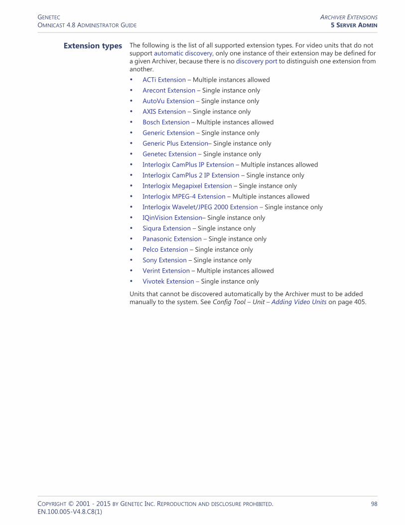
GENETEC ARCHIVER EXTENSIONSOMNICAST 4.8 ADMINISTRATOR GUIDE 5 SERVER ADMIN
Extension types The following is the list of all supported extension types. For video units that do not support automatic discovery, only one instance of their extension may be defined for a given Archiver, because there is no discovery port to distinguish one extension from another.• ACTi Extension – Multiple instances allowed• Arecont Extension – Single instance only• AutoVu Extension – Single instance only• AXIS Extension – Single instance only• Bosch Extension – Multiple instances allowed• Generic Extension – Single instance only• Generic Plus Extension– Single instance only• Genetec Extension – Single instance only• Interlogix CamPlus IP Extension – Multiple instances allowed• Interlogix CamPlus 2 IP Extension – Single instance only• Interlogix Megapixel Extension – Single instance only• Interlogix MPEG-4 Extension – Multiple instances allowed• Interlogix Wavelet/JPEG 2000 Extension – Single instance only• IQinVision Extension– Single instance only• Siqura Extension – Single instance only• Panasonic Extension – Single instance only• Pelco Extension – Single instance only• Sony Extension – Single instance only• Verint Extension – Multiple instances allowed• Vivotek Extension – Single instance only
Units that cannot be discovered automatically by the Archiver must to be added manually to the system. See Config Tool – Unit – Adding Video Units on page 405.
COPYRIGHT © 2001 - 2015 BY GENETEC INC. REPRODUCTION AND DISCLOSURE PROHIBITED. 98EN.100.005-V4.8.C8(1)

GENETEC ARCHIVER EXTENSIONSOMNICAST 4.8 ADMINISTRATOR GUIDE 5 SERVER ADMIN
ACTi Extension
Definition The ACTi extension is used to configure the general settings of ACTi video servers controlled by the Archiver.
To define ACTi extensions, your Archiver license must support the option ACTi MPEG-4 cameras. See Archiver options on page 50.
NOTE Select ACTi units are controlled via the Generic extension; see Generic Extension on page 108. For supported ACTi units, and the correct extension to use, refer to the Omnicast Release Notes.
General settings All ACTi extension settings are found in a single tab:
Parameter Description (1 of 2)
Network card Network card to be used to communicate with the ACTi IP cameras.
Transaction timeout Time to wait for a response before resending a command to the unit. A unit is considered lost after three failed attempts.
Discovery port Corresponds to the Search server port 1 in the ACTi video server settings.
Discovery reply port Corresponds to the Search server port 2 in the ACTi video server settings.
COPYRIGHT © 2001 - 2015 BY GENETEC INC. REPRODUCTION AND DISCLOSURE PROHIBITED. 99EN.100.005-V4.8.C8(1)

GENETEC ARCHIVER EXTENSIONSOMNICAST 4.8 ADMINISTRATOR GUIDE 5 SERVER ADMIN
Unicast period Period whereby the extension repeats its connection tests using unicast to find out whether each unit is still active in the system.
Broadcast period Period whereby the extension attempts to discover new units using broadcast. You may disable the broadcast discovery by clearing the Broadcast period option.
Default login All ACTi units require a username and a password for access control. The login parameters can be defined individually for each unit or for all units. See Config Tool – Unit – Adding Video Units on page 405.
Parameter Description (2 of 2)
COPYRIGHT © 2001 - 2015 BY GENETEC INC. REPRODUCTION AND DISCLOSURE PROHIBITED. 100EN.100.005-V4.8.C8(1)

GENETEC ARCHIVER EXTENSIONSOMNICAST 4.8 ADMINISTRATOR GUIDE 5 SERVER ADMIN
Arecont Extension
Definition The Arecont extension is used to configure the general and security settings of Arecont units controlled by the Archiver. Arecont units do not support automatic discovery.
To define Arecont extensions, your Archiver license must support the option Arecont MJPEG cameras. See Archiver options on page 50.
NOTE Select Arecont units are controlled via the Generic extension; see Generic Extension on page 108. For supported Arecont units, and the correct extension to use, refer to the Omnicast Release Notes.
General settings All Arecont extension settings are found in a single tab:
Parameter Description (1 of 2)
Network card Network card to be used to communicate with the Arecont units.
Transaction timeout Time to wait for a response before resending a command to the unit. A unit is considered lost after three failed attempts.
Number of MJPEG streams
Number of MJPEG streams (1 to 3) that each Arecont unit must generate.
Unicast period Period whereby the extension repeats its connection tests using unicast to find out whether each unit is still active in the system.
COPYRIGHT © 2001 - 2015 BY GENETEC INC. REPRODUCTION AND DISCLOSURE PROHIBITED. 101EN.100.005-V4.8.C8(1)

GENETEC ARCHIVER EXTENSIONSOMNICAST 4.8 ADMINISTRATOR GUIDE 5 SERVER ADMIN
AutoVu Extension
Definition The AutoVu extension is used to configure the general and security settings of all AutoVu Sharp units controlled by the Archiver.
AutoVu Sharp units are used exclusively with the AutoVu LPR plugin to capture license plates from vehicles, optionally match them against a hotlist, and store the data for later queries.
For complete information on this extension, AutoVu Sharp units, and the AutoVu LPR plugin, see the AutoVu LPR Plugins User Guide.
Default login The default login is optional. The login parameters can be defined individually for each unit or for all units. See Config Tool – Unit – Adding Video Units on page 405.
Parameter Description (2 of 2)
COPYRIGHT © 2001 - 2015 BY GENETEC INC. REPRODUCTION AND DISCLOSURE PROHIBITED. 102EN.100.005-V4.8.C8(1)

GENETEC ARCHIVER EXTENSIONSOMNICAST 4.8 ADMINISTRATOR GUIDE 5 SERVER ADMIN
AXIS Extension
Definition The AXIS extension is used to configure the general and security settings of AXIS units controlled by the Archiver. AXIS units do not support automatic discovery.
To define AXIS extensions, your Archiver license must support one of the following options: AXIS H.264 cameras, AXIS MPEG-4 cameras / analog monitors or AXIS MJPEG cameras / analog monitors.
It is not recommended to exceed 6 streams per unit—being the total of H.264, MPEG-4, and MJPEG streams, as explained below.
NOTE Select Axis units are controlled via the Generic extension; see Generic Extension on page 108. For supported Axis units, and the correct extension to use, refer to the Omnicast Release Notes.
See Archiver options on page 50. General settings
General settings All AXIS extension settings are found in a single tab:
Parameter Description (1 of 2)
Network card Network card to be used to communicate with the AXIS units.
Transaction timeout Time to wait for a response before resending a command to the unit. A unit is considered lost after three failed attempts.
COPYRIGHT © 2001 - 2015 BY GENETEC INC. REPRODUCTION AND DISCLOSURE PROHIBITED. 103EN.100.005-V4.8.C8(1)

GENETEC ARCHIVER EXTENSIONSOMNICAST 4.8 ADMINISTRATOR GUIDE 5 SERVER ADMIN
RTSP port Port used for RTSP (Real Time Streaming Protocol). This value should not be modified unless you have specific problems with your firewall.
Unicast period Period whereby the extension repeats its connection tests using unicast to find out whether each unit is still active in the system.
Allow hostname address resolution
Select this option if you want the Archiver to discover new units using a hostname instead of an IP address.
Default login All AXIS units require a username and a password for access control. The login parameters can be defined individually for each unit or for all units. See Config Tool – Unit – Adding Video Units on page 405.
Select the Use HTTPS option to enable HTTPS protocol for your units.
Parameter Description (2 of 2)
COPYRIGHT © 2001 - 2015 BY GENETEC INC. REPRODUCTION AND DISCLOSURE PROHIBITED. 104EN.100.005-V4.8.C8(1)

GENETEC ARCHIVER EXTENSIONSOMNICAST 4.8 ADMINISTRATOR GUIDE 5 SERVER ADMIN
Bosch Extension
Definition Bosch extensions are used to configure the settings of Bosch units. Each Bosch extension allows the Archiver to access a group of Bosch units sharing the same discovery port. A given Archiver may use several Bosch extensions. Each Bosch extension must be configured with a different discovery port.
To define Bosch extensions, your Archiver license must support one of the following two options:• Bosch MPEG-4 cameras / analog monitors
• Bosch MPEG-2 cameras / analog monitors
See Archiver options on page 50.
General settings Click the General tab to see the general settings for the Bosch extension:fjjdfjdhfjkhjdf
Parameter Description (1 of 2)
Network card Network card to be used to communicate with the Bosch units.
Transaction timeout Time to wait for a response before resending a command to the unit. A unit is considered lost after three failed attempts.
Command port Port used by the Archiver to send commands to the Bosch units. This field cannot be changed.
COPYRIGHT © 2001 - 2015 BY GENETEC INC. REPRODUCTION AND DISCLOSURE PROHIBITED. 105EN.100.005-V4.8.C8(1)
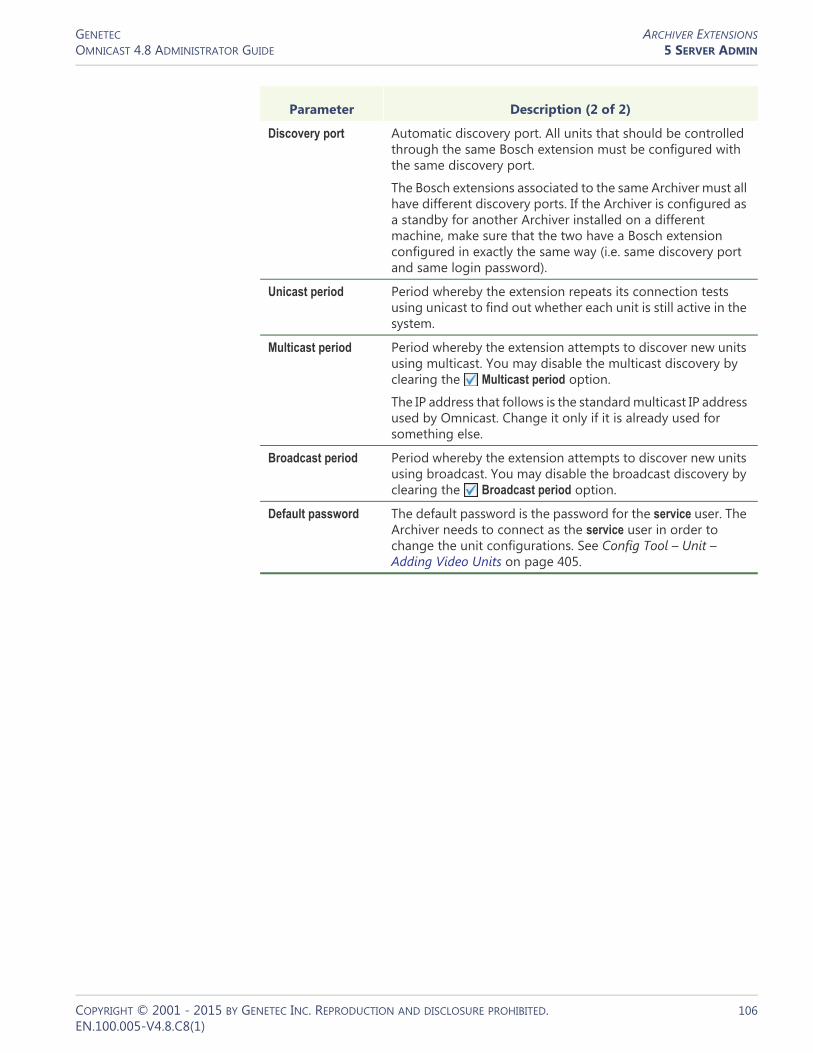
GENETEC ARCHIVER EXTENSIONSOMNICAST 4.8 ADMINISTRATOR GUIDE 5 SERVER ADMIN
Discovery port Automatic discovery port. All units that should be controlled through the same Bosch extension must be configured with the same discovery port.
The Bosch extensions associated to the same Archiver must all have different discovery ports. If the Archiver is configured as a standby for another Archiver installed on a different machine, make sure that the two have a Bosch extension configured in exactly the same way (i.e. same discovery port and same login password).
Unicast period Period whereby the extension repeats its connection tests using unicast to find out whether each unit is still active in the system.
Multicast period Period whereby the extension attempts to discover new units using multicast. You may disable the multicast discovery by clearing the Multicast period option.
The IP address that follows is the standard multicast IP address used by Omnicast. Change it only if it is already used for something else.
Broadcast period Period whereby the extension attempts to discover new units using broadcast. You may disable the broadcast discovery by clearing the Broadcast period option.
Default password The default password is the password for the service user. The Archiver needs to connect as the service user in order to change the unit configurations. See Config Tool – Unit – Adding Video Units on page 405.
Parameter Description (2 of 2)
COPYRIGHT © 2001 - 2015 BY GENETEC INC. REPRODUCTION AND DISCLOSURE PROHIBITED. 106EN.100.005-V4.8.C8(1)

GENETEC ARCHIVER EXTENSIONSOMNICAST 4.8 ADMINISTRATOR GUIDE 5 SERVER ADMIN
VRM Settings You can also add a Bosch Video Recording Manager (VRM) to your Bosch extension. This allows you to query and play back video from a Bosch camera that is managed by a Bosch VRM. Multiple Bosch extensions can use the same VRM.
After exporting Bosch VRM video files, you can validate their watermarking with the Bosch Watermarking Validation Tool. Bosch VRM video files and bookmarks can also be protected and unprotected. For more information, see the Omnicast Archive Player User Guide.
To add a Bosch VRM to the Bosch extension:1 In a Bosch extension, Click the VRM tab.
2 Click the button. The Add a VRM dialog box appears.
3 In the Server URL field, enter the IP address or hostname of the VRM.4 Enter a Username and Password, then click OK. The VRM will be added to the list.
If you add more than one VRM to the list, you can use the move up and move down buttons to move a VRM up or down in the list. By default, Omnicast will use the first VRM in the list for queries and archived video. If the first VRM is not available, Omnicast will use the next VRM in the list. You can see which VRM the Archiver is using at any time by accessing the Archiver logs. For more information about Archiver logging, see Logging on page 95.To delete a VRM from the list, select it and click the button.
COPYRIGHT © 2001 - 2015 BY GENETEC INC. REPRODUCTION AND DISCLOSURE PROHIBITED. 107EN.100.005-V4.8.C8(1)

GENETEC ARCHIVER EXTENSIONSOMNICAST 4.8 ADMINISTRATOR GUIDE 5 SERVER ADMIN
Generic Extension
Definition Generic extensions are used to configure generic encoders supporting either JPEG, MJPEG, H.264 or MPEG-4 compression. Omnicast supports a wide range of generic encoders from vendors such as (but not limited to) AXIS, IQEye, OpenVideo, Panasonic, Sony and Toshiba. To confirm that a specific brand and model of generic encoder is supported, please contact Genetec's Technical Support.
To define generic extensions, your Archiver license must support one of the following options:• Generic H.264 cameras
• Generic MPEG-4 cameras
• Generic MJPEG cameras
See Archiver options on page 50.
General settings All generic extension settings are found in a single tab:
Parameter Description
Network card Network card to be used to communicate with the units.
Unicast period Period whereby the extension repeats its connection tests using unicast to find out whether each unit is still active.
Default login Certain units require a username and a password for access control. The login parameters can be defined individually for each unit or for all units. See Config Tool – Unit – Adding Video Units on page 405.
COPYRIGHT © 2001 - 2015 BY GENETEC INC. REPRODUCTION AND DISCLOSURE PROHIBITED. 108EN.100.005-V4.8.C8(1)

GENETEC ARCHIVER EXTENSIONSOMNICAST 4.8 ADMINISTRATOR GUIDE 5 SERVER ADMIN
Generic Plus Extension
Definition Generic Plus extensions are used to configure generic encoders supporting either H.264, MPEG-4, or MJPEG compression. The Generic Plus extension requires drivers to manage the units. The drivers are automatically installed with your Omnicast software, and defined when you add a unit to the Generic Plus extension. Encoders from multiple vendors are supported, such as JVC and Siqura. To confirm that a specific brand and model of encoder is supported, please contact Genetec's Technical Support.
To define generic plus extensions, your Archiver license must support one of the following options:• Generic Plus H.264 cameras
• Generic Plus MPEG-4 cameras
• Generic Plus MJPEG cameras
See Archiver options on page 50.
General settings The generic plus extension settings are found on the General tab page:
Parameter Description (1 of 2)
Network card Network card to be used to communicate with the units.
Transaction timeout Time to wait for a response before resending a command to the unit. A unit is considered lost after three failed attempts.
COPYRIGHT © 2001 - 2015 BY GENETEC INC. REPRODUCTION AND DISCLOSURE PROHIBITED. 109EN.100.005-V4.8.C8(1)

GENETEC ARCHIVER EXTENSIONSOMNICAST 4.8 ADMINISTRATOR GUIDE 5 SERVER ADMIN
Available drivers Information about the drivers which are available for use with the Generic Plus extension are listed on the Drivers tab. The information includes the Unit driver type, the Omnicast software version the driver was installed with, and the location of the driver on your system.
Genetec Extension
Definition The Genetec extension is used to configure all the general settings of units controlled by the Archiver using the Genetec protocol. The Genetec extension supports encoders supporting either MJPEG, H.264 or MPEG-4 compression. The Genetec protocol can be implemented directly in a video unit. Alternatively, the Genetec protocol can be translated to a video units own protocol by an external mediation device. For more information, please contact Genetec's Technical Support.
To define Genetec extensions, your Archiver license must support one of the following options:• Genetec H.264 cameras
• Genetec MPEG-4 cameras
• Genetec MJPEG cameras
See Archiver options on page 50.
Unicast period Period whereby the extension repeats its connection tests using unicast to find out whether each unit is still active.
Default login Certain units require a username and a password for access control. The login parameters can be defined individually for each unit or for all units. See Config Tool – Unit – Adding Video Units on page 405.
Select the Use HTTPS option to enable HTTPS protocol for your units.
Parameter Description (2 of 2)
COPYRIGHT © 2001 - 2015 BY GENETEC INC. REPRODUCTION AND DISCLOSURE PROHIBITED. 110EN.100.005-V4.8.C8(1)

GENETEC ARCHIVER EXTENSIONSOMNICAST 4.8 ADMINISTRATOR GUIDE 5 SERVER ADMIN
General settings All Genetec extension settings are found in a single tab:
Parameter Description
Network card Network card to be used to communicate with the units.
Transaction timeout Time to wait for a response before resending a command to the unit. A unit is considered lost after three failed attempts.
Unicast period Period whereby the extension repeats its connection tests using unicast to find out whether each unit is still active.
Default login Certain units require a username and a password for access control. The login parameters can be defined individually for each unit or for all units. See Config Tool – Unit – Adding Video Units on page 405.
Select the Use HTTPS option to enable HTTPS protocol for your units.
COPYRIGHT © 2001 - 2015 BY GENETEC INC. REPRODUCTION AND DISCLOSURE PROHIBITED. 111EN.100.005-V4.8.C8(1)

GENETEC ARCHIVER EXTENSIONSOMNICAST 4.8 ADMINISTRATOR GUIDE 5 SERVER ADMIN
Interlogix CamPlus IP Extension
Definition The Interlogix CamPlus IP extensions are used to configure the general settings for most of the Interlogix CamPlus IP cameras. Each Interlogix extension allows the Archiver to access a group of Interlogix Camplus IP cameras sharing the same discovery port. A given Archiver may use several Interlogix CamPlus IP extensions. Each extension must be configured with a different discovery port.
To define Interlogix CamPlus IP extensions, your Archiver license must support the option Interlogix CamPlus IP cameras. See Archiver options on page 50.
General settings All Interlogix CamPlus IP extension settings are found in a single tab:
Parameter Description (1 of 2)
Network card Network card to be used to communicate with the Interlogix CamPlus IP cameras.
Transaction timeout Time to wait for a response before resending a command to the unit. A unit is considered lost after three failed attempts.
Discovery port Corresponds to the Search server port 1 in the Interlogix CamPlus video server settings.
Discovery reply port Corresponds to the Search server port 2 in the Interlogix CamPlus server settings.
COPYRIGHT © 2001 - 2015 BY GENETEC INC. REPRODUCTION AND DISCLOSURE PROHIBITED. 112EN.100.005-V4.8.C8(1)
GENETEC ARCHIVER EXTENSIONSOMNICAST 4.8 ADMINISTRATOR GUIDE 5 SERVER ADMIN
Unicast period Period whereby the extension repeats its connection tests using unicast to find out whether each unit is still active in the system.
Broadcast period Period whereby the extension attempts to discover new units using broadcast. You may disable the broadcast discovery by clearing the Broadcast period option.
Default login All Interlogix CamPlus IP units require a username and a password for access control. The login parameters can be defined individually for each unit or for all units.
See Config Tool – Unit – Adding Video Units on page 405.
Parameter Description (2 of 2)
COPYRIGHT © 2001 - 2015 BY GENETEC INC. REPRODUCTION AND DISCLOSURE PROHIBITED. 113EN.100.005-V4.8.C8(1)

GENETEC ARCHIVER EXTENSIONSOMNICAST 4.8 ADMINISTRATOR GUIDE 5 SERVER ADMIN
Interlogix CamPlus 2 IP Extension
Definition This Interlogix extension is used to configure the general settings of Interlogix CamPlus 2 IP cameras.
To define Interlogix CamPlus 2 IP extensions, your Archiver license must support one of the following two options:• Interlogix CamPlus 2 IP MPEG4 cameras
• Interlogix CamPlus 2 IP MJPEG cameras
See Archiver options on page 50.
General settings All Interlogix CamPlus 2 IP extension settings are found in a single tab:
Parameter Description (1 of 2)
Network card Network card to be used to communicate with the Interlogix CamPlus 2 IP units.
Transaction timeout Time to wait for a response before re-sending a command to the unit. A unit is considered lost after three failed attempts.
Unicast period Period whereby the extension repeats its connection tests using unicast to find out whether each unit is still active in the system.
COPYRIGHT © 2001 - 2015 BY GENETEC INC. REPRODUCTION AND DISCLOSURE PROHIBITED. 114EN.100.005-V4.8.C8(1)

GENETEC ARCHIVER EXTENSIONSOMNICAST 4.8 ADMINISTRATOR GUIDE 5 SERVER ADMIN
Default login All Interlogix CamPlus 2 IP units require a username and a password for access control. The login parameters can be defined individually for each unit or for all units.
See Config Tool – Unit – Adding Video Units on page 405.
TCP notification port Port used by the Archiver to receive notification messages from the Interlogix CamPlus 2 IP units.
When an event occurs, such as Signal lost or Signal recovered, the unit will initiate a TCP connection with the Archiver and send the notification through this port.
Notification channel When multiple archivers are configured to listen to the same units, such as in a failover list, each archiver must be identified with a different notification channel (1 to 8). This parameter can be ignored when you are only using one Archiver.
For multiple archivers, the following rules must be observed:• All archivers that may potentially control the same
Interlogix CamPlus 2 IP units must be configured with the same TCP notification port.
• All archivers must use a different Notification channel.
Parameter Description (2 of 2)
COPYRIGHT © 2001 - 2015 BY GENETEC INC. REPRODUCTION AND DISCLOSURE PROHIBITED. 115EN.100.005-V4.8.C8(1)

GENETEC ARCHIVER EXTENSIONSOMNICAST 4.8 ADMINISTRATOR GUIDE 5 SERVER ADMIN
Interlogix Megapixel Extension
Definition This Interlogix extension is used to configure the Interlogix Megapixel cameras. Interlogix Megapixel units do not support automatic discovery.
To define Interlogix Megapixel extensions, your Archiver license must support the option Interlogix Megapixel cameras. See Archiver options on page 50.
General settings All Interlogix Megapixel extension settings are found in a single tab:
Parameter Description
Network card Network card to be used to communicate with the Interlogix units.
Transaction timeout Time to wait for a response before resending a command to the unit. A unit is considered lost after three failed attempts.
Number of MJPEG streams
Number of MJPEG streams (1 to 3) that each Interlogix Megapixel unit must generate.
Unicast period Period whereby the extension repeats its connection tests using unicast to find out whether each unit is still active in the system.
Default login The default login is optional. The login parameters can be defined individually for each unit or for all units. See Config Tool – Unit – Adding Video Units on page 405.
COPYRIGHT © 2001 - 2015 BY GENETEC INC. REPRODUCTION AND DISCLOSURE PROHIBITED. 116EN.100.005-V4.8.C8(1)

GENETEC ARCHIVER EXTENSIONSOMNICAST 4.8 ADMINISTRATOR GUIDE 5 SERVER ADMIN
Interlogix MPEG-4 Extension
Definition The Interlogix MPEG-4 extensions are used to configure the general settings for most of the Interlogix units (SymVeo, SymNet, SymDec, etc.). Each Interlogix extension allows the Archiver to access a group of Interlogix units sharing the same discovery port. A given Archiver may use several Interlogix MPEG-4 extensions. Each extension must be configured with a different discovery port.
To define Interlogix MPEG-4 extensions, your Archiver license must support the option Interlogix MPEG-4 cameras / analog monitors. See Archiver options on page 50.
General settings All Interlogix MPEG-4 extension settings are found in a single tab:
Parameter Description (1 of 2)
Network card Network card to be used to communicate with the Interlogix units.
Transaction timeout Time to wait for a response before resending a command to the unit. A unit is considered lost after three failed attempts.
Command port Port used by the Archiver to send commands to the Interlogix units.
COPYRIGHT © 2001 - 2015 BY GENETEC INC. REPRODUCTION AND DISCLOSURE PROHIBITED. 117EN.100.005-V4.8.C8(1)
GENETEC ARCHIVER EXTENSIONSOMNICAST 4.8 ADMINISTRATOR GUIDE 5 SERVER ADMIN
Discovery port Automatic discovery port. All units that should be controlled through the same Interlogix MPEG-4 extension must be configured with the same discovery port.
The Interlogix MPEG-4 extensions associated to the same Archiver must all have different discovery ports. If the Archiver is configured as a standby for another Archiver installed on a different machine, make sure that the two have a Interlogix MPEG-4 extension configured in exactly the same way (i.e. same discovery port and same login password).
Unicast period Period whereby the extension repeats its connection tests using unicast to find out whether each unit is still active in the system.
Broadcast period Period whereby the extension attempts to discover new units using broadcast. You may disable the broadcast discovery by clearing the Broadcast period option.
Default login All Interlogix CamPlus IP units require a username and a password for access control. The login parameters can be defined individually for each unit or for all units.
See Config Tool – Unit – Adding Video Units on page 405.
Parameter Description (2 of 2)
COPYRIGHT © 2001 - 2015 BY GENETEC INC. REPRODUCTION AND DISCLOSURE PROHIBITED. 118EN.100.005-V4.8.C8(1)

GENETEC ARCHIVER EXTENSIONSOMNICAST 4.8 ADMINISTRATOR GUIDE 5 SERVER ADMIN
Interlogix Wavelet/JPEG 2000 Extension
Definition This Interlogix extension is used to configure the Interlogix Wavelet/JPEG 2000 units. Interlogix Wavelet/JPEG 2000 units do not support automatic discovery.
To define Interlogix Wavelet/JPEG 2000 extensions, your Archiver license must support the option Interlogix Wavelet/JPEG 2000 cameras. See Archiver options on page 50.
General settings All Interlogix Wavelet/JPEG 2000 extension settings are found in a single tab:
Parameter Description (1 of 2)
Network card Network card to be used to communicate with the Interlogix units.
Transaction timeout Time to wait for a response before resending a command to the unit. A unit is considered lost after three failed attempts.
Command port Port used by the Archiver to send commands to the Interlogix units.
Unicast period Period whereby the extension repeats its connection tests using unicast to find out whether each unit is still active in the system.
Broadcast period Period whereby the extension attempts to discover new units using broadcast. You may disable the broadcast discovery by clearing the Broadcast period option.
COPYRIGHT © 2001 - 2015 BY GENETEC INC. REPRODUCTION AND DISCLOSURE PROHIBITED. 119EN.100.005-V4.8.C8(1)

GENETEC ARCHIVER EXTENSIONSOMNICAST 4.8 ADMINISTRATOR GUIDE 5 SERVER ADMIN
Default password The default password is the password for the service user. The Archiver needs to connect as the service user in order to change the unit configurations.
See Config Tool – Unit – Adding Video Units on page 405.
Parameter Description (2 of 2)
COPYRIGHT © 2001 - 2015 BY GENETEC INC. REPRODUCTION AND DISCLOSURE PROHIBITED. 120EN.100.005-V4.8.C8(1)
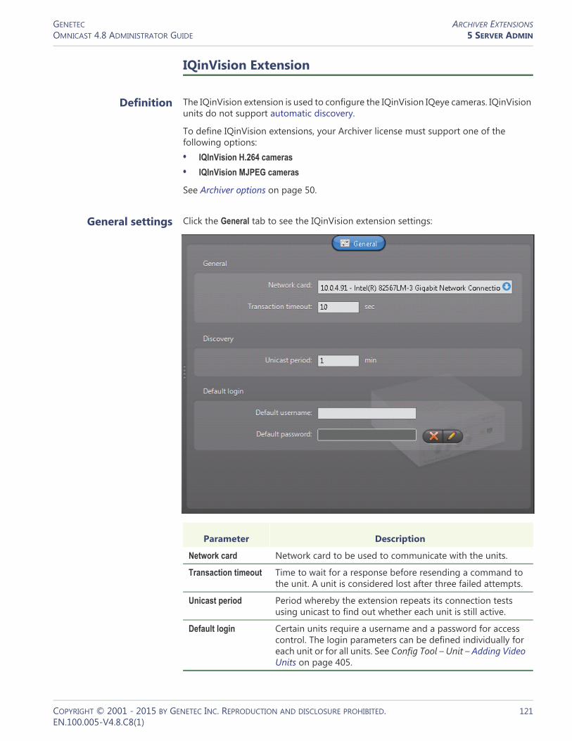
GENETEC ARCHIVER EXTENSIONSOMNICAST 4.8 ADMINISTRATOR GUIDE 5 SERVER ADMIN
IQinVision Extension
Definition The IQinVision extension is used to configure the IQinVision IQeye cameras. IQinVision units do not support automatic discovery.
To define IQinVision extensions, your Archiver license must support one of the following options:• IQInVision H.264 cameras
• IQInVision MJPEG cameras
See Archiver options on page 50.
General settings Click the General tab to see the IQinVision extension settings:
Parameter Description
Network card Network card to be used to communicate with the units.
Transaction timeout Time to wait for a response before resending a command to the unit. A unit is considered lost after three failed attempts.
Unicast period Period whereby the extension repeats its connection tests using unicast to find out whether each unit is still active.
Default login Certain units require a username and a password for access control. The login parameters can be defined individually for each unit or for all units. See Config Tool – Unit – Adding Video Units on page 405.
COPYRIGHT © 2001 - 2015 BY GENETEC INC. REPRODUCTION AND DISCLOSURE PROHIBITED. 121EN.100.005-V4.8.C8(1)

GENETEC ARCHIVER EXTENSIONSOMNICAST 4.8 ADMINISTRATOR GUIDE 5 SERVER ADMIN
Panasonic Extension
Definition The Panasonic extension is used to configure the general and security settings of Panasonic units controlled by the Archiver. Panasonic units do not support automatic discovery.
To define Panasonic extensions, your Archiver license must support one of the following two options: Panasonic MPEG-4 cameras or Panasonic MJPEG cameras.
NOTE Select Panasonic units are controlled via the Generic extension; see Generic Extension on page 108. For supported Panasonic units, and the correct extension to use, refer to the Omnicast Release Notes.
See Archiver options on page 50.
General settings All Panasonic extension settings are found in a single tab:
Parameter Description (1 of 2)
Network card Network card to be used to communicate with the Panasonic units.
Transaction timeout Time to wait for a response before re-sending a command to the unit. A unit is considered lost after three failed attempts.
Unicast period Period whereby the extension repeats its connection tests using unicast to find out whether each unit is still active in the system.
COPYRIGHT © 2001 - 2015 BY GENETEC INC. REPRODUCTION AND DISCLOSURE PROHIBITED. 122EN.100.005-V4.8.C8(1)
GENETEC ARCHIVER EXTENSIONSOMNICAST 4.8 ADMINISTRATOR GUIDE 5 SERVER ADMIN
Default login All Panasonic units require a username and a password for access control. The login parameters can be defined individually for each unit or for all units. See Config Tool – Unit – Adding Video Units on page 405.
Select the Use HTTPS option to enable HTTPS protocol for your units.
TCP notification port Port used by the Archiver to receive notification messages from the Panasonic units.
When an event occurs, such as Signal lost or Signal recovered, the unit will initiate a TCP connection with the Archiver and send the notification through this port.
Notification channel When multiple archivers are configured to listen to the same units, such as in a failover list, each archiver must be identified with a different notification channel (1 to 8). This parameter can be ignored when you are only using one Archiver.
For multiple archivers, the following rules must be observed:• All archivers that may potentially control the same
Panasonic units must be configured with the same TCP notification port.
• All archivers must use a different Notification channel.
Parameter Description (2 of 2)
COPYRIGHT © 2001 - 2015 BY GENETEC INC. REPRODUCTION AND DISCLOSURE PROHIBITED. 123EN.100.005-V4.8.C8(1)
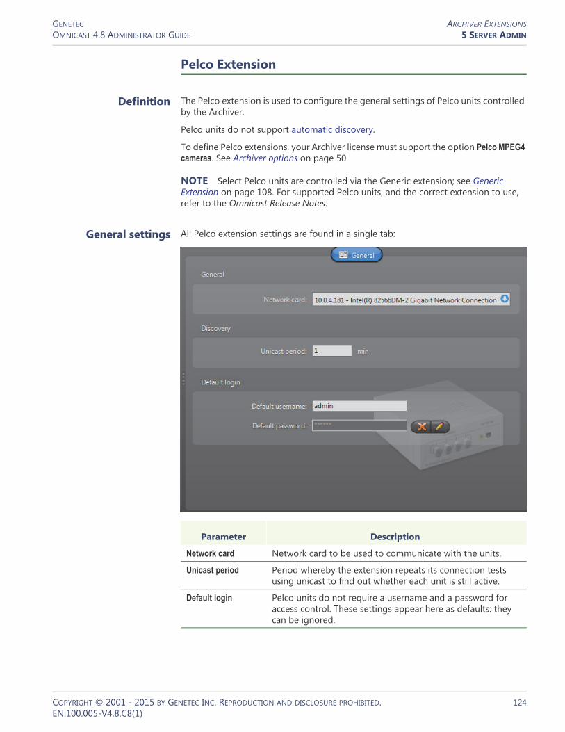
GENETEC ARCHIVER EXTENSIONSOMNICAST 4.8 ADMINISTRATOR GUIDE 5 SERVER ADMIN
Pelco Extension
Definition The Pelco extension is used to configure the general settings of Pelco units controlled by the Archiver.
Pelco units do not support automatic discovery.
To define Pelco extensions, your Archiver license must support the option Pelco MPEG4 cameras. See Archiver options on page 50.
NOTE Select Pelco units are controlled via the Generic extension; see Generic Extension on page 108. For supported Pelco units, and the correct extension to use, refer to the Omnicast Release Notes.
General settings All Pelco extension settings are found in a single tab:
Parameter Description
Network card Network card to be used to communicate with the units.
Unicast period Period whereby the extension repeats its connection tests using unicast to find out whether each unit is still active.
Default login Pelco units do not require a username and a password for access control. These settings appear here as defaults: they can be ignored.
COPYRIGHT © 2001 - 2015 BY GENETEC INC. REPRODUCTION AND DISCLOSURE PROHIBITED. 124EN.100.005-V4.8.C8(1)

GENETEC ARCHIVER EXTENSIONSOMNICAST 4.8 ADMINISTRATOR GUIDE 5 SERVER ADMIN
Siqura Extension
Definition The Siqura extension is used to configure the general and security settings of Siqura units controlled by the Archiver. Siqura units do not support automatic discovery.
To define Siqura extensions, your Archiver license must support one of the following: Siqura H.264 cameras, Siqura MPEG4 cameras, or Siqura MJPEG cameras.
NOTE Select Siqura units are controlled via the Generic extension; see Generic Extension on page 108. For supported Siqura units, and the correct extension to use, refer to the Omnicast Release Notes.
See Archiver options on page 50.
General settings All Siqura extension settings are found in a single tab:
Parameter Description (1 of 2)
Network card Network card to be used to communicate with the Siqura units.
Transaction timeout Time to wait for a response before re-sending a command to the unit. A unit is considered lost after three failed attempts.
COPYRIGHT © 2001 - 2015 BY GENETEC INC. REPRODUCTION AND DISCLOSURE PROHIBITED. 125EN.100.005-V4.8.C8(1)

GENETEC ARCHIVER EXTENSIONSOMNICAST 4.8 ADMINISTRATOR GUIDE 5 SERVER ADMIN
Sony Extension
Definition The Sony extension is used to configure the general settings of Sony IP cameras controlled by the Archiver. Sony units do not support automatic discovery.
To define Sony extensions, your Archiver license must support one of the following two options:• Sony MPEG-4 cameras
• Sony MJPEG cameras
NOTE Select Sony units are controlled via the Generic extension; see Generic Extension on page 108. For supported Sony units, and the correct extension to use, refer to the Omnicast Release Notes.
Unicast period Period whereby the extension repeats its connection tests using unicast to find out whether each unit is still active in the system.
Default login Some units require a username and a password for access control. The login parameters can be defined individually for each unit or for all units.
See Config Tool – Unit – Adding Video Units on page 405.
Parameter Description (2 of 2)
COPYRIGHT © 2001 - 2015 BY GENETEC INC. REPRODUCTION AND DISCLOSURE PROHIBITED. 126EN.100.005-V4.8.C8(1)

GENETEC ARCHIVER EXTENSIONSOMNICAST 4.8 ADMINISTRATOR GUIDE 5 SERVER ADMIN
See Archiver options on page 50.
General settings All Sony extension settings are found in a single tab:
Parameter Description
Network card Network card to be used to communicate with the Sony units.
Transaction timeout Time to wait for a response before resending a command to the unit. A unit is considered lost after three failed attempts.
Default stream Default stream type (MJPEG or MPEG-4) that the Archiver should try to create for every newly discovered unit. All Sony IP cameras support the MJPEG encoder.
This setting merely indicates a preference, not an absolute requirement. If a unit does not support the default encoder type, the one that is supported will be created instead.
Unicast period Period whereby the extension repeats its connection tests using unicast to find out whether each unit is still active in the system.
Default login All Sony units require a username and a password for access control. The login parameters can be defined individually for each unit or for all units. See Config Tool – Unit – Adding Video Units on page 405.
Select the Use HTTPS option to enable HTTPS protocol for your units.
COPYRIGHT © 2001 - 2015 BY GENETEC INC. REPRODUCTION AND DISCLOSURE PROHIBITED. 127EN.100.005-V4.8.C8(1)
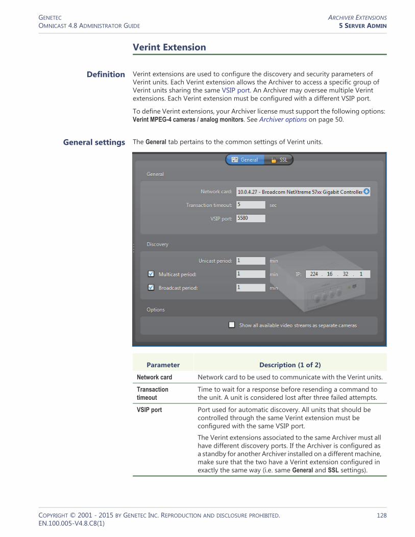
GENETEC ARCHIVER EXTENSIONSOMNICAST 4.8 ADMINISTRATOR GUIDE 5 SERVER ADMIN
Verint Extension
Definition Verint extensions are used to configure the discovery and security parameters of Verint units. Each Verint extension allows the Archiver to access a specific group of Verint units sharing the same VSIP port. An Archiver may oversee multiple Verint extensions. Each Verint extension must be configured with a different VSIP port.
To define Verint extensions, your Archiver license must support the following options: Verint MPEG-4 cameras / analog monitors. See Archiver options on page 50.
General settings The General tab pertains to the common settings of Verint units.
Parameter Description (1 of 2)
Network card Network card to be used to communicate with the Verint units.
Transaction timeout
Time to wait for a response before resending a command to the unit. A unit is considered lost after three failed attempts.
VSIP port Port used for automatic discovery. All units that should be controlled through the same Verint extension must be configured with the same VSIP port.
The Verint extensions associated to the same Archiver must all have different discovery ports. If the Archiver is configured as a standby for another Archiver installed on a different machine, make sure that the two have a Verint extension configured in exactly the same way (i.e. same General and SSL settings).
COPYRIGHT © 2001 - 2015 BY GENETEC INC. REPRODUCTION AND DISCLOSURE PROHIBITED. 128EN.100.005-V4.8.C8(1)

GENETEC ARCHIVER EXTENSIONSOMNICAST 4.8 ADMINISTRATOR GUIDE 5 SERVER ADMIN
SSL settings The SSL tab allows you to tighten the security around a group of units answering to the same VSIP port to prevent tampering and hacking.
Unicast period Period whereby the extension repeats its connection tests using unicast to find out whether each unit is still active in the system.
Multicast period Period whereby the extension attempts to discover new units using multicast. You may disable the multicast discovery by clearing the Multicast period option.
The IP address that follows is the standard multicast IP address used by Omnicast. Change it only if it is already used for something else.
Broadcast period Period whereby the extension attempts to discover new units using broadcast. You may disable the broadcast discovery by clearing the Broadcast period option.
Show all available video streams as separate cameras
Omnicast supports encoders that generate multiple video streams from the same video source. When such a unit is discovered, the Archiver creates a video encoder with multiple streaming alternatives. See Camera – Video stream usage on page 242.
With Verint units, you have the choice to represent every video stream as a separate camera. If this is the desired behavior, select this option.
Parameter Description (2 of 2)
COPYRIGHT © 2001 - 2015 BY GENETEC INC. REPRODUCTION AND DISCLOSURE PROHIBITED. 129EN.100.005-V4.8.C8(1)

GENETEC ARCHIVER EXTENSIONSOMNICAST 4.8 ADMINISTRATOR GUIDE 5 SERVER ADMIN
SSL (Secure Sockets Layer) is a protocol used to secure applications that need to communicate over a network. Omnicast supports SSL on all message transmissions between the Archiver and the units, with the exception of the video streams, because the data volume would be prohibitive. The purpose for using SSL in Omnicast is to prevent malicious attacks, not to stop eavesdropping.
The option SSL on Archiver must be supported in your Omnicast license before you can access the SSL configuration of the Verint extension.
Parameter Description
CA certificate The CA certificate is the common agreement over SSL between the Archivers and the units. Do not change this certificate unless being instructed by the unit manufacturer.
SSL password The SSL password is an additional security over the SSL encryption. All units with SSL enabled must use the same password.
To set a new password or to change the password, click the button. You must enter the password twice to confirm it.
Enforce SSL Select this option only if SSL must be enforced on all units controlled by this Archiver. If this option is cleared, the Archiver will only use SSL to communicate with the units on which SSL is enabled. See Unit – Security on page 415.
COPYRIGHT © 2001 - 2015 BY GENETEC INC. REPRODUCTION AND DISCLOSURE PROHIBITED. 130EN.100.005-V4.8.C8(1)

GENETEC ARCHIVER EXTENSIONSOMNICAST 4.8 ADMINISTRATOR GUIDE 5 SERVER ADMIN
Vivotek Extension
Definition The Vivotek extension is used to configure the general settings of Vivotek IP cameras controlled by the Archiver. Vivotek units do not support automatic discovery.
To define Vivotek extensions, your Archiver license must support one of the following two options:• Vivotek MPEG-4 cameras
• Vivotek MJPEG cameras
NOTE Select Vivotek units are controlled via the Generic extension; see Generic Extension on page 108. For supported Vivotek units, and the correct extension to use, refer to the Omnicast Release Notes.
See Archiver options on page 50.
General settings All Vivotek extension settings are found in a single tab:
Parameter Description (1 of 2)
Network card Network card to be used to communicate with the Vivotek IP cameras.
Transaction timeout Time to wait for a response before resending a command to the unit. A unit is considered lost after three failed attempts.
COPYRIGHT © 2001 - 2015 BY GENETEC INC. REPRODUCTION AND DISCLOSURE PROHIBITED. 131EN.100.005-V4.8.C8(1)

GENETEC ARCHIVER EXTENSIONSOMNICAST 4.8 ADMINISTRATOR GUIDE 5 SERVER ADMIN
Default stream Default stream type (MJPEG or MPEG-4) that the Archiver should try to create for every newly discovered unit. All Vivotek IP cameras support the MJPEG encoder.
This setting merely indicates a preference, not an absolute requirement. If a unit does not support the default encoder type, the one that is supported will be created instead.
Unicast period Period whereby the extension repeats its connection tests using unicast to find out whether each unit is still active in the system.
Default login All Vivotek units require a username and a password for access control. The login parameters can be defined individually for each unit or for all units.
See Config Tool – Unit – Adding Video Units on page 405.
Parameter Description (2 of 2)
COPYRIGHT © 2001 - 2015 BY GENETEC INC. REPRODUCTION AND DISCLOSURE PROHIBITED. 132EN.100.005-V4.8.C8(1)

GENETEC AUXILIARY ARCHIVEROMNICAST 4.8 ADMINISTRATOR GUIDE 5 SERVER ADMIN
Auxiliary Archiver
Introduction
The Auxiliary Archiver is a supplemental archiving service. Unlike the regular Archiver, the Auxiliary Archiver is not bound to any particular discovery port. Therefore, it is free to archive any camera in the system, including the ones that are federated. In addition, the Auxiliary Archiver offers the choice to archive different video streams on different schedules than those followed by the regular Archivers.
Multiple instances of Auxiliary Archivers may be running on the same system, but their use must be granted by the Number of Auxiliary Archivers of your Omnicast license. See Directory options on page 47.
The local settings of the Auxiliary Archiver are found in the following tabs.
The machine independent parameters of this server application are configured with the Config Tool. See Auxiliary Archiver on page 223.
Icon Tab Description
General General Auxiliary Archiver settings (system, network card).
Archiving Archiving settings (database, storage disks, etc.).
Backup Backup settings (backup folder, tape group and size, etc.).
Security Security settings (video watermarking, SSL settings).
COPYRIGHT © 2001 - 2015 BY GENETEC INC. REPRODUCTION AND DISCLOSURE PROHIBITED. 133EN.100.005-V4.8.C8(1)

GENETEC AUXILIARY ARCHIVEROMNICAST 4.8 ADMINISTRATOR GUIDE 5 SERVER ADMIN
General
Description The General tab is used to configure the Gateway the Auxiliary Archiver must connect to and the Network card to use.
If the Gateway and the Auxiliary Archiver are installed on the same machine, leave the Gateway field blank.
You only need to specify the network card if your PC is equipped with more than one.
COPYRIGHT © 2001 - 2015 BY GENETEC INC. REPRODUCTION AND DISCLOSURE PROHIBITED. 134EN.100.005-V4.8.C8(1)
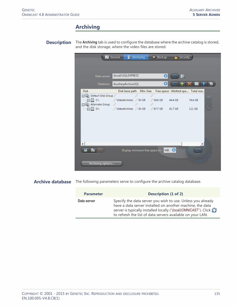
GENETEC AUXILIARY ARCHIVEROMNICAST 4.8 ADMINISTRATOR GUIDE 5 SERVER ADMIN
Archiving
Description The Archiving tab is used to configure the database where the archive catalog is stored, and the disk storage, where the video files are stored.
Archive database The following parameters serve to configure the archive catalog database.
Parameter Description (1 of 2)
Data server Specify the data server you wish to use. Unless you already have a data server installed on another machine, the data server is typically installed locally (“(local)\OMNICAST”). Click to refresh the list of data servers available on your LAN.
COPYRIGHT © 2001 - 2015 BY GENETEC INC. REPRODUCTION AND DISCLOSURE PROHIBITED. 135EN.100.005-V4.8.C8(1)
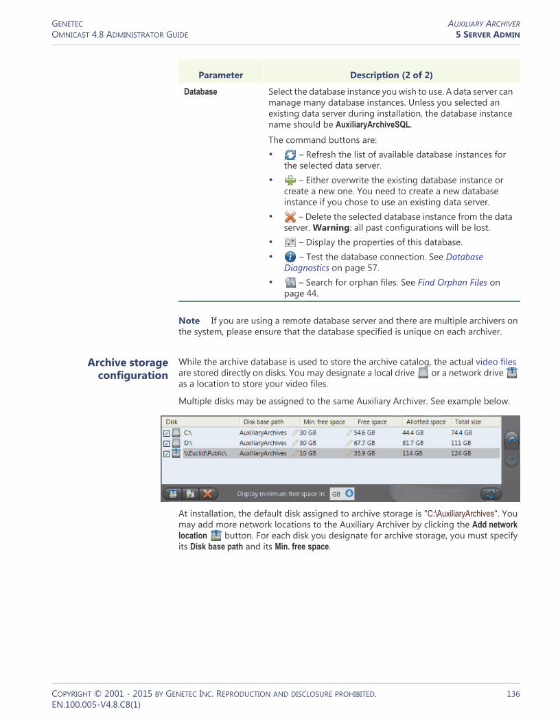
GENETEC AUXILIARY ARCHIVEROMNICAST 4.8 ADMINISTRATOR GUIDE 5 SERVER ADMIN
Note If you are using a remote database server and there are multiple archivers on the system, please ensure that the database specified is unique on each archiver.
Archive storage configuration
While the archive database is used to store the archive catalog, the actual video files are stored directly on disks. You may designate a local drive or a network drive as a location to store your video files.
Multiple disks may be assigned to the same Auxiliary Archiver. See example below.
At installation, the default disk assigned to archive storage is "C:\AuxiliaryArchives". You may add more network locations to the Auxiliary Archiver by clicking the Add network location button. For each disk you designate for archive storage, you must specify its Disk base path and its Min. free space.
Database Select the database instance you wish to use. A data server can manage many database instances. Unless you selected an existing data server during installation, the database instance name should be AuxiliaryArchiveSQL.
The command buttons are:• – Refresh the list of available database instances for
the selected data server.• – Either overwrite the existing database instance or
create a new one. You need to create a new database instance if you chose to use an existing data server.
• – Delete the selected database instance from the data server. Warning: all past configurations will be lost.
• – Display the properties of this database.• – Test the database connection. See Database
Diagnostics on page 57.• – Search for orphan files. See Find Orphan Files on
page 44.
Parameter Description (2 of 2)
COPYRIGHT © 2001 - 2015 BY GENETEC INC. REPRODUCTION AND DISCLOSURE PROHIBITED. 136EN.100.005-V4.8.C8(1)

GENETEC AUXILIARY ARCHIVEROMNICAST 4.8 ADMINISTRATOR GUIDE 5 SERVER ADMIN
Minimum free space on disk
Disk space are not allocated in advance for the archive storage, but rather, the Auxiliary Archiver is allowed to use the available space on the selected disk up to a given maximum which is limited by the minimum free space that must remain on disk. You may choose to display the Min. free space in MB, GB or TB. Note that only the integer part of the value is displayed. Therefore, 5120 MB will be displayed as 5 GB or 0 TB.
WARNING There is nothing to prevent other applications from using up the disk space set aside for the Auxiliary Archiver. The responsibility to make sure that this does not happen is left to the care of the administrator.
The Free space indicates the actual free space remaining on disk. The Allotted space is the total capacity of the disk minus Min. free space. If the selected disk is not dedicated to Omnicast use, then the actual space available for archiving may be less than the allotted space. The Total size indicates the total capacity of the disk.
The disks are used by the Auxiliary Archiver in the order they appear in the list. Use the and buttons to change the order of the selected disk in the list.
Disk groups The main bottleneck on the Auxiliary Archiver is the disk throughput. Omnicast has a way to alleviate this problem by allowing the Auxiliary Archiver to write simultaneously to multiple disks. This optimization is achieved by defining disk groups .
Each disk group must correspond to a separate disk controller. By judiciously splitting the video archive over several disk groups, the administrator can effectively attain the maximum throughput in terms of disk access. The way the video archive should be distributed among the available disk groups is defined in the Config Tool. See Archiving on page 226.
The following example, two disk groups named Default Disk Group and Alternate Group are being used.
When the Auxiliary Archiver is installed, only the Default Disk Group is defined. The disk groups are shown in the list only if there are more than one group defined. You may add more disk groups by clicking on the Add disk group button. Then use the and buttons to move the selected disk from one group to another.
Click on the button to remove a selected disk or disk group.
Click on the button to refresh the remaining free space on each disk.
COPYRIGHT © 2001 - 2015 BY GENETEC INC. REPRODUCTION AND DISCLOSURE PROHIBITED. 137EN.100.005-V4.8.C8(1)

GENETEC AUXILIARY ARCHIVEROMNICAST 4.8 ADMINISTRATOR GUIDE 5 SERVER ADMIN
Additional archiving options
Clicking on the Archiving options button displays the following dialog which lets you configure additional archiving options.
The parameters are separated into two groups:• General archiving options• Video file options
General archiving options
DELETE OLDEST FILES WHEN DISKS FULL – Select this option if you want to recycle the archive storage (the default mode), i.e. oldest files are deleted to make space for new files when all the disks are full. If this selection is cleared, then the Auxiliary Archiver will stop archiving when the disks are full.
NOTE If multiple disk groups are used, each disk group is considered as a single storage unit. The disk group is considered full when all the disks within that group are full.
Another way to manage the archiving space is to set individual archive retention period for each video encoder (see Retention period on page 227). This method allows you to keep the more important data for a longer period of time and to purge the less important video first.
DEFAULT RETENTION PERIOD – Set here the default archive retention period for all new cameras added to this Auxiliary Archiver.
Video file options The video files are the files used to store compressed video. They use the extension ".G64". You have two methods for controlling the size of the video files:
MAXIMUM LENGTH – Set here the maximum length for the video files. The length is the time span between the first video frame and the last video frame stored in the file.
MAXIMUM SIZE – Select this option to set a limit to the size of the video files.
COPYRIGHT © 2001 - 2015 BY GENETEC INC. REPRODUCTION AND DISCLOSURE PROHIBITED. 138EN.100.005-V4.8.C8(1)

GENETEC AUXILIARY ARCHIVEROMNICAST 4.8 ADMINISTRATOR GUIDE 5 SERVER ADMIN
Backup
Description The Backup tab is where the backup feature can be turned on and off, and where the physical devices for backup are configured.
Backup option Select Backup to enable the backup feature on this Auxiliary Archiver.
Before turning this feature on, make sure your software license allows you to restore the backed up files. This feature is controlled by the Number of Restore Archivers you are allowed to have on your system. See Directory options on page 47.
You need to configure the following parameter for Backup.
Additional options, such as the backup frequency and time, must be configured in the Config Tool. See Backup on page 232.
Parameter Description
Folder Folder where the backup sets will be created. See Backup Set on page 235.
COPYRIGHT © 2001 - 2015 BY GENETEC INC. REPRODUCTION AND DISCLOSURE PROHIBITED. 139EN.100.005-V4.8.C8(1)

GENETEC AUXILIARY ARCHIVEROMNICAST 4.8 ADMINISTRATOR GUIDE 5 SERVER ADMIN
Security
Description The Security tab allows you to tighten the security around the Auxiliary Archiver, namely, to prevent tampering with the video archive.
Video watermarking Select Video watermarking to turn this feature on. Video watermarking is the process through which a digital signature is added to each recorded video frame to ensure its authenticity. If anyone later tries to make changes to the video (add, delete or modify a frame), the signatures will no longer match, thus, showing that the video has been tampered with.
The authenticity of the watermarks can be verified with the Archive Player. See “video file – validate the authenticity” in the Omnicast Archive Player User Guide.
When this feature is turned on, the administrator has two options:• Use default encryption values – Use the default encryption values provided with
the system.• Use custom encryption values – Use a custom encryption key instead of the default
one.
To apply custom encryption values:1 Run the program named EncryptionKeyGenerator.exe. This file is found in the folder
where Omnicast Server is installed. Typically “C:\Program Files\Genetec Omnicast Server x.y\”The program will generate two 1 KB files named “fingerprint.bin“ and “private.bin”. The first file contains a random 20 bytes initial fingerprint used for the encryption. The second file contains a RSA 248-bits encryption key. These two files will be different every time the program is executed.
2 Move these two files to a safe location.3 From the Security tab, select Use Custom Encryption Values.
COPYRIGHT © 2001 - 2015 BY GENETEC INC. REPRODUCTION AND DISCLOSURE PROHIBITED. 140EN.100.005-V4.8.C8(1)

GENETEC AUXILIARY ARCHIVEROMNICAST 4.8 ADMINISTRATOR GUIDE 5 SERVER ADMIN
4 Specify the path to “fingerprint.bin“ in Initial Fingerprint.5 Specify the path to “private.bin” in Private key.6 Click Apply.
The Auxiliary Archiver will restart. and the watermark will be applied on all subsequent video recordings.
COPYRIGHT © 2001 - 2015 BY GENETEC INC. REPRODUCTION AND DISCLOSURE PROHIBITED. 141EN.100.005-V4.8.C8(1)

GENETEC RESTORE ARCHIVEROMNICAST 4.8 ADMINISTRATOR GUIDE 5 SERVER ADMIN
Restore Archiver
Introduction
The Restore Archiver is the Omnicast service that is responsible to make restored backup sets available for search and playback in the Archive Player.
Multiple instances of Restore Archiver may be running on the same system, but their use must be granted by the Number of Restore Archivers of your Omnicast license. See Directory options on page 47.
The local settings of the Restore Archiver are found in the following tabs.
The machine independent parameters of this server application are configured with the Config Tool. See Restore Archiver on page 390.
General
Description The General tab contains the essential parameters for the proper working of the Restore Archiver.
Icon Tab Description
General General information about the Restore Archiver.
Restore Restore control panel.
COPYRIGHT © 2001 - 2015 BY GENETEC INC. REPRODUCTION AND DISCLOSURE PROHIBITED. 142EN.100.005-V4.8.C8(1)

GENETEC RESTORE ARCHIVEROMNICAST 4.8 ADMINISTRATOR GUIDE 5 SERVER ADMIN
General settings General settings for the Restore Archiver.
Note If you are using a remote database server and there are multiple archivers on the system, please ensure that the database specified is unique on each archiver
Parameter Description
Gateway Name of the Gateway that the Restore Archiver must use to connect to the Directory. If the Gateway and the Restore Archiver are installed on the same machine, leave this field blank.
Network card Select the network card used for Omnicast if your machine is equipped with more than one network card.
Database type Each Restore Archiver requires its own database instance to store the archives catalog (events, video files, etc.). The database type installed by default is MSSQL.
Data server Specify the data server you wish to use. Unless you already have a data server installed on another machine, the data server is typically installed locally (“(local)\OMNICAST”).
The command buttons are:• – Refresh the list of data servers available on your LAN.• – Delete all databases created by this Restore Archiver.
This is a very dangerous operation and should only be used in extreme situations, as it may introduce major inconsistencies in the database. If deleting restored backup sets is what you really want, use the Config Tool instead. See Config Tool – Restore Archiver – Backup Sets on page 390.
Backup set poll timeout
Frequency at which the Restore Archiver should check for the presence of newly restored backup sets. Backup sets are shown under Restore Archivers in the Physical view of the Config Tool.
Backup set retention period
Number of days a backup set should be kept online after it has been restored. When the retention period expires, the backup set is automatically deleted. Leave the field at zero to keep the restored backup sets indefinitely.
COPYRIGHT © 2001 - 2015 BY GENETEC INC. REPRODUCTION AND DISCLOSURE PROHIBITED. 143EN.100.005-V4.8.C8(1)

GENETEC RESTORE ARCHIVEROMNICAST 4.8 ADMINISTRATOR GUIDE 5 SERVER ADMIN
Restore
Description The Restore tab is used to restore offline video archive kept in backup sets to full search and playback capabilities with the Archive Player.
Restoring a backup set To restore a backup set:1 Make a copy of the backup set.
A backup set CAN ONLY BE RESTORED ONCE. Therefore, it is strongly suggested to make a copy of the backup set before you restore it.This precaution is necessary because the Restore Archiver takes full ownership of the video files contained in the backup set it restores. Data that are not restored are deleted, and restored data will be deleted when the backup set is no longer needed, or when the Backup set retention period is over.
2 Select the Folder to restore.All files belonging to a backup set are placed under a main folder named after the date and time the backup started (e.g. “\2007-07-19_01h00”). Under that folder are two subfolders: “\Tables“ and “VideoBackup”. The first contains the archive catalog and the second contains the video files.Click the browse button to select the folder containing the backup set you want to restore.
COPYRIGHT © 2001 - 2015 BY GENETEC INC. REPRODUCTION AND DISCLOSURE PROHIBITED. 144EN.100.005-V4.8.C8(1)

GENETEC RESTORE ARCHIVEROMNICAST 4.8 ADMINISTRATOR GUIDE 5 SERVER ADMIN
3 Analyze the backup set folder.Click the Analyze folder button to display the content of the backup set. This operation may take several minutes. If the specified folder does not contain a valid backup set, you will get an error message.All available video found in the backup set are listed according to their camera names (see above screen shot). The list will contain as many cameras as there are cameras selected for the backup in the Archiver configuration. See Config Tool – Archiver – Backup on page 213.If video is available for a particular camera, the camera name as well as the start and end time of the video sequence will be displayed. All cameras that do not have video for the backup period are indicated as Unknown name.
4 Select the cameras to restore.You may choose to restore all cameras contained in the backup set or only a few selected ones.All data concerning cameras that are not selected will be immediately deleted after the restore operation. This is why it is important to always make a copy before restoring the data.
5 Restore the video archive.Click the Restore button to start the restore. This may take a long time if you have large amount of data to restore. A message window will appear when the operation is completed.The restored backup set will appear under the Restore Archiver in the Physical view of the Config Tool. See Backup Sets on page 390.
COPYRIGHT © 2001 - 2015 BY GENETEC INC. REPRODUCTION AND DISCLOSURE PROHIBITED. 145EN.100.005-V4.8.C8(1)

GENETEC METADATA ENGINEOMNICAST 4.8 ADMINISTRATOR GUIDE 5 SERVER ADMIN
Metadata Engine
Introduction
The Metadata Engine (ME) is the link between Omnicast and third party applications such as video analytics software and point of sale systems with the goal of enriching its captured video with additional information called metadata. Through the use of specific plugins, the Metadata Engine performs live translations of Omnicast video to and from third party applications and enables users to view the collected metadata along with live video or to query them with the Archive
Player.
Multiple instances of the Metadata Engine may be running on the same system, but their use must be granted by the Number of Metadata Engines option of your Omnicast license. See Directory options on page 47.
The local settings of the Metadata Engine are found in the following tabs.
The machine independent parameters of this server application are configured with the Config Tool. See Metadata Engine on page 350.
Icon Tab Description
General System name, database and security configurations.
Plugins Installed plugins.
COPYRIGHT © 2001 - 2015 BY GENETEC INC. REPRODUCTION AND DISCLOSURE PROHIBITED. 146EN.100.005-V4.8.C8(1)

GENETEC METADATA ENGINEOMNICAST 4.8 ADMINISTRATOR GUIDE 5 SERVER ADMIN
General
Description The General tab is used to configure the essential parameters of the Metadata Engine.
General settings General settings for the Metadata Engine.
Parameter Description
Gateway Name of the Gateway that the Metadata Engine must use to connect to the Directory. If the Gateway and the Metadata Engine are installed on the same machine, leave this field blank.
Network card Select the network card used for Omnicast if your machine is equipped with more than one network card.
COPYRIGHT © 2001 - 2015 BY GENETEC INC. REPRODUCTION AND DISCLOSURE PROHIBITED. 147EN.100.005-V4.8.C8(1)
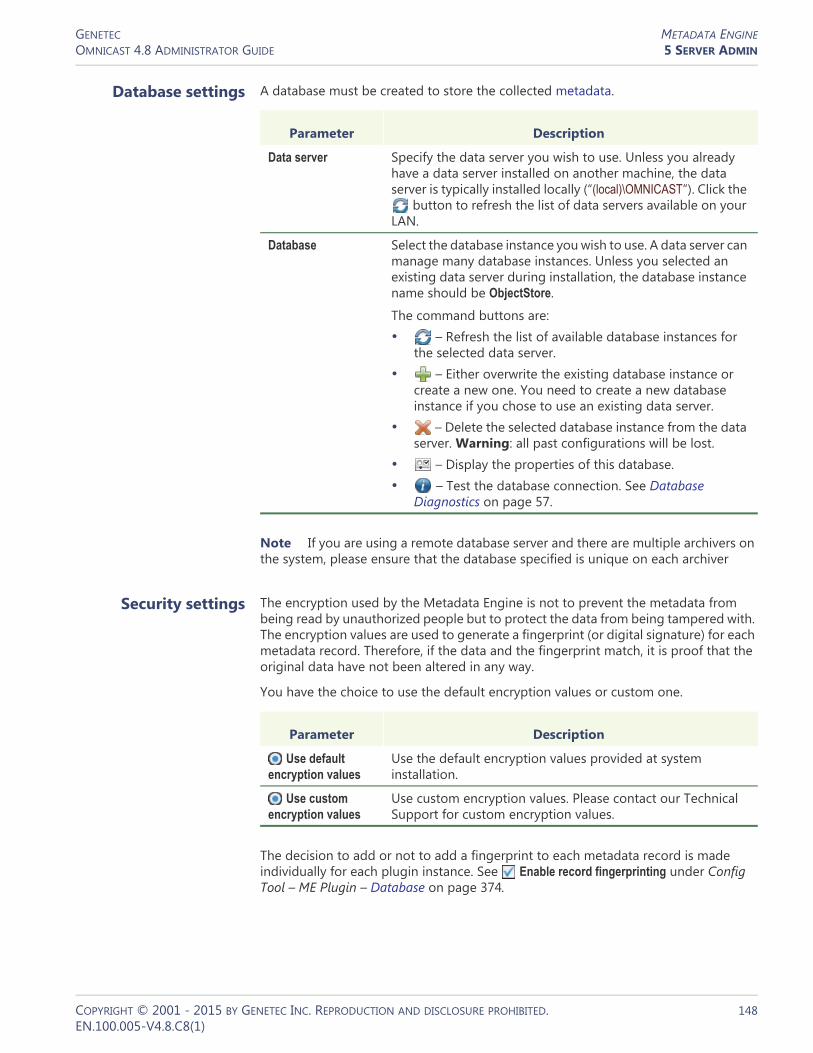
GENETEC METADATA ENGINEOMNICAST 4.8 ADMINISTRATOR GUIDE 5 SERVER ADMIN
Database settings A database must be created to store the collected metadata.
Note If you are using a remote database server and there are multiple archivers on the system, please ensure that the database specified is unique on each archiver
Security settings The encryption used by the Metadata Engine is not to prevent the metadata from being read by unauthorized people but to protect the data from being tampered with. The encryption values are used to generate a fingerprint (or digital signature) for each metadata record. Therefore, if the data and the fingerprint match, it is proof that the original data have not been altered in any way.
You have the choice to use the default encryption values or custom one.
The decision to add or not to add a fingerprint to each metadata record is made individually for each plugin instance. See Enable record fingerprinting under Config Tool – ME Plugin – Database on page 374.
Parameter Description
Data server Specify the data server you wish to use. Unless you already have a data server installed on another machine, the data server is typically installed locally (“(local)\OMNICAST”). Click the
button to refresh the list of data servers available on your LAN.
Database Select the database instance you wish to use. A data server can manage many database instances. Unless you selected an existing data server during installation, the database instance name should be ObjectStore.
The command buttons are:• – Refresh the list of available database instances for
the selected data server.• – Either overwrite the existing database instance or
create a new one. You need to create a new database instance if you chose to use an existing data server.
• – Delete the selected database instance from the data server. Warning: all past configurations will be lost.
• – Display the properties of this database.• – Test the database connection. See Database
Diagnostics on page 57.
Parameter Description
Use default encryption values
Use the default encryption values provided at system installation.
Use custom encryption values
Use custom encryption values. Please contact our Technical Support for custom encryption values.
COPYRIGHT © 2001 - 2015 BY GENETEC INC. REPRODUCTION AND DISCLOSURE PROHIBITED. 148EN.100.005-V4.8.C8(1)

GENETEC METADATA ENGINEOMNICAST 4.8 ADMINISTRATOR GUIDE 5 SERVER ADMIN
Plugins
Description The Plugins tab lists all the ME plugins currently installed on the local machine.
ME plugins typically come in separate InstallShields. All ME plugins must be installed on the Metadata Engine server that is hosting them. After a new plugin installation, the Metadata Engine must be restarted.
The fact that a plugin is installed on a machine does not automatically warrant its usage. In order to use a plugin, your Directory license must permit its use, and you must explicitly create a ME plugin instance and associate it with cameras. See Config Tool – ME Plugin – Creating ME plugins on page 373.
For information on what ME plugins are available and what they can do, see About Omnicast plugin manuals on page iii.
COPYRIGHT © 2001 - 2015 BY GENETEC INC. REPRODUCTION AND DISCLOSURE PROHIBITED. 149EN.100.005-V4.8.C8(1)

GENETEC VIRTUAL MATRIXOMNICAST 4.8 ADMINISTRATOR GUIDE 5 SERVER ADMIN
Virtual Matrix
Introduction
The Virtual Matrix (VM) is the Omnicast server application that provides all of the functionality that one expects from an traditional CCTV matrix without the hardware limitations associated with it. Unlike its hardware counterparts, the Virtual Matrix offers an infinite number of inputs/outputs. Through the Virtual Matrix, legacy hardware can be seamlessly integrated to the new IP solution.
Multiple instances of Virtual Matrix may be running on the same system, but their use must be granted by the Number of Virtual Matrices option of your Omnicast license. See Directory options on page 47.
The local settings of the Virtual Matrix are found in the following tabs.
The machine independent parameters of this server application are configured with the Config Tool. See Virtual Matrix on page 455.
General
Description The General tab is used to configure the essential parameters of the Virtual Matrix.
Icon Tab Description
General System name, database and security configurations.
Plugins Installed plugins.
COPYRIGHT © 2001 - 2015 BY GENETEC INC. REPRODUCTION AND DISCLOSURE PROHIBITED. 150EN.100.005-V4.8.C8(1)

GENETEC VIRTUAL MATRIXOMNICAST 4.8 ADMINISTRATOR GUIDE 5 SERVER ADMIN
General settings General settings for the Virtual Matrix.
Plugins
Description The Plugins tab lists all the VM plugins currently installed on the local machine. It also allows you to install new ones or uninstall the existing ones.
VM plugins typically come in separate InstallShields so you do not need to install them here. The fact that a plugin is installed on a machine does not automatically warrant its usage.
In order to use a plugin, your Directory license must permit its use, and you must explicitly create a VM plugin instance and associate it with cameras. See Config Tool – VM Plugin – Creating VM plugins on page 368.
For information on what VM plugins are available and what they can do, please refer to About Omnicast plugin manuals on page iii.
Parameter Description
Gateway Name of the Gateway that the Virtual Matrix must use to connect to the Directory. If the Gateway and the Virtual Matrix are installed on the same machine, leave this field blank.
Network card Select the network card used for Omnicast if your machine is equipped with more than one network card.
Video port Starting port number used by the Virtual Matrix for video connections used for camera sequences.
COPYRIGHT © 2001 - 2015 BY GENETEC INC. REPRODUCTION AND DISCLOSURE PROHIBITED. 151EN.100.005-V4.8.C8(1)
SECTION 6
CONFIG TOOL
Config Tool reference guide

GENETEC CONFIG TOOL OVERVIEWOMNICAST 4.8 ADMINISTRATOR GUIDE 6 CONFIG TOOL
Config Tool Overview
Introduction
Description The Config Tool is the primary companion of the Omnicast administrator. It takes care of all the security and configuration needs of the system. It allows security managers to program intelligent and sophisticated system behaviors to handle virtually any type of situation.
Aspects of system configuration
Omnicast system configuration covers the following aspects.• System access security• Failover configuration• Hardware device configuration• Video streaming and recording management• Archive management• Event and Alarm management• Federation management• Plugin and macro management
COPYRIGHT © 2001 - 2015 BY GENETEC INC. REPRODUCTION AND DISCLOSURE PROHIBITED. 153EN.100.005-V4.8.C8(1)

GENETEC CONFIG TOOL OVERVIEWOMNICAST 4.8 ADMINISTRATOR GUIDE 6 CONFIG TOOL
Workspace
Description The Config Tool workspace is divided into four main areas.
Main menu The Config Tool main menu is a standard Windows menu. Menus support keyboard shortcuts. Certain commands, such as configuring the Directory failover, can only be reached through the menu. For a complete reference, read Config Tool Menu on page 164.
Main toolbar The Config Tool main toolbar is described below.
The Application Control Panel is the same in all three client applications. It shows the connection status, the current date and time, the CPU gauge, the Video memory gauge, and the volume control . When system pop-up messages are not acknowledged within 10 seconds, they are automatically moved to the Missed notification log. Click the button to view this log.
The Entity Display Panel shows at all times which entity you are currently viewing or editing. The Undo and Apply buttons are enabled when you make changes to an entity's configuration.
Configuration paneConfiguration pane
Main menuMain menuMain toolbarMain toolbar
View selection
pane
View selection
pane
Application Control Panel Entity Display Panel
Logon/logoff Missed notification log
COPYRIGHT © 2001 - 2015 BY GENETEC INC. REPRODUCTION AND DISCLOSURE PROHIBITED. 154EN.100.005-V4.8.C8(1)

GENETEC CONFIG TOOL OVERVIEWOMNICAST 4.8 ADMINISTRATOR GUIDE 6 CONFIG TOOL
View selection pane The View selection pane (lower left) offers various viewing schemes for you to organize and edit the system elements. They are:
Using the View selection pane
To select a view, click the view selector in the View selection pane or use the Config Tool’s View menu.
Click the button to show a pop-up menu allowing you to filter the displayed entities in the tree by entity types.
To view the detailed configuration of an entity, select it from the entity tree shown in the View selection pane. Its configuration page will appear in the right pane of the Config Tool. See Configuration pane on page 156.
TIP If you have trouble finding an entity in any of the above views, call up the Entity Search tool by clicking the button or by typing <Ctrl>+<F>.See Entity Search Tool on page 159.
Icon View Description
Logical View The Logical view organizes the system's entities into a hierarchy of logical groupings called sites. It is through this view that you define how the entities are organized in the Camera pane and the Analog monitor pane of the Live Viewer and the Archive Player.
See Logical View on page 161.
Physical View The Physical view shows the server applications available in the system along with the physical devices they control. The entities are structured in a hierarchy according to their physical relationships.
See Physical View on page 163.
User Management The User Management view allows you to control all aspects of access security of the system through users and user groups entities.
Schedule Management
The Schedule Management view allows you to configure all scheduling entities in the system such as generic schedules, archiving schedules and macro schedules.
Alarm Management
The Alarm Management view puts together all entities pertaining to alarm management, such as alarms, camera groups and monitor groups.
Virtual Matrix Management
The Virtual Matrix Management view groups in a single location all entities directly controlled by a Virtual Matrix, such as camera sequences, CCTV keyboards, hardware matrices and access control systems.
Add-In Management
The Add-In Management view shows all macros and plugins defined in the system.
Federation Management
This view shows all federated Directories and their corresponding federated entities.
COPYRIGHT © 2001 - 2015 BY GENETEC INC. REPRODUCTION AND DISCLOSURE PROHIBITED. 155EN.100.005-V4.8.C8(1)

GENETEC CONFIG TOOL OVERVIEWOMNICAST 4.8 ADMINISTRATOR GUIDE 6 CONFIG TOOL
View selection pane contextual menu
All eight views share the same contextual menu and the same action buttons. The individual commands are explained below.
Configuration pane The Configuration pane presents a detailed view of the selected entity in the View selection pane (on the left). Every configurable entity has a name and a description in Omnicast. The specific settings depend on the selected entity type.
See Entity Configuration on page 157.
Customizing your workspace
The size of the two major panes at the bottom of the Config Tool workspace can be resized at wish. Simply click on the edge separating the two panes and drag it to the left or to the right. Unlike the Live Viewer and the Archive Player, no part of the Config Tool workspace can be hidden from view.
See View menu on page 166 for more information on customizing your workspace.
Command Description
Create Creates a new entity in the system. See the description of the Create command in Action menu on page 165. Same as the button.
Rename Renames the selected entity.
Delete Deletes the selected entity. Note that you cannot delete a discovered device (i.e. a unit or any of its attached devices) unless it is inactive (appears in red). Same as the button.
Copy Entities Copies the configuration of the selected entity for the purpose of pasting it. This command works only with user defined entities.
Paste Entities Pastes the last copied entity. The new entity will be named Copy of <old entity name>. This command works only with user defined entities.
Block Cameras See the description of the Block Cameras command in Tools menu on page 167.
Copy Config See the description of the Copy Configuration Tool in Copy Configuration Tool on page 180.
Sort Entities Sorts the elements either by type or by name. Note that the sorting order only applies to the elements within the same hierarchy level.
Refresh Tree Refreshes the tree structure. Same as the button.
Remove unit from Archiver
This command only appears when the selected entity is a unit that do not support automatic discovery. Therefore, if such a unit is added by mistake to an Archiver, the only way to correct the mistake is to use this command.
COPYRIGHT © 2001 - 2015 BY GENETEC INC. REPRODUCTION AND DISCLOSURE PROHIBITED. 156EN.100.005-V4.8.C8(1)

GENETEC CONFIG TOOL OVERVIEWOMNICAST 4.8 ADMINISTRATOR GUIDE 6 CONFIG TOOL
Entity Configuration
Identity The Identity tab is the first tab shown in the Configuration pane of every entity (with the exception of the Directory). The following screen shot shows the Identity tab of the Camera entity as an illustration.
The following parameters are shared by all entities.
Parameter Description
Type Entity type. The icon corresponding to the entity type is always shown in the background.
Name Entity name. In most cases, the entity name is editable, except when it is a software entity (Omnicast service).
Description The description is an optional text describing the entity. This field is blank and non-editable for all software entities.
Logical ID The Logical ID is a numerical identifier assigned to each entity by the system. It can be modified by the user but it must remain unique within the same category of entities. See also Directory – Logical IDs on page 299.
Logical parent The logical parent is the entity that is directly above the selected entity in the Logical View. Click the Find button to jump to the configuration of the logical parent. If the entity has more than one logical parent, the static field will change into a drop down list.
Physical parent The physical parent is the entity that is directly above the selected entity in the Physical View. Click the Find button to jump to the configuration of the physical parent.
COPYRIGHT © 2001 - 2015 BY GENETEC INC. REPRODUCTION AND DISCLOSURE PROHIBITED. 157EN.100.005-V4.8.C8(1)

GENETEC CONFIG TOOL OVERVIEWOMNICAST 4.8 ADMINISTRATOR GUIDE 6 CONFIG TOOL
Configurable entities Alphabetical list of all configurable entities in Omnicast.• – Access Control System on page 183• – Alarm on page 186• – Analog Monitor (Video Decoder) on page 198• – Archiver on page 204• – Archiving Schedule on page 220• – Auxiliary Archiver on page 223• – Backup Set on page 235• – Camera (Video Encoder) on page 237• – Camera Group on page 280• – Camera Sequence on page 282• – CCTV Keyboard on page 288• – Digital Input on page 291• – Directory on page 294• – Directory Failover Coordinator on page 307• – Federated Directory on page 310• – Federation Server on page 316• – Gateway on page 319• – Generic Schedule on page 324• – Ghost Camera on page 333• – Hardware Matrix on page 334• – Live Viewer Plugin on page 375• – Macro on page 341• – Macro Schedule on page 353• – Metadata Engine on page 350• – Metadata Engine Plugin on page 372• – Microphone (Audio Encoder) on page 356• – Monitor Group on page 361• – Output Relay on page 364• – Alarm on page 186• – PTZ Motor on page 381• – Restore Archiver on page 390• – Serial Port on page 392• – Site on page 395• – Speaker (Audio Decoder) on page 401• – Unit on page 404• – User on page 418• – User Group on page 445• – Viewer Layout on page 451• – Virtual Camera on page 452• – Virtual Matrix on page 455• – Virtual Matrix Plugin on page 368
COPYRIGHT © 2001 - 2015 BY GENETEC INC. REPRODUCTION AND DISCLOSURE PROHIBITED. 158EN.100.005-V4.8.C8(1)

GENETEC CONFIG TOOL OVERVIEWOMNICAST 4.8 ADMINISTRATOR GUIDE 6 CONFIG TOOL
Entity Search Tool
Finding a particular entity among tens of thousands could be a daunting task. To help you in your search, Omnicast offers you the Entity Search tool. This tool is available everywhere a tree structure is displayed. It has two usage methods described below.
Local search The first method is called Local search. It is used to find an entity within the context of the current entity tree. Perform a search as follows.1 Specify your context by clicking on an entity tree.2 Click the button (upper right corner) or type <Ctrl>+<F>. The Search controls
appear at the bottom of the tree.
3 Enter a particular text that you wish to find in the entity’s name and click to find the first match.The search is not case sensitive. If an entity's name matches the text you entered, it will be selected in the tree.
4 Continue to click on either or to find all the matches.5 Click the Close button to hide the search controls.
If you wish to search the entire Directory or to find a match in the entity description, use the Global search instead (see next).
Global search To use the Global search, use one of the following methods:– From the Local search controls, click the Global search button.– Select Tools > Entity search from the main menu.
Find the previous match Find the next match
Close
Global search*
COPYRIGHT © 2001 - 2015 BY GENETEC INC. REPRODUCTION AND DISCLOSURE PROHIBITED. 159EN.100.005-V4.8.C8(1)

GENETEC CONFIG TOOL OVERVIEWOMNICAST 4.8 ADMINISTRATOR GUIDE 6 CONFIG TOOL
The Entity Search dialog appears.
To perform a search from the Entity Search dialog, do as follows:1 Type in the field Search for, the name (or partial name) of the entity you are looking
for. The search is not case sensitive.2 Select from the Search in drop-down list, where you want the match to be found:
in Entity name only, or in Entity name and description.3 Select from the Restrict search to drop-down list, the type of entities you are looking
for. Select All types if you want to search them all.4 Click on Search under drop-down list to reveal the site hierarchy.
5 Select the site under which you wish to perform the search, or All to search the entire system.
Click to reveal the site hierarchy
COPYRIGHT © 2001 - 2015 BY GENETEC INC. REPRODUCTION AND DISCLOSURE PROHIBITED. 160EN.100.005-V4.8.C8(1)
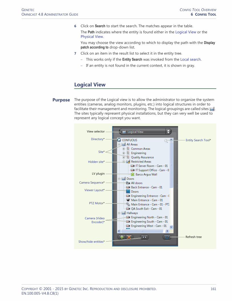
GENETEC CONFIG TOOL OVERVIEWOMNICAST 4.8 ADMINISTRATOR GUIDE 6 CONFIG TOOL
6 Click on Search to start the search. The matches appear in the table.The Path indicates where the entity is found either in the Logical View or the Physical View.You may choose the view according to which to display the path with the Display patch according to drop-down list.
7 Click on an item in the result list to select it in the entity tree.– This works only if the Entity Search was invoked from the Local search.– If an entity is not found in the current context, it is shown in gray.
Logical View
Purpose The purpose of the Logical view is to allow the administrator to organize the system entities (cameras, analog monitors, plugins, etc.) into logical structures in order to facilitate their management and monitoring. The logical groupings are called sites . The sites typically represent physical installations, but they can very well be used to represent any logical concept you want.
View selector
Directory*
Site*
Camera (Video Encoder)*
Camera Sequence*
Viewer Layout*
PTZ Motor*
LV plugin
Show/hide entities*
Entity Search Tool*
Refresh tree
Hidden site*
COPYRIGHT © 2001 - 2015 BY GENETEC INC. REPRODUCTION AND DISCLOSURE PROHIBITED. 161EN.100.005-V4.8.C8(1)

GENETEC CONFIG TOOL OVERVIEWOMNICAST 4.8 ADMINISTRATOR GUIDE 6 CONFIG TOOL
The sites can be nested to form hierarchical structures. Shown below are two examples of logical groupings. The hierarchy to the left represents physical installations while the hierarchy to the right represents security concepts (common areas vs. restricted areas).
The logical structure defined here is what a user would see in the Camera tree and Analog monitor tree of the Live Viewer (tree structures showing only entities that can be viewed from the Live Viewer).
The second usage of the Logical View is to control the user's access rights to different system resources. You can easily hide a group of resources from a user by removing his permission to access one branch of the hierarchy. All resources under that branch will then become inaccessible to that user. See User – Permissions on page 422.
Hidden site Hidden sites can be used to hide the existence of covert cameras from Config Tool users who normally would be able to access all entities in the system. See Hidden site on page 397.
Show/hide entities Click the button at the bottom of this pane to pop a contextual menu allowing you to show or hide different types of entities from the Logical view.
Making copies of resources
For resources shared by different groups of users, you can create multiple copies of the same resource under different sites. To achieve this, simply hold the <Ctrl> key while dragging the resource to the site it should belong to. The site that is immediately above an entity in the logical hierarchy is called the Logical parent of that entity. Logical parents are shown in the Identity tab, which is the first tab in every entity's configuration page. See Identity on page 157.
COPYRIGHT © 2001 - 2015 BY GENETEC INC. REPRODUCTION AND DISCLOSURE PROHIBITED. 162EN.100.005-V4.8.C8(1)
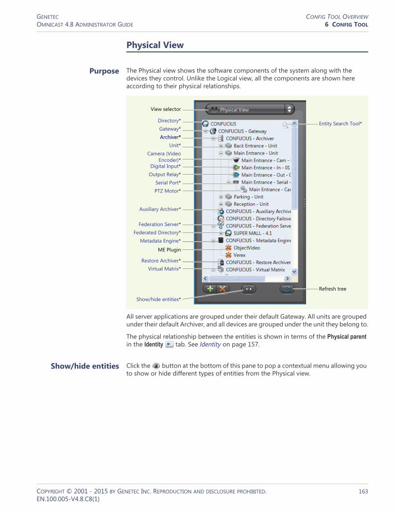
GENETEC CONFIG TOOL OVERVIEWOMNICAST 4.8 ADMINISTRATOR GUIDE 6 CONFIG TOOL
Physical View
Purpose The Physical view shows the software components of the system along with the devices they control. Unlike the Logical view, all the components are shown here according to their physical relationships.
All server applications are grouped under their default Gateway. All units are grouped under their default Archiver, and all devices are grouped under the unit they belong to.
The physical relationship between the entities is shown in terms of the Physical parent in the Identity tab. See Identity on page 157.
Show/hide entities Click the button at the bottom of this pane to pop a contextual menu allowing you to show or hide different types of entities from the Physical view.
View selector
Directory*Gateway*
Digital Input*
Virtual Matrix*
PTZ Motor*Serial Port*
Show/hide entities*
Archiver*Unit*
Output Relay*
Restore Archiver*
ME Plugin
Metadata Engine*
Federation Server*Federated Directory*
Auxiliary Archiver*
Camera (Video Encoder)*
Archiver*
Entity Search Tool*
Refresh tree
COPYRIGHT © 2001 - 2015 BY GENETEC INC. REPRODUCTION AND DISCLOSURE PROHIBITED. 163EN.100.005-V4.8.C8(1)

GENETEC CONFIG TOOL OVERVIEWOMNICAST 4.8 ADMINISTRATOR GUIDE 6 CONFIG TOOL
Config Tool Menu
Introduction The following describes the entire Config Tool menu system.
System menu The System menu is standard for all Omnicast client applications. It lets you connect to a Directory if you have not already done so. Or it lets you disconnect from the current Directory so you can connect to another one.
Submenu Description
System This menu allows you to connect or disconnect from the Directory. See System menu on page 164.
Action This menu allows you to create, rename and delete system entities. It also offers a few very useful commands that are not accessible from anywhere else in the GUI, such as applying the same configuration to a whole list of entities. See Action menu on page 165.
View This menu lets you select the desired view in the View selection pane as well as the sort option (by name or by type). See View menu on page 166.
Tools This menu gives you the commands to start other Omnicast client applications. You will also find in this menu, tools that cannot be accessed from anywhere else in the application, such as the Directory Failover Configuration Wizard. See Tools menu on page 167.
Help This menu lets you access various help functions. See Help menu on page 168.
Command Description (1 of 2)
Connect This command is only available when you are not yet connected to a Directory.
See Connecting to Omnicast in Omnicast Live Viewer User Guide for the different connection options.
Disconnect This command disconnects the Config Tool from its current Directory, but does not exit the application.
Use the Exit command instead if you want to exit the Config Tool.
You need the Change client views privilege to disconnect or exit the application. If you do not have this privilege, you will be prompted to enter the credentials of a user who has it.
Change Password
Allows you to change your own password.
COPYRIGHT © 2001 - 2015 BY GENETEC INC. REPRODUCTION AND DISCLOSURE PROHIBITED. 164EN.100.005-V4.8.C8(1)
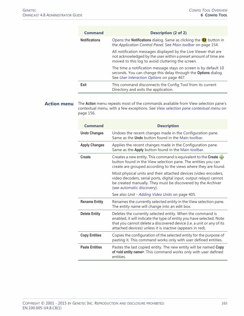
GENETEC CONFIG TOOL OVERVIEWOMNICAST 4.8 ADMINISTRATOR GUIDE 6 CONFIG TOOL
Action menu The Action menu repeats most of the commands available from View selection pane's contextual menu, with a few exceptions. See View selection pane contextual menu on page 156.
Notifications Opens the Notifications dialog. Same as clicking the button in the Application Control Panel. See Main toolbar on page 154.
All notification messages displayed by the Live Viewer that are not acknowledged by the user within a preset amount of time are moved to this log to avoid cluttering the screen.
The time a notification message stays on screen is by default 10 seconds. You can change this delay through the Options dialog. See User Interaction Options on page 467.
Exit This command disconnects the Config Tool from its current Directory and exits the application.
Command Description (2 of 2)
Command Description
Undo Changes Undoes the recent changes made in the Configuration pane. Same as the Undo button found in the Main toolbar.
Apply Changes Applies the recent changes made in the Configuration pane. Same as the Apply button found in the Main toolbar.
Create Creates a new entity. This command is equivalent to the Create button found in the View selection pane. The entities you can create are grouped according to the views where they are found.
Most physical units and their attached devices (video encoders, video decoders, serial ports, digital input, output relays) cannot be created manually. They must be discovered by the Archiver (see automatic discovery).
See also Unit - Adding Video Units on page 405.
Rename Entity Renames the currently selected entity in the View selection pane. The entity name will change into an edit box.
Delete Entity Deletes the currently selected entity. When the command is enabled, it will indicate the type of entity you have selected. Note that you cannot delete a discovered device (i.e. a unit or any of its attached devices) unless it is inactive (appears in red).
Copy Entities Copies the configuration of the selected entity for the purpose of pasting it. This command works only with user defined entities.
Paste Entities Pastes the last copied entity. The new entity will be named Copy of <old entity name>. This command works only with user defined entities.
COPYRIGHT © 2001 - 2015 BY GENETEC INC. REPRODUCTION AND DISCLOSURE PROHIBITED. 165EN.100.005-V4.8.C8(1)

GENETEC CONFIG TOOL OVERVIEWOMNICAST 4.8 ADMINISTRATOR GUIDE 6 CONFIG TOOL
View menu The View menu lets you select the desired view in the View selection pane as well as the sorting order of the elements (by name or by type). You must have Change client views privilege to access the last three commands of this menu.
Command Description Shortcut
Logical View Selects the Logical view. See Logical View on page 161.
<Ctrl>+<1>
Physical View Selects the Physical view. See Physical View on page 163.
<Ctrl>+<2>
User Management
Selects the User Management view. See View selection pane on page 155.
<Ctrl>+<3>
Schedule Management
Selects the Schedule Management view. See View selection pane on page 155.
<Ctrl>+<4>
Alarm Management
Selects the Alarm Management view. See View selection pane on page 155.
<Ctrl>+<5>
Virtual Matrix Management
Selects the Virtual Matrix Management view. See View selection pane on page 155.
<Ctrl>+<6>
Add-In Management
Selects the Add-In Management view. See View selection pane on page 155.
<Ctrl>+<7>
Federation Management
Selects the Federation Management view. See View selection pane on page 155.
<Ctrl>+<8>
Live Video Window
Opens the Live Video window for the selected camera. This can also be achieved by double-clicking on a camera in the View selection pane. See Video stream preview on page 247.
Sort Entities Sorts the entities either by name or by type. Note that the sorting order only applies to the elements within the same hierarchy level.
Refresh Tree Refreshes the entity tree. This command is equivalent to the button found in the View selection pane.
Full Screen Displays the Config Tool without the application border to maximize the display area. Note that the Full Screen mode does more than just maximizing your application window. It also hides the title bar and the task bar.
<F11>
Hide Menu in Full Screen
Hides or shows the Main menu in full screen mode.
Advanced Mode Alternates between Simple and Advanced modes.
In Simple mode, only the most common controls are visible, thus simplifying the user interface for novices.
In Advanced mode, all available controls are visible, thus giving complete control to the experienced users.
<Shift>+ <F10>
COPYRIGHT © 2001 - 2015 BY GENETEC INC. REPRODUCTION AND DISCLOSURE PROHIBITED. 166EN.100.005-V4.8.C8(1)

GENETEC CONFIG TOOL OVERVIEWOMNICAST 4.8 ADMINISTRATOR GUIDE 6 CONFIG TOOL
Tools menu The Tools menu allows you to perform the following functions:
Command Description (1 of 2)
Live Viewer Opens the Live Viewer without having to log on.
Archive Player Opens the Archive Player without having to log on.
Entity Search Opens the Entity Search dialog. See Entity Search Tool on page 159.
Block Cameras Opens the Block cameras dialog which allows you to prevent other less privileged users from viewing selected cameras. See Camera Blocking in Omnicast Live Viewer User Guide.
Test Sounds Opens the Test sounds dialog to hear the available sound files on the system. These are the sound bites that can be played when programming the action Send an alert sound to notify a user of a particular event.
See Appendix B – Omnicast Action Types (sorted by action name) on page 528.
Configure Directory Failover
Opens the Directory Failover Configuration Wizard. See Directory Failover Configuration on page 170.
Copy Configuration Tool
Opens the Copy Configuration Tool. See Copy Configuration Tool on page 180.
COPYRIGHT © 2001 - 2015 BY GENETEC INC. REPRODUCTION AND DISCLOSURE PROHIBITED. 167EN.100.005-V4.8.C8(1)

GENETEC CONFIG TOOL OVERVIEWOMNICAST 4.8 ADMINISTRATOR GUIDE 6 CONFIG TOOL
Help menu The Help menu allows you access various help functions.
Transfer Video Opens the Transfer video dialog. This tool is used when a video encoder (camera) has been replaced. The new device will be detected as a new camera while the old device will become inactive . In order to avoid having two sets of video archives for the same camera, you can transfer the video associated to the inactive device to the new device.
To transfer the video archive from one encoder to another:1 Select the source encoder from the top drop down list. The
source encoder must be a ghost camera or an inactive camera . See Ghost Camera on page 333.
2 Select the destination encoder from the bottom drop-down list.
3 Click OK.
WARNING The two cameras may not have overlapping video files, i.e. covering the same time range. If they do, the transfer will be cancelled and an error message displayed.
Options Opens the Options dialog. See Options Dialog on page 461.
Custom menu items
All menu items listed after Options... in the Tools menu are customizable.
All Omnicast client applications are installed with the custom menu item Launch Field Report Generator. If you ever need to call the technical support for any reason, this command may prove to be very useful. It launches the Field Report Generator, a tool that gathers pertinent information regarding the status of your system that can help the support team diagnose your problem.
See Customizing the Tools Menu on page 181.
Command Description (2 of 2)
Command Description (1 of 3)
Contents Opens the CHM version of this user guide. Same as <F1>.
COPYRIGHT © 2001 - 2015 BY GENETEC INC. REPRODUCTION AND DISCLOSURE PROHIBITED. 168EN.100.005-V4.8.C8(1)

GENETEC CONFIG TOOL OVERVIEWOMNICAST 4.8 ADMINISTRATOR GUIDE 6 CONFIG TOOL
Technical Support
Displays the following dialog:
The Technical support information is useful for contacting Genetec Technical Assistance. The information in this dialog box is saved locally, and can be accessed offline.
Company name: Company that purchased the software license.
System ID: Identification number for the current Directory service. A separate license is required for each computer that runs either the Omnicast Directory service or, the Omnicast Archiver service.
Package name: Name of your software system and the version (for example, Omnicast 4.8).
Expiration: Expiration date of your software license.
OEM: Your Original Equipment Manufacturer (Genetec).
Additional information: Custom information and links, such as the GTAP and Genetec Forum Web sites. You can add your own custom information in the “SupportContactInfo.xml” file, located in: C:\Program Files\Common Files\DVR Software 4.x\Settings\ on 32 bit machines, and C:\Program Files (x86)\Common Files\DVR Software 4.x\Settings\ on 64 bit machines.
NOTE Make sure you edit the “SupportContactInfo.xml” file on the machine where the Directory application is installed, so the information is automatically sent to the rest of your system.
Command Description (2 of 3)
COPYRIGHT © 2001 - 2015 BY GENETEC INC. REPRODUCTION AND DISCLOSURE PROHIBITED. 169EN.100.005-V4.8.C8(1)

GENETEC CONFIG TOOL OVERVIEWOMNICAST 4.8 ADMINISTRATOR GUIDE 6 CONFIG TOOL
Directory Failover Configuration
What is failover? Failover is a backup operational mode in which the functions of a system component (such as the Directory, the Archiver, the Virtual Matrix, for example) are taken on by secondary system components when the primary component becomes unavailable through either failure or scheduled down time.
Used to make systems more fault-tolerant, failover is typically an integral part of mission-critical systems that must be constantly available. The procedure involves automatically off loading tasks to a secondary system component on standby so that the procedure is as seamless as possible to the end user.
About Displays the following dialog:
The License information provided is the following:
Company name: Company that purchased the software license.
System ID: Identification number for the current Directory service. A separate license is required for each computer that runs either the Omnicast Directory service or, the Omnicast Archiver service.
Expiration: Expiration date of your software license.
File versions: Clicking this button lists all the components used by this application and their corresponding software versions.
The version number of the application and its DLLs are displayed for troubleshooting purposes. THEY MUST ALL BE THE SAME! If they are not all the same, it may be due to the uninstallation of a previous version that did not complete successfully, followed by an upgrade to a newer version.
License: Clicking this button lists the copyright information for open source libraries used in Omnicast software.
Command Description (3 of 3)
COPYRIGHT © 2001 - 2015 BY GENETEC INC. REPRODUCTION AND DISCLOSURE PROHIBITED. 170EN.100.005-V4.8.C8(1)

GENETEC CONFIG TOOL OVERVIEWOMNICAST 4.8 ADMINISTRATOR GUIDE 6 CONFIG TOOL
In Omnicast, failover is applied to the following services:• Directory and Gateway• Archiver• Virtual Matrix• Metadata Engine
Directory failover The present chapter only describes the Directory failover mechanism. The Directory failover is configured using the tool called Directory Failover Configuration Wizard, hereafter abbreviated as the Wizard. To learn about the failover configuration of other Omnicast services, please follow the links below: • Archiver – See Unit – Standby Archivers on page 416. • Virtual Matrix – See Virtual Matrix – Standby Virtual Matrices on page 459.
The Wizard is invoked from the Tools menu. There are two ways to configure the Directory failover. You can either let the Wizard set up everything for you by choosing the default failover configuration or configure everything yourself manually by letting the Wizard guide you through the configuration steps.
Default failover configuration
The easiest way to configure the Directory failover is to use the default configuration. It is recommended for most Omnicast installations, namely, installations confined to a single LAN where all Directory servers are equivalent machines.
COPYRIGHT © 2001 - 2015 BY GENETEC INC. REPRODUCTION AND DISCLOSURE PROHIBITED. 171EN.100.005-V4.8.C8(1)

GENETEC CONFIG TOOL OVERVIEWOMNICAST 4.8 ADMINISTRATOR GUIDE 6 CONFIG TOOL
Directory failover list Most settings in the default failover configuration have already been pre-set for you. The only element that you need to configure yourself is the Directory failover list. This list defines: (1) which Directories are involved in the failover; and (2) the order in which the Directories are to successively stand in for each other.
NOTE When a new Directory server is added to the system, it will appear as not selected in the list. You must explicitly select it to make it part of the failover list.
The Directory at the top of the list is called the primary Directory. It is the one that will be running in normal situations. The rest of the Directories in the list are called secondary Directories. They serve as backups in case the primary Directory becomes unavailable. Only one Directory should be running at any given time. The Directory that is presently running is referred to as the current Directory.To change the order of the servers in the failover list, select a DFC in the failover list and use the and buttons to move it up or down.
Directory Failover Coordinator
The Directory Failover Coordinator (DFC) is the guardian of the Directory server. There must be one DFC installed on every Directory server that take part in the failover list. The DFCs remain in constant communication with each other, mirroring all changes made to the failover list and to the two databases managed by the Directory service. See Directory database on page 56.
When the current Directory service becomes unavailable, the next one in the Directory failover list will be started by its failover coordinator. This process can continue until there is no more server available in the Directory failover list.
When a Directory server becomes available, and is currently the highest priority server in the Directory failover list, its local DFC will automatically start its local Directory service and update its Alarm database. At the same time, the DFC on the currently running Directory server will stop its local Directory service so that the higher priority Directory can take the current Directory role.
WARNING The synchronization of the Directory database (DirectorySQL) is always carried out in one direction for performance reasons, i.e. from the primary Directory to the secondary Directories. This means that all the changes made to the entity configurations while the secondary Directory was online will be lost when the primary Directory is restored to service.To avoid loosing any important configuration data, before reinstating a Directory database, make sure to restore it from a recent backup of the current Directory.You do not need to worry about the Alarm database (AlarmSQL). The DFC will automatically synchronize it with the most recent updates.
Directory scope A Directory can be configured with a global or local scope. A global Directory is one that serves the entire system, while a local Directory is only intended to serve a subset of the Omnicast applications, typically within the same LAN. Therefore, on a very large Omnicast system extending over multiple LANs, the primary Directory can be backed up by a multitude of local secondary Directories. When the primary Directory goes offline, all local Directories will start simultaneously, each serving its own LAN. Note that the scope of the primary Directory must always be global.
NOTE With the default failover configuration, all Directories are global.
COPYRIGHT © 2001 - 2015 BY GENETEC INC. REPRODUCTION AND DISCLOSURE PROHIBITED. 172EN.100.005-V4.8.C8(1)

GENETEC CONFIG TOOL OVERVIEWOMNICAST 4.8 ADMINISTRATOR GUIDE 6 CONFIG TOOL
Local address, public address and port
The local and public addresses are the two IP addresses configured for each Directory server in the Server Admin. The public address is used to allow DFCs located on different LANs to communicate with each other. See Server Admin – System – Network on page 54.
The port number corresponds to the TCP command port that the DFC listens to. See Server Admin – Directory Failover Coordinator – Configuration on page 73.
Manual Failover Configuration
Although the default failover configuration will satisfy most Omnicast installations, there may be cases where it would be better to configure the failover manually. Some common reasons are:• Not enough budget to duplicate all mission-critical servers which are often
expensive high-end servers. • The system is distributed over several regional offices running on separate LANs
and you wish to continue to operate the regional offices even when the link to the corporate LAN fails.
COPYRIGHT © 2001 - 2015 BY GENETEC INC. REPRODUCTION AND DISCLOSURE PROHIBITED. 173EN.100.005-V4.8.C8(1)

GENETEC CONFIG TOOL OVERVIEWOMNICAST 4.8 ADMINISTRATOR GUIDE 6 CONFIG TOOL
To illustrate the manual failover configuration, let's consider the following sample system. The sample system is distributed over three LANs, #1, #2 and #3, where LAN #1 is the corporate LAN and LAN #2 and #3 are remote LANs.
COPYRIGHT © 2001 - 2015 BY GENETEC INC. REPRODUCTION AND DISCLOSURE PROHIBITED. 174EN.100.005-V4.8.C8(1)
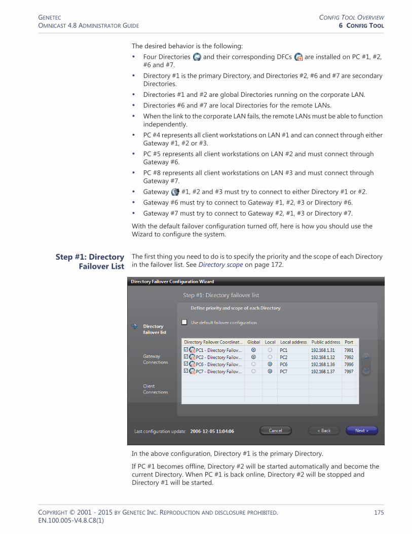
GENETEC CONFIG TOOL OVERVIEWOMNICAST 4.8 ADMINISTRATOR GUIDE 6 CONFIG TOOL
The desired behavior is the following:• Four Directories and their corresponding DFCs are installed on PC #1, #2,
#6 and #7. • Directory #1 is the primary Directory, and Directories #2, #6 and #7 are secondary
Directories. • Directories #1 and #2 are global Directories running on the corporate LAN. • Directories #6 and #7 are local Directories for the remote LANs. • When the link to the corporate LAN fails, the remote LANs must be able to function
independently. • PC #4 represents all client workstations on LAN #1 and can connect through either
Gateway #1, #2 or #3. • PC #5 represents all client workstations on LAN #2 and must connect through
Gateway #6. • PC #8 represents all client workstations on LAN #3 and must connect through
Gateway #7. • Gateway #1, #2 and #3 must try to connect to either Directory #1 or #2. • Gateway #6 must try to connect to Gateway #1, #2, #3 or Directory #6. • Gateway #7 must try to connect to Gateway #2, #1, #3 or Directory #7.
With the default failover configuration turned off, here is how you should use the Wizard to configure the system.
Step #1: Directory Failover List
The first thing you need to do is to specify the priority and the scope of each Directory in the failover list. See Directory scope on page 172.
In the above configuration, Directory #1 is the primary Directory.
If PC #1 becomes offline, Directory #2 will be started automatically and become the current Directory. When PC #1 is back online, Directory #2 will be stopped and Directory #1 will be started.
COPYRIGHT © 2001 - 2015 BY GENETEC INC. REPRODUCTION AND DISCLOSURE PROHIBITED. 175EN.100.005-V4.8.C8(1)

GENETEC CONFIG TOOL OVERVIEWOMNICAST 4.8 ADMINISTRATOR GUIDE 6 CONFIG TOOL
If both PC #1 and #2 become offline (e.g. WAN failure), Directory #6 and #7 will take over simultaneously. Clients on LAN #2 and #3 will continue to view live and archived videos managed by Archivers on their respective LAN but will not be able to view videos managed on any of the two other LANs.
If either PC #1 or PC #2 comes back online, Directory #6 and #7 will be stopped automatically by their respective DFCs and all online applications will reconnect to the running global Directory.
Step #2: Gateway Connections
Since Gateways are the only links to the Directory for all other applications, you need to specify how each Gateway is to find the current Directory. This is the object of Step #2.
A Gateway can connect to the current Directory either directly or indirectly. When both services are located on the same LAN, the Gateway can connect directly to the Directory. When they are located on different LANs, the Gateway must go through another Gateway. The ordered list of services (either Directory or Gateway) that the Gateway must try in order to find the current Directory is called the Directory access path.
The following screen capture shows the configuration for Gateway #1, i.e. the Gateway installed on PC #1.
Note that Gateway #1 is only going to try Directory #1 and #2, the only two services that are selected . The services that are not selected are not part of the Directory access path. Gateway #1 is connecting directly to Directory #1 and #2 because they are located on the same LAN.
The configurations for Gateway #2 and #3 are similar to the one for Gateway #1. Simply interchange Gateway #1 and #2 to get the configuration for Gateway #2, and interchange Gateway #1 and Gateway #3 to get the configuration for Gateway #3.
COPYRIGHT © 2001 - 2015 BY GENETEC INC. REPRODUCTION AND DISCLOSURE PROHIBITED. 176EN.100.005-V4.8.C8(1)

GENETEC CONFIG TOOL OVERVIEWOMNICAST 4.8 ADMINISTRATOR GUIDE 6 CONFIG TOOL
The configuration of Gateway #6 is somewhat different. See screen capture below.
Note that Gateway #6 cannot connect to the global Directories (#1 and #2) directly because they are not located on the same LAN. It must go through one of the Gateways that are located on the same LAN as the global Directories, namely Gateway #1, #2 and #3. In the case the link to the corporate LAN is down, Gateway #6 will fall back on the local Directory #6. When this happens, LAN #2 will operate temporarily as an independent subsystem.
The configuration for Gateway #7 is similar to the one for Gateway #6. Simply interchange PC #6 and PC #7 to get the configuration for Gateway #7.
NOTE Using the default failover configuration is equivalent to using the Directory failover list as the Directory access path for all Gateways on the system.
Step #3: Client Connections
The third step is used to instruct the client applications what to do when the Gateway they request is not available. For each Gateway in the system, you need to specify a list of alternative choices when it is not available. This list of alternative choices is called the Gateway backup list.
COPYRIGHT © 2001 - 2015 BY GENETEC INC. REPRODUCTION AND DISCLOSURE PROHIBITED. 177EN.100.005-V4.8.C8(1)

GENETEC CONFIG TOOL OVERVIEWOMNICAST 4.8 ADMINISTRATOR GUIDE 6 CONFIG TOOL
The following screen capture shows the configuration for Gateway #1.
Note that in Gateway #1 backup list, only Gateway #2 and Gateway #3 are available as alternative choices, this is because these three Gateways are located on the same corporate LAN. It would make no sense for the Gateway #1 to failover to Gateway #6 or Gateway #7 which are located on remote LANs.
Similarly, Gateway #2 should have Gateway #1 and Gateway #3 as backups, and Gateway #3 should have Gateway #1 and Gateway #2 as backups.
For Gateways located on remote LANs such as Gateway #6 and #7, no backup list is available. See picture below. The system "knows" that a Gateway is located on a remote LAN when its Directory access path starts with another Gateway. See Step #2: Gateway Connections on page 176.
COPYRIGHT © 2001 - 2015 BY GENETEC INC. REPRODUCTION AND DISCLOSURE PROHIBITED. 178EN.100.005-V4.8.C8(1)

GENETEC CONFIG TOOL OVERVIEWOMNICAST 4.8 ADMINISTRATOR GUIDE 6 CONFIG TOOL
Limitations A corporate Gateway cannot have a remote Gateway in its backup list, and a remote Gateway cannot have a corporate Gateway in its backup list.
A second limitation is that the remote Gateway cannot have any backup list, even if more Gateways are installed on the same remote LAN.
The above limitations only apply to the failover. For example, if Gateway #6 is offline, nothing prevents a user located on LAN #2 to explicitly connect to a Gateway located on LAN #1.
COPYRIGHT © 2001 - 2015 BY GENETEC INC. REPRODUCTION AND DISCLOSURE PROHIBITED. 179EN.100.005-V4.8.C8(1)

GENETEC CONFIG TOOL OVERVIEWOMNICAST 4.8 ADMINISTRATOR GUIDE 6 CONFIG TOOL
Copy Configuration Tool
Introduction The Copy Configuration Tool lets you copy the configuration of a selected entity to a list of entities of the same type. This dialog is also available from the contextual menu of the View selection pane.
Source and destination
considerations
The configuration of most entity types can be copied onto entities of the same type. For some entity types, however, such as cameras and units, there may be settings from a particular manufacturer that cannot be copied onto entities that do not offer the same settings.
In these cases, the following logic applies:• Every setting in a particular group of Options (for example, Recording or Network) in
the source entity must exist in the destination entity for values to be copied. Otherwise no values are copied. Each group of Options includes the settings from the corresponding tab in the entity’s configuration page.
• Each set of Options is treated separately. For example, if three out of four groups of options are the same between a source and its destination(s), values from these three groups are copied, while the fourth group remains unchanged on the destination entities.
• The value range of settings is not, in general, taken into account. So copied settings can result in configurations with values that are out of bounds.
• An exception to the above point concerns the Video data format of cameras, which is part of the Video quality options. In this case, the value of the source Video data format must be valid for the destination(s) or the whole group of Video quality settings will not be applied.
• When copying the Video quality options, multiple video streams are each treated independently and copied from the source entity to the destination(s). If there are more video streams on a destination than on a source, the configuration of these additional streams are preserved.
COPYRIGHT © 2001 - 2015 BY GENETEC INC. REPRODUCTION AND DISCLOSURE PROHIBITED. 180EN.100.005-V4.8.C8(1)

GENETEC CONFIG TOOL OVERVIEWOMNICAST 4.8 ADMINISTRATOR GUIDE 6 CONFIG TOOL
Copy configuration from a source to
destination(s)
To copy the configuration of the selected entity do the following:1 Select the type of entity you wish to copy. This will determine the available copy
options.2 Select the entity you wish to copy the configuration from.3 Select the copy Options, i.e. the groups of settings you wish to copy.
To select all Options, click the Select All button.To remove all Options, click the Clear All button.
4 Select the entities you wish to copy the configuration to. When selecting entities with available settings that vary from the source, you can refer to Source and destination considerations on page 180.– To select all entities, click the Select All button.– To remove all entities, click the Clear All button.– You can also, for example, select or clear the Directory check box to select
or remove all of the Directory’s entities.5 Click Apply.
– The values of settings from the selected groups of Options are copied from the selected source entity to the selected destinations.
– You are prompted if no options can be copied, or if only particular groups of options cannot. In the latter case, the type of options that cannot be copied to one or more of the destinations, such as Video quality and Specific Settings, are listed.
Customizing the Tools Menu
Introduction The Tools menu of the client applications can be customized by the user. All custom menu items are added after the Options command in the Tools menu.
At installation, all three client applications come standard with two custom items added to the Tools menu: Launch Field Report Generator and Language Tool. The system administrator may choose to remove it, to rename it or to add other custom items to the menu.
The .ini file Custom menu items are configured in the omnicast.ini file located in the directory where the client applications are installed, typically "C:\Program Files\Common Files\DVR Software x.y".
The custom menu items are specified under the section [CustomMenu] of that file. Each custom menu item is specified by three fields:
Field Description
Textn Text to show in the Tools menu for the nth custom menu item.
COPYRIGHT © 2001 - 2015 BY GENETEC INC. REPRODUCTION AND DISCLOSURE PROHIBITED. 181EN.100.005-V4.8.C8(1)

GENETEC CONFIG TOOL OVERVIEWOMNICAST 4.8 ADMINISTRATOR GUIDE 6 CONFIG TOOL
An example The following specifications:
[CustomMenu] Text1=Calculator Command1=calc Apps1=7 Text2=Notepad Command2=notepad Apps2=6 Text3=Paint Command3=mspaint Apps3=2
will produce the following custom menu items in the Live Viewer Tools menu.
while the Archive Player will only show Calculator and Notepad, and the Config Tool will only show Calculator.
Commandn The command associated to the nth custom menu item.
Appsn The applications in which this custom menu item should appear. This field is optional (default = All three applications).• 1 = Config Tool• 2 = Live Viewer• 3 = Config Tool and Live Viewer• 4 = Archive Player• 5 = Archive Player and Config Tool• 6 = Archive Player and Live Viewer• 7 = All three applications
Field Description
COPYRIGHT © 2001 - 2015 BY GENETEC INC. REPRODUCTION AND DISCLOSURE PROHIBITED. 182EN.100.005-V4.8.C8(1)
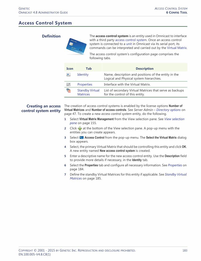
GENETEC ACCESS CONTROL SYSTEMOMNICAST 4.8 ADMINISTRATOR GUIDE 6 CONFIG TOOL
Access Control System
Definition
The access control system is an entity used in Omnicast to interface with a third party access control system. Once an access control system is connected to a unit in Omnicast via its serial port, its commands can be interpreted and carried out by the Virtual Matrix.
The access control system’s configuration page comprises the following tabs.
Creating an access control system entity
The creation of access control systems is enabled by the license options Number of Virtual Matrices and Number of access controls. See Server Admin – Directory options on page 47. To create a new access control system entity, do the following.1 Select Virtual Matrix Management from the View selection pane. See View selection
pane on page 155.2 Click at the bottom of the View selection pane. A pop-up menu with the
entities you can create appears.3 Select Access Control from the pop-up menu. The Select the Virtual Matrix dialog
box appears.4 Select, the primary Virtual Matrix that should be controlling this entity and click OK.
A new entity named New access control system is created.5 Enter a descriptive name for the new access control entity. Use the Description field
to provide more details if necessary, in the Identity tab.6 Select the Properties tab and configure all necessary information. See Properties on
page 184.7 Define the standby Virtual Matrices for this entity if applicable. See Standby Virtual
Matrices on page 185.
Icon Tab Description
Identity Name, description and positions of the entity in the Logical and Physical system hierarchies.
Properties Interface with the Virtual Matrix.
Standby Virtual Matrices
List of secondary Virtual Matrices that serve as backups for the control of this entity.
COPYRIGHT © 2001 - 2015 BY GENETEC INC. REPRODUCTION AND DISCLOSURE PROHIBITED. 183EN.100.005-V4.8.C8(1)
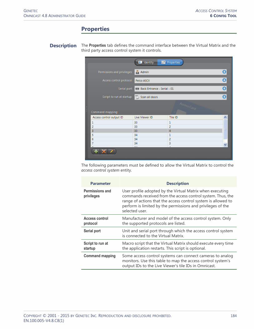
GENETEC ACCESS CONTROL SYSTEMOMNICAST 4.8 ADMINISTRATOR GUIDE 6 CONFIG TOOL
Properties
Description The Properties tab defines the command interface between the Virtual Matrix and the third party access control system it controls.
The following parameters must be defined to allow the Virtual Matrix to control the access control system entity.
Parameter Description
Permissions and privileges
User profile adopted by the Virtual Matrix when executing commands received from the access control system. Thus, the range of actions that the access control system is allowed to perform is limited by the permissions and privileges of the selected user.
Access control protocol
Manufacturer and model of the access control system. Only the supported protocols are listed.
Serial port Unit and serial port through which the access control system is connected to the Virtual Matrix.
Script to run at startup
Macro script that the Virtual Matrix should execute every time the application restarts. This script is optional.
Command mapping Some access control systems can connect cameras to analog monitors. Use this table to map the access control system's output IDs to the Live Viewer's tile IDs in Omnicast.
COPYRIGHT © 2001 - 2015 BY GENETEC INC. REPRODUCTION AND DISCLOSURE PROHIBITED. 184EN.100.005-V4.8.C8(1)

GENETEC ACCESS CONTROL SYSTEMOMNICAST 4.8 ADMINISTRATOR GUIDE 6 CONFIG TOOL
Standby Virtual Matrices
Description The Standby Virtual Matrices tab shows the Virtual Matrix failover list for this device.
The Virtual Matrix appearing at the top of the list is the master of this access control system entity. It is the one that should be controlling this device in normal situations. If the master fails, then the control of this device will be automatically transferred to the next Virtual Matrix in line.
COPYRIGHT © 2001 - 2015 BY GENETEC INC. REPRODUCTION AND DISCLOSURE PROHIBITED. 185EN.100.005-V4.8.C8(1)

GENETEC ALARMOMNICAST 4.8 ADMINISTRATOR GUIDE 6 CONFIG TOOL
Alarm
Definition
An alarm entity defines a set of instructions to handle a particular type of situation that typically presents the following characteristics:•Requires the security personnel's immediate attention •Requires a concerted effort from the security team to handle •Requires all handling actions to be logged (who did what and when) •Can be described through live or recorded videos (optional)
An alarm can be triggered by a user defined action or during the execution of a macro. See Alarm Management on page 7 and Event Management on page 22.
The alarm’s configuration page comprises the following tabs.
Creating an alarm entity
Alarm entities can be created only if the Alarm database option is enabled on your Omnicast system’s Directory. See Server Admin – Alarm database on page 56.
To create a new alarm entity:1 Select Alarm Management from the View selection pane. See View selection pane on
page 155.2 Click at the bottom of the View selection pane. A pop-up menu with the
entities you can create appears.3 Select Alarm from the pop-up menu. The Select recipient(s) dialog box appears.4 Select the persons (users, user groups and monitor groups) that should be notified
by this type of alarm and click OK. A new alarm named New alarm will be created.You must select at least one recipient.
5 Enter a descriptive name for the new alarm. The alarm name must be unique. Use the Description field to provide more details regarding the alarm if necessary, in the Identity tab.
6 Select the Properties tab and configure all necessary information. See Properties on page 187.
7 Select the Cameras tab and select the cameras that should be displayed in the Live Viewer for this type of alarm. See Cameras on page 190.
Icon Tab Description
Identity Name, description and positions of the entity in the Logical and Physical system hierarchies.
Properties Alarm priority, behavior and schedules.
Cameras Cameras used to show the situation to the security guard (live video, playback or still frames).
Recipients Security personnel that should be notified.
Acknowledgement Ways to acknowledge this alarm.
Actions Further actions to trigger following specific alarm events.
COPYRIGHT © 2001 - 2015 BY GENETEC INC. REPRODUCTION AND DISCLOSURE PROHIBITED. 186EN.100.005-V4.8.C8(1)

GENETEC ALARMOMNICAST 4.8 ADMINISTRATOR GUIDE 6 CONFIG TOOL
8 Select the Recipients tab to configure who should be notified by this type of alarm, and how (see Broadcast option). See Recipients on page 194.
9 Define the acknowledgement types for this alarm, if necessary. See Acknowledgement on page 196.
10 Define additional actions associated to this alarm, if necessary.See Actions on page 197.
11 Go back to Recipients tab and click Trigger alarm to test the alarm.
Properties
Description The Properties tab defines the alarm properties, such as its priority, its behavior and when it can be triggered.
General settings The general alarm properties are:
Parameter Description (1 of 3)
Generic schedule The generic schedule defines when the alarm can be activated. See Generic Schedule on page 324.
COPYRIGHT © 2001 - 2015 BY GENETEC INC. REPRODUCTION AND DISCLOSURE PROHIBITED. 187EN.100.005-V4.8.C8(1)

GENETEC ALARMOMNICAST 4.8 ADMINISTRATOR GUIDE 6 CONFIG TOOL
Priority The alarm priority goes from 1 (most important) to 30 (least important) and only affects the alarm display. Higher priority alarms always take precedence over lower priority alarms in terms of display. The exact behavior depends on the display mode in effect (Simple, Salvo or Block).
Note that the display mode is not an alarm property, but a user's preference. See User – Live Viewer on page 439.
Dwell time / camera The dwell time says how much time each camera associated to the alarm is going to take when the alarm is being displayed.
With the Salvo display mode (all cameras displayed simultaneously), the total display time of the alarm is equal to the dwell time if there are enough armed tiles (or monitors) to display all the alarm cameras at once.
With the Block display mode (cameras displayed one after another), the total display time of the alarm is equal to the dwell time multiplied by the number of cameras.
With the Simple display mode, the dwell time is ignored.
Reactivation threshold
Time in seconds before this alarm can be triggered again (reactivated). This parameter is useful to avoid having the same alarm being triggered too frequently. Common sense suggests that the threshold should be at least twice as long as the dwell time.
TIP For the Contextual alarm, it is best to leave this value at zero since the it does not necessarily show the same camera. See Alarm Management – Contextual alarm on page 7.
Alarm recording duration
Whenever an alarm is triggered, the recording always starts automatically on all cameras configured to show this alarm. See Cameras on page 190.
This behavior serves to ensure that recordings will always be available during alarm playbacks.
For each camera, the automatic recording starts n seconds before the alarm is triggered, where n is the length of the recording buffer and lasts for n+m seconds, where m is the Alarm recording duration (see Camera – Recording on page 248). This recording lasts n+m seconds and is called the guaranteed recording span. It is the minimum available recording that the operator can expect during alarm playback.
WARNING All recording is ultimately subject to the archiving schedules in place. If an encoder is not covered by any active archiving schedule at the time the alarm is triggered, no recording will take place.
Parameter Description (2 of 3)
COPYRIGHT © 2001 - 2015 BY GENETEC INC. REPRODUCTION AND DISCLOSURE PROHIBITED. 188EN.100.005-V4.8.C8(1)

GENETEC ALARMOMNICAST 4.8 ADMINISTRATOR GUIDE 6 CONFIG TOOL
Acknowledgement settings
The following parameters define the alarm acknowledgement options.
Protect recorded video for
Number of days the alarm video should be protected against deletion. A zero means do not protect. The alarm video is defined by the next n seconds of recording starting from the time the alarm was triggered, where n is the value of Alarm recording duration. See also Start applying video protection in Appendix B: Actions on page 526.
Procedure (URL) URL (Uniform Resource Locator) address of the alarm procedure. If a procedure is defined, then the Live Viewer user can display it in a separate browser window when the alarm is received by clicking the Show procedure button.
See View alarm procedure in the Omnicast Live Viewer User Guide. The functions available for writing alarm procedures are described in the Omnicast SDK Documentation.
TIP A useful application of the alarm procedure is to show the alarm handling instructions. With the ASP technology, the possibilities are endless.
Show metadata overlays
Select this option if you want all available metadata overlays to be displayed along with the video configured for this alarm in the camera list, whenever it applies, regardless of the selected display option (Live, Playback or Still).
Parameter Description (3 of 3)
Parameter Description
Automatic acknowledgment after...
Alarms usually remain active until someone acknowledges it. Select this option if the alarm should be automatically acknowledged by the system if nobody acknowledges it after n seconds.
Note that the automatic acknowledgement generates the same events as the Default acknowledgement . See Alarm Management – Alarm acknowledgement on page 11.
Once acknowledged, delete after...
All alarms are saved in an alarm history database for future references. You can decide how long this particular type of alarm should be kept in the alarm history database.
If you do not select this option, the alarm retention period is determined by the value of Keep history for parameter set with Server Admin. See Alarm database on page 56.
If you choose to delete the alarms after 0 days, then the alarms will be deleted as soon as they are acknowledged.
COPYRIGHT © 2001 - 2015 BY GENETEC INC. REPRODUCTION AND DISCLOSURE PROHIBITED. 189EN.100.005-V4.8.C8(1)
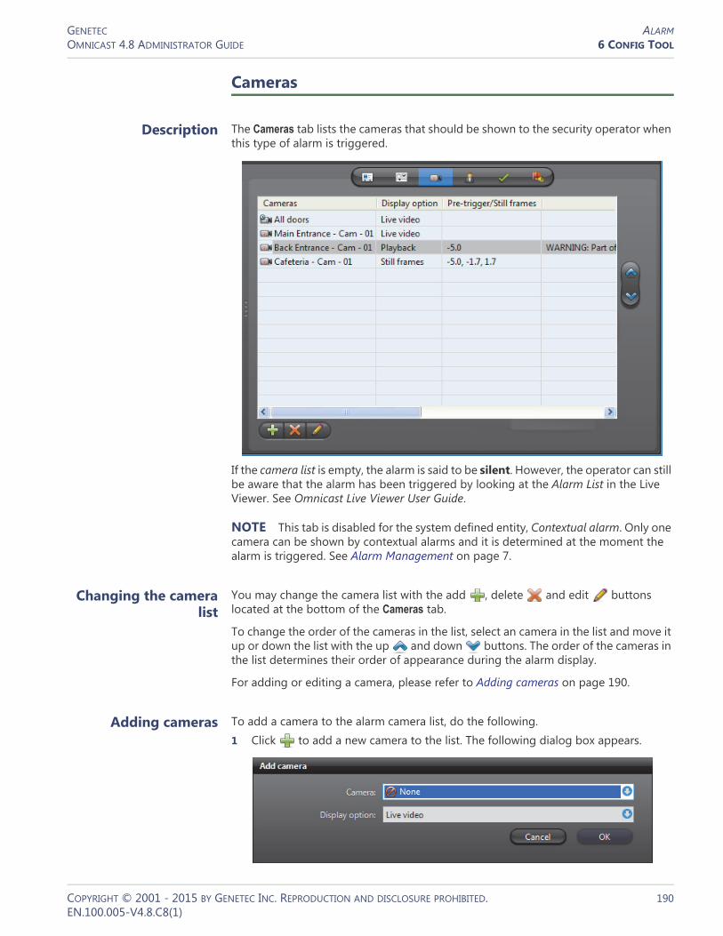
GENETEC ALARMOMNICAST 4.8 ADMINISTRATOR GUIDE 6 CONFIG TOOL
Cameras
Description The Cameras tab lists the cameras that should be shown to the security operator when this type of alarm is triggered.
If the camera list is empty, the alarm is said to be silent. However, the operator can still be aware that the alarm has been triggered by looking at the Alarm List in the Live Viewer. See Omnicast Live Viewer User Guide.
NOTE This tab is disabled for the system defined entity, Contextual alarm. Only one camera can be shown by contextual alarms and it is determined at the moment the alarm is triggered. See Alarm Management on page 7.
Changing the camera list
You may change the camera list with the add , delete and edit buttons located at the bottom of the Cameras tab.
To change the order of the cameras in the list, select an camera in the list and move it up or down the list with the up and down buttons. The order of the cameras in the list determines their order of appearance during the alarm display.
For adding or editing a camera, please refer to Adding cameras on page 190.
Adding cameras To add a camera to the alarm camera list, do the following.1 Click to add a new camera to the list. The following dialog box appears.
COPYRIGHT © 2001 - 2015 BY GENETEC INC. REPRODUCTION AND DISCLOSURE PROHIBITED. 190EN.100.005-V4.8.C8(1)

GENETEC ALARMOMNICAST 4.8 ADMINISTRATOR GUIDE 6 CONFIG TOOL
2 Select the entity to show from the Camera drop-down list. The selected entity can be a camera , a camera sequence , or a camera group .
3 Select a display option from the Display option drop-down list.You have three options.– Select Live video to show live video from the camera. Continue with Step 9.– Select Playback to show the playback of what happened a few seconds before
the alarm was triggered. Continue with Step 4.– Select Still frames to show a series of still frames. Continue with Step 6.
4 If you selected Playback in Step 3, the Add camera dialog will take the following appearance.
The Pre-trigger time is the number of seconds you want to go back in time for the playback, from the time the alarm was triggered.Note that if the pre-trigger time exceeds the length of the recording buffer, you will get a warning. See Warnings on page 193.
5 Continue with Step 9.
COPYRIGHT © 2001 - 2015 BY GENETEC INC. REPRODUCTION AND DISCLOSURE PROHIBITED. 191EN.100.005-V4.8.C8(1)

GENETEC ALARMOMNICAST 4.8 ADMINISTRATOR GUIDE 6 CONFIG TOOL
6 If you selected Still frames in Step 3, the Add camera dialog will take the following appearance.
You have two ways to define still frames.• Same durations, go to Step 7.• Independent durations, go to Step 8.7 For Same durations, enter the Number of frames you want and the Pre-trigger time.
The application will automatically calculate the Relative time for each frame, starting with the first frame at current time minus Pre-trigger time, and by spacing the remaining frames evenly so they all fit within the configured camera Dwell time (indicated in blue). If there are errors, a warning message will be displayed in the dialog box.
COPYRIGHT © 2001 - 2015 BY GENETEC INC. REPRODUCTION AND DISCLOSURE PROHIBITED. 192EN.100.005-V4.8.C8(1)
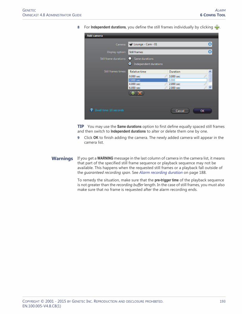
GENETEC ALARMOMNICAST 4.8 ADMINISTRATOR GUIDE 6 CONFIG TOOL
8 For Independent durations, you define the still frames individually by clicking .
TIP You may use the Same durations option to first define equally spaced still frames and then switch to Independent durations to alter or delete them one by one.9 Click OK to finish adding the camera. The newly added camera will appear in the
camera list.
Warnings If you get a WARNING message in the last column of camera in the camera list, it means that part of the specified still frame sequence or playback sequence may not be available. This happens when the requested still frames or a playback fall outside of the guaranteed recording span. See Alarm recording duration on page 188.
To remedy the situation, make sure that the pre-trigger time of the playback sequence is not greater than the recording buffer length. In the case of still frames, you must also make sure that no frame is requested after the alarm recording ends.
COPYRIGHT © 2001 - 2015 BY GENETEC INC. REPRODUCTION AND DISCLOSURE PROHIBITED. 193EN.100.005-V4.8.C8(1)

GENETEC ALARMOMNICAST 4.8 ADMINISTRATOR GUIDE 6 CONFIG TOOL
Recipients
Description The Recipients tab defines who should be notified when the alarm is triggered. The alarm recipient can be a user , a user group or a monitor group .
If a user is defined as alarm recipient, then he will be notified by the Live Viewer every time this alarm is triggered. See Receiving Alarms in Omnicast Live Viewer User Guide.
If a user group is in the recipient list, then all users belonging to that group will receive the notifications for this alarm.
If a monitor group is designated as alarm recipient, then the cameras configured for this alarm will be displayed on the monitors belonging to this monitor group when this alarm is triggered.
NOTE This tab is disabled for the system defined entity, Contextual alarm. Recipients for contextual alarms are selected at the moment the alarm is triggered. See Alarm Management on page 7.
Changing the recipient list
You may change the recipient list with the add , delete and edit buttons located at the bottom of the Recipients tab.
To change the order of the recipients in the list, select a recipient and move it up or down the list with the up and down buttons. If two recipients with different priorities switch positions, then their corresponding priorities will also be switched.
For adding or editing a recipient, please refer to Adding recipients on page 195.
COPYRIGHT © 2001 - 2015 BY GENETEC INC. REPRODUCTION AND DISCLOSURE PROHIBITED. 194EN.100.005-V4.8.C8(1)
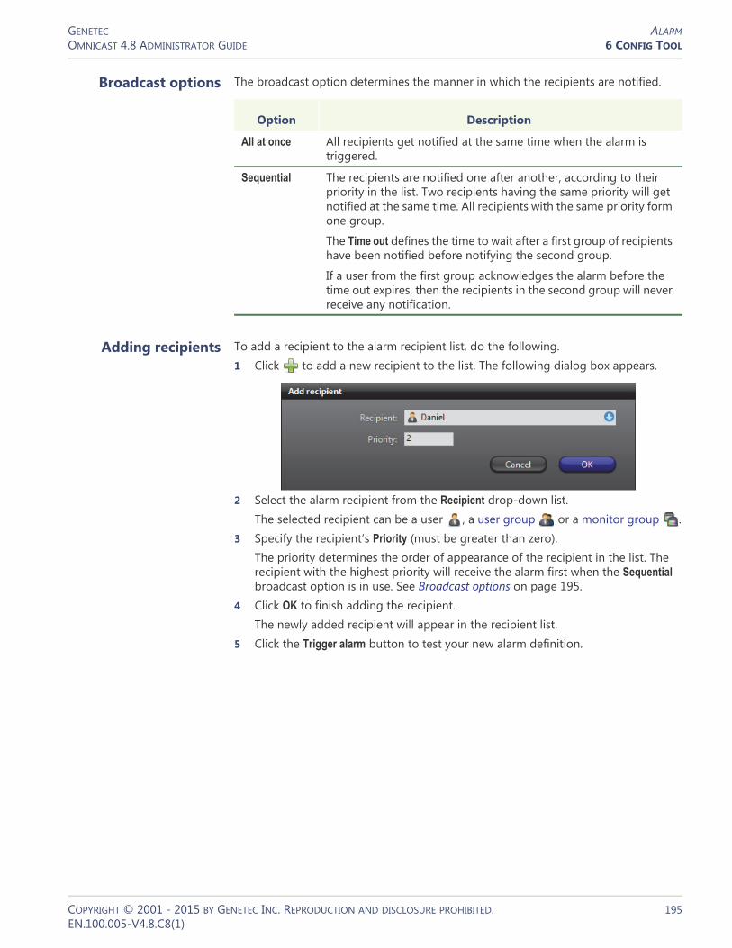
GENETEC ALARMOMNICAST 4.8 ADMINISTRATOR GUIDE 6 CONFIG TOOL
Broadcast options The broadcast option determines the manner in which the recipients are notified.
Adding recipients To add a recipient to the alarm recipient list, do the following.1 Click to add a new recipient to the list. The following dialog box appears.
2 Select the alarm recipient from the Recipient drop-down list.The selected recipient can be a user , a user group or a monitor group .
3 Specify the recipient’s Priority (must be greater than zero).The priority determines the order of appearance of the recipient in the list. The recipient with the highest priority will receive the alarm first when the Sequential broadcast option is in use. See Broadcast options on page 195.
4 Click OK to finish adding the recipient.The newly added recipient will appear in the recipient list.
5 Click the Trigger alarm button to test your new alarm definition.
Option Description
All at once All recipients get notified at the same time when the alarm is triggered.
Sequential The recipients are notified one after another, according to their priority in the list. Two recipients having the same priority will get notified at the same time. All recipients with the same priority form one group.
The Time out defines the time to wait after a first group of recipients have been notified before notifying the second group.
If a user from the first group acknowledges the alarm before the time out expires, then the recipients in the second group will never receive any notification.
COPYRIGHT © 2001 - 2015 BY GENETEC INC. REPRODUCTION AND DISCLOSURE PROHIBITED. 195EN.100.005-V4.8.C8(1)

GENETEC ALARMOMNICAST 4.8 ADMINISTRATOR GUIDE 6 CONFIG TOOL
Acknowledgement
Description The Acknowledgement tab lets you define the variants of acknowledgement permitted for this type of alarm. See Alarm acknowledgement on page 11.
Default acknowledgement
The Default acknowledgement option cannot be cleared. It corresponds to the default acknowledgement command in the Live Viewer.
Alternate acknowledgement
The Alternate acknowledgement option is optional. Selecting it enables the alternate acknowledgement command in the Live Viewer.
Custom acknowledgement
The rest of the options in the list correspond to camera events defined in the system. To enable the custom acknowledgement command in the Live Viewer, select one or more camera events in the list.
NOTE The events you select here will appear in the alarm’s Actions tab. See Actions on page 197.
See camera related events in Appendix A – Omnicast Event Types (sorted by source entity) on page 518.
COPYRIGHT © 2001 - 2015 BY GENETEC INC. REPRODUCTION AND DISCLOSURE PROHIBITED. 196EN.100.005-V4.8.C8(1)

GENETEC ALARMOMNICAST 4.8 ADMINISTRATOR GUIDE 6 CONFIG TOOL
Actions
Description The Actions tab allows you to trigger further actions following specific alarm events shown in the Events/actions list.
NOTE The Alarm acknowledged (Alternate) event and the camera events will appear in this list only if the Alternate acknowledgement option and camera event options are selected in the alarm Acknowledgement tab. See Acknowledgement on page 196.
To learn about general event-to-actions programming, please refer to Event Management on page 22.
COPYRIGHT © 2001 - 2015 BY GENETEC INC. REPRODUCTION AND DISCLOSURE PROHIBITED. 197EN.100.005-V4.8.C8(1)
GENETEC ANALOG MONITOR (VIDEO DECODER)OMNICAST 4.8 ADMINISTRATOR GUIDE 6 CONFIG TOOL
Analog Monitor (Video Decoder)
Definition
In Omnicast, we call analog monitors the CCTV monitors used in traditional video surveillance systems. This is to differentiate them from the PC monitors controlled by the Live Viewer. Each analog monitor corresponds to a unique video output in the system.
To ease their identification, Omnicast automatically assigns a unique logical ID, also known as the monitor ID, to each analog monitor.
Videos are stored and transmitted in digital form in Omnicast. Therefore, to display video on an analog monitor requires that the video signal be converted to an analog signal (NTSC or PAL) first. The video decoder is the device that performs this task. The video decoder is but one of the many devices found in a decoder unit. Because of the intimate relationship between the analog monitor and the video decoder, the two terms are often used interchangeably in Omnicast.
The analog monitor‘s configuration page comprises the following tabs.
Monitor ID You may change the monitor ID assigned automatically to every analog monitor by the system. This can be done either from the Identity tab of the analog monitor or from the Logical IDs tab of the Directory. See Logical IDs on page 299.
Note that analog monitors and the PC monitors controlled by the Live Viewer share the same pool of monitor IDs. This guarantees that every video output is uniquely identified in the system.
Icon Tab Description
Identity Name, description and positions of the entity in the Logical and Physical system hierarchies.
Attributes Analog video format and appearance.
Info Video decoder properties.
Network Network properties.
Links Video decoder connections.
COPYRIGHT © 2001 - 2015 BY GENETEC INC. REPRODUCTION AND DISCLOSURE PROHIBITED. 198EN.100.005-V4.8.C8(1)
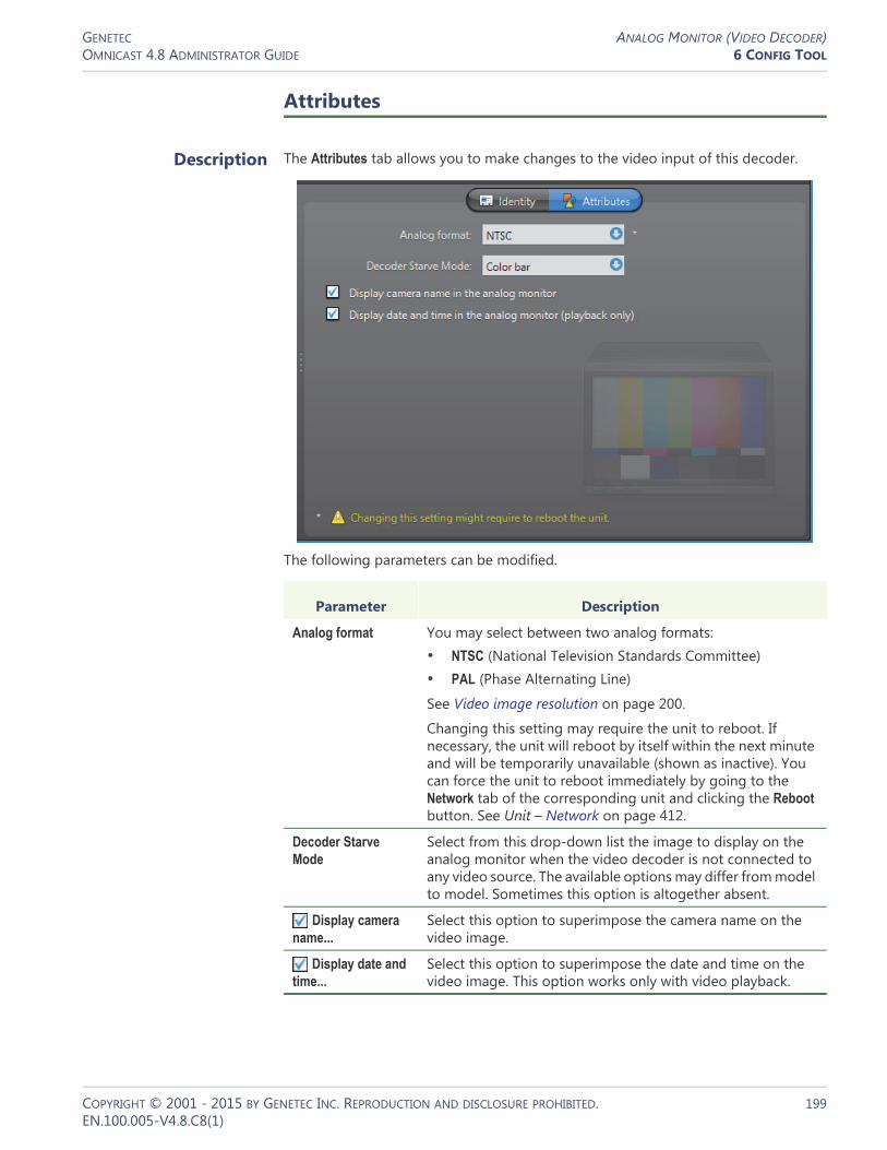
GENETEC ANALOG MONITOR (VIDEO DECODER)OMNICAST 4.8 ADMINISTRATOR GUIDE 6 CONFIG TOOL
Attributes
Description The Attributes tab allows you to make changes to the video input of this decoder.
The following parameters can be modified.
Parameter Description
Analog format You may select between two analog formats:• NTSC (National Television Standards Committee)• PAL (Phase Alternating Line)
See Video image resolution on page 200.
Changing this setting may require the unit to reboot. If necessary, the unit will reboot by itself within the next minute and will be temporarily unavailable (shown as inactive). You can force the unit to reboot immediately by going to the Network tab of the corresponding unit and clicking the Reboot button. See Unit – Network on page 412.
Decoder Starve Mode
Select from this drop-down list the image to display on the analog monitor when the video decoder is not connected to any video source. The available options may differ from model to model. Sometimes this option is altogether absent.
Display camera name...
Select this option to superimpose the camera name on the video image.
Display date and time...
Select this option to superimpose the date and time on the video image. This option works only with video playback.
COPYRIGHT © 2001 - 2015 BY GENETEC INC. REPRODUCTION AND DISCLOSURE PROHIBITED. 199EN.100.005-V4.8.C8(1)

GENETEC ANALOG MONITOR (VIDEO DECODER)OMNICAST 4.8 ADMINISTRATOR GUIDE 6 CONFIG TOOL
Info
Description The Info tab displays the decoding properties of the video decoder.
The following parameters are displayed for information purpose only.
Video image resolution
The following table shows the video image resolution in terms of the analog format (NTSC or PAL) and the resolution standard.
Parameter Description
Board type Type of hardware used by the decoder unit.
Video output number
Output number corresponding to this analog monitor. This attribute is used for decoder units having more than one output.
Format Analog format used by the video decoder (NTSC or PAL). The analog format, along with the video data format, define the resolution of the image. See Video image resolution on page 200.
Video data formats Lists of the compression types (MPEG-4, MPEG-2, or MJPEG) and resolution standards (qcif, cif, 2cif, 4cif, etc.) supported by this video decoder. This list varies from model to model.
Viewed camera Name of the camera currently displayed on that monitor.
qcif cif 2cif 2cif (480) all lines 2/3D1 VGA 2cif H 4cif
NTSC 176 x 128 352 x 240 352 x 384 352 x 480 352 x 480 480 x 480 640 x 480 704 x 240 704 x 480
PAL 176 x 144 352 x 288 352 x 448 352 x 576 352 x 576 480 x 576 640 x 576 704 x 288 704 x 576
COPYRIGHT © 2001 - 2015 BY GENETEC INC. REPRODUCTION AND DISCLOSURE PROHIBITED. 200EN.100.005-V4.8.C8(1)
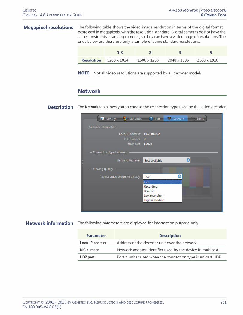
GENETEC ANALOG MONITOR (VIDEO DECODER)OMNICAST 4.8 ADMINISTRATOR GUIDE 6 CONFIG TOOL
Megapixel resolutions The following table shows the video image resolution in terms of the digital format, expressed in megapixels, with the resolution standard. Digital cameras do not have the same constraints as analog cameras, so they can have a wider range of resolutions. The ones below are therefore only a sample of some standard resolutions.
1280 x 1024 1600 x 1200 2048 x 1536 2560 x 1920
NOTE Not all video resolutions are supported by all decoder models.
Network
Description The Network tab allows you to choose the connection type used by the video decoder.
Network information The following parameters are displayed for information purpose only.
1.3 2 3 5
Resolution
Parameter Description
Local IP address Address of the decoder unit over the network.
NIC number Network adapter identifier used by the device in multicast.
UDP port Port number used when the connection type is unicast UDP.
COPYRIGHT © 2001 - 2015 BY GENETEC INC. REPRODUCTION AND DISCLOSURE PROHIBITED. 201EN.100.005-V4.8.C8(1)

GENETEC ANALOG MONITOR (VIDEO DECODER)OMNICAST 4.8 ADMINISTRATOR GUIDE 6 CONFIG TOOL
Connection type between unit and
Archiver
Connection type that should be used between the unit and the Archiver for this video decoder. The possible choices are:• Best available
• Unicast UDP
• Unicast TCP
For more information on the meaning of each connection type, see System Concepts – Network Connections on page 29.
Viewing quality Video stream that should be used when a video encoder is displayed on this monitor. A video encoder can produce up to a maximum of five different video streams from a single analog source. These video streams bear the following generic names:• Live (default stream used for viewing live video) • Recording (default stream used for archiving) • Remote (default stream used by Auxiliary Archivers) • Low resolution (used for automatic stream selection in the Live Viewer)• High resolution (used for automatic stream selection in the Live Viewer)
The mapping of the actual video streams to these generic names is done individually for each encoder. See Video stream usage on page 242.
Links
Description The Links tab is where connections can be made between this video decoder and specific devices.
COPYRIGHT © 2001 - 2015 BY GENETEC INC. REPRODUCTION AND DISCLOSURE PROHIBITED. 202EN.100.005-V4.8.C8(1)
GENETEC ANALOG MONITOR (VIDEO DECODER)OMNICAST 4.8 ADMINISTRATOR GUIDE 6 CONFIG TOOL
The devices that a video decoder can be linked to are:• Speaker (audio decoder)• Microphone (audio encoder)• Digital input• Output relay• Serial port
Creating new links To attach a speaker or a microphone to this analog monitor, click on the corresponding drop-down list and select the appropriate device.
To attach an I/O pin ( or ) or a serial port to this analog monitor, select the ones that apply from the device tree. All links are applied instantly.
Removing existing links
To remove a connection to a speaker or a microphone , select None from the corresponding drop-down list.
To disconnect an I/O pin ( or ) or a serial port , clear its selection in the device tree.
COPYRIGHT © 2001 - 2015 BY GENETEC INC. REPRODUCTION AND DISCLOSURE PROHIBITED. 203EN.100.005-V4.8.C8(1)

GENETEC ARCHIVEROMNICAST 4.8 ADMINISTRATOR GUIDE 6 CONFIG TOOL
Archiver
Definition
The Archiver is the service responsible for automatic discovery and status polling of the video units. All communications with the units are established through this service. It is also where all the video and multimedia streams are archived.
There can be as many Archivers as needed on the same system to share the archiving load. The maximum number of Archivers you
may have on your system is determined by the Number of Archivers option of your Omnicast license. See Server Admin – Directory options on page 47.
The Archiver‘s configuration page comprises the following tabs.
Being an Omnicast server application, the machine specific parameters of the Archiver are configured with the Server Admin. See Archiver on page 85.
Icon Tab Description
Identity Name, description and positions of the entity in the Logical and Physical system hierarchies.
Archiving Disk group, archive cleanup option and archive retention period for each camera.
Statistics Statistical information on disk and bandwidth usage.
Firmware Upgrade
Simultaneous firmware upgrade on selected units.
Actions Actions to perform following specific Archiver events.
Backup Periodic backup behavior configuration and status.
Trickling Data transfer configuration.
Event Search Browser for Archiver events.
COPYRIGHT © 2001 - 2015 BY GENETEC INC. REPRODUCTION AND DISCLOSURE PROHIBITED. 204EN.100.005-V4.8.C8(1)

GENETEC ARCHIVEROMNICAST 4.8 ADMINISTRATOR GUIDE 6 CONFIG TOOL
Archiving
Description The Archiving tab lists all the cameras (video encoders) controlled by this Archiver and allows you to choose individually for each, the Disk group, the Automatic cleanup, and the archive Retention period.
Disk group A disk group is a collection of one or more network drives, each with an allotted space for storing video archives. Disk groups are created in the Server Admin. See Disk groups on page 89. The disk group of a camera is where the future video archives from that camera will be stored. The purpose of having several disk groups is to increase the performance of the archiver by allowing it to write simultaneously on different disks.
If the Archiver uses only one disk group, you will see a single list of cameras in this tab. If the Archiver uses more than one disk group, you will see a tree structure where the cameras are distributed according to their assigned disk group.
Initially, all cameras are assigned to the Default Disk Group. You can change the disk group of a camera any time by drag-and-dropping the camera under the desired disk group or by clicking on the up and down buttons.
Automatic cleanup When this option is selected, the Archiver will automatically delete the recorded video after the specified retention period. If cleared, the video archives will only be deleted when the Archiver runs out of disk space, starting from the oldest.
NOTE You may disable the Automatic cleanup only if your Archiver license permits it, i.e. that the Maximum archive retention period is set to Unlimited. See Archiver options on page 50.
COPYRIGHT © 2001 - 2015 BY GENETEC INC. REPRODUCTION AND DISCLOSURE PROHIBITED. 205EN.100.005-V4.8.C8(1)
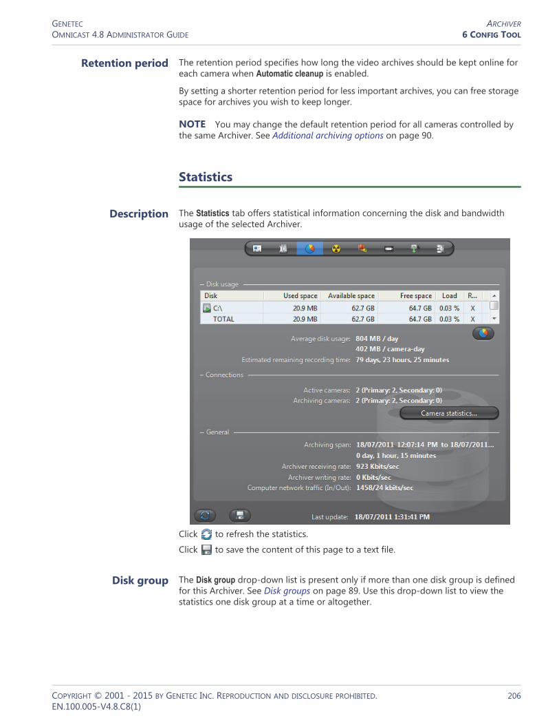
GENETEC ARCHIVEROMNICAST 4.8 ADMINISTRATOR GUIDE 6 CONFIG TOOL
Retention period The retention period specifies how long the video archives should be kept online for each camera when Automatic cleanup is enabled.
By setting a shorter retention period for less important archives, you can free storage space for archives you wish to keep longer.
NOTE You may change the default retention period for all cameras controlled by the same Archiver. See Additional archiving options on page 90.
Statistics
Description The Statistics tab offers statistical information concerning the disk and bandwidth usage of the selected Archiver.
Click to refresh the statistics.
Click to save the content of this page to a text file.
Disk group The Disk group drop-down list is present only if more than one disk group is defined for this Archiver. See Disk groups on page 89. Use this drop-down list to view the statistics one disk group at a time or altogether.
COPYRIGHT © 2001 - 2015 BY GENETEC INC. REPRODUCTION AND DISCLOSURE PROHIBITED. 206EN.100.005-V4.8.C8(1)

GENETEC ARCHIVEROMNICAST 4.8 ADMINISTRATOR GUIDE 6 CONFIG TOOL
Disk usage This section shows the disk usage statistics for the selected disk group. The disk list shows the individual statistics of each disk that is part of the disk group.
Statistics Description
Disk Disk name. The green marker over the disk icon indicates that the disk is currently used by the Archiver.
Used space Space currently used to store video files on the disk.
Available space Space still available on the disk for archiving purpose. The available space is the total free space on the disk minus the minimum free space that the Archiver is not supposed to use. See Archiving on page 87.
Free space Current free space on disk.
Load Indicates the percentage of archiving space used.
R/W Shows whether the Archiver has read/write access to the disk.
Average disk usage Average space used per day (first line) and average space used per camera per day (second line).
Estimated remaining...
Number of days, hours, and minutes of recording left based on the average disk usage and the current load.
Button Click on this button to show the Protected video file statistics dialog.
The yellow slice represents the proportion of video files unprotected manually by the user (see Video File Query in the Omnicast Archive Player User Guide). When a user decides to manually remove the protection on a video file, the system waits 24 hours before the removing the protection, giving the user enough time to change his mind if necessary. During this reprieve, the file is said to be ending protection.
COPYRIGHT © 2001 - 2015 BY GENETEC INC. REPRODUCTION AND DISCLOSURE PROHIBITED. 207EN.100.005-V4.8.C8(1)

GENETEC ARCHIVEROMNICAST 4.8 ADMINISTRATOR GUIDE 6 CONFIG TOOL
Connections This section shows the connection statistics.
Camera statistics dialog
Click the button Camera statistics to view in the following dialog, the latest snapshot of the recording states of all cameras controlled by this Archiver. To refresh this snapshot, click in the Statistics tab.
The possible values for Recording state are:
Statistics Description
Active cameras Primary - Number of active cameras currently under the control of this Archiver. See Archiving on page 205.
Secondary - Number of active cameras that are controlled by another Archiver, but have this Archiver in their failover list.
Archiving cameras Primary - Number of cameras streaming video to the Archiver that are currently under the control of this Archiver.
Secondary - Number of cameras in the redundant archiving mode that are controlled by another Archiver, but are streaming to this Archiver as well. For more information, see Redundant archiving on page 14.
NOTE All archiving cameras are also counted as Active cameras.
Available space Space still available on the disk for archiving purpose. The available space is the total free space on the disk minus the minimum free space that the Archiver is not supposed to use. See Archiving on page 87.
Recording state Description (1 of 2)
Disabled Recording is currently disabled on this camera.
COPYRIGHT © 2001 - 2015 BY GENETEC INC. REPRODUCTION AND DISCLOSURE PROHIBITED. 208EN.100.005-V4.8.C8(1)
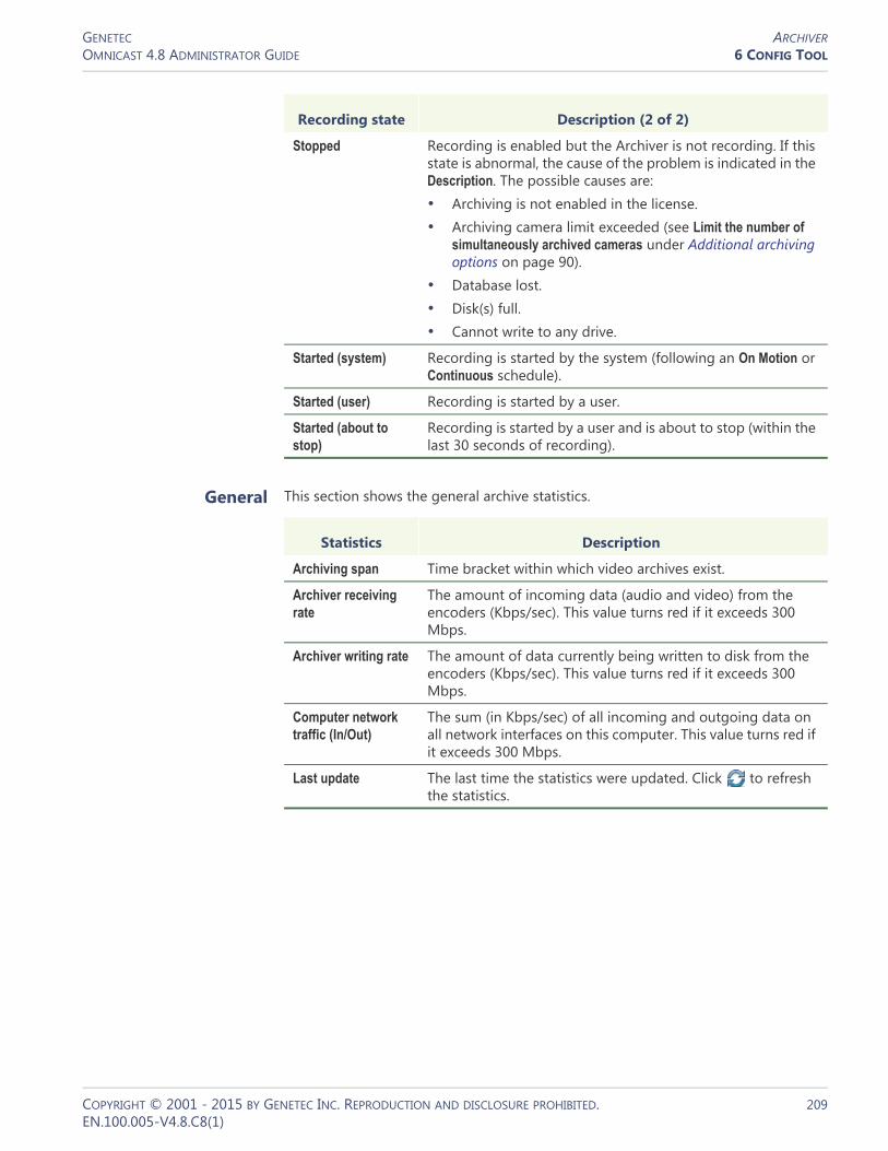
GENETEC ARCHIVEROMNICAST 4.8 ADMINISTRATOR GUIDE 6 CONFIG TOOL
General This section shows the general archive statistics.
Stopped Recording is enabled but the Archiver is not recording. If this state is abnormal, the cause of the problem is indicated in the Description. The possible causes are:• Archiving is not enabled in the license.• Archiving camera limit exceeded (see Limit the number of
simultaneously archived cameras under Additional archiving options on page 90).
• Database lost.• Disk(s) full.• Cannot write to any drive.
Started (system) Recording is started by the system (following an On Motion or Continuous schedule).
Started (user) Recording is started by a user.
Started (about to stop)
Recording is started by a user and is about to stop (within the last 30 seconds of recording).
Recording state Description (2 of 2)
Statistics Description
Archiving span Time bracket within which video archives exist.
Archiver receiving rate
The amount of incoming data (audio and video) from the encoders (Kbps/sec). This value turns red if it exceeds 300 Mbps.
Archiver writing rate The amount of data currently being written to disk from the encoders (Kbps/sec). This value turns red if it exceeds 300 Mbps.
Computer network traffic (In/Out)
The sum (in Kbps/sec) of all incoming and outgoing data on all network interfaces on this computer. This value turns red if it exceeds 300 Mbps.
Last update The last time the statistics were updated. Click to refresh the statistics.
COPYRIGHT © 2001 - 2015 BY GENETEC INC. REPRODUCTION AND DISCLOSURE PROHIBITED. 209EN.100.005-V4.8.C8(1)

GENETEC ARCHIVEROMNICAST 4.8 ADMINISTRATOR GUIDE 6 CONFIG TOOL
Firmware Upgrade
Description The Firmware upgrade tab serves two purposes: (1) It shows the firmware version installed on each unit controlled by this Archiver; and (2) it allows the administrator to simultaneously upgrade the firmware of selected units.
Upgrading the firmware of selected
units
To upgrade the firmware of selected units, do the following.1 Enter the path to the desired firmware file in Firmware file or use the browse button
to select the file.Note that the Upgrade type is always IP for simultaneous firmware upgrade. The choice between IP and Serial is only enabled in the Firmware upgrade tab of the unit. See Unit – Firmware Upgrade on page 409.
2 Select the unit(s) to upgrade from the scrolling list.If the Archiver supports more than one type of units, the Unit type combo box will appear at the right top corner of the list. Use it to list the desired type of units and make sure the specified firmware file is compatible with the selected unit type.
COPYRIGHT © 2001 - 2015 BY GENETEC INC. REPRODUCTION AND DISCLOSURE PROHIBITED. 210EN.100.005-V4.8.C8(1)

GENETEC ARCHIVEROMNICAST 4.8 ADMINISTRATOR GUIDE 6 CONFIG TOOL
3 Click Start to start the upgrade. The Firmware upgrade dialog box appears.
WARNING You will get a warning message for each unit you are downgrading to an older firmware version. If you choose to proceed, all subsequent problems encountered will not be covered by the warranty.4 Click to save the upgrade status log to a file.
COPYRIGHT © 2001 - 2015 BY GENETEC INC. REPRODUCTION AND DISCLOSURE PROHIBITED. 211EN.100.005-V4.8.C8(1)

GENETEC ARCHIVEROMNICAST 4.8 ADMINISTRATOR GUIDE 6 CONFIG TOOL
Actions
Description The Actions tab allows you to trigger further actions following specific Archiver events shown in the Events/actions list.
To learn about general event-to-actions programming, please refer to Event Management on page 22.
COPYRIGHT © 2001 - 2015 BY GENETEC INC. REPRODUCTION AND DISCLOSURE PROHIBITED. 212EN.100.005-V4.8.C8(1)

GENETEC ARCHIVEROMNICAST 4.8 ADMINISTRATOR GUIDE 6 CONFIG TOOL
Backup
Description The Backup tab is where the administrator configures the backup behavior of the selected Archiver.
NOTE This tab is enabled only if the Backup option is enabled for this Archiver in the Server Admin. See Backup on page 92.
Backup configuration To fully configure the Backup, do the following.1 Select from the list to the left, all the cameras you wish to backup.2 Under Backup, enter the backup frequency (Every: _ days) and the time of day (At:)
at which the backup should be executed.3 Under Backup period, enter the period covered by the backup set (Covering: _ days)
and the relative start time of the backup period (Starting from: _ days ago).The backup sets will overlap each other if the backup period length is greater than the backup frequency.
4 Select Export Archive Player to include a stand-alone version of the Archive Player in your backup set.
5 Select Delete oldest backup sets when disk full to allow the Archiver to delete old backup sets when there is not enough disk space for new backup sets.If this option is cleared, the backup will fail when there is not enough disk space.
6 Click Apply in the toolbar to save your changes.
COPYRIGHT © 2001 - 2015 BY GENETEC INC. REPRODUCTION AND DISCLOSURE PROHIBITED. 213EN.100.005-V4.8.C8(1)

GENETEC ARCHIVEROMNICAST 4.8 ADMINISTRATOR GUIDE 6 CONFIG TOOL
Backup status Click the Backup status button to display the following dialog.
Use this dialog to check the last backup status and perform unscheduled backups.
The information shown in this dialog is:
Information Description (1 of 2)
Last backup start Time the last backup started.
Last backup end Time the last backup ended.
Last backup duration Duration of the last backup operation.
Last backup size Total size of the video files contained in the backup set.
Last backup status Status of the last backup operation.
Next backup date Scheduled date and time for the next backup to start. This date is calculated as the last backup date plus the backup frequency.
Note that the first time the Archiver starts with the Backup option enabled, the current date is used as the last backup date.
Change... Click this button to set the next backup date. The backup start time must be changed in the Backup period section.
Current status If a backup operation is currently in progress, it would be indicated here, along with the time the backup started. If nothing is going on, the status would be Idle.
Start now... Click this button to start an unscheduled backup now.
Note that this operation may alter the periodic backup schedule. If you do not want to alter the periodic backup schedule, remember to reset the next backup date after the unscheduled backup completes.
COPYRIGHT © 2001 - 2015 BY GENETEC INC. REPRODUCTION AND DISCLOSURE PROHIBITED. 214EN.100.005-V4.8.C8(1)

GENETEC ARCHIVEROMNICAST 4.8 ADMINISTRATOR GUIDE 6 CONFIG TOOL
Trickling
Description The Trickling tab allows you to transfer video that’s recorded on a unit to the Omnicast Archiver. You can define when and what type of data is transferred.
IMPORTANT To be able to trickle with a unit, you need to:• Select the record on the edge option on the Recording tab of the unit. For more
information, see Recording on page 248. Note that when the record on edge option is selected for a unit, all archiving schedules are ignored. Cameras are trickled independently on each Archiver, even if they are on multiple archivers.
• Configure your unit to record video using the Web Page of the unit.
Trickling can be started in three ways. • When a unit connects to the network.• From a predefined schedule.• Manually.
You can apply your trickling settings to all units or on individual units.
Last update The last time the backup status was updated. The status is always updated after each backup operation.
Click to refresh the backup status.
Click to save the content of this dialog to a text file.
Information Description (2 of 2)
COPYRIGHT © 2001 - 2015 BY GENETEC INC. REPRODUCTION AND DISCLOSURE PROHIBITED. 215EN.100.005-V4.8.C8(1)
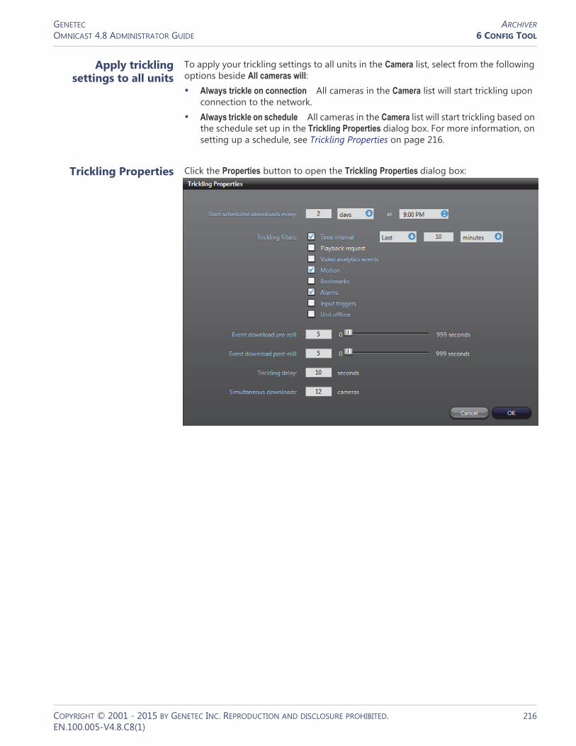
GENETEC ARCHIVEROMNICAST 4.8 ADMINISTRATOR GUIDE 6 CONFIG TOOL
Apply trickling settings to all units
To apply your trickling settings to all units in the Camera list, select from the following options beside All cameras will:• Always trickle on connection All cameras in the Camera list will start trickling upon
connection to the network.• Always trickle on schedule All cameras in the Camera list will start trickling based on
the schedule set up in the Trickling Properties dialog box. For more information, on setting up a schedule, see Trickling Properties on page 216.
Trickling Properties Click the Properties button to open the Trickling Properties dialog box:
COPYRIGHT © 2001 - 2015 BY GENETEC INC. REPRODUCTION AND DISCLOSURE PROHIBITED. 216EN.100.005-V4.8.C8(1)
GENETEC ARCHIVEROMNICAST 4.8 ADMINISTRATOR GUIDE 6 CONFIG TOOL
The following settings are available to configure when and what type of video data will be trickled:• Start scheduled download every Use this setting to define a schedule for when you
want video to be trickled. You can specify the amount of days, hours, and the time. If you’ve set all cameras to always trickle on connection, ignore this setting.
• Trickling filters Use these settings to specify what type of video data you want to be trickled. Multiple filters can be selected at the same time and all video that corresponds to the filters will be trickled.– Time interval Select this filter to trickle video segments recorded during a
specific period of time. You can specify minutes, hours, or days. – Playback request Select this filter to trickle video segments that were played
back from the camera.– Video analytics events Select this filter to trickle video segments that contain
video analytics events.– Motion Select this option to trickle video segments that span between a
‘Motion on’ and ‘Motion off’ event. This option applies to unit motion detection only.
– Bookmarks Select this option to trickle video segments that contain bookmarks.
– Alarms Select this filter to trickle video segments that contain alarm events.– Input triggers Select this filter to trickle video segments that contain input
events.– Unit offline Select this filter to trickle video segments that span between a ‘Unit
lost’ and a ‘Unit discovered’ event.• Event download pre-roll Specify how many seconds of video that will be trickled
before the event occurred. If you specified a Motion or Unit offline event filter, this setting indicates how many seconds are trickled before the ‘motion on’ or ‘Unit lost’ event occurred.
• Event download post-roll Specify how many seconds of video that will be trickled after the event occurred. If you specified a Motion or Unit offline event filter, this setting indicates how many seconds are trickled after the ‘motion off’ or ‘Unit discovered’ event.
• Trickling delay Use this setting to specify how long (in seconds) Omnicast will wait to determine if a unit is truly online before trickling. For example, if your cameras are set to trickle on connection and you have an unstable network where your cameras frequently go on and offline, this setting is useful to prevent trickling from repeatedly starting and stopping.
• Simultaneous downloads Use this setting to specify how many cameras can trickle at the same time. This setting is useful if you have a limited network and do not want too many downloads to occur simultaneously.
COPYRIGHT © 2001 - 2015 BY GENETEC INC. REPRODUCTION AND DISCLOSURE PROHIBITED. 217EN.100.005-V4.8.C8(1)

GENETEC ARCHIVEROMNICAST 4.8 ADMINISTRATOR GUIDE 6 CONFIG TOOL
Camera list The Camera list allows you to specify whether or not you want a unit to trickle on connection or on a schedule, and supplies information about the trickling process. The following columns are provided:• Camera Lists all cameras that are set to record on the edge and perform trickling.• On connection Select the check box for the camera to start to trickle upon
connection to the network.• On schedule Select the checkbox for the camera to trickle based on the schedule
set up using the Trickling Properties dialog box. For more information on setting up a schedule, see Trickling Properties on page 216.
• Last download Lists the date and time of the start of the last trickling occurrence for the camera.
• Last video time Lists the date and time of the last frame downloaded for the last trickling occurrence for the camera.
• Status Lists the trickling status for the camera. The status can be one of the following:– No video There is no video recorded on the camera that is available to trickle
for the filters specified in the Trickling Properties dialog box. For example, if you specify an alarm filter, the camera may have generated an alarm event, however it did not record any video for it.
– No events There are no events recorded on the camera that correspond to the filters specified in the Trickling Properties dialog box. For example, if you specify a motion filter, but there were no motion events generated by the camera, there are no events to trickle.
– Started Trickling has started.– Success Trickling was successfully completed.– Pending Trickling will start as soon as a spot opens in the download queue.
The spots available depend on what is specified in the Simultaneous downloads setting.
– Incomplete Something occurred during the trickling process that prevented the transfer from being completed.
• Details Provides details about the trickling status.You can click at any time to update the trickling information for all (or any selected) cameras that appear in the Camera list.
Start and stop trickling manually
To manually start trickling:• Click the Trickle now button. Trickling will start for all cameras that appear in the
Camera list.
To manually start trickling on specific units:• Select each unit from the Camera list while holding the Ctrl key, and click Trickle
now.
To stop trickling manually: • Click the Stop Trickling button.
COPYRIGHT © 2001 - 2015 BY GENETEC INC. REPRODUCTION AND DISCLOSURE PROHIBITED. 218EN.100.005-V4.8.C8(1)

GENETEC ARCHIVEROMNICAST 4.8 ADMINISTRATOR GUIDE 6 CONFIG TOOL
Limitations The following limitations apply when using the Trickling feature:• It is not possible to trickle video segments that occurred on a unit prior to the Last
video time stored on the Archiver for that unit. For example, if the last frame trickled for a unit is 1:35 and you try to trickle video between 1:30 and 2:30 for that unit, the first five minutes of video will not be trickled, only video between 1:35 and 2:30 will be trickled and stored in the Archiver.
Event Search
Description The Event search tab allows you to search and browse the events associated to the selected Archiver.
Searching for Archiver events
To perform a search, do the following.1 Indicate the search time range by specifying the From date-time and the To date-
time.You may leave the time range open ended by clearing one or both the date-time options.
2 Select the types of events you are looking for.3 Click Search to start the search. The results are displayed in three columns (Type,
Time, Description) in a scrolling list to the right.Please refer to the archiver related events in Appendix A – Omnicast Event Types (sorted by source entity) on page 518.
4 Click to save the search results to a file.
COPYRIGHT © 2001 - 2015 BY GENETEC INC. REPRODUCTION AND DISCLOSURE PROHIBITED. 219EN.100.005-V4.8.C8(1)

GENETEC ARCHIVING SCHEDULEOMNICAST 4.8 ADMINISTRATOR GUIDE 6 CONFIG TOOL
Archiving Schedule
Definition
An archiving schedule is a generic schedule applied to archiving. Archiving schedules are followed by all Archivers to determine when and under which conditions the video stream issued from a given camera should be archived.
An archiving schedule is characterized by the following three elements:
• Generic schedule – When archiving should take place.• Archiving mode – Conditions under which the archiving should take place.• Camera list – Video sources covered under this schedule
The archiving schedule‘s configuration page comprises the following tabs.
Creating an archiving schedule
To create a new archiving schedule entity, do the following.1 Select Schedule Management from the View selection pane. See View selection pane
on page 155.2 Click at the bottom of the View selection pane. A pop-up menu with the
entities you can create appears.3 Select Archiving Schedule from the pop-up menu. A new entity named New
schedule will be created.4 Enter a descriptive name for the new schedule entity.Use the Description field to
provide more details if necessary, in the Identity tab.5 Select the Properties tab to configure the generic schedule, the archiving mode and the
camera list. See Properties on page 221.
Icon Tab Description
Identity Name, description and positions of the entity in the Logical and Physical system hierarchies.
Properties Generic schedule, archiving mode and camera list.
COPYRIGHT © 2001 - 2015 BY GENETEC INC. REPRODUCTION AND DISCLOSURE PROHIBITED. 220EN.100.005-V4.8.C8(1)

GENETEC ARCHIVING SCHEDULEOMNICAST 4.8 ADMINISTRATOR GUIDE 6 CONFIG TOOL
Properties
Description The Properties tab defines everything that characterizes this archiving schedule: the Generic schedule, the Archiving mode, and the Camera list to which this schedule applies.
Generic schedule The generic schedule defines the day(s) and time(s) when archiving is applicable. See Generic Schedule on page 324.
Archiving mode The archiving mode determines the condition under which archiving can take place. The different values are described below.
Archiving mode Description (1 of 2)
Disabled This mode temporarily disable the archiving schedule.
When a camera is not covered by any active schedule, manual recording will be disabled in the Live Viewer (shown by a gray button with a lock ). See Record button in Omnicast Live Viewer User Guide.
WARNING Beware that when all archiving schedules are disabled for a camera, no recording will occur even when an alarm is triggered. See Alarm recording duration on page 188.
Manual Select this mode when recording is allowed only when it is requested by a user or a programmed action, or when it is triggered by an alarm. Automatic recording will not be triggered by motion. See Motion Detection on page 251.
When manual recording is allowed, the Record button in the Live Viewer appears gray when it is not recording, and red
when it is recording.
COPYRIGHT © 2001 - 2015 BY GENETEC INC. REPRODUCTION AND DISCLOSURE PROHIBITED. 221EN.100.005-V4.8.C8(1)

GENETEC ARCHIVING SCHEDULEOMNICAST 4.8 ADMINISTRATOR GUIDE 6 CONFIG TOOL
Camera list The camera list shows all the cameras (video encoders) covered under this schedule. You can easily add or remove cameras from the schedule by selecting or clearing them from the list.
Continuous Select this mode if continuous recording is desired during the time periods defined by the Generic schedule.
When continuous recording is taking place, the Record button in the Live Viewer appears red with a lock , meaning that the recording cannot be stopped manually by the user.
On motion / Manual Select this mode when both automatic (On motion) and Manual recording are allowed during the time periods defined by the Generic schedule.
Archiving mode Description (2 of 2)
COPYRIGHT © 2001 - 2015 BY GENETEC INC. REPRODUCTION AND DISCLOSURE PROHIBITED. 222EN.100.005-V4.8.C8(1)
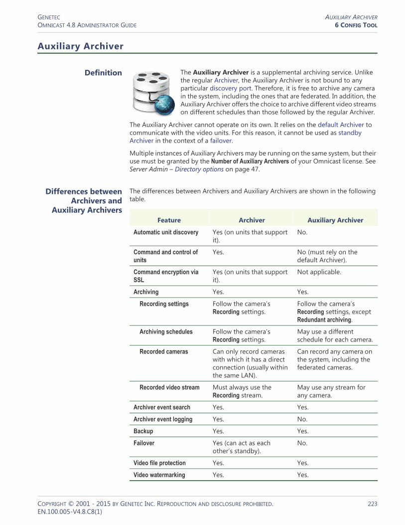
GENETEC AUXILIARY ARCHIVEROMNICAST 4.8 ADMINISTRATOR GUIDE 6 CONFIG TOOL
Auxiliary Archiver
Definition
The Auxiliary Archiver is a supplemental archiving service. Unlike the regular Archiver, the Auxiliary Archiver is not bound to any particular discovery port. Therefore, it is free to archive any camera in the system, including the ones that are federated. In addition, the Auxiliary Archiver offers the choice to archive different video streams on different schedules than those followed by the regular Archiver.
The Auxiliary Archiver cannot operate on its own. It relies on the default Archiver to communicate with the video units. For this reason, it cannot be used as standby Archiver in the context of a failover.
Multiple instances of Auxiliary Archivers may be running on the same system, but their use must be granted by the Number of Auxiliary Archivers of your Omnicast license. See Server Admin – Directory options on page 47.
Differences between Archivers and
Auxiliary Archivers
The differences between Archivers and Auxiliary Archivers are shown in the following table.
Feature Archiver Auxiliary Archiver
Automatic unit discovery Yes (on units that support it).
No.
Command and control of units
Yes. No (must rely on the default Archiver).
Command encryption via SSL
Yes (on units that support it).
Not applicable.
Archiving Yes. Yes.
Recording settings Follow the camera’s Recording settings.
Follow the camera’s Recording settings, except Redundant archiving.
Archiving schedules Follow the camera’s Recording settings.
May use a different schedule for each camera.
Recorded cameras Can only record cameras with which it has a direct connection (usually within the same LAN).
Can record any camera on the system, including the federated cameras.
Recorded video stream Must always use the Recording stream.
May use any stream for any camera.
Archiver event search Yes. Yes.
Archiver event logging Yes. No.
Backup Yes. Yes.
Failover Yes (can act as each other’s standby).
No.
Video file protection Yes. Yes.
Video watermarking Yes. Yes.
COPYRIGHT © 2001 - 2015 BY GENETEC INC. REPRODUCTION AND DISCLOSURE PROHIBITED. 223EN.100.005-V4.8.C8(1)
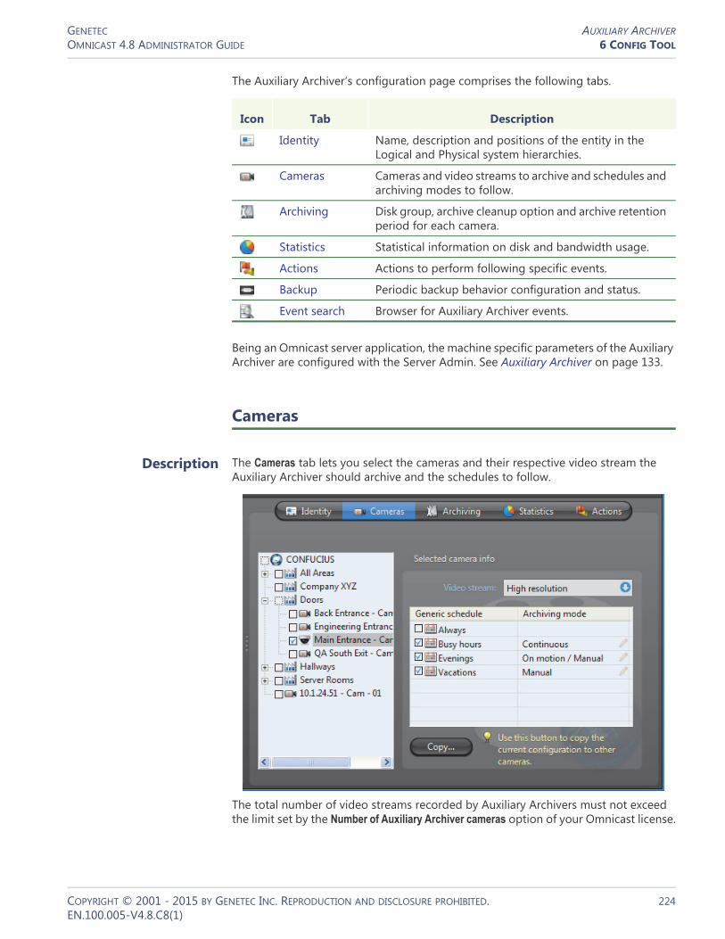
GENETEC AUXILIARY ARCHIVEROMNICAST 4.8 ADMINISTRATOR GUIDE 6 CONFIG TOOL
The Auxiliary Archiver‘s configuration page comprises the following tabs.
Being an Omnicast server application, the machine specific parameters of the Auxiliary Archiver are configured with the Server Admin. See Auxiliary Archiver on page 133.
Cameras
Description The Cameras tab lets you select the cameras and their respective video stream the Auxiliary Archiver should archive and the schedules to follow.
The total number of video streams recorded by Auxiliary Archivers must not exceed the limit set by the Number of Auxiliary Archiver cameras option of your Omnicast license.
Icon Tab Description
Identity Name, description and positions of the entity in the Logical and Physical system hierarchies.
Cameras Cameras and video streams to archive and schedules and archiving modes to follow.
Archiving Disk group, archive cleanup option and archive retention period for each camera.
Statistics Statistical information on disk and bandwidth usage.
Actions Actions to perform following specific events.
Backup Periodic backup behavior configuration and status.
Event search Browser for Auxiliary Archiver events.
COPYRIGHT © 2001 - 2015 BY GENETEC INC. REPRODUCTION AND DISCLOSURE PROHIBITED. 224EN.100.005-V4.8.C8(1)

GENETEC AUXILIARY ARCHIVEROMNICAST 4.8 ADMINISTRATOR GUIDE 6 CONFIG TOOL
Camera tree The selected cameras in the left pane are the ones managed by this Auxiliary Archiver. It means that the Auxiliary Archiver is keeping a copy of the video archives for these cameras.
If you clear a selection in the tree and apply the changes, the system will display the following message.
Answering Yes will permanently delete all copies of the video archives kept for this camera. Answering No will cancel this operation.
TIP To stop the archiving on a selected camera without loosing the video archives, set the archiving mode to Disabled for all selected schedules in the corresponding Selected camera info section.
Selected camera info This sections shows for the selected camera, the video stream to record as well as the archiving schedules and modes to follow.
Parameter Description (1 of 2)
Video stream Most video encoders can generate multiple video streams from the same camera. These streams are given one or more of the following names:• Live (used for live viewing and automatic stream selection) • Recording (used by regular Archivers for recording) • Remote (used for live viewing when the bandwidth is low) • Low resolution (used for automatic stream selection) • High resolution (used for automatic stream selection)
You may choose any one of these video streams for recording. Note that these streams are not necessarily different. To learn how to configure the video streams for a video encoder, please refer to Camera – Video stream usage on page 242.
Generic schedules The generic schedules determine when the archiving should take place. More than one generic schedule may be selected. See Generic Schedule on page 324.
COPYRIGHT © 2001 - 2015 BY GENETEC INC. REPRODUCTION AND DISCLOSURE PROHIBITED. 225EN.100.005-V4.8.C8(1)

GENETEC AUXILIARY ARCHIVEROMNICAST 4.8 ADMINISTRATOR GUIDE 6 CONFIG TOOL
Archiving
Description The Archiving tab lists all the cameras (video encoders) controlled by this Auxiliary Archiver and allows you to choose individually for each, the Disk group, the Automatic cleanup, and the archive Retention period.
Disk group A disk group is a collection of one or more network drives, each with an allotted space for storing video archives. Disk groups are created in the Server Admin. See Disk groups on page 137. The disk group of a camera is where the future video archives from that camera will be stored. The purpose of having several disk groups is to increase the performance of the archiver by allowing it to write simultaneously on different disks.
If the Auxiliary Archiver uses only one disk group, you will see a single list of cameras in this tab. If the Auxiliary Archiver uses more than one disk group, you will see a tree structure where the cameras are distributed according to their assigned disk group.
Archiving mode For each generic schedule you select, you must specify the archiving mode. The choices are:• Disabled – Temporarily disable this schedule. • Manual – Recording will take place only when requested by
the Start recording action.• Continuous – Records continuously during the periods
covered by the schedule.• On motion/manual – Records automatically on motion or
when explicitly requested by the Start recording action.
Parameter Description (2 of 2)
COPYRIGHT © 2001 - 2015 BY GENETEC INC. REPRODUCTION AND DISCLOSURE PROHIBITED. 226EN.100.005-V4.8.C8(1)
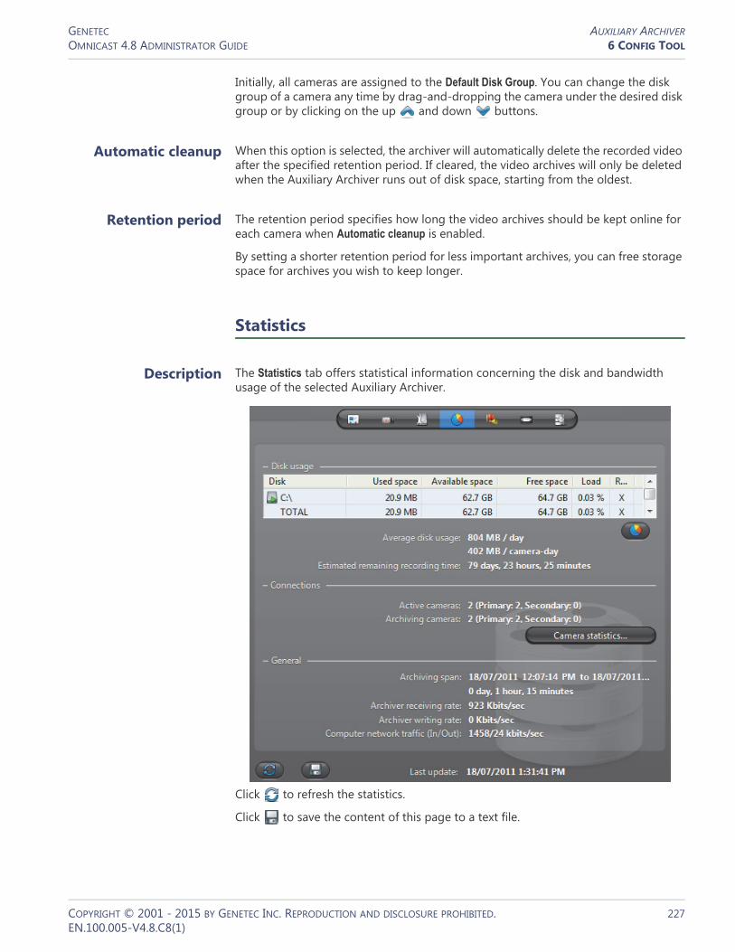
GENETEC AUXILIARY ARCHIVEROMNICAST 4.8 ADMINISTRATOR GUIDE 6 CONFIG TOOL
Initially, all cameras are assigned to the Default Disk Group. You can change the disk group of a camera any time by drag-and-dropping the camera under the desired disk group or by clicking on the up and down buttons.
Automatic cleanup When this option is selected, the archiver will automatically delete the recorded video after the specified retention period. If cleared, the video archives will only be deleted when the Auxiliary Archiver runs out of disk space, starting from the oldest.
Retention period The retention period specifies how long the video archives should be kept online for each camera when Automatic cleanup is enabled.
By setting a shorter retention period for less important archives, you can free storage space for archives you wish to keep longer.
Statistics
Description The Statistics tab offers statistical information concerning the disk and bandwidth usage of the selected Auxiliary Archiver.
Click to refresh the statistics.
Click to save the content of this page to a text file.
COPYRIGHT © 2001 - 2015 BY GENETEC INC. REPRODUCTION AND DISCLOSURE PROHIBITED. 227EN.100.005-V4.8.C8(1)

GENETEC AUXILIARY ARCHIVEROMNICAST 4.8 ADMINISTRATOR GUIDE 6 CONFIG TOOL
Disk group The Disk group drop-down list is present only if more than one disk group is defined for this Auxiliary Archiver. See Disk groups on page 137. Use this drop-down list to view the statistics one disk group at a time or altogether.
Disk usage This section shows the disk usage statistics for the selected disk group. The disk list shows the individual statistics of each disk that is part of the disk group.
Statistics Description (1 of 2)
Disk Disk name. The green marker over the disk icon indicates that the disk is currently used by the Auxiliary Archiver.
Used space Space currently used to store video files on the disk.
Available space Space still available on the disk for archiving purpose. The available space is the total free space on the disk minus the minimum free space that the Auxiliary Archiver is not supposed to use. See Archiving on page 135.
Free space Current free space on disk.
Load Indicates the percentage of archiving space used.
R/W Shows whether the Auxiliary Archiver has read/write access to the disk.
Average disk usage Average space used per day (first line) and average space used per camera per day (second line).
Estimated remaining...
Number of days, hours, and minutes of recording left based on the average disk usage and the current load.
COPYRIGHT © 2001 - 2015 BY GENETEC INC. REPRODUCTION AND DISCLOSURE PROHIBITED. 228EN.100.005-V4.8.C8(1)

GENETEC AUXILIARY ARCHIVEROMNICAST 4.8 ADMINISTRATOR GUIDE 6 CONFIG TOOL
Connections This section shows the connection statistics.
Button Click on this button to show the Protected video file statistics dialog.
The yellow slice represents the proportion of video files unprotected manually by the user (see Video File Query in the Omnicast Archive Player User Guide). When a user decides to manually remove the protection on a video file, the system waits 24 hours before the protection is removed, giving the user enough time to change his mind if necessary. During this reprieve, the file is said to be ending protection.
Statistics Description (2 of 2)
Statistics Description (1 of 2)
Active cameras Primary - Number of active cameras currently under the control of this Auxiliary Archiver. See Archiving on page 226.
Secondary - Number of active cameras that are controlled by another Auxiliary Archiver, but have this Auxiliary Archiver in their failover list.
Archiving cameras Primary - Number of cameras streaming video to the Auxiliary Archiver that are currently under the control of this Auxiliary Archiver.
Secondary - Number of cameras in the redundant archiving mode that are controlled by another Auxiliary Archiver, but are streaming to this Auxiliary Archiver as well. For more information, see Redundant archiving on page 14.
NOTE All archiving cameras are also counted as Active cameras.
COPYRIGHT © 2001 - 2015 BY GENETEC INC. REPRODUCTION AND DISCLOSURE PROHIBITED. 229EN.100.005-V4.8.C8(1)

GENETEC AUXILIARY ARCHIVEROMNICAST 4.8 ADMINISTRATOR GUIDE 6 CONFIG TOOL
Camera statistics dialog
Click the button Camera statistics to view in the following dialog, the latest snapshot of the recording states of all cameras controlled by this Auxiliary Archiver. Click to refresh this snapshot.
The possible values for Recording state are:
Available space Space still available on the disk for archiving purpose. The available space is the total free space on the disk minus the minimum free space that the Auxiliary Archiver is not supposed to use. See Archiving on page 135.
Statistics Description (2 of 2)
Recording state Description
Disabled Recording is currently disabled on this camera.
Stopped Recording is enabled but the Auxiliary Archiver is not recording. If this state is abnormal, the cause of the problem is indicated in the Description. The possible causes are:• Database lost.• Disk(s) full.• Cannot write to any drive.
Started (system) Recording is started by the system (following an On Motion or Continuous schedule).
Started (user) Recording is started by a user.
Started (about to stop)
Recording is started by a user and is about to stop (within the last 30 seconds of recording).
COPYRIGHT © 2001 - 2015 BY GENETEC INC. REPRODUCTION AND DISCLOSURE PROHIBITED. 230EN.100.005-V4.8.C8(1)

GENETEC AUXILIARY ARCHIVEROMNICAST 4.8 ADMINISTRATOR GUIDE 6 CONFIG TOOL
General This section shows the general archive statistics.
Actions
Description The Actions tab allows you to trigger further actions following specific archiver events shown in the Events/actions list.
To learn about general event-to-actions programming, please refer to Event Management on page 22.
Statistics Description
Archiving span Time bracket within which video archives exist.
Archiver receiving rate
The amount of incoming data (audio and video) from the encoders (Kbps/sec). This value turns red if it exceeds 300 Mbps.
Archiver writing rate The amount of data currently being written to disk from the encoders (Kbps/sec).
Computer network traffic (In/Out)
The sum (in Kbps/sec) of all incoming and outgoing data on all network interfaces on this computer. This value turns red if it exceeds 300 Mbps.
Last update The last time the statistics were updated. Click to refresh the statistics.
COPYRIGHT © 2001 - 2015 BY GENETEC INC. REPRODUCTION AND DISCLOSURE PROHIBITED. 231EN.100.005-V4.8.C8(1)
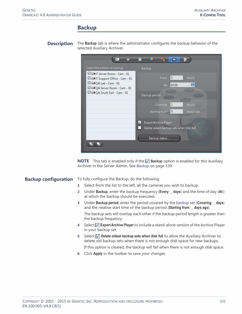
GENETEC AUXILIARY ARCHIVEROMNICAST 4.8 ADMINISTRATOR GUIDE 6 CONFIG TOOL
Backup
Description The Backup tab is where the administrator configures the backup behavior of the selected Auxiliary Archiver.
NOTE This tab is enabled only if the Backup option is enabled for this Auxiliary Archiver in the Server Admin. See Backup on page 139.
Backup configuration To fully configure the Backup, do the following.1 Select from the list to the left, all the cameras you wish to backup.2 Under Backup, enter the backup frequency (Every: _ days) and the time of day (At:)
at which the backup should be executed.3 Under Backup period, enter the period covered by the backup set (Covering: _ days)
and the relative start time of the backup period (Starting from: _ days ago).The backup sets will overlap each other if the backup period length is greater than the backup frequency.
4 Select Export Archive Player to include a stand-alone version of the Archive Player in your backup set.
5 Select Delete oldest backup sets when disk full to allow the Auxiliary Archiver to delete old backup sets when there is not enough disk space for new backups.If this option is cleared, the backup will fail when there is not enough disk space.
6 Click Apply in the toolbar to save your changes.
COPYRIGHT © 2001 - 2015 BY GENETEC INC. REPRODUCTION AND DISCLOSURE PROHIBITED. 232EN.100.005-V4.8.C8(1)

GENETEC AUXILIARY ARCHIVEROMNICAST 4.8 ADMINISTRATOR GUIDE 6 CONFIG TOOL
Backup status Click the Backup status button to display the following dialog.
Use this dialog to check the last backup status and perform unscheduled backups.
The information shown in this dialog are:
Information Description (1 of 2)
Last backup start Time the last backup started.
Last backup end Time the last backup ended.
Last backup duration Duration of the last backup operation.
Last backup size Total size of the video files contained in the backup set.
Last backup status Status of the last backup operation.
Next backup date Scheduled date and time for the next backup to start. This date is calculated as the last backup date plus the backup frequency.
Note that the first time the Auxiliary Archiver starts with the Backup option enabled, the current date is used as the last backup date.
Change... Click this button to set the next backup date. The backup start time must be changed in the Backup period section.
Current status If a backup operation is currently in progress, it would be indicated here, along with the time the backup started. If nothing is going on, the status would be Idle.
Start now... Click this button to start an unscheduled backup now.
Note that this operation may alter the periodic backup schedule. If you do not want to alter the periodic backup schedule, remember to reset the next backup date after the unscheduled backup completes.
COPYRIGHT © 2001 - 2015 BY GENETEC INC. REPRODUCTION AND DISCLOSURE PROHIBITED. 233EN.100.005-V4.8.C8(1)

GENETEC AUXILIARY ARCHIVEROMNICAST 4.8 ADMINISTRATOR GUIDE 6 CONFIG TOOL
Event search
Description The Event search tab allows you to search and browse the events associated to the selected Auxiliary Archiver.
Searching for Auxiliary Archiver events
To perform a search, do the following.1 Indicate the search time range by specifying the From date-time and the To date-
time. You may leave the time range open ended by clearing one or both the date-time options.
2 Select the types of events you are looking for.3 Click Search to start the search. The results are displayed in three columns (Type,
Time, Description) in a scrolling list to the right.Please refer to the archiver related events in Appendix A – Omnicast Event Types (sorted by source entity) on page 518.
4 Click to save the search results to a file.
Last update The last time the backup status was updated. The status is always updated after each backup operation.
Click to refresh the backup status.
Click to save the content of this dialog to a text file.
Information Description (2 of 2)
COPYRIGHT © 2001 - 2015 BY GENETEC INC. REPRODUCTION AND DISCLOSURE PROHIBITED. 234EN.100.005-V4.8.C8(1)

GENETEC BACKUP SETOMNICAST 4.8 ADMINISTRATOR GUIDE 6 CONFIG TOOL
Backup Set
Definition
A backup set is a collection of video archives copied to a backup device (disk or tape) during a single backup operation. They are created for the long term safeguard of the video archives by the archiver (Archiver or Auxiliary Archiver).
Backup sets are visible from the Config Tool only when they are restored through a Restore Archiver. Their properties cannot be
modified. By default, a backup set's name is the archiver's name followed by the backup date.
The backup set's configuration page comprises the following tabs.
For a full description on how to protect your video data with backups, please read the section on Archiving Management – Backup and Restore on page 20.
Info
Description The Info tab describes the content of the restored backup set.
Icon Tab Description
Identity Name, description and positions of the entity in the Logical and Physical system hierarchies.
Info Content description of the backup set.
COPYRIGHT © 2001 - 2015 BY GENETEC INC. REPRODUCTION AND DISCLOSURE PROHIBITED. 235EN.100.005-V4.8.C8(1)

GENETEC BACKUP SETOMNICAST 4.8 ADMINISTRATOR GUIDE 6 CONFIG TOOL
Backup info This section shows the information regarding the Backup operation.
Restore info This section shows the information regarding the Restore operation.
Information Description
Archiver Name of the archiver that originally created this backup set.
Type Type of backup (Folder backup or Tape backup).
Tape backup is for backward compatibility. Starting from version 4.2, tape backup are no longer supported.
Range Date and time range covered by this backup set.
Size Size of the data (video files) contained in this entire backup set. This is not necessarily the size of the restored video files since you can choose to restore only part of the backup set.
Start time Time at which the backup operation started.
Information Description
Start time Time at which the restore operation started.
End time Time at which the restore operation ended.
Size Size of the data (video files) contained in the restored portion of the backup set. This is not necessarily the size of the entire backup set, since it is possible to restore only a subset of the cameras included in the backup set. See Note If you are using a remote database server and there are multiple archivers on the system, please ensure that the database specified is unique on each archiver on page 143.
Camera list List of cameras whose video were restored.• Name – Name of the restored camera. This name is based on
the video file folder name used at the time those files were created by the archiver. Note that spaces are removed.
• Start – Start time of the restored video.• Stop – End time of the restored video.
COPYRIGHT © 2001 - 2015 BY GENETEC INC. REPRODUCTION AND DISCLOSURE PROHIBITED. 236EN.100.005-V4.8.C8(1)

GENETEC CAMERA (VIDEO ENCODER)OMNICAST 4.8 ADMINISTRATOR GUIDE 6 CONFIG TOOL
Camera (Video Encoder)
Definition
A camera is any video surveillance equipment used to monitor a specific area from a particular location. In other words, each camera constitutes a unique video input to the system. To ease their identification, Omnicast automatically assigns a unique logical ID to each camera, also known as the camera ID.
A camera typically produces an analog signal that must be converted into a digital format before it can be transmitted over an IP network.
The video encoder is the device that converts the signal produced by the camera from analog to digital using a standard compression algorithm (H.264, MPEG-4, MPEG-2 or MJPEG). The video encoder is one of the many devices found on an encoder unit.
Each video encoder can generate one or multiple video streams using different compression schemes and formats for different purposes (see Video Quality on page 238). In the case of an IP camera, the camera and the video encoder form an inseparable unit. Because of the intimate relationship between the camera and the video encoder, the two terms are often used interchangeably in Omnicast.
The camera‘s configuration page comprises the following tabs.
Camera ID You may change the camera ID assigned automatically to every camera by the system. This can be done either from the Identity tab of the camera or from the Logical IDs tab of the Directory. See Logical IDs on page 299.
Note that the cameras share the same pool of logical IDs with virtual cameras and viewer layouts.
Icon Tab Description
Identity Name, description and positions of the entity in the Logical and Physical system hierarchies.
Video Quality Video stream selection and quality settings.
Recording Recording options and schedules.
Motion Detection Motion detection settings.
Attributes Analog video format and color settings.
Actions Actions to trigger following specific camera events.
Video Analytics Video analytics settings specific to certain models.
Info Video encoder properties.
Network Network properties.
Links Video encoder connections.
Time Zone Time zone and geographical location.
Specific Settings Other camera settings specific to certain models!
COPYRIGHT © 2001 - 2015 BY GENETEC INC. REPRODUCTION AND DISCLOSURE PROHIBITED. 237EN.100.005-V4.8.C8(1)

GENETEC CAMERA (VIDEO ENCODER)OMNICAST 4.8 ADMINISTRATOR GUIDE 6 CONFIG TOOL
Video Quality
Description The Video quality tab allows you to decide on the number of video streams that the encoder should generate, the usage of each video stream, and the format and quality of each video stream based on specific schedules.
Video stream configuration
The parameters affecting the video stream generated by the video encoder can vary greatly from one model to another. All possible parameters are described in the following table. Note that no video stream requires them all.
Video stream preview on page 247*
Video stream configuration on page 238*
Video stream usage on page 242*
Boosting recording quality on special events on page 245*
Schedule for the displayed configuration on page 243*
Schedule overview on page 244*
Parameter Description (1 of 5)
Video data format The video data format is what determines the resolution of the video image (qcif, cif, 2cif, 4cif, etc.). The available choices vary depending on the model of the video encoder. See Video image resolution on page 272.
The video data format for some units is configured in the Specific settings tab. In these cases, “Specific settings” is indicated as the only available choice from the drop-down list. See “Specific Settings” on page 277.
COPYRIGHT © 2001 - 2015 BY GENETEC INC. REPRODUCTION AND DISCLOSURE PROHIBITED. 238EN.100.005-V4.8.C8(1)

GENETEC CAMERA (VIDEO ENCODER)OMNICAST 4.8 ADMINISTRATOR GUIDE 6 CONFIG TOOL
NOTE On certain models of video units supporting a large number of video feeds (4 to 12), some high resolution formats (2cif and 4cif) may be disabled when you enable all the video streams because the unit will not be able to handle them all at these resolutions.
Quality The quality of the video depends on a combination of settings. The Config Tool proposes a list of predefined quality configurations for you to choose from.
In order to adjust the settings individually, you must select Custom from the Quality drop-down list.
Bit rate Depending on the encoder, this slider sets the maximum bandwidth (kbps) allowed or the average target bit rate.
Bit rate (advanced) For certain brands of encoders, such as AXIS, the maximum bit rate is not set at the encoder level but at the unit level.
For each encoder, additional settings may be configured.
The drop-down list to the left of the bit rate value lets you select the Bit rate mode (see next parameter). This drop-down list is sometimes placed under the Bit rate field.
Bit rate mode The values are:• Variable bit rate (VBR) – Adjusts the bit rate according to
the images' complexity, and thus uses a lot of bandwidth when there is a lot of activity in the image and less bandwidth when the monitored area is quiet.
• Constant bit rate (CBR) – Allows you to set a fixed target bit rate that will consume a predictable amount of bandwidth, and which will not change whatever happens in the image. See next parameter: Bit rate (Priority).
Bit rate (Priority) If you chose to maintain a Constant bit rate, the encoder may not be able to keep both the frame rate and the image quality at their set values when the activity in the image increases. Use the Priority drop-down list to decide how the encoder should behave in these situations.• Frame rate – Maintains the frame rate at the expense of the
image quality.• Image quality – Maintains the image quality at the expense
of the frame rate.• None – Lowers both the frame rate and the image quality
to maintain the bit rate.
Parameter Description (2 of 5)
COPYRIGHT © 2001 - 2015 BY GENETEC INC. REPRODUCTION AND DISCLOSURE PROHIBITED. 239EN.100.005-V4.8.C8(1)

GENETEC CAMERA (VIDEO ENCODER)OMNICAST 4.8 ADMINISTRATOR GUIDE 6 CONFIG TOOL
Maximum bit rate For some encoders, there are two bit rate settings:• Bit rate: Sets the average, target bit rate for the encoder.• Maximum bit rate: Sets the maximum bit rate for the encoder.
This value is greater than, or equal to the target bit rate, and is automatically readjusted each time the bit rate is changed.
Frame rate This slider sets the number of frames per second (fps). A high frame rate (10 fps or more) produces fluid video and is essential for accurate motion detection. However, increasing the frame rate also sends more information over the network and therefore, requires more bandwidth.
Recording frame rate
The purpose of the recording frame rate is to save storage space by recording the video at a frame rate lower than the one used for viewing (see Frame rate). This parameter only reduces the storage usage, not the bandwidth usage.
Setting the Recording frame rate to anything else than All frames locks the Key frame interval.
NOTE When the recording is done at a rate lower than one frame every 2 seconds, you will not be able to play back the video at normal speed. When two consecutive frames are separated by more than 2 seconds during playback, the Archiver will immediately jump to the next frame without pausing between the two frames, creating an accelerated playback.
Key frame interval A key frame is a frame that contains a complete image by itself as opposed to a usual frame that only holds information that changed compared to the previous frame. Frequent key frames require a higher bandwidth. The gain is only felt during the playback. More key frames will enable the user to have a better control during backward search. See Controlling the Playback in the Omnicast Archive Player User Guide.
You can specify the key frame interval in seconds (1 to 20) or by frames (based on the frame rate).
Image quality This slider affects the image quality (the higher the value the better the quality). Higher image quality requires more bandwidth, which may compromise the Frame rate.
When bandwidth is limited, you should consider the following:• To retain very good image quality, restrict the number of
images per second (lower frame rate).• To transmit more images per second at a high frame rate,
lower the image quality.
The encoder will always try to maintain each quality setting. However, if bandwidth is limited, the encoder may reduce the frame rate in favor of the image quality.
Parameter Description (3 of 5)
COPYRIGHT © 2001 - 2015 BY GENETEC INC. REPRODUCTION AND DISCLOSURE PROHIBITED. 240EN.100.005-V4.8.C8(1)

GENETEC CAMERA (VIDEO ENCODER)OMNICAST 4.8 ADMINISTRATOR GUIDE 6 CONFIG TOOL
Automatic settings – Certain models of encoders (like Bosch) lets you select this option instead of setting your own value for Image quality. To set the image quality manually, you have to select Custom in the Quality drop-down list.
Profile and level Used only for MPEG-4 streams, the Profile determines the tools available when generating the stream (e.g., interlace, B frames), and the Level limits the resource usage (e.g. max bit rate).
Video object type The Video Object Type (VOT) to use for the MPEG-4 stream. The available choices are governed by the choice of Profile and Level.
GOP structure Stands for "Group Of Picture" structure. It is possible to set up to four types of GOP structures.• I stands for Intra – frame structure. Meaning only Intra (key
frame) frames will be sent. This is primarily used when using an external multiplexer.
• IP stands for Intra and Predicted – frame structure. This setting will result in the lowest possible video delay.
• IPB stands for Intra and Predicted and Bidirectional – frame structure. This setting enable the user to have a higher quality and a higher delay.
• IPBB stands for Intra and Predicted and Bidirectional and Bidirectional – frame structure. This setting enables the highest quality and a highest delay.
GOP length Stands for "Group Of Picture" length. With this value, it is possible to change the distance (number of frames) between the Intra-Frames in the MPEG-2 video stream.
Streaming type Select between VES (video elementary stream), which sends only video information, or PRG (program stream), which sends both video and audio information.
Input filter mode This drop-down list lets you select a noise filter to apply to the video signal before it is encoded. It has 4 settings: None, Low, Medium, and High.
In removing noise from the video signal, the filter also reduces the sharpness of the image. If the video signal is relatively clean, select None to avoid losing any crispness of the video image. For video images with too much noise, applying the filter can help clean up the image.
Keep in mind however, that the higher the filter level, the more blurry the video image will become. Keeping a very sharp image will create more pixels to encode, therefore, uses more bandwidth. This is why on some video units, the default is set to Medium.
Parameter Description (4 of 5)
COPYRIGHT © 2001 - 2015 BY GENETEC INC. REPRODUCTION AND DISCLOSURE PROHIBITED. 241EN.100.005-V4.8.C8(1)

GENETEC CAMERA (VIDEO ENCODER)OMNICAST 4.8 ADMINISTRATOR GUIDE 6 CONFIG TOOL
For any additional settings not covered here, please refer to the manufacturer's documentation.
Video stream usage Most video encoders can produce more than one video stream from the same video input. When it is the case, the button Stream usage is enabled. Clicking on this button displays the Video stream usage dialog.
This dialog allows you to specify the usage of each of the available video streams (their number depends on the model of video encoder).
The standard video stream usages are:• Live (used for live viewing and Automatic stream selection)• Recording (used by Archivers for recording)• Remote (used for live viewing when the bandwidth is low)• Low resolution (used for Automatic stream selection)• High resolution (used for Automatic stream selection)
Each stream usage must be associated to a video stream but the reverse is not necessary. In the above example, the stream JPEG-4 is not assigned any usage.
Bit rate control Select this option to let the encoder automatically lower the bit rate when one of the decoders is reporting transmission errors (dropped packets). This usually happens when there is a lot of motion on the camera. The encoder will drop the bit rate as low as necessary to let all decoders receive an error free transmission. When the motion subsides, the encoder will gradually pick up the bit rate until it reaches the configured maximum limit.
The trade-off between low bit rate and transmission errors is that with a low bit rate, the image will stay crisp but the video may appear jerky, while with transmission errors, the image will contain noises, but the video will stay fluid.
Compression mode Select between SM4, Verint's proprietary version of MPEG-4 compression, or MPEG4 the standard MPEG-4 compression.
Parameter Description (5 of 5)
COPYRIGHT © 2001 - 2015 BY GENETEC INC. REPRODUCTION AND DISCLOSURE PROHIBITED. 242EN.100.005-V4.8.C8(1)
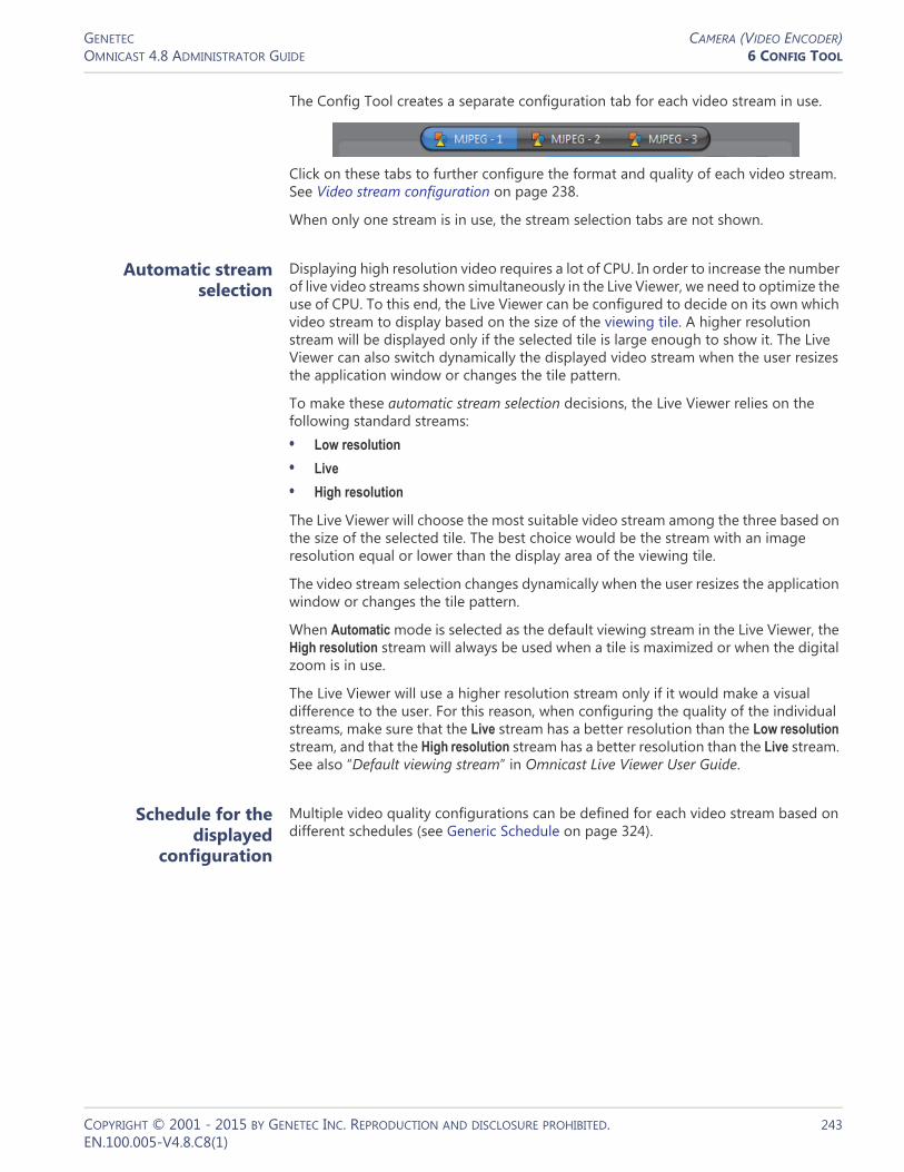
GENETEC CAMERA (VIDEO ENCODER)OMNICAST 4.8 ADMINISTRATOR GUIDE 6 CONFIG TOOL
The Config Tool creates a separate configuration tab for each video stream in use.
Click on these tabs to further configure the format and quality of each video stream. See Video stream configuration on page 238.
When only one stream is in use, the stream selection tabs are not shown.
Automatic stream selection
Displaying high resolution video requires a lot of CPU. In order to increase the number of live video streams shown simultaneously in the Live Viewer, we need to optimize the use of CPU. To this end, the Live Viewer can be configured to decide on its own which video stream to display based on the size of the viewing tile. A higher resolution stream will be displayed only if the selected tile is large enough to show it. The Live Viewer can also switch dynamically the displayed video stream when the user resizes the application window or changes the tile pattern.
To make these automatic stream selection decisions, the Live Viewer relies on the following standard streams:• Low resolution
• Live
• High resolution
The Live Viewer will choose the most suitable video stream among the three based on the size of the selected tile. The best choice would be the stream with an image resolution equal or lower than the display area of the viewing tile.
The video stream selection changes dynamically when the user resizes the application window or changes the tile pattern.
When Automatic mode is selected as the default viewing stream in the Live Viewer, the High resolution stream will always be used when a tile is maximized or when the digital zoom is in use.
The Live Viewer will use a higher resolution stream only if it would make a visual difference to the user. For this reason, when configuring the quality of the individual streams, make sure that the Live stream has a better resolution than the Low resolution stream, and that the High resolution stream has a better resolution than the Live stream. See also “Default viewing stream” in Omnicast Live Viewer User Guide.
Schedule for the displayed
configuration
Multiple video quality configurations can be defined for each video stream based on different schedules (see Generic Schedule on page 324).
COPYRIGHT © 2001 - 2015 BY GENETEC INC. REPRODUCTION AND DISCLOSURE PROHIBITED. 243EN.100.005-V4.8.C8(1)

GENETEC CAMERA (VIDEO ENCODER)OMNICAST 4.8 ADMINISTRATOR GUIDE 6 CONFIG TOOL
Every video stream has at least one configuration based on the default schedule, Always. To add a new configuration, do the following.1 Click the button. The Add configuration dialog box appears.
2 Select the appropriate generic schedule. If no suitable schedule exists, you must create a new one. See Creating a generic schedule on page 324.
3 Select the option Copy the displayed configuration if you wish to use the current configuration as a starting point for the new one.
4 Adjust the settings of the new configuration. See Video stream configuration on page 238.
5 Click Apply changes to finish.
To delete a configuration, select it in the schedules drop-down list and click .
Note that the default configuration may not deleted. However, you may modify it.
Schedule overview To visualize the combined effect of all video quality configurations for a given day, click on the Schedule overview button. The following dialog appears.
COPYRIGHT © 2001 - 2015 BY GENETEC INC. REPRODUCTION AND DISCLOSURE PROHIBITED. 244EN.100.005-V4.8.C8(1)

GENETEC CAMERA (VIDEO ENCODER)OMNICAST 4.8 ADMINISTRATOR GUIDE 6 CONFIG TOOL
The top section lists all video quality configurations. Each configuration is identified by its schedule name, the selected video data format, and a brief quality setting description.
The bottom section shows the different quality settings for the selected date. Use the calendar control to select another date.
When two schedules of different types (i.e. using different recurrence patterns) overlap, priority is evaluated in the following order:1 Specific schedule2 Yearly schedule3 Monthly schedule4 Weekly schedule5 Daily schedule6 Always (the default schedule)
Two schedules with the same recurrence pattern may not overlap. See also Schedule Priorities and Conflict Resolution on page 331.
Boosting recording quality on special
events
On a typical system, the stream used for recording is often of a lesser quality (lower frame rate or lower image resolution) than the stream used for live viewing. The purpose for this is to save on storage space. But when important events occurs, a higher quality recording is needed to provide proper support to after the fact investigations. This is exactly what the Boost quality button/dialog allows you to do.
COPYRIGHT © 2001 - 2015 BY GENETEC INC. REPRODUCTION AND DISCLOSURE PROHIBITED. 245EN.100.005-V4.8.C8(1)
GENETEC CAMERA (VIDEO ENCODER)OMNICAST 4.8 ADMINISTRATOR GUIDE 6 CONFIG TOOL
You can configure a video encoder to temporarily boost the quality of the Recording stream (see Video stream usage on page 242) when the recording is started as the result of one of the following events:• Manual recording
– The Record button was clicked by a Live Viewer user.– The Add bookmark button was clicked by a Live Viewer user.
• Event recording– The Start recording action was triggered by an event.– The Start recording action was executed in a macro.– The recording was started by an alarm.– The recording was triggered by motion.
The quality boost can be configured individually for these two sets of events. If both sets of events are triggered, the Event recording settings will have precedence over the Manual recording settings. The duration of the quality boost will depend on the type of event and the durations configured in the Recording tab of the camera. See Recording on page 248.
NOTE Only the image resolution (cif, 2cif, etc.) and the frame rate can be changed, not the compression type (i.e. MPEG-4, MPEG-2, or MJPEG). Later, if the compression type of the Recording stream is changed, the Boost quality settings will be lost.
The quality boost can be configured to be applied automatically or on demand. To apply the quality boost automatically, select the option Always override video quality on manual/event recording.
To trigger the quality boost on a specific instance, execute one of the following two actions:• Override with manual recording quality • Override with event recording quality
When the quality boost is requested explicitly, the selected quality settings have precedence over any other settings currently in effect. In this case, the quality boost can only be ended by the action:• Recording quality as standard configuration
See the Override actions in Appendix B – Omnicast Action Types (sorted by action name) on page 528.
COPYRIGHT © 2001 - 2015 BY GENETEC INC. REPRODUCTION AND DISCLOSURE PROHIBITED. 246EN.100.005-V4.8.C8(1)
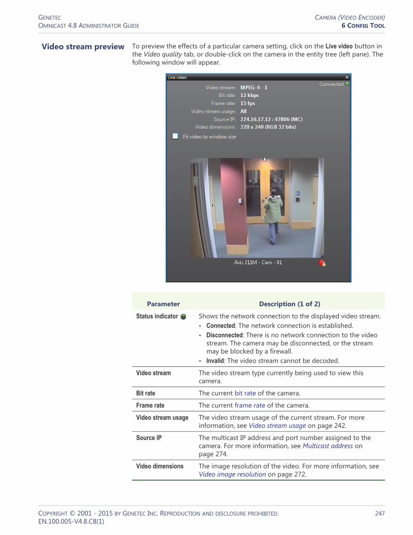
GENETEC CAMERA (VIDEO ENCODER)OMNICAST 4.8 ADMINISTRATOR GUIDE 6 CONFIG TOOL
Video stream preview To preview the effects of a particular camera setting, click on the Live video button in the Video quality tab, or double-click on the camera in the entity tree (left pane). The following window will appear.
Parameter Description (1 of 2)
Status indicator Shows the network connection to the displayed video stream.• Connected: The network connection is established.• Disconnected: There is no network connection to the video
stream. The camera may be disconnected, or the stream may be blocked by a firewall.
• Invalid: The video stream cannot be decoded.
Video stream The video stream type currently being used to view this camera.
Bit rate The current bit rate of the camera.
Frame rate The current frame rate of the camera.
Video stream usage The video stream usage of the current stream. For more information, see Video stream usage on page 242.
Source IP The multicast IP address and port number assigned to the camera. For more information, see Multicast address on page 274.
Video dimensions The image resolution of the video. For more information, see Video image resolution on page 272.
COPYRIGHT © 2001 - 2015 BY GENETEC INC. REPRODUCTION AND DISCLOSURE PROHIBITED. 247EN.100.005-V4.8.C8(1)

GENETEC CAMERA (VIDEO ENCODER)OMNICAST 4.8 ADMINISTRATOR GUIDE 6 CONFIG TOOL
Recording
Description The Recording tab is where you configure all the recording options for the camera.
Recording settings The recording settings are:
Fit video to window size
Select Fit video to window size to allow the video image to follow the window size. If this box is cleared, the actual size (1:1 ratio) of the image will be shown.
Button Shows the recording state of the camera.
Parameter Description (2 of 2)
Parameter Description (1 of 2)
Record on the edge only
Allows Omnicast to retrieve video stored directly on the unit. This option is only available for units that support recording on the edge and your Omnicast license must support Trickling. When this option is selected, archiving schedules are ignored, and the unit will appear in the Camera list of the Trickling tab. See Trickling on page 215.
Record audio Record audio. A microphone must be attached to this camera for it to work. See Links on page 275. This option is disabled if your license does not support audio.
COPYRIGHT © 2001 - 2015 BY GENETEC INC. REPRODUCTION AND DISCLOSURE PROHIBITED. 248EN.100.005-V4.8.C8(1)

GENETEC CAMERA (VIDEO ENCODER)OMNICAST 4.8 ADMINISTRATOR GUIDE 6 CONFIG TOOL
Archiving schedule list The lower part of this tab lists all the archiving schedules available in the system. It is possible to follow more than one archiving schedules on a camera by selecting the ones that apply. To stop using a schedule, simply clear its corresponding check box.
Redundant archiving
Allows all standby Archivers to record simultaneously from this camera. This option is enabled only if your license supports redundant archiving.
Record metadata overlays
Record the metadata overlays generated by Metadata Engine plugins. See Metadata overlays on page 251.
Time to record before an event
Recordings (in seconds) to be added to the recording triggered by an event. This value represents the length of the recording buffer that the Archiver keeps in memory. When recording is started by a user or triggered by an event, the content of this buffer will also be saved, thus, guaranteeing that whatever happened a few seconds before the event’s occurrence will also be captured on video.
Time to record after a motion
This is how long the recording should last (in seconds) when it is triggered by motion detection. See Motion Detection on page 251.
Default manual recording length
This is how long the recording should last (in minutes) when it is manually started by the user. The user may stop the recording any time before the default recording ends.
Note that this value is also used by the Start recording action, when the default recording length is selected.
Parameter Description (2 of 2)
COPYRIGHT © 2001 - 2015 BY GENETEC INC. REPRODUCTION AND DISCLOSURE PROHIBITED. 249EN.100.005-V4.8.C8(1)
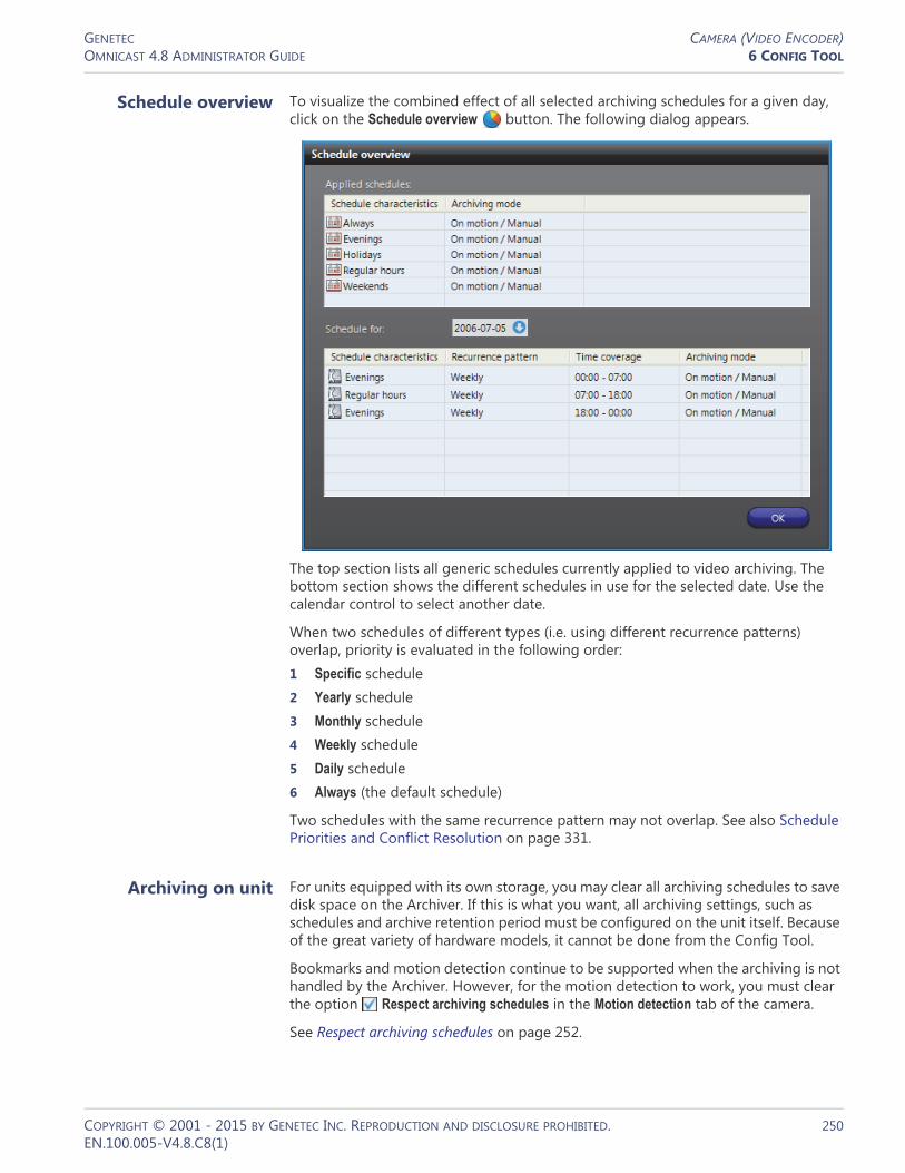
GENETEC CAMERA (VIDEO ENCODER)OMNICAST 4.8 ADMINISTRATOR GUIDE 6 CONFIG TOOL
Schedule overview To visualize the combined effect of all selected archiving schedules for a given day, click on the Schedule overview button. The following dialog appears.
The top section lists all generic schedules currently applied to video archiving. The bottom section shows the different schedules in use for the selected date. Use the calendar control to select another date.
When two schedules of different types (i.e. using different recurrence patterns) overlap, priority is evaluated in the following order:1 Specific schedule2 Yearly schedule3 Monthly schedule4 Weekly schedule5 Daily schedule6 Always (the default schedule)
Two schedules with the same recurrence pattern may not overlap. See also Schedule Priorities and Conflict Resolution on page 331.
Archiving on unit For units equipped with its own storage, you may clear all archiving schedules to save disk space on the Archiver. If this is what you want, all archiving settings, such as schedules and archive retention period must be configured on the unit itself. Because of the great variety of hardware models, it cannot be done from the Config Tool.
Bookmarks and motion detection continue to be supported when the archiving is not handled by the Archiver. However, for the motion detection to work, you must clear the option Respect archiving schedules in the Motion detection tab of the camera.
See Respect archiving schedules on page 252.
COPYRIGHT © 2001 - 2015 BY GENETEC INC. REPRODUCTION AND DISCLOSURE PROHIBITED. 250EN.100.005-V4.8.C8(1)

GENETEC CAMERA (VIDEO ENCODER)OMNICAST 4.8 ADMINISTRATOR GUIDE 6 CONFIG TOOL
Metadata overlays Metadata are additional data that enriches the video. They are generated by plugins, if such plugins are installed on your system, and if the plugins are properly associated to this camera.
The metadata could be any kind of information. All depend on the nature of the associated plugin.
Generally, metadata are stored by the Metadata Engine that controls the plugins. In some cases, part of the metadata must be stored by the Archiver. This is when the metadata constitute graphic information and must be displayed as overlays (images superimposed over the video).
Selecting Record metadata overlays ensures that the Archiver will record all metadata overlays along with the video so they can be reproduced during video playback. See Metadata Search Workflow in Omnicast Archive Player User Guide.
This option has nothing to do with the recording of the metadata performed by the Metadata Engine.
NOTE Metadata overlays can be displayed within the Live Viewer and the Archive Player (software decoders), but not on analog monitors (hardware decoders).
Motion Detection
Description Use the Motion detection tab to set up motion detection on the selected camera.
COPYRIGHT © 2001 - 2015 BY GENETEC INC. REPRODUCTION AND DISCLOSURE PROHIBITED. 251EN.100.005-V4.8.C8(1)

GENETEC CAMERA (VIDEO ENCODER)OMNICAST 4.8 ADMINISTRATOR GUIDE 6 CONFIG TOOL
General concepts
Motion detection can be used to automatically trigger the recording and to generate events (by default Motion on and Motion off) in the system. See Motion related events on page 257.
Motion detection configuration
Multiple motion detection configurations can be defined for a given camera, based on different days and times of the week. Each configuration is associated to a generic schedule which determines when the configuration is applicable. When two configurations’ schedules overlap, the one that applies is determined by the schedule priority rules. See Schedule Priorities and Conflict Resolution on page 331.
Every camera has at least one default motion detection configuration based on the default schedule Always. The default configuration can be modified but cannot be deleted. See Adding new configurations on page 257.
Respect archiving schedules
Select Respect archiving schedules to restrict the motion detection to the periods covered by archiving schedules. Clear this option and the motion events will be generated even when all archiving schedules are disabled. It is recommended to clear this option when the archiving is handled by the unit itself.
See Archiving on unit on page 250.
Motion detection modes
For each configuration, the motion detection can operate in one of the following modes:• Disabled • Full screen – performed by the Archiver • Full screen (Unit) – performed by the unit • Detection zone – performed by the Archiver • Detection zone (Unit) – performed by the unit
Motion detection can operate either on the entire image (Full screen) or within specific areas marked for motion detection, called detection zones. The detection can either be performed by the Archiver (software) or by the Unit (hardware).
When you choose to let the unit perform the motion detection, an additional check box will appear.
Selecting Transmit only when recording can help you save on network bandwidth and Archiver processing time. Since the unit is detecting the motion itself, it does not need to send a continuous video stream to the Archiver to be analyzed. Video streaming over the network will be done only when recording is required. The drawback of this
COPYRIGHT © 2001 - 2015 BY GENETEC INC. REPRODUCTION AND DISCLOSURE PROHIBITED. 252EN.100.005-V4.8.C8(1)

GENETEC CAMERA (VIDEO ENCODER)OMNICAST 4.8 ADMINISTRATOR GUIDE 6 CONFIG TOOL
approach is that there will be no recording before the event (see Recording settings on page 248). The recording will start a fraction of a second after motion is detected, not before. If the recording before the event is important, then do not select this option.
NOTE Axis cameras that support hardware motion detection will display motion indicators in the timeline during playback when motion detection is performed on the unit. However, testing motion detection in the Config Tool and Motion Search remains unsupported like in other cases.
Motion detection capabilities
Clicking on the Capabilities button displays the following dialog showing the motion detection capabilities of the encoder unit.
The capabilities are:
Capability Description
Motion detection Full screen motion detection can be performed by the Archiver.
Detection zone(s) Motion detection by detection zone(s) can be performed by the Archiver. Depending on the model of the unit, up to six detection zones may be defined within a given configuration.
Motion detection in the unit
Full screen motion detection can be performed by the unit.
Detection zone(s) in the unit
Motion detection can be confined to a specific zone when it is performed by the unit.
Multiple detection zones in the unit
Multiple detection zones can be defined for motion detection on the unit.
Irregular shape detection zone
Motion detection zone can take any shape you want. If not supported, you may only draw rectangular shapes.
Test motion through Web access
Motion detection can only be tested from a Web page provided by the unit manufacturer. See Testing motion through Web access on page 256.
Support motion search in Archive Player
Detailed Motion Search on specific areas can be performed with the Archive Player on archived video. See Motion Search Workflow in Omnicast Archive Player User Guide.
COPYRIGHT © 2001 - 2015 BY GENETEC INC. REPRODUCTION AND DISCLOSURE PROHIBITED. 253EN.100.005-V4.8.C8(1)

GENETEC CAMERA (VIDEO ENCODER)OMNICAST 4.8 ADMINISTRATOR GUIDE 6 CONFIG TOOL
The supported motion detection capabilities may depend on the selected video data format (see Video stream configuration on page 238). For certain brand of video units, simply changing the video data format to MJPEG may give you more capabilities.
EXAMPLE For Axis video units, you cannot test motion detection using MPEG-4 streams in Omnicast, so you must change the video data format to MJPEG.
What constitutes a positive motion
detection?
Four parameters are considered by Omnicast to make a positive motion detection. They are:
WARNING Light reflections on windows, switching lights on and off, and light level changes caused by cloud movement can cause undesirable responses from the motion detection algorithm and thereby generate false alarms. Carry out a number of tests for different day and night time conditions in order to ensure correct interpretation of the video images. For surveillance of indoor areas, ensure a constant lighting of the areas during the day and at night. Uniform surfaces without contrast can trigger false alarms even with uniform lighting.
Parameter Description
Sensitivity The sensitivity controls how much difference must be detected in a block between two consecutive frames before it is highlighted as a motion block. See Testing motion detection on page 255. With the sensibility set to the maximum (100%), the slightest variation in an image block will be detected as motion. Lowering the sensitivity will reduce the number of motion blocks detected in the video. It is recommended to set the sensitivity lower than 100% only if your equipment is prone to generate noise. Also note that a plain image, such as viewing an empty wall, is more prone to generate noise than an image containing lots of details.
You can also set the sensitivity value automatically. See Auto Sensitivity on page 256.
Consecutive frame hits
A frame whose number of motion blocks reaches the Motion on threshold is called a hit. Setting the Consecutive frame hits higher than 1 helps avoid making false-positive motion detection such as video noise in a single frame. It ensures that a positive motion detection will not be reported because a hit has been observed in a single frame, but rather that it has been observed over a specified number of consecutive frames. When enough consecutive hits have been observed, the first hit in the series is marked as the beginning of motion.
Motion on threshold
This parameter indicates the minimum number of motion blocks that must be detected before the motion is significant enough to be reported. Together with the Consecutive frame hits, a positive detection of motion is made.
Motion off threshold
In the same way the Motion on threshold detects the beginning of motion, the Motion off threshold detects the end of motion. Motion has ended when the number of motion blocks has dropped below the Motion off threshold for at least 5 seconds.
COPYRIGHT © 2001 - 2015 BY GENETEC INC. REPRODUCTION AND DISCLOSURE PROHIBITED. 254EN.100.005-V4.8.C8(1)

GENETEC CAMERA (VIDEO ENCODER)OMNICAST 4.8 ADMINISTRATOR GUIDE 6 CONFIG TOOL
Testing motion detection
To view the effect of the motion detection settings (if done by the Archiver), click the Show video button. The following window will appear.
For the purpose of motion detection, the video image is divided into a large number of blocks (1,320 for NTSC encoding standard and 1,584 for PAL). To detect motion, consecutive video frames are compared block by block. The ones that are different are highlighted in green. The green squares, called motion blocks, show areas in the video image where motion is being detected.
Whenever positive motion detections are made, the LED at the bottom of the window will turn red and the motion blocks are also displayed in red. See What constitutes a positive motion detection? on page 254. The recording state of the camera is also shown in the bottom-right corner of the window.
See also Testing multi-zone motion detection on page 259.
If motion detection is performed by the unit, the unit may not apply exactly the same Sensitivity settings that were configured in the Config tool. Therefore, when testing motion detection performed by a unit, what is depicted in the Motion detection dialog box may not accurately reflect the Sensitivity that was specified in the Config Tool. Also, the Motion Search in the Archive Player will not be supported. See Omnicast Archive Player User Guide. As well, in most cases, the motion indicators (red blocks) will not be shown in the timeline during video playback.
COPYRIGHT © 2001 - 2015 BY GENETEC INC. REPRODUCTION AND DISCLOSURE PROHIBITED. 255EN.100.005-V4.8.C8(1)

GENETEC CAMERA (VIDEO ENCODER)OMNICAST 4.8 ADMINISTRATOR GUIDE 6 CONFIG TOOL
Auto Sensitivity The Auto Sensitivity feature helps you to determine what constitutes positive motion detection by automatically setting the sensitivity value. Please note that this feature is not supported for hardware (unit) motion detection. Before you begin: Make sure there is no motion in the camera’s field of view (0 motion blocks).
NOTE If your camera is located outdoors, the accuracy of this test might be affected due to wind, moving trees, etc.
To automatically set the Sensitivity value:1 In the Motion detection tab, click the Show video button.2 Click the Auto Sensitivity button.
Different sensitivity values are tested to find the highest value without detecting motion in the image. This test will account for any unwanted background noise that your camera may pick up and consider as motion.During the test, there is a status bar under the Auto Sensitivity button that marks the progress. You can also see the Sensitivity slider adjusting in the Motion detection tab of the Config Tool.
Once the test is finished, it says Done under the Auto Sensitivity button, and the Sensitivity value is set accordingly. For more information about the Sensitivity value, see Sensitivity on page 254.
Testing motion through Web access
For units that require Web access to test the motion detection (see Motion detection capabilities on page 253), an extra Web access button will be provided in the Motion detection window.
Click on Web access to open a separate browser window showing a configuration Web page provided by the manufacturer. From that Web page, you should find tools to help you test the motion. Since these Web pages are manufacturer dependent, they are not covered in this manual.
COPYRIGHT © 2001 - 2015 BY GENETEC INC. REPRODUCTION AND DISCLOSURE PROHIBITED. 256EN.100.005-V4.8.C8(1)

GENETEC CAMERA (VIDEO ENCODER)OMNICAST 4.8 ADMINISTRATOR GUIDE 6 CONFIG TOOL
You will have to perform a separate login because in most cases, the security on the edge device is not managed by Omnicast. However, certain manufacturers, such as Axis, benefit from a tighter integration, therefore the additional login is not required.
WARNING The Web access should only be used to test the motion detection, not to configure it. To configure the motion detection, always make the changes using the Motion detection window (see Edit mode on page 260).Any change made directly through the Web will not be remembered when Omnicast switches configurations based on the schedule (see Motion detection configuration on page 252).
Motion related events By default, the system will generate the Motion on event at the beginning of motion and the Motion off event at the end of motion. However, the user can silence these events by selecting No event in the appropriate drop-down list or replace the default event with a custom event.
Automatic recording on motion
Selecting Trigger recording upon motion will cause the recording to start when the beginning of motion is detected. See What constitutes a positive motion detection? on page 254.
Recording starts n seconds (Time to record before an event) before the beginning of motion (first hit in the series of hits required by Consecutive frame hits), if the motion detection is performed by the Archiver, or immediately after, if the motion detection is performed by the unit.
Recording stops automatically m seconds (Time to record after a motion event) after the motion has officially ended, i.e. 5 seconds after the number of motion blocks has dropped below the Motion off threshold and stayed below.
IMPORTANT While configuring the record on motion feature, choose both Motion on threshold and Motion off threshold carefully. The first parameter determines when the recording should start. The second parameter determines when the recording should stop. Depending on your situation and the quality of the camera, the movement level may never drop to zero. If the Motion off threshold is set too low, once the recording has started, it may never stop!
The recording time before and after an event are specified in the Recording tab of the video encoder. See Recording on page 248.
Adding new configurations
To add a new motion detection configuration, do the following.1 Click the button. The Add configuration dialog appears.
COPYRIGHT © 2001 - 2015 BY GENETEC INC. REPRODUCTION AND DISCLOSURE PROHIBITED. 257EN.100.005-V4.8.C8(1)

GENETEC CAMERA (VIDEO ENCODER)OMNICAST 4.8 ADMINISTRATOR GUIDE 6 CONFIG TOOL
2 Select the appropriate generic schedule. If no suitable schedule exists, you must create a new one. See Creating a generic schedule on page 324.
3 Select the option Copy the displayed configuration if you wish to use the current configuration as a starting point for the new one.
4 Adjust the settings of the new configuration. See General concepts on page 252.5 Define the detection zone. See Detection Zone on page 258.6 Click Apply changes to finish.
Detection Zone
Purpose Using motion detection zones allows the motion detection to be confined to specific areas of the video image marked for motion detection. Motion outside the marked areas are ignored. The advantage of using this method is that it enables the system to detect motions only where it matters. For example, movement at the door versus movement created by people walking inside a room. Up to six motion detection zones can be defined within each configuration.
To switch to motion detection by zones, select Detection zone or Detection zone (Unit) in the Motion detection drop-down list. The extra controls beside the Current detection zone separator will be added to the configuration page as shown below.
The settings shown above the Current detection zone separator are common settings for all detection zones within the current configuration. The settings below the separator are settings specific to each detection zone.
COPYRIGHT © 2001 - 2015 BY GENETEC INC. REPRODUCTION AND DISCLOSURE PROHIBITED. 258EN.100.005-V4.8.C8(1)

GENETEC CAMERA (VIDEO ENCODER)OMNICAST 4.8 ADMINISTRATOR GUIDE 6 CONFIG TOOL
The detection zone command buttons are:• – Create a new detection zone. This button is disabled if you have already
created six detection zones.• – Remove the current detection zone.• – Rename the current detection zone.
In the previous illustration, the current detection zone is called “Back door”. The default event Motion on has been replaced by the custom event Door open and the default event Motion off has been silenced.
TIP The advantage of having multiple detection zones is that it allows you to generate different events depending on where the motion is detected. Based on these events, specific actions may be programmed. See Actions on page 266.
WARNING When switching the motion detection mode from Detection zone to Detection zone (Unit), all previously defined zones may be lost, except the first one, if the unit cannot support as many zones as the Archiver.
Testing multi-zone motion detection
Click on the Show video button to display the motion detection window.
Four modes are available.
Click To
View all motion – This mode allows you to test the motion detection as though in Full screen mode. See Testing motion detection on page 255.
Edit current zone – This mode allows you to edit the detection blocks for the current zone. See Edit mode on page 260.
COPYRIGHT © 2001 - 2015 BY GENETEC INC. REPRODUCTION AND DISCLOSURE PROHIBITED. 259EN.100.005-V4.8.C8(1)

GENETEC CAMERA (VIDEO ENCODER)OMNICAST 4.8 ADMINISTRATOR GUIDE 6 CONFIG TOOL
The detection zone can be defined to cover a door, a window, an entrance, a hallway, etc. The tools for editing the motion detection zone are explained below.
Edit mode To enter the edit mode, click Edit current zone button.
The current detection zone is shown by green blocks on the video image.
The detection blocks making up the motion detection zone may or may not be contiguous. It all depends on whether your unit supports irregular shapes or not.
If other detection zones are defined for the current configuration, they will be shown in blue. Individual zones are allowed to overlap each other.
Use the following edit buttons to draw the desired detection zone.
Test recording – This mode shows all the detection zones at the same time and shows the number of motion blocks detected in each zone. Recording is triggered when all the motion blocks are shown in red.
The LED beside the zone name turns red when the Motion on threshold for that zone is met.
Test current detection zone – This mode shows only the current zone. The detection zone is highlighted in blue. Notice that the motion blocks only appear within the defined zone.
Click To
Tool Description (1 of 2)
Use the Pen to draw motion detection blocks one at a time.
Use the Eraser to erase the motion detection blocks that are not needed.
Use the Rectangle to draw a group of motion detection blocks.
Use the Fill tool to fill the whole image with motion detection blocks.
COPYRIGHT © 2001 - 2015 BY GENETEC INC. REPRODUCTION AND DISCLOSURE PROHIBITED. 260EN.100.005-V4.8.C8(1)

GENETEC CAMERA (VIDEO ENCODER)OMNICAST 4.8 ADMINISTRATOR GUIDE 6 CONFIG TOOL
Once the motion detection zone is set, test it by clicking on .
Click the Load default button to use the default settings (in percentage) for the detection zone you just defined.
When multiple motion detection zones are being used, any zone that meets the Consecutive frame hits can trigger the recording. When showing the video in Test recording mode, the motion blocks are shown in red if a positive motion detection is made by any one of the detection zones. See What constitutes a positive motion detection? on page 254.
Advanced H.264 Motion Detection
When an H.264 stream is selected as the recording stream, the Advanced button is available in the lower right side of the Motion detection tab.
Use the Clear tool to erase all the motion detection blocks in the image.
Use the Invert tool to interchange the area with motion detection blocks with the area without motion detection blocks.
Use the Learn mode to let the computer analyze what is typical motion in the image. When typical motion occurs, the motion detection blocks in the affected areas will be turned off, so it can be ignored.
Tool Description (2 of 2)
COPYRIGHT © 2001 - 2015 BY GENETEC INC. REPRODUCTION AND DISCLOSURE PROHIBITED. 261EN.100.005-V4.8.C8(1)

GENETEC CAMERA (VIDEO ENCODER)OMNICAST 4.8 ADMINISTRATOR GUIDE 6 CONFIG TOOL
Click the Advanced button to open the H.264 advanced motion detection settings dialog box where you can configure your Motion detection settings for an H.264 stream.
Choose a Preset from the drop-down menu:• Custom Allows you to customize your settings using the available sliders.• Vector emphasis Sets motion detection based on the difference in motion vector
values (movement) between consecutive frames.• Luma emphasis Sets motion detection based on the difference in luma values
(brightness) between consecutive frames.
Depending on your unit, the Vector and Luma emphasis presets may not provide desirable results. If you find you are getting too many or too few motion events, choose Custom from the Preset list and adjust the following slider values until you achieve desirable results. Values range between 0 and 100. The higher the value, the more motion is detected.• Luma weight Sets motion detection based on the difference in luma values
(brightness) between consecutive frames.• Chroma weight Sets motion detection based on the difference in chroma (color)
values between consecutive frames.• Vectors weight Sets motion detection based on the difference in vector values
(movement) between consecutive frames.• Macroblocks weight Sets motion detection based on the presence of intra-
macroblocks in your frame. This setting is useful when you notice motion detection indicators on still frames. For example, some units will generate frames completely comprised of intra-macroblocks as a new reference point. When this happens, you will see motion detection blocks covering your whole image. Setting the Macroblocks weight to 0 will help prevent this from happening.
Tip Click the Show video button on the Motion detection tab to see the effect of your changes in real time.
COPYRIGHT © 2001 - 2015 BY GENETEC INC. REPRODUCTION AND DISCLOSURE PROHIBITED. 262EN.100.005-V4.8.C8(1)

GENETEC CAMERA (VIDEO ENCODER)OMNICAST 4.8 ADMINISTRATOR GUIDE 6 CONFIG TOOL
Attributes
Description The Attributes tab lets you change the output of this video encoder.
Analog format The Analog format drop-down list lets you choose between NTSC (National Television Standards Committee) or PAL (Phase Alternating Line) analog format for the video signal.
NOTE Changing this setting might require the unit to reboot. If necessary, the unit will reboot by itself within the next minute and will be temporarily unavailable (shown as inactive). You can force the unit to reboot immediately by going to the Network tab of the corresponding unit and clicking on the Reboot button. See Unit – Network on page 412.
Schedule for the displayed
configuration
Multiple video attribute configurations can be defined for each video stream based on different schedules (see Generic Schedule on page 324).
Every camera has at least one attribute configuration based on the default schedule, Always. To add a new configuration, do the following:1 Click the button. The Add configuration dialog box appears.
COPYRIGHT © 2001 - 2015 BY GENETEC INC. REPRODUCTION AND DISCLOSURE PROHIBITED. 263EN.100.005-V4.8.C8(1)

GENETEC CAMERA (VIDEO ENCODER)OMNICAST 4.8 ADMINISTRATOR GUIDE 6 CONFIG TOOL
2 Select the appropriate generic schedule. If no suitable schedule exists, you must create a new one. See Creating a generic schedule on page 324.
3 Select the option Copy the displayed configuration if you wish to use the current configuration as a starting point for the new one.
4 Adjust the settings of the new configuration. See Video attributes configuration on page 264.
5 Click Apply changes to finish.
Video attributes configuration
The video attribute commands are:
Command Description
Brightness Adjusts the brightness of the encoded video stream. A positive value makes the image brighter.
Contrast Adjusts the contrast of the encoded video stream.
Hue Adjusts the colors of the encoded video stream. A positive value will increase the warm colors (red). A negative value will increase the cold colors (blue).
Saturation Adjusts the strength of the colors. You can remove all colors by setting it to -128.
Load default Resets all attributes to zero.
Live video Displays the live video window to test your settings. See Video stream preview on page 247.
COPYRIGHT © 2001 - 2015 BY GENETEC INC. REPRODUCTION AND DISCLOSURE PROHIBITED. 264EN.100.005-V4.8.C8(1)
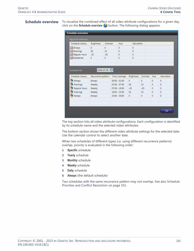
GENETEC CAMERA (VIDEO ENCODER)OMNICAST 4.8 ADMINISTRATOR GUIDE 6 CONFIG TOOL
Schedule overview To visualize the combined effect of all video attribute configurations for a given day, click on the Schedule overview button. The following dialog appears.
The top section lists all video attribute configurations. Each configuration is identified by its schedule name and the selected video attributes.
The bottom section shows the different video attribute settings for the selected date. Use the calendar control to select another date.
When two schedules of different types (i.e. using different recurrence patterns) overlap, priority is evaluated in the following order:1 Specific schedule2 Yearly schedule3 Monthly schedule4 Weekly schedule5 Daily schedule6 Always (the default schedule)
Two schedules with the same recurrence pattern may not overlap. See also Schedule Priorities and Conflict Resolution on page 331.
COPYRIGHT © 2001 - 2015 BY GENETEC INC. REPRODUCTION AND DISCLOSURE PROHIBITED. 265EN.100.005-V4.8.C8(1)

GENETEC CAMERA (VIDEO ENCODER)OMNICAST 4.8 ADMINISTRATOR GUIDE 6 CONFIG TOOL
Actions
Description The Actions tab allows you to program specific system behaviors based on the camera events shown in the Events/actions list.
To learn about general event-to-actions programming, please refer to Event Management on page 22.
COPYRIGHT © 2001 - 2015 BY GENETEC INC. REPRODUCTION AND DISCLOSURE PROHIBITED. 266EN.100.005-V4.8.C8(1)

GENETEC CAMERA (VIDEO ENCODER)OMNICAST 4.8 ADMINISTRATOR GUIDE 6 CONFIG TOOL
Video Analytics
Description The Video Analytics tab allows you to set up rules that will trigger events when using an OV Ready compliant video unit. The following sections describe how to configure ObjectVideo OnBoard events using the Omnicast Config Tool. For more information about each event type and its available settings, see your ObjectVideo documentation.
IMPORTANT In order to view, edit, and configure rules, your video unit needs to be online.
Creating a rule To create a new video analytics rule: 1 Select the ObjectVideo compliant unit from the Physical View in the View selection
pane.
2 Click the Video analytics tab.
COPYRIGHT © 2001 - 2015 BY GENETEC INC. REPRODUCTION AND DISCLOSURE PROHIBITED. 267EN.100.005-V4.8.C8(1)

GENETEC CAMERA (VIDEO ENCODER)OMNICAST 4.8 ADMINISTRATOR GUIDE 6 CONFIG TOOL
3 Click the button below the rules list. The Rule Editor dialog box appears..
4 In the Rule name field, specify a name for the new rule.The rule name you specify will be visible in the Live Viewer and Archive Player to help you distinguish your Object Video OnBoard events from other events.
5 Choose an event from the Event type drop-down list.– If you chose Tripwire, see Creating a tripwire on page 270.– If you chose Area of interest, see Defining an area of interest on page 270.
6 Select the Object type that will trigger the event (not applicable to Camera tampering events).
COPYRIGHT © 2001 - 2015 BY GENETEC INC. REPRODUCTION AND DISCLOSURE PROHIBITED. 268EN.100.005-V4.8.C8(1)

GENETEC CAMERA (VIDEO ENCODER)OMNICAST 4.8 ADMINISTRATOR GUIDE 6 CONFIG TOOL
7 Select your Plane type (Area of interest events only).– Ground Used to trigger events on the ground, when the bottom of an object
is within the area. For example, if the object type is a person, the person’s footprint will trigger an event when the person walks onto an area of interest.
– Image Used to trigger events on vertical surfaces, such as a wall, doorway, or window. For example, if the object type is a person, the person will trigger an event when walking by the area of interest.
For more detailed information about ground and image plane types, see your ObjectVideo documentation.
8 Some events require you to associate actions to the event to trigger it. For more details, see Associating actions on page 271.
9 Click OK in the Rule Editor dialog box. Your new rule will appear in the rules list.
By default, all new rules are enabled in the Active column so they can be triggered and displayed in the Live Viewer. Clear this option if you want to disable a rule.
– To delete a rule, select it in the rules list and click the button.– To edit a rule, select it in the rules list and click the button.– To refresh the rules list, click the button.
You can refine your rules further to detect events more accurately. To do this, click Parameters located below the rules list. For details on the available parameters settings, please see your ObjectVideo documentation.
COPYRIGHT © 2001 - 2015 BY GENETEC INC. REPRODUCTION AND DISCLOSURE PROHIBITED. 269EN.100.005-V4.8.C8(1)

GENETEC CAMERA (VIDEO ENCODER)OMNICAST 4.8 ADMINISTRATOR GUIDE 6 CONFIG TOOL
Creating a tripwire When you select the Tripwire event, a snapshot of the camera view is provided to create a tripwire that triggers an event when an object passes over it.
To create a tripwire:1 Click one of the orientation buttons on the left of the camera view. Each button
represents the direction that the object moves in relation to the tripwire. You can choose from Left to right, Right to left, or Any direction.
You can change the direction of the tripwire at any time by clicking a different orientation button. To delete a tripwire, click the button.
2 Position the pointer in the camera view where you want your tripwire to start. Drag the pointer to draw a straight line. Left-click at each point where you want draw a new line segment. Right-click to set the tripwire.
Defining an area of interest
When you select the Area of interest event, a snapshot of the camera view is provided to define an area of interest that triggers an event when the object enters it.
To define an area of interest:1 Click one of the shape buttons on the left of the camera view. You can choose
Rectangle or Polygon.
You can switch from a Rectangle to a Polygon at any time by clicking the corresponding button. To delete your current shape, click the button.2 To create a rectangle, position your cursor in the camera view where you want the
rectangle to begin and drag until you cover the desired area. Left-click to set the shape.
Left to right
Any direction
Right to left
Rectangle
Polygon
COPYRIGHT © 2001 - 2015 BY GENETEC INC. REPRODUCTION AND DISCLOSURE PROHIBITED. 270EN.100.005-V4.8.C8(1)

GENETEC CAMERA (VIDEO ENCODER)OMNICAST 4.8 ADMINISTRATOR GUIDE 6 CONFIG TOOL
3 To create a polygon, drag for each vertex point you want to draw. Once you’ve created the last vertex point, right-click to set the shape.
Associating actions If your rule uses an Area of interest or Full frame event, an associated action is required for the event to be triggered.
To associate an action to a rule:1 In the Rule Editor dialog box, click the button below the actions table.2 In the Actions dialog box, select an action from the drop-down menu.3 Enter a Duration (in seconds) for the action and click OK. The action appears in the
Actions table.
To edit an action, select it in the actions list and click the button.To delete an action, select it in the actions list and click the button.
Info
Description The Info tab displays the video encoding properties of the selected encoder unit.
COPYRIGHT © 2001 - 2015 BY GENETEC INC. REPRODUCTION AND DISCLOSURE PROHIBITED. 271EN.100.005-V4.8.C8(1)

GENETEC CAMERA (VIDEO ENCODER)OMNICAST 4.8 ADMINISTRATOR GUIDE 6 CONFIG TOOL
The following parameters are displayed for information purpose only.
Video image resolution
The following table shows the video image resolution in terms of the analog format (NTSC or PAL) and the resolution standard.
Megapixel resolutions The following table shows the video image resolution in terms of the digital format, expressed in megapixels, with the resolution standard. Digital cameras do not have the same constraints as analog cameras, so they can have a wider range of resolutions. The ones below are therefore only a sample of some standard resolutions.
1280 x 1024 1600 x 1200 2048 x 1536 2560 x 1920
NOTE Not all video resolutions are supported by all decoder models.
Parameter Description
Board type Type of hardware used by the encoder unit.
Video input number Input number for units having more than one input.
Analog format Analog format used by the video encoder (NTSC or PAL). The analog format, along with the video data format, define the resolution of the image. See Video image resolution on page 272.
Video data formats Lists of the compression types (MPEG-4, MPEG-2, or MJPEG) and resolution standards (qcif, cif, 2cif, 4cif, etc.) supported by this video encoder. This list varies from model to model.
Viewing video decoders
List of video decoders that are currently viewing this camera.
qcif cif 2cif 2cif (480) all lines 2/3D1 VGA 2cif H 4cif
NTSC 176 x 128 352 x 240 352 x 384 352 x 480 352 x 480 480 x 480 640 x 480 704 x 240 704 x 480
PAL 176 x 144 352 x 288 352 x 448 352 x 576 352 x 576 480 x 576 640 x 576 704 x 288 704 x 576
1.3 2 3 5
Resolution
COPYRIGHT © 2001 - 2015 BY GENETEC INC. REPRODUCTION AND DISCLOSURE PROHIBITED. 272EN.100.005-V4.8.C8(1)
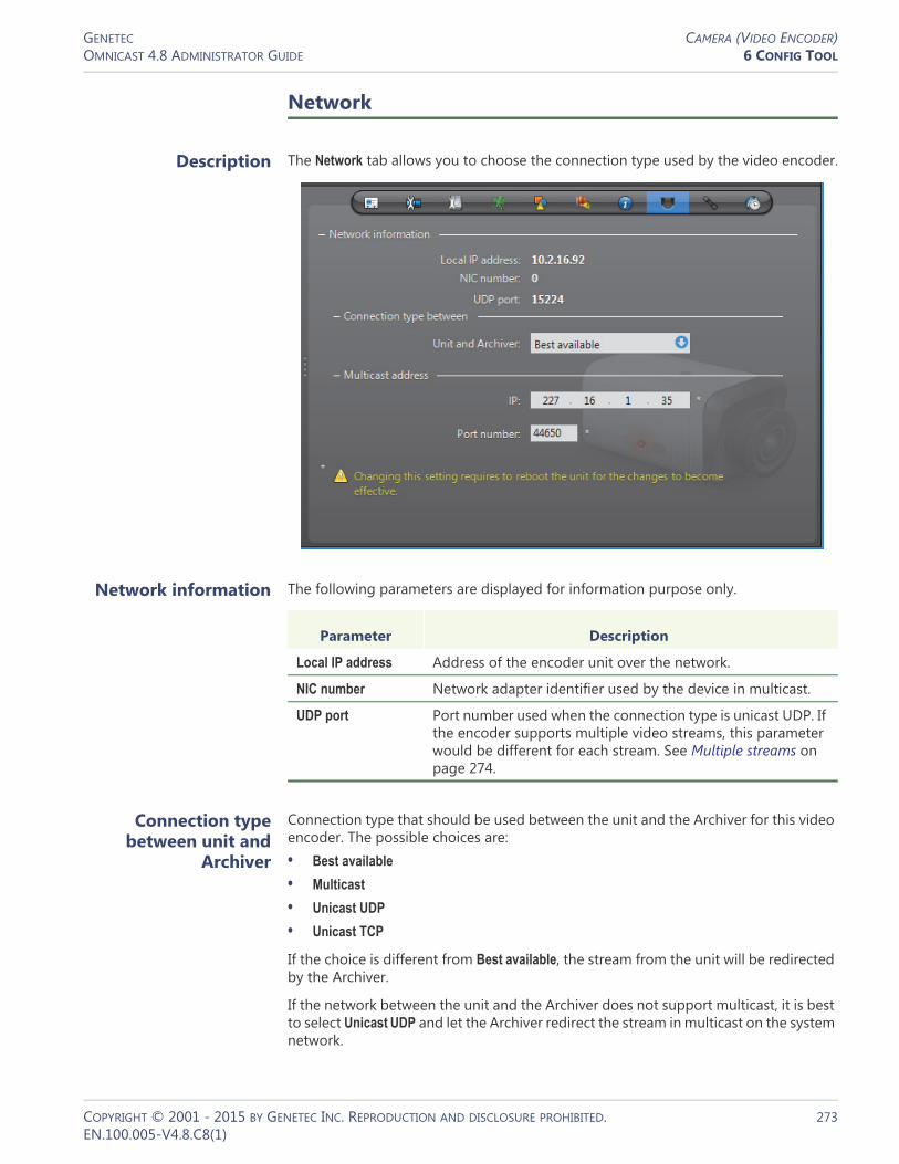
GENETEC CAMERA (VIDEO ENCODER)OMNICAST 4.8 ADMINISTRATOR GUIDE 6 CONFIG TOOL
Network
Description The Network tab allows you to choose the connection type used by the video encoder.
Network information The following parameters are displayed for information purpose only.
Connection type between unit and
Archiver
Connection type that should be used between the unit and the Archiver for this video encoder. The possible choices are:• Best available
• Multicast
• Unicast UDP
• Unicast TCP
If the choice is different from Best available, the stream from the unit will be redirected by the Archiver.
If the network between the unit and the Archiver does not support multicast, it is best to select Unicast UDP and let the Archiver redirect the stream in multicast on the system network.
Parameter Description
Local IP address Address of the encoder unit over the network.
NIC number Network adapter identifier used by the device in multicast.
UDP port Port number used when the connection type is unicast UDP. If the encoder supports multiple video streams, this parameter would be different for each stream. See Multiple streams on page 274.
COPYRIGHT © 2001 - 2015 BY GENETEC INC. REPRODUCTION AND DISCLOSURE PROHIBITED. 273EN.100.005-V4.8.C8(1)

GENETEC CAMERA (VIDEO ENCODER)OMNICAST 4.8 ADMINISTRATOR GUIDE 6 CONFIG TOOL
For more information on the meaning of each connection type, see System Concepts – Network Connections on page 29.
Multicast address The Multicast address and Port number are assigned automatically by the system when the unit is discovered. Each video encoder is assigned a different multicast address with a fixed port number. If the encoder is capable of generating multiple video streams, then a multicast addresses should be assigned to each stream. This is the most efficient configuration.
Normally, you do not need to be concerned with the multicast addresses. However, if you are short of multicast addresses (certain switches are limited to 128), you can solve the problem by using the same multicast address on multiple encoders and by assigning a different port number to each. Note that this solution is less efficient than using a different address for each encoder because it will cause more traffic than it is necessary on the network.
NOTE All multicast addresses must be between the range 224.0.1.0 and 239.255.255.255. For these changes to be effective, you must reboot the unit. To do so, go to the Network tab of the corresponding unit and click the Reboot button. See Unit – Network on page 412.
Multiple streams If this encoder generates more than one video stream, the connection types and the multicast address must be configured separately. See example below.
For more information on multiple stream encoders, see Video stream usage on page 242.
COPYRIGHT © 2001 - 2015 BY GENETEC INC. REPRODUCTION AND DISCLOSURE PROHIBITED. 274EN.100.005-V4.8.C8(1)
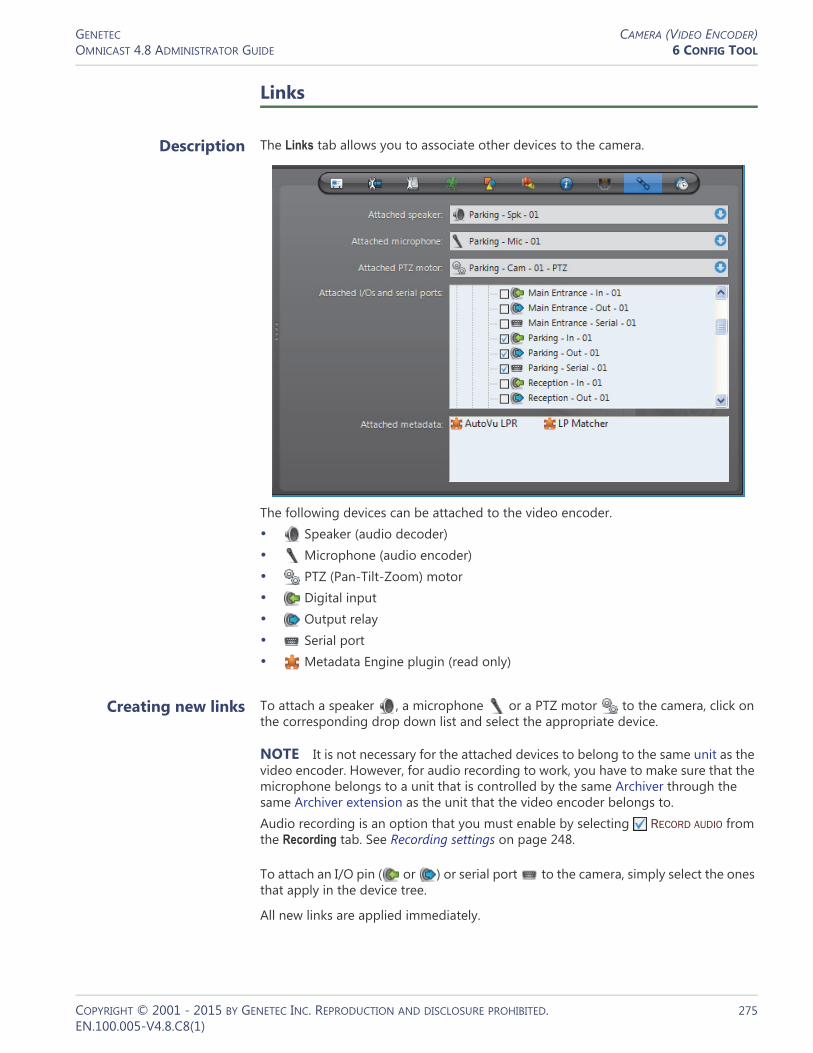
GENETEC CAMERA (VIDEO ENCODER)OMNICAST 4.8 ADMINISTRATOR GUIDE 6 CONFIG TOOL
Links
Description The Links tab allows you to associate other devices to the camera.
The following devices can be attached to the video encoder.• Speaker (audio decoder)• Microphone (audio encoder)• PTZ (Pan-Tilt-Zoom) motor• Digital input• Output relay• Serial port• Metadata Engine plugin (read only)
Creating new links To attach a speaker , a microphone or a PTZ motor to the camera, click on the corresponding drop down list and select the appropriate device.
NOTE It is not necessary for the attached devices to belong to the same unit as the video encoder. However, for audio recording to work, you have to make sure that the microphone belongs to a unit that is controlled by the same Archiver through the same Archiver extension as the unit that the video encoder belongs to.Audio recording is an option that you must enable by selecting RECORD AUDIO from the Recording tab. See Recording settings on page 248.
To attach an I/O pin ( or ) or serial port to the camera, simply select the ones that apply in the device tree.
All new links are applied immediately.
COPYRIGHT © 2001 - 2015 BY GENETEC INC. REPRODUCTION AND DISCLOSURE PROHIBITED. 275EN.100.005-V4.8.C8(1)

GENETEC CAMERA (VIDEO ENCODER)OMNICAST 4.8 ADMINISTRATOR GUIDE 6 CONFIG TOOL
Attached metadata The Attached metadata list shows the ME plugins that are currently associated to this camera. New camera-plugin links must be created from the ME Plugin’s Links tab.
Please refer to the plugin’s own user guide for additional details; see About Omnicast plugin manuals on page iii.
Removing links To disconnect an audio or PTZ connection, select .
To disconnect an I/O pin, clear its selection in the device tree.
To dissociate a ME plugin, you must remove the camera from the Links tab of the associated plugin.
Time Zone
Description The Time zone tab allows you to define the time zone and the geographical location of the camera.
Time zone This section allows the video recording to be associated to a specific time zone. Note that this section would be disabled if the Time zones option is not supported by your Omnicast license. See Directory options on page 47.
The Current time zone indicates the current time zone of the camera.
The option Same time zone as application lets the camera follow the time zone of the Archiver, which is the time zone of its host PC.
COPYRIGHT © 2001 - 2015 BY GENETEC INC. REPRODUCTION AND DISCLOSURE PROHIBITED. 276EN.100.005-V4.8.C8(1)

GENETEC CAMERA (VIDEO ENCODER)OMNICAST 4.8 ADMINISTRATOR GUIDE 6 CONFIG TOOL
Geographical location The geographical location of the camera is necessary for daytime and nighttime calculations. The Archiver uses the specified location and the time of year to calculate the time the sun rises and sets. See Generic Schedule – Daytime/Nighttime on page 330.
Predefined location – Use this option to select the Country and the City where the camera is located. If you cannot find the desired city, enter the nearest major city.
Custom location – Use this option to enter the exact coordinates of the camera location (Latitude and Longitude).
Specific Settings
Description The Specific settings tab is only available to certain models of video encoders and the parameters may differ from one model to another.
COPYRIGHT © 2001 - 2015 BY GENETEC INC. REPRODUCTION AND DISCLOSURE PROHIBITED. 277EN.100.005-V4.8.C8(1)
GENETEC CAMERA (VIDEO ENCODER)OMNICAST 4.8 ADMINISTRATOR GUIDE 6 CONFIG TOOL
The following table describes some of the parameters you may find in this tab:
Parameter Description (1 of 2)
Camera tampering
This setting is present if the unit has the built-in capability of detecting camera tampering.
Typically, any dysfunction that prevents the original scene from being viewed properly can by treated as an attempt to tamper with the camera.
The dysfunction could be a partial or complete obstruction of the camera view, a sudden change of the field of view, or a loss of focus.
You may control the sensitivity of the unit’s alarm notification mechanism by specifying the Minimum duration that a dysfunction must last before the unit issues a Camera tampering event.
Select DARK IMAGE DETECTION if dark images (total obstruction) are to be considered as dysfunctions.
Image rotation Use this setting to correct the orientation of the image when the camera is mounted upside down or at a 90 degree angle. The rotation options may vary depending on the model of the camera.
PTZ motor This setting is present if the unit that the camera is connected to has a dedicated PTZ serial port, for example with the Pelco NET5301T. By selecting a PTZ protocol from the drop-down list that is supported by the hardware, a PTZ motor entity is automatically added and configured to control the camera.
In this case, you do not have to manually create the PTZ motor entity and assign it to the camera and serial port, as explained in PTZ Motor on page 381: you can refer to this section for additional information on adjusting PTZ visibility, properties, and advanced commands.
Data Bits - Baud Rate
Serial port settings appear if the unit that the camera is connected to has a dedicated PTZ serial port, for example with the Pelco NET5301T. The values for the serial port settings should match those of the camera’s dip switches, and those of the encoder. The default values are usually adequate. They could be adjusted, for example, to account for longer cables and for compatibility with older hardware. For a description of each setting, see Serial Port on page 392.
COPYRIGHT © 2001 - 2015 BY GENETEC INC. REPRODUCTION AND DISCLOSURE PROHIBITED. 278EN.100.005-V4.8.C8(1)

GENETEC CAMERA (VIDEO ENCODER)OMNICAST 4.8 ADMINISTRATOR GUIDE 6 CONFIG TOOL
Video data format This setting appears for units that have specific combinations of supported resolutions for dual streaming.
For example, for fourth generation Sony IP cameras, each entry in the drop-down list combines a specific resolution for MJPEG with a specific resolution for MPEG4, for instance:
MJPEG: 1280x960 MPEG4: 640x480
In this case, when configuring stream usage via the Video quality tab, streams you configure to use MJPEG will have a resolution of 1280x960, and streams you configure to use MPEG4 will have a resolution of 640x480.
For some resolutions, dual streaming is not available in which case the complementary video data format is indicated as such, for instance:
MJPEG: 768x576 MPEG4: Off
Only the listed stream combinations are available for the unit.
Note that because the video data format is set in the Specific settings tab it cannot be varied according to a schedule. All other settings in the Video Quality tab, however, can still be scheduled.
Parameter Description (2 of 2)
COPYRIGHT © 2001 - 2015 BY GENETEC INC. REPRODUCTION AND DISCLOSURE PROHIBITED. 279EN.100.005-V4.8.C8(1)

GENETEC CAMERA GROUPOMNICAST 4.8 ADMINISTRATOR GUIDE 6 CONFIG TOOL
Camera Group
Definition
A camera group is a logical grouping of related cameras (video encoders) used to simplify alarm definitions. Typically, cameras monitoring the same area from different angles (room, lobby, etc.) are put together in the same camera group.
Camera groups are only referenced in the Cameras tab of the alarm’s configuration. See Alarm – Cameras on page 190.
The camera group‘s configuration page comprises the following tabs.
Creating a camera group
To create a new camera group entity, do the following.1 Select Alarm Management from the View selection pane. See View selection pane on
page 155.2 Click at the bottom of the View selection pane. A pop-up menu with the
entities you can create appears.3 Select Camera Group from the pop-up menu. A New camera group entity will be
created.4 Enter a descriptive name for the new camera group. Use the Description field to
provide more details if necessary, in the Identity tab.5 Select the Cameras tab to define the constituents of the camera group. See
Cameras on page 281.6 Select the cameras that should belong to the group and click Apply.
Icon Tab Description
Identity Name, description and positions of the entity in the Logical and Physical system hierarchies.
Cameras List of cameras belonging to the group.
COPYRIGHT © 2001 - 2015 BY GENETEC INC. REPRODUCTION AND DISCLOSURE PROHIBITED. 280EN.100.005-V4.8.C8(1)

GENETEC CAMERA GROUPOMNICAST 4.8 ADMINISTRATOR GUIDE 6 CONFIG TOOL
Cameras
Description The Cameras tab defines the cameras that belong to the camera group.
Changing the camera list
To add or change the camera list, do the following.1 Click at the bottom of the tab. The Select camera(s) dialog appears.2 Select from this dialog, the cameras that should belong to the group and click OK.
You must select at least one camera.3 Use the and buttons to change the order of the cameras in the list.4 If there are cameras you do not want in the list, select them and click .5 Click Apply to save your changes.
COPYRIGHT © 2001 - 2015 BY GENETEC INC. REPRODUCTION AND DISCLOSURE PROHIBITED. 281EN.100.005-V4.8.C8(1)

GENETEC CAMERA SEQUENCEOMNICAST 4.8 ADMINISTRATOR GUIDE 6 CONFIG TOOL
Camera Sequence
Definition
A camera sequence is a list of cameras controlled by the Virtual Matrix, where each camera is displayed for a preset amount of time, following a cycling program. The purpose of having a camera sequence is so that multiple cameras can be displayed on a single analog monitor or a single tile within the Live Viewer.
Camera sequences must be executed by Virtual Matrices. In order to use camera sequences in your system, the Number of Virtual Matrices allowed by your Omnicast license must be greater than zero. See Server Admin – Directory options on page 47.
The camera sequence‘s configuration page comprises the following tabs.
Creating a camera sequence
To create a new camera sequence entity, do the following.1 Select Virtual Matrix Management from the View selection pane. See View selection
pane on page 155.2 Click at the bottom of the View selection pane. A pop-up menu with the
entities you can create appears.3 Select Camera Sequence from the pop-up menu. The Select the Virtual Matrix
dialog box appears.4 Select the primary Virtual Matrix that should be controlling this entity and click OK.
A new entity named New sequence will be created.
TIP The best choice of primary VM would be the one that is physically the nearest to the Archiver that controls the cameras that will appear in the sequence. This strategy would minimize the network traffic.5 Enter a descriptive name for the new camera sequence. Use the Description field to
provide more details if necessary, in the Identity tab.6 Select the Cameras tab to define the camera sequence. See Cameras on page 283.
NOTE Each camera sequence requires 3 MB of virtual memory on the machine that runs the Virtual Matrix that controls it.
Icon Tab Description
Identity Name, description and positions of the entity in the Logical and Physical system hierarchies.
Cameras Composition of the camera sequence.
Schedules Scheduling information for automatic execution.
Network Multicast address and port number.
Standby Virtual Matrices
List of secondary Virtual Matrices that serve as backups for the control of this camera sequence.
COPYRIGHT © 2001 - 2015 BY GENETEC INC. REPRODUCTION AND DISCLOSURE PROHIBITED. 282EN.100.005-V4.8.C8(1)

GENETEC CAMERA SEQUENCEOMNICAST 4.8 ADMINISTRATOR GUIDE 6 CONFIG TOOL
Cameras
Description The Cameras tab defines the steps in the camera sequence and allows you to test it.
Step list The camera sequence is defined as a list of steps. Each step is characterized by:• a Camera to display• a Dwell time (time spent on this camera)• an optional PTZ command (Go to Preset # or Run Pattern #)• an optional Auxiliary switch # to either turn ON or OFF
Adding a camera to the sequence
To add a camera to the sequence, do the following.1 Click at the bottom of the tab. The Add camera dialog box appears.
2 Use the Camera drop-down list to select a camera.
COPYRIGHT © 2001 - 2015 BY GENETEC INC. REPRODUCTION AND DISCLOSURE PROHIBITED. 283EN.100.005-V4.8.C8(1)

GENETEC CAMERA SEQUENCEOMNICAST 4.8 ADMINISTRATOR GUIDE 6 CONFIG TOOL
3 Enter the Dwell time, in seconds. It is the time the Virtual Matrix should dwell on this camera.
4 If the camera is PTZ enabled, you may define a PTZ command. Choose Preset to go to a specific preset or Pattern to run a specific pattern. Leave the field at None if no PTZ command is required.
5 Enter an Auxiliary switch number if applicable and indicate the desired position (ON or OFF).
6 Click OK to add the camera to the bottom of the list. Use the and buttons to change the order of the cameras in the list.
7 Modify the settings of a camera with .8 Remove a camera from the list with .9 Click Apply to save your changes.
Testing the camera sequence
Click the Live video button to test the camera sequence. The following dialog appears.
Select Fit video to window size to allow the video image to follow the window size. If this box is cleared, the actual size (1:1 ratio) of the image will be shown.
The name of the camera sequence as well as the name of the currently displayed camera are shown at the bottom of the dialog.
While you are testing the camera sequence, the following buttons are enabled.• Pause the sequence. When paused, this button changes to .• Resume sequence. When resumed, this button changes to .• Move to previous camera. Only enabled when the sequence is paused.• Move to next camera. Only enabled when the sequence is paused.
COPYRIGHT © 2001 - 2015 BY GENETEC INC. REPRODUCTION AND DISCLOSURE PROHIBITED. 284EN.100.005-V4.8.C8(1)

GENETEC CAMERA SEQUENCEOMNICAST 4.8 ADMINISTRATOR GUIDE 6 CONFIG TOOL
Schedules
Description The Schedules tab is used to set up automatic execution of the camera sequence by the Virtual Matrix. Multiple schedules may be defined if the camera sequence is to be displayed at different times on different analog monitors.
Schedule list The schedule list define when and where the camera sequence should be displayed by the Virtual Matrix.
To add a new schedule:1 Click at the bottom of the tab. The Camera sequence scheduling dialog appears.
2 Select a generic schedule. See Generic Schedule on page 324.3 Select an analog monitor. See Analog Monitor (Video Decoder) on page 198.4 Click OK to add the schedule.
COPYRIGHT © 2001 - 2015 BY GENETEC INC. REPRODUCTION AND DISCLOSURE PROHIBITED. 285EN.100.005-V4.8.C8(1)

GENETEC CAMERA SEQUENCEOMNICAST 4.8 ADMINISTRATOR GUIDE 6 CONFIG TOOL
Network
Description The Network tab is used to change the default multicast address and port number assigned to the camera sequence when these parameters are invalidated by a change in your Directory settings.
Network information Please ignore this section.
Connection types This parameter is not applicable for camera sequence. For more information on connection types, see System Concepts – Network Connections on page 29.
Multicast address The Multicast address and Port number are used by the Virtual Matrix to transmit the video. These parameters are assigned automatically by the system when the camera sequence is created. Each camera sequence is assigned a different multicast address with a fixed port number.
Normally, you do not need to be concerned with the multicast addresses. However, if for some reason you have to change the general settings of your Directory (see Server Admin – General settings on page 56), you may stop receiving video streams from the camera sequences created before the change took place. If it is the case, you will have to change their multicast addresses accordingly. If you choose to use the same multicast address as another entity in the system, make sure that their port numbers are different.
NOTE All multicast addresses must be between the range 224.0.1.0 and 239.255.255.255. These changes will become effective the next time you view the camera sequence.
COPYRIGHT © 2001 - 2015 BY GENETEC INC. REPRODUCTION AND DISCLOSURE PROHIBITED. 286EN.100.005-V4.8.C8(1)

GENETEC CAMERA SEQUENCEOMNICAST 4.8 ADMINISTRATOR GUIDE 6 CONFIG TOOL
Standby Virtual Matrices
Description The Standby Virtual Matrices tab shows the Virtual Matrix failover list for this camera sequence.
The Virtual Matrix appearing at the top of the list is the master of this camera sequence. It is the one that should be controlling this sequence in normal situations. If the master fails, then the control of this sequence will be automatically transferred to the next Virtual Matrix in line.
COPYRIGHT © 2001 - 2015 BY GENETEC INC. REPRODUCTION AND DISCLOSURE PROHIBITED. 287EN.100.005-V4.8.C8(1)
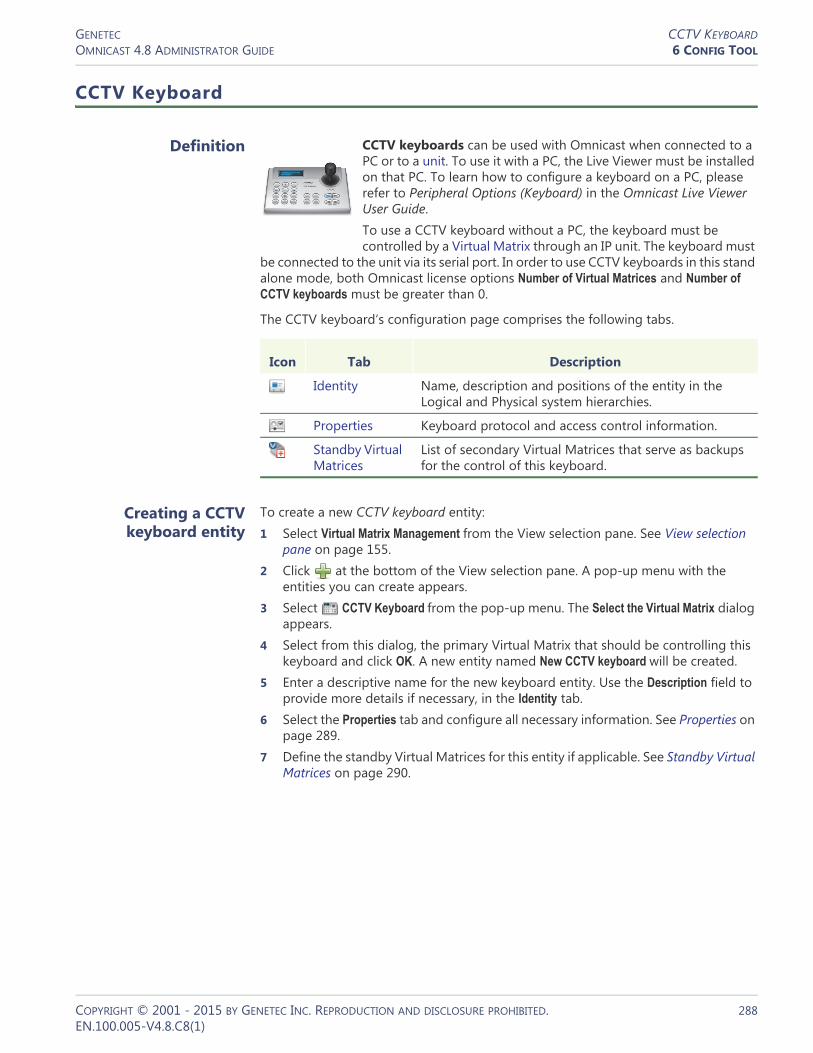
GENETEC CCTV KEYBOARDOMNICAST 4.8 ADMINISTRATOR GUIDE 6 CONFIG TOOL
CCTV Keyboard
Definition
CCTV keyboards can be used with Omnicast when connected to a PC or to a unit. To use it with a PC, the Live Viewer must be installed on that PC. To learn how to configure a keyboard on a PC, please refer to Peripheral Options (Keyboard) in the Omnicast Live Viewer User Guide.To use a CCTV keyboard without a PC, the keyboard must be controlled by a Virtual Matrix through an IP unit. The keyboard must
be connected to the unit via its serial port. In order to use CCTV keyboards in this stand alone mode, both Omnicast license options Number of Virtual Matrices and Number of CCTV keyboards must be greater than 0.
The CCTV keyboard‘s configuration page comprises the following tabs.
Creating a CCTV keyboard entity
To create a new CCTV keyboard entity:1 Select Virtual Matrix Management from the View selection pane. See View selection
pane on page 155.2 Click at the bottom of the View selection pane. A pop-up menu with the
entities you can create appears.3 Select CCTV Keyboard from the pop-up menu. The Select the Virtual Matrix dialog
appears.4 Select from this dialog, the primary Virtual Matrix that should be controlling this
keyboard and click OK. A new entity named New CCTV keyboard will be created.5 Enter a descriptive name for the new keyboard entity. Use the Description field to
provide more details if necessary, in the Identity tab.6 Select the Properties tab and configure all necessary information. See Properties on
page 289.7 Define the standby Virtual Matrices for this entity if applicable. See Standby Virtual
Matrices on page 290.
Icon Tab Description
Identity Name, description and positions of the entity in the Logical and Physical system hierarchies.
Properties Keyboard protocol and access control information.
Standby Virtual Matrices
List of secondary Virtual Matrices that serve as backups for the control of this keyboard.
COPYRIGHT © 2001 - 2015 BY GENETEC INC. REPRODUCTION AND DISCLOSURE PROHIBITED. 288EN.100.005-V4.8.C8(1)

GENETEC CCTV KEYBOARDOMNICAST 4.8 ADMINISTRATOR GUIDE 6 CONFIG TOOL
Properties
Description The Properties tab defines the basic settings necessary to control the CCTV keyboard.
The following parameters must be defined to allow the Virtual Matrix to control the CCTV keyboard.
Parameter Description (1 of 2)
Serial port The serial port to which the keyboard is connected.
Permissions and privileges
The user profile to lend to the keyboard. The actual keyboard user will inherit the same privileges as the user specified here. See User – Toggling the logon mode on page 430.
Keyboard protocol Manufacturer and model of the keyboard.
Keyboard address The keyboard address is only needed for certain types of keyboard. Some models accept more than one keyboard to be connected to the same serial port. Therefore, you must specify which one.
Do not remove selected camera
When connecting a camera to a monitor that is already displaying that camera, the default behavior is to remove that camera (it works as a toggle). If this option is selected, the camera will not be removed at every second connection attempt.
Access control behavior
Select this option only if you are defining a keyboard entity for the purpose of controlling a third party access control system. Do not select this option otherwise.
There is a better way to achieve the same thing. See Access Control System on page 183.
COPYRIGHT © 2001 - 2015 BY GENETEC INC. REPRODUCTION AND DISCLOSURE PROHIBITED. 289EN.100.005-V4.8.C8(1)

GENETEC CCTV KEYBOARDOMNICAST 4.8 ADMINISTRATOR GUIDE 6 CONFIG TOOL
Standby Virtual Matrices
Description The Standby Virtual Matrices tab shows the Virtual Matrix failover list for this device.
The Virtual Matrix appearing at the top of the list is the master of this keyboard. It is the one that should be controlling this keyboard in normal situations. If the master fails, then the control of the keyboard will be automatically transferred to the next Virtual Matrix in line.
Live Viewer list This is a list of all Live Viewer applications installed on the system. Select the ones that this CCTV keyboard is allowed to reference as display monitors.
Parameter Description (2 of 2)
COPYRIGHT © 2001 - 2015 BY GENETEC INC. REPRODUCTION AND DISCLOSURE PROHIBITED. 290EN.100.005-V4.8.C8(1)

GENETEC DIGITAL INPUTOMNICAST 4.8 ADMINISTRATOR GUIDE 6 CONFIG TOOL
Digital Input
Definition
A digital input is an input pin found on a unit that can be used by Omnicast to receive On/Off signals from external devices such as door contacts, motion detectors, card readers, etc. The opening and closing of the input contact are interpreted by Omnicast as digital input events which can be used to trigger actions. See System Concepts – Event Management on page 22.
The digital input‘s configuration page comprises the following tabs.
Properties
Description The Properties tab allows you to map the standard digital input events (Digital input contact closing and Digital input contact opening) to specific custom events. The purpose of this mapping is to give a meaningful name to these events.
Please refer to Directory – Custom Events on page 300 to learn how to create new custom events. Click the button to jump to the Custom Events tab.
Icon Tab Description
Identity Name, description and positions of the entity in the Logical and Physical system hierarchies.
Properties Digital input event mapping.
Actions Digital input event handling.
Network Digital input network properties.
COPYRIGHT © 2001 - 2015 BY GENETEC INC. REPRODUCTION AND DISCLOSURE PROHIBITED. 291EN.100.005-V4.8.C8(1)

GENETEC DIGITAL INPUTOMNICAST 4.8 ADMINISTRATOR GUIDE 6 CONFIG TOOL
Digital input properties
The digital input properties are:
Linking cameras to the digital input
Links between cameras and digital inputs are configured from the camera’s Links tab. See Camera – Links on page 275.
To remove such a link, select the camera from the camera list at the bottom of this tab and click .
Actions
Description The Actions tab allows you to program specific system behaviors based on the digital input events shown in the Events/actions list.
Parameter Description
Digital input contact closing
Use this drop-down list to map the Digital input contact closing event to any custom event already defined in the system.
Digital input contact opening
Use this drop-down list to map the Digital input contact opening event to any custom event already defined in the system.
Respect archiving schedules of attached cameras
Select this option if the digital input events should only be generated during the time when one of the linked cameras is covered by at least one archiving schedule. Clear this option if the digital input events should be generated at all times.
Schedule list of all attached entities
This list appears only when the option Respect archiving schedules... is selected.
The schedule list shows all the archiving schedules used by the cameras linked to this digital input. The linked cameras are displayed in the area below the schedule list.
COPYRIGHT © 2001 - 2015 BY GENETEC INC. REPRODUCTION AND DISCLOSURE PROHIBITED. 292EN.100.005-V4.8.C8(1)
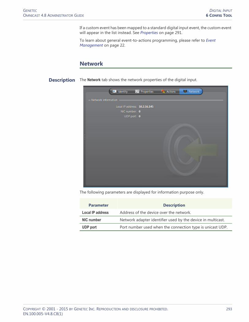
GENETEC DIGITAL INPUTOMNICAST 4.8 ADMINISTRATOR GUIDE 6 CONFIG TOOL
If a custom event has been mapped to a standard digital input event, the custom event will appear in the list instead. See Properties on page 291.
To learn about general event-to-actions programming, please refer to Event Management on page 22.
Network
Description The Network tab shows the network properties of the digital input.
The following parameters are displayed for information purpose only.
Parameter Description
Local IP address Address of the device over the network.
NIC number Network adapter identifier used by the device in multicast.
UDP port Port number used when the connection type is unicast UDP.
COPYRIGHT © 2001 - 2015 BY GENETEC INC. REPRODUCTION AND DISCLOSURE PROHIBITED. 293EN.100.005-V4.8.C8(1)

GENETEC DIRECTORYOMNICAST 4.8 ADMINISTRATOR GUIDE 6 CONFIG TOOL
Directory
Definition
The Directory is the main server application whose service is required to provide a centralized catalog for the other Omnicast services and applications on the system. From the Directory, applications can view, establish connections and receive centralized configuration information.
The Directory‘s configuration page comprises the following tabs.
Being an Omnicast server application, the machine specific parameters of the Directory are configured with the Server Admin. See Directory on page 55.
See also Directory Failover Coordinator on page 307.
Icon Tab Description
License License information for this Directory.
Online Users List of users currently connected to the Directory.
Connections List of all current connections in the system.
Logical IDs List/edit logical IDs by entity type.
Custom Events List/edit custom events in the system.
Custom Actions List/edit custom actions in the system.
Alarms List/delete the content of the alarm database.
Discovery Embedded Discover Tool.
Actions Actions to perform following specific Directory events.
Time Zones List of all currently connected applications and their respective time zone.
COPYRIGHT © 2001 - 2015 BY GENETEC INC. REPRODUCTION AND DISCLOSURE PROHIBITED. 294EN.100.005-V4.8.C8(1)

GENETEC DIRECTORYOMNICAST 4.8 ADMINISTRATOR GUIDE 6 CONFIG TOOL
License
Description The License tab shows the Omnicast license options supported on this Directory, and the actual number of each license item in use. This tab shows the same information as the License tab found in Server Admin. However, only the Directory options are listed here.
Please refer to Server Admin – System – Directory options on page 47 for the complete list of all Directory license options. Click to refresh the license count.
COPYRIGHT © 2001 - 2015 BY GENETEC INC. REPRODUCTION AND DISCLOSURE PROHIBITED. 295EN.100.005-V4.8.C8(1)

GENETEC DIRECTORYOMNICAST 4.8 ADMINISTRATOR GUIDE 6 CONFIG TOOL
Online Users
Description The Online Users tab shows all the users currently connected to this Directory and the client applications they are using. You must have the View application connections privilege to view this tab. See User – Privileges on page 434.
Each online user is indicated by an application icon, the machine name and the application name (written in the language it is currently configured with), and the user name. Click to refresh the list of users.
COPYRIGHT © 2001 - 2015 BY GENETEC INC. REPRODUCTION AND DISCLOSURE PROHIBITED. 296EN.100.005-V4.8.C8(1)

GENETEC DIRECTORYOMNICAST 4.8 ADMINISTRATOR GUIDE 6 CONFIG TOOL
Connections
Description The Connections tab shows all current connections in the system. You must have the View video connections privilege to view this tab. See User – Privileges on page 434.
Types of connections A connection can be made between1 A video encoder and a video decoder
– A video encoder is anything that generates a video stream over the network. It could be a camera , a camera sequence , a virtual camera , or a playback sequence )
– A video decoder is anything that reads a video stream from the network. It could be an analog monitor , the Live Viewer , the Web Live Viewer , the Config Tool , the Virtual Matrix , the Auxiliary Archiver , the Metadata Engine , the Pocket PC Viewer , or the Media Gateway .
2 An audio encoder and an audio decoder– An audio encoder is anything that generates an audio stream over the network.
It is essentially a microphone .– An audio decoder is anything that reads an audio stream from the network. It
could be a speaker , the Live Viewer , the Web Live Viewer , or the Pocket PC Viewer .
3 Two serial ports .
Software decoders are indicated by the application icon followed by the machine name and the application name. Note that the application name is written in the language it is currently configured with.
To find out who are running these applications, select the Online users tab. See Online Users on page 296.
COPYRIGHT © 2001 - 2015 BY GENETEC INC. REPRODUCTION AND DISCLOSURE PROHIBITED. 297EN.100.005-V4.8.C8(1)

GENETEC DIRECTORYOMNICAST 4.8 ADMINISTRATOR GUIDE 6 CONFIG TOOL
Creating a new connection
To create a new connection, do the following.1 Click the button. The New connection dialog box appears.
2 Select a Connection type:– Video Select this option to connect a video encoder to a video decoder– Audio Select this option to connect an audio encoder to an audio decoder– Serial Select this option to connect two serial ports. The choice of encoding and decoding entities depend on the selected Connection type. Only hardware encoders and decoders can be selected.Note When creating a serial connection, ensure that the serial ports used in the connection are not already assigned to another device managed by Omnicast. For example, if a CCTV keyboard already has a serial port connection under the Virtual Matrix you should not use that same port to create a serial connection under the Directory.
3 Specify a Viewing priority. The viewing priority is taken from a user profile. See User – Viewing priority on page 444.This property is necessary in the context of camera blocking. By default, the connection would be established using the your own profile. However, members of the Administrators group are allowed to create connections using someone else's profile.
4 Select the Encoding entity from the left hand pane and the Decoding entity from the right hand pane.
5 Click OK to make the connection.
COPYRIGHT © 2001 - 2015 BY GENETEC INC. REPRODUCTION AND DISCLOSURE PROHIBITED. 298EN.100.005-V4.8.C8(1)

GENETEC DIRECTORYOMNICAST 4.8 ADMINISTRATOR GUIDE 6 CONFIG TOOL
Command buttons The command buttons found in this tab are explained below.
Logical IDs
Description The Logical IDs tab allows you to view and change the logical IDs assigned to the various entities of the system.
Logical IDs must be unique within the entities of a same group. The different groups of entity types are listed in the Show logical ID for: drop-down list. Use it to filter the entities you wish to view.
Click the button to change a particular ID. You may also change the logical ID from the Identity tab of each entity configuration. See Identity on page 157.
Click the button to refresh the list.
Click To
To create a new connection. See Creating a new connection on page 298.
To remove to remove an existing connection.
Select a decoder entity to remove a single connection or select an encoder entity to remove all connections to that entity.
TIP The administrator can use this feature to disconnect a user from viewing a camera that he is not supposed to.
To pause the automatic refresh. The button changes to .
Being able to pause the automatic refresh could prove to be very useful when there are too many camera sequences running in the system.
Refresh the screen when the automatic refresh is paused.
COPYRIGHT © 2001 - 2015 BY GENETEC INC. REPRODUCTION AND DISCLOSURE PROHIBITED. 299EN.100.005-V4.8.C8(1)
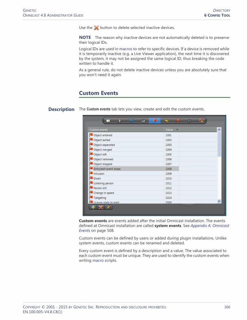
GENETEC DIRECTORYOMNICAST 4.8 ADMINISTRATOR GUIDE 6 CONFIG TOOL
Use the button to delete selected inactive devices.
NOTE The reason why inactive devices are not automatically deleted is to preserve their logical IDs.Logical IDs are used in macros to refer to specific devices. If a device is removed while it is temporarily inactive (e.g. a Live Viewer application), the next time it is discovered by the system, it may not be assigned the same logical ID, thus breaking the code written to handle it.As a general rule, do not delete inactive devices unless you are absolutely sure that you won't need it again.
Custom Events
Description The Custom events tab lets you view, create and edit the custom events.
Custom events are events added after the initial Omnicast installation. The events defined at Omnicast installation are called system events. See Appendix A: Omnicast Events on page 508.
Custom events can be defined by users or added during plugin installations. Unlike system events, custom events can be renamed and deleted.
Every custom event is defined by a description and a value. The value associated to each custom event must be unique. They are used to identify the custom events when writing macro scripts.
COPYRIGHT © 2001 - 2015 BY GENETEC INC. REPRODUCTION AND DISCLOSURE PROHIBITED. 300EN.100.005-V4.8.C8(1)

GENETEC DIRECTORYOMNICAST 4.8 ADMINISTRATOR GUIDE 6 CONFIG TOOL
Creating custom events
To create a custom event, do the following.1 Click the button. The New event dialog box appears.
2 Enter the name of the custom event in the Description field.3 Enter the ID of the custom event in the Value field and click OK.
– Note that the ID must be unique.– If you leave this field blank, the system will assign a value for you.
TIP Once a custom event is created, it can be used to rename any digital input event. See Digital Input – Properties on page 291.
Custom Actions
Description The Custom actions tab lets you view, create and edit the custom actions.
Custom actions are names and identifiers given to output relay behaviors to ease the configuration and programming of event handling in Omnicast.
Every custom action is defined by a description and a value. The value associated to each custom action must be unique. They are used to identify the custom actions when writing macro scripts.
COPYRIGHT © 2001 - 2015 BY GENETEC INC. REPRODUCTION AND DISCLOSURE PROHIBITED. 301EN.100.005-V4.8.C8(1)

GENETEC DIRECTORYOMNICAST 4.8 ADMINISTRATOR GUIDE 6 CONFIG TOOL
Creating custom actions
To create a custom action, do the following.1 Click the button. The New action dialog box appears.
2 Enter the name of the custom action in the Description field.3 Enter the ID of the custom action in the Value field and click OK.
– Note that the ID must be unique.– If you leave this field blank, the system will assign a value for you.
TIP Once a custom action is created, it can be mapped to any output relay behavior. See Output Relay – Properties on page 364.
Alarms
Description The Alarms tab shows the content of the alarm database.
Limiting the number of alarms
The option Limit the number of alarms... allows you to limit the number of alarm instances loaded, starting from the oldest. The current number of items in the list is shown at the bottom of the tab. Clearing this option permits you to load the entire content of the database.
COPYRIGHT © 2001 - 2015 BY GENETEC INC. REPRODUCTION AND DISCLOSURE PROHIBITED. 302EN.100.005-V4.8.C8(1)

GENETEC DIRECTORYOMNICAST 4.8 ADMINISTRATOR GUIDE 6 CONFIG TOOL
You may set the limit with the slider control to the right. Changing the limit does not automatically reload the alarm instances shown in the list. To reload the alarm list, click Refresh .
Command buttons The three command buttons found at the bottom of the tab are described below.
Alarm history dialog You may view the history of any selected alarm instance by clicking the button. The following dialog will appear.
The Alarm history dialog shows for a given alarm instance, every step that the alarm has gone through, from creation to acknowledgement. The meaning of the action icons are described below.
Click To
Show alarm history. See Alarm history dialog on page 303.
Delete the selected alarm.
You may delete an alarm instance even when it is still active, i.e. not yet acknowledged. You must have the Delete alarm instances privilege to perform this operation. See User – Privileges on page 434.
Refresh the alarm list.
Icon Action that took place
Activated. The By field indicates the alarm recipient.
Forwarded. The By field indicates the user who performed the action and the Description field indicates the alarm recipient.
Snoozing. The By field indicates the user who performed the action.
Comment added. The comment is indicated in the Description field. Note that a comment can only be added through an alarm procedure.
Acknowledged (default).
COPYRIGHT © 2001 - 2015 BY GENETEC INC. REPRODUCTION AND DISCLOSURE PROHIBITED. 303EN.100.005-V4.8.C8(1)

GENETEC DIRECTORYOMNICAST 4.8 ADMINISTRATOR GUIDE 6 CONFIG TOOL
Once acknowledged, an alarm is kept in the database for 90 days. This value can be changed by the administrator on an individual basis. See Alarm – Acknowledgement settings on page 189.
Discovery
Description The Discovery tab contains an embedded version of the Discovery Tool. See Discovery Tool on page 476.
The difference between the embedded version and the stand-alone version is that the embedded version features an extra button that allows you to add the discovered units to the Archiver of your choice.
Acknowledged (alternate).
Acknowledged (custom). The Custom event field indicates the event associated to the acknowledgement.
Icon Action that took place
COPYRIGHT © 2001 - 2015 BY GENETEC INC. REPRODUCTION AND DISCLOSURE PROHIBITED. 304EN.100.005-V4.8.C8(1)

GENETEC DIRECTORYOMNICAST 4.8 ADMINISTRATOR GUIDE 6 CONFIG TOOL
Actions
Description The Actions tab allows you to trigger further actions following specific Directory events shown in the Events/actions list.
To learn about general event-to-actions programming, please refer to Event Management on page 22.
WARNING Concerning the Database lost event, the only action that can be used is Send an email, because all other actions require a working connection to the Directory database (DirectorySQL).
COPYRIGHT © 2001 - 2015 BY GENETEC INC. REPRODUCTION AND DISCLOSURE PROHIBITED. 305EN.100.005-V4.8.C8(1)
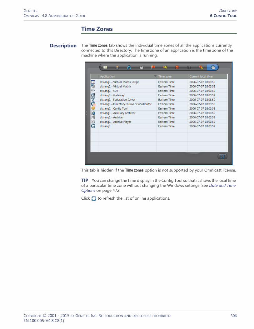
GENETEC DIRECTORYOMNICAST 4.8 ADMINISTRATOR GUIDE 6 CONFIG TOOL
Time Zones
Description The Time zones tab shows the individual time zones of all the applications currently connected to this Directory. The time zone of an application is the time zone of the machine where the application is running.
This tab is hidden if the Time zones option is not supported by your Omnicast license.
TIP You can change the time display in the Config Tool so that it shows the local time of a particular time zone without changing the Windows settings. See Date and Time Options on page 472.
Click to refresh the list of online applications.
COPYRIGHT © 2001 - 2015 BY GENETEC INC. REPRODUCTION AND DISCLOSURE PROHIBITED. 306EN.100.005-V4.8.C8(1)

GENETEC DIRECTORY FAILOVER COORDINATOROMNICAST 4.8 ADMINISTRATOR GUIDE 6 CONFIG TOOL
Directory Failover Coordinator
Definition
The Directory Failover Coordinator (DFC) is an integral part of Omnicast failover mechanism. This service is installed on every server machine hosting the Directory service to guarantee the continuity of the latter in the context of a fully fail-proof system.
The DFC's perform two main functions: (1) Keeping the local Directory and Alarm databases up to date while the Directory service
is on standby; (2) Start or stop the local Directory service when it is appropriate to do so, based on a failover list.
The DFC‘s configuration page comprises the following tabs.
Being an Omnicast service, the machine specific parameters of the DFC are configured with the Server Admin. See Directory Failover Coordinator on page 73.
Statistics
Description The Statistics tab shows the synchronization status of the selected DFC.
Icon Tab Description
Identity Name, description and positions of the entity in the Logical and Physical system hierarchies.
Statistics Directory failover list and synchronization status.
COPYRIGHT © 2001 - 2015 BY GENETEC INC. REPRODUCTION AND DISCLOSURE PROHIBITED. 307EN.100.005-V4.8.C8(1)
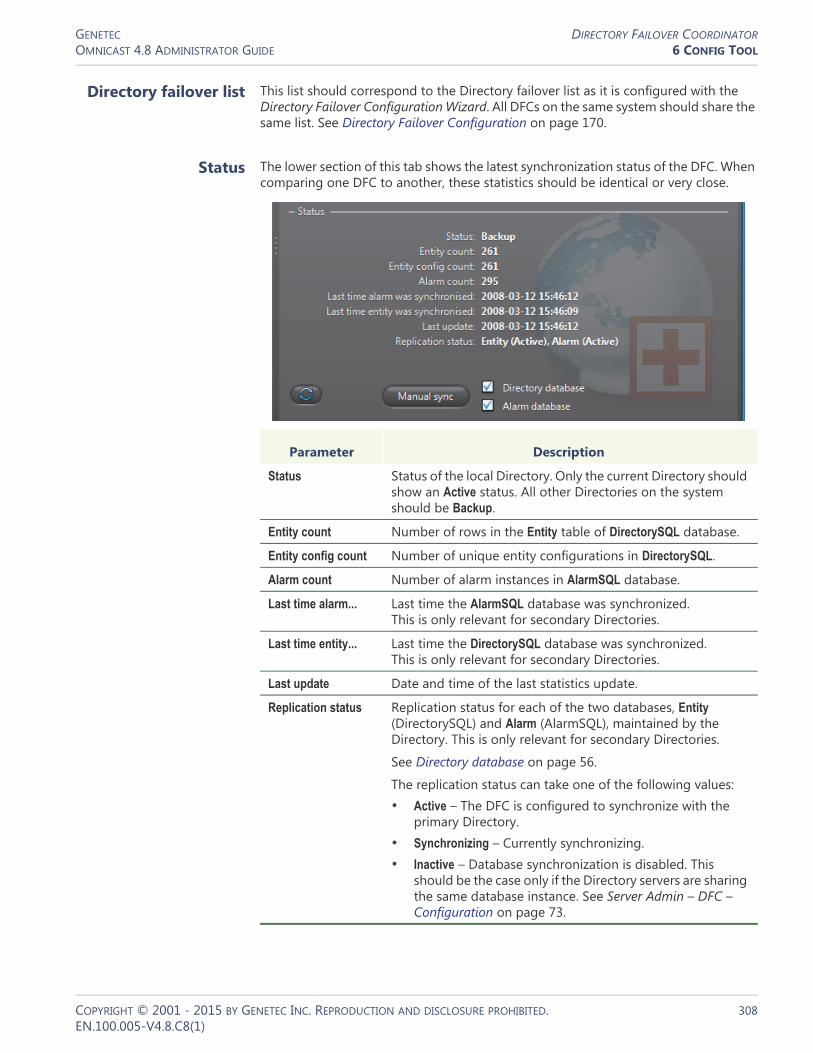
GENETEC DIRECTORY FAILOVER COORDINATOROMNICAST 4.8 ADMINISTRATOR GUIDE 6 CONFIG TOOL
Directory failover list This list should correspond to the Directory failover list as it is configured with the Directory Failover Configuration Wizard. All DFCs on the same system should share the same list. See Directory Failover Configuration on page 170.
Status The lower section of this tab shows the latest synchronization status of the DFC. When comparing one DFC to another, these statistics should be identical or very close.
Parameter Description
Status Status of the local Directory. Only the current Directory should show an Active status. All other Directories on the system should be Backup.
Entity count Number of rows in the Entity table of DirectorySQL database.
Entity config count Number of unique entity configurations in DirectorySQL.
Alarm count Number of alarm instances in AlarmSQL database.
Last time alarm... Last time the AlarmSQL database was synchronized. This is only relevant for secondary Directories.
Last time entity... Last time the DirectorySQL database was synchronized. This is only relevant for secondary Directories.
Last update Date and time of the last statistics update.
Replication status Replication status for each of the two databases, Entity (DirectorySQL) and Alarm (AlarmSQL), maintained by the Directory. This is only relevant for secondary Directories.
See Directory database on page 56.
The replication status can take one of the following values:• Active – The DFC is configured to synchronize with the
primary Directory.• Synchronizing – Currently synchronizing.• Inactive – Database synchronization is disabled. This
should be the case only if the Directory servers are sharing the same database instance. See Server Admin – DFC – Configuration on page 73.
COPYRIGHT © 2001 - 2015 BY GENETEC INC. REPRODUCTION AND DISCLOSURE PROHIBITED. 308EN.100.005-V4.8.C8(1)

GENETEC DIRECTORY FAILOVER COORDINATOROMNICAST 4.8 ADMINISTRATOR GUIDE 6 CONFIG TOOL
Manual synchronization
If for some reason a DFC is not properly synchronized, you can use the Manual sync button to force a synchronization. You need to be connected as an administrator in order to use this command.
You may select individually the databases that you wish to synchronize.
COPYRIGHT © 2001 - 2015 BY GENETEC INC. REPRODUCTION AND DISCLOSURE PROHIBITED. 309EN.100.005-V4.8.C8(1)

GENETEC FEDERATED DIRECTORYOMNICAST 4.8 ADMINISTRATOR GUIDE 6 CONFIG TOOL
Federated Directory
Definition
A federated Directory is a proxy (representative) of a remote Directory, created by the Federation Server to allow local users to view entities on the remote system as if they were on the local system.
The federated Directory‘s configuration page comprises the following tabs.
Creating a federated Directory
The number of federated Directories you may create is limited by the license option Number of federated Directories. See Server Admin – Directory options on page 47.
To create a new federated Directory, do the following.1 Select Federation Management from the View selection pane. See View selection pane
on page 155.2 Click at the bottom of the View selection pane. A pop-up menu with the
entities you can create appears.3 Select Federated Directory from the pop-up menu. The following dialog box
appears.
4 Select the Federation Server from the Federation drop-down list.You need a Federation Server to handle the connections with the remote Directory and manage the federated entities.
5 Specify the Software version of the remote Directory to federate. The software versions shown in the drop-down list are the ones supported by the Federation Server.
6 In Gateway, enter the name of the remote Gateway (for Omnicast 4.0 and more recent).For Omnicast 3.5, enter the name of the remote Directory instead.
Icon Tab Description
Identity Name, description and positions of the entity in the Logical and Physical system hierarchies.
Properties Connection parameters for the federated Directory.
Entities Shows all visible entities and their federated counterparts.
COPYRIGHT © 2001 - 2015 BY GENETEC INC. REPRODUCTION AND DISCLOSURE PROHIBITED. 310EN.100.005-V4.8.C8(1)
GENETEC FEDERATED DIRECTORYOMNICAST 4.8 ADMINISTRATOR GUIDE 6 CONFIG TOOL
7 Select the desired Synchronization option.
ON Forces all entities under the federated Directory to follow the same name and hierarchy as configured in the remote Directory. In other words, the Logical view defined in the remote Directory is replicated under the federated Directory.
This option prevents you from changing the name and the description of the federated entities. When the real entities are renamed or moved in the remote Directory, their local representatives will also be renamed or moved under the federated Directory.
OFF Allows you to move the federated entities freely in the Logical view of the Federation host system. The sites defined in the remote system are not shown.
This option allows you to change the name and description of the federated entities.
WARNING With the exception of the Gateway (or Directory) name, the choices made in this dialog cannot be modified subsequently once the federated Directory is created.8 Click OK to create the new federated Directory.
The new federated Directory is named after the remote Gateway by default. We recommend that you change the name to something that is more representative of the remote system.
9 Select the Properties tab and enter the User name and Password that the Federation Server should use to connect to the remote Directory.
10 Apply the changes and wait until the Status indicates Connected with a green LED. See Properties on page 312.
11 Select the Entities tab and choose among the accessible remote entities, the ones you wish to federate (i.e. to add to the Federation). Only federated entities are accessible to your local users. See Entities on page 313.
12 Adjust the user permissions.Adding a federated Directory to the system adds federated sites to the system. Therefore, you must adjust the users' access rights in the Permissions tab under the user and user group configurations.
COPYRIGHT © 2001 - 2015 BY GENETEC INC. REPRODUCTION AND DISCLOSURE PROHIBITED. 311EN.100.005-V4.8.C8(1)

GENETEC FEDERATED DIRECTORYOMNICAST 4.8 ADMINISTRATOR GUIDE 6 CONFIG TOOL
Properties
Description The Properties tab shows the descriptive attributes of the federated Directory.
Federated Directory properties
The federated Directory properties are:
Parameter Description (1 of 2)
Status The status LED shows the connection status to the remote Directory.
User name/Password
User name and password used by the Federation Server to connect to the remote Directory.
The permissions and privileges granted to this user on the remote Directory will dictate what can be done through the federated Directory.
WARNING The selected user must have Federation Server privilege. Without this privilege, the Federation Server will not be able to connect to the remote Directory.
Gateway Name of the remote Gateway (for software version 4.0 and more recent). It is the name of the remote Directory if the software version is 3.5.
Software version Software version of the remote Directory. Cannot be changed.
Viewing quality Default video stream used for viewing live video from federated cameras. This parameter is meaningful only if the remote Directory is at version 4.0 or more recent.
See Camera – Video stream usage on page 242.
Synchronized Synchronization option selected at creation time.
COPYRIGHT © 2001 - 2015 BY GENETEC INC. REPRODUCTION AND DISCLOSURE PROHIBITED. 312EN.100.005-V4.8.C8(1)

GENETEC FEDERATED DIRECTORYOMNICAST 4.8 ADMINISTRATOR GUIDE 6 CONFIG TOOL
Entities
Description The Entities tab shows all the remote entities that the Federation Server can access and which ones have been selected to be published as federated entities.
Remote entities The first column shows the Logical view on the remote Directory as seen by the user selected in the Properties tab.
Allow events... Select this option if you wish to process the events generated by the remote Archivers. See archiver related events in Appendix A – Omnicast Event Types (sorted by source entity) on page 518.
This option is unrelated to the Receive events option found in the Entities tab. The latter allows you to decide whether or not to receive events from each individual federated entities.
Parameter Description (2 of 2)
COPYRIGHT © 2001 - 2015 BY GENETEC INC. REPRODUCTION AND DISCLOSURE PROHIBITED. 313EN.100.005-V4.8.C8(1)

GENETEC FEDERATED DIRECTORYOMNICAST 4.8 ADMINISTRATOR GUIDE 6 CONFIG TOOL
The entity types eligible to join the Federation™ are:• Cameras ( and ) • Camera sequences ( )• Virtual cameras ( ) • PTZ motors ( ) • Microphones ( ) • Digital inputs ( ) • Output relays ( ) • ME plugins ( )
When the Federation Server connects to the remote Directory, the remote entities do not automatically become available to the Federation users. To make them available to the Federation, you must federate them. This is done by selecting the boxes beside the entity names and clicking on Apply. A name will then appear in the Federated entities column. See Federated entities on page 314.
Command buttons The command buttons found in this tab are explained below.
Federated entities
Definition Federated entities are local entities created by the Federation Server to reference the remote entities. The federated entities can be used anywhere the real entities can. For example, you can define alarms or camera sequences with federated cameras.
Entity creation The federated entities are created in the local Directory when you apply the selections made in the Remote entities list. The new entities will appear in the Physical view under the federated Directory and in the Logical view under a federated site , named after the federated Directory.
You may change the names of the federated entities from the Logical view if synchronization is off.
Command Description
Synchronize This button appears only if synchronization is turned off.
Click this button to reset the names and descriptions of the federated entities to their values on the remote system.
Federate entities Select this option to federate all selected (highlighted) remote entities in the list.
Clear this option to stop federating all selected (highlighted) remote entities in the list.
Receive events Select this option to receive events from all selected (highlighted) federated entities in the list.
Clear this option to stop receiving all selected (highlighted) federated entities in the list.
Refresh Refreshes the remote entity tree.
COPYRIGHT © 2001 - 2015 BY GENETEC INC. REPRODUCTION AND DISCLOSURE PROHIBITED. 314EN.100.005-V4.8.C8(1)

GENETEC FEDERATED DIRECTORYOMNICAST 4.8 ADMINISTRATOR GUIDE 6 CONFIG TOOL
Federated Archivers The physical devices typically found under the units will appear directly under federated Archivers . The federated Archivers cannot be configured and serve no other purpose than to indicate the physical grouping of the federated devices and event processing.
Federated sites Sites in the remote Directory are shown as federated sites in the Logical view only if synchronization is on. Synchronization is an option that must be selected at the time the federated Directory is created and cannot be changed thereafter. See Creating a federated Directory on page 310.
When synchronization is off, all federated entities appear directly under the federated Directory, shown as a site in the Logical view. You can then move them wherever you see fit, within the local site hierarchy.
Entity configuration Most of the federated entities have only two configuration tabs: Identity and Actions. This is because the other properties cannot be changed on the Federation system. Note that the federated cameras ( and ) also feature the Recording tab. This is to allow you to configure the recording by Auxiliary Archivers.
Remote event handling
You can receive the events generated on the remote system regarding the federated entities by selecting the corresponding check box under the Receive events column. This will allow you to handle the remote events locally.
COPYRIGHT © 2001 - 2015 BY GENETEC INC. REPRODUCTION AND DISCLOSURE PROHIBITED. 315EN.100.005-V4.8.C8(1)
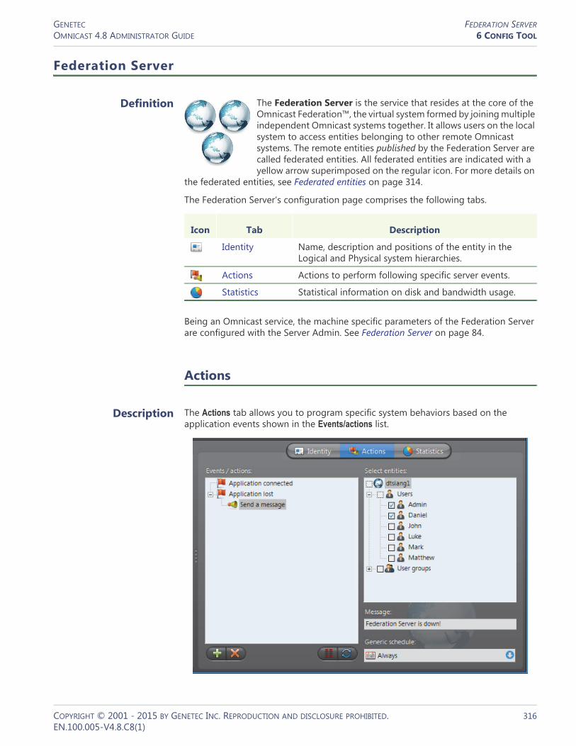
GENETEC FEDERATION SERVEROMNICAST 4.8 ADMINISTRATOR GUIDE 6 CONFIG TOOL
Federation Server
Definition
The Federation Server is the service that resides at the core of the Omnicast Federation™, the virtual system formed by joining multiple independent Omnicast systems together. It allows users on the local system to access entities belonging to other remote Omnicast systems. The remote entities published by the Federation Server are called federated entities. All federated entities are indicated with a yellow arrow superimposed on the regular icon. For more details on
the federated entities, see Federated entities on page 314.
The Federation Server‘s configuration page comprises the following tabs.
Being an Omnicast service, the machine specific parameters of the Federation Server are configured with the Server Admin. See Federation Server on page 84.
Actions
Description The Actions tab allows you to program specific system behaviors based on the application events shown in the Events/actions list.
Icon Tab Description
Identity Name, description and positions of the entity in the Logical and Physical system hierarchies.
Actions Actions to perform following specific server events.
Statistics Statistical information on disk and bandwidth usage.
COPYRIGHT © 2001 - 2015 BY GENETEC INC. REPRODUCTION AND DISCLOSURE PROHIBITED. 316EN.100.005-V4.8.C8(1)

GENETEC FEDERATION SERVEROMNICAST 4.8 ADMINISTRATOR GUIDE 6 CONFIG TOOL
To learn about general event-to-actions programming, please refer to Event Management on page 22.
Statistics
Description The Statistics tab offers statistical information concerning the disk and bandwidth usage of the selected Federation server.
Statistics This section shows the general statistics for the Federation server.
Network packet capture
Creating a Network packet capture, allows you to monitor the current traffic between the Federation server and other services on the network. This packet capture is stored as a temporary log file on the Archiver computer, and can be sent to Genetec Technical Assistance for troubleshooting purposes.
NOTE To create custom filters for your network packet capture, you will require Wireshark and WinPcap knowledge.
Statistics Description
Computer network traffic (In/Out)
The sum (in Kbps/sec) of all incoming and outgoing data on all network interfaces on this computer. This value turns red if it exceeds 300 Mbps.
Click to refresh the statistics.
COPYRIGHT © 2001 - 2015 BY GENETEC INC. REPRODUCTION AND DISCLOSURE PROHIBITED. 317EN.100.005-V4.8.C8(1)

GENETEC FEDERATION SERVEROMNICAST 4.8 ADMINISTRATOR GUIDE 6 CONFIG TOOL
To create a Network packet capture:1 Select a Filter.
– All traffic: All network traffic between the Federation server and other services.– TCP/HTTP traffic: All TCP traffic sent through an HTTP connection.– Custom: Custom filters you can create in WinPcap format. For more information
about creating custom filters, see the WinPcap Web site: http://www.winpcap.org/docs/docs_412/html/group__language.html.
2 If you want to set a maximum amount of time for the capture to run, select the Maximum length option, and type x number of minutes. The default number is 15 minutes.
3 If you want to set a maximum file size for the capture, select the Maximum size option, and type a number. The default file size is 10 MB od data.
4 If you want to capture data continuously, select the Use file rotation option.When the Use file rotation option is selected, the capture continues until you manually stop it. When the file size exceeds 10 MB, a new file is created. When that file exceeds 10 MB, the first file is overridden, and the two files are alternately overridden until the capture is stopped. This allows you to save disk space because you do not have to keep creating new files.
5 Click Start.The Status says Capture Started, and the Capture file location gives the location of the temporary file created.Note: If an error occurs during the capture, the reason is described in the Status field. For example, if you type an incorrect custom filter, it will say “Error: Invalid filter”.
6 To stop the capture, click Stop, or wait for the capture to be completed.7 Click Close.
COPYRIGHT © 2001 - 2015 BY GENETEC INC. REPRODUCTION AND DISCLOSURE PROHIBITED. 318EN.100.005-V4.8.C8(1)
GENETEC GATEWAYOMNICAST 4.8 ADMINISTRATOR GUIDE 6 CONFIG TOOL
Gateway
Definition
The Gateway is the service that provides seamless connections between all Omnicast applications in a given system, regardless of whether they are located on the same LAN or not. The Gateway acts as a doorway to the Directory for all Omnicast applications. Multiple Gateways can be installed on large Omnicast systems to increase service availability and to provide load balancing.
You may have multiple instances of Gateways running on the same system, but their use must be granted by the Number of Gateways of your Omnicast license. See Directory options on page 47.
The Gateway‘s configuration page comprises the following tabs.
Being an Omnicast server application, the machine specific parameters of the Gateway are configured with the Server Admin. See Gateway on page 75.
Icon Tab Description
Identity Name, description and positions of the entity in the Logical and Physical system hierarchies.
Connections Connected applications and supported connection types.
Statistics Statistical information on disk and bandwidth usage.
Actions Actions to perform following specific events.
COPYRIGHT © 2001 - 2015 BY GENETEC INC. REPRODUCTION AND DISCLOSURE PROHIBITED. 319EN.100.005-V4.8.C8(1)
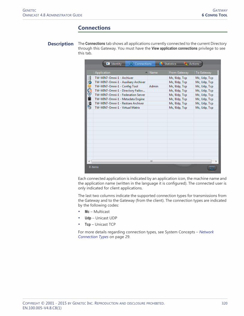
GENETEC GATEWAYOMNICAST 4.8 ADMINISTRATOR GUIDE 6 CONFIG TOOL
Connections
Description The Connections tab shows all applications currently connected to the current Directory through this Gateway. You must have the View application connections privilege to see this tab.
Each connected application is indicated by an application icon, the machine name and the application name (written in the language it is configured). The connected user is only indicated for client applications.
The last two columns indicate the supported connection types for transmissions from the Gateway and to the Gateway (from the client). The connection types are indicated by the following codes:• Mc – Multicast • Udp – Unicast UDP • Tcp – Unicast TCP
For more details regarding connection types, see System Concepts – Network Connection Types on page 29.
COPYRIGHT © 2001 - 2015 BY GENETEC INC. REPRODUCTION AND DISCLOSURE PROHIBITED. 320EN.100.005-V4.8.C8(1)

GENETEC GATEWAYOMNICAST 4.8 ADMINISTRATOR GUIDE 6 CONFIG TOOL
Statistics
Description The Statistics tab offers statistical information concerning the disk and bandwidth usage of the selected Gateway.
Statistics This section shows the general statistics for the Gateway.
Network packet capture
Creating a Network packet capture, allows you to monitor the current traffic between the Gateway and all other services on the network. This packet capture is stored as a temporary log file on the Archiver computer, and can be sent to Genetec Technical Assistance for troubleshooting purposes.
NOTE To create custom filters for your network packet capture, you will require Wireshark and WinPcap knowledge.
Statistics Description
Computer network traffic (In/Out)
The sum (in Kbps/sec) of all incoming and outgoing data on all network interfaces on this computer. This value turns red if it exceeds 300 Mbps.
Click to refresh the statistics.
COPYRIGHT © 2001 - 2015 BY GENETEC INC. REPRODUCTION AND DISCLOSURE PROHIBITED. 321EN.100.005-V4.8.C8(1)
GENETEC GATEWAYOMNICAST 4.8 ADMINISTRATOR GUIDE 6 CONFIG TOOL
To create a Network packet capture:1 Select a Filter.
– All traffic: All network traffic between the Gateway and other services.– TCP/HTTP traffic: All TCP traffic sent through an HTTP connection.– Custom: Custom filters you can create in WinPcap format. For more information
about creating custom filters, see the WinPcap Web site: http://www.winpcap.org/docs/docs_412/html/group__language.html.
2 If you want to set a maximum amount of time for the capture to run, select the Maximum length option, and type x number of minutes. The default number is 15 minutes.
3 If you want to set a maximum file size for the capture, select the Maximum size option, and type a number. The default file size is 10 MB of data.
4 If you want to capture data continuously, select the Use file rotation option.When the Use file rotation option is selected, the capture continues until you manually stop it. When the file size exceeds 10 MB, a new file is created. When that file exceeds 10 MB, the first file is overridden, and the two files are alternately overridden until the capture is stopped. This allows you to save disk space because you do not have to keep creating new files.
5 Click Start.The Status says Capture Started, and the Capture file location gives the location of the temporary file created.Note: If an error occurs during the capture, the reason is described in the Status field. For example, if you type an incorrect custom filter, it will say “Error: Invalid filter”.
6 To stop the capture, click Stop, or wait for the capture to be completed.7 Click Close.
COPYRIGHT © 2001 - 2015 BY GENETEC INC. REPRODUCTION AND DISCLOSURE PROHIBITED. 322EN.100.005-V4.8.C8(1)

GENETEC GATEWAYOMNICAST 4.8 ADMINISTRATOR GUIDE 6 CONFIG TOOL
Actions
Description The Actions tab allows you to trigger further actions following specific archiver events shown in the Events/actions list.
To learn about general event-to-actions programming, please refer to Event Management on page 22.
COPYRIGHT © 2001 - 2015 BY GENETEC INC. REPRODUCTION AND DISCLOSURE PROHIBITED. 323EN.100.005-V4.8.C8(1)

GENETEC GENERIC SCHEDULEOMNICAST 4.8 ADMINISTRATOR GUIDE 6 CONFIG TOOL
Generic Schedule
Definition
The generic schedule defines a set of time constraints that can be applied to a multiple of situations in the Omnicast.
The time constraints are defined by the following characteristics: •Recurrence pattern: Specific dates, yearly, monthly, weekly, or daily •Time coverage: Specific ranges, Daytime, Nighttime, or All day
The generic schedule‘s configuration page comprises the following tabs.
Creating a generic schedule
To create a new generic schedule entity, do the following.1 Select Schedule Management from the View selection pane. See View selection pane
on page 155.2 Click at the bottom of the View selection pane. A pop-up menu with the
entities you can create appears.3 Select Generic Schedule from the pop-up menu. A new entity named New generic
schedule will be created.4 Enter a descriptive name for the new schedule entity. Use the Description field to
provide more details if necessary, in the Identity tab.5 Select the Properties tab to configure the Recurrence pattern and the Time coverage
for this schedule. See Properties on page 325.
Icon Tab Description
Identity Name, description and positions of the entity in the Logical and Physical system hierarchies.
Properties Recurrence pattern and the time coverage.
Linked Entities Other entities that use this generic schedule.
COPYRIGHT © 2001 - 2015 BY GENETEC INC. REPRODUCTION AND DISCLOSURE PROHIBITED. 324EN.100.005-V4.8.C8(1)

GENETEC GENERIC SCHEDULEOMNICAST 4.8 ADMINISTRATOR GUIDE 6 CONFIG TOOL
Properties
Description The Properties tab defines the Recurrence pattern and the Time coverage that characterize this schedule.
See Recurrence pattern on page 325 and Time coverage on page 329.
Recurrence pattern
Introduction The definition of a generic schedule starts with the selection of a recurrence pattern. Only one pattern may be selected per schedule. The choices are:• Daily – Repeats every day• Weekly – Repeats every week on the selected weekdays• Monthly – Repeats every month on the selected days of the month• Yearly – Repeats every year on the selected dates (month/day)• Specific – Applies only once on specific dates (year/month/day)
Each recurrence option offers different date and time settings that are described in what follows.
COPYRIGHT © 2001 - 2015 BY GENETEC INC. REPRODUCTION AND DISCLOSURE PROHIBITED. 325EN.100.005-V4.8.C8(1)

GENETEC GENERIC SCHEDULEOMNICAST 4.8 ADMINISTRATOR GUIDE 6 CONFIG TOOL
Daily Use the Daily option to create a schedule that repeats the same pattern every day. For the different time coverage options, see Time coverage on page 329.
Weekly Use the Weekly option for schedules that repeat on a weekly basis. Only the weekly time grid is available for this option. For more advanced time coverage specifications, use the Monthly option instead.
Monthly Use the Monthly option to cover the recurring monthly events. You can either select a specific day (e.g. Day 15 of every month) in the month or a variable day (e.g., The fourth Wednesday of every month).
For the Time coverage settings, see Time coverage on page 329.
You may define more than one entry within the same monthly schedule. To do so, click the button.
COPYRIGHT © 2001 - 2015 BY GENETEC INC. REPRODUCTION AND DISCLOSURE PROHIBITED. 326EN.100.005-V4.8.C8(1)

GENETEC GENERIC SCHEDULEOMNICAST 4.8 ADMINISTRATOR GUIDE 6 CONFIG TOOL
The advanced mode shows a list of monthly entries that you may define individually.
Use the and buttons to add or delete the entries in the list. Note that as long as you have more than one entry in the list, you may not go back to the simple mode.
Yearly Select the Yearly option to cover the recurring yearly events. You can either select a specific day in the month (e.g. Day 10 of March) or a variable day (e.g., The first Monday of January). Similar to the Monthly option, you may define multiple entries within the same yearly schedule.
COPYRIGHT © 2001 - 2015 BY GENETEC INC. REPRODUCTION AND DISCLOSURE PROHIBITED. 327EN.100.005-V4.8.C8(1)

GENETEC GENERIC SCHEDULEOMNICAST 4.8 ADMINISTRATOR GUIDE 6 CONFIG TOOL
Use the and buttons to add or delete the entries in the list. Note that the simple mode is not available as long as you have more than one entry in the list.
Specific Select the Specific option is used to define non recurrent events. To select the dates, use the calendar control (see image below). Left-click on a date to select it or right-click on a date to remove its selection. You may also click and drag to select a range of dates.
To specify the time range for the selected dates, click the List mode button.
COPYRIGHT © 2001 - 2015 BY GENETEC INC. REPRODUCTION AND DISCLOSURE PROHIBITED. 328EN.100.005-V4.8.C8(1)

GENETEC GENERIC SCHEDULEOMNICAST 4.8 ADMINISTRATOR GUIDE 6 CONFIG TOOL
For the Time coverage settings, see Time coverage on page 329. The list of dates support multiple selection.
Click to go back to the calendar mode.
Time coverage
Introduction To define the Time coverage for a given day, you have the following options:• All day – Covers the whole day.• Range – Covers a single or multiple time ranges.• Daytime/Nighttime – Covers the time between sunrise and sunset or between
sunset and sunrise.
All day Use All day if all 24 hours of the day must be covered.
Range Use the Range option if only certain part of the day must be covered.
You may define a contiguous range:
or multiple discrete ranges.
Use the left mouse button to select a time block or the right mouse button to remove a time block.
When defining a single time range, you may extend the time range to the next day by specifying a Start time greater than the Stop time. This option is not available for the Daily recurrent pattern. See Daily on page 326.
COPYRIGHT © 2001 - 2015 BY GENETEC INC. REPRODUCTION AND DISCLOSURE PROHIBITED. 329EN.100.005-V4.8.C8(1)

GENETEC GENERIC SCHEDULEOMNICAST 4.8 ADMINISTRATOR GUIDE 6 CONFIG TOOL
Daytime/Nighttime The Daytime and Nighttime options define variable time ranges based on when the sun rises and sets. The sunrise and sunset times are calculated based on the day of year and a geographical location. For this reason, this time option is only applicable to cameras for which a geographical location is defined.
You may offset the sunrise and sunset times by up to plus or minus 3 hours for added flexibility.
Linked Entities
Description Schedules are used in a variety of situations where a date/time range and recurrence pattern must be specified to enable or disable certain functions or set certain time dependant properties.
The Linked entities tab is where you can find all other entities that are using this generic schedule.G
Usage context Use this drop-down list to filter the entity list according to a particular type.
COPYRIGHT © 2001 - 2015 BY GENETEC INC. REPRODUCTION AND DISCLOSURE PROHIBITED. 330EN.100.005-V4.8.C8(1)

GENETEC GENERIC SCHEDULEOMNICAST 4.8 ADMINISTRATOR GUIDE 6 CONFIG TOOL
The following table shows the different usage contexts of a generic schedule and whether the Daytime/Nighttime option is applicable.
Schedule Priorities and Conflict Resolution
Default schedule When Omnicast Directory is first installed, a schedule named ALWAYS is created by default. This default schedule cannot be renamed and cannot be deleted. It covers 24 hours a day and 7 days a week.
When entity that requires a generic schedule is created, it is always assigned to the default schedule.
Conflict resolution Since schedules are used to enable or disable certain application functions or set certain properties, it is imperative to understand how conflicts are resolved when two or more schedules overlap.
The conflict is resolved by adopting a concept of priority. Whenever two schedules overlap in a conflicting situation (for example two archiving schedules for the same camera), priority is given to the schedule with the most specific time coverage.
The specificity of a schedule is based on its recurrence pattern. The following is their order of priority.1 Specific (runs only once, highest priority)2 Yearly (repeats once a year)3 Monthly (repeats once a month)4 Weekly (repeats once a week)5 Daily (repeats every day)6 Always (runs all the time, lowest priority)
Two schedules with the same recurrence pattern are not allowed to overlap.
Entity – Tab Usage context Day/Night
Archiving schedule – Properties Archiving schedule Yes
Macro schedule – Properties Macro schedule No
Camera – Video quality Video quality Yes
Camera – Motion detection Motion detection Yes
Camera – Attributes Video attributes Yes
User – Properties User logon Yes
Any entity – Actions Action No
Alarm – Properties Alarm No
VM plugin – Schedules Virtual Matrix plugin No
ME plugin – Properties Metadata Engine plugin No
Camera sequence – Schedules Camera sequence No
COPYRIGHT © 2001 - 2015 BY GENETEC INC. REPRODUCTION AND DISCLOSURE PROHIBITED. 331EN.100.005-V4.8.C8(1)

GENETEC GENERIC SCHEDULEOMNICAST 4.8 ADMINISTRATOR GUIDE 6 CONFIG TOOL
As you can see, the default schedule Always has a lower priority than any other schedule the user may create.
We are going to illustrate the conflict resolution rules by using archiving schedules as examples.
Example #1
Let us consider Camera-1, assigned to the following archiving schedules:
Schedule-1: Specific (2007-Sep-10; from 5:15 PM to 6:30 PM)
Schedule-2: Weekly (Mondays, Wednesdays, Saturdays; from 9 AM to 7 PM)
Schedule-3: Daily (from 7 AM to 9 PM)
Default schedule: based on the default schedule Always.
The conflict resolution rules say:– On September 10th, 2007, between 5:15 PM and 6:30 PM, Camera-1 will follow
the archiving properties set by Schedule-1. – On September 10th, 2007, between 9 AM and 5:15 PM and between 6:30 PM
and 7 PM, Camera-1 will follow the archiving properties set by Schedule-2. – On September 10th, 2003, between 7 AM and 9 AM and between 7 PM and 9
PM, Camera-1 will follow the archiving properties set by Schedule-3. – The rest of the day, Camera-1 will follow the Default schedule.
Example #2
Let use define four more archiving schedules as follow:
Schedule-5: Specific (2007-Sep-11; from 8 AM to 8 PM)
Schedule-6: Weekly (Tuesdays, Thursdays; from 10 AM to 5 PM)
Schedule-7: Weekly (Saturdays; from 5 PM to 7 PM)
Schedule-8: Daily (from 3 PM to 11 PM)
The conflict resolution rules say:– Camera-1 can be put on Schedule-5 and Schedule-6 because they do not conflict
with any other schedules Camera-1 is on. – Camera-1 cannot be put on Schedule-7 because it conflicts with Schedule-2 on
Saturdays between 5 PM and 7 PM, and the priority rule cannot resolve the conflict because both schedules are weekly schedules.
– Camera-1 cannot be put on Schedule-8 because it conflicts with Schedule-3 on a daily basis between 3 PM and 9 PM, and the priority rule cannot resolve the conflict because both schedules are daily schedules.
COPYRIGHT © 2001 - 2015 BY GENETEC INC. REPRODUCTION AND DISCLOSURE PROHIBITED. 332EN.100.005-V4.8.C8(1)

GENETEC GHOST CAMERAOMNICAST 4.8 ADMINISTRATOR GUIDE 6 CONFIG TOOL
COPYRIGHT © 2001 - 2015 BY GENETEC INC. REPRODUCTION AND DISCLOSURE PROHIBITED. 333EN.100.005-V4.8.C8(1)
Ghost Camera
Definition
A ghost camera is a stand in camera that is automatically created by the system when video archives must be restored for a camera whose definition has been deleted from the Directory, either because the physical device (video encoder) no longer exists or because the entity has been deleted by mistake. Ghost cameras cannot be configured like real cameras. They are created so that users can query the video archives that are still available.
The only properties that can be changed on a ghost camera are its name and description. Therefore, only the Identity tab is available.
Ghost cameras can only be seen in the Config Tool and the Archive Player, not the Live Viewer. Like a deceased person, only the memories remain, which in this case, are the video archives. If you delete a ghost camera, the restored video associated to it will also be deleted.
A different scenario that may cause the creation of a ghost camera is when a camera is deleted while its default Archiver is not running. When the default Archiver is back online, it will create a ghost camera for every camera it has in its database that cannot be matched to a physical device. Once the unit to which the video encoder belongs to is discovered, the Archiver will convert the ghost camera into a regular camera. However, any previous camera configuration that you might have will be lost. See Camera (Video Encoder) on page 237.
NOTE While a camera remains a “ghost”, it cannot be displayed during alarm playback. See Alarm Search in Omnicast Archive Player User Guide.
WARNING If you delete an inactive camera while its default Archiver is running, the associated video archives will be permanently lost.
Icon Tab Description
Identity Name, description and positions of the entity in the Logical and Physical system hierarchies.

GENETEC HARDWARE MATRIXOMNICAST 4.8 ADMINISTRATOR GUIDE 6 CONFIG TOOL
Hardware Matrix
Definition
The hardware matrix is an entity used in Omnicast to represent conventional CCTV matrices to ensure their seamless integration to the rest of the system. The interaction between the Omnicast user and the CCTV matrix is handled by the Virtual Matrix. All control settings of the CCTV matrix are captured in the hardware matrix configuration. Once this is done, Omnicast users can view any camera connected to the inputs of the CCTV matrix with the Live
Viewer without ever having to worry about the manual switching commands.
The hardware matrix’s configuration page comprises the following tabs.
Creating a hardware matrix
The creation of hardware matrices is enabled by the license options Number of Virtual Matrices and Number of hardware matrices. See Server Admin – Directory options on page 47. To create a new hardware matrix entity, do the following.1 Select Virtual Matrix Management from the View selection pane. See View selection
pane on page 155.2 Click at the bottom of the View selection pane. A pop-up menu with the
entities you can create appears.3 Select Hardware Matrix from the pop-up menu. The Select the Virtual Matrix dialog
appears.4 Select from this dialog, the primary Virtual Matrix that should be controlling this
entity and click OK. A new entity named New hardware matrix will be created.5 Enter a descriptive name for the new hardware matrix entity.
Use the Description field to provide more details if necessary, in the Identity tab.6 Select the Properties tab and define the control macro and the hardware matrix
users. See Properties on page 335.7 Select the Inputs tab and define the cameras connected to the inputs of the
hardware matrix. See Inputs on page 337.8 Select the Outputs tab and define the video encoders connected to the outputs of
the hardware matrix. See Outputs on page 338.9 Define the standby Virtual Matrices for this entity if applicable. See Standby Virtual
Matrices on page 340.
Icon Tab Description
Identity Name, description and positions of the entity in the Logical and Physical system hierarchies.
Properties Interface with the Virtual Matrix.
Inputs Video inputs configuration (virtual cameras).
Outputs Video outputs configuration (video encoders).
Connections Interface with the Virtual Matrix.
Standby Virtual Matrices
List of secondary Virtual Matrices that serve as backups for the control of this hardware matrix entity.
COPYRIGHT © 2001 - 2015 BY GENETEC INC. REPRODUCTION AND DISCLOSURE PROHIBITED. 334EN.100.005-V4.8.C8(1)

GENETEC HARDWARE MATRIXOMNICAST 4.8 ADMINISTRATOR GUIDE 6 CONFIG TOOL
Properties
Description The Properties tab allows you to monitor the running status of the hardware matrix and to configure its main properties.
Hardware matrix status
The Status field indicates the global status of the hardware matrix. The hardware matrix is running if at least one of the serial port connected to the hardware matrix is running. See Hardware matrix users on page 335 for more details.
Hardware matrix protocol
Use the Hardware matrix protocol drop-down list to select the appropriate protocol used by the hardware manufacturer. Only the supported protocols are listed.
Hardware matrix users
Definition By Hardware matrix users, we mean the serial ports connected to the keyboard inputs of the CCTV matrix. The Virtual Matrix uses these serial ports to send control commands to the hardware matrix. There must be at least one serial port attached for the hardware matrix to work.
The number of serial ports attached determines how many Omnicast users can simultaneously control the PTZ enabled cameras connected to the CCTV matrix. Cameras indirectly controlled by Omnicast are called virtual cameras and are shown by the following icons in the Live Viewer: and .
COPYRIGHT © 2001 - 2015 BY GENETEC INC. REPRODUCTION AND DISCLOSURE PROHIBITED. 335EN.100.005-V4.8.C8(1)
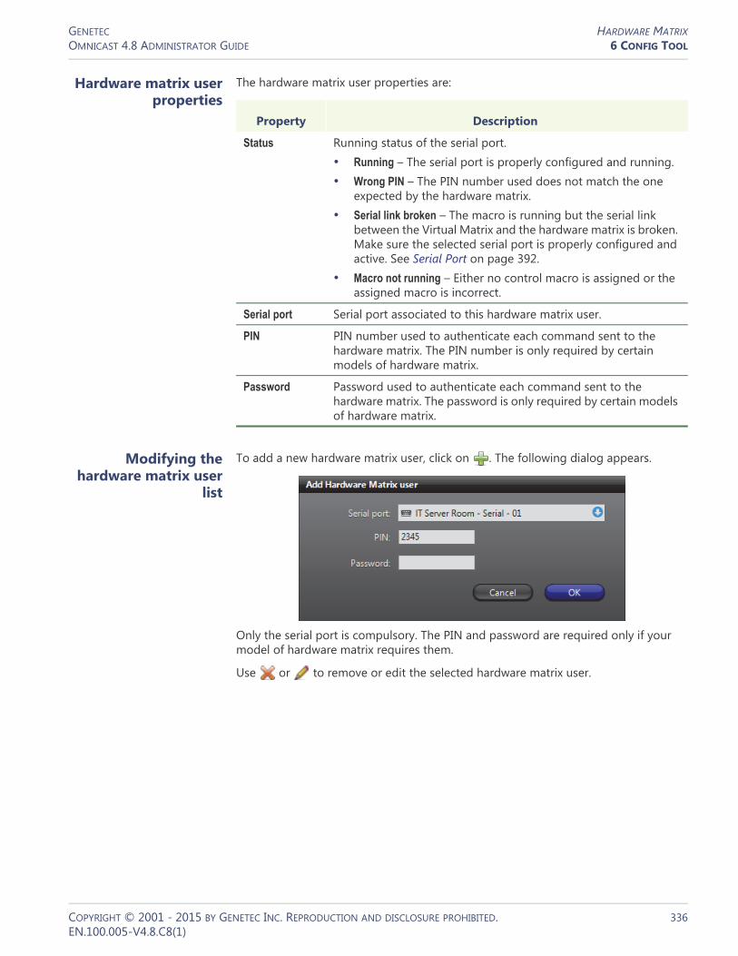
GENETEC HARDWARE MATRIXOMNICAST 4.8 ADMINISTRATOR GUIDE 6 CONFIG TOOL
Hardware matrix user properties
The hardware matrix user properties are:
Modifying the hardware matrix user
list
To add a new hardware matrix user, click on . The following dialog appears.
Only the serial port is compulsory. The PIN and password are required only if your model of hardware matrix requires them.
Use or to remove or edit the selected hardware matrix user.
Property Description
Status Running status of the serial port.• Running – The serial port is properly configured and running.• Wrong PIN – The PIN number used does not match the one
expected by the hardware matrix. • Serial link broken – The macro is running but the serial link
between the Virtual Matrix and the hardware matrix is broken. Make sure the selected serial port is properly configured and active. See Serial Port on page 392.
• Macro not running – Either no control macro is assigned or the assigned macro is incorrect.
Serial port Serial port associated to this hardware matrix user.
PIN PIN number used to authenticate each command sent to the hardware matrix. The PIN number is only required by certain models of hardware matrix.
Password Password used to authenticate each command sent to the hardware matrix. The password is only required by certain models of hardware matrix.
COPYRIGHT © 2001 - 2015 BY GENETEC INC. REPRODUCTION AND DISCLOSURE PROHIBITED. 336EN.100.005-V4.8.C8(1)

GENETEC HARDWARE MATRIXOMNICAST 4.8 ADMINISTRATOR GUIDE 6 CONFIG TOOL
Inputs
Description The Inputs tab allows you to define the cameras connected to the video inputs of the CCTV matrix. These cameras are called virtual cameras because they are not directly connected to video encoders controlled by Omnicast.
Defining the virtual cameras
To define the virtual cameras associated to the hardware matrix, do the following.1 Enter the number of video inputs you have on your CCTV matrix and click the
button. The specified number of inputs (virtual cameras) will be added.The system will not let you add more than 10 inputs at a time. This restriction is in place to prevent you from overloading the Directory. The total number of inputs that you may add can go as high as what your model of CCTV matrix can accept.
2 Give a meaningful name to each of the newly created virtual cameras.Once defined, these virtual cameras will appear in the camera tree of the Live Viewer just like any other cameras.
3 Adjust the visibility of the virtual cameras by moving them under the appropriate sites in the Logical view. See Logical View on page 161.
4 Adjust the camera IDs assigned to the virtual cameras if necessary.To find out the camera ID assigned to each virtual camera, select them from the Logical view and check their Identity tab.
To delete a virtual camera, simply select it from the list and click .
Virtual camera limitations
There are generally more inputs than outputs on a CCTV matrix. This means that not all virtual cameras can be viewed at the same time.
If the request is made from the Config Tool when all video encoders connected to the CCTV matrix's outputs are already taken, an error message will be displayed.
COPYRIGHT © 2001 - 2015 BY GENETEC INC. REPRODUCTION AND DISCLOSURE PROHIBITED. 337EN.100.005-V4.8.C8(1)

GENETEC HARDWARE MATRIXOMNICAST 4.8 ADMINISTRATOR GUIDE 6 CONFIG TOOL
If the request is issued from the Live Viewer, the message No output will be shown in the selected tile.
If several users are viewing the same virtual camera, only one video encoder is necessary.
Outputs
Description The Outputs tab allows you to define the video encoders connected to the video outputs of the CCTV matrix.
Assigning video encoders to the
outputs
To assign video encoders to the outputs, do the following.1 Enter the number of video outputs you wish to configure on your CCTV matrix and
click .The specified number of outputs will be added.2 Select one by one the newly defined outputs and assign a video encoder to each.
– All cameras directly connected to the CCTV matrix will be viewed through these video encoders in Omnicast.
– To assign a video encoder, simply select one from the drop-down list at the bottom of the Outputs tab.
3 You may add more video outputs at any time by repeating Step 1 through Step 2.4 To dissociate a video encoder from an output, select the output and select None
from the drop-down list at the bottom of the tab.5 Click Apply when you are finished.
If you want to delete an output, select it and click the button.
COPYRIGHT © 2001 - 2015 BY GENETEC INC. REPRODUCTION AND DISCLOSURE PROHIBITED. 338EN.100.005-V4.8.C8(1)
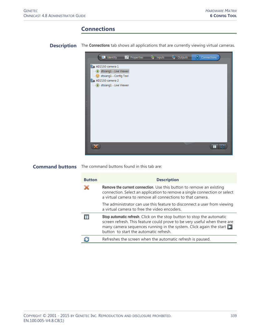
GENETEC HARDWARE MATRIXOMNICAST 4.8 ADMINISTRATOR GUIDE 6 CONFIG TOOL
Connections
Description The Connections tab shows all applications that are currently viewing virtual cameras.
Command buttons The command buttons found in this tab are:
Button Description
Remove the current connection. Use this button to remove an existing connection. Select an application to remove a single connection or select a virtual camera to remove all connections to that camera.
The administrator can use this feature to disconnect a user from viewing a virtual camera to free the video encoders.
Stop automatic refresh. Click on the stop button to stop the automatic screen refresh. This feature could prove to be very useful when there are many camera sequences running in the system. Click again the start button to start the automatic refresh.
Refreshes the screen when the automatic refresh is paused.
COPYRIGHT © 2001 - 2015 BY GENETEC INC. REPRODUCTION AND DISCLOSURE PROHIBITED. 339EN.100.005-V4.8.C8(1)

GENETEC HARDWARE MATRIXOMNICAST 4.8 ADMINISTRATOR GUIDE 6 CONFIG TOOL
Standby Virtual Matrices
Description The Standby Virtual Matrices tab shows the Virtual Matrix failover list for this device.
The Virtual Matrix appearing at the top of the list is the master of this hardware matrix entity. It is the one that should be controlling this device in normal situations. If the master fails, then the control of this device will be automatically transferred to the next Virtual Matrix in line.
COPYRIGHT © 2001 - 2015 BY GENETEC INC. REPRODUCTION AND DISCLOSURE PROHIBITED. 340EN.100.005-V4.8.C8(1)

GENETEC MACROOMNICAST 4.8 ADMINISTRATOR GUIDE 6 CONFIG TOOL
Macro
Definition
A macro is a sequence of commands (or a script) that can be saved, recalled and executed quickly when needed. Macros can be used to create custom actions. For example, a bookmark could be added to a video archive every time someone swipes a security card to walk through a door (if the card reader is connected to Omnicast through a digital input pin). Another example would be to show a rotation of cameras at preset intervals in the Live Viewer application.
Macros must be executed by Virtual Matrices. In order to use macros in your system, the Number of Virtual Matrices allowed by your Omnicast license must be greater than zero and Macros must be supported. See Server Admin – Directory options on page 47.
Macro executions can be launched manually from:• Config Tool – See Virtual Matrix – Statistics on page 456.• Live Viewer – See Tools Menu in the Omnicast Live Viewer User Guide.• PC keyboard – See Keyboard Commands in the Omnicast Live Viewer User Guide.
or automatically from:• Virtual Matrix – See Macro Schedule on page 353.• any event – See Appendix B: Actions on page 526.
The macro‘s configuration page comprises the following tabs.
Creating a macro To create a new macro, do the following.1 Select Add-In Management from the View selection pane. See View selection pane on
page 155.2 Click at the bottom of the View selection pane. A pop-up menu with the
entities you can create appears.3 Select Macro from the pop-up menu. A new entity named New macro will be
created.4 Enter a descriptive name for the new macro. You can click the Identity tab and use
the Description field to provide more details if necessary.5 Select the Properties tab to define the macro steps. See Properties on page 342.6 If you already have a script, you may import it from the Code tab. See Code on
page 349.
Icon Tab Description
Identity Name, description and positions of the entity in the Logical and Physical system hierarchies.
Properties Macro definition Wizard (step by step definition).
Actions Actions to perform following specific macro events.
Code Wizard generated or user-defined VBScript using Omnicast SDK.
COPYRIGHT © 2001 - 2015 BY GENETEC INC. REPRODUCTION AND DISCLOSURE PROHIBITED. 341EN.100.005-V4.8.C8(1)

GENETEC MACROOMNICAST 4.8 ADMINISTRATOR GUIDE 6 CONFIG TOOL
7 Macros can be executed directly by end-users (from the Live Viewer or from a keyboard). So do not forget to change its visibility by dragging or copying it to the appropriate site in the Logical view.See User – Permissions on page 422.
NOTE Each macro requires 1 MB of virtual memory while it is being executed by the Virtual Matrix. Therefore, if you plan on executing many macros simultaneously, make sure to take the virtual memory requirements into consideration.
Properties
Description The Properties tab allows you to define the macro command steps with the help of the Macro Wizard. This is the simplest method for defining a macro.
A macro is composed of three sections:1 Main section
2 OnAction section
3 OnEvent section
You may edit the steps within each individual section.
COPYRIGHT © 2001 - 2015 BY GENETEC INC. REPRODUCTION AND DISCLOSURE PROHIBITED. 342EN.100.005-V4.8.C8(1)

GENETEC MACROOMNICAST 4.8 ADMINISTRATOR GUIDE 6 CONFIG TOOL
Adding a macro step To add a step to your macro, do the following.1 Select the section you wish to edit from the Section to edit list.2 Click at the bottom of the tab. The Step dialog box appears.
3 Select a command from the Command list. Depending on the selected command, the rest of the dialog will change its appearance to prompt the user to enter the appropriate arguments. See Commands and arguments on page 344.
4 Enter the arguments and click OK. The new step will be added at the end of the step list.
5 Use the and buttons to change the ordering of the steps if necessary.6 Click the button to modify the selected step.7 Click the button to remove the selected step.8 Click Apply to save your changes.
The generated VBScript can be viewed from the Code tab.
COPYRIGHT © 2001 - 2015 BY GENETEC INC. REPRODUCTION AND DISCLOSURE PROHIBITED. 343EN.100.005-V4.8.C8(1)

GENETEC MACROOMNICAST 4.8 ADMINISTRATOR GUIDE 6 CONFIG TOOL
Commands and arguments
The following table summarizes the available commands from the Macro Wizard with their corresponding arguments.
Command (1 of 4) Argument 1 Argument 2 Argument 3
Acknowledge alarm Alarm instance ID
Acknowledge alarm in Live Viewer
Monitor ID
Acknowledge alarm in Live Viewer using type
Monitor ID Acknowledgement type
Custom event ID
Acknowledge alarm using context
Context string
Acknowledge alarm using context and type
Context string Acknowledgement type
Custom event ID
Acknowledge alarm using type
Alarm instance ID Acknowledgement type
Custom event ID
Add a bookmark Camera Bookmark text
Add find results Return value First find value Second find value
Arm/disarm active tile for alarms
Monitor ID Action (arm, disarm)
Block a camera Camera Block level
Change input focus in Live Viewer
Monitor ID Region (Live Viewer workspace element)
Change instant replay playback speed
Monitor ID Operation (increase, decrease)
Change PTZ speed of the viewed camera
Monitor ID Operation (increase, decrease)
Close serial port Handle
Connect encoder to decoder
Encoder Decoder
Control PTZ Camera PTZ operation Parameters 1 & 2
Create custom action Description Action ID
Create custom event Description Event ID
Create object ProgID Name of the object
Cycle layout Monitor ID Direction (next, previous)
Cycle pattern Monitor ID Direction (next, previous)
Cycle tile Monitor ID Direction (next, previous)
Destroy object ProgID
Disconnect encoder from decoder
Encoder Decoder
Display a camera Camera Monitor ID Tile ID
Display a sequence Camera sequence Monitor ID Tile ID
COPYRIGHT © 2001 - 2015 BY GENETEC INC. REPRODUCTION AND DISCLOSURE PROHIBITED. 344EN.100.005-V4.8.C8(1)

GENETEC MACROOMNICAST 4.8 ADMINISTRATOR GUIDE 6 CONFIG TOOL
Display a URL address in a Live Viewer
URL Monitor Tile ID
End macro
Expand current tile Monitor ID
Find Find criteria List of results
For each block Opens a definition dialog.
Forward alarm Alarm instance ID User or user group
Forward alarm using context
Context string User or user group
Get connected decoders list
Encoder Result variable name
Get connected encoder Decoder Result variable name
Get current decoder ID Return value
Get current decoder type Return value
Get current encoder ID Return value
Get current encoder type Return value
Get current macro arguments
Return value
Get current macro GUID Return value
Get current tile Return value
Get current user GUID Return value
Get custom action description
Return value Action ID
Get custom event description
Return value Event ID
Get entity Return value Entity GUID
Get entity GUID Return value Entity ID Entity type
Get entity ID Return value Entity GUID
Get entity type Return value Entity GUID
Get number of result Return value List of result
Get user GUID Return value User name
Go to preset Camera Preset number
Go to step Step number
Hold sequence Sequence Monitor
If block Opens a definition dialog.
Listen audio on viewed camera
Monitor ID Operation (start, stop)
Next sequence Sequence Monitor
Open serial port Handle Serial port ID
Command (2 of 4) Argument 1 Argument 2 Argument 3
COPYRIGHT © 2001 - 2015 BY GENETEC INC. REPRODUCTION AND DISCLOSURE PROHIBITED. 345EN.100.005-V4.8.C8(1)
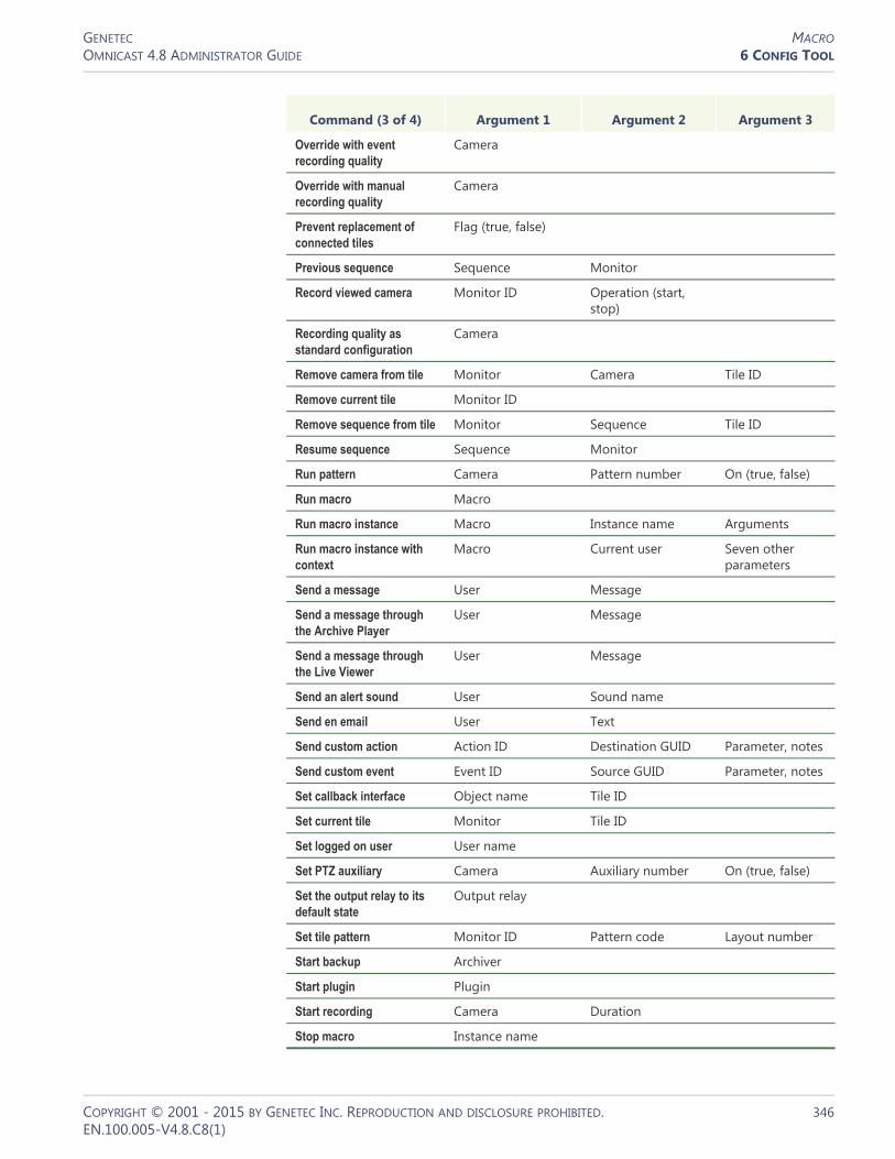
GENETEC MACROOMNICAST 4.8 ADMINISTRATOR GUIDE 6 CONFIG TOOL
Override with event recording quality
Camera
Override with manual recording quality
Camera
Prevent replacement of connected tiles
Flag (true, false)
Previous sequence Sequence Monitor
Record viewed camera Monitor ID Operation (start, stop)
Recording quality as standard configuration
Camera
Remove camera from tile Monitor Camera Tile ID
Remove current tile Monitor ID
Remove sequence from tile Monitor Sequence Tile ID
Resume sequence Sequence Monitor
Run pattern Camera Pattern number On (true, false)
Run macro Macro
Run macro instance Macro Instance name Arguments
Run macro instance with context
Macro Current user Seven other parameters
Send a message User Message
Send a message through the Archive Player
User Message
Send a message through the Live Viewer
User Message
Send an alert sound User Sound name
Send en email User Text
Send custom action Action ID Destination GUID Parameter, notes
Send custom event Event ID Source GUID Parameter, notes
Set callback interface Object name Tile ID
Set current tile Monitor Tile ID
Set logged on user User name
Set PTZ auxiliary Camera Auxiliary number On (true, false)
Set the output relay to its default state
Output relay
Set tile pattern Monitor ID Pattern code Layout number
Start backup Archiver
Start plugin Plugin
Start recording Camera Duration
Stop macro Instance name
Command (3 of 4) Argument 1 Argument 2 Argument 3
COPYRIGHT © 2001 - 2015 BY GENETEC INC. REPRODUCTION AND DISCLOSURE PROHIBITED. 346EN.100.005-V4.8.C8(1)
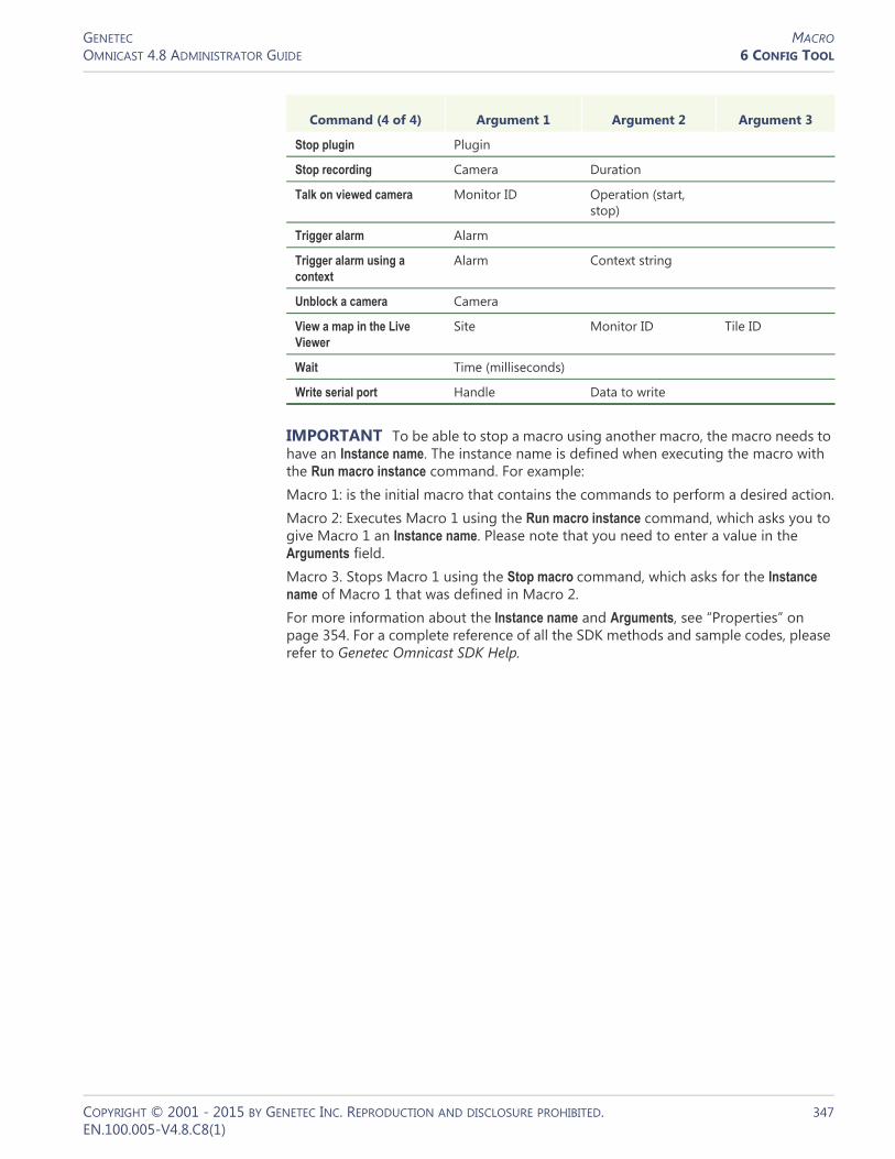
GENETEC MACROOMNICAST 4.8 ADMINISTRATOR GUIDE 6 CONFIG TOOL
IMPORTANT To be able to stop a macro using another macro, the macro needs to have an Instance name. The instance name is defined when executing the macro with the Run macro instance command. For example:Macro 1: is the initial macro that contains the commands to perform a desired action.Macro 2: Executes Macro 1 using the Run macro instance command, which asks you to give Macro 1 an Instance name. Please note that you need to enter a value in the Arguments field.Macro 3. Stops Macro 1 using the Stop macro command, which asks for the Instance name of Macro 1 that was defined in Macro 2. For more information about the Instance name and Arguments, see “Properties” on page 354. For a complete reference of all the SDK methods and sample codes, please refer to Genetec Omnicast SDK Help.
Stop plugin Plugin
Stop recording Camera Duration
Talk on viewed camera Monitor ID Operation (start, stop)
Trigger alarm Alarm
Trigger alarm using a context
Alarm Context string
Unblock a camera Camera
View a map in the Live Viewer
Site Monitor ID Tile ID
Wait Time (milliseconds)
Write serial port Handle Data to write
Command (4 of 4) Argument 1 Argument 2 Argument 3
COPYRIGHT © 2001 - 2015 BY GENETEC INC. REPRODUCTION AND DISCLOSURE PROHIBITED. 347EN.100.005-V4.8.C8(1)

GENETEC MACROOMNICAST 4.8 ADMINISTRATOR GUIDE 6 CONFIG TOOL
Actions
Description The Actions tab allows you to program specific system behaviors based on the macro events and custom events shown in the Events/actions list.
To learn about general event-to-actions programming, please refer to Event Management on page 22.
COPYRIGHT © 2001 - 2015 BY GENETEC INC. REPRODUCTION AND DISCLOSURE PROHIBITED. 348EN.100.005-V4.8.C8(1)

GENETEC MACROOMNICAST 4.8 ADMINISTRATOR GUIDE 6 CONFIG TOOL
Code
Description The Code tab allows you to modify the VBScript generated by the Macro Wizard (see Properties on page 342) or to write your own code.
Working with an external editor
If your needs require something more sophisticated than what the Macro Wizard can generate, you may write your macro with any editor of your choice and import it as macro code, as long as your editor produces a WSC (Windows Script Components) file.
To import a WSC file as macro code, click Import.
You may also write the initial code with the Macro Wizard and export it as a WSC file so you can modify it with a more sophisticated editor.
To export the current macro as a WSC file, click Export.
WARNING Once you have decided to edit the VBScript manually, the Macro Wizard can no longer be used. After you modified the code manually or imported the code from a WSC file, the steps can no longer be shown in the Properties tab.Conversely, if you decide to use the Macro Wizard after manually changing the code, all previously hand-written code will be lost.
Omnicast Macro Editor
Omnicast provides a very basic macro editor that allows you to test your macro within your environment. See Macro Editor on page 488.
COPYRIGHT © 2001 - 2015 BY GENETEC INC. REPRODUCTION AND DISCLOSURE PROHIBITED. 349EN.100.005-V4.8.C8(1)

GENETEC METADATA ENGINEOMNICAST 4.8 ADMINISTRATOR GUIDE 6 CONFIG TOOL
Metadata Engine
Definition
The Metadata Engine (ME) is the link between Omnicast and third party applications such as video analytics software and point of sale systems with the goal of enriching its captured video with additional information called metadata. Through the use of specific plugins, the Metadata Engine performs live translations of Omnicast video to and from third party applications and enables users to view the collected metadata along with live video or to query them with the Archive
Player.
Multiple instances of Metadata Engine may be running on the same system, but their use must be granted by the Number of Metadata Engines option of your Omnicast license. See Server Admin – Directory options on page 47.
The Metadata Engine‘s configuration page comprises the following tabs.
Being an Omnicast service, the machine specific parameters of the Metadata Engine are configured with the Server Admin. See Metadata Engine on page 146.
Icon Tab Description
Identity Name, description and positions of the entity in the Logical and Physical system hierarchies.
Plugins Plugins supported by this Metadata Engine
Actions Actions to perform following specific server events.
COPYRIGHT © 2001 - 2015 BY GENETEC INC. REPRODUCTION AND DISCLOSURE PROHIBITED. 350EN.100.005-V4.8.C8(1)

GENETEC METADATA ENGINEOMNICAST 4.8 ADMINISTRATOR GUIDE 6 CONFIG TOOL
Plugins
Description The Plugins tab lists all the plugin instances controlled by this Metadata Engine. Each plugin instance is identified by its name, type, and running state.
You may only start and stop plugins that are set run in manual mode. See ME Plugins – Properties on page 373.
To learn how to create a new plugin instance for the Metadata Engine, see ME Plugins – Creating ME plugins on page 373.
To delete a ME plugin instance, select the Add-In Management view. Select the plugin you wish to delete and click .
COPYRIGHT © 2001 - 2015 BY GENETEC INC. REPRODUCTION AND DISCLOSURE PROHIBITED. 351EN.100.005-V4.8.C8(1)

GENETEC METADATA ENGINEOMNICAST 4.8 ADMINISTRATOR GUIDE 6 CONFIG TOOL
Actions
Description The Actions tab allows you to program specific system behaviors based on the application events shown in the Events/actions list.
To learn about general event-to-actions programming, please refer to Event Management on page 22.
COPYRIGHT © 2001 - 2015 BY GENETEC INC. REPRODUCTION AND DISCLOSURE PROHIBITED. 352EN.100.005-V4.8.C8(1)
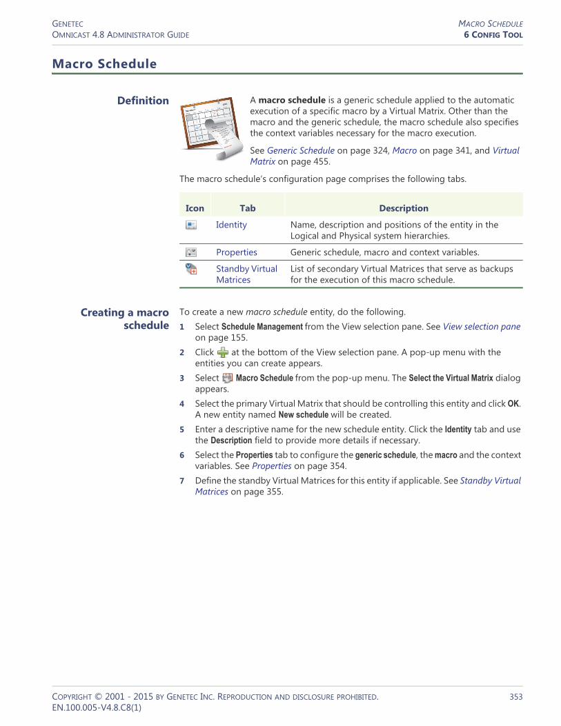
GENETEC MACRO SCHEDULEOMNICAST 4.8 ADMINISTRATOR GUIDE 6 CONFIG TOOL
Macro Schedule
Definition
A macro schedule is a generic schedule applied to the automatic execution of a specific macro by a Virtual Matrix. Other than the macro and the generic schedule, the macro schedule also specifies the context variables necessary for the macro execution.
See Generic Schedule on page 324, Macro on page 341, and Virtual Matrix on page 455.
The macro schedule‘s configuration page comprises the following tabs.
Creating a macro schedule
To create a new macro schedule entity, do the following.1 Select Schedule Management from the View selection pane. See View selection pane
on page 155.2 Click at the bottom of the View selection pane. A pop-up menu with the
entities you can create appears.3 Select Macro Schedule from the pop-up menu. The Select the Virtual Matrix dialog
appears.4 Select the primary Virtual Matrix that should be controlling this entity and click OK.
A new entity named New schedule will be created.5 Enter a descriptive name for the new schedule entity. Click the Identity tab and use
the Description field to provide more details if necessary.6 Select the Properties tab to configure the generic schedule, the macro and the context
variables. See Properties on page 354.7 Define the standby Virtual Matrices for this entity if applicable. See Standby Virtual
Matrices on page 355.
Icon Tab Description
Identity Name, description and positions of the entity in the Logical and Physical system hierarchies.
Properties Generic schedule, macro and context variables.
Standby Virtual Matrices
List of secondary Virtual Matrices that serve as backups for the execution of this macro schedule.
COPYRIGHT © 2001 - 2015 BY GENETEC INC. REPRODUCTION AND DISCLOSURE PROHIBITED. 353EN.100.005-V4.8.C8(1)

GENETEC MACRO SCHEDULEOMNICAST 4.8 ADMINISTRATOR GUIDE 6 CONFIG TOOL
Properties
Description The Properties tab defines the generic schedule and the context variables for running the specified macro.G
The following parameters define the macro schedule. Please refer to Genetec Omnicast SDK Help for more details on the concept of “Current” properties.
Parameter Description
Generic schedule The generic schedule defines the day(s) and time(s) when the macro should be executed. See Generic Schedule on page 324.
Execute The macro to execute. See Macro on page 341.
Current camera The current camera (context variable).
Current decoder The current decoder (context variable).
Current user The current user (context variable).
Instance name This string is used to identify this macro instance in case you need to stop this macro instance from another macro using the Stop macro command. Note that if more than one macro instance bear the same name, the Stop macro command will stop them all.
See Macro – Commands and arguments on page 344.
Arguments Use this string to pass arguments to the selected macro. There is no particular format to follow here. The parsing of the argument string depends on the implementation of the selected macro.
Current tile The current tile ID (context variable). This variable is used only if the Current decoder is the Live Viewer.
COPYRIGHT © 2001 - 2015 BY GENETEC INC. REPRODUCTION AND DISCLOSURE PROHIBITED. 354EN.100.005-V4.8.C8(1)
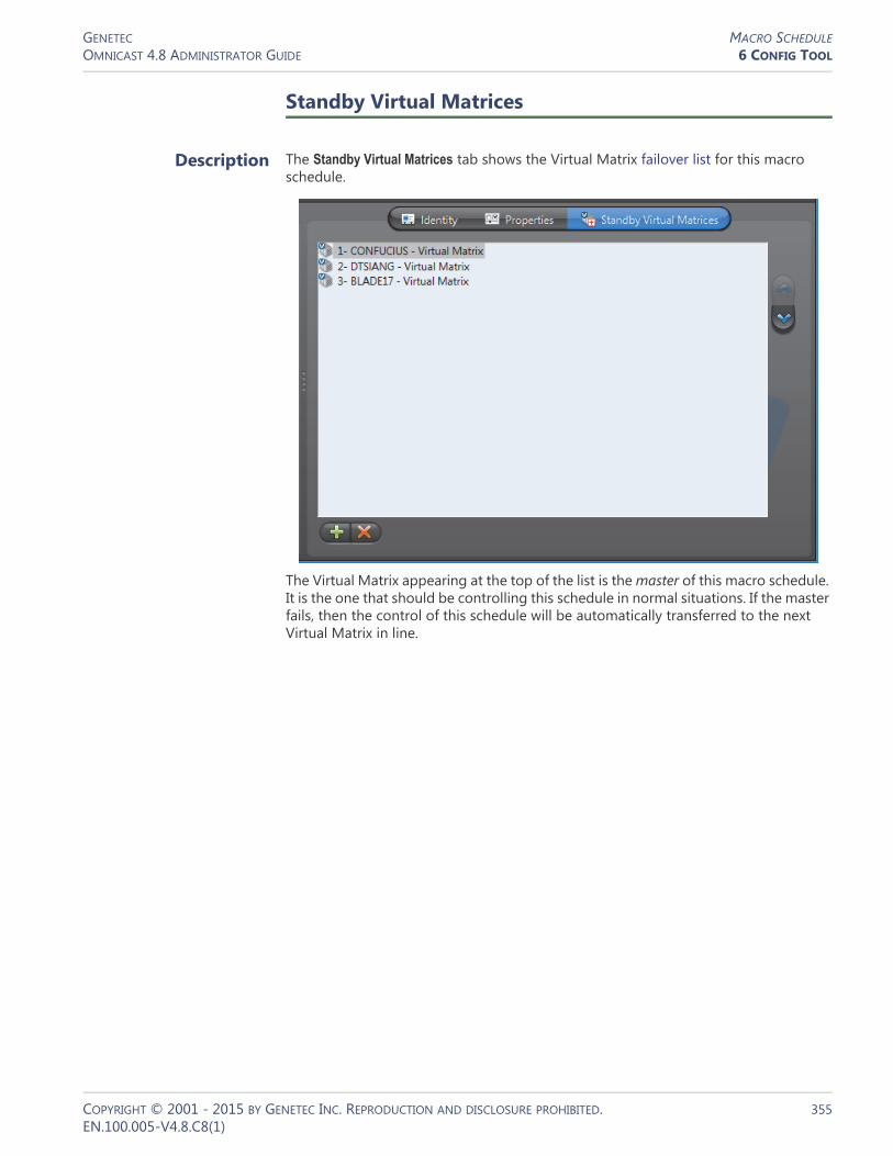
GENETEC MACRO SCHEDULEOMNICAST 4.8 ADMINISTRATOR GUIDE 6 CONFIG TOOL
Standby Virtual Matrices
Description The Standby Virtual Matrices tab shows the Virtual Matrix failover list for this macro schedule.
The Virtual Matrix appearing at the top of the list is the master of this macro schedule. It is the one that should be controlling this schedule in normal situations. If the master fails, then the control of this schedule will be automatically transferred to the next Virtual Matrix in line.
COPYRIGHT © 2001 - 2015 BY GENETEC INC. REPRODUCTION AND DISCLOSURE PROHIBITED. 355EN.100.005-V4.8.C8(1)

GENETEC MICROPHONE (AUDIO ENCODER)OMNICAST 4.8 ADMINISTRATOR GUIDE 6 CONFIG TOOL
Microphone (Audio Encoder)
Definition
A microphone is a device which converts sound waves into electric signals for recording. The audio encoder is the device that converts the analog signal produced by the microphone into digital form so it can be transmitted over an IP network. The audio encoder is but one of the many devices found on an encoder unit.
The microphone and the audio encoder are so intimately related that the two terms are used interchangeably in Omnicast.
The microphone‘s configuration page comprises the following tabs.
Properties
Description The Properties tab allows you configure the attributes of the audio encoder.
Icon Tab Description
Identity Name, description and positions of the entity in the Logical and Physical system hierarchies.
Properties Audio encoder properties.
Specific Settings
Audio mode setting for the encoder unit (only applicable to certain models).
Network Network properties.
COPYRIGHT © 2001 - 2015 BY GENETEC INC. REPRODUCTION AND DISCLOSURE PROHIBITED. 356EN.100.005-V4.8.C8(1)
GENETEC MICROPHONE (AUDIO ENCODER)OMNICAST 4.8 ADMINISTRATOR GUIDE 6 CONFIG TOOL
Audio encoder properties
The audio encoder properties are:
Parameter Description
Data format You have three possible values to choose from:• PCM – Pulse Code Modulation is an algorithm used to
convert an analog wave into digital signals. No compression is used in the algorithm, just straight conversion from analog to digital formats.
• Mulaw – An algorithm used to convert an analog wave into digital signals using a compression algorithm that encodes and compresses the signal information. Mulaw is the recommended format when it is available.
• GSM – Global System for Mobile telecommunication is a protocol used for digital cellular phones. GSM offers the highest compression ratio. Therefore, it saves on bandwidth usage at the expense of audio quality.
• AAC – Advanced Audio Coding is an algorithm used to convert an analog wave into digital signals. Like Mulaw format, it encodes and compresses the signal information, but maintains the high audio quality. This format also lets you set the Sampling rate and Bit rate for the encoder. It is only available for Axis encoders.
Sampling rate (Only with AAC format) The rate (in KHz) in which analog waves are converted into digital signals.
Bit rate (Only with AAC format) The maximum bandwidth (Kbps) allowed for this audio encoder.
Input type Type of input source.• Line in – Used for pre-amplified source.• Mic in – Use this if the microphone is directly connected to
the unit. In this case, the signal is amplified by the hardware.
• Internal – Used microphones integrated to the unit.
Sensitivity Position the slider to the desired amplification level (default=68). The lower the level, the less sensitive is the microphone to ambient noise, but the recording level would also be lower.
Attached cameras The camera tree shows the camera(s) that are connected to the microphone and allows you to change the microphone connections to cameras.
When a camera is connected to a microphone, the sound on/off button becomes enabled in the Live Viewer's tile where the camera is displayed.
Note that a microphone can be associated to many cameras (e.g. cameras showing different angles of a same room), but a camera can only be associated to one microphone. See also Camera – Links on page 275.
COPYRIGHT © 2001 - 2015 BY GENETEC INC. REPRODUCTION AND DISCLOSURE PROHIBITED. 357EN.100.005-V4.8.C8(1)

GENETEC MICROPHONE (AUDIO ENCODER)OMNICAST 4.8 ADMINISTRATOR GUIDE 6 CONFIG TOOL
Specific Settings
Description The Specific settings tab allows you to choose the audio mode for the unit. This tab is only available on units equipped with audio encoders and decoders. The same settings are found in the Audio tab of its unit. Changing anything in this tab will affect all audio devices belonging to the same unit. See Unit – Audio on page 407.
Unit specific audio settings
The unit specific settings are:
Parameter Description (1 of 2)
Audio mode Select Full-Duplex to be able to speak (send signals through the audio encoder) and listen (receive signals through the audio decoder) at the same time. This is the default setting and should be used in most situations.
Select Push-To-Talk (PTT) to operate in half-duplex mode (alternate between speaking and listening). This particular setting is only necessary when two units are connected together and that the audio must be controlled through digital inputs.
Changing the audio mode here also changes the audio mode on the speaker (audio decoder) belonging to the same unit.
NOTE Changing this setting might require the unit to reboot. If necessary, the unit will reboot by itself within the next minute and will be temporarily unavailable (shown as inactive).You can force the unit to reboot immediately by going to the Network tab of the corresponding unit and clicking Reboot. See Unit – Network on page 412.
COPYRIGHT © 2001 - 2015 BY GENETEC INC. REPRODUCTION AND DISCLOSURE PROHIBITED. 358EN.100.005-V4.8.C8(1)

GENETEC MICROPHONE (AUDIO ENCODER)OMNICAST 4.8 ADMINISTRATOR GUIDE 6 CONFIG TOOL
Network
Description The Network tab allows you to choose the connection type used by the audio encoder.
Network information The following parameters are displayed for information purpose only.
Sampling rate This control is enabled only if the unit model you have allows you to configure the sampling rate. A high sampling rate is recommended for languages that have a lot of intonation subtleties, such as Chinese.
Parameter Description (2 of 2)
Parameter Description
Local IP address Address of the device over the network.
NIC number Network adapter identifier used by the device in multicast.
UDP port Port number used when the connection type is unicast UDP.
COPYRIGHT © 2001 - 2015 BY GENETEC INC. REPRODUCTION AND DISCLOSURE PROHIBITED. 359EN.100.005-V4.8.C8(1)
GENETEC MICROPHONE (AUDIO ENCODER)OMNICAST 4.8 ADMINISTRATOR GUIDE 6 CONFIG TOOL
Connection type between unit and
Archiver
Connection type that should be used between the unit and the Archiver for this audio encoder. The possible choices are:• Best available
• Multicast
• Unicast UDP
• Unicast TCP
• RTSP stream over TCP
If the choice is different from Best available, the stream from the unit will be redirected by the Archiver.
If the network between the unit and the Archiver does not support multicast, it is best to select Unicast UDP and let the Archiver redirect the stream in multicast on the system network.
For more information on the meaning of each connection type, see System Concepts – Network Connections on page 29.
Multicast address The Multicast address and Port number are assigned automatically by the system when the unit is discovered. Each audio encoder is assigned a different multicast address with a fixed port number. This is the most efficient configuration.
Normally, you do not need to be concerned with the multicast addresses. However, if you are short of multicast addresses (certain switches are limited to 128), you can solve the problem by using the same multicast address on multiple devices and by assigning a different port number to each. Note that this solution is less efficient than using a different address for each device because it will cause more traffic than it is necessary on the network.
NOTE All multicast addresses must be between the range 224.0.1.0 and 239.255.255.255. For this change to be effective, you must reboot the unit. To do so, go to the Network tab of the corresponding unit and click Reboot.
COPYRIGHT © 2001 - 2015 BY GENETEC INC. REPRODUCTION AND DISCLOSURE PROHIBITED. 360EN.100.005-V4.8.C8(1)

GENETEC MONITOR GROUPOMNICAST 4.8 ADMINISTRATOR GUIDE 6 CONFIG TOOL
Monitor Group
Definition
The monitor group is an entity used to designate analog monitors for alarm display. Besides the monitor groups, the only other way to display alarms is to use the Live Viewer. In the same way a Live Viewer tile can be compared to an analog monitor, arming a tile in the Live Viewer can be compared to assigning a monitor to a monitor group.
Monitor groups must be managed by Virtual Matrices. In order to use monitor groups in your system, the Number of Virtual Matrices allowed by your Omnicast license must be greater than zero. See Server Admin – Directory options on page 47.
The monitor group‘s configuration page comprises the following tabs.
Creating a monitor group
To create a new monitor group entity, do the following.1 Select Alarm Management from the View selection pane. See View selection pane on
page 155.2 Click at the bottom of the View selection pane. A pop-up menu with the
entities you can create appears.3 Select Monitor Group from the pop-up menu. The Select the Virtual Matrix dialog
appears.4 Select from this dialog, the primary Virtual Matrix that should be controlling this
entity and click OK. A new entity named New monitor group will be created.
TIP The best choice of primary VM would be the one that is physically the nearest to the Archiver that controls the analog monitors that will be part of the group. This strategy would minimize the network traffic.5 Enter a descriptive name for the new monitor group. Use the Description field to
provide more details if necessary, in the Identity tab.6 Select the Properties tab to define the monitor group. See Properties on page 362.
NOTE Each monitor group requires at least 10 MB of virtual memory on the machine that runs the Virtual Matrix that controls it.
Icon Tab Description
Identity Name, description and positions of the entity in the Logical and Physical system hierarchies.
Properties Composition of the monitor group and alarm display option.
Standby Virtual Matrices
List of secondary Virtual Matrices that serve as backups for the control of this monitor group.
COPYRIGHT © 2001 - 2015 BY GENETEC INC. REPRODUCTION AND DISCLOSURE PROHIBITED. 361EN.100.005-V4.8.C8(1)

GENETEC MONITOR GROUPOMNICAST 4.8 ADMINISTRATOR GUIDE 6 CONFIG TOOL
Properties
Description The Properties tab defines the constituents of the monitor group and the alarm display properties.
Monitor group properties
The following properties must be defined.
Property Description (1 of 2)
Alarm display mode
There are three distinct alarm display modes to choose from in Omnicast:• Salvo – All cameras assigned to the alarm are displayed
simultaneously, using as many monitors as needed. Only one alarm can be displayed at a time.
• Block – All cameras assigned to the alarm cycle through a same monitor. Multiple alarms can be displayed simultaneously, up to the number of monitors in the group or to the Maximum displayed alarms.
• Simple – Alarm cameras are displayed one per monitor, following their alarm priority. Multiple alarms can be displayed simultaneously as long as there are enough monitors to show them all.
Maximum displayed alarms
Maximum number of alarms that can be displayed simultaneously on this monitor group
With the Block display mode, the best is to use the number of monitors in the group as the maximum.
COPYRIGHT © 2001 - 2015 BY GENETEC INC. REPRODUCTION AND DISCLOSURE PROHIBITED. 362EN.100.005-V4.8.C8(1)

GENETEC MONITOR GROUPOMNICAST 4.8 ADMINISTRATOR GUIDE 6 CONFIG TOOL
Standby Virtual Matrices
Description The Standby Virtual Matrices tab shows the Virtual Matrix failover list for this monitor group.
The Virtual Matrix appearing at the top of the list is the master of this monitor group. It is the one that should be controlling this group in normal situations. If the master fails, then the control of this group will be automatically transferred to the next Virtual Matrix in line.
Analog monitor list
List of analog monitors belonging to this group. The alarm with the highest priority will be displayed on the first monitor in the list.
Use the , , and buttons to add, remove or edit the monitors in the list.
Use the and buttons to change their order in the list.
Property Description (2 of 2)
COPYRIGHT © 2001 - 2015 BY GENETEC INC. REPRODUCTION AND DISCLOSURE PROHIBITED. 363EN.100.005-V4.8.C8(1)

GENETEC OUTPUT RELAYOMNICAST 4.8 ADMINISTRATOR GUIDE 6 CONFIG TOOL
Output Relay
Definition
An output relay is an output pin found on a unit that can be used by Omnicast to send a signal to an external device, such as a buzzer, a light switch, a door lock, etc. The signal can be pulsed or constant. It can be useful for creating behaviors such as turning on a light, ringing a door bell, etc.
The output relay‘s configuration page comprises the following tabs.
Properties
Description The Properties tab is used to associate specific output relay behaviors to custom actions (see Directory – Custom Actions on page 301). Once a custom action is linked to a specific output relay behavior, it is said that the custom action is supported by the output relay.
Default output mode The Default mode is the mode (On/Off) you want the unit to start with when the Archiver is started or when the unit is rebooted.
Icon Tab Description
Identity Name, description and positions of the entity in the Logical and Physical system hierarchies.
Properties Output relay configuration properties.
Network Digital input network properties.
COPYRIGHT © 2001 - 2015 BY GENETEC INC. REPRODUCTION AND DISCLOSURE PROHIBITED. 364EN.100.005-V4.8.C8(1)

GENETEC OUTPUT RELAYOMNICAST 4.8 ADMINISTRATOR GUIDE 6 CONFIG TOOL
Click the button to jump to the Directory’s Custom Actions configuration tab. See Custom Actions on page 301.
To jump back, select the output relay in the Physical View.
Custom action list This list shows all the custom actions currently mapped to an output relay behavior (Signal on, Signal off, or Pulse signal).
To associate a new behavior to a custom action, do the following.1 Click at the bottom of the Properties tab. The New custom action dialog appears.
2 Select the custom action to support from the Action drop-down list.The custom actions must be defined in the Custom actions tab under the Directory before they would appear in this list. To define a new custom action, click the Go to custom actions button.A same custom action cannot be associated to two different behaviors.
3 Select the Mode of the signal that should be generated: Off, On or Pulse). If Pulse is selected, extra fields will appear in the dialog.
4 Define the Pulse signal with the following parameters:– Period – Duration of the pulse in milliseconds.– Duty cycle – Proportion of the On signal within the period.– Number of pulses.
5 Click OK to close this dialog.6 Click Apply to save your changes.
COPYRIGHT © 2001 - 2015 BY GENETEC INC. REPRODUCTION AND DISCLOSURE PROHIBITED. 365EN.100.005-V4.8.C8(1)

GENETEC OUTPUT RELAYOMNICAST 4.8 ADMINISTRATOR GUIDE 6 CONFIG TOOL
Network
Description The Network tab shows the network properties of the output relay.
The following parameters are displayed for information purpose only.
Parameter Description
Local IP address Address of the device over the network.
NIC number Network adapter identifier used by the device in multicast.
UDP port Port number used when the connection type is unicast UDP.
COPYRIGHT © 2001 - 2015 BY GENETEC INC. REPRODUCTION AND DISCLOSURE PROHIBITED. 366EN.100.005-V4.8.C8(1)

GENETEC PLUGINSOMNICAST 4.8 ADMINISTRATOR GUIDE 6 CONFIG TOOL
Plugins
Introduction
A plugin is a software module that adds a specific feature or service to a larger system. The idea is that the new component simply plugs in to the existing system. Plugins are used in Omnicast to extend the capabilities of the Virtual Matrix, the Metadata Engine, and the Live Viewer.
Plugins are each distributed and installed individually. The exception are the following two plugins, which are included with Omnicast, and are described in this document:• SNMP Traps (VM Plugin) on page 370• The Remote Live Viewer plugin is included with Omnicast, and is installed by default
as a program feature while performing the Omnicast Client installation. For more information, see the Omnicast Installation and Upgrade Guide. on page 377
Plugin-specific documentation
All plugins, except the two included with Omnicast, feature their own user guide which you receive when installing the plugin with information specific to that plugin. All other generic information, whether valid for all plugins, or plugins of a particular type (see Plugin Types on page 367), is covered in the Omnicast documentation.
See About Omnicast plugin manuals on page iii.
Versioning Plugins can be version dependent or version independent in relation to the Omnicast version:• Version dependent plugins: The plugin must be of the same version as Omnicast.
For example, if the Omnicast version is 4.3 the plugin version must be 4.3. If you upgrade the Omnicast version, the previous version of the plugin must first be uninstalled so the new version of the plugin can then be installed.
• Version independent plugins: The plugin works on any version of Omnicast from version 4.4 onwards. Any version independent plugin will work with Omnicast 4.4 and any subsequent version, but will not work with Omnicast 4.3 or any previous version.
Whether the particular plugin is version dependent or version independent is indicated in its user guide.
Plugin Types In Omnicast, the plugins are named after the application they seek to augment. The three types of plugins used in Omnicast are:• – Virtual Matrix Plugin on page 368• – Metadata Engine Plugin on page 372• – Live Viewer Plugin on page 375
COPYRIGHT © 2001 - 2015 BY GENETEC INC. REPRODUCTION AND DISCLOSURE PROHIBITED. 367EN.100.005-V4.8.C8(1)

GENETEC PLUGINSOMNICAST 4.8 ADMINISTRATOR GUIDE 6 CONFIG TOOL
Virtual Matrix Plugin
Definition
A Virtual Matrix plugin (or VM plugin) is a specific plugin designed to be used with the Virtual Matrix.
For information about specific VM plugins, see their individual user guides: About Omnicast plugin manuals on page iii.
The VM plugin‘s configuration page comprises the following tabs.
Creating VM plugins To create a new VM plugin instance, do the following.1 Select Add-In Management from the View selection pane. See View selection pane on
page 155.2 Click at the bottom of the View selection pane. A pop-up menu with the
entities you can create appears.3 Select Virtual Matrix Plugin from the pop-up menu. The Create a new Virtual Matrix
plugin dialog appears.4 Select from this dialog, the primary Virtual Matrix that should be controlling this
plugin. A list of VM plugins hosted by the selected Virtual Matrix will appear in the lower part of the dialog.
5 Select the desired plugin type and click OK. A new entity named New Virtual Matrix plugin will be created.
6 Enter a descriptive name for the new VM plugin. Click the Identity tab and use the Description field to provide more details if necessary.
7 Configure the rest of the plugin settings (Properties and Schedules).Please refer to the plugin’s own user guide for the specific settings it requires; see About Omnicast plugin manuals on page iii.
8 Define the actions for this plugin if applicable. See Actions on page 370.
Properties
Refer to a plugin’s own user guides for the specific properties it requires.
Icon Tab Description
Identity Name, description and positions of the entity in the Logical and Physical system hierarchies.
Properties Plugin type dependent properties.
Schedules Schedules and context variables for the execution of this plugin.
Actions Actions to trigger following specific plugin events.
Standby Virtual Matrices
Virtual Matrix failover is not supported for plugins.
COPYRIGHT © 2001 - 2015 BY GENETEC INC. REPRODUCTION AND DISCLOSURE PROHIBITED. 368EN.100.005-V4.8.C8(1)

GENETEC PLUGINSOMNICAST 4.8 ADMINISTRATOR GUIDE 6 CONFIG TOOL
Schedules
Description The Schedules tab allows you to set the values of the context variables necessary for the execution of this VM plugin. However, not all plugins require these variables.
Adding a new schedule
Click the button. The following Plugin schedule dialog appears.
Not all “current” variables need to be set. It depends on the type of plugin you are configuring. Refer to a plugin’s own user guide for details.
The following is a description of each.
Parameter Description (1 of 2)
Generic schedule Controls when the plugin should be executed.
Current camera Current camera (or camera sequence).
Current decoder Current decoder (Live Viewer or analog monitor).
COPYRIGHT © 2001 - 2015 BY GENETEC INC. REPRODUCTION AND DISCLOSURE PROHIBITED. 369EN.100.005-V4.8.C8(1)

GENETEC PLUGINSOMNICAST 4.8 ADMINISTRATOR GUIDE 6 CONFIG TOOL
Actions
Description The Actions tab allows you to program specific system behaviors based on the plugin events shown in the Events/actions list.
To learn about general event-to-actions programming, please refer to Event Management on page 22.
SNMP Traps (VM Plugin)
Introduction
The SNMP Traps VM plugin is described here since it is included with Omnicast, and is installed automatically when the Virtual Matrix service is installed. See the Omnicast Installation and Upgrade Guide for general installation information.
Information specific to other VM plugins is covered in individual plugin user guides. See About Omnicast plugin manuals on page iii.
The use of SNMP Traps plugins must be supported by your Omnicast license. See License on page 46.
Description The SNMP Traps plugin converts all events generated by Omnicast into SNMP traps.
Current user Current user. The user bestows privileges to the plugin.
Current tile Current tile ID. Applicable only if the current decoder is a Live Viewer instance.
Parameter Description (2 of 2)
COPYRIGHT © 2001 - 2015 BY GENETEC INC. REPRODUCTION AND DISCLOSURE PROHIBITED. 370EN.100.005-V4.8.C8(1)

GENETEC PLUGINSOMNICAST 4.8 ADMINISTRATOR GUIDE 6 CONFIG TOOL
The plugin allows you to select the SNMP agent and the SNMP community of your choice.
The SNMP message created by the plugin contains the following values:1 Omnicast event type.2 GUID of the event source in the form "xxxxxxxx-xxxx-xxxx-xxxx-xxxxxxxxxxxx"
» The event source is the main focus of the event. 3 Additional parameter for the event.4 Event notes.
» String containing the event description shown in the Live Viewer's event list. 5 Boolean value describing whether it is a custom event or not.
Configuration
To learn how to create a VM plugin, see Virtual Matrix Plugin on page 368.
Only one instance of the SNMP Traps plugin is necessary per system.
You need to configure its Properties and its Schedules.
Properties The properties direct the SNMP traps so that they can be processed.
Destination address Address of the SNMP agent that should process the messages.
SNMP community SNMP community string.
Schedules The schedule defines when the Virtual Matrix should run this SNMP Traps plugin instance.
Only the generic schedule needs to be defined. Please ignore all the other parameters. For more information on schedules, see Schedules on page 369.
Parameter Description
COPYRIGHT © 2001 - 2015 BY GENETEC INC. REPRODUCTION AND DISCLOSURE PROHIBITED. 371EN.100.005-V4.8.C8(1)
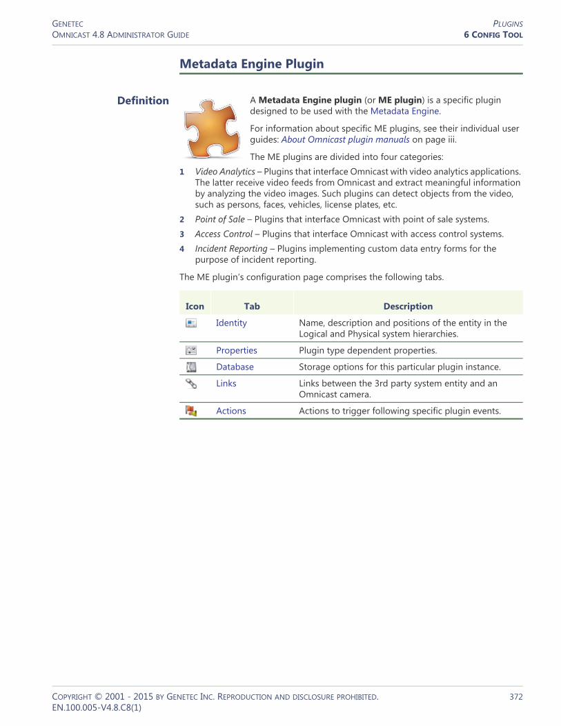
GENETEC PLUGINSOMNICAST 4.8 ADMINISTRATOR GUIDE 6 CONFIG TOOL
Metadata Engine Plugin
Definition
A Metadata Engine plugin (or ME plugin) is a specific plugin designed to be used with the Metadata Engine.
For information about specific ME plugins, see their individual user guides: About Omnicast plugin manuals on page iii.
The ME plugins are divided into four categories:1 Video Analytics – Plugins that interface Omnicast with video analytics applications.
The latter receive video feeds from Omnicast and extract meaningful information by analyzing the video images. Such plugins can detect objects from the video, such as persons, faces, vehicles, license plates, etc.
2 Point of Sale – Plugins that interface Omnicast with point of sale systems.3 Access Control – Plugins that interface Omnicast with access control systems.4 Incident Reporting – Plugins implementing custom data entry forms for the
purpose of incident reporting.
The ME plugin‘s configuration page comprises the following tabs.
Icon Tab Description
Identity Name, description and positions of the entity in the Logical and Physical system hierarchies.
Properties Plugin type dependent properties.
Database Storage options for this particular plugin instance.
Links Links between the 3rd party system entity and an Omnicast camera.
Actions Actions to trigger following specific plugin events.
COPYRIGHT © 2001 - 2015 BY GENETEC INC. REPRODUCTION AND DISCLOSURE PROHIBITED. 372EN.100.005-V4.8.C8(1)

GENETEC PLUGINSOMNICAST 4.8 ADMINISTRATOR GUIDE 6 CONFIG TOOL
Creating ME plugins To create a new ME plugin instance, do the following.1 Select Add-In Management from the View selection pane. See View selection pane on
page 155.2 Click at the bottom of the View selection pane. A pop-up menu with the
entities you can create appears.3 Select Metadata Engine Plugin from the pop-up menu. The Create a new Metadata
Engine plugin dialog box appears.4 Select from this dialog, the primary Metadata Engine that should be controlling
this plugin. A list of ME plugins hosted by the selected Metadata Engine will appear in the lower part of the dialog box.
5 Select the desired plugin type and click OK. A new entity named New Metadata Engine plugin will be created.
6 Enter a descriptive name for the new ME plugin. Click the Identity tab and use the Description field to provide more details if necessary.
7 Configure the rest of the plugin settings (Properties and Links).Please refer to the plugin’s own user guide for the specific settings it requires; see About Omnicast plugin manuals on page iii.
8 Define the actions for this plugin if applicable. See Actions on page 375.
Properties
Description The Properties tab lets you configure the common settings for this ME plugin. The camera specific settings are found in the Links tab.
COPYRIGHT © 2001 - 2015 BY GENETEC INC. REPRODUCTION AND DISCLOSURE PROHIBITED. 373EN.100.005-V4.8.C8(1)

GENETEC PLUGINSOMNICAST 4.8 ADMINISTRATOR GUIDE 6 CONFIG TOOL
The common ME plugin settings are:
You may find other settings in this tab. All other settings after the Plugin mode are type specific settings. To learn about the type specific settings, refer to a plugin’s own user guide. See About Omnicast plugin manuals on page iii.
Database
Description The Database tab is a common configuration tab for all ME plugins. You use it to tell the Metadata Engine how it should handle the database entries generated by the selected plugin. Note that not all metadata generated by the plugins are stored in the ME database. All visual metadata (overlays) are stored along the video by the Archiver, not the Metadata Engine. See Camera – Recording on page 248.
Parameter Description
Generic schedule The generic schedule is a common property to all ME plugins. It tells the Metadata Engine when the plugin is allowed to run. You can temporarily disable a plugin by setting the schedule to None.
Plugin mode The plugin can be set to run in Continuous or Manual mode. The manual mode allows you to start and stop the plugin execution manually or through the Start plugin and Stop plugin actions. In continuous mode, these actions are ignored.
While the plugin is configured to run in manual mode, you can also start and stop the plugin execution from the Metadata Engine’s Plugins tab.
See Metadata Engine – Plugins on page 351.
COPYRIGHT © 2001 - 2015 BY GENETEC INC. REPRODUCTION AND DISCLOSURE PROHIBITED. 374EN.100.005-V4.8.C8(1)

GENETEC PLUGINSOMNICAST 4.8 ADMINISTRATOR GUIDE 6 CONFIG TOOL
The database settings are:
Links
The Links settings are specific to each plugin type. Please refer to a plugin’s own guide for details.
Actions
See Virtual Matrix Plugin – Actions on page 370.
Live Viewer Plugin
Definition
A Live Viewer plugin (or LV plugin) is a specific plugin designed to be used with the Live Viewer.
For information about specific LV plugins, see their individual user guides: About Omnicast plugin manuals on page iii.
The Remote Live Viewer plugin’s properties are described below since it is included by default with Omnicast. See Remote Live Viewer
(LV Plugin) on page 377.
Parameter Description
Delete entries that are older than __ days
Retention period for the metadata of this plugin in terms of days.
If database runs out of space
Indicate here what the Metadata Engine should do when the database is full. It can either stop archiving or free space for the new records by deleting the oldest entries.
Enable record fingerprinting
In order to protect your metadata against tampering, you can enable the record fingerprinting. This feature adds a digital signature to each data record so that if someone alters the data after it has been recorded, the data will no longer match the signature, thus proving that the data has been tampered with.
The private key used for fingerprinting the metadata records is configured in the Server Admin. See Metadata Engine on page 146.
WARNING Enabling record fingerprinting will slow down the processing.
COPYRIGHT © 2001 - 2015 BY GENETEC INC. REPRODUCTION AND DISCLOSURE PROHIBITED. 375EN.100.005-V4.8.C8(1)

GENETEC PLUGINSOMNICAST 4.8 ADMINISTRATOR GUIDE 6 CONFIG TOOL
The LV plugin‘s configuration page comprises the following tabs.
Creating LV plugins To create a new LV plugin instance, do the following.1 Select Add-In Management from the View selection pane. See View selection pane on
page 155.2 Click at the bottom of the View selection pane. A pop-up menu with the
entities you can create appears.3 Select Live Viewer Plugin from the pop-up menu. The Select a Live Viewer plugin
dialog appears.4 Select the desired plugin type and click OK. A new entity named New Live Viewer
plugin will be created.
WARNING For the plugin to work, the same plugin must also be installed on every Live Viewer PC where you intend to run the plugin from.5 Enter a descriptive name for the new LV plugin. Use the Description field to provide
more details if necessary, in the Identity tab.6 Configure the plugin’s Properties.
Please refer to the plugin’s own user guide for the specific settings it requires; see About Omnicast plugin manuals on page iii.
7 Define the actions for this plugin if applicable. See Actions on page 377.
Properties
Please refer to the plugin’s own user guide for its specific properties.
For the Remote Live Viewer plugin’s properties, see Remote Live Viewer (LV Plugin) on page 377.
Icon Tab Description
Identity Name, description and positions of the entity in the Logical and Physical system hierarchies.
Properties Plugin type dependent properties.
Actions Actions to trigger following specific plugin events.
COPYRIGHT © 2001 - 2015 BY GENETEC INC. REPRODUCTION AND DISCLOSURE PROHIBITED. 376EN.100.005-V4.8.C8(1)

GENETEC PLUGINSOMNICAST 4.8 ADMINISTRATOR GUIDE 6 CONFIG TOOL
Actions
Description The Actions tab allows you to program specific system behaviors based on the plugin events shown in the Events/actions list.
You can use the plugin events to monitor the usage of the LV plugin.
To learn about general event-to-actions programming, please refer to Event Management on page 22.
Remote Live Viewer (LV Plugin)
Introduction
The Remote Live Viewer plugin is included with Omnicast, and is installed by default as a program feature while performing the Omnicast Client installation. For more information, see the Omnicast Installation and Upgrade Guide.
Information specific to other LV plugins is covered in individual plugin user guides. See About Omnicast plugin manuals on page iii.
The Remote Live Viewer must be installed on a workstation to configure it in the Config Tool and to use it in the Live Viewer from that workstation.
For more information on using the Remote Live Viewer plugin from the Live Viewer, refer to Advanced Features > Using Plugins > Remote Live Viewer Plugin in the Omnicast Live Viewer User Guide.
The use of Remote Live Viewer plugins must be supported by your Omnicast license. See License on page 46.
COPYRIGHT © 2001 - 2015 BY GENETEC INC. REPRODUCTION AND DISCLOSURE PROHIBITED. 377EN.100.005-V4.8.C8(1)
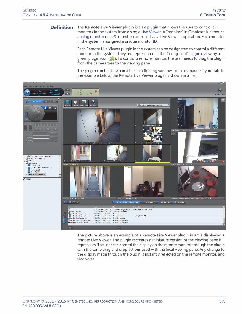
GENETEC PLUGINSOMNICAST 4.8 ADMINISTRATOR GUIDE 6 CONFIG TOOL
Definition The Remote Live Viewer plugin is a LV plugin that allows the user to control all monitors in the system from a single Live Viewer. A "monitor" in Omnicast is either an analog monitor or a PC monitor controlled via a Live Viewer application. Each monitor in the system is assigned a unique monitor ID.
Each Remote Live Viewer plugin in the system can be designated to control a different monitor in the system. They are represented in the Config Tool's Logical view by a green plugin icon ( ). To control a remote monitor, the user needs to drag the plugin from the camera tree to the viewing pane.
The plugin can be shown in a tile, in a floating window, or in a separate layout tab. In the example below, the Remote Live Viewer plugin is shown in a tile.
The picture above is an example of a Remote Live Viewer plugin in a tile displaying a remote Live Viewer. The plugin recreates a miniature version of the viewing pane it represents. The user can control the display on the remote monitor through the plugin with the same drag and drop actions used with the local viewing pane. Any change to the display made through the plugin is instantly reflected on the remote monitor, and vice versa.
COPYRIGHT © 2001 - 2015 BY GENETEC INC. REPRODUCTION AND DISCLOSURE PROHIBITED. 378EN.100.005-V4.8.C8(1)

GENETEC PLUGINSOMNICAST 4.8 ADMINISTRATOR GUIDE 6 CONFIG TOOL
NOTES
• HTML maps displayed on a Remote Live Viewer monitor are not visible with the Remote Live Viewer plugin.
• Live Viewers from federated systems cannot be controlled with the Remote Live Viewer.
Configuration – Properties
The properties of the Remote Live Viewer plugin are specific for this plugin. For a description of its other settings, which are common to other LV plugins, see Live Viewer Plugin on page 375.
Plugin mode When the plugin is viewed in the Live Viewer, it can be displayed in one of the following ways:• Floating window – Displays the plugin in a separate window. This window can be
manipulated, for example by dragging its title bar to a second or third screen, and can be closed by clicking the close button.
• Fit in tile – Displays the plugin in a tile.• Full screen – Displays the plugin in a new layout tab.
Your selection determines how the plugin is displayed by any Live Viewer workstation opening up this plugin instance.
Remote Live Viewer monitor control
You can determine which Live Viewers on the Omnicast system can be controlled by this Remote Live Viewer plugin instance.1 From the Remote Live Viewer drop-down list, select the Live Viewer that the plugin
instance will control. » All the Live Viewers that are logged onto the same Directory as the plugin will
appear.
COPYRIGHT © 2001 - 2015 BY GENETEC INC. REPRODUCTION AND DISCLOSURE PROHIBITED. 379EN.100.005-V4.8.C8(1)

GENETEC PLUGINSOMNICAST 4.8 ADMINISTRATOR GUIDE 6 CONFIG TOOL
2 Do one of the following:– Select Control only the selected monitor if the plugin should only be used to
control the monitor designated in Step 1.– Clear Control only the selected monitor to allow the user the ability to control
any Live Viewer on the system. In this case, the selection made in Step 1 is not taken into account.
Within the plugin, the user can select the monitor he wants to control from a drop-down list. For more information, see Advanced Features > Using Plugins > Remote Live Viewer Plugin in the Omnicast Live Viewer User Guide.
COPYRIGHT © 2001 - 2015 BY GENETEC INC. REPRODUCTION AND DISCLOSURE PROHIBITED. 380EN.100.005-V4.8.C8(1)

GENETEC PTZ MOTOROMNICAST 4.8 ADMINISTRATOR GUIDE 6 CONFIG TOOL
PTZ Motor
Definition
A PTZ motor allows physical control over a camera's movement. PTZ (Pan Tilt Zoom) commands can be issued from either the Live Viewer, the Config Tool or a CCTV keyboard. Omnicast relays these commands to the appropriate PTZ motor through the unit to which the PTZ motor is connected, via its serial port.
The PTZ motor‘s configuration page comprises the following tabs.
Creating a PTZ motor Add a PTZ motor entity by selecting a camera it will control and a serial port it is connected to.
For units with dedicated PTZ serial ports, PTZ motor entities are added via the camera’s Specific settings. See Specific Settings on page 277.
To create a new PTZ motor, do the following.1 Select Logical View or Physical View from the View selection pane. See View selection
pane on page 155.2 Click at the bottom of the View selection pane. A pop-up menu with the
entities you can create appears.
Icon Tab Description
Identity Name, description and positions of the entity in the Logical and Physical system hierarchies.
Properties PTZ motor control protocol and attached camera(s).
Test Test and renaming of the advanced PTZ controls.
Actions PTZ motor event handling specifications.
Network PTZ motor network properties.
Coordinates Reserved for PTZ with direct positioning capabilities.
COPYRIGHT © 2001 - 2015 BY GENETEC INC. REPRODUCTION AND DISCLOSURE PROHIBITED. 381EN.100.005-V4.8.C8(1)

GENETEC PTZ MOTOROMNICAST 4.8 ADMINISTRATOR GUIDE 6 CONFIG TOOL
3 Select PTZ... from the pop-up menu. The Create PTZ dialog appears.
4 Expand the camera tree and select the camera that is controlled by this PTZ motor.– If you selected a virtual camera , click OK and end here. The remainder
controls should all be disabled. – If you selected a video encoder instead, please continue with the next step.
5 Select the serial port that the PTZ motor is connected to.The PTZ motor is typically connected to a serial port belonging to the same unit as the video encoder you selected. In this case, select Serial port(s) on the same unit. Depending on the type of unit you are using, you may see more than one serial port. Select the appropriate one.Sometimes, the only available serial port on the encoder unit is used for something else. When this happens, you can connect the PTZ motor to another unit in your system. To pick a serial port from a different unit than the one of the video encoder, select Any serial port and select the appropriate port from the drop-down list.
6 Select the Protocol supported by your PTZ motor.7 Click OK to end the configuration.
Now, whenever a user with the proper privileges displays the controlled camera in the Live Viewer, the PTZ controls will be enabled. The subsequent steps are optional.
8 If necessary, fine-tune the PTZ properties from the Properties tab. See Properties on page 383.
9 Test your settings with the Test tab. See Test on page 385.
COPYRIGHT © 2001 - 2015 BY GENETEC INC. REPRODUCTION AND DISCLOSURE PROHIBITED. 382EN.100.005-V4.8.C8(1)

GENETEC PTZ MOTOROMNICAST 4.8 ADMINISTRATOR GUIDE 6 CONFIG TOOL
10 Adjust the visibility of the PTZ motor by the system users. To do this, select the Logical View and drag the PTZ motor to the site corresponding to the desired visibility level.
Properties
Description The Properties tab defines the PTZ protocol and the attached cameras. Note that you may not change anything if the PTZ motor is attached to a virtual camera.
When the PTZ motor is built-in with the camera, the Protocol, PTZ number and Attached cameras cannot be modified.
PTZ motor properties The PTZ motor properties explained in the following table.
Parameter Description (1 of 2)
Protocol PTZ protocol used by the hardware manufacturer.
NOTE For units with dedicated PTZ serial ports, the PTZ protocol is configured in the camera’s Specific settings. Refer to Specific Settings on page 277.
PTZ number Number identifying the selected PTZ motor on the serial port. This number is very important as it is possible to connect more than one PTZ motor on the same serial port. Moreover, this number has to correspond to the dip switch settings on the PTZ hardware.
NOTE This property is not relevant for units with dedicated PTZ serial ports.
COPYRIGHT © 2001 - 2015 BY GENETEC INC. REPRODUCTION AND DISCLOSURE PROHIBITED. 383EN.100.005-V4.8.C8(1)

GENETEC PTZ MOTOROMNICAST 4.8 ADMINISTRATOR GUIDE 6 CONFIG TOOL
Idle delay The idle delay is used in two related ways:• The idle delay defines the period of inactivity after which
the PTZ is considered idle. When a user starts moving the PTZ when it is idle, the PTZ activated event is generated. When the idle delay expires, the PTZ stopped event is generated.As long as there are users who continue to move the PTZ, the countdown timer continuously restarts.
• The same idle delay value is also used specifically for the zoom operation on a PTZ. Whenever a user starts to zoom the PTZ, the PTZ zoom by user event is generated. After the last zoom operation, when the idle delay expires, the PTZ zoom by user stopped event is generated.For a particular user, Idle delay delineates a single zoom activity. A user who zooms several times with each zoom activity taking place less than 120 seconds after the previous one, will generate only one PTZ zoom by user event, assuming the Idle delay is 120 seconds. Then, if another user performs a zoom on the same PTZ before the idle delay has expired, the PTZ zoom by user event is again generated, logged to the second user, and the countdown timer is restarted. Note that in this case, the PTZ zoom by user stopped will only be generated once after the Idle delay has expired, and logged to the second user.
NOTE The PTZ activated event will not be triggered by a programmed PTZ action, nor will the accompanying PTZ stopped event.The PTZ zoom by user event will not be generated due to automated PTZ functions such as presets or patterns, or by a programmed PTZ action, nor will the accompanying PTZ zoom by user stopped event.
Lock delay The lock delay defines the maximum time a user can keep the PTZ locked once it has become idle. With this feature in place, a PTZ cannot be locked indefinitely when a user forgets to unlock it.
Example: Let a PTZ motor be configured with the idle delay set to 20 seconds and the lock delay set to 10 seconds. If a user locks the PTZ and forgets about it, the lock will be automatically released 20+10 seconds after the moment the user stopped using the PTZ.
Attached cameras Camera that is controlled by this PTZ motor.
NOTE In some very special configurations where multiple video encoders correspond to the same physical camera, you may attach multiple video encoders to the same PTZ motor.However, a video encoder can only be attached to one PTZ motor. If you select a video encoder that is already attached to another PTZ motor, it will be implicitly detached from the former one.
Parameter Description (2 of 2)
COPYRIGHT © 2001 - 2015 BY GENETEC INC. REPRODUCTION AND DISCLOSURE PROHIBITED. 384EN.100.005-V4.8.C8(1)

GENETEC PTZ MOTOROMNICAST 4.8 ADMINISTRATOR GUIDE 6 CONFIG TOOL
Test
Description The Test tab lets you test your PTZ motor settings and configure the advanced PTZ commands, such as Preset, Pattern and Auxiliary. This is also the only place where you can rename the auxiliary switches.
Testing the PTZ To test your PTZ settings, click the Live video button. The following window will appear. Click on the PTZ commands in the Test tab and you should see the effects live.
COPYRIGHT © 2001 - 2015 BY GENETEC INC. REPRODUCTION AND DISCLOSURE PROHIBITED. 385EN.100.005-V4.8.C8(1)

GENETEC PTZ MOTOROMNICAST 4.8 ADMINISTRATOR GUIDE 6 CONFIG TOOL
Advanced PTZ commands
configuration
The PTZ controls shown in the Test tab are the same as those found in the Live Viewer's Tool pane, with additional buttons for Preset, Pattern and Auxiliary configuration. The behavior of these extra buttons are explained below.
To rename a Preset, a Pattern or an Auxiliary, use the Rename button.
To clear a Preset or a Pattern, use the Clear button.
NOTE Some Axis and Sony cameras require extra configuration to create PTZ patterns, using the camera’s own Web page. For more information, see the Omnicast Video Unit Configuration Guide.
Actions
Description The Actions tab allows you to program specific system behaviors based on the PTZ events shown in the Events/actions list.
Typical application A typical application of these events would be to program the PTZ to automatically go back to a preset position after a specified period of inactivity.
To do so, add a Go to preset action to the PTZ stopped event. The period of inactivity is configured in the Properties tab (see Idle delay under Properties on page 383).
For PTZ motors that support the Go home command, you may use that command instead of the Go to preset command.
To learn about general event-to-actions programming, please refer to Event Management on page 22.
COPYRIGHT © 2001 - 2015 BY GENETEC INC. REPRODUCTION AND DISCLOSURE PROHIBITED. 386EN.100.005-V4.8.C8(1)

GENETEC PTZ MOTOROMNICAST 4.8 ADMINISTRATOR GUIDE 6 CONFIG TOOL
Network
Description The Network tab shows the network properties of the PTZ motor.
The following parameters are displayed for information purpose only.
Parameter Description
Local IP address Address of the device over the network.
NIC number Network adapter identifier used by the device in multicast.
UDP port Port number used when the connection type is unicast UDP.
COPYRIGHT © 2001 - 2015 BY GENETEC INC. REPRODUCTION AND DISCLOSURE PROHIBITED. 387EN.100.005-V4.8.C8(1)

GENETEC PTZ MOTOROMNICAST 4.8 ADMINISTRATOR GUIDE 6 CONFIG TOOL
Coordinates
Description The Coordinates tab allows you to configure a dome camera for direct XYZ positioning. This tab is not available if the selected PTZ motor does not support this feature.
Direct XYZ positioning Direct XYZ positioning is a special type of PTZ command supported by certain models of dome cameras which allows the PTZ motor to turn the camera to any position and zoom setting based on a triplet of values (X, Y, Z), where X is a pan setting (-360° to 360°), Y is a tilt setting (-180° to 180°) and Z is a zoom factor (-999 to 999). An XYZ position is always expressed in terms of a reference position, called the zero position.
A typical application of direct XYZ positioning is to support the “point-and-show” feature. The idea of "point-and-show" is to control a selected dome camera through a map (see Viewing a Map in the Omnicast Live Viewer User Guide.). Instead of using the PTZ commands in the Live Viewer, the user can simply point and click on a map to have the camera turn to the pointed location.
The purpose of the Coordinates tab is to allow the user to set the zero position to a meaningful location that can be used as a reference point on a map.
NOTE The "point-and-show" feature must be programmed in a map, using Genetec Omnicast SDK. For a complete reference of all the SDK methods and sample codes, please refer to Genetec Omnicast SDK Help.
Setting the zero position
Current position The current position is given in terms of the zero position. You can refresh the current position by clicking on the button or by setting the Automatic refresh rate.
COPYRIGHT © 2001 - 2015 BY GENETEC INC. REPRODUCTION AND DISCLOSURE PROHIBITED. 388EN.100.005-V4.8.C8(1)

GENETEC PTZ MOTOROMNICAST 4.8 ADMINISTRATOR GUIDE 6 CONFIG TOOL
Change position The way to change the zero position is to set it to the current position. You have three methods to change the current position:1 Use the PTZ commands found in the Test tab. 2 Enter a new XYZ position based on the zero position and click Absolute.3 Enter a new XYZ position based on the current position and click Relative.
Note that you can enter positive or negative values. Illegal values not supported by your PTZ will be ignored. Once you feel that you have obtained the desired zero position, click Use current position. Once the current position becomes the zero position, the Current position should indicate (0, 0, 1).
Max zoom factor The Max zoom factor tells the system how far the zoom can go on the selected model of PTZ camera. This information is necessary because not all domes supporting the same PTZ protocol offers the same maximum zoom factor.
COPYRIGHT © 2001 - 2015 BY GENETEC INC. REPRODUCTION AND DISCLOSURE PROHIBITED. 389EN.100.005-V4.8.C8(1)
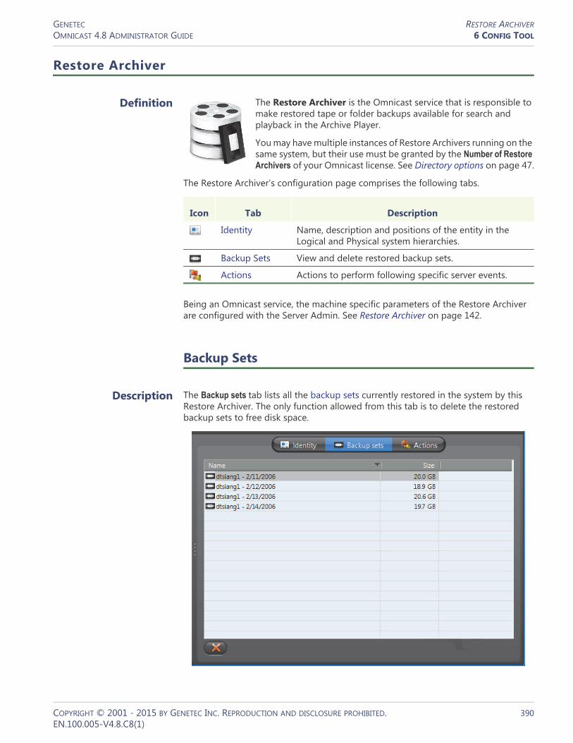
GENETEC RESTORE ARCHIVEROMNICAST 4.8 ADMINISTRATOR GUIDE 6 CONFIG TOOL
Restore Archiver
Definition
The Restore Archiver is the Omnicast service that is responsible to make restored tape or folder backups available for search and playback in the Archive Player.
You may have multiple instances of Restore Archivers running on the same system, but their use must be granted by the Number of Restore Archivers of your Omnicast license. See Directory options on page 47.
The Restore Archiver‘s configuration page comprises the following tabs.
Being an Omnicast service, the machine specific parameters of the Restore Archiver are configured with the Server Admin. See Restore Archiver on page 142.
Backup Sets
Description The Backup sets tab lists all the backup sets currently restored in the system by this Restore Archiver. The only function allowed from this tab is to delete the restored backup sets to free disk space.
Icon Tab Description
Identity Name, description and positions of the entity in the Logical and Physical system hierarchies.
Backup Sets View and delete restored backup sets.
Actions Actions to perform following specific server events.
COPYRIGHT © 2001 - 2015 BY GENETEC INC. REPRODUCTION AND DISCLOSURE PROHIBITED. 390EN.100.005-V4.8.C8(1)

GENETEC RESTORE ARCHIVEROMNICAST 4.8 ADMINISTRATOR GUIDE 6 CONFIG TOOL
Viewing the content of a backup set
To view the content of a backup set, select the Physical View and find the Restore Archiver icon . All the backup sets belonging to that Restore Archiver will appear under it in the entity tree. Select a backup set and its Info tab to view its content. See Backup Set – Info on page 235.
Deleting a backup set To delete a backup set, select it in the list and click .
WARNING When a backup set loaded from tape with NT Backup is handed over to a Restore Archiver, the latter takes full ownership of all the files it contains. When a backup set is later deleted from the Config Tool, all video files associated to the backup set are deleted at that moment.If only part of the backup set is restored by the Restore Archiver, all files that were not restored are immediately deleted after the restore operation. See Server Admin – Note If you are using a remote database server and there are multiple archivers on the system, please ensure that the database specified is unique on each archiver on page 143.The same principle applies to Backup copied to a folder, except that this time, if you delete the restored backup set, you could be deleting your original copy! For this reason, for backup sets stored on disk, we strongly recommend that you make a copy to another location before attempting a restore. See Archiver – Backup on page 213.
Actions
Description The Actions tab allows you to program specific system behaviors based on the application events shown in the Events/actions list.
To learn about general event-to-actions programming, please refer to Event Management on page 22.
COPYRIGHT © 2001 - 2015 BY GENETEC INC. REPRODUCTION AND DISCLOSURE PROHIBITED. 391EN.100.005-V4.8.C8(1)
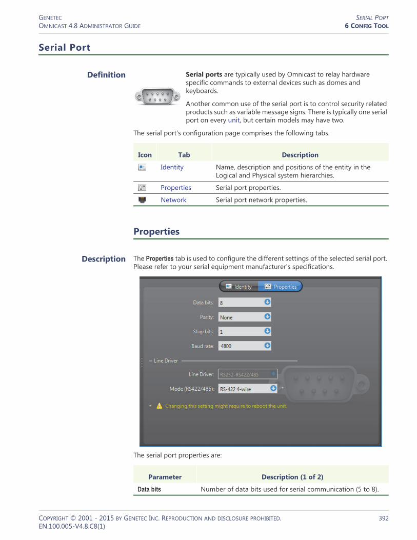
GENETEC SERIAL PORTOMNICAST 4.8 ADMINISTRATOR GUIDE 6 CONFIG TOOL
Serial Port
Definition
Serial ports are typically used by Omnicast to relay hardware specific commands to external devices such as domes and keyboards.
Another common use of the serial port is to control security related products such as variable message signs. There is typically one serial port on every unit, but certain models may have two.
The serial port‘s configuration page comprises the following tabs.
Properties
Description The Properties tab is used to configure the different settings of the selected serial port. Please refer to your serial equipment manufacturer's specifications.
The serial port properties are:
Icon Tab Description
Identity Name, description and positions of the entity in the Logical and Physical system hierarchies.
Properties Serial port properties.
Network Serial port network properties.
Parameter Description (1 of 2)
Data bits Number of data bits used for serial communication (5 to 8).
COPYRIGHT © 2001 - 2015 BY GENETEC INC. REPRODUCTION AND DISCLOSURE PROHIBITED. 392EN.100.005-V4.8.C8(1)

GENETEC SERIAL PORTOMNICAST 4.8 ADMINISTRATOR GUIDE 6 CONFIG TOOL
Line driver Parameters pertaining to line driver.
NOTE Changing this setting might require the unit to reboot. If necessary, the unit will reboot by itself within the next minute and will be temporarily unavailable (shown as inactive). You can force the unit to reboot immediately by going to the Network tab of the corresponding unit and clicking Reboot.
Parity Parity used for serial communication (None, Even, or Odd).
Stop bits Number of stop bits used for serial communication (1 or 2).
Baud rate Baud rate used for serial communication (1200 to 115200).
Parameter Description (2 of 2)
Parameter Description
Line driver This static field indicates the modes supported by the serial port. If this field only indicates RS232, then the mode selection combo-box will not be shown. This is usually the case when the unit supports two independent serial ports. The first port is always fixed at RS232.
Mode (RS422/485) This combo-box allows choosing between RS-422 4-wire, RS-485 4-wire and RS-485 2-wire for the serial port mode. The correct choice will depend on the type of serial equipment connected to the port.
COPYRIGHT © 2001 - 2015 BY GENETEC INC. REPRODUCTION AND DISCLOSURE PROHIBITED. 393EN.100.005-V4.8.C8(1)

GENETEC SERIAL PORTOMNICAST 4.8 ADMINISTRATOR GUIDE 6 CONFIG TOOL
Network
Description The Network tab allows you to choose the connection type used by the serial port.
Network information The following parameters are displayed for information purpose only.
Connection type between unit and
Archiver
Connection type that should be used between the unit and the Archiver for this video encoder. The choices are:• Best available
• Unicast UDP
• Unicast TCP
If the choice is different from Best available, the stream from the unit will be redirected by the Archiver.
If the network between the unit and the Archiver does not support multicast, it is best to select Unicast UDP and let the Archiver redirect the stream in multicast on the system network.
For more information on the meaning of each connection type, see System Concepts – Network Connections on page 29.
Parameter Description
Local IP address Address of the device over the network.
NIC number Network adapter identifier used by the device in multicast.
UDP port Port number used when the connection type is unicast UDP.
COPYRIGHT © 2001 - 2015 BY GENETEC INC. REPRODUCTION AND DISCLOSURE PROHIBITED. 394EN.100.005-V4.8.C8(1)
GENETEC SITEOMNICAST 4.8 ADMINISTRATOR GUIDE 6 CONFIG TOOL
Site
Definition
A site is a user created entity for grouping related system resources together for ease of viewing and management. Typically, a site corresponds to a physical location, like a building or a floor, but it may very well represent any concept in the real world. See Logical View on page 161.
The site‘s configuration page comprises the following tabs.
Creating a new site To create a new site, do the following.1 Select Logical View from the View selection pane. See View selection pane on
page 155.2 Click at the bottom of the View selection pane. A pop-up menu with the
entities you can create appears.3 Select Site from the pop-up menu. A new entity named New site will be
immediately created under the currently selected site.4 Enter a descriptive name for the new hardware matrix entity. Click the Identity tab
and use the Description field to provide more details if necessary.5 Move the new site to the intended position in the hierarchy if necessary by
dragging and dropping it to its new position.6 Move the entities that belong to the logical grouping represented by this site
under this site.7 Select the Accepted users tab and grant access to this site to whoever needs it. See
Accepted Users on page 396.8 Attach an HTML map to the site if necessary. See Maps on page 399.
Deleting a site To delete a site, select it from the Logical View and click .
CAUTION When a selected site is deleted, all inactive devices under that site will also be deleted. If there were cameras among them, all video archives associated to the deleted cameras will be deleted as well. If you do not wish to loose the video archives, move the inactive cameras under another site before deleting the site.
One a site is deleted, the active devices that were under it will fall under the parent site in the site hierarchy. If there is no parent site, they will fall directly under the Directory.
Icon Tab Description
Identity Name, description and positions of the entity in the Logical and Physical system hierarchies.
Accepted Users Users who can view the entities under this site.
Maps View, test and attach HTML maps to the site.
COPYRIGHT © 2001 - 2015 BY GENETEC INC. REPRODUCTION AND DISCLOSURE PROHIBITED. 395EN.100.005-V4.8.C8(1)

GENETEC SITEOMNICAST 4.8 ADMINISTRATOR GUIDE 6 CONFIG TOOL
Accepted Users
Description The Accepted users tab is used to grant or deny access to the entities found under the current site to Omnicast users and user groups. Only administrative users have access to this tab.
Permission list The users and user groups listed in this tab are the ones who can access the entities found under this site in the Logical view. See User – Permissions on page 422.
To add a user or user group to the permission list, click the button at the bottom of the tab. Only the users and user groups that do not yet have access to the site will be available for choosing. Select the ones you wish to add and click Add.
All members of the Administrators user group and all users who have the Always view all entities privilege are implicitly granted the permission to access all entities in the system. For non administrative users, it is possible to hide the existence of certain entities by placing them under hidden sites. See Hidden site on page 397.
To remove a user or user group from the permission list, simply select it and click . Note that you cannot remove a permission entry that is inherited from a parent site.
Permission inheritance The permission list can be inherited from the parent site. When an entry is inherited from a parent site, the name of the site from which the entry is inherited is shown in the Inherited from column.
To inherit the permission list from the parent site, simply select the Inherit parent permission entries option.
You may add more entries to the permission list but you may not remove an inherited entry from the list.
COPYRIGHT © 2001 - 2015 BY GENETEC INC. REPRODUCTION AND DISCLOSURE PROHIBITED. 396EN.100.005-V4.8.C8(1)

GENETEC SITEOMNICAST 4.8 ADMINISTRATOR GUIDE 6 CONFIG TOOL
When removing the inheritance option from a site, you have the choice to keep the inherited permissions in its own list (click Copy) or to remove all permissions that were inherited from the parent site (click Remove).
Hidden site A hidden site is a site that is visible only to the members of the Administrators group and to the users and user groups named in its permission list.
To hide a site, select the Hidden site option. The icon of the site will change to indicating that it is hidden.
The purpose of the hidden site is to hide the existence of covert cameras from users who would otherwise have access to them because of the Always view all entities privilege.
To hide a camera (or any other entity), use one of the following methods:– Hide the site under which the entity is found,– Move the entity to a hidden site,– Copy the entity to a hidden site.
To create a copy of an entity under a different site, hold the <Ctrl> key while dragging the entity to a different site. Note that an entity is hidden from a user as long as one copy of that entity is hidden from that user. See Rules governing the hidden entities on page 398.
The entities that you can hide are the ones found in the Logical view. See Show/hide entities on page 162.
Rules governing the hidden sites
• Only members of the Administrators group can configure the hidden sites, because only administrative users have access to the Accepted users tab.
• The child of a hidden site automatically inherits all the access properties of its parent, i.e. its property of being hidden and its permission list.
• The permission list of the child of a hidden site cannot be modified.• When the child of a hidden site is moved under a parent that is not hidden, its
original properties will be restored.
COPYRIGHT © 2001 - 2015 BY GENETEC INC. REPRODUCTION AND DISCLOSURE PROHIBITED. 397EN.100.005-V4.8.C8(1)

GENETEC SITEOMNICAST 4.8 ADMINISTRATOR GUIDE 6 CONFIG TOOL
Rules governing the hidden entities
• No entities can be hidden from the members of the Administrators group.• An entity is hidden from a user as long as one copy of that entity is hidden from
that user.• A user who does not have access to all the cameras of a camera sequence can still
view the camera sequence in the Live Viewer, except that the hidden cameras will not be displayed. The same is true with alarms that uses hidden cameras.
• A user who does not have access to all the cameras of a camera sequence can still access the configuration of the camera sequence in the Config Tool, except that the hidden cameras will not be listed in the Cameras tab. The same is true with alarms that uses hidden cameras.
• A unit is hidden from a user when all its physical devices are hidden from the user. This means that the unit will not be shown in the Physical view or anywhere else in the Config Tool for that user.
• Hiding or revealing an entity to a user will only take effect the next time the user logs on to an application.
Limitations regarding the configuration of
hidden entities
When granting configuration privileges to users in a context where some entities must be hidden, please be aware of the following limitations.• A user who does not have access to all the cameras of a camera sequence cannot
play the camera sequence in the Config Tool. See Testing the camera sequence on page 284.
• If a user changes the configuration of a camera sequence (or an alarm) involving hidden cameras, the hidden cameras will be removed from the camera list when the user saves his modifications.
• Whenever a hidden camera is used as a parameter in the configuration of another entity such as a macro, an action, a hardware matrix or a plugin, the parameter will appear as blank.
• Although federated cameras can be hidden from a user, the remote entities cannot be hidden from the user in the federated Directory configuration. See Federated Directory – Entities on page 313.
NOTE Because of the above limitations, it is strongly recommended to keep the configuration of hidden entities separate from the configuration of entities visible to all Config Tool users.
COPYRIGHT © 2001 - 2015 BY GENETEC INC. REPRODUCTION AND DISCLOSURE PROHIBITED. 398EN.100.005-V4.8.C8(1)

GENETEC SITEOMNICAST 4.8 ADMINISTRATOR GUIDE 6 CONFIG TOOL
Maps
Description The Maps tab allows you to attach, view, and test the HTML maps attached to this site. This tab is shown only if the HTML maps option is supported by your Omnicast license.
HTML maps HTML maps have a wide variety of applications in Omnicast. Using them to display floor plans with the location and statuses of the cameras like in the above illustration is only one example. If you have cameras with direct XYZ positioning capability, you can even implement maps with the point-and-show feature (see PTZ Motor – Direct XYZ positioning on page 388). The possible applications are only limited by your imagination.
The Map address (URL) field displays the URL (Uniform Resource Locator) address or Web address of the map currently attached to the site. Enter a different address in this field to change the map associated to the site.
Testing the HTML map Click the Go button to load the HTML map in the browser window within the tab. You can test your HTML map with this mini-browser just like any Web browser.
If the map contains action buttons, clicking them will display the events they send to the application in the list box right below the browser window.
Current map / Set current
The URL displayed on top of the browser window corresponds to the URL of the map you are currently viewing.
COPYRIGHT © 2001 - 2015 BY GENETEC INC. REPRODUCTION AND DISCLOSURE PROHIBITED. 399EN.100.005-V4.8.C8(1)

GENETEC SITEOMNICAST 4.8 ADMINISTRATOR GUIDE 6 CONFIG TOOL
If this URL corresponds to the map currently associated to this site, the button shown on the same line as the URL will by labeled Current site.
When you navigate to a different page, the button Current map will change into a button labeled Set current. Click on this button to replace the URL associated to the site by the one that is currently displayed.
COPYRIGHT © 2001 - 2015 BY GENETEC INC. REPRODUCTION AND DISCLOSURE PROHIBITED. 400EN.100.005-V4.8.C8(1)

GENETEC SPEAKER (AUDIO DECODER)OMNICAST 4.8 ADMINISTRATOR GUIDE 6 CONFIG TOOL
Speaker (Audio Decoder)
Definition
A speaker is a device which converts electric signals into audible sound waves. The audio decoder is the device that converts the digital audio signal received from the IP network into an analog signal so it can be played on the speaker. The audio decoder is but one of the many devices found on an decoder unit. The speaker and the audio decoder are so intimately related that the two terms are used interchangeably in Omnicast.
The speaker‘s configuration page comprises the following tabs.
Properties
Description The Properties tab lets you control the volume of the speaker.
Icon Tab Description
Identity Name, description and positions of the entity in the Logical and Physical system hierarchies.
Properties Audio decoder properties.
Network Audio decoder network properties.
COPYRIGHT © 2001 - 2015 BY GENETEC INC. REPRODUCTION AND DISCLOSURE PROHIBITED. 401EN.100.005-V4.8.C8(1)

GENETEC SPEAKER (AUDIO DECODER)OMNICAST 4.8 ADMINISTRATOR GUIDE 6 CONFIG TOOL
Audio decoder properties
The audio decoder properties are:
Parameter Description
Data format You have three possible values to choose from:• PCM – Pulse Code Modulation is an algorithm used to
convert an analog wave into digital signals. No compression is used in the algorithm just straight conversion from analog to digital formats.
• Mulaw – is an algorithm used to convert an analog wave into digital signals using a compression algorithm that encodes and compresses the signal information. Mulaw is the recommended format when it is available.
• GSM – Global System for Mobile telecommunication is a protocol used for digital cellular phones. GSM offers the highest compression ratio. Therefore, it saves on bandwidth usage at the expense of audio quality.
Volume Position the slider to the desired setting (default=68). Alternatively, you can also type the volume setting in the edit field: 0 equals to mute the speaker, and 100% equals maximum volume.
Attached cameras The camera tree shows the camera(s) that are connected to the speaker and allows you to change the speaker connections to cameras.
When a camera is connected to a speaker, the push to talk button will become enabled in the Live Viewer's tile where the camera is displayed.
Note that a speaker can be associated to many cameras (typically cameras showing different angles of a same area), but a camera can only be associated to one speaker. See Camera – Links on page 275.
COPYRIGHT © 2001 - 2015 BY GENETEC INC. REPRODUCTION AND DISCLOSURE PROHIBITED. 402EN.100.005-V4.8.C8(1)
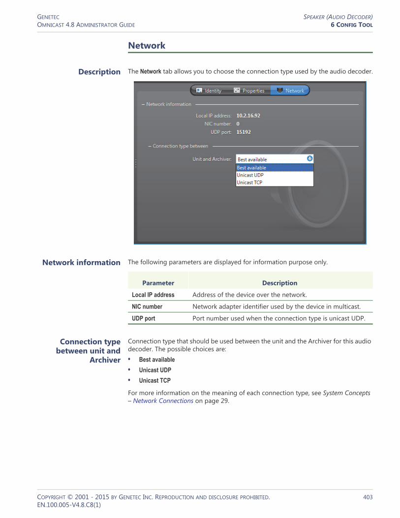
GENETEC SPEAKER (AUDIO DECODER)OMNICAST 4.8 ADMINISTRATOR GUIDE 6 CONFIG TOOL
Network
Description The Network tab allows you to choose the connection type used by the audio decoder.
Network information The following parameters are displayed for information purpose only.
Connection type between unit and
Archiver
Connection type that should be used between the unit and the Archiver for this audio decoder. The possible choices are:• Best available
• Unicast UDP
• Unicast TCP
For more information on the meaning of each connection type, see System Concepts – Network Connections on page 29.
Parameter Description
Local IP address Address of the device over the network.
NIC number Network adapter identifier used by the device in multicast.
UDP port Port number used when the connection type is unicast UDP.
COPYRIGHT © 2001 - 2015 BY GENETEC INC. REPRODUCTION AND DISCLOSURE PROHIBITED. 403EN.100.005-V4.8.C8(1)
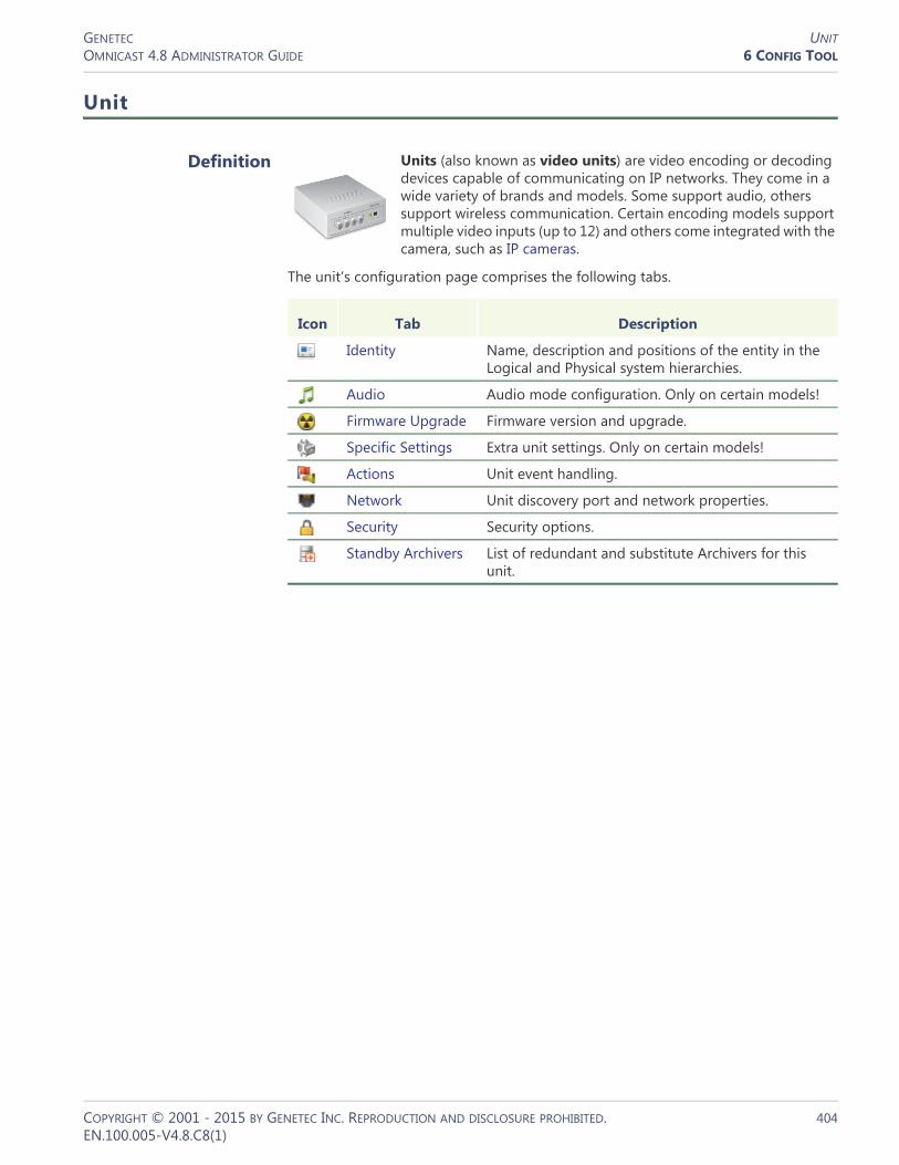
GENETEC UNITOMNICAST 4.8 ADMINISTRATOR GUIDE 6 CONFIG TOOL
Unit
Definition
Units (also known as video units) are video encoding or decoding devices capable of communicating on IP networks. They come in a wide variety of brands and models. Some support audio, others support wireless communication. Certain encoding models support multiple video inputs (up to 12) and others come integrated with the camera, such as IP cameras.
The unit‘s configuration page comprises the following tabs.
Icon Tab Description
Identity Name, description and positions of the entity in the Logical and Physical system hierarchies.
Audio Audio mode configuration. Only on certain models!
Firmware Upgrade Firmware version and upgrade.
Specific Settings Extra unit settings. Only on certain models!
Actions Unit event handling.
Network Unit discovery port and network properties.
Security Security options.
Standby Archivers List of redundant and substitute Archivers for this unit.
COPYRIGHT © 2001 - 2015 BY GENETEC INC. REPRODUCTION AND DISCLOSURE PROHIBITED. 404EN.100.005-V4.8.C8(1)
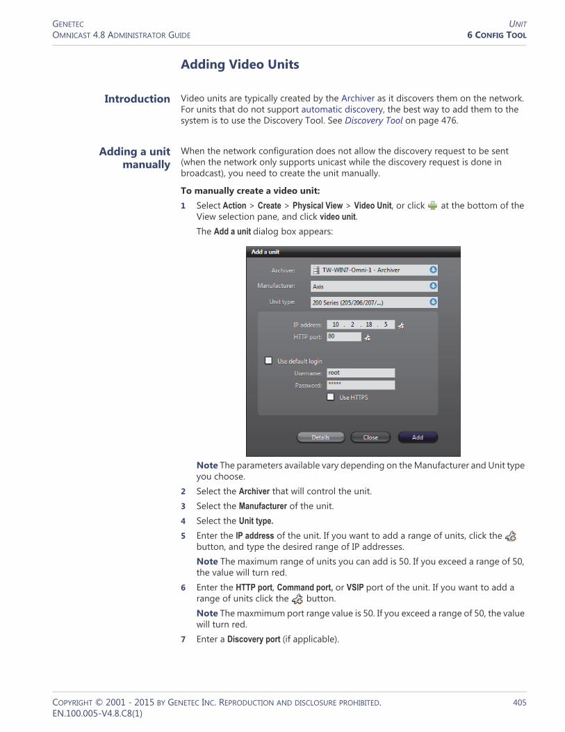
GENETEC UNITOMNICAST 4.8 ADMINISTRATOR GUIDE 6 CONFIG TOOL
Adding Video Units
Introduction Video units are typically created by the Archiver as it discovers them on the network. For units that do not support automatic discovery, the best way to add them to the system is to use the Discovery Tool. See Discovery Tool on page 476.
Adding a unit manually
When the network configuration does not allow the discovery request to be sent (when the network only supports unicast while the discovery request is done in broadcast), you need to create the unit manually.
To manually create a video unit:1 Select Action > Create > Physical View > Video Unit, or click at the bottom of the
View selection pane, and click video unit.The Add a unit dialog box appears:
Note The parameters available vary depending on the Manufacturer and Unit type you choose.
2 Select the Archiver that will control the unit.3 Select the Manufacturer of the unit.4 Select the Unit type.
5 Enter the IP address of the unit. If you want to add a range of units, click the button, and type the desired range of IP addresses. Note The maximum range of units you can add is 50. If you exceed a range of 50, the value will turn red.
6 Enter the HTTP port, Command port, or VSIP port of the unit. If you want to add a range of units click the button. Note The maxmimum port range value is 50. If you exceed a range of 50, the value will turn red.
7 Enter a Discovery port (if applicable).
COPYRIGHT © 2001 - 2015 BY GENETEC INC. REPRODUCTION AND DISCLOSURE PROHIBITED. 405EN.100.005-V4.8.C8(1)

GENETEC UNITOMNICAST 4.8 ADMINISTRATOR GUIDE 6 CONFIG TOOL
8 Select Use default login (if applicable) to use the default login configured for the Archiver extension. See Archiver Extensions on page 97. Some units also enable you to select Use HTTPS for login. If the extension does not already exist on the Archiver, clear Use default login and once the extension is added you can specify the default Username and Password using the Server Admin. For more information, see Creating an Archiver extension on page 97.
9 Click Add.10 To view the results, click the Details button. The Details page lists each unit, and
provides details about whether they were successfully added or not.
For each unit, one of the following will occur:– If your configuration is correct, it says “Unit x has been successfully added” in
the Details column, and a new unit will appear under the selected Archiver in the Physical view. If the proper extension does not already exist, the Archiver will automatically create an instance for you.
– If your configuration is incorrect, the Details column will describe why the unit was not added. Some of the error details given are the following:– A connection timeout occurred: Wrong IP address or Unit type– A connection error occurred: Wrong HTTP port– No x extension with discovery port x: Wrong Discovery port– An authentication error occurred: Wrong Username and Password– The unit has already been added to x Archiver: The unit is already part of your
systemAfter you are done: If the selected Archiver is part of a failover configuration, the unit must also be added to the secondary archivers that are part of the failover list. See Standby Archivers on page 416.
COPYRIGHT © 2001 - 2015 BY GENETEC INC. REPRODUCTION AND DISCLOSURE PROHIBITED. 406EN.100.005-V4.8.C8(1)
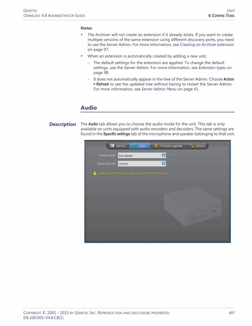
GENETEC UNITOMNICAST 4.8 ADMINISTRATOR GUIDE 6 CONFIG TOOL
Notes• The Archiver will not create an extension if it already exists. If you want to create
multiple versions of the same extension using different discovery ports, you need to use the Server Admin. For more information, see Creating an Archiver extension on page 97.
• When an extension is automatically created by adding a new unit, – The default settings for the extension are applied. To change the default
settings, use the Server Admin. For more information, see Extension types on page 98.
– It does not automatically appear in the tree of the Server Admin. Choose Action > Refresh to see the updated tree without having to restart the Server Admin. For more information, see Server Admin Menu on page 41.
Audio
Description The Audio tab allows you to choose the audio mode for the unit. This tab is only available on units equipped with audio encoders and decoders. The same settings are found in the Specific settings tab of the microphone and speaker belonging to that unit.
COPYRIGHT © 2001 - 2015 BY GENETEC INC. REPRODUCTION AND DISCLOSURE PROHIBITED. 407EN.100.005-V4.8.C8(1)

GENETEC UNITOMNICAST 4.8 ADMINISTRATOR GUIDE 6 CONFIG TOOL
The following parameters can be modified.
Parameter Description
Audio mode Select Full-duplex to be able to speak (send signals through the audio encoder) and listen (receive signals through the audio decoder) at the same time. This is the default setting and should be used in most situations.
Select Push-To-Talk (PTT) to operate in half-duplex mode (alternate between speaking and listening). This particular setting is only necessary when two units are connected together and that the audio must be controlled through digital inputs. See Digital Input on page 291.
Changing the audio mode here changes the audio mode on all audio devices belonging to this unit.
NOTE Changing this setting might require the unit to reboot. If necessary, the unit will reboot by itself within the next minute and will be temporarily unavailable (shown as inactive).You can force the unit to reboot immediately by going to its Network tab and clicking Reboot. See Network on page 412.
Sampling rate This control is enabled only if the unit model you have allows you to configure the sampling rate. A high sampling rate is recommended for languages that have a lot of intonation subtleties, such as Chinese.
COPYRIGHT © 2001 - 2015 BY GENETEC INC. REPRODUCTION AND DISCLOSURE PROHIBITED. 408EN.100.005-V4.8.C8(1)
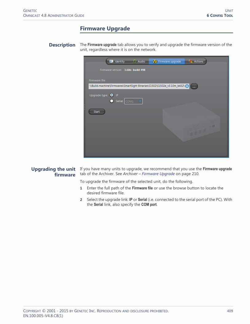
GENETEC UNITOMNICAST 4.8 ADMINISTRATOR GUIDE 6 CONFIG TOOL
Firmware Upgrade
Description The Firmware upgrade tab allows you to verify and upgrade the firmware version of the unit, regardless where it is on the network.
Upgrading the unit firmware
If you have many units to upgrade, we recommend that you use the Firmware upgrade tab of the Archiver. See Archiver – Firmware Upgrade on page 210.
To upgrade the firmware of the selected unit, do the following.1 Enter the full path of the Firmware file or use the browse button to locate the
desired firmware file.2 Select the upgrade link: IP or Serial (i.e. connected to the serial port of the PC). With
the Serial link, also specify the COM port.
COPYRIGHT © 2001 - 2015 BY GENETEC INC. REPRODUCTION AND DISCLOSURE PROHIBITED. 409EN.100.005-V4.8.C8(1)
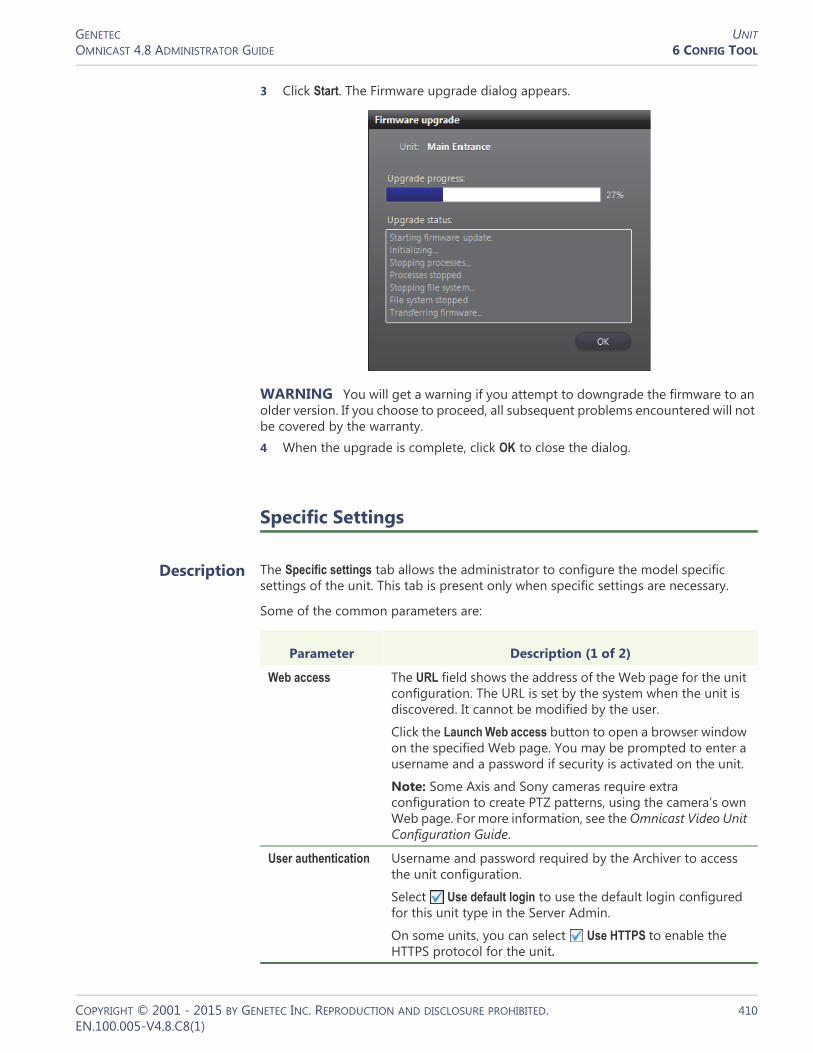
GENETEC UNITOMNICAST 4.8 ADMINISTRATOR GUIDE 6 CONFIG TOOL
3 Click Start. The Firmware upgrade dialog appears.
WARNING You will get a warning if you attempt to downgrade the firmware to an older version. If you choose to proceed, all subsequent problems encountered will not be covered by the warranty.4 When the upgrade is complete, click OK to close the dialog.
Specific Settings
Description The Specific settings tab allows the administrator to configure the model specific settings of the unit. This tab is present only when specific settings are necessary.
Some of the common parameters are:
Parameter Description (1 of 2)
Web access The URL field shows the address of the Web page for the unit configuration. The URL is set by the system when the unit is discovered. It cannot be modified by the user.
Click the Launch Web access button to open a browser window on the specified Web page. You may be prompted to enter a username and a password if security is activated on the unit.
Note: Some Axis and Sony cameras require extra configuration to create PTZ patterns, using the camera’s own Web page. For more information, see the Omnicast Video Unit Configuration Guide.
User authentication Username and password required by the Archiver to access the unit configuration.
Select Use default login to use the default login configured for this unit type in the Server Admin.
On some units, you can select Use HTTPS to enable the HTTPS protocol for the unit.
COPYRIGHT © 2001 - 2015 BY GENETEC INC. REPRODUCTION AND DISCLOSURE PROHIBITED. 410EN.100.005-V4.8.C8(1)
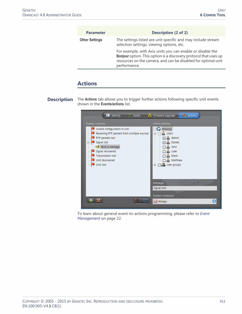
GENETEC UNITOMNICAST 4.8 ADMINISTRATOR GUIDE 6 CONFIG TOOL
Actions
Description The Actions tab allows you to trigger further actions following specific unit events shown in the Events/actions list.
To learn about general event-to-actions programming, please refer to Event Management on page 22.
Other Settings The settings listed are unit specific and may include stream selection settings, viewing options, etc.
For example, with Axis units you can enable or disable the Bonjour option. This option is a discovery protocol that uses up resources on the camera, and can be disabled for optimal unit performance.
Parameter Description (2 of 2)
COPYRIGHT © 2001 - 2015 BY GENETEC INC. REPRODUCTION AND DISCLOSURE PROHIBITED. 411EN.100.005-V4.8.C8(1)

GENETEC UNITOMNICAST 4.8 ADMINISTRATOR GUIDE 6 CONFIG TOOL
Network
Description The Network tab allows you to configure the network settings of the unit.
Network settings The Network settings may be slightly different from one type of unit to another.
Parameter Description
Discovery port This is the port number used by the Archiver to discover or to connect to the unit.
For an AXIS units, this port is called the HTTP port.
For Verint units, this port is called the VSIP port.
For Verint units, the value of this field determines to which Archiver(s) the unit belongs to. The port number can also be changed through the Discovery Tool.
IP address Select Obtain an IP address automatically to have the IP address assigned dynamically.
Select Use the following IP address to impose a fixed address. You will then have to specify the following fields.• Local IP – Fixed IP address.• Subnet mask – The subnet mask tells the unit which
peripherals it can communicate directly with. Anything that does not belong to the same subnet must go through the Gateway.
• Gateway – IP address of the Gateway. It must be on the same subnet as the unit.
COPYRIGHT © 2001 - 2015 BY GENETEC INC. REPRODUCTION AND DISCLOSURE PROHIBITED. 412EN.100.005-V4.8.C8(1)
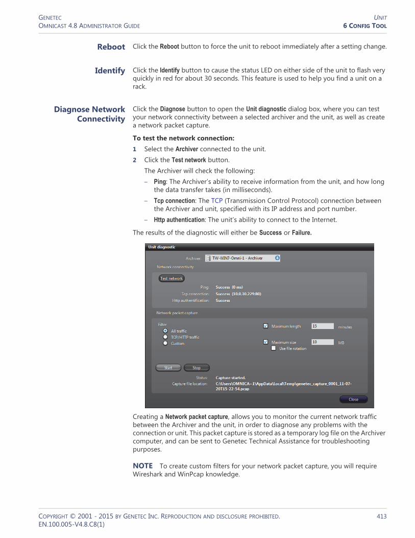
GENETEC UNITOMNICAST 4.8 ADMINISTRATOR GUIDE 6 CONFIG TOOL
Reboot Click the Reboot button to force the unit to reboot immediately after a setting change.
Identify Click the Identify button to cause the status LED on either side of the unit to flash very quickly in red for about 30 seconds. This feature is used to help you find a unit on a rack.
Diagnose Network Connectivity
Click the Diagnose button to open the Unit diagnostic dialog box, where you can test your network connectivity between a selected archiver and the unit, as well as create a network packet capture.
To test the network connection:1 Select the Archiver connected to the unit.2 Click the Test network button.
The Archiver will check the following:– Ping: The Archiver’s ability to receive information from the unit, and how long
the data transfer takes (in milliseconds).– Tcp connection: The TCP (Transmission Control Protocol) connection between
the Archiver and unit, specified with its IP address and port number.– Http authentication: The unit’s ability to connect to the Internet.
The results of the diagnostic will either be Success or Failure.
Creating a Network packet capture, allows you to monitor the current network traffic between the Archiver and the unit, in order to diagnose any problems with the connection or unit. This packet capture is stored as a temporary log file on the Archiver computer, and can be sent to Genetec Technical Assistance for troubleshooting purposes.
NOTE To create custom filters for your network packet capture, you will require Wireshark and WinPcap knowledge.
COPYRIGHT © 2001 - 2015 BY GENETEC INC. REPRODUCTION AND DISCLOSURE PROHIBITED. 413EN.100.005-V4.8.C8(1)
GENETEC UNITOMNICAST 4.8 ADMINISTRATOR GUIDE 6 CONFIG TOOL
To create a Network packet capture:1 Select the Archiver connected to the unit.2 Select a Filter.
– All traffic: All network traffic between the Archiver and the unit.– TCP/HTTP traffic: All TCP traffic sent through an HTTP connection.– Custom: Custom filters you can create in WinPcap format. For more information
about creating custom filters, see the WinPcap Web site: http://www.winpcap.org/docs/docs_412/html/group__language.html.
3 If you want to set a maximum amount of time for the capture to run, select the Maximum length option, and type x number of minutes. The default number is 15 minutes.
4 If you want to set a maximum file size for the capture, select the Maximum size option, and type a number. The default file size is 10 MB of data.
5 If you want to capture data continuously, select the Use file rotation option.When the Use file rotation option is selected, the capture continues until you manually stop it. When the file size exceeds 10 MB, a new file is created. When that file exceeds 10 MB, the first file is overridden, and the two files are alternately overridden until the capture is stopped. This allows you to save disk space because you do not have to keep creating new files.
6 Click Start.The Status says Capture Started, and the Capture file location gives the location of the temporary file created.Note: If an error occurs during the capture, the reason is described in the Status field. For example, if you type an incorrect custom filter, it will say “Error: Invalid filter”.
7 To stop the capture, click Stop, or wait for the capture to be completed.8 Click Close.
COPYRIGHT © 2001 - 2015 BY GENETEC INC. REPRODUCTION AND DISCLOSURE PROHIBITED. 414EN.100.005-V4.8.C8(1)
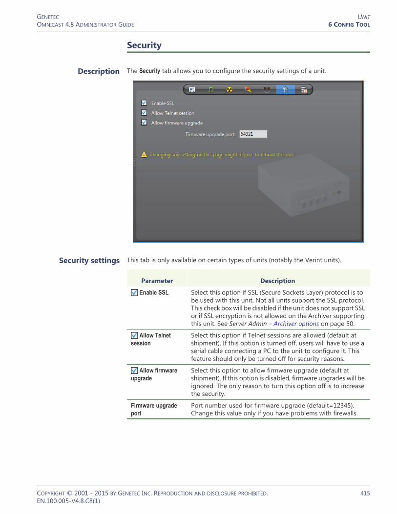
GENETEC UNITOMNICAST 4.8 ADMINISTRATOR GUIDE 6 CONFIG TOOL
Security
Description The Security tab allows you to configure the security settings of a unit.
Security settings This tab is only available on certain types of units (notably the Verint units).
Parameter Description
Enable SSL Select this option if SSL (Secure Sockets Layer) protocol is to be used with this unit. Not all units support the SSL protocol. This check box will be disabled if the unit does not support SSL or if SSL encryption is not allowed on the Archiver supporting this unit. See Server Admin – Archiver options on page 50.
Allow Telnet session
Select this option if Telnet sessions are allowed (default at shipment). If this option is turned off, users will have to use a serial cable connecting a PC to the unit to configure it. This feature should only be turned off for security reasons.
Allow firmware upgrade
Select this option to allow firmware upgrade (default at shipment). If this option is disabled, firmware upgrades will be ignored. The only reason to turn this option off is to increase the security.
Firmware upgrade port
Port number used for firmware upgrade (default=12345). Change this value only if you have problems with firewalls.
COPYRIGHT © 2001 - 2015 BY GENETEC INC. REPRODUCTION AND DISCLOSURE PROHIBITED. 415EN.100.005-V4.8.C8(1)

GENETEC UNITOMNICAST 4.8 ADMINISTRATOR GUIDE 6 CONFIG TOOL
Standby Archivers
Description The Standby Archivers tab lets you define an Archiver failover list for this unit.
Archiver failover list The Archivers appearing in this list are the ones that have been configured to control this unit. The Archiver that appears at the top of the list is called the primary Archiver. It is the one that should be controlling the unit in normal situations. If the primary Archiver fails, then the control of the unit will be transferred to the next Archiver in line. See System Concepts – Archiver Availability on page 17.
Redundant archiving When the standby Archivers are not acting as the primary Archiver, they can be used to produce redundant archives. Redundant archiving is a feature that can be turned on or off on a camera by camera basis. See Camera – Recording settings on page 248.
You may change the order of the standby Archivers with the and buttons.
NOTE A unit becomes associated to an Archiver either through automatic discovery or when it is added manually. The manual association can be done through the Discovery Tool or through the Add a unit dialog. See Adding a unit manually on page 405.
How the failover works
Each unit listens to commands from its primary Archiver on a specific port (see Network settings on page 412).
Archivers on the other hand, can be configured to communicate with multiple groups of units (see Server Admin – Archiver Extensions on page 97). Only one Archiver can be actively controlling a unit at any time.
In the Physical view, the unit always appears under the Archiver that currently has control over it.
COPYRIGHT © 2001 - 2015 BY GENETEC INC. REPRODUCTION AND DISCLOSURE PROHIBITED. 416EN.100.005-V4.8.C8(1)

GENETEC UNITOMNICAST 4.8 ADMINISTRATOR GUIDE 6 CONFIG TOOL
In the following example, we have 12 units evenly distributed between two Archivers. If one of them fails, all the units that were originally controlled by the one that failed are automatically transferred to the one that is still working.
NOTE Once an Archiver becomes part of a unit's failover list, it can no longer be removed from that list until it becomes inactive (shown in red).
Both Archivers working One Archiver failed
COPYRIGHT © 2001 - 2015 BY GENETEC INC. REPRODUCTION AND DISCLOSURE PROHIBITED. 417EN.100.005-V4.8.C8(1)

GENETEC USEROMNICAST 4.8 ADMINISTRATOR GUIDE 6 CONFIG TOOL
User
Definition
A user entity identifies a person to Omnicast and defines their rights to access Omnicast entities and his privileges to run Omnicast applications. Other characteristics of the person such as their email address, preferences and security limitations are also defined by this entity. Common attributes can be inherited from user groups. See User Group on page 445.
Users can be created manually or imported from Windows Active Directory. See Server Admin – Active Directory on page 62.
Any user can act as a supervisor to another user or group, required for logon purposes. See Supervised logon on page 424.
The user‘s configuration page comprises the following tabs.
The Admin user Omnicast is installed with a predefined user called Admin. This user has the rights to access everything in the system and possesses all the privileges. It is defined so you can create other users when logged on to the system with it. The Admin user cannot be renamed nor deleted. Its privileges cannot be modified. It belongs to the Administrators user group. It cannot be removed from it nor can it become a member of another group.
The Admin user is created without a password. It is strongly recommended that you protect it with a password for the security of your system.
Creating a user To create a new user, do the following.1 Select User Management from the View selection pane. See View selection pane on
page 155.2 Click at the bottom of the View selection pane. A pop-up menu with the
entities you can create appears.3 Select User from the pop-up menu. A new entity named NewUser will be
created.
Icon Tab Description
Identity Name, description and positions of the entity in the Logical and Physical system hierarchies.
Properties User's basic properties.
Permissions Access rights, group memberships, and their supervised logon configuration.
Privileges Privileges to carry out specific operations.
Live Viewer User preferences for Live Viewer.
Actions User event handling.
Security PTZ priority, viewing priority, and archive viewing limitation.
COPYRIGHT © 2001 - 2015 BY GENETEC INC. REPRODUCTION AND DISCLOSURE PROHIBITED. 418EN.100.005-V4.8.C8(1)

GENETEC USEROMNICAST 4.8 ADMINISTRATOR GUIDE 6 CONFIG TOOL
4 Enter an appropriate name for the new user.– Note that the user name must be unique and cannot contain spaces.– Use the Description field to enter the user's personal information.
5 Select the Properties tab and define the basic properties. See Properties on page 419.
6 Select the Permissions tab and define the user’s access rights to system resources and its membership to user groups. See Permissions on page 422.
7 Click the button on the lower right of the Configuration pane to define who the user supervises, if necessary. See Supervised logon on page 424.
8 Select the Privileges tab and grant appropriate privileges to the user. See Privileges on page 434.
9 Select the Live Viewer tab and define the user preferences. See Live Viewer on page 439.
10 Define the Actions that should be triggered by user events, if necessary. See Actions on page 441.
11 Select the Security tab and expand or limit the privileges of the user. See Security on page 442.
Properties
Description The Properties tab defines the user's basic information, such as the password, the email address and the times they are allowed to logon to the system.
User email The user’s Email address must be specified to enable the use of the Send an email action on that user. See actions focusing on users in Appendix B – Omnicast Action Types (sorted by object entity) on page 533.
COPYRIGHT © 2001 - 2015 BY GENETEC INC. REPRODUCTION AND DISCLOSURE PROHIBITED. 419EN.100.005-V4.8.C8(1)
GENETEC USEROMNICAST 4.8 ADMINISTRATOR GUIDE 6 CONFIG TOOL
User password All new users are created without a password. However, for security reasons, it is recommended to protect each user account with a password, especially the Admin user and all users who are members of the Administrators user group.
As an administrator, you can change the password of any user on the system. You can set the lifetime of the password, so users are required to change it after a certain amount of time. In addition to this, you can also specify the number of workstations a user can login from. This option prevents a user from using all the available user connection licenses if they logon (or forget to logoff) multiple stations.
To set a new password, click Modify. Enter the new password in the Change password dialog box. Beside Lifetime, enter how many days the password is active or select Infinite. To clear the password for a user at anytime, click the Clear button.
When using supervised logons, the credentials configured in this tab are used for the user, whether logging on themselves, or acting as a supervisor. See Supervised logon on page 424.
NOTE When the Active Directory option is enabled on the Omnicast Directory, you can no longer change the username, password and email address through the Config Tool. For more information, see Server Admin – Active Directory on page 62.
User logon
Logon schedules As an administrator, you can limit the logon time of a user to specific days and times during the week. By default, all users are allowed to logon at all times, defined by the generic schedule Always.
You may combine several schedules if necessary, using them either to allow user logon during certain periods of time or to block it during certain periods of time. The and
buttons allow you to change the usage (allowing or blocking) of a selected schedule. Use and buttons to control the combination of schedules in each list.
COPYRIGHT © 2001 - 2015 BY GENETEC INC. REPRODUCTION AND DISCLOSURE PROHIBITED. 420EN.100.005-V4.8.C8(1)

GENETEC USEROMNICAST 4.8 ADMINISTRATOR GUIDE 6 CONFIG TOOL
Schedule overview Click the button to display the Schedule overview dialog.
The top section lists all logon schedules applied to this user. The bottom section shows the different periods during a selected day where logon is either allowed or blocked.
When two schedules of different types (i.e. using different recurrence patterns) overlap, priority is evaluated in the following order:1 Specific schedule2 Yearly schedule3 Monthly schedule4 Weekly schedule5 Daily schedule6 Always (the default schedule)
Two schedules with the same recurrence pattern may not overlap. See also Schedule Priorities and Conflict Resolution on page 331.
Activating / Deactivating a user
The administrator can expel a suspicious user from the system by deactivating the user. All users are active by default. An active user is shown by a highlighted button with a green LED .
COPYRIGHT © 2001 - 2015 BY GENETEC INC. REPRODUCTION AND DISCLOSURE PROHIBITED. 421EN.100.005-V4.8.C8(1)

GENETEC USEROMNICAST 4.8 ADMINISTRATOR GUIDE 6 CONFIG TOOL
To deactivate a user, simply click the button and answer Yes when asked to confirm the action. If the user is currently connected, he will be immediately logged out. The following message will be displayed.
If an inactive user tries to log on, the following error message will be displayed.
To re-activate a user, click the button.
Permissions
Description The Permissions tab allows you to define the user's access rights to system resources, its membership in user groups, and who the user supervises.
COPYRIGHT © 2001 - 2015 BY GENETEC INC. REPRODUCTION AND DISCLOSURE PROHIBITED. 422EN.100.005-V4.8.C8(1)

GENETEC USEROMNICAST 4.8 ADMINISTRATOR GUIDE 6 CONFIG TOOL
This tab is not applicable to the Admin user nor to the members of the Administrators user group. They always have full access to everything.
Access rights The Access rights pane shows the permissions granted to the user to access each site defined in the Logical view. If a right is inherited from a user group, then the name of the parent group is indicated in brackets, and the access right cannot be removed from the user.
If the user has the privilege Always view all entities, then it will automatically gain access to all sites , with the exception of the hidden ones (see Hidden site on page 397.). If the access right is granted through privilege, the words “User privilege” are indicated in brackets instead of the parent group name.
The following are the access right indicators:• No access granted to the site nor to any of its children sites.• Access granted to some children sites but not to the site itself.• Access granted to the site but not to all its children sites.• Access granted to the site and to all its children sites.
To grant access to a site, simply select the box adjacent to it. Selecting a parent site will automatically include all its children. Clearing a parent site will automatically clear all its children.
Site permission inheritance
You can grant a user the right to access a site without granting him the right to access the parent site. But to prevent a user from accessing a site while having the right to access its parent site, you must first make sure that the site is not inheriting its permission list from its parent site. See Site – Permission inheritance on page 396.
You may not create this exception for the children of hidden sites because they always inherit from their parent sites. See Rules governing the hidden sites on page 397.
NOTE Access to the Directory is only granted to the Administrators group and its members. Other users are not allowed to access anything placed directly under the Directory. You are allowed to select the Directory as a shortcut to select all its children sites. But unless the user is a member of the Administrators group, no permission will be granted to access anything directly placed under the Directory, even if the Directory is selected.
TIP You can use the access rights to control the access to devices that are not shown in the Live Viewer application, such as PTZ motors, microphones and speakers.For example, if a user should only be allowed to view a camera but not to use its PTZ controls, you can configure this by placing the camera under a site that the user can access, and placing the associated PTZ motor under a site that he cannot.
User group membership
The Members of pane lists all the user groups that the selected user belongs to. If the user is a member of a group that belongs to another group, the entire hierarchy is shown.
When a user is a member of a group, it automatically inherits all the group’s access rights and privileges. See User Group on page 445.
COPYRIGHT © 2001 - 2015 BY GENETEC INC. REPRODUCTION AND DISCLOSURE PROHIBITED. 423EN.100.005-V4.8.C8(1)

GENETEC USEROMNICAST 4.8 ADMINISTRATOR GUIDE 6 CONFIG TOOL
You may add the user's membership to new groups or remove its membership from existing groups with the and buttons.
Supervised logon
Description Users can be required to have a supervisor enter their credentials at the same time as the user does to be able to logon to Omnicast, in a process called supervised logon.
Supervised logons are configured by clicking the button found in the lower right corner of the Permission tab, and using the dialog that appears.If a supervised logon is required for a user, at the logon screen of client applications, users enter their username and password, and their supervisor does so as well. Users can then log on.
If a user, or the user group they belong to, has no supervisors, they log on to Omnicast in the regular manner—only their own credentials are required.
Supervisory relationships are created by making a user or group a supervisor of another user or group.
When a user requires a supervised logon, all of their privileges and permissions, logon schedules and other user and user group settings, remain theirs and are not inherited from their supervisor. See Supervised logon usage scenarios on page 432.
By default, the Connect dialog, which appears when logging on to a client application, only displays fields for the user to logon without a supervisor. If at least some users will require a supervised logon, it is recommended to change this behavior. See Toggling the logon mode on page 430.
NOTE The terms user group and group are used interchangeably in this section. See User Group on page 445.
COPYRIGHT © 2001 - 2015 BY GENETEC INC. REPRODUCTION AND DISCLOSURE PROHIBITED. 424EN.100.005-V4.8.C8(1)

GENETEC USEROMNICAST 4.8 ADMINISTRATOR GUIDE 6 CONFIG TOOL
Who can supervise who
Any user that can logon to the Omnicast system can be a supervisor—no special privilege is necessary.
The following relationships are possible:• a user can be the supervisor of another user, • a user can be the supervisor of a group, • a group can be the supervisor of a user, • and a group can be a supervisor of another group, including itself.
Once you assign a supervisor to a user or group, the subordinate users are required to log on with their supervisor.
When you make a group a supervisor, all members of the group can log on the users supervised by that group. Similarly, if a user is a supervisor of a group, the user can log on all members of that group—except for themselves if the user is a member of this group. If a group supervises itself, each member of the group can act as a supervisor to any members of the group except themselves.
In the above example, user A is a member of a group that supervises another group. All members of the supervised group, user B and C, are then supervised by user A.
TIP You can check who user A supervises by looking at the Inherited supervision pane in the Supervision dialog. See Identifying who a user or group supervises on page 428.
There is no limit to how many users, or groups, that can be supervised by a particular user or group. Similarly, users and groups can have multiple supervisors, each with the capability to perform a supervised logon with them.
Supervisor ofSupervisor of
A
B
Member of
C
Effects of configuration
Configured relationships
Legend
Members of
COPYRIGHT © 2001 - 2015 BY GENETEC INC. REPRODUCTION AND DISCLOSURE PROHIBITED. 425EN.100.005-V4.8.C8(1)

GENETEC USEROMNICAST 4.8 ADMINISTRATOR GUIDE 6 CONFIG TOOL
Members of a group can be supervisors of a user because of the group’s supervision of that user, a user can be a supervisor of any other user, but, as illustrated below, user A is not a supervisor of user C just because user A is the supervisor of user B and user B is the supervisor of user C.
The same principle applies to groups: if group A is supervisor of group B, and group B is supervisor of group C, members of group A are not supervisors of group C.
Member of
Supervisor ofSupervisor of
Supervisor of
Not the Supervisor of
Supervisor of
Supervisor of
A
B
C
Effects of configuration
Configured relationships
Legend
COPYRIGHT © 2001 - 2015 BY GENETEC INC. REPRODUCTION AND DISCLOSURE PROHIBITED. 426EN.100.005-V4.8.C8(1)

GENETEC USEROMNICAST 4.8 ADMINISTRATOR GUIDE 6 CONFIG TOOL
You can instead configure this type of relationship by nesting groups within groups. Then, a supervisor of any group that contains other groups, is automatically supervisor of all members of the nested groups.
You can also create direct supervision relationships between multiple entities, for example, having a user be the supervisor of group A, B, and C, where each of these groups are completely separate and have no relationship with one another.
The Admin user cannot be supervised nor can the Administrator user group.
Assigning Supervisors You configure supervised logons by assigning a user or group as a supervisor of another user or group. See Who can supervise who on page 425.
To assign supervisors, do the following:1 If necessary, select User Management from the View selection pane. See View
selection pane on page 155.2 In the entity tree, select the User or User Group that you want to make into
supervisors.3 Click the Permissions tab.4 Click the button on the lower right of the Configuration pane.
Member of
Member of
Member of
Supervisor of
Supervisor of
Effects of configuration
Configured relationships
Legend
COPYRIGHT © 2001 - 2015 BY GENETEC INC. REPRODUCTION AND DISCLOSURE PROHIBITED. 427EN.100.005-V4.8.C8(1)

GENETEC USEROMNICAST 4.8 ADMINISTRATOR GUIDE 6 CONFIG TOOL
The Supervision dialog box appears.
5 Click the button at the lower left of the dialog.6 In the Add users or groups dialog that appears, select the users and groups that will
be supervised by the user or group you are configuring.– The user you are configuring does not appear because users cannot supervise
themselves.– If you are configuring a group, it does appear since a group can supervise itself.
In this case, all members of the group act as supervisors to everyone else. Users remain unable to act as supervisors for themselves.
– Similarly, if you assign a user as the supervisor of a group they are a member of, they will be supervisor of all members of the group except themselves.
– The Admin user and Administrators group do not appear since they cannot be supervised.
7 Click the Add button.– The selected users and groups appear in the Supervisor of pane.If necessary, select one or more users and/or groups in the Supervisor of pane, then click the button to remove them.
8 Click OK.
The selected users and groups are now supervised by the user or group you selected in Step 2.
Identifying who a user or group
supervises
To identify who a user or group supervises do the following:1 If necessary, select User Management from the View selection pane. See View
selection pane on page 155.2 In the entity tree, select the User or User Group whose subordinates you want
to check.3 Click the Permissions tab.4 Click the button on the lower right of the Configuration pane. The
Supervision dialog box appears.
COPYRIGHT © 2001 - 2015 BY GENETEC INC. REPRODUCTION AND DISCLOSURE PROHIBITED. 428EN.100.005-V4.8.C8(1)
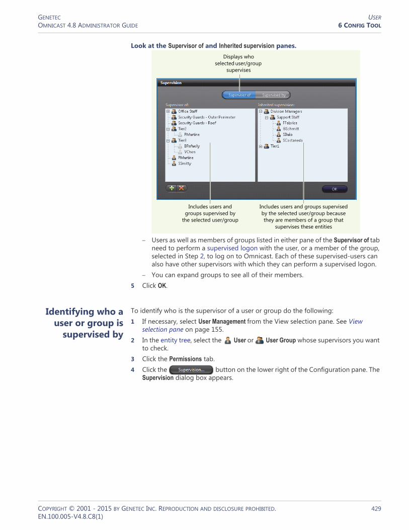
GENETEC USEROMNICAST 4.8 ADMINISTRATOR GUIDE 6 CONFIG TOOL
Look at the Supervisor of and Inherited supervision panes.
– Users as well as members of groups listed in either pane of the Supervisor of tab need to perform a supervised logon with the user, or a member of the group, selected in Step 2, to log on to Omnicast. Each of these supervised-users can also have other supervisors with which they can perform a supervised logon.
– You can expand groups to see all of their members.5 Click OK.
Identifying who a user or group is
supervised by
To identify who is the supervisor of a user or group do the following:1 If necessary, select User Management from the View selection pane. See View
selection pane on page 155.2 In the entity tree, select the User or User Group whose supervisors you want
to check.3 Click the Permissions tab.4 Click the button on the lower right of the Configuration pane. The
Supervision dialog box appears.
Displays who selected user/group
supervises
Includes users and groups supervised by
the selected user/group
Includes users and groups supervised by the selected user/group because they are members of a group that
supervises these entities
COPYRIGHT © 2001 - 2015 BY GENETEC INC. REPRODUCTION AND DISCLOSURE PROHIBITED. 429EN.100.005-V4.8.C8(1)

GENETEC USEROMNICAST 4.8 ADMINISTRATOR GUIDE 6 CONFIG TOOL
5 Select the Supervised by tab.
– Users as well as members of groups listed in the Supervised by tab each can perform a supervised logon with the entity selected in Step 2 to log on to Omnicast.
– You can expand groups to see all of their members—each being a supervisor to the entity selected in Step 2.
6 Click OK.
Toggling the logon mode
You can use supervised logons for three types of Omnicast applications you use to access the system: client applications, the stand-alone Archive Player, and web applications.
For web applications, the procedures described in this section are not applicable since the supervision logon fields are always shown.
Initially, when logging on to a client application, the Connect dialog only displays fields for users, and not for supervisors.
There are two methods to display the supervised logon fields for client applications. It is recommended that administrators of the Omnicast system follow the second method. Only the second method is applicable to the stand-alone Archive Player.
Includes users and groups who supervise
the selected user/group
Displays who the selected user/group
is supervised by
COPYRIGHT © 2001 - 2015 BY GENETEC INC. REPRODUCTION AND DISCLOSURE PROHIBITED. 430EN.100.005-V4.8.C8(1)

GENETEC USEROMNICAST 4.8 ADMINISTRATOR GUIDE 6 CONFIG TOOL
The first method occurs by trial and error: If a supervised user enters their credentials in a Connect dialog that does not display fields for their supervisor, then clicks OK, an error message appears indicating that the supervisor’s credentials are missing.
The next time any user tries to log on to any client application on the workstation, the Connect dialog displays the supervised logon fields. The Connect dialog remains in supervised logon mode for subsequent logon attempts unless toggled by the second method, explained below.
The second method is performed by a system admin on client workstations: If you are aware that at least one user is supervised, you can manually toggle the Connect dialog to supervised logon mode. The logon mode then persists for subsequent logon attempts on the workstation.
For stand-alone Archive Player users, they can follow the procedure below as well. Be aware, however, that the Connect dialog on the stand-alone Archive Player is always displayed initially in single logon mode so will have to be toggled whenever logging on as a supervised user.
Follow the procedure below:1 Open a client application.
NOTE Make sure other client applications are closed. Otherwise these other client applications will not inherit the logon state you set.2 Hold <Ctrl>+<Alt> and click the OK button of the Connect dialog. The dialog
toggles from single logon mode to supervised logon mode.
TIP You can also press <Ctrl>+<Alt>+<Enter>.
<Ctrl>+<Alt>-click
COPYRIGHT © 2001 - 2015 BY GENETEC INC. REPRODUCTION AND DISCLOSURE PROHIBITED. 431EN.100.005-V4.8.C8(1)
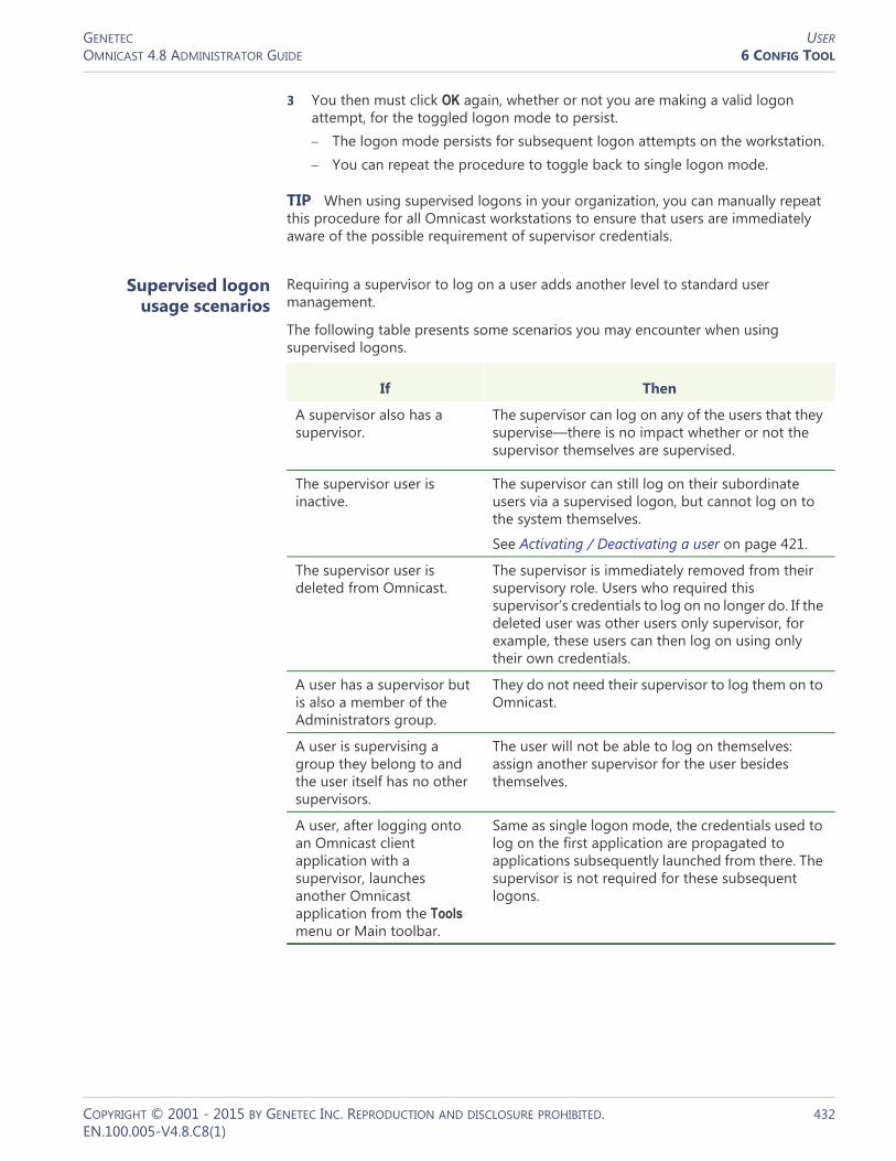
GENETEC USEROMNICAST 4.8 ADMINISTRATOR GUIDE 6 CONFIG TOOL
3 You then must click OK again, whether or not you are making a valid logon attempt, for the toggled logon mode to persist.– The logon mode persists for subsequent logon attempts on the workstation. – You can repeat the procedure to toggle back to single logon mode.
TIP When using supervised logons in your organization, you can manually repeat this procedure for all Omnicast workstations to ensure that users are immediately aware of the possible requirement of supervisor credentials.
Supervised logon usage scenarios
Requiring a supervisor to log on a user adds another level to standard user management.
The following table presents some scenarios you may encounter when using supervised logons.
If Then
A supervisor also has a supervisor.
The supervisor can log on any of the users that they supervise—there is no impact whether or not the supervisor themselves are supervised.
The supervisor user is inactive.
The supervisor can still log on their subordinate users via a supervised logon, but cannot log on to the system themselves.
See Activating / Deactivating a user on page 421.
The supervisor user is deleted from Omnicast.
The supervisor is immediately removed from their supervisory role. Users who required this supervisor’s credentials to log on no longer do. If the deleted user was other users only supervisor, for example, these users can then log on using only their own credentials.
A user has a supervisor but is also a member of the Administrators group.
They do not need their supervisor to log them on to Omnicast.
A user is supervising a group they belong to and the user itself has no other supervisors.
The user will not be able to log on themselves: assign another supervisor for the user besides themselves.
A user, after logging onto an Omnicast client application with a supervisor, launches another Omnicast application from the Tools menu or Main toolbar.
Same as single logon mode, the credentials used to log on the first application are propagated to applications subsequently launched from there. The supervisor is not required for these subsequent logons.
COPYRIGHT © 2001 - 2015 BY GENETEC INC. REPRODUCTION AND DISCLOSURE PROHIBITED. 432EN.100.005-V4.8.C8(1)

GENETEC USEROMNICAST 4.8 ADMINISTRATOR GUIDE 6 CONFIG TOOL
While a user is logged on, the configuration of their supervisor changes.
The only effect is when using the Tools menu or shortcuts in the Main toolbar of the application to launch another Omnicast application. If the supervisor’s username or password has changed, the user will not be able to logon to the other application. They will have to re-enter their credentials, along with the updated supervisor’s credentials, to gain access.
Active Directory is being used on the Omnicast system, and users which are part of groups—including a supervisor— have not been initially imported.
See Step 10 of Enabling the Active Directory on page 63.
The supervisor will not be available in Omnicast to log on users even if their group is configured as such. The supervisor has to log onto Omnicast as a user once themselves, and then can perform the supervised logon for those they supervise.
Also note that even if the supervisor cannot log on to Omnicast because they themselves are supervised and their own supervisor is unavailable for the same reason outlined above, their user will nonetheless be created in Omnicast during the logon attempt and thus will be available to log on others from that point onwards.
A user is confronted with supervisor fields in the Connect dialog when logging on, but has no supervisor.
The user leaves the supervisor credentials blank. Entering only their own credentials logs the user on successfully.
If Then
COPYRIGHT © 2001 - 2015 BY GENETEC INC. REPRODUCTION AND DISCLOSURE PROHIBITED. 433EN.100.005-V4.8.C8(1)

GENETEC USEROMNICAST 4.8 ADMINISTRATOR GUIDE 6 CONFIG TOOL
Privileges
Description The Privileges tab is used to view and modify the user’s privileges. The user privileges control what operations the user is allowed or forbidden to carry out in the system.
Privilege Governing Rules
Privilege grants Each privilege can be explicitly granted to the user or inherited from a parent group. Each privilege can be granted in one of the following ways:• Allow – The privilege is granted to the user.• Deny – The privilege is denied to the user.• Undefined – This privilege must be inherited from a parent user group. If the user is
not a member of any group, then the privilege is denied.
Privilege inheritance The privilege inheritance is governed by the following rules:• A privilege that is undefined to a user group can be allowed or denied to its
members.• A privilege that is allowed to a user group can be denied to its members.• A privilege that is denied to a user group is automatically denied to all its
members.
The Inherited from column shows whether a privilege grant is inherited from parent groups. When the user's own name is also part of this list, it means that the privilege is both inherited and explicitly granted to that user. This happens when the privilege was granted to the user before it became a member of the group.
COPYRIGHT © 2001 - 2015 BY GENETEC INC. REPRODUCTION AND DISCLOSURE PROHIBITED. 434EN.100.005-V4.8.C8(1)

GENETEC USEROMNICAST 4.8 ADMINISTRATOR GUIDE 6 CONFIG TOOL
Privilege hierarchy Certain privileges are organized in a hierarchy with the following behavior.• If a child privilege is to be allowed, the parent privilege has to be allowed.• If a parent privilege is denied, all children privileges are denied.• A child privilege can be denied when the parent privilege is allowed.
Privilege Description
Application privileges The following privileges grants access to Omnicast applications.
Config Tool privileges The following privileges are specific to Config Tool users. For every entity type that can be created manually, there is a CREATE AND DELETION privilege to allow the creation and deletion of that type of entity. Without that privilege, you can only modify existing entities, but not create or delete them. This privilege is not repeated in the following table.
Privilege Description
Live Viewer Allows the user to run the Live Viewer application.
Archive Player Allows the user to run the Archive Player application.
Config Tool Allows the user to run the Config Tool application.
Macro Editor Allows the user to run the Macro Editor application.
Web Live Viewer Allows the user to run the Web Live Viewer.
Web Archive Player Allows the user to run the Web Archive Player.
SDK Allows the user to run applications written with Omnicast SDK.
Pocket PC Allows the user to run the Pocket PC application.
Media Gateway Allows the user to establish connections with the Media Gateway.
Uncompressed Video Filter Allows the user to establish connections with the uncompressed video filter.
Federation Server Allows the user to establish connections with a remote system's Federation Server.
Synergis Allows the user to establish connections with Synergis access control system.
Privilege Description (1 of 2)
Always view all entities Allows the user to view all entities, except those placed under hidden sites. See Hidden site on page 397
Site configuration Allows the user to change the settings of existing sites and the Logical view hierarchy.
Unit configuration Allows the user to change the settings of units.
Firmware upgrade Allows the user to upgrade the firmware of units.
COPYRIGHT © 2001 - 2015 BY GENETEC INC. REPRODUCTION AND DISCLOSURE PROHIBITED. 435EN.100.005-V4.8.C8(1)

GENETEC USEROMNICAST 4.8 ADMINISTRATOR GUIDE 6 CONFIG TOOL
Camera configuration Allows the user to change the settings of video encoders, except the video quality, recording, motion detection, and OV Ready settings. See the next four privileges.
Video quality Allows the user to change the video quality settings.
Recording Allows the user to change the recording settings.
Motion detection Allows the user to change the motion detection settings.
OV Ready Allows the user to change the edge analytic settings.
Analog monitor config. Allows the user to change the settings of analog monitors.
Audio configuration Allows the user to change the settings of audio devices.
Serial port configuration Allows the user to change the settings of serial ports.
digital input config. Allows the user to change the settings of digital inputs.
Output relay config. Allows the user to change the settings of output relays.
PTZ configuration Allows the user to change the settings of PTZ motors.
Hardware matrix config. Allows the user to change the settings of hardware matrices.
Schedule configuration Allows the user to change the settings of schedules.
Custom event and action configuration
Allows the user to change the settings of custom events and actions.
Alarm configuration Allows the user to change the settings of alarms.
Delete alarm instances
Allows the user to delete alarm instances before they are due to be deleted.
Macro configuration Allows the user to change the settings of macros.
Camera sequence config. Allows the user to change the settings of camera sequences.
CCTV keyboard config. Allows the user to change the settings of CCTV keyboards.
Access control system config.
Allows the user to change the settings of access control system entities.
Monitor group config. Allows the user to change the settings of monitor groups.
Camera group config. Allows the user to change the settings of camera groups.
Viewer layout config. Allows the user to change the settings of viewer layouts.
Deletion Allows the user to delete viewer layouts.
Backup operator Allows the user to perform backup operations.
Modify logical IDs Allows the user to change the logical ID of entities.
Plugin configuration Allows the user to change the configuration of plugins.
View application connections
Allows the user to view which applications are connected.
View video connections
Allows the user to view all video connections.
Privilege Description (2 of 2)
COPYRIGHT © 2001 - 2015 BY GENETEC INC. REPRODUCTION AND DISCLOSURE PROHIBITED. 436EN.100.005-V4.8.C8(1)

GENETEC USEROMNICAST 4.8 ADMINISTRATOR GUIDE 6 CONFIG TOOL
Live Viewer privileges The following privileges are specific to Live Viewer users.
PTZ controls The following privileges are specific to the use of PTZ commands.
Privilege Description
Change display Allows the user to change the displayed elements.
Change tile content Allows the user to change the entities displayed in tiles.
Change armed tile content
Allows the user to change the entities displayed in armed tiles.
Arm/Disarm tiles
Allows the user to arm and disarm tiles in the Viewing pane.
Change tile pattern Allows the user to change the tile patterns.
Change layout selection Allows the user to change the list of viewer layouts.
Edit/save layout config. Allows the user to edit and save the viewer layouts.
Start/stop guard tour Allows the user to start and stop the guard tour.
Edit guard tour dwell time Allows the user to change the guard tour dwell time.
Acknowledge alarms Allows the user to acknowledge alarms.
Forward alarms Allows the user to forward alarms and to configure alarms auto-forward.
Alarm snooze Allows the user to make alarms snooze.
Audio (listen/talk) Allows the user to use the audio controls.
Access digital zoom Allows the user to use the digital zoom controls.
Do instant replay Allows the user to use the instant replay controls.
Execute macros Allows the user to execute macros.
Edit/save layout config. Allows the user to change the macro hot key mappings.
Local recording Allows the user to record locally on the PC’s hard disk.
Record manually Allows the user to start and stop recording manually.
Privilege Description
Perform basic operations Allows the user to use the basic PTZ commands.
Change focus and iris settings Allows the user to play with the focus and iris controls.
Use presets Allows the user to use the camera presets.
Edit presets Allows the user to change or rename the camera presets.
Use patterns Allows the user to use the camera patterns.
Edit patterns Allows the user to change or rename the camera patterns.
Use auxiliaries Allows the user to use the auxiliary controls.
Edit auxiliaries Allows the user to rename the auxiliaries.
Use specific commands Allows the user to use the PTZ specific commands and the menu mode.
Lock PTZ Allows the user to lock the PTZ.
Override PTZ locks Allows the user to override PTZ locks.
COPYRIGHT © 2001 - 2015 BY GENETEC INC. REPRODUCTION AND DISCLOSURE PROHIBITED. 437EN.100.005-V4.8.C8(1)
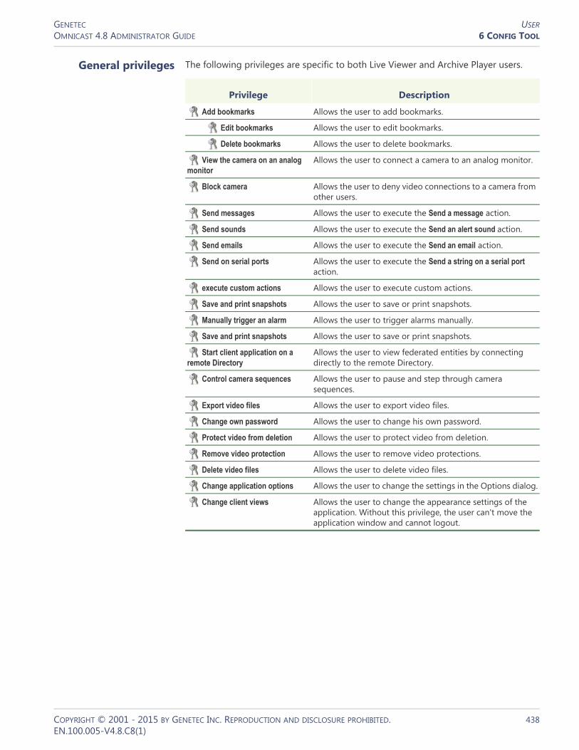
GENETEC USEROMNICAST 4.8 ADMINISTRATOR GUIDE 6 CONFIG TOOL
General privileges The following privileges are specific to both Live Viewer and Archive Player users.
Privilege Description
Add bookmarks Allows the user to add bookmarks.
Edit bookmarks Allows the user to edit bookmarks.
Delete bookmarks Allows the user to delete bookmarks.
View the camera on an analog monitor
Allows the user to connect a camera to an analog monitor.
Block camera Allows the user to deny video connections to a camera from other users.
Send messages Allows the user to execute the Send a message action.
Send sounds Allows the user to execute the Send an alert sound action.
Send emails Allows the user to execute the Send an email action.
Send on serial ports Allows the user to execute the Send a string on a serial port action.
execute custom actions Allows the user to execute custom actions.
Save and print snapshots Allows the user to save or print snapshots.
Manually trigger an alarm Allows the user to trigger alarms manually.
Save and print snapshots Allows the user to save or print snapshots.
Start client application on a remote Directory
Allows the user to view federated entities by connecting directly to the remote Directory.
Control camera sequences Allows the user to pause and step through camera sequences.
Export video files Allows the user to export video files.
Change own password Allows the user to change his own password.
Protect video from deletion Allows the user to protect video from deletion.
Remove video protection Allows the user to remove video protections.
Delete video files Allows the user to delete video files.
Change application options Allows the user to change the settings in the Options dialog.
Change client views Allows the user to change the appearance settings of the application. Without this privilege, the user can't move the application window and cannot logout.
COPYRIGHT © 2001 - 2015 BY GENETEC INC. REPRODUCTION AND DISCLOSURE PROHIBITED. 438EN.100.005-V4.8.C8(1)

GENETEC USEROMNICAST 4.8 ADMINISTRATOR GUIDE 6 CONFIG TOOL
Live Viewer
Description The Live Viewer tab allows you to configure the user’s preferences for the Live Viewer application in terms of alarm display, list of viewer layouts at application start up, and macro mappings to function keys.
Alarm display preferences
The Alarms section pertains to the user’s preferences in terms of alarm display.
Parameter Description
Alarm display mode There are three distinct alarm display modes to choose from:• Simple – Alarm cameras are displayed one per armed
viewing tile, following their alarm priority. Multiple alarms can be displayed simultaneously as long as there are enough armed tiles to fit them all.
• Salvo – All cameras assigned to the alarm are displayed simultaneously, using as many armed viewing tiles as needed. Only one alarm can be displayed at a time.
• Block – All cameras assigned to the alarm cycle through a same viewing tile. Multiple alarms can be displayed simultaneously, up to the number of armed tiles available in the Live Viewer or to the maximum number of alarms to be displayed simultaneously for that user.
See System Concepts – Alarm Display Modes on page 9.
Maximum displayed alarms
Maximum number of alarms that can be displayed simultaneously.
COPYRIGHT © 2001 - 2015 BY GENETEC INC. REPRODUCTION AND DISCLOSURE PROHIBITED. 439EN.100.005-V4.8.C8(1)

GENETEC USEROMNICAST 4.8 ADMINISTRATOR GUIDE 6 CONFIG TOOL
List of viewer layouts The List of viewer layouts indicates which viewer layouts are available to the user from the Live Viewer application. The order of appearance in the list corresponds to their order of appearance in the Live Viewer (left to right). See Viewer Layout on page 451.
To add a layout to the list, click the button at the bottom of the list. The Select the viewer layout dialog appears. Select the desired layout and click OK.
If a layout appears shaded , it means that the user has no permission to view the layout (see Permissions on page 422). However, if the user has access to the layout but not to all the cameras shown in the layout, the layout will be displayed in the Live Viewer but the tiles showing inaccessible cameras will remain empty.
To remove a selected layout from the list, click the button.
To change the order of the layouts in the list, select a layout and click the and buttons to change its position in the list.
Users with the appropriate privileges can also change the list of layouts themselves from the Live Viewer application. See Live Viewer privileges on page 437.
List of hot macros The List of hot macros defines the macros that should appear in the Hot macro list of the Live Viewer application (see Using Hot Macros in the Omnicast Live Viewer User Guide). The order of appearance in the list corresponds to their order of appearance in the Live Viewer.
To add a macro to the list, click the button at the bottom of the list. The Select a macro or plugin dialog appears. Select the desired macro or plugin and click OK.
If a macro appears shaded , it means that the user has no permission to use this macro (see Permissions on page 422).
To remove a selected macro from the list, click the button.
To change the order of the macros in the list, select a macro and click the and buttons to change its position in the list.
COPYRIGHT © 2001 - 2015 BY GENETEC INC. REPRODUCTION AND DISCLOSURE PROHIBITED. 440EN.100.005-V4.8.C8(1)

GENETEC USEROMNICAST 4.8 ADMINISTRATOR GUIDE 6 CONFIG TOOL
Actions
Description The Actions tab allows you to program specific system behaviors based on the user events shown in the Events/actions list.
To learn about general event-to-actions programming, please refer to Event Management on page 22.
COPYRIGHT © 2001 - 2015 BY GENETEC INC. REPRODUCTION AND DISCLOSURE PROHIBITED. 441EN.100.005-V4.8.C8(1)

GENETEC USEROMNICAST 4.8 ADMINISTRATOR GUIDE 6 CONFIG TOOL
Security
Description The Security tab is only visible in Advanced mode. It pertains to parameters that can further expand or limit the actions of the user granted by its permissions and privileges.
PTZ priority The PTZ priority is used in Omnicast to determine which user has priority over a camera's PTZ controls when two or more users are trying to control the movement of the same camera. PTZ priority is set on a per-user, or per-camera basis.
Things you need to understand about PTZ priorities:• PTZ priorities be set explicitly for a user or inherited from a parent user group. If
the option Inherit from parent is selected, then the user will inherit the PTZ priority of its parent group.
• If the user has more than one parent group, the highest PTZ priority will be inherited. If the user has no parent group, the lowest PTZ priority (254) will be inherited by default.
• The highest PTZ priority is 1, and the lowest PTZ priority is 254.• Between users with different PTZ priorities, the system always grants precedence
to the user with the higher priority. Between users having the same PTZ priority, it is decided on a first come first served basis.
• Once a user gains control over a PTZ camera, it is implicitly locked by that user. This means that other users cannot snatch the control away from him unless they have a higher PTZ priority. NOTE The control over the PTZ camera is automatically relinquished after five seconds of inactivity.
COPYRIGHT © 2001 - 2015 BY GENETEC INC. REPRODUCTION AND DISCLOSURE PROHIBITED. 442EN.100.005-V4.8.C8(1)

GENETEC USEROMNICAST 4.8 ADMINISTRATOR GUIDE 6 CONFIG TOOL
PTZ priority overrides You can create PTZ priority overrides for each PTZ motor or site a user or user group has access to. For example, if you want your security operators on the first floor to have the highest viewing priority for cameras in the parking lot, you can create a high PTZ priority override for each PTZ motor located in the parking lot for that user group. Or, if your parking lot is configured as a site, you can simply create a high PTZ priority override for the whole site.
NOTES
• If you do not create any PTZ overrides, the default PTZ priorities apply.• If a PTZ motor belongs to more than one site, the highest PTZ priority applies.• If a user is part of a user group and inherits the user group’s default PTZ priority,
they also inherit any PTZ priority overrides associated with that group.
To create PTZ priority overrides:1 In the Security tab of user or user group entities, deselect the Inherit from parent PTZ
priority option.2 Click the Advanced button.
The PTZ Priority overrides dialog box opens.3 In the Add a PTZ override drop-down list, select a PTZ motor or site.4 To the right of the drop-down list, type a PTZ priority value (1-254).5 Click the Add button.6 Repeat Step 3 to Step 5 for each PTZ motor or site you want to create overrides for.
7 If you need to edit the Priority value of an entity you already added, click the edit button next to the value, type a new value, and press Enter.
8 To remove an override, select a PTZ motor or site in your list, and click Remove.9 When you are finished, click OK.
COPYRIGHT © 2001 - 2015 BY GENETEC INC. REPRODUCTION AND DISCLOSURE PROHIBITED. 443EN.100.005-V4.8.C8(1)
GENETEC USEROMNICAST 4.8 ADMINISTRATOR GUIDE 6 CONFIG TOOL
The permissions hierarchy is as follows (most to least restrictive):• Setting PTZ Motor priorities for a user (most restrictive)• Setting Site (containing PTZ Motors) priorities for a user• Setting PTZ Motor priorities for a user group• Setting Site (containing PTZ Motors) priorities for a user group• Setting a default PTZ priority for a user• Setting a default PTZ priority for a user group (least restrictive)
PTZ locks It is possible for a user with the Lock PTZ privilege to explicitly lock the PTZ controls using either the Live Viewer or Config Tool application. Please refer to PTZ Locking in the Omnicast Live Viewer User Guide.
In the Live Viewer application, whenever a PTZ control attempt is denied by the system, a PTZ locked event is generated to inform the user who is trying to gain control over the PTZ, who is currently holding the lock. In order to unlock a PTZ that is explicitly locked, you need a higher PTZ priority than the person holding the lock and the Override PTZ locks privilege.
Viewing priority The Viewing priority is used in Omnicast to manage camera blocking, which allows users with higher viewing priorities to temporarily block the live video on selected cameras to users with lower viewing priorities.
The viewing priority can be set explicitly for a user or inherited from a parent user group. If the option Inherit from parent is selected, then the user will inherit the viewing priority of its parent group. If the user has more than one parent group, the highest viewing priority will be inherited. If the user has no parent group, the lowest viewing priority (10) will be inherited.
For more information, please read Camera Blocking in the Omnicast Live Viewer User Guide.
Archive viewing limitation
The Archive viewing limitation serves to restrict the user's access to archived video. This limitation can be defined explicitly for a user or inherited from a parent user group.
If the option Limit access to last is selected, you can restrict the user’s access to the last n days, hours, or minutes. If the option Inherit from parent is selected, then the user will inherit its archive viewing limitation from its parent group. If the user has more than one parent group, the most restrictive limitation will be inherited. If the user has no parent group, no limitation will be imposed.
COPYRIGHT © 2001 - 2015 BY GENETEC INC. REPRODUCTION AND DISCLOSURE PROHIBITED. 444EN.100.005-V4.8.C8(1)
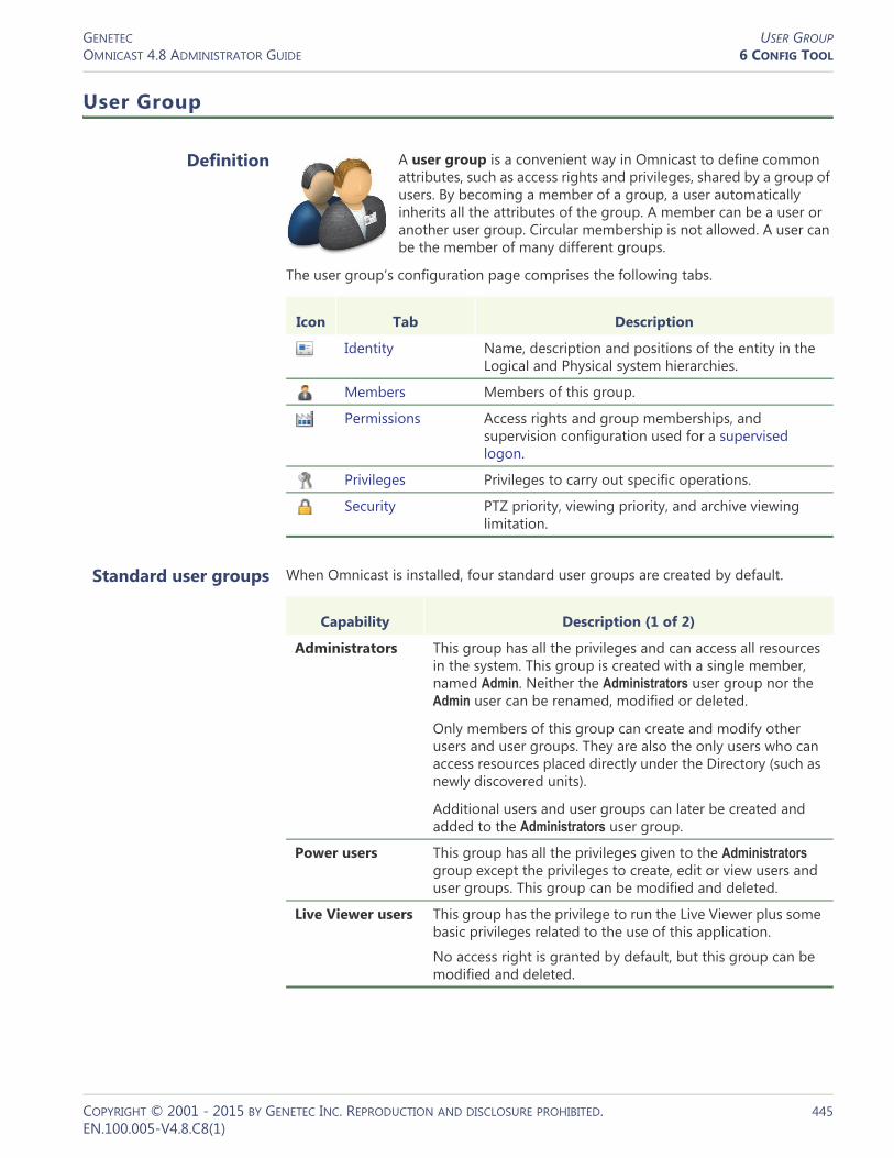
GENETEC USER GROUPOMNICAST 4.8 ADMINISTRATOR GUIDE 6 CONFIG TOOL
User Group
Definition
A user group is a convenient way in Omnicast to define common attributes, such as access rights and privileges, shared by a group of users. By becoming a member of a group, a user automatically inherits all the attributes of the group. A member can be a user or another user group. Circular membership is not allowed. A user can be the member of many different groups.
The user group’s configuration page comprises the following tabs.
Standard user groups When Omnicast is installed, four standard user groups are created by default.
Icon Tab Description
Identity Name, description and positions of the entity in the Logical and Physical system hierarchies.
Members Members of this group.
Permissions Access rights and group memberships, and supervision configuration used for a supervised logon.
Privileges Privileges to carry out specific operations.
Security PTZ priority, viewing priority, and archive viewing limitation.
Capability Description (1 of 2)
Administrators This group has all the privileges and can access all resources in the system. This group is created with a single member, named Admin. Neither the Administrators user group nor the Admin user can be renamed, modified or deleted.
Only members of this group can create and modify other users and user groups. They are also the only users who can access resources placed directly under the Directory (such as newly discovered units).
Additional users and user groups can later be created and added to the Administrators user group.
Power users This group has all the privileges given to the Administrators group except the privileges to create, edit or view users and user groups. This group can be modified and deleted.
Live Viewer users This group has the privilege to run the Live Viewer plus some basic privileges related to the use of this application.
No access right is granted by default, but this group can be modified and deleted.
COPYRIGHT © 2001 - 2015 BY GENETEC INC. REPRODUCTION AND DISCLOSURE PROHIBITED. 445EN.100.005-V4.8.C8(1)
GENETEC USER GROUPOMNICAST 4.8 ADMINISTRATOR GUIDE 6 CONFIG TOOL
Creating a user group manually
To create a new user group, do the following.1 Select User Management from the View selection pane. See View selection pane on
page 155.2 Click at the bottom of the View selection pane. A pop-up menu with the
entities you can create appears.3 Select User Group from the pop-up menu. A new entity named New user group
will be created.4 Enter an appropriate name for the new user group.
– Note that the user group name must be unique.– Use the Description field to further describe the group if necessary.
5 Select the Members tab and add members to the group. See Members on page 447.6 Select the Permissions tab and define the group’s access rights its membership to
other groups. See Permissions on page 448.7 Click the button on the lower right of the Configuration pane to
define who the user supervises, if necessary. See Supervised logon on page 424.8 Select the Privileges tab and grant privileges to the group. See Privileges on
page 449.9 Select the Security tab and expand or limit the privileges of the group. See Security
on page 450.
Archive Player users
This group has the privilege to run the Archive Player plus some basic privileges related to the use of this application.
No access right is granted by default, but this group can be modified and deleted.
Capability Description (2 of 2)
COPYRIGHT © 2001 - 2015 BY GENETEC INC. REPRODUCTION AND DISCLOSURE PROHIBITED. 446EN.100.005-V4.8.C8(1)
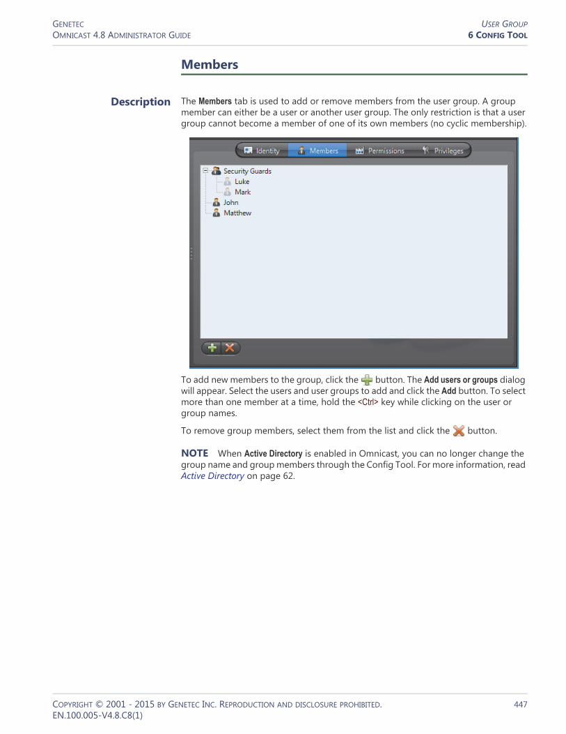
GENETEC USER GROUPOMNICAST 4.8 ADMINISTRATOR GUIDE 6 CONFIG TOOL
Members
Description The Members tab is used to add or remove members from the user group. A group member can either be a user or another user group. The only restriction is that a user group cannot become a member of one of its own members (no cyclic membership).
To add new members to the group, click the button. The Add users or groups dialog will appear. Select the users and user groups to add and click the Add button. To select more than one member at a time, hold the <Ctrl> key while clicking on the user or group names.
To remove group members, select them from the list and click the button.
NOTE When Active Directory is enabled in Omnicast, you can no longer change the group name and group members through the Config Tool. For more information, read Active Directory on page 62.
COPYRIGHT © 2001 - 2015 BY GENETEC INC. REPRODUCTION AND DISCLOSURE PROHIBITED. 447EN.100.005-V4.8.C8(1)

GENETEC USER GROUPOMNICAST 4.8 ADMINISTRATOR GUIDE 6 CONFIG TOOL
Permissions
Description The Permissions tab allows you to define the group's access rights, its memberships in other groups, and who it supervises.
The left pane shows the access rights and the right pane lists the user groups it belongs to. An access right granted to a group cannot be denied to its members.
The name in brackets indicates the group that the permission is inherited from.
The icon indicates a hidden site. See Hidden site on page 397.
For more details on access rights, permission inheritance and supervision used for supervised logon, see User – Permissions on page 422.
COPYRIGHT © 2001 - 2015 BY GENETEC INC. REPRODUCTION AND DISCLOSURE PROHIBITED. 448EN.100.005-V4.8.C8(1)

GENETEC USER GROUPOMNICAST 4.8 ADMINISTRATOR GUIDE 6 CONFIG TOOL
Privileges
Description The Privileges tab s used to view and configure the privileges of the user group.
A privilege granted to the group is automatically granted to all its members, but it can be denied to its members on an individual basis.
A privilege denied to the group is automatically denied to all its members, and it cannot be changed at the member level.
For more details on privileges, see User – Toggling the logon mode on page 430.
COPYRIGHT © 2001 - 2015 BY GENETEC INC. REPRODUCTION AND DISCLOSURE PROHIBITED. 449EN.100.005-V4.8.C8(1)

GENETEC USER GROUPOMNICAST 4.8 ADMINISTRATOR GUIDE 6 CONFIG TOOL
Security
Description The Security tab is only visible in Advanced mode. It pertains to parameters that can further expand or limit the actions of the group members.
For a description of the parameters you can set in this tab, please see User – Security on page 442.
COPYRIGHT © 2001 - 2015 BY GENETEC INC. REPRODUCTION AND DISCLOSURE PROHIBITED. 450EN.100.005-V4.8.C8(1)

GENETEC VIEWER LAYOUTOMNICAST 4.8 ADMINISTRATOR GUIDE 6 CONFIG TOOL
COPYRIGHT © 2001 - 2015 BY GENETEC INC. REPRODUCTION AND DISCLOSURE PROHIBITED. 451EN.100.005-V4.8.C8(1)
Viewer Layout
Definition
A viewer layout is a common screen definition for the Live Viewer that can be shared among different users. The viewer layout defines: (1) the tile pattern; (2) the displayed entity in each tile; and (3) the alarm state (armed or disarmed) of each tile. Viewer layouts can only be created and modified from the Live Viewer. See Viewer Layouts in the Omnicast Live Viewer User Guide.
The only viewer layout properties that can be changed in the Config Tool are its name and description. Therefore, only the Identity tab is available.
Layout ID Each viewer layout is assigned a layout ID (logical ID) so they can be easily referenced. The viewer layouts share the same pool of logical IDs with the cameras and virtual cameras.
Managing viewer layouts
Users with the Change layout selection privilege can modify the list of layouts displayed in their Live Viewer.
Users with the Edit/save layout configuration privilege can create and modify layout definitions.
When a user create a new viewer layout, they appear in the Logical View. To see them, make sure to set the visibility correctly. You can move them around in the Logical View to change their accessibility to users. See Logical View on page 161.
From the Config Tool, the administrator can assign layouts to users, without granting them the previous two privileges. This is done from the Live Viewer tab of the users’s configuration. See User – Live Viewer on page 439.
Icon Tab Description
Identity Name, description and positions of the entity in the Logical and Physical system hierarchies.

GENETEC VIRTUAL CAMERAOMNICAST 4.8 ADMINISTRATOR GUIDE 6 CONFIG TOOL
Virtual Camera
Definition
A virtual camera is a camera that is controlled by Omnicast through a conventional CCTV matrix. It differs from a camera directly controlled by Omnicast because it has no permanent connection to a video encoder. See Camera (Video Encoder) on page 237.
Virtual cameras are created automatically when hardware matrices are configured (See Hardware Matrix – Inputs on page 337).
The virtual camera’s configuration page comprises the following tabs.
WARNING Virtual cameras are viewed through the outputs of the CCTV matrix which are connected to video encoders. Because a CCTV matrix has typically more inputs than outputs, not all virtual cameras can be viewed at the same time.
To find out which user or application is currently viewing the virtual cameras, select the Connections tab of the corresponding Hardware Matrix.
To quickly locate the Hardware Matrix associated to a virtual camera, select the Identity tab of the camera and click the Find button besides its Physical parent. Virtual cameras
are shown directly under the hardware matrix in the Physical View.
Logical ID Virtual cameras share the same pool of logical IDs with cameras, Live Viewer plugins and viewer layouts. See Directory – Logical IDs on page 299.
Icon Tab Description
Identity Name, description and positions of the entity in the Logical and Physical system hierarchies.
Network Network properties.
COPYRIGHT © 2001 - 2015 BY GENETEC INC. REPRODUCTION AND DISCLOSURE PROHIBITED. 452EN.100.005-V4.8.C8(1)

GENETEC VIRTUAL CAMERAOMNICAST 4.8 ADMINISTRATOR GUIDE 6 CONFIG TOOL
Network
Description The Network tab allows you to choose the connection type used by the video encoder associated to the virtual camera.
Network information The following parameters are displayed for information purpose only.
Connection types This parameter is not applicable for virtual camera. For more information on connection types, see System Concepts – Network Connections on page 29.
Multicast address The Multicast address and Port number are assigned automatically by the system when the virtual camera is created. Each virtual camera is assigned a different multicast address with a fixed port number.
Normally, you do not need to be concerned with the multicast addresses. However, if for some reason you have to change the general settings of your Directory (see Server Admin – General settings on page 56), you may stop receiving video streams from the virtual cameras created before the change took place. If it is the case, you will have to
Parameter Description
Local IP address Address of the video encoder over the network.
NIC number Network adapter identifier used by the device in multicast.
UDP port Port number used when the connection type is unicast UDP.
COPYRIGHT © 2001 - 2015 BY GENETEC INC. REPRODUCTION AND DISCLOSURE PROHIBITED. 453EN.100.005-V4.8.C8(1)

GENETEC VIRTUAL CAMERAOMNICAST 4.8 ADMINISTRATOR GUIDE 6 CONFIG TOOL
change their multicast addresses accordingly. If you choose to use the same multicast address as another entity in the system, make sure that their port numbers are different.
NOTE All multicast addresses must be between the range 224.0.1.0 and 239.255.255.255. For these changes to be effective, you must reboot the unit. To do so, go to the Network tab of the corresponding unit and click the Reboot button. See Unit – Network on page 412.
COPYRIGHT © 2001 - 2015 BY GENETEC INC. REPRODUCTION AND DISCLOSURE PROHIBITED. 454EN.100.005-V4.8.C8(1)

GENETEC VIRTUAL MATRIXOMNICAST 4.8 ADMINISTRATOR GUIDE 6 CONFIG TOOL
Virtual Matrix
Definition
The Virtual Matrix (VM) is the Omnicast server application that provides all of the functionality that one expects from an traditional CCTV matrix without the hardware limitations associated with it. Unlike its hardware counterparts, the Virtual Matrix offers an infinite number of inputs/outputs. Through the Virtual Matrix, legacy hardware can be seamlessly integrated to the new IP solution.
The Virtual Matrix is required for the execution and control of the following entities:• Access control systems• Camera sequences• CCTV keyboards• Hardware matrices• Macros• Monitor groups• Virtual Matrix plugins
Multiple instances of Virtual Matrix may be running on the same system, but their use must be granted by the Number of Virtual Matrices option of your Omnicast license. See Server Admin – Directory options on page 47.
The Virtual Matrix‘s configuration page comprises the following tabs.
Being an Omnicast service, the machine specific parameters of the Virtual Matrix are configured with the Server Admin. See Virtual Matrix on page 150.
Icon Tab Description
Identity Name, description and positions of the entity in the Logical and Physical system hierarchies.
Statistics Various status and statistical information on entities controlled by this Virtual Matrix.
Plugins Plugins installed for this Virtual Matrix.
Actions Plugins installed for this Virtual Matrix.
Standby Virtual Matrices
Configure the current Virtual Matrix as backup for other Virtual Matrices on the system.
COPYRIGHT © 2001 - 2015 BY GENETEC INC. REPRODUCTION AND DISCLOSURE PROHIBITED. 455EN.100.005-V4.8.C8(1)

GENETEC VIRTUAL MATRIXOMNICAST 4.8 ADMINISTRATOR GUIDE 6 CONFIG TOOL
Statistics
Description The Statistics tab is divided in two sections. The top section allows you to execute and monitor macros and plugins defined in the system. The bottom section lists the CCTV equipment (Keyboard and Hardware matrix) currently controlled by the Virtual Matrix.
Executing macros and plugins
To execute a macro or a plugin, do the following.1 Click the Start macro button. The Select a macro or plugin dialog appears.2 Select the macro/plugin you wish to execute from the list and click OK. You may
start the same macro/plugin as many times as necessary.3 The started macro will be added to the macro list in the top section of the tab. The
Macro name, the Start time and the Current step it is executing will be indicated.4 Click to refresh the list.5 To stop a macro, select it from the list and click Stop .
Keyboard list Select the Keyboard tab to view the CCTV keyboards controlled by this Virtual Matrix.
Parameter Description
Keyboard name Name of the CCTV keyboard.
Keyboard status Keyboard status (either Connected or Disconnected).
Bytes received Number of bytes received from the keyboard. Click to refresh this value.
COPYRIGHT © 2001 - 2015 BY GENETEC INC. REPRODUCTION AND DISCLOSURE PROHIBITED. 456EN.100.005-V4.8.C8(1)

GENETEC VIRTUAL MATRIXOMNICAST 4.8 ADMINISTRATOR GUIDE 6 CONFIG TOOL
Hardware matrix list Select the Hardware matrix tab to view the list of hardware matrices controlled by this Virtual Matrix.
Parameter Description
Hardware matrix Name of the hardware matrix.
Serial port Serial port through which the Virtual Matrix sends control commands to the hardware matrix. See Hardware matrix users on page 335.
Status Hardware matrix status.
Bytes transmitted Number of bytes transmitted to the hardware matrix. Click to refresh this value.
Bytes received Number of bytes received from the hardware matrix. Click to refresh this value.
COPYRIGHT © 2001 - 2015 BY GENETEC INC. REPRODUCTION AND DISCLOSURE PROHIBITED. 457EN.100.005-V4.8.C8(1)

GENETEC VIRTUAL MATRIXOMNICAST 4.8 ADMINISTRATOR GUIDE 6 CONFIG TOOL
Plugins
Description The Plugins tab lists all the VM plugins controlled by this Virtual Matrix. Each plugin is identified by its Name, Type and its running State.
For a complete list of VM plugins supported by Omnicast, please refer About Omnicast plugin manuals on page iii.
Actions
Description The Actions tab allows you to program specific system behaviors based on the application events shown in the Events/actions list.
COPYRIGHT © 2001 - 2015 BY GENETEC INC. REPRODUCTION AND DISCLOSURE PROHIBITED. 458EN.100.005-V4.8.C8(1)

GENETEC VIRTUAL MATRIXOMNICAST 4.8 ADMINISTRATOR GUIDE 6 CONFIG TOOL
To learn about general event-to-actions programming, please refer to Event Management on page 22.
Standby Virtual Matrices
Description The Standby Virtual Matrices tab allows you to configure the current Virtual Matrix as a hot standby for other Virtual Matrices on the system.
COPYRIGHT © 2001 - 2015 BY GENETEC INC. REPRODUCTION AND DISCLOSURE PROHIBITED. 459EN.100.005-V4.8.C8(1)

GENETEC VIRTUAL MATRIXOMNICAST 4.8 ADMINISTRATOR GUIDE 6 CONFIG TOOL
Configuring the current VM as a
standby for another VM on the system
Before you begin, please ensure the following:• You have a license that supports Standby Virtual Matrices applied on your main
Directory server. It is not required to have it on the Directory failover server.• You have an additional Virtual Matrix service installed on another server on your
system to work as the standby. You can add one by performing a Custom server installation. For more information, see the Omnicast Installation and Upgrade Guide.
The configure a VM as a standby for another VM on the system, do the following.1 Select from the drop-down list, the VM for which the current VM should act as a
standby.– The entities controlled by the selected VM will be shown in the list below.– The ones that are selected are the ones for which the current VM is already
configured as a standby.2 Select the macro/plugin you wish to execute from the list and click OK.
You may start the same macro/plugin as many times as necessary.3 Select the ones for which you wish to protect with the current VM as a standby,
and clear the ones you do not want the current VM to protect.4 Click Apply to save the changes.
The current VM will be automatically added to the end of the failover list of the entities you selected, or removed from the failover list of the ones you cleared.If you wish to set the current Virtual Matrix as the master (or primary controller) of an entity, you must do so directly from the Standby Virtual Matrices tab of the entity you wish to affect.
COPYRIGHT © 2001 - 2015 BY GENETEC INC. REPRODUCTION AND DISCLOSURE PROHIBITED. 460EN.100.005-V4.8.C8(1)

GENETEC CUSTOMIZING THE CONFIG TOOLOMNICAST 4.8 ADMINISTRATOR GUIDE 7 ADVANCED FEATURES
COPYRIGHT © 2001 - 2015 BY GENETEC INC. REPRODUCTION AND DISCLOSURE PROHIBITED. 461EN.100.005-V4.8.C8(1)
Customizing the Config Tool
Options Dialog
Description The Options dialog box allows you to customize most of the Config Tool's behavior to suit your preferences. To open the Options dialog box:
– Select Tools > Options from the main menu.– Type <Ctrl>+<O>.
You must have the Change application options privilege before you can change any application settings. If you do not have this privilege, you can still use this dialog to view the current settings.
The dialog contains the following tabs:
Tab Description
See General Options on page 462.
See Network Options on page 464.
See Audio Options on page 466.
See User Interaction Options on page 467.
See Display Options on page 469.
See Date and Time Options on page 472.

GENETEC CUSTOMIZING THE CONFIG TOOLOMNICAST 4.8 ADMINISTRATOR GUIDE 7 ADVANCED FEATURES
General Options
Description
User logon dialog RESTRICT ACCESS TO CONNECTION PARAMETERS – Enable this feature to prevent the users from changing the Gateway in the Connect dialog. The next time a user starts a client application on this PC, the Gateway drop-down list will turn into a read-only field.
TIP If for some reason the connection parameters are invalidated because of a change in the system (e.g. the Gateway has been moved to a different PC) after you enabled this feature, users will no longer be able to connect to the system.To make the Gateway editable again, enter the username and password of an administrator and type <Ctrl>+<Shift>+<Enter>.
COPYRIGHT © 2001 - 2015 BY GENETEC INC. REPRODUCTION AND DISCLOSURE PROHIBITED. 462EN.100.005-V4.8.C8(1)

GENETEC CUSTOMIZING THE CONFIG TOOLOMNICAST 4.8 ADMINISTRATOR GUIDE 7 ADVANCED FEATURES
USE CURRENT WINDOWS CREDENTIALS BY DEFAULT – Enable this option to use Windows credentials for user logon. When this option is selected, the application will skip the Connect dialog and proceed immediately to logon with the current Windows credentials. The Active Directory must be enabled on the specified Omnicast Directory for this option to work. See Server Admin – Active Directory on page 62.
COPYRIGHT © 2001 - 2015 BY GENETEC INC. REPRODUCTION AND DISCLOSURE PROHIBITED. 463EN.100.005-V4.8.C8(1)
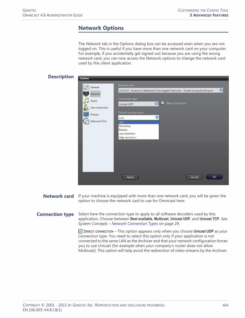
GENETEC CUSTOMIZING THE CONFIG TOOLOMNICAST 4.8 ADMINISTRATOR GUIDE 5 ADVANCED FEATURES
Network Options
The Network tab in the Options dialog box can be accessed even when you are not logged on. This is useful if you have more than one network card on your computer. For example, if you accidentally get signed out because you are using the wrong network card, you can now access the Network options to change the network card used by this client application.
Description
Network card If your machine is equipped with more than one network card, you will be given the option to choose the network card to use for Omnicast here.
Connection type Select here the connection type to apply to all software decoders used by this application. Choose between Best available, Multicast, Unicast UDP, and Unicast TCP. See System Concepts – Network Connection Types on page 29.
DIRECT CONNECTION – This option appears only when you choose Unicast UDP as your connection type. You need to select this option only if your application is not connected to the same LAN as the Archiver and that your network configuration forces you to use Unicast (for example when your company's router does not allow Multicast). This option will help avoid the redirection of video streams by the Archiver.
COPYRIGHT © 2001 - 2015 BY GENETEC INC. REPRODUCTION AND DISCLOSURE PROHIBITED. 464EN.100.005-V4.8.C8(1)

GENETEC CUSTOMIZING THE CONFIG TOOLOMNICAST 4.8 ADMINISTRATOR GUIDE 5 ADVANCED FEATURES
Default viewing stream
Select the default video stream to use when showing live video in preview window. See Camera – Video stream preview on page 247. The choices are:• Live
• Recording
• Remote
• Low resolution
• High resolution
The above choices may or may not be equivalent, depending on the capabilities of the video encoders used in your system. See Camera – Video stream usage on page 242.
The Live stream is the default selection at software installation.
The Recording stream is the one used by the Archivers.
The Remote stream is the recommended choice when the network bandwidth is limited, such as on a wireless or remote LAN.
The Low resolution and High resolution streams are used by the Live Viewer in Automatic mode. It is a mode where the Live Viewer chooses on its own the best stream to display based on the size of the viewing tile.
COPYRIGHT © 2001 - 2015 BY GENETEC INC. REPRODUCTION AND DISCLOSURE PROHIBITED. 465EN.100.005-V4.8.C8(1)
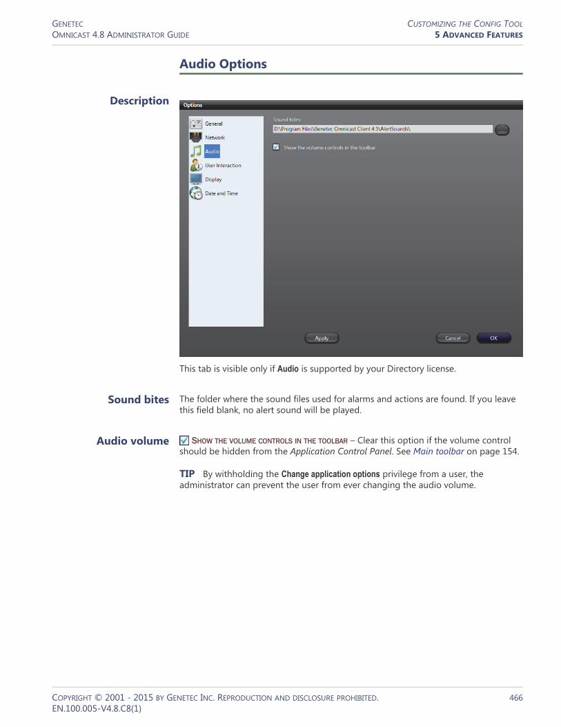
GENETEC CUSTOMIZING THE CONFIG TOOLOMNICAST 4.8 ADMINISTRATOR GUIDE 5 ADVANCED FEATURES
COPYRIGHT © 2001 - 2015 BY GENETEC INC. REPRODUCTION AND DISCLOSURE PROHIBITED. 466EN.100.005-V4.8.C8(1)
Audio Options
Description
This tab is visible only if Audio is supported by your Directory license.
Sound bites The folder where the sound files used for alarms and actions are found. If you leave this field blank, no alert sound will be played.
Audio volume SHOW THE VOLUME CONTROLS IN THE TOOLBAR – Clear this option if the volume control should be hidden from the Application Control Panel. See Main toolbar on page 154.
TIP By withholding the Change application options privilege from a user, the administrator can prevent the user from ever changing the audio volume.

GENETEC CUSTOMIZING THE CONFIG TOOLOMNICAST 4.8 ADMINISTRATOR GUIDE 5 ADVANCED FEATURES
User Interaction Options
Description
System messages SHOW MESSAGES, WARNINGS OR ERRORS – Select this option to prevent the application from showing any warning or error message. This option should be used when the application is running in an unattended mode. When this option is cleared, the next two options will be disabled. You have to restart the application for this option to take effect.
CLOSE AUTOMATICALLY MESSAGES, WARNINGS... – Select this option if you want the notification messages to be moved automatically to the notification message log if they are not acknowledged by the user after a given period of time. See Main toolbar on page 154.
PROMPT USER WHEN CPU USAGE IS ABOVE... – When the CPU is near its maximum capacity, attempting a CPU intensive operation (such as viewing a camera) can sometimes freeze the machine. To prevent this from happening, you can ask the system to prompt you for a confirmation before attempting any CPU intensive operation when the percentage of CPU usage is above a preset level. Select this option to turn this feature on. When you attempt a CPU intensive operation when the CPU usage is above the indicated threshold, the following message will appear.
COPYRIGHT © 2001 - 2015 BY GENETEC INC. REPRODUCTION AND DISCLOSURE PROHIBITED. 467EN.100.005-V4.8.C8(1)
GENETEC CUSTOMIZING THE CONFIG TOOLOMNICAST 4.8 ADMINISTRATOR GUIDE 5 ADVANCED FEATURES
Click Yes if you wish to ignore the warning, or click No to cancel the operation.
Selecting Never ask me that question again and clicking Yes turns this feature off.
When renaming a device
Rename all the devices linked to the camera – Select Yes to let the system rename automatically all devices linked to the camera that you are renaming; No to leave the linked devices unchanged; and Ask the user to ask you first before renaming the linked devices. See Camera – Links on page 275.
Rename all the devices inside the unit – Select Yes to let the system rename automatically all devices attached to the unit that you are renaming; No to leave the attached devices unchanged; and Ask the user to ask you first before renaming the attached devices. The devices attached to the unit are shown under the unit in the Physical view.
When moving a device Move all the devices linked to the camera – Select Yes to let the system move automatically all devices linked to the camera that you are moving in the Logical view; No to not move the linked devices; and Ask the user to ask you first before moving the linked devices. See Camera – Links on page 275.
COPYRIGHT © 2001 - 2015 BY GENETEC INC. REPRODUCTION AND DISCLOSURE PROHIBITED. 468EN.100.005-V4.8.C8(1)

GENETEC CUSTOMIZING THE CONFIG TOOLOMNICAST 4.8 ADMINISTRATOR GUIDE 5 ADVANCED FEATURES
Display Options
Description
Most of the display options are the same for all three client applications (Live Viewer, Archive Player and Config Tool). Changing the settings in one application will automatically change it for the other applications installed on the same machine.
Video options For the Config Tool, only the Live viewing options are configurable.
WAIT FOR VERTICAL BLANK – Turning this option on reduces the tearing effect where movements are shown in the video. The tearing effect is shown as jagged edges or blurred video around moving objects. This effect is noticeable only when the video is displayed in high resolutions (2cif or 4cif).
NOTE This option is only recommended for 2 GHz processors or faster, because it uses up more CPU.
COPYRIGHT © 2001 - 2015 BY GENETEC INC. REPRODUCTION AND DISCLOSURE PROHIBITED. 469EN.100.005-V4.8.C8(1)

GENETEC CUSTOMIZING THE CONFIG TOOLOMNICAST 4.8 ADMINISTRATOR GUIDE 5 ADVANCED FEATURES
Let's look at a concrete example. The picture below shows a 2cif video displayed on a 2 GHz machine with the Wait for vertical blank option turned off.
Notice how blurry the image is around the moving arms. Also notice the CPU gauge. Displaying this video on a 2 GHz machine hardly uses any CPU.
Now let's look at the same scene with the Wait for vertical blank feature turned on.
This time, the same moving arms look much sharper. Also notice that the application is using more CPU.
DEINTERLACING FILTER – This is another CPU intensive option to help reduce the jagged effect around straight lines during movement. This effect affects only high resolution videos (2cif or 4cif format).
DEBLOCKING FILTER – This is a third CPU intensive option to help reduce the appearance of blocks in low resolution videos (qcif and cif).
VIDEO MODE – Omnicast supports two video display modes: RGB and YUV. The latter mode is the preferred mode because it offers a performance gain of 20% to 30% over the default RGB mode. However, it is not supported by all video adapters.
COPYRIGHT © 2001 - 2015 BY GENETEC INC. REPRODUCTION AND DISCLOSURE PROHIBITED. 470EN.100.005-V4.8.C8(1)

GENETEC CUSTOMIZING THE CONFIG TOOLOMNICAST 4.8 ADMINISTRATOR GUIDE 5 ADVANCED FEATURES
The following is a list of video adapters that do support the YUV mode: • Matrox G450 or G550 • nVidia GeForce2 or better • ATI Radeon 7000 or better
TIP The surest way to know whether your video display adapter supports YUV or not is to test it. You must restart your application after changing the video mode. If the video is displayed correctly, then your video adapter supports the selected video mode. Sometimes, upgrading to the latest version of the device driver can fix some compatibility issues.
List of detected display adapters
This table lists all display adaptors installed on your PC. The type indicates whether the adapter supports single or multiple monitors.
COPYRIGHT © 2001 - 2015 BY GENETEC INC. REPRODUCTION AND DISCLOSURE PROHIBITED. 471EN.100.005-V4.8.C8(1)

GENETEC CUSTOMIZING THE CONFIG TOOLOMNICAST 4.8 ADMINISTRATOR GUIDE 5 ADVANCED FEATURES
COPYRIGHT © 2001 - 2015 BY GENETEC INC. REPRODUCTION AND DISCLOSURE PROHIBITED. 472EN.100.005-V4.8.C8(1)
Date and Time Options
Description
The Date and Time settings apply to all client applications. Changing a setting in one automatically affects the other applications installed on the same PC. Note that the date and time display format follows the Windows settings.
Device time zone DISPLAY BASED ON EACH DEVICE'S TIME ZONE – Each device in the system follows a specific time zone. Generally speaking, an application follows the time zone of the PC where it is running and all devices (units) follow the time zone of the application controlling it.
DISPLAY BASED ON THE FOLLOWING TIME ZONE – You can choose to display the time according to each entity's time zone or to display everything following a time zone of your choice. This change is effective immediately and affects all client applications.
Time zone abbreviations
DISPLAY TIME ZONE ABBREVIATIONS – Select this option to display the time zone abbreviation wherever time is displayed. Please refer to the Appendix for the time zone abbreviations used in Omnicast.

SECTION 7
TOOLS
User guides for various administrative tools

GENETECOMNICAST 4.8 ADMINISTRATOR GUIDE 7 TOOLS
Backup Tool
Overview The Backup Tool is designed to reduce the Omnicast administrator's work by taking care of two important routine tasks:• Regular backup of the Omnicast configuration databases.• Management of the backup files (zip files).
With the Backup Tool, you can back up all your Omnicast databases (DirectorySQL, AlarmSQL, VideoArchiveSQL, AuxiliaryArchiveSQL, and ObjectStore) and all associated registry keys to a single .zip file, that can be restored to your system at any time. This tool is useful when you need to upgrade your Omnicast system, because it allows you to keep your database information.
NOTE The Backup Tool is designed to restore data on the machine it is installed on. If you want to use the Backup Tool to restore data on a different machine, please contact Genetec Technical Assistance.
To start the Backup Tool:• In the Server Admin, click Tools > Backup.
The Backup Tool dialog box opens.
COPYRIGHT © 2001 - 2015 BY GENETEC INC. REPRODUCTION AND DISCLOSURE PROHIBITED. 474EN.100.005-V4.8.C8(1)

GENETECOMNICAST 4.8 ADMINISTRATOR GUIDE 7 TOOLS
Using the Backup Tool
Back up your system To back up your Omnicast databases and registry keys:1 Open the Backup Tool. See To start the Backup Tool: on page 474.2 In the Backup Folder field, select the path where you want your backup files.3 From the Version drop-down list, select one of the following:
– If you are backing up the databases and the registry, or a specific database, select Latest Version.
– If you are only backing up the registry, and it is from an older version of Omnicast, select the appropriate version.
4 Select the Omnicast databases and registry to back up.5 Click Backup.6 The OmniBackup.exe tool opens, and begins the backup.
– If the backup is successful, it says Backup succeeded under Current Status, and a .zip file is placed in the folder you specified.
– If the backup is unsuccessful, it says Backup failed under Current Status.
Restore your system To restore your databases and registry keys:1 Open the Backup Tool. See To start the Backup Tool: on page 474.1 Next to the Restore File field, click .2 Select a backup .zip folder to restore.
The .zip folder name includes the date and time the backup was performed.
NOTE All files contained in the .zip folder will be restored. If you do not want a certain database to be restored, you must first remove that file from the folder.
3 Click Open.4 Click Restore.
NOTE Your services will be restarted during the restore.
Automate the Backup Tool
You can configure the Omnicast Backup Tool to run as a Windows shceduled task. For more information, see the Backup Tool Release Notes.
COPYRIGHT © 2001 - 2015 BY GENETEC INC. REPRODUCTION AND DISCLOSURE PROHIBITED. 475EN.100.005-V4.8.C8(1)
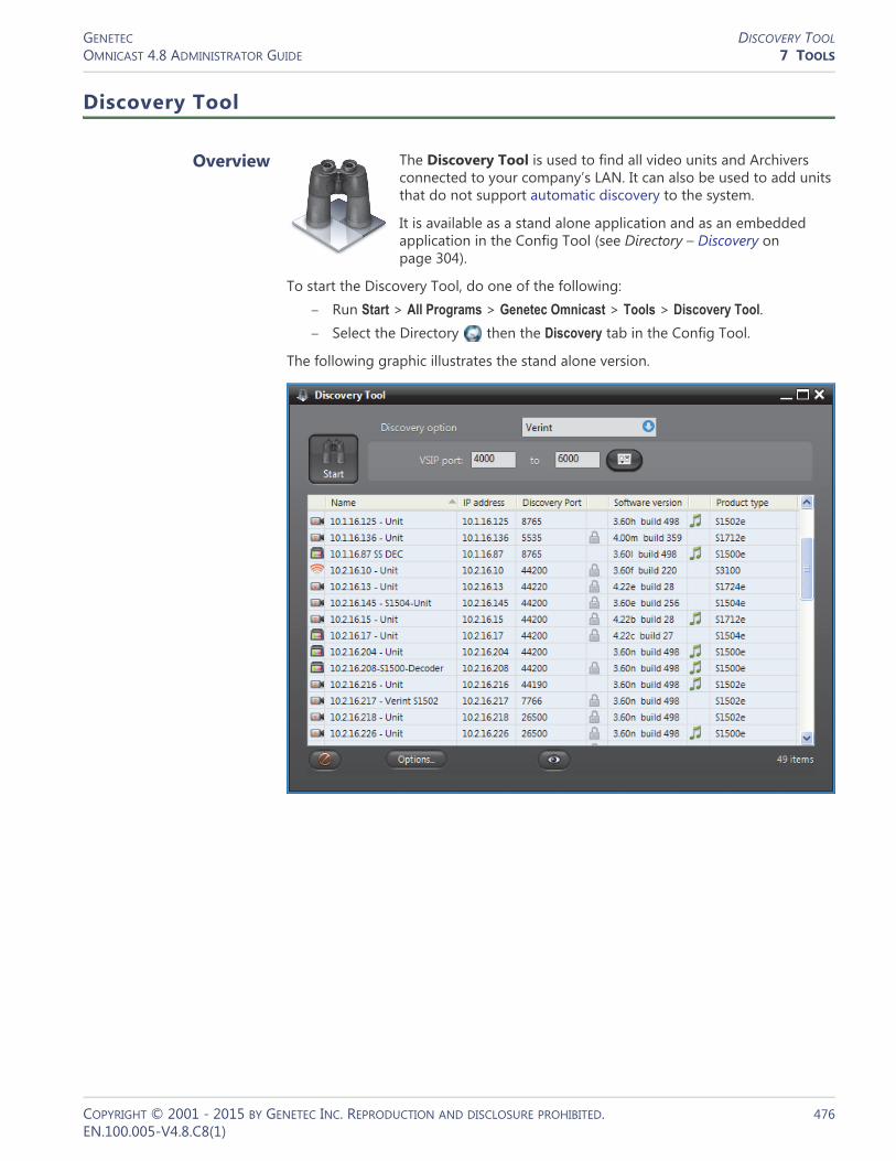
GENETEC DISCOVERY TOOLOMNICAST 4.8 ADMINISTRATOR GUIDE 7 TOOLS
Discovery Tool
Overview
The Discovery Tool is used to find all video units and Archivers connected to your company’s LAN. It can also be used to add units that do not support automatic discovery to the system.
It is available as a stand alone application and as an embedded application in the Config Tool (see Directory – Discovery on page 304).
To start the Discovery Tool, do one of the following:– Run Start > All Programs > Genetec Omnicast > Tools > Discovery Tool.– Select the Directory then the Discovery tab in the Config Tool.
The following graphic illustrates the stand alone version.
COPYRIGHT © 2001 - 2015 BY GENETEC INC. REPRODUCTION AND DISCLOSURE PROHIBITED. 476EN.100.005-V4.8.C8(1)

GENETEC DISCOVERY TOOLOMNICAST 4.8 ADMINISTRATOR GUIDE 7 TOOLS
Using the Discovery Tool
Performing a search To perform a search, do the following.1 Select a Discovery option.2 Specify the parameters according to selected option.
The parameters vary according to the selected option (follow the links).– ACTi on page 479– Archiver Extensions on page 480– Arecont on page 480– AXIS on page 480– Bosch on page 480– Interlogix CamPlus IP on page 481– Interlogix CamPlus 2 IP on page 482– Interlogix Megapixel on page 482– Interlogix MPEG-4 on page 482– Generic Plus on page 483– Genetec on page 483– IQinVision on page 483– Panasonic on page 483– Pelco on page 484– Sony on page 484– UPnP on page 484– Verint on page 484– Vivotek on page 485– Zero Configuration on page 485
3 Click the large Start button to start the discovery. While the application is still searching, the Start button will be replaced by the Stop button. Click it to interrupt the search.The discovered units will gradually appear in the result list. See Discovery Results on page 486.
4 Right-click the result list to pop the contextual menu. See Command menu on page 478.
5 Click a column heading to sort the results according to that column.6 Right-click any column heading to select the displayed columns. See Column
selection menu on page 486.7 Click to add the selected units. This button is only available in the embedded
version. See Config Tool – Directory – Discovery on page 304.
8 Click Options... to view or change the Discovery Tool options. See Options dialog on page 478.
9 Click to select the entity types to show in the result list.10 Click to clear the result list.
COPYRIGHT © 2001 - 2015 BY GENETEC INC. REPRODUCTION AND DISCLOSURE PROHIBITED. 477EN.100.005-V4.8.C8(1)

GENETEC DISCOVERY TOOLOMNICAST 4.8 ADMINISTRATOR GUIDE 7 TOOLS
Command menu Additional commands are available through a command pop-up menu.
Note that the Add Units command is only available in the embedded version.
Options dialog Click the Options button to show the Discovery Tool’s Options dialog.
Command Description
Change Discovery Port
Changes the discovery port of the selected units. It takes a few seconds for the change to take effect. If you are viewing the units in the Live Viewer, the video will disappear while the units reboot.
Change Command Port
Changes the command port of the selected units.
Change IP Address Changes the IP address of the selected unit (one at a time).
Reboot Reboot all selected units.
Identify Causes the status LED on either side of the selected units to flash very quickly in red for about 30 seconds. This feature is used to quickly find the physical units on a rack.
Add Units Adds the selected units to the Archiver of your choice. The selected Archiver will accept the units only if it is configured with the proper discovery ports. See Server Admin – Archiver Extensions on page 97.
For units that do not support automatic discovery, this is the only way to add them to an Archiver.
Clear Results Clears the result list.
Select Visible Entity Types
Allows you to select the types of units you wish to see in the result list. Same as the button.
COPYRIGHT © 2001 - 2015 BY GENETEC INC. REPRODUCTION AND DISCLOSURE PROHIBITED. 478EN.100.005-V4.8.C8(1)

GENETEC DISCOVERY TOOLOMNICAST 4.8 ADMINISTRATOR GUIDE 7 TOOLS
Your options are:
Discovery Options
ACTi This option lets you find all ACTi extensions and units on your network.
You must supply a range of discovery ports. A wider range may help you discover more units but will take more time.
Click the button to view the extra settings.
User authentication is only necessary if you wish to send commands to the units. It will not help you discover more units. See Command menu on page 478.
Under Search settings, the higher the value of Packets/sec, the faster the search will be. The default value is 1000. It is sometimes necessary to reduce the number of packets per second because some network switches are configured to block high traffic for
Option Description
Network card If your PC is equipped with more than one network card, you can select the card through which the discovery commands are sent.
Clear results before running a new search
Select this option to clear the result list before every new search. Clear this option to combine the results of multiple searches.
Search Archivers for each unit type
Select this option to include the Archiver extensions to the search results. Clear this option to show only the units.
COPYRIGHT © 2001 - 2015 BY GENETEC INC. REPRODUCTION AND DISCLOSURE PROHIBITED. 479EN.100.005-V4.8.C8(1)

GENETEC DISCOVERY TOOLOMNICAST 4.8 ADMINISTRATOR GUIDE 7 TOOLS
security reasons. By default, the ACTi units use a discovery reply port that is equal to the discovery port plus 1. If you have configured your units to always reply on the same port, you must select Use unique discovery reply port and enter the proper value.
Archiver Extensions This option lets you find all Archiver extensions and units on your network.
This search constitutes an excellent starting point if you do not know what is available on your LAN.
Arecont This option lets you find all Arecont extensions and units on your network.
You must enter a range of IP addresses. Proper user authentication is also necessary or you may not find anything. If you are not sure of the IP addresses your Arecont units use, it would be a good idea to try UPnP first.
AXIS This option lets you find all Axis extensions and units on your network.
You must enter a range of IP addresses and a HTTP port number. Proper user authentication is also necessary or you may not find anything. If you are not sure of the IP addresses and the port numbers your Axis units use, it would be a good idea to try UPnP first.
Bosch This option lets you find all Bosch extensions and units on your network.
You must supply a range of discovery ports. A wider range may help you discover more units but will take more time.
COPYRIGHT © 2001 - 2015 BY GENETEC INC. REPRODUCTION AND DISCLOSURE PROHIBITED. 480EN.100.005-V4.8.C8(1)
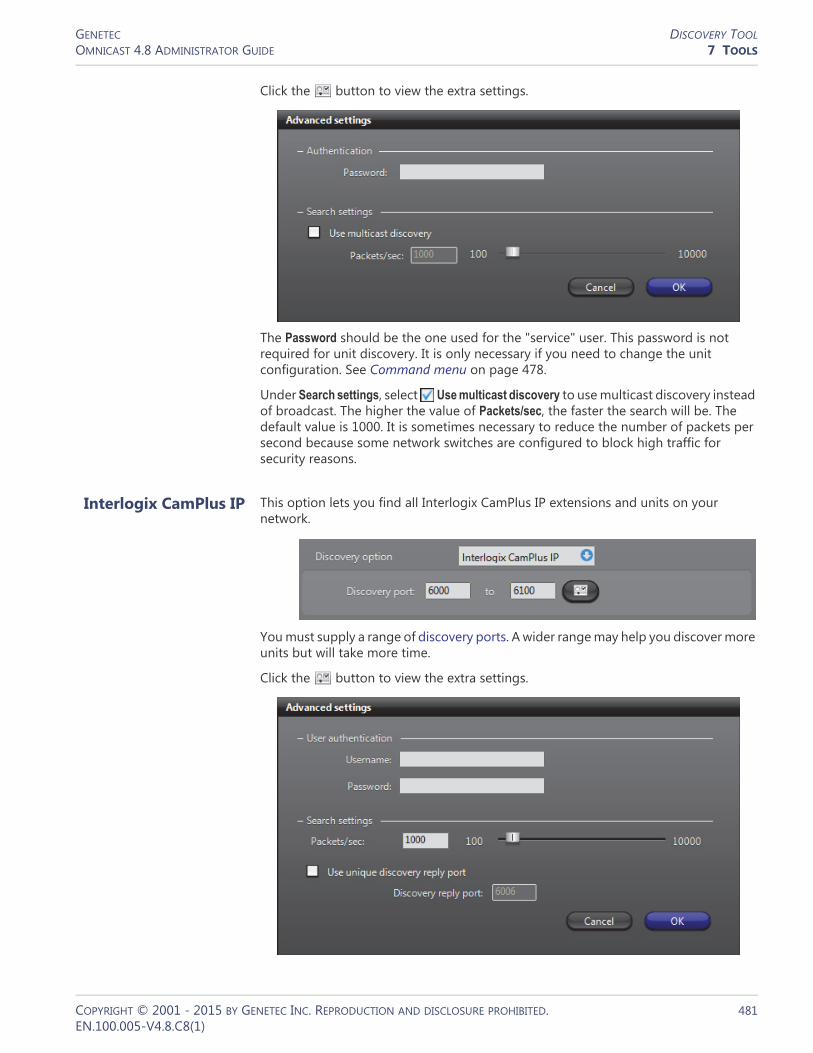
GENETEC DISCOVERY TOOLOMNICAST 4.8 ADMINISTRATOR GUIDE 7 TOOLS
Click the button to view the extra settings.
The Password should be the one used for the "service" user. This password is not required for unit discovery. It is only necessary if you need to change the unit configuration. See Command menu on page 478.
Under Search settings, select Use multicast discovery to use multicast discovery instead of broadcast. The higher the value of Packets/sec, the faster the search will be. The default value is 1000. It is sometimes necessary to reduce the number of packets per second because some network switches are configured to block high traffic for security reasons.
Interlogix CamPlus IP This option lets you find all Interlogix CamPlus IP extensions and units on your network.
You must supply a range of discovery ports. A wider range may help you discover more units but will take more time.
Click the button to view the extra settings.
COPYRIGHT © 2001 - 2015 BY GENETEC INC. REPRODUCTION AND DISCLOSURE PROHIBITED. 481EN.100.005-V4.8.C8(1)

GENETEC DISCOVERY TOOLOMNICAST 4.8 ADMINISTRATOR GUIDE 7 TOOLS
You must enter User authentication values for Interlogix CamPlus IP units to discover the units. See Command menu on page 478.
Interlogix CamPlus 2 IP
This option lets you find all Interlogix CamPlus 2 IP extensions and units on your network.
Select IP scan to search through a range of IP addresses and a HTTP port number. Proper user authentication is also necessary or you may not find anything. If you are not sure of the IP addresses and the port numbers your Interlogix CamPlus 2 IP units use, clear the IP scan option to search with broadcast.
Interlogix Megapixel This option lets you find all Interlogix Megapixel extensions and units on your network.
You must enter a range of IP addresses. Proper user authentication is also necessary or you may not find anything. If you are not sure of the IP addresses your Arecont units use, it would be a good idea to try UPnP first.
Interlogix MPEG-4 This option lets you find all Interlogix MPEG-4 extensions and units on your network.
You must supply a range of discovery ports. A wider range may help you discover more units but will take more time.
Click the button to view the extra settings.
If some Interlogix units are password protected, you will have to enter the proper Password to find them.
COPYRIGHT © 2001 - 2015 BY GENETEC INC. REPRODUCTION AND DISCLOSURE PROHIBITED. 482EN.100.005-V4.8.C8(1)

GENETEC DISCOVERY TOOLOMNICAST 4.8 ADMINISTRATOR GUIDE 7 TOOLS
Under Search settings, the higher the value of Packets/sec, the faster the search will be. The default value is 1000. It is sometimes necessary to reduce the number of packets per second because some network switches are configured to block high traffic for security reasons.
Generic Plus This option lets you find all Generic Plus extensions and units on your network.
You must select the unit driver for the units you want to discover.
Genetec This option lets you find all Genetec extensions and units on your network.
Select IP scan to search through a range of IP addresses and a HTTP port numbers. Proper user authentication is also necessary or you may not find anything. If you are not sure of the IP addresses and the port numbers your Genetec units use, clear the IP scan option to search with broadcast.
IQinVision This option lets you find all IQinVision extensions and units on your network.
Select IP scan to search through a range of IP addresses and a HTTP port numbers. Proper user authentication is also necessary or you may not find anything. If you are not sure of the IP addresses and the port numbers your IQinVision units use, clear the IP scan option to search with broadcast.
Panasonic This option lets you find all Panasonic extensions and units on your network.
Select IP scan to search through a range of IP addresses and a HTTP port numbers. Proper user authentication is also necessary or you may not find anything. If you are not sure of the IP addresses and the port numbers your Panasonic units use, clear the IP scan option to search with broadcast.
COPYRIGHT © 2001 - 2015 BY GENETEC INC. REPRODUCTION AND DISCLOSURE PROHIBITED. 483EN.100.005-V4.8.C8(1)

GENETEC DISCOVERY TOOLOMNICAST 4.8 ADMINISTRATOR GUIDE 7 TOOLS
Pelco This option lets you find all Pelco extensions and units on your network.
Since these units are discovered using Pelco’s implementation of UPnP, you do not have to enter an IP range.
NOTE Pelco units cannot be discovered using the UPnP discovery option.
Sony This option lets you find all Sony extensions and units on your network.
Use the authentication button to specify the "service" username and password if necessary. Note that this authentication is not required for unit discovery. It is only necessary if you need to change the unit configuration. See Command menu on page 478.
UPnP The UPnP option is designed to find units that support the Universal Plug and Play protocol.
It is only available under Windows XP or more recent versions of Windows. This discovery method runs very fast, therefore, it is recommended to try it first if you are not sure where to find the units. For a complete identification of the units, the discovery parameters for the other unit types must be properly configured. Otherwise, the discovered units will be of unknown type.
Verint This option lets you find all Verint extensions and units on your network.
COPYRIGHT © 2001 - 2015 BY GENETEC INC. REPRODUCTION AND DISCLOSURE PROHIBITED. 484EN.100.005-V4.8.C8(1)

GENETEC DISCOVERY TOOLOMNICAST 4.8 ADMINISTRATOR GUIDE 7 TOOLS
To discover Verint extensions and units on your LAN, you must supply a VSIP port range. If some Verint units have SSL enabled, you must also provide a CA certificate and a SSL password through the Advanced settings dialog (click the button).
Under Search settings, select the option Use discovery port range only if you have very old Verint units (such as the S1500-T4) on your system that do not support the unique discovery port. The higher the value of Packets/sec, the faster the search will be. The default value is 1000. It is sometimes necessary to reduce the number of packets per second because some network switches are configured to block high traffic for security reasons.
Select Use multicast discovery if your network supports multicast. It will reduce the bandwidth usage for the search.
Select Use unicast replies if your network switches do not support broadcast on certain subnets.
Vivotek This option lets you find all Vivotek extensions and units on your network.
You must enter a range of IP addresses and a HTTP port number. Proper user authentication is also necessary or you may not find anything. If you are not sure of the IP addresses your Vivotek units use, it would be a good idea to try UPnP first.
Zero Configuration This option is designed to find units that support the Zero Configuration protocol.
COPYRIGHT © 2001 - 2015 BY GENETEC INC. REPRODUCTION AND DISCLOSURE PROHIBITED. 485EN.100.005-V4.8.C8(1)

GENETEC DISCOVERY TOOLOMNICAST 4.8 ADMINISTRATOR GUIDE 7 TOOLS
Several unit types support this protocol. For a complete identification of the units, the discovery parameters for the other unit types must be properly configured. Otherwise, the discovered units will be of unknown type.
Discovery Results
Result list The discovery results are described by the following columns.
– Click a column heading to sort the results according to that column.– Right-click any column heading to pop the column selection menu.– Right-click the result list to pop the command menu.
Column selection menu
Right-clicking any column heading pops the column selection menu.
You can show or hide a given column from the result list by clicking in the selection box beside each column name.
Column Description
Entity type The discovered entity type is represented by an icon.
Name Name of the discovered entity.
IP Address IP address of the discovered entity.
Discovery port Discovery port for the unit. Sorting the results on this column groups the units belonging to the same Archiver together.
Security Protocol A icon in this column means the unit supports SSL or SSL/HTTPS.
Software version For a unit, this value represents the firmware version. For an Archiver, it represents the Omnicast software version.
Audio A icon in this column means the unit supports audio.
Product type The model name of the unit.
COPYRIGHT © 2001 - 2015 BY GENETEC INC. REPRODUCTION AND DISCLOSURE PROHIBITED. 486EN.100.005-V4.8.C8(1)

GENETEC DISCOVERY TOOLOMNICAST 4.8 ADMINISTRATOR GUIDE 7 TOOLS
The following columns are hidden by default.• Command port
• Hardware version
• GUID (global unique identifier)
COPYRIGHT © 2001 - 2015 BY GENETEC INC. REPRODUCTION AND DISCLOSURE PROHIBITED. 487EN.100.005-V4.8.C8(1)

GENETEC MACRO EDITOROMNICAST 4.8 ADMINISTRATOR GUIDE 7 TOOLS
Macro Editor
Overview
The Macro Editor allows you to write macros for the Omnicast Virtual Matrix. You can write and test macros from within the application.
To start the Macro Editor, choose run Start > All Programs > Genetec Omnicast > Tools > Macro Editor.
The Macro Editor is like four tools in one.1 A code editor, equivalent to the one found in the Config Tool.
See Macro – Code on page 349. 2 A script monitor, equivalent to the one found in the Config Tool.
See Virtual Matrix – Statistics on page 456. 3 A debugger. Syntax errors are indicated with the line and column numbers when
running the script. See Using the Macro Editor on page 489.4 An event monitor, similar to the event list found in the Live Viewer. See Event
Monitoring in Omnicast Live Viewer User Guide.
Prerequisites The Macro Editor can only edit macros defined in Omnicast. This is why the tool must be connected to a Directory. To connect the Macro Editor to a Directory, you must have the Macro Editor privilege. See User – Toggling the logon mode on page 430.
To create a new macro, click the New macro button or follow the procedure defined in Config Tool – Macro – Creating a macro on page 341.
COPYRIGHT © 2001 - 2015 BY GENETEC INC. REPRODUCTION AND DISCLOSURE PROHIBITED. 488EN.100.005-V4.8.C8(1)
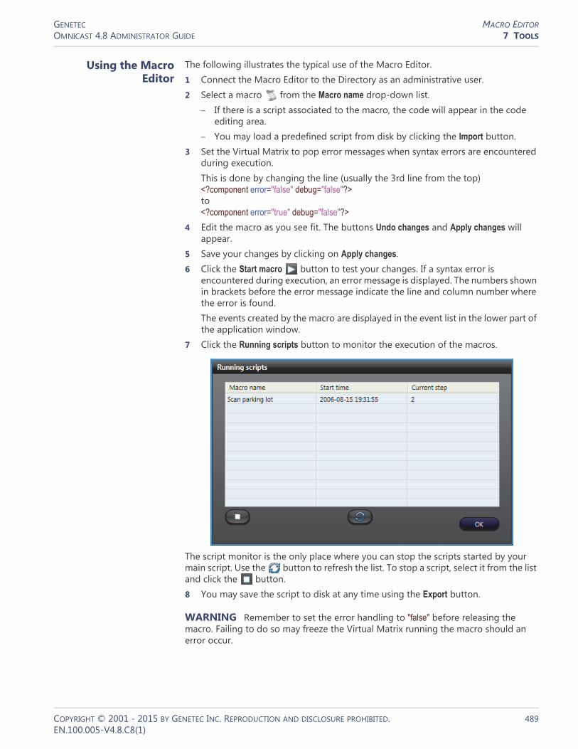
GENETEC MACRO EDITOROMNICAST 4.8 ADMINISTRATOR GUIDE 7 TOOLS
Using the Macro Editor
The following illustrates the typical use of the Macro Editor.1 Connect the Macro Editor to the Directory as an administrative user.2 Select a macro from the Macro name drop-down list.
– If there is a script associated to the macro, the code will appear in the code editing area.
– You may load a predefined script from disk by clicking the Import button.3 Set the Virtual Matrix to pop error messages when syntax errors are encountered
during execution.This is done by changing the line (usually the 3rd line from the top) <?component error="false" debug="false"?> to <?component error="true" debug="false"?>
4 Edit the macro as you see fit. The buttons Undo changes and Apply changes will appear.
5 Save your changes by clicking on Apply changes.6 Click the Start macro button to test your changes. If a syntax error is
encountered during execution, an error message is displayed. The numbers shown in brackets before the error message indicate the line and column number where the error is found.The events created by the macro are displayed in the event list in the lower part of the application window.
7 Click the Running scripts button to monitor the execution of the macros.
The script monitor is the only place where you can stop the scripts started by your main script. Use the button to refresh the list. To stop a script, select it from the list and click the button.8 You may save the script to disk at any time using the Export button.
WARNING Remember to set the error handling to "false" before releasing the macro. Failing to do so may freeze the Virtual Matrix running the macro should an error occur.
COPYRIGHT © 2001 - 2015 BY GENETEC INC. REPRODUCTION AND DISCLOSURE PROHIBITED. 489EN.100.005-V4.8.C8(1)

GENETEC REPORT VIEWEROMNICAST 4.8 ADMINISTRATOR GUIDE 7 TOOLS
Report Viewer
Overview
The Report Viewer is an easy to use reporting tool that offers nine standard reports for the administrator to monitor various aspects of the system. All reports can be customized by sort options and filters.
To start the Report Viewer, choose run Start > All Programs > Genetec Omnicast > Tools > Report Viewer.
Prerequisites
In order to generate reports with the Report Viewer, you will require the following:• Database reporting must be supported by your Omnicast license.• In the Logging tab of the Directory entity in the Server Admin, the Enable
database logging option must be selected, and the Database specified must be ReportingSQL.See Server Admin – Directory – Database logging on page 60.
• To open the Report Viewer, you must have access to the ReportingSQL database. There are two ways the you can connect to the database:– Windows Authentication– SQL Authentication
COPYRIGHT © 2001 - 2015 BY GENETEC INC. REPRODUCTION AND DISCLOSURE PROHIBITED. 490EN.100.005-V4.8.C8(1)
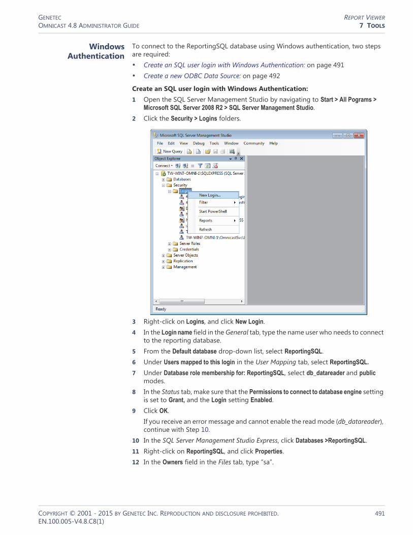
GENETEC REPORT VIEWEROMNICAST 4.8 ADMINISTRATOR GUIDE 7 TOOLS
Windows Authentication
To connect to the ReportingSQL database using Windows authentication, two steps are required:• Create an SQL user login with Windows Authentication: on page 491• Create a new ODBC Data Source: on page 492
Create an SQL user login with Windows Authentication:1 Open the SQL Server Management Studio by navigating to Start > All Pograms >
Microsoft SQL Server 2008 R2 > SQL Server Management Studio.2 Click the Security > Logins folders.
3 Right-click on Logins, and click New Login. 4 In the Login name field in the General tab, type the name user who needs to connect
to the reporting database.5 From the Default database drop-down list, select ReportingSQL.6 Under Users mapped to this login in the User Mapping tab, select ReportingSQL.
7 Under Database role membership for: ReportingSQL, select db_datareader and public modes.
8 In the Status tab, make sure that the Permissions to connect to database engine setting is set to Grant, and the Login setting Enabled.
9 Click OK.If you receive an error message and cannot enable the read mode (db_datareader), continue with Step 10.
10 In the SQL Server Management Studio Express, click Databases >ReportingSQL.11 Right-click on ReportingSQL, and click Properties.12 In the Owners field in the Files tab, type “sa”.
COPYRIGHT © 2001 - 2015 BY GENETEC INC. REPRODUCTION AND DISCLOSURE PROHIBITED. 491EN.100.005-V4.8.C8(1)

GENETEC REPORT VIEWEROMNICAST 4.8 ADMINISTRATOR GUIDE 7 TOOLS
Create a new ODBC Data Source:1 Navigate to Control Panel/Administrative Tools/Data Sources (ODBC).2 In the System DSN tab, click Add.3 Select the SQL Server option, and click Finish.
The Create a new Data Source to SQL Server dialog box opens.
4 Type a name and description for the new ODBC data source.5 From the Server drop-down list, select the server you want to connect to (should
be in the format Remote_Server_Name\Omnicast).6 Click Next.7 Under How should SQL Server verify the authenticity of the login ID, select With
Windows NT authentication using the network login ID.8 Deselect the option Connect to the SQL Server to obtain default settings for the additional
configuration options.9 Click Next.10 Select the Change the default database to option, and select the ReportingSQL
database.11 Click Finish.12 To verify the new data source ODBC configuration, click Test Data Source.
You should get a message saying “TESTS COMPLETED SUCCESSFULLY”.
You can now connect to the ReportingSQL Database using a Windows Authentication.
COPYRIGHT © 2001 - 2015 BY GENETEC INC. REPRODUCTION AND DISCLOSURE PROHIBITED. 492EN.100.005-V4.8.C8(1)

GENETEC REPORT VIEWEROMNICAST 4.8 ADMINISTRATOR GUIDE 7 TOOLS
SQL Authentication To connect to the ReportingSQL database using SQL authentication, two steps are required:• Create an SQL user login with SQL Authentication: on page 493• Create a new ODBC Data Source: on page 493
Create an SQL user login with SQL Authentication:1 Open the SQL Server Management Studio Express by navigating to Start > All
Pograms > Microsoft SQL Server 2008 R2 > SQL Server Management Studio.2 Click the Security > Logins folders.3 Right-click on Logins, and click New Login. 4 In the Login name field in the General tab, type the name user who needs to connect
to the reporting database.5 Under Login name, select SQL Server authentication, and create a password.6 To use the Crystal Reports template packaged in Omnicast, repeat Step 1 to Step
3 to create a second user, and do the following:– In the Login name field in the General tab, type mbrochu.– Under Login name, select SQL Server authentication, but leave the Password field
blank.You now have two new SQL user logins.
7 To go Step 5 and follow the rest of the procedure from “Create an SQL user login with Windows Authentication”.
Create a new ODBC Data Source:1 Navigate to Control Panel/Administrative Tools/Data Sources (ODBC).2 In the System DSN tab, click Add.3 Select the SQL Server option, and click Finish.4 Type a name and description for the new ODBC data source.5 From the Server drop-down list, select the server you want to connect to (eg.
Remote_Server_Name\Omnicast).6 Click Next.7 Under How should SQL Server verify the authenticity of the login ID, select With SQL
Server authentication using a login ID and password.
8 Under the option Connect to the SQL Server to obtain default settings for the additional configuration options, type the user login ID and password you created in the previous procedure.
9 Click Next.
You can now connect to the ReportingSQL Database using an SQL Authentication.
COPYRIGHT © 2001 - 2015 BY GENETEC INC. REPRODUCTION AND DISCLOSURE PROHIBITED. 493EN.100.005-V4.8.C8(1)

GENETEC REPORT VIEWEROMNICAST 4.8 ADMINISTRATOR GUIDE 7 TOOLS
Using the Report Viewer
To generate a report, do the following.1 Start the Report Viewer.2 Select Report > Open from the application menu. You will be presented with a
choice of standard report models.
3 Select the model you want and click Open. Note that if a report is already open, you must close it first before you can open another one. See Standard Report Models on page 497.
4 Select a date range. The date range is a common filter for all report models. This filter helps you avoid to browse the entire database.
To remove a date range criterion, clear the corresponding check box.5 Click OK to start the report generation.
If the report is taking too much time to appear, it is probably because your selection criteria are too broad. Click the button in the toolbar to stop the report generation. The report will appear with the data gathered so far.
COPYRIGHT © 2001 - 2015 BY GENETEC INC. REPRODUCTION AND DISCLOSURE PROHIBITED. 494EN.100.005-V4.8.C8(1)

GENETEC REPORT VIEWEROMNICAST 4.8 ADMINISTRATOR GUIDE 7 TOOLS
If you cannot generate a report and you receive an error message saying “The user is not associated with a trusted SQL Server connection”, do the following:1 In the Microsoft SQL Server Management Studio, right-click on the server, and click
Properties.2 In the Security tab, select SQL Server and Windows Authentification mode.
Report Customization
Adding filters To add a new filter, do the following.1 Click the button to open the Select Expert dialog.2 Select the <New> tab and select the field on which you wish to apply the filter. A
new tab will be added to the Select Expert dialog.
3 Select the comparison operator and the value it should be compared to.4 Repeat Step 2 and 3 as many times as necessary.5 Click OK when you are finished.
Text search Click the button to search for a particular text in the report. The field in which the text is found will be circled in red. A new tab will be added to the Select Expert dialog.
Changing the report properties
Select Report > Properties from the application menu. The following dialog appears.
The Report properties dialog lets you change the document title, the author name, and the comment. The title and the author will appear in the report heading. The comment appears at to the end of the report.
COPYRIGHT © 2001 - 2015 BY GENETEC INC. REPRODUCTION AND DISCLOSURE PROHIBITED. 495EN.100.005-V4.8.C8(1)

GENETEC REPORT VIEWEROMNICAST 4.8 ADMINISTRATOR GUIDE 7 TOOLS
Changing the sort option
Select Report > Sort Expert from the application menu. The following dialog appears.
The Sort Expert lists all available fields in the selected report. To sort by a particular field, select it and click on the right arrow to add it to the sort fields. Please do not forget to specify the sort direction (Ascending or Descending) for each selected field.
The sort can be based on multiple fields. Use the up and down arrows to change the priority of the sorted fields.
When you finished, click Apply. The Report Viewer will then regenerate the report based on the new sort criteria.
Export, refresh and print
Click the button to export the report to another document.
The available formats that you can choose from are: Acrobat, Crystal Report, Excel, Word, etc.
Note that the format Crystal Reports (RPT) is used to saves your report as a new template. It can later be used to generate new reports with fresh data.
Click the button to refresh the report content.
Click the button to print the report.
TIP If you do not find certain expected log entries in your report, check your choice of logging filters in Server Admin. By default, the system does not log user actions. See Directory – Database logging on page 60.
COPYRIGHT © 2001 - 2015 BY GENETEC INC. REPRODUCTION AND DISCLOSURE PROHIBITED. 496EN.100.005-V4.8.C8(1)

GENETEC REPORT VIEWEROMNICAST 4.8 ADMINISTRATOR GUIDE 7 TOOLS
Standard Report Models
The standard reports models are:• Application Failure Report on page 497• Entity Configuration Report on page 497• Entity Connection (by Entity) Report on page 498• Entity Connection (by User) Report on page 498• Equipment Failure Report on page 498• System Monitoring Report on page 498• User Configuration Report on page 499• User Logon Report on page 499• User Tracking Report on page 499
Application Failure Report
This report tracks all major incidents affecting the server applications, such as startup, shutdown, backup failures, etc. This report comprises the following columns:• Machine – Machine where the server application is running• Entity type – Application name• Time – Date and time of the event• Event type – Event type (Application logon, Application logoff, Application lost)• Affected service – Applicable only to Application lost event. Indicates the application
that was lost, detected by the Directory• Description – Details of the event when applicable
Entity Configuration Report
This report tracks all changes to the entity configurations made by human users, except the changes to user configurations. The latter are tracked separately in the User Configuration Report. This report comprises the following columns:• Initiator – User or application that made the change• Time – Date and time of the event• Action – Action type (creation, modification, deletion)• Entity type – Type of the affected entity• Entity name – Name of the affected entity• Description – Description of the change
COPYRIGHT © 2001 - 2015 BY GENETEC INC. REPRODUCTION AND DISCLOSURE PROHIBITED. 497EN.100.005-V4.8.C8(1)
GENETEC REPORT VIEWEROMNICAST 4.8 ADMINISTRATOR GUIDE 7 TOOLS
Entity Connection (by Entity) Report
This report shows all cameras viewed by a user during the selected date range, sorted by camera name. This report comprises the following columns:• Entity name – Entity name and logical ID• Time – Date and time of the event• User name – User name• Machine – Machine from which the user was running the application• Application – Application used (Live Viewer or Config Tool)• User action – Type of user action (see Entity type, Entity name and Description)• Entity type – Entity type (camera, microphone, etc.)• Description – Details of the user action
Entity Connection (by User) Report
This report shows all user who viewed a camera during the selected date range, sorted by user name. This report comprises the following columns:• User name – User name• Time – Date and time of the event• Machine – Machine from which the user was running the application• Application – Application used (Live Viewer or Config Tool)• User action – Type of user action (see Entity type, Entity name and Description)• Entity type – Entity type (camera, microphone, etc.)• Entity name – Entity name and logical ID• Description – Details of the user action
Equipment Failure Report
This report tracks all occurrences of equipment failures (unit lost/discovered, signal loss, etc.). This report comprises the following columns:• Entity name – Entity name• Time – Date and time of the event• Event type – Event type (Application logon, Application logoff, Application lost)• Description – Additional details when applicable
System Monitoring Report
This report is used to monitor all system activities (i.e. not initiated by human users), such as unit discovery, automatic start/stop recording, backup start/stop, file deletion, etc.). This report comprises the following columns:• Machine – Machine where the server application is running• Application – Server application that generated the event• Time – Date and time of the event• System action – Event type or action, depending on the circumstances• Entity type – Type of the affected entity (unit, camera, alarm, etc.)• Entity name – Name of the affected entity• Description – Additional details when applicable
COPYRIGHT © 2001 - 2015 BY GENETEC INC. REPRODUCTION AND DISCLOSURE PROHIBITED. 498EN.100.005-V4.8.C8(1)

GENETEC REPORT VIEWEROMNICAST 4.8 ADMINISTRATOR GUIDE 7 TOOLS
User Configuration Report
This report tracks all user configuration actions: user creation/deletion/renaming, modifications to user properties, privileges, permissions and password change. This report comprises the following columns:• Initiator – User or application that made the change• Time – Date and time of the event• Action – Type of user action (see Entity type, Entity name and Description)• Affected user – Name of the user being created, modified or deleted• Description – Description of the change
User Logon Report This report tracks all user logon and logoff events. The report shows who are using the system, when they are using it and for how long. This report comprises the following columns:• User name – User name• Time – Date and time of the event• Machine – Machine from which the user was running the application• Application – Application used (Live Viewer, Archive Player or Config Tool)• Action – Logon succeeded, Logon failed, or Logoff• Description – Reason in the case of a logon failure or supervisor’s user name in the
case of a supervised logon
User Tracking Report This report tracks all user actions (view cameras, start/stop recording, add bookmark, playback, export, etc.). User and entity configuration actions are excluded. They are respectively shown in the User Configuration Report and the Entity Configuration Report. This report comprises the following columns:• User name – User name• Time – Date and time of the event• Machine – Machine from which the user was running the application• Application – Application used (Live Viewer, Archive Player or Config Tool)• User action – Type of user action (see Entity type, Entity name and Description)• Entity type – Entity type (camera, microphone, etc.)• Entity name – Entity name and logical ID• Description – Details of the user action
COPYRIGHT © 2001 - 2015 BY GENETEC INC. REPRODUCTION AND DISCLOSURE PROHIBITED. 499EN.100.005-V4.8.C8(1)

GENETEC REPORT TOOLOMNICAST 4.8 ADMINISTRATOR GUIDE 7 TOOLS
Report Tool
Overview The Report Tool is a simple tool used for database reporting. It takes a snapshot of the Omnicast Directory database, and generates a report of selected Omnicast entities, such as users, cameras, alarms, and so on.
The results of the report can also be saved locally as a .zip folder, and sent to Genetec Technical Assistance for system status troubleshooting.
NOTE You should run the Report Tool on the server computer, as it only takes a snapshot of the local computer files. That way, you ensure that all Directory database information is included in the report.
Prerequisites To use the Report Tool, you will require the following:• The Report Viewer must be installed on the same computer. See Report Viewer on
page 490.• You must know the following:
– Omnicast Database Server name– Omnicast Directory Database name
NOTE You can find this information in the General tab of the Directory entity in the Server Admin. See General on page 55.
COPYRIGHT © 2001 - 2015 BY GENETEC INC. REPRODUCTION AND DISCLOSURE PROHIBITED. 500EN.100.005-V4.8.C8(1)

GENETEC REPORT TOOLOMNICAST 4.8 ADMINISTRATOR GUIDE 7 TOOLS
Using the Report Tool
To start the Report Tool, do one of the following:• Open the OmnicastReport.exe, located on your Omnicast installation DVD, in
Tools\Free Omnicast Tools\Omnicast Report.• Download the Omnicast Report Tool from GTAP, in Tools > Utilities, and open the
OmnicastReport.exe from the .zip folder.
NOTE You’ll need a username and password to log on to GTAP.
COPYRIGHT © 2001 - 2015 BY GENETEC INC. REPRODUCTION AND DISCLOSURE PROHIBITED. 501EN.100.005-V4.8.C8(1)

GENETEC REPORT TOOLOMNICAST 4.8 ADMINISTRATOR GUIDE 7 TOOLS
Configure the Report Tool
To configure the Report Tool:1 In the Report generator, click the Configurations button.
The Report generator configurations window opens.
2 In the Database server name field, type the Directory database server name, or click Get server name from registry.
3 In the Database name field, type the Directory database name, or click Get database name from registry.
4 In the Omnicast version field, type your Omnicast software version, or click Get latest version in registry.
5 To set a maximum time for the report to query, select a value (seconds) in the Timeout after field.
6 To change the results display, do the following:– Set the Zoom mode to PageWidth, Full page, or Percent.
If you choose Percent, you must also select a Zoom percent value (%).– Set the Display mode to Normal or Print layout.
7 If you want to contract the information underneath each entity in the results, select the Auto hide entity data option.
8 To change how camera, inventory, and PTZ entities are sorted in the results, (for example, by name or IP address) select the sorting types you want for each entity under the Report sort section.
9 Click Apply, and click OK.
COPYRIGHT © 2001 - 2015 BY GENETEC INC. REPRODUCTION AND DISCLOSURE PROHIBITED. 502EN.100.005-V4.8.C8(1)

GENETEC REPORT TOOLOMNICAST 4.8 ADMINISTRATOR GUIDE 7 TOOLS
Generate reports To create a report of entities in your Directory database:1 In the Report generator, select the entities that you want to create a report for. Or,
to select all entities at once, click the Check All button.2 Click the Generate button.
Reports are created for each entity type selected, displayed as separate tabs. Each report tab includes the entity, as well as all information related to that entity in your Directory database.
3 To refresh your results, click the Force Refresh button.
Export the report results
The results of your report can be saved locally as .xsl files, which can be sent to Genetec Technical Assistance for system status troubleshooting purposes.
To export your report results:1 In the Report generator, click the Export All To button.2 Choose a location on your C:\ drive for the exported reports, and type a name for
the .zip folder.The default folder name is OmnicastReports.
3 Click Save.A .zip file is placed in the folder you specified, containing .xsl files of all the generated reports.
COPYRIGHT © 2001 - 2015 BY GENETEC INC. REPRODUCTION AND DISCLOSURE PROHIBITED. 503EN.100.005-V4.8.C8(1)
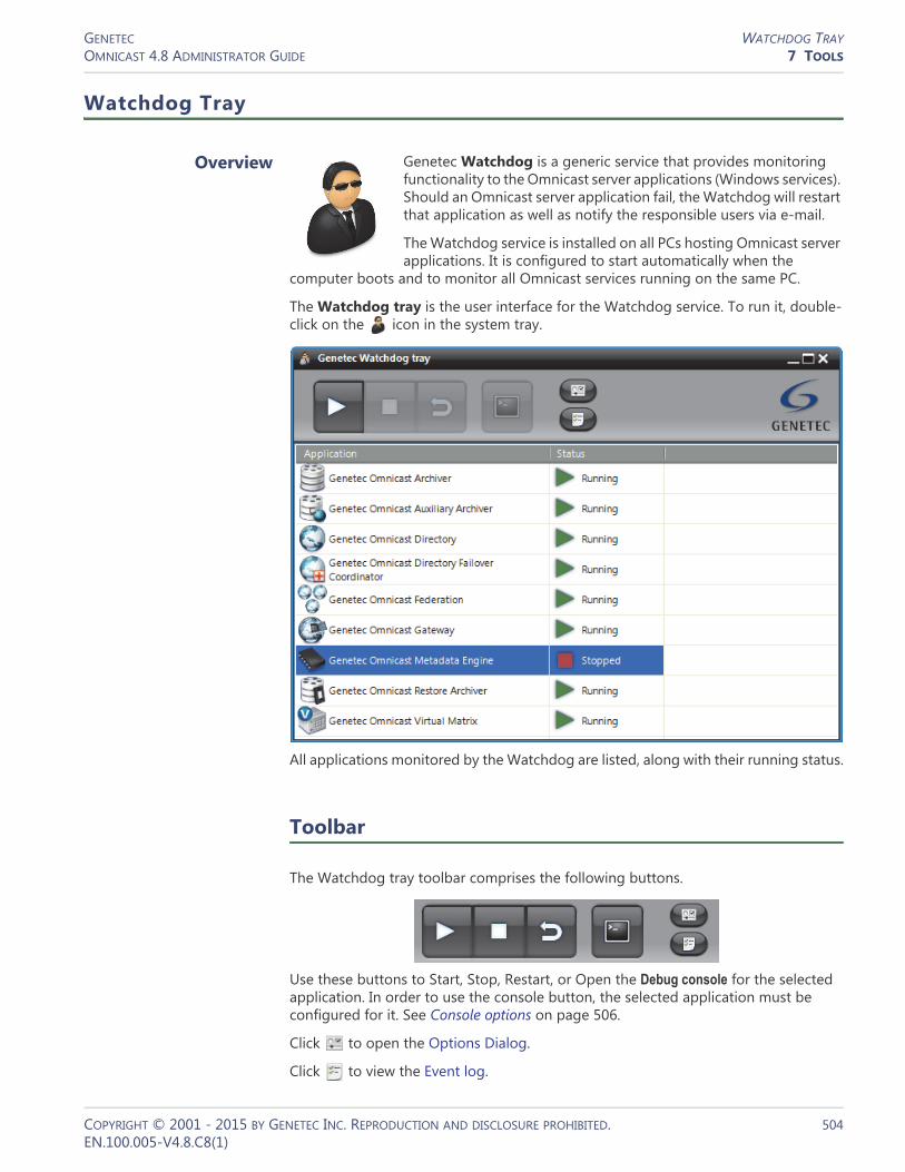
GENETEC WATCHDOG TRAYOMNICAST 4.8 ADMINISTRATOR GUIDE 7 TOOLS
Watchdog Tray
Overview
Genetec Watchdog is a generic service that provides monitoring functionality to the Omnicast server applications (Windows services). Should an Omnicast server application fail, the Watchdog will restart that application as well as notify the responsible users via e-mail.
The Watchdog service is installed on all PCs hosting Omnicast server applications. It is configured to start automatically when the
computer boots and to monitor all Omnicast services running on the same PC.
The Watchdog tray is the user interface for the Watchdog service. To run it, double-click on the icon in the system tray.
All applications monitored by the Watchdog are listed, along with their running status.
Toolbar
The Watchdog tray toolbar comprises the following buttons.
Use these buttons to Start, Stop, Restart, or Open the Debug console for the selected application. In order to use the console button, the selected application must be configured for it. See Console options on page 506.
Click to open the Options Dialog.
Click to view the Event log.
COPYRIGHT © 2001 - 2015 BY GENETEC INC. REPRODUCTION AND DISCLOSURE PROHIBITED. 504EN.100.005-V4.8.C8(1)

GENETEC WATCHDOG TRAYOMNICAST 4.8 ADMINISTRATOR GUIDE 7 TOOLS
Options Dialog
General options
Parameter Description
Incoming connection port
Port used by monitored applications to report their activities to the Watchdog. The default value is 5501.
Email addresses Email addresses of the people to notify when something goes wrong. You may enter multiple email addresses separated by semicolons.
IMPORTANT For email notification to work, the SMTP server must be properly configured in Server Admin. See Server Admin – System – SMTP on page 53.
Send email notification
Select the types of events (error, warning, information) that should trigger email notifications.
COPYRIGHT © 2001 - 2015 BY GENETEC INC. REPRODUCTION AND DISCLOSURE PROHIBITED. 505EN.100.005-V4.8.C8(1)

GENETEC WATCHDOG TRAYOMNICAST 4.8 ADMINISTRATOR GUIDE 7 TOOLS
Startup options
Select all services that should be automatically restarted by the Watchdog when it is not running. The Watchdog polls all selected services at regular intervals, following the specified Timeout period. Click on Default to apply the system default settings.
Console options
This page allows you to set the Telnet console options for each monitored service. Click on Default to apply the system default settings. You need to select a service here in order to activate its Console button in the Toolbar. See Toolbar on page 504.
COPYRIGHT © 2001 - 2015 BY GENETEC INC. REPRODUCTION AND DISCLOSURE PROHIBITED. 506EN.100.005-V4.8.C8(1)

GENETEC WATCHDOG TRAYOMNICAST 4.8 ADMINISTRATOR GUIDE 7 TOOLS
Event log The event log can be viewed by clicking on in the Toolbar.
The icon in front of each log entry indicates the type of message.
Click on to clear the logs.
Icon Description
Information message.
Warning message.
Error message.
COPYRIGHT © 2001 - 2015 BY GENETEC INC. REPRODUCTION AND DISCLOSURE PROHIBITED. 507EN.100.005-V4.8.C8(1)

SECTION 8
APPENDIX A: OMNICAST EVENTS
Complete description of all Omnicast predefined event types and the additional data they carry

GENETEC EVENTS IN OMNICASTOMNICAST 4.8 ADMINISTRATOR GUIDE 8 APPENDIX A: OMNICAST EVENTS
Events in Omnicast
Introduction For more information about events and how they can be used to trigger specific system behaviors, see Coupling Actions to Events on page 23.
Every event is attributed to a source entity, which is the main focus of the event. This section contains two lists. Both describes the same event types, but they are sorted differently.
See• Omnicast Event Types (sorted by event name) on page 510• Omnicast Event Types (sorted by source entity) on page 518
The source entity is indicated in italic in the event description. Events can be monitored live in the Live Viewer. When additional information concerning an event is available, it is indicated in the Description field of the event list shown in the Live Viewer. See Event Monitoring in the Omnicast Live Viewer User Guide.
COPYRIGHT © 2001 - 2015 BY GENETEC INC. REPRODUCTION AND DISCLOSURE PROHIBITED. 509EN.100.005-V4.8.C8(1)

GENETEC OMNICAST EVENT TYPES (SORTED BY EVENT NAME)OMNICAST 4.8 ADMINISTRATOR GUIDE 8 APPENDIX A: OMNICAST EVENTS
Omnicast Event Types (sorted by event name)
Event Source entity Description (1 of 8)
Access control (alarm acknowledged)
camera The external access control system linked to this camera through a ME plugin reported that a door alarm has been acknowledged.
Access control (door alarm)
camera The external access control system linked to this camera through a ME plugin issued a door alarm.
Access control (tampering)
camera The external access control system linked to this camera through a ME plugin reported that a device or a door has been tampered with.
Access control (unit connected)
camera The external access control system linked to this camera through a ME plugin reported that a unit is connected.
Access control (unit lost)
camera The external access control system linked to this camera through a ME plugin reported that a unit is lost.
Access denied camera The external access control system linked to this camera through a ME plugin reported that an access has been denied.
Access granted camera The external access control system linked to this camera through a ME plugin reported that an access has been granted.
Active alarms threshold surpassed
alarm The maximum number of active alarms permitted on the system (100) has been exceeded.
Alarm acknowledged alarm The alarm has been acknowledged. This event is generated every time an alarm is acknowledged, regardless of the acknowledgement type. A second event always accompanies this event and indicates the type of acknowledgement used. In the case of a custom acknowledgement, the second event can be any custom event selected by the user. See Alarm acknowledgement on page 11.
Alarm acknowledged (Alternate)
alarm The alternate acknowledgement has been used on this alarm. This event is also accompanied by the Alarm acknowledged event.
Alarm acknowledged (Default)
alarm The default acknowledgement has been used on this alarm. This event is also accompanied by the Alarm acknowledged event.
Alarm activated alarm The alarm has been activated and a recipient has been notified. An alarm is said to be activated when it is triggered or forwarded to a user, or when it awakens after a snooze. If the five users are notified when an alarm is triggered, then this event will be issued five times.
Alarm forwarded alarm The alarm has been forwarded.
Alarm set to snooze alarm The alarm has been set to snooze.
Alarm triggered alarm The alarm has just been triggered. Not to be been confused with Alarm activated event.
Application connected application The server application has connected to Omnicast. See Server Applications on page 4.
Application lost application The server application has been lost. Normal program terminations would not generate this event.
COPYRIGHT © 2001 - 2015 BY GENETEC INC. REPRODUCTION AND DISCLOSURE PROHIBITED. 510EN.100.005-V4.8.C8(1)
GENETEC OMNICAST EVENT TYPES (SORTED BY EVENT NAME)OMNICAST 4.8 ADMINISTRATOR GUIDE 8 APPENDIX A: OMNICAST EVENTS
Archiving camera limit exceeded
Archiver The maximum number of simultaneously archived cameras for this Archiver has been exceeded. This problem may occur during an Archiver failover. This event means that archiving has to be suspended on certain cameras because they have a lower archiving priority. The affected camera names are indicated in the Description field. See Server Admin – Archiver – Additional archiving options on page 90.
Archiving disk changed
Archiver The Allotted space on one of the disks assigned for archive storage for this Archiver has been used up and the Archiver has switched to the next disk in line. See Archiving on page 87. The names of the previous disk and current disk are indicated in the Description field.
Archiving queue full Archiver The Archiver is unable to write the video stream (packets) to disk as fast as the encoder sends it or there is not enough CPU to process the video stream received from a camera. A problem with the Archiver database will also trigger this event. The name of the camera whose packets are lost is indicated in the Description field.
Archiving stopped archiver Archiving has stopped because the disk(s) allocated for archiving is (are) full. This event always accompanies the Disk(s) full event.
Audio alarm camera A noise has been detected by the camera.
Backup failed archiver The backup operation did not complete successfully. The specific reason that triggered the event is given in the Description field. Some of the most common errors are listed below:• Backup size bigger than tape size• Unable to create file or Directory• Unable to export tables• Unable to open a session with the removable storage manager• NTBackup is not installed• There is no tape in the tape device• No video file to backup• Unable to copy files• A backup configuration is invalid
Backup started archiver A backup has been started by the archiver (Archiver or Auxiliary Archiver).
Backup succeeded archiver Backup completed successfully.
Camera not archiving camera The camera (video encoder) is on an active archiving schedule and yet the Archiver is not receiving any video stream from it. This is not the same as the Signal lost or the Transmission lost events.
Camera tampering camera A dysfunction that may signal an attempt to tamper with the camera has been detected. The dysfunction could be a partial or complete obstruction of the camera view, a sudden change of the field of view, or a loss of focus.
Cannot write on a specified location
archiver The archiver (Archiver or Auxiliary Archiver) cannot write to a specific drive. The path to the problem drive is indicated in the description field.
Event Source entity Description (2 of 8)
COPYRIGHT © 2001 - 2015 BY GENETEC INC. REPRODUCTION AND DISCLOSURE PROHIBITED. 511EN.100.005-V4.8.C8(1)

GENETEC OMNICAST EVENT TYPES (SORTED BY EVENT NAME)OMNICAST 4.8 ADMINISTRATOR GUIDE 8 APPENDIX A: OMNICAST EVENTS
Cannot write to any drive
archiver The archiver (Archiver or Auxiliary Archiver) is unable to write to any of the disk drive(s) allotted to it for archiving. This situation may arise for any of the following reasons:• When write accesses to shared drives are revoked.• When shared drives are inaccessible.• When shared drives no longer exist.
When this happens, the archiving is stopped. The archiver will re-evaluate the drive status every 30 seconds.
Connection lost with the alarm database
Directory The Directory has lost its connection with the alarm database (AlarmSQL). This is a serious problem. When it happens, Alarm Management no longer works!
Connection recovered with the alarm database
Directory The Directory has recovered its connection with its alarm database (AlarmSQL).
Database lost archiver Connection to the archiver's database was lost. This may be because the data server is down or can't be reached by the archiver (Archiver, Auxiliary Archiver, or Restore Archiver).
Database lost Directory Connection to the main Directory database (DirectorySQL) is lost. This is a serious problem. When it happens, the only action that can be used is Send an email, because all other actions require a working connection to the Directory database.
Database out of disk space
plugin This event only applies to ME plugins. It is issued when the metadata generated by the plugin cannot be saved to the database because it ran out of disk space.
Database recovered archiver Connection to the archiver's database is re-established.
Database recovered Directory Connection to the main Directory database (DirectorySQL) has been recovered.
DFC integrity test failed for alarm database
DFC The DFC issues this event when the row count of its alarm database is different from the row count of the current Directory's alarm database. This check is performed every time the DFC connects to the Directory. If the row counts of the two alarm databases do not match, the DFC will resynchronize its database with the one of the current Directory.
DFC integrity test failed for entity database
DFC The DFC issues this event when the row count of its entity database is different from the row count of the current Directory's entity database. This check is performed every time the DFC connects to the Directory. If the row counts of the two entity databases do not match, the DFC will resynchronize its database with the one of the current Directory.
Digital input contact closing
digital input The contact on the digital input has just been closed.
Digital input contact opening
digital input The contact on the digital input has just been opened.
Event Source entity Description (3 of 8)
COPYRIGHT © 2001 - 2015 BY GENETEC INC. REPRODUCTION AND DISCLOSURE PROHIBITED. 512EN.100.005-V4.8.C8(1)

GENETEC OMNICAST EVENT TYPES (SORTED BY EVENT NAME)OMNICAST 4.8 ADMINISTRATOR GUIDE 8 APPENDIX A: OMNICAST EVENTS
Directory Failover Coordinators not synchronized
Directory The UTC time of the Directory Failover Coordinators (DFC) installed on the system are more than 1 minute apart. The DFCs rely on update timestamps to determine which machine has the latest configuration. Having unsynchronized DFCs may result in loss of configuration data and problems during failover.
Disk load is over 80% archiver More than 80% of the disk space allocated for archiving has been used. This situation may be caused by an under evaluation of the disk space required or by another application that is taking more disk space than it should. If 100% of the allotted disk space is used, the archiver (Archiver or Auxiliary Archiver) will start to delete old archive files prematurely to free disk space for new archive files, starting with the oldest files. See File deleted event.
Disk(s) full archiver All disks allotted for archiving are full and the archiver (Archiver or Auxiliary Archiver) is unable to free disk space by deleting existing video files. This event may occur when another application has used up all the disk space reserved for Omnicast or when the Delete oldest files when disks full option is not selected in the Server Admin. When this happens, the archiving is stopped. The archiver will re-evaluate the disk space every 30 seconds.
Door closed camera The external access control system linked to this camera through a ME plugin reported that a door has been closed.
Door forced camera The external access control system linked to this camera through a ME plugin reported that a door has been forced.
Door forced (restored) camera The external access control system linked to this camera through a ME plugin reported that a forced door has been restored.
Door held open camera The external access control system linked to this camera through a ME plugin reported that a door has been held open longer than a predefined safety period.
Door held open (released)
camera The external access control system linked to this camera through a ME plugin reported that a door previously held open has been released.
Door opened camera The external access control system linked to this camera through a ME plugin reported that a door has been opened.
File deleted camera A video file associated to the camera is deleted prematurely, i.e. before its retention period is over. The retention period of a video file depends on the associated camera and the Archiver (see Config Tool – Archiver – Archiving on page 205). This happens when the Archiver runs out of disk space and is forced to delete the older files to make room for the new files. The Description field indicates the path of the deleted video file.
GUID conflict Directory/Gateway
If an Omnicast application is cloned/copied and logs on to your system, you may receive this error message in the Directory or Gateway log files, and in the Live Viewer event pane. The error description will also include the application type and machine related to the conflict.
Intrusion camera The external access control system linked to this camera through a ME plugin reported an intrusion.
Invalid configuration in unit
unit An invalid setting has been rejected by the unit. For example, setting an invalid bit rate.
Event Source entity Description (4 of 8)
COPYRIGHT © 2001 - 2015 BY GENETEC INC. REPRODUCTION AND DISCLOSURE PROHIBITED. 513EN.100.005-V4.8.C8(1)

GENETEC OMNICAST EVENT TYPES (SORTED BY EVENT NAME)OMNICAST 4.8 ADMINISTRATOR GUIDE 8 APPENDIX A: OMNICAST EVENTS
Invalid custom encryption values
archiver This warning is issued by the archiver (Archiver or Auxiliary Archiver) on startup and every 5 minutes if one of the custom encryption values (initial fingerprint or encryption key) specified in the Server Admin is invalid.
License plate in sight camera A complete license plate has been sighted in this camera.
License plate out of sight
camera A license plate previously sighted in this camera has moved out of sight.
License plate reading camera A better or more reliable reading of a sighted license plate is available.
Live bookmark added camera A user has added a bookmark to the live video. The Description field indicates the bookmark text followed by the time the bookmark was added. A typical use of this event is to trigger the action Start applying video protection to prevent a premature deletion of the video.
Loitering camera Loitering activity has been detected.
Macro error macro An error occurred during the execution of this macro.
Macro started macro Macro execution started.
Macro stopped macro Macro execution stopped.
Manual restore failed Restore Archiver
Manual restore has failed.
Manual restore started Restore Archiver
Manual restore has started.
Manual restore succeeded
Restore Archiver
Manual restore has succeeded.
Motion off camera The event is issued following a Motion on event when motion (measured in terms of number of motion blocks) has dropped below the Motion off threshold for at least 5 seconds.
Motion on camera A positive motion detection has been made. See What constitutes a positive motion detection? on page 254.
Not enough disk space for logging
archiver File logging is enabled and there is no more space on disk to write the log entry. Applies to Archiver and Auxiliary Archiver.
Not enough disk space for logging
Directory The Directory has run out of disk space for file logging. See Directory – Logging on page 59.
Object condition change
camera An object suddenly changes direction or speed, such as when a person starts running or slips.
Object crossed line camera An object has crossed a predefined tripwire.
Object detected camera An object is in the camera’s field of view.
Object entered camera An object has entered the camera’s field of view.
Object exited camera An object has exited the camera’s field of view.
Object following route camera An object is following a predetermined route, in a specific direction.
Object left camera An object has been added to the camera’s field of view and left there.
Object merged camera Two separate objects have been merged.
Object removed camera An object has been removed from the camera’s field of view.
Event Source entity Description (5 of 8)
COPYRIGHT © 2001 - 2015 BY GENETEC INC. REPRODUCTION AND DISCLOSURE PROHIBITED. 514EN.100.005-V4.8.C8(1)

GENETEC OMNICAST EVENT TYPES (SORTED BY EVENT NAME)OMNICAST 4.8 ADMINISTRATOR GUIDE 8 APPENDIX A: OMNICAST EVENTS
Object separated camera An object within the camera’s field of view has separated in two.
Object stopped camera A moving object has stopped.
Person falling camera A person appeared to be falling.
Person running camera A person appeared to be running.
Person sliding camera A person appeared to be sliding.
Playback bookmark added
camera A user has added a bookmark during video playback. The Description field indicates the bookmark text followed by the time the bookmark was added. A typical use of this event is to trigger the action Start applying video protection to prevent a premature deletion of the video.
Plugin error plugin An error occurred during the execution of the plugin. The nature of the error is indicated in the Description field.
Plugin started plugin Plugin execution has started. The application responsible for the plugin is indicated in the Description field.
Plugin stopped plugin Plugin execution has stopped. The application responsible for the plugin is indicated in the Description field.
Protected video threshold exceeded
archiver The Protected video threshold configured in the Server Admin is been exceeded. The percentage of disk space occupied by protected video files can be monitored from the Config Tool. See Protected video file statistics in Config Tool – Archiver – Disk usage on page 207.
PTZ activated PTZ motor A user started using the PTZ after it has been idle (see PTZ motor – Idle delay on page 384). The Description field indicates the user who activated the PTZ. This event is regenerated every time a different user takes control of the PTZ, even when the PTZ is still active. PTZ activities caused by PTZ actions triggered by events do not generate this event.
PTZ locked PTZ motor A user has tried to move the PTZ while it is being locked by another user with a higher PTZ priority. The Description field indicates the machine, application type and user who currently holds the lock.
PTZ stopped PTZ motor The PTZ has not been manipulated by any user after a predetermined period of time (see PTZ motor – Idle delay on page 384). The Description field indicates the user who last used the PTZ. This event is not generated following PTZ actions triggered by events.
PTZ zoom by user PTZ motor A user started zooming the PTZ. The Description field indicates the user who performed the zoom. Subsequent PTZ zoom by user events are generated if another user zooms the PTZ, or if the original user zooms the PTZ after the Idle delay has expired (see PTZ motor – Idle delay on page 384). This event is not generated due to automated PTZ functions such as presets or patterns, or PTZ actions triggered by events.
PTZ zoom by user stopped
PTZ motor The PTZ has not been zoomed by any user after a predetermined period of time since the last zoom operation (see PTZ motor – Idle delay on page 384).The Description field indicates the user who last zoomed the PTZ. This event is not generated following automated PTZ functions such as presets or patterns, or PTZ actions triggered by events.
Event Source entity Description (6 of 8)
COPYRIGHT © 2001 - 2015 BY GENETEC INC. REPRODUCTION AND DISCLOSURE PROHIBITED. 515EN.100.005-V4.8.C8(1)

GENETEC OMNICAST EVENT TYPES (SORTED BY EVENT NAME)OMNICAST 4.8 ADMINISTRATOR GUIDE 8 APPENDIX A: OMNICAST EVENTS
Receiving RTP packets from multiple sources
camera The Archiver is receiving more than one video stream for the same camera. When this rare situation arises, the Archiver cannot tell which stream is the correct one just by looking at their source IP address because of the NAT (Network Address Translators), so it has to make an arbitrary choice. If the Archiver makes the wrong choice, it will be archiving the wrong video stream! To help you solve this problem, the source IP address and port number of both streams are indicated in the Description field. The two sources are labeled Archived and Rejected. By examining both pairs of IP address and port number, you can find out which one is the faulty unit that is causing this conflict.
Recording started (alarm)
camera The recording started because an alarm was triggered. This behavior ensures that recording is always available for cameras displayed in an alarm. See Alarm recording duration on page 188.
Recording started (continuous)
camera The recording started because a continuous archiving schedule became active.
Recording started (external)
camera The recording was started through the Start recording action. This action could be triggered by another event or executed from a macro.
Recording started (motion)
camera The recording was started through motion detection. See Automatic recording on motion on page 257.
Recording started (user)
camera The recording was started manually by a user, either by clicking the Record button or by adding a bookmark from the Live Viewer.
Recording stopped (alarm)
camera The recording has stopped because the alarm recording time has elapsed. See Alarm recording duration on page 188.
Recording stopped (continuous)
camera The recording stopped because the camera is no longer covered by a continuous archiving schedule.
Recording stopped (external)
camera The recording was stopped through the Stop recording action. This action could be triggered by another event or executed from a macro.
Recording stopped (motion)
camera The recording stopped because the motion has ceased. See What constitutes a positive motion detection? on page 254.
Recording stopped (user)
camera The recording was stopped manually by a user, either by clicking the Record button in the Live Viewer or because the Default manual recording length has expired. See Camera – Recording settings on page 248.
Redirection started Gateway/Federation Server
A video stream has started to be redirected by a Gateway or Federation Server. When the event is triggered, its description identifies the source and destination of what has been redirected, along with the federated Gateway (if applicable), in an XML string.
Redirection stopped Gateway/Federation Server
A video stream has stopped being redirected by a Gateway or Federation Server. When the event is triggered, its description identifies the source and destination of what was being redirected, along with the federated Gateway (if applicable), in an XML string.
RTP packets lost camera There are RTP (Real-time Transport Protocol) packets that the Archiver never received. This could happen if the packets have been lost on the network or if the Archiver does not have enough CPU to process all the packets received on the network card. The Description field indicates the number of packets lost since the last time this event was issued (no more than once every minute).
Event Source entity Description (7 of 8)
COPYRIGHT © 2001 - 2015 BY GENETEC INC. REPRODUCTION AND DISCLOSURE PROHIBITED. 516EN.100.005-V4.8.C8(1)
GENETEC OMNICAST EVENT TYPES (SORTED BY EVENT NAME)OMNICAST 4.8 ADMINISTRATOR GUIDE 8 APPENDIX A: OMNICAST EVENTS
Signal lost camera This event is triggered by the unit when the camera stops sending its video signal. Only a camera malfunction or a disconnected coaxial cable can cause this event. Network problems will not cause this event.
Signal recovered camera The signal from this camera has been recovered.
Tailgating camera Two persons have entered a secured area following closely each other.
Transmission lost camera This event is triggered when the Archiver has not received any video packets for more than 5 seconds while the TCP/IP (http) connection between the Archiver and the camera is still alive.
Tripwire camera An object has crossed a predefined tripwire.
Unit discovered unit The unit has been discovered (or rediscovered after it has been lost). This event is also generated every time the unit reboots.
Unit lost unit The unit has been lost. When this happens, the icons of all the devices attached to that unit will turn red. This could be caused by the unit rebooting (when a new configuration is being applied) or when the network cable to the unit is unplugged.
Unit not supported Archiver The Archiver discovered a unit type that is not supported.
User logoff user The user has just logged off. The Description field shows the machine name, the application type and the user name (e.g. “JDOE – Live Viewer – John”).
User logon user The user has just logged on. The Description field shows the machine name, the application type and the user name (e.g. “PTREMBLAY – Live Viewer – Pierre”).
Event Source entity Description (8 of 8)
COPYRIGHT © 2001 - 2015 BY GENETEC INC. REPRODUCTION AND DISCLOSURE PROHIBITED. 517EN.100.005-V4.8.C8(1)

GENETEC OMNICAST EVENT TYPES (SORTED BY SOURCE ENTITY)OMNICAST 4.8 ADMINISTRATOR GUIDE 8 APPENDIX A: OMNICAST EVENTS
Omnicast Event Types (sorted by source entity)
The source entity is the main focus of the event.
Source entity Event Description (1 of 8)
Alarm Active alarms threshold surpassed
The maximum number of active alarms permitted on the system (100) has been exceeded.
Alarm Alarm acknowledged The alarm has been acknowledged. This event is generated every time an alarm is acknowledged, regardless of the acknowledgement type. A second event always accompanies this event and indicates the type of acknowledgement used. In the case of a custom acknowledgement, the second event can be any custom event selected by the user. See Alarm acknowledgement on page 11.
Alarm Alarm acknowledged (Alternate)
The alternate acknowledgement has been used on this alarm. This event is also accompanied by the Alarm acknowledged event.
Alarm Alarm acknowledged (Default)
The default acknowledgement has been used on this alarm. This event is also accompanied by the Alarm acknowledged event.
Alarm Alarm activated The alarm has been activated and a recipient has been notified. An alarm is said to be activated when it is triggered or forwarded to a user, or when it awakens after a snooze. If the five users are notified when an alarm is triggered, then this event will be issued five times.
Alarm Alarm forwarded The alarm has been forwarded.
Alarm Alarm set to snooze The alarm has been set to snooze.
Alarm Alarm triggered The alarm has just been triggered. Not to be been confused with Alarm activated event.
Application Application connected The server application has connected to Omnicast. See Server Applications on page 4.
Application Application lost The server application has been lost. Normal program terminations would not generate this event.
Archiver Archiving stopped Archiving has stopped because the disk(s) allocated for archiving is (are) full. This event always accompanies the Disk(s) full event.
Archiver Backup failed The backup operation did not complete successfully. The specific reason that triggered the event is given in the Description field. Some of the most common errors are listed below:• Backup size bigger than tape size• Unable to create file or Directory• Unable to export tables• Unable to open a session with the removable storage manager• NTBackup is not installed• There is no tape in the tape device• No video file to backup• Unable to copy files• A backup configuration is invalid
COPYRIGHT © 2001 - 2015 BY GENETEC INC. REPRODUCTION AND DISCLOSURE PROHIBITED. 518EN.100.005-V4.8.C8(1)

GENETEC OMNICAST EVENT TYPES (SORTED BY SOURCE ENTITY)OMNICAST 4.8 ADMINISTRATOR GUIDE 8 APPENDIX A: OMNICAST EVENTS
Archiver Backup started A backup has been started by the archiver (Archiver or Auxiliary Archiver).
Archiver Backup succeeded Backup completed successfully.
Archiver Cannot write on a specified location
The archiver (Archiver or Auxiliary Archiver) cannot write to a specific drive. The path to the problem drive is indicated in the description field.
Archiver Cannot write to any drive
The archiver (Archiver or Auxiliary Archiver) is unable to write to any of the disk drive(s) allotted to it for archiving. This situation may arise for any of the following reasons:• When write accesses to shared drives are revoked.• When shared drives are inaccessible.• When shared drives no longer exist.
When this happens, the archiving is stopped. The archiver will re-evaluate the drive status every 30 seconds.
Archiver Database lost Connection to the archiver's database was lost. This may be because the data server is down or can't be reached by the archiver (Archiver, Auxiliary Archiver, or Restore Archiver).
Archiver Database recovered Connection to the archiver's database is re-established.
Archiver Disk load is over 80% More than 80% of the disk space allocated for archiving has been used. This situation may be caused by an under evaluation of the disk space required or by another application that is taking more disk space than it should. If 100% of the allotted disk space is used, the archiver (Archiver or Auxiliary Archiver) will start to delete old archive files prematurely to free disk space for new archive files, starting with the oldest files. See File deleted event.
Archiver Disk(s) full All disks allotted for archiving are full and the archiver (Archiver or Auxiliary Archiver) is unable to free disk space by deleting existing video files. This event may occur when another application has used up all the disk space reserved for Omnicast or when the Delete oldest files when disks full option is not selected in the Server Admin. When this happens, the archiving is stopped. The archiver will re-evaluate the disk space every 30 seconds.
Archiver Invalid custom encryption values
This warning is issued by the archiver (Archiver or Auxiliary Archiver) on startup and every 5 minutes if one of the custom encryption values (initial fingerprint or encryption key) specified in the Server Admin is invalid.
Archiver Not enough disk space for logging
File logging is enabled and there is no more space on disk to write the log entry. Applies to Archiver and Auxiliary Archiver.
Archiver Protected video threshold exceeded
The Protected video threshold configured in the Server Admin is been exceeded. The percentage of disk space occupied by protected video files can be monitored from the Config Tool. See Protected video file statistics in Config Tool – Archiver – Disk usage on page 207.
Source entity Event Description (2 of 8)
COPYRIGHT © 2001 - 2015 BY GENETEC INC. REPRODUCTION AND DISCLOSURE PROHIBITED. 519EN.100.005-V4.8.C8(1)

GENETEC OMNICAST EVENT TYPES (SORTED BY SOURCE ENTITY)OMNICAST 4.8 ADMINISTRATOR GUIDE 8 APPENDIX A: OMNICAST EVENTS
Archiver Archiving camera limit exceeded
The maximum number of simultaneously archived cameras for this Archiver has been exceeded. This problem may occur during an Archiver failover. This event means that archiving has to be suspended on certain cameras because they have a lower archiving priority. The affected camera names are indicated in the Description field. See Server Admin – Archiver – Additional archiving options on page 90.
Archiver Archiving disk changed
The Allotted space on one of the disks assigned for archive storage for this Archiver has been used up and the Archiver has switched to the next disk in line. See Archiving on page 87. The names of the previous disk and current disk are indicated in the Description field.
Archiver Archiving queue full The Archiver is unable to write the video stream (packets) to disk as fast as the encoder sends it or there is not enough CPU to process the video stream received from a camera. A problem with the Archiver database will also trigger this event. The name of the camera whose packets are lost is indicated in the Description field.
Archiver Unit not supported The Archiver discovered a unit type that is not supported.
Camera Access control (alarm acknowledged)
The external access control system linked to this camera through a ME plugin reported that a door alarm has been acknowledged.
Camera Access control (door alarm)
The external access control system linked to this camera through a ME plugin issued a door alarm.
Camera Access control (tampering)
The external access control system linked to this camera through a ME plugin reported that a device or a door has been tampered with.
Camera Access control (unit connected)
The external access control system linked to this camera through a ME plugin reported that a unit is connected.
Camera Access control (unit lost)
The external access control system linked to this camera through a ME plugin reported that a unit is lost.
Camera Access denied The external access control system linked to this camera through a ME plugin reported that an access has been denied.
Camera Access granted The external access control system linked to this camera through a ME plugin reported that an access has been granted.
Camera Camera not archiving The camera (video encoder) is on an active archiving schedule and yet the Archiver is not receiving any video stream from it. This is not the same as the Signal lost or the Transmission lost events.
Camera Camera tampering A dysfunction that may signal an attempt to tamper with the camera has been detected. The dysfunction could be a partial or complete obstruction of the camera view, a sudden change of the field of view, or a loss of focus.
Camera Door closed The external access control system linked to this camera through a ME plugin reported that a door has been closed.
Camera Door forced The external access control system linked to this camera through a ME plugin reported that a door has been forced.
Camera Door forced (restored) The external access control system linked to this camera through a ME plugin reported that a forced door has been restored.
Source entity Event Description (3 of 8)
COPYRIGHT © 2001 - 2015 BY GENETEC INC. REPRODUCTION AND DISCLOSURE PROHIBITED. 520EN.100.005-V4.8.C8(1)

GENETEC OMNICAST EVENT TYPES (SORTED BY SOURCE ENTITY)OMNICAST 4.8 ADMINISTRATOR GUIDE 8 APPENDIX A: OMNICAST EVENTS
Camera Door held open The external access control system linked to this camera through a ME plugin reported that a door has been held open longer than a predefined safety period.
Camera Door held open (released)
The external access control system linked to this camera through a ME plugin reported that a door previously held open has been released.
Camera Door opened The external access control system linked to this camera through a ME plugin reported that a door has been opened.
Camera File deleted A video file associated to the camera is deleted prematurely, i.e. before its retention period is over. The retention period of a video file depends on the associated camera and the Archiver (see Config Tool – Archiver – Archiving on page 205). This happens when the Archiver runs out of disk space and is forced to delete the older files to make room for the new files. The Description field indicates the path of the deleted video file.
Camera Intrusion The external access control system linked to this camera through a ME plugin reported an intrusion.
Camera License plate in sight A complete license plate has been sighted in this camera.
Camera License plate out of sight
A license plate previously sighted in this camera has moved out of sight.
Camera License plate reading A better or more reliable reading of a sighted license plate is available.
Camera Live bookmark added A user has added a bookmark to the live video. The Description field indicates the bookmark text followed by the time the bookmark was added. A typical use of this event is to trigger the action Start applying video protection to prevent a premature deletion of the video.
Camera Loitering Loitering activity has been detected.
Camera Motion off The event is issued following a Motion on event when motion (measured in terms of number of motion blocks) has dropped below the Motion off threshold for at least 5 seconds.
Camera Motion on A positive motion detection has been made. See What constitutes a positive motion detection? on page 254.
Camera Object condition change
An object suddenly changes direction or speed, such as when a person starts running or slips.
Camera Object crossed line An object has crossed a predefined tripwire.
Camera Object detected An object is in the camera’s field of view.
Camera Object entered An object has entered the camera’s field of view.
Camera Object exited An object has exited the camera’s field of view.
Camera Object following route An object is following a predetermined route, in a specific direction.
Camera Object left An object has been added to the camera’s field of view and left there.
Camera Object merged Two separate objects have been merged.
Camera Object removed An object has been removed from the camera’s field of view.
Source entity Event Description (4 of 8)
COPYRIGHT © 2001 - 2015 BY GENETEC INC. REPRODUCTION AND DISCLOSURE PROHIBITED. 521EN.100.005-V4.8.C8(1)
GENETEC OMNICAST EVENT TYPES (SORTED BY SOURCE ENTITY)OMNICAST 4.8 ADMINISTRATOR GUIDE 8 APPENDIX A: OMNICAST EVENTS
Camera Object separated An object within the camera’s field of view has separated in two.
Camera Object stopped A moving object has stopped.
Camera Person falling A person appeared to be falling.
Camera Person running A person appeared to be running.
Camera Person sliding A person appeared to be sliding.
Camera Playback bookmark added
A user has added a bookmark during video playback. The Description field indicates the bookmark text followed by the time the bookmark was added. A typical use of this event is to trigger the action Start applying video protection to prevent a premature deletion of the video.
Camera Receiving RTP packets from multiple sources
The Archiver is receiving more than one video stream for the same camera. When this rare situation arises, the Archiver cannot tell which stream is the correct one just by looking at their source IP address because of the NAT (Network Address Translators), so it has to make an arbitrary choice. If the Archiver makes the wrong choice, it will be archiving the wrong video stream! To help you solve this problem, the source IP address and port number of both streams are indicated in the Description field. The two sources are labeled Archived and Rejected. By examining both pairs of IP address and port number, you can find out which one is the faulty unit that is causing this conflict.
Camera Recording started (alarm)
The recording started because an alarm was triggered. This behavior ensures that recording is always available for cameras displayed in an alarm. See Alarm recording duration on page 188.
Camera Recording started (continuous)
The recording started because a continuous archiving schedule became active.
Camera Recording started (external)
The recording was started through the Start recording action. This action could be triggered by another event or executed from a macro.
Camera Recording started (motion)
The recording was started through motion detection. See Automatic recording on motion on page 257.
Camera Recording started (user)
The recording was started manually by a user, either by clicking the Record button or by adding a bookmark from the Live Viewer.
Camera Recording stopped (alarm)
The recording has stopped because the alarm recording time has elapsed. See Alarm recording duration on page 188.
Camera Recording stopped (continuous)
The recording stopped because the camera is no longer covered by a continuous archiving schedule.
Camera Recording stopped (external)
The recording was stopped through the Stop recording action. This action could be triggered by another event or executed from a macro.
Camera Recording stopped (motion)
The recording stopped because the motion has ceased. See What constitutes a positive motion detection? on page 254.
Camera Recording stopped (user)
The recording was stopped manually by a user, either by clicking the Record button in the Live Viewer or because the Default manual recording length has expired. See Camera – Recording settings on page 248.
Source entity Event Description (5 of 8)
COPYRIGHT © 2001 - 2015 BY GENETEC INC. REPRODUCTION AND DISCLOSURE PROHIBITED. 522EN.100.005-V4.8.C8(1)

GENETEC OMNICAST EVENT TYPES (SORTED BY SOURCE ENTITY)OMNICAST 4.8 ADMINISTRATOR GUIDE 8 APPENDIX A: OMNICAST EVENTS
Camera RTP packets lost There are RTP (Real-time Transport Protocol) packets that the Archiver never received. This could happen if the packets have been lost on the network or if the Archiver does not have enough CPU to process all the packets received on the network card. The Description field indicates the number of packets lost since the last time this event was issued (no more than once every minute).
Camera Signal lost This event is triggered by the unit when the camera stops sending its video signal. Only a camera malfunction or a disconnected coaxial cable can cause this event. Network problems will not cause this event.
Camera Signal recovered The signal from this camera has been recovered.
Camera Tailgating Two persons have entered a secured area following closely each other.
Camera Transmission lost This event is triggered when the Archiver has not received any video packets for more than 5 seconds while the TCP/IP (http) connection between the Archiver and the camera is still alive.
DFC DFC integrity test failed for alarm database
The DFC issues this event when the row count of its alarm database is different from the row count of the current Directory's alarm database. This check is performed every time the DFC connects to the Directory. If the row counts of the two alarm databases do not match, the DFC will resynchronize its database with the one of the current Directory.
DFC DFC integrity test failed for entity database
The DFC issues this event when the row count of its entity database is different from the row count of the current Directory's entity database. This check is performed every time the DFC connects to the Directory. If the row counts of the two entity databases do not match, the DFC will resynchronize its database with the one of the current Directory.
Digital input Digital input contact closing
The contact on the digital input has just been closed.
Digital input Digital input contact opening
The contact on the digital input has just been opened.
Directory Connection lost with the alarm database
The Directory has lost its connection with the alarm database (AlarmSQL). This is a serious problem. When it happens, Alarm Management no longer works!
Directory Connection recovered with the alarm database
The Directory has recovered its connection with its alarm database (AlarmSQL).
Directory Database lost Connection to the main Directory database (DirectorySQL) is lost. This is a serious problem. When it happens, the only action that can be used is Send an email, because all other actions require a working connection to the Directory database.
Directory Database recovered Connection to the main Directory database (DirectorySQL) has been recovered.
Source entity Event Description (6 of 8)
COPYRIGHT © 2001 - 2015 BY GENETEC INC. REPRODUCTION AND DISCLOSURE PROHIBITED. 523EN.100.005-V4.8.C8(1)

GENETEC OMNICAST EVENT TYPES (SORTED BY SOURCE ENTITY)OMNICAST 4.8 ADMINISTRATOR GUIDE 8 APPENDIX A: OMNICAST EVENTS
Directory Directory Failover Coordinators not synchronized
The UTC time of the Directory Failover Coordinators (DFC) installed on the system are more than 1 minute apart. The DFCs rely on update timestamps to determine which machine has the latest configuration. Having unsynchronized DFCs may result in loss of configuration data and problems during failover.
Directory Not enough disk space for logging
The Directory has run out of disk space for file logging. See Directory – Logging on page 59.
Directory/Gateway GUID conflict If an Omnicast application is cloned/copied and logs on to your system, you may receive this error message in the Directory or Gateway log files, and in the Live Viewer event pane. The error description will also include the application type and machine related to the conflict.
Federation Server/Gateway
Redirection started A video stream has started to be redirected by a Gateway or Federation Server. When the event is triggered, its description identifies the source and destination of what has been redirected, along with the federated Gateway (if applicable), in an XML string.
Federation Server/Gateway
Redirection stopped A video stream has stopped being redirected by a Gateway or Federation Server. When the event is triggered, its description identifies the source and destination of what was being redirected, along with the federated Gateway (if applicable), in an XML string.
Macro Macro error An error occurred during the execution of this macro.
Macro Macro started Macro execution started.
Macro Macro stopped Macro execution stopped.
Plugin Database out of disk space
This event only applies to ME plugins. It is issued when the metadata generated by the plugin cannot be saved to the database because it ran out of disk space.
Plugin Plugin error An error occurred during the execution of the plugin. The nature of the error is indicated in the Description field.
Plugin Plugin started Plugin execution has started. The application responsible for the plugin is indicated in the Description field.
Plugin Plugin stopped Plugin execution has stopped. The application responsible for the plugin is indicated in the Description field.
PTZ motor PTZ activated A user started using the PTZ after it has been idle (see PTZ motor – Idle delay on page 384). The Description field indicates the user who activated the PTZ. This event is regenerated every time a different user takes control of the PTZ, even when the PTZ is still active. PTZ activities caused by PTZ actions triggered by events do not generate this event.
PTZ motor PTZ locked A user has tried to move the PTZ while it is being locked by another user with a higher PTZ priority. The Description field indicates the machine, application type and user who currently holds the lock.
PTZ motor PTZ stopped The PTZ has not been manipulated by any user after a predetermined period of time (see PTZ motor – Idle delay on page 384). The Description field indicates the user who last used the PTZ. This event is not generated following PTZ actions triggered by events.
Source entity Event Description (7 of 8)
COPYRIGHT © 2001 - 2015 BY GENETEC INC. REPRODUCTION AND DISCLOSURE PROHIBITED. 524EN.100.005-V4.8.C8(1)

GENETEC OMNICAST EVENT TYPES (SORTED BY SOURCE ENTITY)OMNICAST 4.8 ADMINISTRATOR GUIDE 8 APPENDIX A: OMNICAST EVENTS
PTZ motor PTZ zoom by user A user started zooming the PTZ. The Description field indicates the user who performed the zoom. Subsequent PTZ zoom by user events are generated if another user zooms the PTZ, or if the original user zooms the PTZ after the Idle delay has expired (see PTZ motor – Idle delay on page 384). This event is not generated due to automated PTZ functions such as presets or patterns, or PTZ actions triggered by events.
PTZ motor PTZ zoom by user stopped
The PTZ has not been zoomed by any user after a predetermined period of time since the last zoom operation (see PTZ motor – Idle delay on page 384).The Description field indicates the user who last zoomed the PTZ. This event is not generated following automated PTZ functions such as presets or patterns, or PTZ actions triggered by events.
Restore Archiver Manual restore failed Manual restore has failed.
Restore Archiver Manual restore started Manual restore has started.
Restore Archiver Manual restore succeeded
Manual restore has succeeded.
Unit Invalid configuration in unit
An invalid setting has been rejected by the unit. For example, setting an invalid bit rate.
Unit Unit discovered The unit has been discovered (or rediscovered after it has been lost). This event is also generated every time the unit reboots.
Unit Unit lost The unit has been lost. When this happens, the icons of all the devices attached to that unit will turn red. This could be caused by the unit rebooting (when a new configuration is being applied) or when the network cable to the unit is unplugged.
User User logoff The user has just logged off. The Description field shows the machine name, the application type and the user name (e.g. “JDOE – Live Viewer – John”).
User User logon The user has just logged on. The Description field shows the machine name, the application type and the user name (e.g. “PTREMBLAY – Live Viewer – Pierre”).
Source entity Event Description (8 of 8)
COPYRIGHT © 2001 - 2015 BY GENETEC INC. REPRODUCTION AND DISCLOSURE PROHIBITED. 525EN.100.005-V4.8.C8(1)
SECTION 9
APPENDIX B: ACTIONS
Complete description of all Omnicast action types and their required parameters

GENETEC ACTIONS IN OMNICASTOMNICAST 4.8 ADMINISTRATOR GUIDE 9 APPENDIX B: ACTIONS
Actions in Omnicast
Introduction Actions are configurable procedures. You can associate actions to events in the system so that they will be automatically executed when these events occur. For more information about associating actions to events, see Coupling Actions to Events on page 23.
Every action has an object entity which is the main focus of the action. This section contains two lists. Both describe the same action types, but they are sorted differently.
See• Omnicast Action Types (sorted by action name) on page 528• Omnicast Action Types (sorted by object entity) on page 533
The object of the action is indicated in italic in the action description. Some actions generate additional events. When it is the case, the generated events are also indicated.
COPYRIGHT © 2001 - 2015 BY GENETEC INC. REPRODUCTION AND DISCLOSURE PROHIBITED. 527EN.100.005-V4.8.C8(1)

GENETEC OMNICAST ACTION TYPES (SORTED BY ACTION NAME)OMNICAST 4.8 ADMINISTRATOR GUIDE 9 APPENDIX B: ACTIONS
Omnicast Action Types (sorted by action name)
Action Object entity Description (1 of 5)
Add a bookmark camera Add a bookmark to the recording of the camera.Additional parameter:• Bookmark – Bookmark text.Events:• Live bookmark added
• Recording started (user) – If the recording is started as a consequence of adding the bookmark.
Block a camera camera Block the camera at the specified blocking level. See Camera Blocking in the Omnicast Live Viewer User Guide.
Clear PTZ auxiliary PTZ motor Turn the specified auxiliary switch OFF on the selected PTZ motor.Additional parameter:• Auxiliary number – Auxiliary switch to clear.
Display a URL address in a Live Viewer
Live Viewer Display a Web page in the selected Live Viewer.Additional parameter:• URL address – Address of the Web page.
The behavior of this action is similar to View a camera in the Live Viewer.
Execute a macro macro Start the execution of the macro. See Config Tool – Macro on page 341.Additional parameter:• Virtual Matrix – The Virtual Matrix that will be executing the macro.Events:• Macro started – When the macro execution starts.• Macro stopped – When the macro execution ends.• Macro error – If the macro execution fails.
Go to home PTZ motor Command the selected PTZ motor to go to its home position. Not all PTZ protocol supports this feature.
Go to preset PTZ motor Command the PTZ motor to go to the specified preset position.Additional parameter:• Preset number – Preset to go to.
Override with event recording quality
camera Set the recording quality to the Event recording settings as specified in the Boost quality dialog found in the Video quality tab of the camera. This action supersedes the Always override general settings on manual recording option. See Boosting recording quality on special events on page 245.
The effect of this action will last as long as it is not modified by another action, such as Recording quality as standard configuration. The effect is lost when the Archiver restarts.
COPYRIGHT © 2001 - 2015 BY GENETEC INC. REPRODUCTION AND DISCLOSURE PROHIBITED. 528EN.100.005-V4.8.C8(1)
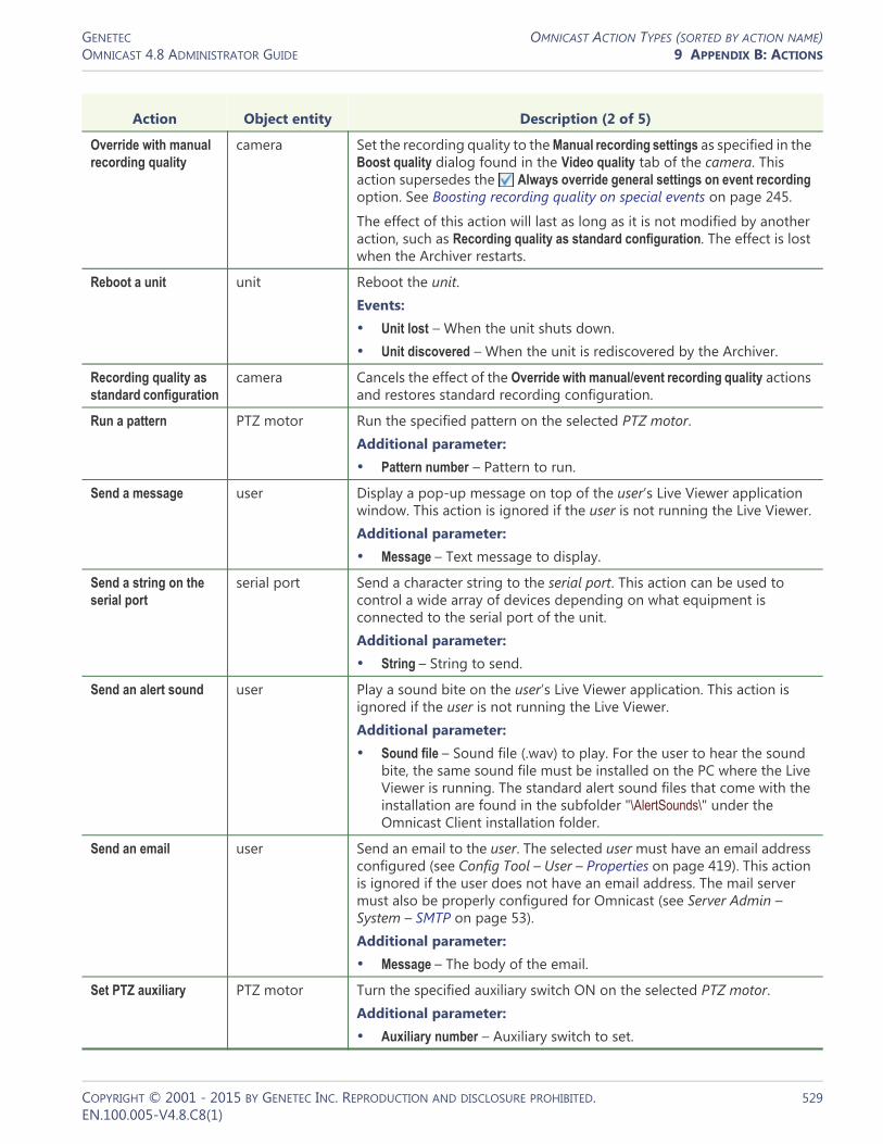
GENETEC OMNICAST ACTION TYPES (SORTED BY ACTION NAME)OMNICAST 4.8 ADMINISTRATOR GUIDE 9 APPENDIX B: ACTIONS
Override with manual recording quality
camera Set the recording quality to the Manual recording settings as specified in the Boost quality dialog found in the Video quality tab of the camera. This action supersedes the Always override general settings on event recording option. See Boosting recording quality on special events on page 245.
The effect of this action will last as long as it is not modified by another action, such as Recording quality as standard configuration. The effect is lost when the Archiver restarts.
Reboot a unit unit Reboot the unit.Events:• Unit lost – When the unit shuts down.• Unit discovered – When the unit is rediscovered by the Archiver.
Recording quality as standard configuration
camera Cancels the effect of the Override with manual/event recording quality actions and restores standard recording configuration.
Run a pattern PTZ motor Run the specified pattern on the selected PTZ motor.Additional parameter:• Pattern number – Pattern to run.
Send a message user Display a pop-up message on top of the user’s Live Viewer application window. This action is ignored if the user is not running the Live Viewer.Additional parameter:• Message – Text message to display.
Send a string on the serial port
serial port Send a character string to the serial port. This action can be used to control a wide array of devices depending on what equipment is connected to the serial port of the unit.Additional parameter:• String – String to send.
Send an alert sound user Play a sound bite on the user’s Live Viewer application. This action is ignored if the user is not running the Live Viewer.Additional parameter:• Sound file – Sound file (.wav) to play. For the user to hear the sound
bite, the same sound file must be installed on the PC where the Live Viewer is running. The standard alert sound files that come with the installation are found in the subfolder "\AlertSounds\" under the Omnicast Client installation folder.
Send an email user Send an email to the user. The selected user must have an email address configured (see Config Tool – User – Properties on page 419). This action is ignored if the user does not have an email address. The mail server must also be properly configured for Omnicast (see Server Admin – System – SMTP on page 53).Additional parameter:• Message – The body of the email.
Set PTZ auxiliary PTZ motor Turn the specified auxiliary switch ON on the selected PTZ motor.Additional parameter:• Auxiliary number – Auxiliary switch to set.
Action Object entity Description (2 of 5)
COPYRIGHT © 2001 - 2015 BY GENETEC INC. REPRODUCTION AND DISCLOSURE PROHIBITED. 529EN.100.005-V4.8.C8(1)

GENETEC OMNICAST ACTION TYPES (SORTED BY ACTION NAME)OMNICAST 4.8 ADMINISTRATOR GUIDE 9 APPENDIX B: ACTIONS
Set the output relay to its default state
output relay Set the value of the output relay to its default state. This action can be used to activate or deactivate a device connected to the output relay (door bell, light, etc.).
Set the output relay to the opposite of its default state
output relay Set the value of the output relay to the opposite value of its default state. This action can be used to activate or deactivate a device connected to the output relay (door bell, light, etc.).
Start applying video protection
camera Protect against deletion all video to be recorded within the next m minutes for a period of n days.Additional parameters:• Protect all video recording to come – What to protect (indefinitely or the
next m minutes). If Indefinitely is selected, all future video recordings will be protected until the action Stop applying video protection is executed.
• For this time period – Duration of the protection (indefinitely or after n days). If Indefinitely is selected, the protection can only be removed manually from the Archive Player See Video File Protection in Omnicast Archive Player User Guide.
The protection will in fact be applied on all video files needed to store the protected video sequence. Since no video file can be partially protected, the actual length of the protected video sequence will depend on the granularity of the video files. See Server Admin – Archiver – Additional archiving options on page 90.
When multiple Start applying video protection actions are applied on the same video file, the longest protection period will be kept.
Start plugin plugin Start the specified plugin (ME plugin or VM plugin). The plugin must be set to Manual mode.Events:• Plugin started – When the plugin starts.• Plugin error – If the plugin execution fails.
Start recording camera Start recording on the camera. This action is ignored if the camera is not on an active archiving schedule. The recording by this action cannot be stopped manually by a user. Additional parameters:• Duration – Duration of the recording.
– Default manual recording length – Follows the Default manual recording length configured for the selected camera in the Recording tab.
– Infinite – The recording must be explicitly stopped by executing the Stop recording action.
– Specific (from 1 to 600 sec.) – Recording will stop after the specified duration.
Events:• The Recording started (external) event is generated when this action is
triggered.• The Recording stopped (external) event is generated when the recording
stops, either by itself or when the Stop recording action is executed.
Action Object entity Description (3 of 5)
COPYRIGHT © 2001 - 2015 BY GENETEC INC. REPRODUCTION AND DISCLOSURE PROHIBITED. 530EN.100.005-V4.8.C8(1)

GENETEC OMNICAST ACTION TYPES (SORTED BY ACTION NAME)OMNICAST 4.8 ADMINISTRATOR GUIDE 9 APPENDIX B: ACTIONS
Stop applying video protection
camera Stop protecting upcoming video recordings against deletion, either immediately or in m minutes.Additional parameters:• Protection on video recordings to come will stop:
– Now – Immediately.– After the time specified in minutes – Video recordings will cease to be
protected after the specified number of minutes.
This action does not affect the video archives that are already protected. It only affects the video archives yet to come.
Stop plugin plugin Stop the specified plugin (ME plugin or VM plugin). The plugin must be set to Manual mode.Events:• Plugin stopped
Stop recording camera Stop recording on the camera. This action works only if the recording was started by the Start recording action.Additional parameters:• Delay before stopping the recording:
– Default time to record after a motion event – See Config Tool – Camera – Recording settings on page 248.
– None – Stops immediately.Events:• The Recording stopped (external) event is generated when this action is
executed successfully.
Trigger alarm alarm Trigger the alarm. See Alarm Management on page 7.Additional parameters:• Description – Optional text that can be used to search for this alarm in
the future. See Alarm Search Workflow in the Omnicast Archive Player User Guide.
• Add the source camera to the list – Applicable only if this action is associated to a camera event. Select this option to add the current camera to the alarm’s camera list. The added camera can only be displayed as live video.
Events:• Alarm triggered – Once.• Alarm activated – Once for every alarm recipient.
Unblock a camera camera Unblock the camera. See Block a camera action.
View a camera in a free Live Viewer’s tile
camera This action is similar to View a camera in the Live Viewer, except that when there is no free viewing tile available, the action is ignored.
To fully grasp the meaning of a "free" viewing tile, please read the section on Display Management in the Omnicast Live Viewer User Guide.
Action Object entity Description (4 of 5)
COPYRIGHT © 2001 - 2015 BY GENETEC INC. REPRODUCTION AND DISCLOSURE PROHIBITED. 531EN.100.005-V4.8.C8(1)

GENETEC OMNICAST ACTION TYPES (SORTED BY ACTION NAME)OMNICAST 4.8 ADMINISTRATOR GUIDE 9 APPENDIX B: ACTIONS
View a camera in the Live Viewer
camera Show the camera in the Live Viewer with a red flashing border around the viewing tile. The purpose of this action is to attract the user's attention to a camera. The highlight will disappear when the user clicks on the tile in the Live Viewer. See Viewing Tile in Omnicast Live Viewer User Guide.
If the camera is already displayed in the Live Viewer, this action will simply turn the red flashing highlight ON. If the camera is not yet displayed in the Live Viewer, the camera will be displayed in an free tile. If there is no free tile, the oldest displayed camera will be replaced by the new one.
If the connected user has no privilege to view the specified camera, the action will be ignored.
View a map in the Live Viewer
map Show the map in the Live Viewer. A map is selected by selecting the site it is attached to (see Config Tool – Site – Maps on page 399).
The HTML Map option must be supported by your Omnicast license for this action to take effect. The behavior of this action is similar to View a camera in the Live Viewer.
View the camera on an analog monitor
analog monitor Display the current camera on the specified analog monitor. This action should be associated to a camera event. The current camera is the source entity of the event. See Omnicast Event Types (sorted by source entity) on page 518.
Action Object entity Description (5 of 5)
COPYRIGHT © 2001 - 2015 BY GENETEC INC. REPRODUCTION AND DISCLOSURE PROHIBITED. 532EN.100.005-V4.8.C8(1)

GENETEC OMNICAST ACTION TYPES (SORTED BY OBJECT ENTITY)OMNICAST 4.8 ADMINISTRATOR GUIDE 9 APPENDIX B: ACTIONS
Omnicast Action Types (sorted by object entity)
The object entity is the main focus of the action.
Action Object entity Description (1 of 5)
Trigger alarm alarm Trigger the alarm. See Alarm Management on page 7.Additional parameters:• Description – Optional text that can be used to search for this alarm in
the future. See Alarm Search Workflow in the Omnicast Archive Player User Guide.
• Add the source camera to the list – Applicable only if this action is associated to a camera event. Select this option to add the current camera to the alarm’s camera list. The added camera can only be displayed as live video.
Events:• Alarm triggered – Once.• Alarm activated – Once for every alarm recipient.
View the camera on an analog monitor
analog monitor Display the current camera on the specified analog monitor. This action should be associated to a camera event. The current camera is the source entity of the event. See Omnicast Event Types (sorted by source entity) on page 518.
Add a bookmark camera Add a bookmark to the recording of the camera.Additional parameter:• Bookmark – Bookmark text.Events:• Live bookmark added
• Recording started (user) – If the recording is started as a consequence of adding the bookmark.
Block a camera camera Block the camera at the specified blocking level. See Camera Blocking in the Omnicast Live Viewer User Guide.
Override with event recording quality
camera Set the recording quality to the Event recording settings as specified in the Boost quality dialog found in the Video quality tab of the camera. This action supersedes the Always override general settings on manual recording option. See Boosting recording quality on special events on page 245.
The effect of this action will last as long as it is not modified by another action, such as Recording quality as standard configuration. The effect is lost when the Archiver restarts.
Override with manual recording quality
camera Set the recording quality to the Manual recording settings as specified in the Boost quality dialog found in the Video quality tab of the camera. This action supersedes the Always override general settings on event recording option. See Boosting recording quality on special events on page 245.
The effect of this action will last as long as it is not modified by another action, such as Recording quality as standard configuration. The effect is lost when the Archiver restarts.
COPYRIGHT © 2001 - 2015 BY GENETEC INC. REPRODUCTION AND DISCLOSURE PROHIBITED. 533EN.100.005-V4.8.C8(1)

GENETEC OMNICAST ACTION TYPES (SORTED BY OBJECT ENTITY)OMNICAST 4.8 ADMINISTRATOR GUIDE 9 APPENDIX B: ACTIONS
Recording quality as standard configuration
camera Cancels the effect of the Override with manual/event recording quality actions and restores standard recording configuration.
Start applying video protection
camera Protect against deletion all video to be recorded within the next m minutes for a period of n days.Additional parameters:• Protect all video recording to come – What to protect (indefinitely or the
next m minutes). If Indefinitely is selected, all future video recordings will be protected until the action Stop applying video protection is executed.
• For this time period – Duration of the protection (indefinitely or after n days). If Indefinitely is selected, the protection can only be removed manually from the Archive Player See Video File Protection in Omnicast Archive Player User Guide.
The protection will in fact be applied on all video files needed to store the protected video sequence. Since no video file can be partially protected, the actual length of the protected video sequence will depend on the granularity of the video files. See Server Admin – Archiver – Additional archiving options on page 90.
When multiple Start applying video protection actions are applied on the same video file, the longest protection period will be kept.
Start recording camera Start recording on the camera. This action is ignored if the camera is not on an active archiving schedule. The recording by this action cannot be stopped manually by a user. Additional parameters:• Duration – Duration of the recording.
– Default manual recording length – Follows the Default manual recording length configured for the selected camera in the Recording tab.
– Infinite – The recording must be explicitly stopped by executing the Stop recording action.
– Specific (from 1 to 600 sec.) – Recording will stop after the specified duration.
Events:• The Recording started (external) event is generated when this action is
triggered.• The Recording stopped (external) event is generated when the recording
stops, either by itself or when the Stop recording action is executed.
Stop applying video protection
camera Stop protecting upcoming video recordings against deletion, either immediately or in m minutes.Additional parameters:• Protection on video recordings to come will stop:
– Now – Immediately.– After the time specified in minutes – Video recordings will cease to be
protected after the specified number of minutes.
This action does not affect the video archives that are already protected. It only affects the video archives yet to come.
Action Object entity Description (2 of 5)
COPYRIGHT © 2001 - 2015 BY GENETEC INC. REPRODUCTION AND DISCLOSURE PROHIBITED. 534EN.100.005-V4.8.C8(1)

GENETEC OMNICAST ACTION TYPES (SORTED BY OBJECT ENTITY)OMNICAST 4.8 ADMINISTRATOR GUIDE 9 APPENDIX B: ACTIONS
Stop recording camera Stop recording on the camera. This action works only if the recording was started by the Start recording action.Additional parameters:• Delay before stopping the recording:
– Default time to record after a motion event – See Config Tool – Camera – Recording settings on page 248.
– None – Stops immediately.Events:• The Recording stopped (external) event is generated when this action is
executed successfully.
Unblock a camera camera Unblock the camera. See Block a camera action.
View a camera in a free Live Viewer’s tile
camera This action is similar to View a camera in the Live Viewer, except that when there is no free viewing tile available, the action is ignored.
To fully grasp the meaning of a "free" viewing tile, please read the section on Display Management in the Omnicast Live Viewer User Guide.
View a camera in the Live Viewer
camera Show the camera in the Live Viewer with a red flashing border around the viewing tile. The purpose of this action is to attract the user's attention to a camera. The highlight will disappear when the user clicks on the tile in the Live Viewer. See Viewing Tile in Omnicast Live Viewer User Guide.
If the camera is already displayed in the Live Viewer, this action will simply turn the red flashing highlight ON. If the camera is not yet displayed in the Live Viewer, the camera will be displayed in an free tile. If there is no free tile, the oldest displayed camera will be replaced by the new one.
If the connected user has no privilege to view the specified camera, the action will be ignored.
Display a URL address in a Live Viewer
Live Viewer Display a Web page in the selected Live Viewer.Additional parameter:• URL address – Address of the Web page.
The behavior of this action is similar to View a camera in the Live Viewer.
Execute a macro macro Start the execution of the macro. See Config Tool – Macro on page 341.Additional parameter:• Virtual Matrix – The Virtual Matrix that will be executing the macro.Events:• Macro started – When the macro execution starts.• Macro stopped – When the macro execution ends.• Macro error – If the macro execution fails.
View a map in the Live Viewer
map Show the map in the Live Viewer. A map is selected by selecting the site it is attached to (see Config Tool – Site – Maps on page 399).
The HTML Map option must be supported by your Omnicast license for this action to take effect. The behavior of this action is similar to View a camera in the Live Viewer.
Action Object entity Description (3 of 5)
COPYRIGHT © 2001 - 2015 BY GENETEC INC. REPRODUCTION AND DISCLOSURE PROHIBITED. 535EN.100.005-V4.8.C8(1)

GENETEC OMNICAST ACTION TYPES (SORTED BY OBJECT ENTITY)OMNICAST 4.8 ADMINISTRATOR GUIDE 9 APPENDIX B: ACTIONS
Set the output relay to its default state
output relay Set the value of the output relay to its default state. This action can be used to activate or deactivate a device connected to the output relay (door bell, light, etc.).
Set the output relay to the opposite of its default state
output relay Set the value of the output relay to the opposite value of its default state. This action can be used to activate or deactivate a device connected to the output relay (door bell, light, etc.).
Start plugin plugin Start the specified plugin (ME plugin or VM plugin). The plugin must be set to Manual mode.Events:• Plugin started – When the plugin starts.• Plugin error – If the plugin execution fails.
Stop plugin plugin Stop the specified plugin (ME plugin or VM plugin). The plugin must be set to Manual mode.Events:• Plugin stopped
Clear PTZ auxiliary PTZ motor Turn the specified auxiliary switch OFF on the selected PTZ motor.Additional parameter:• Auxiliary number – Auxiliary switch to clear.
Go to home PTZ motor Command the selected PTZ motor to go to its home position. Not all PTZ protocol supports this feature.
Go to preset PTZ motor Command the PTZ motor to go to the specified preset position.Additional parameter:• Preset number – Preset to go to.
Run a pattern PTZ motor Run the specified pattern on the selected PTZ motor.Additional parameter:• Pattern number – Pattern to run.
Set PTZ auxiliary PTZ motor Turn the specified auxiliary switch ON on the selected PTZ motor.Additional parameter:• Auxiliary number – Auxiliary switch to set.
Send a string on the serial port
serial port Send a character string to the serial port. This action can be used to control a wide array of devices depending on what equipment is connected to the serial port of the unit.Additional parameter:• String – String to send.
Reboot a unit unit Reboot the unit.Events:• Unit lost – When the unit shuts down.• Unit discovered – When the unit is rediscovered by the Archiver.
Action Object entity Description (4 of 5)
COPYRIGHT © 2001 - 2015 BY GENETEC INC. REPRODUCTION AND DISCLOSURE PROHIBITED. 536EN.100.005-V4.8.C8(1)

GENETEC OMNICAST ACTION TYPES (SORTED BY OBJECT ENTITY)OMNICAST 4.8 ADMINISTRATOR GUIDE 9 APPENDIX B: ACTIONS
Send a message user Display a pop-up message on top of the user’s Live Viewer application window. This action is ignored if the user is not running the Live Viewer.Additional parameter:• Message – Text message to display.
Send an alert sound user Play a sound bite on the user’s Live Viewer application. This action is ignored if the user is not running the Live Viewer.Additional parameter:• Sound file – Sound file (.wav) to play. For the user to hear the sound
bite, the same sound file must be installed on the PC where the Live Viewer is running. The standard alert sound files that come with the installation are found in the subfolder "\AlertSounds\" under the Omnicast Client installation folder.
Send an email user Send an email to the user. The selected user must have an email address configured (see Config Tool – User – Properties on page 419). This action is ignored if the user does not have an email address. The mail server must also be properly configured for Omnicast (see Server Admin – System – SMTP on page 53).Additional parameter:• Message – The body of the email.
Action Object entity Description (5 of 5)
COPYRIGHT © 2001 - 2015 BY GENETEC INC. REPRODUCTION AND DISCLOSURE PROHIBITED. 537EN.100.005-V4.8.C8(1)
SECTION 10
APPENDIX C: TIME ZONE ABBREVIATIONS
Description of time zone abbreviations

GENETEC TIME ZONES IN OMNICASTOMNICAST 4.8 ADMINISTRATOR GUIDE 10 APPENDIX C: TIME ZONE ABBREVIATIONS
Time Zones in Omnicast
Introduction Omnicast supports multiple time zones. On a system where multiple time zones are being used, you have the choice to display a time zone abbreviation wherever a time is displayed. See• Time Zone Abbreviations (sorted by time zone) on page 540• Time Zone Abbreviations (sorted by abbreviation) on page 544
Turning on the time zone display
The time zone abbreviation display can be turned on from any of the three main client applications: Live Viewer, Archive Player, and Config Tool. To do this, select Tools > Options > Date and Time from the main menu, and enable the option Display time zone abbreviations.
COPYRIGHT © 2001 - 2015 BY GENETEC INC. REPRODUCTION AND DISCLOSURE PROHIBITED. 539EN.100.005-V4.8.C8(1)

GENETEC TIME ZONE ABBREVIATIONS (SORTED BY TIME ZONE)OMNICAST 4.8 ADMINISTRATOR GUIDE 10 APPENDIX C: TIME ZONE ABBREVIATIONS
Time Zone Abbreviations (sorted by time zone)
Time zone (1 of 4) Abbrev. Meaning
(GMT-12:00) International Date Line West IDLW International Date Line West
(GMT-11:00) Midway Island, Samoa SST Samoa Standard Time
(GMT-10:00) Hawaii HST Hawaiian Standard Time
(GMT-09:00) Alaska AKST Alaska Standard Time
AKDT Alaska Daylight Time
(GMT-08:00) Pacific Time (US & Canada); Tijuana PST Pacific Standard Time
PDT Pacific Daylight Time
(GMT-07:00) Mountain Time (US & Canada) MST US Mountain Standard Time
MDT US Mountain Daylight Time
(GMT-07:00) Chihuahua, La Paz, Mazatlan MST US Mountain Standard Time
MDT US Mountain Daylight Time
(GMT-07:00) Arizona MST US Mountain Standard Time
(GMT-06:00) Saskatchewan CST Central Standard Time
(GMT-06:00) Guadalajara, Mexico City, Monterrey CST Central Standard Time
CDT Central Daylight Time
(GMT-06:00) Central Time (US & Canada) CST Central Standard Time
CDT Central Daylight Time
(GMT-06:00) Central America CST Central Standard Time
(GMT-05:00) Indiana (East) EST Eastern Standard Time
(GMT-05:00) Eastern Time (US & Canada) EST Eastern Standard Time
EDT Eastern Daylight Time
(GMT-05:00) Bogota, Lima, Quito COT Colombia Time
(GMT-04:00) Santiago CLT Chile Time
CLST Chile Summer Time
(GMT-04:00) Caracas, La Paz VET Venezuela Time
(GMT-04:00) Atlantic Time (Canada) AST Atlantic Standard Time
ADT Atlantic Daylight Time
(GMT-03:30) Newfoundland NST Newfoundland Standard Time
NDT Newfoundland Daylight Time
(GMT-03:00) Greenland GST Greenland Standard Time
GDT Greenland Daylight Time
(GMT-03:00) Buenos Aires, Georgetown ART Argentina Time
(GMT-03:00) Brasilia BST Brazil Standard Time
COPYRIGHT © 2001 - 2015 BY GENETEC INC. REPRODUCTION AND DISCLOSURE PROHIBITED. 540EN.100.005-V4.8.C8(1)

GENETEC TIME ZONE ABBREVIATIONS (SORTED BY TIME ZONE)OMNICAST 4.8 ADMINISTRATOR GUIDE 10 APPENDIX C: TIME ZONE ABBREVIATIONS
BDT Brazil Daylight Time
(GMT-02:00) Mid-Atlantic MAST Mid-Atlantic Standard Time
MADT Mid-Atlantic Daylight Time
(GMT-01:00) Cape Verde Is. CVT Cape Verde Time
(GMT-01:00) Azores AZOT Azores Time
AZOST Azores Summer Time
(GMT) Casablanca, Monrovia GMT Greenwich Mean Time
(GMT) Greenwich Mean Time GMT Greenwich Mean Time
GMST Greenwich Mean Summer Time
(GMT+01:00) Amsterdam, Berlin, Bern, Rome, Stockholm, Vienna
CET Central Europe Time
CEST Central Europe Summer Time
(GMT+01:00) Belgrade, Bratislava, Budapest, Ljubljana, Prague
CET Central Europe Time
CEST Central Europe Summer Time
(GMT+01:00) Brussels, Copenhagen, Madrid, Paris CET Central Europe Time
CEST Central Europe Summer Time
(GMT+01:00) Sarajevo, Skopje, Warsaw, Zagreb CET Central Europe Time
CEST Central Europe Summer Time
(GMT+01:00) West Central Africa WAT West Africa Time
(GMT+02:00) Athens, Istanbul, Minsk EET Eastern Europe Time
EEST Eastern Europe Summer Time
(GMT+02:00) Bucharest EET Eastern Europe Time
EEST Eastern Europe Summer Time
(GMT+02:00) Cairo EET Eastern Europe Time
EEST Eastern Europe Summer Time
(GMT+02:00) Helsinki, Kyiv, Riga, Sofia, Tallinn, Vilnius EET Eastern Europe Time
EEST Eastern Europe Summer Time
(GMT+02:00) Jerusalem IST Israeli Standard Time
(GMT+03:00) Baghdad AST Arabia Standard Time
ADT Arabia Daylight Time
(GMT+03:00) Kuwait, Riyadh AST Arabia Standard Time
(GMT+03:00) Moscow, St. Petersburg, Volgograd MSKS Moscow Summer Time
MSK Moscow Time
(GMT+03:00) Nairobi EAT East Africa Time
(GMT+03:30) Tehran IRT Iran Time
Time zone (2 of 4) Abbrev. Meaning
COPYRIGHT © 2001 - 2015 BY GENETEC INC. REPRODUCTION AND DISCLOSURE PROHIBITED. 541EN.100.005-V4.8.C8(1)

GENETEC TIME ZONE ABBREVIATIONS (SORTED BY TIME ZONE)OMNICAST 4.8 ADMINISTRATOR GUIDE 10 APPENDIX C: TIME ZONE ABBREVIATIONS
IRST Iran Summer Time
(GMT+04:00) Abu Dhabi, Muscat GST Gulf Standard Time
(GMT+04:00) Baku, Tbilisi, Yerevan AZT Azerbaijan Time
AZST Azerbaijan Summer Time
(GMT+04:30) Kabul AFT Afghanistan Time
(GMT+05:00) Ekaterinburg YEKT Yekaterinburg Time
YEKST Yekaterinburg Summer Time
(GMT+05:00) Islamabad, Karachi, Tashkent PKT Pakistan Time
(GMT+05:30) Chennai, Kolkata, Mumbai, New Delhi IST Indian Standard Time
(GMT+05:45) Kathmandu NPT Nepal Time
(GMT+06:00) Almaty, Novosibirsk NOVT Novosibirsk Time
NOVST Novosibirsk Summer Time
(GMT+06:00) Astana, Dhaka BDT Bangladesh Time
(GMT+06:00) Sri Jayawardenepura LKT Lanka Time
(GMT+06:30) Rangoon MMT Myanmar Time
(GMT+07:00) Bangkok, Hanoi, Jakarta ICT Indochina Time
(GMT+07:00) Krasnoyarsk KRAT Krasnoyarsk Time
KRAST Krasnoyarsk Summer Time
(GMT+08:00) Beijing, Chongqing, Hong Kong, Urumqi CST China Time
(GMT+08:00) Irkutsk, Ulaan Bataar IRKT Irkutsk Time
IRKST Irkutsk Summer Time
(GMT+08:00) Kuala Lumpur, Singapore MYT Malaysia Time
(GMT+08:00) Perth AWST Australian Western Standard Time
(GMT+08:00) Taipei CST China Time
(GMT+09:00) Osaka, Sapporo, Tokyo JST Japan Standard Time
(GMT+09:00) Seoul KST Korean Standard Time
(GMT+09:00) Yakutsk YAKT Yakutsk Time
YAKST Yakutsk Summer Time
(GMT+09:30) Adelaide ACST Australian Central Standard Time
ACDT Australian Central Daylight Time
(GMT+09:30) Darwin ACST Australian Central Standard Time
ACDT Australian Central Daylight Time
(GMT+10:00) Brisbane AEST Australian Eastern Standard Time
(GMT+10:00) Canberra, Melbourne, Sydney AEST Australian Eastern Standard Time
AEDT Australian Eastern Daylight Time
Time zone (3 of 4) Abbrev. Meaning
COPYRIGHT © 2001 - 2015 BY GENETEC INC. REPRODUCTION AND DISCLOSURE PROHIBITED. 542EN.100.005-V4.8.C8(1)

GENETEC TIME ZONE ABBREVIATIONS (SORTED BY TIME ZONE)OMNICAST 4.8 ADMINISTRATOR GUIDE 10 APPENDIX C: TIME ZONE ABBREVIATIONS
(GMT+10:00) Guam, Port Moresby PGT Papua New Guinea Time
(GMT+10:00) Hobart AEST Australian Eastern Standard Time
AEDT Australian Eastern Daylight Time
(GMT+10:00) Vladivostok VLAT Vladivostok Time
VLAST Vladivostok Summer Time
(GMT+11:00) Magadan, Solomon Is., New Caledonia MAGT Magadan Time
(GMT+12:00) Auckland, Wellington NZST New Zealand Standard Time
NZDT New Zealand Daylight Time
(GMT+12:00) Fiji, Kamchatka, Marshall Is. FJT Fiji Time
(GMT+13:00) Nuku'alofa TOT Tonga Time
Time zone (4 of 4) Abbrev. Meaning
COPYRIGHT © 2001 - 2015 BY GENETEC INC. REPRODUCTION AND DISCLOSURE PROHIBITED. 543EN.100.005-V4.8.C8(1)

GENETEC TIME ZONE ABBREVIATIONS (SORTED BY ABBREVIATION)OMNICAST 4.8 ADMINISTRATOR GUIDE 10 APPENDIX C: TIME ZONE ABBREVIATIONS
Time Zone Abbreviations (sorted by abbreviation)
Abbrev. Meaning Time zone (1 of 4)
ACDT Australian Central Daylight Time (GMT+09:30) Adelaide
ACDT Australian Central Daylight Time (GMT+09:30) Darwin
ACST Australian Central Standard Time (GMT+09:30) Adelaide
ACST Australian Central Standard Time (GMT+09:30) Darwin
ADT Arabia Daylight Time (GMT+03:00) Baghdad
ADT Arabia Daylight Time (GMT-04:00) Atlantic Time (Canada)
AEDT Australian Eastern Daylight Time (GMT+10:00) Canberra, Melbourne, Sydney
AEDT Australian Eastern Daylight Time (GMT+10:00) Hobart
AEST Australian Eastern Standard Time (GMT+10:00) Brisbane
AEST Australian Eastern Standard Time (GMT+10:00) Canberra, Melbourne, Sydney
AEST Australian Eastern Standard Time (GMT+10:00) Hobart
AFT Afghanistan Time (GMT+04:30) Kabul
AKDT Alaska Daylight Time (GMT-09:00) Alaska
AKST Alaska Standard Time (GMT-09:00) Alaska
ART Argentina Time (GMT-03:00) Buenos Aires, Georgetown
AST Arabia Standard Time (GMT+03:00) Baghdad
AST Arabia Standard Time (GMT+03:00) Kuwait, Riyadh
AST Arabia Standard Time (GMT-04:00) Atlantic Time (Canada)
AWST Australian Western Standard Time (GMT+08:00) Perth
AZOST Azores Summer Time (GMT-01:00) Azores
AZOT Azores Time (GMT-01:00) Azores
AZST Azerbaijan Summer Time (GMT+04:00) Baku, Tbilisi, Yerevan
AZT Azerbaijan Time (GMT+04:00) Baku, Tbilisi, Yerevan
BDT Bangladesh Time (GMT+06:00) Astana, Dhaka
BDT Brazil Daylight Time (GMT-03:00) Brasilia
BST Brazil Standard Time (GMT-03:00) Brasilia
CDT Central Daylight Time (GMT-06:00) Central Time (US & Canada)
CDT Central Daylight Time (GMT-06:00) Guadalajara, Mexico City, Monterrey
CEST Central Europe Summer Time (GMT+01:00) Amsterdam, Berlin, Bern, Rome, Stockholm, Vienna
CEST Central Europe Summer Time (GMT+01:00) Belgrade, Bratislava, Budapest, Ljubljana, Prague
CEST Central Europe Summer Time (GMT+01:00) Brussels, Copenhagen, Madrid, Paris
CEST Central Europe Summer Time (GMT+01:00) Sarajevo, Skopje, Warsaw, Zagreb
COPYRIGHT © 2001 - 2015 BY GENETEC INC. REPRODUCTION AND DISCLOSURE PROHIBITED. 544EN.100.005-V4.8.C8(1)

GENETEC TIME ZONE ABBREVIATIONS (SORTED BY ABBREVIATION)OMNICAST 4.8 ADMINISTRATOR GUIDE 10 APPENDIX C: TIME ZONE ABBREVIATIONS
CET Central Europe Time (GMT+01:00) Amsterdam, Berlin, Bern, Rome, Stockholm, Vienna
CET Central Europe Time (GMT+01:00) Belgrade, Bratislava, Budapest, Ljubljana, Prague
CET Central Europe Time (GMT+01:00) Brussels, Copenhagen, Madrid, Paris
CET Central Europe Time (GMT+01:00) Sarajevo, Skopje, Warsaw, Zagreb
CLST Chile Summer Time (GMT-04:00) Santiago
CLT Chile Time (GMT-04:00) Santiago
COT Colombia Time (GMT-05:00) Bogota, Lima, Quito
CST China Time (GMT+08:00) Beijing, Chongqing, Hong Kong, Urumqi
CST China Time (GMT+08:00) Taipei
CST Central Standard Time (GMT-06:00) Central America
CST Central Standard Time (GMT-06:00) Central Time (US & Canada)
CST Central Standard Time (GMT-06:00) Guadalajara, Mexico City, Monterrey
CST Central Standard Time (GMT-06:00) Saskatchewan
CVT Cape Verde Time (GMT-01:00) Cape Verde Is.
EAT East Africa Time (GMT+03:00) Nairobi
EDT Eastern Daylight Time (GMT-05:00) Eastern Time (US & Canada)
EEST Eastern Europe Summer Time (GMT+02:00) Athens, Istanbul, Minsk
EEST Eastern Europe Summer Time (GMT+02:00) Bucharest
EEST Eastern Europe Summer Time (GMT+02:00) Cairo
EEST Eastern Europe Summer Time (GMT+02:00) Helsinki, Kyiv, Riga, Sofia, Tallinn, Vilnius
EET Eastern Europe Time (GMT+02:00) Athens, Istanbul, Minsk
EET Eastern Europe Time (GMT+02:00) Bucharest
EET Eastern Europe Time (GMT+02:00) Cairo
EET Eastern Europe Time (GMT+02:00) Helsinki, Kyiv, Riga, Sofia, Tallinn, Vilnius
EST Eastern Standard Time (GMT-05:00) Eastern Time (US & Canada)
EST Eastern Standard Time (GMT-05:00) Indiana (East)
FJT Fiji Time (GMT+12:00) Fiji, Kamchatka, Marshall Is.
GDT Greenland Daylight Time (GMT-03:00) Greenland
GMST Greenwich Mean Summer Time (GMT) Greenwich Mean Time
GMT Greenwich Mean Time (GMT) Casablanca, Monrovia
GMT Greenwich Mean Time (GMT) Greenwich Mean Time
GST Gulf Standard Time (GMT+04:00) Abu Dhabi, Muscat
GST Greenland Standard Time (GMT-03:00) Greenland
HST Hawaiian Standard Time (GMT-10:00) Hawaii
Abbrev. Meaning Time zone (2 of 4)
COPYRIGHT © 2001 - 2015 BY GENETEC INC. REPRODUCTION AND DISCLOSURE PROHIBITED. 545EN.100.005-V4.8.C8(1)

GENETEC TIME ZONE ABBREVIATIONS (SORTED BY ABBREVIATION)OMNICAST 4.8 ADMINISTRATOR GUIDE 10 APPENDIX C: TIME ZONE ABBREVIATIONS
ICT Indochina Time (GMT+07:00) Bangkok, Hanoi, Jakarta
IDLW International Date Line West (GMT-12:00) International Date Line West
IRKST Irkutsk Summer Time (GMT+08:00) Irkutsk, Ulaan Bataar
IRKT Irkutsk Time (GMT+08:00) Irkutsk, Ulaan Bataar
IRST Iran Summer Time (GMT+03:30) Tehran
IRT Iran Time (GMT+03:30) Tehran
IST Israeli Standard Time (GMT+02:00) Jerusalem
IST Indian Standard Time (GMT+05:30) Chennai, Kolkata, Mumbai, New Delhi
JST Japan Standard Time (GMT+09:00) Osaka, Sapporo, Tokyo
KRAST Krasnoyarsk Summer Time (GMT+07:00) Krasnoyarsk
KRAT Krasnoyarsk Time (GMT+07:00) Krasnoyarsk
KST Korean Standard Time (GMT+09:00) Seoul
LKT Lanka Time (GMT+06:00) Sri Jayawardenepura
MADT Mid-Atlantic Daylight Time (GMT-02:00) Mid-Atlantic
MAGT Magadan Time (GMT+11:00) Magadan, Solomon Is., New Caledonia
MAST Mid-Atlantic Standard Time (GMT-02:00) Mid-Atlantic
MDT US Mountain Daylight Time (GMT-07:00) Chihuahua, La Paz, Mazatlan
MDT US Mountain Daylight Time (GMT-07:00) Mountain Time (US & Canada)
MMT Myanmar Time (GMT+06:30) Rangoon
MSK Moscow Time (GMT+03:00) Moscow, St. Petersburg, Volgograd
MSKS Moscow Summer Time (GMT+03:00) Moscow, St. Petersburg, Volgograd
MST US Mountain Standard Time (GMT-07:00) Arizona
MST US Mountain Standard Time (GMT-07:00) Chihuahua, La Paz, Mazatlan
MST US Mountain Standard Time (GMT-07:00) Mountain Time (US & Canada)
MYT Malaysia Time (GMT+08:00) Kuala Lumpur, Singapore
NDT Newfoundland Daylight Time (GMT-03:30) Newfoundland
NOVST Novosibirsk Summer Time (GMT+06:00) Almaty, Novosibirsk
NOVT Novosibirsk Time (GMT+06:00) Almaty, Novosibirsk
NPT Nepal Time (GMT+05:45) Kathmandu
NST Newfoundland Standard Time (GMT-03:30) Newfoundland
NZDT New Zealand Daylight Time (GMT+12:00) Auckland, Wellington
NZST New Zealand Standard Time (GMT+12:00) Auckland, Wellington
PDT Pacific Daylight Time (GMT-08:00) Pacific Time (US & Canada); Tijuana
PGT Papua New Guinea Time (GMT+10:00) Guam, Port Moresby
PKT Pakistan Time (GMT+05:00) Islamabad, Karachi, Tashkent
Abbrev. Meaning Time zone (3 of 4)
COPYRIGHT © 2001 - 2015 BY GENETEC INC. REPRODUCTION AND DISCLOSURE PROHIBITED. 546EN.100.005-V4.8.C8(1)
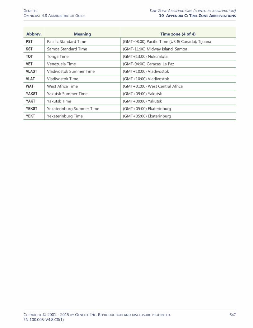
GENETEC TIME ZONE ABBREVIATIONS (SORTED BY ABBREVIATION)OMNICAST 4.8 ADMINISTRATOR GUIDE 10 APPENDIX C: TIME ZONE ABBREVIATIONS
PST Pacific Standard Time (GMT-08:00) Pacific Time (US & Canada); Tijuana
SST Samoa Standard Time (GMT-11:00) Midway Island, Samoa
TOT Tonga Time (GMT+13:00) Nuku'alofa
VET Venezuela Time (GMT-04:00) Caracas, La Paz
VLAST Vladivostok Summer Time (GMT+10:00) Vladivostok
VLAT Vladivostok Time (GMT+10:00) Vladivostok
WAT West Africa Time (GMT+01:00) West Central Africa
YAKST Yakutsk Summer Time (GMT+09:00) Yakutsk
YAKT Yakutsk Time (GMT+09:00) Yakutsk
YEKST Yekaterinburg Summer Time (GMT+05:00) Ekaterinburg
YEKT Yekaterinburg Time (GMT+05:00) Ekaterinburg
Abbrev. Meaning Time zone (4 of 4)
COPYRIGHT © 2001 - 2015 BY GENETEC INC. REPRODUCTION AND DISCLOSURE PROHIBITED. 547EN.100.005-V4.8.C8(1)

SECTION 11
APPENDIX D: DEFAULT PORTS
Information about the default communication settings for services configured in the Server Admin

GENETEC DEFAULT COMMUNICATION PORT SETTINGSOMNICAST 4.8 ADMINISTRATOR GUIDE 11 APPENDIX D: DEFAULT PORTS
Default Communication Port Settings
Introduction This appendix summarizes the default communication port settings configured for services in the Server Admin. It includes related communication information where applicable.
For complete information about each of the services settings, see their respective section in this user guide.
Summary of ports
Directory Directory port—default 7998
Gateway Incoming TCP command—default 5001
Incoming TCP video— default 5002
Outgoing UDP data—default 8000 to 12000
Outgoing UDP data—default 8000 to 12000
Multicast test address—Gateway default 224.4.0.1
Multicast test address—Client default 224.4.0.2
Archiver Unicast video transmission— 15000-16000
Multicast—default video 47806 default audio 4707
Federation Outbound TCP Port—5001 and 5002
Video port—default 6000
Directory Failover Coordinator
Incoming TCP command—default 7999
Virtual Matrix Video port—default 6000
Directory
Introduction For complete information on the Directory, see Directory on page 55.
Directory port—default 7998
This port number is used by the primary Gateway to detect the presence of the Directory service. Its value must match the Directory port configured in the general settings of the Gateway directly connected to this Directory.
NOTE It is recommended to choose a different directory port for networks in which multiple independent directory systems are running.
Service Default Port
COPYRIGHT © 2001 - 2015 BY GENETEC INC. REPRODUCTION AND DISCLOSURE PROHIBITED. 549EN.100.005-V4.8.C8(1)

GENETEC DEFAULT COMMUNICATION PORT SETTINGSOMNICAST 4.8 ADMINISTRATOR GUIDE 11 APPENDIX D: DEFAULT PORTS
Start multicast address and port
In multicast, all sources (audio and video) are streamed using the same port, but with a different multicast IP address for each, since multicast switches and routers use the destination IP to make their routing decisions.
The Directory assigns the same port to each multicast encoder, but increments the multicast address starting with the address entered for the Start multicast address. The first encoder will use the address entered for the Start multicast address and the next one will use Start multicast address + 1, and so on.
Gateway
Introduction For complete information on the Gateway, see Gateway on page 75.
Incoming TCP connection settings
Incoming TCP command—default
5001
This port is used by the Gateway to listen for incoming client connections.
When the default port 5001 is not used, the client needs to specify the port number after the Gateway name, for example:
gateway_name:4812
Incoming TCP video— default 5002
This is the port that the Gateway uses to listen for incoming TCP video connections. If the Gateway is running behind a firewall, make sure that this port is unlocked for inbound TCP packets.
Outgoing UDP data settings
Outgoing UDP data—default 8000 to 12000
Specify the range of ports that the Gateway can use to send video using UDP. The first port number is also used as a discovery port: determining if unicast connections are supported between the Gateway and the remote client. If the Gateway is running behind a firewall, make sure that this port is unlocked for outbound UDP packets.
NOTE It is recommended to choose different TCP and UDP ports for the following cases:
– A network where multiple independent directory systems are running.– In the case where you have 1 directory but multiple gateways on your system.
Connection settings
This section specifies the parameters used by the Gateway when establishing a connection with a client. While processing a client connection, the Gateway detects the video connection types (Multicast, Unicast UDP or Unicast TCP) supported by the client.
COPYRIGHT © 2001 - 2015 BY GENETEC INC. REPRODUCTION AND DISCLOSURE PROHIBITED. 550EN.100.005-V4.8.C8(1)

GENETEC DEFAULT COMMUNICATION PORT SETTINGSOMNICAST 4.8 ADMINISTRATOR GUIDE 11 APPENDIX D: DEFAULT PORTS
Multicast test address—Gateway
default 224.4.0.1
IP address used by the Gateway to transmit multicast packets to client applications during the connection test.
Multicast test address—Client
default 224.4.0.2
Starting address and the number of addresses you wish to reserve in a pool of addresses used to receive multicast transmission from clients.
Firewall rules The ports in the table have to be open if the Gateway is behind a firewall, and the following firewall rules must be applied.
TCP command port 5001 TCP Inbound
TCP video port 5002 TCP Inbound
UDP video port 8000-9000 UDP Outbound
Archiver
Introduction For complete information on the Archiver, see Archiver on page 85.
See the Knowledge Base for information on unit ports which are used by the Archiver extensions: these ports are used to discover the units.
Video is streamed from the encoder to the Archiver using either a unicast or a multicast UDP video stream, and in some cases TCP.
Unicast video transmission—
15000-16000
Use UDP ports 15000 to 16000
NOTE if a firewall is installed between the Archiver and the encoder, the whole port range 15000-16000 must be opened on the firewall.
Multicast—default video 47806
default audio 4707
Use the following:• Video port: (default 47806) • Audio port: (default 47807)
NOTE Directory Audio / Video ports have to be changed manually when installing more than one server on the same network to avoid conflicts.
Video Playback connections are requested on the Archiver using TCP ports 6060 to 6080.
Unicast UDP streams are sent from the Archiver to the Gateway on ports 28000 to 29000.
PortNumber(default) Protocol Direction
COPYRIGHT © 2001 - 2015 BY GENETEC INC. REPRODUCTION AND DISCLOSURE PROHIBITED. 551EN.100.005-V4.8.C8(1)

GENETEC DEFAULT COMMUNICATION PORT SETTINGSOMNICAST 4.8 ADMINISTRATOR GUIDE 11 APPENDIX D: DEFAULT PORTS
Federation
Introduction For complete information on the Federation, see Federation Server on page 84.
Outbound TCP Port—5001 and 5002
The outbound TCP Port 5001 and 5002 must be available for the remote gateway.
Video port—default 6000
The UDP port 6000 is used as the starting port number for video connections used for federated cameras.
Directory Failover Coordinator
Introduction For complete information on the Directory Failover Coordinator (DFC), see Directory Failover Coordinator on page 73.
TCP Port connection settings
Incoming TCP command—default
7999
This is the TCP connection port where the DFC service listens for incoming client connections.
Failover Directory connects to the primary Directory through the Gateway using only the TCP port 5001.
Virtual Matrix
Introduction For complete information on the Virtual Matrix (VM), see Virtual Matrix on page 150.
Video port—default 6000
The starting TCP port number used by the VM for video connections used for camera sequences. It is not necessary to change this value.
COPYRIGHT © 2001 - 2015 BY GENETEC INC. REPRODUCTION AND DISCLOSURE PROHIBITED. 552EN.100.005-V4.8.C8(1)

GLOSSARY
Explains the terminology used in this user guide

GENETECOMNICAST 4.8 ADMINISTRATOR GUIDE GLOSSARY
The term Means
access control system An access control system (ACS) is a computerized security system to protect against unauthorized access to a secured area through the use of credentials, such as proximity cards or PIN numbers. Omnicast allows the integration of third party ACS through the use of the Virtual Matrix.
action User-programmed behavior that is triggered by a specifically defined event (motion detected, doorbell rung, alarm triggered, etc.).
active alarm An active alarm is an alarm that has not yet been acknowledged. Only active alarms can be viewed from the Live Viewer. Alarms that are no longer active may only be viewed from the Archive Player.
Active Directory Active Directory is Microsoft's trademarked Directory service, an integral part of the Windows 2000 architecture. Active Directory is a centralized and standardized system that automates network management of user data, security, and distributed resources, and enables interoperation with other Directories. Omnicast has the ability to synchronize its user and user group definitions with an existing Active Directory for the purpose of having a unified user management system within an organization.
add-in Small program added to another program in order to expand the program's options. Omnicast uses two types of add-ins: plugins and macros.
Advanced mode One of the two operating modes offered by all Omnicast client applications. The other one being the Simple mode. In Advanced mode, all available controls are visible, thus giving complete control to the experienced users. Type <Shift>+<F10> to toggle between the two modes.
alarm An alarm is the notification procedure used to warn the security guard of a particular situation (signal lost on a camera, unexpected motion detected, monitored object removed, etc.) that requires his or her immediate attention. Typically, the situation is described to the security guard by displaying live video or recently recorded video on the Live Viewer.
alarm acknowledgement
User response to an alarm. There are three variants of alarm acknowledgement in Omnicast: (1) Default acknowledgement; (2) Alternate acknowledgement; (3) Custom acknowledgement. Each variant is associated to a different event so that specific actions can be programmed based on the alarm response selected by the user.
analog monitor External hardware monitor requiring a video decoder to view video streams and archives. We use this term in Omnicast to refer to monitors not controlled by a PC.
application shortcut Single “quick launch” button that allows users to automatically open and log on to another Omnicast application using the same username, password, Gateway and connection option.
archive playback Playing back or viewing a video archive (previously recorded video).
Archive Player Omnicast application used to playback and search through archived videos. To learn how to use this application, please refer to Omnicast Archive Player User Guide.
COPYRIGHT © 2001 - 2015 BY GENETEC INC. REPRODUCTION AND DISCLOSURE PROHIBITED. 554EN.100.005-V4.8.C8(1)

GENETECOMNICAST 4.8 ADMINISTRATOR GUIDE GLOSSARY
Archiver The main Omnicast service that is responsible for dynamic discovery and status polling of units (see also Archiver extension). All communications with units are established through this service. This is also where all the video and multimedia streams are archived.
Archiver extension Archiver extensions are additional Archiver settings pertaining to the control of specific groups of units. These settings cover areas such as automatic discovery, communications between the Archiver and the units, archiving priority, and security. Archiver extensions are defined in Server Admin.
archiving mode The criteria by which the Archiver schedules the recording of video streams. There are four possible archiving modes: • Disabled (do not record)• Manual (record only on user requests)• Continuous (always record)• On motion / manual (record according to the motion detection settings
or on user requests)
archiving schedule Generic schedule applied to the archiving function. Archiving schedules are followed by all archivers to determine when and under which conditions (see archiving mode) the video stream issued from a given camera must be recorded.
armed tile An armed tile is a viewing tile that is ready to display alarms. An armed tile is shown with a dark red background. To arm a tile, click on the Arm button in the tile control toolbar or select it and type <A> from the keyboard.
ASF ASF (Advanced Systems Format) is an extensible file format designed to store synchronized multimedia data. It supports data delivery over a wide variety of networks and protocols while still proving suitable for local playback. ASF supports advanced multimedia capabilities including extensible media types, component download, scalable media types, author-specified stream prioritization, multiple language support, and extensive bibliographic capabilities, including document and content management. ASF files can be played back with the Windows Media Player (provided that the appropriate codecs are installed).
asynchronous playback Simultaneous playback of archived videos without regard to synchronization of time between them.
audio decoder Device or software that decodes compressed audio streams for playback.
audio encoder Device or software that encodes audio streams using a compression algorithm.
automatic discovery The process by which units on a network are automatically discovered by the Archiver service. This is done by broadcasting a discovery request on the discovery port and waiting for all listening units to respond with a package that contains connection information about itself. Omnicast uses this information to configure the connection to the unit, thus enabling communication. Not all units support this feature.
The term Means
COPYRIGHT © 2001 - 2015 BY GENETEC INC. REPRODUCTION AND DISCLOSURE PROHIBITED. 555EN.100.005-V4.8.C8(1)
GENETECOMNICAST 4.8 ADMINISTRATOR GUIDE GLOSSARY
Auxiliary Archiver The Auxiliary Archiver is a supplemental archiving service. Unlike the regular Archiver, the Auxiliary Archiver is not bound to any particular discovery port. Therefore, it is free to archive any camera in the system, including the ones that are federated (see federated entity). In addition, the Auxiliary Archiver offers the choice to archive different video streams on different schedules than those followed by the regular Archivers. The Auxiliary Archiver depends on the default Archiver to communicate with its video units. It cannot operate on its own.
AVI file An AVI (Audio Video Interleaved) file is a sound and motion picture file that conforms to the Microsoft Windows Resource Interchange File Format (RIFF) specification. AVI files (which end with an .avi extension) require a special player that may be included with your Web browser or may require downloading.
backup set Collection of video archives copied to a backup device (disk or tape) during a single backup operation. They are created for the long term safeguard of the video archive by the Archiver. To view backed up data, a backup set must first be restored to full playback capabilities with the Restore Archiver.
bit rate Data transfer rate expressed in kilobits per second (kbps).
Block Alarm display mode which consists in displaying all cameras assigned to an alarm one after another on a single monitor. Each camera is being displayed for the amount of time specified in the alarm dwell time. Therefore, a 5-camera alarm with a dwell time of 5 seconds will take 25 seconds to display, regardless the number of monitors available. The alarm display mode is part of the user configuration. See also Salvo.
bookmark Descriptive text that is tagged to a specific point in time on a selected camera or video archive. Bookmarks can later be easily searched and retrieved from the database using the Archive Player application.
broadcast Receiver unspecific transmission over a network.
camera A camera is a video surveillance equipment used to monitor a specific area from a particular location. In other words, each camera constitutes to a unique video input to the system. To ease their identification, Omnicast automatically assigns a unique logical ID (also known as the camera ID) to each camera. See also video encoder.
camera blocking Feature that allows users with sufficient privileges to block other less privileged users from establishing video connections with selected cameras. This feature is particularly targeted for installations that provide the general public access to live video. In such cases, cameras may be viewing situations not suitable for transmission to all users.
camera group Logical grouping of related cameras (video encoders) used to simplify alarm definitions. Typically, cameras showing different angles of a same area (room, lobby, etc.) are put together in the same camera group. The only place that camera groups are used in the system is in the encoder list specification of alarm entities.
Camera pane The Camera pane is part of the Live Viewer workspace. It contains a tree showing all entities that the user is entitled to view.
The term Means
COPYRIGHT © 2001 - 2015 BY GENETEC INC. REPRODUCTION AND DISCLOSURE PROHIBITED. 556EN.100.005-V4.8.C8(1)

GENETECOMNICAST 4.8 ADMINISTRATOR GUIDE GLOSSARY
camera sequence A list of cameras (video encoders) controlled by an analog matrix or Omnicast's Virtual Matrix, where each camera is shown for a preset amount of time, following a cycling program. The purpose of having a camera sequence is so that multiple cameras can be displayed on a single analog monitor or a single viewing tile within the Live Viewer application.
camera tree Hierarchical list of all the available cameras in the system. The cameras can be grouped in a hierarchy of user-defined sites.
cold standby A backup system which needs to be started manually in case of failure of the main system. See also hot standby and warm standby.
command port Communication port used by the Failover System (FOS) and the Gateway to communicate system commands with the Omnicast Directory.
Config Tool Omnicast front-end application that enables management and configuration of many components of the Omnicast system like sites, users, archiving schedules, devices and applications. The Config Tool is described in the Omnicast Administrator Guide.
connection type A setting in the Network tab of the Config Tool that allows choice of unicast, multicast, or auto-detected Best Available. This connection type setting only applies to certain devices such as cameras/encoders, serial ports/PTZ controls, microphones and speakers.
contextual alarm System defined alarm used to generate context sensitive alarms from the Live Viewer. The purpose of this type of alarm is to report on the spot, ad hoc events observed on specific cameras. The generated alarm will follow the properties configured for the Contextual alarm entity and show only live video from the selected camera.
custom event A custom event is an event added after the initial Omnicast installation. Events that were defined at Omnicast installation are called system events. Custom events can be user-defined or automatically added through plugin installations. Unlike system events, custom events can be renamed or deleted.
data server An application that manages data in databases and handles requests made by client applications.
database Collection of data that is organized so that its contents can easily be accessed, managed, and updated.
database type Type or format of the database. Omnicast currently supports only MSSQL.
default Archiver The default Archiver of a unit is the Archiver that currently assumes the command and control function of that unit. The default Archiver does not necessarily handle the archiving function since some units are capable of storing the video archive on the unit itself. A unit may have only one default Archiver at any given time. See also standby Archiver and redundant archiving.
detection zone Motion detection zone. A user defined template that watches for motion in a specific part of the video image, as opposed to simply detecting motion anywhere in the image.
The term Means
COPYRIGHT © 2001 - 2015 BY GENETEC INC. REPRODUCTION AND DISCLOSURE PROHIBITED. 557EN.100.005-V4.8.C8(1)

GENETECOMNICAST 4.8 ADMINISTRATOR GUIDE GLOSSARY
device In Omnicast, any identifiable piece of hardware or software is called a device. Examples of devices used in Omnicast are: video encoders , video decoders , camera sequences , digital input , output relays , serial ports , macros , applications , etc.
DFC Directory Failover Coordinator.
digital input An external device that interfaces with Omnicast providing an On/Off signal to the application. Omnicast can then use the digital input to associate it with a pre-determined action. Digital input sources can include devices like door contacts, motion detectors, card readers, etc.
digital zoom Software manipulation of an image whereby the image is cropped and enlarged creating pixels through interpolation.
Directory The Omnicast Directory is the main server application whose service is required to provide a centralized catalog for all other Omnicast services and applications on the system. From the Directory, applications can view, establish connections and receive centralized configuration information. See also Directory Failover Coordinator.
Directory failover The safety mechanism by which Omnicast switches over to a backup Directory when the main Directory service fails. The Directory failover is configured in the Config Tool.
Directory Failover Coordinator
The Directory Failover Coordinator (DFC) is the special service installed on every Directory server to guarantee the continuity of the Directory service in the context of a failover configuration. The DFC performs two main functions: (1) Keeping the local Directory database up to date while the Directory service is on standby; (2) Start or stop the local Directory service when it is appropriate to do so, based on a failover list.
discovery port The discovery port is the port used by the Archiver service to find units on the LAN (see automatic discovery).
Discovery Tool Tool used to list all units and Archivers connected to the LAN.
edge recording Video is recorded on the unit itself, eliminating the need to constantly stream video to a centralized server (Archiver).
entity Any identifiable physical (see device) or conceptual object in Omnicast. Most entities are uniquely identified in Omnicast by a logical ID for ease of reference. Their properties can be viewed and modified using the Config Tool.
entity tree Any graphical representation of system entities in a tree structure illustrating the hierarchical nature of their relationships.
event An event is the signal that Omnicast sends when something occurs in the system. Events can be used to trigger action(s) or alarm(s) automatically, conferring intelligent behaviors to the system. Events are always linked to its source, which can be any Omnicast entity.
The term Means
COPYRIGHT © 2001 - 2015 BY GENETEC INC. REPRODUCTION AND DISCLOSURE PROHIBITED. 558EN.100.005-V4.8.C8(1)

GENETECOMNICAST 4.8 ADMINISTRATOR GUIDE GLOSSARY
failover A backup operational mode in which the functions of a system component are assumed by secondary system components when the primary component becomes unavailable through either failure or scheduled down time. Used to make systems more fault-tolerant, failover is typically an integral part of mission-critical systems that must be constantly available. The procedure involves automatically off loading tasks to a standby system component so that the procedure is as seamless as possible to the end user. In Omnicast, all mission-critical server applications can be protected by the failover mechanism.
failover list An ordered list of similar system components intended to provide a same service and meant as a series of successive backups for the purpose of keeping that service available when disasters strike. See also failover.
federated Directory The federated Directory is a proxy (representative) of a remote Directory, created by the Federation Server to allow local users to view entities on the remote system as if they were on the local system.
federated entity A federated entity is a local representative of an external entity belonging to a remote Omnicast system. Through these federated entities, local system users can manipulate the external entities (cameras, camera sequences, digital inputs, etc.) as though they belong to the local system. Such a configuration is called a Federation.
Federation The Federation is a virtual system formed by joining multiple independent Omnicast systems together. The purpose of the Federation is to allow Omnicast clients to view video sources belonging to multiple independent Omnicast installations simultaneously as if they were on the same system. The Federation is fully described in the Omnicast Administrator Guide.
Federation Server Omnicast service at the core of the Federation, allowing users on the local Omnicast system to access entities belonging to other remote Omnicast systems. The remote entities published by the Federation Server are called federated entities.
filter A filter is pass-through code that takes input data, makes some specific decision about it and possible transformation of it, and passes it on to another program in a kind of pipeline. Usually, a filter does no input/output operation on its own.
frame A single video image.
frame rate The number of video frames transmitted per second.
Gateway The Gateway is the service that provides seamless connections between all Omnicast applications in a given system, regardless of whether they are located on the same LAN or not. The Gateway acts as a doorway to the Directory for all Omnicast applications. Multiple Gateways can be installed on large Omnicast systems to increase service availability and provide load balancing.
ghost camera A ghost camera is a stand in camera that is automatically created by the system when video archives must be restored for a camera whose definition has been deleted from the Directory, either because the physical device no longer exists or because the entity has been deleted by mistake. Ghost cameras cannot be configured like real cameras. They are created so that users can query the video archives that still remain.
The term Means
COPYRIGHT © 2001 - 2015 BY GENETEC INC. REPRODUCTION AND DISCLOSURE PROHIBITED. 559EN.100.005-V4.8.C8(1)

GENETECOMNICAST 4.8 ADMINISTRATOR GUIDE GLOSSARY
global Directory In the context of Directory failover, a global Directory is a Directory server that serves the entire system as opposed to the local Directory that serves only a subset of the Omnicast applications, typically within the same LAN.
guard tour The guard tour is a feature of the Live Viewer that switches viewer layouts automatically at regular intervals. It allows a single PC to display many more cameras than it would otherwise be possible, but not all at the same time.
GUID Globally unique identifier.
hardware matrix The hardware matrix is an entity type used in Omnicast to represent conventional CCTV matrices to ensure their seamless integration to the rest of the system. All interactions between Omnicast users and the CCTV matrix are handled by the Virtual Matrix. Omnicast users can view any camera connected to the inputs of the CCTV matrix with the Live Viewer without ever having to worry about the manual switching commands.
hidden site A site that is only visible to the administrators and to specifically authorized users. The purpose of the hidden site is to hide the existence of covert cameras from users who would otherwise have access to them because of the Always view all entities privilege.
hot standby A backup system which starts up immediately in case of failure of the main system. See also warm standby and cold standby.
I-frame or Intra-frame. See key frame.
image quality An adjustable setting in the Display quality tab for encoders (cameras) found in the Config Tool. The adjustable slider control ranges from 1 to 10 and reflects the degree of compression used by the encoder when encoding/compressing the video signal. Setting the slider to 1 tells the encoder to use as much compression as possible (reducing the bandwidth requirements, file sizes and picture quality). Setting the slider to 10 tells the encoder to use as little compression as possible (increasing the bandwidth requirements, file sizes and picture quality).
inactive device Devices listed in the Logical or Physical views of the Config Tool that are configured to connect to the Omnicast Directory but are not currently connected. Inactive devices appear in red in the entity tree.
instant replay Allows immediate replay of recently recorded video side by side with the live video stream for a given camera in the Live Viewer application.
intra-macroblock Similar to an intra-frame or a key frame, an intra-macroblock is a block of pixels that contains new information that is generated without referencing blocks of pixels from the previous frame.
IP The Internet Protocol is the method or protocol by which data is sent from one computer to another on the Internet.
IP camera A stand-alone device incorporating a camera and a video encoder which allows users to view live, full motion video from anywhere on a computer network, even over the Internet, using a standard web-browser. IP cameras are viewed as encoding units in Omnicast.
key frame A key frame (or I-frame, or intra-frame) is a frame that contains a complete image by itself as opposed to a usual frame that only holds information that changed compared to the previous frame. It is used as reference in video image compression.
The term Means
COPYRIGHT © 2001 - 2015 BY GENETEC INC. REPRODUCTION AND DISCLOSURE PROHIBITED. 560EN.100.005-V4.8.C8(1)
GENETECOMNICAST 4.8 ADMINISTRATOR GUIDE GLOSSARY
LAN Local Area Network.
layout (or viewer layout) Choice of the tile pattern combined with the selection of video source to display in each tile. Viewer layouts are kept as part of the user profile, so no matter which machine is used to connect to the system, the same layouts will always be available to the same user.
license key Serial number issued by Genetec Inc., reflecting the type of software licensing options purchased for the Omnicast application. The license controls the expiry date, the maximum number of simultaneous connections allowed, and the availability of optional Omnicast features. Omnicast license key is applied using Server Admin.
Live Viewer The Live Viewer is the main Omnicast application used to observe all live camera streams in the system. From a single workstation, a user can view up to 16 cameras simultaneously on a single monitor. To learn how to use this application, please refer to Omnicast Live Viewer User Guide.
load balancing In Omnicast, load balancing refers to the distribution of client connections among the available Gateways. It can be done automatically by the system or configured manually by the administrator through the Directory Failover Configuration Wizard.
local Directory In the context of Directory failover, a local Directory is a Directory server that serves only a subset of the Omnicast applications, typically within the same LAN, as opposed to the global Directory that serves the entire system.
local recording Local recording is a special feature of the Live Viewer that allows the user to keep a local record of all live video displayed in the Viewing pane at any given point in time.
logical ID Logical IDs are unique IDs assigned to each entity in the system for ease of reference. Logical IDs are only unique within a particular entity type. Typical use of logical IDs are CCTV keyboards and Virtual Matrix programming.
Logical view Entity tree shown in the Config Tool where the entities are logically grouped by site. The logical grouping or sorting of the resources may not reflect their physical connections to each other, but rather their relationships to concepts found in the real world.
LV plugin Live Viewer plugin. A plugin that extends the capabilities of the Live Viewer.
macro A sequence of commands that can be saved, recalled and executed quickly when needed. Macros can be used to create custom actions. For example, a bookmark could be added to a video archive every time someone swipes a security card to walk through a door (if the card reader is connected to Omnicast through a digital input pin), or a rotation of cameras could be presented at preset intervals in the Live Viewer application.
Macro Editor The Macro Editor is an integrated development environment for writing macros for Omnicast Virtual Matrix. It allows the user to write and test the macro all from the same environment. The Macro Editor is described in Omnicast Administrator Guide.
macro schedule A schedule followed by the Virtual Matrix for the timed execution of macros. Not to be confused with archiving schedules which are followed by Archivers to record videos.
The term Means
COPYRIGHT © 2001 - 2015 BY GENETEC INC. REPRODUCTION AND DISCLOSURE PROHIBITED. 561EN.100.005-V4.8.C8(1)

GENETECOMNICAST 4.8 ADMINISTRATOR GUIDE GLOSSARY
map A map is an interactive HTML document linked to a site. It can be viewed in the Live Viewer. A site with a map attached is represented by the following icon .
Map Editor The Map Editor is a stand alone application used to create HTML maps to be used in the Live Viewer. The tool presents a simple to use drag-and-drop graphical user interface, allowing the map designer to easily associate Omnicast entities to a map without requiring any extensive HTML knowledge.
ME plugin Metadata Engine plugin. A plugin that adds capabilities to Omnicast through the Metadata Engine.
Media Gateway The Media Gateway is a stand alone application that emulates video capture devices from Omnicast managed video encoders. The purpose of this utility is to allow any third party application that can use video devices (such as Windows Media Encoder) to process, display or broadcast the live video managed by Omnicast.
Message pane The Message pane is the area at the bottom of the Live Viewer's workspace reserved for displaying alarm and event notifications.
metadata Metadata is data about data. In Omnicast, the metadata is the information that describes or enriches the video (the initial data). This metadata is collected from third party applications by the Metadata Engine. For example, metadata collected from Metadata Engine systems could be the identification of people, faces, cars or license plates from the video and for point of sale systems, metadata such as credit card numbers or complete transaction details could be gathered.
Metadata Engine The Metadata Engine (ME) is the link between Omnicast and third party applications such as video analytics and point of sale systems with the goal of enriching its captured video with additional information called metadata. Through the use of specific plugins, the Metadata Engine performs live translations of Omnicast video to and from third party applications and enables users to view the collected metadata along with live video or to search for events captured in the metadata stream.
metadata overlay Metadata overlays refers to visual metadata that are displayed as transparent layers over the associated video. This is typically shown as a colored bounding box around an object identified in the video or an inscription such as a license plate number. Both the Live Viewer and the Archive Player allow you to show or hide these metadata overlays when viewing live or archived video.
monitor group Monitor groups are used to configure analog monitors for alarm display. The only other way to display alarms is to use the Live Viewer application. With respect to alarm display, the monitors in a monitor group can be compared to the armed tiles found in the Live Viewer's Viewing pane.
motion detection The software component within Omnicast that watches for changes in the video image. The definition of what constitutes motion in a video can be based on highly sophisticated criteria.
motion search The database search functionality of Omnicast that searches saved video archives for motion in a specific region of the video image.
The term Means
COPYRIGHT © 2001 - 2015 BY GENETEC INC. REPRODUCTION AND DISCLOSURE PROHIBITED. 562EN.100.005-V4.8.C8(1)

GENETECOMNICAST 4.8 ADMINISTRATOR GUIDE GLOSSARY
MPEG-4 Standard for coded representation of digital audio and video for multimedia in fixed and mobile Web applications.
multicast Communication between a single sender and multiple receivers on a network.
multicast by Archiver When true multicast is not available, multicast can be simulated by Omnicast. Instead of having direct communications established in the true multicast mode, the sender will communicate in unicast UDP with the Archiver, and the Archiver will then establish multicast connections with the selected receivers. This simulated multicast is useful when true multicast is not available, for example cameras or Live Viewer connected through wireless LAN.
network camera See IP camera.
output relay Omnicast can send a signal through an output relay to an external device. The signal can be pulsed or constant. It can be useful for creating actions such as turning on a light, ringing an alarm, etc.
Physical view Entity tree in the Config Tool showing the physical relationships between the system entities (applications, units, devices). See also Logical view.
Playback pane Area in the Archive Player's workspace reserved for viewing video archives. The Playback pane is comprised of the playback tiles and the playback controls. Up to 16 video streams can be played simultaneously.
playback sequence A sequence of archived video streams for a given time period that can be viewed with the Archive Player.
playback tile A section (tile) in the Playback pane used to display a single video stream.
plugin A software module that adds a specific feature or service to a larger system. The idea is that the new component simply plugs in to the existing system. Plugins are used in Omnicast to extend the capabilities of the Virtual Matrix, the Metadata Engine, and the Live Viewer.
point of sale Point of sale (POS) typically refers to the hardware and software used for checkouts - the equivalent of an electronic cash register. Point of sale systems are used in supermarkets, restaurants, hotels, stadiums, and casinos, as well as almost any type of retail establishment. Today's POS systems handle a vast array of features, including, but not limited to, detailed transaction capture, payment authorization, inventory tracking, loss prevention, sales audit and employee management.
The term Means
COPYRIGHT © 2001 - 2015 BY GENETEC INC. REPRODUCTION AND DISCLOSURE PROHIBITED. 563EN.100.005-V4.8.C8(1)

GENETECOMNICAST 4.8 ADMINISTRATOR GUIDE GLOSSARY
port 1) On computer and telecommunication devices, a port (noun) is generally a specific place for being physically connected to some other device, usually with a socket and plug of some kind. Typically, a personal computer is provided with one or more serial ports and usually one parallel port. The serial port supports sequential, one bit-at-a-time transmission to peripheral devices such as scanners and the parallel port supports multiple-bit-at-a-time transmission to devices such as printers.
2) In programming, a port (noun) is a logical connection place and specifically, using the Internet's protocol, TCP/IP, the way a client program specifies a particular server program on a computer in a network. Higher-level applications that use TCP/IP such as the Web protocol, Hypertext Transfer Protocol, have ports with preassigned numbers. These are known as well-known ports that have been assigned by the Internet Assigned Numbers Authority (IANA). Other application processes are given port numbers dynamically for each connection. When a service (server program) initially is started, it is said to bind to its designated port number. As any client program wants to use that server, it also must request to bind to the designated port number.
Port numbers are from 0 to 65535. Ports 0 to 1024 are reserved for use by certain privileged services. For the HTTP service, port 80 is defined as a default and it does not have to be specified in the Uniform Resource Locator (URL).
primary server The default server chosen to perform a specific function in the system. To increase the system's fault-tolerance, the primary server can be backed up by one or many secondary servers that can take its place when the primary server becomes unavailable. See also failover list.
protocol A set of formalized rules that describe how data is transmitted over a network. Low-level protocols define the electrical and physical standard, while high-level protocols deal with formatting of data. TCP and IP are examples of high-level LAN protocols.
PTZ priority The PTZ priority is a user attribute used by Omnicast to determine which user has priority over a camera's PTZ controls when two or more users are trying to control the movement of the same camera. The value of 1 corresponds to the highest priority, and the value of 255 corresponds to the lowest priority.
recording state Current recording status of a given camera, shown in the Live Viewer. There are five possible recording states:
Manual recording enabled
Manual recording disabled
Recording / manual stop disabled
Recording / manual stop enabled
(flashing) Manual recording ending
redundant archiving Option granted to the Archiver service through the Omnicast license key that allows multiple copies of the same video streams to be archived simultaneously as a protection against accidental data loss.
The term Means
COPYRIGHT © 2001 - 2015 BY GENETEC INC. REPRODUCTION AND DISCLOSURE PROHIBITED. 564EN.100.005-V4.8.C8(1)
GENETECOMNICAST 4.8 ADMINISTRATOR GUIDE GLOSSARY
Report Viewer Tool used to generate reports on various aspects of the system. All nine standard reports proposed by the tool are user configurable. The Report Viewer is described in the Omnicast Administrator Guide.
Restore Archiver Omnicast server application used to make restored tape or folder backups available for search and playback in the Archive Player.
Salvo Alarm display mode which consists in displaying all cameras assigned to an alarm simultaneously, using as many available monitors as needed. Only one alarm is displayed at a time. The alarm display mode is configured as a user preference. See also Block.
schedule Omnicast entity defining a generic set of time constraints that can be applied to a multitude of situations in the system. The time constraints are defined by (1) a recurrence pattern: daily, weekly, monthly, yearly, or specific dates; and (2) a time coverage: all day, daytime, nighttime, or specific time ranges.
SDK Software Development Kit that can be used to develop custom applications that can interface with the Omnicast system, such as Web clients.
secondary server Any alternate server intended to replace the primary server in the case the latter becomes unavailable. See also failover list.
Server Admin Application used to configure the Omnicast license and services on each local machine. The Server Admin is described in the Omnicast Administrator Guide.
silent alarm A silent alarm is an alarm that has no associated cameras. Therefore, it cannot be displayed. Other features associated to alarm management such as alarm prioritization, alarm tracking, pre-selection of users for alarm handling, alarm snoozing, alarm forwarding, etc., all remain available.
Simple mode One of the two operating modes offered by all Omnicast client applications, the other one being the Advanced mode. In Simple mode, only the most common controls are visible, thus simplifying the user interface for novices. Type <Shift>+<F10> to toggle between the two modes.
site User created entity for grouping related system resources together for ease of viewing and management. Typically, a site corresponds to a physical location, like a building or a floor, but it may very well be used to represent any concept in the real world.
SNMP SNMP is the Simple Network Management Protocol. The SNMP protocol is used by network management systems to communicate with network elements. For this to work, the network element must be equipped with an SNMP agent. All Omnicast events can be converted to Advanced mode through the use of a VM plugin.
SNMP trap An SNMP TRAP is a message which is initiated by a network element and sent to the network management system.
SSL Secure Sockets Layer is a protocol used to secure applications that need to communicate over a network.
standby Archiver Option granted to the Archiver service through the Omnicast license key that allows multiple Archivers to be configured as each other's backup for a given pool of units. The Archiver that currently assumes the command and control function of a given unit is called the default Archiver of that unit.
The term Means
COPYRIGHT © 2001 - 2015 BY GENETEC INC. REPRODUCTION AND DISCLOSURE PROHIBITED. 565EN.100.005-V4.8.C8(1)

GENETECOMNICAST 4.8 ADMINISTRATOR GUIDE GLOSSARY
supervised logon Requirement whereby a user’s assigned supervisor must enter credentials along with the user’s own to log on to Omnicast. Any user can be assigned as a supervisor of another user. The logon dialog of client applications can be toggled from single logon mode to supervised logon mode to accommodate both sets of credentials.
system event A system event is a standard Omnicast event defined at system installation. Unlike custom events, system events cannot be renamed nor deleted.
TCP The Transmission Control Protocol is a connection-oriented protocol used to send data over an IP network. The TCP/IP protocol defines how data can be transmitted in a secure manner between networks. TCP/IP is the most widely used communications standard and is the basis for the Internet.
tile ID The number displayed at the upper left corner of the viewing tile. This number uniquely identifies each tile within the layout.
tile pattern Prefixed arrangement of viewing tiles within a viewer layout or playback tiles in the Archive Player.
timeline A graphic illustration of a video sequence, showing where in time motion, bookmarks, and metadata are found.
trickling The process of transferring data in small amounts.
UDP The User Datagram Protocol is a connectionless protocol used to exchange data over an IP network. UDP is more efficient than TCP for video transmission because of lower overhead.
uncompressed video filter
The uncompressed video filter is a filter program that takes an encoded video stream from Omnicast and produces an uncompressed video stream as output. This program implements the interface of a source filter defined by Microsoft's DirectShow. The uncompressed video filter is provided in the form of a dynamic link library (DLL) which can be called from third party applications (such as ObjectVideo's VEW 2.0) to perform live video analysis.
unicast Communication between a single sender and a single receiver over a network.
unit A unit (also called video unit) is a video encoding or decoding device capable of communicating over an IP network. They come in a wide variety of brands and models. Some support audio, others support wireless communication. Certain encoding models support multiple video inputs (up to 12) and others come integrated with a camera, such as IP cameras.
UPnP Universal Plug and Play is a set of protocols and processes which allow devices that are added to a network to identify themselves and automatically connect to other compatible devices with no user intervention required. In Omnicast, UPnP enabled devices can simplify the discovery process.
The term Means
COPYRIGHT © 2001 - 2015 BY GENETEC INC. REPRODUCTION AND DISCLOSURE PROHIBITED. 566EN.100.005-V4.8.C8(1)

GENETECOMNICAST 4.8 ADMINISTRATOR GUIDE GLOSSARY
URL A URL (Uniform Resource Locator, previously Universal Resource Locator) - usually pronounced by sounding out each letter but, in some quarters, pronounced Earl - is the unique address for a file that is accessible on the Internet. The URL contains the name of the protocol ("http:", "ftp:", "file:") to be used to access the file resource, a domain name that identifies a specific computer on the Internet, and a pathname, a hierarchical description that specifies the location of a file in that computer. On the Web (which uses the Hypertext Transfer Protocol, or HTTP), an example of a URL is:
http://www.genetec.com/English/Pages/default.aspx
which specifies the use of a HTTP (Web browser) application, a unique computer named www.genetec.com, and the location of a text file or page to be accessed on that computer whose pathname is /English/Pages/default.aspx.
USB (Universal Serial Bus) A plug-and-play interface between a computer and peripheral devices (scanners, printers etc.).
user group User groups are used to define common user attributes, such as permissions, privileges, PTZ priority and Viewing priority. By becoming a member of a group, a user automatically inherits all the attributes of the group. A user can be a member of many groups.
user privilege Particular right granted to a user to perform a specific system function. User privileges can be inherited from user groups.
user profile List of information concerning a particular user, such as the password, the e-mail address, the privileges, etc. Each user profile is identified by a unique username.
validation key Serial number generated by the Server Admin that must be provided to obtain a license key.
video analytics Video analytics is software technology that is used to analyze video for specific data. The technology can evaluate a video stream to determine specific information about its content. Examples of video analytics include counting the number of people entering a door, license plate recognition, detection of unattended objects or the direction of people walking or running, etc.
video archive Digitally recorded video available for playback through the Archive Player.
video data format Resolution of the video. There are typically eight video data formats available: qcif, cif, 2cif, 2cif (480), 2/3D1, VGA, 2cif H and 4cif. The standard video resolution is cif.
video decoder Device that converts a digital video stream into analog signals (NTSC or PAL) for playback on an analog monitor. The video decoder is one of the many devices found on a video decoding unit. In Omnicast, the video decoder is often called analog monitor when the distinction between the two is not important.
video encoder Device that converts the signal produced by the camera from analog to digital using a standard compression algorithm (MPEG-4, MPEG-2 or MJPEG). The video encoder is one of the many devices found on a video encoding unit. In Omnicast, the video encoder is often called camera when the distinction between the two is not important.
The term Means
COPYRIGHT © 2001 - 2015 BY GENETEC INC. REPRODUCTION AND DISCLOSURE PROHIBITED. 567EN.100.005-V4.8.C8(1)

GENETECOMNICAST 4.8 ADMINISTRATOR GUIDE GLOSSARY
video file File created by the Archiver to store archived video. The file extension is .g64.
video sequence 1) A sequence of images forming a video illustrating moving scenes.
2) Any recorded video stream. When this definition is employed, we recommend using the term playback sequence to avoid any confusion.
3) A list of video encoders (cameras) controlled by an analog matrix or Omnicast's Virtual Matrix, where each encoder is given a preset amount of time to play, following a cycling program. When this definition is used, we suggest using the term camera sequence instead, to avoid potential confusion.
viewer layout Common layout definitions for the Live Viewer's Viewing pane that can be shared among different users. The viewer layout defines 1) the tile pattern, 2) the entity mapping to each viewing tile, and 3) the alarm state (armed or disarmed) of each viewing tile. Viewer layouts can only be created and modified from the Live Viewer.
Viewing pane Area of the Live Viewer workspace reserved for viewing alarms and live videos. In a multi-display configuration, the Live Viewer can have as many Viewing panes as there are monitors available. Each Viewing pane is assigned a unique ID in the system.
viewing priority The viewing priority is a user attribute used by Omnicast to manage camera blocking, which allows users with higher viewing priorities to block the live video on selected cameras to users with lower viewing priorities.
viewing tile A section (tile) in the Viewing pane used to display a single video stream.
virtual camera A virtual camera is a camera that is controlled by Omnicast through a conventional CCTV matrix (see hardware matrix). It differs from a camera directly controlled by Omnicast because it has no permanent connection to a video encoder. Virtual cameras are viewed through the outputs of the CCTV matrix which are connected to video encoders. Because a CCTV matrix has typically more inputs than outputs, not all virtual cameras can be viewed at the same time.
Virtual Matrix Omnicast server application that provides all of the functionality that one expects from an traditional CCTV matrix without the hardware limitations associated with it. Unlike its hardware counterparts, the Virtual Matrix (VM) offers an infinite number of inputs/outputs. Like any other Omnicast applications, the Virtual Matrix has no location limitations; this makes it possible for the Virtual Matrix to manage video feeds from multiple locations all around the world.
VM plugin Virtual Matrix plugin. A plugin that adds capabilities to Omnicast through the Virtual Matrix.
VSIP port The VSIP port is the discovery port used by the Archiver service to find Verint SmartSight units on the LAN (see automatic discovery). A given Archiver can be configured to oversee multiple VSIP ports.
WAN Wide Area Network.
warm standby A backup system which starts up after a period of a few seconds in case of failure of the main system. See also hot standby and cold standby.
The term Means
COPYRIGHT © 2001 - 2015 BY GENETEC INC. REPRODUCTION AND DISCLOSURE PROHIBITED. 568EN.100.005-V4.8.C8(1)

GENETECOMNICAST 4.8 ADMINISTRATOR GUIDE GLOSSARY
Watchdog Application used to provide monitoring functionality to the other Omnicast services. Should Omnicast services fail, the Watchdog is responsible for re-starting services as well as notifying the user by e-mail of the reason and time of the crash. The Watchdog is described in the Omnicast Administrator Guide.
watermarking Process by which a digital signature (watermark) is added to each recorded video frame to ensure its authenticity. If anyone later tries to make changes to the video (add, delete or modify a frame), the signatures will no longer match, thus, showing that the video has been tampered with.
The term Means
COPYRIGHT © 2001 - 2015 BY GENETEC INC. REPRODUCTION AND DISCLOSURE PROHIBITED. 569EN.100.005-V4.8.C8(1)
GENETEC INDEXOMNICAST 4.8 ADMINISTRATOR GUIDE
Index
A
Access control (alarm acknowledged) event 510, 520Access control (door alarm) event . . 510, 520Access control (tampering) event . . 510, 520Access control (unit connected) event . 510, 520Access control (unit lost) event . . 510, 520access control system . . . 183Access denied event . . . 510, 520Access granted event . . . 510, 520access right . . . . 423ACTi extension . . . . . 99action . . . . . 22, 527activating your license . . . . 53active alarm . . . . . 8Active alarm threshold surpassed event . 510, 518active directory
effects on supervised logon . . 433Add a bookmark action . . . 528, 533Admin user . . . . . 418Administrators user group . . 445advanced mode . . . . 166alarm . . . . . 7, 186
instance . . . . . . 8queue . . . . . . 8recipient . . . . . . 8recording duration . . . 188viewing history . . . . 303
Alarm acknowledged (Alternate) event . 510, 518Alarm acknowledged (Default) event . 510, 518Alarm acknowledged event . . 510, 518alarm acknowledgement . . . 11Alarm activated event . . . 510, 518alarm display
about . . . . . . 9modes . . . . . . 9
Block . . . . . . 11Salvo . . . . . . 10Simple . . . . . . 9
alarm entity . . . . . 7Alarm forwarded event . . . 510, 518Alarm set to snooze event . . . 510, 518Alarm triggered event . . . 510, 518Always schedule . . . . 331analog monitor . . . . 198Application connected event . . 510, 518Application Control Panel . . 154Application lost event . . . 510, 518Archive Player, users . . . 445
COPYRIGHT © 2001 - 2015 BY GENETEC INC. REPRODUCTION AND DISCLOSURE PROHIBITED. 570EN.100.005-V4.8.C8(1)

GENETEC INDEXOMNICAST 4.8 ADMINISTRATOR GUIDE
archive viewing limitation, about . 444Archiver . . . . . . 13
archiving statistics . . . 209camera statistics . . . 208connection statistics . . . 208in Config Tool . . . . 204in Server Admin . . . . 85
Archiver extension . . . . 97Archiver failover
about . . . . . 416list . . . . . 416
archivingpriority . . . . . 90, 138retention period . . . 90, 138units . . . . . 250
Archiving camera limit exceeded event . 511, 520Archiving disk changed event . . 511, 520Archiving queue full event . . . 511, 520archiving schedule
about . . . . . 220creating . . . . . 220
Archiving stopped event . . . 511, 518Arecont extension . . . 101assigning
supervisors . . . . 427Audio alarm event . . . . 511audio decoder
about . . . . . 401audio encoder
about . . . . . 356properties . . . . 357
Auto Sensitivity, setting for motion detection 256automatic discovery . . . . 97Auxiliary Archiver . . . . . 14
differences from Archiver . . 223in Config Tool . . . . 223in Server Admin . . . 133
AXIS extension . . . . 102, 103
B
backup . . . . . . 20configuration . . . . 213, 232enabling . . . . . . 92unscheduled execution . . 214, 233
Backup failed event . . . 511, 518backup set . . . . . 20, 235
restoring . . . . . 144Backup started event . . . 511, 519Backup succeeded event . . . 511, 519
COPYRIGHT © 2001 - 2015 BY GENETEC INC. REPRODUCTION AND DISCLOSURE PROHIBITED. 571EN.100.005-V4.8.C8(1)
GENETEC INDEXOMNICAST 4.8 ADMINISTRATOR GUIDE
Backup Toolabout . . . . . 474starting . . . . . 474using . . . . . 475
Block a camera action . . . 528, 533boost quality . . . . 245Bosch extension
about . . . . . 105VRM settings . . . . 107
Bosch VRM, adding . . . 107
C
camera . . . . . 237hiding . . . . . 397ID . . . . . . 237
camera groupabout . . . . . 280creating . . . . . 280
Camera not archiving event . . 511, 520camera sequence
about . . . . . 282creating . . . . . 282
Camera tampering event . . . 511, 520Cannot write on a specified location event 511, 519Cannot write to any drive event . . 512, 519CCTV keyboard . . . . 288Check Database Status . . . . 42Clear PTZ auxiliary action . . . 528, 536configuring motion sensitivity . . 256Connect dialog, toggle mode . . 430Connection lost with the alarm database event 512, 523Connection recovered with the alarm database event 512, 523contacting technical support . . . ivContextual alarm entity . . . . 7covert camera . . . . 397creating
archiving schedule . . . 220camera groups . . . . 280camera sequences . . . 282custom
actions . . . . . 302events . . . . . 301
network packet captureFederation Server . . . 317Gateway . . . . 321units . . . . . 414
PTZ priority overrides . . . 443current Directory . . . . 172custom
action
COPYRIGHT © 2001 - 2015 BY GENETEC INC. REPRODUCTION AND DISCLOSURE PROHIBITED. 572EN.100.005-V4.8.C8(1)
GENETEC INDEXOMNICAST 4.8 ADMINISTRATOR GUIDE
about . . . . . 25, 301creating . . . . 302
eventabout . . . . . 22, 300creating . . . . 301
D
Database lost event . . 512, 519, 523Database out of disk space event . . 512, 524Database recovered event . . 512, 519, 523deactivating a user . . . 421decoder unit . . . . 404default
schedule . . . . . 331viewing stream . . . . 465
demo license, acquiring . . . . ivDFC . . . . . . 172DFC integrity test failed for alarm database event 512, 523DFC integrity test failed for entity database event 512, 523Diagnose button . . . . 413diagnosing unit network connectivity . 413digital input . . . . 291Digital input contact closing event . 512, 523Digital input contact opening event . 512, 523direct XYZ positioning . . . 388Directory
in Config Tool . . . . 294in Server Admin . . . . 55
Directory access path . . . 176Directory failover . . . . 171
default configuration . . . 171manual configuration . . . 173
Directory Failover Configuration Wizard 170Directory Failover Coordinator . . 172
in Config Tool . . . . 307in Server Admin . . . . 73
Directory Failover Coordinators not synchronized event 513, 524Directory failover list . . . 172, 308Directory scope . . . . 172Discovery Tool
about . . . . . 476archiver extension options . . 479results . . . . . 486using . . . . . 477
Disk load is over 80% event . . 513, 519Disk(s) full event . . . . 513, 519Display a URL address in a Live Viewer action 528, 535document information . . . . iiDoor closed event . . . . 513, 520Door forced (restored) event . . 513, 520
COPYRIGHT © 2001 - 2015 BY GENETEC INC. REPRODUCTION AND DISCLOSURE PROHIBITED. 573EN.100.005-V4.8.C8(1)

GENETEC INDEXOMNICAST 4.8 ADMINISTRATOR GUIDE
Door forced event . . . . 513, 520Door held open (released) event . . 513, 521Door held open event . . . 513, 521Door opened event . . . . 513, 521dwell time . . . . . . 9
E
editing motion detection zones . 260encoder unit . . . . 404Entity Display Panel . . . 154Entity Search tool . . . . 159
global search . . . . 159local search . . . . 159
event . . . . . . 22event source . . . . . 22Execute a macro action . . . 528, 535
F
federated Directory . . . 310federated entities . . . . 314Federation
concept definition . . . . 26limitations . . . . . 27
Federation Servercreating network packet capture . 317in Config Tool . . . . 316in Server Admin . . . . 84statistics . . . . . 317
File deleted event . . . . 513, 521Find Orphan Files . . . . . 44finding
license information . . . 170technical support information . 169
G
Gatewaycreating network packet capture . 321in Config Tool . . . . 319in Server Admin . . . . 75statistics . . . . . 321
Gateway backup list . . . 177
COPYRIGHT © 2001 - 2015 BY GENETEC INC. REPRODUCTION AND DISCLOSURE PROHIBITED. 574EN.100.005-V4.8.C8(1)

GENETEC INDEXOMNICAST 4.8 ADMINISTRATOR GUIDE
generic extension . . . . 108generic plus extension . . . 109generic schedule . . . . 324Genetec
extension . . . . 110protocol . . . . . 110
ghost camera . . . . 333global Directory . . . . 172Go to home action . . . . 528, 536Go to preset action . . . 528, 536GUID conflict event . . . 513, 524
H
hardware matrix . . . . 334hardware matrix user . . . 335hidden site . . . . 397
I
Identify button . . . . 413Identity tab . . . . 157input pin . . . . . 291Interlogix Camplus 2 IP extension . 114Interlogix Camplus IP extension . 112Interlogix Megapixel extension . . 116Interlogix MEPG-4 extension . . 117Interlogix Wavelet/JPEG 2000 extension 119Intrusion event . . . . 513, 521Invalid configuration in unit event . . 513, 525Invalid custom encryption values event . 514, 519IP filtering . . . . . . 81IQinVision extension . . . 121
K
keyboard (CCTV) . . . . 288
L
license key, about . . . . 53
COPYRIGHT © 2001 - 2015 BY GENETEC INC. REPRODUCTION AND DISCLOSURE PROHIBITED. 575EN.100.005-V4.8.C8(1)

GENETEC INDEXOMNICAST 4.8 ADMINISTRATOR GUIDE
License plate in sight event . . 514, 521License plate out of sight event . . 514, 521License plate reading event . . 514, 521license, finding information . . 170Live bookmark added event . . 514, 521Live video
camera sequence . . . 284testing the PTZ . . . . 385viewing . . . . . 247
Live Viewer, users . . . . 445local address . . . . 173local Directory . . . . 172Logical view . . . . 161logon
supervised . . . . 424supervised, display fields . . 430
Loitering event . . . . 514, 521LV plugin . . . . . 375
M
macro . . . . . 341Macro Editor
about . . . . . 488prerequisites . . . . 488using . . . . . 489
Macro error event . . . . 514, 524macro schedule . . . . 353Macro started event . . . 514, 524Macro stopped event . . . 514, 524Main menu (Config Tool) . . 154, 164
Action menu . . . . 165Help menu . . . . 168System menu . . . . 164Tools menu . . . . 167View menu . . . . 166
Main menu (Server Admin) . . . 41Manual restore failed event . . 514, 525Manual restore started event . . 514, 525Manual restore succeeded event . . 514, 525ME plugin . . . . . 372Metadata Engine
in Config Tool . . . . 146, 350metadata overlays . . . 251microphone . . . . 356minimum free space (on disk) . . 89, 137Missed notification log . . . 154monitor group . . . . 361monitor ID . . . . . 198motion block . . . . 254
COPYRIGHT © 2001 - 2015 BY GENETEC INC. REPRODUCTION AND DISCLOSURE PROHIBITED. 576EN.100.005-V4.8.C8(1)

GENETEC INDEXOMNICAST 4.8 ADMINISTRATOR GUIDE
motion detectionautomatic recording on motion . 257editing . . . . . 260how it works . . . . 254modes . . . . . 252multi-zones . . . . 259testing settings . . . . 255web access . . . . 256
motion detection zone, about . . 258motion events . . . . 257Motion off event . . . . 514, 521motion off threshold . . . 254Motion on event . . . . 514, 521motion on threshold . . . 254Motion sensitivity, configuring . . 256
N
Network options, about . . . 464network packet capture
creating for Federation Server . 317creating for Gateway . . . 321creating for units . . . 414
Not enough disk space for logging event 514, 519, 524
O
Object condition change event . . 514, 521Object crossed line event . . . 514, 521Object detected event . . . 514, 521Object entered event . . . 514, 521object entity . . . . 527Object exited event . . . 514, 521Object following route event . . 514, 521Object left event . . . . 514, 521Object merged event . . . 514, 521Object removed event . . . 514, 521Object separated event . . . 515, 522Object stopped event . . . 515, 522Omnicast architecture . . . . 2
COPYRIGHT © 2001 - 2015 BY GENETEC INC. REPRODUCTION AND DISCLOSURE PROHIBITED. 577EN.100.005-V4.8.C8(1)
GENETEC INDEXOMNICAST 4.8 ADMINISTRATOR GUIDE
Optionsaccessing the dialog . . . 461audio . . . . . 466default viewing stream . . 465display . . . . . 469message display . . . 467restrict access to connection parameters 462time zone . . . . 43, 472use Windows credentials . . 463video display . . . . 469
orphan files . . . . . 44output pin . . . . . 364output relay . . . . 364Override with event recording quality action 528, 533Override with manual recording quality action 529, 533
P
Panasonic extension . . . 122Pelco extension . . . . 124Pelco PTZ serial port . . . 278permission list . . . . 396Person falling event . . . 515, 522Person running event . . . 515, 522Person sliding event . . . 515, 522Physical view . . . . 163Playback bookmark added event . . 515, 522plugin . . . . . 367Plugin error event . . . . 515, 524Plugin started event . . . 515, 524Plugin stopped event . . . 515, 524point-and-show . . . . 388positive motion detection . . 254Power users . . . . 445primary Archiver . . . . 416primary Directory . . . . 172privileges, users . . . . 434Protected video threshold exceeded event 515, 519PTZ activated event . . . 515, 524PTZ lock . . . . . 444PTZ locked event . . . . 515, 524PTZ motor . . . . . 381PTZ priority overrides, creating . . 443PTZ priority, about . . . 442PTZ stopped event . . . . 515, 524PTZ zoom by user event . . . 515, 525PTZ zoom by user stopped event . . 515, 525public address . . . . 54, 173
COPYRIGHT © 2001 - 2015 BY GENETEC INC. REPRODUCTION AND DISCLOSURE PROHIBITED. 578EN.100.005-V4.8.C8(1)
GENETEC INDEXOMNICAST 4.8 ADMINISTRATOR GUIDE
R
Reboot a unit action . . . 529, 536Reboot button . . . . 413Receiving RTP packets from multiple sources event 516, 522recording buffer . . . . 249Recording quality as standard configuration action 529, 534recording span . . . . 188Recording started (alarm) event . . 516, 522Recording started (continuous) event . 516, 522Recording started (external) event . . 516, 522Recording started (motion) event . . 516, 522Recording started (user) event . . 516, 522Recording stopped (alarm) event . . 516, 522Recording stopped (continuous) event . 516, 522Recording stopped (external) event . 516, 522Recording stopped (motion) event . . 516, 522Recording stopped (user) event . . 516, 522Redirection started event . . . 516, 524Redirection stopped event . . . 516, 524redundant Archiver . . . . 14redundant archiving . . . 416Report Tool
about . . . . . 500prerequisites . . . . 500using . . . . . 501
Report Viewerabout . . . . . 490customizing reports . . . 495prerequisites . . . . 490report models . . . . 497using . . . . . 494
resource tree . . . . . 40Restore Archiver . . . . . 13
in Config Tool . . . . 390in Server Admin . . . 142
restoring a backup set . . . 144RTP packets lost event . . . 516, 523Run a pattern action . . . 529, 536
S
schedule . . . . . 324schedule conflict resolution . . 331Schedule overview
recording . . . . 250video attributes . . . . 265video quality . . . . 244
secondary Directory . . . 172Send a message action . . . 529, 537
COPYRIGHT © 2001 - 2015 BY GENETEC INC. REPRODUCTION AND DISCLOSURE PROHIBITED. 579EN.100.005-V4.8.C8(1)
GENETEC INDEXOMNICAST 4.8 ADMINISTRATOR GUIDE
Send an alert sound action . . 529, 537Send an email action . . . 529, 537serial port . . . . . 392
for Pelco PTZ . . . . 278Server Admin, about . . . . 40Set PTZ auxiliary action . . . 529, 536Set the output relay to its default state action 529, 530, 536Set the output relay to the opposite of its default state action 530, 536Signal lost event . . . . 517, 523Signal recovered event . . . 517, 523silent alarm . . . . . 7simple mode . . . . 166Siqura extension . . . . 125site . . . . . . 395sony
specific settings . . . 279video data format . . . 279
Sony extension . . . . 126source entity . . . . 22, 509speaker . . . . . 401Start applying video protection action . 530, 534Start plugin action . . . . 530, 536Start recording action . . . 530, 534Stop applying video protection action . 531, 534Stop plugin action . . . . 531, 536Stop recording action . . . 531, 535supervised logon . . . . 424
active directory, effects . . 433Connect dialog, toggle mode . . 430relationships . . . . 425
supervisors, assigning . . . 427system event . . . . 22, 300
T
Tailgating event . . . . 517, 523technical support, contacting . . . ivTechnical support, finding contact information 169testing motion detection . . 255time to record before an event . . 249time zone abbreviations . . . 539Transmission lost event . . . 517, 523Trigger alarm action . . . 531, 533triggering alarms . . . . . 8Tripwire event . . . . 517
COPYRIGHT © 2001 - 2015 BY GENETEC INC. REPRODUCTION AND DISCLOSURE PROHIBITED. 580EN.100.005-V4.8.C8(1)

GENETEC INDEXOMNICAST 4.8 ADMINISTRATOR GUIDE
U
Unbock a camera action . . . 531, 535unit
about . . . . . 404creating network packet capture . 414diagnosing network connectivity . 413
Unit discovered event . . . 517, 525Unit lost event . . . . 517, 525Unit not supported event . . . 517, 520unscheduled backup . . . 214, 233user . . . . . 418
access rights . . . . 423activate/deactivate . . . 421group memberships . . . 423logon periods . . . . 420permissions
viewing archives . . . 444viewing priority . . . 444
privileges . . . . 434PTZ priority . . . . 442PTZ priority overrides . . 443
types . . . . . 445user group
about . . . . . 445types . . . . . 445
User logoff event . . . . 517, 525User logon event . . . . 517, 525user profile . . . . 418
V
validation key, about . . . . 53Verint extension . . . . 128video data format
specific settings, for sony . . 279video decoder . . . . 198video encoder . . . . 237video file . . . . . . 92
granularity . . . . . 92protection . . . . 207
video unit . . . . . 404View a camera in a free viewing tile of the Live Viewer action 531, 535View a camera in the Live Viewer action . 532, 535View a map in the Live Viewer action . 532, 535View the camera on an analog monitor action 532, 533viewer layout . . . . 451
COPYRIGHT © 2001 - 2015 BY GENETEC INC. REPRODUCTION AND DISCLOSURE PROHIBITED. 581EN.100.005-V4.8.C8(1)

GENETEC INDEXOMNICAST 4.8 ADMINISTRATOR GUIDE
viewingalarm history . . . . 303live video . . . . 247
viewing priority, about . . . 444virtual camera . . . . 337, 452Virtual Matrix
in Config Tool . . . . 455in Server Admin . . . 150
Vivotek extension . . . 131VM plugin . . . . . 368
W
Watchdog . . . . . 504Watchdog Tray
about . . . . . 504options . . . . . 505toolbar . . . . . 504
Windows credentials, forcing use of . 463
Z
zero position . . . . 388
COPYRIGHT © 2001 - 2015 BY GENETEC INC. REPRODUCTION AND DISCLOSURE PROHIBITED. 582EN.100.005-V4.8.C8(1)