Cisco Virtualized Infrastructure Manager Administrator Guide ...
520
Cisco Virtualized Infrastructure Manager Administrator Guide, Release 3.4.2 First Published: 2019-12-18 Last Modified: 2020-10-23 Americas Headquarters Cisco Systems, Inc. 170 West Tasman Drive San Jose, CA 95134-1706 USA http://www.cisco.com Tel: 408 526-4000 800 553-NETS (6387) Fax: 408 527-0883
-
Upload
khangminh22 -
Category
Documents
-
view
1 -
download
0
Transcript of Cisco Virtualized Infrastructure Manager Administrator Guide ...

Cisco Virtualized Infrastructure Manager Administrator Guide, Release3.4.2First Published: 2019-12-18
Last Modified: 2020-10-23
Americas HeadquartersCisco Systems, Inc.170 West Tasman DriveSan Jose, CA 95134-1706USAhttp://www.cisco.comTel: 408 526-4000
800 553-NETS (6387)Fax: 408 527-0883

THE SPECIFICATIONS AND INFORMATION REGARDING THE PRODUCTS IN THIS MANUAL ARE SUBJECT TO CHANGE WITHOUT NOTICE. ALL STATEMENTS,INFORMATION, AND RECOMMENDATIONS IN THIS MANUAL ARE BELIEVED TO BE ACCURATE BUT ARE PRESENTED WITHOUT WARRANTY OF ANY KIND,EXPRESS OR IMPLIED. USERS MUST TAKE FULL RESPONSIBILITY FOR THEIR APPLICATION OF ANY PRODUCTS.
THE SOFTWARE LICENSE AND LIMITED WARRANTY FOR THE ACCOMPANYING PRODUCT ARE SET FORTH IN THE INFORMATION PACKET THAT SHIPPED WITHTHE PRODUCT AND ARE INCORPORATED HEREIN BY THIS REFERENCE. IF YOU ARE UNABLE TO LOCATE THE SOFTWARE LICENSE OR LIMITED WARRANTY,CONTACT YOUR CISCO REPRESENTATIVE FOR A COPY.
The Cisco implementation of TCP header compression is an adaptation of a program developed by the University of California, Berkeley (UCB) as part of UCB's public domain version ofthe UNIX operating system. All rights reserved. Copyright © 1981, Regents of the University of California.
NOTWITHSTANDING ANY OTHERWARRANTY HEREIN, ALL DOCUMENT FILES AND SOFTWARE OF THESE SUPPLIERS ARE PROVIDED “AS IS" WITH ALL FAULTS.CISCO AND THE ABOVE-NAMED SUPPLIERS DISCLAIM ALL WARRANTIES, EXPRESSED OR IMPLIED, INCLUDING, WITHOUT LIMITATION, THOSE OFMERCHANTABILITY, FITNESS FOR A PARTICULAR PURPOSE AND NONINFRINGEMENT OR ARISING FROM A COURSE OF DEALING, USAGE, OR TRADE PRACTICE.
IN NO EVENT SHALL CISCO OR ITS SUPPLIERS BE LIABLE FOR ANY INDIRECT, SPECIAL, CONSEQUENTIAL, OR INCIDENTAL DAMAGES, INCLUDING, WITHOUTLIMITATION, LOST PROFITS OR LOSS OR DAMAGE TO DATA ARISING OUT OF THE USE OR INABILITY TO USE THIS MANUAL, EVEN IF CISCO OR ITS SUPPLIERSHAVE BEEN ADVISED OF THE POSSIBILITY OF SUCH DAMAGES.
Any Internet Protocol (IP) addresses and phone numbers used in this document are not intended to be actual addresses and phone numbers. Any examples, command display output, networktopology diagrams, and other figures included in the document are shown for illustrative purposes only. Any use of actual IP addresses or phone numbers in illustrative content is unintentionaland coincidental.
All printed copies and duplicate soft copies of this document are considered uncontrolled. See the current online version for the latest version.
Cisco has more than 200 offices worldwide. Addresses and phone numbers are listed on the Cisco website at www.cisco.com/go/offices.
Cisco and the Cisco logo are trademarks or registered trademarks of Cisco and/or its affiliates in the U.S. and other countries. To view a list of Cisco trademarks, go to this URL:http://www.cisco.com/go/trademarks. Third-party trademarks mentioned are the property of their respective owners. The use of the word partner does not imply a partnership relationshipbetween Cisco and any other company. (1110R)
© 2020 Cisco Systems, Inc. All rights reserved.

C O N T E N T S
Managing Cisco NFVI 1C H A P T E R 1
Managing Cisco NFVI Pods 2
General Guidelines for Pod Management 2
Identifying the Install Directory 5
Managing Hosts in Cisco VIM or NFVI Pods 6
Recovering Cisco NFVI Pods 11
NUMA Pinning of VMs 13
Managing Nova Compute Scheduler Filters and User Data 13
Monitoring Cisco NFVI Health with CloudPulse 14
Assessing Cisco NFVI Status with Cloud-Sanity 17
Service Catalog URL 20
Get Token from Keystone 20
Get Service Catalog URL for Cloudpulse 21
Cloudpulse APIs 22
List of Cloudpulse Tests 22
Get detailed result of 1 test 22
Get List of Tests Available 23
Schedule a manual cloudpulse test: 23
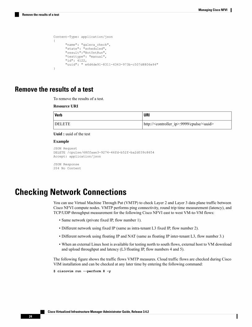
Remove the results of a test 24
Checking Network Connections 24
General Scheme of Enabling Optional Services Post Cisco VIM Deployment 25
Enabling NFVBench Post Deployment 25
NFVBench Usage 29
NFVBench Command-Line Options and Status 30
Using NFVBench Configuration File 30
Control Plane Verification 31
Cisco Virtualized Infrastructure Manager Administrator Guide, Release 3.4.2iii

Fixed Rate Run Test 31
Packet Sizes 31
NDR and PDR Test 31
Multi-chain Test 32
Multi-Flow Test 32
Encapsulation 32
External Chain Test 34
NFVBench Results 34
Examples of NFVIBench Result Execution 34
Cisco VIM CLI 39
NFVBench REST Interface 40
Enabling or Disabling Autobackup of Management Node 40
Forwarding ELK logs to External Syslog Server 40
Adding and Reconfiguring VIM Administrators 41
Enabling Root Login Post Cisco VIM Installation 42
Adding Read-Only OpenStack Role 42
Reconfiguration of Proxy Post Install 44
Reconfiguring NTP 44
Reconfiguring DNS 45
Reconfiguring Sever KVM Console Password Post Install 45
Enabling Head-End Replication Option 46
Enabling Layer BGP Adjacency Between Controllers and Peering Route Reflector 47
Enabling Custom Policy for VNF Manager Post Install 48
Migrate SRIOV from 2-X520 to 2-XL710 in a VIC/NIC POD 49
Augmenting Cisco VIM M4 VIC/(10/40G) NIC pods with M5-based 40G VIC/NIC Computes 50
Adding and Reconfiguring VIM Administrators Authenticated with External LDAP Server 51
Hosting Horizon through NAT/DNS Alias 51
Enabling Banner During SSH Login 52
Enabling DHCP Reservation for VM’s MAC Address 52
Enabling Red Hat Identify Management System 53
Enabling Vault on Day-2 in Cisco VIM Pod 54
Enabling Trusted Virtual Function on Day 2 54
Enabling Ironic Post Installation 55
Hosting Container Workload Post-Installation 58
Cisco Virtualized Infrastructure Manager Administrator Guide, Release 3.4.2iv
Contents

Prerequisites and Assumptions for VIM Update/Upgrade 60
Updating Containers in a Running Cisco VIM Cloud 61
Updating Cisco VIM Software Using a USB 62
Updating Cisco VIM Software Using Network Installation 65
Upgrading Cisco VIM in a Running Cloud 66
Upgrading VIM Software Using a USB 69
Upgrading Cisco VIM Software Using Network Installation 71
Supporting RMA of ToRs with Auto-ToR Configuration 72
Launching OpenStack Baremetal Instances 72
Deploying Baremetal Instances 73
VM Resizing 74
Telemetry for OpenStack 75
Nova Migrate 79
Live Migrate 79
Power Management Of Computes (for C-Series) 80
Power On Compute Nodes 80
Managing Reboot of Cisco VIM Nodes 81
Cisco VIM Client Reboot and Remove Compute Using Force Option 82
Managing Reboot Status of Cisco VIM Nodes 83
Cisco UCS Firmware Upgrade 84
Limitations During Cisco IMC Upgrade 85
Tools Usage 85
Quanta Firmware Upgrade 87
Limitations for Quanta firmware Upgrade 88
Tools Usage 88
Intel FPGA Programmable Acceleration Card N3000 Firmware Update 90
Supporting Management/Storage IP 91
Cisco VIM REST API 93C H A P T E R 2
Overview to Cisco VIM REST API 93
Cisco VIM REST API Resources 95
Cisco VIM REST API Using curl for IPv4 130
Cisco VIM REST API Using curl for IPv6 136
Cisco Virtualized Infrastructure Manager Administrator Guide, Release 3.4.2v
Contents
Monitoring Cisco NFVI Performance 147C H A P T E R 3
Logging and Monitoring in Cisco NFVI 147
Displaying Cisco VIM Log Files Using the CLI 149
Logging Into Kibana Dashboard 152
Rotation of the Cisco VIM Logs 163
Snapshot Manager Tool for Elasticsearch 163
Remote NFS Backup for Elasticsearch Snapshots 165
Network Performance Test with NFVBench 165
Customizing CVIM-MON Dashboard 166
Cisco VIM MON Inventory Discovery API usage 167
API Client 167
Environments 168
Scans 169
Scheduled-scan environment with calipso client 170
Paging 171
Inventory 172
Querying for object details 173
Links 175
Querying for link details 176
Connectivity Analysis 176
Cliques 177
Querying for clique details 179
Collections Scheme 180
Mandatory attributes for inventory object 181
Mandatory attributes for links 182
Mandatory attributes for cliques 183
Managing Cisco NFVI Security 185C H A P T E R 4
Verifying Management Node Network Permissions 185
Verifying Management Node File Permissions 186
Viewing Administrator Access Attempts 186
Verifying SELinux 187
Validating Port Listening Services 187
Cisco Virtualized Infrastructure Manager Administrator Guide, Release 3.4.2vi
Contents

Validating Non-Root Users for OpenStack Services 188
Verifying Password Strength 188
Reconfiguring Passwords and OpenStack Configurations 189
Reconfiguring Glance Client Key for Central Ceph Cluster 195
Enabling Cloud Settings 195
Enabling NFVIMON Post Pod Installation 196
Enabling CVIMMON Post Pod Installation 199
Reconfiguring CIMC/BMC Password on Existing Installation 199
Increasing/Decreasing Provider and Tenant VLAN Ranges 201
Fernet Key Operations 202
Managing Certificates 202
Reconfiguring TLS Certificates 203
Verifying TLS Certificates 204
LDAP/AD support with Keystone v3 205
Moving Netapp transport from http to https 206
Enabling Cinder Volume Encryption in Cisco VIM 207
Replacing ACI Controller in Cisco VIM 207
Hardening Cisco VIM Deployment 208
Cisco VIM Monitor Alerting Rules Customization 211
Alert Manager and Receiver Customization 215
Managing Cisco NFVI Storage 221C H A P T E R 5
Cisco NFVI Storage Architecture 221
Verifying and Displaying Ceph Storage Pools 222
Checking the Storage Cluster Health 223
Checking Glance Connectivity 224
Verifying Glance and Ceph Monitor Keyrings 225
Verifying Glance Image ID on Ceph 226
Checking Cinder Connectivity 226
Verifying Cinder and Ceph Monitor Keyrings 227
Verifying Cinder Volume ID on Ceph 228
Checking Nova Connectivity 229
Verifying the Nova and Ceph Monitor Keyrings 229
Working with Multi-Backend Ceph 230
Cisco Virtualized Infrastructure Manager Administrator Guide, Release 3.4.2vii
Contents

Verifying Nova Instance ID 231
Displaying Docker Disk Space Usage 232
Reconfiguring Administrator Source Networks 233
Password Reset for Cisco VIM Management Node 234
Ceph Storage Expansion 235
Overview to Cisco VIM Unified Management 239C H A P T E R 6
Cisco VIM Unified Management Overview 239
Cisco VIM Unified Management Admin UI Overview 241
Cisco VIM Unified Management Pod UI Overview 241
Managing Cisco VIM through Unified Management 243C H A P T E R 7
UI Administrators Privileges and Responsibilities 243
Pod UI Privileges and Responsibilities 244
Adding Cisco VIM Pod 244
Editing Pod from Cisco VIM Unified Management 246
Deleting Pod from Cisco VIM Unified Management 246
Context Switching Within Unified Management 246
Dashboard 247
Blueprint Name 247
Deployed Cloud Status 247
Deployed Blueprint Details 248
Pod Operation Details 248
Managing Blueprints 249C H A P T E R 8
Blueprints 249
Blueprint Activation 249
Viewing Blueprint Details 250
Creating a Blueprint Using Upload Functionality 250
Activating a Blueprint in an Existing Pod with OpenStack Installed 251
Blueprint Management 251
Creating a Blueprint for B-Series Server Platform 255
Creating Blueprint for C-Series Server Platform 313
Redeploy Multiple Install Stages during Cisco VIM Installation using Unified Management 370
Cisco Virtualized Infrastructure Manager Administrator Guide, Release 3.4.2viii
Contents

Downloading Blueprint 372
Validating Blueprint 372
Managing Post Install Features 373
Monitoring the Pod 373
Cross Launching Horizon 373
NFVI Monitoring 374
Run VMTP 374
Run CloudPulse 375
Run Cloud Sanity Test 376
Run NFV Bench 377
Cisco Container Platform 378
Reconfiguring CIMC Password Through Unified Management 380
Managing Pod Through Cisco VIM Unified Management 383C H A P T E R 9
Monitoring Pod Status 383
Managing Hardware 384
Searching Compute and Storage Nodes 384
POD Management 385
Managing Storage Nodes 386
Adding Storage Node 387
Deleting Storage Node 388
Managing Compute Nodes 388
Adding Compute Node 389
Deleting Compute Node 391
Managing Control Nodes 392
Replacing Control Node 392
Power Management 393
Powering On a Compute Node 393
Powering Off Compute Node 394
Rebooting Compute Node 396
Searching Compute and Storage Nodes 396
Managing Software 397
Reconfigure Openstack Passwords 398
Reconfigure OpenStack Services, TLS Certificates, and ELK Configurations 399
Cisco Virtualized Infrastructure Manager Administrator Guide, Release 3.4.2ix
Contents

Reconfiguring CIMC Password through Unified Management 399
Reconfiguring Optional Services 400
Reconfiguring Optional Features Through Unified Management 402
View Topology 416
Pod User Administration 417
Managing Roles 417
Managing Users 418
Revoke Users 419
Edit Users 419
Managing Root CA Certificate 419
Day 2 Operations of Cisco VIM Unified Management 421C H A P T E R 1 0
Shutting Down Cisco VIM Unified Management 421
Restarting Cisco VIM Unified Management 422
Restoring VIM Unified Management 422
Reconfiguring VIM Unified Management 424
Reconfiguring Unified Management TLS Certificate 425
Reconfiguring Third-party TLS Certificate 425
Reconfiguring Self Signed TLS Certificate 426
Switch from Self Signed TLS Certificate to Third-party TLS Certificate 428
Reconfiguring Unified Management MySQL Database Password 430
System-generated Unified Management DB Password 430
User-supplied Unified Management DB Password 431
Reconfiguring Unified Management SMTP Server 433
Reconfiguring Unified Management LDAP Server 434
Reconfiguring Unified Management Optional Features 436
Adding and Reconfiguring VIM Administrators 438
Enabling Root Login Post UM Node Installation 439
Enabling Banner During SSH Login 439
Adding and Reconfiguring UM Administrators 439
Update VIM Unified Management 440
Upgrade Scenarios 441
Update VIM UM with Internet Access from 3.2.x to 3.4.1 441
Upgrade VIM UM without Internet Access from 3.2.x to 3.4.2 442
Cisco Virtualized Infrastructure Manager Administrator Guide, Release 3.4.2x
Contents

Upgrade Cisco VIM UM from 2.4.x to 3.4.2 443
Rollback VIM Unified Management 444
Commit VIM Unified Management 446
Uploading Glance Images 447
Overview to the Cisco Virtual Topology System 449C H A P T E R 1 1
Understanding Cisco VTS 449
Cisco VTS Architecture Overview 450
Virtual Topology Forwarder 451
Overview to Cisco VTF and VPP 451
VPP + VHOSTUSER 452
Virtual Topology System High Availability 453
Managing Backup and Restore Operations 455C H A P T E R 1 2
Managing Backup and Restore Operations 455
Backing Up the Management Node 455
Backup with Forwarding ELK Logs to External Syslog Server 457
Backing Up VIM UM 457
Autobackup Unified Management 458
Back Up Unified Management at Default Back Up Location 460
Backup Unified Management at User-defined Backup Location 461
Restoring Management Node 462
Management Node Autobackup 464
Managing Cisco VIM Software Hub 465
Updating Cisco VIM Software Hub TLS Certificate and Registry Credentials 465
Cisco VIM Software Hub Server Backup and Restore 465
Checking Integrity of Autobackup Files 466
Restoring Cisco VIM Software Hub from Backup 466
Resolving Low Disk Space 467
Manually Updating Packages 468
Troubleshooting 469C H A P T E R 1 3
Displaying Cisco NFVI Node Names and IP Addresses 469
Verifying Cisco NFVI Node Interface Configurations 470
Cisco Virtualized Infrastructure Manager Administrator Guide, Release 3.4.2xi
Contents

Displaying Cisco NFVI Node Network Configuration Files 471
Viewing Cisco NFVI Node Interface Bond Configuration Files 472
Viewing Cisco NFVI Node Route Information 472
Viewing Linux Network Namespace Route Information 473
Pre-checks for Storage Removal Operation 473
Troubleshooting Cisco NFVI 475
Managing CIMC and ISO Installation 475
Management Node Installation Fails 476
Configuring Boot Order 476
PXE Failure Issue During Baremetal Step 477
Connecting to Docker Container 479
Management Node Recovery Scenarios 480
Recovering Compute Node Scenario 489
Running the Cisco VIM Technical Support Tool 491
Tech-Support Configuration File 492
Tech-Support When Servers Are Offline 495
Running Cisco VIM Software Hub Technical Support Tool 495
Disk-Maintenance Tool to Manage Physical Drives 496
OSD-Maintenance Tool 499
Utility to Resolve Cisco VIM Hardware Validation Failures 501
Command Usage 502
Examples of Command Usage 503
Cisco VIM Client Debug Option 504
Cisco Virtualized Infrastructure Manager Administrator Guide, Release 3.4.2xii
Contents

C H A P T E R 1Managing Cisco NFVI
The following topics provide general management procedures that you can perform if your implementationis Cisco VIM by itself or if it is Cisco VIM and Cisco VIM Unified Management.
• Managing Cisco NFVI Pods, on page 2• NUMA Pinning of VMs, on page 13• Managing Nova Compute Scheduler Filters and User Data, on page 13• Monitoring Cisco NFVI Health with CloudPulse, on page 14• Assessing Cisco NFVI Status with Cloud-Sanity, on page 17• Service Catalog URL, on page 20• Checking Network Connections, on page 24• General Scheme of Enabling Optional Services Post Cisco VIM Deployment, on page 25• Enabling NFVBench Post Deployment, on page 25• NFVBench Usage, on page 29• Enabling or Disabling Autobackup of Management Node, on page 40• Forwarding ELK logs to External Syslog Server, on page 40• Adding and Reconfiguring VIM Administrators, on page 41• Enabling Root Login Post Cisco VIM Installation, on page 42• Adding Read-Only OpenStack Role, on page 42• Reconfiguration of Proxy Post Install, on page 44• Reconfiguring NTP, on page 44• Reconfiguring DNS, on page 45• Reconfiguring Sever KVM Console Password Post Install, on page 45• Enabling Head-End Replication Option, on page 46• Enabling Layer BGP Adjacency Between Controllers and Peering Route Reflector, on page 47• Enabling Custom Policy for VNF Manager Post Install, on page 48• Migrate SRIOV from 2-X520 to 2-XL710 in a VIC/NIC POD, on page 49• Augmenting Cisco VIMM4 VIC/(10/40G) NIC pods with M5-based 40G VIC/NIC Computes, on page50
• Adding and Reconfiguring VIM Administrators Authenticated with External LDAP Server, on page 51• Hosting Horizon through NAT/DNS Alias, on page 51• Enabling Banner During SSH Login, on page 52• Enabling DHCP Reservation for VM’s MAC Address, on page 52• Enabling Red Hat Identify Management System, on page 53• Enabling Vault on Day-2 in Cisco VIM Pod, on page 54
Cisco Virtualized Infrastructure Manager Administrator Guide, Release 3.4.21

• Enabling Trusted Virtual Function on Day 2, on page 54• Enabling Ironic Post Installation, on page 55• Hosting Container Workload Post-Installation, on page 58• Prerequisites and Assumptions for VIM Update/Upgrade, on page 60• Updating Containers in a Running Cisco VIM Cloud, on page 61• Updating Cisco VIM Software Using a USB, on page 62• Updating Cisco VIM Software Using Network Installation, on page 65• Upgrading Cisco VIM in a Running Cloud, on page 66• Upgrading VIM Software Using a USB, on page 69• Upgrading Cisco VIM Software Using Network Installation, on page 71• Supporting RMA of ToRs with Auto-ToR Configuration, on page 72• Launching OpenStack Baremetal Instances, on page 72• VM Resizing, on page 74• Telemetry for OpenStack, on page 75• Nova Migrate, on page 79• Live Migrate, on page 79• Power Management Of Computes (for C-Series), on page 80• Power On Compute Nodes, on page 80• Managing Reboot of Cisco VIM Nodes, on page 81• Cisco VIM Client Reboot and Remove Compute Using Force Option, on page 82• Managing Reboot Status of Cisco VIM Nodes, on page 83• Cisco UCS Firmware Upgrade, on page 84• Quanta Firmware Upgrade, on page 87• Supporting Management/Storage IP, on page 91
Managing Cisco NFVI PodsYou can perform OpenStack management operations on Cisco NFVI pods including addition and removal ofCisco NFVI compute and Ceph nodes, and replacement of controller nodes. Each action is mutually exclusive.You can perform only one pod management action at a time. Before you perform a pod action, ensure thatthe following requirements are met:
• The node is part of an existing pod.
• The node information exists in the setup_data.yaml file, if the pod management task is removal orreplacement of a node.
• The node information does not exist in the setup_data.yaml file, if the pod management task is to add anode.
For more information on operations that can be performed on pods, see the Managing Hosts in CiscoVIM or NFVI Pods , on page 6 section.
General Guidelines for Pod ManagementThe setup_data.yaml file is the only user-generated configuration file that is used to install and manage thecloud. While many instances of pod management indicate that the setup_data.yaml file is modified, theadministrator does not update the system generated setup_data.yaml file directly.
Cisco Virtualized Infrastructure Manager Administrator Guide, Release 3.4.22
Managing Cisco NFVIManaging Cisco NFVI Pods

To avoid translation errors, ensure that you do not copy and paste commands from the documents to the LinuxCLI.
Note
Follow these steps to update the setup_data.yaml file:
1. Copy the setup data into a local directory:[root@mgmt1 ~]# cd /root/[root@mgmt1 ~]# mkdir MyDir[root@mgmt1 ~]# cd MyDir[root@mgmt1 ~]# cp /root/openstack-configs/setup_data.yaml <my_setup_data.yaml>
2. Update the setup data manually:[root@mgmt1 ~]# vi my_setup_data.yaml (update the targeted fields for the setup_data)
3. Run the reconfiguration command:[root@mgmt1 ~]# ciscovim –-setupfile ~/MyDir/<my_setup_data.yaml><pod_management_action>
In Cisco VIM, you can edit and enable a selected set of options in the setup_data.yaml file using the reconfigureoption. After installation, you can change the values of the feature parameters. Unless specified, Cisco VIMdoes not allow you to undo the feature configuration.
The following table provides the list of features that you can reconfigure after installing a pod.
CommentFeatures Enabled after post-pod deployment
• Heat: OpenStack Orchestration Program
• LDAP: Works only with Keystone v3. Full orpartial reconfiguration can be done. Except fordomain, all attributes are reconfigurable.
• Ironic: Baremetal workload post installation
• Container: Cloud-native workload
Optional OpenStack Services
CVIM-MON: monitoring host and service level withor without ui_access
NFVIMON: Third-party monitoring from host toservice level with aid of Cisco Advance Services.
Pod monitoring
Reduces single point of failure on management nodeand provides data aggregation.
Export of EFK logs to External Syslog Server
NFS mount point for Elastic-search snapshot is usedso that the disk on management node does not get full.
NFS for Elasticsearch Snapshot
White list filter for accessingmanagement node adminservice over IPv4 or IPv6.
Admin Source Networks
Cisco Virtualized Infrastructure Manager Administrator Guide, Release 3.4.23
Managing Cisco NFVIGeneral Guidelines for Pod Management

CommentFeatures Enabled after post-pod deployment
Tool to helpmeasure cloud performance.Managementnode needs a dedicated 10G/40G Intel NIC (4x10G710, or 2x40G XL710 Intel NIC).
NFVBench
Enables you to set EFK rotation frequency and size.EFK settings
Implemented for security reasons, so that OpenStackpasswords can be reset on-demand.
OpenStack service password
Implemented for security reasons, so that CIMCpasswords for C-series pod, can be reset on-demand.
CIMC Password Reconfigure Post Install
Integration with third-party Object-Store. TheSwiftStack Post Install feature works only withKeystone v2.
SwiftStack Post Install
Ability to increase or decrease the tenant and providerVLAN ranges on a pod that is up and running. It givescustomers flexibility in network planning.
TENANT_VLAN_RANGES andPROVIDER_VLAN_RANGES
Allow DHCP reservation for virtual machine MACaddresses, so as to get the same IP address alwaysregardless of the host hypervisor or operating systemthey are running.
DHCP reservation for VM’s MAC addresses
Allows virtual functions to become trusted by thephysical function and to perform some privilegedoperations such as enabling VF promiscuous modeand changing VF MAC address within the guest.
Enable TRUSTED_VF on a per (SR-IOV) computebasis
Ability to offload the OpenStack logs to a maximumof four external Syslog servers post-installation.
Support of ,multiple external syslog servers
Ability to replace failed APIC Hosts, and add moreleaf nodes to increase the fabric influence.
Replace of failed APICHosts and addmore leaf nodes
Ability to move the Netapp block storage endpointfrom Clear to TLS post-deployment
Make Netapp block storage end point secure
Ability to enable/disable auto-backup ofManagementNode. It is possible to unconfigure the ManagementNode.
Auto-backup of Management Node
Ability to configure non-root VIM Administrators.
Ability to configure VIM admins authenticated byLDAP.
VIM Admins
Ability to enable TLS on external_vip through FQDN.EXTERNAL_LB_VIP_FQDN
Ability to enable TLS on external_vip through an IPaddress.
EXTERNAL_LB_VIP_TLS
Cisco Virtualized Infrastructure Manager Administrator Guide, Release 3.4.24
Managing Cisco NFVIGeneral Guidelines for Pod Management

CommentFeatures Enabled after post-pod deployment
Ability to reconfigure http and/or https proxy servers.http_proxy and/or https_proxy
Ability to enable admin privileges for VNF Manager(ESC) from a tenant domain.
Admin privileges for VNF Manager (ESC) from atenant domain
Mechanism to switch between 2-X520 and 2-XL710as an SRIOV option in Cisco VIC NIC settings at aglobal and per compute level through reconfiguration.In the absence of per compute and global level, X520card type is set by default.
SRIOV_CARD_TYPE
Migrate NETAPP transport protocol from http to https.NETAPP
Aids to recover the KVM console passwords forservers.
Reset of KVM console passwords for servers
Ability to host Horizon behind NAT or with DNSalias(es)
Horizon behind NAT or with DNS alias(es)
Support of configurable login banner for SSH sessionsLogin banner for SSH sessions
Ability to switch BGP sessions from Layer 2 to Layer3 in the presence of VXLAN configuration.
Ability to add Layer 3 BGP session
Ability to add or remove head-end-replication option,in the presence of VXLAN configuration
Add/remove of head-end-replication option
Ability to set horizon and keystone settings asreconfigurable.
Enabling Cloud settings
Ability to enable vault on day-2.Vault
Ability to enable IPA as a day-2 option.Identity, Policy and Audit (IPA) enablement
Identifying the Install DirectoryIf you are an administrator and want to use CLI to manage the pods, you must know the location of the installerdirectory. To identify the installer directory of a pod, execute the following commands:[root@mgmt1 ~]# cd /root/[root@mgmt1 ~]# ls –lrt | grep openstack-configslrwxrwxrwx. 1 root root 38 Mar 12 21:33 openstack-configs ->/root/installer-<tagid>/openstack-configs
From the output, you can understand that the OpenStack-configs is a symbolic link to the installer directory.
Verify that the REST API server is running from the same installer directory location, by executing thefollowing commands:# cd installer-<tagid>/tools#./restapi.py -a statusStatus of the REST API Server: active (running) since Thu 2016-08-18 09:15:39 UTC; 9h agoREST API launch directory: /root/installer-<tagid>/
Cisco Virtualized Infrastructure Manager Administrator Guide, Release 3.4.25
Managing Cisco NFVIIdentifying the Install Directory

Managing Hosts in Cisco VIM or NFVI PodsIn Cisco VIM, a node can participate in multiple roles based on the pod type. The following rules apply forhardware management of a node:
1. If a node is a Micropod node that acts as controller, compute, and Ceph, the node can only go through theaction of replace controller for its swap. You can perform this action on one node at a time.
2. If a node is a hyper-converged node (that is, acting as both compute and Ceph), the node is treated as aceph node from hardware management point of view and the node can only go through the action of addor remove of Ceph. This action can be done only on one node at a time.
3. If a node is a standalone compute node, the node can only go through the action of add or remove ofcompute. You can add or remove multiple nodes at a time, but you cannot operate the pod with zerocompute at any given time.
4. If a node is a dedicated controller node, the node can only go through the action of replace controller forits swap. This action can be done only on one node at a time.
5. If a node is a dedicated Ceph node, the node can only go through the action of add or remove of Ceph.This action can be done only on one node at a time and you cannot have a pod with less than two nodeCeph at a time.
Based on the prceding rules, to perform hardware management actions on the pod, run the commands specifiedin the following table. If you log in as root, manually change the directory to /root/installer-xxx to get to thecorrect working directory for these Cisco NFVI pod commands.
Cisco Virtualized Infrastructure Manager Administrator Guide, Release 3.4.26
Managing Cisco NFVIManaging Hosts in Cisco VIM or NFVI Pods

Table 1: Cisco NFVI Pod Management
RestrictionsStepsAction
You can remove multiple compute nodesand only one storage at a time;
The pod must have a minimum of onecompute and two storage nodes after theremoval action.
In Cisco VIM, the number of Ceph OSDnodes vary from 3 to 20. You can removeone OSD node at a time as part of the podmanagement.
Note • On a Micro or edge podexpanded with standalonecomputes, only thestandalone compute nodescan be removed. Podmanagement operation forstorage node is notsupported for Micro oredge pod
• Compute managementoperations are notsupported forhyper-converged nodes
• In UMHC or NGENAHCpod, if a VM is running onthe storage node,remove-storage operationfails in pre-validation andgives a warning to the userabout running VM's. Useforce option to forcefullyremove the storage node.
• In Ceph pod, podmanagement operations forcompute is not supported.Removal of storage node isonly allowed for serversthat are exclusivelyavailable with cephosdroles.
1. Remove the node information from theROLES and SERVERS section of thesetup_data.yaml file for the specificnode.
2. Enter one of the following commands.
For compute nodes:ciscovim remove-computes--setupfile~/MyDir/my_setup_data.yaml<"compute-1,compute-2">[--force]
For storage nodes:ciscovim remove-storage--setupfile~/MyDir/my_setup_data.yaml<"storage-1"> [--force]
Remove block_storage or compute node
Cisco Virtualized Infrastructure Manager Administrator Guide, Release 3.4.27
Managing Cisco NFVIManaging Hosts in Cisco VIM or NFVI Pods

RestrictionsStepsAction
You can add multiple compute nodes andonly one storage node at a time.
The pod must have a minimum of onecompute, and two storage nodes before theaddition action.
In Cisco VIM the number of ceph OSDnodes can vary from 3 to 20. You can addone OSD node at a time as part of the podmanagement.
Note • On a Micro or edge podexpanded with standalonecomputes, you can addonly the standalonecompute nodes. Podmanagement operation forstorage node is notsupported.
• In hyper-converged mode,compute managementoperations are notsupported forhyper-converged nodes.
1. Add the node information from theROLES and SERVERS section of thesetup_data.yaml file for the specificnode.
2. Enter one of the following commands.
For compute nodes:ciscovim add-computes --setupfile~/MyDir/my_setup_data.yaml<"compute-1,compute-2">[--skip_vmtp]
For storage nodes:ciscovim add-storage --setupfile~/MyDir/my_setup_data.yaml<"storage-1">[--skip_vmtp]
Add block_storage or compute node
Cisco Virtualized Infrastructure Manager Administrator Guide, Release 3.4.28
Managing Cisco NFVIManaging Hosts in Cisco VIM or NFVI Pods

RestrictionsStepsAction
You can replace only one controller nodeat a time. The pod can have a maximum ofthree controller nodes.
In Cisco VIM, the replace controller nodeoperation is supported in Micro-pod.
Note • While replacing thecontroller node, the IPaddress and hostname arereused. So, do not updateany other controllerinformation other thanCIMC access and hardwareinformation for C-series,and blade and chassisinformation for B-series
• For Micro, edge and Cephpod, this operation issupported on the AIO (allin one), compute-control,and cephcontrol nodes,respectively. In a Micro oredge pod, If a VM isrunning on the controllernode, the replace controlleroperation fails duringpre-validation and gives awarning to the user aboutrunning VM’s. Use forceoption to forcefully replacethe controller.
1. If the controller node is in a rack baseddeployment (UCS C-Series or Quantabased pod), update the CIMC info nodein the SERVERS section of thesetup_data.yaml file for the specificnode
2. For B-series only update the blade andchassis info
3. Enter the following command:ciscovim replace-controller--setupfile~/MyDir/my_setup_data.yaml<"control-1"> [--force][--skip_vmtp]
Replace controller node
When you add a compute or storage node to a rack based pod (UCS C-Series or Quanta), you can increasethe management/provision address pool. Similarly, for a UCS B-Series pod, you can increase the Cisco IMCpool to provide routing space flexibility for pod networking. Along with server information, these are the onlyitems you can change in the setup_data.yaml file after the pod is deployed. Tomake changes to the managementor provisioning sections and/or CIMC (for UCS B-Series pods) network section, you must not change theexisting address block as defined on day 0. You can add only to the existing information by adding newaddress pool block(s) of address pool as shown in the following example:NETWORKING:::
networks:-vlan_id: 99subnet: 172.31.231.0/25gateway: 172.31.231.1## 'pool' can be defined with single ip or a range of ip
Cisco Virtualized Infrastructure Manager Administrator Guide, Release 3.4.29
Managing Cisco NFVIManaging Hosts in Cisco VIM or NFVI Pods

pool:
- 172.31.231.2, 172.31.231.5 -→ IP address pool on Day-0
- 172.31.231.7 to 172.31.231.12 -→ IP address pool ext. on Day-n- 172.31.231.20
segments:## CIMC IP allocation. Needs to be an external routable network- cimc
-vlan_id: 2001subnet: 192.168.11.0/25gateway: 192.168.11.1rt_prefix: < Local to POD > #optional, only for segment management/provision, storage,
tenant and ToR-type NCS-5500rt_suffix: < Region>:< pod_region_number > #optional, only for segement
management/provision, storage, tenant and ToR-type NCS-5500
## 'pool' can be defined with single ip or a range of ippool:
- 192.168.11.2 to 192.168.11.5 -→ IP address pool on Day-0
- 192.168.11.7 to 192.168.11.12 → IP address pool on day-n
- 192.168.11.20 → IP address pool on day-nsegments:## management and provision goes together- management
- provision::
The IP address pool is the only change allowed in the networking space of the specified networksmanagement/provision and/or CIMC (for B-series). The overall network must have enough address space toaccommodate for future enhancement on day-0. After making the changes to servers, roles, and thecorresponding address pool, you can execute the add compute/storage CLI shown above to add new nodes tothe pod.
For C-series M5 pods, with Cisco NCS 5500 as ToR with splitter cable connection onto the server, along withthe server (cimc_ip), and connection (tor_info, dp_tor_info, sriov_tor_info) details, you have to adjust theentry for the splitter_opt_4_10 in respective SWITCHDETAILS for the Cisco NCS 5500 ToR pairs.
For example, to add compute or storage with Cisco NCS 5500 as ToR with splitter cable, add the followingentry to the respective Cisco NCS 5500:
TORSWITCHINFO:CONFIGURE_TORS: true # MandatoryTOR_TYPE: NCS-5500 # MandatoryESI_PREFIX:91.<Pod_number>.<podregion_number>.00.00.00.00 #optional – only for NCS-5500SWITCHDETAILS: -hostname: <NCS-5500-1> # hostname of NCS-5500-1username: adminpassword: <ssh_password of NCS-5500-1>...splitter_opt_4_10: 'FortyGigE<C/D/X/Y>,HundredGigE<E/F/A/B>, …' # Optional for NCS-5500,only when
splitter is needed on per switch basis (i.e. the peer switch may or may not have theentry)
ESI_PREFIX:91.<Pod_number>.<podregion_number>.00.00.00.00 #optional for NCS-5500 only
To remove a compute or a storage, delete the respective information. To replace the controller, swap therelevant port information from which the splitter cables originate.
Cisco Virtualized Infrastructure Manager Administrator Guide, Release 3.4.210
Managing Cisco NFVIManaging Hosts in Cisco VIM or NFVI Pods

For replace controller, you can change only a subset of the server information. For C-series, you can changethe server information such as CIMC IP, CIMC Username, CIMC password, rack_id, and tor_info. ForB-series, you can change the rack_id, chassis_id, and blade_id, but not the server hostname and managementIP during the operation of replace controller.
Note
Recovering Cisco NFVI PodsThis section describes the recovery processes for Cisco NFVI control node and the pod that is installed throughCisco VIM. For recovery to succeed, a full Cisco VIM installation must have occurred in the past. Recoveryis caused by a failure of one or more of the controller services such as Rabbit MQ,MariaDB, and other services.The management node must be up and running and all the nodes must be accessible through SSH withoutpasswords from the management node. You can also use this procedure to recover from a planned shutdownor accidental power outage.
Cisco VIM supports the following control node recovery command:# ciscovim cluster-recovery
The control node recovers after the network partition is resolved.
It may be possible that database sync between controller nodes takes time, which can result in cluster-recoveryfailure. In that case, wait for some time for the database sync to complete and then re-run cluster-recovery.
Note
To make sure Nova services are good across compute nodes, execute the following command:# source /root/openstack-configs/openrc# nova service-list
To check for the overall cloud status, execute the following command:# ciscovim cloud-sanity create test all
To view the results of cloud-sanity, use the following command:#ciscovim cloud-sanity show result all –id <uid of the test >
In case of a complete pod outage, you must follow a sequence of steps to bring the pod back. The first stepis to bring up the management node, and check that the management node containers are up and running usingthe docker ps –a command. After you bring up the management node, bring up all the other pod nodes. Makesure every node is reachable through password-less SSH from the management node. Verify that no networkIP changes have occurred. You can get the node SSH IP access information from/root/openstack-config/mercury_servers_info.
Execute the following command sequence:
• Check the setup_data.yaml file and runtime consistency on the management node:# cd /root/installer-<tagid>/tools# ciscovim run --perform 1,3 -y
• Execute the cloud sanity using ciscovim command:#ciscovim cloud-sanity create test all
Cisco Virtualized Infrastructure Manager Administrator Guide, Release 3.4.211
Managing Cisco NFVIRecovering Cisco NFVI Pods

• To view the results of cloud-sanity, use the command #ciscovim cloud-sanity show result all –id
<uid of the test >
• Check the status of the REST API server and the corresponding directory where it is running:# cd/root/installer-<tagid>/tools#./restapi.py -a statusStatus of the REST API Server: active (running) since Thu 2016-08-18 09:15:39 UTC; 9hagoREST API launch directory: /root/installer-<tagid>/
• If the REST API server is not running from the right installer directory, execute the following to get itrunning from the correct directory:# cd/root/installer-<tagid>/tools#./restapi.py -a setup
Check if the REST API server is running from the correct target directory#./restapi.py -a statusStatus of the REST API Server: active (running) since Thu 2016-08-18 09:15:39 UTC; 9hagoREST API launch directory: /root/new-installer-<tagid>/
• Verify Nova services are good across the compute nodes by executing the following command:# source /root/openstack-configs/openrc# nova service-list
If cloud-sanity fails, execute cluster-recovery (ciscovim cluster-recovery), then re-execute the cloud-sanityand nova service-list steps as listed above.
Recovery of compute and OSD nodes requires network connectivity and reboot so that they can be accessedusing SSH without password from the management node.
To shut down, bring the pod down in the following sequence:
1. Shut down all VMs, then all the compute nodes. It should be noted that graceful shut down of VMs isimportant. Check the VM status from the output of "openstack server list --all-projects", which must showthat all VMs are in SHUTOFF State before you proceed.
2. Shut down all compute node (s).
3. Shut down all the storage nodes serially.Before proceeding to next step, ensure that you wait until thestorage node shutdown is completed.
4. Shut down all the controllers, but one at a time. Before proceeding to next step, wait for the controllernode shutdown to complete.
5. Shut down the management node.
6. Shut down the networking gears.
To shut down a node, SSH to the node or connect to CIMC KVM console and issue the shutdown command# shutdown -h now
Note
Bring the nodes up in reverse order, that is:
Cisco Virtualized Infrastructure Manager Administrator Guide, Release 3.4.212
Managing Cisco NFVIRecovering Cisco NFVI Pods

a. Bring up the networking gears.
b. Bring up the management node.
c. Bring up the control nodes.
d. Bring up the storage nodes.
e. Wait untill the Ceph health reports are fine and then proceed to next step.
f. Bring up the compute nodes.
In each step, ensure that each node type is completely booted up before you move on to the next nodetype.
Run the cluster recovery command, to bring up the pod post power-outage:# ciscovim cluster-recovery
Run cloud sanity using the command # ciscovim cloud-sanity.
Execute docker cloudpulse check to ensure that all containers are up:cloudpulse run --name docker_check
Validate the Cisco API server by running the following command:# ciscovim run -–perform 1,3 -y
Bring up all VMs and validate if they are all up (not in shutdown state). If any of the VMs are in down state,bring them up using the Horizon dashboard.
NUMA Pinning of VMsFrom release Cisco VIM 3.4.0, NUMA pinning of VMs is supported. To make use of this feature, you mustadd “hw:pin_to_numa” in their VM’s flavor, and set its value to 0 or 1.When one spawns VMwith that flavor,the VM uses only the host CPUs from the NUMA that is specified in the flavor.
Managing Nova Compute Scheduler Filters and User DataOpenStack Nova is an OpenStack component that provides on-demand access to compute resources byprovisioning large networks of virtual machines (VMs). In addition to the standard Nova filters, Cisco VIMsupports the following additional scheduler filters:
• ServerGroupAffinityFilter—Ensures that an instance is scheduled onto a host from a set of group hosts.To use this filter, you must create a server group with an affinity policy and pass a scheduler hint usinggroup as the key and the server group UUID as the value. Use the nova command-line tool and the --hintflag. For example:$ nova server-group-create --policy affinity group-1$ nova boot --image IMAGE_ID --flavor 1 --hint group=SERVER_GROUP_UUID server-1
• ServerGroupAntiAffinityFilter—Ensures that each group instance is on a different host. To use this filter,you must create a server group with an anti-affinity policy and pass a scheduler hint, using group as thekey and the server group UUID as the value. Use the nova command-line tool and the --hint flag. Forexample:
Cisco Virtualized Infrastructure Manager Administrator Guide, Release 3.4.213
Managing Cisco NFVINUMA Pinning of VMs

$ nova server-group-create --policy anti-affinity group-1$ nova boot --image IMAGE_ID --flavor 1 --hint group=SERVER_GROUP_UUID server-1
• SameHostFilter—Within an instance set, schedules one instance on the same host as another instance.To use this filter, pass a scheduler hint using same_host as the key and a list of instance UUIDs as thevalue. Use the nova command-line tool and the --hint flag. For example:$ nova boot --image IMAGE_ID --flavor 1 --hint same_host=INSTANCE_ID server-1
• DifferentHostFilter—Within an instance set, schedules one instance on a different host than anotherinstance. To use this filter, pass a scheduler hint using different_host as the key and a list of instanceUUIDs as the value. The filter is the opposite of SameHostFilter. Use the novacommand-line tool andthe --hint flag. For example:$ nova boot --image IMAGE_ID --flavor 1 --hint different_host=INSTANCE_ID server-1
In addition to scheduler filters, you can set up user data files for cloud application initializations. A user datafile is a special key in the metadata service that holds a file that cloud-aware applications in the guest instancecan access. For example, one application that uses user data is the cloud-init system, an open-source packagethat is available on various Linux distributions. The cloud-init system handles early cloud instance initializations.The typical use case is to pass a shell script or a configuration file as user data during the Nova boot, forexample:$ nova boot --image IMAGE_ID --flavor 1 --hint user-data FILE_LOC server-1
Monitoring Cisco NFVI Health with CloudPulseYou can query the state of various Cisco NFVI OpenStack endpoints using CloudPulse, an OpenStackhealth-checking tool. By default, the tool automatically polls OpenStack Cinder, Glance, Nova, Neutron,Keystone, Rabbit, Mariadb, and Ceph every four minutes. However, you can use a CLI REST API call fromthe management node to get the status of these services in real time. You can integrate the CloudPulse APIinto your applications and get the health of the OpenStack services on demand. You can find additionalinformation about using CloudPulse in the following OpenStack sites:
• https://wiki.openstack.org/wiki/Cloudpulse
• https://wiki.openstack.org/wiki/Cloudpulseclient
• https://wiki.openstack.org/wiki/Cloudpulse/DeveloperNotes
• https://wiki.openstack.org/wiki/Cloudpulse/OperatorTests
• https://wiki.openstack.org/wiki/Cloudpulse/APIDocs
CloudPulse has two set of tests: endpoint_scenario (runs as a cron or manually) and operator test (runmanually).The supported Cloudpulse tests groups include:
• nova_endpoint
• neutron_endpoint
• keystone_endpoint
• glance_endpoint
• cinder_endpoint
Cisco Virtualized Infrastructure Manager Administrator Guide, Release 3.4.214
Managing Cisco NFVIMonitoring Cisco NFVI Health with CloudPulse

Operator tests include:
• ceph_check—Executes the command, "ceph -f json status" on the Ceph-mon nodes and parses the output.If the result of the output is not “HEALTH_OK” ceph_check the reports for an error.
• docker_check—Finds out if all the Docker containers are in the running state in all the nodes. It the reportfor an error if any containers are in the Exited state. It runs the command “docker ps -aq --filter'status=exited'”.
• galera_check—Executes the command, "mysql 'SHOW STATUS;” on the controller nodes and displaysthe status.
• node_check—Checks if all the nodes in the system are up and online. It also compares the result of “novahypervisor list” and finds out if all the computes are available.
• rabbitmq_check—Runs the command, “rabbitmqctl cluster_status” on the controller nodes and finds outif the rabbitmq cluster is in quorum. If nodes are offline in the cluster rabbitmq_check the report isconsidered as failed.
CloudPulse servers are installed in containers on all control nodes. The CloudPulse client is installed on themanagement node by the Cisco VIM installer. To execute CloudPulse, source the openrc file in theopenstack-configs directory and execute the following:[root@MercRegTB1 openstack-configs]# cloudpulse --helpusage: cloudpulse [--version] [--debug] [--os-cache]
[--os-region-name <region-name>][--os-tenant-id <auth-tenant-id>][--service-type <service-type>][--endpoint-type <endpoint-type>][--cloudpulse-api-version <cloudpulse-api-ver>][--os-cacert <ca-certificate>] [--insecure][--bypass-url <bypass-url>] [--os-auth-system <auth-system>][--os-username <username>] [--os-password <password>][--os-tenant-name <tenant-name>] [--os-token <token>][--os-auth-url <auth-url>]<subcommand> ...
To check the results of periodic CloudPulse, enter the following command:
[root@MercRegTB1 openstack-configs]# cloudpulse result+--------------------------------------+------+-------------------+----------+---------+| uuid | id | name | testtype | state |+--------------------------------------+------+-------------------+----------+---------+| 4f4c619a-1ba1-44a7-b6f8-3a06b5903260 | 7394 | ceph_check | periodic | success || 68b984fa-2edb-4d66-9d9b-7c1b77d2322e | 7397 | keystone_endpoint | periodic | success || c53d5f0f-a710-4612-866d-caa896e2d135 | 7400 | docker_check | periodic | success || 988d387c-1160-4601-b2ff-9dbb98a3cd08 | 7403 | cinder_endpoint | periodic | success || 5d702219-eacc-47b7-ae35-582bb8e9b970 | 7406 | glance_endpoint | periodic | success || 033ca2fc-41c9-40d6-b007-16e06dda812c | 7409 | rabbitmq_check | periodic | success || 8476b21e-7111-4b1a-8343-afd634010b07 | 7412 | galera_check | periodic | success || a06f8d6e-7b68-4e14-9b03-bc4408b55b48 | 7415 | neutron_endpoint | periodic | success || ef56b26e-234d-4c33-aee1-ffc99de079a8 | 7418 | nova_endpoint | periodic | success || f60021c7-f70a-44fb-b6bd-03804e5b7bf3 | 7421 | node_check | periodic | success |+--------------------------------------+------+-------------------+----------+---------+
By default, 25 results are displayed. Use –number argument to get desired number (up to 240) of results. Forexample,[root@MercRegTB1 openstack-configs]# cloudpulse result –number 100
To view all CloudPulse tests:
Cisco Virtualized Infrastructure Manager Administrator Guide, Release 3.4.215
Managing Cisco NFVIMonitoring Cisco NFVI Health with CloudPulse

# cd /root/openstack-configs# source openrc# cloudpulse test-list
To run a CloudPulse test on demand:# cd /root/openstack-configs# source openrc# cloudpulse run --name <test_name># cloudpulse run --all-tests# cloudpulse run --all-endpoint-tests# cloudpulse run --all-operator-tests
To run a specific CloudPulse test on demand:# cloudpulse run –-name neutron_endpoint+------------+--------------------------------------+| Property | Value |+------------+--------------------------------------+| name | neutron_endpoint || created_at | 2016-03-29T02:20:16.840581+00:00 || updated_at | None || state | scheduled || result | NotYetRun || testtype | manual || id | 3827 || uuid | 5cc39fa8-826c-4a91-9514-6c6de050e503 |+------------+--------------------------------------+
To show detailed results of a specific CloudPulse run:#cloudpulse show 5cc39fa8-826c-4a91-9514-6c6de050e503+------------+--------------------------------------+| Property | Value |+------------+--------------------------------------+| name | neutron_endpoint || created_at | 2016-03-29T02:20:16+00:00 || updated_at | 2016-03-29T02:20:41+00:00 || state | success || result | success || testtype | manual || id | 3827 || uuid | 5cc39fa8-826c-4a91-9514-6c6de050e503 |+------------+--------------------------------------+
To see the CloudPulse options, source the openrc file in openstack-configs dir and execute:
#cloudpulse --help
The CloudPulse project has a RESTful Http service called the Openstack Health API. Through this APIcloudpulse allows the user to list the cloudpulse tests, create new cloudpulse tests and see the results of thecloudpulse results.
The API calls described in this documentation require keystone authentication. From release Cisco VIM 3.0.0onwards, only keystone v3 is supported.
The Identity service generates authentication tokens that permit access to the Cloudpulse REST APIs. Clientsobtain this token and the URL endpoints for other service APIs, by supplying their valid credentials to theauthentication service. Each time you make a REST API request to Cloudpulse, you must provide yourauthentication token in the X-Auth-Token request header.
Cisco Virtualized Infrastructure Manager Administrator Guide, Release 3.4.216
Managing Cisco NFVIMonitoring Cisco NFVI Health with CloudPulse

Cloudpulse is not applicable Ceph pod.Note
Assessing Cisco NFVI Status with Cloud-SanityThe cloud-sanity tool is designed to give you a quick overall status of the pods health checks. Cloud-sanitycan run tests on all node types in the Pod: management, control, compute and ceph storage.
The following are test areas supported in cloud-sanity:
1. RAID Disk health checks.
2. Basic network connectivity between the management node and all other nodes in the Pod.
3. Mariadb cluster size.
4. RabbitMQ operation and status.
5. Nova service and hypervisor list.
6. CEPHMON operation and status.
7. CEPHOSD operation and status.
To run the cloud-sanity tool, login to themanagement node and run the ciscovim commandwith the cloud-sanityoption
Cloud-Sanity user workflow:
1. Use “ciscovim cloud-sanity create …” command to initiate a test.
2. Use “ciscovim cloud-sanity list …” command to view summary/status of current test jobs.
3. Use “ciscovim cloud-sanity show … --id <ID>” command to view detail test results.
4. Use “ciscovim cloud-sanity delete … --id <ID>” to delete test results no longer needed.
The results are maintained so that you can view them any time.
Delete the results which are no longer needed.Note
Step 1 To run the cloud sanity complete the following steps:# ciscovim help cloud-sanityusage: ciscovim cloud-sanity [--id <id>] [--skip-disk-checks] [-y]
create|delete|list|show test|resultall|control|compute|cephmon|cephosd|management
Run cloud-sanity test suite
Positional arguments:create|delete|list|show The control command to perform
Cisco Virtualized Infrastructure Manager Administrator Guide, Release 3.4.217
Managing Cisco NFVIAssessing Cisco NFVI Status with Cloud-Sanity

test|result The identity of the task/actionall|control|compute|cephmon|cephosd|management
The sanity check
Optional arguments:--id <id> ID used to identify specific item to
show/delete.--skip-disk-checks Flag to skip running disk-checks during
cloud-sanity test-y, --yes Yes option to perform the action
Step 2 To run the cloud sanity test, you need to create a test job. Once the test job is created, the system displays a message withthe time and the ID when the test job was created.
Run the following command to create a test job:# ciscovim cloud-sanity create test all+------------+--------------------------------------+| Field | Value |+------------+--------------------------------------+| command | create || created_at | 2018-03-07T15:37:41.727739 || id | c000ca20-34f0-4579-a997-975535d51dda || result | || status | not_run || test_name | all || updated_at | None |+------------+--------------------------------------+The user can create different test suites based on target roles. All, management, control, compute,cephmon and cephosd. Only one test will be run at any time.
Example test create commands:• ciscovim cloud-sanity create test controlo Runs control node tests only• ciscovim cloud-sanity create test computeo Runs compute nodes tests only• ciscovim cloud-sanity create test managemento Runs management node tests only• ciscovim cloud-sanity create test cephmono Runs cephmon tests only• ciscovim cloud-sanity create test cephosdo Runs cephosd tests only
The cloud-sanity tests use the disk-maintenance and osd-maintenance tools to assess overall health and status of the RAIDdisks and OSD status.
Failures detected in RAID disk health and CEPHOSD operational status can be future evaluated with thedisk-maintenance and osd-maintenance tools. See the sections on those tools for information on their use.
Note
Step 3 The ciscovim cloud-sanity list … command is used to monitor a currently running test or just view all the tests that havebeen run/completed in the past.# ciscovim cloud-sanity list test all+--------------------------------------+--------------+----------+---------------------+| ID | Sanity Check | Status | Created |+--------------------------------------+--------------+----------+---------------------+| c000ca20-34f0-4579-a997-975535d51dda | all | Complete | 2018-03-07 15:37:41 || 83405cf0-e75a-4ce2-a438-0790cf0a196a | cephmon | Complete | 2018-03-07 15:52:27 || 6beceb00-4029-423b-87d6-5aaf0ce087ff | cephmon | Complete | 2018-03-07 15:55:01 || 2707a2e1-d1b5-4176-8715-8664a86bbf7d | cephosd | Complete | 2018-03-07 16:11:07 || b30e1f49-a9aa-4f90-978a-88ba1f0b5629 | control | Complete | 2018-03-07 16:14:29 || f024ff94-ac3e-4745-ba57-626b58ca766b | compute | Running | 2018-03-07 16:16:44 |+--------------------------------------+--------------+----------+---------------------+
Cisco Virtualized Infrastructure Manager Administrator Guide, Release 3.4.218
Managing Cisco NFVIAssessing Cisco NFVI Status with Cloud-Sanity

We can filter on cephmon if needed# ciscovim cloud-sanity list test cephmon+--------------------------------------+--------------+----------+---------------------+| ID | Sanity Check | Status | Created |+--------------------------------------+--------------+----------+---------------------+| 83405cf0-e75a-4ce2-a438-0790cf0a196a | cephmon | Complete | 2018-03-07 15:52:27 || 6beceb00-4029-423b-87d6-5aaf0ce087ff | cephmon | Complete | 2018-03-07 15:55:01 |+--------------------------------------+--------------+----------+---------------------+
Example cloud-sanity list commands:• ciscovim cloud-sanity list control• ciscovim cloud-sanity list compute• ciscovim cloud-sanity list management• ciscovim cloud-sanity list cephmon• ciscovim cloud-sanity list cephosd
Step 4 This functionality allows you to view the details results of the test-sanity. Cloud-sanity test results can be passed, failed,or skipped. A skipped test is one that is not supported on this particular POD (ex. RAID test is only support with HardwareRAID.) A skipped test does not count to the overall pass/fail status.# ciscovim cloud-sanity show test all --id c000ca20-34f0-4579-a997-975535d51ddaCloud sanity Results+------------+------------------------------------------------------------+---------+| Role | Task | Result |+------------+------------------------------------------------------------+---------+| Management | Management - Disk Maintenance RAID Health **************** | PASSED || | | || Management | Management - Container Version Check ********************* | PASSED || | | || Management | Management - Disk Maintenance VD Health ****************** | PASSED || | | || Control | Control - Check RabbitMQ is Running ********************** | PASSED || | | || Control | Control - Check RabbitMQ Cluster Status ****************** | PASSED || | | || Control | Control - Container Version Check ************************ | PASSED || | | || Control | Control - Check MariaDB Cluster Size ********************* | PASSED || | | || Control | Control - Ping All Controller Nodes ********************** | PASSED || | | || Control | Control - Check Nova Service List ************************ | PASSED || | | || Control | Control - Ping Internal VIP ****************************** | PASSED || | | || Control | Control - Disk Maintenance RAID Health ******************* | PASSED || | | || Control | Control - Disk Maintenance VD Health ********************* | PASSED || | | || Compute | Compute - Check Nova Hypervisor List ********************* | PASSED || | | || Compute | Compute - Disk Maintenance RAID Health ******************* | PASSED || | | || Compute | Compute - Ping All Compute Nodes ************************* | PASSED || | | || Compute | Compute - Container Version Check ************************ | PASSED || | | || Compute | Compute - Disk Maintenance VD Health ********************* | PASSED || | | || CephOSD | CephOSD - Ping All Storage Nodes ************************* | PASSED || | | || CephOSD | CephOSD - Check OSD Result Without OSDinfo *************** | PASSED || | | |
Cisco Virtualized Infrastructure Manager Administrator Guide, Release 3.4.219
Managing Cisco NFVIAssessing Cisco NFVI Status with Cloud-Sanity

| CephOSD | CephOSD - OSD Overall Status ***************************** | PASSED || | | || CephOSD | CephOSD - Check OSD Result With OSDinfo ****************** | PASSED || | | || CephMon | CephMon - Check Cephmon Status *************************** | PASSED || | | || CephMon | CephMon - Ceph Cluster Check ***************************** | PASSED || | | || CephMon | CephMon - Check Cephmon Results ************************** | PASSED || | | || CephMon | CephMon - Check Cephmon is Running *********************** | PASSED || | | |+------------+------------------------------------------------------------+---------+[PASSED] Cloud Sanity All Checks Passed
Step 5 To delete the cloud sanity test results run the following command:# ciscovim cloud-sanity delete test all --id c000ca20-34f0-4579-a997-975535d51dda
Perform the action. Continue (Y/N)YDelete of UUID c000ca20-34f0-4579-a997-975535d51dda Successful
# ciscovim cloud-sanity list test all+--------------------------------------+--------------+----------+---------------------+| ID | Sanity Check | Status | Created |+--------------------------------------+--------------+----------+---------------------+| 83405cf0-e75a-4ce2-a438-0790cf0a196a | cephmon | Complete | 2018-03-07 15:52:27 || 6beceb00-4029-423b-87d6-5aaf0ce087ff | cephmon | Complete | 2018-03-07 15:55:01 || 2707a2e1-d1b5-4176-8715-8664a86bbf7d | cephosd | Complete | 2018-03-07 16:11:07 || b30e1f49-a9aa-4f90-978a-88ba1f0b5629 | control | Complete | 2018-03-07 16:14:29 || f024ff94-ac3e-4745-ba57-626b58ca766b | compute | Complete | 2018-03-07 16:16:44 |+--------------------------------------+--------------+----------+---------------------+
The cloud-sanity tests use the disk-maintenance and osd-maintenance tools to assess overall health and status of RAIDdisks and OSD status.
Failures detected in RAID disk health and CEPHOSD operational status can be future evaluated with thedisk-maintenance and osd-maintenance tools. See the sections on those tools for information on their use.
Note
Service Catalog URLThe OpenStack Keystone service catalog allows API clients to dynamically discover and navigate to cloudservices. Cloudpulse has its own service URL which is added to the Keystone service catalog. You need tosend a token request to Keystone to find the service URL of cloudpulse. The token request lists all the catalogof services available.
Get Token from KeystoneTo get the token from keystone run the following commands:
Resource URI
Cisco Virtualized Infrastructure Manager Administrator Guide, Release 3.4.220
Managing Cisco NFVIService Catalog URL

URIVerb
http://<controller_lb_ip>:5000/v2.0/tokensPOST
Example
JSON RequestPOST / v2.0/tokensAccept: application/json{
"auth": {"passwordCredentials":{
"username": "admin","password": "iVP1YciVKoMGId1O"
}}
}
JSON Response200 OKContent-Type: application/json{"access": {"token": {"issued_at": "2017-03-29T09:54:01.000000Z","expires": "2017-03-29T10:54:01Z","id":
"gAAAAABY24Q5TDIqizuGmhOXakV2rIzSvSPQpMAmC7SA2UzUXZQXSH-ME98d3Fp4Fsj16G561a420B4BK0fylcykL22EcO9",………………..}
Get Service Catalog URL for CloudpulseResource URI
URIVerb
http://<controller_ip>:35357/v2.0/endpointsGET
Example
JSON RequestGET /v2.0/endpointsAccept: application/json
JSON Response200 OKContent-Type: application/json{"endpoints": [
{"internalurl": "http://<controller>:9999","adminurl": "http://<controller>:9999","publicurl":"http://<controller>:9999"
}]}}
Cisco Virtualized Infrastructure Manager Administrator Guide, Release 3.4.221
Managing Cisco NFVIGet Service Catalog URL for Cloudpulse

Cloudpulse APIsThe following are a list of APIs and the corresponding functions that the API performs. The cloudpulse APIsis accessed with the X-Auth-Token which contains the token which is received from the Keystone tokengeneration API mentioned in the preceding panel.
List of Cloudpulse TestsTo get the list of cloudpulse tests:
Resource URI
URIVerb
http://<controller_ip>:9999/cpulseGET
Example
JSON RequestGET /cpulseAccept: application/json
JSON Response200 OKContent-Type: application/json{"cpulses": [{"name": "galera_check","state": "success","result":"ActiveNodes:16.0.0.37,16.0.0.17,16.0.0.27","testtype": "periodic","id": 4122,"uuid": "a1b52d0a-ca72-448a-8cc0-5bf210438d89"
}]}
Get detailed result of 1 testTo get detailed result of the test.
Resource URI
URIVerb
http://<controller_ip>:9999/cpulse/<uuid>GET
Uuid : uuid of the test
Example
JSON RequestGET /cpulse/e6d4de91-8311-4343-973b-c507d8806e94Accept: application/json
JSON Response200 OKContent-Type: application/json
Cisco Virtualized Infrastructure Manager Administrator Guide, Release 3.4.222
Managing Cisco NFVICloudpulse APIs

{"name": "galera_check","state": "success","result":"ActiveNodes:16.0.0.37,16.0.0.17,16.0.0.27","testtype": "periodic","id": 4122,"uuid": " e6d4de91-8311-4343-973b-c507d8806e94"
}
Get List of Tests AvailableTo get a list of available cloudpulse tests:
Resource URI
URIVerb
http://<controller_ip>:9999/cpulse/list_testsGET
Example
JSON RequestGET /cpulse/list_testsAccept: application/json
JSON Response200 OKContent-Type: application/json{"endpoint_scenario":
"all_endpoint_tests\ncinder_endpoint\nglance_endpoint\nkeystone_endpoint\nneutron_endpoint\nnova_endpoint",
"operator_scenario":"all_operator_tests\nceph_check\ndocker_check\ngalera_check\nnode_check\nrabbitmq_check"}
Schedule a manual cloudpulse test:To schedule a manual test of cloudpulse run the following commands:
Resource URI
URIVerb
http://<controller_ip>:9999/cpulsePOST
Example
JSON RequestPOST /cpulseAccept: application/json{"name": "galera_check"}
JSON Response200 OK
Cisco Virtualized Infrastructure Manager Administrator Guide, Release 3.4.223
Managing Cisco NFVIGet List of Tests Available
Content-Type: application/json{
"name": "galera_check","state": "scheduled","result":"NotYetRun","testtype": "manual","id": 4122,"uuid": " e6d4de91-8311-4343-973b-c507d8806e94"
}
Remove the results of a testTo remove the results of a test.
Resource URI
URIVerb
http://<controller_ip>:9999/cpulse/<uuid>DELETE
Uuid : uuid of the test
Example
JSON RequestDELETE /cpulse/68ffaae3-9274-46fd-b52f-ba2d039c8654Accept: application/json
JSON Response204 No Content
Checking Network ConnectionsYou can use Virtual Machine Through Put (VMTP) to check Layer 2 and Layer 3 data plane traffic betweenCisco NFVI compute nodes. VMTP performs ping connectivity, round trip time measurement (latency), andTCP/UDP throughput measurement for the following Cisco NFVI east to west VM-to-VM flows:
• Same network (private fixed IP, flow number 1).
• Different network using fixed IP (same as intra-tenant L3 fixed IP, flow number 2).
• Different network using floating IP and NAT (same as floating IP inter-tenant L3, flow number 3.)
• When an external Linux host is available for testing north to south flows, external host to VM downloadand upload throughput and latency (L3/floating IP, flow numbers 4 and 5).
The following figure shows the traffic flows VMTP measures. Cloud traffic flows are checked during CiscoVIM installation and can be checked at any later time by entering the following command:$ ciscovim run --perform 8 –y
Cisco Virtualized Infrastructure Manager Administrator Guide, Release 3.4.224
Managing Cisco NFVIRemove the results of a test

Figure 1: VMTP Cloud Traffic Monitoring
General Scheme of Enabling Optional Services Post Cisco VIMDeployment
Before running the reconfigure option, you must run cloud sanity to ensure that the NFVI is up and runningand no faults exists. After successful execution of cloud sanity, take a backup of the setup_data file and updateit manually with the configuration details by running the following command:[root@mgmt1 ~]# cd /root/[root@mgmt1 ~]# mkdir MyDir[root@mgmt1 ~]# cp /root/openstack-configs/setup_data.yaml /root/MyDir/# update the setup_data to for the targeted change[root@mgmt1 ~]# cd /root/MyDir/[root@mgmt1 ~]# vi setup_data.yaml[root@mgmt1 ~]# cd ~/installer-xxxx[root@mgmt1 ~]# ciscovim reconfigure --setupfile /root/MyDir/setup_data.yaml
Enabling NFVBench Post DeploymentNFVBench is a data plane performance benchmark tool for NFVI that can be optionally installed after thepod deployment.
NFVBench is used to:
Cisco Virtualized Infrastructure Manager Administrator Guide, Release 3.4.225
Managing Cisco NFVIGeneral Scheme of Enabling Optional Services Post Cisco VIM Deployment

• Verify that the data plane is working properly and efficiently when using well defined packet paths thatare typical of NFV service chains.
• Measure the actual performance of your data plane so that you can estimate what VNFs can expect fromthe infrastructure when it comes to receiving and sending packets.
While VMTP only measures VM to VM traffic, NFVBench measures traffic flowing from an integratedsoftware traffic generator (TRex) running on the management node to the ToR switches to test VMs runningin compute nodes.
In Cisco VIM, the NFVBench (performance benchmark) is an optional tool. You can deploy NFVBench afterthe installation of the pod.
Before you begin
• If you are using Quanta servers, see Installing the Management Node on the Quanta Servers sectionof Cisco Virtualized Infrastructure Manager Installation Guide, for the day-0 BIOS setting of themanagement node.
• An extra 10 GE (Intel X710 NIC) or 40GE (Intel XL710 NIC) or 25G (xxv710 for Quanta Server) mustbe installed on the management node.
• A TRex traffic generator which uses the DPDK interface to interact with Intel NIC and makes use ofhardware, instead of software to generate packets. This approach is more scalable and enables NFVBenchto perform tests without software limitations.
• Wire two physical interfaces of the Intel NIC to the TOR switches (as shown in the following figure).
Figure 2: NFVBench topology setup
Procedure
PurposeCommand or Action
Sample configuration files for OVS/VLAN or VPPmechanism driver:
Enable the NFVBench configuration in the setup_data.yamlfile.
Step 1
NFVBENCH:enabled: True # True or Falsetor_info: {TORa: eth1/42, TORb: eth1/42} #
Cisco Virtualized Infrastructure Manager Administrator Guide, Release 3.4.226
Managing Cisco NFVIEnabling NFVBench Post Deployment

PurposeCommand or Actionmandatory# tor_info: {TOR: 'eth1/42,eth1/43'} # use ifthere is only one TOR switch# nic_ports: 3,4 # Optional input, indicateswhich 2 of the 4 available ports
# of 10G Intel NIC on themanagement node is NFVbench tool using
# to send and receive traffic.
# Defaults to the first 2ports of NIC (ports 1 and 2) if not specified.
# Port number must be between1 and 4, one port cannot be used twice.
# nic_slot: <int> #Optional, defaults to 1st set of unbonded pair ofNIC ports
in an Intel 710 or 520 cardthe code finds; Via this option, one can choose
to run NFVbench via XL710,520 or X710 card
# Example:# nic_ports: 1,4 # the
first and the last port of Intel NIC are used# nic_slot: 2 # #
Optional, defaults to 1st set of unbonded pair ofNIC ports in an
Intel 710 or 520 card the codefinds; Via this option, one can choose to runNFVbench
via XL710, 520 or X710 card# nic_slot: Management node slot on which theNFVbench NIC card is anchored off# For VTS/VXLAN# vteps: "vtep_ip1,vtep_ip2" # Mandatoryand needed only for VTS/VXLAN. Specify separatedIP pairs in tenant network and not in the tenantpool, reconfigurable## For VXLAN over vxlan-tenant network# vteps: "vtep_ip1,vtep_ip2" # Mandatory,specify separated IP pairs in vxlan-tenant networkand not in the vxlan-tenant pool, reconfigurable# vnis: "vni_id1, vni_id2" # Mandatory,specify the VNI range to be used for all vxlannetworks created by NFVbench for benchmarking
Sample configuration for VTS mechanism driver:NFVBENCH:
enabled: True # True or Falsetor_info: {TORa: eth1/42, TORb: eth1/42} #
mandatoryvtep: "ip1, ip2" # Mandatory and needed only
for VTS/VXLAN.# Specify any pair of unused
VLAN ids to be used# for VLAN to VxLAN
encapsulation in TOR switch.# tor_info: {TOR: 'eth1/42,eth1/43'} # Use ifthere is only one TOR switch.# nic_ports: 3,4 # Optional input, indicateswhich 2 of the 4 available ports
# of 10G Intel NIC on the
Cisco Virtualized Infrastructure Manager Administrator Guide, Release 3.4.227
Managing Cisco NFVIEnabling NFVBench Post Deployment

PurposeCommand or Actionmanagement node is NFVbench tool using
# to send and receive traffic.
# Defaults to the first 2ports of NIC (ports 1 and 2) if not specified.
# Port number must be between1 and 4, one port cannot be used twice.
# Example:# nic_ports: 1,4 # the
first and the last port of Intel NIC are used# nic_slot: 2 # # Optional, defaults to 1stset of unbonded pair of NIC ports in an Intel 710or 520 card the code finds; Via this option, onecan choose to run NFVbench via XL710 or X710 card
# Note: if nic_ports are defined, then nic_slothas to be defined and vice-versa
VTS_PARAMETERS:…
VTS_DAY0: '<True|False>’# Required parameter whenVTS enabledVTS_USERNAME: '<vts_username>'# Required parameterwhen VTS enabledVTS_PASSWORD: '<vts_password>'# Required parameterwhen VTS enabledVTS_NCS_IP: '11.11.11.111'# '<vts_ncs_ip>',mandatory when VTS enabledVTC_SSH_USERNAME: 'admin'# '<vtc_ssh_username>',mandatory for NFVbenchVTC_SSH_PASSWORD: 'my_password'#'<vtc_ssh_password>', mandatory for NFVbench
# Minimal settings required for NFVbenchTORSWITCHINFO:
Configuring minimal settings of NFVBench:Step 2
CONFIGURE_TORS: <True or False> # True ifswitches should be configured to support NFVbench
…SWITCHDETAILS:- hostname: 'TORa' # Hostname matching
'tor_info' switch name.username: 'admin' # Login username for
switch user.password: 'my_password' # Login password for
switch user.ssh_ip: '172.31.230.123' # SSH IP for switch.
- hostname: 'TORb'username: 'admin'password: 'my_password'ssh_ip: '172.31.230.124'
TOR switches will be configured based on informationprovided in tor_info. Two ports specified by interfaces areconfigured in trunk mode. It is not required to set'CONFIGURE_TORS' to 'True', but then manualconfiguration is necessary.
With VTS as mechanism driver additional settings areneeded. NFVBench needs access to VTS NCS to perform
Cisco Virtualized Infrastructure Manager Administrator Guide, Release 3.4.228
Managing Cisco NFVIEnabling NFVBench Post Deployment

PurposeCommand or Action
cleanup after it detaches the traffic generator port fromVTS.Also a pair of VTEP VLANs is required for VLAN toVxLAN mapping. Value can be any pair of unused VLANID.
[root@mgmt1 ~]# cd /root/[root@mgmt1 ~]# mkdir MyDir
Reconfigure Cisco VIM to start or restart the NFVBenchcontainer. To reconfigure add necessary configuration to
Step 3
[root@mgmt1 ~]# cpthe setup_data.yaml file, run the reconfigure command asfollows.
/root/openstack-configs/setup_data.yaml/root/MyDir/[root@mgmt1 ~]# cd /root/[root@mgmt1 ~]# # update the setup_data to includeNFVBENCH section[root@mgmt1 ~]# cd /root/MyDir/[root@mgmt1 ~]# vi setup_data.yaml[root@mgmt1 ~]# cd ~/installer-xxxx[root@mgmt1 ~]# ciscovim reconfigure --setupfile/root/MyDir/setup_data.yaml
After the reconfiguration, you can see that the NFVBenchcontainer is up and ready for use.
Use the below command to source the openrcbefore using the nfvbench.source ~/openstack-configs/openrc
Note
NFVBench UsageBuilt-in packet paths
NFVBench can setup and stage three different packet paths.
The default packet path is called PVP (Physical - VM - Physical) and represents a typical service chain madeof 1 VNF/VM:
Figure 3: Single VNF chain (PVP)
The traffic generator runs inside the NFVBench container on the management node. DC-SW represents thetop of rack switch(es). The VNF is a test VM that contains a fast L3 router based on FD.io VPP. This VNFimage can also be configured to run an L2 forwarder based on DPDK testpmd (both options generally yieldroughly similar throughput results).
Traffic is made of UDP packets generated on the 2 physical interfaces (making it a bi-directional traffic).Packets are forwarded by the switch to the appropriate compute node before arriving to the virtual switch,then to the VNF before looping back to the traffic generator on the other interface. Proper stitching of the
Cisco Virtualized Infrastructure Manager Administrator Guide, Release 3.4.229
Managing Cisco NFVINFVBench Usage

traffic on the switch is performed by NFVbench by using the appropriate mechanism (VLAN tagging forVLAN based deployments, VxLAN VTEP in the case of VTS deployments).
The performance of the PVP packet path provides a very good indication of the capabilities and efficiency ofthe NFVi data plane in the case of a single service chain made of 1 VNF/VM.
NFVBench also supports more complex service chains made of 2 VM in sequence and called PVVP(Physical-VM-VM-Physical).
In a PVVP packet path, the 2 VMs reside on the same compute node (PVVP intra node).
Figure 4: 2-VNF chain (PVVP)
NFVBench Command-Line Options and StatusYou can execute most of the benchmark variants using CLI options from the shell promp on the managementnode. The common NFVBench command-line options are displayed using the --help option:[root@mgmt1 ~]# nfvbench --help
Use the --status option to check the NFVbench version and see if benchmark is running:
[root@mgmt1 ~]# nfvbench –status2018-12-19 20:29:49,656 INFO Version: 3.X.X2018-12-19 20:29:49,656 INFO Status: idle2018-12-19 20:29:49,704 INFO Discovering instances nfvbench-loop-vm...2018-12-19 20:29:50,645 INFO Discovering flavor nfvbench.medium...2018-12-19 20:29:50,686 INFO Discovering networks...2018-12-19 20:29:50,828 INFO No matching NFVbench resources found
Using NFVBench Configuration FileMore advanced use-cases require passing a yaml NFVbench configuration file. You can get the defaultNFVbench configuration file by using the -show-default-config option.
Navigate to the host folder mapped to a container (/root/nfvbench) and copy the default NFVBenchconfiguration by using the following command:
[root@mgmt1 ~]# cd /root/nfvbench[root@mgmt1 ~]# nfvbench –-show-default-config > nfvbench.cfg
Edit the configuration file to remove all the properties that are not changed and retain the properties that arerequired. You can then pass the edited file to NFVbench using the -c option.
Cisco Virtualized Infrastructure Manager Administrator Guide, Release 3.4.230
Managing Cisco NFVINFVBench Command-Line Options and Status

Ensure that you use a container visible pathname as this file is read from the container. The/root/nfvbenchfolder on the host is mapped to the /tmp/nfvbench folder in the container, so that the configuration filestored under /root/nfvbench can be referenced as /tmp/nfvbench/<file> in the CLI option.
For example:[root@mgmt1 ~]# nfvbench -c /tmp/nfvbench/nfvbench.cfg
Control Plane VerificationIf you are trying NFVbench for the first time, verify that the tool can stage the default packet path properlywithout sending any traffic.
The --no-traffic option exercises the control plane by creating a single test service chain with one VM, butdoes not send any traffic.
The following command stages only the default PVP packet path (but does not generate any traffic):[root@mgmt1 ~]# nfvbench --no-traffic
Fixed Rate Run TestThe data plane traffic test is done to generate traffic at a fixed rate for a fixed duration. For example, you cangenerate a total of 10000 packets per second (which is 5000 packets per second per direction) for the defaultduration (60 seconds), with the default frame size of 64 bytes using the following configuration:[root@mgmt1 ~]# nfvbench
Packet SizesYou can specify any list of frame sizes using the -frame-size option (pass as many as desired), including IMIX.
Following is an example, to run a fixed rate with IMIX and 1518 byte frames:[root@mgmt1 ~]# nfvbench --rate 10kpps –-frame-size IMIX –-frame-size 1518
NDR and PDR TestNDR and PDR test is used to determine the performance of the data plane in terms of throughput at a givendrop rate.
• No Drop Rate(NDR) is the highest throughput achieved while allowing zero packet drop (allows a verylow drop rate usually lesser than 0.001%).
• Partial Drop Rate (PDR) is the highest throughput achieved while allowing most at a given drop rate(typically less than 0.1%).
NDR is always less or equal to PDR.
To calculate the NDR and PDR for your pod, run the following command:[root@mgmt1 ~]# nfvbench --rate ndr_pdr
Cisco Virtualized Infrastructure Manager Administrator Guide, Release 3.4.231
Managing Cisco NFVIControl Plane Verification
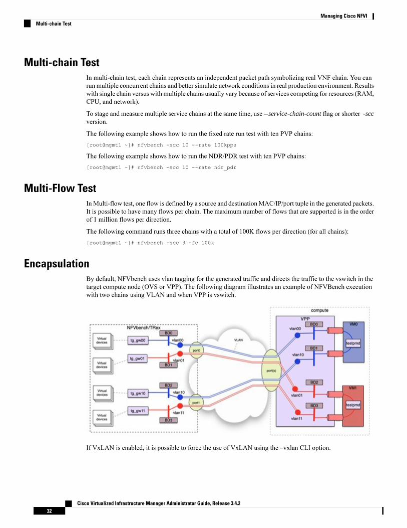
Multi-chain TestIn multi-chain test, each chain represents an independent packet path symbolizing real VNF chain. You canrun multiple concurrent chains and better simulate network conditions in real production environment. Resultswith single chain versus with multiple chains usually vary because of services competing for resources (RAM,CPU, and network).
To stage and measure multiple service chains at the same time, use --service-chain-count flag or shorter -sccversion.
The following example shows how to run the fixed rate run test with ten PVP chains:[root@mgmt1 ~]# nfvbench -scc 10 --rate 100kpps
The following example shows how to run the NDR/PDR test with ten PVP chains:[root@mgmt1 ~]# nfvbench -scc 10 --rate ndr_pdr
Multi-Flow TestInMulti-flow test, one flow is defined by a source and destinationMAC/IP/port tuple in the generated packets.It is possible to have many flows per chain. The maximum number of flows that are supported is in the orderof 1 million flows per direction.
The following command runs three chains with a total of 100K flows per direction (for all chains):[root@mgmt1 ~]# nfvbench -scc 3 -fc 100k
EncapsulationBy default, NFVbench uses vlan tagging for the generated traffic and directs the traffic to the vswitch in thetarget compute node (OVS or VPP). The following diagram illustrates an example of NFVBench executionwith two chains using VLAN and when VPP is vswitch.
If VxLAN is enabled, it is possible to force the use of VxLAN using the –vxlan CLI option.
Cisco Virtualized Infrastructure Manager Administrator Guide, Release 3.4.232
Managing Cisco NFVIMulti-chain Test

The provision of custom configuration allows you to specify more VxLAN options such as specific VNIs touse. For more details, check the default configuration file.
The following diagram illustrates an example of NFVBench execution with two chains using VxLAN andwhen VPP is vswitch.
SR-IOV
If SR-IOV is deployed, NFVbench can support to send the traffic to the test VMs that use SR-IOV instead ofvswitch.
To test SR-IOV, you must have compute nodes configured to support one or more SR-IOV interfaces (alsoknows as PF or physical function) and OpenStack to support SR-IOV.
You need to know:
• The name of the physical networks associated with the SR-IOV interfaces (this is a configuration in Novacompute).
• The VLAN range that can be used on the switch ports that are wired to the SR-IOV ports. Such switchports are normally configured in trunk mode with a range of VLAN ids enabled on that port.
For example, if two SR-IOV ports exist per compute node, two physical networks are generally configuredin OpenStack with a distinct name.
The VLAN range to use is is also allocated and reserved by the network administrator and in coordinationwith the corresponding top of rack switch port configuration.
To enable SR-IOV test, youmust provide the following configuration options to NFVbench in the configurationfile.
This example instructs NFVbench to create the left and right networks of a PVP packet flow to run on twoSRIOV ports named "phys_sriov0" and "phys_sriov1" using resp. segmentation_id 2000 and 2001:
sriov: trueinternal_networks:
left:segmentation_id: 2000physical_network: phys_sriov0
Cisco Virtualized Infrastructure Manager Administrator Guide, Release 3.4.233
Managing Cisco NFVIEncapsulation

right:segmentation_id: 2001physical_network: phys_sriov1
The segmentation ID fields must be different.
In case of PVVP, the middle network must be provisioned properly. The same physical network can also beshared by the virtual networks, but with different segmentation IDs.
External Chain TestNFVBench measures the performance of chains that are pre-staged (using any means external to NFVBench).These chains can be real VNFs with L3 routing capabilities or L2 forwarding chains.
The external chain test is used when you want to use NFVBench only for traffic generation. In this case,NFVBench sends traffic from traffic generator and reports results without performing any staging orconfiguration.
Ensure that the setup is staged externally prior to running NFVbench by creating networks and VMs with aconfiguration that allows generated traffic to pass. You need to provide the name of the two edge neutronnetworks to which the traffic generators are to be attached, during configuration so that NFVbench can discoverthe associated segementation ID (VLAN or VNI).
If the external chains support only L2 forwarding, the NFVBench configuration must specify the destinationMAC to use in each direction for each chain
If the external chains support IPv4 routing, the NFVBench configuration must specify the public IP addressesof the service chain end points (gateway IP) that are used to discover destination MAC using ARP.
To measure performance for external chains, use the --service-chain EXT (or -sc EXT) option:[root@mgmt1 ~]# nfvbench -sc EXT
NFVBench ResultsYou can store the NFVBench detailed results in JSON format using the below command, if you pass the --jsonoption with a destination file name or the --std-json option with a destination folder pathname to use thestandard file name generated by NFVBench.[root@mgmt1 ~]# nfvbench -scc 3 -fc 10 -fs 64 --json /tmp/nfvbench/my.json
The above command stores the results in JSON file in /tmp/nfvbench container directory, which is mappedto the host ~/nfvbench directory. The first file is named as my.json.
Examples of NFVIBench Result Execution
VLAN Fixed Rate
The following example shows the generation of the default frame size (64B) over 100Kpps for the defaultduration (60s) with the default chain type (PVP), default chain count (1) and default flow count (10k):# nfvbench –rate 100kpps -fs IMIX
The summary of NFVBench result is shown below:
Date: 2018-12-19 21:26:26NFVBench version 3.0.4.dev2
Cisco Virtualized Infrastructure Manager Administrator Guide, Release 3.4.234
Managing Cisco NFVIExternal Chain Test

Openstack Neutron:vSwitch: VPPEncapsulation: VLAN
Benchmarks:> Networks:> Components:> Traffic Generator:
Profile: trex-localTool: TRex
> Versions:> Traffic_Generator:
build_date: Nov 13 2017version: v2.32built_by: hhaimmode: STLbuild_time: 10:58:17
> VPP: 18.07> CiscoVIM: 2.4.3-15536
> Service chain:> PVP:> Traffic:
Profile: custom_traffic_profileBidirectional: TrueFlow count: 10000Service chains count: 1Compute nodes: [u'nova:c45-compute-2']
The following NFVBench Result Execution Summary table provides the drop rate measured (in this exampleno drops) and latency measurements in micro-seconds (time for a packet to be sent on one port and receiveback on the other port)
Table 2: NFVBench Result Execution Summary
Max Latency (usec)Min Latency (usec)Avg Latency (usec)Drop RateL2 Frame Size
33020280.0000%IMIX
The following NFVBench Result Configuration table provides the mode details for both forward and reversedirections, where:
• Requested TX Rate is the rate that is requested in bps and pps.
• Actual TX Rate is the actual rate achieved by the traffic generator. It can be lower than the requestedrate if there is not enough CPU.
• RX Rate is the rate of packets received.
Table 3: NFVBench Result Configuration
RX Rate (pps)Actual TXRate (pps)
Requested TXRate (pps)
RX Rate (bps)Actual TXRate (bps)
Requested TXRate (bps)
Direction
50,000 pps50,000 pps50,000 pps152.7344Mbps
152.7334Mbps
152.7333Mbps
| Forward
50,000 pps50,000 pps50,000 pps152.7344Mbps
152.7334Mbps
152.7333Mbps
Reverse
Cisco Virtualized Infrastructure Manager Administrator Guide, Release 3.4.235
Managing Cisco NFVIExamples of NFVIBench Result Execution

RX Rate (pps)Actual TXRate (pps)
Requested TXRate (pps)
RX Rate (bps)Actual TXRate (bps)
Requested TXRate (bps)
Direction
100,000 pps100,000 pps100,000 pps305.4688Mbps
305.4668Mbps
305.4667Mbps
Total
The Forward and Reverse Chain Packet Counters and Latency table shows the number of packets sent orreceived at different hops in the packet path, where:
• TRex.TX.p0 or p1 shows the number of packets sent from each port by the traffic generator.
• Vpp.RX.vlan.<id> shows the number of packets received on the VLAN subinterface with VLAN id <id>in the VPP vswitch.
• Vpp.TX.veth/<id> shows the number of packets sent to the VM.
• Vpp.RX.veth/<id> shows the number of packets received from the VM.
Table 4: Forward Chain Packet Counters and Latency
Max latMin lat.Avg Lat.|TRex.RX.p1
vpp.TX.vlan.1511|vpp.RX.veth/1
vpp.TX.veth/2|vpp.RX.vlan.1547
TRex.TX.p0Chain
320 usec20 usec28 usec3,000,001=>=>=>=>3,000,0010
Table 5: Reverse Chain Packet Counters and Latency
Max latMin lat.Avg Lat.|TRex.RX.p0
vpp.TX.vlan.1547vpp.RX.veth/2vpp.TX.veth/1|vpp.RX.vlan.1511
TRex.TX.p1Chain
330 usec20 usec28 usec3,000,001=>=>=>=>3,000,0010
‘=>’ indicates that no packets are dropped. Otherwise the value will indicate the number of packets dropped.Note
VLAN NDR/PDR
Use the following command to meassure NDR and PDR for IMIX, with the default chain type (PVP), defaultchain count (1) and default flow count (10k):
# nfvbench -fs IMIX
The summary of the NFVBench result execution is shown below:
Date: 2018-12-20 23:11:01NFVBench version 3.0.5.dev2Openstack Neutron:vSwitch: VPPEncapsulation: VLAN
Benchmarks:> Networks:> Components:> Traffic Generator:
Cisco Virtualized Infrastructure Manager Administrator Guide, Release 3.4.236
Managing Cisco NFVIExamples of NFVIBench Result Execution

Profile: trex-localTool: TRex
> Versions:> Traffic_Generator:
build_date: Nov 13 2017version: v2.32built_by: hhaimmode: STLbuild_time: 10:58:17
> VPP: 18.07> CiscoVIM: 2.3.46-17358
> Measurement Parameters:NDR: 0.001PDR: 0.1
> Service chain:> PVP:> Traffic:
Profile: custom_traffic_profileBidirectional: TrueFlow count: 10000Service chains count: 1Compute nodes: [u'nova:a22-mchester-micro-3']
The NFVBench Result Execution Summary table shows the following:
• L2 frame size
• Highest throughput achieved in bps and pps below the drop rate thresholds being the sum of TX for bothports.
• Drop rate measured
• Latency measured (average, min, max)
Table 6: NFVBench Result Execution Summary
MaxLatency(usec)
Min Latency(usec)
Avg Latency(usec)
Avg DropRate
Rate(fwd+rev) inpps
Rate(fwd+rev) inGbps
L2 FrameSize
24510124| 0.0000%2,794,1368.5352IMIXNDR
259101670.0680%3,133,0129.5703IMIXPDR
VXLAN Fixed Rate
It is applicable for platforms that support VxLAN only
Example 1:
In this example, default frame size of 64B is sent over 1Mpps on two chains using VxLAN with flow countof 10k:
# nfvbench --duration 10 -scc 2 --rate 1Mpps --vxlan
The summary of the NFVBench Result is shown below:
2018-12-20 23:28:24,715 INFO --duration 10 -scc 2 --rate 1Mpps --vxlan2018-12-20 23:28:24,716 INFO VxLAN: vlan_tagging forced to False (inner VLAN tagging must
Cisco Virtualized Infrastructure Manager Administrator Guide, Release 3.4.237
Managing Cisco NFVIExamples of NFVIBench Result Execution

be disabled)2018-12-20 23:28:24,716 INFO Using default VxLAN segmentation_id 5034 for middle internalnetwork2018-12-20 23:28:24,716 INFO Using default VxLAN segmentation_id 5017 for right internalnetwork2018-12-20 23:28:24,716 INFO Using default VxLAN segmentation_id 5000 for left internalnetwork
Example 2:
In this example, VxLAN benchmark is ran and 64B frames are sent over 100kpps for the default duration.# nfvbench –rate 100kpps --vxlan
2018-12-18 19:25:31,056 INFO VxLAN: vlan_tagging forced to False (inner VLAN tagging mustbe disabled)2018-12-18 19:25:31,056 INFO Using default VxLAN segmentation_id 5034 for middle internalnetwork2018-12-18 19:25:31,056 INFO Using default VxLAN segmentation_id 5017 for right internalnetwork2018-12-18 19:25:31,056 INFO Using default VxLAN segmentation_id 5000 for left internalnetwork
The NFVBench result summary is as follows:
Date: 2018-12-18 19:26:40NFVBench version 3.0.5.dev2Openstack Neutron:vSwitch: VPPEncapsulation: VxLAN
Benchmarks:> Networks:> Components:> Traffic Generator:
Profile: trex-localTool: TRex
> Versions:> Traffic_Generator:
build_date: Nov 13 2017version: v2.32built_by: hhaimmode: STLbuild_time: 10:58:17
> VPP: 18.07> CiscoVIM: 2.3.46-17358
> Service chain:> PVP:> Traffic:
Profile: traffic_profile_64BBidirectional: TrueFlow count: 10000Service chains count: 1Compute nodes: [u'nova:a22-mchester-micro-1']
Table 7: NFVBench Result Summary
Max Latency (usec)Min Latency (usec)Avg Latency (usec)Drop RateL2 Frame Size
0nan0| 0.0000%64
Cisco Virtualized Infrastructure Manager Administrator Guide, Release 3.4.238
Managing Cisco NFVIExamples of NFVIBench Result Execution

Table 8: NFVBench Result Configuration
RX Rate (pps)Actual TXRate (pps)
Requested TXRate (pps)
RX Rate (bpsActual TXRate (bps)
Requested TXRate (bps)
Direction
50,000 pps50,000 pps50,000 pps33.6000Mbps33.6000Mbps33.6000MbpsForward
50,000 pps50,000 pps50,000 pps33.6000Mbps33.6000Mbps33.6000MbpsReverse
100,000 pps100,000 pps100,000 pps67.2000Mbps67.2000Mbps67.2000MbpsTotal
Table 9: Forward Chain Packet Counters and Latency
TRex.RX.p1vpp.TX.vxlan_tunnel1vpp.RX.veth/1vpp.TX.veth/0vpp.RX.vxlan_tunnel0TRex.TX.p0Chain
50,000=>=>=>=>50,0000
Table 10: Reverse Chain Packet Counters and Latency
TRex.RX.p0vpp.TX.vxlan_tunnel0vpp.RX.veth/0vpp.TX.veth/1vpp.RX.vxlan_tunnel1TRex.TX.p1Chain
50,000=>=>=>=>50,0000
Cisco VIM CLIAn alternate way to NFVBench CLI is to use ciscovimclient. Ciscovimclient is meant to provide an interfacethat is more consistent with the CiscoVIM CLI and can run remotely while the NFVBench CLI is executedon the management node.
Pass JSON configuration matching structure of the NFVBench config file to start a test:[root@mgmt1 ~]# ciscovim nfvbench --config ‘{“rate”: “10kpps”}+------------------+--------------------------------------+| Name | Value |+------------------+--------------------------------------+| status | not_run || nfvbench_request | {"rate": "5kpps"} || uuid | 0f131259-d20f-420f-840d-363bdcc26eb9 || created_at | 2017-06-26T18:15:24.228637 |+------------------+--------------------------------------+
Run the following command with the returned UUID to poll status:[root@mgmt1 ~]# ciscovim nfvbench --stat 0f131259-d20f-420f-840d-363bdcc26eb9+------------------+--------------------------------------+| Name | Value |+------------------+--------------------------------------+| status | nfvbench_running || nfvbench_request | {"rate": "5kpps"} || uuid | 0f131259-d20f-420f-840d-363bdcc26eb9 || created_at | 2017-06-26T18:15:24.228637 || updated_at | 2017-06-26T18:15:32.385080 |+------------------+--------------------------------------+
+------------------+--------------------------------------+| Name | Value |+------------------+--------------------------------------+| status | nfvbench_completed |
Cisco Virtualized Infrastructure Manager Administrator Guide, Release 3.4.239
Managing Cisco NFVICisco VIM CLI

| nfvbench_request | {"rate": "5kpps"} || uuid | 0f131259-d20f-420f-840d-363bdcc26eb9 || created_at | 2017-06-26T18:15:24.228637 || updated_at | 2017-06-26T18:18:32.045616 |+------------------+--------------------------------------+
When the test is done, retrieve results in a JSON format:[root@mgmt1 ~]# ciscovim nfvbench --json 0f131259-d20f-420f-840d-363bdcc26eb9{"status": "PROCESSED", "message": {"date": "2017-06-26 11:15:37", …}}
NFVBench REST InterfaceWhen enabled, the NFVBench container can also take benchmark request from a local REST interface. Accessis only local to the management node in the current Cisco VIM version (that is the REST client must run onthe management node).
Details on the REST interface calls can be found in Chapter 2, Cisco VIM REST API Resources.
Enabling or Disabling Autobackup of Management NodeCisco VIM supports the backup and recovery of the management node. By default, the feature is enabled.Auto snapshot of the management node happens during pod management operation. You can disable the autobackup of the management node.
To enable or disable the management node, update the setup_data.yaml file as follows:# AutoBackup Configuration# Default is True#autobackup: <True or False>
Take a backup of setupdata file and update it manually with the configuration details by running the followingcommand:[root@mgmt1 ~]# cd /root/[root@mgmt1 ~]# mkdir MyDir[root@mgmt1 ~]# cp /root/openstack-configs/setup_data.yaml /root/MyDir/[root@mgmt1 ~]# # update the setup_data to change autobackup[root@mgmt1 ~]# cd /root/MyDir/[root@mgmt1 ~]# vi setup_data.yaml[root@mgmt1 ~]# cd ~/installer-xxxx[root@mgmt1 ~]# ciscovim reconfigure --setupfile /root/MyDir/setup_data.yaml
Forwarding ELK logs to External Syslog ServerCisco VIM supports backup and recovery of the management node. To keep the process predictable and toavoid loss of logs, the software supports the capability of forwarding the ELK logs to multiple external syslogservers (Minimum 1 and Maximum 4). The capability is introduced to enable this feature after the pod is upand running, with Cisco VIM, through the reconfigure option.
The Syslog Export reconfigure option supports the following options:
• Enable forwarding of ELK logs to External Syslog Server on a pod that is already up and running.
• Reconfigure existing External Syslog Setting to point to a different syslog cluster.
Cisco Virtualized Infrastructure Manager Administrator Guide, Release 3.4.240
Managing Cisco NFVINFVBench REST Interface

The following section needs to be configured in the setup_data.yaml file.
##################################### SYSLOG EXPORT SETTINGS###################################SYSLOG_EXPORT_SETTINGS:-remote_host: <Syslog_ipv4_or_v6_addr> # requiredIP address of the remote syslogserver protocol : udp # defaults to udpfacility : <string> # required; possible values local[0-7]or userseverity : <string; suggested value: debug>port : <int>; # defaults, port number to 514clients : 'ELK' # defaults and restricted to ELK;
remote_host: <Syslog_ipv4_or_v6_addr> #requiredprotocol : udp # defaults to udpfacility : <string> # required; possible values local[0-7]or userseverity : <string; suggested value: debug>port : <int>; # defaults, port number to 514
clients : 'ELK' # defaults and restricted to ELK;
Take a backup of the setupdata file and update the file manually with the configuration listed in the preceedingsection. Then run the reconfiguration command as follows:[root@mgmt1 ~]# cd /root/[root@mgmt1 ~]# mkdir MyDir[root@mgmt1 ~]# cp /root/openstack-configs/setup_data.yaml /root/MyDir/[root@mgmt1 ~]# # update the setup_data to include Syslog Export info[root@mgmt1 ~]# cd /root/MyDir/[root@mgmt1 ~]# vi setup_data.yaml[root@mgmt1 ~]# cd ~/installer-xxxx[root@mgmt1 ~]# ciscovim reconfigure --setupfile /root/MyDir/setup_data.yaml
With this configuration, you should now be able to use export ELK logs to an external syslog server. On theremote host, verify if the logs are forwarded from the management node.
Adding and Reconfiguring VIM AdministratorsCisco VIM supports management of the VIM Administrators.VIM administrator has the permission to log into the management node through SSH or the console using the configured password. By configuring to oneVIM admin account, administrators do not have to share credentials. Administrators have individualaccountability.
To enable one or more VIM administrators, perform the following steps:
Step 1 Take a backup of the setupdata file and update the file manually with the configurations listed as,vim_admins:- vim_admin_username: <username>vim_admin_password_hash: <sha512-password-hash>
- vim_admin_username: <username>vim_admin_password_hash: <sha512-password-hash>
- vim_admin_username: <username>vim_admin_password_hash: <sha512-password-hash>
The value of password hash must be in the standard sha512 format. # To generate the hash
Cisco Virtualized Infrastructure Manager Administrator Guide, Release 3.4.241
Managing Cisco NFVIAdding and Reconfiguring VIM Administrators

admin_password_hash should be the output from on the management node# python -c "import crypt; print crypt.crypt('<plaintext password>')"
Step 2 Run the following reconfiguration commands:[root@mgmt1 ~]# cd /root/[root@mgmt1 ~]# mkdir MyDir[root@mgmt1 ~]# cp /root/openstack-configs/setup_data.yaml /root/MyDir/
# update the setup_data to include vim_admin info[root@mgmt1 ~]# cd /root/MyDir/[root@mgmt1 ~]# vi setup_data.yaml[root@mgmt1 ~]# cd ~/installer-xxxx[root@mgmt1 ~]# ciscovim reconfigure --setupfile /root/MyDir/setup_data.yaml
Cisco VIM administrators can manage their own passwords using the Linux passwd command. You can addor remove Cisco VIM administrator through the reconfigure option, while the passwords for their existingaccounts remain unchanged.
Note
Enabling Root Login Post Cisco VIM InstallationTo complement the management of VIM administrators, Cisco VIM supports an option to enable/disable rootaccess at login. By default, this option is set to True. You can optionally disable this facility throughreconfiguration.
Following are the steps to enable te root login:
Step 1 Take a backup of the setupdata file and update the file manually with the configurations listed below:
permit_root_login: <True or False> # if set to false, one has to use su to drop down to root andexecute administrator functionalities.
Step 2 Run the following reconfiguration commands:
[root@mgmt1 ~]# cd /root/ [root@mgmt1 ~]# mkdir MyDir[root@mgmt1 ~]# cp /root/openstack-configs/setup_data.yaml /root/MyDir/
# update the setup_data to include vim_admin info[root@mgmt1 ~]# cd /root/MyDir
[root@mgmt1 ~]# vi setup_data.yaml [root@mgmt1 ~]# cd ~/installer-xxxx[root@mgmt1 ~]# ciscovim --setupfile /root/MyDir/setup_data.yaml reconfigure
Adding Read-Only OpenStack RoleBy default, Cisco VIM’s deployment of OpenStack supports two roles: admin and user. The admin can viewand change all OpenStack resources including system and project resources. The user can view and changeonly the project resources.
Cisco Virtualized Infrastructure Manager Administrator Guide, Release 3.4.242
Managing Cisco NFVIEnabling Root Login Post Cisco VIM Installation

Cisco VIM, optionally provides OpenStack user role, which is the read-only administrator or readonly. Theread-only user can view project resources, but cannot make any changes.
To enable read-only OpenStack role and create read-only OpenStack administrator, perform the followingsteps
Step 1 Take a backup of the setupdata file and update the file manually with the configuration given below:
ENABLE_READONLY_ROLE: True
Step 2 Enable the OpenStack user role, by executing the following reconfiguration commands:
[root@mgmt1 ~]# cd /root/[root@mgmt1 ~]# mkdir MyDir[root@mgmt1 ~]# cp /root/openstack-configs/setup_data.yaml /root/MyDir/
# update the setup_data to include vim_admin info[root@mgmt1 ~]# cd /root/MyDir/[root@mgmt1 ~]# vi setup_data.yaml [root@mgmt1 ~]# cd ~/installer-xxxx[root@mgmt1 ~]# ciscovim reconfigure --setupfile /root/MyDir/setup_data.yaml
When the feature is enabled, an OpenStack administrator can create new user accounts that will have the special privilegesof a Read-Only user.
Step 3 From the management node, load the OpenStack authentication variables:
[root@management-server-cisco ~]# source ~/openstack-configs/openrc
Step 4 Create a new user account with a strong password.
[root@management-server-cisco images]# openstack user create --password-prompt readerUser Password:Repeat User Password:+----------+----------------------------------+| Field | Value |+----------+----------------------------------+| email | None || enabled | True || id | e2f484de1e7d4faa9c9de2446ba8c3de || name | reader || username | reader |+----------+----------------------------------+
Step 5 Assign the project and role to that user account:
[root@management-server-cisco images]# openstack role add --project admin --user readerreadonly+-----------+----------------------------------+| Field | Value |+-----------+----------------------------------+| domain_id | None || id | ed2fb5b2c88e4241918573624090174b || name | readonly |+-----------+----------------------------------+
Cisco Virtualized Infrastructure Manager Administrator Guide, Release 3.4.243
Managing Cisco NFVIAdding Read-Only OpenStack Role

Alternatively, the OpenStack admin logged into the Horizon dashboard can perform the above steps. The actionscorresponding to the CLI commands can be done on the Identity/Users panel in the dashboard.
The OpenStack read-only user can:
• Access the project and identity dashboards, but not the admin dashboard.
• View all the project resources, but cannot make any changes to them.
If the ENABLE_READONLY_ROLE is False (the default value), the readonly role will have no specialpermissions or restrictions. It has create, update, and delete permissions to project resources, similar to that ofthe project member. You need to assign users to the role of readonly, when ENABLE_READONLY_ROLEis set to True.
Note
Reconfiguration of Proxy Post InstallDuring post-install you can update the http/https proxy server information that is listed in NETWORKINGsection of the setup_data.yaml.
To update the proxy in the post-VIM install follow these steps:
Step 1 Take a backup of the setupdata file and update the file manually with the configuration listed below:http_proxy_server: <a.b.c.d:port> # optional, needed if install is through internet, and the pod isbehind a proxyand/orhttps_proxy_server: <a.b.c.d:port> # optional, needed if install is through internet, and the pod isbehind a proxy
Step 2 Run the following command to reconfigure:[root@mgmt1 ~]# cd /root/[root@mgmt1 ~]# mkdir MyDir[root@mgmt1 ~]# cp /root/openstack-configs/setup_data.yaml /root/MyDir/
# update the setup_data to update the proxy info[root@mgmt1 ~]# cd /root/MyDir/[root@mgmt1 ~]# vi setup_data.yaml[root@mgmt1 ~]# cd ~/installer-xxxx[root@mgmt1 ~]# ciscovim reconfigure --setupfile /root/MyDir/setup_data.yaml
Reconfiguring NTPDuring post-installation, you can update the NTP server information that is listed in NETWORKING sectionof the setup_data.yaml.
To update NTP server information post-installation, follow the below steps:
Step 1 Take a backup of the setupdata file and update the file manually with the configuration listed below:
Cisco Virtualized Infrastructure Manager Administrator Guide, Release 3.4.244
Managing Cisco NFVIReconfiguration of Proxy Post Install

ntp_servers: [a.b.c.d, ‘v6_end_point’]
Step 2 Run the following reconfiguration commands:
[root@mgmt1 ~]# cd /root/[root@mgmt1 ~]# mkdir MyDir[root@mgmt1 ~]# cp /root/openstack-configs/setup_data.yaml /root/MyDir/
# update the setup_data to update the ntp_server info[root@mgmt1 ~]# cd /root/MyDir/[root@mgmt1 ~]# vi setup_data.yaml[root@mgmt1 ~]# cd ~/installer-xxxx[root@mgmt1 ~]# ciscovim --setupfile /root/MyDir/setup_data.yaml reconfigure
Maximum number of DNS servers that can be configured is three.Note
Reconfiguring DNSDuring post-installation, you can update the Domain Name Server (DNS) information that is listed inNETWORKING section of the setup_data.yaml.
To update the domain name server information post VIM installation, follow the below steps:
Step 1 Take a backup of the setupdata file and update the file manually with the configuration listed below:domain_name_servers: [a.b.c.d, ‘v6_end_point’]
Step 2 Run the following reconfiguration commands:
[root@mgmt1 ~]# cd /root/[root@mgmt1 ~]# mkdir MyDir[root@mgmt1 ~]# cp /root/openstack-configs/setup_data.yaml /root/MyDir/
update the setup_data to update the domain_name_server info[root@mgmt1 ~]# cd /root/MyDir/[root@mgmt1 ~]# vi setup_data.yaml[root@mgmt1 ~]# cd ~/installer-xxxx[root@mgmt1 ~]# ciscovim --setupfile /root/MyDir/setup_data.yaml reconfigure
Maximum number of NTP servers that can be configured is four.Note
Reconfiguring Sever KVM Console Password Post InstallYou need the reconfigure option to reset the KVM console password for the servers, if the administratorforgets the KVM console password post cloud installation. The risk of forgetting the password leads to thefailure of SSH connectivity to the server and the option of debugging through KVM console.
During post-install, you can update the admin_password_hash information that is listed in COBBLER sectionof the setup_data.yaml.
Cisco Virtualized Infrastructure Manager Administrator Guide, Release 3.4.245
Managing Cisco NFVIReconfiguring DNS

To update the password post-install, follow the below steps:
Step 1 Take a backup of the setupdata file and update the file manually with the configuration listed below:
COBBLER:admin_password_hash: <$6…> # <Please generate the admin pwd hash via the command below; verify
the output starts with $6># execute the following on the management node to get the admin_password_hash
# python -c 'import crypt; print crypt.crypt("<plaintext_strong_password>")'
Step 2 Run the following reconfiguration command:
[root@mgmt1 ~]# cd /root/ [root@mgmt1 ~]# mkdir MyDir[root@mgmt1 ~]# cp /root/openstack-configs/setup_data.yaml /root/MyDir/
# update the setup_data to update the proxy info [root@mgmt1 ~]# cd /root/MyDir/[root@mgmt1 ~]# vi setup_data.yaml [root@mgmt1 ~]# cd ~/installer-xxxx[root@mgmt1 ~]# ciscovim reconfigure --setupfile /root/MyDir/setup_data.yaml
Enabling Head-End Replication OptionFor the releases Cisco VIM 2.4.9 and later, the multi-VXLAN EVPN based design optionally supports thestatic implementation of VXLAN technology using head-end replication (HER). HER helps leverage theVXLAN technology, regardless of the hardware or software limitation of the VXLAN feature set at the remoteend of the VTEP tunnel.
With the static information defined in the HERsetup_data, VPP performs the head-end replication to alldefined remote VTEPs and the Layer-2 Forwarding Information Base (L2FIB) MAC-IP table is populatedbased on flood and learn. When EVPN coexists with HER, Cisco VIM considers them as two different setsof BGP speakers each giving the information which ends up in the same etcd FIB table.
In Cisco VIM, the EVPN acts as the primary mechanism and HER as the fallback methodology. You can addor remove HER to or from an existing EVPN pod through Cisco VIM reconfigure option.
Following are the assumptions for the HER feature:
• VNIs can be allowed in the range of 1 to 65535.
• VNIs can be repeated across two or more remote POD VTEPs for HA.
• VNIs cannot be repeated for the same remote POD VTEP.
• Within the same network segment, no remote POD VTEPs IP address can be repeated.
Step 1 Ensure that multi-VXLAN feature exists in day-0 configuration of the setup_data. Add a new section calledhead-end-replication under the NETWORK_OPTIONS -> vxlan -> vxlan-ecn and vxlan-tenant sections.
NETWORK_OPTIONS:vxlan:
Cisco Virtualized Infrastructure Manager Administrator Guide, Release 3.4.246
Managing Cisco NFVIEnabling Head-End Replication Option

vxlan-tenant:head_end_replication: # Optional and reconfigurable
- vtep_ips: vni_id1:vni_id2, vni_id3, … (upto as many remote POD vteps as required)
vxlan-ecn:head_end_replication: # Optional and reconfigurable
- vtep_ips: vni_id1:vni_id2, vni_id3, … (upto as many remote POD vteps as required)
Update all compute nodes with vtep_ip information under the SERVERS section:SERVERS:Compute1:…
For head-end-replication option, define vtep_ips on all servers that act as control and compute nodes
# vtep_ips: {vxlan-tenant: <ip address>, vxlan-ecn: <ip address>} # These IPs must belong to theassociated IP pool of vxlan-tenant and vxlan-ecn networks, and must match the existing
assigned vtep_ip for EVPN as they are brought in as part of reconfiguration.
Step 2 To determine the respective vtep_ip on a per segment and server basis, run the following reconfiguration commands:
[root@mgmt1 ~]# cd /root/[root@mgmt1 ~]# mkdir MyDir[root@mgmt1 ~]# cp /root/openstack-configs/setup_data.yaml /root/MyDir/
[root@mgmt1 ~]# cd /root/installer-<x.y.z>/tools[root@mgmt1 ~]#./vtep_ip_server_mapping.py# Update the setup_data to include the HER section and vtep_ip corresponding to the network segmentfor the respective servers
[root@mgmt1 ~]# cd /root/MyDir/[root@mgmt1 ~]# vi setup_data.yaml[root@mgmt1 ~]# cd ~/installer-xxxx[root@mgmt1 ~]# ciscovim reconfigure --setupfile /root/MyDir/setup_data.yaml
Enabling Layer BGP Adjacency Between Controllers andPeering Route Reflector
From release Cisco VIM 2.4.9 onwards, the Layer 2 or Layer 3 BGP adjacency with the peering route-reflectoris supported.
For releases prior to Cisco VIM 2.4.9, only Layer 2 BGP adjacency is supported.Note
Following are the assumptions made to move a pod from a Layer 2 BGP adjacency to that of Layer 3:
• The controllers with the bgp_speaker_addresses peer with the route-reflector over Layer 3.
• This option is only available when vxlan is enabled as NETWORK_OPTIONS.
• Every vxlan segment (vxlan-ecn and vxlan-tenant) will have its own IPs.
Cisco Virtualized Infrastructure Manager Administrator Guide, Release 3.4.247
Managing Cisco NFVIEnabling Layer BGP Adjacency Between Controllers and Peering Route Reflector

• IPs are picked up from management subnet, but they do not belong in the management pool.
• Switching from Layer 2 to Layer 3 peering is only supported, but not vice-versa.
• Once enabled, the only way to change the bgm_mgmt_address is through a replace controller.
Step 1 Update all controller nodes with bgp_mgmt_address where the IPs reside in the management subnet, but not in themanagement IP pool.
• VXLAN feature must exists in day-0 configuration of the setup_data.
• One unique IP must be available per VXLAN segment.
Note
SERVERS:Control1:…
# bgp_mgmt_address: {vxlan-tenant: <ip address>, vxlan-ecn: <ip address>} # These IPs must belong tothe
management segment, but not in the management IP pool.
Step 2 Run the following reconfiguration commands:
[root@mgmt1 ~]# cd /root/ [root@mgmt1 ~]# mkdir MyDir[root@mgmt1 ~]# cp /root/openstack-configs/setup_data.yaml /root/MyDir/
# update the setup_data to include HER section and vtep_ips info[root@mgmt1 ~]# cd /root/MyDir/[root@mgmt1 ~]# vi setup_data.yaml [root@mgmt1 ~]# cd ~/installer-xxxx[root@mgmt1 ~]# ciscovim reconfigure --setupfile /root/MyDir/setup_data.yaml
Enabling Custom Policy for VNF Manager Post InstallDuring the post-installation of a cloud, Cisco VIM helps to enable a VNF Manager (such as ESC) to operateand manage tenant VMs in the OpenStack cloud, with additional privileged features.
Following are the steps to enable the custom policy for VNF Manager:
Step 1 Take a backup of the setupdata file and update the file manually with the configurations listed as,ENABLE_ESC_PROV: True
Step 2 Run the following commands to reconfigure:[root@mgmt1 ~]# cd /root/[root@mgmt1 ~]# mkdir MyDir[root@mgmt1 ~]# cp /root/openstack-configs/setup_data.yaml /root/MyDir/
# update the setup_data to update the proxy info[root@mgmt1 ~]# cd /root/MyDir/[root@mgmt1 ~]# vi setup_data.yaml
Cisco Virtualized Infrastructure Manager Administrator Guide, Release 3.4.248
Managing Cisco NFVIEnabling Custom Policy for VNF Manager Post Install

[root@mgmt1 ~]# cd ~/installer-xxxx[root@mgmt1 ~]# ciscovim reconfigure --setupfile /root/MyDir/setup_data.yaml
Migrate SRIOV from 2-X520 to 2-XL710 in a VIC/NIC PODTo use this feature, ensure that both the card types are available on the SRIOV compute nodes of the pod andwith one of the card type participating in SRIOV as part of installation, and then execute the following steps:
Before you begin
In Cisco VIM, you can redeploy the SRIOV ports between 2-X520 and 2-XL710, in a Cisco VIM pod wherethe control and data plane are running OFF Cisco VIC. This is driven through an optional parameterSRIOV_CARD_TYPE listed in the setup_data.yaml.
It is assumed that all computes participating in SRIOV has two sets of card types. Reconfiguration fails if thecard type with a total of 4 ports is not available. Cisco recommends you to have two of each of the card typeinserted on a per-compute basis, so that the correct network ports from the target network cards are pickedby the orchestrator. However, if the SRIOV_CARD_TYPE is present during the fresh install or during addcompute, the SRIOV_CARD_TYPE parameter is given preference for the target/configured card type.
You can define the SRIOV_CARD_TYPE at a per-compute level, to override the global definition. Thisoption allows some computes to run with XL-710, while others to run with X-520 for SRIOV ports. It shouldbe noted that computes without SRIOV can co-exist in this pod.
Step 1 Take a backup of the setupdata file and update the file manually with the configuration listed below:
SRIOV_CARD_TYPE: <X520 or XL710>and/or update the hardware_info at a per compute level (see example below)compute-xx:hardware_info: {SRIOV_CARD_TYPE: <XL710 or X520>}
Step 2 Run the following reconfiguration commands:
[root@mgmt1 ~]# cd /root/[root@mgmt1 ~]# mkdir MyDir[root@mgmt1 ~]# cp /root/openstack-configs/setup_data.yaml /root/MyDir/# update the setup_data to include the target SRIOV card type[root@mgmt1 ~]# cd /root/MyDir/[root@mgmt1 ~]# vi setup_data.yaml[root@mgmt1 ~]# cd ~/installer-xxxx[root@mgmt1 ~]# ciscovim reconfigure --setupfile /root/MyDir/setup_data.yaml
Cisco Virtualized Infrastructure Manager Administrator Guide, Release 3.4.249
Managing Cisco NFVIMigrate SRIOV from 2-X520 to 2-XL710 in a VIC/NIC POD
AugmentingCiscoVIMM4VIC/(10/40G)NICpodswithM5-based40G VIC/NIC Computes
From release Cisco VIM 2.4.9 onwards, the augmentation of an existing M4 VIC/NIC based pod (somecomputes have X520, while others have XL710 for SRIOV), with the M5-based VIC/NIC (40G) computesis supported. To use this augmentation feature, you must define the SRIOV_CARD_TYPE at a per computelevel (default is X520).
You can add M5-based 40G VIC/NIC computes into the pod in the following scenarios:
Use Case 1: If you run a pod with M4-based computes having only X520 cards, execute the reconfigurationoperation and define the SRIOV_CARD_TYPE as XL710 under the hardware_info section of the targetcompute, to add the compute of M5 with 40G Cisco VIC and two XL710 cards,.
Use Case 2: If you run the pod with M4-based VIC/NIC computes having XL710 cards, execute the addcompute operation and define the SRIOV_CARD_TYPE as XL710 for the target compute, to add M5-basedcompute nodes with XL710 cards.
The following steps 1 through 3 are not applicable for Use Case 2, and you can directly add/remove computewhen required.
Note
Before you begin
Identify if the pod has M4 computes running with two XL710 or not, that is, whether the pod is running withUse Case 1 or Use Case 2.
Step 1 If the pod is running with Use Case 1, execute the following command:# ciscovim reconfigure
Step 2 Take a backup of the setupdata file and update the file manually with the configuration listed below:
Update the hardware_info at a per compute level (see example below)compute-xx:hardware_info: {SRIOV_CARD_TYPE: <XL710 or X520>}
Step 3 Run the following reconfiguration commands:[root@mgmt1 ~]# cd /root/ [root@mgmt1 ~]# mkdir MyDir[root@mgmt1 ~]# cp /root/openstack-configs/setup_data.yaml /root/MyDir/ # update the setup_data toinclude the target SRIOV card type [root@mgmt1 ~]# cd /root/MyDir/[root@mgmt1 ~]# vi setup_data.yaml [root@mgmt1 ~]# cd ~/installer-xxxx[root@mgmt1 ~]# ciscovim --setupfile /root/MyDir/setup_data.yaml add-computes <m5compute1, …>
Cisco Virtualized Infrastructure Manager Administrator Guide, Release 3.4.250
Managing Cisco NFVIAugmenting Cisco VIM M4 VIC/(10/40G) NIC pods with M5-based 40G VIC/NIC Computes

Adding and Reconfiguring VIM Administrators Authenticatedwith External LDAP Server
Cisco VIM supports management of the VIM administrators whose access to the management node can beauthenticated through an external LDAP server. For the users to obtain sudo access, you need to manuallyadd the root user or any user with root privileges to the wheel group in the external LDAP server. Also, youmust enable the pod with external TLS. To enable VIM administrators with LDAP authentication, performthe following steps:
Step 1 Take a backup of the setupdata file and update the file manually with the configuration listed below:
vim_ldap_admins:- domain_name: corp_ldap1ldap_uri: "ldaps://10.30.116.253:636,ldaps://10.30.116.254:636"ldap_search_base: "dc=cisco,dc=com"ldap_schema: rfc2307 # Optionalldap_user_object_class: posixAccount # Optionalldap_user_uid_number: uidNumber # Optionalldap_user_gid_number: gidNumber # Optionalldap_group_member: memberUid # Optional
Multiple entries of the LDAP domain are allowed. For each entry, only domain_name and ldap_uri info aremandatory. Ensure that the ldap_uri is secured over ldaps. As part of reconfiguration, you can add newdomain_name, but cannot change the domain_name once it is configured.
Note
.
Step 2 To reconfigure the VIM administrator, run the following commands:
[root@mgmt1 ~]# cd /root/ [root@mgmt1 ~]# mkdir MyDir[root@mgmt1 ~]# cp /root/openstack-configs/setup_data.yaml /root/MyDir/
# update/include the vim_ldap_admin in the setup_data[root@mgmt1 ~]# cd /root/MyDir/[root@mgmt1 ~]# vi setup_data.yaml [root@mgmt1 ~]# cd ~/installer-xxxx[root@mgmt1 ~]# ciscovim reconfigure --setupfile /root/MyDir/setup_data.yaml
Hosting Horizon through NAT/DNS AliasCisco VIM supports hosting of the Horizon dashboard through NAT or with a DNS alias.
To host Horizon, perform the following steps:
Step 1 Take a backup of the setupdata file and update the file manually with the configuration listed below:
HORIZON_ALLOWED_HOSTS:
Cisco Virtualized Infrastructure Manager Administrator Guide, Release 3.4.251
Managing Cisco NFVIAdding and Reconfiguring VIM Administrators Authenticated with External LDAP Server

- <NAT_IP1>- <NAT_IP2>
Step 2 Run the following commands for reconfiguration:
[root@mgmt1 ~]# cd /root/ [root@mgmt1 ~]# mkdir MyDir[root@mgmt1 ~]# cp /root/openstack-configs/setup_data.yaml /root/MyDir/
# update/include the vim_ldap_admin in the setup_data[root@mgmt1 ~]# cd /root/MyDir/[root@mgmt1 ~]# vi setup_data.yaml [root@mgmt1 ~]# cd ~/installer-xxxx[root@mgmt1 ~]# ciscovim reconfigure --setupfile /root/MyDir/setup_data.yaml
Enabling Banner During SSH LoginCisco VIM supports enabling of banner during ssh login to the management node. To enable banner duringlogin, perform the following steps:
Step 1 Take a backup of the setupdata file and update the file manually with the configuration listed below:
ssh_banner:<your Banner Text>
Step 2 Run the following commands for reconfiguration:
[root@mgmt1 ~]# cd /root/ [root@mgmt1 ~]# mkdir MyDir[root@mgmt1 ~]# cp /root/openstack-configs/setup_data.yaml /root/MyDir/
# update/include the vim_ldap_admin in the setup_data[root@mgmt1 ~]# cd /root/MyDir/[root@mgmt1 ~]# vi setup_data.yaml [root@mgmt1 ~]# cd ~/installer-xxxx[root@mgmt1 ~]# ciscovim reconfigure --setupfile /root/MyDir/setup_data.yaml
Enabling DHCP Reservation for VM’s MAC AddressFrom release Cisco VIM 3.2.0 onwards, you can have DHCP reservations for virtual machineMAC addresses,so as to get the same IP address always regardless of the host hypervisor or operating system they are running.To avail this optional feature, few restrictions exist.
If the MAC address ends with 00:00, then
• First entry of the first octect must be a Hex
• Second entry of the first octect must be 2, 6, a or e
Cisco Virtualized Infrastructure Manager Administrator Guide, Release 3.4.252
Managing Cisco NFVIEnabling Banner During SSH Login

For example, the MAC address entry can be [a-f][2,6,a,e]:yz:uv:ws:00:00.
To enable this feature, follow the below steps:
Step 1 Take a backup of the setupdata file and update the file manually with the configuration listed below:BASE_MACADDRESS: <[a-f][2,6,a,e]:yz:uv:ws:00:00>
Step 2 Run the following commands for reconfiguration:
[root@mgmt1 ~]# cd /root/ [root@mgmt1 ~]# mkdir MyDir[root@mgmt1 ~]# cp /root/openstack-configs/setup_data.yaml /root/MyDir/
# update/include the vim_ldap_admin in the setup_data [root@mgmt1 ~]# cd /root/MyDir/[root@mgmt1 ~]# vi setup_data.yaml [root@mgmt1 ~]# cd ~/installer-xxxx
[root@mgmt1 ~]# ciscovim reconfigure --setupfile /root/MyDir/setup_data.yaml
Enabling Red Hat Identify Management SystemCisco VIM supports integration with RedHat IdentityManagement Systemwhich is based on Identity, Policy,Audit (IPA) technology. To enable this feature, follow the below steps:
Step 1 Take a backup of the setupdata file and update the file manually with the configuration listed below:IPA_INFO:ipa_servers:- hostname: <fqdn_of_ipa_server_1>ipaddresses: # --- Optional- ‘<ipv4_address>’- '<ipv6_address>'
- hostname: <fqdn_of_ipa_server_1>ipaddresses: --- Optional- ‘<ipv4_address>’- '<ipv6_address>'
enroller_user: <enroller_username>enroller_password: <enroller_password>ipa_domain_name: <ipa_domain_name>
Step 2 Run the following reconfiguration commands:[root@mgmt1 ~]# cd /root/[root@mgmt1 ~]# mkdir MyDir[root@mgmt1 ~]# cp /root/openstack-configs/setup_data.yaml /root/MyDir/
# update/include the IPA_INFO in the setup_data[root@mgmt1 ~]# cd /root/MyDir/[root@mgmt1 ~]# vi setup_data.yaml[root@mgmt1 ~]# cd ~/installer-xxxx[root@mgmt1 ~]# ciscovim reconfigure --setupfile /root/MyDir/setup_data.yaml
You can change all the parameters other than ipa_domain_name via reconfiguration post installation. Also,you cannot reconfigure IPA in conjunction with any other reconfiguration operation.
Note
Cisco Virtualized Infrastructure Manager Administrator Guide, Release 3.4.253
Managing Cisco NFVIEnabling Red Hat Identify Management System

For pods, ensure that the hostname of the servers and the management node are in FQDN with lower case. As aprecautionary measure, you can perform the following apart from Cisco VIM orchestration using the below command:
• Restore hostnames for all the hosts in the cluster to that defined in setup_data.
• Unregister/unenroll all the hosts from the cluster. This unenrollment process does not have any impact to Cisco VIMfunctionality but the access is lost for all IPA users.
• Use enroll feature to perform role of an installation or reconfiguration operation.
# cd </root/installer-n.n># ./tools/manage_ipa.sh -hmanage_ipa.sh : Cisco VIM Manage IPA ops-----------------------------------------usage: ./manage_ipa.sh [-h]
-r : Restore hostname based on setup_data.yaml-u : Un-enroll all IPA clients from the IPA Server-e : Enroll all IPA clients to the IPA Server-h : To display this help
Enabling Vault on Day-2 in Cisco VIM PodCisco VIM supports Vault as a reconfiguration option.
Step 1 To enable Vault on a pod running Cisco VIM 3.4.1 or higher, update the setup_data.yaml file as follows#Vault:enabled: True # optional, default if not defined is false
Step 2 Take a backup of setupdata file and update it manually with the configuration details by running the following command:[root@mgmt1 ~]# cd /root/[root@mgmt1 ~]# mkdir MyDir[root@mgmt1 ~]# cp /root/openstack-configs/setup_data.yaml /root/MyDir/[root@mgmt1 ~]# # update the setup_data to enable vault[root@mgmt1 ~]# cd /root/MyDir/[root@mgmt1 ~]# vi setup_data.yaml[root@mgmt1 ~]# cd ~/installer-xxxx[root@mgmt1 ~]# ciscovim reconfigure --setupfile /root/MyDir/setup_data.yaml
Enabling Trusted Virtual Function on Day 2For releases earlier to Cisco VIM 3.4.2, you must delete the existing VMs on the target compute to enablethe trusted virtual function (VF) on a server after the initial installation of the cloud. To avoid the disruptioncaused to the existing VMs, a reconfigure option is introduced. You can enable trusted VF on the SRIOVports as a reconfiguration option, on a per server basis using the below steps:
Cisco Virtualized Infrastructure Manager Administrator Guide, Release 3.4.254
Managing Cisco NFVIEnabling Vault on Day-2 in Cisco VIM Pod

Step 1 To enable trusted_vf on a pod running Cisco VIM 3.4.2 or later, update the SERVERS section for the target computeswhere trusted_vf must be enabled in the setup_data.yaml file as given below:SERVERS:<target_compute_name>:Trusted_vf: True
Step 2 Take a backup of setupdata file and update it manually with the configuration details by running the following command:[root@mgmt1 ~]# cd /root/[root@mgmt1 ~]# mkdir MyDir[root@mgmt1 ~]# cp /root/openstack-configs/setup_data.yaml /root/MyDir/[root@mgmt1 ~]# # update the setup_data to enable trusted_vf on the target computes[root@mgmt1 ~]# cd /root/MyDir/[root@mgmt1 ~]# vi setup_data.yaml[root@mgmt1 ~]# cd ~/installer-xxxx[root@mgmt1 ~]# ciscovim reconfigure --setupfile /root/MyDir/setup_data.yaml
Enabling Ironic Post InstallationCisco VIM supports enabling of reference architecture of Ironic to host baremetal workloads. The ironicservice can be brought in day-0 or as a reconfiguration option. Once enabled, it cannot be disabled. Ironicsupport is only available with Cisco UCS C baremetal servers and when Cisco VIM is deployed with OVSas the mechanism driver. The ironic interface to be used on the baremetal servers for Openstack can be eitheran MLOM interface, an Intel NIC, or the onboard 1G LOM port. Ironic supports only the configuration of asingle interface on the baremetal server.
You must have one separate network segment that is used for ironic_management and ironic inspector. Theinspector is a service used to automate the creation of the openstack baremetal port with switch interface, forexample, eth 1/39 and MAC address information of both the switch MAC and server interface MAC, apartfrom automatically adding the deploy image information to the ironic node.
Cisco Virtualized Infrastructure Manager Administrator Guide, Release 3.4.255
Managing Cisco NFVIEnabling Ironic Post Installation

Ensure that the ironic management, ironic inspector, Cisco VIMmanagement, and Ironic CIMC networks arerouted to each other.
The Cisco VIM management network must be able to reach:
• Ironic management network and vice-versa.
• CIMC network of the ironic nodes. This allows the Cisco VIM controller servers to directly reach theCIMC IP of the ironic servers
To enable network reachability, follow one of the below conditions:
• All three networks such as Cisco VIM management, Ironic management and CIMC must be privatenetworks with SVI interfaces on the ToR.
• Routed network must be deployed for all three network segments. In this case, the need for SVI interfaceon ToR is eliminated.
You must include ironic-management/ironic-inspector VLANs on the ToR interfaces that are connected tothe mercury controller servers. This must be manually configured at present.
Note
To enable ironic into an existing pod running Cisco VIM 3.2.0 or higher with provider network segmentdefined from the day-0 installation, perform the following steps:
Step 1 Take a backup of the setupdata file and update the file manually with the configuration listed below:
# Optional Services:OPTIONAL_SERVICE_LIST:- ironic
IRONIC:IRONIC_SWITCHDETAILS: # list of switches off which the ironic servers are hanging. This is mainly
used to provide ironic switch details to neutron- {hostname: <switch_name>, password: <password>, ssh_ip: <ssh_ip>, username: <switch_admin_username>,switch_type: <"Nexus", "ACI", or "BypassNeutron">}
NETWORKING:……
- gateway: <gateway_information> # Mandatory if ironic is presentpool: [<ip_start1 to ip_end1]segments: [ironic]subnet: <subnet with/mask>vlan_id: <unique vlan id across the pod>inspector_pool: [ip_add_1 to ip_add_2, ip_add_3 to ip_add_4, ip_add_5 to ip_add_6] (# of entry
pool : 3, same network as ironic but doesn’t overlap with the pool of IPs defined in the ironicsegment)# alternate format for pool (# of entry pool : 3)
- ip_add_1 to ip_add_2- ip_add_3 to ip_add_4- ip_add_5 to ip_add_6
Step 2 While deploying ironic, you need to follow the below steps before performing VIM reconfiguration:
Cisco Virtualized Infrastructure Manager Administrator Guide, Release 3.4.256
Managing Cisco NFVIEnabling Ironic Post Installation

a) Create a separate ironic_inventory.yaml with CIMC/ IPMI details of the servers to be used as ironicbaremetals. For example:/root/installer-XXX/openstack-configs/ironic_inventory.yaml.
b) Save this file with your ironic server details in /root/installer-XXX/openstack-configs/ironic_inventory.yamlc) Specify the ironic management/ ironic inspector VLAN in all control interfaces of the mercury controller servers.
This is essential to perform ironic introspection, to transfer the images from the controller to the baremetal server.d) If ironic is deployed in Nexus mode of ToR, ensure that no existing configuration is available on the interface of the
ToR connected to the baremetal. The interface is in ACCESS mode. Only the ironic inspector VLAN must be set asthe access VLAN.
e) If ironic is deployed in an ACI mode testbed, you must ensure that ironic management network VLAN and all thetenant VLANs from setup_data are configured on the interface of the ToR connected to the baremetal the ironicinspector VLAN. The interface is in TRUNKmode. You need to set the ironic inspector network as the native VLAN.
f) Verify whether the following are done in the baremetal server CIMC before proceeding:
• Check if IPMI connections are allowed over LAN.
• In BIOS configured Boot order, only pxeboot is present and available as the first option.
• PXE is enabled in VNIC adapters.
• Set the VLAN mode on the VNIC being used as TRUNK.
• Turn ON the baremetal node, to have access to all parameters of CIMC. VIM installer verifies the node at Step1.
• Disable LLDP on Cisco VIC Adaptor of all the servers used for ironic by doing the following and rebooting theserver:
sh [email protected] (CIMC IP)C240-FCH1832V1HW# scope chassisC240-FCH1832V1HW /chassis # show adapterC240-FCH1832V1HW /chassis # scope adapter <PCI slot>C240-FCH1832V1HW /chassis/adapter # set lldp disabledC240-FCH1832V1HW*# commitC240-FCH1832V1HW /chassis/adapter # show detail <To Verify LLDP is disabled>
Step 3 Run the following commands for reconfiguration:
[root@mgmt1 ~]# cd /root/ [root@mgmt1 ~]# mkdir MyDir[root@mgmt1 ~]# cp /root/openstack-configs/setup_data.yaml /root/MyDir/
# update/include the vim_ldap_admin in the setup_data[root@mgmt1 ~]# cd /root/MyDir/[root@mgmt1 ~]# vi setup_data.yaml[root@mgmt1 ~]# cd ~/installer-xxxx[root@mgmt1 ~]# ciscovim reconfigure --setupfile /root/MyDir/setup_data.yaml
If you need to troubleshoot the server before launching the baremetal instance and need to login into the packaged ironicdeploy images, the credentials are – devuser/ Lab1234!
For more information, see Launching OpenStack Baremetal Instances
Cisco Virtualized Infrastructure Manager Administrator Guide, Release 3.4.257
Managing Cisco NFVIEnabling Ironic Post Installation

Hosting Container Workload Post-InstallationCisco VIM supports enabling of container workload by hosting Cisco Container Platform as an applicationin VMs. For assumptions on container workload options, see Container Support section of Cisco VirtualizedInfrastructure Manager Installation Guide. Before installing Cisco Container Platform, ensure that lbaas isenabled as part of optional_service_list.
1. To enable lbaas, use the following commands:[root@mgmt1 ~]# cd /root/[root@mgmt1 ~]# mkdir MyDir[root@mgmt1 ~]# cp /root/openstack-configs/setup_data.yaml /root/MyDir/[root@mgmt1 ~]# # update the setup_data with lbaas under the OPTIONAL_SERVICE_LIST section[root@mgmt1 ~]# cd /root/MyDir/[root@mgmt1 ~]# vi setup_data.yaml[root@mgmt1 ~]# cd ~/installer-xxxx[root@mgmt1 ~]# ciscovim reconfigure --setupfile /root/MyDir/setup_data.yaml
2. Generate a ssh key of ecdsa type using the command:# ssh-keygen -f /root/ecdsa-key -t ecdsa -b 521 (Press Enter till keys are generated)
3. Establish the networking type (tenant or provider) based on which the CCP_DEPLOYMENT section isdefined in the setup_data.
4. Update a copy of the setup_data with the following information. Ensure that care is taken to the itemsthat are needed for tenant or provider network environment.CCP_DEPLOYMENT: # Parameters for CCP Deployment Optional services, LBAAS mandatory
CCP_CONTROL: # Installer creates a new tenant in Openstack based on information belowand set all quotas in that tenant
UI_PASSWORD: <UI_PASSWORD> # password for CCP UI (required)ccp_subnet_cidr: <ip_address/mask> # subnet to create to deploy CCP control plane
(required for tenant network, but must be removed for provider network)installer_subnet_cidr: <ip_address/mask> # subnet to create for bootstrap installer
(required for tenant network, but must be removed for provider network)installer_subnet_gw: <ip_address> # gateway to use for bootstrap installer (required
for tenant network, but must be removed for provider network)password: <password> # password for the Openstack tenant (required)private_key: <absolute path for ed25519 based key> # private key to be used to SSH
to VM must be ed25519 (required)project_name: <tenant_name> # Tenant name to create for CCP control plane installer
will create this Openstack tenant (required)public_key: <absolute path for ed25519 based public key> # Public key for CCP VMs,
e.g. /root/ecdsa-key.pubusername: <string> # username for the CCP control plane tenant (required)
CCP_INSTALLER_IMAGE: <qcow2 absolute image path> # Pointer to the CCP installer image(required)CCP_TENANT: # Test only option not supported in production to create demo tenant clusterusing CCP API (Optional NA in production)
password: <password> # password for tenant (required)project_name: <project_name> # tenant name to create in Openstack to host tenant
cluster (required)username: <username> # username for openstack tenant (required)workers: 1 # no of kubernetes workers in tenant cluster (required)subnet_cidr: <ip_address/mask> # tenant subnet CIDR
CCP_TENANT_IMAGE: <qcow2 based abs path of tenant cluster image> # Pointer to CCPtenant cluster image (required)DNS_SERVER: [list of IPv4 based DNS servers] # DNS server to be reachable from cloud(required)KUBE_VERSION: <x.y.z> # Version of Kubernetes to install (required) normally can be
Cisco Virtualized Infrastructure Manager Administrator Guide, Release 3.4.258
Managing Cisco NFVIHosting Container Workload Post-Installation

deciphered from tenant image name; e.g. 2.3.4NETWORK_TYPE: <tenant or provider> # Network Type valid values provider or tenant
network (required)POD_CIDR: <ip_address/mask> # POD CIDR to use for calico network optional if not to
be changed (optional)PUBLIC_NETWORK_UUID: <UUID of Openstack external network or provider network> (optionalinitially but mandatory when ccp is being run)CCP_FLAVOR: <flavor> optional initially, but mandatory when NFV_HOSTS is enabled duringCisco Container Platform installation
The PUBLIC_NETWORK_UUID information is obtained from the output of "neutron net-list" after sourcingopenrc from /root/openstack-configs
[root@mgmt1 ~]# cd /root/[root@mgmt1 ~]# mkdir MyDir[root@mgmt1 ~]# cp /root/openstack-configs/setup_data.yaml /root/MyDir/[root@mgmt1 ~]# # update the setup_data to update the PUBLIC_NETWORK_UUID and CCP_FLAVORinformation[root@mgmt1 ~]# cd /root/MyDir/[root@mgmt1 ~]# vi setup_data.yaml[root@mgmt1 ~]# cd ~/installer-xxxx[root@mgmt1 ~]# ccp install --setupfile /root/MyDir/setup_data.yaml
.
Note
5. After the installation is done, execute the following command to see the Cisco Container Platform controlplane login URL information:# ciscovim ccp show
6. You can login to the Cisco Container Platform control plane UI with the credentials provided in thesetupdata. The Username defaults to admin and password is available in the setupdata UI_PASSWORD.
Running subsequent Cisco Container Platform install operation is not supported. You need to run the cleanup,before running the installation again. The only operation allowed post installation is ccp verify.
Note
Following command initiates Cisco Container Platform verification on the management node:# ciscovim ccp verify
Following command initiates Cisco Container Platform upgrade on the management node:# ciscovim ccp upgrade –setupfile /<PATH TO SETUPFILE>
As the Cisco Container Platform upgrade preserves installation and verification status, you can check themafter executing ciscovim ccp show command. The only operation allowed after Cisco Container Platformupgrade are Verify and Cleanup.
Note
The cleanup involves cleaning the control cluster and deleting the instances, project and users that were createdas a part of Cisco Container Platform installation. Copy the orifinal setupfile from openstack-configs andremove the Cisco Container Platform section, and then execute Cisco Container Platform cleanup of controlcluster using the following command:
Cisco Virtualized Infrastructure Manager Administrator Guide, Release 3.4.259
Managing Cisco NFVIHosting Container Workload Post-Installation

# ciscovim ccp cleanup --delete-control –setupfile /<PATH TO SETUPFILE>
To verify the status of the Cisco Container Platform cluster, use the command ciscovim ccp show. By default,all logs are dumped in the following directory /var/log/mercury/<random_uuid>..
For example:/var/log/mercury/7194a863-90aa-41ea-915e-2fb99d4d9b68/ccp_install_mon_jul__1_17:04:53_2019.log
Each operation on Cisco Container Platform creates a new UUID. You can view the logs of that specificoperation within UUID.
You can execute "ciscovim last-run-status" post each operation, to check which log file got generated in thelast operation that is executed on Cisco Container Platform.
Ciscovim Client (ciscovimclient) supports the following actions for Cisco Container Platform:ciscovim help ccpusage: ciscovim ccp [--delete-control] [-y] [--setupfile <setupdata_file>]
<install|upgrade|verify|cleanup|show>Execute opertaions for CCPPositional arguments:<install|upgrade|verify|cleanup|show>
The control command to performOptional arguments:--delete-control Destroy CCP Control Cluster.-y, --yes Yes option to perform the action--setupfile <setupdata_file> User setup_data.yaml required only for install,upgrade,
and cleanup
• install : This operation executes control cluster deployment. (--setupfile is a mandatory argument thatneeds to be passed with install action).
• verify: This operation executes tenant cluster deployment and removes the tenant cluster once completedl.
• cleanup: This operation removes the control cluster user and project from openstack. This also removesthe control cluster as well.
• upgrade: This operation upgrades the cluster with latest images and kube version (if changed). The onlykeys allowed tomodifywith this operation are the CCP_INSTALLER_IMAGE,CCP_TENANT_IMAGE,and KUBE_VERSION.Host queenHostName 172.29.84.114User root
• show: This operation lists down all the operations executed on Cisco Container Platform.
Prerequisites and Assumptions for VIM Update/UpgradeDuring Cisco VIM update, ensure that no interference exists with external monitoring services.
To handle the potential of docker corruption post repo/kernel update, you must follow the below steps duringVIM update irrespective of the update methodology (connected or disconnected).
• You must disable NFVIMON monitoring for all server CIMC, only if NFVIMON/Zenoss is used. Thisprevents the failure of VIM update when Cisco VIM is deprived of CIMC login with valid credentials.Once Cisco VIM software update/commit or any other POD management operation is completed, youcan re-enable Zenoss monitoring.
Cisco Virtualized Infrastructure Manager Administrator Guide, Release 3.4.260
Managing Cisco NFVIPrerequisites and Assumptions for VIM Update/Upgrade

• If ACI fabric is integrated with NFVI, you must disable switch policy enforcement that can shutdownthe ToR ports to which the NFVI server interfaces are connected, during software update. This is requiredas MAC-moves for floating IP addresses happen during software update with L3 agent failover due tohost package update and/or L3 agent container update. Multiple L3 agent failover can result in severalMac-moves in a short period of time. Fast Mac-moves over a five minute duration can potentially triggerN9K/ACIMac-move policy violation, thereby causing an immediate shutdown of the server switch port.
Updating Containers in a Running Cisco VIM CloudCisco VIM allows you to update all OpenStack and infrastructure services such as RabbitMQ, MariaDB,HAProxy, and management node containers such as Cobbler, ELK, VMTP and repo containers with almostno impact to the Cisco NFVI implementation. Updates allows you to integrate Cisco VIM patch releaseswithout redeploying the Cisco NFVI stack from the beginning. Updates have minimal service impact becausethey run serially component by component one node at a time. If an error occurs during an update, auto-rollbackis triggered to return the cloud to its pre-update state. After an update you can check for any functional impactson the cloud. If everything is fine you can commit the update, which deletes the old containers and old imagesfrom the nodes. Should you see any functional cloud impact you can perform a manual rollback to start theold containers again.
Before you begin a container update, keep the following in mind:
• Updates are not supported for registry-related containers and authorized_keys.
• You cannot roll back the repo containers on the management node to an older version after they areupdated because rollbacks will delete node packages and might cause the cloud to destabilize.
• To prevent double-faults, a cloud sanity check is performed before the update is started. A cloud sanitycheck is performed as the last step of the update.
The following table provides an overview to the methods to start the OpenStack update using Cisco VIM.The Internet options refer to management node connectivity to the Internet. If your management server lacksInternet access, you must have a staging server with Internet access to download the Cisco VIM installationartifacts to a USB drive. Ensure that you select one method and stay with it for the full pod lifecycle.
Table 11: OpenStack Update Options
With Cisco VIM Unified ManagementWithout Cisco VIM UnifiedManagement
• Prepare the USB on a staging server
• Plug the USB into the managementnode.
• Follow the update steps in the updatewithout Internet procedure.
• Prepare the USB on a stagingserver
• Plug the USB into themanagement node.
• Follow the update steps in theupdate without Internet procedure.
Without Internet
Cisco Virtualized Infrastructure Manager Administrator Guide, Release 3.4.261
Managing Cisco NFVIUpdating Containers in a Running Cisco VIM Cloud

With Cisco VIM Unified ManagementWithout Cisco VIM UnifiedManagement
• Download the .tgz file from the registry.
• Follow the update steps in the updatewith Internet procedure.
• Download the .tgz file from theregistry.
• Follow the update steps in theupdate with Internet procedure.
With Internet
Updating Cisco VIM Software Using a USBThe following procedure describes you how to load the Cisco VIM installation files onto a Cisco NFVImanagement node that does not have Internet access. Installation files include: buildnode-K9.iso,mercury-installer.tar.gz, nova-libvirt.tar, registry-2.3.1.tar.gz, and respective checksums.
Before you begin
This procedure requires a CentOS 7 staging server (VM, laptop, or UCS server) with a 64 GB USB 2.0 stick.You can save the VIM installation files on a USB stick and then use the USB stick to load the installationfiles onto the management node. The installation files are around 24 GB in size, downloading them to theUSB stick might take several hours, depending on the speed of your Internet connection, so plan accordingly.Before you begin, disable the CentOS sleep mode.
Step 1 On the staging server, use yum to install the following packages:
• PyYAML (yum install PyYAML)
• python-requests (yum install python-requests)
Step 2 Connect to the Cisco VIM software download site using a web browser and login credentials provided by your accountrepresentative and download the getartifacts.py script from the external registry.
# download the new getartifacts.py file (see example below)curl -o getartifacts.py -u '<username>:<password>'https//cvim-registry.com/mercury-releases/cvim24-rhel7-osp13/releases/<3.4.0>/getartifacts.py
curl -o getartifacts.py-checksum.txt -u '<username>:<password>'https//cvim-registry.com/mercury-releases/cvim24-rhel7-osp13/releases/<3.4.0>/getartifacts.py-checksum.txt# calculate the checksum and verify that with one in getartifacts.py-checksum.txtsha512sum getartifacts.py
# Change the permission of getartificats.pychmod +x getartifacts.py
Step 3 Run the getartifacts.py script. The script formats the USB 2.0 drive and downloads the installation artifacts. Providethe registry username and password, the tag ID, and the USB partition on the staging server. For example:Run the getartifacts.py script. The script formats the USB 2.0 drive and downloads the installation artifacts. You willneed to provide the registry username and password, the tag ID, and the USB partition on the staging server. Forexample: To identify the USB drive, execute the lsblk command before and after inserting the USB drive. (The commanddisplays a list of available block devices.) The output delta will help find the USB drive location. Provide the entiredrive path in the –d option, instead of any partition.
Cisco Virtualized Infrastructure Manager Administrator Guide, Release 3.4.262
Managing Cisco NFVIUpdating Cisco VIM Software Using a USB

sudo ./ getartifacts.py -t <tag_id> -u <username> -p <password> -d </dev/sdc>
Do not remove the USB stick while the synchronization is going on.Note
Step 4 Verify the integrity of the downloaded artifacts and the container images:# create a directorysudo mkdir -p /mnt/Cisco
# /dev/sdc is the USB drive, same as supplied in get artifacts.py python scriptsudo mount /dev/sdc1 /mnt/Ciscocd /mnt/Cisco
# execute the verification script./test-usb
# failures will be explicitly displayed on screen, sample success output below# sample output of ./test-usb execution with 3.2.x release [root@mgmtnode Cisco]# /test-usbINFO: Checking the integrity of this USB stickINFO: Checking artifact buildnode-K9-13401.isoINFO: Checking artifact registry-2.6.2-13401.tar.gzINFO: Checking required layers:INFO: 605 layer files passed checksum.[root@mgmtnode Cisco]#
Step 5 To resolve download artifact failures, unmount the USB and run the getartifacts command again with the --retry option:sudo ./getartifacts.py -t <tag_id> -u <username> -p <password> -d </dev/sdc> --retry
Step 6 Mount the USB and then run the test-usb command to validate all the files are downloaded:# /dev/sdc is the USB drive, same as supplied in get artifacts.py python scriptsudo mount /dev/sda1 /mnt/Ciscocd /mnt/Cisco
# execute the verification script./test-usb
# In case of failures the out of the above command is explicitly displayed the same on the screen
Step 7 After the synchronization finishes, unmount the USB drive:sudo umount /mnt/Cisco
Step 8 After the synchronization finishes, remove the USB stick from the staging server then insert it into the managementnode.
Step 9 Complete the following steps to import the Cisco NFVI installation artifacts onto the management node:a) Identify the USB on the management node:
blkid -L Cisco-VIM
b) Mount the USB device on the management node:mount < /dev/sdc > /mnt/mkdir /root/cvim-update-mediacd /root/cvim-update-media
c) Extract the import_artifacts.py script:tar --no-same-owner -xvzf /mnt/Cisco/mercury-installer.tar.gz
Cisco Virtualized Infrastructure Manager Administrator Guide, Release 3.4.263
Managing Cisco NFVIUpdating Cisco VIM Software Using a USB

d) Unmount the USB device:umount /mnt/Cisco/
e) Import the artifacts:cd /root/cvim-update-media/installer-<3.x.x>/tools/./import_artifacts.sh
f) Change directory and remove /root/cvim-update-media:cd /root/rm -fr /root/cvim-update-media
Step 10 Execute the update from the old working directory:cd $old_workspace/installer;ciscovim update --file /var/cisco/artifacts/mercury-installer.tar.gz
After the update is complete, use the newly created directory from here onwards (unless a rollback is planned).
Step 11 Commit the update by running the following command:ciscovim commit # from the new workspace
Step 12 To revert the update changes before entering the commit command, enter:ciscovim rollback # and then use older workspace
Do not run any other Cisco VIM actions while the update is in progress.Note
In Cisco VIM, if updates bring in Kernel changes, then the reboot of the compute node with VNFs in ACTIVE stateis postponed. This is done to mitigate the unpredictability of data plane outage when compute nodes go for a rebootfor the kernel changes to take effect, during the rolling upgrade process.
At the end of ciscovim update, the Cisco VIM orchestrator displays the following message on the console and logs:Compute nodes require reboot Kernel updated<compute_1_with_VM_running><compute_3_with_VM_running><compute_4_with_VM_running><compute_12_with_VM_running>
After the Kernel update on Management node, reboot the compute node before proceeding. The logs for this run areavailable in <mgmt._ip_address>:/var/log/mercury/<UUID>
ForMicropod, if the VM landed on the server has dual roles (control and compute), reboot the server and run ciscovimcluster-recovery
As the redundancy in controller and storage nodes are built into the product, the reboot of those nodes areautomatic during the software update. Also, computes that does not have any VNFs in ACTIVE state, areautomatically rebooted during software update. To monitor and reboot the compute nodes through ciscovimcli, see Managing Reboot of Cisco VIM Nodes and Managing Reboot Status of Cisco VIM Nodes. No podmanagement operation is allowed until reboot of all Cisco VIM nodes are successful.
Note
Cisco Virtualized Infrastructure Manager Administrator Guide, Release 3.4.264
Managing Cisco NFVIUpdating Cisco VIM Software Using a USB

Updating Cisco VIM Software Using Network Installation
Step 1 From the download site that is provided by your Cisco account representative, download the mercury-installer.gz
curl -o mercury-installer.tar.gzhttps://{username}:{password}@cvim-registry.com/mercury-releases/mercury-rhel7-osp13/releases/{release number}/mercury-installer.tar.gz
The link to the tar ball preceding is an example.
Step 2 Execute the update from the old working directory:
Do not run any other Cisco VIM actions while the update is in progress.Note
cd /root/installer-<tagid>ciscovim update --file /root/mercury-installer.tar.gz
After the update is complete, use the newly created directory from here onwards (unless a rollback is planned).
Step 3 Commit the update by running the following command:ciscovim commit
Step 4 To revert the update changes before entering the commit command, enter:ciscovim rollback # and then use older workspace
In Cisco VIM, if updates bring in Kernel changes, then the reboot of the compute node with VNFs in ACTIVE state ispostponed. This is done to mitigate the unpredictability of data plane outage when compute nodes go for a reboot for thekernel changes to take effect, during the rolling upgrade process.
At the end of ciscovim update, the Cisco VIM orchestrator displays the following message on the console and logs:Compute nodes require reboot Kernel updated<compute_1_with_VM_running><compute_3_with_VM_running><compute_4_with_VM_running><compute_12_with_VM_running>
After the Kernel update on the Management node, reboot the compute node before proceeding
The logs for this run are available in <mgmt._ip_address>:/var/log/mercury/<UUID>
The redundancy in controller, and storage nodes are built into the product, the reboot of those nodes are automaticduring the software update. Also, computes that does not have any VNFs in ACTIVE state, gets automaticallyrebooted during the software update. To monitor and reboot the compute nodes through ciscovim cli, refer tothe sections titled “Managing Reboot of Cisco VIMNodes: and “Managing Reboot Status of Cisco VIMNodes”,in the later part of this guide. It should be noted no pod management operation is allowed till reboot of all CiscoVIM nodes are successful.
Note
Cisco Virtualized Infrastructure Manager Administrator Guide, Release 3.4.265
Managing Cisco NFVIUpdating Cisco VIM Software Using Network Installation

Upgrading Cisco VIM in a Running CloudIn Cisco VIM 3.4.2, two aspects of pod upgrade are supported:
1. Type 1: Upgrade from Cisco VIM 2.4.x to Cisco VIM 3.4.2 (x=15, 16, 17 or 18) constitutes the following:
a. Upgrade of RHEL from 7.4 to 7.6.
b. Upgrade of OSP from 10.0 (Newton) to 13.0 (Queens).
c. Upgrade of docker 1.10 (running thin-pool infrastructure) to 1.13 (overlay network).
d. d. Upgrade of the REST API of the CVIM installer
e. e. Ceph Upgrade from Jewel to Luminous
2. Type 2: Upgrade from Cisco VIM 3.2.x to Cisco VIM 3.4.2 (x=1, 2 or 3) constitutes the following:
a. Upgrade within OSP 13.0 (OSP is updated as part of maintenance release)
b. Upgrade within RHEL 7.6 (kernel is updated).
c. Upgrade of the REST API of the Cisco VIM installer.
Based on the Cisco VIM image version, the administrator must refer to the appropriate upgrade section.
General Upgrade
Cisco VIM allows you to upgrade all OpenStack services, infrastructure services such as RabbitMQ,MariaDB,HAProxy, and management node containers such as Cobbler, ELK, VMTP and repo containers. You canupgrade to new releases of OpenStack without redeploying the Cisco NFVI stack from the beginning. Duringupgrade, you can expect complete (Type 1 upgrade) to limited control place (Type 2 upgrade) outage. As partof the upgrade, the REST API server managing the VIM orchestrator also gets upgraded using the scriptvim_upgrade_orchestrator.py. Hence, it is important to execute the upgrade as a foreground processin an environment like a VNC session.
Cisco VIM supports an upgrade from Cisco VIM 3.2.x to the current version of Cisco VIM.
As part of the Cisco VIM cloud upgrade:
• The upgrade script is used to automatically upgrade the RESTAPI server managing the VIM orchestrator.
• The setup_data.yaml file is automatically translated so that the setup_data.yaml file is compatible to thetarget release version.
Before you begin an upgrade, consider the following:
• For type 1 upgrade:
• Plan for cloud outage as it entails upgrade of docker infrastructure which is the foundation of CiscoVIM
• Ensure that your cloud is running with Keystone v3 prior to the upgrade.
• Post keystonev3 reconfiguration, all custom or user created openrc file must be modified to usekeystonev3. In addition, ESC/NSO must be reconfigured to use keystonev3 when connecting toOpenStack endpoint.
Cisco Virtualized Infrastructure Manager Administrator Guide, Release 3.4.266
Managing Cisco NFVIUpgrading Cisco VIM in a Running Cloud

• For type 2 upgrade, plan for control plane downtime as the upgrade involves changing the Kernel version.
• Perform a cloud sanity check before initiating the upgrade, to prevent double faults.
• Check CIMC logs for any hardware errors including disk errors.
• No custom (non-CVIM) docker containers must be running on management node orcontrol/compute/storage nodes.
• If Cisco UCS is used, ensure that CIMC of all the servers is 2.0(13n) or greater.
• Use the vim_upgrade_orchestrator.py script available as part of the 3.4.2 artifacts for upgrade. You haveto save a copy of the upgrade script to the /root/ location before upgrade.
• For disconnected upgrade, one USB 2.0 (64GB) must be pre-populated with 3.4.2 artifacts.
• Upgrade from either type to 3.4.2 is restricted to specific start and end points.
• Upgrade of the cloud is supported in both connected and disconnected modes.
• Upgrade of Unified Management on its standalone node is supported.
• Cisco recommends you to not change the installation mode during upgrade.
• No rollback option is available once upgrade is initiated. Hence, planning must be done before upgrade.If you face any issue after upgrade, reach out to Cisco TAC or BU to recover the cloud.
• Post upgrade keystonev3 is the default authentication mechanism. The keystonev3 in OPTIONALSERVICES is not available in the system translated setup_data.yaml.
• See the section Prerequisites and Assumptions for VIM update/upgrade and ensure that all conditionsare met.
• At a high level, the vim_upgrade_orchestrator.py script is broken into two logical steps to abort on failure.In case of failure, reach out to Cisco support for recovery. Cisco does not recommend you to recover thecloud on your own.
The following are the two high level steps into which the vim_upgrade_orchestrator.py script is broken into:
• Pre-upgrade Check
• Registry connectivity (if connected, installation is initiated).
• Setup_data pre check: No UCSM_PLUGIN, sufficient storage pool size.
• Backup the setup_data.yaml file, before translation.
• Check and update INSTALL_MODE in the setup_data.yaml file (connected or disconnected).
• Run cloud sanity on cloud from current workspace using ciscovim.
• Check for reachability to all nodes including compute, controller, and storage.
• Check if cloud is running with KeystoneV3. For clouds running with Cisco VIM 2.4.x, you musenable keystone v3 via a reconfigure before the upgrade. For information on how to enable keystonev3, see Cisco Virtualized Infrastructure Administrator Guide, 2.4.x.
• No in-progress or failed operation exists in RestAPI database as part of pre-validation
• If the setup is coming fromCiscoVIM 2.2.x to 2.4.y to 3.4.x, the haproxy (self-signed) TLS certificatemust be regenerated in 2.4.x workspace followed by ciscovim reconfigure.
Cisco Virtualized Infrastructure Manager Administrator Guide, Release 3.4.267
Managing Cisco NFVIUpgrading Cisco VIM in a Running Cloud

• Upgrade to 3.4.2
• Upgrade to 3.4.2 (in a VNC session). Based on the starting release, RHEL, OSP, and Docker areupgraded.
• Backup the management node.
• Run sanity test on cloud from 3.4.2.
• Check for reachability to compute, controller, and storage nodes.
If upgrading from Cisco VIM 2.4.x to Cisco VIM 3.4.2, take the backup of the management node postsuccessful completion of the upgrade, reimage the management node with Cisco VIM 3.4.2 and restore thesame.
For upgrade from Cisco VIM 3.2.x, power-cycle the management node to complete the management nodeupgrade.
For upgrade from Cisco VIM 2.4.x, remove storage nodes or add storage nodes again so that ceph operatesin bluestore mode rather than filestore mode. As the Ceph migration take a long time, plan for additionalmaintenance window post upgrade. Before initiating remove-storage, ensure that the CEPH health isHEALTH_OK.
Harmless traceback are seen in /var/log/messages and /var/log/tuned/tuned.log post CiscoVIM upgrade. Reboot of management node resolves the traceback. This traceback is not observed postrestoration of the management node (from backup taken after successful upgrade).
The following table provides an overview of upgrade methods available to update OpenStack using CiscoVIM. The Internet options refer to management node connectivity to the Internet. If your management serverlacks Internet access, youmust have a staging server with Internet access to download the CiscoVIM installationartifacts to a USB drive. Ensure that you select one method and stay with it for the full pod lifecycle.
Without Cisco VIM Unified ManagementUpgrade Method
• Prepare 2 USB 2.0 (64G) or 2 USB 3.0 (64G)on M4 or M5 staging server respectively andpopulate them with 3.4.2 artifacts.
• Plug both the USB into the management node.
• Copy the vim_upgrade_orchestrator.py scriptand follow the upgrade steps in the Upgradewithout Internet procedure.
Without Internet
Copy the vim_upgrade_orchestrator.py script andfollow the upgrade steps in theUpgrade with Internetprocedure.
With Internet
• The upgrade of VTS from 3.2.x to 3.4.2 is not supported.
• The upgrade from Cisco VIM 3.0.0 to Cisco VIM 3.4.2 is not supported.
• In case of upgrade failure, ensure that you do not try to recover the cloud by yourself. For help andrecovery, contact Cisco Support.
Note
Cisco Virtualized Infrastructure Manager Administrator Guide, Release 3.4.268
Managing Cisco NFVIUpgrading Cisco VIM in a Running Cloud

Upgrading VIM Software Using a USBThe following procedure describes how to load the Cisco VIM installation files onto a Cisco NFVImanagementnode that does not have Internet access. Installation files include: buildnode-K9.iso, mercury-installer.tar.gz,nova-libvirt.tar, registry-3.4.2.tar.gz, and respective checksums.
Before you begin
This procedure requires a CentOS 7 staging server (VM, laptop, or UCS server) with a 64 GB USB 2.0 stick.You can download the VIM installation files using the staging server with Internet access (wired access isrecommended), and save the files to a USB stick. You can use the USB stick to load the installation files ontothe management node. The size of the installation files comes to around 24 GB, so downloading them to theUSB stick might take several hours, depending on the speed of your Internet connection, so plan accordingly.Before you begin, disable the CentOS sleep mode.
Step 1 On the staging server, use yum to install the following packages:
• PyYAML (yum install PyYAML)
• python-requests (yum install python-requests)
Step 2 Connect to the Cisco VIM software download site using a web browser and login credentials provided by Cisco accountrepresentative and download the getartifacts.py script from the external registry.
# download the new getartifacts.py file (see example below)curl -o getartifacts.py -u '<username>:<password>'https//cvim-registry.com/mercury-releases/cvim34-rhel7-osp13/releases/3.4.2/getartifacts.py
curl -o getartifacts.py-checksum.txt -u '<username>:<password>'https//cvim-registry.com/mercury-releases/cvim34-rhel7-osp13/releases/3.4.2>/getartifacts.py-checksum.txt
# calculate the checksum and verify that with one in getartifacts.py-checksum.txt sha512sumgetartifacts.py
# Change the permission of getartificats.pychmod +x getartifacts.py
Step 3 Run the getartifacts.py script. The script formats the USB 2.0 drive and downloads the installation artifacts. Providethe registry username and password, the tag ID, and the USB partition on the staging server.For example, to identify the USB drive, execute the lsblk command before and after inserting the USB stick. (Thecommand displays a list of available block devices.) You can find the USB drive location from the delta output, andprovide the entire drive path in the –d option instead of any partition.
sudo ./ getartifacts.py -t <tag_id> -u <username> -p <password> -d </dev/sdc>
Do not remove the USB stick during synchronization. Use '-U' option to download Ocata and Pike artifacts.This is applicable only for 2.4.y to 3.4.x upgrade.
Note
Step 4 Verify the integrity of the downloaded artifacts and the container images.# create a directorysudo mkdir -p /mnt/Cisco# /dev/sdc is the USB drive, same as supplied in get artifacts.py python scriptsudo mount /dev/sdc1 /mnt/Ciscocd /mnt/Cisco
Cisco Virtualized Infrastructure Manager Administrator Guide, Release 3.4.269
Managing Cisco NFVIUpgrading VIM Software Using a USB
# execute the verification script./test-usb
# failures will be explicitly displayed on screen. A sample success output is shown# sample output of ./test-usb execution with 3.4.2 release
[root@mgmtnode Cisco]# /test-usbINFO: Checking the integrity of this USB stickINFO: Checking artifact buildnode-K9-13401.isoINFO: Checking artifact registry-2.6.2-13401.tar.gzINFO: Checking required layers:INFO: 605 layer files passed checksum.[root@mgmtnode Cisco]#
Step 5 To resolve download artifact failures, unmount the USB and run the getartifacts command again with the --retry option.sudo ./getartifacts.py -t <tag_id> -u <username> -p <password> -d </dev/sdc> --retry
Step 6 Mount the USB and run the test-usb command to validate if all the files are downloaded.# /dev/sdc is the USB drive, same as supplied in get artifacts.py python scriptsudo mount /dev/sda1 /mnt/Ciscocd /mnt/Cisco
# execute the verification script./test-usb
# In case of failures, the output of the above command will explicitly display the failure on thescreen
Step 7 After synchronization, unmount the USB drive.sudo umount /mnt/Cisco
Step 8 After synchronization, remove the USB drive from the staging server and insert the USB stick into the managementnode.
Step 9 Insert the pre-populated USBs into the management node of the pod running 3.2.x (x<=3).Step 10 Copy the vim_upgrade_orchestrator.py script available in Cisco VIM 3.4.2 artifacts in the /root/ folder, to the
management node of the pod running 2.4.y/3.2.x (x<=4 or y =15, 16, 17, or 18).Step 11 Execute the update from the /root/ location:
# cd /root/# chmod +x vim_upgrade_orchestrator.py# ./vim_upgrade_orchestrator.py –i disconnected -s start image tag -n 3.4.2 [-y] # -y if you don’twant any interactive mode# start_image_tag value can be: 2.4.y/3.0.0/3.2.x (x<=3,y=15,16,17)
After upgrade, start using the newly created directory.
Upgrade process takes several hours (> 6 hours), so execute this process in a VNC. If you do not have a VNCenvironment, execute the same from KVM console of the management node. Do not run this command inbackground or with nohup option as the upgrade will fail. Do not run any other Cisco VIM actions duringupgrade.
Note
Step 12 Copy the management node backup created during the upgrade, and paste it into a separate server through rsync. Formore information, see Managing Backup and Restore Operations, on page 455. For Cisco VIM 2.4.y, reimage themanagement node with Cisco VIM 3.4.2 and then restore the management node with the backup snapshot taken..
Step 13 For pods getting upgrade from Cisco VIM 2.4.y, Ceph continues to run in filestore mode. Use separated toolceph_migration_status.py provided in /installer-3.4.2/tools/ directory to figure out the mode of ceph used..
Cisco Virtualized Infrastructure Manager Administrator Guide, Release 3.4.270
Managing Cisco NFVIUpgrading VIM Software Using a USB

a) Move each ceph node to bluestore mode by doing remove/add of storage nodes for full on or hyper-converged pod.For Micropod, you can achieve the same by replacing controller.
As this is a long process, it is recommended to take subsequent maintenance window for this activityNote
b) Ensure CEPH HEALTH_OK before initiating remove-storage operation. Use the tool provided in theinstaller-3.4.2/tools/ directory to find out the ceph nodes that are pending for migration to bluestore. To executethe tool# cd /root/installer-3.4.2/tools/# python ceph_migration_status.py
Upgrading Cisco VIM Software Using Network Installation
Step 1 From the software download site provided by your Cisco account representative, download thevim_upgrade_orchestrator.py curl -o vim_upgrade_orchestrator.py file.
For example:https://{username}:{password}@cvim-registry.com/mercury-releases/mercury-rhel7-osp10/releases/{releasenumber}/vim_upgrade_orchestrator.py
Step 2 Execute the upgrade from the /root/ directory:# cd /root/# chmod +x vim_upgrade_orchestrator.py# ./vim_upgrade_orchestrator.py –i connected -s start image tag 3.0.0 -n 3.4.2# start_image_tag value can be: 2.4.y/3.2.x (x<=4, oy y=15,16,17, or 18)
Upgrade process takes several hours (> 6 hours), so execute this process in a VNC. If you do not have a VNCenvironment, execute the same from KVM console of the management node. Do not run this command inbackground or with nohup option to avoid upgrade failure. During the upgrade, do not run any other CiscoVIM actions.
Note
After the upgrade, use the newly created directory to continue from step 12 listed in the section Upgrading VIM SoftwareUsing a USB. Ensures built-in redundancy for controller and standalone storage nodes. The reboot of these nodes areautomatic during the software upgrade from 3.x.
The computes that does not have any VNFs in ACTIVE state are automatically rebooted during the software upgrade.To monitor and reboot the compute nodes through ciscovim cli, see the sections Managing Reboot of Cisco VIM Nodesand Managing Reboot Status of Cisco VIM Nodes.
• No pod management operation is allowed until the reboot of all Cisco VIM nodes is successful.
• In case of upgrade failure, ensure that you do not try to recover the cloud by yourself. For help and recovery,contact Cisco Support.
Note
Cisco Virtualized Infrastructure Manager Administrator Guide, Release 3.4.271
Managing Cisco NFVIUpgrading Cisco VIM Software Using Network Installation

Supporting RMA of ToRs with Auto-ToR ConfigurationWhen Cisco VIM cloud uses auto-ToR configuration to manage switch ports, you need to replace the existingswitches if one malfunctions.
Consider the following assumptions made during RMA of ToR with auto-ToR configuration:
• When a switch is getting RMAed, it is in a virtual port-channel (vPC) mode with another switch to supportfull switch redundancy.
• You can replace multiple switches through Cisco VIM CLI, but only one switch from each pair.
• Administrator is responsible for manual configuration of the spine connection and L3 Out for the ToR.
When replacing the ToR, ensure that you use same server ports to have minimal changes in the setup_data.Note
To initiate ToR RMA, take a backup of the setupdata file and update it manually with the configuration detailsby running the following command:
[root@mgmt1 ~]# cd /root/[root@mgmt1 ~]# mkdir MyDir[root@mgmt1 ~]# cp /root/openstack-configs/setup_data.yaml /root/MyDir/ update the setup_datato include the changes associated to the ToR that needs to be RMAs[root@mgmt1 ~]# cd /root/MyDir/[root@mgmt1 ~]# vi setup_data.yaml[root@mgmt1 ~]# cd ~/installer-xxxx[root@mgmt1 ~]# ciscovim reconfigure --setupfile /root/MyDir/setup_data.yaml –rma_tors<”,” separated target ToRs>
Launching OpenStack Baremetal InstancesYou can use OpenStack Ironic service to launch baremetal instances once it is enabled through Cisco VIM.
Procedure
PurposeCommand or Action
Follow the pre-VIM deployment steps as given in thesection Enabling Ironic Post Installation
Step 1
Deploy VIM.Step 2
# openstack baremetal node list --> Once VIMAfter the deployment, run the following commands:Step 3
install has completed, the ironic node will moveto available state and is ready for use.
# openstack baremetal node create(Optional) If you want to add more ironic nodes after VIMinstallation, execute the steps running from Step 1 given
Step 4
--network-interface neutron --driver pxe_ipmitoolunder pre-VIM deployment and then add the nodes. Use --name new-node-$ADDRESS \
Cisco Virtualized Infrastructure Manager Administrator Guide, Release 3.4.272
Managing Cisco NFVISupporting RMA of ToRs with Auto-ToR Configuration

PurposeCommand or Action--driver-info ipmi_username=$USER \--driver-info ipmi_password=$PASS \
correct cimc credentials for $USER, $PASS, and$ADDRESS
--driver-info ipmi_address=$ADDRESS
# openstack baremetal node manage $NODE_UUID# openstack baremetal node inspect $NODE_UUID
Once inspection is completed, run the below commands:
openstack baremetal node show $NODE_UUID → toverify node's resources and capabilities set duringinspection processopenstack baremetal port list --> to verify ports.It should have one port of a baremetal node.openstack baremetal node provide $NODE_UUID -->This PXE boots the deploy image via cleaning andsets node to availableonce done. Do this for all of the ironic nodes
Deploying Baremetal InstancesOnce the ironic nodes are available for use, you can launch an instance on the baremetal using the followingsteps:
Step 1 Create the Nova baremetal flavor
nova flavor-create my-baremetal-flavor auto $RAM_MB $DISK_GB $CPUnova flavor-key my-baremetal-flavor set capabilities:boot_option="local"nova flavor-key my-baremetal-flavor set capabilities:disk_label="gpt"
The trait name should match with the baremetal node. Here, it is CUSTOM_BAREMETAL.nova flavor-key my-baremetal-flavor set trait:CUSTOM_BAREMETAL=required
Step 2 Add user images into glance. For example, if you are using ubuntu image, use the following commands:
IMAGE_OS=ubuntu
MY_VMLINUZ_UUID=$(glance image-create --name user-image-${IMAGE_OS}.vmlinuz --disk-format aki--container-format aki < user-image-${IMAGE_OS}.vmlinuz | awk '/ id /{print $4}')
MY_INITRD_UUID=$(glance image-create --name user-image-${IMAGE_OS}.initrd --disk-format ari--container-format ari < user-image-${IMAGE_OS}.initrd | awk '/ id /{print $4}')
glance image-create --name user-image-${IMAGE_OS}.qcow2 --disk-format qcow2 --container-format bare--property kernel_id=$MY_VMLINUZ_UUID --property ramdisk_id=$MY_INITRD_UUID <user-image-${IMAGE_OS}.qcow2
Step 3 Use the following commands, to create the neutron tenant network to be used with the bare metal node:
# openstack network create my-tenant-net-name
# openstack subnet create --network my-tenant-net-name --subnet-range X.X.X.X/XX --ip-version 4my_tenant_subnet_name
Cisco Virtualized Infrastructure Manager Administrator Guide, Release 3.4.273
Managing Cisco NFVIDeploying Baremetal Instances
Step 4 Create a simple cloud-init script to log into the node after the instance is up:
Example
#cloud-configpassword: Lab1234!chpasswd: { expire: False }ssh_pwauth: True
If this is an ACI or BypassNeutron mode testbed, add the following to the cloud-init script:
Example
#cloud-configpassword: Lab1234!chpasswd: { expire: False }ssh_pwauth: Trueruncmd:- ip link add link enp6s0 name enp6s0.3086 type vlan id <3086 - this will be the segment_id of yourtenant net>- ip link set dev enp6s0.<3086> up- dhclient enp6s0.<3086>
Step 5 Boot the bare metal node using the below command:
# openstack server create --flavor <baremetal_flavor uuid> --image <centos/ubuntu image uuid> --nicnet-id=<tenant network uuid> --config-drive true --user-data user-data.txt <instance-name>
For the creation of host aggregates, do not include controller servers as part of the aggregate.Note
When ironic services are deployed, create a separate nova flavor for your VM instances. Do not use the above referencedbaremetal flavor. When launching a VM instance, use the VM flavor. Additionally, update your VM flavor to containthe following condition :# nova flavor-key <vm-flavor> set capabilities:hypervisor_type="s!= ironic"
VM ResizingVM resize is the process of changing the flavor of an existing VM. Thus, using VM resize you can upscale aVM according to your needs. The size of a VM is indicated by the flavor based on which the VM is launched.
Resizing an instance means using a different flavor for the instance.
By default, the resizing process creates the newly sized instance on a new node, if more than one computenode exists and the resources are available. By default, the software, allows you to change the RAM size,VDISK size, or VCPU count of an OpenStack instance using nova resize. Simultaneous or individualadjustment of properties for the target VM is allowed. If there is no suitable flavor for the new properties ofthe VM, you can create a new one.nova resize [--poll] <server> <flavor>
The resize process takes some time as the VMboots up with the new specifications. For example, the Deployinga Cisco CSR (size in MB) would take approximately 60mins. After the resize process, execute novaresize-confirm <server> to overwrite the old VM image with the new one. If you face any issue, you canrevert to the old VM using the nova-resize-revert <server> command. At this point, you can access theVM through SSH and verify the correct image is configured.
Cisco Virtualized Infrastructure Manager Administrator Guide, Release 3.4.274
Managing Cisco NFVIVM Resizing
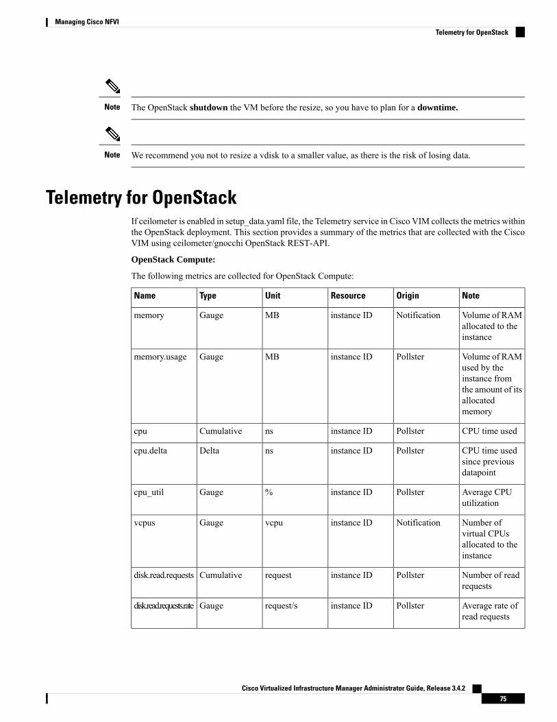
The OpenStack shutdown the VM before the resize, so you have to plan for a downtime.Note
We recommend you not to resize a vdisk to a smaller value, as there is the risk of losing data.Note
Telemetry for OpenStackIf ceilometer is enabled in setup_data.yaml file, the Telemetry service in Cisco VIM collects the metrics withinthe OpenStack deployment. This section provides a summary of the metrics that are collected with the CiscoVIM using ceilometer/gnocchi OpenStack REST-API.
OpenStack Compute:
The following metrics are collected for OpenStack Compute:
NoteOriginResourceUnitTypeName
Volume of RAMallocated to theinstance
Notificationinstance IDMBGaugememory
Volume of RAMused by theinstance fromthe amount of itsallocatedmemory
Pollsterinstance IDMBGaugememory.usage
CPU time usedPollsterinstance IDnsCumulativecpu
CPU time usedsince previousdatapoint
Pollsterinstance IDnsDeltacpu.delta
Average CPUutilization
Pollsterinstance ID%Gaugecpu_util
Number ofvirtual CPUsallocated to theinstance
Notificationinstance IDvcpuGaugevcpus
Number of readrequests
Pollsterinstance IDrequestCumulativedisk.read.requests
Average rate ofread requests
Pollsterinstance IDrequest/sGaugedisk.read.requests.rate
Cisco Virtualized Infrastructure Manager Administrator Guide, Release 3.4.275
Managing Cisco NFVITelemetry for OpenStack

NoteOriginResourceUnitTypeName
Number of writerequests
Pollsterinstance IDrequestCumulativedisk.write.requests
Average rate ofwrite requests
Pollsterinstance IDrequest/sGaugedisk.write.requests.rate
Volume of readsPollsterinstance IDBCumulativedisk.read.bytes
Average rate ofreads
Pollsterinstance IDB/sGaugedisk.read.bytes.rate
Volume ofwrites
Pollsterinstance IDBCumulativedisk.write.bytes
Average rate ofwrites
Pollsterinstance IDB/sGaugedisk.write.bytes.rate
Number of readrequests
Pollsterdisk IDrequestCumulativedisk.device.read.requests
Average rate ofread requests
Pollsterdisk IDrequest/sGaugedisk.device.read.requests.rate
Number of writerequests
Pollsterdisk IDrequestCumulativedisk.device.write.requests
Average rate ofwrite requests
Pollsterdisk IDrequest/sGaugedisk.device.write.requests.rate
Volume of readsPollsterdisk IDBCumulativedisk.device.read.bytes
Average rate ofreads
Pollsterdisk IDB/sGaugedisk.device.read.bytes.rate
Volume ofwrites
Pollsterdisk IDBCumulativedisk.device.write.bytes
Average rate ofwrites
Pollsterdisk IDB/sGaugedisk.device.write.bytes.rate
Size of root diskNotificationinstance IDGBGaugedisk.root.size
Size ofephemeral disk
Notificationinstance IDGBGaugedisk.ephemeral.size
The amount ofdisk that theinstance can see
Pollsterinstance IDBGaugedisk.capacity
The amount ofdisk occupied bythe instance onthe host machine
Pollsterinstance IDBGaugedisk.allocation
Cisco Virtualized Infrastructure Manager Administrator Guide, Release 3.4.276
Managing Cisco NFVITelemetry for OpenStack

NoteOriginResourceUnitTypeName
The physicalsize in bytes ofthe imagecontainer on thehost
Pollsterinstance IDBGaugedisk.usage
The amount ofdisk per devicethat the instancecan see
Pollsterdisk IDBGaugedisk.device.capacity
The amount ofdisk per deviceoccupied by theinstance on thehost machine
Pollsterdisk IDBGaugedisk.device.allocation
The physicalsize in bytes ofthe imagecontainer on thehost per device
Pollsterdisk IDBGaugedisk.device.usage
Number ofincoming bytes
Pollsterinterface IDBCumulativenetwork.incoming.bytes
Average rate ofincoming bytes
Pollsterinterface IDB/sGaugenetwork.incoming.bytes.rate
Number ofoutgoing bytes
Pollsterinterface IDBCumulativenetwork.outgoing.bytes
Average rate ofoutgoing bytes
Pollsterinterface IDB/sGaugenetwork.outgoing.bytes.rate
Number ofincomingpackets
Pollsterinterface IDpacketCumulativenetwork.incoming.packets
Average rate ofincomingpackets
Pollsterinterface IDpacket/sGaugenetwork.incoming.packets.rate
Number ofoutgoing packets
Pollsterinterface IDpacketCumulativenetwork.outgoing.packets
Average rate ofoutgoing packets
Pollsterinterface IDpacket/sGaugenetwork.outgoing.packets.rate
Number ofincomingdropped packets
Pollsterinterface IDpacketCumulativenetwork.incoming.packets.drop
Cisco Virtualized Infrastructure Manager Administrator Guide, Release 3.4.277
Managing Cisco NFVITelemetry for OpenStack

NoteOriginResourceUnitTypeName
Number ofoutgoingdropped packets
Pollsterinterface IDpacketCumulativenetwork.outgoing.packets.drop
Number ofincoming errorpackets
Pollsterinterface IDpacketCumulativenetwork.incoming.packets.error
Number ofoutgoing errorpackets
Pollsterinterface IDpacketCumulativenetwork.outgoing.packets.error
Memory swap inPollsterinterface IDMBCumulativememory.swap.in
Memory swapout
Pollsterinterface IDMBCumulativememory.swap.out
Total time readoperations havetaken
PollsterDisk IDnsCumulativedisk.device.read.latency
OpenStack Image
The following metrics are collected for OpenStack Image service:
NoteOriginResourceUnitTypeName
Size of theuploaded image
Notification,Pollster
image IDBGaugeimage.size
Image isdownloaded
Notificationimage IDBDeltaimage.download
Image is servedout
Notificationimage IDBDeltaimage.serve
OpenStack Block Storage
The following metrics are collected for OpenStack Block Storage:
NoteOriginResourceUnitTypeName
Size of thevolume
NotificationVoulume IDGBGaugevolume.size
Metrics Polling and Retention Policy
Cisco VIM telemetry service polls metrics every 5 minutes and retains the metrics for 48 hours
Cisco Virtualized Infrastructure Manager Administrator Guide, Release 3.4.278
Managing Cisco NFVITelemetry for OpenStack

Nova MigrateThe nova migrate command is used to move an instance from one compute host to another compute host. Thescheduler chooses the destination compute host based on the availability of the zone settings. This processdoes not assume that the instance has shared storage available on the target host.
To initiate the cold migration of the VM, you can execute the following command:nova migrate [--poll] <server>
The VMmigration can take a while, as the VM boots up with the new specifications. After the VMmigrationprocess, you can execute nova resize-confirm <server> --to overwrite the old VM image with the newone. If you encounter an problem, use the nova-resize-revert <server> command to revert to the old VMimage. At this point, access the VM through SSH and verify the correct image is configured.
The OpenStack shutdown the VM before the migrate, so plan for a downtime.Note
Live MigrateLive-migrating an instance means moving its virtual machine to a different OpenStack Compute server whilethe instance continues running. The operator can select which host to live migrate the instance. If the destinationhost is not selected, the nova scheduler chooses the destination compute based on the availability of the zonesettings. Live migration cannot be used without shared storage except a booted from volume VM which doesnot have a local disk.
To initiate the live migration of the VM, you can execute the following command:openstack server migrate <server>--live
The VM migration can take a while. The virtual machine status can be checked with the command:openstack server show < server>
1. With NFV_HOST enabled, you must ensure that the vCPUs are available on the destination host to avoidcollision. With cold migration, the vCPUs available on the destination host are automatically selected andassigned to the VM.
2. If you are trying to live-migrate a VM with config-drive, it is always considered as cold-migration.
3. In VPP pod, live-migration is not supported as it uses huge pages by default.
Note
Cisco Virtualized Infrastructure Manager Administrator Guide, Release 3.4.279
Managing Cisco NFVINova Migrate

Power Management Of Computes (for C-Series)Before you begin
In Cisco VIM 2.4, the power management function of computes optimizes the overall power consumption ofthe data center. Powering down the server through an API/CLI helps you to have a power backup.
Step 1 To power off one or more compute nodes, run the following commands:Run ciscovim power-off help command# ciscovim help power-offusage: ciscovim power-off --setupfile SETUPFILE [-y] <node1,node2,...>
Power Off compute-nodes
Positional arguments:<node1,node2,...> Power off Compute Nodes
Optional arguments:--setupfile SETUPFILE <setupdata_file>. Mandatory for any POD management
operation.-y, --yes Yes option to perform the action
Step 2 To list all the nodes in the Openstack Cloud run the following command:# ciscovim list-nodes
Step 3 Choose one or more Active compute node to be powered offStep 4 Run the following command:
# ciscovim power-off <compute-server-1, compute-server-2, …. > --setupfile <path_setup_data.yaml>
Step 5 Run the following command to verify that the computes are power off# ciscovim list-nodes
The Status for compute nodes that are powered off has to be InActive state.Note
To prevent cloud destabilization, you must ensure that at least one compute node is in the Active state.Podmanagement operation that applies to the entire pod (such as a update, reconfigure, and so on) cannot beperformed if one or more compute nodes are powered off. Computes which run VMs or which provide otherroles (such as All-in-one (AIO) nodes in amicropod) cannot be powered-off using this API. Power error-handlingmethods are added to ensure that such cases are handled. As part of the power-off action, internally cloud-sanityis run and if the cloud sanity fails, then the power-off action is aborted.
Note
Power On Compute NodesFollowing are the steps to power on the compute nodes:
Step 1 Run the following command to power onone or more compute nodes
Cisco Virtualized Infrastructure Manager Administrator Guide, Release 3.4.280
Managing Cisco NFVIPower Management Of Computes (for C-Series)

Run ciscovim power-on help command# ciscovim help power-onusage: ciscovim power-on --setupfile SETUPFILE [-y] <node1,node2,...>
Power On compute-nodes
Positional arguments:<node1,node2,...> Power on Compute Nodes
Optional arguments:--setupfile SETUPFILE <setupdata_file>. Mandatory for any POD management
operation.-y, --yes Yes option to perform the action
Step 2 To list all the nodes in the Openstack Cloud:# ciscovim list-nodes
Step 3 Choose one or more Active compute node to be powered onStep 4 Run the following command:
# ciscovim power-on <compute-server-1, compute-server-2, …. > --setupfile <path_setup_data.yaml>
Step 5 Run the following command to verify the compute(s) are powerd on# ciscovim list-nodes
The Status for compute nodes that were powered on has to be ActiveNote
Managing Reboot of Cisco VIM NodesCisco VIM 2.4 has a ciscovim CLI to reboot the Cisco VIM nodes. CLI can be used for rebooting the CiscoVIM nodes in general. During software update, core libraries like kernel, glibc, systemd and so on. requirerebooting the system to run the latest version. Cisco VIM has the functionality to reboot nodes (if needed)during an update, but we defer the update of compute nodes which are running application VM’s.
Reboot the nodes using the CLI before migrating the VM's on another computes as shown in the followingsteps:
Step 1 Run the following command to Reboot one or more compute nodes:Run ciscovim reboot help command# ciscovim help rebootusage: ciscovim reboot [-y] <node1,node2,...>
Reboot compute-nodes
Positional arguments:<node1,node2,...> Reboot Compute Nodes
Optional arguments:-y, --yes Yes option to perform the action
Step 2 Run the following command to select one or more compute nodes# ciscovim reboot<compute-server-1, compute-server-2, …. >
Cisco Virtualized Infrastructure Manager Administrator Guide, Release 3.4.281
Managing Cisco NFVIManaging Reboot of Cisco VIM Nodes

You cannot reboot all the compute nodes simultaneously. At least one node has to be Active to prevent thecloud destabilization. Also, computes on which VMs are running cannot be rebooted, the CLI prevents it (seethe following steps on mitigation). The nodes which are associated with multiple roles (For Example: All-in-one(AIO) nodes in a micro-pod or Hyper-converged) can be rebooted one at a time.
Note
Cisco VIM Client Reboot and Remove Compute Using ForceOption
When VM’s are running on a particular compute node, you cannot reboot or remove that compute node. CiscoVIM installer internally checks for the presence of VM’s and aborts the operation, if VM is running on thetarget compute node.
To execute remove-compute operation without any failure, migrate or terminate VMs running on computenodes and execute remove or reboot operations using “-f/--force” option in Cisco VIM client.
Note the following before executing reboot or remove compute operations with force option.
• If a remove compute operation is executed with force option, the VMs running on that compute nodeare deleted.
• If a reboot compute operation is executed with force option, the VMs are restored to last running statuspost successful reboot of that compute node.
Example of Remove Compute
# ciscovim help remove-computesusage: ciscovim remove-computes --setupfile SETUPFILE [-y] [-f] <node1,node2,...>
Remove compute-nodes from the Openstack cloud
Positional arguments:<node1,node2,...> Remove compute nodes
Optional arguments:--setupfile SETUPFILE <setupdata_file>. Mandatory for any POD management
operation.-y, --yes Yes option to perform the action-f, --force Force option to remove or reboot
# ciscovim remove-computes --setupfile /tmp/remove_computes_setup_data.yaml gg34-4 -y --force
monitoring remove_compute (gg34-4) operation
........................Cisco VIM Runner logs........................
Example of removing multiple computes
# ciscovim remove-computes --setupfile /tmp/remove_computes_setup_data.yaml gg34-1, gg34-2-y -force
If ToR_TYPE is Cisco NCS 5500, you must manually remove all the sub-interfaces that were manuallyconfigured on the NCS switch, as the Cisco VIM automation does not unconfigure/configure the sub-interfaces
Cisco Virtualized Infrastructure Manager Administrator Guide, Release 3.4.282
Managing Cisco NFVICisco VIM Client Reboot and Remove Compute Using Force Option
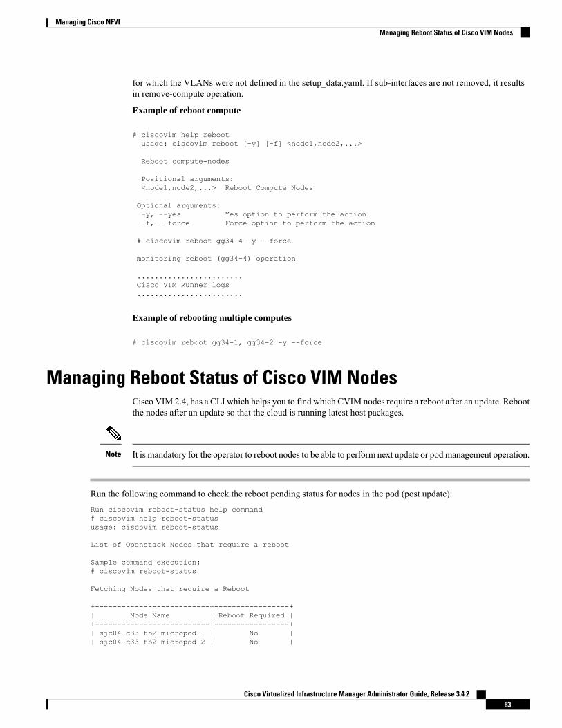
for which the VLANs were not defined in the setup_data.yaml. If sub-interfaces are not removed, it resultsin remove-compute operation.
Example of reboot compute
# ciscovim help rebootusage: ciscovim reboot [-y] [-f] <node1,node2,...>
Reboot compute-nodes
Positional arguments:<node1,node2,...> Reboot Compute Nodes
Optional arguments:-y, --yes Yes option to perform the action-f, --force Force option to perform the action
# ciscovim reboot gg34-4 -y --force
monitoring reboot (gg34-4) operation
........................Cisco VIM Runner logs........................
Example of rebooting multiple computes
# ciscovim reboot gg34-1, gg34-2 -y --force
Managing Reboot Status of Cisco VIM NodesCisco VIM 2.4, has a CLI which helps you to find which CVIM nodes require a reboot after an update. Rebootthe nodes after an update so that the cloud is running latest host packages.
It is mandatory for the operator to reboot nodes to be able to perform next update or podmanagement operation.Note
Run the following command to check the reboot pending status for nodes in the pod (post update):Run ciscovim reboot-status help command# ciscovim help reboot-statususage: ciscovim reboot-status
List of Openstack Nodes that require a reboot
Sample command execution:# ciscovim reboot-status
Fetching Nodes that require a Reboot
+--------------------------+-----------------+| Node Name | Reboot Required |+--------------------------+-----------------+| sjc04-c33-tb2-micropod-1 | No || sjc04-c33-tb2-micropod-2 | No |
Cisco Virtualized Infrastructure Manager Administrator Guide, Release 3.4.283
Managing Cisco NFVIManaging Reboot Status of Cisco VIM Nodes

| sjc04-c33-tb2-micropod-3 | No |+--------------------------+-----------------+
Cisco UCS Firmware UpgradeIn Cisco VIM 2.4.2, the Cisco Host Upgrade Utility (HUU) tool developed using Cisco IntegratedManagementController (IMC) Python SDK module (imcsdk-0.9.2.0) is leveraged automatically to upgrade all firmwarecomponents running on Cisco UCS C-Series servers.
The wrapper tool only updates the CIMC bundle packages, as the entire Cisco IMC Software bundle (thatincludes CIMC, BIOS, adapter and storage controller firmware images through HUU images) is updated bydefault. Adequate planning is required for CIMC upgrade, as it causes the server to get rebooted.
Note
For Cisco VIM 2.4, the CIMC upgrade tool supports the:
• Upgrade of CIMC bundle images for C-series only.
• Concurrent upgrade of CIMC bundle images on multiple C-series servers.
• Pre-validation check for server type and available HUU images.
• Support of the external http server, Cisco VIM Software Hub, or Cisco VIM Management node for thetarget CIMC upgrade image mounts.
• Checks if the cloud is deployed successfully, and notifies the user with a proper message.
• Checks if selected hosts have any active VMs running on them and notifies the user with a proper message.
• Generation of consolidated summary on firmware version status, on completing the pre-upgrade andpost-upgrade.
• Firmware upgrade is supported only on UCSC-series platform and not on UCSB-series and HP platforms.
• If you upgrade CIMC firmware on an existing cloud deployment, it might impact the cloud functionalityas the firmware upgrade reboots the host. Hence, ensure that the cloud is operational, post CIMC firmwareupgrade.
Note
To check if the cloud is operational, execute the following steps:
• Run the cloud sanity.
• If cloud sanity failure occurs, run cluster recovery and then re-run cloud sanity.
Also for the upgrade operation to work, ensure that the image has the following syntax:ucs-<server_type>-huu-<version_number>.iso; for example ucs-c220m4-huu-2.0.13n.iso orucs-c240m4-huu-2.0.13n.iso;
Cisco Virtualized Infrastructure Manager Administrator Guide, Release 3.4.284
Managing Cisco NFVICisco UCS Firmware Upgrade

Running the UCS Firmware upgrade on host(s) running active VMs results in downtime on those VMs.Note
Limitations During Cisco IMC UpgradeThe following are the CVIM management operations which are not allowed when the firmware upgrade is inprogress:
• POD management operations: Add, Remove or Replace of nodes
• CVIM Software Update
• CVIM Software Upgrade
• Reconfigure of CVIM features
Tools UsageThe CIMC upgrade utility is a standalone python file (ucsc_host_upgrade_utility) which is located under<cvim_install_dir>/tools/ directory.
To use the tool, execute the following command:
[root@hiccup-mgmt-228 tools]# python ucsc_host_upgrade_utility.py -husage: ucsc_host_upgrade_utility.py [-h] [--file SETUPFILELOCATION]
[--http-server HTTP_SERVER_IP][--sds-server SDS_SERVER_NAME][--server-uname UNAME][--server-pwd PASSWD][--huu-image-path HUU_IMAGE_PATH][--host HOSTS] [--exclude-hosts E_HOSTS][-y]
Script to perform firmware upgrade
optional arguments:-h, --help show this help message and exit--file SETUPFILELOCATION, -f SETUPFILELOCATION
Optional, if not defined will read the setup_data.yamlin /root/openstack-configs dir for CIMC information ofservers; To override, provide a valid YAML filewith the CIMC Credentials.
--http-server HTTP_SERVER_IP, -hs HTTP_SERVER_IPOptional, only needed if a http server is used to hostthe target CIMC bundle image(s).
--sds-server SDS_SERVER_NAME, -sds SDS_SERVER_NAMEOptional, only needed if a Software DistributionServer (SDS) is used to host the target CIMC bundleimage(s).
--server-uname UNAME, -u UNAMEOptional, only needed if a http server is used to hostthe target CIMC bundle image(s).
--server-pwd PASSWD, -p PASSWDOptional, only needed if a http server is used to hostthe target CIMC bundle image(s).
--huu-image-path HUU_IMAGE_PATH, -path HUU_IMAGE_PATH
Cisco Virtualized Infrastructure Manager Administrator Guide, Release 3.4.285
Managing Cisco NFVILimitations During Cisco IMC Upgrade

Comma separated absolute path of the HUU ISO file(s);In the case of a web server hosting the files,provide the absolute path of the URL that includes thefile names; that is, exclude the scheme://host/ part
--host HOSTSComma separated list of host names targeted for CIMC
bundle upgrade defined in the target setup_data.yaml--exclude-hosts E_HOSTS, -e E_HOSTS
Comma separated list of hostnames excluded for CIMCbundle upgrade defined in the target setup_data.yaml
-y, -yes[root@hiccup-mgmt-228 tools]#
If the target CIMC upgrade images are available on Cisco VIM Management node, use the below command:
python ucsc_host_upgrade_utility.py [--file <setup_data_test.yaml/cimc_servers.yaml>]-path <huu_image_paths>
If the target CIMC upgrade images are hosted in an external http server that is reachable from the Cisco VIMManagement node and CIMC of the servers, use the below command:
python ucsc_host_upgrade_utility.py [--file <setup_data_test.yaml/cimc_servers.yaml>]-hs <http_server_ip/hostname> -u
<https_server_un> -path <http_server_pwd> -path <huu_image_paths>
If the target CIMC upgrade images are hosted in Ciso VIM Software Hub, use the below command:
python ucsc_host_upgrade_utility.py --file [setup_data_test.yaml/cimc_servers.yaml] -sds[Ciso VIM Software Hub_server_ip/hostname] -u
[sds_server_un] -path [sds_server_pwd] -path [huu_image_paths]
Pre-requisites to use Ciso VIM Software Hub for hosting the target CIMC bundle image(s) are:
• Ciso VIM Software Hub server must be reachable from the management node over HTTPS.
• Ciso VIM Software Hub server TLS certificate must be trusted by the management node to make TLSconnection in verified context.
Note
If setup_data.yaml file is not available, you can create it using below command:
# UCSC (C-series) sample format of yaml file to specify the CIMC detailsSERVERS:server-1:cimc_info:cimc_ip: "cimc-ip-address"cimc_username: "cimc-user-name"cimc_password: "cimc-password"
server-2:cimc_info:cimc_ip: "cimc-ip-address"cimc_username: "cimc-user-name"cimc_password: "cimc-password"
server-3:cimc_info:cimc_ip: "cimc-ip-address"cimc_username: "cimc-user-name"cimc_password: "cimc-password"
Cisco Virtualized Infrastructure Manager Administrator Guide, Release 3.4.286
Managing Cisco NFVITools Usage

As the upgrade of CIMC takes more than an hour, execute this process in a VNC. If you do not have a VNCenvironment, execute the same from KVM console of the management node. Do not run this command inbackground or with nohup option.
Note
Quanta Firmware UpgradeFrom release Cisco VIM 3.2.1, the Quanta firmware upgrade utility tool developed using redfish-client isused to upgrade BMC, BIOS, and NVM firmware versions on Quanta servers.
The wrapper tool only updates the BMC, BIOS and NVM versions based on the provided firmware packages.Adequate planning is required for Quanta firmware upgrade, as it causes the server to get rebooted.
Note
For Cisco VIM 3.2.1, the Quanta firmware upgrade tool supports:
• Upgrade of BMC, BIOS and NVM for Quanta servers only.
• Concurrent upgrade of firmware on multiple Quanta servers.
• Pre-validations if another firmware flashing is in progress.
• Generation of consolidated summary on firmware version status, on completing the pre-upgrade andpost-upgrade.
If you upgrade Quanta firmware on an existing cloud deployment, it might impact the cloud functionality asthe firmware upgrade reboots the host. Hence, ensure that the cloud is operational, post Quanta firmwareupgrade.
Note
To check if the cloud is operational, do the following:
1. Run the cloud sanity.
2. If cloud sanity fails, run cluster recovery and then re-run the cloud sanity.
For the upgrade to work, ensure that you specify the proper firmware-package bundle with proper name andversion of the components (BMC/BIOS/NVM).
Few examples given below:
• BIOS firmware package file name must start with a prefix BIOS_XXXX.zip.
• BMC firmware package file name must start with a prefix BMC_XXX.zip.
• NVM firmware package file name must contain NVMXXXXX.zip.
Cisco Virtualized Infrastructure Manager Administrator Guide, Release 3.4.287
Managing Cisco NFVIQuanta Firmware Upgrade

Running the BMC/BIOS/NVM firmware upgrade on host(s) running active VM results in downtime on thoseVMs.
Note
Limitations for Quanta firmware UpgradeThe following Cisco VIMmanagement operations are not allowed when the firmware upgrade is in progress:
• Pod management operations: Addition, removal or replacement of nodes.
• Cisco VIM software update.
• Cisco VIM software upgrade.
• Reconfiguration of Cisco VIM features.
Tools UsageThe Quanta upgrade utility is a standalone python file (quanta_firmware_upgrade.py) which islocated under <cvim_install_dir>/tools/ directory.
To use the tool, execute the following command:
[[root@qatar-mgmt tools]# python quanta_firmware_upgrade.py -husage: quanta_firmware_upgrade.py [-h] [--hosts HOSTS][--exclude-hosts EXCLUDE_HOSTS][--ignore-flash-status] [-v] [-y][--bmc-only | --bios-only | --nvm-only]--setupfile SETUPFILE --firmware-packageFIRMWARE_PACKAGEScript to update BMC and BIOS firmware on Quanta serveroptional arguments:-h, --help show this help message and exit--hosts HOSTS comma separated list of servers defined insetup_data.yaml file target for firmware update--exclude-hosts EXCLUDE_HOSTScomma separated list of servers defined insetup_data.yaml file to exclude for firmware update--ignore-flash-statusignore flash status, needed for older BMC firmwarewhere it lacks the support and continue with BMCfirmware update-v, --verbose enable verbose output-y, --yes skip prompt--bmc-only update BMC firmware only--bios-only update BIOS firmware only--nvm-only update Intel Ethernet NVM onlyrequired arguments:--setupfile SETUPFILEsetup_data.yaml file location--firmware-package FIRMWARE_PACKAGEFirmware package ZIP file location[root@qatar-mgmt tools]#
For upgrade BMC only, use the below command:
Cisco Virtualized Infrastructure Manager Administrator Guide, Release 3.4.288
Managing Cisco NFVILimitations for Quanta firmware Upgrade

python quanta_firmware_upgrade.py --setupfile <setup-data.yaml> --firmware-package<bmc/bios_update_package.zip>
--bmc-only
For upgrade BIOS only, use the below command:
python quanta_firmware_upgrade.py --setupfile <setup-data.yaml> --firmware-package<bmc/bios_update_package.zip>
--bios-only
For upgrade NVM only, use the below command:
python quanta_firmware_upgrade.py --setupfile <setup-data.yaml> --firmware-package<nvm_update_package.zip>
--nvm-only
• If you do not specify any option for particular component with specified BIOS/BMC firmware package,the utility upgrades in the order of BMC followed by BIOS but not NVM.
• If you are planning to update both the BMC and the BIOS separately, always update the BMC first andthen the BIOS.
• To upgrade NVM, you need to specify --nvm-only option with NVM firmware package, otherwiseupgrade fails.
• NVM firmware upgrade does not reboot the servers by default. You need to reboot the nodes manuallyto complete the upgrade process.
Note
As some of the servers running old firmware are upgrading to latest firmware, password might be reset todefault.
You need to manually reset the password by following the below steps:
1. Login to the UI using the factory default admin and cmb9.admin
2. Once logged-in, you are prompted with a message First Login or Password Expired. You need tochange your password.
You need --ignore-flash-status option for older BMC firmware, where it lacks the support andcontinue with BMC firmware update.
Few examples below:
python quanta_firmware_upgrade.py --setupfile <setup-data.yaml> --firmware-package<bmc_update_package.zip> --bmc-only --ignore-flash-status
As the upgrade of BIOS/BMC takes more than 30 minutes, it is imperative to execute this process in a VNC.If you do not have a VNC environment, execute the same from KVM console of the management node. Donot run this command in background or with nohup option.
Note
Cisco Virtualized Infrastructure Manager Administrator Guide, Release 3.4.289
Managing Cisco NFVITools Usage

Intel FPGA Programmable Acceleration Card N3000 Firmware UpdateTo host virtualized Radio Access Network (vRAN) workloads in the edge pod off Quanta hardware, theselected computes (also called accelerated computes) are installed with Intel N3000 cards for hardware offload.Cisco VIM provides a utility script to update the firmware and other relevant packages associated with N3000cards present on the accelerated compute nodes. The utility script checks the presence of N3000 cards on thetarget compute node and updates the necessary packages if there is a match. The utility requires an activelydeployed Cisco VIM edge pod.
For releases from Cisco VIM 3.2.1, the utility script is available at /root/ installer-xxx/tools/directory.
To run the utility, install and deploy the edge pod with Cisco VIM 3.2.1 or later:
#cd installer-xxx/tools/#./intel-fpga-n3000-firmware-update.py [--with-rsu]
• The utility is designed to power-cycle the accelerated computes after a firmware/package update, if--with-rsu is not specified.
• If hyper-threading is disabled on the accelerated compute, it may take up to 60 minutes to complete theflash process with two cards. If hyper-threading is enabled, the flash process takes about 25-30 minutesfor completion.
.
Note
Tools Usage
To use the tool, execute the following command:
[root@mgmt-node tools]# ./intel-fpga-n3000-firmware-update.py -h
usage: intel-fpga-n3000-firmware-update.py [-h] [--hosts HOSTS] [-n] [-f] [-r][-y] [-v]Script to update Intel FPGA N3000 firmware on all Compute nodeoptional arguments:-h, --help show this help message and exit--hosts HOSTS comma separated list of Compute node defined insetup_data.yaml file target for Intel FPGA N3000firmware update-n, --dry-run do not perform any updates, just a dry run-f, --force-update flash all images regardless of version matching or not-r, --with-rsu after update perform RSU command to avoid the need topower-cycle-y, --yes skip prompt-v, --verbose enable verbose output
Sample Output
Following is the sample output:
[root@mgmt-node tools]# ./intel-fpga-n3000-firmware-update.py
Cisco Virtualized Infrastructure Manager Administrator Guide, Release 3.4.290
Managing Cisco NFVIIntel FPGA Programmable Acceleration Card N3000 Firmware Update

Starting Intel FPGA N3000 update scriptFull log can be found at/var/log/mercury/intel_n3000_super_rsu_update-20190506112000514524.logChecking Intel FPGA N3000 firmware on accelerated compute node(s)+------------------+---------------+---------------------+------------------+| Server | Management | Accelerated Compute | Update Available |+------------------+---------------+---------------------+------------------+| quincy-control-1 | 172.29.86.248 | No | No || quincy-control-2 | 172.29.86.249 | No | No || quincy-control-3 | 172.29.86.250 | No | No || quincy-compute-1 | 172.29.86.246 | No | No || quincy-compute-2 | 172.29.86.247 | No | No || quincy-compute-3 | 172.29.86.251 | Yes | Yes || quincy-compute-4 | 172.29.86.252 | Yes | Yes |+------------------+---------------+---------------------+------------------+Following accelerated compute node(s) may be impacted as part of firmware update:quincy-compute-4,quincy-compute-3
Would you like to continue? <y|n> y
Starting Intel FPGA N3000 firmware update process, this may take an hour!!!Successfully executed Intel FPGA N3000 firmware update script
Following compute node(s) require power-cycle:quincy-compute-3,quincy-compute-4
As the upgrade of FPGA firmware takes approximately an hour per card, it is imperative to execute thisprocess in a VNC. If you do not have a VNC environment, execute the same from KVM console of themanagement node. Do not run this command in background or with nohup option.
Note
Supporting Management/Storage IPFrom release Cisco VIM 3.2.2 onwards, along with server management IP (v4 and v6), you can also staticallydefine the server storage IP during pod installation. To help in the transition ,Cisco created a tool that helpsto update the setup_data with the server storage IP information of a pod that is already up and running.
To run the utility, ensure that the pod is up and running Cisco VIM 3.2.2 or later:#cd installer-xxx/tools/#./update_static_addrs.sh
On success, a message "Static Address updates in setup_data.yaml complete" is displayed at the end of therun.
Cisco Virtualized Infrastructure Manager Administrator Guide, Release 3.4.291
Managing Cisco NFVISupporting Management/Storage IP

Cisco Virtualized Infrastructure Manager Administrator Guide, Release 3.4.292
Managing Cisco NFVISupporting Management/Storage IP

C H A P T E R 2Cisco VIM REST API
The following topics explain how to use the Cisco VIM REST API to manage Cisco NFVI.
• Overview to Cisco VIM REST API, on page 93• Cisco VIM REST API Resources, on page 95• Cisco VIM REST API Using curl for IPv4, on page 130• Cisco VIM REST API Using curl for IPv6, on page 136
Overview to Cisco VIM REST APICisco VIM provides a Representational State Transfer (REST) API that is used to install, expand, and updateCisco VIM. Actions performed using the REST APIs are:
• Install Cisco VIM on Cisco NFVI pods
• Add and delete pods to and from Cisco NFVI installations
• Update Cisco VIM software
• Replace controller nodes
• Perform cloud maintenance operations
• Run cloud validations using VirtualMachine ThroughPut (VMTP), a data path performancemeasurementtool for OpenStack clouds
The following figure shows the workflow of Cisco VIM REST API.
Cisco Virtualized Infrastructure Manager Administrator Guide, Release 3.4.293

Figure 5: Workflow of Cisco VIM REST API
The Cisco VIM REST API security is provided by the Secure Sockets Layer (SSL) included on the Apacheweb server. The Pecan-based web application is called by mod_wsgi, which runs the Rest API server. ThePecan RESTAPI server requires a username and password to authorize the RESTAPI server requests. Apachehandles the authorization process, which authorizes the request to access the Pecan web application. Use theCisco VIM API to upload a new setup_data.yaml file, and start, stop, and query the state of the installation.You can use it to manage the cloud, add and remove compute and Ceph nodes, and replace the controllernodes. A REST API to launch VMTP (L2/L3 data plane testing) and CloudPulse is also provided.
The Cisco VIM REST API is enabled by default in the management node if you are using the supplied CiscoVIM buildnode.iso. You can access API server on the br_api interface on port 8445. Authentication is enabledby default in the web service.
You can access the API end points using the following URL format:https://<Management_node_api_ip>:8445
By default, basic authentication is enabled for the API endpoints in the management node. You can find theauthentication credentials in the following file in the management node:
/opt/cisco/ui_config.json
The following code shows a sample ui_config.json file.{"Kibana-Url": "http://10.10.10.10:5601","RestAPI-Url": "https:// 10.10.10.10:8445","RestAPI-Username": "admin","RestAPI-Password": "a96e86ccb28d92ceb1df","RestDB-Password": "e32de2263336446e0f57","BuildNodeIP": "10.10.10.10"
}
For more information on the Rest API for an end-point, see the Ciscovim Client RestAPI section inTroubleshooting, on page 469.
Cisco Virtualized Infrastructure Manager Administrator Guide, Release 3.4.294
Cisco VIM REST APIOverview to Cisco VIM REST API

Cisco VIM REST API ResourcesSetupdata
REST wrapper for setupdata. Provides methods for listing, creating, modifying, and deleting setupdata.
Retrieving the setupdata
Resource URI
URIVerb
/v1/setupdataGET
Example
JSON Request
GET /v1/setupdataAccept: application/json
JSON Response
200 OKContent-Type: application/json{"setupdatas": [{
"status": "Active","name":"GG34","uuid": "123""meta":{
"user":"root"},"jsondata":{.......
}}]}
Creating the setupdata
Resource URI
URIVerb
/v1/setupdataPOST
Example
JSON Request
POST /v1/setupdataAccept: application/json
{"name":"GG34","uuid": "123""meta":{
"user":"root"},"jsondata":{.......
Cisco Virtualized Infrastructure Manager Administrator Guide, Release 3.4.295
Cisco VIM REST APICisco VIM REST API Resources

}}
JSON Response
201 OKContent-Type: application/json{
"status": "Active","name":"GG34","uuid": "123""meta":{
"user":"root"},"jsondata":{.......
}}
400 Bad RequestContent-Type: application/json{
"debuginfo": null"faultcode": "Client""faultstring": "Error"
}
409 CONFLICTContent-Type: application/json{
"debuginfo": null"faultcode": "Client""faultstring": "Error"
}
Retrieving a single setupdata
Resource URI
URIVerb
/v1/setupdata/(id)GET
Property:
id—The ID of the setupdata that you want to retrieve.
Example
JSON Request
GET /v1/setupdata/123Accept: application/json
JSON Response
200 OKContent-Type: application/json{
"status": "Active","name":"GG34","uuid": "123"
Cisco Virtualized Infrastructure Manager Administrator Guide, Release 3.4.296
Cisco VIM REST APICisco VIM REST API Resources
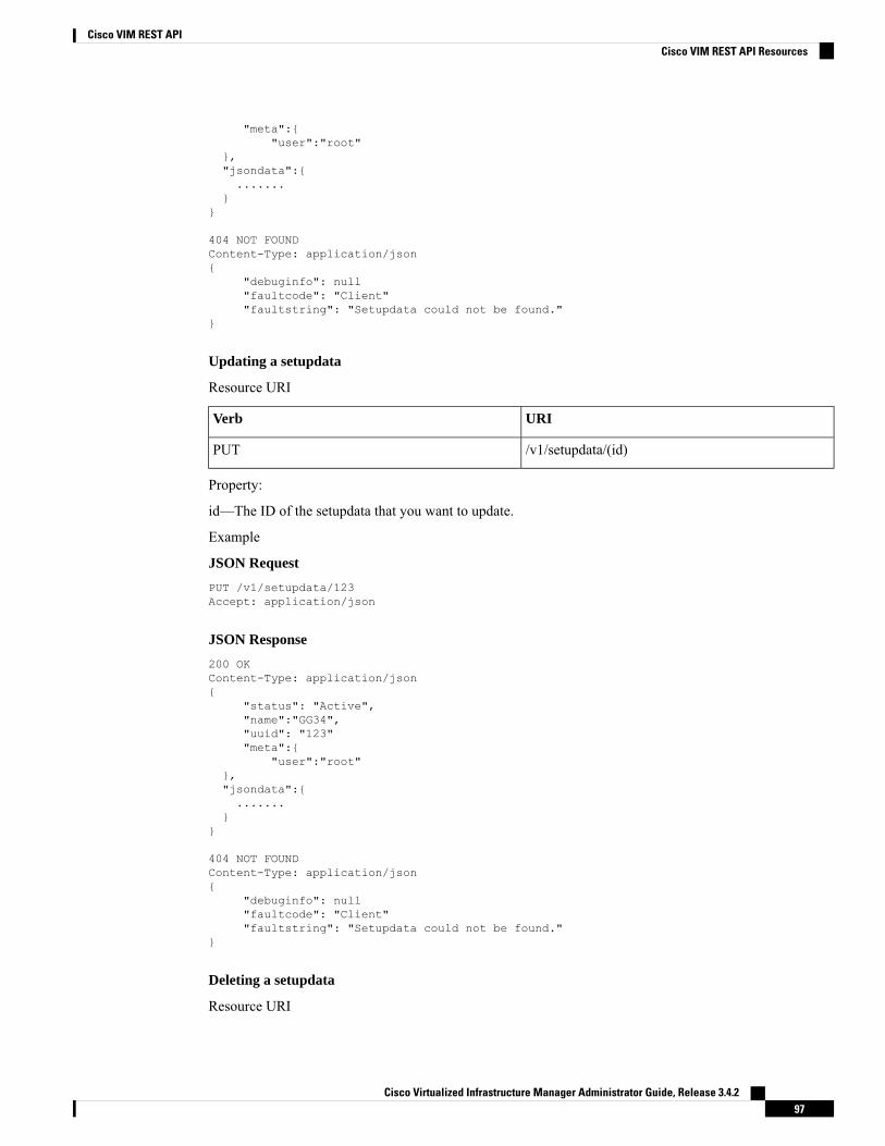
"meta":{"user":"root"
},"jsondata":{.......
}}
404 NOT FOUNDContent-Type: application/json{
"debuginfo": null"faultcode": "Client""faultstring": "Setupdata could not be found."
}
Updating a setupdata
Resource URI
URIVerb
/v1/setupdata/(id)PUT
Property:
id—The ID of the setupdata that you want to update.
Example
JSON Request
PUT /v1/setupdata/123Accept: application/json
JSON Response
200 OKContent-Type: application/json{
"status": "Active","name":"GG34","uuid": "123""meta":{
"user":"root"},"jsondata":{.......
}}
404 NOT FOUNDContent-Type: application/json{
"debuginfo": null"faultcode": "Client""faultstring": "Setupdata could not be found."
}
Deleting a setupdata
Resource URI
Cisco Virtualized Infrastructure Manager Administrator Guide, Release 3.4.297
Cisco VIM REST APICisco VIM REST API Resources

URIVerb
/v1/setupdata/(id)DELETE
Property:
id—The ID of the setupdata that you want to delete.
Example
JSON Request
DELETE /v1/setupdata/123Accept: application/json
JSON Response
204 NO CONTENTReturned on success
404 NOT FOUNDContent-Type: application/json{
"debuginfo": null"faultcode": "Client""faultstring": "Setupdata could not be found."
}400 BAD REQUESTContent-Type: application/json
{"debuginfo": null"faultcode": "Client""faultstring": "Setupdata cannot be deleted when it is being used by an installation"
}
Install resource
REST wrapper for install. Provides methods for starting, stopping, and viewing the status of the installationprocess.
Return a list of installation
Resource URI
URIVerb
/v1/installGET
Example
JSON Request
GET /v1/installAccept: application/json
JSON Response
200 OKContent-Type: application/json
Cisco Virtualized Infrastructure Manager Administrator Guide, Release 3.4.298
Cisco VIM REST APICisco VIM REST API Resources

{"installs": [{"ceph": "Skipped","uuid": "123","setupdata": "345","vmtpresult": "{
"status": "PASS","EXT_NET": []
}","baremetal": "Success","orchestration": "Success","validationstatus": "{
"status": "PASS","Software_Validation": [],"Hardware_Validation": []
}","currentstatus": "Completed","validation": "Success","hostsetup": "Success","vmtp": "Skipped"
}]}
Create an installation
Resource URI
URIVerb
/v1/installPOST
Example
JSON Request
GET /v1/installAccept: application/js{
"setupdata": "123","stages": ["validation","bootstrap","runtimevalidation","baremetal","orchestration","hostsetup","ceph","vmtp"
]}
JSON Response
201 CREATEDContent-Type: application/json{
"ceph": "Skipped","uuid": "123","setupdata": "345","vmtpresult": "{
"status": "PASS","EXT_NET": []
}","baremetal": "Success",
Cisco Virtualized Infrastructure Manager Administrator Guide, Release 3.4.299
Cisco VIM REST APICisco VIM REST API Resources

"orchestration": "Success","validationstatus": "{
"status": "PASS","Software_Validation": [],"Hardware_Validation": []
}","currentstatus": "Completed","validation": "Success","hostsetup": "Success","vmtp": "Skipped"
}
409 CONFLICTContent-Type: application/json{
"debuginfo": null"faultcode": "Client""faultstring": "Install already exists"
}
Retrieve the installation
Resource URI
URIVerb
/v1/install/{id}GET
Property:
id—The ID of the installation that you want to retrieve.
Example
JSON Request
GET /v1/install/345Accept: application/js
JSON Response
200 OKContent-Type: application/json{
"ceph": "Skipped","uuid": "123","setupdata": "345","vmtpresult": "{
"status": "PASS","EXT_NET": []
}","baremetal": "Success","orchestration": "Success","validationstatus": "{"status": "PASS","Software_Validation": [],"Hardware_Validation": []
}","currentstatus": "Completed","validation": "Success","hostsetup": "Success",
Cisco Virtualized Infrastructure Manager Administrator Guide, Release 3.4.2100
Cisco VIM REST APICisco VIM REST API Resources

"vmtp": "Skipped"}
404 NOT FOUNDContent-Type: application/json{
"debuginfo": null"faultcode": "Client""faultstring": "Install doesn’t exists"
}
Stop the installation
Resource URI
URIVerb
/v1/install/{id}DELETE
Property:
id—The ID of the installation that you want to stop.
Example
JSON Request
DELETE /v1/install/345Accept: application/js
JSON Response
204 NO CONTENTContent-Type: application/json
404 NOT FOUNDContent-Type: application/json{
"debuginfo": null"faultcode": "Client""faultstring": "Install doesn’t exists"
}
Nodes
Getting a list of nodes
Resource URI
URIVerb
/v1/nodesGET
Example
JSON Request
Get /v1/nodesAccept: application/js
Cisco Virtualized Infrastructure Manager Administrator Guide, Release 3.4.2101
Cisco VIM REST APICisco VIM REST API Resources
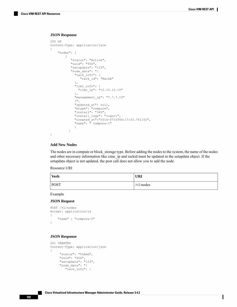
JSON Response
200 OKContent-Type: application/json{
"nodes": [[
"status": "Active","uuid": "456","setupdata": "123","node_data": "{"rack_info": {
"rack_id": "RackA"},"cimc_info": {"cimc_ip": "10.10.10.10"
},"management_ip": "7.7.7.10"}","updated_at": null,"mtype": "compute","install": "345","install_logs": "logurl","created_at":"2016-0710T06:17:03.761152","name": " compute-1"}
]}
Add New Nodes
The nodes are in compute or block_storage type. Before adding the nodes to the system, the name of the nodesand other necessary information like cimc_ip and rackid must be updated in the setupdata object. If thesetupdata object is not updated, the post call does not allow you to add the node.
Resource URI
URIVerb
/v1/nodesPOST
Example
JSON Request
POST /v1/nodesAccept: application/js{
"name" : "compute-5"}
JSON Response
201 CREATEDContent-Type: application/json{
"status": "ToAdd","uuid": "456","setupdata": "123","node_data": "{
"rack_info": {
Cisco Virtualized Infrastructure Manager Administrator Guide, Release 3.4.2102
Cisco VIM REST APICisco VIM REST API Resources

"rack_id": "RackA"},"cimc_info": {"cimc_ip": "10.10.10.10"},"management_ip": "7.7.7.10"}","updated_at": null,"mtype": "compute","install": "345","install_logs": "logurl","created_at":"2016-0710T06:17:03.761152","name": " compute-1"
}
Retrieve information about a particular node
Resource URI
URIVerb
/v1/nodes{id}GET
Property:
id—The ID of the node that you want to retrieve.
Example
JSON Request
POST /v1/nodesAccept: application/js
JSON Response
200 OKContent-Type: application/json{
"status": "Active","uuid": "456","setupdata": "123","node_data": "{"rack_info": {"rack_id": "RackA"},"cimc_info": {"cimc_ip": "10.10.10.10"
},"management_ip": "7.7.7.10"}","updated_at": null,"mtype": "compute","install": "345","install_logs": "logurl","created_at":"2016-0710T06:17:03.761152","name": " compute-1"
}
404 NOT FOUNDContent-Type: application/json{
Cisco Virtualized Infrastructure Manager Administrator Guide, Release 3.4.2103
Cisco VIM REST APICisco VIM REST API Resources

"debuginfo": null"faultcode": "Client""faultstring": "Node doesn’t exists"
}
Remove a Node
The node that must be deletedmust be removed from the setupdata object. Once the setupdata object is updated,you can safely delete the node. The node object cannot be deleted until it calls the remove node backend andsucceeds.
Resource URI
URIVerb
/v1/nodes{id}DELETE
Property:
id—The ID of the node that you want to remove.
Example
JSON Request
DELETE /v1/nodes/456Accept: application/js
JSON Response
204 ACCEPTEDContent-Type: application/json
404 NOT FOUNDContent-Type: application/json{
"debuginfo": null"faultcode": "Client""faultstring": "Node doesn’t exists"
}
To clear the database and delete the entries in the nodes, the delete API is called with special parameters thatare passed along with the delete request. The JSON parameters are in the following format.
JSON Request
DELETE /v1/nodes/456Accept: application/js{
"clear_db_entry":"True"\}
JSON Response
204 ACCEPTEDContent-Type: application/json
404 NOT FOUNDContent-Type: application/json
Cisco Virtualized Infrastructure Manager Administrator Guide, Release 3.4.2104
Cisco VIM REST APICisco VIM REST API Resources

{"debuginfo": null"faultcode": "Client""faultstring": "Node doesn’t exists"
}
This is done only if the node is deleted from the REST API database. The failure reason of the node must berectified manually apart from the API. True is a string and not a boolean in the preceding line.
Note
Replace a controller
Resource URI
URIVerb
/v1/nodes{id}PUT
Property:
id—The ID of the controller that you want to replace.
Example
JSON Request
PUT /v1/nodes/456Accept: application/js
JSON Response
200 OKContent-Type: application/json
404 NOT FOUNDContent-Type: application/json{
"debuginfo": null"faultcode": "Client""faultstring": "Node doesn’t exists"
}
Offline validation
REST wrapper does the offline validation of setupdata. Rest Wrapper does only the Software Validation ofthe input setupdata.
Create an offline validation operation
Resource URI
URIVerb
/v1/offlinevalidationPOST
Example
JSON Request
Cisco Virtualized Infrastructure Manager Administrator Guide, Release 3.4.2105
Cisco VIM REST APICisco VIM REST API Resources

POST /v1/offlinevalidationAccept: application/json{
"jsondata": ".. .. .."}
JSON Response
201 CREATEDContent-Type: application/json{
"status": "NotValidated","uuid": "bb42e4ba-c8b7-4a5c-98b3-1f384aae2b69","created_at": "2016-02-03T02:05:28.384274","updated_at": "2016-02-03T02:05:51.880785","jsondata": "{}","validationstatus": {
"status": "PASS","Software_Validation": [],"Hardware_Validation": []
}}
Retrieve the results of offline validation
Resource URI
URIVerb
/v1/offlinevalidationGET
Property:
id—The ID of the node you want to retrieve.
Example
JSON Request
GET /v1/offlinevalidation/789Accept: application/json
JSON Response
200 OKContent-Type: application/json{
"status": " ValidationSuccess","uuid": "bb42e4ba-c8b7-4a5c-98b3-1f384aae2b69","created_at": "2016-02-03T02:05:28.384274","updated_at": "2016-02-03T02:05:51.880785","jsondata": "{}","validationstatus": {
"status": "PASS","Software_Validation": [],"Hardware_Validation": []
}}
Cisco Virtualized Infrastructure Manager Administrator Guide, Release 3.4.2106
Cisco VIM REST APICisco VIM REST API Resources

Update
Start an Update Process
Resource URI
URIVerb
/v1/updatePOST
Parameters:
• fileupload - "tar file to upload"
• filename - "Filename being uploaded"
Example
JSON Request
curl -sS -X POST --form"fileupload=@Test/installer.good.tgz" --form"filename=installer.good.tgz"https://10.10.10.8445/v1/update
This curl request is done as a form request.Note
JSON Response
200 OKContent-Type: application/json{
"update_logs": "logurl","update_status": "UpdateSuccess","update_filename": "installer-4579.tgz","created_at": "2016-07-10T18:33:52.698656","updated_at": "2016-07-10T18:54:56.885083"
}
409 CONFLICTContent-Type: application/json{
"debuginfo": null"faultcode": "Client""faultstring": "Uploaded file is not in tar format"
}
Roll back an update
Resource URI
URIVerb
/v1/updatePUT
Example
JSON Request
Cisco Virtualized Infrastructure Manager Administrator Guide, Release 3.4.2107
Cisco VIM REST APICisco VIM REST API Resources

PUT /v1/updateAccept: application/json{
"action":"rollback"}
JSON Response
200 OKContent-Type: application/json{
"update_logs": "logurl","update_status": "ToRollback","update_filename": "installer-4579.tgz","created_at": "2016-07-10T18:33:52.698656","updated_at": "2016-07-10T18:54:56.885083"
}
Commit an update
Resource URI
URIVerb
/v1/updatePUT
Example
JSON Request
PUT /v1/updateAccept: application/json{"action":"commit"}
JSON Response
200 OKContent-Type: application/json{
"update_logs": "logurl","update_status": "ToCommit","update_filename": "installer-4579.tgz","created_at": "2016-07-10T18:33:52.698656","updated_at": "2016-07-10T18:54:56.885083"
}
Retrieve the details of an update
Resource URI
URIVerb
/v1/updateGET
Example
Cisco Virtualized Infrastructure Manager Administrator Guide, Release 3.4.2108
Cisco VIM REST APICisco VIM REST API Resources

JSON Request
GET /v1/updateAccept: application/json
JSON Response
200 OKContent-Type: application/json{
"update_logs": "logurl","update_status": "UpdateSuccess","update_filename": "installer-4579.tgz","created_at": "2016-07-10T18:33:52.698656","updated_at": "2016-07-10T18:54:56.885083"
}
Secrets
Retrieve the list of secrets that are associated with the OpenStack Setup
You can retrieve the set of secret password that are associated with the OpenStack setup using the precedingapi. This gives the list of secrets for each service in OpenStack.
Resource URI
URIVerb
/v1/secretsGET
Example
JSON Request
GET /v1/secretsAccept: application/json
JSON Response
200 OKContent-Type: application/json{"HEAT_KEYSTONE_PASSWORD": "xxxx","CINDER_KEYSTONE_PASSWORD": "xxxxx",….…."RABBITMQ_PASSWORD": "xxxxx"}
OpenStack Configs
Retrieve the list of OpenStack configs associated with the OpenStack Setup
You can retrieve the set of OpenStack configs associated with the OpenStack setup using the preceding api.This gives the current settings of different configs such as verbose logging, debug logging for differentOpenStack services.
Resource URI
URIVerb
/v1/openstack_configGET
Cisco Virtualized Infrastructure Manager Administrator Guide, Release 3.4.2109
Cisco VIM REST APICisco VIM REST API Resources

Example
JSON Request
GET /v1/openstack_configAccept: application/json
JSON Response
200 OKContent-Type: application/json{"CINDER_DEBUG_LOGGING": false,"KEYSTONE_DEBUG_LOGGING": false,….…."NOVA_VERBOSE_LOGGING": true}
Version
Retrieve the version of the Cisco Virtualized Infrastructure Manager.
Resource URI
URIVerb
/v1/versionGET
Example
JSON Request
GET /v1/versionAccept: application/json
JSON Response
200 OKContent-Type: application/json{"version": "1.9.1"}
Health of the Management Node
Retrieve the health of the Management node
This API is used to retrieve the health of the management node. It checks various parameters such as partitions,space and so on.
Resource URI
URIVerb
/v1/healthGET
Example
JSON Request
GET /v1/healthAccept: application/json
JSON Response
200 OKContent-Type: application/json
Cisco Virtualized Infrastructure Manager Administrator Guide, Release 3.4.2110
Cisco VIM REST APICisco VIM REST API Resources

{"status": "PASS","pod_status": {"color": "BLUE","version": "<VERSION_NO.>"},"insight_version": "<VERSION_NO.>"}
Color signifies the health of the pod for Insight:
• Grey signifies that no installation is kicked off on the pod.
• Green signifies that everything is in Good state and cloud installation is active.
• Blue signifies that some operation is running on the pod.
• Red signifies that the pod is in critical state and you might need TAC support to recover the pod.
• Amber indicates a warning if a pod management (Add/Remove/Replace) operation failed.
Hardware Information
REST wrapper to query hardware information of setupdata. This returns the hardware information of allhardware available in the setupdata.
Create a HWinfo operation
Resource URI
URIVerb
/v1/hwinfoGET
Example
JSON Request
POST /v1/hwinfoAccept: application/json{
"setupdata":"c94d7973-2fcc-4cd1-832d-453d66e6b3bf"}
JSON Response
201 CREATEDContent-Type: application/json{"status": "hwinfoscheduled","uuid": "928216dd-9828-407b-9739-8a7162bd0676","setupdata": "c94d7973-2fcc-4cd1-832d-453d66e6b3bf","created_at": "2017-03-19T13:41:25.488524","updated_at": null,"hwinforesult": ""
}
Retrieve the results of Hwinfo Operation
Resource URI
URIVerb
/v1/hwinfo/{id}GET
Cisco Virtualized Infrastructure Manager Administrator Guide, Release 3.4.2111
Cisco VIM REST APICisco VIM REST API Resources

Property:
id—The ID of the node you want to query.
Example
JSON Request
GET /v1/hwinfo/789Accept: application/json
JSON Response
200 OKContent-Type: application/json{"status": "hwinfosuccess","uuid": "928216dd-9828-407b-9739-8a7162bd0676","setupdata": "c94d7973-2fcc-4cd1-832d-453d66e6b3bf","created_at": "2017-03-19T13:41:25.488524","updated_at": "2017-03-19T13:42:05.087491","hwinforesult": "{\"172.29.172.73\": {\"firmware\": …………..………………………..
}
Release mapping Information
This api is used to see the list of Features included and list of options which can be reconfigured in theOpenstack Setup.
Retrieve the release mapping information
Resource URI
URIVerb
/v1/releasemappingGET
JSON Request
GET /v1/releasemappingAccept: application/json
JSON Response
200 OKContent-Type: application/json[{"SWIFTSTACK": {"feature_status": true,],"desc": "swift stack feature"
}},……..…………..
}
POST Install operations
The following are the post install operations that can be performed, after the successful installation ofOpenStack. It uses a common api. Following is an Example:
1. reconfigure
Cisco Virtualized Infrastructure Manager Administrator Guide, Release 3.4.2112
Cisco VIM REST APICisco VIM REST API Resources

2. reconfigure -regenerate passwords
3. reconfigure -setpasswords,setopenstack_configs
4. reconfigure -alertmanager_config, -alerting_rules_config
5. check-fernet-keys
6. resync-fernet-keys
7. rotate-fernet-keys
Create a post install operation
Resource URI
URIVerb
/v1/miscPOST
Examples:
JSON Request
POST /v1/miscAccept: application/json{"action": {"reconfigure": true}}
JSON Response
201 CREATEDContent-Type: application/json{"uuid": "7e30a671-bacf-4e3b-9a8f-5a1fd8a46733","created_at": "2017-03-19T14:03:39.723914","updated_at": null,"operation_status": "OperationScheduled","operation_logs": "","operation_name": "{"reconfigure": true}"
}
JSON Request
POST /v1/miscAccept: application/json{"action": {"reconfigure": true, “alertmanager_config”: <json_config>}}
JSON Response
201 CREATEDContent-Type: application/json
{"uuid": "68b67265-8f09-480e-8608-b8aff77e0ec7","created_at": "2019-01-09T16:42:11.484604+00:00","updated_at": null,"operation_status": "OperationScheduled","operation_logs": "","operation_name": "{"alertmanager_config": <json_config>, "reconfigure": true}"
}
Retrieve a status of the post install operation
Cisco Virtualized Infrastructure Manager Administrator Guide, Release 3.4.2113
Cisco VIM REST APICisco VIM REST API Resources

Resource URI
URIVerb
/v1/miscGET
Example
JSON Request
GET /v1/miscAccept: application/json
JSON Response
201 CREATEDContent-Type: application/json{"uuid": "7e30a671-bacf-4e3b-9a8f-5a1fd8a46733","created_at": "2017-03-19T14:03:39.723914","updated_at": "2017-03-19T14:03:42.181180","operation_status": "OperationRunning","operation_logs": "xxxxxxxxxxxxxxxxx","operation_name": "{\"reconfigure\": true}"
}
In VIM Rest APIs exist to support NFVBench, query hardware information and to get a list of optional andmandatory features that the pod supports.
Following are the API details:
NFVBench Network Performance Testing
Create NFVBench Run
Starts the network performance test with provided configuration.
REST API To Create Fixed Rate Test
URIVerb
v1/nfvbench/ create_ndr_pdr_testPost
Example
JSON Request
POST Request URL/v1/nfvbench/create_fixed_rate_testJSON Request:{“nfvbench_request”:{
"duration_sec": 20,"traffic_profile": [
{"name": "custom","l2frame_size": [
"64","IMIX","1518"
]}
],"traffic": {
Cisco Virtualized Infrastructure Manager Administrator Guide, Release 3.4.2114
Cisco VIM REST APICisco VIM REST API Resources

"bidirectional": true,"profile": "custom"
},"flow_count": 1000
}}
JSON Response
201 CREATEDContent-Type: application/json{
"status": "not_run","nfvbench_request":‘{
"duration_sec": 20,"traffic_profile": [
{"name": "custom","l2frame_size": [
"64","IMIX","1518"
]}
],"traffic": {
"bidirectional": true,"profile": "custom"
},"flow_count": 1000
}’,"created_at": "2017-08-16T06:14:54.219106","updated_at": null,"nfvbench_result": "","test_name": "Fixed_Rate_Test"}
Status Polling
Polling of NFVbench run status which is one of nfvbench_running, nfvbench_failed, nfvbench_completed.
Resource URI
URIVerb
v1/nfvbench/<test_name>GET
REST API To Get Fixed Rate Test ResultGET Request URL/v1/upgrade/get_fixed_rate_test_resultJSON Response:Check If NFVbench Test is running200 OKContent-Type: application/json
{"status": "nfvbench_running","nfvbench_request": '{"traffic": {"bidirectional": true, "profile": "custom"},
"rate": "1000000pps","traffic_profile": [{"l2frame_size": ["1518"], "name": "custom"}], "duration_sec": 60,"flow_count": 1000}',"nfvbench_result": ""
"created_at": "2017-05-30T21:40:40.394274",
Cisco Virtualized Infrastructure Manager Administrator Guide, Release 3.4.2115
Cisco VIM REST APICisco VIM REST API Resources

"updated_at": "2017-05-30T21:40:41.367279",}
Check If NFVbench Test is completed200 OKContent-Type: application/json{
"status": "nfvbench_completed","nfvbench_request": '{"traffic": {"bidirectional": true, "profile": "custom"},"rate": "1000000pps","traffic_profile": [{"l2frame_size": ["1518"], "name": "custom"}], "duration_sec": 60,"flow_count": 1000}',"nfvbench_result": '{"status": "PROCESSED", "message": {"date": "2017-08-15 23:15:04","nfvbench_version": "0.9.3.dev2", ….}"created_at": "2017-05-30T21:40:40.394274","updated_at": "2017-05-30T22:29:56.970779",
}
REST API to create NDR/PDR TestPOST Request URL/v1/nfvbench/create_ndr_pdr_test
Accept: application/json{“nfvbench_request”:{
"duration_sec": 20,"traffic_profile": [
{"name": "custom","l2frame_size": [
"64","IMIX","1518"
]}
],"traffic": {
"bidirectional": true,"profile": "custom"
},"flow_count": 1000
}}
JSON Response201 CREATEDContent-Type: application/json{
"status": "not_run",“nfvbench_request”:‘{
"duration_sec": 20,"traffic_profile": [
{"name": "custom","l2frame_size": [
"64","IMIX","1518"
]}
],"traffic": {
"bidirectional": true,
Cisco Virtualized Infrastructure Manager Administrator Guide, Release 3.4.2116
Cisco VIM REST APICisco VIM REST API Resources

"profile": "custom"},"flow_count": 1000
}’
"created_at": "2017-08-16T07:18:41.652891","updated_at": null,
"nfvbench_result": "","test_name": "NDR_PDR_Test"
}
REST API To Get NDR/PDR Test ResultsGET Request URL/v1/ nfvbench/get_ndr_pdr_test_result
JSON Response:If NFVbench NDR/PDR test is running
200 OKContent-Type: application/json
{"status": "nfvbench_running",
"nfvbench_request": '{"duration_sec": 20,"traffic": {"bidirectional": true, "profile": "custom"},"traffic_profile": [{"l2frame_size": ["64", "IMIX", "1518"], "name": "custom"}],"flow_count": 1000}',"nfvbench_result": """created_at": "2017-08-16T07:18:41.652891","updated_at": "2017-09-30T22:29:56.970779",
}
If NFVbench NDR/PDR test is completed200 OKContent-Type: application/json
{"status": "nfvbench_completed","nfvbench_request": '{"duration_sec": 20,"traffic": {"bidirectional": true, "profile": "custom"},"traffic_profile": [{"l2frame_size": ["64", "IMIX", "1518"], "name": "custom"}], "flow_count":1000}',
"nfvbench_result": '{"status": "PROCESSED",...}'"created_at": "2017-08-16T07:18:41.652891","updated_at": "2017-09-30T22:29:56.970779",
}
REST API to Get Node Hardware Information
Rest API helps you to get the hardware information of all the nodes in the POD through CIMC/UCSM.
• Total Memory
• Firmware Info (Model, Serial Number)
• CIMC IP
GET Request URL/v1/hwinfoOutput Response{
"hwinforesult": "{"control-server-2": {"memory": {"total_memory": "131072"},"firmware": {"serial_number": "FCH1905V16Q", "fw_model": "UCSC-C220-M4S"},"cimc_ip": "172.31.230.100", "storage": {"num_storage": 4},"cisco_vic_adapters": {"product_name": "UCS VIC 1225"},
Cisco Virtualized Infrastructure Manager Administrator Guide, Release 3.4.2117
Cisco VIM REST APICisco VIM REST API Resources

"cpu": {"number_of_cores": "24"}, "power_supply": {"power_state": "on"}}…
}
REST API to Get Mandatory Features Mapping
POST Request URL/v1/releasemapping/mandatory_features_mapping
JSON Response:{
"mandatory": {"networkType": {
"C": {"feature_status": true,"values": [{"name": "VXLAN/Linux Bridge", "value": "VXLAN/Linux Bridge"},],
"insight_label": "Tenant Network","desc": "Tenant Network"
},"B": {
"feature_status": true,"values": [{"name": "VXLAN/Linux Bridge", "value": "VXLAN/Linux Bridge"},],
"insight_label": "Tenant Network","desc": "Tenant Network"
}},"cephMode": {
"all": {"feature_status": true,"values": [{"name": "Central", "value": "Central"},],"insight_label": "Ceph Mode","desc": "Ceph Mode"
}},"podType": {
"C": {"feature_status": true,"values": [{"name": "Fullon", "value": "fullon"},],"insight_label": "POD Type","desc": "POD Type"
},"B": {
"feature_status": true,"values": [{"name": "Fullon", "value": "fullon"},],"insight_label": "POD Type","desc": "POD Type"
}},"installMode": {
"all": {"feature_status": true,"values": [{"name": "Connected", "value": "connected"}, ],"insight_label": "Install Mode","desc": "Install Mode"
}}
},"platformType": [{"name": "B-series", "value": "B"}, {"name": "C-series", "value":
"C"}],"postinstalllinks": {
"view_cloudpulse": {"alwayson": true, "feature_status": true, "platformtype": "all","insight_label": "Run VMTP", "desc": "Cloudpluse"},
"password_reconfigure": {"alwayson": true, "feature_status": true, "platformtype":
Cisco Virtualized Infrastructure Manager Administrator Guide, Release 3.4.2118
Cisco VIM REST APICisco VIM REST API Resources
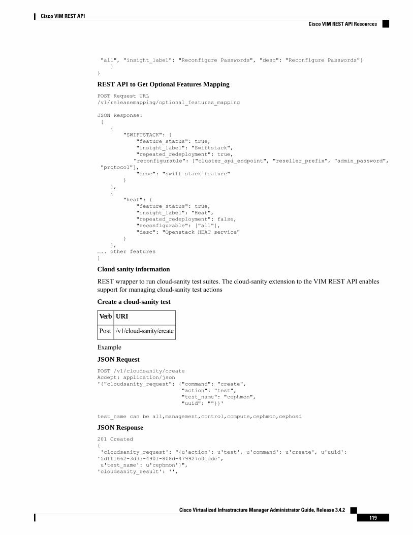
"all", "insight_label": "Reconfigure Passwords", "desc": "Reconfigure Passwords"}}
}
REST API to Get Optional Features Mapping
POST Request URL/v1/releasemapping/optional_features_mapping
JSON Response:[
{"SWIFTSTACK": {
"feature_status": true,"insight_label": "Swiftstack","repeated_redeployment": true,"reconfigurable": ["cluster_api_endpoint", "reseller_prefix", "admin_password",
"protocol"],"desc": "swift stack feature"
}},{
"heat": {"feature_status": true,"insight_label": "Heat","repeated_redeployment": false,"reconfigurable": ["all"],"desc": "Openstack HEAT service"
}},
….. other features]
Cloud sanity information
REST wrapper to run cloud-sanity test suites. The cloud-sanity extension to the VIM REST API enablessupport for managing cloud-sanity test actions
Create a cloud-sanity test
URIVerb
/v1/cloud-sanity/createPost
Example
JSON Request
POST /v1/cloudsanity/createAccept: application/json'{"cloudsanity_request": {"command": "create",
"action": "test","test_name": "cephmon","uuid": ""}}'
test_name can be all,management,control,compute,cephmon,cephosd
JSON Response
201 Created{'cloudsanity_request': "{u'action': u'test', u'command': u'create', u'uuid':'5dff1662-3d33-4901-808d-479927c01dde',u'test_name': u'cephmon'}",'cloudsanity_result': '',
Cisco Virtualized Infrastructure Manager Administrator Guide, Release 3.4.2119
Cisco VIM REST APICisco VIM REST API Resources
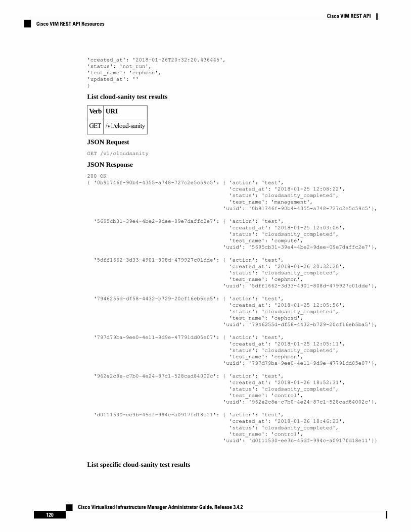
'created_at': '2018-01-26T20:32:20.436445','status': 'not_run','test_name': 'cephmon','updated_at': ''}
List cloud-sanity test results
URIVerb
/v1/cloud-sanityGET
JSON Request
GET /v1/cloudsanity
JSON Response
200 OK{ '0b91746f-90b4-4355-a748-727c2e5c59c5': { 'action': 'test',
'created_at': '2018-01-25 12:08:22','status': 'cloudsanity_completed','test_name': 'management',
'uuid': '0b91746f-90b4-4355-a748-727c2e5c59c5'},
'5695cb31-39e4-4be2-9dee-09e7daffc2e7': { 'action': 'test','created_at': '2018-01-25 12:03:06','status': 'cloudsanity_completed','test_name': 'compute',
'uuid': '5695cb31-39e4-4be2-9dee-09e7daffc2e7'},
'5dff1662-3d33-4901-808d-479927c01dde': { 'action': 'test','created_at': '2018-01-26 20:32:20','status': 'cloudsanity_completed','test_name': 'cephmon',
'uuid': '5dff1662-3d33-4901-808d-479927c01dde'},
'7946255d-df58-4432-b729-20cf16eb5ba5': { 'action': 'test','created_at': '2018-01-25 12:05:56','status': 'cloudsanity_completed','test_name': 'cephosd',
'uuid': '7946255d-df58-4432-b729-20cf16eb5ba5'},
'797d79ba-9ee0-4e11-9d9e-47791dd05e07': { 'action': 'test','created_at': '2018-01-25 12:05:11','status': 'cloudsanity_completed','test_name': 'cephmon',
'uuid': '797d79ba-9ee0-4e11-9d9e-47791dd05e07'},
'962e2c8e-c7b0-4e24-87c1-528cad84002c': { 'action': 'test','created_at': '2018-01-26 18:52:31','status': 'cloudsanity_completed','test_name': 'control',
'uuid': '962e2c8e-c7b0-4e24-87c1-528cad84002c'},
'd0111530-ee3b-45df-994c-a0917fd18e11': { 'action': 'test','created_at': '2018-01-26 18:46:23','status': 'cloudsanity_completed','test_name': 'control',
'uuid': 'd0111530-ee3b-45df-994c-a0917fd18e11'}}
List specific cloud-sanity test results
Cisco Virtualized Infrastructure Manager Administrator Guide, Release 3.4.2120
Cisco VIM REST APICisco VIM REST API Resources

URIVerb
/v1/cloud-sanity/list/?test_name={all,management,
control,compute,cephmon,cephosd}
GET
JSON Request
GET /v1/cloudsanity/list/?test_name=cephmonAccept: application/json
JSON Response
200 OK{ '5dff1662-3d33-4901-808d-479927c01dde': { 'action': 'test',
'created_at': '2018-01-26 20:32:20','status': 'cloudsanity_completed','test_name': 'cephmon',
'uuid': '5dff1662-3d33-4901-808d-479927c01dde'},
'797d79ba-9ee0-4e11-9d9e-47791dd05e07': { 'action': 'test','created_at': '2018-01-25 12:05:11','status': 'cloudsanity_completed','test_name': 'cephmon',
'uuid': '797d79ba-9ee0-4e11-9d9e-47791dd05e07'}}
Show cloud-sanity test results
URIVerb
/v1/cloud-sanity/show/?uuid=<uuid>GET
JSON Request
GET /v1/cloudsanity/show/?uuid=d0111530-ee3b-45df-994c-a0917fd18e11
JSON Response
200 OK{ 'action': 'test','cloudsanity_request':
"{u'action': u'test',u'command': u'create',u'uuid': 'd0111530-ee3b-45df-994c-a0917fd18e11',u'test_name': u'control'}",
'cloudsanity_result':'{"status": "PROCESSED","message": {"status": "Pass",
"message": "[PASSED] Cloud Sanity Control Checks Passed","results": {"control": {"ping_all_controller_nodes": "PASSED",
"check_rabbitmq_is_running": "PASSED","check_rabbitmq_cluster_status": "PASSED","check_nova_service_list": "PASSED","ping_internal_vip": "PASSED","disk_maintenance_raid_health": "PASSED","check_mariadb_cluster_size": "PASSED","disk_maintenance_vd_health": "PASSED"}}}}',
'created_at': '2018-01-26 18:46:23','status': 'cloudsanity_completed','test_name': 'control','updated_at': '2018-01-26 18:47:58','uuid': 'd0111530-ee3b-45df-994c-a0917fd18e11'}
Cisco Virtualized Infrastructure Manager Administrator Guide, Release 3.4.2121
Cisco VIM REST APICisco VIM REST API Resources

Delete cloud-sanity test results
URIVerb
/v1/cloud-sanity/delete/?uuid=<uuid>DELETE
JSON Request
GET /v1/cloudsanity/delete/?uuid=444aa4c8-d2ba-4379-b035-0f47c686d1c4
JSON Response
200 OK{
"status": "deleted","message": "UUID 444aa4c8-d2ba-4379-b035-0f47c686d1c4 deleted from database","uuid": "444aa4c8-d2ba-4379-b035-0f47c686d1c4","error": "None"
}
Disk Maintenance information
REST wrapper to query information about RAID disks on Pod nodes. This returns the RAID disk informationof all or a selection of RAID disks available in the Pod.
The disk management extension to the VIM REST API enables support for Disk Management actions
Create a Check disk operation
Resource URI
URIVerb
/v1/diskmgmt/check_disksPOST
Example
JSON Request
POST /v1/diskmgmt/check_disks Accept: application/json'{"diskmgmt_request": {"command": "create",
"action": "check-disks","role": "control","locator": "False","json_display": "False","servers": "", "uuid": ""}}'
JSON Response
201 CreatedContent-Type: application/json{
'action': 'check-disks','created_at': '2018-03-08T02:03:18.170849+00:00','diskmgmt_request': "{u'uuid': '0729bdea-cc19-440f-8339-ab21e76be84b',
u'json_display': u'False',u'servers': u'',u'locator': u'False',u'role': u'control',u'action': u'check-disks',u'command': u'create'}",'diskmgmt_result': '','status': 'not_run',
Cisco Virtualized Infrastructure Manager Administrator Guide, Release 3.4.2122
Cisco VIM REST APICisco VIM REST API Resources

'updated_at': 'None'}
Create a replace disk operation
URIVerb
/v1/diskmgmt/replace_disksPOST
Example
JSON Request
POST /v1/diskmgmt/replace_disksAccept: application/json'{"diskmgmt_request": {"command": "create",
"action": "replace-disks","role": "control","locator": "False","json_display": "False","servers": "", "uuid": ""}}'
JSON Response
201 CreatedContent-Type: application/json{"status": "not_run","diskmgmt_request": "{u'uuid': 'cb353f41-6d25-4190-9386-330e971603c9',
u'json_display': u'False',u'servers': u'',u'locator': u'False',u'role': u'control',u'action': u'replace-disks',u'command': u'create'}",
"created_at": "2018-03-09T12:43:41.289531+00:00","updated_at": "","diskmgmt_result": "","action": "replace-disks"}
List check disk operation
URIVerb
/v1/diskmgmt/list/?action=
{check-disks,replace-disks
\&role={all,management,control,compute}
GET
Example
JSON Request
GET /v1/diskmgmt/list/?action=check-disks\&role=all
JSON Response
200 OKContent-Type: application/json{
'0be7a55a-37fe-43a1-a975-cbf93ac78893': { 'action': 'check-disks','created_at': '2018-03-05 14:45:45+00:00','role': 'compute','status': 'diskmgmt_completed',
Cisco Virtualized Infrastructure Manager Administrator Guide, Release 3.4.2123
Cisco VIM REST APICisco VIM REST API Resources

'uuid':'0be7a55a-37fe-43a1-a975-cbf93ac78893'},
'861d4d73-ffee-40bf-9348-13afc697ee3d': { 'action': 'check-disks','created_at': '2018-03-05 14:44:47+00:00','role': 'control','status': 'diskmgmt_completed','uuid':
'861d4d73-ffee-40bf-9348-13afc697ee3d'},'cdfd18c1-6346-47a2-b0f5-661305b5d160': { 'action': 'check-disks',
'created_at': '2018-03-05 14:43:50+00:00','role': 'all','status': 'diskmgmt_completed','uuid':
'cdfd18c1-6346-47a2-b0f5-661305b5d160'}}
}
Show a completed diskmgmt operation
URIVerb
v1/diskmgmt/show/?uuid=<uuid>GET
Example
JSON Request
GET /v1/diskmgmt/show/?uuid=d24036c6-4557-4c12-8695-a92f6f9315ed
JSON Response
200 OKContent-Type: application/json{ 'action': 'check-disks',
'created_at': '2018-03-07 21:46:41+00:00','diskmgmt_request': "{u'uuid': 'd24036c6-4557-4c12-8695-a92f6f9315ed',
u'json_display': False,u'servers': u'f24-michigan-micro-2',u'locator': False,u'role': u'compute',u'action': u'check-disks',u'command': u'create'}",
'diskmgmt_result': '{"status": "PROCESSED", "message": ["{\'Overall_Status\': \'PASS\',\'Result\': {\'fcfg_disks_results_list\': [], \'spare_disks_results_list\': [],\'raid_results_list\': [{\'RAID level\': \'RAID1\', \'Disk Med\': \'HDD\', \'server\':\'7.7.7.6\', \'RAID type\': \'HW\', \'host\': \'f24-michigan-micro-2\', \'role\':\'block_storage control compute\', \'VD health\': \'Optl\', \'Num VDs\': 1, \'Num PDs\':8, \'RAID health\': \'Opt\'}], \'bad_disks_results_list\': [], \'rbld_disks_results_list\':[], \'add_as_spares_disks_results_list\': []}}"]}',
'role': 'compute','status': 'diskmgmt_completed','updated_at': '2018-03-07 21:47:35+00:00','uuid': 'd24036c6-4557-4c12-8695-a92f6f9315ed'
}
Delete a completed diskmgmt operation
URIVerb
v1/diskmgmt/delete/?uuid=<uuid>DELETE
Example
Cisco Virtualized Infrastructure Manager Administrator Guide, Release 3.4.2124
Cisco VIM REST APICisco VIM REST API Resources

JSON Request
DELETE /v1/diskmgmt/delete/?uuid=d24036c6-4557-4c12-8695-a92f6f9315ed
JSON Response
200 OKContent-Type: application/json{"status": "deleted","message": "UUID d24036c6-4557-4c12-8695-a92f6f9315ed deleted from database","uuid": "d24036c6-4557-4c12-8695-a92f6f9315ed","error": "None"
}
OSD Maintenance information
REST wrapper to query information about OSD on Pod storage nodes. This returns to the OSD statusinformation of all or a selection of OSDs available in the Pod.
Create a OSD disk operation
URIVerb
/v1/osdmgmt/check_osdsPOST
Example
JSON Request
POST /v1/osdmgmt/osdmgmt/check_osds'{"osdmgmt_request": {"command": "create",
"action": "check-osds","locator": "False","json_display": "False","servers": "","osd": "None","uuid": ""}}'
JSON Response
201 CreatedContent-Type: application/json{
'action': 'check-osds','created_at': '2018-03-08T21:26:15.329195+00:00','osdmgmt_request': "{u'uuid': '9c64ee52-bed5-4b69-91a2-d589411dd223', u'json_display':
u'False', u'servers': u'', u'locator': u'False', u'command': u'create', u'action':u'check-osds', u'osd': u'None'}",
'osdmgmt_result': '','status': 'not_run','updated_at': 'None'
}
Create a replace OSD operation
URIVerb
v1/osdmgmt/replace_osdPOST
Example
JSON Request
Cisco Virtualized Infrastructure Manager Administrator Guide, Release 3.4.2125
Cisco VIM REST APICisco VIM REST API Resources

POST /v1/osdmgmt/replace_osdAccept: application/json'{"osdmgmt_request": {"command": "create",
"action": "replace-osd","locator": "False","json_display": "False","servers": "f24-michigan-micro-1","osd": "osd.9","uuid": ""}}'
JSON Response
201 CreatedContent-Type: application/json{"status": "not_run","osdmgmt_request": "{u'uuid': '5140f6fb-dca3-4801-8c44-89b293405310', u'json_display':
u'False', u'servers': u'f24-michigan-micro-1', u'locator': u'False', u'command': u'create',u'action': u'replace-osd', u'osd': u'osd.9'}","created_at": "2018-03-09T15:07:10.731220+00:00","updated_at": null,"action": "replace-osd","osdmgmt_result": ""
}
}
List check OSD operation
URIVerb
v1/osdmgmt/list/?action=
{check-osds,replace-osd}
GET
Example
JSON Request
GET /v1/osdmgmt/list/?action=check-osds
JSON Response
200 OKContent-Type: application/json{
'4efd0be8-a76c-4bc3-89ce-142de458d844': { 'action': 'check-osds','created_at': '2018-03-08 21:31:01+00:00','status': 'osdmgmt_running','uuid':
'4efd0be8-a76c-4bc3-89ce-142de458d844'},'5fd4f9b5-786a-4a21-a70f-bffac70a3f3f': { 'action': 'check-osds',
'created_at': '2018-03-08 21:11:13+00:00','status': 'osdmgmt_completed','uuid':
'5fd4f9b5-786a-4a21-a70f-bffac70a3f3f'},'9c64ee52-bed5-4b69-91a2-d589411dd223': { 'action': 'check-osds',
'created_at': '2018-03-08 21:26:15+00:00','status': 'osdmgmt_completed','uuid':
'9c64ee52-bed5-4b69-91a2-d589411dd223'}}
}
Cisco Virtualized Infrastructure Manager Administrator Guide, Release 3.4.2126
Cisco VIM REST APICisco VIM REST API Resources

Show a completed osdmgmt operation
URIVerb
v1/osdmgmt/show/?uuid=<uuid>GET
Example
JSON Request
GET /v1/osdmgmt/show/?uuid=9c64ee52-bed5-4b69-91a2-d589411dd223
JSON Response
200 OKContent-Type: application/json{
'action': 'check-osds','created_at': '2018-03-08 21:26:15+00:00','osdmgmt_request': "{u'uuid': '9c64ee52-bed5-4b69-91a2-d589411dd223', u'json_display':
u'False', u'servers': u'', u'locator': u'False', u'command': u'create', u'action':u'check-osds', u'osd': u'None'}",
'osdmgmt_result': '{"status": "PROCESSED", "message": ["{\'Overall_Status\': \'PASS\',\'Result\': { ommitted for doc }}]}',
'status': 'osdmgmt_completed','updated_at': '2018-03-08 21:27:16+00:00','uuid': '9c64ee52-bed5-4b69-91a2-d589411dd223'
}
}
Delete a completed osdmgmt operation
URIVerb
v1/osdmgmt/delete/?uuid=<uuid>DELETE
Example
JSON Request
DELETE /v1/osdmgmt/delete/?uuid=9c64ee52-bed5-4b69-91a2-d589411dd223
JSON Response
200 OKContent-Type: application/json{
'error': 'None','message': 'UUID 9c64ee52-bed5-4b69-91a2-d589411dd223 deleted from database','status': 'deleted','uuid': '9c64ee52-bed5-4b69-91a2-d589411dd223'
}
}
Hardware Management Utility
REST wrapper to control the execution of or query information from the hardware validation utility.
Create a Validate Operation
URIVerb
Cisco Virtualized Infrastructure Manager Administrator Guide, Release 3.4.2127
Cisco VIM REST APICisco VIM REST API Resources

/v1/hardwaremgmt/validatePOST
JSON Request
POST /v1/hardwaremgmt/validate'{"hwmgmt_request": {"command": "create",
"action": "validate","hosts": "None","file": "None","feature_list": "all","uuid": ""}}'
feature_list is a comma separated list of valid features for the given POD
JSON Reponse
201 CreatedContent-Type: application/json{
'action': 'validate','created_at': '2018-03-08T22:01:22.195232+00:00','hwmgmt_request': "{u'feature_list': u'all', u'command': u'create', u'file': None,
u'action': u'validate', u'hosts': None, u'uuid': '89e094d8-b246-4620-afca-ba3529385cac'}",'hwmgmt_result': '','status': 'not_run','updated_at': 'None'
}
Create a Validate Operation for Failure
URIVerb
/v1/hardwaremgmt/resolve_failuresGET
JSON Request
POST /v1/hardwaremgmt/resolve_failures{
"hwmgmt_request": {"command": "create","action": "resolve-failures","hosts": "None","file": "None","feature_list": "all","uuid": ""}
}feature_list is a comma separated list of valid features for the given POD
JSON Response
201 CreatedContent-Type: application/json{"status": "not_run","created_at": "2018-03-09T15:47:36.503712+00:00","hwmgmt_request": "{u'feature_list': u'all', u'command': u'create', u'file': None,
u'action': u'resolve-failures', u'hosts': None, u'uuid':'49dc1dc9-3170-4f68-b152-0f99bd19f7b1'}","updated_at": "","action": "resolve-failures","hwmgmt_result": ""}
Create a Validate Operation
Cisco Virtualized Infrastructure Manager Administrator Guide, Release 3.4.2128
Cisco VIM REST APICisco VIM REST API Resources

URIVerb
v1/hardwaremgmt/listGET
JSON Request
GET /v1/hardwaremgmt/list
JSON Response
200 OKContent-Type: application/json{ '89e094d8-b246-4620-afca-ba3529385cac': { 'action': 'validate',
'created_at': '2018-03-08 22:01:22+00:00','feature_list': 'all','status': 'hardwaremgmt_completed','uuid':
'89e094d8-b246-4620-afca-ba3529385cac'},'9f70e872-a888-439a-8661-2d2f36a4f4b1': { 'action': 'validate',
'created_at': '2018-03-08 20:34:32+00:00','feature_list': 'all','status': 'hardwaremgmt_completed','uuid':
'9f70e872-a888-439a-8661-2d2f36a4f4b1'}}
Show a completed hardwaremgmt operation
URIVerb
/v1/hardwaremgmt/show
/?uuid=<uuid>
GET
JSON Request
GET /v1/hardwaremgmt/show/?uuid=9f70e872-a888-439a-8661-2d2f36a4f4b
JSON Response
200 OKContent-Type: application/json{
'action': 'validate','created_at': '2018-03-08 20:34:32+00:00','feature_list': 'all','hwmgmt_request': "{u'feature_list': u'all', u'hosts': None, u'file': None, u'action':
u'validate', u'command': u'create', u'uuid': '9f70e872-a888-439a-8661-2d2f36a4f4b1'}",'hwmgmt_result': '{"status": "PROCESSED", "message": "Validate of all completed",
"results": {"status": "PASS", "results": [{"status": "PASS", "name": "CIMC Firmware VersionCheck", "err": null}, {"status": "PASS", "name": "All Onboard LOM Ports Check", "err":null}, {"status": "PASS", "name": "PCIe Slot: HBA Status Check", "err": null}, {"status":"PASS", "name": "Server Power Status Check", "err": null}, {"status": "PASS", "name": "NFVConfig Check", "err": null}, {"status": "PASS", "name": "Physical Drives Check", "err":null}, {"status": "PASS", "name": "PCIe Slot(s) OptionROM Check", "err": null}, {"status":"PASS", "name": "Intel Network Adapter Check", "err": null}]}}',
'status': 'hardwaremgmt_completed','updated_at': '2018-03-08 20:38:02+00:00','uuid': '9f70e872-a888-439a-8661-2d2f36a4f4b1'
Delete a completed hardwaremgmt operation
URIVerb
Cisco Virtualized Infrastructure Manager Administrator Guide, Release 3.4.2129
Cisco VIM REST APICisco VIM REST API Resources

/v1/hardwaremgmt/delete/?uuid=<uuid>DELETE
JSON Request
DELETE /v1/hardwaremgmt/delete/?uuid=9f70e872-a888-439a-8661-2d2f36a4f4b1
JSON Response
200 OKContent-Type: application/json{
'error': 'None','message': 'UUID 9f70e872-a888-439a-8661-2d2f36a4f4b1 deleted from database','status': 'deleted','uuid': '9f70e872-a888-439a-8661-2d2f36a4f4b1'
}
Cisco VIM REST API Using curl for IPv4Getting REST API Username & Password
Use the following configuration to get REST API Username and Password:
cat /opt/cisco/ui_config.json{"Kibana-Url": "http://172.31.231.17:5601","RestAPI-Username": "admin","RestAPI-Password": "****","RestDB-Password": "****","RestAPI-Url": "https://172.31.231.17:8445","BuildNodeIP": "172.31.231.17"}
CCP APIs and Commands
Get CCP:
Use the following command to get the list of CCP operations executed:curl -i -X GET -H 'Content-Type: application/json' -H 'Authorization: ****' -H 'Accept:application/json' --cacert /var/www/mercury/mercury-ca.crt https://172.29.84.207:8445/ccp
Response
HTTP/1.1 200 OKcontent-length: 360x-xss-protection: 1x-content-type-options: nosniffstrict-transport-security: max-age=31536000server: WSGIServer/0.1 Python/2.7.5cache-control: no-cache, no-store, must-revalidate, max-age=0date: Mon, 01 Jul 2019 11:22:03 GMTx-frame-options: SAMEORIGINcontent-type: application/json
{u'ccps': {u'status': u'Success', u'ccp_result': {u'delete_tenant': False}, u'created_at':u'2019-07-01T10:50:31+00:00', u'updated_at': u'2019-07-01T11:06:25+00:00', u'op_name':u'CCP_Verify'}}
Cisco Virtualized Infrastructure Manager Administrator Guide, Release 3.4.2130
Cisco VIM REST APICisco VIM REST API Using curl for IPv4

POST CCP Install:
Use the following command to initiate installation of CCP:curl -i -X POST -H 'Content-Type: application/json' -H 'Authorization: ****' -H 'Accept:application/ --cacert /var/www/mercury/mercury-ca.crt -d 'None' https://172.29.84.207:8445/ccp
Response
HTTP/1.1 201 Createdcontent-length: 133x-xss-protection: 1x-content-type-options: nosniffstrict-transport-security: max-age=31536000server: WSGIServer/0.1 Python/2.7.5cache-control: no-cache, no-store, must-revalidate, max-age=0date: Mon, 01 Jul 2019 10:46:18 GMTx-frame-options: SAMEORIGINcontent-type: application/json
{u'status': u'ToRun', u'ccp_result': u'', u'created_at': u'2019-07-01T10:46:18.106517+00:00',u'updated_at': None, u'op_name': u'CCP_Install'}
CCP Verify
Execute the following command to execute CCP Verify (Check tenant cluster status):curl -i -X POST -H 'Content-Type: application/json' -H 'Authorization: ****' -H 'Accept:application/json' --cacert /var/www/mercury/mercury-ca.crt -d '{u'skip_delete': False}'https://172.29.84.207:8445/ccp/ccp_verify
Response
HTTP/1.1 201 Createdcontent-length: 158x-xss-protection: 1x-content-type-options: nosniffstrict-transport-security: max-age=31536000server: WSGIServer/0.1 Python/2.7.5cache-control: no-cache, no-store, must-revalidate, max-age=0date: Mon, 01 Jul 2019 08:04:52 GMTx-frame-options: SAMEORIGINcontent-type: application/json
{u'status': u'ToRun', u'ccp_result': {u'delete_tenant': False}, u'created_at':u'2019-07-01T08:04:52.310432+00:00', u'updated_at': None, u'op_name': u'CCP_Verify'}
DELETE Control Cluster
Use the following command to delete the deployed control cluster:curl -i -X DELETE -H 'Content-Type: application/json' -H 'Authorization: ****' -H 'Accept:application/json' -H 'User-Agent: python-ciscovimclient' --cacert/var/www/mercury/mercury-ca.crt -d '{u'delete_tenant': False, u'delete_control': True}'https://172.29.84.207:8445/ccp
Response
HTTP/1.1 204 No Contentx-xss-protection: 1x-content-type-options: nosniffstrict-transport-security: max-age=31536000server: WSGIServer/0.1 Python/2.7.5cache-control: no-cache, no-store, must-revalidate, max-age=0date: Mon, 01 Jul 2019 11:29:59 GMx-frame-options: SAMEORIGIN
Cisco Virtualized Infrastructure Manager Administrator Guide, Release 3.4.2131
Cisco VIM REST APICisco VIM REST API Using curl for IPv4

Nodes APIs and Commands
List Nodes
Use the following curl command to get the node's status, power status, reboot status, and mtype information:
curl -i -X GET -u admin:**** -H 'Content-Type: application/json' -H 'Accept: application/json'--cacert /var/www/mercury/mercury-ca.crt https://172.31.231.17:8445/v1/nodes
Response
{"nodes": [{"status": ". . . . "name": "Store-2"}]}
Power OFF Nodes
To get the power off status of the nodes, use the below command:
curl -i -X POST -H 'Content-Type: application/json' -u admin:**** -H 'Accept:application/json' --cacert /var/www/mercury/mercury-ca.crt -d '{‘status': ‘PowerOff',‘force_op': False, ‘name': ‘<Node UUID>'}'https://172.31.231.17:8445/v1/nodes/node_power_status
UUID of the node can be found from the above List Nodes commandNote
Power ON Nodes
To get the power ON status of the nodes, use the following command:
curl -i -X POST -H 'Content-Type: application/json' -u admin:**** -H 'Accept:application/json' --cacert /var/www/mercury/mercury-ca.crt -d '{‘status': ‘PowerOn',‘force_op': False, ‘name': ‘<Node UUID>'}'https://172.31.231.17:8445/v1/nodes/node_power_status
Cisco Virtualized Infrastructure Manager Administrator Guide, Release 3.4.2132
Cisco VIM REST APICisco VIM REST API Using curl for IPv4

UUID of the node can be found from the above List Nodes commandNote
Power Status of Nodes
To get the Live status of the nodes, first send POST request to /v1/hwinfoAPI, and then place the GETrequest on v1/hwinfo/get_nodes_power_status after a minute approximately.
Run the below commands to send the POST request and get the power status:
curl -i -X POST -H 'Content-Type: application/json' -u admin:**** -H 'Accept:application/json' --cacert /var/www/mercury/mercury-ca.crt -d '{}'https://172.31.231.17:8445/v1/hwinfocurl -i -X GET -H 'Content-Type: application/json' -u admin:**** -H 'Accept: application/json'--cacert /var/www/mercury/mercury-ca.crthttps://172.31.231.17:8445/v1/hwinfo/get_nodes_power_status
Response
{'Store-3': {'intended_power_state': 'PowerOnSuccess', 'actual_power_state': 'on'},}}
Reboot Node
curl -i -X POST -H 'Content-Type: application/json' -u admin:**** -H 'Accept:application/json' --cacert /var/www/mercury/mercury-ca.crt -d '{‘status': ‘Reboot',‘force_op': False, ‘name': ‘<Node UUID>'}'https://172.31.231.17:8445/v1/nodes/node_power_status
UUID of the node can be found from the above List Nodes commandNote
Reboot Status
Use the following two commands, to get the reboot status of the node:
curl -i -X POST -H 'Content-Type: application/json' -u admin:**** -H 'Accept:application/json' --cacert /var/www/mercury/mercury-ca.crt-d 'None' https://172.31.231.17:8445/v1/nodes/reboot_status
curl -i -X GET -H 'Content-Type: application/json' -u admin:**** -H 'Accept: application/json'--cacert /var/www/mercury/mercury-ca.crt https://172.31.231.17:8445/v1/nodes
List Openstack Configuration
Command
curl -i -X GET -H 'Content-Type: application/json' -u admin:**** -H 'Accept: application/json'--cacert /var/www/mercury/mercury-ca.crt https://172.31.231.17:8445/v1/openstack_config
Response
{"KEYSTONE_VERBOSE_LOGGING": true, "GNOCCHI_VERBOSE_LOGGING": true, . . }
List Password Secrets
Command
Cisco Virtualized Infrastructure Manager Administrator Guide, Release 3.4.2133
Cisco VIM REST APICisco VIM REST API Using curl for IPv4

curl -i -X GET -H 'Content-Type: application/json' -u admin:**** -H 'Accept: application/json'--cacert /var/www/mercury/mercury-ca.crt https://172.31.231.17:8445/v1/secrets
Response
{‘HEAT_KEYSTONE_PASSWORD': '****', ‘CINDER_KEYSTONE_PASSWORD': '****' . . }
Cluster Recovery
Command
curl -i -X POST -H 'Content-Type: application/json' -u admin:**** -H 'Accept:application/json' --cacert /var/www/mercury/mercury-ca.crt -d '{‘action': {‘cluster-recovery':{‘run-disk-checks': False}}}'https://172.31.231.17:8445/v1/misc
Response
{‘uuid': ‘ae3be813-4fae-4510-8467-fab09ac60d2b', ‘created_at':‘2019-01-07T08:17:01.229976+00:00', ‘updated_at': None, ‘operation_status':‘OperationScheduled', ‘operation_logs': ‘', ‘operation_name': {‘cluster-recovery':{‘run-disk-checks': False}}}
NFVIMON
Command
curl -i -X POST -H 'Content-Type: application/json' -u admin:**** -H 'Accept:application/json' --cacert /var/www/mercury/mercury-ca.crt -d '{‘action': {‘nfvimon': True,‘generate_ssh_keys': '****'}}' https://172.31.231.17:8445/v1/misc
Response
{‘uuid': ‘d33e534b-b8c7-41c9-b8e4-7b1befe528c8', ‘created_at':‘2019-01-07T08:27:56.925029+00:00', ‘updated_at': None, ‘operation_status':‘OperationScheduled', ‘operation_logs': ‘', ‘operation_name': {‘generate_ssh_keys': '****',‘nfvimon': True}}
Last-Run-Status
Command
curl -i -X GET -H 'Content-Type: application/json' -H 'Authorization: ****' -H 'Accept:application/json' -H 'User-Agent: python-ciscovimclient' --cacert/var/www/mercury/mercury-ca.crthttps://172.31.231.17:8445/v1/op_info
Response
{‘created_at': ‘2019-01-07 08:27:56+00:00', ‘updated_at': ‘2019-01-07 08:28:03+00:00',‘reboot_required': False, ‘update_status': False, ‘current_op_logs':‘https://172.31.231.17:8008/mercury/79c402d2-f156-4ba2-8f17-ec109401a538',‘current_op_status': ‘OperationRunning', ‘insight_monitor_status': ‘Running',‘current_op_name': ‘Generate_ssh_keys', ‘current_op_monitor': ‘Runner_Op_Generate_ssh_keys'}
Reconfigure Regenerate Secrets
Command
curl -i -X POST -H 'Content-Type: application/json' -u admin:**** -H 'Accept:
Cisco Virtualized Infrastructure Manager Administrator Guide, Release 3.4.2134
Cisco VIM REST APICisco VIM REST API Using curl for IPv4

application/json' --cacert /var/www/mercury/mercury-ca.crt -d '{‘action':{‘regenerate_secrets': '****', ‘reconfigure': True}}' https://172.31.231.17:8445/v1/misc
Response
{‘uuid': ‘83cf2700-275f-4c18-a900-96c36c4987aa', ‘created_at':‘2019-01-07T08:36:19.279425+00:00', ‘updated_at': None, ‘operation_status':‘OperationScheduled', ‘operation_logs': ‘', ‘operation_name': {‘regenerate_secrets': '****',‘reconfigure': True}}
Reconfigure Set Password
Command
curl -i -X POST -H 'Content-Type: application/json' -u admin:**** -H 'Accept:application/json' --cacert /var/www/mercury/mercury-ca.crt -d '{‘action': {‘reconfigure':True, ‘setopenstackconfigs': {‘GNOCCHI_VERBOSE_LOGGING': True}}}'https://172.31.231.17:8445/v1/misc
Response
{‘uuid': ‘5f8d0504-d108-4b88-9d63-f9585dc96d38', ‘created_at':‘2019-01-07T08:48:32.880245+00:00', ‘updated_at': None, ‘operation_status':‘OperationScheduled', ‘operation_logs': ‘', ‘operation_name': {‘setpassword': '****',‘reconfigure': True}}
Reconfigure Set Openstack Configuration
Command
curl -i -X POST -H 'Content-Type: application/json' -u admin:**** -H 'Accept:application/json' --cacert /var/www/mercury/mercury-ca.crt -d '{‘action': {‘reconfigure':True, ‘setopenstackconfigs': {‘GNOCCHI_VERBOSE_LOGGING': True}}}'https://172.31.231.17:8445/v1/misc
Response
{‘uuid': ‘5bbbeff7-76df-4444-a38a-8819a8b579e4', ‘created_at':‘2019-01-07T08:54:13.733254+00:00', ‘updated_at': None, ‘operation_status':‘OperationScheduled', ‘operation_logs': ‘', ‘operation_name': {‘setopenstackconfigs':{‘GNOCCHI_VERBOSE_LOGGING': True}, ‘reconfigure': True}}
Reconfigure CIMC Password
1. List down the setupdata and find UUID of active setupdata using the following command:
curl -i -X GET -H 'Content-Type: application/json' -u admin:**** -H 'Accept:application/json' --cacert /var/www/mercury/mercury-ca.crthttps://172.31.231.17:8445/v1/setupdata
Response
Cisco Virtualized Infrastructure Manager Administrator Guide, Release 3.4.2135
Cisco VIM REST APICisco VIM REST API Using curl for IPv4

2. Put the content of setupdata with new CIMC Password using the following command:curl -i -X PUT -H 'Content-Type: application/json' -u admin:**** -H 'Accept:application/json' --cacert /var/www/mercury/mercury-ca.crt -d '{'meta': {}, 'name':'NEWSETUPDATA', 'jsondata': {'external_lb_vip_address': '172.29.86.9' . . .}, 'uuid':'3e97381e-4b1c-41a2-9af4-f970a1f1493a'}'https://172.31.231.17:8445/v1/setupdata/3e97381e-4b1c-41a2-9af4-f970a1f1493a
3. Post on Misc API using the below command:
curl -i -X POST -H 'Content-Type: application/json' -u admin:**** -H 'Accept:application/json' --cacert /var/www/mercury/mercury-ca.crt -d '{‘action':{‘reconfigure_cimc_password': True, ‘reconfigure': True}}' https://172.31.231.17:8445/misc
Response
{‘uuid': ‘f00e1ae0-5674-4218-b1de-8995c9f9c546', ‘created_at':‘2019-01-07T09:19:40.210121+00:00', ‘updated_at': None, ‘operation_status':‘OperationScheduled', ‘operation_logs': ‘', ‘operation_name':{‘reconfigure_cimc_password': '****', ‘reconfigure': True}}
Cisco VIM REST API Using curl for IPv6Prerequisites
1. You need to copy the certificates from the management node to local machine from where you wouldlaunch the APIs.
2. Create a folder in local machine and copy the certificates.# mkdir ~/certificates
3. Copy REST API CA Certificates (for mercury commands)# scp root@<Management Node>:/var/www/mercury/mercury-ca.crt ~/certificates
The key information that you need are br_api and cloud_api (external_lb_vip_ipv6_address).Note
4. For each POD, get the REST API credentials:
# cat /opt/cisco/ui_config.json
Cisco Virtualized Infrastructure Manager Administrator Guide, Release 3.4.2136
Cisco VIM REST APICisco VIM REST API Using curl for IPv6

{"Kibana-Url": "http://[2001:420:293:2440:b696:91ff:fe22:2dd8]:5601","RestAPI-Username": "admin","RestAPI-Password": "cfb605586d50115333c8","RestDB-Password": "744ebc5feee30b733ac8","RestAPI-Url": "https://[2001:420:293:2440:b696:91ff:fe22:2dd8]:8445","BuildNodeIP": "2001:420:293:2440:b696:91ff:fe22:2dd8" -> br_api}
Offline Validation using curl
1. Create offline validation test
Request
curl -g -i -X POST -H 'Content-Type: application/json' -u admin:46d13357ef15e5482b52 -H'Accept: application/json' -H 'User-Agent: python-ciscovimclient' --cacert~/certificates/mercury-ca.crt -d '{"jsondata" : {<SetupData in JSON Format>}}'https://[2001:420:293:2440:b696:91ff:fe22:2dd8]:8445/v1/offlinevalidationUUID is returned from request
Response
{"status": "NotValidated", "uuid": "2b8253f4-ad9f-4fbf-b224-a65bd210392a", "created_at":"2019-02-28T18:02:36.808740+00:00", "updated_at": null, "jsondata": "{}”}
2. Get the offline validation test result
Request
Curl -g -i -X GET -H 'Content-Type: application/json' -u admin:46d13357ef15e5482b52 -H'Accept: application/json' -H 'User-Agent: python-ciscovimclient' --cacert~/certificates/mercury-ca.crthttps://[2001:420:293:2440:b696:91ff:fe22:2dd8]:8445/v1/offlinevalidation/2b8253f4-ad9f-4fbf-b224-a65bd210392a
Response
{"status": "ValidationFailed", "uuid": "2b8253f4-ad9f-4fbf-b224-a65bd210392a","created_at": "2019-02-28T18:02:36+00:00", "updated_at": "2019-02-28T18:02:57+00:00","jsondata": ""}
Start New Installation
1. Create new setup date before starting new installation, for example:curl -g -i -X POST -H 'Content-Type: application/json' -u admin:46d13357ef15e5482b52 -H'Accept: application/json' -H 'User-Agent: python-ciscovimclient' --cacert~/certificates/mercury-ca.crt -d '{u'meta': {}, u'name': u'NEWSETUPDATA', u'jsondata':{<SetupData in JSON Format>}}'https://[2001:420:293:2440:b696:91ff:fe22:2dd8]:8445/setupdata
2. To start the installation:
Request
Curl -g -i -X POST -H 'Content-Type: application/json' admin:46d13357ef15e5482b52 -H'Accept: application/json' -H 'User-Agent: python-ciscovimclient' --cacert~/certificates/mercury-ca.crt -d '{u'stages': u'vmtp', u'setupdata':u'8b0d4a46-c67f-4121-99af-32fde52a82eb'}'https://[2001:420:293:2440:b696:91ff:fe22:2dd8]:8445/install
Response
{u'uuid': u'6b02c2ab-441e-471a-9dcc-e771136186e1', u'setupdata':u'8b0d4a46-c67f-4121-99af-32fde52a82eb', u'vmtpresult': u'', u'updated_at': None,
Cisco Virtualized Infrastructure Manager Administrator Guide, Release 3.4.2137
Cisco VIM REST APICisco VIM REST API Using curl for IPv6

u'validationstatus': u'', u'currentstatus': u'Not Available', u'install_logs': u'',u'stages': {u'baremetal': u'Scheduled', u'bootstrap': u'Scheduled', u'runtimevalidation':u'Scheduled', u'ceph': u'Scheduled', u'orchestration': u'Scheduled', u'validation':u'Scheduled', u'hostsetup': u'Scheduled', u'vmtp': u'Scheduled'}, u'created_at':u'2019-03-05T05:22:30.986823+00:00'}
3. Get active setupdata with UUID after installation is started
Request
curl -g -i -X GET -H 'Content-Type: application/json' -u admin:46d13357ef15e5482b52 -H'Accept: application/json' -H 'User-Agent: python-ciscovimclient' --cacert~/certificates/mercury-ca.crthttps://[2001:420:293:2440:b696:91ff:fe22:2dd8]:8445/setupdata
Response
It will return in the list format. You must check the status. The status can be Active, Installation Failed,or Installing.
{"setupdatas": [{"status": "Active", "uuid": "c5bc5fd9-6f4b-43e7-a61a-a9d409569943","jsondata": " {<Setupdata JSON>}“, "meta": "{}", "name": "NEWSETUPDATA"}]}
4. Monitoring the installation using OP-information (current operation information):
Request
curl -g -i -X GET -H 'Content-Type: application/json' -u admin:46d13357ef15e5482b52 -H'Accept: application/json' -H 'User-Agent: python-ciscovimclient' --cacert~/certificates/mercury-ca.crthttps://[2001:420:293:2440:b696:91ff:fe22:2dd8]:8445/op_info
Response
Check for the value of key insight_monitor_status. If it is Running, it indicates that the last operation isstill in running state. Once the Operation is completed, the value is either Success/Failed based on theresult.{u'created_at': u'2019-02-25 18:15:00+00:00', u'updated_at': u'2019-02-25 18:15:00+00:00',u'reboot_required': False, u'update_status': False, u'current_op_logs':u'https://[2001:420:293:2440:b696:91ff:fe22:2dd8]:8008/mercury/ae3ed699-2ffe-4ae0-a8ab-83ef7fdce008',u'current_op_status': u'Running', u'insight_monitor_status': u'Running',u'current_op_name': u'install_op Orchestration', u'current_op_monitor':u'Install_Op_orchestration'}
Sample output information after successful completion is given below:{"created_at": "2019-03-04 21:35:00+00:00", "updated_at": "2019-03-04 21:36:24+00:00","reboot_required": false, "update_status": false, "current_op_logs": "","current_op_status": "diskmgmt_completed", "insight_monitor_status": "Success","current_op_name": "DiskMgmt", "current_op_monitor": ""}
Pod Management Operations
Prerequisites
Before performing any pod management operation, you need to update the setup data using PUT method.
Update setup data
1. Get the active setup data UUID using the install API
Request
Cisco Virtualized Infrastructure Manager Administrator Guide, Release 3.4.2138
Cisco VIM REST APICisco VIM REST API Using curl for IPv6

curl -g -i -X GET -H 'Content-Type: application/json' -u admin:46d13357ef15e5482b52 -H'Accept: application/json' -H 'User-Agent: python-ciscovimclient' --cacert~/certificates/mercury-ca.crthttps://[2001:420:293:2440:b696:91ff:fe22:2dd8]:8445/install
Response
{u'installs': {u'uuid': u'6b02c2ab-441e-471a-9dcc-e771136186e1', u'setupdata':u'8b0d4a46-c67f-4121-99af-32fde52a82eb', . . .}}
2. Send PUT request on setup data UUIDcurl -g -i -X PUT -H 'Content-Type: application/json' -u admin:46d13357ef15e5482b52 -H'Accept: application/json' -H 'User-Agent: python-ciscovimclient' --cacert~/certificates/mercury-ca.crt -d '{u'meta': {}, u'name': u'NEWSETUPDATA', u'jsondata':{<Setupdata JSON>}}’https://[2001:420:293:2440:b696:91ff:fe22:2dd8]:8445/setupdata/8b0d4a46-c67f-4121-99af-32fde52a82eb
You can perform the following pod management operations:
• Add compute
• Add storage
• Remove compute
• Remove storage
• Replace controller
Add compute
1. Add the node entry in setup data and update the setup data by following the steps given under prerequisites.
2. POST to nodes to add entry:curl -g -i -X POST -H 'Content-Type: application/json' -u admin:46d13357ef15e5482b52-H 'Accept: application/json' -H 'User-Agent: python-ciscovimclient' --cacert~/certificates/mercury-ca.crt -d '{u'name': u'Compute-4'}'https://[2001:420:293:2440:b696:91ff:fe22:2dd8]:8445/nodes/add_compute
Add storage
1. Add the node entry in setup data and update the setup data by following the steps given under prerequisites.
2. POST to nodes to add entry:curl -g -i -X GET -H 'Content-Type: application/json' -u admin:46d13357ef15e5482b52 -H'Accept: application/json' -H 'User-Agent: python-ciscovimclient' --cacert~/certificates/mercury-ca.crt -d '{u'name': u'Store-4'}'https://[2001:420:293:2440:b696:91ff:fe22:2dd8]:8445/nodes/add_storage
Remove compute
1. List the nodes
Request
curl -g -i -X GET -H 'Content-Type: application/json' -u admin:46d13357ef15e5482b52 -H'Accept: application/json' -H 'User-Agent: python-ciscovimclient' --cacert~/certificates/mercury-ca.crt https://[2001:420:293:2440:b696:91ff:fe22:2dd8]:8445/nodes
Response
Cisco Virtualized Infrastructure Manager Administrator Guide, Release 3.4.2139
Cisco VIM REST APICisco VIM REST API Using curl for IPv6

{"nodes": [{"status": "Active", "uuid": "1929776f-8b77-4b35-b55c-0abd6433b989","setupdata": "8b0d4a46-c67f-4121-99af-32fde52a82eb", "node_data": "{\"rack_info\":{\"rack_id\": \"RackC\"}, \"cimc_info\": {\"cimc_ip\": \"172.29.172.81\"},\"management_ip\": \"21.0.0.13\"}", "updated_at": "2019-03-04T21:42:38+00:00","reboot_required": "No", "mtype": " block_storage", "install":"6b02c2ab-441e-471a-9dcc-e771136186e1", "power_status": "PowerOnSuccess", "install_logs":"https://172.31.231.17:8008/mercury/071e79a5-b279-4628-bcf0-df168152cc42", "created_at":"2019-03-05T05:42:38+00:00", "name": "compute-3"}, . . . ]}
2. Remove the node entry in setup data and update the setup data by following the steps given underprerequisites.
3. Send DELETE request on nodes to remove the storage node for that UUID.curl -g -i -X DELETE -H 'Content-Type: application/json' -u admin:46d13357ef15e5482b52-H 'Accept: application/json' -H 'User-Agent: python-ciscovimclient' --cacert~/certificates/mercury-ca.crt -d '{u'force_op': False, u'name':u'1929776f-8b77-4b35-b55c-0abd6433b989'}'https://[2001:420:293:2440:b696:91ff:fe22:2dd8]:8445/nodes/remove_compute
Remove storage
1. Get the UUID of the node to be removed by getting the list of nodes
Request
curl -g -i -X GET -H 'Content-Type: application/json' -u admin:46d13357ef15e5482b52 -H'Accept: application/json' -H 'User-Agent: python-ciscovimclient' --cacert~/certificates/mercury-ca.crt https://[2001:420:293:2440:b696:91ff:fe22:2dd8]:8445/nodes
Response
{"nodes": [{"status": "Active", "uuid": "0b7b2b6e-305c-48e0-b9f3-0ddb72bd3b3f","setupdata": "8b0d4a46-c67f-4121-99af-32fde52a82eb", "node_data": "{\"rack_info\":{\"rack_id\": \"RackC\"}, \"cimc_info\": {\"cimc_ip\": \"172.29.172.81\"},\"management_ip\": \"21.0.0.13\"}", "updated_at": "2019-03-04T21:42:38+00:00","reboot_required": "No", "mtype": " block_storage", "install":"6b02c2ab-441e-471a-9dcc-e771136186e1", "power_status": "PowerOnSuccess", "install_logs":"https://172.31.231.17:8008/mercury/071e79a5-b279-4628-bcf0-df168152cc42", "created_at":"2019-03-05T05:42:38+00:00", "name": "Store-3"}, . . . ]}
2. Remove the node entry in setup data and update the setup data using steps mentioned in the prerequisites.
3. Send DELETE request on nodes, to remove the storage node for that UUID.curl -g -i -X DELETE -H 'Content-Type: application/json' -u admin:46d13357ef15e5482b52-H 'Accept: application/json' -H 'User-Agent: python-ciscovimclient' --cacert~/certificates/mercury-ca.crt -d '{u'force_op': False, u'name':u'0b7b2b6e-305c-48e0-b9f3-0ddb72bd3b3f'}'https://[2001:420:293:2440:b696:91ff:fe22:2dd8]:8445/nodes/remove_storage
Replace controller
1. Get the UUID of the node to be removed by getting the list of nodes:
Request
curl -g -i -X GET -H 'Content-Type: application/json' -u admin:46d13357ef15e5482b52 -H'Accept: application/json' -H 'User-Agent: python-ciscovimclient' --cacert~/certificates/mercury-ca.crt https://[2001:420:293:2440:b696:91ff:fe22:2dd8]:8445/nodes
Response
Cisco Virtualized Infrastructure Manager Administrator Guide, Release 3.4.2140
Cisco VIM REST APICisco VIM REST API Using curl for IPv6

{"nodes": [{"status": "Active", "uuid": "79e43c4c-8cbd-4c81-8c22-3aec717298e9","setupdata": "8b0d4a46-c67f-4121-99af-32fde52a82eb", "node_data": "{\"rack_info\":{\"rack_id\": \"RackC\"}, \"cimc_info\": {\"cimc_ip\": \"172.29.172.81\"},\"management_ip\": \"21.0.0.13\"}", "updated_at": "2019-03-04T21:42:38+00:00","reboot_required": "No", "mtype": " control", "install":"6b02c2ab-441e-471a-9dcc-e771136186e1", "power_status": "PowerOnSuccess", "install_logs":"https://172.31.231.17:8008/mercury/071e79a5-b279-4628-bcf0-df168152cc42", "created_at":"2019-03-05T05:42:38+00:00", "name": "gg34-10"}, . . . ]}
2. Remove the node entry in setup data and update the setup data using steps mentioned in the prerequisites.
3. PUT nodes to replace entry:curl -g -i -X PUT -H 'Content-Type: application/json' -u admin:46d13357ef15e5482b52 -H'Accept: application/json' -H 'User-Agent: python-ciscovimclient' --cacert~/certificates/mercury-ca.crt -d '{u'status': u'ToReplace', u'force_op': False, u'name':u'gg34-10'}'https://[2001:420:293:2440:b696:91ff:fe22:2dd8]:8445/nodes/79e43c4c-8cbd-4c81-8c22-3aec717298e9
Fetch Hardware Inventory
Request
curl -g -i -X GET -H 'Content-Type: application/json' -u admin:46d13357ef15e5482b52 -H'Accept: application/json' -H 'User-Agent: python-ciscovimclient' --cacert~/certificates/mercury-ca.crt https://[2001:420:293:2440:b696:91ff:fe22:2dd8]:8445/v1/hwinfo
Response
Cisco Virtualized Infrastructure Manager Administrator Guide, Release 3.4.2141
Cisco VIM REST APICisco VIM REST API Using curl for IPv6

Glance Image Upload
With Cisco VIM 3.4.0, RestAPIs are introduced to upload and delete multiple images to/from the cloud.Following are the REST API that’re available for usage.
POST /upload
This API is responsible for uploading the image to respective Openstack Cloud.
JSON Payload
Cisco Virtualized Infrastructure Manager Administrator Guide, Release 3.4.2142
Cisco VIM REST APICisco VIM REST API Using curl for IPv6

{"podsip":[
"172.31.231.17","10.30.116.244",
],"images":[
"Vodafone.iso","Rakuten.qcow2",
]}
Response{"Upload":true}
CURL Request
Following is an example Curl request:curl -s -k -X POST -d '{"upload": {"podsip":["172.23.105.218","172.29.85.78"],"images":["buildnode-internal-20606.iso","CentOS-7-x86_64-GenericCloud-1503.qcow2"]}}'-H "Auth: <Token>" https://172.29.85.78:9001/upload
Delete /upload
This API is responsible for deleting the image from respective Openstack Cloud.
JSON Payload
{"podsip":[
"172.31.231.17","10.30.116.244",
],"images":[
"Vodafone.iso","Rakuten.qcow2",
]}
CURL Request
Following is the example Curl request:curl -s -k -X DELETE -d '{"upload": {"podsip":["172.23.105.218","172.29.85.78"],"images":["buildnode-internal-20606.iso","CentOS-7-x86_64-GenericCloud-1503.qcow2"]}}'-H "Auth: <Token>" https://172.29.85.78:9001/upload
Response
{"Delete":true}
GET /upload
This API is responsible to get the image list from respective Openstack Cloud.
Following are the query string parameters to be passed with GET URL
1. odsip: It is a comma separated string which represents pod IPs, whose Openstack image list needs to befetched.
2. images: It is a comma separated string which represents Openstack images whose status needs to befetched.
3. refresh: Takes the value true or false. Used to get updated Openstack images list.
Following are the CURL request examples:
Cisco Virtualized Infrastructure Manager Administrator Guide, Release 3.4.2143
Cisco VIM REST APICisco VIM REST API Using curl for IPv6

1. curl -s -k -H "Auth: <Token>" https://172.29.85.78:9001/upload
This gives the result of pods on which upload/get/delete operation are performed.
{"uploaded": {"172.29.85.78": {"opsinprogress": 0,"images": null,"error": ""
},"172.23.105.218": {"opsinprogress": 0,"images": null,"error": ""
}}
}
2. 2. curl -s -k -H "Auth: <Token>" https://172.29.85.78:9001/upload?"podsip=172.29.85.78”
{"uploaded": {"172.29.85.78": {"opsinprogress": 0,"images": [{"OSStatus": "active","UploadStatus": "UploadSuccess","ErrStatus": "","ID": "c50284d7-191a-42ed-a289-9b52d19b9fd5","Name": "buildnode-internal-20606.iso"
},{"OSStatus": "active","UploadStatus": "UploadSuccess","ErrStatus": "","ID": "fee44efc-684e-46ac-aa89-b6e785faf1b4","Name": "CentOS-7-x86_64-GenericCloud-1503.qcow2"
}],"error": ""
}}
}
3. curl -s -k -H "Auth: <Token>"https://172.29.85.78:9001/upload?"podsip=172.29.85.78&refresh=true”
{"uploaded": {"172.29.85.78": {"opsinprogress": 1,"images": null,"error": ""
},}
4. curl -s -k -H "Auth: <Token>" https://172.29.85.78:9001/upload?"podsip=172.29.85.78&images=buildnode-internal-20606.iso”
{"uploaded": {
Cisco Virtualized Infrastructure Manager Administrator Guide, Release 3.4.2144
Cisco VIM REST APICisco VIM REST API Using curl for IPv6

"172.29.85.78": {"opsinprogress": 0,"images": [{"OSStatus": "active","UploadStatus": "UploadSuccess","ErrStatus": "","ID": "c50284d7-191a-42ed-a289-9b52d19b9fd5","Name": "buildnode-internal-20606.iso"
}],"error": ""
}}
}
Cisco Virtualized Infrastructure Manager Administrator Guide, Release 3.4.2145
Cisco VIM REST APICisco VIM REST API Using curl for IPv6

Cisco Virtualized Infrastructure Manager Administrator Guide, Release 3.4.2146
Cisco VIM REST APICisco VIM REST API Using curl for IPv6

C H A P T E R 3Monitoring Cisco NFVI Performance
The following topics tell you how to display logs to monitor Cisco VIM performance.
• Logging and Monitoring in Cisco NFVI, on page 147• Displaying Cisco VIM Log Files Using the CLI, on page 149• Logging Into Kibana Dashboard, on page 152• Rotation of the Cisco VIM Logs, on page 163• Snapshot Manager Tool for Elasticsearch, on page 163• Remote NFS Backup for Elasticsearch Snapshots, on page 165• Network Performance Test with NFVBench, on page 165• Customizing CVIM-MON Dashboard, on page 166• Cisco VIM MON Inventory Discovery API usage, on page 167• Connectivity Analysis, on page 176
Logging and Monitoring in Cisco NFVICisco VIM uses a combination of open source tools to collect and monitor the Cisco OpenStack servicesincluding Elasticsearch, Fluentd, and the Kibana dashboard (EFK).
In VIM, we have moved our platform to use Fluentd, instead of logstash. However, to maintain backwardscompatibility, the code, and documentation refers to ELK, instead of EFK at various places. In VIM, thesetwo acronyms are interchangeable, however it refers to the presence of EFK in the offering. OpenStack servicesthat followed by EFK include:
• MariaDB—A relational database management system which is based on MySQL. All the OpenStackcomponents store their data in MariaDB.
• HAProxy—HAProxy is a free open source software that provides a high-availability load balancer, andproxy server for TCP and HTTP-based applications that spreads requests across multiple servers.
• Keystone—Keystone is an OpenStack project that provides identity, token, catalog, and policy servicesfor use specifically by projects in the OpenStack.
• Glance—An OpenStack project that allows you to upload and discover data assets that are meant for usewith other services.
• Neutron—An OpenStack project that provides the network connectivity between interface devices, suchas vNICs, managed by other OpenStack services, such as Nova.
Cisco Virtualized Infrastructure Manager Administrator Guide, Release 3.4.2147

• Nova—An OpenStack project that is designed to provide massively scalable, on demand, self-serviceaccess to compute resources.
• HTTP—The Apache HTTP server Project, an effort to develop and maintain an open-source HTTPserver.
• Cinder—An OpenStack block storage service that is designed to present storage resources to the usersthat are consumed by the OpenStack compute project (Nova).
• Memcached—A general purpose distributed memory caching system.
• CloudPulse—Is an OpenStack tool that checks the health of the cloud. CloudPulse includes operator andend-point tests.
• Heat—The main OpenStack Orchestration program. Heat implements an orchestration engine to launchmultiple composite cloud applications that is based on text file templates.
• Other OpenStack services—RabbitMQ, Ceph, Open vSwitch, Linux bridge, Neutron VTS (optional),and others.
• VMTP—Integrated control and data plane log for testing the cloud.
• NFVBench—Network performance benchmarking tool.
A Fluentd container resides on each control, compute, and storage nodes. They forward log to the Fluentd-aggrserver residing on the management node.
The following figure shows a high-level schematic of the Fluent service assurance architecture.
Cisco Virtualized Infrastructure Manager Administrator Guide, Release 3.4.2148
Monitoring Cisco NFVI PerformanceLogging and Monitoring in Cisco NFVI

Figure 6: EFK Service Assurance Architecture
The EFK flow includes:
• Fluentd extracts the relevant data from the logs and tags them so that Kibana can use it later to displayuseful information about those logs.
• Fluentd sends the logs from all the compute, controller, and storage nodes to the Fluentd-aggr server onthe management node.
• Fluentd-aggr in the management node sends the structured logs into the Elasticsearch database.• Elasticsearch stores the data, indexes it, and supports fast queries against a large amount of log data.• Kibana visualizes the data that is stored in Elasticsearch using a custom dashboard. You can also addfilters to the data to visualize interesting fragments of the log data.
Displaying Cisco VIM Log Files Using the CLICisco VIM log file location depends on the node and log type. Installer logs are found in the managementnode under the /var/log/mercury/<install_uuid>/ directory. The last 20 log directories are tarred and kept inthis directory. These files contain logs related to bootstrap, build orchestration, baremetal, common setup,and OpenStack orchestration.
Cisco Virtualized Infrastructure Manager Administrator Guide, Release 3.4.2149
Monitoring Cisco NFVI PerformanceDisplaying Cisco VIM Log Files Using the CLI

If the installer fails, look at the last tar.gz file for logs, for example:[root@mgmtnode mercury]# ls -lrttotal 20drwxr-xr-x. 2 root root 80 Jul 19 23:42 573f2b7f-4463-4bfa-b57f-98a4a769aceddrwxr-xr-x. 2 root root 4096 Jul 20 03:29 installerdrwxr-xr-x. 2 root root 79 Jul 20 03:29 e9117bc5-544c-4bda-98d5-65bffa56a18fdrwxr-xr-x. 2 root root 79 Jul 20 04:54 36cdf8b5-7a35-4e7e-bb79-0cfb1987f550drwxr-xr-x. 2 root root 79 Jul 20 04:55 bd739014-fdf1-494e-adc0-98b1fba510bcdrwxr-xr-x. 2 root root 79 Jul 20 04:55 e91c4a6c-ae92-4fef-8f7c-cafa9f5dc1a3drwxr-xr-x. 2 root root 79 Jul 20 04:58 1962b2ba-ff15-47a6-b292-25b7fb84cd28drwxr-xr-x. 2 root root 79 Jul 20 04:59 d881d453-f6a0-448e-8873-a7c51d8cc442drwxr-xr-x. 2 root root 78 Jul 20 05:04 187a15b6-d425-46a8-a4a2-e78b65e008b6drwxr-xr-x. 2 root root 4096 Jul 20 06:47 d0346cdd-5af6-4058-be86-1330f7ae09d1drwxr-xr-x. 2 root root 79 Jul 20 17:09 f85c8c6c-32c9-44a8-b649-b63fdb11a79adrwxr-xr-x. 2 root root 67 Jul 20 18:09 179ed182-17e4-4f1f-a44d-a3b6c16cf323drwxr-xr-x. 2 root root 68 Jul 20 18:13 426cb05f-b1ee-43ce-862d-5bb4049cc957drwxr-xr-x. 2 root root 68 Jul 20 18:13 1d2eec9d-f4d8-4325-9eb1-7d96d23e30fcdrwxr-xr-x. 2 root root 68 Jul 20 18:13 02f62a2f-3f59-46a7-9f5f-1656b8721512drwxr-xr-x. 2 root root 68 Jul 20 18:14 c7417be9-473e-49da-b6d0-d1ab8fb4b1fcdrwxr-xr-x. 2 root root 68 Jul 20 18:17 b4d2077b-c7a9-46e7-9d39-d1281fba9bafdrwxr-xr-x. 2 root root 68 Jul 20 18:35 21972890-3d45-4642-b41d-c5fadfeba21adrwxr-xr-x. 2 root root 80 Jul 20 19:17 d8b1b54c-7fc1-4ea6-83a5-0e56ff3b67a8drwxr-xr-x. 2 root root 80 Jul 20 19:17 23a3cc35-4392-40bf-91e6-65c62d973753drwxr-xr-x. 2 root root 80 Jul 20 19:17 7e831ef9-c932-4b89-8c81-33a45ad82b89drwxr-xr-x. 2 root root 80 Jul 20 19:18 49ea0917-f9f4-4f5d-82d9-b86570a02daddrwxr-xr-x. 2 root root 80 Jul 20 19:18 21589a61-5893-4e30-a70e-55ad0dc2e93fdrwxr-xr-x. 2 root root 80 Jul 20 19:22 6ae6d136-7f87-4fc8-92b8-64cd542495bfdrwxr-xr-x. 2 root root 4096 Jul 20 19:46 1c6f4547-c57d-4dcc-a405-ec509306ee25drwxr-xr-x. 2 root root 68 Jul 20 21:20 c6dcc98d-b45b-4904-a217-d25001275c85drwxr-xr-x. 2 root root 68 Jul 20 21:40 ee58d5d6-8b61-4431-9f7f-8cab2c331637drwxr-xr-x. 2 root root 4096 Jul 20 22:06 243cb0f8-5169-430d-a5d8-48008a00d5c7drwxr-xr-x. 2 root root 4096 Jul 20 22:16 188d53da-f129-46d9-87b7-c876b1aea70c
Cisco VIM autobackup logs are found in the following location:# CVIM autobackup logs (auto-backup enabled by default)/var/log/mercury/autobackup_3.2.x_2019-03-19_15-11-10.log
# cobbler apache log (may be needed for PXE troubleshooting)/var/log/cobblerhttpd/access_log/var/log/cobblerhttpd/error_log
# VMTP logs/var/log/vmtp/vmtp.log
Cisco VIM RestAPI log location
# CVIM RestAPI logs/var/log/mercury_restapi/restapi.log
# CIM RestAPI apache logs (TCP port 8445)/var/log/httpd/mercury_access.log/var/log/httpd/mercury_error.log
# CIM RestAPI log-directory logs (TCP port 8008)/var/log/httpd/access_log/var/log/httpd/error_log
EFK log location
# Elasticsearch-fluentd-Kibana/var/log/elasticsearch//var/log/fluentd-aggr//var/log/kibana//var/log/curator/
Cisco Virtualized Infrastructure Manager Administrator Guide, Release 3.4.2150
Monitoring Cisco NFVI PerformanceDisplaying Cisco VIM Log Files Using the CLI

# HAProxy TLS certificate expiration check/var/log/curator/certchecker.log
Viewing Cisco VIM Logs
# list logs sorted reverse on timels -lrt /var/log/mercury/# untar logstar xvzf /var/log/mercury/<UUID>/mercury_install_2018-3-20_10-2.tar.gz -C /tmp/
Cisco VIM Configuration Files
# example configuration files/root/openstack-configs/setup_data.yaml.B_Series_EXAMPLE/root/openstack-configs/setup_data.yaml.C_Series_EXAMPLE
# system maintained setup files - do not modify directly# always supply user copy of setup_data.yaml# when using ciscovim client/root/openstack-configs/setup_data.yaml
# system inventory in pretty format/root/openstack-configs/mercury_servers_info
# passwords store/root/openstack-configs/secrets.yaml
# openstack configuration file/root/openstack-configs/openstack_config.yaml
# RestAPI password/opt/cisco/ui_config.json
# Insight password/opt/cisco/insight/secrets.yaml
Enabling debug logs for certain OpenStack Services
# openstack config file/root/openstack-configs/openstack_config.yaml
# helpciscovim help
# list openstack keysciscovim list-openstack-configs
# help on reconfigure sub-commandciscovim help reconfigure
# how to execute subcommand, example below# important note: reconfigure requires a maintenance windowciscovim reconfigure --setopenstackconfig KEYSTONE_DEBUG_LOGGING,CINDER_DEBUG_LOGGING
On controller and compute nodes, all services are run within their respective Docker™ containers.
To list the Docker containers in the node, execute the following:[root@control-server-2 ~]# docker ps -aCONTAINER ID IMAGE COMMAND
CREATED STATUS PORTS NAMES258b2ca1d46a 172.31.228.164:5000/mercury-rhel7-osp8/nova-scheduler:4780"/usr/bin/my_init /no" 25 minutes ago Up 25 minutes novascheduler_4780ffe70809bbe0 172.31.228.164:5000/mercury-rhel7-osp8/nova-novncproxy:4780"/usr/bin/my_init /st" 25 minutes ago Up 25 minutes novanovncproxy_4780
Cisco Virtualized Infrastructure Manager Administrator Guide, Release 3.4.2151
Monitoring Cisco NFVI PerformanceDisplaying Cisco VIM Log Files Using the CLI
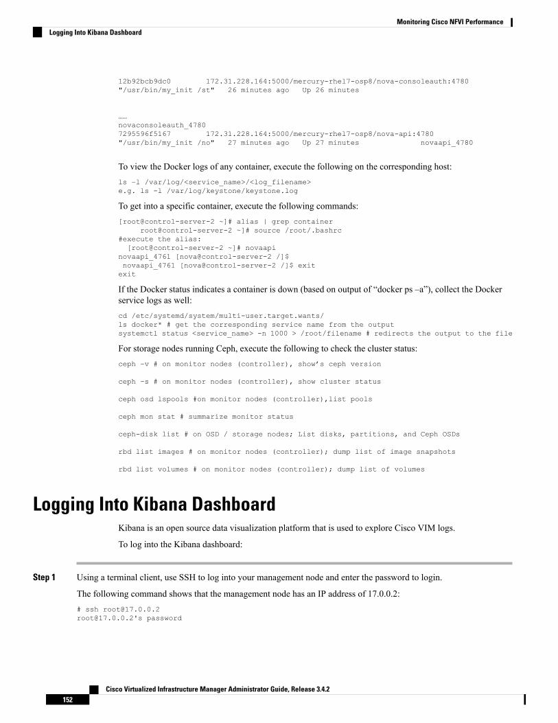
12b92bcb9dc0 172.31.228.164:5000/mercury-rhel7-osp8/nova-consoleauth:4780"/usr/bin/my_init /st" 26 minutes ago Up 26 minutes
……novaconsoleauth_47807295596f5167 172.31.228.164:5000/mercury-rhel7-osp8/nova-api:4780"/usr/bin/my_init /no" 27 minutes ago Up 27 minutes novaapi_4780
To view the Docker logs of any container, execute the following on the corresponding host:ls –l /var/log/<service_name>/<log_filename>e.g. ls -l /var/log/keystone/keystone.log
To get into a specific container, execute the following commands:[root@control-server-2 ~]# alias | grep container
root@control-server-2 ~]# source /root/.bashrc#execute the alias:[root@control-server-2 ~]# novaapi
novaapi_4761 [nova@control-server-2 /]$novaapi_4761 [nova@control-server-2 /]$ exitexit
If the Docker status indicates a container is down (based on output of “docker ps –a”), collect the Dockerservice logs as well:cd /etc/systemd/system/multi-user.target.wants/ls docker* # get the corresponding service name from the outputsystemctl status <service_name> -n 1000 > /root/filename # redirects the output to the file
For storage nodes running Ceph, execute the following to check the cluster status:ceph –v # on monitor nodes (controller), show’s ceph version
ceph –s # on monitor nodes (controller), show cluster status
ceph osd lspools #on monitor nodes (controller),list pools
ceph mon stat # summarize monitor status
ceph-disk list # on OSD / storage nodes; List disks, partitions, and Ceph OSDs
rbd list images # on monitor nodes (controller); dump list of image snapshots
rbd list volumes # on monitor nodes (controller); dump list of volumes
Logging Into Kibana DashboardKibana is an open source data visualization platform that is used to explore Cisco VIM logs.
To log into the Kibana dashboard:
Step 1 Using a terminal client, use SSH to log into your management node and enter the password to login.
The following command shows that the management node has an IP address of 17.0.0.2:# ssh [email protected]@17.0.0.2's password
Cisco Virtualized Infrastructure Manager Administrator Guide, Release 3.4.2152
Monitoring Cisco NFVI PerformanceLogging Into Kibana Dashboard

Step 2 To obtain the password, check whether VAULT feature is enabled. If it is enabled, refer to the Vault section, otherwiselocate the line containing KIBANA_PASSWORD in /root/installer-{tagid}/openstack-configs/secrets.yaml during SSH terminal session. Note the value of theKIBANA_PASSWORD as it is used in Step 4.cat /root/installer-{tag-id}/openstack-configs/secrets.yaml...KIBANA_PASSWORD: <note this value>...
Step 3 Navigate to the http://<management_node_ip_address>:5601.
Kibana uses the HTTPS + TLS to provide a secure connection between the browser and the Kibana service.
By default Kibana uses the certificate located at /var/www/mercury/mercury.<crt|key> or you can provide yourown certificates in /root/openstack-configs/ directory (using the same mercury.<crt|key> file names).
Note
If you are accessing Kibana for the first time, by default it shows self-signed certificate. Some browsers displaythe warning message Your connection is not private. Click Proceed to access the Kibana link. A window dialogbox appears.
Note
Step 4 Enter the Username and Password:
User Name: admin
Password: <value of ELK_PASSWORD from Step 2>. The Kibana dashboard appears which displays the Cisco VIMservice and installer logs.
Step 5 Choose the desired dashboard from the list.
Ensure that you do not use Management option on the left side.Note
Cisco Virtualized Infrastructure Manager Administrator Guide, Release 3.4.2153
Monitoring Cisco NFVI PerformanceLogging Into Kibana Dashboard

Figure 7: Lists of Dashboards
The following are the list of dashboards:
• Hostlogs Dashboard: Provides log information of the system for the cloud nodes. This displays entries from the hostlogs-* index in Elasticsearch. It contains the log from /var/log/messages file on each server.
• Installer Dashboard: Provides information about the management node and the installation process. It can only readuncompressed files. Hence, it reads the files prior to the cloud installation. This displays entries from the installer-*index in Elasticsearch.
• OpenStack Dashboard: (openstack-* index) Provides log information about all the OpenStack processes. This displaysentries from the openstack-* index in Elasticsearch.
• VMTP Dashboard: Provides log information about the VMTP runs performed against the cloud. It displays entriesfrom the vmtp-* index in Elasticsearch
For example, if you click OpenStack Dashboard link, the following screen appears.
Cisco Virtualized Infrastructure Manager Administrator Guide, Release 3.4.2154
Monitoring Cisco NFVI PerformanceLogging Into Kibana Dashboard

Figure 8: OpenStack Dashboard
Cisco Virtualized Infrastructure Manager Administrator Guide, Release 3.4.2155
Monitoring Cisco NFVI PerformanceLogging Into Kibana Dashboard

You can switch on from one dashboard to another by selecting the appropriate dashboard from the right top bar menu.
All dashboards have generic and specific fields.
The generic ones are:
• Title: It is seen at the top left of the page. Ite shows which dashboard is being displayed. For example: OpenStackDashboard.
• Filter bar : It is an input field where you can enter a query in the Lucene syntax format to filter the logs by specificfields (which depend on the fields for the index being selected).
• Time bar: Time is seen at the top right of the page. Time indicates the time schedule for the log information. Youcan modify the time to indicate absolute, relative time in the past or specify automatically refresh rates.
• Add a filter tab: Use this tab to introduce filters graphically.
For more information on using Kibana, see the Kibana documentation (Version 7.2).
Cisco VIM stores the OpenStack logs in Elasticsearch. The Elasticsearch snapshots all the indices (where the data isstored) which are rotated on a periodic basis. You may not see the older data in Kibana if the data is rotated out and/ordeleted.
Logs keep being visualized in Kibana as they are being updated in Elasticsearch on the Discover tab. To debug somethingon kibana, you can program the Kibana dashboard to auto-refresh at specific intervals (by default is off). To enableauto-refresh, click the Calendar drawing at the top right corner of the dashboard and program on Refresh every withdesired value. Configure the desired value by clicking the Start and Auto-refresh.
Cisco Virtualized Infrastructure Manager Administrator Guide, Release 3.4.2156
Monitoring Cisco NFVI PerformanceLogging Into Kibana Dashboard

Figure 9: Auto-Refresh
Once you program a Auto-refresh, the Calendar drawing is replaced by a Clock. Then you can click Stop button on thetop navigator bar to pause the refreshing of logs events. You can also select intervals that you want to see the logs from.
Also you can select an absolute or relative interval:
Cisco Virtualized Infrastructure Manager Administrator Guide, Release 3.4.2157
Monitoring Cisco NFVI PerformanceLogging Into Kibana Dashboard

a) Few examples on usage of filters in Openstack dashboard to gather useful information
• • On the Hostlogs Dashboard, in the Events by Host panel, choose a hostname and click the + or - symbolthat appears close to the hostname to include or exclude that server from the filter. Then, click the desiredslice on the Events By Service panel to add the docker service to the section.
• Under the Filter field, you see included sections in green and excluded sections in red.
Cisco Virtualized Infrastructure Manager Administrator Guide, Release 3.4.2158
Monitoring Cisco NFVI PerformanceLogging Into Kibana Dashboard

Figure 10: Hostlogs Dashboard
b) To know the log events in the Openstack for a given VM by writing the filter directly on the Search field:
The uuid of the VM is identified by executing openstack nova list or looking at the horizon website.Note
• Write the Lucene query (service: nova and service: neutron and message:<uuid>) in the Search field which ison top of the Dashboard. <uuid> is the number got from Horizon or nova list for the identifier of the instanceVM.
Figure 11: Search Query Page
Cisco Virtualized Infrastructure Manager Administrator Guide, Release 3.4.2159
Monitoring Cisco NFVI PerformanceLogging Into Kibana Dashboard

• For example, if you want to know the DHCP events of the Openstack Neutron, select the filters by clicking outercircle of pie chart:
• On the OpenStack Dashboard, the Openstack - Events By Service panel has a pie chart with the inner sectionfor the services and the outer sections for the service_subtypes. To add filters for selecting all the eventsin a service (for example, neutron), click on the inner section of the pie. To add filters for selecting theservice_subtypes (for example, dhcp), click on the outer circle of the pie.
Figure 12: Events by Service
• In the following window, click on Apply:
Cisco Virtualized Infrastructure Manager Administrator Guide, Release 3.4.2160
Monitoring Cisco NFVI PerformanceLogging Into Kibana Dashboard

• You can scroll down the OpenStack Dashboard to see the OpenStack - Errors and the OpenStack - Eventspanel.. The OpenStack - Errors panel displays the error messages. If there are no errors, the No resultsfound message is displayed.
Cisco Virtualized Infrastructure Manager Administrator Guide, Release 3.4.2161
Monitoring Cisco NFVI PerformanceLogging Into Kibana Dashboard

• Without knowing the Lucene Syntax, you can set the filter criteria in the Search field using the Add afilter + option.
Following are the steps to add a filter:
• Click Add a filter (+).
• Set the filter criteria by choosing appropriate label and operators from the drop-down lists, and enteringkeywords and click Save.
Figure 13: Add Filters Page
Set the filter criteria by choosing appropriate label and operators from the drop-down lists, and entering keywords.
Cisco Virtualized Infrastructure Manager Administrator Guide, Release 3.4.2162
Monitoring Cisco NFVI PerformanceLogging Into Kibana Dashboard

Figure 14: Choosing Appropriate Labels
Rotation of the Cisco VIM LogsCisco VIM stores all logs in Elasticsearch. Elasticsearch indices are rotated on a periodic basis to prevent thedisk space overflow by creating snapshots. The following lists show the Snapshots that are defined inopenstack_config.yaml:# vi ~/openstack-configs/openstack_config.yaml…# Elk rotation parameterselk_rotation_frequency: "monthly" # Available: "daily", "weekly", "fortnightly", "monthly"elk_rotation_size: 2 # Unit is in Gigabytes (float is allowed)elk_rotation_del_older: 10 # Delete older than 10 units (where units depends on thevalue set on elk_rotation_frequency)…
You can change the frequency of the rotation by changing the values. For more information on how to set theElasticsearch parameters throughVIMAPI or CLI, refer to the sectionReconfiguring Passwords and OpenStackConfigurations.
Cisco VIM uses the open source Elasticsearch Curator tool to manage the Elasticsearch indices and snapshots.For more information about Elasticsearch handles snapshots, look at the official information on Elastic.co(Version 5.4) https://www.elastic.co/guide/en/elasticsearch/client/curator/5.4/index.html.
Snapshot Manager Tool for ElasticsearchThe snapshot_mgr.sh tool wraps up the Elasticsearch Curator APIs. This tool helps you to access the snapshotsof the logs that are maintained by the Elasticsearch.
Run the following command to view the snapshot logs which is in the tools directory of the installer.# ./tools/snapshot_mgr.py --helpusage: snapshot_mgr.py [options]
Snapshot Manager handles snapshot logs maintained by Elasticsearch
Cisco Virtualized Infrastructure Manager Administrator Guide, Release 3.4.2163
Monitoring Cisco NFVI PerformanceRotation of the Cisco VIM Logs

optional arguments:-h, --help show this help message and exit--list display all snapshots in Elasticsearch--display GET_SS get details of the snapshot called <GET_SS>--create create a snapshot--restore RESTORE_SS restore snapshot named <RESTORE_SS>--delete DELETE_SS delete the snapshot called <DELETE_SS>--autodelete threshold_warning threshold_low threshold_high
autodelete snapshots until reach a disk spacethreshold
Snapshot list gives you the details of the snapshot performed on the system like the UUID, the name thesnapshot, end time of the snapshot, the state and the indices where it was snapshorted:# ./snapshot_mgr.py --list+------------------------+------------------------+---------------------+---------+-----------------------------------------------------------------------------------------------------------------------------------+----------+| uuid | snapshot_name | time_snapshot_ended | state |indices_snapshoted
| failures |+------------------------+------------------------+---------------------+---------+-----------------------------------------------------------------------------------------------------------------------------------+----------+| 6WGVUnKjQbGtZYzfC0yeEg | curator-20180304140002 | 2018-03-04 14:00:04 | SUCCESS |hostlogs-2018.03.02
| - || U4IVWJNnQW6PdFWxpRUc-A | curator-20180304150001 | 2018-03-04 15:00:04 | SUCCESS |hostlogs-2018.03.03
| - || 5RxDuhnETC6TW4XSPDNZlw | curator-20180304160001 | 2018-03-04 16:00:24 | SUCCESS |installer-2018.03.03, installer-2018.03.01, installer-2018.03.02, openstack-2018.03.02,hostlogs-2018.03.04, installer-2018.03.04 | - || k2gZYwLeRPO98bJZslI2pw | curator-20180305040002 | 2018-03-05 04:00:32 | SUCCESS |openstack-2018.03.03, hostlogs-2018.03.04, installer-2018.03.04
| - |+------------------------+------------------------+---------------------+---------+-----------------------------------------------------------------------------------------------------------------------------------+----------+
To view the details of the individual snapshot run the display option command.:# ./tools/snapshot_mgr.py --display curator-20180304140002{ 'duration_in_millis': 1944,'end_time': '2018-03-04T14:00:04.019Z','end_time_in_millis': 1520172004019,'failures': [],'indices': ['hostlogs-2018.03.02'],'shards': { 'failed': 0, 'successful': 5, 'total': 5},'snapshot': 'curator-20180304140002','start_time': '2018-03-04T14:00:02.075Z','start_time_in_millis': 1520172002075,'state': 'SUCCESS','uuid': '6WGVUnKjQbGtZYzfC0yeEg','version': '6.0.0','version_id': 6000099}
To create a snapshot run the following command:# ./tools/snapshot_mgr.py --createExecuting: curl PUThttp://localhost:9200/_snapshot/es_backup/3a9b90c2979b46bf9c7b3f9223074d5d?wait_for_completion=true-d{'indices': 'installer-*,hostlogs-*,openstack-*,vmtp-*', 'ignore_unavailable': 'true','include_global_state': 'false'}Response: {u'snapshot': {u'uuid': u'BSznQj1SQ9mjxxk9swTirQ', u'duration_in_millis': 46496,u'start_time':u'2018-03-06T16:37:49.774Z', u'shards': {u'successful': 35, u'failed': 0, u'total': 35},u'version_id': 6000099,u'end_time_in_millis': 1520354316270, u'state': u'SUCCESS', u'version': u'6.0.0',u'snapshot': u'3a9b90c2979b46bf9c7b3f9223074d5d', u'end_time': u'2018-03-06T16:38:36.270Z',
Cisco Virtualized Infrastructure Manager Administrator Guide, Release 3.4.2164
Monitoring Cisco NFVI PerformanceSnapshot Manager Tool for Elasticsearch

u'indices': [u'installer-2018.03.06', u'vmtp-2018.03.02', u'hostlogs-2018.03.06',u'hostlogs-2018.03.05',u'installer-2018.03.05', u'openstack-2018.03.05', u'openstack-2018.03.06'],u'failures': [], u'start_time_in_millis': 1520354269774}}
Run the following command to delete a snapshot:# ./tools/snapshot_mgr.py --delete 3a9b90c2979b46bf9c7b3f9223074d5dExecuting: curl DELETEhttp://localhost:9200/_snapshot/es_backup/3a9b90c2979b46bf9c7b3f9223074d5d -d NoneResponse: {u'acknowledged': True}
Restore the indices of a snapshot back to the Elasticsearch database by using the restore option. Run thefollowing command to restore:# ./snapshot_mgr.py --restore curator-20180306050001Executing: curl POSThttp://localhost:9200/hostlogs-2018.03.04,installer-2018.03.05,installer-2018.03.04,openstack-2018.03.04,hostlogs-2018.03.05,openstack-2018.03.02/_close -d None
Remote NFS Backup for Elasticsearch SnapshotsCisco VIM 2.4 supports remote NFS backup of the Elasticsearch snapshots. This allows you to empty thedisk space in the Elasticsearch snapshots. You can use the snapshot manager tool to manually create, list,show, and delete snapshots.
Remote NFS backup of the Elasticsearch snapshots feature can be configured by adding the following sectionto the setup_data.yaml configuration file:
ES_REMOTE_BACKUP: # Set if Elasticsearch backups can use a remote hostservice: 'NFS' # Set if an remote NFS server is usedremote_host: <ip_addr> # IP of the NFS serverremote_path: /root/es_remote # Path of location of the backups in the remote server
Important considerations about the remote NFS directory on the remote server (specified by the remote_pathconfig option):
• This directory allows the elasticsearch user (pid number 2020) and group mercury (pid 500) to read, andwrite. Otherwise, Curator cannot copy the snapshots to the remote NFS directory.
• It is good if the folder is empty and is used only by Cisco VIM.
• Cisco VIM does not delete the information in this directory after unbootstrap.
You can enable or disable this feature by running reconfiguration. With reconfiguration, you can change theremote_host ip or remote_path.
Network Performance Test with NFVBenchNFVBench is a network performance benchmarking tool integrated with Cisco VIM. For more details, referto NFVBench section of Chapter 1 in the admin guide for details.
Cisco Virtualized Infrastructure Manager Administrator Guide, Release 3.4.2165
Monitoring Cisco NFVI PerformanceRemote NFS Backup for Elasticsearch Snapshots

Customizing CVIM-MON DashboardWith CVIM-MON, you can create and modify dashboards.You must save the created or edited dashboardsin Grafana, and use CLI command on the management node to make the dashboards persistent across reboots.Though the modifications to built-in dashboards does not persist, you can customize the dashboards byexporting them and importing back as a new dashboard.
The command “ciscovim help cvimmon-dashboard” provides all the details associated with CVIMMONdashboard customization.
Following are the steps to get the Grafana edits in sync with the management node repository so that it persists(also called Persistence workflow).
Step 1 Create a new Dashboard or edit a custom dashboard on grafana UI.Step 2 Once all the new dashboards are ok, save it on grafana.Step 3 On the management node, execute the list to see the current status of custom dashboards:
# ciscovim cvimmon-dashboard list
Step 4 To sync all custom dashboards to the management repository and make it persist across reboots, execute the followingcommand:# ciscovim cvimmon-dashboard save
• To delete custom dashboard from the management node repository (if deleted from Grafana), execute thesteps associated to add followed by using save command that is augmented with “-f or –force” option.
• You can save all the custom dashboards on the Grafana server, to a specified directory only if that directoryis empty.
Note
Step 5 To export the custom dashboard to a directory, use the below command:# ciscovim cvimmon-dashboard save --dir-path <target_empty_dir_on_mgmt_node>
Step 6 To import back the saved dashboard from a specified directory with custom dashboard snapshots, execute the followingcommand:# ciscovim cvimmon-dashboard upload -–force --dir-path <dir_on_mgmt_node_where customization_exist>
The 'upload' command supports two options:
• -f or --force option: To delete all existing dashboards in the management node repository, and replace them with thenew custom dashboard.
• -p or --preserve: To preserve all dashboards and add new dashboard to the management node repository.
All the logs for cvimmon-dashboards are populated under /var/log/mercury_restapi/restapi.log file.
Cisco Virtualized Infrastructure Manager Administrator Guide, Release 3.4.2166
Monitoring Cisco NFVI PerformanceCustomizing CVIM-MON Dashboard

Cisco VIM MON Inventory Discovery API usage
API ClientBy default, Inventory_Discovery API is running on TCP port 8747 on the Cisco VIM management node.
The pod administrator can use the below tools offered on the management node:
1. API client: Available at / /var/lib/calipso/calipso_client.py
2. Data replication client: Available at /var/lib/calipso/calipso_replication_client.py
The API client provides options to interact with the Inventory API on any Cisco VIM pod.
On the Cisco VIM management node, aliases are available for both clients that run with calipso_client andcalipso_replication_client. You can use them on desktop and any CiscoVIM node, if the following pre-requisitesare met:
• python 2.7 or 3.5
• python requests
You can use any common REST query tool against the Inventory_Discovery API like curl, postman, httpie,and so on.
As the client source code is available, you can use it to understand the API and build similar client using otherlanguages. The main library used is ‘requests’ which can be obtained for more capabilities fromhttps://pypi.org/project/requests/
Running calipso_client --help provides details of the options available with API client.
Listed below are the key parameters of the tool:
• api_server API_SERVER - FQDN or IP address of the API Serve (default=localhost)
• api_port API_PORT - TCP Port exposed on the API Server (default=8747)
• api_passwordAPI_PASSWORD -API password (secret) used by the API Server (default=calipso_default)
• environment ENVIRONMENT - specify environment (pod) name configured on the API server(default=None)
• scan SCAN - actively discover the specific cloud environme -options:NOW/HOURLY/DAILY/WEEKLY/MONTHLY/YEARLY (default=None)
• method METHOD - method to use on the API server - options: get/post/delete/put (default=None)
• endpoint ENDPOINT - endpoint url extension to use on the API server - options: see API documentationfor endpoints (default=None)
• payload PAYLOAD - 'dict' string with parameters to send to the API - options: see API documentationper endpoint (default=None)
• page PAGE - a page number for retrieval (default=0)
• page_size PAGE_SIZE - a number of total objects listed per page (default=1000)
Cisco Virtualized Infrastructure Manager Administrator Guide, Release 3.4.2167
Monitoring Cisco NFVI PerformanceCisco VIM MON Inventory Discovery API usage

• version-get a reply back with calipso_client version.
The default parameters for api_server and api_port are used for cases where the client is used on the samemanagement node and the API server is running. For other cases, specific details are needed.
Environment name is used to describe the cloud facility endpoints managed by a specific entity. This namingconvention is used to support multiple cloud types.
Note
api_password is obtained through Cisco VIM secrets, either through cat /root/openstack-configs/secrets.yaml| grep CALIPSO_API_SERVICE_PWD cat /root/openstack-configs/secrets.yaml or when VAULT is usedin setup_data, then retrieve using vault api:
1. Get vault data from source /var/lib/calipso/calipso_config as vault token is rendered in calipso_config inplace of passwords if vault is defined.
2. Fetch Mongo password from curlhttp://$MGMT_IP:8200/v1/secret/data/cvim-secrets/CALIPSO_MONGO_SERVICE_PWD-H "X-Vault-Token: $VAULT_TOKEN
EnvironmentsThe first parameter that must be configured on the API server is an 'environment_config' that holds all theparameters forattributes of an 'environment'.
Environment_config is mandatory step before any scan discovery request can be made. The Environment isa generic cloud facility (of many types) to be discovered by the scanning server. In CVIM the Environmentdefinition holds all the configurations needed to interact with the cloud and discover it's content, for examplethe API endpoints, the admin passwords, the DB passwords, the SSH passwords/keys, the Message-BUSaccess url and credentials etc.
To obtain the list of environments available on a specific API server use the examples below (using curl orcalipso_client).:
The x-token is grabbed per session, allowing one-time password for secure communication with the server,any 'FQDN' or IP for API server can be used:
Token request using curl:
request:
curl -i -H "Content-Type: application/json" -H "Accept: application/json"-X POST -d '{"auth": {"methods": ["credentials"],"credentials": {"username": "calipso","password": "<CALIPSO_API_SERVICE_PWD> "}}}'http://localhost:8747/auth/tokens
response:{"issued_at": "2019-06-17T09:13:17.388124", "method": "credentials", "expires_at":"2019-06-18T09:13:17.388124","token": "a1fcff2023894061898a80fea6d5dd52", "_id": "5d0759ad6d07b1001214934b"}
As the underlying data is always json, it is recommended that each request has those two headers: Content-Typeapplication/json and Accept application/json.
Post request requires data in json format (-d in curl), Get requests need to include attributes in the url.
Cisco Virtualized Infrastructure Manager Administrator Guide, Release 3.4.2168
Monitoring Cisco NFVI PerformanceEnvironments

For the duration of the session ('expires_at' is returned) the value of the 'token' mustbe used for all requeststo the API server in a X-Auth-Token header, for example:
Environment request using curl:
request:
curl -i -H "Content-Type: application/json" -H "Accept: application/json" -H"X-Auth-Token: a7d13511ad44406281362d18366d99fc" -XGET http://localhost:8747/environment_configs
response:
{"environment_configs": [{"name": "cvim-cloud", "distribution": "Mercury"}]}
In the above example, GET is used ands url includes the values in case of the endpoint of /environment_configs.
The calipso_client handles all security needs automatically per request, and defaults to 'localhost' with defaultport and default username. You can give the API secret in a single call to get the same response
Environment request using calipso_client:
request:
calipso_client --api_server <br_api_mgmt_node> --api_password <CALIPSO_API_SERVICE_PWD>--method get --endpoint environment_configs
response:
{"environment_configs": [{"name": "cvim-cloud", "distribution": "Mercury"}"}]}
Once the name of the environment is known, you can make a SCAN request to discover cloud content.
ScansDiscovering the details (inventory and dependencies) of a specific environment is handled through scanrequests, scan requests can be made once (automated as needed)
or can be scheduled in-advance through scheduled scan request.
A prerequisite for any scan request is the existent of an environment_config (see validations above).
It is advised to kick off a Scan request once some configurations (instances, flavors, networks etc) has beenmade on the OpenStack environment.
Scan request and a successfully completed scan with full discovery is a mandatory step before any other querycan be made against the underlying data .
Here is an example of a one-time scan request, note that specifying an environment parameter is mandatoryfor scan request:Scan environment with calipso_client
Scan can take a while, depending on the size of the customer deployed resources on the OpenStack environment,if scan_status returns errors this needs to be debugged in the calipso_scan container (hint: look at the logs).
When scan_status is 'completed' and all Inventory, Links and Cliques has been discovered, the API can nowbe further used to grab data for analysis.
Scan can also be scheduled in advance, here is an example of a scheduled scan request:
Cisco Virtualized Infrastructure Manager Administrator Guide, Release 3.4.2169
Monitoring Cisco NFVI PerformanceScans

Scheduled-scan environment with calipso clientrequest:
calipso_client --api_password <CALIPSO_API_SERVICE_PWD> --environment cvim-cloud --scanWEEKLY
response:Scheduled scan at: 2019-06-24T12:49:35.332000Submitted at: 2019-06-17T05:49:34.426000Scan frequency: WEEKLY
For scheduled-scan the reply above provides details about the submitted time and the time of the next scheduledscan, the scan will be repeated at the frequency defined in the request.
To watch the details of any previously submitted scan request, use the /scans or /scheduled_scans as endpointfor the request, also environment name is mandatory to get scans per that environment:
Get historical scan and scheduled scans with calipso_client
request:calipso_client --api_password <CALIPSO_API_SERVICE_PWD>--method get --endpoint scans --environment cvim-cloud
response
{"scans": [
{"environment": "cvim-cloud","id": "5cdd9d7c6d07b10013ade7f2","status": "completed"
},{
"environment": "cvim-cloud","id": "5cddb2726d07b10013ade7ff","status": "completed"
},{
"environment": "cvim-cloud","id": "5cdff1476d07b10013ade80f","status": "running"
},]
}
request:
calipso_client --api_password <CALIPSO_API_SERVICE_PWD> --method get --endpointscheduled_scans --environment cvim-cloud
response:{
"scheduled_scans": [{
"environment": "cvim-cloud","freq": "WEEKLY","id": "5ce2f78e6d07b10013ade824","scheduled_timestamp": "2019-06-17T18:53:04.519000"
},{
"environment": "cvim-cloud","freq": "WEEKLY","id": "5d078c5e6d07b10012149382",
Cisco Virtualized Infrastructure Manager Administrator Guide, Release 3.4.2170
Monitoring Cisco NFVI PerformanceScheduled-scan environment with calipso client

"scheduled_timestamp": "2019-06-24T12:49:35.332000"},{
"environment": "cvim-cloud","freq": "WEEKLY","id": "5d078f3a6d07b10012149385","scheduled_timestamp": "2019-06-24T13:01:46.794000"
}]
}
The developer needs to make sure schedules are well known and there are not too many overlapping or toofrequent scans running against the same pod, during scan the data is cleared by default and scan can take sometime.
Note
PagingEach Inventory Discovery API server may hold many objects, depending on the customer deployment thiscan get quite large.
A mechanism of paging is available for all API queries to the server, supporting page number and page size,and engineer can use this mechanism to request a certain page from a big list of items on the server and requesttotal number of items to be listed per page (page_size).
Here is an example of request using paging, this example runs against the scans endpoint:
request:
calipso_client --api_password <CALIPSO_API_SERVICE_PWD>--method get --endpoint scans --environment cvim-cloud --page 0 --page_size 1
response:
{"scans": [
{"environment": "cvim-cloud","id": "5cdd9d7c6d07b10013ade7f2","status": "completed"
}]
}
request:
request:calipso_client --api_password <CALIPSO_API_SERVICE_PWD>--method get --endpoint scans --environment cvim-cloud --page 0 --page_size 2
response:
{"scans": [
{"environment": "cvim-cloud","id": "5cdd9d7c6d07b10013ade7f2",
Cisco Virtualized Infrastructure Manager Administrator Guide, Release 3.4.2171
Monitoring Cisco NFVI PerformancePaging

"status": "completed"},{
"environment": "cvim-cloud","id": "5cddb2726d07b10013ade7ff","status": "completed"
}]
}
InventoryEach Inventory Discovery API server runs on a specific pod/environment and holds the latest scan results forall objects and resources on that specific environment in the mongoDB 'calipso' in a special collection called'inventory'.
Query for inventory collection requires specifying an environment name and the common 'get' method.
The first logical query would be getting a list of all objects in that environment of a specific 'type'.
The list of supported object types can be grabbed from constants, here is the latest output for 3.4 release, withembedded explanations for the different types:
request:
calipso_client --api_password <CALIPSO_API_SERVICE_PWD>--methodget --endpoint constants --payload "{'name': 'object_types'}"
response:
request:calipso_client --api_password <CALIPSO_API_SERVICE_PWD>--method get --endpoint constants--payload "{'name': 'object_types'}"
response:{
"_id": "5cdd5f92bac311001dfbdbca","data": [
{"label": "vnic", --> virtual NIC attached to a VM or a Namespace (ex: tap
interface, virtualEthernet interface)"value": "vnic"
},{
"label": "vconnector", --> Local Bridge connecting VMs running inside thesame node )ex: linux_bridge , bridge_domain)
"value": "vconnector"},{
"label": "vedge", --> The device connecting VMs running inside a node to thephysical network (ex: VPP, OVS, SR-IOV)
"value": "vedge"},{
"label": "instance", --> VM"value": "instance"
},{
"label": "container", --> Container"value": "container"
},{
Cisco Virtualized Infrastructure Manager Administrator Guide, Release 3.4.2172
Monitoring Cisco NFVI PerformanceInventory

"label": "pod", --> K8s Pod"value": "pod"
},{
"label": "vservice", --> a Namespace, a process/device providing networkingservices(ex: DHCP, Router, Proxy)
"value": "vservice"},{
"label": "host_pnic", --> physical NIC on a node/host"value": "host_pnic"
},{
"label": "switch_pnic", --> physical NIC on a switch"value": "switch_pnic"
},{
"label": "network", --> the logical representation of an end-to-endcommunication ,like an OpenStack network
"value": "network"},{
"label": "switch", --> physical switching device"value": "switch"
},{
"label": "port", --> endpoint on a network"value": "port"
},{
"label": "otep", --> overlay tunneling endpoint, of many types (gre, vxlan,geneve etc ...)
"value": "otep"},{
"label": "agent", --> a process running on a host for control (ex: ovs agent,dhcp agent etc)
"value": "agent"},{
"label": "host", --> the node, physical server (or VM in nested environments)"value": "host"
},{
"label": "project", --> openstack's tenant"value": "project"
}],"id": "5cdd5f92bac311001dfbdbca","name": "object_types"
}
Querying for object detailsTo query the MongoDB for objects you need the following information:
• type of the specific object
• specific id of the object
Cisco Virtualized Infrastructure Manager Administrator Guide, Release 3.4.2173
Monitoring Cisco NFVI PerformanceQuerying for object details

The list of available objects of certain type with their names, ids and some generic attributes can be listed byquery to inventory endpoint for a paged list of certain object type, for example here we look for instances, 5per page:
request:
calipso_client --api_password <CALIPSO_API_SERVICE_PWD>--environment cvim-cloud--method get --endpoint inventory --page_size 5 --payload "{'type': 'instance'}"
response:
{"objects": [
{"environment": "cvim-cloud","id": "3959f44c-5e76-4648-a8b7-86039f6f9372","name": "gold-vm-1","name_path": "/cvim-cloud/Regions/RegionOne/Availability
Zones/aio-zone/cloud-aio-2/Instances/gold-vm-1",
"type": "instance"},{
"environment": "cvim-cloud","id": "5a3cb117-714a-4086-a414-c162dab583cc","name": "gold-vm-4","name_path": "/cvim-cloud/Regions/RegionOne/Availability
Zones/aio-zone/cloud-aio-2/Instances/gold-vm-4",
"type": "instance"}
]
All objects in the API have a unique id, this id is listed in the query for any object type list, this should thenbe used to grab the more detailed data available for specific object, for example:
request:
calipso_client --api_password <CALIPSO_API_SERVICE_PWD>--environment cvim-cloud --methodget --endpointinventory --payload "{'id': 'fb7cb28a-08aa-497e-9d70-5dae755c18a2'}"
response:
{"_id": "5d078b2184c6929f454701d8","accessIPv4": "","accessIPv6": "","addresses": {
"flat-network": [{
"OS-EXT-IPS-MAC:mac_addr": "fa:16:3e:db:29:4a","OS-EXT-IPS:type": "fixed","addr": "192.168.90.4","version": 4
}]
},Etc….etc….
"revision_number": 0,"security_group_id": "ce305d1f-4d02-4759-89b7-a5f92446bb8d","tags": [],"tenant_id": "c7488606a2ac40ccbd79172ba1ae8b93","updated_at": "2019-05-16T14:29:13Z"
}
Cisco Virtualized Infrastructure Manager Administrator Guide, Release 3.4.2174
Monitoring Cisco NFVI PerformanceQuerying for object details

],"tags": [],"tenant_id": "c7488606a2ac40ccbd79172ba1ae8b93","updated_at": "2019-05-16T14:29:13Z"
}},"show_in_tree": true,"task_state": null,"tenant_id": "c7488606a2ac40ccbd79172ba1ae8b93","terminated_at": null,"type": "instance","user_id": "5d0068c060d146789c3bbaf085e573ed","uuid": "fb7cb28a-08aa-497e-9d70-5dae755c18a2","vm_state": "active","volumes_attached": []
}
Inventory is offering dat discovered fromOpenStack APIs , Databases and also from host-level CLI commands.
LinksLinks represent relationships, a certain connection between specific object and another object, for examplean instance connected to it's vnic or a host_pnic connected to a network.
Each Inventory Discovery API server runs on a specific pod/environment and holds the latest scan results forall links on that specific environment in the mongoDB 'calipso' in a special collection called 'links'.
Query for links collection requires specifying an environment name and the common 'get' method.
The first logical query would be getting a list of all links in that environment of a specific 'link_type'.
The list of supported link_types can be grabbed from constants, here is the latest output for 3.4 release, withembedded explanations for the different types:
request:
calipso_client --api_password <CALIPSO_API_SERVICE_PWD>--method get --endpoint constants --payload "{'name': 'link_types'}"
response:
{"data": [
{"label": "instance-vnic","value": "instance-vnic"
},{
"label": "vnic-instance","value": "vnic-instance"
},{
"label": "vnic-vconnector","value": "vnic-vconnector"
},}, etc ..etc ..{
"label": "host_pnic-switch_pnic","value": "host_pnic-switch_pnic"
Etc…etc.."id": "5cdd5f92bac311001dfbdbc7","name": "link_types"
}
Cisco Virtualized Infrastructure Manager Administrator Guide, Release 3.4.2175
Monitoring Cisco NFVI PerformanceLinks

Querying for link detailsTo query the MongoDB for links you need the following information:
• link_type of the specific link
• specific id of the link
The list of available links of a certain type with their names, ids and some generic attributes can be listed byquery to links endpoint for a paged list of certain link type, for example here we look for instance-vnic links,5 per page:
request:
calipso_client --api_password <CALIPSO_API_SERVICE_PWD>--environment cvim-cloud --methodget --endpoint links --page_size 5 --payload "{'link_type': 'instance-vnic'}"
response:
{"links": [
{"environment": "cvim-cloud","host": "cloud-aio-2","id": "5d078b4184c6929f454705a3","link_name": "flat-network","link_type": "instance-vnic"
},{
"environment": "cvim-cloud","host": "cloud-aio-2","id": "5d078b4184c6929f454705a8","link_name": "flat-network","link_type": "instance-vnic"
},Etc…etc…}
Connectivity AnalysisAll links in the API have a unique id, this id is listed in the query for any link type list, this should then beused to grab the more detailed data available for specific link, for example:
request:
request:calipso_client --api_password <CALIPSO_API_SERVICE_PWD>--environment cvim-cloud --method get --endpoint links --payload "{'id': '5d078b4184c6929f454705b2'}"
response:{
"attributes": {"network": "12772133-b894-4a06-8cfb-1f01154721f1"
},"environment": "cvim-cloud","host": "cloud-aio-1","id": "5d078b4184c6929f454705b2","implicit": false,"link_name": "flat-network",
Cisco Virtualized Infrastructure Manager Administrator Guide, Release 3.4.2176
Monitoring Cisco NFVI PerformanceQuerying for link details
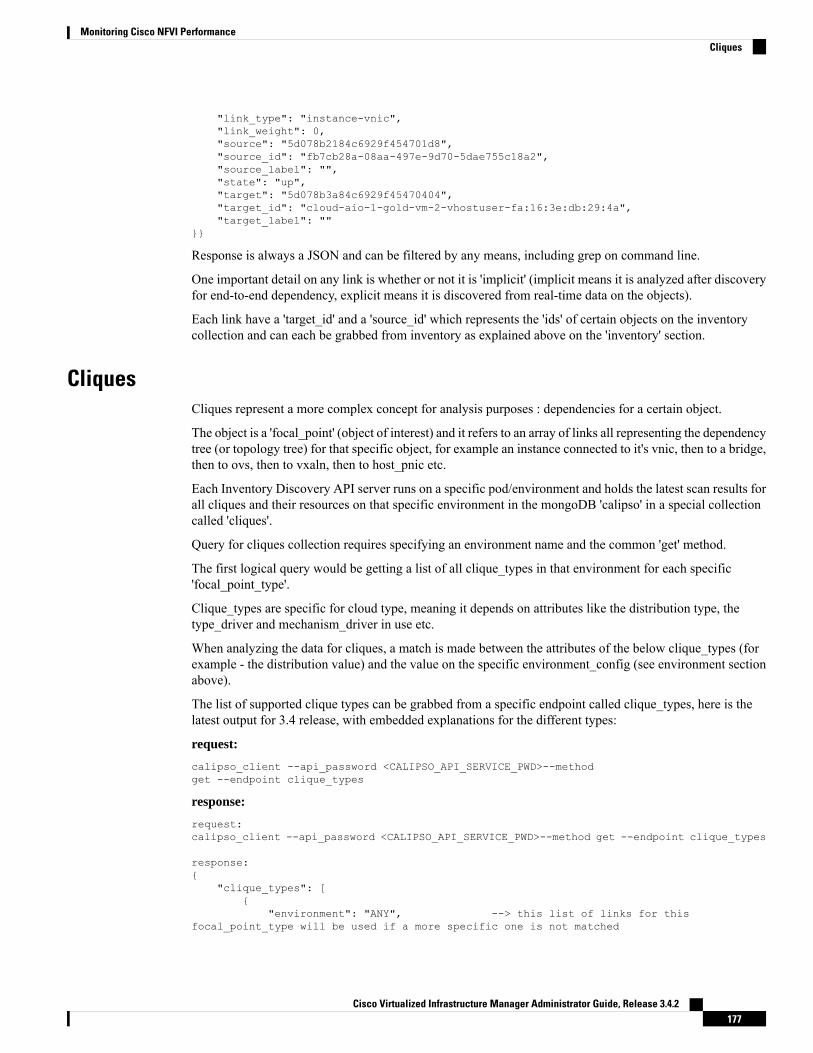
"link_type": "instance-vnic","link_weight": 0,"source": "5d078b2184c6929f454701d8","source_id": "fb7cb28a-08aa-497e-9d70-5dae755c18a2","source_label": "","state": "up","target": "5d078b3a84c6929f45470404","target_id": "cloud-aio-1-gold-vm-2-vhostuser-fa:16:3e:db:29:4a","target_label": ""
}}
Response is always a JSON and can be filtered by any means, including grep on command line.
One important detail on any link is whether or not it is 'implicit' (implicit means it is analyzed after discoveryfor end-to-end dependency, explicit means it is discovered from real-time data on the objects).
Each link have a 'target_id' and a 'source_id' which represents the 'ids' of certain objects on the inventorycollection and can each be grabbed from inventory as explained above on the 'inventory' section.
CliquesCliques represent a more complex concept for analysis purposes : dependencies for a certain object.
The object is a 'focal_point' (object of interest) and it refers to an array of links all representing the dependencytree (or topology tree) for that specific object, for example an instance connected to it's vnic, then to a bridge,then to ovs, then to vxaln, then to host_pnic etc.
Each Inventory Discovery API server runs on a specific pod/environment and holds the latest scan results forall cliques and their resources on that specific environment in the mongoDB 'calipso' in a special collectioncalled 'cliques'.
Query for cliques collection requires specifying an environment name and the common 'get' method.
The first logical query would be getting a list of all clique_types in that environment for each specific'focal_point_type'.
Clique_types are specific for cloud type, meaning it depends on attributes like the distribution type, thetype_driver and mechanism_driver in use etc.
When analyzing the data for cliques, a match is made between the attributes of the below clique_types (forexample - the distribution value) and the value on the specific environment_config (see environment sectionabove).
The list of supported clique types can be grabbed from a specific endpoint called clique_types, here is thelatest output for 3.4 release, with embedded explanations for the different types:
request:
calipso_client --api_password <CALIPSO_API_SERVICE_PWD>--methodget --endpoint clique_types
response:
request:calipso_client --api_password <CALIPSO_API_SERVICE_PWD>--method get --endpoint clique_types
response:{
"clique_types": [{
"environment": "ANY", --> this list of links for thisfocal_point_type will be used if a more specific one is not matched
Cisco Virtualized Infrastructure Manager Administrator Guide, Release 3.4.2177
Monitoring Cisco NFVI PerformanceCliques

"focal_point_type": "instance", --> this object type (instance) will dependon the below list of link_types
"id": "5cdd5f92bac311001dfbdbaa","link_types": [
"instance-vnic","vnic-vconnector","vconnector-vedge","vedge-otep","otep-vconnector","vconnector-host_pnic","host_pnic-network"
],"name": "instance"
},{
"environment": "ANY", --> this list of links for thisfocal_point_type will be used if a more specific one is not matched
"focal_point_type": "vservice", -> this object type (vservice) will dependon the below list of link_types
"id": "5cdd5f92bac311001dfbdbab","link_types": [
"vservice-vnic","vnic-vedge","vedge-otep","otep-vconnector","vconnector-host_pnic","host_pnic-network"
],"name": "vservice"
}{
"distribution": "Mercury", --> for a more specific distribution of thistype (Mercury) the below links will be used for this focal_point_type
"environment": "","focal_point_type": "instance","id": "5cdd5f92bac311001dfbdbb2","link_types": [
"instance-vnic","vnic-vconnector","vconnector-vedge","vedge-host_pnic","host_pnic-network"
],"name": "instance_vconnector_clique"
},{
"distribution": "Mercury","environment": "","focal_point_type": "vservice","id": "5cdd5f92bac311001dfbdbb3","link_types": [
"vservice-vnic","vnic-vconnector","vconnector-vedge","vedge-host_pnic","host_pnic-network"
],"name": "vservice_vedge_clique"
},{
"distribution": "Mercury","environment": "","focal_point_type": "network","id": "5cdd5f92bac311001dfbdbb4",
Cisco Virtualized Infrastructure Manager Administrator Guide, Release 3.4.2178
Monitoring Cisco NFVI PerformanceCliques

"link_types": ["network-host_pnic","host_pnic-vedge","vedge-vconnector","vedge-vnic","vconnector-vnic","vnic-instance","vnic-vservice"
],"name": "network"
}, etc…etc…}
]}
Querying for clique detailsTo query the MongoDB for cliques you need the following information:
• focal_point_type for the specific clique
• specific focal_point_object_id of the clique
• id of the specific clique
The actual logical flow of getting full clique details is listed further below in this section:
The list of available cliques with the specific focal_point ids and some generic attributes can be listed by queryto cliques endpoint for a paged list of certain clique type, for example here we look for instance as focal_point,and list 5 per page:
request:
calipso_client --api_password <CALIPSO_API_SERVICE_PWD>--method get --endpoint cliques --environment cvim-cloud --payload"{'focal_point_type': 'instance'}" --page_size 5
All objects in the API have a unique id, this id is listed in the query for any clique type list, this should thenbe used to grab the more detailed data available for specific clique, for example:
response:
request:calipso_client --api_password <CALIPSO_API_SERVICE_PWD>--environment cvim-cloud --methodget --endpoint cliques --payload "{'id': '5d07d78084c6929f454a99fa'}"
response:{
"clique_type": "5cdd5f92bac311001dfbdbb2","constraints": {
"network": ["e4ab9d18-21a3-4241-b220-5070753251ec"
]},"environment": "cvim-cloud","focal_point": "5d07d76784c6929f454a881a","focal_point_object_id": "ae3fa0a0-e21b-47c1-b531-9a86f7cdd602","focal_point_type": "instance","id": "5d07d78084c6929f454a99fa","links": [
"5d07d77e84c6929f454a8ba1","5d07d77e84c6929f454a8c50","5d07d77e84c6929f454a8d4c",
Cisco Virtualized Infrastructure Manager Administrator Guide, Release 3.4.2179
Monitoring Cisco NFVI PerformanceQuerying for clique details

"5d07d77e84c6929f454a8d52","5d07d77e84c6929f454a8d5f","5d07d77e84c6929f454a8d64","5d07d77e84c6929f454a8d6e","5d07d77e84c6929f454a8ecb","5d07d77e84c6929f454a8ed0","5d07d77e84c6929f454a8ec6","5d07d77e84c6929f454a8ed5"
],"links_detailed": [
{"_id": "5d07d77e84c6929f454a8ba1","attributes": {
"network": "e4ab9d18-21a3-4241-b220-5070753251ec"},"environment": "cvim-cloud","host": "cloud-compute-1","implicit": false,"link_name": "my-network","link_type": "instance-vnic","link_weight": 0,"source": "5d07d76784c6929f454a881a","source_id": "ae3fa0a0-e21b-47c1-b531-9a86f7cdd602","source_label": "","state": "up","target": "5d07d77a84c6929f454a8a44","target_id": "cloud-compute-1-test-vm-2-vhostuser-fa:16:3e:0b:6e:b2","target_label": ""
}, etc…etc..],"nodes": [
"5d07d76b84c6929f454a884c","5d07d77a84c6929f454a8a44","5d07d77b84c6929f454a8aaf","5d07d77b84c6929f454a8ab6","5d07d77b84c6929f454a8aa8","5d07d77b84c6929f454a8abd","5d07d74384c6929f454a8398","5d07d76b84c6929f454a885a","5d07d76784c6929f454a881a"
]}
Collections SchemeWhile not restricted to any specific scheme, each object, based on its type, can hold lots of attributes, specificto its technology domain, but several attributes are mandatory on the server, for accuracy, analysis andUI/Front-End common requirements.
The following main collections are always deployed with the DB for Inventory Discovery:
• api_tokens - not exposed externally, used to hold session tokens for interaction with the DB
• attributes_for_hover_on_data - not exposed externally, used for UI to control the display of specificattributes from a specific object
• clique_constraints - not exposed externally, defined the depth of the topology discovery (see 'constraints'in clique attributes)
• clique_types - exposed externally, defines the type of topology / dependency tree available on eachspecific cloud / environment type
Cisco Virtualized Infrastructure Manager Administrator Guide, Release 3.4.2180
Monitoring Cisco NFVI PerformanceCollections Scheme

• cliques - exposed externally, holds the details of each dependency tree for each object in the inventory
• connection_tests - not exposed externally, holds the requests for testing a connection to API endpoints,DBs and CLI on hosts
• constants - exposed externally, holds the list of all supported objects and thier attributes for the differentclouds
• environment_options - not exposed externally, holds lists of all supported environment configurationsusedby UI
• environments_config - exposed externally, the real time details of how to interact and communicate witha specific cloud / environment
• inventory - exposed externally, holds the list of all object discovered in real time from the cloudenvironment
• link_types - exposed externally, holds the list of all supported link types
• links - exposed externally, holds the list of all links discovered in real time from the cloud environment
• messages - exposed externally, holds the list of all messages and events discovered in real time from thecloud environment
• monitoring_config - not exposed externally, holds the list of actual monitoring configurations for thedifferent clouds
• monitoring_config_templates - not exposed externally, holds the list of supported monitoringconfigurations templates for the different clouds
• network_agent_types - not exposed externally, holds the list of all supported network agents (per cloudrelease)
• roles - not exposed externally, used for role definitions for RBAC to access the system with LDAP orInternal
• scans - exposed externally, holds the list of requested scans to discover, per cloud environment
• scheduled_scans - exposed externally, holds the list of requested scheduled scans to discover, per cloudenvironment
• statistics - not exposed externally, holds the list of metrics and statistics over time for sensu with TSDBcases
• supported_environments - not exposed externally, holds the list of all supported variances for the differentclouds (distributions, type_drivers etc)
• user_settings - not exposed externally, used for user authorization definitions for RBAC to access thesystem with LDAP or Internal
• users - not exposed externally, used for user definitions for RBAC to access the system with LDAP orInternal
Mandatory attributes for inventory objectThe following attributes are mandatory per colection, while each object, linkd and clique based on it's typehave many more additional attributes:
Cisco Virtualized Infrastructure Manager Administrator Guide, Release 3.4.2181
Monitoring Cisco NFVI PerformanceMandatory attributes for inventory object

• Mandatory attributes for inventory objects
• environment - name of cloud environment where this object was discovered
• id - unique identification across all the inventory
• type - specific type of the object (ex: instance, switch, host etc)
• name and object_name - none-unique identification as name and per-environment unique name asobject_name
• show_in_tree - boolean , if object needs to be presented in a tree
• name_path - clear placement in the herarchical tree, per environment/cloud type, based on names
• id_path - clear placement in the herarchical tree, per environment/cloud type, based on ids
• parent - name of the parent object (like instances under a certain host, ports under a certain network,containers under a certain pod etc)
• parent_id - id of the parent object
• parent_type - object type of the parent object
• launched_at - when this object was discovered last
• created_at - when this object was created
• state - for monitoring purposes, several values apply per type
• host/switch - (one of which mandatory) - physical device that runs this object (more attributes apply fornested environments)
••
Mandatory attributes for links• environment - name of cloud environment where this link was discovered
• id - unique identification across all the links
• link_type - specific link type of the link (ex: instance-vnic, switch_pnic-host_pnic etc) per supportedlink_types in constants
• link_name - per-environment unique name for the link
• state - for monitoring purposes, several values apply per type
• source_id - id of the source object of this link
• link_weight - level of importance per clique, defaults to 0
• implicit - boolean value, represent if link is real-time discovered per data presented in inventory oranalyzed through other links
• host/switch - (one of which mandatory) - physical device that runs this link (more attributes apply fornested environments
Cisco Virtualized Infrastructure Manager Administrator Guide, Release 3.4.2182
Monitoring Cisco NFVI PerformanceMandatory attributes for links

Mandatory attributes for cliques• environment - name of cloud environment where this link was discovered
• id - unique identification across all the links
• focal_point - mongoDB id of the specific 'object of intrest' that is the source of the listed links (ex: instanceis a start of a list of links: instance-vnic, vnic-vconnector etc) per supported clique_types
• focal_point_object_id - inventory id of the specific focal_point on the inventory
• nodes - all the objects that are part of the clqiue (for UI graphing purposes)
• links - all the links that are part of the clqiue (for UI graphing purposes)
• clique_type - the type of the clique, per the supported clique_types
• links_detailed - all details per link
• constraints - which object type is the final 'depth' (lowest, last) object in the specific topology tree
Cisco Virtualized Infrastructure Manager Administrator Guide, Release 3.4.2183
Monitoring Cisco NFVI PerformanceMandatory attributes for cliques

Cisco Virtualized Infrastructure Manager Administrator Guide, Release 3.4.2184
Monitoring Cisco NFVI PerformanceMandatory attributes for cliques

C H A P T E R 4Managing Cisco NFVI Security
The following topics describe Cisco NFVI network and application security and best practices.
• Verifying Management Node Network Permissions, on page 185• Verifying Management Node File Permissions, on page 186• Viewing Administrator Access Attempts, on page 186• Verifying SELinux, on page 187• Validating Port Listening Services, on page 187• Validating Non-Root Users for OpenStack Services, on page 188• Verifying Password Strength, on page 188• Reconfiguring Passwords and OpenStack Configurations, on page 189• Reconfiguring Glance Client Key for Central Ceph Cluster, on page 195• Enabling Cloud Settings, on page 195• Enabling NFVIMON Post Pod Installation, on page 196• Enabling CVIMMON Post Pod Installation, on page 199• Reconfiguring CIMC/BMC Password on Existing Installation, on page 199• Increasing/Decreasing Provider and Tenant VLAN Ranges, on page 201• Fernet Key Operations, on page 202• Managing Certificates, on page 202• Reconfiguring TLS Certificates, on page 203• Verifying TLS Certificates, on page 204• LDAP/AD support with Keystone v3, on page 205• Moving Netapp transport from http to https, on page 206• Enabling Cinder Volume Encryption in Cisco VIM, on page 207• Replacing ACI Controller in Cisco VIM, on page 207• Hardening Cisco VIM Deployment, on page 208• Cisco VIM Monitor Alerting Rules Customization, on page 211• Alert Manager and Receiver Customization, on page 215
Verifying Management Node Network PermissionsThe Cisco NFVI management node stores sensitive information related to Cisco NFVI operations. Access tothe management node can be restricted to requests coming from IP addresses known to be used byadministrators. The administrator source networks is configured in the setup file, under [NETWORKING]using the admin_source_networks parameter.
Cisco Virtualized Infrastructure Manager Administrator Guide, Release 3.4.2185

To verify this host based firewall setting, log into the management node as an admin user and list the rulescurrently enforces by iptables. Verify that the source networks match the values configured. If no sourcenetworks have been configured, then all source traffic is allowed. However, note that only traffic destined toports with known admin services is allowed to pass. The admin_source_networks value can be set at installtime or changed through a reconfigure.[root@control-server-1 ~]# iptables –listChain INPUT (policy ACCEPT)target prot opt source destinationACCEPT icmp -- anywhere anywhereACCEPT tcp -- 10.0.0.0/8 anywhere tcp dpt:sshACCEPT tcp -- 172.16.0.0/12 anywhere tcp dpt:sshACCEPT tcp -- 10.0.0.0/8 anywhere tcp dpt:httpsACCEPT tcp -- 172.16.0.0/12 anywhere tcp dpt:httpsACCEPT tcp -- 10.0.0.0/8 anywhere tcp dpt:4979ACCEPT tcp -- 172.16.0.0/12 anywhere tcp dpt:4979ACCEPT tcp -- 10.0.0.0/8 anywhere tcp dpt:esmagentACCEPT tcp -- 172.16.0.0/12 anywhere tcp dpt:esmagentACCEPT tcp -- 10.0.0.0/8 anywhere tcp dpt:8008ACCEPT tcp -- 172.16.0.0/12 anywhere tcp dpt:8008ACCEPT tcp -- 10.0.0.0/8 anywhere tcp dpt:copyACCEPT tcp -- 172.16.0.0/12 anywhere tcp dpt:copyACCEPT tcp -- 10.0.0.0/8 anywhere tcp dpt:22250ACCEPT tcp -- 172.16.0.0/12 anywhere tcp dpt:22250ACCEPT all -- anywhere anywhere state RELATED,ESTABLISHEDDROP all -- anywhere anywhere
Verifying Management Node File PermissionsThe Cisco NFVI management node stores sensitive information related to Cisco NFVI operations. These filesare secured by strict file permissions. Sensitive files include secrets.yaml, openrc, *.key, and *.pem. To verifythe file permissions, log into the management node as an admin user and list all of the files in the~/openstack-configs/ directory. Verify that only the owner has read and write access to these files. For example:[root@control-server-1 ~]# ls –l ~/openstack-configstotal 172-rw-------. 1 root root 3272 Jun 21 17:57 haproxy.key-rw-------. 1 root root 5167 Jun 21 17:57 haproxy.pem-rw-------. 1 root root 223 Aug 8 18:09 openrc-rw-------. 1 root root 942 Jul 6 19:44 secrets.yaml
[…]
Viewing Administrator Access AttemptsAs the UCS servers are part of the critical Cisco NFVI infrastructure, Cisco recommends monitoringadministrator login access periodically.
To view the access attempts, use the journalctl command to view the log created by ssh. For example:[root@control-server-1 ~]# journalctl –u sshd-- Logs begin at Tue 2016-06-21 17:39:35 UTC, end at Mon 2016-08-08 17:25:06 UTC. --Jun 21 17:40:03 hh23-12 systemd[1]: Started OpenSSH server daemon.Jun 21 17:40:03 hh23-12 systemd[1]: Starting OpenSSH server daemon...Jun 21 17:40:03 hh23-12 sshd[2393]: Server listening on 0.0.0.0 port 22.Jun 21 17:40:03 hh23-12 sshd[2393]: Server listening on :: port 22.Jun 21 17:40:43 hh23-12 sshd[12657]: Connection closed by 171.70.163.201 [preauth]
Cisco Virtualized Infrastructure Manager Administrator Guide, Release 3.4.2186
Managing Cisco NFVI SecurityVerifying Management Node File Permissions

Jun 21 17:41:13 hh23-12 sshd[12659]: Accepted password for root from 171.70.163.201 port40499Jun 21 17:46:41 hh23-12 systemd[1]: Stopping OpenSSH server daemon...Jun 21 17:46:41 hh23-12 sshd[2393]: Received signal 15; terminating.Jun 21 17:46:41 hh23-12 systemd[1]: Started OpenSSH server daemon.Jun 21 17:46:41 hh23-12 systemd[1]: Starting OpenSSH server daemon...Jun 21 17:46:41 hh23-12 sshd[13930]: Server listening on 0.0.0.0 port 22.Jun 21 17:46:41 hh23-12 sshd[13930]: Server listening on :: port 22.Jun 21 17:50:45 hh23-12 sshd[33964]: Accepted password for root from 171.70.163.201 port40545Jun 21 17:56:36 hh23-12 sshd[34028]: Connection closed by 192.168.212.20 [preauth]Jun 21 17:57:08 hh23-12 sshd[34030]: Accepted publickey for root from 10.117.212.20 port62819Jun 22 16:42:40 hh23-12 sshd[8485]: Invalid user user1 from 10.117.212.20Jun 22 16:42:40 hh23-12 sshd[8485]: input_userauth_request: invalid user user1 [preauth]s
Verifying SELinuxTominimize the impact of a security breach on a Cisco NFVI server, the Cisco VM enables SELinux (SecurityEnhanced Linux) to protect the server resources. To validate that SELinux is configured and running inenforcing mode, use the sestatus command to view the status of SELinux and verify that its status is enabledand in enforcing mode. For example:[root@mgmt1 ~]# /usr/sbin/sestatus -vSELinux status: enabledSELinuxfs mount: /sys/fs/selinuxSELinux root directory: /etc/selinuxLoaded policy name: targetedCurrent mode: enforcingMode from config file: permissivePolicy MLS status: enabledPolicy deny_unknown status: allowedMax kernel policy version: 28
Validating Port Listening ServicesTo prevent access by unauthorized users and processes, Cisco NFVI has no extra services listening on networkports. To verify this, use the netstat -plnt command to get a list of all services listening on the node and verifythat no unauthorized services are listening. For example:[root@-control-server-1 ~]# netstat -plntActive Internet connections (only servers)Proto Recv-Q Send-Q Local Address Foreign Address State PID/Programnametcp 0 0 23.23.4.101:8776 0.0.0.0:* LISTEN 24468/python2tcp 0 0 23.23.4.101:5000 0.0.0.0:* LISTEN 19874/httpdtcp 0 0 23.23.4.101:5672 0.0.0.0:* LISTEN 18878/beam.smp
tcp 0 0 23.23.4.101:3306 0.0.0.0:* LISTEN 18337/mysqldtcp 0 0 127.0.0.1:11211 0.0.0.0:* LISTEN 16563/memcachedtcp 0 0 23.23.4.101:11211 0.0.0.0:* LISTEN 16563/memcachedtcp 0 0 23.23.4.101:9292 0.0.0.0:* LISTEN 21175/python2tcp 0 0 23.23.4.101:9999 0.0.0.0:* LISTEN 28555/pythontcp 0 0 23.23.4.101:80 0.0.0.0:* LISTEN 28943/httpdtcp 0 0 0.0.0.0:4369 0.0.0.0:* LISTEN 18897/epmd
tcp 0 0 127.0.0.1:4243 0.0.0.0:* LISTEN 14673/docker
Cisco Virtualized Infrastructure Manager Administrator Guide, Release 3.4.2187
Managing Cisco NFVI SecurityVerifying SELinux

tcp 0 0 0.0.0.0:22 0.0.0.0:* LISTEN 2909/sshd
tcp 0 0 23.23.4.101:4567 0.0.0.0:* LISTEN 18337/mysqld
tcp 0 0 23.23.4.101:15672 0.0.0.0:* LISTEN 18878/beam.smp
tcp 0 0 0.0.0.0:35672 0.0.0.0:* LISTEN 18878/beam.smp
tcp 0 0 127.0.0.1:25 0.0.0.0:* LISTEN 4531/master
tcp 0 0 23.23.4.101:35357 0.0.0.0:* LISTEN 19874/httpd
tcp 0 0 23.23.4.101:8000 0.0.0.0:* LISTEN 30505/python
tcp 0 0 23.23.4.101:6080 0.0.0.0:* LISTEN 27996/python2
tcp 0 0 23.23.4.101:9696 0.0.0.0:* LISTEN 22396/python2
tcp 0 0 23.23.4.101:8004 0.0.0.0:* LISTEN 30134/python
tcp 0 0 23.23.4.101:8773 0.0.0.0:* LISTEN 27194/python2
tcp 0 0 23.23.4.101:8774 0.0.0.0:* LISTEN 27194/python2
tcp 0 0 23.23.4.101:8775 0.0.0.0:* LISTEN 27194/python2
tcp 0 0 23.23.4.101:9191 0.0.0.0:* LISTEN 20752/python2
tcp6 0 0 :::9200 :::* LISTEN 18439/xinetd
tcp6 0 0 :::4369 :::* LISTEN 18897/epmd
tcp6 0 0 :::22 :::* LISTEN 2909/sshd
tcp6 0 0 ::1:25 :::* LISTEN 4531/master
Validating Non-Root Users for OpenStack ServicesTo prevent unauthorized access, Cisco NFVI runs OpenStack processes as a non-root user. To verify OpenStackprocesses are not running as root, use the ps command to get a list of all node processes. In the followingexample the user is 162:[root@control-server-1 ~]# ps -aux | grep nova-api162 27194 0.6 0.0 360924 132996 ? S Aug08 76:58 /usr/bin/python2/usr/bin/nova-api162 27231 0.0 0.0 332192 98988 ? S Aug08 0:01 /usr/bin/python2/usr/bin/nova-api162 27232 0.0 0.0 332192 98988 ? S Aug08 0:01 /usr/bin/python2/usr/bin/nova-api162 27233 0.0 0.0 332192 98988 ? S Aug08 0:01 /usr/bin/python2/usr/bin/nova-api
Verifying Password StrengthCisco NFVI passwords can be generated in two ways during installation:
• The Cisco NFVI installer generates unique passwords automatically for each protected service.
Cisco Virtualized Infrastructure Manager Administrator Guide, Release 3.4.2188
Managing Cisco NFVI SecurityValidating Non-Root Users for OpenStack Services
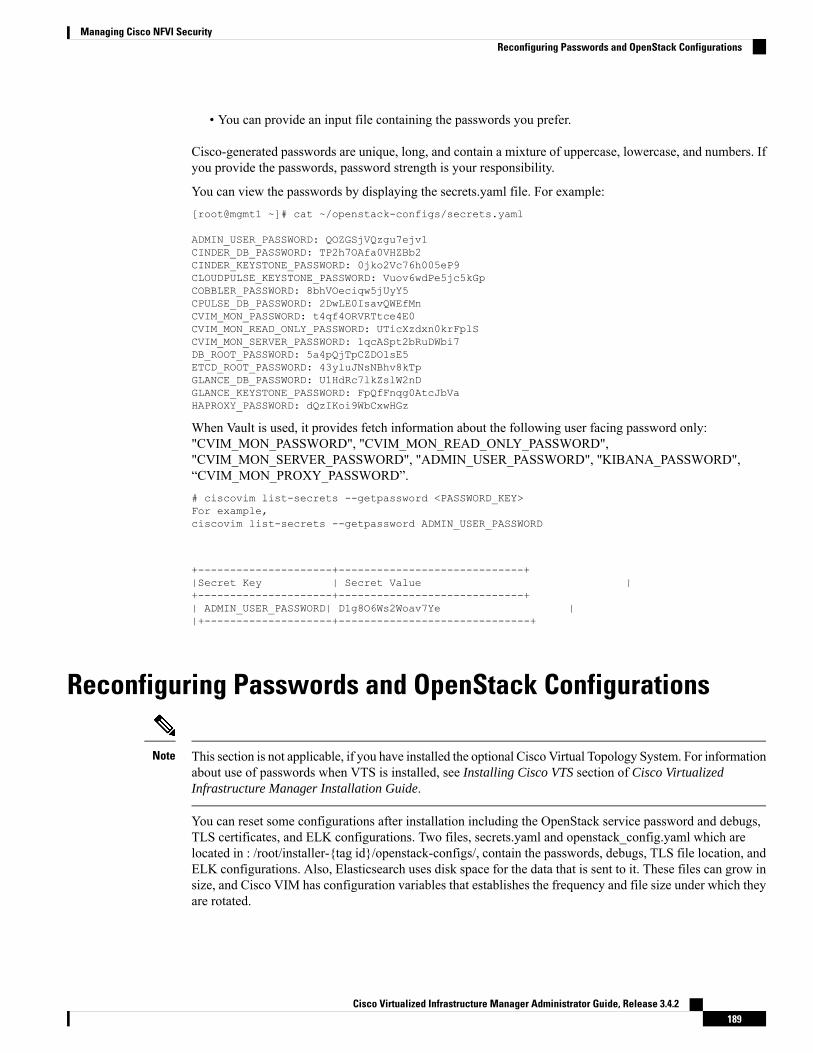
• You can provide an input file containing the passwords you prefer.
Cisco-generated passwords are unique, long, and contain a mixture of uppercase, lowercase, and numbers. Ifyou provide the passwords, password strength is your responsibility.
You can view the passwords by displaying the secrets.yaml file. For example:[root@mgmt1 ~]# cat ~/openstack-configs/secrets.yaml
ADMIN_USER_PASSWORD: QOZGSjVQzgu7ejv1CINDER_DB_PASSWORD: TP2h7OAfa0VHZBb2CINDER_KEYSTONE_PASSWORD: 0jko2Vc76h005eP9CLOUDPULSE_KEYSTONE_PASSWORD: Vuov6wdPe5jc5kGpCOBBLER_PASSWORD: 8bhVOeciqw5jUyY5CPULSE_DB_PASSWORD: 2DwLE0IsavQWEfMnCVIM_MON_PASSWORD: t4qf4ORVRTtce4E0CVIM_MON_READ_ONLY_PASSWORD: UTicXzdxn0krFplSCVIM_MON_SERVER_PASSWORD: 1qcASpt2bRuDWbi7DB_ROOT_PASSWORD: 5a4pQjTpCZDO1sE5ETCD_ROOT_PASSWORD: 43yluJNsNBhv8kTpGLANCE_DB_PASSWORD: U1HdRc7lkZslW2nDGLANCE_KEYSTONE_PASSWORD: FpQfFnqg0AtcJbVaHAPROXY_PASSWORD: dQzIKoi9WbCxwHGz
When Vault is used, it provides fetch information about the following user facing password only:"CVIM_MON_PASSWORD", "CVIM_MON_READ_ONLY_PASSWORD","CVIM_MON_SERVER_PASSWORD", "ADMIN_USER_PASSWORD", "KIBANA_PASSWORD",“CVIM_MON_PROXY_PASSWORD”.# ciscovim list-secrets --getpassword <PASSWORD_KEY>For example,ciscovim list-secrets --getpassword ADMIN_USER_PASSWORD
+---------------------+-----------------------------+|Secret Key | Secret Value |+---------------------+-----------------------------+| ADMIN_USER_PASSWORD| D1g8O6Ws2Woav7Ye ||+--------------------+------------------------------+
Reconfiguring Passwords and OpenStack Configurations
This section is not applicable, if you have installed the optional Cisco Virtual Topology System. For informationabout use of passwords when VTS is installed, see Installing Cisco VTS section of Cisco VirtualizedInfrastructure Manager Installation Guide.
Note
You can reset some configurations after installation including the OpenStack service password and debugs,TLS certificates, and ELK configurations. Two files, secrets.yaml and openstack_config.yaml which arelocated in : /root/installer-{tag id}/openstack-configs/, contain the passwords, debugs, TLS file location, andELK configurations. Also, Elasticsearch uses disk space for the data that is sent to it. These files can grow insize, and Cisco VIM has configuration variables that establishes the frequency and file size under which theyare rotated.
Cisco Virtualized Infrastructure Manager Administrator Guide, Release 3.4.2189
Managing Cisco NFVI SecurityReconfiguring Passwords and OpenStack Configurations

Cisco VIM installer generates the OpenStack service and database passwords with 16 alphanumeric charactersand stores those in /root/openstack-configs/secrets.yaml. You can change the OpenStack service and databasepasswords using the password reconfigure command on the deployed cloud. The command identifies thecontainers affected by the password change and restarts them so the new password can take effect.
Always schedule the password reconfiguration in a maintenance window as the container restart might disruptthe control plane.
Note
Run the following command to view the list of passwords and configurations:[root@mgmt1 ~]# cd ~/installer-xxxx[root@mgmt1 installer-xxxx]# ciscovim help reconfigureusage: ciscovim reconfigure [--regenerate_secrets] [--setpassword <secretkey>]
[--setopenstackconfig <option>]
Reconfigure the openstack cloudOptional arguments:--regenerate_secrets Regenerate All Secrets--setpassword <secretkey> Set of secret keys to be changed.--setopenstackconfig <option> Set of Openstack config to be changed.
[root@mgmt1 ~]# ciscovim list-openstack-configs
+----------------------------+-----------------------------------------------------------------------------------------------------------------+| Name | Option
|+----------------------------+-----------------------------------------------------------------------------------------------------------------+| IRONIC_DEBUG_LOGGING | True
|| OPFLEX_DEBUG_LOGGING | True
|| GNOCCHI_VERBOSE_LOGGING | True
|| AIM_DEBUG_LOGGING | True
|| CINDER_DEBUG_LOGGING | False
|| KEYSTONE_DEBUG_LOGGING | False
|| log_rotation_size | 100M
|| CLOUDPULSE_VERBOSE_LOGGING | True
|| MAGNUM_VERBOSE_LOGGING | True
|| NOVA_DEBUG_LOGGING | True
|| NEUTRON_VERBOSE_LOGGING | True
|| external_lb_vip_cert | /root/openstack-configs/haproxy.pem
|| GLANCE_VERBOSE_LOGGING | True
|| elk_rotation_frequency | weekly
|| CEILOMETER_VERBOSE_LOGGING | True
|| NOVA_CPU_ALLOCATION_RATIO | 16.0
|| CLOUDPULSE_DEBUG_LOGGING | False
|
Cisco Virtualized Infrastructure Manager Administrator Guide, Release 3.4.2190
Managing Cisco NFVI SecurityReconfiguring Passwords and OpenStack Configurations

| log_rotation_frequency | weekly|
| HEAT_DEBUG_LOGGING | False|
| KEYSTONE_VERBOSE_LOGGING | True|
| external_lb_vip_cacert | /root/openstack-configs/haproxy-ca.crt|
| GNOCCHI_DEBUG_LOGGING | False|
| MAGNUM_DEBUG_LOGGING | True|
| log_rotation_del_older | 8|
| CINDER_VERBOSE_LOGGING | True|
| elk_rotation_size | 2|
| IRONIC_VERBOSE_LOGGING | True|
| elk_rotation_del_older | 8|
| NEUTRON_DEBUG_LOGGING | True|
| HEAT_VERBOSE_LOGGING | True|
| CEILOMETER_DEBUG_LOGGING | False|
| ES_SNAPSHOT_AUTODELETE | {u'threshold_warning': 60, u'enabled': True, u'period':u'hourly', u'threshold_high': 80, u'threshold_low': 50} || GLANCE_DEBUG_LOGGING | False
|| NOVA_VERBOSE_LOGGING | True
|| NOVA_RAM_ALLOCATION_RATIO | 1.5
|+----------------------------+-----------------------------------------------------------------------------------------------------------------+
In the absence of Vault, the following commands lists the password keys[root@mgmt1 installer-xxxx]# ciscovim list-password-keys
The corresponding command in a pod with Vault enabled is:[root@mgmt1 installer-xxxx]# ciscovim list-secrets
+----------------------------------+| Password Keys |+----------------------------------+| ADMIN_USER_PASSWORD || CINDER_DB_PASSWORD || CINDER_KEYSTONE_PASSWORD || CLOUDPULSE_KEYSTONE_PASSWORD || COBBLER_PASSWORD || CPULSE_DB_PASSWORD || CVIM_MON_PASSWORD || CVIM_MON_READ_ONLY_PASSWORD || CVIM_MON_SERVER_PASSWORD || DB_ROOT_PASSWORD || ETCD_ROOT_PASSWORD || GLANCE_DB_PASSWORD || GLANCE_KEYSTONE_PASSWORD || HAPROXY_PASSWORD || HEAT_DB_PASSWORD || HEAT_KEYSTONE_PASSWORD || HEAT_STACK_DOMAIN_ADMIN_PASSWORD |
Cisco Virtualized Infrastructure Manager Administrator Guide, Release 3.4.2191
Managing Cisco NFVI SecurityReconfiguring Passwords and OpenStack Configurations

| HORIZON_SECRET_KEY || KEYSTONE_DB_PASSWORD || KIBANA_PASSWORD || METADATA_PROXY_SHARED_SECRET || NEUTRON_DB_PASSWORD || NEUTRON_KEYSTONE_PASSWORD || NOVA_DB_PASSWORD || NOVA_KEYSTONE_PASSWORD || RABBITMQ_ERLANG_COOKIE || RABBITMQ_PASSWORD || VOLUME_ENCRYPTION_KEY || WSREP_PASSWORD |+----------------------------------+[root@mgmt1 installer-xxxx]#
When using Vault, you can fetch information about the following user facing password only:"CVIM_MON_PASSWORD", "CVIM_MON_READ_ONLY_PASSWORD","CVIM_MON_SERVER_PASSWORD", "ADMIN_USER_PASSWORD", "KIBANA_PASSWORD",“CVIM_MON_PROXY_PASSWORD”.
You can change specific password and configuration identified from the available list.
Run the reconfiguration command as follows:# ciscovim help reconfigureusage: ciscovim reconfigure [--regenerate_secrets]
[--setupfile <setupdata_file>][--alertmanager_config <alertmanager_config_file>][--alerting_rules_config <alerting_rules_config_file>][--setpassword <secretkey>][--setopenstackconfig <option>][--setopenstackconfig_file <config_file>][--cimc_password] [--rma_tors <tor1,tor3,...>][--regenerate_ceph_keyring] [-y]
Reconfigure the Openstack cloud
Optional arguments:--regenerate_secrets Regenerate All Secrets--setupfile <setupdata_file> User setup_data.yaml--alertmanager_config <alertmanager_config_file>
User alertmanager_config.yaml--alerting_rules_config <alerting_rules_config_file>
User alerting_rules_config.yaml--setpassword <secretkey> Set of secret keys to be changed.--setopenstackconfig <option> Set of Openstack config to be changed.--setopenstackconfig_file <config_file>
Set of Openstack configs to be changed fromfile.
--cimc_password Reconfigure CIMC password--rma_tors <tor1,tor3,...> Comma separated list of ToRs--regenerate_ceph_keyring Regenerate Ceph Keyring-y, --yes Yes option to perform the action
[root@mgmt1 ~]# ciscovim reconfigure --setpassword ADMIN_USER_PASSWORD,NOVA_DB_PASSWORD--setopenstackconfig HEAT_DEBUG_LOGGING,HEAT_VERBOSE_LOGGING Password for ADMIN_USER_PASSWORD:Password for NOVA_DB_PASSWORD:Enter T/F for option HEAT_DEBUG_LOGGING:T Enter T/F for option HEAT_VERBOSE_LOGGING:T
The password must be alphanumeric and can be maximum 32 characters in length.
Following are the configuration parameters for OpenStack:
Cisco Virtualized Infrastructure Manager Administrator Guide, Release 3.4.2192
Managing Cisco NFVI SecurityReconfiguring Passwords and OpenStack Configurations

Allowed ValuesConfiguration Parameter
T/F (True or False)CEILOMETER_DEBUG_LOGGING
T/F (True or False)CEILOMETER_VERBOSE_LOGGING
T/F (True or False)CINDER_DEBUG_LOGGING
T/F (True or False)CINDER_VERBOSE_LOGGING
T/F (True or False)CLOUDPULSE_DEBUG_LOGGING
T/F (True or False)CLOUDPULSE_VERBOSE_LOGGING
T/F (True or False)GLANCE_DEBUG_LOGGING
T/F (True or False)GLANCE_VERBOSE_LOGGING
T/F (True or False)HEAT_DEBUG_LOGGING
T/F (True or False)HEAT_VERBOSE_LOGGING
T/F (True or False)KEYSTONE_DEBUG_LOGGING
T/F (True or False)KEYSTONE_VERBOSE_LOGGING
T/F (True or False)MAGNUM_DEBUG_LOGGING
T/F (True or False)MAGNUM_VERBOSE_LOGGING
T/F (True or False)NEUTRON_DEBUG_LOGGING
T/F (True or False)NEUTRON_VERBOSE_LOGGING
T/F (True or False)NOVA_DEBUG_LOGGING
T/F (True or False)NOVA_VERBOSE_LOGGING
Days after which older logs are purgedelk_rotation_del_older
Available options: "daily", "weekly", "fortnightly","monthly"
elk_rotation_frequency
Gigabytes (entry of type float/int is allowed)elk_rotation_size
Location of HAProxy CA certificateexternal_lb_vip_cacert
Location of HAProxy certificateexternal_lb_vip_cert
Mem oversubscription ratio (from 1.0 to 4.0)NOVA_RAM_ALLOCATION_RATIO
CPU allocation ratio (from 1.0 to 16.0)NOVA_CPU_ALLOCATION_RATIO
Cisco Virtualized Infrastructure Manager Administrator Guide, Release 3.4.2193
Managing Cisco NFVI SecurityReconfiguring Passwords and OpenStack Configurations

Elastic search auto-delete configuration, can managethe following:
period: ["hourly", "daily", "weekly", "monthly"] #Frequency of cronjob to check for disk space
threshold_warning: <1-99> # % of disk spaceoccupied to display warning message
threshold_low: <1-99> # % of disk space occupiedafter cleaning up snapshots
threshold_high: <1-99> # % of disk space whenstarting to delete snapshots
ES_SNAPSHOT_AUTODELETE
Alternatively, you can regenerate all passwords using regenerate_secrets command option as follows:[root@mgmt1 ~]# cd ~/installer-xxxx[root@mgmt1 ~]# ciscovim reconfigure --regenerate_secrets
In addition to the services passwords, you can change the debug and verbose options for Heat, Glance, Cinder,Nova, Neutron, Keystone and Cloudpulse in /root/openstack-configs/openstack_config.yaml. You can modifythe other configurations including the ELK configuration parameters, API and Horizon TLS certificates, RootCA, NOVA RAM ALLOCATION RATIO, NOVA CPU ALLOCATION RATIO andES_SNAPSHOT_AUTODELETE. When reconfiguring these options (For Example API and TLS), somecontrol plane downtime will occur, so plan the changes during maintenance windows.
The command to reconfigure these elements are:ciscovim reconfigure
The command includes a built-in validation to ensure that you do not enter typos in the secrets.yaml oropenstack_config.yaml files.
When reconfiguration of password or enabling of openstack-services fails, all subsequent pod managementoperations are blocked. In such case, you can contact Cisco TAC to resolve the situation.
From Cisco VIM 3.4.1, you can enable NOVA_RAM_ALLOCATION_RATIO andNOVA_CPU_ALLOCATION_RATIO on a per server basis during day-0 installation or day-2 as part of podmanagement. For more information, see the Cisco Virtualized Infrastructure Manager Installation Guide.
• For pod operations, OpenStack uses the service accounts such as admin, cinder, glance, heat,heat_domain_admin, neutron, nova, placement, and cloudpulse. These accounts use passwords toauthenticate each other for standard operations. Youmust not change the password used by these accounts,other than using the ciscovim reconfigure operation. To enforce this behavior, starting Cisco VIM 2.4.5,the "change password" panel is disabled on the Horizon dashboard for these accounts.
• You should create personal OpenStack user accounts for those who need OpenStack admin or memberaccess. You can change the passwords for these accounts through the Horizon dashboard, OpenStackCLI, or OpenStack client interface.
Note
Cisco Virtualized Infrastructure Manager Administrator Guide, Release 3.4.2194
Managing Cisco NFVI SecurityReconfiguring Passwords and OpenStack Configurations

Reconfiguring Glance Client Key for Central Ceph ClusterFrom release Cisco VIM 3.0.0, the installation of a central ceph cluster is automated to serve the images toedge pods through Glance service. No local ceph cluster for edge pods as they have constraints on power andspace. The edge pods do not need any persistent storage and provide services via a central ceph cluster forglance. For the edge pods to communicate with central ceph cluster using a cluster id, aGLANCE_CLIENT_KEY is required.
Follow the below steps to reset the GLANCE_CLIENT_KEY:
Step 1 Regenerate the client keyring for glance.a) On the central ceph cluster, ssh to the management node and execute the following:# ciscovim reconfigure --regenerate_ceph_keyring –-setupfile /root/Save<setup_data.yaml> -y
Alternatively, you can regenerate the key via the corresponding RestAPI call:# curl -u <user>:<password> -X POST https://<ip|host>:8445/v1/misc --header "Content-Type:application/json" -d '{"action": {"reconfigure": "true", "regenerate_ceph_keyring": true}}'
Step 2 Retrieve the generated client keyring for glance. From the management node, execute the following command to get thecluster UUID:
# cat /root/openstack-configs/ceph/fetch/ceph_cluster_uuid.conf<cluster_uuid># cat /root/openstack-configs/ceph/fetch/<cluster_uuid>/etc/ceph/ceph.client.glance.keyring[client.glance]key = <GLANCE_CLIENT_KEY>caps mon = "allow r"caps osd = "allow class-read object_prefix rbd_children, allow rwx pool=images"
Step 3 Reconfigure the edge pod to use the new keyring generated on central ceph. SSH to the management node of each edgepod and execute the following:
[root@mgmt1 ~]# cd /root/ [root@mgmt1 ~]# mkdir MyDir [root@mgmt1 ~]# cd MyDir[root@mgmt1 ~]# cp /root/openstack-configs/setup_data.yaml <my_setup_data.yaml> [root@mgmt1 ~]# cp<my_setup_data.yaml> <my_setup_data_original.yaml>[root@mgmt1 ~]# vi my_setup_data.yaml (update the GLANCE_CLIENT_KEY with the new info)[root@mgmt1 ~]# cd ~/installer-xxxx[root@mgmt1 ~]# ciscovim reconfigure –-setupfile ~/MyDir/<my_setup_data.yaml>
Step 4 Optional, but recommended to do it on a handful of pods. Once reconfiguration is done, test if the keyring works bycreating and deleting glance images.
Enabling Cloud SettingsYou can enable specific cloud settings as a day-0 or day-n option via reconfiguration. Listed below are thesettings that are allowed in Cisco VIM.cloud_settings:
keystone_lockout_failure_attempts: <int> # Number of incorrect password attempts before
Cisco Virtualized Infrastructure Manager Administrator Guide, Release 3.4.2195
Managing Cisco NFVI SecurityReconfiguring Glance Client Key for Central Ceph Cluster

user is locked out. Default 0 for no lockout. Range: 0 to 10# keystone_lockout_duration: <int> # Number of seconds a user is locked out. Defaultis 1800 for 30 minutes. Range: minimum: 300 (5 minutes), maximum 86400 (24 hours)# keystone_unique_last_password_count: <int> # Forces to change your password to a valuenot used before. Default 0 for no history check. Range: minimum 0, maximum 10# keystone_minimum_password_age: <int> # Restrict users to change their passwordfor preset number of days. Default is 0 for no limit. Range: minimum 0, maximum 2# keystone_disable_inactive_account: <int> # Disable user accounts if inactive for thismany days. Default is 0 for no limit. Range: minimum 0, maximum 365 (1 year).# horizon_session_timeout: <int> # Number of seconds of inactivity before Horizondashboard is logged out. Default is 1800 for 30 minutes. Range: minimum 300 (5 minutes),maximum 86400 (24 hours)
OpenSource documentation of cloud settings is available at:https://docs.openstack.org/keystone/latest/admin/configuration.html#security-compliance-and-pci-dss
To initiate the integration of cloud_settings on an existing pod, copy the setupdata into a local directory andupdate it manually with information listed above, and then run the reconfiguration command as follows:[root@mgmt1 ~]# cd /root/[root@mgmt1 ~]# mkdir MyDir[root@mgmt1 ~]# cd MyDir[root@mgmt1 ~]# cp /root/openstack-configs/setup_data.yaml <my_setup_data.yaml>[root@mgmt1 ~]# vi my_setup_data.yaml (update the setup_data to include cloud_settingsrelated info)[root@mgmt1 ~]# cd ~/installer-xxxx[root@mgmt1 ~]# ciscovim reconfigure –-setupfile ~/MyDir/<my_setup_data.yaml>
Enabling NFVIMON Post Pod InstallationYou can optionally install Cisco VIM with a third-party software known as NFVIMON which is used tomonitor the health and performance of the NFV infrastructure. The NFVIMON feature enables extensivemonitoring and performance data for various components of the cloud infrastructure including Cisco UCSblade and rack servers, service profiles, Nexus top of rack switches, fabric connections and also the OpenStackinstances. The monitoring system is designed such that it can monitor single or multiple pods from a singlemanagement system. NFVIMON can be enabled by extending the setup_data.yaml with relevant informationon an existing pod, through the reconfigure option.
NFVIMON consists of four components: ceilometer for data collection, collector, Resource Manager (RM),and control-center with Cisco Zenpacks (CC). As NVIFMON is a third party software, care has been takento make sure its integration into VIM is loosely coupled and the VIM automation only deals with installingthe ceilometer service software piece needed to monitor the pod. The installing of the other NFVIMONcomponents (collector, Resource Manager (RM) and control-center with Cisco Zenpacks (CC)), are CiscoAdvance Services led activity and those steps are outside the scope of the install guide.
Before you Begin
Ensure that you have engagedwith Cisco Advance Services on the planning and installation of the NFVIMONaccessories along with its network requirements. Also, the image information of collector, Resource Manager(RM) and control-center with Cisco Zenpacks (CC)) is available only through Cisco Advance Services. At ahigh level, you can have a node designated to host a pair of collector VM for each pod, and a common nodeto host CC and RM VMs, which can aggregate and display monitoring information from multiple pods.
The collector VMs must have two interfaces: an interface to br_mgmt of the VIM, and another interface thatis routabl and reachable to the VIM Installer REST API and the RM VMs. As the collector VM is availablein an independent node, four IPs from the management network of the pod must be pre-planned and reserved.
Cisco Virtualized Infrastructure Manager Administrator Guide, Release 3.4.2196
Managing Cisco NFVI SecurityEnabling NFVIMON Post Pod Installation

The installation steps of the collector, ResourceManager (RM) and control-center with Cisco Zenpacks (CC))are part of Cisco Advance Services led activity.
Installation of NFVIMON
The ceilometer service is the only component in NFVIMON offering that is managed by VIM orchestrator.While the ceilometric service collects the metrics to pass openstack information of the pod to the collectors,the CiscoNFVI Zenpack available in the CC/RMnode gathers the node level information. To enable NFVIMONas part of the VIM Install, update the setup_data with the following information:
#Define the PODNAMEPODNAME: <PODNAME with no space>; ensure that this is unique across all the podsNFVIMON:MASTER: # Master Sectionadmin_ip: <IP address of Control Centre VM>
COLLECTOR: # Collector Sectionmanagement_vip: <VIP for ceilometer/dispatcher to use> #Should be unique across the VIM
Pod; Should be part of br_mgmt networkCollector_VM_Info:-hostname: <hostname of Collector VM 1>password: <password_for_collector_vm1> # max length of 32
ccuser_password: <password from master for 'ccuser' (to be used for self monitoring)># max length of 32
admin_ip: <ssh_ip_collector_vm1> # Should be part of br_api networkmanagement_ip: <mgmt_ip_collector_vm1> # Should be part of br_mgmt network
-hostname: <hostname of Collector VM 2>password: <password_for_collector_vm2> # max length of 32
ccuser_password: <password from master for 'ccuser' (to be used for self monitoring)># max length of 32
admin_ip: <ssh_ip_collector_vm2> # Should be part of br_api networkmanagement_ip: <mgmt_ip_collector_vm2> # Should be part of br_mgmt network
COLLECTOR_TORCONNECTIONS: # Optional. Indicates the port where the collector is hangingoff. Recommended when Cisco NCS 5500 is used as ToR
- tor_info: {po: <int>, switch_a_hostname: ethx/y, switch_b_hostname: ethx/y}# Section of MASTER_2 and COLLECTOR_2 are optional and only needed to support NFVIMON inHAMASTER_2: # Master Sectionadmin_ip: <IP address of Control Centre VM>
COLLECTOR_2: # Collector Sectionmanagement_vip: <VIP for ceilometer/dispatcher to use> #Should be unique across the VIM
Pod; Should be part of br_mgmt networkCollector_VM_Info:-
hostname: <hostname of Collector VM 1>password: <password_for_collector_vm1> # max length of 32
ccuser_password: <password from master for 'ccuser' (to be used for self monitoring)># max length of 32
admin_ip: <ssh_ip_collector_vm1> # Should be reachable from br_api networkmanagement_ip: <mgmt_ip_collector_vm1> # Should be part of br_mgmt network
-hostname: <hostname of Collector VM 2>password: <password_for_collector_vm2> # max length of 32
ccuser_password: <password from master for 'ccuser' (to be used for self monitoring)># max length of 32
admin_ip: <ssh_ip_collector_vm2> # Should be reachable from br_api networkmanagement_ip: <mgmt_ip_collector_vm2> # Should be part of br_mgmt network
COLLECTOR_TORCONNECTIONS: # Optional. Indicates the port where the collector is hangingoff. Recommended when Cisco NCS 5500 is used as ToR
- tor_info: {po: <int>, switch_a_hostname: ethx/y, switch_b_hostname: ethx/y}DISPATCHER:rabbitmq_username: admin # Pod specific user for dispatcher module.
Cisco Virtualized Infrastructure Manager Administrator Guide, Release 3.4.2197
Managing Cisco NFVI SecurityEnabling NFVIMON Post Pod Installation

NFVIMON_ADMIN: admin_name # Optional, once enabled, need to have only 1 adminreconfigurable to add/update user id
If NFVIMON HA is enabled, ensure that all the admin IPs are on the same subnet for NFVIMON VMs anddeployed servers.
Note
To monitor ToR, ensure that the following TORSWITCHINFO sections are defined in the setup_data.yaml.TORSWITHCINFO:SWITCHDETAILS:-
hostname: <switch_a_hostname>: # Mandatory for NFVIMON if switch monitoring isneeded
username: <TOR switch username> # Mandatory for NFVIMON if switch monitoring isneeded
password: <TOR switch password> # Mandatory for NFVBENCH; Mandatory for NFVIMONif switch monitoring is needed
ssh_ip: <TOR switch ssh ip> # Mandatory for NFVIMON if switch monitoring isneeded
....-
hostname: <switch_b_hostname>: # Mandatory for NFVIMON if switch monitoring isneeded
username: <TOR switch username> # Mandatory for NFVIMON if switch monitoring isneeded
password: <TOR switch password> # Mandatory for NFVIMON if switch monitoring isneeded
ssh_ip: <TOR switch ssh ip> # Mandatory for NFVIMON if switch monitoring isneeded
....
To initiate the integration of NFVIMON on an existing pod, copy the setupdata into a local directory andupdate it manually with information listed above, and then run the reconfiguration command as follows:
[root@mgmt1 ~]# cd /root/[root@mgmt1 ~]# mkdir MyDir[root@mgmt1 ~]# cd MyDir[root@mgmt1 ~]# cp /root/openstack-configs/setup_data.yaml <my_setup_data.yaml>[root@mgmt1 ~]# vi my_setup_data.yaml (update the setup_data to include NFVIMON relatedinfo)[root@mgmt1 ~]# cd ~/installer-xxxx[root@mgmt1 ~]# ciscovim reconfigure –-setupfile ~/MyDir/<my_setup_data.yaml>
To initiate the uninstallation of NFVIMON on an existing pod, copy the setupdata into a local directory andremove the entire NFVIMON section listed above, and then run the reconfiguration command as follows:
[root@mgmt1 ~]# cd /root/ [root@mgmt1 ~]# mkdir MyDir [root@mgmt1 ~]# cd MyDir[root@mgmt1 ~]# cp /root/openstack-configs/setup_data.yaml <my_setup_data.yaml>[root@mgmt1 ~]# vi my_setup_data.yaml (update the setup_data to exclude NFVIMON relatedinfo)[root@mgmt1 ~]# cd ~/installer-xxxx[root@mgmt1 ~]# ciscovim –-setupfile ~/MyDir/<my_setup_data.yaml> reconfigure
Cisco Virtualized Infrastructure Manager Administrator Guide, Release 3.4.2198
Managing Cisco NFVI SecurityEnabling NFVIMON Post Pod Installation

• NFVIMON is supported only on a pod running with Keystone v3 (Default for release Cisco VIM 3.2.0).
• NFVIMON can run with either root or non-root admin keys for monitoring.
Note
Enabling CVIMMON Post Pod InstallationCVIMMON, an extensive monitoring solution, is designed to monitor a single pod from a single managementsystem. Cisco VIM can be optionally installed with CVIMMON, to monitor the health and performance ofthe NFV infrastructure. CVIMMON is enabled by extending the setup_data.yaml with relevant informationon an existing pod, using the reconfigure option.
You can enable CVIMMON and CVIM-TRAP (SNMP, SERVER_MON) using the reconfigure option, postinstallation of Cisco VIM.
CVIM-TRAP can be enabled, only if CVIMMON exists. Once the CVIMMON or CVIM-TRAP is enabled,it cannot be disabled again.
Note
To enable the CVIMMON and SNMP-Trap features or to change the individual parameters in CVIMMON,SNMP, or SERVER_MON:
1. Take a backup of setup_data file and update it manually with the configuration details by entering thefollowing command:
# cd /root/# mkdir MyDir# cp /root/openstack-configs/setup_data.yaml /root/MyDir# cd /root/MyDir
2. Edit the setup data.
3. Save the file and execute the below command. For sample configuration, see Enabling CVIMMON onCisco VIM section of Cisco Virtualized Infrastructure Manager Installation Guide
#ciscovim --setupfile /root/MyDir/setup_data.yaml reconfigure
Migration from SNMPv2 to SNMPv3 is only supported, but not vice-versa.Note
Reconfiguring CIMC/BMC Password on Existing InstallationCisco VIM allows you to reconfigure the CIMC/BMC password on an existing installation along withOpenStack services.
Cisco Virtualized Infrastructure Manager Administrator Guide, Release 3.4.2199
Managing Cisco NFVI SecurityEnabling CVIMMON Post Pod Installation
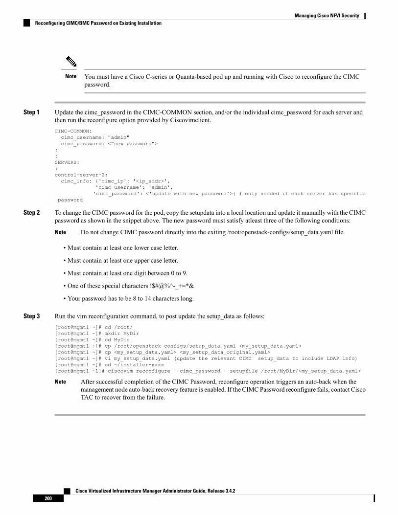
You must have a Cisco C-series or Quanta-based pod up and running with Cisco to reconfigure the CIMCpassword.
Note
Step 1 Update the cimc_password in the CIMC-COMMON section, and/or the individual cimc_password for each server andthen run the reconfigure option provided by Ciscovimclient.CIMC-COMMON:cimc_username: "admin"cimc_password: <"new password">
::SERVERS::control-server-2:cimc_info: {'cimc_ip': '<ip_addr>',
'cimc_username': 'admin','cimc_password': <'update with new passowrd'>} # only needed if each server has specific
password
Step 2 To change the CIMC password for the pod, copy the setupdata into a local location and update it manually with the CIMCpassword as shown in the snippet above. The new password must satisfy atleast three of the following conditions:
Do not change CIMC password directly into the exiting /root/openstack-configs/setup_data.yaml file.Note
• Must contain at least one lower case letter.
• Must contain at least one upper case letter.
• Must contain at least one digit between 0 to 9.
• One of these special characters !$#@%^-_+=*&
• Your password has to be 8 to 14 characters long.
Step 3 Run the vim reconfiguration command, to post update the setup_data as follows:[root@mgmt1 ~]# cd /root/[root@mgmt1 ~]# mkdir MyDir[root@mgmt1 ~]# cd MyDir[root@mgmt1 ~]# cp /root/openstack-configs/setup_data.yaml <my_setup_data.yaml>[root@mgmt1 ~]# cp <my_setup_data.yaml> <my_setup_data_original.yaml>[root@mgmt1 ~]# vi my_setup_data.yaml (update the relevant CIMC setup_data to include LDAP info)[root@mgmt1 ~]# cd ~/installer-xxxx[root@mgmt1 ~1]# ciscovim reconfigure --cimc_password --setupfile /root/MyDir/<my_setup_data.yaml>
After successful completion of the CIMC Password, reconfigure operation triggers an auto-back when themanagement node auto-back recovery feature is enabled. If the CIMC Password reconfigure fails, contact CiscoTAC to recover from the failure.
Note
Cisco Virtualized Infrastructure Manager Administrator Guide, Release 3.4.2200
Managing Cisco NFVI SecurityReconfiguring CIMC/BMC Password on Existing Installation

Increasing/Decreasing Provider and Tenant VLAN RangesCisco VIM, provides the flexibility of increasing or decreasing the provider and tenant VLAN ranges afterthe post pod installation. Increasing provider and tenant VLAN ranges applies to C-series and B-series podthat is enabled with Cisco UCS Manager plugin. B-series pod running without Cisco UCS Manager plugin,cannot use this feature because of the inherent day-0 networking configuration to be done in FI.
You should have the tenant and provider networks enabled on the pod from day-0.Note
To increase provider and tenant VLAN ranges, enter the TENANT_VLAN_RANGES and/orPROVIDER_VLAN_RANGES in the setup_data.yaml file and run the reconfigure command throughCiscovimclient as follows:TENANT_VLAN_RANGES: old_vlan_info, new_vlan_infoor/andPROVIDER_VLAN_RANGES: old_vlan_info, new_vlan_info
To decrease provider and tenant VLAN ranges, update the TENANT_VLAN_RANGES and/orPROVIDER_VLAN_RANGES to be a subset of the original one in the setup_data.yaml file and run thereconfigure command through Ciscovimclient as follows:TENANT_VLAN_RANGES: subset_old_vlan_infoPROVIDER_VLAN_RANGES: subset_old_vlan_info
You cannot remove and add newVLANs at the same time. Also if you remove VLAN, they cannot be reducedto less than 2 and 1 VLANs for tenant and provider network, respectively.
Note
To change the pod, copy the setupdata into a local dir and update it manually by running the followingcommand:[root@mgmt1 ~]# cd /root/[root@mgmt1 ~]# mkdir MyDir[root@mgmt1 ~]# cd MyDir
Update the setup_data, by running the following command:[root@mgmt1 ~]# cp /root/openstack-configs/setup_data.yaml <my_setup_data.yaml> [root@mgmt1~]# vi my_setup_data.yaml (update the setup_data with the right info)
Run the re-configuration command as follows:
[root@mgmt1 ~]# cd ~/installer-xxxx[root@mgmt1 ~]# ./ciscovimclient/ciscovim reconfigure –-setupfile ~/MyDir/<my_setup_data.yaml>
While using auto-ToR via ACI APIs without the APIC plugin, ensure that you update the vim_apic_networkssection with the right VLAN information as part of the reconfiguration option.
Note
Cisco Virtualized Infrastructure Manager Administrator Guide, Release 3.4.2201
Managing Cisco NFVI SecurityIncreasing/Decreasing Provider and Tenant VLAN Ranges

Fernet Key OperationsKeystone fernet token format is based on the cryptographic authentication method - Fernet. Fernet is animplementation of Symmetric Key Encryption. Symmetric key encryption is a cryptographic mechanism thatuses the same cryptographic key to encrypt plaintext and the same cryptographic key to decrypt ciphertext.Fernet authentication method also supports multiple keys where it takes a list of symmetric keys, performsall encryption using the first key in a list and attempts to decrypt using all the keys from that list.
The Cisco NFVI pods uses Fernet keys by default. The following operations can be carried out in Cisco NFVIpods.
To check if the fernet keys are successfully synchronized across the keystone nodes.[root@mgmt1 ~]# cd ~/installer-xxxx[root@mgmt1 ~]# ciscovim help check-fernet-keysusage: ciscovim check-fernet-keys
Check whether the fernet keys are successfully synchronized across keystone nodes.
To forcefully rotate the fernet keys:[root@mgmt1 ~]# cd ~/installer-xxxx[root@mgmt1 ~]# ciscovim help rotate-fernet-keysusage: ciscovim rotate-fernet-keysTrigger rotation of the fernet keys on keystone
To resync the fernet keys across the keystone nodes:[root@mgmt1 ~]# cd ~/installer-xxxx[root@mgmt1 ~]# ciscovim help resync-fernet-keysusage: ciscovim resync-fernet-keysResynchronize the fernet keys across all the keystone nodes
Managing CertificatesWhen TLS protection is configured for the OpenStack APIs, the two certificate files, haproxy.pem andhaproxy-ca.crt, are stored in the /root/openstack-configs/directory. To verify cloud authenticity,the clients running on servers outside of the deployed cloud need a copy of the root certificate (haproxy-ca.crt).If the installed certificate is signed by a well-known certificate authority, no additional configuration is neededon client servers. However, if a self-signed or local CA is used, copy haproxy-ca.crt to each client. Followinginstructions are specific to the client operating system or browser to install the certificate as a trusted certificate.
Alternatively, you can explicitly reference the certificate using the environment variable OS_CACERT orcommand line parameter –cacert, if OpenStack CLI is used. When Cisco NFVI is operational, a daily checkis made to monitor the expiration dates of the installed certificates. If certificates are not nearing expiration,an informational message is logged. As the certificate approaches expiration, an appropriate warning or criticalmessage is logged.2017-04-24T13:56:01 INFO Certificate for OpenStack Endpoints at 192.168.0.2:5000 expiresin 500 days
Cisco Virtualized Infrastructure Manager Administrator Guide, Release 3.4.2202
Managing Cisco NFVI SecurityFernet Key Operations

Reconfiguring TLS CertificatesCisco VIM provides a way to configure TLS certificates on-demand for any reason. For example: certificateexpiration policies governing certificate management.
Reconfiguration of certificates in general is supported in the following components:
• Cisco VIM Rest API endpoints
• OpenStack API endpoints
Cisco VIM Rest API Endpoints
To reconfigure certificate files, follow the below steps:
1. Copy the new key, CA root, and certificate files into the /root/openstack-configs folder underthe following filenames:
Cisco VIM RestAPI endpoint supports IP based CN (common name) TLS certificate.Note
cp <new-ca-root-cert> /root/openstack-configs/mercury-ca.crtcp <new-key-file> /root/openstack-configs/mercury.keycp <new-cert-file> /root/openstack-configs/mercury.crt
mercury-ca.crt must contain the entire trust chain including RootCA and any intermediate CA.
mercury.pemmust contain the TLS certificate and the private key. The private key must not have anypassphrase (non-encrypted key).
2. Once copied, run the reconfiguration command:cd /root/installer-xxxx/tools/./restapi.py -a reconfigure-tls
3. If the copied certificate in Step 1 is FQDN based, use following option to reconfigure:cd /root/installer-xxxx/tools/./restapi.py -a reconfigure-tls -d <FQDN>For example:./restapi.py -a reconfigure-tls -d gg34-bn.cisco.com
4. To get the FQDN name from certificate, use following command:# openssl x509 -in /root/openstack-configs/mercury-ca.crt -text -noout. . .Subject: C=US, ST=California, L=San Jose, O=IT, CN=gg34-bn.cisco.com
5. Execute ciscovim reconfigure to deploy TLS certificate to other services like Kibana and so on.
OpenStack API Endpoints
It is important to replace the certificates before they expire. After Cisco NFVI is installed, you can update thecertificates by replacing the haproxy.pem and haproxy-ca.crt files and running the reconfigure command:
To reconfigure certificate files, follow the below steps:
Cisco Virtualized Infrastructure Manager Administrator Guide, Release 3.4.2203
Managing Cisco NFVI SecurityReconfiguring TLS Certificates

1. Copy the new key, CA root, and certificate files into the ~/openstack-configs folder under the followingfilenames : haproxy-ca.crt must contain entire trust chain including RootCA and any intermediateCA. If LDAP certificate for keystone authentication is issued by a different authority than that of haproxycertificate, the entire trust chain (RootCA and any intermediate CA) for LDAP certificate must be appendedto the file.
haproxy.pemmust contain the TLS certificate and the private key. The private key must not have anypassphrase (non-encrypted key).cp <new-ca-root-cert> /root/openstack-configs/haproxy-ca.crtcp <new-cert-file> /root/openstack-configs/haproxy.pem
2. Once copied, run the reconfiguration command:mv /root/openstack-configs/openrc /root/<your_dir>/ # workaround as listed inCSCvt33521cd /root/installer-xxxxciscovim reconfigure
3. For generating third-party certificates, follow the below:
a. If external_lb_vip_fqdn is defined in the setup_data, generate the certificate using theexternal_lb_vip_fqdn as DNS.
b. If external_lb_vip_ipv6_address is defined but not external_lb_vip_fqdn, generate the certificate usingthe external_lb_vip_ipv6_address as IP Address.
c. If the setup_data contains only external_lb_vip_address, but neither external_lb_vip_ipv6_addressnor external_lb_vip_fqdn, generate the certificate using the external_lb_vip_address as IP Address.
Verifying TLS CertificatesCisco VIM provides a tool to check the expiration date of the installed certificates. If a certificate is expired,you may not be able to access the HTTPS endpoints. Checks are run daily and a syslog message is created ifa certificate is nearing expiration.
In addition, a tool is provided to check certificate expiration on demand.
The tool’s command line support can be shown as follows:
# cd ~/installer-xxxx/tools# python certificate-check.py –help
To check all certificates, run the following commands:
#cd ~/installer-xxxx/tools# python certificate-check.py
To check a single certificate, run the following commands:
cd ~/installer-xxxx/tools# python certificate-check.py –s openstack
Cisco Virtualized Infrastructure Manager Administrator Guide, Release 3.4.2204
Managing Cisco NFVI SecurityVerifying TLS Certificates

LDAP/AD support with Keystone v3With the introduction of KeystoneV3, the openstack service authentication can be delegated to an externalLDAP/AD server. In Cisco VIM, this feature has been introduced optionally if the authorization is done byKeystone v3. Just like Keystonev3, this feature can be enabled on an existing pod running Cisco VIM. Toavail this feature post pod deployment, the setup_data needs to be augmented with the following informationduring the pod installation.
An important pre-requisite for enabling AD/LDAP integration is that the AD/LDAP endpoint MUST bereachable from all the Controller nodes that run OpenStack Keystone Identity Service.LDAP:domain: <Domain specific name>user_objectclass: <objectClass for Users> # e.g organizationalPersongroup_objectclass: <objectClass for Groups> # e.g. groupOfNamesuser_tree_dn: '<DN tree for Users>' # e.g. 'ou=Users,dc=cisco,dc=com'group_tree_dn: '<DN tree for Groups>' # e.g. 'ou=Groups,dc=cisco,dc=com'suffix: '<suffix for DN>' # e.g. 'dc=cisco,dc=com'url: '<ldap:// host:port>' # e.g. 'ldap://172.26.233.104:389'
orurl: '<ldaps|ldap>://[<ip6-address>]:[port]'e.g.ldap://[2001:420:293:2487:d1ca:67dc:94b1:7e6c]:389 ---> note the mandatory "[.. ]"around the ipv6 addressuser: '<DN of bind user>' # e.g. 'dc=admin,dc=cisco,dc=com', Optional but need to added
along with password.password: <password> # e.g. password of bind user, Optional but need to be added along
with DN of bind user.
user_filter = (memberOf=CN=os-users,OU=OS-Groups,DC=mercury,DC=local)user_id_attribute = sAMAccountNameuser_name_attribute = sAMAccountNameuser_mail_attribute = mail # Optionalgroup_tree_dn = ou=OS-Groups,dc=mercury,dc=localgroup_name_attribute = sAMAccountNamegroup_filter: '(&(objectClass=group)(|(cn=server-ops)(cn=admins)))' # Optionalgroup_member_attribute: memberUid # Optionalgroup_id_attribute: gidNumber # Optionalgroup_members_are_ids: True # Optionalchase_referrals: <True or False> # Optional
Condition for LDAP user and password parameters are as follows:
• 1 – Can be optional
• 2 – Should be mutually inclusive
• 3 – If defined, it cannot be empty
To initiate the integration of LDAP with Keystone v3 on an existing pod, copy the setupdata into a localdirectory, update it manually with the relevant LDAP configuration, and then run the following reconfigurationcommands:
[root@mgmt1 ~]# cd /root/[root@mgmt1 ~]# mkdir MyDir[root@mgmt1 ~]# cd MyDir[root@mgmt1 ~]# cp /root/openstack-configs/setup_data.yaml <my_setup_data.yaml>[root@mgmt1 ~]# vi my_setup_data.yaml (update the setup_data to include LDAP info)
Cisco Virtualized Infrastructure Manager Administrator Guide, Release 3.4.2205
Managing Cisco NFVI SecurityLDAP/AD support with Keystone v3

[root@mgmt1 ~]# cd ~/installer-xxxx[root@mgmt1 ~]# ciscovim reconfigure –-setupfile ~/MyDir/<my_setup_data.yaml>
The reconfigure feature supports a full or partial reconfiguration of the LDAP integration service.
All the parameters within the LDAP stanza are configurable with the exception of the domain parameter.Note
Integrating identity with LDAP over TLS: The automation supports keystone integration with LDAP overTLS. In order to enable TLS, the CA root certificate must be presented as part of the/root/openstack-configs/haproxy-ca.crt file. The url parameter within the LDAP stanza must be set to ldaps.
Additionally, the url parameter supportsthe following format: url: '<ldaps | ldap>://<FQDN | IP-Address>:[port]'
The protocol can be one of the following: ldap for non-ssland ldaps when TLS has to be enabled.
The ldap host can be a fully-qualified domainname (FQDN) or an IPv4 or v6 Address depending on how theSSL certificates are generated. .
The port number is optional and if not provided assumes that the ldap services are running on the defaultports. For Example:. 389 for non-ssl and 636 for ssl. However, if these are not the defaults, then the non-standardport numbers must be provided. Except for the domain, all other item values can be changed via the 'reconfigure'option.
Moving Netapp transport from http to httpsFor deployements, with NETAPP running over http protocol you can migrate it to https, post-deployment.
Step 1 To initiate the change, copy the setupdata into a local dir and update it manually the name/value pair in the netapp section:
NETAPP:…….server_port: 443transport_type: https….netapp_cert_file: <root ca path for netapp cluster only if protocol is https>
Step 2 Excute the following commands to update the netapp section:[root@mgmt1 ~]# cd /root/[root@mgmt1 ~]# mkdir MyDir [root@mgmt1 ~]# cd MyDir[root@mgmt1 ~]# cp /root/openstack-configs/setup_data.yaml <my_setup_data.yaml>[root@mgmt1 ~]# vi my_setup_data.yaml (update the setup_data to netapp section as listed above)[root@mgmt1 ~]# cd ~/installer-xxxx[root@mgmt1 ~]# ciscovim reconfigure –-setupfile ~/MyDir/<my_setup_data.yaml>
Cisco Virtualized Infrastructure Manager Administrator Guide, Release 3.4.2206
Managing Cisco NFVI SecurityMoving Netapp transport from http to https

Enabling Cinder Volume Encryption in Cisco VIMCisco VIM supports the configuration and creation of encrypted volumes managed by Cinder. The encryptionis done natively using Linux Unified Key Setup (LUKS). Administrators can use the standard OpenStackAPIs to create and mount the volumes. From release Cisco VIM 3.0.0, the Cinder volume encryption issupported by default. No configuration parameters are available in the setup data.
The following are the steps to create an encrypted volume:
Step 1 From the management node, load the OpenStack authentication variables:[root@management-server-cisco ~]# source ~/openstack-configs/openrc
Step 2 Create a volume type that defines the desired encryption parameters using the below command:
[root@management-server-cisco images]# openstack volume type create \--encryption-provider nova.volume.encryptors.luks.LuksEncryptor \--encryption-cipher aes-xts-plain64 \--encryption-key-size 256 \--encryption-control-location front-end LUKS
Step 3 Create an encrypted volume using the following command:[root@management-server-cisco images]# openstack volume create --size 1 --type LUKS encrypted_volume
Replacing ACI Controller in Cisco VIMTheOpflexML2 plugin (in Unifiedmode) integrated with Cisco VIMmanages the tenant VLANs dynamically,as VMs come and go in the cloud. In addition, we support an administrator driven automated workflow toprovision the provider networks. This feature is supported on a C-series based Fullon or Micropod runningwith Cisco VIC 1227 and Intel NIC x710 with redundancy at NIC level. While the integration of ACI intoCisco VIM is a day-0 activity, Cisco VIM supports the replacement of the ACI controller in the ACI clusterand the expansion of the leaf switches to increase the fabric.
Step 1 To update the setup_data, follow the below steps:APICINFO:apic_hosts: '<ip1|host1>:[port], <ip2|host2>:[port], <ip3|host3>:[port]'# max of 3, min of 1, not 2; reconfigurable
Since the APIC manages the Leaf switches, its mandatory to define the new Leaf switches (in pairs)in the following format:
TORSWITCHINFO: (mandatory)
SWITCHDETAILS:::-hostname: <leaf-hostname-1>vpc_peer_keepalive: <leaf-hostname-2>
Cisco Virtualized Infrastructure Manager Administrator Guide, Release 3.4.2207
Managing Cisco NFVI SecurityEnabling Cinder Volume Encryption in Cisco VIM

vpc_domain: 1 # Must be unique across pairsbr_mgmt_port_info: 'eth1/27' # br_mgmt_* attributes must exist on at least one pairbr_mgmt_vlan_info: '3401'node_id: <int> # unique across switches
-hostname: <leaf-hostname-2>vpc_peer_keepalive: <leaf-hostname-1>vpc_domain: 1br_mgmt_port_info: 'eth1/27' # br_mgmt_* attributes must exist on at least one pairbr_mgmt_vlan_info: '3401'node_id: <int> # unique across switches
Step 2 T o initiate the change in ACI config on an existing pod, copy the setupdata into a local dir and update it manually withthe relevantapic_hosts and/or new TORSWITCH information, then run reconfiguration commands follows:[root@mgmt1 ~]# cd /root/ [root@mgmt1 ~]# mkdir MyDir [root@mgmt1 ~]# cd MyDir[root@mgmt1 ~]# cp /root/openstack-configs/setup_data.yaml <my_setup_data.yaml> [root@mgmt1 ~]# vimy_setup_data.yaml (update the setup_data to include ACI info)[root@mgmt1 ~]# cd ~/installer-xxxx[root@mgmt1 ~]# ciscovim reconfigure –-setupfile ~/MyDir/<my_setup_data.yaml>
Hardening Cisco VIM DeploymentIf you want to harden the Cisco VIM deployment, set up the firewalls ahead of the external interfaces.
The following tables provide information about the expected traffic from the management interfaces of CiscoVIM.
Table 12: Management Nodes
NoteApplicationPortUDP/TCPProtocolDirectionInterface
RestAPI8445TCPHTTPSincomingbr_api
RestAPI logs8008TCPHTTPSincomingbr_api
UnifiedManagementUI
9000TCPHTTPSincomingbr_api
Kibana5601TCPHTTPSincomingbr_api
SSH22TCPSSHincomingbr_api
Grafana3000TCPHTTPSincomingbr_api
NTP123UDPNTPoutgoingbr_api
DNS53UDPDNSoutgoingbr_api
Userconfigurable.Default valueis 514.
Syslog514UDPSyslogoutgoingbr_api
Cisco Virtualized Infrastructure Manager Administrator Guide, Release 3.4.2208
Managing Cisco NFVI SecurityHardening Cisco VIM Deployment

NoteApplicationPortUDP/TCPProtocolDirectionInterface
From allnodes tomgmt node
Fluentd-aggr7081TCPHTTPincomingbr_mgmt
Prometheus9090TCPHTTPoutgoingbr_api
Alertmanager9093TCPHTTPoutgoingbr_api
Internalcommunicationbetweenprocesses
SNMP /CVIM_MON
1162TCPHTTPincoming /outgoing
localhost
Userdefined.Default valueis 162
SNMP162UDPSNMPoutgoingbr_api
From CIMCof the UCSservers.
SERVER_MON22TCPHTTPincomingbr_api
From CIMCof the UCSservers to themanagementnode
SERVER_MON+ Syslog
5140UDPSyslogincomingbr_api
Default: 389or defined insetup_data
LDAP389TCPLDAPoutgoingbr_api
Default: 636or defined insetup_data
LDAPS636TCPLDAPSoutgoingbr_api
Table 13: Controller Nodes
NoteApplicationPortUDP/TCPProtocolDirectionInterface
Redirects to443
80TCPHTTPincomingexternal_lb_vip
Horizon443TCPHTTPSincomingexternal_lb_vip
Nova8774TCPHTTPSincomingexternal_lb_vip
NovaNoVNCProxy
6080TCPHTTPSincomingexternal_lb_vip
Neutron9696TCPHTTPSincomingexternal_lb_vip
Cinder8776TCPHTTPSincomingexternal_lb_vip
Cisco Virtualized Infrastructure Manager Administrator Guide, Release 3.4.2209
Managing Cisco NFVI SecurityHardening Cisco VIM Deployment

NoteApplicationPortUDP/TCPProtocolDirectionInterface
Galance9292TCPHTTPSincomingexternal_lb_vip
Heat8000TCPHTTPSincomingexternal_lb_vip
Heat8004TCPHTTPSincomingexternal_lb_vip
Cloudpulse9999TCPHTTPSincomingexternal_lb_vip
Ceilometer8777TCPHTTPSincomingexternal_lb_vip
Gnocchi8041TCPHTTPSincomingexternal_lb_vip
Placement8778TCPHTTPSincomingexternal_lb_vip
Keystone5000TCPHTTPSincomingexternal_lb_vip
Frommanagementnode only
RabbitMQmonitoring
156272TCPHTTPoutgoingbr_mgmt
Default: 389or defined insetup_data
LDAP389TCPLDAPoutgoingbr_mgmt
Default: 636or defined insetup_data
LDAPS636TCPLDAPSincomingbr_mgmt
Tomanagementnode
Fluentd7081TCPHTTPincomingbr_mgmt
Table 14: Cisco VIM Software Hub Server Node
NoteApplicationPortUDP/TCPProtocolDirectionInterface
NTP123UDPNTPoutgoingbr_public
Browsingartifacts on aweb browser
HTTPD443TCPHTTPSincomingbr_public
Reverse proxyfor dockerregistry
HTTPD8441TCPHTTPSincomingbr_private
SSH22TCPSSHincomingbr_public
Cisco Virtualized Infrastructure Manager Administrator Guide, Release 3.4.2210
Managing Cisco NFVI SecurityHardening Cisco VIM Deployment
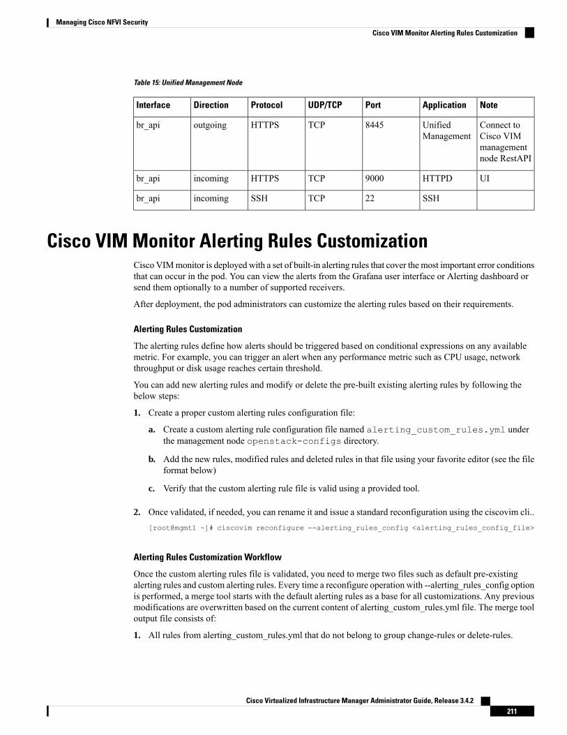
Table 15: Unified Management Node
NoteApplicationPortUDP/TCPProtocolDirectionInterface
Connect toCisco VIMmanagementnode RestAPI
UnifiedManagement
8445TCPHTTPSoutgoingbr_api
UIHTTPD9000TCPHTTPSincomingbr_api
SSH22TCPSSHincomingbr_api
Cisco VIM Monitor Alerting Rules CustomizationCisco VIMmonitor is deployed with a set of built-in alerting rules that cover themost important error conditionsthat can occur in the pod. You can view the alerts from the Grafana user interface or Alerting dashboard orsend them optionally to a number of supported receivers.
After deployment, the pod administrators can customize the alerting rules based on their requirements.
Alerting Rules Customization
The alerting rules define how alerts should be triggered based on conditional expressions on any availablemetric. For example, you can trigger an alert when any performance metric such as CPU usage, networkthroughput or disk usage reaches certain threshold.
You can add new alerting rules and modify or delete the pre-built existing alerting rules by following thebelow steps:
1. Create a proper custom alerting rules configuration file:
a. Create a custom alerting rule configuration file named alerting_custom_rules.yml underthe management node openstack-configs directory.
b. Add the new rules, modified rules and deleted rules in that file using your favorite editor (see the fileformat below)
c. Verify that the custom alerting rule file is valid using a provided tool.
2. Once validated, if needed, you can rename it and issue a standard reconfiguration using the ciscovim cli..[root@mgmt1 ~]# ciscovim reconfigure --alerting_rules_config <alerting_rules_config_file>
Alerting Rules Customization Workflow
Once the custom alerting rules file is validated, you need to merge two files such as default pre-existingalerting rules and custom alerting rules. Every time a reconfigure operation with --alerting_rules_config optionis performed, a merge tool starts with the default alerting rules as a base for all customizations. Any previousmodifications are overwritten based on the current content of alerting_custom_rules.yml file. The merge tooloutput file consists of:
1. All rules from alerting_custom_rules.yml that do not belong to group change-rules or delete-rules.
Cisco Virtualized Infrastructure Manager Administrator Guide, Release 3.4.2211
Managing Cisco NFVI SecurityCisco VIM Monitor Alerting Rules Customization

2. Rules from default_alerting_rules.yml:
• that do not duplicate from custom file rules.
• that are not supposed to be deleted.
• that can be modified based on change-rules input.
Custom Alerting Rule File Format
The alerting_custom_rules.yml file must follow the format defined in this section. This format isidentical to the one used by the Prometheus configuration file, with a few additional semantic extensions tosupport deletion and modification of pre-built existing rules.
General Format
The group entry contains a list of groups identified by (group_name), where each group can include one ormore rules. Use the labels to determine the severity and other snmp trap attributes.
Following are the limitations to set labels:
• severity, snmp_fault_code, and snmp_fault_severity must be set to one of the values specified inthe example below.
• snmp_fault_source should indicate the metric used in the alert expression
• snmp_node must not be changed.
• snmp_podid must be same as the pod name specified insetup_data.yaml
groups:- name: {group_name}rules:- alert: {alert_name}annotations:description: {alert_description}summary: {alert_summary}
expr: {alert_expression}for: {pending_time}labels:severity: {informational/warning/critical}snmp_fault_code:
{other/resourceUsage/resourceThreshold/serviceFailure/hardwareFailure/networkConnectivity}snmp_fault_severity: {emergency/critical/major/alert/informational}snmp_fault_source: {fault_source}snmp_node: '{{ $labels.instance }}'snmp_podid: {pod_id}
Addition of Alerting Rules
Any alert rule specified under a group other than change-rules group or delete-rules group is populated tothe merged output file. You can prioritize the custom rules over the pre-existing rules if there are two alertswith the same name in both the files, such that only the one from custom file is kept as a result of the merge.
Modification of Alerting Rules
You can modify any pre-existing rule using the following syntax:
Cisco Virtualized Infrastructure Manager Administrator Guide, Release 3.4.2212
Managing Cisco NFVI SecurityCisco VIM Monitor Alerting Rules Customization

groups:- name: change-rulesrules:- alert: {alert_name}expr: {new_alert_expression}annotations:summary: {new_alert_summary}
The abovemerge script finds only the group named change-rules andmodifies the expression and/or summaryof the corresponding alert.
If the alert to be changed does not exist, it will not be created and no changes are performed.
Deletion of Alerting Rule
You can delete any built-in rule using the following construct:
groups:- name: delete-rulesrules:- alert: {alert_name/regular_expression}
The above merge script finds only the group named delete-rules and deletes the pre-existing rules that matchthe alert name or regular expressions.
If the alert to be deleted does not exist, no changes are performed.
Example
The following custom configuration file includes examples of new alerting rule, modified alerting rule anddeleted alerting rules:
groups:- name: cpurules:- alert: cpu_idleannotations:description: CPU idle usage is too high - resources under-utilizedsummary: CPU idle too high
expr: cpu_usage_idle > 80for: 5mlabels:severity: informationalsnmp_fault_code: resourceUsagesnmp_fault_severity: informationalsnmp_fault_source: cpu_usage_idlesnmp_node: '{{ $labels.instance }}'snmp_podid: pod7
- alert: cpu_iowaitannotations:description: CPU iowait usage is too highsummary: CPU iowait too high
expr: cpu_usage_iowait > 10for: 3mlabels:severity: warningsnmp_fault_code: resourceUsagesnmp_fault_severity: alertsnmp_fault_source: cpu_usage_iowait
Cisco Virtualized Infrastructure Manager Administrator Guide, Release 3.4.2213
Managing Cisco NFVI SecurityCisco VIM Monitor Alerting Rules Customization
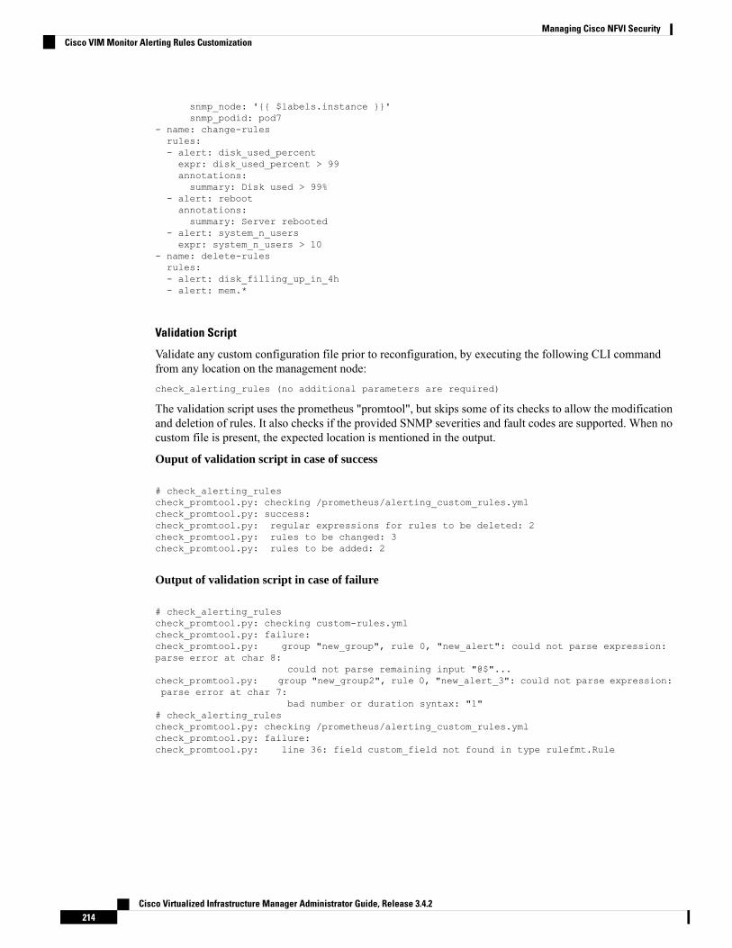
snmp_node: '{{ $labels.instance }}'snmp_podid: pod7
- name: change-rulesrules:- alert: disk_used_percentexpr: disk_used_percent > 99annotations:summary: Disk used > 99%
- alert: rebootannotations:summary: Server rebooted
- alert: system_n_usersexpr: system_n_users > 10
- name: delete-rulesrules:- alert: disk_filling_up_in_4h- alert: mem.*
Validation Script
Validate any custom configuration file prior to reconfiguration, by executing the following CLI commandfrom any location on the management node:check_alerting_rules (no additional parameters are required)
The validation script uses the prometheus "promtool", but skips some of its checks to allow the modificationand deletion of rules. It also checks if the provided SNMP severities and fault codes are supported. When nocustom file is present, the expected location is mentioned in the output.
Ouput of validation script in case of success
# check_alerting_rulescheck_promtool.py: checking /prometheus/alerting_custom_rules.ymlcheck_promtool.py: success:check_promtool.py: regular expressions for rules to be deleted: 2check_promtool.py: rules to be changed: 3check_promtool.py: rules to be added: 2
Output of validation script in case of failure
# check_alerting_rulescheck_promtool.py: checking custom-rules.ymlcheck_promtool.py: failure:check_promtool.py: group "new_group", rule 0, "new_alert": could not parse expression:parse error at char 8:
could not parse remaining input "@$"...check_promtool.py: group "new_group2", rule 0, "new_alert_3": could not parse expression:parse error at char 7:
bad number or duration syntax: "1"# check_alerting_rulescheck_promtool.py: checking /prometheus/alerting_custom_rules.ymlcheck_promtool.py: failure:check_promtool.py: line 36: field custom_field not found in type rulefmt.Rule
Cisco Virtualized Infrastructure Manager Administrator Guide, Release 3.4.2214
Managing Cisco NFVI SecurityCisco VIM Monitor Alerting Rules Customization
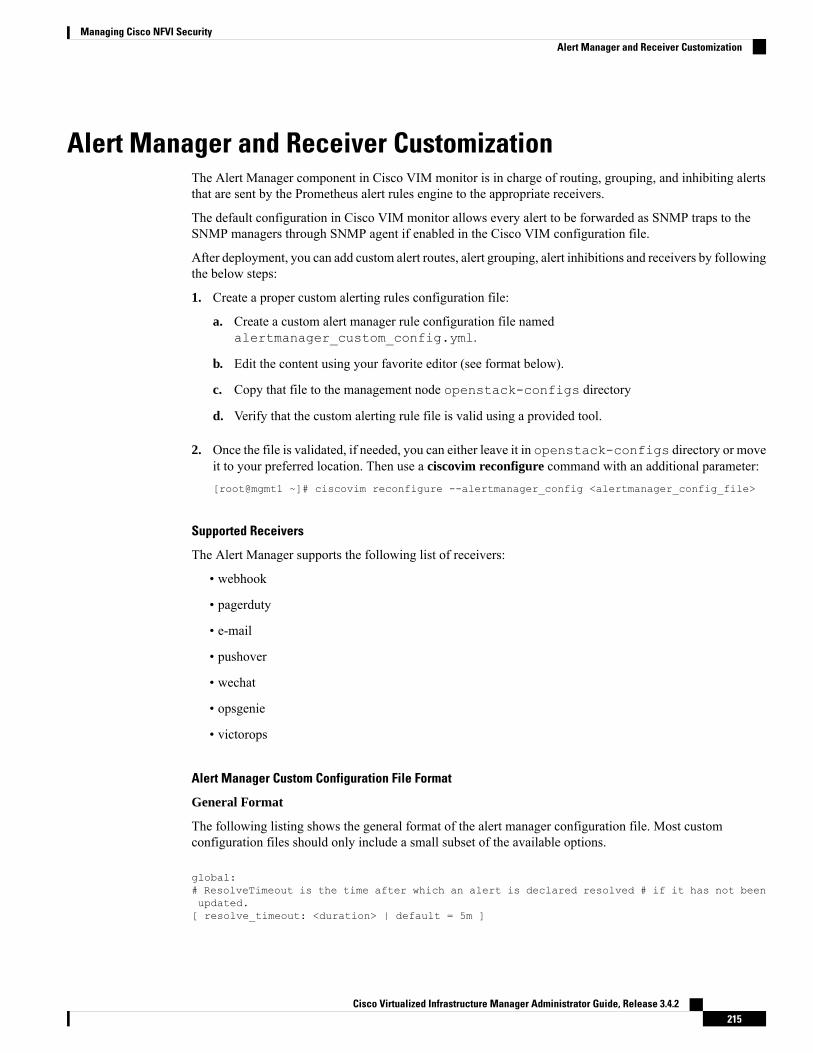
Alert Manager and Receiver CustomizationThe Alert Manager component in Cisco VIM monitor is in charge of routing, grouping, and inhibiting alertsthat are sent by the Prometheus alert rules engine to the appropriate receivers.
The default configuration in Cisco VIM monitor allows every alert to be forwarded as SNMP traps to theSNMP managers through SNMP agent if enabled in the Cisco VIM configuration file.
After deployment, you can add custom alert routes, alert grouping, alert inhibitions and receivers by followingthe below steps:
1. Create a proper custom alerting rules configuration file:
a. Create a custom alert manager rule configuration file namedalertmanager_custom_config.yml.
b. Edit the content using your favorite editor (see format below).
c. Copy that file to the management node openstack-configs directory
d. Verify that the custom alerting rule file is valid using a provided tool.
2. Once the file is validated, if needed, you can either leave it in openstack-configs directory or moveit to your preferred location. Then use a ciscovim reconfigure command with an additional parameter:[root@mgmt1 ~]# ciscovim reconfigure --alertmanager_config <alertmanager_config_file>
Supported Receivers
The Alert Manager supports the following list of receivers:
• webhook
• pagerduty
• pushover
• opsgenie
• victorops
Alert Manager Custom Configuration File Format
General Format
The following listing shows the general format of the alert manager configuration file. Most customconfiguration files should only include a small subset of the available options.
global:# ResolveTimeout is the time after which an alert is declared resolved # if it has not beenupdated.[ resolve_timeout: <duration> | default = 5m ]
Cisco Virtualized Infrastructure Manager Administrator Guide, Release 3.4.2215
Managing Cisco NFVI SecurityAlert Manager and Receiver Customization

# The default SMTP From header field. [ smtp_from: <tmpl_string> ]# The default SMTP smarthost used for sending emails, including port number.# Port number usually is 25, or 587 for SMTP over TLS (sometimes referred to as STARTTLS).
# Example: smtp.example.org:587 [ smtp_smarthost: <string> ]# The default hostname to identify to the SMTP server. [ smtp_hello: <string> | default ="localhost" ][ smtp_auth_username: <string> ]# SMTP Auth using LOGIN and PLAIN. [ smtp_auth_password: <secret> ]# SMTP Auth using PLAIN.[ smtp_auth_identity: <string> ] # SMTP Auth using CRAM-MD5.[ smtp_auth_secret: <secret> ]# The default SMTP TLS requirement.[ smtp_require_tls: <bool> | default = true ]
# The API URL to use for Slack notifications. [ slack_api_url: <secret> ][ victorops_api_key: <secret> ][ victorops_api_url: <string> | default ="https://alert.victorops.com/integrations/generic/20131114/alert/" ][ pagerduty_url: <string> | default = "https://events.pagerduty.com/v2/enqueue" ] [opsgenie_api_key: <secret> ][ opsgenie_api_url: <string> | default = "https://api.opsgenie.com/" ] [ hipchat_api_url:<string> | default = "https://api.hipchat.com/" ] [ hipchat_auth_token: <secret> ][ wechat_api_url: <string> | default = "https://qyapi.weixin.qq.com/cgi-bin/" ] [wechat_api_secret: <secret> ][ wechat_api_corp_id: <string> ]
# The default HTTP client configuration [ http_config: <http_config> ]
# Files from which custom notification template definitions are read.
# The last component may use a wildcard matcher, e.g. 'templates/*.tmpl'. templates:[ - <filepath> ... ]
# The root node of the routing tree. route: <route>
# A list of notification receivers. receivers:- <receiver> ...
# A list of inhibition rules. inhibit_rules:[ - <inhibit_rule> ... ]
The custom configuration must be a full working config file with the following template. It should containthree main keys (global, route, receiver).
The global configuration must have at least one attribute, for example, resolve_timeout = 5m. Ensure that allnew receivers must be part of the route so the alerts can be routed to the proper receivers. The receiver namecannot be snmp.
You can find the configuration details for creating route/receiver in the Prometheus Alert Managerdocumentation (publicly available online).
global: resolve_timeout: 5m
route: <route>
receivers:- <receiver> ...
The following is a custom config to add a webhook receiver.
Cisco Virtualized Infrastructure Manager Administrator Guide, Release 3.4.2216
Managing Cisco NFVI SecurityAlert Manager and Receiver Customization

global:resolve_timeout: 5m
route:group_by: ['alertname', 'cluster', 'service']group_wait: 30sgroup_interval: 5mrepeat_interval: 8737hreceiver: receiver-webhook
receivers:- name: ‘receiver-webhook’webhook_configs:- send_resolved: trueurl: 'http://webhook-example:####/xxxx/xxx'
Default Built-in Configuration File
Two different default configuration files are available to define the following in order:
1. Generic route for all alerts to the SNMP agent running on the management node.
2. Route to a generic receiver that can be customized to add a channel of notification (webhook, slack andothers).
Default configuration file with SNMP enabled
:global:resolve_timeout: 5m
route:group_by: ['alertname', 'cluster', 'service']group_wait: 30sgroup_interval: 5mrepeat_interval: 8737h
# A default receiverreceiver: snmp
receivers:- name: 'snmp'webhook_configs:- send_resolved: trueurl: 'http://localhost:1161/alarms'
Default configuration file with SNMP disabled
route:receiver: recvgroup_by:- alertname- cluster- servicegroup_wait: 30sgroup_interval: 5mrepeat_interval: 8737h
receivers:- name: recv
Cisco Virtualized Infrastructure Manager Administrator Guide, Release 3.4.2217
Managing Cisco NFVI SecurityAlert Manager and Receiver Customization
SNMP Trap Receivers
You can send the SNMP traps to SNMP managers enabled in the Cisco VIM configuration filesetup_data.yaml.
Example: inhibit (mute) alerts matching a set of labels
Inhibit alerts is a tool that prevents certain alerts to be trigged if other alert/alerts is/are trigged. If one alerthaving the target attribute matches with the another alert having source attribute, this tool inhibits the alertwith target attribute.
This is the general format for inhibit alerts. You can set a regex to match both the source and target alerts andto filter the alerts per label name.
# Matchers that have to be fulfilled in the alerts to be muted.target_match:[ <labelname>: <labelvalue>, ... ]
target_match_re:[ <labelname>: <regex>, ... ]
# Matchers for which one or more alerts have to exist for the# inhibition to take effect.source_match:[ <labelname>: <labelvalue>, ... ]
source_match_re:[ <labelname>: <regex>, ... ]
# Labels that must have an equal value in the source and target# alert for the inhibition to take effect.[ equal: '[' <labelname>, ... ']' ]
Example: Inhibit alerts if other alerts are active
The following is an example of inhibit rule that inhibits all the warning alerts that are already critical.
inhibit_rules:- source_match:
severity: 'critical'target_match:severity: 'warning'
# Apply inhibition if the alertname is the same.equal: ['alertname', 'cluster', 'service']
This is an example of inhibit all alerts docker_container in containers that are down (which has the alertdocker_container_down on).
inhibit_rules:- target_match_re:
alertname: 'docker_container.+'source_match:
alertname: 'docker_container_down'equal: ['job', 'instance']
Validation Script
When a new configuration is set, execute the check_alertmanager_config from anywhere in themanagement node and ensure that you get a SUCCESS in the output from the configuration POV.
Cisco Virtualized Infrastructure Manager Administrator Guide, Release 3.4.2218
Managing Cisco NFVI SecurityAlert Manager and Receiver Customization

> check_alertmanager_configChecking '/var/lib/cvim_mon/alertmanager_custom_config.yml' SUCCESSFound:- global config- route- 0 inhibit rules- 1 receivers- 0 templates
Cisco Virtualized Infrastructure Manager Administrator Guide, Release 3.4.2219
Managing Cisco NFVI SecurityAlert Manager and Receiver Customization

Cisco Virtualized Infrastructure Manager Administrator Guide, Release 3.4.2220
Managing Cisco NFVI SecurityAlert Manager and Receiver Customization

C H A P T E R 5Managing Cisco NFVI Storage
This chapter describes basic architectural concepts that will help you understand the Cisco NFVI data storagearchitecture and data flow. It also provides techniques you can use to monitor the storage cluster health andthe health of all systems that depend on it
• Cisco NFVI Storage Architecture, on page 221• Verifying and Displaying Ceph Storage Pools, on page 222• Checking the Storage Cluster Health, on page 223• Checking Glance Connectivity, on page 224• Verifying Glance and Ceph Monitor Keyrings, on page 225• Verifying Glance Image ID on Ceph, on page 226• Checking Cinder Connectivity, on page 226• Verifying Cinder and Ceph Monitor Keyrings, on page 227• Verifying Cinder Volume ID on Ceph, on page 228• Checking Nova Connectivity, on page 229• Verifying the Nova and Ceph Monitor Keyrings, on page 229• Working with Multi-Backend Ceph, on page 230• Verifying Nova Instance ID, on page 231• Displaying Docker Disk Space Usage, on page 232• Reconfiguring Administrator Source Networks, on page 233• Password Reset for Cisco VIM Management Node, on page 234• Ceph Storage Expansion, on page 235
Cisco NFVI Storage ArchitectureOpenStack has multiple storage back ends. Cisco NFVI uses the Ceph back end. Ceph supports both blockand object storage and is therefore used to store VM images and volumes that can be attached to VMs.MultipleOpenStack services that depend on the storage backend include:
• Glance (OpenStack image service)—Uses Ceph to store images.
• Cinder (OpenStack storage service)—Uses Ceph to create volumes that can be attached to VMs.
• Nova (OpenStack compute service)—Uses Ceph to connect to the volumes created by Cinder.
The following figure shows the Cisco NFVI storage architecture component model.
Cisco Virtualized Infrastructure Manager Administrator Guide, Release 3.4.2221

Figure 15: Cisco NFVI Storage Architecture
Verifying and Displaying Ceph Storage PoolsCeph is configured with four independent pools: images, volumes, vms, and backups. (A default rbd pool isused internally.) Each Ceph pool is mapped to an OpenStack service. The Glance service stores data in theimages pool, and the Cinder service stores data in the volumes pool. The Nova service can use the vms poolto boot ephemeral disks directly from the Ceph cluster depending on how the NOVA_BOOT_FROM optionin the ~/openstack-configs/setup_data.yaml was configured prior to Cisco NFVI installation. IfNOVA_BOOT_FROM is set to ceph before you run the Cisco NFVI installation, the Nova service boot upfrom the Ceph vms pool. By default, NOVA_BOOT_FROM is set to local, whichmeans that all VM ephemeraldisks are stored as files in the compute nodes. Changing this option after installation does not affect the useof the vms pool for ephemeral disks.
The Glance, Cinder, and Nova OpenStack services depend on the Ceph cluster for backend storage. Therefore,they need IP connectivity to the controller nodes. The default port used to connect Glance, Cinder, and Novato the Ceph cluster is 6789. Authentication through cephx is required, which means authentication tokens,called keyrings, must be deployed to the OpenStack components for authentication.
To verify and display the Cisco NFVI Ceph storage pools:
Step 1 Launch a SSH session to a controller node, for example:[root@management-server-cisco ~]# ssh root@controller_server-1
Step 2 Navigate to the Ceph Monitor container:[root@controller_server-1 ~]# cephmon
Cisco Virtualized Infrastructure Manager Administrator Guide, Release 3.4.2222
Managing Cisco NFVI StorageVerifying and Displaying Ceph Storage Pools

Step 3 List the Ceph pools:cephmon_4612 [root@controller_server-1 ~]# ceph osd lspools0 rbd,1 images,2 volumes,3 vms,4 backups,
Step 4 List the images pool content:cephmon_4612 [ceph@controller_server-1 /]$ rbd list imagesa4963d51-d3b7-4b17-bf1e-2ebac07e1593
Checking the Storage Cluster HealthCisco recommends that you perform a few verifications to determine whether the Ceph cluster is healthy andis connected to the Glance, Cinder, and Nova OpenStack services, which have Ceph cluster dependencies.The first task to check the health of the cluster itself by completing the following steps:
Step 1 From the Cisco NFVI management node, launch a SSH session to a controller node, for example:[root@management-server-cisco ~]# ssh root@controller_server-1
Step 2 Navigate to the Ceph Monitor container:[root@controller_server-1 ~]# cephmon
Step 3 Check the Ceph cluster status:cephmon_4612 [ceph@controller_server-1 ceph]$ ceph status
Sample response:cluster dbc29438-d3e0-4e0c-852b-170aaf4bd935
health HEALTH_OKmonmap e1: 3 mons at {ceph-controller_server-1=20.0.0.7:6789/0,ceph-controller_server-2=20.0.0.6:6789/0,ceph-controller_server-3=20.0.0.5:6789/0}
election epoch 8, quorum 0,1,2 ceph-controller_server-3,ceph-controller_server-2,ceph-controller_server-1osdmap e252: 25 osds: 25 up, 25 inpgmap v593: 1024 pgs, 5 pools, 406 MB data, 57 objects
2341 MB used, 61525 GB / 61527 GB avail1024 active+clean
This example displays three monitors, all in good health, and 25 object storage devices (OSDs). All OSDs show as upand in the cluster.
Step 4 To see a full listing of all OSDs sorted by storage node, enter:cephmon_4612 [ceph@controller_server-1 ceph]$ ceph osd tree
Sample response:ID WEIGHT TYPE NAME UP/DOWN REWEIGHT PRIMARY-AFFINITY-1 60.18979 root default-2 18.96994 host controller_server-21 2.70999 osd.1 up 1.00000 1.000005 2.70999 osd.5 up 1.00000 1.000006 2.70999 osd.6 up 1.00000 1.00000
Cisco Virtualized Infrastructure Manager Administrator Guide, Release 3.4.2223
Managing Cisco NFVI StorageChecking the Storage Cluster Health

11 2.70999 osd.11 up 1.00000 1.0000012 2.70999 osd.12 up 1.00000 1.0000017 2.70999 osd.17 up 1.00000 1.0000020 2.70999 osd.20 up 1.00000 1.00000-3 18.96994 host controller_server-10 2.70999 osd.0 up 1.00000 1.000004 2.70999 osd.4 up 1.00000 1.000008 2.70999 osd.8 up 1.00000 1.0000010 2.70999 osd.10 up 1.00000 1.0000013 2.70999 osd.13 up 1.00000 1.0000016 2.70999 osd.16 up 1.00000 1.0000018 2.70999 osd.18 up 1.00000 1.00000-4 18.96994 host controller_server-32 2.70999 osd.2 up 1.00000 1.000003 2.70999 osd.3 up 1.00000 1.000007 2.70999 osd.7 up 1.00000 1.000009 2.70999 osd.9 up 1.00000 1.0000014 2.70999 osd.14 up 1.00000 1.0000015 2.70999 osd.15 up 1.00000 1.0000019 2.70999 osd.19 up 1.00000 1.00000-5 3.27997 host controller_server-421 0.81999 osd.21 up 1.00000 1.0000022 0.81999 osd.22 up 1.00000 1.0000023 0.81999 osd.23 up 1.00000 1.0000024 0.81999 osd.24 up 1.00000 1.00000
What to do next
After you verify the Ceph cluster is in good health, check that the individual OpenStack components haveconnectivity and their authentication tokens—keyrings—match the Ceph Monitor keyrings. The followingprocedures show how to check the connectivity and authentication between Ceph and Glance, Ceph andCinder, and Ceph and Nova.
Checking Glance ConnectivityThe Glance API container must be connected to the Cisco NFVI controller nodes. Complete the followingsteps to verify the Glance to controller node connectivity:
Step 1 From the management node, examine the IP addresses of controller node:[root@management-server-cisco ~]# cat /root/openstack-configs/mercury_servers_info
Step 2 From the management node, launch a SSH session to a controller node, for example:[root@management-server-cisco ~]# ssh root@controller_server-1
Step 3 Navigate to the Glance API container:[root@controller_server-1 ~]# glanceapi
Step 4 Check the Glance API container connectivity to the storage IP address of the controller node different from the oneentered in Step 2:glanceapi_4612 [glance@controller_server-1 /]$ curl <storage_ip_of_another_controller>:6789
If the connection is successful, no message is displayed, but you need to do Ctrl+C to terminate the connection:
Cisco Virtualized Infrastructure Manager Administrator Guide, Release 3.4.2224
Managing Cisco NFVI StorageChecking Glance Connectivity

glanceapi_4612 [glance@controller_server-1 /]$ curl 7.0.0.16:6789
If the connection is not successful, you see a message like the following:
glanceapi_4612 [glance@controller_server-1 /]$ curl 7.0.0.16:6789 curl: (7)Failed connect to controller_server-2:6789; Connection refused
The above message indicates that the Ceph monitor running on the target controller node controller_server-2 is notlistening on the specified port or there is no route to it from the Glance API container.
Checking one controller node should be enough to ensure one connection path available for the Glance API. As CiscoNFVI controller nodes run as part of an HA cluster, you should run Step 3 above targeting all the controller nodes in theCisco NFVI pod.
What to do next
After you verify the Glance API connectivity to all Cisco NFVI controller nodes, check the Glance keyringto ensure that it matches with the Ceph monitor keyring.
Verifying Glance and Ceph Monitor KeyringsComplete the following steps to verify the Glance API keyring matches the Ceph Monitor keyring.
Step 1 Launch a SSH session to a controller node, for example:[root@management-server-cisco ~]# ssh root@controller_server-1
Step 2 Navigate to the Glance API container:[root@controller_server-1 ~]# glanceapi
Step 3 Check the Glance keyring content, for example:glanceapi_4612 [glance@controller_server-1 /]$ cat /etc/ceph/client.glance.keyring [client.glance]key = AQA/pY1XBAnHMBAAeS+0Wmh9PLZe1XqkIW/p0A==
Step 4 On the management node, check the CEPH cluster UUID:[root@management-server-cisco ~]# cat /root/openstack-configs/ceph/fetch/ceph_cluster_uuid.conf0e96e7f2-8175-44b3-ac1a-4f62de12ab9e
Step 5 Display the Ceph Glance keyring content:
[root@management-server-cisco ~]# cat/root/openstack-configs/ceph/fetch/0e96e7f2-8175-44b3-ac1a-4f62de12ab9e/etc/ceph/ceph.client.glance.keyring
[mon.]
key = AQA/pY1XBAnHMBAAeS+0Wmh9PLZe1XqkIW/p0A==
Verify whether the keyring matches the Glance API keyring displayed in Step 3.
Cisco Virtualized Infrastructure Manager Administrator Guide, Release 3.4.2225
Managing Cisco NFVI StorageVerifying Glance and Ceph Monitor Keyrings

What to do next
A final check to ensure that Ceph and Glance are connected is to actually import a Glance image using Horizonor the Glance CLI. After you import an image, compare the IDs seen by Glance and by Ceph. They shouldmatch, indicating Ceph is handling the backend for Glance.
Verifying Glance Image ID on CephThe following steps verify Ceph is properly handling new Glance images by checking that the image ID fora new Glance image is the same as the image ID displayed in Ceph.
Step 1 From the management node, load the OpenStack authentication variables:[root@management-server-cisco ~]# source ~/openstack-configs/openrc
Step 2 Import any Glance image. In the example below, a RHEL 7.1 qcow2 image is used.
[root@management-server-cisco images]# openstack image create"rhel" --disk-format qcow2 --container-format bare --file rhel-guest-image-7.1-20150224.0.x86_64.qcow2
Step 3 List the Glance images:
[root@management-server-cisco images]# openstack image list | grep rhel| a4963d51-d3b7-4b17-bf1e-2ebac07e1593 | rhel
Step 4 Navigate to the Ceph Monitor container:[root@controller_server-1 ~]# cephmon
Step 5 Display the contents of the Ceph images pool:
cephmon_4612 [ceph@controller_server-1 ceph]$ rbd list images | grepa4963d51-d3b7-4b17-bf1e-2ebac07e1593a4963d51-d3b7-4b17-bf1e-2ebac07e1593
Step 6 Verify that the Glance image ID displayed in Step 3 matches with the image ID displayed by Ceph.
Checking Cinder ConnectivityThe Cinder volume container must have connectivity to the Cisco NFVI controller nodes. Complete thefollowing steps to verify Cinder volume has connectivity to the controller nodes:
Step 1 From the management node, examine the IP addresses of controller node:[root@management-server-cisco ~]# cat /root/openstack-configs/mercury_servers_info
Step 2 From the management node, launch a SSH session to a controller node, for example:[root@management-server-cisco ~]# ssh root@controller_server-1
Cisco Virtualized Infrastructure Manager Administrator Guide, Release 3.4.2226
Managing Cisco NFVI StorageVerifying Glance Image ID on Ceph

Step 3 Navigate to the Cinder volume container:[root@controller_server-1 ~]# cindervolume
Step 4 Check the Cinder volume container connectivity to the storage IP address of controller node different from the one enteredin Step 1:cindervolume_4612 [cinder@controller_server-1 /]$ curl 7.0.0.16:6789
If the connection is successful, no message is displayed, but you need to do a Ctrl-C to terminate the connection:cindervolume_4612 [cinder@controller_server-1 /]$ curl 7.0.0.16:6789
If the connection is not successful, you see a message like the following:cindervolume_4612 [cinder@controller_server-1 /]$ curl controller_server-2:6789curl: (7) Failed connect to controller_server-2:6789; Connection refused
A message like the one above means the Ceph monitor running on the target controller node controller_server-2 is notlistening on the specified port or there is no route to it from the Cinder volume container.
Checking one controller node should be enough to ensure one connection path is available for the Cinder volume. However,because Cisco NFVI controller nodes run as part of an HA cluster, repeat Step 3 targeting all the controller nodes in theCisco NFVI pod.
What to do next
After you verify the Cinder volume connectivity to all Cisco NFVI controller nodes, check the Cinder keyringto ensure it matches the Ceph monitor keyring.
Verifying Cinder and Ceph Monitor KeyringsComplete the following steps to verify the Cinder volume keyring matches the Ceph Monitor keyring.
Step 1 From the management node, launch a SSH session to a controller node, for example:[root@management-server-cisco ~]# ssh root@controller_server-1
Step 2 Navigate to the Cinder volume container:[root@controller_server-1 ~]# cindervolume
Step 3 Check the Cinder keyring content, for example:cindervolume_4612 [cinder@controller_server-1 /]$ cat /etc/ceph/client.cinder.keyring[client.cinder]key = AQA/pY1XBAnHMBAAeS+0Wmh9PLZe1XqkIW/p0A==
Step 4 On management node, check the CEPH cluster UUID:
[root@management-server-cisco ~]# cat /root/openstack-configs/ceph/fetch/ceph_cluster_uuid.conf0e96e7f2-8175-44b3-ac1a-4f62de12ab9e
Step 5 Display the Ceph Cinder keyring content:
[root@management-server-cisco ~]# cat
Cisco Virtualized Infrastructure Manager Administrator Guide, Release 3.4.2227
Managing Cisco NFVI StorageVerifying Cinder and Ceph Monitor Keyrings

/root/openstack-configs/ceph/fetch/0e96e7f2-8175-44b3-ac1a-4f62de12ab9e/etc/ceph/ceph.client.cinder.keyring[client.cinder]key = AQA/pY1XBAnHMBAAeS+0Wmh9PLZe1XqkIW/p0A==
Verify whether the keyring matches with the Cinder volume keyring displayed in Step 3.
What to do next
As a final Ceph and Cinder connectivity verification, import a Cinder image using Horizon or the Cinder CLI.After you import the image, compare the IDs seen by Cinder and by Ceph. If the IDs match, it indicates thatCeph is handling the backend for Cinder.
Verifying Cinder Volume ID on CephThe following steps verify Ceph is properly handling new Cinder volumes by checking that the volume IDfor a new Cinder volume is the same as the volume ID displayed in Ceph.
Step 1 From the management node, load the OpenStack authentication variables:[root@management-server-cisco ~]# source ~/openstack-configs/openrc
Step 2 Create an empty volume:[root@management-server-cisco ~]# openstack volume create --size 5 ciscovol1
The preceding command creates a new 5 GB Cinder volume named ciscovol1.
Step 3 List the Cinder volumes:
[[root@management-server-cisco ~]# openstack volume list+--------------------------------------+-----------+-----------+------+-------------+| ID | Name | Status | Size | Attached to |+--------------------------------------+-----------+-----------+------+-------------+| 3017473b-6db3-4937-9cb2-bd0ba1bf079d | ciscovol1 | available | 5 | |+--------------------------------------+-----------+-----------+------+-------------+
Step 4 Navigate to the Ceph Monitor container:[root@controller_server-1 ~]# cephmon
Step 5 Display the contents of the Ceph volumes pool:
cephmon_4612 [ceph@controller_server-1 ceph]$ rbd list volumesvolume-3017473b-6db3-4937-9cb2-bd0ba1bf079d
Step 6 Verify that the Cinder volume ID displayed in Step 3 matches with the volume ID displayed by Ceph, excluding the"volume-" prefix.
Cisco Virtualized Infrastructure Manager Administrator Guide, Release 3.4.2228
Managing Cisco NFVI StorageVerifying Cinder Volume ID on Ceph

Checking Nova ConnectivityThe Nova libvirt container must have connectivity to the Cisco NFVI controller nodes. Complete the followingsteps to verify Nova has connectivity to the controller nodes:
Step 1 From the management node, examine the IP addresses of controller node:[root@management-server-cisco ~]# cat /root/openstack-configs/mercury_servers_info
Step 2 From the management node, launch a SSH session to a controller node, for example:[root@management-server-cisco ~]# ssh root@Computenode_server-1
Step 3 Navigate to the Nova libvirt container:[root@compute_server-1 ~]# libvirt
Step 4 Check the Nova libvirt container connectivity to the storage address of the controller node different from the one enteredin Step 1:novalibvirt_4612 [root@compute_server-1 /]$ curl 7.0.0.16:6789
If the connection is successful, no message is displayed, but you need to do a Ctrl-C to terminate the connection:
If the connection is not successful, a message is displayed as follows:novalibvirt_4612 [root@compute_server-1 /]$ curl 7.0.0.16:6789curl: (7) Failed connect to controller_server-1:6789; Connection refused
The above message indicates that the Ceph monitor running on the target controller node controller_server-1 is notlistening on the specified port or there is no route to it from the Nova libvirt container.
Checking one controller node is sufficient to ensure that one connection path is available for the Nova libvirt. As CiscoNFVI controller nodes run as part of an HA cluster, you should run Step 3 above targeting all the controller nodes in theCisco NFVI pod.
What to do next
After you verify the Nova libvirt connectivity to all Cisco NFVI controller nodes, check the Nova keyring toensure it matches the Ceph monitor keyring.
Verifying the Nova and Ceph Monitor KeyringsComplete the following steps to verify the Nova libvirt keyring matches the Ceph Monitor keyring.
Step 1 From the management node, launch a SSH session to a controller node, for example:[root@management-server-cisco ~]# ssh root@compute_server-1
Step 2 Navigate to the Nova libvert container:[root@compute_server-1 ~]# libvirt
Cisco Virtualized Infrastructure Manager Administrator Guide, Release 3.4.2229
Managing Cisco NFVI StorageChecking Nova Connectivity

Step 3 Extract the libvirt secret that contains the Nova libvirt keyring:novalibvirt_4612 [root@compute_server-1 /]# virsh secret-listUUID Usage …-----------------------------------------------------------------b5769938-e09f-47cb-bdb6-25b15b557e84 ceph client.cinder
Step 4 Get the keyring from the libvert secret:novalibvirt_4612 [root@controller_server-1 /]# virsh secret-get-valueb5769938-e09f-47cb-bdb6-25b15b557e84 AQBApY1XQCBBEBAAroXvmiwmlSMEyEoXKl/sQA==
Step 5 On management node, check the CEPH cluster UUID::[root@management-server-cisco ~]# cat /root/openstack-configs/ceph/fetch/ceph_cluster_uuid.conf0e96e7f2-8175-44b3-ac1a-4f62de12ab9e
Step 6 Display the Ceph Cinder keyring content:
[root@management-server-cisco ~]# cat/root/openstack-configs/ceph/fetch/0e96e7f2-8175-44b3-ac1a-4f62de12ab9e/etc/ceph/ceph.client.cinder.keyring[client.cinder]
key = AQBApY1XQCBBEBAAroXvmiwmlSMEyEoXKl/sQA==
Step 7 Verify whether the keyring matches with the Nova libvirt keyring displayed in Step 3.
In the above example, the Cinder keyring is checked even though this procedure is for the Nova libvirt keyring.This occurs because the Nova services need access to the Cinder volumes and so authentication to Ceph usesthe Cinder keyring.
Note
What to do next
Complete a final check to ensure that Ceph and Nova are connected by attaching a Nova volume using Horizonor the Nova CLI. After you attach the Nova volume, check the libvirt domain.
Working with Multi-Backend CephThe OpenStack component that provides an API to create block storage for cloud is called OpenStack BlockStorage service or Cinder. Cinder requires you to configure single backend (by default) or multiple backend.
Cisco VIM supports the following Cinder backends either configured in isolation or parallel.
• Storage nodes full of SSDs disks
• Storage nodes full of HDDs disks
Choosing multi-backend ceph is currently a day-0 option, that is, the cloud administrator must choose singlebackend or multi-backend storage option at the beginning. It is recommended to have four nodes with aminimum being three nodes for each storage type (HDD or SSD).
To enable support for Cinder multi-backends, update the setup_data.yaml to include theosd_disk_type as HDD/SSD under 'hardware_info' of the storage server as given below:
storage-hdd-server-1: --- Need mininmum of 3; recommend to have 4cimc_info: {cimc_ip: <cimc_ip}
Cisco Virtualized Infrastructure Manager Administrator Guide, Release 3.4.2230
Managing Cisco NFVI StorageWorking with Multi-Backend Ceph

hardware_info: {osd_disk_type: HDD}rack_info: {rack_id: RackA}
storage-ssd-server-1: -- --- Need mininmum of 3; recommend to have 4cimc_info: {cimc_ip: <cimc_ip>}hardware_info: {osd_disk_type: SSD}rack_info: {rack_id: RackB}
After successful deployment of Cisco VIM, follow the below steps to create Cinder multi-backends:
Step 1 Log into Horizon of the cloud and navigate to <Admin/Volume/Volume Types taba) Specify the Name and Description (Optional). The Name can be volume-ssd or volume-hdd for SSD or HDD,
respectivelyb) Click the dropdown and select view extra specsc) Click on Create and update the Key with volume_backend_name.d) Enter the Value as given below:
For SSD, the Value is ceph-ssd
For HDD, the Value is ceph
Step 2 Create Volume from Horizon for each backend typea) Choose Project/Volumes/Volumesb) Click Create Volume
Volume name : SSD volume (example)
Description: Optional
Volume Source : use the default
Type : Choose the volume type from the dropdown. It can be volume-ssd/volume-hdd
Step 3 Attach the volume to Instance.a) Navigate to Project/compute/instance.b) Select the instance to be attached the volume.c) Click on the drop down Attach volume and select the Volume ID from the dropdown.
Verifying Nova Instance IDFrom the management node, complete the following steps to verify the Nova instance ID of a guest VM havinga cinder volume attached::
Step 1 Load the OpenStack authentication variables:[root@management-server-cisco installer]# source ~/openstack-configs/openrc
Step 2 List the Nova instances:[root@management-server-cisco images]# nova list+--------------------------------------+------------+--------+--------| ID | Name | Status | Task
Cisco Virtualized Infrastructure Manager Administrator Guide, Release 3.4.2231
Managing Cisco NFVI StorageVerifying Nova Instance ID

+--------------------------------------+------------+--------+--------| 77ea3918-793b-4fa7-9961-10fbdc15c6e5 | cisco-vm | ACTIVE | -+----------------------------------+-----------+-------+-
Step 3 Show the Nova instance ID for one of the instances:[root@management-server-cisco images]# nova show77ea3918-793b-4fa7-9961-10fbdc15c6e5 | grep instance_name| OS-EXT-SRV-ATTR:instance_name | instance-00000003
The Nova instance ID in this example is instance-00000003. This ID will be used later with the virsh command. Novainstance IDs are actually the libvirt IDs of the libvirt domain associated with the Nova instance.
Step 4 Identify the compute node where the VM was deployed:[root@management-server-cisco images]# nova show 77ea3918-793b-4fa7-9961-10fbdc15c6e5 | grephypervisor| OS-EXT-SRV-ATTR:hypervisor_hostname | compute_server-1
The compute node in this case is compute_server-1. You will connect to this compute node to call the virsh commands.Next, you get the volume ID from the libvirt domain in the Nova libvirt container.
Step 5 Launch a SSH session to the identified compute node, compute_server-1:[root@management-server-cisco ~]# ssh root@compute_server-1
Step 6 Navigate to the Nova libvirt container:[root@compute_server-1 ~]# libvirt
Step 7 Get the instance libvirt domain volume ID:novalibvirt_4612 [root@compute_server-1 /]# virsh dumpxml instance-00000003 | grep rbd<source protocol='rbd' name='volumes/volume-dd188a5d-f822-4769-8a57-c16694841a23'>
Step 8 Launch a SSH session to a controller node:[root@management-server-cisco ~]# ssh root@controller_server-1
Step 9 Navigate to the Ceph Monitor container:[root@compute_server-1 ~]# cephmon
Step 10 Verify volume ID matches the ID in Step 7:cephmon_4612 [ceph@controller_server-1 ceph]$ rbd list volumes | grep volume-dd188a5d-f822-4769-8a57-c16694841a23volume-dd188a5d-f822-4769-8a57-c16694841a23
Displaying Docker Disk Space UsageDocker supports multiple storage back ends such as Device Mapper, thin pool, overlay, and AUFS. CiscoVIM uses the devicemapper storage driver because it provides strong performance and thin provisioning.DeviceMapper is a kernel-based framework that supports advanced volumemanagement capability. Completethe following steps to display the disk space used by Docker containers.
Step 1 Launch a SSH session to a controller or compute node, for example:
Cisco Virtualized Infrastructure Manager Administrator Guide, Release 3.4.2232
Managing Cisco NFVI StorageDisplaying Docker Disk Space Usage

[root@management-server-cisco ~]# ssh root@controller_server-1
Step 2 Enter the docker info command to display the disk space used by Docker containers:[root@controller_server_1 ~]# docker infoContainers: 24Images: 186Storage Driver: devicemapperPool Name: vg_var-docker--poolPool Blocksize: 524.3 kBBacking Filesystem: xfsData file:Metadata file:Data Space Used: 17.51 GBData Space Total: 274.9 GBData Space Available: 257.4 GB…
Reconfiguring Administrator Source NetworksTo access the administrator services, Cisco VIM provides source IP based filtering of network requests onthe management node. These services include SSH and Kibana dashboard access. When the services areconfigured all admin network requests made to the management node are dropped, except the white listedaddresses in the configuration.
Reconfiguring administrator source network supports the following options:
• Set administrator source network list: Network addresses can be added or deleted from the configuration;the list is replaced in whole during a reconfigure operation.
• Remove administrator source network list: If the admin_source_networks option is removed, the sourceaddress does not filter the incoming admin service requests.
The following section needs to be configured in the Setup_data.yaml file:admin_source_networks: # optional, host based firewall to white list admin's source IP- 10.0.0.0/8- 172.16.0.0/12
You must be careful while updating the source networks. If the list is misconfigured, you are locked and notallowed to access the management node through SSH. If it is locked, you must log into the management nodethrough the console port to repair the configuration.
Note
To initiate the integration, copy the setupdata into a local directory by running the following command:[root@mgmt1 ~]# cd /root/[root@mgmt1 ~]# mkdir MyDir[root@mgmt1 ~]# cd MyDir[root@mgmt1 ~]# cp /root/openstack-configs/setup_data.yaml <my_setup_data.yaml>
Update the setupdata by running the following command:[root@mgmt1 ~]# vi my_setup_data.yaml (update the setup_data to include Admin source networkinformation)
Cisco Virtualized Infrastructure Manager Administrator Guide, Release 3.4.2233
Managing Cisco NFVI StorageReconfiguring Administrator Source Networks

Run the reconfiguration command as follows:
[root@mgmt1 ~]# cd ~/installer-xxxx[root@mgmt1 ~]# ciscovim reconfigure –-setupfile ~/MyDir/<my_setup_data.yaml>
Password Reset for Cisco VIM Management NodeRun the following command to reset the Root Password of Cisco VIMmanagement nodeRHEL-7 / systemd.
1. Boot your system and wait until the GRUB2 menu appears.
2. In the boot loader menu, highlight any entry and press e.
3. Find the line beginning with linux. At the end of this line, append the following:init=/bin/sh
Or if you face any alarm, instead of ro change rw to sysroot as shown in the following example:rw init=/sysroot/bin/sh
4. Press Ctrl+X to boot the system using the options you edited.
Once the system boots, you can see the shell prompt without having to enter any user name or password:sh-4.2#
5. Load the installed SELinux policy by running the following command:sh-4.2# /usr/sbin/load_policy -i
6. Execute the following command to remount your root partition:sh4.2#
mount -o remount,rw /
7. Reset the root password by running the following command:sh4.2# passwd root
When prompted, enter your new root password and click Enter key to confirm. Enter the password forthe second time to make sure you typed it correctly and confirm with Enter again. If both the passwordsmatch, a confirmation message appears.
8. Execute the following command to remount the root partition again, this time as read-only:sh4.2#
mount -o remount,ro /
9. Reboot the system. Now you can log in as the root user using the new password set up during this procedure.
To reboot the system, enter exit and exit again to leave the environment and reboot the system.
References: https://access.redhat.com/solutions/918283.
Cisco Virtualized Infrastructure Manager Administrator Guide, Release 3.4.2234
Managing Cisco NFVI StoragePassword Reset for Cisco VIM Management Node

Ceph Storage ExpansionFrom release Cisco VIM 3.0.0, a command expand-storage is available to add disks so as to expand analready deployed Ceph storage cluster. You can deploy the storage nodes in the Openstack PoD in one of twoways:
• Combination of HDD and SSD drives with Ceph deployed with dedicated journals.
• All SSD drives with Ceph deployed with collocated journals.
The expand-storage command is supported only on storage nodes with a combination of HDD and SSD drives.Note
You must install disk drives based on how the node was originally deployed. If you have a storage node witha 1 SSD/4 HDDs ratio, insert disks with that same SSD/HDD ratio for expanding the storage. Theexpand-storage command looks for blocks of disks with that ratio during the expansion process, and installsone block at a time.
Workflow
• Use ciscovim list-nodes to find a node with a role of “block-storage”
• Insert a block of disks based on your storage deployment into the target node
• Log into the CIMC of the target node and navigate to the storage panel.
• Verify that no disks are reporting errors.
• If any disk reports foreign configuration, clear the configuration.
• Enable JBOD if RAID controller is used.
• Run cloud-sanity and ensure that no failure occurs.
• Run osdmgmt check-osds to check the state and number of the OSDs currently installed.
• Run expand-storage with the name of the target storage node.
• Run osdmgmt check-osds to check the state and number of the OSDs .
• Compare the outputs of the two osdmgmt check-osd commands and verify whether the new disks wereadded as additional OSDs.
The expand storage command runs in the same manner as other ciscovim commands but with various stepsexecuted at a time.The command execution is stopped in case of any failure. You can view the logs once thecommand execution is complete. The steps for the expand-storage command are:
• Hardware validations
• Baremetal
• CEPH for expansion
• VMTP
Command Help
Cisco Virtualized Infrastructure Manager Administrator Guide, Release 3.4.2235
Managing Cisco NFVI StorageCeph Storage Expansion

$ ciscovim help expand-storageusage: ciscovim expand-storage --setupfile SETUPFILE [-y] <node>
Expand storage node capacity
Positional arguments:<node> Expand Storage capacity of a storage node
Optional arguments:--setupfile SETUPFILE <setupdata_file>. Mandatory for any POD management
operation.-y, --yes Yes option to perform the action
Workflow command examples:
To expand the storage of node i13-27-test, get the current number/state of the OSDs in the cluster.
$ ciscovim list-nodes+-------------+--------+---------------+---------------+| Node Name | Status | Type | Management IP |+-------------+--------+---------------+---------------+| i13-20 | Active | control | 15.0.0.7 || i13-21 | Active | control | 15.0.0.8 || i13-22 | Active | control | 15.0.0.5 || i13-23 | Active | compute | 15.0.0.6 || i13-24 | Active | compute | 15.0.0.10 || i13-25 | Active | block_storage | 15.0.0.11 || i13-26 | Active | block_storage | 15.0.0.9 || i13-27-test | Active | block_storage | 15.0.0.4 |+-------------+--------+---------------+---------------+
ciscovim osdmgmt show check-osds --id <id>+--------------------+-------------+---------------+-----------+---------+| Message | Host | Role | Server | State |+--------------------+-------------+---------------+-----------+---------+| Overall OSD Status | i13-25 | block_storage | 15.0.0.11 | Optimal || | i13-26 | block_storage | 15.0.0.9 | Optimal || | i13-27-test | block_storage | 15.0.0.4 | Optimal || | | | | || Number of OSDs | i13-25 | block_storage | 15.0.0.11 | 10 || | i13-26 | block_storage | 15.0.0.9 | 10 || | i13-27-test | block_storage | 15.0.0.4 | 12 |+--------------------+-------------+---------------+-----------+---------++-------------+--------+--------+----+------------+-----------+-----------| Host | OSDs | Status | ID | HDD Slot | Path | Mount+-------------+--------+--------+----+------------+-----------+-----------.omitted for doc.| i13-27-test | osd.2 | up | 2 | 4 (JBOD) | /dev/sda1 || | osd.5 | up | 5 | 3 (JBOD) | /dev/sdb1 || | osd.8 | up | 8 | 6 (JBOD) | /dev/sdc1 || | osd.11 | up | 11 | 2 (JBOD) | /dev/sdd1 || | osd.14 | up | 14 | 5 (JBOD) | /dev/sde1 || | osd.19 | up | 19 | 9 (JBOD) | /dev/sdi1 || | osd.24 | up | 24 | 10 (JBOD) | /dev/sdj1 || | osd.27 | up | 27 | 8 (JBOD) | /dev/sdl1 || | osd.28 | up | 28 | 12 (JBOD) | /dev/sdm1 || | osd.29 | up | 29 | 11 (JBOD) | /dev/sdn1 || | osd.30 | up | 30 | 13 (JBOD) | /dev/sdo1 || | osd.31 | up | 31 | 17 (JBOD) | /dev/sdp1 |+-------------+--------+--------+----+------------+-----------+
Cisco Virtualized Infrastructure Manager Administrator Guide, Release 3.4.2236
Managing Cisco NFVI StorageCeph Storage Expansion

Run the expand-storage command
# ciscovim expand-storage i13-27-test --setupfile setup_data.yaml
Perform the action. Continue (Y/N)Y
Monitoring StorageMgmt Operation
. . . . Cisco VIM Runner logsThe logs for this run are available in<ip>:/var/log/mercury/05f068de-86fd-479c-afda-c54b14ffdd3e
############################################Cisco Virtualized Infrastructure Manager############################################
[1/3][VALIDATION: INIT] [ / ]0min 0secManagement Node Validations!..Omitted for doc..[1/3][VALIDATION: Starting HW Validation, takes time!!!] [ DONE! ]
Ended Installation [VALIDATION] [Success]
[2/3][CEPH: Checking for Storage Nodes] [ DONE! ][2/3][CEPH: Creating Ansible Inventory] [ DONE! ]..Omitted for doc..[2/3][CEPH: Waiting for server to come back first try] [ DONE! ]
Ended Installation [CEPH] [Success]VMTP Starts
/home/vmtp/.ssh/id_rsa already exists...Omitted for doc..
[3/3][VMTP: INIT] [ DONE! ]
Ended Installation [VMTP] [Success]
The logs for this run are available in<ip>:/var/log/mercury/05f068de-86fd-479c-afda-c54b14ffdd3e===========
Check the OSDsciscovim osdmgmt create check-osds+------------+--------------------------------------+| Field | Value |+------------+--------------------------------------+| action | check-osds |
Cisco Virtualized Infrastructure Manager Administrator Guide, Release 3.4.2237
Managing Cisco NFVI StorageCeph Storage Expansion

| command | create || created_at | 2019-01-07T19:00:23.575530+00:00 || id | adb56a08-fdc5-4810-ac50-4ea6c6b38e3f || locator | False || osd | None || result | || servers | None || status | not_run || updated_at | None |+------------+--------------------------------------+ciscovim osdmgmt list check-osds+--------------------------------------+------------+----------+----------| ID | Action | Status | Created|+--------------------------------------+------------+----------+----------| cd108b85-2678-4aac-b01e-ee05dcd6fd02 | check-osds | Complete | 2019-01-| adb56a08-fdc5-4810-ac50-4ea6c6b38e3f | check-osds | Complete | 2019-01-|+--------------------------------------+------------+----------+----------
ciscovim osdmgmt show check-osds --id <id>+--------------------+-------------+---------------+-----------+---------+| Message | Host | Role | Server | State |+--------------------+-------------+---------------+-----------+---------+| Overall OSD Status | i13-25 | block_storage | 15.0.0.11 | Optimal || | i13-26 | block_storage | 15.0.0.9 | Optimal || | i13-27-test | block_storage | 15.0.0.4 | Optimal || | | | | || Number of OSDs | i13-25 | block_storage | 15.0.0.11 | 10 || | i13-26 | block_storage | 15.0.0.9 | 10 || | i13-27-test | block_storage | 15.0.0.4 | 16 |+--------------------+-------------+---------------+-----------+---------++-------------+--------+--------+----+------------+-----------+-----------| Host | OSDs | Status | ID | HDD Slot | Path | Mount+-------------+--------+--------+----+------------+-----------+-----------.omitted for doc.| i13-27-test | osd.2 | up | 2 | 4 (JBOD) | /dev/sda1 || | osd.5 | up | 5 | 3 (JBOD) | /dev/sdb1 || | osd.8 | up | 8 | 6 (JBOD) | /dev/sdc1 || | osd.11 | up | 11 | 2 (JBOD) | /dev/sdd1 || | osd.14 | up | 14 | 5 (JBOD) | /dev/sde1 || | osd.19 | up | 19 | 9 (JBOD) | /dev/sdi1 || | osd.24 | up | 24 | 10 (JBOD) | /dev/sdj1 || | osd.27 | up | 27 | 8 (JBOD) | /dev/sdl1 || | osd.28 | up | 28 | 12 (JBOD) | /dev/sdm1 || | osd.29 | up | 29 | 11 (JBOD) | /dev/sdn1 || | osd.30 | up | 30 | 13 (JBOD) | /dev/sdo1 || | osd.31 | up | 31 | 17 (JBOD) | /dev/sdp1 || | osd.32 | up | 32 | 15 (JBOD) | /dev/sdq1 || | osd.33 | up | 33 | 14 (JBOD) | /dev/sdr1 || | osd.34 | up | 34 | 16 (JBOD) | /dev/sds1 || | osd.35 | up | 35 | 7 (JBOD) | /dev/sdt1 |+-------------+--------+--------+----+------------+-----------+
Cisco Virtualized Infrastructure Manager Administrator Guide, Release 3.4.2238
Managing Cisco NFVI StorageCeph Storage Expansion
C H A P T E R 6Overview to Cisco VIM Unified Management
Cisco VIM Unified Management is an optional application, which acts as a single point of management forthe Cisco VIM. Inclusive of your Cisco NFVI package, you can use Cisco VIM Unified Management tomanage Cisco NFVI for day-0 and day-n and for multi-site and multi-pod management features.
• Cisco VIM Unified Management Overview, on page 239• Cisco VIM Unified Management Admin UI Overview, on page 241• Cisco VIM Unified Management Pod UI Overview, on page 241
Cisco VIM Unified Management OverviewCisco VIM provides an Intuitive and easy way to deploy and manage the NFVI platform, reducing user-errorand providing visualization deployment to manage multiple Cisco VIM Pods from a single portal. In CiscoVIM 2.2 and higher releases, a light-weight UI which is a dockerized application, supports multi-tenancy withlocal RBAC support and CiscoVIM Rest layer are integrated. The container-based UI platform managesmultiple CiscoVIM pods from day-0, or above in the lifecycle of the cloud.
The following figure shows the architecture of the CiscoVIM UM's interaction with a Pod:
Cisco Virtualized Infrastructure Manager Administrator Guide, Release 3.4.2239

Figure 16: Cisco VIM UM's Interaction with a Pod
The architecture of the CiscoVIMUM is light-weight, hierarchical, and scalable. Each local site is autonomouswith localized toolsets. Global Unified Management UI, provides ease of management with multisite andmulti-pod capability for distributed NFV deployment at scale. This facility can be used through browsers suchas IE, Firefox, Safari, and Chrome. Cisco VIM UM by itself, is designed to operate in HA. The platform is amodular, loosely coupled architecture, that provides the capability to manage multiple pods, with RBACsupport as depicted in the following figure:
Figure 17: Cisco VIM UM Architecture
Cisco Virtualized Infrastructure Manager Administrator Guide, Release 3.4.2240
Overview to Cisco VIM Unified ManagementCisco VIM Unified Management Overview

Cisco VIM UM can be installed in Standalone or non-HA mode: You can Install in a Standalone or non-HAmode (on the management node of the pod) or a standalone (BOM same as the management node) server.Migrating from one install mode to another can be done effectively as the UI interacts with each Pod throughREST API and little RBAC information of the Admin and user is kept in the DB.
The UI has two types of views:
• UI Admin: UI Admin can add users as UI Admin or Pod Admin.
• Pod Admin: Pod Admin has the privilege only at the Pod level, unless Pod Admin is also a UI Admin.
Cisco VIM Unified Management Admin UI OverviewAdmin UI is responsible for managing the UI and Pod admin, which includes adding and revoking userprivileges. Also, the UI Admin can delete an existing Pod from the management pane.
Cisco VIM Unified Management Pod UI OverviewThe Pod UI, is responsible for managing each Pod. VIM UM gives easy access to switch between multiplePods. Through the Pod UI, a Pod Admin can manage users and their respective roles and responsibilities.Also, the Pod UI provides the user to execute day-0 (install) and day-n (Pod management, software update,and so on.) activities seamlessly. ELK, Horizon Web UI, and so on, are also cross-launched and visible foreach Pod through the Pod UI.
Cisco Virtualized Infrastructure Manager Administrator Guide, Release 3.4.2241
Overview to Cisco VIM Unified ManagementCisco VIM Unified Management Admin UI Overview

Cisco Virtualized Infrastructure Manager Administrator Guide, Release 3.4.2242
Overview to Cisco VIM Unified ManagementCisco VIM Unified Management Pod UI Overview
C H A P T E R 7Managing Cisco VIM through UnifiedManagement
This funcationality brings in clear separation of roles. It does not store any pod related details obtained directlythrough Rest API from the pods locally, except for RBAC information.
• UI Administrators Privileges and Responsibilities, on page 243• Pod UI Privileges and Responsibilities, on page 244• Adding Cisco VIM Pod, on page 244• Editing Pod from Cisco VIM Unified Management, on page 246• Deleting Pod from Cisco VIM Unified Management, on page 246• Context Switching Within Unified Management, on page 246• Dashboard, on page 247
UI Administrators Privileges and ResponsibilitiesThe Unified Management UI Admin has the following privileges and responsibilities:
1. Unified Management UI Admin(s) can only add Pod Admin. The Pod Admin can be added in two ways:
• Local database
• LDAP with registration type as mail, uid, cn or group.
2. Unified Management UI Admin can manage all the users in Unified Management from Manage PodUsers.
• UI Admin can revoke permission of Users: If UI Admin wants to revoke a user from a Pod, clickRevoke permission icon under Action column.
• UI Admin can delete a User: If UI Admin wants to delete a user from the UM, Click Delete iconunder Action column. If there is only one user associated with a Pod then UI Admin needs to deletethe pod and then delete or revoke the user permission.
3. Unified Management UI Admin can manage Pod Admin(s) from Manage Pod Admin.
• UI Admin can add a new Pod Admin in Unified Management.
• UI Admin can revoke permission of a user or LDAP group from being a Pod Admin.
Cisco Virtualized Infrastructure Manager Administrator Guide, Release 3.4.2243

4. Unified Management UI Admin can manage Pods from Manage Pods.
• UI Admin can delete a Pod from Unified Management.
• UI Admin can also update password for the REST incase there was a system update on the pod andREST password was changed in that process.
5. Unified Management UI Admin can manage other UI Admin(s) from Manage UI Admin Users.
• Unified Management UI Admin can add another UI Admin.
• Unified Management UI Admin can revoke permission of the user from being an UI Admin.
If there is only one UI Admin for Unified Management, the revoke permission icon is disabled for the user.Note
Pod UI Privileges and ResponsibilitiesAs Cisco VIM is Rest API based, you can manage a pod through CLI, Rest API or UI. You can always bringin a partial or fully functional Pod and register with VIM UM. UM queries the pod status through Rest APIand reflect the same.
We recommend the admin to choose only one path to manage the pod.Note
Adding Cisco VIM PodBefore you begin
Complete the following pre-requisites to add a Cisco VIM pod:
• Bootstrap of VIM Unified Management must be complete and successful.
• UI and Pod Admin must be available.
Step 1 Navigate to https://br_api:9000Step 2 Click Register Management Node link. Options for selecting IPv4, IPv6, and FQDN are displayed. Checking one of
these options displays the corresponding input fields for IPv4, IPv6 and FQDN respectively.
• Enter the endpoint IP (IPv4/IPv6) which is the br_api of your pod, or add FQDN address.
Perform the runtime validation to check if the endpoint IP is already registered to Unified Management.No validation is available for IPv6 and FQDN.
Note
• Give a name or tag for the pod you are registering.
• Enter the REST API password for the Pod.
Cisco Virtualized Infrastructure Manager Administrator Guide, Release 3.4.2244
Managing Cisco VIM through Unified ManagementPod UI Privileges and Responsibilities

• You can locate the REST API password on the pod you are registering.
• The path to locate REST API password is : /opt/cisco/ui_config.json.
• A brief description about management node. Description field is optional and can be left blank.
• Enter the email ID of the Pod Admin.
• Run time validation to check if the email ID is Pod admin or not.
• If False, the Unified Management gives an error that the User is not registered as Pod Admin.
• If True, the User Name is auto-populated and the Register button is enabled.
Step 3 Click Browse to upload restapi server CA Certificate. This is enabled once the Pod Admin validation is successful.
• Navigate to /var/www/mercury/mercury-ca.crt of the management node.
• Download the Certificate to the local machine and upload the certificate using Unified Management.
Validation check for file size and extension is done as a part of upload and in case of failure the Certificate is deleted andyou need to upload the valid certificate again.
If the Certificate is uploaded successfully then Register button is enabled. To do a management node health check clickRegister.
• If the REST API service is down on the management node then a failure message will be displayed as : InstallerREST API service not available. The certificate will not be deleted.
• If the Certificate is invalid and there is a SSL connection problem with the management node then certificate isdeleted and message is displayed to upload the certificate again.
• If the Certificate is valid user is redirected to the login page with a message- management node registered successfully.
Step 4 Click Register to redirect the user to the landing or login page. Pod Admin receives the notification mail that themanagement node is registered successfully.
If UM_ADMIN_AS_POD_ADMIN is set to True, all UM-Admins are added as pod-users withFull-Pod-Accessduring pod registration.
Note
Step 5 If you encounter an error stating Certificate file size is more than allowed limit during pod registration, use a script tochange the default value of the size of your certificate file to 4000 bytes. To change the default value, follow the belowprocedure:a) Navigate to Insight installer directory on the UM node: /root/insight-<tag_if>/tools/b) Execute the script: insight_cert_size_change.sh:
/insight_cert_size_change.sh -s <pass the size in bytes>
Ensure that you pass the value in bytes as it might decrease the limit from the default value.Note
.
c) Once the script is executed, Insight service is restarted automatically with the new file size check.d) Follow the above steps to register the management node again.
Cisco Virtualized Infrastructure Manager Administrator Guide, Release 3.4.2245
Managing Cisco VIM through Unified ManagementAdding Cisco VIM Pod

Editing Pod from Cisco VIM Unified ManagementYou can edit the pod by following the below steps:
Step 1 Log in as the UM UI AdminStep 2 In the navigation pane, click PODS
Step 3 Choose the pod that you want to EDIT in the Action column.Step 4 In the Edit Pod popup window, you can edit the Node name and Description.Step 5 Click Save to update the Pod.
Deleting Pod from Cisco VIM Unified ManagementWhen you delete a Pod from Cisco VIM UM, you are not deleting the Pod from your OpenStack deployment.
Before you begin
Following the steps to delete a Cisco VIM Pod:
• Bootstrap of VIM Unified Management is complete and successful as per the install guide.
• At least one UI and Pod Admin exists as per the install guide.
• The UM manages the targeted Pod.
Step 1 Log in as the UM UI Admin.Step 2 In the navigation pane, click Manage Pods.Step 3 Choose the pod that you want to delete in the Action column and click Delete.Step 4 Click Proceed, to confirm the deletion.
Context Switching Within Unified ManagementCisco VIM UM has permissions to switch between two or more pods for a particular node. The user can bea admin for one or more pods, and a normal user for some other pod, simultaneously. Ability to access multiplepods, provides the user to maintain context and yet scale from a pod management point of view.
There are two ways a user can switch to another pod.
• Context Switching Icon: Context Switching Icon is situated on the top right corner and is the third iconfrom the right tool tip of the UI. Click Context Switching Icon to view all the pods that you can access.Pod with a red dot indicates that the REST Password that is entered during registration of theManagementnode does not match with the current REST Password for that of particular node. In such a situation the
Cisco Virtualized Infrastructure Manager Administrator Guide, Release 3.4.2246
Managing Cisco VIM through Unified ManagementEditing Pod from Cisco VIM Unified Management

Pod admin or User has to reach out to UI admin to update the password for that Node. UI admin updatesthe password from Manage Pods in Unified Management UI admin Portal.
• Switch Between Management Nodes: Switch BetweenManagement Nodes is available in theDashboard.The user can see all the pods in the table and can navigate to any Pod using a single click. If mousepointer changes from hand or cursor to a red dot sign it indicates that the REST Password entered duringregistration of Management node does not match with the current REST Password for that particularnode.
DashboardAfter selecting a Pod from landing page, you will be redirected to the Dashboard of that particular Pod.
Blueprint NameBlueprint section provides the name of the Blueprint, the health status of the blueprint and the variousinstallation stages with the status. The different status is Success, Failed or Not Run.
Click Next and Previous, you can navigate between various installation stages.
Deployed Cloud StatusThis section highlights the cloud status on the Pod.
Cisco Virtualized Infrastructure Manager Administrator Guide, Release 3.4.2247
Managing Cisco VIM through Unified ManagementDashboard

• Active (Green): If the cloud is deployed without any failures.
• Failed (Red): If the cloud deployment fails.
• Not Available (Gray): If the cloud is not deployed on the Pod.
Deployed Blueprint DetailsIn this section you get information about deployed blueprint which includes Deployment Status, Operationstart time, Operation update time, and a link to the log of last operation. In case of the failure of cloudinstallation, the name with keyword regarding component failure is visible as Deployment Status.
Pod Operation DetailsThe Pod operation details table provides information regarding the current and last operation which includesCurrent operation details, Pod operation status and information about the operation start time and update time.Refresh icon facilitates the user to fetch latest operation status from the Pod.
Cisco Virtualized Infrastructure Manager Administrator Guide, Release 3.4.2248
Managing Cisco VIM through Unified ManagementDeployed Blueprint Details

C H A P T E R 8Managing Blueprints
The following topics tell you how to manage Cisco NFVI Blueprints.
• Blueprints, on page 249• Creating a Blueprint Using Upload Functionality, on page 250• Managing Post Install Features , on page 373
BlueprintsBlueprints contain the configuration metadata required to deploy an OpenStack system through a Cisco VIMpod in Cisco VIM Uinfied Management. You can create a blueprint in Cisco UM or you can upload a yamlfile that contains the metadata for a blueprint. You can also create a blueprint from an existing OpenStacksystem that you are configuring as a Cisco VIM pod.
The configuration in the blueprint is specific to the type of Cisco UCS server that is in the OpenStack system.A blueprint for a C-Series server-based OpenStack system cannot be used to configure a B-Series server-basedOpenStack system. Cisco UM displays an error if the blueprint does not match the configuration of theOpenStack system.
The blueprint enables you to quickly change the configuration of an OpenStack system. While only oneblueprint can be active, you can create or upload multiple blueprints for a Cisco VIM pod. If you change theactive blueprint for a pod, you have to update the configuration of the OpenStack system to match the newblueprint.
You can modify and validate an existing blueprint, or delete a blueprint. However, you cannot modify any ofthe configuration metadata in the active blueprint for a Cisco VIM pod.
Note
Blueprint ActivationA blueprint becomes active when you use it in a successful installation for a Cisco VIM pod. Other blueprintsthat you created or uploaded to that pod are in nonactive state.
Uploading or creating a blueprint does not activate that blueprint for the pod. Install a blueprint through theCisco VIM Suite wizard. If the installation is successful, the selected blueprint becomes active.
Cisco Virtualized Infrastructure Manager Administrator Guide, Release 3.4.2249

If you want to activate a new blueprint in an existing pod, you have to delete certain accounts and the credentialpolicies for that pod before you activate the blueprint. See Activating a Blueprint in an Existing Pod withOpenStack Installed, on page 251.
Note
Viewing Blueprint DetailsTo view blueprint details:
Step 1 Log in to Cisco VIM Unified Management as pod user.Step 2 Choose the Cisco VIM pod with the blueprint that you want to view.Step 3 Click Menu at the top left corner to expand the navigation pane.Step 4 Choose Pre-Install > Blueprint Management.
Step 5 Choose a blueprint from the list.Step 6 Click Preview and Download YAML.
Creating a Blueprint Using Upload FunctionalityBefore you begin
• You must have a YAML file (B series or C Series) on your system.
• Only one blueprint can be uploaded at a time. To create a blueprint off-line, refer to thesetup_data.yaml.B_Series_EXAMPLE or setup_data.yaml.C_Series_EXAMPLE.
• The respective keys in the sample YAML have tomatch or the corresponding pane does not get populatedduring the upload.
Step 1 Log in to Cisco VIM UM.Step 2 In the navigation pane, expand thePre-Install section and click Blueprint setup.Step 3 Click theBrowse in the Blueprint Initial Setup.Step 4 ClickSelect.Step 5 ClickLoad in the Unified Management UI Application.
All the fields present in the YAML file is uploaded to the respective fields in the UI.Step 6 Provide a Name for the Blueprint.
While saving the blueprint name has to be unique.
Step 7 Click Offline Validation.
• If all the mandatory fields in the UI are populated, then Offline Validation of the Blueprint commences, or else apop up message indicating the section of Blueprint creation that has missing information error shows up.
Cisco Virtualized Infrastructure Manager Administrator Guide, Release 3.4.2250
Managing BlueprintsViewing Blueprint Details

Step 8 On Offline Blueprint Validation being successful, Save Blueprint and Cancel is enabled.
If the Blueprint Validation Fails, only the Cancel button is enabled.Note
Activating a Blueprint in an Existing Pod with OpenStack Installed
Before you begin
Youmust have a PODwhich has an active Installation of OpenStack. If the OpenStack installation is in FailedState, then UM UI will not be able to fetch the Blueprint.
Step 1 Go to the Landing page of the UM Log in.Step 2 Click Register Management Node.Step 3 Enter the following details:
• Management Node IP Address.
• Management Node Name (Any friendly Name).
• REST API Password ( /opt/cisco/ui_config.json).
• Description about the Management Node.
• POD Admin's Email ID.
A notification email is sent to the email id entered during registration.Step 4 Log in using the same email id and password.Step 5 In the navigation pane, click Pre-Install > Blueprint Management.
Choose the NEWSETUPDATA from the Blueprint Management pane.
This is the same setup data which was used by ciscovimclient, to run the installation on the Management Node.
Blueprint Management
You must have at least one blueprint (In any state Active or In-Active or In-progress), in the BlueprintManagement Pane.
Note
Cisco Virtualized Infrastructure Manager Administrator Guide, Release 3.4.2251
Managing BlueprintsActivating a Blueprint in an Existing Pod with OpenStack Installed

Blueprint Management grid contains the list of all the blueprints that are saved. You can save the blueprinteven if it is failed in the Blueprint Setup. However, you will not be allowed to deploy those Blueprints.
Blueprint Management table provides the following information:
• Blueprint Name
• Modified Date
• Edit, Remove, and Download Blueprint
• Search Blueprint
Blueprint Name: It shows the name of the Blueprint. You cannot edit this field. It shows the name of theblueprint that is saved after Offline Validation.
No two blueprints can have the same Blueprint name.Note
Modified Date:This shows when blueprint was last modified.
Blueprint Status: There are 6 total status for the Blueprint.
• Valid: Blueprint that is saved after offline validation success.
• Invalid: Blueprint that is saved after Offline Validation failure.
• Inprogress: Blueprint that is saved without running Offline Validation.
• Deployed: Blueprint that is used to bring up cloud without failures.
• Installing: Blueprint that is used to initiate the cloud deployment.
Cisco Virtualized Infrastructure Manager Administrator Guide, Release 3.4.2252
Managing BlueprintsBlueprint Management

• Failed: Blueprint that is used to deploy the cloud which eventually failed.
With every blueprint record, there are some operations associated that you can perform by using the buttons– Topology, Install, and Remove.
Topology
Topology allows you to view graphical representation of the control, compute, and storage node that isassociated with the various network segments.
Install Button
Click Install, a confirmation message is generated requesting to initiate the deployment with the stages youwants to run. By default all stages are selected but you can also do an incremented install. In case of IncrementedInstall, you have to choose stages in the order. For Example: If you choose Validation Stage then the 2ndstage Management Node Orchestration is enabled. You cannot skip stages and run a deployment. Once youclick Proceed, the Cloud Deployment is initiated and the progress can be viewed from the Dashboard.
Remove Button
Choose the blueprint and click Remove to remove the blueprint. A confirmation message appears. If youclickProceed, the blueprint removal operation is initiated.
Edit, Remove, and Download Blueprint
You can edit or delete a Blueprint which is not in Deployed State. If you want to take a backup of the Blueprintlocally, click Download icon which generates the preview to download the Blueprint.
Following are the ways to deploy a Blueprint:
• If there is no Blueprint in Deployed state, then you can choose any Valid Blueprint from the list.
• If there is a Blueprint in a Failed state, you can choose another Valid Blueprint but Unified Managementasks you to remove the previous deployment before proceeding.
• If there is a Blueprint in Deployed state, you can choose another Valid Blueprint but UnifiedManagementasks you to remove the previous deployment before proceeding.
Cisco Virtualized Infrastructure Manager Administrator Guide, Release 3.4.2253
Managing BlueprintsBlueprint Management

The deployment of Blueprint occurs stepwise and if any one step fails for some reason, a Play button isdisplayed on that particular step. You can click aPlay button and begin the installation for that particular state.
There is always one blueprint in Deployed state. You cannot deploy multiple blueprints in the cloud.Note
Search Blueprint: Search box is displayed on top-right of the table which facilitates you to lookup forBlueprint by their name or status. Navigate to Topology and choose a Blueprint which redirects you to thedefault blueprint, the one which is selected in the Blueprint Management pane.
During the various operations across the application the cloud icon in the center of the header changes itscolor which is based on the following table.
Note
Table 16:
Icon or ColorStatusPOD Operation
GrayPendingManagement Node Registered, NoActive Deployment
GreenActiveCloudUpAndRunning, No Failure
BlueIn-ProgressCloud Installation/ Any OperationIn Progress
RedCritical WarningsCloudpulse Failed
AmberWarningPod Operation Failed
RedCritical WarningsSoftware Update (Auto) RollbackFailed
AmberWarningUncommitted Software Update
RedCritical WarningReconfigure Openstack Password
AmberWarningReconfigure CIMC Password
RedCritical WarningReconfigure Optional Features/ OS
AmberWarningPowerManagementOperation Fails
RedNot-ReachableManagement Not-Reachable
Cisco Virtualized Infrastructure Manager Administrator Guide, Release 3.4.2254
Managing BlueprintsBlueprint Management

Creating a Blueprint for B-Series Server Platform
Procedure
PurposeCommand or Action
In the navigation pane, choose Pre-Install > BlueprintSetup.
Step 1
To create a B Series Blueprint:Step 2 a. On the Blueprint Initial Setup pane of the Cisco VIMUnified Management, complete the following fields:
DescriptionName
Enter blueprintconfiguration name.
Blueprint Name field
Choose one of thefollowing platform types:
• B-Series (By default)choose B series forthis section.
• C-Series
Platform Typedrop-down list
Cisco Virtualized Infrastructure Manager Administrator Guide, Release 3.4.2255
Managing BlueprintsCreating a Blueprint for B-Series Server Platform

PurposeCommand or Action
DescriptionName
Choose one of thefollowing tenant networktypes:
• Linuxbridge/VXLAN
• OVS/VLAN
Tenant Networkdrop-down list
Choose one of thefollowing pod types:
• Fullon(By Default)
Pod Type drop-down list
Choose one of thefollowing Ceph types:
• Dedicated
• Central (By Default)- Not supported inProduction
Ceph Mode drop-downlist
An optional parameterssh_banner is availablein the setup_data, to accepta string or message that isto be displayed before thelogin prompt. Thismessage indicates awarning consistent with acompany’s IT policies.
SSH Banner
LDAP, Syslog ExportSettings, Install Mode,ToR Switch Information,TLS, NFVMON, PodName, VMTP, NFVBench, Auto-backup,Heat, Keystone v3, EnableEsc Priv.
If any one is selected, thecorresponding section isvisible in variousBlueprint sections.
By default all features aredisabled except Auto-backup.
Optional Features andServices Checkbox
Cisco Virtualized Infrastructure Manager Administrator Guide, Release 3.4.2256
Managing BlueprintsCreating a Blueprint for B-Series Server Platform

PurposeCommand or Action
DescriptionName
Click Browse button toimport the existing yamlfile.
If you have an existing BSeries YAML file you canuse this feature to uploadthe file.
Unified Managementautomatically fill in thefields and if anymandatory field is missedthen it gets highlighted inthe respective section.
Import Existing YAMLfile
b. Click Physical Setup to navigate to theRegistry Setupconfiguration page. Fill in the following details forRegistry Setup:
DescriptionName
Enter the User-Name forRegistry (Mandatory).
Registry User Name textfield
Enter the Password forRegistry (Mandatory).
Registry Password textfield
Enter the Email ID forRegistry (Mandatory).
Registry Email text field
Once all mandatory fields are filled the ValidationCheck Registry Pane shows a Green Tick.
c. ClickUCSM Common Tab and complete the followingfields:
Cisco Virtualized Infrastructure Manager Administrator Guide, Release 3.4.2257
Managing BlueprintsCreating a Blueprint for B-Series Server Platform

PurposeCommand or Action
DescriptionName
By default the value isAdmin.
User name disabled field
Enter Password for UCSMCommon (Mandatory).
Password text field
Enter IP Address forUCSM Common(Mandatory).
UCSM IP text field
Enter the resourceprefix(Mandatory).
Resource Prefix text field
Choose one of thefollowing types:
• NFVI (Default)
• Media
QOS Policy Typedrop-down
Cisco Virtualized Infrastructure Manager Administrator Guide, Release 3.4.2258
Managing BlueprintsCreating a Blueprint for B-Series Server Platform

PurposeCommand or Action
DescriptionName
Select the Max VF Count.
<1-54> Maximum VFcount 54, default is 20.
If VF performance isenabled we recommendyou to keepMAX_VF_COUNT to 20else may fail on someVICs like 1240.
Max VF Count text field
Default is false. Set to trueto apply adaptor policy atVF level.
Enable VF Performanceoptional checkbox
Default is false.Enable Prov FI PINoptional checkbox
Enables JBODmode to beset on disks. Applicableonly if you have RAIDcontroller configured onStorage C240 Rackservers.
MRAID-CARD optionalcheckbox
Visible when TenantNetwork type isOVS/VLAN.
Enable UCSM Pluginoptional checkbox
Visible only when UCSMPlugin is enabled. IfUCSM Plugin is disabledthen this option is set toFalse.
Enable QoS Policyoptional checkbox
Visible only when UCSMPlugin is enabled.
Enable QOS for PortProfile optional checkbox
Visible when UCSMPlugin is enabled. Enterthe values for network andvlans ranges. Grid canhandle all CRUDoperations such as Add,Delete, Edit and, MultipleDelete.
SRIOV Multi VLANTrunk optional grid
d. ClickNetworking to advance to the networking sectionof the Blueprint:
Cisco Virtualized Infrastructure Manager Administrator Guide, Release 3.4.2259
Managing BlueprintsCreating a Blueprint for B-Series Server Platform

PurposeCommand or Action
DescriptionName
Enter the domain name(Mandatory).
Domain Name field
If your configuration usesan HTTP proxy server,enter the IP address of theserver.
HTTP Proxy Server field
If your configuration usesan HTTPS proxy server,enter the IP address of theserver.
HTTPS Proxy Serverfield
Specifies the list of IPAddress with Mask.
IP Tables onManagement Pods
Enter a maximum of fourand minimum of one IPv4and /or IPv6 addresses inthe table.
NTP Server
Cisco Virtualized Infrastructure Manager Administrator Guide, Release 3.4.2260
Managing BlueprintsCreating a Blueprint for B-Series Server Platform

PurposeCommand or Action
DescriptionName
Enter a maximum of threeand minimum of one IPv4and/or IPv6 addresses.
Domain Name Server
Cisco Virtualized Infrastructure Manager Administrator Guide, Release 3.4.2261
Managing BlueprintsCreating a Blueprint for B-Series Server Platform

PurposeCommand or Action
DescriptionName
Network table
Cisco Virtualized Infrastructure Manager Administrator Guide, Release 3.4.2262
Managing BlueprintsCreating a Blueprint for B-Series Server Platform

PurposeCommand or Action
DescriptionName
Network table ispre-populated withsegments. To addNetworks you can eitherclear all the table usingDelete All or click Editicon for each segment andfill in the details.
You can add, edit, ordelete network informationin the table:
• Click + to enter newentries (networks) tothe table.
• Specify the followingfields in the EditEntry to Networksdialog box.
DescriptionName
Enter theVLAN ID.
VLAN field
ForSegment -Provider,the VLANID value is
Cisco Virtualized Infrastructure Manager Administrator Guide, Release 3.4.2263
Managing BlueprintsCreating a Blueprint for B-Series Server Platform

PurposeCommand or Action
DescriptionName
DescriptionName
alwaysnone.
You canselect anyonesegmentfrom thedrop-downlist.
• API
• Management/Provision
• Tenant
• CIMC
• Storage
• External
• Provider(optional)
Somesegmentsdo notneedsome ofthevalueslisted intheprecedingpoints.
Note
Segmentdrop-downlist
Enter theIPv4address forthe subnet.
Subnetfield
IPv6Subnetfield
Cisco Virtualized Infrastructure Manager Administrator Guide, Release 3.4.2264
Managing BlueprintsCreating a Blueprint for B-Series Server Platform

PurposeCommand or Action
DescriptionName
DescriptionName
Enter IPv6address.This field isavailableonly forManagementprovisionand API.
Enter theIPv4address fortheGateway.
Gatewayfield
Enter IPv6gateway.This field isavailableonly forManagementprovisionand APInetwork.
IPv6Gatewayfield
Enter thepoolinformationin thefollowingformat. Forexample:10.30.1.1 or10.30.1.1 to10.30.1.12
Pool field
IPv6 Poolfield
Cisco Virtualized Infrastructure Manager Administrator Guide, Release 3.4.2265
Managing BlueprintsCreating a Blueprint for B-Series Server Platform

PurposeCommand or Action
DescriptionName
DescriptionName
Enter thepoolinformationin thefollowingformat. Forexample:10.1.1.5-10.1.1.10,10.2.1.5-10.2.1.10
This field isonlyavailablefor theMgmt/Provision.
Click Save.
e. On the Servers and Roles page of the Cisco VIM Suitewizard, you see a pre-populated table filled with Roles:Control, Compute and Block Storage (Only if CEPHDedicated is selected in Blueprint Initial Setup.
Cisco Virtualized Infrastructure Manager Administrator Guide, Release 3.4.2266
Managing BlueprintsCreating a Blueprint for B-Series Server Platform

PurposeCommand or Action
DescriptionName
Enter the username of theserver.
Server User Name field
Default value is false. Youcan set it as true or false.
Disable Hyperthreading
Set vendor type at theglobal level
Vendor
Set Vendor type at per rolelevel in the roles table
Roles
Cisco Virtualized Infrastructure Manager Administrator Guide, Release 3.4.2267
Managing BlueprintsCreating a Blueprint for B-Series Server Platform

PurposeCommand or Action
DescriptionName
Cobbler
Cisco Virtualized Infrastructure Manager Administrator Guide, Release 3.4.2268
Managing BlueprintsCreating a Blueprint for B-Series Server Platform

PurposeCommand or Action
DescriptionName
Enter the Cobbler detailsin the following fields:
DescriptionName
The defaultvalue is 45min.
CobblerTimeoutfield
This is anoptionalparameter.Timeout isdisplayed inminutes,and itsvalueranges from30 to 120.
Kickstartfile for
BlockStorage
StorageNode.
Kickstartfield
Enter theAdmin
AdminPasswordHash field Password.
Passwordmust beAlphanumeric.Passwordshouldcontainminimum 8charactersandmaximumof 32characters.
Enter thecobbler
CobblerUsernamefield username to
access thecobblerserver.
Kickstartfile for
ControlKickstart
Cisco Virtualized Infrastructure Manager Administrator Guide, Release 3.4.2269
Managing BlueprintsCreating a Blueprint for B-Series Server Platform

PurposeCommand or Action
DescriptionName
DescriptionName
ControlNode.
field
Kickstartfile forComputeNode.
ComputeKickstartfield
Enter theadminusername ofthe Cobbler.
CobblerAdminUsernamefield
Cisco Virtualized Infrastructure Manager Administrator Guide, Release 3.4.2270
Managing BlueprintsCreating a Blueprint for B-Series Server Platform

PurposeCommand or Action
DescriptionName
Add Entry to Serversand Roles
Cisco Virtualized Infrastructure Manager Administrator Guide, Release 3.4.2271
Managing BlueprintsCreating a Blueprint for B-Series Server Platform
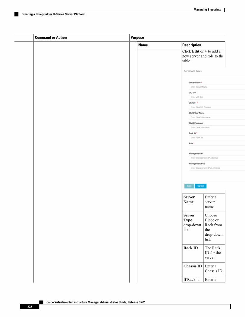
PurposeCommand or Action
DescriptionName
Click Edit or + to add anew server and role to thetable.
Enter aservername.
ServerName
ChooseBlade or
ServerType
Rack fromdrop-downlist the
drop-downlist.
The RackID for theserver.
Rack ID
Enter aChassis ID.
Chassis ID
Enter aIf Rack is
Cisco Virtualized Infrastructure Manager Administrator Guide, Release 3.4.2272
Managing BlueprintsCreating a Blueprint for B-Series Server Platform

PurposeCommand or Action
DescriptionName
chosen, theRack Unit
Rack UnitID.
ID field isdisplayed.
Enter aBlade ID.
If Blade ischosen, theBlade IDfield isdisplayed.
If Servertype isBlade thenselectControlandCompute.If server isRack thenselectBlockStorage.
Select theRole fromthedrop-downlist.
Applicableonly forCisco VICthatsupports tochange theadmin FECmode. Canbeauto/off/cl74/cl91.
VICAdminFEC mode
Optional.By default,it is true.Can beeither trueor false.
VIC PortChannelEnable
Optional, itcan beeither 0 or1. Bydefault, it is1 if notdefined.
SecureComputingmode
Cisco Virtualized Infrastructure Manager Administrator Guide, Release 3.4.2273
Managing BlueprintsCreating a Blueprint for B-Series Server Platform
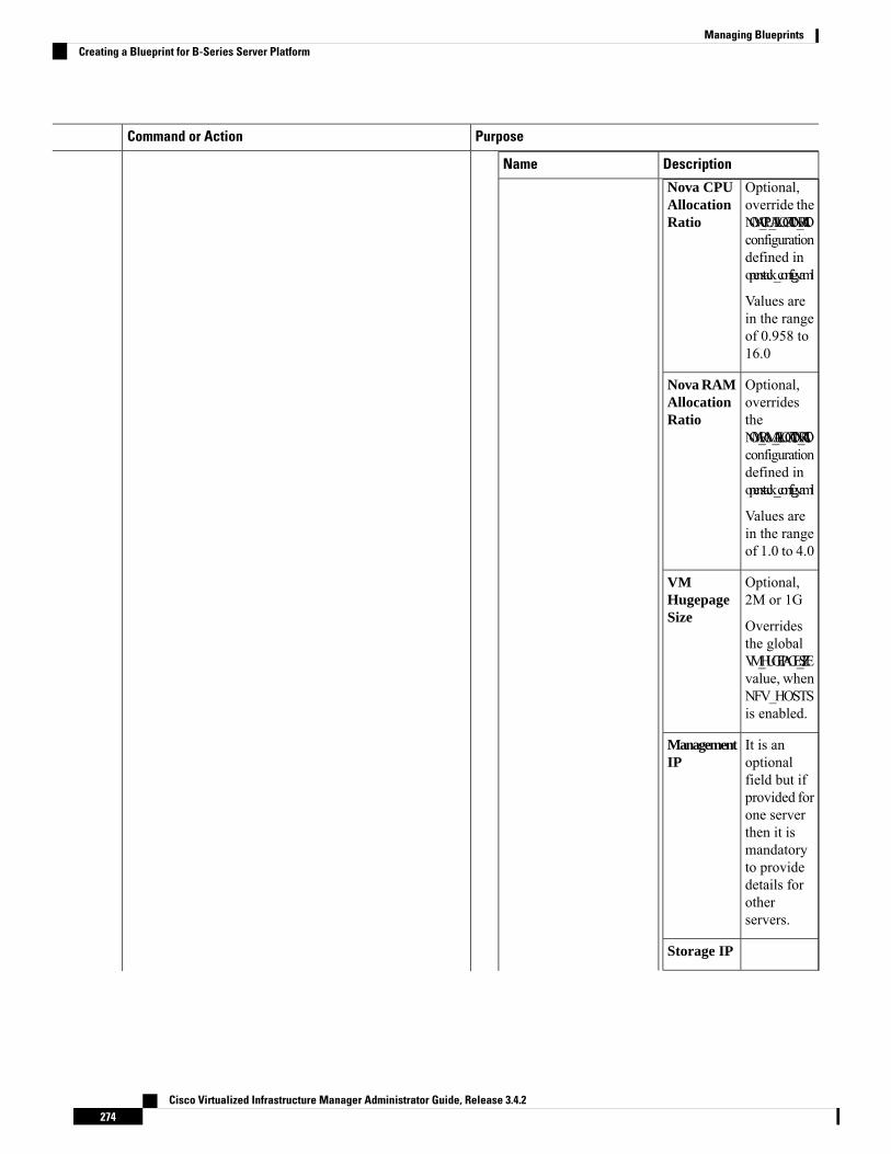
PurposeCommand or Action
DescriptionName
Nova CPUAllocationRatio
Optional,override theNOVA_CPU_ALLOCATION_RATIOconfigurationdefined inopenstack_config.yaml
Values arein the rangeof 0.958 to16.0
Optional,overridestheNOVA_RAM_ALLOCATION_RATIOconfigurationdefined inopenstack_config.yaml
Values arein the rangeof 1.0 to 4.0
Nova RAMAllocationRatio
Optional,2M or 1G
Overridesthe globalVM_HUGEPAGE_SIZEvalue, whenNFV_HOSTSis enabled.
VMHugepageSize
It is anoptionalfield but ifprovided forone serverthen it ismandatoryto providedetails forotherservers.
ManagementIP
Storage IP
Cisco Virtualized Infrastructure Manager Administrator Guide, Release 3.4.2274
Managing BlueprintsCreating a Blueprint for B-Series Server Platform
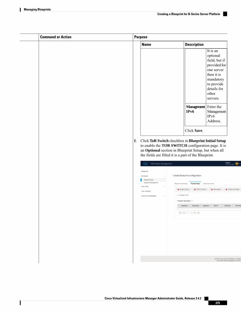
PurposeCommand or Action
DescriptionName
It is anoptionalfield, but ifprovided forone serverthen it ismandatoryto providedetails forotherservers.
Enter theManagementIPv6Address.
ManagementIPv6
Click Save.
f. ClickToR Switch checkbox inBlueprint Initial Setupto enable the TOR SWITCH configuration page. It isan Optional section in Blueprint Setup, but when allthe fields are filled it is a part of the Blueprint.
Cisco Virtualized Infrastructure Manager Administrator Guide, Release 3.4.2275
Managing BlueprintsCreating a Blueprint for B-Series Server Platform

PurposeCommand or Action
DescriptionName
Enabling this checkbox,changes the configure ToRsection from false to true.
Configure ToR optionalcheckbox.
Cisco Virtualized Infrastructure Manager Administrator Guide, Release 3.4.2276
Managing BlueprintsCreating a Blueprint for B-Series Server Platform

PurposeCommand or Action
DescriptionName
ToR SwitchInformationmandatorytable.
Cisco Virtualized Infrastructure Manager Administrator Guide, Release 3.4.2277
Managing BlueprintsCreating a Blueprint for B-Series Server Platform

PurposeCommand or Action
DescriptionName
Click (+) to add informationfor ToR Switch.
DescriptionName
ToR switchhostname.
Hostname
ToR switchusername.
Username
ToR switchpassword.
Password
ToR switchSSH IP
SSH IP
Cisco Virtualized Infrastructure Manager Administrator Guide, Release 3.4.2278
Managing BlueprintsCreating a Blueprint for B-Series Server Platform

PurposeCommand or Action
DescriptionName
Address.
ToR switchssn num.
SSN Num
PeerManagementIP. You donot define ifthere is nopeer.
VPC PeerKeepalive
Do notdefine if peeris absent.
VPCDomain
Interface forvpc peerports.
VPC PeerPort Info
Managementinterface ofthemanagementnode.
BRManagementPort Info
Port channelnumber formanagementinterface ofthemanagementnode.
BRManagementPO Info
ClickSave.
Enter thePort Channelinput.
PortChannelfield.
On clicking save button,Add ToR InfoConnected to Fabricfield is visible.
Enter thename of theSwitch.
Switch Namefield.
g. Click NFVI Monitoring checkbox in Blueprint InitialSetup to enable the NFVIMonitoring configuration tab.
Cisco Virtualized Infrastructure Manager Administrator Guide, Release 3.4.2279
Managing BlueprintsCreating a Blueprint for B-Series Server Platform

PurposeCommand or Action
DescriptionName
IP Address of ControlCenter VM
Admin IP
VIP forceilometer/dispatcher touse, must be unique acrossVIM Pod
Management VIP
Hostname of CollectorVM
Host Name
Password of Collector VMPassword
Password of CCUSERCCUSER Password
SSH IP of Collector VMAdmin IP
Management IP ofCollector VM
Management IP
Optional, but becomesmandatory if collector 2 isdefined. Must containvalid Admin IP.
Master 2
Cisco Virtualized Infrastructure Manager Administrator Guide, Release 3.4.2280
Managing BlueprintsCreating a Blueprint for B-Series Server Platform

PurposeCommand or Action
DescriptionName
Optional, but becomesmandatory if Master 2 isdefined. Collector 2 issecondary set to collectorand with all the propertiesof Collector.
ContainsManagementVIPand Collector VMinformation.
Collector 2
1. Click on (+) icon toAdd Collector ToRConnections.
2. Select the ToRswitches from list toadd the information.
3. It is optional andavailable for ToR typeNCS-5500
4. For now, it supportsadding only oneCollector ToRConnection
Enter portchannel.
PortChannel
Enter portnumber,E.g:eth1/15.
Switch -{torSwitch-hostname}
Click Save
Collector ToRConnections
Cisco Virtualized Infrastructure Manager Administrator Guide, Release 3.4.2281
Managing BlueprintsCreating a Blueprint for B-Series Server Platform

PurposeCommand or Action
DescriptionName
Enter Rabbit MQusername.
Rabbit MQ User Name
h. Click CVIMMON option in Blueprint Initial Setupto enable the CVIM Monitoring configuration tab.
Cisco Virtualized Infrastructure Manager Administrator Guide, Release 3.4.2282
Managing BlueprintsCreating a Blueprint for B-Series Server Platform

PurposeCommand or Action
DescriptionName
By default, it is false. It iscase-sensitive and can beTrue or False
Enable
Optional, and if notdefined it is set to True bydefaul. With this optiondisabled, CVIM_MONwith SNMP is availablebut you cannot accessGrafana, Alert-Manager,and Prometheus UIs
UI Access
Optional. Denotes 's' forseconds, m for minutes,and h for hours
Polling Interval
Minimum of 10 seconds(10s) and maximum of 60mins (1h). If not defined,defaults to 15s.
High Frequency
Minimum of 30 seconds(30s) and maximum of 60mins (1h). If not defined,defaults to 30s. It must bemore than high interval
Medium Frequency
Minimum of 1 minute(1m) and maximum of 60mins (1h). If not defined,defaults to 1 minute. Itmust be more thanmedium interval.
Low Frequency
Optional, if not defined,defaults to False.With thisoption enabled, you willget central CVIM-MON(only telegraf agentsrunning on pod), withoutlocal Prometheus,AlertManager, or Grafana
CVIMMON Central
Optional, list of externalserver IPs (v4 or v6) to bemonitoried by CVIMMON
External Servers
Cisco Virtualized Infrastructure Manager Administrator Guide, Release 3.4.2283
Managing BlueprintsCreating a Blueprint for B-Series Server Platform

PurposeCommand or Action
i. Click OpenStack Setup tab to advance to theOpenStack Setup Configuration page. On theOpenStack Setup page of the Cisco VIM UnifiedManagement wizard, complete the following fields:
DescriptionName
Fill in the following details:
Enter the IPaddress ofthe ExternalVIP.
ExternalVIPAddressfield
Enter theIPv6 addressof theExternalVIP.
ExternalVIPAddressIPv6 field
Enter theRouter IDfor the HA.
VirtualRouter IDfield
Enter theIPv6 addressof theInternal IP.
InternalVIPAddressIPv6 field
Enter the IPaddress ofthe InternalVIP.
InternalVIPAddressfield
HA Proxy
Cisco Virtualized Infrastructure Manager Administrator Guide, Release 3.4.2284
Managing BlueprintsCreating a Blueprint for B-Series Server Platform

PurposeCommand or Action
DescriptionName
The following are thePre-populated field values.This option is always set tobe true.
adminAdminUsernamefield
adminAdminTenantName field
Keystone
Cisco Virtualized Infrastructure Manager Administrator Guide, Release 3.4.2285
Managing BlueprintsCreating a Blueprint for B-Series Server Platform

PurposeCommand or Action
DescriptionName
LDAP (Only ifKeystonev3 is enabled)
This option isonlyavailablewithKeystone v3
Note
Cisco Virtualized Infrastructure Manager Administrator Guide, Release 3.4.2286
Managing BlueprintsCreating a Blueprint for B-Series Server Platform

PurposeCommand or Action
DescriptionName
This is available only whenKeystone v3 and LDAPboth are enabled underOptional Features andServices in Blueprint InitialSetup.
Enter theDomainname.
DomainName field
Enter astring asinput.
ObjectClass forUsers field
Enter astring.
ObjectClass forGroupsfield
Enter astring.
DomainName Treefor Usersfield
Enter astring.
DomainName Treefor Groups
Cisco Virtualized Infrastructure Manager Administrator Guide, Release 3.4.2287
Managing BlueprintsCreating a Blueprint for B-Series Server Platform

PurposeCommand or Action
DescriptionName
field
Enter astring.
Suffix forDomainName field
Enter a URLwith endingport number.
URL field
Enter astring.
DomainName ofbind userfield
EnterPassword asstringformat.
Passwordfield
Enter filtername asstring.
User Filterfield
Enter astring.
User IDAttributefield
Enter astring.
User NameAttributefield
Enter astring.
User MailAttributefield
Enter astring.
GroupNameAttributefield
Cisco Virtualized Infrastructure Manager Administrator Guide, Release 3.4.2288
Managing BlueprintsCreating a Blueprint for B-Series Server Platform

PurposeCommand or Action
DescriptionName
Neutron
Cisco Virtualized Infrastructure Manager Administrator Guide, Release 3.4.2289
Managing BlueprintsCreating a Blueprint for B-Series Server Platform

PurposeCommand or Action
DescriptionName
Neutron fields change on thebasis of Tenant NetworkType selection fromBlueprint Initial Setup.Following are the optionsavailable for Neutron forOVS/VLAN:
It isAuto-filled
TenantNetworkType field based on the
TenantNetworkTypeselectedin theBlueprintInitial Setuppage.
It isAuto-filled
MechanismDriversfield based on the
TenantNetworkTypeselected inBlueprintInitial Setuppage.
It isAuto-filled
NFV Hostsfield
with theComputeyou added in
Cisco Virtualized Infrastructure Manager Administrator Guide, Release 3.4.2290
Managing BlueprintsCreating a Blueprint for B-Series Server Platform

PurposeCommand or Action
DescriptionName
Server andRoles.
If you selectAll in thissectionNFV_HOSTS:ALL isadded to theBlueprint oryou canselect oneparticularcompute.ForExample:
NFV_HOSTS:compute-server-1,compute-server-2.
List ofrangesseparated bycomma formstart:end.
TenantVLANRanges field
List ofrangesseparated bycomma formstart:end.
ProviderVLANRangesfield
2M or 1GVM HughPage Size(availableforNFV_HOSTSoption)field
Enable thecheckbox.
EnableJumboFramesfield
Cisco Virtualized Infrastructure Manager Administrator Guide, Release 3.4.2291
Managing BlueprintsCreating a Blueprint for B-Series Server Platform

PurposeCommand or Action
DescriptionName
For Tenant Network Type,Linux Bridge everythingremains the same butTenant VLAN Ranges isremoved.
Cisco Virtualized Infrastructure Manager Administrator Guide, Release 3.4.2292
Managing BlueprintsCreating a Blueprint for B-Series Server Platform

PurposeCommand or Action
DescriptionName
CEPH
Cisco Virtualized Infrastructure Manager Administrator Guide, Release 3.4.2293
Managing BlueprintsCreating a Blueprint for B-Series Server Platform

PurposeCommand or Action
DescriptionName
1. 1. When Object StorageBackend is selected asCentral in the blueprintinitial setup.
By defaultCephMode isCentral.
CEPHMode
Enter theCluster ID.
ClusterID
Enter theMonitor Hostfor CEPH
MonitorHost
Enter theMonitor
MonitorMembers
Members forCEPH
Enter theSecret UUIDfor CEPH
SecretUUID
You canchooseCEPH
NOVABootfrom or local from
thedrop-downlist.
Enter theNOVA RBD
NOVARBDPOOL Pool
(default's tovms)
CEPH NATCEPH
Cisco Virtualized Infrastructure Manager Administrator Guide, Release 3.4.2294
Managing BlueprintsCreating a Blueprint for B-Series Server Platform

PurposeCommand or Action
DescriptionName
NAT is requiredfor CentralCeph andwhen mgmtnetwork isnot routable.
Cisco Virtualized Infrastructure Manager Administrator Guide, Release 3.4.2295
Managing BlueprintsCreating a Blueprint for B-Series Server Platform

PurposeCommand or Action
DescriptionName
2. When Object StorageBackend is selected asDedicated in theblueprint initial setup.
• CEPH Mode: Bydefault, it is set toDedicated.
• Nova Boot From: Youcan choose CEPH orlocal.
• Cinder Percentage:Must be 60 when NovaBoot From is local, andmust be 40 when NovaBoot is Ceph
• Nova Percentage:Only applicable whenNova Boot From isCeph. Must be 30%otherwise.
• Glance Percentage :Must be 40 when NovaBoot From is local, andmust be 30 whenNOVA Boot From isCeph. If Ceilometer isenabled, it must be 35%for Nova Boot fromlocal and 25% forNOVA Boot From isCeph.
Cisco Virtualized Infrastructure Manager Administrator Guide, Release 3.4.2296
Managing BlueprintsCreating a Blueprint for B-Series Server Platform

PurposeCommand or Action
DescriptionName
• Gnocchi Percentage:Only applicable whenceilometer is enabled,and must be 5%.
3. When Object StorageBackend is selected asNetApp in the blueprintinitial setup.
• Ceph mode : ByDefault netapp
• Cinder Percenatge :Must be 60%
• Glance Percenatge:Must be 40%
Cisco Virtualized Infrastructure Manager Administrator Guide, Release 3.4.2297
Managing BlueprintsCreating a Blueprint for B-Series Server Platform

PurposeCommand or Action
DescriptionName
1. When Object StorageBackend is selected asCentral in the blueprintinitial setup.
By defaultCEPH.
StoreBackend
By defaultimages.
GlanceRBD Poolfield
EnterGLANCEClient Key
GlanceClient Key
2. When Object StorageBackend is selected asDedicated in the blueprintinitial setup.
By default Populated forCEPHDedicated with StoreBackend value as CEPH.
GLANCE
Cisco Virtualized Infrastructure Manager Administrator Guide, Release 3.4.2298
Managing BlueprintsCreating a Blueprint for B-Series Server Platform

PurposeCommand or Action
DescriptionName
Vim LDAP Admins
Cisco Virtualized Infrastructure Manager Administrator Guide, Release 3.4.2299
Managing BlueprintsCreating a Blueprint for B-Series Server Platform
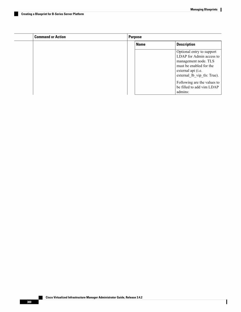
PurposeCommand or Action
DescriptionName
Optional entry to supportLDAP for Admin access tomanagement node. TLSmust be enabled for theexternal api (i.e.external_lb_vip_tls: True).
Following are the values tobe filled to add vim LDAPadmins:
Cisco Virtualized Infrastructure Manager Administrator Guide, Release 3.4.2300
Managing BlueprintsCreating a Blueprint for B-Series Server Platform

PurposeCommand or Action
DescriptionName
Cisco Virtualized Infrastructure Manager Administrator Guide, Release 3.4.2301
Managing BlueprintsCreating a Blueprint for B-Series Server Platform

PurposeCommand or Action
DescriptionName
• domain_name:Mandatory to definevim LDAP admins.
• ldap_uri : Theldap_uris must besecured over ldaps. Itis mandatory field
.• ldap_search_base: Itis mandatory. Entersearch base
• ldap_schema:Optional. Enter theschema.
• ldap_user_object_class:Optional. Indicates theposixAccount.
• ldap_user_uid_number:Optional. Enter theuser id number.
• ldap_user_gid_number:Optional. Enter thegroup id number.
• ldap_group_member:Optional. Enter thegroup member.
• ldap_default_bind_dn:Optional . Enter defaultdistinguished name
• ldap_default_authtok:Optional. Defaultauthentication token.
• ldap_default_authtok_type:Optional. Defaultauthentication tokentype.
• ldap_group_search_base:Optional. Enter groupsearch base
• ldap_user_search_base:
Cisco Virtualized Infrastructure Manager Administrator Guide, Release 3.4.2302
Managing BlueprintsCreating a Blueprint for B-Series Server Platform

PurposeCommand or Action
DescriptionName
Optional. Enter userSearch Base
• access_provider:Optional
• simple_allow_groups:Optional
• ldap_id_use_start_tls:Optional. Can be trueor false.
• ldap_tls_reqcert:Optional . Can benever/allow/try/demand.
• chpass_provider:Optional. Can beldap/krb5/ad/none.
Cisco Virtualized Infrastructure Manager Administrator Guide, Release 3.4.2303
Managing BlueprintsCreating a Blueprint for B-Series Server Platform

PurposeCommand or Action
DescriptionName
By default Populated forCEPH Dedicated withVolume Driver value asCEPH.
By defaultCEPH.
VolumeDriver
By defaultvolumes.
CinderRBD Poolfield
Enter CinderClient Key
CinderClient Key
CINDER
Cisco Virtualized Infrastructure Manager Administrator Guide, Release 3.4.2304
Managing BlueprintsCreating a Blueprint for B-Series Server Platform

PurposeCommand or Action
DescriptionName
VMTP
VMTP optional sectionwill only be visible onceVMTP is selected fromBlueprint Initial Setup.
Cisco Virtualized Infrastructure Manager Administrator Guide, Release 3.4.2305
Managing BlueprintsCreating a Blueprint for B-Series Server Platform

PurposeCommand or Action
DescriptionName
Check one of the checkboxes to specify a VMTPnetwork:
• Provider Network
• External Network
For the Provider Networkcomplete the following:
Enter thename for the
NetworkName field
externalnetwork.
Enter theSubnet for
Subnet field
ProviderNetwork.
Enter thestart of the
Network IPStart field
floating IPv4address.
Enter the endof the
Network IPEnd field
floating IPv4address.
Enter theIPv4 address
NetworkGatewayfield
for theGateway.
Cisco Virtualized Infrastructure Manager Administrator Guide, Release 3.4.2306
Managing BlueprintsCreating a Blueprint for B-Series Server Platform

PurposeCommand or Action
DescriptionName
DNS Serverfield
Enter theDNS serverIPv4address.
Enter thesegmentationID.
SegmentationID field
For External Network fillin the following details:
Enter thename for theexternalnetwork.
NetworkName field
Enter theSubnet forthe externalNetwork.
Subnet field
Enter thestart of thefloating IPv4address.
Network IPStart field
Enter theendof thefloating IPv4address.
Network IPEnd field
Enter theIPv4 addressfor theGateway.
NetworkGatewayfield
Enter theDNS serverIPv4address.
DNS Serverfield
Cisco Virtualized Infrastructure Manager Administrator Guide, Release 3.4.2307
Managing BlueprintsCreating a Blueprint for B-Series Server Platform

PurposeCommand or Action
DescriptionName
TLS has two options:
• External LB VIPFQDN - -Text field.
• External LB VIP TLSTrue/False. By defaultthis option is false.
TLS This optionalsection will only bevisible once TLS isselected from BlueprintInitial Setup Page.
Following are the fielddescriptions for VIMAdmins:
• User Name - Textfield.
• Password -Passwordfield. Admin hashpassword shouldalways start with $6.
Under the OpenStacksetup tab, Vim_adminstab will be visible onlywhen Vim_admins isselected from theOptional Features &Services under theBlueprint Initial setuptab
Cisco Virtualized Infrastructure Manager Administrator Guide, Release 3.4.2308
Managing BlueprintsCreating a Blueprint for B-Series Server Platform

PurposeCommand or Action
DescriptionName
If the external_lb_vip isbehind a NAT router or hasa DNS alias, provide a listof those addresses.HorizonAllowed Hosts uses commaseparated list of IP addressesand/or DNS names forhorizon hosting.
Horizon Aliases
Cisco Virtualized Infrastructure Manager Administrator Guide, Release 3.4.2309
Managing BlueprintsCreating a Blueprint for B-Series Server Platform

PurposeCommand or Action
DescriptionName
Following are the optionsthat needs to be filled forSwiftStack:
IP address ofPAC(Proxy-Account-Container)endpoint.
Cluster EndPoint field
Admin userfor swift toauthenticatein keystone.
Admin Userfield
The servicetenantcorrespondingto theAccount-Containerused by theSwiftstack.
AdminTenant field
Reseller_prefixasconfiguredfor KeysoneAuth,AuthTokensupport inSwiftstack.Example:KEY_
ResellerPrefix field
swiftstack_admin_passwordAdminPasswordfield
http or httpsProtocol
SwiftStack optionalsection will be visibleonce SwiftStack isselected fromBlueprintInitial Setup Page.SwiftStack is onlysupported withKeyStonev2 . If youselect Keystonev3,swiftstack will not beavailable forconfiguration.
Cisco Virtualized Infrastructure Manager Administrator Guide, Release 3.4.2310
Managing BlueprintsCreating a Blueprint for B-Series Server Platform

PurposeCommand or Action
j. For SolidFire, enter the following:
DescriptionName
SolidFire is visible forconfiguration on day0
SolidFire is not allowed asa day-2 deployment option
SolidFire is alwaysavailable with CEPH.
ManagementIP ofSolidFirecluster.
ClusterMVIPfield
Storage VIPof SolidFirecluster.
ClusterSVIPfield
Admin useron SolidFirecluster
AdminUsername
Adminpassword onSolidFirecluster.
AdminPassword
k. If Syslog Export or NFVBENCH is selected inBlueprint Initial Setup, the Services Setup pane isenabled for the user to view.
Following are the options under Services Setup Tab:
Cisco Virtualized Infrastructure Manager Administrator Guide, Release 3.4.2311
Managing BlueprintsCreating a Blueprint for B-Series Server Platform

PurposeCommand or Action
DescriptionName
Following are the options forSyslog Settings:
Enter SyslogIP address.
Remote Host
Only UDP issupported.
Protocol
Defaults tolocal5.
Facility
Defaults todebug.
Severity
Defaults toELK.
Clients
Defaults to514 but canbe modifiedby the User.
Port
Syslog Export
Cisco Virtualized Infrastructure Manager Administrator Guide, Release 3.4.2312
Managing BlueprintsCreating a Blueprint for B-Series Server Platform

PurposeCommand or Action
DescriptionName
NFVBENCH enablecheckbox which by default isFalse.
Add ToR informationconnected to switch:
• Select a TOR Switch andenter the Switch name.
• Enter the port number.For example:eth1/5.VTEP VLANS(mandatory and neededonly for VXLAN): Enter2 different VLANs forVLAN1 and VLAN2
• NIC Ports: INT1 andINT2 optional input.Enter the 2 port numbersof the 4-port 10G IntelNIC at the managementnode used for theNFVBench.
NFVBENCH
Enable the checkbox to set itas True. By default it is False.
ENABLE_ESC_PRIV
Creating Blueprint for C-Series Server PlatformCreate a Cisco VIM Unified Management User Account and register the respective Pod.
Cisco Virtualized Infrastructure Manager Administrator Guide, Release 3.4.2313
Managing BlueprintsCreating Blueprint for C-Series Server Platform

Step 1 Log into CISCO VIM Unified Management.Step 2 In the Navigation pane, expand the Pre-Install Section.Step 3 Click Blueprint Setup.Step 4 To create a C Series Blueprint:
a. On the Blueprint Initial Setup page of the Cisco VIM Unified Management, complete the following fields:
DescriptionName
Enter the name for the blueprint configuration.Blueprint Name field.
Choose one of the following platform types:
• B-Series (By default)
• C-Series ( Select C Series)
Platform Type drop-down list
Cisco Virtualized Infrastructure Manager Administrator Guide, Release 3.4.2314
Managing BlueprintsCreating Blueprint for C-Series Server Platform

DescriptionName
Choose one of the following tenant network types:
• Linux Bridge/VXLAN
• OVS/VLAN
• VTS/VLAN
• VPP/VLAN
• ACI/VLAN
when VTS/VLAN or ACI/VLAN is selectedthen respective tabs are available on Blueprintsetup. When Mechanism driver OVS or ACIis selected,VM_HUGEPAGE_PERCENTAGE field isenabled for all standalone compute nodes,when NFV_HOSTS is enabled.
Note
Tenant Network drop-down list
Choose one of the following pod type :
• Fullon(By Default)
• Micro
• UMHC
• NGENAHC
Note • UMHC pod type is only supported forOVS/VLAN tenant type.
• NGENAHC is supported for VPP/VLANtenant type with no SRIOV
• Pod type micro is supported forOVS/VLAN, ACI/VLAN,VPP/VLAN.
Pod Type drop-down list
Choose one of the following Ceph types:
• Dedicated: Enabled by default.
• Central. It is not supported in production
Ceph Mode drop-down list
Optional parameter ssh_banner is available in thesetup_data, to accept a string or message that is to bedisplayed before the login prompt. This message indicatesa warning in consistent with company’s IT policies.
SSH Banner
Cisco Virtualized Infrastructure Manager Administrator Guide, Release 3.4.2315
Managing BlueprintsCreating Blueprint for C-Series Server Platform
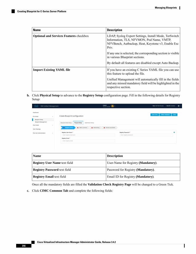
DescriptionName
LDAP, Syslog Export Settings, Install Mode, TorSwitchInformation, TLS, NFVMON, Pod Name, VMTP,NFVBench, Autbackup, Heat, Keystone v3, Enable EscPriv.
If any one is selected, the corresponding section is visiblein various Blueprint sections.
By default all features are disabled except Auto Backup.
Optional and Services Features checkbox
If you have an existing C Series YAML file you can usethis feature to upload the file.
Unified Management will automatically fill in the fieldsand anymissedmandatory field will be highlighted in therespective section.
Import Existing YAML file
b. Click Physical Setup to advance to the Registry Setup configuration page. Fill in the following details for RegistrySetup:
DescriptionName
User-Name for Registry (Mandatory).Registry User Name text field
Password for Registry (Mandatory).Registry Password text field
Email ID for Registry (Mandatory).Registry Email text field
Once all the mandatory fields are filled the Validation Check Registry Page will be changed to a Green Tick.
c. Click CIMC Common Tab and complete the following fields:
Cisco Virtualized Infrastructure Manager Administrator Guide, Release 3.4.2316
Managing BlueprintsCreating Blueprint for C-Series Server Platform

DescriptionName
By default value is Admin.User Name disabled field
Enter Password for UCSM Common (Mandatory).Password text field
d. Click Networking to advance to the networking section of the Blueprint.
DescriptionName
Enter the domain name. (Mandatory)Domain Name field
Cisco Virtualized Infrastructure Manager Administrator Guide, Release 3.4.2317
Managing BlueprintsCreating Blueprint for C-Series Server Platform

DescriptionName
If your configuration uses an HTTP proxy server, enterthe IP address of the server.
HTTP Proxy Server field
If your configuration uses an HTTPS proxy server, enterthe IP address of the server.
HTTPS Proxy Server field
Specifies the list of IP Address with Mask.IP Tables on Management Pods
Enter a maximum of four and minimum of one IPv4and/or IPv6 addresses in the table.
NTP Servers field
Enter a maximum of three and minimum of one IPv4and/or IPV6 addresses.
Domain Name Servers field
Cisco Virtualized Infrastructure Manager Administrator Guide, Release 3.4.2318
Managing BlueprintsCreating Blueprint for C-Series Server Platform

DescriptionName
Networks table
Cisco Virtualized Infrastructure Manager Administrator Guide, Release 3.4.2319
Managing BlueprintsCreating Blueprint for C-Series Server Platform

DescriptionName
Network table is pre-populated with Segments. To addNetworks you can either clear all the table with Deleteall or click edit icon for each segment and fill in thedetails.
You can add, edit, or delete network information in thetable.
• Click Add (+) to add new entries (networks) to thetable.
• Specify the following fields in the Edit Entry toNetworks dialog:
DescriptionName
Enter the VLAN ID.VLAN field
For Segment - Provider, theVLAN ID value is 'none'.
When you add/edit newsegment then following
Segment drop-down list
segments types areavailable in the form ofdropdown list and you canselect only one.
• API
• Management/provision
• Tenant
• Storage
Cisco Virtualized Infrastructure Manager Administrator Guide, Release 3.4.2320
Managing BlueprintsCreating Blueprint for C-Series Server Platform

DescriptionName
• External
• Provider
• ACIINFRA
Aciinfra segmentis available onlywhenACI/VLANtenant type isselected)Depending uponthe segment someof the entriesbelow are notneeded. Pleaserefer to theexample file inopenstack-configsdir for details.
Note
Enter the IPv4 address forthe subnet.
Subnet field
Enter IPv6 Address. Thisfield will be available onlyfor Management provisionand API
IPv6 Subnet field
Enter the IPv4 address forthe Gateway.
Gateway field
Enter the IPv6 address forthe gateway. This willsupport for API andmanagement provision.
Gateway IPv6 field
Enter the pool informationin the required format, forexample:10.1.1.5-10.1.1.10,10.2.1.5-10.2.1.10
This field is available onlyfor the Mgmt/Provision,Storage, and Tenantsegments.
Pool field
Enter the pool informationin the required format. Forexample:10.1.1.5-10.1.1.10,10.2.1.5-10.2.1.10
IPv6 Pool field
Cisco Virtualized Infrastructure Manager Administrator Guide, Release 3.4.2321
Managing BlueprintsCreating Blueprint for C-Series Server Platform

DescriptionName
Allowed only when ToR isNCS-5500
Can only be defined formanagement/provision,storage, and tenantsegments
Click Save.
e. On the Servers and Roles page of the Cisco VIM Suite wizard, a pre-populated table filled with Roles : Control,Compute and Block Storage (Only if CEPH Dedicated is selected in Blueprint Initial Setup is available.
If you choose mechanism driver as OVS or ACI, VM_HUGEPAGE_PERCENTAGE field column isavailable for compute nodes, where you can fill values from 0 to 100%, when NFV_HOSTS: ALL is chosen.
Note
DescriptionName
Enter the username of the Server.Server User Name field
Default value is false. You can set it as true or false.Disable Hyperthreading
Cisco Virtualized Infrastructure Manager Administrator Guide, Release 3.4.2322
Managing BlueprintsCreating Blueprint for C-Series Server Platform

DescriptionName
Enter the Cobbler details in the following fields:
DescriptionName
The default value is 45 min.
This is an optional parameter.Timeout is displayed inminutes, and its value rangesfrom 30 to 120.
Cobbler Timeout field
Kickstart file for StorageNode.
Block Storage Kickstartfield
Enter the Admin Password.Password should beAlphanumeric. Passwordshould contain minimum 8characters and maximum of32 characters.
Admin Password Hash field
Enter the cobbler usernameto access the cobbler server.
Cobbler Username field
Kickstart file for ControlNode.
Control Kickstart field
Kickstart file for ComputeNode.
Compute Kickstart field
Enter the admin username ofthe Cobbler.
Cobbler Admin Usernamefield
Cobbler
Cisco Virtualized Infrastructure Manager Administrator Guide, Release 3.4.2323
Managing BlueprintsCreating Blueprint for C-Series Server Platform

DescriptionName
Add Entry to Servers and Roles
when Pod type micro is selected then allthe three servers will be associated withcontrol, compute and block storage role.
Note
For Example:
Roles
• Block Storage
• -Server 1
• -Server 2
• -Server 3
• Control
• -Server 1
• -Server 2
• -Server 3
• Compute
• -Server 1
• -Server 2
• -Server 3
When Pod type UMHC is selected thenauto ToR configuration is not supportedand the ToR info at server and roles levelis not allowed to be entered.
Note
Cisco Virtualized Infrastructure Manager Administrator Guide, Release 3.4.2324
Managing BlueprintsCreating Blueprint for C-Series Server Platform

DescriptionName
Click Edit or + to add a new server and role to the table.
If mechanism driver is either OVS or ACI, an additionaloptional field VM_HUGEPAGE_PERCENTAGE is shownwhen compute role is chosen; This option is only valid whenNFV_HOSTS is set to ALL; If no value is entered then theglobal value of VM_HUGEPAGE_PERCENTAGE is used.
Entry the name of the server.Server Name
Cisco Virtualized Infrastructure Manager Administrator Guide, Release 3.4.2325
Managing BlueprintsCreating Blueprint for C-Series Server Platform

DescriptionName
Rack ID field The rack ID for the server.
Enter a VIC slot.VIC Slot field
Enter an IP address. BothIPv4 and IPv6 supported.
CIMC IP
Enter a Username.CIMC Username field
Enter a Password for CIMC.CIMC Password field
Choose Control or Computeor Block Storage from thedrop-down list.
Select theRole from the dropdown list
Applicable only for CiscoVIC that supports to changethe admin FEC mode.
Can be auto/off/cl74/cl91.
VIC Admin FEC mode
Optional. Default is true. Canbe either true or false.
VIC Port Channel Enable
Optional, can be either 0 or1. By default,it is 1 if notdefined.
Secure Computing mode
Optional, overrides theNOVA_CPU_ALLOCATION_RATIOdefined inopenstack_config.yaml.Values are in the range of0.958 to 16.0
Nova CPU Allocation Ratio
Optional, overrides theNOVA_RAM_ALLOCATION_RATIOdefined inopenstack_config.yaml.Values are in the range of 1.0to 4.0
Nova RAM AllocationRatio
Optional, 2M or 1G.Overrides the globalVM_HUGEPAGE_SIZEvalue, if NFV_HOSTS isenabled.
VM Hugepage Size
True or False. Optional,overrides the globalhyper-threadingconfiguration.
Disable Hyperthreading
Cisco Virtualized Infrastructure Manager Administrator Guide, Release 3.4.2326
Managing BlueprintsCreating Blueprint for C-Series Server Platform

DescriptionName
Root Drive Type Optional, HDD or SSD infront or rear drive bay.
M.2_SATA internal SSD. Itis a mandatory configurationif booting off M.2 SATASSD, and not valid for M4platform.
It is an optional field, but ifprovided for one server thenit is mandatory to provide itfor other servers.
Management IP
It is an optional field but ifprovided for one server thenit is mandatory to providedetails for other servers.
Storage IP
Allows static override valuefor platform vendor insteadof dynamic discovery atruntime. Can be CISCO -Cisco Systems Inc/ QCT -Quanta Cloud TechnologyInc/ HPE - Hewlett PackardEnterprise.
Vendor
Routable and valid IPv6address. It is an optional fieldbut if provided for one serverthen it is mandatory for allother servers as well.
Management IPv6
On clicking Save or Add all information related to Serversand Roles gets saved.
Click Save or Add .
• Enter the port channelinput.
• Enter the switch name.
• Enter the switch portinformation.
• Port Channel field
• Switch Name field
• Switch Port Info field
If Configure ToR checkbox is Truewith at-least oneswitch detail, these fields will be displayed for eachserver and this is similar to DP Tor: Port Channeland Switch Name (Mandatory if Configure ToR istrue)
• Enter the port channelinput.
• Enter the switch name.
• Enter the switch portinformation.
• Port Channel field
• Switch Name field
• Switch Port Info field
DP ToR (Only for Control and Compute) : Mandatoryif Intel NIC and Configure TOR is True.
Cisco Virtualized Infrastructure Manager Administrator Guide, Release 3.4.2327
Managing BlueprintsCreating Blueprint for C-Series Server Platform
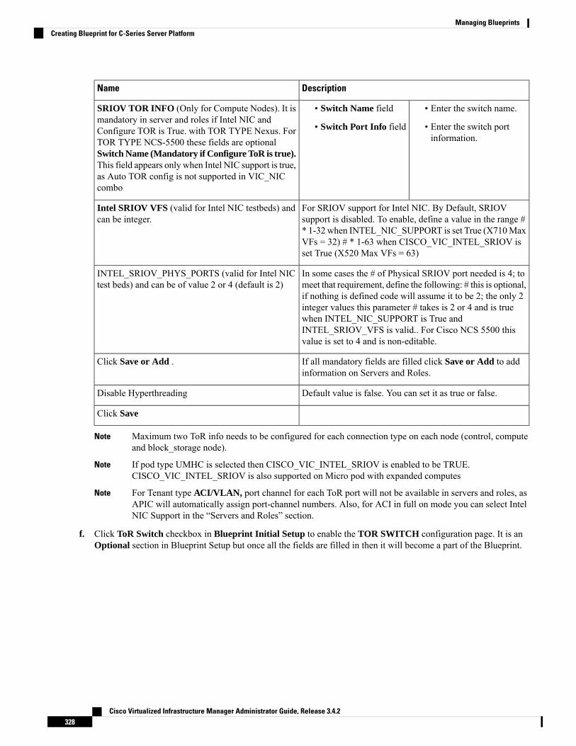
DescriptionName
• Enter the switch name.
• Enter the switch portinformation.
• Switch Name field
• Switch Port Info field
SRIOV TOR INFO (Only for Compute Nodes). It ismandatory in server and roles if Intel NIC andConfigure TOR is True. with TOR TYPE Nexus. ForTOR TYPE NCS-5500 these fields are optionalSwitch Name (Mandatory if Configure ToR is true).This field appears only when Intel NIC support is true,as Auto TOR config is not supported in VIC_NICcombo
For SRIOV support for Intel NIC. By Default, SRIOVsupport is disabled. To enable, define a value in the range #* 1-32 when INTEL_NIC_SUPPORT is set True (X710MaxVFs = 32) # * 1-63 when CISCO_VIC_INTEL_SRIOV isset True (X520 Max VFs = 63)
Intel SRIOV VFS (valid for Intel NIC testbeds) andcan be integer.
In some cases the # of Physical SRIOV port needed is 4; tomeet that requirement, define the following: # this is optional,if nothing is defined code will assume it to be 2; the only 2integer values this parameter # takes is 2 or 4 and is truewhen INTEL_NIC_SUPPORT is True andINTEL_SRIOV_VFS is valid.. For Cisco NCS 5500 thisvalue is set to 4 and is non-editable.
INTEL_SRIOV_PHYS_PORTS (valid for Intel NICtest beds) and can be of value 2 or 4 (default is 2)
If all mandatory fields are filled click Save or Add to addinformation on Servers and Roles.
Click Save or Add .
Default value is false. You can set it as true or false.Disable Hyperthreading
Click Save
Maximum two ToR info needs to be configured for each connection type on each node (control, computeand block_storage node).
Note
If pod type UMHC is selected then CISCO_VIC_INTEL_SRIOV is enabled to be TRUE.CISCO_VIC_INTEL_SRIOV is also supported on Micro pod with expanded computes
Note
For Tenant type ACI/VLAN, port channel for each ToR port will not be available in servers and roles, asAPIC will automatically assign port-channel numbers. Also, for ACI in full on mode you can select IntelNIC Support in the “Servers and Roles” section.
Note
f. Click ToR Switch checkbox in Blueprint Initial Setup to enable the TOR SWITCH configuration page. It is anOptional section in Blueprint Setup but once all the fields are filled in then it will become a part of the Blueprint.
Cisco Virtualized Infrastructure Manager Administrator Guide, Release 3.4.2328
Managing BlueprintsCreating Blueprint for C-Series Server Platform

DescriptionName
Enabling this checkbox, changes the configure ToR section fromfalse to true.
Configure tor is true then ToR switch info maps inservers
Note
Configure ToR optional checkbox.
If UMHC is selected as podtype,configure TOR is not allowed.
Note
Cisco Virtualized Infrastructure Manager Administrator Guide, Release 3.4.2329
Managing BlueprintsCreating Blueprint for C-Series Server Platform

DescriptionName
ToR Switch Information mandatory table ifyou want to enter ToR information.
Cisco Virtualized Infrastructure Manager Administrator Guide, Release 3.4.2330
Managing BlueprintsCreating Blueprint for C-Series Server Platform

DescriptionName
Click (+) to add information for ToR Switch.
DescriptionName
ToR switch name.Name
ToR switch username.Username
ToR switch password.Password
ToR switch SSH IP.SSH IP
ToR switch ssn num.SSN Num
Peer Management IP. Youcannot define if there is no peer.
VPC Peer Keepalive
Cannot define if there is noVPC Domain
Cisco Virtualized Infrastructure Manager Administrator Guide, Release 3.4.2331
Managing BlueprintsCreating Blueprint for C-Series Server Platform

DescriptionName
peer.
Interface for vpc peer ports.VPC Peer Port Info
VLAN ids for vpc peer ports(optional).
VPC Peer VLAN Info
Management interface of buildnode.
BR Management Port Info
Port channel number formanagement interface of buildnode.
BR Management PO Info
VLAN id for managementinterface of build node (access).
BR Management VLAN info
Click Save.
When tenant type ACI/VLAN is selected, the TOR switch information table differs and is mandatory.Note
DescriptionName
Enabling this checkbox, changes the configure ToR section fromfalse to true.
Configure tor is true then ToR switch info maps inservers
Note
Configure ToR optional checkbox.
If UMHC is selected as podtype,configure TOR is not allowed.
Note
Cisco Virtualized Infrastructure Manager Administrator Guide, Release 3.4.2332
Managing BlueprintsCreating Blueprint for C-Series Server Platform

DescriptionName
ToR Switch Information mandatory table ifyou want to enter ToR information.
Cisco Virtualized Infrastructure Manager Administrator Guide, Release 3.4.2333
Managing BlueprintsCreating Blueprint for C-Series Server Platform

DescriptionName
Click (+) to add information for ToR Switch.
DescriptionName
ToR switch name.Name
ToR switch username.Username
ToR switch password.Password
ToR switch SSH IP.SSH IP
ToR switch ssn num.SSN Num
Peer Management IP. Youcannot define if there is no peer.
VPC Peer Keepalive
Cannot define if there is noVPC Domain
Cisco Virtualized Infrastructure Manager Administrator Guide, Release 3.4.2334
Managing BlueprintsCreating Blueprint for C-Series Server Platform

DescriptionName
peer.
Interface for vpc peer ports.VPC Peer Port Info
VLAN ids for vpc peer ports(optional).
VPC Peer VLAN Info
Management interface of buildnode.
BR Management Port Info
Port channel number formanagement interface of buildnode.
BR Management PO Info
VLAN id for managementinterface of build node (access).
BR Management VLAN info
Click Save.
When the Tenant type ACI/VLAN is selected, the ToR switch information table differs and is mandatory.Note
Cisco Virtualized Infrastructure Manager Administrator Guide, Release 3.4.2335
Managing BlueprintsCreating Blueprint for C-Series Server Platform

DescriptionName
Is not checked, as by default ACI will configure the ToRs
ToR switch name.Host Name
Enter Peer must be existpair.
VPC Peer keep alive
Enter an integer.VPC Domain
Enter BRmanagement portinfo eg. Eth1/19 ,atleast onepair to be exist.
BR management port info
Entered integer must beunique.
Enter Node ID
Configure ToR
If TOR_TYPE is selected as NCS-5500, the TOR switch information table differs and is mandatory.Note
DescriptionName
Enabling this checkbox, changes the configure ToRsection from false to true.
Configure TOR is true then ToR switchinfomaps in servers.
Note
Configure ToR optional checkbox
If NSC-5500 is selected as TOR_TYPE,configure TOR is set as mandatory.
Note
Cisco Virtualized Infrastructure Manager Administrator Guide, Release 3.4.2336
Managing BlueprintsCreating Blueprint for C-Series Server Platform

DescriptionName
If you want to enter NCS details fill in the NCS-5500Information table.
Cisco Virtualized Infrastructure Manager Administrator Guide, Release 3.4.2337
Managing BlueprintsCreating Blueprint for C-Series Server Platform
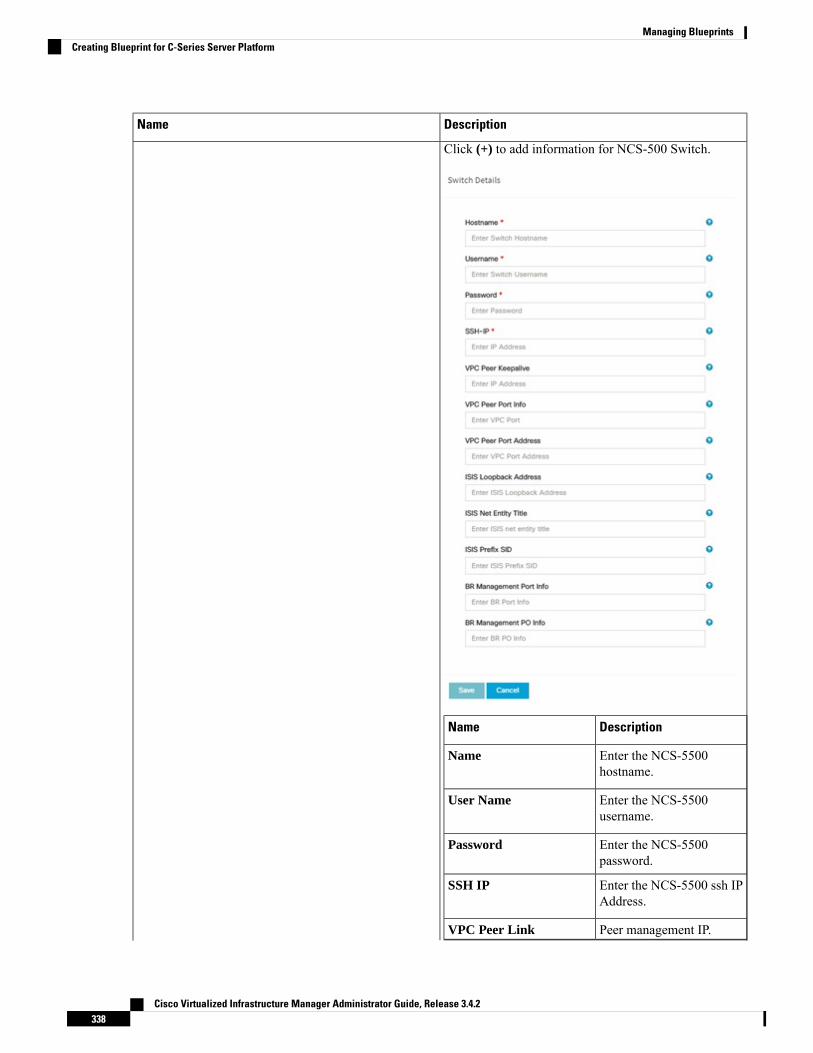
DescriptionName
Click (+) to add information for NCS-500 Switch.
DescriptionName
Enter the NCS-5500hostname.
Name
Enter the NCS-5500username.
User Name
Enter the NCS-5500password.
Password
Enter the NCS-5500 ssh IPAddress.
SSH IP
Peer management IP.VPC Peer Link
Cisco Virtualized Infrastructure Manager Administrator Guide, Release 3.4.2338
Managing BlueprintsCreating Blueprint for C-Series Server Platform
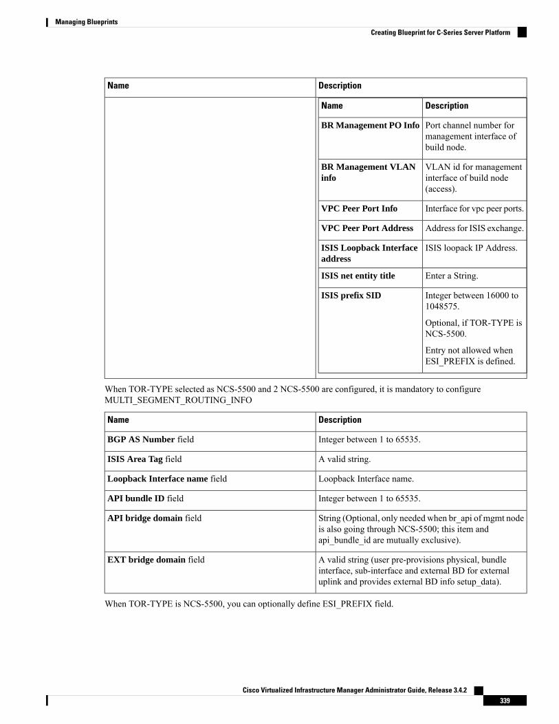
DescriptionName
DescriptionName
BR Management PO Info Port channel number formanagement interface ofbuild node.
VLAN id for managementinterface of build node(access).
BR Management VLANinfo
Interface for vpc peer ports.VPC Peer Port Info
Address for ISIS exchange.VPC Peer Port Address
ISIS loopack IP Address.ISIS Loopback Interfaceaddress
Enter a String.ISIS net entity title
Integer between 16000 to1048575.
Optional, if TOR-TYPE isNCS-5500.
Entry not allowed whenESI_PREFIX is defined.
ISIS prefix SID
When TOR-TYPE selected as NCS-5500 and 2 NCS-5500 are configured, it is mandatory to configureMULTI_SEGMENT_ROUTING_INFO
DescriptionName
Integer between 1 to 65535.BGP AS Number field
A valid string.ISIS Area Tag field
Loopback Interface name.Loopback Interface name field
Integer between 1 to 65535.API bundle ID field
String (Optional, only needed when br_api of mgmt nodeis also going through NCS-5500; this item andapi_bundle_id are mutually exclusive).
API bridge domain field
A valid string (user pre-provisions physical, bundleinterface, sub-interface and external BD for externaluplink and provides external BD info setup_data).
EXT bridge domain field
When TOR-TYPE is NCS-5500, you can optionally define ESI_PREFIX field.
Cisco Virtualized Infrastructure Manager Administrator Guide, Release 3.4.2339
Managing BlueprintsCreating Blueprint for C-Series Server Platform

DescriptionName
Ethernet-segment identifier type
Example:91.<Pod_number>.<pod_region_number>.00.00.00.00.
ESI_PREFIX
g. Click NFVI Monitoring checkbox in Blueprint Initial Setup, to enable the NFVI Monitoring configuration tab.NFVIMON can be un-configured once configured.
DescriptionName
IP Address of Control Center VMMaster - Admin IP
VIP for ceilometer/dispatcher to use, must be uniqueacross VIM Pod
Collector - Management VIP
Cisco Virtualized Infrastructure Manager Administrator Guide, Release 3.4.2340
Managing BlueprintsCreating Blueprint for C-Series Server Platform

DescriptionName
Hostname of Collector VMHost Name
Password of Collector VMPassword
Password of CCUSERCCUSER Password
SSH IP of Collector VMAdmin IP
Management IP of Collector VMManagement IP
Optional, but becomesmandatory if collector 2 is defined.Must contain valid Admin IP.
Master 2
Optional, but becomes mandatory if Master 2 is defined.Collector 2 is secondary set to collector and with all theproperties of Collector.
Contains Management VIP and Collector VMinformation.
Collector 2
Optional and reconfigurable to add/update user id. Onceenabled, you must have only one admin.
NFVIMON ADMIN
1. Click on (+) icon to Add Collector ToR Connections.
2. Select the ToR switches from list to add theinformation.
3. It is optional and available for ToR type NCS-5500
4. For now, it supports adding only one Collector ToRConnection
Enter port channel.Port Channel
Enter port number,E.g:eth1/15.
Switch -{torSwitch-hostname}
Click Save
Collector ToR Connections
Enter Rabbit MQ username.Rabbit MQ User Name
Cisco Virtualized Infrastructure Manager Administrator Guide, Release 3.4.2341
Managing BlueprintsCreating Blueprint for C-Series Server Platform

h. Click CVIMMON option in Blueprint Initial Setup to enable the CVIM Monitoring configuration tab.
DescriptionName
By default, it is false. It is case-sensitive and can be Trueor False
Enable
Optional, and if not defined it is set to True by defaul.With this option disabled, CVIM_MON with SNMP isavailable but you cannot access Grafana, Alert-Manager,and Prometheus UIs
UI Access
Optional. Denotes 's' for seconds, m for minutes, and hfor hours
Polling Interval
Cisco Virtualized Infrastructure Manager Administrator Guide, Release 3.4.2342
Managing BlueprintsCreating Blueprint for C-Series Server Platform

DescriptionName
Minimum of 10 seconds (10s) and maximum of 60 mins(1h). If not defined, defaults to 15s.
High Frequency
Minimum of 30 seconds (30s) and maximum of 60 mins(1h). If not defined, defaults to 30s. It must be more thanhigh interval
Medium Frequency
Minimum of 1 minute (1m) and maximum of 60 mins(1h). If not defined, defaults to 1 minute. It must be morethan medium interval.
Low Frequency
Optional, if not defined, defaults to False.With this optionenabled, you will get central CVIM-MON (only telegrafagents running on pod), without local Prometheus,AlertManager, or Grafana
CVIMMON Central
Optional, list of external server IPs (v4 or v6) to bemonitoried by CVIM MON
External Servers
If defined, the group mappings and domain mappings aremandatory.
CVIMMON LDAP
Must contain at least one group with org_role Admin
Optionally, you can add a second group with org_roleViewer
group_mappings
Must contain one domain exactly.domain_mappings
Any non-empty name is acceptable.domain_name
All subkeys are mandatoryattributes
Describes the user that can connect to the LDAP serverto check credentials.
It can be a read-only user or refer to a group that matchesall possible users.
bind_dn
This is the password of the bind_dn user. When thebind_dn is a group, this field must be omitted.
bind_password
The URI used to connect to the LDAP servers One ormultiple URIs are configurable and separated by a comma.
ldap_uri
The base dns name used for all queriessearch_base_dns
Filter used for the queriessearch_filter
i. Click OpenStack Setup Tab to advance to the OpenStack Setup Configuration page. On the OpenStack SetupConfiguration page of the Cisco VIM Unified Management wizard, complete the following fields:
Cisco Virtualized Infrastructure Manager Administrator Guide, Release 3.4.2343
Managing BlueprintsCreating Blueprint for C-Series Server Platform

DescriptionName
Fill in the following details:
Enter IP address of ExternalVIP.
External VIP Address field
Enter IPv6 address of ExternalVIP.
External VIP Address IPv6field
Enter the Router ID for HA.Virtual Router ID field
Enter IPv6 address of InternalIP.
Internal VIP Address IPv6field
Enter IP address of InternalVIP.
Internal VIP Address field
HA Proxy
Mandatory fields are pre-populated.
admin.Admin User Name
admin.Admin Tenant Name
Keystone
Cisco Virtualized Infrastructure Manager Administrator Guide, Release 3.4.2344
Managing BlueprintsCreating Blueprint for C-Series Server Platform

DescriptionName
If the external_lb_vip is behind a NAT router or with a DNS alias,provide a list of those addresses.
Horizon Allowed hosts– NAT IP : Uses comma separated listof IP addresses and/or DNS names
Horizon Aliases
Cisco Virtualized Infrastructure Manager Administrator Guide, Release 3.4.2345
Managing BlueprintsCreating Blueprint for C-Series Server Platform

DescriptionName
LDAP
Cisco Virtualized Infrastructure Manager Administrator Guide, Release 3.4.2346
Managing BlueprintsCreating Blueprint for C-Series Server Platform

DescriptionName
LDAP enable checkbox which by default is false, if LDAP isenabled on keystone.
Enter name for Domain name.Domain Name field
Enter a string as input.Object Class for Users field
Enter a string.Object Class for Groups field
Enter a string.Domain Name Tree for Usersfield
Enter a string.Domain Name Tree forGroups field
Enter a string.Suffix for Domain Name field
Enter a URL with ending portnumber.
URL field
Enter a string.Domain Name of Bind Userfield
Enter Password as stringformat.
Password field
Enter filter name as string.User Filter field
Enter a string.User ID Attribute field
Enter a string.User Name Attribute field
Enter a string.User Mail Attribute field
Cisco Virtualized Infrastructure Manager Administrator Guide, Release 3.4.2347
Managing BlueprintsCreating Blueprint for C-Series Server Platform

DescriptionName
Group Name Attribute field Enter a string.
Cisco Virtualized Infrastructure Manager Administrator Guide, Release 3.4.2348
Managing BlueprintsCreating Blueprint for C-Series Server Platform

DescriptionName
Neutron
Cisco Virtualized Infrastructure Manager Administrator Guide, Release 3.4.2349
Managing BlueprintsCreating Blueprint for C-Series Server Platform

DescriptionName
Neutron fields would change on the basis of Tenant NetworkType Selection from Blueprint Initial Setup. Following are theoptions available for Neutron for OVS/VLAN:
Auto Filled based on the TenantNetwork Type selected in theBlueprint Initial Setup page.
Tenant Network Type field
Auto Filled based on the TenantNetwork Type selected inBlueprint Initial Setup page.
Mechanism Drivers field
Auto filled with the Computeyou added in Server and Roles.
NFV Hosts field
If you select All in this sectionNFV_HOSTS: ALL will beadded to the Blueprint or youcan select one particularcompute. For Eg:
NFV_HOSTS:compute-server-1,compute-server-2.
List of ranges separated bycomma form start:end.
Tenant VLAN Ranges field
List of ranges separated bycomma form start:end.
Provider VLAN Ranges field
2M or 1G (optional, defaults to2M)
VM Hugh Page Size(available for NFV_HOSTSoption) field
Optional, defaults to 100%; canrange between 0 and 100
VM_HUGHPAGE_PERCENTAGE
Cisco Virtualized Infrastructure Manager Administrator Guide, Release 3.4.2350
Managing BlueprintsCreating Blueprint for C-Series Server Platform

DescriptionName
VSWITCH_WORKER_PROFILE Allowed only for VPP
Optionally available options:numa_zero and even
• numa_zero: Reservedcores will always reside inNUMA node 0.
• Even : Reserved cores willbe evenly distributedacross all NUMA.
Allowed only for VPP
Number of cores associated toVPP, defaults to 2.
NR_RESERVED_VSWITCH_PCORES
Enable the checkboxEnable Jumbo Frames field
For Tenant Network Type Linux Bridge everything remains thesame but Tenant VLAN Ranges will be removed.
Cisco Virtualized Infrastructure Manager Administrator Guide, Release 3.4.2351
Managing BlueprintsCreating Blueprint for C-Series Server Platform

DescriptionName
CEPH
Cisco Virtualized Infrastructure Manager Administrator Guide, Release 3.4.2352
Managing BlueprintsCreating Blueprint for C-Series Server Platform

DescriptionName
1. 1. When Object Storage Backend is selected Central inblueprint initial setup.
By default Central.CEPH Mode
Enter Cluster ID.Cluster ID
Enter Monitor Host for CEPHMonitor Host
Enter Monitor Members for CEPHMonitor Members
Enter Secret UUID for CEPHSecret UUID
Drop down selection. You can chooseCEPH or local.
NOVA Boot from
Enter NOVA RBD Pool (default's tovms)
NOVARBDPOOL
Optional, needed for Central Ceph andwhen mgmt network is not routable
CEPH NAT
2. When Object Storage Backend is selected Dedicated inblueprint initial setup.
• CEPH Mode: By default Dedicated.
• NOVA Boot: From drop down selection you can chooseCEPH or local.
• Cinder Percentage: Must be 60 when Nova Boot From islocal, and must be 40 when Nova Boot is Ceph
• Nova Percentage: Only applicable when Nova Boot From
Cisco Virtualized Infrastructure Manager Administrator Guide, Release 3.4.2353
Managing BlueprintsCreating Blueprint for C-Series Server Platform

DescriptionName
is Ceph. Must be 30% otherwise.
• Glance Percentage : Must be 40 when Nova Boot From islocal, and must be 30 when NOVA Boot From is Ceph. IfCeilometer is enabled, it must be 35% for Nova Boot fromlocal and 25% for NOVA Boot From is Ceph.
• Gnocchi Percentage: Only applicable when ceilometer isenabled, and must be 5%.
3. WhenObject Storage Backend is selectedNetApp in blueprintinitial setup.
• Ceph mode : By default, it is NetApp
• Cinder Percenatge : Must be 60%
• Glance Percenatge: Must be 40%
1. When Object Storage Backend is selected Central in blueprintinitial setup.
When Object Storage Backend is selected Dedicated in blueprintinitial setup.
By default Populated for CEPH Dedicated with StoreBackend value as CEPH.
Note
GLANCE
Cisco Virtualized Infrastructure Manager Administrator Guide, Release 3.4.2354
Managing BlueprintsCreating Blueprint for C-Series Server Platform

DescriptionName
By default Populated for CEPH Dedicated with Volume Drivervalue as CEPH.
2. When Object Storage Backend is selected Dedicated inblueprint initial setup.
By default Populated for CEPH Dedicated withVolume Driver value as CEPH.
Note
CINDER
Cisco Virtualized Infrastructure Manager Administrator Guide, Release 3.4.2355
Managing BlueprintsCreating Blueprint for C-Series Server Platform

DescriptionName
VMTP optional section, this will be visible onlyif VMTP is selected from Blueprint Initial Setup.For VTS tenant type Provider network is onlysupported.
Cisco Virtualized Infrastructure Manager Administrator Guide, Release 3.4.2356
Managing BlueprintsCreating Blueprint for C-Series Server Platform

DescriptionName
Check one of the check boxes to specify a VMTP network:
• Provider Network
• External Network
For the Provider Network complete the following:
Enter the name for the externalnetwork.
Network Name field
Enter the Subnet for ProviderNetwork.
Subnet field
Enter the starting floating IPv4address.
Network IP Start field
Enter the ending floating IPv4address.
Network IP End field
Enter the IPv4 address for theGateway.
Network Gatewayfield
Enter the DNS server IPv4address.
DNS Server field
Enter the segmentation ID.Segmentation ID field
For External Network fill in the following details:
Cisco Virtualized Infrastructure Manager Administrator Guide, Release 3.4.2357
Managing BlueprintsCreating Blueprint for C-Series Server Platform

DescriptionName
Network Name field Enter the name for the externalnetwork.
Enter the starting floating IPv4address.
IP Start field
Enter the ending floating IPv4address.
IP End field
Enter the IPv4 address for theGateway.
Gateway field
Enter the DNS server IPv4address.
DNS Server field
Enter the Subnet for ExternalNetwork.
Subnet field
TLS has two options:
• External LB VIP FQDN - Text Field.
• External LB VIP TLS - True/False. By default this optionis false.
TLS optional section, this will be visible only ifTLS is selected fromBlueprint Initial Setup Page.
Following are the field descriptions for VIM Admins:
Enter usernameUser Name
Password field. Admin hashpassword should always startwith $6.
Password
Under the OpenStack setup tab, Vim_admins tabwill be visible only when Vim_admins is selectedfrom the Optional Features & Services under theBlueprint Initial setup tab
Cisco Virtualized Infrastructure Manager Administrator Guide, Release 3.4.2358
Managing BlueprintsCreating Blueprint for C-Series Server Platform

DescriptionName
Vim LDAP Admins: Optional entry to supportLDAP for admin access to management node. Forthis feature, TLS has to be enabled for the externalapi (i.e. external_lb_vip_tls: True).
Cisco Virtualized Infrastructure Manager Administrator Guide, Release 3.4.2359
Managing BlueprintsCreating Blueprint for C-Series Server Platform
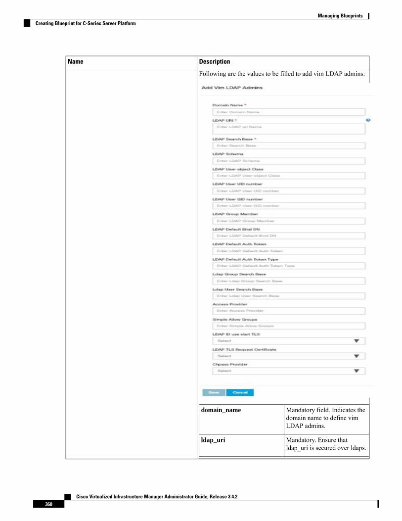
DescriptionName
Following are the values to be filled to add vim LDAP admins:
Mandatory field. Indicates thedomain name to define vimLDAP admins.
domain_name
Mandatory. Ensure thatldap_uri is secured over ldaps.
ldap_uri
Cisco Virtualized Infrastructure Manager Administrator Guide, Release 3.4.2360
Managing BlueprintsCreating Blueprint for C-Series Server Platform
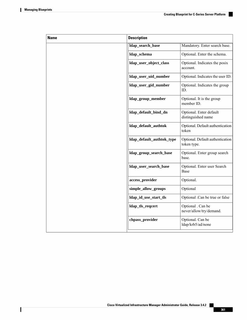
DescriptionName
ldap_search_base Mandatory. Enter search base.
Optional. Enter the schema.ldap_schema
Optional. Indicates the posixaccount.
ldap_user_object_class
Optional. Indicates the user ID.ldap_user_uid_number
Optional. Indicates the groupID.
ldap_user_gid_number
Optional. It is the groupmember ID.
ldap_group_member
Optional. Enter defaultdistinguished name
ldap_default_bind_dn
Optional. Default authenticationtoken
ldap_default_authtok
Optional. Default authenticationtoken type.
ldap_default_authtok_type
Optional. Enter group searchbase.
ldap_group_search_base
Optional. Enter user SearchBase
ldap_user_search_base
Optional.access_provider
Optionalsimple_allow_groups
Optional .Can be true or falseldap_id_use_start_tls
Optional . Can benever/allow/try/demand.
ldap_tls_reqcert
Optional. Can beldap/krb5/ad/none
chpass_provider
Cisco Virtualized Infrastructure Manager Administrator Guide, Release 3.4.2361
Managing BlueprintsCreating Blueprint for C-Series Server Platform

DescriptionName
DescriptionName
Enter host input. Example:<ip1|host1>:[port] . max of 3,min of 1, not 2;
APIC Hosts field
Enter a string format.apic_username field
Enter Password.apic_password filed
Enter input as string. Maxlength 8.
apic_system_id field
Enter string max length 6.apic_resource_prefix field
Allowed only 10.0.0.0/16apic_tep_address_ pool field
Allowed only 225.0.0.0/15multiclass_address_pool field
Enter integer(1- 65535)apic_pod_id field
Enter String, max length 32apic_installer_tenant field
Enter String, max length 32apic_installer_vrf field
Enter String, max length 32api_l3out_network field
APICINFO tab is available in Openstack setup,when the Tenant type ACI/VLAN is selected inblueprint initial setup.
WhenACI/VLAN is selected then ToRswitch from initial setup is mandatory.
Note
Cisco Virtualized Infrastructure Manager Administrator Guide, Release 3.4.2362
Managing BlueprintsCreating Blueprint for C-Series Server Platform

DescriptionName
DescriptionName
True or false default is false.VTS Day0 (checkbox)
Enter as string does not containspecial characters.
VTS User name
Enter passwordVTS Password
Enter IP Address format.VTS NCS IP
Enter a stringVTC SSH Username
Enter passwordVTC SHH Password
VTS tab is available in Openstack setup, whenTenant Type is VTS/VLAN selected.
If vts day0 is enabled then SSH username andSSH password is mandatory.
If SSH_username is input present then SSHpassword is mandatory vice-versa
j. For SolidFire, enter the following:
DescriptionName
SolidFire is visible for configuration on day0
SolidFire is not allowed as a day-2 deployment option
SolidFire is always available with CEPH.
Management IP of SolidFire cluster.Cluster MVIPfield
Storage VIP of SolidFire cluster.Cluster SVIP field
Admin user on SolidFire clusterAdmin Username
Admin password on SolidFirecluster.
Admin Password
Cisco Virtualized Infrastructure Manager Administrator Guide, Release 3.4.2363
Managing BlueprintsCreating Blueprint for C-Series Server Platform

k. If Syslog Export or NFVBENCH is selected in Blueprint Initial Setup Page, then Services Setup page will beenabled for user to view. Following are the options under Services Setup Tab:
DescriptionName
Following are the options for Syslog Settings:
User can add maximum of three entries.
To add new SysLog information, click on Add SysLog button, fill all the requiredinformation listed below and hit Save button.
Enter Syslog IP address.Remote Host
Only UDP is supported.Protocol
Defaults to local5.Facility
Defaults to debug.Severity
Defaults to ELK.Clients
Defaults to 514 but can be modified bythe User.
Port
Syslog Export
Cisco Virtualized Infrastructure Manager Administrator Guide, Release 3.4.2364
Managing BlueprintsCreating Blueprint for C-Series Server Platform

DescriptionName
NFVBENCH enable checkbox by default isfalse.
Add ToR information connect to Switch:
• Select a TOR Switch and enter the Switch name.
• Enter the port number. For example, eth1/5 . VTEP VLANS (mandatory andneeded only for VTS/VXLAN). Enter two different VLANs for VLAN1 andVLAN2.
• NIC Ports: INT1 and INT2 optional input. Enter the two port numbers of the4-port 10G Intel NIC at the management node used for NFVBench.
NIC Slot: Optional input, indicates which NIC to use in case there are multipleNICs.
NIC port and slot need to be together.Note
NFVBENCH
Enable the checkbox to set it as True. By default it is False.ENABLE_ESC_PRIV
Cisco Virtualized Infrastructure Manager Administrator Guide, Release 3.4.2365
Managing BlueprintsCreating Blueprint for C-Series Server Platform
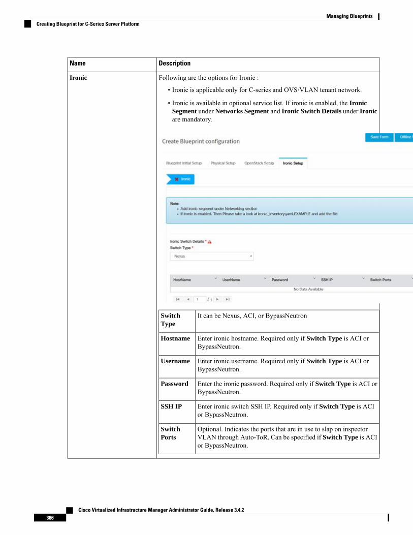
DescriptionName
Following are the options for Ironic :
• Ironic is applicable only for C-series and OVS/VLAN tenant network.
• Ironic is available in optional service list. If ironic is enabled, the IronicSegment under Networks Segment and Ironic Switch Details under Ironicare mandatory.
It can be Nexus, ACI, or BypassNeutronSwitchType
Enter ironic hostname. Required only if Switch Type is ACI orBypassNeutron.
Hostname
Enter ironic username. Required only if Switch Type is ACI orBypassNeutron.
Username
Enter the ironic password. Required only if Switch Type is ACI orBypassNeutron.
Password
Enter ironic switch SSH IP. Required only if Switch Type is ACIor BypassNeutron.
SSH IP
Optional. Indicates the ports that are in use to slap on inspectorVLAN through Auto-ToR. Can be specified if Switch Type is ACIor BypassNeutron.
SwitchPorts
Ironic
Cisco Virtualized Infrastructure Manager Administrator Guide, Release 3.4.2366
Managing BlueprintsCreating Blueprint for C-Series Server Platform

DescriptionName
CCP
Cisco Virtualized Infrastructure Manager Administrator Guide, Release 3.4.2367
Managing BlueprintsCreating Blueprint for C-Series Server Platform
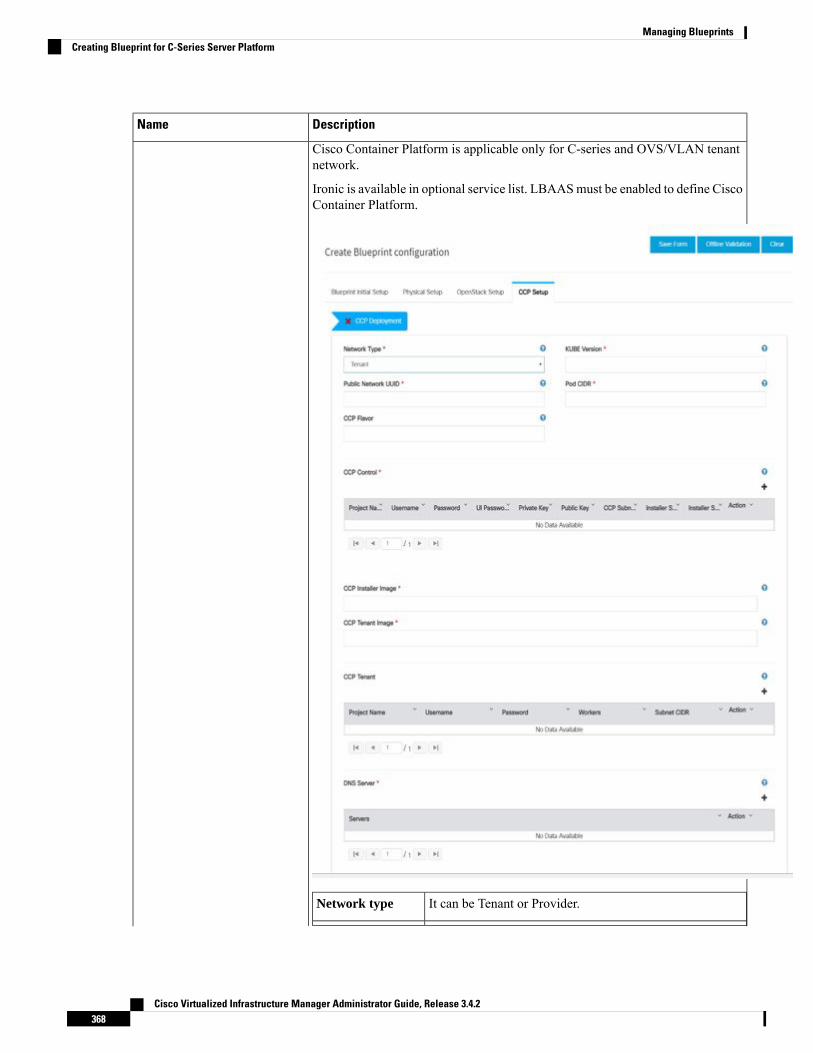
DescriptionName
Cisco Container Platform is applicable only for C-series and OVS/VLAN tenantnetwork.
Ironic is available in optional service list. LBAASmust be enabled to define CiscoContainer Platform.
It can be Tenant or Provider.Network type
Cisco Virtualized Infrastructure Manager Administrator Guide, Release 3.4.2368
Managing BlueprintsCreating Blueprint for C-Series Server Platform

DescriptionName
KubernetesVersion
Version of Kubernetes to be installed
UUID of Openstack external network or provider networkPublic NetworkUUID
Pod CIDR to use for calico network optional if not to bechanged
Pod CIDR
Optional, but mandatory when NFV_HOSTS is enabledduring Cisco Container Platform installation.
CCP Flavor
Following fields are mandatory for network types tenant andprovider.
Project Name - Tenant name to create in Openstack to hosttenant cluster
Username - Username for openstack tenant
Password - Password for the Openstack tenant
UI Password - Password for Cisco Container Platform UI
Private Key - Private key to be used to SSH to VM mustbe ed25519
Public Key - Public key for Cisco Container PlatformVMs,for example, /root/ecdsa-key.pub
Following fields are mandatory for network type tenant:
Cisco Container Platform Subnet - Subnet to create todeploy Cisco Container Platform control plane
Installer Subnet - Subnet used for creating bootstrapinstaller
Installer Subnet Gateway - Gateway used for bootstrapinstaller
CCP Control
Pointer to the CCP Installer image (required)CCP InstallerImage
Pointer to CCP tenant cluster image (required)CCP TenantImage
CCP Tenant
Cisco Virtualized Infrastructure Manager Administrator Guide, Release 3.4.2369
Managing BlueprintsCreating Blueprint for C-Series Server Platform

DescriptionName
Fields are mandatory
Project Name - Tenant name to be created in Openstack tohost tenant cluster
Username - Username for openstack tenant.
Password - Password for tenant.
Workers - Number of kubernetes workers in tenant cluster(required).
Tenant Subnet CIDR - Tenant subnet CIDR.
DNS server must be reachable from cloud (required)DNS Server
Step 5 Click Offline validation button to initiate an offline validation of the Blueprint.Step 6 Once the Offline validation is successful, Save option will be enabled for you which when clicked would redirect you
to the Blueprint Management page.
Redeploy Multiple Install Stages during Cisco VIM Installation using UnifiedManagement
You can redeploy Cisco VIM in multiple stages during blueprint installation using the Cisco VIM UnifiedManagement dashboard.
Step 1 When the blueprint installation status is in Active/failed/Installation failed and stage install status asFailed/NotRun/Skipped., the redeployed icon is displayed.
Cisco Virtualized Infrastructure Manager Administrator Guide, Release 3.4.2370
Managing BlueprintsRedeploy Multiple Install Stages during Cisco VIM Installation using Unified Management

Step 2 Click Reployed icon to redeploy multiple stages during installation. A confirmation dialogue box appears.
Step 3 Select the stages to be installed.
Cisco Virtualized Infrastructure Manager Administrator Guide, Release 3.4.2371
Managing BlueprintsRedeploy Multiple Install Stages during Cisco VIM Installation using Unified Management

Step 4 You can select the stages only in sequence. For example,you can select the VMTP stage (current) stage only if theOrchestration (previous) stage is selected for blueprint installation (assuming Orchestration was in Failed/NotRun state)
Step 5 Click Proceed to run the installation.
Downloading Blueprint
Before you begin
You must have atleast one blueprint (In any state Active/In-Active or In-progress), in the BlueprintManagement Page.
Step 1 Log in to CISCO VIM Unified Management.Step 2 In the navigation pane, expand the Pre-Install Section.Step 3 Click Blueprint Management.Step 4 Go-to Download for any Blueprint under Action title. (Download Button > Downward Arrow (with tooltip Preview
& Download YAML).Step 5 Click the Download icon.
A pop to view the Blueprint in the YAML format is displayed.Step 6 Click the Download button at the bottom left of the pop-up window.
YAML is saved locally with the same name of the Blueprint.
Validating Blueprint
Step 1 Log in to CISCO VIM Unified Management.Step 2 In the Navigation pane, expand the Pre-Install Section.Step 3 Click Blueprint Creation.Step 4 Upload an existing YAML, or create a New Blueprint.
Fill all the mandatory fields so that all Red Cross changes to Green Tick.
Step 5 Enter the name of the Blueprint.Step 6 ClickOffline Validation.
Only, if the Validation is successful, the Unified Management allows you to save the blueprint.
What to do next
If you see any errors, a hyperlink is created for those errors. Click the link to be navigated to the page whereerror has been encountered.
Cisco Virtualized Infrastructure Manager Administrator Guide, Release 3.4.2372
Managing BlueprintsDownloading Blueprint

Managing Post Install FeaturesCisco VIM provides an orchestration that helps in lifecycle management of a cloud. VIM is responsible forpodmanagement activities which includes fixing both hardware and software issues with one-touch automation.VIM Unified Management provides the visualization of the stated goal. As a result, it integrates with POSTinstall features that Cisco VIM offers through its Rest API. These features are enabled only if there is an activeBlueprint deployment on the pod.
Monitoring the PodCisco VIM uses EFK (Elasticsearch, Fluentd, and Kibana) to monitor the OpenStack services, bycross-launching the Kibana dashboard.
To cross launch Kibana, complete the following instructions:
Step 1 In the navigation pane, click Post-Install > Logging.Step 2 Click Click here to view Kibana in new tab.
Step 3 Enter the Username as Admin.Step 4 Enter the Kibana_PASSWORD password that is obtained from /root/installer-<tagid>/openstack-configs/secrets.yaml
in the management node.
Cross Launching HorizonHorizon is the canonical implementation of OpenStack's Dashboard, which provides a web-based user interfaceto OpenStack services including Nova, Swift and, Keystone.
Cisco Virtualized Infrastructure Manager Administrator Guide, Release 3.4.2373
Managing BlueprintsManaging Post Install Features
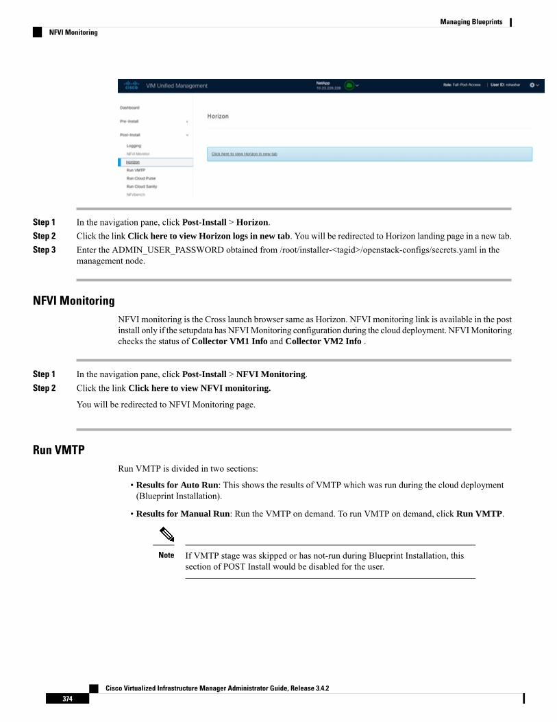
Step 1 In the navigation pane, click Post-Install > Horizon.Step 2 Click the link Click here to view Horizon logs in new tab. You will be redirected to Horizon landing page in a new tab.Step 3 Enter the ADMIN_USER_PASSWORD obtained from /root/installer-<tagid>/openstack-configs/secrets.yaml in the
management node.
NFVI MonitoringNFVI monitoring is the Cross launch browser same as Horizon. NFVI monitoring link is available in the postinstall only if the setupdata has NFVIMonitoring configuration during the cloud deployment. NFVIMonitoringchecks the status of Collector VM1 Info and Collector VM2 Info .
Step 1 In the navigation pane, click Post-Install > NFVI Monitoring.Step 2 Click the link Click here to view NFVI monitoring.
You will be redirected to NFVI Monitoring page.
Run VMTPRun VMTP is divided in two sections:
• Results for Auto Run: This shows the results of VMTP which was run during the cloud deployment(Blueprint Installation).
• Results for Manual Run: Run the VMTP on demand. To run VMTP on demand, click Run VMTP.
If VMTP stage was skipped or has not-run during Blueprint Installation, thissection of POST Install would be disabled for the user.
Note
Cisco Virtualized Infrastructure Manager Administrator Guide, Release 3.4.2374
Managing BlueprintsNFVI Monitoring

Run CloudPulseIn VIM 2.0 and later, we provide an integrated tool, called Cloud Pulse, that periodically checks the cloudservices endpoint. The results of these tests are reflected under the Cloud Pulse link. Also, you can run theseAPI endpoint tests on demand, and fetch the result of these tests by refreshing the table.
OpenStack CloudPulse tool is used to verify Cisco NFVI health. CloudPulse servers are installed in containerson all Cisco NFVI control nodes and CloudPulse clients are installed on the management node.
CloudPulse has two test sets: endpoint scenario (runs as a cron or manually) and operator test (run manually).
Following are the tests which are supported in CloudPulse:
Endpoint tests include
• cinder_endpoint
• glace_endpoint
• keystone_endpoint
• nova_endpoint
• neutron_endpoint
Operator tests include
• ceph_check
• docker_check
• galera_check
• node_check
• rabbitmq_check
Cisco Virtualized Infrastructure Manager Administrator Guide, Release 3.4.2375
Managing BlueprintsRun CloudPulse

To run a cloud pulse test, choose a particular test from the dropdown and click Run Test. Once the test is inprogress, Click (Spin/refresh) icon to fetch the latest result. This grid does not fetch the latest resultautomatically.
Run Cloud Sanity TestYou can use the cloud sanity tool to test the Cisco NFVI pod and cloud infrastructure (host connectivity, basicmraiadb, rabbit, ceph cluster check, and RAID disks).
Following are the test available to run from Unified Management.
• Control
• Compute
• Cephmon
• Cephosd
• Management
• All
Step 1 To run a Cloud sanity test choose a particular test from the dropdown.
Cisco Virtualized Infrastructure Manager Administrator Guide, Release 3.4.2376
Managing BlueprintsRun Cloud Sanity Test

Step 2 Click Run Test to proceed with the operation. Once the test is completed, clickSee Details for more
details.
Run NFV BenchYou canRun NFV Bench forB andC series Pod, through Cisco VIMUnifiedManagement. On a pod runningwith CVIM, choose a NFVbench link on the NAV-Menu.
You can run either fixed rate test or NDR/PDR test. As the settings and results for the test types differ, theoptions to run these tests are presented in two tabs, with its own settings and results. To run a particular test,you can either select a particular hypervisor from the available list or allow the system to select any hypervisor.
NDR/PDR Test
Step 1 Log in to CISCO VIM Unified Management.Step 2 In the Navigation pane, click Post-Install >Run NFV Bench.Step 3 Click NDR/PDR test and complete the following fields
DescriptionName
Select any hypervisor to run the NDR/PDR. By default, theoption Use any hypervisor is selected.
Select a hypervisor (Optional)
Choose duration from 10 to 60 sec. Default is 20 sec.Iteration Duration
Choose the correct frame size to run.Frame Size
Enable VXLAN encapsulation, only if VXLAN is enabled.VXLAN
Click Run NDR/PDR test. After, completion it displayseach type of test with its own settings and results.
Run NDR/PDR test
Cisco Virtualized Infrastructure Manager Administrator Guide, Release 3.4.2377
Managing BlueprintsRun NFV Bench

Cisco Container PlatformYou can install, verify, and cleanup Cisco Container Platform for B and C series pod with OVS/VLAN tenanttype, through Cisco VIM Unified Management. On a pod running with Cisco VIM, choose a Cisco ContainerPlatform link on the NAV menu.
You can either install Cisco Container Platform during initial installation or add Cisco Container Platformduring install operation.
After successful installation, you can either do verify or cleanup operation.
Cisco Virtualized Infrastructure Manager Administrator Guide, Release 3.4.2378
Managing BlueprintsCisco Container Platform
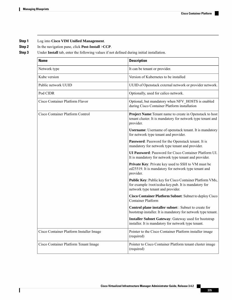
Step 1 Log into Cisco VIM Unified Management.Step 2 In the navigation pane, click Post-Install >CCP.Step 3 Under Install tab, enter the following values if not defined during initial installation.
DescriptionName
It can be tenant or provider.Network type
Version of Kubernetes to be installedKube version
UUID of Openstack external network or provider network.Public network UUID
Optionally, used for calico network.Pod CIDR
Optional, but mandatory when NFV_HOSTS is enabledduring Cisco Container Platform installation
Cisco Container Platform Flavor
Project Name:Tenant name to create in Openstack to hosttenant cluster. It is mandatory for network type tenant andprovider.
Username: Username of openstack tenant. It is mandatoryfor network type tenant and provider.
Password: Password for the Openstack tenant. It ismandatory for network type tenant and provider.
UI Password: Password for Cisco Container Platform UI.It is mandatory for network type tenant and provider.
Private Key: Private key used to SSH to VM must beed25519. It is mandatory for network type tenant andprovider.
Public Key: Public key for Cisco Container PlatformVMs,for example /root/ecdsa-key.pub. It is mandatory fornetwork type tenant and provider.
Cisco Container Platform Subnet: Subnet to deploy CiscoContainer Platform
Control plane installer subnet : Subnet to create forbootstrap installer. It is mandatory for network type tenant.
Installer Subnet Gateway: Gateway used for bootstrapinstaller. It is mandatory for network type tenant.
Cisco Container Platform Control
Pointer to the Cisco Container Platform installer image(required)
Cisco Container Platform Installer Image
Pointer to Cisco Container Platform tenant cluster image(required)
Cisco Container Platform Tenant Image
Cisco Virtualized Infrastructure Manager Administrator Guide, Release 3.4.2379
Managing BlueprintsCisco Container Platform

DescriptionName
Project Name: Tenant name to create in Openstack to hosttenant cluster. It is mandatory.
Username: Username for openstack tenant. It is mandatory.
Password: Password for tenant. It is mandatory.
Workers: Number of kubernetes workers in tenant cluster.It is mandatory
Tenant Subnet CIDR: Tenant subnet CIDR. It ismandatory.
Cisco Container Platform Tenant
DNS server to be reachable from cloud (required)DNS Server
Reconfiguring CIMC Password Through Unified ManagementUpdate the cimc_password in the CIMC-COMMON section, or the individual cimc_password for each serverand then run the update password option.
To update a password, you have to follow the password rules:
• Must contain at least one lower-case letter.
• Must contain at least one upper-case letter.
• Must contain at least one digit between 0 to 9.
• One of these special characters !$#@%^-_+=*&
• Your password has to be 8 to 14 characters long.
Before you begin
You must have a C-series pod up and running with Cisco VIM to reconfigure CIMC password.
Reconfigure CIMC password section is disabled if the pod is in failed state as indicated by ciscoviminstall-status.
Note
Step 1 Log in to CISCO VIM Unified Management.Step 2 In the navigation pane, choose Post-Install
Step 3 Click Reconfigure CIMC Password.Step 4 On the Reconfigure CIMC Password page of the Cisco VIM UM, complete the following fields:
DescriptionName
CIMC_COMMON old password field cannot be edited.CIMC_COMMON old Password
Cisco Virtualized Infrastructure Manager Administrator Guide, Release 3.4.2380
Managing BlueprintsReconfiguring CIMC Password Through Unified Management

DescriptionName
Enter the CIMC-COMMON password. Password has tobe alphanumeric according to the password rule.
CIMC-COMMON new Password
OldCIMC-COMMON password can be updatedwith newCIMC-COMMON password.
Click Update
Cisco Virtualized Infrastructure Manager Administrator Guide, Release 3.4.2381
Managing BlueprintsReconfiguring CIMC Password Through Unified Management

Cisco Virtualized Infrastructure Manager Administrator Guide, Release 3.4.2382
Managing BlueprintsReconfiguring CIMC Password Through Unified Management

C H A P T E R 9Managing Pod Through Cisco VIM UnifiedManagement
The following are the naming conventions used in the Cisco VIM UM
1. Super Administrator (UM Admin): User having access to UM Admin profile
2. PODAdministrator: User having access to register a Pod in the system(Only UM can add new Pod Adminin the system)
3. Pod users (Normal users): o All the users which are associated with the Pod. Full-pod-access: Role assignedto user which gives full access of a specific Pod(This has nothing to do with Pod Admins)
The following are the Key Points
• User who are UM admin or Pod admin but not associated with any Pod are not counted in UM admindashboard user count section
• Only Pod Admins can register a new Pod
• Every Pod must a user with “Full-pod-Access” role.
• User cannot be revoked/delete if the users is the last user on the pod with “Full-Pod-Access” role.
• User cannot be delete if user is a Pod admin or UM admin.
The following topics tell you how to install and replace Cisco Virtual Infrastructure Manager (VIM) nodesusing Cisco VIM Unified Management.
• Monitoring Pod Status, on page 383• Managing Hardware, on page 384• Power Management, on page 393• Managing Software, on page 397• Pod User Administration, on page 417
Monitoring Pod StatusThe unified management application manages the pods and displays the pod management action status witha cloud icon.
Cisco Virtualized Infrastructure Manager Administrator Guide, Release 3.4.2383

The following table displays a summary of the pod operation, the corresponding cloud-icon color, and thepod status.
Table 17: Pod Operation Status
Pod StatusUM Icon-ColorPod Operation
ActiveGreenActive cloud with no failures
In-progressBlueCloud installation or podmanagement operation is inprogress
Critical WarningsRedSoftware update (auto) rollback isfailed
WarningAmberPending commit post softwareupdate
Critical WarningRedReconfigure failed (for anyoperation)
Critical WarningRedUpdate, commit, or Rollback failed
WarningAmberPower management operation fails
Not ReachableRedManagement not reachable
Managing HardwareManagement of your Cisco VIM pods includes adding, removing, or replacing the nodes.
In a pod, multiple nodes cannot be changed at the same time. For example, if you want to replace two controlnodes, you must successfully complete the replacement of the first node before you begin to replace the secondnode. Same restriction applies for addition and removal of storage nodes. Only, in case of Compute Nodesyou can add or remove multiple nodes together.However, there must always be one active compute node inthe pod at any given point. VNF manager stays active and monitors the compute nodes so that moving theVNFs accordingly as compute node management happens.
When you change a control, storage, or compute node in a Cisco VIM pod using Unified Management, itautomatically updates the server and role in the active blueprint, as a result, your OpenStack deploymentchanges. When a node is removed from Cisco VIM, sensitive data may remain on the drives of the server.Administrator advice you to use Linux tools to wipe the storage server before using the same server for anotherpurpose. The drives that are used by other application server must be wiped out before adding to Cisco VIM.
Note
Searching Compute and Storage NodesThis functionality allows you to search the Compute and Storage nodes by server names only. The searchresult is generated or shows an empty grid if there are no results.
Cisco Virtualized Infrastructure Manager Administrator Guide, Release 3.4.2384
Managing Pod Through Cisco VIM Unified ManagementManaging Hardware

Figure 18: Search Storage Nodes
POD ManagementCisco VIM allows the admin to perform pod life-cycle management from a hardware and software perspective.Cisco VIM provides the ability to power on/off compute node, add, remove or replace nodes based on therespective roles when the nodes of a given pod corrupts at times.
Figure 19: POD Management
Pod Management page has two sections–
1. Node Summary: This section shows how many nodes are available and the detailed count of Control,Compute and Storage type.
Cisco Virtualized Infrastructure Manager Administrator Guide, Release 3.4.2385
Managing Pod Through Cisco VIM Unified ManagementPOD Management

2. IP Pool Summary: This section shows the Total Pool Summary and the current available pool count.
The operations performed on the running pod are:
Replace Control Nodes: Double fault scenario is not supported. Only the replacement of one controller at atime is supported.
If the TOR type is Cisco NCS 5500, an additional popup is displayed to enable the user to update splitterconfiguration before replacing the control node.
Note
Add Computes/Storage Nodes: N-computes nodes can be replaced simultaneously; however at any givenpoint, at least one compute node has to be active.
If the TOR type is Cisco NCS 5500, an option is available to update the splitter cable configuration.Note
Power On/ Off compute Nodes: You can Power On or Power Off compute node. At least one compute nodemust be powered on.
Remove Compute/Storage Nodes: You can add one node at a time, when Ceph is run as a distributed storageoffering.
If TOR type is Cisco NCS 5500, an additional popup is displayed to enable the user to update the splittercable configuration, before the removal of compute or storage node.
Note
Add Pool: You can increase pool size at any time.
Managing Storage NodesBefore you add or remove a storage node, review the following guidelines for Managing Storage Nodes.
• Required Number of Storage Nodes: A Cisco VIM pod must have a minimum of three and a maximumof 20 storage nodes. If your pod has only two storage nodes, you cannot delete a storage node until youadd another storage node. If you have fewer than three storage nodes, you can add one node at a timeuntil you get to 20 storage nodes.
• Validation of Nodes: When you add a storage node to a pod, Cisco VIM Unified Management validatesthat all the nodes in the pod meet the minimum requirements and are in active state. If you have a controlor compute node in a faulty state, you must either correct, delete or replace that node before you can adda storage node.
• Update Blueprint: When you add or delete a storage node, Unified Management updates the blueprintfor the Cisco VIM pod.
• Storage Node Logs: You can access the logs for each storage node from the link in the Log column onthe Storage Nodes tab.
Cisco Virtualized Infrastructure Manager Administrator Guide, Release 3.4.2386
Managing Pod Through Cisco VIM Unified ManagementManaging Storage Nodes

Adding Storage NodeComplete the following instructions to add a storage node:
You cannot add more than one storage node at a time.Note
Before you begin
• Remove the non-functional storage node from the pod. You can have maximum 20 storage nodes in aCisco VIM pod.
• Ensure that the server for the new storage node is in powered state in OpenStack for C Series.
Step 1 In the navigation pane, choose Post-Install > Pod Management > Storage.Step 2 Click on Add Storage node button on the Storage tab. A popup will open where you can provide information about the
new Storage node.Step 3 For C Series, add the following details:
• Server Name: Name for the Storage Server to be added.
• Rack ID: Enter the Rack ID. (Accepts String format).
• CIMC IP: Enter the CIMC IP.
• CIMC User Name: User name for the CIMC.
• CIMC Password: Enter the password for the CIMC
• VIC Slot: Enter the VIC Slot (Optional).
• ToR switch info:Mandatory if ToR is configured as True
• Management IPv6: Enter IPv6 Address.
Step 4 For B Series, add the following details:
• Server Name: Name for the Storage Server to be added.
• Rack ID: Enter the Rack ID. (Accepts String format).
• Rack Unit ID: Enter the Rack Unit ID.
• Management IPv6: Enter IPv6 Address.
Cancel will discard the changes and popup will be closedNote
If all mandatory fields are filled in correctly then Add Storage button will be enabled.
Step 5 Click Initiate Add Storage. Add node initialized message will be displayed.Step 6 To view logs, click View logs under Logs column.
The status of the POD will change to Active.
Cisco Virtualized Infrastructure Manager Administrator Guide, Release 3.4.2387
Managing Pod Through Cisco VIM Unified ManagementAdding Storage Node

Step 7 Two kinds of failure may occur:
• Add Node Pre-Failed: When addition of node failed before the bare-metal stage (step 4), the Active Blueprint ismodified but the Node is not yet added in the Cloud. If you press X Icon, then Unified Management will delete thenode information form the Blueprint and the state would be restored.
• Add Node Post-Failed: When addition of node failed after the bare-metal stage (step 4), the Active Blueprint ismodified and the node is registered in the cloud. If you press X Icon, thn Unified Management will first delete thenode from the Blueprint and then node removal from cloud would be initiated.
You can view the logs for this operation under Logs column.
Deleting Storage NodeYou cannot delete more than one storage node at a time.
Step 1 In the Navigation pane, choose Post-Install > POD Management > Storage.Step 2 Click X adjacent to the storage node you want to delete.
Yor can delete a storage node with Force option for hyper-converged POD. The Force option is useful when VM’s arerunning on the node.
Step 3 Node Removal Initiated successfully message will be displayed.
To view logs, click View logs under logs column.
• If the Storage Node is deleted successfully, the storage node will be removed from the list under Add/Removestorage Node.
• In deletion failed, a new button Clear Failed Nodes will be displayed. Click Clear Failed Nodes to remove thenode form cloud and Blueprint.
Managing Compute NodesBefore you add or remove a compute node, review the following guidelines:
• Required number of compute nodes: Cisco VIM pod must have a minimum of one compute node anda maximum of 128 nodes. Out of 128 nodes, three nodes are control nodes and remaining 125 nodes isbetween compute and ceph nodes with a maximum of 25 ceph nodes. If your pod has only one computenode, you cannot delete that node until you add another compute node.
• Update blueprint: When you add or remove a compute node, UnifiedManagement updates the blueprintfor the Cisco VIM pod.
• Compute node logs: You can access the Logs for each compute node from the link in the Log columnon the Compute Nodes table.
Cisco Virtualized Infrastructure Manager Administrator Guide, Release 3.4.2388
Managing Pod Through Cisco VIM Unified ManagementDeleting Storage Node

Adding Compute NodeAdd IP Pool
If all the existing pool size is already used, then you need to increase the pool size. On the Add compute orAdd storage popup, Click Expand Management IP pool to add a new Pool.
Complete the instructions, to add a compute node:
Before you begin
Ensure that the server for the new compute node is in powered state in OpenStack. You can add more thanone compute node at a time.
Step 1 In the navigation pane, click Post-Install > Pod Management > Compute.Step 2 Click Add Compute Node on the Compute tab a popup opens . Add the required information in the popup. To add
another node clcik Add Another Node if you planned to add another compute node OR hit Initiate Add Compute if youso not plan to add any more compute node. If you hit Add Another Node button, the existing form will be emptied. Youneed to fill the information for the new compute node and then repeat step 1. You may use Previous and Next button tonavigate among different added node information.
Step 3 For C-series, add the following details:
• Server Name: Name for the Compute Server.
• Rack ID: Enter the Rack ID. (Accepts String format).
• CIMC IP: Enter the CIMC IP.
• CIMC User Name: User name for the CIMC.
• CIMC Password: Enter the password for the CIMC.
• VIC Slot: Enter the VIC Slot (Optional).
• ToR switch info: Mandatory if configured ToR is true.
• DP ToR switch info: Enter input as string format.
• SRIVO ToR info : Enter input as string format.
Cisco Virtualized Infrastructure Manager Administrator Guide, Release 3.4.2389
Managing Pod Through Cisco VIM Unified ManagementAdding Compute Node

• Management IPv6 : Enter IPv6 address.
• Trusted_vf: Optional and not reconfigurable. Applicable only for SRIOV node with compute role for C-series pod.
• Vtep IPs: IP address from vxlan-tenant and vxlan-tenant.
• INTEL_SRIOV_VFS :Value range is 1 to 32.
• INTEL_FPGA_VFS: Value range is 1 to 8.
• INTEL_VC_SRIOV_VFS: Value range is 1 to 32.
• Vendor: Optional. It can be CISCO - Cisco Systems Inc or QCT - Quanta Cloud Technology Inc or HPE - HewlettPackard Enterprise.
:• VM Hugepage Size: Optional. It can be 2M or 1G. Only applicable with NFV HOSTS.
• RX TX Queue Size: Optional. It can be 256, 512, or 1024.
• SECCOMP_SANDBOX : Optional. If not defined, set to 1.
• NOVA_CPU_ALLOCATION_RATIO: Optional, overrides the NOVA_CPU_ALLOCATION_RATIO definedin openstack_config.yaml. Values lie in the range of 0.958 to 16.0
• NOVA_RAM_ALLOCATION_RATIO: Optional, overrides the NOVA_RAM_ALLOCATION_RATIO definedin openstack_config.yaml. Values lie in the range of 1.0 to 4.0
• NUM GPU CARDS: Optional, for server with GPU. Value lies in the range from 0 to 6
• root_drive_type: <HDD or SSD or M.2_SATA, NUM_GPU_CARDS: 0 to 6
• VIC Port Channel Enable: Optional. It can be True or False. By default, it is set to True.
• VIC Admin FEC mode: Optional. It can be auto, off, cl74, or cl91.
Step 4 For B series, add the following details:
• Server Name: Name for the Storage Server to be added.
• Rack ID: Enter the Rack ID. (Accepts String format).
• Rack Unit ID: Enter the Rack Unit ID.
• Chassis ID: Enter the Chassis ID. Range for Chassis ID is 1-24.
• Blade ID: Enter the Blade ID. Range for Blade ID is 1-8.
• CIMC Password: Enter the CIMC Password.
• VM Hugepage Size: Optional. It can be 2M or 1G. Only applicable for NFV HOSTS.
• RX TX Queue Size: Optional. It can be 256, 512, or 1024.
• SECCOMP_SANDBOX : Optional. If not defined, set to 1.
• NOVA_CPU_ALLOCATION_RATIO: Optional, overrides the NOVA_CPU_ALLOCATION_RATIO definedin openstack_config.yaml. Values lie in the range of 0.958 to 16.0
• NOVA_RAM_ALLOCATION_RATIO: Optional, overrides the NOVA_RAM_ALLOCATION_RATIO definedin openstack_config.yaml. Values lie in the range of 1.0 to 4.0
Cisco Virtualized Infrastructure Manager Administrator Guide, Release 3.4.2390
Managing Pod Through Cisco VIM Unified ManagementAdding Compute Node

• Management IPv6: Enter IPv6 address.
If all mandatory fields are filled in correctly, click Save
• Add compute process can initiate multiple addition of compute nodes. Fill in the mandatory fields to savenew compute node or press cancel to exit.
• Fields of pod management will remain mandatory for user input based on setup-data.
Note
Step 5 You may perform one among these steps mentioned below:
• ClickingCancel displays the compute node information listed in the table andAdd Compute Node button is enabled.
• If you feel you have filled in a wrong entry for the compute node information, click Delete. This will delete theentry from the table as this information is not added in the Blueprint.
• Click Initiate Add Compute, displays Add node initialized message.
Step 6 To view logs, click View logs under Logs column. The status of the POD will change to Active.Step 7 Two kinds of failure may occur:
• Add Node Pre-Failed: When addition of node failed before the bare-metal stage (step 4) the Active Blueprint willbe modified but the Node is not yet added in the Cloud. If you press X Icon, then Unified Management will deletethe node information form the Blueprint and the state would be restored.
• Add Node Post-Failed: When addition of node failed after the bare-metal stage (step 4) the Active Blueprint willbe modified and the node is registered in the cloud. If you press X Icon, then Unified Management will first deletethe node from the Blueprint and then node removal from cloud would be initiated.
You can view the logs for this operation under Logs column.
Deleting Compute NodeCompute node is deleted due to a hardware failure. You can delete one compute node at a time.
If your pod has only one compute node, you cannot delete that node until you add another compute node.Note
Step 1 In the navigation pane, choose Post-Install > POD Management > Compute.Step 2 Click X for the compute node to be deleted. To remove multiple compute nodes, choose the target compute nodes which
is on the extreme left column, then click Trash to remove multiple computes.
You can delete a compute node with Force option which is useful when VM’s are running on the node.
"Node removal initiated successfully" message is displayed.Step 3 To view the Logs, click View logs under Logs column.
• If compute nodes are deleted successfully, you cannot view the compute node in the list under Add or RemoveCompute Node.
Cisco Virtualized Infrastructure Manager Administrator Guide, Release 3.4.2391
Managing Pod Through Cisco VIM Unified ManagementDeleting Compute Node

• If Compute Note is deleted, a new button Clear Failed Nodes is displayed.
Step 4 Click Clear Failed Nodes to remove the node form Cloud and Blueprint.
Managing Control NodesBefore you replace a control node, review the following guidelines:
• Required Number of Control Nodes: A Cisco VIM pod must have three control nodes and you canonly replace one node at a time.
• Validation of Nodes: When you replace a control node, Cisco VIM Unified Management validates ifall the other nodes in the pod meet the minimum requirements and are in active state. If you have a storageor a compute node in a faulty state, you must correct the faulty state or delete or replace that node beforeyou can replace the control node.
• Update Blueprint: When you replace a control node, Unified Management updates the Active blueprintfor the Cisco VIM pod.
• Control Node Logs: You can access the logs for each control node from the link in the Logs column ofControl Nodes table.
Replacing Control NodeYou can replace only one control node at a time.
Step 1 In the navigation pane, click Post-Install > Pod Management > Control.Step 2 Click (Spin) icon. A confirmation pop-up appears, Click Proceed to continue.
You can replace a control node with Force option for Micropod. The Force option is useful when VM’s are running onthe node.
Step 3 If you want to edit a specific control node before replace, click Edit to update the changes.Step 4 On success, Replace Node Initiated successfully message is displayed.Step 5 You can view the logs in the Logs column on the Control Nodes table.
What to do next
If the replacement of the control node fails, do the following:
• Click the link in the Logs column.
• Check the logs to determine the cause of the failure.
• Correct the issue and attempt to replace the control node again.
Cisco Virtualized Infrastructure Manager Administrator Guide, Release 3.4.2392
Managing Pod Through Cisco VIM Unified ManagementManaging Control Nodes

For replace controller, you can change only a subset of the server information. For C-series, you can changethe server information such as CIMC IP, CIMC Username, CIMC password, rack_id, and tor_info. ForB-series, you can change the rack_id, chassis_id, and blade_id, but not the server hostname and managementIP during the operation of replace controller.
Note
Power ManagementCompute node can be powered on or powered off from the Compute Tab in Pod Management section. Thereis a power button associated with each compute with information provided as tooltip when you hover on thaticon.
Following are the steps to power on/off multiple compute node:
1. Click Power button located to the left of delete button.
2. Choose the compute nodes by selecting the check box, the corresponding power button gets enabled.
Powering On a Compute NodeFollowing are the steps to power on the compute node:
1. Click the Compute tab.
2. In the Pod Management area, check the check box corresponding to the Compute node that you want topower on.
The Power button of a Compute node is enabled only after you select the Compute node.Note
Figure 20: Powering On a Compute Node
3. Under the Actions column, click the Power button of the Compute node. It may take a few minutes forthe Compute node to power on. The tooltip of the power button displays the status of the Compute node.Once the compute node is powered on, the Power button stops blinking and its color changes to green.
Cisco Virtualized Infrastructure Manager Administrator Guide, Release 3.4.2393
Managing Pod Through Cisco VIM Unified ManagementPower Management

Figure 21: Power On Operation
You can add a Compute node only once a power on task is complete.
Powering Off Compute Node
You cannot power off all the Compute nodes. There must be at least one Compute node that is in the On state.Note
Follow these steps to power off a Compute node:
1. Click the Compute tab.
2. In the Pod Management area, under the Actions column, click the Power button of the Compute nodethat you want to power off.
3. Click Yes in the confirmation dialog box.
Cisco Virtualized Infrastructure Manager Administrator Guide, Release 3.4.2394
Managing Pod Through Cisco VIM Unified ManagementPowering Off Compute Node

It may take a few minutes for the Compute node to power off. The tooltip of the power button displaysthe status of the Compute node. Once the compute node is powered off, the Power button stops blinkingand its color changes to grey.
If there is only one compute node in the grid, and you try to power off it, a message Last compute node can’tbe powered off is displayed. Also, when you power off the last available compute node in the list of nodes,then the message At least one compute node should be powered on is displayed.
Note
Multiple compute power/ delete/ reboot operation
You can perform power, delete, and reboot operation on multiple compute nodes using the global buttonslocated at the top of grid. To enable this operation, select at least one compute node.
Cisco Virtualized Infrastructure Manager Administrator Guide, Release 3.4.2395
Managing Pod Through Cisco VIM Unified ManagementPowering Off Compute Node

Rebooting Compute NodeTo reboot the compute node, follow the below steps:
1. Click on Compute tab.
2. In the Pod Management pane, under the Actions column, click Reboot of the compute node that youwant to reboot.
3. Click Yes in the confirmation dialog box, to perform reboot. You can reboot a compute node with Forceoption which is useful when VM’s are running on the node.
Multiple compute power/ delete/ reboot operation
You can perform power, delete, and reboot operation on multiple compute nodes using the global buttonslocated at the top of grid. To enable this operation, select at least one compute node.
Figure 22: Pod Management
Searching Compute and Storage NodesThis functionality allows you to search the Compute and Storage nodes by server names only. The searchresult is generated or shows an empty grid if there are no results.
Cisco Virtualized Infrastructure Manager Administrator Guide, Release 3.4.2396
Managing Pod Through Cisco VIM Unified ManagementRebooting Compute Node

Figure 23: Search Storage Nodes
Managing SoftwareSoftware management of your Cisco VIM pods includes software update, reconfigure of openstack servicesand password, etc.
VIM Software Update
As part of the lifecycle management of the cloud, VIM has the ability to bring in patches (bug fixes relatedto code, security, etc.), thereby providing cloud management facility from software point of view. Softwareupdate of the cloud is achieved by uploading a valid tar file, following initiation of a System Update form theUnified Management as follows:
Step 1 In the Navigation pane, click Post-Install > System Update.Step 2 Click Browse and select the valid tar file.Step 3 Click Open.Step 4 Click Upload and Update.
Update started Successfully message will be displayed.Step 5 Update status will be shown as ToUpdate.
Click the hyperlink to view the reconfigure logs for install logs.
Reconfigure status will be available on the page or the dashboard under POD Operation details.
What to do next
System Update has been initiated message will be displayed. Logs front-ended by hyperlink will be in thesection below in-front of Update Logs which shows the progress of the update. During the software update,all other pod management activities will be disabled. Post-update, normal cloud management will commence.Once update has completed you will see the status of update in the box below.
If log update fails, Auto-RollBack will be initiated automatically.
Cisco Virtualized Infrastructure Manager Administrator Guide, Release 3.4.2397
Managing Pod Through Cisco VIM Unified ManagementManaging Software

If log update is successful, you will have two options to be performed:
1. Commit—To proceed with the update.
2. RollBack—To cancel the update.
If Auto-rollback fails during software update fails through Unified Management UI, it is advised that theadministrator contact Cisco TAC for help. Do not re-try the update or delete the new or the old installerworkspace.
If the update is successful and reboot is required for at least one compute node:
• Only commit or rollback is allowed.
• Following operations are not permitted:
• Reconfigure
• System update
• Pod management
You can reboot the node, only after the commit or rollback operation.Note
.
Reconfigure Openstack PasswordsThere are two options to regenerate the passwords:
• Regenerate all passwords: Click Regenerate all passwords checkbox and click Set Password. Thiswill automatically regenerate all passwords in alphanumeric format.
• Regenerate single or more password: This will set a specific password by doing an inline edit for anyservice like Horizon's ADMIN_USER_PASSWORD. Double click on the filed under Password andenter the password to enable Set Password button.
Cisco Virtualized Infrastructure Manager Administrator Guide, Release 3.4.2398
Managing Pod Through Cisco VIM Unified ManagementReconfigure Openstack Passwords

During the reconfiguration of password, all other pod management activities will be disabled. Post-update,normal cloud management will commence. If the reconfigure of the password fails, all subsequent podmanagement operations will be blocked. It is advised to contact Cisco TAC to resolve the situation throughCLI.
Reconfigure OpenStack Services, TLS Certificates, and ELK ConfigurationsCisco VIM supports the reconfiguration of OpenStack log level services, TLS certificates, and ELKconfiguration. Following are the steps to reconfigure the OpenStack and other services:
Step 1 In the navigation pane, click Post-Install > Reconfigure Openstack Config.Step 2 Click the specific item that you want to change and update. For example: to update the TLS certificate click the path to
the certificate location.Step 3 Enter Set Config to commence the process.
What to do next
During the reconfiguration process, all other pod management activities are disabled. Post-update, normalcloud management commences. If reconfigure of OpenStack Services fails, all subsequent pod managementoperations are blocked. Contact, Cisco TAC to resolve the situation through CLI.
Reconfiguring CIMC Password through Unified ManagementCisco VIM allows you to update the cimc_password in the CIMC-COMMON section, and/or the individualcimc_password for each server and then run the update password option.
You need to match the following password rule to update the password:
Cisco Virtualized Infrastructure Manager Administrator Guide, Release 3.4.2399
Managing Pod Through Cisco VIM Unified ManagementReconfigure OpenStack Services, TLS Certificates, and ELK Configurations

• Must contain at least one lower case letter.
• Must contain at least one upper case letter.
• Must contain at least one digit between 0 to 9.
• One of these special characters !$#@%^-_+=*&
• Your password has to be 8 to 14 characters long.
Before you begin
You must have a C-series pod up and running with Cisco VIM to reconfigure CIMC password.
Reconfigure CIMC password section is disabled if the pod is in failed state as indicated by ciscoviminstall-status.
Note
Step 1 Log-in to CISCO VIM Unified Management.Step 2 In the navigation pane, select Post-Install.Step 3 Click Reconfigure CIMC Password.Step 4 You can reconfigure the CIMC Password at global level by adding new CIMC_COMMON Password. To reconfigure
CIMC Password for individual servers, double-click the server password that you want to edit.Step 5 Click Reconfigure to initiate reconfigure process.
Reconfiguring Optional ServicesCisco VIM offers optional services such as heat, migration to Keystone v3, NFVBench, NFVIMON, etc, thatcan be enabled post-pod deployment. These services can be enabled in one-shot or selectively.
Listed below are the steps to enable optional services:
Step 1 In the navigation pane, click Post-Install > Reconfigure Optional Services.Step 2 Choose the right services and update the fields with the right values.Step 3 Click Offline validation.Step 4 Once offline validation is successful, click Reconfigure to commence the process.
During the reconfiguration process, all other pod management activities will be disabled. Post-update, normal cloudmanagement will commence.
If reconfigured OpenStack Services fail, all subsequent pod management operations are blocked. Contact Cisco TAC toresolve the situation through CLI.
All reconfiguration features contain repeated re-deployment option set to true or false.
• Repeated re-deployment true - Feature can be re-deployed again.
• Repeated re-deployment false- Deployment of feature allowed only once.
Note
Cisco Virtualized Infrastructure Manager Administrator Guide, Release 3.4.2400
Managing Pod Through Cisco VIM Unified ManagementReconfiguring Optional Services

Deployment Status :
Repeated re-deployment OptionOptional Features
TrueAPICINFO
TrueDHCP reservation for VM MAC address
FalseEXTERNAL_LB_VIP_FQDN
FalseEXTERNAL_LB_VIP_TLS
TrueINSTALL_MODE
TrueHTTP_PROXY & HTTPS_PROXY
TrueLDAP
TrueNETWORKING
FalseNFVBENCH
True. Can be unconfigured.NFVIMON
FalsePODNAME
TruePROVIDER_VLAN_RANGES
FalseSYSLOG_EXPORT_SETTINGS
TrueTENANT_VLAN_RANGES
FalseTORSWITCHINFO
TrueVIM _ ADMINS
FalseVMTP
FalseVTS_PARAMETERS
`
True
AUTOBACKUP
FalseHeat
TrueCobbler
TrueES Remote Backup
TrueCVIM-MON
TrueNETAPP_SUPPORT
TrueEnable Read-only OpenStack Admins
TrueBase MAC address
Cisco Virtualized Infrastructure Manager Administrator Guide, Release 3.4.2401
Managing Pod Through Cisco VIM Unified ManagementReconfiguring Optional Services

Repeated re-deployment OptionOptional Features
FalseVAULT
TrueCloud Settings
TrueIPA
FalseTrusted_vf on a per server basis
Reconfiguring Optional Features Through Unified Management
Step 1 Log into Cisco VIM UM.Step 2 In the Navigation pane, expand the Post-Install Section.Step 3 Click Reconfiguring Optional Feature through UM.Step 4 On the Reconfiguring Optional Feature through UM page of the Cisco VIM UM, enter the data for the following
fields:
DescriptionName
• Enable Heat.
• Click Offline Validation .
• When Offline Validation is successful, clickReconfigure to commence the process.
Heat check box
• Check/uncheck Enable Read-only OpenStackAdmins
• Click Offline Validation
When Offline Validation is successful, click
Reconfigure to commence the process.
Enable Read-only OpenStack Admins checkbox
• Enable Keystone v3.
• Click Offline Validation .
• When Offline Validation is successful, clickReconfigure to commence the process.
Keystone v3 check box
• Enable ENABLE_ESC_PRIV .
• Click Offline Validation .
• When Offline Validation is successful, clickReconfigure to commence the process.
ENABLE_ESC_PRIV
Cisco Virtualized Infrastructure Manager Administrator Guide, Release 3.4.2402
Managing Pod Through Cisco VIM Unified ManagementReconfiguring Optional Features Through Unified Management

DescriptionName
• Enable/Disable Autobackup.
• Click Offline Validation .
• When Offline Validation is successful, clickReconfigure to commence the process.
Autobackup check box
• Enable External LB VIP TLS.
• Click Offline Validation .
• When Offline Validation is successful, clickReconfigure to commence the process.
External LB VIP TLS check box
• Enter input as a string.
• Click Offline Validation .
• When Offline Validation is successful, clickReconfigure to commence the process.
External LB VIP FQDN check box
• Enter Input as a string.
• Click Offline Validation .
• When Offline Validation is successful, clickReconfigure to commence the process.
Pod Name
• Augment tenant vlan ranges input. For Example:3310:3315.
• Click Offline Validation .
• When Offline Validation is successful, clickReconfigure to commence the process.
Tenant Vlan Ranges
• Enter input to tenant vlan ranges. For Example:3310:3315.
• Click Offline Validation .
• When Offline Validation is successful, clickReconfigure to commence the process.
Provider VLAN Ranges
• Select Connected or Disconnected, any one form thedrop-down list.
• Click Offline Validation .
• When Offline Validation is successful, clickReconfigure to commence the process.
Install Mode
Cisco Virtualized Infrastructure Manager Administrator Guide, Release 3.4.2403
Managing Pod Through Cisco VIM Unified ManagementReconfiguring Optional Features Through Unified Management
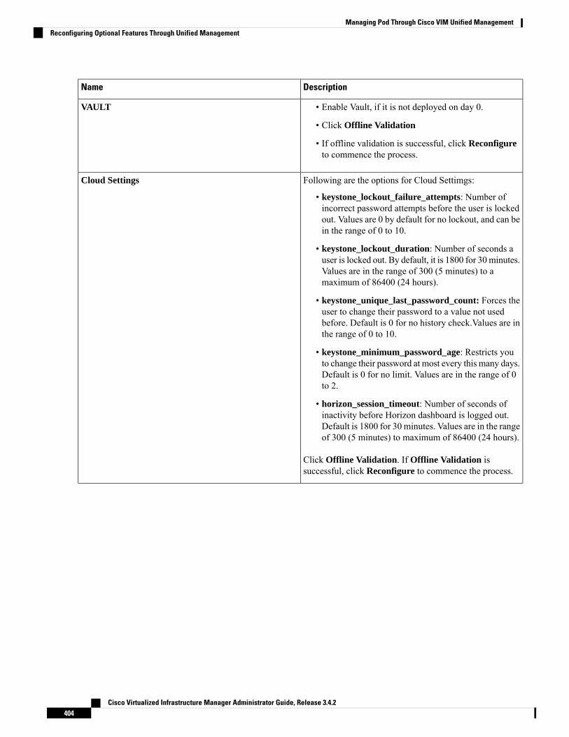
DescriptionName
• Enable Vault, if it is not deployed on day 0.
• Click Offline Validation
• If offline validation is successful, click Reconfigureto commence the process.
VAULT
Following are the options for Cloud Settimgs:
• keystone_lockout_failure_attempts: Number ofincorrect password attempts before the user is lockedout. Values are 0 by default for no lockout, and can bein the range of 0 to 10.
• keystone_lockout_duration: Number of seconds auser is locked out. By default, it is 1800 for 30minutes.Values are in the range of 300 (5 minutes) to amaximum of 86400 (24 hours).
• keystone_unique_last_password_count: Forces theuser to change their password to a value not usedbefore. Default is 0 for no history check.Values are inthe range of 0 to 10.
• keystone_minimum_password_age: Restricts youto change their password at most every this many days.Default is 0 for no limit. Values are in the range of 0to 2.
• horizon_session_timeout: Number of seconds ofinactivity before Horizon dashboard is logged out.Default is 1800 for 30 minutes. Values are in the rangeof 300 (5 minutes) to maximum of 86400 (24 hours).
Click Offline Validation. If Offline Validation issuccessful, click Reconfigure to commence the process.
Cloud Settings
Cisco Virtualized Infrastructure Manager Administrator Guide, Release 3.4.2404
Managing Pod Through Cisco VIM Unified ManagementReconfiguring Optional Features Through Unified Management

DescriptionName
For Registry Setup:
• Enter theRegistry User Name. It is a mandatory field
• Enter the Registry Password. The minimum lengthof the password is three.
• Enter the Registry Email. It is a mandatory field.
• Enter the Registry Name. For example, RegistryFQDN name. It is a mandatory field, only when CiscoVIM Software Hub is enabled.
• Click Offline Validation
• If offline validation is successful, click Reconfigureto commence the process.
.
Registry Setup Settings checkbox
Following are the options for Syslog Settings:
Enter Syslog IP Address.Remote Host
Defaults to local5Facility
Defaults to debugSeverity
Defaults to ELKClients
Defaults to 514 but ismodified by the User.
Port
Supports only UDPProtocol
Click Offline Validation .
• When Offline Validation is successful, clickReconfigure to commence the process.
Syslog Export Settings
True or False. Default is false.Configure ToR checkbox
Cisco Virtualized Infrastructure Manager Administrator Guide, Release 3.4.2405
Managing Pod Through Cisco VIM Unified ManagementReconfiguring Optional Features Through Unified Management

DescriptionName
Click + to add information for ToR Switch.
DescriptionName
ToR switch name.Name
ToR switch username.Username
ToR switch Password.Password
ToR switch SSH IPAddress.SSH IP
ToR switch ssn num. outputof show license host-id.
SSN Num
Peer Management IP. Youneed not define if there is nopeer.
VPC Peer Keepalive
Need not define if there is nopeer.
VPC Domain
Interface for vpc peer ports.VPC Peer port
vlan ids for vpc peer ports(optional).
VPC Peer VLAN Info
Management interface of thebuild node.
BR Management Port Info
Port channel number for themanagement interface of thebuild node.
BR Management PO Info
Click Save
• Click Offline Validation .
• When Offline Validation is successful, clickReconfigure to commence the process.
ToR Switch Information
When setup data is ACI VLAN with TOR then reconfigure options are:Note
Cisco Virtualized Infrastructure Manager Administrator Guide, Release 3.4.2406
Managing Pod Through Cisco VIM Unified ManagementReconfiguring Optional Features Through Unified Management

Click + to add information for ToR Switch.
DescriptionName
ToR switch name.Host Name
Peer Management IP.VPC Peer Keepalive
Do not define if there is noVPC Domain
Integer, unique across allswitches
Node ID
Click Save
• Click Offline Validation .
• When Offline Validation is successful, clickReconfigure to commence the process.
TORSwitch Information mandatory table if you want toenter ToR information
Enable check box which by default is false.
Add ToR information connected to switch:
• Select a ToR Switch and enter the Switch name.
• Enter the port number. For example: eth1/5
• NIC Ports: INT1 and INT2 optional input, enter thetwo port numbers of the 4-port 10G Intel NIC at themanagement node used for NFVBench.
For mechanism driver VPP, there are two optional fields inNFVBENCH if network option is available:
• VTEP IPs: Mandatory for NFVBench with VXLAN.It must be comma separated IP pair in vxlan-tenantnetwork, but not in the tenant pool.
• VNIs: Mandatory for NFVBench with VXLAN, andmust be comma separated vnid_id pairs.
For mechanism driver VTS:
VTEP IPs: Mandatory for VTS/VXLAN only. It must becomma separated IP pair belonging to tenant networksegment, but not in the tenant network pool.
• Click Offline Validation .
• When Offline Validation is successful, clickReconfigure to commence the process.
If ToR is already present in setup-data or alreadydeployed, Tor info need not be added. By defaultToR information switch name is mapped in NFVbench.
Note
NFVBench
Cisco Virtualized Infrastructure Manager Administrator Guide, Release 3.4.2407
Managing Pod Through Cisco VIM Unified ManagementReconfiguring Optional Features Through Unified Management

IP address of PAC(proxy-account-container)endpoint.
Cluster End Point
Admin user for swift toauthenticate in keystone.
Admin User
The service tenantcorresponding to theAccount-Container used bySwiftstack.
Admin Tenant
Reseller_prefix asconfigured for KeystoneAuth,AuthToken support inSwiftstack E.g KEY_
Reseller Prefix
swiftstack_admin_passwordAdmin Password
http or httpsProtocol drop-down list
• Click Offline Validation .
• When Offline Validation is successful, clickReconfigure to commence the process.
Swiftstack
SwiftStack is only supported with Keystone v2. If you selectKeystone v3, swiftstack will not be available forconfiguration.
Cisco Virtualized Infrastructure Manager Administrator Guide, Release 3.4.2408
Managing Pod Through Cisco VIM Unified ManagementReconfiguring Optional Features Through Unified Management

Enter the Domain name.Domain Name field
Enter a string as input.Object Class for Users field
Enter a string.Object Class for Groups
Enter a string.Domain Name Tree forUsers
Enter a string.Domain Name Tree forGroups field
Enter a string.Suffix for Domain Namefield
Enter a URL with portnumber.
URL field
Enter a string.Domain Name for BindUser field
Enter Password as stringformat.
Password field
Enter filter name as string.User Filter
Enter a string.User ID Attribute
Enter a string.User Name Attribute
Enter a string.User Mail Attribute
Enter a string.Group Name Attribute
• Click Offline Validation .
• When Offline Validation is successful, clickReconfigure to commence the process.
LDAP with Keystone v3
Cisco Virtualized Infrastructure Manager Administrator Guide, Release 3.4.2409
Managing Pod Through Cisco VIM Unified ManagementReconfiguring Optional Features Through Unified Management

Followings are the field values for NFVI monitoring:
Enter the input in IP format.Master Admin IP
Enter the input in IP format.Master 2 Admin IP field.
Enter the input in IP format.Collector Management IP
Collector VM1 info
Enter Host Name as a string.Host Name field
Enter Password.CCUSER password field
Enter password.Password field
Enter Input as IP format.Admin IP field
Enter Input as IP format.Management IP field
Collector VM2 info
Enter a string.Host Namefield
Enter Password.CCUSER field
Enter Input as IP format.Management IP field
Dispatcher
Enter a string.Rabbit MQ UsernameField
Enter a single string. Canhave only one and isoptional.
NFVIMON_ADMIN
• Click Offline Validation .
• When Offline Validation is successful, clickReconfigure to commence the process.
NFVI Monitoring
Following are the fields to reconfigure for VTS parameters
Enter the string.VTC SSH Username field.
Enter the password.VTC SSH Username field.
• Click Offline Validation .
• When Offline Validation is successful, clickReconfigure to commence the process.
VTS Parameter
Cisco Virtualized Infrastructure Manager Administrator Guide, Release 3.4.2410
Managing Pod Through Cisco VIM Unified ManagementReconfiguring Optional Features Through Unified Management

Check one of the check boxes to specify a VMTP network:
• Provider Network
• External Network
For the Provider Network complete the following:
Enter the name for theexternal network.
Network Name field.
Enter the starting floatingIPv4 address.
IP Start field.
Enter the ending floatingIPv4 address.
IP End field.
Enter the IPv4 address forthe Gateway.
Gateway field
Enter the DNS server IPv4address.
DNS Server field.
Enter the segmentation ID.Segmentation ID field.
Enter the Subnet forProvider Network.
Subnet
For External Network fill in the following details:
Enter the name for theexternal network.
Network Name field.
Enter the starting floatingIPv4 address.
Network IP Start field.
Enter the ending floatingIPv4 address.
Network IP End field.
Enter the IPv4 address forthe Gateway.
Network Gateway field
Enter the DNS server IPv4address.
DNS Server field.
Enter the Subnet for ExternalNetwork.
Subnet
• Click Offline Validation .
• When Offline Validation is successful, clickReconfigure to commence the process.
VMTP
Cisco Virtualized Infrastructure Manager Administrator Guide, Release 3.4.2411
Managing Pod Through Cisco VIM Unified ManagementReconfiguring Optional Features Through Unified Management

Networking
In Reconfigure optional services networking, you canreconfigure IP tables, or add http_proxy/https_proxy.
Cisco Virtualized Infrastructure Manager Administrator Guide, Release 3.4.2412
Managing Pod Through Cisco VIM Unified ManagementReconfiguring Optional Features Through Unified Management

To reconfigure networking, update the relevant information:
Click Add(+) to add a table.Enter input as subnet format.
IP Tables
E.g. 12.1.0.1/2
EnterHTTP_PROXY_SERVER
http_proxy_server
E.g. <a.b.c.d:port>
EnterHTTP_PROXY_SERVER
https_proxy_server
E.g. <a.b.c.d:port>
Click Add (+) to add serverNTP Server
• You can delete or editthe entered value
• You cannot delete allthe data (minimum 1server should bepresent)
• Maximum of four NTPservers can be present.
Click Add (+) to add serverDomain Name Server
• You can delete or editthe entered value.
• You cannot delete allthe data (minimum 1server must be present)
• Maximum of threeDNS servers can bepresent.
Add VTEP IP address andcomma separated VNI IDs.
Head-end replication
Multiple entries are allowed.You can changeVTEP IP forindividual compute/controlservers.
Whenever HERis removed from
Note
both vxlan-tenantand vxlan-tenant,all the vtep ipsassociated with
Cisco Virtualized Infrastructure Manager Administrator Guide, Release 3.4.2413
Managing Pod Through Cisco VIM Unified ManagementReconfiguring Optional Features Through Unified Management

the computes areremoved.
Applicable to control serversonly when VXLAN isenabled in NETWORKOPTIONS.IPs are picked upfrom management subnet,but not from IP pool. Youcan change the existing IPvalues if required.
Layer 3 BGP Adjacency
• Click Save.
• Click Offline Validation.
• When Offline Validation is successful, clickReconfigure to commence the process.
To reconfigure APICINFO, follow the process:
• Enter input for APIC hosts format. <ip1|host1>:[port]or eg.12.1.0.12
• Click Save.
• Click Offline Validation.
• When Offline Validation is successful, clickReconfigure to commence the process.
APIC hosts can be reconfigure minimum 1 hostand max 3 but not 2 hosts.
Note
APICINFO
Reconfigure optional services only APIC hostscan be reconfigure.
Note
To reconfigure vim_admins, follow the process:
• To add a new root user, Click + and add the Usernameand admin hash password (Starting with $6). At least,one VimAdminmust be configured, when Permit rootlogin is false.
• To remove the existing user, Click -.
• When Offline Validation is successful, clickReconfigure to commence the process.
Vim_admins
Cisco Virtualized Infrastructure Manager Administrator Guide, Release 3.4.2414
Managing Pod Through Cisco VIM Unified ManagementReconfiguring Optional Features Through Unified Management

To reconfigure Cobbler, follow the process:
• Generate the admin password hash by executing thebelow command:
python -c 'import crypt; print crypt.crypt("<plaintext_strong_password>")'on the management node.
• Validate that the admin_password_hash starts with '$6'
• Enter Admin Password Hash.
• Click Offline Validation.
• When Offline Validation is successful, clickReconfigure to commence the process.
Cobbler
To reconfigure Elastic Search Remote Backup:
Service field displays NFS by default, if the remote NFSserver is used.
• Enter theRemote Host, which is IP of the NFS server.
• Enter the Remote Path. . It is the path of the backuplocation in the remote server.
• Click Offline Validation.
• If Offline Validation is successful, click Reconfigureto commence the process.
ES Remote Backup
To reconfigure CVIM-MON, enter the following details:
• Enter the Low Frequency, such that it is higher thanmedium frequency. Minimum value is 1 minute. Bydefault, it is set to 1 minute.
• Enter theMedium Frequencysuch that it is more thanhigh frequency. Minimum value is 30 seconds. Bydefault, it is set to 30 seconds.
• Enter the High Frequency such that the minimumvalue is 10 seconds. By default, it is set to 10 seconds.
• Click Offline Validation.
• If Offline Validation is successful, click Reconfigureto commence the process.
• Set ui_access to True in deployed Blueprint, to enablethe Cisco VIM monitor link. This property isreconfigurable. If set to False, the link is disabled.
CVIM-MON
Cisco Virtualized Infrastructure Manager Administrator Guide, Release 3.4.2415
Managing Pod Through Cisco VIM Unified ManagementReconfiguring Optional Features Through Unified Management

To reconfigure NETAPP_SUPPORT, enter the followingdetails:
• Select the Server Port. It is the port of NetAppmanagement or API server. Select 80 for HTTP and443 for HTTPS.
• Select theTransport Type of the NetAppmanagementor API server. It can be HTTP or HTTPS.
• Select theNetApp Cert Path. It is the root ca path forNetApp cluster, only if protocol is HTTPS.
• Click Offline Validation.
• If Offline Validation is successful, click Reconfigureto commence the process.
NETAPP_SUPPORT
View TopologyYou can view the graphical representation of the control, compute, and storage node that is associated withthe various network segments.
You can click Control, Compute, or Storage from the topology, to view the details of respective node.
Cisco Virtualized Infrastructure Manager Administrator Guide, Release 3.4.2416
Managing Pod Through Cisco VIM Unified ManagementView Topology

Pod User AdministrationCisco VIM UM offers Users (Pod Admins or Pod Users) to manage Users and roles that are associated withthem.
Managing RolesUser can create multiple Roles and assign them to other pod users. System has a default role that is named asFull-Pod-Access which is assigned to the person who registers the Pod.
Manage Roles
Step 1 Click Login as POD User.
Step 2 Navigate to Pod User Administration and click Manage Roles. By default you see full-pod-access role in the table.Step 3 Click Add New Role to create a new role.Step 4 Complete the following fields in the Add Roles page in Cisco VIM UM:
Field DescriptionField Name
Enter the name of the role.Role
Enter the description of the role.Description
Check the Permission check box to select the permission.Permission
Once the Blueprint is in Active state all the permissions aresame for C-series and B-series Pods other than ReconfigureCIMC Password which is missing for B-series Pod.
Click Save.
Permissions are divided in the granular level where viewing Dashboard is the default role that is implicitlyadded while creating a role.
Note
Permissions are divided in the granular level where viewing Dashboard is the default role that is implicitlyadded while creating a role.
Note
Cisco Virtualized Infrastructure Manager Administrator Guide, Release 3.4.2417
Managing Pod Through Cisco VIM Unified ManagementPod User Administration

Managing UsersThis section allows you to add the users. It shows all the users associated with the Pod. You can check theonline status of all the user. ClickRefresh on upper right corner to check the status.
To add a new user:
Step 1 Click Login as POD User.Step 2 Navigate to POD User Administration and click Manage Users .Step 3 Click Add Users to add a new user.Step 4 Complete the following fields in the Add Users pane of the Cisco VIM Unified Management:
Field DescriptionField Name
Select the User auth for the new user. This option is enabled only if LDAP mode is True.User auth
• While adding new pod-user, a drop-down appears in the user-registration form containing all userswith pod-user permissions.
• Only available when DISPLAY_ALL_POD_USERS is set to True.
Select User
Registration type can be User/Group only when User Auth is LDAP.
Following fields are available when the Registration Type is ‘Group’:
• Group Dn – Enter the distinguished name of the LDAP group.
• Group Name – Enter the name of the LDAP group
RegistrationType
Enter the Email ID of the user or the LDAP user id if LDAP user attribute is set to uid.Email ID
Enter the User Name if the User is new. If the User is already registered to the Unified Managementthe User-Name gets auto-populated.
User Name
Select the Role from the drop-down list.Role
Cisco Virtualized Infrastructure Manager Administrator Guide, Release 3.4.2418
Managing Pod Through Cisco VIM Unified ManagementManaging Users

Step 5 Click Save Once the Blueprint is in Active state all the permissions are same for C-series and B-series Pods other thanReconfigure CIMC Password which is missing for B-series Pod.
Revoke UsersUser with Full-Pod-Access or Manage Users permission can revoke other users from the specific Pod.
To revoke users:
Step 1 Click Undo icon. A confirmation pop up will appear.Step 2 Click Proceed to continue.
Self revoke is not permitted. After revoking the another user, if the user is not associated with any other podthen the revoked user will be auto deleted from the system.
Note
Edit UsersUser with Full-Pod-Access or Manage Users permission can edit other user’s permission for that specific Pod.
To edit user’s permission
Step 1 Click Edit icon.Step 2 Update the permission.Step 3 Click Save. The Grid will get refreshed automatically.
Managing Root CA CertificateYou can update the CA Certificate during the registration of the POD. Once, logged in as POD User and ifyou have the permission to update the certificate you can view under POD User Administration>> ManageRoot CA Certificate.
Cisco Virtualized Infrastructure Manager Administrator Guide, Release 3.4.2419
Managing Pod Through Cisco VIM Unified ManagementRevoke Users

To update the Certificate:
Step 1 Click Login as POD User
Step 2 Navigate to POD User Administration>>Manage Root CA certificate.Step 3 Click Browse and select the certificate that you want to upload.Step 4 Click Upload.
• If the certificate is Invalid, and does not matches with the certificate on the management node located at(var/www/mercury/mercury-ca.crt) then UnifiedManagement reverts the certificate which was working previously.
• If the Certificate is valid, Unified Management runs a management node health check and then update the certificatewith the latest one.
The CA Certificate which is uploaded should be same as the one which is in the management node.Note
Cisco Virtualized Infrastructure Manager Administrator Guide, Release 3.4.2420
Managing Pod Through Cisco VIM Unified ManagementManaging Root CA Certificate

C H A P T E R 10Day 2 Operations of Cisco VIM UnifiedManagement
The following topic guides you the details about the Day 2 Operations of Cisco VIM Unified Management.
• Shutting Down Cisco VIM Unified Management, on page 421• Restarting Cisco VIM Unified Management, on page 422• Restoring VIM Unified Management, on page 422• Reconfiguring VIM Unified Management , on page 424• Adding and Reconfiguring VIM Administrators, on page 438• Enabling Root Login Post UM Node Installation, on page 439• Enabling Banner During SSH Login, on page 439• Adding and Reconfiguring UM Administrators, on page 439• Update VIM Unified Management, on page 440• Rollback VIM Unified Management, on page 444• Commit VIM Unified Management, on page 446• Uploading Glance Images, on page 447
Shutting Down Cisco VIM Unified ManagementTo stop the Cisco VIM Unified Management Container services, shut down Cisco UCS VIM UnifiedManagement by running the systemctl stop service command.
Step 1 Log in to a server in which the Unified Management container is running.Step 2 Stop the Unified Management service by running the following command from the Shell window:
systemctl stop docker-insight
a) Check the status of Unified Management Container by running the following command: docker ps -a | grep insight.STATUSUp 6 seconds
b) Check the status of the service by running the following command:systemctl staus docker-insight
Cisco Virtualized Infrastructure Manager Administrator Guide, Release 3.4.2421
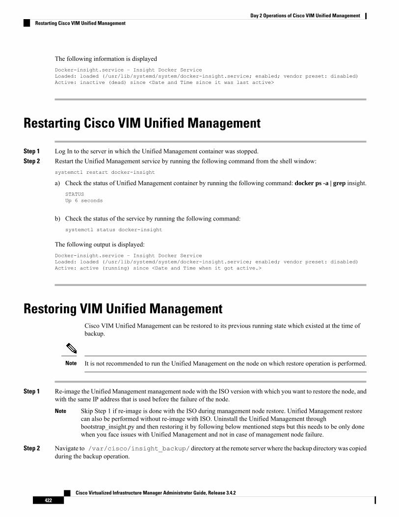
The following information is displayedDocker-insight.service – Insight Docker ServiceLoaded: loaded (/usr/lib/systemd/system/docker-insight.service; enabled; vendor preset: disabled)Active: inactive (dead) since <Date and Time since it was last active>
Restarting Cisco VIM Unified Management
Step 1 Log In to the server in which the Unified Management container was stopped.Step 2 Restart the Unified Management service by running the following command from the shell window:
systemctl restart docker-insight
a) Check the status of Unified Management container by running the following command: docker ps -a | grep insight.STATUSUp 6 seconds
b) Check the status of the service by running the following command:systemctl status docker-insight
The following output is displayed:Docker-insight.service – Insight Docker ServiceLoaded: loaded (/usr/lib/systemd/system/docker-insight.service; enabled; vendor preset: disabled)Active: active (running) since <Date and Time when it got active.>
Restoring VIM Unified ManagementCisco VIM Unified Management can be restored to its previous running state which existed at the time ofbackup.
It is not recommended to run the Unified Management on the node on which restore operation is performed.Note
Step 1 Re-image the Unified Management management node with the ISO version with which you want to restore the node, andwith the same IP address that is used before the failure of the node.
Skip Step 1 if re-image is done with the ISO during management node restore. Unified Management restorecan also be performed without re-image with ISO. Uninstall the Unified Management throughbootstrap_insight.py and then restoring it by following below mentioned steps but this needs to be only donewhen you face issues with Unified Management and not in case of management node failure.
Note
Step 2 Navigate to /var/cisco/insight_backup/ directory at the remote server where the backup directorywas copiedduring the backup operation.
Cisco Virtualized Infrastructure Manager Administrator Guide, Release 3.4.2422
Day 2 Operations of Cisco VIM Unified ManagementRestarting Cisco VIM Unified Management

Step 3 Copy the backup file to the /var/cisco/insight_backup/ directory of the re-imaged management node. Forexample, to copy the backup directory from the remote host 20.0.0.5 to the management node/var/cisco/insight_backup/directory, execute the following command sequence: rsync -e ssh -go -rtvpX --numeric-ids
[email protected]:/var/cisco/insight_backup/backup_2017-01-09_14-04-38 /var/cisco/insight_backup.Step 4 In /var/cisco/insight_backup/backup_<date-time> directory, execute the following command:
# ./insight_restore –h
insight_restore : Cisco VIM Insight Restore Script----------------------------------------------------
Usage: ./insight_restore
-v : Enable verbose mode
-h : To display this help message
# ./insight_restoreThis will initiate an Insight install with the backed up data.
VIM Insight restore logs are at: /var/log/insight/<bootstrap_insight_<date>_<time>.log
Management Node Validations!+-------------------------------+--------+-------+| Rule | Status | Error |+-------------------------------+--------+-------+| Check Kernel Version | PASS | None || Check Docker Version | PASS | None || Check Management Node Tag | PASS | None || Check Bond Intf. Settings | PASS | None || Root Password Check | PASS | None || Check Boot Partition Settings | PASS | None || Check LV Swap Settings | PASS | None || Check Docker Pool Settings | PASS | None || Check Home Dir Partition | PASS | None || Check Root Dir Partition | PASS | None || Check /var Partition | PASS | None || Check LVM partition | PASS | None || Check RHEL Pkgs Install State | PASS | None |+-------------------------------+--------+-------+
Insight standalone Input Validations!+-------------------------------------------+--------+-------+| Rule | Status| Error |+-------------------------------------------+--------+-------+| Insight standalone schema validation | PASS | None || Valid key check in Insight Setup Data | PASS | None || Duplicate key check In Insight Setup Data | PASS | None || CVIM/Insight workspace conflict check | PASS | None || Check registry connectivity | PASS | None || Check Email server for Insight | PASS | None |+-------------------------------------------+--------+-------+
Setting up Insight, Kindly wait!!!Cisco VIM Insight Installed successfully!+-----------------------+------------+-----------------------------------------------------+| Description | Status | Details |+-----------------------+--------+---------------------------------------------------------+| VIM Insight UI URL | PASS | https://<br_api:9000> || VIM UI Admin Email ID | PASS | Check for info @: <abs path of insight_setup_data.yaml> || | | |
Cisco Virtualized Infrastructure Manager Administrator Guide, Release 3.4.2423
Day 2 Operations of Cisco VIM Unified ManagementRestoring VIM Unified Management
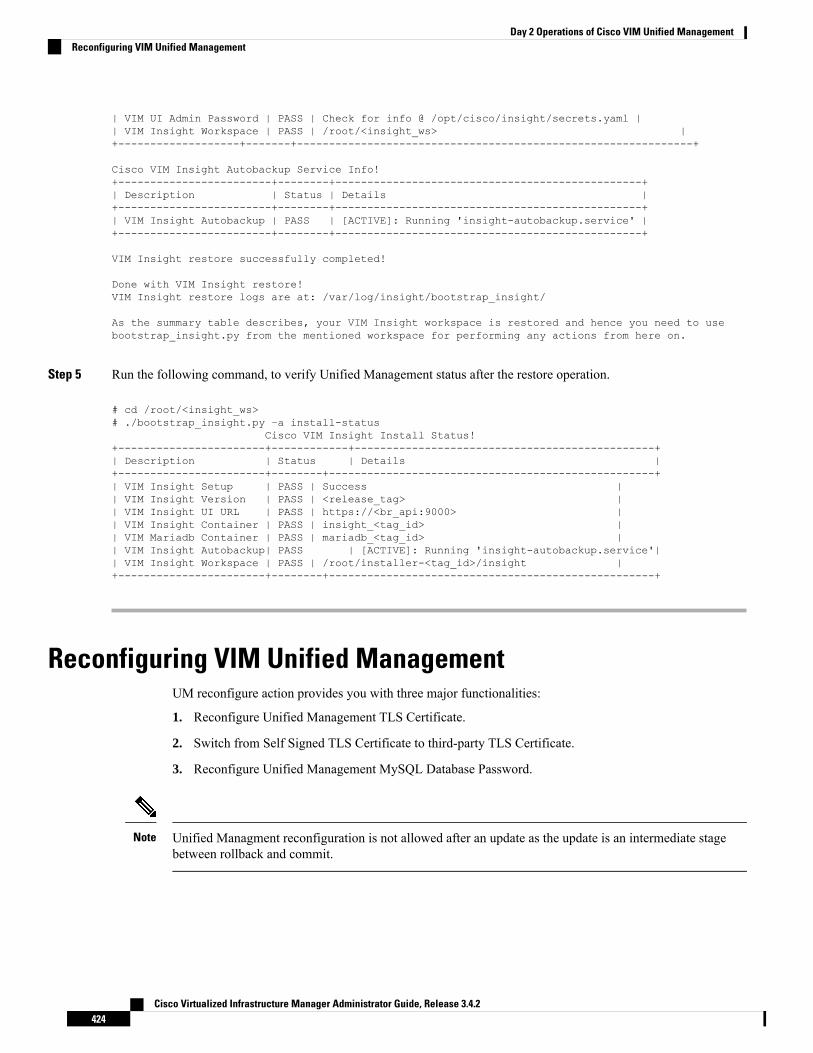
| VIM UI Admin Password | PASS | Check for info @ /opt/cisco/insight/secrets.yaml || VIM Insight Workspace | PASS | /root/<insight_ws> |+-------------------+-------+--------------------------------------------------------------+
Cisco VIM Insight Autobackup Service Info!+------------------------+--------+------------------------------------------------+| Description | Status | Details |+------------------------+--------+------------------------------------------------+| VIM Insight Autobackup | PASS | [ACTIVE]: Running 'insight-autobackup.service' |+------------------------+--------+------------------------------------------------+
VIM Insight restore successfully completed!
Done with VIM Insight restore!VIM Insight restore logs are at: /var/log/insight/bootstrap_insight/
As the summary table describes, your VIM Insight workspace is restored and hence you need to usebootstrap_insight.py from the mentioned workspace for performing any actions from here on.
Step 5 Run the following command, to verify Unified Management status after the restore operation.
# cd /root/<insight_ws># ./bootstrap_insight.py –a install-status
Cisco VIM Insight Install Status!+-----------------------+------------+-----------------------------------------------+| Description | Status | Details |+-----------------------+--------+---------------------------------------------------+| VIM Insight Setup | PASS | Success || VIM Insight Version | PASS | <release_tag> || VIM Insight UI URL | PASS | https://<br_api:9000> || VIM Insight Container | PASS | insight_<tag_id> || VIM Mariadb Container | PASS | mariadb_<tag_id> || VIM Insight Autobackup| PASS | [ACTIVE]: Running 'insight-autobackup.service'|| VIM Insight Workspace | PASS | /root/installer-<tag_id>/insight |+-----------------------+--------+---------------------------------------------------+
Reconfiguring VIM Unified ManagementUM reconfigure action provides you with three major functionalities:
1. Reconfigure Unified Management TLS Certificate.
2. Switch from Self Signed TLS Certificate to third-party TLS Certificate.
3. Reconfigure Unified Management MySQL Database Password.
Unified Managment reconfiguration is not allowed after an update as the update is an intermediate stagebetween rollback and commit.
Note
Cisco Virtualized Infrastructure Manager Administrator Guide, Release 3.4.2424
Day 2 Operations of Cisco VIM Unified ManagementReconfiguring VIM Unified Management
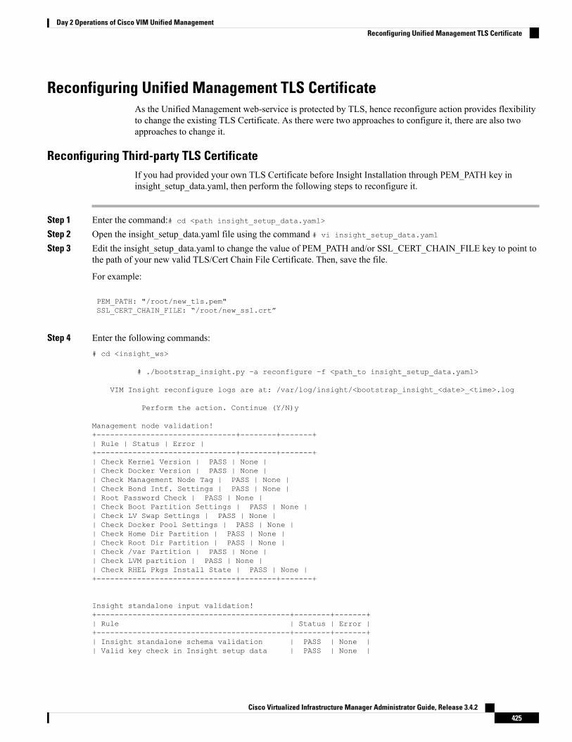
Reconfiguring Unified Management TLS CertificateAs the Unified Management web-service is protected by TLS, hence reconfigure action provides flexibilityto change the existing TLS Certificate. As there were two approaches to configure it, there are also twoapproaches to change it.
Reconfiguring Third-party TLS CertificateIf you had provided your own TLS Certificate before Insight Installation through PEM_PATH key ininsight_setup_data.yaml, then perform the following steps to reconfigure it.
Step 1 Enter the command:# cd <path insight_setup_data.yaml>
Step 2 Open the insight_setup_data.yaml file using the command # vi insight_setup_data.yaml
Step 3 Edit the insight_setup_data.yaml to change the value of PEM_PATH and/or SSL_CERT_CHAIN_FILE key to point tothe path of your new valid TLS/Cert Chain File Certificate. Then, save the file.
For example:
PEM_PATH: "/root/new_tls.pem"SSL_CERT_CHAIN_FILE: “/root/new_ssl.crt”
Step 4 Enter the following commands:# cd <insight_ws>
# ./bootstrap_insight.py –a reconfigure –f <path_to insight_setup_data.yaml>
VIM Insight reconfigure logs are at: /var/log/insight/<bootstrap_insight_<date>_<time>.log
Perform the action. Continue (Y/N)y
Management node validation!+-------------------------------+--------+-------+| Rule | Status | Error |+-------------------------------+--------+-------+| Check Kernel Version | PASS | None || Check Docker Version | PASS | None || Check Management Node Tag | PASS | None || Check Bond Intf. Settings | PASS | None || Root Password Check | PASS | None || Check Boot Partition Settings | PASS | None || Check LV Swap Settings | PASS | None || Check Docker Pool Settings | PASS | None || Check Home Dir Partition | PASS | None || Check Root Dir Partition | PASS | None || Check /var Partition | PASS | None || Check LVM partition | PASS | None || Check RHEL Pkgs Install State | PASS | None |+-------------------------------+--------+-------+
Insight standalone input validation!+-------------------------------------------+--------+-------+| Rule | Status | Error |+-------------------------------------------+--------+-------+| Insight standalone schema validation | PASS | None || Valid key check in Insight setup data | PASS | None |
Cisco Virtualized Infrastructure Manager Administrator Guide, Release 3.4.2425
Day 2 Operations of Cisco VIM Unified ManagementReconfiguring Unified Management TLS Certificate

| Duplicate key check In Insight setup data | PASS | None || CVIM/Insight workspace conflict check | PASS | None || Check registry connectivity | PASS | None || Check Email server for Insight | PASS | None |+-------------------------------------------+--------+-------+
WARNING!! reconfigure will have few secs of Outage for Insight!
Cisco VIM Insight Already Exists!+-----------------------+--------+---------------------------------------------------------+| Description | Status | Details |+-----------------------+--------+---------------------------------------------------------+| VIM Insight UI URL | PASS | https://<br_api:9000> || VIM UI Admin Email ID | PASS | Check for info @: <abs path of insight_setup_data.yaml> || | | || VIM UI Admin Password | PASS | Check for info @ /opt/cisco/insight/secrets.yaml || VIM Insight Workspace | PASS | /root/<insight_ws> |
+-----------------------+--------+---------------------------------------------------------+
Cisco VIM Insight backup Info!+-----------------------+--------+--------------------------------------------------------------+| Description | Status | Details |+-----------------------+--------+--------------------------------------------------------------+| Insight backup Status | PASS | Backup done @ || | | /var/cisco/insight_backup/backup-<release_tag>-<date_time> |+-----------------------+--------+--------------------------------------------------------------+
Done with VIM Insight reconfigure!VIM Insight reconfigure logs are at: "/var/log/insight/bootstrap_insight/"
As the summary table describes Insight gets autobacked up after reconfigure at /var/cisco/insight_backupto preserve the latest state of Insight.
Reconfiguring Self Signed TLS CertificateIf you had created a new TLS Certificate through tls_insight_cert_gen.py before Unified ManagementInstallation, follow the steps to reconfigure it.
Step 1 Run the following commands to reconfigure the self signed TLS certificate:# cd <insight_ws># ./tls_insight_cert_gen.py –husage: tls_insight_cert_gen.py [-h] [--overwrite] --file INSIGHTSETUPDATATLS cert generator Insight
optional arguments:-h, --help show this help message and exit
--overwrite, -o Overwrite Insight certificates if already present in openstack config directory--file INSIGHTSETUPDATA, -f INSIGHTSETUPDATALocation of insight_setup_data.yaml
# ./tls_insight_cert_gen.py –f <path insight_setup_data.yaml> --overwriteThis will overwrite the existing TLS certificate.
Management node validation+---------------------------------+-------+-------+| Rule |Status | Error |+---------------------------------+-------+-------+
Cisco Virtualized Infrastructure Manager Administrator Guide, Release 3.4.2426
Day 2 Operations of Cisco VIM Unified ManagementReconfiguring Self Signed TLS Certificate

| Check Kernel Version | PASS | None || Check Ansible Version | PASS | None || Check Docker Version | PASS | None || Check Management Node Tag | PASS | None || Check Bond Intf. Settings | PASS | None || Root Password Check | PASS | None || Check Boot Partition Settings | PASS | None || Check LV Swap Settings | PASS | None || Check Docker Pool Settings | PASS | None || Check Home Dir Partition | PASS | None || Check Root Dir Partition | PASS | None || Check /var Partition | PASS | None || Check LVM partition | PASS | None || Check RHEL Pkgs Install State | PASS | None |+-------------------------------+--------+-------+
Insight standalone input validation+-------------------------------------------+--------+-------+| Rule | Status | Error |+-------------------------------------------+--------+-------+| Insight standalone schema validation | PASS | None || Valid key check in Insight setup data | PASS | None || Duplicate key check In Insight setup data | PASS | None || CVIM/Insight workspace conflict check | PASS | None || Check registry connectivity | PASS | None || Check Email server for Insight | PASS | None |+-------------------------------------------+--------+-------+
Generating a 4096 bit RSA private key.....................................................................................++.......++writing new private key to '../openstack-configs/insight.key'
Step 2 Use the following command, to run the bootstrap:# ./bootstrap_insight.py –a reconfigure –f <path_to insight_setup_data.yaml>VIM Insight reconfigure logs are at: /var/log/insight/<bootstrap_insight_<date>_<time>.log
Perform the action. Continue (Y/N)y
Management node validations+-------------------------------+--------+-------+| Rule | Status | Error |+-------------------------------+--------+-------+| Check Kernel Version | PASS | None || Check Ansible Version | PASS | None || Check Docker Version | PASS | None || Check Management Node Tag | PASS | None || Check Bond Intf. Settings | PASS | None || Root Password Check | PASS | None || Check Boot Partition Settings | PASS | None || Check LV Swap Settings | PASS | None || Check Docker Pool Settings | PASS | None || Check Home Dir Partition | PASS | None || Check Root Dir Partition | PASS | None || Check /var Partition | PASS | None || Check LVM partition | PASS | None || Check RHEL Pkgs Install state | PASS | None |+-------------------------------+--------+-------+
Insight standalone input validation+-------------------------------------------+--------+-------+| Rule | Status | Error |+-------------------------------------------+--------+-------+
Cisco Virtualized Infrastructure Manager Administrator Guide, Release 3.4.2427
Day 2 Operations of Cisco VIM Unified ManagementReconfiguring Self Signed TLS Certificate
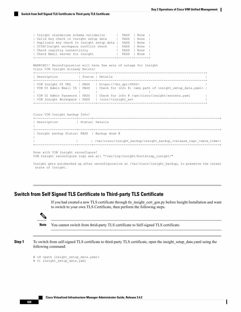
| Insight standalone schema validation | PASS | None || Valid key check in Insight setup data | PASS | None || Duplicate key check In Insight setup data | PASS | None || CVIM/Insight workspace conflict check | PASS | None || Check registry connectivity | PASS | None || Check Email server for Insight | PASS | None |+-------------------------------------------+--------+-------+
WARNING!! Reconfiguration will have few secs of outage for InsightCisco VIM Insight Already Exists!+-----------------------+--------+---------------------------------------------------------+| Description | Status | Details |+-----------------------+--------+---------------------------------------------------------+| VIM Insight UI URL | PASS | https://<br_api:9000> || VIM UI Admin Email ID | PASS | Check for info @: <abs path of insight_setup_data.yaml> || | | || VIM UI Admin Password | PASS | Check for info @ /opt/cisco/insight/secrets.yaml || VIM Insight Workspace | PASS | /root/<insight_ws> |+-----------------------+--------+---------------------------------------------------------+
Cisco VIM Insight backup Info!+----------------------+-------+-------------------------------------------------------------------+| Description | Status| Details|+----------------------+-------+-------------------------------------------------------------------+| Insight backup Status| PASS | Backup done @|| | | /var/cisco/insight_backup/insight_backup_<release_tag>_<date_time>|+----------------------+-------+-------------------------------------------------------------------+
Done with VIM Insight reconfigure!VIM Insight reconfigure logs are at: "/var/log/insight/bootstrap_insight/"
Insight gets autobacked up after reconfiguration at /var/cisco/insight_backup, to preserve the lateststate of Insight.
Switch from Self Signed TLS Certificate to Third-party TLS CertificateIf you had created a new TLS certificate through tls_insight_cert_gen.py before Insight Installation and wantto switch to your own TLS Certificate, then perform the following steps.
You cannot switch from thrid-party TLS certificate to Self-signed TLS certificate.Note
Step 1 To switch from self-signed TLS certificate to third-party TLS certificate, open the insight_setup_data.yaml using thefollowing command:
# cd <path insight_setup_data.yaml># vi insight_setup_data.yaml
Cisco Virtualized Infrastructure Manager Administrator Guide, Release 3.4.2428
Day 2 Operations of Cisco VIM Unified ManagementSwitch from Self Signed TLS Certificate to Third-party TLS Certificate

Step 2 Edit the insight_setup_data.yaml to add PEM_PATH and SSL_CERT_CHAIN_FILE key to point to path of your newvalid TLS and SSL_CERT_CHAIN certificate. Save the file after editing.
For example:
PEM_PATH: “/root/new_tls.pem”SSL_CERT_CHAIN_FILE: “/root/new_ssl.crt”
Step 3 Following is the command to run the bootstrap:
# cd <insight_ws># ./bootstrap_insight.py –a reconfigure –f <path_to insight_setup_data.yaml>
VIM Insight reconfigure logs are at: /var/log/insight/<bootstrap_insight_<date>_<time>.logPerform the action. Continue (Y/N)y
Management node validation+-------------------------------+--------+-------+| Rule | Status | Error |+-------------------------------+--------+-------+| Check Kernel Version | PASS | None || Check Ansible Version | PASS | None || Check Docker Version | PASS | None || Check Management Node Tag | PASS | None || Check Bond Intf. Settings | PASS | None || Root Password Check | PASS | None || Check Boot Partition Settings | PASS | None || Check LV Swap Settings | PASS | None || Check Docker Pool Settings | PASS | None || Check Home Dir Partition | PASS | None || Check Root Dir Partition | PASS | None || Check /var Partition | PASS | None || Check LVM partition | PASS | None || Check RHEL Pkgs Install State | PASS | None |+-------------------------------+--------+-------
Insight standalone input validation+-------------------------------------------+--------+-------+| Rule | Status | Error |+-------------------------------------------+--------+-------+| Insight standalone schema validation | PASS | None || Valid key check in Insight setup data | PASS | None || Duplicate key check In Insight setup data | PASS | None || CVIM/Insight workspace conflict check | PASS | None || Check registry connectivity | PASS | None || Check Email server for Insight | PASS | None |+-------------------------------------------+--------+-------+
WARNING!! Reconfiguration will have few secs of outage for Insight!
Cisco VIM Insight Already Exists!+-----------------------+--------+---------------------------------------------------------+| Description | Status | Details |+-----------------------+--------+---------------------------------------------------------+| VIM Insight UI URL | PASS | https://<br_api:9000> || VIM UI Admin Email ID | PASS | Check for info @: <abs path of insight_setup_data.yaml> || | | || VIM UI Admin Password | PASS | Check for info @ /opt/cisco/insight/secrets.yaml || VIM Insight Workspace | PASS | /root/<insight_ws> |
+-----------------------+--------+---------------------------------------------------------+
Cisco VIM Insight backup Info!
Cisco Virtualized Infrastructure Manager Administrator Guide, Release 3.4.2429
Day 2 Operations of Cisco VIM Unified ManagementSwitch from Self Signed TLS Certificate to Third-party TLS Certificate

+----------------------+-------+-------------------------------------------------------------------+| Description | Status| Details|+----------------------+-------+-------------------------------------------------------------------+| Insight backup Status| PASS | Backup done @|| | | /var/cisco/insight_backup/insight_backup_<release_tag>_<date_time>|+----------------------+-------+-------------------------------------------------------------------+
Done with VIM Insight reconfigure!VIM Insight reconfigure logs are at: "/var/log/insight/bootstrap_insight/"
Insight gets autobacked up after reconfiguration at /var/cisco/insight_backup to preserve the lateststate of Insight.
Reconfiguring Unified Management MySQL Database PasswordThere are two approaches to reconfigure the MySQL DB password:
1. System generated Unified Management DB password.
2. User supplied Unified Management DB password.
System-generated Unified Management DB PasswordFollowing are the steps to generate MySQL Unified Management DB password:
Step 1 To generate the Unified Management DB Password run the following command:# cd <insight_ws># ./bootstrap_insight.py –a reconfigure –f <path_to insight_setup_data.yaml> --regenerate_secrets
VIM Insight reconfigure logs are at: /var/log/insight/<bootstrap_insight_<date>_<time>.logPerform the action. Continue (Y/N)yManagement node validation+-------------------------------+--------+-------+| Rule | Status | Error |+-------------------------------+--------+-------+| Check Kernel Version | PASS | None || Check Docker Version | PASS | None || Check Management Node Tag | PASS | None || Check Bond Intf. Settings | PASS | None || Root Password Check | PASS | None || Check Boot Partition Settings | PASS | None || Check LV Swap Settings | PASS | None || Check Docker Pool Settings | PASS | None || Check Home Dir Partition | PASS | None || Check Root Dir Partition | PASS | None || Check /var Partition | PASS | None || Check LVM partition | PASS | None || Check RHEL Pkgs Install State | PASS | None |+-------------------------------+--------+-------+
Insight standalone input validation+-------------------------------------------+--------+-------+| Rule | Status | Error |
Cisco Virtualized Infrastructure Manager Administrator Guide, Release 3.4.2430
Day 2 Operations of Cisco VIM Unified ManagementReconfiguring Unified Management MySQL Database Password

+-------------------------------------------+--------+-------+| Insight standalone schema validation | PASS | None || Valid key check in Insight setup data | PASS | None || Duplicate key check In Insight setup data | PASS | None || CVIM/Insight workspace conflict check | PASS | None || Check registry connectivity | PASS | None || Check Email server for Insight | PASS | None |+-------------------------------------------+--------+-------+
WARNING!! reconfiguration will have few secs of Outage for Insight!
Cisco VIM Insight Already Exists!+-----------------------+--------+---------------------------------------------------------+| Description | Status | Details |+-----------------------+--------+---------------------------------------------------------+| VIM Insight UI URL | PASS | https://<br_api:9000> || VIM UI Admin Email ID | PASS | Check for info @: <abs path of insight_setup_data.yaml> || | | || VIM UI Admin Password | PASS | Check for info @ /opt/cisco/insight/secrets.yaml || VIM Insight Workspace | PASS | /root/<insight_ws> |
+-----------------------+--------+---------------------------------------------------------+
Cisco VIM Insight backup Info!+-----------------------+--------+--------------------------------------------------------------+| Description | Status | Details |+-----------------------+--------+--------------------------------------------------------------+| Insight backup Status | PASS | Backup done @ || | | /var/cisco/insight_backup/backup-<release_tag>-<date_time> |+-----------------------+--------+--------------------------------------------------------------+Done with VIM Insight reconfigure!VIM Insight reconfigure logs are at: "/var/log/insight/bootstrap_insight/"As the summary table describes Insight gets autobacked up after reconfigure at /var/cisco/insight_backupto preserve the latest state of Insight.
Step 2 Verify the password change by running the following command:# cat /opt/cisco/insight/secrets.yamlDB_ROOT_PASSWORD: <new_db_password>
User-supplied Unified Management DB Password
Step 1 To provide your own MYSQL DB Password follow the below steps:
Your new DB password must contain alphanumeric characters and should be at least 8 characters long.Note
# cd <insight_ws># ./bootstrap_insight.py –a reconfigure –f <path_to insight_setup_data.yaml> --setpassword
VIM Insight reconfigure logs are at: /var/log/insight/<bootstrap_insight_<date>_<time>.logPerform the action. Continue (Y/N)yPassword for DB_ROOT_PASSWORD: <enter_valid_db_password>
Management node validation+-------------------------------+--------+-------+| Rule | Status | Error |+-------------------------------+--------+-------+| Check Kernel Version | PASS | None || Check Ansible Version | PASS | None |
Cisco Virtualized Infrastructure Manager Administrator Guide, Release 3.4.2431
Day 2 Operations of Cisco VIM Unified ManagementUser-supplied Unified Management DB Password

| Check Docker Version | PASS | None || Check Management Node Tag | PASS | None || Check Bond Intf. Settings | PASS | None || Root Password Check | PASS | None || Check Boot Partition Settings | PASS | None || Check LV Swap Settings | PASS | None || Check Docker Pool Settings | PASS | None || Check Home Dir Partition | PASS | None || Check Root Dir Partition | PASS | None || Check /var Partition | PASS | None || Check LVM partition | PASS | None || Check RHEL Pkgs Install State | PASS | None |+-------------------------------+--------+-------+
Insight standalone input validation+-------------------------------------------+--------+-------+| Rule | Status | Error |+-------------------------------------------+--------+-------+| Insight standalone schema validation | PASS | None || Valid key check in Insight setup data | PASS | None || Duplicate key check In Insight setup data | PASS | None || CVIM/Insight workspace conflict check | PASS | None || Check registry connectivity | PASS | None || Check Email server for Insight | PASS | None |+-------------------------------------------+--------+-------+WARNING!!Reconfiguration will have few secs of Outage for Insight!
Cisco VIM Insight Already Exists!+-----------------------+--------+---------------------------------------------------------+| Description | Status | Details |+-----------------------+--------+---------------------------------------------------------+| VIM Insight UI URL | PASS | https://<br_api:9000> || VIM UI Admin Email ID | PASS | Check for info @: <abs path of insight_setup_data.yaml> || | | || VIM UI Admin Password | PASS | Check for info @ /opt/cisco/insight/secrets.yaml || VIM Insight Workspace | PASS | /root/<insight_ws> |
+-----------------------+--------+---------------------------------------------------------+
Cisco VIM Insight backup Info!+----------------------+-------+-------------------------------------------------------------------+| Description | Status| Details|+----------------------+-------+-------------------------------------------------------------------+| Insight backup Status| PASS | Backup done @|| | | /var/cisco/insight_backup/insight_backup_<release_tag>_<date_time>|+----------------------+-------+-------------------------------------------------------------------+Done with VIM Insight reconfigure!VIM Insight reconfigure logs are at: "/var/log/insight/bootstrap_insight/"
As the summary table describes Insight gets autobacked up after reconfigure at /var/cisco/insight_backupto preserve the latest state of Insight.
Step 2 Verify the password change by running the following command:# cat /opt/cisco/insight/secrets.yamlDB_ROOT_PASSWORD: <new_db_password>
Cisco Virtualized Infrastructure Manager Administrator Guide, Release 3.4.2432
Day 2 Operations of Cisco VIM Unified ManagementUser-supplied Unified Management DB Password

Reconfiguring Unified Management SMTP ServerUnifiedManagement requires a valid SMTP Server to sendmails to users (Pod-Admin, UI-Admin, and regularusers). If SMTP Server goes down, you can reconfigure it.
Following values can be reconfigured:
• INSIGHT_SMTP_SERVER
• INSIGHT_EMAIL_ALIAS_PASSWORD (only needed for Authenticated SMTP server)
• INSIGHT_EMAIL_ALIAS
• INSIGHT_SMTP_PORT (optional, defaults to 25)
Step 1 Run the following command to reconfigure the SMTP server:# cd <path insight_setup_data.yaml>Open insight_setup_data.yaml file# vi insight_setup_data.yamlEdit the insight_setup_data.yaml to change value of INSIGHT_SMTP_SERVER key. Save the file afterediting.
Step 2 Run the bootstrap command as follows:# cd <insight_ws># ./bootstrap_insight.py –a reconfigure –f <path_to insight_setup_data.yaml>VIM Insight reconfigure logs are at: /var/log/insight/<bootstrap_insight_<date>_<time>.logPerform the action. Continue (Y/N)y
Management node validation+-------------------------------+--------+-------+| Rule | Status | Error |+-------------------------------+--------+-------+| Check Kernel Version | PASS | None || Check Ansible Version | PASS | None || Check Docker Version | PASS | None || Check Management Node Tag | PASS | None || Check Bond Intf. Settings | PASS | None || Root Password Check | PASS | None || Check Boot Partition Settings | PASS | None || Check LV Swap Settings | PASS | None || Check Docker Pool Settings | PASS | None || Check Home Dir Partition | PASS | None || Check Root Dir Partition | PASS | None || Check /var Partition | PASS | None || Check LVM partition | PASS | None || Check RHEL Pkgs Install State | PASS | None |+-------------------------------+------- -+-------+
Insight standalone input validation+-------------------------------------------+--------+-------+| Rule | Status | Error |+-------------------------------------------+--------+-------+| Insight standalone schema validation | PASS | None || Valid key check in Insight setup data | PASS | None || Duplicate key check In Insight setup data | PASS | None || CVIM/Insight workspace conflict check | PASS | None || Check registry connectivity | PASS | None || Check Email server for Insight | PASS | None |+-------------------------------------------+--------+-------+
Cisco Virtualized Infrastructure Manager Administrator Guide, Release 3.4.2433
Day 2 Operations of Cisco VIM Unified ManagementReconfiguring Unified Management SMTP Server

WARNING!! Reconfiguration will have few secs of Outage for Insight!
Cisco VIM Insight Already Exists!+-----------------------+--------+---------------------------------------------------------+| Description | Status | Details |+-----------------------+--------+---------------------------------------------------------+| VIM Insight UI URL | PASS | https://<br_api:9000> || VIM UI Admin Email ID | PASS | Check for info @: <abs path of insight_setup_data.yaml> || | | || VIM UI Admin Password | PASS | Check for info @ /opt/cisco/insight/secrets.yaml || VIM Insight Workspace | PASS | /root/<insight_ws> |+-----------------------+--------+---------------------------------------------------------+
Cisco VIM Insight backup Info!+----------------------+-------+-------------------------------------------------------------------+| Description | Status| Details|+----------------------+-------+-------------------------------------------------------------------+| Insight backup Status| PASS | Backup done @|| | | /var/cisco/insight_backup/insight_backup_<release_tag>_<date_time>|+----------------------+-------+-------------------------------------------------------------------+
Done with VIM Insight reconfigure!VIM Insight reconfigure logs are at: "/var/log/insight/bootstrap_insight/"
Insight gets autobacked up after reconfiguration at /var/cisco/insight_backup to preserve the lateststate of Insight.
Reconfiguring Unified Management LDAP ServerUnified Management supports both LDAP and LDAP over SSL (LDAPS) for an Active Directory (AD)environment. If the LDAP server is down or if you need to change any of its configuration, execute UnifiedManagement reconfigure acion.
Step 1 Reconfigure the LDAP(s) server:a) Run the following command to open insight_setup_data.yaml file:
# cd <path insight_setup_data.yaml>
b) Edit the insight_setup_data.yaml, using the following command, to change the value of LDAP keys.:# vi insight_setup_data.yaml
LDAP keys are listed below:
• LDAP_MODE: This key can be reconfigured only to 'True’, to allow the user to switch only from No-LDAPto LDAP, and not vice-versa.
• LDAP_SERVER: This key is reconfigurable to switch to new LDAP server.
• LDAP_PORT: Reconfiguration of this key is allowed.
• LDAP_ADMIN: Reconfiguration of this key is allowed.
Cisco Virtualized Infrastructure Manager Administrator Guide, Release 3.4.2434
Day 2 Operations of Cisco VIM Unified ManagementReconfiguring Unified Management LDAP Server

• LDAP_ADMIN_PASSWORD: Reconfiguration of this key is allowed.
• LDAP_SECURE: This key can be reconfigured only to ‘True’, to allow the user to switch from non-secureLDAP to secure LDAP connection, and not vice-versa.
• LDAP_CERT_PATH: This key can be reconfigured, to switch from self-signed certificate to CA-signed certificate,and not vice-versa.
• LDAP_USER_ID_ATTRIBUTE: This key can be reconfigured to point to new LDAP user id attribute.
• LDAP_GROUP_SEARCH_FILTER: This key be reconfigured to set new group search filter.
• LDAP_GROUP_MEMBER: This key can be reconfigured to set new attribute used on LDAP server for defininguser-group association.
• LDAP_GROUP_USER_SEARCH_FILTER: This key can be reconfigured to set new group-user search filter.
• UM_ADMIN_GROUP: This key can be reconfigured to map LDAP role/group to Insight UM-Admin(s). Thiskey is used when Insight authorization is via LDAP server.
• POD_ADMIN_GROUP: This key can be reconfigured to map LDAP role/group to Insight Pod-Admin(s). Thiskey is used when Insight authorization is via LDAP server.
• POD_USER_GROUP: This key can be reconfigured to map LDAP role/group to Insight pod users with'Full-pod-access'. This key is used, when Insight authorization is via LDAP server.
• READ_ONLY_POD_USER_GROUP: This key can be reconfigured to map LDAP role/group to Insight podusers with 'Read-only-access'. This key is used when Insight authorization is via LDAP server.
• LDAP_ROLE_MEMBER: This key can be reconfigured to set new attribute used on LDAP server for defininguser-role/group-role association.
c) Save the edited file.
Step 2 Run the bootstrap command
# cd <insight_ws># ./bootstrap_insight.py –a reconfigure –f <path_to insight_setup_data.yaml>
VIM Insight reconfigure logs are at: /var/log/insight/<bootstrap_insight_<date>_<time>.logPerform the action. Continue (Y/N)y
Management node validation+-------------------------------+--------+-------+| Rule | Status | Error |+-------------------------------+--------+-------+| Check Kernel Version | PASS | None || Check Ansible Version | PASS | None || Check Docker Version | PASS | None || Check Management Node Tag | PASS | None || Check Bond Intf. Settings | PASS | None || Root Password Check | PASS | None || Check Boot Partition Settings | PASS | None || Check LV Swap Settings | PASS | None || Check Docker Pool Settings | PASS | None || Check Home Dir Partition | PASS | None || Check Root Dir Partition | PASS | None || Check /var Partition | PASS | None || Check LVM partition | PASS | None || Check RHEL Pkgs Install State | PASS | None |+-------------------------------+--------+-------
Cisco Virtualized Infrastructure Manager Administrator Guide, Release 3.4.2435
Day 2 Operations of Cisco VIM Unified ManagementReconfiguring Unified Management LDAP Server

Insight standalone input validation+-------------------------------------------+--------+-------+| Rule | Status | Error |+-------------------------------------------+--------+-------+| Insight standalone schema validation | PASS | None || Valid key check in Insight setup data | PASS | None || Duplicate key check In Insight setup data | PASS | None || CVIM/Insight workspace conflict check | PASS | None || Check registry connectivity | PASS | None || Check LDAP connectivity | PASS | None || Check Email server for Insight | PASS | None |+-------------------------------------------+--------+-------+
WARNING!! Reconfiguration will have few secs of Outage for Insight!
Cisco VIM Insight Already Exists!+-----------------------+--------+---------------------------------------------------------+| Description | Status | Details |+-----------------------+--------+---------------------------------------------------------+| VIM Insight UI URL | PASS | https://<br_api:9000> || VIM UI Admin Email ID | PASS | Check for info @: <abs path of insight_setup_data.yaml> || | | || VIM UI Admin Password | PASS | Check for info @ /opt/cisco/insight/secrets.yaml || VIM Insight Workspace | PASS | /root/<insight_ws> |+-----------------------+--------+---------------------------------------------------------+
Cisco VIM Insight backup Info!+----------------------+-------+-------------------------------------------------------------------+| Description | Status| Details|+----------------------+-------+-------------------------------------------------------------------+| Insight backup Status| PASS | Backup done @|| | | /var/cisco/insight_backup/insight_backup_<release_tag>_<date_time>|+----------------------+-------+-------------------------------------------------------------------+
Done with VIM Insight reconfigure!VIM Insight reconfigure logs are at: "/var/log/insight/bootstrap_insight/"
Insight gets autobacked up after reconfiguration at /var/cisco/insight_backup to preserve the lateststate of Insight.
Reconfiguring Unified Management Optional FeaturesUnified Management supports reconfiguration of optional features.
Step 1 Reconfigure the UM optional feature:a) Run the following command to open insight_setup_data.yaml file.
# cd <path insight_setup_data.yaml>
b) Edit the insight_setup_data.yaml, using the following command, to change the value of optional feature keys# vi insight_setup_data.yaml
Optional features keys are listed below:
Cisco Virtualized Infrastructure Manager Administrator Guide, Release 3.4.2436
Day 2 Operations of Cisco VIM Unified ManagementReconfiguring Unified Management Optional Features

• UM_ADMIN_AS_POD_ADMIN: When set to True, all UM-Admins are added as pod-users withFull-Pod-Access during pod registration.
• DISPLAY_ALL_POD_USERS: If set to True, a drop-down appears in the user-registration form with a list ofall the users with pod-user permissions while adding a new pod-user.
c) Save the edited file
Step 2 Run the bootstrap command:
# cd <insight_ws># ./bootstrap_insight.py –a reconfigure –f <path_to insight_setup_data.yaml>
VIM Insight reconfigure logs are at: /var/log/insight/<bootstrap_insight_<date>_<time>.log Performthe action. Continue (Y/N)y
Management node validation+-------------------------------+--------+-------+| Rule | Status | Error |+-------------------------------+--------+-------+| Check Kernel Version | PASS | None || Check Ansible Version | PASS | None || Check Docker Version | PASS | None || Check Management Node Tag | PASS | None || Check Bond Intf. Settings | PASS | None || Root Password Check | PASS | None || Check Boot Partition Settings | PASS | None || Check LV Swap Settings | PASS | None || Check Docker Pool Settings | PASS | None || Check Home Dir Partition | PASS | None || Check Root Dir Partition | PASS | None || Check /var Partition | PASS | None || Check LVM partition | PASS | None || Check RHEL Pkgs Install State | PASS | None |+-------------------------------+--------+-------
Insight standalone input validation+-------------------------------------------+--------+-------+| Rule | Status | Error |+-------------------------------------------+--------+-------+| Insight standalone schema validation | PASS | None || Valid key check in Insight setup data | PASS | None || Duplicate key check In Insight setup data | PASS | None || CVIM/Insight workspace conflict check | PASS | None || Check registry connectivity | PASS | None || Check LDAP connectivity | PASS | None || Check Email server for Insight | PASS | None |+-------------------------------------------+--------+-------+WARNING!! Reconfiguration will have few secs of Outage for Insight
Cisco VIM Insight Already Exists!+-----------------------+--------+---------------------------------------------------------+| Description | Status | Details |+-----------------------+--------+---------------------------------------------------------+| VIM Insight UI URL | PASS | https://<br_api:9000> || VIM UI Admin Email ID | PASS | Check for info @: <abs path of insight_setup_data.yaml> || | | || VIM UI Admin Password | PASS | Check for info @ /opt/cisco/insight/secrets.yaml || VIM Insight Workspace | PASS | /root/<insight_ws> |+-----------------------+--------+---------------------------------------------------------+
Cisco Virtualized Infrastructure Manager Administrator Guide, Release 3.4.2437
Day 2 Operations of Cisco VIM Unified ManagementReconfiguring Unified Management Optional Features

Cisco VIM Insight backup Info!+----------------------+-------+-------------------------------------------------------------------+| Description | Status| Details|+----------------------+-------+-------------------------------------------------------------------+| Insight backup Status| PASS | Backup done @|| | | /var/cisco/insight_backup/insight_backup_<release_tag>_<date_time>|+----------------------+-------+-------------------------------------------------------------------+
Done with VIM Insight reconfigure!VIM Insight reconfigure logs are at: "/var/log/insight/bootstrap_insight/"
Insight gets autobacked up after reconfiguration at /var/cisco/insight_backup to preserve the lateststate of Insight.
Adding and Reconfiguring VIM AdministratorsCisco VIM UM supports management of the VIM Administrators.VIM administrator can log into the unifiedmanagement node through SSH or the console using the configured password. By configuring to one VIMadmin account, administrators do not have to share credentials. Administrators have individual accountability.
To enable one or more VIM administrators, perform the following steps:
Step 1 Take a backup of the setupdata file and update the file manually with the configurations listed as below:vim_admins:- vim_admin_username: <username>vim_admin_password_hash: <sha512-password-hash>
- vim_admin_username: <username>vim_admin_password_hash: <sha512-password-hash>
- vim_admin_username: <username>vim_admin_password_hash: <sha512-password-hash>
The value of password hash must be in the standard sha512 format. # To generate the hashadmin_password_hash should be the output from on the management node# python -c "import crypt; print crypt.crypt('<plaintext password>')"
Step 2 Run the following reconfiguration commands:# cd <insight_ws># ./bootstrap_insight.py –a reconfigure –f <path_to insight_setup_data.yaml>
Cisco VIM administrators can manage their own passwords using the Linux passwd command. You can addor remove Cisco VIM administrator through the reconfigure option, while the passwords for their existingaccounts remain unchanged.
Note
Cisco Virtualized Infrastructure Manager Administrator Guide, Release 3.4.2438
Day 2 Operations of Cisco VIM Unified ManagementAdding and Reconfiguring VIM Administrators

Enabling Root Login Post UM Node InstallationTo complement the management of VIM administrators, Cisco VIM supports an option to enable/disable rootaccess at login. By default, this option is set to True. You can optionally disable this facility throughreconfiguration.
Following are the steps to enable root login:
Step 1 Take a backup of the setupdata file and update the file manually with the configurations listed below:
permit_root_login: <True or False> # if set to false, one has to use su to drop down to root andexecute administrator functionalities.
Step 2 Run the following reconfiguration commands:# cd <insight_ws># ./bootstrap_insight.py –a reconfigure –f <path_to insight_setup_data.yaml>
Enabling Banner During SSH LoginCisco VIM supports enabling of banner during ssh login to the management node. To enable banner duringlogin, perform the following steps:
Step 1 Take a backup of the setupdata file and update the file manually with the configuration listed below:
ssh_banner:<your Banner Text>
Step 2 Run the following commands for reconfiguration:# cd <insight_ws># ./bootstrap_insight.py –a reconfigure –f <path_to insight_setup_data.yaml>
Adding and Reconfiguring UM AdministratorsCisco VIM UM supports management of the UM Administrators whose access to the management node canbe authenticated through an external LDAP server. For the users to obtain sudo access, you need to manuallyadd the root user or any user with root privileges to the wheel group in the external LDAP server. Also, youmust enable the pod with external TLS. To enable UM administrators with LDAP authentication, performthe following steps:
To enable one or more UM administrators, perform the following steps:
Cisco Virtualized Infrastructure Manager Administrator Guide, Release 3.4.2439
Day 2 Operations of Cisco VIM Unified ManagementEnabling Root Login Post UM Node Installation

Step 1 Take a backup of the setupdata file and update the file manually with the configuration listed below:UM_LDAP_ADMINS:- domain_name: corp_ldap2 # Requiredldap_uri: "ldaps://172.29.84.231" # Required For multiple ldap server pass comma separated
value.ldap_search_base: "dc=cisco,dc=com" # Requiredldap_schema: rfc2307 # Optionalldap_user_object_class: posixAccount # optionalldap_user_uid_number: uidNumber # Optionalldap_user_gid_number: uidNumber # Optionalldap_group_member: memberUid # Optionalldap_default_bind_dn: "<string>" # Optionalldap_default_authtok: "<string>" # Optionalldap_default_authtok_type: "<string>" # Optional (password|obfuscated_password)ldap_group_search_base: "<string>" # Optionalldap_user_search_base: "<string>" # Optionalaccess_provider: "<string>" # Optionalsimple_allow_groups: "<string>" # Optionalldap_cert_path: "<cert_path>" # Requiredldap_id_use_start_tls: <boolean> # Optionalldap_tls_reqcert: "<string>" # Optional (never|allow|try|demand)chpass_provider: "<string>" # Optional (ldap|krb5|ad|none)
Multiple entries of the LDAP domain are allowed. For each entry, only domain_name and ldap_uri info aremandatory. Ensure that the ldap_uri is secured over ldaps. As part of reconfiguration, you can add newdomain_name, but cannot change the domain_name once it is configured.
Note
Step 2 To reconfigure the UM LDAP admin, run the following commands:# cd <insight_ws># ./bootstrap_insight.py –a reconfigure –f <path_to insight_setup_data.yaml>
Update VIM Unified ManagementVIM Unified Management update allows you to switch to a new Unified Management release.
The update action makes the old docker containers of Unified Management and mariadb in exit state, andbrings up new ones with the new tag. The old containers and images are restored until you perform theCommitaction.
Update is an intermediate action and allows you to do either a Commit action to settle for the current versionor do a Rollback to revert back to the old version.
The old workspace is preserved, if you want to do a rollback to the previous version.
After an update:
• Your Unified Management workspace is set as the new workspace that you just extracted out of thetarball.
• Backup and reconfigure action are not allowed either from old or new Unified Management workspace.
Cisco Virtualized Infrastructure Manager Administrator Guide, Release 3.4.2440
Day 2 Operations of Cisco VIM Unified ManagementUpdate VIM Unified Management

Upgrade ScenariosFollowing are the upgrade scenarios:
• Insight and mariadb containers gets updated to a new tag.
• Either insight or mariadb container gets updated to a new tag.
Update VIM UM with Internet Access from 3.2.x to 3.4.1Following are the steps to update VIM Unified Management:
Step 1 Get the new installer tar ball, which will be available after each release.
Extract the tar ball to get the new Unified Management workspace by running the following command:# tar –xvzf mercury-installer.tar.gz
Step 2 Create an empty directory for Insight workspace: insight-<tag_id>Step 3 Copy that extracted directory installer-<tag_ig> inside insight-<tag_id>Step 4 Update the VIM UM by running the following commands:
# cd /root/<new_insight_ws>/insight//bootstrap_insight.py –a update
VIM Insight update logs are at: /var/log/insight/<bootstrap_insight_<date>_<time>.logManagement Node validation!+-------------------------------+--------+-------+| Rule | Status | Error |+-------------------------------+--------+-------+| Check Kernel Version | PASS | None || Check Docker Version | PASS | None || Check Management Node Tag | PASS | None || Check Bond Intf. Settings | PASS | None || Root Password Check | PASS | None || Check Boot Partition Settings | PASS | None || Check LV Swap Settings | PASS | None || Check Docker Pool Settings | PASS | None || Check Home Dir Partition | PASS | None || Check Root Dir Partition | PASS | None || Check /var Partition | PASS | None || Check LVM partition | PASS | None || Check RHEL Pkgs Install State | PASS | None |+-------------------------------+--------+-------+
Insight standalone input validation+-------------------------------------------+--------+-------+| Rule | Status | Error |+-------------------------------------------+--------+-------+| Insight standalone schema validation | PASS | None || Valid key check in Insight setup data | PASS | None || Duplicate key check In Insight setup data | PASS | None || CVIM/Insight workspace conflict check | PASS | None || Check registry connectivity | PASS | None || Check Email server for Insight | PASS | None |+-------------------------------------------+--------+-------+
Downloading Updated VIM Insight Artifacts, will take time!!!
Cisco Virtualized Infrastructure Manager Administrator Guide, Release 3.4.2441
Day 2 Operations of Cisco VIM Unified ManagementUpgrade Scenarios

Cisco VIM Insight update Info!+------------------------------------------+--------+------------------------------+| Description | Status | Details |+------------------------------------------+--------+-------------------------------+| VIM Insight Container: insight_<new_tag> | PASS | Updated from insight_<old_tag>|| VIM Mariadb Container: mariadb_<new_tag> | PASS | Updated from mariadb_<old_tag>|+------------------------------------------+--------+-------------------------------+
Done with VIM Insight update!VIM Insight update logs are at: "/var/log/insight/bootstrap_insight/"
Step 5 Verify the Unified Management Update.# ./bootstrap_insight.py –a update-statusCisco VIM Insight Update Status!+------------------------------------------+--------+--------------------------------+| Description | Status | Details |+------------------------------------------+--------+--------------------------------+| VIM Insight Container: insight_<new_tag> | PASS | Updated from insight_<old_tag> || VIM Mariadb Container: insight_<new_tag> | PASS | Updated from mariadb_<old_tag> |+------------------------------------------+--------+--------------------------------+
Upgrade VIM UM without Internet Access from 3.2.x to 3.4.2
Step 1 Copy the new installer tar ball to the Unified Management Node.
Extract the tar ball to get the new Unified Management workspace by running the following command:# tar –xvzf mercury-installer.tar.gz
Step 2 To download the new Unified Management artifacts, follow the steps given in section Preparing to Install Cisco NFVIon Management Nodes Without Internet Access, of Cisco VIM Install_Guide.
Step 3 Run Import Artifacts:
# cd /root/installer_<tag_id>/tools# ./import_artifacts.shThis verifies that /var/cisco/artifacts on the management node has the following Insight artifacts,along with the other components 'insight-K9.tar' and 'mariadb-app-K9.tar'.'
Step 4 Update the Unified Management by running the following command:
# cd insight/# ./bootstrap_insight.py –a update
VIM Insight update logs are at: /var/log/insight/<bootstrap_insight_<date>_<time>.logManagement node validations!+-------------------------------+--------+-------+| Rule | Status | Error |+-------------------------------+--------+-------+| Check Kernel Version | PASS | None || Check Ansible Version | PASS | None || Check Docker Version | PASS | None || Check Management Node Tag | PASS | None |
Cisco Virtualized Infrastructure Manager Administrator Guide, Release 3.4.2442
Day 2 Operations of Cisco VIM Unified ManagementUpgrade VIM UM without Internet Access from 3.2.x to 3.4.2

| Check Bond Intf. Settings | PASS | None || Root Password Check | PASS | None || Check Boot Partition Settings | PASS | None || Check LV Swap Settings | PASS | None || Check Docker Pool Settings | PASS | None || Check Home Dir Partition | PASS | None || Check Root Dir Partition | PASS | None || Check /var Partition | PASS | None || Check LVM partition | PASS | None || Check RHEL Pkgs Install State | PASS | None |+-------------------------------+--------+-------+
Insight standalone input validation+-------------------------------------------+--------+-------+| Rule | Status | Error |+-------------------------------------------+--------+-------+| Insight standalone schema validation | PASS | None || Valid key check in Insight setup data | PASS | None || Duplicate key check In Insight setup data | PASS | None || CVIM/Insight workspace conflict check | PASS | None || Check registry connectivity | PASS | None || Check Email server for Insight | PASS | None |+-------------------------------------------+--------+-------+
Updating VIM Insight, Kindly wait!!!Cisco VIM Insight update Info!+------------------------------------------+--------+-------------------------------+| Description | Status | Details |+------------------------------------------+--------+-------------------------------+| VIM Insight UI URL | PASS | https://<br_api:9000> || VIM Insight Container: insight_<new_tag> | PASS | Updated from insight_<old_tag>|| VIM Mariadb Container: mariadb_<new_tag> | PASS | Updated from mariadb_<old_tag>|| VIM Insight Workspace | PASS | /root/<new_insight_ws> |+------------------------------------------+--------+-------------------------------+Done with VIM Insight update!VIM Insight update logs are at: "/var/log/insight/bootstrap_insight/"
Step 5 Verify Unified Management update by running the following command:
# ./bootstrap_insight.py –a update-statusCisco VIM Insight Update Status!+------------------------------------------+--------+--------------------------------+| Description | Status | Details |+------------------------------------------+--------+--------------------------------+| VIM Insight Container: insight_<new_tag> | PASS | Updated from insight_<old_tag> || VIM Mariadb Container: insight_<new_tag> | PASS | Updated from mariadb_<old_tag> |+------------------------------------------+--------+--------------------------------+
Upgrade Cisco VIM UM from 2.4.x to 3.4.2Following are the steps to upgrade Cisco VIM Unified Management from 2.4.x to 3.4.2.
Step 1 Get the installer tar ball for 3.4.2 release. Extract the tar ball to get the new UM workspace by running the followingcommand:# tar –xvzf mercury-installer.tar.gz
Cisco Virtualized Infrastructure Manager Administrator Guide, Release 3.4.2443
Day 2 Operations of Cisco VIM Unified ManagementUpgrade Cisco VIM UM from 2.4.x to 3.4.2
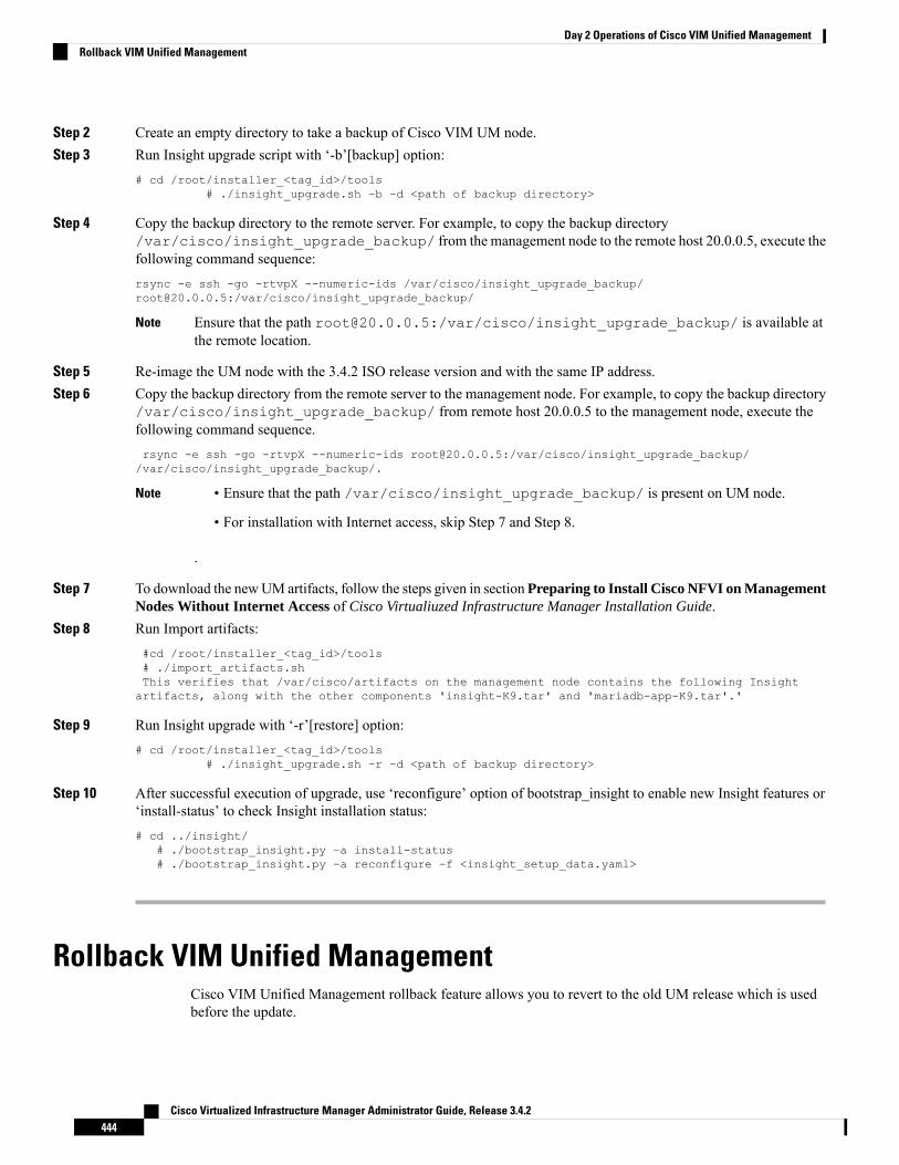
Step 2 Create an empty directory to take a backup of Cisco VIM UM node.Step 3 Run Insight upgrade script with ‘-b’[backup] option:
# cd /root/installer_<tag_id>/tools# ./insight_upgrade.sh –b –d <path of backup directory>
Step 4 Copy the backup directory to the remote server. For example, to copy the backup directory/var/cisco/insight_upgrade_backup/ from the management node to the remote host 20.0.0.5, execute thefollowing command sequence:rsync -e ssh -go -rtvpX --numeric-ids /var/cisco/insight_upgrade_backup/[email protected]:/var/cisco/insight_upgrade_backup/
Ensure that the path [email protected]:/var/cisco/insight_upgrade_backup/ is available atthe remote location.
Note
Step 5 Re-image the UM node with the 3.4.2 ISO release version and with the same IP address.Step 6 Copy the backup directory from the remote server to the management node. For example, to copy the backup directory
/var/cisco/insight_upgrade_backup/ from remote host 20.0.0.5 to the management node, execute thefollowing command sequence.rsync -e ssh -go -rtvpX --numeric-ids [email protected]:/var/cisco/insight_upgrade_backup//var/cisco/insight_upgrade_backup/.
• Ensure that the path /var/cisco/insight_upgrade_backup/ is present on UM node.
• For installation with Internet access, skip Step 7 and Step 8.
.
Note
Step 7 To download the newUM artifacts, follow the steps given in section Preparing to Install Cisco NFVI on ManagementNodes Without Internet Access of Cisco Virtualiuzed Infrastructure Manager Installation Guide.
Step 8 Run Import artifacts:#cd /root/installer_<tag_id>/tools# ./import_artifacts.shThis verifies that /var/cisco/artifacts on the management node contains the following Insightartifacts, along with the other components 'insight-K9.tar' and 'mariadb-app-K9.tar'.'
Step 9 Run Insight upgrade with ‘-r’[restore] option:# cd /root/installer_<tag_id>/tools
# ./insight_upgrade.sh –r –d <path of backup directory>
Step 10 After successful execution of upgrade, use ‘reconfigure’ option of bootstrap_insight to enable new Insight features or‘install-status’ to check Insight installation status:# cd ../insight/
# ./bootstrap_insight.py –a install-status# ./bootstrap_insight.py –a reconfigure –f <insight_setup_data.yaml>
Rollback VIM Unified ManagementCisco VIM Unified Management rollback feature allows you to revert to the old UM release which is usedbefore the update.
Cisco Virtualized Infrastructure Manager Administrator Guide, Release 3.4.2444
Day 2 Operations of Cisco VIM Unified ManagementRollback VIM Unified Management

Following are some of the key points:
• The rollback action removes the new docker containers of Unified Management and mariadb which iscreated after an update and bring up old ones with the old tag.
• The new workspace is used to update the operation later or the VIM may be running from it.
• After rollback, your UM workspace is the old workspace which you were using before the update.
Following are the steps to perform UM rollback:
Step 1 Run the following command to rollback VIM Unified Management:
# cd /root/<new_insight_ws># ./bootstrap_insight.py –a rollback
VIM Insight rollback logs are at: /var/log/insight/<bootstrap_insight_<date>_<time>.log
Management node validation!+-------------------------------+--------+-------+| Rule | Status | Error |+-------------------------------+--------+-------+| Check Kernel Version | PASS | None || Check Ansible Version | PASS | None || Check Docker Version | PASS | None || Check Management Node Tag | PASS | None || Check Bond Intf. Settings | PASS | None || Root Password Check | PASS | None || Check Boot Partition Settings | PASS | None || Check LV Swap Settings | PASS | None || Check Docker Pool Settings | PASS | None || Check Home Dir Partition | PASS | None || Check Root Dir Partition | PASS | None || Check /var Partition | PASS | None || Check LVM partition | PASS | None || Check RHEL Pkgs Install State | PASS | None |+-------------------------------+--------+-------+
Insight standalone input validation+-------------------------------------------+--------+-------+| Rule | Status | Error |+-------------------------------------------+--------+-------+| Insight standalone schema validation | PASS | None || Valid key check in Insight setup data | PASS | None || Duplicate key check In Insight setup data | PASS | None || CVIM/Insight workspace conflict check | PASS | None || Check registry connectivity | PASS | None || Check Email server for Insight | PASS | None |+-------------------------------------------+--------+-------+
VIM Insight rollback in progress, Kindly wait!!!Cisco VIM Insight rollback Info!+------------------------------------------+--------+-------------------------------+| Description | Status | Details |+------------------------------------------+--------+--------------------------------+| VIM Insight UI URL | PASS | https://<br_api:9000> || VIM Insight Container: insight_<old_tag> | PASS | Rollback from insight_<new_tag>|| VIM Mariadb Container: mariadb_<old_tag> | PASS | Rollback from mariadb_<new_tag>|| VIM Insight Workspace | PASS | /root/<old_insight_ws> |+------------------------------------------+--------+--------------------------------+
Cisco Virtualized Infrastructure Manager Administrator Guide, Release 3.4.2445
Day 2 Operations of Cisco VIM Unified ManagementRollback VIM Unified Management

Done with VIM Insight rollback!VIM Insight rollback logs are at: "/var/log/insight/bootstrap_insight/"
Step 2 Verify the rollback status by running the following command:
# ./bootstrap_insight.py –a install-statusCisco VIM Insight Install Status!+-----------------------+--------+----------------------------------+| Description | Status | Details |+-----------------------+--------+----------------------------------+| VIM Insight Version | PASS | <release_tag> || VIM Insight UI URL | PASS | https://<br_api:9000> || VIM Insight Container | PASS | insight_<tag_id> || VIM Mariadb Container | PASS | mariadb_<tag_id> || VIM Insight Workspace | PASS | /root/<insight_ws> |+-----------------------+--------+----------------------------------+
Commit VIM Unified ManagementVIM Insight commit supports for a new Insight release after an update.
Following are some of the key points:
• The old workspace is not deleted and retained as it is.
• After the commit, your Unified Management workspace which has been used for the update is the newworkspace.
Step 1 Run the following command to commit VIM Insight:
# cd /root/<new_insight_ws>/Insight# ./bootstrap_insight.py –a commitVIM Insight commit logs are at: /var/log/insight/<bootstrap_insight_<date>_<time>.logManagement Node Validation!+-------------------------------+---------+-------+| Rule | Status | Error |+-------------------------------+----------+-------+| Check Kernel Version | PASS | None || Check Ansible Version | PASS | None || Check Docker Version | PASS | None || Check Management Node Tag | PASS | None || Check Bond Intf. Settings | PASS | None || Root Password Check | PASS | None || Check Boot Partition Settings | PASS | None || Check LV Swap Settings | PASS | None || Check Docker Pool Settings | PASS | None || Check Home Dir Partition | PASS | None || Check Root Dir Partition | PASS | None || Check /var Partition | PASS | None || Check LVM partition | PASS | None || Check RHEL Pkgs Install State | PASS | None |+-------------------------------+--------+-------+
Cisco Virtualized Infrastructure Manager Administrator Guide, Release 3.4.2446
Day 2 Operations of Cisco VIM Unified ManagementCommit VIM Unified Management

Insight standalone Input Validation!+-------------------------------------------+--------+-------+| Rule | Status | Error |+-------------------------------------------+--------+-------+| Insight standalone Schema Validation | PASS | None || Valid Key Check in Insight Setup Data | PASS | None || Duplicate Key Check In Insight Setup Data | PASS | None || CVIM/Insight workspace conflict | PASS | None || Check registry connectivity | PASS | None || Check Email server for Insight | PASS | None |+-------------------------------------------+--------+-------+
VIM Insight commit in progress, Kindly wait!!!Cisco VIM Insight commit Info!+----------------------------------------- +--------+--------------------------------------------| Description | Status | Details |+------------------------------------------+--------+-------------------------------------------+| VIM Insight UI URL | PASS | https://<br_api:9000> || VIM Insight Container: insight_<old_tag> | PASS | Old container: insight-<old_tag> removed> || VIM Mariadb Container: mariadb_<old_tag> | PASS | Old container: mariadb-<old_tag> removed> || VIM Insight Workspace | PASS | /root/<old_insight_ws> |+------------------------------------------+--------+-------------------------------------------+Done with VIM Insight commit!VIM Insight commit logs are at: "/var/log/insight/bootstrap_insight/"
If update is done from 3.0.x to 3.4.2, the following warning message to reconfigure Insight is displayed.
Warning: Insight setup-data key 'UM_ADMIN_AS_POD_ADMIN' is deprecated from version 3.4.2 andPlease 'reconfigure' using 'UM_ADMIN_WITH_FULL_POD_ACCESS' as a new name of the key
Note
Step 2 Verify the commit status by running the following command:
# ./bootstrap_insight.py –a install-statusCisco VIM Insight Install Status!+-----------------------+--------+-----------------------+| Description | Status | Details |+-----------------------+--------+-----------------------+| VIM Insight Version | PASS | <release_tag> || VIM Insight UI URL | PASS | https://<br_api:9000> || VIM Insight Container | PASS | insight_<tag_id> || VIM Mariadb Container | PASS | mariadb_<tag_id> || VIM Insight Workspace | PASS | /root/<insight_ws> |+-----------------------+--------+-----------------------+
Uploading Glance ImagesOn Day0, all the Glance Images to be uploaded are kept in a folder. To view those images under Pod ImageManagement, copy those images using the glance_image_copy.sh script.
1. The glance_image_copy.sh script is available in the insight folder, same as the bootstrap_insight.py level.[root@gg34-bn insight]# ./glance_image_copy.sh -hglance_image_copy.sh : Cisco Glance Images Validator-----------------------------------------------------d : Input Glance Images Directory.
Allowed Images Formats:- 'raw', 'qcow2', 'iso', 'ami', 'ari', 'aki', 'vhd', 'vhdx', 'vmdk', 'vdi',
Cisco Virtualized Infrastructure Manager Administrator Guide, Release 3.4.2447
Day 2 Operations of Cisco VIM Unified ManagementUploading Glance Images

'ploop'-h : To display this help
2. Use -d option, which represents the directory path of Glance Images to be uploaded, and copy the GlanceImages by running the following command:[root@gg34-bn insight]# ./glance_image_copy.sh -d /root/ImagesDir/Copying /root/ImagesDir/mini.iso ...Copying /root/ImagesDir/xenial-server-cloudimg-amd64-disk1.vmdk ...Copying /root/ImagesDir/cirros-0.4.0-x86_64-disk.img ...Copying /root/ImagesDir/CentOS-7-x86_64-GenericCloud-1905.raw ...
After copying images using the glance_image_copy.sh script, refresh Cisco VIM Unified Managementappliance to view the Glance Images under Pod Image Management. Now, you can select multiple imagesand upload it.
Cisco Virtualized Infrastructure Manager Administrator Guide, Release 3.4.2448
Day 2 Operations of Cisco VIM Unified ManagementUploading Glance Images

C H A P T E R 11Overview to the Cisco Virtual Topology System
The Cisco Virtual Topology System (VTS) is an optional Cisco NFVI application that uses the Neutron driverand supports Cisco Vector Packet Processing. The following topics provide an overview to VTS architectureand features. When using VTS with Cisco NFVI, keep the following OpenStack tenant restrictions in mind:
DescriptionRestriction
This limitation is due to NUMA and huge pages.Nova flavors: VM RAM > 512MB and equal to amultiple of 512MB
VHOSTmode is the only mode supported by the VTSinstallation at this time. To support VHOSTconnections nova needs the following configurationson each flavor that will be used.
Nova Flavors:
nova flavor-key m1.medium sethw:mem_page_size=large
• Understanding Cisco VTS, on page 449• Cisco VTS Architecture Overview, on page 450• Virtual Topology Forwarder, on page 451• Virtual Topology System High Availability, on page 453
Understanding Cisco VTSThe Cisco Virtual Topology System (VTS) is a standards-based, open, overlay management, and provisioningsystem for data center networks. It automates the DC overlay fabric provisioning for both physical and virtualworkloads.
Cisco VTS provides a network virtualization architecture and software-defined networking (SDN) frameworkthat meets the requirements of multitenant data centers for cloud services. It enables a policy-based approachfor overlay provisioning.
Cisco VTS automates complex network overlay provisioning and management tasks through integration withcloud orchestration systems such as OpenStack and VMware vCenter. It reduces the complexity involved inmanaging heterogeneous network environments.
You can manage the solution in the following ways:
• Using the embedded Cisco VTS GUI
• Using a set of northbound Representational State Transfer (REST) APIs that can be consumed byorchestration and cloud management systems.
Cisco Virtualized Infrastructure Manager Administrator Guide, Release 3.4.2449

Cisco VTS provides:
• Fabric automation
• Programmability
• Open, scalable, standards-based solution
• Cisco Nexus 2000, 3000, 5000, 7000, and 9000 Series Switches. For more information, see SupportedPlatforms in Cisco VTS 2.6.2.1 Installation Guide.
• Software forwarder (Virtual Topology Forwarder [VTF])
Cisco VTS Architecture OverviewCisco VTS architecture has two main components, namely, the Policy Plane and the Control Plane. Thesecomponents perform core functions such as SDN control, resource allocation, and core management function.
Figure 24: Cisco VTS Architecture
• Policy Plane: The Policy Plane enables Cisco VTS to implement a declarative policy model which isdesigned to capture intent and render of the user into a specific device-level construct. The solutionexposes a set of modular policy constructs that can be flexibly organized into user-defined services foruse cases across service provider and cloud environments. These policy constructs are exposed usingRESTAPIs that are consumed by orchestrators and applications or using the Cisco VTSGUI. The policymodels are exposed as system policies or service policies.
Cisco Virtualized Infrastructure Manager Administrator Guide, Release 3.4.2450
Overview to the Cisco Virtual Topology SystemCisco VTS Architecture Overview

System policies allow administrators to logically group devices into pods within or across data centersto define Admin Domains with common system parameters. For example, BGP-EVPN Control Planewith distributed Layer 2 and 3 gateways.
The inventory module maintains a database of the available physical entities (for example, data centerinterconnect [DCI] routers and top-of-rack leaf, spine, and border-leaf switches) and virtual entities (forexample, VTFs) in the Virtual Topology System domain. The database also includes interconnectionsbetween these entities and details about the services instantiated within a Virtual Topology Systemdomain.
The resource management module manages the available resource pools in the Virtual Topology Systemdomain, including VLANs, VXLAN Network Identifiers (VNIs), IP addresses, and multicast groups.
• Control Plane: The Control Plane module serves as the SDN control subsystem that programs the variousdata planes including the VTFs residing on the x86 servers, hardware leafs, DCI gateways. The ControlPlane hosts Service Routing (SR) module, which provides routing services to Cisco VTS. The ServiceRouting (SR) module calculates the L2 and L3tables and routes to provide connectivity between thedifferent VMs for a given tenant and service chaining. The main components of this module are VTSRand VTF. VTSR is the controller and Virtual topology forwarder (VTF) runs on each compute serverhosting the tenant VMs.
Virtual Topology ForwarderVirtual Topology Forwarder (VTF) runs on each compute server in the DC and provides connectivity to alltenant VMs hosted on the compute server. VTF supports both intra and inter DC/WAN connectivity. VTFallows Cisco VTS to terminate the VXLAN tunnels on host servers by using the VTF as a Software VXLANTunnel Endpoint (VTEP). Cisco VTS also supports hybrid overlays by combining the physical and virtualendpoints into a single VXLAN segment.
VTF has two major components, namely, Cisco's VPP (Vector Packet Processing) and VPFA. VPFA is aCisco agent running on each VMM compute resource. VPFA is the FIB agent that receives the L2/L3 tableforwarding information from VTSR to provide connectivity to the local tenant VMs that are hosted on itscompute, and programs them in the VPP.
VTF is deployed as a virtual machine or in vhost mode, to deliver a high-performance software Data Planeon a host server.
Overview to Cisco VTF and VPPCisco VTF is a Cisco Soft switch that is built on the Cisco Vector Packet Processing (VPP) technology.
TheVPP platform is an extensible framework that provides productive and quality switch or router functionality.It is the open source version of the Cisco VPP technology, which is a high performance, packet-processingstack that can run on commodity CPUs.
The benefits of VPP are its high performance, proven technology, modularity, flexibility, and rich feature set.
The VPP platform is built on a packet-processing graph. This modular approach allows anyone to plugin newgraph nodes. This makes extensibility rather simple, and the plugins can be customized for specific purposes.
Cisco Virtualized Infrastructure Manager Administrator Guide, Release 3.4.2451
Overview to the Cisco Virtual Topology SystemVirtual Topology Forwarder

Figure 25: VPP Platform
The VPP platform grabs all available packets from RX rings to form a vector of packets. A packet-processinggraph is applied, node by node (including plugins) to the entire packet vector. Graph nodes are small andmodular, and loosely coupled which makes it easy to include new graph nodes and rewire existing graphnodes.
A plugin can introduce new graph nodes or rearrange the packet-processing graph. You can also build a pluginindependent from the VPP source and consider it as an independent component. A plugin can be installed byadding it to a plugin directory.
VTF uses remote plugin that binds into VPP using VPFA (VPF agent). The VPFA interacts with VPPapplication using low-level API. The VPFA exposes netconf or yang based API for remote devices to programthe VTF through the VPFA.
VPP + VHOSTUSERVhost is a solution that allows the user space process to share a number of virtqueues directly with a Kerneldriver. The transport mechanism in this case is the ability of the kernel side to access the user space applicationmemory, and a number of ioeventfds and irqfds to serve as the kick mechanism. A QEMU guest uses anemulated PCI device, as the control plane to handle the QEMU. Once a virtqueue has been set up, the QEMUguest uses the Vhost API to pass direct control of a virtqueue to a Kernel driver.
In this model, a vhost_net driver directly passes the guest network traffic to a TUN device directly from theKernel side, improving performance significantly.
Cisco Virtualized Infrastructure Manager Administrator Guide, Release 3.4.2452
Overview to the Cisco Virtual Topology SystemVPP + VHOSTUSER

Figure 26: VTF Vhost
In the above implementation, the guest NFV application directly writes packets into the TX rings, which areshared through a common vhost socket as the RX ring on the VPP. The VPP grabs these packets from the RXring buffer and forwards the packets using the vector graphs it maintains.
Virtual Topology System High AvailabilityThe Virtual Topology System solution is designed to support redundancy, with two solution instances runningon separate hosts in an active-standby configuration.
During the initial setup, each instance is configured with an underlay IP address and a virtual IP address.Virtual Router Redundancy Protocol (VRRP) is used between the instances to determine the active instance.
The data from the active-instance is synchronized with the standby instance after each transaction to ensureconsistency of the Control Plane information to accelerate failover after a failure. BGP peering is establishedfrom both VTS instances for the distribution of tenant-specific routes. During the switchover, youmust performa Nonstop Forwarding (NSF) and a graceful restart to ensure that services are not disrupted.
For more information on setting up high availability, refer to the Installing VTS in the High Availability Modesection of the Cisco VTS 2.6.2.1 Installation Guide.
Cisco Virtualized Infrastructure Manager Administrator Guide, Release 3.4.2453
Overview to the Cisco Virtual Topology SystemVirtual Topology System High Availability

Cisco Virtualized Infrastructure Manager Administrator Guide, Release 3.4.2454
Overview to the Cisco Virtual Topology SystemVirtual Topology System High Availability

C H A P T E R 12Managing Backup and Restore Operations
The following topics describe Cisco NFVI management node backup and restore operations.
• Managing Backup and Restore Operations, on page 455• Backing Up VIM UM, on page 457• Restoring Management Node, on page 462• Management Node Autobackup, on page 464• Managing Cisco VIM Software Hub, on page 465
Managing Backup and Restore OperationsThe management node hosts critical services such as Cisco VIM REST API, Cobbler for PXE, ELK forLogging/Kibana dashboard, and VMTP for the cloud validation in Cisco VIM.
The management node is not redundant during the initial Cisco VIM offering, hence it is recommended totake backup of the management node. Using the saved management node information, you can restore themanagement node if you are facing any issues with the platform.
Backing Up the Management NodeAn administrator must maintain the number of backup snapshots on the management node. The backup ofthe management node is possible only after complete deployment of at least one Cisco VIM. Two copies ofbackup folders are maintained at the management node itself and the older copy will be overwritten when anext backup is performed.
During the backup operation, activities such as pod management, software update or upgrade, and additionor deletion or replacement of nodes cannot be performed.
The REST API and ELK services are stopped during the backup operation, the OpenStack Logs are cachedon the control, compute, and storage nodes until the restoration of the management node is completed.
As part of the backup operation, two files are created: .backup_files and .backup_hash. .backup_files is a listof files that are backed up, while the second one is the hash. These two files are placed under the backupfolder /var/cisco/backup_<tag>_<date-time> at the management node and also at the /var/cisco/ folder of allthree controllers. These two files are used during the restore validation. When you attempt to restore from aparticular backup, these two files within this backup are compared to the files that are kept in the controllers.If there is any discrepancy, the restore validation fails and you are prompted to either terminate the restoreoperation or continue despite the validation failure. Only one copy of the .backup_files and .backup_hash are
Cisco Virtualized Infrastructure Manager Administrator Guide, Release 3.4.2455

kept at the controllers, that is every time a new backup is created, these two files are overwritten with the mostrecent ones. Hence the restore validation passes only when the latest backup is used for restore.
Figure 27: Cisco NFVI Management Node Backup Operation
Before you begin
• Save themanagement node information (for example, IP address of themanagement node) for use duringthe restore operation.
• Ensure that you have the br_mgmt and br_api IP addresses and respective network information.
Step 1 Launch a SSH session to the Cisco NFVI management node.Step 2 Navigate to the <installer-ws>/tools/mgmt/ directory.Step 3 Execute mgmt_node_backup.py.
What to do next
The backup operation takes approximately 30 minutes and creates the backup_<tag>_<date-time>directory in the /var/cisco/ path.
Copy the directory to a remote server, to recover the management node using rsync.
For example, to copy the backup directory to the remote server 20.0.0.5 /var/cisco/directory ,execute the following command sequence:
# autobackup triggered as part of POD management operationrsync -e ssh -go -rtvpX --numeric-ids /var/cisco/autobackup_<version>_<date-time>[email protected]:/var/cisco/# manual backup triggered by adminrsync -e ssh -go -rtvpX --numeric-ids /var/cisco/backup_<version>_<date-time>[email protected]:/var/cisco/
On the remote server, protect the backup directory for any unauthorized access as the backup files may containsensitive information. To preserve the file ownership and Linux markings, run as root to sync the remoteserver. The remote server must run RHEL or CentOS 7.x, so that no permission or markings are lost.
Note
Cisco Virtualized Infrastructure Manager Administrator Guide, Release 3.4.2456
Managing Backup and Restore OperationsBacking Up the Management Node

At the remote server, change directory to where the backup directory is copied to; in this example/var/cisco/backup_<version>_<date-time>/.
To verify if the backup is not corrupted or modified, execute ./check_integrity.
Check_integrity depends on the following packages, the packages are installed on the server wherecheck_integrity is executed.python-prettytablepython-jinja2python-babelpython-markupsafepython-setuptoolspytz
Backup with Forwarding ELK Logs to External Syslog ServerWhen the feature Forwarding ELK Logs to External Syslog Server is enabled, during the backup process, inboth the autobackup and manual backup, the ELK Logs are not collected. For manual backups, you canoverride by appending the -a or --add-elk option to the backup command. The -s or --skip-elk option is to skipthe ELK Logs collection regardless of the forwarding feature is enabled or not.# cd installer/tools/mgmt# ./mgmt_node_backup.py --helpUsage: ./mgmt_node_backup.py [options]Options:
-h, --help show this help message and exit-s, --skip-elk do not collect ELK logs during backup-a, --add-elk force to also collect ELK logs on backup
Backing Up VIM UMAdministrator maintains the backup for Unified Management on the management node. The backup of theUnified Management is done only after the complete deployment of the Unified Management bootstrap. Onlytwo copies of backup directory are maintained at the management node. The older copy is overwritten whena next Unified Management backup or autobackup takes place.
Unified Management backup is stored at the default backup location/var/cisco/insight_backup/insight_backup_<release_tag>_<date>_<time>. If you want to take a backup ofUnified Management at a different location use -backupdir/-b option from bootstrap_insight; details of whichare provided later in this section.
UnifiedManagement UI triggers an autobackup whenever it detects an operation relating to MySQL databaseentry to preserve the latest state of Unified Management.
Unified Management backup is not allowed after an update. Update is an intermediate stage between rollbackand commit. Any change that is made relating to MySQL database entry after an update from UM UI is notbacked up.
Note
Cisco Virtualized Infrastructure Manager Administrator Guide, Release 3.4.2457
Managing Backup and Restore OperationsBackup with Forwarding ELK Logs to External Syslog Server

Autobackup Unified ManagementIf there is a change, Unified Management Installation automatically run a daemon process to take theautobackup.
Live status of the process is determined by checking the log located at"/var/log/insight/insight_autobackup/insight_autobackup.logs" or systemctl status insight-autobackup.
Max of 10-log files of size 1024*1024 are maintained in the directory.Note
Following are the scenarios where autobackup is initiated:
Auto-backup PerformedUnified Management Operation
YesAdding or Deleting POD
YesChanging POD REST Password and Certificate
YesAdd/Edit/Delete all types of users
YesAdd/Edit/Delete Roles
YesModify User and Role association
YesRevoking or Adding user permission
NoLog in or Logout
NoContext Switching
YesChange User Password
Step 1 To check the status of the Unified Management perform the following steps:systemctl status insight-autobackupinsight-autobackup.service - Insight Autobackup Service
Loaded: loaded (/usr/lib/systemd/system/insight-autobackup.service; enabled; vendor preset:disabled)
Active: active (running) since Wed 2017-08-30 01:17:18 PDT; 19s agoMain PID: 19949 (python)Memory: 12.4MCGroup: /system.slice/insight-autobackup.service
└─19949 /usr/bin/python /root/<installer-tag>/insight/playbooks/../insight_autobackup.py
Step 2 To stop Unified Management autobackup do the following:systemctl stop insight-autobackupinsight-autobackup.service - Insight Autobackup Service
Loaded: loaded (/usr/lib/systemd/system/insight-autobackup.service; enabled; vendor preset:disabled)
Active: inactive (dead) since Mon 2017-09-04 00:43:43 PDT; 5s agoProcess: 19993 ExecStop=/bin/kill ${MAINPID} (code=exited, status=0/SUCCESS)Main PID: 19984Memory: 56.0KCGroup: /system.slice/insight-autobackup.service
Cisco Virtualized Infrastructure Manager Administrator Guide, Release 3.4.2458
Managing Backup and Restore OperationsAutobackup Unified Management

Step 3 The following are the steps to start Unified Management autobackup:systemctl start insight-autobackupinsight-autobackup.service - Insight Autobackup Service
Loaded: loaded (/usr/lib/systemd/system/insight-autobackup.service; enabled; vendor preset:disabled)
Active: active (running) since Wed 2017-08-30 01:17:18 PDT; 19s agoMain PID: 19949 (python)Memory: 12.4MCGroup: /system.slice/insight-autobackup.service
└─19949 /usr/bin/python /root/<installer-tag>/insight/playbooks/../insight_autobackup.py
Step 4 The way Unified Management works is as follows:
a. Install
• As soon as galera db and Unified Management containers are up the script will be invoked.
• Log dir : tailf /var/log/insight/insight_autobackup_logs/insight_autobackup.log.
• It has a 10-seconds pulse which tells if the service is up or not.
• [ 2017-09-04 00:49:01,504] INFO [Insight Autobackup] Insight Autobackup Service Running.• [2017-09-04 00:49:11,514] INFO [Insight Autobackup] Insight Autobackup Service Running.• [2017-09-04 00:49:21,525] INFO [Insight Autobackup] Insight Autobackup Service Running.
• If there is any change it takes a backup (time to check Sql diff is 30 seconds).
• It creates "rbac_latest.sql" and "insight_latest.tar.gz" and dump in the latest backup dir.
• During restore the bootstrap script checks if "rbac_latest.sql" or "insight_latest.tar.gz" is present in the backupdir.
b. Update
• During update bootstrap insight does not support backup.
• Autobackup service would be terminated and no backup would be maintained in the intermediate state.
c. Rollback
• Script are invoked again from the previous workspace.
d. Commit
• Script are invoked again from the new workspace.
e. Uninstall
• Service files are deleted.
• Log directory remains as the same.
Cisco Virtualized Infrastructure Manager Administrator Guide, Release 3.4.2459
Managing Backup and Restore OperationsAutobackup Unified Management
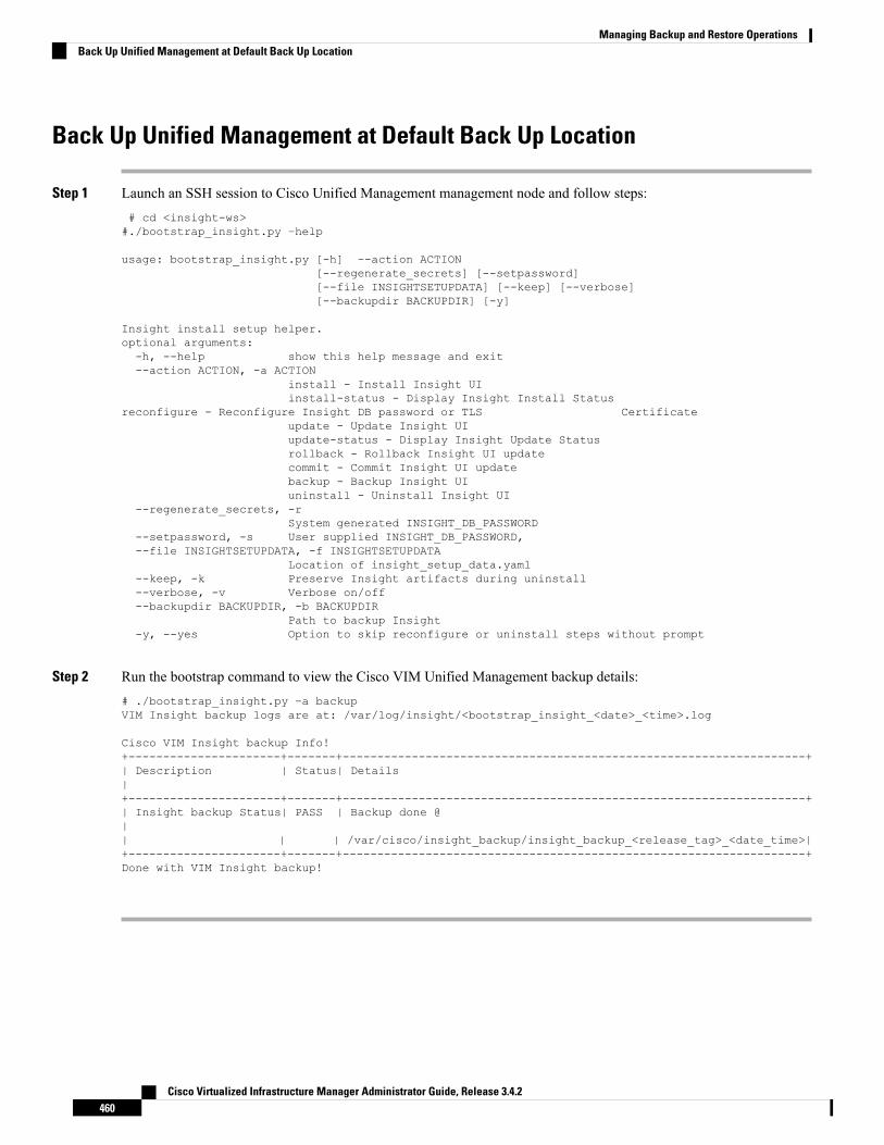
Back Up Unified Management at Default Back Up Location
Step 1 Launch an SSH session to Cisco Unified Management management node and follow steps:# cd <insight-ws>#./bootstrap_insight.py –help
usage: bootstrap_insight.py [-h] –-action ACTION[--regenerate_secrets] [--setpassword][--file INSIGHTSETUPDATA] [--keep] [--verbose][--backupdir BACKUPDIR] [-y]
Insight install setup helper.optional arguments:-h, --help show this help message and exit--action ACTION, -a ACTION
install - Install Insight UIinstall-status - Display Insight Install Status
reconfigure - Reconfigure Insight DB password or TLS Certificateupdate - Update Insight UIupdate-status - Display Insight Update Statusrollback - Rollback Insight UI updatecommit - Commit Insight UI updatebackup - Backup Insight UIuninstall - Uninstall Insight UI
--regenerate_secrets, -rSystem generated INSIGHT_DB_PASSWORD
--setpassword, -s User supplied INSIGHT_DB_PASSWORD,--file INSIGHTSETUPDATA, -f INSIGHTSETUPDATA
Location of insight_setup_data.yaml--keep, -k Preserve Insight artifacts during uninstall--verbose, -v Verbose on/off--backupdir BACKUPDIR, -b BACKUPDIR
Path to backup Insight-y, --yes Option to skip reconfigure or uninstall steps without prompt
Step 2 Run the bootstrap command to view the Cisco VIM Unified Management backup details:# ./bootstrap_insight.py –a backupVIM Insight backup logs are at: /var/log/insight/<bootstrap_insight_<date>_<time>.log
Cisco VIM Insight backup Info!+----------------------+-------+-------------------------------------------------------------------+| Description | Status| Details|+----------------------+-------+-------------------------------------------------------------------+| Insight backup Status| PASS | Backup done @|| | | /var/cisco/insight_backup/insight_backup_<release_tag>_<date_time>|+----------------------+-------+-------------------------------------------------------------------+Done with VIM Insight backup!
Cisco Virtualized Infrastructure Manager Administrator Guide, Release 3.4.2460
Managing Backup and Restore OperationsBack Up Unified Management at Default Back Up Location

Backup Unified Management at User-defined Backup Location
Step 1 Launch a SSH session to Cisco Unified Management management node and follow the below steps:# cd <insight-ws>#./bootstrap_insight.py –helpusage: bootstrap_insight.py [-h] –-action ACTION
[--regenerate_secrets] [--setpassword][--file INSIGHTSETUPDATA] [--keep] [--verbose][--backupdir BACKUPDIR] [-y]
Insight install setup helper.optional arguments:-h, --help show this help message and exit--action ACTION, -a ACTION
install - Install Insight UIinstall-status - Display Insight Install Status
reconfigure - Reconfigure Insight DB password or TLS Certificateupdate - Update Insight UIupdate-status - Display Insight Update Statusrollback - Rollback Insight UI updatecommit - Commit Insight UI updatebackup - Backup Insight UIuninstall - Uninstall Insight UI
--regenerate_secrets, -rSystem generated INSIGHT_DB_PASSWORD
--setpassword, -s User supplied INSIGHT_DB_PASSWORD,--file INSIGHTSETUPDATA, -f INSIGHTSETUPDATA
Location of insight_setup_data.yaml--keep, -k Preserve Insight artifacts during uninstall--verbose, -v Verbose on/off--backupdir BACKUPDIR, -b BACKUPDIR
Path to backup Insight-y, --yes Option to skip reconfigure or uninstall steps without prompt
Step 2 Run the following command to view the Cisco VIM Unified Management backup details:# ./bootstrap_insight.py –a backup –-backupdir <user_defined_path>VIM Insight backup logs are at: /var/log/insight/<bootstrap_insight_<date>_<time>.log
Cisco VIM Insight backup Info!+-----------------------+--------+----------------------------------------------------------+| Description | Status | Details |+-----------------------+--------+----------------------------------------------------------+| Insight backup Status | PASS | Backup done @ <user_defined_path> || | | |+-----------------------+--------+----------------------------------------------------------+Done with VIM Insight backup!
What to do next
Copy the backup directory to a remote server using rsync to recover the Insight later. Cisco recommends youto copy backup directory using rsync as it preserves the permissions of the files.
For example, to copy the backup directory to the remote server 20.0.0.5/var/cisco/insight_backup/directory, execute the following command sequence: .
Cisco Virtualized Infrastructure Manager Administrator Guide, Release 3.4.2461
Managing Backup and Restore OperationsBackup Unified Management at User-defined Backup Location

rsync -e ssh -go -rtvpX --numeric-ids/var/cisco/insight_backup/[email protected]:/var/cisco/insight_backup/
On the remote server, protect the backup directory for any unauthorized access, as the backup files may containsensitive information
Restoring Management NodeYou have to reimage the management node with the running Cisco VIM release ISO version when the backupis performed, before initiating the restore operation. The restoration fails, when there is a version mismatch.
Version checking is available only for offline installation.Note
As part of the restore operation, system checks for the management node's IP address information to matchthe prior configuration. Logs are cached on the control, compute, and storage nodes from the moment of themanagement node fails until its restoration.
If you are using Cisco VIMUnified Management (in Tech Preview), in the same management node, you haveto rebootstrap it for installation. During installation, RBAC and Pod registration information is lost, hence itis advised to make a note of the RBAC and Pod information.
Figure 28: Cisco NFVI Management Node Restore Operation
Before you begin
Ensure that you have the br_mgmt and br_api IP addresses of the failed management node.
Step 1 Reimage the management node with the ISO version with which you want to restore the node, and with the same IPaddress that is used before the failure of the node.
Step 2 Navigate to /var/cisco/directory at the remote server where the backup folder is copied during the backup operation.Execute ./check_integrity to verify if the backup is not corrupted or modified.
Step 3 Copy the backup file to the /var/cisco/directory of the reimaged management node.
For example, to copy the backup folder from the remote host 20.0.0.5 to the management node /var/cisco/directory,execute the following command sequence:rsync -e ssh -go -rtvpX --numeric-ids [email protected]:/var/cisco/backup_2017-01-09_14-04-38 /var/cisco/
Cisco Virtualized Infrastructure Manager Administrator Guide, Release 3.4.2462
Managing Backup and Restore OperationsRestoring Management Node

Step 4 Navigate to the backup folder and execute the following command to verify if the backup is not corrupted or modified.# cd /var/cisco/backup_<date-time># ./check-integrity
Step 5 In /var/cisco/backup_<date-time> folder, execute the following command:/var/cisco/backup_<date-time> # ./restore
The restore operation takes around 45 minutes.
Step 6 Before restoration, the restore script performs validation of the backup folder. If validation fails, restore operation ishalted and an error message is displayed. The script also verifies the last performed backup folder in the ManagementNode, and if any defects are detected, the you does confirm to proceed with restore operation.…2017-02-02 21:25:23 INFO Starting Cisco VIM restore...2017-02-02 21:25:23 INFO Cisco VIM restore: estimated run time is approx. 45 mins...2017-02-02 21:25:23 INFO Please see progress log for restore at/var/log/mercury/installer/restore_2017-02-02_21:25:23.log2017-02-02 21:25:27 ERROR Error: Backup id is not the one expectedError: Found hashID file only in controller(s): j10-controller-2, j10-controller-3Management backup files are ok (as per j10-controller-2)Management backup files are ok (as per j10-controller-3)The management node changed after the last backup was stored. Do you still want to proceed restoringthis management node? [Y/n] y2017-02-02 22:17:55 INFO Workspace restored to /root/installer-65182017-02-02 22:17:55 INFO Cisco VIM restore: Executing restore playbook ...2017-02-02 22:18:47 INFO Cisco VIM restore: Executing bootstrap playbook ...
The default behavior is to continue by keying Return or Y. Keying N terminates the restore operation.Note
…2017-02-02 21:25:23 INFO Starting Cisco VIM restore...2017-02-02 21:25:23 INFO Cisco VIM restore: estimated run time is approx. 45 mins...2017-02-02 21:25:23 INFO Please see progress log for restore at/var/log/mercury/installer/restore_2017-02-02_21:25:23.log2017-02-02 21:25:27 ERROR Error: Backup id is not the one expectedError: Found hashID file only in controller(s): j10-controller-2, j10-controller-3Management backup files are ok (as per j10-controller-2)Management backup files are ok (as per j10-controller-3)The management node changed after the last backup was stored. Do you still want to proceed restoringthis management node? [Y/n] nAborting the restore operation as per user request
Once, restore operation ends, several health check points are automatically executed and the summary of results for thatparticular cloud avaliability is displayed.
Step 7 Run the following checks manually to verify the status of the restore:
• Check the status of the REST API server:# cd installer-<tagid>/tools#./restapi.py -a statusStatus of the REST API Server: active (running) since Thu 2016-08-18 09:15:39 UTC; 9h agoREST API launch directory: /root/installer-<tagid>/
• Check the setup_data and runtime consistency of the management node:# cd installer-<tagid>/; ciscovim run -–perform 1,3 –y
• Execute the cloud sanity using ciscovim command:#ciscovim cloud-sanity create test all
Cisco Virtualized Infrastructure Manager Administrator Guide, Release 3.4.2463
Managing Backup and Restore OperationsRestoring Management Node

• To view the results of cloud sanity, use the command #ciscovim cloud-sanity show result all –id <uid of
the test >
Management Node AutobackupAfter the successful completion of certain Pod management operations, a backup of the management node isperformed automatically. Only one copy of the autobackup folder is kept at /var/cisco/ at any given time.Directory format for the autobackup_<tag>_<timestamp>.
Following are the list of operations:
• Fresh install of Cisco VIM
• Commit an update
• Replace controller
• Add or Remove compute nodes
• Add or Remove the storage node
• Reconfigure
• CVIM-MON
Enabling or disabling the variable autobackup, is defined in the setup_data.yaml file. It is enabled by default.
Add the following setup-data.yaml file snippet:
###################################################### AutoBackup configuration######################################################Default is True#autobackup: True or False
The following tables shows when an auto-backup is performed during update or rollback or commit.
Autobackup performedPOD operation
NoUpdate
NoRollback
YesCommit
NoUpdate fail with auto rollback
After creating a successful autobackup folder, you can copy it to an external server for later restoration asmentioned in Restoring Management Node, on page 462.
During the autobackup, if Forwarding ELK Logs to the External Syslog server option is enabled, theElasticSearch database will not be maintained and the ELK Logs will not be recovered after restoring themanagement node.
Cisco Virtualized Infrastructure Manager Administrator Guide, Release 3.4.2464
Managing Backup and Restore OperationsManagement Node Autobackup

Managing Cisco VIM Software HubCisco VIM Software Hub helps mitigate the need to ship USBs across different pods during installing orupdating Cisco VIM. To ensure the long-term viability of Cisco VIM Software Hub, it is designed to handlethe following Day 2 scenarios:
• Updating Cisco VIM Software Hub TLS Certificate and Registry Credentials, on page 465
• Cisco VIM Software Hub Server Backup and Restore, on page 465
• Resolving Low Disk Space, on page 467
• Manually Updating Packages, on page 468
Updating Cisco VIM Software Hub TLS Certificate and Registry CredentialsBefore installing the release artifacts from the Cisco VIM Software Hub server, you must provide a valid TLScertificate and Cisco VIM Software Hub registry credentials in the sds_setup_data.yaml file. Takinginto account the security policies of an organization, Cisco VIM Software Hub allows you to update the TLScertificate and registry credentials on the Cisco VIM Software Hub server as required.
Step 1 Navigate to the last installed release workspace using the ls –lrt command.Step 2 Replace the TLS certificate in the openstack-configs directory.Step 3 Modify the credentials in the sds_setup_data.yaml file.Step 4 Run the following command for the changes to take effect:
# cd /root/cvim_sds-<last-tag> # directory of last installed release and execute the following command.
# ./sds_runner/runner.py
This operation validates the changes in the sds_setup_data.yaml file and the new TLS certificate. It reconfiguresthe Cisco VIM Software Hub server components with this new information.
The Cisco VIM Software Hub registry credentials of the pods that rely on Cisco VIM Software Hub are alsoreconfigured.
Note
Cisco VIM Software Hub Server Backup and RestoreCisco VIM Software Hub triggers an autobackup operation when a new Cisco VIM release is installed on theCisco VIM Software Hub server. It takes a backup of the relevant files from the Cisco VIM Software Hubserver, and saves it in the following location on the Cisco VIM Software Hub server:directory /var/cisco/autobackup_<tag>_<date-time>
Only the latest two backup directories are maintained on Cisco VIM Software Hub. The older copy isoverwritten when the next autobackup operation is triggered. If you want to use an older backup directory fora restore operation later, you need to save it to another location before it is overwritten. You can use the rsyncor scp commands to save it to an RHEL7/CentOS based system, which is outside the Cisco VIM SoftwareHub server.
Cisco Virtualized Infrastructure Manager Administrator Guide, Release 3.4.2465
Managing Backup and Restore OperationsManaging Cisco VIM Software Hub

Checking Integrity of Autobackup FilesYou can use the script provided in the autobackup directory to check the integrity of the autobackup files afterusing the rsync or scp commands.
Before you begin
Ensure that the following packages are installed on the backup server using yum:
• python-prettytable
• python-jinja2
• python-babel
• python-markupsafe
• python-setuptools
• pytz
Step 1 Navigate to the autobackup directory.Step 2 Execute the following command to run the script:
# ./check_integrity
Restoring Cisco VIM Software Hub from BackupAn Cisco VIM Software Hub restore operation is usually performed when the original Cisco VIM SoftwareHub server is being replaced by a new one.
Step 1 Re-image the Cisco VIM Software Hub server with the ISO version with which you want to restore the node, and withthe same IP address that is used before the failure of the node.
Step 2 Navigate to the location where the backup directory is copied during the backup operation.Step 3 Verify the integrity of the backup files as described in Checking Integrity of Autobackup Files, on page 466.Step 4 Copy the backup file to the directory of the re-imaged Cisco VIM Software Hub node.
For example, you can copy the backup directory from the remote host 20.0.0.5 to the Cisco VIM Software Hub nodedirectory /var/cisco/ as follows:rsync -e ssh -go -rtvpX --numeric-ids [email protected]:/var/cisco/autobackup_2017-01-09_14-04-38/var/cisco/
Step 5 Navigate to the backup directory and execute the following command to verify if the backup is not corrupted or modified.# cd /var/cisco/autobackup_<tag>_<date-time># ./check-integrity
Step 6 In the /var/cisco/autobackup_<tag>_<date-time> directory, execute the following commands:# cd /var/cisco/backup_<date-time># ./restore
It may take about 45 minutes for the restore operation to complete.
Cisco Virtualized Infrastructure Manager Administrator Guide, Release 3.4.2466
Managing Backup and Restore OperationsChecking Integrity of Autobackup Files

Before restoring a backup directory, the restore script validates the backup directory. If the validation fails, therestore operation is interrupted and an error message is displayed. The restore script also verifies the latestbackup directory in the Cisco VIM Software Hub Node. If defects are detected, you need to confirm whetheryou want to proceed with the restore operation.
Note
For example:2017-02-02 21:25:23 INFO Starting Cisco VIM restore...2017-02-02 21:25:23 INFO Cisco VIM restore: estimated run time is approx. 45 mins...2017-02-02 21:25:23 INFO Please see progress log for restore at/var/log/mercury/installer/restore_2017-02-02_21:25:23.log2017-02-02 21:25:27 ERROR Error: Backup id is not the one expectedError: Found hashID file only in controller(s): j10-controller-2, j10-controller-3 Management backupfiles are ok (as per j10controller-2)Management backup files are ok (as per j10-controller-3)The management node changed after the last backup was stored. Do you still want to proceed restoringthis management node? [Y/n] y2017-02-02 22:17:55 INFO Workspace restored to /root/installer-65182017-02-02 22:17:55 INFO Cisco VIM restore: Executing restore playbook ...2017-02-02 22:18:47 INFO Cisco VIM restore: Executing bootstrap playbook ...
To continue the restore operation, you can press the Enter key or the Y key. If you want to abort the restoreoperation, you need to press the N key.
Note
2017-02-02 21:25:23 INFO Starting Cisco VIM restore...2017-02-02 21:25:23 INFO Cisco VIM restore: estimated run time is approx. 45 mins...2017-02-02 21:25:23 INFO Please see progress log for restore at/var/log/mercury/installer/restore_2017-02-02_21:25:23.log2017-02-02 21:25:27 ERROR Error: Backup id is not the one expectedError: Found hashID file only in controller(s): j10-controller-2, j10-controller-3 Management backupfiles are ok (as per j10controller-2)Management backup files are ok (as per j10-controller-3)The management node changed after the last backup was stored. Do you still want to proceed restoringthis management node? [Y/n] nAborting the restore operation as per user request
Resolving Low Disk SpaceInstalling releases on Cisco VIM Software Hub server is not allowed, if the free disk space is less than 20%.Hence, a utility to remove docker images from the container registry running on the Cisco VIM Software Hubserver is provided. You can find the cleanup script at the following location:/root/cvim_sds-<last-tag>/sds/registry_cleanup.py
Example of running the cleanup script:# ./registry_cleanup.py -husage: registry_cleanup.py [-h] (--list | --delete DELETE | --unused_tags)
[-u USERNAME] [-p PASSWORD] [-r REGISTRY]
List/Delete image tags in the registry
optional arguments:-h, --help Show this help message and exit--list List Image Tags in Registry
--delete DELETE Delete Images of provided tags from registry--unused_tags List unused Tags in SDS registry-u USERNAME, --username USERNAME
Registry Username
Cisco Virtualized Infrastructure Manager Administrator Guide, Release 3.4.2467
Managing Backup and Restore OperationsResolving Low Disk Space
-p PASSWORD, --password PASSWORDRegistry Password
-r REGISTRY, --registry REGISTRYRegistry URL
The cleanup script requires three mandatory parameters, namely, Registry URL, Registry username, andRegistry password. The script supports the following three options:
• List Image Tags–The option lists all the images and corresponding tags present in the docker registry.
• Unused Tags–This option lists all the releases present on the Cisco VIM Software Hub server but arenot used by any of the Cisco VIM pods. By default, the pods are registered with the Cisco VIM SoftwareHub server. When a pod is installed, updated, roll backed, or upgraded, the release information is sentto Cisco VIM Software Hub. You can use this command to identify the releases that can be safely removedfrom the Cisco VIM Software Hub server.
• Delete Tags–You can specify the releases that you want to remove from the docker registry. The scriptremoves these images and frees the disk space.
A sample snippet of the command template is listed below:#./registry_cleanup.py -u <username> -p <password> -r https://<sds_domian_name>/ --list#./registry_cleanup.py -u <username> -p <password> -r https://<sds_domian_name>/ --delete3.2.0
Manually Updating PackagesCisco VIM Software Hub installs repositories inside docker containers so that all the packages to be installedare obtained from those repositories. These repositories are updated when you install a later version of CiscoVIM release on the Cisco VIM Software Hub server. Once the repositories are updated, all the packages,except httpd package and its dependencies are updated. Updating httpd is deferred because when httpd isupdated, all downstream connections are disrupted thereby requiring you to restart the Cisco VIM pod install.
To update httpd and its dependent packages, you can use the update script found in the tools directory. Ensurethat you run this script during the maintenance phase so that non of the Cisco VIM pods are currently attemptingto get artifacts from the Cisco VIM Software Hub server.
Run the following command to execute the update script:# cd /root/cvim_sds-<last-tag> # directory of last installed release and execute the followingcommand.# ./update_httpd.sh
Cisco Virtualized Infrastructure Manager Administrator Guide, Release 3.4.2468
Managing Backup and Restore OperationsManually Updating Packages

C H A P T E R 13Troubleshooting
The following topics describe various Cisco NFVI troubleshooting operations:
• Displaying Cisco NFVI Node Names and IP Addresses, on page 469• Verifying Cisco NFVI Node Interface Configurations, on page 470• Displaying Cisco NFVI Node Network Configuration Files, on page 471• Viewing Cisco NFVI Node Interface Bond Configuration Files, on page 472• Viewing Cisco NFVI Node Route Information, on page 472• Viewing Linux Network Namespace Route Information, on page 473• Pre-checks for Storage Removal Operation, on page 473• Troubleshooting Cisco NFVI, on page 475• Management Node Recovery Scenarios, on page 480• Recovering Compute Node Scenario, on page 489• Running the Cisco VIM Technical Support Tool, on page 491• Tech-Support Configuration File, on page 492• Tech-Support When Servers Are Offline, on page 495• Running Cisco VIM Software Hub Technical Support Tool, on page 495• Disk-Maintenance Tool to Manage Physical Drives, on page 496• OSD-Maintenance Tool, on page 499• Utility to Resolve Cisco VIM Hardware Validation Failures, on page 501• Cisco VIM Client Debug Option, on page 504
Displaying Cisco NFVI Node Names and IP AddressesComplete the following steps to display the Cisco NFVI node names and IP addresses.
Step 1 Log into the Cisco NFVI build node.Step 2 The openstack-configs/mercury_servers_info file displays the node name and the address as follows.
# more openstack-configs/mercury_servers_info Total nodes: 5Controller nodes: 3+------------------+--------------+--------------+--------------+-----------------+---------+| Server | CIMC | Management | Provision | Tenant | Storage |+------------------+--------------+--------------+--------------+-----------------+---------+| test-c-control-1 | 10.10.223.13 | 10.11.223.22 | 10.11.223.22 | 169.254.133.102 | None || | | | | | |
Cisco Virtualized Infrastructure Manager Administrator Guide, Release 3.4.2469

| test-c-control-3 | 10.10.223.9 | 10.11.223.23 | 10.11.223.23 | 169.254.133.103 | None |
| | | | | | || test-c-control-2 | 10.10.223.10 | 10.11.223.24 | 10.11.223.24 | 169.254.133.104 | None || | | | | | |+------------------+--------------+--------------+--------------+-----------------+---------+Compute nodes: 2+------------------+--------------+--------------+--------------+-----------------+---------+| Server | CIMC | Management | Provision | Tenant | Storage |+------------------+--------------+--------------+--------------+-----------------+---------+| test-c-compute-1 | 10.10.223.11 | 10.11.223.25 | 10.11.223.25 | 169.254.133.105 | None || | | | | | || test-c-compute-2 | 10.10.223.12 | 10.11.223.26 | 10.11.223.26 | 169.254.133.106 | None || | | | | | |+
During the Cisco NFVI deployment, SSH public keys for each node are added to .../.ssh/authorized_keys, soyou should be able to log in from the build node into each of the Cisco NFVI nodes without passwords. If, forsome reason you do need account information, see the openstack-configs/secrets.yaml file on the build node.
Note
Verifying Cisco NFVI Node Interface ConfigurationsComplete the following steps to verify the interface configurations of Cisco NFVI nodes:
Step 1 SSH into the target node, for example, one of the Cisco VIM controllers:[root@mgmt-node~]# ssh root@control-server-1[root@control-server-1 ~]#
Step 2 Enter the ip a command to get a list of all interfaces on the node:
[root@control-server-1 ~]# ip a1: lo: <LOOPBACK,UP,LOWER_UP> mtu 65536 qdisc noqueue state UNKNOWN link/loopback 00:00:00:00:00:00brd 00:00:00:00:00:00inet 127.0.0.1/8 scope host lovalid_lft forever preferred_lft forever2: enp8s0: <BROADCAST,MULTICAST,UP,LOWER_UP> mtu 1500 qdisc mq state UP qlen 1000 link/ether54:a2:74:7d:42:1d brd ff:ff:ff:ff:ff:ff3: enp9s0: <BROADCAST,MULTICAST,UP,LOWER_UP> mtu 1500 qdisc mq state UP qlen 1000 link/ether54:a2:74:7d:42:1e brd ff:ff:ff:ff:ff:ff4: mx0: <BROADCAST,MULTICAST,SLAVE,UP,LOWER_UP> mtu 1500 qdisc mq master mx state UP qlen 1000link/ether 54:a2:74:7d:42:21 brd ff:ff:ff:ff:ff:ff5: mx1: <BROADCAST,MULTICAST,SLAVE,UP,LOWER_UP> mtu 1500 qdisc mq master mx state UP qlen 1000link/ether 54:a2:74:7d:42:21 brd ff:ff:ff:ff:ff:ff6: t0: <BROADCAST,MULTICAST,SLAVE,UP,LOWER_UP> mtu 1500 qdisc mq master t state UP qlen 1000 link/ether54:a2:74:7d:42:23 brd ff:ff:ff:ff:ff:ff7: t1: <BROADCAST,MULTICAST,SLAVE,UP,LOWER_UP> mtu 1500 qdisc mq master t state UP qlen 1000 link/ether54:a2:74:7d:42:23 brd ff:ff:ff:ff:ff:ff8: e0: <BROADCAST,MULTICAST,SLAVE,UP,LOWER_UP> mtu 1500 qdisc mq master e state UP qlen 1000 link/ether54:a2:74:7d:42:25 brd ff:ff:ff:ff:ff:ff9: e1: <BROADCAST,MULTICAST,SLAVE,UP,LOWER_UP> mtu 1500 qdisc mq master e state UP qlen 1000 link/ether54:a2:74:7d:42:25 brd ff:ff:ff:ff:ff:ff10: p0: <BROADCAST,MULTICAST,SLAVE,UP,LOWER_UP> mtu 1500 qdisc mq master p state UP qlen 1000 link/ether
Cisco Virtualized Infrastructure Manager Administrator Guide, Release 3.4.2470
TroubleshootingVerifying Cisco NFVI Node Interface Configurations

54:a2:74:7d:42:27 brd ff:ff:ff:ff:ff:ff11: p1: <BROADCAST,MULTICAST,SLAVE,UP,LOWER_UP> mtu 1500 qdisc mq master p state UP qlen 1000 link/ether54:a2:74:7d:42:27 brd ff:ff:ff:ff:ff:ff12: a0: <BROADCAST,MULTICAST,SLAVE,UP,LOWER_UP> mtu 1500 qdisc mq master a state UP qlen 1000 link/ether54:a2:74:7d:42:29 brd ff:ff:ff:ff:ff:ff13: a1: <BROADCAST,MULTICAST,SLAVE,UP,LOWER_UP> mtu 1500 qdisc mq master a state UP qlen 1000
link/ether 54:a2:74:7d:42:29 brd ff:ff:ff:ff:ff:ff14: bond0: <BROADCAST,MULTICAST,MASTER> mtu 1500 qdisc noop state DOWN link/ether 4a:2e:2a:9e:01:d1brd ff:ff:ff:ff:ff:ff15: a: <BROADCAST,MULTICAST,MASTER,UP,LOWER_UP> mtu 1500 qdisc noqueue master br_api state UP link/ether54:a2:74:7d:42:29 brd ff:ff:ff:ff:ff:ff16: br_api: <BROADCAST,MULTICAST,UP,LOWER_UP> mtu 1500 qdisc noqueue state UP link/ether54:a2:74:7d:42:29 brd ff:ff:ff:ff:ff:ff17: e: <BROADCAST,MULTICAST,MASTER,UP,LOWER_UP> mtu 1500 qdisc noqueue state UP link/ether54:a2:74:7d:42:25 brd ff:ff:ff:ff:ff:ff18: mx: <BROADCAST,MULTICAST,MASTER,UP,LOWER_UP> mtu 1500 qdisc noqueue master br_mgmt state UPlink/ether 54:a2:74:7d:42:21 brd ff:ff:ff:ff:ff:ff19: br_mgmt: <BROADCAST,MULTICAST,UP,LOWER_UP> mtu 1500 qdisc noqueue state UP link/ether54:a2:74:7d:42:21 brd ff:ff:ff:ff:ff:ffinet 10.23.221.41/28 brd 10.23.221.47 scope global br_mgmt valid_lft forever preferred_lft forever20: p: <BROADCAST,MULTICAST,MASTER,UP,LOWER_UP> mtu 1500 qdisc noqueue state UP link/ether54:a2:74:7d:42:27 brd ff:ff:ff:ff:ff:ff21: t: <BROADCAST,MULTICAST,MASTER,UP,LOWER_UP> mtu 1500 qdisc noqueue state UP link/ether54:a2:74:7d:42:23 brd ff:ff:ff:ff:ff:ffinet 17.16.3.8/24 brd 17.16.3.255 scope global t valid_lft forever preferred_lft forever22: docker0: <NO-CARRIER,BROADCAST,MULTICAST,UP> mtu 1500 qdisc noqueue state DOWN link/ether02:42:70:f6:8b:da brd ff:ff:ff:ff:ff:ffinet 172.17.42.1/16 scope global docker0 valid_lft forever preferred_lft forever24: mgmt-out@if23: <BROADCAST,MULTICAST,UP,LOWER_UP> mtu 1500 qdisc pfifo_fast master br_mgmt stateUP qlen 1000link/ether 5a:73:51:af:e5:e7 brd ff:ff:ff:ff:ff:ff link-netnsid 026: api-out@if25: <BROADCAST,MULTICAST,UP,LOWER_UP> mtu 1500 qdisc pfifo_fast master br_api state UPqlen 1000link/ether 6a:a6:fd:70:01:f9 brd ff:ff:ff:ff:ff:ff link-netnsid 0
Displaying Cisco NFVI Node Network Configuration FilesComplete the following steps to view a Cisco NFVI node network configuration files:
Step 1 SSH into the target node, for example, one of the Cisco VIM controllers:[root@mgmt-node~]# ssh root@control-server-1[root@control-server-1 ~]#
Step 2 List all of the network configuration files in the /etc/sysconfig/network-scripts directory, for example:[root@control-server-1 ~]# ls /etc/sysconfig/network-scripts/ifcfg-a ifcfg-enp15s0 ifcfg-mx0 ifdown-ib ifup ifup-pppifcfg-a0 ifcfg-enp16s0 ifcfg-mx1 ifdown-ippp ifup-aliases ifup-routesifcfg-a1 ifcfg-enp17s0 ifcfg-p ifdown-ipv6 ifup-bnep ifup-sitifcfg-br_api ifcfg-enp18s0 ifcfg-p0 ifdown-isdn ifup-eth ifup-Teamifcfg-br_mgmt ifcfg-enp19s0 ifcfg-p1 ifdown-post ifup-ib ifup-TeamPortifcfg-e ifcfg-enp20s0 ifcfg-t ifdown-ppp ifup-ippp ifup-tunnelifcfg-e0 ifcfg-enp21s0 ifcfg-t0 ifdown-routes ifup-ipv6 ifup-wireless
Cisco Virtualized Infrastructure Manager Administrator Guide, Release 3.4.2471
TroubleshootingDisplaying Cisco NFVI Node Network Configuration Files

ifcfg-e1 ifcfg-enp8s0 ifcfg-t1 ifdown-sit ifup-isdn init.ipv6-globalifcfg-enp12s0 ifcfg-enp9s0 ifdown ifdown-Team ifup-plip network-functionsifcfg-enp13s0 ifcfg-lo ifdown-bnep ifdown-TeamPort ifup-plusb network-functions-ipv6ifcfg-enp14s0 ifcfg-mx ifdown-eth ifdown-tunnel ifup-post
Viewing Cisco NFVI Node Interface Bond Configuration FilesComplete the following steps to view the Cisco NFVI node interface bond configuration files:
Step 1 SSH into the target node, for example, one of the Cisco VIM controllers:[root@mgmt-node~]# ssh root@control-server-1[root@control-server-1 ~]#
Step 2 List all of the network bond configuration files in the /proc/net/bonding/ directory:[root@control-server-1 ~]# ls /proc/net/bonding/a bond0 e mx p t
Step 3 To view more information about a particular bond configuration, enter:[root@control-server-1 ~]# more /proc/net/bonding/aEthernet Channel Bonding Driver: v3.7.1 (April 27, 2011)
Bonding Mode: load balancing (xor)Transmit Hash Policy: layer3+4 (1)MII Status: upMII Polling Interval (ms): 100Up Delay (ms): 0Down Delay (ms): 0
Slave Interface: a0MII Status: upSpeed: 10000 MbpsDuplex: fullLink Failure Count: 1Permanent HW addr: 54:a2:74:7d:42:29Slave queue ID: 0
Slave Interface: a1MII Status: upSpeed: 10000 MbpsDuplex: fullLink Failure Count: 2Permanent HW addr: 54:a2:74:7d:42:2aSlave queue ID: 0
Viewing Cisco NFVI Node Route InformationComplete the following steps to view Cisco NFVI node route information. Note that this is not the HAProxycontainer running on the controller. The default gateway should point to the gateway on the managementnetwork using the br_mgmt bridge.
Cisco Virtualized Infrastructure Manager Administrator Guide, Release 3.4.2472
TroubleshootingViewing Cisco NFVI Node Interface Bond Configuration Files

Step 1 SSH into the target node, for example, one of the Cisco VIM controllers:[root@mgmt-node~]# ssh root@control-server-1[root@control-server-1 ~]#
Step 2 View the routing table (verify the default gateway) of the Cisco NFVI node:[root@control-server-1 ~]# route -nKernel IP routing tableDestination Gateway Genmask Flags Metric Ref Use Iface0.0.0.0 10.23.221.33 0.0.0.0 UG 0 0 0 br_mgmt10.23.221.32 0.0.0.0 255.255.255.240 U 0 0 0 br_mgmt17.16.3.0 0.0.0.0 255.255.255.0 U 0 0 0 t169.254.0.0 0.0.0.0 255.255.0.0 U 1016 0 0 br_api169.254.0.0 0.0.0.0 255.255.0.0 U 1017 0 0 e169.254.0.0 0.0.0.0 255.255.0.0 U 1019 0 0 br_mgmt169.254.0.0 0.0.0.0 255.255.0.0 U 1020 0 0 p169.254.0.0 0.0.0.0 255.255.0.0 U 1021 0 0 t172.17.0.0 0.0.0.0 255.255.0.0 U 0 0 0 docker0
Viewing Linux Network Namespace Route InformationComplete the following steps to view the route information of the Linux network namespace that the HAProxycontainer uses on a Cisco NFVI controller node. The default gateway must point to the gateway on the APInetwork using the API interface in the Linux network namespace.
Step 1 SSH into the target node. For example, one of the Cisco VIM controllers:[root@mgmt-node~]# ssh root@control-server-1[root@control-server-1 ~]#
Step 2 Enter the ip netns command to find the name of the network namespace:
[root@control-server-2 ~]# ip netns 17550 (id: 0)
Step 3 Enter the ip netns exec command to view the routing table (verify the default gateway) of the Linux networknamespace:[root@control-server-2 ~]# ip netns exec 17550 route -nKernel IP routing tableDestination Gateway Genmask Flags Metric Ref Use Iface0.0.0.0 172.29.86.1 0.0.0.0 UG 0 0 0 api10.23.221.32 0.0.0.0 255.255.255.240 U 0 0 0 mgmt172.29.86.0 0.0.0.0 255.255.255.0 U 0 0 0 api
Pre-checks for Storage Removal OperationUpon completion of the pod management operations like add-storage, you need to ensure that any subsequentoperation such as remove-storage is done on the same storage node after accounting for all of the devices and
Cisco Virtualized Infrastructure Manager Administrator Guide, Release 3.4.2473
TroubleshootingViewing Linux Network Namespace Route Information
their corresponding OSDs have been marked in the persistent crush map as shown in the output of the cephosd crush tree.
Execute the following command on the storage node where a remove-storage pod operation is performed, toget a list of all the devices configured for ceph osds:[root@storage-3 ~]$ df | grep -oh ceph-[0-9]*[root@storage-3 ~]$ df | grep -oh ceph-[0-9]*ceph-1ceph-5ceph-7ceph-10
Login to any of the controller nodes and run the following commands within the ceph mon container:$ cephmon$ ceph osd crush tree
From the json output, locate the storage node to be removed and ensure all of the devices listed for ceph osdshave corresponding osd entries for them by running the following commands:{
"id": -3,"name": "storage-3","type": "host","type_id": 1,"items": [
{"id": 1,"name": "osd.1","type": "osd","type_id": 0,"crush_weight": 1.091095,"depth": 2
},{
"id": 5,"name": "osd.5","type": "osd","type_id": 0,"crush_weight": 1.091095,"depth": 2
},{
"id": 7,"name": "osd.7","type": "osd","type_id": 0,"crush_weight": 1.091095,"depth": 2
},{
"id": 10,"name": "osd.10","type": "osd","type_id": 0,"crush_weight": 1.091095,"depth": 2
}]
},
Cisco Virtualized Infrastructure Manager Administrator Guide, Release 3.4.2474
TroubleshootingPre-checks for Storage Removal Operation

If ToR_TYPE is Cisco NCS 5500, you must manually remove all the sub-interfaces that were manuallyconfigured on the NCS switch, as Cisco VIM automation does not unconfigure/configure the sub-interfacesfor which the VLANswere not defined in the setup_data.yaml. If manual removal of sub-interface is not done,remove-compute operation is initiated.
Note
Troubleshooting Cisco NFVIThe following topics provide Cisco NFVI general troubleshooting procedures.
Managing CIMC and ISO InstallationWhen you are remote it is good to map the ISO through the CIMC Mapped vMedia.
To add new mapping:
Step 1 Click Server > Remote Presence > Virtual Media > Add New Mapping.
Step 2 Enter the field values such as the Volume, Mount Type, Remote Share, Remote File, User name, and Password.
Cisco Virtualized Infrastructure Manager Administrator Guide, Release 3.4.2475
TroubleshootingTroubleshooting Cisco NFVI

Step 3 Click Save. .The CIMC pulls the ISO directly from the HTTP server.
Management Node Installation FailsManagement node installation fails if the CIMC is configured for cisco card mode.
Choose the dedicated mode in the following screen:
The selected method that is shown in the preceding screen is the incorrect mode.
Configuring Boot OrderManagement node does not come up post reboot. It must boot from hard drive to check for the actual bootorder.
Choose Server > BIOS > Configure Boot Order > Boot Order.
Cisco Virtualized Infrastructure Manager Administrator Guide, Release 3.4.2476
TroubleshootingManagement Node Installation Fails

PXE Failure Issue During Baremetal StepPerform the following steps in case of PXE boot failure:
Step 1 Check log file /var/log/mercury/mercury_baremetal_install.log and connect to failing node CIMC KVM console tofind out more on PXE boot failure reason.
Step 2 Ensure all validations (step 1) and hardware validations (step 3) pass.Step 3 Check log file /var/log/mercury/<UUID>/mercury_baremetal_install.log.Step 4 Connect to KVM console of failing node(s) to find out more on PXE boot failure.Step 5 Check L2/L3 network connectivity between failing node(s) and management node.Step 6 Check for VPC configuration and port-channel status of failing node(s) and ensure no lacp suspend-individual is
configured on the port-channel.Step 7 Check the actual PXE boot order must not differ from the boot-order configured.Step 8 Perform tcpdump on the management node interface br_mgmt to watch for UDP port 67 (dhcp) or UDP pot 69 (tftp)
tcpdump -I br_mgmt port 67 or port 69 # on the management node.Step 9 Perform tcpdump on the management node management interfacebr_mgmt on TCP 80 tcpdump -I br_mgmt port 80 #
on the management node.Step 10 Check the apache log to watch the management IP address of failing node (if static allocated) tail -f
/var/log/cobblerhttpd/access_log # on the management node.Step 11 For Authorization Required error messages during baremetal (Step 4) with CIMC operations such as hardware validations
or cleaning up vNIC, check whether the maximum allowed simultaneous connection (4) are in use. All four connectionsare run when the 3rd party applicationmonitoring CIMC does not properly close CIMC. This makes CiscoVIM installernot to log in using xmlapi with valid username and password. Check Cisco IMC logs on CIMC (Server > Faults andLogs > Cisco IMC Logs) for the reason why user was denied the access (maximum session, incorrect credentials.). Theworkaround is to disable 3rd party monitoring, wait at least 10 minutes and then perform CiscoVIM operations.
Cisco Virtualized Infrastructure Manager Administrator Guide, Release 3.4.2477
TroubleshootingPXE Failure Issue During Baremetal Step

Step 12 In case none of the nodes are getting DHCP address; DHCP requests arrive at the management node but no responsegoes out, then check CIMCVIC adapter settings. Server > Inventory > Cisco VIC Adapters > vNICs | VLAN&VLANMode. Ensure the VLAN (both id and mode) configured does not matche with that of N9K switch
DescriptionOption
Trunk:NoneCIMC
Access:vlan_mgmtSwitch
The following topics provide Cisco NFVI general troubleshooting procedures.
Container Download Problems
a. Check installer logs log file /var/log/mercury/mercury_buildorchestration.log for any build node orchestrationfailures including stuck "registry-Populate local registry". Downloaing the Docker container from your managementnode can be slow.
b. Check the network connectivity between the management node and the remote registry in defaults.yaml on themanagement node (grep "^registry:" openstack-configs/defaults.yaml).
c. Verify valid remote registry credentials are defined in setup_data.yaml file.
d. A proxy server is required to pull the container images from remote registry. If a proxy is required, exclude all IPaddresses for your setup including management node.
Cisco IMC Connection Problems during Bare Metal Installation
The cause may be Cisco IMC has too many connections, so the installer cannot connect to it. Clear the connections bylogging into your Cisco IMC, going into the Admin->Sessions tab and clearing the connections.
API VIP Connection Problems
Verify the active HAProxy container is running in one of the controller nodes. On that controller within the HAProxycontainer namespace verify the IP address is assigned to the API interface. Also, verify that your ToR and the networkinfrastructure connecting your ToR is provisioned with API network segment VLAN.
HAProxy Services Downtime after Initial Installation or HA Failover
Cisco Virtualized Infrastructure Manager Administrator Guide, Release 3.4.2478
TroubleshootingPXE Failure Issue During Baremetal Step
The HAProxy web interface can be accessed on TCP port 1936http://<external_lb_vip_address>:1936/Username: haproxyPassword: <HAPROXY_PASSWORD> from secrets.yaml file
After initial installation, the HAProxy web interface can report to several OpenStack services with downtime dependingupon when that OpenStack service was installed after HAProxy install. The counters are not synchronized betweenHAProxy active and standby. After HA proxy failover, the downtime timers can change based on the uptime of newactive HAproxy container.
Management Node Problems
Service Commands
To identify all the services that are running, enter:$ systemctl -a | grep docker | grep serviceOn controller ignore status of:docker-neutronlbOn compute ignore status of:docker-neutronlb, docker-keystone
To start a service on a host, enter:$ systemctl start <service_name>
To stop a service on a host, enter:$ systemctl stop <service_name>
To restart a service on a host, enter:$ systemctl restart <service_name>
To check service status on a host, enter:$ systemctl status <service_name>
Connecting to Docker Container
To connect to the docket container do the following:# generally, aliases are created for all containers# use alias to identify thosealias | grep in_container# checking specific alias by namealias cobbler
# check docker containers# alias created by CVIMdp# list docker containersdocker ps -a# list docker imagesdocker images
# connecting to containerdocker exec -it my_cobbler_<tag_id> /bin/bash
# connecting to docker container as privileged user
Cisco Virtualized Infrastructure Manager Administrator Guide, Release 3.4.2479
TroubleshootingConnecting to Docker Container

docker exec -it -u root my_cobbler_<tag_id> /bin/bash
# systemctl filessystemctl -a | egrep "docker-.*.service"
# check specific servicesystemctl status mercury-restapi -lsystemctl status docker-vmtp
# restart specific servicesystemctl restart docker-vmtp
Management Node Recovery ScenariosThe Cisco NFVI management node hosts the Cisco VIM Rest API service, Cobbler for PXE services, ELKfor Logging to Kibana dashboard services and VMTP for the cloud validation. As the maintenance node doesnot have redundancy, understanding its points of failure and recovery scenarios is important. Managing Noderecovery scenarios are described in the following steps.
The management node architecture includes a Cisco UCS C240 M4 server with dual CPU socket. It has a1-Gbps on-board (LOM) NIC and a 10-Gbps Cisco VIC mLOM. HDDs are used in 8,16, or 24 diskconfigurations.
The following figure shows the high-level maintenance node of the hardware and software architecture.
Cisco Virtualized Infrastructure Manager Administrator Guide, Release 3.4.2480
TroubleshootingManagement Node Recovery Scenarios

Figure 29: Cisco NFVI Management Node Architecture
Different management node hardware or software failures can cause Cisco NFVI service disruptions andoutages. Some failed services can be recovered throughmanual intervention. In cases if the system is operationalduring a failure, double faults cannot be recoverable.
The following table lists the management node failure scenarios and their recovery options.
Table 18: Management Node Failure Scenarios
Operational ImpactRecoverable?Failure or TriggerScenario #
NoYesFailure of 1 or 2 active HDD1
YesNoSimultaneous failure of more than 2active HDD
2
NoYesSpare HDD failure: 4 spare for 24HDD; or 2 spare for 8 HDD
3
Cisco Virtualized Infrastructure Manager Administrator Guide, Release 3.4.2481
TroubleshootingManagement Node Recovery Scenarios

Operational ImpactRecoverable?Failure or TriggerScenario #
YesYesPower outage/hard reboot4
YesYesGraceful reboot5
YesYesDocker daemon start failure6
YesYesService container (Cobbler, ELK) startfailure
7
NoYesOne link failure on bond interface8
YesYesTwo link failures on bond interface9
NoYesREST API service failure10
Yes; CLI alternatives existduring reboot.
YesGraceful reboot with Cisco VIMUnified Management
11
YesYesPower outage or hard reboot withCisco VIM Unified Management
12
Yes; CLI alternatives existduring reinstall.
YesVIM Unified Management Containerreinstallation
13
Yes; CLI alternatives existduring reboot.
YesCisco VIM Unified ManagementContainer reboot
14
YesYesIntel 1350 1Gbps LOM failure15
YesYesCisco VIC 1227 10-Gbps mLOMfailure
16
NoYesDIMM memory failure17
NoYesOne CPU failure18
Scenario 1: Failure of one or two active HDDs
The management node has either 8,16, or 24-HDDs. The HDDs are configured with RAID 6, which helps toenable data redundancy and storage performance and overcomes any unforeseen HDD failures.
• When 8 HDDs are installed, 7 are active disks and one is spare disk.
• When 16 HDDs are installed, 14 are active disks and two are spare disks.
• When 24 HDDs are installed, 20 are active disks and four are spare disks.
With RAID 6 up, two simultaneous active HDD failures can occur. When an HDD fails, the system beginsautomatic recovery by moving the spare disk to active state and begins recovering and rebuilding the newactive HDD. It takes approximately 4 hours to rebuild the new disk and move to synchronized state. Duringthis operation, the system is fully functional and no impacts are seen. However, you must monitor the systemto ensure that more failures do not occur to enter into a double fault situation.
You can use the storcli commands to check the disk and RAID state as shown in the following commands:
Cisco Virtualized Infrastructure Manager Administrator Guide, Release 3.4.2482
TroubleshootingManagement Node Recovery Scenarios

Make sure that the node is running with hardware RAID by checking the storcli output and comparing to theone preceding.
Note
[root@mgmt-node ~]# /opt/MegaRAID/storcli/storcli64 /c0 show
<…snip…>
TOPOLOGY:========-----------------------------------------------------------------------------DG Arr Row EID:Slot DID Type State BT Size PDC PI SED DS3 FSpace TR-----------------------------------------------------------------------------0 - - - - RAID6 Optl N 4.087 TB dflt N N dflt N N0 0 - - - RAID6 Optl N 4.087 TB dflt N N dflt N N <== RAID6 in optimal state0 0 0 252:1 1 DRIVE Onln N 837.258 GB dflt N N dflt - N0 0 1 252:2 2 DRIVE Onln N 837.258 GB dflt N N dflt - N0 0 2 252:3 3 DRIVE Onln N 930.390 GB dflt N N dflt - N0 0 3 252:4 4 DRIVE Onln N 930.390 GB dflt N N dflt - N0 0 4 252:5 5 DRIVE Onln N 930.390 GB dflt N N dflt - N0 0 5 252:6 6 DRIVE Onln N 930.390 GB dflt N N dflt - N0 0 6 252:7 7 DRIVE Onln N 930.390 GB dflt N N dflt - N0 - - 252:8 8 DRIVE DHS - 930.390 GB - - - - - N
-----------------------------------------------------------------------------
<…snip…>
PD LIST:=======-------------------------------------------------------------------------EID:Slt DID State DG Size Intf Med SED PI SeSz Model Sp-------------------------------------------------------------------------252:1 1 Onln 0 837.258 GB SAS HDD N N 512B ST900MM0006 U <== all disksfunctioning252:2 2 Onln 0 837.258 GB SAS HDD N N 512B ST900MM0006 U252:3 3 Onln 0 930.390 GB SAS HDD N N 512B ST91000640SS U252:4 4 Onln 0 930.390 GB SAS HDD N N 512B ST91000640SS U252:5 5 Onln 0 930.390 GB SAS HDD N N 512B ST91000640SS U252:6 6 Onln 0 930.390 GB SAS HDD N N 512B ST91000640SS U252:7 7 Onln 0 930.390 GB SAS HDD N N 512B ST91000640SS U252:8 8 DHS 0 930.390 GB SAS HDD N N 512B ST91000640SS D-------------------------------------------------------------------------
[root@mgmt-node ~]# /opt/MegaRAID/storcli/storcli64 /c0 show
<…snip…>
TOPOLOGY :========-----------------------------------------------------------------------------DG Arr Row EID:Slot DID Type State BT Size PDC PI SED DS3 FSpace TR-----------------------------------------------------------------------------0 - - - - RAID6 Pdgd N 4.087 TB dflt N N dflt N N <== RAID 6in degraded state0 0 - - - RAID6 Dgrd N 4.087 TB dflt N N dflt N N0 0 0 252:8 8 DRIVE Rbld Y 930.390 GB dflt N N dflt - N0 0 1 252:2 2 DRIVE Onln N 837.258 GB dflt N N dflt - N0 0 2 252:3 3 DRIVE Onln N 930.390 GB dflt N N dflt - N0 0 3 252:4 4 DRIVE Onln N 930.390 GB dflt N N dflt - N
Cisco Virtualized Infrastructure Manager Administrator Guide, Release 3.4.2483
TroubleshootingManagement Node Recovery Scenarios

0 0 4 252:5 5 DRIVE Onln N 930.390 GB dflt N N dflt - N0 0 5 252:6 6 DRIVE Onln N 930.390 GB dflt N N dflt - N0 0 6 252:7 7 DRIVE Onln N 930.390 GB dflt N N dflt - N-----------------------------------------------------------------------------
<…snip…>
PD LIST :=======-------------------------------------------------------------------------EID:Slt DID State DG Size Intf Med SED PI SeSz Model Sp-------------------------------------------------------------------------252:1 1 UGood - 837.258 GB SAS HDD N N 512B ST900MM0006 U <== active diskin slot 1 disconnected from drive group 0252:2 2 Onln 0 837.258 GB SAS HDD N N 512B ST900MM0006 U252:3 3 Onln 0 930.390 GB SAS HDD N N 512B ST91000640SS U252:4 4 Onln 0 930.390 GB SAS HDD N N 512B ST91000640SS U252:5 5 Onln 0 930.390 GB SAS HDD N N 512B ST91000640SS U252:6 6 Onln 0 930.390 GB SAS HDD N N 512B ST91000640SS U252:7 7 Onln 0 930.390 GB SAS HDD N N 512B ST91000640SS U252:8 8 Rbld 0 930.390 GB SAS HDD N N 512B ST91000640SS U <== spare diskin slot 8 joined drive group 0 and in rebuilding state-------------------------------------------------------------------------
[root@mgmt-node ~]# /opt/MegaRAID/storcli/storcli64 /c0/e252/s8 show rebuildController = 0Status = SuccessDescription = Show Drive Rebuild Status Succeeded.
------------------------------------------------------Drive-ID Progress% Status Estimated Time Left------------------------------------------------------/c0/e252/s8 20 In progress 2 Hours 28 Minutes <== spare disk in slot 8 rebuildstatus------------------------------------------------------
To replace the failed disk and add it back as a spare:[root@mgmt-node ~]# /opt/MegaRAID/storcli/storcli64 /c0/e252/s1 add hotsparedrive dg=0Controller = 0Status = SuccessDescription = Add Hot Spare Succeeded.
[root@mgmt-node ~]# /opt/MegaRAID/storcli/storcli64 /c0 show
<…snip…>
TOPOLOGY :========-----------------------------------------------------------------------------DG Arr Row EID:Slot DID Type State BT Size PDC PI SED DS3 FSpace TR-----------------------------------------------------------------------------0 - - - - RAID6 Pdgd N 4.087 TB dflt N N dflt N N0 0 - - - RAID6 Dgrd N 4.087 TB dflt N N dflt N N0 0 0 252:8 8 DRIVE Rbld Y 930.390 GB dflt N N dflt - N0 0 1 252:2 2 DRIVE Onln N 837.258 GB dflt N N dflt - N0 0 2 252:3 3 DRIVE Onln N 930.390 GB dflt N N dflt - N0 0 3 252:4 4 DRIVE Onln N 930.390 GB dflt N N dflt - N0 0 4 252:5 5 DRIVE Onln N 930.390 GB dflt N N dflt - N0 0 5 252:6 6 DRIVE Onln N 930.390 GB dflt N N dflt - N
Cisco Virtualized Infrastructure Manager Administrator Guide, Release 3.4.2484
TroubleshootingManagement Node Recovery Scenarios

0 0 6 252:7 7 DRIVE Onln N 930.390 GB dflt N N dflt - N0 - - 252:1 1 DRIVE DHS - 837.258 GB - - - - - N-----------------------------------------------------------------------------
<…snip…>
PD LIST :=======-------------------------------------------------------------------------EID:Slt DID State DG Size Intf Med SED PI SeSz Model Sp-------------------------------------------------------------------------252:1 1 DHS 0 837.258 GB SAS HDD N N 512B ST900MM0006 U <== replacementdisk added back as spare252:2 2 Onln 0 837.258 GB SAS HDD N N 512B ST900MM0006 U252:3 3 Onln 0 930.390 GB SAS HDD N N 512B ST91000640SS U252:4 4 Onln 0 930.390 GB SAS HDD N N 512B ST91000640SS U252:5 5 Onln 0 930.390 GB SAS HDD N N 512B ST91000640SS U252:6 6 Onln 0 930.390 GB SAS HDD N N 512B ST91000640SS U252:7 7 Onln 0 930.390 GB SAS HDD N N 512B ST91000640SS U252:8 8 Rbld 0 930.390 GB SAS HDD N N 512B ST91000640SS U-------------------------------------------------------------------------
Scenario 2: Simultaneous failure of more than two active HDDs
If more than two HDD failures occur at the same time, the management node goes into an unrecoverablefailure state because RAID 6 allows for recovery of up to two simultaneous HDD failures. To recover themanagement node, reinstall the operating system.
Scenario 3: Spare HDD failure
When the management node has 24 HDDs, four are designated as spares. Failure of any of the disks does notimpact the RAID or system functionality. Cisco recommends replacing these disks when they fail (see thesteps in Scenario 1) to serve as standby disks and so when an active disk fails, an auto-rebuild is triggered.
Scenario 4: Power outage or reboot
If a power outage or hard system reboot occurs, the system boots up, and come back to operational state.Services running on the management node during down time gets disrupted. See the steps in Scenario 9 forthe list of commands to check the services status after recovery.
Scenario 5: System reboot
If a graceful system reboot occurs, the system boots up and come back to operational state. Services runningon the management node during down time gets disrupted. See the steps in Scenario 9 for the list of commandsto check the services status after recovery.
Scenario 6: Docker daemon start failure
The management node runs the services using Docker containers. If the Docker daemon fails to come up, itcauses services such as ELK, Cobbler, and VMTP to go into down state. You can use the systemctl commandto check the status of the Docker daemon, for example:# systemctl status dockerdocker.service - Docker Application Container EngineLoaded: loaded (/usr/lib/systemd/system/docker.service; enabled; vendor preset: disabled)Active: active (running) since Mon 2016-08-22 00:33:43 CEST; 21h agoDocs: http://docs.docker.comMain PID: 16728 (docker)
If the Docker daemon is in down state, use the systemctl restart docker command to restart the Dockerservice. Run the commands that are listed in Scenario 9 to verify that all the Docker services are active.
Scenario 7: Service container (Cobbler, ELK) start failure
Cisco Virtualized Infrastructure Manager Administrator Guide, Release 3.4.2485
TroubleshootingManagement Node Recovery Scenarios

As described in Scenario 8, all the services run as Docker containers on the management node. To find allservices running as containers, use the docker ps –a command. If any services are in Exit state, use thesystemctl command and grep for Docker to find the exact service name, for example:# systemctl | grep docker- | awk '{print $1}'docker-cobbler-tftp.servicedocker-cobbler-web.servicedocker-cobbler.servicedocker-container-registry.servicedocker-elasticsearch.servicedocker-kibana.servicedocker-logstash.servicedocker-vmtp.service
If any services need restarting, use the systemctl command. For example, to restart a Kibana service:# systemctl restart docker-kibana.service
Scenario 8: One link failure on the bond Interface
management node is set up with two different networks: br_api and br_mgmt. The br_api interface is theexternal. It is used for accessing outside services such as the Cisco VIM REST API, Kibana, and Cobbler.The br_mgmt interface is internal. It is used for provisioning and to provide management connectivity to allOpenStack nodes (control, compute and storage). Each network has two ports that are bonded to provideredundancy. If one port fails, the system remains completely functional through the other port. If a port fails,check for physical network connectivity, and remote switch configuration to debug the underlying cause ofthe link failure.
Scenario 9: Two link failures on the bond Interface
As described in Scenario 10, each network is configured with two ports. If both ports are down, the systemis not reachable and management node services could be disrupted. After the ports are back up, the system isfully operational. Check the physical network connectivity and the remote switch configuration to debug theunderlying link failure cause.
Scenario 10: REST API service failure
The management node runs the REST API service for Cisco VIM clients to reach the server. If the RESTservice is down, Cisco VIM clients cannot reach the server to trigger any server operations. However, withthe exception of the REST service, other management node services remain operational.
To verify the management node REST services are fully operational, use the following command to checkthat the httpd and mercury-restapi services are in active and running state:# systemctl status httpdhttpd.service - The Apache HTTP Server
Loaded: loaded (/usr/lib/systemd/system/httpd.service; enabled; vendor preset: disabled)
Active: active (running) since Mon 2016-08-22 00:22:10 CEST; 22h ago
# systemctl status mercury-restapi.servicemercury-restapi.service - Mercury Restapi
Loaded: loaded (/usr/lib/systemd/system/mercury-restapi.service; enabled; vendor preset:disabled)Active: active (running) since Mon 2016-08-22 00:20:18 CEST; 22h ago
A tool is also provided so that you can check the REST API server status and the location of the folder it isrunning from. To execute run the following command:# cd installer-<tagid>/tools#./restapi.py -a status
Status of the REST API Server: active (running) since Thu 2016-08-18 09:15:39 UTC; 9h
Cisco Virtualized Infrastructure Manager Administrator Guide, Release 3.4.2486
TroubleshootingManagement Node Recovery Scenarios

agoREST API launch directory: /root/installer-<tagid>/
Confirm the server status is active and check that the restapi launch folder matches the folder where theinstallation was launched. The restapi tool also provides the options to launch, tear down, and reset passwordfor the restapi server as shown in the following command:# ./restapi.py –h
usage: restapi.py [-h] --action ACTION [--yes] [--verbose]
REST API setup helper
optional arguments:-h, --help show this help message and exit--action ACTION, -a ACTION
setup - Install and Start the REST API server.teardown - Stop and Uninstall the REST API
server.restart - Restart the REST API server.regenerate-password - Regenerate the password for
REST API server.reset-password - Reset the REST API password with
user given password.status - Check the status of the REST API server
--yes, -y Skip the dialog. Yes to the action.--verbose, -v Perform the action in verbose mode.
If the REST API server is not running, execute ciscovim to show the following error message:# cd installer-<tagid>/# ciscovim -setupfile ~/Save/<setup_data.yaml> run
If the installer directory or the REST API state is not correct or points to an incorrect REST API launchdirectory, go to the installer-<tagid>/tools directory and execute:# ./restapi.py –action setup
To confirm that the REST API server state and launch directory is correct run the following command:# ./restapi.py –action status
Scenario 11: Graceful reboot with Cisco VIM Unified Management
Cisco VIM Unified Management runs as a container on the management node. After a graceful reboot of themanagement node, the VIM Unified Management and its associated database containers comes up. So thereis no impact on recovery.
Scenario 12: Power outage or hard reboot with VIM Unified Management
The Cisco VIM Unified Management container comes up automatically following a power outage or hardreset of the management node.
Scenario 13: Cisco VIM Unified Management reinstallation
If the management node which is running the Cisco VIM Unified Management fails and cannot come up, youmust uninstall and reinstall the Cisco VIM UM. After the VM Unified Management container comes up, addthe relevant bootstrap steps as listed in the install guide to register the pod. VIM Unified Management thenautomatically detects the installer status and reflects the present status appropriately.
To clean up and reinstall Cisco VIM UM run the following command:# cd /root/installer-<tagid>/insight/# ./bootstrap_insight.py –a uninstall –o standalone –f </root/insight_setup_data.yaml>
Cisco Virtualized Infrastructure Manager Administrator Guide, Release 3.4.2487
TroubleshootingManagement Node Recovery Scenarios

Scenario 14: VIM Unified Management Container reboot
On Reboot of the VIM Unified Management container, services continue to work as it is.
Scenario 15: Intel (I350) 1Gbps LOM failure
The management node is set up with an Intel (I350) 1-Gbps LOM for API connectivity. Two 1-Gbps portsare bonded to provide connectivity redundancy. No operational impact occurs if one of these ports goes down.However, if both ports fail, or the LOM network adapter fails, the system cannot be reached through the APIIP address. If this occurs youmust replace the server because the LOM is connected to the systemmotherboard.To recover the management node with a new server, complete the following steps. Make sure the newmanagement node hardware profile, matches the existing server and the Cisco IMC IP address is assigned.
1. Shut down the existing management node.
2. Unplug the power from the existing and new management nodes.
3. Remove all HDDs from existing management node and install them in the same slots of the newmanagement node.
4. Plug in the power to the new management node, but do not boot the node.
5. Verify the configured boot order is set to boot from local HDD.6. Verify the Cisco NFVI management VLAN is configured on the Cisco VIC interfaces.
7. Boot the management node for the operating system to begin.
After the management node is up, the management node bond interface is down due to the incorrectMAC address. It points to old node network card MAC address.
8. Update the MAC address under /etc/sysconfig/network-scripts.
9. Reboot the management node.
It is fully operational. All interfaces has to be in an up state and be reachable.
10. Verify that Kibana and Cobbler dashboards are accessible.
11. Verify the Rest API services are up. See Scenario 15 for any recovery steps.
Scenario 16: Cisco VIC 1227 10Gbps mLOM failure
Themanagement node is configured with a Cisco VIC 1227 dual port 10-Gbps mLOM adapter for connectivityto the other Cisco NFVI nodes. Two 10 Gbps ports are bonded to provide connectivity redundancy. If one ofthe 10-Gbps ports goes down, no operational impact occurs. However, if both Cisco VIC 10 Gbps ports fail,the system goes into an unreachable state on the management network. If this occurs, you must replace theVIC network adapters. Otherwise pod management and the Fluentd forwarding service isdisrupted. If youreplace a Cisco VIC, update the management and provisioning VLAN for the VIC interfaces using CiscoIMC and update theMAC address in the interfaces under /etc/sysconfig/network-scripts interface configurationfile.
Scenario 17: DIMM memory failure
The management node is set up with multiple DIMMmemory across different slots. Failure of one or memorymodules could cause the system to go into unstable state, depending on how many DIMM memory failuresoccur. DIMM memory failures are standard system failures like any other Linux system server. If a DIMMmemory fails, replace the memory module(s) as soon as possible to keep the system in stable state.
Scenario 18: One CPU failure
Cisco Virtualized Infrastructure Manager Administrator Guide, Release 3.4.2488
TroubleshootingManagement Node Recovery Scenarios

Cisco NFVI management nodes have dual core Intel CPUs (CPU1 and CPU2). If one CPU fails, the systemremains operational. However, always replace failed CPU modules immediately. CPU failures are standardsystem failures such as any other Linux system server. If a CPU fails, replace it immediately to keep thesystem in stable state.
Recovering Compute Node ScenarioThe Cisco NFVI Compute node hosts the OpenStack services to provide processing, network, and storageresources to run instances. The node architecture includes a Cisco UCS C220M4 server with dual CPU socket,10-Gbps Cisco VIC mLOM, and two HDDs in RAID 1 configuration.
Failure of one active HDD
With RAID 1, data are shown and allows up to one active HDD failure. When an HDD fails, the node is stillfunctional with no impacts. However, the data are no longer illustrated and losing another HDD results inunrecoverable and operational downtime. The failed disk has to be replaced soon as it takes approximately 2hours to rebuild the new disk and move to synchronized state.
To check the disk and RAID state, run the storcli commands as follows:
Make sure that the node is running with hardware RAID by checking the storcli output and comparing to theone that is shown in the following command.
Note
[root@compute-node ~]# /opt/MegaRAID/storcli/storcli64 /c0 show
<…snip…>
TOPOLOGY :========-----------------------------------------------------------------------------DG Arr Row EID:Slot DID Type State BT Size PDC PI SED DS3 FSpace TR-----------------------------------------------------------------------------0 - - - - RAID1 Optl N 837.258 GB dflt N N dflt N N <== RAID 1 inoptimal state0 0 - - - RAID1 Optl N 837.258 GB dflt N N dflt N N0 0 0 252:2 9 DRIVE Onln N 837.258 GB dflt N N dflt - N0 0 1 252:3 11 DRIVE Onln N 837.258 GB dflt N N dflt - N-----------------------------------------------------------------------------
<…snip…>
Physical Drives = 2
PD LIST :=======-------------------------------------------------------------------------EID:Slt DID State DG Size Intf Med SED PI SeSz Model Sp-------------------------------------------------------------------------252:2 9 Onln 0 837.258 GB SAS HDD N N 512B ST900MM0006 U <== all disksfunctioning252:3 11 Onln 0 837.258 GB SAS HDD N N 512B ST900MM0006 U-------------------------------------------------------------------------
[root@compute-node ~]# /opt/MegaRAID/storcli/storcli64 /c0 show
Cisco Virtualized Infrastructure Manager Administrator Guide, Release 3.4.2489
TroubleshootingRecovering Compute Node Scenario

<…snip…>
TOPOLOGY :========-----------------------------------------------------------------------------DG Arr Row EID:Slot DID Type State BT Size PDC PI SED DS3 FSpace TR-----------------------------------------------------------------------------0 - - - - RAID1 Dgrd N 837.258 GB dflt N N dflt N N <== RAID 1 indegraded state.0 0 - - - RAID1 Dgrd N 837.258 GB dflt N N dflt N N0 0 0 - - DRIVE Msng - 837.258 GB - - - - - N0 0 1 252:3 11 DRIVE Onln N 837.258 GB dflt N N dflt - N-----------------------------------------------------------------------------
<…snip…>
PD LIST :=======-------------------------------------------------------------------------EID:Slt DID State DG Size Intf Med SED PI SeSz Model Sp-------------------------------------------------------------------------252:2 9 UGood - 837.258 GB SAS HDD N N 512B ST900MM0006 U <== active diskin slot 2 disconnected from drive group 0252:3 11 Onln 0 837.258 GB SAS HDD N N 512B ST900MM0006 U-------------------------------------------------------------------------
To replace the failed disk and add it back as a spare run the following command:[root@compute-node ~]# /opt/MegaRAID/storcli/storcli64 /c0/e252/s2 add hotsparedrive dg=0Controller = 0Status = SuccessDescription = Add Hot Spare Succeeded.
[root@compute-node ~]# /opt/MegaRAID/storcli/storcli64 /c0 show
<…snip…>
TOPOLOGY :========-----------------------------------------------------------------------------DG Arr Row EID:Slot DID Type State BT Size PDC PI SED DS3 FSpace TR-----------------------------------------------------------------------------0 - - - - RAID1 Dgrd N 837.258 GB dflt N N dflt N N0 0 - - - RAID1 Dgrd N 837.258 GB dflt N N dflt N N0 0 0 252:2 9 DRIVE Rbld Y 837.258 GB dflt N N dflt - N0 0 1 252:3 11 DRIVE Onln N 837.258 GB dflt N N dflt - N-----------------------------------------------------------------------------
<…snip…>
PD LIST :=======-------------------------------------------------------------------------EID:Slt DID State DG Size Intf Med SED PI SeSz Model Sp-------------------------------------------------------------------------252:2 9 Rbld 0 837.258 GB SAS HDD N N 512B ST900MM0006 U <== replacementdisk in slot 2 joined device group 0 and in rebuilding state252:3 11 Onln 0 837.258 GB SAS HDD N N 512B ST900MM0006 U-------------------------------------------------------------------------
[root@compute-node ~]# /opt/MegaRAID/storcli/storcli64 /c0/e252/s2 show rebuildController = 0
Cisco Virtualized Infrastructure Manager Administrator Guide, Release 3.4.2490
TroubleshootingRecovering Compute Node Scenario

Status = SuccessDescription = Show Drive Rebuild Status Succeeded.
------------------------------------------------------Drive-ID Progress% Status Estimated Time Left------------------------------------------------------/c0/e252/s2 10 In progress 1 Hours 9 Minutes <== replacement disk in slot 2 rebuildstatus------------------------------------------------------
Running the Cisco VIM Technical Support ToolCisco VIM includes a tech-support tool that you can use to gather Cisco VIM information to help solve issuesworking with Cisco Technical Support. The tech-support tool can be extended to execute custom scripts. Itcan be called after runner is executed at least once. The tech-support tool uses a configuration file that specifieswhat information to collect. The configuration file is located in the following location:/root/openstack-configs/tech-support/tech_support_cfg.yaml.
The tech-support tool checks the point where the Cisco VIM installer has executed and collects the output offiles or commands that is indicated by the configuration file. For example, if the installer fails at Step 3(VALIDATION), the tech-support provides information that is listed in the configuration file up to Step 3(included). You can override this default behavior by adding the --stage option to the command.
The tech-support script is located at the management node /root/installer-{tag-id}/tech-support directory. Torun it after the runner execution, enter the following command:./tech-support/tech_support.py
The command creates a compressed tar file containing all the information that is gathered. The file locationis displayed in the console at the end of the execution. You need not have to execute the command with anyoptions. However, if you want to override any default behavior, you can use the following options:#/tech_support.py --helpUsage: tech_support.py [options]
Tech-support collects information about your cloud
Options:-h, --help show this help message and exit--stage=STAGE specify the stage where installer left off--config-file=CFG_FILE
specify alternate configuration file name--tmp-dir=TMP_DIR specify alternate temporary directory name--file-size=TAIL_SIZE
specify max size (in KB) of each file collected--host-list=HOST_LIST
List (comma separated) of the hostnames of the serversto collect info from
--ip-list=IP_LIST List (comma separated) of the IPv4 of the hosts tocollect info from
--exclude-mgmt-node specify if mgmt node info needs to be excluded--include-cimc specify if cimc techsupport needs to be included--include-hw-diags specify if hardware diagnostics need to be included
Where:
Cisco Virtualized Infrastructure Manager Administrator Guide, Release 3.4.2491
TroubleshootingRunning the Cisco VIM Technical Support Tool

• stage—tells at which state the installer left off. The possible values are: INPUT_VALIDATION,BUILDNODE_ORCHESTRATION, VALIDATION, BAREMETAL_INSTALL, COMMON_SETUP,CEPH, ORCHESTRATION or VMTP
• config-file—Provides the path for a specific configuration file. Make sure that your syntax is correct.Look at the default /root/tech-support/openstack-configs/tech_support_cfg.yaml file as an example onhow to create a new config-file or modify the default file.
• tmp-dir—Provides the path to a temp directory tech-support can use to create the compressed tar file.The tech-support tool provides the infrastructure to execute standard Linux commands from packagesthat are included in the Cisco VIM installation. This infrastructure is extensible and you can addcommands, files, or custom bash or Python scripts into the configuration file pane for the tool to collectthe output of those commands or scripts. (See the README pane for more details.)
• file-size—Is an integer that specifies (in KB) the maximum file size that tech-support captures and tailthe file if needed. By default, this value is set to 10 MB. For example, if no file-size option is providedand the tech-support has to collect /var/log/mercury/data.log and the data.log is more than 10 MB,tech-support gets the last 10 MB from /var/log/mercury/data.log.
• host-list—Provides the list of hosts one wants to collect from the tech-support through hostname, defaultsto all hosts.
• ip-list—Provides the list of hosts to collect tech-support when their management IPv4 defaults to allhosts.
• exclude-mgmt-node—It is an option not to collect tech-support from the management node.
• include-cimc—(Only applied for Cisco servers) .This option allows to specify the list of hosts to get theCIMC tech-support. You can use this option along with the –host-list and –ip-list options.
• include-hw-diags—(Only applied for Quanta servers). This option allows to specify the list of hosts toget the hardware support information collected on Quanta servers. It also collects the hardware informationof the management node if it is a Quanta server. This option can be used along with the –host-list option.
You can avail tech-support for CIMC via this tool. With the given design associated to the CIMC tech-supportcommand, ensure that you do not use –include-cimc option by default. It is recommended to use tech-supportfor CIMC for specific servers where issues are seen. Ensure that you use a maximum of three servers at atime using the below command:#./tech-support.py --include-cimc --host-list=server_hostname_1,server_hostname_2or#./tech-support.py –include-cimc --ip-list=cimc_ip_host1,cimc_ip_host2
When using the ip-list option, provide the list of the management IP addresses. The tech-support can figureout the CIMC IP address from the setup_data.yaml file.
Note
Tech-Support Configuration FileCisco VIM tech-support is a utility tool is designed to collect the VIM pod logs which help users to debugthe issues offline. The administrator uses the tech-support configuration files to provide the list of commandsor configuration files. The tech support tool of the Cisco VIM gathers list of commands or configuration filesfor the offline diagnostic or debugging purposes.
Cisco Virtualized Infrastructure Manager Administrator Guide, Release 3.4.2492
TroubleshootingTech-Support Configuration File

By default the tech-support configuration file is located at the/root/openstack-configs/tech-support/tech_support_cfg.yaml file. Alternatively, you can use a different oneby specifying the -config-file option. The syntax of this configuration file must be as follows:
The tech-support configuration file section is divided into eight sections which corresponds to each of theinstaller stages:
• INPUT_VALIDATION
• BUILDNODE_ORCHESTRATION
• VALIDATION
• BAREMETAL_INSTALL
• COMMON_SETUP
• CEPH
• ORCHESTRATION
• VMTP
Inside each of these eight sections, there are tags divided on hierarchical levels. At the first level, the tagindicates the host(s) or path on which the command(s) run and from where the file(s) can be collected. Thepossible tags are as follows:
• - HOSTS_MANAGEMENT: Run in the Management node only
• - HOSTS_CONTROL: Run in all the Control nodes
• - HOSTS_COMPUTE: Run in all the Compute nodes
• - HOSTS_STORAGE: Run in all the Storage nodes
• - HOSTS_COMMON: Run in all the Compute and Control nodes
• - HOSTS_ALL: Run in all the Compute, Control and Storage nodes
In any of these eight sections, if HOSTS tag is not specified then no information is collected for that stage.Note
For each of the hosts mentioned above there is a second level tag which specifies where to run the command.The possible values of those tags are as follows:
• - SERVER_FILES: Path(s) to the file(s) that tech-support has to collect.
• - SERVER_COMMANDS: Command(s) or script name(s) which has to be executed directly on theserver. The command(s) has to be included before in the $PATH. For the scripts, refer to the CustomScripts paragraph below.
• - CONTAINERS: Indicates the tech-support tool that the command(s) has to be executed and the filesto be gathered from inside a container. See the following steps for more specific information of what canbe added in this section.
Cisco Virtualized Infrastructure Manager Administrator Guide, Release 3.4.2493
TroubleshootingTech-Support Configuration File

In the CONTAINERS section, indicate the path in which container the commands are executed or gatheredfrom. This is done with a <container_name> tag The following are the shown to get the string for the<container_name> tag):
• all_containers: Execute inside all containers (regardless of the state).
• <container_name>: Container Name must be the name of a container and it indicates in which containerto run the command or gather the information. It runs commands inside the container only if the mentionedcontainer is up (as we cannot run commands on dead containers). Examples of how to get the containername:
• Execute docker ps and get the name (without any numbers) of the last column of output dockerps -a.
For example:CONTAINER ID IMAGE COMMAND <snip> NAMES81bc4e54cbfb <registry>/vmtp:4263 /bin/bash" vmtp_4263
The tech-support runs the linux commands on the server (from packages that is included in RHEL7.3). Addthe name of the commands under the SERVER_COMMANDS section of the configuration file to run thecommands.
However, if the administrator wants to add a custom bash or python script to be executed in some set of serversin the cloud. In such case you need to add the script into the custom-scripts directory on the current directorypath (/root/openstack-configs/tech-support/) and add the script name into the correspondingSERVER_COMMANDS section.
The tech-support tool will scp the script(s) included in the custom-scripts directory into the appropriate cloudnodes where it will be executed (as# indicated in this config file) and capture the output (stdout and stderr)and add it to the collection of files collected by the tech-support tool. It is assumed that the scripts areself-standing and independent and needs no external input.
Following is an example of a custom tech-support configuration file. This is just an example of what informationthe tech-support tool will gather if given the following configuration file:COMMON_SETUP:HOSTS_ALL: # All compute, control and storage hostsSERVER_FILES:- /usr/lib/docker-storage-setup
SERVER_COMMANDS:- docker info- my_script.sh
CONTAINERS:all_containers: #execute in all containers (even if they are in down state)CONTAINER_COMMANDS:- docker inspect- docker logs
logstash:CONTAINER_FILES:- /var/log/
CONTAINER_COMMANDS:- ls -l
Given this example of configuration, and assuming that the installer ended in at least the COMMON_SETUPstate, the tech-support tool will run under all OpenStack nodes (Compute, Control and Storage) and it will:
• Gather (if exists) the contents of /usr/lib/docker-storage-setup file.
• Run docker info command and collect the output.
Cisco Virtualized Infrastructure Manager Administrator Guide, Release 3.4.2494
TroubleshootingTech-Support Configuration File

• Run my_script.sh and collect the output. The my_script.sh is an example of a bash script which theuser previously added to the /root/openstack-configs/tech-support/custom-scripts directory.
• Collect the output of docker inspect and docker logs for all containers.
• Collect the files in /var/log inside the logstash container (if there is container with that name). This isequivalent to running the following command (where /tmp indicates a temporary location where thetech-support tool gathers all the information): docker cp logstash_{tag}:/var/log/ /tmp.
• Collect the output of the command docker exec logstash_{{tag}}: ls -l.
.
Tech-Support When Servers Are OfflineIt is difficult to collect the information from the servers if one or more cloud nodes are not reachable. In thiscase, you can connect through the KVM console into those servers and run the local tech-support tool.
Step 1 To run the local tech-support tool run the following command:/root/tech_support_offline
Step 2 Cisco VIM tech_support _offline collects the Logs and other troubleshooting output from the server and place it in thelocation of the other server:/root/tech_support
After the server is reachable, you can use the Cisco VIM tech-support tool which collects all the files underthe /root/tech-support/ directory which can be used to debug any issue which are offline.
Note
Running Cisco VIM Software Hub Technical Support ToolThe Cisco VIM Software Hub technical support tool uses a configuration file that specifies the informationto be collected. The configuration file is located in the following location:
/root/cvim_sds-{tag-id}/openstack-configs/tech-support/tech_support_sds.yaml
This tool checks the point where the Cisco VIM Software Hub has executed and collects the output of filesor commands indicated by the configuration file.
The technical support script is available at the Software Hub node in the following location:
/root/cvim_sds-{tag-id}/tech-support/ directory.
To run the script, enter the following command:
./tech-support/tech_support_sds
This command execution creates a compressed tar file containing all the collected information and displaysthe file location.
Cisco Virtualized Infrastructure Manager Administrator Guide, Release 3.4.2495
TroubleshootingTech-Support When Servers Are Offline

Disk-Maintenance Tool to Manage Physical DrivesIn VIM you can use the disk-maintenance tool to check the status of all physical drives that are present inrunning and operational nodes in the following roles -
• Management
• Control (all or specific nodes)
• Compute (all or specific nodes) (Expect for third party)
This provides the information about the present status of the physical drives - if they are in Online, Offline,Rebuilding, Unconfigured Good or JBOD states if all disks are ok. If not, the disks that have gone bad aredisplayed with the slot number and server information, that has to be replaced. When multiple disks have tobe replaced, we recommend you to execute remove or add of the node.
• Physically remove and insert a new disk before attempting to replace.
• For smooth operation, wipe out disk before attempting replace operations.
• Call Cisco TAC if you face any issue. Do not reattempt.
Make sure that each node is running with hardware RAID, the steps for which can be found in the sectiontitled Recovering Compute Node Scenario. Refer to step 15 of the section "Upgrading Cisco VIM SoftwareUsing a USB" on how to move the pod from hardware RAID to software RAID.
Note
To check the status of the Diskmgmt log in to the management node and run the ciscovim command with thediskmgmt option. The design of the diskmgmt user interface follows a test job create, list, show, and deletethe workflow.
Diskmgmt user workflow:
A database of disk operation results is maintained so that you can keep the results of multiple disk check orreplace and view them at any time.
Step 1 Run the Help command to see all available command line options:
# ciscovim help diskmgmtusage: ciscovim diskmgmt [--server <node1,node2,...>] [--id <id>]
[--locator {on,off}] [--json-display] [-y]create|delete|list|show check-disks|replace-disksall|management|control|compute
HDD maintenance helper
Positional arguments:create|delete|list|show The control command to performcheck-disks|replace-disks The identity of the task/actionall|management|control|compute The role of the target host(s)
Optional arguments:--server <node1,node2,...> List of specific control/compute host names
within the target role.
Cisco Virtualized Infrastructure Manager Administrator Guide, Release 3.4.2496
TroubleshootingDisk-Maintenance Tool to Manage Physical Drives

--id <id> ID used to identify specific item toshow/delete.
--locator {on,off} Turn on|off locator LED for server with baddisks and for the physical drives.
--json-display Shows output in JSON format.-y, --yes Yes option to perform the action
Step 2 Check disk operation creates check-disks operation for all control nodes in the POD. The system responds with a messageindicating the Time, ID and when it was created. Run the following check-disk operation command:# ciscovim diskmgmt create check-disks control+------------+--------------------------------------+| Field | Value |+------------+--------------------------------------+| action | check-disks || command | create || created_at | 2018-03-07T21:12:20.684648+00:00 || id | 0c6d27c8-bdac-493b-817e-1ea8640dae57 || locator | False || result | || role | control || servers | None || status | not_run || updated_at | None |+------------+--------------------------------------+
Step 3 The cisco vim diskmgmt list command is used to monitor a currently running task, and the completed tasks. The listcommand can filter based on the role. Using ‘all’ command lists all the tests that are in the database.# ciscovim diskmgmt list check-disks control+--------------------------------------+-------------+---------+----------+---------------------------+| ID | Action | Role | Status | Created
|+--------------------------------------+-------------+---------+----------+---------------------------+| 861d4d73-ffee-40bf-9348-13afc697ee3d | check-disks | control | Complete | 2018-03-05 14:44:47+00:00|| 0c6d27c8-bdac-493b-817e-1ea8640dae57 | check-disks | control | Running | 2018-03-07 21:12:20+00:00|+--------------------------------------+-------------+---------+----------+---------------------------+[root@F24-Michigan ~]# ciscovim diskmgmt list check-disks compute+--------------------------------------+-------------+---------+----------+---------------------------+| ID | Action | Role | Status | Created
|+--------------------------------------+-------------+---------+----------+---------------------------+| 0be7a55a-37fe-43a1-a975-cbf93ac78893 | check-disks | compute | Complete | 2018-03-05 14:45:45+00:00|+--------------------------------------+-------------+---------+----------+---------------------------+[root@F24-Michigan ~]# ciscovim diskmgmt list check-disks all+--------------------------------------+-------------+---------+----------+---------------------------+| ID | Action | Role | Status | Created
|+--------------------------------------+-------------+---------+----------+---------------------------+| cdfd18c1-6346-47a2-b0f5-661305b5d160 | check-disks | all | Complete | 2018-03-05 14:43:50+00:00|| 861d4d73-ffee-40bf-9348-13afc697ee3d | check-disks | control | Complete | 2018-03-05 14:44:47+00:00|| 0be7a55a-37fe-43a1-a975-cbf93ac78893 | check-disks | compute | Complete | 2018-03-05 14:45:45+00:00|| 0c6d27c8-bdac-493b-817e-1ea8640dae57 | check-disks | control | Complete | 2018-03-07 21:12:20+00:00|+--------------------------------------+-------------+---------+----------+---------------------------+
Step 4 Run the following command to show the detailed results of a diskmgmt check-disks operation:
Cisco Virtualized Infrastructure Manager Administrator Guide, Release 3.4.2497
TroubleshootingDisk-Maintenance Tool to Manage Physical Drives

# ciscovim diskmgmt show check-disks control --id 0c6d27c8-bdac-493b-817e-1ea8640dae57+----------------------------+----------------------+-------------------------------+---------+--------------------------+| Message | Host | Role | Server | State
|+----------------------------+----------------------+-------------------------------+---------+--------------------------+| Raid Health Status | f24-michigan-micro-1 | block_storage control compute | 7.7.7.7 |Optimal || | f24-michigan-micro-2 | block_storage control compute | 7.7.7.6 |Optimal || | f24-michigan-micro-3 | block_storage control compute | 7.7.7.5 |Optimal || | | | |
|| VD Health Status | f24-michigan-micro-1 | block_storage control compute | 7.7.7.7 |Optimal || | f24-michigan-micro-2 | block_storage control compute | 7.7.7.6 |Optimal || | f24-michigan-micro-3 | block_storage control compute | 7.7.7.5 |Optimal || | | | |
|| RAID Level and Type | f24-michigan-micro-1 | block_storage control compute | 7.7.7.7 | Type- HW; Level - RAID1 || | f24-michigan-micro-2 | block_storage control compute | 7.7.7.6 | Type- HW; Level - RAID1 || | f24-michigan-micro-3 | block_storage control compute | 7.7.7.5 | Type- HW; Level - RAID1 || | | | |
|| Number of Physical Disks | f24-michigan-micro-1 | block_storage control compute | 7.7.7.7 | 8
|| | f24-michigan-micro-2 | block_storage control compute | 7.7.7.6 | 8
|| | f24-michigan-micro-3 | block_storage control compute | 7.7.7.5 | 8
|| | | | |
|| Number of Virtual Disks | f24-michigan-micro-1 | block_storage control compute | 7.7.7.7 | 1
|| | f24-michigan-micro-2 | block_storage control compute | 7.7.7.6 | 1
|| | f24-michigan-micro-3 | block_storage control compute | 7.7.7.5 | 1
|| | | | |
|| Boot Drive Disk Media-Type | f24-michigan-micro-1 | block_storage control compute | 7.7.7.7 | HDD
|| | f24-michigan-micro-2 | block_storage control compute | 7.7.7.6 | HDD
|| | f24-michigan-micro-3 | block_storage control compute | 7.7.7.5 | SSD
|+----------------------------+----------------------+-------------------------------+---------+--------------------------+State Keys:DHS-Dedicated Hot Spare|UGood-Unconfigured Good|GHS-Global HotspareUBad-Unconfigured Bad|Onln-Online|Offln-OfflineRbld-Rebuilding|JBOD-Just a Bunch Of Disks
Step 5 Run the following command to delete the diskmgmt check-disks:Delete a diskmgmt check-disks result:
Cisco Virtualized Infrastructure Manager Administrator Guide, Release 3.4.2498
TroubleshootingDisk-Maintenance Tool to Manage Physical Drives

Cisco recommends you to delete the tests which are not in use.Note
OSD-Maintenance ToolYou can use the osd-maintenance tool to check the status of all OSDs that are present in running and operationalblock storage nodes. OSD maintenance tool gives you the detailed information about the status of the OSDs- if they are Up or Down, in addition to what HDD corresponds to which OSD, including the slot number andserver hostname.
• If it is down OSD is discovered after check_osds is performed, run the cluster recovery and recheck.
• If still down, wait 30 minutes before attempting replace - time for ceph-mon to sync.
• Physically remove and insert a new disk before attempting replace.
• For smooth operation, wipe out disk before attempting replace operations.
• Need a dedicated journal SSD for each storage server where osdmgmt is attempted.
• Only allowed to replace one OSD at a time. Space out each replace OSD by 30 minutes - time forceph-mon to sync.
• Call TAC if any issue is hit. Do not reattempt.
To check the status of the osdmgmt tool log in the management node and run the ciscovim command withthe osdmgmt option. The osdmgmt user interface allows you to create, list, show, and delete a workflow.
• Use ‘ciscovim osdmgmt create …’ command to initiate a check and replace OSD operation
• Use ‘ciscovim osdmgmt list …’ command to view summary and status of current OSD operations
• Use ‘ciscovim osdmgmt show … --id <ID>’ command to view detail OSD operation results
• Use ‘ciscovim osdmgmt delete … --id <ID>’ command to delete the results.
Examples of usage of this tool:
Step 1 Run the Help command to see all the option:# ciscovim help osdmgmtusage: ciscovim osdmgmt [--server <node1,node2,...>] [--detail] [--id <id>]
[--osd <osd_name>] [--locator {on,off}][--json-display] [-y]create|delete|list|show check-osds|replace-osd
OSD maintenance helper
Positional arguments:create|delete|list|show The control command to performcheck-osds|replace-osd The identity of the task/action
Optional arguments:--server <node1,node2,...> List of specific block_storage hostnames--detail Display full OSD details
Cisco Virtualized Infrastructure Manager Administrator Guide, Release 3.4.2499
TroubleshootingOSD-Maintenance Tool

--id <id> ID used to identify specific item toshow/delete.
--osd <osd_name> Name of down OSD to replace. Eg. 'osd.xx'--locator {on,off} Turn on|off locator LED for server with bad OSDs
and for the physical drives.--json-display Show output will be in JSON format.-y, --yes Yes option to perform the action
--+------------+----------+-----------+---------------------------+-----------+
Step 2 To check the osds run the following command:
# ciscovim osdmgmt create check-osds+------------+--------------------------------------+| Field | Value |+------------+--------------------------------------+| action | check-osds || command | create || created_at | 2018-03-08T21:11:13.611786+00:00 || id | 5fd4f9b5-786a-4a21-a70f-bffac70a3f3f || locator | False || osd | None || result | || servers | None || status | not_run || updated_at | None |+------------+--------------------------------------+
Step 3 Monitor the osdmgmt check operations using te list command. Cisco Vim Osd mgmt list commands are used to monitorthe currently running test. It also helps you to view the tests that are run/ completed.
# ciscovim osdmgmt list check-osds+--------------------------------------+------------+----------+---------------------------+| ID | Action | Status | Created |+--------------------------------------+------------+----------+---------------------------+| 5fd4f9b5-786a-4a21-a70f-bffac70a3f3f | check-osds | Complete | 2018-03-08 21:11:13+00:00 || 4efd0be8-a76c-4bc3-89ce-142de458d844 | check-osds | Complete | 2018-03-08 21:31:01+00:00 |+--------------------------------------+------------+----------+---------------------------+
Step 4 To show the detailed results of osdmgmt check-osds operation, run the following command:# ciscovim osdmgmt show check-osds --id 5fd4f9b5-786a-4a21-a70f-bffac70a3f3f+--------------------+----------------------+-------------------------------+---------+---------+| Message | Host | Role | Server | State |+--------------------+----------------------+-------------------------------+---------+---------+| Overall OSD Status | f24-michigan-micro-3 | block_storage control compute | 7.7.7.5 | Optimal || | f24-michigan-micro-1 | block_storage control compute | 7.7.7.7 | Optimal || | f24-michigan-micro-2 | block_storage control compute | 7.7.7.6 | Optimal || | | | | || Number of OSDs | f24-michigan-micro-3 | block_storage control compute | 7.7.7.5 | 5 || | f24-michigan-micro-1 | block_storage control compute | 7.7.7.7 | 5 || | f24-michigan-micro-2 | block_storage control compute | 7.7.7.6 | 5 |+--------------------+----------------------+-------------------------------+---------+---------++----------------------+--------+--------+----+-----------+-----------+---------------------------+-----------+| Host | OSDs | Status | ID | HDD Slot | Path | Mount |Journal |+----------------------+--------+--------+----+-----------+-----------+---------------------------+-----------+| f24-michigan-micro-3 | osd.0 | up | 0 | 4 (JBOD) | /dev/sda1 | /var/lib/ceph/osd/ceph-0 |/dev/sdf1 || | osd.1 | up | 1 | 5 (JBOD) | /dev/sdb1 | /var/lib/ceph/osd/ceph-1 |/dev/sdf2 || | osd.3 | up | 3 | 7 (JBOD) | /dev/sdc1 | /var/lib/ceph/osd/ceph-3 |/dev/sdf3 |
Cisco Virtualized Infrastructure Manager Administrator Guide, Release 3.4.2500
TroubleshootingOSD-Maintenance Tool

| | osd.5 | up | 5 | 8 (JBOD) | /dev/sdd1 | /var/lib/ceph/osd/ceph-5 |/dev/sdf4 || | osd.6 | up | 6 | 6 (JBOD) | /dev/sde1 | /var/lib/ceph/osd/ceph-6 |/dev/sdf5 || | | | | | | |
|| f24-michigan-micro-1 | osd.2 | up | 2 | 5 (JBOD) | /dev/sda1 | /var/lib/ceph/osd/ceph-2 |/dev/sdf1 || | osd.7 | up | 7 | 7 (JBOD) | /dev/sdb1 | /var/lib/ceph/osd/ceph-7 |/dev/sdf2 || | osd.9 | up | 9 | 8 (JBOD) | /dev/sdc1 | /var/lib/ceph/osd/ceph-9 |/dev/sdf3 || | osd.11 | up | 11 | 6 (JBOD) | /dev/sdd1 | /var/lib/ceph/osd/ceph-11 |/dev/sdf4 || | osd.13 | up | 13 | 4 (JBOD) | /dev/sde1 | /var/lib/ceph/osd/ceph-13 |/dev/sdf5 || | | | | | | |
|| f24-michigan-micro-2 | osd.4 | up | 4 | 8 (JBOD) | /dev/sda1 | /var/lib/ceph/osd/ceph-4 |/dev/sdf1 || | osd.8 | up | 8 | 5 (JBOD) | /dev/sdb1 | /var/lib/ceph/osd/ceph-8 |/dev/sdf2 || | osd.10 | up | 10 | 4 (JBOD) | /dev/sdc1 | /var/lib/ceph/osd/ceph-10 |/dev/sdf3 || | osd.12 | up | 12 | 6 (JBOD) | /dev/sdd1 | /var/lib/ceph/osd/ceph-12 |/dev/sdf4 || | osd.14 | up | 14 | 7 (JBOD) | /dev/sde1 | /var/lib/ceph/osd/ceph-14 |/dev/sdf5 |+----------------------+--------+--------+----+-----------+-----------+---------------------------+-----------+
Step 5 To delete the check-disk osds, run the following command:# ciscovim osdmgmt delete check-osds --id 5fd4f9b5-786a-4a21-a70f-bffac70a3f3f
Perform the action. Continue (Y/N)YDelete of UUID 5fd4f9b5-786a-4a21-a70f-bffac70a3f3f Successful
[root@F24-Michigan ~]# ciscovim osdmgmt list check-osds+--------------------------------------+------------+----------+---------------------------+| ID | Action | Status | Created |+--------------------------------------+------------+----------+---------------------------+| 4efd0be8-a76c-4bc3-89ce-142de458d844 | check-osds | Complete | 2018-03-08 21:31:01+00:00 |+--------------------------------------+------------+----------+---------------------------++--------------------+------------------------+---------------+----------+-----------------+
OSDmaintenance is supported only on standaloneOSD drives (based onHDD), but not when they are co-locatedwith journaling.
Note
Utility to Resolve Cisco VIM Hardware Validation FailuresThe Cisco VIMHardware Validation utility tool is used to perform hardware validation during the installationof UCS C-series servers. It captures the user and environmental hardware validation errors that occur duringthe installation process. The tool enables you to fix these errors that are based on the inputs you provide atthe Command Line Interface (CLI). It validates the updated configurations to verify if the changes are appliedproperly. After the error is resolved, you can resume the installation from the point of failure.
Cisco Virtualized Infrastructure Manager Administrator Guide, Release 3.4.2501
TroubleshootingUtility to Resolve Cisco VIM Hardware Validation Failures

The ciscovim hardware-mgmt user interface allows you to test the job validate orresolve-failures(create), list,show, and delete workflow
Hardware-mgmt user workflow:
1. Use “ciscovim hardware-mgmt validate …” command to initiate a validation.
2. Use “ciscovim hardware-mgmt list …” command to view summary/status of current test jobs.
3. Use “ciscovim hardware-mgmt show … --id <ID>” command to view detail test results
4. Use “ciscovim hardware-mgmt delete … --id <ID>” to delete test results.
A database of results is maintained so that the user can keep the results of multiple hardware-mgmt operationsand view them at any time.
You cannot use the utility for the following tasks:
• Configuring BIOS settings for the B-series pods.
• Upgrading or changing the firmware version.
• Resolving hardware failures other than lom, hba, flexflash, pcie_slot, power, and vnic_pxe_boot.
Note
Command UsageTo capture the list of failures that can be resolved by using the utility, go to the install directory and executethe help command:
# cd <installer-id>/clouddeploy
# python hw_validations.py -help .
The following shows the output of the help command.usage: hw_validations.py [-h] [--resolve-failures RESOLVE_FAILURES][--validate VALIDATE_OF] [-y] [--host HOSTS][--file SETUP_FILE_LOCATION]UCS Hardware Validationsoptional arguments:-h, --help show this help message and exit--resolve-failures RESOLVE_FAILURES, -rf RESOLVE_FAILURES
all - Fix all the failures.lom - Fix LOM port(s) status failures.hba - Fix HBA port status failures.flexflash - Fix Flexflash failures.pcie_slot - Fix PCIe slot status failures.power - Fix Power failures.vnic_pxe_boot - Fix Vnic PXE_Boot statusfailures
-y, -yes--host HOSTS Comma separated list of hostnames--file SETUP_FILE_LOCATION, -f SETUP_FILE_LOCATION
Provide a valid 'setup_data.yaml' file
Command Syntax
hw_validations.py [-h] [--resolve-failures RESOLVE_FAILURES] [--validate VALIDATE_OF] [-y][--host HOSTS] [--file SETUP_FILE_LOCATION]
Cisco Virtualized Infrastructure Manager Administrator Guide, Release 3.4.2502
TroubleshootingCommand Usage

The following table provides the description of the parameters of the command.
DescriptionOptional
Provides detailed information about the command.[-h], --help
Enables you to specify the failure that you want toresolve. The optional arguments are as follows:
[--resolve-failures RESOLVE_FAILURES], -rfRESOLVE_FAILURES
Yes[-y]
Enables you to specify the hostname of the server forwhich you want to resolve failures. You cannotspecify the IP address or CIMC IP address of serversas arguments. You can specify a list of hostnames ascomma-separated arguments.
If the -host option is not specified, the failures of allthe servers that are specified in the setup_data.yamlfile are resolved.
[--host HOSTS]
Enables you to specify the name of a setup_data.yamlfile.
[--file SETUP_FILE_LOCATION]
[-f SETUP_FILE_LOCATION]
Examples of Command UsageThe following table provides the commonly used commands along with their examples.
ExampleSyntaxPurpose
python hw_validations.py--resolve-failures all -y
python hw_validations.py--resolve-failures all -y
To resolve all failures.
To resolve the lom and hba statusfailures: python hw_validations.py--resolve-failures lom,hba -y
python hw_validations.py--resolve-failures<failure-1>,<failure-2> -y
To simultaneously resolve one ormore failures.
To resolve the LOM status failuresby using ~/save/setup_data.yamlfile:
python hw_validations.py--resolve-failures lom,hba -y --file~/save/setup_data.yaml
python hw_validations.py--resolve-failures<failure-1>,<failure-2> -y --file<location-of-yaml file>
To resolve the errors by using thesetup_data.yaml file.
To resolve the PCIe slot failures onhiccup-controller-1 server asspecified in the setup_data.yaml:
python hw_validations.py--resolve-failures pcie_slot -y --hosthiccup-controller-1
python hw_validations.py--resolve-failures <failure-1> -y--host<name-of-host-server-1>,<name-of-host-server-2>
To resolve failures on a particularserver as specified in thesetup_data.yaml file by using the-- host option.
Cisco Virtualized Infrastructure Manager Administrator Guide, Release 3.4.2503
TroubleshootingExamples of Command Usage

Cisco VIM Client Debug OptionThe --debug option enables you to get verbose logging on the ciscovim client console. You can use verboselogging to troubleshoot issues with the ciscovim client.
The debug option has the following parts:
• Curl Command: Curl command can be used for debugging. It can be executed standalone. Curl Commandalso displays the REST API Endpoint and the Request Payload.
• Response of REST API
Examples of Using debug Option to get list of passwords
# ciscovim --debug list-password-keys2018-05-28 22:13:21,945 DEBUG [ciscovimclient.common.httpclient][MainThread] curl -i -X GET-H 'Content-Type: application/json' -H 'Authorization: ****' -H 'Accept: application/json'-H 'User-Agent: python-ciscovimclient' --cacert /var/www/mercury/mercury-ca.crthttps://172.31.231.17:8445/secrets2018-05-28 22:13:21,972 DEBUG [ciscovimclient.common.httpclient][MainThread]HTTP/1.1 200 OKcontent-length: 1284x-xss-protection: 1x-content-type-options: nosniffstrict-transport-security: max-age=31536000server: WSGIServer/0.1 Python/2.7.5cache-control: no-cache, no-store, must-revalidate, max-age=0date: Tue, 29 May 2018 05:13:21 GMTx-frame-options: SAMEORIGINcontent-type: application/json; charset=UTF-8
{u'HEAT_KEYSTONE_PASSWORD': '****', u'CINDER_KEYSTONE_PASSWORD': '****',u'METADATA_PROXY_SHARED_SECRET': '****', u'WSREP_PASSWORD': '****', u'ETCD_ROOT_PASSWORD':'****', u'HEAT_DB_PASSWORD': '****', u'CINDER_DB_PASSWORD': '****', u'KEYSTONE_DB_PASSWORD':'****', u'NOVA_DB_PASSWORD': '****', u'GLANCE_KEYSTONE_PASSWORD': '****',u'CLOUDPULSE_KEYSTONE_PASSWORD': '****', u'VPP_ETCD_PASSWORD': '****', u'COBBLER_PASSWORD':'****', u'DB_ROOT_PASSWORD': '****', u'NEUTRON_KEYSTONE_PASSWORD': '****',u'HEAT_STACK_DOMAIN_ADMIN_PASSWORD': '****', u'KIBANA_PASSWORD': '****',u'IRONIC_KEYSTONE_PASSWORD': '****', u'ADMIN_USER_PASSWORD': '****', u'HAPROXY_PASSWORD':'****', u'NEUTRON_DB_PASSWORD': '****', u'IRONIC_DB_PASSWORD': '****', u'GLANCE_DB_PASSWORD':'****', u'RABBITMQ_ERLANG_COOKIE': '****', u'NOVA_KEYSTONE_PASSWORD': '****',u'CPULSE_DB_PASSWORD': '****', u'HORIZON_SECRET_KEY': '****', u'RABBITMQ_PASSWORD': '****'}
+----------------------------------+| Password Keys |+----------------------------------+| ADMIN_USER_PASSWORD || CINDER_DB_PASSWORD || CINDER_KEYSTONE_PASSWORD || CLOUDPULSE_KEYSTONE_PASSWORD || COBBLER_PASSWORD || CPULSE_DB_PASSWORD || DB_ROOT_PASSWORD || ETCD_ROOT_PASSWORD || GLANCE_DB_PASSWORD || GLANCE_KEYSTONE_PASSWORD || HAPROXY_PASSWORD || HEAT_DB_PASSWORD || HEAT_KEYSTONE_PASSWORD || HEAT_STACK_DOMAIN_ADMIN_PASSWORD || HORIZON_SECRET_KEY |
Cisco Virtualized Infrastructure Manager Administrator Guide, Release 3.4.2504
TroubleshootingCisco VIM Client Debug Option

| IRONIC_DB_PASSWORD || IRONIC_KEYSTONE_PASSWORD || KEYSTONE_DB_PASSWORD || KIBANA_PASSWORD || METADATA_PROXY_SHARED_SECRET || NEUTRON_DB_PASSWORD || NEUTRON_KEYSTONE_PASSWORD || NOVA_DB_PASSWORD || NOVA_KEYSTONE_PASSWORD || RABBITMQ_ERLANG_COOKIE || RABBITMQ_PASSWORD || VPP_ETCD_PASSWORD || WSREP_PASSWORD |+----------------------------------+
Examples of Using debug option to get list of nodes
# ciscovim --debug list-nodes2018-05-28 22:13:31,572 DEBUG [ciscovimclient.common.httpclient][MainThread] curl -i -X GET-H 'Content-Type: application/json' -H 'Authorization: ****' -H 'Accept: application/json'-H 'User-Agent: python-ciscovimclient' --cacert /var/www/mercury/mercury-ca.crthttps://172.31.231.17:8445/nodes2018-05-28 22:13:31,599 DEBUG [ciscovimclient.common.httpclient][MainThread]HTTP/1.1 200 OKcontent-length: 2339x-xss-protection: 1x-content-type-options: nosniffstrict-transport-security: max-age=31536000server: WSGIServer/0.1 Python/2.7.5cache-control: no-cache, no-store, must-revalidate, max-age=0date: Tue, 29 May 2018 05:13:31 GMTx-frame-options: SAMEORIGINcontent-type: application/json; charset=UTF-8
{u'nodes': {u'status': u'Active', u'uuid': u'6b1ea6ee-b15b-41ca-9d79-3bb9ec0002bc',u'setupdata': u'fe78b5f9-5a46-447c-9317-2bf7362c1e81', u'node_data': {u'rack_info':{u'rack_id': u'RackD'}, u'cimc_info': {u'cimc_ip': u'172.29.172.81'}, u'management_ip':u'21.0.0.10'}, u'updated_at': u'2018-05-25T11:14:46+00:00', u'reboot_required': u'No',u'mtype': u'control', u'install': u'372aa3c1-1ab0-4dd0-a8a8-1853a085133c', u'power_status':u'PowerOnSuccess', u'install_logs':u'https://172.31.231.17:8008//edd3975c-8b7c-4d3c-93de-a033ae10a6b6', u'created_at':u'2018-05-21T13:25:50+00:00', u'name': u'gg34-2'}}
+-----------+--------+---------+---------------+| Node Name | Status | Type | Management IP |+-----------+--------+---------+---------------+| gg34-1 | Active | control | 21.0.0.12 || gg34-2 | Active | control | 21.0.0.10 || gg34-3 | Active | control | 21.0.0.11 || gg34-4 | Active | compute | 21.0.0.13 |+-----------+--------+---------+---------------+
Example of Getting Response from REST API using Curl Commands
Get the REST API Password.# cat /opt/cisco/ui_config.json{"Kibana-Url": "http://172.31.231.17:5601","RestAPI-Url": "https://172.31.231.17:8445","RestAPI-Username": "admin","RestAPI-Password": "*******************","RestDB-Password": "*******************","BuildNodeIP": "172.31.231.17"}
Cisco Virtualized Infrastructure Manager Administrator Guide, Release 3.4.2505
TroubleshootingCisco VIM Client Debug Option

Form the Curl Command.curl -k –u <RestAPI-Username>:<RestAPI-Password> <RestAPI-Url>/<Endpoint>E.g. To get Nodes Info of Cloudcurl -k -u admin:**** http://172.31.231.17:5601/v1/nodes
Examples of Response of REST APIs
API “/”
# curl -k -u admin:**** https://172.31.231.17:8445/
{"default_version": {"id": "v1", "links": [{"href": "http://127.0.0.1:8083/v1/", "rel":"self"}]}, "versions": [{"id": "v1", "links": [{"href": "http://127.0.0.1:8083/v1/", "rel":"self"}]}], "name": "Virtualized Infrastructure Manager Rest API", "description":"Virtualized Infrastructure Manager Rest API is used to invoke installer from API."}
API “/v1/setupdata/”
# curl -k -u admin:**** https://172.31.231.17:8445/v1/setupdata/
{"setupdatas": [. . .]}
API “/v1/nodes”
# curl -k -u admin:**** https://172.31.231.17:8445/v1/nodes
{"nodes": [{"status": "Active", "uuid": "0adabc97-f284-425b-ac63-2d336819fbaf", "setupdata":"fe78b5f9-5a46-447c-9317-2bf7362c1e81", "node_data": "{\"rack_info\": {\"rack_id\":\"RackC\"}, \"cimc_info\": {\"cimc_ip\": \"172.29.172.75\"}, \"management_ip\":\"21.0.0.13\"}", "updated_at": "2018-05-21T15:11:05+00:00", "reboot_required": "No", "mtype":"compute", "install": "372aa3c1-1ab0-4dd0-a8a8-1853a085133c", "power_status":"PowerOnSuccess", "install_logs":"https://172.31.231.17:8008//edd3975c-8b7c-4d3c-93de-a033ae10a6b6", "created_at":"2018-05-21T13:25:50+00:00", "name": "gg34-4"}, . . . . ]}
API “/v1/secrets”
# curl -k -u admin:**** https://172.31.231.17:8445/v1/secrets
{"HEAT_KEYSTONE_PASSWORD": "5oNff4jWsvAwnWk1", "CINDER_KEYSTONE_PASSWORD": "Hq4i6S5CnfQe7Z2W","RABBITMQ_ERLANG_COOKIE": "XRMHBQHTLVJSVWDFKJUX", "METADATA_PROXY_SHARED_SECRET":"XNzrhosqW4rwiz7c", "WSREP_PASSWORD": "z1oQqhKd1fXDxJTV", "ETCD_ROOT_PASSWORD":"LMLC8gvi1IA3KiIc", "HEAT_DB_PASSWORD": "J8zt8ldMvdtJxAtG", "CINDER_DB_PASSWORD":"BVX3y2280DSx2JkY", "KEYSTONE_DB_PASSWORD": "55fVNzxR1VxCNOdh", "NOVA_DB_PASSWORD":"Rk1MK1OIJgsjGZal", "IRONIC_KEYSTONE_PASSWORD": "9tYZgIw6SZERZ1dZ", "ADMIN_USER_PASSWORD":"DjDQrk4QT7pgHy94", "GLANCE_KEYSTONE_PASSWORD": "w4REb8uhrHquCfRm", "HAPROXY_PASSWORD":"oB0v7VJoo2IfB8OW", "CLOUDPULSE_KEYSTONE_PASSWORD": "q6QVvxBQhrqv6Zhx", "NEUTRON_DB_PASSWORD":"FZVMWgApcZR4us5q", "IRONIC_DB_PASSWORD": "dq3Udmu95DWyX1jy", "GLANCE_DB_PASSWORD":"O7vQ2emuPDrrvD4x", "KIBANA_PASSWORD": "azHHhP4ewxpZVwcg", "VPP_ETCD_PASSWORD":"NLyIAvECMW2qI7Bp", "NOVA_KEYSTONE_PASSWORD": "JUfMNGz0BZG7JwXV", "NEUTRON_KEYSTONE_PASSWORD":"QQ0lo8Q87BjFoAYQ", "CPULSE_DB_PASSWORD": "DaFthNtpX2RvwTSs", "COBBLER_PASSWORD":"XoIJ9mbWcmVyzvvN", "HORIZON_SECRET_KEY":"NHkA0qwHIWUSwhPZowJ8Ge3RyRd6oM8XjOT8PHnZdckxgm3kbb1MSltsw0TAQJnx", "DB_ROOT_PASSWORD":"seqh5DRIKP6ZsKJ8", "HEAT_STACK_DOMAIN_ADMIN_PASSWORD": "Vu6LexEadAxscsvY","RABBITMQ_PASSWORD": "LBoYoxuvGsMsl1TX"}
API “/v1/nodes/mgmt._node”
# curl -k -u admin:**** https://172.31.231.17:8445/v1/nodes/mgmt_node
Cisco Virtualized Infrastructure Manager Administrator Guide, Release 3.4.2506
TroubleshootingCisco VIM Client Debug Option

{"api_ip": "172.31.231.17", "mgmt_ip": "21.0.0.2"}
Cisco Virtualized Infrastructure Manager Administrator Guide, Release 3.4.2507
TroubleshootingCisco VIM Client Debug Option

Cisco Virtualized Infrastructure Manager Administrator Guide, Release 3.4.2508
TroubleshootingCisco VIM Client Debug Option