
Home Septic System Site Evaluation And System Design
31
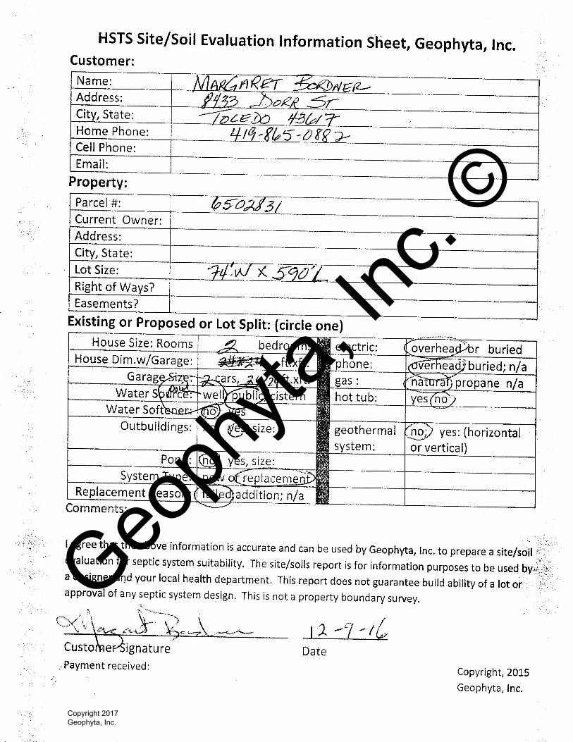
Home Septic System Site Evaluation And System Design For Margaret Bordner 8433 Dorr St. Toledo OH 43617 419-865-0882 Property Location: Same As Above Springfield Township, Lucas County Replacement System By Nathan Wright Geophyta, Inc. 2685 C.R. 254 Vickery, OH 43464 419-547-8538 January 31, 2017 Geophyta, Inc. © Copyright 2017 Geophyta, Inc.
-
Upload
khangminh22 -
Category
Documents
-
view
2 -
download
0
Transcript of Home Septic System Site Evaluation And System Design

Home Septic System
Site Evaluation
And
System Design
For
Margaret Bordner
8433 Dorr St.
Toledo OH 43617
419-865-0882
Property Location:
Same As Above
Springfield Township, Lucas County
Replacement System
By
Nathan Wright
Geophyta, Inc.
2685 C.R. 254
Vickery, OH 43464
419-547-8538
January 31, 2017
Geoph
yta, In
c. ©
Copyright 2017 Geophyta, Inc.

To The Homeowner:
A septic system is designed based on all the information you provide and Geophyta Inc
collects at the site. It must be accurate. This information includes local soil limits and
topography, plus existing and future locations of your home, number of bedrooms, out
buildings, driveways, drinking water wells, ponds, septic systems, and property lines.
Geophyta Inc. relies on this information to construct detailed design drawings that must
meet local health department regulations before installation.
Any design changes required by the local health department to meet existing
regulations are the responsibility of Geophyta Inc.
Any information changes made by you after the initial site inspection are your
responsibility and will result in additional charges to you above the original quote for
services. These charges may include additional site inspection work, system redesign,
and resubmitted drawings.
To The Installer:
The registered installer of this septic system design is responsible for preparing an “as-
built” record, as stated in the Ohio Administrative Code Chapter 3701-29-09, Par. F
(p.32) of the “Sewage Treatment System Rules,” Ohio Department of Health, January 1,
2015. Additionally, the installer is responsible for measuring and recording distal
pressure head and float switch settings as baseline measures for future operation and
maintenance of any pressure distribution system (3701-29-15, Appendix B, Par. V(p.93)
of above referenced rules.
If the installer requests “as-built” record creation from Geophyta Inc., additional charges
will be billed to the installer by Geophyta Inc. and must be arranged prior to installation.
Geophyta Inc. must assume that any registered installer has the knowledge, equipment,
ability, and experience to properly layout, install, and create as-built drawings for any
septic system design approved by a local board of health. This includes the ability to
read detailed design prints with an associated bill of materials. For this reason, any
Geophyta Inc project supervision prior to or during installation will be billed to the
installer.
Any product substitution made by the installer that is not specifically permitted in the
design prints may result in Health Dept. disapproval and will result in additional re-
design costs billed to the installer.
Geoph
yta, In
c. ©
Copyright 2017 Geophyta, Inc.
Geoph
yta, In
c. ©
Copyright 2017 Geophyta, Inc.
Disturbed soil; red
Area Equal To Soil A; purple
Approx. Parcel Lines; lt. blue
Point Well; To Be Decomissioned
10 ft. Decomissioned Well Setback
ATU & Dose TankW/UV & ReAeration
Gravelless Chamber Leach Trenches
Elevation BM1 = 10.00'On Top Of Point Well Cap
Relative Elevation Contours; 3 inch
8.95 gs
9.72 pipetp12in
gasline
gasline
DORR
9.43 gs
9.00 gs9.16 gs
9.25 gs
8.72 gs9.42 gs
9.21 gs
9.25 gs9.10 gs
9.23 gs
9.49 gs
9.37 gs
9.06 soilA
9.76 tnktp10in
9.38 gsPW10.00
fence
gasline
disturbedSoilSiteA
pointwell
.Geophyta Inc.
Copyright 2017
HSTS Layout - 8433 Dorr St.
0 80 16040 Feet
Geoph
yta, In
c. ©
Copyright 2017 Geophyta, Inc.
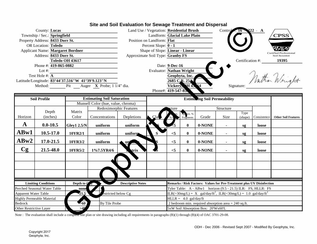
Site and Soil Evaluation for Sewage Treatment and DispersalControl #: - -
Pit Auger Probe; 1 1/4" dia.
Phone#:
Note : The evaluation shall include a complete site plan or site drawing including all requirements in paragraphs (B)(1) through (B)(4) of OAC 3701-29-08.
Vickery, OH 43464
Other Restrictive Layer >48 5xW Soil Absorption Box: 20'Wx60'L
Bedrock >60 By Tile Probe 2 bedroom min. required absorption area = 240 sq.ft.
Highly Permeable Material >48 HLLR = 4.0 gal/day/ft
Apparent Water Table 21.5 Restricted below Cg ILR(>30mg/L) = X gal/day/ft2, ILR(<30mg/L) = 1.0 gal/day/ft
2
Perched Seasonal Water Table none Tyler Table: A - ABw1 horizon (9.5 - 21.5) ILR: FS, HLLR: FS
Limiting Conditions Depth to (in.) Descriptive Notes Remarks / Risk Factors: Values for Pre-Treatment plus UV Disinfection
sg loosematrix S <5 0Cg 21.5-48.0 10YR5/2 1%7.5YR4/6
- sg 0 0-NONE
0-NONE -
looseABw2 17.0-21.5 10YR3/2 uniform uniform S <5
sg looseuniform S <5 0ABw1 10.5-17.0 10YR2/1 uniform
- sg 0 0-NONE
0-NONE -
loose
Type
(shape)
A 0.0-10.5 Gley1 2.5/N uniform uniform FS <5
Texture Structure
ConsistenceConcentrations Depletions Class Approx.
% Clay
Approx. %
Fragments Grade Size
Soil Profile Estimating Soil Saturation Estimating Soil Permeability
Other Soil Features
Munsell Color (hue, value, chroma)
Horizon
Depth
(inches)
Matrix
Color
Redoximorphic Features
Test Hole #: A Geophyta, Inc.
Method: X
Latitude/Longitude: 2685 C.R. 25483°44'37.516"W 41°39'9.123"N
Signature:
Phone #: 419-865-0882 Date: 9-Dec-16
Certification #:
Lot #: Evaluator: Nathan Wright
19395Toledo OH 43617
Address: 8433 Dorr St. Approximate Soil Type: Granby FS
Applicant Name: Margaret Bordner Shape of Slope: Linear - Linear
OR Location: Toledo Percent Slope: 0 - 1
Position on Landform: Flat
Township / Sec.: Springfield Landform: Glacial Lake Plain
16 222 A
419-547-8538
County: Lucas Land Use / Vegetation: Residential Brush
Property Address: 8433 Dorr St.
ODH - Dec 2006 - Revised Sept 2007 - Modified By Geophyta, Inc.
Geoph
yta, In
c. ©
Copyright 2017 Geophyta, Inc.
Subangular Blocky
Schoeneberger, P.J., Wysocki, D.A., Benham, E.C., and Broderson, W.D. (editors) 2002. Field book for describing and
sampling soils, version 2.0. Natural Resources Conservation Service, USDA, National Soil Survey Center, Lincoln, NE.
*Estimate approximate clay percentage within 5 percent Extremely Firm efi
For a more detailed explanation on describing and sampling soils, please refer to the "Field Book for Describing and Sampling Soils"
Very Firm vfi
Silty Clay sic
Clay c Extremely Flaggy XFL
Very Flaggy VFL
Very Friable vfr
Friable fr
Firm fi
Sandy Clay sc Flaggy FL
Silty Clay Loam sicl Extremely Channery XCN
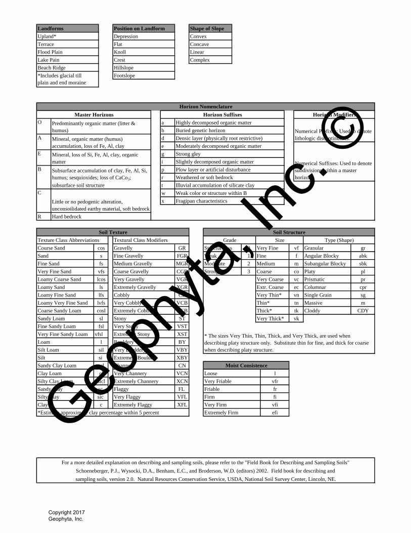
Moist Consistence
Clay Loam cl Very Channery VCN Loose l
Sandy Clay Loam scl Channery
Very Fine Sandy Loam
CN
Silt si Extremely Bouldery XBY
Silt Loam sil Very Bouldery VBY
l Bouldery BY
vfsl Extremely Stony XST * The sizes Very Thin, Thin, Thick, and Very Thick, are used when
describing platy structure only. Substitute thin for fine, and thick for coarse
when describing platy structure.
vk
Fine Sandy Loam fsl Very Stony VST
Sandy Loam sl Stony
Loam
ST
Thick* tk Cloddy CDYCoarse Sandy Loam cosl Extremely Cobbly XCB
Very Thick*
Thin* tn Massive mLoamy Very Fine Sand lvfs Very Cobbly VCB
Single Grain sgLoamy Fine Sand lfs Cobbly CB
Loamy Sand ls Extremely Gravelly XGR
Very Thin* vn
Prismatic pr
Extr. Coarse ec Columnar cpr
Loamy Coarse Sand lcos Very Gravelly VGR Very Coarse vc
Very Fine Sand vfs Coarse Gravelly CGR Platy pl
Medium m sbk
Strong 3 Coarse co
Fine f Angular Blocky abk
Fine Sand fs Medium Gravelly MGR Moderate 2
Very Fine vf Granular gr
Sand s Fine Gravelly FGR Weak 1
Course Sand cos Gravelly GR Structureless 0
Texture Class Abbreviations Textural Class Modifiers Grade Size
R Hard bedrock
Soil Texture Soil Structure
Type (Shape)
C
Little or no pedogenic alteration,
unconsoilidated earthy material, soft bedrock
w Weak color or structure within B
x Fragipan characteristics
B Subsurface accumulation of clay, Fe, Al, Si,
humus; sesquioxides; loss of CaCo3;
subsurface soil structure
p Plow layer or artificial disturbance
r Weathered or soft bedrock
t Illuvial accumulation of silicate clay
E Mineral, loss of Si, Fe, Al, clay, organic
matter
g Strong gley
i Slightly decomposed organic matter
Numerical Prefixes: Used to denote
lithologic discontinuities.
b Buried genetic horizon
A Mineral, organic matter (humus)
accumulation, loss of Fe, Al, clay
d Densic layer (physically root restrictive)
e Moderately decomposed organic matter
Numerical Suffixes: Used to denote
subdivisions within a master
horizon.
O Predominantly organic matter (litter &
humus)
a Highly decomposed organic matter
*Includes glacial till
plain and end moraine
Footslope
Horizon Nomenclature
Master Horizons Horizon Suffixes Horizon Modifiers
Lake Pain Crest Complex
Beach Ridge Hillslope
Terrace Flat Concave
Flood Plain Knoll Linear
Landforms Position on Landform Shape of Slope
Upland* Depression Convex
Geoph
yta, In
c. ©
Copyright 2017 Geophyta, Inc.
Geophyta, Inc.
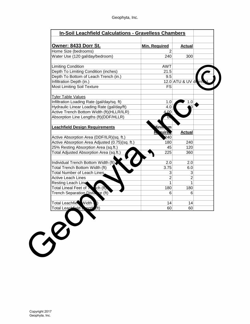
Owner: 8433 Dorr St. Min. Required Actual
Home Size (bedrooms) 2
Water Use (120 gal/day/bedroom) 240 300
Limiting Condition AWT
Depth To Limiting Condition (inches) 21.5
Depth To Bottom of Leach Trench (in.) 9.5
Infiltration Depth (in.) 12.0 ATU & UV disinfect.
Most Limiting Soil Texture FS
Tyler Table Values
Infiltration Loading Rate (gal/day/sq. ft) 1.0 1.0
Hydraulic Linear Loading Rate (gal/day/ft) 4.0 4.0
Active Trench Bottom Width (ft)(HLLR/ILR) 4.00
Absorption Line Lengths (ft)(DDF/HLLR) 60
Leachfield Design Requirements Minimum
Required Actual
Active Absorption Area (DDF/ILR)(sq. ft.) 240
Active Absorption Area Adjusted (0.75)(sq. ft.) 180 240
25% Resting Absorption Area (sq.ft.) 45 120
Total Adjusted Absorption Area (sq.ft.) 225 360
Individual Trench Bottom Width (ft) 2.0 2.0
Total Trench Bottom Width (ft) 3.75 6.0
Total Number of Leach Lines 3 3
Active Leach Lines 2 2
Resting Leach Lines 1 1
Total Lineal Feet of Trench (ft) 180 180
Trench Separation Distance (ft) 6 6
Total Leachfield Width (ft) 14 14
Total Leachfield Length (ft) 60 60
In-Soil Leachfield Calculations - Gravelless Chambers
Geoph
yta, In
c. ©
Copyright 2017 Geophyta, Inc.
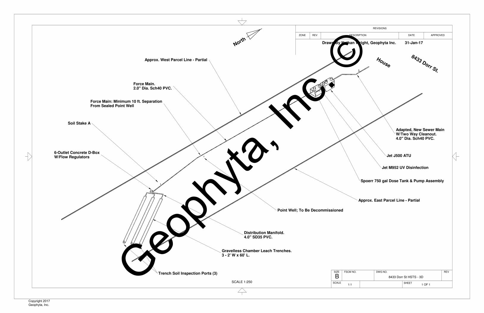
SCALE 1:250
Drawn By Nathan Wright, Geophyta Inc. 31-Jan-17North y
8433 Dorr St.
House
Adapted, New Sewer MainW/Two Way Cleanout.4.0" Dia. Sch40 PVC.
Jet J500 ATU
Jet M952 UV Disinfection
Spoerr 750 gal Dose Tank & Pump Assembly
Point Well; To Be Decommissioned
Approx. East Parcel Line - Partial
Approx. West Parcel Line - Partial
Soil Stake A
6-Outlet Concrete D-BoxW/Flow Regulators
Distribution Manifold.4.0" SD35 PVC.
Gravelless Chamber Leach Trenches.3 - 2' W x 60' L.
Trench Soil Inspection Ports (3)
Force Main.2.0" Dia. Sch40 PVC.
Force Main: Minimum 10 ft. SeparationFrom Sealed Point Well
ZONE
SCALE
REV
REVISIONS
8433 Dorr St HSTS - 3D
APPROVED
B
DESCRIPTION
DWG NO.
SHEET
FSCM NO.SIZE REV
DATE
1 OF 11:1
Geoph
yta, In
c. ©
Copyright 2017 Geophyta, Inc.
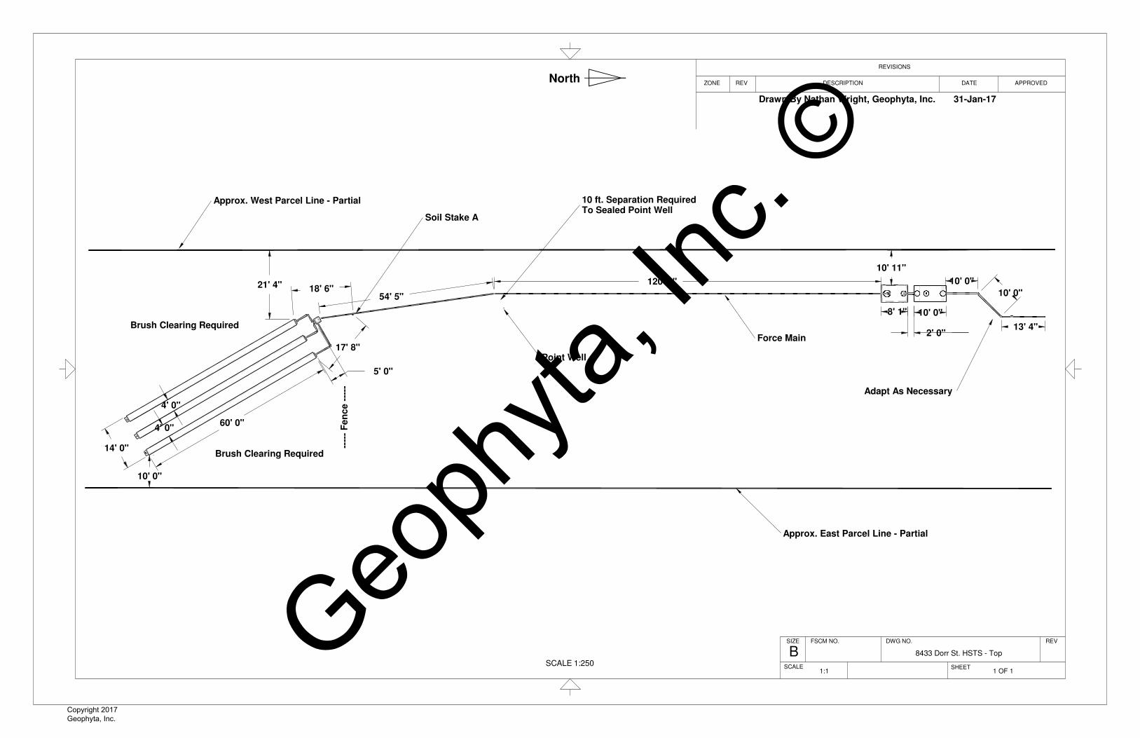
13' 4"
10' 0"
10' 0"
10' 0"8' 1"
2' 0"
10' 11"
120' 2"
54' 5"
17' 8"
18' 6"21' 4"
5' 0"
10' 0"
60' 0"
14' 0"
4' 0"
4' 0"
SCALE 1:250
Approx. West Parcel Line - Partial
Approx. East Parcel Line - Partial
Soil Stake A
Point Well
Brush Clearing Required
Brush Clearing Required
----
- F
en
ce
---
-- Adapt As Necessary
10 ft. Separation RequiredTo Sealed Point Well
Force Main
REV DATE
REVFSCM NO.
BSIZE DWG NO.
REVISIONS
ZONE DESCRIPTION
SCALE
8433 Dorr St. HSTS - Top
APPROVED
SHEET1 OF 11:1
Drawn By Nathan Wright, Geophyta, Inc. 31-Jan-17
North y
Geoph
yta, In
c. ©
Copyright 2017 Geophyta, Inc.
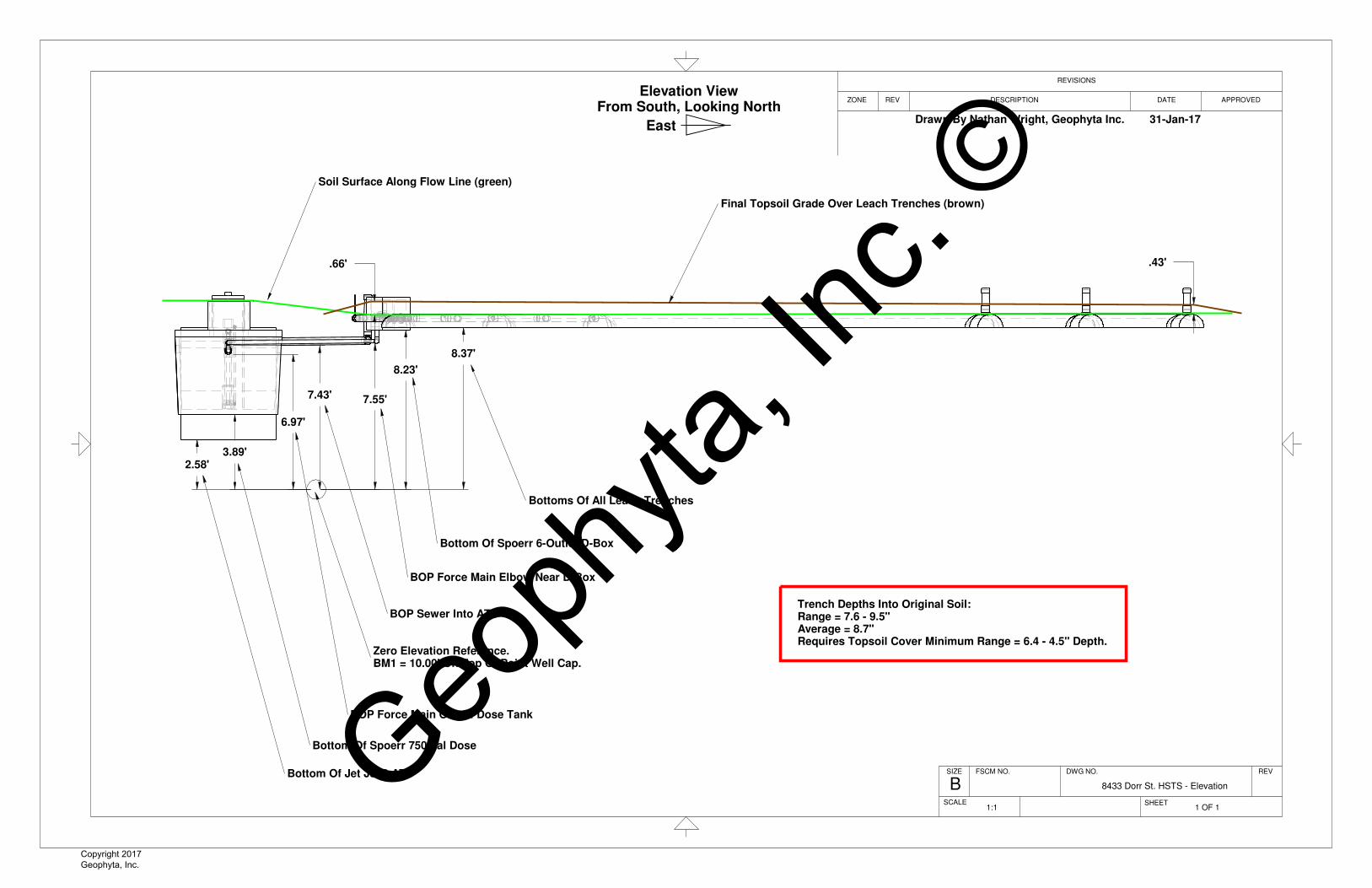
2.58'3.89'
7.43'
6.97'
7.55'
8.23'
8.37'
.66' .43'
Bottom Of Jet J500 ATU
Bottom Of Spoerr 750 gal Dose
BOP Sewer Into ATU
BOP Force Main Out Of Dose Tank
Zero Elevation Reference.BM1 = 10.00' On Top Of Point Well Cap.
BOP Force Main Elbow Near D-Box
Bottom Of Spoerr 6-Outlet D-Box
Bottoms Of All Leach Trenches
Trench Depths Into Original Soil:Range = 7.6 - 9.5"Average = 8.7"Requires Topsoil Cover Minimum Range = 6.4 - 4.5" Depth.
Soil Surface Along Flow Line (green)
Final Topsoil Grade Over Leach Trenches (brown)
REV
FSCM NO.
SCALE
APPROVED
8433 Dorr St. HSTS - Elevation
DWG NO.
DESCRIPTION
REV
REVISIONS
SIZE
SHEET
ZONE DATE
B
1 OF 11:1
Drawn By Nathan Wright, Geophyta Inc. 31-Jan-17
Elevation ViewFrom South, Looking North
East y
Geoph
yta, In
c. ©
Copyright 2017 Geophyta, Inc.
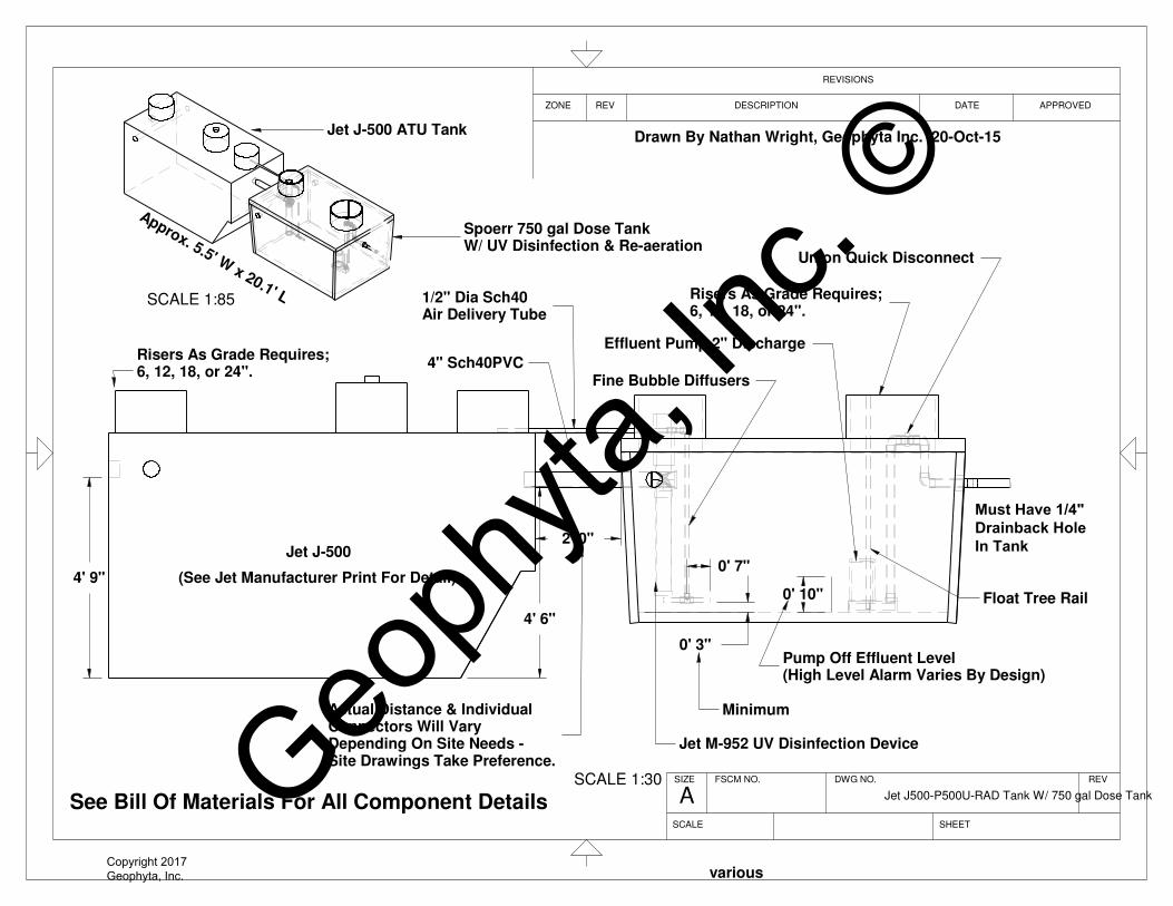
0' 3"
0' 7"
0' 10"
4' 6"
4' 9"
2' 0"
SCALE 1:30
4" Sch40PVC
Effluent Pump 2" Discharge
Minimum
various
Union Quick Disconnect
Risers As Grade Requires;6, 12, 18, or 24".
Float Tree Rail
See Bill Of Materials For All Component Details
(See Jet Manufacturer Print For Detail)
Jet J-500
Fine Bubble Diffusers
Pump Off Effluent Level(High Level Alarm Varies By Design)
Risers As Grade Requires;6, 12, 18, or 24".
Jet M-952 UV Disinfection Device
1/2" Dia Sch40Air Delivery Tube
Actual Distance & IndividualConnectors Will Vary Depending On Site Needs - Site Drawings Take Preference.
Approx. 5.5' W x 20.1' LSCALE 1:85
Jet J-500 ATU Tank
Spoerr 750 gal Dose TankW/ UV Disinfection & Re-aeration
Drawn By Nathan Wright, Geophyta Inc. 20-Oct-15
Jet J500-P500U-RAD Tank W/ 750 gal Dose Tank
REV
DESCRIPTION
DWG NO.FSCM NO.SIZE
DATEZONE
SHEET
REVISIONS
APPROVEDREV
SCALE
A
Must Have 1/4" Drainback HoleIn Tank
Geoph
yta, In
c. ©
Copyright 2017 Geophyta, Inc.
TITLE:
USED ON:
DRAWN BY: DATE
APPROVED BY: DATE:
MATERIAL:
SCALE:
DRAWING NUMBER:
REV:
SIZE:
N J K 12/16/14
TML 12/23/14
1 : 20C
J-500-P500U
-
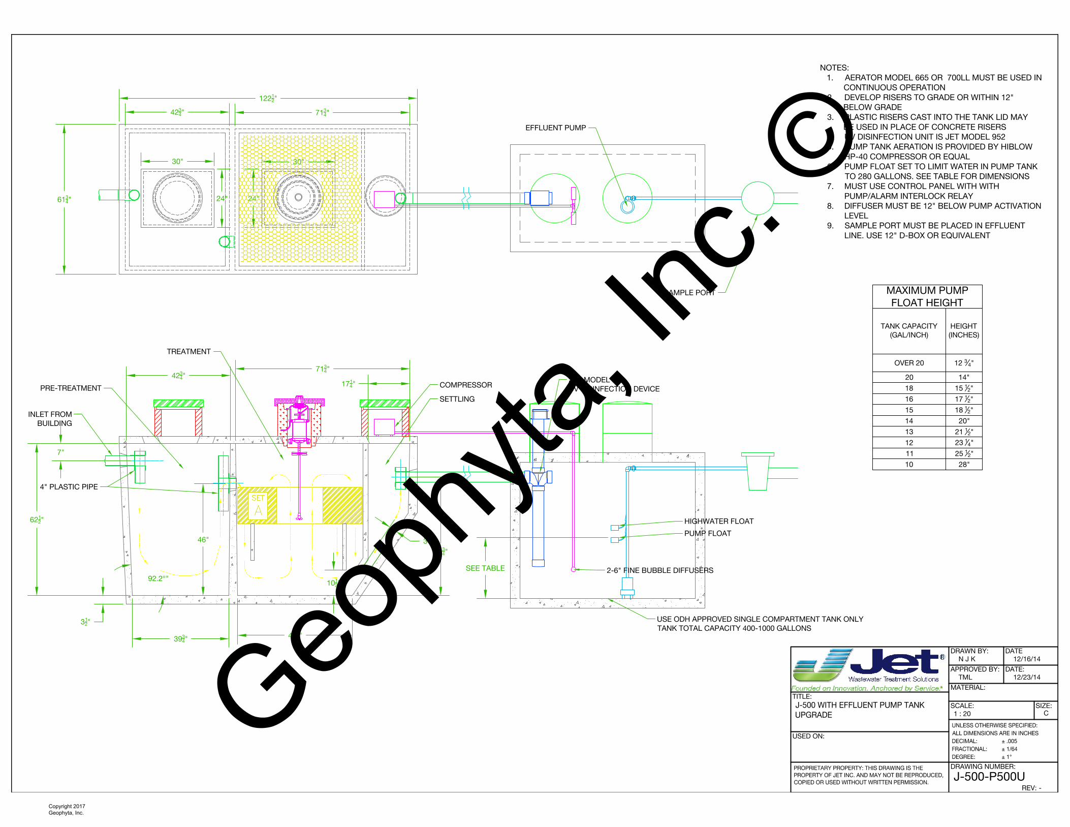
NOTES:
1. AERATOR MODEL 665 OR 700LL MUST BE USED IN
CONTINUOUS OPERATION
2. DEVELOP RISERS TO GRADE OR WITHIN 12"
BELOW GRADE
3. PLASTIC RISERS CAST INTO THE TANK LID MAY
BE USED IN PLACE OF CONCRETE RISERS
4. UV DISINFECTION UNIT IS JET MODEL 952
5. PUMP TANK AERATION IS PROVIDED BY HIBLOW
HP-40 COMPRESSOR OR EQUAL
6. PUMP FLOAT SET TO LIMIT WATER IN PUMP TANK
TO 280 GALLONS. SEE TABLE FOR DIMENSIONS
7. MUST USE CONTROL PANEL WITH WITH
PUMP/ALARM INTERLOCK RELAY
8. DIFFUSER MUST BE 12" BELOW PUMP ACTIVATION
LEVEL
9. SAMPLE PORT MUST BE PLACED IN EFFLUENT
LINE. USE 12" D-BOX OR EQUIVALENT
2-6" FINE BUBBLE DIFFUSERS
COMPRESSOR
HIGHWATER FLOAT
PUMP FLOAT
JET MODEL 952
UV DISINFECTION DEVICE
EFFLUENT PUMP
SEE TABLE
MAXIMUM PUMP
FLOAT HEIGHT
TANK CAPACITY
(GAL/INCH)
HEIGHT
(INCHES)
OVER 20 12
3
4
"
20 14"
18 15
1
2
"
16 17
1
2
"
15 18
1
2
"
14 20"
13 21
1
2
"
12 23
1
4
"
11 25
1
2
"
10 28"
39
3
4
"
42
3
4
"
71
3
4
"
47
1
4
"
62
1
2
"
92.2°"
7"
3"
122
1
2
"
3
1
2
"
10
1
2
"
30"
61
3
4
"
46"
17
1
4
"
30"
24"24"
42
3
4
"71
3
4
"
48
3
4
"
PRE-TREATMENT
INLET FROM
BUILDING
4" PLASTIC PIPE
TREATMENT
SETTLING
USE ODH APPROVED SINGLE COMPARTMENT TANK ONLY
TANK TOTAL CAPACITY 400-1000 GALLONS
SAMPLE PORT
Geoph
yta, In
c. ©
Copyright 2017 Geophyta, Inc.

www.jetincorp.com 1.800.3�1.6960 15
UV Disinfection Lamp
Specifically designed to disinfect the effluent from small aerobic treatment plants, the Ultraviolet Disinfection Unit can reduce fecal coliform bacteria levels to well below the most stringent U.S. treatment standards, even when the upstream treatment plant is operating in a mild upset condition. Designed to disinfect residential wastewater, UV disinfection units are safe and harmless. There are no adverse effects from overexposing the effluent to germicidal ultraviolet light because UV disinfection does not form by-products.
The disinfection chamber couples directly to the aerobic plant 4’’ discharge pipe and is permanently installed below grade. When fully inserted, the sub-assembly is properly positioned by pins mounted near the top of the disinfection chamber. This well-defined flow path gives the proper fluid exposure time.
The light source is mounted in the center of an anodized aluminum frame that divides the disinfection chamber in half. The frame seals against the inner surface of the disinfection chamber and prevents flow by-pass. To control the lamp’s surface temperature, the ultraviolet light is surrounded by a clear fused quartz tube. When the disinfection chamber is filled with water, the ultraviolet light can operate continuously, whether or not water is flowing. Continuous operation within a lamp surface temperature range of 105-1�0° F provides optimum ultraviolet light output and long lamp life.
The disinfection sub-assembly, which extends approximately one foot above grade, is watertight. This protects the electrical connections against a fluid backup that could cause the wastewater effluent level to rise to the maximum height of the upstream treatment plant.
The UV system operates on 1�0vAC and consumes less than �5 Watts. A green LED indicator on the junction box confirms the operating status of the UV system.
Maximum flow through the unit is rated at 3 gallons per minute (gpm), or 4,3�0 gallons per day (gpd), with the following effluent conditions:
Suspended Solids < 30 mg/liter - 5-day BOD < 30 mg/liter
Under the above conditions, fecal coliform reduction exceeds 3-logs, or 99.9%, at the end of the UV lamp life (one year of continuous operation).
Fecal coliform counts in the home aerobic treatment effluent typically range from 800 - �0,000 colony-forming units (CFU) per 100ml. CFUs measure viable fungal and bacterial cells.
Item Part Number UV Disinfection Lamp Assembly 95�0034 Replacement UV lamp 9990115 UV Control Panel Assembly 95�0038
Geoph
yta, In
c. ©
Copyright 2017 Geophyta, Inc.
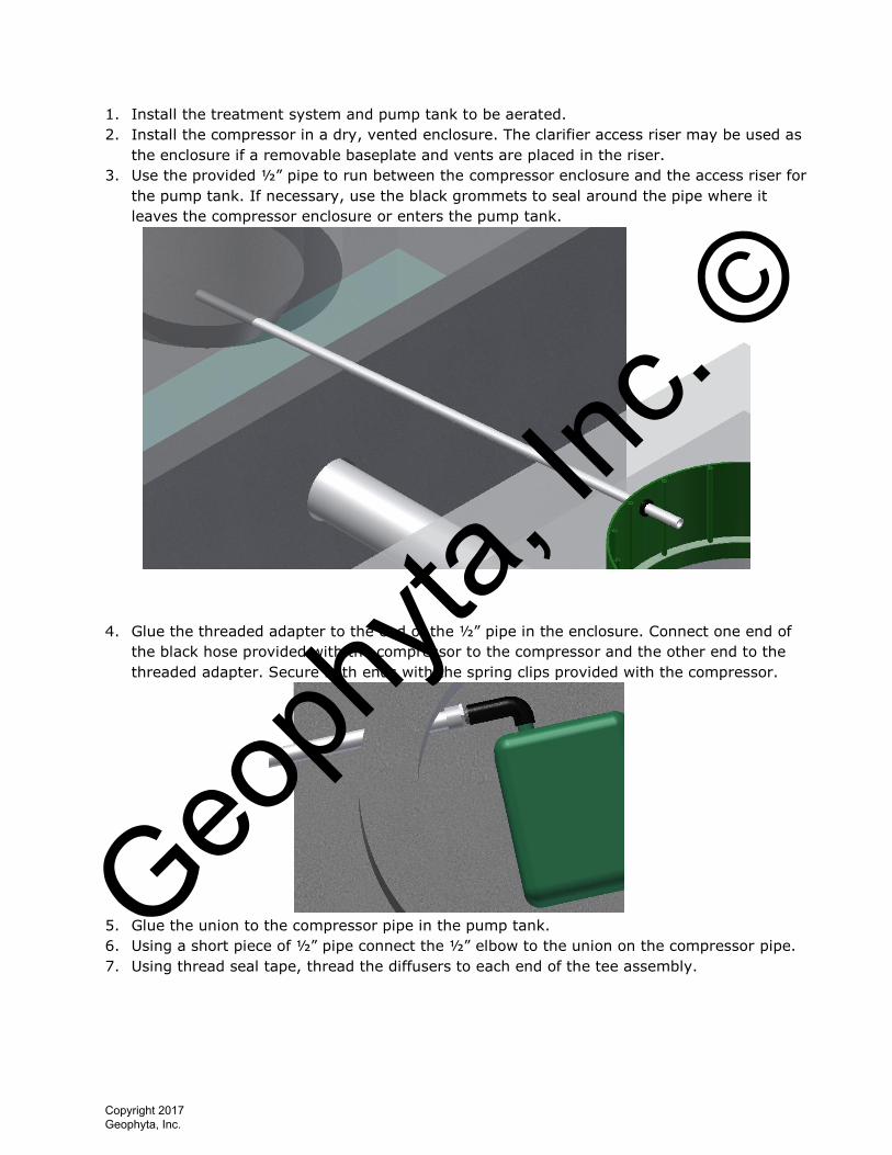
1. Install the treatment system and pump tank to be aerated.
2. Install the compressor in a dry, vented enclosure. The clarifier access riser may be used as
the enclosure if a removable baseplate and vents are placed in the riser.
3. Use the provided ½” pipe to run between the compressor enclosure and the access riser for
the pump tank. If necessary, use the black grommets to seal around the pipe where it
leaves the compressor enclosure or enters the pump tank.
4. Glue the threaded adapter to the end of the ½” pipe in the enclosure. Connect one end of
the black hose provided with the compressor to the compressor and the other end to the
threaded adapter. Secure both ends with the spring clips provided with the compressor.
5. Glue the union to the compressor pipe in the pump tank.
6. Using a short piece of ½” pipe connect the ½” elbow to the union on the compressor pipe.
7. Using thread seal tape, thread the diffusers to each end of the tee assembly.
Geoph
yta, In
c. ©
Copyright 2017 Geophyta, Inc.
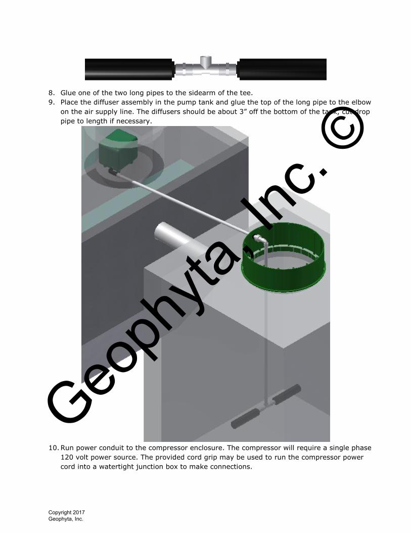
8. Glue one of the two long pipes to the sidearm of the tee.
9. Place the diffuser assembly in the pump tank and glue the top of the long pipe to the elbow
on the air supply line. The diffusers should be about 3” off the bottom of the tank, cut drop
pipe to length if necessary.
10. Run power conduit to the compressor enclosure. The compressor will require a single phase
120 volt power source. The provided cord grip may be used to run the compressor power
cord into a watertight junction box to make connections.
Geoph
yta, In
c. ©
Copyright 2017 Geophyta, Inc.

www.jetincorp.com 1.800.3�1.6960 11
Residential Control Panels - Model 197 Hybrid Control Panel
The Jet Incorporated model 197 control panel monitors and controls the operation of Jet system aerators and additional components. The panel can be configured to control single or dual aeration systems. A single aerator system controls the operation of one aerator. A dual aerator system can control two aerators, or one aerator and one re-aeration compressor.
In addition to the aerator control circuits, the control panel also contains the following circuits or features:
• Three auxiliary output circuits
• Three auxiliary input circuits with normally open or normally closed selection
• One power indicator LED, and four additional error indicator LED’s
• An alarm buzzer with an output for an additional external audible alarm
• A 9-position DIP switch for selection of configuration options
• User accessible reset switch and circuit board master reset switch
• Alarm mode Auto-Dialer power and control interface
• RS�3� interface circuit
• Circuit board mounted power switch and fuse
Control Panel Features
Master Reset ButtonInternal HornOn/Off SwitchExternal Reset ButtonPump Power Supply ContactsAlarm and Aerator Power Supply ContactsGround BussCentral Alarm BeaconDIP Switch ArrayAuxiliary Alarm Settings (NC/NO)Indicator Light ArrayAuxiliary Alarm ContactsAuxiliary Alarm Contacts
A.B.C.D.E.F.G.H.I.J.K.L.M.
Item Part NumberModel 197 Control Panel 197Auto Dialer Package for 197 197D
Geoph
yta, In
c. ©
Copyright 2017 Geophyta, Inc.
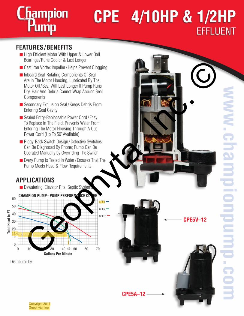
CPE 4/10HP & 1/2HPEffluEnt
ww
w.cham
pionpump.com
CPE5A–12
CPE5V–12
Distributed by:
FEAturEs / BEnEFits■ High Efficient Motor With Upper & Lower Ball
Bearings / Runs Cooler & Last Longer■ Cast Iron Vortex Impeller / Helps Prevent Clogging■ Inboard Seal-Rotating Components Of Seal
Are In The Motor Housing, Lubricated By TheMotor Oil / Seal Will Last Longer If Pump RunsDry, Hair And Debris Cannot Wrap Around SealComponents
■ Secondary Exclusion Seal / Keeps Debris FromEntering Seal Cavity
■ Sealed Entry-Replaceable Power Cord / EasyTo Replace In The Field, Prevents Water FromEntering The Motor Housing Through A CutPower Cord (Up To 50’ Available)
■ Piggy-Back Switch Design / Defective SwitchesCan Be Diagnosed By Phone; Pump Can BeOperated Manually by Overriding The Switch
■ Every Pump Is Tested In Water / Ensures That ThePump Meets Head & Flow Requirements
APPLiCAtiOns■ Dewatering, Elevator Pits, Septic Systems
CHAmPiOn PumP – PumP PErFOrmAnCE CurVE
30
40
50
0
10
20
tota
l Hea
d in
Ft
60
30 50400 2010Gallons Per minute
60 70
CPE4
CPE5
CPEf5
- - - - - - - - - - - - - - - - - - - - - - - - |
|
12.4
46Geoph
yta, In
c. ©
Copyright 2017 Geophyta, Inc.
Nathan
Highlight
Nathan
Highlight
Nathan
Highlight
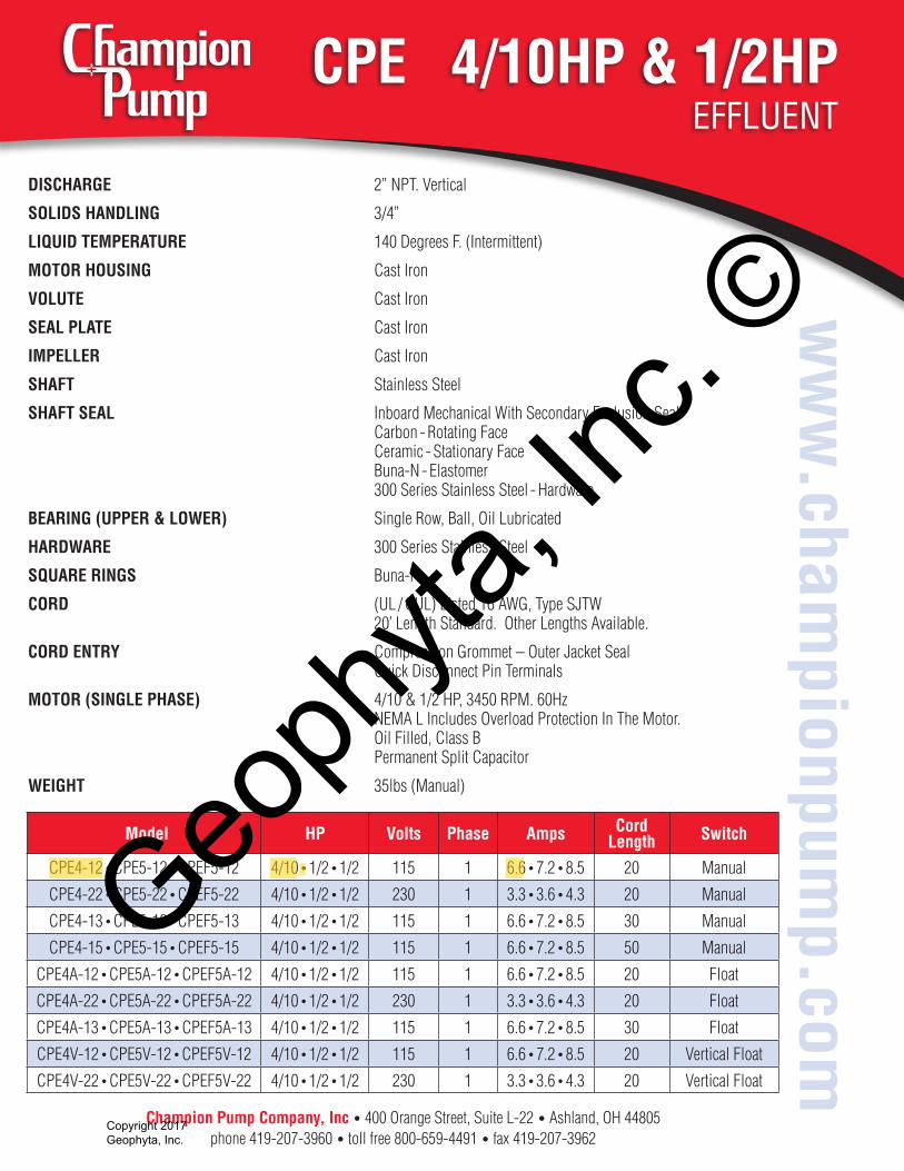
CPE 4/10HP & 1/2HPEffluEnt
ww
w.cham
pionpump.com
model HP Volts Phase Amps Cord Length switch
CPE4-12 • CPE5-12 • CPEF5-12 4/10 • 1/2 • 1/2 115 1 6.6 • 7.2 • 8.5 20 Manual
CPE4-22 • CPE5-22 • CPEF5-22 4/10 • 1/2 • 1/2 230 1 3.3 • 3.6 • 4.3 20 Manual
CPE4-13 • CPE5-13 • CPEF5-13 4/10 • 1/2 • 1/2 115 1 6.6 • 7.2 • 8.5 30 Manual
CPE4-15 • CPE5-15 • CPEF5-15 4/10 • 1/2 • 1/2 115 1 6.6 • 7.2 • 8.5 50 Manual
CPE4A-12 • CPE5A-12 • CPEF5A-12 4/10 • 1/2 • 1/2 115 1 6.6 • 7.2 • 8.5 20 Float
CPE4A-22 • CPE5A-22 • CPEF5A-22 4/10 • 1/2 • 1/2 230 1 3.3 • 3.6 • 4.3 20 Float
CPE4A-13 • CPE5A-13 • CPEF5A-13 4/10 • 1/2 • 1/2 115 1 6.6 • 7.2 • 8.5 30 Float
CPE4V-12 • CPE5V-12 • CPEF5V-12 4/10 • 1/2 • 1/2 115 1 6.6 • 7.2 • 8.5 20 Vertical Float
CPE4V-22 • CPE5V-22 • CPEF5V-22 4/10 • 1/2 • 1/2 230 1 3.3 • 3.6 • 4.3 20 Vertical Float
Champion Pump Company, inc • 400 Orange Street, Suite L-22 • Ashland, OH 44805phone 419-207-3960 • toll free 800-659-4491 • fax 419-207-3962
DisCHArGE 2” NPT. Vertical
sOLiDs HAnDLinG 3/4”
LiQuiD tEmPErAturE 140 Degrees F. (Intermittent)
mOtOr HOusinG Cast Iron
VOLutE Cast Iron
sEAL PLAtE Cast Iron
imPELLEr Cast Iron
sHAFt Stainless Steel
sHAFt sEAL Inboard Mechanical With Secondary Exclusion SealCarbon - Rotating FaceCeramic - Stationary FaceBuna-N - Elastomer300 Series Stainless Steel - Hardware
BEArinG (uPPEr & LOWEr) Single Row, Ball, Oil Lubricated
HArDWArE 300 Series Stainless Steel
sQuArE rinGs Buna-N
COrD (UL / CUL) Listed 16 AWG, Type SJTW 20’ Length Standard. Other Lengths Available.
COrD EntrY Compression Grommet – Outer Jacket SealQuick Disconnect Pin Terminals
mOtOr (sinGLE PHAsE) 4/10 & 1/2 HP, 3450 RPM. 60HzNEMA L Includes Overload Protection In The Motor.Oil Filled, Class BPermanent Split Capacitor
WEiGHt 35lbs (Manual)
Geoph
yta, In
c. ©
Copyright 2017 Geophyta, Inc.
Nathan
Highlight
Nathan
Highlight
Nathan
Highlight
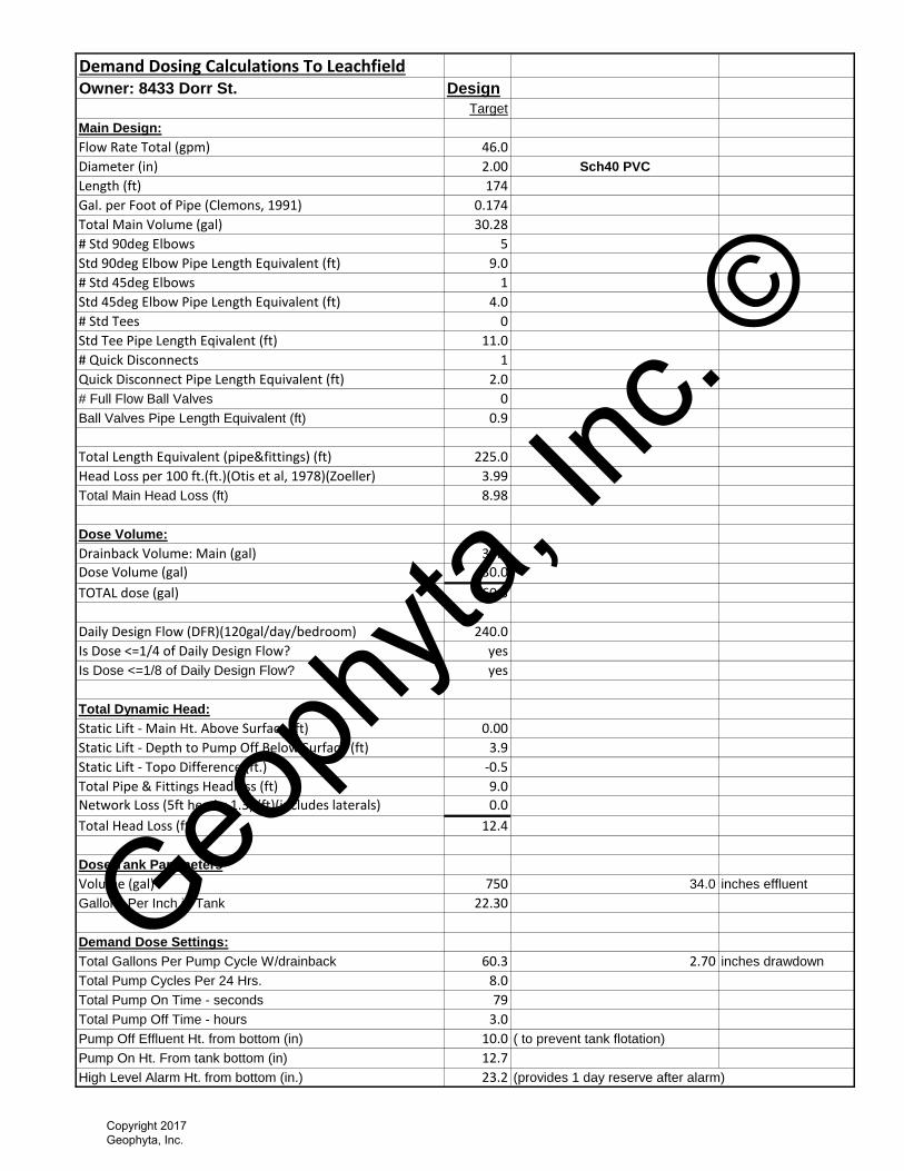
Demand Dosing Calculations To LeachfieldOwner: 8433 Dorr St. Design
Target
Main Design:
Flow Rate Total (gpm) 46.0
Diameter (in) 2.00 Sch40 PVC
Length (ft) 174
Gal. per Foot of Pipe (Clemons, 1991) 0.174
Total Main Volume (gal) 30.28
# Std 90deg Elbows 5
Std 90deg Elbow Pipe Length Equivalent (ft) 9.0
# Std 45deg Elbows 1
Std 45deg Elbow Pipe Length Equivalent (ft) 4.0
# Std Tees 0
Std Tee Pipe Length Eqivalent (ft) 11.0
# Quick Disconnects 1
Quick Disconnect Pipe Length Equivalent (ft) 2.0
# Full Flow Ball Valves 0
Ball Valves Pipe Length Equivalent (ft) 0.9
Total Length Equivalent (pipe&fittings) (ft) 225.0
Head Loss per 100 ft.(ft.)(Otis et al, 1978)(Zoeller) 3.99
Total Main Head Loss (ft) 8.98
Dose Volume:
Drainback Volume: Main (gal) 30.3
Dose Volume (gal) 30.0
TOTAL dose (gal) 60.3
Daily Design Flow (DFR)(120gal/day/bedroom) 240.0
Is Dose <=1/4 of Daily Design Flow? yes
Is Dose <=1/8 of Daily Design Flow? yes
Total Dynamic Head:
Static Lift - Main Ht. Above Surface (ft) 0.00
Static Lift - Depth to Pump Off Below Surface (ft) 3.9
Static Lift - Topo Difference (ft.) -0.5
Total Pipe & Fittings Headloss (ft) 9.0
Network Loss (5ft head x 1.3) (ft)(includes laterals) 0.0
Total Head Loss (ft) 12.4
Dose Tank Parameters
Volume (gal) 750 34.0 inches effluent
Gallons Per Inch in Tank 22.30
Demand Dose Settings:
Total Gallons Per Pump Cycle W/drainback 60.3 2.70 inches drawdown
Total Pump Cycles Per 24 Hrs. 8.0
Total Pump On Time - seconds 79
Total Pump Off Time - hours 3.0
Pump Off Effluent Ht. from bottom (in) 10.0 ( to prevent tank flotation)
Pump On Ht. From tank bottom (in) 12.7
High Level Alarm Ht. from bottom (in.) 23.2 (provides 1 day reserve after alarm)
Geoph
yta, In
c. ©
Copyright 2017 Geophyta, Inc.
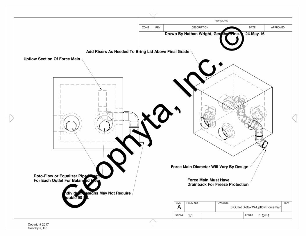
Add Risers As Needed To Bring Lid Above Final Grade
Force Main Diameter Will Vary By Design
Force Main Must HaveDrainback For Freeze Protection
Upflow Section Of Force Main
Roto-Flow or Equalizer Pipe InsertsFor Each Outlet For Balanced Flow
Individual Designs May Not RequireDouble 90 Ell.
DWG NO.FSCM NO.
ZONE
SHEET
DATE APPROVED
SCALE
REV
REVISIONS
DESCRIPTION
6 Outlet D-Box W/Upflow Forcemain
SIZE REV
A
1:1 1 OF 1
Drawn By Nathan Wright, Geophyta Inc. 24-May-16
Geoph
yta, In
c. ©
Copyright 2017 Geophyta, Inc.

Equalizer
The Equalizer’s patented weir opening maintainsequal flow, even in unlevel D-Boxes thatcontinue to move their entire lives.Equalizer Features:� Maintains equal flow from distribution box.� Automatically compensates for box movement.� Engineered plastic is non-corrosive. ��Extends septic system life.� Inserts without tools.� Resets equal flow when D-Box has moved.
1-877-765-956542
Roto-Flow
Roto-Flow enables equal distribution to yourleaching fields. Available in 3” and 4” sizes.
The Roto-Flow is the low cost solution to yourD-Box flow regulating problems. The simpleRoto-Flow for D-Box outlet pipes gives youthe easiest “set & forget” flow regulatoravailable.
The Roto-Flow fits Schedule 40, SDR 35 andthin wall pipe sizes. Both 3 inch and 4 inch sizesare available. Simply place the Roto-Flow intothe D-Box outlet pipe then adjust to equalizeflow.
The Roto-Flow is made from HDPE; it isdesigned to stand up in the septic environmentwithout failing. Our Roto-Flow design ensuresa good fit in all pipe sizes.
The Roto-Flow is made to fit pipes withoutcollapsing or creating a loose fit. This willguarantee equal flow performance.
www.polylok.comTechnical Specifications: Page 119 - 120
Roto-Flow & Equalizer
4” 3”
izer
Simple to install, just pushinto any 4”pipe, SCHD 40,SDR 35, or thin wall.
Adjustment knob movesopening up or down in 1/16”increments; total is 7/8”.
Water tight fit.
Tough engineered plasticwill not corrode and installswithout tools.
�
�
���
�
��
Custom Distribution Boxes with Equalizers installed
PATENTS: U.S.A. - 5,680,989 - 5,154,353 - 5,107,892Geoph
yta, In
c. ©
Copyright 2017 Geophyta, Inc.
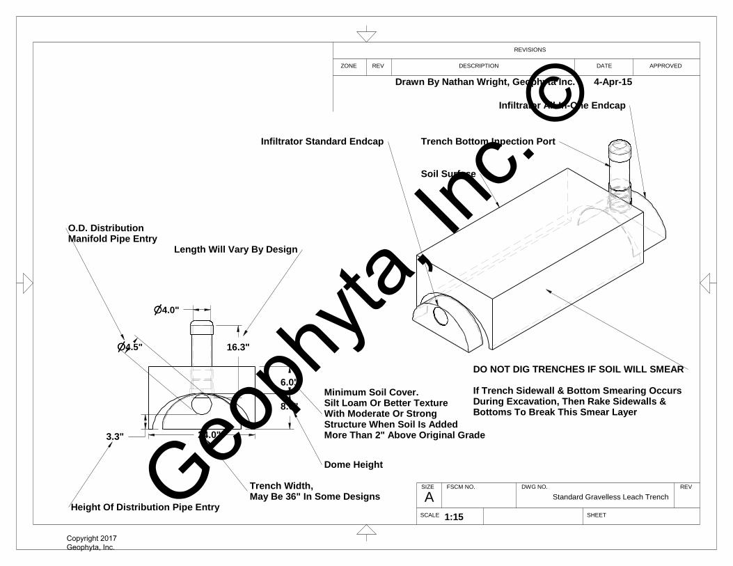
8.0"
6.0"
24.0"3.3"
nnnn4.5"
nnnn4.0"
16.3"
O.D. DistributionManifold Pipe Entry
Trench Width,May Be 36" In Some Designs
Dome Height
Minimum Soil Cover.Silt Loam Or Better TextureWith Moderate Or StrongStructure When Soil Is AddedMore Than 2" Above Original Grade
Height Of Distribution Pipe Entry
Length Will Vary By Design
Trench Bottom Inpection Port
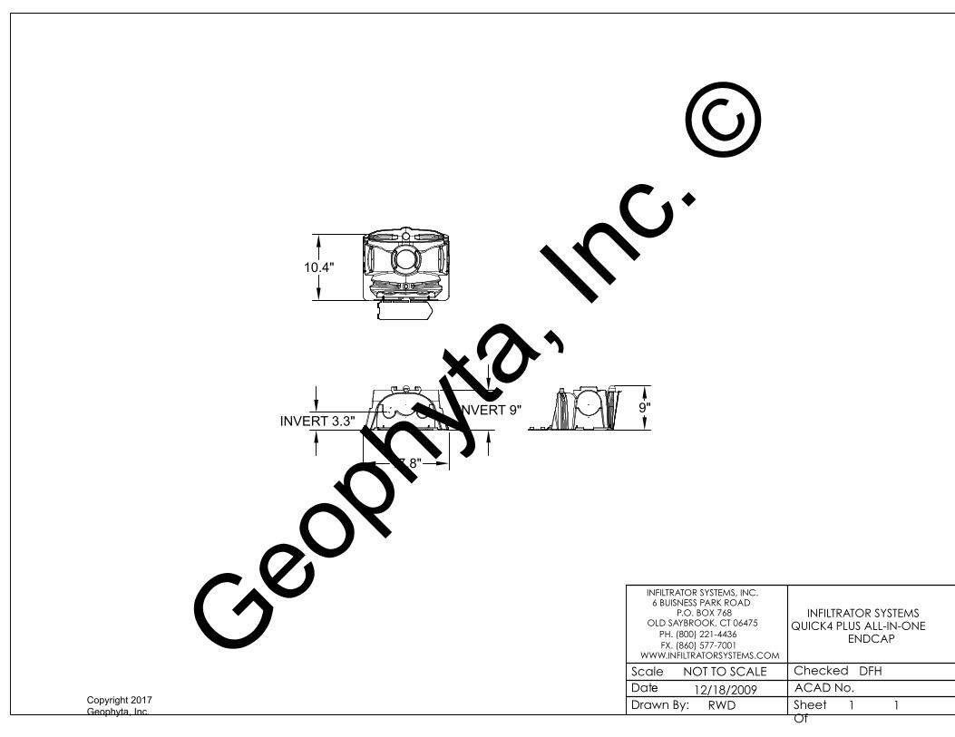
Infiltrator All-In-One Endcap
Infiltrator Standard Endcap
Soil Surface
DATE
REVISIONS
DWG NO.
SHEET
Standard Gravelless Leach Trench
ZONE
ASCALE
REV
REV
FSCM NO.SIZE
DESCRIPTION APPROVED
Drawn By Nathan Wright, Geophyta Inc. 4-Apr-15
DO NOT DIG TRENCHES IF SOIL WILL SMEAR
If Trench Sidewall & Bottom Smearing OccursDuring Excavation, Then Rake Sidewalls &Bottoms To Break This Smear Layer
1:15
Geoph
yta, In
c. ©
Copyright 2017 Geophyta, Inc.
1ACAD No.Checked
DateDrawn By:
Scale NOT TO SCALE
12/18/2009RWD
INFILTRATOR SYSTEMS, INC. 6 BUISNESS PARK ROAD
P.O. BOX 768OLD SAYBROOK, CT 06475
PH. (800) 221-4436FX. (860) 577-7001
WWW.INFILTRATORSYSTEMS.COM
Sheet Of
DFH
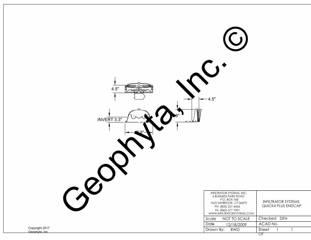
INFILTRATOR SYSTEMS QUICK4 PLUS ENDCAP
1
17.8"
4.5"
INVERT 3.3"
4.5"
8"
Geoph
yta, In
c. ©
Copyright 2017 Geophyta, Inc.
1ACAD No.Checked
DateDrawn By:
Scale NOT TO SCALE
12/18/2009RWD
INFILTRATOR SYSTEMS, INC. 6 BUISNESS PARK ROAD
P.O. BOX 768OLD SAYBROOK, CT 06475
PH. (800) 221-4436FX. (860) 577-7001
WWW.INFILTRATORSYSTEMS.COM
Sheet Of
DFH
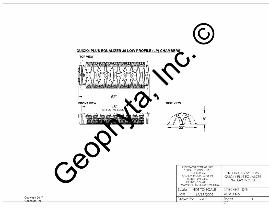
INFILTRATOR SYSTEMS QUICK4 PLUS EQUALIZER
36 LOW PROFILE
1
QUICK4 PLUS EQUALIZER 36 LOW PROFILE (LP) CHAMBERSTOP VIEW
SIDE VIEWFRONT VIEW
22"
8"
48"(EFFECTIVE LENGTH)
52"
Geoph
yta, In
c. ©
Copyright 2017 Geophyta, Inc.
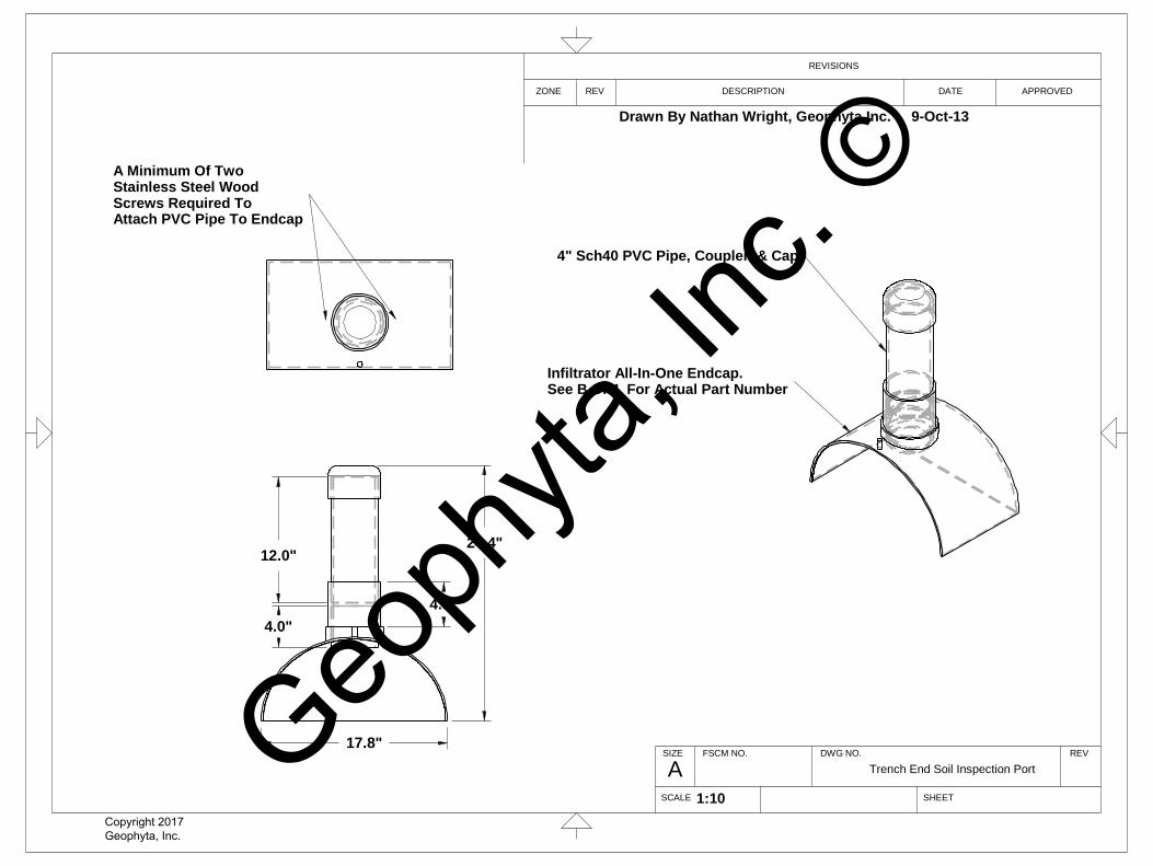
4.0"
12.0"
4.3"
24.4"
17.8"
A Minimum Of TwoStainless Steel WoodScrews Required ToAttach PVC Pipe To Endcap
4" Sch40 PVC Pipe, Coupler, & Cap
Infiltrator All-In-One Endcap.See B.O.M. For Actual Part Number
A
REVISIONS
ZONE DESCRIPTION
SCALE
DATE APPROVED
DWG NO.
SHEET
FSCM NO.SIZE
REV
REV
Trench End Soil Inspection Port
1:10
Drawn By Nathan Wright, Geophyta Inc. 9-Oct-13
Geoph
yta, In
c. ©
Copyright 2017 Geophyta, Inc.
1ACAD No.Checked
DateDrawn By:
Scale NOT TO SCALE
12/18/2009RWD
INFILTRATOR SYSTEMS, INC. 6 BUISNESS PARK ROAD
P.O. BOX 768OLD SAYBROOK, CT 06475
PH. (800) 221-4436FX. (860) 577-7001
WWW.INFILTRATORSYSTEMS.COM
Sheet Of
DFH
INFILTRATOR SYSTEMS QUICK4 PLUS ALL-IN-ONE
ENDCAP
1
17.8"
INVERT 3.3"
10.4"
9"INVERT 9"
Geoph
yta, In
c. ©
Copyright 2017 Geophyta, Inc.
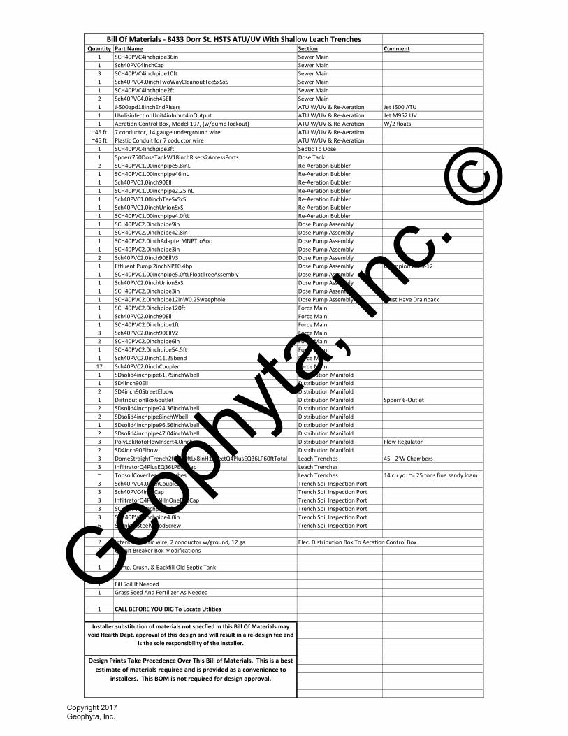
Quantity Part Name Section Comment
1 SCH40PVC4inchpipe36in Sewer Main
1 Sch40PVC4inchCap Sewer Main
3 SCH40PVC4inchpipe10ft Sewer Main
1 Sch40PVC4.0inchTwoWayCleanoutTeeSxSxS Sewer Main
1 SCH40PVC4inchpipe2ft Sewer Main
2 Sch40PVC4.0inch45Ell Sewer Main
1 J-500gpd18InchEndRisers ATU W/UV & Re-Aeration Jet J500 ATU
1 UVdisinfectionUnit4inInput4inOutput ATU W/UV & Re-Aeration Jet M952 UV
1 Aeration Control Box, Model 197, (w/pump lockout) ATU W/UV & Re-Aeration W/2 floats
~45 ft 7 conductor, 14 gauge underground wire ATU W/UV & Re-Aeration
~45 ft Plastic Conduit for 7 coductor wire ATU W/UV & Re-Aeration
1 SCH40PVC4inchpipe3ft Septic To Dose
1 Spoerr750DoseTankW18inchRisers2AccessPorts Dose Tank
2 SCH40PVC1.00inchpipe5.8inL Re-Aeration Bubbler
1 SCH40PVC1.00inchpipe46inL Re-Aeration Bubbler
1 Sch40PVC1.0inch90Ell Re-Aeration Bubbler
1 SCH40PVC1.00inchpipe2.25inL Re-Aeration Bubbler
1 Sch40PVC1.00inchTeeSxSxS Re-Aeration Bubbler
1 Sch40PVC1.0inchUnionSxS Re-Aeration Bubbler
1 SCH40PVC1.00inchpipe4.0ftL Re-Aeration Bubbler
1 SCH40PVC2.0inchpipe9in Dose Pump Assembly
1 SCH40PVC2.0inchpipe42.8in Dose Pump Assembly
1 SCH40PVC2.0inchAdapterMNPTtoSoc Dose Pump Assembly
1 SCH40PVC2.0inchpipe3in Dose Pump Assembly
2 Sch40PVC2.0inch90EllV3 Dose Pump Assembly
1 Effluent Pump 2inchNPT0.4hp Dose Pump Assembly Champion CPE4-12
1 SCH40PVC1.00inchpipe5.0ftLFloatTreeAssembly Dose Pump Assembly
1 Sch40PVC2.0inchUnionSxS Dose Pump Assembly
1 SCH40PVC2.0inchpipe3in Dose Pump Assembly
1 SCH40PVC2.0inchpipe12inW0.25weephole Dose Pump Assembly Must Have Drainback
1 SCH40PVC2.0inchpipe120ft Force Main
1 Sch40PVC2.0inch90Ell Force Main
1 SCH40PVC2.0inchpipe1ft Force Main
3 Sch40PVC2.0inch90EllV2 Force Main
2 SCH40PVC2.0inchpipe6in Force Main
1 SCH40PVC2.0inchpipe54.5ft Force Main
1 Sch40PVC2.0inch11.25bend Force Main
17 Sch40PVC2.0inchCoupler Force Main
1 SDsolid4inchpipe61.75inchWbell Distribution Manifold
1 SD4inch90Ell Distribution Manifold
2 SD4inch90StreetElbow Distribution Manifold
1 DistributionBox6outlet Distribution Manifold Spoerr 6-Outlet
2 SDsolid4inchpipe24.36inchWbell Distribution Manifold
2 SDsolid4inchpipe8inchWbell Distribution Manifold
1 SDsolid4inchpipe96.56inchWbell Distribution Manifold
2 SDsolid4inchpipe47.04inchWbell Distribution Manifold
3 PolyLokRotoFlowInsert4.0inch Distribution Manifold Flow Regulator
2 SD4inch90Elbow Distribution Manifold
3 DomeStraightTrench2ftWx4ftLx8inH15SectQ4PlusEQ36LP60ftTotal Leach Trenches 45 - 2'W Chambers
3 InfiltratorQ4PlusEQ36LPEndCap Leach Trenches
~ TopsoilCoverLeachTrenches Leach Trenches 14 cu.yd. ~= 25 tons fine sandy loam
3 Sch40PVC4.0inchCoupler Trench Soil Inspection Port
3 Sch40PVC4inchCap Trench Soil Inspection Port
3 InfiltratorQ4PlusAllInOneEndCap Trench Soil Inspection Port
3 SCH40PVC4inchpipe1ft Trench Soil Inspection Port
3 SCH40PVC4inchpipe4.0in Trench Soil Inspection Port
6 StainlessSteelWoodScrew Trench Soil Inspection Port
? Interior electric wire, 2 conductor w/ground, 12 ga Elec. Distribution Box To Aeration Control Box
? Circuit Breaker Box Modifications
1 Pump, Crush, & Backfill Old Septic Tank
1 Fill Soil If Needed
1 Grass Seed And Fertilizer As Needed
1 CALL BEFORE YOU DIG To Locate Utlities
Installer substitution of materials not specfied in this Bill Of Materials may
void Health Dept. approval of this design and will result in a re-design fee and
is the sole responsibility of the installer.
Design Prints Take Precedence Over This Bill of Materials. This is a best
estimate of materials required and is provided as a convenience to
installers. This BOM is not required for design approval.
Bill Of Materials - 8433 Dorr St. HSTS ATU/UV With Shallow Leach Trenches
Geoph
yta, In
c. ©
Copyright 2017 Geophyta, Inc.
Copyright, 2011 Geophyta, Inc. Page 1 of 4
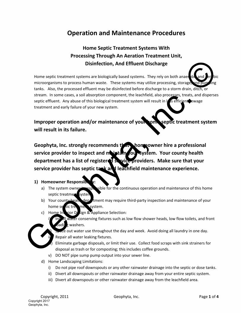
Operation and Maintenance Procedures
Home Septic Treatment Systems With
Processing Through An Aeration Treatment Unit,
Disinfection, And Effluent Discharge
Home septic treatment systems are biologically based systems. They rely on both anaerobic and aerobic
microorganisms to process human waste. These systems may utilize processing, storage, and pumping
tanks. Also, the processed effluent may be disinfected before discharge to a storm drain, ditch, or
stream. In some cases, a soil absorption component, the leachfield, also processes, treats, and disperses
septic effluent. Any abuse of this biological treatment system will result in less efficient sewage
treatment and early failure of your new system.
Improper operation and/or maintenance of your home septic treatment system
will result in its failure.
Geophyta, Inc. strongly recommends that a homeowner hire a professional
service provider to inspect and maintain your system. Your county health
department has a list of registered service providers. Make sure that your
service provider has septic tank and leachfield maintenance experience.
1) Homeowner Responsibility:
a) The system owner is responsible for the continuous operation and maintenance of this home
septic treatment system
b) Your county health department may require third-party inspection and maintenance of your
home septic treatment system.
c) Home Interior Design & Appliance Selection:
i) Install water conserving fixtures such as low flow shower heads, low flow toilets, and front
loading washers.
ii) Space out water use throughout the day and week. Avoid doing all laundry in one day.
iii) Repair all water leaking fixtures.
iv) Eliminate garbage disposals, or limit their use. Collect food scraps with sink strainers for
disposal as trash or for composting; this includes coffee grounds.
v) DO NOT pipe sump pump output into your sewer line.
d) Home Landscaping Limitations:
i) Do not pipe roof downspouts or any other rainwater drainage into the septic or dose tanks.
ii) Divert all downspouts or other rainwater drainage away from your entire septic system.
iii) Divert all downspouts or other rainwater drainage away from the leachfield area.
Geoph
yta, In
c. ©
Copyright 2017 Geophyta, Inc.
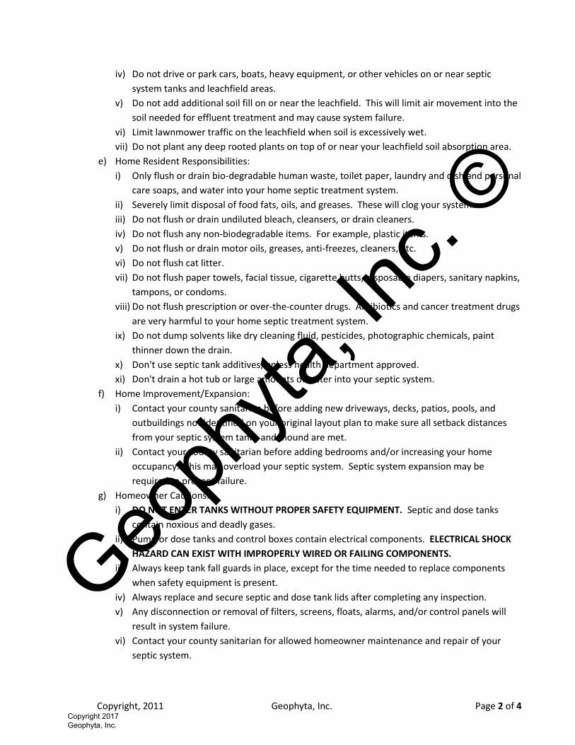
Copyright, 2011 Geophyta, Inc. Page 2 of 4
iv) Do not drive or park cars, boats, heavy equipment, or other vehicles on or near septic
system tanks and leachfield areas.
v) Do not add additional soil fill on or near the leachfield. This will limit air movement into the
soil needed for effluent treatment and may cause system failure.
vi) Limit lawnmower traffic on the leachfield when soil is excessively wet.
vii) Do not plant any deep rooted plants on top of or near your leachfield soil absorption area.
e) Home Resident Responsibilities:
i) Only flush or drain bio-degradable human waste, toilet paper, laundry and dish and personal
care soaps, and water into your home septic treatment system.
ii) Severely limit disposal of food fats, oils, and greases. These will clog your system.
iii) Do not flush or drain undiluted bleach, cleansers, or drain cleaners.
iv) Do not flush any non-biodegradable items. For example, plastic items.
v) Do not flush or drain motor oils, greases, anti-freezes, cleaners, etc.
vi) Do not flush cat litter.
vii) Do not flush paper towels, facial tissue, cigarette butts, disposable diapers, sanitary napkins,
tampons, or condoms.
viii) Do not flush prescription or over-the-counter drugs. Antibiotics and cancer treatment drugs
are very harmful to your home septic treatment system.
ix) Do not dump solvents like dry cleaning fluid, pesticides, photographic chemicals, paint
thinner down the drain.
x) Don't use septic tank additives, unless health department approved.
xi) Don't drain a hot tub or large amounts of water into your septic system.
f) Home Improvement/Expansion:
i) Contact your county sanitarian before adding new driveways, decks, patios, pools, and
outbuildings not identified on your original layout plan to make sure all setback distances
from your septic system tanks and mound are met.
ii) Contact your county sanitarian before adding bedrooms and/or increasing your home
occupancy. This may overload your septic system. Septic system expansion may be
required to prevent failure.
g) Homeowner Cautions:
i) DO NOT ENTER TANKS WITHOUT PROPER SAFETY EQUIPMENT. Septic and dose tanks
contain noxious and deadly gases.
ii) Pump or dose tanks and control boxes contain electrical components. ELECTRICAL SHOCK
HAZARD CAN EXIST WITH IMPROPERLY WIRED OR FAILING COMPONENTS.
iii) Always keep tank fall guards in place, except for the time needed to replace components
when safety equipment is present.
iv) Always replace and secure septic and dose tank lids after completing any inspection.
v) Any disconnection or removal of filters, screens, floats, alarms, and/or control panels will
result in system failure.
vi) Contact your county sanitarian for allowed homeowner maintenance and repair of your
septic system.
Geoph
yta, In
c. ©
Copyright 2017 Geophyta, Inc.
Copyright, 2011 Geophyta, Inc. Page 3 of 4
2) Inspection & Maintenance Requirements:
a) Perform inspection & maintenance every six months.
b) Review Baseline Operation and Maintenance Data:
i) The installer of your system set and recorded all float/liquid level heights, pump down
times, cycles per day, and distal head pressures required in the design specifications.
ii) Review all previous six month inspection data.
c) Identify any house additions, patios, pools, ponds, driveways, outbuildings, etc. added since the
last inspection that may impact the home septic treatment system. Draw a sketch of these
differences.
d) Inspect the house sewer main two-way cleanout tee bottom:
i) Check for clogging.
ii) Check for continuous clear water flows from the home.
e) Evaluate Aeration Treatment Tank & Pump Tank:
i) Measure sludge and scum depths; pump tank when cumulative thickness is 1/3 of the tank
depth.
ii) Look for signs of clogging and tank damage.
iii) Look for signs of tank and riser leakage.
iv) Clean & inspect any tank outlet filter.
v) Make sure lids are securely attached to risers.
f) Evaluate Pump/Dose Tank & Pumping Equipment:
i) Measure sludge and scum depths; pump tank when septic tank is pumped.
ii) Look for signs of clogging and tank damage.
iii) Look for signs of tank and riser leakage.
iv) Inspect and assure proper functioning of floats or other liquid level controls.
v) Clean and inspect dose pump outlet filter. May not be present in some designs.
vi) Inspect and assure proper condition and functioning of the effluent pump.
vii) Make sure lids are securely attached to risers.
g) Evaluate Drain Fields:
i) Inspect all leachfield soil inspection tubes for surface condition, surface color, and depth of
ponded effluent, if present.
ii) Look for surfacing effluent.
iii) Look for excessively moist soil around leachfield area.
iv) Identify appropriate vegetative cover.
v) Look for surface disturbances, compaction, abnormal settling, and erosion.
vi) Identify any deep rooted vegetation recently planted near the leachfield area.
h) Switch leachfield resting trench in D-box:
i) Determine a rotation sequence for closing off flow to the resting trench/trenches.
ii) Open the previously rested leach trench.
iii) Close the next trench in sequence for resting.
i) Measure Pump Run Time and/or Drawdown:
i) For demand dosed systems, verify original design effluent drawdown depth.
Geoph
yta, In
c. ©
Copyright 2017 Geophyta, Inc.
Copyright, 2011 Geophyta, Inc. Page 4 of 4
ii) For time dosed systems, verify original design pump run time.
iii) For systems with a cycle counter or run time meter, record the current values.
j) Test Alarms:
i) Evaluate proper function of low liquid level alarm.
ii) Evaluate proper function of high liquid level alarm and warning light.
3) Findings & Repairs:
a) All findings during inspection and maintenance must be recorded.
b) Any system adjustments must be recorded.
c) Any system deficiencies, worn out components, and/or damage must be repaired to return your
septic system to a properly functioning state.
d) All repairs must be recorded.
Geoph
yta, In
c. ©
Copyright 2017 Geophyta, Inc.