DESIGN AND IMPLEMENTAION OF A MICROCONTROLLER BASED HOME AUTOMATION SYSTEM USING AIWA REMOTE
Upload
khangminh22Category
view
0download
0
International Journal of Engineering and Technology Research
Published by Cambridge Research and Publications
IJETR ISSN-2329-7309 (Print)
153
Vol. 18 No.5
March, 2020.
DEVELOPMENT AND IMPLEMENTATION OF A PC-
BASED HOME AUTOMATION SYSTEM USING USB
PROTOCOL
*ADEJUMOBI, O.K., **SADIQ, M.O., **AYENI., M.O.,
**FAWOLE, A. O AND **FAKUNLE, A. O.
*Computer Engineering Department, the Polytechnic, Ibadan,
Oyo State. **Department of Electrical Engineering, the Polytechnic, Ibadan,
Oyo Stat.
Abstract-
In our day to day life every electrical appliance is to be controlled manually or
automatically. For example, an electric fan needs a regulatory system to control
its speed or a switch to turn it ON or OFF as required. In such circumstances,
one may forget to turn it OFF which could lead to wastage of electricity since
the control of such appliance or device is manual. The problem can be solved
using PC control technique where the user can get to know the status of each
appliance whether OFF/ON as well as switching operation using Home
Automation Technique. This Paper therefore presents, ‘the Development and
Implementation of a PC-Based Automation System’ with the use of the
Computer’s USB Port Protocol. This design is divided into two parts; the first
part is the Hardware development where all the electronic components used
are built around the Microcontroller which is the main controlling component.
The second part is based on the Visual Basic programming to operate all the
hardware structure. The Objective of this design is to design and implement a
system that will interface pre-existing home appliances with the PC’s USB Port
using simple Graphical User Interface (G.U.I) which is provided on the Visual
Basic Platform. The interfaces are easy to use and provide the user with a more
accessible interface. The devices are also very easy to integrate into existing
applications and require only a little knowledge of computer to install. Since
this development is limited to a PC based home automation via USB protocol
however, it is recommended that the design be modified to incorporate voice
recognition and other wireless networked systems.
Index Terms-- Automation, USB, Protocol, Microcontroller, Electrical
Appliances.
International Journal of Engineering and Technology Research
Published by Cambridge Research and Publications
IJETR ISSN-2329-7309 (Print)
154
Vol. 18 No.5
March, 2020.
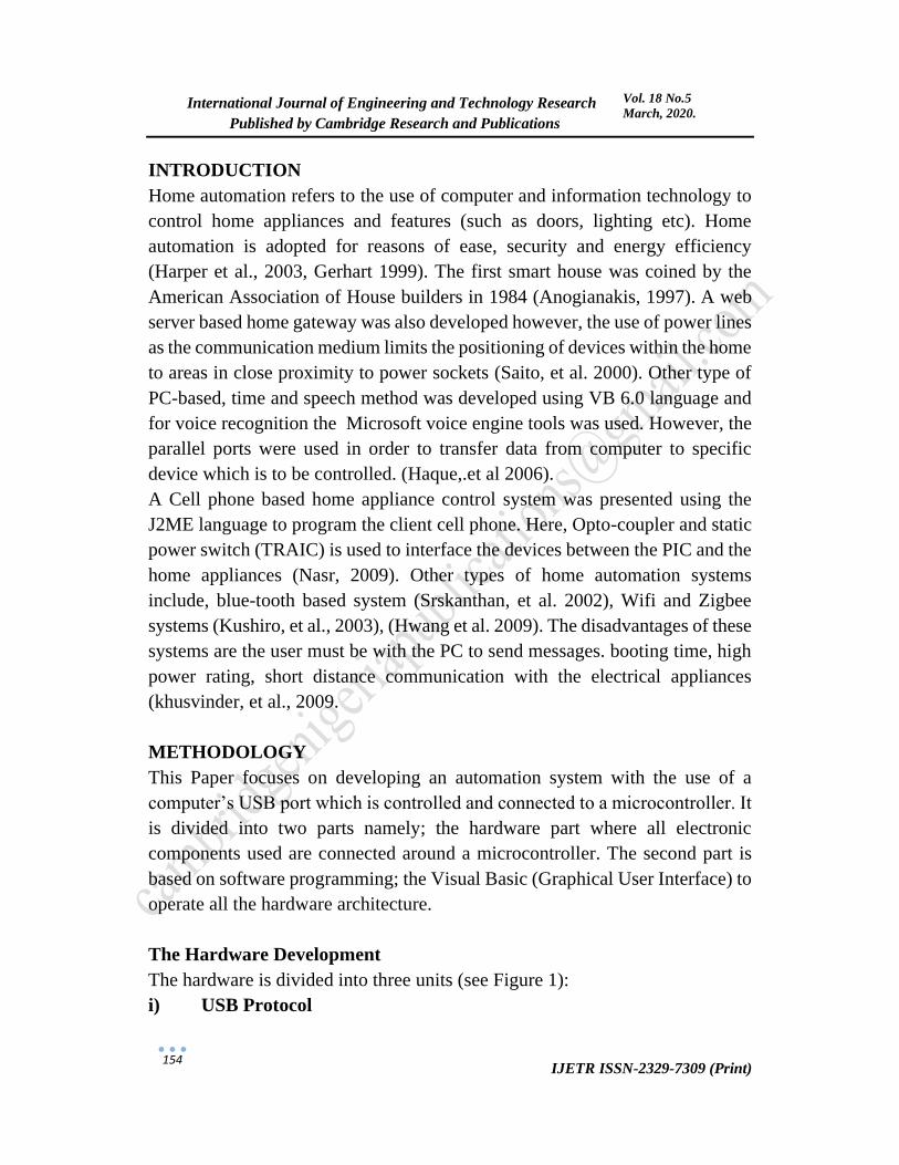
INTRODUCTION
Home automation refers to the use of computer and information technology to
control home appliances and features (such as doors, lighting etc). Home
automation is adopted for reasons of ease, security and energy efficiency
(Harper et al., 2003, Gerhart 1999). The first smart house was coined by the
American Association of House builders in 1984 (Anogianakis, 1997). A web
server based home gateway was also developed however, the use of power lines
as the communication medium limits the positioning of devices within the home
to areas in close proximity to power sockets (Saito, et al. 2000). Other type of
PC-based, time and speech method was developed using VB 6.0 language and
for voice recognition the Microsoft voice engine tools was used. However, the
parallel ports were used in order to transfer data from computer to specific
device which is to be controlled. (Haque,.et al 2006).
A Cell phone based home appliance control system was presented using the
J2ME language to program the client cell phone. Here, Opto-coupler and static
power switch (TRAIC) is used to interface the devices between the PIC and the
home appliances (Nasr, 2009). Other types of home automation systems
include, blue-tooth based system (Srskanthan, et al. 2002), Wifi and Zigbee
systems (Kushiro, et al., 2003), (Hwang et al. 2009). The disadvantages of these
systems are the user must be with the PC to send messages. booting time, high
power rating, short distance communication with the electrical appliances
(khusvinder, et al., 2009.
METHODOLOGY
This Paper focuses on developing an automation system with the use of a
computer’s USB port which is controlled and connected to a microcontroller. It
is divided into two parts namely; the hardware part where all electronic
components used are connected around a microcontroller. The second part is
based on software programming; the Visual Basic (Graphical User Interface) to
operate all the hardware architecture.
The Hardware Development
The hardware is divided into three units (see Figure 1):
i) USB Protocol

International Journal of Engineering and Technology Research
Published by Cambridge Research and Publications
IJETR ISSN-2329-7309 (Print)
155
Vol. 18 No.5
March, 2020.
Universal Serial Bus (USB) defines the cables, connectors and communications
protocols used in a bus for connection, communication, and power supply
between computers and electrical appliances.
Basic Operation of USB
When a USB device is first connected to a USB host, the USB device
enumeration process is started. The enumeration starts by sending a reset signal
to the USB device. The data rate of the USB device is determined during the
reset signaling. After reset, the USB device's information is read by the host and
the device is assigned a unique 7-bit address. If the device is supported by the
host, the device drivers needed for communicating with the device are loaded
and the device is set to a configured state. If the USB host is restarted, the
enumeration process is repeated for all connected devices.
The host controller directs traffic flow to devices, so no USB device can transfer
any data on the bus without an explicit request from the host controller. In USB
2.0, the host controller polls the bus for traffic, usually in a round-robin fashion.
The throughput of each USB port is determined by the slower speed of either
the USB port or the USB device connected to the port.
FT232RL
The FT232RL provides true CMOS Drive Outputs and TTL level Inputs. It was
used to convert signals from a USB port to serial signals suitable for use in TTL.
The device operating supply current has been reduced to 15mA, and the suspend
current has been reduced to around 70μA. This allows greater margin for
peripheral designs to meet the USB suspend current limit of 500μA. It operates
over an extended temperature range of -40º to +85º C thus allowing the device
to be used in automotive and industrial applications. Previous generations of the
chip required 5V supply on the VCC pin. The FT232R will work with a Vcc
supply in the range 3.3V - 5.25V. Bus powered designs would still take their
supply from the 5V on the USB bus, but for self-powered designs where only
3.3V is available and there is no 5V supply there is no longer any need for an
additional external regulator. It has internally generated clock (6MHz, 12MHz,
24MHz, and 48MHz) which can be brought out of the device and use to drive a
microcontroller or external logic.

International Journal of Engineering and Technology Research
Published by Cambridge Research and Publications
IJETR ISSN-2329-7309 (Print)
156
Vol. 18 No.5
March, 2020.
Figure 1: Block Diagram of A PC Based Home Automation Using USB
Protocol
The Software Development
(i) The design’s Flow Chart (see Figure 2)
(ii) Installing Visual Basic (Graphical User Interface)
PORT A
PORT B
PORT C
PORT D
YES YES YES YES
Start
End
PC
NONO NO
receive datafrom PC
receive datafrom PC
receive datafrom PC
receive datafrom PC
Bulb I Bulb II FanWall
socket
NO
Figure 2:
Flowchart of the Operation
SYSTEM
VISUAL
BASIC
µC
UL
N
2803
FT2
32R
L
RLY
RLY
RLY
RLY

International Journal of Engineering and Technology Research
Published by Cambridge Research and Publications
IJETR ISSN-2329-7309 (Print)
157
Vol. 18 No.5
March, 2020.
Controller Code Used
load1equ p2.0
load2equ p2.1
load3equ p2.2
load4equ p2.3
;...........mainprog....................
org 0000h
main: mov a,#0
mov p2,a
go: call serial_init
callreciev_byte
call compare
ajmp go
compare: cjne a,#'A',go1
setb load1ret
go1: cjne a,#'B',go2
setb load2ret
go2:cjne a,#'C',go3
setb load3ret
go3:cjne a,#'D',go4
setb load4ret
go4: cjne a,#'E',go5
clr load1ret
go5: cjne a,#
'F',go6clr load2ret
go6: cjne a,#'G',go7
clr load3ret
go7: cjne a,#'H',go8
clr load4
go8:ret
end

International Journal of Engineering and Technology Research
Published by Cambridge Research and Publications
IJETR ISSN-2329-7309 (Print)
158
Vol. 18 No.5
March, 2020.
Figure 3: Circuit Diagram of PC Based Home Automation System Using USB
Protocol
MODE OF OPERATION
The Visual basic application installed on the PC allows remote it to display user
interfaces. It uses the visual basic (VB) to transmit the user interface to the
remote device (PC).
The basic operation is stated and explained below:
Then the USB cable of the circuit is connected to the computer system and when
it is recognized by the computer
system, G.U.I (VB software) is
launched which makes the circuit to
communicate with the computer
system serially.
Figure 4: The G.U.I Interface
The G.U.I (VB software) brings out
the interface (see Figure 4). Then the

International Journal of Engineering and Technology Research
Published by Cambridge Research and Publications
IJETR ISSN-2329-7309 (Print)
159
Vol. 18 No.5
March, 2020.
user is allowed to log in. and a welcome message observed.
Figure 5: Welcome Message Interface
A dialog box will appear that shows the control interface where all the electrical
appliances can be controlled. The user can also know the status of these
appliances either ON/OFF (see Figure 6).
Figure 6: Control Button Interface
IV. TESTING AND DISCUSSION
(i) Testing for and Electric FAN
When the ON button of the FAN is clicked; a message will pop-up to display
its status (either ON or OFF).. It is shown in the Figure 7.
Figure 7: Message displayed When Fan is switched ON

International Journal of Engineering and Technology Research
Published by Cambridge Research and Publications
IJETR ISSN-2329-7309 (Print)
160
Vol. 18 No.5
March, 2020.
When the OFF button of the FAN is clicked; a message will pop-up to display
the result (see Figure 8).
Figure 8: Message displayed When Fan is switched OFF
(ii) Testing for RADIO
When the ON button of the RADIO is clicked; a message will pop-up to display
the result (see Figure 9).
Figure 9: Message displayed When RADIO is switched ON
When the OFF button of the RADIO is clicked; a message will pop-up to display
the result (see Figure 10)

International Journal of Engineering and Technology Research
Published by Cambridge Research and Publications
IJETR ISSN-2329-7309 (Print)
161
Vol. 18 No.5
March, 2020.
Figure 10: Message displayed When RADIO is switched OFF
Once the user is through with the operation, the “EXIT” on the interface is
clicked to close the Interface.
CONCLUSION AND RECOMMENDATIONS
This Paper presents the development implementation of a sPC-based home
automation system using the USB Protocol. It easily interfaces the pre-existing
home appliances with the PC’s USB Port.
This Paper therefore successfully designed a system that communicates with a
PC via a USB port/cable. The design worked according to specifications. It is
however recommended that a wireless or a voice recognition system be
incorporated into the circuit to serve longer range distances and facilitate high
performances.
REFERENCES
Al-Ali, A. and Al-Rousan, M. (2004) "Java-based home automation system",
IEEE Transactions on Consumer Electronics, vol. 50, no. 2, pp. 498-504.
Ardam, H. and Coskun, I. (1998) "A remote controller for home and office
appliances by telephone", IEEE Transactions on Consumer Electronics,
vol. 44, no. 4, pp. 1291-1297.
Baudel, T. et al., (1993) “Remote control of objects using free-hand gestures",
Communications of the ACM, vol. 36, no. 7, pp. 28-35.
Bromley, K., et al. (2003) "Trends in Smart Home Systems, Connectivity and
Services", www.nextwave.org.uk.

International Journal of Engineering and Technology Research
Published by Cambridge Research and Publications
IJETR ISSN-2329-7309 (Print)
162
Vol. 18 No.5
March, 2020.
Gerhart, J. (1999), “Home Automation and wiring” pg. 1
Harper et al., (2003) “Inside the Smart” pg. 17…18-19…
Haque, S. et al., (2006) “A System for Smart-Home Control of Appliances
Based on Timer and Speech Interaction”, Proceedings of the 4th
International Conference on Electrical Engineering & 2nd Annual Paper
Meet. pp. 128-131.
Hwang, I. et al., (2009) “Home Network Configuring Scheme for All Electric
Appliances Using ZigBee-based Integrated Remote Controller”, IEEE
Transactions on Consumer Electronics, vol. 55, no. 3. pp. 1300-1307.
Jawarkar, N. P., et al., (2007) “Remote Control using Mobile through Spoken
Commands”, IEEE - International Consortium of Stem Cell Networks
(ICSCN) pp. 622-625.
Khusvinder Gill, et al., (2009) “A ZigBee Based Home Automation System”,
IEEE Transactions on Consumer Electronics, Vol. 55, No. 2
Krishna, Y. B., and S. Nagendram, (2012) “Zigbee Based Voice Control System
for Smart Home”, International Journal Computer Techology &
Applications, vol. 3, no. 1, pp.163-168.
Kushiro, N., et al., (2003) "Integrated home gateway controller for home energy
management system", IEEE International Conference on Consumer
Electronics, pp. 386-387
Mardiana, B., et al., (2009) "Homes Appliances Controlled Using Speech
Recognition in Wireless Network Environment", International Conference
on Computer Technology and Development (ICCTD) pp. 285- 288.
Nasr, M. et al., (2009) "Friendly home automation system using cell phone and
J2ME with feedback instant voice messages", 2009 IEEE/ACS
International Conference on Computer Systems and Applications. pp. 531-
538.
Saito, T., et al., (2000) "Home Gateway Architecture and Its Implementation",
IEEE International Conference on Consumer Electronics, pp. 194-195.
Sriskanthan, N., et al., (2002) "Bluetooth based home automation system",
Microprocessors and Microsystems, Vol. 26, no. 6, pp. 281-289.
http://jaspreetscodezone.blogspot.com/2008/01/interfacing-relays-using-
parallel-port.html
http://ww1.microchip.com/downloads/en/devicedoc/39582b.pdf.

International Journal of Engineering and Technology Research
Published by Cambridge Research and Publications
IJETR ISSN-2329-7309 (Print)
163
Vol. 18 No.5
March, 2020.
www.circuitstudy.com/basics-of-microcontrollers
www.en.m.wikipedia.org/wiki/microcontoller
Copyright © 2022 FDOKUMEN